Pneumatic Muscle Actuated Wrist Rehabilitation Equipment ...
10
*Corr. Author’s Address: Transilvania University, 29 Eroilor Bd., Brasov, Romania, [email protected] 383 Strojniški vestnik - Journal of Mechanical Engineering 64(2018)6, 383-392 Received for review: 2017-12-01 © 2018 Journal of Mechanical Engineering. All rights reserved. Received revised form: 2018-03-29 DOI:10.5545/sv-jme.2017.5123 Original Scientific Paper Accepted for publication: 2018-04-26 0 INTRODUCTION The wrist is an extremely complex joint, and its integrity is essential for everyday activity. The basic skeleton of the palm and the fingers includes 27 bones, eight of which (the carpal bones) form the most complex joint of the human body – the wrist. The actual hand consists of the five metacarpal bones followed by the 14 phalanges of the fingers. While the wrist ensures a wide range of motions in flexion, extension, circumduction, radial and ulnar deviation, its complexity renders it vulnerable to a series of affections likely to limit its functionality. Lesions of the wrist can be the cause of problems in the long term, ranging from articular stiffness, pain, numbness to partial or total disability. Rehabilitation by mobilization of the wrist has to commence as soon as physically possible, and the risk of relapse has been diminished significantly. The mobilization of the joints aims at correcting the retractions of the soft tissue, improvement of blood circulation, recovery of the gripping function, increase of muscle force and strength. Wrist rehabilitation can be achieved by a procedure known as continuous passive motion that entails setting the injured joint into motion by mechanized means, without straining the patient’s muscles. This is possible by means of specially designed equipment, capable of applying the optimum rehabilitation motions to the wrist. As its primary control parameters, passive mobilization has the applied force, the stroke, the velocity, acceleration, duration and frequency of the displacement; all these quantities need to be adapted to the patient’s clinical state and the set target. This means that equipment for passive mobilization has to allow the adjustment between certain limits of all the mentioned parameters. Equipment based on continuous passive motion currently available on the marketplace provides in addition to mobilizing the damaged joint also an assessment of muscle performance, thus allowing patient state monitoring during the entire period of recovery. Of the various manoeuvres possible as part of the mobilization exercises, slow progressive motion at varying amplitudes is most often applied. The force applied by the physical therapist at the maximum possible amplitude is typically dosed depending on the onset of pain, but also according to the therapist’s experience with patients displaying either very high or very low pain thresholds. The necessity of rehabilitation of the human body joints by mobilization was documented as early as nearly 5000 years ago. Chinese documents, 4700 years old, held information about therapeutic postures and motions aimed at pain relief [1]. It was Pneumatic Muscle Actuated Wrist Rehabilitation Equipment Based on the Fin Ray Principle Petre, I. – Deaconescu, A. – Sârbu, F. – Deaconescu, T. Ioana Petre – Andrea Deaconescu – Flavius Sârbu – Tudor Deaconescu * Transylvania University of Brasov, Romania Rehabilitation of the hand entails the deployment of equipment that, by motion, accelerates the regaining of its specific functions and allow the swift social reintegration of patients at a minimum cost. In this context, the paper presents and discusses a pneumatic muscle actuated piece of equipment that allows the simultaneous rehabilitation of the radiocarpal, metacarpophalangeal and interphalangeal joints. The main novelty of this equipment consists in the solution selected for the support and mobilization of the hand; the construction put forward is based on a couple of bar mechanisms that form a Fin Ray type structure, specific to fish fins. The paper presents the constructive solution, the structure of the actuation system and the experimental results that highlight both the benefits and disadvantages of the proposed equipment. Of particular interest is the compliance of the system that contributes to its adaptability to the particular pain threshold of the patient. Keywords: compliance, fin ray effect, pneumatic muscles, wrist rehabilitation equipment Highlights • New bio-inspired wrist rehabilitation equipment is proposed. • A fin ray type structure is designed to support and mobilize the palm. • The structural diagram of the rehabilitation equipment, its construction, and its pneumatic control diagram are presented. • Attaining the angular motion limits of the hand joints and the variation of the rehabilitation equipment compliance are both demonstrated.
-
Upload
khangminh22 -
Category
Documents
-
view
0 -
download
0
Transcript of Pneumatic Muscle Actuated Wrist Rehabilitation Equipment ...
*Corr. Author’s Address: Transilvania University, 29 Eroilor Bd., Brasov, Romania, [email protected] 383
Strojniški vestnik - Journal of Mechanical Engineering 64(2018)6, 383-392 Received for review: 2017-12-01© 2018 Journal of Mechanical Engineering. All rights reserved. Received revised form: 2018-03-29DOI:10.5545/sv-jme.2017.5123 Original Scientific Paper Accepted for publication: 2018-04-26
0 INTRODUCTION
The wrist is an extremely complex joint, and its integrity is essential for everyday activity. The basic skeleton of the palm and the fingers includes 27 bones, eight of which (the carpal bones) form the most complex joint of the human body – the wrist. The actual hand consists of the five metacarpal bones followed by the 14 phalanges of the fingers.
While the wrist ensures a wide range of motions in flexion, extension, circumduction, radial and ulnar deviation, its complexity renders it vulnerable to a series of affections likely to limit its functionality. Lesions of the wrist can be the cause of problems in the long term, ranging from articular stiffness, pain, numbness to partial or total disability.
Rehabilitation by mobilization of the wrist has to commence as soon as physically possible, and the risk of relapse has been diminished significantly. The mobilization of the joints aims at correcting the retractions of the soft tissue, improvement of blood circulation, recovery of the gripping function, increase of muscle force and strength.
Wrist rehabilitation can be achieved by a procedure known as continuous passive motion that entails setting the injured joint into motion by mechanized means, without straining the patient’s muscles. This is possible by means of specially
designed equipment, capable of applying the optimum rehabilitation motions to the wrist.
As its primary control parameters, passive mobilization has the applied force, the stroke, the velocity, acceleration, duration and frequency of the displacement; all these quantities need to be adapted to the patient’s clinical state and the set target. This means that equipment for passive mobilization has to allow the adjustment between certain limits of all the mentioned parameters.
Equipment based on continuous passive motion currently available on the marketplace provides in addition to mobilizing the damaged joint also an assessment of muscle performance, thus allowing patient state monitoring during the entire period of recovery.
Of the various manoeuvres possible as part of the mobilization exercises, slow progressive motion at varying amplitudes is most often applied. The force applied by the physical therapist at the maximum possible amplitude is typically dosed depending on the onset of pain, but also according to the therapist’s experience with patients displaying either very high or very low pain thresholds.
The necessity of rehabilitation of the human body joints by mobilization was documented as early as nearly 5000 years ago. Chinese documents, 4700 years old, held information about therapeutic postures and motions aimed at pain relief [1]. It was
Pneumatic Muscle Actuated Wrist Rehabilitation Equipment Based on the Fin Ray Principle
Petre, I. – Deaconescu, A. – Sârbu, F. – Deaconescu, T.Ioana Petre – Andrea Deaconescu – Flavius Sârbu – Tudor Deaconescu*
Transylvania University of Brasov, Romania
Rehabilitation of the hand entails the deployment of equipment that, by motion, accelerates the regaining of its specific functions and allow the swift social reintegration of patients at a minimum cost. In this context, the paper presents and discusses a pneumatic muscle actuated piece of equipment that allows the simultaneous rehabilitation of the radiocarpal, metacarpophalangeal and interphalangeal joints. The main novelty of this equipment consists in the solution selected for the support and mobilization of the hand; the construction put forward is based on a couple of bar mechanisms that form a Fin Ray type structure, specific to fish fins. The paper presents the constructive solution, the structure of the actuation system and the experimental results that highlight both the benefits and disadvantages of the proposed equipment. Of particular interest is the compliance of the system that contributes to its adaptability to the particular pain threshold of the patient.Keywords: compliance, fin ray effect, pneumatic muscles, wrist rehabilitation equipment
Highlights• New bio-inspired wrist rehabilitation equipment is proposed.• A fin ray type structure is designed to support and mobilize the palm.• The structural diagram of the rehabilitation equipment, its construction, and its pneumatic control diagram are presented.• Attaining the angular motion limits of the hand joints and the variation of the rehabilitation equipment compliance are both
demonstrated.
Strojniški vestnik - Journal of Mechanical Engineering 64(2018)6, 383-392
384 Petre, I. – Deaconescu, A. – Sârbu, F. – Deaconescu, T.
in ancient Greece where the fundamentals of kinetic therapy were truly laid by Aristoteles, considered its founder. Later it was Hippocrates who noticed that motion contributes to regaining muscle force, while immobilization leads to atrophy.
The utilization of wrist rehabilitation equipment has been a usual practice for centuries. One of the oldest achievements are the mechanical devices of Zander based on the pulley and weight mechanism built in 1857 [2]. In 1919, the Otto Bock Company put forward a series of rehabilitation devices designed for all joints of the upper and lower limbs [3]. At present several manufacturers of such equipment are present on the marketplace, like Kinetek, producer of Kinetec Maestra Hand & Wrist CPM [4], Remington Medical marketing the WaveFlex Hand [5] or Kinex with its Kinex Hand [6].
Of interest in the recovery of the wrist is also the system with three degrees of freedom that can be attached to the MIT-MANUS robot [7]. The limits of motion of this equipment are flexion/extension 60°/60°, abduction/adduction 30°/45°, pronation/supination 70°/70°.
Paper [8] presents a novel lightweight hand exoskeleton robot, which is called an advanced service robots (ASR) glove. The study shows that the proposed system can flex and extend fingers in their range of motion and grasp objects efficiently.
The vast majority of rehabilitation equipment for continuous passive motion available on the marketplace at present is actuated by electric motors [9]. An analysis of the actuation systems of wrist rehabilitation equipment has revealed that about 72 % are electrically driven, 20 % pneumatically, 5 % hydraulically, and the remaining 3 % is covered by other energy sources [10].
At present, given the diversification, miniaturization and significant improvement of pneumatic components, the deployment of compressed air increasingly becomes a solution to be considered. Thus, in recent years. pneumatically actuated wrist rehabilitation equipment has been the object of several patents, a number of which are presented in [11] to [13]. Another example of pneumatically driven rehabilitation equipment is the parallel manipulator suitable for the complex motion of the human wrist joint [14].
A study of wrist rehabilitation equipment currently available on the marketplace has revealed that mobilization is achieved separately for each joint. It could also be observed that most equipment is actuated electrically, and pneumatic drives are neglected. Consequently, the authors of this paper
put forward innovative equipment that mobilizes the wrist and finger joints at the same time, the actuation being ensured by a pneumatic muscle. Another novel aspect of the proposed solution is the bio-inspired construction of the palm support, based on the fin-ray effect, specific to fish fins. The benefit of the solution put forward consists in the fact that the complex motion performed by each of the hand segments, even though not all are affected, helps to improve their muscle and articular tone. Thus, in addition to the prophylaxis of joint pain achieved by the proposed equipment, it also helps to maintain and/or increase the muscle excitability of the healthy segments.
The first part of the paper presents the biomechanics of the hand and fingers, highlighting the limits of the motions that have to be reached by the rehabilitation equipment. Furthermore, the actuation motor is presented, with a focus on a specific property of pneumatic muscles known as compliance. The second part describes the construction of the rehabilitation equipment and its actuation, followed by the third part in which the experimental results are presented. The paper concludes with a section of conclusions.
1 DESIGN REQUIREMENTS
The development of rehabilitation equipment for the hand joints entails a thorough knowledge of the motions of the hand, of the forces and couples developed by it. It is further essential to identify the limits of these motions so that the new equipment can achieve them. With respect to this, the anatomic principles of the motions carried out by the joints of the hand are presented further on.
1.1 Biomechanics of the Joints of the Hand
The possible motions of the joints of the hand are incredibly numerous and complex. A rehabilitation device capable of conducting all these motions would require extremely complicated kinematics and would be economically inefficient. For this reason, rehabilitation equipment available on the marketplace at present is typically designed for a single joint, for either the wrist or the finger joints. The proposed rehabilitation system discussed in this paper achieves mobilization by the continuous passive motion of the radiocarpal joint and at the same time of the metacarpophalangeal and interphalangeal joints. The proposed equipment can reproduce in the case of all mentioned joints the motions of flexion-extension (Fig. 1).
Strojniški vestnik - Journal of Mechanical Engineering 64(2018)6, 383-392
385Pneumatic Muscle Actuated Wrist Rehabilitation Equipment Based on the Fin Ray Principle
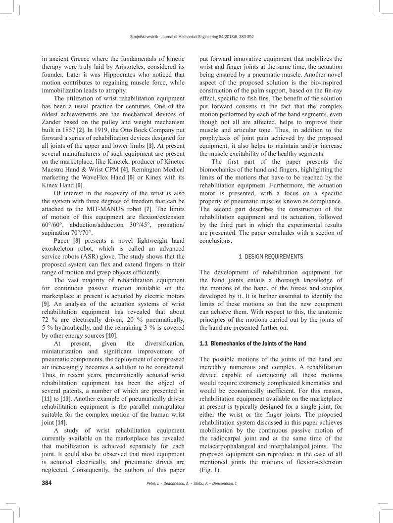
Fig. 1. Flexion/extension of the wrist and joints of the fingers
The flexion of the wrist or the palmar flexion is obtained by rotating the palm in the volar direction. Zero position is obtained when the forearm is in flexion at 90º and in pronation. In this case, the maximum rotation angle is of 80º. The extension of the wrist or dorsiflexion is obtained by rotating the palm in a dorsal direction, the maximum rotation angle being of 70º.
In the case of the fingers, zero position is considered for the extended palm and fingers. For the metacarpophalangeal joints, the angle of flexion increases from finger II to finger V from 90º to 100º. The extension of the fingers varies from one individual to another and ranges from 0º to 90º, the latter value describing hyperextension of the fingers.
Proximal flexion is the movement of the middle phalanx towards the inner palm, towards the proximal phalanx, until the limit of the motion is reached. The amplitude of this motion is of 100º to 120º. This flexion has small values for fingers I and II and greater ones for fingers IV and V.
Distal flexion is the motion of the distal phalanx towards the inner palm, towards the middle phalanx. To obtain the maximum value, the proximal joint has to be in flexion. The maximum flexion value of this joint does not exceed 90º.
The extension is possible only in the distal joints, its maximum amplitude being of 20º, and is encountered only in certain individuals. A larger extension angle causes the so-called hyperextension.
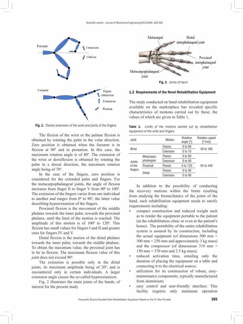
Fig. 2 illustrates the main joints of the hands, of interest for the present study.
Fig. 2. Joints of hand
1.2 Requirements of the Novel Rehabilitation Equipment
The study conducted on hand rehabilitation equipment available on the marketplace has revealed specific characteristics of motions carried out by these, the values of which are given in Table 1.
Table 1. Limits of the motions carried out by rehabilitation equipment of the wrist and fingers
Joint MotionRotation angle [º]
Rotation speed [º/min]
WristFlexion 0 to 80
30 to 180Extension 0 to 70
Joints of the fingers
Metacarpo-phalangeal
Flexion 0 to 90
55 to 440Extension 0 to 90
Proximal Flexion 0 to 120
DistalFlexion 0 to 90Extension 0 to 90
In addition to the possibility of conducting the recovery motions within the limits resulting from studying the biomechanics of the joints of the hand, such rehabilitation equipment needs to satisfy requirements including:• compact construction and reduced weight such
as to render the equipment portable to the patient (in the rehabilitation clinic or even at the patient’s home). The portability of the entire rehabilitation system is assured by its construction, including the actual equipment (of dimensions 500 mm × 300 mm × 250 mm and approximately 3 kg mass) and the compressor (of dimensions 310 mm × 150 mm × 370 mm and 2.5 kg mass);
• reduced activation time, entailing only the duration of placing the equipment on a table and connecting it to the electrical source;
• utilization for its construction of robust, easy-maintenance components, typically manufactured from aluminium;
• easy control and user-friendly interface. This facility requires only minimum operation
Strojniški vestnik - Journal of Mechanical Engineering 64(2018)6, 383-392
386 Petre, I. – Deaconescu, A. – Sârbu, F. – Deaconescu, T.
proficiency of the user, given the easy command of the rehabilitation motions;
• adaptive behaviour to the pain threshold of the person undergoing rehabilitation treatment.The latter requirement is achieved by using so-
called adjustable compliance actuators (ACAs) for driving the equipment. A motor of this kind is selected given its benefits, such as its capacity of minimizing mechanical shocks, safe interaction with people or the ability to store and release energy in/from its passive-type elastic elements.
The utilization of adjustable compliance motors can ensure the adaptability of the rehabilitation equipment to a given concrete working situation determined by the patient’s pain threshold, which in some cases may be different than initially envisaged. If the recovery motion is opposed by a force generated, for example, by the increased rigidity of the joint to be rehabilitated, and implicitly by the pain felt by the patient, the pneumatic muscle will absorb (due to air compressibility) the induced shock, without forcing the movement.
2 CONSTRUCTION OF THE REHABILITATION EQUIPMENT
2.1 Constructive Principle
Starting from the observation that maximum flexion of the wrist is obtained when flexion of the fingers is simultaneously induced, and the maximum extension of the wrist is achieved with the fingers being extended, the idea underlying the development of the novel rehabilitation equipment was bio-inspired, based on the Fin Ray effect, specific to fish fins. A pneumatic muscle was used as the motion generator element.
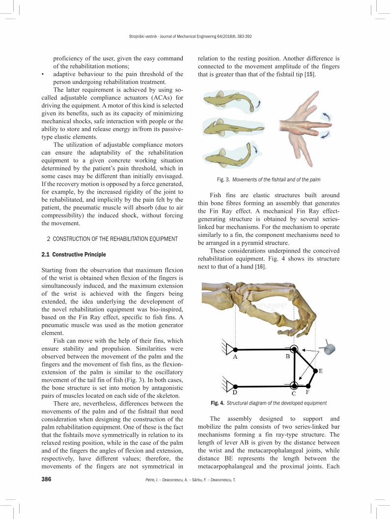
Fish can move with the help of their fins, which ensure stability and propulsion. Similarities were observed between the movement of the palm and the fingers and the movement of fish fins, as the flexion-extension of the palm is similar to the oscillatory movement of the tail fin of fish (Fig. 3). In both cases, the bone structure is set into motion by antagonistic pairs of muscles located on each side of the skeleton.
There are, nevertheless, differences between the movements of the palm and of the fishtail that need consideration when designing the construction of the palm rehabilitation equipment. One of these is the fact that the fishtails move symmetrically in relation to its relaxed resting position, while in the case of the palm and of the fingers the angles of flexion and extension, respectively, have different values; therefore, the movements of the fingers are not symmetrical in
relation to the resting position. Another difference is connected to the movement amplitude of the fingers that is greater than that of the fishtail tip [15].
Fig. 3. Movements of the fishtail and of the palm
Fish fins are elastic structures built around thin bone fibres forming an assembly that generates the Fin Ray effect. A mechanical Fin Ray effect-generating structure is obtained by several series-linked bar mechanisms. For the mechanism to operate similarly to a fin, the component mechanisms need to be arranged in a pyramid structure.
These considerations underpinned the conceived rehabilitation equipment. Fig. 4 shows its structure next to that of a hand [16].
Fig. 4. Structural diagram of the developed equipment
The assembly designed to support and mobilize the palm consists of two series-linked bar mechanisms forming a fin ray-type structure. The length of lever AB is given by the distance between the wrist and the metacarpophalangeal joints, while distance BE represents the length between the metacarpophalangeal and the proximal joints. Each
Strojniški vestnik - Journal of Mechanical Engineering 64(2018)6, 383-392
387Pneumatic Muscle Actuated Wrist Rehabilitation Equipment Based on the Fin Ray Principle
of joints B and C that link the two bar mechanisms includes a torsion spring with a 270º angle between its arms; the role of these springs is to cancel a degree of mobility of the entire assembly. For this system, the maximum flexion of the palm is obtained for extended fingers, and maximum palm extension is achieved when flexion of the fingers is induced. Fig. 5 shows the positions of the hand on the mechanism for the maximum flexion and maximum extension of the wrist, respectively.
Fig. 5. Limit positions of the mechanism
The first bar mechanism (ABCD) ensures the rotation of the palm. The counter-clockwise rotation of lever AB causes the extension of the palm, namely its lifting. At the same time, the second bar mechanism (BCFE) responsible for the movement of the finger joints will rotate clockwise. Thus, the counter-clockwise rotation of the palm will cause it to make a fist, while the clockwise rotation will open it. It can be noticed that this equipment provides (as an innovation) the simultaneous motion of the palm and finger joints, ensuring mobilization of several muscle sets at the same time.
The degree of mobility of this mechanism, not considering the two torsion springs, is given by Eq. (1):
M n fi
ke e= ⋅ − − = ⋅ − ⋅ −( ) =
=∑ e
1
3 6 8 3 1 2( ) , (1)
where ϰe is the dimension of the actual kinematic space, n the number of mobile elements, k the number
of couples, fe the dimension of the space of relative velocities for couple k.
Introducing the two springs linking element AB to BE and DC to CF, respectively, cancels a degree of mobility of the mechanism, as the movement of element BE becomes dependent on the movement of element AB. For bar mechanism BCFE to function correctly, the torsion springs mounted in couples B and C have to be twisted, thus tensioned over the entire working interval of this mechanism.
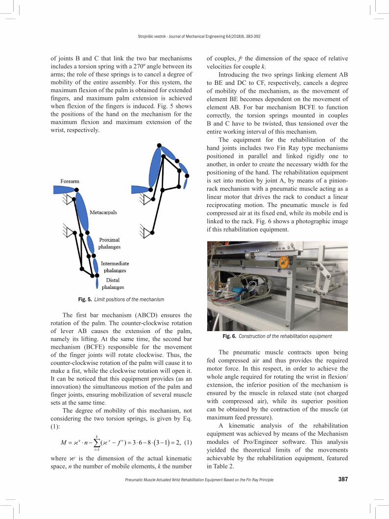
The equipment for the rehabilitation of the hand joints includes two Fin Ray type mechanisms positioned in parallel and linked rigidly one to another, in order to create the necessary width for the positioning of the hand. The rehabilitation equipment is set into motion by joint A, by means of a pinion-rack mechanism with a pneumatic muscle acting as a linear motor that drives the rack to conduct a linear reciprocating motion. The pneumatic muscle is fed compressed air at its fixed end, while its mobile end is linked to the rack. Fig. 6 shows a photographic image if this rehabilitation equipment.
Fig. 6. Construction of the rehabilitation equipment
The pneumatic muscle contracts upon being fed compressed air and thus provides the required motor force. In this respect, in order to achieve the whole angle required for rotating the wrist in flexion/extension, the inferior position of the mechanism is ensured by the muscle in relaxed state (not charged with compressed air), while its superior position can be obtained by the contraction of the muscle (at maximum feed pressure).
A kinematic analysis of the rehabilitation equipment was achieved by means of the Mechanism modules of Pro/Engineer software. This analysis yielded the theoretical limits of the movements achievable by the rehabilitation equipment, featured in Table 2.
Strojniški vestnik - Journal of Mechanical Engineering 64(2018)6, 383-392
388 Petre, I. – Deaconescu, A. – Sârbu, F. – Deaconescu, T.
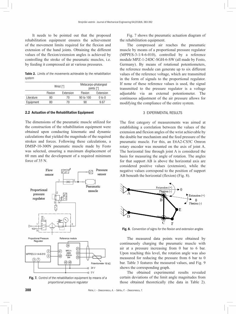
It needs to be pointed out that the proposed rehabilitation equipment ensures the achievement of the movement limits required for the flexion and extension of the hand joints. Obtaining the different values of the flexion/extension angles is achieved by controlling the stroke of the pneumatic muscles, i.e. by feeding it compressed air at various pressures.
Table 2. Limits of the movements achievable by the rehabilitation system
Wrist [°]Metacarpo-phalangeal
joints [°]Flexion Extension Flexion Extension
Literature 80 70 90 to 100 0 to 0Equipment 80 70 90 9.67
2.2 Actuation of the Rehabilitation Equipment
The dimensions of the pneumatic muscle utilized for the construction of the rehabilitation equipment were obtained upon conducting kinematic and dynamic calculations that yielded the magnitude of the required strokes and forces. Following these calculations, a DMSP-10-300N pneumatic muscle made by Festo was selected, ensuring a maximum displacement of 60 mm and the development of a required minimum force of 35 N.
Fig. 7. Control of the rehabilitation equipment by means of a proportional pressure regulator
Fig. 7 shows the pneumatic actuation diagram of the rehabilitation equipment.
The compressed air reaches the pneumatic muscle by means of a proportional pressure regulator (MPPES-3-1/4-6-010), controlled by a reference module MPZ-1-24DC-SGH-6-SW (all made by Festo, Germany). By means of rotational potentiometers, the reference module can generate up to six different values of the reference voltage, which are transmitted in the form of signals to the proportional regulator. If none of these reference values is used, the signal transmitted to the pressure regulator is a voltage adjustable via an external potentiometer. The continuous adjustment of the air pressure allows for modifying the compliance of the entire system.
3 EXPERIMENTAL RESULTS
The first category of measurements was aimed at establishing a correlation between the values of the extension and flexion angles of the wrist achievable by the double bar mechanism and the feed pressure of the pneumatic muscle. For this, an E6A2-CS5C Omron rotary encoder was mounted on the axis of joint A. The horizontal line through joint A is considered the basis for measuring the angle of rotation. The angles for that support AB is above the horizontal axis are considered positive values (extension), while the negative values correspond to the position of support AB beneath the horizontal (flexion) (Fig. 8).
Fig. 8. Convention of signs for the flexion and extension angles
The measured data points were obtained by continuously charging the pneumatic muscle with air at a pressure increasing from 0 bar to 6 bar. Upon reaching this level, the rotation angle was also measured for reducing the pressure from 6 bar to 0 bar. Table 3 features the measured values, and Fig. 9 shows the corresponding graph.
The obtained experimental results revealed certain deviations of the limit angle magnitudes from those obtained theoretically (the data in Table 2).
Strojniški vestnik - Journal of Mechanical Engineering 64(2018)6, 383-392
389Pneumatic Muscle Actuated Wrist Rehabilitation Equipment Based on the Fin Ray Principle
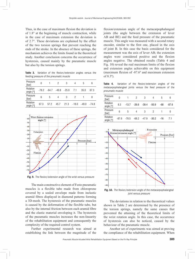
Thus, in the case of maximum flexion the deviation is of 1.8° at the beginning of muscle contraction, while in the case of maximum extension the deviation is of 2.7°. These deviations are explained by the effect of the two torsion springs that prevent reaching the ends of the stroke. In the absence of these springs, the mechanism achieves the limits found in the theoretical study. Another conclusion concerns the occurrence of hysteresis, caused mainly by the pneumatic muscle but also by the torsion springs.
Table 3. Variation of the flexion/extension angles versus the feeding pressure of the pneumatic muscle
Pressure [bar]
0 1 2 3 4 5 6
Rotation angle [º]
–78.2 –64.7 –49.8 –25.0 7.1 35.0 67.3
Pressure [bar]
6 5 4 3 2 1 0
Rotation angle [º]
67.3 57.2 45.7 21.3 –18.0 –49.0 –74.8
Fig. 9. The flexion/extension angle of the wrist versus pressure
The main constructive element of Festo pneumatic muscles is a flexible tube made from chloroprene covered by a sealed envelope made from inelastic aramid fibres displayed in diamond patterns forming a 3D-mesh. The hysteresis of the pneumatic muscles is caused by the deformation of the flexible tube, but also by the internal friction between each aramid fibre and the elastic material enveloping it. The hysteresis of the pneumatic muscles increases the non-linearity of the rehabilitation equipment and consequently the complexity of the required control system.
Further experimental research was aimed at establishing the link between the magnitude of the
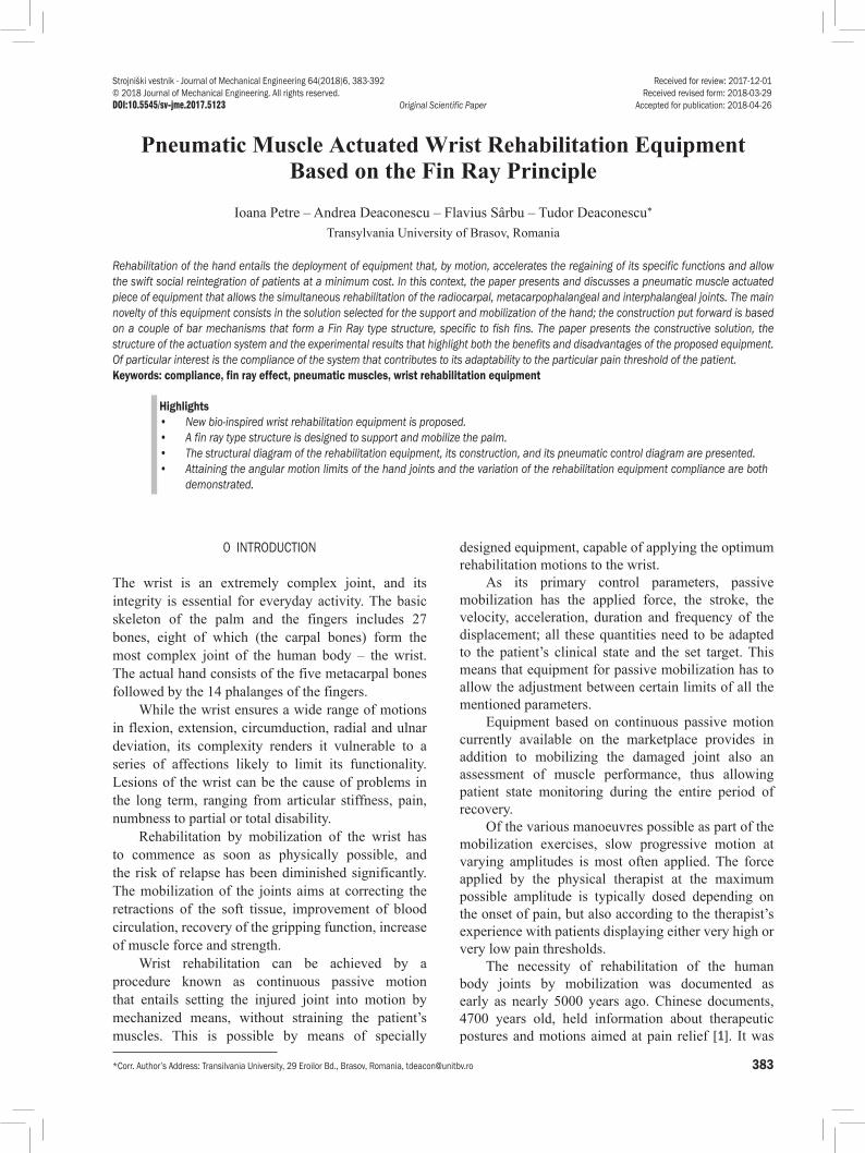
flexion/extension angle of the metacarpophalangeal joints (the angle between the extension of lever AB and BE) and the feed pressure of the pneumatic muscle. This angle was measured with a second rotary encoder, similar to the first one, placed in the axis of joint B. In this case the basis considered for the measurement was the axis of lever AB; the extension angles were considered positive and the flexion angles negative. The obtained results (Table 4 and Fig. 10) reveal the real maximum limits of the flexion and extension angles achievable on this equipment (maximum flexion of -87.6º and maximum extension of 8.3º).
Table 4. Variation of the flexion/extension angles of the metacarpophalangeal joints versus the feed pressure of the pneumatic muscle
Pressure [bar]
0 1 2 3 4 5 6
Rotation angle [º]
8.3 -13.7 -26.6 -39.4 -50.9 -68 -87.6
Pressure [bar]
6 5 4 3 2 1 0
Rotation angle [º]
-87.6 -78.5 -68.2 -47.9 -30.2 -16 7.1
Fig. 10. The flexion/extension angle of the metacarpophalangeal joint versus pressure
The deviations in relation to the theoretical values shown in Table 2 are determined by the presence of the torsion springs, namely the same causes that prevented the attaining of the theoretical limits of the wrist rotation angle. In this case, the occurrence of hysteresis can also be noticed, caused by the behaviour of the pneumatic muscle.
Another set of experiments was aimed at proving the compliance of the rehabilitation equipment. When
Strojniški vestnik - Journal of Mechanical Engineering 64(2018)6, 383-392
390 Petre, I. – Deaconescu, A. – Sârbu, F. – Deaconescu, T.
the dependency between the force generated by a motor and the displacement caused by it is of a non-linear type, the stiffness of the actuator and implicitly its compliance are variable. This is the case of the pneumatic muscle that actuates the rehabilitation equipment.
In order to determine the compliance of the rehabilitation equipment, the forces must be measured, developed by the pneumatic muscles in order to attain the various angular positions of the palm support. Measurements were conducted by means of a force sensor supplied by Festo, with the following characteristics: measuring range: 0 kN to 1 kN; supply voltage: 24 V DC; output voltage: 0 V to 10 V. The data provided by the sensor were processed by means of dedicated software FluidLab®-P V1.0, developed for the collection and processing of pneumatic system data.
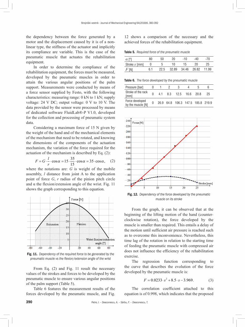
Considering a maximum force of 15 N given by the weight of the hand and of the mechanical elements of the mechanism that need to be rotated, and knowing the dimensions of the components of the actuation mechanism, the variation of the force required for the actuation of the mechanism is described by Eq. (2):
F G lr
= ⋅ ⋅ = ⋅ ⋅ = ⋅cos cos cos ,α α α1535
1535 (2)
where the notations are: G is weight of the mobile assembly, l distance from joint A to the application point of force G, r radius of the pinion pitch circle and α the flexion/extension angle of the wrist. Fig. 11 shows the graph corresponding to this equation.
Fig. 11. Dependency of the required force to be generated by the pneumatic muscle vs the flexion/extension angle of the wrist
From Eq. (2) and Fig. 11 result the necessary values of the strokes and forces to be developed by the pneumatic muscle to ensure various angular positions of the palm support (Table 5).
Table 6 features the measurement results of the forces developed by the pneumatic muscle, and Fig.
12 shows a comparison of the necessary and the achieved forces of the rehabilitation equipment.
Table 5. Required force of the pneumatic muscle
α [º] 80 50 20 -10 -40 -70
Stroke s [mm] 0 5 10 15 20 25
F [N] 6.1 22.5 32.89 34.46 26.82 11.99
Table 6. The force developed by the pneumatic muscle
Pressure [bar] 0 1 2 3 4 5 6Stroke of the rack [mm]
0 4.1 8.3 12.5 16.6 20.8 25
Force developed by the muscle [N]
0 26.9 64.8 106.3 147.5 185.8 219.9
Fig. 12. Dependency of the force developed by the pneumatic muscle on its stroke
From the graph, it can be observed that at the beginning of the lifting motion of the hand (counter-clockwise rotation), the force developed by the muscle is smaller than required. This entails a delay of the motion until sufficient air pressure is reached such as to overcome this inconvenience. Nevertheless, this time lag of the rotation in relation to the starting time of feeding the pneumatic muscle with compressed air does not influence the efficiency of the rehabilitation exercise.
The regression function corresponding to the curve that describes the evolution of the force developed by the pneumatic muscle is:
F s s= ⋅ + ⋅ −0 0233 8 5 3 9692. . . . (3)
The correlation coefficient attached to this equation is of 0.998, which indicates that the proposed
Strojniški vestnik - Journal of Mechanical Engineering 64(2018)6, 383-392
391Pneumatic Muscle Actuated Wrist Rehabilitation Equipment Based on the Fin Ray Principle
function describes the studied phenomenon with excellent precision.
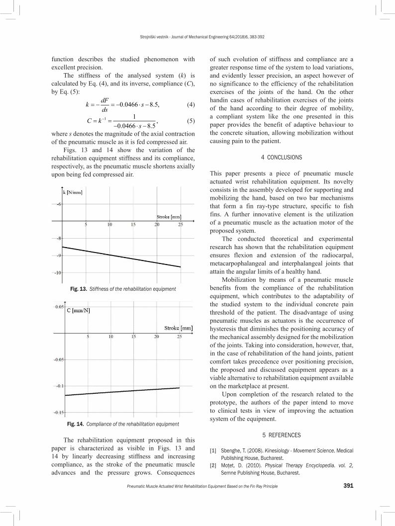
The stiffness of the analysed system (k) is calculated by Eq. (4), and its inverse, compliance (C), by Eq. (5):
k dFds
s= − = − ⋅ −0 0466 8 5. . , (4)
C ks
= =− ⋅ −
−1 1
0 0466 8 5. ., (5)
where s denotes the magnitude of the axial contraction of the pneumatic muscle as it is fed compressed air.
Figs. 13 and 14 show the variation of the rehabilitation equipment stiffness and its compliance, respectively, as the pneumatic muscle shortens axially upon being fed compressed air.
Fig. 13. Stiffness of the rehabilitation equipment
Fig. 14. Compliance of the rehabilitation equipment
The rehabilitation equipment proposed in this paper is characterized as visible in Figs. 13 and 14 by linearly decreasing stiffness and increasing compliance, as the stroke of the pneumatic muscle advances and the pressure grows. Consequences
of such evolution of stiffness and compliance are a greater response time of the system to load variations, and evidently lesser precision, an aspect however of no significance to the efficiency of the rehabilitation exercises of the joints of the hand. On the other handin cases of rehabilitation exercises of the joints of the hand according to their degree of mobility, a compliant system like the one presented in this paper provides the benefit of adaptive behaviour to the concrete situation, allowing mobilization without causing pain to the patient.
4 CONCLUSIONS
This paper presents a piece of pneumatic muscle actuated wrist rehabilitation equipment. Its novelty consists in the assembly developed for supporting and mobilizing the hand, based on two bar mechanisms that form a fin ray-type structure, specific to fish fins. A further innovative element is the utilization of a pneumatic muscle as the actuation motor of the proposed system.
The conducted theoretical and experimental research has shown that the rehabilitation equipment ensures flexion and extension of the radiocarpal, metacarpophalangeal and interphalangeal joints that attain the angular limits of a healthy hand.
Mobilization by means of a pneumatic muscle benefits from the compliance of the rehabilitation equipment, which contributes to the adaptability of the studied system to the individual concrete pain threshold of the patient. The disadvantage of using pneumatic muscles as actuators is the occurrence of hysteresis that diminishes the positioning accuracy of the mechanical assembly designed for the mobilization of the joints. Taking into consideration, however, that, in the case of rehabilitation of the hand joints, patient comfort takes precedence over positioning precision, the proposed and discussed equipment appears as a viable alternative to rehabilitation equipment available on the marketplace at present.
Upon completion of the research related to the prototype, the authors of the paper intend to move to clinical tests in view of improving the actuation system of the equipment.
5 REFERENCES
[1] Sbenghe, T. (2008). Kinesiology - Movement Science. Medical Publishing House, Bucharest.
[2] Moţet, D. (2010). Physical Therapy Encyclopedia. vol. 2, Semne Publishing House, Bucharest.
Strojniški vestnik - Journal of Mechanical Engineering 64(2018)6, 383-392
392 Petre, I. – Deaconescu, A. – Sârbu, F. – Deaconescu, T.
[3] Otto bock Group (2017). from http://www.ottobock.com/en/, accessed on 2017-08-15.
[4] Maestra (2017). Kinetec, from http://kinetec.fr/en/kinetec-selection/cpm-continuous-passive-motion/attelle-kinetec-maestra-detail.html, accessed on 2017-08-15.
[5] Waveflex Hand CPM (2017). Remington Medical, from http://www.remingtonmedical.com/product/detail/A1, accessed on 2017-08-15.
[6] Kinex Hand (2017). Kinex CPM Devices, from https://www.kinexmedical.com/cpm-devices, accessed on 2017-08-15.
[7] Krebs, H.I., Volpe, B.T., Williams, D., Celestino, J., Charles, S.K., Lynch, D., Hogan, N. (2007). Robot-aided neurorehabilitation: a robot for wrist rehabilitation. IEEE Transactions on Neural Systems and Rehabilitation Engineering, vol. 15, no. 3, p. 327-335, DOI:10.1109/TNSRE.2007.903899.
[8] Hadi, A., Alipour, K., Kazeminasab, S., Elahinia, M. (2017). ASR glove: A wearable glove for hand assistance and rehabilitation using shape memory alloys. Journal of Intelligent Material Systems and Structures, vol. 29, no. 8, p. 1575-1585, DOI:10.1177/1045389X17742729.
[9] Maciejasz, P., Eschweiler, J., Gerlach-Hahn, K., Jansen-Troy, A., Leonhardt, S. (2014). A survey on robotic devices for upper limb rehabilitation. Journal of NeuroEngineering and Rehabilitation, vol. 11, no.3, p. 1-29, DOI:10.1186/1743-0003-11-3.
[10] Gopura, R.A.R.C., Bandara, D.S.V., Kiguchi, K., Mann, G.K.I. (2016). Developments in hardware systems of active
upper-limb exoskeleton robots: A review. Robotics and Autonomous Systems, vol. 75, p. 203-220, DOI:10.1016/j.robot.2015.10.001.
[11] Dongming, Y., Binrui, W., Yinglian, J. (2011). Pneumatic Muscle Flexible Elbow Joint Device with Buffer Spring and Flexible Shaft Sleeve. Patent CN202071080, China Institute of Metrology, Beijing.
[12] Canjun, Y., Jiafan, Z., Jie, Z., Ying, C. (2007). Flexible Exoskeleton Elbow Joint Based on Pneumatic Power. Patent CN200984250, China Institute of Metrology, Beijing..
[13] Zhang, J., Liu, Y., Jia, Y., Shen, Z. (2012). Device for Hand Rehabilitation. Patent WO2012120393, World Intellectual Property Organization, Geneva.
[14] Takaiwa, M., Noritsugu, T. (2005). Development of wrist rehabilitation equipment using pneumatic parallel manipulator. Proceedings of IEEE International Conference on Robotics and Automation, p. 2302-2307, DOI:10.1109/ROBOT.2005.1570456.
[15] Deaconescu, T., Deaconescu, A. (2016). Applications of pneumatic muscles developed within the Festo national fluid actuation and automation training centre in Braşov. Recent Review, vol. 17, no. 4(50), p. 540-547.
[16] Filip, O., Deaconescu, T. (2017). Mathematical modelling of a Fin Ray type mechanism, used in the case of the wrist rehabilitation equipment. The 4th International Conference on Computing and Solutions in Manufacturing Engineering, vol. 94, DOI:10.1051/matecconf/20179401006.