Centrifugo-pneumatic valving utilizing dissolvable films
9
Centrifugo-pneumatic valving utilizing dissolvable films{ Robert Gorkin III,* ab Charles E. Nwankire, ab Jennifer Gaughran, ab Xin Zhang, ac Gerard G. Donohoe, d Martha Rook, d Richard O’Kennedy ac and Jens Ducre ´e ab Received 9th October 2011, Accepted 30th April 2012 DOI: 10.1039/c2lc20973j In this article we introduce a novel technology that utilizes specialized water dissolvable thin films for valving in centrifugal microfluidic systems. In previous work (William Meathrel and Cathy Moritz, IVD Technologies, 2007), dissolvable films (DFs) have been assembled in laminar flow devices to form efficient sacrificial valves where DFs simply open by direct contact with liquid. Here, we build on the original DF valving scheme to leverage sophisticated, merely rotationally actuated vapour barriers and flow control for enabling comprehensive assay integration with low-complexity instrumentation on ‘‘lab-on-a-disc’’ platforms. The advanced sacrificial valving function is achieved by creating an inverted gas-liquid stack upstream of the DF during priming of the system. At low rotational speeds, a pocket of trapped air prevents a surface-tension stabilized liquid plug from wetting the DF membrane. However, high-speed rotation disrupts the metastable gas/liquid interface to wet the DF and thus opens the valve. By judicious choice of the radial position and geometry of the valve, the burst frequency can be tuned over a wide range of rotational speeds nearly 10 times greater than those attained by common capillary burst valves based on hydrophobic constrictions. The broad range of reproducible burst frequencies of the DF valves bears the potential for full integration and automation of comprehensive, multi-step biochemical assay protocols. In this report we demonstrate DF valving, discuss the biocompatibility of using the films, and show a potential sequential valving system including the on-demand release of on-board stored liquid reagents, fast centrifugal sedimentation and vigorous mixing; thus providing a viable basis for use in lab-on-a-disc platforms for point-of-care diagnostics and other life science applications. 1. Introduction Robust valving over a wide range of rotational burst frequencies is pivotal for developing highly integrated centrifugal micro- fluidic platforms for advanced clinical analysis. 2,3 Valving structures are fundamental in enabling sequential fluidic proces- sing required for intricate assays, and typically assay protocols rely on key fluidic elements (e.g., decanting, metering, mixing, siphoning) that are either derived from or can be improved through valving technologies. 4–8 In the disc format, the assay fluidics are multiplexed and, as such, several valving components must work simultaneously. 9 Fundamentally valving issues become more complex when used within the area of clinical diagnostics; valves must be compatible to common manufactur- ing schemes of the testing device, in addition, they must be actuated in accordance with the design paradigms of the instrument, and furthermore, they must provide long-term stability to address the important topics of on-board liquid reagent storage and the prevention of cross-contamination. In a common arrangement, valving in centrifugal microfluidics has taken the form of constrictions in microchannels, whereby liquids driven outwards by centrifugal forces are prevented from flowing due to opposing surface tension created at the interface (this can be termed a passive valve). The valve holds until spin velocities, measured in rotations per minute (RPMs), are increased above a critical threshold, known as the burst frequency. In native polymers and on (locally) deposited hydrophobic layers, these structures are called hydrophobic valves. 10 While comparatively easy to fabricate, hydrophobic valves have a limited gamut of use. Their operational band of rotational burst frequencies is quite narrow and scales only linearly with radial position on the disc. As such, only simple disc designs utilizing a few valves, and thus limited sequential assay steps, are possible as rotational frequency bands start to overlap and cause unwanted valving failures. Furthermore, for a given valve design, the burst frequency decreases with increasing distance away from the disc centre. This characteristic that valves would yield first near the edge and then near the centre of the disc contradicts the design paradigm of centrifugal systems where samples are introduced near the disc centre and are then a Biomedical Diagnostics Institute, National Centre for Sensor Research, Dublin City University, Glasnevin, Dublin 9, IRELAND. E-mail: Robert Gorkin [email protected]; Jens Ducre ´e [email protected] b School of Physics, Dublin City University, Dublin 9, IRELAND c School of Biotechnology, Dublin City University, Dublin 9, IRELAND d EMD Millipore, 80 Ashby Road, Bedford, MA, USA { Electronic supplementary information (ESI) available. See DOI: 10.1039/c2lc20973j Lab on a Chip Dynamic Article Links Cite this: Lab Chip, 2012, 12, 2894–2902 www.rsc.org/loc PAPER 2894 | Lab Chip, 2012, 12, 2894–2902 This journal is ß The Royal Society of Chemistry 2012 Downloaded by Dublin City University on 23 July 2012 Published on 13 June 2012 on http://pubs.rsc.org | doi:10.1039/C2LC20973J View Online / Journal Homepage / Table of Contents for this issue
-
Upload
independent -
Category
Documents
-
view
0 -
download
0
Transcript of Centrifugo-pneumatic valving utilizing dissolvable films

Centrifugo-pneumatic valving utilizing dissolvable films{
Robert Gorkin III,*ab Charles E. Nwankire,ab Jennifer Gaughran,ab Xin Zhang,ac Gerard G. Donohoe,d
Martha Rook,d Richard O’Kennedyac and Jens Ducreeab
Received 9th October 2011, Accepted 30th April 2012
DOI: 10.1039/c2lc20973j
In this article we introduce a novel technology that utilizes specialized water dissolvable thin films for
valving in centrifugal microfluidic systems. In previous work (William Meathrel and Cathy Moritz,
IVD Technologies, 2007), dissolvable films (DFs) have been assembled in laminar flow devices to form
efficient sacrificial valves where DFs simply open by direct contact with liquid. Here, we build on the
original DF valving scheme to leverage sophisticated, merely rotationally actuated vapour barriers
and flow control for enabling comprehensive assay integration with low-complexity instrumentation
on ‘‘lab-on-a-disc’’ platforms. The advanced sacrificial valving function is achieved by creating an
inverted gas-liquid stack upstream of the DF during priming of the system. At low rotational speeds,
a pocket of trapped air prevents a surface-tension stabilized liquid plug from wetting the DF
membrane. However, high-speed rotation disrupts the metastable gas/liquid interface to wet the DF
and thus opens the valve. By judicious choice of the radial position and geometry of the valve, the
burst frequency can be tuned over a wide range of rotational speeds nearly 10 times greater than those
attained by common capillary burst valves based on hydrophobic constrictions. The broad range of
reproducible burst frequencies of the DF valves bears the potential for full integration and
automation of comprehensive, multi-step biochemical assay protocols. In this report we demonstrate
DF valving, discuss the biocompatibility of using the films, and show a potential sequential valving
system including the on-demand release of on-board stored liquid reagents, fast centrifugal
sedimentation and vigorous mixing; thus providing a viable basis for use in lab-on-a-disc platforms
for point-of-care diagnostics and other life science applications.
1. Introduction
Robust valving over a wide range of rotational burst frequencies
is pivotal for developing highly integrated centrifugal micro-
fluidic platforms for advanced clinical analysis.2,3 Valving
structures are fundamental in enabling sequential fluidic proces-
sing required for intricate assays, and typically assay protocols
rely on key fluidic elements (e.g., decanting, metering, mixing,
siphoning) that are either derived from or can be improved
through valving technologies.4–8 In the disc format, the assay
fluidics are multiplexed and, as such, several valving components
must work simultaneously.9 Fundamentally valving issues
become more complex when used within the area of clinical
diagnostics; valves must be compatible to common manufactur-
ing schemes of the testing device, in addition, they must be
actuated in accordance with the design paradigms of the
instrument, and furthermore, they must provide long-term
stability to address the important topics of on-board liquid
reagent storage and the prevention of cross-contamination.
In a common arrangement, valving in centrifugal microfluidics
has taken the form of constrictions in microchannels, whereby
liquids driven outwards by centrifugal forces are prevented from
flowing due to opposing surface tension created at the interface
(this can be termed a passive valve). The valve holds until spin
velocities, measured in rotations per minute (RPMs), are
increased above a critical threshold, known as the burst
frequency. In native polymers and on (locally) deposited
hydrophobic layers, these structures are called hydrophobic
valves.10 While comparatively easy to fabricate, hydrophobic
valves have a limited gamut of use. Their operational band of
rotational burst frequencies is quite narrow and scales only
linearly with radial position on the disc. As such, only simple disc
designs utilizing a few valves, and thus limited sequential assay
steps, are possible as rotational frequency bands start to overlap
and cause unwanted valving failures. Furthermore, for a given
valve design, the burst frequency decreases with increasing
distance away from the disc centre. This characteristic that valves
would yield first near the edge and then near the centre of the
disc contradicts the design paradigm of centrifugal systems
where samples are introduced near the disc centre and are then
aBiomedical Diagnostics Institute, National Centre for Sensor Research,Dublin City University, Glasnevin, Dublin 9, IRELAND. E-mail: RobertGorkin [email protected]; Jens Ducree [email protected] of Physics, Dublin City University, Dublin 9, IRELANDcSchool of Biotechnology, Dublin City University, Dublin 9, IRELANDdEMD Millipore, 80 Ashby Road, Bedford, MA, USA{ Electronic supplementary information (ESI) available. See DOI:10.1039/c2lc20973j
Lab on a Chip Dynamic Article Links
Cite this: Lab Chip, 2012, 12, 2894–2902
www.rsc.org/loc PAPER
2894 | Lab Chip, 2012, 12, 2894–2902 This journal is � The Royal Society of Chemistry 2012
Dow
nloa
ded
by D
ublin
City
Uni
vers
ity o
n 23
Jul
y 20
12Pu
blis
hed
on 1
3 Ju
ne 2
012
on h
ttp://
pubs
.rsc
.org
| do
i:10.
1039
/C2L
C20
973J
View Online / Journal Homepage / Table of Contents for this issue

sequentially driven through the processing chambers for analysis
towards the perimeter of the disc.
More recently, sacrificial valves were introduced to overcome
the limitations of passive valving and to increase centrifugal
microfluidic capabilities for expanded use. Serving as superior
liquid/vapour barriers, sacrificial valves act as programmable
flow control elements where a physical gating material is
changed or removed by an external actuation source. Wax
valving using native compositions of different temperature waxes
has been shown using focused infrared (IR) lamp sources as the
actuator.12 Another prominent example is a sacrificial valving
technology utilizes ferrowax impregnated with IR absorbing
nanoparticles which are actuated by laser diodes.11 Additionally
optofluidic valves have been developed where cyclo-olefin
polymer (COP) and polyethylene terephthalate (PET) films
spotted with heat absorbing printer toner could be ablated using
laser diodes.12 Such active valves allow for the increase in the
number of processes that can be independently controlled on a
single disc.8,13 The use of these sacrificial valves lessens the
restraints due to operational frequency range since they are not
reliant on rotational frequency to open. However, while superior
in their flexibility of flow control, the fact that sacrificial valves
necessitate embedding a barrier material and actuating those
gating mechanisms through rather complex external actuation
units and trigger control (to be azimuthally synchronised with
the rotational motion) poses severe challenges to manufacturing
and instrumentation.
In the latest evolution of valving technology on a disc, new
concepts have been developed that retain the liquid and vapour
barrier properties of sacrificial valves, while at the same time the
valves are actuated without the need for peripheral equipment
(other than the platform-immanent spindle motor). Two notable
examples based on a similar concept are the burstable foil seal
valves from Hoffman et al.14 and the elastomeric membrane
valves by Hwang et al.15 Both groups introduced a weakly bonded
flexible barrier in a microchannel that was actuated entirely via the
frequency of rotation. Pressures introduced by the liquids during
centrifugation deformed the foil/membrane, thereby allowing for
liquid to pass through the valve site. While these valves show an
improvement in centrifugal microfluidic operation, their use may
be restricted as they operate only at low spin speeds and also
introduce manufacturing complexity to the system.
Here we report for the first time on a novel concept describing
valving based on water-soluble films. The material choice
coupled with a unique chamber design enables a new variant
on centrifugo-pneumatic flow control, which, dramatically
increases the working range of the burst frequencies as compared
to purely surface-tension derived valving while eliminating the
need for peripheral actuation mechanisms like laser sources
as previously described for the phase-change wax valves.
Additionally, the simple, lamination-based fabrication technique
has the potential to provide a novel active valving mechanism
that provides the strength of a physical barrier in a manner that
easily integrates with commercial production techniques.
This paper commences with the concept of dissolvable film
(DF) based valving, followed by a detailed examination of our
refinements for an advanced centrifugo-pneumatic flow control
succeeded by an experimental validation and evaluation of the
system. In order to complete the discussion of valving for use in
real-world life-science applications, the next section provides an
analysis on the compatibility of the films in bioassays. Finally,
we will also demonstrate applications for advanced control of
fluidic processes enabled by the use of the valves. Overall the
report reveals the potential for dissolvable film valving in
centrifugal microfluidics.
2. Design of dissolvable film valves
The fundamental concept underlying our system is the interac-
tion of liquids with a DF barrier. When a liquid is introduced to
the DF surface, the film begins to breakdown, eventually
disintegrating and allowing liquids to pass through the valve
opening. However, standalone films cannot be used for valving
as they lack the ability to be embedded in microfluidic devices. In
order to overcome this limitation, a valving ‘‘tab’’ is assembled
using multifunctional adhesive film technology to form a
supporting structure for the DF, and to enable simple placement
inside microfluidic systems. To fabricate the plugs, two materials
are used: the first layer contains pressure sensitive adhesives
(PSA films) whereas the second layer consists of a specialized DF
membrane. Inserting the tabs (Fig. 1) to restrict the microfluidic
pathway creates the transient physical barriers for the valving;
the tacky nature of the PSA films allows for closing off
microchannels by merely sticking the plugs into the system
features.
The DFs are derived from an aqueous polymer matrix
consisting of a range of constituents such as various cellulose
derivatives, hydrocolloids, acrylate copolymers, gums, polysac
charides and plasticizers. The dissolution times of the DFs
Fig. 1 Assembly of a valving tab consisting of a dissolvable film and a
pressure sensitive adhesive. As liquid wets the surface, the film starts to
deteriorate, eventually completely dissolving the barrier. The structure
allows for fluid movement through the remaining feature.
This journal is � The Royal Society of Chemistry 2012 Lab Chip, 2012, 12, 2894–2902 | 2895
Dow
nloa
ded
by D
ublin
City
Uni
vers
ity o
n 23
Jul
y 20
12Pu
blis
hed
on 1
3 Ju
ne 2
012
on h
ttp://
pubs
.rsc
.org
| do
i:10.
1039
/C2L
C20
973J
View Online
depend on the specific mixture of the constituents.1,16 In the
current demonstrations two commercially available films were
tested: one rated as a quick dissolution film (y10 s) and one
rated as a slow dissolving film (y5 min).
3. Centrifugo-pneumatic valving
3.1 Concept
DFs can be used to enhance valving in centrifugal microfluidics;
the current architecture expands on the established centrifugo-
pneumatic valving concept. Fig. 2A illustrates the design of the
system where a valving tab is embedded into a specially devised
microchannel conduit. This tab is placed on the bottom of an
air ballast chamber that is positioned between the loading and
waste chambers.While still intact, the tabs form a fluid barrier
sealing off a through hole connecting the two fluidic layers
(Fig. 2B). After the introduction of the liquids into the loading
chamber and priming of the microchannels, typically at low
rotational speeds, a gas pocket forms above the tab. The action
of the liquid traps the air, and the gas pocket prevents any
further movement of the liquid. Akin to the pneumatic valving
mechanism described in Mark et al.,17 the balance of the
pressure in the gas pocket and the centrifugally induced
hydrostatic pressure exerted by the liquid plug halts the flow.
The valve then follows a two-step actuation process. First, the
valve will remain closed until spinning rates are increased to a
critical rotational frequency at which the inverted liquid-gas
stack destabilizes, causing the liquid to enter the air ballast
chamber and wetting the film. Second, as fluids are pumped to
the interface, the film rapidly liquefies and the valve fully opens.
Continuously applied centrifugal force then propels the liquid
through the valve opening into the exit microchannel. Fig. 2C
shows an image series of the valve in action. For clarity, as both
the liquid inversion and the film dissolution occur at the same
critical spin speed, the more traditional notion of a ‘‘burst
frequency’’ will be expanded to describe two-step valving
actuation in this report.
3.2 Valving mechanics
As outlined, the valving mechanism depends on the balance
between the centrifugally induced pressure head Dp and a critical
yield pressure pcrit which needs to be determined experimentally.
Qualitative measurements provide strong evidence that the
critical yield pressure is dependent on the volume of the air-
filled chamber on top of the DF membrane and the detailed
contour of the expansion of the channel into the DF chamber.
The centrifugally induced pressure
Dpv = rDrrv2 (1)
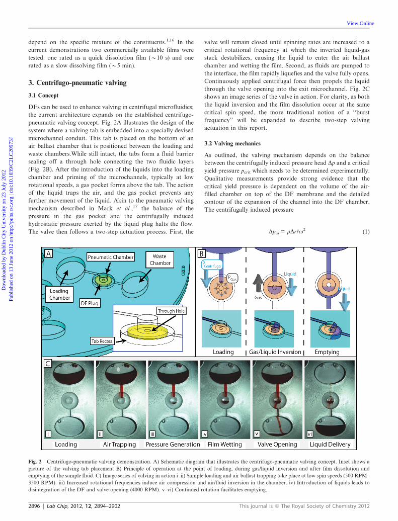
Fig. 2 Centrifugo-pneumatic valving demonstration. A) Schematic diagram that illustrates the centrifugo-pneumatic valving concept. Inset shows a
picture of the valving tab placement B) Principle of operation at the point of loading, during gas/liquid inversion and after film dissolution and
emptying of the sample fluid. C) Image series of valving in action i–ii) Sample loading and air ballast trapping take place at low spin speeds (500 RPM–
3500 RPM). iii) Increased rotational frequencies induce air compression and air/fluid inversion in the chamber. iv) Introduction of liquids leads to
disintegration of the DF and valve opening (4000 RPM). v–vi) Continued rotation facilitates emptying.
2896 | Lab Chip, 2012, 12, 2894–2902 This journal is � The Royal Society of Chemistry 2012
Dow
nloa
ded
by D
ublin
City
Uni
vers
ity o
n 23
Jul
y 20
12Pu
blis
hed
on 1
3 Ju
ne 2
012
on h
ttp://
pubs
.rsc
.org
| do
i:10.
1039
/C2L
C20
973J
View Online
scales with the density r, the radial length Dr and the mean
position r of the liquid plug spinning at the angular frequency v.
The protruding meniscus stops as Dpv is balanced by pressure
in the valve chamber
p~p01
1{DV=V0(2)
as derived from Boyle’s law. In (2) p0 represents the ambient
pressure, V0 is the (full) chamber volume initially available to the
gas pocket and DV is the (gas) volume reduction due to the
advancing liquid meniscus.
The liquid-gas interface in this metastable, inverted-layer
configuration is stabilized by the surface tension. As the
centrifugal pressure Dpv head (1) increases, the liquid plug can
move farther into the pneumatic chamber, thus making it harder
for the surface tension to sustain the ‘‘hanging’’ liquid volume
DV. At the so-called burst frequency, the liquid plug disrupts to
invert the metastable liquid-gas configuration. Liquid thus
proceeds into the pneumatic chamber to dissolve the DF
membrane and hence open the valve.
For a given, rotationally induced pressure head Dpv (1), the
distance the plug can protrude into the compression chamber
(and the displaced air volume DV) until Dpv (1) balances the
counter pressure p (2) increases with the dead volume of the
chamber V0. In other words, the fluidic capacitance defined
volume change DV induced by a given pressure change p (2)
increases with V0. As the ‘‘burst’’ is induced towards increasing
DV, the burst frequency shrinks with increasing chamber size
V0.
For a given (incompressible) liquid (r = const.), a chamber
volume V0, and plug volume, Dr cannot drastically be changed as
a too wide channel would compromise the surface-tension
dependent stabilization of the meniscus at the entrance of the
DF chamber. Overall, the pressure head Dpv (1) is hence mainly
controlled through r, i.e. essentially the (fixed) radial position of
the valve on the disc, and through its square dependence on the
dynamically set angular frequency v. For the work presented in
this manuscript will most often induce the valving condition pcrit
, Dp y rv2 (1) most often by ramping up v. In section 7 dealing
with sequential valving on the disc, valve triggering is demon-
strated by raising v as well as by jointly raising v and r.
4. Materials and methods
4.1 Device fabrication
In order to demonstrate our advanced, DF-assisted centrifugo-
pneumatic valving concept, the multilayer tabs were integrated
into a centrifugal microfluidic device. To begin with, the valving
tabs were manufactured using a standard cutter-plotter machine
(CraftROBO Pro cutter/plotter, Graphtec, USA). Through
holes were first machined in double-sided PSA films. Next,
the top carrier layer of the PSA was removed and the DF
material was pressed to the exposed adhesive (PSA and DFs
were acquired from Adhesives Research, Limerick, Ireland). A
final cut was then performed to contour the complete assembly.
The DF tabs could thus be manufactured in mass and premade
for implantation into the microfluidic lab-on-a-chip devices
when necessary.
The disc-based devices were created using established PSA/
polymer lamination techniques.18,19 To fabricate the rotor
layers, large chamber features were laser machined (Zing 16
Laser, Epilog, USA) in 1.5-mm thick poly(methylmethacrylate)
(PMMA, sourced from Radionics, Ireland) discs. Microfluidic
channel features were defined in disc shaped 50–86 mm thick PSA
layers using the same cutter plotter device as for the valving tabs
(the same PSA material was also used to create the film tabs).
The individual plastic and adhesive layers were sequentially
stacked and tabs placed where necessary. The layers were
machine pressed together to complete the final device.
4.2 Centrifugal microfluidic design
The design of the final disc incorporated several features
necessary for centrifugo-pneumatic valving: an area for air
trapping that included the 3D vial which created the air pocket
region, a recess for receiving the plugs, as well as the DF tabs. In
order to guide primary proof-of-principle experiments, a range
of geometrical parameters was also set (e.g., radial placement of
valve, radial length of the liquid plug, 3D vial diameter, and
microchannel width) to replicate a conceivable valving situation
(details of the dimensions can be found in the supplementary
Figure S1{.).
The DF plug design and tab placement in the disc was chosen
in order to distinguish between valve dissolution and opening of
the valve due to mechanical failure. A small through hole was
centred within the 3D vial, so that after film dissolution, a small
liquid retention pocket could be observed. In contrast, if
mechanical failure occurred and the film broke free from the
PMMA surface, no fluid was preserved in the pocket.
4.3 Experimental setup
Once a suitable design was established, a series of experiments
was performed which targeted the burst frequency (BF) of the
valve. The discs were placed on a spin stand setup, which
contained a computer-controlled motor (Faulhaber Minimotor
SA, Crogilio, Switzerland) that precisely modulated the rota-
tional frequencies of the microfluidic device. In addition, this
setup featured additional equipment that allowed for imaging
during high-speed rotation. Using a sensitive camera (Pixelfly,
PCO, Kehlheim, Germany) with motorized zoom optics
(Navitar, Rochester, NY, USA) and a stroboscopic light source
(Drelloscop 3244, Drello, Germany) the system allowed for the
collection of one image of a defined area on the disc per rotation
(details of a similar setup can be found in Grumann et al.20). The
resulting images were then analysed, and measurements taken to
evaluate the operation of the valving structure. It was of
paramount importance to try to identify the critical BF where
centrifugal forces cause the liquids to displace the trapped gas
and open the valve. Additional trials using structures without
plugs were run to establish negative controls for the system.
5. Results and discussions
5.1 System performance
The experiments demonstrated the centrifugo-pneumatic operat-
ing principle of our novel valving concept. Initially, a micro-
fluidic design that did not incorporate a DF tab was first tested
This journal is � The Royal Society of Chemistry 2012 Lab Chip, 2012, 12, 2894–2902 | 2897
Dow
nloa
ded
by D
ublin
City
Uni
vers
ity o
n 23
Jul
y 20
12Pu
blis
hed
on 1
3 Ju
ne 2
012
on h
ttp://
pubs
.rsc
.org
| do
i:10.
1039
/C2L
C20
973J
View Online

(with no tab the feature functioned as a hydrophobic valve). In
absence of a sacrificial barrier, fluids flowed unimpeded from the
loading to the collection chamber at speeds of approximately
500 RPM. Next, a setup with identical features and with the DF
valve in place was investigated. In that design, low speed rotation
propelled the sample from the loading chamber through the
intake microchannel. However, the flow was stopped at the
entrance of the air ballast compartment as expected from the
centrifugo-pneumatic design concept. Rotational speeds were
then increased at defined rates until the valve opened. The
microfluidic experiments showed that the gas-liquid inversion
did not occur instantaneously, but acted in a stepwise manner.
During acceleration, small droplets of liquid occasionally
moved into the air ballast compartment. As the exposed film
surface was located nearer to the centre of the chamber, the
droplets were collected without prematurely opening the valve.
Beyond a critical spinning rate, the gas-liquid interface fully
destabilized, allowing for liquid to more fully fill the chamber
and then contact the film surface. At this point film dissolution
and valve opening occurred. An image series showing the
progression of a sample test exhibiting the valving principle is
depicted in Fig. 2C.
These experiments confirmed that the addition of the DF tabs
dramatically increased the burst frequencies of the valves to a
range that was not achievable with conventional capillary
constrictions. Plugs that contained either the slow or quick
dissolvable films maintain stability at rotational rates of
approximately 3000 RPM as shown in Fig. 3. In this design,
the measurement represented a rise in the burst centrifugal
frequency by nearly a factor of 10. The notable increase in the
burst frequency is important as the ability to maintain integrity
at those high speeds is necessary for many fluidic processes, e.g.,
centrifugally induced particle sedimentation.
In terms of actuation time, valves placed in the centrifugal
system had limited dependence on the rated time dependency. In
the disc, both the slow/quick dissolve tabs opened less than 10 s
after contact; this roughly corresponds to the expected dissolu-
tion time of the quick dissolve film (10 s) but much more rapidly
than the rating of the slow dissolve film (5 mins). It is plausible
that the active introduction of fluids to the film surface
intensifies liquidation and accelerates valve opening. It should
be noted that the rapid valve opening made pinpointing the exact
operational RPM value difficult; this may have contributed to
some of the observed error in the burst frequencies between the
slow and quick dissolve films in Fig. 3. Regardless, the time-
dependency of the films was greatly reduced, and as such, a
range of films displaying various dissolution rates could be
integrated easily. Future development could include adapting
fluidic designs to take advantage of both frequency and
dissolution times for valving.{
5.2 System evaluation
DF-based valving introduces a new development in microfluidic
process control on centrifugal platforms. Foremost, the DF
valve represents the first instance where it is possible to create a
sacrificial barrier that is merely actuated by the rotation of the
substrate intrinsic to the centrifugal platform, and thus
eliminates the need for external actuation, like those required
in laser ablation or heating-based techniques.12,21,22 The vapour
barrier properties of the DFs may also allow transient sealing
and gating of liquid reagents for on-board storage.
In addition, the DF centrifugo-pneumatic concept improves
on the previously introduced flexible burst seal valves, as DF
valves allow free passage of liquids after opening and are capable
of functioning at much higher rotational speeds (and thus
operations required by such). Furthermore the DF valves
avoid manufacturing activities associated with foils/polymers
and Polydimethylsiloxane (PDMS)/polymers. The design also
improves on the original centrifugo-pneumatic system of Mark
et al.17 In that design, where a microchannel exits to a closed
reservoir, the liquid shift into the gas pocket represents an
endpoint operation. In contrast, the novel DF design creates an
opening in the reservoir chamber. The DF system is capable of
acting as an intermediate valving step connecting to subsequent
liquid handling procedures. Moreover, as a consequence of the
fabrication of the tabs, the valve is not dependent on the
manufacturing process for the device. In terms of mass
production, one could envision a pick-and-place manufacturing
setup with prefabricated valves tailored to the specific use in the
system.
6. Biocompatibility of dissolvable films
While the mechanical demonstration proved the potential for
valving actuation on the disc, it was also important to verify that
the films could be used with biological assays. Therefore, it was
examined how the presence of the film affected the performance
of molecular and immunoassays.
Mouse immunoglobulin variable genes were polymerase chain
reaction (PCR) amplified in the presence and absence of the
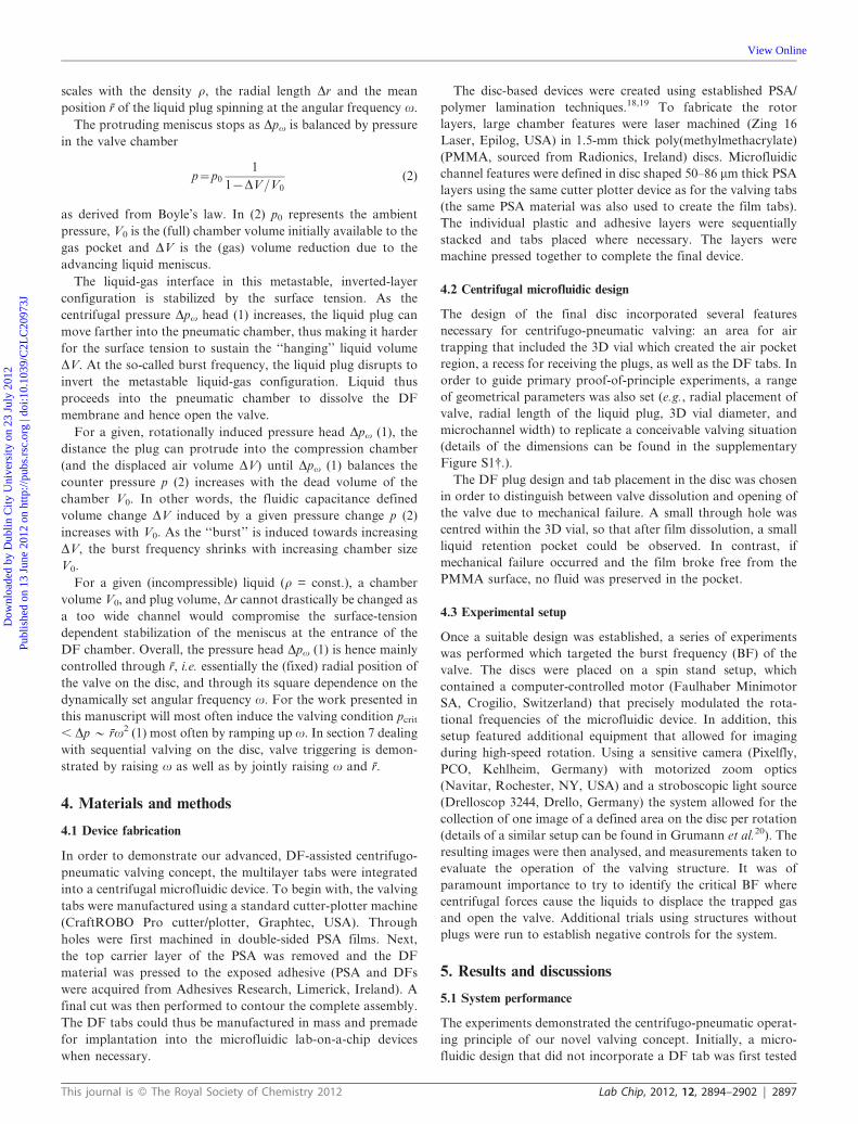
DFs. PCR amplification was performed according to protocolsFig. 3 Graph showing a dramatic increase in the burst frequency of the
dissolvable film valves. Experimentation showed a 10-fold increase in
valve stability with either the quick or slow dissolve films (versus a native
hydrophobic valve at the same location) withholding fluids at above
3000 RPM. Error bars represent the range of opening speeds observed
over a series of burst frequency experiments using discs with identical
design structures.
{ The valves retain their time-dependent nature in traditional ‘‘sta-tionary’’ microfluidic systems. Figure S2 in the ESI{ shows ademonstration of DF valving in a straightforward 3D microvial usingquick and slow dissolve film plugs. In that system the valves actuate nearthe film’s rated dissolution times validating the rating from themanufacturer.
2898 | Lab Chip, 2012, 12, 2894–2902 This journal is � The Royal Society of Chemistry 2012
Dow
nloa
ded
by D
ublin
City
Uni
vers
ity o
n 23
Jul
y 20
12Pu
blis
hed
on 1
3 Ju
ne 2
012
on h
ttp://
pubs
.rsc
.org
| do
i:10.
1039
/C2L
C20
973J
View Online
previously described (Barbas et al.).23 The PCR reaction
contained the following: 1 ml of murine cDNA, 60 pmol of
forward and reverse oligonucleotide primers, 5x PCR buffer,
2-mM MgCl2, 2.5-mM dNTPs and 0.25 ml Platinum Taq DNA
polymerase. Either quick or slow dissolve films were added to the
PCR mix prior to processing. The PCR amplification profile was
as follows: initial denaturation at 94 uC for 2 min, 30 cycles with
denaturation at 94 uC for 15 s, annealing at 56 uC for 30 s, and
extension at 72 uC for 90 s, followed by a final cycle of extension
at 72 uC for 10 min. The amplicons were assessed using gel
electrophoresis. No discernible differences in PCR amplification
were observed when the dissolvable films were added to the PCR
reaction versus the control (data shown in S3{).
An immunoglobulin G (IgG) sandwich assay was also used to
assess the biological effect of the dissolvable films. Human IgG
(SeraCare Life Sciences, US) samples were analysed using both
colorimetric and fluorescence based assay formats. MaxiSorpTM
Immuno plates (Nunc) were coated overnight at 4 uC with
100 mL of protein A (10 mg mL21, Thermo Scientific, US). After
washing with phosphate buffered saline solution (PBS, 150 mM,
pH 7.4) plates were blocked with a 3% (v/v) solution of Bovine
Serum Albumin (BSA, Jackson ImmunoResearch Laboratories,
US) and incubated for 1 h at 37 uC. The plates were further
washed and 100 mL of human IgG standards (50, 10, 2, 0.4, 0.08
and 0.016 mg mL21) diluted in either PBS, representing the
control, or with either quick or slow dissolvable films added. In
addition, a PBS only sample served as a negative control. The
plate was then incubated for 1 h at 37 uC. After washing, 100 mL
of an avian secondary (IgY) antibody against human IgG
(Gallus Immunotech Inc., US) was applied, and the plate was
incubated for 1 h at 37 uC. For the fluorescence assay, the plate
was washed and 100 mL of a fluorescent Neutravidin-Dylight 649
complex (Thermo Scientific, US) was applied. The plate was
incubated for 1 h at 37 uC and subsequently washed. After the
addition of 100 mL of PBS, the fluorescence was measured using
a commercial microplate reader (Tecan Safire2TM). The excita-
tion wavelength was 645 nm and the emission wavelength
675 nm. A similar procedure was used for colorimetric analysis
except that, a 100 mL solution of horseradish peroxidase-labeled,
avian, secondary antibody (Gallus Immunotech Inc., US)
against human IgG was used for detection. After extensive
washing bound antibody was detected by incubation with
3,39,5,59-tetramethylbenzidine. After chromophore development,
the reaction was stopped by the addition of 100 mL of 10% (v/v)
HCl and the absorbance at 450 nm was measured with the same
microplate reader.
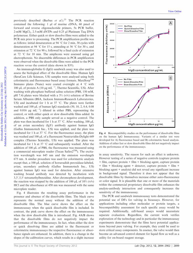
Fig. 4 illustrates the resulting assay performance in the
presence and absence of the dissolvable films. The black curve
represents the normal assay without the addition of the
dissolvable film. The blue curve shows the effect on the
immunoassay when the quick dissolvable film is included. In
contrast, the pink curve shows the effect on the immunoassay
when the slow dissolvable film is introduced. Fig. 4A/B shows
that the dissolvable films do not negatively impact the
performance of the immunoassays. In fact, when either the slow
or quick dissolving films are added to the fluorescent or
colorimetric immunoassays the respective fluorescence or absor-
bance signals are enhanced. In addition, there is a change in the
slopes of the calibration curves, which results in a slight increase
in assay sensitivity. The reason for such an effect is unknown.
However testing of a series of negative controls (capture protein
+ film, capture protein + film + blocking agent, capture protein
+ film + blocking agent + detector, capture protein + film +
blocking agent + analyte) did not reveal any significant increase
in background signal. Therefore it does not appear that the
dissolvable films by themselves increase either auto-fluorescence
or color signal. It is plausible that one or more of the materials
within the commercial proprietary dissolvable film enhances the
analyte-antibody interaction and consequently increases the
sensitivity of the immunoassay.
The PCR and sandwich immunoassay tests demonstrated the
potential use of DFs for valving in bioassays. However, for
applications including other molecular or protein targets, a
biocompatibility assessment for each specific assay would be
required. Additionally, cell-based assays would necessitate
separate evaluation. Regardless, the current work verifies
exploration of the technology and in particular the immunoassay
experiments demonstrate that the films have potential applica-
tions beyond pure valving. For example, they could be used to
store critical assay components. In essence, the valve would then
become an advanced control element for liquid flow as well as a
utility for on-board reagent storage.
Fig. 4 Biocompatibility studies on the performance of dissolvable films
on the human IgG Immunoassay. Variants of a similar test were
developed for A) fluorescence based and B) colorimetric based analysis.
Addition of either fast or slow dissolvable films did not negatively impact
on the performance of the immunoassays.
This journal is � The Royal Society of Chemistry 2012 Lab Chip, 2012, 12, 2894–2902 | 2899
Dow
nloa
ded
by D
ublin
City
Uni
vers
ity o
n 23
Jul
y 20
12Pu
blis
hed
on 1
3 Ju
ne 2
012
on h
ttp://
pubs
.rsc
.org
| do
i:10.
1039
/C2L
C20
973J
View Online

7. Multiple valving operation
Valves play a critical role in facilitating complex flow control
for the full integration and automation of complex bioassay
protocols. In this manner, DF valving can also be used for more
advanced sample processing. For instance, the retention of the
valves at high-speeds shows potential for storing and with-
holding reagents throughout a series of spin protocols with
opening on-demand at designated points in time. Such attributes
are desirable, especially in applications like biomedical diagnos-
tics where high-speed centrifugation is necessary. This is often
the case in blood-based diagnostic assays where plasma
separation from whole blood represents the critical initial assay
processing step.
Valving is vital at this stage in integrated designs when dealing
with blood for analysis; for example such assays require
centrifugation to separate the blood constitutes of erythrocytes
from plasma. In such a design, valves should initially retain
regents/buffers required for analysis and subsequently process
the components remaining in the supernatant. Therefore valves
that remain intact throughout high-speed centrifugation are
required.
Fig. 5A/B shows a microfluidic design that demonstrates a set
of DF valving structures. This system provides an example of a
comprehensive design that would enable integrated analysis from
whole blood. In each representative processing component, the
valve implements the protocol features necessary to function or
improves on the operation by allowing processing at higher
RPM values. Fig. 5C–J demonstrates example assay steps with
non-biological fluid samples. Of key importance is the fact that
the DF-based valving introduced here allows the retention of
prospective samples and reagents during fast centrifugal
sedimentation at speeds well beyond the burst frequencies that
could be achieved with capillary valves.
In brief, the device works by first enabling plasma separation
through a typical disc-based decanting structure. In such designs
a blood sample can be centrifugally separated in the loading
chamber; the plasma is restricted using a DF valve to
temporarily seal off a microchannel to the next processing
chamber. To isolate the plasma layer, the disc is accelerated
above the burst frequency of the first valve, allowing for
controlled liquid removal (Fig. 5C–D). DF valves could thus
replace the traditional plasma isolation method based on
siphoning which has manufacturing issues around hydrophilic
treatments24 or requires the use of specialized hydrophilic
surfaces.25 In the next step of analysis, the sample liquid passes
into another chamber where a centrifugal metering step is
implemented (Fig. 5E). Fluid is restricted in a similar fashion as
before, remaining in the chamber until accelerated past the burst
frequency of a second DF valve (Fig. 5F) which then propels the
Fig. 5 Centrifugal microfluidic system with multiple DF valves outlining potential assay processing from whole blood. Note that non-clinical aqueous
fluids were used to demonstrate sequential fluidic control. A) Image and schematic of the device profiling the fluidic designs (and potential fluidic
functions) in the disc. B–J) Video stills demonstrating sequential fluidic control during operation of the disc.
2900 | Lab Chip, 2012, 12, 2894–2902 This journal is � The Royal Society of Chemistry 2012
Dow
nloa
ded
by D
ublin
City
Uni
vers
ity o
n 23
Jul
y 20
12Pu
blis
hed
on 1
3 Ju
ne 2
012
on h
ttp://
pubs
.rsc
.org
| do
i:10.
1039
/C2L
C20
973J
View Online
liquid into a further mixing chamber. Although not fundamental
to the mixing operation (which can be achieved using various
techniques like batch processing or by shaking26), the valve
increases the speeds and magnitude of the rotational acceleration
in which mixing is preformed while preventing premature
‘‘leakage’’ of samples to subsequent processing areas (Fig. 5G).
Two (or more) components can be vigorously agitated under
high-amplitude accelerations rates by inhibiting any fluid flow.
The mixture is then driven past a third valve and over a potential
detection site, potentially functionalized with a capture reagent
for the target analytes (Fig. 5H–I). Further acceleration breaks
the final valve, and results in the release of a secondary reagent
(for example a reagent with labelling chemistries or wash buffers)
(Fig. 5J).
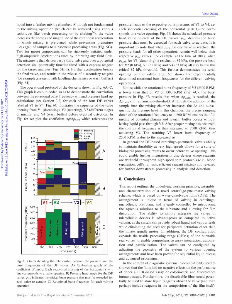
The operational protocol of the device is shown in Fig. 6A–C.
This graph is colour–coded so as to demonstrate the correlation
between the rotational burst frequency pcrit and pressure head Dp
calculations (see Section 3.2) for each of the four DF valves
labelled V1 to V4. Fig. 6C illustrates the sequence of the valve
opening from V1 (decanting), V2 (metering), V3 (different stages
of mixing) and V4 (wash buffer) before eventual detection. In
Fig. 6A we plot the coefficient Dp/Dpi,crit which references the
pressure heads to the respective burst pressures of V1 to V4, i.e.
each sequential crossing of the horizontal (y = 1)-line corre-
sponds to a valve opening. Fig. 6B shows the calculated pressure
head value of each of the DF valves. pcrit denotes the burst
pressure that must be exceeded for each valve to actuate. It is
important to note that when pcrit for one valve is reached, the
pressure heads for all other operations remain well below their
respective pcrit values. For example, at the time of 300 s, when
p1,crit for V1 (decanting) is reached at 82 hPa, the pressure head
for V2 (0 hPa), V3 (65 hPa) and V4 (33 hPa) all stay below this
critical 82 hPa threshold. This further demonstrates the serial
opening of the valves. Fig. 6C shows the experimentally
determined rotational burst frequencies for the different valving
operations.
Notice while the rotational burst frequency of V3 (2500 RPM)
is lower than that of V2 of 3300 RPM (Fig. 6C), the burst
pressure in Fig. 6B reveals that when Dp2,crit is reached, the
Dp3,crit still remains sub-threshold. Although the addition of the
sample into the mixing chamber increases the Dr and subse-
quently the pressure head in this chamber, the precise ramping
down of the rotational frequency to y600 RPM ensures that full
mixing of potential plasma and reagent buffer occurs without
letting liquid pass through V3. After proper mixing has occurred,
the rotational frequency is then increased to 2500 RPM, thus
actuating V3. The resulting V3 lower burst frequency of
2500 RPM is due to the increased Dr.
In general the DF-based centrifugo-pneumatic valve’s ability
to maintain durability at very high speeds allows for a suite of
biological processing events to occur before valve opening. This
could enable further integration in disc devices where reagents
are withheld throughout high-speed spin protocols (e.g., blood
separation, cell/viral lysis, efficient reagent mixing) and released
for further downstream processing in analysis and detection.
8. Conclusions
This report outlines the underlying working principle, assembly,
and characterization of a novel centrifugo-pneumatic valving
scheme, which is based on water-dissolvable films (DFs). The
arrangement is unique in terms of valving in centrifugal
microfluidic platforms, and is easily controlled by introducing
the aqueous solutions to the substrate and allowing for film
dissolution. The ability to simply integrate the valves in
microfluidic devices is advantageous as compared to active
valving, as the system can provide robust liquid and vapour seals
while eliminating the need for peripheral actuation other than
the innate spindle motor. In addition, the DF configuration
expands the usable processing range (RPMs) of the burstable
seal valves to enable comprehensive assay integration, automa-
tion and parallelization. The valves can be configured by
adjusting the geometry of the system to various opening
arrangements and have been proven for sequential liquid release
and advanced processing.
In the context of diagnostic systems, biocompatibility studies
showed that the films had no negative effects on the performance
of either a PCR-based assay or colorimetric and fluorescence
immunoassays. Furthermore, the dissolvable films could poten-
tially be used to store liquid reagents above the valve (and even
perhaps include reagents in the composition of the film itself).
Fig. 6 Graph detailing the relationship between the pressure and the
burst frequencies of the DF valves. A) Calibration graph of the
coefficient of p/pcrit. Each sequential crossing of the horizontal y = 1
line corresponds to a valve opening. B) Pressure head graph for the DF
valves. pcrit indicates the critical burst pressure that must be exceeded for
each valve to actuate. C) Rotational burst frequency for each valving
operation.
This journal is � The Royal Society of Chemistry 2012 Lab Chip, 2012, 12, 2894–2902 | 2901
Dow
nloa
ded
by D
ublin
City
Uni
vers
ity o
n 23
Jul
y 20
12Pu
blis
hed
on 1
3 Ju
ne 2
012
on h
ttp://
pubs
.rsc
.org
| do
i:10.
1039
/C2L
C20
973J
View Online

Overall, the system has high potential for advanced, high-
pressure valving and reagent storage on the disc with low
(lateral) footprint. Future work will include additional optimiza-
tion of the design, continued biocompatibility validation for
multiple biological analytes, and the eventual demonstration of
fully integrated, multi-step assays utilizing such valves.
Acknowledgements
This work was supported by the Science Foundation Ireland under
Grant No. 10/CE/B1821. The authors wish to thank Mary Robertson
and Hilda Russell at Adhesives Research (Limerick, Ireland) for their
assistance and expertise in dissolvable film technology.
References
1 W. Meathrel and B. Meathrel, IVD Technol., 2007, 13, 53–58.2 R. Gorkin, J. Park, J. Siegrist, M. Amasia, B. S. Lee, J. M. Park, J. Kim,
H. Kim, M. Madou and Y. K. Cho, Lab Chip, 2010, 10, 1758–1773.3 M. Madou, J. Zoval, G. Jia, H. Kido, J. Kim and N. Kim, Annu. Rev.
Biomed. Eng., 2006, 8, 601–628.4 J. Ducree, S. Haeberle, S. Lutz, S. Pausch, F. von Stetten and R.
Zengerle, J. Micromech. Microeng., 2007, 17, S103–S115.5 S. Haeberle, T. Brenner, R. Zengerle and J. Ducree, Lab Chip, 2006,
6, 776–781.6 J. Steigert, T. Brenner, M. Grumann, L. Riegger, S. Lutz, R. Zengerle
and J. Ducree, Biomed. Microdevices, 2007, 9, 675–679.7 H. Kido, M. Micic, D. Smith, J. Zoval, J. Norton and M. Madou,
Colloids Surf., B, 2007, 58, 44–51.8 B. S. Lee, J. N. Lee, J. M. Park, J. G. Lee, S. Kim, Y. K. Cho and C.
Ko, Lab Chip, 2009, 9, 1548–1555.
9 P. Andersson, G. Jesson, G. Kylberg, G. Ekstrand and G. Thorsen,Anal. Chem., 2007, 79, 4022–4030.
10 D. D. Nolte, Rev. Sci. Instrum., 2009, 80, 101101.11 J. Park, Y. K. Cho, B. Lee, J. Lee and C. Ko, Lab Chip, 2007, 7,
557–564.12 J. L. Garcia-Cordero, D. Kurzbuch, F. Benito-Lopez, D. Diamond,
L. P. Lee and A. J. Ricco, Lab Chip, 2010, 10, 2680–2687.13 B. S. Lee, Y. U. Lee, H. S. Kim, T. H. Kim, J. Park, J. G. Lee, J.
Kim, H. Kim, W. G. Lee and Y. K. Cho, Lab Chip, 2011, 11, 70–78.14 J. Hoffmann, D. Mark, R. Zengerle and F. von Stetten, in
Proceedings of Transducers, Denver, CO, USA, 2009.15 H. Hwang, H. H. Kim and Y. K. Cho, Lab Chip, 2011, 11,
1434–1436.16 C. Moritz, Med. Design Technol., 2006, 10, 11–13.17 D. Mark, P. Weber, S. Lutz, M. Focke, R. Zengerle and F. voin
Stetten, Microfluid. Nanofluid., 2011, 10, 1279–1288.18 J. Siegrist, R. Gorkin, M. Bastien, G. Stewart, R. Peytavi, H. Kido,
M. Bergeron and M. Madou, Lab Chip, 2010, 10, 363–371.19 D. A. Bartholomeusz, R. W. Boutte and J. D. Andrade, J. Microelectromech.
Syst., 2005, 14, 1364–1374.20 M. Grumann, T. Brenner, C. Beer, R. Zengerle and J. Ducree, Rev.
Sci. Instrum., 2005, 76, 025101.21 J. M. Park, Y. K. Cho, B. S. Lee, J. G. Lee and C. Ko, Lab Chip,
2007, 7, 557–564.22 K. Abi-Samra, R. Hanson, M. Madou and R. A. Gorkin, Lab Chip,
2011, 11, 723–726.23 C. F. Barbas III, D. R. Burton, J. K. Scott and G. J. Silverman,
Phage Display: A Laboratory Manual. Cold Spring HarborLaboratory Press: Cold Spring Harbor, New York, 2001.
24 A. Larsson and H. Derand, J. Colloid Interface Sci., 2002, 246,214–221.
25 J. L. Garcia-Cordero, L. Basabe-Desmonts, J. Ducree and A. J.Ricco, Microfluid. Nanofluid., 2010, 9, 695–703.
26 M. Grumann, A. Geipel, L. Riegger, R. Zengerle and J. Ducree, LabChip, 2005, 5, 560–565.
2902 | Lab Chip, 2012, 12, 2894–2902 This journal is � The Royal Society of Chemistry 2012
Dow
nloa
ded
by D
ublin
City
Uni
vers
ity o
n 23
Jul
y 20
12Pu
blis
hed
on 1
3 Ju
ne 2
012
on h
ttp://
pubs
.rsc
.org
| do
i:10.
1039
/C2L
C20
973J
View Online