Design and Fabrication of Pneumatically Actuated Mars ...
18
2010 COSGC Space Research Symposium Page 1 FROGGER: Design and Fabrication of Pneumatically Actuated Mars Exploration Rover Stacy Jonett, Joseph Kennedy, Tim Schneider, Ian Smith Colorado State University Dr. Azar Yalin; Grant Rhodes [email protected] April 17 th , 2010 Abstract Owing to the difficulties encountered by NASA in trying to liberate the Mars rover Spirit, which had become stuck in sand earlier last summer, a Colorado State University DemoSAT team elected to design, fabricate and test a jumping Mars rover. The goal was to demonstrate pneumatic actuators as a viable method for the dislodgment of rovers in unpredictable terrain. The team focused on a hybrid rover having wheels to navigate terrain but also with an on board pneumatic system to launch itself to a height of approximately one meter as could be needed in precarious situations. A preliminary design was developed and fabricated from the results of calculations and experiments. The initial Frogger unit with weight of thirty pounds could jump to a height of 2.5 feet with a gage air pressure of ninety psi. Currently, Frogger is undergoing major redesign in an attempt to reduce mass and improve reliability. 1. Introduction The purpose of this Mars rover prototype is to prove that pneumatic actuators are a viable option for dislodging Mars rovers in unpredictable terrain. The idea of developing a pneumatically actuated Mars rover was selected after learning of the difficulties encountered by NASA in trying to liberate the Mars rover Spirit, which had become stuck in sand during the summer of 2008 The group decided to look into the possibility of using the thin Martian atmosphere, consisting of mainly carbon dioxide, as a resource to benefit the rovers. On Mars, a rover could use solar or nuclear power to compress the thin CO 2 atmosphere, as shown in figure 1, into large pressure reservoirs. These pressure tanks could then be used to power pneumatic actuators that would dislodge a rover if it were to become stuck like Spirit. 2. Project Requirements To design a pneumatic prototype the DemoSAT team first had to develop and define realistic requirements in order to define concept viability and they were as follows: PRIMARY OBJECTIVE The rover will jump a minimum of 1 meter on earth: This requirement will sufficiently demonstrate that the pneumatics system is capable of propelling the rover to a height many times higher than what is necessary to simply dislodge the rover if it were to become stuck. It will also show that the rover design is capable of withstanding the impacts from landing. SECONDARY OBJECTIVES The rover will drive at least ¼ mile on a single battery charge: The budget for this prototype did not allow for solar panel integration or other alternative power generation. A DC motor driven system was used because the rover will not consume excessive amounts of power during normal operation. The rover will navigate inclines of at least 45 degrees: This was to measure the rover’s ability to navigate through tough terrain. By designing the rover with enough torque and traction to lift itself up steep inclines, it is more likely to be able to navigate over obstacles, such as rocks, without difficulty. The rover will drive at a minimum speed of 3 in/s on flat ground: This specification was chosen based on the top speed of the current Mars rovers, Spirit and Opportunity, which travel at 2 in/s. A 50% increase in speed was chosen due to the reduced size and lack of additional payload of the prototype. Figure 1: Mars with thin CO 2 atmosphere visible
-
Upload
khangminh22 -
Category
Documents
-
view
0 -
download
0
Transcript of Design and Fabrication of Pneumatically Actuated Mars ...

2010 COSGC Space Research Symposium Page 1
FROGGER: Design and Fabrication of Pneumatically Actuated Mars Exploration Rover
Stacy Jonett, Joseph Kennedy, Tim Schneider, Ian Smith
Colorado State University Dr. Azar Yalin; Grant Rhodes [email protected]
April 17th, 2010
Abstract Owing to the difficulties encountered by NASA in trying to liberate the Mars rover Spirit, which had become stuck in sand earlier last summer, a Colorado State University DemoSAT team elected to design, fabricate and test a jumping Mars rover. The goal was to demonstrate pneumatic actuators as a viable method for the dislodgment of rovers in unpredictable terrain. The team focused on a hybrid rover having wheels to navigate terrain but also with an on board pneumatic system to launch itself to a height of approximately one meter as could be needed in precarious situations. A preliminary design was developed and fabricated from the results of calculations and experiments. The initial Frogger unit with weight of thirty pounds could jump to a height of 2.5 feet with a gage air pressure of ninety psi. Currently, Frogger is undergoing major redesign in an attempt to reduce mass and improve reliability. 1. Introduction
The purpose of this Mars rover prototype is to prove that pneumatic actuators are a viable option for dislodging Mars rovers in unpredictable terrain. The idea of developing a pneumatically actuated Mars rover was selected after learning of the difficulties encountered by NASA in trying to liberate the Mars rover Spirit, which had become stuck in sand during the summer of 2008 The group decided to look into the possibility of using the thin Martian atmosphere, consisting of mainly carbon dioxide, as a resource to benefit the rovers. On Mars, a rover could use solar or nuclear power to compress the thin CO2 atmosphere, as shown in figure 1, into large pressure reservoirs. These pressure tanks could then be used to power pneumatic actuators that would dislodge a rover if it were to become stuck like Spirit.
2. Project Requirements To design a pneumatic prototype the DemoSAT team
first had to develop and define realistic requirements in order to define concept viability and they were as follows:
PRIMARY OBJECTIVE The rover will jump a minimum of 1 meter on earth:
This requirement will sufficiently demonstrate that the pneumatics system is capable of propelling the rover to a height many times higher than what is necessary to simply dislodge the rover if it were to become stuck. It will also show that the rover design is capable of withstanding the impacts from landing. SECONDARY OBJECTIVES
The rover will drive at least ¼ mile on a single battery charge: The budget for this prototype did not allow for solar panel integration or other alternative power generation. A DC motor driven system was used because the rover will not consume excessive amounts of power during normal operation.
The rover will navigate inclines of at least 45 degrees: This was to measure the rover’s ability to navigate through tough terrain. By designing the rover with enough torque and traction to lift itself up steep inclines, it is more likely to be able to navigate over obstacles, such as rocks, without difficulty.
The rover will drive at a minimum speed of 3 in/s on flat ground: This specification was chosen based on the top speed of the current Mars rovers, Spirit and Opportunity, which travel at 2 in/s. A 50% increase in speed was chosen due to the reduced size and lack of additional payload of the prototype.
Figure 1: Mars with thin CO2 atmosphere visible

2010 COSGC Space Research Symposium Page 2
3. Original Rover Design
In the original rover design the team focused on the development of five major systems in order to meet all criteria. These systems were categorized as the pneumatic system, the electronic control system, the drive train system, the suspension system, and the frame and balance system.
The pneumatic system dealt primarily with the placement, size, and quantity of the actuators. Electronic systems focused primarily on the integration and timing of the drive systems and pneumatic systems into a remote control unit. The drive system focused on the number of motors and type of wheel motion. Both a tank tread and conventional wheel design were considered with tank treads being the final choice in the original design due to the rough Martian terrain. In addition to the rough terrain, the impact forces that are associated with a “jumping” rover dictated that the rover has a robust internal suspension system in all three axes in order to support the more sensitive components such as the electronics and pneumatics. All of these systems need to be accommodated in a strong, but relatively lightweight and compact frame. Given the possibility that after the launch the rover could land either right side up or upside down, it was decided to design the rover to work in either orientation.
During the design process, weight was a large concern. Many of the simple components could only be purchased as-is, restricting weight control. To compensate, most of the parts were custom manufactured, including the wheels and pneumatic actuators, to reduce weight in those areas.
Due to the lack of an external suspension system, the frame, wheels, and two drive motors received the majority of the impact forces during landing. To compensate, these components were made larger and stronger, but also heavier. A table of the original rover’s major components and their weight allocations can be seen in Table 1.
After a weight estimate was calculated, the actuator’s force, drive motor torque, suspension spring stiffness, and component strength was adjusted accordingly. This was mostly an iterative process, but detailed calculations of actuator design, suspension spring selection, motor and battery selection, and frame strength can be found in the appendices.
3.1. Pneumatic Actuator Design
Actuator orientations were analyzed base on a one, two, or four actuator system. Using only one centralized actuator, launch stability had a high probability of being sacrificed, and four corner pinned actuators would significantly complicate the design and manufacturing as well as add unnecessary weight.
Therefore, a two in-line actuator system was developed along the center of the rover, with the center of gravity at the approximant midpoint. The actuators were designed to fit an arbitrarily set rover size. This design attempted to maximize the stroke length and bore size given the set size of the rover. The largest size actuator that could be accommodated was a 1.875 inch diameter cylinder with a stroke length of four inches. At that size, a calculated pressure of about 90 psi would be required to launch the rover 1 meter. Taking these values as constants, failure modes were determined and components were sized and given relatively large safety factors to prevent possibly dangerous failures of the high pressure actuators. The actuators were then manufactured and assembled for preliminary testing to verify they functioned as predicted. The original design can be seen in Figure 2.
Component Weight (lbs) Center Support Bars and Actuator Tilt Drive Assy.
6.1
Wheels (4) 4.3 Frame 4.2 Pneumatic Actuators (2) 3.1 Batteries 2.7 Valves and Fittings 2.2 Suspension Springs 1.9 Drive Motors (2) 1.6 Compressor 1.0 Drive Belts (2) 0.4 Tank 0.3 Roller Chain 0.1 Total Weight 27.9
Table 1: Component Weight Budget

2010 COSGC Space Research Symposium Page 3
3.2. Electronics Design
The main emphasis of the project was to demonstrate the use of pneumatics in a Mars rover therefore the electrical design was kept relatively simple. While the rover was not made to be autonomous, electrical components were still needed to interface the rover’s functions to a remote control. For each motor, high current H-bridges were designed and built by soldering four bipolar junction transistors (BJT) onto custom etched circuit board. The two valves are also triggered using high-current BJTs. Short programs were written in Basic to interface these functions with the remote allowing for drive, actuator tilt, and actuator launch controls. Figure 3 shows a functional block diagram.
3.3. Power train Design
Two designs were investigated for the power train design; a track-and-wheel combination verses a 2-wheel drive system. The track-and-wheel combination was the preferred driving method because of the ability to utilize slip steering and the added benefit of increased traction.
After several tests using gears, belts, and a chain and sprocket driven system, the chain drive proved to be the most effective option for power transmission providing a reliable and durable way to transmit power to the wheels, without slip, while allowing for a gear reduction. An example of the chain and sprocket transmission system can be seen in Figure 4.
A two motor combination was selected, as opposed to four motors because of cost and weight efficiency. The motors were selected using three criteria: weight, current draw, and stall torque. The weight and nominal current draw was to be kept as low as possible for the purpose of long range use and power efficiency. A torque large enough to theoretically drive the rover up a 90 degree incline was chosen so that the rover would have plenty of power to climb hills. Matching the speed of 3 in/s was not a limiting factor and was easily surpassed.
Power was supplied by three-eight AA packs battery packs wired in parallel due to ease of replacement and its light weight.
Figure 3: Functional Block Diagram Figure 4: Picture of the rover’s motor, chain drive, and wheel with the track removed.
Figure 2: CAD model of the pneumatic actuator design to launch the rover to a height of 1 meter.

2010 COSGC Space Research Symposium Page 4
3.4. Suspension Design
To provide suspension to critical components in all three axes, a three dimensional mass and spring design was adapted. Several variations of this design were discussed with the final consensus being that an internal system would be better than having an external system. This decision was based on the fact that if the springs were on the frame, they would be subject to direct impact during some landing scenarios, possibly damaging the springs and impairing their functionality. The tradeoff was that the pneumatics and electronics systems must now be separated into two separate “bays” on each side of a suspension component that goes directly down the middle of the rover (See Figure 5), while avoiding the actuators that are also in this area. The springs were sized according to the estimated weight so that the suspended components would be cushioned by the springs for any fall under 3 feet without the springs fully compressing.
3.5. Frame and System Layout Design
The original frame design was developed to maximize the frame’s strength while minimizing its weight. Again, due to no external suspension system the frame needed a high level of strength to endure impact forces. The wheels were slightly offset from the frame for a more compact design as shown above in Figure 5.
The pneumatic and electronic components are mounted together, and suspended by springs and designed to translate in any direction. Extra space is necessary to prevent these components from colliding with the ground or with the frame during spring compression. In addition, these components also need to be positioned to keep the keep the center of gravity directly between the two actuators.
4. Testing Results
Repeated testing was performed in parallel with manufacturing to ensure manufactured components and systems functioned as planned.
Testing was first performed on the pneumatic actuators to obtain performance capabilities needed to set other design criteria. Testing consisted of manufacturing a rough model functionally identical to the actual design. Numerous tests were performed with the actuator model by launching various weights at varying pressures and recording the varying launch heights. The test data formed a consistent linear fit, and the required pressure to reach the required height of 1 meter was predicted. The required pressure predicted from experimentation consistently read about 30% above the calculated values, likely due to fluid flow inefficiencies and friction. Figure 6 shows this test data.
Drive testing was done to verify that power could
successfully be transmitted from the batteries to the track system. The three AA battery packs were found to supply the motors with sufficient current, and a fourth battery pack did not add any visual benefit.
The three different power transmission systems were also tested: gears, belt drive, and chain drive. Gears required high precision to mesh properly, and there were concerns that the plastic gears teeth might shatter during impact. The belt drive worked, but did not provide the necessary grip when placed under high-torque situations. The chain drive was selected after numerous successful tests.
The track system for the wheels was also fine tuned during the drive test. It was noticed that minute changes in the wheel placement had dramatic effects on the tracking system alignment. Spacers were added to either side of the wheel to aid in keeping the tracks aligned and seated.
The climb tests were performed to find the rover’s maximum angle of attack. After each successful test, the angled surface was set to a steeper angle. Discrepancies
Figure 5: CAD model of the rover with select components removed to show the frame details
Figure 6: Pneumatic Actuator test data and

2010 COSGC Space Research Symposium Page 5
between the measured motor torque and the manufactures claim, along with a heavier than expected rover weight limited the climbing angle to between 15º and 20º; far short of the goal of 45º.
Pressure testing was performed on the air tanks to ensure that they could withstand pressure up to 100 psi and possible impact loading. Testing was carried out by inflating the pressure tanks to excessive pressures, and subjecting the tanks to significant impact loads by repeatedly hitting the bottle with a 10 foot steel rod. The bottle never exploded, but the cap failed at higher pressures as seen in Figure 7. Epoxy has since been added to the cap to increase strength.
Post-assembly tests consisted of drop testing,
climbing, and jumping. The drop test consisted of a three foot drop with the rover at varying orientation onto a tile floor. With the exception of minor frame deformation when landing from its known worst possible orientation, all tests were successful. The deformation was minor, and future landings in this orientation are extremely unlikely.
The jump test reached just over two feet at ninety-five psi shown in Figure 8. While the expected height was closer to 3 feet, the jump tests were preliminary and minor modifications between the initial tests and final assembly should increase the jump height about six more inches, bringing us closer to the one meter (three foot) goal.
5. Conclusions
During the designing, manufacturing, and testing of the rover, much was learned about what it takes to employ a pneumatic jumping mechanism. After completing the project, there is enough empirical evidence to argue that pneumatics actuators are indeed a practical means of dislodging Mars rovers. With the budget and time allotted, this rover prototype is a simplified demonstration of how such a system would work. By demonstrating how a thirty pound rover can jump over two feet on earth with one hundred psi and two actuators, it can be extrapolated and inferred what a similar system would look like on larger applications. By making a few hypothetical design decisions, the mass a rover that could successfully employ a pneumatics system on Mars could be estimated. Assume the following occurs in order to accommodate a larger rover:
1) A rover only needs to “jump” 6 inches to become dislodged.
2) The rover is jumping on planet Mars, with 1/3 the gravity of earth.
3) Four actuators are used, instead of two. 4) Each actuator is double the size of the current
actuators. 5) The tank pressure is 4500 psi (the pressure of
many carbon fiber high pressure tanks) With these assumptions in addition to the
experimental tests that yielded a linear relationship, the allowable rover weight to successfully use this setup can be extrapolated to over 60,000 lbs. That is,
(4 times less jump height) * (3 times less gravity) * (2 times the number of actuators) * (2 times the size of the actuators) * (45 time the pressure) = 2160 times experimental rover’s weight! That comes out to 2160*30 lbs = 64800 lbs.
Figure 8: Rover beginning to lift off the ground during a jump test.
Figure 7: Air tank trajectory for the first quarter second after cap failure.

2010 COSGC Space Research Symposium Page 6
The basic design without modifications could propel the 400 lb Sprit and Opportunity rovers to a height of just over 5 inches with the help of Mars’ low gravity. Such a jump would likely be enough to dislodge the rover from a stuck position.
(3 times less gravity) * (24 inches on earth) * (30lbs experimental rover / 400lbs Spirit Rover) = 5.4 inches
6. Improvement Suggestions Based on Tests
After the completion of experiments and the design process, the original design was not the most ideal option for employing a pneumatically actuated system in a Mars rover. The original design has shown that using pneumatic actuators to launch the rover is a viable option, which was the purpose of this prototype, but in order to get a feel of real applications, a new prototype would need to be manufactured utilizing the following improvements:
1. Lighter weight, non-electrical conductive materials. A lighter design would be more beneficial in reducing required inputs to get the desired output, which would allow for the addition of payloads to the chassis.
2. A new chassis design consisting of an improved suspension system. The current system doesn’t protect the drive motors at all. In addition to the motor issues, testing results yielded that the rover lands approximately flat relative to the launch surface 90% of the time. The majority of the current suspension system was designed to allow for in flight reorientation and landing, which means the majority of the current suspension system is rarely utilized.
3. The containment area used in housing electronics and pneumatics would need to be enclosed and ideally combined into one unit instead of two. It would be beneficial to the pneumatic system if the majority of the pneumatics could be run inline instead of jumping to odd orientations in order to minimize tubing necessary to transport high pressure air.
4. The application and use of CO2 gas should be employed instead of compressed air, with possible research into liquid CO2 or dry ice as propellant, which means introducing thermal insulation or even thermal heating, into the pneumatic line to keep the CO2 from freezing when released from a pressurized container.
5. Large improvements can be made to the electrical system including the addition of solar panels to charge batteries, use of pressure and temperature sensors to regulate gas pressure and
consistency, range, tilt, and acceleration sensors to better control pneumatic launches and landings, and integrating all of this into an autonomous system.
7. Benefits to NASA Community
The completion of this objective has shown that pneumatic systems could be practically employed in larger applications with the use of higher tank pressure in conjunction with more and/or larger actuators. In addition to the ability to get rovers dislodged from rough terrain, the ability to trigger a pneumatic launch while in driving motion and clear obstacles also has certain appealing aspects such as the ability to gain access to low level mesas, plateaus and buttes currently inaccessible to present day rovers. Looking beyond the rover application, the integration of pneumatic actuators into new Mars missions would be advantageous. Making pneumatic actuators an addition into human controlled space suits would allow the controller the ability to gain access to and explore low level or large obstacles with a couple of well placed jumps instead of trying to hike around and find a suitable climbing path, which would increase exploration range and better utilize exploration time. 8. Lessons Learned
If the opportunity to redo this experience was presented, less weight would provide more options with better results. Carbon fiber and high density polyethylene were not used for the frame, which would have significantly reduced the weight, due to a lack of knowledge and experience with these materials. Given a 10 week project schedule, it was not feasible to gain the required knowledge of the materials or the skill set to work with the materials. With a lower frame weight the team could have employed smaller motors, actuators, used smaller, low pressure tubing, producing an overall smaller product thus reducing the weight and increasing performance. The reduction in weight would allow for a reduction in required air pressure to achieve the desired results along with a reduction of impact forces on landing which would have been extremely beneficial.
Another lesson learned would be to design the subsystems layout for the pneumatic system and electrical systems before or at least in conjunction with the design of the chassis. One of the largest problems we encountered was trying to integrate subsystems into an arbitrarily set amount of space when the parts ordered after design didn’t fit well into the allotted volume.

2010 COSGC Space Research Symposium Page 7
9. Rover Upgrades to Date Since the completion of the original prototype shown
in figure 9, Frogger, in comparison, has seen a complete redesign as seen in figure 10. The steel and aluminum frame has been replaced with high density polyethylene and ultra high molecular weight polyethylene. These plastics were chosen due to their relatively high tensile strength as well as their flexural strength. The increased flexibility of the frame allows it to work as the suspension system. This allows the internal systems to be directly attached to the frame. See figure 11. In addition the track system has been removed and replaced with a four wheel drive system. Figure 12 shows the redesigned pneumatics system which has been modified to run inline utilizing pipes instead of tubing to increase the reliability of the system as well as the functionality of the cylinder rotation. Figure 13 show the updated cylinders themselves, which have been redesign using UHMWPE instead of stainless steel for the casing. A half inch diameter titanium piston rod replaced the old quarter inch 1018 steel rod, and again the piping replaces the old tubing. The electronics use a fully digital remote control to reduce the number of misfires that occurred from using a mixed digital/analog controller. The principal components have been removed from the original rover and are ready to be mounted in the newly upgraded Frogger which is currently in the process of being machined.
Figure 9: The origanal rover assembly.
Figure 10: The current Frogger design.
Figure 11: Notice the four wheel drive system and the three point corner braces for the suspension system.
Figure 12: The pneumatics system is now run inline improving efficiency, and actuator motion.
Figure 13: Upgraded pneumatic cylinder. Utilizing pipe instead of tubing, and a titanium pistion for a better weight to strength ratio.
10. References [1] E.Oberg, F.D. Jones, H.L. Horton, and H.H. Ryffel, 27Machinery’s Handbook, Industrial Press, New York, 2004.

2010 COSGC Space Research Symposium Page 8
11. Appendices
Frame Strength: Assumptions: Dtube 0.75in
ttube 0.0625in
Ltot 16in
Fmax 151lbf
Lbeam 20in
Calculate the Bending Stress:
Mbend ymax
I Find Bending Moment:
Mbend
Fmax
2
Lbeam
2
Mbend 755 lbf in
Find Moment of Inertia:
I
64Dtube 4 Dtube 2 ttube
4
I 0.008041in4
Find "y max":
ymax
Dtube
2
ymax 0.375 in
Determine Bending Stress: y_alum 21000psi
y_steel 63250psi
max
Mbend ymax
I
max 3.521 10
4 psi
0.931 0.593 0.338
SFalum
y_alum
max
SFsteel
y_steel
max
SFalum 0.596
SFsteel 1.796

2010 COSGC Space Research Symposium Page 9
Determine Weight:
steel 0.23lbm
in3
alum 0.0975lbm
in3
Find Cross Sectional Area:
Across_sec_tube
4Dtube 2 Dtube 2 ttube
2
Across_sec_tube 0.135 in2
Find the Total Frame Weight: Wtot_alum alum Across_sec_tube Ltot
Wtot_steel steel Across_sec_tube Ltot
Wtot_alum 0.211lb
Wtot_steel 0.497lb
Determine Strength To Weight Ratio:
SWRalum
y_alum
alum
SWRsteel
y_steel
steel
SWRalum 5.775 105
ft
2
s2
SWRsteel 7.373 105
ft
2
s2
Spring Calculations:
Longitudinal Springs Calculation: Assumptions:
k 51lbf
in
xfree 4.18in xsolid 2.1in mtot 12lbm
Nsprings 4 <--Number of springs in the direction of impact (total longititudinal springs is double this)
mper_spring
mtot
Nsprings mper_spring 3 lbm
Variables: xprecomp 3.35in

2010 COSGC Space Research Symposium Page 10
Calculate Drop Height (Using Energy Method): *** There will be a "limiter" that prevents the opposing spring from pushing in the direction of impact. (Undesirable).
m g h1
2k xf
2xi
2
2.5 g h
1
2k xfree xsolid 2 xfree xprecomp 2
h
1
2k xfree xsolid 2 xfree xprecomp 2
mper_spring g h 2.577 ft
Calculate Drop Height (Using Kinematic Equations):
Favg
k xf x i 2
Favg
k xfree xsolid xfree xprecomp
2
Favg m aavg Favg 74.205lbf
aavg
Favg
mper_spring aavg 795.825
ft
s2
aavg_spring aavg aavg_spring 242.567m
s2
V 2 a s Vspring Vfall
2 aavg_spring sspring 2 agravity sfall aavg_spring xprecomp xsolid g sfall
sfall
aavg_spring xprecomp xsolid
g sfall 2.577 ft
Calculate Maximum G-Forces Frebound k xfree xsolid Frebound 106.08lbf
F m a
arebound
Frebound
mper_spring arebound 1.138 10
3
ft
s2
Gsarebound
g Gs 35.36

2010 COSGC Space Research Symposium Page 11
Actuator Pressure Calculations: xfall 1m "Fall" height and/or jump height
g 9.807m
s2
Force of gravity
xtakeoff 4in Stroke of the actuator (length of acceleration)
mass 20lbm Mass launched per actuator per cylinder Dpiston 1.875in Actuator piston diameter
x xo v0 t1
2a t
2 General Kinematic Equation Eqn. 1
xfall1
2g tfall
2 Initial x and v equal zero, and are removed. a = gravity
tfall
2xfall
g Previous equation (Eqn. 1) rearranged
tfall 0.452s The time it would take to fall from the "fall" height and/or jump
height v a t General Kinematic Equation Eqn. 2 Vfall g tfall Equation 2 with gravity substituted for the acceleration
Vtakeoff Vfall
The initial velocity of launch will equal the velocity at the end of the
fall
Vtakeoff 4.429m
s The required takeoff velocity to reach the predetermined jump
height
v2
v02
2 a x General Kinematic Equation Eqn. 3
Vtakeoff2
2 atakeoff xtakeoff The initial velocity is equal to zero and was removed
atakeoff
Vtakeoff2
2 xtakeoff The previous equation (Eqn. 3) rearranged
This is the acceleration required to achieve the required velocity in the predetermined actuator stroke distance.
2010 COSGC Space Research Symposium Page 12
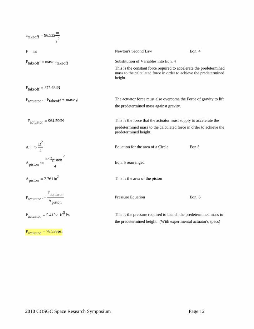
atakeoff 96.522m
s2
F ma Newton's Second Law Eqn. 4 Ftakeoff mass atakeoff Substitution of Variables into Eqn. 4
This is the constant force required to accelerate the predetermined mass to the calculated force in order to achieve the predetermined height.
Ftakeoff 875.634N
Factuator Ftakeoff mass g The actuator force must also overcome the Force of gravity to lift
the predetermined mass against gravity.
Factuator 964.599N This is the force that the actuator must supply to accelerate the
predetermined mass to the calculated force in order to achieve the predetermined height.
A D
2
4 Equation for the area of a Circle Eqn.5
Apiston
Dpiston2
4 Eqn. 5 rearranged
Apiston 2.761 in2
This is the area of the piston
Pactuator
Factuator
Apiston Pressure Equation Eqn. 6
Pactuator 5.415 105
Pa This is the pressure required to launch the predetermined mass to
the predetermined height. (With experimental actuator's specs) Pactuator 78.536psi

2010 COSGC Space Research Symposium Page 13
Pneumatic Cylinder Failure Calculations: Goal: Verify the structural integrity of the pneumatic actuator by performing failure analysis calculations for all anticipated modes of failure. Possible Modes of Failure: 1) Cylinder Bursts 2) Tie Rod Yielding Due to Tension 3) Top of Cylinder Shears Due to Impact 4) Threads Strip *Fatigue is taken into account in the safety factor. Under 1000 cycles, 90% of the initial strength of the material is retained, making fatigue calculations negligible.
CylinderTop
FAxialMax
Ashear
Impulse Calculations (to be used in failure analysis): Assumptions (worst case): mLaunchStructure 0.5lbm Per cylinder.
hjump 1m
xaccel1
8in 1 1/8in washer and one 1/16in washer (assuming not fully
compressed, that is why we use 1/8, not 1/8 + 1/16) Find Takeoff Velocity:
Vtakeoff2
2 g hjump
Vtakeoff 2 g hjump
Vtakeoff 4.429m
s
Find Acceleration of Launch Structure:
Vtakeoff2
2 aLaunchStructure xaccel
aLaunchStructure
Vtakeoff2
2 xaccel

2010 COSGC Space Research Symposium Page 14
aLaunchStructure 3.089 103
m
s2
Find the Force (per cylinder) Due to Impulse of Launch: FAxialMax mLaunchStructure aLaunchStructure
FAxialMax 0.701 kN
FAxialMax 157 lbf PER CYLINDER
1) Cylinder Burst - Failure Analysis: Assumptions (worst case): Cylinder will initially be under compression; however, this was neglected because the worst case will occur when the cylinder is loaded in tension.
twall1
16in
SteelYield 234MPa <--- Stainless Steel 302A (A weaker steel)
Pmax 200psi
rcylinder 0.9375in
Thin-Wall Cylinder Equation for Hoop Stress:
hoop
Pmaxrcylinder
twall hoop 20.684MPa
Axial Cylinder Stress: rinner rcylinder
router rcylinder twall
ACylinderCrossSection router2
rinner2
CylinderAxial
FAxialMax
ACylinderCrossSection
CylinderAxial 2.854 MPa

2010 COSGC Space Research Symposium Page 15
Von Mises Stress: 1 hoop <--------------- Negative because 1) quantitatively, von
Mises stress is less than the axial cylinder stress if it is positive, and 2) qualitatively, because the pressure pushing outward on the cylinder is creating stress in compression in the axial direction (compression is negative, tension is positive).
2 CylinderAxia
e 12
22
1 2
e 22.249MPa
Calculate the Safety Factor Using Maximum-Distortion-Energy Theory (von Mises):
SFcylinder
SteelYield
e SFcylinder 10.517
2) Tie Rods Yielding - Failure Analysis: Assumptions (worst case): NumberOfRods 4 Drod 0.125in
Stainless Steel 302A Rods ---> Defined Above Force Per Rod Using the Maximum Axial Force Due to Impulse from Takeoff: 2 times the maximum axial load because the rod will initially be preset in tension to a value that is near the maximum axial load in order to avoid leakage during the small periods of time when the actual load is applied. Ideally, the value would be at least 2x, but it is unlikely that this will actually be true. 2x is probably a safe number, it will likely have lower initial tension.
FRodMax
2FAxialMax
NumberOfRods FRodMax 0.35 kN
Cross Sectional Area of the Tie Rods:
Arod Drod
2
4 Arod 7.917 10
6 m
2
Maximum Axial Stress of the Tie Rods:
rods
FRodMax
Arod rods 44.239MPa

2010 COSGC Space Research Symposium Page 16
Calculate the Safety Factor of the Tie Rods:
SFrods
SteelYield
rods SFrods 5.289
3) Top of Cylinder Shear Yielding - Failure Analysis: Assumptions (worst case): AlumYield 110MPa Aluminum Alloy 6061-T4
tshear1
8in
Shear Strength of Aluminum: AlumYield 0.55AlumYield AlumYield 60.5 MPa
Shear Area:
Ashear 2 rcylinder tshear Ashear 4.75 104
m2
Shear Stress: CylinderTop 1.475 MPa
Calculate the Safety Factor of the Top of the Cylinder:
SFshear
AlumYield
CylinderTop SFshear 41.027
4) Thread Stripping - Failure Analysis: Similar to Tie Rod calculations, we will use a value of 2x the maximum axial force to represent a static force on the threads. This value is chosen because the rod will be under an initial tensile force in addition to the maximum axial force from the impulse of takeoff. Assumptions (worst case): Stainless Steel 302A Rods and Nuts ---> Defined Above Nrods 4 <-- Number of Tie Rods
http://www.rjleahy.com/Techcenter/nuts/hex_nuts.htm "Square and Hex Machine Nuts - Size No. 5
tnut 0.102in Specs for UNC No. 5 (D=0.125") Class 2A threads -
(Machinery's Handbook):
pcoarse1
40in
do 0.1242in
di 0.1191in

2010 COSGC Space Research Symposium Page 17
Stress on threads:
threads
4 2FAxialMax
Nrods
do2
di2
pcoarse
tnut Eqn. 10.10 in Machines Book
The "2" is explained above. threads 136.538MPa
Calculate the Safety Factor of the Threads:
SFthreads
SteelYield
threads SFthreads 1.714
Conclusion (Before changes of launch structure weight and extra rubber washer thickness): The chosen materials and thicknesses are probably sufficient; however, to maximize strength, the following should be done (in order of importance). 1) Add extra-thick rubber washers to minimize the maximum axial force! (VERY IMPORTANT) 2) Minimize the weight of the launch structure to minimize axial force. 3) Increase the shear thickness on the top of the cylinder. 4) Increase the thickness of the tie rods if need be (however, this will add weight). 5) Increase the threaded thickness (or number of nuts) if need be. 6) Using higher quality materials or adhering to more realistic assumptions will help the safety factors all around. The safety factors shown are Worst Case. THICK RUBBER WASHERS IS, BY FAR, THE MOST IMPORTANT!

2010 COSGC Space Research Symposium Page 18
Motor Calculations: Design Constraints: Wtot 30lbf Dwheel 8in
Calculate Stall Torque Required to Climb a Vertical Wall: We are calculating this unrealistic situation so that we can be positive that the rover will not be short of the required torque. Assumptions: Nmotors 2 <-- Number of Motors
Calculations:
rwheel
Dwheel
2
Fclimb Wtot Fclimb 133.447N
Ttot rwheel Fclimb Ttot 13.558N m
Tstall
Ttot
Nmotors Tstall 6.779 N m
Tstall 5 ft lbf
Tstall 960 ozf in Ounce-force * inch PER MOTOR
Calculate the Maximum Endurance and Range of the Motor: Assumptions: Qbattery 5A hr
Inominal 0.1A <--- "Nominal" Current Draw per motor
Endurance Calculations: Itot Inominal Nmotors Itot 0.2A
IQ
t
tQbattery
Itot t 25 hr