Design, development and fabrication of circuits using ... - CORE
Upload
khangminh22Category
view
3download
0
Prof. Roshan R. Shrirao et al www.ijetst.in Page 3995
IJETST- Vol.||03||Issue||05||Pages 3995-4015||May||ISSN 2348-9480 2016
International Journal of Emerging Trends in Science and Technology
Impact Factor: 2.838 DOI: http://dx.doi.org/10.18535/ijetst/v3i05.23
Design & Fabrication of ACV
Authors
Prof Roshan R. Shrirao, Mr Sachin P. Kale, Mr Dipak K. Rakhde, Mr Ajinkya S. Khot Department of Mechanical Engineering
G. H. Raisoni College of Engineering & Management, Amravati – 444701
ABSTRACT
Air Cushion Vehicle is a machine that can move on the land surface or water and it is supported by cushion
that has high compressed air inside. The cushion is a closed canvas and better known as a skirt. An ACV
moves on most of surface either in rough, soft or slippery condition. The design and construction of an ACV
with full basic function is reported by taking into consideration, size, material and component availability
intermediate fabrication skill. In-depth research was carried out to determine the component of ACV system
and their basic function and in particular it’s principle of operation. For this research project, there are two
basic requirements. The first requirement is to design and construct a physical model of ACV. The second
requirement is to control motion of constructed ACV and to make it suitable torun on water and land surfaces.
The fabrication of designed ACV by using material that are easily available by taking into consideration the
economic constraints and time constraints. The systems that can be used to increase human life quality during
military operations, pipeline survey, and border patrol, during the natural disaster and situation faced by
human are such as earthquake, flood etc. Further research is required to improve the efficiency of ACV.
CHAPTRE 1
INTRODUCTION
The history of the ACV spans over three hundred years. The idea of the ACV has had over three hundred
years to be perfected and modified. In fact, over eight men have taken the idea first presented by Emanuel
Swedenborg in 1716 and elaborated upon it. We should also note that the term ACV can also be
interchanged with ACV. The idea of Swedenborg's hovering machine rested in the minds of the educated
elite until 1865, when a researcher William Fronde whose idea never got off the ground. In 1876 the true
design of a modern day ACV was starting to come together. A researcher John B. Ward came up with the
idea of a platform made out of aluminium that had blades that pushed air down for the creation of the air-
cushion and another set of blades that would push air backwards, so as to provide for propulsion.
In 1888 James Walker developed a system of containing the air under the platform and in 1897 Culbertson
made the first suggestion for sidewall air cushion vehicles. The realization that man can fly come in 1903 by
the Wright Brothers, further supported the controversial idea of the funnel effect (the funnel effect is also
known as a cushion of air, which later became known as the ground effect). In fact, the first working model
was displayed in 1916. However, as far as practical applications, Dogbert Muller developed a torpedo boat
for the Austrian navy using the same ideas expressed by Swedenborg's first model thought up in 1716. One
of the most important ground effect craft is the German Dornier DO-X twelve in 1929 the Dornier crossed
entirely in ground effect. Furthermore, even Charles Lindbergh flew in ground effect so as to conserve fuel.
It wasn't until the 1950's that the ACV that we know today was developed by Christopher Cockerell. He
created the idea of peripheral jets, which aided in the balancing of the ACV while it is hovering, thus
increasing stability.
In the recent times most of the vehicle gets customized. So our aim is also to customize the ACV. ACV is
the vehicle which is working on a hovering effect where the vehicle gets detached from the ground surface.
In general the brief note on report is laid down below; Chapter 1 gives brief introduction about an ACV. It
includes the history of ACV. In chapter 2, we have mentioned various research papers which help to
gathered information’s about an ACV. The objective and purpose behind this project are highlighted also in

Prof. Roshan R. Shrirao et al www.ijetst.in Page 3996
IJETST- Vol.||03||Issue||05||Pages 3995-4015||May||ISSN 2348-9480 2016
this chapter, the detailed about construction and working of ACV are given in chapter 3. In construction
information about different parts of an ACV is given. The working principle also shown in this chapter.
Design of various components such as propeller, skirt and shaft etc. Given in chapter 4. Calculation of
various forces acting on a different parts, thrust created by the propeller etc. Is also given in this chapter.
Application of an ACV is given in chapter 5. In chapter 6, result which we found and discussion are given.
In chapter 7 the future scope of this project and conclusion are given.
CHAPTER 2
LITERATURE REVIEW
The purpose of this chapter is to provide some of the relevant background information regarding Air cushion
vehicle. The ACV appears to be a simple structure comprise of propeller, skirt, Blower etc. The performance
can be affected by various things including geometries of ACV and its component, the skirt material and
type of skirt.
In a paper by Rakesh Chandmal Sharma, Manish Dhingra, Rajeev Kumar Pathak, Manish Kumar on, “Air
Cushion Vehicle Configuration, Resistance and Control,”
Are discussed, different types of aerostatic and aerodynamic craft. The craft configurations have also been
discussed in this study. The all possible types of drag due to resistance of air cushion vehicles are discussed
here. Finally the control aspect of air cushion vehicles is presented in this paper [1]
.
In a paper by S.V. Uma Maheswara Rao, V.S. Surya Prakash on, “Development of a Integrated Air
Cushioned Vehicle (Hovercraft),”
It is studied, the design and development of a hovercraft prototype with full ACV basic functions is reported
by taking into consideration, size, material and component availability and intermediate fabrication skill. In-
depth research was carried out to determine the components of a ACV system and their basic functions and
in particular its principle of operation. Detailed research in design was done to determine the size of
component parts, quite in accordance with relevant standard requirements as applicable in the air cushioned
vehicles (ACV). The fabrication of the designed ACV by using materials that are readily available by taking
into consideration the economic constraints and time constraints. It also includes the testing process which
includes the tweaking of various parameters that govern lift and thrust of the hovercraft. Further research is
recommended to improve on the efficiency of the craft [2]
.
Another paper by Michael McPeake on, “A Research Paper on the History of the ACV,”
Introduce that, the vehicle itself is very interesting, yet how it came to be may even be more interesting. It
all started with one man in 1716. His name was Emanuel Swedenborg, and he was a Swedish designer and
philosopher. Besides coming up with the idea of the ACV he also started his own religion in form of the
New Jerusalem Church and wrote many religious papers of which he is most notably renowned for. Because
Emanuel introduced the idea of the ACV way before it's time of possible implementation, he knew that it
would be impossible to make it work, due to the fact that if he were to make an ACV, it would require a
great deal of energy to make it hover. The ACV itself is not just a piece of machinery it is a work of art [3]
.
In a paper by Jeffyschleigh on, “Construction of an ACV model and control of it motion,”
It is studied that, there are two basic requirements. The first requirement is to design and construct a physical
model of an ACV prototype. The second requirement is to control the motion of the constructed ACV
prototype, such as following a track, which consists of straight lines and curves. There are three software
systems available in the completion of this research project. These systems are Pro/Engineer, Solid Works
and Robotics Invention System [4]
.
In a paper by Zachary Kulis on, “Feedback Control of an ACV Over a Wireless Link,”
It was studied that, Nonlinear under actuated systems (i.e. systems with fewer control inputs than
configuration variables) present significant challenges for automatic control. This thesis explores feedback
control of an under actuated ACV over a wireless communication channel using techniques from nonlinear
control theory. A family of control laws, stabilizing the ACV reduced dynamic including zero velocity
constant forward reverse velocity & constant angular velocity stabilization are derived. Lyapunov arguments
are used to prove convergence of the reduced dynamics under the control laws. It is shown that heading
cannot be stabilized by a continuously differentiable state feedback law. In response two hybrid control

Prof. Roshan R. Shrirao et al www.ijetst.in Page 3997
IJETST- Vol.||03||Issue||05||Pages 3995-4015||May||ISSN 2348-9480 2016
algorithms for heading stabilization are proposed. Experimental and simulated results from a high fidelity
model are shown to agree nicely [5]
.
In a paper by Amit Tiwari on, “To Study and Fabrication of Air Cushion Vehicle,”
Introduce that, An Air cushion vehicle is a vehicle that flies like a plane but can float like a boat, can drive
like a car but will traverse ditches and gullies as it is a flat terrain. An air cushion vehicle also sometimes
called an air cushion vehicle because it can hover over or move across land or water surfaces while being
held off from the surfaces by a cushion of air. An ACV can travel over all types of surfaces including grass,
mud, muskeg, sand, quicksand, water and ice. ACV prefers gentle terrain although they are capable of
climbing slopes up to 20%, depending upon surface characteristics. Modern ACVs are used for many
applications where people and equipment need to travel at speed over water but be able load and unload on
land [6]
.
In a paper by ZheLuo, Fan Yu, Bing-Cong Chen on, “Design of a Novel Semi Racked Air Cushion Vehicle
for Soft Terrain,”
It is studied that, In order to improve the crossing ability and the tractive performance of a vehicle operating
on soft and wet terrain, the travelling mechanism must be properly designed and the adaptation ability to the
changes of prevailing operation conditions is obviously needed. Based on the previous researches and
developments of a wheeled air cushion vehicle and a semi walking wheeled air cushion vehicle, a new
hybrid vehicle that combines air cushion technology with a travelling mechanism, i.e. a semi tracked air
cushion (STAC) vehicle has been developed. This paper proposed a new design principle for the semi track
air cushion vehicle. A novel structure, i.e. a flexible joint mechanism as the prototype suspension system, is
particularly described. Based on theoretical analysis, an optimization model is established for minimizing
total power consumption. Experiments have been carried out to investigate the relationships among load
distribution ratio, slip ratio, clearance height, vehicle speed sand resistances and power consumption in
given terrain conditions [7]
.
In a paper by Yu Guoxin, Lu Xinsen on, “Dynamic Analysis of ACV Structures,”
Are discussed, a method is presented for dynamic analysis of ACV and its machinery and propulsion
system. The dynamic behaviour of the main hull structure of the ACV (buoyancy tank) is calculated by
using the curved orthotropic shell element. The dynamic behaviour of the machinery and propulsion system
is calculated by using 3 dimensional beam elements. Dynamic substructure method is introduced to analyses
the coupled vibration of the main hull structure and the machinery and propulsion system. The dynamic
analysis of a complete ACV is thus preceded and the feasibility and the accuracy of the method offered are
verified by a readymade measurement [8]
.
In a paper by M. M. El-khatib, W. M. Hussein on, “Stabilization and Design of an ACV Intelligent Fuzzy
Controller,”
It was studied that, the objective of the paper is to design, stabilize, simulate and implement an autonomous
model of a small ACV that can travel over any terrains. A real time layered fuzzy navigator for an ACV in a
dynamic environment is proposed. It intelligently combines two behaviours to cope with obstacle avoidance
as well as approaching a goal using a proportional navigation path accounting for ACV kinematics. State
space method is used to represent the dynamics of an ACV. MATLAB software tool is used to design and
verify the proposed algorithm. The fuzzy stabilizer is tuned such that its nonlinearity lies in a bounded sector
results using the circle criterion theory. An application example for the proposed system has been suggested [9]
.
Based on literature survey following objectives are formulated:
1. To design & develop ACV with minimal cost.
2. To run ACV on water surface.
3. To run ACV on road surface.
4. To run ACV on slippy surface or ice.
5. To keep minimum, the loss of cushion air.
6. Offer little resistance to the passage of obstacles beneath it.
7. To absorb large portion of energy this is produced on impact or collision with obstacles greater than
cushion depth.

Prof. Roshan R. Shrirao et al www.ijetst.in Page 3998
IJETST- Vol.||03||Issue||05||Pages 3995-4015||May||ISSN 2348-9480 2016
CHAPTER 3
CONSTRUCTION AND WORKING
3.1 Construction:
The ACV consists of several parts, the plywood sheet as a chassis, and then centrifugal blower is mount on
it at front side and which give air to the skirt. 2- stroke engine mounted at back side on which propeller is
mounted; a casing is given over 2 stroke engine for safety purpose and getting the thrust from the propeller.
The rider’s seat is given at middle, and steering mechanism near the seat for easy to handle. The skirt is
made for the pressure required to lift the vehicle, and it is attached to the bottom side of the chassis.
The air cushion vehicle consists of following main parts.
1. Chassis (use plywood)
2. Skirt (hull)
3. Centrifugal blower
4. 2-stroke petrol engine
5. Propeller
6. Propeller casing
7. Rider’s seat
8. Steering mechanism
Figure.3.1: Air Cushion Vehicle
3.2 Principle of Working
The principle of working of an ACV is to lift the craft by a cushion of air to propel it using propellers. The
idea of supporting the vehicle on a cushion of air developed from the idea to increase the speed of boat by
feeding air beneath them. The air beneath the hull would lubricate the surface and reduce the water dragon
boat and so increasing its speed through water. The air sucked in through a port by large lifting fans which
are fitted to the primary structure of the craft. They are powered by 2 stroke petrol engine. The air is pushed
to the underside of the craft. On the way a portion of air from the lift fan is used to inflate the skirt and rest is
ducted down under the craft to fill area enclosed by the skirt. At the point when the pressure equals the
weight of the craft, the craft lifts up and air is escaped around the edges of the skirt. So a constant feed of air
is needed to lift the craft and compensate for the losses. Thus craft is lifted up. After the propulsion is
provided by the propellers mounted on the ACV. The air from the propeller is passed over rudders, which
are used to steer the craft similar to an aircraft. ACV is thus propelled and controlled and its powerful engine
makes it to run.
3.3 Chassis (use Plywood)
Plywood is made of three or more thin layers of wood bonded together with an adhesive. Each layer of
wood, or ply, is usually oriented with its grain running at right angles to the adjacent layer in order to reduce
the shrinkage and improve the strength of the finished piece. Most plywood is pressed into large, flat sheets
used in building construction. Other plywood pieces may be formed into simple or compound curves for use
in furniture, boats, and aircraft.
3
4
6
7
1
8
2
5

Prof. Roshan R. Shrirao et al www.ijetst.in Page 3999
IJETST- Vol.||03||Issue||05||Pages 3995-4015||May||ISSN 2348-9480 2016
The use of thin layers of wood as a means of construction dates to approximately 1500 B.C. when Egyptian
craftsmen bonded thin pieces of dark ebony wood to the exterior of a cedar casket found in the tomb of King
Tut-Ankh-Amon. This technique was later used by the Greeks and Romans to produce fine furniture and
other decorative objects. In the 1600s, the art of decorating furniture with thin pieces of wood became
known as veneering, and the pieces themselves became known as veneers.
Until the late 1700s, the pieces of veneer were cut entirely by hand. In 1797, Englishman Sir Samuel
Bentham applied for patents covering several machines to produce veneers. In his patent applications, he
described the concept of laminating several layers of veneer with glue to form a thicker piece-the first
description of what is now called as plywood.
Despite this development, it took almost another hundred years before laminated veneers found any
commercial uses outside of the furniture industry. In about 1890, laminated woods were first used to build
doors. As the demand grew, several companies began producing sheets of multiple ply laminated wood, not
only for doors, but also for use in railroad cars, busses, and airplanes. Despite this increased usage, the
concept of using "pasted woods" as some craftsmen sarcastically called them generated a negative image for
the product. To counter this image, the laminated wood manufacturers met and finally settled on the term
"plywood" to describe the new material.
In 1928, the first standard-sized 4 ft by 8 ft (1.2 m by 2.4 m) plywood sheets were introduced in the United
States for use as a general building material. In the following decades, improved adhesives and new methods
of production allowed plywood to be used for a wide variety of applications. Today, plywood has replaced
cut lumber for many construction purposes, and plywood manufacturing has become a multi-billion dollar,
worldwide industry.
3.3.1 Raw Materials:
The outer layers of plywood are known respectively as the face and the back. The face is the surface that is
to be used or seen, while the back remains unused or hidden. The centre layer is known as the core. In
plywood with five or more plies, the intermediate layers are known as the cross bands. Plywood may be
made from hardwoods, softwoods, or a combination of the two. Some common hardwoods include ash,
maple, mahogany, oak, and teak. The most common softwood used to make plywood in the United States is
Douglas fir, although several varieties of pine, cedar, spruce, and redwood are also used. Composite
plywood has a core made of particleboard or solid lumber pieces joined edge to edge. It is finished with a
plywood veneer face and back. Composite plywood is used where very thick sheets are needed. The type of
adhesive used to bond the layers of wood together depends on the specific application for the finished
plywood. Softwood plywood sheets designed for installation on the exterior of a structure usually use a
phenol formaldehyde resin as an adhesive because of its excellent strength and resistance to moisture.
Softwood plywood sheets designed for installation on the interior of a structure may use a blood protein or a
soybean protein adhesive, although most softwood interior sheets are now made with the same phenol-
formaldehyde resin used for exterior sheets. Hardwood plywood used for interior applications and in the
construction of furniture usually is made with a urea formaldehyde resin.
Some applications require plywood sheets that have a thin layer of plastic, metal, or resin-impregnated paper
or fabric bonded to either the face or back (or both) to give the outer surface additional resistance to
moisture and abrasion or to improve its paint-holding properties. Such plywood is called overlaid plywood
and is commonly used in the construction, transportation, and agricultural industries.
Other plywood sheets may be coated with a liquid stain to give the surfaces a finished appearance, or may be
treated with various chemicals to improve the plywood's flame resistance or resistance to decay.

Prof. Roshan R. Shrirao et al www.ijetst.in Page 4000
IJETST- Vol.||03||Issue||05||Pages 3995-4015||May||ISSN 2348-9480 2016
Figure.3.2: Chassis (On plywood)
3.3.2 Comparison of Wooden Material
Table3.1: Comparison of wooden material
Company Grade Cost Availability Water
Resistance 8mm 12mm
National Plywood Company A Rs.90/sq.ft Rs.120/sq.ft Not Available Yes
Flamingo Plywood
Company
B Rs.85/sq.ft Rs.105/sq.ft Available Yes
Century Ply Company A Rs.87/sq.ft Rs.111/sq.ft Less
Available
Yes
Internat Plywood Company C Rs.75/sq.ft Rs.85/sq.ft Available No
3.4 Skirt:
They are air bags inflated by air are fitted around the perimeter of the craft hold air under the craft and thus
upon a cushion of air. It enables to obtain greater Hover height.
3.4.1 Following are the types of Skirt:
1] Bag skirt: It is like an inner tube with a piece of plywood on top, holes feeding into the middle, and an air supply.
When it inflates it’s the same principle as simply sitting on an O-shaped balloon, since that's essentially
what it is. Air goes into the bag, inflating it so it is about two inches high. The air inflating it goes out the
holes located towards the centre, making the air also build up pressure in a chamber between the ground, the
plywood, and the inflated ring of the bag skirt. The pressure eventually build up enough so that it and the
bag skirt is lifting the plywood, and the air slides out underneath the bag, creating a nearly frictionless
environment.
Figure.3.3: Bag skirt

Prof. Roshan R. Shrirao et al www.ijetst.in Page 4001
IJETST- Vol.||03||Issue||05||Pages 3995-4015||May||ISSN 2348-9480 2016
[2] Wall Skirt
Wall skirts hang down from the edge of your ACV (hence the wall name). The skirt inflates and pushes
outwards, so the ACV rides on a cushion of air. It's like an electric inflating mattress, if the bottom was cut
out of it, and a piece of plywood placed on top of it, the mattress would still inflate, but when it was fully
inflated some air would pick it up still a centimetre more so it could slide out from underneath. A good bag
skirt is like a wall skirt that uses an inflated wall to contain the air.
Figure.3.4: Wall skirt
[3] Finger skirt: Finger skirts are used on professional ACVs. A finger skirt has tons of little segments that each individually
inflate that conform to the ground so the ACV can go over all terrain. Professional finger skirts are generally
made out of very strong rubber material. The fingers are actually a bunch of separated "little skirts" that
inflate independently. To build a finger skirt, you need a large hull with a built in plenum chamber and that
takes a lot of work.
Figure.3.5: Finger skirt
3.5 Material for Skirts:
The skirt is one of the most important part of an ACV. As it is part that allows the ACV to clear the
obstacles. Generally speaking, the higher the skirt, longer the obstacles that the vehicle will clear. However
the skirt is too tall, the vehicle will side of the cushion and the cushion will deflate or the vehicle will
become unstable. So the selection of material plays an important role to select the right material for the skirt.
3.5.1 Following are the material used as skirt:
1. Neoprene
2. Natural Rubber
3. Hypalon
4. PVC
5. 6 Oz Material
6. Urethane-Coated Nylon Fabric

Prof. Roshan R. Shrirao et al www.ijetst.in Page 4002
IJETST- Vol.||03||Issue||05||Pages 3995-4015||May||ISSN 2348-9480 2016
1] 6 Oz Material:
6 ounce nylon cloth is the perfect finger skirt material. It has a 3/4 ounce urethane coating for superior water
repellence and low friction, yet remains soft and flexible. There is no need to worry about rot or mildew,
common problems with some other finger skirt material, due to the special treatment of this fabric.
Features
1. Water resistant.
2. Soft and flexible.
3. Rot and mildew resistant-60" wide.
2] Urethane Coated Nylon Fabric:
Urethane coated nylon fibre is the best material for the wall skirt. The coating of urethane is coated on one
side of denier ballistic nylon. This fibre is light in weight, flexible in cold temperature and very high
resistance to abrasion.
Features
1. Greater wear resistance.
2. Light weight.
3] Standard vinyl (PVC):
Standard vinyl (PVC) coated skirt fabric with one important difference 1000*1300 denier polyester has
better tear resistance than the commonly used nylon based fabrics. Also, it is treated to be mildew and UV
resistant. This material is guaranteed to give you a longer lasting skirt and fewer repairs than vinyl coated
nylon. This fabric can be easily glued with HH-66 Vinyl Cement. It dries in minutes and creates a strong,
permanent bond.
Features
1. Greater tear resistance than nylon based fabric.
2. Mildew resistant.
3. UV resistant.
4. Holds colar longer-61" wide-Glues easily with HH-66 Vinyl Cement.
3.6 An ACV skirt is required to fulfil the following functions: 1. Contain the cushion of air beneath the craft at required Hover height.
2. Have the ability to confirm or contour effectively over obstacles so as to keep minimum, the loss of
cushion air.
3. Return to its original shape after having been deformed.
4. Give adequate stability.
5. Offer little resistance to passage of obstacles beneath it.
6. Have the ability to absorb a large portion of the energy which is produced on
impacts or Collision with obstacles greater than hover height or cushion depth.
3.7 Comparison of skirt material:
Table 3.2: Comparison of skirt material
Material Cost Availability
6 Oz $ 13.78per linear yard Not available
18 Oz $ 16.83per linear yard Not available
Urethane-Coated Nylon Fabric $17.95 per linear yard Not available

Prof. Roshan R. Shrirao et al www.ijetst.in Page 4003
IJETST- Vol.||03||Issue||05||Pages 3995-4015||May||ISSN 2348-9480 2016
Figure.3.6: skirt material used
From the above comparison the material used for the making of skirt is not available and also the cost of the
material is high, hence we used this local material which is made up of nylon coated fibres, which is
available and the cost is also comparatively low.
3.8 Casing
Generally casing is used for the safety purpose. We have a propeller mounted over a 2-stroke petrol engine.
Propeller rotates when motor starts. The casing for safety purpose is provide to avoid accident.
Figure.3.7: Casing on over the propeller
It consists of a 2mm thick metal sheet which wound on two iron rods connecting at two ends. It gives the
strength to metal sheet, hence any vibration or air resistance cannot damage the casing.
It is fitted on plywood with the nut and bolt arrangement. It is easy for fixing and removing, as it is low in
weight with high strength.
3.9 Rider Seat: Rider seat is essential thing for any vehicle. Our driving seat is situated at the middle of our ACV. It gives
the proper balance to driver while floating or running on water surface.
Figure.3.8: driver’s seat

Prof. Roshan R. Shrirao et al www.ijetst.in Page 4004
IJETST- Vol.||03||Issue||05||Pages 3995-4015||May||ISSN 2348-9480 2016
It is made up of high quality foam with rexine coated. The rexine coating is waterproof, if it hurt by water
then it will not damage. It provides high comfort while driving. It has good compressive strength and it
sustain up to 90 kg of weight of any person.
3.10 2 Strokes Petrol Engine
Use of the TU- 26 engine for the propulsion of the air cushion vehicle which has following specification.
This engine used because of the cost is low and specifications are fulfilling by the engine.
3.10.1 Specifications of 2 Stroke Petrol Engine:
Table 3.3: Specifications of 2 stroke petrol engine
Engine Model TU-26
Engine Type Air-cooling,2-Stroke,Single Cylinder
Engine power 1.06kw/5500r/min
Starting Method Manually Drawing Wound Rope
Displacement 26cc
Form of Carburettor Diaphragm
Ratio of Fuel and Lubricant 30:1
Packing Size 24*19*24cm
G.W/N.W 3./2.5kgs
Figure.3.9: 2-Stroke petrol engine
3.11 Centrifugal blower:
Centrifugal blower is a mechanical device for moving air or other gases. The terms "blower" and "squirrel
cage fan" are frequently used as synonyms. These fans increase the speed of air stream with the rotating
impellers.
They use the kinetic energy of the impellers or the rotating blade to increase the pressure of the air/gas
stream which in turn moves them against the resistance caused by ducts, dampers and other components.
Centrifugal fans accelerate air radially, changing the direction (typically by 90°) of the airflow. They are
quiet reliable and capable of operating over a wide range of conditions.

Prof. Roshan R. Shrirao et al www.ijetst.in Page 4005
IJETST- Vol.||03||Issue||05||Pages 3995-4015||May||ISSN 2348-9480 2016
Centrifugal fans are constant displacement devices or constant volume devices, meaning that, at a constant
fan speed, a centrifugal fan will pump a constant volume of air rather than a constant mass. This means that
the air velocity in a system is fixed even though the mass flow rate through the fan is not. They are often
cheaper than axial fans and simpler in construction.
It has a fan wheel composed of a number of fan blades, or ribs, mounted around a hub. The hub turns on
a drive shaft that passes through the fan housing. The gas enters from the side of the fan wheel, turns
and accelerates due to centrifugal force as it flows over the fan blades and exits the fan housing.
Figure.3.10: Centrifugal blower
3.11.1 Specifications of Centrifugal Blower:
Table 3.4: Specifications of centrifugal blower
Model BL 77
Displacement 77 cc
Power (HP) 5.0
Fuel Petrol + 2T
Air speed (m/sec) 125
Weight (kg) 10.2
3.12 Steering Mechanism: Steering mechanism is generally used to turn the vehicle in respected direction. In ACV, the Baffle plates
used for turning or give direction to ACV. When the propeller rotates at high speed then air passes from
these baffles. If baffle turn then air passes form baffle and give the direction to ACV. If baffle plate turn in
left direction the ACV turns into the right direction, also if baffle plate turn the in right direction the ACV
turn into the left direction.
3.12.1 Baffle:
It is the thin sheet of plywood which is used to divert the high velocity air, which is produced by propeller
for the steering. It is mounted on rectangular frame, baffle are operated by lever.

Prof. Roshan R. Shrirao et al www.ijetst.in Page 4006
IJETST- Vol.||03||Issue||05||Pages 3995-4015||May||ISSN 2348-9480 2016
Figure.3.11: Steering Mechanism (baffles)
Figure.3.12: Model of Baffle (creo parametric)
3.12.2 Lever Mechanism in Steering of an ACV:
It is lever used to turn the baffle plate which is mounted on chassis near rider’s seat. The baffle plates and
lever are connected with the help of cable; if right lever is push then baffle takes direction to right, similar to
the left direction. It is simple mechanism and easy to operate.

Prof. Roshan R. Shrirao et al www.ijetst.in Page 4007
IJETST- Vol.||03||Issue||05||Pages 3995-4015||May||ISSN 2348-9480 2016
Figure.3.13: Lever mechanism
3.13 Propeller
The propeller can be considered simply as a series of rotating wings or rotating aerofoils of equal length
meeting at the centre hub attached to the shaft of the 2 stroke engine and working their way through the air
mainly by means of their shape. The propeller is a simply a series of rotating aerofoils or blades.
Streamlined surface developed by the aeronautical experimentation and research for purpose of producing
thrust by their rotation in the air. The propeller blade is shaped much like the wings of an aeroplane; but
while the aircraft wing is especially designed to take care of lifting, the blade is especially designed to
produce a desired reaction from the air upon which it acts in order to drive the ACV ahead.
Figure.3.14: Model of Propeller (creo parametric)
Since the propeller blade and aeroplane wings are similar in shape, for all practical purpose, the blade of
propeller may be considered as a reduce wing, that is, a wing which has been reduce reduced in its width,
breadth and length to the dimension of propeller blade.
Thus, although considerably smaller, the shape through the propeller segment is still the same as that of a
wing. And if one end of this reduced wing is shaped into a shank, with provision for attaching it to a shaft,
then it must be called as propeller blade in rough.

Prof. Roshan R. Shrirao et al www.ijetst.in Page 4008
IJETST- Vol.||03||Issue||05||Pages 3995-4015||May||ISSN 2348-9480 2016
Figure.3.15: Model of blade section of propeller (creo parametric)
Now it is nothing but the wing which is converted into rough blade, turn the shaft to which the blade is
attached and make it rotate. As soon as the blade start rotating it is noticed that the flow of air drawn around
the blade creates a force which is exactly same as that of created by the flow of air on wing, expect that the
horizontal wing is lifted upward, while the rotating wing or blade is push forward.
3.14 Lift system: The main requirement of lift system is light weight Air Cushion Vehicle is to providing sufficient air flow to
maintain the design ACV’s height without excessive skirt drag and with the minimum expenditure of power
and fuel. The system must also have an overload pressure capacity to prevent blower due to cushion pressure
fluctuation as the craft traverse undulating waves.
In the case of the ACV lift system, it is the air pressure that acts upon the underside of the ACV that
provides the lifting force to make the ACV hover. Also, because the skirt does not form a perfect seal
around the ACV perimeter there is leakage of the air and that must be balanced by constant air input from
the lift fan. The best result is only possible if the lift system is designed for lift alone without regard for the
provision of thrust air. If air is considered to be a fluid because it takes the shape of the container
surrounding it. In the case of an ACV, the air takes the shape of the bottom of the ACV, the inside edges of
the skirt, and the surface its ACV above.
Figure.3.16: Air gap between the skirt and the surface
The fan that blows air under the bottom of the ACV keeps pushing more and more air below the ACV, thus
increasing the pressure in the air cushion. The pressurized air cushion exerts a force on its container, when
the force this pressurized air exerts on the surface grows to equal the weight of the ACV, it becomes buoyant

Prof. Roshan R. Shrirao et al www.ijetst.in Page 4009
IJETST- Vol.||03||Issue||05||Pages 3995-4015||May||ISSN 2348-9480 2016
(like a boat in water) and begins to float on air. When an ACV hovers, it will lift as high as the skirt’s
designed shape will permit. Lift air begins escaping through the gap between the bottom of the skirt and
the surface it's over. The size of this gap will be large enough so that the same amount of air escapes
through the gap as is pushed in by the fan, keeping the pressure inside the air cushion constant. Usually,
this air gap will be 0 to 5 mm between the skirt bottom and the surface and is called daylight clearance.
3.15 Thrust system:
The force is created by rotating blade is known as thrust, that is, forward pull of the propeller, which tends to
bend the blade forward. However, in contending with this blade bending force, propeller designer are
fortunate in having the centrifugal force, which counteracts this forward thrust, or pull, to some extent. So,
while the thrust force tends to bend the blade forward, the tremendous centrifugal force pulling out on each
blade tends to hold it straight. The air is not directed to the cushion and skirt is propelled backwards,
providing forward thrust to the ACV. The size of the propeller, rpm output of the engine, and height of the
lift/thrust divider are the determining parameters for the thrust force.
CHAPTER 4
DESIGN & CALCULATIONS
Design is a creation of a plan of a convention for the construction of an object or a system. The design
process is a methodical series of step that we use in creating functional objects.
4.1 Skirt:
Assuming:
Length = 6 feet
Breadth = 3 feet
Area of base = 18 sq. ft = 1.67
Weight of driver = 60 kg (max.)
Weight of two engines (blower, engine & propeller) = 20 kg
Weight of plywood sheet and skirt = 20 kg
Total weight = 60 + 20 + 20 = 100 kg
For lifting this weight considered twice of total weight i.e. = 200 kg
Factor of safety = 2
Area of the rectangular section = 36 × 12
= 432
=
= 278709
Cushion pressure,
Pc = weight/area of base
=
= 119.67 kg/
= 119.67 × 9.81 = 1174.84
= 1174.84 × bar
We know that,
Pressure from the blower at rectangular section =
=
= 7.175 ×
= 717.59
= 717.59 × bar
We know that,
Discharge Q = A × V
= (36 × 2.54 ×12 ×2.54) × 125
= 27.87 × 125
= 3483.75

Prof. Roshan R. Shrirao et al www.ijetst.in Page 4010
IJETST- Vol.||03||Issue||05||Pages 3995-4015||May||ISSN 2348-9480 2016
Q = 58.06
Escape Velocity,
Ve =
=
= 13.97 m/s
Perimeter of Skirt = 6 + 6 + 3 + 3 = 18 ft = 5.4864 m
Hover Gap = 2 mm = 2× cm = 2× m
4.2 Thrust:
Escape Area, Ae = 5.48646 2× = 0.0109
Volume of Air Lost = Ve x Ae = 13.97 × 0.0109 = 0.15277
4.3 Design of shaft:
Given:
Power = 1.06 kw
N (rpm) = 3736 rpm
Diameter = 22 mm
∴ Torque on shaft,
T =
=
= 2.70 N-m = 2.70 N-mm
Figure.4.1: Design of shaft
Figure.4.2: Model of shaft (creo parametric)

Prof. Roshan R. Shrirao et al www.ijetst.in Page 4011
IJETST- Vol.||03||Issue||05||Pages 3995-4015||May||ISSN 2348-9480 2016
Shaft is made up of C.I
∴ Ultimate tensile strength = u = 200 Mpa
Ultimate compressive strength = 400 to 1000 Mpa
Ultimate shear strength = 120 Mpa
Considering sharing of shaft,
W =
= 3.4 N
Bending moment at M = W L
= 3.4 80 = 274.68 N-mm
Section modulus
Z =
=
= 1045.36
Bending stress, (induced)
∴b =
=
= 0.26
From the article 14.10 we can take the permissible bending stress as a maximum tensile stress.
Tensile stress t = b = 0.36 u
= 0.36 100
= 36
OR
t = b =
Induced Bending stress < permissible
0.26 < 16.66
∴ Shaft is safe in Bending.
4.4 Propeller:
The propeller is a simply a series of rotating airfoils or blades. Aircraft wing is especially designed to take
care of lifting; the blade is especially designed to produce a desired reaction from the air upon which it acts
in order to drive the ACV ahead.
Assumptions:
1. Airfoil section used is NACA 4412
2. Material used for propeller is pine wood.
3. Section of propeller = 2.5” × 2.5”
Maximum camber = (4%×2.5”) = (4% × 6.35)
= 0.254 cm.
Location of maximum camber = (0.4×2.5”) = 0.4 × 6.35
= 2.54cm.
Maximum thickness = (12% × 2.5”) = 1.662cm.
Pitch = 2.36 ×
= 2.36 ×
= 49.41cm.

Prof. Roshan R. Shrirao et al www.ijetst.in Page 4012
IJETST- Vol.||03||Issue||05||Pages 3995-4015||May||ISSN 2348-9480 2016
Figure.4.3: Nomenclature used in propeller
Lift: A fluid flowing past the surface of a body exerts a force on it. Lift is a component of this force that is
perpendicular to the oncoming flow direction.
Drag: It is force acting opposite to the relative motion of any object moving with respect to a surrounding
fluid. This can be existing between two fluid layers or a fluid and a solid surface. Unlike other resistive
forces such as dry friction.
Angle of attack: Blade pitch or simply pitch refers to turning the angle of attack of a blade of a propeller.
Camber: Camber is the asymmetry between top and the bottom surface if an aerofoil.
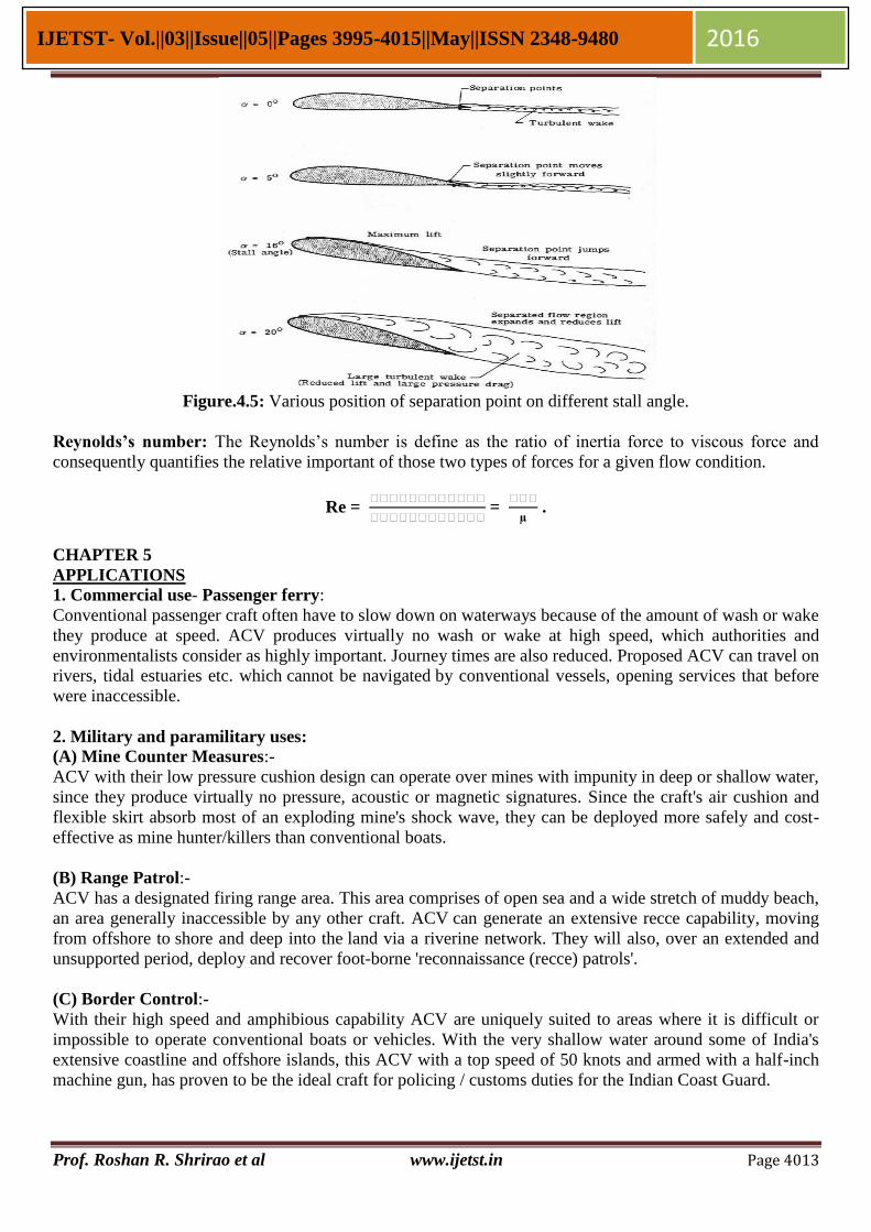
\Stall angle: A stall is a condition in an aerodynamics and aviation where in the angle of attack increases
beyond a critical point such that the lift begins to decreases.
Figure.4.4: Position of stall angle
Prof. Roshan R. Shrirao et al www.ijetst.in Page 4013
IJETST- Vol.||03||Issue||05||Pages 3995-4015||May||ISSN 2348-9480 2016
Figure.4.5: Various position of separation point on different stall angle.
Reynolds’s number: The Reynolds’s number is define as the ratio of inertia force to viscous force and
consequently quantifies the relative important of those two types of forces for a given flow condition.
Re =
=
.
CHAPTER 5
APPLICATIONS
1. Commercial use- Passenger ferry:
Conventional passenger craft often have to slow down on waterways because of the amount of wash or wake
they produce at speed. ACV produces virtually no wash or wake at high speed, which authorities and
environmentalists consider as highly important. Journey times are also reduced. Proposed ACV can travel on
rivers, tidal estuaries etc. which cannot be navigated by conventional vessels, opening services that before
were inaccessible.
2. Military and paramilitary uses:
(A) Mine Counter Measures:-
ACV with their low pressure cushion design can operate over mines with impunity in deep or shallow water,
since they produce virtually no pressure, acoustic or magnetic signatures. Since the craft's air cushion and
flexible skirt absorb most of an exploding mine's shock wave, they can be deployed more safely and cost-
effective as mine hunter/killers than conventional boats.
(B) Range Patrol:-
ACV has a designated firing range area. This area comprises of open sea and a wide stretch of muddy beach,
an area generally inaccessible by any other craft. ACV can generate an extensive recce capability, moving
from offshore to shore and deep into the land via a riverine network. They will also, over an extended and
unsupported period, deploy and recover foot-borne 'reconnaissance (recce) patrols'.
(C) Border Control:-
With their high speed and amphibious capability ACV are uniquely suited to areas where it is difficult or
impossible to operate conventional boats or vehicles. With the very shallow water around some of India's
extensive coastline and offshore islands, this ACV with a top speed of 50 knots and armed with a half-inch
machine gun, has proven to be the ideal craft for policing / customs duties for the Indian Coast Guard.

Prof. Roshan R. Shrirao et al www.ijetst.in Page 4014
IJETST- Vol.||03||Issue||05||Pages 3995-4015||May||ISSN 2348-9480 2016
3. Medical Evacuation & Humanitarian Aid:
ACV has the ability to reach areas where, for conventional vessels and vehicles, a rescue would be
extremely dangerous for emergency personnel.
Configured to the customer's requirements, ACV will both prepare the theatre and take part in an
amphibious assault, through reconnaissance, the insertion and support of Special Forces’.
4. Rescue and Search: Truly amphibious vehicles, ACV are the only vehicle able to provide high speed casualty response and
medical evacuation in a flood rescue role. ACV have more craft in service with Search and Rescue (SAR)
organizations than any other manufacturer, including the UK Royal National Lifeboat Institution (RNLI)
and Coastguards from Canada to Kuwait, all of which use these craft for flood rescue, medical evacuation
and disaster relief.
CHAPTER 6
RESULT AND DISCUSSION
6.1 Result:
According to calculations, we find- Pressure inside cushion = 1174.85 N/m², speed of propeller = 3736 rpm.
Navigation is done with the help of steering mechanism and baffle plate. The speed of navigation is
depending upon the velocity of air diverted by the baffle plate. ACV has high velocity on water surface and
easy to move on water surface rather than ground.
Hence, proposed Air Cushion Vehicle is successfully run/float on water surface. Also, ACV offer little
resistance to the passage of obstacles beneath it.
6.2 Discussion Although the ACV achieved basic goals for movement, we are limited in our capabilities. This is due to
several inefficiencies and problems in the construction and design of the craft. As can be seen by the
capability to support over 200 kg with the engine at full throttle, overestimating the necessary amount of
power from the propeller and engine to divert to lift. A more powerful engine would provide more energy
for both lift and thrust. This would require re-considering the design of the engine mount because a much
larger engine would require a metal support. A larger propeller correctly matched to the engine would
increase the air flow, achieving the same results as a more powerful engine.
CHAPTER 7
CONCLUSION AND FUTURE SCOPE
7.1 Conclusion:
The concept of an ACV is very simple, but the actual construction is a tough task. The calculations involved
are complex and they should be extremely accurate. The weight should be evenly distributed and the centre
of gravity should be properly identified. It helped to understand a lot of concepts and saw those concepts put
to use.
As well as it gives some advantages like it can run on water and against the flow of water without concern of
depth or hidden obstacles. Also can travel with a good speed and can travel on any surface. It gives
comfortable and smooth ride and exhaust from the engine cannot direct into the water. Also, according to its
disadvantages like, consumes quite more fuel with little bit noise. On land it can take inclination only up to
200 After the ACV was built, a lot of testing and tweaking was required to make it work. After days of up’s
and down’s, the ACV finally hovered and was working fine.
7.2 Future Scope:
The intension is to understand the basic principle of an ACV and to fabricate the same keeping the
constraints such as monetary constraints, time constraints etc. in mind. The ACV attempted was a primitive
one and as many aspect that needs to be optimized in the future such as,
a) Vibration and noise reduction.
b) Minimization of fuel consumption.

Prof. Roshan R. Shrirao et al www.ijetst.in Page 4015
IJETST- Vol.||03||Issue||05||Pages 3995-4015||May||ISSN 2348-9480 2016
c) Improvement in skirt material.
d) To get maximum speed need to increase the power of engine.
e) Need to increase the design of propeller to get maximum thrust.
f) To run on road & mud surfaces.
Copyright © 2022 FDOKUMEN