Design, Analysis and Fabrication of Automated Center Stand ...
10
GRD Journal for Engineering | Volume 3 | Issue 11 | October 2018 ISSN: 2455-5703 All rights reserved by www.grdjournals.com 5 Design, Analysis and Fabrication of Automated Center Stand for Two Wheeler Kiran Mukund Assistant Professor Department of Mechanical Engineering Adi Shankara Institute of Engineering and Technology, Kerala, India Abstract A center stand is a device on a bicycle or motorcycle that allows the bike to be kept upright without leaning against another object or the aid of a person. A center stand is usually a made of metal that comes down from the frame and makes contact with the ground. It is generally located in the middle of the bike or towards the rear. Some touring bicycles have two: one at the rear, and a second in the front. A new standing device which replaces center stand using external power which reduces human effort is being proposed. An existing center stand is modified by using electrical and mechanical components at optimum cost. The different mechanical parameters of stand are analyzed using Computational software and the best model is selected for fabrication. Keywords- Automobile, Center Stand, Computational Mechanics, FEM, Structural Analysis I. INTRODUCTION A center stand support means adapted to position vehicle on a ground surface in an operative vertical position. Displacement means adapted to displace support from an inoperative folded, retracted configuration to an inoperative unfolded, retracted configuration and further to an operative unfolded, extended configuration and vice versa in one continuous movement. Guided locking means adapted to lock support in operative configuration. Fitting means adapted to fit stand to frame of a two wheeled vehicle. As the problems identified by studying the existing system it is decided to design an alternative. Here hydraulic power is used to assist human effort. A double acting hydraulic cylinder takes power from motor to place and displace the stand. The entire system is housed just below the engine on the frame. From the history of motorcycle, it is seen that several components are optimized from time to time. Chassis, engine assembly and suspension system is optimized but still there are several open loop for different components. There are several problems associated with center and side stand. Ian falloon (2003) in his book tells that putting bike on side stand for a long time adversely effects on the tire as large force is transmitted through tires [1]. US Patent 4084656 [2] discloses a "Motorcycle stand with safety switch". This device prevents starting of the engine of a two-wheeled motorcycle, unless the stand is in an inoperative position. A stand switch is opened by the stand when the latter is in a neutral position so that the ignition circuit for the engine cannot be rendered operative, thereby preventing actuation of the engine. This safety device is suitable for a side stand but does not reduce the effort and balance required in deploying the stand or taking the motorcycle from a parked position to a ready to ride position. US Patent 40105823 [3] discloses an "Automatic side stand retreating device for motorcycle'. This device is suitable for automatically folding a side stand of a motorcycle when the motorcycle is started but not suitable for a center stand of the motorcycle. US patent 4580804 [4] discloses a "Jack stand for motorcycles". In this device retractable leg assemblies are used for raising the frame of a motorcycle from the ground to permit servicing the motor cycle. Each leg assembly includes a pair of telescopically engaged members having a cooperating pin and slot arrangement which enables them to be extended and locked simply by extending and twisting the same. Latching mechanisms are provided for release-ably retaining the leg assemblies in either the retracted position for riding or the extended position for jacking. The motorcycle has to be rocked side to side for extending the leg assemblies. This device enables stable positioning of the motorcycle even in an uneven terrain but the effort required to rock the motorcycle is beyond the capacity of most of the users. II. METHODOLOGY AND DESIGN As the problems and difficulties identified from exiting system it is decided to solve it by replacing an alternative system. A detailed study is conducted on the proposed project, finding critical dimensions of standing device. Designing standing device and predicting safe by finding stress at different points. Predicting device safety by analysis of standing device. Manufacturing standing device by properly prepared material. Actual fitting the standing device to the motorcycle and checking its safety experimentally. Figure 1 shows the model of stand designed using modeling software Solid Edge.
-
Upload
khangminh22 -
Category
Documents
-
view
1 -
download
0
Transcript of Design, Analysis and Fabrication of Automated Center Stand ...
GRD Journal for Engineering | Volume 3 | Issue 11 | October 2018
ISSN: 2455-5703
All rights reserved by www.grdjournals.com 5
Design, Analysis and Fabrication of Automated
Center Stand for Two Wheeler
Kiran Mukund
Assistant Professor
Department of Mechanical Engineering
Adi Shankara Institute of Engineering and Technology, Kerala, India
Abstract
A center stand is a device on a bicycle or motorcycle that allows the bike to be kept upright without leaning against another object
or the aid of a person. A center stand is usually a made of metal that comes down from the frame and makes contact with the
ground. It is generally located in the middle of the bike or towards the rear. Some touring bicycles have two: one at the rear, and a
second in the front. A new standing device which replaces center stand using external power which reduces human effort is being
proposed. An existing center stand is modified by using electrical and mechanical components at optimum cost. The different
mechanical parameters of stand are analyzed using Computational software and the best model is selected for fabrication.
Keywords- Automobile, Center Stand, Computational Mechanics, FEM, Structural Analysis
I. INTRODUCTION
A center stand support means adapted to position vehicle on a ground surface in an operative vertical position. Displacement means
adapted to displace support from an inoperative folded, retracted configuration to an inoperative unfolded, retracted configuration
and further to an operative unfolded, extended configuration and vice versa in one continuous movement. Guided locking means
adapted to lock support in operative configuration. Fitting means adapted to fit stand to frame of a two wheeled vehicle.
As the problems identified by studying the existing system it is decided to design an alternative. Here hydraulic power is used to
assist human effort. A double acting hydraulic cylinder takes power from motor to place and displace the stand. The entire system
is housed just below the engine on the frame.
From the history of motorcycle, it is seen that several components are optimized from time to time. Chassis, engine
assembly and suspension system is optimized but still there are several open loop for different components. There are several
problems associated with center and side stand. Ian falloon (2003) in his book tells that putting bike on side stand for a long time
adversely effects on the tire as large force is transmitted through tires [1].
US Patent 4084656 [2] discloses a "Motorcycle stand with safety switch". This device prevents starting of the engine of
a two-wheeled motorcycle, unless the stand is in an inoperative position. A stand switch is opened by the stand when the latter is
in a neutral position so that the ignition circuit for the engine cannot be rendered operative, thereby preventing actuation of the
engine. This safety device is suitable for a side stand but does not reduce the effort and balance required in deploying the stand or
taking the motorcycle from a parked position to a ready to ride position.
US Patent 40105823 [3] discloses an "Automatic side stand retreating device for motorcycle'. This device is suitable for
automatically folding a side stand of a motorcycle when the motorcycle is started but not suitable for a center stand of the
motorcycle.
US patent 4580804 [4] discloses a "Jack stand for motorcycles". In this device retractable leg assemblies are used for
raising the frame of a motorcycle from the ground to permit servicing the motor cycle. Each leg assembly includes a pair of
telescopically engaged members having a cooperating pin and slot arrangement which enables them to be extended and locked
simply by extending and twisting the same. Latching mechanisms are provided for release-ably retaining the leg assemblies in
either the retracted position for riding or the extended position for jacking. The motorcycle has to be rocked side to side for
extending the leg assemblies. This device enables stable positioning of the motorcycle even in an uneven terrain but the effort
required to rock the motorcycle is beyond the capacity of most of the users.
II. METHODOLOGY AND DESIGN
As the problems and difficulties identified from exiting system it is decided to solve it by replacing an alternative system. A detailed
study is conducted on the proposed project, finding critical dimensions of standing device. Designing standing device and
predicting safe by finding stress at different points. Predicting device safety by analysis of standing device. Manufacturing standing
device by properly prepared material. Actual fitting the standing device to the motorcycle and checking its safety experimentally.
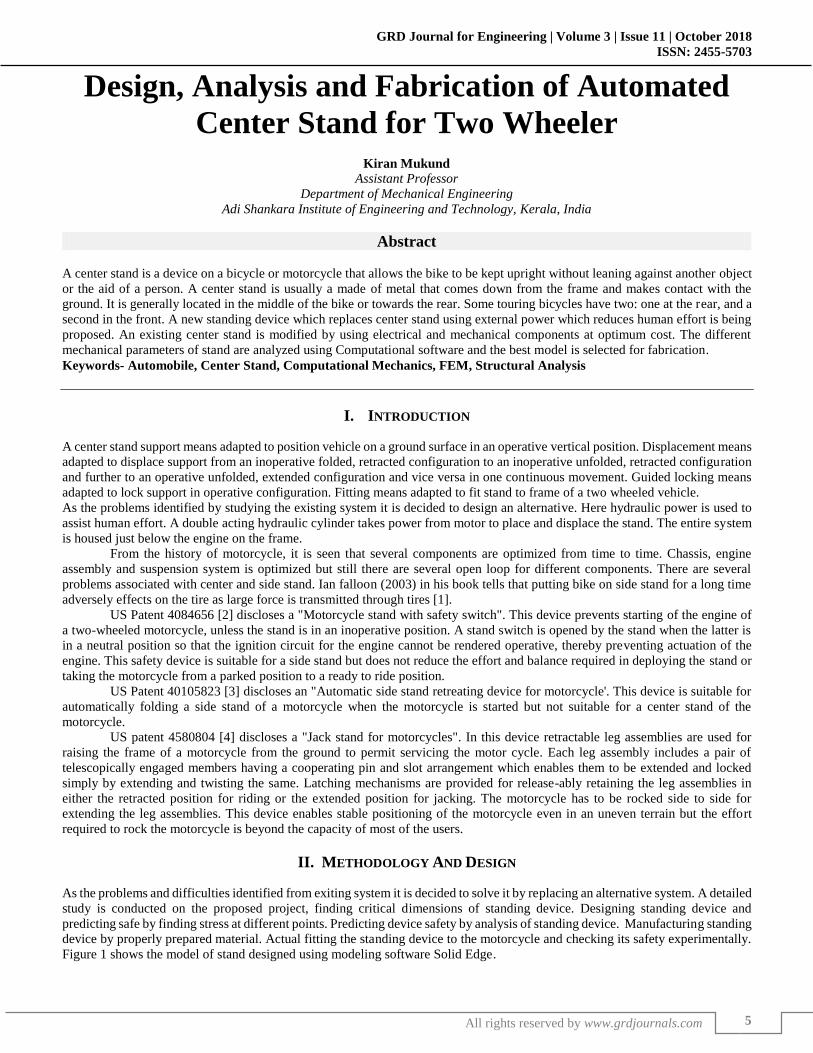
Figure 1 shows the model of stand designed using modeling software Solid Edge.
Design, Analysis and Fabrication of Automated Center Stand for Two Wheeler (GRDJE/ Volume 3 / Issue 11 / 002)
All rights reserved by www.grdjournals.com
6
III. MATERIALS AND CONSTRUCTION
A. Basic Frame
A motorcycle frame is a motorcycle's core structure. It supports the engine, provides a location for the steering and rear suspension,
and supports the rider and any passenger or luggage. At the front of the frame is found the steering head tube that holds the pivoting
front fork, while at the rear there is a pivot point for the swing arm suspension motion as in Figure 2
Fig. 1: Model of proposed center stand Fig. 2: Basic Frame
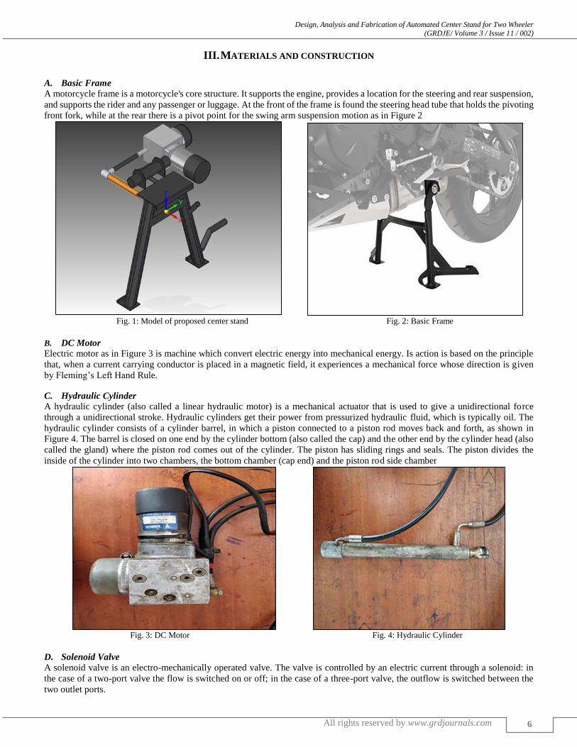
B. DC Motor
Electric motor as in Figure 3 is machine which convert electric energy into mechanical energy. Is action is based on the principle
that, when a current carrying conductor is placed in a magnetic field, it experiences a mechanical force whose direction is given
by Fleming’s Left Hand Rule.
C. Hydraulic Cylinder
A hydraulic cylinder (also called a linear hydraulic motor) is a mechanical actuator that is used to give a unidirectional force
through a unidirectional stroke. Hydraulic cylinders get their power from pressurized hydraulic fluid, which is typically oil. The
hydraulic cylinder consists of a cylinder barrel, in which a piston connected to a piston rod moves back and forth, as shown in
Figure 4. The barrel is closed on one end by the cylinder bottom (also called the cap) and the other end by the cylinder head (also
called the gland) where the piston rod comes out of the cylinder. The piston has sliding rings and seals. The piston divides the
inside of the cylinder into two chambers, the bottom chamber (cap end) and the piston rod side chamber
Fig. 3: DC Motor Fig. 4: Hydraulic Cylinder
D. Solenoid Valve
A solenoid valve is an electro-mechanically operated valve. The valve is controlled by an electric current through a solenoid: in
the case of a two-port valve the flow is switched on or off; in the case of a three-port valve, the outflow is switched between the
two outlet ports.
Design, Analysis and Fabrication of Automated Center Stand for Two Wheeler (GRDJE/ Volume 3 / Issue 11 / 002)
All rights reserved by www.grdjournals.com
7
E. Links
A link is a rigid body which has two nodes which are used to attach other links. Linkages are the basic for all mechanisms. Linkages
are made up of links and joints.
Types of links depending upon nodes:
– Binary link with two nodes.
– Ternary link with three nodes
– Quaternary link with four nodes
A joint is used to connect two or more links, which gives some motion between the links which are connected. Joints are
also called kinematic pairs. These can be classified in several ways:
– By the type of contact in between the two, points line, elements or surface
– By the number of degrees of freedom at the joint
– By the type of physical closure of the joint: either force or form closed
– By the number of links joined
The term lower pair describes joints with surface contact as with a pin enclosed by a hole and the term higher pair describes
joints with point or line contact. However, if clearance is present between pin and hole must be for motion, surface contact in the
pin joint actually becomes line contact, as the pin contacts only one side of the hole. Likewise, at a microscopic level, a block
sliding on a flat surface actually has contact only at discrete points, which are the tops of the surfaces' asperities. The advantage of
lower pairs over higher pairs is their better ability to trap lubricant between their enveloping surfaces. This is especially true for
the rotating pin joint. The lubricant is more easily squeezed out of a higher pair, none developing joint. As a result, the pin joint is
preferred for low wear and long life, even over its lower pair cousin, the prismatic or slider the revolute and the prismatic pairs are
the only lower pairs usable in a planar mechanism. The screw, cylindrical, spherical, and flat lower pairs are all combinations of
the revolute and prismatic pairs and are used in spatial mechanisms.
IV. ANALYSIS
A. Introduction to Analysis
ANSYS is a general purpose finite element modeling package for numerically solving a wide variety of mechanical problems.
These problems include: static/dynamic structural analysis (both linear and non-linear), heat transfer and fluid problems, as well
as acoustic and electro-magnetic problems. In general, a finite element solution may be broken into the following three stages. This
is a general guideline that can be used for setting up any finite element analysis.
1) Preprocessing
Defining the problem; the major steps in preprocessing are given below:
– Define key points/lines/areas/volumes
– Define element type and material/geometric properties
– Mesh lines/areas/volumes as required
– The amount of detail required will depend on the dimensionality of the analysis (i.e. 1D, 2D, axi-symmetric, 3D).
2) Solution
Assigning loads, constraints and solving; here the loads (point or pressure), and constraints (translation and rotation) are specified
and finally solve the resulting set of equations.
3) Post Processing
Further processing and viewing of the results; in this stage one may wish to see:
– Lists of nodal displacements
– Element forces and moments
– Deflection plots
– Stress contour diagrams
B. Objective of Analysis
A 3D model of the Center stand was created. The different models are to be subjected to force acting on different parts of the stand
main body. The force acting on the different models will present different results in form of total deformation, stress acting on the
joints, force reaction, moment reaction etc.
The fabricated model is to be analyzed and compared to the other designed models. The data obtained is to use to find out
the failure points and the possible deformations which will occur on the fabricated stand.
C. Material used
The material used for the analysis of created 3D model is Structural steel. Structural steel is preferred for the use of 3D model
analysis is due to fact that it gives a basic composition of steel. Structural steel is a category of steel used for making construction
Design, Analysis and Fabrication of Automated Center Stand for Two Wheeler (GRDJE/ Volume 3 / Issue 11 / 002)
All rights reserved by www.grdjournals.com
8
materials in a variety of shapes. Many structural steel shapes take the form of an elongated beam having a profile of a specific
cross section. Structural steel shapes, sizes, chemical composition, mechanical properties such as strengths, storage practices, etc.,
are regulated by standards in most industrialized countries. Typical grades are described as 'S275J2' or 'S355K2W'. In these
examples, 'S' denotes structural rather than engineering steel; 275 or 355 denotes the yield strength in newton per square millimeter
or the equivalent Mega Pascal. J2 or K2 denotes the materials toughness by reference to Charpy impact test values; and the 'W'
denotes weathering steel. Further letters can be used to designate fine grain steel ('N' or 'NL'); quenched and tempered steel ('Q' or
'QL'); and thermo-mechanically rolled steel ('M' or 'ML').
1) Mechanical Properties of Structural Steel
Table 1 shows the different Mechanical properties of Structural steel used as Stand material. Table 1: Mechanical Properties of Materials used in Analysis
Material used Young’s modulus Poisson’s ratio Bulk modulus Shear modulus
Structural steel 200 GPa 0.3 1.6667e+05 Pa 761023 Pa
2) Characteristics of Structural Steel
Having high strength, stiffness, toughness, and ductile properties, structural steel is one of the most commonly used materials in
commercial and industrial building construction. Structural steel can be developed into nearly any shape, which are either bolted
or welded together in construction. And also it can be erected as soon as the materials are delivered on site, whereas concrete must
be cured at least 2 weeks after pouring before construction can continue, making steel a schedule-friendly construction material.
Steel is inherently a noncombustible material. However, when heated to temperatures seen in a fire scenario, the strength and
stiffness of the material is significantly reduced. The International Building Code requires steel be enveloped in sufficient fire-
resistant materials, increasing overall cost of steel structure buildings. Steel, when in contact with water, can corrode, creating a
potentially dangerous structure. Measures must be taken in structural steel construction to prevent any lifetime corrosion. The steel
can be painted, providing water resistance. Also, the fire resistance material used to envelope steel is commonly water resistant.
Steel provides a less suitable surface environment for mold to grow than wood.
D. Steps in Analysis
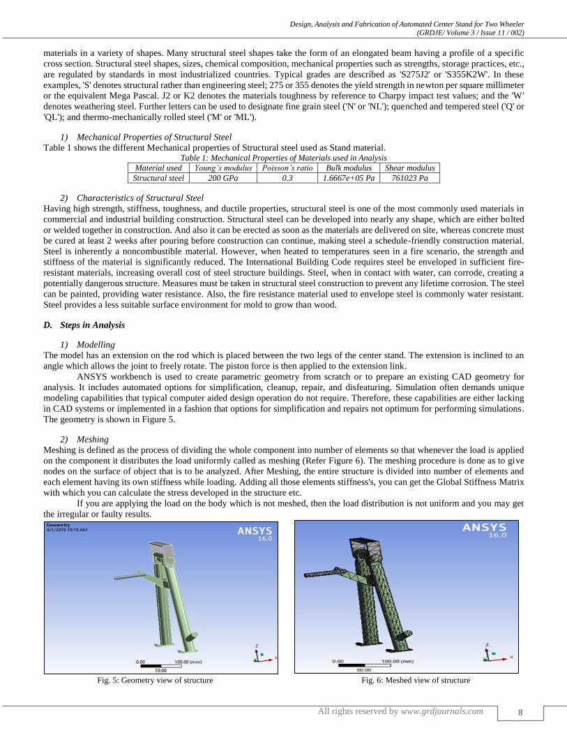
1) Modelling
The model has an extension on the rod which is placed between the two legs of the center stand. The extension is inclined to an
angle which allows the joint to freely rotate. The piston force is then applied to the extension link.
ANSYS workbench is used to create parametric geometry from scratch or to prepare an existing CAD geometry for
analysis. It includes automated options for simplification, cleanup, repair, and disfeaturing. Simulation often demands unique
modeling capabilities that typical computer aided design operation do not require. Therefore, these capabilities are either lacking
in CAD systems or implemented in a fashion that options for simplification and repairs not optimum for performing simulations.
The geometry is shown in Figure 5.
2) Meshing
Meshing is defined as the process of dividing the whole component into number of elements so that whenever the load is applied
on the component it distributes the load uniformly called as meshing (Refer Figure 6). The meshing procedure is done as to give
nodes on the surface of object that is to be analyzed. After Meshing, the entire structure is divided into number of elements and
each element having its own stiffness while loading. Adding all those elements stiffness's, you can get the Global Stiffness Matrix
with which you can calculate the stress developed in the structure etc.
If you are applying the load on the body which is not meshed, then the load distribution is not uniform and you may get
the irregular or faulty results.
Fig. 5: Geometry view of structure Fig. 6: Meshed view of structure
Design, Analysis and Fabrication of Automated Center Stand for Two Wheeler (GRDJE/ Volume 3 / Issue 11 / 002)
All rights reserved by www.grdjournals.com
9
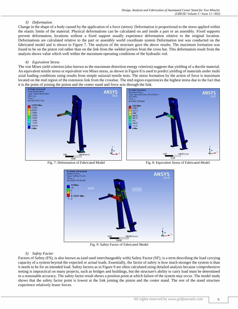
3) Deformation
Change in the shape of a body caused by the application of a force (stress). Deformation is proportional to the stress applied within
the elastic limits of the material. Physical deformations can be calculated on and inside a part or an assembly. Fixed supports
prevent deformation; locations without a fixed support usually experience deformation relative to the original location.
Deformations are calculated relative to the part or assembly world coordinate system Deformation test was conducted on the
fabricated model and is shown in Figure 7. The analysis of the structure gave the above results. The maximum formation was
found to be on the piston rod rather than on the link from the welded portion from the cross bar. This deformation result from the
analysis shows value which well within the maximum operating conditions of the hydraulic rod.
4) Equivalent Stress
The von Mises yield criterion (also known as the maximum distortion energy criterion) suggests that yielding of a ductile material.
An equivalent tensile stress or equivalent von Mises stress, as shown in Figure 8 is used to predict yielding of materials under multi
axial loading conditions using results from simple uniaxial tensile tests. The stress formation by the action of force is maximum
located on the mid region of the extension link from the crossbar. The mid region experiences the highest stress due to the fact that
it is the point of joining the piston and the center stand and force acts through the link.
Fig. 7: Deformation of Fabricated Model Fig. 8: Equivalent Stress of Fabricated Model
Fig. 9: Safety Factor of Fabricated Model
5) Safety Factor
Factors of Safety (FS), is also known as (and used interchangeably with) Safety Factor (SF), is a term describing the load carrying
capacity of a system beyond the expected or actual loads. Essentially, the factor of safety is how much stronger the system is than
it needs to be for an intended load. Safety factors as in Figure 9 are often calculated using detailed analysis because comprehensive
testing is impractical on many projects, such as bridges and buildings, but the structure's ability to carry load must be determined
to a reasonable accuracy. The safety factor result shows a position point at which failure of the system may occur. The model study
shows that the safety factor point is lowest at the link joining the piston and the center stand. The rest of the stand structure
experience relatively lesser forces.
Design, Analysis and Fabrication of Automated Center Stand for Two Wheeler (GRDJE/ Volume 3 / Issue 11 / 002)
All rights reserved by www.grdjournals.com
10
V. ANALYSIS OF DIFFERENT MODELS
To study the variation of parameters with difference is point of application of force, four different stands are modeled and analyzed.
Even though the basic frame and materials used in all models are same, application of force differs.
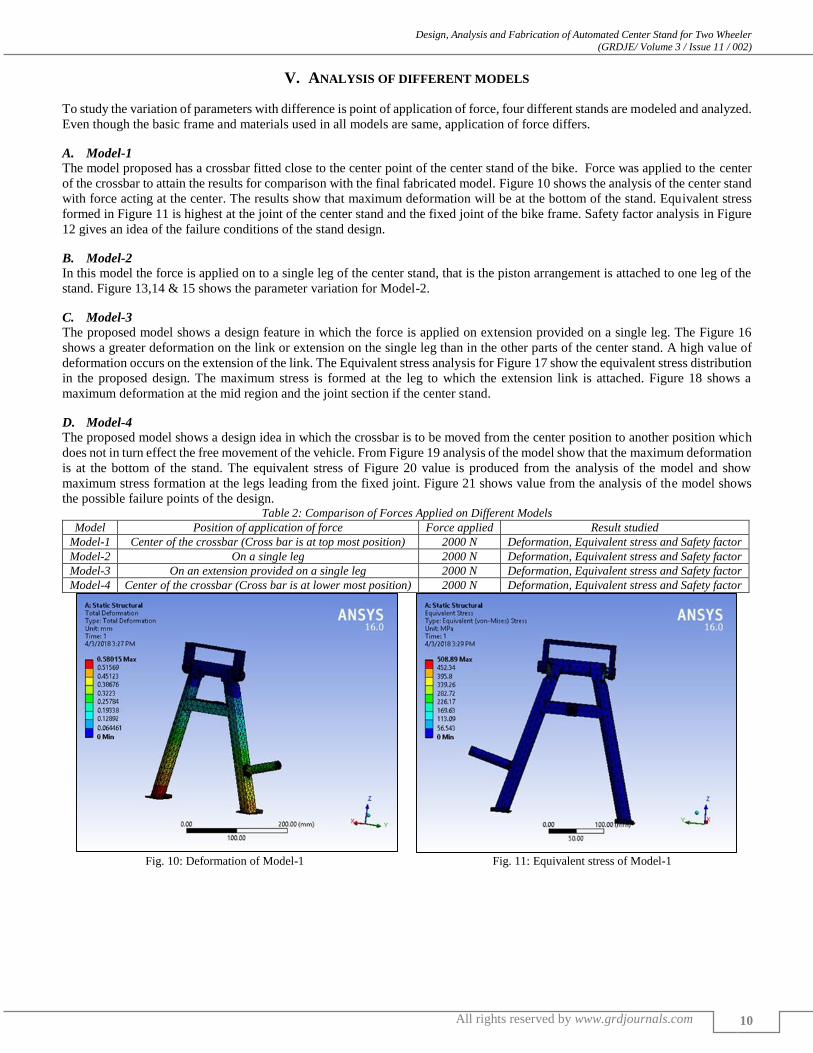
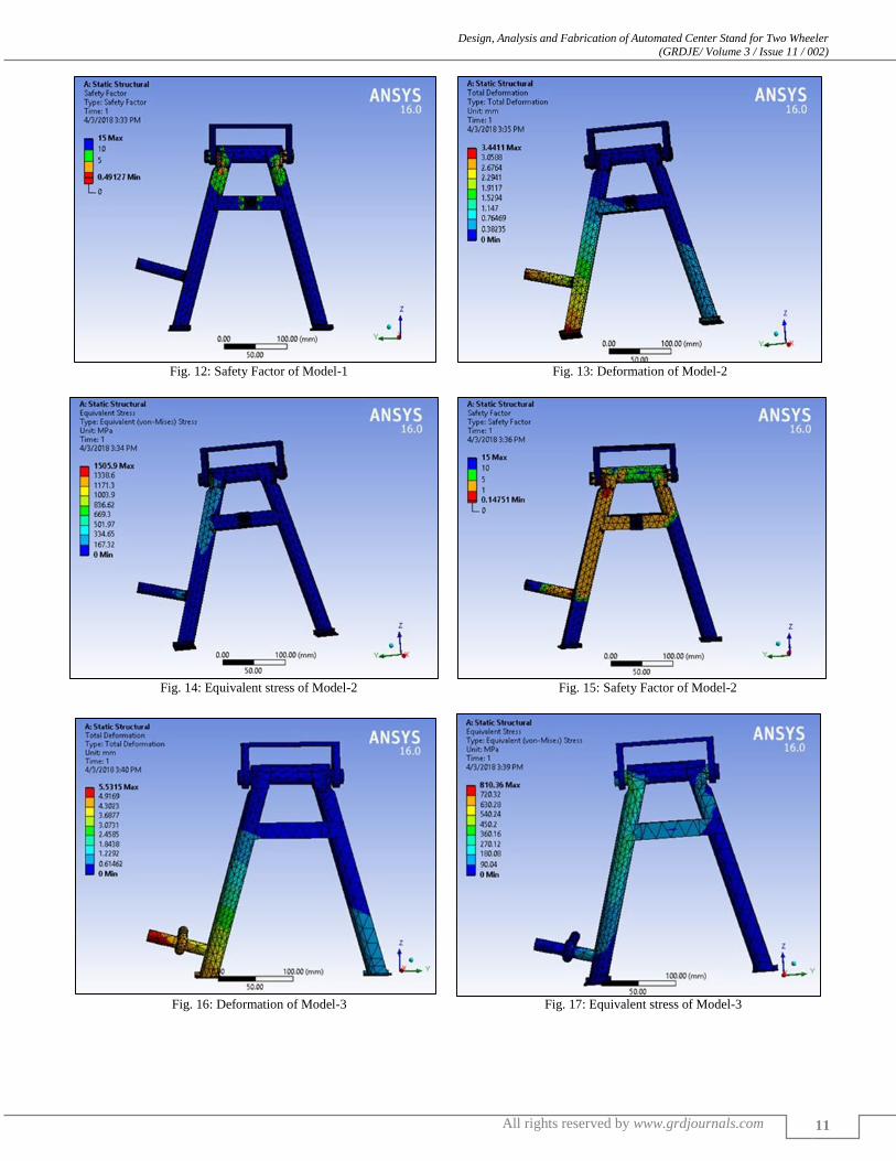
A. Model-1
The model proposed has a crossbar fitted close to the center point of the center stand of the bike. Force was applied to the center
of the crossbar to attain the results for comparison with the final fabricated model. Figure 10 shows the analysis of the center stand
with force acting at the center. The results show that maximum deformation will be at the bottom of the stand. Equivalent stress
formed in Figure 11 is highest at the joint of the center stand and the fixed joint of the bike frame. Safety factor analysis in Figure
12 gives an idea of the failure conditions of the stand design.
B. Model-2
In this model the force is applied on to a single leg of the center stand, that is the piston arrangement is attached to one leg of the
stand. Figure 13,14 & 15 shows the parameter variation for Model-2.
C. Model-3
The proposed model shows a design feature in which the force is applied on extension provided on a single leg. The Figure 16
shows a greater deformation on the link or extension on the single leg than in the other parts of the center stand. A high value of
deformation occurs on the extension of the link. The Equivalent stress analysis for Figure 17 show the equivalent stress distribution
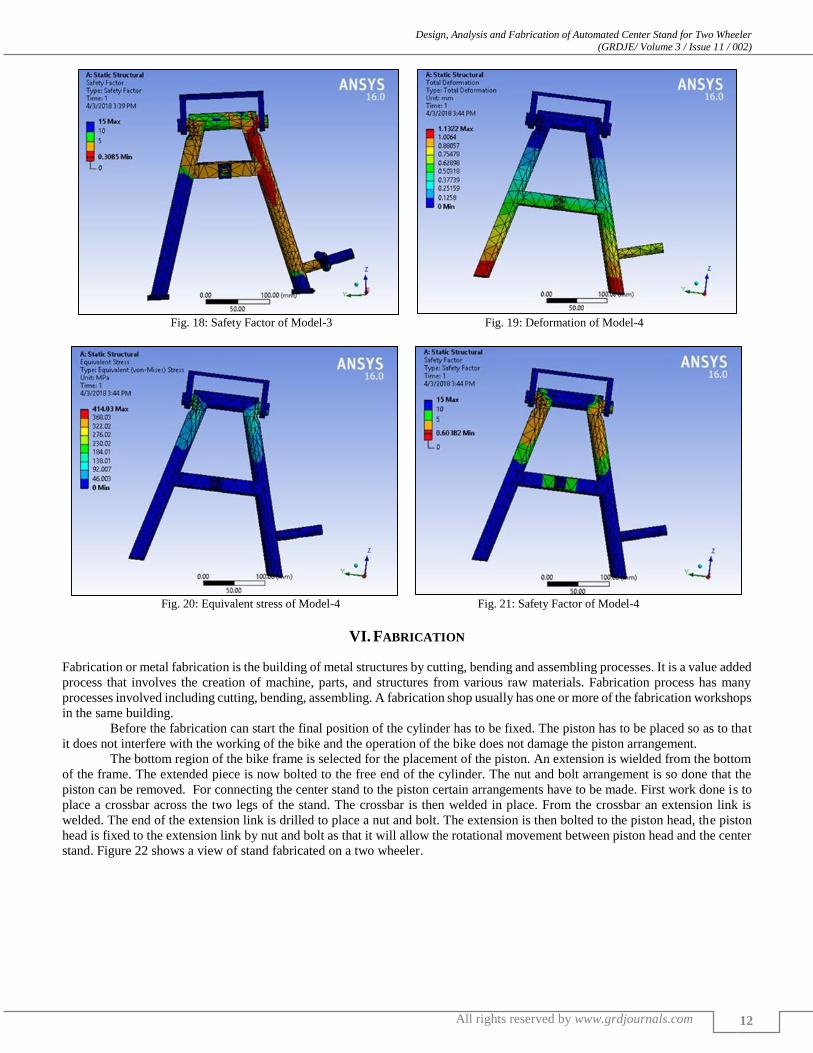
in the proposed design. The maximum stress is formed at the leg to which the extension link is attached. Figure 18 shows a
maximum deformation at the mid region and the joint section if the center stand.
D. Model-4
The proposed model shows a design idea in which the crossbar is to be moved from the center position to another position which
does not in turn effect the free movement of the vehicle. From Figure 19 analysis of the model show that the maximum deformation
is at the bottom of the stand. The equivalent stress of Figure 20 value is produced from the analysis of the model and show
maximum stress formation at the legs leading from the fixed joint. Figure 21 shows value from the analysis of the model shows
the possible failure points of the design. Table 2: Comparison of Forces Applied on Different Models
Model Position of application of force Force applied Result studied
Model-1 Center of the crossbar (Cross bar is at top most position) 2000 N Deformation, Equivalent stress and Safety factor
Model-2 On a single leg 2000 N Deformation, Equivalent stress and Safety factor
Model-3 On an extension provided on a single leg 2000 N Deformation, Equivalent stress and Safety factor
Model-4 Center of the crossbar (Cross bar is at lower most position) 2000 N Deformation, Equivalent stress and Safety factor
Fig. 10: Deformation of Model-1 Fig. 11: Equivalent stress of Model-1
Design, Analysis and Fabrication of Automated Center Stand for Two Wheeler (GRDJE/ Volume 3 / Issue 11 / 002)
All rights reserved by www.grdjournals.com
11
Fig. 12: Safety Factor of Model-1 Fig. 13: Deformation of Model-2
Fig. 14: Equivalent stress of Model-2 Fig. 15: Safety Factor of Model-2
Fig. 16: Deformation of Model-3 Fig. 17: Equivalent stress of Model-3
Design, Analysis and Fabrication of Automated Center Stand for Two Wheeler (GRDJE/ Volume 3 / Issue 11 / 002)
All rights reserved by www.grdjournals.com
12
Fig. 18: Safety Factor of Model-3 Fig. 19: Deformation of Model-4
Fig. 20: Equivalent stress of Model-4 Fig. 21: Safety Factor of Model-4
VI. FABRICATION
Fabrication or metal fabrication is the building of metal structures by cutting, bending and assembling processes. It is a value added
process that involves the creation of machine, parts, and structures from various raw materials. Fabrication process has many
processes involved including cutting, bending, assembling. A fabrication shop usually has one or more of the fabrication workshops
in the same building.
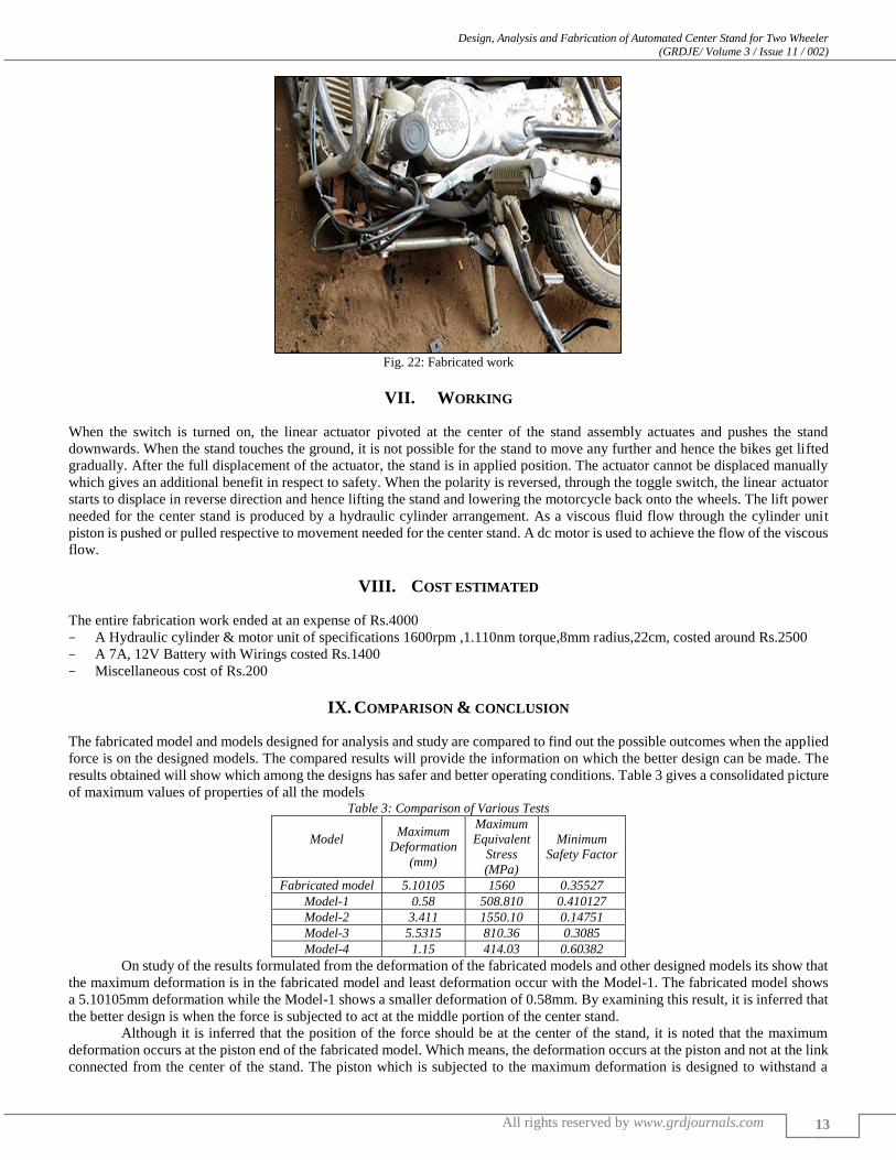
Before the fabrication can start the final position of the cylinder has to be fixed. The piston has to be placed so as to that
it does not interfere with the working of the bike and the operation of the bike does not damage the piston arrangement.
The bottom region of the bike frame is selected for the placement of the piston. An extension is wielded from the bottom
of the frame. The extended piece is now bolted to the free end of the cylinder. The nut and bolt arrangement is so done that the
piston can be removed. For connecting the center stand to the piston certain arrangements have to be made. First work done is to
place a crossbar across the two legs of the stand. The crossbar is then welded in place. From the crossbar an extension link is
welded. The end of the extension link is drilled to place a nut and bolt. The extension is then bolted to the piston head, the piston
head is fixed to the extension link by nut and bolt as that it will allow the rotational movement between piston head and the center
stand. Figure 22 shows a view of stand fabricated on a two wheeler.
Design, Analysis and Fabrication of Automated Center Stand for Two Wheeler (GRDJE/ Volume 3 / Issue 11 / 002)
All rights reserved by www.grdjournals.com
13
Fig. 22: Fabricated work
VII. WORKING
When the switch is turned on, the linear actuator pivoted at the center of the stand assembly actuates and pushes the stand
downwards. When the stand touches the ground, it is not possible for the stand to move any further and hence the bikes get lifted
gradually. After the full displacement of the actuator, the stand is in applied position. The actuator cannot be displaced manually
which gives an additional benefit in respect to safety. When the polarity is reversed, through the toggle switch, the linear actuator
starts to displace in reverse direction and hence lifting the stand and lowering the motorcycle back onto the wheels. The lift power
needed for the center stand is produced by a hydraulic cylinder arrangement. As a viscous fluid flow through the cylinder unit
piston is pushed or pulled respective to movement needed for the center stand. A dc motor is used to achieve the flow of the viscous
flow.
VIII. COST ESTIMATED
The entire fabrication work ended at an expense of Rs.4000
– A Hydraulic cylinder & motor unit of specifications 1600rpm ,1.110nm torque,8mm radius,22cm, costed around Rs.2500
– A 7A, 12V Battery with Wirings costed Rs.1400
– Miscellaneous cost of Rs.200
IX. COMPARISON & CONCLUSION
The fabricated model and models designed for analysis and study are compared to find out the possible outcomes when the applied
force is on the designed models. The compared results will provide the information on which the better design can be made. The
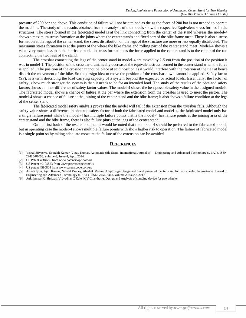
results obtained will show which among the designs has safer and better operating conditions. Table 3 gives a consolidated picture
of maximum values of properties of all the models Table 3: Comparison of Various Tests
Model
Maximum
Deformation
(mm)
Maximum
Equivalent
Stress
(MPa)
Minimum
Safety Factor
Fabricated model 5.10105 1560 0.35527
Model-1 0.58 508.810 0.410127
Model-2 3.411 1550.10 0.14751
Model-3 5.5315 810.36 0.3085
Model-4 1.15 414.03 0.60382
On study of the results formulated from the deformation of the fabricated models and other designed models its show that
the maximum deformation is in the fabricated model and least deformation occur with the Model-1. The fabricated model shows
a 5.10105mm deformation while the Model-1 shows a smaller deformation of 0.58mm. By examining this result, it is inferred that
the better design is when the force is subjected to act at the middle portion of the center stand.
Although it is inferred that the position of the force should be at the center of the stand, it is noted that the maximum
deformation occurs at the piston end of the fabricated model. Which means, the deformation occurs at the piston and not at the link
connected from the center of the stand. The piston which is subjected to the maximum deformation is designed to withstand a
Design, Analysis and Fabrication of Automated Center Stand for Two Wheeler (GRDJE/ Volume 3 / Issue 11 / 002)
All rights reserved by www.grdjournals.com
14
pressure of 200 bar and above. This condition of failure will not be attained as the as the force of 200 bar is not needed to operate
the machine. The study of the results obtained from the analysis of the models show the respective Equivalent stress formed in the
structures. The stress formed in the fabricated model is at the link connecting from the center of the stand whereas the model-4
shows a maximum stress formation at the joints where the center stands and fixed part of the bike frame meet. There is also a stress
formation at the legs of the center stand, the stress distribution on the legs of the structure are more or less equally distributed. The
maximum stress formation is at the joints of the where the bike frame and rolling part of the center stand meet. Model-4 shows a
value very much less than the fabricate model in stress formation as the force applied to the center stand is to the center of the rod
connecting the two legs of the stand.
The crossbar connecting the legs of the center stand in model-4 are moved by 2-5 cm from the position of the position it
was in model-1. The position of the crossbar dramatically decreased the equivalent stress formed in the center stand when the force
is applied. The position of the crossbar cannot be place at said position as it would interfere with the rotation of the tier at hence
disturb the movement of the bike. So the design idea to move the position of the crossbar down cannot be applied. Safety factor
(SF), is a term describing the load carrying capacity of a system beyond the expected or actual loads. Essentially, the factor of
safety is how much stronger the system is than it needs to be for an intended load. The study of the results of the obtained safety
factors shows a minor difference of safety factor values. The model-4 shows the best possible safety value in the designed models.
The fabricated model shows a chance of failure at the par where the extension from the crossbar is used to meet the piston. The
model-4 shows a chance of failure at the joining of the center stand and the bike frame; it also shows a failure condition at the legs
of the center stand.
The fabricated model safety analysis proves that the model will fail if the extension from the crossbar fails. Although the
safety value shows a difference in obtained safety factor of both the fabricated model and model-4, the fabricated model only has
a single failure point while the model-4 has multiple failure points that is the model-4 has failure points at the joining area of the
center stand and the bike frame, there is also failure pints at the legs of the center stand.
On the first look of the results obtained it would be noted that the model-4 should be preferred to the fabricated model,
but in operating case the model-4 shows multiple failure points with show higher risk to operation. The failure of fabricated model
is a single point so by taking adequate measure the failure of the extension can be avoided.
REFERENCES
[1] Vishal Srivastva, Sourabh Kumar, Vinay Kumar, Automatic side Stand, International Journal of Engineering and Advanced Technology (IJEAT), ISSN: 22410-81058, volume-3, Issue-4, April 2014.
[2] US Patent 4084656 from www.patentscope.com/us
[3] US Patent 40105823 from www.patentscope.com/us
[4] US patent 4580804 from www.patentscope.com/us
[5] Ashish Jyou, Ajith Kumar, Nabdal Pandey, Abishek Mishra, Amjith sign,Design and development of center stand for two wheeler, International Journal of
Engineering and Advanced Technology (IJEAT), ISSN: 2456-3463, volume 2, issue-5,2017 [6] Ankitkumar K, Shriwas, Vidyadhar C Kale, K V Chandratre, Design and Analysis of standing device for two wheeler