Design Fabrication and Experimental Analysis of Thermal ...
12
ISSN(Online) : 2319-8753 ISSN (Print) : 2347-6710 International Journal of Innovative Research in Science, Engineering and Technology (An ISO 3297: 2007 Certified Organization) Vol. 5, Special Issue 8, May 2016 Copyright to IJIRSET www.ijirset.com 120 Design Fabrication and Experimental Analysis of Thermal Storage System Using Paraffin Based PCM S.Senthilkumar 1 , J.Jai antony 2 , K.Manivannan 3 , M.Manojkumar 4 , J.Sivasankar 5 Assistant Professor, Department of Mechanical Engineering, TRP Engineering College, Tiruchirapalli, India 1 UG Scholars, Department of Mechanical Engineering, TRP Engineering College, Tiruchirapalli, India 2,3,4,5 ABSTRACT: Thermal energy storage systems are necessary because the availability of energy like solar is intermittent whereas the utilization of the thermal energy is continuous. The various methods of storing thermal energy are sensible heat storage, latent heat storage and thermo chemical storage, among these methods latent heat storage is preferred . Various materials are available to store thermal energy as latent heat ; paraffin widely used phase change materials(PCM). This is because paraffin maintains its properties even after thousands of charging and discharging cycles. In this project work, a Shell and helical coil tube type Heat exchanger has been designed and fabricated for low temperature HTF(water) using phase change material (PCM) paraffin wax (PW). Experiments were performed for three different mass flow rates and inlet temperature of heat transfer fluid (HTF) is maintained at constant in charging process. In order to recovery of heat during discharging process temperature of HTF is maintained at atmospheric temperature. The effect of mass flow rate on the performance of the system were studied. The amount of heat stored and released during charging (melting of PCM) and discharging (solidification of PCM) were calculated. The experimental results were plotted for various mass flow rates. I. INTRODUCTION Latent Heat Storage (LHS) is based on the heat absorption or release when a storage material undergoes a phase change from solid to liquid or liquid to gas or vice–versa. The storage capacity of the LHS system with a PCM medium is given by, Q = m c p (T m –T i ) + m L + m c p (T f – T m ). Amongst thermal heat storage techniques, latent heat thermal energy storage is particularly attractive due to its ability to provide high energy storage density typically 5 to 10 times higher can be reached and its characteristics to store heat at constant temperature corresponding to the phase transition temperature of the PCM. However, many practical problems are encountered with latent heat storage due to low thermal conductivity, variation in thermo-physical properties under extended cycles, these problems have to be technically resolved before latent heat storage can be widely used. 3D VIEW OF EXPERIMENTAL SETUP Fig. 1 3D VIEW OF EXPERIMENTAL SETUP
-
Upload
khangminh22 -
Category
Documents
-
view
1 -
download
0
Transcript of Design Fabrication and Experimental Analysis of Thermal ...
ISSN(Online) : 2319-8753 ISSN (Print) : 2347-6710
International Journal of Innovative Research in Science, Engineering and Technology
(An ISO 3297: 2007 Certified Organization)
Vol. 5, Special Issue 8, May 2016
Copyright to IJIRSET www.ijirset.com 120
Design Fabrication and Experimental Analysis of Thermal Storage System Using Paraffin
Based PCM
S.Senthilkumar1, J.Jai antony2, K.Manivannan3, M.Manojkumar4, J.Sivasankar5 Assistant Professor, Department of Mechanical Engineering, TRP Engineering College, Tiruchirapalli, India1
UG Scholars, Department of Mechanical Engineering, TRP Engineering College, Tiruchirapalli, India 2,3,4,5
ABSTRACT: Thermal energy storage systems are necessary because the availability of energy like solar is intermittent whereas the utilization of the thermal energy is continuous. The various methods of storing thermal energy are sensible heat storage, latent heat storage and thermo chemical storage, among these methods latent heat storage is preferred . Various materials are available to store thermal energy as latent heat ; paraffin widely used phase change materials(PCM). This is because paraffin maintains its properties even after thousands of charging and discharging cycles. In this project work, a Shell and helical coil tube type Heat exchanger has been designed and fabricated for low temperature HTF(water) using phase change material (PCM) paraffin wax (PW). Experiments were performed for three different mass flow rates and inlet temperature of heat transfer fluid (HTF) is maintained at constant in charging process. In order to recovery of heat during discharging process temperature of HTF is maintained at atmospheric temperature. The effect of mass flow rate on the performance of the system were studied. The amount of heat stored and released during charging (melting of PCM) and discharging (solidification of PCM) were calculated. The experimental results were plotted for various mass flow rates.
I. INTRODUCTION
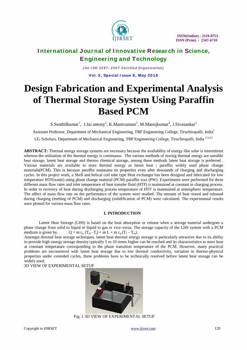
Latent Heat Storage (LHS) is based on the heat absorption or release when a storage material undergoes a phase change from solid to liquid or liquid to gas or vice–versa. The storage capacity of the LHS system with a PCM medium is given by, Q = m cp (Tm –Ti) + m L + m cp (Tf – Tm). Amongst thermal heat storage techniques, latent heat thermal energy storage is particularly attractive due to its ability to provide high energy storage density typically 5 to 10 times higher can be reached and its characteristics to store heat at constant temperature corresponding to the phase transition temperature of the PCM. However, many practical problems are encountered with latent heat storage due to low thermal conductivity, variation in thermo-physical properties under extended cycles, these problems have to be technically resolved before latent heat storage can be widely used. 3D VIEW OF EXPERIMENTAL SETUP
Fig. 1 3D VIEW OF EXPERIMENTAL SETUP
ISSN(Online) : 2319-8753 ISSN (Print) : 2347-6710
International Journal of Innovative Research in Science, Engineering and Technology
(An ISO 3297: 2007 Certified Organization)
Vol. 5, Special Issue 8, May 2016
Copyright to IJIRSET www.ijirset.com 121
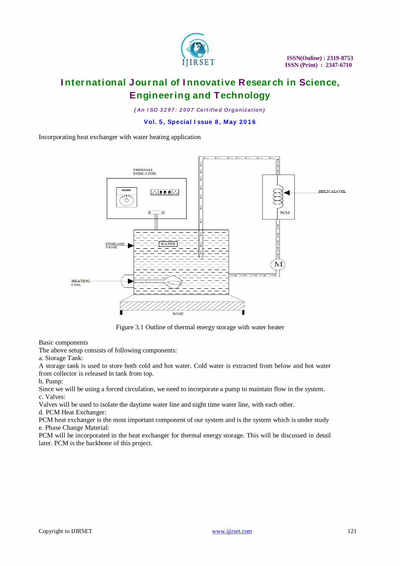
Incorporating heat exchanger with water heating application
Figure 3.1 Outline of thermal energy storage with water heater
Basic components The above setup consists of following components: a. Storage Tank: A storage tank is used to store both cold and hot water. Cold water is extracted from below and hot water from collector is released in tank from top. b. Pump: Since we will be using a forced circulation, we need to incorporate a pump to maintain flow in the system. c. Valves: Valves will be used to isolate the daytime water line and night time water line, with each other. d. PCM Heat Exchanger: PCM heat exchanger is the most important component of our system and is the system which is under study e. Phase Change Material: PCM will be incorporated in the heat exchanger for thermal energy storage. This will be discussed in detail later. PCM is the backbone of this project.

ISSN(Online) : 2319-8753 ISSN (Print) : 2347-6710
International Journal of Innovative Research in Science, Engineering and Technology
(An ISO 3297: 2007 Certified Organization)
Vol. 5, Special Issue 8, May 2016
Copyright to IJIRSET www.ijirset.com 122
Figure 3 Actual test rig for testing energy storage unit
II. WORKING
During sunshine period, valve 1 is kept open and valve 2 is kept closed. The cold water from the storage tank goes through the flat plate solar collector, absorbing heat energy from the solar radiations. It then passes through the PCM heat exchanger, where it loses its heat to the phase change material. It then goes back to the storage tank. In this way, the PCM gains heat energy which will then be used to heat water during non-sunshine period. During non-sunshine period, valve 1 is kept closed and valve 2 is kept open. The cold water from the storage tank goes through the PCM heat exchanger, absorbing heat energy from the heat stored in the phase change material. It then goes back to the storage tank. By this way cold water is heated with the help of heat stored in the PCM. EXPERIMENTS AND TABULATIONS DURING CHARGING OF PARAFFIN:
TABLE 1 Mass flow rate = 0.01 kg/sec
S.NO
TIME TAKEN IN(MIN)
TEMPERATURE T1°C
TEMPERATURE T2°C
TEMPERATURE T3°C
TEMPERATURE T4°C
TEMPERATURE T5°C
TEMPATURE T(avg)
1 10 51 49 35 35 33 35
2 20 58 56 36 35 36 36
3 30 68 67 38 38 40 37
4 40 71 69 42 40 41 41
5 50 76 74 46 45 44 47

ISSN(Online) : 2319-8753 ISSN (Print) : 2347-6710
International Journal of Innovative Research in Science, Engineering and Technology
(An ISO 3297: 2007 Certified Organization)
Vol. 5, Special Issue 8, May 2016
Copyright to IJIRSET www.ijirset.com 123
In these table the mass flow rate is 0.01 kg/sec.The temperature of the (T1,T2,T3,T4,T5) Are indicated .where,
TABLE 2 Mass flow rate = 0.03 kg/sec
S.NO
TIME TAKEN IN(MIN)
TEMPERATURE T1°C
TEMPERATURE T2°C
TEMPERATURE T3°C
TEMPERATURE T4°C
TEMPERATURE T5°C
TEMPERATURE T(avg)
1 10 55 53 33 33 34 35
2 20 58 56 34 34 36 36
3 30 68 66 39 38 39 39
4 40 71 68 41 41 43 42
5 50 75 74 46 47 52 48
In these table the mass flow rate is 0.03 kg/sec.The temperature of the (T1,T2,T3,T4,T5) Are indicated .where,
TABLE 3
Mass flow rate = 0.06 kg/sec S.NO
TIME TAKEN IN(MIN)
TEMPERATURE T1°C
TEMPERATURE T2°C
TEMPERATURE T3°C
TEMPERATURE T4°C
TEMPERATURE T5°C
TEMPERATURE T(avg)
DESCRITION
10 MIN
20 MIN
30 MIN
40 MIN
50 MIN
HEAT ABSORBED BY PARAFFIN (KJ)
218.91
232.19
248.5
250
252.23
HEAT ABSORBED BY HOT WATER (KW)
0.0836
0.0836
0.0836
0.0836
0.0836
DESCRITION
10 MIN
20 MIN
30 MIN
40 MIN
50 MIN
HEAT ABSORBED BY PARAFFIN (KJ)
227.53
232.19
248.59
250.49
252.59
HEAT REALISED BY HOT WATER (KW)
0.250
0.250
0.250
0.250
0.250

ISSN(Online) : 2319-8753 ISSN (Print) : 2347-6710
International Journal of Innovative Research in Science, Engineering and Technology
(An ISO 3297: 2007 Certified Organization)
Vol. 5, Special Issue 8, May 2016
Copyright to IJIRSET www.ijirset.com 124
1 10 54 51 33 34 35 35
2 20 59 58 35 36 37 36
3 30 68 66 39 39 40 40
4 40 70 71 43 42 43 44
5 50 76 74 46 47 51 48
DESCRITION
10 MIN
20 MIN
30 MIN
40 MIN
50 MIN
HEAT ABSORBED BY PARAFFIN (KJ)
226.61
233.59
244.5
245.63
246.49
HEAT REALISED BY HOT WATER (KW)
0.5016
0.5016
0.5016
0.5016
0.5016
In these table the mass flow rate is 0.06 kg/sec.The temperature of the (T1,T2,T3,T4,T5) Are indicated .where, DURING DISCHARGING OF PARAFFIN
TABLE 1 Mass flow rate = 0.01kg/sec 1
S.NO
TIME TAKEN IN(MIN)
TEMPERATURE T1°C
TEMPERATURE T2°C
TEMPERATURE T3°C
TEMPERATURE T4°C
TEMPERATURE T5°C
TEMPERATURE T(avg)
1 0 30 34 48 53 54 46
2 10 30 38 47 50 50 44
3 20 30 36 46 49 49 43
4 30 30 35 44 47 47 42
5 40 30 35 43 46 46 41

ISSN(Online) : 2319-8753 ISSN (Print) : 2347-6710
International Journal of Innovative Research in Science, Engineering and Technology
(An ISO 3297: 2007 Certified Organization)
Vol. 5, Special Issue 8, May 2016
Copyright to IJIRSET www.ijirset.com 125
In these table the mass flow rate is 0.01kg/sec.The temperature of the (T1,T2,T3,T4,T5) Are indicated .where, TABLE 2
Mass flow rate = 0.03 kg/sec
DESCRITION
10 MIN
20 MIN
30 MIN
40 MIN
50 MIN
HEAT RELISED BY PARAFFIN (KJ)
158.1
156.3
154.2
153.1
152.3
HEAT ABSORBED BY HOT WATER (KW)
1.254
1.128
1.003
0.874
0.752
In these table the mass flow rate is 0.03 kg/sec.The temperature of the (T1,T2,T3,T4,T5) Are indicated .where,
DESCRITION
10 MIN
20 MIN
30 MIN
40 MIN
50 MIN
HEAT RELISED BY PARAFFIN (KJ)
156.4
154.4
153.1
153.0
152.7
HEAT ABSORBED BY HOT WATER (KW)
0.1672
0.3344
0.256
0.209
0.208
S.NO
TIME TAKEN IN(MIN)
TEMPERATURE
T1°C
TEMPERATURE T2°C
TEMPERATURE T3°C
TEMPERATURE T4°C
TEMPERATURE T5°C
TEMPERATURE
T(avg)
1 0 30 40 45 49 50 48
2 10 30 39 42 45 47 45
3 20 30 38 42 44 46 44
4 30 30 37 42 43 44 43
5 40 30 35 40 41 42 42

ISSN(Online) : 2319-8753 ISSN (Print) : 2347-6710
International Journal of Innovative Research in Science, Engineering and Technology
(An ISO 3297: 2007 Certified Organization)
Vol. 5, Special Issue 8, May 2016
Copyright to IJIRSET www.ijirset.com 126
TABLE 3 Mass flow rate = 0.06 kg/sec
DESCRITION
10 MIN
20 MIN
30 MIN
40 MIN
50 MIN
HEAT RELISED BY PARAFFIN (KJ)
10 MIN
20 MIN
30 MIN
40 MIN
50 MIN
HEAT ABSORBED BY HOT WATER (KW)
161.1
158.3
156.3
155.4
153.4
In these table the mass flow rate is 0.06 kg/sec.The temperature of the (T1,T2,T3,T4,T5) Are indicated .where, T1 -Inlet temperature of hot water before entering PCM T2 -Outlet temperature of hot water after leaving from PCM T3,T4,T5 -Temperature of PCM in different places
S.NO
TIME TAKEN IN(MIN)
TEMPERATURE T1°C
TEMPERATURE T2°C
TEMPERATURE T3°C
TEMPERATURE T4°C
TEMPERATURE T5°C
TEMPERATURE T(avg)
1 0 30 40 45 49 50 51
2 10 30 39 42 45 47 48
3 20 30 38 42 44 46 46
4 30 30 37 42 43 44 44
5 40 30 35 40 41 42 43

ISSN(Online) : 2319-8753 ISSN (Print) : 2347-6710
International Journal of Innovative Research in Science, Engineering and Technology
(An ISO 3297: 2007 Certified Organization)
Vol. 5, Special Issue 8, May 2016
Copyright to IJIRSET www.ijirset.com 127
III. RESULT AND DISSCUSSION
3.1 DURING CHARGING 3.1.1 Temperature of paraffin VS Time taken
FIG 7.1- Temperature of paraffin VS Time taken
In these figure graph plotted between temperature of paraffin vs time taken. Time taken are increased gradually Temperature of paraffin also increased The temperature of paraffin in °C, time taken in min. The melting curve mass flow rate m1=0.01kg/sec is greater than m2=0.03kg/sec & m3=0.06kg/sec
3.1.2 Hot water temperature VS Time taken
FIG 7.2- Hot water temperature VS Time taken
In these figure graph plotted between hot water temperature vs time taken. Time taken are increased gradually hot water Temperature also increased The hot water temperature °C, time taken in min. The melting curve mass flow rate m1=0.01kg/sec is greater than m2=0.03kg/sec & m3=0.06kg/sec

ISSN(Online) : 2319-8753 ISSN (Print) : 2347-6710
International Journal of Innovative Research in Science, Engineering and Technology
(An ISO 3297: 2007 Certified Organization)
Vol. 5, Special Issue 8, May 2016
Copyright to IJIRSET www.ijirset.com 128
3.1.3 Heat absorbed by paraffin VS Time taken
FIG 7.3 Heat absorbed by paraffin VS Time taken
In these figure graph plotted between heat absorbed by paraffin vs time taken. Time taken are increased gradually heat absorbed by paraffin also increased The heat absorbed by paraffin in KJ ,time taken in min. The melting curve mass flow rate m1=0.01kg/sec is greater than m2=0.03kg/sec & m3=0.06kg/sec
7.1.4 Heat absorbed by paraffin VS Water temperature
FIG 7.4 Heat absorbed by paraffin VS Water temperature
In these figure graph plotted between heat absorbed by paraffin vs water inlet temperature
ISSN(Online) : 2319-8753 ISSN (Print) : 2347-6710
International Journal of Innovative Research in Science, Engineering and Technology
(An ISO 3297: 2007 Certified Organization)
Vol. 5, Special Issue 8, May 2016
Copyright to IJIRSET www.ijirset.com 129
Water inlet temperature are increased gradually heat absorbed by paraffin are increased The heat absorbed by paraffin in KJ , Water inlet temperature in °C The melting curve mass flow rate m1=0.01kg/sec is greater than m2=0.03kg/sec & m3=0.06kg/sec
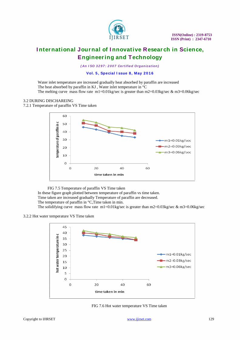
3.2 DURING DISCHAREING 7.2.1 Temperature of paraffin VS Time taken
FIG 7.5 Temperature of paraffin VS Time taken In these figure graph plotted between temperature of paraffin vs time taken. Time taken are increased gradually Temperature of paraffin are decreased. The temperature of paraffin in °C,Time taken in min. The solidifying curve mass flow rate m1=0.01kg/sec is greater than m2=0.03kg/sec & m3=0.06kg/sec
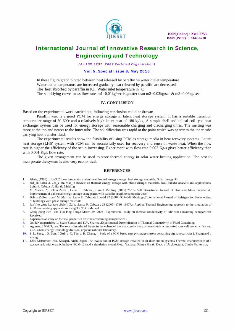
3.2.2 Hot water temperature VS Time taken
FIG 7.6 Hot water temperature VS Time taken

ISSN(Online) : 2319-8753 ISSN (Print) : 2347-6710
International Journal of Innovative Research in Science, Engineering and Technology
(An ISO 3297: 2007 Certified Organization)
Vol. 5, Special Issue 8, May 2016
Copyright to IJIRSET www.ijirset.com 130
In these figure graph plotted between hot water temperature vs time taken. Time taken are increased gradually hot water Temperature also decreased. The hot water temperature °C, time taken in min. The solidifying curve mass flow rate m1=0.01kg/sec is greater than m2=0.03kg/sec & m3=0.06kg/sec
3.2.3 Heat released by paraffin VS Time taken
FIG 7.7 Heat released by paraffin VS Time taken
In these figure graph plotted between heat released by paraffin vs time taken. Time taken are increased gradually heat released by paraffin are decreased. The heat released by paraffin in KJ ,time taken in min. The solidifying curve mass flow rate m1=0.01kg/sec is greater than m2=0.03kg/sec & m3=0.06kg/sec
7.2.4 Heat released by paraffin VS Water outlet temperarure
FIG 7.8- Heat released by paraffin VS Water inlet temperarure
ISSN(Online) : 2319-8753 ISSN (Print) : 2347-6710
International Journal of Innovative Research in Science, Engineering and Technology
(An ISO 3297: 2007 Certified Organization)
Vol. 5, Special Issue 8, May 2016
Copyright to IJIRSET www.ijirset.com 131
In these figure graph plotted between heat released by paraffin vs water outlet temperature Water outlet temperature are increased gradually heat released by paraffin are decreased. The heat absorbed by paraffin in KJ , Water inlet temperature in °C The solidifying curve mass flow rate m1=0.01kg/sec is greater than m2=0.03kg/sec & m3=0.06kg/sec
IV. CONCLUSION
Based on the experimental work carried out, following conclusion could be drawn: Paraffin wax is a good PCM for energy storage in latent heat storage system. It has a suitable transition temperature range of 50-60oc and a relatively high latent heat of 180 kj/kg. A simple shell and helical coil type heat exchanger system can be used for energy storage with reasonable charging and discharging times. The melting was more at the top and nearer to the inner tube. The solidification was rapid at the point which was nearer to the inner tube carrying heat transfer fluid. The experimental results show the feasibility of using PCM as storage media in heat recovery systems. Latent heat storage (LHS) system with PCM can be successfully used for recovery and reuse of waste heat. When the flow rate is higher the efficiency of the setup increasing. Experiment with flow rate 0.003 Kg/s gives better efficiency than with 0.001 Kg/s flow rate. The given arrangement can be used to store thermal energy in solar water heating application. The cost to incorporate the system is also very economical.
REFERENCES
1. Abate, (1983) 313–332. Low temperature latent heat thermal energy storage: heat storage materials, Solar Energy 30 2. Bel_en Zalba ,1, Jos_e Ma Mar_ın Review on thermal energy storage with phase change: materials, heat transfer analysis and applications,
Luisa F. Cabeza ,*, Harald Mehling 3. M. Marı´n ,*, Bele´n Zalba , Luisa F. Cabeza , Harald Mehling (2005) 2561– 570,International Journal of Heat and Mass Transfer 48
Improvement of a thermal energy storage using plates with paraffin–graphite composite Jose´ 4. Bele´n Zalbaa, Jose´ M. Marı´na, Luisa F. Cabezab, Harald 27 (2004) 839–849 Mehlingc,2International Journal of Refrigeration Free-cooling
of buildings with phase change materials 5. Iba´n˜ez ,Ana La´zaro ,Bele´n Zalba ,Luisa F. Cabeza , 25 (2005) 1796–1807An Applied Thermal Engineering approach to the simulation of
PCMs in building applications using TRNSYS Manuel 6. Ching-Song Jwo1 and Tun-Ping Teng2 March 29, 2008 Experimental study on thermal conductivity of lubricant containing nanoparticles
Received: 7. Experimental study on thermal properties ofBrines containing nanoparticles . 8. OxideNanoparticles .L. Syam Sundar and K.V. Sharma .Experimental Determination of Thermal Conductivity of Fluid Containing 9. argonne, il 60439, usa; The role of interfacial layers in the enhanced thermal conductivity of nanofluids: a renovated maxwell model w. Yu and
s.u.s. Choi∗ energy technology division, argonne national laboratory, 10. St L. Zeng, l. X. Sun, f. Xu1, z. C. Tan, z. H. Zhang, j. Sudy of a PCM based energy storage system containing Ag nanoparticles j. Zhang and t.
Zhang. 11. 1200 Matsumoto-cho, Kasugai, Aichi, Japan . An evaluation of PCM storage installed in air distribution systems Thermal characteristics of a
storage tank with organic hydrate (PCM-13) and a simulation model.Motoi Yamaha, Shinya Misaki Dept. of Architecture, Chubu University,