MetaSilicone: Design and Fabrication ... - Université de Montréal
13
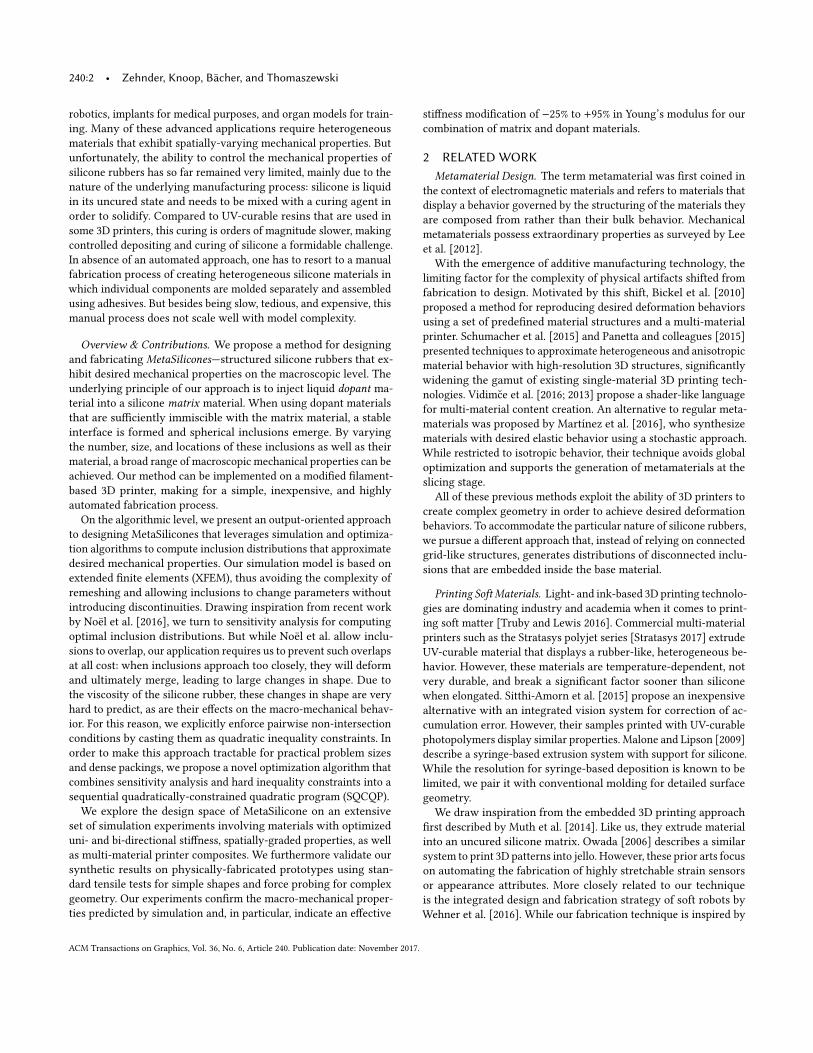
MetaSilicone: Design and Fabrication of Composite Silicone with Desired Mechanical Properties JONAS ZEHNDER ∗ , Disney Research and Université de Montréal ESPEN KNOOP ∗ , Disney Research MORITZ BÄCHER, Disney Research BERNHARD THOMASZEWSKI, Université de Montréal Fig. 1. Using a modified filament-based 3D printer, we inject inclusions of dopant material into a silicone matrix (1). By controlling the size, position, and material properties of the inclusions, we can achieve a broad range of macroscopic mechanical properties, which we demonstrate on physically-fabricated materials with optimized macroscopic stiffness (2), multi-material prints for pathology-specific organ models (3), and extensions to complex geometry (4). We present a method for designing and fabricating MetaSilicones—composite silicone rubbers that exhibit desired macroscopic mechanical properties. The underlying principle of our approach is to inject spherical inclusions of a liquid dopant material into a silicone matrix material. By varying the num- ber, size, and locations of these inclusions as well as their material, a broad range of mechanical properties can be achieved. The technical core of our ap- proach is formed by an optimization algorithm that, combining a simulation model based on extended finite elements (XFEM) and sensitivity analysis, computes inclusion distributions that lead to desired stiffness properties on the macroscopic level. We explore the design space of MetaSilicone on an extensive set of simulation experiments involving materials with optimized uni- and bi-directional stiffness, spatially-graded properties, as well as multi- material composites. We present validation through standard measurements on physical prototypes, which we fabricate on a modified filament-based 3D printer, thus combining the advantages of digital fabrication with the mechanical performance of silicone elastomers. ∗ The first two authors contributed equally. Authors’ addresses: Jonas Zehnder, Disney Research and Université de Montréal; Espen Knoop, Disney Research; Moritz Bächer, Disney Research; Bernhard Thomaszewski, Université de Montréal. Permission to make digital or hard copies of all or part of this work for personal or classroom use is granted without fee provided that copies are not made or distributed for profit or commercial advantage and that copies bear this notice and the full citation on the first page. Copyrights for components of this work owned by others than the author(s) must be honored. Abstracting with credit is permitted. To copy otherwise, or republish, to post on servers or to redistribute to lists, requires prior specific permission and/or a fee. Request permissions from [email protected]. © 2017 Copyright held by the owner/author(s). Publication rights licensed to Association for Computing Machinery. 0730-0301/2017/11-ART240 $15.00 https://doi.org/10.1145/3130800.3130881 CCS Concepts: • Computer graphics → Computational geometry and object modeling; Physically based modeling; ACM Reference Format: Jonas Zehnder, Espen Knoop, Moritz Bächer, and Bernhard Thomaszewski. 2017. MetaSilicone: Design and Fabrication of Composite Silicone with De- sired Mechanical Properties. ACM Trans. Graph. 36, 6, Article 240 (Novem- ber 2017), 13 pages. https://doi.org/10.1145/3130800.3130881 1 INTRODUCTION Progress in digital fabrication technology has given rise to a new wave of research on metamaterials—composite materials with com- plex structures that exhibit a rich space of properties. Manufactur- ing such materials traditionally required expensive machinery, but thanks to the increasing power of affordable 3D printers, the ability to fabricate metamaterials is now arriving at the consumer level. Consequently, the graphics community has started to embrace the problem of designing materials with desired deformation behavior, as evidenced by a stream of recent work in this direction [Bickel et al. 2010; Martínez et al. 2016; Panetta et al. 2015; Schumacher et al. 2015]. Although the spectrum of materials that can be 3D-printed is steadily increasing, there are still many limitations, especially when it comes to highly-deformable materials. Whether filament-, resin-, or powder-based—3D-printed materials are still far away from the level of quality offered by natural or synthetic polymers. Silicone rubbers, by contrast, are valued for their excellent compliance, re- silience to failure and heat resistance. For these reasons, silicone rubbers are widely used across automotive and apparel industries, but also for more specialized applications such as synthetic skin for ACM Transactions on Graphics, Vol. 36, No. 6, Article 240. Publication date: November 2017.
-
Upload
khangminh22 -
Category
Documents
-
view
0 -
download
0
Transcript of MetaSilicone: Design and Fabrication ... - Université de Montréal

MetaSilicone: Design and Fabrication of Composite Silicone withDesired Mechanical Properties
JONAS ZEHNDER∗, Disney Research and Université de Montréal
ESPEN KNOOP∗, Disney Research
MORITZ BÄCHER, Disney Research
BERNHARD THOMASZEWSKI, Université de Montréal
Fig. 1. Using a modified filament-based 3D printer, we inject inclusions of dopant material into a silicone matrix (1). By controlling the size, position, and
material properties of the inclusions, we can achieve a broad range of macroscopic mechanical properties, which we demonstrate on physically-fabricated
materials with optimized macroscopic stiffness (2), multi-material prints for pathology-specific organ models (3), and extensions to complex geometry (4).
We present a method for designing and fabricatingMetaSilicones—composite
silicone rubbers that exhibit desired macroscopic mechanical properties. The
underlying principle of our approach is to inject spherical inclusions of a
liquid dopant material into a silicone matrix material. By varying the num-
ber, size, and locations of these inclusions as well as their material, a broad
range of mechanical properties can be achieved. The technical core of our ap-
proach is formed by an optimization algorithm that, combining a simulation
model based on extended finite elements (XFEM) and sensitivity analysis,
computes inclusion distributions that lead to desired stiffness properties on
the macroscopic level. We explore the design space of MetaSilicone on an
extensive set of simulation experiments involving materials with optimized
uni- and bi-directional stiffness, spatially-graded properties, as well as multi-
material composites. We present validation through standard measurements
on physical prototypes, which we fabricate on a modified filament-based
3D printer, thus combining the advantages of digital fabrication with the
mechanical performance of silicone elastomers.
∗The first two authors contributed equally.
Authors’ addresses: Jonas Zehnder, Disney Research and Université de Montréal; EspenKnoop, Disney Research; Moritz Bächer, Disney Research; Bernhard Thomaszewski,Université de Montréal.
Permission to make digital or hard copies of all or part of this work for personal orclassroom use is granted without fee provided that copies are not made or distributedfor profit or commercial advantage and that copies bear this notice and the full citationon the first page. Copyrights for components of this work owned by others than theauthor(s) must be honored. Abstracting with credit is permitted. To copy otherwise, orrepublish, to post on servers or to redistribute to lists, requires prior specific permissionand/or a fee. Request permissions from [email protected].
© 2017 Copyright held by the owner/author(s). Publication rights licensed to Associationfor Computing Machinery.0730-0301/2017/11-ART240 $15.00https://doi.org/10.1145/3130800.3130881
CCS Concepts: • Computer graphics→ Computational geometry and
object modeling; Physically based modeling;
ACM Reference Format:
Jonas Zehnder, Espen Knoop, Moritz Bächer, and Bernhard Thomaszewski.
2017. MetaSilicone: Design and Fabrication of Composite Silicone with De-
sired Mechanical Properties. ACM Trans. Graph. 36, 6, Article 240 (Novem-
ber 2017), 13 pages. https://doi.org/10.1145/3130800.3130881
1 INTRODUCTION
Progress in digital fabrication technology has given rise to a new
wave of research on metamaterials—composite materials with com-
plex structures that exhibit a rich space of properties. Manufactur-
ing such materials traditionally required expensive machinery, but
thanks to the increasing power of affordable 3D printers, the ability
to fabricate metamaterials is now arriving at the consumer level.
Consequently, the graphics community has started to embrace the
problem of designing materials with desired deformation behavior,
as evidenced by a stream of recent work in this direction [Bickel
et al. 2010; Martínez et al. 2016; Panetta et al. 2015; Schumacher et al.
2015].
Although the spectrum of materials that can be 3D-printed is
steadily increasing, there are still many limitations, especially when
it comes to highly-deformable materials. Whether filament-, resin-,
or powder-based—3D-printed materials are still far away from the
level of quality offered by natural or synthetic polymers. Silicone
rubbers, by contrast, are valued for their excellent compliance, re-
silience to failure and heat resistance. For these reasons, silicone
rubbers are widely used across automotive and apparel industries,
but also for more specialized applications such as synthetic skin for
ACM Transactions on Graphics, Vol. 36, No. 6, Article 240. Publication date: November 2017.
240:2 • Zehnder, Knoop, Bächer, and Thomaszewski
robotics, implants for medical purposes, and organ models for train-
ing. Many of these advanced applications require heterogeneous
materials that exhibit spatially-varying mechanical properties. But
unfortunately, the ability to control the mechanical properties of
silicone rubbers has so far remained very limited, mainly due to the
nature of the underlying manufacturing process: silicone is liquid
in its uncured state and needs to be mixed with a curing agent in
order to solidify. Compared to UV-curable resins that are used in
some 3D printers, this curing is orders of magnitude slower, making
controlled depositing and curing of silicone a formidable challenge.
In absence of an automated approach, one has to resort to a manual
fabrication process of creating heterogeneous silicone materials in
which individual components are molded separately and assembled
using adhesives. But besides being slow, tedious, and expensive, this
manual process does not scale well with model complexity.
Overview & Contributions. We propose a method for designing
and fabricating MetaSilicones—structured silicone rubbers that ex-
hibit desired mechanical properties on the macroscopic level. The
underlying principle of our approach is to inject liquid dopant ma-
terial into a silicone matrix material. When using dopant materials
that are sufficiently immiscible with the matrix material, a stable
interface is formed and spherical inclusions emerge. By varying
the number, size, and locations of these inclusions as well as their
material, a broad range of macroscopic mechanical properties can be
achieved. Our method can be implemented on a modified filament-
based 3D printer, making for a simple, inexpensive, and highly
automated fabrication process.
On the algorithmic level, we present an output-oriented approach
to designing MetaSilicones that leverages simulation and optimiza-
tion algorithms to compute inclusion distributions that approximate
desired mechanical properties. Our simulation model is based on
extended finite elements (XFEM), thus avoiding the complexity of
remeshing and allowing inclusions to change parameters without
introducing discontinuities. Drawing inspiration from recent work
by Noël et al. [2016], we turn to sensitivity analysis for computing
optimal inclusion distributions. But while Noël et al. allow inclu-
sions to overlap, our application requires us to prevent such overlaps
at all cost: when inclusions approach too closely, they will deform
and ultimately merge, leading to large changes in shape. Due to
the viscosity of the silicone rubber, these changes in shape are very
hard to predict, as are their effects on the macro-mechanical behav-
ior. For this reason, we explicitly enforce pairwise non-intersection
conditions by casting them as quadratic inequality constraints. In
order to make this approach tractable for practical problem sizes
and dense packings, we propose a novel optimization algorithm that
combines sensitivity analysis and hard inequality constraints into a
sequential quadratically-constrained quadratic program (SQCQP).
We explore the design space of MetaSilicone on an extensive
set of simulation experiments involving materials with optimized
uni- and bi-directional stiffness, spatially-graded properties, as well
as multi-material printer composites. We furthermore validate our
synthetic results on physically-fabricated prototypes using stan-
dard tensile tests for simple shapes and force probing for complex
geometry. Our experiments confirm the macro-mechanical proper-
ties predicted by simulation and, in particular, indicate an effective
stiffness modification of −25% to +95% in Young’s modulus for our
combination of matrix and dopant materials.
2 RELATED WORK
Metamaterial Design. The term metamaterial was first coined in
the context of electromagnetic materials and refers to materials that
display a behavior governed by the structuring of the materials they
are composed from rather than their bulk behavior. Mechanical
metamaterials possess extraordinary properties as surveyed by Lee
et al. [2012].
With the emergence of additive manufacturing technology, the
limiting factor for the complexity of physical artifacts shifted from
fabrication to design. Motivated by this shift, Bickel et al. [2010]
proposed a method for reproducing desired deformation behaviors
using a set of predefined material structures and a multi-material
printer. Schumacher et al. [2015] and Panetta and colleagues [2015]
presented techniques to approximate heterogeneous and anisotropic
material behavior with high-resolution 3D structures, significantly
widening the gamut of existing single-material 3D printing tech-
nologies. Vidimce et al. [2016; 2013] propose a shader-like language
for multi-material content creation. An alternative to regular meta-
materials was proposed by Martínez et al. [2016], who synthesize
materials with desired elastic behavior using a stochastic approach.
While restricted to isotropic behavior, their technique avoids global
optimization and supports the generation of metamaterials at the
slicing stage.
All of these previous methods exploit the ability of 3D printers to
create complex geometry in order to achieve desired deformation
behaviors. To accommodate the particular nature of silicone rubbers,
we pursue a different approach that, instead of relying on connected
grid-like structures, generates distributions of disconnected inclu-
sions that are embedded inside the base material.
Printing Soft Materials. Light- and ink-based 3D printing technolo-
gies are dominating industry and academia when it comes to print-
ing soft matter [Truby and Lewis 2016]. Commercial multi-material
printers such as the Stratasys polyjet series [Stratasys 2017] extrude
UV-curable material that displays a rubber-like, heterogeneous be-
havior. However, these materials are temperature-dependent, not
very durable, and break a significant factor sooner than silicone
when elongated. Sitthi-Amorn et al. [2015] propose an inexpensive
alternative with an integrated vision system for correction of ac-
cumulation error. However, their samples printed with UV-curable
photopolymers display similar properties. Malone and Lipson [2009]
describe a syringe-based extrusion system with support for silicone.
While the resolution for syringe-based deposition is known to be
limited, we pair it with conventional molding for detailed surface
geometry.
We draw inspiration from the embedded 3D printing approach
first described by Muth et al. [2014]. Like us, they extrude material
into an uncured silicone matrix. Owada [2006] describes a similar
system to print 3D patterns into jello. However, these prior arts focus
on automating the fabrication of highly stretchable strain sensors
or appearance attributes. More closely related to our technique
is the integrated design and fabrication strategy of soft robots by
Wehner et al. [2016]. While our fabrication technique is inspired by
ACM Transactions on Graphics, Vol. 36, No. 6, Article 240. Publication date: November 2017.

MetaSilicone: Design and Fabrication of Composite Silicone with Desired Mechanical Properties • 240:3
theirs, their design strategy is not automated and requires expert
knowledge. While our focus is on the computational and physical
placement of calibrated inclusions inside silicone, we rely on a
molding process and recent methods on mold design [Herholz et al.
2015; Malomo et al. 2016] complement our technique.
There are myriad applications for composited silicone with de-
sired deformation properties. While bioprinting of organs [Murphy
and Atala 2014] and tissue [Kolesky et al. 2014] is still in its infancy,
silicones are bio-compatible and their behavior similar when prop-
erly graded. Hence, we see applications in surgical training [Lin
and Otaduy 2008], providing surgeons with haptic feedback that
closely resembles the one received when operating on patients.
Other application areas include the computational design and fabri-
cation of animatronic skin [Bickel et al. 2012], deformation-aware
sensors [Bächer et al. 2016], printable hydraulics [MacCurdy et al.
2016], and characters [Skouras et al. 2013] or robots [Rus and Tolley
2015] that deform in desired ways.
Efficient Simulation of Complex Materials. Numerical coarsen-
ing [Kharevych et al. 2009], embedding [Nesme et al. 2009], Bézier
[Bargteil and Cohen 2014] or data-driven [Chen et al. 2015] finite
elements, or model reduction [Xu et al. 2015] are all strategies for
the efficient simulation of a highly complex material behavior. More-
over, solution strategies such as the quasi-Newton approach by Liu
et al. [2016] or the ADMM-based technique by Narain et al. [2016]
enable the rapid simulation of hyperelastic materials for the purpose
of animation.
Several works from the graphics community have investigated the
simulation of materials undergoing large deformations and topology
changes. Bargteil et al. [2007] propose a robust global remeshing
scheme in order to deal with problems of ill-conditioning for large el-
ement deformations. The method byWicke et al. [2010] extends this
concept to local remeshing. The approach described by Chentanez
et al. [2009] differs in that the simulation mesh is adapted for needle
insertion. For problems involving fracturing and cutting, an alterna-
tive to remeshing is the extended finite element method, allowing
for topology changes without the need for remeshing [Kaufmann
et al. 2009; Manteaux et al. 2015]. In the field of mechanical engineer-
ing, XFEM is widely used for fracture and crack propagation [Moës
et al. 1999], but also for modeling interfaces in composite materials
[Sukumar et al. 2001]. Our method is most closely related to the re-
cent work by Noël et al. [2016], but we target significantly larger and
more tightly-packed inclusion distributions. For this purpose, we
introduce the possibility of having multiple material interfaces per
element and explicitly enforce non-intersection constraints, both
vital requirements for densely-packed inclusions.
Silicone Composites. There are many different examples of sili-
cone composite materials with tuned mechanical properties and
behaviors. This includes open- and closed-cell silicone foams [Liu
et al. 2009], hydrogels [Lopour et al. 1993], low-melting-point alloys
[VanMeerbeek et al. 2016], fiber-reinforced silicones [Rus and Tolley
2015] and combinations of silicones with different stiffness [Oxman
et al. 2012]. While these composite silicones show a large range
of interesting properties and behaviors, the design and fabrication
of the composite structures is largely manual. This highlights the
need for our contribution of an automated fabrication process and
a computational design tool in order to fully harness the potential
of MetaSilicones.
3 COMPUTATIONAL MODEL
Our goal is to compute an optimal distribution of spherical inclu-
sions in the matrix material that minimizes the design objective
while satisfying constraints such as minimal distance between in-
clusions. The optimization will lead to inclusions changing size
and moving through the domain. Conforming meshes with static
topology are clearly ill-suited for this scenario, but remeshing is ex-
pensive and introduces discontinuities that slow down convergence
or make the optimization grind to a halt.
We therefore lay aside conforming meshes and instead turn to
XFEM—a general framework for modeling discontinuities without
the need for remeshing. The basic idea is to enrich elements that
extend across discontinuities with internal nodes and correspond-
ing enrichment functions that add discontinuities to the otherwise
smooth interpolation field. Originally applied to crack propagation
[Moës et al. 1999], XFEM also extends naturally to multi-material
interface problems. While XFEM is a well-established tool in compu-
tational engineering, we briefly summarize the particular approach
that we pursue in the following and describe some adaptations that
we made for our setting.
3.1 Finite Element Model
We assume that the problem domain Ω is discretized into a tetra-
hedral mesh T with X ∈ R3N and x ∈ R3N denoting vectors of
nodal positions for the undeformed and deformed configurations,
respectively. We follow a standard FEM approach and, assuming
linear tetrahedron elements, start by computing a set of piecewise
linear basis functions Ni : R3 → R in the undeformed setting such
that Ni (Xj ) = δi j . For elements without enrichment, we define the
interpolated geometry in the undeformed setting as
Xe (u) =
4∑i=1
Ne,i (u)Xe,i , (1)
where u ∈ Ωe is a parameter point in the element’s undeformed
domain, andXe,i are its four nodal positions. Similarly, the deformed
geometry, parameterized over the undeformed configuration, is
defined as xe (u) =∑i Ne,i (u)xe,i . Furthermore, we let Fe =
∂xe∂Xe
denote the deformation gradient for a given element and define the
right Cauchy-Green tensor as Ce = FTe Fe . Finally, with a view to
modeling incompressible materials, we define the deviatoric (i.e.,
volume-preserving) version of the right Cauchy-Green tensor as
Ce = J− 2
3e Ce , where Je = det Fe . (2)
We use different types of silicone rubbers for dopant and matrix
materials, both of which we model using the Mooney-Rivlin con-
stitutive law. The corresponding strain energy density is defined
as
Ψe = μ10(I1 − 3) + μ01(I2 − 3)
+ μ11(I1 − 3)(I2 − 3) +κ
2(Je − 1)2 , (3)
ACM Transactions on Graphics, Vol. 36, No. 6, Article 240. Publication date: November 2017.

240:4 • Zehnder, Knoop, Bächer, and Thomaszewski
where μi j and κ are material parameters and I1 = tr(Ce ) and I2 =
tr(CTe Ce ) are the first invariants of Ce . The energy for the element
is obtained as
We =
∫Ωe
Ψe dV . (4)
To further increase compliance, we also experimented with water as
dopant material, which requires some adaptations to the computa-
tional model. As an inviscid fluid, water has zero shear stiffness but
is perfectly incompressible. In oder to provide sufficient freedom
for elements inside water inclusions to deform, we do not require
incompressibility on the elemental level but instead introduce a
penalty term asking that the integral volume be equal to the initial
volume,
Pk =κ
2
(vk −Vk )2
Vk, with vk (x) =
1
3
∫Ak
x · n dA , (5)
where Vk is the undeformed volume of the inclusion and vk its
deformed volume which, using the divergence theorem, is computed
by integrating over its surface Ak with normal n. For numerical
reasons, we add aweak regularizer for deviatoric deformations using
(3) with μ01 = μ11 = 0 and μ10 = 10.
3.2 Modeling Inclusions with XFEM
The spherical inclusions are characterized by their type of material
as well as their size and position relative to the undeformed config-
uration. Elements that are completely inside or outside inclusions
are assigned the corresponding material and treated in the usual
way. However, elements intersected by inclusions require special
treatment in order to properly model the effect of the inclusion
parameters on the location of the material interface and its impact
on the mechanical properties of the element.
Let p ∈ R4M denote a vector holding the parameters pi =
(si , ri ) ∈ R4 of all M inclusions with si and ri denoting their
centers and radii, respectively. We represent each spherical inclu-
sion in the underformed configuration using a level set function
φ(u) = |u − p| − r , where p and r denote the center and the radius
of the inclusion. For later reference, we also define the discrete ap-
proximation of the level set function on the finite element mesh
as
φhi (u) =∑i
Ni (u)φi , where φi = φ(Xi ) . (6)
The level set determines the location of the material interface I as
the set of points for which it vanishes, I = {u ∈ R3 |φ(u) = 0}. As
the inclusion moves or changes size, the location of the interface
within the intersected elements will change accordingly, and so
will their mechanical properties. The basic idea of XFEM is to add
degrees of freedom around the interface, thus enabling it to move
without having to change the finite element mesh. On the techni-
cal level, this enrichment is implemented through additional basis
functions and corresponding degrees of freedom that extend the
original element to account for discontinuities in the displacement
field or its derivatives. More concretely, instead of the usual geom-
etry interpolation, the finite element approximation for enriched
elements is defined as
x =
4∑i=1
(Ni (u)xi + Ni (u)xi
), (7)
where Ni (u) = ψ (u)Ni (u) are enriched basis functions, defined
through an enrichment functionψ (u), and xi are their correspond-
ing degrees of freedom.
The question of which type of function to use for enrichment
depends on the problem. While crack propagation calls for disconti-
nuity in displacements, the interface between inclusions and matrix
remains intact in our case. Deformations, however, are generally dis-
continuous across the interface. For this type of problem, a common
choice is the so called ridge function
ψ (u) =∑i
Ni (u)|φi | −
�����∑i
Ni (u)φi
����� , (8)
see also Moës et al. [2003]. The underlying reasoning for this con-
struction is to create an interpolation function that, at the material
interface I, is continuous but has discontinuous derivatives, allow-
ing for jumps in deformation across I. Observing that the level set
function has a different sign on the two sides of the interface, a
natural option that fulfills this C0-but-not-C1 property is the abso-
lute value of the interpolated level set function, |φhi (u)|, shown in
Fig. 2 left. However, a problem arising with this function is that it
does not vanish at the element boundary, which creates undesir-
able discontinuities between neighboring elements. As illustrated
in Fig. 2 right, this problem can be solved by using the complement
of the absolute value of the interpolation |φhi | with respect to the
interpolation of the absolute values, which is precisely (8). Finally,
it is important to note that the enrichment function vanishes at
the nodes of the element since Ni (uj ) = δi j . This property ensures
continuity whenever the interface moves across vertices.
3.3 Decomposition andQuadrature
To evaluate the strain energy for enriched elements, we first subdi-
vide them into a set of sub-elements that geometrically resolve the
material interfaces while forming a proper tetrahedral decomposi-
tion. We then use the enriched interpolation function (7) in order
to compute the energy of the sub-elements. We first consider the
case of a single inclusion, then generalize to multiple inclusions per
element.
Single Inclusion Case. For a given pair of inclusion and intersected
element, we first have to determine which of the element’s edges
are intersected by the corresponding interface. This is achieved by
testing, for each of its four nodes, whether it is inside or outside of
the element. While the number of possible combinations is large,
the only distinction that needs to be made is between (1) one node
inside, three nodes outside, and (2) two nodes inside, two nodes
outside—all other cases are trivial or follow from symmetry. Both
of these cases can be decomposed in multiple ways, but in order to
simplify the computation of derivatives, we procedurally implement
the same topology regardless of element geometry and interface
location. It should be noted that the XFEM formulation is such
that the transition between these two cases does not introduce
discontinuities since the corresponding functions in (7) decrease
ACM Transactions on Graphics, Vol. 36, No. 6, Article 240. Publication date: November 2017.

MetaSilicone: Design and Fabrication of Composite Silicone with Desired Mechanical Properties • 240:5
Fig. 2. Constructing enrichment functions in 1D. An element with linear
basis functions N1 and N2, whose two nodes lie on different sides of the
interface, as indicated by the signs of the level set function values φ1 and
φ2 (1). Interpolating the level set values across the element (2), adding
the interpolated values (3), and taking the absolute value (4) leads to a
discontinuous derivative at the interface. Subtracting this function from the
linear interpolation of |φ1 | and |φ2 | (5) leads to the enrichment function ψ
(6). ψ multiplied with the linear basis functions yields the corresponding
basis functions for the enrichment variables (7, 8).
to zero as the inclusion moves toward the transition. Once the
set of intersected edges is determined, we have to compute the
actual intersection points of the element’s edges with the interface.
This is achieved by computing the roots of the discretized level
set function, i.e., for all edges (Xi ,Xj ) that are intersected by the
interface, we compute ui j such that Ni (ui j )φi +Nj (ui j )φ j = 0. With
the decomposition established, the energy density is evaluated as
We =∑k
∫Ωk
Ψk (x) dV , (9)
where the sum runs over all k sub-elements and Ψk is the energy
density evaluated with the corresponding material law using Gauss-
ian quadrature. Unlike for non-enriched elements, x is not a linear
function on the sub-elements and we therefore resort to a four-point
quadrature scheme.
Multiple Inclusions. The process described above has to be adapted
if a given finite element is intersected by more than one inclusion.
It is worth noting that this is not an exotic case, but one that occurs
quite frequently, especially for dense packings. Whenever a new in-
clusion moves onto an already enriched element, all of its nodes are
enriched again, i.e., they are assigned additional degrees of freedom
corresponding to the new interface. The geometry interpolation
Fig. 3. Hierarchical subdivision for multi-enriched elements. Once a second
inclusion moves onto the element (right), the corresponding sub-element
due to the first inclusion (left) is subdivided again. The resulting hierarchy
is indicated on the top right of the two cases, with active (leaf) elements
shown in color.
function is extended to multiple intersections as
x =
4∑i=1
�Ni (u)xi +∑j
Ni j (u)xi j�� , (10)
where Ni j denotes the enriched basis function for node i due to inclu-sion j, and xi j are the corresponding degrees of freedom. Although
the interpolation function is straightforward for suchmulti-enriched
elements, evaluating the energy density and its derivatives requires
careful consideration of all possible decomposition cases. To this
end, we implement a hierarchical approach that makes integration
transparent to the actual state of decomposition. The basis for this
scheme is a vector of trees whose leaves define the set of elements
to be processed for integral evaluation. In the absence of any in-
clusions, these leaves are merely the original elements. Once an
inclusion moves onto a new element, a set of sub-elements is gen-
erated according to the decomposition scheme and corresponding
child entries are added to the node (Fig. 3 left), thus changing the
set of leaf elements to be processed. This operation is oblivious to
whether the original element is already enriched (Fig. 3 right). It
should be noted that the hierarchical approach to integration trans-
lates directly to the evaluation of derivatives, which are computed
using automatic differentiation software.
4 MATERIAL OPTIMIZATION
The power of MetaSilicone lies in the ability to optimize the material
structure in order to achieve desired mechanical properties on the
macroscopic level. In order to establish a formal way of controlling
the macro-mechanical properties of MetaSilicone, we consider a
simple example of an elastic bar whose ends are attached to rigid
plates on both sides (see Fig. 4). We constrain one of the plates to
stay fixed, whereas the opposite plate is subject to a constant load
along the axis of the bar, which translates into a vector of equivalent
nodal forces fext ∈ R3N with nonzero entries for the boundary
vertices on the free end. Given parameter values p for the inclusions
and properties for matrix and dopant material, we can compute the
displacement at the free end by solving a static equilibrium problem,
f(x, p) − fext = 0 , (11)
for the deformed nodal positions x. This simulation experiment
yields a load-displacement ratio that characterizes the overall stiff-
ness of the MetaSilicone in a given material direction. Conversely,
ACM Transactions on Graphics, Vol. 36, No. 6, Article 240. Publication date: November 2017.

240:6 • Zehnder, Knoop, Bächer, and Thomaszewski
we can ask for parameter values that lead to a desired load-displace-
ment ratio. To this end, we start by formulating an objective function
д(x) = d(x) −dtarget, where d(x) measures the distance between the
two boundaries of the bar for a given deformed configuration x and
dtarget is the target distance. In order to minimize this objective, we
exploit the implicit relation between parameters and state provided
by (11): The deformed state x has to be an equilibrium configuration
for the material distribution defined by the inclusion parameters p.
We therefore have x = x(p) and write the gradient of the objective
function asdд
dp=∂д
∂x
∂x
∂p. (12)
The above expression requires the derivative of equilibrium state
with respect to inclusion parameters, which can be computed using
the fact that, for any admissible choice of parameters, we must have
df(x(p), p)
dp=∂f
∂x
∂x
∂p+∂f
∂p= 0 . (13)
This linear system is well known from sensitivity analysis and while
it could be solved numerically to yield the equilibrium state deriva-
tives, we use the adjoint method [Allaire 2015] to directly compute
the objective gradient (12). Instead of performing steepest descent
on these gradients, we use an L-BFGS approximation of the Hessian
to accelerate convergence with a quasi-Newton method.
Multiple Load Cases. Our formulation readily extends to objective
functions involvingmultiple load cases, which is required, e.g., when
matching a material behavior for a range of deformations instead
of a single probe. Each of the load cases leads to an additional set
of force equilibrium conditions (11) and corresponding degrees of
freedom xi . The gradient of the objective function follows as
dд
dp=∑i
∂д
∂xi
∂xi∂p+∂д
∂p, (14)
Fig. 4. Optimizing for desired displacement (dashed line) under a given force
fext. The homogeneous base material is too soft (top), whereas the initial
inclusion distribution is too stiff (middle). After optimization, the target
displacement is accurately matched (bottom).
requiring multiple solutions of independent linear systems of the
form (13), which are readily parallelized.
Inclusion vs. Element Sizes. As its central advantage, XFEM avoids
the complexity of conforming remeshing, both in terms of implemen-
tation and the number of elements required to geometrically resolve
material interfaces. In order to obtain sufficient accuracy, however,
the resolution of the finite el-
ement mesh should be chosen
such that a typical inclusion will
enclose, and intersect with, mul-
tiple elements. The inset figure
shows an example of a simula-
tion mesh along with inclusions
(shown in blue) from one of the
experiments described in Sec. 6, and it can be seen that even the
smallest inclusions intersect with multiple elements. During opti-
mization, however, inclusions can in principle decrease in size to
a point where they do not enclose any mesh vertex. In this case,
no interface is created and the inclusion effectively ceases to influ-
ence the simulation. This situation does indeed arise in practice if
advantageous for decreasing the objective.
4.1 Preventing Intersections
As inclusions approach each other, they start to deform and, ulti-
mately, merge. Our assumption on the spherical shape of inclusions
breaks down below a certain minimal distance, but merging inclu-
sions also poses problems for the fabrication process. For these
reasons, we require inclusions to maintain a safe distance from one
another. This requirement translates into a set of quadratic inequal-
ity constraints on the inclusion parameters that have to be enforced
during update steps.
There are several alternatives that can be considered in this con-
text. One is to add the distance constraints to the set of equations (11)
used for computing the sensitivity matrix, but their unilateral nature
makes this approach all but impractical. Another option would be to
abandon sensitivity analysis altogether and model both equilibrium
state and parameters as explicit variables, linked by equilibrium and
distance constraints. Though standard nonlinear programming prac-
tice, this approach would lead to three constraints per finite element
node, adding up to more than 35K constraints even for the smallest
of our examples. Yet another and arguably more promising alterna-
tive would be a gradient projection approach that walks along the
update direction returned by sensitivity analysis and projects onto
the feasible subspace whenever constraints would be violated. But
unfortunately, this gradient projection approach does not lead to
satisfying performance in practice.
Ideally, we would like to leverage the advantages of sensitivity
analysis but at the same time prevent intersections in a robust and
efficient way. This goal can be achieved by approximating the true
objective with a quadratic function of the inclusion parameters,
combined with quadratic inequality constraints. To this end, we
formulate a quadratically-constrained quadratic program (QCQP)
ACM Transactions on Graphics, Vol. 36, No. 6, Article 240. Publication date: November 2017.

MetaSilicone: Design and Fabrication of Composite Silicone with Desired Mechanical Properties • 240:7
as
minΔp
д(p) + ΔpT ∇д(p) + 12Δp
THΔp (15)
s.t. ri ≥ 0 ∀i (16)
| |si − sj | |2 − (ri + r j )
2 ≥ ε ∀i, j (17)
| |Δp| |2 ≤ Δp2max . (18)
In the above QCQP, (15) is a quadratic approximation of the true
objective, withH denoting the L-BFGS-approximation of its Hessian.
A set of bound constraints (16) prevents inclusions from assuming
negative radii, whereas (17) models distance constraints as qua-
dratic functions of the free variables, with ε denoting the smallest
admissible distance. It is worth noting that each QCQP is exact for
the constraints, but only approximate for the objective. We there-
fore adopt a sequential approach and repeatedly solve QCQPs with
updated quadratic approximations, using a trust region method to
enforce an upper bound on the step size Δpmax. If necessary, we
tighten this bound and solve the QCQP again until the objective is
sufficiently decreased.
In order to estimate its performance, we compared our method to
a gradient projection approach using the example shown in Fig. 11.
Starting from an initial objective value of 61.52, we let the gradient
projection method run until a value of 0.19 was reached, beyond
which progress slowed down significantly. Our method reached
the same value roughly 10 times faster, with further iterations not
causing a noticeable slowdown.
5 FABRICATION
This section provides information on the fabrication setup, the ma-
terials used, and all processes followed for creating our results.
Fabrication Challenges. When the dopant material is injected into
the matrix material, a spherical bubble forms around the tip of
the needle. The main challenges in this fabrication process are (1)
ensuring that the bubbles stay spherical as the needle retracts, and
(2) that they remain in the correct position while adjacent bubbles
are being printed. As a further constraint, the extrusion process
needs to be sufficiently fast such that the print is completed before
the silicones cure.
In order to ensure that the bubbles remain in the correct posi-
tion, a rheological modifier is added to the base silicone, making
it thixotropic—a property of non-Newtonian fluids such as tomato
ketchup, causing the viscosity of the fluid to decrease as the shear
stress increases. However, adding too much thixotropic agent will
make it difficult to remove entrapped air from the silicone.
The spherical nature of the bubbles is due to surface tension
forces at the interface between matrix and dopant materials, acting
to minimize the interface area. Higher surface tension generally
leads to more stable, spherical shapes, which is the case when using
water as dopant, and silicone as matrix material. For the case of
silicone as dopant material, however, the surface tension at the
interface is very low so that we have to rely on viscosity to maintain
its shape. We find that, in this case, it is desirable that the viscosity
of the dopant material is greater than the viscosity of the matrix
material—intuitively, the matrix material will move more readily in
this case, and we can accommodate further bubbles.
Fig. 5. A modified FDM printer was used for all experiments. The print head
has been replaced by a syringe, driven by a pneumatic fluid dispenser.
Printer. Our MetaSilicone printer, shown in Fig. 5, is based around
an Ultimaker Original 3D printer, where the stock print head has
been replaced by a custom print head with a syringe and needle.
Extrusion is done with a pneumatic fluid dispenser (TS-350, Techcon
Systems), which is interfaced to the Ultimaker. The fluid dispenser
applies air pressure above the liquid in the syringe, which forces it
through the needle. The print order is bottom-up in order to prevent
intersections of the needle with previously printed bubbles. This
print order also ensures that the volume of the injected bubbles does
not cause previously printed bubbles to shift.
The build volume of the printer is 175 mm × 200 mm × 45 mm
for water inclusions, and 175 mm × 200 mm × 38 mm for silicone
inclusions. The limiting factor for the z-direction is the length of the
syringe nozzle. The costs of the Ultimaker and the fluid dispensing
system are approximately $1000 and $500, respectively.
The print head extrudes liquid at a constant volumetric flow rate,
which depends on the dimensions of the needle, the pressure, and
the viscosity of the liquid. We control the bubble size by changing
the bubble extrusion time. For calibration, we measure the mass of
liquid that is extruded in 60 s. When printing the bubbles, we match
the extruded volume to that of the discretized simulated bubbles.
Printing Materials and Processes. As a matrix material, we use
Ecoflex 00-30 silicone (Smooth-On, Inc.), a highly-compliant, plati-
num-cure silicone with a Young’s modulus of approximately EEF =99.6 kPa and very low mixed viscosity. We add 2% SloJo silicone re-
tarder, to increase the working time of the silicone, and 0.5% ThiVex
rheological modifier (both from Smooth-On, Inc.). The silicone is
mixed and then placed in a vacuum chamber for degassing. Once
poured into the mold, it is degassed a second time to remove any
entrapped air.
For silicone inclusions, we use MoldStar 30 (Smooth-On, Inc.), a
platinum-cure silicone with an approximate Youngs’ modulus of
EMS = 738.8 kPa and also relatively lowmixed viscosity. To increase
the working time we add 2% SloJo silicone retarder. Again, the
ACM Transactions on Graphics, Vol. 36, No. 6, Article 240. Publication date: November 2017.

240:8 • Zehnder, Knoop, Bächer, and Thomaszewski
Fig. 6. Printing sequence.
silicone is mixed and degassed, and after pouring into the syringe it
is degassed a second time. The MoldStar silicone is printed through
an 18 g needle (outer diameter 1.27 mm, inner diameter 0.84 mm)
with length 38 mm, modified so that the outer diameter at the tip
tapers down to 1.00 mm. The pressure of the extruder is set to 80 psi.
When using water as a dopant, we mix distilled water with color
pigment as required and 0.25% of Xanthan gum to increase viscosity.
The water is printed through a 23 g needle (outer diameter 0.64 mm,
inner diameter 0.34 mm) of length 45 mm, with the pressure of the
extruder set to 5 psi.
Silicones are mixed and degassed as per manufacturers guidelines,
and poured into the mold. We degas a second time after pouring to
remove entrapped air. The mold is then placed at a known location
on the print bed, and the printer is zeroed before the print is started.
After printing, the parts are cured in a 65◦C oven for 1 hour. Excess
silicone is trimmed off the top of the mold with a knife, after which
the parts are demolded. Fig. 6 shows a sequence of images illustrating
the printing process for MoldStar inclusions into an Ecoflex matrix.
5.1 Printing Complex Geometries
The printing process is limited to geometries with a planar top
surface that can be represented as a height-field, as the mold must be
open-topped and the needle must be able to reach all the inclusion
locations. However, more complex geometries can be printed in
multiple parts. For the Stanford bunny example shown in Fig. 1
we manually split the model into 3 parts as shown in Fig. 7 left.
The left ear, back, and front parts are printed separately and then
assembled using the matrix silicone material as an adhesive. Fig. 7
right shows the mold for the back half of the bunny. For automated
model decomposition into printable geometries, the technique by
Herholz et al. [2015] could be used.
Fig. 7. Printing complex geometries. The Stanford bunny is manually split
into 3 pieces for printing and then assembled (left). The mold for printing
the back half of the bunny (right).
6 RESULTS
In order to analyze and illustrate the design space of MetaSilicone,
we performed a set of experiments aimed at achieving desiredmacro-
scopic deformation behavior with optimized inclusion distributions.
This section presents our findings.
6.1 Averaged Stiffness
The first set of experiments considers the design of MetaSilicone
with desired uni-axial stress-strain behavior. The experimental setup
consists of a rectangular bar of 40 mm length and a square profile
of 20 mm × 20 mm. As illustrated in Fig. 4, both ends of the bar are
attached to rigid blocks, one of which is clamped (at x = 0), whereas
the other one (at x = L) is loaded with a controllable force.
Silicone as Dopant Material. In the first experiment, we seek to
compute inclusion distributions that interpolate between given soft
and stiff reference materials, Msoft and Mstiff . We use a compara-
tively stiff siliconematerial (MoldStar) for the inclusions, and a softer
silicone (Ecoflex) as the matrix material. In order to model these two
materials in simulation, we perform standard tensile tests on pure
Ecoflex and MoldStar specimens and fit the material coefficients
μ = (μ01, μ10, μ11,κ) of the Mooney-Rivlin solid (3) to these data us-
ing sensitivity analysis, leading to μEF = (21.3,−5.4, 3.8, 123.0) ·103
and μMS = (143.4,−25.9, 54.6, 979.4) · 103, respectively, omitting
SI units for brevity. We then use Ecoflex as Msoft and estimate an
upper bound Mstiff for the feasible stiffness range by performing
another tensile test on a maximally-dense, axis-aligned grid of Mold-
Star inclusions. We interpolate between the simulated stress-strain
curves of the reference materials using interpolation weights 0.25,
0.5, 0.75, and 1.1, where 0.0 corresponds toMsoft and 1.0 toMstiff .
For each of these cases, we set up simulations with two applied loads
chosen from the interpolated stress-strain curves at 15% and 30%
strain, respectively. Starting from random dense sphere packings as
initialization, we then optimize the inclusion distributions such as to
minimize the difference between target and simulated deformations.
Having computed optimal distributions, we print physical samples
(see Fig. 8) and perform tensile tests to measure the corresponding
stress-strain curves.
The quantitative results for these experiments are shown in Fig. 9
(1-4). One can see that our optimization found distributions with
stress-strain curves (orange) accurately matching the two target
values (red crosses). Moreover, our physical experiments (black
crosses) confirm this prediction, showing very good agreement with
the desired stress-strain behavior with a relative error below 8%. It
is also worth noting that we can achieve stiffnesses greater than
Mstiff since non-axis-aligned packings can be made more dense than
their axis-aligned counterparts.
Water as Dopant Material. The first set of experiments demon-
strated the ability to stiffen a soft material using silicone as dopant
material. We can also soften the matrix material by using water
for the inclusions. For illustration, we set up a test with the same
boundary conditions as before, but chose load cases that correspond
to a material roughly 25% softer than the Ecoflex matrix. As can be
seen in Fig. 9 (5), the simulated stress-strain curve indicates that
ACM Transactions on Graphics, Vol. 36, No. 6, Article 240. Publication date: November 2017.

MetaSilicone: Design and Fabrication of Composite Silicone with Desired Mechanical Properties • 240:9
Fig. 8. Overview of physical samples with optimized distributions of MoldStar inclusions corresponding to interpolation weights 0.25, 0.5, 0.75, and 1.1.
0 0.1 0.2 0.3 0.4 0.50
1
2
3
4
5
6 104
EcoflexSimulatedTargetsMeasured on print
0 0.1 0.2 0.3 0.4 0.50
1
2
3
4
5
6 104
EcoflexSimulatedTargetsMeasured on print
0 0.1 0.2 0.3 0.4 0.50
1
2
3
4
5
6 104
EcoflexSimulatedTargetsMeasured on print
0 0.1 0.2 0.3 0.4 0.50
1
2
3
4
5
6 104
EcoflexSimulatedTargetsMeasured on print
0 0.1 0.2 0.3 0.4 0.50
1
2
3
4
5
6 104
EcoflexSimulatedMeasured on print
Fig. 9. Material interpolation for uniaxial load cases. Stress-strain curves for MoldStar inclusions with interpolation weights 0.25, 0.5, 0.75, and 1.1 (1-4).
Stress-strain curve for water inclusions (5).
this softening is indeed possible, and the physical sample confirms
this prediction.
As a way of summarizing the effective difference in stiffness
achieved for these samples, we compute Young’s moduli from the
measurements using the ratio between stress and (linearized) strain
at the origin. This leads to E = 99.6 kPa for pure Ecoflex, E =73.9 kPa for water inclusions, and E = 194.5 kPa for MoldStar
inclusions with interpolation value 1.1. These values correspond to
roughly −25% and +95% of stiffness variation relative to the Ecoflex
base material.
Matching Anisotropy. In addition to matching stress-strain curves
for one material direction, we can also ask for different directions
to produce different macroscopic deformation behavior. To this end,
we use a cube-shaped specimen and prescribe two sets of bound-
ary conditions corresponding to tensile loads in two orthogonal
directions. We note that both the matrix and dopant materials are
isotropic such that any anisotropy arises from the inclusion distri-
bution. In order to define the stiffness range for this experiment,
we first simulate a uniform grid of MoldStar inclusions inside an
Ecoflex matrix, using a radius of 1.5 mm forMsoft and 2.0 mm for
Mstiff . We then select target stress-strain points from these reference
simulations and optimize for a distribution such as to simultane-
ously match the target deformations for the corresponding loads in
the two directions. The quantitative results in Fig. 10 show that the
stiffness ratio between the two reference materials is approximately
1.5. One can see that the simulated behavior of the optimized dis-
tribution accurately reproduces the target stress-strain curves in
both directions. Tensile tests on the physical samples (red crosses)
confirm this behavior.
6.2 Spatially-Graded Stiffness
Another central feature of MetaSilicone and our material design pro-
cess is the ability to produce spatially-varying stiffness properties.
In order to experimentally validate this capability, we use the same
setup as for the first series of tests as a basis. However, instead of
matching material properties averaged over the entire specimen, we
now seek to match local deformations along the sample. To this end,
we use a finite element simulation of a continuously graded material
as reference. Specifically, we interpolate the material coefficients of
two target materials along the axis of the bar as
μ(x) =(1 −
x
L
)μsoft +
x
Lμstiff , (19)
where μ = (μ01, μ10, μ11,κ)T are Mooney-Rivlin material coeffi-
cients interpolated from the same base materials as in the first series
of tests. For the reference simulation, we evaluate the interpolated
properties at each quadrature point. In order to locally match de-
formations, we first define a regular grid of sample points on the
free surface of the specimen in the undeformed configuration. For
a given pair of adjacent sample points (i, j), we measure the dis-
placement d(xi , xj ) = (xi − xj ) · a in the deformed configuration
of the reference simulation, projected onto the specimen’s axis a.
To compute an optimal inclusion distribution, we minimize the
sum of squared differences between the reference displacement and
0 0.1 0.2 0.3 0.4 0.50
1
2
3
4
5
6 104
EcoflexPresimulation (radius = 0.0015)Simulation of optimization resultMeasured on print
0 0.1 0.2 0.3 0.4 0.50
1
2
3
4
5
6 104
EcoflexPresimulation (radius = 0.002)Simulation of optimization resultMeasured on print
Fig. 10. Anisotropic MetaSilicone. The plots show stress-strain curves in
two orthogonal material directions.
ACM Transactions on Graphics, Vol. 36, No. 6, Article 240. Publication date: November 2017.

240:10 • Zehnder, Knoop, Bächer, and Thomaszewski
the displacement of the MetaSilicone. The resulting distribution is
shown in Fig. 11, indicating that, as expected, the size of the inclu-
sions decreases when moving from the stiff to the soft end. The
mean relative displacement error decreased from 13.5% to 0.6% after
optimization.
6.3 Additional Results
The set of experiments described above demonstrates the ability
of our approach to control the mechanical properties of silicone
materials within a significant and practically-interesting range—
and to do so in a directionally and spatially-varying manner. In the
following, we illustrate two possible applications of MetaSilicone.
Kidney Model. As a concrete use case for this technology, we
designed and fabricated a kidney model that could be used in the
context of surgery training. For this purpose, we first created a vir-
tual model of the kidney including the renal capsule (main body),
pelvis and ureter (connecting to bladder), as well as parts of the
vascular network as shown in Fig. 12 left. Additionally, we included
two regions of anomalous tissue (tumors) with stiffer constituency.
The elements in the corresponding tetrahedral mesh were assigned
a Young’s modulus of 80 kPa for the vascular network, pelvis, and
ureter, Ecoflex for the capsule, and a Young’s modulus of 196 kPa for
the anomalies. To create targets for optimization, we fix the model at
its bottom horizontal layer and set up 4 load cases corresponding to a
probe applying forces to the surface at different locations. The equi-
librium displacements obtained using conventional finite element
simulation are then used to construct a corresponding objective
Fig. 11. Initial (top) and optimized (bottom) inclusion distributions for
MetaSilicone with spatially-graded stiffness.
Fig. 12. Kidney model with renal capsule, pelvis and ureter, vascular net-
work, and two regions of anomalous tissue (left). Initialization with water
inclusions in red and MoldStar inclusions in blue (middle). Result after
optimization with inclusions optimally positioned and sized (right).
function for inclusion optimization, asking that the difference be-
tween equilibrium states of XFEM (MetaSilicone) and conventional
(input) simulations be minimized in an L2-sense over all vertices. Itshould be noted that, although the applied forces act only on a small
part of the surface, the resulting deformations propagate through
the entire volume and can thus be used to infer material properties
even in distant regions.
The distribution is initialized by manually placing inclusions in
the regions corresponding toMsoft andMstiff that are assigned water
and MoldStar as material, respectively. Some of the water inclusions
close to the boundary are placed in order to create a desired visual
appearance and are not considered during optimization. We then
compute optimal values for both positions and radii of the inclu-
sions while keeping their material assignments fixed. The difference
between this best-guess initialization and the final distribution is sig-
nificant, with a reduction of 48% and 25% in maximum and average
displacement error, respectively. At the same time, the optimized
inclusion distribution remains visually similar to the initialization
as desired. As best seen in the accompanying video, the spatial het-
erogeneity of the material is clearly noticeable when interacting
with the physical model—an indication of the potential for applying
our technology to patient- and pathology-specific organ models
in surgical training systems. This example also demonstrates the
ability to combine multiple dopant materials in a single print.
Complex Geometry. Although our fabrication process is 2.5-di-
mensional in nature, it is still possible to create more complex ge-
ometries by following the multi-step process described in Sec. 5. For
illustration, we procedurally distributed a set of 368 inclusions of
different sizes inside the Stanford Bunny model. For fabrication, the
model was split into three pieces corresponding to the front and
back halves, and the left ear. Fig. 1 (4) shows the assembled model,
revealing a familiar pattern when illuminated from the back.
In order to verify thatMetaSiliconematerials are indeed capable of
producing complex-shaped geometry with locally varying stiffness,
we conducted another experiment in which we probe the bunny
model at different surface locations and measure the corresponding
force displacement behavior (see Fig. 13). The experimental setup
consists of a linear actuator that allows for high-precision displace-
ment control of a tool tip, which is connected to a force sensor as
Table 1. Optimization statistics. Number of vertices, tetrahedra, and itera-
tions, average time per iteration, as well as initial and optimized objective
value for the following results: averaged stiffness for interpolation weights
0.25 (1), 0.5 (2), 0.75 (3), and 1.1 (4), anisotropic cube (5), graded bar (6), and
kidney (7).
# vert. # tets # iter. avg. time init. д opt. д
1 12k 60k 6 47.00 s 3168.9 0.0482
2 12k 60k 7 54.23 s 1164.2 0.432
3 12k 60k 28 60.36 s 479.58 0.438
4 12k 60k 26 75.00 s 16.79 0.422
5 12k 60k 49 50.18 s 247.37 0.0542
6 23k 119k 57 563.1 s 61.52 0.119
7 24k 147k 30 1859 s 2.295 0.183
ACM Transactions on Graphics, Vol. 36, No. 6, Article 240. Publication date: November 2017.

MetaSilicone: Design and Fabrication of Composite Silicone with Desired Mechanical Properties • 240:11
Fig. 13. Local stiffness variations for complex shapes. Measurement setup
(left) with probe locations (top left) and corresponding force-displacement
curves (right) for the softest (1) and stiffest (2) of the four probing points.
One can see that the effective local stiffness varies significantly depending
on the probe location. Our model accurately predicts these variations from
the inclusion distribution and their material parameters.
shown in Fig. 13 left. To simplify measurements, we use only one
half of the bunny model, fix its bottom surface, and embed four
threaded metal spheres at different locations near the top surface.
The threaded spheres enable secure connection with the tool tip
and allow for both tensile and compressive loading. We measure
the force resulting from moving the metal spheres with a constant
velocity. No averaging or smoothing was performed, but the results
show little variation over multiple measurements. We reproduce the
setup in simulation, where the attachment of the metal spheres are
simulated with Dirichlet boundary conditions, and perform anal-
ogous virtual experiments. The results show consistent behavior
between physical and virtual experiments, indicating a factor of
approximately 1.6 in local stiffness variation.
Position vs. Size Variables. Although we optimize for both position
and size variables in all our examples, changes in inclusion sizes
are generally more prominent. This behavior can be explained by
the fact that our L-BFGS approximation of the Hessian H in (15) is
initialized with the identity matrix, which has an effect similar to
adding Tikhonov (i.e., viscous) regularization to the problem. Since
a unit change in size typically has a larger impact on the material
behavior than a unit change in position, changes in size will be
preferred as long as they can decrease the objective. While we could
have accounted for this bias, we found it visually preferrable for
some examples (in particular the kidney) to minimize inclusion
displacements during optimization.
Performance. The timings for the different optimizations can be
seen in Tab. 1. The measurements were done on a machine with
an Intel i7-3930K (3.20 GHz, 6 physical cores) processor and 32 GB
of memory. Tab. 2 lists the number and sizes of inclusions for the
different printed examples, along with the time required for printing.
Table 2. Number of inclusions, inclusion radius (mm) and printing time for
the fabricated examples. Note that the bunny was fabricated in 3 parts as
described previously; this shows the total for the 3 parts. Printing time does
not include silicone mixing and preparation, nor curing.
# inc. min r max r print time
avg. stiffness, 0.25 100 0.53 2.79 420 s
avg. stiffness, 0.50 100 0.49 2.60 448 s
avg. stiffness, 0.75 100 0.74 2.98 466 s
avg. stiffness, 1.10 100 0.70 3.00 493 s
avg. stiffness, water 96 0.03 2.00 414 s
anisotropic 47 2.00 3.75 280 s
kidney 228 0.02 3.23 895 s
bunny 368 1.01 2.53 1466 s
7 CONCLUSIONS
We presented a method for design and fabrication of MetaSilicone—
silicone-based composites with tunable and spatially-varying me-
chanical properties. As the core technical component of our ap-
proach, we proposed a derivative-based optimization algorithm
that leverages XFEM simulation, sensitivity analysis, and sequential
quadratically-constrained quadratic programming in order to com-
pute inclusion distributions that lead to desired macro-mechanical
behavior. As indicated by our simulation results and corresponding
physical prototypes, optimizing the distribution of inclusions for
a given combination of dopant and matrix material provides sig-
nificant freedom to adapt the macroscopic stiffness of a given base
silicone. In particular, we achieved 25% softening and 95% stiffening
when combining an Ecoflex matrix with water and MoldStar inclu-
sions, respectively. We furthermore showed results for directionally-
and spatially-varying deformation behavior, and indicated exten-
sions to complex geometry.
7.1 Limitations & Future Work
Homogenization. We have focused on optimizing inclusion dis-
tributions for the entire domain of a given input geometry. While
the computational performance of this approach does not scale well
with model size, our formulation can also be applied to unit-cell
domains with periodic boundary conditions, opening the door to
homogenization.
Mechanical Properties. So far, we have only considered controlling
elastic properties of silicone rubbers. However, by using different
injection materials with plastic or viscous behavior, we can create
MetaSilicones with desired visco-elastic or visco-plastic properties.
Developing methods for inverse design of viscoelastoplastic silicone
composites is an exciting avenue for future research. Similarly, the
possibility of injecting magneto- or electro-active materials opens
another direction of interesting research.
Adaptive Inclusion Nucleation. By enforcing only positivity on
their radii, our optimization method allows inclusions to effectively
vanish if it leads to an improved objective. Complementing this
ability to disappear, it would be interesting to explore automatic
seeding of new inclusions in regions where the derivative of the
ACM Transactions on Graphics, Vol. 36, No. 6, Article 240. Publication date: November 2017.

240:12 • Zehnder, Knoop, Bächer, and Thomaszewski
objectivewith respect tomaterial properties indicates that a decrease
or increase in stiffness would be advantageous.
Dense Packings. Our assumption is that inclusions remain spheri-
cal during injection and curing process. This assumption is, however,
only valid up to a certain packing ratio, beyondwhich the interaction
between inclusions leads to deformations. Our experiments have
shown that, at least for some combinations of materials, printing
inclusions in close contact is not problematic. However, predicting
the shape of tightly packed inclusions requires simulation, which
renders the map between inclusion parameters and their shape sig-
nificantly more complex. The work by Clausen et al. [2013] might
be a starting point to account for such effects.
Visual Aspects. While our focus was on modulating mechanical
properties, the approach of structuring siliconewith different dopant
materials could also be used to create silicone-based models with
custom, spatially-varying appearance properties.
ACKNOWLEDGMENTS
We thank the anonymous reviewers for their helpful comments;
Alessia Marra for model design; Steven Poulakos for help with the
video. This work has been supported by the SOMA project (Euro-
pean Commission, Horizon 2020 Framework Programme, H2020-
ICT-645599).
REFERENCESGrégoire Allaire. 2015. A review of adjoint methods for sensitivity analysis, uncertainty
quantification and optimization in numerical codes. Ingénieurs de l’Automobile 836(July 2015), 33–36. https://hal.archives-ouvertes.fr/hal-01242950
Moritz Bächer, Benjamin Hepp, Fabrizio Pece, Paul G. Kry, Bernd Bickel, BernhardThomaszewski, and Otmar Hilliges. 2016. DefSense: Computational Design ofCustomized Deformable Input Devices. In Proceedings of the 2016 CHI Conference onHuman Factors in Computing Systems (CHI ’16). 3806–3816.
Adam W. Bargteil and Elaine Cohen. 2014. Animation of Deformable Bodies withQuadratic Bézier Finite Elements. ACM Trans. Graph. 33, 3, Article 27 (June 2014),10 pages. DOI:http://dx.doi.org/10.1145/2567943
Adam W. Bargteil, Chris Wojtan, Jessica K. Hodgins, and Greg Turk. 2007. A FiniteElement Method for Animating Large Viscoplastic Flow. ACM Trans. Graph. 26, 3,Article 16 (July 2007). DOI:http://dx.doi.org/10.1145/1276377.1276397
Bernd Bickel, Moritz Bächer, Miguel A. Otaduy, Hyunho Richard Lee, Hanspeter Pfister,Markus Gross, and Wojciech Matusik. 2010. Design and Fabrication of Materialswith Desired Deformation Behavior. Proc. of ACM SIGGRAPH ’10 (2010).
Bernd Bickel, Peter Kaufmann,Mélina Skouras, Bernhard Thomaszewski, Derek Bradley,Thabo Beeler, Phil Jackson, Steve Marschner, Wojciech Matusik, and Markus Gross.2012. Physical face cloning. In Proc. of ACM SIGGRAPH ’12.
Desai Chen, David I. W. Levin, Shinjiro Sueda, andWojciechMatusik. 2015. Data-DrivenFinite Elements for Geometry and Material Design. ACM Trans. Graph. 34, 4, Article74 (July 2015), 10 pages. DOI:http://dx.doi.org/10.1145/2766889
Nuttapong Chentanez, Ron Alterovitz, Daniel Ritchie, Lita Cho, Kris K. Hauser, KenGoldberg, Jonathan R. Shewchuk, and James F. O’Brien. 2009. Interactive Simulationof Surgical Needle Insertion and Steering. ACM Trans. Graph. 28, 3, Article 88 (July2009), 10 pages. DOI:http://dx.doi.org/10.1145/1531326.1531394
Pascal Clausen, Martin Wicke, Jonathan R. Shewchuk, and James F. O’Brien. 2013.Simulating Liquids and Solid-Liquid Interactions with Lagrangian Meshes. ACMTrans. Graph. 32, 2, Article 17 (April 2013), 15 pages. DOI:http://dx.doi.org/10.1145/2451236.2451243
Philipp Herholz, Wojciech Matusik, and Marc Alexa. 2015. Approximating Free-formGeometry with Height Fields for Manufacturing. Computer Graphics Forum (Proc.of Eurographics) 34, 2 (2015), 239–251. DOI:http://dx.doi.org/10.1111/cgf.12556
Peter Kaufmann, Sebastian Martin, Mario Botsch, Eitan Grinspun, and Markus Gross.2009. Enrichment Textures for Detailed Cutting of Shells. ACM Trans. Graph. 28, 3,Article 50 (July 2009), 10 pages. DOI:http://dx.doi.org/10.1145/1531326.1531356
Lily Kharevych, Patrick Mullen, Houman Owhadi, and Mathieu Desbrun. 2009. Nu-merical Coarsening of Inhomogeneous Elastic Materials. ACM Trans. Graph. 28, 3,Article 51 (July 2009), 8 pages. DOI:http://dx.doi.org/10.1145/1531326.1531357
D.B. Kolesky, R. L. Truby, A. S. Gladman, T. A. Busbee, K. A. Homan, and J.A. Lewis.2014. 3D Bioprinting of Vascularized, Heterogeneous Cell-Laden Tissue Constructs.Advanced Materials 26 (2014), 3124–3130.
Jae-Hwang Lee, Jonathan P. Singer, and Edwin L. Thomas. 2012. Micro-/NanostructuredMechanical Metamaterials. Advanced Materials 24, 36 (2012), 4782–4810. DOI:http://dx.doi.org/10.1002/adma.201201644
Ming C. Lin and Miguel Otaduy. 2008. Haptic Rendering: Foundations, Algorithms, andApplications. A K Peters, Ltd.
Jeffrey I Lipton, Daniel Cohen, Michael Heinz, Maxim Lobovsky, Warren Parad, GarrettBernstien, Tianyou Li, Justin Quartiere, Kamaal Washington, A Umaru, and others.2009. Fab@ home model 2: Towards ubiquitous personal fabrication devices. InSolid freeform fabrication symposium (SFF’09). 70–81.
Pengbo Liu, Daolong Liu, Huawei Zou, Ping Fan, and Wen Xu. 2009. Structure andproperties of closed-cell foam prepared from irradiation crosslinked silicone rubber.Journal of applied polymer science 113, 6 (2009), 3590–3595.
Tiantian Liu, Sofien Bouaziz, and Ladislav Kavan. 2016. Towards Real-time Simulation ofHyperelastic Materials. CoRR abs/1604.07378 (2016). http://arxiv.org/abs/1604.07378
P. Lopour, Z. Plichta, Z. Volfová, P. Hron, and P. Vondráček. 1993. Silicone rubber-hydrogel composites as polymeric biomaterials: IV. Silicone matrix-hydrogel fillerinteraction and mechanical properties. Biomaterials 14, 14 (1993), 1051 – 1055. DOI:http://dx.doi.org/10.1016/0142-9612(93)90204-F
R. MacCurdy, R. Katzschmann, Youbin Kim, and D. Rus. 2016. Printable hydraulics:A method for fabricating robots by 3D co-printing solids and liquids. In 2016 IEEEInternational Conference on Robotics and Automation (ICRA). 3878–3885. DOI:http://dx.doi.org/10.1109/ICRA.2016.7487576
Luigi Malomo, Nico Pietroni, Bernd Bickel, and Paolo Cignoni. 2016. FlexMolds: Au-tomatic Design of Flexible Shells for Molding. ACM Trans. on Graphics - SiggraphAsia 2016 35, 6 (dec 2016).
Pierre-Luc Manteaux, Wei-Lun Sun, François Faure, Marie-Paule Cani, and James F.O’Brien. 2015. Interactive Detailed Cutting of Thin Sheets. In Proceedings of the 8thACM SIGGRAPH Conference on Motion in Games (MIG ’15). ACM, New York, NY,USA, 125–132. DOI:http://dx.doi.org/10.1145/2822013.2822018
Jonàs Martínez, Jérémie Dumas, and Sylvain Lefebvre. 2016. Procedural Voronoi Foamsfor Additive Manufacturing. ACM Trans. Graph. 35, 4, Article 44 (July 2016), 12 pages.DOI:http://dx.doi.org/10.1145/2897824.2925922
N. Moës, M. Cloirec, P. Cartraud, and J.-F. Remacle. 2003. A computational approach tohandle complex microstructure geometries. Computer Methods in Applied Mechanicsand Engineering 192, 28-30 (2003), 3163 – 3177. DOI:http://dx.doi.org/10.1016/S0045-7825(03)00346-3
Nicolas Moës, John Dolbow, and Ted Belytschko. 1999. A finite element methodfor crack growth without remeshing. Internat. J. Numer. Methods Engrg. 46, 1(1999), 131–150. DOI:http://dx.doi.org/10.1002/(SICI)1097-0207(19990910)46:1<131::AID-NME726>3.0.CO;2-J
Sean V Murphy and Anthony Atala. 2014. 3D bioprinting of tissues and organs. NatureBiotechnology 32 (August 2014), 773–785.
J. T. Muth, D. M. Vogt, R. L. Truby, Y. Menguc, D.B. Kolesky, R. J. Wood, and J.A. Lewis.2014. Embedded 3D Printing of Strain Sensors within Highly Stretchable Elastomers.Advanced Materials 26 (2014), 6307–6312.
Rahul Narain, Matthew Overby, and George E. Brown. 2016. ADMM ⊇ Projec-tive Dynamics: Fast Simulation of General Constitutive Models. In Proceedingsof the ACM SIGGRAPH/Eurographics Symposium on Computer Animation (SCA ’16).Eurographics Association, Aire-la-Ville, Switzerland, Switzerland, 21–28. http://dl.acm.org/citation.cfm?id=2982818.2982822
Matthieu Nesme, Paul G. Kry, Lenka Jeřábková, and François Faure. 2009. PreservingTopology and Elasticity for Embedded Deformable Models. ACM Trans. Graph. 28,3, Article 52 (July 2009), 9 pages. DOI:http://dx.doi.org/10.1145/1531326.1531358
Lise Noël, Laurent Van Miegroet, and Pierre Duysinx. 2016. Analytical sensitivityanalysis using the extended finite element method in shape optimization of bima-terial structures. Internat. J. Numer. Methods Engrg. 107, 8 (2016), 669–695. DOI:http://dx.doi.org/10.1002/nme.5181
Shigeru Owada. 2006. Jello Printer. Computer Software 23, 4 (2006), 47–50.Neri Oxman, Elizabeth Tsai, andMichal Firstenberg. 2012. Digital anisotropy: A variable
elasticity rapid prototyping platform. Virtual and Physical Prototyping 7, 4 (2012),261–274. DOI:http://dx.doi.org/10.1080/17452759.2012.731369
Julian Panetta, Qingnan Zhou, Luigi Malomo, Nico Pietroni, Paolo Cignoni, and DenisZorin. 2015. Elastic Textures for Additive Fabrication. ACM Trans. Graph. 34, 4,Article 135 (July 2015), 12 pages. DOI:http://dx.doi.org/10.1145/2766937
Daniela Rus and Michael T. Tolley. 2015. Design, fabrication and control of soft robots.Nature 521 (May 2015), 467–475.
Christian Schumacher, Bernd Bickel, Jan Rys, Steve Marschner, Chiara Daraio, andMarkus Gross. 2015. Microstructures to Control Elasticity in 3D Printing. ACMTrans.Graph. 34, 4, Article 136 (July 2015), 13 pages. DOI:http://dx.doi.org/10.1145/2766926
Pitchaya Sitthi-Amorn, Javier E. Ramos, Yuwang Wangy, Joyce Kwan, Justin Lan,Wenshou Wang, and Wojciech Matusik. 2015. MultiFab: A Machine Vision AssistedPlatform for Multi-material 3D Printing. ACM Trans. Graph. 34, 4, Article 129 (July2015), 11 pages. DOI:http://dx.doi.org/10.1145/2766962
ACM Transactions on Graphics, Vol. 36, No. 6, Article 240. Publication date: November 2017.

MetaSilicone: Design and Fabrication of Composite Silicone with Desired Mechanical Properties • 240:13
Mélina Skouras, Bernhard Thomaszewski, Stelian Coros, Bernd Bickel, and MarkusGross. 2013. Computational design of actuated deformable characters. In Proc. ofACM SIGGRAPH ’13.
Stratasys. 2017. Stratasys PolyJet Series. http://www.stratasys.com/. (2017). Accessed:2017-01-14.
N. Sukumar, D.L. Chopp, N. Moës, and T. Belytschko. 2001. Modeling holes andinclusions by level sets in the extended finite-element method. Computer Methodsin Applied Mechanics and Engineering 190, 46-47 (2001), 6183 – 6200. DOI:http://dx.doi.org/10.1016/S0045-7825(01)00215-8
R. L. Truby and J. A. Lewis. 2016. Printing Soft Matter in Three Dimensions. Nature540 (2016), 371–378.
Ilse M. Van Meerbeek, Benjamin C. Mac Murray, Jae Woo Kim, Sanlin S. Robinson,Perry X. Zou, Meredith N. Silberstein, and Robert F. Shepherd. 2016. MorphingMetal and Elastomer Bicontinuous Foams for Reversible Stiffness, Shape Memory,and Self-Healing Soft Machines. Advanced Materials 28, 14 (2016), 2801–2806. DOI:http://dx.doi.org/10.1002/adma.201505991
Kiril Vidimče, Alexandre Kaspar, Ye Wang, and Wojciech Matusik. 2016. Foundry:Hierarchical Material Design for Multi-Material Fabrication. In Proceedings of the29th Annual Symposium on User Interface Software and Technology (UIST ’16). ACM,New York, NY, USA, 563–574. DOI:http://dx.doi.org/10.1145/2984511.2984516
Kiril Vidimče, Szu-PoWang, Jonathan Ragan-Kelley, andWojciech Matusik. 2013. Open-Fab: A Programmable Pipeline for Multi-Material Fabrication. ACM Transactions onGraphics 32 (July 2013), 11. Issue 4.
M. Wehner, R. L. Truby, D. J. Fitzgerald, B. Mosadegh, G. M. Whitesides, J. A. Lewis,and R. J. Wood. 2016. An integrated design and fabrication strategy for entirely soft,autonomous robots. Nature 536 (2016), 451–466.
Martin Wicke, Daniel Ritchie, Bryan M. Klingner, Sebastian Burke, Jonathan R.Shewchuk, and James F. O’Brien. 2010. Dynamic Local Remeshing for Elasto-plastic Simulation. ACM Trans. Graph. 29, 4, Article 49 (July 2010), 11 pages. DOI:http://dx.doi.org/10.1145/1778765.1778786
Hongyi Xu, Yijing Li, Yong Chen, and Jernej Barbič. 2015. Interactive Material DesignUsing Model Reduction. ACM Trans. Graph. 34, 2, Article 18 (March 2015), 14 pages.DOI:http://dx.doi.org/10.1145/2699648
ACM Transactions on Graphics, Vol. 36, No. 6, Article 240. Publication date: November 2017.