Design and Fabrication of Cooling Tower
11
International Journal of Latest Engineering Research and Applications (IJLERA) ISSN: 2455-7137 Volume – 02, Issue – 05, May – 2017, PP – 27-37 www.ijlera.com 2017 IJLERA – All Right Reserved 27 | Page Design and Fabrication of Cooling Tower Dileep KJ 1 , Dileep Kumar Baniya 2 , Anoop Chandran Kurup 3 , Arun Varghese 4 1234 (Department of Mechanical Engineering, Bangalore Technological Institute,India) Abstract: Cooling tower is a heat rejection device. It is used to dissipate waste heat into the atmosphere. This paper is all about the developing a cooling tower that cools the hot water coming from the different equipment in energy conversion lab. In energy conversion lab, there are total five equipments from which we are getting hot water while conducting the experiment. Due to hotness the water is not suitable for experimentation. So the hot water is directly released into the ground without being recirculated. This necessitates the development of cooling tower to cool the water. For this purpose a tank used where the hot water coming from the different equipment gets collected. The hot water is then supplied to the cooling tower for cooling by the use of motor pump. The cooling effect is obtained by the natural air which is entering in the gap provided by the louvers. After the water is cooled it gets collected in another tank which is kept at the bottom of the cooling tower. The cooled water is recirculated into the equipment for conducting the experiment. Keywords: Cooling tower, Equipment, Louver, Motor pump, Tank. 1. Introduction A cooling tower is a heat rejection device which extracts waste heat to the atmosphere through the cooling of a water stream to a lower temperature. Cooling towers may either use the evaporation of water to remove process heat and cool the working fluid to near the wet-bulb air temperature or, in the case of closed circuit dry cooling towers, rely solely on air to cool the working fluid to near the dry-bulb air temperature. In energy conversion lab there are five different engine in which experiment is conducted. These engine require cold water for conducting the experiment. After successfully completion of experiment hot water comes out from the engine as bi product. Since the water coming from the engines are hot, so this water is not suitable to use in the lab. So this water is discharged in the ground as a waste behind the lab.To utilize the water again or to overcome from the water problem, a cooling tower is developed. This cooling tower will do the work of reducing the water temperature. The water coming from the different engine will be supplied into the cooling tower and after cooling is done again it is supplied into the main stream. The tower provides a horizontal air flow as the water falls down the tower in the form of small droplets. The fan centered at the top of units draws air through two cells that are paired to a suction chamber partitioned beneath the fan. The outstanding feature of this tower is lower air static pressure loss as there is less resistance to air flow. The evaporation and effective cooling of air is greater when the air outside is warmer and dryer than when it is cold and already saturated. Originally, cooling towers were constructed primarily with wood, including the frame, casing, louvers, fill and cold-water basin. Sometimes the cold water basin was made of concrete. Today, manufacturers use a variety of materials to construct cooling towers. Materials are chosen to enhance corrosion resistance, reduce maintenance, and promote reliability and long service life. Galvanized steel, various grades of stainless steel, glass fiber and concrete are widely used in tower construction, as well as aluminium and plastics for some components. Fig. 1 shows the proposed model of cooling tower. Fig. 1 proposed model
-
Upload
khangminh22 -
Category
Documents
-
view
6 -
download
0
Transcript of Design and Fabrication of Cooling Tower

International Journal of Latest Engineering Research and Applications (IJLERA) ISSN: 2455-7137
Volume – 02, Issue – 05, May – 2017, PP – 27-37
www.ijlera.com 2017 IJLERA – All Right Reserved 27 | Page
Design and Fabrication of Cooling Tower
Dileep KJ1, Dileep Kumar Baniya
2, Anoop Chandran Kurup
3, Arun Varghese
4
1234(Department of Mechanical Engineering, Bangalore Technological Institute,India)
Abstract: Cooling tower is a heat rejection device. It is used to dissipate waste heat into the atmosphere. This
paper is all about the developing a cooling tower that cools the hot water coming from the different equipment
in energy conversion lab. In energy conversion lab, there are total five equipments from which we are getting
hot water while conducting the experiment. Due to hotness the water is not suitable for experimentation. So the
hot water is directly released into the ground without being recirculated. This necessitates the development of
cooling tower to cool the water. For this purpose a tank used where the hot water coming from the different
equipment gets collected. The hot water is then supplied to the cooling tower for cooling by the use of motor
pump. The cooling effect is obtained by the natural air which is entering in the gap provided by the louvers.
After the water is cooled it gets collected in another tank which is kept at the bottom of the cooling tower. The
cooled water is recirculated into the equipment for conducting the experiment.
Keywords: Cooling tower, Equipment, Louver, Motor pump, Tank.
1. Introduction A cooling tower is a heat rejection device which extracts waste heat to the atmosphere through the
cooling of a water stream to a lower temperature. Cooling towers may either use the evaporation of water to
remove process heat and cool the working fluid to near the wet-bulb air temperature or, in the case of closed
circuit dry cooling towers, rely solely on air to cool the working fluid to near the dry-bulb air temperature.
In energy conversion lab there are five different engine in which experiment is conducted. These
engine require cold water for conducting the experiment. After successfully completion of experiment hot water
comes out from the engine as bi product. Since the water coming from the engines are hot, so this water is not
suitable to use in the lab. So this water is discharged in the ground as a waste behind the lab.To utilize the water
again or to overcome from the water problem, a cooling tower is developed. This cooling tower will do the work
of reducing the water temperature. The water coming from the different engine will be supplied into the cooling
tower and after cooling is done again it is supplied into the main stream.
The tower provides a horizontal air flow as the water falls down the tower in the form of small
droplets. The fan centered at the top of units draws air through two cells that are paired to a suction chamber
partitioned beneath the fan. The outstanding feature of this tower is lower air static pressure loss as there is less
resistance to air flow. The evaporation and effective cooling of air is greater when the air outside is warmer and
dryer than when it is cold and already saturated.
Originally, cooling towers were constructed primarily with wood, including the frame, casing, louvers,
fill and cold-water basin. Sometimes the cold water basin was made of concrete. Today, manufacturers use a
variety of materials to construct cooling towers. Materials are chosen to enhance corrosion resistance, reduce
maintenance, and promote reliability and long service life. Galvanized steel, various grades of stainless steel,
glass fiber and concrete are widely used in tower construction, as well as aluminium and plastics for some
components. Fig. 1 shows the proposed model of cooling tower.
Fig. 1 proposed model

International Journal of Latest Engineering Research and Applications (IJLERA) ISSN: 2455-7137
Volume – 02, Issue – 05, May – 2017, PP – 27-37
www.ijlera.com 2017 IJLERA – All Right Reserved 28 | Page
2. Literature survey Seetharamu and Swaroop [1], has found the effect of size on the performance of a fluidized bed cooling
tower. Application of the principles of the fluidization is made for cooling towers. The performance on a smaller
size Fluidized Bed Cooling Tower (FBCT) is found to be encouraging. Hence a larger size FBCT is designed
and the performance is found to be equally good. The pressure drop encountered in FBCT is comparable to that
of conventional cooling towers. The packing height in FBCT reduces considerably because of fluidization.
Experiments are conducted in two sizes of tower column. In the smaller tower ambient air is forced into the test
section by a blower through a diffuser and suitable turning vanes to have a uniform air flow distribution. The
flow is regulated by a throttle control valve fitted at the discharge of the blower section. Water is heated in a
large tank fitted with electric heaters and fed to the tower. A spray nozzle is used for uniform distribution of hot
water in to the test section. The water flow is regulated by a control valve. The cooled water collected in the
basin and returned back to the tank for recirculation. Air flow is measured by a flow nozzle placed at the entry
to the blower. Water flow is measured by a orifice plate with differential mercury manometer at the hot water
entry to the tower. Trappings are provided to fit thermocouples and also to make pressure drop readings. Digital
multivoltmeters and multiple junction manometers are used for their measurements. A back up thermometer is
used for temperature measurement. Psychrometer is used for wet bulb and dry bulb temperature measurements.
Ramkumar and Ragupathy [2],did Experiment on the thermal performance of forced draft counter flow
wet cooling tower with expanded wire mesh type packing. The packing used in this work is Vertical
Orientations Wire Mesh Packing (VOWMP) and Horizontal Orientations Wire Mesh Packing (HOWMP). The
packing is 1.25 m height and having a zigzag form. From the experiments it is concluded that the vertical
orientation of the packing enhance the performance of the cooling tower. Performance of the cooling tower was
analyzed with expanded wire mesh packing with two different orientations. From the experimental results, the
VOWMP is having better performance than HOWMP. It is due water passing over the flank angle of the wire
mesh fills and fine water droplets formed in the VOWMP. In VOWMP the water droplets are split into fine size
compared with HOWMP. The air to water contact is more in VOWMP, so better heat transfer has been occurred
and the cooling water outlet temperature is reduced compared with HOWMP. From the experimental study the
efficiency of the cooling tower and cooling tower characteristics are higher in VOWMP due to higher contact
area of water to air. Up to 0.8 Liquid/Gas (L/G) ratio because of better contact area between airs to water the
drop in performance of the cooling tower is less. Above 0.8 L/G ratio, the cooling tower performance was
decreased drastically due to large quantity of water and lesser quantity of air. For that reason the contact area
between airs to water is in improper ratio. The L/G ratio up to 0.8, the VOWMP performance is good and over
0.8 L/G the performance is dropdown. The present study can be extended with different pitch of the mesh and
different size of the diamonds shape.
Nagam and Hayder [3], they found experimentally and theoretically heat and mass transfer
characteristics of the cooling tower. Through experimentation they absorbed the variation of outlet air
temperature with air flow rate at different inlet water temperature tends to decrease with increasing air flow rate.
However, for high air flow rate region, decreasing rate of outlet air temperature decreases. At specific air and
water flow rates and inlet air temperature, effect of inlet water temperature on the outlet air temperature is very
small. The reasonable agreement is obtained from the comparison between the predicted results and the present
experimental data. It can be seeing that the model give high accuracy relatively with real results (experiment
results). The tower effectiveness increased with the temperature ratio because the outlet water temperature
decreases as airflow rate increases number of transfer unit increases as the temperature ratio increases at
different L/G. However, trends of curves become cajole as L/G decreases. The pressure drop increasing with
increasing airflow rate at different temperature. Variation of outlet air temperature with airflow rate at different
inlet water temperature tends to decrease with increasing airflow rate.
3. Design of cooling tower The design of cooling tower is based on the following parameter
Mass flow rate = 10 LPM = 10 × 60 LPH
Mass flow rate = 600 LPH
Mass flow rate = 1.667 × 10 -4
m3 /sec
Mass flow rate = 1.667 × 10-4× 1000
Mass flow rate = 0.1667 Kg/sec
Where 1 m3/sec = 1000 Kg / sec
Surrounding condition = 5% WBT & 28º C
Taking 80% load condition the average temperature of hot water coming from the engine is 65º C.
Water inlet temperature from cooling tower, T1 = 65º C
International Journal of Latest Engineering Research and Applications (IJLERA) ISSN: 2455-7137
Volume – 02, Issue – 05, May – 2017, PP – 27-37
www.ijlera.com 2017 IJLERA – All Right Reserved 29 | Page
Assuming, Water outlet temperature to cooling tower, T2 = 60º C
Assumption, tower base dimension = 1 m × 1 m
Fan capacity = 0.36 m3/ sec
Step: 1 Water loading (L)
Water loading: L = Mass flow rate
Area (1)
Mass flow rate, M = 0.1667 Kg/sec
Tower Area, A = 1 m × 1 m
= 1 m2
L = 0.1667
1
L = 0.1667 kg/m2sec
Step: 2 Air loading: G = Fan Capacity
Tower Area Density (air + water) (2)
G = FC
A× ρa+w
ρa+w = 1
Va +w [Va+w = Sp. vol. of air + water]
From Table 17.2 (from data handbook)
When temp of air 28º C, V = 0.8939 m3/kg
ρa+w = 1
0.8939 = 1.1186 kg/m
3
G = 0.36
1× 1.118
G = 0.402719 kg/m2-sec
Step: 3 Enthalpies and humidity of air water mixture
From Table 17.2
When temp of air 29.44º C: enthalpy = 116.3 KJ/ kg
When temp of air 32.22º C: enthalpy = 131.884 3 KJ/ kg
Enthalpy at 30º C is given by interpolation method
Let enthalpy at 30º C be x. then by interpolation method x−116.3
131.884 −116.3 =
30−29.44
32.22−29.44
X = H1 = 119.43 KJ/ kg
Step: 4 Enthalpies
H2 = H1 + L
G× (T1 – T2) (3)
Water loading
Air loading:
L
G =
0.1667
0.402719 = 0.4133
H2 = 119.43 + 0.4133 × (65-60)
= 121.49 KJ/ kg
TABLE 1 shows the effect of temperature on enthalpy. It shows the value of of ºC, H’, H, (H’-H), (H’-H)avg, dtw
/(H’-H)avg
Table 1Effect of temperature on enthaply
Step: 5 Number of diffusion units: nd = kaV
L =
dtw
H’−H avg = 0.01144
Step: 7 Height of diffusion units: HDU = 𝑍
𝑛𝑑 (4)
Temp ºC H’
Enthalpy of air
(KJ/kg)
H
H2 =H1 +L/G x (T2-T1)
(KJ/kg)
(H’-H)
(KJ/kg)
(H’-H)avg
(KJ/kg)
dtw/(H’-H)avg
(KJ/kg)
60 485.20 121.49 363.71 _ _
61.67 534.32 121.69 412.63 388.17 0.0043
62.78 567.07 122.148 444.922 428.776 0.002588
63.88 606.34 122.6 483.74 464.331 0.00236
65 645.6 123.062 522.53 503.135 0.00222
Total 0.0114

International Journal of Latest Engineering Research and Applications (IJLERA) ISSN: 2455-7137
Volume – 02, Issue – 05, May – 2017, PP – 27-37
www.ijlera.com 2017 IJLERA – All Right Reserved 30 | Page
Where, Transfer unit: Z = nd × L
kaV (5)
Z = 0.01144
1× 0.1667
Z = 1.9 × 10⁻³
HDU = 𝑍
𝑛𝑑
= 1.9 × 10⁻³
0.01144
= 1.66 m
Fig. 2 shows the 3d model of the cooling tower and Fig. 3 shows the assemblies of the sub components.
Fig. 2 3D model of cooling tower
Fig. 3 assemblies of the sub component
4. Working principle The working principles makes use of tank, pump, cooling tower and reservoir (for collecting the water)
for cooling purpose. The cooled water from the tank is supplied into the equipment for conducting the
experiment. When the experiment is conducted successfully the water coming out of the equipment becomes hot
and the water has to be cooled for re conducting the experiment and this is achieved by the help of cooling
tower. The main task of the cooling tower is to cool the water. For cooling of water, first of all, the hot waters
coming through the different equipments are collected into the tank through the use of pipe. Now, the hot water
from the tank is supplied into the cooling tower with the help of water pump.
The water is passed into the cooling tower through the pipe and sprayed from the top of the cooling
tower with the help of nozzle. Nozzle helps in proper distribution of the water all around the cooling tower so
that effective cooling is obtained. As the water falls down it comes in contact with the natural air which is
entering into the cooling tower through the gap provided between the louvers. When the water comes in contact
with the air, heat transfer takes place between the hot water and the cold air. As soon the air gets heated it rises
up and comes out of the cooling tower through the exhaust fan.
International Journal of Latest Engineering Research and Applications (IJLERA) ISSN: 2455-7137
Volume – 02, Issue – 05, May – 2017, PP – 27-37
www.ijlera.com 2017 IJLERA – All Right Reserved 31 | Page
At the bottom of the cooling tower thermocol are bed are placed. Thermocol are basically polystyrene
bed material that increases the contact between the cold air and the hot water so that maximum heat transfer can
take place. As the hot water gets cooled it passes through the cooling tower through the outlet provided and it is
collected in the reservoir or supplied to the main tank.
5. Major components The components used in the design of cooling tower are as follows:
5.1Collecting tank
In this project two tanks are required. The first tank is required to collect the hot water coming from the
energy lab and the water from the same tank is supplied into the cooling tower. The second tank is required to
collect the cold water coming from the cooling tower. The tanks which we are using in this project are made up
polyethylene plastic to store the hot water coming from the equipment and also the cold water coming from the
cooling tower. Both the tank provided in this project are having capacity to hold water up to 50 liters.
5.2 Water pump
A pump is a device that moves fluids (liquids or gases), by mechanical action. Pumps can be classified
into three major groups according to the method they use to move the fluid: direct lift, displacement
and gravity pumps. Pumps operate by some mechanism (typically reciprocating or rotary) and
consume energy to perform mechanical work by moving the fluid. There are two pump provided in this cooling
tower. This pump is placed left side of the cooling tower and it supplies water to cooling tower which is
maintained at a height of 3 meter and this pump is having the discharge between 900 LPH to 1200 LPH. The
head of this pump is limited to between 12 meter depth and 18 meter height.
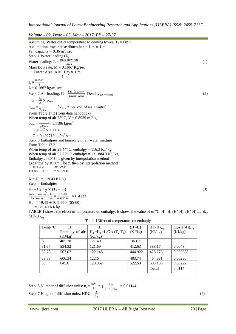
5.3 Frame and casing
Wooden towers are still available, but many components are made of different materials such as the
casing around the wooden framework of glass fiber, inlet air louvers of glass fiber, the fill of plastic and the
cold-water basin of steel. Fig. 4 shows frame of the cooling tower.
Fig. 4 frame

International Journal of Latest Engineering Research and Applications (IJLERA) ISSN: 2455-7137
Volume – 02, Issue – 05, May – 2017, PP – 27-37
www.ijlera.com 2017 IJLERA – All Right Reserved 32 | Page
Fig. 5 shows casing of the cooling tower.
Fig. 5 frame and casing
Many towers (casings and basins) are constructed of galvanized steel or where a corrosive atmosphere
is a problem, the tower and the basis are made of stainless steel. Larger towers sometimes are made of concrete.
Glass fiber is also widely used for cooling tower casings and basins, because they extend the life of the cooling
tower and provide protection against harmful chemicals. The frame is made up of mild steel. The casing is done
by galvanized iron (GI) sheet.
5.4 Water flow meter
A flow meter is an instrument used to measure linear, nonlinear, mass or volumetric flow rate of a
liquid or a gas. When choosing flow meters, we should consider such intangible factors as familiarity of plant
personnel, their experience with calibration and maintenance, spare parts availability.
Here, in this cooling tower project the maximum flow rate of hot water is maintained up to 10 Liter per Minute
(LPM) i.e. 600 Liter per Hour (LPH). So the flow meter device which is capable of measuring the flow rate of
water up to 10 LPM is used. A valve is provided near the flow meter to regulate the flow of water. By adjusting
this valve the required quantity of flow rate of water is achieved. Fig. 6 shows the water flow meter used in the
cooling tower.
Fig. 6 water flow meter
5.5 Temperature measuring indicator
Temperature measuring indicators are the devices used to display the temperature being measured. For
measuring the temperature we are using temperature sensor at different points. Temperature sensor senses the
temperature and give signal to temperature measuring indicator. At different points we are measuring the
temperature of water as well as the air entering into the cooling tower and these temperature will be shown by
the temperature measuring indicator.Fig. 7 shows the 6 channel temperature indicator.

International Journal of Latest Engineering Research and Applications (IJLERA) ISSN: 2455-7137
Volume – 02, Issue – 05, May – 2017, PP – 27-37
www.ijlera.com 2017 IJLERA – All Right Reserved 33 | Page
Fig. 7temperature measuring indicator
The temperature indicator used in this project is a 6- channel temperature indicator which gives the
temperature of water and the air at different point of cooling tower. By rotating the knob we are able to measure
the temperature and the temperature are displayed in the degree Celsius format.
5.6 Bed material
The bed material which we are using in this cooling tower is a polystyrene. Polystyrene is a
synthetic aromatic polymermade from the monomer styrene which can be solid or foamed. Fig. 8 shows the bed
material used in this cooling tower.
Fig. 8 bed material
It is a long chain hydrocarbon wherein alternating carbon centers are attached to phenyl groups. It is
also called as thermocol. Bed material is used to increase the contact time of air and water. The height of the bed
material will be maintained about 0.25 to 0.30 m. The polystyrene we are using in this cooling tower will be
spherical plastic ball.
5.7 Nozzle
A nozzle is a device designed to control the direction or characteristics of a fluid flow as it exits an
enclosed chamber or pipe. A nozzle is often a pipe or tube of varying cross sectional area, and it can be used to
direct or modify the flow of a fluid. Nozzles are frequently used to control the rate of flow, speed, direction or
pressure of the stream that emerges from them. Nozzles can either be fixed and spray in a round or square
patterns or they can be part of a rotating assembly. Fig. 9 shows the image of nozzle used in this project. It is a
spray type nozzle having four holes. There are three nozzles of same kind explained in this paper.
Fig. 9 nozzle
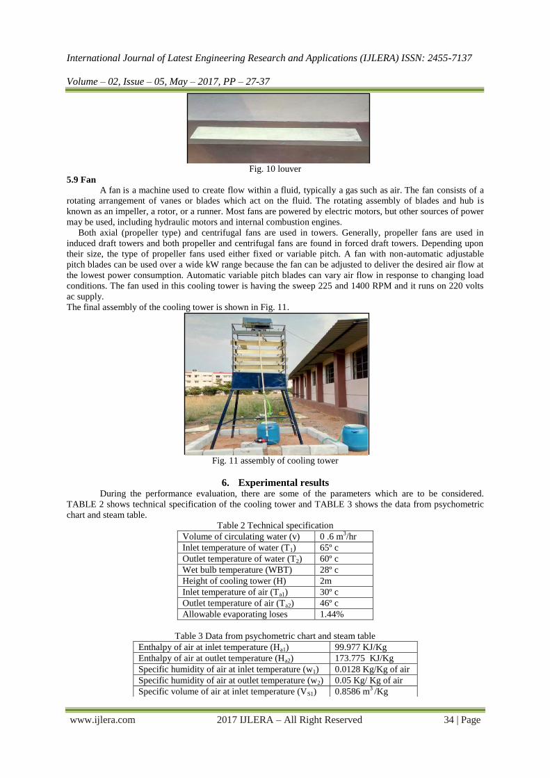
5.8 Louver
A louver or louvreis a window blind or shutter with horizontal slats that are angled to admit light and
air, but to keep out rain and direct sunshine. The angle of the slats may be adjustable, usually in blinds and
windows or fixed. Modern louvers are often made of aluminium, metal, wood or glass. The louver used in this
project is made of water resistant plywood and it is painted with water resistant paint. The size of the louver is
0.13 m and they are fixed at an angle of 60º. There are 20 louvers in two opposite side and 16 louvers in the next
two opposite sides. The thickness of the louver is 0.008 m. They are fixed in the slot provided at an angle of 60º
to act as a louver. Fig. 10 shows the position of louver in horizontal and Fig. 9 assembled view of the cooling
tower.
International Journal of Latest Engineering Research and Applications (IJLERA) ISSN: 2455-7137
Volume – 02, Issue – 05, May – 2017, PP – 27-37
www.ijlera.com 2017 IJLERA – All Right Reserved 34 | Page
Fig. 10 louver
5.9 Fan
A fan is a machine used to create flow within a fluid, typically a gas such as air. The fan consists of a
rotating arrangement of vanes or blades which act on the fluid. The rotating assembly of blades and hub is
known as an impeller, a rotor, or a runner. Most fans are powered by electric motors, but other sources of power
may be used, including hydraulic motors and internal combustion engines.
Both axial (propeller type) and centrifugal fans are used in towers. Generally, propeller fans are used in
induced draft towers and both propeller and centrifugal fans are found in forced draft towers. Depending upon
their size, the type of propeller fans used either fixed or variable pitch. A fan with non-automatic adjustable
pitch blades can be used over a wide kW range because the fan can be adjusted to deliver the desired air flow at
the lowest power consumption. Automatic variable pitch blades can vary air flow in response to changing load
conditions. The fan used in this cooling tower is having the sweep 225 and 1400 RPM and it runs on 220 volts
ac supply.
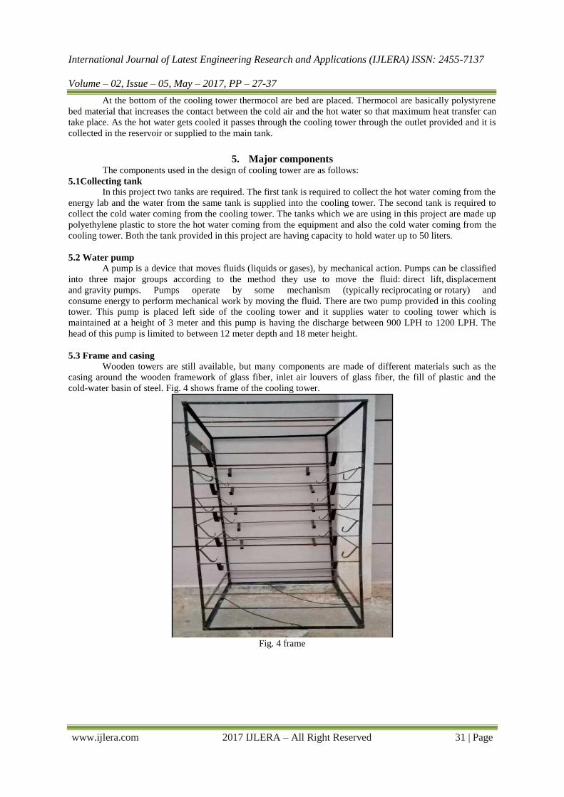
The final assembly of the cooling tower is shown in Fig. 11.
Fig. 11 assembly of cooling tower
6. Experimental results During the performance evaluation, there are some of the parameters which are to be considered.
TABLE 2 shows technical specification of the cooling tower and TABLE 3 shows the data from psychometric
chart and steam table.
Table 2 Technical specification
Volume of circulating water (v) 0 .6 m3/hr
Inlet temperature of water (T1) 65º c
Outlet temperature of water (T2) 60º c
Wet bulb temperature (WBT) 28º c
Height of cooling tower (H) 2m
Inlet temperature of air (Ta1) 30º c
Outlet temperature of air (Ta2) 46º c
Allowable evaporating loses 1.44%
Table 3 Data from psychometric chart and steam table
Enthalpy of air at inlet temperature (Ha1) 99.977 KJ/Kg
Enthalpy of air at outlet temperature (Ha2) 173.775 KJ/Kg
Specific humidity of air at inlet temperature (w1) 0.0128 Kg/Kg of air
Specific humidity of air at outlet temperature (w2) 0.05 Kg/ Kg of air
Specific volume of air at inlet temperature (VS1) 0.8586 m3 /Kg

International Journal of Latest Engineering Research and Applications (IJLERA) ISSN: 2455-7137
Volume – 02, Issue – 05, May – 2017, PP – 27-37
www.ijlera.com 2017 IJLERA – All Right Reserved 35 | Page
A prototype model of forced draft fluidized bed cooling tower is designed, fabricated, assembled and
finally carry out the tests for the performance according to Mahendran and Mukund [4].
6.1 Cooling tower range (CTR)
This is the difference between the cooling tower water inlet and outlet temperature. A high CT range
means that the cooling tower has been able to reduce the water temperature effectively, and is thus performing
well. The formula is
CT Range (°C) = [HW inlet temp (°C) – CW outlet temp (°C)]
CTR = T1 – T2 = 65º C - 60º C = 5º C
6.2 Cooling tower approach (CTA)
This is the difference between the cooling tower outlet cold water temperature and ambient wet bulb
temperature. The lower the approach the better the cooling tower performance. Although, both range and
approach should be monitored, the `Approach’ is a better indicator of cooling tower performance.
CT Approach (°C) = [CW outlet temp (°C) – Wet bulb temp (°C)]
CTA = T2 – WBT = 60º C - 28º C = 32º C
6.3 Heat loss by water (HL)
This is the amount of heat loss by the water. This indicates the amount of heat loss by the water in per
unit of time. It is denoted as HL and is given by the formula
HL = mw1 × cpw × (T1 – T2) (6)
Where,
Mw1 = Mass of water circulated in cooling tower
Mw1 = Volume of circulating water x Mass density of water
Mw1 = 0.6 × 1000
Mw1 = 600 Kg/hr
HEAT LOSS BY WATER (HL)
HL = mw1 × cpw × (T1 – T2)
HL = 600 × 4.186 × (65 - 60)
HL = 12558 KJ / hr
6.4 Volume of air required (V)
This is the volume of air required for cooling the hot water. This indicates the volume of air required in
per unit of time. It is denoted by V and is given by the formula.
V = HL × Vs1
Ha 2−Ha 1 − w2−w1 × Cpw × T2 (7)
V = 12558 × 0.8586
173.775 − 99.977 − 0.05 − 0.0128 ×4.186 ×60
V = 146.42 m3 / hr
6.5 Heat gain by air (HG)
This is the amount of heat gained by the air. This indicates the amount of heat gained by the air in per unit of
time. It is denoted by HG and is given by the formula
HG = V × Ha 2− Ha 1 − w2− w1 × Cpw × T2
Vs1 (8)
HG = 6.42 × 173.775− 99.977 − 0.05 – 0.0128 × 4.186 × 60
0.856
HG= 12425.69 KJ / hr
Specific volume of air at outlet temperature (VS2) 0.9040 m3 /Kg
Enthalpy of water at inlet temperature (Hw1) 272.0 KJ/Kg
Enthalpy of water at outlet temperature (Hw2) 251.1 KJ/Kg

International Journal of Latest Engineering Research and Applications (IJLERA) ISSN: 2455-7137
Volume – 02, Issue – 05, May – 2017, PP – 27-37
www.ijlera.com 2017 IJLERA – All Right Reserved 36 | Page
6.6 Mass of air required (Ma)
This is the mass of air required for cooling. This indicates the mass of air required for cooling of hot
water in per unit of time. It is denoted by Ma and is given by the formula
Ma = Volume of air required / Specific volume of air at inlet temperature
Ma = V
Vs1
Ma = 146.42
0.8586
Ma = 170.53 Kg / hr
6.7 The quantity of make up water (Mmak)
Make up water is defined as the quantity of water required to compensate different type of losses occurring in
the cooling tower. It is given by the formula
Mmak = 𝑉 × 𝑤2−𝑤1
𝑉𝑠2 (9)
Mmak = 6.42 × 0.05−0.012
0.9040
Mmak = 6.025 Kg / hr
Now, taking Evaporating loss in calculation
Mmak = 6.025 × 1 +1.44
100
Mmak = 6.11 Kg /hr
Mmak = 205.70 / 60 = 0.1018 Kg / min
6.8 Efficiency of cooling tower
The calculation of cooling tower efficiency involves the range and approach of the cooling tower. Cooling tower
efficiency is limited by the ambient wet bulb temperature. The efficiency of cooling tower is given by
η = 𝑇1−𝑇2
𝑇1−𝑊𝐵𝑇 (10)
η = 65−60
65−28
η = 14 %
6.9 Effectiveness of cooling tower
This is the ratio between the range and the ideal range (in percentage), i.e. difference between cooling water
inlet temperature and ambient wet bulb temperature. The higher this ratio, the higher the cooling tower
effectiveness. It is denoted ε and given by formula.
ε = T1−T2
T1− Ta 1 (11)
ε = 65−60
65− 30
ε = 0.142
6.10 Windage losses (WL)
Windage losses are generally taken as 0.005 of circulating water.
WL = 0.005 × mw1 (12)
WL = 0.005 × 600
WL = 3 Kg / hr
6.11 Evaporation losses (EL)
Evaporation losses are generally taken as 0.00085 of circulating water.
EL = 0.00085 × mw1× (T1 – T2) (13)
EL = 0.00085 × 600 x (65 - 60)
EL = 2.55 Kg / hr
7. Advantages The advantages of cooling tower are as follows:
Effective cooling of water is possible.
Simple in construction
Low construction cost

International Journal of Latest Engineering Research and Applications (IJLERA) ISSN: 2455-7137
Volume – 02, Issue – 05, May – 2017, PP – 27-37
www.ijlera.com 2017 IJLERA – All Right Reserved 37 | Page
Operation cost is low
Easy to operate
Conclusion
Experiments were conducted on a fluidized bed cooling tower. Performance of the cooling tower was
analyzed with fluidized bed. The experiments show the effects of the water and air on the tower characteristic,
the air to water contact is more in fluidized bed cooling tower, so better heat transfer has been occurred and the
cooling water outlet temperature is reduced. The range of cooling tower can be increased by using fluidized bed.
The increase in inlet temperature of water decreases the effectiveness as same quantity of air is available for
cooling for all operating temperatures of cooling tower. As L/G ratio decreases the cooling rate increases. For
optimum utilization of fluidized bed the flow rate of cooling air should be increased.
References [1] K. N. Seetharamu and Swaroop, “The Effect of Size on the Performance of a Fluidized Bed Cooling
tower”, International Journal of Engineering Trends and Technology (IJETT), 26(1),1991, 17-21.
[2] R. Ramkumar and Ragupathy, “Thermal Performance of Forced Draft counter Flow Cooling tower
with Expanded Wire Mesh Packing”,International Journal Technical and Physical Problems of
Engineering (IJTPE), 3(6),2011, 19-23.
[3] Dr. Nagam Obaid Kariem & Hayder Mohamad Jaffal “Performance of CoolingTower with
Honeycomb Packing”, Eng. &Tech. Journal,29(6),2011,2-10.
[4] Mahendran and Mukund, “Design and Fabrication of Mini Draft Cooling tower”, International
Conference on Explorations and Innovation in Engineering and Technology,25(3),2016, 92-95.