Small-RPS Enabled Mars Rover Concept
14
Small-RPS Enabled Mars Rover Concept Tibor S. Balint Jet Propulsion Laboratoty, California Institute of Technolop, Pre-Projects and Advanced Mission Studia (Ofice-61 0) 4800 Oak Grove Drive, M/S 301-170U,Pasadena, CA 91109-8099 telephone: (818)354-1105; email: [email protected] Abstract. Both the MER and the Mars Pathfinder rovers operated on Mars in an energy-limitedmode, since the solar panels generated power during daylight hours only. At other times the rovers relied on power stored in batteries. In comparison, Radioisotope Power Systems (RPS) offer a power-enabled paradigm, where power can be generated for long mission durations (measured in years), independently from the Sun, and on a continuous basis. A study was performed at PL to assess the feasibility of a small-RPS enabled MER-class rover concept and any associated advantages of its mission on Mars. The rover concept relied on design heritage from MER with two significant changes. First, the solar panels were replaced with two single GPHS module based small-RPSs. Second,the Mossbauer spectroscopewas substituted with a laser Raman spectroscope,in order to move towards MEPAG defined astrobiology driven science goals. The highest power requirements were contributed to mobility and telecommunication type operating modes, hence influencing power system sizing. The resulting hybrid power system included two small-RPSs and two batteries. Each small-RPS was assumed to generate 50We of power or 62OWsol of energy (BOL), comparable to that of MER The two 8Ah batteries were considered available during peak power usage. Mission architecture, power trades, science instruments, data, communication, thermal and radiation environments, mobility, mass issues were also addressed. The study demonstrated that a new set of RPS-enabled rover missions could be envisioned for Mars exploration within the next decade, targeting astrobiology oriented science objectives, while powered by 2 to 4 GPHS modules. INTRODUCTION Following the great success of the Mars Exploration Rovers (MER), Spirit and Opportunity (NASA, 2004), NASA continues working on fbture mission concepts in support of the Mars Exploration Program. Next decade potential missions could include rovers to achieve surface mobility, deep drills for subsurface access, in addition to landers and sample return. This section focuses on surface mobility, and describes a point design that demonstrates the feasibility of a MER.-class Mars rover powered by small Radioisotope Power Systems (RPS). Although the power level for this point design is sized to match MER-class rover mission requirements, additional rover designs are identified and scaled to various power levels. SCIENCE & MISSION GOALS The nation's vision for space exploration (Bush, 2004) recognized Mars and the Moon as prime destinations for both robotic and human exploration. In addition, NASA's Mars Exploration Program interfaces with the Mars Exploration Program Analysis Group (MEPAG, 2004) to identify high priority science and technology issues relevant to the program. The four highest priority objectives identified by MEPAG are: (1) the search for life; understanding the (2) climate and (3) Martian geology; and (4) preparing for human exploration. Consequently, the conceptual mission design described in this study builds on heritage from the MER missions, while specifically addresses astrobioloby-driven science goals. This systematic approach places the present rover mission in line with other planned Mars exploration missions, while helping to establish an exploration path that leads towards the ultimate goal of human presence on Mars.
Transcript of Small-RPS Enabled Mars Rover Concept

Small-RPS Enabled Mars Rover Concept
Tibor S. Balint
Jet Propulsion Laboratoty, California Institute of Technolop, Pre-Projects and Advanced Mission Studia (Ofice-61 0)
4800 Oak Grove Drive, M/S 301-170U, Pasadena, CA 91109-8099 telephone: (818)354-1105; email: [email protected]
Abstract. Both the MER and the Mars Pathfinder rovers operated on Mars in an energy-limited mode, since the solar panels generated power during daylight hours only. At other times the rovers relied on power stored in batteries. In comparison, Radioisotope Power Systems (RPS) offer a power-enabled paradigm, where power can be generated for long mission durations (measured in years), independently from the Sun, and on a continuous basis. A study was performed at P L to assess the feasibility of a small-RPS enabled MER-class rover concept and any associated advantages of its mission on Mars. The rover concept relied on design heritage from MER with two significant changes. First, the solar panels were replaced with two single GPHS module based small-RPSs. Second, the Mossbauer spectroscope was substituted with a laser Raman spectroscope, in order to move towards MEPAG defined astrobiology driven science goals. The highest power requirements were contributed to mobility and telecommunication type operating modes, hence influencing power system sizing. The resulting hybrid power system included two small-RPSs and two batteries. Each small-RPS was assumed to generate 50We of power or 62OWsol of energy (BOL), comparable to that of MER The two 8Ah batteries were considered available during peak power usage. Mission architecture, power trades, science instruments, data, communication, thermal and radiation environments, mobility, mass issues were also addressed. The study demonstrated that a new set of RPS-enabled rover missions could be envisioned for Mars exploration within the next decade, targeting astrobiology oriented science objectives, while powered by 2 to 4 GPHS modules.
INTRODUCTION
Following the great success of the Mars Exploration Rovers (MER), Spirit and Opportunity (NASA, 2004), NASA continues working on fbture mission concepts in support of the Mars Exploration Program. Next decade potential missions could include rovers to achieve surface mobility, deep drills for subsurface access, in addition to landers and sample return. This section focuses on surface mobility, and describes a point design that demonstrates the feasibility of a MER.-class Mars rover powered by small Radioisotope Power Systems (RPS). Although the power level for this point design is sized to match MER-class rover mission requirements, additional rover designs are identified and scaled to various power levels.
SCIENCE & MISSION GOALS
The nation's vision for space exploration (Bush, 2004) recognized Mars and the Moon as prime destinations for both robotic and human exploration. In addition, NASA's Mars Exploration Program interfaces with the Mars Exploration Program Analysis Group (MEPAG, 2004) to identify high priority science and technology issues relevant to the program. The four highest priority objectives identified by MEPAG are: (1) the search for life; understanding the (2) climate and (3) Martian geology; and (4) preparing for human exploration. Consequently, the conceptual mission design described in this study builds on heritage from the MER missions, while specifically addresses astrobioloby-driven science goals. This systematic approach places the present rover mission in line with other planned Mars exploration missions, while helping to establish an exploration path that leads towards the ultimate goal of human presence on Mars.

Both MER and Mars Pathfinder (NASA, 2004) operatd on Mars in an energy-limited mode, since their solar panels generated power during daylight hours only. At other times the rovers relied on power stored in secondary batteries. Radioisotope Power Systems (RpSs) offer a power-enabled paradigm, where power is generated for long mission durations (measured in years), independently from the Sun, and on a continuous basis. To take advantage of these benefits, the goal of this mission study concept is to assess the feasibility of a small RPS-enabled generic MER-class rover, and to assess the relative advantages of such a mission.
MISSION ARCHITECTURE OVERVIEW
In order to conduct high priority science in line with MEPAG goals the science community needs a mobile platform to perform astrobioiogy, geology and climate experiments at locations not accessible to solar powered rovers. This rover concept extends the capability and longevity of the power source, using small-RPSs, to further increase the science return. For the present astrobiology-oriented mission concept the Mars Exploration Rovers present a suitable starting point, while providing design heritage (Diehl et al., 2004). Consequently, a significant portion of this mission is based on the original MER mission architecture and hardware configuration.
The launch and arrival characteristics are determined for two launch periods, one that would allow access to maximum northern latitudes and one to maximum southern latitudes. The Iatitudes bridged by the two trajectories would range from 70's to 70°N. A Type I1 trajectory would be used for either latitude regime. The permissible range of latitudes is limited by the launch configuration and not by the power system - RE'S enabled rovers would be operational at any given Martian location.
To land between 70"s and 40°N the launch window is assumed between October 27 and November 16,2009. This corresponds to a cruise phase of 334 to 354 days and an arrival date of October 16,2010. The heliocentric longitude of the Sun (Ls) at arrival is 165'. The C3 for this launch period is 20km2/s2. The corresponding injected mass is 3lOOkg on an Atlas 521 launch vehicle (LV) or 2897kg on a Delta 4450-14 LV.
To reach the maximum northern latitude of 70°N (and ranging down to 50"s). the launch window would be set between October 6 and 26,2009. The corresponding cruise phase is -300 days with an arrival date between July 23 and August 22, 2010. The Iongitude of the Sun at arrival ranges &om 120° to 1 3 3 O . The C3 is 15kmz/s2, which allows for injecting a mass of 2923kg on the Delta 4240-14 LV or 2806kg on an Atlas 51 1 LV.
Entry, descent and landing (EDL) is assumed using either MER type airbags or VikinglPhoenix-type powered descent. Using an airbag configuration (see Figure l), the rover could be accommodated on a 2.57m Viking-type aeroshell, with a total launch mass of -1070kg. The Viking-type powered landing configuration with a larger 3.6511 Viking-type aeroshell would have a launch mass of -1620kg. For both cases the launch mass is less than half of the available LV capacity. Therefore, further optimization could be made by choosing a smaller LV, for example Atlas lHB (SEC) (1995kg) or Delta 1V 4040-12 (1565kg) for C=20kmz/s2. (NASA-KSC, 2004)
Figure 1. MER type airbag without the aeroshell

Figure 2 shows a Viking-type amhel l and lander with the mer. The choice of airbag landing versus powered landing results in different landing accuracies and acceleration load environments. The ellipse for airbag landing with no entry guidance (attitude hold only) and optical navigation would be -96kn-1, similar to the MER landing ellipse. For powered descent the h d i n g ellipse could be as small as -lOkm, but at a significantly increased propellant penalty. Akbag landing results in -4Og or higher acceleration load$, while a powered landing requires only -2Og. Both configurations would employ a single parachute.
Figure 2. Viking type aeroshell, lander and rover
It is assumed that during landing, the rover decouples from the lander, performs initial health checks and environment assessment, egresses from the lander and initiates the surface operation phase. Active measurements would be planned for a 3-year mission duration, resulting in a total mission time of -1400 days. Note that a radioisotope power system would provide continuous power through an extended mission phase. The actual mission duration is theoretically limited only by the failure of a key subsystem; most likely an actuator or other moving component, and is accelerated by uncontrolled themud cycling. Component failures could be reduced by tight themal control. When a mission extends over several years, additional development work is required to improve the reliability of the moving parts, including motors, actuators, wheels and robotic arm joints. The present rovef configuration is shown in Figure 3. The top and mast of the rover are identical to those used on MER, and are mot included in the figures to allow for better illustration of the internal components. The two small-RPSs would be placed at the end of the rover. Modular design of the RPSs would allow for much flexibility in placing them at the most suitable Locations. In turn, the configuration (e.g., side-by-si&, back-&back) would impact the thermal and the radiation environments inside and around the mer. During the surface operation phase of the mission, the rover would perform scientific measurements and relays the data back to Earth. These issues are further discussed at latter sections of this paper.
#- 1
Figure 3. Rover configuration (top removed to show internal systems)

GENERAL ISSUES RELATED TO POWER
This section introduces the various issues associated with power system selection €or Mars missions with a focus on small-RPS systems. It also provides a characterbtion of a small-RPS, and discusses alternate power systems. The actual power system sizing and power requirements for the present Mars rover will be discussed under the rover payload and system section.
Overview of the Power Source Trades
The Mars Exploration Rovers employed solar panels for power generation. The unfolded 1.3mZ GaInP/SaAdGe triple-junction solar panels were capable of generating -140We (electrical)(BOL) peak power for up to 4 hours per sol, depending upon the season. Although solar power generation has many advantages out to 3.5 to 4.5 AU from the Sun, this section discusses the advantages of RPS power on the surface of Mars. Solar insolation varies inversely with the square of distance from the Sun (i.e., R"). Thus, the solar flux at Mars (-1.5AU) is only about 43% ofthat at Earth (Balint, 2003). In addition, solar power generation on Mars i s further impactd by atmospheric conditions, sand storms, operating latitude, seasons (defined by Ls), eclipses, terrain shadowing, and solar panel degradation (due to dust accumulation and thermal cycling from diurnal temperature variations) (Dawson et al., 2003). This can reduce the received solar flux on the Martian surface to 6.5% of that at Earth. Continuous year around solar availability i s limited to the equatorial region and middle latitudes (from 60°N to 605). At higher latitudes, above 60°N and bdow W S , continuous power generation with solar panels is not feasible due to seasonal variations, resulting in low solar insulation during polar winters (see Figure 4).
I
Figure 4. Power source selection for landing locations
RPS presents distinct advantages over solar panels. R P S - b a d power generation i s independent of solar insolation and atmospheric effects. It also enables a significantly longer lifetime (measured in years), which translates into a longer mobility range that potentially allows for greater scientific returns and data accumulation. RPSs are ideal for rovm operating at high latitude regions, especially at poles during winters. They enable operations in partially or permanently shadowed regions such as valleys, canyons and caves. Radioactive decay of the plutonium fuel generates a significant amount of thermal power, of which only a small percentage is converted into electricity. The rest is excess heat and nominally reject4 to the environment. However, this waste heat can be used to achieve tight temperature control of subsystem inside the mwr. This could reduce thermal cycling of the components, potentially decreasing component failures and extending operability. Additionally, batteries have tight temperature windows, and maintaining them at a constant 0°C helps preserve battery performance, and extend battery life. This characteristic advantage of RPSs is beneficial not only in Polar Regions, but at any given location on Mars. In comparison, solar powered systems rely on batteries to heat components overnight using high-powered resistance heating. It impacts the lifetime of the batteries, use up valuable resources and may result in an oversized power system, dnven by system survivability requirements. Power system sizing is further discuss4 later in this paper.

General Characteristics of a Small-LIPS
The power source for this rover study consists of two individual small-RPSs, each configured with a single GPHS module. There are 4 plutonium dioxide fuel pellets in each module. The total fuel and GPHS module masses are 0.5kg and 1.445kg respectively. The thermal power output for each module is -250Wt (thermal) at BOL. This heat output decreases exponentially, (approximated at a rate of -0.79% per year) due to radioactive decay of the plutonium fuel. (Surampudi, 2001)
Figure 5. Conceptual small RPS using a single GPHS module
The heat generated through the decay process is converted into electric power using thermoelectric (TE) conversion. The selection of materials used for TE conversion varies, depending on the operating environment. For use in the Martian atmosphere, PbTe TAGS couples are proposed. There is a -0.8% loss associated with TEs per year, resulting in a total pwer system degradation of -1.6% per year.
Based on these assumptions, 2 s d l (single GPHS module based) RPSs can generate -25We of power (or -62OWh energy per sol) at BOL and -23.44We (or -S80Wsol) at EOL. The calculated EOL values cormpond to a 1 year cruise phase and 3 years of surface operation. In addition, the design also amounts for an appropriate heat rejection system for the 475Wt waste heat. The total mass of the two small-RPSs is a s s u m e d at -12 kg, with approximate bounding dimensions of 320 rtlfn b 230 mm by 140 mm. This is significantly smaller than a solar array system with similar power output (e.g., a 1.3 m solar panel generates -6OOWsol at EOL and weights -16.5 kg.) A conceptual drawing of a single GPHS module based RJ?S is present4 in Figure 5 (Abetson et al., 2004), and is based on the works of Wiley & Carpenter (Wiley & Carpenter, 2oW).
Y
Alternate RPS Power Systems
For an alternate concept, segmented PbTe TAGS I BiTe couples could be used in a close-packed a m y (CPA) configuration, replacing the PbTe TAGS thermoelectric converters. CPA provides better structural support during acceleration loading (e.g., landing or roving) than the larger unicouples. This configuration could potentially increase the TE conversion efficiency from the conservatively assumed 5% to -9-9.7% in the future (Wiley &
Carpenter, 2004). Beside static conversion technologies, dynamic power conversion could also be considered. A Stirling system would require less plutonium, while achieving higher power conversion efficiencies. This technology, however, has not been tested in a space environment; thus its acceleration load tolerance and lifetime must be demonstrated before use in fbture space missions.
PAYLOAD AND SYSTEMS DESCRIPTION OF THE MARS ROVER
This section describes the science instruments for the Mars rover and the supporting key systems such as the data and telecom systems, the thermal system and the power system. A summary of the mass breakdown is also provided.
Science Instruments
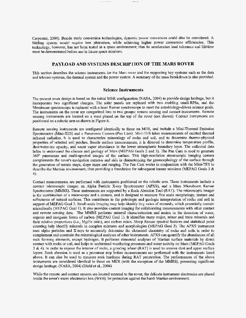
The present rover design is based on the initial MER configuration (NASA, 2004) to provide design heritage, but it incorporates two significant changes. The solar panels are replaced with two enabling small-RPSs, and the Mossbauer spectroscope is replaced with a laser Raman spectroscope to meet the astrobiology-driven science goals. The instruments on the rover are categorized into to two groups: remote sensing and contact instruments. Remote sensing instruments are located on a mast placed on the top of the rover (not shown). Contact instruments are positioned on a robotic arm as shown in Figure 6.
Remote sensing instruments are configured identically to those on MER, and include a Mini-Thermal Emission Spectrometer (Mini-TES) and a Panoramic Camera (Pan Cam). Mini-TES takes measurements of emitted thermal infrared radiation. It is used to characterize mineralogy of rocks and soil, and to determine thermo-physical properties of selected soil patches. Beside surface measurements, it is directed to determine temperature profile, dustiwater-ice opacity, and water vapor abundance in the lower atmospheric boundary layer. The collected data helps to understand the climate and geology of Mars (MEPAG Goals 2 and 3). The Pan Cam is used to generate 360" panoramas and multi-spectral images of the surface. This high-resolution stereoscopic imaging camera complements the rover's navigation cameras and aids in characterizing the geomorphology of the surface through the generation of terrain maps, slope maps and ranging. The Pan Cam works in conjunction with the Mini-TES to describe the Martian environment, thus providing a foundation for subsequent human missions (MEPAG Goals 3 & 4).
Contact measurements are performed with instruments positioned on the robotic arm. These instruments include a contact microscopic imager, an Alpha Particle X-ray Spectrometer (APXS), and a Mars Microbeam Raman Spectrometer (MMRS). These instruments are supported by a Rock Abrasion Tool (RAT). The microscopic imager is the combination of a microscope and a camera, and is designed to measure fine scale morphology, texture and reflectance of natural surfaces. This contributes to the petrologic and geologic interpretation of rocks and soil in support of MEPAG Goal 3. Small-scale imaging may help identify tiny veins of minerals, which potentially contain microfossils (MEPAG Goal 1). It also provides context imaging for collaborating measurements with other contact and remote sensing data. The MMRS performs mineral characterization and assists in the detection of water, organic and inorganic forms of carbon (MEPAG Goal I). It identifies many major, minor and trace minerals and their relative proportions (Le,, MgEe ratio), and carbon ratios. Sharp Raman spectral features and statistical point counting help identify minerals in complex mixtures and morphologies (MEPAG Goal 3). The APXS instrument uses alpha particles and X-rays to accurately determine the elemental chemistry of rocks and soils in order to complement and constrain the mineralogical analyses of other instruments. APXS can quanti6 the abundances of all rock forming elements, except hydrogen. It performs elemental analyses of Martian surface materials by direct contact with rocks or soil, and helps to understand weathering processes and water activity on Mars (MEPAG Goals 3 & 4), In order to expose the interior of rocks, a grinding wheel (RAT) is used to remove dust and upper surface layers. Rock abrasion is used as a precursor step before measurements are performed with the instruments listed above. It can also be used to measure rock hardness during RAT penetration. The performances of the above instruments are considered identical to those on MER (with the exception of the MMRS), presenting significant design heritage. (NASA, 2004) (Diehl et al., 2004)
While the remote and contact sensors are located external to the rover, the delicate instrument electronics are placed inside the rover's warm electronics box (WEB) for protection against the harsh Martian environment.

1.m
1 -
Side view a' I
7
Figure 6. Rover instrumentation
Data and Communications Systems
All science instruments described above generate valuable scientific data that needs to be stored and returned to Earth. Engineering data i s also collected and returned. A bounding estimate is given here for the present rover configuration. The rover is calculated to collsct, on average, between 50 to lOOMbits of data per sol (Spirit and Opportunity each generated and collected up to SOMbits of data per sol). The actual data accumulation rate is driven by the science needs. For example, taking high-resolution stereoscopic Pan Cam images or using the microscopic imager results in raw data up 12.5Mbits per image. All collected data is stored on a 256MB flash memory card. If required, this storage capacity can be increased without significant impact on the rover design.
The telecom design for the rover is similar to that used on MER. Communication between the rover and Earth relies on the Mars Telecom Orbiter planned to arr iwat Mars in 2010, which for the purposes of this study would be just before the arrival of our concept rover. The MTO will orbit Mars at an altitude of 4450km with a 13.5" inclination. The rover would also utilize the Mars Global Surveyor, ador the Mars Odyssey, and potentially any other orbiting assets available at the time of the mission.
The rover design uses X-band and UHF electronics. Antennas include a 0.28m X-band high gain antenna (HGA), an X-band low gain antenna (LGA), and a UHF monopole antenna. This configuration is identical to the MER design, except MER'S CE 505 UHF mnsceiver is replaced with the new ElectmLite transceiver.
This configuration would be capable of transmitting up to MTO in the X-band at a rate of 1.024Mbps. The UHF downlink from MTO to the rover i s available at a rate of Skbps. From MTO the rover data is sent to the Deep Space Network (DSN) in X-band at MOkbps or Ka-band at 5OOkbps. Direct to Earth (DTE) communication from the rover is avaiiable from the rover's X-band HGA to the 34m DSN antenna at a rate of 1 kbps. The uplink from DSN (34m) to the rover's X-band HGA can reach a maximum data rate of 2kbps.

It is concluded that with the availability of high uplink data rate to the Mars Telecom Orbiter (MTO), significantly more data can be collected and relayed to Earth than the specified 50 to lOOMbits per sol, allowing for increased operational flexibility throughout a mission. The multiple orbital assets around Mars and the capability of DTE communication would provide a well-supported mission environment for the rover to transfer all collected science and engineering data to Earth.
Thermal System
Radioisotope Power Systems generate continuous heat through radioisotope alpha decay of ha', which has an 87.75-year atomic half-life. The generated heat degrades exponentially at a very low rate (-0.79% per year), making Pd3' an ideal choice for powering long duration missions (Surampudi, 2001). However, the waste heat must be removed throughout all mission phases, including RPS integration with the spacecraft, launch, cruise, EDL and surface o p t i o n . Two GPHS modules of the type considered in this study would generate -500Wt of them1 power. For the present design, fluid thermal ioops are used for both the cruise and surface operation phases. During cruise phase, heat is generated by electrical systems (CPU, avionics, etc.) in the warm electronics box that must be removed to prevent overheating (see Figure 7). Thermal valves (TV) direct the coolant from the WEB to the heat rejection system (HE) at a flow rate of OSVmin, driven by a 5W pump. From there, the heat is rejected to the aeroshell and then radiated to space. An additional loop also removes heat through the cruise stage to radiators, rejecting the remaining waste heat into space. Before EDL, the aeroshell separates from the cruise stage and disoonnects the fluid loop from the aeroshell. For the short EDL phase, the heat generated by the RPS is absorbed by the aeroshell. A successful landing initiates the surface operation phase, during which heat is rernoved by the r o d s HRS, consisting of two fluid loops connected to radiators and routed through the WEB. Thermal control valves inside the rover's WEB, along with aerogel thermal insulation, maintain the internal temperature within a set range. This thermal control helps minimizing thermal cycling of critical rover subsystems during the diurnat period, thereby increasing the mission lifetime. A primary loop services equipment both inside and outside of the rover's thermal enclosure. Fluid lines, installed external to the thermal enclosure, provide thermal management to the mobility electronics (ME). The backup loop services only the equipment inside the WEB and Ras no lines external to the thermal enclosure. Heat exchangers outside the rover can be sized to remove waste heat during daytime, when the WEB does not require heating. This thermal design is similar to that suggested for MSL. Other heat rejection systems can also be considered, for example removing excess heat from the RPSs with heatpipes. (Diehl et al., 2004)
Radiates to space
Figure 7. Thennal design concept for an RPS-enablsd rover

Power System Sizing
This section describes power-sizing msiderations, including power allocation to science instruments and assumed activity modes. Being a MER derivative, the power requimnents for this rover are similar to that of MER, where the solar panels generate 9OOWhlsol energy at BOL, and 6OOWh/sol at EOL. For successful substitution of the power smce, RPSs on the rover should provide as much energy as similarly sized solar panels. Thus, the RPS enabied rover quires a minimum of two GPHS modules, supplying a total of 42OWh/sol, based on continuous power generation of -25We at BOL. Figure 8 shows the position of the two RPSs at the back of the rover.
Figure 8. View of the rover wheels and the EWSs
On solar powered rovers, high load activities are performed around Martian noon to maximize the use of the peak solar flux. Since the peak power from the two RPSs would be lower than that of the solar variant, a hybrid power system is considered. This system would combine two small-RPSs and two 8Ah 28V Li Ion batteries to obtain MER type capability. The total energy stored in the fully charged secondary batteries is 448Wh.
The power system is sized by assessing the power requirements for typical activity days, based on instrumentation, operating procedures and assumed measurement sequences. The power requirements for the rover's instruments are given in Table 1. Additional systems that require power include command and data handling, power distribution, attitude determination and control (for mobility), and telecommunications.
Five distinct activity modes are identified for the power analysis, with each representing a single activity day. The panorama d e defines the use of the panoramic camera (-1 1Wh). The Mini-TES mode represents the use of the Mini-Thermal Emission Spectrometer (-4OWh). Three dnve modes are considered. During simple drive (low impact) the terrain is characterized by low hazard levels and low rock abundance {-85Wh). During complex drive the terrain has large rocks, deep sand or steeper hills drawing higher power than simple drive (-125Wh). Approach drive precedes the use of contact instruments and is characterized by slow motion over short (<lorn) distances while drawing -1OOWh of energy. Contact measurement activities with the microscope or Raman use -40Wh. When using the RAT, the energy requirement for this mode of operation increases to -55Wh. The last activity is defined as a charge day, which usually follows a high-energy activity day to recharge the depletsd secondary batteries.
TABLE 1. Rover instrument power requirements
Instrument Power
Remote sensing ins:rumenls PANCAM on mast Mini-TES Conlac# insinmlenrs Microscopic Imager Raman Spectrometer APXS Support Imtrurnent Rock Abrasion Tool (RAT) Support Equipment HazcamNavcam {Context) Mast actuator
4.3 w 5.6 W
2.1 w 18 W 0.7 W
11w 5w 0.1 w

In addition to the energy requirements for any of these activity days, a housekeeping overhead and two 80Wh telecom loads are also added. Detailed analysis of the activities indicated that the highest power usage occurs during complex drive days, and the highest operating modes are mobility and telecom. For these operations, batteries complement RPS power. Assuming 1 hour of intense drive and two one hour telecom windows, the battery charge ends in a power negative mode, which means that the charge level at the end of sol is below that at start. This can be resolved by following on with a charge day. Continuous driving represents the bounding case for traversing, when the system uses all of the RPS generated power and simultaneously draws power from the batteries. Driving can be made more efficient by either increasing the battery size (impacting rover mass and size) or by changing from continuous drive to stop-and-go operation, where after a short drive the rover would stop, charge back the batteries and then go again.
In summary, the power analysis indicates that two GPHS modules would provide enough power and energy to enable a MER-class rover design, with a similar instrument complement and power profile.
Rover Mass Summary
The rover mass is calculated at I Xlkg, but the launch mass differs depending on the landing approach. For an airbag landing, the launch mass i s 1070kg and the final landed mass (rover, landing platform and airbags) is 410kg. Using a powered lander the launch mass is 1620kg, and the landed mass is 700kg. The higher landed mass is attributed to the powered descent stage. A breakdown of the rover's mass allocation is shown in Table 2, detailing both the instrument mass and the support system mass allocation. The rover carries 9.5kg of science instrument payload. The support system includes components for telecommunication, attitude control system, thermal management, power, mechanical and avionics systems. Telecom covers electronics and antennas. The thermal system accounts for the heat rejection system (radiations), thermal valves, pipes and pumps. The power system includes the small RPSs (12kg), batteries (7.5kg) and power electronics. Avionics accounts for electronics and interface boards to the various systems and sub-systems. The largest mass is assigned to the mechanical components, including the rover's body (with thermal insulation), the drive mechanisms, drive train, and wheels. The dimensions, instrumentation and total mass of this rover concept are comparable to that of MER.
Table 2. Rover mass allocation
Instrument Mass
Remote sensing instruments PAEJCAM on mast 0.7 kg Mini-TES 2.7 kg Contact instruments Microscopic Imager 0.3 kg Raman Spectrometer 2.5 kg APXS 0.5 kg Support Instruments Rock Abrasion Tool (RAT) 0.9 kg Calibration Target; Magnets etc. 1.9 kg Total Instrument Mass 9.5 kg Rover Support Systems Telecom 16.6 kg ACS 2.6 kg Thewal 2.7 kg Power 23.0 kg Mechanical 97.0 kg Avionics 30.0 kg Total Rover System with Instruments 181.4 kg

ISSUES aELATED TO ROVER OPERATIONS AND TO THE ENVIRONMENT
Mobility Related Issues
Two important mobility requirements are addressed in this section, namely traversing and h d o b s t a c l e avoidance. It has been shown in previous and current landed missions (NASA, 2004) that the Martian terrain varies significantly with Iocation. Experience from the Mars Pathfinder mission showed that lauding site determination is important relative to the size of the rover. The highest resolution Mars orbital cameras provide only 1Sdpixel resolution. The Sojourner Rover, with a length of Ohm, had to land in an area where rock size, distribution and abundance would not significantly affect its operation (Golombek, 2002). Figure 9 shows Sojourner in-situ, illustrating the relationship between rover size and environment (’NASA, 2004). Similarly, boulder fields at Olympus Mons Caldera include terrains with 12m diameter rocks. Such fields with over 20% rock abundance might be difficult or even impossible to traverse using any of the planned rovers. Other areas such as the Gusev Crater and the Meridiani Planum presented a suitable environment in wmparison to the size of MER.
Flgure 9. Sojourner and the rock named Yogi
The present design uses MER heritage for mobility. The diameter of each of the 6 wheels is 25cm (see Figure 8), identical to those on MER. Larger wheels can assist with negotiating tougher terrains, but require more torque and, consequently, larger wheel actuators. In fact, the cascade effect h r n an enlarged wheel size can result in a significantly greater total mass.
The terrain also influences rover traversability and associatsd power requirements. Driving on rocky, sandy or hilly topography requires more power than driving on flat hard surfaces. To account for these diverse conditions, the traversing analysis for this rover concept divided driving into a number of operating mod-, such as complex or normal driving. These modes are further explain4 above under the power sizing section. MER-class rovers are capable of traversing at speeds about 35 to 72mlhour depending on the terrain. Assuming 2 drivedays per week, 1 hour drive per day and 3 years of o p t i o n on the surface, the small RPS enabtd toyer could traverse distances up to 20-25km over its nominal lifetime. In comparison, a solar powered rover could only mer about 1 to 2km due to its limited lifetime. It can be concluded that small RPS enabled rovers could cover an order of maguitude more terrain than solar powered rovers, due primarily to the significantly longer mission time. This would allow more opportunity for traversing, exploration, and data collection than a solar powersd equivalent.
Radiation Environment
Electronic components are affected by radiation and can tolerate ionizing radiation doses only up to a certain limit. Space based instruments counteract the damaging effect4 by using radiation hardend components. Today’s state-of- the-art radiation hardened electronics can tolerate doses up to 300-500kRad and there are discussions about increasing this tolerance in the near fume to as high as 1-d. For RPS enabled missions, ionizi radiation is attributed to natural (wsmic) radiation sources and to radiation from radioisotope decay of the Pu’fuel. Decay radiation primarily consists of alpha particles, which are essentially helium nuclei. These high mass particles can be blocked easily even with a sheet of paper. However, a small amount of secondary radiation is also present in the
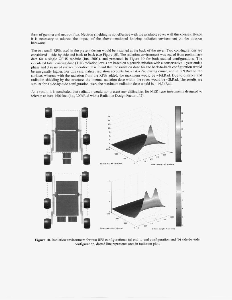
form of gamma and neutron flux. Neutron shielding is not effective with the available rover wall thicknesses. Hence it is necessary to address the impact of the above-mentioned ionizing radiation environment on the mission hardware.
The two small-RPSs used in the present design would be installed at the back of the rover. Two con-figurations are considered - sideby-side and back-&back (see Figure 10). The radiation environment was scaled from preliminary data for a single GPHS module (Jun, 2003), and presented in Figure 10 for both studied configurations. The calculated total ionizing dose (TID) radiation levels are based on a generic mission with a conservative 1-year cruise phase and 3 years of surface operation. it is found that the radiation dose for the back-to-back configuration would be marginally higher. For this case, natural radiation accounts for -1.43kRad during cruise, and -0.52kRad on the surface, whereas with the radiation from the RPSs added, the maximum would be -16kRad. Due to distance and radiation shielding by the structure, the internal radiation dose within the rover would be -2kRd. The results are similar for a side-by-side configuration, were the maximum radiation dose would be -14.5kRad.
As a result, it is concluded that radiation would not present any diffmlties for MER-type instruments designed to tolerate at least 15OkRad (i.e., 300kRad with a Radiation Design Factor of 2).
I '
--L
Figure 10. Radiation environment for two RPS configurations: (a) end-bend configuration and (b) side-by-side configuration, dotted line represents area in radiation plots

ADDITIONAL RPS-ENABLED ROVER MISSIONS
This section described a Mars surface rover mission concept using 2 GPHS mdules, providing 25We of power to a 1 SOkg MER-class rover. Further studies were also performed to scale the rover up to about 230kg, requiring 50We of power (or 1 2 5 0 W d energy), supplied by 4 GPHS modules. The largest, but only slightly larger rover accommodated additional astrobiology driven instruments, such as a Gas Chromatograph / Mass Spectrometer (GCMS) with an oven, X-ray Diffractometer I X-ray Fluorescence Spactrometer (XRDKRF), a Mossbauer Spectrometer and a high-resolution contextual microscope. Scaling further up, a predecisional early variant of the MSL rover was envisioned with two multi-mission RTGs (MMRTGs), generating a total of 220We power (or 550OWh/sol energy}. However, the size of this rover and its power source is not withii the scope of the present smalEWS study. Scaling down, a Mars Pathfinder-class rover required around 15OWh/sol, which corresponds to a half-fuelled GPHS module. Micro-rovers are found to be too small to accom&te a GHPS module. Radioisotope Heater Unit based power sources coupled with a battery or a capacitor could provide enough energy in a trickle charge / burst operating mode to enable a certain amount of functionality. However, the small size in relation to the surrounding terrain and the power needs to perfom power intensive functions, such as traversing or telecommunication, may limit the applicability of such mobility devices (see Figure 1 1 ) .
In summary, these studies demonstrated the viability of a class of small rovers enabled by 2 to 4 stacked singte- GPHS module b a d RPSs, with special focus on a power range between 25 and 50We.
Figure 11. Additional rover concepts
CONCLUSIONS
The study described here assessed the feasibility of a MER-class rover using two small-RPSs. Each of the power systems utilizes a single GPHS module, generating -12.5We of power. Since RPSs operate continuously, the 25We power from the two GPHS modules could produce up to 620Wh energy per sol, which with the proper battery system would enable MER-class rover operations. Assuming 3 years of surface operation and a l-year cruise phase, the power would drop to 23.44We (corresponding to 580wh/sol), due to degradation of the fuel and the thermoelectric converter. This energyhol is comparable to that of MER. However, the RPS-enabled rover would have a lifetime much greater than the nominal 90 days o f the MER mission. The rover's power system is sized to handle peak power demands and to maintain a positive energy balance, based on typical daily surface activities. The highest power usage is contributed to mobility and telecom for this configuration. To perform these activities, a hybrid power system was adopted using the combination of RPSs and batteries. Such a system has the potential to surpass solar powered systems in mission duration, location accessibility, and mobility over lifetime. Besides rejecting the excess heat generated by radioisotope decay, a portion of it can be utilized by routing through the rover's warm electronic box, controlled by thermal valves. This provides another unique capability even where solar power is feasible, due to tighter temperature control with waste heat utilization. It is also found that radiation from the RpSs should not present problems to the rover's electronics and instruments. While this point design focuses on a rover with two small RPSs, the conclusions are applicable to other scaled up rovers as well. Therefore, it is believed that this technology has the potential to support future rover missions for Mars exploration, targeting astrobiology related science objectives and powered by 2 to 4 GPHS modules.
ACKNOWLEDGMENTS
An extensive study of MER-class rovers, using both solar and RPS enabled power systems, were performed at JPL for the Pre-Projects and Advances Studies Program Office (610). The author of this paper wishes to extend his thanks to all the members of the Next-Generation Product Development Team at JPL who worked on these point designs. The team included: Roger Diehl, Knut Oxnevad, Luther Beegle, Salvador Distefano, David Hansen, Keith Warfield, Robert Carnright, Raymond Ellyin, Greg Mungas, Gail Watson-Ashe, Willi'am Straws, Timothy Ho, Guillemo Olarte, Cesar Sepulveda, Gary Ball, Eric Wood, Michael Gregory, Thomas Valdez, Eug-Yun Kwack, John Ralhr, Randel Lindemann, Michael Henry. Initial data on the radiation environment was provided by Insoo Jun. Further thanks to Frank Jordan for supporting the studies under Office-610, and to the Small RPS Team for the constructive discussions. This work was performed at the Jet Propulsion Laboratory, California Institute of Technology, under contract to NASA.
REFERENCES
Abelson, R.D., Baht, T.S., Marshall, K.E., Noravian, H., Randolph, J.E., Satter, C.M., Schmidt, G.R. and Shirley, J.H.,
Baht, T., "Power System Breakpoints for Mars Exploration", Pre-Projects and Advanced Studies (Office-610), Jet Propulsion
President Bush, G.W., "A Renewed Spirit of Discovery, The President's Vision for U.S. Space Exploration", January 2004 Dawson, S., Mardesich, N., Rapp, D., "Solar Energy on Mars, Volumes 1 to 3", Jet Propulsion Laboratory, California Institute of
Diehl, R.., et al, "AFL Study, MER Expansion Studies", Pre-Projects and Advanced Studies (Of€ice-610), Jet Propulsion
Golombek, M.P., "Rock Statistics Calculations for the MER Landing Sites", 3rd MER Landing Site Workshop, Pasadena, CA,
Jun, I., "Single Brick GPHS Total Dose Estimates", Mars Smart Lander Study, Jet Propulsion Laboratory, California Institute of
MEPAG (Mars Exploration Program Analysis Group), Website: http://mepag.jpl.nasa.gov (2004) NASA, "NASA's Mars Exploration Program", Website: http://marsprogram.jpl.nasa.gov/ (2004) NASA-ICSC, "Launch vehicle database", Website: http://elvperf.ksc.nasa.gov/elvMap/ (2004) Surampudi, R., Carpenter, R., El-Genk, M., Herrera, L., Mason, L., Mondt, J., Nesmith, B., Rapp, D., Wiley, R., "Advanced
Wiley, R., Carpenter, R., "Small Radioisotope Power Source Concepts", Proc. of Space Technology & Applications International
"Enabling Exploration with Small Radioisotope Power Systems", NASA, Washington DC, September 2004
Laboratory, California Institute of Technology, Pasadena, CA, September 24,2003
Technology, Pasadena, CA, May 2003
Laboratory, California Institute of Technology, Pasadena, CA, April 2004
March 27,2002
Technology, Pasadena, CA, December 23,2003
Radioisotope Power Systems Report", Report to NASA Code S, March 200 1
Forum (STAIF-2004), Albuquerque, NM, February 8th-1 lth, 2004