Range Rover Body Repair Manual - Eng - FuddyMuckers
201
01 04 60 75 76 77 Body Repair Manual NEW RANGE ROVER This manual covers vehicles from introduction 1995 01 INTRODUCTION 04 GENERAL SPECIFICATION DATA 60 FRONT SUSPENSION 75 SUPPLEMENTARY RESTRAINT SYSTEM 76 CHASSIS AND BODY 77 PANEL REPAIRS Published by Rover Technical Communication P O Box 47, Cowley, OXFORD, OX45NL 1996 Rover Group Limited Publication part no. LRL 0085ENG
-
Upload
khangminh22 -
Category
Documents
-
view
4 -
download
0
Transcript of Range Rover Body Repair Manual - Eng - FuddyMuckers

0104
60
7576
77
Body Repair ManualNEW RANGE ROVER
This manual covers vehicles fromintroduction 1995
01 INTRODUCTION04 GENERAL SPECIFICATION DATA60 FRONT SUSPENSION75 SUPPLEMENTARY RESTRAINT SYSTEM76 CHASSIS AND BODY77 PANEL REPAIRS
Published by Rover Technical CommunicationP O Box 47, Cowley, OXFORD, OX45NL
1996 Rover Group LimitedPublication part no. LRL 0085ENG

INTRODUCTION
1INFORMATION
INTRODUCTION
This Body Repair Manual is designed to provide theexperienced bodyshop technician with the informationrequired to carry out efficient and cost effectiverepairs.
To assist in the use of this Manual, the section title isgiven at the top and the relevant sub-section at thebottom of each page.
The individual items comprising operations are to befollowed in the sequence in which they appear, seeBODY and SRS sections. Items numbers in theillustration are referred to in the text. Adjustment andrepair operations include reference to Service Toolnumbers. Each adjustment or repair operation is givenits Service Repair Operation number.
The repair operations cover replacement of therelevant welded panels and panel assemblies on thevehicle, see PANEL REPAIRS. The sequence ofoperations progresses from the front to the rear of thevehicle. Each operation details any special points toobserve when replacing a welded panel, together withcross-references to the relevant trim items to beremoved and replaced for access.
DIMENSIONS
The dimensions quoted are to design engineeringspecification with service limits where applicable.
REFERENCES
References to the LH or RH side given in this Manualare made when viewing the vehicle from the rear.With the engine and gearbox assembly removed, thewater pump end of the engine is referred to as thefront.
WARNINGS, CAUTIONS and NOTES have thefollowing meanings:
WARNING: Procedures which must befollowed precisely to avoid the possibilityof injury.
CAUTION: Calls attention to procedureswhich must be followed to avoid damageto components.
NOTE: Gives helpful information.
REPAIRS AND REPLACEMENTS
When replacement parts are required it is essentialthat Land Rover parts are used.Attention is particularly drawn to the following pointsconcerning repairs and the fitting of replacement partsand accessories: Safety features embodied in thevehicle may be impaired if other than Land Roverparts are fitted. In certain territories, legislationprohibits the fitting of parts not to the vehiclemanufacturer’s specification. Torque spanner valuesgiven in the Workshop Manual must be strictlyadhered to. Locking devices, where specified, must befitted. If the efficiency of a locking device is impairedduring removal it must be replaced with a new one.Certain fasteners must not be re-used. Thesefasteners are specified in the Workshop Manual.
Owners purchasing accessories while travellingabroad should ensure that the accessory and its fittedlocation on the car conform to legal requirements.
The terms of the vehicle Warranty may be invalidatedby the fitting of other than Land Rover recommendedparts.
All Land Rover recommended parts have the fullbacking of the vehicle Warranty.
Land Rover dealers are obliged to supply only LandRover recommended parts.

01 INTRODUCTION NEW RANGE ROVER
2 INFORMATION
SPECIFICATION
Land Rover are constantly seeking to improve thespecification, design and production of their vehiclesand alterations take place accordingly. While everyeffort has been made to ensure the accuracy of thisManual, it should not be regarded as an infallibleguide to current specifications of any particularvehicle.
This Manual does not constitute an offer for sale ofany particular vehicle. Land Rover dealers are notagents of Land Rover and have no authority to bindthe manufacturer by any expressed or impliedundertaking or representation.

INTRODUCTION
1BODY DIMENSIONS
ALIGNMENT JIG DIMENSIONS
1. 1190mm (46.8in.)2. 1709mm (67.3in.)3. 2527mm (99.6in.)4. 4173mm (164.4in.)5. 717mm (28.3in.)6. 982.5mm (38.7in.)7. 1328mm (52.3in.)8. 1697mm (66.9in.)9. 3159mm (124.5in.)
10. 1340mm (52.8in.)11. 1302mm (51.3in.)12. 665mm (26.2in.)
13. 1400mm (55.2in.)14. 2364mm (93.1in.)15. 1803mm (71.0in.)
A = No. 1 body mount RH and LHB = Front spring seat RH and LHC = No. 2 body mount RH and LHD = Front crossmember piercing RH and LHE = Front radius arm mounting bracket RH and LHF = No. 3 body mount RH and LHG = Rear composite link mounting bracket RH and
LHH = No. 5 body mount RH and LH
All dimensions taken at centre line of set screw or set screw hole.

01 INTRODUCTION NEW RANGE ROVER
2 BODY DIMENSIONS
Straightening
Whenever possible, structural members should becold straightened under tension. Do not attempt tostraighten with a single pull, but rework the damagedarea using a series of pulls, releasing tension betweeneach stage and using the opportunity to checkalignment.
Body jig
Unless damage is limited to cosmetic panels, all repairwork to body members must be carried out on a bodyjig, to ensure that impact damage has not spread intomore remote parts of the body structure. Mounting ona jig will also ensure that the straightening and panelreplacement procedures do not cause furtherdistortion. If original dimensions cannot besatisfactorily restored by these methods, damagedstructural members should be replaced. Damagedareas should be cut away using a high speed saw,NOT an oxy-acetylene torch.
As a rule, body dimensions are symmetrical about thecentre line. A good initial check for distortion istherefore to measure diagonally and to investigateapparent differences in dimensions.
Inspection
Every accident produces individual differences indamage. Each repair is influenced by the extent of thedamage and by the facilities and equipment availablefor its rectification.
Most accident damage can be visually inspected andthe approximate extent of the damage assessed.Sometimes deformation will extend beyond the areaof direct damage, and the severity of this must beaccurately established so that steps may be taken torestore critical body components to their originaldimensions.
An initial check of critical dimensions can be carriedout by means of drop checks or (preferably) trammels.Gauges are available which will check accurately forbody twist. Where repairs necessitate renewal of acritical body component it is recommended that abody jig is used.
GENERAL SPECIFICATION DATA
1INFORMATION
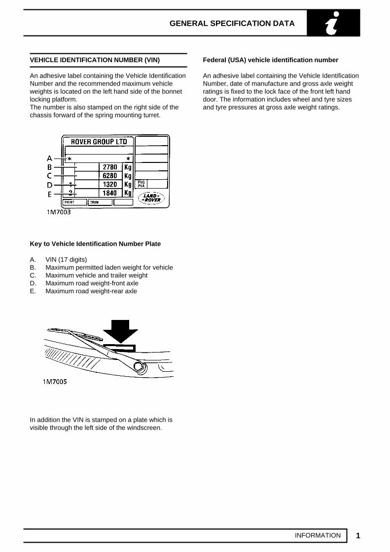
VEHICLE IDENTIFICATION NUMBER (VIN)
An adhesive label containing the Vehicle IdentificationNumber and the recommended maximum vehicleweights is located on the left hand side of the bonnetlocking platform.The number is also stamped on the right side of thechassis forward of the spring mounting turret.
Key to Vehicle Identification Number Plate
A. VIN (17 digits)B. Maximum permitted laden weight for vehicleC. Maximum vehicle and trailer weightD. Maximum road weight-front axleE. Maximum road weight-rear axle
In addition the VIN is stamped on a plate which isvisible through the left side of the windscreen.
Federal (USA) vehicle identification number
An adhesive label containing the Vehicle IdentificationNumber, date of manufacture and gross axle weightratings is fixed to the lock face of the front left handdoor. The information includes wheel and tyre sizesand tyre pressures at gross axle weight ratings.

04 GENERAL SPECIFICATION DATA NEW RANGE ROVER
2 INFORMATION
LOCATION OF IDENTIFICATION NUMBERS
Engine serial number - V8 engine
Stamped on a cast pad on the cylinder block, betweennumbers 3 and 5 cylinders.
NOTE: The engine compression ratio isstamped above the serial number.
Engine serial number - BMW Diesel engine
Stamped on the LH side of the cylinder block abovethe sump.
Main gearbox R380 - 5 speed
Stamped on a cast pad on the bottom right hand sideof the gearbox.
Automatic gearbox ZF4HP22
Stamped on a plate riveted to the bottom left handside of the gearbox casing.

GENERAL SPECIFICATION DATA
3INFORMATION
Transfer gearbox-Borg Warner
Stamped on a plate attached to the gearbox casing,between filler/level and drain plug.
Front and rear axle
Stamped on the left hand axle tubes.
Vehicle identification number (VIN)
Made up of 17 digits, these numbers are used toidentify manufacturer, model range, specification,body type, engine, transmission/steering, model year,plant and build sequence number and serve to identifythe vehicle.
This example shows the sequence:
European code
S AL LP A M J 7 M A
S EuropeAL UKLP Range RoverA European Spec.M 4 Door Station WagonJ 4.6 Litre Fuel Injection7 Manual right steeringM 1995 Model YearA Solihull
Federal (USA) code
S AL P V 1 2 4 2 S A
S EuropeAL UKP Range RoverV North America Spec.1 4 Door Station Wagon2 4.0 Litre fuel injection4 Automatic, Left Hand Steering2 Check DigitS 1995 Model YearA Solihull

04 GENERAL SPECIFICATION DATA NEW RANGE ROVER
4 INFORMATION
SAFETY INSTRUCTIONS
Jacking
The recommended jacking points are given inLIFTING AND TOWING.Always ensure that any liftingapparatus has adequate load and safety capacity forthe weight to be lifted. Ensure the vehicle is standingon level ground prior to lifting or jacking. Apply thehandbrake and chock the wheels.
Never rely on a jack as the sole means of supportwhen working beneath the vehicle. Use additionalsafety supports beneath the vehicle.
Do not leave tools, lifting equipment, spilt oil, etc.around or on the work bench area.
Precautions against damage
Always fit wing and seat covers before commencingwork. Avoid spilling brake fluid or battery acid onpaintwork. Wash off with water immediately if thisoccurs.
Disconnect the battery earth lead before starting work.See ELECTRICAL PRECAUTIONS.
Always use the recommended service tool or asatisfactory equivalent where specified.
Protect exposed bearing and sealing surfaces andscrew threads from damage.
Brake Hydraulics
WARNING: It is imperative that the correctbrake fittings are used and that threads ofcomponents are compatible.
Always use two spanners when slackening ortightening brake pipe or hose connections. Ensurethat hoses run in a natural curve and are not kinked ortwisted. Fit brake pipes securely in their retaining clipsand ensure that the pipe run cannot contact apotential chafing point.
Containers used for hydraulic fluid must be keptabsolutely clean. Do not store hydraulic fluid in anunsealed container; it will absorb water and in thiscondition will be dangerous to use. Do not allowhydraulic fluid to be contaminated with mineral oil, oruse a container which has previously containedmineral oil. Do not re-use fluid from the system.Always use clean brake fluid or a recommendedalternative to clean hydraulic components. Fit ablanking cap to an hydraulic union and a plug to itssocket after removal to prevent the ingress of dirt.Absolute cleanliness must be observed with hydrauliccomponents.
Engine coolant caps and plugs
Extreme care is necessary when removing enginecoolant caps and plugs when the engine is hot andespecially if it is overheated. To avoid the possibility ofscalding allow the engine to cool before attemptingcoolant cap or plug removal.
Cleaning components
Always use the recommended cleaning agent orequivalent.
Do not use degreasing equipment for componentscontaining items which could be damaged by the useof its process. Whenever possible clean componentsand the area surounding them before removal. Alwaysobserve scrupulous cleanliness when cleaningdismantled components.

GENERAL SPECIFICATION DATA
5INFORMATION
FUEL HANDLING PRECAUTIONS
The following information provides basic precautionswhich must be observed if fuel is to be handled safely.It also outlines the other areas of risk which must notbe ignored.
This information is issued for basic guidance only, andin any case of doubt, appropriate enquiries should bemade of your local Fire Officer or Fire Department.
Fuel vapor is highly flammable and in confined spacesis also very explosive and toxic.
When fuel evaporates it produces 150 times its ownvolume in vapor, which when diluted with air becomesa readily ignitable mixture. The vapor is heavier thanair and will always fall to the lowest level. It can readilybe distributed throughout a workshop by air current,consequently, even a small spillage of fuel is verydangerous.
Always have a fire extinguisher containing FOAM CO2
GAS, or POWDER close at hand when handling fuel,or when dismantling fuel systems and in areas wherefuel containers are stored.
WARNING: lt is imperative that the batteryis not disconnected during fuel systemrepairs as arcing at the battery terminal
could ignite fuel vapour in the atmosphere.Always disconnect the vehicle battery BEFOREcarrying out work on the fuel system.
Whenever fuel is being handled, transferred orstored, or when fuel systems are being dismantledall forms of ignition must be extinguished orremoved, any leadlamps used must be flame proofand kept clear of spillage.
No one should be permitted to repair componentsassociated with fuel without first having had fuelsystem training.
Hot fuel handling precautions
WARNING: Before commencing anyoperation requiring fuel to be drained fromthe fuel tank, the following procedure must
be adhered to:
1. Allow sufficient time for the fuel to cool, thusavoiding contact with hot fuels.
2. Vent the system by removing the fuel filler cap ina well ventilated area. Refit the filler cap until thecommencement of fuel drainage.
Fuel transfer
WARNING: Fuel must not be extracted ordrained from any vehicle while it isstanding over a pit.
The transfer of fuel from the vehicle fuel tank must becarried out in a well ventilated area. An approvedtransfer tank must be used according to the transfertank manufacturer’s instructions and local regulations,including attention to grounding of tanks.
Fuel tank removal
A FUEL VAPOUR warning label must be attached tothe fuel tank upon removal from the vehicle.
Fuel tank repair
Under no circumstances should a repair to any tankbe attempted.

04 GENERAL SPECIFICATION DATA NEW RANGE ROVER
6 INFORMATION
ELECTRICAL PRECAUTIONS
General
The following guidelines are intended to ensure thesafety of the operator whilst preventing damage to theelectrical and electronic components fitted to thevehicle. Where necessary specific precautions aredetailed in the relevant sections of this Manual whichshould be referred to prior to commencing repairoperations.
Equipment - Prior to commencing any test procedureon the vehicle ensure that the relevant test equipmentis working correctly and any harness or connectorsare in good condition. This particularly applies tomains lead and plugs.
WARNING: Before commencing work onan ignition system all high tensionterminals, adaptors and diagnostic
equipment for testing should be inspected toensure that they are adequately insulated andshielded to prevent accidental personal contactsand minimise the risk of shock. Wearers ofsurgically implanted pacemaker devices shouldnot be in close proximity to ignition circuits ordiagnostic equipment.
Polarity - Never reverse connect the vehicle batteryand always observe the correct polarity whenconnecting test equipment.
High Voltage Circuits - Whenever disconnecting live htcircuits always use insulated pliers and never allowthe open end of the ht lead to come into contact withother components, particularly ECU’s. Exercisecaution when measuring the voltage on the coilterminals while the engine is running, as high voltagespikes can occur on these terminals.
Connectors and Harness - The engine compartmentof a vehicle is a particularly hostile environment forelectrical components and connectors. Always ensurethese items are dry and oil free before disconnectingand connecting test equipment. Never forceconnectors apart either by using tools or by pulling onthe wiring harness. Always ensure locking tabs aredisengaged before removal and not orientation toenable correct reconnection. Ensure that anyprotective covers and substances are replaced ifdisturbed.
Having confirmed a component to be faulty, switch offthe ignition and disconnect the battery. Remove thecomponent and support the disconnected harness.When replacing the component keep oily hands awayfrom electrical connection areas and push connectorshome until any locking tabs fully engage.
Battery disconnecting
Before disconnecting the battery, switch off allelectrical equipment. If the radio is to be serviced,ensure the security code has been deactivated.
CAUTION: To prevent damage to electricalcomponents ALWAYS disconnect thebattery when working on the vehicle
electrical system. The earth lead must bedisconnected first and reconnected last. Alwaysensure that battery leads are routed correctly andare not close to any potential chafing points.
Battery charging
Recharge the battery out of the vehicle and keep thetop well ventilated. While being charged ordischarged, and for approximately fifteen minutesaferwards, batteries emit hydrogen gas. This gas isinflammable.
Always ensure any battery charging is well ventilatedand that every precaution is taken to avoid nakedflames and sparks.

GENERAL SPECIFICATION DATA
7INFORMATION
Jump starting
WARNING: Hydrogen and oxygen gasesare produced during normal batteryoperation. This gas mixture can explode if
flames, sparks or lighted tobacco are broughtnear battery. When charging or using a battery inan enclosed space, always provide ventilation andshield your eyes.
Keep out of reach of children. Batteries containsulphuric acid. Avoid contact with skin, eyes, orclothing. Also, shield eyes when working nearbattery to protect against possible splashing ofacid solution. In case of acid contact with skin,eyes, or clothing, flush immediately with water fora minimum of fifteen minutes. If acid is swallowed,drink large quantities of milk or water, followed bymilk of magnesia, a beaten egg, or vegetable oil.SEEK MEDICAL AID IMMEDIATELY.
To Jump Start - Negative Ground Battery
WARNING: To avoid any possibility ofinjury use particular care when connectinga booster battery to a discharged battery.
1. Position vehicles so that jump leads will reach,ensuring that vehicles DO NOT TOUCH,alternatively a fully charged slave battery may bepositioned on floor adjacent to vehicle.
2. Ensuring that ignition and all electricalaccessories are switched off, that parking brakeis applied and neutral is selected on a manualgearbox, with an automatic gearbox selectneutral (N) or park (P) and then connect thejump leads as follows;
A. Connect one end of first jumper cable to positive(+) terminal of booster battery.
B. Connect other end of first jumper cable topositive (+) terminal of discharged battery.
C. Connect one end of second jumper cable tonegative terminal of booster battery.
D. Connect other end of second jumper cable to agood earth point on the engine, NOT TONEGATIVE TERMINAL OF DISCHARGEDBATTERY. Keep jumper lead away from movingparts, pulleys, drive belts and fan bladeassembly.
WARNING: Making final cable connectioncould cause an electrical arc which ifmade near battery could cause an
explosion.

04 GENERAL SPECIFICATION DATA NEW RANGE ROVER
8 INFORMATION
3. If booster battery is installed in another vehicle,start engine and allow to idle.
4. Start engine of vehicle with discharged battery,following starting procedure in Owners’ Manual.
CAUTION: If vehicle fails to start within amaximum time of 12 seconds, switchignition off and investigate cause. Failing
to follow this instruction could result inirrepairable damage to catalysts.
5. Remove negative (-) jumper cable from theengine and then terminal of booster battery.
6. Remove positive (+) jumper cable from positiveterminals of booster battery and dischargedbattery.
Disciplines
Switch off ignition prior to making any connection ordisconnection in the system as electrical surgecaused by disconnecting ’live’ connections candamage electrical components.
Ensure hands and work surfaces are clean and free ofgrease, swarf, etc. as grease collects dirt which cancause tracking or high-resistance contacts.
When handling printed circuit boards, treat them asyou would a disc - hold by the edges only; note thatsome electronic components are susceptible to bodystatic.
Connectors should never be subjected to forcedremoval or refit, especially inter-board connectors, asdamaged contacts will cause short circuit andopen-circuit conditions.
Prior to commencing test, and periodically during test,touch a good earth (i.e. cigar lighter socket) todischarge body static as some electronic componentsare vulnerable to static electricity.
Grease for electrical connectors
All underbonnet and underbonnet connectors areprotected against corrosion by the application of aspecial grease on production. Should connectors bedisturbed in service, repaired or replaced, a grease ofthis type (available in 150gm tubes under Part No.BAU 5811) should again be applied.
NOTE: The use of other greases must beavoided as they can migrate into relays,switches etc., contaminating the contacts
and leading to intermittent operation or failure.

GENERAL SPECIFICATION DATA
9INFORMATION
BODY REPAIRS
Body shells are of welded construction and bolted tothe chassis frame. Front and rear sections of the shellare designed as ’energy absorbing’ zones. Thismeans they are designed to deform progressivelywhen subjected to impact in order to minimise thelikelihood of injury to vehicle occupants.
It is essential that design dimensions and strength arerestored in accident rectification. It is important thatneither structural weakness nor excessive localstiffness are introduced into the vehicle during body orchassis repair.
Repairs usually involve a combination of operationsranging from straightening procedures to renewal ofeither individual panels or panel assemblies. Therepairer will determine the repair method and thisdecision will take into account a balance of economicsbetween labour and material costs and the availabilityof repair facilities in both equipment and skills. It mayalso involve considerations of vehicles down-time,replacement vehicle availability and repair turn-aroundtime.
It is expected that a repairer will select the best andmost economic repair method possible, making use ofthe facilities available. The instructions given areintended to assist a skilled body repairer by expandingapproved procedures for panel replacement with theobjective of restoring the vehicle to a safe runningcondition and effecting a repair which is visuallyacceptable and which, even to the experienced eye,does not advertise the fact that it has been damaged.
This does not necessarily mean that the repairedvehicle will be identical in all respects with originalfactory build. Repair facilities cannot always duplicatemethods of construction used during production.
Operations covered in this Manual do not includereference to testing the vehicle after repair. It isessential that work is inspected and suspensiongeometry checked after completion and if necessary aroad test of the vehicle is carried out, particularlywhere safety related items are concerned.
Where major units have been disconnected orremoved, it is necessary to ensure that fluid levels arechecked and topped up when necessary. It is alsonecessary to ensure that the repaired vehicle is in aroadworthy condition in respect of tyre pressures,lights, washer fluid etc.
Body repairs often involve the removal of mechanicaland electrical units as well as associated wiring. SeeBODY and SRS sections.

04 GENERAL SPECIFICATION DATA NEW RANGE ROVER
10 INFORMATION
Taking into consideration the differences in bodystyles, steering and suspension systems as well asengine and suspension layouts, the location of thefollowing components as applicable to a particularvehicle is critical:
• Front suspension upper dampermountings.
• Front suspension or sub frame mountings.
• Engine mounting on RH and LH chassislongitudinals.
• Rear suspension upper damper mountings.
• Rear suspension mountings or lowerpivots.
• Steering rack mountings.
Additional points which can be used to checkalignment and assembly are:
• Inner holes in crossmember - side - mainfloor.
• Holes in front longitudinals.
• Holes in extension - side member - front.
• Holes in rear longitudinals.
• Holes in rear lower panels or extensionrear floor.
• Fuel tank mountings.
Apertures for windscreen, backlight, bonnet and doorscan best be checked by offering up an undamagedcomponent as a gauge.

GENERAL SPECIFICATION DATA
11INFORMATION
JACKING
The following instructions must be carried out beforeraising the vehicle off the ground.
1. Use a solid level ground surface.2. Apply parking brake.3. Select ’P’ or 1st gear in main gearbox.4. Select Low range in transfer gearbox.
CAUTION: To avoid damage occurring tothe under body components of the vehiclethe following jacking procedures must be
adhered to.
DO NOT POSITION JACKS OR AXLE STANDSUNDER THE FOLLOWING COMPONENTS.
Body structure Air suspension pipesBumpers Fuel linesBrake lines Front radius armsPanhard rod Steering linkageRear Trailing links Fuel tankEngine sump Gearbox bell housing
CAUTION: If supporting vehicle by thefront crossmember, the safety standsmust be postioned carefully to avoid
damage to air suspension pipes.
Vehicle jack
The jack provided with the vehicle is only intended tobe used in an emergency, for changing a tyre. DoNOT use the jack for any other purpose. Refer toOwner’s Manual for vehicle jack location points andprocedure. Never work under a vehicle supported bythe vehicle jack.
Hydraulic jack
A hydraulic jack with a minimum 1500 kg, 3,300 lbsload capacity must be used.
CAUTION: Do not commence work on theunderside of the vehicle until suitable axlestands have been positioned under the
axle.
Raise the front of the vehicle
1. Position cup of hydraulic arm under differentialcasing.
NOTE: The differential casing is notcentral to the axle. Care should be takenwhen raising the front road wheels off the
ground as the rear axle has less sway stiffness.

04 GENERAL SPECIFICATION DATA NEW RANGE ROVER
12 INFORMATION
2. Raise front road wheels to enable an axle standto be installed under left hand axle tube.
3. Position an axle stand under right hand axletube, carefully lower jack until axle sits securelyon both axle stands, remove trolley jack.
4. Before commencing work on underside ofvehicle re-check security of vehicle on stands.
5. Reverse procedure when removing vehicle fromstands.
Raise rear of vehicle
1. Position cup of hydraulic arm under differentialcasing.
2. Raise vehicle to enable axle stands to beinstalled under left and right hand axle tubes.
3. Lower jack until axle sits securely on axlestands, remove trolley jack.
4. Before commencing work on underside ofvehicle re-check security of vehicle on stands.
5. Reverse procedure when removing vehicle fromstands.

GENERAL SPECIFICATION DATA
13INFORMATION
HYDRAULIC VEHICLE RAMP (FOUR POST)
Use only a ’drive on’ type ramp which supports vehicleby its own road wheels. If a ’wheel-free’ condition isrequired, use a ’drive on’ ramp incorporating a’wheel-free’ system that supports under axle casings.Alternatively, place vehicle on a firm, flat floor andsupport on axle stands.
TWO POST VEHICLE RAMPS
The manufacturer of RANGE ROVER VEHICLESDOES NOT recommend using ’Two Post’ rampsthat employ four adjustable support arms. Theseare NOT considered safe for Range Rovervehicles.If vehicle is installed on a Two Post rampresponsibility for safety of vehicle and personnelperforming service operations is in the hands ofthe Service Provider.
DYNAMOMETER TESTING - VEHICLES WITHANTI-LOCK BRAKES (ABS)
WARNING: Do not attempt to test ABSfunction on a dynamometer
Four wheel dynamometers
NOTE: Before testing a vehicle on a fourwheel dynamometer disconnect the valverelay. See Electrical Trouble Shooting
Manual.The ABS function will not work, the ABS warninglight will illuminate. Normal braking will beavailable.
Provided that front and rear rollers are rotating atidentical speeds and that normal workshop safetystandards are applied, there is no speed restrictionduring testing except any that may apply to the tyres.
Two wheel dynamometers
IMPORTANT: Use a four wheel dynamometer forbrake testing if possible.
NOTE: ABS will not function on a twowheel dynamometer. The ABS light willilluminate during testing. Normal braking
will be available.
If brake testing on a single rig is necessary it must becarried out with propeller shaft to the rear axleremoved, AND neutral selected in BOTH main andtransfer boxes.
If checking engine performance, the transfer box mustbe in high range and drive shaft to stationary axleremoved.

04 GENERAL SPECIFICATION DATA NEW RANGE ROVER
14 INFORMATION
EMERGENCY TOWING
CAUTION: The New Range Rover haspermanent four-wheel drive. The followinginstructions must be adhered to when
towing:-
Towing the vehicle on four wheels
If it is necessary to recover the vehicle by towing onall four wheels, ’Transfer neutral’ MUST be selected.
1. With the starter key removed, insert a fuse of 5amps or more in fuse position ’11’ in the RH seatfuse box.
2. Turn the starter switch to position ’2’; the transferbox will now automatically select neutral.
3. Wait until the message centre displays’TRANSFER NEUTRAL’ and then turn thestarter switch off, position ’0’.
4. Turn the starter switch to position ’1’ to unlockthe steering and leave in this position while thevehicle is being towed.
5. Secure tow rope to the front towing eye.6. Release the parking brake.
CAUTION: The brake servo and powerassisted steering system will not befunctional without the engine running.
Heavier pedal pressure will be required to applythe brakes, the steering system will requiregreater effort to turn the front wheels.The vehicle tow connection should be used onlyin normal road conditions.
CAUTION: DO NOT remove the starter keyor turn the switch to position ’0’ when thevehicle is in motion.
7. To reactivate the transfer box after towing, turnthe starter switch off to position ’0’ and removethe fuse from position ’11’. On automaticvehicles the transfer box will automaticallyengage the Low or High gear range.
8. On manual vehicles, first press the rangechange switch. The transfer box will then engagethe Low or High gear range.
Suspended tow by breakdown vehicle
CAUTION: To prevent vehicle damage,front or rear propeller shaft MUST beremoved, dependant upon which axle is
being trailed.
9. To facilitate reassembly, first mark the propellershaft drive flanges at transfer box and axle.
10. Remove propeller shaft fixings and lift shaft fromvehicle.
11. If the front axle is to be trailed turn ignition key toposition ’1’ to release the steering lock.
CAUTION: If the rear axle is to be raised,the steering wheel and/or linkage MUST besecured in a straight ahead position. DO
NOT use the steering lock for this purpose.

GENERAL SPECIFICATION DATA
15INFORMATION
TRANSPORTING THE VEHICLE BY TRAILER
If the vehicle should require transporting on a trailer orthe back of a lorry, the air suspension must be set to’ACCESS’ before being lashed. See FRONTSUSPENSION, Description and operation.
Lashing eyes are provided on the front and rearchassis cross members to facilitate the securing of thevehicle, as shown.
CAUTION: DO NOT secure lashing hooksor trailer fixings to any other part of thevehicle.
CAUTION: If the air suspension cannot beset to the ’ACCESS’ position, then thevehicle must be lashed by its wheels and
not the lashing eyes.
Install vehicle on the trailer and apply park brake.Select neutral in main gearbox; this will preventdamage to the parking pawl of the automatic gearbox.

04 GENERAL SPECIFICATION DATA NEW RANGE ROVER
16 INFORMATION
VEHICLE DIMENSIONS
mm inchesOverall length 4713................................................................... 185.6
with Europe/UK towbar 4804........................................... 189.1Overall width 1889.................................................................... 74.4Overall height at standard profile 1817.5..................................... 71.6Wheelbase 2745....................................................................... 108.1Track:
Front 1540........................................................................ 60.6Rear 1530........................................................................ 60.2
Turning circle between kerbs 1189 mm (39 ft)...........................................
STEERING
Power steering boxMake/type ZF type 8055, recirculating ball steering gear........................................................................Steering wheel turns, lock-to-lock 3.2....................................
Steering pumpMake/type:
V8 engine ZF type 7691, vane type................................................................Diesel engine ZF type7681, vane type..........................................................
Steering geometrySteering wheel diameter 406.4mm (16 in.)..................................................Toe-out measurement 0.6 to 1.80mm (0.02 - 0.07 in.)......................................................Toe-out included angle 0˚ 5’ to 0˚ 15’.....................................................Camber angle 0˚.................................................................. NOTE:Castor angle 4˚..................................................................... Check atSwivel pin inclination static 8˚............................................... kerbweight

GENERAL SPECIFICATION DATA
17INFORMATION
VEHICLE WEIGHTS AND PAYLOAD
When loading a vehicle to its maximum (Gross Vehicle Weight), consideration must be taken of the vehicle kerbweight and the distribution of the payload to ensure that axle loadings do not exceed the permitted maximumvalues. It is the customer’s responsibility to limit the vehicle’s payload in an appropriate manner such that neithermaximum axle loads nor Gross Vehicle Weight are exceeded.
GROSS VEHICLE WEIGHT
Petrol Models Diesel Models
Front Axle 1320 kg (2910 lb).............................. 1320 kg (2910 lb).............Rear Axle 1840 kg (4056 lb).............................. 1840 kg (4056 lb).............Total 2780 kg (6129 lb)...................................... 2780 kg (6129 lb).............Maximum Payload 603 kg (1329 lb)................. 596 kg (1314 lb)...............
EEC KERB WEIGHT AND DISTRIBUTION
4.0 Litre Manual 4.0 Litre Automatic 4.6 Litre Automatic
EEC Kerb Weight 2090 kg (4607 lb).................. 2100 kg (4629 lb)............. 2220 kg (4894 lb).............Front Axle 1095 kg (2414 lb).............................. 1100 kg (2425 lb)............. 1165 kg (2568 lb).............Rear Axle 995 kg (2193 lb).............................. 1000 kg (2204 lb)............... 1055 kg (2325 lb).............
2.5 Diesel Manual 2.5 Diesel Automatic
EEC Kerb Weight 2115 kg (4662 lb).................. 2130 kg (4695 lb).............Front Axle 1110 kg (2447 lb).............................. 1120 kg (2469 lb).............Rear Axle 1005 kg (2215 lb).............................. 1010 kg (2226 lb).............
NOTE: EEC KERB WEIGHT is the minimum vehicle specification plus full fuel tank and 75 kg(165lb) driver.
NOTE: GROSS VEHICLE WEIGHT is the maximum all-up weight of the vehicle including driver,passengers, and equipment. This figure is liable to vary according to legal requirements in certaincountries.
NOTE: MAXIMUM ROOF RACK LOAD (including weight of rack) 75 kg (165 lb) must be included intotal vehicle weight.

GENERAL SPECIFICATION DATA
1BODY DIMENSIONS
ALIGNMENT JIG DIMENSIONS
1. 1190mm (46.8in.)2. 1709mm (67.3in.)3. 2527mm (99.6in.)4. 4173mm (164.4in.)5. 717mm (28.3in.)6. 982.5mm (38.7in.)7. 1328mm (52.3in.)8. 1697mm (66.9in.)9. 3159mm (124.5in.)
10. 1340mm (52.8in.)11. 1302mm (51.3in.)12. 665mm (26.2in.)
13. 1400mm (55.2in.)14. 2364mm (93.1in.)15. 1803mm (71.0in.)
A = No. 1 body mount RH and LHB = Front spring seat RH and LHC = No. 2 body mount RH and LHD = Front crossmember piercing RH and LHE = Front radius arm mounting bracket RH and LHF = No. 3 body mount RH and LHG = Rear composite link mounting bracket RH and
LHH = No. 5 body mount RH and LH
All dimensions taken at centre line of set screw or set screw hole.

04 GENERAL SPECIFICATION DATA NEW RANGE ROVER
2 BODY DIMENSIONS
Straightening
Whenever possible, structural members should becold straightened under tension. Do not attempt tostraighten with a single pull, but rework the damagedarea using a series of pulls, releasing tension betweeneach stage and using the opportunity to checkalignment.
Body jig
Unless damage is limited to cosmetic panels, all repairwork to body members must be carried out on a bodyjig, to ensure that impact damage has not spread intomore remote parts of the body structure. Mounting ona jig will also ensure that the straightening and panelreplacement procedures do not cause furtherdistortion. If original dimensions cannot besatisfactorily restored by these methods, damagedstructural members should be replaced. Damagedareas should be cut away using a high speed saw,NOT an oxy-acetylene torch.
As a rule, body dimensions are symmetrical about thecentre line. A good initial check for distortion istherefore to measure diagonally and to investigateapparent differences in dimensions.
Inspection
Every accident produces individual differences indamage. Each repair is influenced by the extent of thedamage and by the facilities and equipment availablefor its rectification.
Most accident damage can be visually inspected andthe approximate extent of the damage assessed.Sometimes deformation will extend beyond the areaof direct damage, and the severity of this must beaccurately established so that steps may be taken torestore critical body components to their originaldimensions.
An initial check of critical dimensions can be carriedout by means of drop checks or (preferably) trammels.Gauges are available which will check accurately forbody twist. Where repairs necessitate renewal of acritical body component it is recommended that abody jig is used.

GENERAL SPECIFICATION DATA
1COMPONENT LOCATION
ELECTRONIC CONTROL UNITS
1. Engine control module (ECM) (at RH of enginebay)
2. ABS ECU (behind access plate at LH ofdashboard)
3. Cruise control ECU (behind fascia closing panel)
4. Diagnostic control unit (on centre tunnel)5. Electronic suspension ECU (beneath LH front
seat)6. Body electrical control module (BeCM) (beneath
RH front seat)
The electronic control units fitted to Land Rovervehicles make it advisable to follow suitableprecautions prior to carrying out welding repairoperations. Harsh conditions of heat and vibrationmay be generated during these operations whichcould cause damage to the units. See ELECTRICALPRECAUTIONS section.
In particular, it is essential to follow the appropriateprecautions when disconnecting or removing the SRSdiagnostic unit. See SUPPLEMENTARY RESTRAINTSYSTEM, Precautions section.

GENERAL SPECIFICATION DATA
1SEALING AND CORROSION PROTECTION
APPROVED MATERIALS
MATERIAL MANUFACTURER
3M:Bodygard (08158, 08159)Weld Thru’ Sealer (08625)Drip-Chek Clear (08401)Drip-Chek Heavy (08531)Flexseal Polyurethane Seam Sealer (08684, 08689, 08694)Polyurethane Sealer (sachet) (08703, 08783, 08788)Super Seam Sealer (08537)Sprayable Sealer (08800, 08823)Bolted Panel Sealer (08572)Body Caulking (08568)Windscreen Sealer (08509)Gurit-Essex:Betafill Clinch and Brushable Sealer (Black) (10215)Betafill Clinch and Brushable Sealer (Grey) (10211)Betafill Clinch and Brushable Sealer (White) (10220)Clinch Joint and Underbody Coating (Grey) (10101)Clinch Joint and Underbody Coating (Beige) (10707)
SEALERS Kent Industries:Leak-Chek Clear Putty (10075)PPG:Polyurethane Seam Sealer (6500)Polyurethane Seam Sealer (92)Terostat Preformed Strip (V11)Terolan Light Seam SealerTeroson:Terolan Special Brushable Seam SealerTerostat 1K PU Seam Sealer (SE20)Terostat Sprayable Seam Sealer (9320)Unipart:Promatch Sealing Compound (UBS605, UBS606, UBS607)Promatch Bolted Panel Sealer (UBS111)Wurth:Sealing Compound (890100, 890101, 890102, 890103, 890104,890105, 890106)Astrolan Engine Bay Wax & Cosmetic Wax (DA3241/DA3243)Weld Thru’ Coating (05913)

04 GENERAL SPECIFICATION DATA NEW RANGE ROVER
2 SEALING AND CORROSION PROTECTION
Approved materials (continued)
MATERIAL MANUFACTURER
3M:Automotive Structural Adhesive (08120)Aerosol Auto Adhesive (Trim) (08080)
ADHESIVES Spray 80 Adhesive (08090)Ciba-Geigy:Structural Two-Part Epoxy (XB5106/XB5107)
3M:Spray Schutz (08877)Body Schutz (08861)Stone Chip Coating (Textured) (08868, 08878, 08879)Stone Chip Coating (Smooth) (08158, 08160, 08886)Croda:Crodapol Brushable Underbody Sealer (PV75)
UNDERBODY COATINGS Underbody Wax (PW61)Dinol:Tectacote Underbody Wax (205)Teroson:Terotex Underseal CP02 (9320)Unipart:Promatch Underbody Schutz (UBS410)Promatch Underbody Wax (PW61)
3M:Inner Cavity Wax (Transparent) (08909, 08919, 08929)Inner Cavity Wax (Amber) (08901, 08911, 08921)Dinol:Engine Bay & Cosmetic Wax/Lacquer (PW197)
WAX COATINGS Cavity Wax (PW57)Engine Bay Cosmetic Wax/Lacquer (4010)Unipart:Promatch Cavity Wax (UBS508)

GENERAL SPECIFICATION DATA
3SEALING AND CORROSION PROTECTION
Approved materials (continued)
MATERIAL MANUFACTURER
3M:Zinc Spray (09113)
WELD-THROUGH PRIMERS ICI:Zinc Rich Primer (P-565 634)
3M:Flexible Parts Repair Material (05900)Cleaner and Wax Remover (1 litre) (08984)Waterproof Cloth Tape (Y387/YS3998)
GENERAL MATERIALS Teroson:Sprayable Aerosol, Water Shedder RepairUnipart:Waterproof Tape (GWS121)Urethane Butyl Tape (BHM605)

04 GENERAL SPECIFICATION DATA NEW RANGE ROVER
4 SEALING AND CORROSION PROTECTION
MATERIALS APPLICATIONS
Joint Types:
1. Between bolted panels2. Between bolted panel edges3. Between spot welded panels4. Between spot welded panel edges5. Between bonded panels6. Between bonded panel edges
7. Clinch joints (type a)8. Clinch joints (type b)9. Clinch joints (type c)
10. Gaps between panels (type a)11. Gaps between panels (type b)

GENERAL SPECIFICATION DATA
5SEALING AND CORROSION PROTECTION
Materials applications (continued)
MANUFACTURER MATERIAL/JOINT TYPE
ICI P565 634 Zinc rich primer. Between bolted and spot welded panels,3M 09113 clinch joints (type a). Brush or spray application.
Teroson Terostat V11 Preformed strip. Between bolted panels. Hand application.
Kent Industries 100753M 084013M 085723M 086843M 086893M 086943M 08703 Seam sealer. Between bolted panel edges. Applicator gun/by hand.3M 087833M 08788PPG Polyurethane 6500Teroson 92Terolan LightTerostat 1K PUTerostat 9320Unipart UBS 605/6/7Wurth 890100/1/2/3/4/5/6
Ciba-Geigy XBS106/7 Structural adhesive. Between spot welded and bonded panels,3M 08120 clinch joints (type a). Applicator gun, caulking gun.
3M 08625 Seam sealer. Between spot welded panels. Applicator gun.
Kent Industries 100753M 084013M 08684PPG 6500Teroson 92 Seam sealer light. Between spot welded panel edges.Terolan Light Hand applicator gun.Terostat 9320Terostat 1K PUUnipart UBS605/6/7Wurth 890100/1/2/3/4/5/6

04 GENERAL SPECIFICATION DATA NEW RANGE ROVER
6 SEALING AND CORROSION PROTECTION
Materials applications (continued)
MANUFACTURER MATERIAL/JOINT TYPE
Ciba-Geigy XBS106/7 Structural adhesive. Between bonded panels. Caulking gun.3M 08120
PPG 6500Teroson 92Terostat 9320 Semi-structural adhesive/anti-flutter material. BetweenUnipart UBS605/6/7 bonded panels. Caulking gun.Wurth 890100/1/2/3/4/5/6
Kent Industries 100753M 084013M 08694PPG 6500 Seam sealer light. Between bonded panel edges.Teroson 92 Hand applicator gun.Teroson LightTeroson 9320Terostat 1K PUUnipart UBS605/6/7Wurth 890100/1/2/3/4/5/6
Gurit-Essex 10211Gurit-Essex 10215Gurit-Essex 102203M 08531 Seam sealer. Clinch joints (type b). Caulking gun.3M 085373M 087033M 087833M 08788

GENERAL SPECIFICATION DATA
7SEALING AND CORROSION PROTECTION
Materials applications (continued)
MANUFACTURER MATERIAL/JOINT TYPE
Kent Industries 100753M 08401 Seam sealer light. Clinch joints (type c). Caulking gun,3M 08531 hand applicator gun.Teroson Terolan Light
Kent Industries 100753M 084013M 086843M 086893M 08694 Seam sealer light. Gaps between panels (type a).PPG 6500 Hand applicator gun.Teroson 92Terolan LightTerostat 1K PUUnipart UBS605/6/7Wurth 890100/1/2/3/4/5/6
Kent Industries 10075Kent Industries Putty3M 084013M 085313M 085683M 086843M 08689 Seam sealer heavy. Gaps between panels (type b). Hand3M 08694 applicator gun, applicator tube or caulking gun.PPG 6500Teroson 92Terolan LightTerostat 9320Terostat 1K PUUnipart UBS605/6/7Wurth 890100/1/2/3/4/5/6Gurit-Essex 10101Gurit-Essex 107073M 08537
Gurit-Essex 10211Gurit-Essex 10215 Brushable sealer. Overlap joints (e.g. floor pans).Gurit-Essex 10220 Brush.Teroson Brushable Sealer
Croda PW573M Cavity Waxes Cavity wax. Box members, sills. Injection equipment.Unipart UBS508

04 GENERAL SPECIFICATION DATA NEW RANGE ROVER
8 SEALING AND CORROSION PROTECTION
Materials applications (continued)
MANUFACTURER MATERIAL/JOINT TYPE
Croda PV753M 088613M 08877 Underbody sealing coat. Underbody. Schutz gun, aerosol.Teroson Terotex UndersealUnipart UBS410
Croda PW61Dinol 205 Underbody wax coat. Underbody. Spray gun or brush.Unipart PW61
Astors 3241/3Croda PW197 Engine bay cosmetic wax/lacquer. Spray gun or brush.Dinol 4010
3M Stone Chip Anti-chip coating. Sill panels. Schutz gun.Coatings
3M 05900 Plastic Two-pack material. Repair of plastic parts.Parts Repair Material Spreader or palette knife.
3M 08509 Dry glazed windscreen sealer. Applicator gun.
Unipart BHM605 Urethane butyl sealer for direct glazing. Caulking gun.
3M YS39983M Y387 Waterproof tape for sealing apertures. Hand application.Unipart GS121
Evode Evo-Stik3M 080303M 08034 Trim fixing adhesive. Brush or aerosol.3M 080803M 08090
3M 08984 Adhesive cleaner/wax remover. Hand application with cloth.

GENERAL SPECIFICATION DATA
9SEALING AND CORROSION PROTECTION
APPLICATION EQUIPMENT
SATA Schutz Gun Model UBE
Specifications:Air consumption 200 litres/min. (7cu/ft. min.) @ 45PSI...............................................................Weight 660grams (23.3oz)..............................................................................Manufactured and supplied by:Sata GmbhMinden Industrial Ltd.16 Greyfriars RoadMoreton HallBury St. EdmundsSuffolk IP32 7DXTel. (01284) 760791
The Sata Schutz Gun is approved for the re-treatmentof vehicle underbody areas with protective coatings assupplied in 1-litre (1.76pt.), purpose-designed,’one-way’ containers. The screw thread fitting (femaleon the gun) will fit most Schutz-type packs.
Full operating details are supplied with the equipment.
NOTE: Always clean gun after use with theappropriate solvent.
Sata HKD1 Wax Injection EquipmentThe Sata HKD1 is approved by Rover for use in allcavity wax re-treatment operations. The equipmentcomprises a high quality forged gun with 1-litrecapacity pressure feed container, a flexible nylonlance, 1100mm (43.3in.) straight steel lance andhooked wand lance. A quick-change coupling is astandard fitting to enable lances to be easilyinterchanged. The lances each have their own spraypattern characteristics to suit the type of box sectionto be treated.
The Sata HKD1 is covered by a 12 month warranty.All replacement parts and service are obtainable fromthe suppliers.

04 GENERAL SPECIFICATION DATA NEW RANGE ROVER
10 SEALING AND CORROSION PROTECTION
Cooper Pegler Falcon Junior Pneumatic (Airless)Manufacturer and supplier:Cooper Pegler & Co. Ltd.Burgess HillSussex RH15 9LATel. 04 446 42526
Intended primarily for applying transit wax, the FalconJunior pneumatic sprayer has a 5-litre (1 gal.)container with integral hand pump. This high qualityunit provides a simple and effective means of waxspraying without the need for compressed air oradditional services.
A selection of nozzles, lances and hoses together witha trigger valve assembly incorporating a filter enablethe sprayer to be used in a variety of applications.These include general maintenance, wax injection andpaint application. All parts are fully replaceable andinclude a wide range of nozzle configurations.
The Falcon Junior is fitted with Viton seals and isguaranteed for 12 months.
3M Application EquipmentManufacturer:3M UK PLCAutomotive Trades Group3M HousePO Box 1Market PlaceBracknellBerks. RG12 1JUTel. (01344) 858611
All 3M equipment is available from local trade factorsor 3M refinishing factors.
3M Caulking Gun 08002A lightweight, robust metal skeleton gun designed toaccommodate 325mm (12.8in.) cartridge fordispensing sealants etc. This gun facilitates rapidcartridge loading and features a quick-release leverfor accurate material ejection and cut-off control.
3M Pneumatic Cartridge Gun 08012An air line fed gun for application of 3M cartridgeproducts. Excellent ease of application for a smoothsealant bead, and incorporates a regulator valve foradditional control.
Other 3m applicator equipment available:
3M Pneumatic Applicator GunsAir line fed gun for application of 3M sachet sealers(Part No. 08006 for 200ml [6fl/oz.] and 310ml [9fl/oz.]sachets, and Part No. 08007 for all size sachetsincluding 600ml [18fl/oz.]).
3M Applicator Gun 08190For application of 3M Structural Adhesive 08120.
3M Inner Cavity Wax Applicator GunFeatures 750mm (29.6in.) flexible tube and using1-litre (1.76pt.) canisters, this approved equipment isavailable from all 3M refinishing factors.
Other 3m applicator equipment available:
Heavy Duty Manual Gun.

GENERAL SPECIFICATION DATA
11SEALING AND CORROSION PROTECTION
MATERIALS GUIDE
3M Automotive Structural Adhesive 08120a two-part epoxy structural adhesive, with ’automix’twin-cartridge dispenser. For doorskin and for bondingpanel stiffeners. Supplied as twin pack for use in smalltrigger gun (No. 08190).
3M Bolted Panel Sealer 08572Preformed strip 20mm (0.8in.) wide x 2mm (0.08in.)thick supplied in 4.6 metre (81.2in.) reels.Permanently flexible with good adhesion, for sealingwing to body joints and other bolted or riveted panels.
3M Body Caulking 08568Thumb-applied sealing compound supplied in60-packs of preformed strips 300mm (11.8in.) long x6mm (0.24in.) wide. For sealing large openings andfissures. Non-hardening, does not dry out or crack,can be overpainted immediately.
3M Drip-Chek Sealer Heavy 08531
For use on vertical fissures and seams up to 3mm(0.12in.) wide for a firm but flexible seal which will notharden or shrink. Self-levelling, will not sag on verticalsurfaces. May be worked with a tool or smoothed witha wet finger.
Supplied in 150ml (4.5fl/oz.) tubes.
3M Drip-Chek Sealer Clear 08401An easily flowing sealer similar to Drip-Chek Heavybut of clear consistency. Ideal for an almost invisiblespot weal over finished paintwork. Can be overpaintedor even mixed with paint colour to form a self-colouredsealant.
Supplied in 150ml (4.5fl/oz.) tubes.
3M Super Seam Sealer 08537A brushable sealer designed to simulate originalfactory-applied sealer on all overlap joints such asfloor pans, wheel arches, boot and load space seamsand fuel filler cap surrounds. Resistant to oil, petroland water. Should be brushed on in ONE directiononly for best results.
WARNING: Must be stored underconditions applicable to highly flammablematerials.
3M Flexseal 08684, 08689 AND 08694A high solid, non-shrinking, polyurethane body sealerfor use in either a hand gun or pneumatic applicatorgun. Excellent adhesion and sealing properties.Resistant to oil, petrol and water. Supplied in 310ml(9fl/oz.) cartridges and in a choice of black, white orgrey.
3M Polyurethane Sachet Sealer 08703, 08783,08788Similar to Flexseal polyurethane but available incollapsible foil sachets in 310ml (9fl/oz.) and 600ml(18fl/oz.) sizes with a choice of three colours: black,grey or white.
3M Windscreen Sealer 08509Non-hardening sealant for dry-glazed,weatherstrip-type windscreens. Applied with applicatorgun.
Supplied in 310ml (9fl/oz.) cartridges.
3M Spray Schutz 08877, Body Schutz 08861Flexible, rubberised, fast-drying coating which dries toa black textured finish.
Spray Schutz supplied in 600ml (18fl/oz.) aerosols.Spray Schutz and Body Schutz also supplied in 1-litre(1.76pt.) cartridges to fit Schutz Gun.

04 GENERAL SPECIFICATION DATA NEW RANGE ROVER
12 SEALING AND CORROSION PROTECTION
3M Flexible Parts Repair Material 05900A fast-curing, two-part system for repairing minordamage to plastic bumpers, spoilers, valances etc.Dries in 30 mins.
Supplied as two-pack 320ml (10fl/oz.) kit.
3M Weld Thru’ SEALER 08625For anti-corrosion protection between spot weldedpanels. Brush application.
Supplied in 1-litre (1.76pt.) canisters.
3M BodygardRubber-based, stone chip protective coating forpanels. Fast drying, low bake compatible and may beoverpainted. Varying textures obtainable dependingon type of finish required. Available in black (1-litre[1.76pt.] pack 08858, aerosol 08158) or grey (1-litre[1.76pt.] pack 08859, aerosol 08159).
3M Inner Cavity WaxFor protective coating on inner panels. Excellentanti-corrosion properties. Available in transparent oramber consistencies, and 1-litre (1.76pt.) canister or500ml (0.88pt.) aerosol packs.
3M Zinc Spray 09113Anti-corrosive coating for spot welding applications onjoints and seams. Supplied in 500ml (0.88pt.) aerosolpacks.
3M Waterproof Cloth Tape YS3998Black waterproof tape for sealing door apertures andbody box section access holes. Long-lasting,moisture-resistant adhesive will withstand immersionin water.
Supplied in 50-metre (164.2ft.) rolls in a variety ofwidths.
3M Adhesive Cleaner and Wax Remover 08984For surface preparation before application of mosttypes of adhesive, coating and sealant, also forremoval of tar, silicone polish, wax, grease and oil.Non-staining. May also be used for cleaning adhesiveremnants from sander disc backing pads.
Supplied in 1-litre (1.76pt.) canisters.

ELECTRONIC AIR SUSPENSION
1DESCRIPTION AND OPERATION
ELECTRONIC AIR SUSPENSION - EAS
Description
The Range Rover concept of air supension is alreadywell established, the system fitted to the New RangeRover is broadly similar. Progressive developmenthas resulted in added features to improve the controland operation of the system.Air springs provide a soft and comfortable feel to theride of the vehicle. The use of a microprocessor tocontrol the system exploits the advantages of airsuspension.The system provides a near constant ride frequencyunder all load conditions resulting in:
• Improved ride quality
• Consistency of ride quality
• Constant ride height
• Improved headlamp levelling
The system provides five ride height settings plus selflevelling. Each setting is automatically maintained atthe correct height by the system logic with theminimum of driver involvement. Vehicle height issensed by four rotary potentiometer type heightsensors. Height information from each sensor signalsthe electronic control unit (ECU) to adjust each airspring by switching the solenoid valves to hold, add orrelease air.
The five height settings are as follows:
Standard: Profile
Low profile: 25 mm (1 in.) below standard.
Access: 65 mm (2.6 in.) below standard. Crawl: It ispossible to drive at the access ride height at speedsless than 32 km/h (20 mph), where headroom isrestricted.
High profile: 40 mm (1.6 in.) above standard.
Extended profile: 70 mm (2.75 in.) above standard.This setting is not manually selectable.
Self levelling
On a coil sprung vehicle the effect of adding weight isfor the vehicle to lean either from front to back or sideto side unless the increased weight is evenly spread.With air suspension, the system detects this body leanand automatically compensates for it. The vehicle willself level to the lowest corner height for 20 secondseach time the driver exits vehicle and closes thedoors.The system will check vehicle height every 6 hoursand make minor corrections, not exceeding 8 mm,(0.31 in) as necessary.When unloading through the tailgate the system willself level to compensate for the decreased load afterdoor closure.
NOTE: If the vehicle is parked on unevenground or with a wheel or wheels on thekerb, self levelling will lower the vehicle to
the lowest spring height.
CAUTION: The underside of the vehiclemust be kept clear of any obstacles whilethe vehicle is parked, as self levelling may
result in a reduced trim height.
WARNING: Before commencing workwhich requires access to the underside orwheel arches of the vehicle, the
suspension must be allowed to relevel.Relevelling is achieved by opening and closing ofany of the side doors, while all other doors andtail gate remain closed, and the ignition off.
EAS must be set in ’high-lock’ using TestBook,during any work which does not require chassisto axle displacement. This will hold thesuspension in extended profile position, untilreset by TestBook.

60 FRONT SUSPENSION NEW RANGE ROVER
2 DESCRIPTION AND OPERATION
LOCATION OF COMPONENTS
Key to location of components
1. Electrical control unit2. Compressor3. Air dryer4. Valve block5. Reservoir6. Height sensors front
7. Height sensors rear8. Front air spring9. Rear air spring
10. Relays, fuses11. Driver controls

ELECTRONIC AIR SUSPENSION
3DESCRIPTION AND OPERATION
DESCRIPTION OF COMPONENTS
Electrical control unit - ECU
The ECU is located underneath the front left handseat. The ECU maintains the requested vehicle rideheight by adjusting the volume in each air spring. It isconnected to the cable assembly by a 35 wayconnector. To ensure safe operation the ECU hasextensive on board diagnostic and safety features.The ECU must be replaced in case of failure.
Air compressor
NOTE: The air compressor and valve blockare contained in the under bonnet unitmounted on the left hand inner wing.
The air compressor provides system pressure. Athermal switch is incorporated which cuts outcompressor operation at 120˚ C. An air filter is fitted tothe compressor head. The filter is renewed every40,000 kms. (24,000 miles).
Air dryer
The air dryer is connected into the air line between thecompressor and reservoir. It is mounted on the engineair cleaner box. The dryer removes moisture frompressurised air entering the system. All air exhaustedfrom the system passes through the dryer in theopposite direction. The air dryer is regenerative in thatexhaust air absorbs moisture in the dryer and expels itto atmosphere.
The air dryer is non-servicable, designed to last thelife of the vehicle. However, if any water is found inthe system, the air dryer must be replaced.
CAUTION: If the air dryer is removed fromthe vehicle the ports must be plugged toprevent moisture ingress.
Valve block
The valve block controls the direction of air flow. Airflow to and from the air springs is controlled by sevensolenoid operated valves, one for each spring plus aninlet, exhaust and outlet. In response to signals fromthe ECU, the valves allow high pressure air to flow inor out of the air springs according to the need toincrease or decrease pressure. A diaphragm valveoperated by the solenoid outlet valve ensures that allexhausted air passes through the air dryer.
Mounted on the valve block is a pressure switch whichsenses air pressure and signals the ECU to operatethe compressor when required.The compressor willoperate when the pressure falls between 7.2 and 8.0bar. It will cut out at a rising pressure of between 9.5and 10.5 bar.
The valve block contains the following serviceablecomponents: solenoid coils 1 to 6, drive pack andpressure switch.The valve block must only be dismantled after thecorrect diagnosis procedure.
Reservoir
The 10 litre reservoir is mounted on the right handside of the chassis. One connection acts as air inletand outlet for the rest of the system. The reservoirstores compressed air between set pressure levels.The reservoir drain plug requires removing to checkfor moisture in the system every 40,000 kms. (24,000miles).
Height sensors
Four potentiometer type height sensors signal vehicleheight information to the ECU. The potentiometers aremounted on the chassis and activated by links to thefront radius arms and rear trailing links. A heightsensor must be replaced in case of failure, and thevehicle recalibrated using TestBook.

60 FRONT SUSPENSION NEW RANGE ROVER
4 DESCRIPTION AND OPERATION
Air springs - front and rear
The air springs consist of the following components:
1. Top plate2. Rolling rubber diaphragm3. Piston
Front and rear air springs are of similar constuctionbut are NOT interchangeable. The diaphragm is notrepairable, if failure occurs the complete air springmust be replaced
Driver controls
Mounted in the centre of the dashboard, the drivercontrols consist of an UP/DOWN switch, an INHIBITswitch and a height setting indicator. For fulldescription. See this section.
Relays, fuses
Located in the under bonnet fuse/relay box are 2relays, plus 10, 20 and 30 amp fuses.
DRIVER CONTROLS
The driver controls are located in the centre of thefascia. The controls consist of:
1. The HEIGHT CONTROL is a press and releasetype rocker switch which is used to select therequired ride height. The vehicle will not responduntil switch is released. All movements selectedby operation of this switch are indicated by theride height indicator lights located next to theswitch.
2. The INHIBIT switch is a mechanically latchingswitch. When selected it modifies the automaticheight changes of the system, for further details.See Electrical Trouble Shooting Manual.Selection of ’inhibit’ is indicated by illumination ofthe switch tell-tale lamp, which is also bulbtested with the ride height indicator.
3. High indicator light.4. Standard indicator light.5. Low indicator light.6. Access indicator light.7. Instrument pack warning light.
Indicator lights
When the ignition key is turned to position 2 all fourindicator lights, the air suspension warning light andthe inhibit switch will be illuminated continuously.When the engine is started, the lights will remainilluminated for 2 seconds, after which the current rideheight will be indicated. Two indicators will beilluminated if the vehicle is between ride heights, withthe selected height flashing. When the new height isachieved the indicator will be illuminated constantlyand the previous height indicator extinguished. Theinhibit switch indicator is illuminated while it isactivated. Both switches are illuminated with sidelightsswitched on. Additional driver information is given bythe message centre in the instrument pack. For detailsof the messages. See this section.
Air suspension warning lamp
This amber lamp is located in the instrument pack.The lamp will be constantly illuminated when driving athigh ride height and will flash when vehicle is atextended height. The lamp will also illumunate if afault within the system is detected. A bulb check isprovided when the ignition switch is turned to position2 and for 2 seconds after vehicle start.

ELECTRONIC AIR SUSPENSION
5DESCRIPTION AND OPERATION
HEIGHT SETTINGS
Standard ride height
With the Inhibit switch off (unlatched), at speedsbelow 80 km/h (50 mph) the standard ride heightindicator will be illuminated.
Standard vehicle ride height is maintained under allload conditions. This also maintains headlamplevelling.
Low ride height
Low ride height is automatically selected when thevehicle speed exceeds 80 km/h (50 mph) for at least30 seconds with the inhibit switch off. Low ride heightindicator lamp will flash during height change andstandard ride height indicator will extinguish when lowride height is attained.
Standard ride height is automatically selected whenthe vehicle speed drops below 56 km/h (35 mph) forat least 30 seconds with the inhibit switch off.
The driver can select low ride height at any speed.With the vehicle at low ride height, depressing theinhibit switch (latched) will result in the vehiclemaintaining low ride height regardless of speed.
The height control switch can be used to changebetween low and standard ride heights regardless ofspeed.
Access mode
This position eases access to and from the vehicle.With the vehicle stationary, doors and tailgate closed,park brake applied, foot brake released and gearshiftin ’Park’ on automatic vehicles, press and release thedown switch. The vehicle will descend to accessmode. While the vehicle is descending, the accessindicator will flash. When access mode is attained, theindicator will remain constantly illuminated, andstandard ride height lamp will be extinguished.
Access mode can be selected up to 40 secondsbefore stopping vehicle. On stopping, applying thehandbrake, releasing the foot brake and selecting’Park’ on automatic vehicles, the vehicle will lower toaccess mode.
It is possible to select access up to 40 seconds afterswitching engine off.
NOTE: Opening a door or tailgate willimmediately stop vehicle height change.When the door is closed, the height
change will be completed. If the door is open formore than thirty seconds, the system will need’reminding’ of the new height when the door isclosed.
Driving the vehicle will result in vehicle risingautomatically to standard ride height. Alternativelystandard ride height can be achieved by closing alldoors, starting engine and pressing the up switch. Thestandard indicator will flash during the change. Whenstandard ride height is attained the indicator willremain constantly illuminated and access indicator willbe extinguished.
Crawl mode
In areas where height is restricted, the vehicle may bedriven in access mode. To achieve this, ensure theinhibit switch is unlatched and select access mode.When access height is achieved, press the inhibitswitch, the lamp will be illumunated. The messagecentre in the instrument binnacle will beep three timesand display AIRSUS ISOLATED. The vehicle maynow be driven at speeds up to 32 km/h (20 mph).
If the vehicle is accelerated to 16 km/h (10 mph) themessage centre will beep three times and displaySLOW 20 MPH (32 KM/H) MAX.
If speed exceeds 40 km/h (25 mph) the vehicle willrise to low profile, with low warning flashing. Onslowing to 32 km/h (20 mph) the vehicle will lower toaccess mode with access warning illuminated.
When speed falls below 8 km/h (5 mph) the messagecentre will beep three times and display AIRSUSISOLATED.
To cancel crawl mode, release the inhibit switch ordepress the up switch.

60 FRONT SUSPENSION NEW RANGE ROVER
6 DESCRIPTION AND OPERATION
High ride height
This position is used to improve approach anddeparture angles and when wading. When at standardride height, pressing the up switch will select high rideheight provided the road speed is below 56 km/h (35mph). The high ride height indicator will flash duringthe height change. When the change is complete theindicator will remain constantly illuminated, andstandard ride height indicator will be extinguished.The indicator in the instrument pack will also beilluminated. If speed exceeds 56 km/h (35 mph), thevehicle will return to standard profile.
Extended ride height
This position is achieved if chassis is groundedleaving wheel or wheels unsupported. Initial ECUreaction is to lower (deflate) affected springs. After atimed period the ECU detects no height change, ittherefore reinflates springs to extended profile in anattempt to regain traction. The position will be held for10 minutes, after which time the vehicle willautomatically return to standard ride height.
Pressing the down switch will lower vehicle 20 mm tohigh profile.
If vehicle speed exceeds 56 km/h (35 mph) thevehicle will immediately lower to standard ride height.This speed could be achieved, for example, bywheelspin.
VEHICLE TRANSPORTATION
New vehicles are transported from the factory with theEAS system electronically ’frozen’ in access mode.When road speed exceeds 40 km/h (25 mph), thevehicle will rise to low ride height. It will return toaccess mode if speed falls below 38.4 km/h (24 mph).This condition is cancelled at pre-delivery inspection,by entering the appropriate command via TestBook.
Vehicle transportation/recovery
CAUTION: When an air suspension vehicleis secured to a transporter using thechassis lashing eyes, there is a possibility
due to air leakage, self levelling or operation ofride height controls that the tension of thesecuring straps will be lost. To prevent this theride height should be set to access mode beforesecuring to transporter.
If the engine cannot be run and the vehicle is not inaccess mode, the vehicle can be transported, but itmust be secured to the transporter by the roadwheels,not the chassis.
ELECTRICAL TROUBLESHOOTING
For electrical details of the air suspension circuit. SeeElectrical Trouble Shooting Manual.

ELECTRONIC AIR SUSPENSION
7DESCRIPTION AND OPERATION
SYSTEM OPERATION
Numbers refer to pneumatic circuit diagram
Air is drawn through the inlet filter (1) to thecompressor (2), where it is compressed to 10 æ 0,5bar.
Compressed air passes to the air dryer (3) wheremoisture is removed as it flows through the dryerdessicant. The dessicant in the lower portion of thedryer becomes wet.
Dried air passes through a non-return valve NRV1 tothe reservoir (4).
The 3 non-return valves (6) ensure correct air flow.They also prevent loss of spring pressure if total lossof reservoir pressure occurs.
The pressure switch (5) maintains system pressurebetween set limits by switching on and off thecompressor via an ECU controlled relay.
For air to be admitted to an air spring (10), the inletvalve (7) must be energised together with the relevantair spring solenoid valve (9).
For air to be exhausted from an air spring, the exhaustvalve (8) must be energised together with the relevantair spring solenoid valve.
The solenoid diaphragm valve (12) ensures that all airexhausted to atmosphere passses through the dryer.Exhausted air passes vertically downwards throughthe dryer. This action purges moisture from thedessicant and regenerates the air dryer.
Air is finally exhausted through the system airoperated diaphragm valve (13) and to atmospherethrough a silencer (14) mounted below the valveblock.

60 FRONT SUSPENSION NEW RANGE ROVER
8 DESCRIPTION AND OPERATION
FRONT SUSPENSION
Description
The front suspension design on the New Range Roverallows maximum wheel travel and axle articulation,providing good ground clearance without loss oftraction or directional stability.
Near constant ride frequency under all load conditionsis achieved by utilizing advancements in suspensiongeometry complemented to control and operation ofthe air suspension system. See this section.
Front axle suspension
1. Radius arms2. Panhard rod3. Shock absorbers4. Bump stops5. Anti-roll bar6. Air springs7. Front axle

ELECTRONIC AIR SUSPENSION
9DESCRIPTION AND OPERATION
Long front radius arms (1) are fitted to the front axle(7) and provide maximum axle articulation which isvital for off road performance. The radius arm,comprising a forged steel link with twin frontmountings using ferrule rubber bushes, is secured tofabricated mounting brackets welded to the front axle.Flexible rubber bushes are used on a stem end jointto secure the rear of the radius arm to a mounting onthe chassis cross member as shown in 60M7040. Thevehicle height sensors are also linked to the frontradius arms; for full details of the height settings. Seethis section.
A panhard rod (2), which ensures that the axleremains centrally located, is fitted transversely andalso uses ferrule rubber bush mountings at both axleand chassis locations. An anti-roll bar (5) is fitted tothe front axle to control body roll and directionalstability. Two rubber bearing bushes, with retainingstraps, secure the anti-roll bar to the front axle, whileball jointed links, suspended from the chassis, supportthe rear of the anti-roll bar.
Conventional telescopic shock absorbers (3), used tocontrol body movement, are secured to fabricatedtowers which are welded to the chassis. The upperfixing uses a single retaining bolt passing through aflexible rubber bush. The lower fixing of the shockabsorber comprises of a stem type mounting with twoflexible rubber bushes and support washers securedto an axle mounting by a single retaining nut. Cellularfoam bump stops (4) are fitted under the chassisadjacent to the air springs (6) and prevent possibledamage that could occur should there be excessiveaxle to chassis movement. Should there be a loss ofair pressure in the air springs the vehicle can still bedriven safely at a speed not exeeding 35 mph (56kph)with the bump stops resting on the axle, although thiswill result in a hard ride. The loss of air pressureshould be investigated as soon as possible. The bumpstops are ’progressive’ and will reform from acompressed state when the load is released.

SUPPLEMENTARY RESTRAINT SYSTEM
1DESCRIPTION AND OPERATION
SYSTEM COMPONENTS - DISTRIBUTED SRSSYSTEM
1. Airbag crash sensors2. SRS warning light (airbag)3. Rotary coupler4. Driver’s airbag module5. Passenger’s airbag module
6. Airbag diagnostic socket7. Airbag diagnostic control unit8. Airbag harness

75 SUPPLEMENTARY RESTRAINT SYSTEM NEW RANGE ROVER
2 DESCRIPTION AND OPERATION
OPERATION
The airbag supplementary restraint system (SRS) is asafety device which, when used in conjunction withthe seat belt, is designed to protect the driver andfront passenger by operating when the vehiclereceives a frontal impact (in the area shown)exceeding a certain set speed.
In the event of a frontal impact, when the airbagdiagnostic control unit and one of the airbag crashsensors senses the impact, the diagnostic control unittriggers the airbag modules which fires an igniter. Thisin turn ignites tablets of sodium azide which generatea large amount of Nitrogen gas leading to airbaginflation in approximately 30 milli-seconds.
When fully deployed the airbag offers additionalprotection to the front seat occupant. As an occupantmoves into the airbag it immediately discharges thegas from vent holes to provide progressivedeceleration and reduce risk of injuries. The wholeprocess is completed in approximately 0.3 seconds.
WARNING: All the airbag systemcomponents, including the wiring harness,MUST be renewed after the airbags have
deployed.
SRS warning light (airbag)
The warning light in the instrument pack illuminatesafter the electrical circuits are switched on whilst asystem check is carried out. After about 7 seconds thewarning light will go out. The system checks theairbag diagnostic control unit, airbag crash sensorsand the airbag harness.
In the event of a fault in the system the warning lightwill lluminate and begin modulating. The airbagdiagnostic control unit logs the fault which can only beaccessed using TestBook .

SUPPLEMENTARY RESTRAINT SYSTEM
3DESCRIPTION AND OPERATION
SYSTEM COMPONENTS - SINGLE POINT SENSEDSRS SYSTEM
1. SRS warning light (airbag)2. Rotary coupler3. Driver’s airbag module
4. Passenger’s airbag module5. Airbag diagnostic socket6. Airbag diagnostic control unit (DCU)

75 SUPPLEMENTARY RESTRAINT SYSTEM NEW RANGE ROVER
4 DESCRIPTION AND OPERATION
OPERATION
The airbag supplementary restraint system (SRS) is asafety device which, when used in conjunction withthe seat belt, is designed to protect the driver andfront passenger in the event of a frontal collision.
The diagnostic control unit (DCU) is able to distinguishbetween rough road conditions and a frontal collision.If the DCU detects a frontal collision of sufficientseverity, it sends a fire signal to the airbag moduleinitiators. The initiators ignite tablets of sodium azidewhich generate a large amount of Nitrogen gasleading to airbag inflation in approximately 30milli-seconds.
As the occupant moves into the fully inflated airbag,the nitrogen gas discharges from vent holes in therear of the airbag. As the airbag deflates, it provideprogressive deceleration for the occupant andreduces the risk of injuries. The process from airbaginitiation to deflation is completed in approximately 0.3seconds.
WARNING: All the airbag systemcomponents, including the wiring harness,MUST be renewed after airbag
deployment.
SRS warning light
The airbag system carries out a system check everytime the ignition is switched to position 2. During thesystem check, the instrument pack warning light isilluminated to provide a bulb check. The warning lampis extinguished when the system check is complete,after about 5 seconds.
If a system fault is found during the initial systemcheck or subsequently during driving, the warning lightwill illuminate, indicating to the driver that there is afault with the airbag system. With the warning light on,the airbag system will not operate in the event of afrontal collision. The DCU records system faults in aninternal memory. The memory can be interrogatedusing TestBook via the diagnostic socket located onthe passenger side fascia closing panel.

SUPPLEMENTARY RESTRAINT SYSTEM
1PRECAUTIONS
GENERAL PRECAUTIONS
Making the system safe
Before commencing repair work on any airbagcomponents:
• Remove the key from the starter switch.
• Disconnect both battery leads, earth leadfirst.
• Wait 10 minutes for DCU back-up powercircuit to discharge.
Care Points
WARNING: The airbag module containsSodium Azide which is poisonous andextremely flammable. Contact with water,
acid or heavy metals may produce harmful orexplosive compounds. Do not dismantle,incinerate or bring into contact with electricity.

75 SUPPLEMENTARY RESTRAINT SYSTEM NEW RANGE ROVER
2 PRECAUTIONS
NEVER
• Drop any airbag system component.
NOTE: The airbag DCU is a shocksensitive device and must be handled withextreme care.
• Wrap arms around an airbag module.
• Attach anything to the airbag cover.
• Attempt to repair any component.
• Apply electrical power to a componentunless instructed to do so by an approvedtest procedure.
• Transport airbag modules in the passengercompartment of a car. Use the luggagecompartment.
• Install any airbag component that showssigns of being dropped or improperlyhandled, such as dents, cracks ordeformation.
• Install used airbag components fromanother vehicle. When repairing an airbagsystem, use only genuine new parts.
ALWAYS
• Carefully inspect any airbag componentbefore installation.
• Check airbag harness is correctly routed.
• Check airbag connectors are fully matedand latched after completion of work.
Airbag handling and storage
• Do not try to dismantle the airbag module.It has NO serviceable parts. Once anairbag has been deployed, it cannot berepaired or reused.
• Be careful that the airbag module receivesno strong shocks, it could deploy.
• Special bolts are necessary for installingthe airbag module. Do not use other bolts.
For temporary storage of the airbag module duringservice, observe the following precautions.
• Always keep components dry.
• Always carry the airbag module with thepad surface face up.
• Store the removed airbag module with thepad surface face up.
• Do not allow anything to rest on the airbagmodule.
• Place the airbag module in the designatedstorage area.

SUPPLEMENTARY RESTRAINT SYSTEM
3PRECAUTIONS
• If no designated storage area is available,then the luggage compartment of thevehicle should be used. Always lock theluggage compartment when an airbagmodule is stored in it and inform theworkshop supervisor.
WARNING: If the airbag module isimproperly stored face down, accidentaldeployment could propel the unit with
enough force to cause serious injury.
• Store the removed airbag assembly on asecure flat surface away from any electricalequipment or high heat source (exceeding85˚ C/185˚ F) and free of any oil, grease,detergent of water.
CAUTION: Improper handling of storagecan internally damage the airbag module,making it inoperative. If you suspect the
airbag module has been damaged, install a newunit and refer to the Deployment/DisposalProcedures for disposal of the damaged airbag.
Overnight storage
Airbag modules are classed as explosive devices andas such must be stored in an approved secure steelcabinet which has been registered by the localauthority.
CRASH SENSOR INSPECTION - DISTRIBUTEDSRS SYSTEM ONLY
1. After any degree of front body damage, inspectboth front crash sensors. Replace a sensor ifthere are any signs of dents, cracks ordeformation.
2. Ensure the sensors are installed correctly. Theremust be no gap between the sensor and body ofthe vehicle. Use the fixing screws supplied withthe sensor and tighten to the correct torque.Tighten front sensor fixing before rear sensorfixing.
CAUTION: Take extra care when paintingor doing body work in the vicinity of thesensors. Avoid direct exposure of the
sensors or harness to heat guns, welding orspraying equipment.

75 SUPPLEMENTARY RESTRAINT SYSTEM NEW RANGE ROVER
4 PRECAUTIONS
WIRING AND CONNECTORS
• Never attempt to modify, splice or repairthe airbag wiring. Never install electronicequipment such as; a mobile telephone,two-way radio or in-car entertainmentsystem in such a way that it interfereselectrically with the airbag wiring.
• Always ensure airbag wiring is routedcorrectly. Be careful to avoid trapping orpinching the airbag wiring. Look forpossible points of chaffing.
• Always use specified earth fixingstightened to the correct torque. Poorearthing can cause intermittent problemsthat are difficult to diagnose.
• Ensure all airbag harness connectors aremated correctly and securely fastened. Donot leave the connectors hanging loose.

SUPPLEMENTARY RESTRAINT SYSTEM
5PRECAUTIONS
WARNING LABELS
A combination of symbols/icons are displayed (eitherin a suitable, prominent position or attached to thecomponent itself) to indicate:
• The need for caution when working in closeproximity to SRS components.
• The publication where suitable referenceand advice can be found (usually RepairManual or Owner’s Handbook).
NOTE: It is imperative that before any workis undertaken on the SRS system that theappropriate publication is read and
understood.
The following list indicates current locations forwarning lables. Exact positions may vary dependenton legislation and market trends.
1. Bonnet locking platform. Refer to Owner’sHandbook for information on the SRS system.
2. Driver’s and passenger’s sun visor. Refer to
Owner’s Handbook for information on the SRSsystem.
3. End of fascia, passenger’s side (not all markets).Do not use rear facing child seat in passengerseat of vehicles fitted with passenger airbag.
4. Rotary coupler. Ensure wheels are positioned instraight ahead position before removal andrefitting. Do not rotate mechanism. Refer to theRepair Manual for information on the airbagsystem.

75 SUPPLEMENTARY RESTRAINT SYSTEM NEW RANGE ROVER
6 PRECAUTIONS
5. Airbag modules
A- Land Rover bar code. The code number(s) must berecorded if the airbag module is to be replaced.
B- Warning, the use of gas generators is permittedonly for occupant restraint systems in vehicles fittedwith airbags. Not repairable. Handling is permittedonly by authorized personnel. Do not use any liveelectrical test equipment. Do not open, remove orinstall in another vehicle. Risk of malfunction andpersonal injury. Upon deployment, an airbag unitwhich is not properly mounted may become adangerous projectile. Refer to Repair Manual forfurther instructions.
C- Danger Poison. Keep out of reach of children.Contains sodium azide and sodium nitrate. Contentsare poisonous and extremely flammable. Contact withacid or heavy metals may produce toxic gases.
VEHICLE RECOVERY
Towing - airbag not deployed
Normal towing procedures are unlikely to cause anairbag to deploy. However, as a precaution, switch theignition off and then disconnect both battery leads.Disconnect the negative lead first.
Towing - airbag deployed
Once the driver’s airbag has been deployed thevehicle must have a front suspended tow. However,as a precaution, switch the ignition off and thendisconnect both battery leads. Disconnect thenegative ’-’ lead first.

SUPPLEMENTARY RESTRAINT SYSTEM
7PRECAUTIONS
AIRBAG MANUAL DEPLOYMENT
If a vehicle is to be scrapped and contains anundeployed airbag module, the module must bemanually deployed. This operation should only becarried out using the following recommended manualdeployment procedure.
Before deployment is started, the deployment tool selftest should be carried out.
Deployment tool SMD 4082/1 self test procedure
1. Insert blue and yellow connectors of tool leadinto corresponding sockets on face of tool.
2. Connect crocodile clips of second tool lead tobattery, red to positive and black to negative.
3. Red "READY" light should illuminate.4. Press and hold both operating buttons.5. Green "DEFECTIVE" light should illuminate.6. Release both operating buttons.7. Red "READY" light should illuminate.8. Disconnect tool from battery.9. Disconnect blue and yellow connectors from tool
face sockets.10. Self test now complete.
Deployment with module fitted to vehicle
These guidelines are written to aid authorisedpersonnel to carry out the safe disposal of the airbagmodule when fitted to the vehicle.
WARNING: Only use the Land Roverapproved deployment equipment. Deployairbag modules in a well ventilated,
designated area. Ensure airbag module is notdamaged or ruptured before deploying.
Driver’s airbag module
1. Carry out deployment tool self test.2. Remove driver’s side fascia closing panel. See
CHASSIS AND BODY, Repair.
3. Release airbag multiplug from fascia anddisconnect multiplug.

75 SUPPLEMENTARY RESTRAINT SYSTEM NEW RANGE ROVER
8 PRECAUTIONS
WARNING: Ensure tool SMD 4082/1 is notconnected to battery.
4. Connect flylead SMD 4082/5 to airbagconnector.
5. Connect flylead SMD 4082/5 to tool SMD4082/1.
WARNING: Ensure airbag module issecure within steering wheel.
6. Connect tool SMD 4082/1 to battery.
WARNING: Ensure all personnel arestanding at least 15 metres away fromvehicle.
7. Press both operating buttons to deploy airbagmodule.
8. DO NOT return to airbag module for 30 minutes.9. Using gloves and face mask, remove airbag
module from steering wheel, place airbagmodule in plastic bag and seal bag.
10. Transport deployed airbag module to designatedarea for incineration.
NOTE: DO NOT transport airbag module inthe vehicle passenger compartment.
11. Scrap all remaining parts of airbag system. DONOT re-use or salvage any parts of the airbagsystem, including steering wheel or steeringcolumn.

SUPPLEMENTARY RESTRAINT SYSTEM
9PRECAUTIONS
Passenger’s airbag module
1. Carry out deployment tool self test.2. Remove glove box assembly. See CHASSIS
AND BODY, Repair.
3. Release airbag connector from fascia anddisconnect multiplug.
WARNING: Ensure tool SMD 4982/1 is notconnected to battery.
4. Connect flylead SMD 4082/5 to harnessconnector.
5. Connect flylead SMD 4082/5 to tool SMD4082/1.
WARNING: Ensure airbag module issecure within fascia.
6. Connect tool SMD 4082/1 to battery.
WARNING: Ensure all personnel arestanding at least 15 metres away fromvehicle.

75 SUPPLEMENTARY RESTRAINT SYSTEM NEW RANGE ROVER
10 PRECAUTIONS
7. Press both operating buttons to deploy airbagmodule.
8. DO NOT return to airbag module for 30 minutes.9. Using gloves and face mask, remove airbag
module from fascia. Place airbag module inplastic bag adn seal bag.
10. Transport deployed airbag module to designatedarea for incineration.
NOTE: DO NOT transport airbag module inthe vehicle passenger compartment.
11. Scrap all remaining parts of airbag system. DONOT re-use or salvage any parts of the airbagsystem.
Following the deployment of the airbags, the followingcomponents must be replaced:
SRS wiring harness,Airbag crash sensors (distributed system only),Rotary coupler,Driver’s airbag module,Passenger’s airbag module,Airbag diagnostic control unit,Complete steering wheel assembly includingassociated switches.
PRECAUTIONS
Dimensions ’A’ AND ’B’ on steering column must bewithin tolerance.
Dimension ’A’ 3.0 - 4.0 mmDimension ’B’ 91.5 - 92.8 mm
If dimension ’A’ is incorrect replace steering column.
If dimension ’B’ is incorrect replace steering column,and pedal box.

SUPPLEMENTARY RESTRAINT SYSTEM
11PRECAUTIONS
Deployment with module removed from vehicle
These guidelines are written to aid authorisedpersonnel to carry out the safe disposal of airbagmodules when removed from the vehicle.
WARNING: Only use Land Rover approveddeployment equipment. Deploy airbagmodules in a well ventilated, designated
area.
Driver’s airbag module
1. Carry out deployment tool self test.2. Remove airbag module from steering wheel.
See Repair.
3. Position tool SMD 4082/2 in vice, ensuring thatvice jaws grip tool above bottom flange toprevent possibility of tool being forced upwardsfrom vice. Tighten vice.
4. Secure airbag module to tool SMD 4082/2.Ensure module is correctly secured using bothfixings.
5. Ensure airbag module mounting brackets aresecure.
WARNING: Ensure tool SMD 4082/1 is notconnected to battery.
6. Connect flylead SMD 4082/4 to airbag module.7. Connect flylead SMD 4082/4 to tool SMD
4082/1.
WARNING: Do not lean over module whilstconnecting.
8. Connect tool SMD 4082/1 to battery.
WARNING: Ensure all personnel arestanding at least 15 metres away frommodule.

75 SUPPLEMENTARY RESTRAINT SYSTEM NEW RANGE ROVER
12 PRECAUTIONS
9. Press both operating buttons to deploy airbagmodule.
10. DO NOT return to airbag module for 30 minutes.11. Using gloves and face mask, remove airbag
module from tool, place airbag module in plasticbag and seal bag.
12. Wipe down tool with damp cloth.13. Transport deployed airbag module to designated
area for incineration
NOTE: DO NOT transport airbag module inthe vehicle passenger compartment.
Passenger’s airbag module
1. Carry out deployment tool self test.2. Remove airbag module from fascia. See
Repair.
3. Position tool SMD 4082/6 in vice, ensuring thatvice jaws grip tool above bottom flange toprevent possibility of tool being forced upwardsfrom vice. Tighten vice.
4. Position brackets SMD 4082/7 to tool; lightlytighten bolts.
5. Secure airbag module to tool SMD 4082/6.Ensure module is correctly secured using allfixings.

SUPPLEMENTARY RESTRAINT SYSTEM
13PRECAUTIONS
6. Ensure airbag module mounting brackets aresecure.
WARNING: Ensure tool SMD 4082/1 is notconnected to battery.
7. Connect flylead SMD 4082/5 to airbag module.
8. Connect flylead SMD 4082/5 to tool SMD4082/1.
WARNING: Do not lean over module whilstconnecting.
9. Connect tool SMD 4082/1 to battery.
WARNING: Ensure all personnel arestanding at least 15 metres away frommodule.
10. Press both operating buttons to deploy airbagmodule.
11. DO NOT return to airbag module for 30 minutes.12. Using gloves and face mask, remove airbag
module from tool, place airbag module in plasticbag and seal bag.
13. Wipe down tool with damp cloth.14. Transport deployed airbag module to designated
area for incineration
NOTE: DO NOT transport airbag module inthe vehicle passenger compartment.

SUPPLEMENTARY RESTRAINT SYSTEM
1REPAIR
AIRBAG MODULE - PASSENGER SIDE
Service repair no - 76.73.69
WARNING: All the airbag systemcomponents, including the wiring harness,MUST be renewed after the airbags have
deployed.
Remove
1. Disconnect both battery terminals, disconnectnegative lead first.
2. Remove glove box assembly. See CHASSISAND BODY, Repair.
3. Release and disconnect air bag modulemultiplug.
4. Remove 4 bolts and washers (E-10 Torx Bit)securing air bag module to fascia frame.
5. Carefully release and remove air bag module.
CAUTION: Store the airbag modulecorrectly. See this section.
Refit
NOTE: If a new airbag module is beingfitted the serial numbers must berecorded.
6. Carefully fit air bag module to fascia. Fit Torxbolts, and washers.
7. Tighten bolts to 9 Nm. (7 lbf.ft)8. Connect air bag module multiplug and secure to
location.9. Fit glove box assembly. See CHASSIS AND
BODY, Repair.10. Connect battery terminals, fit battery cover and
secure with turnbuckles.11. Check Supplementary Restraint System using
TestBook .

75 SUPPLEMENTARY RESTRAINT SYSTEM NEW RANGE ROVER
2 REPAIR
SRS ECU
Service repair no - 76.73.72
Remove
WARNING: Always disconnect negativelead from battery first. Disconnection ofpositive lead with negative lead connected
risks short circuit and severe sparking throughaccidental grounding of spanner. Personal injurycould result.
1. Disconnect both battery terminals.2. Remove centre console. See CHASSIS AND
BODY, Repair.3. Lift rear of sound deadener pad from
transmission tunnel.
4. Disconnect SRS ECU multiplug.
5. Release 2 multiplugs from bracket.6. Remove 2 bolts securing ECU to bracket.
Remove ECU.
Refit
7. Reverse removal procedure.

SUPPLEMENTARY RESTRAINT SYSTEM
3REPAIR
SRS HARNESS - SINGLE POINT SENSED SYSTEM
Service repair no - 76.73.73
The SRS harness is incorporated into the fasciaharness. See ELECTRICAL, Repair.
SRS HARNESS - DISTRIBUTED SYSTEM
Service repair no - 76.73.73
Remove
1. Raise the vehicle.
WARNING: Support on safety stands.
2. Remove battery. See ELECTRICAL, Repair.3. Remove centre console. See CHASSIS AND
BODY, Repair.4. Remove passenger air bag module. See this
section.5. Remove radio. See ELECTRICAL, Repair.6. Remove instrument pack binnacle. See
INSTRUMENTS, Repair.7. Remove 5 screws securing switch pack to
fascia.8. Disconnect switches, clock and temperature
sensor. Remove switch pack.9. Remove 4 screws securing heater control panel.
10. Disconnect multiplugs. Remove control panel.11. Release door aperture seal adjacent to A post
lower trim panels.12. Driver’s side - LHD automatic vehicles only:
Remove 3 bolts securing foot rest. Remove footrest.

75 SUPPLEMENTARY RESTRAINT SYSTEM NEW RANGE ROVER
4 REPAIR
13. Remove screw securing each A post lower trimpanel. Release panels from sprag clips. Removeboth trim panels.
14. Remove 4 scrivet fasteners securing drivers sidelower closing panel.
15. Disconnect footwell lamp multiplug. Removeclosing panel.
16. Disconnect SRS harness from main harness.Release multiplug from clip.
17. Remove sound deadener pad from transmissiontunnel.
18. Disconnect multiplug from SRS ECU. Release 3harness clips.
19. Remove both front wheel arch liners. SeeCHASSIS AND BODY, Repair.

SUPPLEMENTARY RESTRAINT SYSTEM
5REPAIR
20. Remove 2 trim studs securing air cleaner bafflebeneath LH wheel arch. Remove baffle.
21. Disconnect both SRS crash sensor multiplugs.
22. Remove 4 bolts securing battery tray.

75 SUPPLEMENTARY RESTRAINT SYSTEM NEW RANGE ROVER
6 REPAIR
23. Remove 2 bolts securing air cleaner to valance.24. Raise air cleaner and battery tray to gain access
to crash sensor harness clips.25. Release clips securing each crash sensor
harness to valance.26. Release harness grommets. Feed both
harnesses through valance into wheel arches.27. Release 3 clips securing each crash sensor
harness to underside of wheel arches.28. Release harness bulkhead grommets. Feed
harnesses through bulkhead into passengercompartment.
29. Disconnect SRS multiplug from instrument pack.

SUPPLEMENTARY RESTRAINT SYSTEM
7REPAIR
30. Disconnect drivers air bag module connector.Release connector and harness from clips.
31. Release 13 clips securing SRS harness to fasciaframe.
NOTE: Due to restricted access, two outerclips ’A’ securing harness above heaterunit may have to be cut. Ensure that
location holes are clear. Collect loose ends ofclips.
32. Release 3 clips securing fascia harness trunkingto passenger side fascia frame.
33. Remove nut securing lower end of each blowerassembly to fascia frame.
34. Route crash sensor ends of harness intopassenger air bag module space.
35. Feed SRS ECU connector into passenger airbag module space.
36. Remove harness.
Refit
37. Position harness in passenger air bag modulespace. Feed SRS ECU connector betweenheater and fascia frame.
38. Route harness along transmission tunnel.Secure harness clips.
39. Connect multiplug to ECU.40. Fit sound deadener pad to transmission tunnel.41. Route crash sensor ends of harness correctly
around fascia frame and behind blowerassemblies.
42. Secure harness clips to fascia frame.43. Position fascia harness trunking. Secure with
clips.44. Secure blower assemblies to fascia frame with
nuts.45. Connect drivers air bag module, secure
multiplug and harness to trunking.46. Connect SRS multiplug to instrument pack.

75 SUPPLEMENTARY RESTRAINT SYSTEM NEW RANGE ROVER
8 REPAIR
47. Route SRS crash sensor harnesses throughbulkhead into wheel arches, locate harnessgrommets.
48. Secure harness clips beneath wheel arches.49. Route harnesses through valances into engine
bay. Locate harness grommets.50. Raise battery tray and air cleaner for access.
Route crash sensor harnesses. Secure harnessclips.
51. Connect multiplugs to crash sensors.52. Secure battery tray and air cleaner with bolts.53. Connect SRS harness multiplug to main
harness. Secure multiplug to bracket.54. Fit air cleaner baffle beneath LH wheel arch.
Secure with trim studs.55. Fit wheel arch liners. See CHASSIS AND
BODY, Repair.56. Position drivers side lower closing panel.
Connect footwell lamp multiplug.57. Align closing panel. Secure with scrivet
fasteners.58. Position ’A’ post lower trim panels. Engage
sprag clips. Secure with screws.59. Re-fit door aperture seals.60. LHD automatic vehicles only: Position foot
rest. Secure with bolts.61. Position heater controls. Connect multiplugs.
Secure to fascia with screws.62. Position fascia switch pack. Connect multiplugs.
Secure to fascia with screws.63. Fit instrument pack binnacle. See
INSTRUMENTS, Repair.64. Fit radio. See ELECTRICAL, Repair.65. Fit passenger air bag module. See this section.66. Fit centre console. See CHASSIS AND BODY,
Repair.67. Fit battery. See ELECTRICAL, Repair.68. Remove safety stands. Lower vehicle.
SRS CRASH SENSOR
Service repair no - 76.73.70
Remove
WARNING: Always disconnect negativelead from battery first. Disconnection ofpositive lead with negative lead connected
risks short circuit and severe sparking throughaccidental grounding of spanner. Personal injurycould result.
1. Disconnect both battery terminals.2. Disconnect sensor multiplug.3. Remove 2 bolts securing sensor to valance.
Remove sensor.
Refit
4. Reverse removal procedure.

SUPPLEMENTARY RESTRAINT SYSTEM
9REPAIR
AIRBAG MODULE - DRIVER SIDE
Service repair no - 76.73.71
Remove
1. Disconnect both battery terminals, negative leadfirst.
2. Remove steering column nacelle. SeeSTEERING, Repair.
3. Disconnect Supplementary Restraint System(SRS) ’shorting link’.
4. Unscrew 4 bolts (TX 30 Torx bit) securingmodule to steering wheel.
NOTE: Fixings remain captive in steeringwheel.
NOTE: Rotate steering wheel for access toall fixings.
5. Release module from steering wheel, disconnectmultiplug.
6. Remove module.
CAUTION: Store the airbag modulecorrectly. See Description and operation.
Refit
NOTE: If a new airbag module is beingfitted, the serial numbers must berecorded.
7. Position module and connect multiplug.8. Tighten bolts to 9 Nm. (7 lbf.ft)9. Connect SRS ’shorting link’and secure
connector to location.10. Fit steering column nacelle. See STEERING,
Repair.11. Connect battery terminals, positive before
negative. Fit and secure battery cover.12. Check SRS using TestBook .

CHASSIS AND BODY
1ADJUSTMENT
FRONT DOOR
Service repair no - 76.28.07
NOTE: Adjustment should not benecessary unless door or hinges havebeen renewed.
Alignment of door to aperture.
1. Gain access to ’A’ post hinge bolts by removingrelevant wheel arch liner. See Repair.
2. Slacken 2 bolts securing striker to ’B/C’ post.3. Slacken 6 bolts securing door hinges to ’A’ post.4. With assistance, adjust door position in aperture.
Tighten hinge bolts to 30 Nm. (22 lbf.ft)
Profile adjustment, door skin/frame to adjacentbody panels.
5. Slacken 4 bolts securing hinges to door.6. With assistance adjust inboard/outboard position
of door. Tighten hinge bolts to 30 Nm. (22 lbf.ft)
CAUTION: Ensure that leading edge ofdoor is flush with adjacent panels or windnoise will result.
7. When alignment of door is correct, adjust heightand inboard/outboard position of striker. Tightenstriker bolts. Check for correct door latching.
8. Slacken bolts and readjust striker position asnecessary. Tighten striker bolts to 22 Nm. (16lbf.ft)
9. Fit wheel arch liner. See Repair.
REAR DOOR
Service repair no - 76.28.08
NOTE: Adjustment should not benecessary unless door or hinges havebeen renewed.
1. Open door and slacken 2 bolts securing strikerto ’D’ post.
2. Open front door and slacken 6 bolts securingrear door hinges to ’B/C’ post.
3. With assistance, adjust door position in apertureand tighten hinge bolts to 25 Nm. (18 lbf.ft)
4. To adjust profile of door skin and frame relativeto adjacent body panels, slacken 4 boltssecuring hingess to door.
5. With assistance adjust inboard/outboard positionof door. Tighten hinge bolts to 25 Nm. (18 lbf.ft)
CAUTION: Ensure that leading edge ofdoor is flush with adjacent panels or windnoise will result.
6. When alignment of door is correct, adjust heightand inboard/outboard position of striker. Tightenstriker bolts and check for correct door latching.
7. Slacken bolts and readjust striker position asnecessary. Tighten striker bolts to 22 Nm. (16lbf.ft)

CHASSIS AND BODY
1REPAIR
BONNET
Service repair no - 76.16.01
Remove
1. Open bonnet.2. Mark hinge outlines on bonnet.3. Remove 2 hinge bolts from each side.
4. Disconnect washer tube at T piece on bonnet,release tube from clip.
5. With assistance, release bonnet support struts atlower ends.
6. With assistance, remove 2 remaining hinge boltsand remove bonnet.
Refit
7. With assistance, fit bonnet. Fit, but do not tightenbolts.
8. With assistance, connect bonnet support struts.9. Connect washer tube, secure to clip.
10. Close bonnet, check alignment.11. Open bonnet, tighten hinge bolts.12. Close bonnet.

76 CHASSIS AND BODY NEW RANGE ROVER
2 REPAIR
BONNET LOCK PIN
Service repair no - 76.16.24
Remove
1. Remove bolts securing lock pin to bonnet.2. Remove pin.
Refit
3. Position lock pin to bonnet.4. Fit bolts but do not tighten.5. Close and open bonnet to align pin.6. Secure pin with bolts.7. Lubricate pin.
BONNET LOCK - LEFT HAND
Service repair no - 76.16.21
Remove
1. Remove bolts securing bonnet lock.
2. Release outer and inner cables from lock.3. Remove lock.
Refit
4. Reverse removal procedure.

CHASSIS AND BODY
3REPAIR
BONNET LOCK - RIGHT HAND
Service repair no - 76.16.25
Remove
1. Release 3 turnbuckles securing battery cover.Remove cover
2. Remove 2 bolts securing bonnet lock to platform.
3. Manoeuvre lock and disconnect alarm switchmultiplug.
4. Release inner and outer cables from lock.5. Remove lock.
Refit
6. Reverse removal procedure.

76 CHASSIS AND BODY NEW RANGE ROVER
4 REPAIR
BONNET SAFETY CATCH
Service repair no - 76.16.34
Remove
1. Remove bolts securing safety catch to bonnet.2. Remove safety catch.
Refit
3. Position catch to bonnet.4. Fit bolts, do not tighten.5. Close and open bonnet to align catch.6. Secure catch with bolts.
BONNET STRUT
Service repair no - 76.16.14
Remove
1. Support bonnet in open position.2. Release clip securing strut lower ball joint.
3. Remove screws securing strut bracket to bonnet.4. Remove strut and bracket.
5. Remove strut from bracket.
Refit
6. Fit strut to bonnet bracket, fit to bonnet.7. Secure strut to lower ball joint.8. Fit bracket screws. Remove support, close
bonnet.

CHASSIS AND BODY
5REPAIR
CENTRE CONSOLE
Service repair no - 76.25.01
Remove
1. Remove electric window switch pack. SeeELECTRICAL, Repair.
2. Disconnect rear footwell lamp multiplug.3. Remove base in console bin.
4. Remove nuts securing rear of console to floorstuds.
5. Move both front seats fully rearward.6. Remove 2 screws securing each side panel to
centre console. Release sprag clips from fasciaswitch pack by firmly pulling rearwards. Removeside panels.
7. Remove screw at rear of gear lever applique.Raise rear end of applique to disengage 2 springclips at forward end.
8. Disconnect cigar lighter multiplug, release cigarlighter bulb. Remove gear lever applique.
9. Manual gearbox models:Remove gear knob. Remove 2 bolts securingfront of console to floor.
10. Automatic gearbox models:Remove 2 screws securing selector lever.
11. Remove selector lever.

76 CHASSIS AND BODY NEW RANGE ROVER
6 REPAIR
12. Remove 3 screws securing selector graphicsplate.
13. Raise selector graphics plate, disconnectmultiplug.
14. Remove selector graphics plate.15. All models:
Remove clip securing park brake lever clevis pin,remove clevis pin. Raise park brake lever tovertical position.
16. Raise rear of console to disengage rear ventducts. Remove centre console.
Refit
17. Fit centre console, ensuring that ducts to rearfresh air vents are correctly engaged.
18. Fit nuts securing centre console to floor.19. Automatic - position graphics plate over selector
lever, connect multiplug.20. Align graphics plate to console, secure with
screws.21. Fit selector lever, secure with screws.22. Manual - secure front of centre console to floor
with bolts.23. Fit gear knob.24. Lower park brake lever, fit clevis pin and secure
pin with clip.25. Position gear/selector lever applique, connect
cigar lighter multiplug and insert illumination bulbin holder.
26. Engage applique clips to console. Secureapplique with screw.
27. Position console side panels. Firmly pushforward to engage sprag clips into fascia switchpack. Fit and tighten screws.
28. Return front seats to original positions.29. Fit base to console bin, tighten with screws.30. Connect rear footwell lamp multiplug.31. Fit electric window switch pack. See
ELECTRICAL, Repair.

CHASSIS AND BODY
7REPAIR
CHASSIS CROSS MEMBER
Remove
1. Disconnect battery negative lead.2. Raise vehicle on four post lift.3. Support transmission with a suitable stand.4. Remove and discard 6 nuts securing
transmission mount to crossmember. Removesnubber bar.
5. Remove 3 of 4 nuts and bolts securing each sideof crossmember to chassis.
6. With assistance, remove remaining bolt securingcrossmember. Remove crossmember.
Refit
7. With assistance, position crossmember tochassis. Secure with nuts and bolts. Tighten to45 Nm. (33 lbf.ft)
8. Fit snubber bar. Secure transmission mount tocrossmember with new flange nuts. Tighten to45 Nm. (33 lbf.ft)
9. Remove support from transmission.10. Lower vehicle.11. Reconnect battery negative lead.

76 CHASSIS AND BODY NEW RANGE ROVER
8 REPAIR
ENGINE ACOUSTIC COVER
Service repair no - 76.11.06
Remove
1. Raise front of vehicle.
WARNING: Support on safety stands.
2. Release 4 threaded fasteners securing engineacoustic cover to chassis brackets.
3. Release acoustic cover from brackets andmanoeuvre past steering gear.
Refit
4. Fit acoustic cover to brackets and secure withthreaded fasteners.
GEARBOX LOWER ACOUSTIC COVER
Service repair no - 76.11.13
Remove
1. Raise front of vehicle.
WARNING: Support on safety stands.
2. Release 6 threaded fasteners securing loweracoustic cover to side acoustic covers.
3. Remove lower acoustic cover.
Refit
4. Fit acoustic cover to side acoustic covers.5. Tighten threaded fasteners securing lower cover
to side covers.6. Remove stand(s) and lower vehicle.

CHASSIS AND BODY
9REPAIR
GEARBOX ACOUSTIC COVER - RH
Service repair no - 76.11.14
Remove
1. Raise front of vehicle.
WARNING: Support on safety stands.
2. Remove gearbox lower acoustic cover. See thissection.
3. Remove bolt securing RH acoustic cover tocrossmember.
4. Remove bolt securing RH acoustic cover tochassis member.
5. Remove gearbox RH acoustic cover.
Refit
6. Fit acoustic cover to chassis and secure withbolts.
7. Fit gearbox lower acoustic cover. See thissection.
GEARBOX ACOUSTIC COVER - LH
Service repair no - 76.11.15
Remove
1. Raise front of vehicle.
WARNING: Support on safety stands.
2. Remove gearbox lower acoustic cover. See thissection.
3. Remove bolt securing LH acoustic cover tocrossmember.
4. Remove bolt securing LH acoustic cover tochassis member.
5. Remove gearbox LH acoustic cover.
Refit
6. Fit acoustic cover to chassis and secure withbolts.
7. Fit gearbox lower acoustic cover. See thissection.
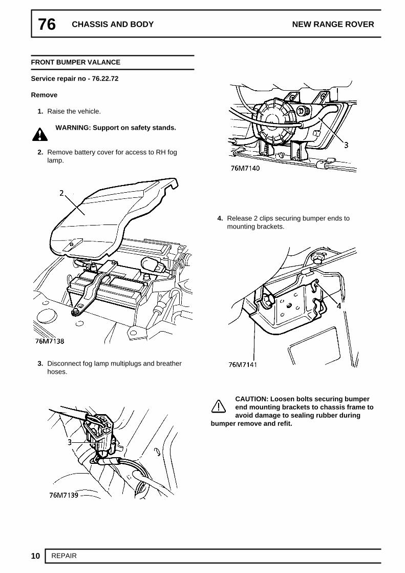
76 CHASSIS AND BODY NEW RANGE ROVER
10 REPAIR
FRONT BUMPER VALANCE
Service repair no - 76.22.72
Remove
1. Raise the vehicle.
WARNING: Support on safety stands.
2. Remove battery cover for access to RH foglamp.
3. Disconnect fog lamp multiplugs and breatherhoses.
4. Release 2 clips securing bumper ends tomounting brackets.
CAUTION: Loosen bolts securing bumperend mounting brackets to chassis frame toavoid damage to sealing rubber during
bumper remove and refit.

CHASSIS AND BODY
11REPAIR
5. Remove 2 bumper bolt access plugs frombumper valance. Remove bolts.
6. With assistance remove bumper assembly. Donot carry out further dismantling ifcomponent is removed for access only.
7. Remove 8 studs and 6 clips securing extensionsspoiler. Remove extension.
8. Remove 8 screws securing fog lamps. Removelamps.
9. Remove 8 bolts securing bumper end bracketsto bumper. Remove brackets.
WARNING: If front bumper is damaged dueto impact, the impact cans must beinspected. There must be no visible
deformation. The overall length must be 188.25mm æ 0.5 mm. Replace the impact cans ifnecessary.
Refit
10. Fit end brackets and secure with bolts. Fit foglamps and secure with screws.
11. Fit extension and secure with clips and studs.12. With assistance fit bumper assembly, tighten
bolts to 70Nm. (52 lbf.ft)13. Fit bolt access plugs.14. Align end brackets, tighten bolts and secure
bumper end clips.15. Connect fog lamp multiplugs and breather
hoses, fit battery cover.16. Remove safety stands. Lower vehicle.

76 CHASSIS AND BODY NEW RANGE ROVER
12 REPAIR
EXTENSION SPOILER FRONT BUMPER
Service repair no - 76.22.78
Remove
1. Raise the vehicle.
WARNING: Support on safety stands.
2. Remove 8 studs and 6 clips securing spoiler tofront bumper.
3. Remove spoiler halves.
Refit
4. Fit spoiler halves to bumper. Secure with clipsand studs.
5. Remove safety stands. Lower vehicle.
REAR BUMPER VALANCE
Service repair no - 76.22.74
Remove
1. Raise the vehicle.
WARNING: Support on safety stands.
2. Remove rear road wheels.3. Remove 3 screws securing each mud flap.
Remove mud flaps.4. Remove 2 screws securing each wheel arch
liner extension panel to rear bumper/chassis.5. Remove 2 wheel arch liner extension panels.6. Release 2 clips securing bumper ends to
mounting brackets.

CHASSIS AND BODY
13REPAIR
7. Disconnect 3 towing harness multiplugs.8. Remove 2 mounting bolt covers.9. Remove 2 bolts securing bumper to chassis.
10. With assistance, release bumper ends frombrackets. Remove bumper.
Refit
11. With assistance, position bumper. Engage nylonend supports to brackets.
12. If necessary, slacken bolts securing end supportbrackets. Align bumper to body. Tighten to 29Nm. (22 lbf.ft)
13. Fit bumper mounting bolts. Tighten to 70 Nm.(52 lbf.ft)
14. Fit bolt covers.15. Secure bumper end clips.16. Connect towing harness multiplugs.17. Position wheel arch liner extensions. Secure with
screws.18. Position mud flaps. Secure with screws.19. Fit road wheels. Tighten to 108 Nm. (80 lbf.ft)20. Remove safety stands. Lower vehicle.
FASCIA ASSEMBLY
Service repair no - 76.46.23/99
WARNING: The fascia assembly housesthe heater distribution unit, blowerassemblies and air conditioning
evaporator. Assistance is essential duringremoval and refit procedures.
CAUTION: When removed from thevehicle, the fascia should be placed on asoft covered work surface, supported on
suitable wooden blocks.
Remove
1. Vehicles with SRS only: Remove battery. SeeELECTRICAL, Repair.
2. Vehicles without SRS: Disconnect batterynegative lead.
3. Drain cooling system. See COOLING SYSTEM,Repair.
4. Loosen hose clips, disconnect hoses fromheater pipes.
5. Remove centre console. See this section.6. Remove steering column. See STEERING,
Repair.7. Remove wiper motor and linkage. See WIPERS
AND WASHERS, Repair.8. Disconnect passenger side heated front screen
multiplug. Release multiplug from clip.

76 CHASSIS AND BODY NEW RANGE ROVER
14 REPAIR
9. Remove 6 bolts, remove remaining scuttle sidepanel.
10. Remove heater intake pollen filters.11. Remove 8 screws securing each pollen filter
housing. Remove both housings.
12. Remove radio. See ELECTRICAL, Repair.13. Release door aperture seal adjacent to ’A’ post
lower trim panels.
14. Driver’s side - LHD automatic vehicles only:Remove 3 bolts securing foot rest through ’A’post lower trim, remove foot rest.
15. Remove screw securing each ’A’ post lower trimpanel, release from single sprag clip, removeboth trim panels.

CHASSIS AND BODY
15REPAIR
16. Remove fuse cover from driver’s seat base trim.
17. Remove screw and 2 trim studs, remove seatbase trim.
18. Release 4 sprag clips, remove driver’s sidecarpet retainer.
19. Remove 2 scrivet fasteners securing lowerclosing panel to passenger side of fascia.
20. Release closing panel, disconnect footwell lamp,release diagnostic multiplug. Remove closingpanel.
21. Remove 4 bolts, remove fascia centre bracket.

76 CHASSIS AND BODY NEW RANGE ROVER
16 REPAIR
22. Disconnect 4 multiplugs from Body ElectricalControl Module (BeCM)
23. Remove captive nut, remove earth wires fromstud at base of driver’s side ’A’ post.
24. Disconnect multiplugs at base of each ’A’ post.
25. Release BeCM harness from sill, route intofascia to prevent fouling as fascia is removed.
26. Disconnect multiplugs and release vacuum hosefrom brake and clutch switches.
27. Models with SRS only: Disconnect SRSmultiplug from main harness.

CHASSIS AND BODY
17REPAIR
28. Disconnect multiplug from SRS control module,route harness into fascia to prevent fouling asfascia is removed.
29. Remove both front wheel arch liners. See thissection.
30. Remove 2 scrivet fasteners securing air cleanerbaffle beneath LH wheel arch. Remove baffle.
31. Disconnect both SRS crash sensor multiplugs.
32. Remove 4 bolts securing battery tray and 2 boltssecuring air cleaner to valance.

76 CHASSIS AND BODY NEW RANGE ROVER
18 REPAIR
33. Raise air cleaner and battery tray for access tocrash sensor harness clips.
34. Release clips securing each crash sensorharness to valance. Release harness grommetsand feed both harnesses through valance intowheel arches.
35. Release 3 clips securing each crash sensorharness to underside of wheel arches.
36. Release harness grommets, feed harnessesthrough bulkhead and route into fascia toprevent fouling as fascia is removed.
37. Vehicles with air conditioning only: Dischargeair conditioning system. See AIRCONDITIONING, Adjustment.
38. Remove bolt securing pipe clamp toThermostatic Expansion Valve (TXV).
39. Release pipes from TXV and remove ’O’ rings.Seal pipes and ports of TXV.
40. All models: Remove 4 tube bolts securingfascia to scuttle panel.

CHASSIS AND BODY
19REPAIR
41. Remove nuts and washers securing fascia tobase of ’A’ posts.
42. Remove bolt securing fascia to pedal box.43. Using assistance, carefully manoeuvre the
fascia through the driver’s door aperture. Placefascia on a soft covered work surface, supportedon suitable wooden blocks.
44. Remove rubber seals from air intake ducts.45. Collect rear heater duct connecting tubes.
Refit
46. Fit intake seals to blower motor ducts. Taperubbers inside blower ducts to aid fitment.
NOTE: Tape the rubbers at this stage, asthey are almost impossible to locate afterdash fitment.
47. Fit guide pins LRT-76-001 to outer fascia studs.48. With assistance, manoeuvre fascia into position
through driver’s front door aperture. Locateguide pins.
NOTE: Assistance from a third person maybe necessary when guiding heater pipesthrough bulkead.
49. Loosely fit 1 tube bolt, fascia to scuttle.
50. Fit bolt securing fascia to pedal box. Tighten to25 Nm. (18 lbf.ft)
51. Fit nuts and washers at base of A posts. Tightento 25 Nm. (18 lbf.ft)
52. Remove guide pins.53. Fit remaining tube bolts. Tighten to 25 Nm. (18
lbf.ft)54. Fit rear heater duct connecting pipes.55. Remove tape from intake seals.56. Engage lips of sealing rubbers around scuttle
apertures.57. Fit pollen filter housings, tighten bolts.58. Fit scuttle side panel to passenger side of
vehicle, tighten bolts.59. Connect heated screen multiplug, fit to side
panel clip.60. Connect hoses to heater pipes. Tighten clips.61. Air conditioning vehicles: Remove seals from
air conditioning pipes and TXV ports.62. Lubricate new O rings with clean compressor oil,
fit to pipes.63. Locate pipes in TXV ports, position clamp and fit
clamp bolt.64. Engage evaporator drain tubes over pipes in
transmission tunnel.65. Vehicles with SRS only: Route SRS crash
sensor harnesses through bulkhead into wheelarches, locate harness grommets.
66. Secure harness clips beneath wheel arches,route harnesses through valances into enginebay, locate harness grommets.
67. Raise battery tray and air cleaner for access.Route crash sensor harnesses, secure harnessclips, connect multiplugs to crash sensors.
68. Tighten battery tray and air cleaner bolts.69. Connect multiplug to SRS control module.70. Connect SRS harness multiplug to main
harness.71. Fit air cleaner baffle beneath LH wheel arch,
secure with scrivet fasteners.72. Fit wheel arch liners. See this section.73. All models:Route harness along sill, connect
multiplugs to BeCM.74. Connect multiplugs at base of ’A’ posts and
secure plugs to brackets.75. Fit earth wires to stud, tighten captive nut.76. Connect vacuum hose and multiplugs to brake
and clutch pedal switches.77. Position closing panel beneath passenger side
of fascia. Secure dianostic plug, connect footwelllamp. Align closing panel, secure with scrivetfasteners.
78. Fit carpet retainer, engage sprag clips.79. Fit seat base trim panel, secure trim studs,
tighten screw.80. Fit fuse cover to seat base trim.81. Fit both ’A’ post lower trim panels, secure sprag
clips. Engage door aperture seals.

76 CHASSIS AND BODY NEW RANGE ROVER
20 REPAIR
82. LHD automatic vehicles only: Fit foot rest,secure with bolts.
83. Fit radio. See ELECTRICAL, Repair.84. Fit wiper motor and linkage. See WIPERS AND
WASHERS, Repair.85. Fit steering column. See STEERING, Repair.86. Fit centre console. See this section.87. Refill cooling system. See COOLING SYSTEM,
Repair.88. Vehicles with SRS only: Fit battery. See
ELECTRICAL, Repair.89. Reconnect battery negative lead.90. Evacuate and recharge air conditioning. See
AIR CONDITIONING, Adjustment.
FASCIA ASSEMBLY - VEHICLES WITH SINGLEPOINT SENSED SRS
Service repair no - 76.46.23/99
WARNING: Refer to SRS safetyprecautions before commencing repair.
WARNING: The fascia assembly housesthe heater distribution unit, blowerassemblies and air conditioning
evaporator and is therefore heavy. Assistance isessential during removal and refit procedures.
CAUTION: When removed from thevehicle, the fascia should be placed on awork surface with a soft covering and
supported on suitable wooden blocks.
Remove
1. Remove key from starter switch and wait 10minutes for SRS back up power circuit todischarge.
2. Disconnect both battery terminals, earth leadfirst.
3. Drain cooling system. See COOLING SYSTEM,Repair.
4. Release 2 clips securing heater hoses to heatermatrix and disconnect hoses.
5. Cap both heater matrix pipes to prevent coolantspillage inside vehicle during fascia removal.
6. Recover refrigerant from air conditioning system.See AIR CONDITIONING, Adjustment.

CHASSIS AND BODY
21REPAIR
7. Remove bolt securing pipe clamp to thermostaticexpansion valve (TXV) and release pipes.
8. Remove and discard ’O’ ring seals from airconditioning pipes.
9. Immediately cap both air conditioning pipes andTXV ports to prevent moisture entering the airconditioning system.
10. Remove wiper motor and linkage. See WIPERSAND WASHERS, Repair.
11. Disconnect passenger side heated screenmultiplug.
12. Release heated screen multiplug from scuttleside panel and position aside.
13. Remove 6 bolts securing scuttle side panel toscuttle and remove panel.
14. Remove pollen filter from both heater intakehousings.
15. Remove 8 screws securing each heater intakehousing to scuttle and remove intake housings.Release sealing rubbers from scuttle panelaperture.
16. Remove centre console. See this section.
17. Remove transmission tunnel insulation pad.

76 CHASSIS AND BODY NEW RANGE ROVER
22 REPAIR
18. Release latching mechanism and disconnectmultiplug from airbag diagnostic and control unit(DCU).
19. Release SRS harness from transmission tunneland position to fascia to avoid snagging.
20. Remove 6 nuts securing gear lever gaiter ring totransmission tunnel and release gaiter.
21. Remove 2 bolts securing gear lever to gearboxremote and remove gear lever.
22. Disconnect high/low switch multiplug.23. Remove 4 bolts securing fascia centre bracket to
fascia and transmission tunnel.24. Remove fascia centre bracket.25. Remove radio. See ELECTRICAL, Repair.26. Remove steering column. See STEERING,
Repair.

CHASSIS AND BODY
23REPAIR
27. Remove 3 scrivets securing lower fascia closingpanel to passenger’s side of fascia.
28. Release closing panel and release diagnosticconnector from panel.
29. Release door aperture seal adjacent to ’A’ postlower trim panels.
30. Remove screw securing each ’A’ post lower trimpanel to ’A’ post.
31. Release ’A’ post lower trim panels from spragclip and remove panels.
32. Remove fuse box cover from driver’s seat basetrim.
33. Remove screw and 3 trim studs securing seatbase trim to body and remove seat base trim.
34. Release 4 sprag clips securing driver’s sidecarpet retainer to body and remove carpetretainer.
35. Disconnect 3 multiplugs from Body ElectricalControl Module (BeCM).
36. Position carpet aside and disconnect multiplugfrom rear of BeCM.

76 CHASSIS AND BODY NEW RANGE ROVER
24 REPAIR
37. Remove captive nut securing earth wires todriver’s side lower ’A’ post and release 3additional earth wires.
38. Disconnect 3 multiplugs at base of driver’s side’A’ post.
39. Release harness from driver’s side carpet andposition to fascia to avoid snagging.
40. Disconnect multiplugs from clutch and 2 brakepedal switches.
41. Disconnect vacuum hose from clutch and brakepedal switches.
42. Disconnect 2 multiplugs at base of passenger’sside ’A’ post.
43. Remove 2 nuts securing fascia to ’A’ post andtransmission tunnel bracket, passenger’s side
44. Remove 2 nuts securing fascia to ’A’ post andtransmission tunnel bracket, driver’s side.

CHASSIS AND BODY
25REPAIR
45. Remove 4 tube bolts securing fascia assemblyto scuttle panel.
46. Disconnect 2 evaporator drain hoses fromevaporator.
47. Using assistance, carefully manoeuvre fasciaassembly through the driver’s door aperture.Position the fascia on a work surface with a softcovering and support on suitable wooden blocks.
48. Collect 2 ducts connecting rear heating pipes tofascia assembly.
Refit
49. Tape intake duct seals inside blower duct to aidfitment.
50. Fit guide pins LRT-76-001 to outer fascia studs.51. With assistance, manoeuvre fascia assembly
through driver’s door aperture and locate guidepins to scuttle panel.
NOTE: Assistance from a third person maybe required to guide heater pipes throughbulkhead.
52. Fit one tube bolt securing fascia to scuttle panelbut do not tighten.
53. Fit nuts securing fascia to lower ’A’ posts andtighten to 25 Nm. (18 lbf.ft)
54. Fit nuts securing fascia to transmission tunnelbrackets and tighten to 25 Nm. (18 lbf.ft)
55. Remove LRT-76-001.56. Fit remaining tube bolts securing fascia to scuttle
panel and tighten to 25 Nm. (18 lbf.ft)57. Fit fascia centre bracket, fit bolts and tighten to
25 Nm. (18 lbf.ft)58. Connect evaporator drain hoses to evaporator.59. Fit ducts connecting rear heating pipes to fascia
assembly.60. Fit gearlever to gearbox remote, fit bolts and
tighten to 25 Nm. (18 lbf.ft)61. Fit gear lever gaiter and ring to transmission
tunnel and secure with nuts.62. Connect high/low switch multiplug.63. Position SRS harness to transmission tunnel.64. Connect multiplug to airbag DCU. Ensure
connector latching mechanism is correctlyengaged.
65. Fit transmission tunnel insulation pad totransmission tunnel and position multiplugsthrough pad.
66. Fit radio. See ELECTRICAL, Repair.67. Connect multiplugs at base of passenger’s side
’A’ post.68. Fit passenger’s side ’A’ post lower trim panel
and secure with screw.69. Engage door aperture seal to door aperture.70. Position fascia lower closing panel and engage
diagnostic connector to panel.71. Position closing panel to fascia and secure with
scrivets.72. Connect vacuum hose to clutch and brake pedal
switches.73. Connect multiplugs to clutch and brake pedal
switches.74. Position harness to driver’s side carpet.75. Connect multiplugs to BeCM.76. Connect multiplugs at base to driver’s side ’A’
post.77. Position earth wires to ’A’ post stud, fit and
secure captive nut.78. Fit driver’s side carpet retainer and engage to
clips.79. Fit seat base trim and secure with trim studs and
screw.80. Fit seat base fuse box cover.81. Fit driver’s side lower ’A’ post trim and secure
with screw.82. Fit steering column. See STEERING, Repair.83. Fit radio. See ELECTRICAL, Repair.84. Fit centre console. See this section.85. Remove tape from heater intake ducts.86. Engage heater intake seals to scuttle apertures.87. Fit heater intake housings and secure with
screws.88. Fit pollen filters to intake housings.

76 CHASSIS AND BODY NEW RANGE ROVER
26 REPAIR
89. Fit wiper motor and linkage. See WIPERS ANDWASHERS, Repair.
90. Fit scuttle side panel to scuttle and secure withbolts.
91. Connect heated screen multiplug and engagemultiplug to scuttle side panel bracket.
92. Remove caps from heater matrix pipes.93. Engage heater matrix grommet to bulkhead
aperture.94. Connect heater hoses to heater matrix and
secure with clips.95. Remove caps from air conditioning pipes and
TXV.96. Lubricate NEW ’O’ ring seals with clean
compressor oil and fit to air conditioning pipes.97. Connect air conditioning pipes to TXV, position
clamp and fit bolt.98. Tighten clamp bolt to 6 Nm. (4 lbf.ft)99. Charge air conditioning system. See AIR
CONDITIONING, Adjustment.100. Fill coolant system. See COOLING SYSTEM,
Repair.101. Connect both battery terminals, earth lead last.
FASCIA CLOSING PANEL
Service repair no - 76.46.27
Remove
1. Remove closing panel screw covers and screws.2. Lower closing panel.3. Disconnect air tube from closing panel, remove
panel.
Refit
4. Reverse removal procedure.

CHASSIS AND BODY
27REPAIR
FRONT DOOR ASSEMBLY
Service repair no - 76.28.01/99
Remove
1. Release door harness protective sleeve from ’A’post.
2. Disconnect door harness multiplugs.
3. Remove door check strap retaining pin.
CAUTION: Apply protective tape to ’A’post before drifting out retaining pin.
4. Remove door hinge pin retaining clips.5. With assistance, remove door assembly.
Refit
6. With assistance, position door on hinges. Fitretaining clips.
7. Align door check strap. Fit retaining pin.8. Remove protective tape from ’A’ post.9. Connect harness multiplugs. Secure protective
sleeve to ’A’ post.10. If necessary adjust door. See Adjustment.
GLASS - FRONT DOOR
Service repair no - 76.31.01
Remove
1. Remove front door outer waist seal. See thissection.
2. Remove front door plastic sheet. See thissection.
3. Turn ignition ON.4. Lower glass approximately 120mm (5 in.)
Remove rear regulator arm retaining clip.
5. Lower glass to align forward clip with theregulator plate lower retaining rivet. Turn ignitionOFF.

76 CHASSIS AND BODY NEW RANGE ROVER
28 REPAIR
6. Remove front lower fixing clip.7. Remove nut securing bracket to vertical slide.8. Release bracket from slide.
CAUTION: Chock glass with woodenblock, or retain with tape, to prevent glassdropping when regulator arms are
released.
9. Using a suitable lever, release 2 regulator armsfrom glass lower fixings.
10. Support weight of glass. Remove wooden chockor tape.
11. Rotate glass anti-clockwise to release fromrunners.
12. Remove front door glass.
Refit
13. Refit front door glass.14. Rotate glass anti-clockwise, fit to runners.15. Secure glass fixings to regulator arms.16. Position glass bracket to vertical runner, fit
retaining nut.17. Fit clip securing regulator arm to glass runner.18. Turn ignition ON.19. Raise door glass approximately 120mm (5 in.)
Fit rear glass retaining clip.20. Raise door glass.21. Turn ignition OFF.22. Fit front door plastic sheet. See this section.23. Fit front door outer waist seal. See this section.

CHASSIS AND BODY
29REPAIR
GLASS REGULATOR - FRONT DOOR
Service repair no - 76.31.45
Remove
1. Remove front door glass. See this section.2. Disconnect window lift motor harness connector.3. Remove rivet securing regulator runner to door
panel.
4. Remove 3 rivets.5. Remove regulator assembly.
Refit
6. Reverse removal procedure.
LATCH - FRONT DOOR
Service repair no - 76.37.12
Remove
1. Remove front door trim casing. See thissection.
2. Release rear of plastic sheet.3. Release retaining clip, private lock to latch
operating rod, at latch end.
4. Release control rod from latch.5. Release retaining clip, outside handle to latch
operating rod, at latch end.6. Release control rod from latch.7. Disconnect 2 latch motor multiplugs.8. Remove door sill button from operating rod.9. Release remote handle to latch operating cable
from clip.10. Remove 3 screws securing latch.11. Release latch from door.12. Remove sill button operating rod from latch.

76 CHASSIS AND BODY NEW RANGE ROVER
30 REPAIR
13. Release outer operating cable from latchabutment.
14. Release inner cable from latch.15. Remove latch from door.
Refit
16. Fit latch.17. Fit inner operating cable to latch.18. Fit outer operating cable to latch abutment.19. Fit sill button operating rod to latch.20. Align latch to door, tighten 3 screws.21. Secure remote handle cable to door panel clip.22. Fit sill button to operating rod.23. Reconnect 2 latch motor multiplugs.24. Fit outside handle operating rod to latch.25. Fit retaining clip.26. Fit private lock operating rod to latch.27. Fit retaining clip.28. Secure plastic sheet.29. Fit front door trim casing. See this section.

CHASSIS AND BODY
31REPAIR
REMOTE CONTROL - FRONT DOOR
Service repair no - 76.37.31
Remove
1. Remove front door trim casing. See thissection.
2. Release top rear corner of plastic sheet.3. Pull remote handle out. Release inner cable from
remote handle.
4. Release remote handle.5. Remove 2 screws securing remote handle.6. Remove outer cable from housing.7. Remove remote by sliding rearwards.
Refit
8. Reverse removal procedure.
OUTER WAIST SEAL - FRONT DOOR
Service repair no - 76.31.53
Remove
1. Remove screw securing rear edge of outer waistseal.
2. Remove outer waist seal.
Refit
3. Reverse removal procedure.

76 CHASSIS AND BODY NEW RANGE ROVER
32 REPAIR
OUTSIDE HANDLE - FRONT DOOR
Service repair no - 76.58.07
Remove
1. Remove front door trim casing. See thissection.
2. Release rear half of plastic sheet.3. Remove retaining clip, private lock to latch
operating rod, at latch end.
4. Remove control rod from latch and private lock.5. Remove retaining clip, outside handle to latch
operating rod, at latch end.6. Remove control rod from latch and outside
handle.7. Remove bolt securing rear of outside handle.
8. Slide outside handle forwards. Pull handle out,release rear of handle from door.

CHASSIS AND BODY
33REPAIR
9. Remove handle from front fixing by pivotting rearend of handle out.
10. Remove gasket from handle.11. Remove rubber locking plate from door.12. Remove plastic locking plate from door.13. Remove screw securing mounting plate to door,
remove plate.
Refit
14. Clean handle and door mating faces.15. Reverse removal procedure.
PLASTIC SHEET - FRONT DOOR
Service repair no - 76.34.26
Remove
1. Remove front door trim casing. See thissection.
2. Remove 2 screws securing door outstation ECU.
3. Remove 2 screws securing speaker amplifier.4. Remove 4 screws securing front door speaker.5. Release speaker, disconnect multiplug.6. Remove plastic sheet.
Refit
7. Reverse removal procedure.

76 CHASSIS AND BODY NEW RANGE ROVER
34 REPAIR
PRIVATE LOCK - FRONT DOOR
Service repair no - 76.37.39
Remove
1. Remove outside handle. See this section.2. Fit door lock key.3. Remove screw securing lock.4. Remove cam and washer from lock.5. Remove cam lock and stop from lock.6. Remove cam return spring. Remove lock from
outside handle.
Refit
7. Apply grease to lock barrel.8. Fit lock to outside handle.9. Fit cam return spring, cam stop, cam lock,
washer and cam.10. Fit screw securing lock to outside handle.11. Remove door lock key.12. Refit front door outside handle. See this
section.
TRIM CASING - FRONT DOOR
Service repair no - 76.34.01
Remove
1. Release cheater panel.
2. Disconnect 2 tweeter speaker connectors,remove cheater panel.
3. Remove screw securing remote handleescutcheon, remove escutcheon.
4. Remove 3 screws securing trim casing.5. Release 12 clips retaining trim casing.

CHASSIS AND BODY
35REPAIR
6. Disconnect speaker connector.
7. Remove door trim casing.
Disassemble
8. Remove 12 trim casing retaining clips.9. Remove 4 screws, remove speaker.
10. Remove 4 screws, remove speaker grille.11. Remove 7 screws, remove trim casing pocket.12. Remove 3 screws, remove arm rest.13. Remove retaining clamp and sill button
escutcheon.

76 CHASSIS AND BODY NEW RANGE ROVER
36 REPAIR
14. Remove door trim casing waist seal.
Assemble
15. Fit door trim casing waist seal.16. Fit sill button escutcheon, position retaining
clamp, tighten screw.17. Fit arm rest to trim casing, tighten 3 screws.18. Fit trim casing pocket, tighten 7 screws.19. Fit speaker grille to trim casing, tighten 4 screws.20. Fit speaker to trim, tighten 4 screws.21. Fit 12 retaining clips.
Refit
22. Connect trim casing speaker connector.23. Fit trim casing, locating 12 retaining clips.24. Fit 3 screws securing trim casing.25. Fit remote handle escutcheon, tighten screw.26. Position cheater panel, connect 2 tweeter
speaker connectors.27. Secure cheater panel.
INSERT CAPPING - FRONT DOOR
Service repair no - 76.34.32
Remove
1. Fit protection to door trim casing.2. Position a blunt flat blade between trim casing
and insert upper edge.3. Gently raise blade to remove insert.4. Remove retaining clips from insert.
Refit
5. Fit insert to door casing. Secure with clips.6. Remove protection from door casing.

CHASSIS AND BODY
37REPAIR
REAR DOOR ASSEMBLY
Service repair no - 76.28.02/99
Remove
1. Release door harness protective sleeve from’B/C’ post.
2. Disconnect door harness multiplugs.3. Remove check strap retaining pin.
CAUTION: Apply protective tape to ’B/C’post before drifting out pin.
4. Remove hinge pin retaining clips.5. With assistance, remove door assembly.
Refit
6. With assistance fit door to hinges.7. Fit hinge retaining clips.8. Align check strap and fit retaining pin.9. Remove protective tape.
10. Connect harness multiplugs, secure protectivesleeve to ’B/C’ post.
11. If necessary adjust door. See Adjustment.
GLASS - REAR DOOR
Service repair no - 76.31.02
Remove
1. Remove outer waist seal. See this section.2. Remove door trim casing. See this section.3. Remove speaker and plastic sheet. See this
section.4. Remove window motor and control panel
assembly. See ELECTRICAL, Repair.5. Remove glass rear channel. See this section.6. Remove wedges or tape from glass.7. Release glass from channel. Raise to remove
glass from door.
Refit
8. Fit glass to door and align to frame.9. Wedge or use tape to hold glass in door.
10. Fit glass rear channel. See this section.11. Fit window motor and control panel. See
ELECTRICAL, Repair.12. Fit speaker and plastic sheet. See this section.13. Fit trim casing. See this section.14. Fit outer waist seal. See this section.

76 CHASSIS AND BODY NEW RANGE ROVER
38 REPAIR
PLASTIC SHEET - REAR DOOR
Service repair no - 76.34.28
Remove
1. Remove rear door trim casing. See thissection.
2. Remove speaker. See ELECTRICAL, Repair.3. Remove 2 screws securing amplifier to door.4. Remove plastic sheet.
Refit
5. Reverse removal procedure.
OUTSIDE HANDLE - REAR DOOR
Service repair no - 76.58.02
Remove
1. Remove rear door trim casing. See thissection.
2. Remove bolt securing handle.
3. Remove outside handle.
NOTE: Operate and pull handle outward,pivotting at forward mounting point.
4. Remove gasket.5. Remove locking plates.6. Remove screw securing mounting plate, remove
plate.

CHASSIS AND BODY
39REPAIR
Refit
7. Clean handle face on door.8. Fit handle mounting plate, tighten screw.9. Fit locking plates.
10. Fit gasket to handle, position handle, secure withscrew.
11. Refit door trim casing. See this section.
LATCH - REAR DOOR
Service repair no - 76.37.13/70
Remove
1. Remove window lift motor/control unit assembly.See ELECTRICAL, Repair.
2. Release door lock remote control cable from clipon window lift panel.
3. Remove 2 studs securing latch to window liftpanel.
4. Disconnect outer cable from abutment bracket.5. Release remote cable from latch.6. Release sill button link rod from latch. Remove
latch.
Refit
7. Lubricate new latch.8. Fit latch to sill button link rod.9. Fit remote control cable to latch.
10. Fit latch to window lift panel, secure with 2retaining studs.
11. Refit window lift motor/control unit assembly.See ELECTRICAL, Repair.

76 CHASSIS AND BODY NEW RANGE ROVER
40 REPAIR
FIXED QUARTER LIGHT - REAR DOOR
Service repair no - 76.31.31
Remove
1. Remove outer waist seal. See this section.2. Remove door trim casing. See this section.3. From inside release seal from frame. Remove
seal and glass assembly outwards.4. Remove seal from glass.
Refit
5. Clean glass, seal and frame.6. Fit seal to glass. Fit assembly to door frame. If
necessary use a draw string to locate rubber.
NOTE: The opening light seal fits over thefixed glass seal.
7. Fit door trim casing. See this section.8. Fit outer waist seal. See this section.
REMOTE CONTROL - REAR DOOR
Service repair no - 76.37.32
Remove
1. Remove rear door trim casing. See thissection.
2. Release plastic sheet to clear remote.3. Remove foam pad from under window lift switch
multiplug.4. Disconnect switch multiplug.
5. Release inner cable from remote lever.6. Remove 2 screws securing remote to window lift
control panel.7. Release remote outer cable from remote
housing.8. Remove remote control.
Refit
9. Reverse removal procedure.

CHASSIS AND BODY
41REPAIR
GLASS CHANNEL - REAR DOOR
Service repair no - 76.31.17
Remove
1. Remove window lift motor/control panelassembly. See ELECTRICAL, Repair.
2. Remove 2 bolts securing channel to door andremove channel.
Refit
3. Fit channel to door, secure with 2 bolts.4. Refit window lift motor/control panel assembly.
See ELECTRICAL, Repair.
SEAL - REAR DOOR
Service repair no - 76.40.02
Remove
1. Open rear door.2. Remove rear door carpet retainer.3. Remove rear door aperture seal.
Refit
4. Fit rear door aperture seal.5. Refit rear door carpet retainer.6. Close rear door.
TRIM CASING - REAR DOOR
Service repair no - 76.34.04
Remove
1. Remove remote handle escutcheon.

76 CHASSIS AND BODY NEW RANGE ROVER
42 REPAIR
2. Remove 2 screws securing trim casing.
3. Release 11 door trim casing retaining studs.4. Disconnect rear door speaker connector.
Remove door trim casing.
Disassemble
5. Remove 11 trim casing retaining studs.
6. Remove 4 screws, remove upper speaker grille.7. Remove 4 screws, remove lower speaker grille.8. Remove 3 screws, remove arm rest.9. Remove screw, remove retaining clamp and sill
button escutcheon.

CHASSIS AND BODY
43REPAIR
10. Remove trim from door casing.
Assemble
11. Fit trim to door casing.12. Fit sill button escutcheon and position retaining
clamp.13. Tighten screw securing retaining clamp.14. Fit arm rest to trim casing, secure with 3 screws.15. Fit upper speaker grille to trim casing, secure
with 4 screws.16. Fit lower speaker grille to trim casing, secure
with 4 screws.17. Fit 11 trim casing retaining studs.
Refit
18. Fit and align door trim casing.19. Secure 11 trim casing retaining studs.20. Tighten 2 screws securing trim casing.21. Fit remote handle escutcheon, tighten securing
screw.
OUTER WAIST SEAL - REAR DOOR
Service repair no - 76.31.54
Remove
1. Remove screw securing seal finisher to forwardedge of door.
2. Release seal finisher from clip at rear edge ofdoor.
3. Remove seal and finisher assembly.4. Remove screw and securing clip.
Refit
5. Fit clip to door, secure with screw.6. Fit seal and finisher assembly to door. Align at
forward edge, secure with screw.

76 CHASSIS AND BODY NEW RANGE ROVER
44 REPAIR
RUBBING STRIPS & DOOR FINISHERS
Remove
CAUTION: When removing exterior trim,NEVER lever directly against body panels.Use an approved trim fork. Protect body
panel with suitable material, such as fabriccovered hardboard.
Rubbing Strip - Front Fender
1. Remove relevant wheel arch liner. See thissection.
2. Remove nut securing forward edge of rubbingstrip.
3. Remove rubbing strip from single clip.
Rubbing Strip - Rear Quarter Panel
4. Release 5 clips securing rubbing strip. Removestrip.
NOTE: Rearmost clip is unique.
Rubbing Strips - Front & Rear Doors
5. Remove nut securing rear of rubbing strip.6. Front Door Rubbing Strip: Release 5 clips
securing rubbing strip.7. Rear Door Rubbing Strip: Release 3 clips
securing rubbing strip.8. Remove rubbing strips.
Lower Door Finishers
9. Remove screw securing rear of fininsher.10. Front Door Finisher: Release 5 clips securing
rubbing strip.11. Rear Door Finisher: Release 3 clips securing
rubbing strip.12. Remove finishers.
Refit
13. Reverse removal procedure.
GLOVE BOX AND LID
Service repair no - 76.52.03 - Glove BoxService repair no - 76.52.02 - Glove Box LidService repair no - 76.52.13 - Glove Box Lid - Align
Remove
1. Remove centre screw from 2 scrivet fasteners.Release closing panel for access to glove boxhinge fixings. Collect outer parts of fastenersfrom closing panel.
2. Remove 2 bolts securing glove box hinges tofascia frame.
3. Open glove box lid, remove 5 screws securingglove box. Release glove box from fascia.
4. Disconnect glove box lamp multiplug.

CHASSIS AND BODY
45REPAIR
5. Disconnect cable latch, remove glove boxassembly.
Glove Box Lid
6. Remove split pin, disengage gas strut from lid.
7. Remove 2 bolts and square nuts, remove lidfrom glove box.
Refit Glove Box Lid
8. Position lid to glove box and secure with boltsand square nuts.
9. Engage gas strut, secure with split pin.
Refit Glove Box Assembly
10. Position glove box assembly, connect lampmultiplug. Secure cable latch.
11. Open glove box lid, align assembly to fascia.Secure with screws.
12. Fit bolts securing hinges to fascia frame, do notighten.
13. Check alignment and latching of glove box lid,adjusting hinges as necessary using centraladjusting screws.
14. Tighten screws, hinges to fascia.15. Close glove box lid.16. Position closing panel. Secure with scrivet
fasteners.

76 CHASSIS AND BODY NEW RANGE ROVER
46 REPAIR
GLOVE BOX RELEASE CABLE
Service repair no - 76.52.14
NOTE: Release cables are supplied presetand do not normally require adjustment.
Remove
1. Open glove box. Remove 5 screws securingglove box liner to fascia.
2. Lower glove box liner. Release 2 clips todisengage cable latch from location.
3. Remove finisher from lock.
4. Remove 2 screws securing lock and withdrawcable assembly from fascia.
5. Pry cover from lock button.6. Insert key into lock, turn key through 45 degrees,
remove barrel.
Refit
7. Insert barrel, turn to engage in button.8. Remove key, fit cover to lock button.9. Route release cable assembly into fascia.
Engage cable latch to glove box.10. Align glove box liner to fascia, tighten screws.11. Close glove box lid.12. Position glove box lock to fascia, check
operation of latch.13. If adjustment is necessary, release lock from
fascia, loosen cable lock nut, adjust outer cablelength. Tighten cable lock nut.
14. Reposition lock to fascia. Recheck operation oflatch before securing lock with screws.
15. Fit finisher to lock.

CHASSIS AND BODY
47REPAIR
GRAB HANDLE
Service repair no - 76.58.30
Remove
1. Pull down grab handle.2. Remove 2 grab handle retaining screw access
covers.3. Remove 2 screws, remove grab handle.
Refit
4. Position grab handle, fit 2 retaining screws.5. Fit 2 retaining screw access covers.6. Release grab handle.
FRONT GRILLE
Service repair no - 76.55.03
Remove
1. Remove 6 screws securing grille.2. Remove front grille.
Refit
3. Reverse removal procedure.

76 CHASSIS AND BODY NEW RANGE ROVER
48 REPAIR
EXTERIOR MIRROR
Service repair no - 76.10.52
Remove
1. Release cheater panel, disconnect 2 tweeterspeaker connectors. Remove cheater panel.
2. Disconnect mirror multiplug.3. Remove 3 screws, remove mirror.
Refit
4. Fit mirror, tighten 3 retaining screws.5. Connect mirror multiplug.6. Position cheater panel, connect 2 tweeter
speaker connectors, secure panel to door.
INTERIOR MIRROR
Service repair no - 76.10.51
Remove
1. Remove cover.2. If fitted, diconnect multiplug.3. Remove mirror from windscreen location by
pulling sharply downwards.
Refit
4. Reverse removal procedure.

CHASSIS AND BODY
49REPAIR
PARCEL TRAY SUPPORT
Service repair no - 76.67.11
Remove
1. Release 2 squab catches and fold rear seatsforward.
2. Remove parcel tray.3. Remove 3 studs securing parcel tray support.
Remove support.
Refit
4. Reverse removal procedure.
PARCEL TRAY SUPPORT TRIM
Service repair no - 76.67.12 - Right HandService repair no - 76.67.21 - Left Hand
Remove
1. Remove parcel tray support. See this section.2. Remove ’D’ post lower trim.3. Release tailgate aperture seal from support trim
flange.4. Remove 3 trim studs.
LH Trim Only
5. Remove CD autochanger. See ELECTRICAL,Repair.
6. Remove 2 nuts and 2 bolts securing sub-wooferassembly.

76 CHASSIS AND BODY NEW RANGE ROVER
50 REPAIR
7. Disconnect multiplug from sub-woofer.
Both Trim Panels
8. Release 2 sprag clips securing support trim tobody.
9. Remove support trim panel.10. LH Trim Only: Separate sub-woofer from trim
panel.
Refit
11. Reverse removal procedure.
A,B,D and E POST TRIMS
Remove
1. Remove aperture seal from appropriate area.2. Remove retaining screws (’A’ post lower trims)3. Remove seat belt top mounting (’B’ and ’D’ post
upper trims)4. Release retaining clips, remove finisher.
Refit
5. Position finisher, secure with retaining clips andscrews.
6. Fit seat belt top mounting. Tighten to 25 Nm.(18lbf. ft)
7. Secure aperture seal.
NOTE: Illustration 76M 7128 shows thefixing method for the A, B, D and E posttrim finishers.
1. A post upper2. A post lower left hand3. A post lower right hand4. B post upper5. B post lower6. D post upper7. D post lower8. E post

CHASSIS AND BODY
51REPAIR

76 CHASSIS AND BODY NEW RANGE ROVER
52 REPAIR
’E’ POST - EXTERIOR TRIM
Service repair no - 76.43.
Remove
1. Open upper tailgate.2. Remove 3 screws securing trim to ’E’ post.
3. Remove trim.
Refit
4. Position trim to ’E’ post, engage slot beneathspecial washer on tailgate strut ball joint andengage channel to rear edge of quarter glass.
5. Secure trim with screws.6. Close tailgate.
SEAT BELT - FRONT
Service repair no - 76.73.13
Remove
1. Remove lower ’B’ post finisher.
2. Remove cover and nut securing seat belt toupper anchorage point.
3. Release seat belt guide from ’B’ post.4. Move seat fully forwards.5. Remove bolt cover. Release seat belt from lower
anchorage point on seat.

CHASSIS AND BODY
53REPAIR
6. Remove bolt securing belt reel to ’B’ post,remove belt reel.
7. Move seat fully rearwards.8. Remove cover from seat belt stalk fixing.
Remove bolt. Collect stalk.
Refit
9. Position seat belt stalk. Secure with retainingbolt. Tighten to 35 Nm. (26 lbf.ft). Fit boltcover.
10. Fit seat belt reel to ’B’ post. Secure with retainingbolt. Tighten to 35 Nm. (26 lbf.ft)
11. Move seat fully forwards.12. Secure seat belt to lower anchorage point. Fit
bolt cover.
WARNING: Ensure that belt is correctlylocated before fitting bolt cover.
13. Align belt to upper anchorage point. Secure withnut. Tighten to 25 Nm. (18 lbf.ft). Fit cover.
14. Secure seat belt guide to ’B’ post.15. Refit lower ’B’ post finisher.

76 CHASSIS AND BODY NEW RANGE ROVER
54 REPAIR
FRONT SEAT BELT ADJUSTABLE MOUNTING
Service repair no - 76.73.26
Remove
1. Remove ’B’ post trim upper.2. Remove 2 screws securing adjustable mounting.
Remove mounting.
Refit
3. Position adjustable mounting. Secure withscrews. Tighten to 25 Nm. (18 lbf.ft)
4. Fit ’B’ post trim upper.
SEAT BELT ADJUSTABLE MOUNTING - ’D’ POST
Service repair no - 76.73.36
Remove
1. Remove ’D’ post trim - upper.2. Remove 2 screws securing adjustable mounting.
Remove mounting.
Refit
3. Position adjustable mounting. Secure withscrews. Tighten to 25 Nm. (18 lbf.ft)
4. Refit ’D’ post trim - upper.

CHASSIS AND BODY
55REPAIR
REAR SEAT BELT - CENTRE
Service repair no - 76.73.20
Remove
1. Remove right hand rear seat. See SEATS,Repair.
2. Remove 3 screws securing squab hinge cover.Remove cover.
3. Remove 2 bolts securing squab to cushionassembly.
4. Remove squab from cushion assembly.5. Remove bolt and wave washer securing stalk to
squab hinge. Remove stalk. Collect plainwasher.
6. Release beaded edge of cushion cover fromseat pan flange. Remove cushion cover/foamassembly.
CAUTION: Take care when releasingcover/foam from belt anchorage finisher.

76 CHASSIS AND BODY NEW RANGE ROVER
56 REPAIR
7. Remove 3 screws securing anchorage cover toseat pan. Remove cover in 2 pieces.
8. Remove bolt securing seat belt to seat pan.Remove belt, collect spacer.
Refit
9. Fit seat belt to seat pan. Secure with bolt andspacer. Tighten to 35 Nm. (26 lbf.ft)
10. Fit seat belt anchorage cover. Secure withscrews.
11. Fit cushion assembly to seat pan. Securebeaded edge of cover to seat pan flange.
12. Fit stalk to squab hinge. Secure with bolt.Tighten to 35 Nm. (26 lbf.ft)
13. Position seat squab to cushion assembly.Secure with bolts. Tighten to 45 Nm. (33 lbf.ft)
14. Refit squab hinge cover. Secure with screws.15. Refit rear seat assembly. See SEATS, Repair.

CHASSIS AND BODY
57REPAIR
REAR SEAT BELT - LEFT HAND
Service repair no - 76.73.23
Remove
1. Remove parcel shelf support trim. See thissection.
2. Remove ’D’ post lower trim. See this section.3. Remove cover and nut securing seat belt to
upper anchorage point.4. Remove bolt securing seat belt reel.
5. Remove seat belt reel.6. Remove left hand rear seat. See SEATS,
Repair.7. Remove 3 screws securing squab hinge cover.
Remove cover.
8. Remove 2 bolts securing squab to cushionassembly.
9. Remove squab from cushion assembly.10. Remove bolt and wave washer securing stalk to
squab hinge.11. Remove stalk. Collect plain washer.
Refit
12. Fit stalk to squab hinge. Secure with bolt.Tighten to 35 Nm. (26 lbf.ft)
13. Position seat squab to cushion assembly.Secure with bolts. Tighten to 45 Nm. (33 lbf.ft)
14. Refit squab hinge cover. Secure with screws.15. Refit rear seat assembly. See SEATS, Repair.16. Position belt to upper anchorage point. Secure
with nut. Tighten to 25 Nm. (18 lbf.ft). Fitcover.
17. Position seat belt reel. Secure with bolt. Tightento 35 Nm. (26 lbf.ft)
18. Fit ’D’ post lower trim. See this section.19. Fit parcel shelf support trim. See this section.

76 CHASSIS AND BODY NEW RANGE ROVER
58 REPAIR
REAR SEAT BELT - RIGHT HAND
Service repair no - 76.73.24
Remove
1. Remove parcel shelf support trim. See thissection.
2. Remove ’D’ post lower trim.3. Remove cover and nut securing seat belt to
upper anchorage point.4. Remove bolt securing seat belt reel.
5. Remove seat belt reel.6. Remove right hand rear seat. See SEATS,
Repair.7. Remove 3 screws securing squab hinge cover.
Remove cover.
8. Remove 2 bolts securing squab to cushionassembly. Remove squab.
9. Release beaded edge of cushion cover fromseat pan flange. Remove cushion cover/foamassembly.

CHASSIS AND BODY
59REPAIR
CAUTION: Take care when releasingcover/foam from belt anchorage finisher.
10. Remove 3 screws securing anchorage cover toseat pan. Remove cover in 2 pieces.
11. Remove bolt securing stalk to seat pan. Removestalk. Collect 2 spacers and wave washer.

76 CHASSIS AND BODY NEW RANGE ROVER
60 REPAIR
Refit
12. Fit stalk to seat pan. Secure with bolt, spacersand wave washer. Tighten to 35 Nm. (26 lbf.ft)
13. Fit seat belt anchorage cover. Secure withscrews.
14. Fit cushion assembly to seat pan. Securebeaded edge of cover to seat pan flange.
15. Fit stalk to squab hinge. Secure with bolt.Tighten to 35 Nm. (26 lbf.ft)
16. Position seat squab to cushion assembly.Secure with bolts. Tighten to 45 Nm. (33 lbf.ft)
17. Refit squab hinge cover. Secure with screws.18. Refit rear seat assembly. See SEATS, Repair.19. Position belt to upper anchorage point. Secure
with nut. Tighten to 35 Nm. (26 lbf.ft). Fitcover.
20. Position seat belt reel. Secure with bolt. Tightento 35 Nm. (26 lbf.ft)
21. Fit ’D’ post lower trim.22. Fit parcel shelf support trim. See this section.

CHASSIS AND BODY
61REPAIR
SLIDING ROOF - ELECTRIC
Service repair no - 76.82.44
Remove
1. Remove headlining. See this section.2. Disconnect motor multiplug.3. Disconnect sliding roof drain tubes.4. Remove 8 bolts securing sliding roof.5. With assistance, remove 2 remaining bolts.
Remove sliding roof.6. Remove seal from sliding roof.
Refit
7. Ensure mating faces are clean.8. Fit new seal to sliding roof.9. With assistance, position sliding roof. Fit 2 bolts.
10. Fit remaining bolts.11. Connect drain tubes. Secure with clips.12. Connect motor multiplug.13. Refit headlining. See this section.

76 CHASSIS AND BODY NEW RANGE ROVER
62 REPAIR
HEADLINING - SLIDING ROOF
Service repair no - 76.64.15
Remove
1. Remove upper trims from ’A’,’B’,’D’ & ’E’ posts.See this section.
2. Remove both sun visors. See this section.3. Remove grab handles. See this section.4. Remove parcel tray support trim. See this
section.5. Remove interior lamps. See ELECTRICAL,
Repair.6. Remove front courtesy lamp. See
ELECTRICAL, Repair.7. Remove ultrasonic sensor. See ELECTRICAL,
Repair.8. Fold down rear seat squabs. Recline front seat
squabs.9. Release aperture sealing rubbers at tops of
doors and tailgate.10. Release sun visor clip retaining screw cover
plugs.
11. Remove sun visor retaining clip screws. Removeclips.
12. Remove sun roof aperture finisher.13. Remove 2 headlining grab handle blanks.14. Remove 2 studs securing rear of headlining.15. With assistance remove headlining.
Refit
16. Reverse removal procedure.

CHASSIS AND BODY
63REPAIR
SUNROOF DRAIN TUBE - FRONT
Service repair no - 76.82.21
Remove
1. Remove headlining. See this section.2. Remove wheelarch liner. See this section.3. Release drain tube from sunroof.
4. Release drain tube grommet from body behindwheel arch liner.
5. Tie draw string to one end of drain tube and pulltube from ’A’ post.
Refit
6. Tie draw string to new drain tube and pullthrough ’A’ post.
7. Fit grommet to drain tube, secure to body.8. Secure drain tube to sunroof.9. Fit headlining. See this section.
10. Refit wheel arch liner. See this section.

76 CHASSIS AND BODY NEW RANGE ROVER
64 REPAIR
SUNROOF DRAIN TUBE - REAR
Service repair no - 76.82.22
Remove
1. Remove headlining. See this section.
NOTE: Ensure that parcel shelf supportpanel is removed from side of drain tubeto be removed.
2. Release clip from drain tube.
3. Disconnect drain tube from sunroof.4. Remove drain tube from wheel arch grommet.
Refit
5. Fit drain tube to sunroof, secure with clip.6. Fit drain tube through wheel arch grommet.7. Refit headlining. See this section.

CHASSIS AND BODY
65REPAIR
SUN VISOR
Service repair no - 76.10.47
Remove
1. Release visor from clip.2. Remove 3 visor retaining screws.
3. Disconnect visor lamp multiplug.4. Remove visor.5. Remove clip if required. Carefully lever plastic
tag down.
6. Remove screw, remove clip.
Refit
7. Reverse removal procedure.
SILL FINISHER
Service repair no - 76.43.84
Remove
1. Remove 3 screws securing front tread plate.2. Remove 2 screws securing rear tread plate.3. Remove trim stud securing rear of sill finisher.4. Release 8 clips securing finisher to sill.5. Remove sill finisher.
Refit
6. Renew clips as necessary.7. Reverse removal procedure.

76 CHASSIS AND BODY NEW RANGE ROVER
66 REPAIR
TAILGATE - UPPER
Service repair no - 76.28.29
Remove
1. Remove both ’E’ post finishers.2. Remove 2 trim fixing studs. Release headlining
from ’E’ posts.
3. Release 4 turn buckles securing access panel toLH side load space trim. Remove panel.
4. Locate rear screen washer non-return valve.Disconnect tailgate feed tube from valve.
5. Attach draw string to tube to aid re-assembly.6. Release tailgate harness protective sleeve from
roof panel.
7. Disconnect 3 tailgate harness multiplugs frombody harness. Pull plugs out through hole in roofpanel.
8. Pull screen washer tube out through hole in roofpanel. Disconnect draw string.
9. Mark outline of hinge on tailgate to aidre-assembly.
10. Apply protective tape to roof panel beforereleasing tailgate.
11. With assistance, disconnect gas struts fromtailgate.
12. With assistance, remove 4 bolts securing hingesto tailgate. Remove tailgate.

CHASSIS AND BODY
67REPAIR
Refit
13. With assistance, position tailgate to hinges. Alignmarks. Secure with bolts. Tighten to 25 Nm. (18lbf.ft)
14. With assistance, connect gas struts to tailgate.15. Remove protective tape from roof panel.16. Attach draw string to washer tube. Pull tube
along roof into position at ’E’ post. Remove drawstring.
17. Connect tube to non-return valve.18. Feed 3 tailgate harness multiplugs through roof
panel. Connect to body harness.19. Secure tailgate harness protective sleeve to roof
panel.20. Reposition headlining at ’E’ posts. Secure with
studs.21. Fit load space access panel. Secure with turn
buckles.22. Fit both ’E’ post finishers.
Adjust
23. Check alignment of lower tailgate. See thissection.
24. Align tailgate to aperture by adjusting position ofhinges on tailgate or body.
25. Align tailgate to adjacent body panels byadjusting position of hinges on body.
NOTE: To prevent wind noise, ensure topedge of tailgate does not stand proud ofroof panel.
TAILGATE - LOWER
Service repair no - 76.28.30
Remove
1. Remove parcel tray support trim from RH side ofluggage area. See this section.
2. Disconnect tailgate harness multiplug from bodyharness. Release grommet from lower of ’E’post. Pull harness from body.
3. Fit protection under tailgate.4. Mark outline of hinges to body to aid
reassembly.5. Remove bolt securing each check strap to body.
Collect spacer and fibre sealing washer.

76 CHASSIS AND BODY NEW RANGE ROVER
68 REPAIR
6. With assistance, remove bolts securing tailgatehinges to body. Remove tailgate complete withhinges.
Refit
7. With assistance, position tailgate to body.Secure with bolts. Tighten to 25 Nm. (18 lbf.ft)
8. Position support stays with spacer and sealingwasher next to body. Tighten to 22 Nm. (16lbf.ft)
9. Remove protection.10. Feed tailgate harness into ’E’ post. Connect
multiplug to body harness.11. Fit harness grommet to ’E’ post.12. Fit parcel tray support trim. See this section.
Adjust
13. Align tailgate to aperture by adjusting position ofhinges on tailgate or body.
14. Align tailgate to adjacent body panels byadjusting position of hinge to tailgate.
15. When tailgate alignment is correct, adjust heightand inboard/outboard position of each striker.Tighten striker bolts. Check for correct latching.
16. Slacken bolts, re-adjust striker positions asnecessary. Tighten to 8 Nm. (6 lbf.ft)
TAILGATE STRIKER
Service repair no - 76.37.26
Remove
1. Remove 2 bolts securing striker. Remove striker.
Refit
2. Position striker. Secure with bolts3. Close tailgate. Check alignment.4. If necessary, open tailgate, slacken bolts, realign
striker. Re-tighten bolts.

CHASSIS AND BODY
69REPAIR
TAILGATE LATCH
Service repair no - 76.37.17
Remove
1. Release studs securing tailgate board. Removeboard.
2. Release clips securing operating rods to tailgatecentre latch. Release rods.
3. Disconnect latch multiplug.4. Remove 2 bolts securing latch to tailgate.
Remove latch.
Refit
5. Reverse removal procedure.
TAILGATE LATCH - OUTER
Service repair no - 76.37.73
Remove
1. Release studs securing tailgate board. Removeboard.
2. Release clip securing outer latch rod. Disconnectrod from centre latch.

76 CHASSIS AND BODY NEW RANGE ROVER
70 REPAIR
3. Remove 2 bolts securing outer latch to tailgate.Remove latch and rod.
4. Rotate release rod 90˚ to remove from outerlatch.
Refit
5. Reverse removal procedure.
UPPER TAILGATE - INTERIOR TRIM
Service repair no - 76.34.13
Remove
Lower trim assembly
1. Release load space lamp from trim panel,disconnect 2 Lucar terminals and remove lamp.
2. Remove 6 screws securing trim panel to sidetrims and tailgate.
3. Release 4 studs securing trim panel to tailgate.4. Disconnect high level stop lamp multiplug, if
fitted.5. Remove lower trim assembly.
Upper trim
6. Remove 6 screws securing trim panel to tailgate.

CHASSIS AND BODY
71REPAIR
7. Remove trim panel and collect 2 foam pads.
Side trims
8. Release 3 studs securing each side trim.
9. Remove 2 side trims.
Refit
10. Reverse removal procedure.
TAILGATE STRUT
Service repair no - 76.40.33
Remove
1. Secure tailgate in open position using suitablesupport.
2. Release clips securing strut to ball joints.Remove strut.
Refit
3. Reverse removal procedure.

76 CHASSIS AND BODY NEW RANGE ROVER
72 REPAIR
WHEEL ARCH LINER - FRONT
Service repair no - 76.10.48
Remove
1. Raise the vehicle.
WARNING: Support on safety stands.
2. Remove relevant road wheel.3. Remove 3 screws securing mud flap. Remove
mud flap.4. Remove 8 studs securing wheel arch liner.
Refit
5. Position liner and secure with trim studs.6. Fit mud flap and secure with screws.7. Refit road wheel. Secure with nuts. Tighten to
108 Nm. (80 lbf.ft)8. Remove safety stands. Lower vehicle.
WHEEL ARCH LINER - REAR
Service repair no - 76.10.49
Remove
1. Raise the vehicle.
WARNING: Support on safety stands.
2. Remove relevant road wheel.3. Remove screws from wheel arch liner fixings.
Remove fixings.
4. Remove liner.
Refit
5. Position liner. Fit liner fixings. Secure withscrews.
6. Refit road wheel. Secure with nuts. Tighten to108 Nm. (80 lbf.ft)
7. Remove safety stands. Lower vehicle.

CHASSIS AND BODY
73REPAIR
WINDSCREEN
Service repair no - 76.81.01
NOTE: The following equipment isrequired:
masking tape;sharp knife;reciprocating blade, powered cutting knife*, orcutting wire and handles;suction lifters;windscreen repair kit;sealer applicator gun.
* A reciprocating blade cutting tool, such as ’FEINSpecial Cutter’, is recommended for this operation. Aflat blade, with an effective length of at least 25mmand a ’U’ shaped blade of at least 30mm is required.
CAUTION: Extreme care is necessary toensure that paintwork and trim does notbecome damaged during the removal
process.Particular care should be taken when usingcutting wire and handles to avoid damage to sealalong leading edge of fascia.
WARNING: Wear protective gloves whenhandling glass, solvents and primers.
Remove
1. Remove interior mirror. See this section.2. Remove plenum panels. See HEATING AND
VENTILATION, Repair.
3. Insert a thin plastic strip, such as a credit card,between windcreen upper finisher and roofpanel.
4. Disengage 8 clips securing upper finisher bysliding clips towards left hand side of vehicle.
5. Remove upper screen finisher.

76 CHASSIS AND BODY NEW RANGE ROVER
74 REPAIR
6. If fitted, disconnect heating element multiplugs.Disconnect heating element earth wire. Tapeheater connections onto windscreen to preventfouling during removal procedure.
7. Mask around windscreen aperture to protectpaintwork.
8. Fit protective cover over fascia and bonnet.
Removal Using Reciprocating Blade Tool
9. Cut through P.U. adhesive along sides of screenusing flat blade.
10. Using a ’U’ shaped blade, cut through adhesivebead along upper and lower edges of screen.
CAUTION: Access to adhesive aroundlower screen supports is restricted.Manoeuvre blade to cut as much sealant
from around screen supports as possible.
11. Attach suction lifters to glass. With assistance,cut through remaining sealant around screensupports using a sharp knife.
12. With assistance, remove windscreen glass.
Removal Using Cutting Wire and Handles.
13. Remove both ’A’ post finishers. See thissection.
14. Remove both sun visors. See this section.15. Remove map/courtesy lamp assembly. See
ELECTRICAL, Repair.

CHASSIS AND BODY
75REPAIR
16. Mask along leading edge of headlining.17. Using a sharp knife, cut through P.U. sealer at
side of screen, towards lower corner.18. Insert cutting wire through knife cut and fit
handles, as shown, with approximately 200 mm(8 in) of wire between handles.
19. With assistance, wedge tube of handle ’A’between glass and body, ahead of the cuttingposition, and carefully cut the sealer using acontinuous pull on handle ’B’ from the outside.Cut side and top edges first. Attach suction liftersand restrain glass as last of sealant is cut.
NOTE: When cutting along lower edge,manoeuvre wire between glass edge andscreen supports to reduce strain on wire.
20. Attach suction lifters to glass. With assistance,remove windscreen.
Refit
21. carefully cut old sealer from body flange toobtain a smooth surface, approximately 2 mm(1/16 in) thick.
CAUTION: Do not cut down to paintedsurface.
22. Inspect supports, renew if damaged.23. Position screen on felt covered surface.24. If original screen is to be refitted, cut old sealer
from glass to obtain a smooth surface,approximately 2 mm (1/16 in) thick.

76 CHASSIS AND BODY NEW RANGE ROVER
76 REPAIR
CAUTION: Do not cut down to surface ofglass.
25. Position and centralise new windscreen to body.Apply tape reference marks to aid final fitment.Remove screen and position to work surface.
26. Apply cleaning solvent to sealing surface ofglass and body flange.
CAUTION: Do not touch cleaned or primedareas with fingers.
27. Position 5 screen spacer blocks on inside edgeof glass, over cut-out marks in obscuration band.
28. If necessary, peel off backing strip and stickfoam glazing dam along inside surface of glass,approximately 13 mm (1/2 in) from top edge.
29. Shake primer tins for at least 30 seconds. Applybody primer to sealing surface of body flangeusing supplied applicator.
30. Apply glass primer to sealing surface of glass.
CAUTION: Use a separate applicator foreach primer.
31. Remove lid from sealer cartridge, removecrystals, pierce membrane and fit pre-cut nozzle.Fit cartridge to applicator gun.
NOTE: The profile of the nozzle must bemodified slightly to produce the requiredbead section.

CHASSIS AND BODY
77REPAIR
32. Apply a continuous bead of sealer to windscreenas shown.
33. Fit suction lifters to glass.34. With assistance, position glass centrally, using
previously made tape markings and lower ontosupports. Seat glass to spacer blocks.
CAUTION: Do not apply heavy pressure tothe sides of the screen. Lightly pressscreen from centre outwards until edges
are to required gap. Pushing screen edges intoposition can bend screen and lead to cracking inservice.
35. Remove protection from fascia and bonnet.36. Remove masking tape.37. If fitted, connect heating element multiplugs and
earth wire.38. Remove clips from upper screen finisher.39. Fit clips to body studs. Position upper screen
finisher and engage to clips.
40. Fit plenum panels. See HEATING ANDVENTILATION, Repair.
41. Fit interior mirror. See this section.
If Cutting Wire and Handles Used
42. Remove masking from leading edge ofheadlining.
43. Fit map/courtesy lamp assembly. SeeELECTRICAL, Repair.
44. Fit sun visors. See this section.45. Fit ’A’ post finishers. See this section.
CAUTION: A curing time of 6 hours isrecommended. During this time, leave thewindows open and DO NOT slam the
doors.

76 CHASSIS AND BODY NEW RANGE ROVER
78 REPAIR
WINDSCREEN LOWER FINISHER
Service repair no - 76.43.41
Remove
1. Remove both windscreen side finishers. Seethis section.
2. Remove both windscreen wiper arms. SeeWIPERS AND WASHERS, Repair.
3. Release 10 clips securing windscreen lowerfinisher.
4. Remove windscreen lower finisher.
Refit
5. Reverse removal procedure.
WINDSCREEN SIDE FINISHER
Service repair no - 76.43.39
Remove
1. Lift side finisher seal to reveal fixings.2. Remove 4 screws securing side finisher.
3. Remove side finisher.
Refit
4. Position side finisher. Secure side with screws.

CHASSIS AND BODY
79REPAIR
BACKLIGHT GLASS
Service repair no - 76.81.10
NOTE: The following equipment isrequired:
masking tape.Sharp knife.Cutting wire and handles, or a reciprocatingblade, powered cutting knife*.Suction lifters.Windscreen repair kit.Sealer applicator gun.
*A reciprocating blade cutting tool, such as ’FEINSpecial Cutter’ is recommended for this operation. Aflat blade, with an effective length of at least 25mmand a ’U’ shaped blade of at least 30mm are required.
WARNING: Wear protective gloves whenhandling glass, solvents and primers.
Remove
1. Remove interior trim from tailgate, See thissection.
2. Release backlight lower finisher from 7 clips.3. Remove backlight lower finisher.
4. Remove backlight side finishers.
NOTE: Side finishers are secured tobacklight with P.U. sealer. New backlightglasses are supplied with side finishers
fitted. Side finishers are available separatley iforiginal glass is to be refitted.
5. Remove rubber finisher from upper edge ofbacklight glass.
6. Protect tailgate panel with masking tape.7. Disconnect two Lucar terminals from screen
heater element.
Removal Using Reciprocating Blade Tool
8. Cut through P.U. adhesive along sides of screenusing flat blade.
9. Using a ’U’ shaped blade, cut through adhesivebead along upper and lower edges of glass.
CAUTION: Access around lower clips isrestricted. Manoeuvre blade to cut throughas much adhesive as possible.
10. Attach suction lifters to glass. With assistance,cut through remaining sealant around lowerclips.
11. With assistance, remove backlight glass.

76 CHASSIS AND BODY NEW RANGE ROVER
80 REPAIR
Removal Using Cutting Wire Handles
12. Using a sharp knife, cut through P.U. sealer atside of backlight.
13. Insert cutting wire through knife cut and fithandles, as shown, with approximatley 200mmof wire between handles.
14. With assistance, wedge tube of handle ’A’between glass and body, ahead of the cuttingposition, and carefully cut the sealer using acontinuous pull on handle ’B’ from the outside.Cut side and top edges first. Attach suction liftersand restrain glass as last of sealant is cut.
NOTE: When cutting along lower edge,manoeuvre wire between glass edge andfinisher clips to reduce strain on wire.
15. With assistance, remove backlight glass.
Refit
16. Carefully cut old sealer from body flange toobtain a smooth surface, approximately 2mmthick.
CAUTION: Do not cut down to paintedsurface.
17. Renew broken finisher clips as necessary.Position finisher clips centrally on tailgate studs.
NOTE: Clips control height and seating oflower glass edge.
18. Position and centralize new backlight to tailgate.Apply tape reference mark to aid final fitment.
19. Position new backlight on felt covered surface.20. Fit and centralize rubber finisher to top of glass.
NOTE: Finisher controls seating depth ofglass top edge.
21. Apply cleaning solvent to sealing surface ofglass and body flange.
CAUTION: Do not touch cleaned or primedareas with fingers.
22. Shake primer tins for at least 30 seconds. Applybody primer to sealing surface of body flangeusing supplied applicator.
23. Apply glass primer to sealing surface of glass.
CAUTION: Use a separate applicator foreach primer.
24. Remove lid from sealer cartridge, removecrystals, pierce membrane and fit pre-cut nozzle.Fit cartridge to applicator gun.
NOTE: The profile of the nozzle must bemodified slightly to produce the requiredbead section.

CHASSIS AND BODY
81REPAIR
25. Apply a continuous bead of sealer to backlightas shown.
26. Original glass:Apply 3mm bead of sealer tochannels of side finishers and fit to backlight.
27. Fit suction lifters to glass.28. With assistance, fit glass and centralize to
previously made tape markings. Set glass tocorrect depth.
29. Connect screen heater.30. Remove reference and protective tapes.31. Position lower finisher and secure to clips.32. Fit interior trim to tailgate, See this section.
CAUTION: A curing time of 6 hours isrecommended. During this time, leave thewindows open and DO NOT slam the
doors.
REAR QUARTER LIGHT
Service repair no - 76.81.20
NOTE: The following equipment isrequired:
Masking tape.Sharp knife.Cutting wire and handles, or a reciprocatigblade, powered cutting knife*.Suction Lifters.Windscreen repair kit.Sealer applicator gun.
*A reciprocating blade cutting tool, such as ’FEINSpecial Cutter’ is recommended for this operation. Aflat blade, with an effective length of at least 25mmand a ’U’ shaped blade of at least 30mm is required.
NOTE: New rear quarter glass is suppliedwith exterior trim fitted.
WARNING: Wear protective gloves whenhandling glass, solvents and primers.
Remove
1. Remove parcel tray support, See this section.2. Remove both ’E’ post trims, See this section.3. Remove relevant ’B’ post upper trim, See this
section.4. Remove relevant side interior lamp assembly,
See ELECTRICAL, Repair.5. Remove relevant grab handle, See this
section.6. Remove relevant exterior ’E’ post finisher, See
this section.

76 CHASSIS AND BODY NEW RANGE ROVER
82 REPAIR
7. Remove 2 trim studs securing headlining to ’E’posts.
8. Release headlining from tailgate seal. Lowerheadlining as necessary during glass removal toprovide access to sealant along top edge ofglass.
9. Disconnect aerial amplifier plugs.
10. R.H. glass only:Disconnect alarm receiver plug.11. Protect surrounding area of body using masking
tape.
Removal Using Reciprocating Blade Tool
12. Lift flip seal to reveal trim fixings.
13. Remove 2 screws securing exterior trim to ’D’post.
14. Cut through P.U. adhesive from inside of glassalong lower and side edges.

CHASSIS AND BODY
83REPAIR
CAUTION: Manoeuvre knife blade around 3parcel tray support clips. Ensure aerialamplifier and alarm reciever plugs do not
become damaged.
15. Attach suction lifters to glass. With assistance,cut through sealant along top of edge glass.
16. Remove rear quarter glass.
Removal Using Cutting Wire Handles
17. Protect surrounding area of body using maskingtape.
18. Lift flip seal to reveal trim fixings.19. Remove 2 screws securing exterior trim to ’D’
post.
20. Carefully cut through adhesive bead betweenglass and trim using a sharp knife.
NOTE: A reciprocating blade cutting tool,such as ’FEIN Special Cutter’ will ease theremoval of the trim. Use a cranked blade
with an effective length of not more than 22mm.
21. Remove and discard quarter light trim.
NOTE: Rear quarter lights are suppliedwith finisher fitted. Finisher is notavailable separately.
22. Using a sharp knife, cut through P.U. sealer atforward edge of quarter glass.
23. Insert cutting wire through knife cut and fithandles, as shown, with approximatley 200mmof wire between handles.
24. With assistance, wedge tube of handles ’A’between glass and body, ahead of the cuttingposition, and carefully cut the sealer using acontinuous pull on handle ’B’ from the outside.Cut side and top edges first. Attach suction liftersas last sealant is cut.
NOTE: When cutting along lower edge,manoeuvre wire between glass edge andparcel tray support clips to reduce strain
on wire.
CAUTION: Ensure aerial amplifier andalarm receiver plugs do not becomedamaged.
25. Remove rear quarter glass.

76 CHASSIS AND BODY NEW RANGE ROVER
84 REPAIR
Refit
26. Carefully cut old sealer from body flange toobtain a smooth surface, approximatley 2mmthick.
CAUTION: Do not cut down to paintedsurface.
27. Position new quarter glass on felt coveredsurface.
28. Apply cleaning solvent to sealing surface ofglass and body flange.
CAUTION: Do not touch cleaned or primedareas with fingers.
29. Stick 4 self adhesive spacers on the inside edgeof glass at corners.
30. Shake primer tins for at least 30 seconds. Applybody primer to sealing surface of body flangeusing supplied applicator.
31. Apply glass primer to sealing surface of glass.
CAUTION: Use a separate applicator foreach primer.
32. Remove lid from sealer cartridge, removecrystals, pierce membrane and fit pre-cut nozzle.Fit cartridge to applicator gun.
NOTE: The profile of the nozzle must bemodified slightly to produce the requiredbead section.
33. Apply a continuous bead of sealer to rear quarterglass as shown.
34. Fit suction lifters to glass.35. With assistance, fit glass and align to body. Seat
glass to spacer rubbers.36. Remove protective tape.37. Secure exterior trim to ’D’ post with screws.38. Connect aerial amplifier plug.39. R.H. glass only:Connect alarm receiver plug.40. Position headlining and engage beneath tailgate
flip seal.41. Secure headlining to ’E’ posts with trim studs.42. Fit exterior ’E’ post finisher, See this section.43. Fit grab handle, See this section.44. Fit side interior lamp assembly, See
ELECTRICAL, Repair.45. Fit ’B’ post upper trim, See this section.46. Fit ’E’ post trims, See this section.47. Fit parcel tray support, See this section.
CAUTION: A curing time of 6 hours isrecommended. During this time, leave thewindows open and DO NOT slam the
doors.

PANEL REPAIRS
1SEALING AND CORROSION PROTECTION
CORROSION PROTECTION
Factory TreatmentsThe New Range Rover is treated with the followinganti-corrosion materials in production:
• A PVC-based underbody sealer materialwhich is sprayed onto the underfloor, wheelarches and undersill areas.
• An application of cavity wax which issprayed into enclosed cavities, boxsections and lower inner door panels.
• A final coating of underbody wax to coverthe complete underfloor includingcomponents but excluding brake discs.
• A coat of protective lacquer or wax appliedto the engine bay area.
In addition to the above measures, all steel parts arezinc-coated both sides, and front wings, door andtailgate skins are manufactured from aluminium.
The information given on the following pages isintended as a guide and shows the areas to betreated with cavity wax, as well as the access holesused during manufacture. See GENERALINFORMATION DATA, Sealing and corrosionprotection section.
Underbody WaxA coat of underbody wax is applied to the entireunderbody inboard of the sill vertical flanges, andcovers all moving and flexible components EXCEPTfor wheels and tyres, brakes and exhaust. The wax isapplied over paints and underbody sealers.
The underbody wax must be reinstated following allrepairs affecting floor panels.
CAUTION: Old underbody wax must becompletely removed from a zoneextending at least 200mm (7.9in.) beyond
the area where new underbody sealer is to beapplied.
Underbody SealerUnderfloor areas and outer sill panels are treated witha Plastisol PVC underbody sealer. This material is notsuitable for re-treatment.
When repairing areas of underbody sealer, strip thefactory-applied material back to a suitable break point,ensuring that a clean metal surface is exposed andthat the edge of the existing material adheres soundlyto the panel.
Blanking plugs and grommets in the floor pan (exceptthose used for wax injection) MUST be fitted beforeunderbody sealer application. Heat-fusible plugswhich have been disturbed should either be refittedwith the aid of a hot air blower or replaced with rubbergrommets.
NOTE: Application of new underbodysealer must be carried out between primerand surfacer paint operations. Areas
where seam sealer is used should be re-treated asnecessary before application of underbody sealer.
CAUTION: Ensure that suspension units,wheels, tyres, power unit, driveshafts,exhaust and brakes (including all
mounting points) are shielded prior to applicationof fresh underbody sealer.
Engine Bay WaxReinstate protective engine bay wax disturbed duringrepairs using the approved material.

77 PANEL REPAIRS NEW RANGE ROVER
2 SEALING AND CORROSION PROTECTION
Stone Chip Resistant Paint/PrimerRe-treat all areas protected with factory-appliedanti-chip primer with suitable approved material inrepair.
Inspections during Maintenance ServicingIt is a requirement of the Land Rover CorrosionWarranty that the vehicle body is checked forcorrosion by an authorised Land Rover dealer at leastonce a year, to ensure that the factory-appliedprotection remains effective.
Service Job Sheets include the following operations tocheck bodywork for corrosion:
• With the vehicle on a lift, carry out visualcheck of underbody sealer for damage.
• With the vehicle lowered, inspect exteriorpaintwork for damage and body panels forcorrosion.
NOTE: Wash the vehicle and ensure that itis free from deposits prior to inspection. Itis part of the owner’s responsibility to
ensure that the vehicle is kept free ofaccumulations of mud which could accelerate theonset of corrosion. The Dealer MUST wash thevehicle prior to inspection of bodywork if thecustomer has offered it in a dirty condition, andpay special attention to areas where access isdifficult.
NOTE: The checks described above areintended to be visual only. It is notintended that the operator should remove
trim panels, finishers, rubbing strips or sounddeadening materials when checking the vehiclefor corrosion and paint damage.
With the vehicle on a lift, and using an inspection orspot lamp, visually check for the following:
• Corrosion damage and damagedpaintwork, condition of underbody sealeron front and rear lower panels, sills andwheel arches.
• Damage to underbody sealer on main floorand chassis members. Corrosion in areasadjacent to suspension mountings and fueltank fixings.
NOTE: The presence of small blisters inPVC underbody sealer is acceptable,providing they do not expose bare metal.
Special attention must be paid to signs of damagecaused to panels or corrosion material by incorrectjack positioning.
It is essential to follow the correct jacking and liftingprocedures. See GENERAL INFORMATION DATA,Information section.
With the vehicle lowered, visually check for evidenceof damage and corrosion on all painted areas, inparticular the following:
• Front edge of bonnet.
• Visible flanges in engine compartment andboot.
• Lower body and door panels.
Where bodywork damage or evidence of corrosion isfound during inspection, rectify this as soon as ispracticable, both to minimise the extent of the damageand to ensure the long term effectiveness of thefactory-applied corrosion protection treatment. Wherethe cost of rectification work is the owner’sresponsibility, the Dealer must advise the owner andendorse the relevant documentation accordingly.
Where corrosion has become evident and isemanating from beneath a removable component(e.g. trim panel, window glass, seat etc.), remove thecomponent as required to permit effective rectification.

PANEL REPAIRS
3SEALING AND CORROSION PROTECTION
Underbody Protection RepairsWhen body repairs are carried out, always ensure thatfull sealing and corrosion protection treatments arerestored. This applies both to the damaged area, andalso to areas where protection has been indirectlyimpaired as a result of accident damage or repairoperations.
Prior to straightening out or panel beating, remove allcorrosion protection material in the damaged area.This applies in particular to panels coated with wax,PVC underbody sealer, sound deadening pads etc.
WARNING: DO NOT use oxy-acetylene gasequipment to remove corrosion preventionmaterials. Large amounts of fumes and
gases are liberated by these materials when theyburn.
Equipment for the removal of tough anti-corrosionsealers offers varying degrees of speed andeffectiveness. The compressed air-operated scraper(NOT an air chisel) offers a relatively quiet mechanicalmethod of removal using an extremely rapidreciprocating action. During use, direct the operatingend of the tool along the work surface.
The most common method is by the use of a hot airblower with integral scraper.
CAUTION: High temperatures can begenerated with this equipment which maycause fumes. Always exercise care in its
use.
Another tool, and one of the most efficient methods, isthe rapid-cutting ’hot knife’. This tool uses a wideblade and is quick and versatile, able to be usedeasily in profiled sections where access is otherwiseawkward.
Use the following procedure when repairingunderbody coatings:
1. Remove existing underbody coatings.
2. After panel repair, clean the affected area with asolvent wipe, and treat bare metal with an etchphosphate material.
3. Re-prime the affected area. DO NOT under anycircumstances apply underbody sealerdirectly to bare metal surfaces.
4. Replace all heat-fusible plugs which have beendisturbed. Use rubber grommets of equivalentsize if plugs are not available, but ensure thatthey are embedded in sealer.
5. Mask off all mounting faces from whichmechanical components, hoses and pipe clips,have been removed. Underbody sealer must beapplied before such components are refitted.
6. Brush sealer into all exposed seams.7. Spray the affected area with an approved
service underbody sealer.8. Remove masking from component mating faces,
and touch-in where necessary. Allow adequatedrying time before applying underbody wax.
Underbody WaxAfter refitting mechanical components, includinghoses, pipes and small fixtures, mask off the brakediscs and apply a coat of approved underbody wax.
NOTE: Where repairs include theapplication of finish paint coats in theareas requiring underbody wax, paint
operations must be carried out BEFORE waxapplication.
Underbonnet WaxWhere repairs have involved replacement of enginebay panels, treat the entire engine compartmentincluding all components, clips and small fixtures withan approved underbonnet lacquer or wax.
Proprietary Anti-Corrosion TreatmentsThe application of proprietary anti-corrosiontreatments in addition to the factory-applied treatmentcould invalidate the Corrosion Warranty and should bediscouraged. This does not apply to approved,compatible, preservative waxes which may be appliedon top of existing coatings.

77 PANEL REPAIRS NEW RANGE ROVER
4 SEALING AND CORROSION PROTECTION
Fitting Approved AccessoriesWhen fitting accessories it is important that thevehicle’s corrosion protection is not affected, either bybreaking the protective coating or by introducing amoisture trap.
DO NOT screw self-tapping screws directly into thebody panel but fit plastic inserts first. Protect theedges of holes drilled into panels, chassis membersand other body parts with a suitable zinc rich or acidetch primer, followed by a protective wax coatingbrushed onto the surrounding area.
DO NOT affix unpainted metal surfaces of anyaccessory directly to the vehicle bodywork unless theyare suitably protected. Where metal faces are boltedtogether always interpose a suitable interface materialsuch as weldable zinc rich primer, extruded strip orzinc tape.
Cavity Wax InjectionBox sections treated with cavity wax are shown in thissection. Repairs affecting these areas must includere-treatment with an approved cavity wax, using theaccess points ilustrated. In addition, all interiorsurfaces which have been disturbed during repairsmust be wax injected whether they have been treatedin production or not. This includes all box members,cavities, door interiors etc. It is permissible to drillextra holes for access where necessary, providedthese are not positioned in load-bearing members.Ensure that such holes are treated with a suitable zincrich primer, brushed with wax and then sealed with arubber grommet.
Prior to wax injection, ensure that the cavity to betreated is free from any contamination or foreignmatter. Where necessary, clear out any debris using acompressed air supply.
Carry out wax injection after final paint operations.During application, ensure that the wax covers allflange and seam areas and that it is applied to allrepaired areas of both new and existing panels.
NOTE: Apply cavity wax AFTER the finalpaint process and BEFORE refitting of anytrim components.
It should also be noted that new panel assemblies andbody shells are supplied without wax injectiontreatment which must be carried out after repairs.
Effective cavity wax protection is vital. Always observethe following points:
• Complete all finish paint operations beforewax application.
• Clean body panel areas and blow-cleancavities if necessary, before treatment.
• Maintain a temperature of 18˚ C duringapplication and drying.
• Check the spray pattern of injectionequipment.
• Mask off all areas not to be wax coatedand which could be contaminated by waxoverspray.
• Remove body fixings, such as seat beltretractors, if contamination is at all likely.
• Move door glasses to fully closed positionbefore treating door interiors.
• Treat body areas normally covered by trimbefore refitting items.
• Check that body and door drain holes areclear after the protective wax has dried.
• Keep all equipment clean, especially waxinjection nozzles.

PANEL REPAIRS
5SEALING AND CORROSION PROTECTION
Application Equipment and Techniques
1. Air inlet2. Flow control (spray pattern adjustment)3. Pressure cup (1 litre [1.7pt.] capacity). Maximum
pressure 140PSI (9.7 bar, 9.8kg/cm2).4. Gun connector5. Lance nipple connection6. Flexible lance7. Rigid directional hook wand (forward cone spray
pattern)8. Flexible nylon 1100mm (43.3in.) lance with 360˚
spray pattern9. Rigid 1100mm (43.3in.) lance with 360˚ spray
pattern
When re-treating wax-injected areas which have beendisturbed during repairs, it is necessary to use acompressed air spray gun with integral pressure cupand a selection of interchangeable lances.
The following points must be observed during use,according to the attachments fitted:
• Use the rigid or flexible lance attachmentswith 360˚ spray dispersal when treatingenclosed areas, to ensure maximumcoverage.
• Where openings are restricted, use thehook nozzle to provide a more directionalspray (e.g. inside narrow or short boxsections).
• Spray exposed underbody surfaces directlyfrom the gun less lance attachment andwithout disconnecting the fluid coupling.
1100 mm (43.3in.) Rigid Lance:The nozzle on therigid lance produces a 360˚ circular spray patterncombined with a forward-directed spray. Although waxis distributed to all box section surfaces in a singlestroke, effective and complete coverage is bestachieved in long, straight structures and box sectioncavities by spraying on both outbound and returnstrokes of the lance.
The rigid lance also provides the positional accuracyrequired in shaped sections, by allowing visualassessment.
CAUTION: Do not force the lance intoaccess holes when using this attachment.
1100 mm (43.3in.) Flexible Nylon Lance:This lanceis similar in pattern to the rigid version, but providesthe additional penetration needed for curved sectionsor in places where access is difficult. Its mainlimitation is a lack of positional accuracy inside boxsections.
Carry out spraying on the outward stroke of the lance.Withdraw the lance slowly to ensure sufficientcoverage. DO NOT withdraw the lance too quickly.
Keep the nylon tube of the lance away from the edgesof the access hole to eliminate abrasion and extendthe life of the tube. Take care to ensure that sprayingceases just before the nozzle emerges from theaccess hole. To assist this process, apply RED paintto the final 30mm (1.2in.) of the nozzle.

77 PANEL REPAIRS NEW RANGE ROVER
6 SEALING AND CORROSION PROTECTION
Hook Nozzle on Flexible Lance:The rigid hookproduces a highly atomised, forward-directed, fullyconical spray pattern having long range and gooddispersion characteristics. This combination has gooddirectional capabilities for the treatment of short,narrow sections and may also be used for directspraying of inner wheelarches etc.
Position the flat area at the end of the lance at 180˚ tothe nozzle spray direction. This will help to guide thespray more accurately when it is concealed in a boxsection or access hole.
For general spraying move the nozzle in an arc fromside to side, to ensure full coverage.
NOTE: Keep all wax injection/applicationequipment clean. Use white spirit for thispurpose immediately after wax injection
operations.
Precautions during Body Repairs and Handling
Take care when handling the vehicle in the workshop.PVC underbody sealers, seam sealers, underbodywax and body panels may be damaged if the vehicleis carelessly lifted.
Always follow the correct lifting, jacking and towingprocedures as shown in GENERAL INFORMATIONDATA, Information section, paying particularattention to the following points:
• Locate trolley jack pads properly beforelifting and lower the jack fully beforewithdrawal.
• Use only the approved hoisting pointswhen overhead hoisting is required.
• Locate the lifting heads of wheel-free liftscorrectly, with rubber or similar materialplaced between lifting head andunderbody.
Steam Cleaning and DewaxingDue to the high temperatures generated by steamcleaning equipment, there is a risk that certain trimitems could be damaged and some adhesives andcorrosion prevention materials softened or liquified.
Adjust the equipment so that the nozzle temperaturedoes not exceed 90˚ C (194˚ F). Take care not toallow the steam jet to dwell on one area, and keep thenozzle at least 300mm (11.8in.) from panel surfaces.
Do NOT remove wax or lacquer from underbody orunderbonnet areas during repairs. Should it benecessary to steam clean these areas, apply a newcoating of wax or underbody protection as soon aspossible.

PANEL REPAIRS
7SEALING AND CORROSION PROTECTION
CAVITY WAX
1. Injection hole at lower ’A’ post.2. Injection hole at lower ’B’ post.
All areas symmetrically opposite to those shown are also treated.
See GENERAL INFORMATION DATA, Information section.

77 PANEL REPAIRS NEW RANGE ROVER
8 SEALING AND CORROSION PROTECTION
SEALANTS AND ADHESIVES
Structural AdhesiveMetal-to-metal adhesive is applied to critical jointareas during factory assembly. The material used is ahigh-temperature, heat cured, nitrile phenolic whichserves both to bond two metal surfaces and also toseal the joint against ingress of dust, water, petrol andfumes. This material is not suited for service use, andshould be substituted in repair using a suitablemedium strength adhesive.
When separating a joint treated with metal-to-metaladhesive, to avoid distortion it is recommended thatthe joint be gently heated until the bonds weakenssufficiently to permit panel separation.
NOTE: Spot welding throughmetal-to-metal adhesive is feasible, buttake special care to adjust the transformer
setting to ensure a reliable weld. DO NOT carryout MIG welding on a joint area which has beentreated with metal-to-metal adhesive until alltraces of adhesive have been removed.
Seam SealersA heat cured, PVC Plastisol sealer is applied to jointareas during factory assembly. This material is notsuitable for service use.
Carry out seam sealing after the application of primerand before the surfacer and final paint coats. Ensurethat surfaces are first cleaned of all grease and oil.Apply the sealer material to the joint as a bead, eitherby hand or using an applicator gun. Brush sealer wellinto the joint and wipe smooth using a cloth soakedwith solvent such as Shell SBP3. This will ensure anacceptable cosmetic finish.
Apply sealer to ALL accessible joints following repairwork. Be aware that damage to a vehicle can oftenresult in deflection to those areas of the body whichare remote from the impact. The sealers in theseareas can therefore be disturbed by subsequentstraightening and repair operations. Check joints inthe vicinity of the area undergoing repair for evidenceof cracked sealer, clean them out as required andre-treat them with fresh sealer using the followingprocedure:
• Clean the affected joint or seam andre-treat any exposed metal areas with asuitable etch phosphate primer.
• Treat affected area with an acid-etchprimer.
• Apply appropriate seam sealer asnecessary.
• Apply appropriate colour coat (andunderbody sealer as applicable).
Where joints are inaccessible following thereassembly or fitment of components, ensure that apaste-type sealer is applied to such joints. Certainseams also become inaccessible after the completionof panel repairs. In such instances the paint processshould be carried out and sealers applied before finalassembly.
Provided access is adequate, apply the sealer to bothsides of the repair joint. Where access is limited toone side only (e.g. box sections), inject the affectedbox member with cavity wax.
CAUTION: ALWAYS deploy an extractorunit to remove toxic fumes when usingoxy-acetylene equipment to remove panels
treated with wax and sealers.

PANEL REPAIRS
9SEALING AND CORROSION PROTECTION
Sealing Water LeaksSealing charts in this section show those areas of thebodyshell most likely to be affected by accidentdamage and water leaks, and which could thereforerequire re-treatment in repair. They do not show thosejoint areas which only apply to factory assemblyoperations and which are unlikely to be disturbed inservice (e.g. centre tunnel), or where the damagewould be so severe that the entire bodyshell wouldnormally be written off.
When water leakage occurs, always adopt a logicalapproach to the problem using a combination of skill,experience and intuition. Do not attempt to reach aconclusion based only on visual evidence, such asassuming that a leak emanates from the windscreenbecause the footwell is wet. It will often be found thatthe source of the leak is elsewhere. The correctprocedure will increase the chance of locating a leak,however obscure it may seem.
Tools and EquipmentThe following tools and equipment are recommendedfor detection and rectification of water leaks:
1. Garden sprayer (hand-operated).2. Wet/dry vacuum cleaner.3. Dry absorbent cloths.4. Battery torch.5. Small mirror.6. Weatherstrip locating tool.7. Trim panel remover.8. Small wooden or plastic wedges.9. Dry compressed air supply.
10. Hot air blower.11. Sealer applicators.12. Ultrasonic leak detector.
During leak detection, the vehicle should beconsidered in three basic sections:
• The front interior space,
• The rear passenger space (whereapplicable), and
• The rear loadspace or boot.
TestingFrom the information supplied by the customer itshould be possible for the bodyshop operator to locatethe starting point from which the leak may bedetected. After the area of the leak has beenidentified, find the actual point of entry into the vehicle.A simple and effective means initially is an ordinarygarden spray with provision for pressure and jetadjustment. This will allow water to be directed in a jetor turned into a fine spray. Use a mirror and abattery-powered torch (NOT a mains voltageinspection lamp) to see into dark corners.
The sequence of testing is particularly important. Startat the lowest point and work slowly upwards, to avoidtesting in one area while masking the leak in another.For example, if testing started at the level of thewindscreen, any water cascading into the plenumchamber could leak through a bulkhead grommet andinto the footwells. Even at this point it could still bewrongly assumed that the windscreen seal was atfault.
Another important part of identifying a water leak is byvisual examination of door aperture seals, grommetsand weatherstrips for damage, deterioration ormisalignment, together with the fit of the door itselfagainst the seals.

77 PANEL REPAIRS NEW RANGE ROVER
10 SEALING AND CORROSION PROTECTION
SealingWhen the point of the leak has been detected,proceed to rectify it using the following procedure:
1. Renew all door aperture seals and weatherstripswhich have suffered damage, misalignment ordeterioration.
2. Check all body seals to ensure that they arecorrectly located on their mounting flanges/facesusing a locating tool if necessary.
3. Dry out body seams to be treated usingcompressed air and/or a hot air blower asnecessary.
4. Apply sealant on the outside of the jointwherever possible to ensure the exclusion ofwater.
5. When rectifying leaks between a screen glassand its weatherstrip (or in the case of directglazing, between the glass and bodywork), avoidremoving the glass if possible. Apply theapproved material either at the glass toweatherstrip or glass to body.

PANEL REPAIRS
11SEALING AND CORROSION PROTECTION
SEALING CHARTS
1. Structural adhesive2. Structural adhesive3. Structural adhesive4. Structural adhesive5. Structural adhesive, seam sealer6. Structural adhesive, seam sealer
7. Semi-structural adhesive/anti-flutter material8. Semi-structural adhesive/anti-flutter material9. Semi-structural adhesive/anti-flutter material
10. Semi-structural adhesive/anti-flutter material11. Structural adhesive12. Structural adhesive
All areas symmetrically opposite to those shown are also treated.
see GENERAL INFORMATION DATA, Information section.

77 PANEL REPAIRS NEW RANGE ROVER
12 SEALING AND CORROSION PROTECTION
13. Putty14. Putty15. Structural adhesive16. Putty, seam sealer heavy17. Putty, seam sealer heavy
18. Structural adhesive19. Structural adhesive20. Structural adhesive21. Structural adhesive
All areas symmetrically opposite to those shown are also treated.
See GENERAL INFORMATION DATA, Information section.

PANEL REPAIRS
13SEALING AND CORROSION PROTECTION
22. Structural adhesive23. Semi-structural adhesive/anti-flutter material24. Seam sealer light25. Seam sealer light, structural adhesive26. Seam sealer light
27. Seam sealer28. Seam sealer29. Seam sealer heavy30. Seam sealer light31. Seam sealer light
All areas symmetrically opposite to those shown are also treated.
See GENERAL INFORMATION DATA, Information section.

77 PANEL REPAIRS NEW RANGE ROVER
14 SEALING AND CORROSION PROTECTION
34. Seam sealer light35. Seam sealer light36. Seam sealer light37. Seam sealer light
All areas symmetrically opposite to those shown are also treated.
See GENERAL INFORMATION DATA, Information section.

PANEL REPAIRS
15SEALING AND CORROSION PROTECTION
32. Brushable sealer33. Seam sealer light38. Seam sealer light
39. Seam sealer light40. Seam sealer light41. Seam sealer light
All areas symmetrically opposite to those shown are also treated.
See GENERAL INFORMATION DATA, Information section.

PANEL REPAIRS
1PANELS
PAINT
Replacement PanelsService panels are supplied with a cathodic primercoating as part of the panel protection, and incompliance with the vehicle’s Corrosion Warrantywhere applicable. DO NOT remove this primerbefore paint refinishing. In the event of localisedsurface damage or imperfections, ensure that theminimum of primer is removed during rectificationwork for effective repair.
Rectify damage by panel beating or straightening. Toremove corrosion or paint runs on outer surfaces,abrade primer coat in the affected area as necessaryusing the following procedure:
1. Clean the panel using a solvent wipe.2. Treat exposed areas of metal with an etch
phosphate process.3. Re-treat the affected area using either a
separate acid-etch primer and two-packsurfacer, or an integrated etch primer/filler.
Bolted PanelsBefore fitting bolt-on panels, ensure that all matingand adjacent surfaces on the vehicle and replacementpanel are free from damage and distortion. Rectify ifnecessary as described in this section, and applypreformed strip sealer where specified.
Welded Panels
1. Remove primer from the immediate vicinity ofnew and existing panel flanges, cleaning tobright metal finish.
2. On joints to be spot welded, apply weld-throughzinc rich primer to joint faces of both flanges.Make spot welds while primer is still wet oraccording to the manufacturer’s instructions.
3. Dress accessible weld seams.4. Clean panel using solvent wipe.5. Treat bare metal with an etch phosphate
process.6. Re-treat repaired areas.
NOTE: It is not satisfactory to useweld-through, zinc rich primers inconjunction with arc or MIG welding.
Sectioned PanelsWhen replacing part or sectioned panels, the basicprocedure is the same as for welded panels describedabove, with the following variations:
1. Remove primer from both new and existing jointfaces, cleaning to a bright metal finish.
2. Where an overlap joint with the existing panel isto be spot welded, apply weld-through, zinc richprimer to both joint faces and spot weld while theprimer is still wet or according to themanufacturer’s instructions.
3. MIG weld butt joints where applicable.4. Clean the panel with a solvent wipe.5. Treat bare metal areas using an etch phosphate
process.6. Re-prime affected areas as necessary as for
rectifying transit damage. See this section.7. Treat the inner faces of lap or butt joints with a
suitable cavity wax. See Sealing and corrosionprotection.

77 PANEL REPAIRS NEW RANGE ROVER
2 PANELS
Clinch Panels (eg Doorskins etc.)
1. Abrade primer on new and existing panel jointfaces, and clean using a solvent wipe.
2. Apply metal-to-metal adhesive where applicable.3. Where joints are to be spot welded, apply
suitable weld-through, zinc rich primer to weldareas.
4. Where joints are to be MIG, arc or gas welded,apply zinc rich primer in adjacent areas butleave the welded area untreated.
5. To retain the panel whilst clinching the flanges,tack spot weld or plug weld as appropriate.
6. Clean the panel with a solvent wipe.7. Treat bare metal areas with a suitable etch
phosphate process.8. Re-prime affected areas as necessary as for
rectifying transit damage. See this section.
NOTE: Replacement doors, bonnets andtailgates must be treated with a suitableseam sealer on clinched seams, following
the primer coat.
Paint Refinishing
1. Seal all accessible exterior and interior seamswith an approved seam sealer. Certain jointssuch as sill lower flange seams must be leftunsealed.
2. Apply a suitable anti-chip primer wherespecified.
3. Apply a two-pack paint refinishing system.4. Repair any damage to underbody sealers either
at this stage or before paint operations.
Paint RepairsBefore carrying out paintwork repairs, the vehiclemust be thoroughly cleaned using either a steamcleaner or high-pressure washer.
Wash locally repaired areas using a mildwater-mixable detergent and wipe them clean withsolvent, immediately prior to paint application.
Abrade damaged paintwork where bare metal hasbeen exposed until the metal is clean and extendsbeyond the area of immediate damage. Treat the baremetal with an etch phosphate to remove all traces ofrust and provide a key for new paint coats. Re-treatthe affected area using either a separate acid-etchprimer and two-pack surfacer or an integrated etchprimer/filler, and follow with a two-pack paint system.Those surfaces not receiving paint must be treatedwith a cavity wax following paint operations.
A. Two-pack top coat
B. Two-pack primer filler and etch primer
C. Etch phosphate

PANEL REPAIRS
3PANELS
SERVICE CONDITION OF PANELS
Bodyshell Assembly
Bodyshells, which are also supplied with sunroofaperture (not shown), are serviced less front wings,bonnet,door assemblies and upper/lower tailgates.
Headlamp and Grille Panel
Headlamp/grille panels are serviced as a completeassembly including a bolt-on bonnet lock platform.
Front Wing
Front wings are serviced as separate bolt-onaluminium panels.
Bonnet
Bonnets are serviced less hinges which are availableseparately.

77 PANEL REPAIRS NEW RANGE ROVER
4 PANELS
Valance and Wheelarch
Valance and wheelarch panels are serviced as aseparate part and are fitted to the bulkhead.
Front Sidemember
Front sidemembers are fitted to the ’A’ post andvalance/wheelarch.
’A’ Post Lower
The ’A’ post lower is fitted to the bulkhead, inner silland ’A’ post reinforcement.
’A’ Post Panels
’A’ posts are serviced as separate ’A’ post repairpanel (1), upper ’A’ post (2) and ’A’ post reinforcement(3).
’B’ Post Panels
’B’ posts are serviced as separate ’BC’ postreinforcement (1) and inner ’BC’ post panels (2, 3).

PANEL REPAIRS
5PANELS
Door Assemblies and Outer Door Panels
Door assemblies comprise an aluminium outer panelfitted to a steel frame.
’BC’ Post Repair Panel
’BC’ posts are serviced as a complete panel includingthe sill.
Roof Assembly
Roof assemblies are serviced complete with innerframes.

77 PANEL REPAIRS NEW RANGE ROVER
6 PANELS
Outer Rear Quarter Panel
Outer rear quarters are serviced as a separate panel.
Lower Panel
Lower panels are serviced as an assembly includingthe tailgate lock reinforcement.
Upper Tailgate Assembly
Upper tailgates are serviced less hinges, which areavailable separately.
Lower Tailgate Assembly
Lower tailgate assemblies comprise an aluminiumouter panel fitted to a steel frame and are servicedless hinges, which are available separately. Lowertailgate outer panels are also serviced as separateitems.

PANEL REPAIRS
7PANELS
Inner Rear Quarter Panel
Inner rear quarters are serviced as an assembly withassociated reinforcements and brackets.
Rear Crossmember Panel
The rear crossmember is serviced as a separatepanel.
Load Floor Side
Load floor sides are serviced as a separate panel.
Rear Crossmember Extension
The rear crossmember extension is servicedseparately.

77 PANEL REPAIRS NEW RANGE ROVER
8 PANELS
Rear Quarter Repair Panel
The rear quarter which is fitted between the outerpanel and inner quarter is serviced as a separaterepair panel.
Spare Wheel Closing Panel
The spare wheel closing panel is serviced separatelyand fits at the upper front of the spare wheel well.

PANEL REPAIRS
1PROCEDURES
GENERAL WELDING PRECAUTIONS
For ease of reference the diagrams on the followingpages show only the type of weld used in repair wherethis varies from that used in production.
When carrying out welding operations the followingcriteria must be observed:
• Where resistance spot welds have beenused in production, these must bereproduced with new spot welds inreplacement where possible. All suchreproduction spot welds must be spaced30mm (1.2in.) apart.
• When spot welding, it is recommended thattest coupons of the same metal gaugesand materials are produced to carry outpeel tests to ensure that weldingequipment being used can produce asatisfactory joint. Plug welds must be usedif a satisfactory spot weld cannot beproduced.
• The electrode arms on hand-held spotwelding guns must not exceed 300mm inlength.
• Single-sided spot welding is notacceptable.
• Brazing and gas welding are notacceptable EXCEPT where they have beenspecified in production.
• Where 3 metal thicknesses or more are tobe welded together it is imperative to useMIG plug welds to ensure joint strength.
• MIG plug welds must be used in repairjoints where there is no access for aresistance spot welder. To replace eachproduction spot weld a hole must be drilledand/or punched, and a MIG weld thenmade in its place. The number of plugwelds must match exactly the number ofspot welds which have been removed.
• Where holes are left in an existing panelafter removal of the spot welds, a singleMIG plug weld will be made in each hole asappropriate.
• The replacement welds in the weldingdiagrams are denoted by the followingsymbols:
A. Single thickness plug welds
B. Multiple thickness plug welds
C. MIG seam weld
Seat Belt AnchoragesSeat belt anchorages are safety critical. When makingrepairs in these areas it is essential to follow designspecifications. Note that High Strength Low Alloy(HSLA) steel may be used for seat belt anchorages.
Where possible, the original production assemblyshould be used, complete with its seat beltanchorages, or the cut line should be so arranged thatthe original seatbelt anchorage is not disturbed.
All welds within 250mm (9.9in.) of seat beltanchorages must be carefully checked for weldquality, including spacing of spot welds.
WARNING: Body parts incorporating seatbelt anchorages MUST be renewedcompletely if damaged beyond repair, as
the welds in these areas are safety critical andcannot be disturbed.

77 PANEL REPAIRS NEW RANGE ROVER
2 PROCEDURES
PANEL REPLACEMENT PROCEDURE
GeneralThis information is designed to explain the basic panelremoval and replacement method. This standardmethod may vary slightly from one vehicle to another.The main criterion in removal and replacement ofbody panels is that Land Rover’s original standard ismaintained as far as possible.
Remove Panel
1. Expose resistance spot welds. For those spotwelds which are not obviously visible, use arotary impregnated wire brush fitted to an airdrill, or alternatively a hand held wire brush.
NOTE: In wheelarch areas it may benecessary to soften underbody coatingusing a hot air gun, prior to exposing spot
welds.
2. Cut out welds using a cobalt drill.
3. Alternatively use a clamp-type spot weldremover.

PANEL REPAIRS
3PROCEDURES
4. Cut away the bulk of the panel as necessaryusing an air saw.
NOTE: On certain panel joints MIG weldsand braze should be removed using asander where possible, before cutting out
the panel bulk.
5. Separate spot welded joints and remove panelremnants using hammer, bolster chisel andpincers.
Prepare Old Surfaces
6. Clean all panel joint edges to a bright smoothfinish, using a belt-type sander.
NOTE: Prior to sanding, remove remainingsealant using a hot air gun to minimise therisk of toxic fumes caused by generated
heat. CARE MUST BE TAKEN TO AVOIDEXCESSIVE HEAT BUILD UP WHICH MAY BECAUSED BY THIS EQUIPMENT.
7. As an alternative a disc sander may be used.Straighten existing joint edges using shapingblock and hammer.

77 PANEL REPAIRS NEW RANGE ROVER
4 PROCEDURES
Prepare New Surfaces
8. Mark out bulk of new panel and trim to size,leaving approximately 50mm (1.9in.) overlapwith existing panel. Offer up new panel/section,align with associated panels (e.g. new rearquarter aligned with door and tailgate). Clampinto position.
9. Cut new and existing panels as necessary toform butt, joggle or brace joint as required.Remove all clamps and metal remnants.
10. Prepare new panel joint edges for welding bysanding to a bright finish. This must include inneras well as outer faces.
11. Apply suitable weld-through primer to panel jointsurfaces to be welded, using brush or aerosolcan.

PANEL REPAIRS
5PROCEDURES
12. Apply adhesive sealant to panel joint surfaces.See GENERAL SPECIFICATION DATA,Information section.
Offer Up and AlignOffer up new panel and align with associated panels.Clamp into position using welding clamps or Molegrips. Where a joggle or brace joint is being adopted,make a set in the original panel joint edge or insert abrace behind the joint.
NOTE: In cases where access for weldingclamps is difficult, it may be necessary touse tack welds.
Welding
13. Select arms for resistance spot welding andshape electrode tips using a tip trimmer.
NOTE: To maintain efficiency, the tips willrequire regular cleaning with emery cloth.
CAUTION: Use electrode arms notexceeding 300mm (11.8in.) in length.
14. Fit resistance spot welding arms and testequipment for satisfactory operation, using testcoupons. Where monitoring equipment is notavailable, verify weld strength by checking thatmetal around the weld puddle pulls apart undertension during pulling.

77 PANEL REPAIRS NEW RANGE ROVER
6 PROCEDURES
15. Use a resistance spot welder where accesspermits. Try to ensure weld quality by using aweld monitor where possible.
16. MIG tack weld butt joints and re-check alignmentand panel contours where necessary. Ensurethat a gap is maintained to minimise weldingdistortion, by inserting a hacksaw blade as anapproximate guide.
17. Dress MIG tack welds using a sander with 36 gritdisc, or a belt-type sander where access islimited.

PANEL REPAIRS
7PROCEDURES
18. MIG seam weld butt joints.
19. Always use MIG plug welds where excessivemetal thickness or lack of access makeresistance spot welding impractical. Make plugwelds either by using holes left by the spot weldcutter, or through holes punched or drilled for thepurpose.
20. Dress all welds using a sander with 36 grit disc,or a belt-type sander and/or impregnated wirebrush.
NOTE: Brazing operations, if required,must be carried out at this point.
Body TrimThe following panel repair operations itemise bodytrim components which must be removed for accessduring each repair. See Repairs section.
Because of the unpredictable nature of accidentdamage, the items listed make no allowance for anydifficulties which may be found in removal and onlyapply to an undamaged vehicle. No allowance ismade for any difficulties which may be found duringpanel removal. Damaged body trim items must berenewed as necessary following body repairs.

PANEL REPAIRS
1REPAIR
VALANCE AND WHEELARCH
Remove
1. Disconnect battery earth lead.2. Raise front of vehicle.
WARNING: Support on safety stands.
3. Disconnect all ECUs.4. Disconnect airbags and sensor system.5. Remove airbag modules. See
SUPPLEMENTARY RESTRAINT SYSTEM,Repair.
6. Disconnect alternator.7. Remove front bumper valance. See CHASSIS
AND BODY, Repair.8. Remove extension spoiler front bumper. See
CHASSIS AND BODY, Repair.9. Remove front grille. See CHASSIS AND BODY,
Repair.10. Remove headlamp. See Workshop Manual -
ELECTRICAL.11. Remove bonnet. See CHASSIS AND BODY,
Repair.12. Remove bonnet strut. See CHASSIS AND
BODY, Repair.13. Remove bonnet lock RH or LH. See CHASSIS
AND BODY, Repair.14. Remove wheel arch liner - front. See CHASSIS
AND BODY, Repair.15. Remove front door assembly. See CHASSIS
AND BODY, Repair.16. Remove ’A’ post trim. See CHASSIS AND
BODY, Repair.17. Remove fascia. See CHASSIS AND BODY,
Repair.18. Remove front wing.19. Remove engine. See Workshop Manual -
ENGINE.20. Remove gearbox. See Workshop Manual -
GEARBOX.
Refit
NOTE: In this operation the valance andwheelarch is fitted in combination with afront sidemember.
21. Prepare and clean panel joint faces. Punch ordrill holes in new valance and wheelarch for plugwelding as shown.
22. Reverse removal procedure.23. Remove stands and lower vehicle.

77 PANEL REPAIRS NEW RANGE ROVER
2 REPAIR
FRONT SIDEMEMBER
Remove
1. Disconnect battery earth lead.2. Raise front of vehicle.
WARNING: Support on safety stands.
3. Disconnect all ECUs.4. Disconnect airbags and sensor system.5. Remove airbag module. See
SUPPLEMENTARY RESTRAINT SYSTEM,Repair.
6. Disconnect alternator.7. Remove front bumper valance. See CHASSIS
AND BODY, Repair.8. Remove extension spoiler front bumper. See
CHASSIS AND BODY, Repair.9. Remove front grille. See CHASSIS AND BODY,
Repair.10. Remove headlamp. See Workshop Manual -
ELECTRICAL11. Remove bonnet. See CHASSIS AND BODY,
Repair.12. Remove bonnet strut. See CHASSIS AND
BODY, Repair.13. Remove bonnet lock RH or LH. See CHASSIS
AND BODY, Repair.14. Remove wheel arch liner - Front. See CHASSIS
AND BODY, Repair.15. Remove front door assembly. See CHASSIS
AND BODY, Repair.16. Remove ’A’ post trim. See CHASSIS AND
BODY, Repair.17. Remove front wing.
Refit
18. Prepare and clean panel joint faces. Punch ordrill holes in new front sidemember for plugwelding as shown.
WARNING: Remove ALL traces ofadhesive from valance upper edge beforeplug welding.
19. Reverse removal procedure.20. Remove stands and lower vehicle.

PANEL REPAIRS
3REPAIR
UPPER ’A’ POST PANEL AND REPAIR PANEL
Remove
1. Disconnect battery earth lead.2. Raise front of vehicle.
WARNING: Support on safety stands.
3. Disconnect all ECUs.4. Disconnect airbags and sensor system.5. Remove both airbag modules. See
SUPPLEMENTARY RESTRAINT SYSTEM,Repair. See SUPPLEMENTARY RESTRAINTSYSTEM, Repair.
6. Disconnect alternator.7. Remove front bumper valance. See CHASSIS
AND BODY, Repair.8. Remove extension spoiler front bumper. See
CHASSIS AND BODY, Repair.9. Remove front grille. See CHASSIS AND BODY,
Repair.10. Remove windscreen. See CHASSIS AND
BODY, Repair.11. Remove headlamp. See Workshop Manual -
ELECTRICAL.12. Remove bonnet. See CHASSIS AND BODY,
Repair.13. Remove wheel arch liner - front. See CHASSIS
AND BODY, Repair.14. Remove front door assembly. See CHASSIS
AND BODY, Repair.15. Remove ’A’ post trim. See CHASSIS AND
BODY, Repair.16. Remove fascia assembly. See CHASSIS AND
BODY, Repair.17. Remove front wing.
Refit
NOTE: In this operation, the ’A’ post paneland repair panel are replaced incombination with the lower ’A’ post and
reinforcement. It is also necessary to remove thefront sidemember for access.
18. Prepare and clean panel joint faces. Punch ordrill holes in new panels for plug welding asshown.
WARNING: Remove ALL traces ofadhesive from outer face of ’A’ postreinforcement before plug welding.
Cut upper ’A’ post and repair panel to form seamwelded joints with existing panels.
19. Reverse removal procedure.20. Remove stands and lower vehicle.

77 PANEL REPAIRS NEW RANGE ROVER
4 REPAIR
LOWER ’A’ POST AND REINFORCEMENT
Remove
1. Disconnect battery earth lead.2. Raise front of vehicle.
WARNING: Support on safety stands.
3. Disconnect all ECUs.4. Disconnect airbags and sensor system.5. Remove both airbag modules. See
SUPPLEMENTARY RESTRAINT SYSTEM,Repair. See SUPPLEMENTARY RESTRAINTSYSTEM, Repair.
6. Disconnect alternator.7. Remove front bumper valance. See CHASSIS
AND BODY, Repair.8. Remove extension spoiler front bumper. See
CHASSIS AND BODY, Repair.9. Remove front grille. See CHASSIS AND BODY,
Repair.10. Remove windscreen. See CHASSIS AND
BODY, Repair.11. Remove headlamp. See Workshop Manual -
ELECTRICAL.12. Remove bonnet. See CHASSIS AND BODY,
Repair.13. Remove wheel arch liner - front. See CHASSIS
AND BODY, Repair.14. Remove front door assembly. See CHASSIS
AND BODY, Repair.15. Remove ’A’ post trim. See CHASSIS AND
BODY, Repair.16. Remove fascia assembly. See CHASSIS AND
BODY, Repair.17. Remove front wing.
Refit
NOTE: In this operation, the lower ’A’ postand reinforcement are replaced incombination with the upper ’A’ post and
repair panel. It is also necessary to remove thefront sidemember for access.
18. Prepare and clean panel joint faces. Punch ordrill holes in new panels for plug welding asshown.
WARNING: Remove ALL traces ofstructural adhesive from dashreinforcement end flange before plug
welding.
Cut ’A’ post reinforcement to form a seam welded buttjoint with existing panel.
19. Reverse removal procedure.20. Remove stands and lower vehicle.

PANEL REPAIRS
5REPAIR
’BC’ POST REPAIR PANEL
Remove
1. Disconnect battery earth lead.2. Raise side of vehicle.
WARNING: Support on safety stands.
3. Disconnect all ECUs.4. Disconnect airbags and sensor system.5. Remove both airbag modules. See
SUPPLEMENTARY RESTRAINT SYSTEM,Repair. See SUPPLEMENTARY RESTRAINTSYSTEM, Repair.
6. Disconnect alternator.7. Remove front seat. See CHASSIS AND BODY,
Repair.8. Remove seat belt - front. See CHASSIS AND
BODY, Repair.9. Remove front seat belt adjustable mounting.
See CHASSIS AND BODY, Repair.10. Remove B post trim. See CHASSIS AND
BODY, Repair.11. Remove rear door assembly. See CHASSIS
AND BODY, Repair.
Refit
12. Prepare and clean panel joint faces. Punch ordrill holes in new ’BC’ post repair panel for plugwelding as shown. Cut panel to form seamwelded butt joints with existing panel.
13. Reverse removal procedure.14. Remove stands and lower vehicle.

77 PANEL REPAIRS NEW RANGE ROVER
6 REPAIR
’BC’ POST REINFORCEMENT
Remove
1. Disconnect battery earth lead.2. Raise side of vehicle.
WARNING: Support on safety stands.
3. Disconnect all ECUs.4. Disconnect airbags and sensor system.5. Disconnect alternator.6. Remove front seat. See CHASSIS AND BODY,
Repair.7. Remove seat belt - front. See CHASSIS AND
BODY, Repair.8. Remove front seat belt adjustable mounting.
See CHASSIS AND BODY, Repair.9. Remove B post trim. See CHASSIS AND
BODY, Repair.10. Remove rear door assembly. See CHASSIS
AND BODY, Repair.
Refit
NOTE: In this operation, the ’B’ postreinforcement and ’B’ post repair panel arereplaced in combination.
11. Prepare and clean panel joint faces. Punch ordrill holes in new panel for plug welding asshown. Cut new panel to form seam welded buttjoint with existing panel.
12. Reverse removal procedure.13. Remove stands and lower vehicle.

PANEL REPAIRS
7REPAIR
’BC’ POST INNER PANELS
Remove
1. Disconnect battery earth lead.2. Raise side of vehicle.
WARNING: Support on safety stands.
3. Disconnect all ECUs.4. Disconnect airbags and sensor system.5. Disconnect alternator.6. Remove front seat. See CHASSIS AND BODY,
Repair.7. Remove seat belt - front. See CHASSIS AND
BODY, Repair.8. Remove front seat belt adjustable mounting.
See CHASSIS AND BODY, Repair.9. Remove ’B’ post trim. See CHASSIS AND
BODY, Repair.10. Remove rear door assembly. See CHASSIS
AND BODY, Repair.
Refit
NOTE: In this operation, the inner panelsare replaced in combination with a ’B’ postreinforcement and repair panel.
11. Prepare and clean panel joint faces. Punch ordrill holes in new ’BC’ post inner panels for plugwelding as shown.
12. Reverse removal procedure.13. Remove stands and lower vehicle.

77 PANEL REPAIRS NEW RANGE ROVER
8 REPAIR
ROOF ASSEMBLY
Remove
1. Disconnect battery earth lead.2. Disconnect all ECUs.3. Disconnect airbags and sensor system.4. Disconnect alternator.5. Remove headlining - sliding roof. See CHASSIS
AND BODY, Repair.6. Remove sliding roof - electric. See CHASSIS
AND BODY, Repair.7. Remove windscreen. See CHASSIS AND
BODY, Repair.8. Remove front door assembly. See CHASSIS
AND BODY, Repair.9. Remove rear door assembly. See CHASSIS
AND BODY, Repair.10. Remove tailgate - upper. See CHASSIS AND
BODY, Repair.11. Remove seat belt - front. See CHASSIS AND
BODY, Repair.12. Remove front seat belt adjustable mounting.
See CHASSIS AND BODY, Repair.13. Remove A, B, D and E post trims. See
CHASSIS AND BODY, Repair.14. Remove sunroof drain tube - front. See
CHASSIS AND BODY, Repair.15. Remove sunroof drain tube - rear. See
CHASSIS AND BODY, Repair.
Refit
16. Prepare and clean panel joint faces. Punch ordrill holes in new roof assembly for plug weldingas shown.
WARNING: Remove ALL traces ofadhesive from joints to cant rail front andrear corners before plug welding.
17. Reverse removal procedure.

PANEL REPAIRS
9REPAIR
OUTER REAR QUARTER PANEL
Remove
1. Disconnect battery earth lead.2. Raise rear of vehicle.
WARNING: Support on safety stands.
3. Disconnect all ECUs.4. Disconnect airbags and sensor system.5. Disconnect alternator.6. Remove tailgate - lower. See CHASSIS AND
BODY, Repair.7. Remove parcel tray support. See CHASSIS
AND BODY, Repair.8. Remove parcel tray support trim. See CHASSIS
AND BODY, Repair.9. Remove ’E’ post - exterior trim. See CHASSIS
AND BODY, Repair.10. Remove D and E post trims. See CHASSIS
AND BODY, Repair.11. Remove wheel arch liner - rear. See CHASSIS
AND BODY, Repair.12. Remove rear quarter light. See CHASSIS AND
BODY, Repair.13. Remove quarter panel rubbing strips. See
CHASSIS AND BODY, Repair.14. Remove rear bumper valance. See CHASSIS
AND BODY, Repair.15. Remove rear seat belt - left hand or right hand.
See CHASSIS AND BODY, Repair. SeeCHASSIS AND BODY, Repair.
16. Remove sunroof drain tube - rear. SeeCHASSIS AND BODY, Repair.
Refit
17. Prepare and clean panel joint faces. Punch ordrill holes in new panel for plug welding asshown. Apply structural adhesive at joint to outerwheelarch. See Corrosion protection.
WARNING: Remove ALL traces ofadhesive from joint to lower panel beforeplug welding.
18. Reverse removal procedure.19. Remove stands and lower vehicle.

77 PANEL REPAIRS NEW RANGE ROVER
10 REPAIR
INNER REAR QUARTER PANEL
Remove
1. Disconnect battery earth lead.2. Raise rear of vehicle.
WARNING: Support on safety stands.
3. Disconnect all ECUs.4. Disconnect airbags and sensor system.5. Disconnect alternator.6. Remove tailgate - lower. See CHASSIS AND
BODY, Repair.7. Remove tailgate - upper. See CHASSIS AND
BODY, Repair.8. Remove parcel tray support and trim. See
CHASSIS AND BODY, Repair.9. Remove ’E’ post - exterior trim. See CHASSIS
AND BODY, Repair.10. Remove ’D’ and ’E’ post trims. See CHASSIS
AND BODY, Repair.11. Remove wheel arch liner - rear. See CHASSIS
AND BODY, Repair.12. Remove rear quarterlight. See CHASSIS AND
BODY, Repair.13. Remove appropriate rubbing strip. See
CHASSIS AND BODY, Repair.14. Remove rear bumper valance. See CHASSIS
AND BODY, Repair.15. Remove rear seat belt - left hand or right hand.
See CHASSIS AND BODY, Repair. SeeCHASSIS AND BODY, Repair.
16. Remove sunroof drain tube - rear. SeeCHASSIS AND BODY, Repair.
Refit
NOTE: In this operation, the inner rearquarter panel, outer quarter and rearquarter repair panel are replaced in
combination .
17. Prepare and clean panel joint faces. Applystructural adhesive at joint to floor at lower edgeof wheelarch. See Corrosion protection.
Plug weld at joints to floor using holes left by spotweld cutter. Cut inner rear quarter to form seamwelded butt joints with existing panel.
WARNING: Remove ALL traces ofadhesive from joint to floor inside vehiclebefore plug welding.
18. Reverse removal procedure.19. Remove stands and lower vehicle.

PANEL REPAIRS
11REPAIR
REAR QUARTER REPAIR PANEL
Remove
1. Disconnect battery earth lead.2. Raise rear of vehicle.
WARNING: Support on safety stands.
3. Disconnect all ECUs.4. Disconnect airbags and sensor system.5. Disconnect alternator.6. Remove tailgate - lower. See CHASSIS AND
BODY, Repair.7. Remove tailgate - upper. See CHASSIS AND
BODY, Repair.8. Remove parcel tray support and trim. See
CHASSIS AND BODY, Repair.9. Remove ’E’ post - exterior trim. See CHASSIS
AND BODY, Repair.10. Remove ’D’ and ’E’ post trims. See CHASSIS
AND BODY, Repair.11. Remove wheel arch liner - rear. See CHASSIS
AND BODY, Repair.12. Remove rear quarterlight. See CHASSIS AND
BODY, Repair.13. Remove rear quarter rubbing strip. See
CHASSIS AND BODY, Repair.14. Remove rear bumper valance. See CHASSIS
AND BODY, Repair.15. Remove rear seat belt - left hand or right hand.
See CHASSIS AND BODY, Repair.16. Remove sunroof drain tube - rear. See
CHASSIS AND BODY, Repair.
Refit
NOTE: In this operation, the rear quarterrepair panel, outer quarter and rear quarterrepair panel are replaced in combination.
17. Cut new rear quarter repair panel to form MIGwelded butt joints with existing panels.
CAUTION: Do NOT cut into the innerquarter during this operation.
18. Reverse removal procedure.19. Remove stands and lower vehicle.

77 PANEL REPAIRS NEW RANGE ROVER
12 REPAIR
LOAD FLOOR SIDE
Remove
1. Disconnect battery earth lead.2. Raise rear of vehicle.
WARNING: Support on safety stands.
3. Disconnect all ECUs.4. Disconnect airbags and sensor system.5. Disconnect alternator.6. Remove tailgate - lower. See CHASSIS AND
BODY, Repair.7. Remove rear bumper valance. See CHASSIS
AND BODY, Repair.
Refit
8. Prepare and clean panel mating faces. Punch ordrill holes in new rear floor panel for plug weldingas shown. Plug weld also to spare wheel welledges using holes left by spot weld cutter.
9. Reverse removal procedure.10. Remove stands and lower vehicle.
REAR CROSSMEMBER PANEL
Remove
1. Disconnect battery earth lead.2. Raise rear of vehicle.
WARNING: Support on safety stands.
3. Disconnect all ECUs.4. Disconnect airbags and sensor system.5. Disconnect alternator.6. Remove tailgate - lower. See CHASSIS AND
BODY, Repair.7. Remove rear bumper valance. See CHASSIS
AND BODY, Repair.
Refit
8. Prepare and clean panel joint faces. Punch ordrill holes in new rear crossmember panel forplug welding as shown.
9. Reverse removal procedure.10. Remove stands and lower vehicle.

PANEL REPAIRS
13REPAIR
REAR FLOOR EXTENSION PANEL
Remove
1. Disconnect battery earth lead.2. Raise rear of vehicle.
WARNING: Support on safety stands.
3. Disconnect all ECUs.4. Disconnect airbags and sensor system.5. Disconnect alternator.6. Remove tailgate - lower. See CHASSIS AND
BODY, Repair.7. Remove rear bumper valance. See CHASSIS
AND BODY, Repair.
Refit
8. Prepare and clean panel joint faces. Punch ordrill holes in new rear crossmember extensionpanel for plug welding as shown.
9. Reverse removal procedure.10. Remove stands and lower vehicle.
SPARE WHEEL CLOSING PANEL
Remove
1. Disconnect battery earth lead.2. Disconnect all ECUs.3. Disconnect airbags and sensor system.4. Disconnect alternator.5. Remove rear seat belt - left hand. See
CHASSIS AND BODY, Repair.6. Remove rear seat belt - right hand. See
CHASSIS AND BODY, Repair.7. Remove rear seatbelt - centre. See CHASSIS
AND BODY, Repair.
Refit
8. Prepare and clean panel joint faces. Punch ordrill holes in new spare wheel closing panel forplug welding as shown.
9. Reverse removal procedure.

77 PANEL REPAIRS NEW RANGE ROVER
14 REPAIR
LOWER PANEL
Remove
1. Disconnect battery earth lead.2. Disconnect all ECUs.3. Disconnect airbags and sensor system.4. Disconnect alternator.5. Remove tailgate - lower. See CHASSIS AND
BODY, Repair.6. Remove tailgate striker. See CHASSIS AND
BODY, Repair.7. Remove rear bumper valance. See CHASSIS
AND BODY, Repair.
Refit
8. Prepare and clean panel joint faces. Punch ordrill holes in new lower panel for plug welding asshown.
WARNING: remove ALL traces of adhesivefrom joints to quarter panels before plugwelding.
9. Reverse removal procedure.