Coordination of dual incision and repair synthesis in human nucleotide excision repair
Upload
khangminh22Category
view
0download
0
BODY EXTERIOR, DOORS, ROOF & VEHICLE SECURITY
C
D
E
SECTION BRMA
B
BODY REPAIR
F
G
H
I
J
L
M
RM
N
O
P
CONTENTS
B
FOR USA AND CANADA
VEHICLE INFORMATION ............................. 2
BODY EXTERIOR PAINT COLOR ..................... 2Body Exterior Paint Color .......................................2
PRECAUTION ............................................... 3
REPAIRING HIGH STRENGTH STEEL .............. 3High Strength Steel (HSS) ......................................3Handling of Ultra High Strength Steel Plate Parts ......5
PREPARATION ............................................ 6
REPAIRING MATERIAL ..................................... 6Foam Repair .............................................................6
BODY COMPONENT PARTS ............................. 8Underbody Component Parts ..................................8Body Component Parts ...........................................10
REMOVAL AND INSTALLATION ...............12
CORROSION PROTECTION .............................12Description ..............................................................12Anti-corrosive Wax ..................................................12Undercoating ...........................................................13Stone Guard Coat ...................................................14Body Sealing ...........................................................15
BODY CONSTRUCTION ....................................19Body Construction ...................................................19Rear Fender Hemming Process ..............................20
REPLACEMENT OPERATIONS ........................22Description ..............................................................22Hoodledge ...............................................................25Hoodledge (Partial Replacement) ...........................27
Front Side Member ..................................................29Front Side Member (Partial Replacement) ...........33Front Pillar ..............................................................34Center Pillar .............................................................37Outer Sill .................................................................41Rear Fender ............................................................42Rear Panel ..............................................................46Rear Floor Rear .....................................................46Rear Side Member Extension ...............................47
SERVICE DATA AND SPECIFICATIONS (SDS) ............................................................49
BODY ALIGNMENT ..........................................49Body Center Marks ................................................49Description ...............................................................50Engine Compartment ..............................................50Underbody ...............................................................53Passenger Compartment ........................................56Rear Body ...............................................................58
LOCATION OF PLASTIC PARTS ....................60Precautions for Plastics ...........................................60Location of Plastic Parts ..........................................61
FOR MEXICO
SERVICE DATA AND SPECIFICATIONS (SDS) ............................................................63
BODY ALIGNMENT ..........................................63Body Center Marks ................................................63Description ...............................................................64Engine Compartment ..............................................64Underbody ...............................................................67Passenger Compartment ........................................70Rear Body ...............................................................72
BRM-1Revision: 2013 December 2013 ROGUE
[FOR USA AND CANADA]BODY EXTERIOR PAINT COLOR
< VEHICLE INFORMATION >
VEHICLE INFORMATIONBODY EXTERIOR PAINT COLOR
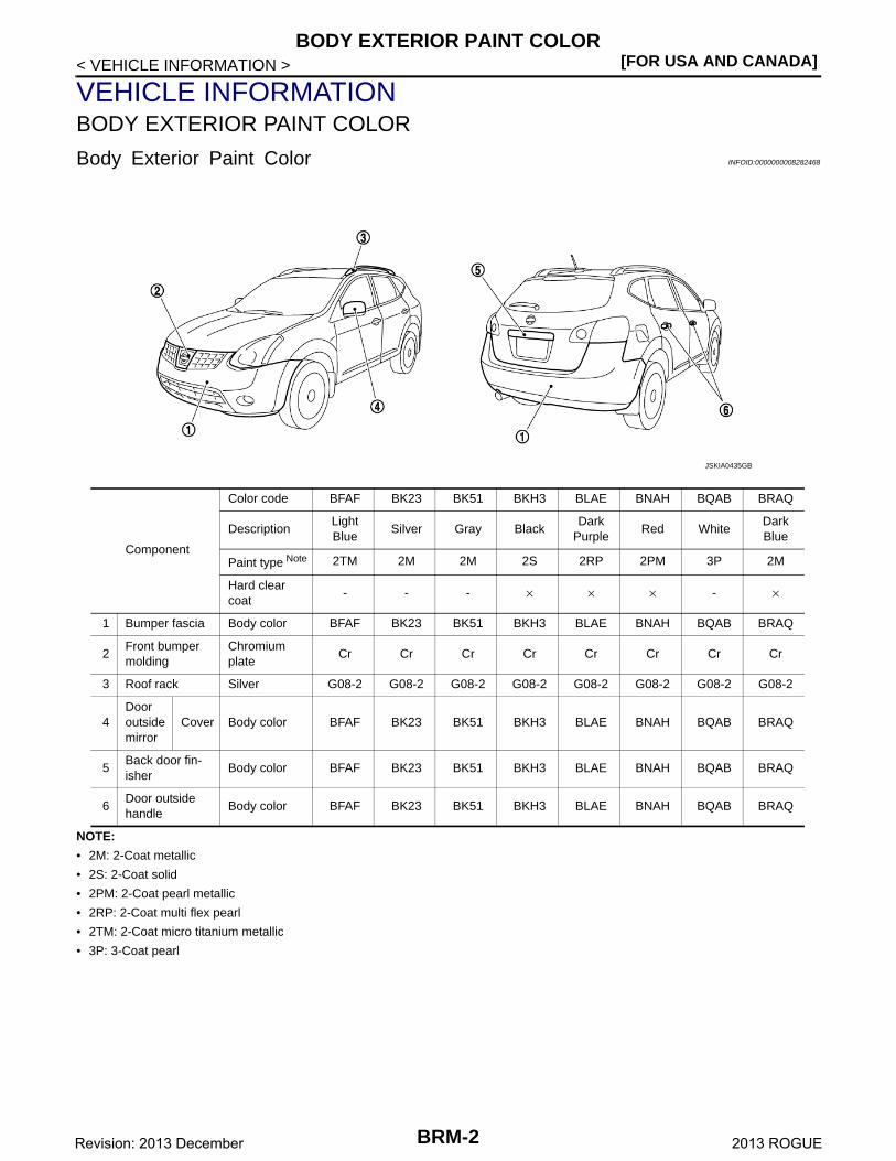
Body Exterior Paint Color INFOID:0000000008282468
NOTE:
• 2M: 2-Coat metallic
• 2S: 2-Coat solid
• 2PM: 2-Coat pearl metallic
• 2RP: 2-Coat multi flex pearl
• 2TM: 2-Coat micro titanium metallic
• 3P: 3-Coat pearl
Component
Color code BFAF BK23 BK51 BKH3 BLAE BNAH BQAB BRAQ
DescriptionLight Blue
Silver Gray BlackDark
PurpleRed White
Dark Blue
Paint type Note 2TM 2M 2M 2S 2RP 2PM 3P 2M
Hard clear coat
- - - × × × - ×
1 Bumper fascia Body color BFAF BK23 BK51 BKH3 BLAE BNAH BQAB BRAQ
2Front bumper molding
Chromium plate
Cr Cr Cr Cr Cr Cr Cr Cr
3 Roof rack Silver G08-2 G08-2 G08-2 G08-2 G08-2 G08-2 G08-2 G08-2
4Door outside mirror
Cover Body color BFAF BK23 BK51 BKH3 BLAE BNAH BQAB BRAQ
5Back door fin-isher
Body color BFAF BK23 BK51 BKH3 BLAE BNAH BQAB BRAQ
6Door outside handle
Body color BFAF BK23 BK51 BKH3 BLAE BNAH BQAB BRAQ
JSKIA0435GB
BRM-2Revision: 2013 December 2013 ROGUE
REPAIRING HIGH STRENGTH STEEL[FOR USA AND CANADA]
C
D
E
F
G
H
I
J
L
M
A
B
RM
N
O
P
< PRECAUTION >
B
PRECAUTIONREPAIRING HIGH STRENGTH STEEL
High Strength Steel (HSS) INFOID:0000000008282469
High strength steel is used for body panels in order to reduce vehicle weight.Accordingly, precautions in repairing automotive bodies made of high strength steel are described below:
Read the following precautions when repairing HSS:1. Additional points to consider
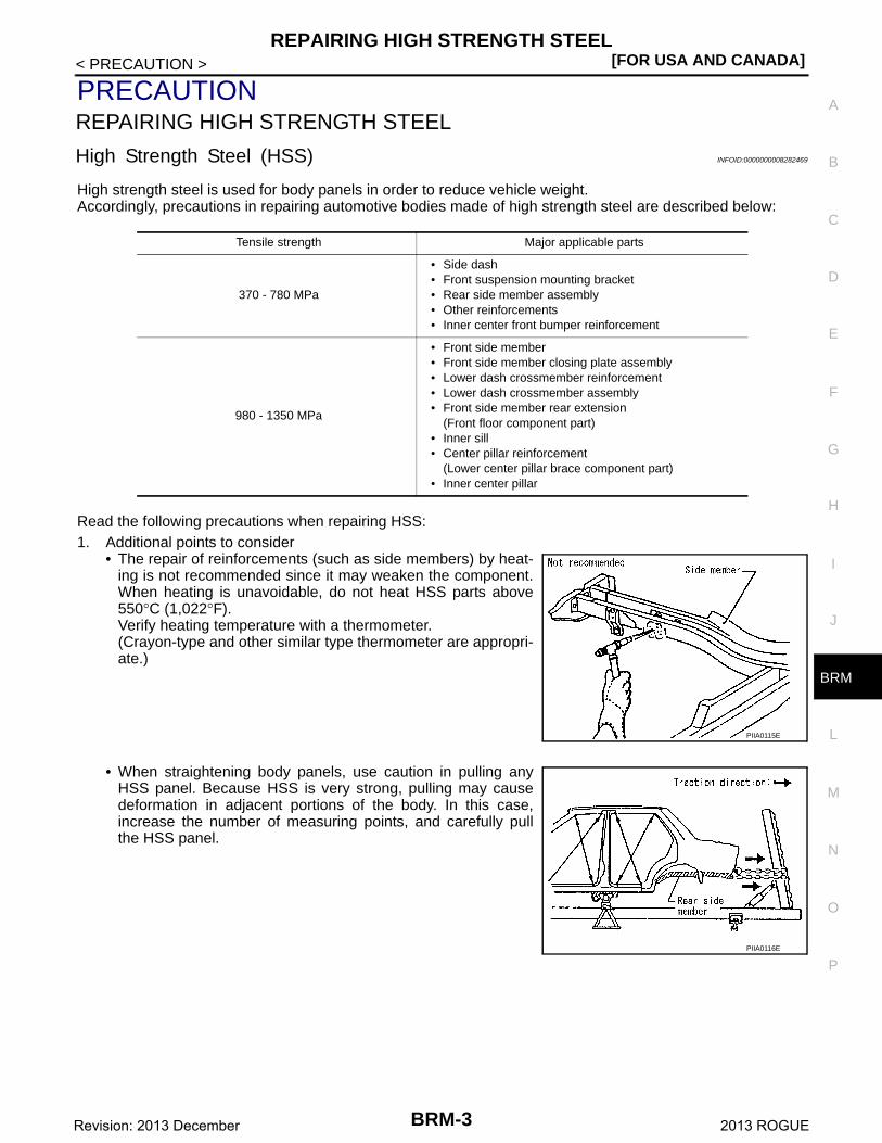
• The repair of reinforcements (such as side members) by heat-ing is not recommended since it may weaken the component.When heating is unavoidable, do not heat HSS parts above550°C (1,022°F).Verify heating temperature with a thermometer.(Crayon-type and other similar type thermometer are appropri-ate.)
• When straightening body panels, use caution in pulling anyHSS panel. Because HSS is very strong, pulling may causedeformation in adjacent portions of the body. In this case,increase the number of measuring points, and carefully pullthe HSS panel.
Tensile strength Major applicable parts
370 - 780 MPa
• Side dash• Front suspension mounting bracket• Rear side member assembly• Other reinforcements• Inner center front bumper reinforcement
980 - 1350 MPa
• Front side member• Front side member closing plate assembly• Lower dash crossmember reinforcement• Lower dash crossmember assembly• Front side member rear extension
(Front floor component part)• Inner sill• Center pillar reinforcement
(Lower center pillar brace component part)• Inner center pillar
PIIA0115E
PIIA0116E
BRM-3Revision: 2013 December 2013 ROGUE
[FOR USA AND CANADA]REPAIRING HIGH STRENGTH STEEL
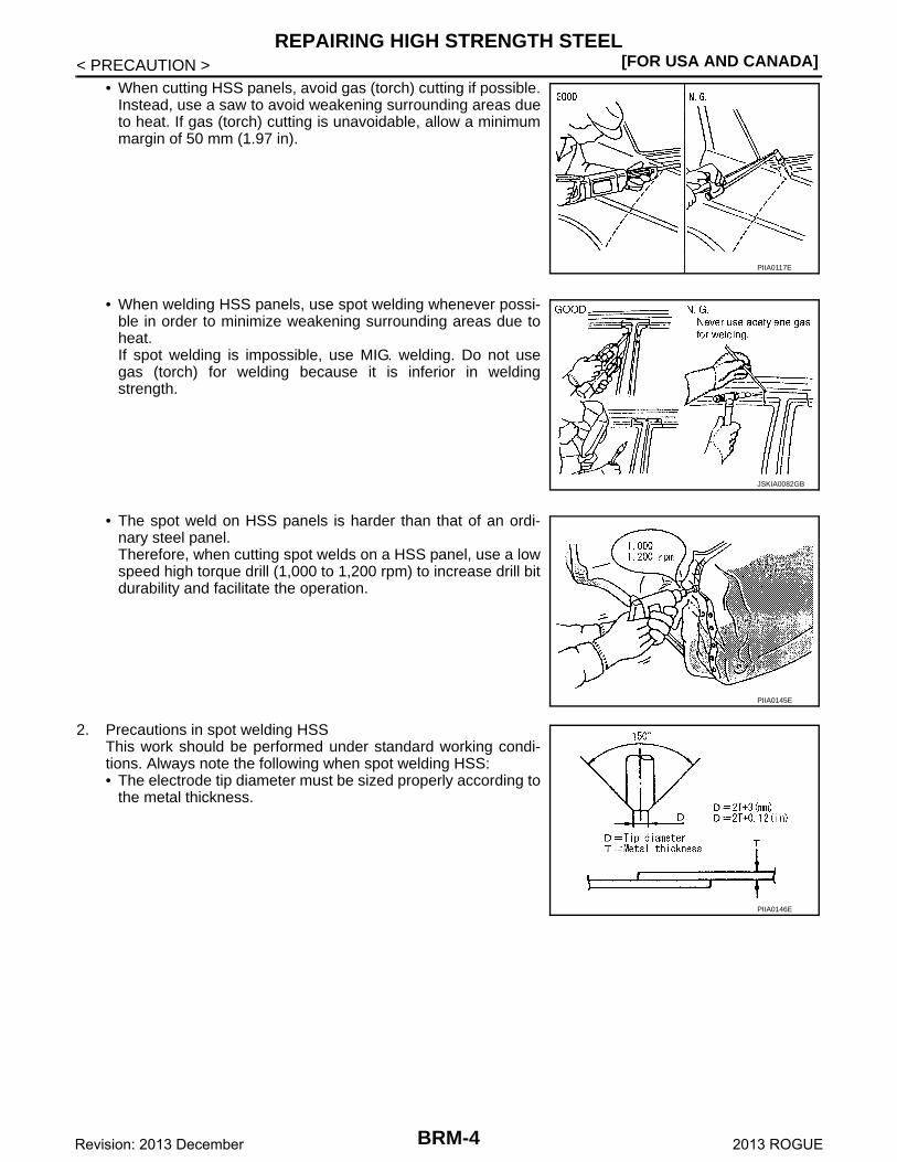
< PRECAUTION >• When cutting HSS panels, avoid gas (torch) cutting if possible.
Instead, use a saw to avoid weakening surrounding areas dueto heat. If gas (torch) cutting is unavoidable, allow a minimummargin of 50 mm (1.97 in).
• When welding HSS panels, use spot welding whenever possi-ble in order to minimize weakening surrounding areas due toheat.If spot welding is impossible, use MIG. welding. Do not usegas (torch) for welding because it is inferior in weldingstrength.
• The spot weld on HSS panels is harder than that of an ordi-nary steel panel.Therefore, when cutting spot welds on a HSS panel, use a lowspeed high torque drill (1,000 to 1,200 rpm) to increase drill bitdurability and facilitate the operation.
2. Precautions in spot welding HSSThis work should be performed under standard working condi-tions. Always note the following when spot welding HSS:• The electrode tip diameter must be sized properly according to
the metal thickness.
PIIA0117E
JSKIA0082GB
PIIA0145E
PIIA0146E
BRM-4Revision: 2013 December 2013 ROGUE
REPAIRING HIGH STRENGTH STEEL[FOR USA AND CANADA]
C
D
E
F
G
H
I
J
L
M
A
B
RM
N
O
P
< PRECAUTION >
B
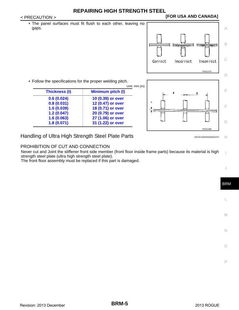
• The panel surfaces must fit flush to each other, leaving nogaps.
• Follow the specifications for the proper welding pitch.Unit: mm (in)
Handling of Ultra High Strength Steel Plate Parts INFOID:0000000008282470
PROHIBITION OF CUT AND CONNECTIONNever cut and Joint the stiffener front side member (front floor inside frame parts) because its material is highstrength steel plate (ultra high strength steel plate). The front floor assembly must be replaced if this part is damaged.
PIIA0147E
Thickness (t) Minimum pitch (l)
0.6 (0.024)0.8 (0.031)1.0 (0.039)1.2 (0.047)1.6 (0.063)1.8 (0.071)
10 (0.39) or over12 (0.47) or over18 (0.71) or over20 (0.79) or over27 (1.06) or over31 (1.22) or over
PIIA0148E
BRM-5Revision: 2013 December 2013 ROGUE
[FOR USA AND CANADA]REPAIRING MATERIAL
< PREPARATION >
PREPARATIONREPAIRING MATERIAL
Foam Repair INFOID:0000000008282471
During factory body assembly, foam insulators are installed in certain body panels and locations around thevehicle. Use the following procedure(s) to replace any factory-installed foam insulators.
URETHANE FOAM APPLICATIONSUse commercially available Urethane foam for sealant (foam material) repair of material used on vehicle.
Read instructions on product for fill procedures.
Example of foaming agent filling operation procedure
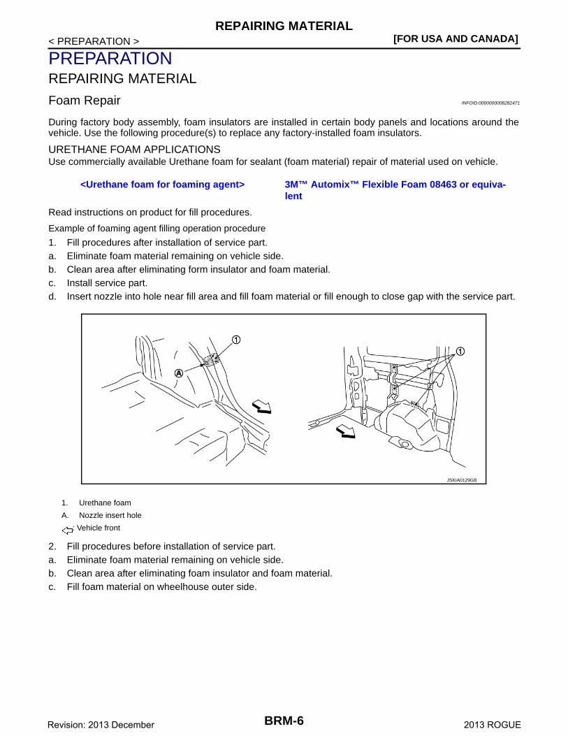
1. Fill procedures after installation of service part.a. Eliminate foam material remaining on vehicle side.b. Clean area after eliminating form insulator and foam material.c. Install service part.d. Insert nozzle into hole near fill area and fill foam material or fill enough to close gap with the service part.
2. Fill procedures before installation of service part.a. Eliminate foam material remaining on vehicle side.b. Clean area after eliminating foam insulator and foam material.c. Fill foam material on wheelhouse outer side.
<Urethane foam for foaming agent> 3M™ Automix™ Flexible Foam 08463 or equiva-lent
1. Urethane foam
A. Nozzle insert hole
: Vehicle front
JSKIA0129GB
BRM-6Revision: 2013 December 2013 ROGUE
REPAIRING MATERIAL[FOR USA AND CANADA]
C
D
E
F
G
H
I
J
L
M
A
B
RM
N
O
P
< PREPARATION >
B
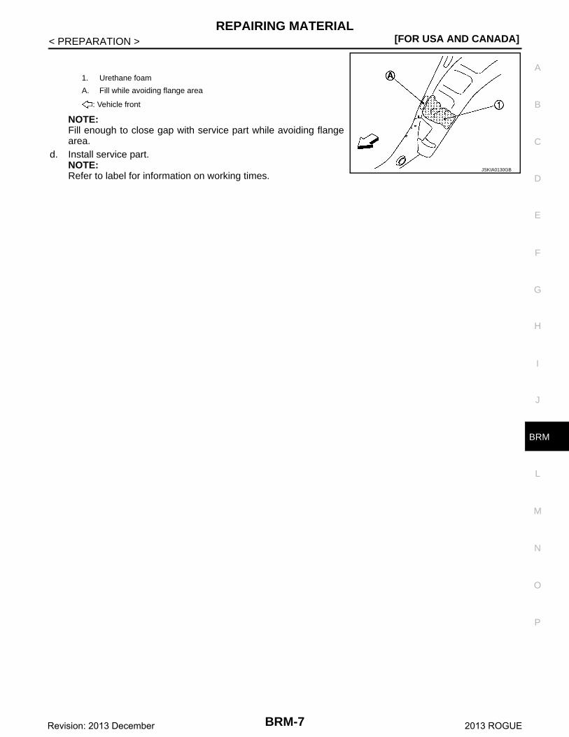
NOTE:Fill enough to close gap with service part while avoiding flangearea.
d. Install service part.NOTE:Refer to label for information on working times.
1. Urethane foam
A. Fill while avoiding flange area
: Vehicle front
JSKIA0130GB
BRM-7Revision: 2013 December 2013 ROGUE
[FOR USA AND CANADA]BODY COMPONENT PARTS
< PREPARATION >
BODY COMPONENT PARTS
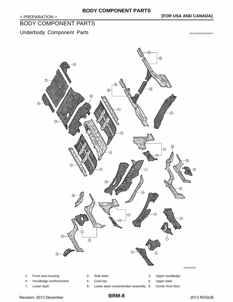
Underbody Component Parts INFOID:0000000008282472
1. Front strut housing 2. Side dash 3. Upper hoodledge
4. Hoodledge reinforcement 5. Cowl top 6. Upper dash
7. Lower dash 8. Lower dash crossmember assembly 9. Center front floor
JSKIA0438GB
BRM-8Revision: 2013 December 2013 ROGUE
BODY COMPONENT PARTS[FOR USA AND CANADA]
C
D
E
F
G
H
I
J
L
M
A
B
RM
N
O
P
< PREPARATION >
B
10. Front floor 11. Inner sill 12. Rear floor front extension
13. Rear floor front 14. Rear floor rear 15. Rear floor side
16. Front side member 17. Engine mounting member bracket 18. Front side member closing plate as-sembly
19. Hoodledge connector assembly 20. Front suspension mounting bracket 21. Rear seat crossmember
22. Center rear crossmember assembly 23. Rear side member assembly 24. Rear side member extension
: Both sided anti-corrosive precoated steel portions
: High strength steel (HSS) portions
: Both sided anti-corrosive steel and HSS portions
BRM-9Revision: 2013 December 2013 ROGUE
[FOR USA AND CANADA]BODY COMPONENT PARTS
< PREPARATION >
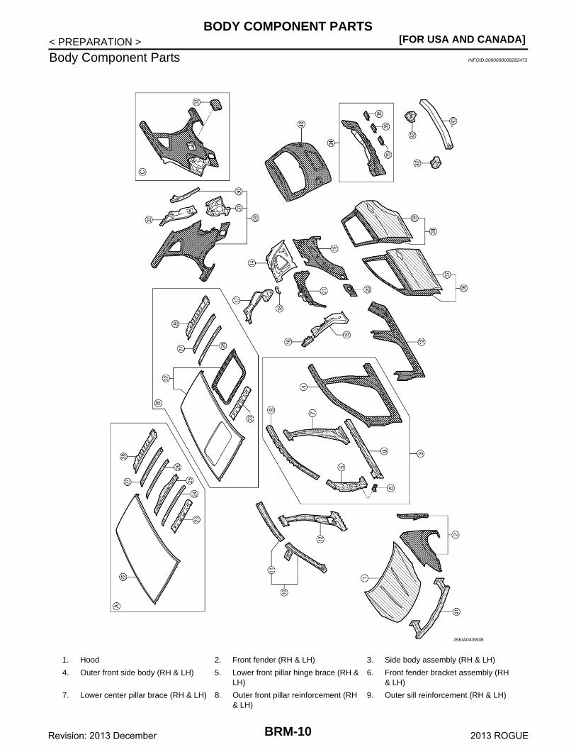
Body Component Parts INFOID:0000000008282473
1. Hood 2. Front fender (RH & LH) 3. Side body assembly (RH & LH)
4. Outer front side body (RH & LH) 5. Lower front pillar hinge brace (RH & LH)
6. Front fender bracket assembly (RH & LH)
7. Lower center pillar brace (RH & LH) 8. Outer front pillar reinforcement (RH & LH)
9. Outer sill reinforcement (RH & LH)
JSKIA0439GB
BRM-10Revision: 2013 December 2013 ROGUE
BODY COMPONENT PARTS[FOR USA AND CANADA]
C
D
E
F
G
H
I
J
L
M
A
B
RM
N
O
P
< PREPARATION >
B
10. Upper inner front pillar (RH & LH) 11. Inner side roof rail (RH & LH) 12. Inner center pillar (RH & LH)
13. Outer sill (RH & LH) 14. Inner rear pillar (RH & LH) 15. Inner rear pillar reinforcement (RH & LH)
16. Rear pillar seat belt anchor (RH & LH)
17. Back pillar main assembly (RH & LH) 18. Trim mounting bracket (RH & LH)
19. Outer rear wheelhouse (RH & LH) 20. Outer rear wheelhouse extension (RH & LH)
21. Inner rear wheelhouse (RH & LH)
22. Roof 23. Front roof rail 24. Roof bow No. 1
25. Roof bow No. 2 26. Roof bow No. 3 27. Roof bow No. 4
28. Rear roof rail 29. Rear fender assembly (RH & LH) 30. Outer back pillar (RH & LH)
31. Rear combination lamp base (RH & LH)
32. Back pillar reinforcement assembly (RH & LH)
33. Fuel filler lid
34. Rear panel assembly 35. Upper rear bumper retainer 36. Front door assembly (RH & LH)
37. Outer front door panel (RH & LH) 38. Rear door assembly (RH & LH) 39. Outer rear door panel (RH & LH)
40. Back door 41. Front bumper reinforcement assem-bly
42. Rear bumper stay
43. Inner center rear bumper reinforce-ment
A. Standard roof B. With sunroof C. RH side
: Both sided anti-corrosive precoated steel portions
: High strength steel (HSS) portions
: Both sided anti-corrosive steel and HSS portions
* : Aluminum portion
BRM-11Revision: 2013 December 2013 ROGUE
[FOR USA AND CANADA]CORROSION PROTECTION
< REMOVAL AND INSTALLATION >
REMOVAL AND INSTALLATIONCORROSION PROTECTION
Description INFOID:0000000008282474
To provide improved corrosion prevention, the following anti-corrosive measures have been implemented inNISSAN production plants. When repairing or replacing body panels, it is necessary to use the same anti-cor-rosive measures.
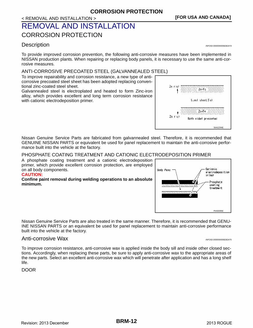
ANTI-CORROSIVE PRECOATED STEEL (GALVANNEALED STEEL)To improve repairability and corrosion resistance, a new type of anti-corrosive precoated steel sheet has been adopted replacing conven-tional zinc-coated steel sheet.Galvannealed steel is electroplated and heated to form Zinc-ironalloy, which provides excellent and long term corrosion resistancewith cationic electrodeposition primer.
Nissan Genuine Service Parts are fabricated from galvannealed steel. Therefore, it is recommended thatGENUINE NISSAN PARTS or equivalent be used for panel replacement to maintain the anti-corrosive perfor-mance built into the vehicle at the factory.
PHOSPHATE COATING TREATMENT AND CATIONIC ELECTRODEPOSITION PRIMERA phosphate coating treatment and a cationic electrodepositionprimer, which provide excellent corrosion protection, are employedon all body components.CAUTION:Confine paint removal during welding operations to an absoluteminimum.
Nissan Genuine Service Parts are also treated in the same manner. Therefore, it is recommended that GENU-INE NISSAN PARTS or an equivalent be used for panel replacement to maintain anti-corrosive performancebuilt into the vehicle at the factory.
Anti-corrosive Wax INFOID:0000000008282475
To improve corrosion resistance, anti-corrosive wax is applied inside the body sill and inside other closed sec-tions. Accordingly, when replacing these parts, be sure to apply anti-corrosive wax to the appropriate areas ofthe new parts. Select an excellent anti-corrosive wax which will penetrate after application and has a long shelflife.
DOOR
SIIA2294E
PIIA0095E
BRM-12Revision: 2013 December 2013 ROGUE
CORROSION PROTECTION[FOR USA AND CANADA]
C
D
E
F
G
H
I
J
L
M
A
B
RM
N
O
P
< REMOVAL AND INSTALLATION >
B
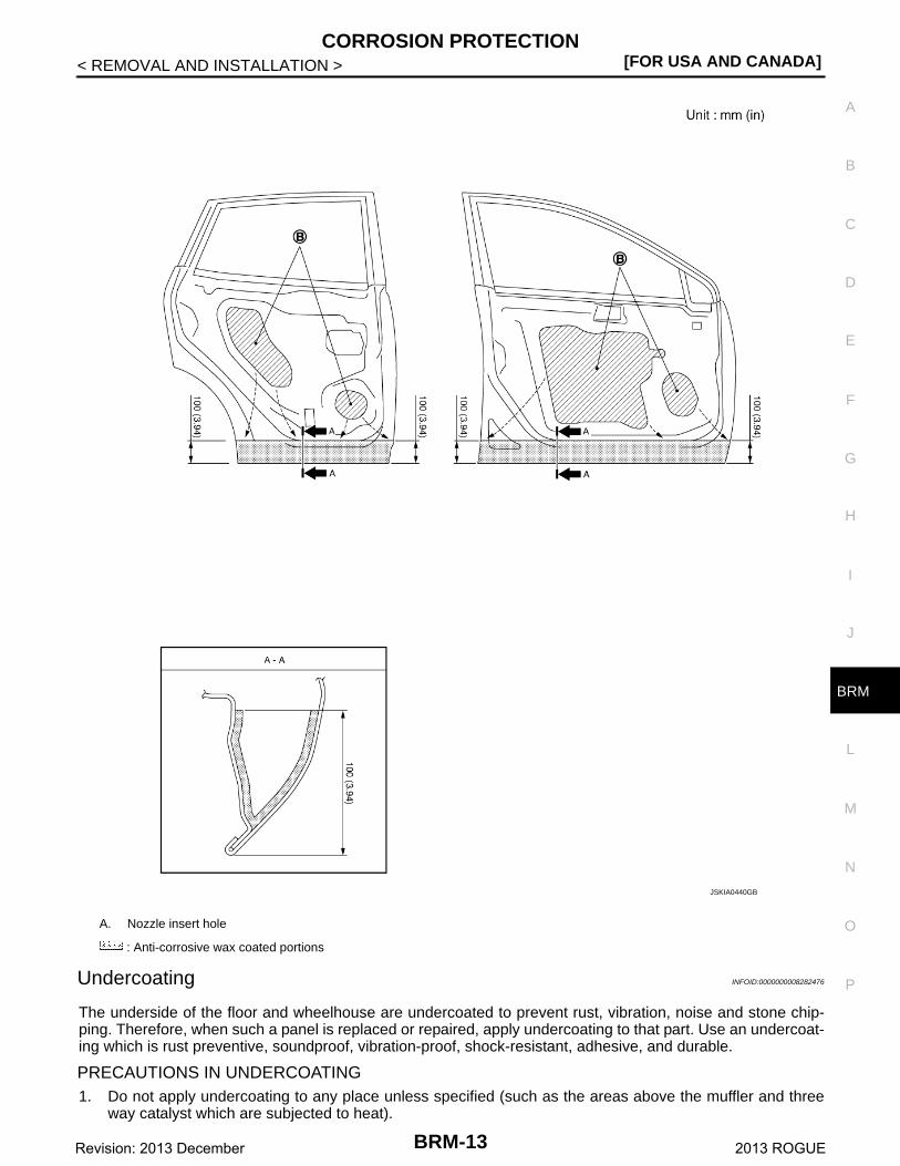
Undercoating INFOID:0000000008282476
The underside of the floor and wheelhouse are undercoated to prevent rust, vibration, noise and stone chip-ping. Therefore, when such a panel is replaced or repaired, apply undercoating to that part. Use an undercoat-ing which is rust preventive, soundproof, vibration-proof, shock-resistant, adhesive, and durable.
PRECAUTIONS IN UNDERCOATING1. Do not apply undercoating to any place unless specified (such as the areas above the muffler and three
way catalyst which are subjected to heat).
A. Nozzle insert hole
: Anti-corrosive wax coated portions
JSKIA0440GB
BRM-13Revision: 2013 December 2013 ROGUE
[FOR USA AND CANADA]CORROSION PROTECTION
< REMOVAL AND INSTALLATION >2. Do not undercoat the exhaust pipe or other parts which become hot.3. Do not undercoat rotating parts.4. Apply bitumen wax after applying undercoating.5. After putting seal on the vehicle, put undercoating on it.
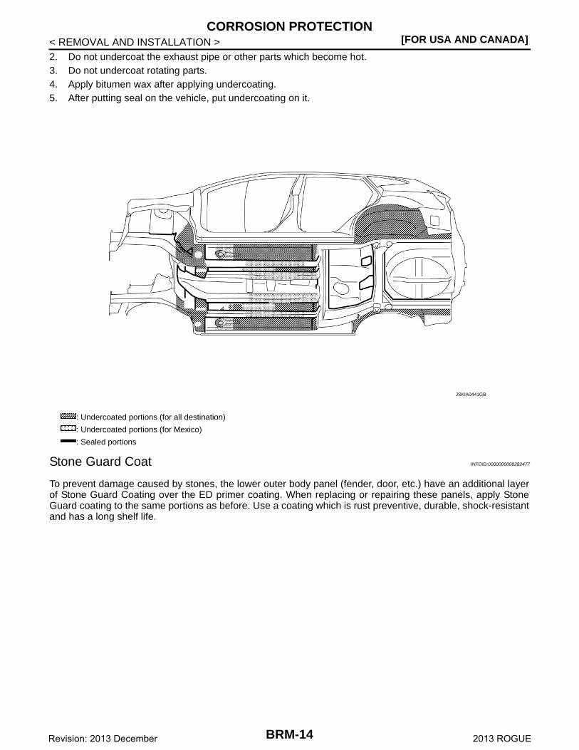
Stone Guard Coat INFOID:0000000008282477
To prevent damage caused by stones, the lower outer body panel (fender, door, etc.) have an additional layerof Stone Guard Coating over the ED primer coating. When replacing or repairing these panels, apply StoneGuard coating to the same portions as before. Use a coating which is rust preventive, durable, shock-resistantand has a long shelf life.
: Undercoated portions (for all destination)
: Undercoated portions (for Mexico)
: Sealed portions
JSKIA0441GB
BRM-14Revision: 2013 December 2013 ROGUE
CORROSION PROTECTION[FOR USA AND CANADA]
C
D
E
F
G
H
I
J
L
M
A
B
RM
N
O
P
< REMOVAL AND INSTALLATION >
B
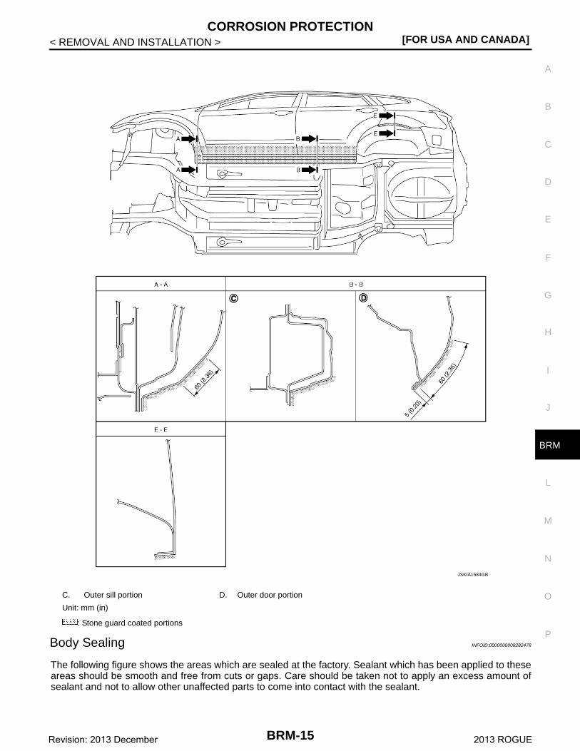
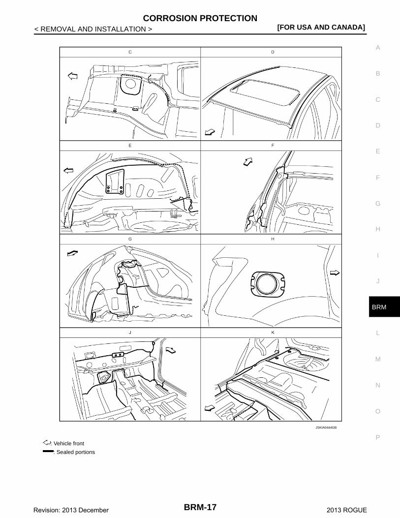
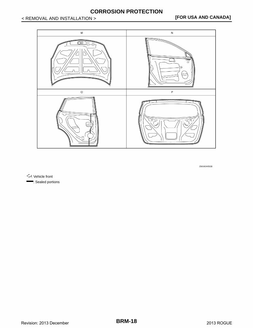
Body Sealing INFOID:0000000008282478
The following figure shows the areas which are sealed at the factory. Sealant which has been applied to theseareas should be smooth and free from cuts or gaps. Care should be taken not to apply an excess amount ofsealant and not to allow other unaffected parts to come into contact with the sealant.
C. Outer sill portion D. Outer door portion
Unit: mm (in)
: Stone guard coated portions
JSKIA1584GB
BRM-15Revision: 2013 December 2013 ROGUE
[FOR USA AND CANADA]CORROSION PROTECTION
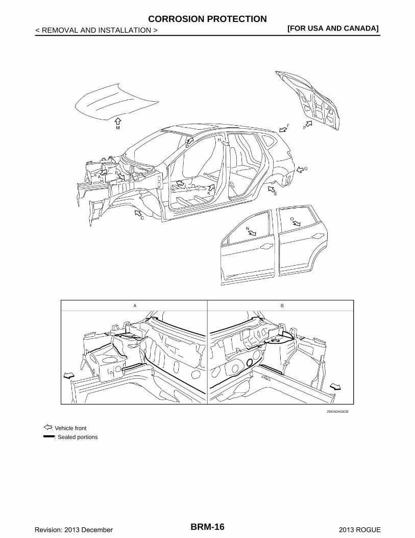
< REMOVAL AND INSTALLATION >
: Vehicle front
: Sealed portions
JSKIA0443GB
BRM-16Revision: 2013 December 2013 ROGUE
CORROSION PROTECTION[FOR USA AND CANADA]
C
D
E
F
G
H
I
J
L
M
A
B
RM
N
O
P
< REMOVAL AND INSTALLATION >
B
: Vehicle front
: Sealed portions
JSKIA0444GB
BRM-17Revision: 2013 December 2013 ROGUE
[FOR USA AND CANADA]CORROSION PROTECTION
< REMOVAL AND INSTALLATION >
: Vehicle front
: Sealed portions
JSKIA0445GB
BRM-18Revision: 2013 December 2013 ROGUE
BODY CONSTRUCTION[FOR USA AND CANADA]
C
D
E
F
G
H
I
J
L
M
A
B
RM
N
O
P
< REMOVAL AND INSTALLATION >
B
BODY CONSTRUCTION
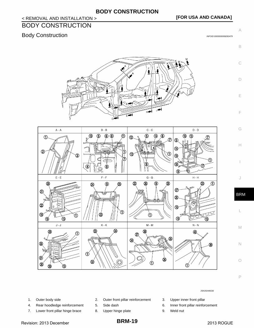
Body Construction INFOID:0000000008282479
1. Outer body side 2. Outer front pillar reinforcement 3. Upper inner front pillar
4. Rear hoodledge reinforcement 5. Side dash 6. Inner front pillar reinforcement
7. Lower front pillar hinge brace 8. Upper hinge plate 9. Weld nut
JSKIA0446GB
BRM-19Revision: 2013 December 2013 ROGUE
[FOR USA AND CANADA]BODY CONSTRUCTION
< REMOVAL AND INSTALLATION >
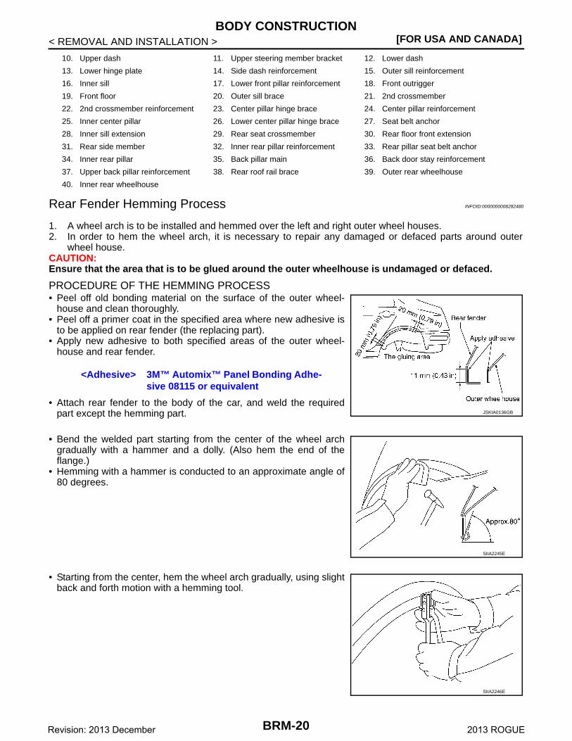
Rear Fender Hemming Process INFOID:0000000008282480
1. A wheel arch is to be installed and hemmed over the left and right outer wheel houses.2. In order to hem the wheel arch, it is necessary to repair any damaged or defaced parts around outer
wheel house.CAUTION:Ensure that the area that is to be glued around the outer wheelhouse is undamaged or defaced.
PROCEDURE OF THE HEMMING PROCESS• Peel off old bonding material on the surface of the outer wheel-
house and clean thoroughly.• Peel off a primer coat in the specified area where new adhesive is
to be applied on rear fender (the replacing part).• Apply new adhesive to both specified areas of the outer wheel-
house and rear fender.
• Attach rear fender to the body of the car, and weld the requiredpart except the hemming part.
• Bend the welded part starting from the center of the wheel archgradually with a hammer and a dolly. (Also hem the end of theflange.)
• Hemming with a hammer is conducted to an approximate angle of80 degrees.
• Starting from the center, hem the wheel arch gradually, using slightback and forth motion with a hemming tool.
10. Upper dash 11. Upper steering member bracket 12. Lower dash
13. Lower hinge plate 14. Side dash reinforcement 15. Outer sill reinforcement
16. Inner sill 17. Lower front pillar reinforcement 18. Front outrigger
19. Front floor 20. Outer sill brace 21. 2nd crossmember
22. 2nd crossmember reinforcement 23. Center pillar hinge brace 24. Center pillar reinforcement
25. Inner center pillar 26. Lower center pillar hinge brace 27. Seat belt anchor
28. Inner sill extension 29. Rear seat crossmember 30. Rear floor front extension
31. Rear side member 32. Inner rear pillar reinforcement 33. Rear pillar seat belt anchor
34. Inner rear pillar 35. Back pillar main 36. Back door stay reinforcement
37. Upper back pillar reinforcement 38. Rear roof rail brace 39. Outer rear wheelhouse
40. Inner rear wheelhouse
<Adhesive> 3M™ Automix™ Panel Bonding Adhe-sive 08115 or equivalent
JSKIA0136GB
SIIA2245E
SIIA2246E
BRM-20Revision: 2013 December 2013 ROGUE
BODY CONSTRUCTION[FOR USA AND CANADA]
C
D
E
F
G
H
I
J
L
M
A
B
RM
N
O
P
< REMOVAL AND INSTALLATION >
B
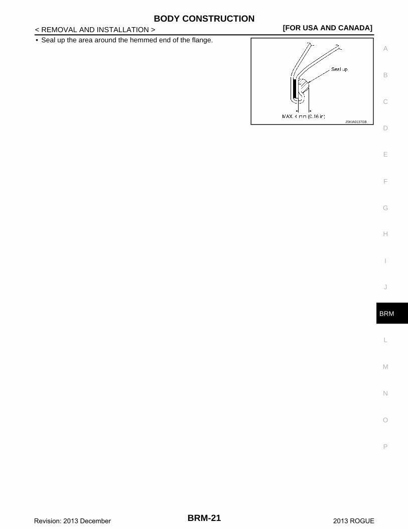
• Seal up the area around the hemmed end of the flange.
JSKIA0137GB
BRM-21Revision: 2013 December 2013 ROGUE
[FOR USA AND CANADA]REPLACEMENT OPERATIONS
< REMOVAL AND INSTALLATION >
REPLACEMENT OPERATIONS
Description INFOID:0000000008282481
• This section is prepared for technicians who have attained a high level of skill and experience in repairingcollision-damaged vehicles and also use modern service tools and equipment. Persons unfamiliar with bodyrepair techniques should not attempt to repair collision-damaged vehicles by using this section.
• Technicians are also encouraged to read Body Repair Manual (Fundamentals) in order to ensure that theoriginal functions and quality of the vehicle can be maintained. The Body Repair Manual (Fundamentals)contains additional information, including cautions and warning, that are not including in this manual. Techni-cians should refer to both manuals to ensure proper repairs.
• Please note that these information are prepared for worldwide usage, and as such, certain procedures mightnot apply in some regions or countries.
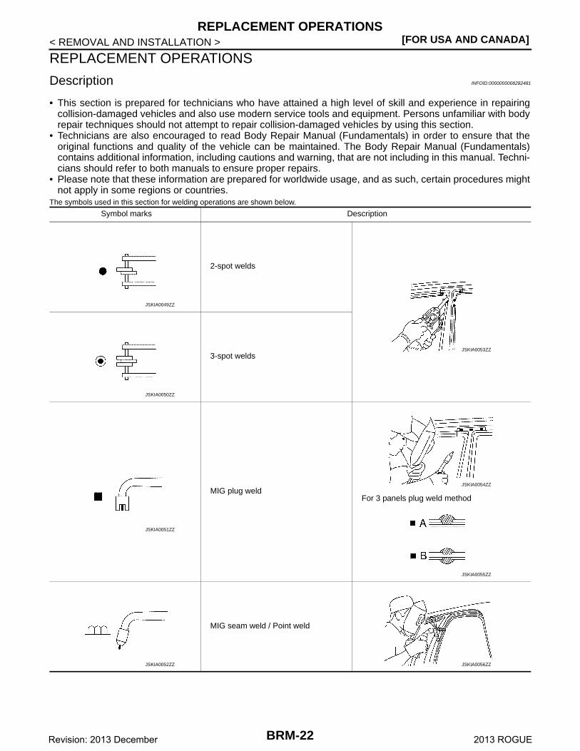
The symbols used in this section for welding operations are shown below.
Symbol marks Description
2-spot welds
3-spot welds
MIG plug weldFor 3 panels plug weld method
MIG seam weld / Point weld
JSKIA0049ZZ
JSKIA0053ZZ
JSKIA0050ZZ
JSKIA0051ZZ
JSKIA0054ZZ
JSKIA0055ZZ
JSKIA0052ZZ JSKIA0056ZZ
BRM-22Revision: 2013 December 2013 ROGUE
REPLACEMENT OPERATIONS[FOR USA AND CANADA]
C
D
E
F
G
H
I
J
L
M
A
B
RM
N
O
P
< REMOVAL AND INSTALLATION >
B
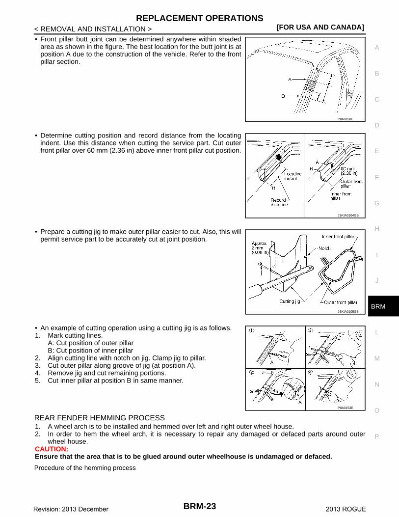
• Front pillar butt joint can be determined anywhere within shadedarea as shown in the figure. The best location for the butt joint is atposition A due to the construction of the vehicle. Refer to the frontpillar section.
• Determine cutting position and record distance from the locatingindent. Use this distance when cutting the service part. Cut outerfront pillar over 60 mm (2.36 in) above inner front pillar cut position.
• Prepare a cutting jig to make outer pillar easier to cut. Also, this willpermit service part to be accurately cut at joint position.
• An example of cutting operation using a cutting jig is as follows.1. Mark cutting lines.
A: Cut position of outer pillarB: Cut position of inner pillar
2. Align cutting line with notch on jig. Clamp jig to pillar.3. Cut outer pillar along groove of jig (at position A).4. Remove jig and cut remaining portions.5. Cut inner pillar at position B in same manner.
REAR FENDER HEMMING PROCESS1. A wheel arch is to be installed and hemmed over left and right outer wheel house.2. In order to hem the wheel arch, it is necessary to repair any damaged or defaced parts around outer
wheel house.CAUTION:Ensure that the area that is to be glued around outer wheelhouse is undamaged or defaced.
Procedure of the hemming process
PIIA0150E
JSKIA0104GB
JSKIA0105GB
PIIA0153E
BRM-23Revision: 2013 December 2013 ROGUE
[FOR USA AND CANADA]REPLACEMENT OPERATIONS
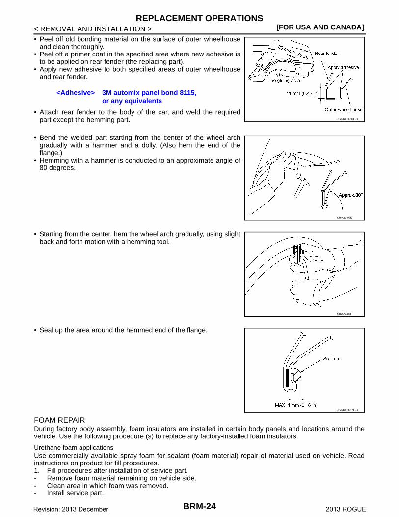
< REMOVAL AND INSTALLATION >• Peel off old bonding material on the surface of outer wheelhouse
and clean thoroughly.• Peel off a primer coat in the specified area where new adhesive is
to be applied on rear fender (the replacing part).• Apply new adhesive to both specified areas of outer wheelhouse
and rear fender.
• Attach rear fender to the body of the car, and weld the requiredpart except the hemming part.
• Bend the welded part starting from the center of the wheel archgradually with a hammer and a dolly. (Also hem the end of theflange.)
• Hemming with a hammer is conducted to an approximate angle of80 degrees.
• Starting from the center, hem the wheel arch gradually, using slightback and forth motion with a hemming tool.
• Seal up the area around the hemmed end of the flange.
FOAM REPAIRDuring factory body assembly, foam insulators are installed in certain body panels and locations around thevehicle. Use the following procedure (s) to replace any factory-installed foam insulators.
Urethane foam applicationsUse commercially available spray foam for sealant (foam material) repair of material used on vehicle. Readinstructions on product for fill procedures.1. Fill procedures after installation of service part.- Remove foam material remaining on vehicle side.- Clean area in which foam was removed.- Install service part.
<Adhesive> 3M automix panel bond 8115,or any equivalents
JSKIA0136GB
SIIA2245E
SIIA2246E
JSKIA0137GB
BRM-24Revision: 2013 December 2013 ROGUE
REPLACEMENT OPERATIONS[FOR USA AND CANADA]
C
D
E
F
G
H
I
J
L
M
A
B
RM
N
O
P
< REMOVAL AND INSTALLATION >
B
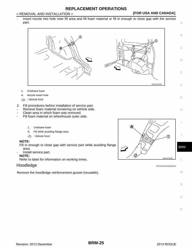
- Insert nozzle into hole near fill area and fill foam material or fill in enough to close gap with the servicepart.
2. Fill procedures before installation of service part.- Remove foam material remaining on vehicle side.- Clean area in which foam was removed.- Fill foam material on wheelhouse outer side.
NOTE:Fill in enough to close gap with service part while avoiding flange
area.- Install service part.
NOTE:Refer to label for information on working times.
Hoodledge INFOID:0000000008282482
Remove the hoodledge reinforcement gusset (reusable).
1. Urethane foam
A. Nozzle insert hole
: Vehicle front
1. Urethane foam
A. Fill while avoiding flange area
: Vehicle front
JSKIA0129GB
JSKIA0130GB
BRM-25Revision: 2013 December 2013 ROGUE
[FOR USA AND CANADA]REPLACEMENT OPERATIONS
< REMOVAL AND INSTALLATION >
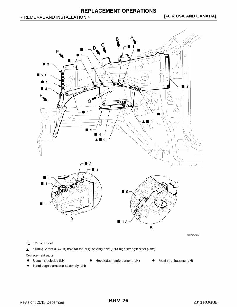
: Vehicle front
: Drill φ12 mm (0.47 in) hole for the plug welding hole (ultra high strength steel plate).
Replacement parts
Upper hoodledge (LH) Hoodledge reinforcement (LH) Front strut housing (LH)
Hoodledge connector assembly (LH)
JSKIA0404GB
BRM-26Revision: 2013 December 2013 ROGUE
REPLACEMENT OPERATIONS[FOR USA AND CANADA]
C
D
E
F
G
H
I
J
L
M
A
B
RM
N
O
P
< REMOVAL AND INSTALLATION >
B
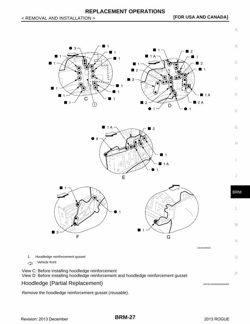
View C: Before installing hoodledge reinforcementView D: Before installing hoodledge reinforcement and hoodledge reinforcement gusset
Hoodledge (Partial Replacement) INFOID:0000000008282483
Remove the hoodledge reinforcement gusset (reusable).
1. Hoodledge reinforcement gusset
: Vehicle front
JSKIA0405GB
BRM-27Revision: 2013 December 2013 ROGUE
[FOR USA AND CANADA]REPLACEMENT OPERATIONS
< REMOVAL AND INSTALLATION >
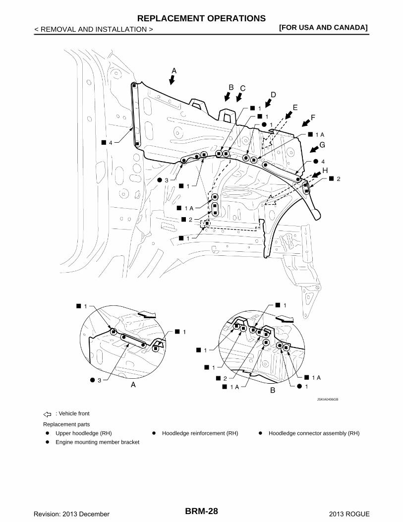
: Vehicle front
Replacement parts
Upper hoodledge (RH) Hoodledge reinforcement (RH) Hoodledge connector assembly (RH)
Engine mounting member bracket
JSKIA0406GB
BRM-28Revision: 2013 December 2013 ROGUE
REPLACEMENT OPERATIONS[FOR USA AND CANADA]
C
D
E
F
G
H
I
J
L
M
A
B
RM
N
O
P
< REMOVAL AND INSTALLATION >
B
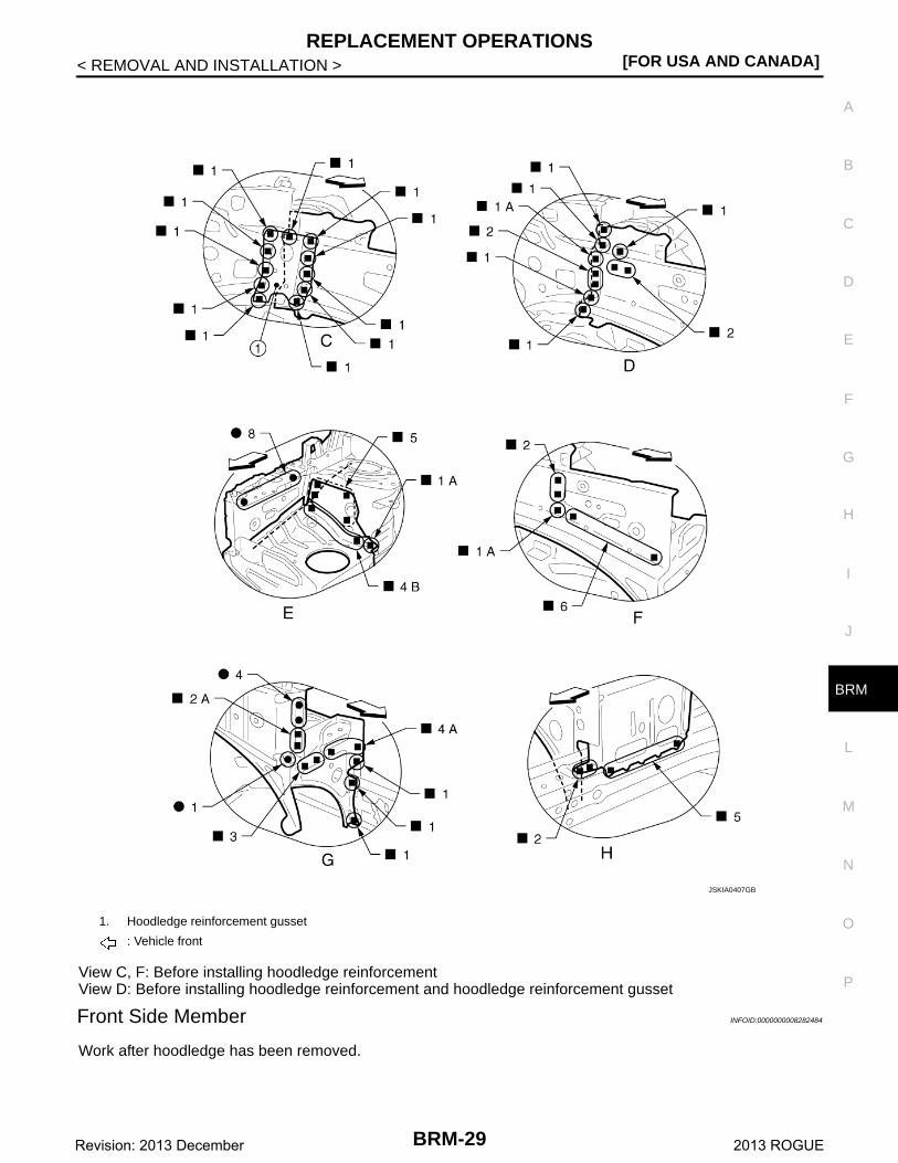
View C, F: Before installing hoodledge reinforcementView D: Before installing hoodledge reinforcement and hoodledge reinforcement gusset
Front Side Member INFOID:0000000008282484
Work after hoodledge has been removed.
1. Hoodledge reinforcement gusset
: Vehicle front
JSKIA0407GB
BRM-29Revision: 2013 December 2013 ROGUE
[FOR USA AND CANADA]REPLACEMENT OPERATIONS
< REMOVAL AND INSTALLATION >
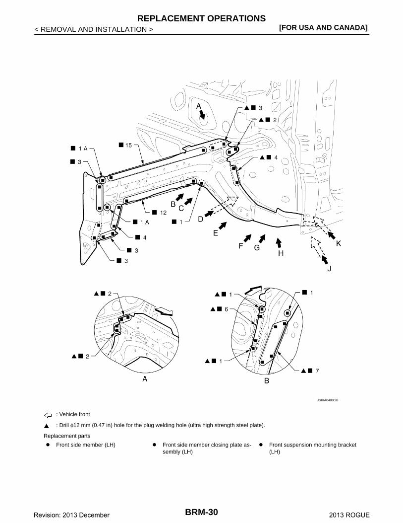
: Vehicle front
: Drill φ12 mm (0.47 in) hole for the plug welding hole (ultra high strength steel plate).
Replacement parts
Front side member (LH) Front side member closing plate as-sembly (LH)
Front suspension mounting bracket (LH)
JSKIA0408GB
BRM-30Revision: 2013 December 2013 ROGUE
REPLACEMENT OPERATIONS[FOR USA AND CANADA]
C
D
E
F
G
H
I
J
L
M
A
B
RM
N
O
P
< REMOVAL AND INSTALLATION >
B
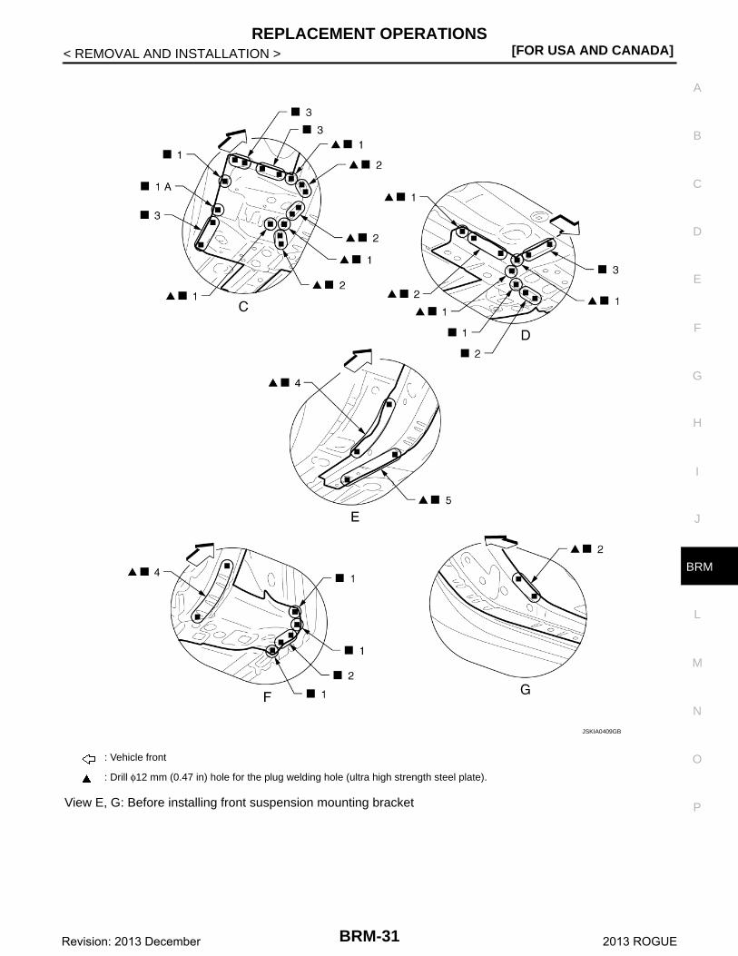
View E, G: Before installing front suspension mounting bracket
: Vehicle front
: Drill φ12 mm (0.47 in) hole for the plug welding hole (ultra high strength steel plate).
JSKIA0409GB
BRM-31Revision: 2013 December 2013 ROGUE
[FOR USA AND CANADA]REPLACEMENT OPERATIONS
< REMOVAL AND INSTALLATION >
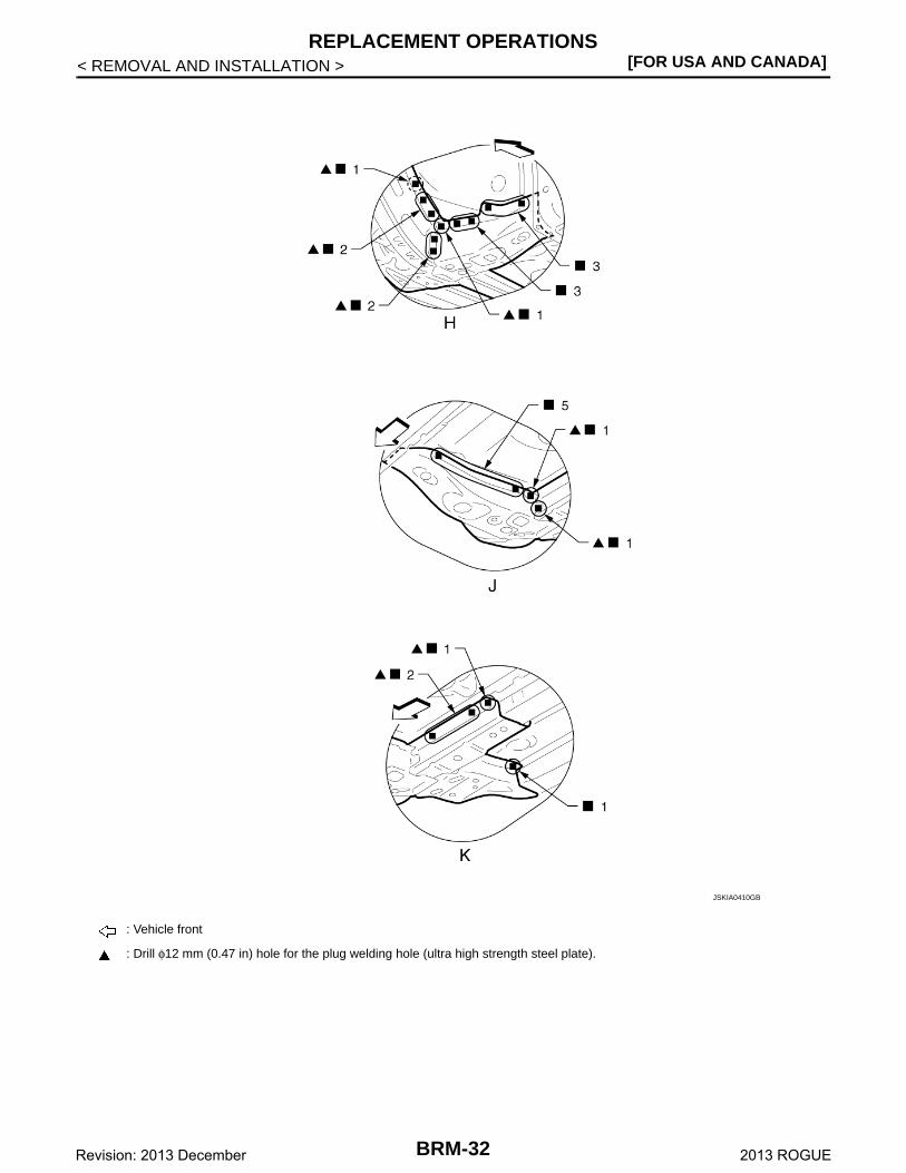
: Vehicle front
: Drill φ12 mm (0.47 in) hole for the plug welding hole (ultra high strength steel plate).
JSKIA0410GB
BRM-32Revision: 2013 December 2013 ROGUE
REPLACEMENT OPERATIONS[FOR USA AND CANADA]
C
D
E
F
G
H
I
J
L
M
A
B
RM
N
O
P
< REMOVAL AND INSTALLATION >
B
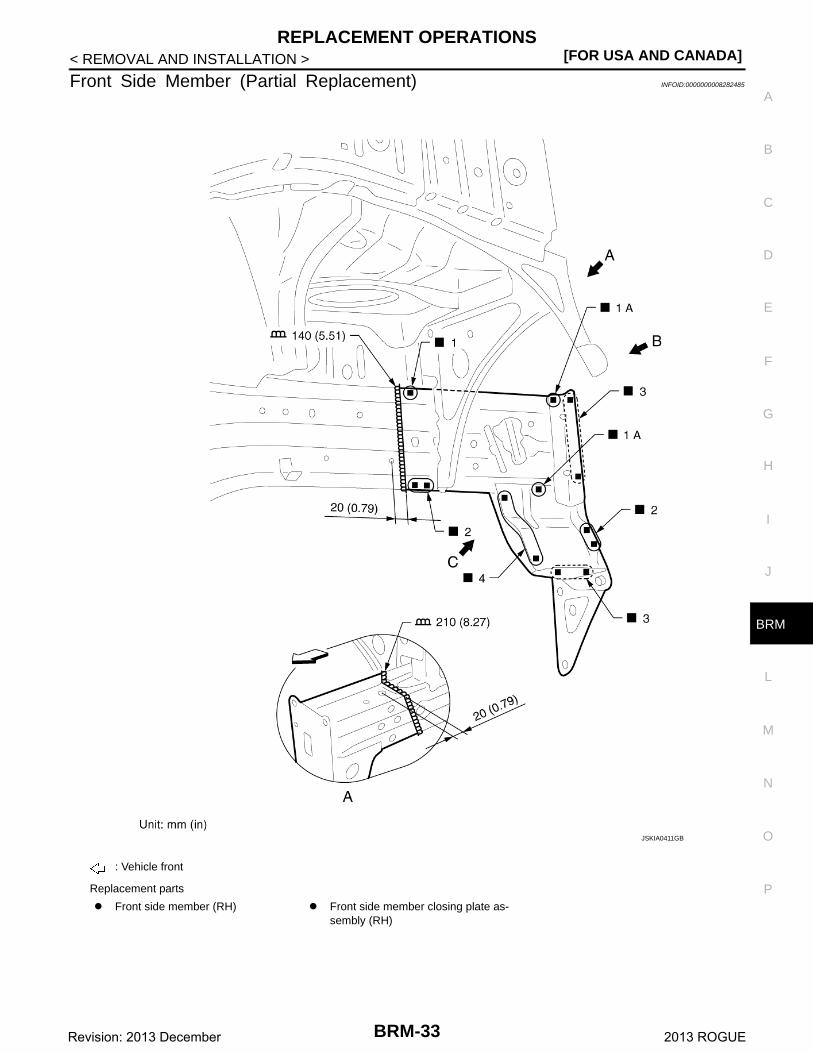
Front Side Member (Partial Replacement) INFOID:0000000008282485
: Vehicle front
Replacement parts
Front side member (RH) Front side member closing plate as-sembly (RH)
JSKIA0411GB
BRM-33Revision: 2013 December 2013 ROGUE
[FOR USA AND CANADA]REPLACEMENT OPERATIONS
< REMOVAL AND INSTALLATION >
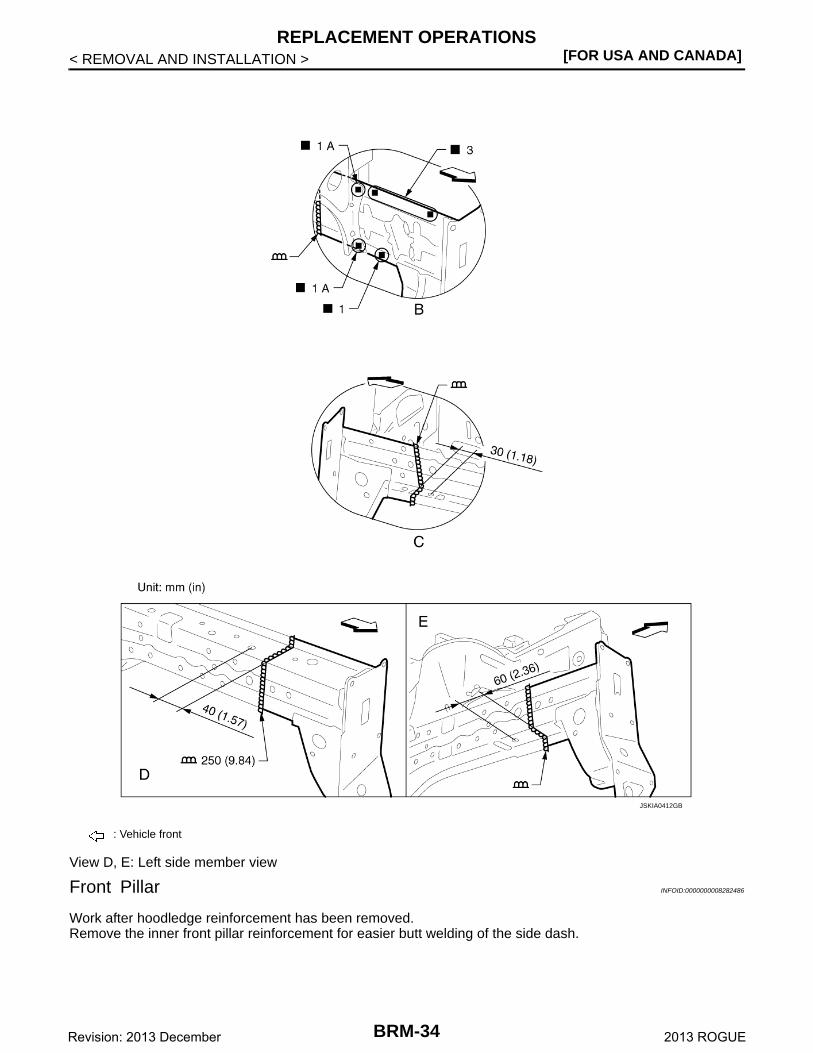
View D, E: Left side member view
Front Pillar INFOID:0000000008282486
Work after hoodledge reinforcement has been removed.Remove the inner front pillar reinforcement for easier butt welding of the side dash.
: Vehicle front
JSKIA0412GB
BRM-34Revision: 2013 December 2013 ROGUE
REPLACEMENT OPERATIONS[FOR USA AND CANADA]
C
D
E
F
G
H
I
J
L
M
A
B
RM
N
O
P
< REMOVAL AND INSTALLATION >
B
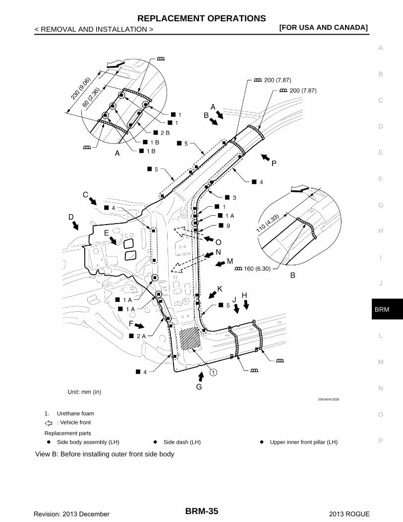
View B: Before installing outer front side body
1. Urethane foam
: Vehicle front
Replacement parts
Side body assembly (LH) Side dash (LH) Upper inner front pillar (LH)
JSKIA0413GB
BRM-35Revision: 2013 December 2013 ROGUE
[FOR USA AND CANADA]REPLACEMENT OPERATIONS
< REMOVAL AND INSTALLATION >
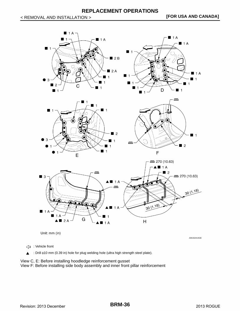
View C, E: Before installing hoodledge reinforcement gussetView F: Before installing side body assembly and inner front pillar reinforcement
: Vehicle front
: Drill φ10 mm (0.39 in) hole for plug welding hole (ultra high strength steel plate).
JSKIA0414GB
BRM-36Revision: 2013 December 2013 ROGUE
REPLACEMENT OPERATIONS[FOR USA AND CANADA]
C
D
E
F
G
H
I
J
L
M
A
B
RM
N
O
P
< REMOVAL AND INSTALLATION >
B
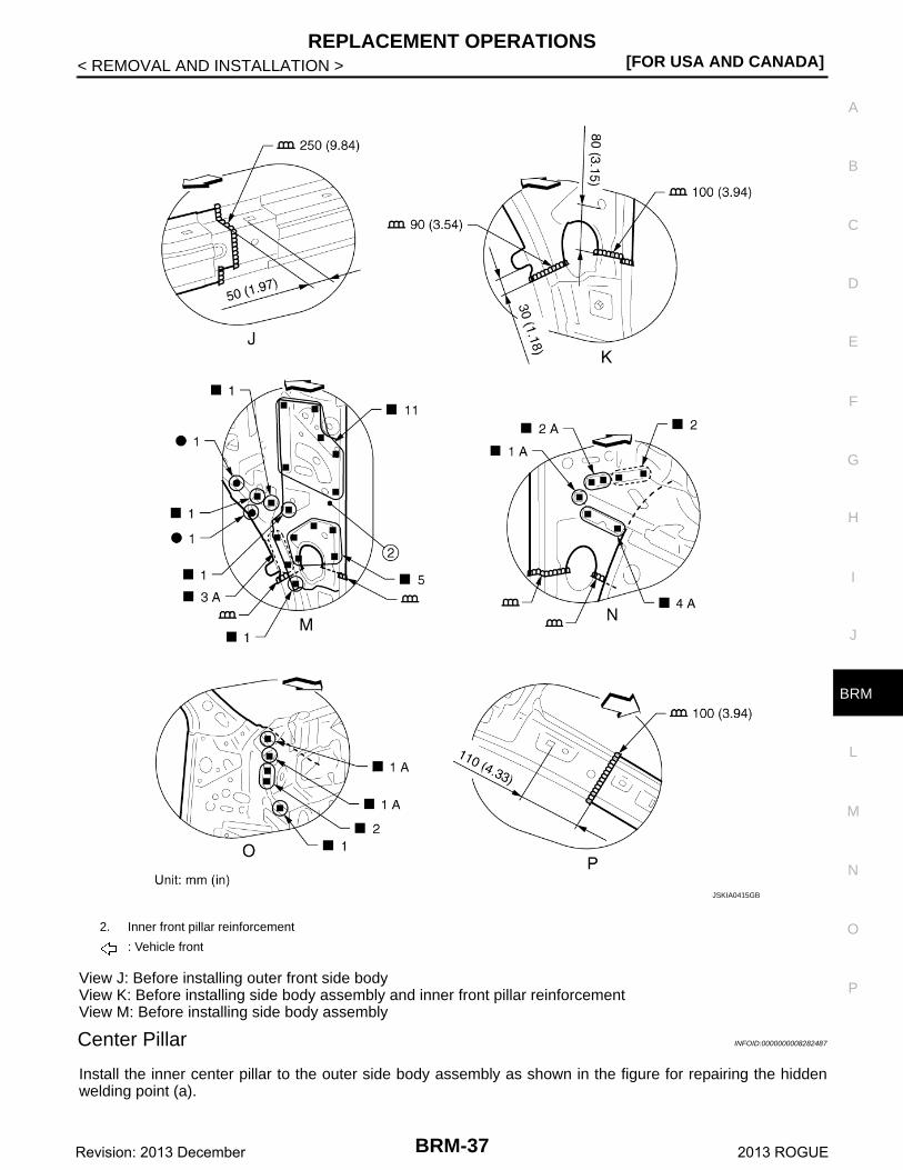
View J: Before installing outer front side bodyView K: Before installing side body assembly and inner front pillar reinforcementView M: Before installing side body assembly
Center Pillar INFOID:0000000008282487
Install the inner center pillar to the outer side body assembly as shown in the figure for repairing the hiddenwelding point (a).
2. Inner front pillar reinforcement
: Vehicle front
JSKIA0415GB
BRM-37Revision: 2013 December 2013 ROGUE
[FOR USA AND CANADA]REPLACEMENT OPERATIONS
< REMOVAL AND INSTALLATION >
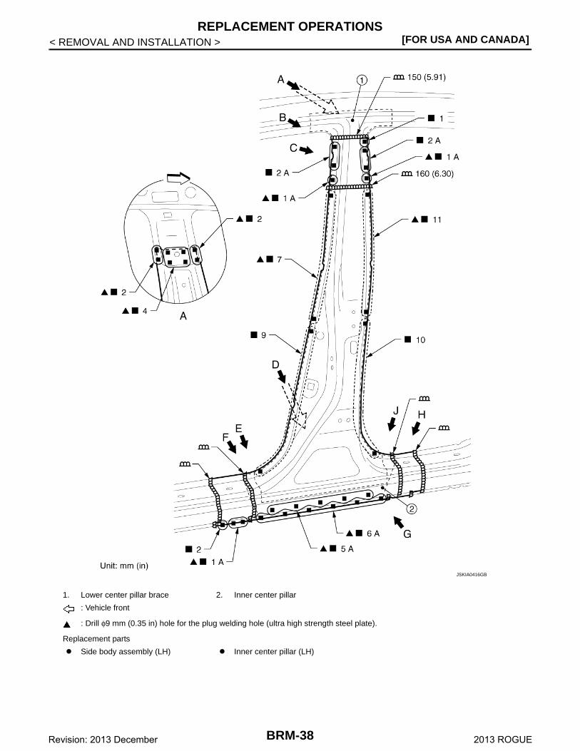
1. Lower center pillar brace 2. Inner center pillar
: Vehicle front
: Drill φ9 mm (0.35 in) hole for the plug welding hole (ultra high strength steel plate).
Replacement parts
Side body assembly (LH) Inner center pillar (LH)
JSKIA0416GB
BRM-38Revision: 2013 December 2013 ROGUE
REPLACEMENT OPERATIONS[FOR USA AND CANADA]
C
D
E
F
G
H
I
J
L
M
A
B
RM
N
O
P
< REMOVAL AND INSTALLATION >
B
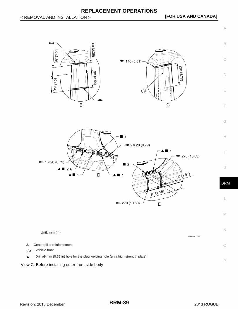
View C: Before installing outer front side body
3. Center pillar reinforcement
: Vehicle front
: Drill φ9 mm (0.35 in) hole for the plug welding hole (ultra high strength plate).
JSKIA0417GB
BRM-39Revision: 2013 December 2013 ROGUE
[FOR USA AND CANADA]REPLACEMENT OPERATIONS
< REMOVAL AND INSTALLATION >
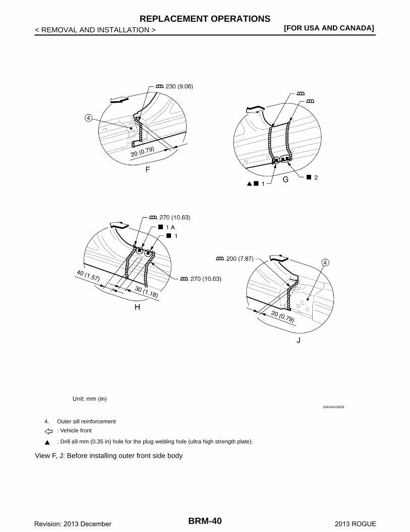
View F, J: Before installing outer front side body
4. Outer sill reinforcement
: Vehicle front
: Drill φ9 mm (0.35 in) hole for the plug welding hole (ultra high strength plate).
JSKIA0418GB
BRM-40Revision: 2013 December 2013 ROGUE
REPLACEMENT OPERATIONS[FOR USA AND CANADA]
C
D
E
F
G
H
I
J
L
M
A
B
RM
N
O
P
< REMOVAL AND INSTALLATION >
B
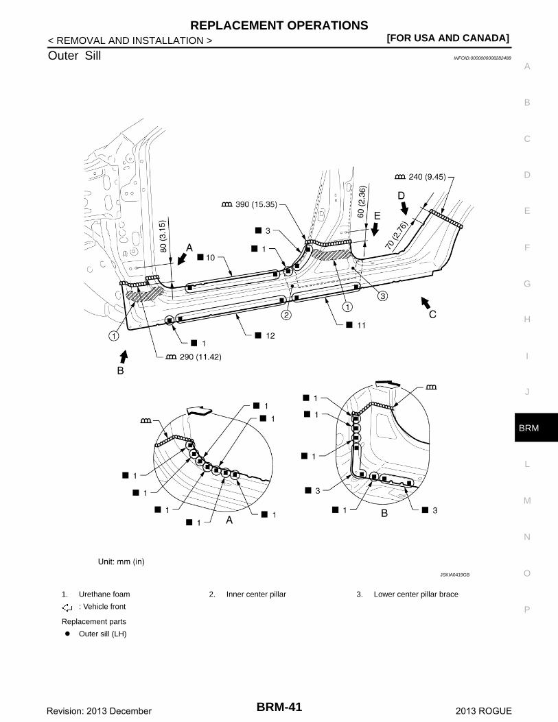
Outer Sill INFOID:0000000008282488
1. Urethane foam 2. Inner center pillar 3. Lower center pillar brace
: Vehicle front
Replacement parts
Outer sill (LH)
JSKIA0419GB
BRM-41Revision: 2013 December 2013 ROGUE
[FOR USA AND CANADA]REPLACEMENT OPERATIONS
< REMOVAL AND INSTALLATION >
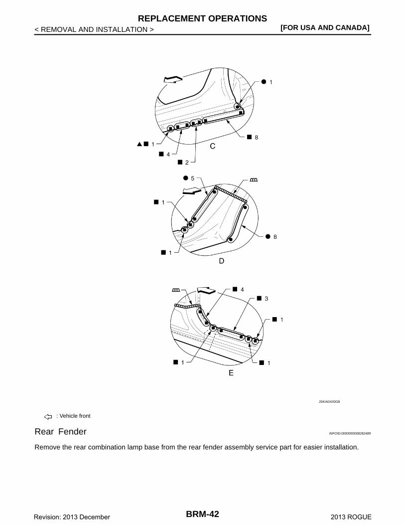
Rear Fender INFOID:0000000008282489
Remove the rear combination lamp base from the rear fender assembly service part for easier installation.
: Vehicle front
JSKIA0420GB
BRM-42Revision: 2013 December 2013 ROGUE
REPLACEMENT OPERATIONS[FOR USA AND CANADA]
C
D
E
F
G
H
I
J
L
M
A
B
RM
N
O
P
< REMOVAL AND INSTALLATION >
B
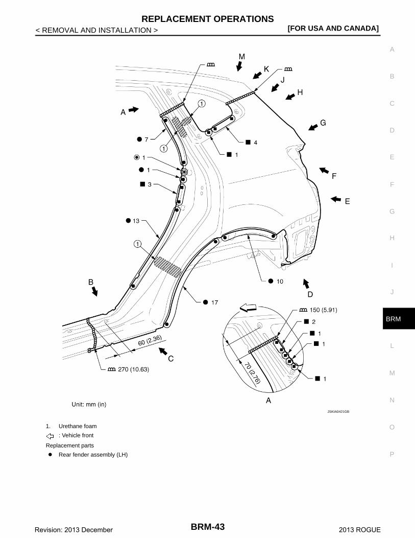
1. Urethane foam
: Vehicle front
Replacement parts
Rear fender assembly (LH)
JSKIA0421GB
BRM-43Revision: 2013 December 2013 ROGUE
[FOR USA AND CANADA]REPLACEMENT OPERATIONS
< REMOVAL AND INSTALLATION >
: Vehicle front
JSKIA0422GB
BRM-44Revision: 2013 December 2013 ROGUE
REPLACEMENT OPERATIONS[FOR USA AND CANADA]
C
D
E
F
G
H
I
J
L
M
A
B
RM
N
O
P
< REMOVAL AND INSTALLATION >
B
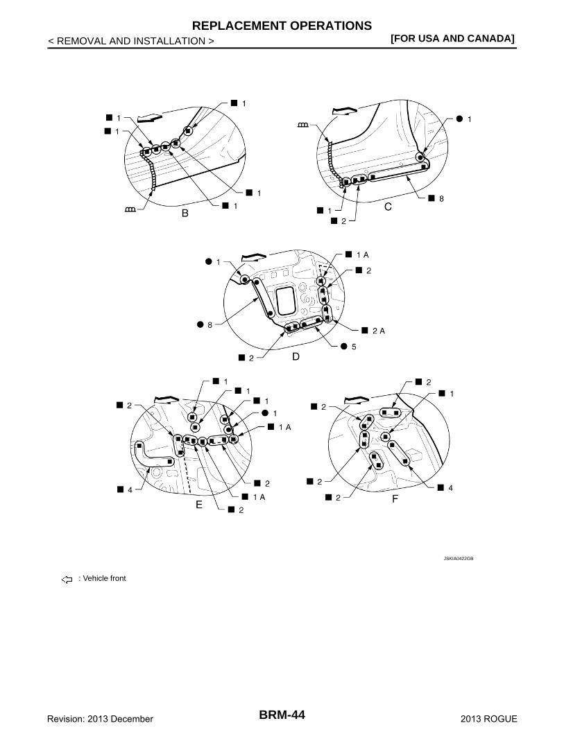
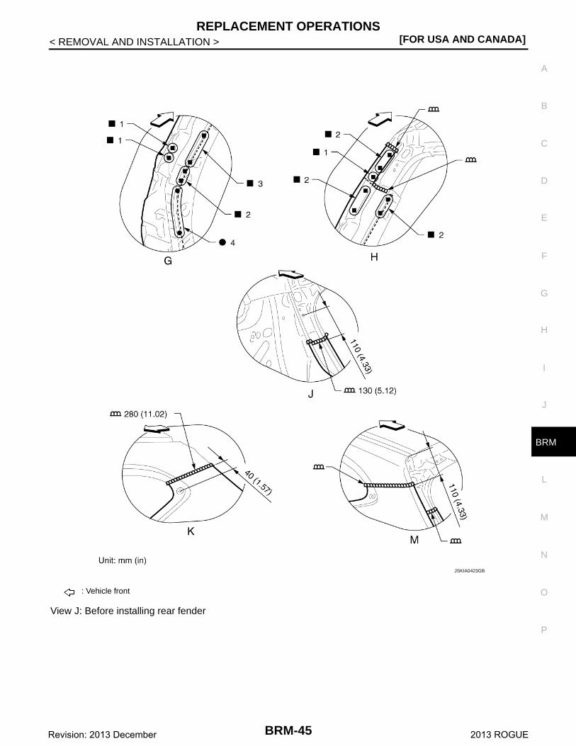
View J: Before installing rear fender
: Vehicle front
JSKIA0423GB
BRM-45Revision: 2013 December 2013 ROGUE
[FOR USA AND CANADA]REPLACEMENT OPERATIONS
< REMOVAL AND INSTALLATION >
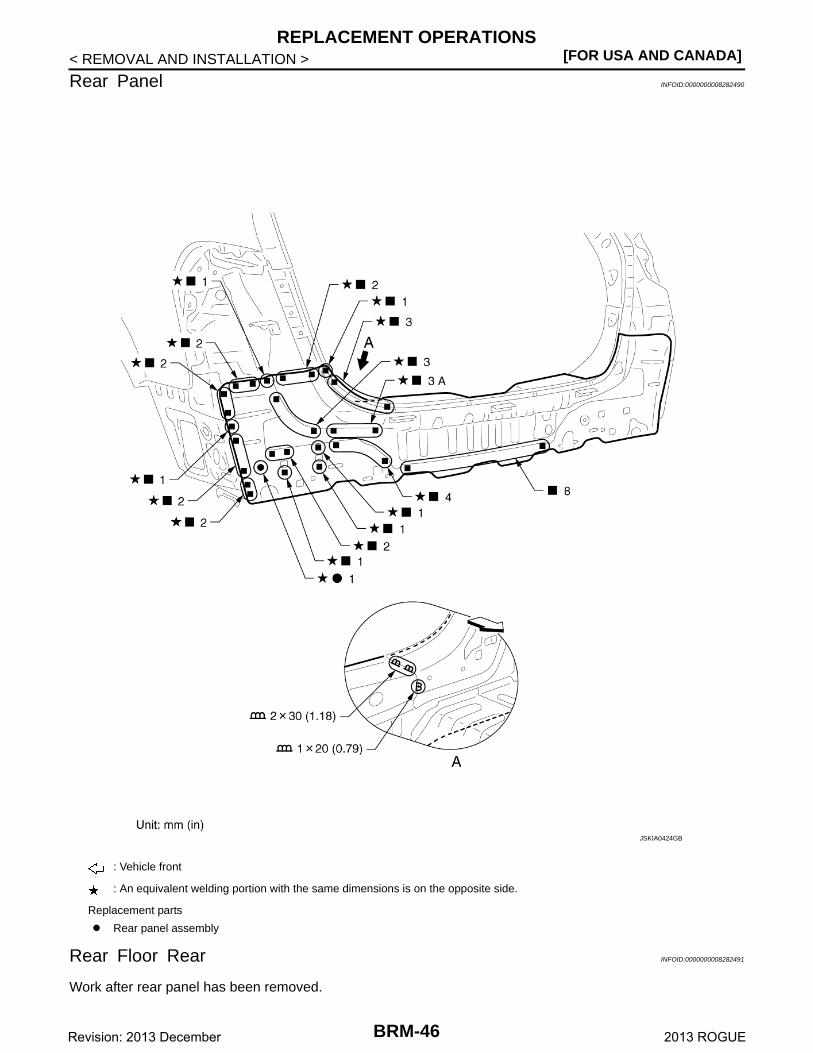
Rear Panel INFOID:0000000008282490
Rear Floor Rear INFOID:0000000008282491
Work after rear panel has been removed.
: Vehicle front
: An equivalent welding portion with the same dimensions is on the opposite side.
Replacement parts
Rear panel assembly
JSKIA0424GB
BRM-46Revision: 2013 December 2013 ROGUE
REPLACEMENT OPERATIONS[FOR USA AND CANADA]
C
D
E
F
G
H
I
J
L
M
A
B
RM
N
O
P
< REMOVAL AND INSTALLATION >
B
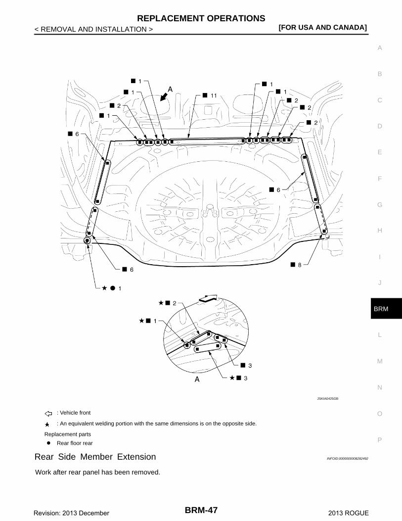
Rear Side Member Extension INFOID:0000000008282492
Work after rear panel has been removed.
: Vehicle front
: An equivalent welding portion with the same dimensions is on the opposite side.
Replacement parts
Rear floor rear
JSKIA0425GB
BRM-47Revision: 2013 December 2013 ROGUE
[FOR USA AND CANADA]REPLACEMENT OPERATIONS
< REMOVAL AND INSTALLATION >
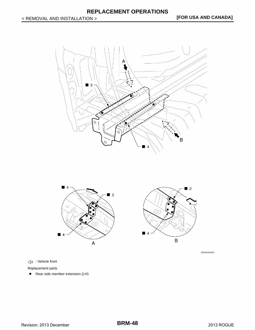
: Vehicle front
Replacement parts
Rear side member extension (LH)
JSKIA0426GB
BRM-48Revision: 2013 December 2013 ROGUE
BODY ALIGNMENT[FOR USA AND CANADA]
C
D
E
F
G
H
I
J
L
M
A
B
RM
N
O
P
< SERVICE DATA AND SPECIFICATIONS (SDS)
B
SERVICE DATA AND SPECIFICATIONS (SDS)BODY ALIGNMENT
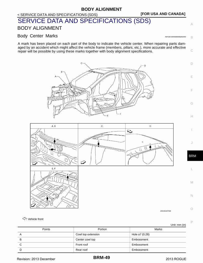
Body Center Marks INFOID:0000000008282493
A mark has been placed on each part of the body to indicate the vehicle center. When repairing parts dam-aged by an accident which might affect the vehicle frame (members, pillars, etc.), more accurate and effectiverepair will be possible by using these marks together with body alignment specifications.
Unit: mm (in)
: Vehicle front
Points Portion Marks
A Cowl top extension Hole φ7 (0.28)
B Center cowl top Embossment
C Front roof Embossment
D Rear roof Embossment
JSKIA0447GB
BRM-49Revision: 2013 December 2013 ROGUE
[FOR USA AND CANADA]BODY ALIGNMENT
< SERVICE DATA AND SPECIFICATIONS (SDS)
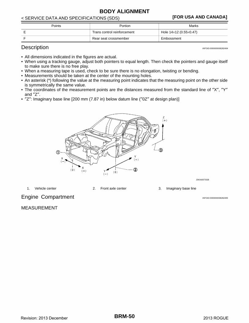
Description INFOID:0000000008282494
• All dimensions indicated in the figures are actual.• When using a tracking gauge, adjust both pointers to equal length. Then check the pointers and gauge itself
to make sure there is no free play.• When a measuring tape is used, check to be sure there is no elongation, twisting or bending.• Measurements should be taken at the center of the mounting holes.• An asterisk (*) following the value at the measuring point indicates that the measuring point on the other side
is symmetrically the same value.• The coordinates of the measurement points are the distances measured from the standard line of ″X″, ″Y″
and ″Z″.• ″Z″: Imaginary base line [200 mm (7.87 in) below datum line (″0Z″ at design plan)]
Engine Compartment INFOID:0000000008282495
MEASUREMENT
E Trans control reinforcement Hole 14×12 (0.55×0.47)
F Rear seat crossmember Embossment
Points Portion Marks
1. Vehicle center 2. Front axle center 3. Imaginary base line
JSKIA0073GB
BRM-50Revision: 2013 December 2013 ROGUE
BODY ALIGNMENT[FOR USA AND CANADA]
C
D
E
F
G
H
I
J
L
M
A
B
RM
N
O
P
< SERVICE DATA AND SPECIFICATIONS (SDS)
B
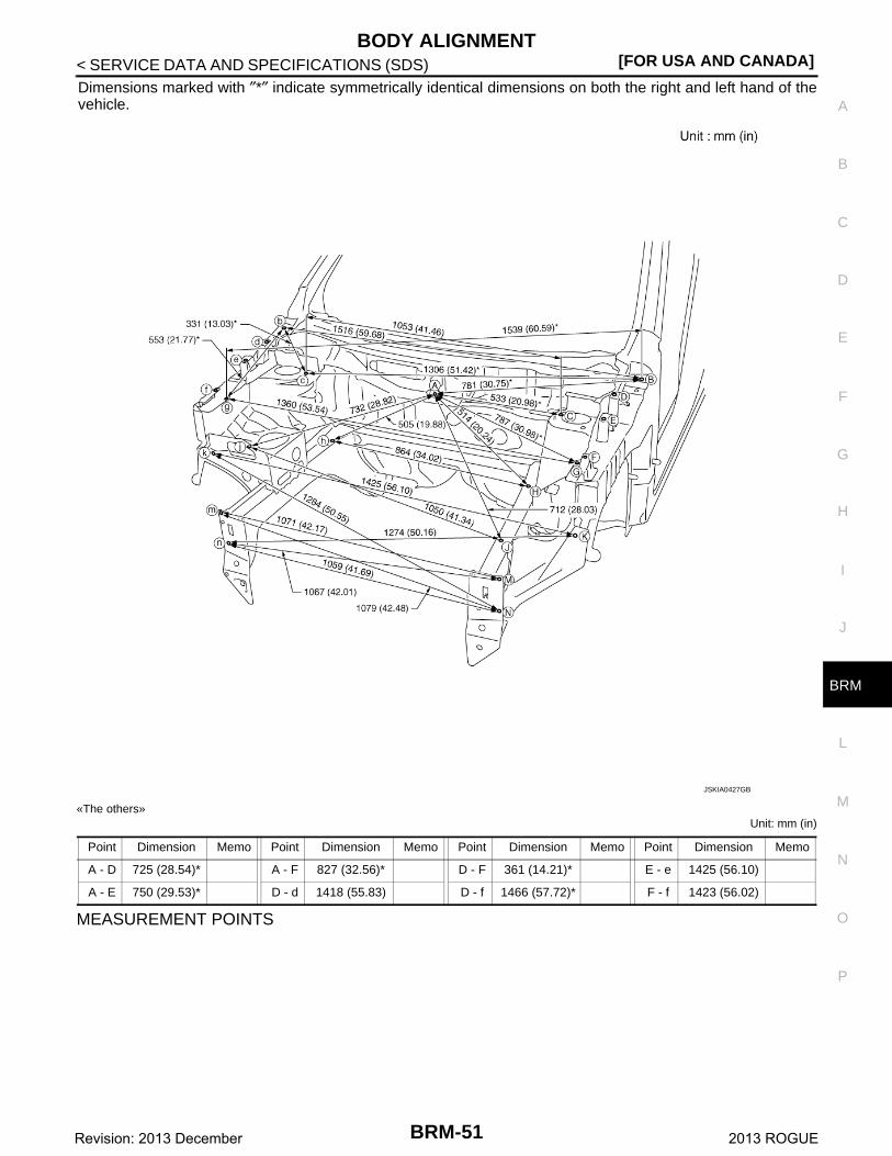
Dimensions marked with ″*″ indicate symmetrically identical dimensions on both the right and left hand of thevehicle.
«The others»Unit: mm (in)
MEASUREMENT POINTS
JSKIA0427GB
Point Dimension Memo Point Dimension Memo Point Dimension Memo Point Dimension Memo
A - D 725 (28.54)* A - F 827 (32.56)* D - F 361 (14.21)* E - e 1425 (56.10)
A - E 750 (29.53)* D - d 1418 (55.83) D - f 1466 (57.72)* F - f 1423 (56.02)
BRM-51Revision: 2013 December 2013 ROGUE
[FOR USA AND CANADA]BODY ALIGNMENT
< SERVICE DATA AND SPECIFICATIONS (SDS)
Unit: mm (in)
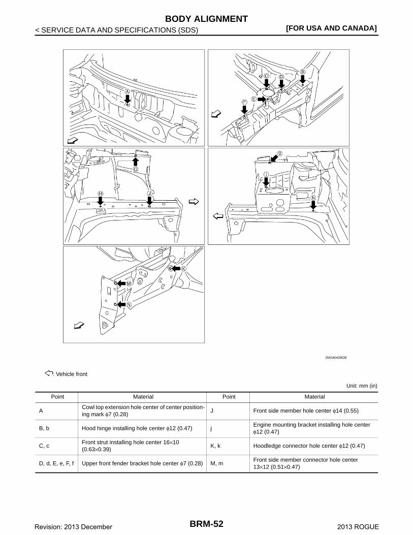
: Vehicle front
JSKIA0428GB
Point Material Point Material
ACowl top extension hole center of center position-ing mark φ7 (0.28)
J Front side member hole center φ14 (0.55)
B, b Hood hinge installing hole center φ12 (0.47) jEngine mounting bracket installing hole centerφ12 (0.47)
C, cFront strut installing hole center 16×10 (0.63×0.39)
K, k Hoodledge connector hole center φ12 (0.47)
D, d, E, e, F, f Upper front fender bracket hole center φ7 (0.28) M, mFront side member connector hole center 13×12 (0.51×0.47)
BRM-52Revision: 2013 December 2013 ROGUE

BODY ALIGNMENT[FOR USA AND CANADA]
C
D
E
F
G
H
I
J
L
M
A
B
RM
N
O
P
< SERVICE DATA AND SPECIFICATIONS (SDS)
B
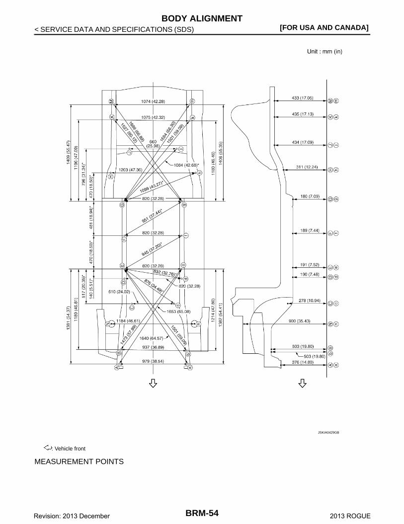
Underbody INFOID:0000000008282496
MEASUREMENTDimensions marked with ″*″ indicate symmetrically identical dimensions on both the right and left hand of thevehicle.As viewed from underside.
G, gHoodledge reinforcement hole centerφ8 (0.31)
N, nFront side member connector hole centerN: φ15 (0.59)n: φ13 (0.51)
H, hFront side member hole center H: φ7 (0.28)h: φ8 (0.31)
Point Material Point Material
BRM-53Revision: 2013 December 2013 ROGUE
[FOR USA AND CANADA]BODY ALIGNMENT
< SERVICE DATA AND SPECIFICATIONS (SDS)
MEASUREMENT POINTS
: Vehicle front
JSKIA0429GB
BRM-54Revision: 2013 December 2013 ROGUE
BODY ALIGNMENT[FOR USA AND CANADA]
C
D
E
F
G
H
I
J
L
M
A
B
RM
N
O
P
< SERVICE DATA AND SPECIFICATIONS (SDS)
B
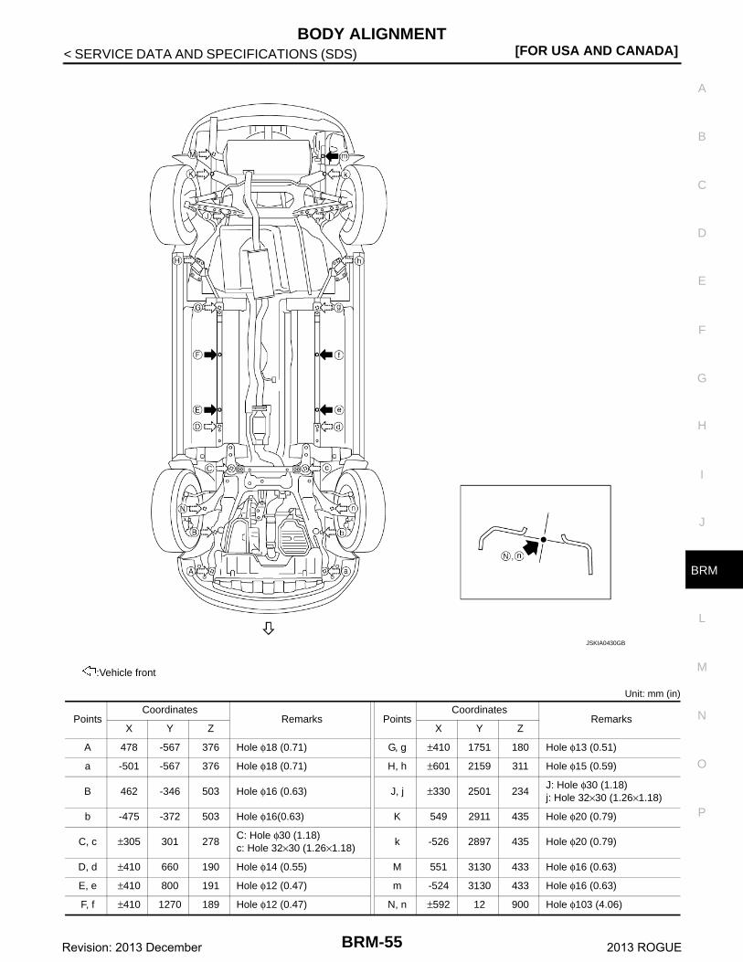
Unit: mm (in)
:Vehicle front
PointsCoordinates
Remarks PointsCoordinates
RemarksX Y Z X Y Z
A 478 -567 376 Hole φ18 (0.71) G, g ±410 1751 180 Hole φ13 (0.51)
a -501 -567 376 Hole φ18 (0.71) H, h ±601 2159 311 Hole φ15 (0.59)
B 462 -346 503 Hole φ16 (0.63) J, j ±330 2501 234J: Hole φ30 (1.18)j: Hole 32×30 (1.26×1.18)
b -475 -372 503 Hole φ16(0.63) K 549 2911 435 Hole φ20 (0.79)
C, c ±305 301 278C: Hole φ30 (1.18)c: Hole 32×30 (1.26×1.18)
k -526 2897 435 Hole φ20 (0.79)
D, d ±410 660 190 Hole φ14 (0.55) M 551 3130 433 Hole φ16 (0.63)
E, e ±410 800 191 Hole φ12 (0.47) m -524 3130 433 Hole φ16 (0.63)
F, f ±410 1270 189 Hole φ12 (0.47) N, n ±592 12 900 Hole φ103 (4.06)
JSKIA0430GB
BRM-55Revision: 2013 December 2013 ROGUE
[FOR USA AND CANADA]BODY ALIGNMENT
< SERVICE DATA AND SPECIFICATIONS (SDS)
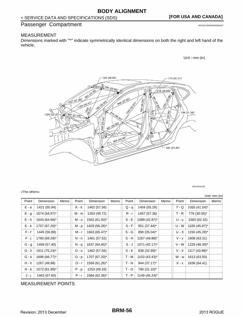
Passenger Compartment INFOID:0000000008282497
MEASUREMENTDimensions marked with ″*″ indicate symmetrically identical dimensions on both the right and left hand of thevehicle.
«The others»Unit: mm (in)
MEASUREMENT POINTS
JSKIA0431GB
Point Dimension Memo Point Dimension Memo Point Dimension Memo Point Dimension Memo
E - e 1421 (55.94) K - k 1462 (57.56) Q - q 1404 (55.28) T - Q 1055 (41.54)*
E - g 1574 (64.97)* M - m 1263 (49.72) R - r 1457 (57.36) T - R 776 (30.55)*
E - h 1643 (64.68)* M - o 1562 (61.50)* S - E 1089 (42.87)* U - u 1583 (62.32)
E - k 1707 (67.20)* M - p 1429 (56.26)* S - F 951 (37.44)* U - W 1165 (45.87)*
F - f 1445 (56.89) M - r 1663 (65.47)* S - G 890 (35.04)* U - X 1150 (45.28)*
F - j 1760 (69.29)* N - n 1461 (57.52) S - H 1267 (49.88)* V - v 1608 (63.31)
G - g 1458 (57.40) N - q 1637 (64.45)* S - J 1071 (42.17)* V - W 1229 (48.39)*
G - h 1911 (75.24)* O - o 1462 (57.56) S - K 838 (32.99)* V - X 1117 (43.98)*
G - k 1696 (66.77)* O - p 1707 (67.20)* T - M 1103 (43.43)* W - w 1613 (63.50)
H - h 1267 (49.88) O - r 1556 (61.26)* T - N 944 (37.17)* X - x 1636 (64.41)
H - k 1572 (61.89)* P - p 1253 (49.33) T - O 790 (31.10)*
J - j 1463 (57.60) P - r 1584 (62.36)* T - P 1149 (45.24)*
BRM-56Revision: 2013 December 2013 ROGUE
BODY ALIGNMENT[FOR USA AND CANADA]
C
D
E
F
G
H
I
J
L
M
A
B
RM
N
O
P
< SERVICE DATA AND SPECIFICATIONS (SDS)
B
Unit: mm (in)
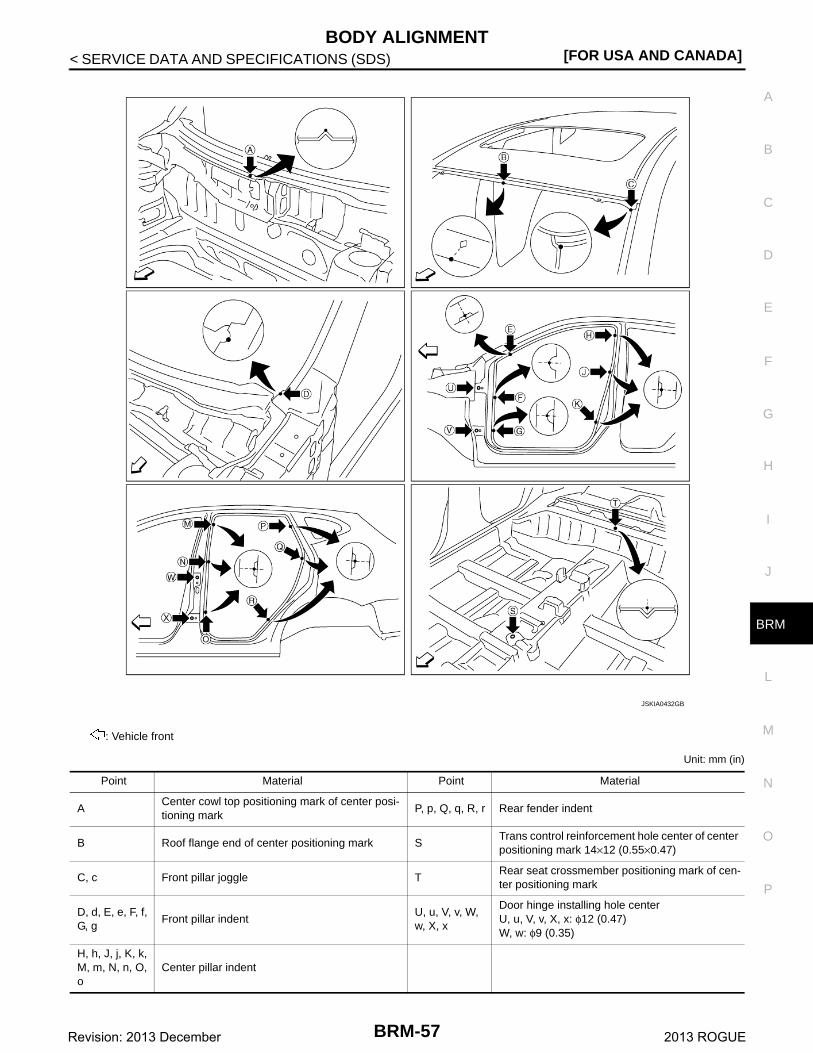
: Vehicle front
JSKIA0432GB
Point Material Point Material
ACenter cowl top positioning mark of center posi-tioning mark
P, p, Q, q, R, r Rear fender indent
B Roof flange end of center positioning mark STrans control reinforcement hole center of center positioning mark 14×12 (0.55×0.47)
C, c Front pillar joggle TRear seat crossmember positioning mark of cen-ter positioning mark
D, d, E, e, F, f, G, g
Front pillar indentU, u, V, v, W, w, X, x
Door hinge installing hole centerU, u, V, v, X, x: φ12 (0.47)W, w: φ9 (0.35)
H, h, J, j, K, k, M, m, N, n, O, o
Center pillar indent
BRM-57Revision: 2013 December 2013 ROGUE
[FOR USA AND CANADA]BODY ALIGNMENT
< SERVICE DATA AND SPECIFICATIONS (SDS)
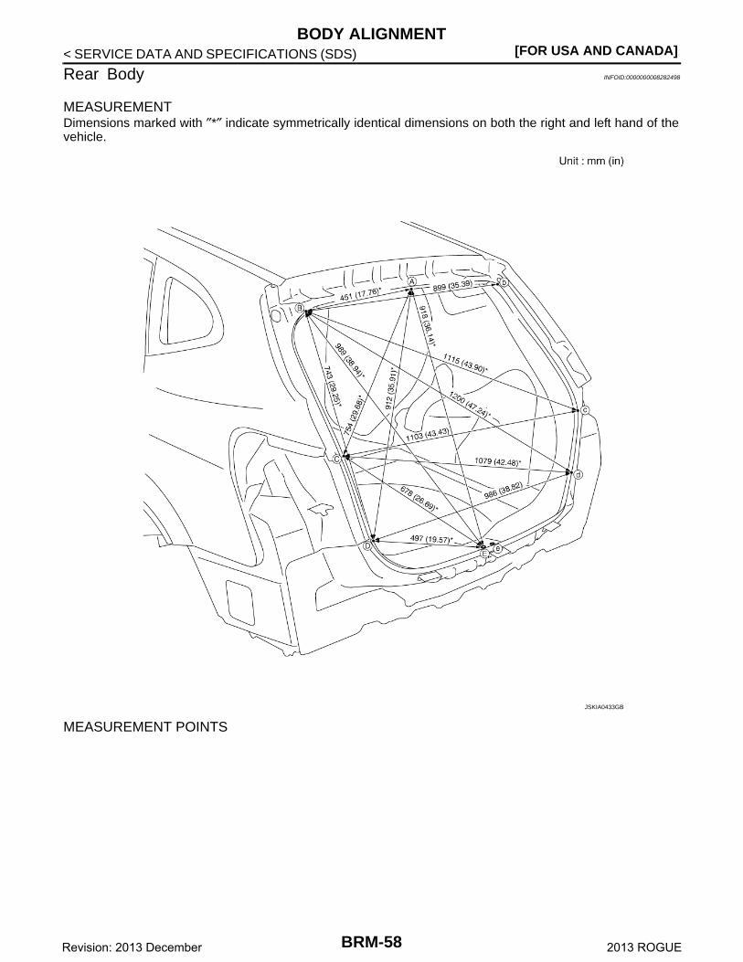
Rear Body INFOID:0000000008282498
MEASUREMENTDimensions marked with ″*″ indicate symmetrically identical dimensions on both the right and left hand of thevehicle.
MEASUREMENT POINTS
JSKIA0433GB
BRM-58Revision: 2013 December 2013 ROGUE
BODY ALIGNMENT[FOR USA AND CANADA]
C
D
E
F
G
H
I
J
L
M
A
B
RM
N
O
P
< SERVICE DATA AND SPECIFICATIONS (SDS)
B
Unit: mm (in)
: Vehicle front
JSKIA0434GB
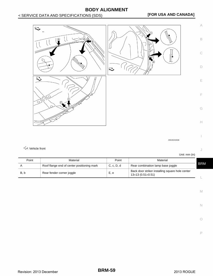
Point Material Point Material
A Roof flange end of center positioning mark C, c, D, d Rear combination lamp base joggle
B, b Rear fender corner joggle E, eBack door striker installing square hole center 13×13 (0.51×0.51)
BRM-59Revision: 2013 December 2013 ROGUE
[FOR USA AND CANADA]LOCATION OF PLASTIC PARTS
< SERVICE DATA AND SPECIFICATIONS (SDS)
LOCATION OF PLASTIC PARTS
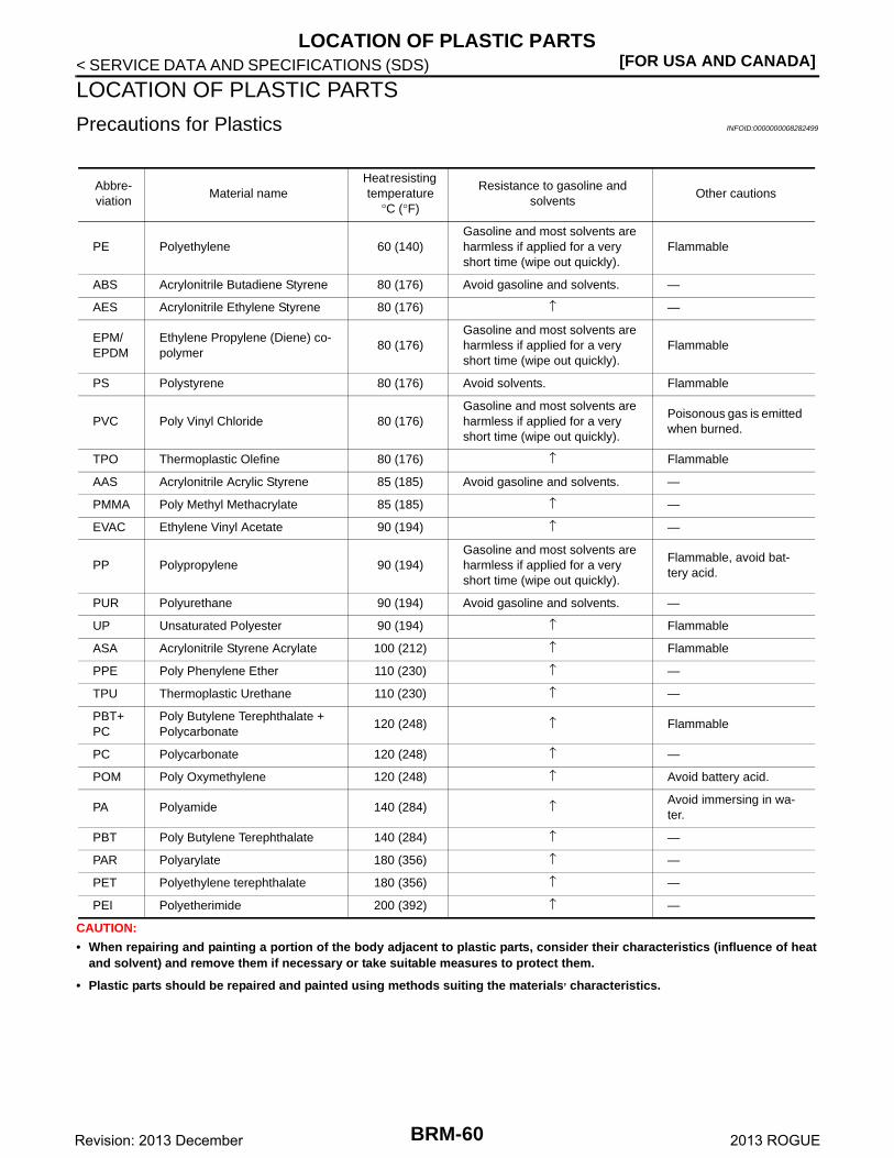
Precautions for Plastics INFOID:0000000008282499
CAUTION:
• When repairing and painting a portion of the body adjacent to plastic parts, consider their characteristics (influence of heatand solvent) and remove them if necessary or take suitable measures to protect them.
• Plastic parts should be repaired and painted using methods suiting the materials, characteristics.
Abbre-viation
Material nameHeat resisting temperature
°C (°F)
Resistance to gasoline and solvents
Other cautions
PE Polyethylene 60 (140)Gasoline and most solvents are harmless if applied for a very short time (wipe out quickly).
Flammable
ABS Acrylonitrile Butadiene Styrene 80 (176) Avoid gasoline and solvents. —
AES Acrylonitrile Ethylene Styrene 80 (176) ↑ —
EPM/EPDM
Ethylene Propylene (Diene) co-polymer
80 (176)Gasoline and most solvents are harmless if applied for a very short time (wipe out quickly).
Flammable
PS Polystyrene 80 (176) Avoid solvents. Flammable
PVC Poly Vinyl Chloride 80 (176)Gasoline and most solvents are harmless if applied for a very short time (wipe out quickly).
Poisonous gas is emitted when burned.
TPO Thermoplastic Olefine 80 (176) ↑ Flammable
AAS Acrylonitrile Acrylic Styrene 85 (185) Avoid gasoline and solvents. —
PMMA Poly Methyl Methacrylate 85 (185) ↑ —
EVAC Ethylene Vinyl Acetate 90 (194) ↑ —
PP Polypropylene 90 (194)Gasoline and most solvents are harmless if applied for a very short time (wipe out quickly).
Flammable, avoid bat-tery acid.
PUR Polyurethane 90 (194) Avoid gasoline and solvents. —
UP Unsaturated Polyester 90 (194) ↑ Flammable
ASA Acrylonitrile Styrene Acrylate 100 (212) ↑ Flammable
PPE Poly Phenylene Ether 110 (230) ↑ —
TPU Thermoplastic Urethane 110 (230) ↑ —
PBT+ PC
Poly Butylene Terephthalate + Polycarbonate
120 (248) ↑ Flammable
PC Polycarbonate 120 (248) ↑ —
POM Poly Oxymethylene 120 (248) ↑ Avoid battery acid.
PA Polyamide 140 (284) ↑ Avoid immersing in wa-ter.
PBT Poly Butylene Terephthalate 140 (284) ↑ —
PAR Polyarylate 180 (356) ↑ —
PET Polyethylene terephthalate 180 (356) ↑ —
PEI Polyetherimide 200 (392) ↑ —
BRM-60Revision: 2013 December 2013 ROGUE
LOCATION OF PLASTIC PARTS[FOR USA AND CANADA]
C
D
E
F
G
H
I
J
L
M
A
B
RM
N
O
P
< SERVICE DATA AND SPECIFICATIONS (SDS)
B
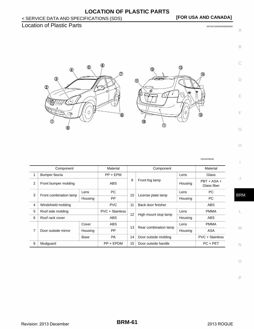
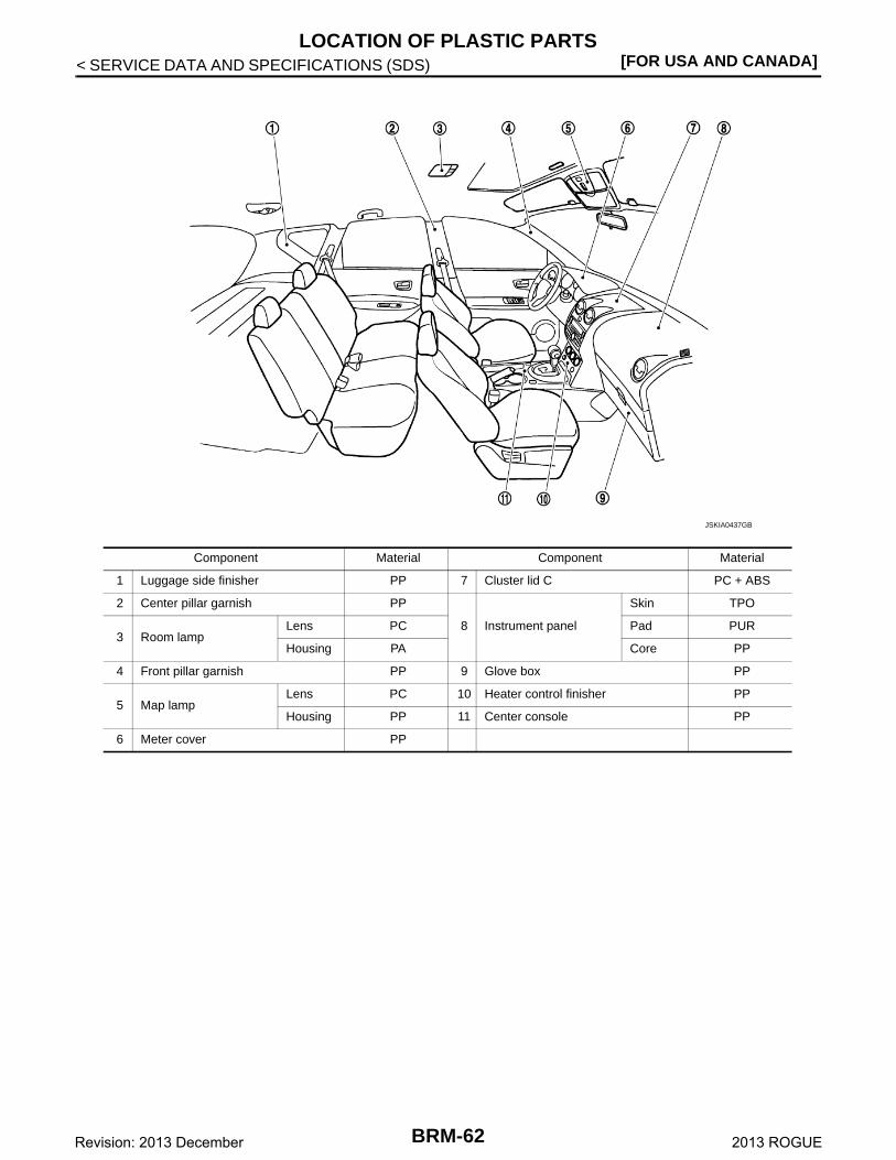
Location of Plastic Parts INFOID:0000000008282500
Component Material Component Material
1 Bumper fascia PP + EPM
9 Front fog lamp
Lens Glass
2 Front bumper molding ABS HousingPBT + ASA +
Glass fiber
3 Front combination lampLens PC
10 License plate lampLens PC
Housing PP Housing PC
4 Windshield molding PVC 11 Back door finisher ABS
5 Roof side molding PVC + Stainless12 High mount stop lamp
Lens PMMA
6 Roof rack cover ABS Housing ABS
7 Door outside mirror
Cover ABS13 Rear combination lamp
Lens PMMA
Housing PP Housing ASA
Base PA 14 Door outside molding PVC + Stainless
8 Mudguard PP + EPDM 15 Door outside handle PC + PET
JSKIA0436GB
BRM-61Revision: 2013 December 2013 ROGUE
[FOR USA AND CANADA]LOCATION OF PLASTIC PARTS
< SERVICE DATA AND SPECIFICATIONS (SDS)
Component Material Component Material
1 Luggage side finisher PP 7 Cluster lid C PC + ABS
2 Center pillar garnish PP
8 Instrument panel
Skin TPO
3 Room lampLens PC Pad PUR
Housing PA Core PP
4 Front pillar garnish PP 9 Glove box PP
5 Map lampLens PC 10 Heater control finisher PP
Housing PP 11 Center console PP
6 Meter cover PP
JSKIA0437GB
BRM-62Revision: 2013 December 2013 ROGUE
BODY ALIGNMENT[FOR MEXICO]
C
D
E
F
G
H
I
J
L
M
A
B
RM
N
O
P
< SERVICE DATA AND SPECIFICATIONS (SDS)
B
SERVICE DATA AND SPECIFICATIONS (SDS)BODY ALIGNMENT
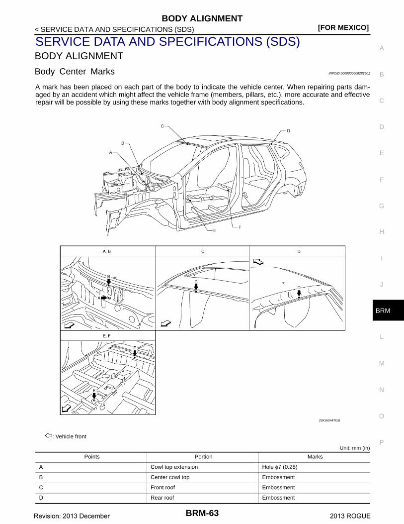
Body Center Marks INFOID:0000000008282501
A mark has been placed on each part of the body to indicate the vehicle center. When repairing parts dam-aged by an accident which might affect the vehicle frame (members, pillars, etc.), more accurate and effectiverepair will be possible by using these marks together with body alignment specifications.
Unit: mm (in)
: Vehicle front
Points Portion Marks
A Cowl top extension Hole φ7 (0.28)
B Center cowl top Embossment
C Front roof Embossment
D Rear roof Embossment
JSKIA0447GB
BRM-63Revision: 2013 December 2013 ROGUE
[FOR MEXICO]BODY ALIGNMENT
< SERVICE DATA AND SPECIFICATIONS (SDS)
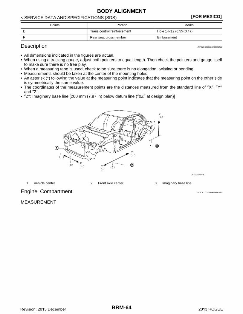
Description INFOID:0000000008282502
• All dimensions indicated in the figures are actual.• When using a tracking gauge, adjust both pointers to equal length. Then check the pointers and gauge itself
to make sure there is no free play.• When a measuring tape is used, check to be sure there is no elongation, twisting or bending.• Measurements should be taken at the center of the mounting holes.• An asterisk (*) following the value at the measuring point indicates that the measuring point on the other side
is symmetrically the same value.• The coordinates of the measurement points are the distances measured from the standard line of ″X″, ″Y″
and ″Z″.• ″Z″: Imaginary base line [200 mm (7.87 in) below datum line (″0Z″ at design plan)]
Engine Compartment INFOID:0000000008282503
MEASUREMENT
E Trans control reinforcement Hole 14×12 (0.55×0.47)
F Rear seat crossmember Embossment
Points Portion Marks
1. Vehicle center 2. Front axle center 3. Imaginary base line
JSKIA0073GB
BRM-64Revision: 2013 December 2013 ROGUE
BODY ALIGNMENT[FOR MEXICO]
C
D
E
F
G
H
I
J
L
M
A
B
RM
N
O
P
< SERVICE DATA AND SPECIFICATIONS (SDS)
B
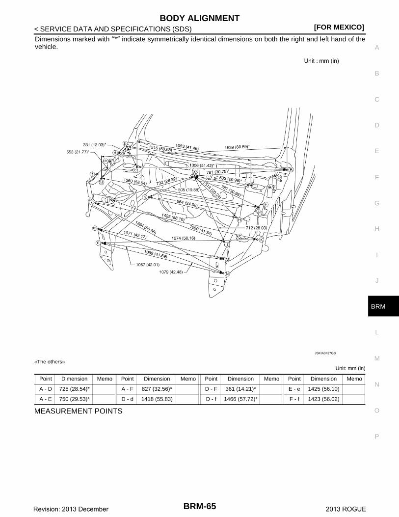
Dimensions marked with ″*″ indicate symmetrically identical dimensions on both the right and left hand of thevehicle.
«The others»Unit: mm (in)
MEASUREMENT POINTS
JSKIA0427GB
Point Dimension Memo Point Dimension Memo Point Dimension Memo Point Dimension Memo
A - D 725 (28.54)* A - F 827 (32.56)* D - F 361 (14.21)* E - e 1425 (56.10)
A - E 750 (29.53)* D - d 1418 (55.83) D - f 1466 (57.72)* F - f 1423 (56.02)
BRM-65Revision: 2013 December 2013 ROGUE
[FOR MEXICO]BODY ALIGNMENT
< SERVICE DATA AND SPECIFICATIONS (SDS)
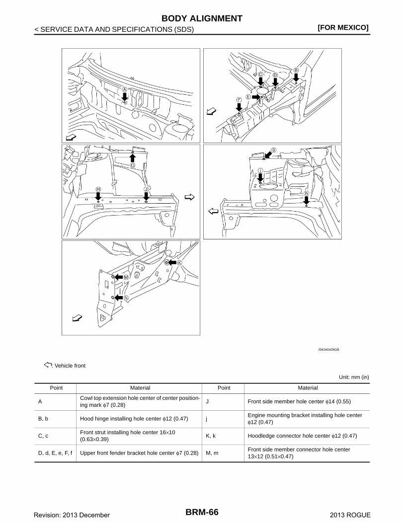
Unit: mm (in)
: Vehicle front
JSKIA0428GB
Point Material Point Material
ACowl top extension hole center of center position-ing mark φ7 (0.28)
J Front side member hole center φ14 (0.55)
B, b Hood hinge installing hole center φ12 (0.47) jEngine mounting bracket installing hole centerφ12 (0.47)
C, cFront strut installing hole center 16×10 (0.63×0.39)
K, k Hoodledge connector hole center φ12 (0.47)
D, d, E, e, F, f Upper front fender bracket hole center φ7 (0.28) M, mFront side member connector hole center 13×12 (0.51×0.47)
BRM-66Revision: 2013 December 2013 ROGUE
BODY ALIGNMENT[FOR MEXICO]
C
D
E
F
G
H
I
J
L
M
A
B
RM
N
O
P
< SERVICE DATA AND SPECIFICATIONS (SDS)
B
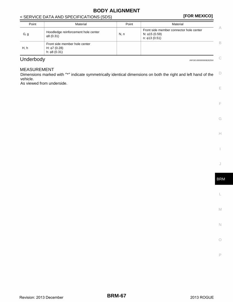
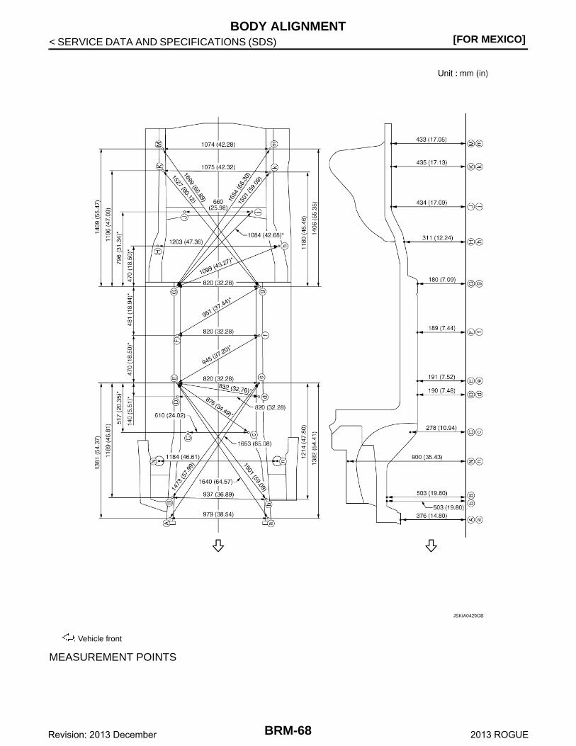
Underbody INFOID:0000000008282504
MEASUREMENTDimensions marked with ″*″ indicate symmetrically identical dimensions on both the right and left hand of thevehicle.As viewed from underside.
G, gHoodledge reinforcement hole centerφ8 (0.31)
N, nFront side member connector hole centerN: φ15 (0.59)n: φ13 (0.51)
H, hFront side member hole center H: φ7 (0.28)h: φ8 (0.31)
Point Material Point Material
BRM-67Revision: 2013 December 2013 ROGUE
[FOR MEXICO]BODY ALIGNMENT
< SERVICE DATA AND SPECIFICATIONS (SDS)
MEASUREMENT POINTS
: Vehicle front
JSKIA0429GB
BRM-68Revision: 2013 December 2013 ROGUE

BODY ALIGNMENT[FOR MEXICO]
C
D
E
F
G
H
I
J
L
M
A
B
RM
N
O
P
< SERVICE DATA AND SPECIFICATIONS (SDS)
B
Unit: mm (in)
:Vehicle front
PointsCoordinates
Remarks PointsCoordinates
RemarksX Y Z X Y Z
A 478 -567 376 Hole φ18 (0.71) G, g ±410 1751 180 Hole φ13 (0.51)
a -501 -567 376 Hole φ18 (0.71) H, h ±601 2159 311 Hole φ15 (0.59)
B 462 -346 503 Hole φ16 (0.63) J, j ±330 2501 234J: Hole φ30 (1.18)j: Hole 32×30 (1.26×1.18)
b -475 -372 503 Hole φ16(0.63) K 549 2911 435 Hole φ20 (0.79)
C, c ±305 301 278C: Hole φ30 (1.18)c: Hole 32×30 (1.26×1.18)
k -526 2897 435 Hole φ20 (0.79)
D, d ±410 660 190 Hole φ14 (0.55) M 551 3130 433 Hole φ16 (0.63)
E, e ±410 800 191 Hole φ12 (0.47) m -524 3130 433 Hole φ16 (0.63)
F, f ±410 1270 189 Hole φ12 (0.47) N, n ±592 12 900 Hole φ103 (4.06)
JSKIA0430GB
BRM-69Revision: 2013 December 2013 ROGUE
[FOR MEXICO]BODY ALIGNMENT
< SERVICE DATA AND SPECIFICATIONS (SDS)
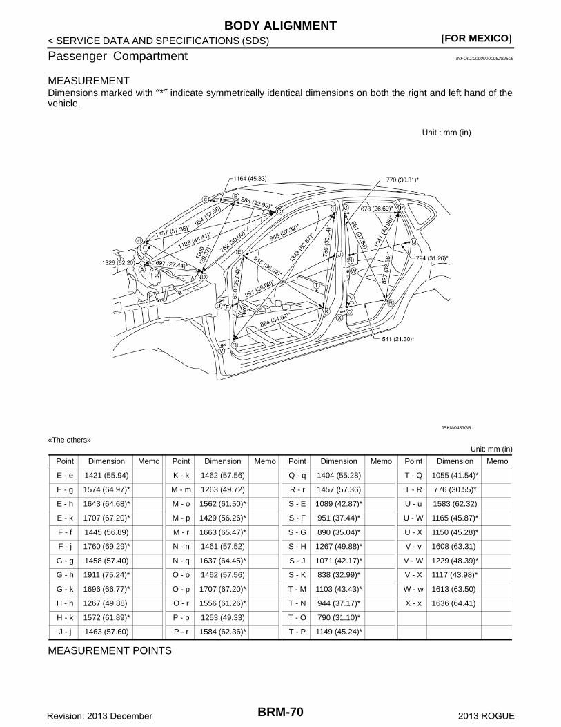
Passenger Compartment INFOID:0000000008282505
MEASUREMENTDimensions marked with ″*″ indicate symmetrically identical dimensions on both the right and left hand of thevehicle.
«The others»Unit: mm (in)
MEASUREMENT POINTS
JSKIA0431GB
Point Dimension Memo Point Dimension Memo Point Dimension Memo Point Dimension Memo
E - e 1421 (55.94) K - k 1462 (57.56) Q - q 1404 (55.28) T - Q 1055 (41.54)*
E - g 1574 (64.97)* M - m 1263 (49.72) R - r 1457 (57.36) T - R 776 (30.55)*
E - h 1643 (64.68)* M - o 1562 (61.50)* S - E 1089 (42.87)* U - u 1583 (62.32)
E - k 1707 (67.20)* M - p 1429 (56.26)* S - F 951 (37.44)* U - W 1165 (45.87)*
F - f 1445 (56.89) M - r 1663 (65.47)* S - G 890 (35.04)* U - X 1150 (45.28)*
F - j 1760 (69.29)* N - n 1461 (57.52) S - H 1267 (49.88)* V - v 1608 (63.31)
G - g 1458 (57.40) N - q 1637 (64.45)* S - J 1071 (42.17)* V - W 1229 (48.39)*
G - h 1911 (75.24)* O - o 1462 (57.56) S - K 838 (32.99)* V - X 1117 (43.98)*
G - k 1696 (66.77)* O - p 1707 (67.20)* T - M 1103 (43.43)* W - w 1613 (63.50)
H - h 1267 (49.88) O - r 1556 (61.26)* T - N 944 (37.17)* X - x 1636 (64.41)
H - k 1572 (61.89)* P - p 1253 (49.33) T - O 790 (31.10)*
J - j 1463 (57.60) P - r 1584 (62.36)* T - P 1149 (45.24)*
BRM-70Revision: 2013 December 2013 ROGUE
BODY ALIGNMENT[FOR MEXICO]
C
D
E
F
G
H
I
J
L
M
A
B
RM
N
O
P
< SERVICE DATA AND SPECIFICATIONS (SDS)
B
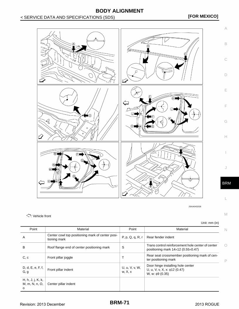
Unit: mm (in)
: Vehicle front
JSKIA0432GB
Point Material Point Material
ACenter cowl top positioning mark of center posi-tioning mark
P, p, Q, q, R, r Rear fender indent
B Roof flange end of center positioning mark STrans control reinforcement hole center of center positioning mark 14×12 (0.55×0.47)
C, c Front pillar joggle TRear seat crossmember positioning mark of cen-ter positioning mark
D, d, E, e, F, f, G, g
Front pillar indentU, u, V, v, W, w, X, x
Door hinge installing hole centerU, u, V, v, X, x: φ12 (0.47)W, w: φ9 (0.35)
H, h, J, j, K, k, M, m, N, n, O, o
Center pillar indent
BRM-71Revision: 2013 December 2013 ROGUE

[FOR MEXICO]BODY ALIGNMENT
< SERVICE DATA AND SPECIFICATIONS (SDS)
Rear Body INFOID:0000000008282506
MEASUREMENTDimensions marked with ″*″ indicate symmetrically identical dimensions on both the right and left hand of thevehicle.
MEASUREMENT POINTS
JSKIA0433GB
BRM-72Revision: 2013 December 2013 ROGUE

BODY ALIGNMENT[FOR MEXICO]
C
D
E
F
G
H
I
J
L
M
A
B
RM
N
O
P
< SERVICE DATA AND SPECIFICATIONS (SDS)
B
Unit: mm (in)
: Vehicle front
JSKIA0434GB
Point Material Point Material
A Roof flange end of center positioning mark C, c, D, d Rear combination lamp base joggle
B, b Rear fender corner joggle E, eBack door striker installing square hole center 13×13 (0.51×0.51)
BRM-73Revision: 2013 December 2013 ROGUE
Copyright © 2022 FDOKUMEN