Range Rover Workshop Manual
809
Workshop Manual System Description & Operation
-
Upload
khangminh22 -
Category
Documents
-
view
1 -
download
0
Transcript of Range Rover Workshop Manual

Workshop ManualSystem Description & Operation
NRRWM 21/11/01 11:21 am Page 1
2002MY
WORKSHOP MANUAL - SYSTEM DESCRIPTION AND OPERATION
LRL0424ENG (2nd Edition)Published by Land Rover – Technical Service
© 2002 Land Rover
All rights reserved. No part of this publication may be reproduced, stored in a retrieval system or transmitted in any form, electronic, mechanical, recording or other means without written prior permission from Land Rover.

CONTENTS
ENGINE – Td6 12-1-1Td 6 – External View. . . . . . . . . . . . . . . . . . . . . . . . . . . . . . . . . . . . . . . . . . . . . . . . . . . . . . . . . . . .12-1-1Description . . . . . . . . . . . . . . . . . . . . . . . . . . . . . . . . . . . . . . . . . . . . . . . . . . . . . . . . . . . . . . . . . . .12-1-2
ENGINE - V8 12-2-1V8 – External View . . . . . . . . . . . . . . . . . . . . . . . . . . . . . . . . . . . . . . . . . . . . . . . . . . . . . . . . . . . . .12-2-1Description . . . . . . . . . . . . . . . . . . . . . . . . . . . . . . . . . . . . . . . . . . . . . . . . . . . . . . . . . . . . . . . . . . .12-2-2
ENGINE MANAGEMENT SYSTEM – Td6 18-1-1Engine Management Component Location – Sheet 1 of 2 . . . . . . . . . . . . . . . . . . . . . . . . . . . . . . .18-1-2Engine Management Component Location – Sheet 2 of 2 . . . . . . . . . . . . . . . . . . . . . . . . . . . . . . .18-1-4Engine Management Control Diagram – Sheet 1 of 2 . . . . . . . . . . . . . . . . . . . . . . . . . . . . . . . . . .18-1-6Engine Management Control Diagram – Sheet 2 of 2 . . . . . . . . . . . . . . . . . . . . . . . . . . . . . . . . . .18-1-8Description . . . . . . . . . . . . . . . . . . . . . . . . . . . . . . . . . . . . . . . . . . . . . . . . . . . . . . . . . . . . . . . . . . .18-1-10Operation . . . . . . . . . . . . . . . . . . . . . . . . . . . . . . . . . . . . . . . . . . . . . . . . . . . . . . . . . . . . . . . . . . . .18-1-35Cruise Control Component Location. . . . . . . . . . . . . . . . . . . . . . . . . . . . . . . . . . . . . . . . . . . . . . . .18-1-39Cruise Control, Control Diagram. . . . . . . . . . . . . . . . . . . . . . . . . . . . . . . . . . . . . . . . . . . . . . . . . . .18-1-40Description . . . . . . . . . . . . . . . . . . . . . . . . . . . . . . . . . . . . . . . . . . . . . . . . . . . . . . . . . . . . . . . . . . .18-1-42
ENGINE MANAGEMENT SYSTEM – V8 18-2-1Engine Management Component Location – Sheet 1 of 2 . . . . . . . . . . . . . . . . . . . . . . . . . . . . . . .18-2-2Engine Management Component Location – Sheet 2 of 2 . . . . . . . . . . . . . . . . . . . . . . . . . . . . . . .18-2-4Engine Management Control Diagram – Sheet 1 of 2 . . . . . . . . . . . . . . . . . . . . . . . . . . . . . . . . . .18-2-6Engine Management Control Diagram – Sheet 2 of 2 . . . . . . . . . . . . . . . . . . . . . . . . . . . . . . . . . .18-2-8Bosch ME 7.2 Engine Management System . . . . . . . . . . . . . . . . . . . . . . . . . . . . . . . . . . . . . . . . .18-2-10Variable Camshaft Control Components . . . . . . . . . . . . . . . . . . . . . . . . . . . . . . . . . . . . . . . . . . . .18-2-41VCC System . . . . . . . . . . . . . . . . . . . . . . . . . . . . . . . . . . . . . . . . . . . . . . . . . . . . . . . . . . . . . . . . .18-2-42Cruise Control Component Location. . . . . . . . . . . . . . . . . . . . . . . . . . . . . . . . . . . . . . . . . . . . . . . .18-2-50Cruise Control System Control Diagram. . . . . . . . . . . . . . . . . . . . . . . . . . . . . . . . . . . . . . . . . . . . .18-2-51Cruise Control . . . . . . . . . . . . . . . . . . . . . . . . . . . . . . . . . . . . . . . . . . . . . . . . . . . . . . . . . . . . . . . .18-2-53EVAP System . . . . . . . . . . . . . . . . . . . . . . . . . . . . . . . . . . . . . . . . . . . . . . . . . . . . . . . . . . . . . . . . .18-2-55Emissions . . . . . . . . . . . . . . . . . . . . . . . . . . . . . . . . . . . . . . . . . . . . . . . . . . . . . . . . . . . . . . . . . . . .18-2-56
FUEL DELIVERY SYSTEM – Td6 19-1-1Td6 Fuel Delivery Component Location – Sheet 1 of 2 . . . . . . . . . . . . . . . . . . . . . . . . . . . . . . . . .19-1-1Td6 Fuel Delivery Component Location – Sheet 2 of 2 . . . . . . . . . . . . . . . . . . . . . . . . . . . . . . . . .19-1-2Td6 Fuel System Schematic . . . . . . . . . . . . . . . . . . . . . . . . . . . . . . . . . . . . . . . . . . . . . . . . . . . . . .19-1-4Description . . . . . . . . . . . . . . . . . . . . . . . . . . . . . . . . . . . . . . . . . . . . . . . . . . . . . . . . . . . . . . . . . . .19-1-6
FUEL DELIVERY SYSTEM – V8 19-2-1Fuel Delivery System Component Location (All Except NAS) . . . . . . . . . . . . . . . . . . . . . . . . . . . .19-2-2Fuel Delivery System Component Location (NAS) . . . . . . . . . . . . . . . . . . . . . . . . . . . . . . . . . . . . .19-2-4V8 Fuel Delivery System . . . . . . . . . . . . . . . . . . . . . . . . . . . . . . . . . . . . . . . . . . . . . . . . . . . . . . . .19-2-6
CONTENTS 1
CONTENTS
COOLING SYSTEM – Td6 26-1-1Td6 Cooling System – Sheet 1 of 2 . . . . . . . . . . . . . . . . . . . . . . . . . . . . . . . . . . . . . . . . . . . . . . . . 26-1-2Td6 Cooling System – Sheet 2 of 2 . . . . . . . . . . . . . . . . . . . . . . . . . . . . . . . . . . . . . . . . . . . . . . . . 26-1-4Td6 Coolant Flow. . . . . . . . . . . . . . . . . . . . . . . . . . . . . . . . . . . . . . . . . . . . . . . . . . . . . . . . . . . . . . 26-1-6Description . . . . . . . . . . . . . . . . . . . . . . . . . . . . . . . . . . . . . . . . . . . . . . . . . . . . . . . . . . . . . . . . . . 26-1-8
COOLING SYSTEM – V8 26-2-1V8 Cooling System – Sheet 1 of 2. . . . . . . . . . . . . . . . . . . . . . . . . . . . . . . . . . . . . . . . . . . . . . . . . 26-2-2V8 Cooling System – Sheet 2 of 2. . . . . . . . . . . . . . . . . . . . . . . . . . . . . . . . . . . . . . . . . . . . . . . . . 26-2-4V8 Coolant Flow – Models With FBH . . . . . . . . . . . . . . . . . . . . . . . . . . . . . . . . . . . . . . . . . . . . . . 26-2-6 Description . . . . . . . . . . . . . . . . . . . . . . . . . . . . . . . . . . . . . . . . . . . . . . . . . . . . . . . . . . . . . . . . . 26-2-8
MANIFOLDS AND EXHAUST SYSTEM – Td6 30-1-1Exhaust Manifold Component Layout . . . . . . . . . . . . . . . . . . . . . . . . . . . . . . . . . . . . . . . . . . . . . . 30-1-2Inlet Manifold Component Layout . . . . . . . . . . . . . . . . . . . . . . . . . . . . . . . . . . . . . . . . . . . . . . . . . 30-1-4Exhaust System Component Layout . . . . . . . . . . . . . . . . . . . . . . . . . . . . . . . . . . . . . . . . . . . . . . . 30-1-6Description . . . . . . . . . . . . . . . . . . . . . . . . . . . . . . . . . . . . . . . . . . . . . . . . . . . . . . . . . . . . . . . . . . 30-1-8
MANIFOLDS AND EXHAUST SYSTEM – V8 26-2-1Exhaust Manifold Component Layout . . . . . . . . . . . . . . . . . . . . . . . . . . . . . . . . . . . . . . . . . . . . . . 26-2-1Inlet Manifold Component Layout . . . . . . . . . . . . . . . . . . . . . . . . . . . . . . . . . . . . . . . . . . . . . . . . . 26-2-2Exhaust System Component Layout . . . . . . . . . . . . . . . . . . . . . . . . . . . . . . . . . . . . . . . . . . . . . . . 26-2-4Description . . . . . . . . . . . . . . . . . . . . . . . . . . . . . . . . . . . . . . . . . . . . . . . . . . . . . . . . . . . . . . . . . . 26-2-6
TRANSFER BOX 41-1Transfer Box Component Location . . . . . . . . . . . . . . . . . . . . . . . . . . . . . . . . . . . . . . . . . . . . . . . . 41-1Transfer Box Exploded View . . . . . . . . . . . . . . . . . . . . . . . . . . . . . . . . . . . . . . . . . . . . . . . . . . . . . 41-2Transfer Box Control Diagram. . . . . . . . . . . . . . . . . . . . . . . . . . . . . . . . . . . . . . . . . . . . . . . . . . . . 41-4Description . . . . . . . . . . . . . . . . . . . . . . . . . . . . . . . . . . . . . . . . . . . . . . . . . . . . . . . . . . . . . . . . . . 41-6Operation . . . . . . . . . . . . . . . . . . . . . . . . . . . . . . . . . . . . . . . . . . . . . . . . . . . . . . . . . . . . . . . . . . . 41-20
AUTOMATIC TRANSMISSION – GM 5L40-E 44-1-1GM 5L40-E Automatic Transmission Component Location. . . . . . . . . . . . . . . . . . . . . . . . . . . . . . 44-1-2GM 5L40-E Automatic Transmission – Exploded View . . . . . . . . . . . . . . . . . . . . . . . . . . . . . . . . . 44-1-4GM 5L40-E Automatic Transmission – Sectional View . . . . . . . . . . . . . . . . . . . . . . . . . . . . . . . . . 44-1-6GM 5L40-E Automatic Transmission – Valve Block and Solenoid Valves . . . . . . . . . . . . . . . . . . 44-1-8GM 5L40-E Automatic Transmission – Fluid Pump Cover Plate Assembly . . . . . . . . . . . . . . . . . 44-1-10GM 5L40-E Automatic Transmission Control Diagram . . . . . . . . . . . . . . . . . . . . . . . . . . . . . . . . . 44-1-12Description . . . . . . . . . . . . . . . . . . . . . . . . . . . . . . . . . . . . . . . . . . . . . . . . . . . . . . . . . . . . . . . . . . 44-1-14Operation . . . . . . . . . . . . . . . . . . . . . . . . . . . . . . . . . . . . . . . . . . . . . . . . . . . . . . . . . . . . . . . . . . . 44-1-58
2 CONTENTS
CONTENTS
AUTOMATIC TRANSMISSION – ZF 5HP24 44-2-1ZF 5HP24 Automatic Transmission Component Location . . . . . . . . . . . . . . . . . . . . . . . . . . . . . . .44-2-2ZF 5HP24 Automatic Transmission – Exploded View. . . . . . . . . . . . . . . . . . . . . . . . . . . . . . . . . . .44-2-4ZF 5HP24 Automatic Transmission – Sectional View. . . . . . . . . . . . . . . . . . . . . . . . . . . . . . . . . . .44-2-6ZF 5HP24 Automatic Transmission – Valve Block and Solenoid Valves . . . . . . . . . . . . . . . . . . . .44-2-8ZF 5HP24 Automatic Transmission Control Diagram . . . . . . . . . . . . . . . . . . . . . . . . . . . . . . . . . . .44-2-10Description . . . . . . . . . . . . . . . . . . . . . . . . . . . . . . . . . . . . . . . . . . . . . . . . . . . . . . . . . . . . . . . . . . .44-2-12Operation . . . . . . . . . . . . . . . . . . . . . . . . . . . . . . . . . . . . . . . . . . . . . . . . . . . . . . . . . . . . . . . . . . . .44-2-50
DRIVE AND PROPELLER SHAFTS 47-1Drive and Propeller Shafts – Component Location. . . . . . . . . . . . . . . . . . . . . . . . . . . . . . . . . . . . .47-1Description . . . . . . . . . . . . . . . . . . . . . . . . . . . . . . . . . . . . . . . . . . . . . . . . . . . . . . . . . . . . . . . . . . .47-2
FINAL DRIVE 51-1Differentials – Component Location . . . . . . . . . . . . . . . . . . . . . . . . . . . . . . . . . . . . . . . . . . . . . . . .51-1Description . . . . . . . . . . . . . . . . . . . . . . . . . . . . . . . . . . . . . . . . . . . . . . . . . . . . . . . . . . . . . . . . . . .51-2Operation . . . . . . . . . . . . . . . . . . . . . . . . . . . . . . . . . . . . . . . . . . . . . . . . . . . . . . . . . . . . . . . . . . . .51-10
STEERING 57-1Steering Component Location – Td6 . . . . . . . . . . . . . . . . . . . . . . . . . . . . . . . . . . . . . . . . . . . . . . .57-1Steering Component Location – V8 . . . . . . . . . . . . . . . . . . . . . . . . . . . . . . . . . . . . . . . . . . . . . . . .57-2Steering Control Diagram – Servotronic . . . . . . . . . . . . . . . . . . . . . . . . . . . . . . . . . . . . . . . . . . . . .57-3Steering Control Diagram – Column Adjustment – Without Memory . . . . . . . . . . . . . . . . . . . . . . .57-4Steering Control Diagram – Column Adjustment – With Memory. . . . . . . . . . . . . . . . . . . . . . . . . .57-5Steering Control Diagram – Column Lock . . . . . . . . . . . . . . . . . . . . . . . . . . . . . . . . . . . . . . . . . . .57-6Steering Control Diagram – Steering Wheel Heating . . . . . . . . . . . . . . . . . . . . . . . . . . . . . . . . . . .57-8Description . . . . . . . . . . . . . . . . . . . . . . . . . . . . . . . . . . . . . . . . . . . . . . . . . . . . . . . . . . . . . . . . . . .57-9Operation . . . . . . . . . . . . . . . . . . . . . . . . . . . . . . . . . . . . . . . . . . . . . . . . . . . . . . . . . . . . . . . . . . . .57-22
SUSPENSION 60-1Suspension Component Location . . . . . . . . . . . . . . . . . . . . . . . . . . . . . . . . . . . . . . . . . . . . . . . . . .60-1Suspension Control Diagram . . . . . . . . . . . . . . . . . . . . . . . . . . . . . . . . . . . . . . . . . . . . . . . . . . . . .60-2Description . . . . . . . . . . . . . . . . . . . . . . . . . . . . . . . . . . . . . . . . . . . . . . . . . . . . . . . . . . . . . . . . . . .60-3Operation . . . . . . . . . . . . . . . . . . . . . . . . . . . . . . . . . . . . . . . . . . . . . . . . . . . . . . . . . . . . . . . . . . . .60-27
BRAKES 70-1Braking System Component Location. . . . . . . . . . . . . . . . . . . . . . . . . . . . . . . . . . . . . . . . . . . . . . .70-2Front Brake Components . . . . . . . . . . . . . . . . . . . . . . . . . . . . . . . . . . . . . . . . . . . . . . . . . . . . . . . .70-4Rear Brake Components . . . . . . . . . . . . . . . . . . . . . . . . . . . . . . . . . . . . . . . . . . . . . . . . . . . . . . . .70-5Foundation Brakes . . . . . . . . . . . . . . . . . . . . . . . . . . . . . . . . . . . . . . . . . . . . . . . . . . . . . . . . . . . . .70-6Dynamic Stability Control System Control Diagram . . . . . . . . . . . . . . . . . . . . . . . . . . . . . . . . . . . .70-12Dynamic Stability Control . . . . . . . . . . . . . . . . . . . . . . . . . . . . . . . . . . . . . . . . . . . . . . . . . . . . . . . .70-14Operation . . . . . . . . . . . . . . . . . . . . . . . . . . . . . . . . . . . . . . . . . . . . . . . . . . . . . . . . . . . . . . . . . . . .70-26Hand Brake Component Location. . . . . . . . . . . . . . . . . . . . . . . . . . . . . . . . . . . . . . . . . . . . . . . . . .70-32Hand Brake . . . . . . . . . . . . . . . . . . . . . . . . . . . . . . . . . . . . . . . . . . . . . . . . . . . . . . . . . . . . . . . . . .70-34
CONTENTS 3

CONTENTS
RESTRAINT SYSTEMS 75-1Front Seat Belts . . . . . . . . . . . . . . . . . . . . . . . . . . . . . . . . . . . . . . . . . . . . . . . . . . . . . . . . . . . . . . . 75-1Rear Seat Belts . . . . . . . . . . . . . . . . . . . . . . . . . . . . . . . . . . . . . . . . . . . . . . . . . . . . . . . . . . . . . . . 75-2SRS Component Layout – Sheet 1 of 2. . . . . . . . . . . . . . . . . . . . . . . . . . . . . . . . . . . . . . . . . . . . . 75-3SRS Component Layout – Sheet 2 of 2. . . . . . . . . . . . . . . . . . . . . . . . . . . . . . . . . . . . . . . . . . . . . 75-4Description . . . . . . . . . . . . . . . . . . . . . . . . . . . . . . . . . . . . . . . . . . . . . . . . . . . . . . . . . . . . . . . . . . 75-5SRS Control Diagram . . . . . . . . . . . . . . . . . . . . . . . . . . . . . . . . . . . . . . . . . . . . . . . . . . . . . . . . . . 75-18Operation . . . . . . . . . . . . . . . . . . . . . . . . . . . . . . . . . . . . . . . . . . . . . . . . . . . . . . . . . . . . . . . . . . . 75-20
DOORS 76-1-1Front Door . . . . . . . . . . . . . . . . . . . . . . . . . . . . . . . . . . . . . . . . . . . . . . . . . . . . . . . . . . . . . . . . . . . 76-1-1Doors . . . . . . . . . . . . . . . . . . . . . . . . . . . . . . . . . . . . . . . . . . . . . . . . . . . . . . . . . . . . . . . . . . . . . . 76-1-2Operation . . . . . . . . . . . . . . . . . . . . . . . . . . . . . . . . . . . . . . . . . . . . . . . . . . . . . . . . . . . . . . . . . . . 76-1-10
INTERIOR TRIM COMPONENTS 76-3-1Interior Mirror . . . . . . . . . . . . . . . . . . . . . . . . . . . . . . . . . . . . . . . . . . . . . . . . . . . . . . . . . . . . . . . . . 76-3-1Description . . . . . . . . . . . . . . . . . . . . . . . . . . . . . . . . . . . . . . . . . . . . . . . . . . . . . . . . . . . . . . . . . . 76-3-2
SEATS 76-5-1Front Seat . . . . . . . . . . . . . . . . . . . . . . . . . . . . . . . . . . . . . . . . . . . . . . . . . . . . . . . . . . . . . . . . . . . 76-5-1Description . . . . . . . . . . . . . . . . . . . . . . . . . . . . . . . . . . . . . . . . . . . . . . . . . . . . . . . . . . . . . . . . . . 76-5-2Seat Heating . . . . . . . . . . . . . . . . . . . . . . . . . . . . . . . . . . . . . . . . . . . . . . . . . . . . . . . . . . . . . . . . . 76-5-8
SUNROOF 76-6-1Sunroof Layout . . . . . . . . . . . . . . . . . . . . . . . . . . . . . . . . . . . . . . . . . . . . . . . . . . . . . . . . . . . . . . . 76-6-1Sunroof . . . . . . . . . . . . . . . . . . . . . . . . . . . . . . . . . . . . . . . . . . . . . . . . . . . . . . . . . . . . . . . . . . . . . 76-6-2Operation . . . . . . . . . . . . . . . . . . . . . . . . . . . . . . . . . . . . . . . . . . . . . . . . . . . . . . . . . . . . . . . . . . . 76-6-3
AIR CONDITIONING 82-1Refrigerant System Component Location . . . . . . . . . . . . . . . . . . . . . . . . . . . . . . . . . . . . . . . . . . . 82-1Heater Assembly and Ducting Component Location . . . . . . . . . . . . . . . . . . . . . . . . . . . . . . . . . . . 82-2Control System Component Location . . . . . . . . . . . . . . . . . . . . . . . . . . . . . . . . . . . . . . . . . . . . . . 82-4FBH System Component Location . . . . . . . . . . . . . . . . . . . . . . . . . . . . . . . . . . . . . . . . . . . . . . . . 82-5Description . . . . . . . . . . . . . . . . . . . . . . . . . . . . . . . . . . . . . . . . . . . . . . . . . . . . . . . . . . . . . . . . . . 82-6A/C Control Diagram – Low Line System, Sheet 1 of 2. . . . . . . . . . . . . . . . . . . . . . . . . . . . . . . . . 82-32A/C Control Diagram – Low Line System, Sheet 2 of 2. . . . . . . . . . . . . . . . . . . . . . . . . . . . . . . . . 82-34A/C Control Diagram – High Line System, Sheet 1 of 2 . . . . . . . . . . . . . . . . . . . . . . . . . . . . . . . . 82-36A/C Control Diagram – High Line System, Sheet 2 of 2 . . . . . . . . . . . . . . . . . . . . . . . . . . . . . . . . 82-38Operation . . . . . . . . . . . . . . . . . . . . . . . . . . . . . . . . . . . . . . . . . . . . . . . . . . . . . . . . . . . . . . . . . . . 82-40
WIPERS AND WASHERS 84-1Wiper and Washer System Component Location . . . . . . . . . . . . . . . . . . . . . . . . . . . . . . . . . . . . . 84-2Wipers and Washers Control Diagram . . . . . . . . . . . . . . . . . . . . . . . . . . . . . . . . . . . . . . . . . . . . . 84-4Description . . . . . . . . . . . . . . . . . . . . . . . . . . . . . . . . . . . . . . . . . . . . . . . . . . . . . . . . . . . . . . . . . . 84-6Operation . . . . . . . . . . . . . . . . . . . . . . . . . . . . . . . . . . . . . . . . . . . . . . . . . . . . . . . . . . . . . . . . . . . 84-18
4 CONTENTS

CONTENTS
CHARGING AND STARTING 86-1-1Charging and Starting Component Location – Td6. . . . . . . . . . . . . . . . . . . . . . . . . . . . . . . . . . . . .86-1-1Charging and Starting Component Location – V8 . . . . . . . . . . . . . . . . . . . . . . . . . . . . . . . . . . . . .86-1-2Description . . . . . . . . . . . . . . . . . . . . . . . . . . . . . . . . . . . . . . . . . . . . . . . . . . . . . . . . . . . . . . . . . . .86-1-3
LIGHTING 86-2-1Exterior Lighting Component Location . . . . . . . . . . . . . . . . . . . . . . . . . . . . . . . . . . . . . . . . . . . . . .86-2-2Exterior Lighting Control Diagram – Sheet 1 of 2 . . . . . . . . . . . . . . . . . . . . . . . . . . . . . . . . . . . . . .86-2-4Exterior Lighting Control Diagram – Sheet 2 of 2 . . . . . . . . . . . . . . . . . . . . . . . . . . . . . . . . . . . . . .86-2-6Description . . . . . . . . . . . . . . . . . . . . . . . . . . . . . . . . . . . . . . . . . . . . . . . . . . . . . . . . . . . . . . . . . . .86-2-8Operation . . . . . . . . . . . . . . . . . . . . . . . . . . . . . . . . . . . . . . . . . . . . . . . . . . . . . . . . . . . . . . . . . . . .86-2-27Interior Lighting Component Location . . . . . . . . . . . . . . . . . . . . . . . . . . . . . . . . . . . . . . . . . . . . . . .86-2-32Interior Lighting Control Diagram . . . . . . . . . . . . . . . . . . . . . . . . . . . . . . . . . . . . . . . . . . . . . . . . . .86-2-34Description . . . . . . . . . . . . . . . . . . . . . . . . . . . . . . . . . . . . . . . . . . . . . . . . . . . . . . . . . . . . . . . . . . .86-2-36Operation . . . . . . . . . . . . . . . . . . . . . . . . . . . . . . . . . . . . . . . . . . . . . . . . . . . . . . . . . . . . . . . . . . . .86-2-38
BODY CONTROL UNIT 86-3-1BCU Component Location . . . . . . . . . . . . . . . . . . . . . . . . . . . . . . . . . . . . . . . . . . . . . . . . . . . . . . .86-3-1Description . . . . . . . . . . . . . . . . . . . . . . . . . . . . . . . . . . . . . . . . . . . . . . . . . . . . . . . . . . . . . . . . . . .86-3-2
COMMUNICATION DATA BUSES 86-4-1Communication Data Buses Control Diagram – Sheet 1 of 2 . . . . . . . . . . . . . . . . . . . . . . . . . . . . .86-4-2Communication Data Buses Control Diagram – Sheet 2 of 2 . . . . . . . . . . . . . . . . . . . . . . . . . . . . .86-4-4Description . . . . . . . . . . . . . . . . . . . . . . . . . . . . . . . . . . . . . . . . . . . . . . . . . . . . . . . . . . . . . . . . . . .86-4-6
SECURITY 86-5-1Locking and Alarm Component Layout – Sheet 1 of 2 . . . . . . . . . . . . . . . . . . . . . . . . . . . . . . . . . .86-5-1Locking and Alarm Component Layout – Sheet 2 of 2 . . . . . . . . . . . . . . . . . . . . . . . . . . . . . . . . . .86-5-2Immobilisation Component Layout . . . . . . . . . . . . . . . . . . . . . . . . . . . . . . . . . . . . . . . . . . . . . . . . .86-5-3Description . . . . . . . . . . . . . . . . . . . . . . . . . . . . . . . . . . . . . . . . . . . . . . . . . . . . . . . . . . . . . . . . . . .86-5-4Alarm and Locking Control Diagram . . . . . . . . . . . . . . . . . . . . . . . . . . . . . . . . . . . . . . . . . . . . . . . .86-5-16Immobilisation Control Diagram – Diesel . . . . . . . . . . . . . . . . . . . . . . . . . . . . . . . . . . . . . . . . . . . .86-5-18Immobilisation Control Diagram – Petrol. . . . . . . . . . . . . . . . . . . . . . . . . . . . . . . . . . . . . . . . . . . . .86-5-19Operation . . . . . . . . . . . . . . . . . . . . . . . . . . . . . . . . . . . . . . . . . . . . . . . . . . . . . . . . . . . . . . . . . . . .86-5-20
WINDOWS 86-6-1Windows Component Layout . . . . . . . . . . . . . . . . . . . . . . . . . . . . . . . . . . . . . . . . . . . . . . . . . . . . .86-6-1Description . . . . . . . . . . . . . . . . . . . . . . . . . . . . . . . . . . . . . . . . . . . . . . . . . . . . . . . . . . . . . . . . . . .86-6-2Windows Control Diagram . . . . . . . . . . . . . . . . . . . . . . . . . . . . . . . . . . . . . . . . . . . . . . . . . . . . . . .86-6-6Operation . . . . . . . . . . . . . . . . . . . . . . . . . . . . . . . . . . . . . . . . . . . . . . . . . . . . . . . . . . . . . . . . . . . .86-6-8
CONTENTS 5

CONTENTS
ENTERTAINMENT AND INFORMATION SYSTEMS 86-8-1MID Audio System Component Location. . . . . . . . . . . . . . . . . . . . . . . . . . . . . . . . . . . . . . . . . . . . 86-8-2MID Audio System Control Diagram . . . . . . . . . . . . . . . . . . . . . . . . . . . . . . . . . . . . . . . . . . . . . . . 86-8-4Multi-Function Display Audio Component Location . . . . . . . . . . . . . . . . . . . . . . . . . . . . . . . . . . . . 86-8-6Multi-Function Display Audio Control Diagram . . . . . . . . . . . . . . . . . . . . . . . . . . . . . . . . . . . . . . . 86-8-8Screen Aerial Components . . . . . . . . . . . . . . . . . . . . . . . . . . . . . . . . . . . . . . . . . . . . . . . . . . . . . . 86-8-10Speaker System Component Location . . . . . . . . . . . . . . . . . . . . . . . . . . . . . . . . . . . . . . . . . . . . . 86-8-11Base Speaker Control Diagram. . . . . . . . . . . . . . . . . . . . . . . . . . . . . . . . . . . . . . . . . . . . . . . . . . . 86-8-12Power Amplifier Speaker System Control Diagram. . . . . . . . . . . . . . . . . . . . . . . . . . . . . . . . . . . . 86-8-14DSP Amplifier Speaker System Control Diagram . . . . . . . . . . . . . . . . . . . . . . . . . . . . . . . . . . . . . 86-8-16Audio Systems . . . . . . . . . . . . . . . . . . . . . . . . . . . . . . . . . . . . . . . . . . . . . . . . . . . . . . . . . . . . . . . 86-8-18Navigation System Component Location (Except Japan) . . . . . . . . . . . . . . . . . . . . . . . . . . . . . . . 86-8-37Navigation System Control Diagram (Except Japan) . . . . . . . . . . . . . . . . . . . . . . . . . . . . . . . . . . 86-8-38Navigation System Component Location (Japan Only) . . . . . . . . . . . . . . . . . . . . . . . . . . . . . . . . . 86-8-40Navigation System Control Diagram (Japan Only) . . . . . . . . . . . . . . . . . . . . . . . . . . . . . . . . . . . . 86-8-42New Range Rover Navigation System . . . . . . . . . . . . . . . . . . . . . . . . . . . . . . . . . . . . . . . . . . . . . 86-8-44Telephone System Component Location. . . . . . . . . . . . . . . . . . . . . . . . . . . . . . . . . . . . . . . . . . . . 86-8-55 Telephone System Control Diagram. . . . . . . . . . . . . . . . . . . . . . . . . . . . . . . . . . . . . . . . . . . . . . . 86-8-56Telecommunication System . . . . . . . . . . . . . . . . . . . . . . . . . . . . . . . . . . . . . . . . . . . . . . . . . . . . . 86-8-58Voice Recognition System Control . . . . . . . . . . . . . . . . . . . . . . . . . . . . . . . . . . . . . . . . . . . . . . . . 86-8-63
DRIVING AIDS 86-10-1 Park Distance Control Component Layout . . . . . . . . . . . . . . . . . . . . . . . . . . . . . . . . . . . . . . . . . 86-10-1 PDC Control Diagram. . . . . . . . . . . . . . . . . . . . . . . . . . . . . . . . . . . . . . . . . . . . . . . . . . . . . . . . . . 86-10-2Description . . . . . . . . . . . . . . . . . . . . . . . . . . . . . . . . . . . . . . . . . . . . . . . . . . . . . . . . . . . . . . . . . . 86-10-3Operation . . . . . . . . . . . . . . . . . . . . . . . . . . . . . . . . . . . . . . . . . . . . . . . . . . . . . . . . . . . . . . . . . . . 86-10-6 Tyre Pressure Monitoring Component Layout . . . . . . . . . . . . . . . . . . . . . . . . . . . . . . . . . . . . . . . 86-10-8 TPM Control Diagram. . . . . . . . . . . . . . . . . . . . . . . . . . . . . . . . . . . . . . . . . . . . . . . . . . . . . . . . . . 86-10-10Description . . . . . . . . . . . . . . . . . . . . . . . . . . . . . . . . . . . . . . . . . . . . . . . . . . . . . . . . . . . . . . . . . . 86-10-12Operation . . . . . . . . . . . . . . . . . . . . . . . . . . . . . . . . . . . . . . . . . . . . . . . . . . . . . . . . . . . . . . . . . . . 86-10-15
INSTRUMENTS 88-1Instrument Pack – Front View . . . . . . . . . . . . . . . . . . . . . . . . . . . . . . . . . . . . . . . . . . . . . . . . . . . . 88-1Instrument Pack – Front View – NAS Only . . . . . . . . . . . . . . . . . . . . . . . . . . . . . . . . . . . . . . . . . . 88-2Instrument Pack – Control Diagram. . . . . . . . . . . . . . . . . . . . . . . . . . . . . . . . . . . . . . . . . . . . . . . . 88-4Description . . . . . . . . . . . . . . . . . . . . . . . . . . . . . . . . . . . . . . . . . . . . . . . . . . . . . . . . . . . . . . . . . . 88-6Operation . . . . . . . . . . . . . . . . . . . . . . . . . . . . . . . . . . . . . . . . . . . . . . . . . . . . . . . . . . . . . . . . . . . 88-31
6 CONTENTS

ENGINE – TD6
ENGINE – Td6DESCRIPTION AND OPERATIONTd 6 – External View
M12 7758A
DESCRIPTION AND OPERATION 12-1-1

ENGINE – TD6
Description
GeneralThe Td6 diesel engine is a 3.0 litre, 6 cylinder, in-line direct injection unit, with 4 valves per cylinder, operated by two overhead camshafts. The engine emissions comply with ECD3 (European Commission Directive) legislative requirements and employs a catalytic converter, electronic engine management control, positive crankcase ventilation and exhaust gas recirculation to limit the emission of pollutants. The unit is water cooled and turbo-charged. The fuel injection system features common rail technology.
The cylinder block is of cast iron construction with a cast aluminium stiffening plate bolted to the bottom of the block to improve lower structure rigidity. The cylinder head is cast aluminium with a moulded plastic camshaft cover. The single-piece oil sump is also cast aluminium. The exhaust manifold is mounted on the right side of the engine and a moulded plastic acoustic cover is fitted over the upper engine to reduce engine generated noise.
To reduce the level of transmitted engine vibration to the vehicle body, the engine is mounted on two hydraulically damped mountings, fitted between the engine support brackets and engine sub-frame. These are controlled by the Engine Control Module (ECM). + ENGINE MANAGEMENT SYSTEM – Td6, DESCRIPTION AND OPERATION, Description.
Technical FeaturesThe technical features include:l In-line 6–cylinder engine with a cast iron crankcasel Plastic cylinder head coverl Light alloy cylinder headl 4-valve technology with centrally arranged fuel injectorl Valves and springs identical to the Td4l Plastic manifold based on two-shell weld technologyl Exhaust turbocharger, with Variable Nozzle Turbine (VNT)l Compression ratio 18:1l Common rail fuel injection systeml High pressure fuel pumpl Cooling duct pistons with central crown bowll Electronically controlled Exhaust Gas Recirculation (EGR)l Exhaust re-treatment by means of a diesel specific oxidation catalytic converter and primary catalytic converterl Switchable hydraulic engine mountsl 7-blade cooling fan with viscous clutch drivel Engine cut out begins at 4000 rpm. The cutout limit is reached at approx. 4800 rpm.
Engine DataThe technical data is detailed below.
DESCRIPTION TYPEEngine type/valves R6/4Displacement (eff.) 2926 ccm
Stroke/bore 88.0/84.0 mmCompression ratio 18 : 1
Firing order 1, 5, 3, 6, 2, 4
Engine weight 210 kgPower to weight ratio 1.56 kg/kW
Total oil capacity (including filter)
8.8 litres
12-1-2 DESCRIPTION AND OPERATION

ENGINE – TD6
Cylinder Block ComponentsThe cylinder block components are described below:
Cylinder BlockThe cylinders and crankcase are contained in the cylinder block, which is of single grey cast iron construction with hollow beam structure. The cylinders are direct bored. Oil is supplied via lubrication jets for piston and gudgeon pin lubrication and cooling.
Lubrication oil is distributed throughout the block via the main oil gallery to critical moving parts through channels bored in the block which divert oil to the main bearings, and to the big-end bearings via holes machined into the crankshaft.
A tapping at the front RH side of the cylinder block connects a pipe to the turbocharger by means of a banjo connection. Oil under pressure from the oil pump provides lubrication for the turbocharger bearings.
Cylinder cooling is achieved by coolant circulating through chambers in the engine block casting.
NOTE: The water jacket does not have core plugs.
Two hollow metal dowels are used to locate the cylinder block to the cylinder head, one on each side at the front of the unit. Two additional hollow metal dowels are used to locate the timing cover to the cylinder block.
A port is included at the rear right hand side of the cylinder block which connects to the turbocharger oil drain pipe to return lubrication oil to the sump.
A plug sealing the lubrication cross-drilling gallery is located at the front right hand side of the cylinder block. Plugs for the main lubrication gallery are included at the front and rear of the cylinder block.
Connecting RodsThe connecting rods are machined, H-sectioned steel forgings. The big-end bearing shells are plain split halves. The upper half of the bearing shell is treated using the sputtering process (cathodic surface coating process) to improve its resistance to wear.
The small-end of the connecting rod has a bushed solid eye which is free to move on the gudgeon pin. The small-end bush is a hand-push transition fit.
DESCRIPTION AND OPERATION 12-1-3

ENGINE – TD6
Connecting Rod and Piston
PistonsThe six pistons are gravity die cast with graphite-compound coated aluminium alloy skirts. Although the piston is similar to that fitted to the Td4 engine the lobe in the piston crown bowl is higher.
The combustion chamber is designed on a swirl chamber principle.
The swirl chamber partly contains the inlet air during the combustion process and helps provide turbulence for efficient air/fuel mixture to promote complete combustion. This reduces fuel consumption, exhaust emission and smoke produced at full load. The four recesses in the piston's crown also provide clearance for the valve heads.
The pistons are attached to the small-end of the connecting rods by fully floating gudgeon pins which are retained in the piston by circlips.
The pistons incorporate an oil cooling channel for piston and gudgeon pin cooling, oil being supplied under pressure from the piston lubrication jets.
Piston RingsEach piston is fitted with two compression rings and an oil control ring. The top compression ring is located in a steel insert ring carrier which helps to provide a minimal reaction to compression forces.
The top ring is a 10° chromium-plated keystone ring. The 2nd compression ring is a tapered compression ring and the lower ring is a chromium-plated spring loaded bevelled ring.
Piston Lubrication JetsThe six lubrication jets (one for each cylinder) have a long hook-type nozzle and are fitted at the bottom right hand side of each cylinder.
The jets provide lubrication to the cylinder walls, and to the piston underskirt for cooling the pistons and lubricating the gudgeon pins and small-end bearings. The input port to each lubrication jet mates with a port provided in each mounting position, tapped at the underside of the cylinder block from a main gallery on the RH side of the block.
12-1-4 DESCRIPTION AND OPERATION
ENGINE – TD6
Integrated Oil Cooler and Filter Assembly
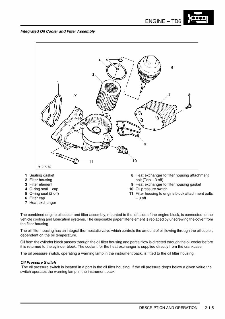
1 Sealing gasket2 Filter housing3 Filter element4 O-ring seal – cap5 O-ring seal (2 off)6 Filter cap7 Heat exchanger
8 Heat exchanger to filter housing attachment bolt (Torx –3 off)
9 Heat exchanger to filter housing gasket10 Oil pressure switch11 Filter housing to engine block attachment bolts
– 3 off
The combined engine oil cooler and filter assembly, mounted to the left side of the engine block, is connected to the vehicle cooling and lubrication systems. The disposable paper filter element is replaced by unscrewing the cover from the filter housing.
The oil filter housing has an integral thermostatic valve which controls the amount of oil flowing through the oil cooler, dependent on the oil temperature.
Oil from the cylinder block passes through the oil filter housing and partial flow is directed through the oil cooler before it is returned to the cylinder block. The coolant for the heat exchanger is supplied directly from the crankcase.
The oil pressure switch, operating a warning lamp in the instrument pack, is fitted to the oil filter housing.
Oil Pressure Switch The oil pressure switch is located in a port in the oil filter housing. If the oil pressure drops below a given value the switch operates the warning lamp in the instrument pack
DESCRIPTION AND OPERATION 12-1-5

ENGINE – TD6
High Pressure Fuel PumpThe high pressure fuel pump supplies fuel to the fuel rail and is fixed to a flange on the front LH side of the cylinder block. The pump is a 3 radial piston type controlled by the EDC engine management system and chain driven from the crankshaft at 0.75 times engine speed. + ENGINE MANAGEMENT SYSTEM – Td6, DESCRIPTION AND OPERATION, Description.
Crankshaft Position (CKP) SensorThe crankshaft position (CKP) sensor is mounted on the rear LH side of the cylinder block. The sensor is an inductive type which acts on a reluctor on the flywheel. + ENGINE MANAGEMENT SYSTEM – Td6, DESCRIPTION AND OPERATION, Description.
Crankshaft and Sump ComponentsThe crankshaft and sump and oil pump components are described below:
Crankshaft
Crankshaft Drive
Arrow denotes front of engine.
1 No 1 Piston2 No 6 Piston
3 Incremental wheel
The crankshaft is manufactured from high tensile steel. The bearing surfaces and radii are inductively hardened for toughness and fatigue resistance. It is supported on 7 main bearings with a flanged thrust bearing located between No 5 and No 6 cylinders. Dynamic balancing is achieved by the use of twelve balance weights.
Cross-drillings in the crankshaft between the adjoining main and big-end bearings are used to divert the lubrication oil to the big-end bearings.
12-1-6 DESCRIPTION AND OPERATION

ENGINE – TD6
Crankshafts are available in three sizes:l Standardl Undersize 1l Undersize 2.
Colour coding identifies the size of the journal.
At the front of the crankshaft is a four-hole threaded connection, used to attach the axially vibration damper and cooling fan. The engine RPM signal is taken from the reluctor “target” attached to the crankshaft.
The crankshaft oil seals are manufactured from PTFE.
Main BearingsThe main crankshaft bearing shells have oil grooves and a drilling in the upper bearing shell, to provide oil via the crankshaft drillings to the connecting rod big-end bearings.
SumpThe one-piece aluminium die-cast sump, with an integral tunnel for the differential drive shaft, is sealed to the lower crankcase extension using a rubber metal-backed gasket. The sump is fixed to the lower crankcase extension using 25 bolts. An oil deflector plate is attached to the crankcase reinforcing shell above the sump.
Oil PumpThe oil pump assembly is bolted to the bottom of the cylinder block and is located in front of the engine block stiffener plate. The pump is an internal gear-type with sintered rotors and is driven through a chain and sprocket system from the crankshaft.
A pressure relief valve is included at the outlet side of the oil pump to control oil pressure at high engine speeds by recirculating oil through the relief valve back around the pump to the inlet. The relief valve and spring is a plunger type; when oil pressure is great enough to lift the plunger, oil is allowed to escape past the plunger to relieve pressure and prevent any further rise in pressure.
Oil is delivered to the pump from the pick-up pipe, and the outlet side of the oil pump delivers pressurised oil flow to the engine block main oil delivery gallery.
FlywheelLocated between the engine and transmission the flywheel is of sheet metal laminated construction.
DESCRIPTION AND OPERATION 12-1-7
ENGINE – TD6
Camshaft Timing Components
Chain Drive
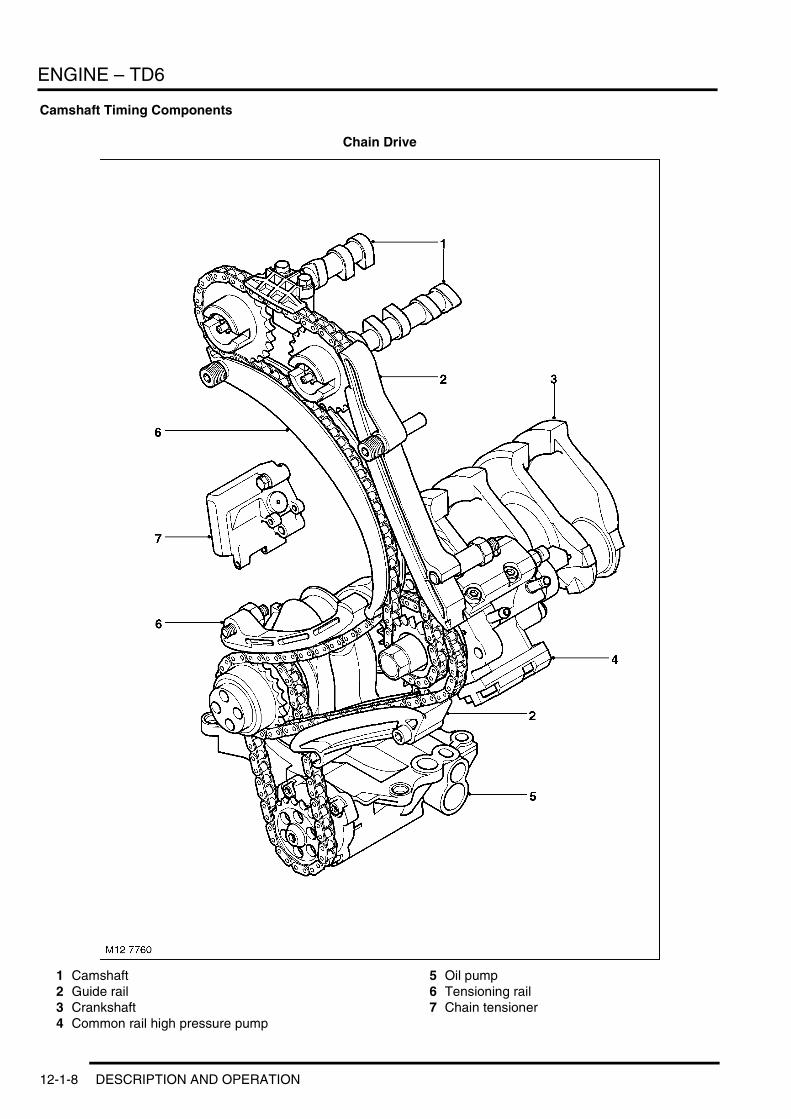
1 Camshaft2 Guide rail3 Crankshaft4 Common rail high pressure pump
5 Oil pump6 Tensioning rail7 Chain tensioner
12-1-8 DESCRIPTION AND OPERATION
ENGINE – TD6
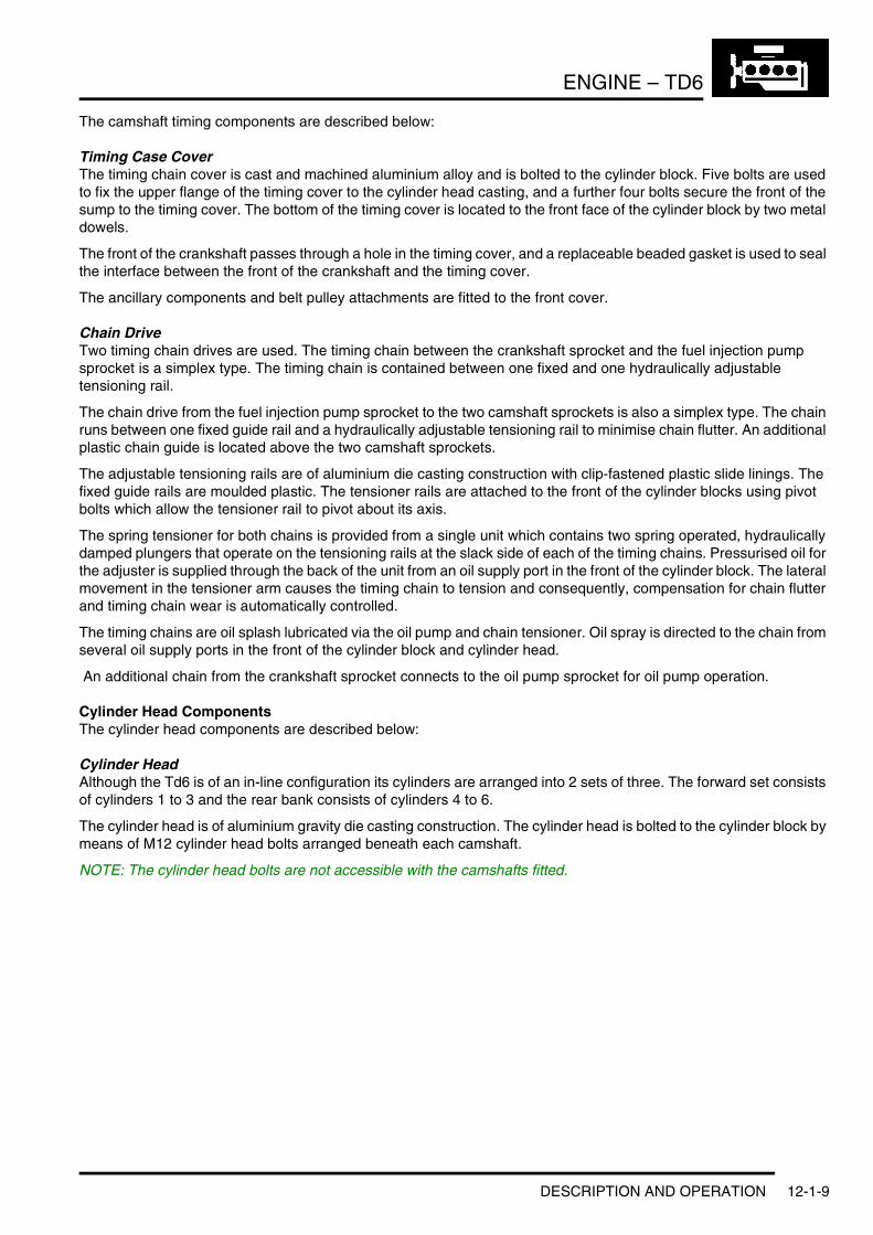
The camshaft timing components are described below:
Timing Case CoverThe timing chain cover is cast and machined aluminium alloy and is bolted to the cylinder block. Five bolts are used to fix the upper flange of the timing cover to the cylinder head casting, and a further four bolts secure the front of the sump to the timing cover. The bottom of the timing cover is located to the front face of the cylinder block by two metal dowels.
The front of the crankshaft passes through a hole in the timing cover, and a replaceable beaded gasket is used to seal the interface between the front of the crankshaft and the timing cover.
The ancillary components and belt pulley attachments are fitted to the front cover.
Chain DriveTwo timing chain drives are used. The timing chain between the crankshaft sprocket and the fuel injection pump sprocket is a simplex type. The timing chain is contained between one fixed and one hydraulically adjustable tensioning rail.
The chain drive from the fuel injection pump sprocket to the two camshaft sprockets is also a simplex type. The chain runs between one fixed guide rail and a hydraulically adjustable tensioning rail to minimise chain flutter. An additional plastic chain guide is located above the two camshaft sprockets.
The adjustable tensioning rails are of aluminium die casting construction with clip-fastened plastic slide linings. The fixed guide rails are moulded plastic. The tensioner rails are attached to the front of the cylinder blocks using pivot bolts which allow the tensioner rail to pivot about its axis.
The spring tensioner for both chains is provided from a single unit which contains two spring operated, hydraulically damped plungers that operate on the tensioning rails at the slack side of each of the timing chains. Pressurised oil for the adjuster is supplied through the back of the unit from an oil supply port in the front of the cylinder block. The lateral movement in the tensioner arm causes the timing chain to tension and consequently, compensation for chain flutter and timing chain wear is automatically controlled.
The timing chains are oil splash lubricated via the oil pump and chain tensioner. Oil spray is directed to the chain from several oil supply ports in the front of the cylinder block and cylinder head.
An additional chain from the crankshaft sprocket connects to the oil pump sprocket for oil pump operation.
Cylinder Head ComponentsThe cylinder head components are described below:
Cylinder HeadAlthough the Td6 is of an in-line configuration its cylinders are arranged into 2 sets of three. The forward set consists of cylinders 1 to 3 and the rear bank consists of cylinders 4 to 6.
The cylinder head is of aluminium gravity die casting construction. The cylinder head is bolted to the cylinder block by means of M12 cylinder head bolts arranged beneath each camshaft.
NOTE: The cylinder head bolts are not accessible with the camshafts fitted.
DESCRIPTION AND OPERATION 12-1-9
ENGINE – TD6
Inlet Port Configuration
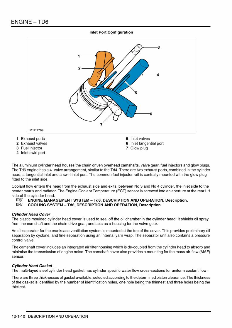
1 Exhaust ports2 Exhaust valves3 Fuel injector4 Inlet swirl port
5 Inlet valves6 Inlet tangential port7 Glow plug
The aluminium cylinder head houses the chain driven overhead camshafts, valve gear, fuel injectors and glow plugs. The Td6 engine has a 4–valve arrangement, similar to the Td4. There are two exhaust ports, combined in the cylinder head, a tangential inlet and a swirl inlet port. The common fuel injector rail is centrally mounted with the glow plug fitted to the inlet side.
Coolant flow enters the head from the exhaust side and exits, between No 3 and No 4 cylinder, the inlet side to the heater matrix and radiator. The Engine Coolant Temperature (ECT) sensor is screwed into an aperture at the rear LH side of the cylinder head. + ENGINE MANAGEMENT SYSTEM – Td6, DESCRIPTION AND OPERATION, Description. + COOLING SYSTEM – Td6, DESCRIPTION AND OPERATION, Description.
Cylinder Head CoverThe plastic moulded cylinder head cover is used to seal off the oil chamber in the cylinder head. It shields oil spray from the camshaft and the chain drive gear, and acts as a housing for the valve gear.
An oil separator for the crankcase ventilation system is mounted at the top of the cover. This provides preliminary oil separation by cyclone, and fine separation using an internal yarn wrap. The separator unit also contains a pressure control valve.
The camshaft cover includes an integrated air filter housing which is de-coupled from the cylinder head to absorb and minimise the transmission of engine noise. The camshaft cover also provides a mounting for the mass air-flow (MAF) sensor.
Cylinder Head GasketThe multi-layed steel cylinder head gasket has cylinder specific water flow cross-sections for uniform coolant flow.
There are three thicknesses of gasket available, selected according to the determined piston clearance. The thickness of the gasket is identified by the number of identification holes, one hole being the thinnest and three holes being the thickest.
1
6
M12 7769
3
7
2
5
4
12-1-10 DESCRIPTION AND OPERATION
ENGINE – TD6
Vacuum PumpThe vacuum pump is located on a support bracket at the front RH side of the cylinder head and is driven from the exhaust camshaft.
CamshaftsThere are two camshafts, exhaust (right) and intake (left). Each camshaft is maintained in position by seven bearing caps. Each bearing cap is fixed to the cylinder head by two bolts. The camshafts are made using the clear chill casting process and are hollow cast. The cam lobes have a negative cam radius. The camshafts are driven from the crankshaft using a simplex chain and sprocket arrangement.
Each camshaft has twelve machined lobes for operating the inlet and exhaust valves through lash adjusters and roller-type finger levers.
Inlet and Exhaust Valves
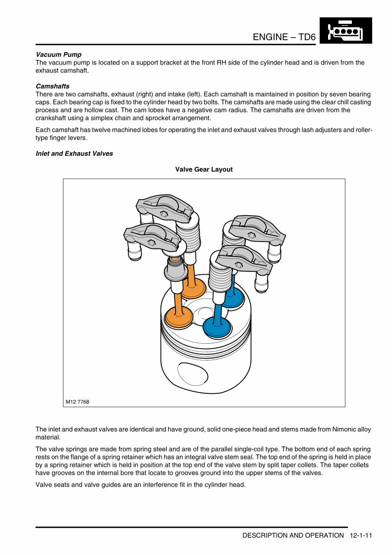
Valve Gear Layout
The inlet and exhaust valves are identical and have ground, solid one-piece head and stems made from Nimonic alloy material.
The valve springs are made from spring steel and are of the parallel single-coil type. The bottom end of each spring rests on the flange of a spring retainer which has an integral valve stem seal. The top end of the spring is held in place by a spring retainer which is held in position at the top end of the valve stem by split taper collets. The taper collets have grooves on the internal bore that locate to grooves ground into the upper stems of the valves.
Valve seats and valve guides are an interference fit in the cylinder head.
M12 7768
DESCRIPTION AND OPERATION 12-1-11

ENGINE – TD6
Hydraulic Lash Adjusters and Roller Finger RockersThe valves are operated through roller-type finger rockers and hydraulic lash adjusters, actuated by the camshaft lobes. When the camshaft lobe presses down on the top of a finger rocker, roller mechanism, the respective valve is forced down, opening the affected inlet or exhaust port. The use of this type of actuation method helps reduce friction in the valve timing mechanism.
The body of the hydraulic lash adjusters contains a plunger and two chambers for oil feed and pressurised oil. The pressurised oil is supplied to the lash adjusters via the main oil galleries in the cylinder head and through a hole in the side of the lash adjuster body. The oil passes into a feed chamber in the lash adjuster and then through to a separate pressure chamber via a one way ball valve.
Oil flow from the pressure chamber is determined by the amount of clearance between the lash adjuster outer body and the centre plunger. Oil escapes up the side of the plunger every time the lash adjuster is operated, the downward pressure on the plunger forcing a corresponding amount of oil in the lash adjuster body to be displaced. When the downward pressure from the camshaft and finger rocker is removed (i.e. after the trailing flank of the camshaft lobe has passed), oil pressure forces the lash adjuster's plunger up again. This pressure is not sufficient to effect the valve operation, but eliminates the clearance between the finger rocker and top of the valve stem.
Electronic Fuel InjectorsThere are six electronic fuel injectors (one for each cylinder), each located in the centre of a cylinder's four valves. The electronic fuel injectors are supplied with fuel from the fuel rail and deliver finely atomised fuel directly into the fuel chambers. + ENGINE MANAGEMENT SYSTEM – Td6, DESCRIPTION AND OPERATION, Description.
Ancillary Components and Belt DrivesThe ancillary components, which comprise the torsional vibration damper, alternator, A/C compressor, steering pump and water pump, are driven by the engine crankshaft via the ancillary drive belts.
The belts, which are maintenance free poly-V type belts, are automatically pre-loaded by the tensioning rollers and are routed over deflection pulleys in order to maintain sufficient adhesion about the drive wheels. This ensures slip-free drive of the ancillary components.
12-1-12 DESCRIPTION AND OPERATION
ENGINE – TD6
Belt Drive
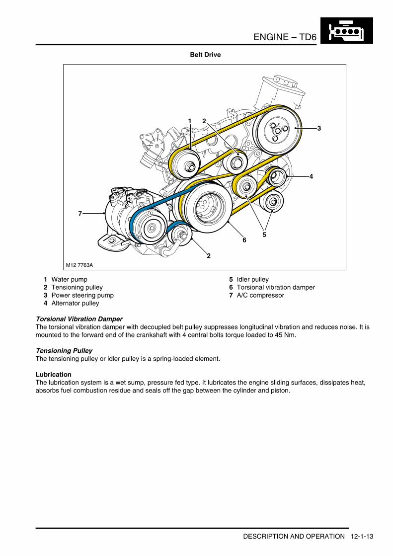
1 Water pump2 Tensioning pulley3 Power steering pump4 Alternator pulley
5 Idler pulley6 Torsional vibration damper7 A/C compressor
Torsional Vibration DamperThe torsional vibration damper with decoupled belt pulley suppresses longitudinal vibration and reduces noise. It is mounted to the forward end of the crankshaft with 4 central bolts torque loaded to 45 Nm.
Tensioning PulleyThe tensioning pulley or idler pulley is a spring-loaded element.
LubricationThe lubrication system is a wet sump, pressure fed type. It lubricates the engine sliding surfaces, dissipates heat, absorbs fuel combustion residue and seals off the gap between the cylinder and piston.
M12 7763A
2
6
213
4
7
5
DESCRIPTION AND OPERATION 12-1-13
ENGINE – TD6
Lubrication Circuit
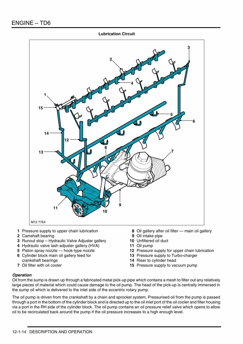
1 Pressure supply to upper chain lubrication2 Camshaft bearing3 Runout stop – Hydraulic Valve Adjuster gallery4 Hydraulic valve lash adjuster gallery (HVA)5 Piston spray nozzle — hook-type nozzle6 Cylinder block main oil gallery feed for
crankshaft bearings7 Oil filter with oil cooler
8 Oil gallery after oil filter — main oil gallery9 Oil intake pipe
10 Unfiltered oil duct11 Oil pump12 Pressure supply for upper chain lubrication13 Pressure supply to Turbo-charger14 Riser to cylinder head15 Pressure supply to vacuum pump
OperationOil from the sump is drawn up through a fabricated metal pick-up pipe which contains a mesh to filter out any relatively large pieces of material which could cause damage to the oil pump. The head of the pick-up is centrally immersed in the sump oil which is delivered to the inlet side of the eccentric rotary pump.
The oil pump is driven from the crankshaft by a chain and sprocket system. Pressurised oil from the pump is passed through a port in the bottom of the cylinder block and is directed up to the oil inlet port of the oil cooler and filter housing via a port in the RH side of the cylinder block. The oil pump contains an oil pressure relief valve which opens to allow oil to be recirculated back around the pump if the oil pressure increases to a high enough level.
911
87
4
5
3
2
1
15
14
M12 7764
13
10
12
6
12-1-14 DESCRIPTION AND OPERATION

ENGINE – TD6
The inlet port of the oil cooler and filter housing has an integral non-return valve which allows flow into the filter, but prevents unfiltered oil draining back out of the filter housing when oil pressure is reduced.
The oil passes through the oil filter element and out to the oil cooler. The percentage of oil flow passed through to the oil cooler is dependent on a thermostatic by-pass valve which is integrated into the oil filter housing. An increase in oil temperature causes the by-pass valve to open and allow a greater percentage of oil flow to be directed through the oil cooler. The remainder of the oil flow from the outlet side of the filter element is directed to the outlet port of the oil filter housing where it combines with the oil flow being returned from the oil cooler before being passed back into the cylinder block.
An oil pressure switch is included in the outlet port of the oil filter housing to sense the oil pressure level before the oil flow enters the main oil gallery in the engine block. A warning lamp in the instrument pack is switched on if the oil pressure is detected to be too low. + INSTRUMENTS, DESCRIPTION AND OPERATION, Description.
Oil entering the cylinder block main gallery passes through drillings to the crankshaft main bearings and cross drillings in the crankshaft direct oil to the big-end bearings. An additional four drillings in the cylinder block supply oil at reduced pressure to the lubrication jets for piston and cylinder cooling and gudgeon pin lubrication.
A cross channel from the LH main oil gallery crosses to the RH side of the cylinder block where there is an outlet port which provides a pressurised oil supply to the turbocharger bearings via a banjo connection and external piping.
Riser channels at the front RH side and rear LH side of the cylinder block are used to channel oil to mating ports in the cylinder head and provide a source for cylinder head lubrication and operating pressure for the lash adjusters.
Oil is fed through oil galleries at the LH and RH side of the engine and six cross channels from each gallery directs oil to the camshaft bearings. Lubrication oil fed to the lash adjusters passes up through the lash adjuster's body to the finger rockers for lubrication of the surfaces between the finger rockers and the camshaft lobes.
Tapered plugs seal the cylinder head oil galleries at the rear of the cylinder head, and an additional tapered plug is included inside the cylinder head at the front of the RH gallery.
An additional riser channel from the cylinder block LH main oil gallery is used to supply lubrication to the timing chain system through several outlet ports at the front of the cylinder block and cylinder head.
DESCRIPTION AND OPERATION 12-1-15

ENGINE – TD6
Engine Mounts
System Layout
1 Right hydraulic damper2 Right engine mounting3 Left engine mounting
4 Left hydraulic damper5 Vacuum supply pipe6 Engine mount damping control actuator
Two hydraulically dampened engine mounts are fitted between the engine support brackets and engine sub-frame to reduce the level of transmitted engine vibration and noise.
The damping characteristics of the mounts are regulated by controlling the rate of hydraulic fluid transfer between two internal chambers.
The system consists of two hydraulic mounts, with variable damping regulated by a vacuum, a control actuator, electric and vacuum lines. The vacuum, controlled by the electrical control actuator, is supplied via a distributor in the vacuum line between the vacuum pump and brake booster. The system is controlled by the EDC System.
12-1-16 DESCRIPTION AND OPERATION

ENGINE – TD6
Hydraulic Engine Mount
1 Vacuum connection2 Bellows3 Nozzle4 Annular channel5 Diaphragm6 Upper hydraulic chamber7 Orifice
8 Upper nozzle plate9 Nozzle
10 Lower nozzle plate11 Lower hydraulic chamber12 Support cup13 Spring14 Channel
M12 7766
10
3
4
5
6
8
7
9
14
12
13
11
1
2
DESCRIPTION AND OPERATION 12-1-17

ENGINE – TD6
OperationBy applying a vacuum, the Engine Control Module (ECM) controls the engine damping mounting in two stages:
“Hard” Engine MountIn the basic setting no vacuum is applied to the hydraulic mount. The spring (13) acts on the support cup (12) to close the U-bellows against the upper nozzle plate (8). Hydraulic fluid flows from the upper hydraulic chamber (6) via the nozzle (9), the annular channel (4) and via nozzle (3) into the lower hydraulic chamber (11).
The annular channel extends over approximately 300 degrees. Due to the length of the annular channel and the small nozzle orifice hydraulic oil flows between the upper and lower hydraulic chamber only in the case of vibrations up to the natural frequency of the engine (approximately. 10 Hz), thus producing a vibration absorber effect.
At higher frequencies, the equalisation between the hydraulic chambers is inhibited by the length of the annular channel and the small nozzle orifices. In practical terms, equalisation between the upper and lower hydraulic chamber does not take place.
Diaphragms (5) are fitted in the holes (7) of the nozzle plates in order to achieve good acoustic characteristics at high frequencies with small amplitude.
"Soft" Engine MountAt idling speed and in the speed range close to idling, the spring (13) is pulled down by applying vacuum at vacuum connection (1). The channel (14) in the centre of the upper nozzle plate now acts as a bypass between the upper and lower hydraulic chamber. This allows the hydraulic fluid to flow unrestricted between the upper and lower chambers. The increase in the fluid flow rate softens the damping action of the hydraulic mount, reducing the dynamic rigidity of the engine mount.
EDC ParametersThe ECM controls the engine mounts based on the following parameters:
Switching ValueEngine Speed 900 RPM
Vehicle speed 60 km/h (36 MPH)
12-1-18 DESCRIPTION AND OPERATION

ENGINE – TD6
Vacuum Supply
Distributor
The vacuum necessary for activating the engine mounts is obtained via a distributor located in the vacuum line between the vacuum pump and brake booster.
For this purpose, the vacuum line of the damping-controlled hydraulic mount is connected to the long outlet of the distributor.
The vacuum varies within the pressure range from 0.5 to 0.9 bar. It is switched by means of a damping control actuator.
DESCRIPTION AND OPERATION 12-1-19

ENGINE – TD6
12-1-20 DESCRIPTION AND OPERATION

ENGINE - V8
ENGINE - V8DESCRIPTION AND OPERATIONV8 – External View
M12 7816
DESCRIPTION AND OPERATION 12-2-1

ENGINE - V8
Description
GeneralThe V8 petrol engine is a 4.4 litre, eight cylinder water cooled engine having two banks of four cylinders, arranged at 90 degrees to each other, with four valves per cylinder. The engine emissions comply with ECD3 (European Commission Directive) and NAS LEV 2 legislative requirements. The engine comprises five main castings - two cylinder heads, cylinder block, timing cover and the oil sump, all of which are manufactured from aluminium alloy.
Plastic rocker covers are fitted to the cylinder heads and, between the cylinder heads, is a plastic manifold intake assembly. A plastic moulded acoustic cover is fitted over the upper engine to reduce engine generated noise.
The engine is supported, between cast mounting brackets and the front subframe, on two self-contained hydraulically damped mounts.
Technical FeaturesThe technical features include:
l Four valves per cylinderl Single plenum chamberl Variable Camshaft Control (VCC) systeml Double roller timing chainl Hydraulic Valve Adjusters (HVA)l Water Cooled Oil Cooler.
Engine Data The technical data is detailed below
The cylinders are numbered as follows:
NOTE: Cylinders 4 and 8 are at the rear of the engine
Cylinder Block ComponentsThe cylinder block components are described below:
Engine type 90° VCylinders 8
Displacement 4398 ccmStroke/bore 82.7/92.0 mm
Maximum Power 210 kW (285 PS; 282 bhp) @ 5400 rev/min
Maximum Torque 440 Nm (324 lbf.ft) @ 3600 rev/minCompression ratio 10: 1
Firing order 1–5–4–8–6–3–7–2
Left bank 5 — 8
Right bank 1 — 4
12-2-2 DESCRIPTION AND OPERATION

ENGINE - V8
Crankcase
The crankcase is made from Alusil for markets where the fuel contains a high sulphur content. The cylinder barrels have a nickel dispersion coating (Nikasil), and are finished by polishing only.
An adaptor plate for the feed and return flexible pipes to the oil filter assembly is fitted to the left side of the crankcase.
A water drain plug is located at the lower LH rear corner to drain coolant from the crankcase.
Crankcase VentilationThe crankcase ventilation system is pressure regulated by a valve mounted at the rear of the inlet manifold. Vacuum supply ports are incorporated on the valve for the power brake booster and the fuel pressure regulator
The pressure regulating vent valve varies the vacuum applied to the crankcase depending on engine load. The valve is balanced between spring pressure and the amount of manifold vacuum. At idle when the vacuum is high, the valve closes down and only allows a small amount of blow-by vapours to pass into the manifold. At part to full load conditions, the spring opens the valve and additional blow-by gasses flow into the manifold. An additional tube leads the blow-by gasses through the manifold and up to the mixing plate.
The crankcase ventilation system is completely sealed. Hose clamps are used at all connections to ensure that the system does not contain any leaks.
The crankcase ventilation system uses a cyclone separator to purge the blow-by gasses of any oil vapours. The oil vapours condense in the separator and drain back into the sump.
DESCRIPTION AND OPERATION 12-2-3

ENGINE - V8
Crankcase Ventilation System
1 Oil separator2 Breather hose, oil separator to vent valve3 Breather hose, LH camshaft cover to oil
separator4 Inlet manifold cover and vent valve5 Inlet manifold6 Oil drain pipe assembly
7 Inlet manifold vacuum pipe8 Mixing plate9 Vent valve spring
10 Vent valve diaphragm11 Atmospheric vent12 Blow-by gasses
M12 7839A
1
23
4
5
6
10
7
9
12
11
7
8
12-2-4 DESCRIPTION AND OPERATION

ENGINE - V8
Crankshaft
The crankshaft is manufactured from forged steel with five main bearings and the thrust bearing on number five bearing. Six counterweights fitted. These are positioned in harmony with the ignition firing order to ensure smooth running.
The crank pins are offset by 90° and hollow bored to reduce weight.
There are four sizes of crankshaft available, standard and three undersizes.
Colour coding identifies the size of the journal.
The main bearing caps have a unique four bolt fixing for additional strength, and threaded protective bushes which are torqued before the collar screws are installed.
NOTE: For information on colour coding and journal sizes, refer to the General Data section of the workshop manual.
At the front of the crankshaft, incorporated in the auxiliary belt pulley is a torsional vibration damper. Fitted behind the damper, to the crankshaft, is the drive sprocket for the camshaft and oil pump.
Torsional Vibration DamperThe torsional vibration damper with decoupled belt pulley suppresses longitudinal vibration and reduces noise. It is mounted at front of the crankshaft with 4 bolts torque loaded to 45 Nm.
DESCRIPTION AND OPERATION 12-2-5

ENGINE - V8
Bearing Shells The upper bearing shells have oil grooves and a drilling to provide oil, via drillings in the crankshaft to the crankshaft main bearings and the connecting rod journals
Flywheel
1 Flywheel2 Torque converter attachment holes
3 Reluctor ring4 Starter motor ring gear
The single piece steel flywheel is bolted to the rear of the crankshaft with nine bolts. The torque converter is bolted to the rear of the flywheel with four bolts.
Attached to the flywheel is the reluctor ring for the crankshaft position sensor and the starter motor ring gear.
12-2-6 DESCRIPTION AND OPERATION

ENGINE - V8
Connecting Rods
The connecting rods are sintered type, one piece forged rods which feature a fracture-split at the big-end between the connecting rod and the bearing cap. The mating surface of the rod and bearing cap form a rough surface (interference fit) that eliminates the need for centering sleeves. Each matched rod and bearing cap pair is stamped with a pairing code.
All of the rods are of one weight class and conform to the double bearing classification, red or blue. One red and one blue bearing shell are fitted to each connecting rod. The red shell is fitted to the bearing cap.
PistonsThe pistons are of a short skirt design and “iron coated” for use with the Alusil block. Each piston has a flat crown surface with a front facing arrow for installation direction. The relevant cylinder bank number is engraved into the piston crown.
Each piston is fitted with two compression rings and an oil control ring.
There are no thermal control strips in the pistons. The pistons are cooled with specific spray jets, mounted in the crankcase.
M12 7806
DESCRIPTION AND OPERATION 12-2-7

ENGINE - V8
Piston Lubrication Jets
Hook-type nozzles are connected directly into an oil gallery in the crankcase and secured by two screws.
The jets provide lubrication to the cylinder walls, and to the piston underskirt for cooling the pistons and lubricating the gudgeon pins and small-end bearings.
M12 7843
12-2-8 DESCRIPTION AND OPERATION

ENGINE - V8
Timing Case Covers
Separate timing case covers are bolted to the two cylinder heads and the crankcase.
The upper timing case covers have ports for the VCC solenoid valves and Camshaft Position (CMP) sensors. The lower cover has an integral mounting for the alternator which acts as a water jacket. A drain plug and sealing ring is fitted to the bottom of the mounting.
Rubber pre-formed gaskets form seals between the cylinder heads and crankcase and respective timing case covers.
DESCRIPTION AND OPERATION 12-2-9

ENGINE - V8
Sump
The two-piece aluminium die-cast sump, with an integral tunnel for the differential drive shaft, is sealed to the lower crankcase extension using a rubber metal-backed gasket. The sump is fixed to the lower crankcase extension using 25 bolts. An oil deflector plate is attached to the crankcase reinforcing shell above the sump. The sump incorporates a drain plug and a dip-stick guide tube.
Oil PumpThe oil pump housing and cover is manufactured from cast aluminium. The gear type oil pump is driven via the crankshaft.
The oil pump is located in the sump and is attached to Nos 1 and 2 main bearing caps. The rotor-type pump produces a regulated pressure of approximately 4.5 bar.
A metal suction pipe obtains oil from the sump.
12-2-10 DESCRIPTION AND OPERATION

ENGINE - V8
Oil Filter Assembly
The oil filter assembly, with a replaceable element, is mounted remote to the engine. It is attached to a mounting bracket fitted to the left of the radiator and the filter is mounted on two rubber mounts to reduce vibration.
Two re-inforced flexible hoses, feed and return, are fitted between the filter assembly and the crankcase mounted adaptor plate. The hose connections are of the push fit type and sealed with an “O” ring seal. The filter hose connections are secured by a locking plate bolted to the filter body. The sump hose connections are secured to the crankcase adaptor with a securing bracket. This bracket is attached with a stud and nut.
A by-pass valve is located internally in the lower end of the filter body. This allows the oil to by-pass the filter if the filter element becomes blocked
A second valve is screwed into the filter body. It is connected to a rigid pipe on the sump by a flexible hose secured by two hose clips. The rigid pipe has a banjo fitting on the sump connection. When the filter is removed, the valve opens allowing oil in the housing to drain to the sump.
The oil pressure switch screws into the base of the filter body.
DESCRIPTION AND OPERATION 12-2-11
ENGINE - V8
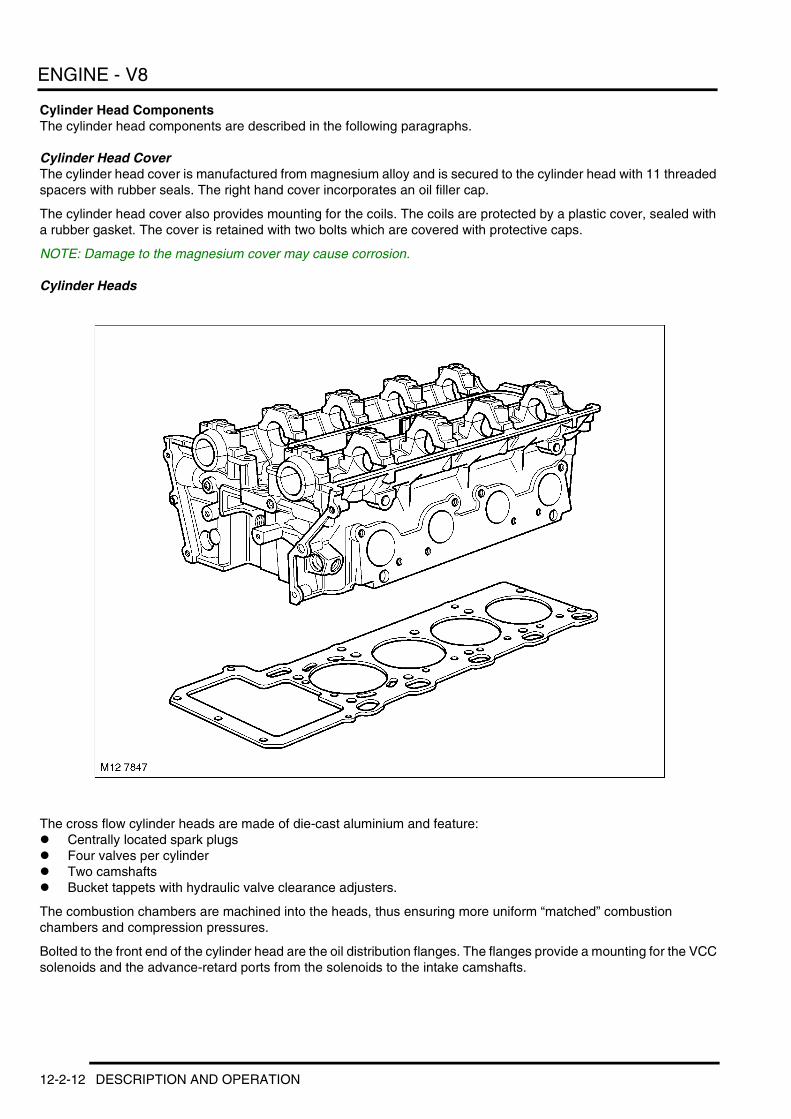
Cylinder Head ComponentsThe cylinder head components are described in the following paragraphs.
Cylinder Head CoverThe cylinder head cover is manufactured from magnesium alloy and is secured to the cylinder head with 11 threaded spacers with rubber seals. The right hand cover incorporates an oil filler cap.
The cylinder head cover also provides mounting for the coils. The coils are protected by a plastic cover, sealed with a rubber gasket. The cover is retained with two bolts which are covered with protective caps.
NOTE: Damage to the magnesium cover may cause corrosion.
Cylinder Heads
The cross flow cylinder heads are made of die-cast aluminium and feature:l Centrally located spark plugsl Four valves per cylinderl Two camshaftsl Bucket tappets with hydraulic valve clearance adjusters.
The combustion chambers are machined into the heads, thus ensuring more uniform “matched” combustion chambers and compression pressures.
Bolted to the front end of the cylinder head are the oil distribution flanges. The flanges provide a mounting for the VCC solenoids and the advance-retard ports from the solenoids to the intake camshafts.
12-2-12 DESCRIPTION AND OPERATION

ENGINE - V8
The cylinder heads for each bank are different lengths due to the offset of the cylinder rows (cylinder bank 1–4 is shorter).
NOTE: The cylinder head gasket part numbers are different for the two cylinder banks.
The cylinder head is machineable to a limit of 0.3 mm. A repair cylinder head gasket is available and is identified by a small hole beside the 4th and 8th cylinder apertures.
CamshaftsTwo solid cast iron camshafts are used for each cylinder head. The cams run in five machined bearing surfaces with numbered caps for identification.
The camshafts are also marked for identification and incorporate hexagonal machined blocks for timing the cams during installation.
For installation and servicing, the camshafts are held in position with locking pins. These pins are inserted into the front camshaft bearing caps on both cylinder heads.
ValvesThe intake and exhaust valves are arranged in a “V” pattern. The valves use single, conical, coil bound shaped valve springs and Hydraulic Valve Adjustment (HVA) tappets and each comprises the following components:l Valve x 1 (inlet or exhaust)l Valve stem seal x 1l Valve spring x 1l Valve spring seat x 1l Valve spring cap x 1l Valve collets x 2l Tappet x 1.
Hydraulic Valve Adjustment TappetsBucket type hydraulic tappets are used for adjusting the valve clearance. The buckets are self-breathing with a carbon nitride finished cam contact surface.
Primary drivePrimary drive is provided by a single roller chain from the crankshaft to the two rubber coated cam gears. The train is guided by a centrally positioned V-shaped aluminium deflector rail, a straight rail on cylinder bank 5 to 8 and a curved tensioner rail on cylinder bank 1 to 4.
Timing chain adjustment is carried out with a hydraulic tensioner mounted on the upper case for cylinders 1 to 4
Secondary DriveSecondary drive is from the intake camshaft to the exhaust camshaft by a single roller chain. Chain tension is maintained by a hydraulic, spring assisted tensioner that incorporates an oil spray jet.
The oil supply for the chain tensioner also supplies the VCC hydraulic units through a pressure control valve.
DESCRIPTION AND OPERATION 12-2-13
ENGINE - V8
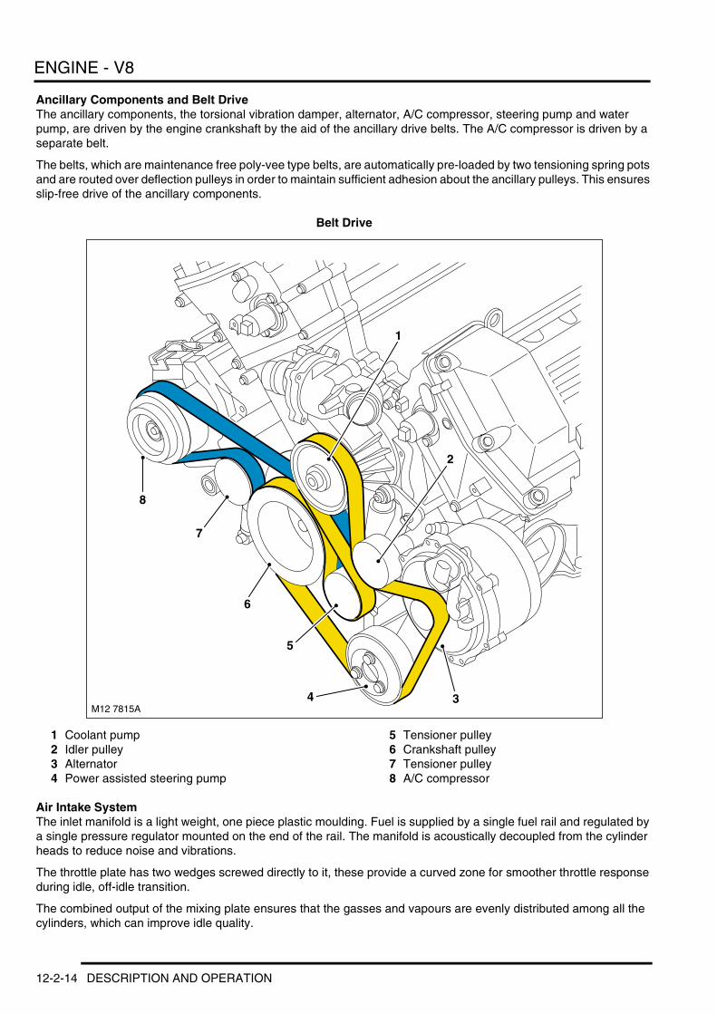
Ancillary Components and Belt DriveThe ancillary components, the torsional vibration damper, alternator, A/C compressor, steering pump and water pump, are driven by the engine crankshaft by the aid of the ancillary drive belts. The A/C compressor is driven by a separate belt.
The belts, which are maintenance free poly-vee type belts, are automatically pre-loaded by two tensioning spring pots and are routed over deflection pulleys in order to maintain sufficient adhesion about the ancillary pulleys. This ensures slip-free drive of the ancillary components.
Belt Drive
1 Coolant pump2 Idler pulley3 Alternator4 Power assisted steering pump
5 Tensioner pulley6 Crankshaft pulley7 Tensioner pulley8 A/C compressor
Air Intake SystemThe inlet manifold is a light weight, one piece plastic moulding. Fuel is supplied by a single fuel rail and regulated by a single pressure regulator mounted on the end of the rail. The manifold is acoustically decoupled from the cylinder heads to reduce noise and vibrations.
The throttle plate has two wedges screwed directly to it, these provide a curved zone for smoother throttle response during idle, off-idle transition.
The combined output of the mixing plate ensures that the gasses and vapours are evenly distributed among all the cylinders, which can improve idle quality.
M12 7815A
8
7
6
5
4 3
2
1
12-2-14 DESCRIPTION AND OPERATION

ENGINE - V8
LubricationThe lubrication system is a wet sump, pressure fed type. It lubricates the engine sliding surfaces, dissipates heat and absorbs fuel combustion residue.
OperationOil from the sump is drawn up through a fabricated metal pick-up pipe which contains a mesh to filter out any relatively large particles of material which could cause damage to the oil pump. The head of the pick-up is centrally immersed in the sump oil which is delivered to the rotor pump.
Variable Camshaft Control (VCC)The V8 engine uses a VCC (Variable Camshaft Control) system for valve timing on the intake camshaft. While the engine is running the inlet camshafts are continuously adjusted to their optimum position.
Both camshafts are simultaneously adjusted to a maximum of 20° of the crankshaft rotational axis. This equates to a maximum span of 40° crankshaft rotation. + ENGINE MANAGEMENT SYSTEM – V8, DESCRIPTION AND OPERATION, VCC System.
Cylinder Bank ComponentsEach cylinder bank contains the following:l Cylinder head with oil ports for the VCC systeml Control solenoid valvel VCC Transmission and sprocketsl Oil distribution flangesl Oil check valvel Camshaft position impulse wheelsl Camshaft position sensors.
Control Solenoid ValveThe control solenoid valve is fitted with an integral non-return valve and has four ports:
1 Input supply port — engine oil pressure2 Output retard port — to rear of piston/helical gear (retarded camshaft position)3 Output advance port — to rear of piston/helical gear (advanced camshaft position)4 Vent — released oil pressure.
The non-return valve is fitted to the rear of the solenoid valve in the cylinder head oil gallery. The non-return valve maintains an oil supply in the VCC transmission and oil circuits after the engine is switched off. This prevents piston movement when the engine is restarted. + ENGINE MANAGEMENT SYSTEM – V8, DESCRIPTION AND OPERATION, VCC System.
VCC Transmission and SprocketsThe primary and secondary timing chain sprockets are integrated with the self-contained VCC transmission.
The controlled adjustment of the camshaft occurs inside the “transmission”. Controlled oil pressure moves the piston axially.
The helical gear cut of the piston acts on the helical gears on the inside surface of the transmission and rotates the camshaft to the specific advanced or retarded angle position.
Three electrical pin contacts are located on the front surface to verify the default maximum retard position using an ohmmeter. This is required during assembly and adjustment.
Oil Distribution Flanges The oil distribution flanges are bolted to the front surface of each cylinder head. They provide a mounting location for the VCC solenoids as well as the advance-retard oil ports from the solenoids to the intake camshafts.
Camshafts Each intake camshaft has two oil ports separated by three sealing rings on their forward ends. The ports direct pressurized oil from the oil distribution flange to the inner workings of the VCC transmission. Each camshaft has left-hand threaded bores in their centres for the attachment of the timing chain sprockets on the exhaust cams and the VCC transmissions for each intake camshaft.
DESCRIPTION AND OPERATION 12-2-15

ENGINE - V8
Camshaft Position Impulse Wheels The camshaft position impulse wheels provide camshaft position status to the engine control module via the camshaft position sensors. The asymmetrical placement of the sensor wheel pulse plates provides the engine control module with cylinder specific position ID in conjunction with crankshaft position. + ENGINE MANAGEMENT SYSTEM – V8, DESCRIPTION AND OPERATION, Bosch ME 7.2 Engine Management System.
Camshaft Position SensorsThere are two CMP position sensors which are located on the upper timing case covers. The camshaft position sensors monitor the position of the camshafts to establish ignition timing order, fuel injection triggering and for accurate Variable Camshaft Control (VCC) camshaft advance-retard timing feedback. The camshaft position sensor is a Hall-effect sensor which switches a battery fed supply on and off. The supply is switched when the teeth machined onto the camshaft gear pass by the tip of the sensor. The four teeth are of differing shapes, so the ECM can determine the exact position of the camshaft at any time. + ENGINE MANAGEMENT SYSTEM – V8, DESCRIPTION AND OPERATION, Bosch ME 7.2 Engine Management System.
12-2-16 DESCRIPTION AND OPERATION

ENGINE MANAGEMENT SYSTEM – TD6
Deze pagina werd opzettelijk niet gebruikt
Cette page est intentionnellement vierge
Questa pagina è stata lasciata in bianco di proposito
Diese Seite ist leer
Esta página foi deixada intencionalmente em branco
Esta página fue dejada en blanco intencionalmente
This page is intentionally left blank
ENGINE MANAGEMENT SYSTEM – Td6DESCRIPTION AND OPERATION
DESCRIPTION AND OPERATION 18-1-1

ENGINE MANAGEMENT SYSTEM – TD6
Engine Management Component Location – Sheet 1 of 2
18-1-2 DESCRIPTION AND OPERATION

ENGINE MANAGEMENT SYSTEM – TD6
1 Exhaust Gas Recirculation (EGR) modulator2 Boost pressure sensor3 Engine Coolant Temperature (ECT) sensor4 Engine mount damping control actuator5 Anti-lock Brake System (ABS) ECU6 Low Pressure (LP) sensor7 Fuel filter8 High Pressure (HP) fuel pump9 Instrument pack
10 Exhaust Gas Recirculation (EGR) valve11 Diagnostic socket12 Accelerator Pedal Position (APP) sensor13 Camshaft Position (CMP) sensor14 Glow plug relay15 Electronic Automatic Transmission (EAT) ECU16 Environmental box (E-box)
DESCRIPTION AND OPERATION 18-1-3

ENGINE MANAGEMENT SYSTEM – TD6
Engine Management Component Location – Sheet 2 of 2
1 Engine control Module (ECM)2 Fuel rail pressure sensor3 Crankshaft Position (CKP) sensor4 Boost control solenoid valve5 Fuel temperature sensor6 Glow plugs
7 Oil pressure switch8 Fuel rail pressure control valve9 Fuel injectors
10 Mass Air Flow/Inlet Air Temperature (MAF/IAT) sensor
11 Main relay
18-1-4 DESCRIPTION AND OPERATION
ENGINE MANAGEMENT SYSTEM – TD6
Deze pagina werd opzettelijk niet gebruikt
Cette page est intentionnellement vierge
Questa pagina è stata lasciata in bianco di proposito
Diese Seite ist leer
Esta página foi deixada intencionalmente em branco
Esta página fue dejada en blanco intencionalmente
This page is intentionally left blank
DESCRIPTION AND OPERATION 18-1-5

ENGINE MANAGEMENT SYSTEM – TD6
Engine Management Control Diagram – Sheet 1 of 2
A = Hardwired connection; D = CAN bus
M18 0774B A
1
D
2 3 4
5 6 7
8 9
10
11
12
13
14
1516
17
18
19
20
21
22
23
24 25
26
18-1-6 DESCRIPTION AND OPERATION
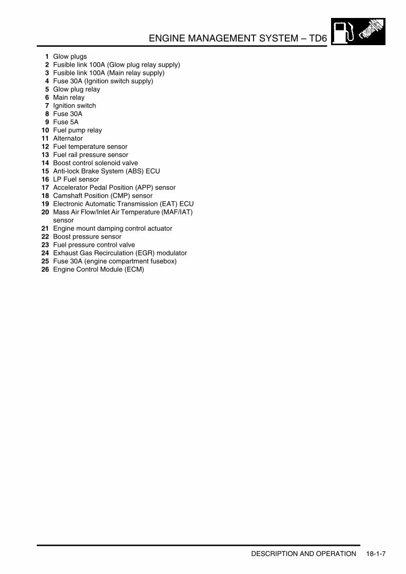
ENGINE MANAGEMENT SYSTEM – TD6
1 Glow plugs2 Fusible link 100A (Glow plug relay supply)3 Fusible link 100A (Main relay supply)4 Fuse 30A (Ignition switch supply)5 Glow plug relay6 Main relay7 Ignition switch8 Fuse 30A9 Fuse 5A
10 Fuel pump relay11 Alternator12 Fuel temperature sensor13 Fuel rail pressure sensor14 Boost control solenoid valve15 Anti-lock Brake System (ABS) ECU16 LP Fuel sensor17 Accelerator Pedal Position (APP) sensor18 Camshaft Position (CMP) sensor19 Electronic Automatic Transmission (EAT) ECU20 Mass Air Flow/Inlet Air Temperature (MAF/IAT)
sensor21 Engine mount damping control actuator22 Boost pressure sensor23 Fuel pressure control valve24 Exhaust Gas Recirculation (EGR) modulator25 Fuse 30A (engine compartment fusebox)26 Engine Control Module (ECM)
DESCRIPTION AND OPERATION 18-1-7
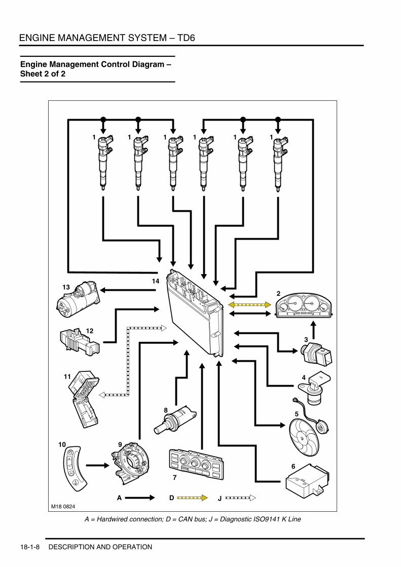
ENGINE MANAGEMENT SYSTEM – TD6
Engine Management Control Diagram – Sheet 2 of 2
A = Hardwired connection; D = CAN bus; J = Diagnostic ISO9141 K Line
M18 0824
A D
1 1 1 1 1 1
2
3
4
5
6
8
910
11
12
1314
7
J
18-1-8 DESCRIPTION AND OPERATION

ENGINE MANAGEMENT SYSTEM – TD6
1 Fuel injectors2 Instrument pack3 Engine oil pressure switch4 Crankshaft Position (CKP) sensor5 Electric engine/air conditioning cooling fan6 Immobilisation ECU7 Automatic Temperature Control (ATC) ECU8 Engine Coolant Temperature (ECT) sensor9 Rotary coupler
10 Cruise control switches11 Diagnostic socket12 Brake switch13 Starter motor14 Engine Control Module (ECM)
DESCRIPTION AND OPERATION 18-1-9

ENGINE MANAGEMENT SYSTEM – TD6
Description
GeneralThe Td6 engine has an Electronic Diesel Control (EDC) engine management system. The system is controlled by an Engine Control Module (ECM) and is able to monitor, adapt and precisely control the fuel injection. The ECM uses multiple sensor inputs and precision control of actuators to achieve optimum performance during all driving conditions.
The ECM controls fuel delivery to all six cylinders via a Common Rail (CR) injection system. The CR system uses a fuel rail to accumulate highly pressurised fuel and feed the six, electronically controlled injectors. The fuel rail is located in close proximity to the injectors, which assists in maintaining full system pressure at each injector at all times.
The ECM uses the drive by wire principle for acceleration control. There are no control cables or physical connections between the accelerator pedal and the engine. Accelerator pedal demand is communicated to the ECM by two potentiometers located in a throttle position sensor. The ECM uses the two signals to determine the position, rate of movement and direction of movement of the pedal. The ECM then uses this data, along with other engine information from other sensors, to achieve the optimum engine response.
The ECM also controls the Exhaust Gas Recirculation (EGR) system which is fitted to reduce the formation of oxides of nitrogen (NOx). This group of gases is formed in the combustion chamber under conditions of high temperature and high pressure. It is not desirable to reduce the compression ratio, so the ECM reduces the combustion temperature by introducing a controlled volume of inert gas into the cylinders on the induction stroke.
The inert gas used is exhaust gas, which is freely available. It is directed from the exhaust manifold, via a control valve, into the intake manifold. The flow of gas is monitored by the ECM using a Mass Air Flow (MAF) sensor. The EGR system is not required until the engine is hot, and is turned off during engine idling and wide open 'throttle' to preserve smooth operation and driveability.
The ECM processes information from the following input sources:l Brake switchl Crankshaft Position (CKP) sensorl Camshaft Position (CMP) sensorl Anti-lock Brake System (ABS) ECUl Engine Coolant Temperature (ECT) sensorl Boost Pressure (BP) sensorl Low side fuel pressure sensorl Accelerator Pedal Position (APP) sensorl Mass Air Flow/Intake Air Temperature (MAF/IAT) sensorl Fuel rail pressure sensorl Controller Area Network (CAN)l Glow plug relayl Immobilisation ECU.
The ECM outputs controlling signals to the following sensors and actuator:l Fuel injector solenoidsl Boost control solenoid valvel Exhaust Gas Recirculation (EGR) actuatorl Engine mount damping control actuatorl Glow plug relayl Rail pressure control valvel Electric cooling fan controll Automatic Temperature Control (ATC) ECU.
18-1-10 DESCRIPTION AND OPERATION

ENGINE MANAGEMENT SYSTEM – TD6
Engine Control Module (ECM)
1 Glow plug relay2 Engine compartment fusebox3 Circulation fan
4 Main relay5 ECM6 EAT ECU
The ECM has a steel casing to provide protection from electromagnetic radiation, and is located in the Environmental box (E-box). The ECM connected to the vehicle harnesses via 5 connectors.
The ECM contains data processors and memory microchips. The output signals to the actuators are in the form of ground paths provided by driver circuits within the ECM. The ECM driver circuits produce heat during normal operation and dissipate this heat via the casing. The fan in the E-box assists with the cooling process by maintaining a constant temperature with the E-box. The fan is controlled by a thermostatic switch located in the E-box. The E-box has pipe connections to the vehicle interior and receives additional cooled air via the A/C system.
Some sensors receive a regulated voltage supplied by the ECM. This avoids incorrect signals caused by voltage drop during cranking.
DESCRIPTION AND OPERATION 18-1-11

ENGINE MANAGEMENT SYSTEM – TD6
The ECM performs self diagnostic routines and stores fault codes in its memory. These fault codes and diagnostics can be accessed using TestBook/T4. If the ECM is to be replaced, the new ECM is supplied 'blank' and must be configured to the vehicle using TestBook/T4. When the ECM is fitted, it must also be synchronised to the immobilisation ECU using TestBook/T4. ECM's cannot be 'swopped' between vehicles.
The ECM is connected to the engine sensors which allow it to monitor the engine operating conditions. The ECM processes these signals and decides the actions necessary to maintain optimum engine performance in terms of driveability, fuel efficiency and exhaust emissions. The memory of the ECM is programmed with instructions for how to control the engine, this known as the strategy. The memory also contains data in the form of maps which the ECM uses as a basis for fuelling and emission control. By comparing the information from the sensors to the to the data in the maps, the ECM is able to calculate the various output requirements. The ECM contains an adaptive strategy which updates the system when components vary due to production tolerances or ageing.
The ECM receives a vehicle speed signal on a CAN bus connection from the ABS ECU. Vehicle speed is an important input to the ECM strategies. The ABS ECU derives the speed signal from the ABS wheel speed sensors. The frequency of this signal changes according to road speed. The ECM uses this signal to determine the following:l How much to reduce engine torque during gear changesl When to permit cruise control operationl To control the operation of the cruise controll Implementation of the idle strategy when the vehicle is stationary.
Engine ImmobilisationThe immobilisation ECU receives information from related systems on the vehicle and passes a coded signal to the ECM to allow starting if all starting parameters have been met. The information is decoded by the ECM which will allow the engine to run if the information is correct.
The information is on a rolling code system and both the immobilisation ECU and the ECM will require synchronisation if either component is renewed.
The immobilisation ECU also protects the starter motor from inadvertent operation. The immobilisation ECU receives an engine speed signal from the ECM via the instrument pack. When the engine speed exceeds a predetermined value, the immobilisation ECU prevents operation of the starter motor via an integral starter disable relay. + SECURITY, DESCRIPTION AND OPERATION, Description.
Diagnostic Self-TestThe ECM performs a self test routine every time the ignition is switched to position II. The ECM constantly monitors the system while the ignition is in this position. Any faults found are stored in a non-volatile fault memory.
The fault memory contents can be read using TestBook/T4 (See Diagnostics below). TestBook/T4 also allows for the testing of certain functions and the activation of actuators.
When a fault is detected, the component in question is tagged as defective. The tag is initially regarded as provisional and is not changed to a confirmed status until a certain period of time has elapsed. When the fault is changed to confirmed, the ECM adopts the default value for that function, if one is available.
Once the fault is classed as confirmed, a fault memory entry is generated. This entry is accompanied by the current mileage and the environmental conditions at the time of the fault occurrence. The fault entry is stored in the ECM EEPROM. If the fault is engine management system related, the ECM may illuminate the MIL in the instrument pack to notify the driver of the fault condition.
18-1-12 DESCRIPTION AND OPERATION

ENGINE MANAGEMENT SYSTEM – TD6
ECM Harness Connector C0331 Pin Details
ECM Harness Connector C0332 Pin Details
Pin No. Description Input/Output1 Alternator warning lamp Output2 Engine cranking signal Output3 Not used –
4 Cooling fan control unit Output5 and 6 Not used –
7 APP sensor 1 ground –
8 APP sensor 1 signal Input9 APP sensor 1 supply Output
10 Fuel pump relay Output
11 Oil pressure signal Output12 APP sensor 2 ground –13 APP sensor 2 signal Input
14 APP sensor 2 supply Output15 and 16 Not used –
17 Diagnostic socket ground –
18 Not used –19 Reverse gear signal Output20 Not used –
21 LCM22 Road speed signal Input23 Not used –
24 Brake pedal switch Input25 Not used –26 Ignition power supply Input
27 Steering wheel cruise control switches Input28 Brake pedal switch –29 A/C compressor clutch disengage signal Output
30 and 31 Not used –32 Diagnostic ISO 9141 K line bus Input/Output33 Immobilisation signal Input/Output
36 CAN bus high (connection with main bus system) Input/Output37 CAN bus low (connection with main bus system) Input/Output
38 to 40 Not used –
Pin No. Description Input/Output1 Feed to fuel injectors 4, 5 and 6 Output2 Not used –3 Ground for fuel injector 6 –
4 Feed to fuel injectors 1, 2 and 3 Output5 Ground for fuel injector 1 –6 Ground for fuel injector 4 –
7 Ground for fuel injector 2 –8 Ground for fuel injector 3 –9 Ground for fuel injector 5 –
DESCRIPTION AND OPERATION 18-1-13
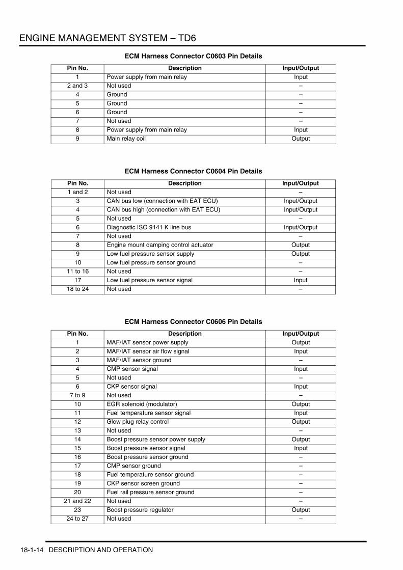
ENGINE MANAGEMENT SYSTEM – TD6
ECM Harness Connector C0603 Pin Details
ECM Harness Connector C0604 Pin Details
ECM Harness Connector C0606 Pin Details
Pin No. Description Input/Output1 Power supply from main relay Input
2 and 3 Not used –4 Ground –
5 Ground –6 Ground –7 Not used –
8 Power supply from main relay Input9 Main relay coil Output
Pin No. Description Input/Output1 and 2 Not used –
3 CAN bus low (connection with EAT ECU) Input/Output4 CAN bus high (connection with EAT ECU) Input/Output5 Not used –
6 Diagnostic ISO 9141 K line bus Input/Output7 Not used –8 Engine mount damping control actuator Output
9 Low fuel pressure sensor supply Output10 Low fuel pressure sensor ground –
11 to 16 Not used –
17 Low fuel pressure sensor signal Input18 to 24 Not used –
Pin No. Description Input/Output1 MAF/IAT sensor power supply Output
2 MAF/IAT sensor air flow signal Input3 MAF/IAT sensor ground –4 CMP sensor signal Input
5 Not used –6 CKP sensor signal Input
7 to 9 Not used –
10 EGR solenoid (modulator) Output11 Fuel temperature sensor signal Input12 Glow plug relay control Output
13 Not used –14 Boost pressure sensor power supply Output15 Boost pressure sensor signal Input
16 Boost pressure sensor ground –17 CMP sensor ground –18 Fuel temperature sensor ground –
19 CKP sensor screen ground –20 Fuel rail pressure sensor ground –
21 and 22 Not used –
23 Boost pressure regulator Output24 to 27 Not used –
18-1-14 DESCRIPTION AND OPERATION
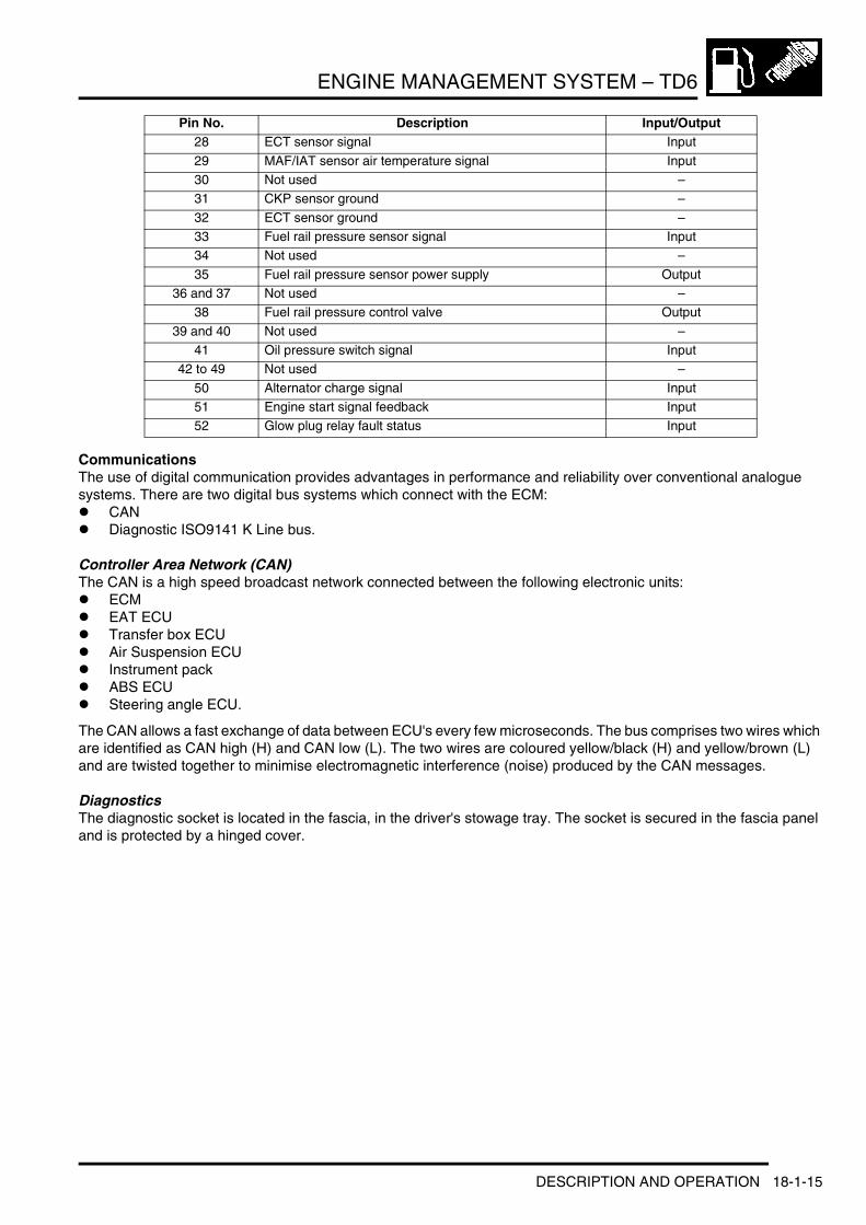
ENGINE MANAGEMENT SYSTEM – TD6
CommunicationsThe use of digital communication provides advantages in performance and reliability over conventional analogue systems. There are two digital bus systems which connect with the ECM:l CANl Diagnostic ISO9141 K Line bus.
Controller Area Network (CAN)The CAN is a high speed broadcast network connected between the following electronic units:l ECMl EAT ECUl Transfer box ECUl Air Suspension ECUl Instrument packl ABS ECUl Steering angle ECU.
The CAN allows a fast exchange of data between ECU's every few microseconds. The bus comprises two wires which are identified as CAN high (H) and CAN low (L). The two wires are coloured yellow/black (H) and yellow/brown (L) and are twisted together to minimise electromagnetic interference (noise) produced by the CAN messages.
DiagnosticsThe diagnostic socket is located in the fascia, in the driver's stowage tray. The socket is secured in the fascia panel and is protected by a hinged cover.
28 ECT sensor signal Input
29 MAF/IAT sensor air temperature signal Input30 Not used –31 CKP sensor ground –
32 ECT sensor ground –33 Fuel rail pressure sensor signal Input34 Not used –
35 Fuel rail pressure sensor power supply Output36 and 37 Not used –
38 Fuel rail pressure control valve Output
39 and 40 Not used –41 Oil pressure switch signal Input
42 to 49 Not used –
50 Alternator charge signal Input51 Engine start signal feedback Input52 Glow plug relay fault status Input
Pin No. Description Input/Output
DESCRIPTION AND OPERATION 18-1-15

ENGINE MANAGEMENT SYSTEM – TD6
1 Cover 2 Diagnostic socket
The diagnostic socket allows the exchange of information between various ECU's on the bus systems and TestBook/T4 or a diagnostic tool using KW2000* protocol. The information is communicated to the socket via the diagnostic ISO 9141 K line. This allows the fast retrieval of diagnostic information and programming of certain functions using TestBook/T4 or a suitable diagnostic tool.
Engine Sensors and ActuatorsThe EDC system uses sensors and actuators to monitor and control the operation of the engine. The sensors supply data to the ECM and the actuators receive signals from the ECM to control certain functions.
18-1-16 DESCRIPTION AND OPERATION
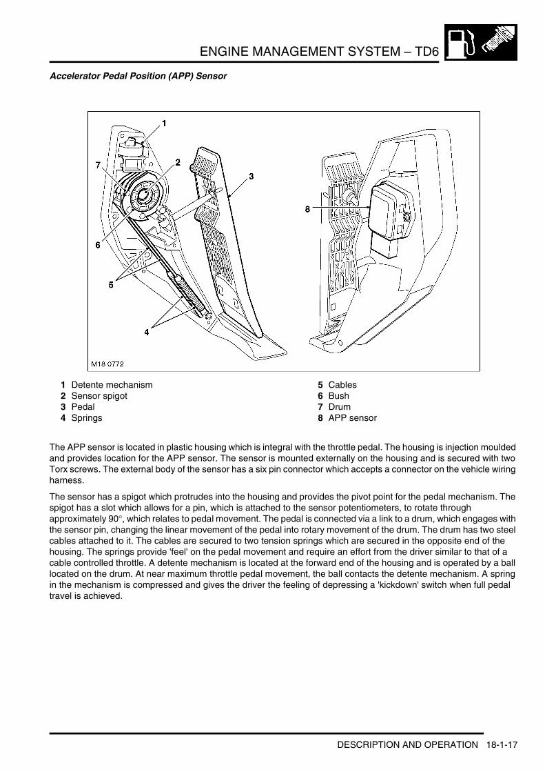
ENGINE MANAGEMENT SYSTEM – TD6
Accelerator Pedal Position (APP) Sensor
1 Detente mechanism2 Sensor spigot3 Pedal4 Springs
5 Cables6 Bush7 Drum8 APP sensor
The APP sensor is located in plastic housing which is integral with the throttle pedal. The housing is injection moulded and provides location for the APP sensor. The sensor is mounted externally on the housing and is secured with two Torx screws. The external body of the sensor has a six pin connector which accepts a connector on the vehicle wiring harness.
The sensor has a spigot which protrudes into the housing and provides the pivot point for the pedal mechanism. The spigot has a slot which allows for a pin, which is attached to the sensor potentiometers, to rotate through approximately 90°, which relates to pedal movement. The pedal is connected via a link to a drum, which engages with the sensor pin, changing the linear movement of the pedal into rotary movement of the drum. The drum has two steel cables attached to it. The cables are secured to two tension springs which are secured in the opposite end of the housing. The springs provide 'feel' on the pedal movement and require an effort from the driver similar to that of a cable controlled throttle. A detente mechanism is located at the forward end of the housing and is operated by a ball located on the drum. At near maximum throttle pedal movement, the ball contacts the detente mechanism. A spring in the mechanism is compressed and gives the driver the feeling of depressing a 'kickdown' switch when full pedal travel is achieved.
DESCRIPTION AND OPERATION 18-1-17

ENGINE MANAGEMENT SYSTEM – TD6
APP Sensor Output Graph
A = VoltageB = APP sensor angleC = Kick down angle
18-1-18 DESCRIPTION AND OPERATION

ENGINE MANAGEMENT SYSTEM – TD6
The APP sensor has two potentiometer tracks which each receive a 5V input voltage from the ECM. Track 1 provides an output of 0.5V with the pedal at rest and 2.0V at 100% full throttle. Track 2 provides an output of 0.5V with the pedal at rest and 4.5V at 100% full throttle. The signals from the two tracks are used by the ECM to determine fuelling for engine operation and also by the ECM and the EAT ECU to initiate a kickdown request for the automatic transmission.
The ECM monitors the outputs from each of the potentiometer tracks and can determine the position, rate of change and direction of movement of the throttle pedal. The 'closed throttle' position signal is used by the ECM to initiate idle speed control and also overrun fuel cut-off.
Mass Air Flow/Intake Air Temperature (MAF/IAT) Sensor
The MAF/IAT sensor is located on the engine air intake manifold. The sensor combines the two functions of a MAF sensor and an IAT sensor in one unit. The sensor is housed in a plastic moulding which is connected between the intake manifold and the air intake pipe.
The MAF sensor works on the hot film principle. Two sensing elements are contained within a film. One element is maintained at ambient (air intake) temperature, e.g. 25°C (77°F). The other element is heated to 200°C (392°F) above the ambient temperature, e.g. 225°C (437°F). Intake air entering the engine passes through the MAF sensor and has a cooling effect on the film. The ECM monitors the current required to maintain the 200°C (392°F) differential between the two elements and uses the differential to provide a precise, non-linear, signal which equates to the volume of air being drawn into the engine.
The MAF sensor output is an analogue signal proportional to the mass of the incoming air. The ECM uses this data, in conjunction with signals from other sensors and information from stored fuelling maps, to determine the precise fuel quantity to be injected into the cylinders. The signal is also used as a feedback signal for the EGR system.
The IAT sensor incorporates a Negative Temperature Coefficient (NTC) thermistor in a voltage divider circuit. The NTC thermistor works on the principle of decreasing resistance in the sensor as the temperature of the intake air increases. As the thermistor allows more current to pass to ground, the voltage sensed by the ECM decreases. The change in voltage is proportional to the temperature change of the intake air. Using the voltage output from the IAT sensor, the ECM can correct the fuelling map for intake air temperature. The correction is an important requirement because hot air contains less oxygen than cold air for any given volume.
The MAF sensor receives a 12V supply from the engine compartment fusebox and a ground connection via the ECM. Two further connections to the ECM provide signal and signal ground from the MAF sensor.
DESCRIPTION AND OPERATION 18-1-19
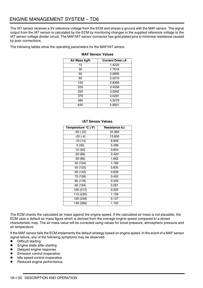
ENGINE MANAGEMENT SYSTEM – TD6
The IAT sensor receives a 5V reference voltage from the ECM and shares a ground with the MAF sensor. The signal output from the IAT sensor is calculated by the ECM by monitoring changes in the supplied reference voltage to the IAT sensor voltage divider circuit. The MAF/IAT sensor connector has gold plated pins to minimise resistance caused by poor connections.
The following tables show the operating parameters for the MAF/IAT sensor.
MAF Sensor Values
IAT Sensor Values
The ECM checks the calculated air mass against the engine speed. If the calculated air mass is not plausible, the ECM uses a default air mass figure which is derived from the average engine speed compared to a stored characteristic map. The air mass value will be corrected using values for boost pressure, atmospheric pressure and air temperature.
If the MAF sensor fails the ECM implements the default strategy based on engine speed. In the event of a MAF sensor signal failure, any of the following symptoms may be observed:l Difficult startingl Engine stalls after startingl Delayed engine responsel Emission control inoperativel Idle speed control inoperativel Reduced engine performance.
Air Mass kg/h Current Draw µA15 1.422530 1.7616
50 2.089560 2.2270
120 2.8356
220 3.4558250 3.5942370 4.0291
480 4.3279640 4.6601
Temperature °C (°F) Resistance kΩ-30 (-22) 22.960
-20 (-4) 13.850-10 (14) 8.6090 (32) 5.499
10 (50) 3.60420 (68) 2.42030 (86) 1.662
40 (104) 1.16650 (122) 0.83560 (140) 0.609
70 (158) 0.45280 (176) 0.34090 (194) 0.261
100 (212) 0.202110 (230) 1.159120 (248) 0.127
130 (266) 1.102
18-1-20 DESCRIPTION AND OPERATION

ENGINE MANAGEMENT SYSTEM – TD6
If the IAT sensor fails the ECM uses a default intake air temperature of -5°C (23°F). In the event of an IAT sensor failure, any of the following symptoms may be observed:l Over fuelling, resulting black smoke emitting from the exhaustl Idle speed control inoperative.
Boost Pressure (BP) Sensor
The BP sensor is located on the rear of the inlet manifold, adjacent to the fuel rail pressure sensor. The sensor provides a voltage signal to the ECM relative to the intake manifold pressure. The BP sensor has a three pin connector which is connected to the ECM and provides a 5V reference supply from the ECM, a signal input to the ECM and a ground for the sensor.
The BP sensor uses piezo ceramic crystals. These are sensitive to pressure changes and oscillate at different rates according to air pressure. The oscillation changes the resistance of the piezo crystal. The resistance through the crystal produces an output voltage from the sensor of between 0 and 5V, proportional to the pressure in the intake manifold. A signal of 0V indicates low pressure and 5V indicates high pressure. This signal is processed by the ECM which determines the manifold pressure by comparing the signal to stored values. The ECM then uses the signal for the following functions:l Maintain manifold boost pressurel Reduce exhaust smoke emissions when driving at high altitudel Control of the EGR systeml Control of the vacuum control module.
If the BP sensor fails, the ECM uses a default pressure of 0.9 bar (13 lbf/in2). In the event of a BP sensor failure, the following symptoms may be observed:l Altitude compensation inoperative (black smoke emitted from the exhaust)l Active boost control inoperative.
DESCRIPTION AND OPERATION 18-1-21

ENGINE MANAGEMENT SYSTEM – TD6
Boost Control Solenoid Valve
The boost control solenoid valve is located in the RH side of the engine compartment and is attached to the RH inner wing, below the vacuum reservoir. The solenoid valve is identical in its construction to the EGR modulator.
The boost control solenoid valve is used by the ECM to control the Variable Nozzle Turbine (VNT) within the turbocharger unit. The solenoid valve receives a battery voltage via the main relay in the E-box. The ECM controls the ground for the solenoid.
The ground for the solenoid is controlled using PWM. The ECM controls the duty cycle of the PWM ground to determine the amount of vacuum supplied to the VNT. The VNT improves turbine boost pressure by varying the gas flow of the turbine. This is controlled by a vacuum actuator located on the turbo, which moves a rod which in turn changes the angle of the guide vanes. + MANIFOLDS AND EXHAUST SYSTEM – Td6, DESCRIPTION AND OPERATION, Description.
If the boost control solenoid valve fails, the vanes remain in the fully open position. In the event of solenoid valve failure, the following symptom will be observed:l The engine will produce less torque at lower engine speeds.
The solenoid coil has a resistance of 15.4 ±7.0Ω at 20°C (68°F). The solenoid valve can be activated using TestBook/T4 for test and diagnostic purposes.
Engine Coolant Temperature (ECT) Sensor
The ECT sensor is located on the LH side of the cylinder head, between the two rear air inlet ports. The ECT sensor provides the ECM and the instrument pack with engine coolant temperature status.
18-1-22 DESCRIPTION AND OPERATION
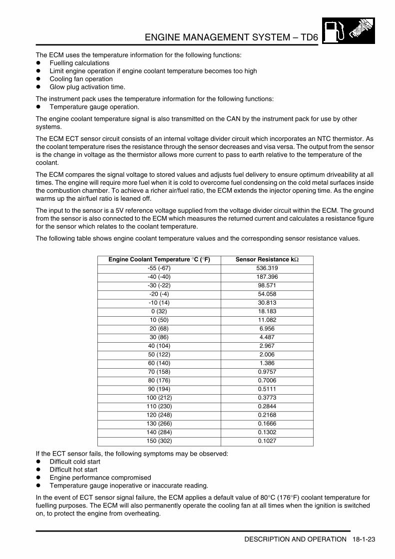
ENGINE MANAGEMENT SYSTEM – TD6
The ECM uses the temperature information for the following functions:l Fuelling calculationsl Limit engine operation if engine coolant temperature becomes too highl Cooling fan operationl Glow plug activation time.
The instrument pack uses the temperature information for the following functions:l Temperature gauge operation.
The engine coolant temperature signal is also transmitted on the CAN by the instrument pack for use by other systems.
The ECM ECT sensor circuit consists of an internal voltage divider circuit which incorporates an NTC thermistor. As the coolant temperature rises the resistance through the sensor decreases and visa versa. The output from the sensor is the change in voltage as the thermistor allows more current to pass to earth relative to the temperature of the coolant.
The ECM compares the signal voltage to stored values and adjusts fuel delivery to ensure optimum driveability at all times. The engine will require more fuel when it is cold to overcome fuel condensing on the cold metal surfaces inside the combustion chamber. To achieve a richer air/fuel ratio, the ECM extends the injector opening time. As the engine warms up the air/fuel ratio is leaned off.
The input to the sensor is a 5V reference voltage supplied from the voltage divider circuit within the ECM. The ground from the sensor is also connected to the ECM which measures the returned current and calculates a resistance figure for the sensor which relates to the coolant temperature.
The following table shows engine coolant temperature values and the corresponding sensor resistance values.
If the ECT sensor fails, the following symptoms may be observed:l Difficult cold startl Difficult hot startl Engine performance compromisedl Temperature gauge inoperative or inaccurate reading.
In the event of ECT sensor signal failure, the ECM applies a default value of 80°C (176°F) coolant temperature for fuelling purposes. The ECM will also permanently operate the cooling fan at all times when the ignition is switched on, to protect the engine from overheating.
Engine Coolant Temperature °C (°F) Sensor Resistance kΩ-55 (-67) 536.319
-40 (-40) 187.396-30 (-22) 98.571-20 (-4) 54.058
-10 (14) 30.8130 (32) 18.183
10 (50) 11.082
20 (68) 6.95630 (86) 4.48740 (104) 2.967
50 (122) 2.00660 (140) 1.38670 (158) 0.9757
80 (176) 0.700690 (194) 0.5111
100 (212) 0.3773
110 (230) 0.2844120 (248) 0.2168130 (266) 0.1666
140 (284) 0.1302150 (302) 0.1027
DESCRIPTION AND OPERATION 18-1-23

ENGINE MANAGEMENT SYSTEM – TD6
Fuel Temperature Sensor
The fuel temperature sensor is located in a plastic housing, behind the fuel cooler on the LH side of the engine compartment. The sensor is positioned in the return fuel flow from the engine and measures the fuel temperature returning from the engine to the fuel tank.
The sensor is an NTC sensor which is connected to the ECM by two wires. The ECM fuel temperature sensor circuit consists of an internal voltage divider circuit which incorporates an NTC thermistor. As the fuel temperature rises the resistance through the sensor decreases and visa versa. The output from the sensor is the change in voltage as the thermistor allows more current to pass to earth relative to the temperature of the fuel.
The ECM monitors the fuel temperature constantly. If the fuel temperature exceeds 85°C (185°F), the ECM invokes an engine 'derate' strategy. This reduces the amount of fuel delivered to the injectors in order to allow the fuel to cool. When this occurs, the driver may notice a loss of performance.
Further fuel cooling is available by a bi-metallic valve diverting fuel through the fuel cooler when the fuel reaches a predetermined temperature. In hot climate markets, an electrically operated cooling fan is positioned in the air intake ducting to the fuel cooler. This is controlled by a thermostatic switch, which switches the fan on and off when the fuel reaches a predetermined temperature. + FUEL DELIVERY SYSTEM – Td6, DESCRIPTION AND OPERATION, Description.
18-1-24 DESCRIPTION AND OPERATION

ENGINE MANAGEMENT SYSTEM – TD6
Low Pressure (LP) Fuel Sensor
The LP fuel sensor is located in a port on the top of the fuel filter and sealed to the filter with an O-ring seal and secured with a clamp plate and screw. The sensor monitors the absolute fuel pressure between the fuel filter and the high pressure fuel pump. The ECM uses the sensor to ensure that fuel is being supplied to the high pressure fuel pump at the correct rate. During engine start-up, only the LP fuel sensor signal is used. When the engine is running, the ECM compares the LP fuel sensor signal and a nominal pre-programmed 'setpoint' value.
The low fuel pressure sensor is connected by three wires to ECM. The three connections provide a 5V supply to the sensor, an earth and a variable signal back to the ECM which corresponds to the fuel pressure.
The sensor measures the pressure on the output side of the filter and therefore can detect a blockage within the filter or failure of the LP fuel supply. The ECM will monitor the LP fuel sensor and, in the event of very low pressure, will stop the engine to prevent damage to the HP injector pump. + FUEL DELIVERY SYSTEM – Td6, DESCRIPTION AND OPERATION, Description.
The wires to the fuel sensor are monitored by the ECM for short and open circuit. The ECM also monitors the 5V supply. If a failure occurs a fault is recorded in the ECM memory and the ECM uses a default fuel pressure value.
If the ECM registers an 'out of range' deviation between the pressure signal from the sensor and the pre-programmed 'setpoint' a fault is stored in the ECM memory. Depending on the extent of the deviation, the ECM will reduce the injection quantity, stop the engine immediately or prevent further engine starting.
NOTE: In addition to the low pressure supply to the high pressure fuel pump, the pressure in the fuel line is of equal importance with regard to correct fuel injection. The pressure in the fuel return line must not exceed 1.5 bar (22 lbf/in2). If the pressure in the return line exceeds this figure, the pressure differential across the high pressure fuel pump will be unbalanced and incorrect priming of the fuel rail will occur. The ECM does not monitor the return line pressure.
DESCRIPTION AND OPERATION 18-1-25
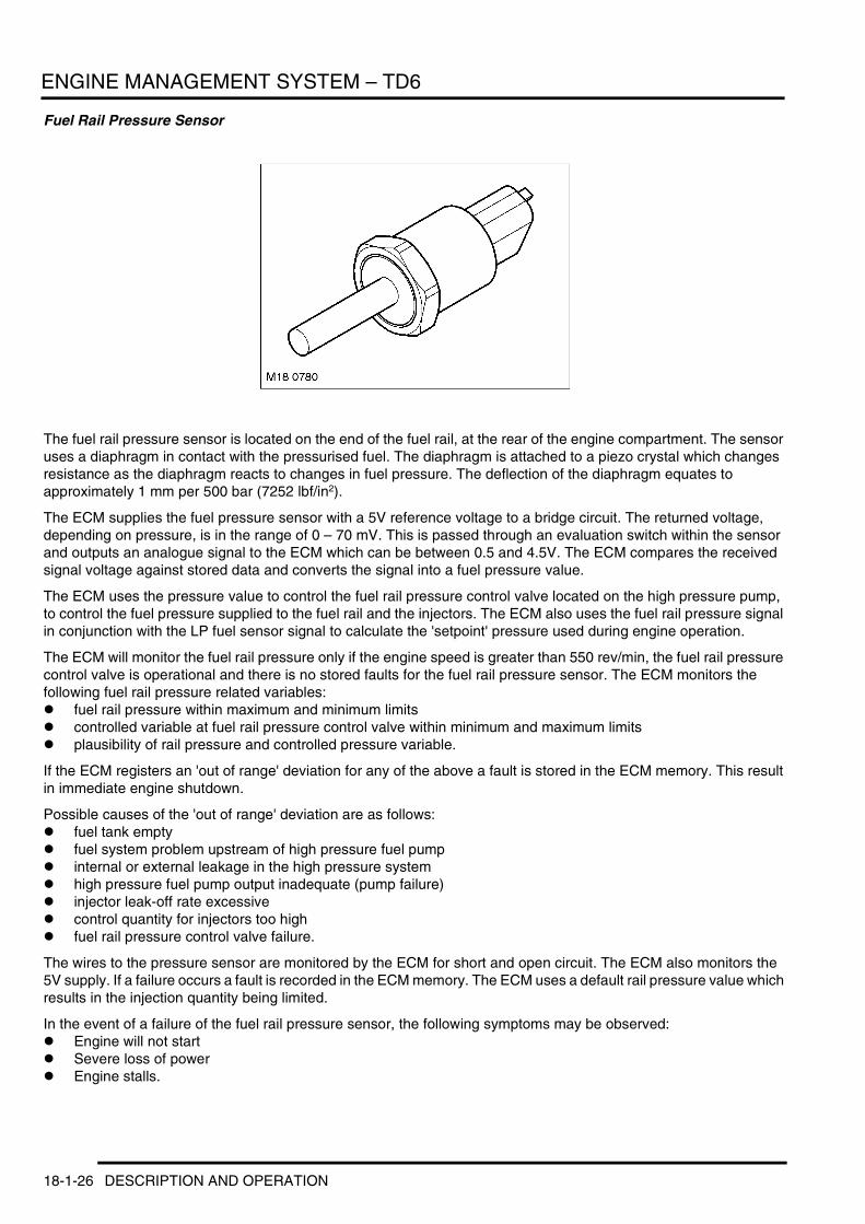
ENGINE MANAGEMENT SYSTEM – TD6
Fuel Rail Pressure Sensor
The fuel rail pressure sensor is located on the end of the fuel rail, at the rear of the engine compartment. The sensor uses a diaphragm in contact with the pressurised fuel. The diaphragm is attached to a piezo crystal which changes resistance as the diaphragm reacts to changes in fuel pressure. The deflection of the diaphragm equates to approximately 1 mm per 500 bar (7252 lbf/in2).
The ECM supplies the fuel pressure sensor with a 5V reference voltage to a bridge circuit. The returned voltage, depending on pressure, is in the range of 0 – 70 mV. This is passed through an evaluation switch within the sensor and outputs an analogue signal to the ECM which can be between 0.5 and 4.5V. The ECM compares the received signal voltage against stored data and converts the signal into a fuel pressure value.
The ECM uses the pressure value to control the fuel rail pressure control valve located on the high pressure pump, to control the fuel pressure supplied to the fuel rail and the injectors. The ECM also uses the fuel rail pressure signal in conjunction with the LP fuel sensor signal to calculate the 'setpoint' pressure used during engine operation.
The ECM will monitor the fuel rail pressure only if the engine speed is greater than 550 rev/min, the fuel rail pressure control valve is operational and there is no stored faults for the fuel rail pressure sensor. The ECM monitors the following fuel rail pressure related variables:l fuel rail pressure within maximum and minimum limitsl controlled variable at fuel rail pressure control valve within minimum and maximum limitsl plausibility of rail pressure and controlled pressure variable.
If the ECM registers an 'out of range' deviation for any of the above a fault is stored in the ECM memory. This result in immediate engine shutdown.
Possible causes of the 'out of range' deviation are as follows:l fuel tank emptyl fuel system problem upstream of high pressure fuel pumpl internal or external leakage in the high pressure systeml high pressure fuel pump output inadequate (pump failure)l injector leak-off rate excessivel control quantity for injectors too highl fuel rail pressure control valve failure.
The wires to the pressure sensor are monitored by the ECM for short and open circuit. The ECM also monitors the 5V supply. If a failure occurs a fault is recorded in the ECM memory. The ECM uses a default rail pressure value which results in the injection quantity being limited.
In the event of a failure of the fuel rail pressure sensor, the following symptoms may be observed:l Engine will not startl Severe loss of powerl Engine stalls.
18-1-26 DESCRIPTION AND OPERATION
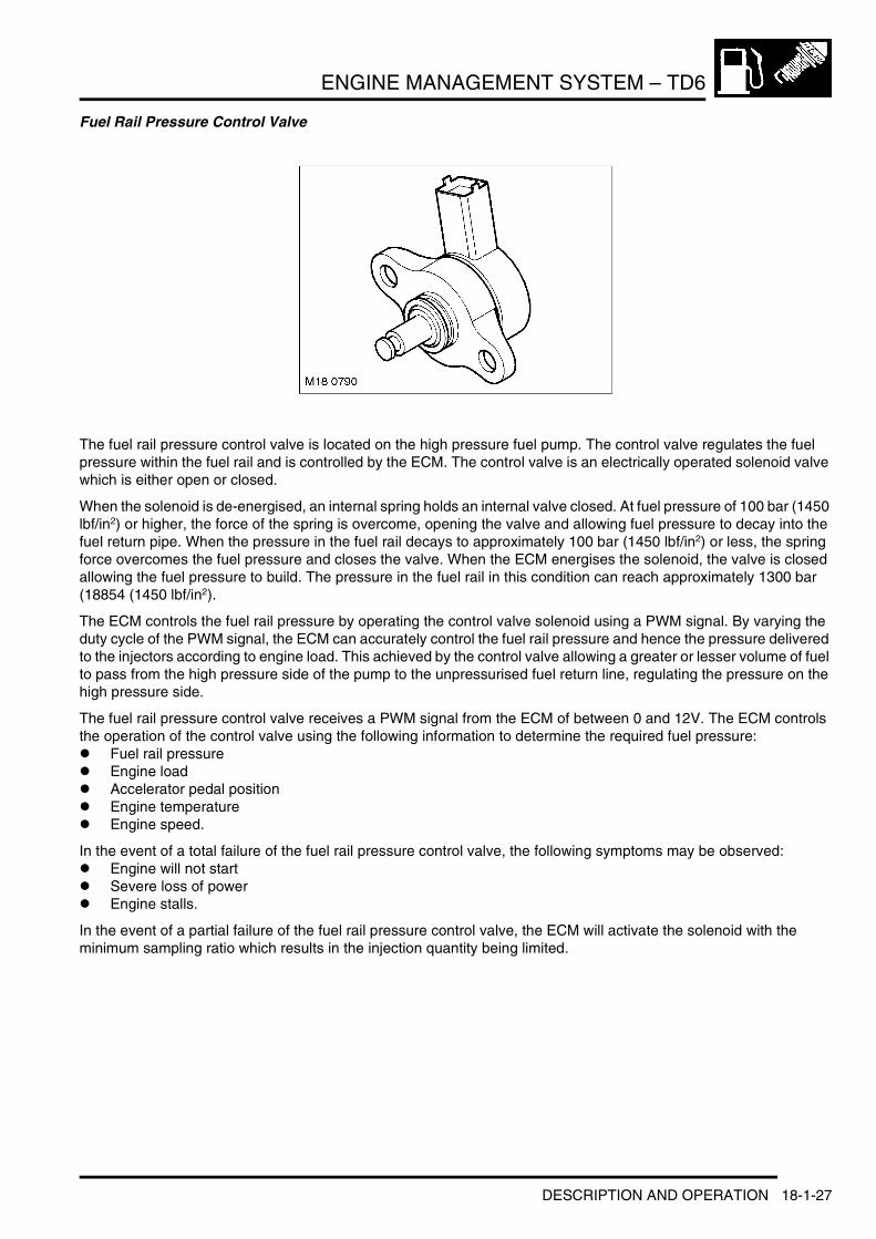
ENGINE MANAGEMENT SYSTEM – TD6
Fuel Rail Pressure Control Valve
The fuel rail pressure control valve is located on the high pressure fuel pump. The control valve regulates the fuel pressure within the fuel rail and is controlled by the ECM. The control valve is an electrically operated solenoid valve which is either open or closed.
When the solenoid is de-energised, an internal spring holds an internal valve closed. At fuel pressure of 100 bar (1450 lbf/in2) or higher, the force of the spring is overcome, opening the valve and allowing fuel pressure to decay into the fuel return pipe. When the pressure in the fuel rail decays to approximately 100 bar (1450 lbf/in2) or less, the spring force overcomes the fuel pressure and closes the valve. When the ECM energises the solenoid, the valve is closed allowing the fuel pressure to build. The pressure in the fuel rail in this condition can reach approximately 1300 bar (18854 (1450 lbf/in2).
The ECM controls the fuel rail pressure by operating the control valve solenoid using a PWM signal. By varying the duty cycle of the PWM signal, the ECM can accurately control the fuel rail pressure and hence the pressure delivered to the injectors according to engine load. This achieved by the control valve allowing a greater or lesser volume of fuel to pass from the high pressure side of the pump to the unpressurised fuel return line, regulating the pressure on the high pressure side.
The fuel rail pressure control valve receives a PWM signal from the ECM of between 0 and 12V. The ECM controls the operation of the control valve using the following information to determine the required fuel pressure:l Fuel rail pressurel Engine loadl Accelerator pedal positionl Engine temperaturel Engine speed.
In the event of a total failure of the fuel rail pressure control valve, the following symptoms may be observed:l Engine will not startl Severe loss of powerl Engine stalls.
In the event of a partial failure of the fuel rail pressure control valve, the ECM will activate the solenoid with the minimum sampling ratio which results in the injection quantity being limited.
DESCRIPTION AND OPERATION 18-1-27

ENGINE MANAGEMENT SYSTEM – TD6
Brake Light Switch
The brake switch is located on the pedal box and is operated by the brake pedal. The switch is a Hall effect switch which detects the position of the brake pedal and determines when the driver has applied the brakes. The switch is connected directly to the ECM.
The brake switch consists of an inner sensor in an outer mounting sleeve. To ensure correct orientation, the sensor is keyed to the mounting sleeve and the mounting sleeve is keyed to the pedal mounting bracket. Mating serrations hold the sensor in position in the mounting sleeve. While the brakes are off, the tang on the brake pedal rests against the end of the sensor. When the brake pedal is pressed, the tang moves away from the sensor and induces a change of sensor output voltages. This is sensed by the ECM which detects that the brake pedal has been applied. The ECM uses the brake signal for the following:l To limit fuelling during brakingl To inhibit/cancel cruise control if the brakes are applied.
In the event of a brake switch failure, the following symptoms may be observed:l Cruise control inactivel Increased fuel consumption.
Crankshaft Position (CKP) Sensor
The CKP sensor is located on the LH side of the engine block, below the starter motor. The sensor is sealed in the block with an O-ring seal and secured with a screw. The sensor tip is aligned with a target (reluctor) which is attached to the crankshaft. The sensor produces a sine wave signal with speed dependant amplitude, the frequency of which is proportional to engine speed.
18-1-28 DESCRIPTION AND OPERATION
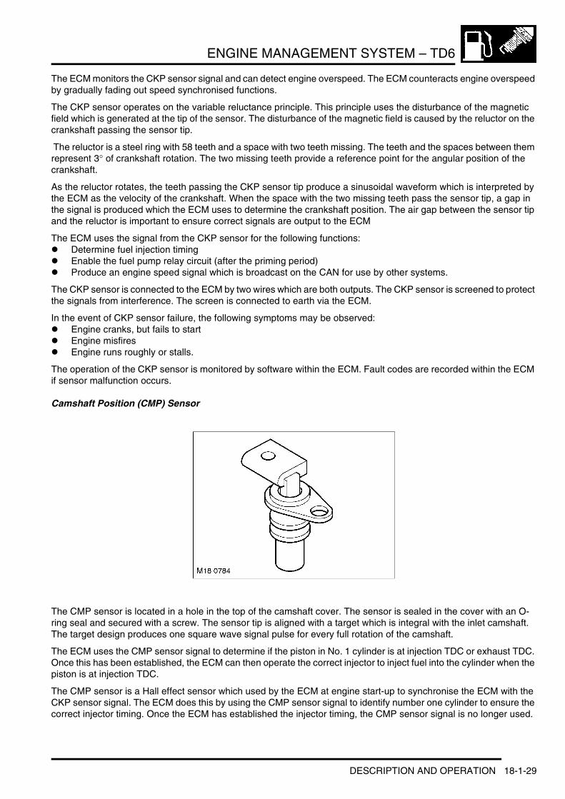
ENGINE MANAGEMENT SYSTEM – TD6
The ECM monitors the CKP sensor signal and can detect engine overspeed. The ECM counteracts engine overspeed by gradually fading out speed synchronised functions.
The CKP sensor operates on the variable reluctance principle. This principle uses the disturbance of the magnetic field which is generated at the tip of the sensor. The disturbance of the magnetic field is caused by the reluctor on the crankshaft passing the sensor tip.
The reluctor is a steel ring with 58 teeth and a space with two teeth missing. The teeth and the spaces between them represent 3° of crankshaft rotation. The two missing teeth provide a reference point for the angular position of the crankshaft.
As the reluctor rotates, the teeth passing the CKP sensor tip produce a sinusoidal waveform which is interpreted by the ECM as the velocity of the crankshaft. When the space with the two missing teeth pass the sensor tip, a gap in the signal is produced which the ECM uses to determine the crankshaft position. The air gap between the sensor tip and the reluctor is important to ensure correct signals are output to the ECM
The ECM uses the signal from the CKP sensor for the following functions:l Determine fuel injection timingl Enable the fuel pump relay circuit (after the priming period)l Produce an engine speed signal which is broadcast on the CAN for use by other systems.
The CKP sensor is connected to the ECM by two wires which are both outputs. The CKP sensor is screened to protect the signals from interference. The screen is connected to earth via the ECM.
In the event of CKP sensor failure, the following symptoms may be observed:l Engine cranks, but fails to startl Engine misfiresl Engine runs roughly or stalls.
The operation of the CKP sensor is monitored by software within the ECM. Fault codes are recorded within the ECM if sensor malfunction occurs.
Camshaft Position (CMP) Sensor
The CMP sensor is located in a hole in the top of the camshaft cover. The sensor is sealed in the cover with an O-ring seal and secured with a screw. The sensor tip is aligned with a target which is integral with the inlet camshaft. The target design produces one square wave signal pulse for every full rotation of the camshaft.
The ECM uses the CMP sensor signal to determine if the piston in No. 1 cylinder is at injection TDC or exhaust TDC. Once this has been established, the ECM can then operate the correct injector to inject fuel into the cylinder when the piston is at injection TDC.
The CMP sensor is a Hall effect sensor which used by the ECM at engine start-up to synchronise the ECM with the CKP sensor signal. The ECM does this by using the CMP sensor signal to identify number one cylinder to ensure the correct injector timing. Once the ECM has established the injector timing, the CMP sensor signal is no longer used.
DESCRIPTION AND OPERATION 18-1-29

ENGINE MANAGEMENT SYSTEM – TD6
The CMP sensor receives a 12V supply from the ECM. Two further connections to the ECM provide ground and signal output.
If a fault occurs, an error is registered in the ECM. Two types of failure can occur; camshaft signal frequency too high or total failure of the camshaft signal. The error recorded by the ECM can also relate to a total failure of the crankshaft signal or crankshaft signal dynamically implausible. Both components should be checked to determine the cause of the fault.
If a fault occurs with the CMP sensor when the engine is running, the engine will continue to run but the ECM will deactivate boost pressure control. Once the engine is switched off, the engine will crank but will not restart while the fault is present.
Fuel Injector
There are six electronic fuel injectors (one for each cylinder) located in a central position between the four valves of each cylinder. The ECM divides the injectors into two banks of three with cylinders 1 to 3 being designated bank 1 and cylinders 4 to 6 designated bank 2. + FUEL DELIVERY SYSTEM – Td6, DESCRIPTION AND OPERATION, Description.
Each injector is supplied with pressurised fuel from the fuel rail and delivers finely atomised fuel directly into the combustion chambers. Each injector is individually controlled by the ECM which operates each injector in the firing order and controls the injector opening period via PWM signals.
Each injector receives a 12V supply via the main relay. The ECM controls the ground for each injector solenoid and, using programmed injection/timing maps and sensor signals, determines the precise pilot and main injector timing for each cylinder.
If battery voltage falls to between 6 and 9V, fuel injector operation is restricted, affecting emissions, engine speed range and idle speed. In the event of a failure of a fuel injector, the following symptoms may be observed:l Engine misfirel Idle irregularl Reduced engine performancel Reduced fuel economyl Difficult startingl Increased smoke emissions.
The ECM monitors the wires for each injector for short circuit and open circuit, each injector solenoid coil and the transient current within the ECM. If a defect is found, an error is registered in the ECM for the injector in question.
18-1-30 DESCRIPTION AND OPERATION

ENGINE MANAGEMENT SYSTEM – TD6
The voltage in the injector output stages is monitored. If a fault occurs it is registered in the memory as capacitor voltage 1 for cylinders 1, 2, 3 and capacitor voltage 2 for cylinders 4, 5, and 6. If a fault occurs of the type 'current on high side too high' or 'current on low side too high', it is assigned to a particular injector. The cause of this fault can be in any of the wires to the three cylinders in that bank because the wires for each bank are bundled.
If a fault occurs of the type 'current on high side too high' or 'current on low side too high', the ECM will stop the engine. If the fault is of the type 'load drop', signifying a break in the wiring, the ECM will maintain the engine running providing not more than one injector is affected. Any fault in the injector output stages will result in the ECM stopping the engine.
When an injector is installed in the cylinder head, care must be taken to ensure that the mounting claw is in the correct position, the flat side of the claw must face upwards. If the claw is installed incorrectly, the injector will be wrongly installed resulting in the seal at the base of the injector being ineffective and the injector will be loose in the cylinder head.
Injector Calibration – To compensate for tolerances in the fuel injection system, a characteristic map with engine specific compensation values is programmed into the ECM on production. If one or more injectors is replaced, the calibration function must be performed to reset the compensation values to 0. This must only be performed when injectors are removed and replaced with new items. The calibration procedure must only be used for this purpose. The procedure is performed using TestBook/T4 and following the on-screen instructions.
Exhaust Gas Recirculation (EGR) Modulator
The EGR modulator is located on a bracket on the LH side of the engine block, near the starter motor. The EGR modulator is a solenoid operated valve which regulates the vacuum supplied to the EGR valve, causing it to open or close. The ECM uses the EGR modulator to control the amount of exhaust gas being recirculated in order to reduce exhaust emissions and combustion noise. The EGR is enabled when the engine is at normal operating temperature and under cruising conditions.
The EGR modulator receives a 12V supply from the main relay. The ground for the solenoid is via the ECM and is controlled using a PWM signal. The PWM duty signal of the solenoid ground is varied to determine the precise amount of vacuum supplied to the EGR valve, and consequently the volume of exhaust gas delivered to the cylinders.
In the event of a failure of the EGR modulator, the EGR function will become inoperative. The ECM can monitor the EGR modulator solenoid for short circuits and store fault codes in the event of failure. The modulator can also be activated for testing using TestBook/T4.
DESCRIPTION AND OPERATION 18-1-31

ENGINE MANAGEMENT SYSTEM – TD6
Engine Mounting Damping Control Actuator
The mounting damping system comprises two hydraulic mounts with controlled damping characteristics, a control actuator, the ECM and the pneumatic vacuum lines.
The damping system provides the following benefits:l Increased passenger comfort at idle speedl Isolation of engine vibrationl Reduction in natural resonance of engine induced by uneven road surfacesl Reduction in engine judder when engine is stopped.
The engine mounting damping control system uses vacuum taken from a connection in the vacuum line between the vacuum pump and the brake booster. The vacuum is in the range of 0.5 – 0.9 bar (7.20 – 13.05 lbf/in2). Vacuum is supplied simultaneously to both mounts when the engine is idling and in the speed range close to idling.
The engine mounting damping control actuator is located on a bracket on the LH side of the engine block, behind the EGR modulator, near the starter motor. The actuator is a solenoid operated valve which regulates the vacuum supplied to the engine mountings. The ECM uses the actuator to control the damping of the mountings. When the actuator solenoid is de-energised, the engine mountings are hard. When the ECM energises the actuator solenoid, the vacuum is applied to the mountings and they become soft. The ECM controls the actuator solenoid using a PWM signal and can vary the damping of the engine mounts according to operating conditions. + ENGINE – Td6, DESCRIPTION AND OPERATION, Description.
The engine mounting damping control actuator receives a 12V supply from the main relay. The ground for the solenoid is via the ECM.
In the event of a failure of the engine mounting damping control actuator, the damping control will become inoperative. The ECM can monitor the actuator solenoid for short circuits and store fault codes in the event of failure. The engine mounting damping control actuator can also be activated for testing using TestBook/T4.
18-1-32 DESCRIPTION AND OPERATION

ENGINE MANAGEMENT SYSTEM – TD6
Glow Plug Relay
1 Fusible link (100A) 2 Glow plug relay
The glow plug relay is located in the E-box. The ECM uses the glow plug relay to control operation of the glow plugs. Operation of the glow plug relay and the glow plugs is indicated to the driver via a glow plug warning lamp in the instrument pack.
The glow plug relay is supplied with a permanent power feed directly from the battery, via a 100A fusible link located on the bulkhead, behind the battery. A second power feed is also supplied via the main relay and fuse 2 in the engine compartment fusebox. The relay is connected to ground directly to the vehicle body.
The glow plug relay is also connected to the ECM which supplies engine coolant temperature and pre-heat and post heat timer calculations. The relay processes this data and provides the appropriate output control for the glow plugs.
In the event of glow plug relay failure, the following symptoms may be observed:l Difficult startingl Excessive smoke emissions after starting.
DESCRIPTION AND OPERATION 18-1-33

ENGINE MANAGEMENT SYSTEM – TD6
Glow Plugs
Six glow plugs are located in the cylinder head, on the inlet side. The glow plugs and the glow plug relay are a vital part of the engine starting strategy. The glow plugs heat the air inside the cylinder during cold starts to assist combustion. The use of glow plugs helps reduce the amount of additional fuel required on start-up, and consequently reduces the emission of black smoke. The use of glow plugs also reduces the amount of injection advance required, which reduces engine noise, particularly when idling with a cold engine.
The main part of the glow plug is a tubular heating element which protrudes into the combustion chamber of the engine. The heating element contains a spiral filament encased in magnesium oxide powder. At the tip of the tubular heating element is the heater coil. Behind the heater coil, and connected in series, is a control coil. The control coil regulates the heater coil to ensure that it does not overheat.
Pre-heat is the length of time the glow plugs operate prior to engine cranking. The ECM controls the pre-heat time based on ECT sensor output and battery voltage. If the ECT sensor fails, the ECM will use the IAT sensor value as a default value. The pre-heat duration is extended if the coolant temperature is low and the battery is not fully charged.
Post heat is the length of time the glow plugs operate after the engine starts. The ECM controls the post heating time based on ECT sensor output. The post heat phase reduces engine noise, improves idle quality and reduces hydrocarbon emissions.
When the ignition is switched on to position II, the glow plug warning lamp illuminates and the instrument pack displays' PREHEATING' in the message centre. The engine should not be cranked until the glow warning lamp goes off.
In the event of glow plug failure, the following symptoms may be observed:l Difficult startingl Excessive smoke emissions after starting.
The glow plug warning lamp also serves a second function within the EDC system. If a major EDC system fault occurs, the glow plug warning lamp will be illuminated permanently and a message generated in the instrument pack. The driver must seek attention to the engine management system at a Land Rover dealer as soon as possible.
18-1-34 DESCRIPTION AND OPERATION
ENGINE MANAGEMENT SYSTEM – TD6
Operation
GeneralThe ECM controls the operation of the engine using information stored in its memory in the form of maps. The maps contain data which is used to determine the most efficient fuelling for any given driving condition. The ECM also has maps for the operation of sub-systems such as EGR.
The ECM is an adaptive unit which learns the characteristics of the vehicle components. This feature allows the ECM to compensate for any variations in components fitted to the vehicle in production, and to adapt to changes of components which may occur in service. The ability to compensate for 'wear and tear' and environmental changes during the life of the vehicle ensures that the ECM can comply with emission control legislation over extended periods.
The ECM is programmed with a 'strategy' which controls the decisions about when to turn specific functions on and off. The inputs to this decision making process are supplied by sensors, mounted at various locations on the vehicle, which supply information to the ECM. If a sensor fails to supply information, the ECM, where possible, will use data from other sensors and use a default value for the missing information. In cases where default values cannot be used, the vehicle will be disabled. Use of a default value may result in reduced performance, increased fuel consumption and exhaust emissions.
The ECM is programmed with vehicle specific information known as 'calibration'. This data is used to calculate ECM outputs. This information, together with data inputs from sensors and other system ECU's, determines output signals from the ECM to the actuators.
The ECM uses strategies such as:l Smoke limitationl Active surge dampingl Automatic gear changel Fuel reductionl Engine coolingl Combustion noise limitation.
During idle and wide open throttle conditions, the ECM uses mapped data to respond to the input signals from the APP sensor. To implement the optimum fuelling strategy for idle and wide open throttle, the ECM requires input data from the following sensors:l CKP sensorl APP sensorl ECT sensorl MAF/IAT sensorl Fuel rail pressure sensor.
This data is then compared to mapped data within the ECM to control acceleration using the following actuators and controllers:l EGR modulator – closed for cleaner combustionl Fuel pressure control valve – increase fuel pressure supplied to fuel raill Electronic fuel injectors – change injector durationl A/C compressor clutch relay – de-energised during wide open throttle to reduce engine loadl EAT ECU – kickdown activation.
During cold start conditions, the ECM uses ECT sensor data to determine if the cold start strategy is required. During cold start conditions, the ECM will inject more fuel into the cylinders and will initiate the glow plug timing strategy for effective cold starting. Normal fuel strategy is used during hot starts.
DESCRIPTION AND OPERATION 18-1-35
ENGINE MANAGEMENT SYSTEM – TD6
Injection ControlThe purpose of the injection control is to deliver a precise quantity of finely atomised fuel into the combustion chambers at the correct times in the engine cycle. To precise control the fuel injection quantity and timing, the following data must be available to the ECM:l Crankshaft speed and position: This information enables the ECM to determine the volume of air induced into
the cylinders and the position of the crankshaft for timing purposes.l Camshaft position: This data enables the ECM to determine the relative positions of the crankshaft and
camshaft for timing purposes.l Injection timing map: This data provides the basic data which is used by the ECM when calculating the injection
timing and quantity.l Engine coolant temperature: This information is used, in conjunction with the CKP sensor data and the fuelling
map, to set the injection quantity to the correct value.l Fuel rail pressure: This data is used during fuelling calculations to correct the electrical opening times (injector
duty cycle) to compensate for variations in fuel pressure.l Mass air flow: This data is used by the ECM to calculate the mass of air which has entered the cylinders and
consequently the volume of oxygen available for combustion with the fuel. It also allows the ECM to monitor EGR flow when the EGR system is active.
l Intake air temperature: This data is required by the ECM to provide a correction factor for differing intake air temperatures. Cold air contains more oxygen than hot air for any given volume, therefore the fuelling must be adjusted to suit the current conditions.
l Accelerator pedal position: This data is vital to the operation of the ECM and the vehicle. The ECM interprets the electrical signals from the APP sensor as throttle demand and controls the power output of the engine accordingly.
Pilot Fuel InjectionPilot fuel injection helps reduce engine clatter and vibration. The ECM provides this feature by opening the electronic fuel injectors briefly, before injecting the main charge of fuel. This makes the flame front propagation through the main charge less abrupt, giving reduced levels of diesel knock.
Smoke LimitationThis requires high injection pressure to improve the atomisation of the fuel injected into the cylinders. By maintaining high fuel pressures at low engine speeds, the ECM maximises the atomisation of the fuel for conditions where turbulence in the combustion chamber is reduced.
The strategy contained in the ECM does not allow more fuel to be injected than there is oxygen in the cylinders.
Active Surge DampingActive surge damping is implemented to prevent the engine surging when the EAT ECU initiates a gear change. The ECM reduces fuelling to lower the engine torque output, thereby preventing engine surge and consequently providing a smooth gear change.
Variable Nozzle Turbine (VNT)The VNT makes it possible to vary the exhaust gas flow of turbine by changing the angle that the turbine guide vanes are set at. With the guide vanes in a closed position, the exhaust gas flow is reduced and the gas flow to the turbine wheel is increased. This results in increased boost pressure.
The boost pressure sensor provides a feed back signal to the ECM relative to the inlet manifold pressure. The ECM also calculates engine load and uses this along with the boost pressure sensor signal to send a PWM signal to the boost control solenoid valve to determine the amount of vacuum supplied to the boost control vacuum actuator on the turbocharger. The amount of vacuum operates between 0 mbar and 640 mbar depression. At 640 mbar the vanes are fully closed providing maximum boost.
18-1-36 DESCRIPTION AND OPERATION

ENGINE MANAGEMENT SYSTEM – TD6
Crankshaft and Camshaft SynchronisationThe crankshaft and camshaft must be synchronised for the engine to start. The CKP sensor registers the crankshaft position. The ECM calculates from the signal the TDC positions (exhaust or injection TDC). The ECM uses the CMP sensor signal to determine which TDC position relates to exhaust or injection.
The ECM compares the two signals to provide the correct injector sequence. The injector sequence is then repeated corresponding to the engine firing order 1–5–3–6–2–4.
If a valid signal from the CMP sensor is not received after two full engine revolutions, fuel injection is terminated and the engine will not start.
Electric Fuel Pump and Fuel Rail Pressure Control ValveThe electric fuel pumps and the fuel rail pressure control valve are similar in their activation by the ECM. The pumps and the control valve are both energised for 60 seconds from the ignition switch being moved to position II. This time period is variable depending on engine coolant temperature and the characteristics of the components.
This strategy is implemented to prevent thermal damage poor cooling or non productive pumping of fuel against an inactive high pressure fuel pump with the engine not running. When engine speed increases past 50 rev/min both components are activated continuously until the ignition is switched off.
In the event of a crash, the SRS Diagnostic Control Unit (DCU) generates a message which is passed to the instrument pack and passed on the CAN to the ECM. This message causes the ECM to shut down the electric fuel pumps which cannot be reactivated until the ignition is switched off and then on again. + RESTRAINT SYSTEMS, DESCRIPTION AND OPERATION, Description.
Air Conditioning (A/C)The ATC ECU sends a message via the K bus to the instrument pack which is then passed on the CAN to the ECM that the ATC ECU is preparing to activate the A/C compressor clutch. If all engine operating conditions are correct the ECM will respond with an OK signal. If engine conditions are not correct for additional loads to be applied to the engine, the ECM will refuse the A/C on request. This message is returned from the ECM on the CAN to the instrument pack and then passed to the ATC ECU on the K bus.
When high engine torque is required (pulling away from rest or accelerating), the ATC ECU compressor control logic shuts down the A/C compressor to ensure that sufficient engine torque is available. + AIR CONDITIONING, DESCRIPTION AND OPERATION, Operation.
Cooling StrategyThe ECM controls the electric cooling fan operation for the engine, automatic transmission and air conditioning. With the ECM in full control of the cooling fan, it can also adjust injector duration and timing to compensate for additional engine load imposed by the alternator during cooling fan operation. The cooling fan is controlled using PWM signals to provide up to 15 different fan speeds. The ATC ECU requests cooling fan operation for condenser cooling under certain conditions. + AIR CONDITIONING, DESCRIPTION AND OPERATION, Operation.
Operation of the cooling fan will be given priority to operate for engine cooling, overriding any request from the ATC ECU. The fan speed for engine cooling is dependant on engine coolant temperature and current road speed.
The ECM will allow the cooling fan to 'run-on' after the engine is stopped. This is limited by engine coolant temperature or a maximum run-on time. If the ECT sensor fails a default value is used and the cooling fan will run permanently.
DESCRIPTION AND OPERATION 18-1-37
ENGINE MANAGEMENT SYSTEM – TD6
Electronic Automatic Transmission (EAT) ECU StrategyThe EAT ECU implements an idle neutral strategy, which forms part of the fuel reduction strategy. Neutral is selected, reducing engine load and fuel consumption, when all of the following conditions are met:l ECM confirms engine is at idlel 'D' selected on transmission selector leverl Foot brake applied.
If one of these conditions changes after neutral has been selected, drive 'D' will automatically be reselected.
When the EAT ECU is changing gear, it requests on the CAN for a reduction in engine torque. The ECM reduces the engine torque output momentarily while the gear change is in progress by reducing the fuel delivery to the injectors. This ensures smooth gear changes throughout the engine speed and load ranges and also reduces exhaust emissions.
The ECM sends the following data to the EAT ECU using the CAN:l Accelerator pedal positionl Engine torquel Engine speedl Engine coolant temperaturel Ignition key positionl Virtual throttle angle.
The EAT ECU sends the following data to the ECM using the CAN:l Torque reduction requestl Selector lever positionl Current gearl Gear change in progressl Additional cooling request.
Immobilisation SystemThe ECM plays a major role in the immobilisation of the vehicle. The ECM prevents engine fuelling until it receives a valid coded signal from the immobilisation ECU. The coded signal from the immobilisation ECU is supplied in the form of a rolling code, preventing the code from being copied or by-passed.
When new, the immobilisation ECU is blank and is programmed with a starting code known as a 'seed'. The seed is then used as a base point for the rolling code when the immobilisation ECU is synchronised to the ECM during manufacture.
Once synchronised, the ECM and the immobilisation ECU are not interchangeable and operate as a matching pair.
When a new ECM is fitted to a vehicle during service, the new immobilisation ECU must be supplied with a seed which matches the vehicle. The rolling codes in the new immobilisation ECU and the existing ECM must be synchronised using TestBook/T4.
The immobilisation ECU receives an engine speed signal from the ECM to inhibit starter motor operation when the engine is running, to prevent damage to the starter motor and ring gear. Engine speed information is broadcast on the CAN by the ECM. The instrument pack passes the engine speed signal on the K bus to other systems, including the immobilisation ECU.
Cruise ControlThe ECM incorporates a cruise control program which controls all functions of the cruise control system.
During cruise control operation, the ECM controls vehicle speed by adjusting fuel injection duration and timing. When the accelerator pedal is pressed with cruise control active, the ECM outputs a calculated throttle angle signal in place of the actual throttle angle signals produced by the APP sensor. The calculated throttle angle is derived from fuel demand.
18-1-38 DESCRIPTION AND OPERATION

ENGINE MANAGEMENT SYSTEM – TD6
DESCRIPTION AND OPERATIONCruise Control Component Location
1 Instrument pack2 Cruise control switches3 Anti-lock Brake System (ABS) ECU
4 Brake switch5 Accelerator Pedal Position (APP) sensor6 Engine Control Module (ECM)
DESCRIPTION AND OPERATION 18-1-39

ENGINE MANAGEMENT SYSTEM – TD6
Cruise Control, Control Diagram
A = Hardwired connection; D = CAN bus; J = Diagnostic ISO9141 K Line; K = I bus
M18 0793M18 0793AKA
1 2
3
4
6
7
9
8
10
12
13
11
JJD
5
18-1-40 DESCRIPTION AND OPERATION

ENGINE MANAGEMENT SYSTEM – TD6
1 Fuse 30A2 Cruise control switches3 Rotary coupler4 Instrument pack5 EAT ECU6 ABS ECU7 Brake switch8 Diagnostic socket9 Fuel injectors
10 APP sensor11 ECM12 Fuse 5A13 Ignition switch
DESCRIPTION AND OPERATION 18-1-41
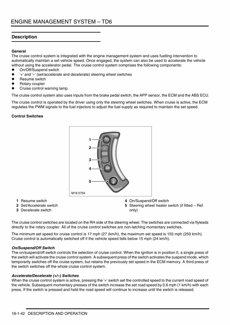
ENGINE MANAGEMENT SYSTEM – TD6
Description
GeneralThe cruise control system is integrated with the engine management system and uses fuelling intervention to automatically maintain a set vehicle speed. Once engaged, the system can also be used to accelerate the vehicle without using the accelerator pedal. The cruise control system comprises the following components:l On/Off/Suspend switchl '+' and '–' (set/accelerate and decelerate) steering wheel switchesl Resume switchl Rotary couplerl Cruise control warning lamp.
The cruise control system also uses inputs from the brake pedal switch, the APP sensor, the ECM and the ABS ECU.
The cruise control is operated by the driver using only the steering wheel switches. When cruise is active, the ECM regulates the PWM signals to the fuel injectors to adjust the fuel supply as required to maintain the set speed.
Control Switches
1 Resume switch2 Set/Accelerate switch3 Decelerate switch
4 On/Suspend/Off switch5 Steering wheel heater switch (if fitted – Ref.
only)
The cruise control switches are located on the RH side of the steering wheel. The switches are connected via flyleads directly to the rotary coupler. All of the cruise control switches are non-latching momentary switches.
The minimum set speed for cruise control is 17 mph (27 (km/h), the maximum set speed is 155 mph (250 km/h). Cruise control is automatically switched off if the vehicle speed falls below 15 mph (24 km/h).
On/Suspend/Off SwitchThe on/suspend/off switch controls the selection of cruise control. When the ignition is in position II, a single press of the switch will activate the cruise control system. A subsequent press of the switch activates the suspend mode, which temporarily switches off the cruise system, but retains the previously set speed in the ECM memory. A third press of the switch switches off the whole cruise control system.
Accelerate/Decelerate (+/–) SwitchesWhen the cruise control system is active, pressing the '+' switch set the controlled speed to the current road speed of the vehicle. Subsequent momentary presses of the switch increase the set road speed by 0.6 mph (1 km/h) with each press. If the switch is pressed and held the road speed will continue to increase until the switch is released.
M18 0794
1
2
3
4
5
18-1-42 DESCRIPTION AND OPERATION

ENGINE MANAGEMENT SYSTEM – TD6
Momentarily pressing the '–' switch, decreases the set speed by 0.6 mph (1 km/h) with each press. If the switch is pressed and held, the set speed is decreased until the switch is released.
Resume SwitchThe resume switch re-activates the previously set speed after the cruise control has been suspended by pressing the suspend switch or by depressing the brake pedal.
DESCRIPTION AND OPERATION 18-1-43

ENGINE MANAGEMENT SYSTEM – TD6
18-1-44 DESCRIPTION AND OPERATION

ENGINE MANAGEMENT SYSTEM – V8
Deze pagina werd opzettelijk niet gebruikt
Cette page est intentionnellement vierge
Questa pagina è stata lasciata in bianco di proposito
Diese Seite ist leer
Esta página foi deixada intencionalmente em branco
Esta página fue dejada en blanco intencionalmente
This page is intentionally left blank
ENGINE MANAGEMENT SYSTEM – V8DESCRIPTION AND OPERATION
DESCRIPTION AND OPERATION 18-2-1

ENGINE MANAGEMENT SYSTEM – V8
Engine Management Component Location – Sheet 1 of 2
18-2-2 DESCRIPTION AND OPERATION

ENGINE MANAGEMENT SYSTEM – V8
1 ECM2 Variable Camshaft Control (VCC) solenoid3 Knock sensor (x4)4 Heated thermostat5 Mass air flow sensor/Inlet air temperature
(MAF/IAT)6 Crankshaft Position (CKP) sensor7 Electric throttle8 Main relay
DESCRIPTION AND OPERATION 18-2-3

ENGINE MANAGEMENT SYSTEM – V8
Engine Management Component Location – Sheet 2 of 2
M18 0797
1
23 4
5
6
1112
13
8
9
10
14
7
7
18-2-4 DESCRIPTION AND OPERATION
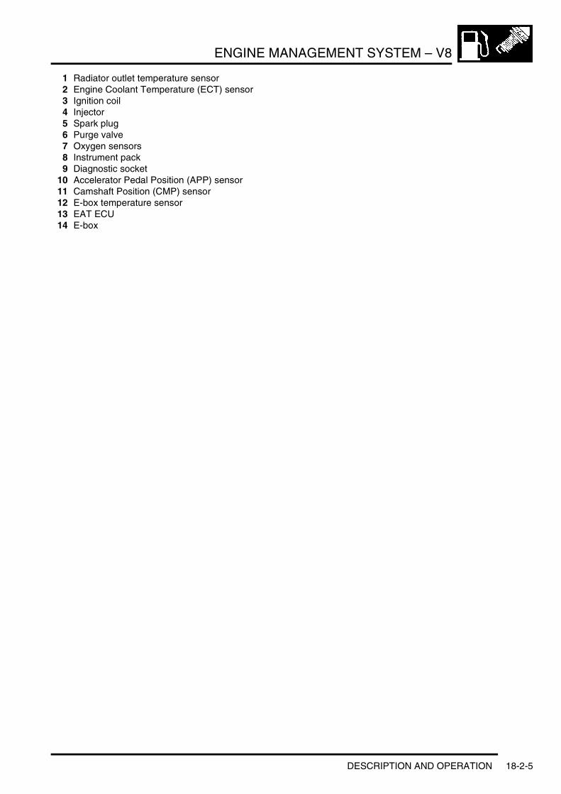
ENGINE MANAGEMENT SYSTEM – V8
1 Radiator outlet temperature sensor2 Engine Coolant Temperature (ECT) sensor3 Ignition coil4 Injector5 Spark plug6 Purge valve7 Oxygen sensors8 Instrument pack9 Diagnostic socket
10 Accelerator Pedal Position (APP) sensor 11 Camshaft Position (CMP) sensor12 E-box temperature sensor13 EAT ECU14 E-box
DESCRIPTION AND OPERATION 18-2-5

ENGINE MANAGEMENT SYSTEM – V8
Engine Management Control Diagram – Sheet 1 of 2
A = Hardwired connection; D = CAN bus; J = Diagnostic ISO 9141 K line bus
M18 0805ADA
12
54
3
6
7
9
10
11
12
13
15
1716
14
19
20
21
22
18
J
8
18-2-6 DESCRIPTION AND OPERATION
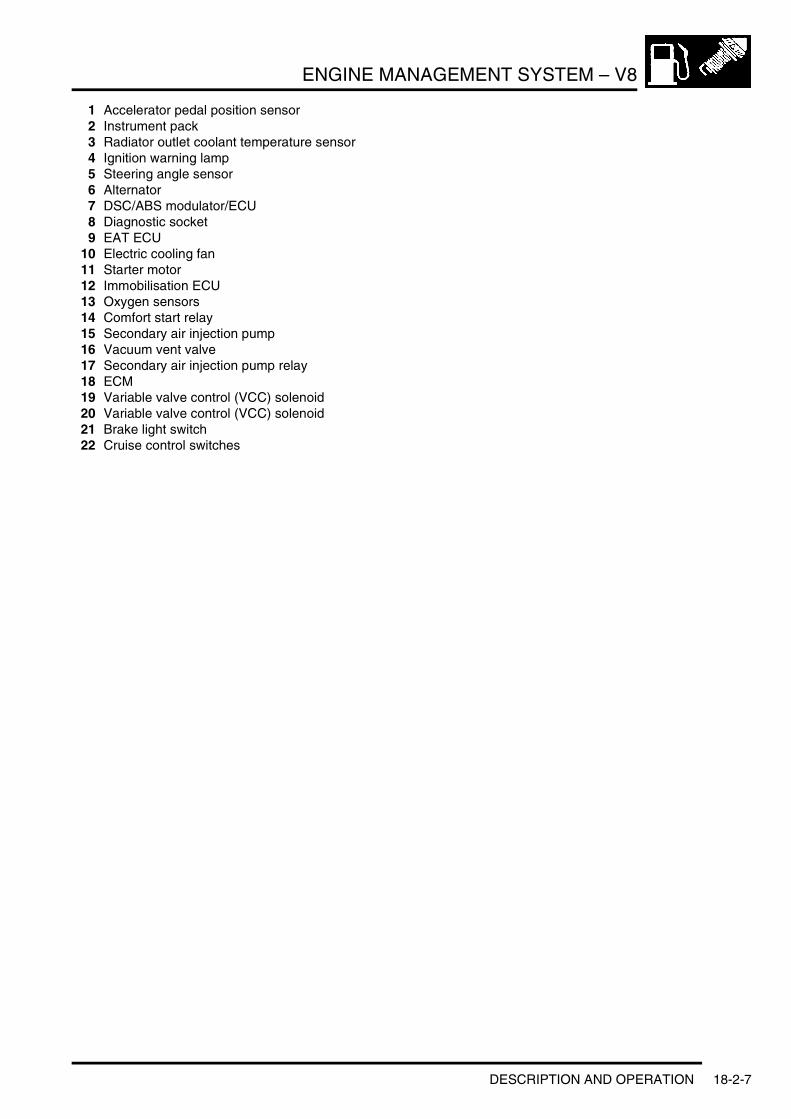
ENGINE MANAGEMENT SYSTEM – V8
1 Accelerator pedal position sensor2 Instrument pack3 Radiator outlet coolant temperature sensor4 Ignition warning lamp5 Steering angle sensor6 Alternator7 DSC/ABS modulator/ECU8 Diagnostic socket9 EAT ECU
10 Electric cooling fan11 Starter motor12 Immobilisation ECU13 Oxygen sensors14 Comfort start relay15 Secondary air injection pump16 Vacuum vent valve17 Secondary air injection pump relay18 ECM19 Variable valve control (VCC) solenoid20 Variable valve control (VCC) solenoid21 Brake light switch22 Cruise control switches
DESCRIPTION AND OPERATION 18-2-7
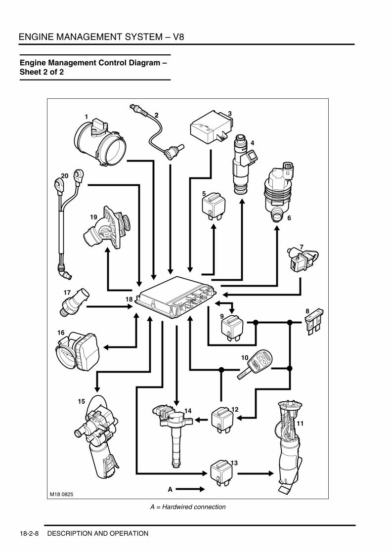
ENGINE MANAGEMENT SYSTEM – V8
Engine Management Control Diagram – Sheet 2 of 2
A = Hardwired connection
M18 0825A
1 22 3
4
6
5
89
10
11
1215
16
19
20
18
7
13
14
17
18-2-8 DESCRIPTION AND OPERATION

ENGINE MANAGEMENT SYSTEM – V8
1 MAF/IAT sensor2 Camshaft sensor3 Immobilisation ECU4 Injector5 Auxiliary cooling fan relay6 Purge valve7 Crankshaft Position (CKP) sensor8 Fuse 259 Main relay
10 Ignition switch11 Fuel pump12 Ignition coil relay13 Fuel pump relay14 Ignition coil15 Tank leakage detection module16 Electric throttle17 Radiator outlet temperature sensor18 ECM19 Electrical heated thermostat20 Knock sensors
DESCRIPTION AND OPERATION 18-2-9

ENGINE MANAGEMENT SYSTEM – V8
Bosch ME 7.2 Engine Management System
IntroductionThe V8 engine used in New Range Rover is controlled by the Bosch ME 7.2 engine management system (EMS). This system is similar to the Bosch 5.2.1 system used in previous Land Rover V8 engines. The main difference between the two systems is the “drive by wire” capabilities of the Me 7.2 EMS.
Another main difference between the 5.2.1 system and the ME 7.2 system is that ME 7.2 uses the Keyword protocol 2000* (KWP2000*) which is a ISO 9141 K Line compatible version of the Key Word 2000 protocol.
GeneralThe key functions of the Bosch ME 7.2 engine management system are:l To control the amount of fuel supplied to each cylinderl To calculate and control the exact point of fuel injectionl To calculate and control the exact point of ignition in each cylinderl To optimise adjustment of the injection timing and ignition timing to deliver the maximum engine performance
throughout all engine speed and load conditionsl To calculate and maintain the desired air/fuel ratio, to ensure the 3 way catalysts operate at their maximum
efficiencyl To maintain full idle speed control of the enginel To ensure the vehicle adheres to the emission standards (set at the time of homologation)l To ensure the vehicle meets with the fault handling requirements, as detailed in the European On-Board
Diagnostic (EOBD) III legislationl To provide an interface with other electrical systems on the vehiclel To facilitate the drive by wire functionsl To control the Variable Camshaft Control (VCC).
To deliver these key functions, the Bosch ME 7.2 Engine Control Module (ECM) relies upon a number of inputs and controls a number of outputs. As with all electronic control units, the ECM needs information regarding the current operating conditions of the engine and other related systems before it can make calculations, which determine the appropriate outputs. A Controller Area Network (CAN) bus is used to exchange information between the ECM and the Electronic Automatic Transmission (EAT) ECU
ECM
ECM
The ECM is located in the Environmental (E) box, in the front right corner of the engine compartment. The E-box provides a protective environment for the ECM and is cooled by an electric fan. The main relay for the ECM is also located in the E-box.
18-2-10 DESCRIPTION AND OPERATION

ENGINE MANAGEMENT SYSTEM – V8
E-Box
1 Fuse block2 Cooling fan3 Main relay
4 ECM5 E Box temperature sensor6 EAT ECU
A separate temperature sensor is used to monitor E-box temperature and provides a path to earth to control the electric fan. The sensor turns the fan on when the E-box temperature reaches 35°C and turns the fan off when the temperature drops below 35°C. The E-box fan draws air in from the passenger compartment, into the E-box and vents back into the passenger compartment. The fan is also driven for a short period on engine crank, independently of temperature. This is done to ensure the correct function of the fan.
The ECM is programmed during manufacture by writing the program and the engine tune into a Flash Electronic Erasable Programmable Read Only Memory (EEPROM). The EEPROM can be reprogrammed in service using TestBook/T4. In certain circumstances, it is possible to alter the tune or functionality of the ECM using this process.
DESCRIPTION AND OPERATION 18-2-11

ENGINE MANAGEMENT SYSTEM – V8
Advanced fault monitoring is incorporated into the ECM. It can detect the type and severity of faults, store relevant engine operating conditions (environmental and freeze frame data) and time that a fault occurs, suspend the operation of some functions and replace the inputs from faulty sensors with default values. Environmental data is stored for each fault detected, and consists of the inputs from three engine sensors, with the inputs stored depending on the fault. The ECM also records additional data in connection with each fault, as follows:l The number of occurrencesl If the fault is currently presentl If the fault is historic, the number of drive cycles that have elapsed since the fault last occurredl The time the fault occurred. Time is incremented in hours, hour 0 being the first time the ECM is powered-up,
hour 1 being 60 minutes of ignition 'on' time, etc.
OBD freeze frame data is only stored for emissions related faults. Only one set of freeze frame data can be stored at any one time. Faults are prioritised according to their likely impact on exhaust gas emissions. If more than one emissions related fault occurs, freeze frame data is stored for the fault with the highest priority. Freeze frame data consists of the following:l Engine speedl Engine loadl Short term fuelling trim of LH and RH cylinder banksl Long term fuelling trim of LH and RH cylinder banksl Fuelling status of LH and RH cylinder banksl Engine coolant temperaturel Road speed.
Fault information is stored in a volatile Random Access Memory (RAM) in the ECM, so will be deleted if a power failure or battery disconnection occurs.
Five electrical connectors provide the interface between the ECM and the engine/vehicle wiring. The five connectors interlock with each other when installed in the ECM. Adjacent connectors should be disconnected in turn. The installation sequence is the reverse of removal. Each connector groups associated pins together.
18-2-12 DESCRIPTION AND OPERATION

ENGINE MANAGEMENT SYSTEM – V8
ECM Harness Connector C0331 Pin Details
ECM Harness Connector C0332 Pin Details
Pin No. Description Input/Output1 Alternator warning lamp Output2 Engine cranking signal Output3 SAI pump relay Output
4 Cooling fan control unit Output5 Not used –6 Engine cranking signal Input
7 APP sensor 1 ground –8 APP sensor 1 signal Input9 APP sensor 1 supply Output
10 Fuel pump relay Output11 Not used –12 APP sensor 2 ground –
13 APP sensor 2 signal Input14 APP sensor 2 supply Output
15 and 16 Not used –
17 Diagnostic socket ground –18 Not used –19 Reverse gear signal Output
20 Not used –21 LCM22 Road speed signal Input
23 Not used –24 Brake pedal switch Input25 Not used –
26 Ignition power supply Input27 Steering wheel cruise control switches Input28 Brake pedal switch –
29 A/C compressor clutch disengage signal Output30 and 31 Not used –
32 Diagnostic ISO 9141 K line bus Input/Output
33 Immobilisation signal Input/Output34 and 35 Not used –
36 CAN bus high (connection with main bus system) Input/Output
37 CAN bus low (connection with main bus system) Input/Output38 Thermostat monitoring sensor ground –39 Thermostat monitoring signal Input
40 Starter motor relay Output
Pin No. Description Input/Output1 Ignition coil 7 Output2 Ignition coil 8 Output
3 Ignition coil 2 Output4 Ignition coil 3 Output5 Ignition ground –
6 Ignition coil 1 Output7 Ignition coil 4 Output8 Ignition coil 5 Output
9 Ignition coil 6 Output
DESCRIPTION AND OPERATION 18-2-13

ENGINE MANAGEMENT SYSTEM – V8
ECM Harness Connector C0603 Pin Details
ECM Harness Connector C0604 Pin Details
ECM Harness Connector C0606 Pin Details
Pin No. Description Input/Output1 to 3 Not used –
4 Ground –5 Ground –
6 Ground –7 Not used –8 Permanent battery power supply Input
9 Not used –
Pin No. Description Input/Output1 RH rear HO2S heater Output2 Not used –
3 CAN bus low (connection with EAT ECU) Input/Output4 CAN bus high (connection with EAT ECU) Input/Output
5 and 6 Not used –
7 LH rear HO2S heater Outer8 RH rear HO2S ground –9 LH front HO2S ground –
10 RH front HO2S ground –11 LH rear HO2S ground –12 Not used –
13 RH front HO2S heater Output14 RH rear HO2S signal Input15 LH front HO2S signal Input
16 RH front HO2S signal Input17 LH rear HO2S signal Input18 Not used –
19 LH front HO2S heater Output20 to 22 Not used –
23 Main relay coil Output
24 Not used –
Pin No. Description Input/Output1 Fuel injector 2 Output2 Fuel injector 3 Output
3 EVAP purge valve Output4 and 5 Not used –
6 Ground –
7 MAF/IAT sensor power supply Output8 Throttle position sensor 2 signal Input9 MAF/IAT sensor ground –
10 Throttle position sensors reference voltage Output11 Not used –12 Starter motor feedback Input
13 Alternator charge signal Input14 Fuel injector 7 Output
18-2-14 DESCRIPTION AND OPERATION

ENGINE MANAGEMENT SYSTEM – V8
15 Fuel injector 6 Output
16 VCC solenoid valve 2 Output17 Not used –18 CMP sensor signal 2 Input
19 Not used –20 CMP sensor signal 1 Input21 ECT sensor ground –
22 ECT sensor signal Input23 MAF/IAT sensor air flow signal Input24 Throttle position sensor 1 signal –
25 Throttle position sensor ground –26 Not used –27 Fuel injector 8 Output
28 Fuel injector 5 Output29 VCC solenoid valve 1 Output30 Not used –
31 Electric thermostat heater Output32 CKP sensor signal Input33 Not used –
34 MAF/IAT sensor air temperature signal Input35 Knock sensor cylinders 3 and 4 ground –36 Knock sensor cylinders 3 and 4 signal Input
37 Knock sensor cylinders 7 and 8 signal Input38 Knock sensor cylinders 7 and 8 ground –39 Not used –
40 Fuel injector 4 Output41 Fuel injector 1 Output42 Throttle position actuator 1 Output
43 Throttle position actuator 2 Output44 Not used –45 CKP sensor ground –
46 CKP sensor signal Input47 Not used –48 Knock sensor cylinders 1 and 2 ground –
49 Knock sensor cylinders 1 and 2 signal Input50 Knock sensor cylinders 5 and 6 signal Input51 Knock sensor cylinders 5 and 6 ground –
52 SAI vacuum solenoid valve Output
Pin No. Description Input/Output
DESCRIPTION AND OPERATION 18-2-15

ENGINE MANAGEMENT SYSTEM – V8
System InputsThe ECM optimises engine performance by interpreting signals from numerous vehicle sensors and other inputs. Some of these signals are produced by the actions of the driver, some are supplied by sensors located on and around the engine and some are supplied by other vehicle systems. The inputs are as follows:l Ignition switchl Accelerator pedal position sensor (APP)l Throttle position feedbackl Crankshaft Position (CKP) sensorl Cruise control signal (from steering wheel switch pack)l Brake light switchl Camshaft Position (CMP) sensorsl Engine Coolant Temperature (ECT) sensorl Knock sensorsl Air Mass/Intake Air Temperature (MAF/IAT) sensorl Heated Oxygen Sensors (HO2S)l Immobilisation signal (from immobilisation ECU)l Fuel level signal (via CAN)l Vehicle speed signal (from ABS ECU)l Radiator outlet temperature sensorl Internal ambient barometric pressure sensor (altitude sensor)l Electronic Automatic Transmission (EAT) information.
Electric Throttle SystemThe EMS incorporates an electric throttle control system. This system comprises three main components:l Electronic throttle control valvel Accelerator pedal position sensor (APP)l ECM.
When the accelerator pedal is depressed the APP sensor provides a change in the monitored signals. The ECM compares this against an electronic “map” and moves the electronic throttle valve via a pulse width modulated control signal which is in proportion to the APP angle signal.
The system is required to:l Regulate the calculated intake air load based on the accelerator pedal sensor input signals and programmed
mappingl Monitor the drivers input request for cruise control operationl Automatically position the electronic throttle for accurate cruise controll Perform all dynamic stability control throttle control interventionsl Monitor and carry out maximum engine and road speed cut out.
18-2-16 DESCRIPTION AND OPERATION

ENGINE MANAGEMENT SYSTEM – V8
Accelerator Pedal Position (APP) Sensor
1 Detente mechanism2 Sensor spigot3 Pedal4 Springs
5 Cables6 Bush7 Drum8 APP sensor
The APP sensor is located in a plastic housing which is integral with the throttle pedal. The housing is injection moulded and provides location for the APP sensor. The sensor is mounted externally on the housing and is secured with two Torx screws. The external body of the sensor has a six pin connector which accepts a connector on the vehicle wiring harness.
The sensor has a spigot which protrudes into the housing and provides the pivot point for the pedal mechanism. The spigot has a slot which allows for a pin, which is attached to the sensor potentiometers, to rotate through approximately 90°, which relates to pedal movement. The pedal is connected via a link to a drum, which engages with the sensor pin, changing the linear movement of the pedal into rotary movement of the drum. The drum has two steel cables attached to it. The cables are secured to two tension springs which are secured in the opposite end of the housing. The springs provide 'feel' on the pedal movement and require an effort from the driver similar to that of a cable controlled throttle. A detente mechanism is located at the forward end of the housing and is operated by a ball located on the drum. At near maximum throttle pedal movement, the ball contacts the detente mechanism. A spring in the mechanism is compressed and gives the driver the feeling of depressing a 'kickdown' switch when full pedal travel is achieved.
DESCRIPTION AND OPERATION 18-2-17

ENGINE MANAGEMENT SYSTEM – V8
APP Sensor Output Graph
A = VoltageB = APP sensor angleC = Kick down angle
18-2-18 DESCRIPTION AND OPERATION

ENGINE MANAGEMENT SYSTEM – V8
The APP sensor has two potentiometer tracks which each receive a 5V input voltage from the ECM. Track 1 provides an output of 0.5V with the pedal at rest and 2.0V at 100% full throttle. Track 2 provides an output of 0.5V with the pedal at rest and 4.5V at 100% full throttle. The signals from the two tracks are used by the ECM to determine fuelling for engine operation and also by the ECM and the EAT ECU to initiate a kickdown request for the automatic transmission.
The ECM monitors the outputs from each of the potentiometer tracks and can determine the position, rate of change and direction of movement of the throttle pedal. The 'closed throttle' position signal is used by the ECM to initiate idle speed control and also overrun fuel cut-off.
Electric Throttle
Electric Throttle Control Valve
The Electric Throttle control valve is controlled by the APP sensor via the ECM. The throttle valve plate is positioned by gear reduction DC motor drive. The DC motor is controlled by a proportionally switched high/low PWM signals at a basic frequency of 2000Hz. Engine idle speed control is a function of the Electric Throttle control valve, therefore a separate idle control valve is not required.
The electric throttle control valve throttle plate position is monitored by two integrated potentiometers. The potentiometers provide DC voltage feedback signals to the ECM for throttle and idle control functions.
Potentiometer one is used as a the primary signal, potentiometer two is used as a plausibility check through the total range of throttle plate movement.
If the ECM detects a plausibility error between Pot 1 and Pot 2 it will calculate the inducted air mass from the air mass (from the air mass sensor) and only utilise the potentiometer signal which closely matches the detected intake air mass. It does this to provide a fail-safe operation by using a 'virtual' potentiometer as a comparative source.
If the ECM cannot calculate a plausible value from the monitored potentiometers (1 and 2) the throttle motor is switched off and the fuel injection cut out is activated.
The electric throttle control valve is continuously monitored during operation. It is also briefly activated when the ignition switch is initially turned to position II. This is done to check the valves mechanical integrity by monitoring the motor control amperage and the reaction speed of the feedback potentiometers.
Should the electronic throttle need replacing the adaption values of the previous unit will need to be cleared from the ECM. This is achieved by the following process:
1 Using TestBook/T4 clear the adaption values2 Switch the ignition “OFF” for 10 seconds3 Switch the ignition “ON”, for approximately 30 seconds the electric throttle control valve is briefly activated
allowing the ECM to learn the new component.
This procedure is also necessary after the ECM has been replaced. However the adaption values do not require clearing since they have not yet been established.
DESCRIPTION AND OPERATION 18-2-19

ENGINE MANAGEMENT SYSTEM – V8
Crankshaft Position (CKP) SensorThe CKP sensor is located in the lower right side of the transmission bell housing, in line with the engine flywheel. The sensor reacts to a reluctor ring to ascertain engine speed and position information. The sensor has three wires attached to it; two signal wires and a sensor earth screen. The sensor earth screen is connected to chassis earth through the ECM.
CKP Sensor
The CKP sensor is an inductive type sensor which produces a sinusoidal output voltage signal. This voltage is induced by the proximity of the moving reluctor ring, which excites the magnetic flux around the tip of the sensor when each tooth passes. This output voltage will increase in magnitude and frequency as the engine speed rises and the speed at which the teeth on the reluctor ring pass the sensor increases. The signal voltage will peak at approximately 6.5 volts if connected to the ECM (further increases in engine speed will not result in greater magnitude). The ECM neither specifically monitors nor reacts to the output voltage (unless it is very small or very large), instead it measures the time intervals between each pulse (i.e. signal frequency). The signal is determined by the number of teeth passing the sensor, and the speed at which they pass. The reluctor ring has 58 teeth spaced at 6° intervals, with two teeth missing to give the ECM a synchronisation point.
The signal produced by the CKP sensor is critical to engine running. There is no back-up strategy for this sensor and failure of the signal will result in the engine stalling and/or failing to start. If the sensor fails when the engine is running, then the engine will stall, a fault code will be stored and details captured of the battery voltage, engine coolant temperature and intake air temperature at the time of the failure. If the signal fails when the engine is cranking, then the engine will not start and no fault will be stored, as the ECM will not detect that an attempt had been made to start the engine. In both cases the tachometer will also cease to function immediately and the MIL lamp will be permanently illuminated.
During the power-down procedure, which occurs when the ignition is switched off, the ECM stores details of the position of the CKP and CMP sensors. This enables the ECM to operate the injectors in the correct sequence immediately the engine cranks, to produce a quick engine start, which serves to reduce emissions when the engine is cold.
Camshaft Position (CMP) SensorThere are two CMP sensors which are located on the upper timing case covers. The CMP sensors monitor the position of the camshafts to establish ignition timing order, fuel injection triggering and for accurate Variable Camshaft Control (VCC) camshaft advance-retard timing feedback. The CMP sensor is a Hall-effect sensor which switches a battery fed supply on and off. The supply is switched when the teeth machined onto the camshaft gear pass by the tip of the sensor. The four teeth are of differing shapes, so the ECM can determine the exact position of the camshaft at any time.
18-2-20 DESCRIPTION AND OPERATION

ENGINE MANAGEMENT SYSTEM – V8
CMP Sensor
Unlike an inductive type sensor, a Hall-effect sensor does not produce a sinusoidal output voltage (sine wave). Instead it produces a square wave output. The wave edges are very sharp, giving the ECM a defined edge on which to base its calculations.
An implausible signal from the CMP sensor will result in the following:l The MIL lamp illuminated after de-bouncing the fault (NAS only and EU)l Loss of performance, due to the corrective ignition strategy being disabled. A default ignition map is used which
retards the timing to a safe positionl Injector operation possibly 360° out of phase, i.e. fuel injected during exhaust stroke rather than during
compression strokel Quick crank/cam synchronisation on start-up feature disabledl Some Oxygen sensor diagnostics disabled.
In addition, the ECM will store a relevant fault code and capture the input signal supplied by the engine coolant temperature sensor, the engine load calculation and the engine speed at the time of failure. TestBook/T4 will display the live readings from the CMP sensor.
Ambient Barometric Pressure SensorThe ECM incorporates an integral ambient barometric pressure sensor. This internal sensor is supplied with a 5V feed and returns a linear voltage of between 2.4 and 4.5 Volts. This represents the barometric pressure.
The system monitors barometric pressure for the following reasons:l The barometric pressure along with the calculated air mass provides additional correction for refining injection
“ON” timel The value provides a base value for the ECM to calculate the air mass being injected into the exhaust system by
the secondary air injection system. This correction factor changes the secondary air injection “ON” time which in turn optimises the necessary air flow into the exhaust system
l The signal is used to recognise down hill driving to postpone the start of evaporative emission leakage diagnosis.
DESCRIPTION AND OPERATION 18-2-21

ENGINE MANAGEMENT SYSTEM – V8
Engine Coolant Temperature (ECT) SensorThe ECT sensor is located front of the engine, adjacent to the thermostat housing. The sensor incorporates two Negative Temperature Coefficient (NTC) thermistors and four electrical connections. One set of connections are used by the ECM while the other set are used by the instrument pack temperature gauge.
ECT Sensor
Each thermistor used forms part of a voltage divider circuit operating with a regulated 5 V feed and an earth.
The signal supplied by the ECT sensor is critical to many fuel and ignition control strategies. Therefore, the ECM incorporates a complex ECT sensor default strategy, which it implements in the event of failure. The ECM uses a software model, based on the time the engine has been running and the air intake temperature, to provide a changing default value during the engine warm-up. When the software model calculates the coolant temperature has reached 60 °C, a fixed default value of 85 °C is adopted for the remainder of the ignition cycle. The software model also forms part of the sensor diagnostics: if there is too great a difference between the temperatures from the sensor input and the software model, for more than 2.54 seconds, the ECM concludes there is a fault with the sensor input.
The following symptoms may be noticeable in the event of an ECT sensor failure:l The MIL lamp illuminatedl Poor engine hot and cold startl Instrument pack engine overheat warning lamp illuminated l Excessively hot or cold reading on the temperature gauge.
At the time of a failure, the ECM will also store details of the engine speed, engine load and intake air temperature in its memory. This information is stored to aid diagnosis of the fault.
Knock SensorsTwo knock sensors are located on each cylinder block between the first and second and third and fourth cylinders of each cylinder bank. The knock sensors produce a voltage signal in proportion to the amount of mechanical vibration generated at each ignition point. Each sensor monitors two cylinders in the related cylinder bank.
18-2-22 DESCRIPTION AND OPERATION

ENGINE MANAGEMENT SYSTEM – V8
Knock Sensor
The knock sensors incorporate a piezo-ceramic crystal. This crystal produces a voltage whenever an outside force tries to deflect it, (i.e. exerts a mechanical load on it). When the engine is running, the compression waves in the material of the cylinder block, caused by the combustion of the fuel/air mixture within the cylinders, deflect the crystal and produce an output voltage signal. The signals are supplied to the ECM, which compares them with `mapped' signals stored in memory. From this, the ECM can determine when detonation occurs on individual cylinders. When detonation is detected, the ECM retards the ignition timing on that cylinder for a number of engine cycles, then gradually returns it to the original setting.
Care must be taken at all times to avoid damaging the knock sensors, but particularly during removal and fitting procedures. The recommendations regarding torque and surface preparation must be adhered to. The torque applied to the sensor and the quality of the surface preparation both have an influence over the transfer of mechanical noise from the cylinder block to the crystal.
The ECM uses the signals supplied by the knock sensors, in conjunction with the signal it receives from the camshaft sensor, to determine the optimum ignition point for each cylinder. The ignition point is set according to pre-programmed ignition maps stored within the ECM. The ECM is programmed to use ignition maps for 95 RON premium specification fuel. It will also function on 91 RON regular specification fuel but without adaptions. If the only fuel available is of poor quality, or the customer switches to a lower grade of fuel after using a high grade for a period of time, the engine may suffer slight pre-ignition for a short period. This amount of pre-ignition will not damage the engine. This situation will be evident while the ECM learns and then modifies its internal mapping to compensate for the variation in fuel quality. This feature is called adaption. The ECM has the capability of adapting its fuel and ignition control outputs in response to several sensor inputs.
The ECM will cancel closed loop control of the ignition system if the signal received from either knock sensor becomes implausible. In these circumstances the ECM will default to a safe ignition map. This measure ensures the engine will not become damaged if low quality fuel is used. The MIL lamp will not illuminate, although the driver may notice that the engine 'pinks' in some driving conditions and displays a slight drop in performance and smoothness.
When a knock sensor fault is stored, the ECM will also store details of the engine speed, engine load and the coolant temperature.
DESCRIPTION AND OPERATION 18-2-23

ENGINE MANAGEMENT SYSTEM – V8
Mass Air Flow/Air Intake Temperature (MAF/IAT) SensorThe MAF/IAT sensor is located in the air intake ducting, between the air cleaner and the throttle body. The sensor outputs intake air flow and temperature signals to the ECM to enable calculation of the mass of the air entering the engine.
In addition to the air flow and temperature outputs, a regulated 5 V feed and an earth are connected between the sensor and the ECM, and the sensor receives a battery power feed from the main relay.
Air flow: The air flow signal is produced from a hot film element in the sensor. The film is connected between the 5 V feed and the air flow output to the ECM. The film is also heated by the battery power feed and cooled by the air flow into the engine. The greater the air flow, the greater the cooling effect and the lower the electrical resistance across the sensor. So the air flow output voltage varies with changes in air flow and, from voltage/air flow maps stored in memory, the ECM determines the mass of air entering the engine.
Air intake temperature: The air intake temperature signal is produced by a NTC thermistor connected between the 5 V feed and earth to complete a voltage divider circuit. The ECM monitors the voltage drop across the thermistor and, from voltage/temperature maps stored in memory, determines the temperature of the intake air.
The MAF/IAT sensor is sensitive to sudden shocks and changes in its orientation. It should, therefore, be handled carefully. It is also important that the intake ducting between the air cleaner and the throttle body is not altered in diameter or modified in any way. The air mass flow meter contains electronic circuitry, so never attempt to supply it directly from the battery. The terminals have a silver coating to provide a superior quality of connection over many years. If, at any time, a probe is used to measure the output directly from the sensor, then care must be taken to ensure this coating is not damaged.
MAF/IAT Sensor
If the air flow signal fails the ECM adopts a default value for air flow volume based on throttle position and engine speed. The following engine symptoms will be noticeable:l The engine speed might 'dip' before the default strategy enables continued runningl The engine may be difficult to start and prone to stallingl The overall performance of the engine will be adversely affected (throttle response in particular)l Exhaust emissions will be out of tolerance, because the air/fuel ratio value is now assumed, not calculated; no
closed loop fuellingl Idle speed control disabled, leading to rough idle and possible engine stall.
At the time of failure, the ECM will store details of the engine speed, coolant temperature and throttle angle.
If the intake air temperature signal fails, the ECM adopts a default value of 45 °C. This default value is then used within all the calculations involving intake air temperature. The effect on the vehicle of a failed air temperature signal will not be so noticeable to the driver, who may notice a reduction in engine performance when operating the vehicle at high altitudes or in hot ambient temperatures. The occurrence of this fault will also disable fuelling adaptions.
The ECM will store details of the engine speed, engine load and battery voltage when this fault is first detected.
18-2-24 DESCRIPTION AND OPERATION

ENGINE MANAGEMENT SYSTEM – V8
Heated Oxygen Sensors (HO2S)The HO2S provide feedback signals to the ECM to enable closed loop control of the Air Fuel Ratio (AFR). Four HO2S are installed, one pre-catalyst and one post-catalyst per cylinder bank. Each HO2S produces an output voltage which is inversely proportional to the oxygen content of the exhaust gases.
HO2S
Each HO2S consists of a zirconium sensing element with a gas permeable ceramic coating on the outer surface. The outer surface of the sensing element is exposed to the exhaust gas and the inner surface is exposed to ambient air. The difference in the oxygen content of the two gases produces an electrical potential difference across the sensing element. The voltage produced depends on the differential between the two oxygen contents. When the AFR is Lambda 1 (i.e. stoichiometric AFR of 14.7:1 by mass) the voltage produced is approximately 450 mV. With a lean mixture of Lambda 1.2, the higher oxygen content of the exhaust gases results in a voltage of approximately 100 mV. With a rich mixture of Lambda 0.8, the lower oxygen content of the exhaust gases results in a voltage of approximately 900 mV.
The ECM monitors the effect of altering the injector pulse widths using the information supplied by the two HO2S. Injector pulse width is the length of time the injector is energised, which determines how much fuel is injected. The response time is such that under certain driving conditions, the ECM can assess individual cylinder contributions to the total exhaust emissions. This enables the ECM to adapt the fuelling strategy on a cylinder by cylinder basis, i.e. inject the precise amount of fuel required by each individual cylinder at any given time.
HO2S Principle of Operation
A = Ambient air; B = Exhaust gases
1 Protective ceramic coating2 Electrodes
3 Zirconium oxide
M18 0837
V
A
B
2
3
1
DESCRIPTION AND OPERATION 18-2-25

ENGINE MANAGEMENT SYSTEM – V8
HO2S Output
A = Output, mV; B = AFR, lambda
1 Lambda window2 Lean AFR
3 Rich AFR
The ECM continuously checks the signals supplied by the HO2S for plausibility. If it detects an implausible signal, the ECM stores a relevant fault code and details of engine speed, engine load and the HO2S signal voltage. The ECM requires the HO2S signals to set most of its adaptions. Failure of an HO2S results in most of these adaptions resetting to their default values. This, in turn, results in loss of engine refinement. The engine may exhibit poor idle characteristics and emit a strong smell of rotten eggs from the exhaust (caused by an increase in hydrogen sulphide).
The efficiency of the HO2S slowly deteriorates with use and must be periodically replaced (currently every 120,000 miles, but refer to the maintenance schedules for the latest service replacement period). The ECM is able to detect this steady deterioration from the HO2S signals. If a sensor deteriorates beyond a predetermined threshold, the ECM stores a fault code and captures details of the engine speed, engine load and battery voltage.
The HO2S needs a high operating temperature to work effectively. To ensure a suitable operating temperature is reached as soon as possible, each sensor incorporates a heating element inside the ceramic tip. This element heats the HO2S to a temperature greater than 350 °C. The heating rate (the speed at which the temperature rises) is carefully controlled by the ECM to prevent thermal shock to the ceramic material. The ECM supplies a Pulse Width Modulated (PWM) supply to the heater elements to control the rate at which the HO2S temperature is increased. The HO2S are heated during engine warm-up and again after a period of engine idle.
The ECM monitors the state of the heating elements by calculating the amount of current supplied to each sensor during operation. If the ECM identifies that the resistance of either heating element is too high or too low, it will store a fault code, the engine speed, coolant temperature and the battery voltage.
HO2S are very sensitive devices. They must be handled carefully at all times. Failure to handle correctly will result in a very short service life, or non-operation. HO2S are threads coated with an anti-seize compound prior to installation. Care should be taken to avoid getting this compound on the sensor tip. If the sensor needs to be removed and refitted, a small amount of anti-seize compound should be applied (see workshop manual for details).
18-2-26 DESCRIPTION AND OPERATION

ENGINE MANAGEMENT SYSTEM – V8
Radiator Outlet Temperature Sensor
The ECM uses an additional engine coolant temperature sensor located in the radiator outlet. The sensor monitors the temperature of the coolant leaving the radiator for precise activation of the auxiliary fan. The sensor is an NTC thermistor type. The signal is used by the ECM to activate the auxiliary fan when the engine coolant temperature leaving the radiator is in the range of 80°C to 104°C.
Fuel Level SignalThe ECM monitors the contents of the fuel tank as part of the misfire detection strategy. If a misfire occurs while a low fuel level exists, the ECM stores an additional fault code to indicate that fuel starvation resulting from fuel slosh is a possible cause of the misfire. On New Range Rover, the low fuel level signal is internally generated by the ECM, from a CAN signal via the instrument pack.
Vehicle Speed SignalThe ECM receives the vehicle speed signal from the ABS ECU. The ECM uses this signal within its calculations for idle speed control. The signal is transmitted at 8000 pulses/mile and is the average of the road speed signals from all four wheel speed sensors. The ABS ECU outputs the vehicle speed signal to the EAT ECU on the CAN bus.
Rough Road SignalWhen the vehicle is travelling over a rough road surface the engine crankshaft is subjected to torsional vibrations caused by mechanical feedback from the road surface through the transmission. To prevent misinterpretation of these torsional vibrations as a misfire, the ECM calculates a rough road level by monitoring individual wheel speeds from the ABS ECU on the CAN bus. The ECM determines the quality of the road surface by monitoring a CAN signal from the ABS ECU, which modulates the duty cycle of the signal in response to variations between ABS sensor inputs. Misfire monitoring is restored when the quality of the road surface improves again.
If there is a fault with the CAN data, the ECM defaults to permanent misfire monitoring.
A/C Request SignalsBecause of the loads imposed on the engine when the air conditioning system operates, the ECM is included in the control loop for the compressor and the cooling fans. If it becomes necessary to limit or reduce the load on the engine, the ECM can then prevent or discontinue operation of the air conditioning compressor.
DESCRIPTION AND OPERATION 18-2-27

ENGINE MANAGEMENT SYSTEM – V8
Automatic Gearbox InformationInformation sent to and from the EAT ECU is transmitted on the CAN bus.
The ECM requires information on gear position to calculate the likely engine load during acceleration and deceleration conditions. The ECM also disables the misfire detection function whenever low range is selected. The ECM receives this information from the transfer box ECU on the CAN Bus.
There are several possible fault codes associated with the CAN bus and the validity of the messages exchanged between the ECM and the EAT ECU. In most cases, the ECM will store engine speed, engine coolant temperature and details of the battery voltage at the time a CAN fault is detected.
If the EAT ECU detects a gearbox fault, it requests the ECM to illuminate the MIL in the instrument pack and to store freeze frame data.
Ignition SwitchThe ignition switch signal enables the ECM to detect if the ignition is on or off. The signal is a power feed that is connected to the ECM while the ignition switch is positions II and III. On the New Range Rover, the power feed comes from the ignition relay in the engine compartment fuse box.
When it first receives the signal, the ECM 'wakes-up' and initiates a power-up sequence to enable engine starting and operation. The power-up sequence includes energising the main relay, which supplies the main power feed to the ECM, energising the fuel pump relay and initiating a self check of the engine management system.
When it detects the ignition has been turned off, the ECM stops activating the fuel injectors and ignition coil, to stop the engine, and de-energises the fuel pump relay, but keeps the main relay energised while it performs a power down sequence. During the power down sequence the ECM records the engine sensor values required for a quick-start function to operate the next time the engine is cranked. At the end of the power down sequence, the ECM de-energises the main relay to switch itself off.
System OutputsThe ECM receives and processes the input information previously described and modifies the fuelling and the ignition points for each cylinder accordingly. The ECM will also supply output information to other vehicle systems.
The ECM drives the following components:l Fuel injectorsl Ignition coilsl Main relay and fuel pump relayl Tank Leakage Detection (NAS)l Secondary Air Injection Pumpl Secondary Air Injection valvel VCC Valvesl Electrically heated thermostatl Air conditioning compressor (relay drive).
The ECM provides other systems with information regarding the:l Engine speedl Driver demandl ATC requestl Automatic Transmission l Fuel usedl Auxiliary cooling fan.
Ignition CoilsThe ME 7.2 EMS utilises plug top coils which are mounted directly on top of the spark plug.
18-2-28 DESCRIPTION AND OPERATION
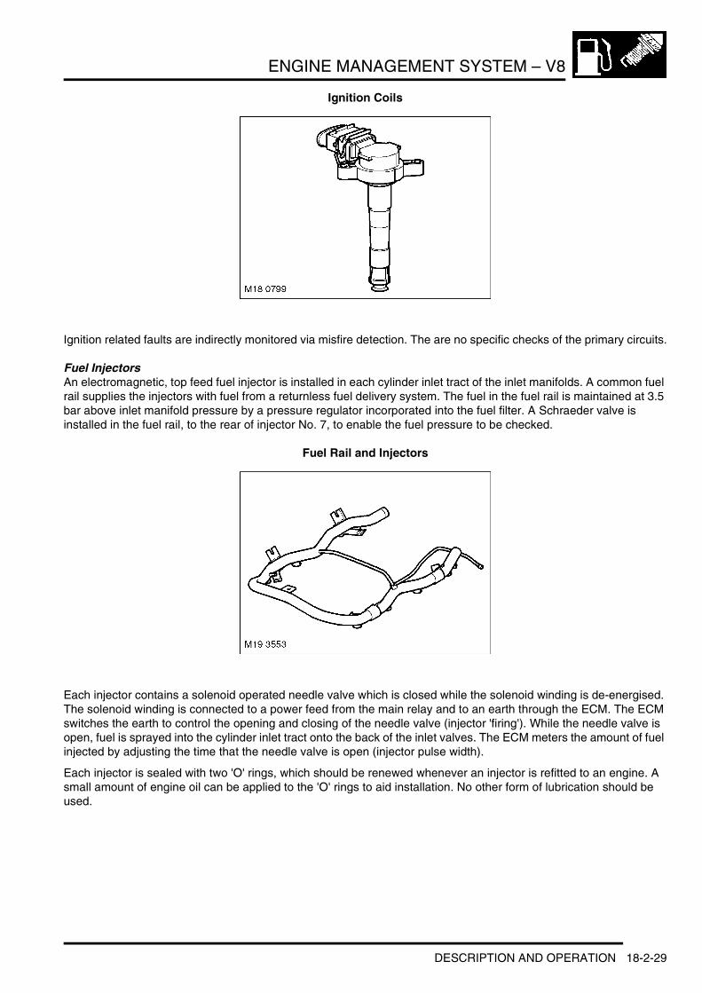
ENGINE MANAGEMENT SYSTEM – V8
Ignition Coils
Ignition related faults are indirectly monitored via misfire detection. The are no specific checks of the primary circuits.
Fuel InjectorsAn electromagnetic, top feed fuel injector is installed in each cylinder inlet tract of the inlet manifolds. A common fuel rail supplies the injectors with fuel from a returnless fuel delivery system. The fuel in the fuel rail is maintained at 3.5 bar above inlet manifold pressure by a pressure regulator incorporated into the fuel filter. A Schraeder valve is installed in the fuel rail, to the rear of injector No. 7, to enable the fuel pressure to be checked.
Fuel Rail and Injectors
Each injector contains a solenoid operated needle valve which is closed while the solenoid winding is de-energised. The solenoid winding is connected to a power feed from the main relay and to an earth through the ECM. The ECM switches the earth to control the opening and closing of the needle valve (injector 'firing'). While the needle valve is open, fuel is sprayed into the cylinder inlet tract onto the back of the inlet valves. The ECM meters the amount of fuel injected by adjusting the time that the needle valve is open (injector pulse width).
Each injector is sealed with two 'O' rings, which should be renewed whenever an injector is refitted to an engine. A small amount of engine oil can be applied to the 'O' rings to aid installation. No other form of lubrication should be used.
DESCRIPTION AND OPERATION 18-2-29
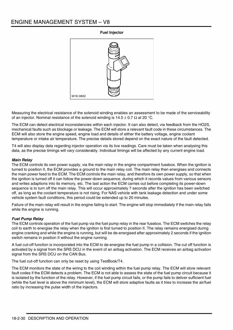
ENGINE MANAGEMENT SYSTEM – V8
Fuel Injector
Measuring the electrical resistance of the solenoid winding enables an assessment to be made of the serviceability of an injector. Nominal resistance of the solenoid winding is 14.5 ± 0.7 Ω at 20 °C.
The ECM can detect electrical inconsistencies within each injector. It can also detect, via feedback from the HO2S, mechanical faults such as blockage or leakage. The ECM will store a relevant fault code in these circumstances. The ECM will also store the engine speed, engine load and details of either the battery voltage, engine coolant temperature or intake air temperature. The precise details stored depend on the exact nature of the fault detected.
T4 will also display data regarding injector operation via its live readings. Care must be taken when analysing this data, as the precise timings will vary considerably. Individual timings will be affected by any current engine load.
Main RelayThe ECM controls its own power supply, via the main relay in the engine compartment fusebox. When the ignition is turned to position II, the ECM provides a ground to the main relay coil. The main relay then energises and connects the main power feed to the ECM. The ECM controls the main relay, and therefore its own power supply, so that when the ignition is turned off it can follow the power-down sequence, during which it records values from various sensors and writes adaptions into its memory, etc. The last action the ECM carries out before completing its power-down sequence is to turn off the main relay. This will occur approximately 7 seconds after the ignition has been switched off, as long as the coolant temperature is not rising. For NAS vehicle with tank leakage detection and under some vehicle system fault conditions, this period could be extended up to 20 minutes.
Failure of the main relay will result in the engine failing to start. The engine will stop immediately if the main relay fails while the engine is running.
Fuel Pump RelayThe ECM controls operation of the fuel pump via the fuel pump relay in the rear fusebox. The ECM switches the relay coil to earth to energise the relay when the ignition is first turned to position II. The relay remains energised during engine cranking and while the engine is running, but will be de-energised after approximately 2 seconds if the ignition switch remains in position II without the engine running.
A fuel cut-off function is incorporated into the ECM to de-energise the fuel pump in a collision. The cut off function is activated by a signal from the SRS DCU in the event of an airbag activation. The ECM receives an airbag activation signal from the SRS DCU on the CAN Bus.
The fuel cut-off function can only be reset by using TestBook/T4.
The ECM monitors the state of the wiring to the coil winding within the fuel pump relay. The ECM will store relevant fault codes if the ECM detects a problem. The ECM is not able to assess the state of the fuel pump circuit because it is isolated by the function of the relay. However, if the fuel pump circuit fails, or the pump fails to deliver sufficient fuel (while the fuel level is above the minimum level), the ECM will store adaptive faults as it tries to increase the air/fuel ratio by increasing the pulse width of the injectors.
18-2-30 DESCRIPTION AND OPERATION

ENGINE MANAGEMENT SYSTEM – V8
Failure of the fuel pump relay will result in the engine failing to start. If the fuel pump fails while the engine is running, the symptoms will be engine hesitation and engine misfire. These symptoms will worsen progressively until the engine stops. The ECM will store several fault codes under this condition.
Electrically Heated ThermostatThe electrically heated thermostat is used to regulate the engine coolant temperature. The thermostat regulates the coolant temperature depending upon engine load and vehicle speed. This allows the engine coolant temperature to be raised when the engine is operating at part load. Raising the coolant temperature while the engine is at part load has a beneficial effect on fuel consumption and emissions.
If a conventional thermostat with higher constant operating temperature is used, poor response when accelerating and in traffic could result.
The thermostat is controlled by the ECM is response to engine load against a 'map' stored within the ECM.
The map is based upon the following inputs:l Engine loadl Engine speedl Vehicle speedl Intake air temperaturel Coolant temperature.
The thermostat unit is a one piece construction comprising the thermostat, thermostat housing and heater element. The housing is of a die-cast aluminium. The electrical connection for the heater element is housed in the body. The heater element is an expanding (wax) element.
Heated Thermostat
The thermostat is set to open when the coolant temperature reaches 103°C at the thermostat. Once the coolant has passed through the engine its temperature is approximately 110°C at the engine temperature sensor.
If the ECM starts to regulate the system the ECM supplies an earth path for the heater element in the thermostat. This causes the element to expand and increase the opening dimension of the thermostat.
The warmer the element the sooner the thermostat opens and the lower the resulting coolant temperature is. The thermostat regulates the coolant temperature in the range 80°C to 103°C. The expanding element in the thermostat is heated to a higher temperature than the surrounding coolant to generate the correct opening aperture. Should the coolant temperature exceed 113°C the electrically heated thermostat is activated independently of the prevailing engine parameters.
Should the heated thermostat fail, (fault codes will be stored in the ECM) the EMS will ensure the safe operation of the engine and the thermostat will operate as a conventional unit.
DESCRIPTION AND OPERATION 18-2-31
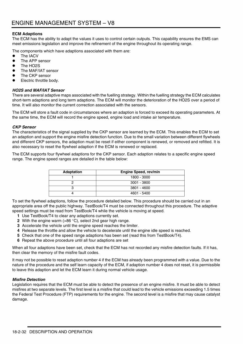
ENGINE MANAGEMENT SYSTEM – V8
ECM AdaptionsThe ECM has the ability to adapt the values it uses to control certain outputs. This capability ensures the EMS can meet emissions legislation and improve the refinement of the engine throughout its operating range.
The components which have adaptions associated with them are:l The IACV l The APP sensorl The HO2S l The MAF/IAT sensorl The CKP sensorl Electric throttle body.
HO2S and MAF/IAT SensorThere are several adaptive maps associated with the fuelling strategy. Within the fuelling strategy the ECM calculates short-term adaptions and long term adaptions. The ECM will monitor the deterioration of the HO2S over a period of time. It will also monitor the current correction associated with the sensors.
The ECM will store a fault code in circumstances where an adaption is forced to exceed its operating parameters. At the same time, the ECM will record the engine speed, engine load and intake air temperature.
CKP SensorThe characteristics of the signal supplied by the CKP sensor are learned by the ECM. This enables the ECM to set an adaption and support the engine misfire detection function. Due to the small variation between different flywheels and different CKP sensors, the adaption must be reset if either component is renewed, or removed and refitted. It is also necessary to reset the flywheel adaption if the ECM is renewed or replaced.
The ECM supports four flywheel adaptions for the CKP sensor. Each adaption relates to a specific engine speed range. The engine speed ranges are detailed in the table below:
To set the flywheel adaptions, follow the procedure detailed below. This procedure should be carried out in an appropriate area off the public highway. TestBook/T4 must be connected throughout this procedure. The adaptive speed settings must be read from TestBook/T4 while the vehicle is moving at speed.
1 Use TestBook/T4 to clear any adaptions currently set.2 With the engine warm (>86 °C), select 2nd gear high range.3 Accelerate the vehicle until the engine speed reaches the limiter.4 Release the throttle and allow the vehicle to decelerate until the engine idle speed is reached.5 Check that one of the speed range adaptions has been set (read this from TestBook/T4).6 Repeat the above procedure until all four adaptions are set
When all four adaptions have been set, check that the ECM has not recorded any misfire detection faults. If it has, then clear the memory of the misfire fault codes.
It may not be possible to reset adaption number 4 if the ECM has already been programmed with a value. Due to the nature of the procedure and the self learn capacity of the ECM, if adaption number 4 does not reset, it is permissible to leave this adaption and let the ECM learn it during normal vehicle usage.
Misfire DetectionLegislation requires that the ECM must be able to detect the presence of an engine misfire. It must be able to detect misfires at two separate levels. The first level is a misfire that could lead to the vehicle emissions exceeding 1.5 times the Federal Test Procedure (FTP) requirements for the engine. The second level is a misfire that may cause catalyst damage.
Adaptation Engine Speed, rev/min1 1800 - 3000
2 3001 - 38003 3801 - 46004 4601 - 5400
18-2-32 DESCRIPTION AND OPERATION

ENGINE MANAGEMENT SYSTEM – V8
The ECM monitors the number of misfire occurrences within two engine speed ranges. If the ECM detects more than a predetermined number of misfire occurrences within either of these two ranges, over two consecutive journeys, the ECM will record a fault code and details of the engine speed, engine load and engine coolant temperature. In addition, the ECM monitors the number of misfire occurrences that happen in a 'window' of 200 engine revolutions. The misfire occurrences are assigned a weighting according to their likely impact on the catalysts. If the number of misfires exceeds a certain value, the ECM stores catalyst-damaging fault codes, along with the engine speed, engine load and engine coolant temperature.
The signal from the crankshaft position sensor indicates how fast the poles on the flywheel are passing the sensor tip. A sine wave is generated each time a pole passes the sensor tip. The ECM can detect variations in flywheel speed by monitoring the sine wave signal supplied by the crankshaft position sensor.
By assessing this signal, the ECM can detect the presence of an engine misfire. At this time, the ECM will assess the amount of variation in the signal received from the crankshaft position sensor and assigns a roughness value to it. This roughness value can be viewed within the real time monitoring feature, using TestBook/T4. The ECM will evaluate the signal against a number of factors and will decide whether to count the occurrence or ignore it. The ECM can assign a roughness and misfire signal for each cylinder, (i.e. identify which cylinder is misfiring).
TestBook/T4 DiagnosticsThe ECM stores faults as Diagnostic Trouble Codes (DTC), referred to as 'P' codes. The 'P' codes are defined by OBD legislation and, together with their associated environmental and freeze frame data, can be read using a third party scan tool or TestBook/T4. TestBook/T4 can also read real time data from each sensor, the adaptive values currently being employed and the current fuelling, ignition and idle settings.
DESCRIPTION AND OPERATION 18-2-33
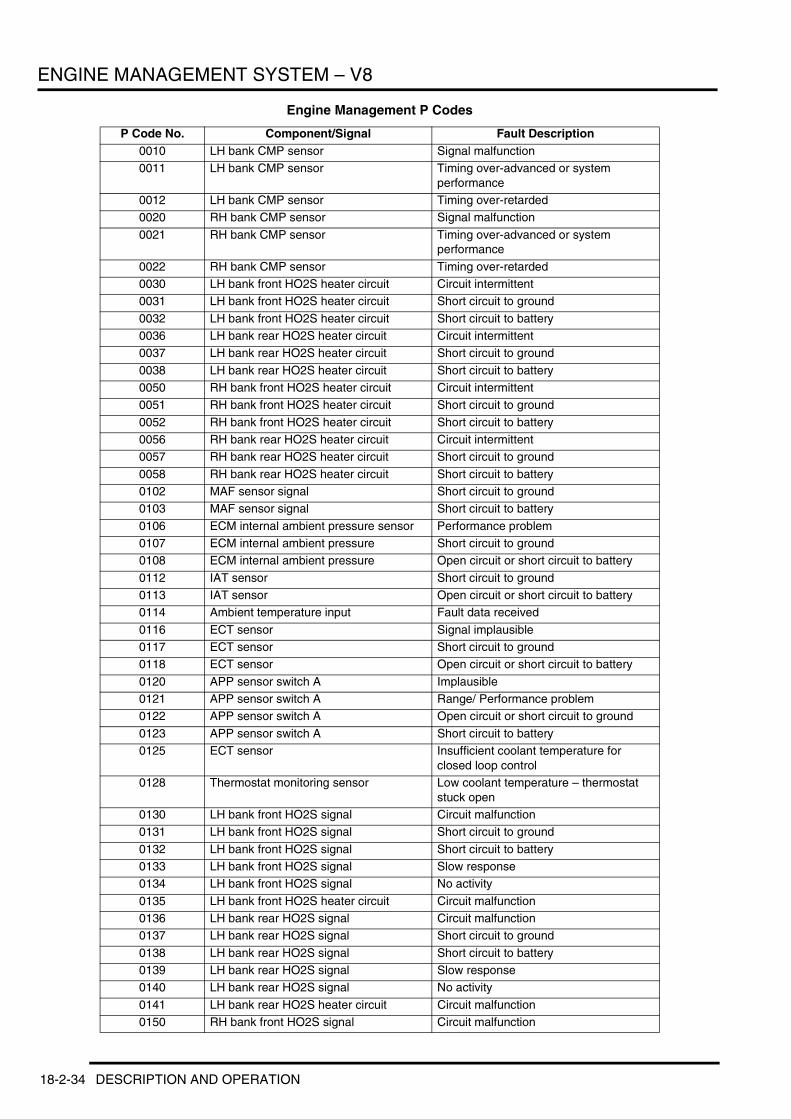
ENGINE MANAGEMENT SYSTEM – V8
Engine Management P Codes
P Code No. Component/Signal Fault Description0010 LH bank CMP sensor Signal malfunction0011 LH bank CMP sensor Timing over-advanced or system
performance0012 LH bank CMP sensor Timing over-retarded0020 RH bank CMP sensor Signal malfunction
0021 RH bank CMP sensor Timing over-advanced or system performance
0022 RH bank CMP sensor Timing over-retarded0030 LH bank front HO2S heater circuit Circuit intermittent0031 LH bank front HO2S heater circuit Short circuit to ground
0032 LH bank front HO2S heater circuit Short circuit to battery0036 LH bank rear HO2S heater circuit Circuit intermittent0037 LH bank rear HO2S heater circuit Short circuit to ground
0038 LH bank rear HO2S heater circuit Short circuit to battery0050 RH bank front HO2S heater circuit Circuit intermittent0051 RH bank front HO2S heater circuit Short circuit to ground
0052 RH bank front HO2S heater circuit Short circuit to battery0056 RH bank rear HO2S heater circuit Circuit intermittent0057 RH bank rear HO2S heater circuit Short circuit to ground
0058 RH bank rear HO2S heater circuit Short circuit to battery0102 MAF sensor signal Short circuit to ground0103 MAF sensor signal Short circuit to battery
0106 ECM internal ambient pressure sensor Performance problem0107 ECM internal ambient pressure Short circuit to ground0108 ECM internal ambient pressure Open circuit or short circuit to battery
0112 IAT sensor Short circuit to ground0113 IAT sensor Open circuit or short circuit to battery0114 Ambient temperature input Fault data received
0116 ECT sensor Signal implausible0117 ECT sensor Short circuit to ground0118 ECT sensor Open circuit or short circuit to battery
0120 APP sensor switch A Implausible0121 APP sensor switch A Range/ Performance problem0122 APP sensor switch A Open circuit or short circuit to ground
0123 APP sensor switch A Short circuit to battery0125 ECT sensor Insufficient coolant temperature for
closed loop control0128 Thermostat monitoring sensor Low coolant temperature – thermostat
stuck open0130 LH bank front HO2S signal Circuit malfunction0131 LH bank front HO2S signal Short circuit to ground
0132 LH bank front HO2S signal Short circuit to battery0133 LH bank front HO2S signal Slow response0134 LH bank front HO2S signal No activity
0135 LH bank front HO2S heater circuit Circuit malfunction0136 LH bank rear HO2S signal Circuit malfunction0137 LH bank rear HO2S signal Short circuit to ground
0138 LH bank rear HO2S signal Short circuit to battery0139 LH bank rear HO2S signal Slow response0140 LH bank rear HO2S signal No activity
0141 LH bank rear HO2S heater circuit Circuit malfunction0150 RH bank front HO2S signal Circuit malfunction
18-2-34 DESCRIPTION AND OPERATION

ENGINE MANAGEMENT SYSTEM – V8
0151 RH bank front HO2S signal Short circuit to ground
0152 RH bank front HO2S signal Short circuit to battery0153 RH bank front HO2S signal Slow response0154 RH bank front HO2S signal No activity
0155 RH bank front HO2S heater circuit Circuit malfunction0156 RH bank rear HO2S signal Circuit malfunction0157 RH bank rear HO2S signal Short circuit to ground
0158 RH bank rear HO2S signal Short circuit to battery0159 RH bank rear HO2S signal Slow response0160 RH bank rear HO2S signal No activity
0161 RH bank rear HO2S heater circuit Malfunction0171 LH bank lambda control Fuelling too lean0172 LH bank lambda control Fuelling too rich
0174 RH bank lambda control Fuelling too lean0175 RH bank lambda control Fuelling too rich0201 Fuel injector 1 Open circuit
0202 Fuel injector 2 Open circuit0203 Fuel injector 3 Open circuit0204 Fuel injector 4 Open circuit
0205 Fuel injector 5 Open circuit0206 Fuel injector 6 Open circuit0207 Fuel injector 7 Open circuit
0208 Fuel injector 8 Open circuit0221 APP sensor switch B Range/ Performance problem0222 APP sensor switch B Open circuit or short circuit to ground
0223 APP sensor switch B Short circuit to battery0231 Fuel pump motor drive Short circuit to ground0232 Fuel pump motor drive Short circuit to battery
0233 Fuel pump motor drive Circuit fault0261 Fuel injector 1 Short circuit to ground0262 Fuel injector 1 Short circuit to battery
0264 Fuel injector 2 Short circuit to ground0265 Fuel injector 2 Short circuit to battery0267 Fuel injector 3 Short circuit to ground
0268 Fuel injector 3 Short circuit to battery0270 Fuel injector 4 Short circuit to ground0271 Fuel injector 4 Short circuit to battery
0273 Fuel injector 5 Short circuit to ground0274 Fuel injector 5 Short circuit to battery0276 Fuel injector 6 Short circuit to ground
0277 Fuel injector 6 Short circuit to battery0279 Fuel injector 7 Short circuit to ground0280 Fuel injector 7 Short circuit to battery
0282 Fuel injector 8 Short circuit to ground0283 Fuel injector 8 Short circuit to battery0300 Misfire detection Random/Multiple cylinder misfire
0301 Misfire detection Cylinder 1 misfire0302 Misfire detection Cylinder 2 misfire0303 Misfire detection Cylinder 3 misfire
0304 Misfire detection Cylinder 4 misfire0305 Misfire detection Cylinder 5 misfire0306 Misfire detection Cylinder 6 misfire
P Code No. Component/Signal Fault Description
DESCRIPTION AND OPERATION 18-2-35

ENGINE MANAGEMENT SYSTEM – V8
0307 Misfire detection Cylinder 7 misfire
0308 Misfire detection Cylinder 8 misfire0324 Knock sensors Control system error0327 LH bank knock sensor 1 Short circuit to ground
0328 LH bank knock sensor 1 Short circuit to battery0332 RH bank knock sensor 3 Short circuit to ground0333 RH bank knock sensor 3 Short circuit to battery
0335 CKP sensor Signal implausible0340 LH bank CMP sensor Signal implausible0342 LH bank CMP sensor Short circuit to ground
0343 LH bank CMP sensor Short circuit to battery0345 RH bank CMP sensor Signal implausible0347 RH bank CMP sensor Short circuit to ground
0348 RH bank CMP sensor Short circuit to battery0370 Reference mark detection Timing reference high resolution signal A0411 SAI vacuum solenoid valve Incorrect flow detected
0412 SAI vacuum solenoid valve drive Circuit malfunction0413 SAI vacuum solenoid valve drive Open circuit0414 SAI vacuum solenoid valve drive Short circuit
0418 SAI air injection pump relay Open circuit0420 LH bank catalytic converter Efficiency below threshold – light off too
long0430 RH bank catalytic converter Efficiency below threshold – light off too
long0442 EVAP system Minor leak (1.0 mm or less)0443 Purge valve drive Circuit malfunction
0444 Purge valve drive Open circuit0445 Purge valve drive Short circuit to battery or ground0455 EVAP system Major leak (more than 1.0 mm)
0456 EVAP system Minor leak (0.5 mm or less)0461 Fuel tank level signal Range/Performance problem0462 Fuel tank level signal Short circuit to ground
0463 Fuel tank level signal Short circuit to battery0464 Fuel tank level signal Circuit intermittent0491 SAI system Malfunction on LH bank
0492 SAI system Malfunction on RH bank0500 Vehicle speed signal Signal implausible0501 Rough road detection vehicle speed
signalIntermittent, erratic or high
0503 Rough road detection vehicle speed signal
Range/Performance
0512 Comfort start Request circuit malfunction
0530 A/C refrigerant pressure sensor Signal fault0532 A/C refrigerant pressure sensor Short circuit to ground0533 A/C refrigerant pressure sensor Short circuit to battery
0561 Battery voltage monitor System voltage unstable0562 Battery voltage monitor System voltage low0563 Battery voltage monitor System voltage high
0571 Brake lights switch Cruise control/brake switch circuit A0604 ECM self test RAM error0605 ECM self test ROM error
0606 ECM self test Processor fault0615 Comfort start relay drive Open circuit
P Code No. Component/Signal Fault Description
18-2-36 DESCRIPTION AND OPERATION

ENGINE MANAGEMENT SYSTEM – V8
0616 Comfort start relay drive Short circuit to ground
0617 Comfort start relay drive Short circuit to battery0634 ECU internal temperature ECU temperature high0650 MIL output drive Open circuit, or short circuit to ground or
battery0660 Manifold valve output drive Control circuit malfunction
0661 Manifold valve output drive Open circuit or short circuit to ground0662 Manifold valve output drive Short circuit to battery0691 Engine cooling fan control Short circuit to ground
0692 Engine cooling fan control Short circuit to battery0693 Engine cooling fan control Circuit intermittent0704 A/C compressor clutch switch Input circuit malfunction
1000 DMTL pump motor drive Intermittent or short circuit to ground or battery
1102 Throttle position to mass air flow plausibility not active
Air mass too small
1103 Throttle position to mass air flow plausibility not active
Air mass too large
1117 Thermostat monitoring sensor Short circuit to ground1118 Thermostat monitoring sensor Open circuit or short circuit to battery1120 APP sensor Implausible signals
1121 APP sensor 1 Range/ Performance problem1122 APP sensor 1 Short circuit to ground1123 APP sensor 1 Short circuit to battery
1129 HO2S Swapped sensors (LH to RH)1161 LH bank lambda control Adaption per ignition too small1162 LH bank lambda control Adaption per ignition too large
1163 RH bank lambda control Adaption per ignition too small1164 RH bank lambda control Adaption per ignition too large1170 LH bank front HO2S signal Fuel trim malfunction
1171 LH bank lambda control Adaption over time too large1172 LH bank lambda control Adaption over time too small1173 RH bank front HO2S signal Fuel trim malfunction
1174 RH bank lambda control Adaption over time too large1175 RH bank lambda control Adaption over time too small1221 APP sensor 2 Range/ Performance problem
1222 APP sensor 2 Short circuit to ground1223 APP sensor 2 Short circuit to battery1300 Misfire detection Catalyst damaging misfire
1301 Misfire detection Multiple cylinder misfire1327 LH bank knock sensor 2 Short circuit to ground1328 LH bank knock sensor 2 Short circuit to battery
1332 RH bank knock sensor 4 Short circuit to ground1333 RH bank knock sensor 4 Short circuit to battery1413 SAI air injection pump relay Short circuit to ground
1414 SAI air injection pump relay Short circuit to battery1450 DMTL pump motor Reference current above limit1451 DMTL pump motor Reference current below limit
1452 DMTL pump motor Reference current unstable1453 DMTL pump motor Changeover valve stuck1454 DMTL changeover valve drive Short circuit to battery
1455 DMTL changeover valve drive Short circuit to ground1456 DMTL changeover valve drive Open circuit
P Code No. Component/Signal Fault Description
DESCRIPTION AND OPERATION 18-2-37
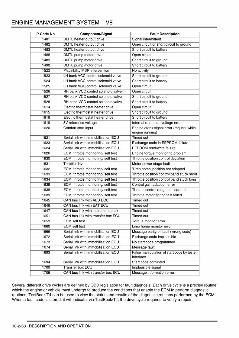
ENGINE MANAGEMENT SYSTEM – V8
Several different drive cycles are defined by OBD legislation for fault diagnosis. Each drive cycle is a precise routine which the engine or vehicle must undergo to produce the conditions that enable the ECM to perform diagnostic routines. TestBook/T4 can be used to view the status and results of the diagnostic routines performed by the ECM. When a fault code is stored, it will indicate, via TestBook/T4, the drive cycle required to verify a repair.
1481 DMTL heater output drive Signal intermittent
1482 DMTL heater output drive Open circuit or short circuit to ground1483 DMTL heater output drive Short circuit to battery1488 DMTL pump motor drive Open circuit
1489 DMTL pump motor drive Short circuit to ground1490 DMTL pump motor drive Short circuit to battery1522 Plausibility MSR intervention No activity
1523 LH bank VCC control solenoid valve Short circuit to ground1524 LH bank VCC control solenoid valve Short circuit to battery1525 LH bank VCC control solenoid valve Open circuit
1526 RH bank VCC control solenoid valve Open circuit1527 RH bank VCC control solenoid valve Short circuit to ground1528 RH bank VCC control solenoid valve Short circuit to battery
1614 Electric thermostat heater drive Open circuit1615 Electric thermostat heater drive Short circuit to ground1616 Electric thermostat heater drive Short circuit to battery
1619 5V reference voltage Internal reference voltage error1620 Comfort start input Engine crank signal error (request while
engine running)1621 Serial link with immobilisation ECU Timed out1623 Serial link with immobilisation ECU Exchange code in EEPROM failure
1624 Serial link with immobilisation ECU EEPROM read/write failure1626 ECM, throttle monitoring/ self test Engine torque monitoring problem1630 ECM, throttle monitoring/ self test Throttle position control deviation
1631 Throttle drive Motor power stage fault1632 ECM, throttle monitoring/ self test 'Limp home' position not adapted1633 ECM, throttle monitoring/ self test Throttle position control band stuck short
1634 ECM, throttle monitoring/ self test Throttle position control band stuck long1635 ECM, throttle monitoring/ self test Control gain adaption error1638 ECM, throttle monitoring/ self test Throttle control range not learned
1639 ECM, throttle monitoring/ self test Throttle motor spring test failed1645 CAN bus link with ABS ECU Timed out1646 CAN bus link with EAT ECU Timed out
1647 CAN bus link with instrument pack Timed out1651 CAN bus link with transfer box ECU Timed out1659 ECM self test Torque monitor error
1660 ECM self test Limp home monitor error1666 Serial link with immobilisation ECU Message parity bit fault (wrong code)1672 Serial link with immobilisation ECU Exchange code implausible
1673 Serial link with immobilisation ECU No start code programmed1674 Serial link with immobilisation ECU Message fault1693 Serial link with immobilisation ECU False manipulation of start code by tester
interface1694 Serial link with immobilisation ECU Start code corrupted
1700 Transfer box ECU Implausible signal1709 CAN bus link with transfer box ECU Message information error
P Code No. Component/Signal Fault Description
18-2-38 DESCRIPTION AND OPERATION
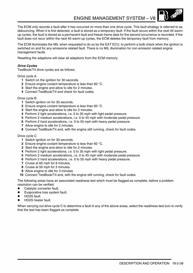
ENGINE MANAGEMENT SYSTEM – V8
The ECM only records a fault after it has occurred on more than one drive cycle. This fault strategy is referred to as debouncing. When it is first detected, a fault is stored as a temporary fault. If the fault recurs within the next 40 warm-up cycles, the fault is stored as a permanent fault and freeze frame data for the second occurrence is recorded. If the fault does not recur within the next 40 warm-up cycles, the ECM deletes the temporary fault from memory.
The ECM illuminates the MIL when requested to do so by the EAT ECU, to perform a bulb check when the ignition is switched on and for any emissions related fault. There is no MIL illumination for non emission related engine management faults.
Resetting the adaptions will clear all adaptions from the ECM memory.
Drive CyclesTestBook/T4 drive cycles are as follows:
Drive cycle A1 Switch on the ignition for 30 seconds.2 Ensure engine coolant temperature is less than 60 °C.3 Start the engine and allow to idle for 2 minutes.4 Connect TestBook/T4 and check for fault codes.
Drive cycle B1 Switch ignition on for 30 seconds.2 Ensure engine coolant temperature is less than 60 °C.3 Start the engine and allow to idle for 2 minutes.4 Perform 2 light accelerations, i.e. 0 to 35 mph with light pedal pressure.5 Perform 2 medium accelerations, i.e. 0 to 45 mph with moderate pedal pressure.6 Perform 2 hard accelerations, i.e. 0 to 55 mph with heavy pedal pressure.7 Allow engine to idle for 2 minutes.8 Connect TestBook/T4 and, with the engine still running, check for fault codes.
Drive cycle C1 Switch ignition on for 30 seconds.2 Ensure engine coolant temperature is less than 60 °C.3 Start the engine and allow to idle for 2 minutes.4 Perform 2 light accelerations, i.e. 0 to 35 mph with light pedal pressure.5 Perform 2 medium accelerations, i.e. 0 to 45 mph with moderate pedal pressure.6 Perform 2 hard accelerations, i.e. 0 to 55 mph with heavy pedal pressure.7 Cruise at 60 mph for 8 minutes.8 Cruise at 50 mph for 3 minutes.9 Allow engine to idle for 3 minutes.
10 Connect TestBook/T4 and, with the engine still running, check for fault codes.
The following areas have an associated readiness test which must be flagged as complete, before a problem resolution can be verified:l Catalytic converter fault.l Evaporative loss system fault.l HO2S fault.l HO2S heater fault.
When carrying out drive cycle C to determine a fault in any of the above areas, select the readiness test icon to verify that the test has been flagged as complete.
DESCRIPTION AND OPERATION 18-2-39
ENGINE MANAGEMENT SYSTEM – V8
Drive cycle D1 Switch ignition on for 30 seconds.2 Ensure engine coolant temperature is less than 35 °C.3 Start the engine and allow to idle for 2 minutes.4 Perform 2 light accelerations, i.e. 0 to 35 mph with light pedal pressure.5 Perform 2 medium accelerations, i.e. 0 to 45 mph with moderate pedal pressure.6 Perform 2 hard accelerations, i.e. 0 to 55 mph with heavy pedal pressure.7 Cruise at 60 mph for 5 minutes.8 Cruise at 50 mph for 5 minutes.9 Cruise at 35 mph for 5 minutes.
10 Allow engine to idle for 2 minutes.11 Connect TestBook/T4 and check for fault codes.
Drive cycle E1 Ensure fuel tank is at least a quarter full.2 Carry out drive cycle A.3 Switch off ignition.4 Leave vehicle undisturbed for 20 minutes.5 Switch on ignition.6 Connect TestBook/T4 and check for fault codes.
18-2-40 DESCRIPTION AND OPERATION

ENGINE MANAGEMENT SYSTEM – V8
DESCRIPTION AND OPERATIONVariable Camshaft Control Components
1 Locking nut2 Impulse wheel3 Camshaft to sprocket retaining screw4 VCC transmission unit5 Bolt6 Oil distribution flange
7 Oil distribution flange gasket8 Inlet camshaft9 Exhaust camshaft
10 Drive train gear retaining bolt11 Check valve12 VCC solenoid valve
DESCRIPTION AND OPERATION 18-2-41

ENGINE MANAGEMENT SYSTEM – V8
VCC System
IntroductionThe variable intake valve timing system on the V8 is known as Variable Camshaft Control (VCC).
The V8 VCC system is a new system providing stepless VCC functionality on each intake camshaft. The system is continuously variable within its range of adjustment providing optimised camshaft positioning for all engine operating conditions.
While the engine is running, both intake camshafts are continuously adjusted to their optimum positions. This enhances engine performance and reduces exhaust emissions.
Both camshafts are adjusted simultaneously within 20° (maximum) of the camshafts rotational axis.
1 VCC transmission unit 2 VCC control solenoid valve
This equates to a maximum span of 40° crankshaft rotation. The camshaft spread angles for both banks are as follows.
M18 0818
20 20
1
2
1
2
18-2-42 DESCRIPTION AND OPERATION

ENGINE MANAGEMENT SYSTEM – V8
A = Valve liftB = Crankshaft rotationC = Open duration 228°D = Open duration 236°
E = Default retardF = Maximum retardG = Exhaust valveH = Intake valve
The design of a camshaft for a non adjustable valve timing system is limited to the required overall performance of the engine.
An intake camshaft with an advanced (early) profile will provide a higher performing power curve at a lower engine speed. But at idle speed the advanced position will create a large area of intake/exhaust overlap that causes a rough, unstable idle.
An intake camshaft with a retarded (late) profile will provide a very smooth, stable idle but will lack the cylinder filling dynamics needed for performance characteristics at mid range engine speeds.
The ability to adjust the valve timing improves the engines power dynamics and reduces exhaust emissions by optimising the camshaft angle for all ranges of engine operation. VCC provides the following benefits:l Increased torque at lower to mid range engine speeds without a loss of power in the upper range engine speedsl Increased fuel economy due to optimised valve timing anglesl Reduction of exhaust emissions due to optimised valve overlapl Smoother idle quality due to optimised valve overlap.
M18 0826
B
H
E
F
A
G
CD
DESCRIPTION AND OPERATION 18-2-43

ENGINE MANAGEMENT SYSTEM – V8
Variable Camshaft Control Electronic ControlThe following describes the electronic control of the VCC system.
Electronic ControlThe engine control module is responsible for activating a VCC variable position solenoid valve based on EMS program mapping. The activation parameters are influenced by the following input signals:l Engine speed l Load (intake air mass)l Engine temperaturel Camshaft position.
Mechanical ControlThe position of the solenoid valve directs the hydraulic flow of engine oil. The controlled oil flow acts on the mechanical components of VCC system to position the camshaft.
The hydraulic engine oil flow is directed through advance or retard activation oil ports by the VCC solenoid. Each port exits into a sealed chamber on the opposite sides of a control piston.
In its default position the oil flow is directed to the rear surface of the piston. This pulls the helical gear forward and maintains the retarded valve timing position.
When the oil flow is directed to the front surface of the piston, the oil pushes the helical gear in the opposite direction which rotates the matched helical gearing connected to the camshaft.
The angled teeth of the helical gears cause the pushing movement to be converted into a rotational movement. The rotational movement is added to the turning of the camshaft providing the variable camshaft positioning.
System ComponentsThe V8 VCC components include the following for each cylinder bank: l Cylinder heads with oil ports for VCCl VCC transmission with sprocketsl Oil distribution flangel Oil check valvel PWM controlled solenoid valvel Camshaft position impulse wheel.
18-2-44 DESCRIPTION AND OPERATION

ENGINE MANAGEMENT SYSTEM – V8
Control Solenoid and Check Valve
A = AdvanceB = RetardC = Vent
The VCC solenoid is a two wire, pulse width modulated, oil pressure control valve. The valve has four ports;1 Input Supply Port, Engine Oil Pressure 2 Output Retard Port, to rear of piston/helical gear (retarded camshaft position)3 Output Advance Port , to front of piston/helical gear (advanced camshaft position) 4 Vent released oil pressure.
A check valve is positioned forward of the solenoid in the cylinder head oil gallery. The check valve maintains an oil supply in the VCC transmission and oil circuits after the engine is turned off. This prevents the possibility of piston movement (noise) within the VCC transmission system on the next engine start.
VCC TransmissionThe primary and secondary timing chain sprockets are integrated with the VCC transmission. The transmission is a self contained unit.
The adjustment of the camshaft occurs inside the transmission, controlled oil pressure then moves the piston axially.
The helical gear cut of the piston acts on the helical gears on the inside surface of the transmission and rotates the camshaft to the specific advanced or retarded angle position.
Three electrical pin contacts are located on the front surface to verify the default maximum retard position using an ohmmeter. This is required during assembly and adjustment. (see service notes further on).
Oil Distribution Flanges:The oil distribution flanges are bolted to the front surface of each cylinder head. They provide a mounting location for the VCC solenoids as well as the advance-retard oil ports from the solenoids to the intake camshafts.
M18 0812A
A B
C
DESCRIPTION AND OPERATION 18-2-45
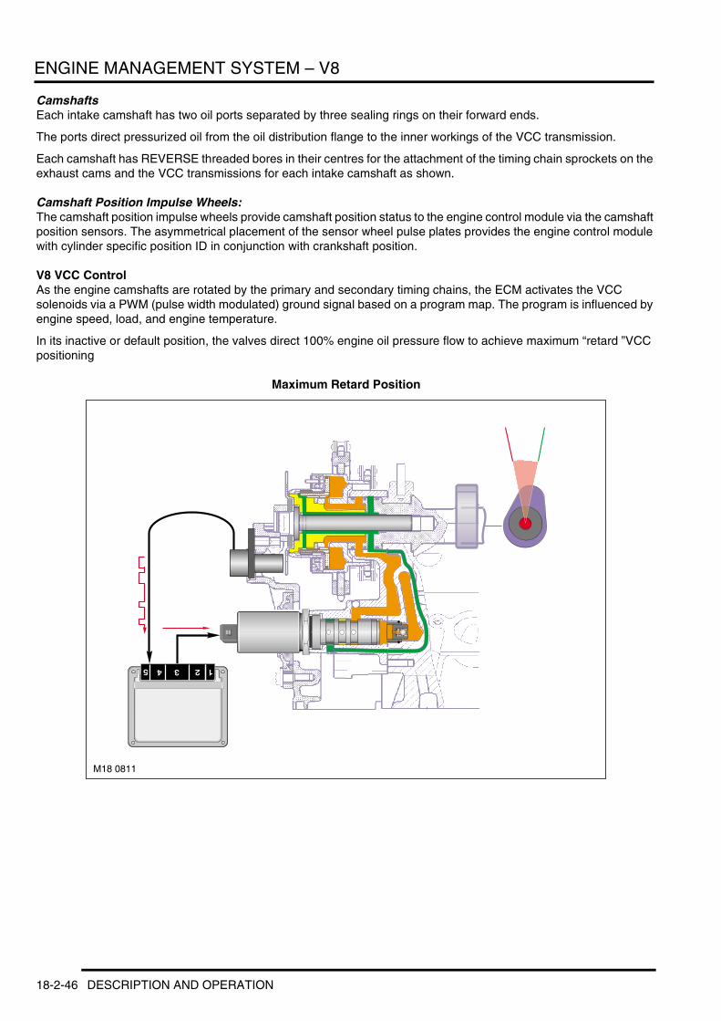
ENGINE MANAGEMENT SYSTEM – V8
CamshaftsEach intake camshaft has two oil ports separated by three sealing rings on their forward ends.
The ports direct pressurized oil from the oil distribution flange to the inner workings of the VCC transmission.
Each camshaft has REVERSE threaded bores in their centres for the attachment of the timing chain sprockets on the exhaust cams and the VCC transmissions for each intake camshaft as shown.
Camshaft Position Impulse Wheels:The camshaft position impulse wheels provide camshaft position status to the engine control module via the camshaft position sensors. The asymmetrical placement of the sensor wheel pulse plates provides the engine control module with cylinder specific position ID in conjunction with crankshaft position.
V8 VCC ControlAs the engine camshafts are rotated by the primary and secondary timing chains, the ECM activates the VCC solenoids via a PWM (pulse width modulated) ground signal based on a program map. The program is influenced by engine speed, load, and engine temperature.
In its inactive or default position, the valves direct 100% engine oil pressure flow to achieve maximum “retard ”VCC positioning
Maximum Retard Position
M18 0811
18-2-46 DESCRIPTION AND OPERATION
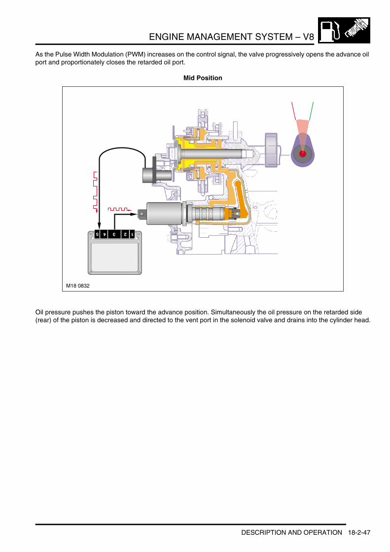
ENGINE MANAGEMENT SYSTEM – V8
As the Pulse Width Modulation (PWM) increases on the control signal, the valve progressively opens the advance oil port and proportionately closes the retarded oil port.
Mid Position
Oil pressure pushes the piston toward the advance position. Simultaneously the oil pressure on the retarded side (rear) of the piston is decreased and directed to the vent port in the solenoid valve and drains into the cylinder head.
M18 0832
DESCRIPTION AND OPERATION 18-2-47
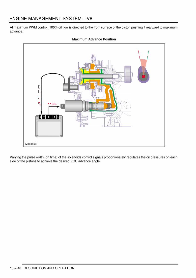
ENGINE MANAGEMENT SYSTEM – V8
At maximum PWM control, 100% oil flow is directed to the front surface of the piston pushing it rearward to maximum advance.
Maximum Advance Position
Varying the pulse width (on time) of the solenoids control signals proportionately regulates the oil pressures on each side of the pistons to achieve the desired VCC advance angle.
M18 0833
18-2-48 DESCRIPTION AND OPERATION

ENGINE MANAGEMENT SYSTEM – V8
VCC Timing ProceduresAlways refer to the Service Procedures Workshop Manual for valve timing procedures. The V8 valve timing adjustment requires the setting of the VCC transmissions to their maximum retard positions with an ohmmeter and attaching the camshaft gears to each camshaft with single reverse threaded bolts.
The process is as follows:l After locking the crankshaft at TDC, the camshaft alignment tools are placed on the square blocks on the rear of
the camshafts locking them in placel The exhaust camshaft sprockets and VCC transmission units with timing chains are placed onto their respective
camshaftsl The exhaust camshaft sprockets and VCC transmissions are secured to the camshafts with their respective
single, reverse threaded bolt. Finger tighten only at this point. Install the chain tensioner into the timing chain case and tension the chain
l Connect an ohmmeter across two of the three pin contacts on the front edge of one of the VCC transmissions. Twist the inner hub of transmission to the left (counter clock- wise). Make sure the ohmmeter indicates closed circuit. This verifies that the trans- mission in the default maximum retard position
l Using an open end wrench on the camshaft to hold it in place, torque the VCC trans- mission centre bolt to specification.
Camshaft Impulse Wheel Position ToolsThe camshaft impulse wheels require a special tool set to position them correctly prior to torquing the retaining nuts.
The impulse wheels are identical for each cylinder bank. The alignment hole in each wheel must align with the tools alignment pin. Therefore the tools are different and must be used specifically for their bank.
The tool rests on the upper edge of the cylinder head and is held in place by the timing case bolts.
VCC Solenoid ReplacementRefer to the Service Procedures Workshop Manual for complete solenoid replacement procedure.
The solenoids are threaded into the oil distribution flanges through a small opening in the upper timing case covers.
VCC Transmission Retard Position Set Up ToolsA special tool (see Service Procedures Workshop Manual for correct tool number) is used to rotate the transmission to the full retard position when checking the piston position with an ohmmeter.
This tool engages the inner hub of the transmission to provide an easy method of twisting it to the left for the ohmmeter test.
DiagnosticsThe VCC is fully compatible with the diagnostic software providing specific fault codes and test modules. Additionally, diagnostic requests section provides status of the PWM of the VCC solenoids and camshaft position feedback via the camshaft position sensors. The Service Functions section of the TestBook/T4 also provides a VCC system test.
DESCRIPTION AND OPERATION 18-2-49

ENGINE MANAGEMENT SYSTEM – V8
DESCRIPTION AND OPERATIONCruise Control Component Location
1 Diagnostic socket2 Instrument pack3 Cruise control switch pack4 Main fuse5 ABS/DSC ECU
6 Brake light switch7 Accelerator pedal position sensor (APP)8 Electric throttle.9 EMS ECU
18-2-50 DESCRIPTION AND OPERATION

ENGINE MANAGEMENT SYSTEM – V8
Cruise Control System Control Diagram
A = Hardwired connections; D = CAN bus; J = ISO 9141 K line bus; K = I bus
M18 0817AKA
1 2
3
4
6
7
9
8
10
12
13
11
JJD
5
DESCRIPTION AND OPERATION 18-2-51

ENGINE MANAGEMENT SYSTEM – V8
1 Main fuse2 Cruise control switch pack3 Rotary coupler4 Instrument pack5 EAT ECU6 ABS/DSC ECU7 Brake light switch8 Diagnostic socket9 Electric throttle
10 Accelerator pedal position sensor (APP)11 ECM12 Fuse 9, switch supply (5 amp)13 Ignition switch
18-2-52 DESCRIPTION AND OPERATION

ENGINE MANAGEMENT SYSTEM – V8
Cruise Control
GeneralCruise control functionality is fully integrated into the ECM and uses electric throttle intervention to automatically maintain a set vehicle speed. Once engaged, the system can also be used to accelerate the vehicle without using the accelerator pedal. The cruise control system consists of:l Cruise control master switchl +/- Speed switchl Resume switchl EMS ECUl Electric throttle.
The Controller Area Network (CAN) bus is used by the cruise control system for the exchange of data between the ECM, EAT ECU, DSC ECU and instrument pack.
Cruise control is enabled when the master switch is pressed. Once enabled, the cruise control system is operated using the steering wheel switches. The steering wheel switches output a serial data stream to the ECM, the ECM then adjusts the electric throttle to maintain the vehicle at the set speed.
The cruise control warning lamp provides a visual indication of when the system is engaged.
Master SwitchThe master switch controls a feed to the ECM to enable the system. The switch is a momentary contact push switch on the left hand steering wheel switch pack.
Steering Wheel SwitchesThe steering wheel switches, SET+ and RES, are non latching push switches that engage and disengage cruise control and adjust the set speed. While pressed, the switches supply a serial data stream to the ECM to adjust the set speed.
ECMThe ECM receives serial data from the steering wheel switches, which are interpreted by the ECM to operate cruise control. The ECM also controls the output of a cruise engaged signal to the EAT ECU.
The ECM incorporates a software module and associated components to enable cruise control operation by direct control of the electric throttle. In addition to controlling the throttle, the software module monitors hardwired and CAN bus inputs to the ECM and prevents or suspends cruise control operation when the vehicle is not in the correct driving configuration.
While the master switch is selected off, only the OFF message can be transmitted. When the master switch is selected on, the power feed from the switch enables the interface switches to send either the SET or RESUME messages, depending on the inputs from the steering wheel switches and the cruise control status message from the CAN bus. When the master switch is first switched on, the output of the RESUME message is automatically inhibited until after the first engagement of cruise control.
When cruise control is engaged, the ECM outputs a signal on CAN to the EAT ECU to provide a cruise control engaged signal. The EAT ECU uses the signal to switch between normal and cruise control modes of operation.
Brake Pedal Sensor Outputs from the brake pedal sensor are supplied to the ECM to enable the system to detect when the brakes are applied. The brake pedal sensor is a Hall effect sensor that produces two outputs. Both outputs should be 0 to 2 volts while the brake pedal is released. When the brake pedal is pressed, the Brake Lamp Switch (BLS) output increases to between 6 and battery volts, the Brake Lamp Test Switch (BLTS) output increases to between 10 and battery volts.
DESCRIPTION AND OPERATION 18-2-53

ENGINE MANAGEMENT SYSTEM – V8
Cruise Control OperationCruise control is operated from the steering wheel mounted switches. Switch symbols are market dependent! There are 4 switches for cruise control.
1 Cruise control ON/OFF switch (O/I)2 Cruise control accelerate/tip-up switch (+)3 Cruise control decelerate/tip-down switch (-)4 Cruise control resume switch.
The driver can enable cruise control at any time by pressing the ON/OFF (O/I) switch. Pressing this switch places the cruise control function into "stand by mode" and illuminates the instrument pack mounted cruise control lamp.
When in "stand-by" mode, pressing the "+", "-" or "RESUME " cruise switch once will activate the cruise control function and set the "set speed" equal to the current vehicle speed.
Note that the vehicle speed has to be greater than the minimum cruise control speed value of 26 km/h (16 mph) for the cruise control function to operate. There is no maximum speed limit.
Once the cruise control function is active, switch presses will have the following actions:l Each "short" press on the "+" switch will cause the "set speed" to be increased by 1 km/h (tip-up functionl Each "short" press on the "-" switch will cause the "set speed" to be decreased by 1 km/h (tip-down function).
Note that the "set speed" cannot be adjusted to lower than the minimum cruise control speed valuel A "continuous" press on the "+" switch will cause the vehicle to accelerate until the switch is released. The vehicle
speed at the point the switch is released becomes the new "set speed"l A "continuous" press on the "-" switch will cause the vehicle to decelerate until the switch is released. The vehicle
speed at the point the switch is released becomes the new "set speed". Note that the "set speed" cannot be adjusted to lower than the minimum cruise control speed value
l A press on the "RESUME" switch when returned to "stand-by" mode will re-activate the cruise control function using the remembered "set speed".
Other aspects of the cruise control function are:l Pedal over-ride function
l If the driver uses the accelerator pedal while cruise control is active, the "set speed" remains unchanged. Hence when the driver releases the accelerator pedal, the cruise control function will remain active and return the vehicle to the current "set speed"
l If the driver presses the "+" or "-" switches during pedal over-ride, the "set speed" will change to the actual vehicle speed when the switch is pressed.
l The cruise control function is not available in "low range". Note however, that if cruise control was active or in stand-by mode when low range was selected, the cruise function will automatically return to stand-by mode when high range is re-engaged, and the previous set speed is remembered.
l When in stand-by mode, pressing the "I/O" switch will disable the cruise control function, switch OFF the instrument pack mounted cruise control lamp, and the "set speed" will be lost
l The cruise control function will change from "active" to "stand-by" modes if:l The driver brakesl The driver presses the "O/I" switchl The driver moves from "D" to "N" l The driver selects "low range"l The DSC system activates above a defined level. This should be indicated to the driver by the instrument pack
"DSC active" warning lamp.
18-2-54 DESCRIPTION AND OPERATION

ENGINE MANAGEMENT SYSTEM – V8
DESCRIPTION AND OPERATIONEVAP System
1 Charcoal canister vent hose2 Atmospheric vent pipe
3 Vapour separator4 Charcoal canister
DESCRIPTION AND OPERATION 18-2-55

ENGINE MANAGEMENT SYSTEM – V8
Emissions
Evaporative Emissions (EVAP) Purge ValveThe EVAP purge valve is located on the LH side of the engine in the line between the charcoal canister and the inlet manifold. The EVAP purge valve is part of the EVAP control system and is used to control the extraction of fuel vapour stored in the EVAP canister.
The EVAP control system reduces the level of hydrocarbons released into the atmosphere by fuel vapour venting from the fuel tank. The system comprises fuel cut off valves, a vapour separator, a two way valve, vent lines, the canister and the purge valve.
Purge Valve
The ECM controls the amount of vapour drawn from the charcoal canister by controlling the length of time the purge valve is open. It controls the length of time it is open by supplying the purge valve with a PWM voltage. Control is used to maintain the required level of emissions, as a hydrocarbon vapour level of 1% can affect the air/fuel ratio by as much as 20%.
The ECM can diagnose faults with the purge valve and will store the related fault codes, along with details of the engine speed, battery voltage and intake air temperature. The driver may notice the following effects if the purge valve fails in the open position:l The engine may stall periodically when returning to idlel The engine may suffer from poor idle quality
18-2-56 DESCRIPTION AND OPERATION

ENGINE MANAGEMENT SYSTEM – V8
Secondary Air InjectionThe ECM controls the secondary air injection which is used to quickly heat the catalytic converters for emission legislation compliance.
1 Non return valve2 Vacuum vent valve
3 Vacuum reservoir4 SAI pump
The ECM controls the vacuum vent valve and the air injection pump relay. The air pump operates at a start temperature of between –9°C and 50°C. The pump continues to operate for a maximum of 2 minutes, when the engine speed drops to idle.
Note that the secondary air valve is always open when the air pump is operating.
The secondary air injection system is used to limit the emission of carbon monoxide (CO) and hydrocarbons (HC) that are prevalent in the exhaust during cold starting of a spark ignition engine. The concentration of hydrocarbons experienced during cold starting at low temperatures are particularly high until the engine and catalytic converter reach normal operating temperature. The lower the cold start temperature, the greater the prevalence of hydrocarbons emitted from the engine.
3
2
M19 3550
1
4
DESCRIPTION AND OPERATION 18-2-57

ENGINE MANAGEMENT SYSTEM – V8
There are several reasons for the increase of HC emissions at low cold start temperatures, including the tendency for fuel to be deposited on the cylinder walls, which is then displaced during the piston cycle and expunged during the exhaust stroke. As the engine warms up through operation, the cylinder walls no longer retain a film of fuel and most of the hydrocarbons will be burnt off during the combustion process.
The SAI pump is used to provide a supply of air into the exhaust ports in the cylinder head, onto the back of the exhaust valves, during the cold start period. The hot unburnt fuel particles leaving the combustion chamber mix with the air injected into the exhaust ports and immediately combust. This subsequent combustion of the unburnt and partially burnt CO and HC particles help to reduce the emission of these pollutants from the exhaust system. The additional heat generated in the exhaust manifold also provides rapid heating of the exhaust system catalytic converters. The additional oxygen which is delivered to the catalytic converters also generate an exothermic reaction which causes the catalytic converters to 'light off' quickly.
The catalytic converters only start to provide effective treatment of emission pollutants when they reach an operating temperature of approximately 250°C (482°F) and need to be between temperatures of 400°C (752°F) and 800°C (1472°F) for optimum efficiency. Consequently, the heat produced by the secondary air injection “after burning”, reduces the time delay before the catalysts reach an efficient operating temperature.
The engine control module (ECM) checks the engine coolant temperature when the engine is started, and if it is above -9º C but below 75°C, the SAI pump is started. Secondary air injection will remain operational for a period controlled by the ECM. The SAI pump operation can be cut short due to excessive engine speed or load.
Air from the SAI pump is supplied to the cylinder head, via a metal pipe which splits the air flow evenly to each bank.
At the same time the secondary air pump is started, the ECM operates a SAI vacuum solenoid valve, which opens to allow vacuum from the reservoir to be applied to the non return valve on the metal delivery tube on the engine. Secondary air is injected into the inner most exhaust ports on each bank.
When the ECM breaks the ground circuit to de-energise the SAI vacuum solenoid valve, the vacuum supply to the SAI non return valve is cut off and the valve is closed to prevent further air being injected into the exhaust manifold. At the same time as the SAI vacuum solenoid valve is closed, the ECM opens the ground circuit to the SAI pump relay, to stop the SAI pump.
A vacuum reservoir is included in the vacuum line between the intake manifold and the SAI vacuum solenoid valve. This prevents changes in vacuum pressure from the intake manifold being passed on to cause fluctuations of the secondary air injection solenoid valve. The vacuum reservoir contains a one way valve and ensures a constant vacuum is available for the SAI vacuum solenoid valve operation. This is particularly important when the vehicle is at high altitude.
18-2-58 DESCRIPTION AND OPERATION

ENGINE MANAGEMENT SYSTEM – V8
Secondary Air Injection System ComponentsThe secondary air injection (SAI) system components are described below:
Secondary Air Injection (SAI) Pump
The SAI pump is attached to a bracket at the front LH side of the engine compartment and is fixed to the bracket by three studs and nuts. The pump is electrically powered from a 12V battery supply via a dedicated relay and supplies approximately 35kg/hr of air when the vehicle is at idle in Neutral/Park on a start from 20°C (68°F).
Air is drawn into the pump from the "clean" side of the air cleaner. The air is delivered to the cylinder head on each side of the engine through a metal pipe.
The foam filter in the air intake of the SAI pump provides noise reduction and protects the pump from damage due to particulate contamination.
If the secondary air injection pump malfunctions, fault codes may be stored in the ECM diagnostic memory, which can be retrieved using Testbook/T4.
Secondary Air Injection (SAI) Pump RelayThe secondary air injection pump relay, coloured pink for identification, is located in the E-Box. The engine control module (ECM) is used to control the operation of the SAI pump via the SAI pump relay. Power to the coil of the relay is supplied from the vehicle battery via the main relay and the ground connection to the coil is via the ECM.
Secondary Air Injection Non Return ValveThe secondary air injection non return valve is located on the steel air delivery tube at the front of the engine. The valve is controlled by the ECM via the vacuum vent solenoid.
Vacuum Vent Valve
DESCRIPTION AND OPERATION 18-2-59
ENGINE MANAGEMENT SYSTEM – V8
18-2-60 DESCRIPTION AND OPERATION

FUEL DELIVERY SYSTEM – TD6
FUEL DELIVERY SYSTEM – Td6DESCRIPTION AND OPERATIONTd6 Fuel Delivery Component Location – Sheet 1 of 2
1 Cooling fan (hot climate markets only)2 Fuel cooler3 Fuel temperature sensor housing4 Fuel temperature sensor5 Fuel filter
6 Bimetallic valve7 High pressure fuel pump8 Fuel rail9 Spill return pipe.
10 Fuel rail pressure sensor
M19 3541
79
8
10
2
6
5
1
3 4
DESCRIPTION AND OPERATION 19-1-1
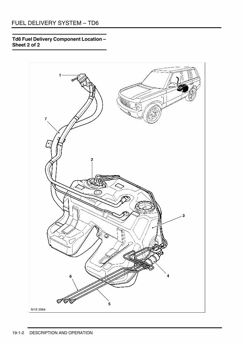
FUEL DELIVERY SYSTEM – TD6
Td6 Fuel Delivery Component Location – Sheet 2 of 2
19-1-2 DESCRIPTION AND OPERATION

FUEL DELIVERY SYSTEM – TD6
1 Fuel filler cap2 Fuel pump3 Fuel tank4 Secondary fuel pump5 Fuel return pipe6 Fuel delivery pipe7 Fuel filler tube
DESCRIPTION AND OPERATION 19-1-3

FUEL DELIVERY SYSTEM – TD6
Td6 Fuel System Schematic
M19 3585
1516
12
3
10
9
6
5
7 8
11
13
12
144
19-1-4 DESCRIPTION AND OPERATION

FUEL DELIVERY SYSTEM – TD6
1 Common rail2 Fuel rail pressure sensor3 Injector4 Bi-metal valve5 Fuel cooler6 Fan temperature switch7 Fuel temperature sensor8 Electric fan9 Restrictor
10 Fuel pump11 Secondary fuel pump12 Fuel filter13 LP Pressure sensor14 Differential pressure valve15 High pressure fuel pump16 Pressure control valve
DESCRIPTION AND OPERATION 19-1-5

FUEL DELIVERY SYSTEM – TD6
Description
GeneralThe Td6 is equipped with a high pressure common rail fuel injection system. With this fuel injection process, a high pressure pump delivers a uniform level of pressure to the shared fuel line (the common rail) which serves all the fuel injection valves. Pressure develops to the optimum level for smooth operation. This means that each injector nozzle is capable of delivering fuel at spray pressures of up to 1350 bar.
The common rail system disconnects fuel injection and pressure generation functions. Fuel injection pressure is generated independently of engine speed and fuel injection volume and is available in the "Rail" for injection to the cylinders.
The fuel injection timing and volume are calculated in the DDE and delivered to each engine cylinder by the injectors, each of which is actuated by energizing the appropriate solenoid valve.
The fuel system is divided into 2 sub systems:l Low pressure system l High pressure system.
The low pressure system features the following components:l Fuel tank l Advance delivery pumpl Outlet protection valvesl Auxiliary delivery pumpl Fuel filter with inlet pressure sensorl Pressure relief valve (LP system)l Fuel cooler.
The high pressure system features the following components:l High pressure pumpl High pressure common raill Pressure control valvel Rail pressure sensorl Injectors.
The low pressure system pressure is approx. 1.5 bar to 5 bar and return end < 0.6 bar. The pressure in the high pressure end is 200 bar to 1350 bar.
Fuel TankThe fuel tank is a saddle type tank and is constructed from moulded plastic. It is located towards the rear of the vehicle just in front of the rear axle. The fuel tank has a 100 litre capacity with a fuel warning lamp in the instrument pack which is activated when the fuel level reaches 10 litres. The tank incorporates one roll over valve to prevent fuel leakage through the vent in the event of an accident.
19-1-6 DESCRIPTION AND OPERATION

FUEL DELIVERY SYSTEM – TD6
Advance Delivery Pump
The electrical fuel pump is located inside the fuel tank in the left hand side of the tank.
The pump transports fuel from the fuel swirl pot towards the "engine" and operates the syphon jet pumps in the left and right sides of the tank. Both syphon jet pumps deliver fuel to the fuel swirl pot in the right side of the tank.
The pump is controlled by the ECM via the fuel pump relay.
Should the fuel pump electrical connection need to be disconnected, it is imperative that the ignition should be switched off. If the ignition is on in any position the fuel gauge will memorise its last needle position prior to power down. Once power is restored the gauge will display the last remembered position regardless of the actual level of fuel in the tank. This could result in incorrect fuel gauge readings if the fuel tank has been drained and not filled worth exactly the same quantity of fuel that was removed.
DESCRIPTION AND OPERATION 19-1-7

FUEL DELIVERY SYSTEM – TD6
Secondary Pump
Secondary Pump
The secondary fuel pump is located on the side of the fuel tank. The pump is an in line electric pump and boosts the fuel pressure for delivery to the High pressure pump. The pump is activated at the same time as the electric fuel pump by the ECM controlling the fuel pump relay.
High Pressure Fuel Injection PumpThe high pressure fuel injection pump is located at the front of the engine and is driven by a chain from the crankshaft. The pump has maximum delivery pressure of 1350 bar.
The high pressure pump is the interface between the low pressure and the high pressure fuel systems. The pump has the task of ensuring that there is always enough fuel delivered at a sufficient pressure in operating conditions over the entire service life of the vehicle. This includes the delivery of spare fuel, required for a rapid start and pressure increase in the fuel rail.
19-1-8 DESCRIPTION AND OPERATION

FUEL DELIVERY SYSTEM – TD6
High Pressure Fuel Pump Cross Section
1 Drive shaft2 Cam3 Piston4 Chamber5 Inlet valve6 Pressure valve7 HP supply to fuel rail
8 Pressure control valve9 Ball valve
10 HP return11 LP fuel supply12 Safety valve with throttle bore13 LP fuel gallery
Fuel is delivered via the filter to the high pressure fuel pump intake and the safety valve situated behind it. It is forced through the throttle bore into the low pressure duct. This duct is connected to the lubrication and coolant circuit of the high pressure pump. It is therefore not connected to an oil circuit.
The drive shaft is driven via the chain drive at more than half of the engine speed (max. 3300 rpm). It moves the three pump pistons up and down with its eccentric cam, depending on the cam shape.
If the pressure in the low-pressure duct exceeds the opening pressure of the suction valve (0.5 -1.5 bar), the advance delivery pump can force fuel into the element chamber where the pump piston moves downwards (suction stroke). If the dead centre point of the pump piston is exceeded, then the intake valve closes. The fuel in the element chamber can no longer escape. It is then compressed in the intake line by the delivery pressure. The accumulating pressure opens the exhaust valve as soon as the pressure in the rail is achieved. The compressed fuel enters the high pressure system.
The pump piston delivers fuel until the upper dead centre point is reached (delivery stroke). The pressure then falls again, which closes the outlet valve. The remaining fuel is no longer subject to pressure. The pump piston moves downwards.
If the pressure in the element chamber falls below the pressure in the low pressure duct, then the intake valve opens again. The whole process is repeated from the beginning.
The high pressure pump constantly generates the system pressure for the high pressure accumulator (rail). The pressure in the rail is determined by the pressure control valve.
The high pressure is generated by means of three pump pistons arranged radially within the high pressure pump. Three delivery strokes per revolution ensure low injection torque and uniform load over the pump drive. At 16 Nm, the average torque is only approx. 1/9 of the drive torque required for a comparable distributor pump.
M19 3609
10
12
3
4 56
7
89
11
12
13
4
3
5
DESCRIPTION AND OPERATION 19-1-9
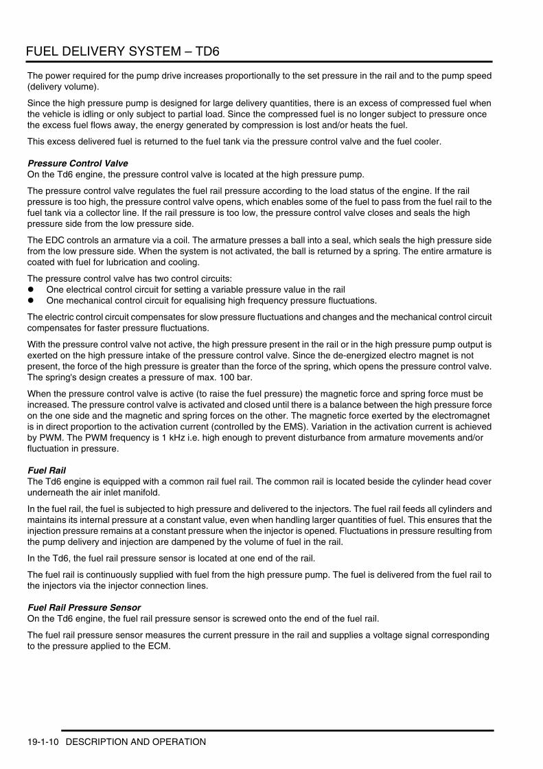
FUEL DELIVERY SYSTEM – TD6
The power required for the pump drive increases proportionally to the set pressure in the rail and to the pump speed (delivery volume).
Since the high pressure pump is designed for large delivery quantities, there is an excess of compressed fuel when the vehicle is idling or only subject to partial load. Since the compressed fuel is no longer subject to pressure once the excess fuel flows away, the energy generated by compression is lost and/or heats the fuel.
This excess delivered fuel is returned to the fuel tank via the pressure control valve and the fuel cooler.
Pressure Control ValveOn the Td6 engine, the pressure control valve is located at the high pressure pump.
The pressure control valve regulates the fuel rail pressure according to the load status of the engine. If the rail pressure is too high, the pressure control valve opens, which enables some of the fuel to pass from the fuel rail to the fuel tank via a collector line. If the rail pressure is too low, the pressure control valve closes and seals the high pressure side from the low pressure side.
The EDC controls an armature via a coil. The armature presses a ball into a seal, which seals the high pressure side from the low pressure side. When the system is not activated, the ball is returned by a spring. The entire armature is coated with fuel for lubrication and cooling.
The pressure control valve has two control circuits:l One electrical control circuit for setting a variable pressure value in the raill One mechanical control circuit for equalising high frequency pressure fluctuations.
The electric control circuit compensates for slow pressure fluctuations and changes and the mechanical control circuit compensates for faster pressure fluctuations.
With the pressure control valve not active, the high pressure present in the rail or in the high pressure pump output is exerted on the high pressure intake of the pressure control valve. Since the de-energized electro magnet is not present, the force of the high pressure is greater than the force of the spring, which opens the pressure control valve. The spring's design creates a pressure of max. 100 bar.
When the pressure control valve is active (to raise the fuel pressure) the magnetic force and spring force must be increased. The pressure control valve is activated and closed until there is a balance between the high pressure force on the one side and the magnetic and spring forces on the other. The magnetic force exerted by the electromagnet is in direct proportion to the activation current (controlled by the EMS). Variation in the activation current is achieved by PWM. The PWM frequency is 1 kHz i.e. high enough to prevent disturbance from armature movements and/or fluctuation in pressure.
Fuel RailThe Td6 engine is equipped with a common rail fuel rail. The common rail is located beside the cylinder head cover underneath the air inlet manifold.
In the fuel rail, the fuel is subjected to high pressure and delivered to the injectors. The fuel rail feeds all cylinders and maintains its internal pressure at a constant value, even when handling larger quantities of fuel. This ensures that the injection pressure remains at a constant pressure when the injector is opened. Fluctuations in pressure resulting from the pump delivery and injection are dampened by the volume of fuel in the rail.
In the Td6, the fuel rail pressure sensor is located at one end of the rail.
The fuel rail is continuously supplied with fuel from the high pressure pump. The fuel is delivered from the fuel rail to the injectors via the injector connection lines.
Fuel Rail Pressure SensorOn the Td6 engine, the fuel rail pressure sensor is screwed onto the end of the fuel rail.
The fuel rail pressure sensor measures the current pressure in the rail and supplies a voltage signal corresponding to the pressure applied to the ECM.
19-1-10 DESCRIPTION AND OPERATION

FUEL DELIVERY SYSTEM – TD6
Fuel Rail Pressure Sensor Cross Section
1 Electrical connections2 Evaluation switch3 Diaphragm with sensor elements
4 High pressure connection5 Retaining thread
The fuel reaches a sensor diaphragm through the high pressure connection. There is a sensor element located on this diaphragm (semiconductor component) to convert the changes in shape caused by pressure into an electrical signal. The signal generated is sent to an evaluation switch via connecting lines, which relays the prepared measuring signal to the control unit via the connections. The diaphragm's electrical resistance varies when its shape changes. This change in shape (approx. 1 mm per 500 bar) created by the accumulation of system pressure alters the electrical resistance and changes the voltage of the resistance bridge which has a supply of 5 volts. This voltage is in the 0 - 70 mV range (depending on the pressure) and is increased by the evaluation switch to a range of 0.5 - 4.5 volts. The exact measurement of the rail pressure is essential if the system is to function correctly. For this reason, the permissible tolerance ranges for the pressure sensor are also kept to a minimum when the pressure is measured. In the main operating range, the measuring precision is at 30 bar, i.e. at approx. ± 2 from the final value. If the rail pressure sensor malfunctions, the pressure control valve is activated by the control unit's emergency function.
M19 3569
2
3
4
5
1
DESCRIPTION AND OPERATION 19-1-11

FUEL DELIVERY SYSTEM – TD6
InjectorsThe injectors are arranged in the central area above the combustion chambers in the cylinder head.
Injector Cross Section
1 Fuel return (outlet)2 Electrical connection3 Activation unit (2/2 solenoid valve)4 Fuel supply (inlet), high pressure from rail5 Valve control chamber6 Ball valve
7 Inlet throttle8 Outlet throttle9 Valve control piston
10 Supply channel to nozzle11 Nozzle needle
M19 3570
11
10
9
7
65
4
3
21
4
8
19-1-12 DESCRIPTION AND OPERATION

FUEL DELIVERY SYSTEM – TD6
The injector can be divided into four main sections:l Hole nozzle with injector needlel Hydraulic servo systeml Solenoid valvel Connections and fuel channels.
The high pressure connection (4) guides the fuel through channel (10) to the nozzle and also through the supply throttle (7) in the control chamber (5).
The control chamber is connected to the fuel return line (1) by the outlet throttle (8), which is opened by a solenoid valve. When the outlet throttle is closed, hydraulic force on the valve piston (9) exceeds that on the pressure stage of the injector needle (11). Consequently, the injector needle is pressed into seat and seals the high pressure channel off from the engine compartment. Fuel cannot enter the combustion chamber, although it is constantly pressurized at the high pressure connection.
When the injector activation unit is actuated (2/2 solenoid valve), the outlet throttle is opened. This reduces the pressure in the control chamber, and therefore the hydraulic force on the valve piston.
As soon as the hydraulic force drops below that on the pressure stage of the injector needle, the injector needle opens, which allows the fuel to enter the combustion chamber through the spray apertures.
This indirect activation of the injector needle via a hydraulic force increasing system is used because the force required to open the injector needle using the solenoid valve cannot be produced directly. The control quantity required in addition to the fuel quantity injected enters the fuel return line via the control chamber throttle.
In addition to the pilot control volume, fuel is also lost (leakage quantity) at the nozzle needle and valve piston guides.
The control and leakage quantities can be up to 50 mm3 per stroke. They are guided back to the fuel tank via the fuel return line with a manifold, to which the overflow valve, high pressure pump and pressure control valve are connected.
The function of the injector can be subdivided into four operating statuses when the engine is running and the high pressure pump is delivering fuel:l Injector closed (under high pressure)l Injector opens (start of injection)l Injector fully openl Injector closes (end of injection).
These operating statuses are applied according to the distribution of force amongst the components of the injectors. If the engine is not running and there is an absence of pressure in the rail, the nozzle spring closes the injector.
When at rest, the 2/2-solenoid valve is not activated and is therefore closed. Because the outlet throttle is closed, the armature ball is pressed into the lodgment at the drain throttle by the valve spring. The rail high pressure accumulates in the valve control chamber. The same pressure is also exerted in the chamber volume of the nozzle. The forces applied by the pressure to the surfaces of the control piston and the force of the nozzle spring keeps the injector needle closed against the opening force attacking its pressure stage.
Wen the injector starts to open the 2/2-solenoid valve is activated by the starting current (I = 20 amps), which enables the 2/2 solenoid valve to be opened quickly. The force of the activated electromagnet exceeds that of the valve spring and the armature opens the final throttle. After a maximum of 450 ms, the increased starting current (I = 20 amps) is reduced to a lower retaining current of the electromagnet (I= 12 amps). This is possible because the air gap of the magnetic circuit is now smaller.
Opening the drain throttle allows fuel to flow out of the valve control chamber into the cavity above, and then to the fuel tank via the fuel return line. The inlet throttle prevents complete compensation from taking place and the pressure in the valve control chamber drops. As a consequence, the pressure in the valve control chamber is lower than the pressure in the chamber volume of the nozzle which still has the same level of pressure as the rail. The reduced pressure in the valve control chamber leads to less pressure being exerted on the control piston and to the injector needle being opened. Injection commences.
The speed at which the injector needle opens is determined by the difference in throughput in the inlet and outlet throttle. After a stroke of approx. 200 mm, the control piston reaches its upper limit point and stays there, supported by a cushion of fuel. The cushion is created by the flow of fuel between the inlet and outlet throttle. The injector nozzle is now completely open and the fuel is injected into the combustion chamber at a pressure approaching that of the pressure in the rail.
DESCRIPTION AND OPERATION 19-1-13

FUEL DELIVERY SYSTEM – TD6
At the end of injection, the 2/2 solenoid valve is no longer activated, then the armature is forced downwards by the force of the valve spring. The ball then closes the outlet throttle. To prevent excessive wear from the contact between the ball and the valve seat, lodgment, the armature consists of two parts. Although the armature plate is guided downwards by a cam, it can also oscillate downwards by means of the reset spring, thereby preventing the armature and ball from being subject to any downward forces. As in the rail, closing the outlet throttle causes pressure to accumulate in the control compartment through the inlet of the inlet throttle. This increased pressure exerts greater force on the surface at the head end of the control piston. This force from the valve control chamber and the spring force exceed the force from the chamber volume, the injector needle closes. The speed at which the injector needle closes is determined by the throughput of the inlet throttle. Injection stops once the nozzle needle reaches its lower limit point.
Fuel FilterThe fuel filter is located in the engine compartment on the left hand side.
The fuel filter cleans fuel before the high pressure pump and prevents premature wear to delicate components. Insufficient filtration can cause damage to pump components, pressure valves and fuel injection nozzles.
To prevent paraffin residue from clogging up the filter at low temperatures, there is a bimetal valve in the return line. This valve prevents heated fuel residue from mixing with cool fuel from the tank.
Incorporated into the fuel filter is a fuel pressure sensor. This sensor measures the pressure of the fuel being delivered to the high pressure fuel pump. This enables the ECM to reduce the fuel injection quantity at excessively low inlet pressures to the point where engine speed and rail pressure are reduced accordingly. The volume required at the inlet of the high pressure pump is reduced. This makes it possible for the inlet pressure to the high pressure pump to rise back to the required level.
At an inlet pressure of < 1.5 bar, the high pressure pump can be damaged due to inadequate fill.
Another pump protection feature is that should the inlet pressure difference between the inlet and the return fuel lines ≤ 0.5 bar develops the engine can stall suddenly.
Pressure Relief ValveThe pressure relief valve is located between the fuel filter and the high pressure pump. It is located in the connecting line between the inlet line before the high pressure pump and the return line after the high pressure pump.
The pressure relief valve limits the inlet pressure to the high pressure pump from 2.0 to between 2.0 and 3.0 bar. This relieves excess pressure by diverting fuel into the return line. The pressure relief valve protects the high pressure pump and the secondary pump from overloads.
Fuel Temperature ControlFuel temperature is controlled by a thermocouple (bimetal valve). If the returning fuel is ≤ 85°C the fuel is returned directly to the fuel tank. If the returning fuel is ≥ 85ºC the fuel is returned via the fuel cooler. On cold start up the warm fuel is partial (75%) redirected to the secondary fuel pump which pumps the fuel back into the system to improve cold starting characteristics.
If the bimetal valve allows the fuel to return to the tank, the fuel flows through a cooler. Cool external air enters the cooler through a ducted air guide and flows through the fuel cooler. In hotter climate markets there is an electric fan located in the ducting. The fan assists the fuel cooling by drawing extra air past the cooler thus improving the fuel cooling characteristics.
19-1-14 DESCRIPTION AND OPERATION
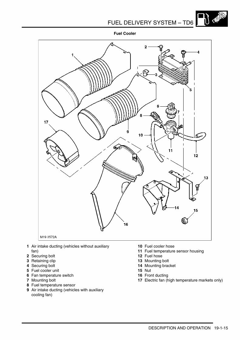
FUEL DELIVERY SYSTEM – TD6
Fuel Cooler
1 Air intake ducting (vehicles without auxiliary fan)
2 Securing bolt3 Retaining clip4 Securing bolt5 Fuel cooler unit6 Fan temperature switch7 Mounting bolt8 Fuel temperature sensor9 Air intake ducting (vehicles with auxiliary
cooling fan)
10 Fuel cooler hose11 Fuel temperature sensor housing12 Fuel hose13 Mounting bolt14 Mounting bracket15 Nut16 Front ducting17 Electric fan (high temperature markets only)
DESCRIPTION AND OPERATION 19-1-15

FUEL DELIVERY SYSTEM – TD6
19-1-16 DESCRIPTION AND OPERATION

FUEL DELIVERY SYSTEM – V8
Deze pagina werd opzettelijk niet gebruikt
Cette page est intentionnellement vierge
Questa pagina è stata lasciata in bianco di proposito
Diese Seite ist leer
Esta página foi deixada intencionalmente em branco
Esta página fue dejada en blanco intencionalmente
This page is intentionally left blank
FUEL DELIVERY SYSTEM – V8DESCRIPTION AND OPERATION
DESCRIPTION AND OPERATION 19-2-1

FUEL DELIVERY SYSTEM – V8
Fuel Delivery System Component Location (All Except NAS)
19-2-2 DESCRIPTION AND OPERATION

FUEL DELIVERY SYSTEM – V8
1 Fuel filler cap2 Fuel pump3 Fuel tank4 Fuel filter/pressure regulator5 Fuel feed pipe6 Charcoal canister7 Vapour separator8 Fuel filler tube
DESCRIPTION AND OPERATION 19-2-3

FUEL DELIVERY SYSTEM – V8
Fuel Delivery System Component Location (NAS)
19-2-4 DESCRIPTION AND OPERATION

FUEL DELIVERY SYSTEM – V8
1 Fuelling vapour recovery tube2 Vent tube3 Fuel pump4 Vapour separator5 Fuel tank6 Fuel filter/pressure regulator7 Fuel feed pipe8 Charcoal canister9 Fuel filler tube
DESCRIPTION AND OPERATION 19-2-5

FUEL DELIVERY SYSTEM – V8
V8 Fuel Delivery System
Fuel Delivery System ComponentsThe Land Rover V8 fuel delivery system comprises the following main components:l Saddle type fuel tankl Fuel injectorsl Non return fuel raill Fuel pumpl On board refuelling vapour recovery system (NAS only)l Tank leakage detection system (NAS only).
Fuel TankThe fuel tank is constructed from moulded plastic and is mounted under the rear seat just forward of the rear axle. The fuel tank has a 100 Litre capacity and activates a low fuel warning lamp in the instrument pack when there is 12 litres in the tank. The tank is of the saddle tank design with a siphon jet pump in the left side to transfer fuel to the right side where the fuel pump is mounted. The fuel is delivered along pipes that run along the underside of the vehicle to a fuel rail mounted on the engine.
Fuel Filter
The fuel filter/pressure regulator is mounted on the lower right hand side of the tank. The charcoal canister is mounted at the front of the tank on the right hand side. The components are covered by a plastic under tray to protect them when driving off-road. The undertray has an inspection cover to enable access to the charcoal canister and the fuel filter.
Fuel PumpThe fuel pump comprises a pump, sender unit, pot and venturi. The unit has an integral filter inside the pot. The pump unit operates at 3.5 bar for 170–205 l/hr (the V8 has a maximum operating requirement of 90 l/hr).
The pump is controlled by the ECM via the fuel pump relay.
19-2-6 DESCRIPTION AND OPERATION

FUEL DELIVERY SYSTEM – V8
Fuel Pump
Should the fuel pump electrical connection need to be disconnected, it is imperative that the ignition should be switched off. If the ignition is on in any position the fuel gauge will memorise its last needle position prior to power down. Once power is restored the gauge will display the last remembered position regardless of the actual level of fuel in the tank. This will result in incorrect fuel gauge readings if the fuel tank has been drained and not filled worth exactly the same quantity of fuel that was removed.
InjectorsAn electromagnetic, top feed fuel injector is installed in each cylinder inlet tract of the inlet manifolds. A common fuel rail supplies the injectors with fuel from a returnless fuel delivery system. The fuel in the fuel rail is maintained at a pressure of 3.5 bar by a pressure regulator incorporated in the fuel filter unit on the side of the fuel tank. A Schraeder valve is installed in the fuel rail, to the rear of injector No.7, to enable the fuel pressure to be checked.
Injector
DESCRIPTION AND OPERATION 19-2-7

FUEL DELIVERY SYSTEM – V8
Fuel railA contoured steel tube common fuel rail, supplies the injectors with fuel from the returnless fuel delivery system. The fuel in the fuel rail is maintained at a pressure of 3.5 bar by a pressure regulator incorporated into the fuel filter.
Fuel Rail
Tank Leakage Detection (NAS Only)
Tank Leakage Detection Module
New Range Rover is equipped with a tank leakage detection system. The system is controlled by the ECM.
The tank leakage detection module is located inside the wheel arch at the top of the wheel arch next to the fuel filler neck on a metal bracket.
19-2-8 DESCRIPTION AND OPERATION

FUEL DELIVERY SYSTEM – V8
Leak Detection Normal Operation
1 Throttle plate2 Air flow to engine3 Purge valve4 Charcoal canister5 Fuel tank6 Tank leakage detection module
7 Air intake8 Air filter9 Change over valve
10 Pump11 Reference orifice
In its inactive state, filtered fresh air enters the evaporative system through the sprung open valve of the tank leakage detection module. When the ECM activates the tank leakage detection module for leak testing, it first activates only the pump motor. This pumps air through a reference orifice (0.5 mm) which causes the electric motor to draw a specific amperage value. This value is then equivalent to the size of the reference orifice. The solenoid valve is then energized which seals the EVAP system and directs the pump output to pressurize the EVAP system.
The system is detected as having a large leak if the amperage value is not realized, a small leak if the same reference amperage is realized or no leak if the amperage value is higher than the reference leak value.
The leak detection module ensures accurate fuel system leak detection for leaks as small as 0.5mm. The pump contains an integral DC motor which is activated directly by the engine control module. The ECM monitors the pump motor operating current as the measurement for detecting leaks.
In its inactive state the pump motor and the change over valve of the DC Motor LDP are not energized. When purge valve operation occurs filtered air enters the fuel system compensating for engine vacuum drawing on the hydrocarbon vapours stored in the charcoal canister.
M
M19 3566
0.5mm
1
3
2
4
5
6
7
8
9
10
11
DESCRIPTION AND OPERATION 19-2-9
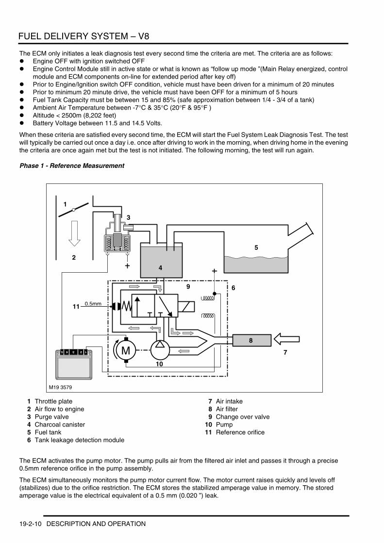
FUEL DELIVERY SYSTEM – V8
The ECM only initiates a leak diagnosis test every second time the criteria are met. The criteria are as follows:l Engine OFF with ignition switched OFFl Engine Control Module still in active state or what is known as “follow up mode ”(Main Relay energized, control
module and ECM components on-line for extended period after key off)l Prior to Engine/Ignition switch OFF condition, vehicle must have been driven for a minimum of 20 minutesl Prior to minimum 20 minute drive, the vehicle must have been OFF for a minimum of 5 hoursl Fuel Tank Capacity must be between 15 and 85% (safe approximation between 1/4 - 3/4 of a tank)l Ambient Air Temperature between -7°C & 35°C (20°F & 95°F )l Altitude < 2500m (8,202 feet)l Battery Voltage between 11.5 and 14.5 Volts.
When these criteria are satisfied every second time, the ECM will start the Fuel System Leak Diagnosis Test. The test will typically be carried out once a day i.e. once after driving to work in the morning, when driving home in the evening the criteria are once again met but the test is not initiated. The following morning, the test will run again.
Phase 1 - Reference Measurement
1 Throttle plate2 Air flow to engine3 Purge valve4 Charcoal canister5 Fuel tank6 Tank leakage detection module
7 Air intake8 Air filter9 Change over valve
10 Pump11 Reference orifice
The ECM activates the pump motor. The pump pulls air from the filtered air inlet and passes it through a precise 0.5mm reference orifice in the pump assembly.
The ECM simultaneously monitors the pump motor current flow. The motor current raises quickly and levels off (stabilizes) due to the orifice restriction. The ECM stores the stabilized amperage value in memory. The stored amperage value is the electrical equivalent of a 0.5 mm (0.020 ”) leak.
M
M19 3579
0.5mm
1
3
2
4
5
6
7
8
9
10
11
19-2-10 DESCRIPTION AND OPERATION
FUEL DELIVERY SYSTEM – V8
Phase 2 - Leak Detection
1 Throttle plate2 Air flow to engine3 Purge valve4 Charcoal canister5 Fuel tank6 Tank leakage detection module
7 Air intake8 Air filter9 Change over valve
10 Pump11 Reference orifice
The ECM energizes the Change Over Valve allowing the pressurized air to enter the fuel system through the Charcoal Canister. The ECM monitors the current flow and compares it with the stored reference measurement over a duration of time.
Once the test is concluded, the ECM stops the pump motor and immediately de-energizes the change over valve. This allows the stored pressure to vent thorough the charcoal canister trapping hydrocarbon vapour and venting air to atmosphere through the filter.
M
M19 3580
0.5mm
1
3
2
4
5
6
7
8
9
10
11
DESCRIPTION AND OPERATION 19-2-11

FUEL DELIVERY SYSTEM – V8
Test Results
A = Current stabilisesB = Current dropsC = Current rises
D = No leak detectedE = 0.5mm leak
F = Leak >1.0mmG = Change over valve energised
H = Pump motor energisedI = Motor current-Pressure
J = Reference measurement 0.5mmK = Time duration
The time duration varies between 45 & 270 seconds depending on the resulting leak diagnosis test results (developed tank pressure “amperage ”within a specific time period). However the chart above depicts the logic used to determine fuel system leaks.
M19 3581
A B C
G
H
D
E
F
I
K
J
19-2-12 DESCRIPTION AND OPERATION

COOLING SYSTEM – TD6
Deze pagina werd opzettelijk niet gebruikt
Cette page est intentionnellement vierge
Questa pagina è stata lasciata in bianco di proposito
Diese Seite ist leer
Esta página foi deixada intencionalmente em branco
Esta página fue dejada en blanco intencionalmente
This page is intentionally left blank
COOLING SYSTEM – Td6DESCRIPTION AND OPERATION
DESCRIPTION AND OPERATION 26-1-1
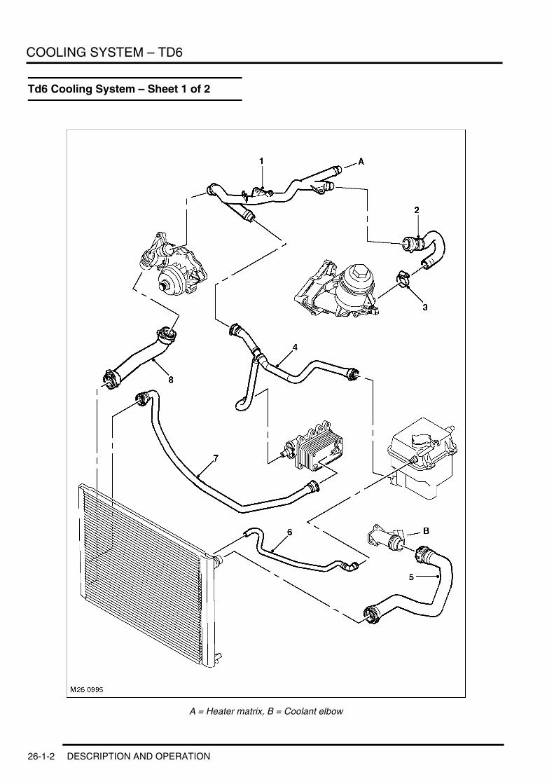
COOLING SYSTEM – TD6
Td6 Cooling System – Sheet 1 of 2
A = Heater matrix, B = Coolant elbow
26-1-2 DESCRIPTION AND OPERATION
COOLING SYSTEM – TD6
1 Coolant rail2 Hose – Coolant rail to engine oil cooler3 Clip4 Hose – Expansion tank return5 Radiator top hose6 Hose – Coolant/air bleed to expansion tank7 Hose – Radiator to transmission cooler8 Radiator bottom hose
DESCRIPTION AND OPERATION 26-1-3

COOLING SYSTEM – TD6
Td6 Cooling System – Sheet 2 of 2
A = Heater matrix, B = Coolant elbow
26-1-4 DESCRIPTION AND OPERATION

COOLING SYSTEM – TD6
1 Hose – Changeover valve to Fuel Burning Heater (FBH)
2 Clip3 Hose – FBH to auxiliary coolant pump4 Hose – Auxiliary coolant pump to coolant valve5 Clip6 Clip7 Hose – Coolant valve to heater assembly8 Clip9 Hose – Coolant valve to heater assembly
10 Clip11 Hose – Coolant outlet elbow to changeover
valve12 Clip13 Hose – Coolant rail to heater assembly
DESCRIPTION AND OPERATION 26-1-5

COOLING SYSTEM – TD6
Td6 Coolant Flow
A and B = Heater matrix to engine coolant connections
26-1-6 DESCRIPTION AND OPERATION

COOLING SYSTEM – TD6
1 Hose – Coolant outlet elbow to changeover valve
2 Hose – Coolant rail to heater assembly3 Bulkhead connections4 Hose – Coolant valve to heater assembly5 Fuel Burning Heater (FBH)6 Coolant elbow7 Coolant rail8 Radiator top hose9 Expansion tank
10 Hose – Coolant rail to engine oil cooler11 Oil cooler12 Hose – Coolant/air bleed to expansion tank13 Hose – Expansion tank return14 Transmission oil cooler15 Hose – Radiator to transmission oil cooler16 Radiator bottom hose17 Thermostat housing18 Exhaust Gas Recirculation (EGR) cooler19 Hose – FBH to auxiliary coolant pump20 Auxiliary coolant pump21 Hose – Auxiliary coolant pump to coolant valve22 Hose – Coolant valve to heater assembly23 Coolant valves24 Changeover valve
DESCRIPTION AND OPERATION 26-1-7

COOLING SYSTEM – TD6
Description
GeneralThe cooling system employed is the bypass type, which allows coolant to circulate around the engine and the heater circuit while the thermostat is closed. The primary function of the cooling system is to maintain the engine within an optimum temperature range under changing ambient and engine operating conditions. Secondary functions are to provide heating for the passenger compartment and cooling the engine oil, Exhaust Gas Recirculation (EGR) system and transmission fluid. The cooling system comprises:l Radiatorl Passenger compartment heater matrixl Integrated Oil Cooler and Filter Assemblyl Coolant pumpl Thermostatl Expansion tank l Viscous cooling fanl Electric cooling fanl Connecting hoses and pipesl Fuel Burning Heater (FBH).
The coolant is circulated by a centrifugal type pump mounted on the front of the engine and driven by the ancillary drive 'polyvee' belt. The coolant pump circulates coolant around the cylinder block and cylinder head, to the radiator, integrated oil cooler and filter assembly, the heater matrix and the transmission fluid coolers, via the coolant hoses and pipes.
The thermostat is integral to the coolant pump housing on the inlet side of the cooling circuit. This provides a more stable control of the coolant temperature in the engine.
The radiator is a cross flow type with an aluminium matrix. The bottom of the radiator is located in rubber bushes supported by plastic brackets which are clipped into the body longitudinals. The top of the radiator is located in rubber bushes secured by brackets fitted to the bonnet locking platform.
The radiator top hose is connected to a coolant outlet pipe which is bolted to the centre of the cylinder head. The elbow also has a connection for the feed to the heater matrix via a flexible hose.
The radiator bottom hose is connected to the inlet side of the coolant pump housing.
An expansion tank is fitted forward of the LH suspension turret in the engine compartment. The expansion tank allows for expansion of the coolant when the engine is hot and replaces the coolant into the system as the engine cools down.
The Fuel Burning Heater (FBH) is located below the battery. The unit is connected in series with the coolant supply to the heater matrix. + AIR CONDITIONING, DESCRIPTION AND OPERATION, Description.
For additional airflow through the radiator matrix, particularly when the vehicle is stationary, two cooling fans are fitted.
A viscous fan is attached to the coolant pump pulley at the front of the engine. The fan is attached to a threaded spigot on the pulley with a left hand threaded nut. The fan draws air through the radiator to assist in cooling when the vehicle is stationary.
An electric fan controlled by the Electronic Diesel Control (EDC) system is fitted in front of the radiator assembly. It is controlled by the Engine Control Module (ECM) via a cooling fan ECU. The cooling fan ECU is located behind the radiator, below the bonnet closing panel. The temperature of the cooling system is monitored by the ECM via signals from an Engine Coolant Temperature (ECT) sensor, which is mounted at the rear of the cylinder head.
OperationWith the engine running, the coolant pump pulley is driven by the ancillary drive belt. When the engine is cold, the thermostat is closed and coolant is prevented from circulating through the radiator. Coolant is able to circulate through the bypass, heater matrix and coolers.
26-1-8 DESCRIPTION AND OPERATION
COOLING SYSTEM – TD6
As the temperature increases, at 88 °C (190 °F) the thermostat begins to open, bleeding cool fluid from the radiator bottom hose through the pump and into the cylinder block. This allows hot coolant to flow from the cylinder block to the radiator through the top hose, balancing the flow of hot and cold fluid to maintain the optimum operating temperature. When the thermostat opens fully, the full flow of coolant passes through the radiator.
The increased coolant volume, created by heat expansion, is directed to the expansion tank through a bleed hose from the top of the radiator. The expansion tank has an outlet hose which is connected into the coolant circuit. This outlet hose returns the coolant to the system when the engine cools.
Coolant flows through the radiator from the top right hand tank to the bottom left hand tank and is cooled by air passing through the matrix. The temperature of the cooling system is monitored by the ECM via a temperature sensor located in the cylinder head. The ECM uses signals from this sensor to control the cooling fan operation and adjust fuelling according to engine temperature. + ENGINE MANAGEMENT SYSTEM – Td6, DESCRIPTION AND OPERATION, Description.
To control the cooling fan, the ECM sends a Pulse Width Modulated (PWM) signal to the cooling fan ECU. The frequency of the PWM signal, which is varied by the ECM, is used by the ECU to determine the output voltage supplied to the fan motors.
The ECM operates the fan in response to inputs from the ECT sensor, the air conditioning (A/C) switch and the A/C pressure sensor. + AIR CONDITIONING, DESCRIPTION AND OPERATION, Operation.
The speed of the electric cooling fan is also influenced by vehicle road speed. The ECM adjusts the speed of the cooling fan, to compensate for the ram effect of vehicle speed, using the CAN bus road speed signal received from the ABS ECU.
When the engine is switched off, the ECM maintains the cooling fans in an active condition for up to 8 minutes. If the temperature does not reach a predetermined value within 4 minutes, the ECM will terminate the active period. If the fans are active and the temperature falls below a predetermined value, the ECM will terminate further fan operation.
DESCRIPTION AND OPERATION 26-1-9
COOLING SYSTEM – TD6
26-1-10 DESCRIPTION AND OPERATION
COOLING SYSTEM – V8
Deze pagina werd opzettelijk niet gebruikt
Cette page est intentionnellement vierge
Questa pagina è stata lasciata in bianco di proposito
Diese Seite ist leer
Esta página foi deixada intencionalmente em branco
Esta página fue dejada en blanco intencionalmente
This page is intentionally left blank
COOLING SYSTEM – V8DESCRIPTION AND OPERATION
DESCRIPTION AND OPERATION 26-2-1

COOLING SYSTEM – V8
V8 Cooling System – Sheet 1 of 2
A and B = Heater matrix
26-2-2 DESCRIPTION AND OPERATION
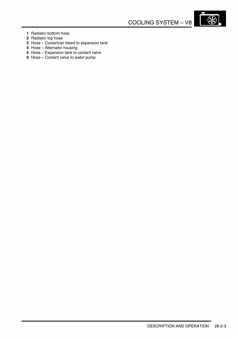
COOLING SYSTEM – V8
1 Radiator bottom hose2 Radiator top hose3 Hose – Coolant/air bleed to expansion tank4 Hose – Alternator housing5 Hose – Expansion tank to coolant valve6 Hose – Coolant valve to water pump
DESCRIPTION AND OPERATION 26-2-3

COOLING SYSTEM – V8
V8 Cooling System – Sheet 2 of 2
A and B = Heater matrix
26-2-4 DESCRIPTION AND OPERATION

COOLING SYSTEM – V8
1 Hose – Changeover valve to Fuel Burning Heater (FBH)
2 Hose – FBH to auxiliary coolant pump3 Hose – Coolant valve to heater assembly4 Hose – Auxiliary coolant pump to coolant valve5 Hose – Coolant valve to heater assembly6 Hose – Engine to changeover valve7 Hose – Engine to heater assembly
DESCRIPTION AND OPERATION 26-2-5
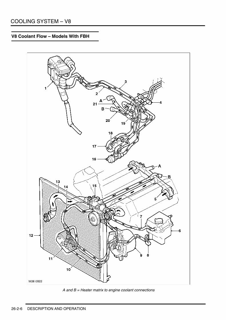
COOLING SYSTEM – V8
V8 Coolant Flow – Models With FBH
A and B = Heater matrix to engine coolant connections
26-2-6 DESCRIPTION AND OPERATION

COOLING SYSTEM – V8
1 Fuel Burning Heater (FBH)2 Hose – Changeover valve to FBH3 Hose – FBH to auxiliary coolant pump4 Bulkhead connections5 Coolant manifold6 Expansion tank7 Hose – Coolant/air bleed to expansion tank8 Hose – Expansion tank to coolant valve9 Water cooled alternator housing
10 Hose – Radiator11 Transmission oil cooler12 Radiator13 Radiator bottom hose14 Hose – Coolant valve to water pump15 Thermostat housing16 Auxiliary coolant pump17 Hose – Coolant valve to heater assembly18 Coolant valve19 Changeover valve20 Hose – Engine to heater assembly21 Hose – Engine to changeover valve
DESCRIPTION AND OPERATION 26-2-7

COOLING SYSTEM – V8
Description
General The cooling system employed is the bypass type, which allows coolant to circulate around the engine and the heater circuit while the thermostat is closed. The primary function of the cooling system is to maintain the engine within an optimum temperature range under changing ambient and engine operating conditions. Secondary functions are to provide heating for the passenger compartment and cooling for the transmission fluid. The cooling system comprises:l Radiatorl Passenger compartment heater matrixl Transmission fluid coolerl Coolant pumpl Thermostat l Expansion tankl Viscous cooling fanl Electric cooling fanl Connecting hoses and pipesl Fuel Burning Heater (FBH) – selected markets onlyl Liquid cooled alternator housing.
The coolant is circulated by a centrifugal type pump mounted on the front of the engine and driven by an ancillary drive 'polyvee' belt. The coolant pump circulates coolant through the cylinder block and the cylinder heads via a chamber located in the 'vee' of the engine. Having passed through the engine, the coolant returns via a rear-mounted manifold that features the connections for the heater matrix and through pipes running in the 'vee' of the engine to the coolant pump. The coolant pump also circulates coolant to the radiator-mounted transmission fluid cooler and the liquid cooled alternator housing via flexible hoses.
The die-cast coolant pump, driven by an ancillary drive belt, is fitted to the timing case cover. It contains the dual coolant temperature sensor and the electrically heated 'map controlled' thermostat controlled by the engine management system.
The map controlled thermostat incorporates a heating element inside a conventional expanding wax thermostat core which enables the engine management system to 'power' the thermostat open when the engine is under full load and/or high output conditions. This provides sufficient cooling reserve through anticipation of the thermal load whilst allowing the engine to run at higher operating temperatures under part load conditions. + ENGINE MANAGEMENT SYSTEM – V8, DESCRIPTION AND OPERATION, Bosch ME 7.2 Engine Management System.
The radiator is a cross flow type with an aluminium matrix and has a drain tap on the lower left hand rear face. The bottom of the radiator is located in rubber bushes supported by plastic brackets which are clipped into the body longitudinals. The top of the radiator is located in rubber bushes secured by brackets fitted to the bonnet locking platform.
The radiator top and bottom hoses are connected to the outlet and inlet sides of the coolant pump housing respectively.
An expansion tank is fitted forward of the LH suspension turret in the engine compartment. The expansion tank allows for expansion of the coolant when the engine is hot and replaces the coolant into the system as the engine cools down.
The liquid cooled transmission fluid cooler is mounted on the plastic radiator support adjacent to the lower right hand rear of the matrix and receives coolant from either the bottom of the radiator or the return elbow pipe between the coolant pump and the radiator as required.
The Fuel Burning Heater (FBH) is located below the battery. The unit is connected in series with the coolant supply to the heater matrix. + AIR CONDITIONING, DESCRIPTION AND OPERATION, Description.
For additional airflow through the radiator matrix, particularly when the vehicle is stationary, two cooling fans are fitted; one being driven by the engine via the coolant pump drive shaft and one being driven by an integral electric motor.
CAUTION: The fan is attached to a threaded spigot on the pulley with a left hand thread.
26-2-8 DESCRIPTION AND OPERATION

COOLING SYSTEM – V8
The engine driven fan contains a viscous coupling that allows the fan to slip as the engine speed increases. The fan is attached to a threaded spigot on the pulley with a left hand threaded nut. The fan draws air through the radiator to assist in cooling when the vehicle is stationary.
An electric fan controlled by the engine management system is fitted in front of the radiator assembly. + ENGINE MANAGEMENT SYSTEM – V8, DESCRIPTION AND OPERATION, Bosch ME 7.2 Engine Management System.
OperationWith the engine running, the coolant pump pulley is driven by an ancillary drive belt. When the engine is cold, the thermostat is closed and coolant is prevented from circulating through the radiator. Coolant is able to circulate through the engine and the passenger compartment heater matrix via a thermostat bypass.
As the temperature increases the thermostat begins to open, allowing cool fluid to be drawn from the radiator bottom hose through the pump and into the cylinder block and hot coolant to flow from the coolant pump housing to the radiator via the radiator top hose, where it is cooled by air passing through the matrix. When the thermostat opens fully, the full flow of coolant passes through the radiator.
Coolant is also drawn through the liquid cooled transmission fluid cooler and the liquid cooled alternator housing by the coolant pump via the coolant circuit.
The increased coolant volume, created by heat expansion, is directed to the expansion tank through a bleed hose from the top of the radiator. The expansion tank has an outlet hose which is connected into the coolant circuit. This outlet hose returns the coolant to the system when the engine cools.
DESCRIPTION AND OPERATION 26-2-9

COOLING SYSTEM – V8
26-2-10 DESCRIPTION AND OPERATION

MANIFOLDS AND EXHAUST SYSTEM – TD6
Deze pagina werd opzettelijk niet gebruikt
Cette page est intentionnellement vierge
Questa pagina è stata lasciata in bianco di proposito
Diese Seite ist leer
Esta página foi deixada intencionalmente em branco
Esta página fue dejada en blanco intencionalmente
This page is intentionally left blank
MANIFOLDS AND EXHAUST SYSTEM – Td6DESCRIPTION AND OPERATION
DESCRIPTION AND OPERATION 30-1-1

MANIFOLDS AND EXHAUST SYSTEM – TD6
Exhaust Manifold Component Layout
30-1-2 DESCRIPTION AND OPERATION

MANIFOLDS AND EXHAUST SYSTEM – TD6
1 Heat shield2 Bolt – Turbocharger to exhaust manifold (3 off)3 Exhaust manifold4 Nut – Exhaust manifold to cylinder head (12 off)5 Gasket – Exhaust manifold to turbocharger6 Gasket – Exhaust manifold to cylinder head (3
off)7 Turbocharger8 Stud9 Banjo bolt – Oil feed pipe
10 Washer11 Oil feed pipe12 Turbocharger support bracket13 Turbocharger mounting bolt (3 off)14 Banjo bolt – Oil feed pipe15 Washer16 Hose – Turbocharger oil drain17 Clamp18 Oil drain pipe19 Bolt – Oil drain pipe to turbocharger20 Gasket – Oil drain pipe to turbocharger
DESCRIPTION AND OPERATION 30-1-3

MANIFOLDS AND EXHAUST SYSTEM – TD6
Inlet Manifold Component Layout
30-1-4 DESCRIPTION AND OPERATION
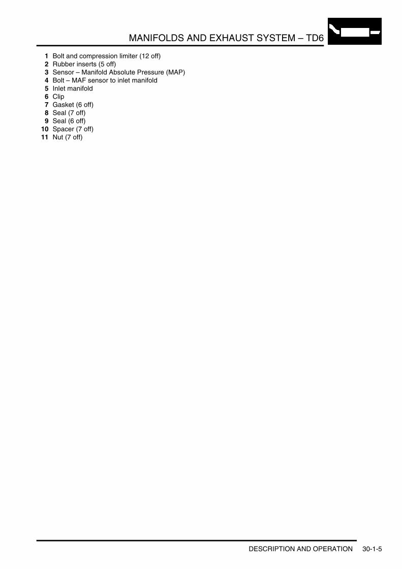
MANIFOLDS AND EXHAUST SYSTEM – TD6
1 Bolt and compression limiter (12 off)2 Rubber inserts (5 off)3 Sensor – Manifold Absolute Pressure (MAP)4 Bolt – MAF sensor to inlet manifold5 Inlet manifold6 Clip7 Gasket (6 off)8 Seal (7 off)9 Seal (6 off)
10 Spacer (7 off)11 Nut (7 off)
DESCRIPTION AND OPERATION 30-1-5
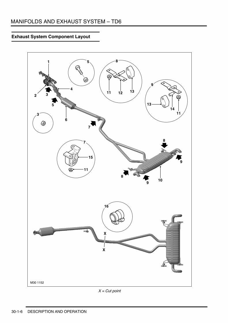
MANIFOLDS AND EXHAUST SYSTEM – TD6
Exhaust System Component Layout
X = Cut point
M30 1152
1
4
2
6
7
8
9
8
9
3
5
5
3
8
9
7
15
11
11 12 13
1314
11
16
10
X
X
30-1-6 DESCRIPTION AND OPERATION

MANIFOLDS AND EXHAUST SYSTEM – TD6
1 Exhaust Manifold2 Turbocharger3 Nut - Turbocharger to exhaust pipe4 Pre-catalytic converter5 Bolt-Exhaust front pipe to exhaust 6 Catalytic Converter7 Mounting bracket - middle8 Mounting brackets - rear (2 off)9 Mounting brackets - rear (2 off)
10 Rear silencer11 Nut - Mounting brackets (10 off)12 Mounting bracket - Rear13 Mounting rubber- Rear14 Mounting rubber - Rear15 Mounting bracket - Rear16 Repair sleeve
DESCRIPTION AND OPERATION 30-1-7

MANIFOLDS AND EXHAUST SYSTEM – TD6
Description
GeneralThe inlet manifold directs cooled and compressed air from the turbocharger and intercooler into the cylinders, where it is mixed with fuel from the injectors. Exhaust gases from the exhaust manifold can also be directed into the inlet manifold via a pipe from the exhaust manifold and an Exhaust Gas Regulator (EGR) valve on the inlet manifold. The exhaust manifold allows combustion gases from the cylinders to leave the engine where they are directed into the turbocharger and exhaust system.
The exhaust system is attached to the turbocharger and is directed along the underside of the vehicle to emit exhaust gases from the tail pipes located at the rear of the vehicle.
Intake Assembly
1 Upper Timing Chain Cover2 Air Filter3 Oil filler aperture4 Camshaft Cover
5 Oil Depression Limiter6 Oil Depression Limiter7 Inlet Manifold
30-1-8 DESCRIPTION AND OPERATION

MANIFOLDS AND EXHAUST SYSTEM – TD6
Inlet ManifoldThe inlet manifold is a one piece plastic moulding with inlet tracts feeding intake air into the cylinder head ports directly in the cylinder head via the camshaft cover. The manifold is secured to the cylinder using seven studs. All incorporate sealing washers and compression limiters.
The manifold is secured to the camshaft cover with twelve bolts incorporating compression limiters. Sealing between the manifold, cylinder head, and camshaft cover is achieved using moulded rubber seals located in recesses in the manifold.
A boost pressure sensor is located on the rear of the inlet manifold. The sensor is secured to the manifold with a bolt and sealed with an 'O' ring. On the front of the inlet manifold, four threaded holes provide for the attachment of the EGR valve. The valve is sealed to the manifold with an 'O' ring.
DESCRIPTION AND OPERATION 30-1-9

MANIFOLDS AND EXHAUST SYSTEM – TD6
Intercooler
Intercooler
1 Inlet Air2 Unfiltered air inlet3 Intake silencer and filter4 Sensor - Manifold Absolute Pressure (MAP)5 Intake manifold6 EGR Valve7 Cooled air to inlet manifold
8 Bypass hose9 Intake air to turbocharger
10 Intercooler11 Compressed air from turbocharger12 Turbocharger13 Exhaust front pipe
M00 0000
1
2
2
56
7
4
3
8
9
13
12
1110
M30 1151
30-1-10 DESCRIPTION AND OPERATION

MANIFOLDS AND EXHAUST SYSTEM – TD6
The intercooler is mounted below the radiator, and receives compressed air from the turbocharger. By cooling the compressed air, the intercooler further increases the mass of air delivered to the inlet manifold.
Exhaust ManifoldThe cast iron exhaust manifold is secured to the cylinder head using twelve studs with nuts. Three metal gaskets seal the manifold to the cylinder head.
A flanged connection on the underside of the manifold provides for the attachment of the turbocharger. The turbocharger is attached to the flange with three bolts and sealed with a metal gasket.
A second flange, located on the front of the manifold provides the connection point for the EGR pipe. The pipe flange is secured to the manifold with two bolts. There is no gasket between the EGR pipe and the exhaust manifold.
Exhaust Gas Recirculation (EGR)The EGR system directs exhaust gases into the inlet manifold to be used in the combustion process. The principal effect of this is to reduce combustion temperatures, which in turn reduces Nitrous Oxide (NOx) emissions.
The aluminium EGR valve is fitted at the inlet to the intake manifold. It is supplied by cooled air via the intercooler. + ENGINE MANAGEMENT SYSTEM – Td6, DESCRIPTION AND OPERATION, Description.
DESCRIPTION AND OPERATION 30-1-11

MANIFOLDS AND EXHAUST SYSTEM – TD6
Turbocharger
Turbocharger
1 Compressor2 Driveshaft3 Adjustment ring4 Guide vanes5 Turbine
6 Exhaust outlet7 Exhaust gas from engine8 Bearing housing9 Air to intercooler
10 Air from intake silencer
The turbocharger is secured to the exhaust manifold by three bolts, and to the front part of the exhaust system by two studs and lock nuts. The turbocharger utilises a Variable Nozzle Turbine (VNT), with a boost pressure of up to 2.1 bar. The VNT makes it possible to vary the exhaust gas flow of the turbine dependent on engine operation. Variable turbine geometry facilitates better use of the exhaust gas energy so as to further improve the efficiency of the turbocharger when compared to the more conventional wastegate control.
M30 1156
1
2 3 4
5
8
6
7
9
10
30-1-12 DESCRIPTION AND OPERATION

MANIFOLDS AND EXHAUST SYSTEM – TD6
1 Exhaust turbine2 Guide vanes
3 Guide vane – Open4 Guide vane – Closed
Closing the guide vanes on the VNT results in a reduction of exhaust gas flow and an increase in the flow rate of exhaust gas to the turbine wheel. This improves the power transfer to the turbine wheel and compressor, particularly at low engine speeds, thus increasing boost pressure. The guide vanes are opened progressively as engine speed increases so that power transfer always remains in balance with the required charger speed and the required boost pressure level. + ENGINE MANAGEMENT SYSTEM – Td6, DESCRIPTION AND OPERATION, Description.
M30 1150
4
3
2
1
DESCRIPTION AND OPERATION 30-1-13

MANIFOLDS AND EXHAUST SYSTEM – TD6
Exhaust SystemThe stainless steel exhaust system is supplied as a one-piece assembly and is connected to the turbocharger exhaust stub pipe flange by two screws and hexagonal nuts. It is attached to the underside of the body with five rubber mountings.
It consists of a stub pipe, a catalytic converter, a single intermediate pipe which divides into two branch pipes, before joining the single rear silencer assembly. Internally the rear silencer assembly is divided into two independent silencers each with its own tailpipe. The tailpipes are bent downwards and not normally visible.
Although supplied as a one-piece assembly, in service, sections of the system can be replaced individually. Service joints, identified by indentations on the pipes, show where the exhaust pipes can be cut to accommodate replacement sections.
After the replacement sections are positioned the system integrity is restored by sealing the service joints with one piece sleeves.
30-1-14 DESCRIPTION AND OPERATION

MANIFOLDS AND EXHAUST SYSTEM – V8
MANIFOLDS AND EXHAUST SYSTEM – V8DESCRIPTION AND OPERATIONExhaust Manifold Component Layout
1 Exhaust Manifold – Cylinders 1 – 42 Nut – (16 off)3 Stud – Manifold to Exhaust Pipe — (4 off)
4 Gasket – cylinders 3 – 4 5 Gasket – cylinders 1 – 2, 5 – 6 and 7 – 8 6 Exhaust Manifold – Cylinders 5 – 8
DESCRIPTION AND OPERATION 30-2-1

MANIFOLDS AND EXHAUST SYSTEM – V8
Inlet Manifold Component Layout
30-2-2 DESCRIPTION AND OPERATION

MANIFOLDS AND EXHAUST SYSTEM – V8
1 Gasket2 Vent Pipe3 Cover bolt4 Supporting ring5 Cap6 Connector7 Plug8 Clip9 O-ring Seal
10 Gasket11 Manifold intake assembly12 Gasket13 Gasket14 Bolt15 Front Cover16 Gasket17 Compression limiter18 Intake manifold nuts
DESCRIPTION AND OPERATION 30-2-3
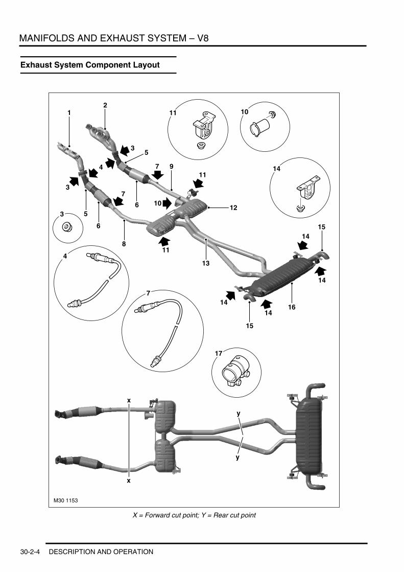
MANIFOLDS AND EXHAUST SYSTEM – V8
Exhaust System Component Layout
X = Forward cut point; Y = Rear cut point
M30 1153
12
5
6
7 94
7
5
6
8
11
12
13
11
14
14
15
1416
14
15
4
7
3
3
10
14
3
1011
17
7
x
x
y
y
30-2-4 DESCRIPTION AND OPERATION

MANIFOLDS AND EXHAUST SYSTEM – V8
1 Left manifold2 Right manifold3 Exhaust flange nuts4 Pre-catalyst Heated Oxygen Sensor (HO2S)5 Pre-catalyst6 Main catalyst7 Main Catalyst Heated Oxygen Sensor (HO2S)8 Left front pipe9 Right front pipe
10 Mass Damper11 Mounting bracket (2 off)12 Front silencer assembly13 Rear pipe14 Mounting bracket (4 off)15 Tailpipe16 Rear silencer assembly17 Repair sleeve
DESCRIPTION AND OPERATION 30-2-5

MANIFOLDS AND EXHAUST SYSTEM – V8
Description
GeneralThe inlet manifold on the V8 engine is located on the top of the engine, between the cylinders.
The two exhaust manifolds, one for each bank of four cylinders, directs the engine combustion gases from the cylinders to the exhaust system.
The exhaust system consists of two identical systems, sharing a common rear silencer assembly, connected to each exhaust manifold. Two catalytic converters are located in each of the front pipes from it's respective manifold and a silencer is installed midway along the system.
Inlet ManifoldThe inlet manifold is a light weight, one piece plastic moulding. The manifold is acoustically decoupled from the cylinder heads to reduce noise and vibrations.
The throttle plate has two wedges screwed directly to it, these provide a curved zone for smoother throttle response during idle, off-idle transition.
The combined output of the mixing plate ensures that the intake air is evenly distributed among all the cylinders, which can improve idle quality.
Exhaust ManifoldTwo handed, double skinned stainless steel sheet metal manifolds are used on the V8 engine. Each manifold has four ports which merge into one flanged outlet positioned centrally on the manifold.
Each manifold is secured to its cylinder head using eight studs with nuts and sealed with two gaskets. The flanged outlet on each manifold provides the attachment for the exhaust system.
NOTE: The exhaust manifold gasket for cylinders 3–4 is not interchangeable with the gaskets for cylinders 1–2, 5–6 or 7–8.
Exhaust SystemThe stainless steel exhaust system is supplied as a one-piece assembly.
It consists of two stub pipes and pre-catalytic converter HO2S, two intermediate catalytic converters, two main catalytic converters and down pipes, each with a post catalytic converter HO2S, two intermediate silencer assemblies and pipes joining the single rear silencer assembly. Internally the rear silencer assembly is divided into two independent silencers, each with its own tailpipe. The tail pipes are bent downwards and not normally visible. + ENGINE MANAGEMENT SYSTEM – V8, DESCRIPTION AND OPERATION, Bosch ME 7.2 Engine Management System.
The exhaust system is attached to the underside of the body with five rubber mountings and a mass damper. The mass damper is fitted forward of the right intermediate silencer.
Although supplied as a one-piece assembly, in service, sections of the system can be replaced individually. Service joints, identified by indentations on the pipes, show where the exhaust pipes can be cut to accommodate replacement sections.
After the replacement sections are positioned the system integrity is restored by sealing the service joints with one piece sleeves. For more information, refer to the Service Procedures Workshop manual.
30-2-6 DESCRIPTION AND OPERATION

TRANSFER BOX
TRANSFER BOXDESCRIPTION AND OPERATIONTransfer Box Component Location
1 Instrument pack2 Low range warning lamp3 Selector lever assembly
4 High/low range selection switch5 Transfer box6 Transfer box ECU
DESCRIPTION AND OPERATION 41-1

TRANSFER BOX
Transfer Box Exploded View
41-2 DESCRIPTION AND OPERATION

TRANSFER BOX
1 Sun gear2 Thrust washer3 Planetary gear set assembly4 Inner blocker ring5 Cone6 Detente (3 off)7 Outer blocker ring8 Hub - synchroniser9 Sleeve - synchroniser
10 Outer blocker ring11 Cone12 Input shaft assembly13 Main shaft14 Thrust washer15 Drive sprocket assembly16 Torsen® differential assembly17 Fork and rail assembly18 Chain19 Front output shaft assembly20 Bolt (23 off)21 Flange assembly - rear output22 Flange O-ring23 Flange nut24 Actuator assembly25 Thrust bearing (2 off)26 Lead screw27 Filler/level plug28 Seal29 Drain plug30 Seal31 Filter screen32 Chip collector magnet33 Connector tube34 Pump feed tube35 O-ring seal36 Dowel (2 off)37 Oil pump assembly38 Rear casing assembly39 Front output flange assembly40 Flange O-ring41 Flange nut42 Mounting bush43 Input seal44 Retaining ring45 Front casing assembly46 Vent assembly47 Pinion thrust washer (8 off)48 Roller separator ring (12 off)49 Pinion planet roller (144 off)50 Planet pinion shaft (4 off)51 Planet pinion gear (4 off)
DESCRIPTION AND OPERATION 41-3

TRANSFER BOX
Transfer Box Control Diagram
A = Hardwired connection; C = Diagnostic DS2 bus; D = CAN Bus
M41 7838A
A
8 6
5
3
4
2
7
11
D
9
10
1
C
41-4 DESCRIPTION AND OPERATION

TRANSFER BOX
1 High/Low range selection switch2 EAT ECU3 Engine Control Module (ECM)4 Actuator potentiometer5 Actuator6 Fuse 33 Ignition feed7 Fusible link Permanent battery feed8 Fuse 37 Neutral selection9 Ignition switch
10 Diagnostic socket11 Transfer box ECU
DESCRIPTION AND OPERATION 41-5

TRANSFER BOX
Description
GeneralThe NV225 Transfer Box is a full time, permanent four wheel drive, torque splitting transmission with equal torque distribution to the front and rear propeller shafts. The transfer box has the following features:l Permanent four wheel drive with 50/50 torque splitl Two speed, fully synchronised 'shift on the move' system with electronic control and operationl High range direct drive and low range via epicyclic gearsetl Torsen® Type B torque sensing and torque biasing centre differentiall Self lubricating oil pump system.
The transfer box is located under the vehicle in a subframe, behind the transmission. The units used on both the Td6 and V8 variants are identical, with the exception of the large mounting bush. The transfer box is manufactured by New Venture Gear in Roitzsch, Germany.
The transfer box receives an input from the transmission output shaft which is passed through the unit to two outputs for the front and rear propeller shafts.
The transfer box provides full time four wheel drive via a 50:50 torque sensing Torsen® differential. The unit design allows “shift on the move” from high to low range and visa versa. A planetary gearset with helical planetary pinion gears provides low range operation. When in low range, the planetary gearset provides a ratio of 2.69:1 which gives the vehicle an extremely low, low range crawl speed. High range is a direct drive from the transmission output shaft and provides a 1:1 ratio.
The transfer box has electronic control, via a PWM actuator (DC motor), on the shift from high to low range. The actuator is controlled by a transfer box ECU, which is located behind the battery in the engine compartment.
41-6 DESCRIPTION AND OPERATION

TRANSFER BOX
Deze pagina werd opzettelijk niet gebruikt
Cette page est intentionnellement vierge
Questa pagina è stata lasciata in bianco di proposito
Diese Seite ist leer
Esta página foi deixada intencionalmente em branco
Esta página fue dejada en blanco intencionalmente
This page is intentionally left blank
DESCRIPTION AND OPERATION 41-7
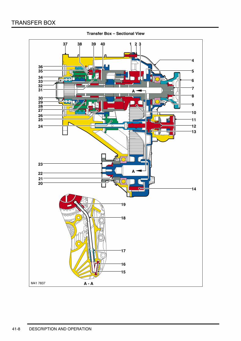
TRANSFER BOX
Transfer Box – Sectional View
M41 7837
A
A
4037
14
1
A - A
19
18
17
16
15
1312
11
8
6
7
9
5
4
10
343332
30
2625
24
29
36
23
222120
32
31
38 39
2827
35
41-8 DESCRIPTION AND OPERATION

TRANSFER BOX
1 Dowel (2 off)2 Bolt (23 off)3 Thrust washer4 Rear casing assembly5 Oil pump assembly6 Rear output flange assembly7 Main shaft8 Flange nut9 Flange O-ring
10 Drive sprocket assembly11 Actuator assembly12 Lead screw13 Thrust bearing (2 off)14 Chain15 Chip collector magnet16 Filter screen17 Connector – pump feed tube18 Pump feed tube19 O-ring seal20 Flange O-ring21 Flange nut22 Front output shaft assembly23 Front output flange assembly24 Fork and rail assembly25 Outer blocker ring26 Sleeve - synchroniser27 Thrust washer28 Sun gear29 Retaining ring30 O-ring seal31 Hub - synchroniser32 Input shaft assembly33 Input seal34 Planetary gearset assembly35 Inner blocker ring36 Cone37 Front casing assembly38 Outer blocker ring39 Detente (3 off)40 Torsen® differential assembly
DESCRIPTION AND OPERATION 41-9

TRANSFER BOX
The major components of the transfer box are; the front casing assembly, the rear casing assembly, the planetary gearset, the Torsen® differential, the fork and rail assembly and the actuator assembly.
The front and rear casing assemblies are manufactured from cast aluminium. Fins are cast into the front casing to aid heat dissipation. Both casing assemblies are bolted together and provide the bearing locations for the main shaft, the Torsen® differential and the planetary gearset. The rear casing provides the attachment location for the actuator assembly.
An oil pump assembly is located in the rear casing and is driven by a splined coupling on the main shaft. The pump has an oil tube to the bottom of the two casings with a filter screen to collect particulate matter. A magnet is located below the filter screen to collect any metallic particulate matter. The oil pump provides a pressurised supply to a drilling in the centre of the main shaft. Cross-drillings in the main shaft provide lubrication for the bearings and rotary components.
Mass Damper (Td6 models only)
On Td6 engine models, a mass damper is fitted to the front casing assembly. The damper is located next to the front output flange and secured to the casing with bolts. The damper absorbs vibration and resonance inherent with diesel engines, reducing passenger compartment noise and vibration.
The front casing assembly houses a mounting bush which differs in its material between engine variants. The bushes are identified by a colour code; red is for V8 engine models and blue is for Td6 engine models. The construction of the bushes is visually identical. The material from which the bushes are constructed differs to absorb the differing vibrational frequencies between the engine variants.
Drive is passed from the input shaft and via the Torsen® differential to the mainshaft and the drive sprocket assembly. The mainshaft rotates and passes the rotational motion to the rear propshaft. The drive sprocket assembly rotates and passes this rotation, via the chain, to the front propshaft. The drive sprocket carries a 3/8” pitch drive chain which drives a sprocket which is integral with the front output shaft. Because both sprockets are the same, with the same number of drive teeth, the rotational motion of the drive sprocket is identical to that of the front output shaft sprocket.
The 50:50 torque output ratio is produced from the Torsen® differential unit. This unit can drive the output to the main shaft and the drive sprocket assembly at a 50:50 ratio during normal driving conditions.
The transfer box requires a unique oil developed with NVG and Burmah-Castrol specifically for the Land Rover transfer box. The oil is a fully synthetic with the following specification: BOT 26 FMB 1 75W-90. The oil contains unique additives which enhance the transfer box operation. No other oil must be used in the transfer box.
Should the transfer box require repair, the only serviceable items are the input and two output shaft seals, the drain and filler plugs, the actuator and gearbox assembly and the breather tube. Any repairs beyond the items listed requires a replacement transfer box.
A filler/level plug is provided to ensure that the correct oil level is achieved after a service repair has been carried out. The level must be checked and adjusted with the transmission fully assembled and the vehicle on level ground. The transfer box contains 0.996 litres of oil. The transfer box is a fill for life unit and no level check is required at service unless a leak is present.
41-10 DESCRIPTION AND OPERATION

TRANSFER BOX
Planetary GearsetThe planetary gearset comprises a front and rear carrier half, an input shaft, four planet pinion gears, four planet pinion shafts and one hundred and forty four needle rollers.
The input shaft is located through the planetary carriers and is driven by the output shaft from the transmission. The sun gear is located on splines on the input shaft and rotates at the same speed. Rotation of the sun gear is transferred to the four pinion planet gears which in turn rotate around an annulus gear located in the front casing and secured with a retaining ring.
The rotation of the planetary pinion gears causes the front and rear carriers to rotate. The rear carrier has gear teeth which mesh with the teeth in the sleeve. To smooth the transition of the gear teeth of the sleeve and the rear carrier, an inner and outer blocker ring and a cone are fitted. When the fork moves the sleeve, the three detents in the hub are pushed, which in turn push the inner and outer blocker rings and the cone together. These items mesh together at an angle and operate as a synchromesh to provide smooth engagement of the gear teeth and the transition into low range.
The input shaft also has an outer blocker ring and a cone between the shaft and the hub. When the fork moves the sleeve, the three detents in the hub are pushed, which in turn push the outer blocker ring and the cone together. These items also mesh together at an angle and operate as a synchromesh to provide smooth engagement of the gear teeth of the hub and the input shaft and the transition into high range.
Fork and Rail AssemblyThe fork and rail assembly is the main component for changing from high to low ratio and is driven by the actuator assembly and the lead screw. The actuator rotates the lead screw, via the gearbox, which in turn moves the fork and rail assembly linearly in plain bearings in the front and rear casings. The fork is positively located in a stepped ring on the outer diameter of the synchroniser sleeve. Therefore, linear movement of the fork is transferred to the sleeve which initiates the range change.
DESCRIPTION AND OPERATION 41-11

TRANSFER BOX
Motor and Gearbox Assembly
41-12 DESCRIPTION AND OPERATION

TRANSFER BOX
1 Screw (2 off)2 Housing3 Shims4 Armature and brush assembly5 Thrust washer6 Planet gears7 Sun gear and carrier plate8 Planet gears9 Annulus housing
10 Bevel drive gear11 Housing12 Electrical connector13 Thrust washer14 Drive shaft and bevel gear assembly15 Mounting plate16 Screw (3 off)17 Potentiometer18 Circlip19 Gasket (2 off)20 Cover21 Screw (6 off)
DESCRIPTION AND OPERATION 41-13

TRANSFER BOX
The actuator and gearbox is located on the rear casing and secured with three bolts. The purpose of the actuator and gearbox is to electrically change the ratio of the transfer box from low to high and visa versa.
The actuator is a DC four brush motor which is controlled by PWM signals from the transfer box ECU. The wires from the ECU are large diameter and are twisted to minimise electrical interference. The motor has an internal four pin integral connector which, when installed in the housing, mates with a female connector located in the housing. The motor housing contains the magnets which, along with the armature and brush assembly, operate the motor. The housing is located on the armature and brush assembly mounting plate which in turn is secured with screws into the main housing. The shaft of the armature and brush assembly locates in a pressed plain bearing in the housing and is adjusted for end float with shims. The opposite end of the shaft has a toothed gear which mates with the reduction gearbox.
The reduction gearbox comprises an annulus housing, eight planetary gears and a sun gear and carrier plate. The annulus housing has a shaft and a planet gear carrier plate. The planet gear carrier plate is attached to the shaft inside the annulus housing. A bevel gear is attached to the opposite end of the shaft on the outside of the housing. The planet gear carrier plate has four pins which provide the attachment and pivot points for four planet gears. The sun gear and carrier plate is located in the annulus housing with the sun gear locating between the four planetary gears. The carrier plate has four pins which provide for the location and pivot points for four further planetary gears. The toothed gear on the armature and brush assembly shaft locates between these four gears and provides the drive input into the reduction gearbox.
The housing is manufactured from cast aluminium and is machined to accept the reduction gearbox and the drive shaft and bevel gear assembly. Three bosses with holes provide for the attachment of the housing to the transfer box rear casing assembly. An cast aluminium cover is sealed to the housing with two 'O' section gaskets and secured with six screws. The housing has a machined hole which is fitted with a plain brass bush to accept the drive shaft and bevel gear assembly. An oil seal is fitted behind the bush to provide a seal between the drive shaft and the transfer box rear casing half.
A hole in a boss on the housing allows for the fitment of the ten pin electrical connector to the ECU. The connector is secured in the housing with a spring clip and lip seal. A machined slot in the housing provides location for a second connector with four female pins. This connector mates with a similar male connector which is an integral part of the armature and brush assembly mounting plate and supplies power feed and ground connections for the motor.
The drive shaft and bevel gear assembly comprises a machined shaft, bevel gear and a mounting plate. The drive shaft has internal splines at one end. The splines have a missing tooth to act as a keyway which mates with the lead screw, providing the correct timing for the lead screw to the motor position. The bevel gear is an interference fit and is pressed onto the drive shaft. The opposite end of the shaft accepts the mounting plate and has a machined groove to provide a positive drive for the rotary potentiometer.
The mounting plate is located on the shaft and is secured in the housing with three screws and retains the drive shaft laterally. An external hexagonal boss on the mounting plate mates with a hexagonal moulding on the potentiometer. This provides a positive location for the potentiometer, preventing the potentiometer housing from rotating and providing the correct orientation for the potentiometer connector.
A third connector in the housing has three female pins which mate with similar male pins on the potentiometer. These pins supply a 5V reference supply, an output signal and ground for the potentiometer. The connector is connected to the pins of the ten pin electrical connector.
If the actuator and gearbox assembly is to be removed, the synchroniser sleeve position must be set to high range using TestBook/T4 before the assembly is removed.
41-14 DESCRIPTION AND OPERATION

TRANSFER BOX
Torsen® Differential
1 Bolt (3 off)2 Cover plate3 Pinion gear (6 off)4 Thrust washer
5 Friction thrust washer6 Side gear (front propshaft drive)7 Side gear (rear propshaft drive)8 Housing/ring gear
The Torsen® Type B traction differential unit is an integral part of the transfer box and is produced by Zexel Torsen of Belgium. The unit is a full time torque sensing and biasing system using parallel gearing for increased life and quiet operation.
During normal driving conditions, the Torsen® unit supplies a nominal 50:50 torque output to the front and rear drive shafts via the transfer box main shaft and the drive sprocket assembly.
The torque biasing capability consists of the ability to 'bias' the torque from the transmission to the axle and wheels with the higher grip. This must be achieved without causing wheel slip to the wheels of the axle with the lower grip within the biasing range of approximately 35/65 to 65/35 front to rear.
The torque biasing capability is instantaneous and operates as a preventative system. The unit does not need wheel slip and speed differentiation to be activated. The unit senses, via torque saturation within the unit, that one propeller shaft has the intention to rotate faster than the other one. The unit then biases the torque away from that propeller shaft and applies it to the other propeller shaft. Conventional systems require the wheel slip to occur first before initiating the torque biasing action. Because the Torsen® unit reacts before the slip occurs, the driving action is very smooth which results in enhanced grip for the road wheels.
DESCRIPTION AND OPERATION 41-15
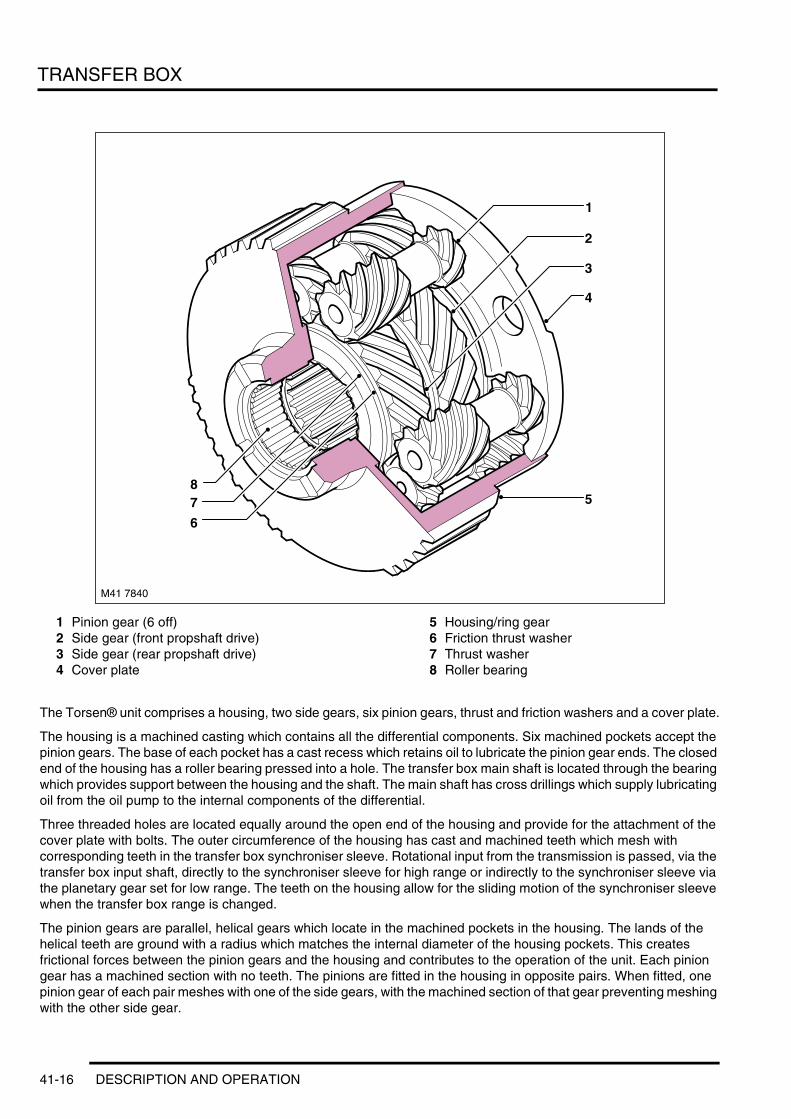
TRANSFER BOX
1 Pinion gear (6 off)2 Side gear (front propshaft drive)3 Side gear (rear propshaft drive)4 Cover plate
5 Housing/ring gear6 Friction thrust washer7 Thrust washer8 Roller bearing
The Torsen® unit comprises a housing, two side gears, six pinion gears, thrust and friction washers and a cover plate.
The housing is a machined casting which contains all the differential components. Six machined pockets accept the pinion gears. The base of each pocket has a cast recess which retains oil to lubricate the pinion gear ends. The closed end of the housing has a roller bearing pressed into a hole. The transfer box main shaft is located through the bearing which provides support between the housing and the shaft. The main shaft has cross drillings which supply lubricating oil from the oil pump to the internal components of the differential.
Three threaded holes are located equally around the open end of the housing and provide for the attachment of the cover plate with bolts. The outer circumference of the housing has cast and machined teeth which mesh with corresponding teeth in the transfer box synchroniser sleeve. Rotational input from the transmission is passed, via the transfer box input shaft, directly to the synchroniser sleeve for high range or indirectly to the synchroniser sleeve via the planetary gear set for low range. The teeth on the housing allow for the sliding motion of the synchroniser sleeve when the transfer box range is changed.
The pinion gears are parallel, helical gears which locate in the machined pockets in the housing. The lands of the helical teeth are ground with a radius which matches the internal diameter of the housing pockets. This creates frictional forces between the pinion gears and the housing and contributes to the operation of the unit. Each pinion gear has a machined section with no teeth. The pinions are fitted in the housing in opposite pairs. When fitted, one pinion gear of each pair meshes with one of the side gears, with the machined section of that gear preventing meshing with the other side gear.
5
M41 7840
1
4
3
2
7
6
8
41-16 DESCRIPTION AND OPERATION
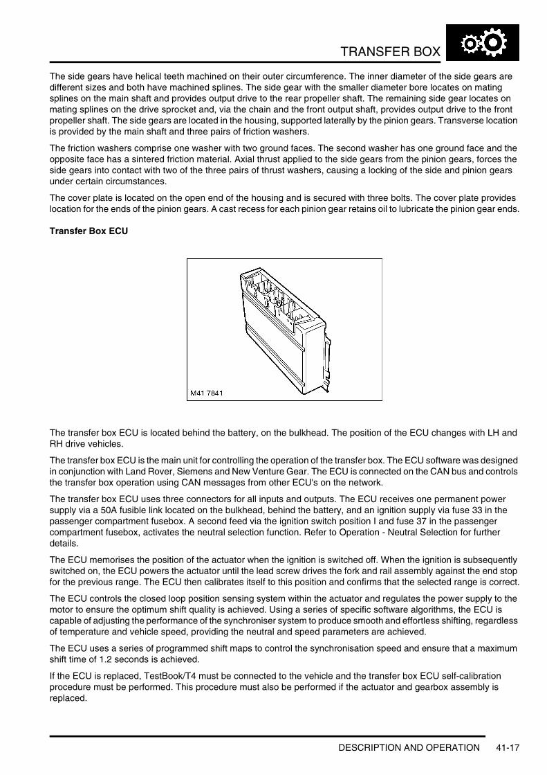
TRANSFER BOX
The side gears have helical teeth machined on their outer circumference. The inner diameter of the side gears are different sizes and both have machined splines. The side gear with the smaller diameter bore locates on mating splines on the main shaft and provides output drive to the rear propeller shaft. The remaining side gear locates on mating splines on the drive sprocket and, via the chain and the front output shaft, provides output drive to the front propeller shaft. The side gears are located in the housing, supported laterally by the pinion gears. Transverse location is provided by the main shaft and three pairs of friction washers.
The friction washers comprise one washer with two ground faces. The second washer has one ground face and the opposite face has a sintered friction material. Axial thrust applied to the side gears from the pinion gears, forces the side gears into contact with two of the three pairs of thrust washers, causing a locking of the side and pinion gears under certain circumstances.
The cover plate is located on the open end of the housing and is secured with three bolts. The cover plate provides location for the ends of the pinion gears. A cast recess for each pinion gear retains oil to lubricate the pinion gear ends.
Transfer Box ECU
The transfer box ECU is located behind the battery, on the bulkhead. The position of the ECU changes with LH and RH drive vehicles.
The transfer box ECU is the main unit for controlling the operation of the transfer box. The ECU software was designed in conjunction with Land Rover, Siemens and New Venture Gear. The ECU is connected on the CAN bus and controls the transfer box operation using CAN messages from other ECU's on the network.
The transfer box ECU uses three connectors for all inputs and outputs. The ECU receives one permanent power supply via a 50A fusible link located on the bulkhead, behind the battery, and an ignition supply via fuse 33 in the passenger compartment fusebox. A second feed via the ignition switch position I and fuse 37 in the passenger compartment fusebox, activates the neutral selection function. Refer to Operation - Neutral Selection for further details.
The ECU memorises the position of the actuator when the ignition is switched off. When the ignition is subsequently switched on, the ECU powers the actuator until the lead screw drives the fork and rail assembly against the end stop for the previous range. The ECU then calibrates itself to this position and confirms that the selected range is correct.
The ECU controls the closed loop position sensing system within the actuator and regulates the power supply to the motor to ensure the optimum shift quality is achieved. Using a series of specific software algorithms, the ECU is capable of adjusting the performance of the synchroniser system to produce smooth and effortless shifting, regardless of temperature and vehicle speed, providing the neutral and speed parameters are achieved.
The ECU uses a series of programmed shift maps to control the synchronisation speed and ensure that a maximum shift time of 1.2 seconds is achieved.
If the ECU is replaced, TestBook/T4 must be connected to the vehicle and the transfer box ECU self-calibration procedure must be performed. This procedure must also be performed if the actuator and gearbox assembly is replaced.
DESCRIPTION AND OPERATION 41-17

TRANSFER BOX
Default/Limp Home StrategyIf a fault occurs with the transfer box, the transfer box ECU or one of the required input signals, i.e.; road speed signal, the ECU records an error code and the transfer box low range 'mountain' symbol in the instrument pack flashes permanently.
As a default setting, the ECU will attempt to engage high or low range in order to allow the vehicle to be driven to a Land Rover dealer for repair. To ensure a range is engaged, the ignition must be switched off and then on again (timed shift performs this without ignition cycling). This causes the ECU to power the actuator and engage the previously selected range.
Transfer Box Harness Connector C1319 Pin Details
Transfer Box Harness Connector C1854 Pin Details
Transfer Box Harness Connector C1855 Pin Details
Pin No. Description Input/Output1 to 6 Not used –
7 Auxiliary power supply Input
8 HDC switch Input9 to 12 Not used –
13 CAN bus low Input/Output
14 Not used –15 Ignition power supply Input16 Not used –
17 Range change request 1 Input18 Range change request 2 Input19 Diagnostic ISO 9141 K line bus Input/Output
20 to 25 Not used –26 CAN bus high Input/Output
27 to 52 Not used –
Pin No. Description Input/Output1 to 5 Not used –
6 Actuator potentiometer 5 volt reference voltage Output7 to 9 Not used –
10 Actuator potentiometer signal Input11 to 16 Not used –
17 Actuator potentiometer ground –
18 to 40 Not used –
Pin No. Description Input/Output1 Not used –2 Ground –
3 Ground –4 Motor A supply/ground Input/Output5 Permanent battery power supply Input
6 Permanent battery power supply Input7 Motor A supply/ground Input/Output8 Motor B supply/ground Input/Output
9 Motor B supply/ground Input/Output
41-18 DESCRIPTION AND OPERATION
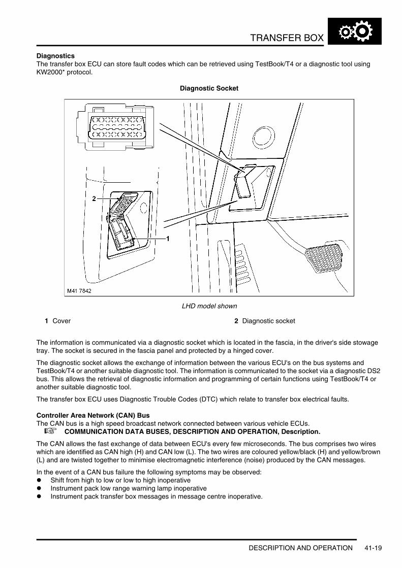
TRANSFER BOX
DiagnosticsThe transfer box ECU can store fault codes which can be retrieved using TestBook/T4 or a diagnostic tool using KW2000* protocol.
Diagnostic Socket
LHD model shown
1 Cover 2 Diagnostic socket
The information is communicated via a diagnostic socket which is located in the fascia, in the driver's side stowage tray. The socket is secured in the fascia panel and protected by a hinged cover.
The diagnostic socket allows the exchange of information between the various ECU's on the bus systems and TestBook/T4 or another suitable diagnostic tool. The information is communicated to the socket via a diagnostic DS2 bus. This allows the retrieval of diagnostic information and programming of certain functions using TestBook/T4 or another suitable diagnostic tool.
The transfer box ECU uses Diagnostic Trouble Codes (DTC) which relate to transfer box electrical faults.
Controller Area Network (CAN) BusThe CAN bus is a high speed broadcast network connected between various vehicle ECUs. + COMMUNICATION DATA BUSES, DESCRIPTION AND OPERATION, Description.
The CAN allows the fast exchange of data between ECU's every few microseconds. The bus comprises two wires which are identified as CAN high (H) and CAN low (L). The two wires are coloured yellow/black (H) and yellow/brown (L) and are twisted together to minimise electromagnetic interference (noise) produced by the CAN messages.
In the event of a CAN bus failure the following symptoms may be observed:l Shift from high to low or low to high inoperativel Instrument pack low range warning lamp inoperativel Instrument pack transfer box messages in message centre inoperative.
DESCRIPTION AND OPERATION 41-19

TRANSFER BOX
Operation
GeneralThe selection of high/low range is selected by the driver using a switch adjacent to the transmission selector lever. A range change can only be performed when the transmission selector lever is in neutral, position 'N'. The accelerator pedal must not be depressed when a range change is in progress.
If high or low range is requested and the transmission selector lever is a position other than 'N' or 'P', the instrument pack message centre will display 'SELECT NEUTRAL'.
NOTE: With the transmission selector lever in 'P', the range change will not take place and the 'SELECT NEUTRAL' message will not be displayed.
When low range is selected, the low range 'mountain' symbol will flash when the range change is taking place and then remain illuminated when the range change is complete. The instrument pack message centre will display 'LOW RANGE' for approximately 3 seconds followed by a chime from the instrument pack to confirm that the range change has been completed. Only 'D' and 'Manual mode' are available on the transmission, the 'Sport mode' selection is not available.
When high range is selected, the low range 'mountain' symbol will flash when the range change is taking place and then extinguish when the range change is complete. The instrument pack message centre will display 'HIGH RANGE' for approximately 3 seconds followed by a chime from the instrument pack to confirm that the range change has been completed.
The design of the transfer box allows range changes when the vehicle is moving, within set limitations as follows:l High to Low – at speeds not exceeding 10 mph (16 km/h)l Low to High – at speeds not exceeding 30 mph (48 km/h).
If the vehicle speed is higher than the parameters given above, the instrument pack message centre will display 'SLOW DOWN'. When the correct speed range is reached, the message will be deleted and the range change will commence.
A road speed of less than 2 mph (3 km/h) is interpreted by the transfer box ECU as a static shift (vehicle not moving). In this instance the driver must use the shift lock procedure of operating the brake pedal to allow the selector lever to be moved from 'N' to 'D' after the range change has been performed.
High range should be used for all normal road driving and also for off-road driving across dry, level terrain. Low range should only be required where low speed manoeuvring is necessary, such as reversing a trailer, negotiating steep slippery surfaces or boulder strewn terrain. Low range should also be used for extreme off-road conditions where progress in high range cannot be maintained. Low range should never be used for normal road driving.
Neutral SelectionThe transfer box can be moved into a neutral position for towing the vehicle. The vehicle must not be towed with the transfer box in high or low range. The transmission must also be in the neutral position. If neutral cannot be selected on the transmission, the vehicle must not be towed.
41-20 DESCRIPTION AND OPERATION

TRANSFER BOX
1 Spare 5A fuse 2 Fuse 37
To engage the transfer box in neutral, switch the ignition to position II and select neutral 'N' on the transmission selector lever. Insert a spare 5 Ampere fuse or greater into the empty fuse position 37 in the passenger compartment fusebox, which is located at the back of the glovebox. Fuse position 37 can be identified using the legend on the fusebox cover.
Once the fuse is installed, the actuator will engage the transfer box in the neutral position.
Once in neutral, the low range 'mountain' symbol in the instrument pack flashes permanently and 'TRANSFERBOX NEUTRAL' is displayed in the instrument pack message centre.
Cold Climate OperationIn low ambient temperatures, there may be an increased time delay for the transmission to select neutral. To prevent the transfer box changing range before the transmission has selected neutral, the transfer box ECU contains software to delay the range change.
The transfer box ECU receives a transmission fluid temperature message on the CAN. If this temperature is 5°C (41°F) or below, the transfer box ECU initiates a nominal delay in the range change to allow the transmission to engage neutral. The delay period is dependant on transmission fluid temperature.
High Range OperationIn high range, the torque input from the transmission is passed to the transfer box input shaft. The position of the synchroniser sleeve couples the shaft directly to the differential housing. The differential splits the torque between the two side gears. One side gear is connected by splines and passes the torque to the rear output flange. The second side gear is connected to the chain drive sprocket and passes the torque, via the chain, to the front output flange.
Low Range OperationIn low range, the torque input from the transmission is passed to the transfer box input shaft. The synchroniser sleeve is moved and connects the planetary carrier to the differential housing. The torque from the transmission is now directed through the sun gear of the epicyclic gearset and, via the pinion gears and pinion gear shafts, into the planetary carrier. The annulus gear of the epicyclic gearset is secured inside the casing and generates the low range ratio of 2.69:1. The torque is then passed, via the synchroniser sleeve, to the differential housing where it is split between the two side gears. One side gear is connected by splines and passes the torque to the rear output flange. The second side gear is connected to the chain drive sprocket and passes the torque, via the chain, to the front output flange.
DESCRIPTION AND OPERATION 41-21

TRANSFER BOX
Torsen® Differential OperationThe input torque from the transmission is passed via the synchroniser sleeve to the differential housing. The torque is then transmitted from the housing, through the three pairs of pinion gears and into the differential side gears.
The side gears have opposite handed helical gear forms and intermesh with only one of the pinion gears in each pair. The pinion gears intermesh with each other as well as individually meshing with only one of the side gears. Between each pinion gear and the differential housing and on either side of each side gear are friction surfaces or pairs of thrust washers and friction thrust washers. The pairs of thrust washers control the torque biasing function of the differential.
During normal driving, the differential housing rotates at the same speed as that of the input shaft in high range or the planetary carrier in low range. If there is no differential motion between the front and rear propeller shafts, then the differential gear and therefore the side gears will have no relative motion and the whole unit functions as a normal differential.
If the front or rear wheels suddenly loose traction, a large differential motion between the front and rear propeller shafts occurs as the slipping wheels begin to accelerate or spin. In this case with a normal differential, the torque applied to the non-slipping wheels is lost through the differential. With the Torsen® differential, as soon as one wheel begins to slip, the front and rear output side gears are encouraged to rotate at different speeds. With the side gears in constant mesh with their relative pinion gears, and the pinion gears meshing with each other, the differential begins to generate axial and radial thrust loads.
The thrust loads are generated as a result of the helical gear form of the pinion and side gears and they are exerted onto the thrust washers and friction thrust washers within the differential housing. The friction thrust washers generate a resistance to the relative motion and produce a locking effect within the differential. This ensures that the torque is always directed, or biased, towards the propeller shaft with the highest traction and ensures that the vehicle maintains continuous motion on slippery or uneven surfaces. This action takes place progressively and the driver will be unaware of its operation.
41-22 DESCRIPTION AND OPERATION
AUTOMATIC TRANSMISSION – GM 5L40-E
Deze pagina werd opzettelijk niet gebruikt
Cette page est intentionnellement vierge
Questa pagina è stata lasciata in bianco di proposito
Diese Seite ist leer
Esta página foi deixada intencionalmente em branco
Esta página fue dejada en blanco intencionalmente
This page is intentionally left blank
AUTOMATIC TRANSMISSION – GM 5L40-EDESCRIPTION AND OPERATION
DESCRIPTION AND OPERATION 44-1-1

AUTOMATIC TRANSMISSION – GM 5L40-E
GM 5L40-E Automatic Transmission Component Location
RHD model shown
44-1-2 DESCRIPTION AND OPERATION

AUTOMATIC TRANSMISSION – GM 5L40-E
1 Electronic Automatic Transmission (EAT) ECU2 Engine Control Module (ECM)3 Instrument pack4 Selector lever assembly5 Gearbox6 Gearbox valve block and solenoids7 Gearbox fluid cooler
DESCRIPTION AND OPERATION 44-1-3

AUTOMATIC TRANSMISSION – GM 5L40-E
GM 5L40-E Automatic Transmission – Exploded View
Note the transmission shown is exploded to the extent of the serviceable items
44-1-4 DESCRIPTION AND OPERATION

AUTOMATIC TRANSMISSION – GM 5L40-E
1 Seal2 Selector shaft3 Washer4 Gasket5 Extension6 Seal - Ring extension7 Speed sensor8 Selector inhibitor switch9 Insert - Valve body to main case
10 Solenoids - On/Off11 Screw - valve body to main case12 Fluid filter13 Gasket14 Fluid pan15 Drain plug16 Screw - Fluid pan to main case17 Solenoid - PWM Torque converter clutch18 Solenoid - Pressure regulator19 Wiring harness20 Harness connector clip21 Valve body22 O-ring seal23 Seal ring24 Torque converter assembly
DESCRIPTION AND OPERATION 44-1-5
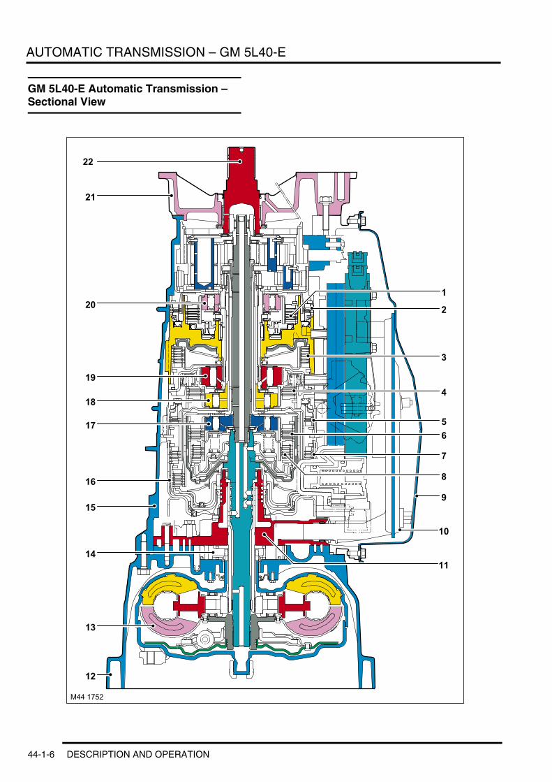
AUTOMATIC TRANSMISSION – GM 5L40-E
GM 5L40-E Automatic Transmission – Sectional View
22
12
14
15
16
17
18
19
20
21
13
11
10
7
65
4
3
2
1
8
9
M44 1752
44-1-6 DESCRIPTION AND OPERATION

AUTOMATIC TRANSMISSION – GM 5L40-E
1 Drive clutch (C2)2 Brake clutch (CC2)3 Brake clutch (LBC)4 Drive clutch (CI)5 Drive clutch (COD)6 Drive clutch (C1)7 Drive clutch (CR)8 Brake clutch (CC1)9 Fluid pan
10 Fluid filter11 Fluid pump cover plate12 Bell housing13 Torque converter14 Fluid pump15 Main casing16 Drive clutch (CD)17 Freewheel clutch FW1 (forward clutch sprag)18 Freewheel clutch FW3 (intermediate clutch
sprag)19 Freewheel clutch FW4 (low clutch sprag)20 Freewheel clutch FW2 (second clutch sprag)21 Extension case22 Output shaft
DESCRIPTION AND OPERATION 44-1-7

AUTOMATIC TRANSMISSION – GM 5L40-E
GM 5L40-E Automatic Transmission – Valve Block and Solenoid Valves
44-1-8 DESCRIPTION AND OPERATION

AUTOMATIC TRANSMISSION – GM 5L40-E
1 Torque converter clutch PWM solenoid2 Feed limit valve3 Torque converter clutch regulator valve4 Low pressure regulator valve5 Reverse lockout valve6 Manual valve7 4th-5th shift valve8 4th-5th control valve9 4th-5th shift solenoid (C)
10 2nd-3rd shift solenoid (B)11 2nd-3rd control valve12 1st-2nd shift solenoid (A)13 2nd-3rd shift valve14 1st-2nd control valve15 1st-2nd shift valve16 Accumulators17 Default mode valve18 Pressure control solenoid19 3rd-4th shift valve20 3rd-4th control valve21 Solenoid retaining clip
DESCRIPTION AND OPERATION 44-1-9

AUTOMATIC TRANSMISSION – GM 5L40-E
GM 5L40-E Automatic Transmission – Fluid Pump Cover Plate Assembly
A. Fluid pump line (output) pressureB. Pressure regulator fluid pump decrease pressure
C. Fluid pump suction (feed) line from fluid pan
11
5
132
18
1514
19
1615
716
17
13
12
11109
7
8
6
217
20
M44 1754
A =B =C =
12
43
4
44-1-10 DESCRIPTION AND OPERATION

AUTOMATIC TRANSMISSION – GM 5L40-E
1 Bleed valves2 Line pressure (pump output)3 Reverse clutch4 Forward clutch5 Coast clutch6 Direct clutch7 Exhaust (return to fluid pan)8 Pressure relief ball valve9 Torque converter clutch release pressure
10 Feed to fluid cooler11 Torque converter clutch apply pressure12 Torque converter clutch control valve13 Torque converter clutch enable valve14 Regulated apply pressure15 Torque converter clutch signal pressure16 Fluid pump17 Fluid pump screen assembly18 Suction feed from fluid pan19 Throttle signal (from pressure regulator
solenoid)20 Boost valve21 Pressure regulator valve
DESCRIPTION AND OPERATION 44-1-11

AUTOMATIC TRANSMISSION – GM 5L40-E
GM 5L40-E Automatic Transmission Control Diagram
A = Hardwired; D = CAN Bus; J = ISO 9141 K Line
M44 1755
A JD
13 12
14
15
16
9
1
2
3 45
6 7
8
10
11
44-1-12 DESCRIPTION AND OPERATION
AUTOMATIC TRANSMISSION – GM 5L40-E
1 Permanent battery supply (30A Fuse)2 Battery supply (100A Fuse)3 Main relay4 Starter relay5 Transmission fluid temperature sensor6 Input speed sensor7 Output speed sensor8 Brake switch9 EAT ECU
10 Inhibitor switch11 Solenoid valves12 Engine Control Module (ECM)13 Instrument pack14 Diagnostic socket15 Selector lever switches16 Shift interlock solenoid
DESCRIPTION AND OPERATION 44-1-13

AUTOMATIC TRANSMISSION – GM 5L40-E
Description
GeneralThe GM 5L40-E transmission is an electronically controlled, five speed unit specifically for use with the Td6 diesel engine. The transmission is manufactured by General Motors (GM) Powertrain in Strasbourg, France.
The transmission is controlled by an Electronic Automatic Transmission (EAT) ECU which contains software to provide operation as a semi-automatic 'Steptronic' transmission. This allows the transmission to be operated as a conventional automatic unit by selecting P, R, N, D on the selector lever. Movement of the selector lever across the gate to the 'M/S' position puts the transmission into electronic sport mode. Movement of the selector lever in a lateral position to the + or – positions puts the transmission into electronic manual 'Steptronic' mode.
The GM 5L40-E transmission has the following features:l Designed to provide maintenance free operationl Transmission fluid is 'fill for life'l The torque converter features a gradual slip lock up feature with electronic control of lock up and smooth
transition to the fully locked conditionl Torque converter lock up is available in 3rd, 4th and 5th gearsl EAT ECU controls shift program logicl Connected to ECM via the CAN for system communicationsl Diagnostics available from the EAT ECU via the ISO 9141 K Linel Default mode if major faults occur.
The transmission comprises three main castings; the bell housing, the main casing and the extension case. These items are bolted together to form the housing for the transmission components.
A single piece fluid pan is bolted to the lower face of the main case and secured with screws. The fluid pan is sealed to the main case by a controlled compression gasket. Removal of the fluid pan allows access to the valve block and solenoids. The fluid pan is fitted with a magnet which collects any metallic particles present in the fluid.
The fluid pan also houses a fluid filter which is non-serviceable. If the transmission fluid becomes contaminated or after any procedure requiring the fluid to be drained, the filter must be replaced.
The bell housing provides protection for the torque converter. The torque converter is a complete assembly which also contains the variable control lockup clutch. The torque converter also drives a vane type fluid pump via two drive tangs. The fluid pump is located in the bell housing, behind the fluid pump cover. The fluid pump cover and the bell housing are bolted together. The bell housing and fluid pump cover assembly is bolted to the main casing.
The main casing contains the following components:l Input shaftl Output shaftl Valve block and solenoidsl Six multiplate drive clutchesl Three multiplate brake clutchesl Four free wheel, one way, sprag type clutchesl A planetary gearset assembly.
Draining and refilling the transmission is carried out via a drain plug, located in the sump of the transmission and a refill/level plug located on the left hand side of the transmission. When checking the transmission fluid level the fluid must be between 35°C and 45°C. Only Texaco ETL-7045E Automatic transmission fluid should be used for refilling / topping up the transmission.
44-1-14 DESCRIPTION AND OPERATION

AUTOMATIC TRANSMISSION – GM 5L40-E
Torque Converter
Torque Converter Components
1 Converter housing cover assembly2 Pressure plate assembly3 Damper assembly
4 Turbine5 Stator6 Impeller
The torque converter is located in the bell housing on the engine side of the transmission. The torque converter is the coupling element between the engine and the transmission. The driven power from the engine crankshaft is transmitted hydraulically and mechanically according to the gear selected and the operating conditions, through the torque converter to the transmission. The torque converter is connected to the engine by a drive plate.
The torque converter comprises an impeller, a stator and a turbine. The torque converter is an enclosed unit between the converter housing cover assembly and the impeller assembly. The two components are welded together to provide a sealed housing with all torque converter components located in a fluid filled housing.
The converter housing cover assembly has three threaded bosses which provide for attachment to a drive plate which in turn is connected to the engine crankshaft. The threaded bosses also provide for location of special tools to allow the torque converter to be removed from the bell housing. With the impeller assembly welded to the converter housing cover assembly, the impeller speed is therefore governed by engine speed.
ImpellerThe impeller is mechanically connected to the engine and rotates at engine speed. The impeller outer body has a boss with two machined slots. The boss is located over the transmission input shaft and the slots locate in two tangs on the fluid pump to provide the fluid pump drive.
The impeller comprises a continuous row of blades attached to the outer body. The root of the blades collect fluid which flows by centrifugal force around the curved outer surface of the impeller to the tip of the blades.
DESCRIPTION AND OPERATION 44-1-15

AUTOMATIC TRANSMISSION – GM 5L40-E
Fluid Flow
1 Turbine2 Stator
3 Impeller
When the engine is running, the rotating impeller acts as a centrifugal pump, picking up fluid at its centre and discharging fluid at high velocity through the blades on its outer rim. The design and shape of the outer row of blades and the impeller outer body cause the fluid to rotate in a clockwise direction as it leaves the impeller. This improves the efficiency of the fluid as it contacts the outer row of blades on the turbine.
The centrifugal force of the fluid exiting the impeller outer blades is passed to the curved inner surface of the turbine via the outer row of blades. The velocity and clockwise rotation of the fluid causes the turbine to rotate.
TurbineThe turbine is similar in design to the impeller with a continuous row of blades. The fluid entering the tip of the blades is directed around the curved body of the turbine to the root of the blades. The curved surface of the turbine redirects the fluid back in the opposite direction to which it entered the turbine, increasing the turning force applied to the turbine from the impeller. This is known as torque multiplication.
When the engine is idling, the impeller is rotating at a slow speed. The force of the fluid exiting the impeller does not have sufficient force to turn the turbine at high speed. In this condition the vehicle can be in gear without any forward or reverse motion being generated.
When the engine speed increases, the turbine speed also increases. The fluid leaving the inner row of the turbine blades is rotated in an anti-clockwise direction due to the curve of the turbine and the shape of the blades. The fluid is now flowing in the opposite direction to the engine rotation and therefore the impeller. If the fluid was allowed to hit the impeller in this condition, it would have the effect of applying a brake to the impeller, eliminating the torque multiplication effect. To prevent this, the stator is located between the impeller and the turbine.
StatorThe stator is mounted on the transmission shaft on a roller clutch. The stator comprises a number of blades which are aligned in an opposite direction to those of the impeller and the turbine. The main function of the stator is to redirect the fluid returning from the turbine, changing its direction of rotation to that of the impeller.
The redirected fluid from the stator is directed at the inner row of blades of the impeller, assisting the engine in turning the impeller. This sequence increases the force of the fluid emitted from the impeller and thereby increasing the torque multiplication effect of the torque converter.
44-1-16 DESCRIPTION AND OPERATION

AUTOMATIC TRANSMISSION – GM 5L40-E
Stator Functions
1 Blades2 Stator held - fluid flow re-directed3 Stator rotates freely4 Roller clutch5 Converter at coupling speed6 Fluid flow from turbine7 Converter multiplying
8 Fluid flow from impeller9 Drive from engine
10 Impeller11 Stator12 Turbine13 Output to transmission
Refer to the 'Stator Functions' illustration
Fluid emitted from the impeller acts on the turbine. If the turbine is rotating at a slower speed than the fluid from the impeller, the fluid will be deflected by the turbine blades in the path 'A'. The fluid is directed at and deflected by the stator blades from path 'B' to path 'C'. This ensures that the fluid is directed back to the pump in the optimum direction. In this condition the roller clutch is engaged and the force of the fluid on the stator blades assists the engine in rotating the impeller
As the rotational speed of the engine and therefore the turbine increases, the direction of the fluid leaving the turbine changes to path 'D'. The fluid is now directed from the turbine to the opposite side of the stator blades, rotating the stator in the opposite direction. To prevent the stator from resisting the smooth flow of the fluid from the turbine, the roller clutch releases, allowing the stator to rotate freely on it shaft.
When the stator becomes inactive, the torque converter no longer multiples the engine torque. When the torque converter reaches this operational condition it ceases to multiply the engine torque and acts solely as a fluid coupling, with the impeller and the turbine rotating at approximately the same speed.
DESCRIPTION AND OPERATION 44-1-17

AUTOMATIC TRANSMISSION – GM 5L40-E
Uni-directional Roller Clutch
A. Unlock; B. Lock
1 Roller2 Cage3 Spring
4 Inner race5 Stator
The roller clutch used on the stator uses ten parallel rollers, located between the smooth, cylindrical inner race and the inclined cam faces of the stator body. Springs are used to hold the rollers in position between the two contact faces.
When the stator is rotated in a clockwise direction, the rollers become trapped between the inner race and the inclined cam faces of the stator body, providing positive (locked) rotation of the inner race. When the stator is rotated in an anti-clockwise direction, the rollers are moved away from the inclined cam faces and can rotate freely (unlocked) with the stator body, providing no drive from the stator to the inner race. In this condition the stator can rotate freely on the inner race.
Lock-up Clutch MechanismThe Torque Converter Clutch (TCC) is hydraulically controlled by a solenoid which in turn is controlled by PWM signals from the EAT ECU. This allows the torque converter to have three states of operation as follows:l Fully engagedl Controlled slip variable engagementl Fully disengaged.
44-1-18 DESCRIPTION AND OPERATION

AUTOMATIC TRANSMISSION – GM 5L40-E
Lock-up Clutch Mechanism Circuit
1 Torque converter2 Fluid cooler return3 TCC Apply pressure4 TCC release pressure5 Fluid cooler feed6 TCC control valve7 TCC regulated apply pressure8 TCC signal pressure9 TCC enable valve
10 Regulated apply pressure11 TCC regulator valve12 TCC solenoid valve13 Pressure input from feed limit valve14 Line pressure input from fluid pump15 Torque converter pressure (from pressure
regulator valve)16 Fluid cooler17 Converter feed limit circuit
1112
16
1
M44 1759
2
3
4
5
7
10
15
14
13
17 6
8
9
DESCRIPTION AND OPERATION 44-1-19

AUTOMATIC TRANSMISSION – GM 5L40-E
The Torque Converter Clutch (TCC) is controlled by a solenoid valve located in the valve block. The solenoid valve is activated by PWM signals from the EAT ECU to provide no lock-up, partial lock-up or full lock-up of the TCC.
The solenoid valve provides signal pressure to a TCC enable valve and a TCC control valve which are located in the fluid pump cover assembly. These two valves together control the operation of the TCC and also the fluid flow to the fluid cooler.
TCC Control Valve – The TCC control valve is controlled by signal pressure from the TCC solenoid valve. The TCC control valve directs torque converter pressure to the release side of the TCC and into the fluid cooler circuit. The control valve also directs regulated apply pressure to the TCC.
The control valve is held in the release position by spring force when the TCC solenoid valve is de-energised. When the EAT ECU energises the TCC solenoid, signal pressure from the regulator valve moves the control valve against the spring force into the apply position. This allows regulated pressure to be applied to the TCC apply circuit.
TCC Enable Valve – When the TCC is in the released condition, torque converter pressure is directed through the valve and into the converter feed limit circuit to the control valve. If the TCC control valve becomes defective and stays at the TCC apply position when the TCC solenoid is de-energised, the converter feed limit pressure enters the release side of the TCC and prevents TCC overheating.
When the TCC solenoid is energised, signal pressure from the regulator valve moves the enable valve against the spring force and allows regulated pressure to be directed to the TCC control valve and into the TCC apply circuit.
Fluid PumpThe fluid pump is an integral part of the transmission. The fluid pump is used to supply hydraulic pressure for control valve and clutch operation and also to pass the fluid through the transmission fluid cooler.
The 5L40-E fluid pump is a vane type pump which is driven from a direct coupling with the torque converter impeller. The fluid pump rotational speed is therefore governed by the engine speed.
44-1-20 DESCRIPTION AND OPERATION
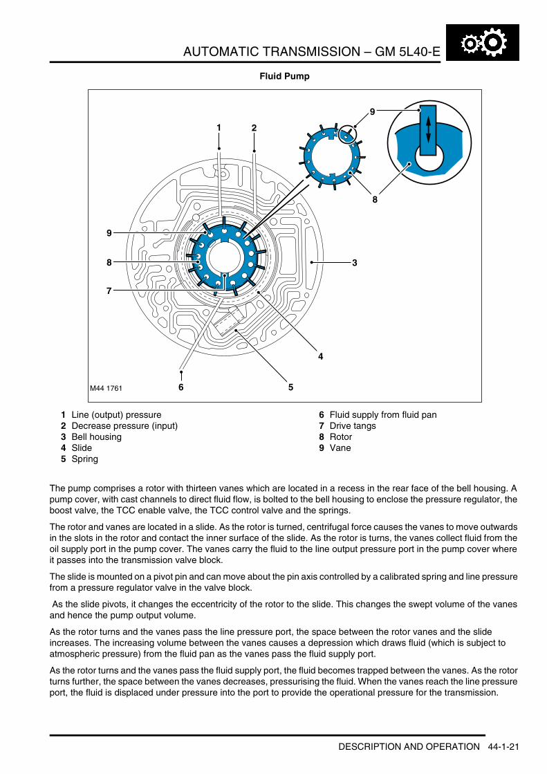
AUTOMATIC TRANSMISSION – GM 5L40-E
Fluid Pump
1 Line (output) pressure2 Decrease pressure (input)3 Bell housing4 Slide5 Spring
6 Fluid supply from fluid pan7 Drive tangs8 Rotor9 Vane
The pump comprises a rotor with thirteen vanes which are located in a recess in the rear face of the bell housing. A pump cover, with cast channels to direct fluid flow, is bolted to the bell housing to enclose the pressure regulator, the boost valve, the TCC enable valve, the TCC control valve and the springs.
The rotor and vanes are located in a slide. As the rotor is turned, centrifugal force causes the vanes to move outwards in the slots in the rotor and contact the inner surface of the slide. As the rotor is turns, the vanes collect fluid from the oil supply port in the pump cover. The vanes carry the fluid to the line output pressure port in the pump cover where it passes into the transmission valve block.
The slide is mounted on a pivot pin and can move about the pin axis controlled by a calibrated spring and line pressure from a pressure regulator valve in the valve block.
As the slide pivots, it changes the eccentricity of the rotor to the slide. This changes the swept volume of the vanes and hence the pump output volume.
As the rotor turns and the vanes pass the line pressure port, the space between the rotor vanes and the slide increases. The increasing volume between the vanes causes a depression which draws fluid (which is subject to atmospheric pressure) from the fluid pan as the vanes pass the fluid supply port.
As the rotor turns and the vanes pass the fluid supply port, the fluid becomes trapped between the vanes. As the rotor turns further, the space between the vanes decreases, pressurising the fluid. When the vanes reach the line pressure port, the fluid is displaced under pressure into the port to provide the operational pressure for the transmission.
M44 1761
8
9
6 5
4
3
1 2
8
7
9
DESCRIPTION AND OPERATION 44-1-21

AUTOMATIC TRANSMISSION – GM 5L40-E
Fluid Pump Output (Slide) Adjustment
1 Pivot pin2 Decrease flow3 Decrease pressure
4 Calibrated spring pressure5 Increase flow
When the engine is cranked, there is no pressure in the system, and the calibrated spring holds the slide at a position to provide the pump with the maximum swept volume. This provides a fast prime of the pump and immediate lubrication and hydraulic pressure for the transmission.
During normal driving conditions, maximum output is not required. The pressure regulator valve applies a decrease pressure to the slide against the calibrated spring pressure to maintain the optimum output to meet the operating conditions. Minimum pump output is obtained when the spring is fully compressed by the decrease pressure.
M44 1762
1 2
5
3
4
44-1-22 DESCRIPTION AND OPERATION

AUTOMATIC TRANSMISSION – GM 5L40-E
Valve Block and Solenoid Valves
1 Torque converter clutch PWM solenoid2 Feed limit valve3 Torque converter clutch regulator valve4 Low pressure regulator valve5 Reverse lockout valve6 Manual valve7 4th-5th shift valve8 4th-5th control valve9 4th-5th shift solenoid (C)
10 2nd-3rd shift solenoid (B)11 2nd-3rd control valve12 1st-2nd shift solenoid (A)
13 2nd-3rd shift valve14 1st-2nd control valve15 1st-2nd shift valve/clutch accumulator16 1st-2nd shift valve17 2nd-3rd shift valve/clutch accumulator18 4th-5th shift valve/clutch accumulator19 Default mode valve20 3rd-4th shift valve/clutch accumulator21 Pressure control solenoid22 3rd-4th shift valve23 3rd-4th control valve.
The valve block is located in the bottom of the transmission and is covered by the fluid pan. The valve block provides electro-hydraulic control for all transmission functions and comprises the following components:l Valve block bodyl Pressure regulator solenoidl Torque converter clutch solenoidl Three shift solenoidsl Thirteen hydraulic spool valvesl Four accumulatorsl Manual valve.
DESCRIPTION AND OPERATION 44-1-23

AUTOMATIC TRANSMISSION – GM 5L40-E
Pressure Regulator Solenoid
1 Coil winding2 Valve3 Pressure supply
4 Regulated control pressure5 Return6 Spring.
The pressure regulator solenoid is located in the valve block and is secured with a spring clip. The solenoid operates in conjunction with the pressure regulator valve to control line pressure supplied to the clutches and shift control valves. The solenoid is controlled by PWM signals from the EAT ECU in response to throttle position and engine torque signals from the ECM.
When the solenoid is de-energised the pressure controlled by the solenoid is at maximum. In this condition the valve is moved under the influence of the spring, closing the return port and allowing supply pressure to pass to the clutches and control valves. As the EAT ECU increases the PWM output to the solenoid coil winding, the valve is lifted, against the spring force, opening the return port to the supply pressure. The supply pressure is directed into the return port proportional to the controlled opening of the valve. By varying the PWM signal to the coil winding and consequentially adjusting the valve opening, the pressure regulator solenoid controls the supply pressure and the regulated pressure supplied to the clutches and valves. The pressure regulator solenoid receives the supply pressure from the feed limit valve.
The resistance of the solenoid coil winding is between 3.5 and 4.6 Ω at 20°C (68°F).
Pressure Regulator ValveThe pressure regulator valve is located in the fluid pump cover. Output from the fluid pump is directed to the pressure regulator valve via the regulator solenoid valve, to control the output pressure before distribution to the transmission.
When the pump is operating at maximum output, i.e.; at initial engine start-up, line pressure from the fluid pump is felt at the accumulators, the spool valves, the pressure regulator valve and the manual valve. The pressure moves the regulator valve against its spring and line pressure is directed into the feed line to the torque converter clutch control valve, which is located in the fluid pump body, and the decrease pressure feed line to the fluid pump slide.
M44 17656 5 4
1 23
44-1-24 DESCRIPTION AND OPERATION

AUTOMATIC TRANSMISSION – GM 5L40-E
1 Fluid pump decrease pressure2 Fluid pump line (output) pressure3 Torque converter clutch control valve feed
pressure4 Pressure regulator valve
5 Boost valve6 Boost valve sleeve7 Throttle signal from pressure regulator solenoid8 Reverse clutch pressure9 Air bleed valve.
The pressure in the decrease fluid pressure line acts on the slide, reducing the fluid pump output and the pressure in the feed line. The reduced line pressure is subsequently felt at the pressure regulator valve and consequently exerts less fluid pressure in the decrease pressure line. This causes the slide to move under the calibrated spring pressure and increase the pump output. In this way the fluid pressure is constantly regulated.
The fluid pressure required to operate the clutches is controlled by the pressure regulator solenoid located in the valve block. The EAT ECU controls the position of the solenoid in relation to throttle position and engine torque signals from the ECM. As the solenoid is operated, a throttle signal pressure is applied which moves the boost valve and varies the spring pressure on the regulator valve.
M44 1764
1 2 3
9
78
4
5
6
DESCRIPTION AND OPERATION 44-1-25
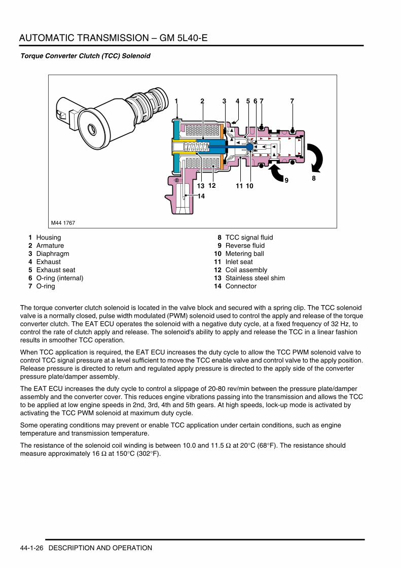
AUTOMATIC TRANSMISSION – GM 5L40-E
Torque Converter Clutch (TCC) Solenoid
1 Housing2 Armature3 Diaphragm4 Exhaust5 Exhaust seat6 O-ring (internal)7 O-ring
8 TCC signal fluid9 Reverse fluid
10 Metering ball11 Inlet seat12 Coil assembly13 Stainless steel shim14 Connector
The torque converter clutch solenoid is located in the valve block and secured with a spring clip. The TCC solenoid valve is a normally closed, pulse width modulated (PWM) solenoid used to control the apply and release of the torque converter clutch. The EAT ECU operates the solenoid with a negative duty cycle, at a fixed frequency of 32 Hz, to control the rate of clutch apply and release. The solenoid's ability to apply and release the TCC in a linear fashion results in smoother TCC operation.
When TCC application is required, the EAT ECU increases the duty cycle to allow the TCC PWM solenoid valve to control TCC signal pressure at a level sufficient to move the TCC enable valve and control valve to the apply position. Release pressure is directed to return and regulated apply pressure is directed to the apply side of the converter pressure plate/damper assembly.
The EAT ECU increases the duty cycle to control a slippage of 20-80 rev/min between the pressure plate/damper assembly and the converter cover. This reduces engine vibrations passing into the transmission and allows the TCC to be applied at low engine speeds in 2nd, 3rd, 4th and 5th gears. At high speeds, lock-up mode is activated by activating the TCC PWM solenoid at maximum duty cycle.
Some operating conditions may prevent or enable TCC application under certain conditions, such as engine temperature and transmission temperature.
The resistance of the solenoid coil winding is between 10.0 and 11.5 Ω at 20°C (68°F). The resistance should measure approximately 16 Ω at 150°C (302°F).
M44 1767
1
111213
14
10
2 3
8
77654
9
44-1-26 DESCRIPTION AND OPERATION

AUTOMATIC TRANSMISSION – GM 5L40-E
Shift Control Solenoids
1 Housing2 Armature3 Diaphragm4 Exhaust5 Exhaust seat6 O-ring7 Fluid screen8 O-ring
9 Fluid screen10 Solenoid signal fluid11 Feed limit fluid12 Metering ball13 Plunger14 Coil assembly15 Spring16 Connector
Three identical shift solenoids are used to control the operation of the transmission and select the required gear ranges. Each solenoid is a three port, on/off, normally closed solenoid controlled by the EAT ECU and are similar in construction to the torque converter clutch solenoid.
The EAT ECU provides a ground which energises the solenoid. Current flows through the solenoid coil, energising the coil which, in turn retracts the plunger. The feed limit pressure pushes the metering ball against the exhaust seat, blocking the exhaust port. The feed limit pressure is now directed through the nose of the solenoid valve and creates the signal pressure.
The shift control solenoids are de-energised when the EAT ECU removes the ground, breaking the electrical circuit. When the solenoid is de-energised, the spring force pushes the plunger which in turn, lifts the metering ball off its exhaust port seat. The metering ball then blocks feed limit pressure from entering the signal pressure port. Any residual signal pressure remaining flows past the metering ball and exits via the exhaust port.
The resistance of the solenoid coil winding is between 15.0 and 17.0 Ω at 20°C (68°F). The resistance should measure approximately 24 Ω at 150°C (302°F).
M44 1916
1
1011131415
16
12
2 3 987654
DESCRIPTION AND OPERATION 44-1-27

AUTOMATIC TRANSMISSION – GM 5L40-E
Spool ValvesThe valve block contains fourteen spool valves which control various functions of the transmission. The spool valves are of a conventional design and are either operated by fluid pressure or by solenoid operation.
Typical Spool Valve
1 Spring2 Ports3 Solenoid valve4 Spring5 Exhaust ports (return to fluid pan)
6 Spool - control valve7 Spool - shift valve8 Waisted area9 Piston
Each spool valve is located in its spool bore and held in a default (unpressurised) position by a spring. The spool bore has a number of ports which allow fluid flow to other valves and clutches to enable transmission operation. Each spool comprises one or more pistons which are waisted to allow fluid to be diverted into the applicable ports when the valve is operated.
When fluid pressure or solenoid actuation moves the spool, a port in the spool bore is uncovered or covered. Fluid flows or is prevented from flowing into the waisted area and into another uncovered port where it is passed to either another spool valve, clutch or returned to the fluid pan.
AccumulatorsThe valve block has four accumulators which are used to improve the shift 'feel' of shift changes. This is achieved by absorbing the clutch apply pressure for the second, third, fourth and fifth clutches.
M44 1768
1 2
346789
5 5 5 5
44-1-28 DESCRIPTION AND OPERATION

AUTOMATIC TRANSMISSION – GM 5L40-E
1 Line pressure from fluid pump2 Bleed port3 Clutch apply pressure from shift control valve4 Damped clutch apply pressure from shift
control valve
5 Spring6 Piston
The accumulators comprise a piston, a housing and a spring. The piston is sealed in the housing with O-ring seals and is subject to pressure applied by the spring. The housing has connection ports for fluid pump line pressure which is applied to the annulus of the piston and a port which receives clutch apply pressure from the shift valve and is applied to the full area of the piston.
When line pressure from the pump is present, the piston is moved against the spring pressure. When a shift valve moves to supply clutch apply pressure, this is applied not only to the clutch piston but also to the accumulator piston. With the clutch apply pressure on the full area of the piston and with assistance from the spring, the piston is moved back against the line pressure. These opposing pressures create an action similar to a shock absorber.
When the shift valve supplies clutch apply pressure, the pressure initially moves the clutch piston against the clutch piston spring and clutch plates. When the initial clearance between the plates is taken up, the clutch apply pressure builds rapidly. The clutch apply pressure is also applied to the full area of the accumulator piston and the rapid build up of pressure moves the accumulator piston against the line pressure, assisted by the spring.
The movement of the accumulator piston delays the build up of pressure in the circuit and provides for a more gradual application of the clutch, resulting in a smoother clutch take-up.
When the shift valve moves to cut-off the clutch apply pressure, the line pressure pushes the piston down the housing against the spring.
5
5
M44 1769
1
2
3
4
6
1
2
6
DESCRIPTION AND OPERATION 44-1-29

AUTOMATIC TRANSMISSION – GM 5L40-E
Feed Limit ValveThe shift control solenoids and the pressure regulator solenoid will be damaged if subjected to the line pressure output from the fluid pump. The feed limit valve reduces the pressure supplied to the solenoids to a pressure within the design limits of the solenoids.
The feed limit valve is spring loaded spool valve which moves under line pressure to relieve some fluid to the return line and the fluid pan, allowing fluid at reduced pressure to feed the solenoids.
Reverse Lock-out ValveThe reverse lock-out valve prevents reverse gear from being engaged until the vehicle speed is below 5 mph (8 km/h) in high range or below 2 mph (3 km/h) in low range.
When the vehicle is travelling above the defined speeds, the EAT ECU maintains the pressure regulator valve solenoid in the energised condition. This allows the torque converter signal pressure from the solenoid to hold the reverse lock-out valve spool. The spool is held in a position which prevents the reverse signal pressure from the manual valve activating the clutches required for reverse selection.
Drive Clutches
Multiplate Drive or Brake Clutch – Typical
1 Clutch housing2 Apply piston3 Friction plate4 Hub
5 Steel drive plate6 Piston release springs7 Input shaft8 Clutch apply pressure
M44 1770 6
7
8
13
2 4
5
44-1-30 DESCRIPTION AND OPERATION
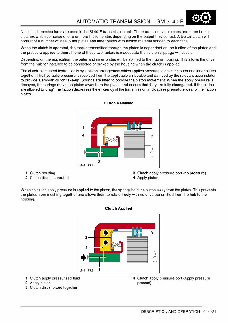
AUTOMATIC TRANSMISSION – GM 5L40-E
Nine clutch mechanisms are used in the 5L40-E transmission unit. There are six drive clutches and three brake clutches which comprise of one or more friction plates depending on the output they control. A typical clutch will consist of a number of steel outer plates and inner plates with friction material bonded to each face.
When the clutch is operated, the torque transmitted through the plates is dependant on the friction of the plates and the pressure applied to them. If one of these two factors is inadequate then clutch slippage will occur.
Depending on the application, the outer and inner plates will be splined to the hub or housing. This allows the drive from the hub for instance to be connected or braked by the housing when the clutch is applied.
The clutch is actuated hydraulically by a piston arrangement which applies pressure to drive the outer and inner plates together. The hydraulic pressure is received from the applicable shift valve and damped by the relevant accumulator to provide a smooth clutch take-up. Springs are fitted to oppose the piston movement. When the apply pressure is decayed, the springs move the piston away from the plates and ensure that they are fully disengaged. If the plates are allowed to 'drag', the friction decreases the efficiency of the transmission and causes premature wear of the friction plates.
Clutch Released
1 Clutch housing2 Clutch discs separated
3 Clutch apply pressure port (no pressure)4 Apply piston
When no clutch apply pressure is applied to the piston, the springs hold the piston away from the plates. This prevents the plates from meshing together and allows them to rotate freely with no drive transmitted from the hub to the housing.
Clutch Applied
1 Clutch apply pressurised fluid2 Apply piston3 Clutch discs forced together
4 Clutch apply pressure port (Apply pressure present)
M44 1771
2
3
4
1
M44 1772 4
3
1
2
DESCRIPTION AND OPERATION 44-1-31

AUTOMATIC TRANSMISSION – GM 5L40-E
When hydraulic apply pressure from the applicable shift valve is initially applied to the piston, the pressure overcomes the spring force and moves the piston into contact with the plates. This initial movement takes up any clearance between the plates. As the pressure behind the piston rapidly increases, the rapid pressure rise is damped by the appropriate accumulator, allowing the piston to apply force to the plates gradually. This provides a smoother clutch take up. With the plates meshed together, the housing can now be driven with the hub or the hub can be held stationary.
One Way Free Wheel Clutch
1 Sprags2 Inner race3 Outer race4 Sprag and cage assembly
5 Sprag outer race6 Sprag inner race7 Retaining ring
The 5L40-E transmission uses four free wheel clutches to perform shifting and component holding functions. The free wheel clutch, in conjunction with the damped application of the hydraulic clutches helps prevent disruption to the power output during up shifts and downshifts.
44-1-32 DESCRIPTION AND OPERATION

AUTOMATIC TRANSMISSION – GM 5L40-E
The free wheel clutches can perform three functions; hold components stationary, drive components and free wheel allowing components to rotate without a drive output. The free wheel clutches used in the 5L40-E transmission are of the sprag type and comprise an inner and outer race and a sprag and cage assembly. The inner and outer races are pressed into their related components with which they rotate. The sprag and cage assembly is located between the inner and outer races.
The sprags are located in a cage which is a spring which holds the sprags in the 'wedge' direction and maintains them in contact with the inner and outer races.
Referring to the illustration, the sprags are designed so that the dimension 'B' is larger than the distance between the inner and outer race bearing surfaces. When the outer race rotates in a clockwise direction, the sprags twist and the edges across the dimension 'B' wedge between the races, providing a positive drive through each sprag to the inner race. The dimension 'A' is smaller than the distance between the inner and outer race bearing surfaces. When the outer race rotates in an anti-clockwise direction, the dimension 'A' is too small to allow the sprags to wedge between the races, allowing the outer race to rotate freely.
On the illustration shown, when the outer race is rotated in a clockwise direction, the sprags twist and are 'wedged' between the inner and outer races. The sprags then transfer the rotation of the outer race to the inner race, which rotates at the same speed.
DESCRIPTION AND OPERATION 44-1-33

AUTOMATIC TRANSMISSION – GM 5L40-E
Planetary Gearset
1 Input sun - front2 Planetary pinion - long3 Input sun - rear4 Rear planetary pinion - short
5 Output shaft gear6 Ring gear - front7 Front planetary pinion - short8 Planetary carrier
The planetary gearset used in the 5L40-E transmission comprises of a front and rear section which together form a compound gear train. The gearset operates in conjunction with the clutches, brakes and freewheel clutches to produce the five forward gears and the reverse gear.
The planetary gearset is a single integral assembly with a common planetary carrier and a common set of long planetary gears. The gearset assembly comprises:l Two separate external ring gearsl A common planetary carrierl Two separate (front and rear) input sun gearsl One set of rear short planetary gearsl One set of front short planetary gearsl One set of three long planetary gears which are common to front and rear sections.
1
5
6
M44 1774
A B
A B
4
5
4
6
7
3
2
1
8
2
7
3
44-1-34 DESCRIPTION AND OPERATION

AUTOMATIC TRANSMISSION – GM 5L40-E
The gearset has three elements; torque inputs, reaction components and torque outputs.
The three possible torque inputs are:l Planetary carrierl Front input sun gearl Rear input sun gear.
The three possible reaction components are:l Planetary carrierl Front ring gearl Front input sun gear.
One torque output:l Rear ring gear.
The following table shows the different combinations of input components, reaction components and output components required to achieve the five forward gears and the one reverse gear ratio.
Gear Ratios
Gear Input Reaction Output Ratio1st Rear input sun gear Planetary carrier Rear ring gear 3.422nd Rear input sun gear Front ring gear Rear ring gear 2.21
3rd Rear input sun gear Front input sun gear Rear ring gear 1.6004th Rear input sun gear and planetary carrier None Rear ring gear 1.005th Planetary carrier Front input sun gear Rear ring gear 0.75
Reverse Front input sun gear Planetary carrier Rear ring gear 3.03
DESCRIPTION AND OPERATION 44-1-35

AUTOMATIC TRANSMISSION – GM 5L40-E
Power FlowsOperation of the transmission is controlled by the EAT ECU which electrically activates various solenoids to control the transmission gear selection. The sequence of solenoid activation is based on programmed information in the ECU memory and physical transmission operating conditions such as vehicle speed, engine load, throttle position and selector lever position.
Powerflow Schematic Diagram
1 Torque input from engine2 Torque converter lock-up clutch3 Torque converter unit4 Fluid pump5 One way clutch6 Transmission case7 Front input sun gear8 Planetary carrier
9 Front ring gear10 Front planetary pinion – short11 Planetary pinion – long12 Output shaft ring gear13 Rear planetary pinion – short14 Rear input sun gear15 Torque output from transmission
Engine torque output is transferred, via operation of single or combinations of clutches, to the planetary gearset. The planetary gearset is controlled by reactionary inputs from brake clutches and freewheel clutches to produce five progressive forward ratios and a single reverse ratio.
The following tables show which clutches are operating for selected gear ratios and which solenoids are activated to produce the required torque output from the transmission.
Gear Range Reference Chart
M44 1775
2
3
1
4
5
CC1 C1 CD CR
FW1
FW3
FW4
FW2
CI COD LBC C2 CC2
7
8
6
9
1011
12
1314 15
Gear Selector
Lever Position
Gear Engine Braking Yes/No
Ratio Clutches FreewheelsC1 C2 CI CD COD CC1 LBC CC2 CR 1 2 3 4
D 1 Y * 3.42 X X X(*) X XD 2 Y 2.21 X X X X X X D 3 Y 1.60 X X X X X X X
D 4 Y 1.00 X X X X X X D 5 Y 0.75 X X X X X
P/N – – –
R Y –3.03 X X RLO
* = Optional
44-1-36 DESCRIPTION AND OPERATION

AUTOMATIC TRANSMISSION – GM 5L40-E
Hydraulic Default Mode Reference Chart
Gear Change Solenoid Reference Chart
Hydraulic Default Mode Solenoid Reference Chart
NOTE: When default mode occurs when driving (no EAT ECU signal to the shift solenoid valve), the transmission will shift to 5th gear.
If the engine is then switched off and then on, 4th gear will then be selected (for better take off from standstill). The transmission will then remain in 4th gear.
Gear Selector
Lever Position
Gear Engine Braking Yes/No
Ratio Clutches FreewheelsC1 C2 CI CD COD CC1 LBC CC2 CR 1 2 3 4
D 5 Y 0.75 X X X X XD 4 Y 4 X X X X X X
Gear Selector Lever Position
Gear SolenoidsHigh Range Low
RangeA B C TCC TCC
D 1 OFF ON OFF/ON * N Y/ND 2 ON ON ON N Y/N
D 3 ON OFF ON Y/N Y/ND 4 OFF OFF ON Y/N Y/ND 5 OFF OFF OFF Y/N Y/N
P/N – OFF ON OFFR OFF ON OFF N
RLO OFF ON OFF Y
* High Range Solenoid C 'ON' (for engine braking)* High Range Solenoid C 'OFF' (no engine braking)
Gear Selector Lever Position
Gear SolenoidsHigh Range
A B C TCCD 5 – – – N
D 4 – – – N
DESCRIPTION AND OPERATION 44-1-37

AUTOMATIC TRANSMISSION – GM 5L40-E
1st Gear (D Selected)
Drive – The gear selector lever and the manual selector valve spool are in the 'D' position. Engine torque is transmitted through clutch 'C1', 'CC1' and freewheel clutch 'FW1' to the rear input sun gear. The freewheel clutch 'FW4' holds the planetary carrier stationary.
The shift solenoids are applied as follows:l Shift solenoid 'A' is OFF (de-energised)l Shift solenoid 'B' is ON (energised)l Shift solenoid 'C' is ON/OFF (energised/de-energised).
NOTE: The clutches 'C1', 'CC1' and 'LBC' are applied without damping from the accumulators.
The torque converter lock-up clutch is not applied in 1st gear high range.
Coast – The gear selector lever and manual selector valve spool are in the 'D' position. The planetary carrier is held stationary by the 'LBC' clutch. Freewheel clutch 'FW4' has no effect. Clutch 'CC1' transmits torque from the rear input sun gear to the engine input shaft. Clutch 'C1' is applied to hold freewheel clutch 'FW1' outer race stationary which becomes ineffective. Freewheel clutches 'FW2' and 'FW3' are overrunning (freewheeling).
The shift solenoids are applied as follows:l Shift solenoid 'A' is OFF (de-energised)l Shift solenoid 'B' is ON (energised)l Shift solenoid 'C' is ON (energised).
NOTE: The torque converter lock-up clutch is not applied in 1st gear high range.
M44 1776
2
3
1
45
CC1 C1
FW1
FW3
FW4
FW2
LBC
7
8
6
9
1011
12
1314
15
44-1-38 DESCRIPTION AND OPERATION
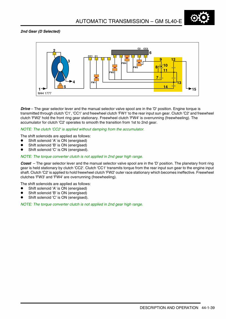
AUTOMATIC TRANSMISSION – GM 5L40-E
2nd Gear (D Selected)
Drive – The gear selector lever and the manual selector valve spool are in the 'D' position. Engine torque is transmitted through clutch 'C1', 'CC1' and freewheel clutch 'FW1' to the rear input sun gear. Clutch 'C2' and freewheel clutch 'FW2' hold the front ring gear stationary. Freewheel clutch 'FW4' is overrunning (freewheeling). The accumulator for clutch 'C2' operates to smooth the transition from 1st to 2nd gear.
NOTE: The clutch 'CC2' is applied without damping from the accumulator.
The shift solenoids are applied as follows:l Shift solenoid 'A' is ON (energised)l Shift solenoid 'B' is ON (energised)l Shift solenoid 'C' is ON (energised).
NOTE: The torque converter clutch is not applied in 2nd gear high range.
Coast – The gear selector lever and the manual selector valve spool are in the 'D' position. The planetary front ring gear is held stationary by clutch 'CC2'. Clutch 'CC1' transmits torque from the rear input sun gear to the engine input shaft. Clutch 'C2' is applied to hold freewheel clutch 'FW2' outer race stationary which becomes ineffective. Freewheel clutches 'FW3' and 'FW4' are overrunning (freewheeling).
The shift solenoids are applied as follows:l Shift solenoid 'A' is ON (energised)l Shift solenoid 'B' is ON (energised)l Shift solenoid 'C' is ON (energised).
NOTE: The torque converter clutch is not applied in 2nd gear high range.
M44 1777
2
3
1
45
CC1 C1
FW1
FW3
FW4
FW2
C2 CC2
7
8
6
9
1011
12
1314
15
DESCRIPTION AND OPERATION 44-1-39

AUTOMATIC TRANSMISSION – GM 5L40-E
3rd Gear (D Selected)
Drive – The gear selector lever and the manual selector valve spool are in the 'D' position. Engine torque is transmitted the clutch 'C1', 'CC1' and freewheel clutch 'FW1' to the rear input sun gear. Clutch 'CI' and freewheel clutch 'FW3' hold the front input sun gear stationary. The clutch 'C2' is applied to hold the freewheel clutch 'FW2' outer race stationary. Freewheel clutch 'FW2' is overrunning (freewheeling). The accumulator for clutch 'CI' operates to smooth the transition from 2nd to 3rd gear. Freewheel clutch 'FW4' is overrunning (freewheeling).
The shift solenoids are applied as follows:l Shift solenoid 'A' is ON (energised)l Shift solenoid 'B' is OFF (de-energised)l Shift solenoid 'C' is ON (energised).
From 3rd gear shifting the torque converter lock-up clutch can be applied or released by the torque converter clutch solenoid.
Coast – The gear selector lever and manual selector valve spool are in the 'D' position. The front input sun gear is held stationary by clutch 'COD'. Freewheel clutch 'FW3' has no effect. Clutch 'CC1' transmits torque from the rear input sun gear to the engine input shaft. Freewheel clutch 'FW1' has no effect. Clutch 'C2' is applied to hold freewheel clutch 'FW2' outer race stationary. Freewheel clutches 'FW2' and 'FW4' are overrunning (freewheeling).
The shift solenoids are applied as follows:l Shift solenoid 'A' is ON (energised)l Shift solenoid 'B' is OFF (de-energised)l Shift solenoid 'C' is ON (energised).
From 3rd gear shifting the torque converter lock-up clutch can be applied or released by the torque converter clutch solenoid.
M44 1778
2
3
1
45
CC1 C1
FW1
FW3
FW4
FW2
CI COD C2
7
8
6
9
1011
12
1314
15
44-1-40 DESCRIPTION AND OPERATION

AUTOMATIC TRANSMISSION – GM 5L40-E
4th Gear (D Selected)
Drive – The gear selector lever and the manual selector valve spool are in the 'D' position. Engine torque is transmitted through clutch 'C1', 'CC1' and freewheel clutch 'FW1' to the rear input sun gear. The 'CD' clutch transmits torque to the planetary carrier, enabling a 1:1 ratio. Clutch 'C2' is applied to hold freewheel clutch 'FW2' outer race stationary. Freewheel clutch 'FW2' is overrunning (freewheeling). The 'CI' clutch is applied to hold freewheel clutch 'FW3' outer race stationary. The freewheel clutches ”FW3' and FW4' are overrunning (freewheeling).
The accumulator for clutch 'CD' operates to smooth the transition from 3rd to 4th gear.
The shift solenoids are applied as follows:l Shift solenoid 'A' is OFF (de-energised)l Shift solenoid 'B' is OFF (de-energised)l Shift solenoid 'C' is ON (energised).
From 3rd gear shifting the torque converter lock-up clutch can be applied or released by the torque converter clutch solenoid.
Coast – The gear selector lever and the manual selector valve spool are in the 'D' position. Clutch 'CC1' transmits torque from the rear input sun gear to the engine input shaft. Freewheel clutch 'FW1' has no effect. The clutch 'CD' transmits torque from the planetary carrier to the engine input shaft, enabling the 1:1 ratio. Clutch 'C2' is applied to hold freewheel clutch 'FW2' outer race stationary. Freewheel clutch 'FW2' is overrunning (freewheeling). The 'CI' clutch is applied to hold freewheel clutch 'FW3' outer race stationary. Freewheel clutches 'FW3' and 'FW4' are overrunning (freewheeling).
The shift solenoids are applied as follows:l Shift solenoid 'A' is OFF (de-energised)l Shift solenoid 'B' is OFF (de-energised)l Shift solenoid 'C' is ON (energised).
From 3rd gear shifting the torque converter lock-up clutch can be applied or released by the torque converter clutch solenoid.
M44 1779
2
3
1
45
CC1 C1 CD
FW1
FW3
FW4
FW2
CI C2
7
8
6
9
1011
12
1314
15
DESCRIPTION AND OPERATION 44-1-41

AUTOMATIC TRANSMISSION – GM 5L40-E
5th Gear (D Selected)
Drive – The gear selector lever and the manual selector valve spool are in the 'D' position. Engine torque is transmitted through clutch 'CD' to the planetary carrier. Clutch 'COD' holds the front input sun gear stationary. Clutch 'C1' is applied to hold freewheel clutch 'FW1' outer race stationary. Freewheel clutch 'FW1' is overrunning (freewheeling). Clutch 'C2' is applied to hold freewheel clutch 'FW2' outer race stationary. The freewheel clutch 'FW2' is overrunning (freewheeling). The 'CI' clutch is applied to hold freewheel clutch 'FW3' outer race stationary. The freewheel clutches ”FW3' and FW4' are overrunning (freewheeling). Clutch 'CC1' is released.
The accumulator for clutch 'COD' operates to smooth the transition from 4th to 5th gear.
The shift solenoids are applied as follows:l Shift solenoid 'A' is OFF (de-energised)l Shift solenoid 'B' is OFF (de-energised)l Shift solenoid 'C' is OFF (de-energised).
From 3rd gear shifting the torque converter lock-up clutch can be applied or released by the torque converter clutch solenoid.
Coast – The gear selector lever and the manual selector valve spool are in the 'D' position. The 'CD' clutch transmits torque from the planetary carrier to the engine input shaft. The 'COD' clutch holds the front input sun gear stationary through the freewheel clutch 'FW3' inner race. The 'C1' clutch is applied to hold the freewheel clutch 'FW1' outer race stationary. The freewheel clutch 'FW1' is overrunning (freewheeling). The 'CI' clutch is applied to hold the freewheel clutch 'FW3' outer race stationary and the clutch 'COD' holds the freewheel clutch 'FW3' inner race stationary. The freewheel clutch 'FW3' becomes ineffective. The freewheel clutch 'FW4' is overrunning (freewheeling).
The shift solenoids are applied as follows:l Shift solenoid 'A' is OFF (de-energised)l Shift solenoid 'B' is OFF (de-energised)l Shift solenoid 'C' is OFF (de-energised).
From 3rd gear shifting the torque converter lock-up clutch can be applied or released by the torque converter clutch solenoid.
M44 1780
2
3
1
45
C1 CD
FW1
FW3
FW4
FW2
CI COD C2
7
8
6
9
1011
12
1314 15
44-1-42 DESCRIPTION AND OPERATION

AUTOMATIC TRANSMISSION – GM 5L40-E
Reverse Gear
Drive – The gear selector lever and the manual selector valve spool are in the 'R' position. Engine torque is transmitted through clutch 'CR' to the front input sun gear. The clutch 'LBC' holds the planetary carrier stationary. The clutch 'CR' is applied without damping from the accumulator.
The reverse gear is selected using hydraulic selections only.
The shift solenoids are energised as follows:l Shift solenoid 'A' is OFF/ON (de-energised/energised)l Shift solenoid 'B' is OFF/ON (de-energised/energised)l Shift solenoid 'C' is OFF/ON (de-energised/energised).
NOTE: The torque converter lock-up clutch is not applied in reverse gear.
Coast – The gear selector lever and the manual selector valve spool are in the 'R' position. The clutch 'CR' transmits torque from the front input sun gear to the engine input shaft. The clutch 'LBC' holds the planetary carrier stationary.
NOTE: The clutch 'CR' is applied without damping from the accumulators.
The reverse gear is selected using hydraulic selections only.
The shift solenoids are energised as follows:l Shift solenoid 'A' is OFF/ON (de-energised/energised)l Shift solenoid 'B' is OFF/ON (de-energised/energised)l Shift solenoid 'C' is OFF/ON (de-energised/energised).
NOTE: The torque converter lock-up clutch is not applied in reverse gear.
ParkThe gear selector lever and the manual selector valve spool are in the 'P' PARK position. In this condition no clutches or freewheel clutches are applied. The engine input shaft rotates freely and the planetary carrier output shaft is held stationary by the parking lock pawl.
The shift solenoids are energised as follows:l Shift solenoid 'A' is OFF (de-energised)l Shift solenoid 'B' is ON (energised)l Shift solenoid 'C' is OFF (de-energised).
NeutralThe gear selector lever and the manual selector valve spool are in the 'N' NEUTRAL position. In this condition no clutches or freewheel clutches are applied. The engine input shaft rotates freely with no torque transferred to the output shaft.
The shift solenoids are energised as follows:l Shift solenoid 'A' is OFF/ON (de-energised/energised)l Shift solenoid 'B' is OFF/ON (de-energised/energised)l Shift solenoid 'C' is OFF/ON (de-energised/energised).
M44 1781
2
3
1
45
CC1 C1 CD CR
FW1
FW3
FW4
FW2
CI COD LBC C2 CC2
7
8
6
9
1011
12
1314 15
DESCRIPTION AND OPERATION 44-1-43

AUTOMATIC TRANSMISSION – GM 5L40-E
Default Mode
The shift solenoids are energised as follows:l Shift solenoid 'A' is OFF (de-energised)l Shift solenoid 'B' is OFF (de-energised)l Shift solenoid 'C' is OFF (de-energised)
The EAT ECU cannot operate the torque converter clutch solenoid, so torque converter lock-up is not available.
When default mode occurs when driving (no EAT ECU signal to the shift solenoid valve), the transmission will shift to 5th gear. Powerflow diagram and drive description is the same as described for 5th gear.
When the engine is switched off and then on, 4th gear will be selected. Powerflow diagram and drive description is the same as described for 4th gear.
SensorsThe transmission contains two speed sensors and a transmission temperature sensor. These sensors are located inside the transmission, with only the speed sensors being serviceable items. The sensors play an important part in the operation of the transmission and provide signal information to the EAT ECU. This information is used by the EAT ECU to control shift timing, fluid temperature and provide the optimum operating condition for the transmission.
Speed Sensors
The speed sensors are used to by the EAT ECU to monitor the input shaft and output shaft speeds.
The input shaft speed is monitored to allow the EAT ECU to calculate the slip of the torque converter clutch and internal clutch slip. This allows the EAT ECU to accurately control the slip time during shifts and alter the clutch application or release pressure for overlap shift control.
M44 1782
2
3
1
45
7
8
6
9
1011
12
1314
15
44-1-44 DESCRIPTION AND OPERATION
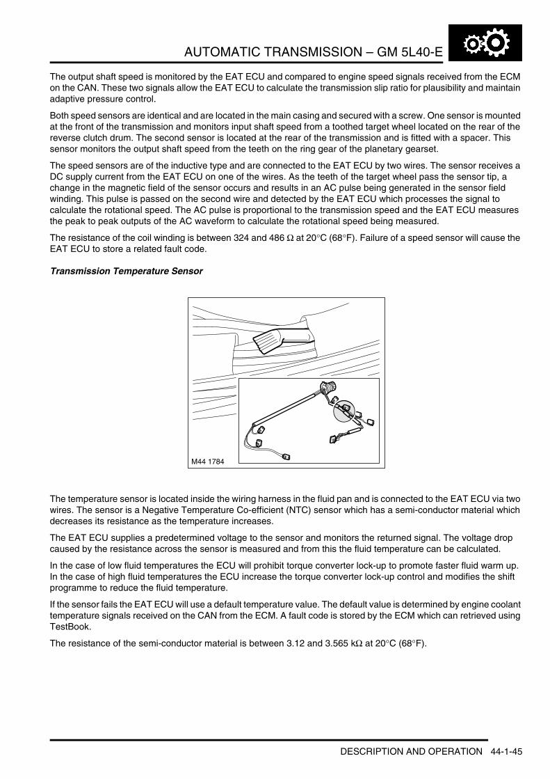
AUTOMATIC TRANSMISSION – GM 5L40-E
The output shaft speed is monitored by the EAT ECU and compared to engine speed signals received from the ECM on the CAN. These two signals allow the EAT ECU to calculate the transmission slip ratio for plausibility and maintain adaptive pressure control.
Both speed sensors are identical and are located in the main casing and secured with a screw. One sensor is mounted at the front of the transmission and monitors input shaft speed from a toothed target wheel located on the rear of the reverse clutch drum. The second sensor is located at the rear of the transmission and is fitted with a spacer. This sensor monitors the output shaft speed from the teeth on the ring gear of the planetary gearset.
The speed sensors are of the inductive type and are connected to the EAT ECU by two wires. The sensor receives a DC supply current from the EAT ECU on one of the wires. As the teeth of the target wheel pass the sensor tip, a change in the magnetic field of the sensor occurs and results in an AC pulse being generated in the sensor field winding. This pulse is passed on the second wire and detected by the EAT ECU which processes the signal to calculate the rotational speed. The AC pulse is proportional to the transmission speed and the EAT ECU measures the peak to peak outputs of the AC waveform to calculate the rotational speed being measured.
The resistance of the coil winding is between 324 and 486 Ω at 20°C (68°F). Failure of a speed sensor will cause the EAT ECU to store a related fault code.
Transmission Temperature Sensor
The temperature sensor is located inside the wiring harness in the fluid pan and is connected to the EAT ECU via two wires. The sensor is a Negative Temperature Co-efficient (NTC) sensor which has a semi-conductor material which decreases its resistance as the temperature increases.
The EAT ECU supplies a predetermined voltage to the sensor and monitors the returned signal. The voltage drop caused by the resistance across the sensor is measured and from this the fluid temperature can be calculated.
In the case of low fluid temperatures the ECU will prohibit torque converter lock-up to promote faster fluid warm up. In the case of high fluid temperatures the ECU increase the torque converter lock-up control and modifies the shift programme to reduce the fluid temperature.
If the sensor fails the EAT ECU will use a default temperature value. The default value is determined by engine coolant temperature signals received on the CAN from the ECM. A fault code is stored by the ECM which can retrieved using TestBook.
The resistance of the semi-conductor material is between 3.12 and 3.565 kΩ at 20°C (68°F).
M44 1784
DESCRIPTION AND OPERATION 44-1-45

AUTOMATIC TRANSMISSION – GM 5L40-E
Inhibitor Switch
The inhibitor switch is located internally on the left hand side of the transmission. It is connected via a selector shaft which rotates with the position of the selector lever. The switch allows the EAT ECU to monitor the position of the manual selector spool valve and the selected drive program.
The switch is connected to the EAT ECU via six wires and a multiplug. One of the wires supplies a 12V supply to the switch. The remaining wires are connected to ground within the EAT ECU. When the selector lever is moved to the selected position, one or more contacts within the switch are made completing a circuit back to the ECU. From the switch contacts which are made, the ECU determines which selection is required and responds accordingly.
When the selector lever is in Park, the EAT ECU transmits a signal to the immobilisation ECU to enable starter operation.
The following table shows which switch contacts are made for a given selector lever position.
Inhibitor Switch Track N/P A B C PEAT ECU Connector 4 Pins Pin 2 Pin 14 Pin 15 Pin 16 Pin 17Transmission Harness Connector Pins
4 16 7 19 11
PARK X X XREVERSE X X
NEUTRAL X X XDRIVE X XX = High signal
44-1-46 DESCRIPTION AND OPERATION

AUTOMATIC TRANSMISSION – GM 5L40-E
Fluid Cooling
1 Fluid feed2 Fluid return3 Transmission fluid cooler
4 Engine coolant feed5 Engine coolant return
The fluid cooler is located on the left hand side of the engine and is attached to the sump near the front of the engine. The cooler is cooled by engine coolant which flows in a water jacket around cores within the cooler body. Transmission fluid enters the cooler and flows through the cores where it is cooled by the engine coolant. The fluid leaves the cooler and is passed back to lubricate the transmission before it returns to the transmission sump.
The fluid cooler receives its engine coolant supply from the radiator via a hose into a quick release fitting on the side of the cooler. The coolant flows through the cooler and exits via another hose on the forward face of the cooler, where it is passed through the engine coolant circuit.
The fluid cooler has a thermostatic valve which is opened by transmission fluid temperature. The thermostatic valve is opened at a transmission fluid temperature of between 91 and 95°C (196 and 203°F) and allows engine coolant to flow through the fluid cooler.
M44 1788A
3
5
4
1
3
1
2
2
DESCRIPTION AND OPERATION 44-1-47

AUTOMATIC TRANSMISSION – GM 5L40-E
Gear Selector Lever Assembly
1 Selector cable2 Shift interlock solenoid3 Selector lever4 Manual +/– Steptronic switch5 Selector knob and shroud6 Park/Reverse release button7 Selector lever cover8 High/Low range selector switch
9 Selector position LED display10 Hill Descent Control (HDC) switch11 Key interlock cable12 Key interlock mechanism13 Selector lever position switch14 Manual/Sport switch15 Mounting plate
The gear selector lever assembly is located in a central position on the transmission tunnel, between the front driver and passenger seats. A mounting plate is secured to the transmission tunnel and provides the mounting for the selector lever assembly.
44-1-48 DESCRIPTION AND OPERATION

AUTOMATIC TRANSMISSION – GM 5L40-E
The selector lever comprises a cast mounting plate which provides for the location of the selector components. The lever is connected to a gimbal mechanism which allows for the selection of P, R, N, D in a forward or backward direction and selection between automatic and manual/sport in a left/right transverse direction. When manual/sport mode is selected, the lever can be moved in a forward or backward direction to select + or – for manual (Steptronic) operation.
When the selector lever is moved to the M/S position, the Bowden cable to the transmission is mechanically disconnected at the shifter. If left in Sport mode all gear changes are performed automatically. If Manual (Steptronic) mode is selected, all gear changes are based on switched ground inputs received by the EAT ECU from the Manual +/– Steptronic switch.
The selector mechanism houses the following components:l Manual +/– Steptronic switchl Shift interlock solenoidl High/Low range selector switchl Hill Descent Control (HDC) switchl Selector position LED displayl Selector lever position switchl Manual/Sport switchl Key interlock mechanism.
There are four selector lever positions and two additional positions for manual/sport operation:l P (Park) – Prevents the vehicle from moving by locking the transmissionl R (Reverse) – Select only when the vehicle is stationary and the engine is at idle – selects reverse directionl N (Neutral) – No torque transmitted to drive wheelsl D (Drive) – This position uses all five forward gears in high and low rangesl M/S (Sport mode) – This position uses all five forward gears as in 'D', but will upshift at higher engine speeds
improving accelerationl + and – ('Steptronic' mode)– Movement of the selector lever in the +/– positions, when the lever is in the M/S
position, will operate the transmission in manual (Steptronic) mode, allowing the driver to manually select all five forward gears.
The selector lever position is displayed to the driver on the selector position LED display and in the instrument pack. In 'Steptronic' mode, if a gear is selected, but the EAT ECU logic prevents selection of that gear, the requested gear is initially displayed. The EAT ECU will engage the next allowed gear and then display that gear.
Manual +/– Steptronic SwitchThe manual +/– switch is located on the left hand side of the selector lever assembly. The switch comprises a housing which provides the location for a sliding contact. When the selector lever is moved to the manual/sport position, a dog on the lever engages with a slotted abutment on the switch sliding contact. When the lever is moved to the + or – position the dog moves the switch completing a momentary earth circuit with one of two microswitches at each end of the switch which correspond to the + or – positions.
This momentary signal is received by the EAT ECU which, on first operation of the switch, initiates manual mode and operates the transmission in the selected gear.
In this position, a spring will move the selector lever to the centre position when released.
Shift Interlock SolenoidThe shift interlock solenoid is located at the front of the selector lever assembly. The selector lever is connected to a locking plate which has two holes which correspond to the 'P' and 'N' positions. When the ignition is on or the engine is running, the solenoid is energised by the EAT ECU when the selector lever is in the 'P' or 'N' positions. When energised, the solenoid ejects a pin which engages in the locking plate preventing the lever from being moved.
When the footbrake is applied, a signal from a brake switch is passed to the EAT ECU which de-energises the solenoid allowing the lever to be moved from the 'P' or 'N' position. This prevents the selector from being moved to the 'D' or 'R' position unintentionally and the application of the brakes also prevents the vehicle 'creeping' when the gear is engaged.
DESCRIPTION AND OPERATION 44-1-49
AUTOMATIC TRANSMISSION – GM 5L40-E
High/Low Range Selector SwitchThe high/low range switch is located on the selector lever cover, on the right hand side of the selector lever. The switch can be identified by the a high/low range legend graphic and the switch lever is coloured white. High or low range can be selected using this switch providing the vehicle speed is within defined limits and the gear selector lever is in the neutral position. + TRANSFER BOX, DESCRIPTION AND OPERATION, Description.
Hill Descent Control (HDC) SwitchThe HDC switch is located on the selector lever cover, on the left hand side of the selector lever. The switch can be identified by the HDC legend graphic and the switch lever is coloured yellow. Operation of the HDC switch is not directly related to automatic transmission operation. + BRAKES, DESCRIPTION AND OPERATION, Foundation Brakes.
Selector Position LED DisplayThe selector position LED display is located on the selector lever cover, between the HDC and high/low range switches. The display has a graphic which shows the lever positions P, R, N, D, M/S and +/–. The P, R, N, D and M/S positions each have a small, red LED which illuminates when that position is selected. The +/– positions do not have an LED.
The LED display is controlled by the selector lever position switch, with the two components connected via a five wire ribbon cable. The LED display is powered from the Body Control Unit (BCU) and remains illuminated until the BCU is in sleep mode. The LED display is active at all times when the ignition is on.
Selector Lever Position SwitchThe selector lever position switch is located on the right hand side of the selector lever assembly. The switch has a moving contact which is connected to the selector lever. As the lever is moved, the sliding contact moves in the switch completing a circuit with four further contacts in the switch which represent the four lever positions; P, R, N and D. The switch is connected to the selector position LED display via a ribbon cable and provides the power for the display LED's. The switch receives its power supply from the BCU.
Manual/Sport SwitchThe manual/sport switch is located at the rear of the selector lever assembly. The manual/sport switch is a cam operated microswitch. A lever with a roller is attached to the switch body. When the selector lever is moved from the automatic 'D' position to the manual/sport 'M/S' position, the roller contacts a cam on the selector lever which depresses the switch lever and operates the switch. The switch contacts remain closed when the selector lever is in the manual/sport position.
The operation of the switch completes an earth path which is sensed by the EAT ECU which switches the transmission operation to sport when ’M/S’ is selected and deselects sport mode when ’D’ (automatic operation) is reselected. The completed earth path is connected to the EAT ECU via the M/S LED on the selector lever display which is illuminated by an output from the ECU when M/S is selected.
Selector CableThe selector cable is a Bowden type cable that connects the selector lever to the manual selector spool valve. A ’C’ clip secures the outer cable to the selector lever assembly. The inner cable is secured to an arm which is connected to the selector lever via a 'U' shaped bracket and pin.
The transmission end of the outer cable is secured to a bracket on the transmission by a clamp nut. The transmission has an operating lever which is attached to and operates the manual selector control spool valve. The inner cable is attached to the operating lever by a clamp bush and locknut. The clamp bush allows for the adjustment of the selector cable.
44-1-50 DESCRIPTION AND OPERATION

AUTOMATIC TRANSMISSION – GM 5L40-E
Key Interlock Mechanism
1 Ignition key2 Ignition switch3 Bowden cable
4 Latch gate5 Selector lever assembly
The key interlock mechanism prevents the key from being removed from the ignition switch when the selector lever is any position other than 'P' PARK. This prevents the vehicle being accidentally left in neutral which would cause the vehicle to move if the handbrake was not applied.
The mechanical mechanism is operated by a Bowden cable which is attached between the selector lever assembly and the ignition switch. When the ignition switch is turned to the on position, the switch rotates a lever which in turn pulls the cable. This lifts a latch in the selector lever assembly which is engaged with the selector lever when in the 'P' position.
DESCRIPTION AND OPERATION 44-1-51

AUTOMATIC TRANSMISSION – GM 5L40-E
Instrument Pack
1 Instrument pack2 Transmission status display
3 Message centre4 Malfunction Indicator Lamp (MIL)
The instrument pack is connected to the EAT ECU via the CAN. Transmission status is transmitted by the EAT ECU and displayed to the driver on one of two displays in the instrument pack. + INSTRUMENTS, DESCRIPTION AND OPERATION, Description.
Malfunction Indicator Lamp (MIL)The MIL is located in the lower left hand corner of the instrument pack, below the fuel gauge. Transmission related faults which may affect the vehicle emissions output will illuminate the MIL.
The MIL is illuminated by the ECM on receipt of a relevant fault message from the EAT ECU on the CAN. The nature of the fault can be diagnosed using TestBook which reads fault codes stored in the ECU memory.
Transmission Status DisplayThe transmission status display is located on the right hand side of the instrument pack, below the tachometer. The display shows the selector lever position and in the case of manual (Steptronic) mode, the selected gear. The selector lever position and gear selected displays are illuminated in a green colour when active.
70
1/21/2
1/11/1
MPHMPH
10
90
50503
03
0
1101
30
150
M44 1910
4 3 2
1
Symbol DescriptionP Park selectedR Reverse selected
N Neutral selectedD Drive selected1 1st gear selected (Manual mode)
2 2nd gear selected (Manual mode)3 3rd gear selected (Manual mode)4 4th gear selected (Manual mode)
5 5th gear selected (Manual mode)Low range selected. Flashes when changing from low to high range.
44-1-52 DESCRIPTION AND OPERATION

AUTOMATIC TRANSMISSION – GM 5L40-E
Additionally, the display also shows a low range symbol when low range is selected on. The low range symbol is illuminated in an amber colour when active. When the transfer box is changing from low to high range, the low range symbol flashes until the range change is complete.
Message Centre DisplayThe message centre is located below the speedometer and the tachometer at the bottom of the instrument pack. The message centre is a Liquid Crystal Display (LCD) to relay vehicle status information to the driver. The message centre can display the following transmission related messages:l SPORT MODEl MANUAL MODEl SELECT NEUTRALl TRANSMISS'N OVERHEATl TRANSMISS'N FAILSAFE PROGl LOW RANGEl HIGH RANGEl SLOW DOWNl SELECT NEUTRAL.
DESCRIPTION AND OPERATION 44-1-53
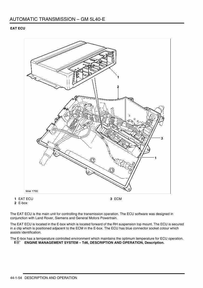
AUTOMATIC TRANSMISSION – GM 5L40-E
EAT ECU
1 EAT ECU2 E-box
3 ECM
The EAT ECU is the main unit for controlling the transmission operation. The ECU software was designed in conjunction with Land Rover, Siemens and General Motors Powertrain.
The EAT ECU is located in the E-box which is located forward of the RH suspension top mount. The ECU is secured in a clip which is positioned adjacent to the ECM in the E-box. The ECU has blue connector socket colour which assists identification.
The E-box has a temperature controlled environment which maintains the optimum temperature for ECU operation. + ENGINE MANAGEMENT SYSTEM – Td6, DESCRIPTION AND OPERATION, Description.
44-1-54 DESCRIPTION AND OPERATION

AUTOMATIC TRANSMISSION – GM 5L40-E
Inputs and OutputsThe sensor signals allow the EAT ECU to monitor the transmission operation. The ECU processes the incoming signals and compares this information with data stored in its memory. If the received signals are not within the stored values, the ECU will make adjustments to the transmission operation using the solenoids to provide optimum driveability and performance.
The sensor inputs provide the EAT ECU with a constant update of the operating condition of the transmission and the engine. The ECU compares this input data with mapped information stored in its memory and will make any required adjustment to the operation of the transmission by operating the solenoids.
The EAT ECU uses three harness connectors for all input and output information.
EAT ECU Harness Connector C0193 Pin Details
EAT ECU Harness Connector C0932 Pin Details
Pin No. Description Input/Output1 Ground for shift interlock solenoid Input2 Power supply for shift interlock solenoid Output
3 Park signal to steering lock ECU Output4 to 8 Not used –
9 Range change request 1 Output
10 Range change request 2 Output11 to 17 Not used –
18 High/Low range switch Input
19 Selector manual Steptronic switch UP Input20 Selector manual Steptronic switch DOWN Input
21 to 52 Not used –
Pin No. Description Input/Output1 Ignition power supply Input
2 and 3 Not used –4 Electronic ground –
5 Power ground –6 Power ground –7 Permanent battery power supply Input
8 Power supply from main relay Input9 Power supply from main relay Input
DESCRIPTION AND OPERATION 44-1-55

AUTOMATIC TRANSMISSION – GM 5L40-E
EAT ECU Harness Connector C1835 Pin Details
Main RelayThe main relay is located inside the E-box and is identified by its blue colour. The relay is connected direct from the battery via a 100 Amp remote fuse, located behind the battery, adjacent to the transfer box ECU. The relay coil is controlled by the ECM which provides a ground for the coil when the relay is to be energised.
When energised the main relay supplies battery voltage, via fuse 4 in the engine compartment fusebox, to the EAT ECU.
DiagnosticsThe diagnostic socket is located in the fascia, in the driver's side stowage tray. The socket is secured in the fascia panel and protected by a hinged cover.
Pin No. Description Input/Output1 Neutral/Park selected signal Input2 Ignition supply to inhibitor switch Output3 Power supply for solenoids Output
4 and 5 Not used –6 Ground for TCC PWM Solenoid Input7 Not used –
8 Ground for pressure regulator solenoid Input9 Ground for shift valve solenoid C Input
10 Ground for shift valve solenoid B Input
11 Power supply for pressure regulator solenoid Output12 and 13 Not used –
14 Inhibitor switch track A Input
15 Inhibitor switch track B Input16 Inhibitor switch track C Input17 Inhibitor switch track P Input
18 Power supply for temperature sensor Output19 Temperature sensor analogue signal Input20 Ground for shift valve solenoid A Input
21 and 22 Not used –23 Input shaft speed sensor supply Output24 Input shaft speed sensor signal Input
25 Input shaft speed sensor screen –26 to 31 Not used –
32 Diagnostic K line (via ECM) Input/Output
33 to 35 Not used –36 CAN bus high Input/Output37 CAN bus low Input/Output
38 Output shaft speed sensor screen –39 Output shaft speed sensor signal Input40 Output shaft speed sensor supply Output
44-1-56 DESCRIPTION AND OPERATION

AUTOMATIC TRANSMISSION – GM 5L40-E
Diagnostic Socket
1 Cover 2 Diagnostic socket
The diagnostic socket allows the exchange of information between the various ECU's on the bus systems and TestBook or a diagnostic tool using Keyword 2000 protocol. The information is communicated to the socket via a diagnostic ISO9141 K Line. This allows the retrieval of diagnostic information and programming of certain functions using TestBook or a suitable diagnostic tool.
The EAT ECU uses a P Code strategy which stores industry standard and Land Rover specific Diagnostic Trouble Codes (DTC) relating to faults.
Controller Area Network (CAN) BusThe CAN bus is a high speed broadcast network connected between the following electronic units:l EAT ECUl ECMl Transfer box ECUl Air suspension ECUl Instrument packl ABS ECUl Steering angle ECU.
The CAN allows the fast exchange of data between ECU's every few microseconds. The bus comprises two wires which are identified as CAN high (H) and CAN low (L). The two wires are coloured yellow/black (H) and yellow/brown (L) and are twisted together to minimise electromagnetic interference (noise) produced by the CAN messages. + COMMUNICATION DATA BUSES, DESCRIPTION AND OPERATION, Description.
In the event of a CAN bus failure the following symptoms may be observed:l Transmission operates in default model Torque converter lock-up control is disabledl ECM to EAT ECU engine torque reduction message inoperativel Gear position display in instrument pack inoperative.
DESCRIPTION AND OPERATION 44-1-57

AUTOMATIC TRANSMISSION – GM 5L40-E
Operation
Driving ModesThere are a number of different driving modes of operation. Some can be selected by the driver and some are automatically initiated by the EAT ECU during driving:l Normal model Sport model Manual (Steptronic) model Hill Descent Control (HDC) model Cruise model Hill model Default (Limp home) model Reverse lock-out model Cooling strategy.
Normal ModeNormal mode is automatically selected by the EAT ECU on power up. In this mode all automatic and adaptive modes are active. Normal mode uses gear shift and lock-up maps to allow vehicle operation which is a compromise between performance, fuel consumption and emissions. If the transmission is operated in sport or manual mode and the selector lever is moved to the 'D' position, normal mode is automatically resumed.
Sport ModeThe sport mode operates in high range only and provides enhanced acceleration and responsiveness. In sport mode the EAT ECU uses shift maps which allow the transmission to downshift more readily, hold gears for longer at higher engine speeds, and limits the transmission to 4th gear.
Sport mode is selected by moving the selector lever to the left into the 'M/S' position. When the sport mode is first selected, 'SPORT' is displayed in the message centre for 6 seconds and, if 5th gear is currently engaged, the EAT ECU downshifts to 4th.
Manual (Steptronic) ModeManual mode allows the transmission to operate as a semi-automatic 'Steptronic' unit. The driver can change up and down the five forward gears with the freedom of a manual transmission.
Shift maps are provided for manual mode to protect the engine at high engine speeds. The EAT ECU will automatically change up to a higher gear ratio to prevent engine overspeed and change down to a lower gear ratio to avoid engine labouring and stalling.
When kickdown is requested the EAT ECU downshifts at least 2 gears.
When the vehicle is stationary, to drive off the driver can select 1st or 2nd gear in high range, or 1st, 2nd or 3rd gear in low range. Any other gear selection will be rejected by the EAT ECU.
When driving off, upshifts can be pre-selected by making + selections with the selector lever for the number of upshifts required. The EAT ECU then automatically performs a corresponding number of upshifts when the appropriate shift points are reached. So, for example, when starting off in 1st gear, if three + selections are made in quick succession, the EAT ECU will automatically change up through the box to 4th gear as the vehicle accelerates, without any further selections being made.
In manual mode a low gear can be selected to provide engine braking for descending a slope without HDC or continuous use of the brake pedal. The driver can prepare for the end of the descent by moving the selector lever to D. The EAT ECU will maintain the low gear and only revert to automatic shift control when the throttle is opened and vehicle speed increases.
44-1-58 DESCRIPTION AND OPERATION

AUTOMATIC TRANSMISSION – GM 5L40-E
HDC ModeThe HDC mode assists the ABS ECU in controlling the downhill speed of the vehicle. When HDC is selected on, the EAT ECU selects the most appropriate gear for the descent, to maximise engine braking.
Cruise ModeWhen cruise control is activated, the EAT ECU receives a cruise active message on the CAN. The EAT ECU activates a cruise control map which prevents locking and unlocking of the torque converter clutch and minimises up and down shifts. If cruise control is operative and the vehicle speed increases due to coasting downhill, the ECM can request a down shift via a CAN message if the vehicle speed exceeds the set cruise limit.
Hill ModeHill mode is initiated by the EAT ECU when high engine torque, high throttle angle and low engine speed is detected via ECM signals on the CAN. The EAT ECU defines this combination of signals to determine when the vehicle is travelling on a steep gradient.
In hill mode the EAT ECU adopts one of three shift maps which hold the transmission in low gears throughout the ascent. The shift map chosen depends on the severity of the slope as determined from the engine signals.
Hill mode can also be initiated when the vehicle is at very high altitudes.
Default (Limp Home) ModeIf a transmission fault is detected by the EAT ECU, the ECU adopts a limp home mode strategy. 'TRANS.FAILSAFE' is displayed in the message centre and, if the fault has an effect on engine emissions, the MIL will also be illuminated.
In default mode, P, R and N functions operate normally (if the fault allows these selections) and the EAT ECU locks the transmission in 5th gear to allow the driver to take the vehicle to the nearest dealer. The torque converter lock-up clutch is disabled and reverse lock-out will not function.
If the vehicle is stopped and subsequently restarted in the default mode condition, the EAT ECU operates normally until the fault which caused the condition is detected again.
Reverse Lock-Out ModeWhen the vehicle is travelling forwards, selecting reverse could cause transmission damage. To protect against this, reverse gear is prohibited if the vehicle is travelling forwards at a road speed above 5 mph (8 km/h).
Cooling StrategyThe purpose of the cooling strategy is to reduce engine and transmission temperatures during high load conditions, when towing a trailer for example. Under these conditions the engine and transmission may generate excessive heat.
If the transmission fluid temperature increases to 140°C (284°F) or higher, the EAT ECU employs the cooling strategy.
The strategy uses a specific shift and torque converter lock-up clutch map. This map allows torque converter clutch lock-up and gear shifts to operate outside of their normal operation. This will reduce the engine speed and/or slip in the torque converter, therefore reducing heat generated by the engine and the transmission.
The cooling strategy is cancelled when the transmission fluid temperature decreases to 130°C (266°F) or below.
Transmission Fault StatusIf the EAT ECU detects a fault with the transmission system, it will enter a default mode to prevent further damage to the transmission and allow the vehicle to be driven.
When a fault is detected a CAN message is sent from the EAT ECU and is received by the instrument pack. The instrument pack illuminates the MIL and displays 'TRANS.FAILSAFE' in the message centre.
Some transmission faults may not illuminate the MIL or display a fault message, but the driver may notice a reduction in shift quality.
DESCRIPTION AND OPERATION 44-1-59

AUTOMATIC TRANSMISSION – GM 5L40-E
Engine Speed and Throttle MonitoringThe ECM constantly supplies the EAT ECU with information on engine speed and throttle angle through messages on the CAN. The EAT ECU uses this information to calculate the correct and appropriate timing of shift changes.
If the messages are not received by the ECM, the EAT ECU will implement a back-up strategy to protect the transmission from damage and allow the vehicle to be driven.
In the event of an engine speed signal failure, any of the following symptoms may be observed:l Decrease in fuel economyl Increase in engine emissionsl Harsh shifting.
In the event of a throttle position signal failure, any of the following symptoms may be observed:l Harsh shift changesl No kickdownl Torque reduction request inhibitedl Decrease in fuel economy.
44-1-60 DESCRIPTION AND OPERATION

AUTOMATIC TRANSMISSION – ZF 5HP24
Deze pagina werd opzettelijk niet gebruikt
Cette page est intentionnellement vierge
Questa pagina è stata lasciata in bianco di proposito
Diese Seite ist leer
Esta página foi deixada intencionalmente em branco
Esta página fue dejada en blanco intencionalmente
This page is intentionally left blank
AUTOMATIC TRANSMISSION – ZF 5HP24DESCRIPTION AND OPERATION
DESCRIPTION AND OPERATION 44-2-1

AUTOMATIC TRANSMISSION – ZF 5HP24
ZF 5HP24 Automatic Transmission Component Location
RHD model shown
44-2-2 DESCRIPTION AND OPERATION

AUTOMATIC TRANSMISSION – ZF 5HP24
1 Electronic Automatic Transmission (EAT) ECU2 Engine Control Module (ECM)3 Instrument pack4 Selector lever5 Transmission6 Transmission valve block (behind fluid pan)7 Transmission fluid cooler
DESCRIPTION AND OPERATION 44-2-3

AUTOMATIC TRANSMISSION – ZF 5HP24
ZF 5HP24 Automatic Transmission – Exploded View
Note the transmission shown is exploded to the extent of the serviceable items
44-2-4 DESCRIPTION AND OPERATION
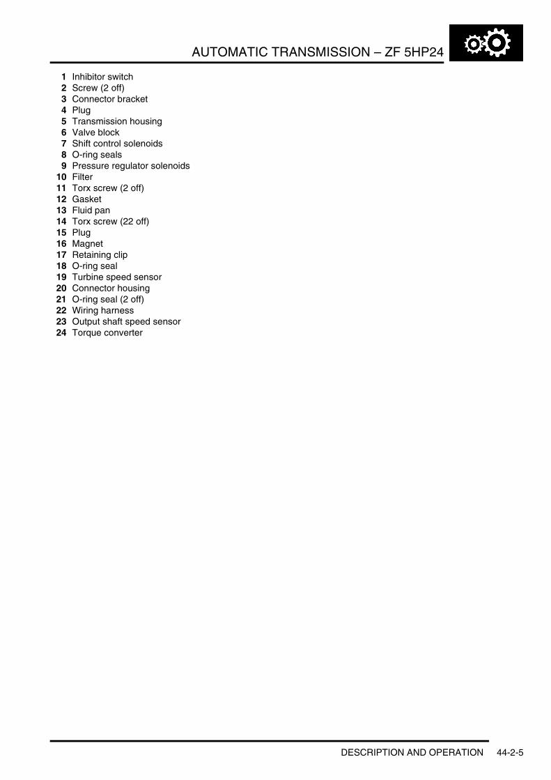
AUTOMATIC TRANSMISSION – ZF 5HP24
1 Inhibitor switch2 Screw (2 off)3 Connector bracket4 Plug5 Transmission housing6 Valve block7 Shift control solenoids8 O-ring seals9 Pressure regulator solenoids
10 Filter11 Torx screw (2 off)12 Gasket13 Fluid pan14 Torx screw (22 off)15 Plug16 Magnet17 Retaining clip18 O-ring seal19 Turbine speed sensor20 Connector housing21 O-ring seal (2 off)22 Wiring harness23 Output shaft speed sensor24 Torque converter
DESCRIPTION AND OPERATION 44-2-5
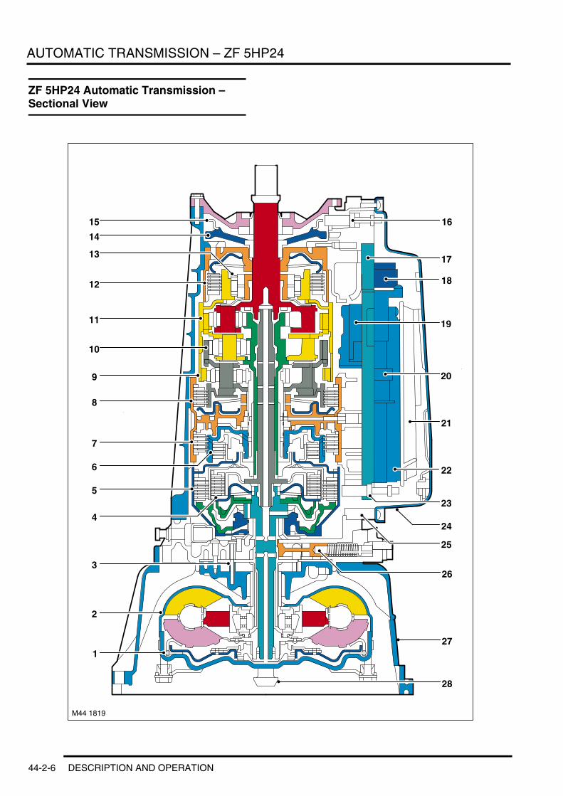
AUTOMATIC TRANSMISSION – ZF 5HP24
ZF 5HP24 Automatic Transmission – Sectional View
24
27
M44 1819
10
1
28
26
2
3
4
5
6
7
8
9
11
12
13
14
15 16
17
18
19
20
21
22
23
25
44-2-6 DESCRIPTION AND OPERATION

AUTOMATIC TRANSMISSION – ZF 5HP24
1 Torque converter lock-up clutch2 Torque converter3 Fluid pump4 Clutch A5 Clutch B6 Clutch C7 Clutch D8 Clutch E9 Planetary gearset 1
10 Planetary gearset 211 Planetary gearset 312 Clutch F13 Freewheel clutch – 1st Gear14 Park lock pawl15 Speed sensor target wheel16 Output shaft speed sensor17 Valve body channel plate18 Pressure regulator and shift control solenoids19 Upper valve body20 Rear lower valve body21 Fluid filter22 Forward lower valve body23 Turbine speed sensor24 Fluid pan25 Main casing26 Fluid pressure control valve27 Bell housing28 Input shaft
DESCRIPTION AND OPERATION 44-2-7

AUTOMATIC TRANSMISSION – ZF 5HP24
ZF 5HP24 Automatic Transmission – Valve Block and Solenoid Valves
44-2-8 DESCRIPTION AND OPERATION
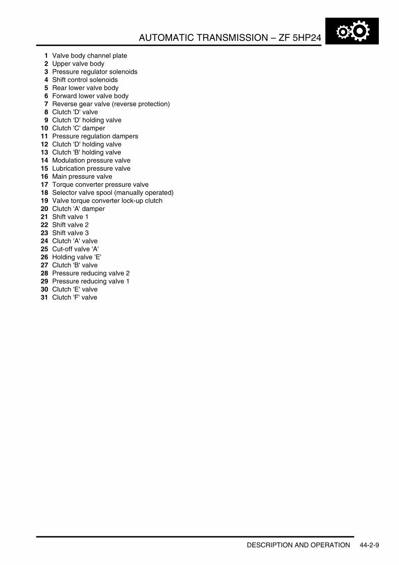
AUTOMATIC TRANSMISSION – ZF 5HP24
1 Valve body channel plate2 Upper valve body3 Pressure regulator solenoids4 Shift control solenoids5 Rear lower valve body6 Forward lower valve body7 Reverse gear valve (reverse protection)8 Clutch 'D' valve9 Clutch 'D' holding valve
10 Clutch 'C' damper11 Pressure regulation dampers12 Clutch 'D' holding valve13 Clutch 'B' holding valve14 Modulation pressure valve15 Lubrication pressure valve16 Main pressure valve17 Torque converter pressure valve18 Selector valve spool (manually operated)19 Valve torque converter lock-up clutch20 Clutch 'A' damper21 Shift valve 122 Shift valve 223 Shift valve 324 Clutch 'A' valve25 Cut-off valve 'A'26 Holding valve 'E'27 Clutch 'B' valve28 Pressure reducing valve 229 Pressure reducing valve 130 Clutch 'E' valve31 Clutch 'F' valve
DESCRIPTION AND OPERATION 44-2-9

AUTOMATIC TRANSMISSION – ZF 5HP24
ZF 5HP24 Automatic Transmission Control Diagram
A = Hardwired; D = CAN Bus; J = ISO 9141 K Line
M44 1821AA JD
13 12
14
15
16
9
1
2
3 45
6 7
8
10
11
44-2-10 DESCRIPTION AND OPERATION
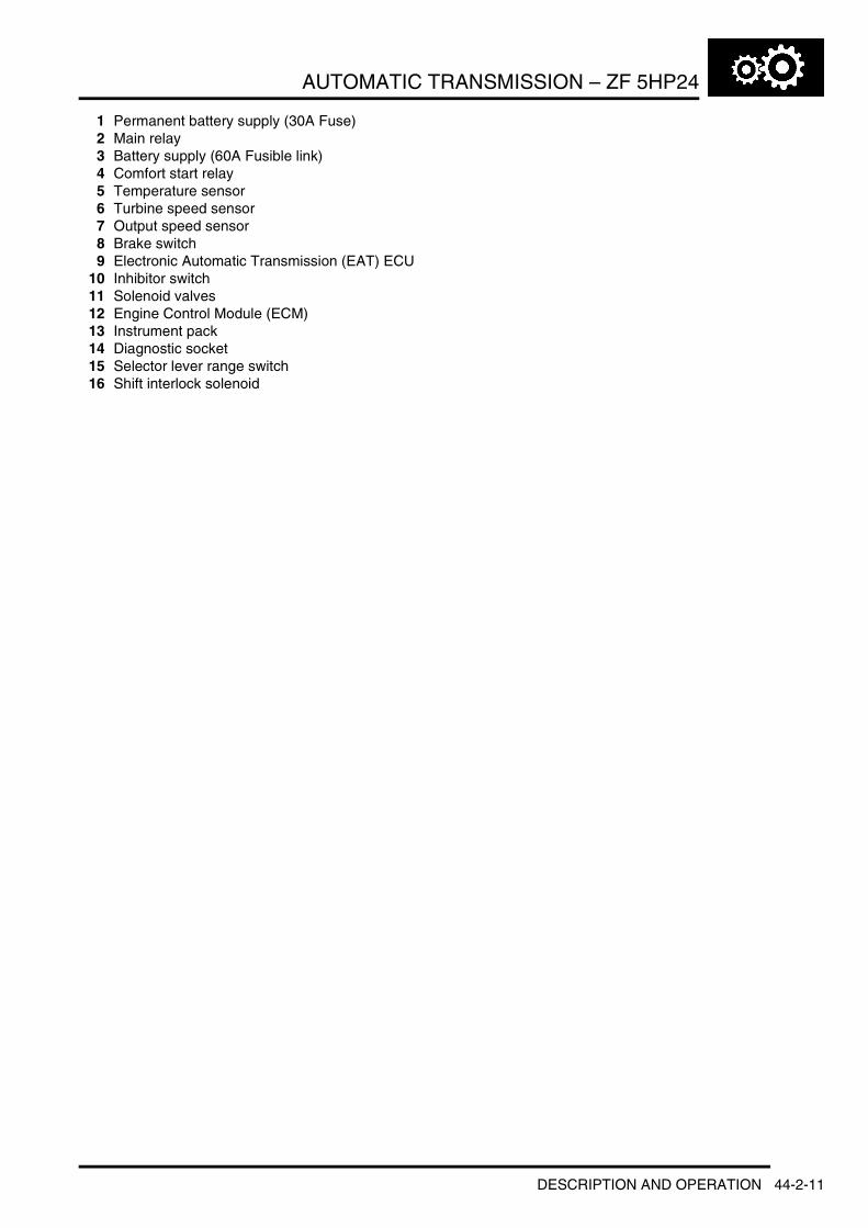
AUTOMATIC TRANSMISSION – ZF 5HP24
1 Permanent battery supply (30A Fuse)2 Main relay3 Battery supply (60A Fusible link)4 Comfort start relay5 Temperature sensor6 Turbine speed sensor7 Output speed sensor8 Brake switch9 Electronic Automatic Transmission (EAT) ECU
10 Inhibitor switch11 Solenoid valves12 Engine Control Module (ECM)13 Instrument pack14 Diagnostic socket15 Selector lever range switch16 Shift interlock solenoid
DESCRIPTION AND OPERATION 44-2-11
AUTOMATIC TRANSMISSION – ZF 5HP24
Description
GeneralThe ZF 5HP24 transmission is an electronically controlled, five speed unit for use with the V8 petrol engine. The transmission is manufactured by ZF Transmissions GmbH in Saarbrücken, Germany.
The transmission is controlled by an Electronic Automatic Transmission (EAT) ECU which contains software to provide operation as a semi-automatic 'Steptronic' transmission. The EAT ECU allows the transmission to be operated as a conventional automatic unit by selecting P, R, N, D on the selector lever. Movement of the selector lever across the gate to the 'M/S' position puts the transmission into electronic 'Sport' mode. Further movement of the lever in a lateral position to the + or – position puts the transmission into electronic manual 'Steptronic' mode.
The 5HP24 transmission has the following features:l Designed to be maintenance freel Transmission fluid is 'fill for life'l The torque converter features a controlled slip feature with electronically regulated control of lock-up, creating a
smooth transition to the fully locked conditionl Shift programs controlled by the EAT ECUl Connected to the ECM via the CAN for communicationsl Default mode if major faults occurl Diagnostics available from the EAT ECU via the ISO 9141 K Line.
The gearbox comprises three main casings; the bell housing, the intermediate plate and the main case. These items are bolted together to form the housing for the transmission components.
A fluid pan is bolted to the lower face of the main case and is secured with bolts. The fluid pan is sealed to the main case with a gasket. Removal of the fluid pan allows access to the valve block and solenoids and speed sensors. The fluid pan has four magnets located in each corner which collect any metallic particles present in the transmission fluid.
A non-serviceable fluid filter is located inside the fluid pan. If the transmission fluid becomes contaminated or after any service work the filter must be replaced.
The bell housing provides protection for the torque converter assembly and also provides the attachment for the gearbox to the engine block. The torque converter is a non-serviceable assembly which also contains the lock-up clutch mechanism. The torque converter drives a crescent type pump via drive tangs. The fluid pump is located in the intermediate plate, between the bell housing and the main case.
The main case contains the following components:l Input shaftl Output shaftl Valve block and solenoidsl Three rotating multiplate drive clutchesl Three fixed multiplate brake clutchesl One freewheel, one way, sprag type clutchl A planetary gear train comprising three planetary gear sets.
44-2-12 DESCRIPTION AND OPERATION
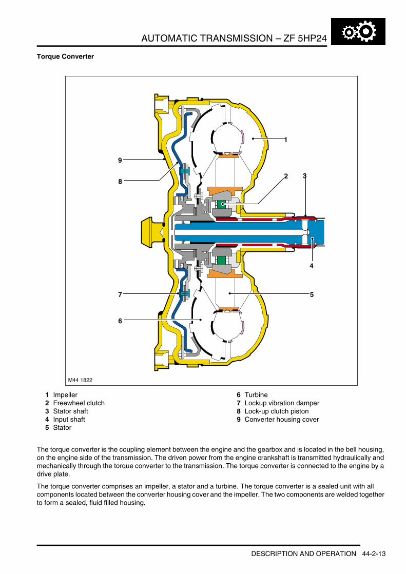
AUTOMATIC TRANSMISSION – ZF 5HP24
Torque Converter
1 Impeller2 Freewheel clutch3 Stator shaft4 Input shaft5 Stator
6 Turbine7 Lockup vibration damper8 Lock-up clutch piston9 Converter housing cover
The torque converter is the coupling element between the engine and the gearbox and is located in the bell housing, on the engine side of the transmission. The driven power from the engine crankshaft is transmitted hydraulically and mechanically through the torque converter to the transmission. The torque converter is connected to the engine by a drive plate.
The torque converter comprises an impeller, a stator and a turbine. The torque converter is a sealed unit with all components located between the converter housing cover and the impeller. The two components are welded together to form a sealed, fluid filled housing.
9
M44 1822
7
6
82
1
3
4
5
DESCRIPTION AND OPERATION 44-2-13

AUTOMATIC TRANSMISSION – ZF 5HP24
The converter housing cover has four threaded bosses which provide for attachment of the engine drive plate which is connected to the engine crankshaft. The threaded bosses also provide for location of special tools which are required to removed the torque converter from the bell housing. With the impeller welded to the converter housing cover, the impeller is therefore driven at engine crankshaft speed.
ImpellerThe impeller outer body has a boss with two machined slots. The boss locates over the transmission input shaft and the slots engage with two tangs on the fluid pump. This arrangement allows the fluid pump to be driven at engine speed.
The impeller comprises a row of blades attached to the outer body. The root of the blades collect fluid which flows by centrifugal force around the curved outer surface of the impeller to the tip of the blades.
Fluid Flow
Typical torque converter shown
1 Turbine2 Stator
3 Impeller
When the engine is running the rotating impeller acts as a centrifugal pump, picking up fluid at its centre and discharging it at high velocity through the blades on its outer rim. The design and shape of the blades and the curve of the impeller body cause the fluid to rotate in a clockwise direction as it leaves the impeller. This rotation improves the efficiency of the fluid as it contacts the outer row of blades on the turbine.
The centrifugal force of the fluid leaving the blades of the impeller is passed to the curved inner surface of the turbine via the tip of the blades. The velocity and clockwise rotation of the fluid causes the turbine to rotate.
TurbineThe turbine is similar in design to the impeller with a continuous row of blades. The fluid from the impeller enters the turbine through the tip of the blades and is directed around the curved body of the turbine to the root of the blades. The curved surface redirects the fluid back in the opposite direction to which it entered the turbine, effectively increasing the turning force applied to the turbine from the impeller. This principle is known as torque multiplication.
44-2-14 DESCRIPTION AND OPERATION

AUTOMATIC TRANSMISSION – ZF 5HP24
When the engine speed increases, the turbine speed also increases. The fluid leaving the inner row of the turbine blades is rotated in an anti-clockwise direction due to the curve of the turbine and the shape of the blades. The fluid is now flowing in the opposite direction to the engine rotation and therefore the impeller. If the fluid was allowed to hit the impeller in this condition, it would have the effect of applying a brake to the impeller, eliminating the torque multiplication effect. To prevent this, the stator is located between the impeller and the turbine.
StatorThe stator is located on the splined transmission input shaft via a freewheel clutch. The stator comprises a number of blades which are aligned in an opposite direction to those of the impeller and turbine. The main function of the stator is to redirect the returning from the turbine, changing its direction to that of the impeller.
The redirected fluid from the stator is directed at the inner row of blades of the impeller, assisting the engine in turning the impeller. This sequence increases the force of the fluid emitted from the impeller and thereby increases the torque multiplication effect of the torque converter.
Stator Functions
Typical stator shown
1 Blades2 Stator held – fluid flow redirected3 Stator rotates freely4 Roller clutch5 Converter at coupling speed6 Fluid flow from turbine7 Converter multiplying
8 Fluid flow from impeller9 Drive from engine
10 Impeller11 Stator12 Turbine13 Output to transmission
Refer to the 'Stator Functions' illustration
Fluid emitted from the impeller acts on the turbine. If the turbine is rotating at a slower speed than the fluid from the impeller, the fluid will be deflected by the turbine blades in the path 'A'. The fluid is directed at and deflected by the stator blades from path 'B' to path 'C'. This ensures that the fluid is directed back to the pump in the optimum direction. In this condition the sprag clutch is engaged and the force of the fluid on the stator blades assists the engine in rotating the impeller
DESCRIPTION AND OPERATION 44-2-15

AUTOMATIC TRANSMISSION – ZF 5HP24
As the rotational speed of the engine and therefore the turbine increases, the direction of the fluid leaving the turbine changes to path 'D'. The fluid is now directed from the turbine to the opposite side of the stator blades, rotating the stator in the opposite direction. To prevent the stator from resisting the smooth flow of the fluid from the turbine, the sprag clutch releases, allowing the stator to rotate freely on it shaft.
When the stator becomes inactive, the torque converter no longer multiples the engine torque. When the torque converter reaches this operational condition it ceases to multiply the engine torque and acts solely as a fluid coupling, with the impeller and the turbine rotating at approximately the same speed.
The stator uses a sprag type clutch. When the stator is rotated in a clockwise direction the sprags twist and are wedged between the inner and outer races. In this condition the sprags transfer the rotation of the outer race to the inner race which rotates at the same speed. Refer to 'One Way Freewheel Clutch' in this manual for further details of the sprag type clutch.
Lock-up Clutch MechanismThe Torque Converter Clutch (TCC) is hydraulically controlled by an electronic pressure regulating solenoid (EPRS4) which is controlled by the EAT ECU. This allows the torque converter to have three states of operation as follows:l Fully engagedl Controlled slip variable engagementl Fully disengaged.
The TCC is controlled by two hydraulic spool valves located in the valve block. These valves are actuated by pilot pressure supplied via a solenoid valve which is also located in the valve block. The solenoid valve is operated by PWM signals from the EAT ECU to give full, partial or no lock-up of the torque converter.
A = Unlocked conditionB = Locked condition
1 Clutch plate2 Clutch piston3 Torque converter body4 Turbine
5 Impeller6 Stator7 Piston chamber8 Turbine chamber
The lock-up clutch is a hydro-mechanical device which eliminates torque converter slip, improving fuel consumption. The engagement and disengagement is controlled by the EAT ECU to allow a certain amount of controlled 'slip'. This allows a small difference in the rotational speeds of the impeller and the turbine which results in improved shift quality. The lock-up clutch comprises a piston and a clutch friction plate.
M44 1824 A B
1
4
6
5
7
8
1
4
6
5
7
8
2 3 2 3
44-2-16 DESCRIPTION AND OPERATION

AUTOMATIC TRANSMISSION – ZF 5HP24
In the unlocked condition, the oil pressure supplied to the piston chamber and the turbine chamber is equal. Pressurised fluid flows through a drilling in the turbine shaft and through the piston chamber to the turbine chamber. In this condition the clutch plate is held away from the torque converter body and torque converter slip is permitted.
In the locked condition, the TCC spool valves are actuated by the electronic pressure regulating solenoid (EPRS4). The fluid flow in the unlocked condition is reversed and the piston chamber is vented. Pressurised fluid is directed into the turbine chamber and is applied to the clutch piston. The piston moves with the pressure and pushes the clutch plate against the torque converter body. As the pressure increases, the friction between the clutch plate and the body increases, finally resulting in full lock-up of the clutch plate with the body. In this condition there is direct mechanical drive from the engine crankshaft to the transmission planetary gear train.
Fluid PumpThe fluid pump is an integral part of the transmission. The fluid pump is used to supply hydraulic pressure for the operation of the control valves and clutches and also to pass the fluid through the transmission cooler.
The 5HP24 fluid pump is a crescent type pump and is located between the intermediate plate and the torque converter. The pump has a delivery rate of 16cm3 per revolution.
1 Securing ring2 Shaft oil seal3 O-ring seal4 Pump housing5 Ring gear6 Crescent spacer
7 Roller bearing8 Impeller9 Centring pin
10 Spring washer11 Outlet port (high pressure)12 Inlet port (low pressure)
The pump is driven by a positive coupling with the torque converter impeller, therefore the pump is driven at engine crankshaft speed.
The pump comprises a housing, a crescent spacer, an impeller and a ring gear. The housing has inlet and outlet ports to direct flow and is located in the intermediate plate by a centring pin. The pump action is achieved by the impeller, ring gear and crescent spacer.
M44 1823
10
4
65
8
9
31
7
2
12
5 6
11
8
DESCRIPTION AND OPERATION 44-2-17

AUTOMATIC TRANSMISSION – ZF 5HP24
The crescent spacer is fixed in its position by a pin and is located between the ring gear and the impeller. The impeller is driven by the drive from the torque converter which is located a needle roller bearing in the pump housing. The impeller teeth mesh with those of the ring gear. When the impeller is rotated, the motion is transferred to the ring gear which rotates in the same direction.
The rotational motion of the ring gear and the impeller collects fluid from the intake port in the spaces between the teeth. When the teeth reach the crescent spacer, the oil is trapped in the spaces between the teeth and is carried with the rotation of the gears. The spacer tapers near the outlet port. This reduces the space between the gear teeth causing a build up of fluid pressure as the oil reaches the outlet port. When the teeth pass the end of the spacer the pressurised fluid is passed to the outlet port.
The fluid emerging from the outlet port is passed through the fluid pressure control valve. At high operating speeds the pressure control valve maintains the output pressure to the gearbox at a predetermined maximum level. Excess fluid is relieved from the pressure control valve and is directed, via the main pressure valve in the valve block, back to the pump inlet port. This provides a pressurised feed to the pump inlet which prevents cavitation and reduces pump noise.
Valve Block and Solenoid ValvesThe valve block is located in the bottom of the transmission and is covered by the fluid pan. The valve block houses electrical actuators, and control valves which provide all electro-hydraulic control for all transmission functions. The valve block comprises the following components:l Five pressure regulator solenoidsl Three shift control solenoidsl Six dampersl Twenty one hydraulic spool valvesl Manually operated selector valve.
Pressure Regulator Solenoids
1 Coil winding2 Valve
3 Spring
Five Electronic Pressure Regulator Solenoids (EPRS) are located in the valve block. The solenoids are controlled by PWM signals from the EAT ECU. The solenoids convert the electrical signals into hydraulic control pressure proportional to the signal to actuate the spool valves for precise transmission operation. EPRS4 is used for pressure regulation for the torque converter lock-up clutch.
M44 1825
1
23
44-2-18 DESCRIPTION AND OPERATION

AUTOMATIC TRANSMISSION – ZF 5HP24
Solenoid EPRS1 supplies a lower control pressure as the signal amperage increases. The EPRS1 solenoid is a normally closed regulating flow solenoid valve and regulates the main line pressure. The solenoid is used for adaptive pressure control. The EAT ECU operates the solenoid using PWM signals. The EAT ECU monitors engine load and clutch slip and varies the solenoid duty cycle accordingly.
Solenoids EPRS2, 3 and 5 supply a higher control pressure as the signal amperage increases. The solenoids are normally open solenoids regulating flow solenoid valves. The solenoids are used to regulate the supply of fluid pressure for clutch application during overlap up and down shifts of gears 2–3, 3–4 and 4–5. The EAT ECU operates the solenoids using a PWM earth proportional to the required increasing or decreasing clutch pressures.
The resistance of the coil winding for solenoid EPRS1 is between 5.4 to 6.4Ω at 20°C (68°F). The resistance of the coil windings for solenoids EPRS2, 3, 4 and 5 is between 5.9 and 6.9Ω at 20°C (68°F).
Shift Control Solenoids
1 Coil winding2 Valve
3 Spring
Three shift control Solenoid Valves (SV) are located in the valve block. The solenoids are controlled by the EAT ECU and convert electrical signals into hydraulic control signals to control clutch application.
The shift control solenoids SV1, 2 and 3 are normally closed, on/off solenoids which are controlled by the EAT ECU switching the solenoid to earth. The EAT ECU also supplies the power to solenoids. The EAT ECU energises the solenoids in a programmed sequence for clutch application for gear ratio changes and shift control.
The resistance of the coil winding for solenoids SV1, 2 and 3 is between 26 to 30.4Ω at 20°C (68°F).
DampersThere are six dampers located in the valve block. Four of the dampers are used to regulate and dampen the regulated pressure supplied via the pressure regulating solenoid valves. The two remaining dampers are used for operation of clutches 'A' and 'C' and providing damping of the fluid pressure during shift changes. All of the dampers are load dependent through modulation of the damper against its return spring pressure.
The dampers comprise a piston, a housing bore and a spring. The piston is subject to the pressure applied by the spring. The bore has a connecting port to the function to which it applies. Fluid pressure applied to the applicable component (i.e. a clutch) is also subjected to the full area of the piston, which moves against the opposing force applied by the spring. The movement of the piston creates an action similar to a shock absorber, momentarily delaying the build up of pressure in the circuit. This results in a more gradual application of clutches improving shift quality.
M44 1826
1
23
DESCRIPTION AND OPERATION 44-2-19

AUTOMATIC TRANSMISSION – ZF 5HP24
Spool ValvesThe valve block contains twenty one spool valves which control various functions of the transmission. The spool valves are of conventional design and are operated by fluid pressure.
Each spool valve is located in its spool bore and held in a default (unpressurised) position by a spring. The spool bore has a number of ports which allow fluid to flow to other valves and clutches to enable transmission operation. Each spool has a piston which is waisted to allow fluid to be diverted into the applicable ports when the valve is operated.
When fluid pressure moves a spool, one or more ports in the spool bore are covered or uncovered. Fluid is prevented from flowing or is allowed to flow around the applicable waisted area of the spool and into another uncovered port. The fluid is either passed through galleries to actuate another spool, operate a clutch or is returned to the fluid pan.
Drive Clutches
Multiplate Drive or Brake Clutch – Typical
1 Input shaft2 Main pressure supply port3 Piston4 Cylinder – External plate carrier5 Clutch plate assembly6 Baffle plate
7 Diaphragm spring8 Output shaft9 Bearing
10 Dynamic pressure equalisation chamber11 Piston chamber12 Lubrication channel
M44 1827
1
10
2
34
5
6
7
8
9
11
12
44-2-20 DESCRIPTION AND OPERATION
AUTOMATIC TRANSMISSION – ZF 5HP24
There are three drive clutches and three brake clutches used in the 5HP24 transmission. Each clutch comprises one or more friction plates dependent on the output controlled. A typical clutch consists of a number of steel outer plates and inner plates with friction material bonded to each face.
The clutch plates are held apart mechanically by a diaphragm spring and hydraulically by dynamic pressure. The pressure is derived from a lubrication channel which supplies fluid to the bearings etc. The fluid is passed via a drilling in the output shaft into the chamber between the baffle plate and the piston. To prevent inadvertent clutch application due to pressure build up due to centrifugal force, the fluid in the dynamic pressure equalisation chamber overcomes any pressure in the piston chamber and holds the piston off the clutch plate assembly.
When clutch application is required, main pressure from the fluid pump is applied to the piston chamber from the supply port. This main pressure overcomes the low pressure fluid present in the dynamic pressure equalisation chamber. The piston moves, against the pressure applied by the diaphragm spring, and compresses the clutch plate assembly. When the main pressure falls, the diaphragm spring pushes the piston away from clutch plate assembly, disengaging the clutch.
DESCRIPTION AND OPERATION 44-2-21

AUTOMATIC TRANSMISSION – ZF 5HP24
One Way Free Wheel Clutch – Typical
1 Sprags2 Inner race3 Outer race4 Sprag and cage assembly
5 Sprag outer race6 Sprag inner race7 Retaining ring
The 5HP24 transmission uses only one free wheel clutch to perform a component holding function. The free wheel clutch, in conjunction with the hydraulic clutches, prevent disruption of the power output during shift changes. The freewheel clutch is located at the rear of the planetary gearset and controls brake clutch 'F'.
The free wheel clutch can perform three functions; hold components stationary, drive components and free wheel allowing components to rotate without a drive output. The free wheel clutch used in the 5HP24 transmission is of the sprag type and comprises an inner and outer race and a sprag and cage assembly. The inner and outer races are pressed into their related components with which they rotate. The sprag and cage assembly is located between the inner and outer races.
The sprags are located in a cage which is a spring which holds the sprags in the 'wedge' direction and maintains them in contact with the inner and outer races.
44-2-22 DESCRIPTION AND OPERATION

AUTOMATIC TRANSMISSION – ZF 5HP24
Referring to the illustration, the sprags are designed so that the dimension 'B' is larger than the distance between the inner and outer race bearing surfaces. When the outer race rotates in a clockwise direction, the sprags twist and the edges across the dimension 'B' wedge between the races, providing a positive drive through each sprag to the inner race. The dimension 'A' is smaller than the distance between the inner and outer race bearing surfaces. When the outer race rotates in an anti-clockwise direction, the dimension 'A' is too small to allow the sprags to wedge between the races, allowing the outer race to rotate freely.
On the illustration shown, when the outer race is rotated in a clockwise direction, the sprags twist and are 'wedged' between the inner and outer races. The sprags then transfer the rotation of the outer race to the inner race, which rotates at the same speed.
DESCRIPTION AND OPERATION 44-2-23

AUTOMATIC TRANSMISSION – ZF 5HP24
Planetary Gear Train
Planetary Gearset – Sectional View
1 Planetary gearset 12 Ring gear 13 Ring gear 24 Planetary gearset 25 Ring gear 3
6 Planetary gearset 37 Output shaft8 Input shaft gear9 Intermediate shaft gear
10 Planet carrier 2
M44 1828
2 1 9 3 8 4 5 8 6
1 2 3 4 5 6
10
9 8
7
44-2-24 DESCRIPTION AND OPERATION

AUTOMATIC TRANSMISSION – ZF 5HP24
The planetary gear train used on the 5HP24 transmission comprises three planetary gearsets which together form a compound gear train. The gearset operates in conjunction with the clutches, brakes and freewheel clutch to produce five forward gears and one reverse gear.
Planetary Gearset – Exploded View
1 Ring gear 12 O-ring3 Snap ring4 Planetary gearset 15 Planetary gearset 26 Planetary gearset 37 Snap ring
8 Ring gear 39 Intermediate shaft gear
10 Ring gear 211 Input shaft gear12 Needle roller bearing13 Snap ring
DESCRIPTION AND OPERATION 44-2-25

AUTOMATIC TRANSMISSION – ZF 5HP24
The planetary gear train is a single integral assembly which comprises the following components:l Three single planet carrier gearsets connected in seriesl A single sun gearl A twin sun gearl Three ring gears.
Power FlowsOperation of the transmission is controlled by the EAT ECU which electrically activates various solenoids to control the transmission gear selection. The sequence of solenoid activation is based on programmed information in the ECU memory and physical transmission operating conditions such as vehicle speed, engine load, throttle position and selector lever position.
Powerflow Schematic Diagram
1 Torque input from engine2 Torque converter lock-up clutch3 Transmission case4 Planet gearset 1 carrier5 Planet gearset 2 carrier6 Input shaft sun gear – large7 Planet gearset ring gear 1
8 Planet gearset 3 carrier9 Planet gearset ring gear 3
10 Intermediate shaft sun gear11 Input shaft sun gear – small12 Planet gearset ring gear 213 Freewheel clutch
Gear Input Reaction Output Ratio1st Planetary gearset 2 and 3 via
input shaft gearRing gear 1 and clutch 'F' Planetary gear 3 carrier 3.57
2nd Planetary gearset 2 and 3 via input shaft gear
Planet gear 2 carrier and ring gear 3
Planetary gear 3 carrier 2.20
3rd Ring gear 1 Planet gear 1 carrier and ring gear 2
Planetary gear 3 carrier 1.51
4th Planetary gearset 2 and 3 via input shaft gear and planet gear 2 carrier
Ring gear 3 Planetary gear 3 carrier 1.00
5th Planetary gearset 2 carrier Ring gears 1 and 3, Planetary gear 2 carrier and input shaft gear
Planetary gearset 3 carrier 0.80
Reverse Intermediate shaft gear Ring gear 2, planetary gearset 2 carrier and input shaft gear
Planetary gearset 3 carrier 4.10
M44 1829
2
1
10
A
B
C
D E
78
4
11
5
9
6
12
13
3
44-2-26 DESCRIPTION AND OPERATION

AUTOMATIC TRANSMISSION – ZF 5HP24
Engine torque is transferred, via operation of single or combinations of clutches, to the planetary gear train. The planetary gear train is controlled by reactionary inputs from brake clutches and the freewheel clutch to produce five forward gears and one reverse gear.
The following tables show which clutches are operating for selected gear ratios and which solenoids are activated to produce the required torque output from the transmission.
Gear Range Reference Chart
Gear Change Solenoid Reference Chart
Gear Selector
Lever Position
Gear Engine Braking Yes/No
Ratio Clutches Freewheel Locked Y/NA B C D E F
D 1 Y 3.57 X YD 2 Y 2.20 X X
D 3 Y 1.51 X XD 4 Y 1.00 X XD 5 Y 0.80 X X
P/N – – – XR Y – 4.10 X X
Gear Selector Lever Position
Gear Shift Control Solenoids Pressure Regulating SolenoidsSV1 SV2 SV3 EPRS1 EPRS2 EPRS3 EPRS4 EPRS5
D 1 ON OFF OFF ON ON – ON OFF ON –D 2 ON ON OFF ON OFF ON OFF OND 3 OFF ON OFF ON ON ON OFF OFF
D 4 OFF ON OFF ON OFF OFF – ON – OFFD 5 OFF OFF OFF ON ON OFF – ON – OFFN ON OFF ON ON – ON ON OFF – ON
R OFF ON OFF ON ON – ON OFF ON –TCC Lock-up OFF OFF OFF OFF OFF OFF ON OFF
ON = Active (pressure build up) OFF = Inactive – = Inactive (pressure drain)
DESCRIPTION AND OPERATION 44-2-27

AUTOMATIC TRANSMISSION – ZF 5HP24
1st Gear (D Selected)
The gear selector lever and the manual selector valve spool are in the 'D' position. Engine torque is transmitted from the torque converter to the planet gearset 3. The torque is applied to the input shaft gear via the application of clutch 'A'. The freewheel clutch locks the planet carrier of gearset 2 in the direction of rotation.
The larger diameter input shaft gear drives the planet gears of gearset 3, which rotate inside the locked ring gear 3. This rotation is passed via the planet carrier of gearset 3 to the output shaft.
In 1st gear with braking effect when coasting, the brake clutch 'F' is also applied locking the ring gear 3 in both directions.
M44 1938
WK
A
B
C
D E F
M44 1944
F
A
44-2-28 DESCRIPTION AND OPERATION

AUTOMATIC TRANSMISSION – ZF 5HP24
2nd Gear (D Selected)
The gear selector lever and the manual selector valve spool are in the 'D' position. Engine torque is transmitted from the torque converter to the planet gearset 3. The torque is applied to the input shaft gear via the application of clutch 'A'.
The clutch 'E' is applied which locks the planet carrier of gearset 1. The planet carrier is physically connected to the ring gear 2 which is subsequently also locked.
The small diameter input shaft gear drives the planet gears of gearset 2, which rotate around the stationary ring gear 2 in the direction of engine rotation. The planet carrier of gearset 2 is physically connected to the ring gear 3 which subsequently rotates in the same direction. The rotation of the ring gear 3 is transmitted to the planet gearset 3, which rotates around the large diameter gear of the input shaft gear. The rotation is passed via the planet carrier of gearset 3 to the output shaft which rotates at an increased speed compared to 1st gear.
M44 1939
WK
A
B
C
D E F
M44 1945
E
A
DESCRIPTION AND OPERATION 44-2-29

AUTOMATIC TRANSMISSION – ZF 5HP24
3rd Gear (D Selected)
The gear selector lever and the manual selector valve spool are in the 'D' position. Engine torque is transmitted from the torque converter through the input shaft gear via the application of clutch 'A'. Clutch brake 'D' is applied and holds the intermediate shaft gear stationary.
Ring gear 1 is driven by the planet gearsets 2 and 3. The torque applied to ring gear 1 is passed via the stationary intermediate shaft gear to the planet carrier of gearset 1. The planet carrier of gearset 1 is physically connected to the ring gear 2. This causes the planet carrier of gearset 2 to rotate at a higher speed. Because the planet carrier of gearset 2 is physically connected to the ring gear 3, the ring gear 3 rotates in the same direction. This causes the ring gear 3 and subsequently the planet carrier of gearset 3 and the output shaft to rotate at an increased speed compared to 2nd gear.
M44 1940
WK
A
B
C
D E F
M44 1946C AD
44-2-30 DESCRIPTION AND OPERATION

AUTOMATIC TRANSMISSION – ZF 5HP24
4th Gear (D Selected)
The gear selector lever and the manual selector valve spool are in the 'D' position. Engine torque is transmitted from the torque converter to the input shaft gear via clutch 'A' and the planet carrier of gearset 2 via the clutch 'B'. The planet carrier of gearset 2 is physically connected to the ring gear 3 and this drive is transmitted, via the ring gear 3 and the planet gears and carrier of gearset 3 to the output shaft, which rotates at an increased speed compared to 3rd gear.
The drive transmitted from the planet carrier of gearset 2 and the input shaft gear to planet gearset 3 results in a complete locking of the planetary gear train. Therefore, in this condition the engine input speed is identical to the output shaft speed creating a 1:1 output ratio.
M44 1941
WK
A
B
C
D E F
M44 1947
B
A
DESCRIPTION AND OPERATION 44-2-31

AUTOMATIC TRANSMISSION – ZF 5HP24
5th Gear (D Selected)
The gear selector lever and the manual selector valve spool are in the 'D' position. Engine torque is transmitted from the torque converter to the planet carrier of gearset 2 via the application of clutch 'B'. Clutch 'D' is applied to lock the intermediate shaft gear.
The planet carrier of gear 2 is physically connected to the ring gears 1 and 3 and drives them at the same speed. The rotation of ring gear 1 is passed to the planet gears of gearset 1 which rotate around the locked intermediate shaft gear. The rotation of the planet gears is passed through the planet carrier of gearset 1 to the ring gear 2, to which it is physically connected.
The rotation of the ring gear 2 is passed to the planet gears of gearset 2 which in turn rotates the small diameter gear of the input shaft gear. This rotation is then passed, via the larger diameter gear of the input shaft gear, to the planet gears of gearset 3 in the direction of engine rotation.
This rotation of the planet gears of gearset 3 increases the rotational speed of the planet carrier of gearset 3 and subsequently drives the output shaft at an increased speed compared to 4th gear.
M44 1942
WK
A
B
C
D E F
M44 1948
B
C D
44-2-32 DESCRIPTION AND OPERATION

AUTOMATIC TRANSMISSION – ZF 5HP24
Reverse Gear (R Selected)
The gear selector lever and the manual selector valve spool are in the 'R' position. Engine torque is transmitted from the torque converter to the intermediate shaft gear. The torque is applied to the intermediate shaft gear via the application of clutch 'C'.
Clutch 'F' is applied and holds the ring gears 1 and 3 stationary and subsequently the planet carrier of gearset 2 which is physically connected to ring gear 3.
The intermediate shaft gear drives the planet gears of gearset 1 which in turn rotate around the locked ring gear 1. The rotation of the planet carrier of gearset 1 is transferred to the ring gear 2 to which it is physically connected. The rotation of ring gear 2 is transferred to the planet gears of gearset 2. Because the planet carrier of gearset 2 is held by clutch 'F', the drive is passed from the planet gears to the small gear on the input shaft gear.
The rotation is transferred via the large gear on the input shaft gear to the planet gears of gearset 3, which rotate around the stationary ring gear 3. The rotation of the planet gears rotates the planet carrier of gearset 3 which in turn rotates the output shaft in the reverse direction to that of the forward gears.
M44 1943
WK
A
B
C
D E F
M44 1949
F
C D
DESCRIPTION AND OPERATION 44-2-33

AUTOMATIC TRANSMISSION – ZF 5HP24
SensorsThe 5HP24 transmission contains two speed sensors and a temperature sensor. The sensors are located inside the transmission housing, with the speed sensors being the only serviceable items.
The sensors play an important part in the operation of the transmission and provide signal information to the EAT ECU. This information is used by the ECU to control shift timing and fluid temperature to provide the optimum operating condition for the transmission.
Speed Sensors
Two speed sensors are used in the 5HP24 transmission to monitor turbine speed and output shaft speed.
The turbine speed sensor is monitored by the EAT ECU to calculate the slip of the torque converter clutch and internal clutch slip. This allows the EAT ECU to accurately control the slip timing during shifts and adjust clutch application or release pressure for overlap shift control.
The output shaft speed is monitored by the EAT ECU and compared to engine speed signals received on the CAN from the ECM. Using the comparison of the two signals the EAT ECU calculates the transmission slip ratio for plausibility and maintain adaptive pressure control.
The turbine speed sensor is located in the main casing and secured with a screw. The sensor monitors turbine speed from a toothed target wheel which on the outer diameter of clutch 'B' housing.
The output shaft speed sensor is located at the rear of the main casing and secured with a screw. The sensor monitors the output shaft speed from a toothed target wheel which is an integral part of the park lock gear.
Both sensors are of the inductive type and are connected to the EAT ECU with two wires. The EAT ECU supplies a positive DC supply and a signal return wire to monitors the sensor signals. Both wires are covered by a screen which is connected to ground by the EAT ECU.
The sensor receives the DC supply from the EAT ECU. As the teeth of the target wheel pass the sensor tip, a change in the magnetic field of the sensor occurs and generates an AC pulse in the sensor field winding. The pulse is passed on the negative (ground) wire to the EAT ECU which calculates the rotational speed. The AC pulse generated is proportional to the rotational speed of the target wheel. The EAT ECU measures the peak to peak outputs of the AC waveform to calculate the rotational speed being measured.
The resistance of the coil winding in each sensor is between 285 and 365Ω at 20°C (68°F). Failure of either speed sensor will cause the EAT ECU to store a related fault code.
44-2-34 DESCRIPTION AND OPERATION

AUTOMATIC TRANSMISSION – ZF 5HP24
Transmission Temperature Sensor
The temperature sensor is located inside the wiring harness in the fluid pan and is connected to the EAT ECU with two wires. The sensor is a Positive Temperature Co-efficient (PTC) sensor which has a semi-conductor material which increases its resistance as the temperature increases.
The sensor receives a predetermined current from the EAT ECU on one of the wires and is connected to earth via the ECU on the second wire. The EAT ECU measures the returned voltage and using this information calculates the fluid temperature.
In the case of low fluid temperatures, the EAT ECU prohibits torque converter lock-up to promote faster fluid warm up. In the case of high fluid temperatures, the EAT ECU increases the converter lock-up control and modifies the shift programme to reduce fluid temperature.
If the temperature sensor fails, the EAT ECU uses a programmed default temperature value. The default value is derived from the engine coolant temperature sensor and received on the CAN from the ECM. A fault code is stored in the ECM which can be retrieved using TestBook.
The temperature sensor has a semi-conductor material with resistance to temperature values as shown in the following table.
Temperature Sensor Resistance Values
Temperature Resistance0°C (32°F) 820 Ω
20°C (68°F) 962 Ω40°C (104°F) 1118 Ω60°C (140°F) 1289 Ω
DESCRIPTION AND OPERATION 44-2-35

AUTOMATIC TRANSMISSION – ZF 5HP24
Inhibitor Switch
The inhibitor switch is located externally on the right hand side of the transmission. The switch is located on the selector shaft and secured to the main casing with screws. A protective cover is also fitted over the switch to prevent impact damage. The switch rotates with the selector shaft, moving the switch contacts to correspond to the selected programme. The switch provides signals which allows the EAT ECU to monitor the position of the manual selector spool valve and the selected drive programme.
The switch is connected via an integral harness and multiplug on five wires to the EAT ECU. One of the wires supplies a 12V supply to the switch. The remaining wires are connected to the EAT ECU. When the transmission selector lever is moved to the selected position, one or more of the contacts within the switch are made, completing a circuit back to the ECU. From the switch contacts which are made, the ECU determines which selection is required and responds accordingly.
When the selector lever is in Park, the EAT ECU transmits a signal to the immobilisation ECU to enable starter operation. The signal also energises the starter relay, allowing the crank signal from the immobilisation ECU to pass to the starter solenoid.
The following table shows which switch contacts are made for a given selector lever position.
Selector Lever Position
Switch ContactsL1 L2 L3 L4
Park X X X Reverse X X
Neutral X X XDrive XX = High signal
44-2-36 DESCRIPTION AND OPERATION

AUTOMATIC TRANSMISSION – ZF 5HP24
Fluid Cooling
1 Fluid feed2 Fluid return3 Fluid cooler
4 Engine coolant feed5 Engine coolant return
The fluid cooler is located at the bottom right hand corner of the engine. The cooler is cooled by engine coolant which flows in a water jacket around cores within the cooler body. Transmission fluid enters the cooler and flows through the cores where it is cooled by the engine coolant. The fluid leaves the cooler and is passed back to the transmission. The transmission fluid is pumped through the cooler by the transmission fluid pump.
The fluid cooler has a thermostatic valve which is opened by transmission fluid temperature. The thermostatic valve is opened at a transmission fluid temperature of 80°C (176°F) and allows engine coolant to flow through the fluid cooler.
2
M44 1839
3
2
1
1
5
3
4
DESCRIPTION AND OPERATION 44-2-37

AUTOMATIC TRANSMISSION – ZF 5HP24
Gear Selector Lever Assembly
1 Selector cable2 Shift interlock solenoid3 Selector lever4 Manual +/– Steptronic switch5 Selector knob and shroud6 Park/Reverse release button7 Selector lever cover8 High/Low range selector switch
9 Selector position LED display10 Hill Descent Control (HDC) switch11 Key interlock cable12 Key interlock mechanism13 Selector lever position switch14 Manual/Sport switch15 Mounting plate
The gear selector lever assembly is located in a central position on the transmission tunnel, between the front driver and passenger seats. A mounting plate is secured to the transmission tunnel and provides the mounting for the selector lever assembly.
44-2-38 DESCRIPTION AND OPERATION
AUTOMATIC TRANSMISSION – ZF 5HP24
The selector lever comprises a cast mounting plate which provides for the location of the selector components. The lever is connected to a gimbal mechanism which allows for the selection of P, R, N, D is a forward or backward direction and selection between automatic and manual/sport in a left/right transverse direction. When manual/sport mode is selected, the lever can be moved in a forward or backward direction to select + or – for manual (Steptronic) operation.
When the selector lever is moved to the M/S position, the Bowden cable to the transmission is mechanically disconnected at the shifter. If left in Sport mode all gear changes are performed automatically. If Manual (Steptronic) mode is selected, all gear changes are based on switched ground inputs received by the EAT ECU from the Manual +/– Steptronic switch.
The selector lever mechanism houses the following components:l Manual +/– Steptronic switchl Shift interlock solenoidl High/Low range selector switchl Hill Descent Control (HDC) switchl Selector position LED displayl Selector lever position switchl Manual/Sport switchl Key interlock mechanism.
There are four selector lever positions and two additional positions for manual/sport operation:l P ( Park) – Prevents the vehicle from moving by locking the transmissionl R (Reverse) – Select only when the vehicle is stationary and the engine is at idlel N (Neutral) – No torque transmitted to drive wheelsl D (Drive) – This position uses all five forward gears in high and low rangesl M/S (Sport mode) – This position uses all five forward gears as in 'D', but will upshift at higher engine speeds
improving accelerationl + and – (Manual 'Steptronic' mode) – Movement of the selector lever in the +/– positions, when the lever is in
the M/S position, will operate the transmission in manual (Steptronic) mode, allowing the driver to manually select all five forward gears.
The selector lever position is displayed to the driver on the selector position LED display and in the instrument pack. In 'Steptronic' mode, if a gear is selected but the EAT ECU logic prevents selection of that gear, the requested gear will be initially displayed. The EAT ECU will engage the next allowed gear and then display that gear.
Manual +/– Steptronic SwitchThe manual +/– switch is located on the left hand side of the selector lever assembly. The switch comprises a housing which provides the location for a sliding contact. When the selector lever is moved to the manual/sport position, a dog on the lever engages with a slotted abutment on the switch sliding contact. When the lever is moved to the + or – position the dog moves the switch completing a momentary earth circuit with one of two microswitches at each end of the switch which correspond to the + or – positions.
This momentary signal is received by the EAT ECU which, on first operation of the switch, initiates manual mode and operates the transmission in the selected gear.
In this position, a spring will move the selector lever to the centre position when released.
Shift Interlock SolenoidThe shift interlock solenoid is located at the front of the selector lever assembly. The selector lever is connected to a locking plate which has two holes which correspond to the 'P' and 'N' positions. When the ignition is on or the engine is running, the solenoid is energised by the EAT ECU when the selector lever is in the 'P' or 'N' positions. When energised, the solenoid ejects a pin which engages in the locking plate preventing the lever from being moved.
When the footbrake is applied, a signal from a brake switch is passed to the EAT ECU which de-energises the solenoid allowing the lever to be moved from the 'P' or 'N' position. This prevents the selector from being moved to the 'D' or 'R' position unintentionally and the application of the brakes also prevents the vehicle 'creeping' when the gear is engaged.
Movement of the selector lever from the 'P' or 'N' positions is also prevented if the EAT ECU senses that the engine speed is above 2500 rev/min, even if the brake pedal is depressed.
DESCRIPTION AND OPERATION 44-2-39

AUTOMATIC TRANSMISSION – ZF 5HP24
High/Low Range Selector SwitchThe high/low range switch is located on the selector lever cover, on the right hand side of the selector lever. The switch can be identified by the a high/low range legend graphic and the switch lever is coloured white. High or low range can be selected using this switch providing the vehicle speed is within defined limits and the gear selector lever is in the neutral position. + TRANSFER BOX, DESCRIPTION AND OPERATION, Description.
Hill Descent Control (HDC) SwitchThe HDC switch is located on the selector lever cover, on the left hand side of the selector lever. The switch can be identified by the HDC legend graphic and the switch lever is coloured yellow. Operation of the HDC switch it not directly related to automatic transmission operation. + BRAKES, DESCRIPTION AND OPERATION, Foundation Brakes.
Selector Position LED DisplayThe selector position LED display is located on the selector lever cover, between the HDC and high/low range switches. The display has a graphic which shows the lever positions P, R, N, D, M/S and +/–. The P, R, N, D and M/S positions each have a small, red LED which illuminates when that position is selected. The +/– positions do not have an LED.
The LED display is controlled by the selector lever position switch, with the two components connected via a five wire ribbon cable. The LED display is powered from the Body Control Unit (BCU) and remains illuminated until the BCU is in sleep mode. The LED display is active at all times when the ignition is on.
Selector Lever Position SwitchThe selector lever position switch is located on the right hand side of the selector lever assembly. The switch has a moving contact which is connected to the selector lever. As the lever is moved, the sliding contact moves in the switch completing a circuit with four further contacts in the switch which represent the four lever positions; P, R, N and D. The switch is connected to the selector position LED display via a ribbon cable and provides the power for the display LED's. The switch receives its power supply from the BCU.
Manual/Sport SwitchThe manual/sport switch is located at the rear of the selector lever assembly. The manual/sport switch is a cam operated microswitch. A lever with a roller is attached to the switch body. When the selector lever is moved from the automatic 'D' position to the manual/sport 'M/S' position, the roller contacts a cam on the selector lever which depresses the switch lever and operates the switch. The switch contacts remain closed when the selector lever is in the manual/sport position.
The operation of the switch completes an earth path which is sensed by the EAT ECU which switches the transmission operation to sport when ’M/S’ is selected and deselects sport mode when ’D’ (automatic operation) is reselected. The completed earth path is connected to the EAT ECU via the M/S LED on the selector lever display which is illuminated by an output from the ECU when M/S is selected.
Selector CableThe selector cable is a Bowden type cable that connects the selector lever to the manual selector spool valve. A ’C’ clip secures the outer cable to the selector lever assembly. The inner cable is secured to an arm which is connected to the selector lever via a 'U' shaped bracket and pin.
The transmission end of the outer cable is secured to a bracket on the transmission by a clamp nut. The transmission has an operating lever which is attached to and operates the manual selector control spool valve. The inner cable is attached to the operating lever by a clamp bush and locknut. The clamp bush allows for the adjustment of the selector cable.
44-2-40 DESCRIPTION AND OPERATION

AUTOMATIC TRANSMISSION – ZF 5HP24
Key Interlock Mechanism
1 Ignition key2 Ignition switch3 Bowden cable
4 Latch gate5 Selector lever assembly
The key interlock mechanism prevents the key from being removed from the ignition switch when the selector lever is any position other than 'P' PARK. This prevents the vehicle being accidentally left in neutral which would cause the vehicle to move if the handbrake was not applied.
The mechanical mechanism is operated by a Bowden cable which is attached between the selector lever assembly and the ignition switch. When the ignition switch is turned to the on position, the switch rotates a lever which in turn pulls the cable. This lifts a latch in the selector lever assembly which is engaged with the selector lever when in the 'P' position.
DESCRIPTION AND OPERATION 44-2-41

AUTOMATIC TRANSMISSION – ZF 5HP24
Instrument Pack
1 Instrument pack2 Transmission status display
3 Message centre4 Malfunction Indicator Lamp (MIL)
The instrument pack is connected to the EAT ECU via the CAN. Transmission status is transmitted by the EAT ECU and displayed to the driver on one of two displays in the instrument pack. + INSTRUMENTS, DESCRIPTION AND OPERATION, Description.
Malfunction Indicator Lamp (MIL)The MIL is located in the lower left hand corner of the instrument pack, below the fuel gauge. Transmission related faults which may affect the vehicle emissions output will illuminate the MIL.
The MIL is illuminated by the ECM on receipt of a relevant fault message from the EAT ECU on the CAN. The nature of the fault can be diagnosed using TestBook which reads fault codes stored in the ECU memory.
Transmission Status DisplayThe transmission status display is located on the right hand side of the instrument pack, below the tachometer. The display shows the selector lever position and in the case of manual (Steptronic) mode, the selected gear. The selector lever position and gear selected displays are illuminated in a green colour when active.
70
1/21/2
1/11/1
MPHMPH
10
90
50503
03
0
1101
30
150
M44 1910
4 3 2
1
Symbol DescriptionP Park selectedR Reverse selected
N Neutral selectedD Drive selected1 1st gear selected (Manual mode)
2 2nd gear selected (Manual mode)3 3rd gear selected (Manual mode)4 4th gear selected (Manual mode)
5 5th gear selected (Manual mode)Low range selected. Flashes when changing from low to high range.
44-2-42 DESCRIPTION AND OPERATION
AUTOMATIC TRANSMISSION – ZF 5HP24
Additionally, the display also shows a low range symbol when low range is selected on. The low range symbol is illuminated in an amber colour when active. When the transfer box is changing from low to high range, the low range symbol flashes until the range change is complete.
Message Centre DisplayThe message centre is located below the speedometer and the tachometer at the bottom of the instrument pack. The message centre is a Liquid Crystal Display (LCD) to relay vehicle status information to the driver. The message centre can display the following transmission related messages:l SPORT MODEl MANUAL MODEl SELECT NEUTRALl TRANSMISS'N OVERHEATl TRANSMISS'N FAILSAFE PROGl LOW RANGEl HIGH RANGEl SLOW DOWN.
DESCRIPTION AND OPERATION 44-2-43

AUTOMATIC TRANSMISSION – ZF 5HP24
EAT ECU
1 EAT ECU2 E-box
3 ECM
The EAT ECU is the controlling component of the transmission. The ECU software was designed in conjunction with Land Rover, Bosch and ZF Getriebe GmbH.
The EAT ECU is located in the E-box, which is positioned forward of the RH suspension top mount. The ECU is secured in a clip adjacent to the ECM. The ECU has a blue connector socket colour which assists identification.
The E-box has a temperature controlled environment which maintains the optimum temperature for ECU operation. + ENGINE MANAGEMENT SYSTEM – V8, DESCRIPTION AND OPERATION, Bosch ME 7.2 Engine Management System.
The EAT ECU uses three harness connectors for all input and output information.
44-2-44 DESCRIPTION AND OPERATION

AUTOMATIC TRANSMISSION – ZF 5HP24
Inputs and OutputsThe sensor signals allow the EAT ECU to monitor transmission operation. The ECU processes the incoming signals and compares this with data stored in its memory. If the received signals are not within the stored values, the ECU will make adjustments to the transmission operation using the solenoids to provide optimum driveability and performance.
The sensor inputs provide the EAT ECU with a constant update of the operating condition of the transmission and the engine. The ECU compares this input data with mapped information stored in its memory and will make any required adjustments.
EAT ECU Harness Connector C0193 Pin Details
EAT ECU Harness Connector C0932 Pin Details
EAT ECU Harness Connector C1835 Pin Details
Pin No. Description Input/Output1 Ground for shift interlock solenoid Input2 Power supply for shift interlock solenoid Output
3 Park signal to steering lock ECU Output4 to 8 Not used –
9 Range change request 1 Output
10 Range change request 2 Output11 to 17 Not used –
18 High/Low range switch Input
19 Selector manual Steptronic switch UP Input20 Selector manual Steptronic switch DOWN Input
21 to 52 Not used –
Pin No. Description Input/Output1 and 2 Not used –
3 Diagnostic ISO 9141 K line bus Input/Output4 Electronic ground –
5 Power ground –6 Power ground –7 Permanent battery power supply Input
8 Power supply from main relay Input9 Power supply from main relay Input
Pin No. Description Input/Output1 Ignition power supply Input
2 Output shaft speed sensor screen –3 Output shaft speed sensor signal Input4 Inhibitor switch contacts L4 Input
5 Input shaft speed sensor screen –6 Ground for EPRS 5 Input7 Ground for EPRS 4 Input
8 to 10 Not used –11 Power supply for EPRS's Output12 Temperature sensor supply Output
13 Output shaft speed sensor supply Output14 Inhibitor switch contacts L3 Input15 Not used –
DESCRIPTION AND OPERATION 44-2-45

AUTOMATIC TRANSMISSION – ZF 5HP24
Main RelayThe main relay is located inside the E-box and is identified by its blue colour. The relay is connected directly from the battery via a 100 Amp remote fuse. The relay coil is controlled by the ECM which provides a ground for the coil when the relay is energised.
When energised, the main relay supplies battery voltage, via fuse 1 in the engine compartment fusebox, to the EAT ECU.
DiagnosticsThe diagnostic socket is located in the fascia, in the driver's side stowage tray. The socket is secured in the fascia panel and is protected by a hinged cover.
16 Ground for SV 3 Input17 Ground for EPRS 3 Input
18 to 20 Not used –21 Power supply for SV's Output22 Temperature sensor signal Input
23 Input shaft speed sensor supply Output24 Inhibitor switch contacts L2 Input25 Not used –
26 Ground for SV 2 solenoid Input27 Ground for EPRS 2 Input28 Ground for EPRS 2 Input
29 and 30 Not used –31 Ignition power supply to inhibitor switch Output32 Not used –
33 Input shaft speed sensor signal Input34 Inhibitor switch contacts L1 Input35 Not used –
36 CAN bus high Input/Output37 CAN bus low Input/Output38 Ground for SV 1 Input
39 and 40 Not used –
44-2-46 DESCRIPTION AND OPERATION

AUTOMATIC TRANSMISSION – ZF 5HP24
Diagnostic Socket
1 Cover 2 Diagnostic socket
The diagnostic socket allows the exchange of information between the various ECU's on the bus systems and TestBook/T4 or a diagnostic tool using Keyword 2000 protocol. The information is communicated to the socket via a diagnostic ISO9141 K Line. This allows the retrieval of diagnostic information and programming of certain functions using TestBook/T4 or a suitable diagnostic tool.
The EAT ECU uses a P code strategy which stores industry standard and Land Rover specific Diagnostic Trouble Codes (DTC) relating to faults.
Transmission P Codes
P Code No. Component/Signal Fault Description0702 EAT ECU internal error 4 (FET/FET 1) Open circuit, short circuit to ground or
battery
0705 Inhibitor switch (PRNDL input) Implausible0710 Gearbox temperature sensor Implausible0711 Gearbox temperature sensor Open circuit
0712 Gearbox temperature sensor Short circuit to ground0713 Gearbox temperature sensor Short circuit to battery0715 Input speed sensor Implausible
0716 Input speed sensor Value too large0720 Output speed sensor Implausible0721 Output speed sensor Implausible, value too large
0730 Gear ratio monitoring Implausible0731 1st gear ratio Implausible0732 2nd gear ratio Implausible
0733 3rd gear ratio Implausible0734 4th gear ratio Implausible0735 5th gear ratio Implausible
DESCRIPTION AND OPERATION 44-2-47

AUTOMATIC TRANSMISSION – ZF 5HP24
0740 Pressure regulator solenoid 4 Implausible
0741 Torque converter lock-up clutch performance
Implausible
0743 Pressure regulator solenoid 4 Open circuit, or short circuit to battery or ground
0745 Pressure regulator solenoid 1 Implausible0748 Pressure regulator solenoid 1 Open circuit, or short circuit to battery or
ground0750 Shift control solenoid 1 Implausible0751 Shift control solenoid 1 Open circuit
0752 Shift control solenoid 1 Short circuit to ground0753 Shift control solenoid 1 Short circuit to battery0755 Shift control solenoid 2 Implausible
0756 Shift control solenoid 2 Open circuit0757 Shift control solenoid 2 Short circuit to ground0758 Shift control solenoid 2 Short circuit to battery
0760 Shift control solenoid 3 Implausible0761 Shift control solenoid 3 Open circuit0762 Shift control solenoid 3 Short circuit to ground
0763 Shift control solenoid 3 Short circuit to battery0775 Pressure regulator solenoid 2 Implausible0778 Pressure regulator solenoid 2 Open circuit, or short circuit to battery or
ground0780 Shift control No shift change
0782 Shift from 2 to 3 Value too big, no change0783 Shift from 3 to 4 Value too big, no change0795 Pressure regulator solenoid 3 Implausible
0798 Pressure regulator solenoid 3 Open circuit, or short circuit to battery or ground
1601 EAT ECU checksum Implausible1602 EAT ECU programme sensing Implausible1604 EAT ECU internal error 3 (watchdog) General error
1605 EAT ECU EEPROM General error1710 Battery voltage Implausible, too low1711 Battery voltage Implausible
1743 Pressure regulator solenoid 5 Open circuit, or short circuit to battery or ground
1745 Pressure regulator solenoid 5 Implausible1748 Pressure regulator solenoid sum current Implausible1789 Steptronic Implausible
1825 Shift lock solenoid Open circuit, or short circuit to ground or battery
1840 Observation CAN bus Implausible1842 CAN version fault Implausible1844 CAN bus link with ECM Timed out
1845 CAN traction control timeout Implausible1885 CAN brake signal Implausible1884 CAN throttle signal Implausible
P Code No. Component/Signal Fault Description
44-2-48 DESCRIPTION AND OPERATION
AUTOMATIC TRANSMISSION – ZF 5HP24
Controller Area Network (CAN)The CAN is a high speed broadcast bus network connected between the following electronic units:l EAT ECUl ECMl Transfer box ECUl Air suspension ECUl Instrument packl ABS ECUl Steering angle ECU.
The CAN allows fast exchange of data between ECU's. The CAN comprises two wires which are identified as CAN high (H) and CAN low (L). The two wires are coloured yellow/black (H) and yellow/brown (L) and are twisted together to minimise electromagnetic interference (noise) produced by the CAN messages. + COMMUNICATION DATA BUSES, DESCRIPTION AND OPERATION, Description.
In the event of a CAN failure, the following symptoms may be observed:l Transmission operates in default model Torque converter lock-up control is disabledl ECM to EAT ECU engine torque reduction message inoperativel Gear position display in instrument pack inoperative.
DESCRIPTION AND OPERATION 44-2-49

AUTOMATIC TRANSMISSION – ZF 5HP24
Operation
Driving ModesThere are a number of different driving modes of operation. Some can be selected by the driver and some are automatically initiated by the EAT ECU during driving:l Normal model Sport model Manual (Steptronic) model Engine warm up model Hill Descent Control (HDC) model Cruise model Hill model Default (Limp home) model Reverse lock-out model Cooling strategy.
Normal ModeNormal mode is automatically selected by the EAT ECU on power up. In this mode all automatic and adaptive modes are active. Normal mode uses gear shift and lock-up maps to allow vehicle operation which is a compromise between performance, fuel consumption and emissions. If the transmission is operated in sport or manual mode and the selector lever is moved to the 'D' position, normal mode is automatically resumed.
Sport ModeThe sport mode operates in high range only and provides enhanced acceleration and responsiveness. In sport mode the EAT ECU uses shift maps which allow the transmission to downshift more readily, hold gears for longer at higher engine speeds, and limits the transmission to 4th gear.
Sport mode is selected by moving the selector lever to the left into the 'M/S' position. When the sport mode is first selected, 'SPORT' is displayed in the message centre for 6 seconds and, if 5th gear is currently engaged, the EAT ECU downshifts to 4th.
Manual (Steptronic) ModeManual mode allows the transmission to operate as a semi-automatic 'Steptronic' unit. The driver can change up and down the five forward gears with the freedom of a manual transmission.
Shift maps are provided for manual mode to protect the engine at high engine speeds. The EAT ECU will automatically change up to a higher gear ratio to prevent engine overspeed and change down to a lower gear ratio to avoid engine labouring and stalling.
When kickdown is requested the EAT ECU downshifts at least 2 gears.
When the vehicle is stationary, to drive off the driver can select 1st gear in high range, or 1st, 2nd or 3rd gear in low range. Any other gear selection will be rejected by the EAT ECU.
When driving off, upshifts can be pre-selected by making + selections with the selector lever for the number of upshifts required. The EAT ECU then automatically performs a corresponding number of upshifts when the appropriate shift points are reached. So, for example, when starting off in 1st gear, if three + selections are made in quick succession, the EAT ECU will automatically change up through the box to 4th gear as the vehicle accelerates, without any further selections being made.
In manual mode a low gear can be selected to provide engine braking for descending a slope without HDC or continuous use of the brake pedal. The driver can prepare for the end of the descent by moving the selector lever to D. The EAT ECU will maintain the low gear and only revert to automatic shift control when the throttle is opened and vehicle speed increases.
44-2-50 DESCRIPTION AND OPERATION

AUTOMATIC TRANSMISSION – ZF 5HP24
Engine Warm-Up ModeThe EAT ECU monitors the output from the transmission fluid temperature sensor in the transmission and also receives an ECT sensor signal from the ECM on the CAN. When the transmission fluid and/or the engine coolant temperature is less than 60°C (140°F), the EAT ECU initiates the shift maps used in sport mode, when driving after a cold start.
The sport mode shift points raise the engine speed. This, in turn, promotes faster transmission fluid warm-up and also decreases the warm-up time for the catalytic converter to reach optimum temperature.
The warm-up mode is terminated if the vehicle speed exceeds 37 mph (60 km/h), the transmission fluid or the engine coolant temperature exceeds 60°C (140°F) or a maximum time of 3 minutes is exceeded.
HDC ModeThe HDC mode assists the ABS ECU in controlling the downhill speed of the vehicle. When HDC is selected on, the EAT ECU selects the most appropriate gear for the descent, to maximise engine braking.
Cruise ModeWhen cruise control is activated, the EAT ECU receives a cruise active message on the CAN. The EAT ECU activates a cruise control map which prevents locking and unlocking of the torque converter clutch and minimises up and down shifts. If cruise control is operative and the vehicle speed increases due to coasting downhill, the ECM can request a down shift via a CAN message if the vehicle speed exceeds the set cruise limit.
Hill ModeHill mode is initiated by the EAT ECU when high engine torque, high throttle angle and low engine speed is detected via ECM signals on the CAN. The EAT ECU defines this combination of signals to determine when the vehicle is travelling on a steep gradient.
In hill mode the EAT ECU adopts one of three shift maps which hold the transmission in low gears throughout the ascent. The shift map chosen depends on the severity of the slope as determined from the engine signals.
Hill mode can also be initiated when the vehicle is at very high altitudes.
Default (Limp Home) ModeIf a transmission fault is detected by the EAT ECU, the ECU adopts a limp home mode strategy. 'TRANS. FAILSAFE' is displayed in the message centre and, if the fault has an effect on engine emissions, the MIL will also be illuminated.
In default mode, P, R and N functions operate normally (if the fault allows these selections) and the EAT ECU locks the transmission in 4th gear to allow the driver to take the vehicle to the nearest dealer. The torque converter lock-up clutch is disabled and reverse lock-out will not function.
If the vehicle is topped and subsequently restarted in the default mode condition, the EAT ECU operates normally until the fault which caused the condition is detected again.
Reverse Lock-Out ModeWhen the vehicle is travelling forwards, selecting reverse could cause transmission damage. To protect against this, reverse gear is prohibited if the vehicle is travelling forwards at a road speed above 5 mph (8 km/h).
Cooling StrategyThe purpose of the cooling strategy is to reduce engine and transmission temperatures during high load conditions, when towing a trailer for example. Under these conditions the engine and transmission may generate excessive heat.
If the transmission fluid temperature increases to 140°C (284°F) or higher, the EAT ECU employs the cooling strategy.
The strategy uses a specific shift and torque converter lock-up clutch map. This map allows torque converter clutch lock-up and gear shifts to operate outside of their normal operation. This will reduce the engine speed and/or slip in the torque converter, therefore reducing heat generated by the engine and the transmission.
The cooling strategy is cancelled when the transmission fluid temperature decreases to 130°C (266°F) or below.
DESCRIPTION AND OPERATION 44-2-51

AUTOMATIC TRANSMISSION – ZF 5HP24
Transmission Fault StatusIf the EAT ECU detects a fault with the transmission system, it will enter a default mode to prevent further damage to the transmission and allow the vehicle to be driven.
When a fault is detected a CAN message is sent from the EAT ECU and is received by the instrument pack. The instrument pack illuminates the MIL and displays 'TRANS. FAILSAFE' in the message centre.
Some transmission faults may not illuminate the MIL or display a fault message, but the driver may notice a reduction in shift quality.
Engine Speed and Throttle MonitoringThe ECM constantly supplies the EAT ECU with information on engine speed and throttle angle through messages on the CAN. The EAT ECU uses this information to calculate the correct and appropriate timing of shift changes.
If the messages are not received by the ECM, the EAT ECU will implement a back-up strategy to protect the transmission from damage and allow the vehicle to be driven.
In the event of an engine speed signal failure, any of the following symptoms may be observed:l Decrease in fuel economyl Increase in engine emissions.
In the event of a throttle position signal failure, any of the following symptoms may be observed:l Harsh shift changesl No kickdownl Torque reduction request inhibited.
44-2-52 DESCRIPTION AND OPERATION

DRIVE AND PROPELLER SHAFTS
DRIVE AND PROPELLER SHAFTSDESCRIPTION AND OPERATIONDrive and Propeller Shafts – Component Location
V8 specification shown, Td6 specification similar
1 Front RH drive shaft2 Mounting bracket3 Engine sump4 Transfer box5 Rear propeller shaft assembly6 Rear RH drive shaft
7 Rear differential8 Rear LH drive shaft9 Support bearing
10 Front propeller shaft11 Front LH drive shaft12 Front differential.
DESCRIPTION AND OPERATION 47-1

DRIVE AND PROPELLER SHAFTS
Description
GeneralThe front drive shafts are handed components with the RH drive shaft being longer than the LH drive shaft. Both shafts are of similar construction with constant velocity (CV) joints at each end to allow for steering and suspension movement.
The rear drive shafts are identical with a CV joint at each end to allow for suspension movement.
Propeller shafts are used to transmit drive from the transfer box to the front and rear differentials.
The front propeller shaft is a one piece unit, connected to the transfer box by a flexible rubber coupling and mating with the front differential unit via a splined shaft.
The rear propeller shaft is a two piece unit, supported on a central bearing due to its increased length. The propeller shaft is connected to the transfer box and the rear differential with CV joints. A universal joint allows for the angular deviations of the propeller shaft due to acceleration and braking.
Front Drive ShaftsThe front drive shafts are similar in their construction. The only difference is the lengths of each shaft. The LH drive shaft has a total length of 677 mm. The RH drive shaft is a longer shaft which passes through a housing and the engine sump to the differential and has a total length of 1024 mm.
LH drive shaft shown, RH drive shaft similar
1 Snap ring (3 off)2 Drive shaft3 Outer CV joint
4 Stake nut5 Inner CV joint.
47-2 DESCRIPTION AND OPERATION
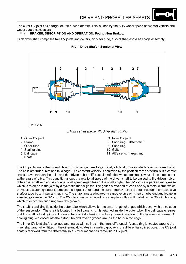
DRIVE AND PROPELLER SHAFTS
The outer CV joint has a target on the outer diameter. This is used by the ABS wheel speed sensor for vehicle and wheel speed calculations. + BRAKES, DESCRIPTION AND OPERATION, Foundation Brakes.
Each drive shaft comprises two CV joints and gaiters, an outer tube, a solid shaft and a ball cage assembly.
Front Drive Shaft – Sectional View
LH drive shaft shown, RH drive shaft similar
1 Outer CV joint2 Clamp3 Outer tube4 Sealing plug5 Ball cage6 Shaft
7 Inner CV joint8 Snap ring – differential9 Snap ring
10 Gaiter11 ABS sensor target ring.
The CV joints are of the Birfield design. This design uses longitudinal, elliptical grooves which retain six steel balls. The balls are further retained by a cage. The constant velocity is achieved by the position of the steel balls. If a centre line is drawn through the balls and the driven hub or differential shaft, the two centre lines always bisect each other at the angle of drive. This condition allows the rotational speed of the driven shaft to be passed to the driven hub or differential shaft with no loss of rotational speed regardless of the shaft angle. The CV joints are packed with grease which is retained in the joint by a synthetic rubber gaiter. The gaiter is retained at each end by a metal clamp which provides a water tight seal to prevent the ingress of dirt and moisture. The CV joints are retained on their respective shaft or tube by an internal snap ring. The snap rings are located in a groove on each shaft or tube end and locate in a mating groove in the CV joint. The CV joints can be removed by a sharp tap with a soft mallet on the CV joint housing which releases the snap ring from the groove.
The shaft is a sliding fit inside the outer tube which allows for the small length changes which occur with articulation of the suspension. The shaft is located in a ball cage which is retained inside the outer tube. The ball cage ensures that the shaft is held rigidly in the outer tube whilst allowing it to freely move in and out of the tube as necessary. A sealing plug is pressed into the outer tube and retains grease around the balls in the cage.
The inner CV joint shaft is splined and mates with splines in the front differential. A snap ring is located around the inner shaft and, when fitted in the differential, locates in a mating groove in the differential splined bore. The CV joint shaft is removed from the differential in a similar manner as removing a CV joint.
910109
M47 0439
1 87262542 32
11
DESCRIPTION AND OPERATION 47-3

DRIVE AND PROPELLER SHAFTS
Rear Drive Shafts
1 Drive shaft2 Outer CV joint3 Stake nut4 Snap ring (2 off)
5 Bolt M12 (6 off)6 Shim (3 off)7 Inner CV joint.
The rear drive shafts are identical in their construction. Each drive shaft has a total length of 687 mm. The inner CV joint has six holes for attachment with bolts to the differential output flange. Each pair of bolts is fitted with shim which secures the bolts after tightening.
The outer CV joint has a target on the outer diameter. This is used by the ABS wheel speed sensor for vehicle and wheel speed calculations. + BRAKES, DESCRIPTION AND OPERATION, Foundation Brakes.
Each drive shaft comprises two CV joints and gaiters and a tubular shaft.
47-4 DESCRIPTION AND OPERATION

DRIVE AND PROPELLER SHAFTS
Rear Drive Shaft – Sectional View
1 End cap2 Inner CV joint3 Circlip4 Gaiter5 Tube
6 Outer CV joint7 ABS Sensor target ring8 Snap ring9 Clamp
10 Circlip.
The CV joints used on the rear drive shafts are of the Birfield design. Refer to the Front Drive Shafts for a description of the CV joints.
The outer CV joint is retained on the tube by an internal snap ring. The CV joint can be removed by a sharp tap with a soft mallet on the CV joint housing which releases the snap ring from the groove. The inner CV joint is retained on the shaft by two circlips. This CV joint is different in design to the outer CV joint but the operating principle is the same. An end cap is pressed over the inner end of the CV joint to prevent the ingress of dirt and moisture. Both CV joints are fitted with gaiters which are secured with metal clamps.
7
M47 0441
9 8999
42 31 5 64
10
DESCRIPTION AND OPERATION 47-5

DRIVE AND PROPELLER SHAFTS
Front Propeller Shaft
1 Front propeller shaft2 Nut M12 (6 off)3 Coupling adaptor
4 Coupling5 Bolt M12 (6 off)6 Seal.
The front propeller shaft is constructed from 2.1 mm wall tubular steel. A three arm coupling is welded at one end. The opposite end has a splined shaft welded to the tube. The shaft has an overall length of 752 mm.
The three arm coupling has three holes which allow for attachment to the coupling and the coupling adaptor. The coupling adaptor and the coupling are secured to the shaft with three bolts and nuts. The flexible coupling attaches to the front output shaft of the transfer box and is secured with bolts in the three remaining holes in the coupling.
The coupling is a rubber moulding. The coupling is designed to transfer rotational drive from the transfer box to the front propeller shaft without wind-up, but simultaneously compensating for small amounts of misalignment and absorbing torque and vibrational loading. Each of the six attachment holes is lined with a metal bush. The bush is required to prevent compression of the coupling by the attachment bolts and nuts.
The splined shaft has 42 splines which mate with corresponding splines in the input shaft of the front differential. A shroud is pressed over the splined shaft. The shroud seals against an O-ring seal on the front differential input shaft, preventing the ingress of dirt and moisture. The splines allow for movement of the propeller shaft caused by small movements in the transmission and transfer box mountings.
47-6 DESCRIPTION AND OPERATION

DRIVE AND PROPELLER SHAFTS
Rear Propeller Shaft
1 Washer2 Bolt M123 Propeller shaft - Front4 Stud (6 off)5 Shim (3 off)6 Nut (6 off)
7 Nut (2 off)8 Shaft bearing assembly9 Propeller shaft - Rear
10 Bolt M12 (6 off)11 Shim (3 off).
The rear propeller shaft assembly comprises front and rear shaft assemblies and a centrally mounted shaft bearing. The rear propeller shaft assembly has an overall length of 1280 mm.
DESCRIPTION AND OPERATION 47-7

DRIVE AND PROPELLER SHAFTS
Front Shaft AssemblyThe front shaft assembly comprises a CV joint at the front and a splined shaft at the rear. The front shaft comprises a tube with welded, splined shafts at each end.
The forward splined shaft accepts the CV joint which is secured with a circlip. The CV joint is packed with grease and sealed on both sides with metal shrouds to prevent the ingress of dirt and moisture. The CV joint has six radial holes which provide for the attachment to the transfer box rear output flange. The joint is secured to the output flange with six bolts, which screw into threaded holes in the flange. Three shims are fitted under each pair of bolts. The shims have tabs which are bent to secure the bolts. The CV joint is not a serviceable item and failure will require replacement of the rear propshaft assembly. The rear splined shaft mates with splines in the rear shaft universal joint. A threaded hole is provided in the splined shaft to secure the front and rear propeller shaft sections together. A machined surface on the shaft accepts the shaft bearing, which is a press fit.
Shaft Bearing AssemblyThe shaft bearing assembly comprises a pressed steel housing, a rubber bush and a ball bearing. The rubber bush is bonded into the housing. An internal metal ring, bonded to the bush, allows for the bearing to be press fitted into it. The rubber bush allows for small deviations in alignment and also absorbs vibrational forces. The shaft bearing assembly is located on studs, which are integral with the body, and secured with flanged nuts.
Rear Shaft AssemblyThe rear shaft assembly comprises a universal joint at the front and a CV joint at the rear. The rear shaft comprises a tube with the welded universal joint at one end and a welded splined shaft at the opposite end.
The universal joint is welded to the rear shaft tube. The opposite end of the universal joint has a splined bore which mates with the splined shaft on the rear of the front shaft assembly. A bolt and washer is fitted through the splined bore and screws into the splined shaft on the front shaft assembly, securing the front and rear shaft assemblies together.
The splined shaft accepts the CV joint which is secured with a circlip. The CV joint is packed with grease and sealed on both sides with metal shrouds to prevent the ingress of dirt and moisture. The CV joint has six radial holes into which, six knurled bolts are pressed. The knurled shanks of the bolts provide a secure mounting for each bolt, preventing them from rotating. Three shims are fitted under each pair of bolts. The shims have tabs which are bent to further secure the bolts. The CV joint is secured to the input shaft of the rear differential with six flanged nuts. The CV joint is not a serviceable item and failure will require replacement of the rear propshaft assembly.
47-8 DESCRIPTION AND OPERATION

FINAL DRIVE
FINAL DRIVEDESCRIPTION AND OPERATIONDifferentials – Component Location
1 Front RH drive shaft2 Mounting bracket3 Engine sump4 Transfer box5 Rear propeller shaft assembly6 Rear RH drive shaft
7 Rear differential8 Rear LH drive shaft9 Front propeller shaft
10 Front LH drive shaft11 Front differential.
DESCRIPTION AND OPERATION 51-1
FINAL DRIVE
Description
GeneralThe front and rear differentials convert the "angle of drive" through 90° and distribute drive, via the drive shafts, to the front and rear wheels.
The front and rear differentials have different output ratios for the V8 and Td6 variants and, although visually similar, can be identified by part number.
The front differential is mounted on the LH side of the engine sump. The rear differential is mounted on the rear subframe.
Front DifferentialThe front differential is mounted on the LH side of the vehicle sump. The sump has a cast tube through it, which allows for the fitment of the RH drive shaft and separates the engine oil from the differential oil. The differential unit is secured to the engine sump with 4 bolts. The bolts pass through lugs in the differential casing and are secured into threaded holes in the sump. An O-ring seal is fitted to the casing and locates in the sump to provide a seal between the casing and the sump.
The casing comprises two halves with machined mating faces. When assembled, the iron casing halves are sealed with a thin film of Loctite 574 sealant and secured together with twelve bolts. The LH casing is the carrier for all the rotating parts and the RH casing is a cover to close the unit and a support for the RH carrier bearing. A breather tube is fitted to the casings. This allows a plastic tube to be fitted and routed to a high point in the engine compartment, preventing the ingress of water when the vehicle is wading.
The LH casing is fitted with a drain plug and a filler/level plug. The level plug allows the unit to be filled with oil until it leaks from the filler hole, ensuring the correct quantity of oil is added. The differential unit contains approximately 0.8 litre of oil for a dry fill and requires approximately 0.75 litre if oil is changed due to residual oil retained in the casings.
The differential is a conventional design using a hypoid gear layout. This employs a hypoid bevel pinion gear and crown wheel, with the pinion offset below the centre line of the crown wheel. This design allows for a larger pinion gear to be used which has the advantages of increased gear strength and reduced operating noise.
The front differential is available in two ratios. V8 engine vehicles use a differential with a final drive ratio of 3.73:1 and Td6 engine vehicles use a final drive ratio of 4.10:1. The ratio is changed by changing the amount of teeth between the crown wheel drive gear and pinion gear. Therefore for a ratio of 4.10:1, the crown wheel drive gear will have 4.10 times more teeth than the pinion gear. This equates to the crown wheel drive gear having 41 teeth and the pinion gear having 10 teeth.
51-2 DESCRIPTION AND OPERATION

FINAL DRIVE
Deze pagina werd opzettelijk niet gebruikt
Cette page est intentionnellement vierge
Questa pagina è stata lasciata in bianco di proposito
Diese Seite ist leer
Esta página foi deixada intencionalmente em branco
Esta página fue dejada en blanco intencionalmente
This page is intentionally left blank
DESCRIPTION AND OPERATION 51-3

FINAL DRIVE
Front Differential – Exploded View
51-4 DESCRIPTION AND OPERATION

FINAL DRIVE
1 O-ring seal2 Bearing pre-load spacer3 Bearing cup4 Taper roller bearing5 Casing screws (12 off)6 Dowel (2 off)7 RH Casing8 Gasket9 Crown wheel gear screws (10 off)
10 Carrier11 Pinion gear and shaft assembly12 Oil slinger13 Taper roller bearing14 Bearing cup15 Oil baffle16 Collapsable spacer17 Bearing cup18 Roller bearing19 Oil seal20 Deflector21 Seal deflector22 Input flange23 O-ring seal24 Pinion nut25 Oil seal26 Cap27 Vent28 LH Casing29 Information label30 Filler/Level plug31 Drain plug32 Crown wheel drive gear33 Roll pin34 Thrust washer35 Dished plate36 Sunwheel37 Shaft38 Planet gear39 Thrust washer.
DESCRIPTION AND OPERATION 51-5

FINAL DRIVE
Front Differential – Sectional View
1 Crown wheel gear screw (10 off)2 Planet gear3 Taper roller bearing4 Sun wheel (RH drive shaft output)5 O-ring seal6 Roll pin7 RH casing8 Input flange9 Pinion nut
10 Oil seal11 Taper roller bearing
12 Collapsable spacer13 Taper roller bearing14 Pinion gear15 Planet gear16 Oil seal17 Taper roller bearing18 Sun wheel (LH drive shaft output)19 Shaft20 Crown wheel drive gear21 LH casing22 Carrier
The differential comprises a pinion shaft and hypoid bevel gear, a crown wheel drive gear with an integral cage which houses two planet gears. Two sun wheels are also located in the cage and pass the rotational drive to the drive shaft shafts.
The pinion shaft is mounted on two opposed taper roller bearings with a collapsable spacer located between them. The spacer is used to hold the bearings in alignment and also collapses under the pressure applied to the pinion nut. This allows the nut to be tightened to a predetermined torque, which collapses the spacer, setting the correct bearing preload.
The pinion shaft has an externally splined outer end which accepts and locates the input flange, which is retained by the pinion nut. The opposite end of the output flange has an internal spline which provides positive location for the front propeller shaft. The flange has an external O-ring seal which seals against the front propeller shaft shroud preventing the ingress of dirt and moisture into the splines. An oil seal is pressed into the LH casing and seals the input flange to the differential unit. The pinion shaft has a hypoid bevel gear at its inner end which mates with the crown wheel drive gear.
The crown wheel drive gear is located on the carrier and secured with ten screws. The carrier is mounted on taper roller bearings located in each casing half. The bearings are press fitted into the casing and a spacer is located on the outside face to apply preload to the bearing.
M51 0149
1 2 3 7 8
9142021
22
19
4 5 6
12 1011131618 1517
51-6 DESCRIPTION AND OPERATION

FINAL DRIVE
The carrier is fitted with a shaft onto which the two planet gears are mounted. The shaft is secured in the carrier with a roll pin. The sun wheels are located in pockets within the carrier and mesh with the planet gears. Curved plates are located between the carrier and the sun wheels and hold the sun wheels in mesh with the planet gears. Each sun wheel has a machined, splined, bore to accept the drive shaft. A groove is machined in the bore to locate the snap ring fitted to the drive shaft, providing positive drive shaft location.
Rear DifferentialThe rear differential is located centrally in the rear subframe. The front of the differential is attached to the subframe via rubber bushes and bolts. The rear of the differential is mounted to the subframe via a single, offset rubber bush and a bolt.
The casing comprises two parts. The pinion housing is made from cast iron and provides locations for all the internal components. The pinion housing is sealed at the rear by an aluminium casting which is secured to the pinion housing with eight bolts and spring washers. A gasket between the two casings seals the unit. The rear cover has cast fins which assist heat dissipation. A breather tube is fitted to the rear cover. This allows a plastic tube to be fitted and routed to a high point under the vehicle body, preventing the ingress of water when the vehicle is wading.
The rear cover contains an oil level plug which allows for oil filling and level checking, with the differential installed in the vehicle. The level plug allows the unit to be filled with oil until it leaks from the filler hole, ensuring the correct quantity of oil is added. The differential unit contains approximately 1.2 litres of oil from a dry fill. If oil is being replaced, a smaller quantity of oil will be required due to residual oil retained in the pinion housing.
The differential is a conventional design using a hypoid gear layout, similar to the front differential. The rear differential is available in two ratios. V8 engine vehicles use a differential with a final drive ratio of 3.73:1 and Td6 engine vehicles use a final drive ratio of 4.10:1. The ratio is changed by changing the amount of teeth between the crown wheel drive gear and pinion gear. Therefore for a ratio of 4.10:1, the crown wheel drive gear will have 4.10 times more teeth than the pinion gear. This equates to the crown wheel drive gear having 41 teeth and the pinion gear having 10 teeth.
DESCRIPTION AND OPERATION 51-7

FINAL DRIVE
Rear Differential – Sectional View
1 Input flange2 Bush mounting holes3 Taper roller bearing4 Collapsable spacer5 Taper roller bearing6 Snap ring7 Oil seal8 RH output flange9 Taper roller bearing
10 Gasket11 Sun wheel (RH drive shaft output)12 Snap ring13 Planet gear (2 off)14 Shaft15 Snap ring
16 Rear cover17 Crown wheel gear bolt (10 off)18 Rear cover bolt (8 off)19 Sun wheel (LH drive shaft output)20 Carrier21 LH output flange22 Oil seal23 Taper roller bearing24 Crown wheel drive gear25 Pinion gear26 Pinion housing27 Pinion shaft28 Oil seal29 Nut retainer30 Flanged nut.
M51 0150
9
10
11
653 421 7 8
2224
16
17
18
19202125262930
1413
15
2328
12
27
51-8 DESCRIPTION AND OPERATION

FINAL DRIVE
The differential comprises a pinion shaft and spiral bevel pinion gear and a crown wheel drive gear with an integral cage which houses two planet gears. Two sun wheels are also located in the cage and pass the rotational drive to the drive shafts.
The pinion shaft is mounted on two opposed taper roller bearings, with a collapsable spacer located between them. The spacer is used to hold the bearings in alignment and also collapses under the pressure applied to the pinion flanged nut. This allows the flanged nut to be tightened to a predetermined torque, which collapses the spacer, setting the correct bearing preload.
The pinion shaft has an externally splined outer end which accepts and locates the input flange, which is retained by the pinion nut. The output flange has six threaded holes and mates with the rear propeller shaft. Six bolts secure the rear propeller shaft to the input flange. An oil seal is pressed into the pinion housing and seals the input flange to the pinion housing. The pinion shaft has a spiral bevel gear at its inner end which mates with the crown wheel drive gear.
The crown wheel drive gear is located on the carrier and secured with ten screws. The carrier is mounted on taper roller bearings located in machined bores on each side of the pinion housing. The bearings are retained in the casing by a circlip, the thickness of which is selected to apply the correct bearing preload.
The carrier has a through hole which provides location for the shaft. The shaft provides the mounting for the planet gears in the carrier cage. The shaft is fitted with a snap ring at one end which locates in a machined groove in the carrier, locking the shaft in position.
The sun wheels are located in pockets in the carrier cage and mesh with the planet gears. Spacers are fitted between the sun wheels and the carrier and set the correct mesh contact between the planet gears and the sun wheels. Each sun wheel has a machined bore with internal splines and machined groove near the splined end. The groove provides positive location for a snap ring fitted to the end of each output flange.
Each output flange has a splined shaft which located in each sun wheel. A snap ring fitted to the splined shaft locates in the groove the sun wheel bore and positively located the output flange. Oil seals are pressed into each side of the pinion housing and seal the output flange to the housing. Each output flange has six threaded holes which provide for the attachment of the rear drive shafts.
The rear cover is located on the rear of the pinion housing and is sealed to the housing with a gasket and secured with eight bolts.
DESCRIPTION AND OPERATION 51-9

FINAL DRIVE
Operation
Differential OperationThe operating principles of the front and rear differentials are the same. Rotational input from the propeller shaft is passed via the input flange to the pinion shaft and pinion gear. The angles of the pinion gear to the crown wheel drive gear moves the rotational direction through 90°.
The transferred rotational motion is now passed to the crown wheel drive gear, which in turn rotates the carrier. The shaft, which is secured to the carrier also rotates at the same speed as the carrier. The planet gears, which are mounted on the shaft, also rotate with the carrier. In turn, the planet gears transfer their rotational motion to the left and right hand sun wheels, rotating the drive shafts.
When the vehicle is moving in a forward direction, the torque applied through the differential to each sun wheel is equal. In this condition both drive shafts rotate at the same speed. The planet gears do not rotate and effectively lock the sun wheels to the carrier.
If the vehicle is turning, the outer wheel will be forced to rotate faster than the inner wheel by having a greater distance to travel. The differential senses the torque difference between the sun wheels. The planet gears rotate on their axes to allow the outer wheel to rotate faster than the inner one.
51-10 DESCRIPTION AND OPERATION

STEERING
Deze pagina werd opzettelijk niet gebruikt
Cette page est intentionnellement vierge
Questa pagina è stata lasciata in bianco di proposito
Diese Seite ist leer
Esta página foi deixada intencionalmente em branco
Esta página fue dejada en blanco intencionalmente
This page is intentionally left blank
STEERINGDESCRIPTION AND OPERATION
Steering Component Location – Td6
RHD shown, LHD similar
1 Fluid cooler2 Servotronic valve3 Lower column4 Upper column5 Steering wheel6 Column adjustment motor – tilt
7 Column adjustment motor – reach8 PAS pump9 PAS fluid reservoir
10 Steering rack11 LH track rod12 RH track rod
M57 1177
12
1
2
3
4
56
7
8 9
10
11
DESCRIPTION AND OPERATION 57-1
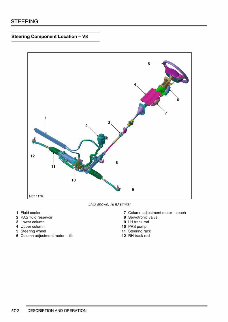
STEERING
Steering Component Location – V8
LHD shown, RHD similar
1 Fluid cooler2 PAS fluid reservoir3 Lower column4 Upper column5 Steering wheel6 Column adjustment motor – tilt
7 Column adjustment motor – reach8 Servotronic valve9 LH track rod
10 PAS pump11 Steering rack12 RH track rod
M57 1178
1
23
4
5
6
7
8
9
10
11
12
57-2 DESCRIPTION AND OPERATION

STEERING
Steering Control Diagram – Servotronic
A = Hardwired; B = K Bus; C = Diagnostic DS2 bus
1 Fuse 5A – Battery permanent supply2 Servotronic valve3 Body Control Unit (BCU)
4 ABS ECU5 Instrument pack6 Diagnostic socket
M57 1179A
1
A
2
3
4
5
6
B C
DESCRIPTION AND OPERATION 57-3

STEERING
Steering Control Diagram – Column Adjustment – Without Memory
A = Hardwired
1 Fuse (15A) – Permanent battery supply2 Column adjustment motor – reach3 Column adjustment motor – tilt
4 Column adjustment control unit5 Steering column adjustment switch
57-4 DESCRIPTION AND OPERATION
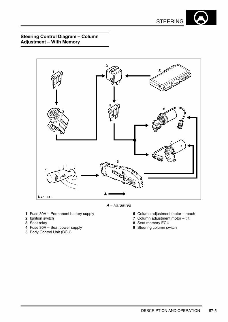
STEERING
Steering Control Diagram – Column Adjustment – With Memory
A = Hardwired
1 Fuse 30A – Permanent battery supply2 Ignition switch3 Seat relay4 Fuse 30A – Seat power supply5 Body Control Unit (BCU)
6 Column adjustment motor – reach7 Column adjustment motor – tilt8 Seat memory ECU9 Steering column switch
DESCRIPTION AND OPERATION 57-5

STEERING
Steering Control Diagram – Column Lock
A = Hardwired; B = K Bus; C= Diagnostic DS2 bus
M57 1182B
1
A
14
13 12 11
2
4
5
6
3
7
8
9
CB
10
57-6 DESCRIPTION AND OPERATION

STEERING
1 Fuse 30A – Permanent battery supply2 Ignition switch3 Instrument pack4 Diagnostic socket5 Body Control Unit (BCU)6 Anti-lock Brake System (ABS) ECU7 Electronic Automatic Transmission (EAT) ECU8 Key in sensor9 Immobilisation ECU
10 Steering lock ECU11 Fuse 5A – Auxiliary supply12 Fuse 5A – Ignition supply13 Fuse 10A – Permanent battery supply14 Fuse 50A – Permanent battery supply
DESCRIPTION AND OPERATION 57-7

STEERING
Steering Control Diagram – Steering Wheel Heating
A = Hardwired
1 Fuse 30A – Permanent battery supply2 Ignition switch3 Steering wheel relay4 Fuse 10A – Steering wheel heating ECU supply5 Rotary coupler
6 Steering wheel heater element7 Steering wheel heater thermostat8 Steering wheel heating ECU9 Steering wheel heater switch
57-8 DESCRIPTION AND OPERATION
STEERING
Description
GeneralRack and pinion steering is introduced on Range Rover for the first time. A ZF power assisted steering rack is fitted on the front subframe. The rack is a conventional end take-off rack and pinion power assisted unit with the addition of ZF Servotronic 2 assistance.
Servotronic 2 adds electronic control and speed sensitive steering to the steering rack. The Servotronic 2 feature provides easy and comfortable steering operation when parking, improved 'road feel' at increased road speeds and adds an integrated, positive centre feel feature which optimises steering wheel torque during high speed driving.
The Servotronic 2 system is controlled by software which is incorporated into the Body Control Unit (BCU). The software responds to steering torque inputs and road speed signals and controls the assistance via a transducer valve located on the steering rack valve.
The steering column features fully electrical adjustment for tilt and reach. On vehicles fitted with memory seats, the steering wheel position control is incorporated into the memory seat ECU.
The column also features an electronically controlled steering lock. The lock is operated when the ignition switch senses that the correct key has been inserted. An ECU, located inside the steering column, controls a motor operated lock, releasing the steering lock when appropriate.
DESCRIPTION AND OPERATION 57-9

STEERING
Steering Column
1 Bolt – Flanged2 Steering wheel3 Column adjustment motor – tilt4 Column adjustment motor – reach5 Steering angle sensor6 Lower column – upper shaft7 Lower column – lower shaft
8 Bulkhead mounting9 Flexible coupling
10 Upper column – lower shaft11 Upper column – upper shaft12 Adjustable upper column13 Lock housing/Tilt head
57-10 DESCRIPTION AND OPERATION

STEERING
The steering column comprises the upper column assembly which is connected to the steering rack via several shafts which are connected via flexible couplings and universal joints.
The lower column comprises upper and lower shafts which are connected together as a sliding fit. The sliding fit allows the shafts to collapse in the event of a frontal collision, preventing column intrusion into the vehicle interior. The upper shaft is connected to a flexible coupling and provides the attachment to the upper column. The lower shaft has internal splines which connect with splines on the steering rack valve input shaft.
The upper column also comprises two shafts which are also connected together as a sliding fit. The shafts are a double 'D' section to prevent rotation. The sliding fit allows the shafts to collapse in the event of a frontal collision further preventing intrusion into the vehicle interior. The lower shaft is connected to the flexible coupling which transfers torque to the lower column and the steering rack. The upper shaft has a splined internal bore which connects with the adjustable upper column assembly.
The upper column assembly comprises two extruded aluminium sections which connect together and can slide on each other in the event of a frontal impact, further preventing column intrusion into the vehicle interior. The column is attached to the cross-car tube with four bolts. A strap is bolted to the upper of the two aluminium sections. The strap is coiled around a bush on the upper section and has a hook which locates on the lower section. In the event of a frontal impact, the strap can unwind, allowing the upper column to collapse in a controlled manner absorbing energy.
The upper column also provides the location for the steering angle sensor which is used by the ABS system. + BRAKES, DESCRIPTION AND OPERATION, Foundation Brakes.
The upper column provides the locations for the column adjustment motors and the steering lock mechanism and steering lock ECU. The steering lock operates via a locking bolt which engages with a locking sleeve located around the column shaft. The locking sleeve has a tolerance ring which is located between the sleeve and the column. The tolerance ring allows the locking sleeve to slip on the upper column shaft if a high torque is applied to the steering wheel when the lock is engaged. This prevents the locking bolt from being sheared by someone forcibly turning the steering wheel while the steering lock is engaged, yet still effectively locking the steering.
DESCRIPTION AND OPERATION 57-11

STEERING
Column Adjustment
1 Vertical adjustment cam2 Adjustment motor – tilt3 Worm drive – tilt adjustment motor
4 Worm drive – reach adjustment motor5 Adjustment motor – reach
The steering column is adjusted using a four way switch located on the LH side of the steering column, below the LH column control switch.
The steering column adjustment is achieved by two electric motors and a column adjustment control unit on vehicles without memory seats or by the memory seat ECU on vehicles with memory seats. Both motors are attached to the lock housing / tilt head assembly and move the column via worm drive screws.
The reach adjustment motor drives a screw shaft which moves the column in and out for reach adjustment. The adjustment is achieved by the two extruded aluminium sections which slide on one another. The tilt adjustment motor also drives a screw shaft. This shaft is connected to a cam, which causes the tilt head to pivot, adjusting the column angle.
57-12 DESCRIPTION AND OPERATION

STEERING
On vehicles without memory seats, inputs from the column adjustment switch are received by the adjustment control unit located under the column. The control unit interprets the signals from the switch and operates the requested adjustment motor in the required direction.
On vehicles with memory seats, the adjustment control unit is not fitted. Inputs from the column adjustment switch are received by the memory seat ECU which is incorporated into the driver's seat switch pack. The ECU interprets the signals from the switch and operates the requested adjustment motor in the required direction. The motors used on the memory vehicles have Hall effect sensors known as 'ripple counters'. These counters output the position of the column when the seat memory store function is used and applies this setting to the applicable ignition key.
DESCRIPTION AND OPERATION 57-13
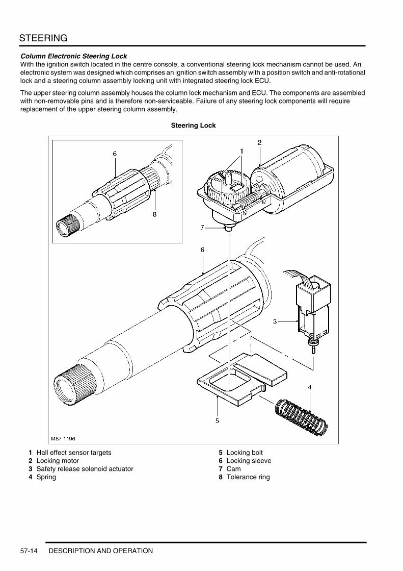
STEERING
Column Electronic Steering LockWith the ignition switch located in the centre console, a conventional steering lock mechanism cannot be used. An electronic system was designed which comprises an ignition switch assembly with a position switch and anti-rotational lock and a steering column assembly locking unit with integrated steering lock ECU.
The upper steering column assembly houses the column lock mechanism and ECU. The components are assembled with non-removable pins and is therefore non-serviceable. Failure of any steering lock components will require replacement of the upper steering column assembly.
Steering Lock
1 Hall effect sensor targets2 Locking motor3 Safety release solenoid actuator4 Spring
5 Locking bolt6 Locking sleeve7 Cam8 Tolerance ring
57-14 DESCRIPTION AND OPERATION
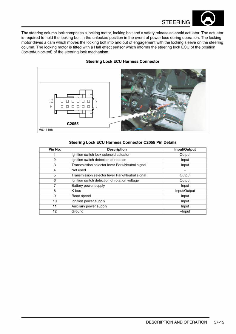
STEERING
The steering column lock comprises a locking motor, locking bolt and a safety release solenoid actuator. The actuator is required to hold the locking bolt in the unlocked position in the event of power loss during operation. The locking motor drives a cam which moves the locking bolt into and out of engagement with the locking sleeve on the steering column. The locking motor is fitted with a Hall effect sensor which informs the steering lock ECU of the position (locked/unlocked) of the steering lock mechanism.
Steering Lock ECU Harness Connector
Steering Lock ECU Harness Connector C2055 Pin Details
Pin No. Description Input/Output1 Ignition switch lock solenoid actuator Output2 Ignition switch detection of rotation Input3 Transmission selector lever Park/Neutral signal Input
4 Not used –5 Transmission selector lever Park/Neutral signal Output6 Ignition switch detection of rotation voltage Output
7 Battery power supply Input8 K-bus Input/Output9 Road speed Input
10 Ignition power supply Input11 Auxiliary power supply Input12 Ground –Input
M57 1198
C2055
DESCRIPTION AND OPERATION 57-15

STEERING
Ignition Switch and Locking Mechanism
1 Ignition switch contacts housing2 Spacer3 Key interlock mechanism4 Ignition switch lock solenoid actuator5 Hall sensor pick-up
6 Locking pin7 Hall sensor target8 Ignition key lock barrel9 Key interlock cable connection point
10 Drive shaft and ignition switch lock cam
The ignition switch assembly also has a locking mechanism which works in conjunction with the immobilisation ECU and the steering lock ECU. The ignition switch mechanism comprises an ignition switch lock solenoid actuator which prevents the ignition switch being rotated unless the key has been recognised by the immobilisation ECU. A Hall sensor is located in the ignition switch body and senses the rotation of the ignition switch. This signal is transmitted on the K bus and is used by the steering lock ECU to confirm the key status with the immobilisation ECU. Refer to Operation later in this section for functional description.
57-16 DESCRIPTION AND OPERATION

STEERING
Ignition Switch Lock Harness Connector
Ignition Switch Lock Harness Connector C0672 Pin Details
Pin No. Description Input/Output1 Ignition switch detection of rotation Output2 Ignition switch detection of rotation voltage Input3 Ignition switch lock solenoid actuator Input
4 Ground –
M57 1199
C0672
DESCRIPTION AND OPERATION 57-17

STEERING
Steering Rack
1 Banjo bolt (4 off)2 Seal (8 off)3 Pipe4 Pipe5 Steering rack6 Locknut7 LH track rod8 Spacer9 Nut
10 Inner track rod joint11 Clamp (2 off)12 Gaiter (2 off)13 Seal (2 off)14 Clamp (2 off)15 Torx bolt M12 (2 off) – rack to subframe
mounting16 Nut M12 (2 off) – rack to subframe mounting17 RH track rod18 Locknut M16
57-18 DESCRIPTION AND OPERATION
STEERING
The steering gear comprises the mechanical steering rack, the valve and an integrated hydraulic power cylinder.
The steering rack uses a rack with an integrated piston which is guided on plain bearings within the rack housing. The pinion, which is attached to the valve runs in bearings and meshes with the rack teeth. The rack is pressed against the pinion by a spring loaded yoke which ensures that the teeth mesh without any play. The pinion is connected to the valve rotor via a torsion bar.
The rotary motion of the steering wheel is converted into axial movement of the rack by the pinion and is initiated by the valve. This motion is transferred into movement of the wheels by adjustable track rod arms.
The rotary valve is used to control the pressurised fluid required for power assistance. The valve comprises a valve body, a control bush and a torsion bar. The valve body has eight control groove in its bore. The control bush also has eight radial grooves which are matched to the valve. The control bush is positively attached to the pinion. The torsion bar is the connecting element between the valve body, the pinion and the control bush.
Torque input from the steering wheel is passed to the valve body and causes a rotary motion of the torsion bar. The valve body changes its relative position to the control bush and subsequently the relative positions of the control grooves is also changed. This allows pressurised fluid to pass via the mismatched grooves to the rack piston and provide the required assistance in the selected direction.
The piston is located at one end of the rack housing. Each side of the piston is connected to fluid pressure or fluid return via a metal external pipe which is connected to the valve housing.
Each end of the rack has a threaded hole which provides for the fitment of an inner track rod joint. The external ends of the rack are sealed with gaiters which prevent the ingress of dirt and moisture. The inner track rod joints has a long outer threaded shank which screws into the outer track rod. The steering toe can be adjusted using the threaded end of the inner track rod. When the correct toe is achieved, a locknut on the inner tie rod is tightened to prevent further inadvertent movement.
Servotronic Transducer ValveThe Servotronic transducer valve is located in a port on the side of the steering rack valve housing. The valve is sealed in the housing with an O-ring seal and is secured with two long screws into threaded holes in the housing.
The Servotronic valve is a transducer controlled valve which responds to control signals supplied from the Body Control Unit (BCU). The BCU contains a microprocessor which receives road speed signals from the ABS ECU and calculates the correct controlling signal for the Servotronic valve. The Servotronic software within the BCU has a diagnostic capability which allows TestBook/T4 to check the tune of the steering.
The Servotronic valve determines the hydraulic reaction at the steering rack rotary valve and controls the input torque required to turn the steering wheel. The Servotronic system allows the steering to be turned with minimum effort when the vehicle is stationary or manoeuvred at slow speed. The hydraulic reaction changes proportional to the vehicle speed, with the required steering effort increasing as the vehicle moves faster. At high speeds, the Servotronic system provides the driver with a good feedback through the steering providing precise steering and improved stability.
A major advantage of the Servotronic system is that fluid pressure and flow through the rotary valve remains constant and allows full steering pressure to be available in an emergency where a sudden and unexpected steering correction may be required.
Power Assisted Steering (PAS) Pump and ReservoirThe PAS fluid pumps used on both the Td6 and V8 models are of the vane type and are similar in their operation. The pumps are driven by a polyvee belt from the engine crankshaft pulley. A tensioner is used to maintain the correct tension on the belt.
DESCRIPTION AND OPERATION 57-19
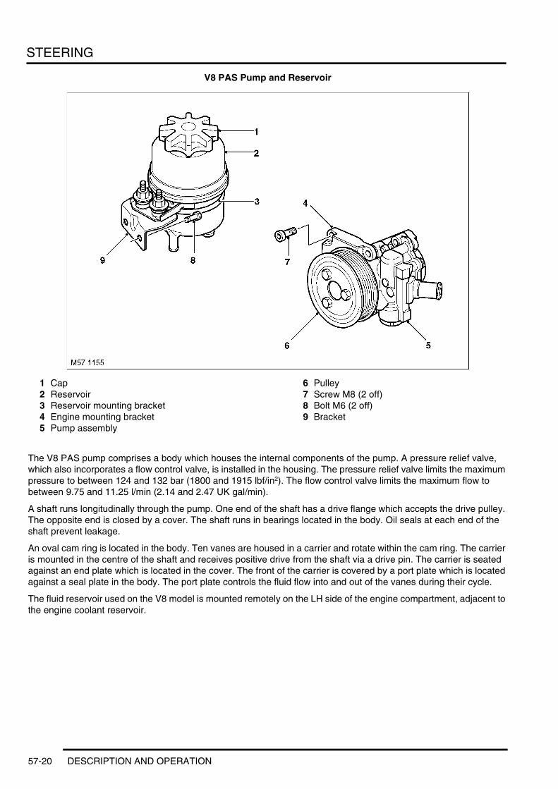
STEERING
V8 PAS Pump and Reservoir
1 Cap2 Reservoir3 Reservoir mounting bracket4 Engine mounting bracket5 Pump assembly
6 Pulley7 Screw M8 (2 off)8 Bolt M6 (2 off)9 Bracket
The V8 PAS pump comprises a body which houses the internal components of the pump. A pressure relief valve, which also incorporates a flow control valve, is installed in the housing. The pressure relief valve limits the maximum pressure to between 124 and 132 bar (1800 and 1915 lbf/in2). The flow control valve limits the maximum flow to between 9.75 and 11.25 l/min (2.14 and 2.47 UK gal/min).
A shaft runs longitudinally through the pump. One end of the shaft has a drive flange which accepts the drive pulley. The opposite end is closed by a cover. The shaft runs in bearings located in the body. Oil seals at each end of the shaft prevent leakage.
An oval cam ring is located in the body. Ten vanes are housed in a carrier and rotate within the cam ring. The carrier is mounted in the centre of the shaft and receives positive drive from the shaft via a drive pin. The carrier is seated against an end plate which is located in the cover. The front of the carrier is covered by a port plate which is located against a seal plate in the body. The port plate controls the fluid flow into and out of the vanes during their cycle.
The fluid reservoir used on the V8 model is mounted remotely on the LH side of the engine compartment, adjacent to the engine coolant reservoir.
57-20 DESCRIPTION AND OPERATION

STEERING
Td6 PAS Pump and Reservoir
1 Cap2 Reservoir3 Rear engine mounting bracket
4 Pump assembly5 Pulley6 Front engine mounting bracket
The Td6 PAS pump comprises a body which houses the internal components of the pump. A pressure relief valve, which also incorporates a flow control valve, is installed in the housing. The pressure relief valve limits the maximum pressure to between 120 and 127 bar (1740 and 1840 lbf/in2). The flow control valve limits the maximum flow to between 9.75 and 11.25 l/min (2.14 and 2.47 UK gal/min).
A shaft runs longitudinally through the pump. One end of the shaft has a drive flange which accepts the drive pulley. The opposite end is closed by a cover. The shaft runs in bearings located in the body. Oil seals at each end of the shaft prevent leakage.
An oval cam ring is located in the body. Ten vanes are housed in a carrier and rotate within the cam ring. The carrier is mounted in the centre of the shaft and receives positive drive from the shaft via a drive pin. The carrier is seated against an end plate which is located in the cover. The front of the carrier is covered by a port plate which is located against a seal plate in the body. The port plate controls the fluid flow into and out of the vanes during their cycle.
The fluid reservoir used on the Td6 model is mounted integral with the pump. The fluid supply to the pump is direct from a connection to the housing and the return is via a hose connection.
DESCRIPTION AND OPERATION 57-21

STEERING
Operation
Hydraulic Circuit OperationThe following hydraulic circuits show power steering operation and fluid flow for the steering in a straight ahead, neutral position and when turning right. The circuit diagram for turning left is similar to that shown for turning right.
Steering in Neutral Position
Circuit shows steering rotary valve in neutral position with the vehicle not moving.
1 Return fluid control groove2 Radial groove3 Feed fluid control groove4 Radial groove5 Axial groove6 Feed fluid control edge7 Feed fluid radial groove8 Return fluid control edge9 Return fluid chamber
10 Cut-off valve11 Radial groove12 Servotronic transducer13 Feed fluid radial groove14 Radial groove15 Orifice16 Balls17 Compression spring
18 PAS fluid reservoir19 Torsion bar20 Valve rotor21 Reaction piston22 Reaction chamber23 Centering piece24 Pressure relief/flow limiting valve25 PAS pump26 Inner track rod27 Pinion28 Valve sleeve29 Steering rack30 Rack housing31 Power assist cylinder – right32 Piston33 Power assist cylinder – left
M57 1184
24
1 2 3 4
5
678
9
9101112
131415
16 17 19
18
20
2122
25
2627282930313233
23
57-22 DESCRIPTION AND OPERATION

STEERING
When the engine is started, the PAS pump draws fluid from the reservoir down the low pressure suction line. The fluid passes through the pump and is delivered, via a hose, to the steering rack valve unit.
The pressurised fluid flows through a connecting bore in the valve and, via the feed fluid radial groove and the transverse bores in the valve sleeve, passes to the feed fluid control groove of the valve rotor.
In the neutral (straight ahead) position , the fluid passes over the open feed fluid control edges to all valve sleeve axial grooves. The fluid then passes through the open return fluid control edges and the return fluid control grooves of the valve rotor. The fluid then passes via connecting bores to the return fluid chamber and to the reservoir via an external hose.
Simultaneously, the radial grooves of the valve body and their associated pipes provide a connection between the left and right power assist cylinders.
DESCRIPTION AND OPERATION 57-23

STEERING
Steering in Right Turn Position
Circuit shows steering rotary valve in right turn position, at high vehicle speed and with rapid steering corrections. The Servotronic transducer valve is fully open and the maximum hydraulic reaction is limited by the cut-off valve.
1 Return fluid control groove2 Radial groove3 Feed fluid control groove4 Radial groove5 Axial groove6 Feed fluid control edge7 Feed fluid radial groove8 Return fluid control edge9 Return fluid chamber
10 Cut-off valve11 Radial groove12 Servotronic transducer13 Feed fluid radial groove14 Radial groove15 Orifice16 Balls17 Compression spring
18 PAS fluid reservoir19 Torsion bar20 Valve rotor21 Reaction piston22 Reaction chamber23 Centering piece24 Pressure relief/flow limiting valve25 PAS pump26 Inner track rod27 Pinion28 Valve sleeve29 Steering rack30 Rack housing31 Power assist cylinder – right32 Piston33 Power assist cylinder – left
When the steering wheel is turned to the right, the steering rack and piston moves to the left in the piston bore. The valve rotor is rotated to the right (clockwise) and pressurised fluid is directed over the further opened feed fluid control edges and to the associated axial grooves, the radial groove and via an external pipe to the left power assist cylinder chamber. The pressure applied to the piston from the left power assist cylinder chamber provides the hydraulic assistance.
An adaptable pressure build-up is achieved by the partially or fully closed feed fluid control edges restricting or preventing a connection between the fluid pressure inlet and the other axial grooves connected to the radial groove.
M57 1185
1 2 3 4
5
678
9
24
9101112
131415
16 17 19
18
20
2122
23
25
2627282930313233
57-24 DESCRIPTION AND OPERATION
STEERING
Simultaneously, the fluid pressure outlet to the pressurised axial grooves are restricted or partially restricted by the closing return fluid control edges. The fluid displaced by the piston from the right power assist cylinder chamber, flows through an external pipe to the radial grooves. From there the fluid passes to the associated axial grooves and on to the return fluid control grooves, via the further opened return fluid control edges. The return flow of fluid to the reservoir passes via interconnecting bores which lead to the return fluid chamber.
When the steering wheel is turned to the left the operating sequence is as above but the pressure is applied to the opposite side of the piston.
Servotronic OperationWhen the vehicle is manoeuvred into and out of a parking space (or other similar manoeuvre), the Servotronic function of the BCU uses road speed data from the ABS ECU to determine the vehicle speed, which in this case will be slow or stationary. The BCU microprocessor analyses the signals and outputs an appropriate control current to the Servotronic transducer valve. The Servotronic valve closes and prevents fluid flowing from the feed fluid radial groove to the reaction chamber. An orifice also ensures that there is return pressure in the reaction chamber. This condition eliminates any 'reaction' ensuring that the steering is very light to operate, reducing the effort required to turn the steering wheel.
As the vehicle is driven and the road speed increases, the BCU microprocessor analyses the road speed signals from the ABS ECU and reduces the amount of control current supplied to the Servotronic valve. The Servotronic valve reacts to the control current and opens the valve by an amount appropriate to the road speed. This allows a controlled fluid supply from the feed fluid radial groove to the reaction chamber. The orifice prevents the loss of large amounts of fluid to the return fluid chamber. The higher fluid pressure acting on the reaction piston causes compression of the balls which are located between the reaction piston and the centering piece which in turn is securely connected to the valve sleeve. When driving in a straight line, this has a positive effect on the exact centralising of the steering valve. When the steering valve is actuated, the balls, with a higher load on them, provide additional torsional resistance to rotation of the valve rotor. This mode of Servotronic assistance requires an established higher steering wheel torque until the hydraulic assistance required in the left or right power assist cylinder is determined.
At high driving speeds, i.e. on a motorway, the Servotronic valve is fully open due to a very low or nonexistent control current supplied from the BCU. This enables maximum pressure supply from the feed fluid radial groove to the reaction piston. When the steering wheel is turned, the reaction pressure increases appropriate to the existing operating pressure and pressurises the piston in the reaction chamber. As soon as the reaction pressure reaches its upper limit, the fluid is discharged to the return fluid chamber via the cut-off valve and prevents further increases in reaction pressure. This maintains the input torque applied through the steering wheel and provides the driver with an improved 'road feel' allowing precise steering and directional stability.
Steering Lock ECU OperationThe steering lock ECU operates in conjunction with the immobilisation ECU and the ignition switch.
Detection of Unlock RequestWhen a 'valid' key is inserted in the ignition switch, the immobilisation ECU transmits a 'valid key in lock' message on the K Bus. The steering lock ECU receives this message and starts the unlocking process of operating the steering lock motor to disengage the locking bolt.
The immobilisation ECU goes into sleep mode 60 seconds after the vehicle is unlocked and a key is not inserted in the ignition switch. When the key is subsequently inserted in the ignition switch and rotated, the rotation is sensed by the Hall rotation sensor in the switch. Further rotation is prevented by the ignition switch lock solenoid actuator. The rotation sensor transmits a signal which is received by the steering lock ECU. This ECU sends a 'request immobilisation ECU status' message on the K bus which wakes the immobilisation ECU. When the immobilisation ECU confirms that a valid key is inserted, the ignition switch lock disengages and the steering lock ECU starts the unlocking process.
If the K bus is inoperative, the unlocking operation is initiated by the rotation sensor signal. This is indicated to the driver through a delayed operation of the solenoid actuator preventing the key from being turned initially. The solenoid actuator is operated on a delay which will initially prevent the key from being turned. The solenoid actuator will unlock and allow the key to turn on the second attempt. A defect in the K bus is detected if no response from the immobilisation ECU is received after a 2.4 seconds period after the 'request immobilisation ECU status' is sent.
DESCRIPTION AND OPERATION 57-25
STEERING
Unlocking of Steering LockIf the battery voltage is 9V or less, the steering lock will be inoperative.
When a valid key is inserted and confirmed, the steering lock ECU activates the steering lock motor in the unlock direction. Movement from the locked to the unlocked position is detected by the Hall sensor in the motor and sensed by the steering lock ECU.
When the Hall sensor detects that the unlocked position has been reached, the ECU brakes the motor. The safety release solenoid actuator is de-energised and its spring loaded pin drops into a recess in the locking bolt. This forms a mechanical lock securing the locking bolt in the unlocked position preventing the steering lock from being applied when the vehicle is being operated. A Hall sensor in the safety release solenoid actuator informs the steering lock ECU of this condition. Once the unlocking procedure is successfully performed, the steering lock ECU de-energises the steering lock motor.
Once the steering is successfully unlocked, the ignition switch lock disengages allowing the key to be turned to positions II and III.
Detection of Locking RequestWhen the ignition key is turned to position 0, the ignition switch lock solenoid actuator remains active (unlocked) for 16 minutes. This function allows immediate restarting of the vehicle as long as the key is not removed from the ignition switch. When the key is removed, the immobilisation ECU senses the removal and transmits a 'no valid key in lock' message on the K bus. The steering lock ECU checks that the ignition switch position II or III outputs and the rotation sensor are not active and initiates the steering locking process. This check ensures that the steering is not locked when the vehicle may be being driven.
If the K bus is inoperative, locking of the steering column is prevented by the steering lock ECU. This is indicated to the driver when attempting to start the vehicle through a delayed operation of the ignition switch lock solenoid actuator preventing the key from being turned initially. The solenoid actuator is operated on a delay which will initially prevent the key from being turned. The solenoid actuator will unlock and allow the key to turn on the second attempt. A defect in the K bus is detected if no response from the immobilisation ECU is received after a 2.4 seconds period after the 'request immobilisation ECU status' is sent.
Locking of Steering LockThe battery voltage must be greater than 10V and the vehicle must be stationary.
The ABS ECU transmits vehicle speed on a hardwired connection with the steering lock ECU. The steering lock ECU uses the signal to determine when the vehicle has stopped.
When the key is removed and the steering lock ECU receives the 'no valid key in lock' message from the immobilisation ECU, the steering lock motor is activated. The safety release solenoid actuator in the steering column is energised, withdrawing the pin from the locking bolt. The Hall sensor in the solenoid actuator informs the steering lock ECU that the lock is released.
The steering lock ECU then operates the steering lock motor in the lock direction. Movement from the unlocked to the locked position is detected by the Hall sensor in the motor and sensed by the steering lock ECU. The safety release solenoid actuator is de-energised and rests on the locking bolt.
57-26 DESCRIPTION AND OPERATION
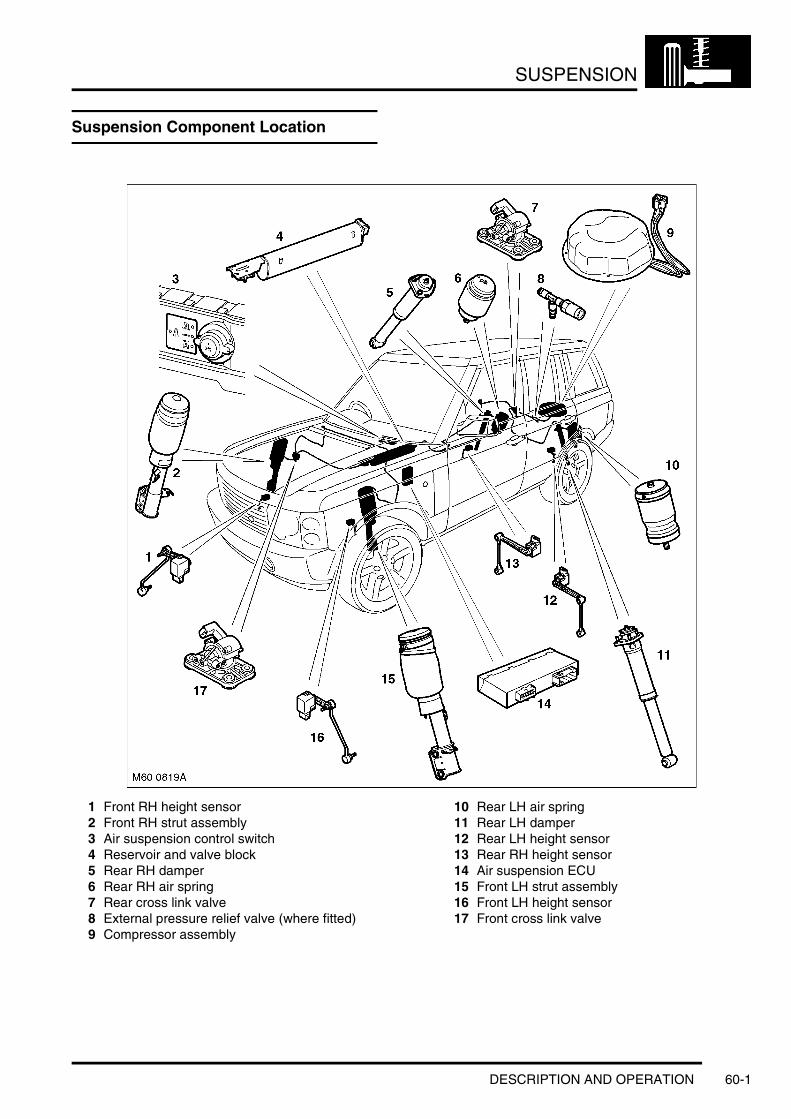
SUSPENSION
SUSPENSIONDESCRIPTION AND OPERATIONSuspension Component Location
1 Front RH height sensor2 Front RH strut assembly3 Air suspension control switch4 Reservoir and valve block5 Rear RH damper6 Rear RH air spring7 Rear cross link valve8 External pressure relief valve (where fitted)9 Compressor assembly
10 Rear LH air spring11 Rear LH damper12 Rear LH height sensor13 Rear RH height sensor14 Air suspension ECU15 Front LH strut assembly16 Front LH height sensor17 Front cross link valve
DESCRIPTION AND OPERATION 60-1

SUSPENSION
Suspension Control Diagram
A = Hardwired connections; B = K bus; C = Diagnostic DS2 bus; D = CAN bus
1 Fuse 15A – Permanent feed2 Fusible link 100A3 Fuse 50A4 Air suspension relay5 Compressor and motor6 Temperature sensor7 HP exhaust valve8 Exhaust valve9 Control switch
10 Body control Unit (BCU)11 Air suspension ECU12 Driver door module (Access mode switch)
13 Reservoir pressure sensor14 Valve block15 Front cross link valve16 Rear cross link valve17 LH rear height sensor18 RH rear height sensor19 LH front height sensor20 RH front height sensor21 ABS ECU22 Instrument pack23 Diagnostic socket
M60 0820A
1
A
2
3
4
9
1011
12
13
14151617
18
19
20
8
5
7
6
C
21
23
B D
22
60-2 DESCRIPTION AND OPERATION

SUSPENSION
Description
GeneralThe main function of the four corner air suspension system is to maintain the vehicle at the correct ride height, irrespective of load. Additionally, the system allows the driver to request ride height changes to improve off-road performance or ease of access or loading. The system automatically adjusts the ride height to improve the vehicle handling and dynamics when speed increases or decreases.
The system will temporarily inhibit height adjustments when the vehicle is subject to cornering, heavy acceleration or heavy braking. The inhibit function prevents unsettling of the vehicle by reducing the effective spring rates.
Height changes are also inhibited for safety reasons, when a door is opened and the vehicle is stationary for example.
The air suspension system fitted to Range Rover is controlled by an ECU located behind the passenger side of the fascia. The ECU monitors the height of each corner of the vehicle via four height sensors, which are mounted in-board of each road wheel. The ECU also performs an 'on-board diagnostic' function to perform 'health checks' on the system. If faults are detected, codes are stored in the ECU and can be retrieved using TestBook/T4.
The independent front and rear suspension offers many design and performance advantages over the conventional beam axle design.
Front SuspensionThe independent front suspension offers a reduction of un-sprung mass over the conventional beam axle design. The suspension geometry features positive ground level off-set for improved control under braking. The suspension arms have been designed for maximum ground clearance. Suspension geometry can be adjusted via the strut top mount for camber and on the steering rack track rod ends for toe-in.
Front suspension features a 6mm positive off-set.
The following wheel travels are shown for on road and off-road vehicle operation. The difference between the two operating conditions is a result of operation of the front cross-link valve. When the cross-link valve is opened the suspension travel is as given for off-road wheel travel. When the cross-link valve is closed the suspension travel given for on road applies.
The off road mode wheel travel is:l 175 mm bumpl 95 mm reboundl This gives a total of 270 mm off road suspension travel.
The on road standard wheel travel is:l 115 mm bumpl 155 mm reboundl This gives a total of 270 mm on road suspension travel.
The front suspension comprises:l Two air spring damping strutsl Subframel Anti-roll barl Anti-roll bar linksl Suspension armsl Two hub assemblies.
DESCRIPTION AND OPERATION 60-3

SUSPENSION
Front Suspension Components
1 RH front strut assembly2 RH compression link3 Subframe body mounts4 Front cross link valve5 Anti-roll bar6 LH front strut assembly7 LH compression link8 LH front hub assembly
9 LH transverse link10 LH anti-roll bar link11 LH front height sensor12 Front subframe13 RH front height sensor (hidden)14 RH transverse link15 RH anti-roll bar link16 RH front hub assembly
StrutsThe front suspension struts are a MacPherson twin tube design with the conventional coil spring replaced by an air spring. The lower end of the strut is connected to the front hub assembly with two bolts. The upper top mount is attached to the inner wing with three studs and nuts.
The top mount has a bearing installed which reduces the force required on the steering when the strut rotates. A paper gasket is fitted on the underside of the inner wing, between the inner wing and the top mount. The gasket prevents the ingress of dirt and moisture into the bearing. When the strut is removed, this gasket must be replaced with a new item to maintain the performance of the bearing and care must be taken to ensure that the gasket is correctly positioned.
The damper functions by restricting the flow of hydraulic fluid through internal galleries within the damper. A damper rod moves axially within the damper. As the rod moves, its movement is limited by the flow of fluid through the galleries thus providing damping of undulations in the terrain. The damper rod is sealed at its exit point from the damper body to maintain fluid within the unit and to prevent the ingress of dirt and moisture. The seal also acts as a wiper to keep the rod outer diameter clean.
M60 0821
1
4
3
5 6
3
8
910
11312
1314
16
15
3
2
3
7
60-4 DESCRIPTION AND OPERATION

SUSPENSION
The air spring is fitted on the upper part of the strut. Within the strut module the air spring elements comprise a top plate assembly, an air bag and a base piston. The air bag is attached to the top plate and the piston with a crimped ring. The air bag is made from a flexible rubber material which allows the bag to expand with air pressure and deform under load. On the side of the top cap is a connector which allows for the attachment of the air hose from the cross-link valve. The piston is made from plastic and is shaped to allow the air bag to roll over its outer diameter.
SubframeThe subframe is fabricated from steel tubing to provide a robust platform for the mounting of the suspension and engine. The subframe is attached to the vehicle body via six mountings.
The subframe fabrication provides accurate location for the suspension components and the steering rack. Additional brackets allow for the attachment of the height sensors and the engine mountings. The anti-roll bar is attached across the rear of the subframe and is mounted in flexible bushes which are secured with 'D' shaped clamp plates.
Anti-Roll Bar and LinksThe anti-roll bar is fabricated from 30mm diameter, solid spring steel bar. The anti-roll bar operates, via a pair of links, from a bracket mounted on each strut.
The anti-roll bar is attached to the rear of the subframe with two bushes which are bonded to the bar and cannot be removed. Clamp plates are pressed onto the bushes and must not be removed. The anti-roll bar is secured to the subframe with the clamp plates which are located on studs on the subframe and secured with nuts.
The ends of the anti-roll bar are attached to each strut spring seat via an anti-roll bar link. This arrangement allows the anti-roll bar to act on a 1:1 ratio with the wheel travel providing maximum roll bar effectiveness. A hardened washer is fitted between the ball joint and the strut mounting plate. The hardened washer prevents the ball joint damaging the bracket, which could lead to loosening of the torque on the nut. When the link is removed from the strut, it is important to ensure that the correct hardened washer is replaced in the correct position.
Each anti-roll bar link has a ball joint fitting at each end which improves response and efficiency. The top ball joint is mounted at 90° to the axis of the link and attaches directly to the strut and is secured with a locknut. The lower ball joint is mounted at 90° to the axis of the link. The ball joint attaches to the anti-roll bar and is secured with a locknut. The link must be attached to the anti-roll bar with the ball joint on the outside of the bar and the locknut facing inwards. The ball joints on the anti-roll bar links are not serviceable and if replacement of either is necessary, a new anti-roll bar link will be required.
Suspension LinksTransverse Link
The front suspension hub assembly is secured to the subframe via two suspension links. Each transverse link is fitted with a bush which is secured with a bolt between two brackets on the subframe. The opposite end of the transverse link is fitted with a ball joint which attaches to the hub assembly.
Compression Link
The compression is located rearward of the transverse link. The compression link is fitted with a compliance bush which is secured with a bolt between two brackets on the subframe. The opposite end of the compression link has a tapered hole which locates on a ball joint which is bolted to the hub assembly.
Hub AssemblyThe hub assembly comprises a swivel hub, drive flange and bearing. A seal and bearing are fitted in the swivel hub and are secured with a circlip. The drive flange has the wheel studs attached to it and locates on the splined drive shaft and is secured with a stake nut.
The forged swivel hub has a vertical boss with two cross holes. This provides location for the strut assembly which is secured with bolts and nuts to the swivel hub. Two additional bosses provide location for the brake calliper.
The lower part of the swivel hub has two threaded holes which allow for the attachment of the ball joint which locates the outer end of the compression link. A further tapered hole allows for the attachment of the transverse link ball joint.
A hole is machined at 90° to the hub bearing. This hole allows for the fitment of the ABS speed sensor which is secured with a screw into an adjacent threaded hole. The speed sensor reads off a target which is part of the drive shaft assembly.
DESCRIPTION AND OPERATION 60-5

SUSPENSION
Rear Suspension
1 Subframe mounts2 RH air spring3 RH lower wishbone4 Anti-roll bar5 LH air spring6 LH lower wishbone7 Rear cross link valve8 RH rear hub assembly9 RH damper
10 RH upper wishbone
11 LH damper12 Compressor assembly13 LH rear hub assembly14 LH toe control arm15 LH upper wishbone16 LH rear height sensor17 Rear subframe18 RH rear height sensor19 RH toe control arm
M60 0822
8
1314
16
9
10
11
15
1
1
7
12
1
3
6
4
2
15
17
1918
60-6 DESCRIPTION AND OPERATION

SUSPENSION
The independent rear suspension offers a reduction of un-sprung mass over the conventional beam axle design. The suspension arms have been designed for maximum ground clearance. Wheel alignment can be adjusted for camber and toe-in using eccentric bolts.
The following wheel travels are shown for on road and off-road vehicle operation. The difference between the two operating conditions is a result of operation of the rear cross-link valve. When the cross-link valve is opened the suspension travel is as given for off-road wheel travel. When the cross-link valve is closed the suspension travel given for on road applies.
The off road mode wheel travel is:l 190 mm bumpl 140 mm reboundl This gives a total of 330 mm off road suspension travel.
The on road standard height wheel travel is:l 140 mm bumpl 190 mm reboundl This gives a total of 330 mm on road suspension travel.
The rear suspension comprises:l Two dampersl Two air springsl Subframel Two upper wishbonesl Two lower wishbonesl Two toe control armsl Anti-roll barl Anti-roll bar linksl Two hub assemblies.
DampersThe rear dampers are unique to New Range Rover and are of a mono-tube design manufactured by Bilstein. The mono-tube design gives the following advantages over conventional twin tube dampers:l Lightweight constructionl Excellent high frequency responsel Consistent performance – mono-tube design eliminates fluid aeration and emulsificationl Larger diameter piston produces increased fluid displacement for a given damper stroke resulting in more
accurate damping control.
The damper comprises a single tube which forms the operating cylinder. The lower end of the cylinder has an eye which accepts the bush for mounting to the lower wishbone. A piston and rod slides inside the cylinder. The rod emerges from the top of the cylinder which is fitted with a rod guide and a seal.
A dust cover is fitted to the top of the rod and protects the rod from damage. A bump stop is fitted to the top of the piston rod, under the dust cover, and protects the damper from full travel impacts. A top mount is fitted at the top of the piston rod and is secured with a flanged nut. A hardened washer is fitted between the shoulder on the piston rod and the bump washer which is fitted inside the dust cover. When the damper is removed and replaced, care must taken to ensure that the correct hardened washer is refitted in the correct position. The washer prevents the piston rod shoulder causing damage to the bump washer.
The piston is fitted with reed valves which cover a series of holes, through which oil can pass. A chamber at the base of the damper is sealed by a free floating piston. The chamber is filled with inert gas. When the damper is assembled and filled with oil, the gas is in a compressed condition below the piston. On the bump stroke, the downward movement of the piston displaces oil from the full area (bottom) of the cylinder to the cylinder annulus (top). The energy required to pump the oil through the piston drillings and reed valves creates the damping action.
As the piston moves downwards, the volume available on the annulus side of the piston is less than required by the displaced oil from the full area side. When this occurs, the free floating piston moves downwards, further compressing the gas and providing the additional volume for the displaced oil and further enhancing the damping process.
DESCRIPTION AND OPERATION 60-7
SUSPENSION
The dampers are located between the lower wishbone and the vehicle body. The lower mounting is fitted with a bush which provides for the attachment to the wishbone with a bolt and nut. The damper top mounting is located in a turret in the body and secured to the body with three nuts. A paper gasket is located between the damper top mounting and the body and prevents the ingress of dirt and moisture into the mounting studs and corresponding holes in the body. It is important that this gasket is discarded and replaced with a new item when the damper is removed.
Air SpringsEach air spring comprises a top plate assembly, an air bag and a base piston. The air bag is attached to the top plate and the piston with a crimped ring. The air bag is made from a flexible rubber material which allows the bag to expand with air pressure and deform under load. The top plate assembly comprises the plastic top plate with a spigot which protrudes through a hole in the subframe. On the side of the top cap is a connector which allows for the attachment of the air hose from the cross-link valve. The piston is made from plastic and is shaped to allow the air bag to roll over its outer diameter. The base of the piston has a splined stud in the centre and an offset timing peg for correct orientation of the air spring into the lower wishbone.
The air springs are located rearward of the dampers and are retained between the subframe and the lower wishbone. The air spring is attached to the lower wishbone with a screw which is fitted from the underside of the wishbone into the splined stud on the base of the piston. The air spring top plate is attached to the subframe via an integral 'D' shaped spigot which is secured with a retaining clip.
SubframeThe subframe is fabricated from steel tubing to provide a robust platform for the mounting of the suspension and the rear differential. The subframe is attached to the vehicle body via four, voided rubber mounts.
The subframe provides location for the suspension components and the rear differential. Two bushes at the front of the subframe and one at the rear allow for the attachment of the rear differential. Additional brackets, bolted to the subframe, allow for the attachment of the height sensors. The anti-roll bar is attached across the rear of the subframe and is mounted in flexible bushes which are secured with 'D' shaped clamps.
Upper and Lower WishbonesUpper Wishbone
The steel fabricated upper wishbone has two bushes pressed into housings which provide for the attachment to the subframe. The bushes are located between brackets on the subframe and are secured with bolts and nuts. The outer end of the upper wishbone has two brackets with slotted holes. A boss on the hub is fitted with a ball joint which locates between the brackets and is secured with an eccentric bolt, washer and nut. This allows for the adjustment of the rear wheel camber. Rotation of the bolt moves the eccentric head against a recessed slot in the bracket, moving the location of the hub in the upper wishbone slots, allowing the camber to be adjusted to within the set limits. A rubber bump stop is fitted centrally on the upper wishbone to cushion the wishbone movement when the suspension is at the extremes of its travel.
Lower Wishbone
The lower wishbone is larger than the upper wishbone and is a steel fabrication. Two bushes are pressed into the wishbone and provide for the attachment to the subframe. The bushes are located between brackets on the subframe and secured with bolts and nuts. The lower wishbone has a platform which provides for the attachment of the air spring. A welded bracket allows for the attachment of the anti-roll bar link. A boss on the hub is fitted with a ball joint which locates between brackets on the lower wishbone. The hub is secured to the lower wishbone with a bolt and nut. A bracket with a tubular extension provides for the attachment of the damper lower mounting.
Toe Control ArmsThe toe control arm is a forged steel component. One end is fitted with a taper ball joint and the opposite end has a bush pressed into an integral housing.
The bush locates between brackets on the subframe and is secured with a special eccentric bolt, washer and nut. This allows for the adjustment of the rear wheel toe in. Rotation of the bolt moves the eccentric head within a recessed slot in the bracket, allowing the toe-in to be adjusted within the set limits.
The taper ball joint locates in a tapered hole in the hub and is secured with a nut.
60-8 DESCRIPTION AND OPERATION

SUSPENSION
Anti-Roll Bar and LinksThe anti-roll bar is fabricated from 23 mm diameter, solid spring steel. The anti-roll bar operates, via a pair of links, from a bracket on the upper face of each lower arm.
The anti-roll bar is attached to the rear of the subframe with two bushes which are bonded to the bar and cannot be removed. Clamp plates are pressed onto the bushes and must not be removed. The anti-roll bar is secured to the subframe with the clamp plates which are secured with bolts. The ends of the anti-roll bar are attached to the lower arms via anti-roll bar links. This arrangement allows the anti-roll bar to act on a 1:1 ratio with the wheel travel providing maximum effectiveness. A hardened steel washer is fitted between the ball joint and the lower wish bone bracket. The hardened washer prevents the ball joint damaging the bracket which could lead to loosening of the torque nut. When the link is removed it is important to ensure that the correct hardened washer is replaced in the correct position.
Each anti-roll bar link has a ball joint fitting at each end which improves response and efficiency. The top ball joint is mounted at 90° to the axis of the link and attaches to the anti-roll bar and is secured with a nut. The lower ball joint is also mounted at 90° to the axis of the link. The ball joint attaches to the lower arm and is secured with a nut. The ball joints on the anti-roll bar links are not serviceable and if replacement of either is necessary, a new anti-roll bar link will be required.
Hub AssemblyThe hub assembly comprises a wheel hub, drive flange and bearing. A seal and bearing are fitted in the wheel hub and are secured with a circlip. The drive flange has wheel studs attached to it and locates on the splined drive shaft and is secured with a stake nut.
The cast wheel hub has a vertical boss with a cross hole. A ball joint is pressed in the hole and provides the attachment point for the upper wishbone. The upper wishbone is secured to the wheel hub with a bolt and nut. An additional boss with two cross holes provide location for the brake calliper.
A second vertical boss with a cross hole at the bottom of the wheel hub provides for the attachment of the lower wishbone. A ball joint is pressed in the hole and the lower wishbone is secured with a bolt and nut. A further tapered hole in the wheel hub allows for the attachment of the toe control arm ball joint.
A hole is machined in the wheel hub at 90° to the hub bearing. This hole allows for the fitment of the ABS speed sensor which is secured with a screw into an adjacent threaded hole. The speed sensor reads off a target which is part of the drive shaft assembly.
Air SuspensionThe air suspension comprises the following:l Two front struts incorporating air springsl Two rear air springsl Two cross link valvesl An air reservoir, pressure sensor and valve blockl Four height sensorsl Air supply unitl Air suspension ECUl Air supply pipesl External pressure relief valve (only on systems with a lower maximum operating pressure)l Air suspension fascia control switch.
The air suspension system is controlled by the air suspension ECU which is located adjacent to the passenger compartment fusebox, behind the fascia. The ECU is located in a white coloured plastic bracket for identification.
Suspension geometry changes when moving from off-road to access heights. See the following table for data:
Front RearToe change 30 mins 10 mins
Camber change 90 mins 90 mins
DESCRIPTION AND OPERATION 60-9

SUSPENSION
Cross Link Valves
1 Electrical connector2 RH air spring supply/return3 RH air spring supply/return from valve block
4 Cross link valve body5 LH air spring supply/return6 LH air spring supply/return from valve block
The cross-link valves are located at the rear of the front RH wheel arch, behind the liner for the front valve and at the top of the rear RH wheel arch, behind the liner for the rear valve. The valves are attached to the body by three fixing and are rubber mounted to isolate solenoid noise.
The cross-link valves comprise a single large solenoid valve with connections to the LH and RH air springs and also connections for each air spring from the reservoir mounted valve block. The solenoid operated valve is controlled by the air suspension ECU. When the solenoid is energised, the cross-link valve connects the two air springs together, allowing air to flow between them if required. This provides additional articulation of the suspension improving the off-road capabilities of the vehicle and an improvement in low speed ride comfort.
The air suspension ECU senses that the vehicle is off-road by comparing rapid changes in signals from the height sensors. The operation of the cross-link valves is fully automatic, requiring no driver intervention.
The cross link valves are only operated at vehicle speeds of 12.5 mph (20 km/h) and below. At vehicle speeds above 12.5 mph (20 km/h), the cross link valves remain closed.
60-10 DESCRIPTION AND OPERATION

SUSPENSION
Air Supply Unit
1 Electric motor2 Compressor3 Compressor temperature sensor4 Electrical and air supply connectors
5 High pressure exhaust valve6 Rubber mounting (3 off)7 Exhaust hose8 Exhaust pilot valve
The air supply unit is located in a sealed housing which is mounted in the spare wheel well. The unit is secured with four bolts into threaded inserts in the vehicle floorpan. The unit is connected to the system via a single air pipe and harness wiring and multiplug. The air pipe from the unit passes through a grommet in the wheel well. It is important to ensure that this grommet is not disturbed and correctly installed. Incorrect fitment will allow water to enter the wheel well leading to possible damage to and failure of the air supply unit.
The unit comprises a piston compressor, a 12V electric motor, a solenoid operated exhaust pilot valve, a pressure relief valve and an air dryer unit.
The electric motor, compressor, air dryer and pressure limiting and exhaust valve are mounted on a frame which in turn is mounted on flexible rubber mountings to reduce operating noise.
Removal of the air supply unit does not require depressurisation of the air suspension system. The corner and the reservoir valves close, retaining the air in the system.
DESCRIPTION AND OPERATION 60-11

SUSPENSION
The electric motor drives a crank with an eccentric pin to which a connecting rod is attached. The connecting rod has a piston which fits in the bore of the compressor. Operation of the motor rotates the crank, moving the piston in the bore of the compressor. The compressor is attached with special bolts to the motor housing and sealed with an O-ring. The compressor has a temperature sensor located in its housing. The sensor measures the compressor temperature which is measured by the air suspension ECU.
Attached to the compressor is the air dryer which contains a silicate box for removing moisture from the compressed air. Air supplied to inflate the air springs passes through the air dryer. When the air springs are deflated, the exhaust air also passes through the air dryer, removing the moisture from the unit.
Attached to the end of the air dryer unit is a solenoid operated exhaust pilot valve. This valve is opened when the air springs are to be deflated.
Located in the same housing as the exhaust pilot valve is a pressure limiting valve which, on systems without an external pressure relief valve, protects the air springs from over inflation. The valve is pneumatically operated, responding to air pressure applied to it to overcome pressure from a spring located behind the valve. The pressure limiting valve also operates when the exhaust pilot valve is opened, allowing air returning from the air springs to be exhausted.
The compressor is used to supply air pressure to the air suspension reservoir. The ECU monitors the pressure within the reservoir and, when the engine is running, maintains a pressure of:l 13.7 bar (199 lbf/in2), in systems without an external pressure relief valvel 11.8 bar (171 lbf/in2), in systems with an external pressure relief valve
There are a number of conditions that will inhibit operation of the air suspension compressor. It is vitally important that these inhibits are not confused with a system malfunction. A full list of compressor inhibits is contained in the Air Suspension Control section.
A temperature sensor is located within the compressor. If the compressor temperature rises above set limits, the ECU will inhibit compressor operation.
60-12 DESCRIPTION AND OPERATION

SUSPENSION
Reservoir
1 Reservoir mounting screw – front2 Reservoir mounting screw – rear3 Air pressure sensor4 Reservoir
5 Air hose connectors6 Hose – reservoir pressure to valve block7 Valve block
The air suspension reservoir is fabricated from aluminium and is located under the RH sill of the vehicle. The reservoir is secured with four bolts to the underside of the vehicle. The reservoir has an additional bracket on the forward facing end which provides the mounting for the valve block. A pressure sensor is screwed into the rear face of the reservoir. The sensor is connected to the air suspension ECU and measures the pressure within the reservoir. The pressure sensor cannot be replaced. If failure of the sensor occurs, the reservoir, complete with the sensor must be replaced.
The reservoir supplies pressurised air to the four air springs, via the valve block, to enable the air suspension system to carry out ride height changes.
Valve BlockThe five way air suspension valve block is located under the RH sill of the vehicle, and is mounted forward of the air reservoir. The valve block is held in place on the air reservoir support bracket by 3 studs and secured by nuts. The studs are bonded into rubber mounts which isolates solenoid operation from the vehicle.
The valve block contains five solenoid operated valves which are controlled by the air suspension ECU. Four of the valves, known as corner valves, control the air flow to and from air springs, via the cross-link valves. The fifth valve, known as the reservoir valve, controls the air pressure supply from the reservoir to the air springs, via the corner valves and cross-link valves and also from the compressor to the reservoir.
Removal of the valve block will require full depressurisation of the air suspension system. The valve block is a non-seviceable item and should not be disassembled.
DESCRIPTION AND OPERATION 60-13

SUSPENSION
Height Sensors
1 Bracket – front sensor2 Screw3 Nut4 Connecting link5 Nut6 Electrical connector
7 Sensor8 Bolt9 Nut
10 Connecting link11 Bracket – rear sensor
A height sensor is fitted in each corner of the vehicle to monitor the ride height of the vehicle. The sensors are mounted on the front and rear subframes, with a mechanical link to the suspension lower arms. There are six different types of sensor fitted to Range Rover:l LH front height sensor – All vehiclesl RH front height sensor – Halogen headlamps fittedl RH front height sensor – Xenon headlamps fittedl LH rear height sensor – All vehicles.l RH rear height sensor – Halogen headlamps fittedl RH rear height sensor – Xenon headlamps fitted.
NOTE: RH front and RH rear height sensors fitted to vehicles with Xenon headlamps have a white stripe across the back face of the sensor housing for identification.
The height sensors are attached to brackets on the subframes and are connected to the lower arms by links. The links allow articulation of the arm to allow for suspension travel. Each sensor is connected by a six pin multiplug. Standard height sensors use three of the six pins and height sensors for vehicles fitted with xenon headlamps use all six.
The height sensors contain a circuit board with a Hall effect sensor. The sensor is supplied with a reference voltage from the air suspension ECU which measures the returned voltage to determine the sensor arm position. The sensors used on vehicles with xenon headlamps use a sensor with a second circuit. This second circuit is used by the xenon headlamp levelling ECU.
The front sensor ball jointed linkage is a serviceable item. The rear sensor linkage cannot be serviced and must be changed as a complete assembly.
60-14 DESCRIPTION AND OPERATION

SUSPENSION
Air Springs
1 Cover2 Seal plate3 Nut
4 Front air spring5 Air hose connector6 Rear air spring
The air springs on the front and rear suspension are similar in construction. The air springs are manufactured from a flexible rubber. Each air spring forms an air tight cavity which provides the required spring rate for each corner of the vehicle.
As the air spring is compressed, the rubber material compresses and rolls down the side of the vertical housing below the spring. An air connection port is located on the top of each spring and allows air to be added or removed from each spring. The port is connected via a Voss connector and a plastic tube to the valve block on the reservoir.
Replacement of an individual air spring does not require a full depressurisation of the air suspension system. Only the corner concerned need be depressurised.
When servicing of an air spring or a full system depressurisation is required, the weight of the vehicle must be supported before the system is depressurised. On reassembly, the air spring must be fully pressurised before the weight of the vehicle is applied to it.
Air PipesThe system is interconnected via yellow and black nylon pipes. The yellow pipes denote RH side and the black pipes denote LH side. The pipes are attached to the subframes and vehicle body with clips. To ensure that the correct routing is maintained, the pipes have timing marks which align with various clip positions. The timing marks are in the form of a white band around the pipe, indicating the clip position. If the correct routing is not achieved, unnecessary tension at the pipe joints will occur resulting in possible early failure.
DESCRIPTION AND OPERATION 60-15

SUSPENSION
External Pressure Relief ValveOn vehicles from VIN 106310 onwards, the maximum system pressure was reduced from 13.7 to 11.8 bar (199 to 171 lbf/in2) with the introduction of a new level of software for the air suspension ECU. For systems running with the higher operating pressure, a relief valve in the air supply unit protects the subsequent components in the circuit. The relief valve in the air supply unit became redundant with the introduction of the lower maximum system pressure, so an external pressure relief valve was introduced to maintain protection.
The external pressure relief valve is installed in the air pipe between the compressor and the reservoir, in the front right corner of the spare wheel well. If the pressure of the air from the compressor increases to 12.3 bar (178 lbf/in2), the external pressure relief valve opens and releases excess pressure to atmosphere.
External Pressure Relief Valve Location
Leak DetectionLeak detection can be carried out using a Land Rover approved leak detection spray.
If the vehicle appears to be leaking, perform a leak check on all aspects of the system, i.e.; air spring hose fittings and the associated connections on the valve block and cross-link valve, air springs, reservoir. Failure to correctly diagnose leakage will result in unnecessary exchange of serviceable components and recurrence of original problem.
Air Suspension ECUThe air suspension ECU monitors vehicle ride height via four height sensors. The ECU has three modes of operation:l Normall Periodic Wake-Upl Transportation.
When a new air suspension ECU is fitted, the air suspension system will not function until configured with TestBook/T4.
60-16 DESCRIPTION AND OPERATION
SUSPENSION
Normal ModeThe air suspension ECU will enter normal mode when it receives a 'wake up' signal from the Body Control Unit (BCU). The BCU will provide the 'wake up' signal when the following occurs:l A door is opened.l The vehicle is unlocked using the remote handset.l The ignition is switched on.
The BCU will continue to supply the 'wake up' signal for 15 minutes after the ignition is switched off. The air suspension ECU will then remain active for a further 10–15 seconds to enable any new data to be written to its Electronic Erasable Programmable Read Only Memory (EEPROM).
If the BCU has supplied a 'wake up' signal, but the ignition is off, the air suspension ECU will enter an Inactive Mode. Under these circumstances, air suspension functionality is reduced. Although the air suspension ECU will continue to monitor vehicle ride height and make any necessary adjustments, to keep the vehicle at the correct height, all ride height selections made via the rotary switch will be ignored. The ECU will not illuminate the LED's or allow the compressor to fill the reservoir. If a height increase is necessary and the pressure in the air reservoir is below 9 bar (130 lbf/in2), the ECU will power the compressor to raise the vehicle back to the correct height.
If the ignition is switched on but the engine is not running, the air suspension ECU will continue to monitor vehicle ride height and make any necessary adjustments. Downwards ride height selections made via the rotary switch will be accepted, and the LED's will illuminate as normal. Upward ride height selections made via the rotary control switch will be rejected. However, if the vehicle height decreases (e.g. if a load is added to the car), the ECU will return the vehicle to the current ride height. These height changes are made using the air suspension reservoir providing the available air pressure is more than 9 bar (130 lbf/in2). If the air pressure is less than 9 bar (130 lbf/in2), the compressor is used for the height changes. Filling of the reservoir remains inhibited.
Periodic Wake-Up ModeWhen the 'wake up' signal is removed by the BCU, the air suspension ECU powers down. After it powers down, the air suspension ECU will wake up approximately every six hours and level the vehicle ride height. The air suspension ECU will determine which corner of the vehicle is lowest, and adjust the remaining corners to the same level. This action takes approximately 6–10 seconds to perform. The air suspension ECU will then remain active for a further 10–15 seconds to enable any new data to be written to its EEPROM.
If the air suspension ECU fails to level the vehicle (if there is an obstruction beneath the vehicle for instance), periodic wake-up mode will be suspended until the air suspension ECU receives a wake-up signal from the BCU.
NOTE: The air suspension ECU will not raise the vehicle in this mode.
Transportation ModeTo enable the vehicle to be delivered safely from the factory to the dealership, the air suspension system is set in transportation mode. When the engine is running, the ride height will be set at 'Transportation High', which is 20 mm below standard ride height. All four LED's will remain illuminated.
When the engine is not running, the air suspension ECU will drop the ride height by 40 mm (Transportation Low). All four LED's will flash.
When the ride height is at 'Transportation Low' the vehicle can be lashed to a transporter, without the risk of loosening due to the suspension ride height lowering.
DESCRIPTION AND OPERATION 60-17

SUSPENSION
Air Suspension ECU Harness Connectors
Air Suspension ECU Harness Connector C0867 Pin Details
Pin No. Description Input/Output1 Not used –2 CAN bus high Input/Output
3 Control switch up selection Input4 Control switch hold selection Input5 Control switch motorway ride height LED Output
6 Front RH corner valve control Output7 Front LH and RH corner valves power supply Output8 Front LH corner valve control Output
9 Rear RH corner valves control Output10 Rear LH and RH corner valves power supply Output11 Rear LH corner valve control Output
12 Reservoir valve control Input13 Reservoir valve power supply Output14 Exhaust pilot valve power supply Output
15 Exhaust pilot valve control Output16 Air suspension compressor rrelay control Output17 High pressure exhaust valve power supply Output
18 and 19 Not used –20 CAN bus low Input/Output21 Control switch down selection Input
22 Control switch off-road ride height LED Output23 Control switch access ride height LED Output
60-18 DESCRIPTION AND OPERATION
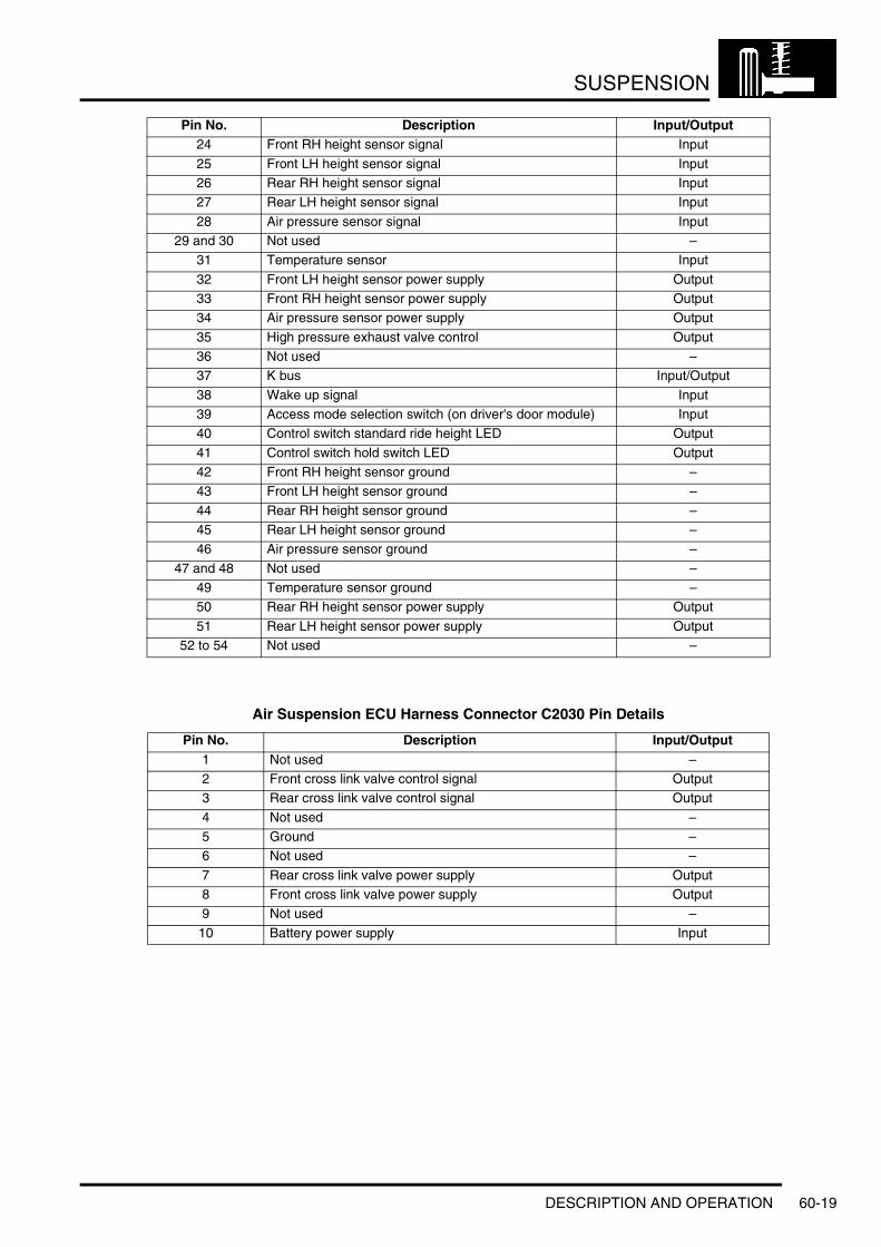
SUSPENSION
Air Suspension ECU Harness Connector C2030 Pin Details
24 Front RH height sensor signal Input
25 Front LH height sensor signal Input26 Rear RH height sensor signal Input27 Rear LH height sensor signal Input
28 Air pressure sensor signal Input29 and 30 Not used –
31 Temperature sensor Input
32 Front LH height sensor power supply Output33 Front RH height sensor power supply Output34 Air pressure sensor power supply Output
35 High pressure exhaust valve control Output36 Not used –37 K bus Input/Output
38 Wake up signal Input39 Access mode selection switch (on driver's door module) Input40 Control switch standard ride height LED Output
41 Control switch hold switch LED Output42 Front RH height sensor ground –43 Front LH height sensor ground –
44 Rear RH height sensor ground –45 Rear LH height sensor ground –46 Air pressure sensor ground –
47 and 48 Not used –49 Temperature sensor ground –50 Rear RH height sensor power supply Output
51 Rear LH height sensor power supply Output52 to 54 Not used –
Pin No. Description Input/Output1 Not used –2 Front cross link valve control signal Output3 Rear cross link valve control signal Output
4 Not used –5 Ground –6 Not used –
7 Rear cross link valve power supply Output8 Front cross link valve power supply Output9 Not used –
10 Battery power supply Input
Pin No. Description Input/Output
DESCRIPTION AND OPERATION 60-19

SUSPENSION
Air Suspension Control
Air Suspension Control Switch
1 Driver's door module access switch2 Air suspension rotary control switch
3 Air suspension LED display
The air suspension ECU is able to provide four different ride heights:l Standardl Off-roadl Motorwayl Access.
The ride heights are selected via the rotary control switch mounted on the centre console. Rotating the switch upwards or downwards selects a different ride height (providing all the criteria outlined below are met). The centre of the rotary switch contains the 'Hold' switch. The 'Hold' switch prevents the air suspension ECU from automatically changing from the currently selected ride height, and prevents the user selecting a new ride height.
2
3
M60 0839
1
60-20 DESCRIPTION AND OPERATION
SUSPENSION
Next to the rotary control switch are mounted a series of four LED's. An illuminated LED indicates which ride height is active. If a new ride height is selected using the rotary control switch, the 'current' height LED remains illuminated and the 'requested' height LED flashes until the vehicle achieves the new ride height. If a new ride height is selected using the rotary control switch and the 'current' height LED flashes briefly, this indicates that the ride height selection is invalid and will not be performed. When the operating parameters are correct for the new ride height, the height change request must be repeated.
Standard Ride HeightStandard ride height is used during most driving conditions. This setting is used as a datum for the remaining ride heights, and is defined as 0 mm. All other ride height settings are described as above or below this setting. The standard ride height can be active at any vehicle speed.
Access or off-road ride height can be selected from standard ride height using the rotary control or the drivers door access switch.
When the vehicle is in standard ride height, the 'Hold' switch can be selected. This prevents automatic height changes from taking place and disables manual height changes until the 'Hold' switch is deselected. If a height change is selected with the hold function active, the standard height LED will flash.
When towing, the electrical connection of the trailer socket will cause the vehicle to set the air suspension to standard height. No other height setting is available whilst towing.
Off-Road Ride HeightOff-road ride height is the highest of the four settings, and raises the front of the vehicle by 60 mm, and the rear of the vehicle by 50 mm. Off-road ride height is selected by turning the rotary switch upwards when the vehicle is travelling at less than 31 mph (50 km/h). The suspension will return to the standard ride height setting if the rotary control switch is turned downwards, or vehicle speed rises above 31 mph (50 km/h).
If the vehicle is travelling too fast when off-road ride height is selected, the standard road height LED will flash, and the request will not be carried out. The driver must repeat the off-road ride height request once the vehicle speed is reduced.
When the vehicle is in the off-road ride height setting, the 'Hold' switch will not be operational. Similarly, if the vehicle is in the standard ride height setting with 'Hold' selected, the vehicle will not move into the off-road ride height setting until 'Hold' is deselected.
Motorway Ride HeightMotorway ride height lowers the vehicle by 20 mm, and improves the high speed handling of the vehicle. Motorway ride height is only active when the vehicle is travelling at more than 62 mph (100 km/h) for more than 30 seconds, and is not selectable by the driver.
If the vehicle speed falls to below 43 mph (70 km/h) for more than 60 seconds, the ECU automatically returns the vehicle to the standard ride height setting. If the vehicle stops while the motorway ride height is active, the timer is paused, stopping the vehicle rising unnecessarily.
Although motorway ride height isn't selectable by the driver, the 'Hold' switch can be used to keep the motorway ride height active, and prevent the automatic return to the standard ride height. The vehicle will return to the standard ride height once the 'Hold' switch is deselected (and vehicle speed is less than 43 mph (70 km/h).
Motorway ride height may be deselected by the driver at any speed by turning the rotary control switch upwards. The vehicle may return to motorway ride height if the vehicle speed remains greater than 62 mph (100 km/h) and the driver does not select 'Hold' when the vehicle has returned to standard ride height.
If the vehicle speed is within the required parameters, the driver can select access ride height by turning the rotary control switch downwards or pressing the access switch on the drivers door.
Access Ride HeightAccess ride height lowers the vehicle by 40 mm when the vehicle is stationary or moving at very low speeds in order to improve ease of access to the vehicle. Access ride height can be selected by operating the access switch on the drivers door module when the vehicle is in standard, off-road or motorway ride heights or by turning the rotary control switch downwards when the vehicle is in standard or motorway ride heights.
DESCRIPTION AND OPERATION 60-21

SUSPENSION
Access ride height has three different modes of operation:l Access Heightl Access Pre-Selectl Crawl Mode.
Access Height
If the vehicle is stationary or travelling at less than 15 mph (25 km/h) 'Access Height' mode can be selected. If vehicle speed increases to more than 18 mph (30 km/h) the vehicle automatically returns to the standard ride height.
Access Pre-Select
If the vehicle is travelling below 49 mph (80 km/h) and access ride height is selected, the vehicle enters the 'Access Pre-Select' mode. The ECU acknowledges this request by flashing the 'Access' LED, but the height of the vehicle does not change immediately. If the vehicle is travelling above 49 mph (80 km/h) and access ride height is selected, the 'Standard' LED will flash and the request will be denied.
When access pre-select mode is active, the vehicle will automatically lower to Access ride height if the speed drops below 15 mph (25 km/h) within 65 seconds of the request being made. If the vehicle speed rises above 49 mph (80 km/h) after 'Access Pre-Select' mode is selected, or if it takes longer than 65 seconds to come to rest, access ride height will not be activated and the vehicle will remain at its current height.
Crawl Mode
Crawl mode does not change the vehicle height, but inhibits manual height changes and allows the vehicle to be driven at a higher speed than in normal access mode.
Crawl mode is activated when the vehicle is at the access ride height and 'Hold' is selected. If 'Access Height' has been selected, but the air suspension ECU has not lowered the vehicle because the road speed is too high, when 'hold' is selected the 'Access Height' request is cancelled and the vehicle remains at standard ride height. The 'Hold' button remains active so that all automatic and manual height changes are disabled.
Crawl mode allows the vehicle to be driven at speeds up to 25 mph (40 km/h) without returning to the standard ride height. If the vehicle speed reaches 22 mph (35 km/h), a chime will sound from the instrument pack sounder and the message centre will display a 'SLOW DOWN' warning message. If the vehicle speed exceeds 25 mph (40 km/h), crawl mode is cancelled and standard ride height will become active automatically.
System InhibitsA number of conditions exist where a change in ride height is undesirable. To counter this, the air suspension ECU is programmed with a number of system inhibits. If any of the conditions detailed below exist, the air suspension ECU will suspend height changes and height corrections.
CompressorThe temperature sensor located within the compressor protects the compressor from overheating. If the compressor temperature rises above set limits, the ECU will inhibit compressor operation. These limits are shown in the table below:
Compressor Timeout
Compressor operation will be halted after 180 seconds of continuous operation. If the compressor was attempting to regulate vehicle height, it remains inhibited for 20 seconds. If the compressor was attempting to fill the air suspension reservoir, it remains inhibited for 180 seconds. These time out functions act as a further safe guard against over heating.
Filling Reservoir
Height Regulation
Stop 100 °C (212 °F) 110 °C (230 °F)Start 80 °C (176 °F) 105 °C (221 °F)
60-22 DESCRIPTION AND OPERATION

SUSPENSION
CorneringIf the air suspension ECU registers a cornering force greater than 0.2g it will inhibit all height changes and corrections. The system will remain inhibited until the cornering force falls to less than 0.15g for 0.5 seconds. The air suspension ECU receives a message from the ABS sensor on the CAN Bus for the cornering force.
Rapid AccelerationIf the air suspension ECU registers a rapid acceleration greater than 0.2g it will inhibit all height changes and corrections. The system will remain inhibited until the rapid acceleration falls to less than 0.2g for 1 second. Acceleration is calculated by the ECU from a vehicle speed signal received via the CAN bus.
Rapid DecelerationIf the air suspension ECU registers a rapid deceleration smaller than – 0.2g it will inhibit all height changes and corrections. The system will remain inhibited until the rapid deceleration rises above – 0.2g for 1 second. Deceleration is calculated by the ECU from a vehicle speed signal received via the CAN bus.
Axle ArticulationTo avoid excess pressure differentials between different air springs, the air suspension ECU will inhibit all height changes and corrections if axle articulation is greater than 350 mm. The system will remain inhibited until axle articulation falls below 350 mm.
Vehicle LiftThe air suspension ECU will inhibit all height changes and corrections if it detects all four corner heights are greater than 90 mm. This is interpreted as the vehicle being on a wheels free car lift with all wheels hanging freely. In this situation, the corner heights will not change when air is released from the air springs. The system will remain inhibited until any of the following conditions exist:l All four corner heights fall below 90 mml The rotary switch is moved to the 'UP' or 'DOWN' position.l Vehicle speed rises to greater than 25 mph (40 km/h) for longer than 3 seconds.
Vehicle JackThe air suspension ECU will inhibit all height changes and corrections if it detects a corner lowering too slowly for more than 3 seconds. This is interpreted as the corner identified as moving too slowly being supported on a jack. In this situation, the corner height will not change when air is released from the air spring because the jack acts as a mechanical prop. The system will remain inhibited until any of the following conditions exist:l The height of the wheel identified as lowering too slowly, returns to the height where jacking was detected.l The rotary switch is moved to the 'UP' or 'DOWN' position.l Vehicle speed rises to greater than 25 mph (40 km/h) for longer than 3 seconds.
Door OpenThe air suspension ECU will stop all height change requests while any of the doors are open. Vehicle levelling is also inhibited with a door open.
Trailer ModeUsing the electrical trailer connection will cause the air suspension to be set to standard height. If the vehicle is at any other height when the trailer is connected the air suspension will adjust to standard height and stay in that mode until the trailer is disconnected.
DiagnosticsThe air suspension ECM can store fault codes which can be retrieved using TestBook/T4. The diagnostics information is obtained via the diagnostic socket which is located in the fascia, in the drivers stowage tray. The socket is secured in the fascia panel and protected by a hinged cover.
The diagnostic socket allows the exchange of information between the various ECU's on the bus systems and TestBook/T4 or a diagnostic tool. This allows the fast retrieval of diagnostic information and programming of certain functions using TestBook/T4 or a suitable diagnostic tool.
DESCRIPTION AND OPERATION 60-23
SUSPENSION
Fault DetectionThe air suspension ECU performs fault detection and plausibility checks. Fault detection is limited to faults that the ECU can directly measure, as follows:l Sensor hardware faultsl Valve hardware faultsl Sensor and actuator supply faultsl Bus failuresl ECU hardware errors.
Plausibility checks are checks on signal behaviour, as follows:l Average height does not change correctly
l Height changes too slowlyl Suspension moves in the wrong direction.
l Reservoir pressurel Does not increase when reservoir filling requestedl Does not decrease when reservoir used to lift vehiclel Does not decrease when reservoir is ventedl Pressure varies too much when inactive.
l Compressor temperaturel Increases when compressor inactivel Does not increase when compressor active.
l 'Energy' used to change height of cornerl Too much 'energy' used – height change takes too long or long term filtered height does not reach target.
l Sensor activityl Signal floatingl Inconsistent signal characteristics – signal on one side of axle is varying but other side remains staticl Constant articulation when moving.
When a fault is detected, the ECU will attempt to maintain a comfortable ride quality with restricted functionality of the air suspension system.
The system functionality depends on the severity of the fault. The faults are defined as minor or major faults.
Minor faults are:l Most sensor faults (hardware faults and plausibility faults)l Cross link valve failurel Reservoir valve failure.
For most minor faults, height changes are inhibited except for a return to standard height. If the suspension is not in standard height, the ECU will respond to a request for manual or automatic height change to return the vehicle to standard height. The ECU will continue to level the vehicle at the 'current' ride height.
Major faults are:l Compressor faultsl Plausibility errors – for example:
l Average height does not increase when lifting and the vehicle is moving. This could be caused by a compressor fault or a fault in the reservoir valve.
l Reservoir pressure decreases when filling requested. This could be caused by a leak in the common gallery in the valve block or connecting pipe.
For major faults the ECU will not level the vehicle at the 'current' ride height. The ECU freezes height changes until it receives a manual or automatic request for height change. The ECU will return to standard height and freezes once standard height is achieved.
If the air suspension ECU loses information regarding vehicle speed, the ECU cannot determine if the current ride height is suitable for the vehicle speed. The ECU immediately returns to the 'default' height, which is 20 mm below the standard height. Once at the default height, the ECU will continue to level the vehicle at this height. A loss of the speed signal could be due to a fault in the CAN Bus or a fault in the ABS ECU. It is unlikely to be a fault in the air suspension ECU. It may, for example, be caused if the battery is disconnected and the steering sensor is not recalibrated immediately after reconnection. In this case a CAN Bus fault is recorded in the error memory. If this fault is seen, other ECU's using the CAN Bus should be also be checked for faults. When the fault is repaired, the air suspension ECU will resume full functionality but the CAN error remains in the memory.
60-24 DESCRIPTION AND OPERATION

SUSPENSION
If the suspension is above the standard height and the air suspension ECU cannot lower the suspension or cannot determine the vehicle height, all height changes will be frozen. The ECU will issue a message on the CAN Bus which is received by the instrument pack which displays a maximum advisable speed in the message centre of '35MPH'. an immediate 'freeze' of the vehicle height is caused by the following:l Failure of more than one height sensorl Implausible articulation symptoms detectedl Valve or solenoid failure (does not include reservoir valve)l Stuck corner or whole vehicle (diagnosed using plausibility of the sensor inputs).
If the air suspension ECU has a hardware fault, the ECU will disable all air suspension functions. Detectable hardware errors include memory error, ECU failure, calibrations errors.
Fault MessagesThe air suspension has two methods which it can use to inform the driver of a fault in the air suspension system; the air suspension control switch LED's and the instrument pack message centre.
When minor faults occur and the air suspension ECU is able to level the vehicle to the 'current' ride height, the control switch LED's will display the current ride height. When the vehicle returns to the standard ride height and further height changes are disabled, the 'HOLD' LED in the control switch will be permanently illuminated.
The air suspension ECU suffers a major failure and there is no air suspension control, all the control switch LED's will remain unlit.
If a fault occurs and the ECU can determine the ride height and the vehicle is not above standard ride height, the driver will be notified via a 'AIR SUSP. INACTIVE' message in the message centre. If the ECU cannot determine the height of the vehicle, or the vehicle is above standard ride height and cannot be lowered, the 'AIR SUSP. INACTIVE' message is accompanied with an alternating 'MAX 35MPH' message.
DESCRIPTION AND OPERATION 60-25

SUSPENSION
Operation
GeneralUnder normal operating conditions, the air suspension ECU keeps the vehicle level at the 'current' ride height. The incoming height signals from the sensors are passed through filters to remove irregular signals produced by road noise or other irregularities. When the vehicle is stationary or a height change is in progress, the signals are passed through a 'fast' filter, which tracks the true rate of change of height. When the vehicle is moving, the signals are passed through a 'slow' filter. The 'slow' filtered signals remove almost all road noise from the signals and output a true long term average for each corner height. The 'slow' filtered signals cannot be used to respond quickly during height changes.
The air suspension ECU monitors each corner height signal using the fast filtered signals if the vehicle is stationary or the slow filtered signals if the vehicle is moving. If the height remains in a 'dead band' which is ±10 mm from the target height, the ECU does not implement any height adjustment changes. When the ECU detects that a corner has moved outside of the 'dead band', the ECU operates the compressor and/or the valves to raise or lower the corresponding corner(s) back into the target height.
When the engine is not running, the 'dead band' target height tolerance is increased to +20 mm and -25 mm. During 'wake-up', the tolerance band is ±20 mm. In all cases, the ECU will bring the corner height as close as possible to the target height. The ECU monitors the rate of change of height of the corner signals to predict when to close the valve so that the target height is not overshot.
ReservoirThe reservoir supplies pressurised air to the four air springs, via the valve block, to enable the air suspension system to carry out ride height changes.
If an upwards height change request is made when the engine is not running, air pressure within the reservoir is used to lift the vehicle. If the pressure within the reservoir has dropped below 9 bar (130 lbf/in2) when an upwards height change request is made, the lift procedure is performed by the compressor. When the engine is started, the ECU runs the compressor to increase reservoir pressure to:l 13.7 bar (199 lbf/in2), in systems without an external pressure relief valvel 11.8 bar (171 lbf/in2), in systems with an external pressure relief valve
60-26 DESCRIPTION AND OPERATION

SUSPENSION
Deze pagina werd opzettelijk niet gebruikt
Cette page est intentionnellement vierge
Questa pagina è stata lasciata in bianco di proposito
Diese Seite ist leer
Esta página foi deixada intencionalmente em branco
Esta página fue dejada en blanco intencionalmente
This page is intentionally left blank
DESCRIPTION AND OPERATION 60-27
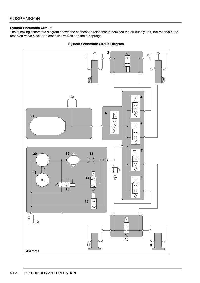
SUSPENSION
System Pneumatic CircuitThe following schematic diagram shows the connection relationship between the air supply unit, the reservoir, the reservoir valve block, the cross-link valves and the air springs.
System Schematic Circuit Diagram
M60 0838A
12
3
4
9
10
11
14
1819
15
16
20
M
5
6
7
8
12
13
21
22
17
60-28 DESCRIPTION AND OPERATION

SUSPENSION
1 Front LH damper air spring2 Front cross link valve3 Front RH damper air spring4 Front LH corner valve5 Reservoir valve6 Front RH corner valve7 Rear RH corner valve8 Rear LH corner valve9 Rear RH air spring
10 Rear cross link valve11 Rear LH air spring12 Compressor inlet/exhaust port13 HP pressure exhaust valve14 Exhaust pilot valve15 Pressure limiting valve16 Electric motor17 External pressure relief valve (where fitted)18 Restrictor19 Drier20 Compressor21 Reservoir22 Pressure sensor
DESCRIPTION AND OPERATION 60-29

SUSPENSION
60-30 DESCRIPTION AND OPERATION
BRAKES
Deze pagina werd opzettelijk niet gebruikt
Cette page est intentionnellement vierge
Questa pagina è stata lasciata in bianco di proposito
Diese Seite ist leer
Esta página foi deixada intencionalmente em branco
Esta página fue dejada en blanco intencionalmente
This page is intentionally left blank
BRAKESDESCRIPTION AND OPERATION
DESCRIPTION AND OPERATION 70-1
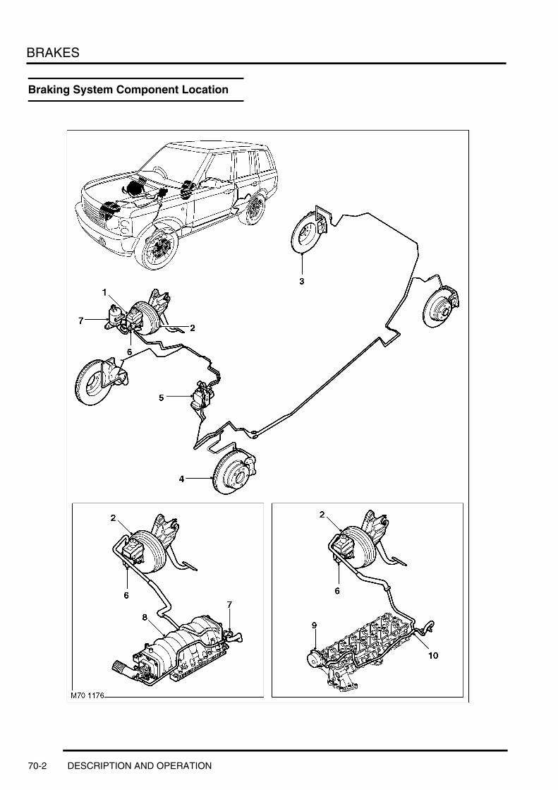
BRAKES
Braking System Component Location
70-2 DESCRIPTION AND OPERATION

BRAKES
1 Brake fluid reservoir2 Servo3 Rear disc brake4 Front brake disc5 ABS control unit and hydraulic modulator6 Brake master cylinder7 Vacuum hose8 Inlet manifold (petrol)9 Vacuum pump
10 Vacuum hose
DESCRIPTION AND OPERATION 70-3

BRAKES
Front Brake Components
1 Brake pad wear detection sensor2 Guide pin dust cover3 Guide pin slider4 Guide pin5 Calliper carrier6 Brake pad retainer7 Mud shield retaining bolt8 Brake disc9 Brake disc retaining bolt
10 Mud shield11 Calliper body12 Piston seal13 Piston dust cover14 Mounting bolt15 Bleed valve dust cap16 Brake pads17 Bleed valve
70-4 DESCRIPTION AND OPERATION

BRAKES
Rear Brake Components
1 Guide pin dust cover2 Guide pin slider3 Guide pin4 Bleed valve dust cap5 Bleed valve6 Brake pad wear detection sensor7 Calliper body8 Piston seal9 Piston dust cover
10 Brake disc retaining bolt
11 Brake disc retaining bolt dust cover12 Mud shield retaining bolt13 Mud shield14 Brake disc15 Brake pad retainer16 Calliper carrier17 Brake pad18 Mounting bolt19 Brake pad
DESCRIPTION AND OPERATION 70-5
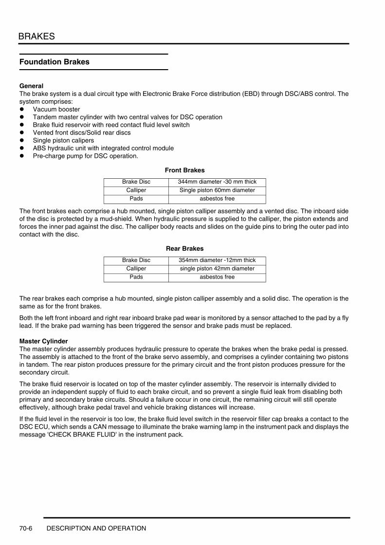
BRAKES
Foundation Brakes
GeneralThe brake system is a dual circuit type with Electronic Brake Force distribution (EBD) through DSC/ABS control. The system comprises:l Vacuum booster l Tandem master cylinder with two central valves for DSC operationl Brake fluid reservoir with reed contact fluid level switchl Vented front discs/Solid rear discsl Single piston calipersl ABS hydraulic unit with integrated control modulel Pre-charge pump for DSC operation.
Front Brakes
The front brakes each comprise a hub mounted, single piston calliper assembly and a vented disc. The inboard side of the disc is protected by a mud-shield. When hydraulic pressure is supplied to the calliper, the piston extends and forces the inner pad against the disc. The calliper body reacts and slides on the guide pins to bring the outer pad into contact with the disc.
Rear Brakes
The rear brakes each comprise a hub mounted, single piston calliper assembly and a solid disc. The operation is the same as for the front brakes.
Both the left front inboard and right rear inboard brake pad wear is monitored by a sensor attached to the pad by a fly lead. If the brake pad warning has been triggered the sensor and brake pads must be replaced.
Master CylinderThe master cylinder assembly produces hydraulic pressure to operate the brakes when the brake pedal is pressed. The assembly is attached to the front of the brake servo assembly, and comprises a cylinder containing two pistons in tandem. The rear piston produces pressure for the primary circuit and the front piston produces pressure for the secondary circuit.
The brake fluid reservoir is located on top of the master cylinder assembly. The reservoir is internally divided to provide an independent supply of fluid to each brake circuit, and so prevent a single fluid leak from disabling both primary and secondary brake circuits. Should a failure occur in one circuit, the remaining circuit will still operate effectively, although brake pedal travel and vehicle braking distances will increase.
If the fluid level in the reservoir is too low, the brake fluid level switch in the reservoir filler cap breaks a contact to the DSC ECU, which sends a CAN message to illuminate the brake warning lamp in the instrument pack and displays the message 'CHECK BRAKE FLUID' in the instrument pack.
Brake Disc 344mm diameter -30 mm thick
Calliper Single piston 60mm diameterPads asbestos free
Brake Disc 354mm diameter -12mm thickCalliper single piston 42mm diameter
Pads asbestos free
70-6 DESCRIPTION AND OPERATION

BRAKES
Brake Master Cylinder, Servo and Fluid Reservoir
1 Brake fluid level switch2 Brake fluid reservoir3 Retaining pin4 Retaining nut5 Plate6 Retaining clip
7 Brake servo8 O ring9 Nut
10 Master cylinder assembly11 Seals
DESCRIPTION AND OPERATION 70-7
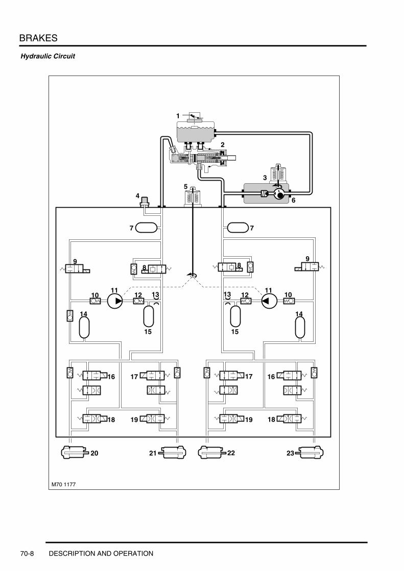
BRAKES
Hydraulic Circuit
M70 1177
1
2
3
64
77
98
13 1211
10
15
14
16
1819
23222120
1717
1918
16
15
14
9
1011
12 13
8
5
70-8 DESCRIPTION AND OPERATION

BRAKES
1 Fluid reservoir cap with fluid level sensor2 Master cylinder3 Pre charge pump motor4 Brake pressure sensor5 ABS pump motor6 Pre charge pump7 Damper8 Separation valve9 Solenoid valve
10 One way check valve11 ABS pump12 Check valve13 Restrictor valve14 Low pressure accumulator15 Damper16 Right Inlet valves17 Left Inlet valves18 Right outlet valves19 Left outlet valves20 Right rear brake21 Left rear brake22 Left front brake23 Right front brake
DESCRIPTION AND OPERATION 70-9

BRAKES
When the brake pedal is pressed, the front push rod in the brake servo assembly pushes the primary piston along the cylinder bore. This produces pressure in the primary pressure chamber which, in conjunction with the primary spring, overcomes the secondary spring and simultaneously moves the secondary piston along the cylinder bore. The initial movement of the pistons, away from the piston stops, closes the primary and secondary centre valves. Further movement of the pistons then pressurizes the fluid in the primary and secondary pressure chambers, and thus the brake circuits. The fluid in the chambers, behind the pistons, is unaffected by movement of the pistons and can flow unrestricted through the feed holes between the chambers and the reservoir. When the brake pedal is released, the primary and secondary springs push the pistons back down the bore of the cylinder. As the pistons contact the piston stops, the primary and secondary centre valves open, which allows fluid to circulate unrestricted between the two hydraulic circuits and the reservoir, through the centre valves, the chambers behind the pistons and the feed holes.
Brake ServoThe brake servo assembly provides power assistance to reduce the pedal load when braking. The assembly is attached to the front of the pedal box and comprises a circular housing containing a diaphragm, push rods, valve and filter. A push rod at the rear of the housing is connected to the brake pedal.
The vacuum line is connected to a port in the front face of the housing. With the brake pedal released and the engine running, vacuum pressure is present on both sides of the diaphragm. When the brake pedal is pressed, the rear push rod moves forward and opens the valve to allow atmospheric pressure through the filter into the pedal side of the diaphragm. The pressure differential acting on the diaphragm increases the pressure being applied by the brake pedal, which is transmitted to the master cylinder via the forward push rod. If the servo fails, the hydraulic system will still function but will require greater pedal effort due to the lack of vacuum assistance.
70-10 DESCRIPTION AND OPERATION

BRAKES
Deze pagina werd opzettelijk niet gebruikt
Cette page est intentionnellement vierge
Questa pagina è stata lasciata in bianco di proposito
Diese Seite ist leer
Esta página foi deixada intencionalmente em branco
Esta página fue dejada en blanco intencionalmente
This page is intentionally left blank
DESCRIPTION AND OPERATION
DESCRIPTION AND OPERATION 70-11

BRAKES
Dynamic Stability Control System Control Diagram
A = Hardwired connection; C= DS2; D = CAN bus
22
M70 1189
20
1
A
4
5
6
7
9
10
11
12
13
14
18
17
16
15
21
2423
19
2
2526
D
27
8
C
3
70-12 DESCRIPTION AND OPERATION

BRAKES
1 HDC lamp2 Handbrake warning lamp3 Brake assist/brake warning lamp4 Steering angle sensor5 ECM6 EAT ECU7 Air suspension ECU8 Transfer box ECU9 Diagnostic socket
10 Parking brake switch11 Fuse12 Light check module (LCM)13 Brake light switch14 Brake pressure sensor15 Wheel speed sensors16 Wheel speed sensors17 Wheel speed sensors18 Wheel speed sensors19 Fuse 20 DSC sensor21 HDC switch22 DSC hydraulic unit23 Main relay24 DSC switch25 ABS lamp26 DSC lamp27 Instrument pack
DESCRIPTION AND OPERATION 70-13

BRAKES
Dynamic Stability Control
Introduction The New Range Rover is equipped with Dynamic Stability Control (DSC) for enhanced braking and stability control.
Functions of the DSC include:l Hill Decent Control (HDC)l Electronic traction control (ETC)l ABSl Providing Corner Braking Control (CBC)l Providing Emergency Brake Assist (EBA)l Providing Electronic Brake Force Distribution (EBD).
Dynamic Stability Control System Components
Hydraulic Modulator
1 ABS ECU2 Brake pressure sensor3 Bolt washer4 Spacer
5 Mounting bush6 Bracket mounting bolt7 Mounting bracket
70-14 DESCRIPTION AND OPERATION
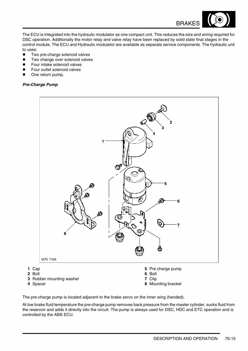
BRAKES
The ECU is integrated into the hydraulic modulator as one compact unit. This reduces the size and wiring required for DSC operation. Additionally the motor relay and valve relay have been replaced by solid state final stages in the control module. The ECU and Hydraulic modulator are available as separate service components. The hydraulic unit to uses:l Two pre-charge solenoid valvesl Two change over solenoid valvesl Four intake solenoid valvesl Four outlet solenoid valvesl One return pump.
Pre-Charge Pump
1 Cap2 Bolt3 Rubber mounting washer4 Spacer
5 Pre charge pump6 Bolt7 Clip8 Mounting bracket
The pre-charge pump is located adjacent to the brake servo on the inner wing (handed).
At low brake fluid temperature the pre-charge pump removes back pressure from the master cylinder, sucks fluid from the reservoir and adds it directly into the circuit. The pump is always used for DSC, HDC and ETC operation and is controlled by the ABS ECU.
DESCRIPTION AND OPERATION 70-15
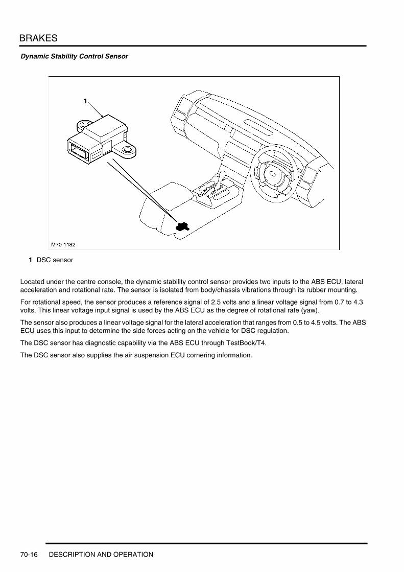
BRAKES
Dynamic Stability Control Sensor
1 DSC sensor
Located under the centre console, the dynamic stability control sensor provides two inputs to the ABS ECU, lateral acceleration and rotational rate. The sensor is isolated from body/chassis vibrations through its rubber mounting.
For rotational speed, the sensor produces a reference signal of 2.5 volts and a linear voltage signal from 0.7 to 4.3 volts. This linear voltage input signal is used by the ABS ECU as the degree of rotational rate (yaw).
The sensor also produces a linear voltage signal for the lateral acceleration that ranges from 0.5 to 4.5 volts. The ABS ECU uses this input to determine the side forces acting on the vehicle for DSC regulation.
The DSC sensor has diagnostic capability via the ABS ECU through TestBook/T4.
The DSC sensor also supplies the air suspension ECU cornering information.
70-16 DESCRIPTION AND OPERATION

BRAKES
Brake Pressure Sensor
1 Brake pressure sensor
A brake pressure sensor is installed in the hydraulic unit to determine the degree of pressure build up in the braking system. It is installed in the front axle brake circuit.
The sensor receives its power supply from the ABS ECU and produces a linear voltage input signal ranging from 0.5 to 4.5 volts depending on the brake pressure in the circuit.
The brake pressure sensor is used for emergency brake assist and to calculate brake torque applied to each wheel for all DSC functions. Torque is calculated using engine torque from the ECM, gear selected from the EAT ECU and range selected from the transfer box ECU. The sensor is also used for brake temperature calculation.
DESCRIPTION AND OPERATION 70-17

BRAKES
HDC Switch
1 HDC switch
The Hill Descent Control function is activated by operating the HDC switch located to the left of the gear selector. The green HDC information lamp in the instrument pack, will illuminate when the system is selected and available.
If the vehicle is outside of normal HDC operating parameters, the lamp only illuminates when switch is held. Message centre displays the message 'NO HDC SLOW DOWN'.
M70 1183
1
70-18 DESCRIPTION AND OPERATION
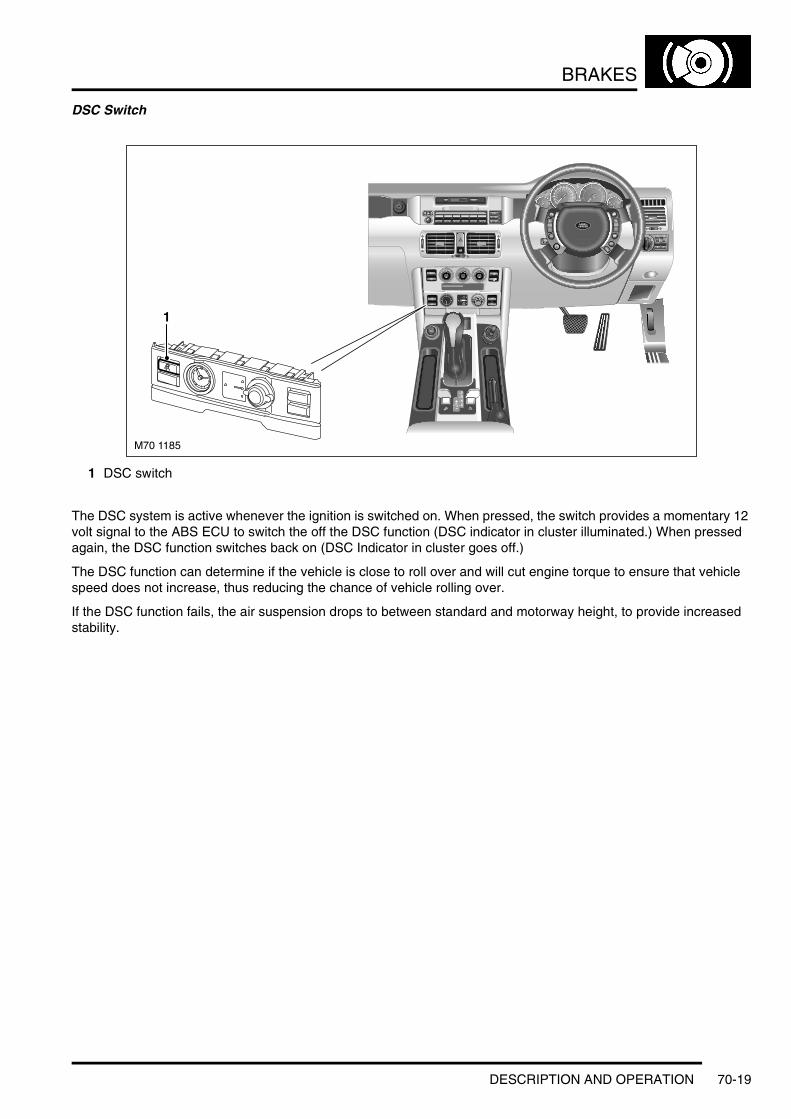
BRAKES
DSC Switch
1 DSC switch
The DSC system is active whenever the ignition is switched on. When pressed, the switch provides a momentary 12 volt signal to the ABS ECU to switch the off the DSC function (DSC indicator in cluster illuminated.) When pressed again, the DSC function switches back on (DSC Indicator in cluster goes off.)
The DSC function can determine if the vehicle is close to roll over and will cut engine torque to ensure that vehicle speed does not increase, thus reducing the chance of vehicle rolling over.
If the DSC function fails, the air suspension drops to between standard and motorway height, to provide increased stability.
M70 1185
1
DESCRIPTION AND OPERATION 70-19

BRAKES
Wheel Speed Sensors
1 Wheel speed sensor2 Location bolt3 Cable clip
4 Cable clip5 Grommet
The wheel speed sensors are 2 wire Hall Effect type sensors. These sensors picks up on a 48 pulse incremental wheel speed sensor pole wheel on the drive shaft. 48 pulses = one complete wheel revolution. The sensor receives a stabilized 8 volt power supply to hall element on one wire, ground path for sensor through second wire back to the ABS ECU. The signal is generated by the pulse wheel affecting voltage flow through the hall element creating a low of 0.75 and a high of 2.5 volts. The sensors provide immediate vehicle speed recognition.
70-20 DESCRIPTION AND OPERATION

BRAKES
Steering Angle Sensor
1 Steering angle sensor
The Steering angle sensor is mounted at the bottom of the steering spindle at the base of the upper steering column assembly.
The sensor is equipped with a processor and is directly linked to the CAN bus to communicate with the ABS ECU.
The sensor utilizes two potentiometers to determine the steering angle and the rate of steering. These are the raw signals the steering angle microprocessor utilizes to create the steering angle signal for broadcast on the CAN bus.
The sensor requires calibration after repairs to the steering or suspension system. Once the calibration is completed the sensor now also sends an identification number over the CAN bus to the ABS ECU. The ID provides confirmation in the ABS ECU that the steering angle sensor is properly calibrated.
If the ID differs due to component replacement it will be necessary to enter the diagnostic system of the ABS system to initiate the steering angle sensor calibration. DSC will not be available on the vehicle until the steering angle sensor is calibrated. Once complete a new ID number is generated and the DSC ECU and Steering angle sensor are properly mated.
The DSC logic checks the plausibility of the steering angle sensor against the other DSC inputs (front wheel speeds, rotation and DSC sensor). If battery voltage is interrupted, the current steering wheel rotation is recalculated by the ABS ECU evaluating the wheel speeds.
Replacement steering angle sensors must be coded when installed in the vehicle prior to the calibration procedure in order to add the VIN to the angle sensor. Re-calibration is carried out by turning the steering lock to lock with the engine running while stationary.
Brake Fluid Level Warning SwitchA fluid level switch is incorporated into the reservoir cap.l With sufficient fluid level the reed contact is closedl When level drops below allowable limits, switch opens.
Since the normal position is closed, this circuit is monitored for shorts to + and ground.
The ABS ECU monitors the fluid level and issues a low fluid level message on the CAN.
DESCRIPTION AND OPERATION 70-21

BRAKES
The LCM receives the message and illuminates the warning lamp and generates the low brake fluid message for the message centre. If the ground signal is momentary, the LCM signals the Instrument cluster of the condition. The instrument cluster then informs the ABS ECU over the CAN bus. If the signal is received prior to the activation of the pre-charge pump, the pre-charge pump activation is delayed.
If the signal is present for more then 25 seconds, the LCM issues two I BUS messages for the Instrument Cluster:l Post “Brake Fluid Level ”in the Message centrel Notify the ABS via CAN that the Fluid level has been low for more than 25 seconds.
The ABS ECU immediately switches DSC functions off and continuously illuminates the DSC indicator in the cluster.
DSC System Warning Lamps
Instrument Pack Warning Lamps
1 HDC lamp2 Brake warning lamp3 Brake assist /brake warning lamp
4 ABS warning lamp5 DSC warning / information lamp
M70 1184
1/2
1/1
MPH
30
110130
15010
9090
50
70
5 4
31 2
70-22 DESCRIPTION AND OPERATION

BRAKES
The following table describes the warning lamps, their associated faults and system response.
ABS ModulatorThe ABS modulator controls the supply of hydraulic pressure to the brakes in response to inputs from the ABS ECU. The modulator is attached by three mounting bushes to a bracket on the LH inner wing, and connected to the primary and secondary hydraulic circuits downstream of the master cylinder assembly. Two electrical connectors link the ABS modulator to the vehicle wiring. Internal passages in the ABS modulator, separated into primary and secondary circuits, connect to the various components that control the supply of hydraulic pressure to the brakes. Valves and check valves control the flow through the internal circuits. A damper chamber and restrictor are included in each circuit to refine system operation. Inlet and outlet solenoid valves control the flow to the individual brakes. An expansion chamber is connected to each circuit to absorb pressure. A return pump is connected to both circuits to provide a pressure source.
System Status Hand Brake Warning
Lamp
Brake Warning
Lamp
ABS Lamp DSC Lamp HDC Lamp
Message Centre
Lamp check On for 2 seconds
Amber for 1 second then red for 1 second
On for 2 seconds
On for 2 seconds
On for 2 seconds
ECU under voltage On, red and amber
On On Off
Hand brake On On, red Release park brake (when driving)
Low brake fluid level On, red Check brake fluidElectric Brake Assist (EBA) failure) ABS & EBD available)
On, amber Off
ABS Failure (EBD available) On, amber On On Off
EBD failure On, red On On OffDSC failure On, amber,
or redOn On Single gong 1st
time failure occursHDC failure On, amber
or redOn Off HDC Inactive
DSC activity (including engine intervention)
flash 2 Hz
ETC activity (brakes only)DSC switched passive (TC function still available)
On
ETC activity while DSC switched passive
On
HDC switched on (not enabled or fading out)
flash 2 Hz
HDC switched on and enabled On
HDC temporarily unavailable (brake overheat)
Off HDC temp. Not available
HDC switching off (due to high speed in high range)
Off No HDC - slow down
Driver attempt to switch on HDC at high speed in high range
Off No HDC - slow down
DESCRIPTION AND OPERATION 70-23

BRAKES
ABS ECU Harness Connector
ABS ECU Harness Connector C0506 Pin Details
Pin No. Description Input/Output1 Ground –
2 Battery power supply Input3 Pre-charge pump power supply Output4 Pre-charge pump ground –
5 Ground –6 Battery power supply Input7 HDC active signal Output
8 DSC sensor lateral acceleration Input9 DSC sensor test Output
10 DSC sensor rotation rate Input
11 Diagnostic DS2 bus Input/Output12 Front LH wheel speed sensor signal Input13 Rear LH wheel speed sensor reference voltage Output
14 Rear RH wheel speed sensor reference voltage Output15 Front RH wheel speed sensor reference voltage Output16 Front RH wheel speed sensor signal Input
17 HDC switch Input18 Front RH wheel speed Output19 Rear RH wheel speed Output
20 ABS indicator light Output21 DSC sensor ground –22 Not used –
23 Power supply from ECM relay Input24 CAN bus high Input/Output25 Brake pressure sensor ground –
26 Brake pressure sensor signal Input27 DSC switch Input28 Front LH wheel speed sensor reference voltage Output
29 Rear LH wheel speed sensor signal Input30 Not used –31 Rear RH wheel speed sensor signal Input
32 Brake switch Input33 Not used –34 Rear LH wheel speed Output
70-24 DESCRIPTION AND OPERATION

BRAKES
35 Front LH wheel speed Output
36 Brake fluid level switch Input37 and 38 Not used –
39 DSC sensor power supply Output
40 CAN bus low Input/Output41 DSC sensor rotation rate reference Input42 Brake pressure sensor reference voltage Output
Pin No. Description Input/Output
DESCRIPTION AND OPERATION 70-25
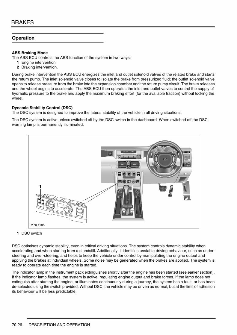
BRAKES
Operation
ABS Braking ModeThe ABS ECU controls the ABS function of the system in two ways:
1 Engine intervention2 Braking intervention.
During brake intervention the ABS ECU energizes the inlet and outlet solenoid valves of the related brake and starts the return pump. The inlet solenoid valve closes to isolate the brake from pressurized fluid; the outlet solenoid valve opens to release pressure from the brake into the expansion chamber and the return pump circuit. The brake releases and the wheel begins to accelerate. The ABS ECU then operates the inlet and outlet valves to control the supply of hydraulic pressure to the brake and apply the maximum braking effort (for the available traction) without locking the wheel.
Dynamic Stability Control (DSC)The DSC system is designed to improve the lateral stability of the vehicle in all driving situations.
The DSC system is active unless switched off by the DSC switch in the dashboard. When switched off the DSC warning lamp is permanently illuminated.
1 DSC switch
DSC optimises dynamic stability, even in critical driving situations. The system controls dynamic stability when accelerating and when starting from a standstill. Additionally, it identifies unstable driving behaviour, such as under-steering and over-steering, and helps to keep the vehicle under control by manipulating the engine output and applying the brakes at individual wheels. Some noise may be generated when the brakes are applied. The system is ready to operate each time the engine is started.
The indicator lamp in the instrument pack extinguishes shortly after the engine has been started (see earlier section). If the indicator lamp flashes, the system is active, regulating engine output and brake forces. If the lamp does not extinguish after starting the engine, or illuminates continuously during a journey, the system has a fault, or has been de-selected using the switch provided. Without DSC, the vehicle may be driven as normal, but at the limit of adhesion its behaviour will be less predictable.
M70 1185
1
70-26 DESCRIPTION AND OPERATION
BRAKES
If the power supply has been interrupted by disconnecting the vehicle's battery, ABS and DSC will be deactivated. These functions are reactivated by driving a short distance, or by turning the steering wheel from lock to lock while the vehicle is stationary and the engine is running. Reactivation is indicated by extinguishing of the warning lamps.
ETC is continuously available to boost vehicle traction when one or more wheels has a tendency to spin. It operates in conjunction with the DSC system. If a wheel is tending to spin, ETC automatically brakes that wheel until it regains grip and can transmit the engine's power again. This braking activity causes the engine's power to be transferred to the remaining wheels. Some noise may be generated when the brake is applied to the spinning wheel.
It is possible to de-select the stability control function of DSC, leaving the ETC system active, by pressing the DSC button. The amber DSC lamp illuminates continuously, to indicate that the stability function is passive. It is recommended that the DSC system should be temporarily de-selected, in order to maximise forward traction, only in the following exceptional circumstances:l If the vehicle needs to be rocked out of a hollow or a soft surfacel Starting in deep snow, or on a loose surfacel Driving in deep sandl On tracks with deep longitudinal rutsl Driving through deep mud.
If the DSC button is pressed a second time, the system will be re-selected, and the amber DSC lamp will extinguish.
Electronic Traction Control (ETC) The ability to control the vehicle while driving, is lost as a result of excessive wheel spin or slip if a tyre exceeds its ability to:l Maintain tractionl Accept side forces to maintain directional control
The ETC feature of the DSC on the New Range Rover cannot be switched OFF with the DSC switch. Pressing the button will only switch off the dynamic stability control function of the DSC.
The traction control feature is needed at all times to provide anti-wheel spin control especially when driving the vehicle off road. The DSC warning lamp in the instrument cluster will come on when the system is switched off manually or there is a fault in the system.
Off road traction control or HDC operation places an additional load on the brakes. To prevent overheating of the brakes and discs, the temperature of the discs is calculated over time from the road speed and amount of brake application (from the pressure sensor). If the temperature of one or more discs goes above approximately 600°C, the traction control function for that wheel will be cancelled temporarily. Engine intervention is still active to prevent spinning of that wheel. Once the temperature of the disc goes below approximately 500°C, the traction application will be reactivated.
The normal braking function (including ABS) is always active at any temperatures.
Corner Braking Control (CBC)CBC improves stability control while braking through corners.
As the vehicle enters a corner, the weight of the vehicle shifts to the outside wheels. With non CBC equipped vehicles, if the driver brakes while driving through a corner an equal hydraulic force is applied to each wheel. Though the pressure is equal the grip available for braking is unequal at the tyre footprint due to the increased weight on the outside wheels.
With a CBC equipped vehicle, the feature regulates the applied pressure to the wheels based on the rate of cornering. When the driver brakes, an unequal hydraulic pressure is applied to each side of the vehicle. Though the brake application pressure to each wheel is unequal, the dynamic of the vehicles weight transfer compensates for the unequal pressure, as a result braking effort is distributed in proportion to the grip available ensuring that lateral grip is maintained.
DESCRIPTION AND OPERATION 70-27
BRAKES
Electronic Brake Distribution (EBD)Electronic brake proportioning allows the DSC system to adjust the braking force to the rear wheels based on the vehicles loading to maximize the braking force at all wheels.
The ABS control module monitors the wheel speed sensors inputs when the brakes are applied, for activation of this feature. The control module compares the speed at which the front and rear axles are slowing down to determine vehicle loading.
If the rear axle is slowing at a similar rate to the front, it indicates that the vehicle is loaded and braking force need not be limited to the rear axle.
If the deceleration of the rear axle is greater than the front, the vehicle is lightly laden and less force can be applied to the rear. If the same force were applied, then the vehicle could become unstable.
The values for the relative deceleration are programmed in the ABS ECU. Equal force will be applied to the front and rear axles until the threshold values are exceeded. At this point, the ABS ECU will cycle the inlet valves at the rear calipers to limit or reduce the braking force on the rear axle.
Emergency Brake Assist (EBA)The EBA is designed to enhance the braking control of the DSC for the driver of the vehicle. The EBA includes two functions that are programmed into the control electronics of the ABS ECU with no additional hardware changes.
The first EBA function is designed to provide the maximum braking force available during rapid (panic) braking situations. The ABS control module looks at the inputs from the brake pedal switch and the signal from the brake pressure sensor on the master cylinder. The criteria for activation of EBA is the speed at which brake pressure builds up with the brake pedal depressed. The total criteria required for EBA activation includes:l Brake switch ONl Brake pressure build up >threshold valuel Vehicle road speed >5mph (8 km/h)l Vehicle not in reversel Not all wheels in ABS operation.
If the threshold for EBA activation is achieved, the ABS control module will activate a pressure build up regulation phase through the hydraulic unit. The pressure at all wheels is increased up to the ABS operation point. This occurs even if the driver does not achieve the ABS operation point with the pedal.
The front and rear axle brakes are controlled individually. ABS operation will continue until the driver releases the pedal and the pressure in the master cylinder drops below the threshold value stored in the ABS ECU.
The second EBA function is also designed to enhance a driver initiated braking procedure. The EBA will build up the pressure in the rear brake circuit when the front brakes are already in an ABS regulation cycle. The additional braking pressure at the rear wheels will shorten the stopping distance. The following criteria must be met before the ABS control module will activate EBA:l Both front wheel brakes in ABS operationl Vehicle speed >5mph (8km/h)l Vehicle not in reversel EBA and pressure sensor initialisation test OKl Rear wheels not in ABS operation.
EBA sensitivity can be adjusted using TestBook/T4. There are three sensitivity settings, default is the most sensitive.
Hill Descent Control (HDC)Hill Decent Control (HDC) is designed for off road use to automatically slow the vehicle and maintain a steady speed on steep gradients. This function allows the driver to focus on steering and controlling the vehicle without having to use the brakes to slow the vehicle.
70-28 DESCRIPTION AND OPERATION

BRAKES
1 HDC switch
HDC is activated manually through the switch located in the centre console next to the transmission gear selector. HDC can be selected under any conditions while low range is selected, and below the 21 mph (35 km/h) speed threshold when high range is selected. The HDC Lamp in the instrument pack indicates HDC selection status. If enable conditions are not met, system goes in to stand by mode. When activated, the vehicles speed is held to approximately 5 MPH (3 km/h) by the DSC ECU pulsing the brakes to maintain the speed.
The following conditions must be met before the HDC will activate:l HDC switch operated -LED “ON “l Vehicle speed:<21 MPH (35 km/h)l Accelerator pedal pressed <15%l Downhill driving recognised.
If the HDC switch is operated above 21 mph (35 km/h) in high range, "NO HDC - SLOW DOWN" message will be displayed in the instrument pack, and HDC will not be selected.
If the HDC switch is held down for more than 10 seconds, the HDC selection status does not change
If HDC is selected, then vehicle ignition switched off, the HDC selection status remains in the ABS ECU memory for 6 hours. If the vehicle is restarted within this time, HDC remains selected. If vehicle is not started within this time HDC will be automatically de-selected. If the vehicle speed exceeds 37 mph (60 km/h) while high range is selected, HDC is automatically de-selected.
M70 1183
1
DESCRIPTION AND OPERATION 70-29

BRAKES
Hill Descent Control Enable Criteria
The target speed used by the HDC varies in response to driver inputs. Current target speed will lie in the range between Maximum Target Speed and Minimum Target Speed.
Hill Descent Control Target Speeds
When HDC is first activated, if the driver does not press the brake or accelerator pedals, then current target speed is set to default target speed. If HDC is activated and the driver presses the brake pedal, the vehicle brakes operate as normal. While the brake pedal is pressed:l If vehicle speed is equal to or more than current target speed, current target speed is unchangedl If vehicle speed is less than current target speed, current target speed is set to vehicle speed
When the brake pedal is released:l If vehicle speed is equal to or more than minimum target speed, then current target speed is unchangedl If vehicle speed is less than minimum target speed, then Current Target Speed is set to minimum target speed.
If HDC is activated and the driver presses the accelerator pedal, current target speed is defined by a characteristic as follows:l If current target speed is less then default target speed, then the target speed is set to current speed.
When the accelerator pedal is released:l If current target speed is greater than default target speed and vehicle speed is equal to or more than default
target speed, then current target speed is set to default target speedl If current target speed is more than default target speed and vehicle speed is less than default target speed,
then current target speed is set to vehicle speedl If current target speed is less than or equal to default target speed, and vehicle speed is less than current target
speed , then current target speed is set to vehicle speedl If current target speed is less than or equal to default target speed , and vehicle speed is equal to or more than
current target speed , then current target speed is unchanged.
To ensure that the vehicle is in an appropriate gear during HDC activity the ABS ECU communicates with the EAT ECU. A unique gearbox map is activated when HDC braking activity begins. The characteristics of the map are that lower gears are selected sooner than normal, and higher gears are selected later than normal. This reduces the work done by the foundation brakes, and improves the response time of HDC.
Fade-Out ModeFade-out and system switch off is triggered by the following:l Driver de-selection l System failure.
Gear Detected Neutral Auto Transmission D, 1-5, R Throttle less than 5%
Enabled Enabled
5% to 20% Stand by EnabledThrottle more than 20%
Stand by Stand by
Low HighGear selector position
D 1 2 3 4 5 R N D,1,2,3,4,5
R N
Maximum target speed
35 km/h(22 mph)
35 km/h(22 mph)
35 km/h(22 mph)
35 km/h(22 mph)
35 km/h(22 mph)
35 km/h(22 mph)
35 km/h(22 mph)
— 35 km/h(22 mph)
35 km/h(22 mph)
—
Standard target speed
6 km/h(4 mph)
3.5 km/h(2 mph)
6 km/h (4 mph)
6 km/h (4 mph)
6 km/h(4 mph)
6 km/h (4 mph)
3.5 km/h(2 mph)
6 km/h(4 mph)
10 km/(6 mph)
6 km/h (4 mph)
10 km/h(6 mph)
Minimum target speed
3.5 km/h(2 mph)
3.5 km/h(2 mph)
3.5 km/h(2 mph)
3.5 km/h(2 mph)
3.5 km/h(2 mph)
3.5 km/h (2 mph)
3.5 km/h(2 mph)
6 km/h (4 mph)
6 km/h (4 mph)
6 km/h (4 mph)
70-30 DESCRIPTION AND OPERATION

BRAKES
Fade-out and system stand by mode is triggered by the following:l Throttle pedal pressed in neutral l Brake overheat.
By gradual reduction of brake pressure, the vehicle is allowed to accelerate at a maximum rate of 0.5 m/s2 until maximum target speed is reached, or until no active pressure in system for 0.5 sec. The system then switches off, or into stand by mode, depending on the trigger for fade-out mode.
If the throttle pedal is pressed less than 20% (parameter), fade-out acceleration limited to 1 m/s2. If the throttle pedal is pressed 20% or more, system switches off, or into stand by mode, depending on the trigger for fade-out mode.
Off-Road ABS Control Module ProgrammingThe programming for ABS regulation allows a higher threshold for ABS regulation when driving off-road in loose gravel or dirt. A locked wheel is more effective in slowing or stopping the vehicle because of the wedge that is built up in front of the tyre.
The programming in the ABS control module allows one or both front wheel(s) to lock up at low speeds on a rough road as long as the vehicle is travelling straight ahead. If the ABS ECU receives a signal from the steering angle sensor indicating a turn, ABS regulation will activate to prevent the lock and allow the vehicle to be steered.
DESCRIPTION AND OPERATION 70-31

BRAKES
DESCRIPTION AND OPERATIONHand Brake Component Location
70-32 DESCRIPTION AND OPERATION

BRAKES
1 Hand brake lever2 Ratchet mechanism (internal)3 Rear brake4 Hand brake cable5 Hand brake cable inner cable connection6 Cable divider7 Brake lamp switch8 Hand brake cable9 Return spring
10 Brake shoe11 Brake shoe retainer spring12 Brake shoe retainer13 Rear brake shoe adjuster14 Hand brake shoe expander15 Expander return shoe spring16 Hand brake cable to trailing arm grommet17 Hand brake cable mounting bracket18 Bolt19 Hand brake cable to body clip
DESCRIPTION AND OPERATION 70-33
BRAKES
Hand Brake
IntroductionThe parking brake system utilised on the New Range Rover is a new application on Land Rover vehicles. The characteristics of the system are significantly different to the transmission brake based system that is currently fitted to most Land Rover vehicles.
DescriptionThe handbrake lever is a clenched two-shell construction incorporating an automatic cable adjuster. The handbrake cables are actuated via an equaliser and a cable centrally mounted within the lever, which is in turn attached to one half of the spring loaded adjuster
The design of this hand brake incorporates an automatic adjuster which eliminates the need for warranty adjustments. The two-shell design allows automatic assembly of the internal components.
The hand brake cable is centrally mounted within the lever as a significant offset of the cable causes the lever to rotate sideways under the high cable loads required. This construction means that the part of the bracket that supports the lever pivot must be moved outside the lever rather than having the conventional inboard position. The lever is high mounted to suit the 'Command' driving position, on a secondary - mounting bracket, which also allows the assembly of necessary components under the handbrake.
FunctionWhen the lever is in the rest position, the adjuster opener holds the adjuster open. In this position, the lever is effectively disconnected from the handbrake cable. This allows the adjuster spring, if required, to remove slack in the handbrake cables. After less than 5 degrees of lever travel and normally before the first tooth is engaged, the adjuster is closed and the cables and hence the parking brakes are actuated. No adjustment of the cables is required during assembly or by the dealer. The function of the adjuster is to remove slack in the handbrake cables and not to provide any adjustment of the parking brake itself. The adjuster spring force is always lower than the brake shoe return spring force.
PerformanceIn order to achieve the required performance targets, the lever ratio is relatively high at 7.25:1. Also, in comparison to Range Rover, fine ratchet teeth are employed for the convenience of slighter drivers. The overall performance of the system is totally dependent on the correct adjustment and bedding of the Duo-Servo parking brake. The adjuster travel is 25-30 mm, in other words in the worst tolerance condition the system can compensate for 25mm of slack in the cable system. Slack in the system can be caused by both initial tolerance stack-up in the body / parking brake system and actual 'stretch' in the system.
ReplacementThe handbrake is supplied with a pin in position that locks the adjuster spring in the fully compressed condition. This allows the handbrake to be raised to the fully up position with the cables connected, in order to facilitate the assembly of the centre console. Subsequent to the assembly of the centre console, the pin can be removed and the lever lowered, at which point the adjuster will provide the required cable tension.
A mounting clip is provided, which is clipped to the equaliser and fitted over the ends of the body tubes, in order to provide location whilst the cables are fed through the body tubes and into the 'quick fit' connections in the equaliser. This allows a 'one man' operation for cable fitment.
70-34 DESCRIPTION AND OPERATION

BRAKES
System Specifications
ServiceThe servicing requirements for the handbrake lever and cable system are minimal. However, the handbrake cables remain a serviceable item and will need to be periodically replaced. The cables will always be in tension due to the automatic adjuster and this tension must be released in order to facilitate replacement. The process to achieve this is as follows:
1 Lower handbrake to rest position2 Release gaiter from centre console and roll back to expose lever assembly3 Remove access panel from rear of centre console4 Pull back equaliser until adjuster spring is fully compressed5 Replace pin. A suitably sized pin of adequate strength (preferably steel) may be used6 Replace cables7 Remove pin. The pin may be removed with the handbrake in any position8 Replace gaiter and rear access panel.
Lever Ratio 7.25 : 1
Max Travel 38°Max No of Teeth on Ratchet 16Max cable travel 20 mm
Max Adjuster Travel 20 mm
DESCRIPTION AND OPERATION 70-35
BRAKES
70-36 DESCRIPTION AND OPERATION

RESTRAINT SYSTEMS
RESTRAINT SYSTEMSDESCRIPTION AND OPERATIONFront Seat Belts
1 Height adjuster2 Buckle
3 Anchor point4 Inertia reel
DESCRIPTION AND OPERATION 75-1
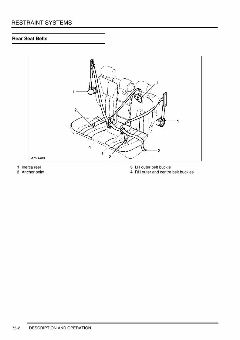
RESTRAINT SYSTEMS
Rear Seat Belts
1 Inertia reel2 Anchor point
3 LH outer belt buckle4 RH outer and centre belt buckles
75-2 DESCRIPTION AND OPERATION

RESTRAINT SYSTEMS
SRS Component Layout – Sheet 1 of 2
1 Front head airbag2 Rear head airbag3 Side airbag
4 Pretensioner5 Side impact sensor6 Battery disconnection unit
DESCRIPTION AND OPERATION 75-3

RESTRAINT SYSTEMS
SRS Component Layout – Sheet 2 of 2
1 Seat occupancy module2 Passenger airbag3 Airbag warning lamp
4 Driver airbag5 DCU6 Seat occupancy sensor
75-4 DESCRIPTION AND OPERATION

RESTRAINT SYSTEMS
Description
GeneralRestraints consist of seat belts at each seat position and a Supplementary Restraint System (SRS) in the form of airbags and seat belt pretensioners.
Seat BeltsThe seat belts are all three point inertia reel belts. The front seat belts incorporate load limiters and have height adjusters on the B/C post. The outer rear seat belts have height adjusters on the D post.
On NAS vehicles, all passenger seat belts are the Automatic Locking Retractor (ALR) type for use with child restraint systems.
A seat belt warning lamp and associated message are activated on the instrument pack, by the Light Check Module (LCM), at the beginning of each ignition cycle as a reminder to fasten seat belts.
ISO child seat fixings are installed on the back of each outer rear seat.
SRSThe SRS activates pretensioners and/or airbags if the vehicle suffers an impact above preset limits. When it activates the pretensioners/airbags the SRS also disconnects the starter lead from the battery. The SRS consists of:l A Diagnostic Control Unitl Two side impact sensorsl A seat occupancy sensorl A seat occupancy modulel Seat belt switchesl Seat belt pretensionersl A driver airbagl A passenger airbagl Side airbagsl Front head airbagsl Rear head airbagsl A battery disconnect unitl The rotary couplerl A warning lamp.
The SRS features selective activation of the airbags and pretensioners, and two stage driver and passenger airbags. The driver and passenger airbags each have two gas generators which are fired sequentially, with a variable time delay between firings to adjust the speed of airbag inflation to the severity of the crash impact.
DESCRIPTION AND OPERATION 75-5

RESTRAINT SYSTEMS
DCU
The DCU is installed on the top of the transmission tunnel, alongside the handbrake, and controls the operation of the SRS. The main functions of the DCU include:l Crash detection and recordingl Airbag and pretensioner firingl Self test and system monitoring, with status indication via the warning lamp and non-volatile storage of fault
information.
Accelerometers in the DCU provide crash detection for front and rear impacts. A safing sensor provides confirmation of a frontal impact. Various firing strategies are employed by the DCU to ensure the airbags/pretensioners that are fired are appropriate to the severity and direction of the impact. The firing strategy used also depends on the inputs from the seat belt buckle switches and the occupancy detector sensor, and varies between NAS and other markets. An energy reserve in the DCU ensures the firing signals can be produced for a minimum of 150 milliseconds after a crash is detected, in case of disruption to the system power supply from the ignition switch.
When the ignition is switched on the DCU performs a self test and then performs cyclical monitoring of the system. If a fault is detected the DCU stores a related fault code in memory and illuminates the SRS warning lamp. Faults can be retrieved by TestBook/T4 from the DCU via the K bus connection with the instrument pack. If a fault that could cause a false fire signal is detected, the DCU actively disables the respective firing circuit, and keeps it disabled during a crash event.
SRS DCU Harness Connector
75-6 DESCRIPTION AND OPERATION

RESTRAINT SYSTEMS
SRS DCU Harness Connector C0256 Pin Details
Pin No. Description Input/Output1 RH front seat belt pretensioner positive Output2 RH front seat belt pretensioner negative Input3 LH front seat belt pretensioner negative Input
4 LH front seat belt pretensioner positive Output5 Auxiliary power Input7 SRS warning lamp Output
8 Front passenger seat belt buckle switch (where fitted) Input9 K bus Input/Output
10 Driver airbag squib 1 positive Output
11 Driver airbag squib 1 negative Input12 Driver seat belt buckle switch Input13 Passenger airbag squib 1 negative Input
14 Passenger airbag squib 1 positive Output15 Seat occupancy detection Input16 LH side airbag negative Input
17 LH side airbag positive Output18 RH side airbag positive Output19 RH side airbag positive Input
20 LH side impact sensor Input21 RH side impact sensor Input
22 to 25 Not used –
26 Driver airbag squib 2 negative Input27 Driver airbag squib 2 positive Output28 LH rear head airbag negative Input
29 LH rear head airbag positive Output30 to 32 Not used –
33 Passenger airbag squib 2 positive Output
34 Crash signal Output35 to 39 Not used –
40 Passenger airbag squib 2 negative Input
41 RH rear head airbag negative Input42 RH rear head airbag positive Output
43 and 44 Not used –
45 LH front head airbag negative Input46 LH front head airbag positive Output47 RH front head airbag positive Output
48 LH front head airbag positive Input49 Battery disconnect unit negative Input50 Battery disconnect unit positive Output
51 to 75 Not used –
DESCRIPTION AND OPERATION 75-7

RESTRAINT SYSTEMS
Side Impact Sensor
A side impact sensor is installed in each B/C post and connected to the DCU. The use of independent side impact sensors provides shorter airbag triggering times, through faster detection of lateral acceleration, and improves detection accuracy.
Each side impact sensor incorporates an accelerometer and a microcontroller powered by a feed from the DCU. The power feed also provides the interface connection through which the side impact sensor communicates with the DCU using serial data messages. Lateral acceleration is evaluated by the microcontroller and transmitted to the DCU, which then makes the decision on whether or not to activate the side and head airbags.
When the ignition is switched on the DCU supplies power to the side impacts sensors, which perform a self test. After satisfactory self tests the side impact sensors continually output 'sensor active' messages to the DCU. If a fault is detected the relevant side impact sensor sends a fault message, instead of the sensor active message, to the DCU, which stores a related fault code in memory and illuminates the SRS warning lamp. Faults can be retrieved by TestBook/T4 from the DCU via the K bus connection with the instrument pack.
Seat Occupancy Sensor
The seat occupancy sensor is installed in the cushion of the front passenger seat between the foam padding and the cover. The sensor consists of a foil contact circuit, embedded in a plastic sheet. Weight on the sensor reduces the resistance of the circuit.
75-8 DESCRIPTION AND OPERATION
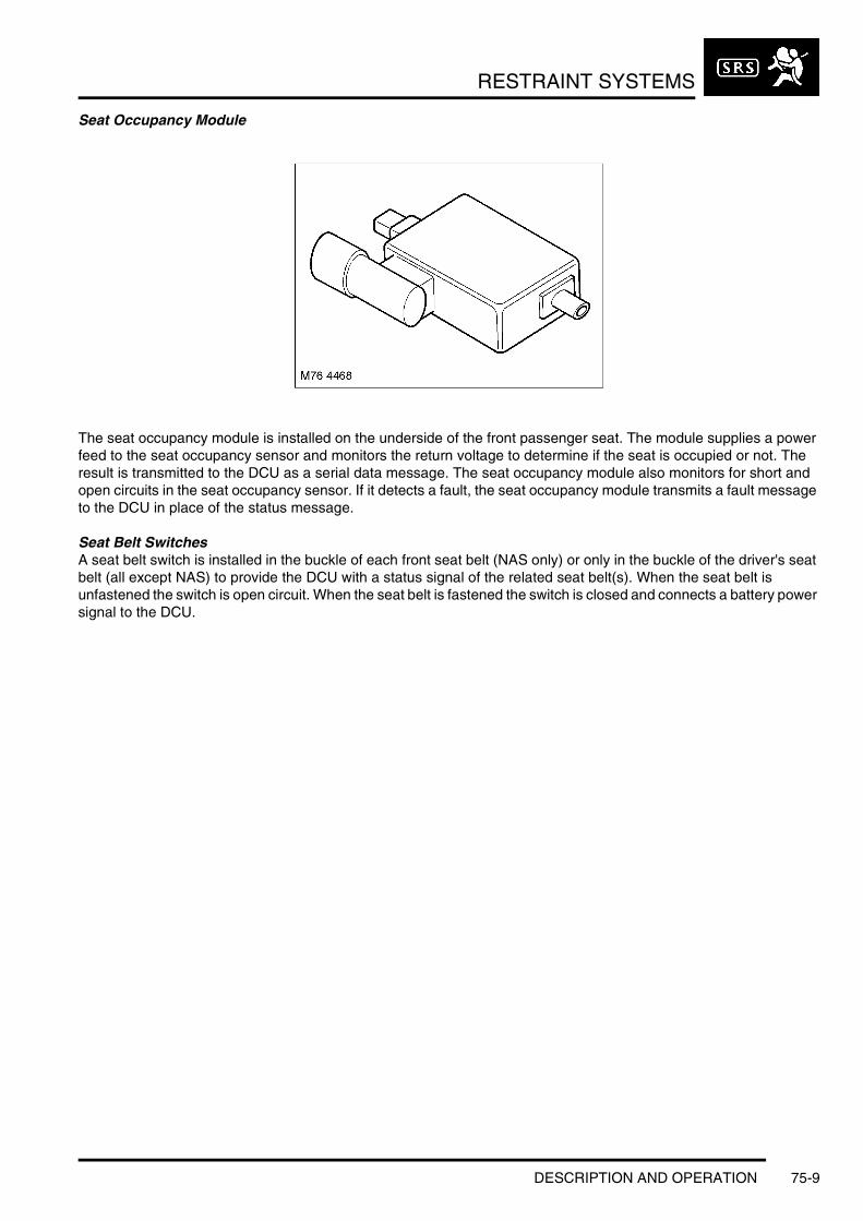
RESTRAINT SYSTEMS
Seat Occupancy Module
The seat occupancy module is installed on the underside of the front passenger seat. The module supplies a power feed to the seat occupancy sensor and monitors the return voltage to determine if the seat is occupied or not. The result is transmitted to the DCU as a serial data message. The seat occupancy module also monitors for short and open circuits in the seat occupancy sensor. If it detects a fault, the seat occupancy module transmits a fault message to the DCU in place of the status message.
Seat Belt SwitchesA seat belt switch is installed in the buckle of each front seat belt (NAS only) or only in the buckle of the driver's seat belt (all except NAS) to provide the DCU with a status signal of the related seat belt(s). When the seat belt is unfastened the switch is open circuit. When the seat belt is fastened the switch is closed and connects a battery power signal to the DCU.
DESCRIPTION AND OPERATION 75-9

RESTRAINT SYSTEMS
Pretensioner
1 Seat belt buckle2 Electrical connector3 Piston4 Piston housing5 Direction of piston travel
6 Expanding gas7 Squib/Gas generator8 Steel cable9 Gaiter
The pretensioners are used to tighten the front seat belts during a collision to ensure the occupants are securely held in their seats. A pretensioner is integrated into each front seat belt buckle and attached to a bracket on the inboard side of the seat.
Each pre-tensioner has a tube containing propellant and a piston. The piston is attached to a steel cable, the opposite end of which is attached to the seat belt buckle. A squib in the base of the tube provides an ignition source when triggered by a fire signal from the DCU.
On receipt of a fire signal from the DCU, the squib ignites the propellant. The propellant produces nitrogen gas that rapidly expands to drive the piston along the tube, pulling the cable and drawing the buckle downwards.
75-10 DESCRIPTION AND OPERATION
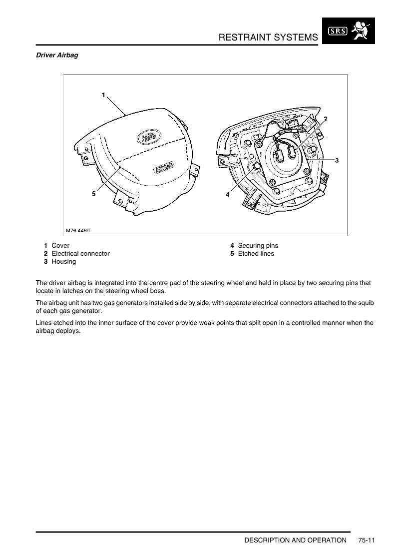
RESTRAINT SYSTEMS
Driver Airbag
1 Cover2 Electrical connector3 Housing
4 Securing pins5 Etched lines
The driver airbag is integrated into the centre pad of the steering wheel and held in place by two securing pins that locate in latches on the steering wheel boss.
The airbag unit has two gas generators installed side by side, with separate electrical connectors attached to the squib of each gas generator.
Lines etched into the inner surface of the cover provide weak points that split open in a controlled manner when the airbag deploys.
DESCRIPTION AND OPERATION 75-11

RESTRAINT SYSTEMS
Passenger Airbag
1 Securing flange2 Airbag
3 Housing4 Electrical connector
The passenger airbag module is installed in the fascia above the glovebox.
The airbag unit has a gas generator installed at each end with separate electrical connectors attached to the squib of each gas generator.
A hinged deployment door is etched into the inner surface of the fascia trim panel that covers the airbag.
Passenger Airbag Deployment
1 Airbag 2 Deployment door
75-12 DESCRIPTION AND OPERATION

RESTRAINT SYSTEMS
Side Airbag
1 Securing lug2 Airbag cover
3 Perforated break lines4 Electrical connector
A side airbag is installed behind the trim panel of each front door. An electrical connector links the squib in the airbag to the DCU. The airbag is contained in a metal housing closed by a plastic cover. Perforated lines in the cover, and etched lines in the door trim panel, provide weak points that split open in a controlled manner when the airbag deploys. When the airbag deploys it covers the adjacent areas of the door above and to the rear of the airbag module.
Side Airbag Deployment
1 Deployment flap2 Tether strap
3 Airbag
DESCRIPTION AND OPERATION 75-13

RESTRAINT SYSTEMS
Front Head Airbag
1 Electrical connector2 Inflation tube3 Retaining clip4 Airbag
5 Rear tether strap6 Front tether strap7 Gas generator
The front head airbags are installed behind the A post trim and above the outer edges of the headlining. The inflatable bag incorporates tether straps at each end which are attached to the body. When the airbag deploys, the inflating bag shortens in length and pulls on the tether straps, which forces it from behind the trim to cover the window in a straight line between the tether strap anchor points.
Rear Head Airbag
1 Housing2 Gas generator3 Electrical connector
4 Securing bracket5 Deployment flap
75-14 DESCRIPTION AND OPERATION

RESTRAINT SYSTEMS
The rear head airbags are installed behind the outer edges of the headlining above the D post. When the airbag deploys, the inflating bag forces itself from behind the trim to cover the upper part of the D post and adjacent areas of the rear door and quarter light.
Battery Disconnect UnitThe battery disconnect unit is attached to the positive terminal on the battery and allows the DCU to disconnect the main starter cable during a crash.
The battery disconnect unit incorporates the positive terminal connector and heavy duty cables for the starter and for engine and passenger compartment power distribution. The starter cable connection is contained in a plastic housing next to the battery terminal. The end fitting of the starter cable is a tapered press fit in one end of a gas discharge tube. The other end of the gas discharge tube contains a gas generator and a squib connected to the DCU.
When the DCU fires the squib, the gas from the gas generator forces the end fitting of the starter cable out of the gas discharge tube and breaks the connection with the starter motor. As the end fitting is pushed out of the gas discharge tube, spring tabs in the plastic housing engage with the rim of the end fitting to hold it clear of the gas discharge tube.
The fuel pump motor is shut off by the relevant ECM after the ECM receives a crash signal from the SRS DCU. See relevant engine management sections for more detail.
1 Battery terminal connector2 Electrical connector3 Gas generator4 Gas discharge tube
5 Spring tab6 Starter cable7 Power distribution cable8 View after firing
M76 4543
21 3 4 5 6
7
8
DESCRIPTION AND OPERATION 75-15

RESTRAINT SYSTEMS
Rotary Coupler
1 Outer housing2 Electrical connector3 Inner housing
4 Drive spigot5 Locking lever6 Electrical connector
The rotary coupler is installed on the steering column to provide the electrical interface between the fixed wiring harness and the steering wheel. The rotary coupler provides connections for the driver airbag, horn and steering wheel switch packs.
A rotating link harness is encapsulated into a plastic cassette comprising outer and inner housings with integral connectors. Brackets on the outer housing accommodate the column stalk switches. A spring loaded locking lever attached to the outer housing automatically engages and disengages with the inner housing when the steering wheel is removed and installed. To prevent damage to the rotating link harness, both the steering and the rotary coupler must be centralised when removing and installing the steering wheel.
75-16 DESCRIPTION AND OPERATION
RESTRAINT SYSTEMS
Deze pagina werd opzettelijk niet gebruikt
Cette page est intentionnellement vierge
Questa pagina è stata lasciata in bianco di proposito
Diese Seite ist leer
Esta página foi deixada intencionalmente em branco
Esta página fue dejada en blanco intencionalmente
This page is intentionally left blank
DESCRIPTION AND OPERATION
DESCRIPTION AND OPERATION 75-17

RESTRAINT SYSTEMS
SRS Control Diagram
A = Hardwired connection; B = K bus; C = Diagnostic DS2 bus
M76 4464A
1 2 3
4 5
6
7
8
9
1011
12
13
14
15
16
17
18
19
20
21
22
A B C
75-18 DESCRIPTION AND OPERATION

RESTRAINT SYSTEMS
1 Ignition switch2 Occupancy detection sensor3 Driver airbag4 Rotary coupler5 Passenger airbag6 Battery disconnection unit7 BCU8 Instrument pack9 Diagnostic socket
10 RH side airbag11 LH side airbag12 RH front head airbag13 RH rear head airbag14 LH front head airbag15 LH rear head airbag16 DCU17 RH side impact sensor18 LH side impact sensor19 Driver pretensioner20 Passenger pretensioner21 Occupancy detection unit22 Fuse 14, passenger compartment fusebox
DESCRIPTION AND OPERATION 75-19

RESTRAINT SYSTEMS
Operation
SRSIn a collision the sudden deceleration or acceleration is measured by the side impact sensors and the crash sensors in the DCU. The DCU evaluates the readings to determine the impact point on the vehicle and whether the deceleration/acceleration readings exceed the limits for firing the airbags, the pretensioners and the battery disconnect unit. The DCU incorporates the following limits to cater for impacts of varying severity and at different points on the vehicle:l Pretensionerl Driver and passenger airbag 1l Driver and passenger airbag 2l Driver and passenger airbag 3l Driver and passenger airbag 4l Rear impactl Battery disconnect unitl LH side and head airbagsl RH side and head airbags.
Firing StrategiesThe seat belt pretensioners are fired when either the pretensioner or the rear impact limit is exceeded. In a frontal impact, the DCU only fires the pretensioners if the safing sensor has closed, and also evaluates the inputs from the seat belt switches and the seat occupancy module before it comes to a firing decision.
The driver and passenger airbags are fired in a frontal impact. The time delay between firing the two gas generators in each airbag decreases with the increasing severity of the impact, until, at the most severe impact limit (driver and passenger airbag 4), the gas generators are fired simultaneously. In a frontal impact, the DCU only fires the driver and passenger airbags if the safing sensor has closed, and also evaluates the inputs from the seat belt switches and the seat occupancy module before it comes to a firing decision.
If there is a fault with a seat belt switch input, the DCU assumes the seat belt is fastened for the pretensioner firing strategy and unfastened for the airbag firing strategy. If there is a fault with the occupancy detection sensor, the DCU assumes the front passenger seat is occupied.
Front and Rear Impact Firing Strategy
Seat Belt Status Passenger Seat Status
StrategyDriver Passenger Pretensioner Driver Airbag Passenger Airbag
Fastened – – Fired at pretensioner or rear impact limit
Fired at limit 2 or above –
Unfastened – – Not fired NAS: Fired at limit 1 or aboveAll except NAS: Fired at limit 2 or above
–
– Fastened Occupied Fired at pretensioner or rear impact limit
– Fired at limit 2 or above
Unoccupied Fired at pretensioner or rear impact limit
– Not fired
– Unfastened Occupied Not fired – NAS: Fired at limit 1 or aboveAll except NAS: Fired at limit 2 or above
Unoccupied Not fired – Not fired
75-20 DESCRIPTION AND OPERATION

RESTRAINT SYSTEMS
The battery disconnect unit is fired:l At driver and passenger airbag limit 2 in a frontal impactl At the battery disconnect unit limit in a side impactl At the rear impact limit in a rear impact.
If one of the side impact limits is exceeded the DCU fires the side airbag and the head airbag(s) on that side of the vehicle. If the side impact limit on the front passenger side of the vehicle is exceeded, the DCU also evaluates the input from the seat occupancy module, and fires only the head airbag(s) if the front passenger seat is unoccupied.
In a roll-over, the airbags, pretensioners and battery disconnect unit are only fired if a related impact limit is exceeded. If multiple impacts occur during a crash event, after responding to the primary impact the DCU will output fire signals in response to secondary and further impacts if unfired units are available.
Crash SignalWhen the DCU outputs any of the fire signals it also outputs a crash signal to the Body Control Unit (BCU) and the ECM. On receipt of the crash signal, the BCU goes into a crash mode and the ECM cuts the power supply to the fuel pump relay. In the crash mode, the BCU:l Activates all of the unlock signals of the vehicle locking system, even if the vehicle is already unlockedl Ignores all locking/superlocking inputs until it receives an unlock input, when it returns the locking system to
normal operationl Activates the interior lamps. The interior lamps remain on permanently until they are manually switched off at the
lamp unit, or the BCU crash mode is switched off and they return to normal operationl Disables the rear window child lock input until the crash mode is switched offl Sends a crash message to the Light Check Module (LCM), via the K bus, instrument pack and I bus, to activate
the hazard warning lamps. The hazard warning lamps remain on until cancelled by the hazard warning switch or the crash mode is switched off.
The BCU crash mode is switched off by a valid locking and unlocking cycle of the locking system.
Component ReplacementAfter a crash event in which any of the SRS components have been deployed:l The deployed components and the DCU must be replaced.l If a side and/or head airbag has been deployed, the side impact sensor on that side of the vehicle must also be
replaced.l The SRS harness must be examined and replaced if damaged.
DESCRIPTION AND OPERATION 75-21
RESTRAINT SYSTEMS
75-22 DESCRIPTION AND OPERATION

DOORS
DOORSDESCRIPTION AND OPERATIONFront Door
DESCRIPTION AND OPERATION 76-1-1

DOORS
Doors
GeneralThe door structure and skins are manufactured from aluminium alloy and are fitted with an impact resistant plastic panel, finished in the body colour scheme, bolted to the lower external door skins.
The doors are attached to the door posts by two hinges. A door brake, with a metal retaining strap, is fitted between the door and body frame to restrict the angle that the doors open.
Structurally, the difference between the front and rear doors is the extruded aluminium alloy Side Impact Protection bar fitted to the front doors. The rear doors have, in addition to the window, a fixed quarter light.
The external door handles are bolted to the door structure and are accessed by removing the door trim casing. The rear doors are each fitted with a manually operated child protection safety lock.
Child Protection Safety Lock
Fitted within the door structure, is the window regulator and glass, door locking mechanism , door wiring harness and speakers. A moulded foam sound insulation panel, secured with a non-curing sealant, is fitted between the inner door skin and trim casing. Between the door actuator and lock is a bowden cable, protected by an insulated sleeve. The audio system, electric windows and door locking system are serviced by an electric wiring harness.
Trim CasingThe trim finish is dependent on the vehicle option level, either colour matched to the vehicle interior trim or leather finished.
The trim casings are secured by screws and retaining studs. A moulded sound insulation panel is attached to the door internal structure with a non-curing sealant.
All four doors have speaker grilles integral with the door trim, a switch to operate the door window mechanism, a recessed sill lock button, arm rest and door handle.
The driver's door trim casing is fitted with a switch pack linked to the Body Control Unit (BCU) via the P-Bus. This controls all four windows, and includes an isolation switch for the rear door windows, the door mirrors and the central locking system.
In addition to the side protection bars, to protect the front seat occupants, a side impact air bag is stowed in the front trim casings. + RESTRAINT SYSTEMS, DESCRIPTION AND OPERATION, Description.
M76 4549A
76-1-2 DESCRIPTION AND OPERATION
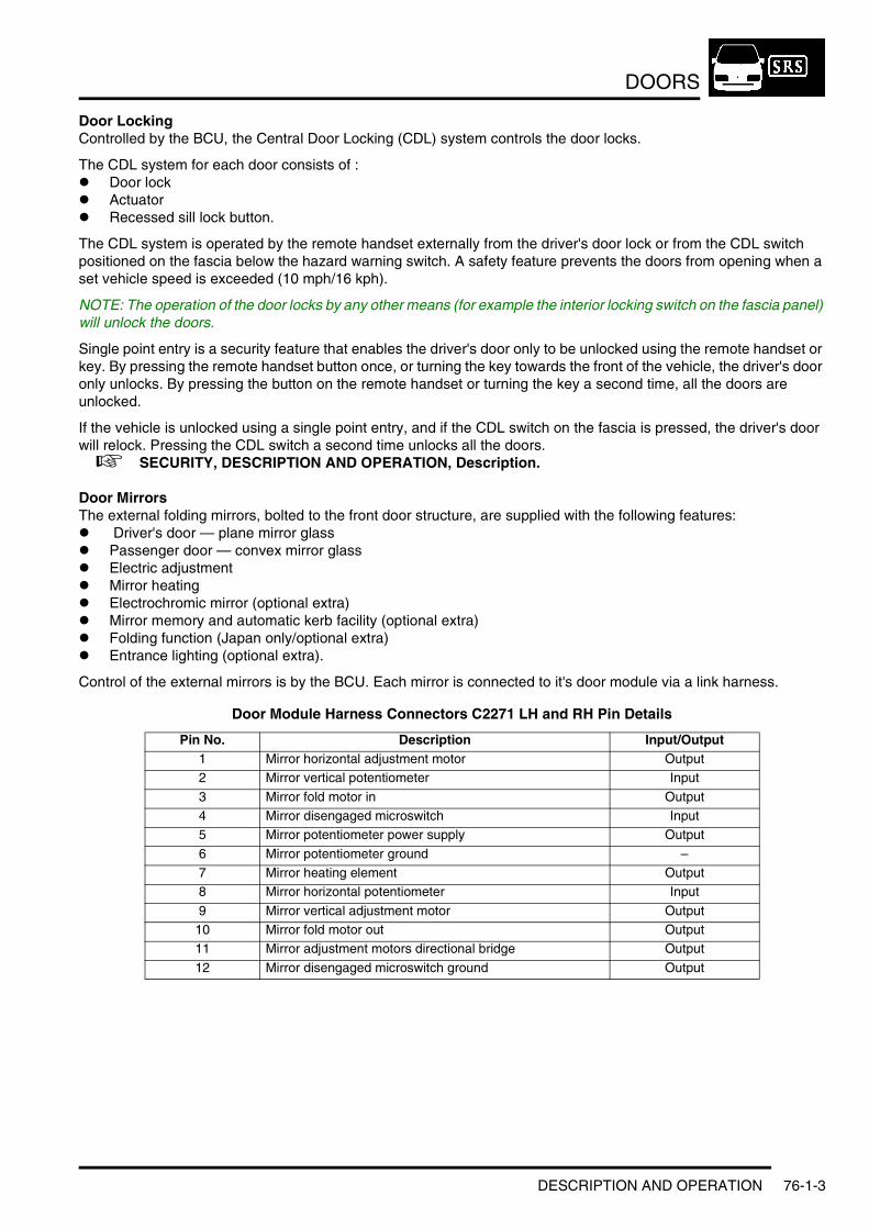
DOORS
Door LockingControlled by the BCU, the Central Door Locking (CDL) system controls the door locks.
The CDL system for each door consists of :l Door lockl Actuatorl Recessed sill lock button.
The CDL system is operated by the remote handset externally from the driver's door lock or from the CDL switch positioned on the fascia below the hazard warning switch. A safety feature prevents the doors from opening when a set vehicle speed is exceeded (10 mph/16 kph).
NOTE: The operation of the door locks by any other means (for example the interior locking switch on the fascia panel) will unlock the doors.
Single point entry is a security feature that enables the driver's door only to be unlocked using the remote handset or key. By pressing the remote handset button once, or turning the key towards the front of the vehicle, the driver's door only unlocks. By pressing the button on the remote handset or turning the key a second time, all the doors are unlocked.
If the vehicle is unlocked using a single point entry, and if the CDL switch on the fascia is pressed, the driver's door will relock. Pressing the CDL switch a second time unlocks all the doors. + SECURITY, DESCRIPTION AND OPERATION, Description.
Door MirrorsThe external folding mirrors, bolted to the front door structure, are supplied with the following features:l Driver's door — plane mirror glass l Passenger door — convex mirror glassl Electric adjustmentl Mirror heatingl Electrochromic mirror (optional extra)l Mirror memory and automatic kerb facility (optional extra)l Folding function (Japan only/optional extra)l Entrance lighting (optional extra).
Control of the external mirrors is by the BCU. Each mirror is connected to it's door module via a link harness.
Door Module Harness Connectors C2271 LH and RH Pin Details
Pin No. Description Input/Output1 Mirror horizontal adjustment motor Output2 Mirror vertical potentiometer Input
3 Mirror fold motor in Output4 Mirror disengaged microswitch Input5 Mirror potentiometer power supply Output
6 Mirror potentiometer ground –7 Mirror heating element Output8 Mirror horizontal potentiometer Input
9 Mirror vertical adjustment motor Output10 Mirror fold motor out Output11 Mirror adjustment motors directional bridge Output
12 Mirror disengaged microswitch ground Output
DESCRIPTION AND OPERATION 76-1-3
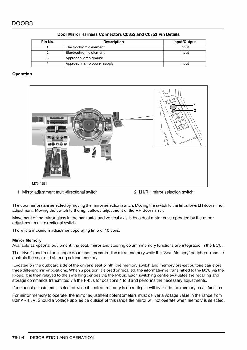
DOORS
Door Mirror Harness Connectors C0352 and C0353 Pin Details
Operation
1 Mirror adjustment multi-directional switch 2 LH/RH mirror selection switch
The door mirrors are selected by moving the mirror selection switch. Moving the switch to the left allows LH door mirror adjustment. Moving the switch to the right allows adjustment of the RH door mirror.
Movement of the mirror glass in the horizontal and vertical axis is by a dual-motor drive operated by the mirror adjustment multi-directional switch.
There is a maximum adjustment operating time of 10 secs.
Mirror MemoryAvailable as optional equipment, the seat, mirror and steering column memory functions are integrated in the BCU.
The driver's and front passenger door modules control the mirror memory while the “Seat Memory” peripheral module controls the seat and steering column memory.
Located on the outboard side of the driver's seat plinth, the memory switch and memory pre-set buttons can store three different mirror positions. When a position is stored or recalled, the information is transmitted to the BCU via the K-bus. It is then relayed to the switching centres via the P-bus. Each switching centre evaluates the recalling and storage commands transmitted via the P-bus for positions 1 to 3 and performs the necessary adjustments.
If a manual adjustment is selected while the mirror memory is operating, it will over-ride the memory recall function.
For mirror memory to operate, the mirror adjustment potentiometers must deliver a voltage value in the range from 80mV - 4.8V. Should a voltage applied be outside of this range the mirror will not operate when memory is selected.
Pin No. Description Input/Output1 Electrochromic element Input2 Electrochromic element Input3 Approach lamp ground –
4 Approach lamp power supply Input
M76 4551
21
76-1-4 DESCRIPTION AND OPERATION

DOORS
Automatic Mirror Tilting (Kerb View)If reverse gear is selected when the ignition is at position I or II, the passenger door mirror dips to provide a better view of the kerb. The mirror returns to it's original position immediately reverse gear is disengaged.
The kerb view mirror position can be adjusted using the mirror adjustment multi-directional switch when reverse gear is selected and the ignition is at position I or II.
Mirror HeatingMirror heating on the driver's and front passenger's doors is controlled by the respective door modules.
The BCU receives the outside temperature value via the K-bus. This outside temperature value is converted to a switch on-time percentage according to the following table and then transmitted via the P-bus to the two door modules. Mirror heating is active with the ignition at position II.
If the wiper is switched on, the switch on-time percentage is raised in accordance with the following table.
If the park heat function (if fitted) is selected, mirror heating is automatically selected.
Temperature in °C < -10° -10 to 0° 0 to 15° 15 to 25° 25 to 35° > 35°Switch on-time percentage 100% 75% 50% 25 % 0 % 0 %
Switch on-time percentage with wiper
100% 100% 75% 50% 25% 0 %
DESCRIPTION AND OPERATION 76-1-5

DOORS
Mirror Fold
1 Mirror fold button
The mirror fold function, standard for Japan and available as optional equipment for other markets, enables the mirrors to be electrically folded.
The “mirror fold” button is located in the switching centre of the driver's door for operation of the fold-in mechanism for both outside mirrors. When the “mirror fold” button is pressed, both mirror drives are driven in the fold-in direction by the relevant switching centre.
If the “mirror fold” button is pressed again, the two door mirrors are returned to their original positions.
Since it is possible, with frequent mirror fold-in operations, to cause the mirror motors to overheat, a repeat lockout facility is provided.
If the “mirror fold” button is pressed more than 5 times within 1 minute, the mirrors will extend and the mirror fold-in feature is disabled for 3 minutes.
M76 4548
1
76-1-6 DESCRIPTION AND OPERATION

DOORS
Tail Door
Tail Door Construction
DESCRIPTION AND OPERATION 76-1-7

DOORS
The steel tail door is of a two-piece horizontally split design.
The upper tail door, attached to the body with zinc coated hinges, is supported, when fully open, by two gas struts. The tinted, heated rear window is bonded to the window aperture.
Bolted to the upper tail door, and accessed by removing the upper trim panel, are the fixed spoiler, a suppressor and a centrally mounted single blade wash/wipe assembly. The fixed spoiler is fitted with a high level brake light and an optional multi-band telephone antenna.
Fitted to the upper tail door lower sill, accessed by removing the lower trim panel, is the upper tail door latch and locking mechanism, operated by a flush fitting switch located between the two number plate lights. To illuminate the loading area two lights are fitted to the lower trim panel. A “P”-section rubber weather seal is fitted to the lower sill.
The lower tail door is mounted on two spring-damped hinges and supported, when lowered, by two straps. A carpeted sprung-flap seals the gap between the tail door and the luggage area. Centrally mounted, is the striker plate for the upper tail door .
The two lower tail door locks engage the laterally mounted striker plates fitted on the vertical tail door frames, and are operated by a switch that can be accessed when the upper tail door is in the open position.
Tail Door OperationThe components for the tail door locking system are:l Upper tail door external push-buttonl Lower tail door internal push-buttonl CDL button on centre consolel Upper tail door actuatorl Lower tail door actuators, fitted directly to locksl Relay for upper tail door actuatorl Relay for lower tail door actuators.
Upper Tail Door ButtonThe upper tail door can be opened electrically by pressing the taildoor release button on the remote handset, the external switch located between the number plate lamps or by pressing the tail door release button on the fascia.
Upper Tail DoorThe centrally mounted upper tail door lock can be operated by either the tailgate mounted switch, the remote handset or the tail gate release button mounted on the central console.
In an emergency, or when there is no electrical power, the upper tail door can be manually unlocked by pulling a cable attached to a plastic toggle located in the upper tail door trim panel.
Lower Tail DoorThe lower tail door is released by the operating switch fitted to the upper sill and is only accessible with the upper tail door open.
76-1-8 DESCRIPTION AND OPERATION

DOORS
Lower Tail Door Switch Location
ActuatorsThe actuators are accommodated in their respective CDL units and powered by relays.
RelaysThe relay for the upper tail door is integrated in the BCU.
The relay for the lower tail door is fitted at the RH rear of the load space.
Lower Tail Door LocksEach of the two lateral locks is directly fitted to it's respective actuator. Fitted to the top of each lock is a manual release lever.
M76 4550
DESCRIPTION AND OPERATION 76-1-9

DOORS
Operation
GeneralThe operating logic for controlling the tailgate locking system is a function of the BCU.
NOTES:l It is possible to open the tail door with the remote control irrespective of the vehicle central locking statusl At vehicle speeds > 5 mph (8 km/h) it is not possible to operate the tail door . This facility prevents inadvertent
operation while driving.
Upper Tail DoorThe tail door is released by a special central locking unit with return spring shuttle.
To unlock/release the tail door, the CDL unit is powered directly for 0.7 seconds via a load switching relay in the BCU.
The table below shows the functions of the upper tail door for which the central locking unit is activated.
Power is applied to the actuator in the CDL unit and the tail door opens.
The return spring in the CDL unit re-establishes the initial position of the CDL unit.
Lower Tail DoorThe lower tail door is opened by a special CDL unit with return spring (shuttle).
The CDL unit is activated by the BCU via a load switching relay and power is applied for 0.7 seconds.
The actuator releases the tail door lock so that the lower tail door can be opened. After power has been applied, the return spring resets the CDL unit to its initial position.
The table below shows the functions of the lower tail door for which the CDL unit is activated.
Repeat LockoutA repeat lockout facility similar to the repeat lockout function of the CDL is used in order to protect the motors from thermal overload in the event of the tail door being locked/unlocked too often in succession.
Inside upper tailgate push-button
Outside upper tailgate push-button
Remote control for upper tailgate
Terminal R + v>0 − − −Unlock + +Lock + +
Central secure − +Selective unlock + +"+" = CDL unit is activated; "-" = CDL unit is not activated
Inside lower tailgate push-button When upper tail door open When upper tail door closed
Terminal R + v>0 − −Unlock + −Lock + −Central secure + −Selective unlock + −"+" = CDL unit is activated; "-" = CDL unit is not activated
76-1-10 DESCRIPTION AND OPERATION

INTERIOR TRIM COMPONENTS
INTERIOR TRIM COMPONENTSDESCRIPTION AND OPERATIONInterior Mirror
1 Rear light sensor2 Alarm LED3 Front light sensor
4 Universal transmitter channel buttons (NAS only)
5 Universal transmitter LED (NAS only)
DESCRIPTION AND OPERATION 76-3-1
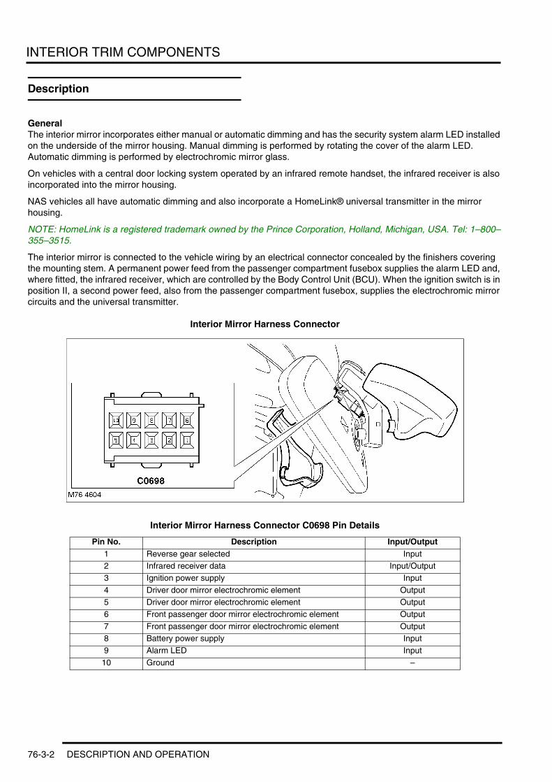
INTERIOR TRIM COMPONENTS
Description
GeneralThe interior mirror incorporates either manual or automatic dimming and has the security system alarm LED installed on the underside of the mirror housing. Manual dimming is performed by rotating the cover of the alarm LED. Automatic dimming is performed by electrochromic mirror glass.
On vehicles with a central door locking system operated by an infrared remote handset, the infrared receiver is also incorporated into the mirror housing.
NAS vehicles all have automatic dimming and also incorporate a HomeLink® universal transmitter in the mirror housing.
NOTE: HomeLink is a registered trademark owned by the Prince Corporation, Holland, Michigan, USA. Tel: 1–800–355–3515.
The interior mirror is connected to the vehicle wiring by an electrical connector concealed by the finishers covering the mounting stem. A permanent power feed from the passenger compartment fusebox supplies the alarm LED and, where fitted, the infrared receiver, which are controlled by the Body Control Unit (BCU). When the ignition switch is in position II, a second power feed, also from the passenger compartment fusebox, supplies the electrochromic mirror circuits and the universal transmitter.
Interior Mirror Harness Connector
Interior Mirror Harness Connector C0698 Pin Details
Pin No. Description Input/Output1 Reverse gear selected Input2 Infrared receiver data Input/Output3 Ignition power supply Input
4 Driver door mirror electrochromic element Output5 Driver door mirror electrochromic element Output6 Front passenger door mirror electrochromic element Output
7 Front passenger door mirror electrochromic element Output8 Battery power supply Input9 Alarm LED Input
10 Ground –
76-3-2 DESCRIPTION AND OPERATION

INTERIOR TRIM COMPONENTS
Electrochromic MirrorThe electrochromic mirror automatically dims to reduce glare from the headlights of following vehicles in dark or low light conditions. In addition to dimming the interior mirror, the electrochromic mirror circuits also control the dimming of the two door mirrors, via positive and negative connections between the interior mirror and each door mirror.
A light sensor on the front of the mirror monitors ambient light at the front of the vehicle and a light sensor in the mirror glass monitors the light coming from behind the vehicle. When the light from behind the vehicle exceeds the ambient light level, the electrochromic circuits simultaneously dim the interior and door mirrors. Dimming is inhibited when reverse gear is selected. The interior mirror is provided with a reverse gear signal by the Light Check Module (LCM).
Universal TransmitterThe universal transmitter can operate up to three home or office remotely operated systems (e.g. garage door/gate openers, lighting and security systems), replacing the individual hand held transmitters required for each system. The universal transmitter can learn the radio frequency codes of most current transmitters.
WARNING: The universal transmitter must not be used with any garage door that lacks safety ‘stop’ and ‘reverse’ features, as required by federal safety standards (this includes any garage or door opener model manufactured before April 1 1982). A garage door opener which cannot ‘detect’ an object in the path of a closing door and then automatically ‘stop’ and ‘reverse’ the door, does not meet current federal safety standards. Using a garage door opener without these features increases the risk of serious injury or death.
The universal transmitter incorporates three buttons, one for each channel, and an amber LED installed on the underside of the interior mirror. When one of the buttons is pressed the universal transmitter outputs the radio signal programmed for the related channel (if any) and illuminates the LED to confirm transmission.
Hand held transmitters are programmed into the universal transmitter as follows:1 Turn the ignition switch to position II.2 Press and hold the two outer buttons of the universal transmitter until the LED begins to flash, then release the
buttons. This initialises the universal transmitter and erases previous settings from all three channels.
WARNING: When programming the universal transmitter in the vicinity of the affected system, the system will operate. If the system controls garage doors or gates, ensure they are clear of people and objects to prevent personal injury or damage to equipment.
3 Place the signal emitting end of the hand held transmitter against the underside of the interior mirror.4 Simultaneously press and hold the activation button on the hand held transmitter and the chosen button of the
universal transmitter. When the LED of the universal transmitter flashes rapidly, indicating the channel has been programmed, release the buttons.
NOTE: The LED flashes slowly at first and can take up to a minute before it flashes rapidly.5 To programme another channel on the universal transmitter, repeat steps 3 and 4.6 Turn the ignition switch to 0.
The radio signals used to operate some home/office systems incorporate a code protection feature. After a channel has been programmed from the hand held transmitter, these systems will need to be trained to accept the signal from the universal transmitter. To check if a system is code protected, press the appropriate universal transmitter button. If the LED flashes rapidly for 1 to 2 seconds, before illuminating permanently, the system has a code protection feature.
The system is trained to the universal transmitter, as follows:1 Locate the training button on the system receiver. Refer to the system's literature for details.2 Press the training button on the system receiver for 1 to 2 seconds.3 On the vehicle, press and hold the appropriate universal transmitter button. When the amber LED stops flashing
rapidly (1 to 2 seconds), indicating training is complete, release the button.
DESCRIPTION AND OPERATION 76-3-3

INTERIOR TRIM COMPONENTS
76-3-4 DESCRIPTION AND OPERATION

SEATS
SEATSDESCRIPTION AND OPERATIONFront Seat
DESCRIPTION AND OPERATION 76-5-1

SEATS
Description
Front SeatsThere are three versions of seat available for the New Range Rover. The front seats are fitted with the seat belt bolted to the seat rail. The seat buckle, bolted to the seat frame, is supplied, for the US market, with a seat belt warning switch.
The three seat options available are:l Manual seat – finished in clothl Electric seat – finished in clothl Contour seat – finished in Oxford Leather.
The electric and contour seats are fitted with a folding armrest (manually adjustable) on the inboard side of the seat, additional optional equipment is: seat heating and memory recall facility.
Manual Seats
Manual Seat — Adjustment
1 Seat back adjustment2 Height adjustment3 Lumbar support adjustment
4 Forward/backward adjustment5 Cushion front edge adjustment (driver's seat
only)
The manual seats are adjustable in the following axes:l Forward/backwardl Seat heightl Seat angle — driver's seat onlyl Backrest anglel Headrest height and angle.
Electrically adjusted lumbar support, in the horizontal and vertical axes is available as optional equipment.
M76 4562
1 2 3 4 5
76-5-2 DESCRIPTION AND OPERATION

SEATS
Electric Seats The electric seats are adjusted in the following axes by switches fitted in the seat side trim panel: l Forward/back adjustmentl Seat cushion heightl Seat cushion angle – driver's seat onlyl Backrest anglel Lumbar support – horizontal and vertical.
The seat has the following manual adjustments:l Headrest anglel Headrest height.
Contour Seats
Contour Seat – Adjustment
1 Memory store and preset switches2 Upper backrest adjustment3 Seat backrest adjustment
4 Forward/backward/cushion height/cushion angle adjustment
5 Lumbar support adjustment
In addition to the electric seat adjustments the Contour seat has the following additional functions:l Electrical adjustment of the seatback head adjustmentl Seat angle adjustment – driver and passenger seatsl Seat heating.
Memory Function This function, available as optional equipment, has three memory positions stored for the seats and exterior mirrors. The switch for this function is located on driver's seat outer side trim panel.
Controlled by the Body Control Unit, the memory recall functions are:l Forward/backward adjustmentl Seat heightl Seat angle – driver's side onlyl Backrest anglel External mirror adjustment – left and rightl Steering column forward/backward adjustment.
M76 4561
1 2 4 53
DESCRIPTION AND OPERATION 76-5-3

SEATS
Rear seatsThe three rear bench style seats, designed to fold forward to increase the rear load space, are asymmetrically split 60:40 and are equipped with seat belts and adjustable head rests. The outer seats have optional heating.
Seat Control UnitThe are two versions available; the standard and contour version.
The control unit is configured to move the seat, depending on the version fitted, through 6 axes. It can also be configured for adjusting the steering column.
Standard Control Unit The standard seat control unit is capable of controlling four seat motors with hall sensors and two steering column motors. The switches for the controls are located in the control unit and shaped to give an indication of their corresponding function.
The control functions are:1 Forward/backward movement2 Seat height3 Recline4 Tilt.
The steering column switches are connected to the unit via a 4 pin connector. The functions are:1 Up/down2 Forward/backward
Contour VersionThe contour version is fitted with two additional motors to control the seat in the following axes:
1 Seatback head adjustment2 Seat angle.
Seat Control Unit Sub-SystemsThe are two versions available; the standard and contour version.
The system consists of an electrical sub-system and a mechanical sub-system and is controlled by the seat control unit fitted to the seat valance.
The electrical sub-system comprises the following components:
76-5-4 DESCRIPTION AND OPERATION

SEATS
1 Seat switch panel2 Body Control Unit (BCU)3 Seat relay4 Lumbar pump5 Lumbar deflate solenoid valve
6 Seat squab motor7 Seat cushion up/down motor8 Seat forward/backward motor9 Seat cushion front up/down motor
DESCRIPTION AND OPERATION 76-5-5

SEATS
The mechanical sub-system comprises the following components:l Gear wheelsl Rack and pinion assemblies.
Seat Power RelayLocated in the passenger compartment fusebox, the seat power relay supplies battery voltage for seat adjustment. The motors are energised when a selection is made.
Seat Switch PackEach seat switch pack, mounted on the seat valance, provides movement in the following axes:l Seat forward/backward adjustl Seat height adjustmentl Seat angle adjustmentl Backrest angle adjustmentl Backrest head adjustmentl Head restraint height adjustment.
Manual adjustment of the seat position can be carried out at any time, having priority over memory recall. The control unit sequences the order of adjustment.
Seat Forward/Backward Motor The seat forward/backward motor is a permanent magnet motor coupled to a rack and pinion assembly. Should the motor seize or stick for 6 seconds or more, an internal thermal cut-out switch will trip to remove voltage from the motor. Reset time for the switch is 35 seconds. Two pins within the seat switch pack control the seat forward/backward motor. Both pins are normally earthed. Operating the backward switch applies voltage to that pin while the other pin remains earthed. Operating the forward switch reverses power and earth to the motor allowing the motor to run in the opposite direction.
Seat Cushion Front Up/Down MotorThe seat cushion front up/down motor is a permanent magnet motor coupled to a rack and pinion assembly. Should the motor seize or stick for 6 seconds or more an internal thermal cut out switch will trip to remove voltage from the motor. Reset time for the switch is 35 seconds. Two pins within the seat switch pack control the seat cushion front up/down motor. Both pins are normally earthed. Operating the up switch applies voltage to that pin while the other pin remains earthed. Operating the down switch reverses power and earth to the motor allowing the motor to run in the opposite direction.
Seat Cushion Rear Up/ Down MotorThe seat cushion rear up/down motor is a permanent magnet motor coupled to a rack and pinion assembly. Should the motor seize or stick for 6 seconds or more, an internal thermal cut out switch will trip to remove voltage from the motor. Reset time for the switch is 35 seconds. Two pins within the seat switch pack control the seat cushion rear up/down motor. Both pins are normally earthed. Operating the up switch applies voltage to that pin while the other pin remains earthed. Operating the down switch reverses power and earth to the motor allowing the motor to run in the opposite direction.
Seat Squab Forward/Backward MotorThe squab forward/backward motor is a permanent magnet motor coupled to a rotary rack and pinion assembly. Should the motor seize or stick for 6 seconds or more, an internal thermal cut out switch will trip to remove voltage from the motor. Reset time for the switch is 35 seconds. Two pins within the seat switch pack control the squab fore/aft motor. Both pins are normally earthed. Operating the fore switch applies voltage to that pin while the other pin remains earthed. Operating the aft switch reverses power and earth to the motor allowing the motor to run in the opposite direction
Lumbar PumpThe lumbar pump inflates a bladder in the squab which provides extra support for the seat occupant. With no load on the seat it takes approximately 10 seconds to completely inflate the bladder. With a load of 25 kg (55 lb) it takes approximately 15 seconds to inflate the bladder. A pressure cut off switch in the system will operate at 0.12 to 1.93 bar (1.8 to 28 lbf.in2 ). The lumbar bladder can be replaced independently of the pump. The components are not serviceable.
76-5-6 DESCRIPTION AND OPERATION

SEATS
Manual Adjustment of Drive MotorsThe seats can be manually adjusted at any time. Positioning is interrupted if manual adjustment is required during automatic adjustment (memory recall). The manual adjustment is not effective before the switch is operated again.
Due to the sequential activation of the drive motors, the switch requests are prioritised in the following order:l Forward/backward adjustmentl Backrestl Height l Anglel Head restraintl Backrest headl Steering column anglel Steering column forward/backward adjustment.
DESCRIPTION AND OPERATION 76-5-7

SEATS
Seat Heating
DescriptionThe heated seat system is fitted to both the driver's and front passenger's seat and selected by individual push-button switches, each with an integrated LED display.
Location of Seat Heating Controls
The electrical sub-system consists of the following components:l Seat heater switchesl Seat heater elements (squab/backrest)l Temperature control unitl Temperature sensor.
Temperature Control UnitFeedback of the seat temperature is via a Negative Temperature Coefficient (NTC) sensor within the seat cushion. The resistance of this sensor changes with the temperature of the seat cushion allowing the temperature control unit to raise or lower the voltage to the seat heater elements to raise or lower their temperature.
An ignition feed is supplied via the heater switch. The temperature sensor supplies an input. Output is a supply to the cushion heater element and an earth.
Seat Heater SwitchesThe two push-button switches, fitted in the central console, each have an integrated functional display and, to assist system fault diagnosis, a self-test function. The display indicates the heating level selected and, when used for fault diagnosis, the fault code.
Both LEDs OFF – No heating
Two LEDs ON – High level heating (44°C)
One LED ON – Low level heating (39°C)
The seat heater switches supply an ignition feed to the temperature control unit. When a seat heater switch is operated, current flows to the seat heater elements causing them to heat the seat.
The switch regulates the level of seat heating if its internal temperature starts to rise above 85°C. Initially the level of seat heating is reduced to 88 % then progressively reduced until, if the internal temperature exceeds 95°C, the system shuts-down.
M76 4553
76-5-8 DESCRIPTION AND OPERATION

SEATS
Seat Heater ElementsThe seat heater elements are located in the seat cushion and squab. The cushion and squab heater elements are wired in parallel. Total power consumption at 13.5 volts is approximately 115 Watts. The cushion heater element has an input feed from the temperature control unit or heater switch and an output to the squab heater element, which outputs to earth.
OperationWhen the seat heater switch is initially pressed High level heating is selected, pressing the switch a second time selects Low level heating and pressing the switch a third time switches the heating off.
The seat heaters are thermostatically controlled and will operate intermittently to maintain a predetermined temperature. The indicator lights in the switches will remain illuminated until either the heaters are manually turned off, or the starter switch is turned off.
CAUTION: The seat heaters consume considerable power from the battery. For this reason, they should ONLY be operated while the engine is running.
When the seat heater switch is operated, power is supplied to the heater elements in the seat, causing the seat to heat up. The temperature control unit senses seat temperature via the sensor in the cushion and regulates voltage to the seat heater elements to maintain a constant temperature.
The heater elements increase and then maintain the seat at a temperature of between 37 and 44°C.
Fault FindingIn the self-test mode the switch indicates faults by displaying a flashing code.
The sequence to select test mode is :1 Press the heating switch with the ignition off2 With the switch depressed turn on the ignition switch to Position II3 Release the switch, this activates the self-test mode4 After 10 seconds the flashing code is displayed.
The flashing code indicates the following faultsl 1 Flash — Switch overtemperature (T > 95°C)l 2 Flashes — Short circuit and/or interruption in the sensorl 3 Flashes — Short circuit and/or interruption in the heating elements.
With the switch set to test mode, maximum heating is selected and both lamps are lit. If a fault is identified the heating is switched off and, after 10 seconds, the left LED switches off , this LED generates the flashing code. If no fault is detected the LED remains unlit.
To return to the test mode the switch is pressed twice and the sequence starts again. To cancel the test mode the ignition switch is turned off.
DESCRIPTION AND OPERATION 76-5-9

SEATS
76-5-10 DESCRIPTION AND OPERATION

SUNROOF
SUNROOFDESCRIPTION AND OPERATIONSunroof Layout
1 Closing panel2 Clamp plate3 Glass panel4 Sunshade panel
5 Carriage6 Sunroof motor7 Frame
DESCRIPTION AND OPERATION 76-6-1

SUNROOF
Sunroof
GeneralThe sunroof is electrically operated by a three-way switch co-located with the forward interior light assembly. The sunroof drive unit, operating the sunroof panel to the tilt or open positions, is actuated by the integrated sunroof control electronics.
The sunroof frame is bolted to mounting points on the roof panel. The frame, constructed from pressed steel, supports all the sunroof components.
A rubber gaiter is fitted between the sides of the glass panel and drive assembly. The gaiter, reducing wind noise with the sunroof in the tilt position, conceals the drive linkage.
The sunroof drive unit, accessible by removing the motor access panel ( integral with the forward interior light assembly), is mounted ahead of the roof segment between the roof liner and lower frame section of the sunroof. It comprises a motor with add-on reduction gear (worm drive), two hall-effect integral position sensors and integrated control circuit. The software within the integrated control unit is configured to meet individual national regulations. It is connected by a 13–pin multiplug to the P-Bus.
The worm drive drives a gear in a cast housing attached to the end of the motor. The gear has a small pinion gear attached to the outer part of its spindle. The pinion engages with the spiral cables to form a rack and pinion drive. Rotation of the motor turns the pinion which in turn drives the cables in the required direction.
The two cables are attached either side of the pinion. One end of each cable is attached to the guide. The opposite end is clamped in its position on the pinion by a riveted bracket. The cables run in metal tubes to the guides. As the sunroof panel is closed, the cables are pulled through the metal tubes. The displaced cable is guided into plastic tubes which protect the cable and prevent it snagging. The cables are made from rigid spring steel and therefore can push as well as pull the sunroof along the guides.
A sunshade is also located in the guides. When the sunroof panel is opened or tilted, the sunshade moves rearward. When the sunroof panel is opened, two brackets on the sunshade engage with the panel as it is retracted. The sunshade is then pulled back by the retracting panel. When the panel is closed, the sunshade remains retracted until pulled manually to its closed position.
Drain hoses are connected to the front and rear corners of the frame. The drain hoses are located inside the 'A' and 'D' post pillars to allow water which has collected in the frame to escape. A one-way valve is fitted to the end of each drain hose to prevent the ingress of dirt and moisture.
ServicingServicing is limited to adjusting the glass panel and replacing the drive unit. The drive unit is accessed by removing the access panel fitted to the forward interior light panel.
76-6-2 DESCRIPTION AND OPERATION

SUNROOF
Operation
General
Sunroof Controls
1 Access panel for motor drive output shaft 2 Sunroof switch
The sunroof is operated by the three-way switch, via the Body Control Unit (BCU), with the following switch position options:l Rest positionl Open sliding/tilting sunroof (sliding open)l Open by pressing and holding (one-touch function for sliding open)l Raise sliding/tilting sunroof (tilting open)l Close sliding/tilting sunroof (sliding shut/tilting shut)l Close by over-pressing (one-touch function for sliding closed).
The drive is automatically shut down when the limit positions are reached. Limit position shutdown is initiated by the integral increment sensor isolating the motor. Limit position shutdown occurs even if the control remains actuated or is operated a further time in the direction of the limit position.
If a failure of the sunroof motor occurs, the sunroof can be closed manually. Access to the motor drive output shaft, in the roof access panel, enables the fitting of a special key which can be used to manually drive the sunroof to the closed position.
The sliding/tilting sunroof is operational with the ignition switch in position II for one-touch operation and position I for operating the control. In addition to the basic functional specifications, nationally specific specifications are configured via the encoding of the basic module. The necessary signals are transmitted via the P-Bus. If no signals are transmitted via the P-Bus, the functions remain limited to manual operation.
NOTE: The encoding functions are configured using TestBook/T4
The following functions are available:
Manual OperationThe desired sunroof position can be selected by operating the control in the open/tilt/close sliding/tilting sunroof positions. The control must be pressed permanently to do this.
M76 4507
21
DESCRIPTION AND OPERATION 76-6-3
SUNROOF
One-touch FunctionPressing and holding the sunroof switch momentarily, for either the open or close selection, will enable the sliding/tilting sunroof to travel fully to the selected closed position. This selection can be interrupted by operating the switch a further time.
If the "tilting" control is operated while the panel position is within the "sliding open" range, the roof automatically moves to the limit position of tilting. This process can be interrupted by operating the control a further time.
The one-touch functions are encodable. This is a function of TestBook/T4.
Anti-Trap Function The anti-trap function, configured to meet the specific requirements of individual national regulations, operates by monitoring the torque output of the sliding/tilting sunroof drive. It operates when the sunroof is closing and the opening is greater than 4 mm. To ensure that the sunroof fully closes it is disabled for the last 4 mm of travel.
NOTE: The encoding functions are configured using TestBook/T4
Operating during one-touch operation, actuation in the first switch position and during one-touch closing, the anti-trap function is disabled when emergency closing (panic mode) is selected.
After the anti-trap function has been activated the sunroof will return, depending on vehicle configuration, at maximum system speed, to the point at which the close selection was initially made.
Convenience OperationThe sunroof and windows can be fully closed or opened by holding the door key in either the locking or unlocking position, or with the remote control. Releasing the key before the operation is completed will stop the sunroof travelling.
The anti-trap function also operates when convenient closing is selected.
If the key is returned to the rest position, any convenience function that is currently in progress is terminated. If the control is operated during a convenience function, the convenience function that is currently in progress is terminated and must be restarted. Automatic resumption after the control is released is not permissible.
Consumer ShutdownDuring the starting process (Ignition position II), the sunroof is deactivated via the P-bus. The current selection , e.g. opening or one-touch functions, is immediately terminated and sunroof movement is halted.
If an undervoltage of less than 9.5 V occurs, the one-touch operation that is in progress will be terminated and no new sliding/tilting sunroof movement is initiated.
Sleep ModeTo reduce the current consumption of the vehicle, the sunroof control system switches to an electricity-saving mode after receiving the telegram "Go to Sleep" from the BCU via the P-Bus. In this condition manual operation of the sunroof will result in the loss of its absolute position. It will require re-initialising.
The electricity-saving mode is exited again by any telegram on the P-bus. The first telegram on the P-bus need not be evaluated. However, the P-Bus must not be influenced by the wake-up process. The following telegrams in the sliding/tilting sunroof must not be misinterpreted or destroyed by the wake-up process.
Fault PatternsThe following fault patterns are provided:l Overriding temporary shutdown (max. switch-on time 15 s)l Shutdown of the drive in event of relay contacts sticking or faulty semiconductor after max. 500 msl Shutdown of the drive in event of no signal from the increment sensors after max. 300 msl Substitute function (e.g. motor stop) in event of implausible signals from sliding/tilting sunroof control and other
faults (signal lines)l Repeat interlock (by software, as substitute for motor thermo switch).
76-6-4 DESCRIPTION AND OPERATION

SUNROOF
DiagnosisThe sunroof control unit has a built in test function to allow self-checking and self-diagnosis.
The exchange of information with the diagnostic unit takes place through the basic module via the P-bus. It can be used to identify three possible faults.
1 Mechanical stiffness (fault in the sunroof unit)1 Implausible input signals (control fault)2 Electronic fault.
InitialisationInitialising the sunroof allows the control unit to learn the end positions of the motor's travel. The hall sensors provide pulses for motor rotation, the control module counts the pulses and determines where the panel is by memorizing the stored pulses.
If the system is not initialised, the sunroof will only operate in the tilt up and slide close positions.
Initialisation ProcedurePressing and holding the sunroof switch in either the tilt up or slide close positions for 15 seconds momentarily operates the sunroof motor.
The control module memorizes the pulses from the hall sensors on the next activation of the motor by driving the panel to its end run positions. The control module senses an amperage increase and determines the end run position. The counted number of pulses is then used as the basis for calculating the panel position.
DESCRIPTION AND OPERATION 76-6-5

SUNROOF
76-6-6 DESCRIPTION AND OPERATION
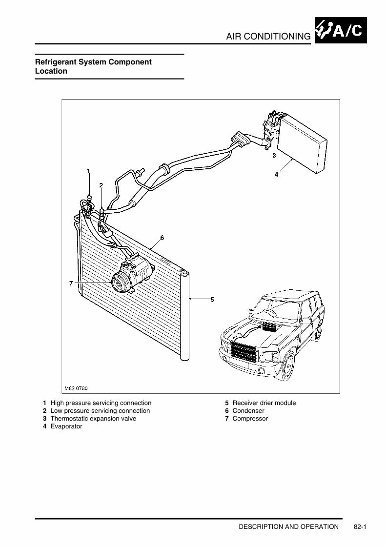
AIR CONDITIONING
AIR CONDITIONINGDESCRIPTION AND OPERATIONRefrigerant System Component Location
1 High pressure servicing connection2 Low pressure servicing connection3 Thermostatic expansion valve4 Evaporator
5 Receiver drier module6 Condenser7 Compressor
DESCRIPTION AND OPERATION 82-1
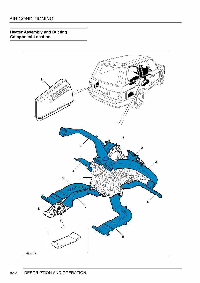
AIR CONDITIONING
Heater Assembly and Ducting Component Location
6
8
44
3
4
8
6
7
23
M82 0781
1
9
2
55
82-2 DESCRIPTION AND OPERATION

AIR CONDITIONING
1 Forced ventilation outlet2 Windscreen duct3 Face level duct4 Front footwell duct5 Heater assembly6 Rear footwell duct7 Rear face duct8 Rear blower (high line system only)9 Rear face duct extension (low line system only)
DESCRIPTION AND OPERATION 82-3
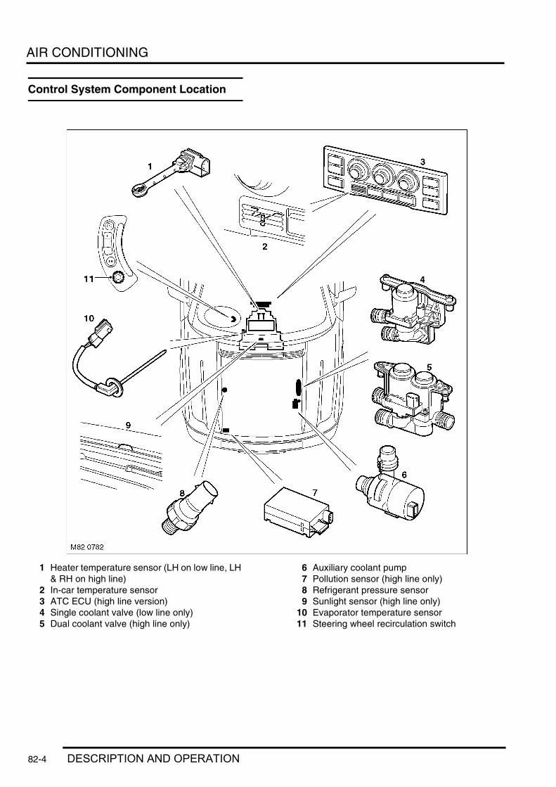
AIR CONDITIONING
Control System Component Location
1 Heater temperature sensor (LH on low line, LH & RH on high line)
2 In-car temperature sensor3 ATC ECU (high line version)4 Single coolant valve (low line only)5 Dual coolant valve (high line only)
6 Auxiliary coolant pump7 Pollution sensor (high line only)8 Refrigerant pressure sensor9 Sunlight sensor (high line only)
10 Evaporator temperature sensor11 Steering wheel recirculation switch
82-4 DESCRIPTION AND OPERATION

AIR CONDITIONING
FBH System Component Location
1 FBH fuel pipe tank connection2 FBH receiver (where fitted)3 Changeover valve (where fitted)
4 FBH fuel pump5 FBH unit
DESCRIPTION AND OPERATION 82-5

AIR CONDITIONING
Description
GeneralEither a low or high line Air Conditioning (A/C) system is installed on the vehicle. The low line system features automatic control of a common temperature setting for both sides of the passenger compartment, with manual control of the blower speed, air recirculation and air distribution. The high line system is fully automatic with separate temperature settings for the LH and RH sides of the passenger compartment and manual overrides for blower speed, air recirculation and air distribution. The high line system also incorporates independent temperature and volume control for the rear passengers. The low and high line systems both include:l A refrigerant systeml An air inlet housingl A heater assemblyl Distribution ductsl Two forced ventilation outletsl An Automatic Temperature Control (ATC) ECU and sensorsl An auxiliary coolant pumpl A coolant valve.
The high line system incorporates the following additional components:l A second coolant valvel A pollution sensorl A rear blower unit.
A Fuel Burning Heater (FBH) system is installed as standard on Td6 models and as an option on V8 models. The FBH is a supplementary heater installed in the heater coolant circuit. The FBH can be operated without the engine running to pre-heat the passenger compartment and after the engine starts to reduce the heater coolant warm-up time. On Td6 models, the FBH also boosts the heater coolant temperature while the engine is running at low ambient air and engine coolant temperatures, to maintain heater performance at an acceptable level.
Refrigerant SystemThe refrigerant system transfers heat from the vehicle interior to the outside atmosphere to provide the heater assembly with dehumidified cool air. The system comprises:l A compressorl A condenser and receiver drierl A thermostatic expansion valvel An evaporatorl Refrigerant lines.
The system is a sealed, closed loop, filled with a charge weight of R134a refrigerant as the heat transfer medium. Oil is added to the refrigerant to lubricate the internal components of the compressor.
To accomplish the transfer of heat, the refrigerant is circulated around the system, where it passes through two pressure/temperature regimes. In each of the pressure/temperature regimes, the refrigerant changes state, during which process maximum heat absorption or release occurs. The low pressure/temperature regime is from the thermostatic expansion valve, through the evaporator to the compressor; the refrigerant decreases in pressure and temperature at the thermostatic expansion valve, then changes state from liquid to vapour in the evaporator, to absorb heat. The high pressure/temperature regime is from the compressor, through the condenser and receiver drier to the thermostatic expansion valve; the refrigerant increases in pressure and temperature as it passes through the compressor, then releases heat and changes state from vapour to liquid in the condenser.
82-6 DESCRIPTION AND OPERATION

AIR CONDITIONING
Refrigerant System Schematic
1 Evaporator2 Thermostatic expansion valve3 Desiccant (in modulator)4 Filter (in modulator)5 Electric cooling fan6 Refrigerant pressure sensor7 Condenser8 Compressor
9 High pressure servicing connection10 Low pressure servicing11 Blower12 Air flows:
a Ambient air flow through condenserb Fresh/Recirculated air flow through blowerc Cooled air flow to vehicle interior
7
4
3
M82 0815
8
65
1012b
12b
11
12b
1
12c
2
A
B
9
12a
12b
DESCRIPTION AND OPERATION 82-7

AIR CONDITIONING
CompressorThe compressor circulates the refrigerant around the system by compressing low pressure, low temperature vapour from the evaporator and discharging the resultant high pressure, high temperature vapour to the condenser.
The compressor is a fixed displacement unit attached to a mounting bracket on the engine. A dedicated drive belt on the engine crankshaft drives the compressor via a pulley and an electrically actuated clutch. Operation of the clutch is controlled by the ATC ECU.
Compressor Assembly
1 Clutch connector2 Pulley
3 Outlet port4 Inlet port
CondenserThe condenser transfers heat from the refrigerant to the surrounding air to convert the vapour from the compressor into a liquid. A receiver drier module, integrated onto the LH side of the condenser, incorporates a filter and a desiccant to remove solid impurities and moisture from the refrigerant. The receiver drier module also functions as a reservoir for liquid refrigerant, to accommodate changes of heat load at the evaporator.
The condenser is installed immediately in front of the radiator.
The condenser is classified as a sub-cooling condenser and consists of a fin and tube heat exchanger installed between two end tanks. Divisions in the end tanks separate the heat exchanger into a three pass upper (condenser) section and a single pass lower (sub-cooler) section, which are interconnected by the receiver drier module. The desiccant pack and the filter in the receiver drier module are serviceable items retained in position by a threaded plug.
82-8 DESCRIPTION AND OPERATION

AIR CONDITIONING
Condenser Assembly
1 Cap2 Spring clip3 Sealing plug4 Desiccant module
5 Condenser6 Outlet pipe7 Inlet pipe
DESCRIPTION AND OPERATION 82-9

AIR CONDITIONING
Thermostatic Expansion ValveThe thermostatic expansion valve meters the flow of refrigerant into the evaporator, to match the refrigerant flow with the heat load of the air passing through the evaporator matrix.
The temperature and pressure of the refrigerant leaving the evaporator act on the thermostatic expansion valve to control the volume of refrigerant flowing through the evaporator. The warmer the air flowing through the evaporator matrix, the more heat available to evaporate refrigerant and thus the greater the volume of refrigerant allowed through the metering valve.
EvaporatorThe evaporator is installed in the heater assembly between the blower and the heater matrix, to absorb heat from the exterior or recirculated air. Low pressure, low temperature refrigerant changes from liquid to vapour in the evaporator, absorbing large quantities of heat as it changes state.
Most of the moisture in the air passing through the evaporator condenses into water, which drains through the floorpan to the underside of the vehicle through two drain tubes.
Evaporator and Thermostatic Expansion Valve
1 Insulated connecting pipes2 Thermostatic expansion valve
3 Evaporator
Refrigerant LinesTo maintain similar flow velocities around the system, the diameter of the refrigerant lines varies to suit the two pressure/temperature regimes. The larger diameters are installed in the low pressure/temperature regime and the smaller diameters are installed in the high pressure/temperature regime.
Low and high pressure charging connections are incorporated into the refrigerant lines near the front RH corner of the engine compartment.
Air Inlet HousingThe air inlet housing directs fresh air into the heater unit. The air inlet housing is centrally mounted on the engine bulkhead, below a ventilation grille in the bonnet, and secured to the bulkhead closing panels.
A serviceable particle filter, or particle/odour filter, is installed in the air inlet housing to prevent odours and/or particulate matter from entering the vehicle with the fresh air.
82-10 DESCRIPTION AND OPERATION

AIR CONDITIONING
Air inlet Housing
1 Air outlet to heater assembly2 Fixing lug3 Filter flap catch4 Filter flap
5 Particle/carbon filter6 Inlet grille7 Seal
DESCRIPTION AND OPERATION 82-11
AIR CONDITIONING
Heater AssemblyThe heater assembly controls the temperature, volume and distribution of air supplied to the distribution ducts as directed by selections made on the ATC ECU control panel. The assembly is installed on the vehicle centre-line, between the fascia and the engine bulkhead. The heater assembly consists of a casing formed from a series of plastic mouldings. Internal passages integrated into the casing guide the air through the casing and separate it into two flows, one for the LH outlets and one for the RH outlets. Two drain outlets at the bottom of the casing are connected to overboard drain hoses in the sides of the transmission tunnel.
The heater assembly incorporates:l A blowerl A heater matrixl Control flapsl Control flap motorsl The thermostatic expansion valve and the evaporator of the refrigerant systeml The evaporator temperature sensor and either one (low line system) or two (high line system) heater matrix
temperature sensors.
82-12 DESCRIPTION AND OPERATION

AIR CONDITIONING
Low Line Heater Assembly
1 Fresh air inlet2 Fresh/Recirculated air flap3 Face level temperature blend flap control4 Insulated refrigerant pipes5 Windscreen air outlet6 Face level air outlets7 Front footwell air outlet
8 Rear face level air outlet9 Rear footwell air outlet
10 Water drain11 Coolant pipes12 Fresh/Recirculated air flaps motor13 Distribution flaps motor
DESCRIPTION AND OPERATION 82-13

AIR CONDITIONING
High Line Heater Assembly
1 Fresh air inlet2 Fresh/Recirculated air flap3 Ram air flap4 Face level temperature blend flap control5 Rear face level temperature blend motor6 Insulated refrigerant pipes7 Ram air flaps motor8 Windscreen air outlet9 Face level air outlets
10 Front footwell air outlet11 Footwell (RH) and face level (LH) air flaps
motors12 Rear face level air outlet13 Rear footwell air outlet14 Water drain15 Windscreen distribution motor16 Coolant pipes17 Fresh/Recirculated air flap motor
82-14 DESCRIPTION AND OPERATION

AIR CONDITIONING
BlowerThe blower is installed between the air inlets and the evaporator, and consists of two open hub, centrifugal fans powered by a single electric motor. Operation of the electric motor is controlled by the ATC ECU via an output stage (voltage amplifier) installed in the outlet of the RH fan.
To produce the seven blower speeds the ATC ECU outputs a stepped control voltage between 0 and 8 V to the output stage, which regulates a battery power feed from the passenger compartment fusebox to the blower. The control voltage changes, in 1 V steps, between 2 V (blower speed 1) and 8 V (blower speed 7). If the control voltage is less than 2 V the blower is off.
Blower Output Stage
DESCRIPTION AND OPERATION 82-15
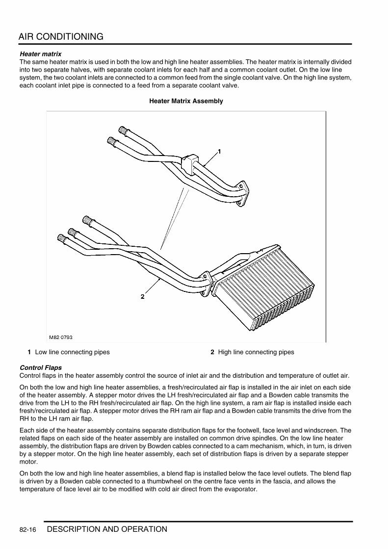
AIR CONDITIONING
Heater matrixThe same heater matrix is used in both the low and high line heater assemblies. The heater matrix is internally divided into two separate halves, with separate coolant inlets for each half and a common coolant outlet. On the low line system, the two coolant inlets are connected to a common feed from the single coolant valve. On the high line system, each coolant inlet pipe is connected to a feed from a separate coolant valve.
Heater Matrix Assembly
1 Low line connecting pipes 2 High line connecting pipes
Control FlapsControl flaps in the heater assembly control the source of inlet air and the distribution and temperature of outlet air.
On both the low and high line heater assemblies, a fresh/recirculated air flap is installed in the air inlet on each side of the heater assembly. A stepper motor drives the LH fresh/recirculated air flap and a Bowden cable transmits the drive from the LH to the RH fresh/recirculated air flap. On the high line system, a ram air flap is installed inside each fresh/recirculated air flap. A stepper motor drives the RH ram air flap and a Bowden cable transmits the drive from the RH to the LH ram air flap.
Each side of the heater assembly contains separate distribution flaps for the footwell, face level and windscreen. The related flaps on each side of the heater assembly are installed on common drive spindles. On the low line heater assembly, the distribution flaps are driven by Bowden cables connected to a cam mechanism, which, in turn, is driven by a stepper motor. On the high line heater assembly, each set of distribution flaps is driven by a separate stepper motor.
On both the low and high line heater assemblies, a blend flap is installed below the face level outlets. The blend flap is driven by a Bowden cable connected to a thumbwheel on the centre face vents in the fascia, and allows the temperature of face level air to be modified with cold air direct from the evaporator.
82-16 DESCRIPTION AND OPERATION

AIR CONDITIONING
Fascia Face Level Vent
1 RH air control thumbwheel2 Temperature control thumbwheel
3 LH air control thumbwheel
On high line heater assemblies, a blend flap is installed for the rear passenger face level outlet to allow the temperature of rear face level air to be adjusted independently from the temperatures selected on the control panel. The blend flap is driven by a stepper motor controlled by a thumbwheel on the rear passenger face vent. The blend flap is also used to close off the rear face level outlet when maximum air output is required for the front outlets, e.g. when defrost is selected.
Rear Passenger Face Level Vent
1 Blower control 2 Temperature control
DESCRIPTION AND OPERATION 82-17

AIR CONDITIONING
Control Flap MotorsTwo types of electrical stepper motor are used to operate the control flaps in the heater assembly. A conventional 500 Hz stepper motor operates the recirculation flaps, on the low and high line systems. On the high line system, five bus controlled 200 Hz stepper motors operate the ram air, distribution (windscreen, face level and footwell) and the rear face level temperature control flaps. On the low line system a bus controlled stepper motor operates the distribution flaps cam mechanism. All of the stepper motors are controlled by the ATC ECU. None of the stepper motors are interchangeable.
Typical Control Flap Motor
1 Electrical connector2 Release clip
3 Output shaft
Each bus controlled stepper motor incorporates a microprocessor and is connected to an M bus from the ATC ECU, which consists of three wires making up power, ground and signal circuits. The microprocessor in each bus controlled stepper motor is programmed with a different address. Each M bus message from the ATC ECU contains the address of an individual bus controlled stepper motor, so only that motor responds to the message.
None of the stepper motors incorporate a feedback potentiometer. Instead, the ATC ECU determines the positions of the flaps by using either their closed or open position as a datum and memorising the steps that it drives the individual stepper motors. Each time the ignition is switched on, the ATC ECU checks the memorised position of the stepper motors against fixed values for the current system configuration. If there is an error (e.g. after a power supply failure during operation or after replacement of the ATC ECU), the ATC ECU calibrates the applicable stepper motors, to re-establish the datums, by driving them fully closed or open before re-setting them to their nominal position. A calibration run can also be invoked using TestBook/T4.
When any of the control flaps are set to fully closed or open, the ATC ECU signals the related stepper motor to move the appropriate number of steps in the applicable direction. To accommodate build tolerances and wear, and to ensure the flaps are held in the selected position, every 20 seconds the ATC ECU signals the stepper motor to move an additional 10 steps in the relevant direction.
Distribution DuctsAir from the heater assembly is distributed around the vehicle interior through distribution ducts to outlets in the fascia, the front and rear footwells, and the rear of the cubby box between the front seats.
In the fascia, the distribution ducts are connected to fixed vents for the windscreen and side windows and adjustable vent assemblies for face level air. An adjustable vent assembly is also installed on the rear of the cubby box for rear face level air. The footwell outlets are fixed vents formed in the end of the related distribution ducts.
82-18 DESCRIPTION AND OPERATION
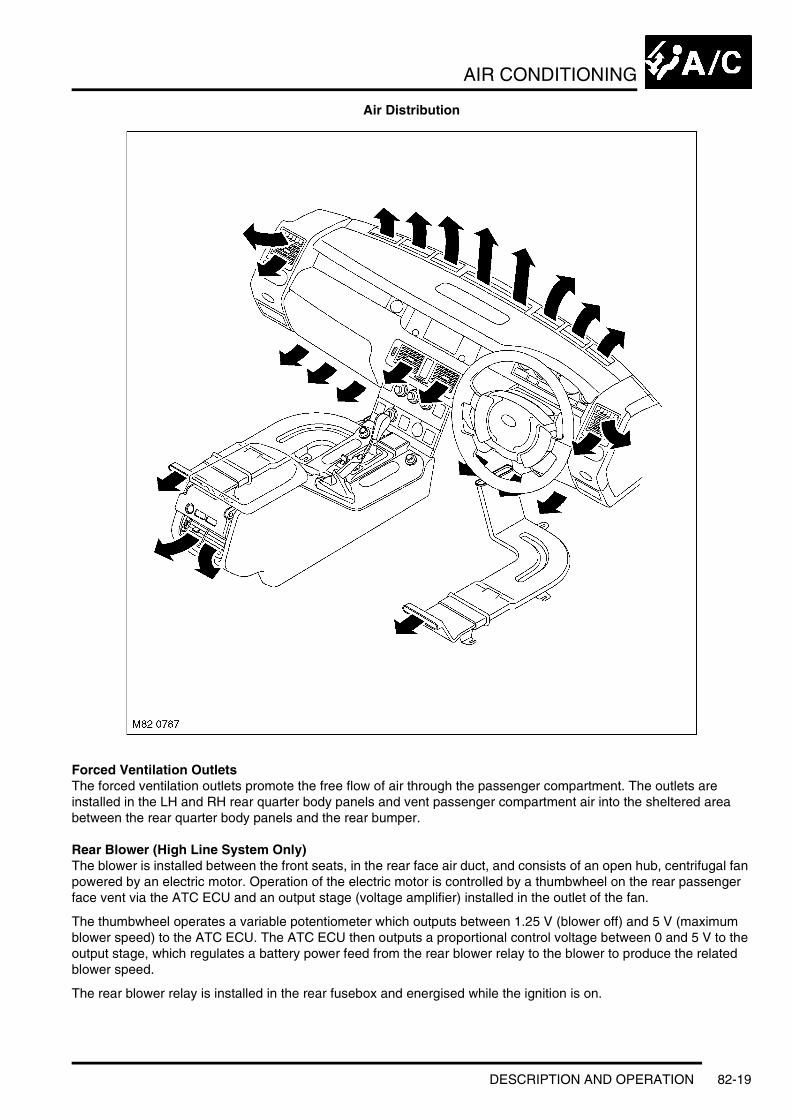
AIR CONDITIONING
Air Distribution
Forced Ventilation OutletsThe forced ventilation outlets promote the free flow of air through the passenger compartment. The outlets are installed in the LH and RH rear quarter body panels and vent passenger compartment air into the sheltered area between the rear quarter body panels and the rear bumper.
Rear Blower (High Line System Only)The blower is installed between the front seats, in the rear face air duct, and consists of an open hub, centrifugal fan powered by an electric motor. Operation of the electric motor is controlled by a thumbwheel on the rear passenger face vent via the ATC ECU and an output stage (voltage amplifier) installed in the outlet of the fan.
The thumbwheel operates a variable potentiometer which outputs between 1.25 V (blower off) and 5 V (maximum blower speed) to the ATC ECU. The ATC ECU then outputs a proportional control voltage between 0 and 5 V to the output stage, which regulates a battery power feed from the rear blower relay to the blower to produce the related blower speed.
The rear blower relay is installed in the rear fusebox and energised while the ignition is on.
DESCRIPTION AND OPERATION 82-19

AIR CONDITIONING
Rear Blower Output Stage
ATC ECUThe ATC ECU is installed in the centre of the fascia. An integral control panel contains push switches and rotary switches/knobs for system control inputs. Orange tell-tale LED's in the switches and switch surrounds illuminate to indicate the current settings of the system. The rotary temperature switch is graduated in degrees Celsius, except on USA vehicles, where it is graduated in degrees Fahrenheit.
An in-car temperature sensor and associated electric fan are installed behind a grille in the control panel.
The ATC ECU processes inputs from the control panel switches and system sensors, then outputs the appropriate signals to control the A/C system. In addition to controlling the A/C system, the ATC ECU also controls the following:l The windscreen heater and windscreen wiper parking area heater (optional fit, not available on vehicles with infra
red protection glass)l The windscreen washer jet heatersl The rear window heaterl The front seat heaters.
Low Line Control Panel
1 Windscreen heater switch2 LH front seat heater switch3 Temperature switch4 Blower switch5 RH front seat heater switch
6 Distribution control knob7 A/C switch8 Recirculation switch9 In-car temperature sensor
10 Rear window heater switch
82-20 DESCRIPTION AND OPERATION
AIR CONDITIONING
The switches on the low line control panel have the following functions:l Windscreen Heater Switch:Enabled only with the engine running. Pressing the switch energises the windscreen
heater and the windscreen wiper parking area heater for a set time period, until the switch is pressed again or until the engine stops, whichever occurs first. A LED above the switch is illuminated while the heaters are on.
l LH and RH Seat Heater Switches:Activates the heater elements in the seat cushion and seat back at one of two heat levels. The first press of the switch energises the heater elements at the higher heat setting and illuminates two LED in the switch. A second press of the switch sets the heater elements to the lower heat setting and extinguishes one of the LED's. A further press of the switch de-energises the heater elements and extinguishes the second LED. The seat heaters remain on until selected off or the ignition is switched off.
l Temperature Switch: Adjusts the passenger compartment nominal temperature setting between 16 and 28 °C (60 and 84 °F). The temperature range is engraved on the switch surround (°F for NAS, °C for rest of world). A pointer on the switch indicates the selected temperature. In the minimum and maximum temperature positions, the temperature is set to maximum cooling or maximum heating respectively.
l Blower Switch: For manual adjustment of blower speed. Up to seven LED's in the switch surround illuminate to indicate the selected blower speed.
l Distribution Control Knob: For manual adjustment of air distribution. Includes AUTO setting where distribution flaps are set to a nominal comfort position.
l A/C Switch: Activates the A/C compressor. Allows the A/C compressor to be selected off for economy operation. A LED above the switch is illuminated when the A/C compressor is selected on.
l Recirculation Switch: For manual selection of fresh or recirculated air. A LED above the switch is illuminated when recirculated air is selected.
l Rear Window Heater Switch: Enabled only with the engine running. Pressing the switch energises the rear window heater for a set time period, until the switch is pressed again or until the engine stops, whichever occurs first. A LED above the switch is illuminated while the heater is on.
DESCRIPTION AND OPERATION 82-21

AIR CONDITIONING
High Line Control Panel
1 Windscreen heater switch2 LH front seat heater switch3 LH temperature switch4 Automatic mode switch5 Blower switch6 RH front seat heater switch7 RH temperature switch8 A/C switch
9 Recirculation switch10 Maximum A/C switch11 Windscreen distribution switch12 Face distribution switch13 Footwell distribution switch14 In-car temperature sensor15 Defrost programme switch16 Rear window heater switch
The switches on the high line control panel have the following functions:l Windscreen Heater Switch:Energises the windscreen heater and the windscreen wiper parking area heater for a
set time period, until the switch is pressed again or until the engine stops, whichever occurs first. A LED above the switch is illuminated while the heaters are on.
l LH and RH Seat Heater Switches:Activates the heater elements in the seat cushion and seat back at one of two heat levels. The first press of the switch energises the heater elements at the higher heat setting and illuminates two LED in the switch. A second press of the switch sets the heater elements to the lower heat setting and extinguishes one of the LED's. A further press of the switch de-energises the heater elements and extinguishes the second LED. The seat heaters remain on until selected off or the ignition is switched off.
l LH and RH Temperature Switches:Adjusts the nominal temperature settings of the LH and RH sides of the passenger compartment between 16 and 28 °C (60 and 84 °F). The temperature range is engraved on the switch surrounds. A pointer on each switch indicates the selected temperature. In the minimum and maximum temperature positions, the system operates at maximum cooling or maximum heating respectively.
l Automatic Mode Switch: Activates the automatic modes for air volume and distribution and also activates the compressor. Separate LED's in the automatic mode switch illuminate when the blower and the distribution control flaps are in automatic mode. Manually selecting the blower speed or a distribution switch extinguishes the related LED.
l Blower Switch: For manual adjustment of blower speed. Up to seven LED's in the switch surround illuminate to indicate the selected blower speed.
l A/C Switch: Controls activation of the A/C compressor. Allows the A/C compressor to be selected off for economy operation. A LED above the switch is illuminated when the A/C compressor is selected on.
l Recirculation Switch: For manual or automatic selection of fresh or recirculated air. Two LED's above the switch illuminate to indicate the mode and position of the recirculation flaps. The first press of the switch sets the recirculation flaps to automatic mode and illuminates the LH LED. A second press of the switch manually sets the recirculation flaps to the recirculation position, extinguishes the LH LED and illuminates the RH LED. A further press of the switch manually sets the recirculation flaps to the fresh air position and extinguishes the RH LED.
82-22 DESCRIPTION AND OPERATION

AIR CONDITIONING
l Maximum A/C Switch: For selection of maximum A/C when the ignition is on or rest heating when the ignition is off. A LED above the switch is illuminated when maximum cooling or rest heating is selected.
l Distribution Switches (Windscreen, Face and Footwell): For manual selection of air distribution in any combination of windscreen, face and footwell outlets. A LED above each switch illuminates when a selection is made.
l Defrost Programme Switch: Activates a programme that automatically selects the windscreen heater on, activates the compressor and changes the system settings to direct dry heat to the windscreen. A LED above the switch is illuminated while the defrost programme is active.
l Rear Window Heater Switch: Enabled only with the engine running. Pressing the switch energises the rear window heater for a set time period, until the switch is pressed again or until the engine stops, whichever occurs first. A LED above the switch is illuminated while the heater is on.
Inputs and OutputsFive electrical connectors provide the interface between the ATC ECU and the vehicle/heater assembly wiring.
Both the low and high line systems receive ambient temperature, engine coolant temperature, engine speed and vehicle speed inputs in K bus messages from the instrument pack. If the K bus messages are missing or faulty, the ATC ECU adopts the following default values:l Ambient temperature = 0 °C (32 °F)l Engine coolant temperature = 80 °C (176 °F)l Engine speed = 800 rev/minl Vehicle speed = zero.
If a fault develops in the input from the temperature selector switch on the control panel, the ATC ECU adopts a default value of 24 °C (75 °F).
ATC ECU Harness Connector C0249 Pin Details
ATC ECU Harness Connector C0923 Pin Details
Pin No. Description System Input/OutputLow High
1 Front seat heating battery power supply Yes Yes Input
2 LH front seat heater Yes Yes Output3 RH front seat heater Yes Yes Output
Pin No. Description System Input/OutputLow High
1 Rear blower switch signal No Yes Input2 Rear blower switch power supply No Yes Output3 Automatic distribution switch Yes No Input
4 LH heater matrix temperature sensor No Yes Input5 RH heater matrix temperature sensor Yes Yes Input6 Evaporator temperature sensor Yes Yes Input
7 Blower control voltage Yes Yes Output8 Rear temperature switch No Yes Input9 Sensor ground (evaporator, and heater
temperature sensors)Yes Yes –
10 to 12 Not used – – –
13 Recirculation flap motor signal 2 Yes Yes Input14 Recirculation flap motor signal 2 Yes Yes Output15 Recirculation flap motor signal 1 Yes Yes Output
16 Recirculation flap motor signal 1 Yes Yes Input17 Rear blower and temperature switch power
supplyNo Yes Output
18 Not used – – –
DESCRIPTION AND OPERATION 82-23

AIR CONDITIONING
ATC ECU Harness Connector C1629 Pin Details
ATC ECU Harness Connector C1630 Pin Details
ATC ECU Harness Connector C2295 Pin Details
Pin No. Description System Input/OutputLow High
1 Ignition power supply Yes Yes Input2 Sunlight sensor ground No Yes –
3 K bus Yes Yes Input/Output4 Delayed accessory power Yes Yes Input5 LH coolant valve Yes Yes Output
6 RH coolant valve No Yes Output7 HRW relay Yes Yes Output8 Windscreen washer jet heater relay Yes Yes Output
9 Auxiliary coolant pump Yes Yes Output10 Refrigerant pressure sensor signal Yes Yes Input11 Not used – – –
12 Pollution sensor signal No Yes Input13 Pollution sensor power supply No Yes Output14 Windscreen heater relay Yes Yes Output
15 LH seat heating temperature sensor Yes Yes Output16 RH seat heating temperature sensor Yes Yes Output17 Engine full load signal Yes Yes Input
18 LH sunlight sensor signal No Yes Input19 RH sunlight sensor signal No Yes Input20 Refrigerant pressure sensor ground Yes Yes –
21 Refrigerant pressure sensor power supply Yes Yes Output22 Coolant changeover valve Yes Yes Output23 Instrument illumination Yes Yes Input
24 Sunlight sensor power supply No Yes Output25 Pollution sensor heater ground No Yes –26 Pollution sensor heater power supply No Yes Output
Pin No. Description System Input/OutputLow High
1 Battery power supply Yes Yes Input2 A/C compressor clutch Yes Yes Output
3 System ground Yes Yes –
Pin No. Description System Input/OutputLow High
1 M bus power supply No Yes Output
2 M bus ground No Yes –3 M bus interface line No Yes Input/Output
82-24 DESCRIPTION AND OPERATION

AIR CONDITIONING
SensorsBoth the low and the high line systems incorporate:l An in-car temperature sensorl A refrigerant pressure sensorl An evaporator temperature sensorl A heater matrix temperature sensor.
The high line system also incorporates:l A second heater matrix temperature sensorl A sunlight sensorl A pollution sensor.
In-car Temperature SensorThe in-car temperature sensor is an encapsulated Negative Temperature Coefficient (NTC) thermistor that provides the ATC ECU with an input of passenger compartment air temperature. The in-car temperature sensor is installed behind a grille in the ATC ECU control panel. An electric fan in the ATC ECU runs continuously, while the ignition is on, to draw air through the grille and across the in-car temperature sensor.
The ATC ECU uses the signal from the in-car temperature sensor for control of the coolant temperature valve(s), blower speed and air distribution.
The signal voltage from the in-car temperature sensor is between 0 and 5 V. The ATC ECU monitors the signal voltage and defaults to a temperature of 20 °C (68 °F) if it goes out of the range 0.573 – 4.882 V:l If the signal voltage is less than 0.573 V, the ATC ECU assumes there is a short circuit to groundl If the signal voltage is more than 4.882 V, the ATC ECU assumes there is an open circuit or a short circuit to
battery.
Refrigerant Pressure SensorThe refrigerant pressure sensor provides the ATC ECU with a pressure input from the high pressure side of the refrigerant system. The refrigerant pressure sensor is located in the refrigerant line between the condenser and the thermostatic expansion valve.
The ATC ECU supplies a 5 V reference voltage to the refrigerant pressure sensor and receives a return signal voltage, between 0 and 5 V, related to system pressure.
The ATC ECU uses the signal from the refrigerant pressure sensor to protect the system from extremes of pressure and to calculate compressor load on the engine for idle speed control. The ATC ECU also transfers the pressure value to the Engine Control Module (ECM), via the K bus, instrument pack and CAN bus, for use in controlling the speed of the engine cooling fan.
To protect the system from extremes of pressure, the ATC ECU disengages the compressor clutch if the pressure:l Decreases to 1.9 ± 0.2 bar ( 27.5 ± 3 lbf/in2): the ATC ECU engages the compressor clutch again when pressure
increases to 2.8 ± 0.2 bar (40.5 ± 3 lbf/in2)l Increases to 33 ± 1 bar (479 ± 14.5 lbf/in2): the ATC ECU engages the compressor clutch again when pressure
decreases to 23.5 ± 1 bar (341 ± 14.5 lbf/in2).
Evaporator Temperature SensorThe evaporator temperature sensor is a NTC thermistor that provides the ATC ECU with a temperature signal from the air outlet side of the evaporator. The evaporator temperature sensor is installed in the RH side of the heater assembly casing, and extends into the core of the evaporator.
The ATC ECU uses the input from the evaporator temperature sensor to control the engagement and disengagement of the compressor clutch, to prevent the formation of ice on the evaporator.
The signal voltage from the evaporator temperature sensor is between 0 and 5 V. The ATC ECU monitors the signal voltage and defaults to a temperature of 0 °C (32 °F) if it goes out of the range 0.157 – 4.784 V:l If the signal voltage is less than 0.157 V, the ATC ECU assumes there is a short circuit to groundl If the signal voltage is more than 4.784 V, the ATC ECU assumes there is an open circuit or a short circuit to
battery.
DESCRIPTION AND OPERATION 82-25
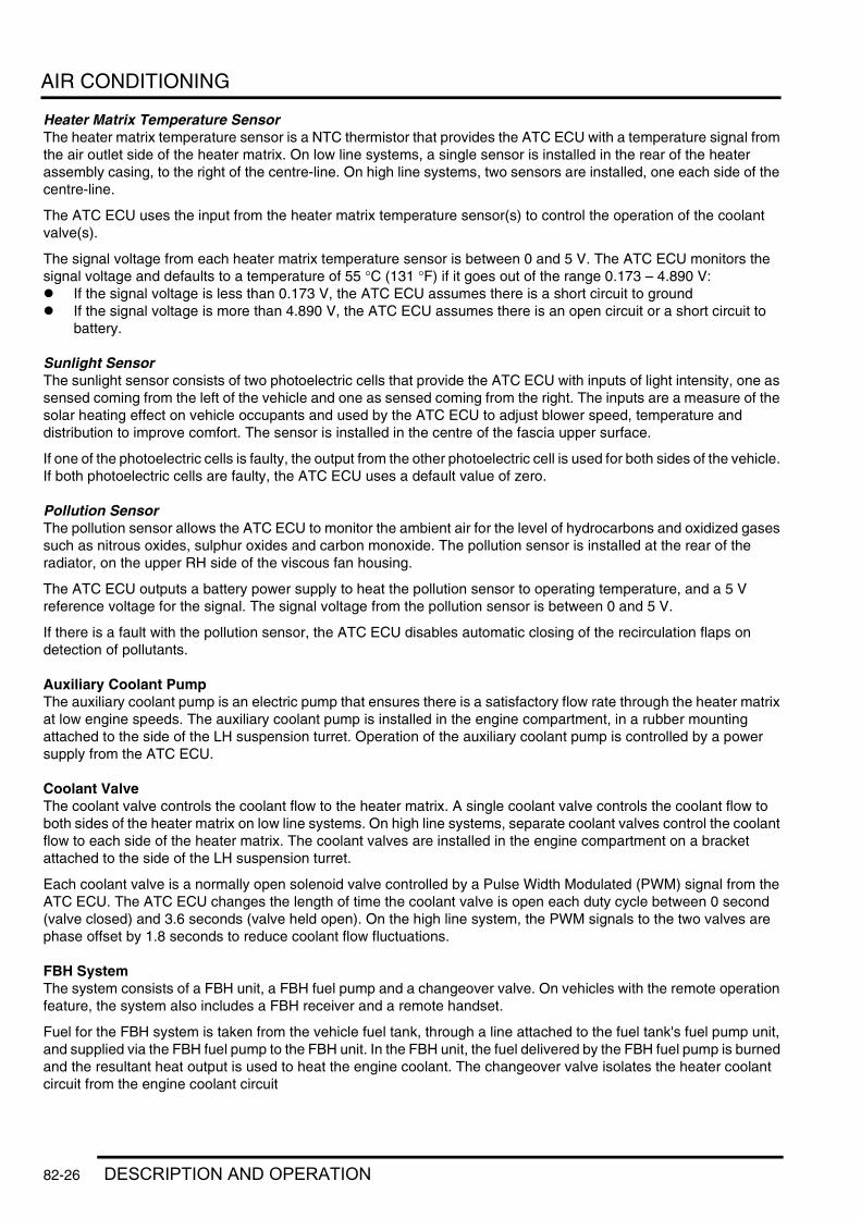
AIR CONDITIONING
Heater Matrix Temperature SensorThe heater matrix temperature sensor is a NTC thermistor that provides the ATC ECU with a temperature signal from the air outlet side of the heater matrix. On low line systems, a single sensor is installed in the rear of the heater assembly casing, to the right of the centre-line. On high line systems, two sensors are installed, one each side of the centre-line.
The ATC ECU uses the input from the heater matrix temperature sensor(s) to control the operation of the coolant valve(s).
The signal voltage from each heater matrix temperature sensor is between 0 and 5 V. The ATC ECU monitors the signal voltage and defaults to a temperature of 55 °C (131 °F) if it goes out of the range 0.173 – 4.890 V:l If the signal voltage is less than 0.173 V, the ATC ECU assumes there is a short circuit to groundl If the signal voltage is more than 4.890 V, the ATC ECU assumes there is an open circuit or a short circuit to
battery.
Sunlight SensorThe sunlight sensor consists of two photoelectric cells that provide the ATC ECU with inputs of light intensity, one as sensed coming from the left of the vehicle and one as sensed coming from the right. The inputs are a measure of the solar heating effect on vehicle occupants and used by the ATC ECU to adjust blower speed, temperature and distribution to improve comfort. The sensor is installed in the centre of the fascia upper surface.
If one of the photoelectric cells is faulty, the output from the other photoelectric cell is used for both sides of the vehicle. If both photoelectric cells are faulty, the ATC ECU uses a default value of zero.
Pollution SensorThe pollution sensor allows the ATC ECU to monitor the ambient air for the level of hydrocarbons and oxidized gases such as nitrous oxides, sulphur oxides and carbon monoxide. The pollution sensor is installed at the rear of the radiator, on the upper RH side of the viscous fan housing.
The ATC ECU outputs a battery power supply to heat the pollution sensor to operating temperature, and a 5 V reference voltage for the signal. The signal voltage from the pollution sensor is between 0 and 5 V.
If there is a fault with the pollution sensor, the ATC ECU disables automatic closing of the recirculation flaps on detection of pollutants.
Auxiliary Coolant PumpThe auxiliary coolant pump is an electric pump that ensures there is a satisfactory flow rate through the heater matrix at low engine speeds. The auxiliary coolant pump is installed in the engine compartment, in a rubber mounting attached to the side of the LH suspension turret. Operation of the auxiliary coolant pump is controlled by a power supply from the ATC ECU.
Coolant ValveThe coolant valve controls the coolant flow to the heater matrix. A single coolant valve controls the coolant flow to both sides of the heater matrix on low line systems. On high line systems, separate coolant valves control the coolant flow to each side of the heater matrix. The coolant valves are installed in the engine compartment on a bracket attached to the side of the LH suspension turret.
Each coolant valve is a normally open solenoid valve controlled by a Pulse Width Modulated (PWM) signal from the ATC ECU. The ATC ECU changes the length of time the coolant valve is open each duty cycle between 0 second (valve closed) and 3.6 seconds (valve held open). On the high line system, the PWM signals to the two valves are phase offset by 1.8 seconds to reduce coolant flow fluctuations.
FBH SystemThe system consists of a FBH unit, a FBH fuel pump and a changeover valve. On vehicles with the remote operation feature, the system also includes a FBH receiver and a remote handset.
Fuel for the FBH system is taken from the vehicle fuel tank, through a line attached to the fuel tank's fuel pump unit, and supplied via the FBH fuel pump to the FBH unit. In the FBH unit, the fuel delivered by the FBH fuel pump is burned and the resultant heat output is used to heat the engine coolant. The changeover valve isolates the heater coolant circuit from the engine coolant circuit
82-26 DESCRIPTION AND OPERATION

AIR CONDITIONING
An ECU integrated into the FBH unit controls the operation of the FBH unit and the FBH fuel pump. The ATC ECU controls the changeover valve. System operation is initiated by:l The instrument pack, via the ATC ECU, using I and K bus messages, for parked heating selections made on the
Multi Information Display (MID) or Multi-Function Display (MFD)l The remote handset, via the TV antenna, TV amplifier and the FBH receiver, using radio and hardwired signals,
for instant activation of parked heatingl The ATC ECU, using K bus messages, for additional heating while the engine is running.
FBH Fuel PumpThe FBH fuel pump regulates the fuel supply to the FBH unit. The FBH fuel pump is installed below the RH side of the fuel tank in a rubber mounting attached to the rear subframe. The pump is a self priming, solenoid operated plunger pump. The ECU in the FBH unit outputs a pulse width modulated signal to control the operation of the pump. When the pump is de-energised, it provides a positive shut-off of the fuel supply to the FBH unit.
Sectioned View of FBH Fuel Pump
1 Solenoid coil2 Plunger3 Filter insert4 Fuel line connector5 'O' ring seal
6 Spring7 Piston8 Bush9 Fuel line connector
10 Non return valve
The solenoid coil of the FBH fuel pump is installed around a housing which contains a plunger and piston. The piston locates in a bush, and a spring is installed on the piston between the bush and the plunger. A filter insert and a fuel line connector are installed in the inlet end of the housing. A non return valve and a fuel line connector are installed in the fuel outlet end of the housing.
While the solenoid coil is de-energised, the spring holds the piston and plunger in the 'closed' position at the inlet end of the housing. An 'O' ring seal on the plunger provides a fuel tight seal between the plunger and the filter insert, preventing any flow through the pump. When the solenoid coil is energised, the piston and plunger move towards the outlet end of the housing, until the plunger contacts the bush; fuel is then drawn in through the inlet connection and filter. The initial movement of the piston also closes transverse drillings in the bush and isolates the pumping chamber at the outlet end of the housing. Subsequent movement of the piston then forces fuel from the pumping chamber through the non return valve and into the line to the FBH unit. When the solenoid de-energises, the spring moves the piston and plunger back towards the closed position. As the piston and plunger move towards the closed position, fuel flows past the plunger and through the annular gaps and transverse holes in the bush to replenish the pumping chamber.
M80 0471
1 2 3 4
5678
109
DESCRIPTION AND OPERATION 82-27

AIR CONDITIONING
FBH UnitThe FBH unit is installed in the passenger side rear of the engine compartment, below the battery. It is connected in series with the coolant supply to the heater assembly. Two electrical connectors on the FBH unit connect it to the vehicle wiring.
FBH Unit Components
1 Coolant outlet hose2 Electrical connectors3 Air inlet filter4 Mounting bracket
5 Exhaust pipe6 Fuel supply line7 Coolant inlet hose
82-28 DESCRIPTION AND OPERATION
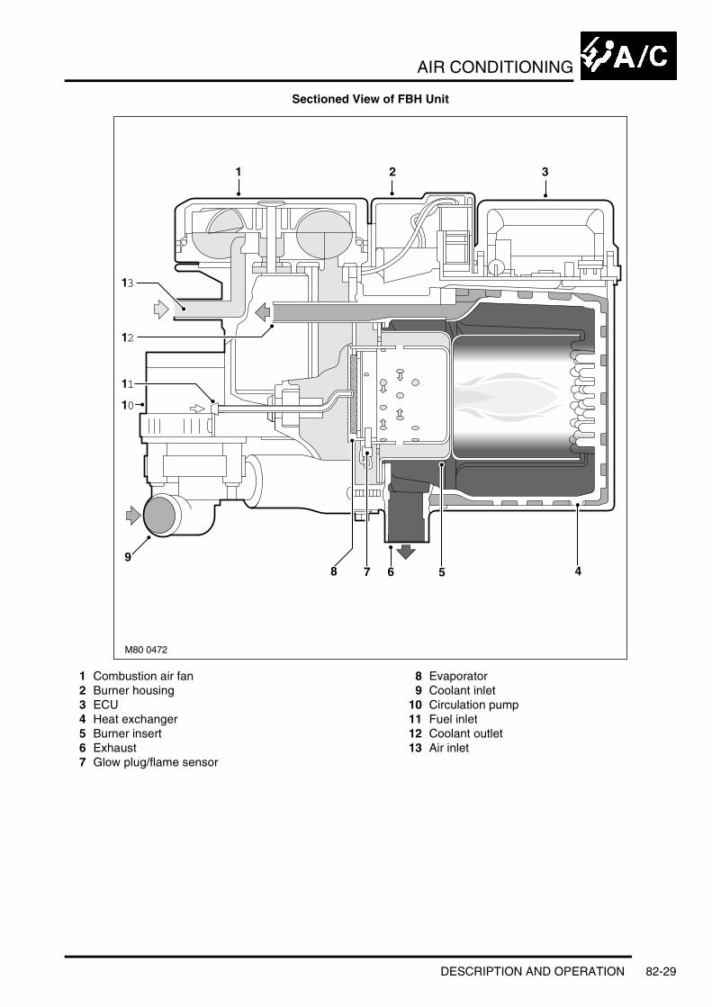
AIR CONDITIONING
Sectioned View of FBH Unit
1 Combustion air fan2 Burner housing3 ECU4 Heat exchanger5 Burner insert6 Exhaust7 Glow plug/flame sensor
8 Evaporator9 Coolant inlet
10 Circulation pump11 Fuel inlet12 Coolant outlet13 Air inlet
M80 0472
1 2
456789
11
12
13
10
3
DESCRIPTION AND OPERATION 82-29

AIR CONDITIONING
The FBH unit consists of:l A circulation pumpl A combustion air fanl A burner housingl An ECU/heat exchangerl An air inlet hosel An exhaust pipel An air inlet filter.
Circulation Pump: The circulation pump is installed at the coolant inlet to the FBH unit to assist the coolant flow through the FBH unit and the heater assembly. The pump runs continuously while the FBH unit is in standby or active operating modes. While the FBH unit is inactive, coolant flow is reliant on the engine coolant pump and the auxiliary coolant pump.
Combustion Air Fan: The combustion air fan regulates the flow of air into the unit to support combustion of the fuel supplied by the FBH pump and to purge and cool the FBH unit. A canister type filter is included in the air inlet supply line to prevent particulates entering and contaminating the FBH unit.
Burner Housing: The burner housing contains the burner insert and also incorporates connections for the exhaust pipe, the coolant inlet from the circulation pump and the coolant outlet to the heater assembly. The exhaust pipe directs exhaust combustion gases to atmosphere through a pipe below the FBH unit.
The burner insert incorporates the fuel combustion chamber, an evaporator and a glow plug/flame sensor. Fuel from the FBH fuel pump is supplied to the evaporator, where it evaporates and enters the combustion chamber to mix with air from the combustion air fan. The glow plug/flame sensor provides the ignition source of the fuel:air mixture and, once combustion is established, monitors the flame.
ECU/Heat Exchanger: The ECU controls and monitors operation of the FBH system. Ventilation of the ECU is provided by an internal flow of air from the combustion air fan. The heat exchanger transfers heat generated by combustion to the coolant. A sensor in the heat exchanger provides the ECU with an input of heat exchanger casing temperature, which the ECU relates to coolant temperature and uses to control system operation. The temperature settings in the ECU are calibrated to compensate for the difference between coolant temperature and the heat exchanger casing temperature detected by the sensor. Typically, as the coolant temperature increases, the coolant will be approximately 7 °C (12.6 °F) hotter than the temperature detected by the sensor; as the coolant temperature decreases, the coolant will be approximately 2 °C (3.6 °F) cooler than the temperature detected by the sensor.
Changeover ValveThe changeover valve is a normally open solenoid valve installed between the supply and return sides of the heater coolant circuit. The changeover valve is located in the engine compartment on the engine bulkhead. When de-energised, the changeover valve connects the heater coolant circuit to the engine coolant circuit. When energised, the changeover valve isolates the heater coolant circuit from the engine coolant circuit.
The changeover valve is controlled by a power feed from the ATC ECU.
FBH ReceiverThe FBH receiver translates the FBH request radio signals, relayed from the antenna receiver, into a voltage output to the FBH unit. When a request for parked heating is received, the FBH receiver outputs a battery power feed to the FBH unit. When a request to switch off parked heating is received, the FBH receiver disconnects the power feed.
The FBH receiver has a permanent power feed from the vehicle battery and is connected to the antenna receiver by a coaxial cable.
82-30 DESCRIPTION AND OPERATION

AIR CONDITIONING
FBH Remote Handset
1 Antenna2 Off button
3 On button4 LED
The remote handset allows parked heating to be remotely controlled up to a minimum of 100 m (328 ft) from the vehicle. On and off buttons activate and de-activate parked heating, a red LED illuminates to indicate when parked heating is active and when the on/off signals have been received by the vehicle. The remote handset is powered by two serviceable 1.5 V batteries located under a cover on the rear of the handset.
FBH Remote Handset Battery Replacement
M82 0835
4
1
23
M82 0836
DESCRIPTION AND OPERATION 82-31
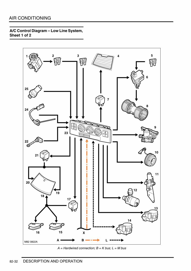
AIR CONDITIONING
DESCRIPTION AND OPERATIONA/C Control Diagram – Low Line System, Sheet 1 of 2
A = Hardwired connection; B = K bus; L = M bus
M82 0822A
X
1 2 3 5
6
10
9
11
13
22
24
25
23
8
12
A B
14
4
7
L
1516
18
20
19
21
17
82-32 DESCRIPTION AND OPERATION

AIR CONDITIONING
1 Ignition switch2 Fuse 34, passenger compartment fusebox3 Fuse 12, passenger compartment fusebox4 HRW5 Fuse 64, passenger compartment fusebox6 Blower output stage7 HRW relay8 Blower9 Coolant valve
10 Compressor clutch11 Changeover valve12 Auxiliary coolant pump13 Fresh/Recirculated air flaps motor14 Air distribution motor15 LH washer jet16 RH washer jet17 Washer jet heater relay18 Wiper park heater19 Windscreen LH heater20 Windscreen RH heater21 Windscreen heater relay22 Heater temperature sensor23 ATC ECU24 Evaporator temperature sensor25 Refrigerant pressure sensor
DESCRIPTION AND OPERATION 82-33

AIR CONDITIONING
A/C Control Diagram – Low Line System, Sheet 2 of 2
A = Hardwired connection; B = K bus; C = Diagnostic DS2 bus; D = CAN bus; F = RF transmission; K = I bus; M = P bus
M82 0827B
16
6
7
8
10
9
12
13 11
15
14
X
A BA
KF
B
D
C
1
2
4 5
3
M
82-34 DESCRIPTION AND OPERATION

AIR CONDITIONING
1 BCU2 Passenger door module3 Passenger door mirror4 Drivers door module5 Drivers door mirror6 FBH unit7 FBH receiver8 Remote handset9 RH side window antenna
10 Antenna amplifier11 Diagnostic socket12 Multi function display13 Multi information display14 Steering wheel recirculation switch15 Instrument pack16 ECM
DESCRIPTION AND OPERATION 82-35

AIR CONDITIONING
A/C Control Diagram – High Line System, Sheet 1 of 2
A = Hardwired connection; B = K bus; L = M bus
M82 0821A
X
AutoPROG
MAX
3031
3
4 56
7 8
9
11
12
10
14
17
1325
26
16
28
29
27
15
A B L
12
1819
22
23
21
24
20
82-36 DESCRIPTION AND OPERATION
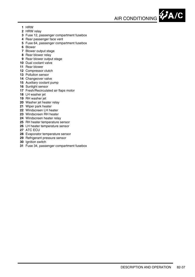
AIR CONDITIONING
1 HRW2 HRW relay3 Fuse 12, passenger compartment fusebox4 Rear passenger face vent5 Fuse 64, passenger compartment fusebox6 Blower7 Blower output stage8 Rear blower relay9 Rear blower output stage
10 Dual coolant valve11 Rear blower12 Compressor clutch13 Pollution sensor14 Changeover valve15 Auxiliary coolant pump16 Sunlight sensor17 Fresh/Recirculated air flaps motor18 LH washer jet19 RH washer jet20 Washer jet heater relay21 Wiper park heater22 Windscreen LH heater23 Windscreen RH heater24 Windscreen heater relay25 RH heater temperature sensor26 LH heater temperature sensor27 ATC ECU28 Evaporator temperature sensor29 Refrigerant pressure sensor30 Ignition switch31 Fuse 34, passenger compartment fusebox
DESCRIPTION AND OPERATION 82-37

AIR CONDITIONING
A/C Control Diagram – High Line System, Sheet 2 of 2
A = Hardwired connection; B = K bus; C = Diagnostic DS2 bus; D = CAN bus; F = RF transmission; K = I bus; L = M bus; M = P bus
M82 0826B
1
3
4
5
6
7
12
11
8
10
9
14
1513
2
16
X
L
A
K
B C D
17
19 18
2120
MF
82-38 DESCRIPTION AND OPERATION

AIR CONDITIONING
1 ECM2 Instrument pack3 Windscreen distribution motor4 Face level distribution motor5 Footwell distribution motor6 Rear face level temperature blend motor7 Ram air motor8 Remote handset9 RH side window antenna
10 Antenna amplifier11 FBH receiver12 FBH unit13 Diagnostic socket14 Multi function display15 Multi information display16 Steering wheel recirculation switch17 BCU18 Drivers door module19 Passenger door module20 Passenger door mirror21 Drivers door mirror
DESCRIPTION AND OPERATION 82-39

AIR CONDITIONING
Operation
GeneralBoth the low and high line systems operate on the reheat principle. The air entering the heater assembly is cooled to a constant value by the evaporator and then reheated as necessary by the heater matrix to produce the temperature(s) selected on the control panel.
To determine the various system settings, the ATC ECU derives a reference value (called the Y factor) from:l The temperature setting on the control panell The ambient temperaturel The in-car temperature.
The reference value is measured in %, where –27.5% means maximum cooling is required and 100% means maximum heating is required. On the high line system, separate reference values are produced for the LH and RH sides of the heater assembly.
On both the low and high line systems the reference value is used for temperature control. On the high line system the driver's side reference value is also used for flap positioning and blower speed calculations.
When the ignition is turned off the ATC ECU memorises the system settings and resumes the same settings the next time the ignition is switched on.
Compressor ControlThe compressor is engaged by pressing either the automatic mode switch, defrost switch, A/C switch or maximum A/C switch. To prevent a dip in engine speed when the engine is at idle, a time delay of approximately 0.5 second is built into the compressor engagement process. The time delay allows the ECM to increase throttle angle and fuelling in anticipation of the additional load on the engine when the compressor engages.
When it receives an input to engage the compressor, the ATC ECU sends a message to the ECM, via the K bus, instrument pack and CAN bus, to advise that it wants to engage the compressor. Provided there are no engine management problems, the ECM responds by increasing throttle angle and fuelling and sending a message granting the request to the ATC ECU over the CAN bus, instrument pack and K bus. When it receives the grant message, the ATC ECU energises the compressor clutch provided the following conditions exist:l Engine speed is more than 400 rev/minl Evaporator temperature is more than 3 °C (37 °F)l The refrigerant pressure is within limitsl Battery voltage is less than 16 Vl The blower is runningl There are no faults detected by the ATC ECU.
The compressor remains engaged until selected off or the required conditions no longer exist. If the evaporator temperature decreases to approximately 2 °C (36 °F) the compressor is disengaged, then re-engaged when the evaporator temperature increases to more than 3 °C (37 °F) again. If battery voltage exceeds 16 V for more than 5 seconds the compressor is disengaged, then re-engaged when voltage decreases to less than 15.8 V.
The compressor can also be disengaged by the ECM changing the grant message to a negative value or outputting a hardwired signal direct to the ATC ECU. Changing the grant message involves a time delay of up to 4 seconds before the ATC ECU de-energises the compressor clutch. The time delay allows the ECM to decrease throttle angle and fuelling, in anticipation of the reduction in engine load when the compressor disengages, to prevent a sudden increase in engine speed if the engine is at idle. The hardwired signal is used to obtain instant disengagement of the compressor to ensure maximum acceleration when accelerator pedal demand suddenly goes from no load to full load. When this occurs the ECM sends a 12 V signal on a hardwired connection direct to the ATC ECU. When it receives the signal the ATC ECU immediately de-energises the compressor clutch.
82-40 DESCRIPTION AND OPERATION

AIR CONDITIONING
Engine Idle Speed ControlThe ATC ECU signals the ECM to increase engine idle speed settings if a high current application is switched on or if low battery voltage is detected. The signal consists of a message transmitted via the K bus, instrument pack and CAN bus, and increases idle speed between 100 and 200 rev/min. The ATC ECU requests the engine idle speed increase when the following high current applications are switched on:l Rear window heaterl Blower, at speed 6 or 7l Headlamp main beam.
The engine idle speed increase is also requested if battery voltage decreases to less than 11.4 V. The speed increase request is discontinued when battery voltage increases to more than 12.2 V again.
Engine Cooling Fan ControlThe engine's electric cooling fan is controlled by the ECM. When the compressor is engaged the ATC ECU sends a fan speed message between 0 (off) and 15 (maximum speed) to the ECM, via the K bus, instrument pack and CAN bus. The ATC ECU requests the cooling fan on when:l The vehicle speed is less than 44 mph (70 km/h)l There is no fault with the compressor clutch circuitl Battery voltage is less than 16 V.
The fan speed requested depends on the pressure in the refrigerant system. The higher the pressure the faster the fan speed that is requested. When vehicle speed increases to more than 50 mph (80 km/h) the ATC ECU changes the fan speed request to 0 until vehicle speed decreases to less than 44 mph (70 km/h) again.
If battery voltage increases to more than 16 V for 5 seconds the ATC ECU changes the fan speed to 0 until the voltage decreases to less than 15.8 V.
Temperature ControlTo determine the amount of heat required, in the form of coolant flow through the heater, the ATC ECU compares the reference value with the heater matrix temperature and incorporates a correction factor to compensate for changes of coolant flow rate with engine speed. From the resultant value the ATC ECU determines the open duration of the coolant valve and outputs the appropriate control signal. On the high line system, separate values and output signals are generated for each coolant valve to produce the individual temperature control for the LH and RH sides of the passenger compartment.
When the temperature setting on the control panel is set to maximum, the ATC ECU signals the coolant valve to remain open. When the temperature setting on the control panel is set to minimum, the ATC ECU signals the coolant valve to remain closed.
On the high line system, the minimum setting is over-ridden when the defrost programme, maximum A/C, rest heating or FBH functions are selected.
DESCRIPTION AND OPERATION 82-41

AIR CONDITIONING
Heater Coolant Circuit - Without FBH
1 Coolant valve (low line system)2 Heater matrix3 Coolant valves (high line system)
4 Auxiliary coolant pump5 Engine cooling system6 ATC ECU
Flap Control – Low Line SystemWhile the ignition is on, the position of the recirculation flaps is manually controlled by selection of the recirculation switch on the control panel and the steering wheel switch. If the recirculation flaps are in the recirculation position when the ignition is switched off, the ATC ECU automatically sets them to the fresh air position, to ensure that fresh air is available if a fault occurs with the recirculation flap drive circuit at the next ignition on.
The positions of the distribution flaps are manually controlled by selection of the distribution rotary switch on the control panel. The flaps are also automatically positioned by the ATC ECU to open the:l Windscreen and footwell outlets, when parked heating is initiated by the FBHl Face and footwell outlets, when parked ventilation is initiatedl Windscreen outlets, when the ignition is switched off and the ambient temperature is less than 0 °C, or
windscreen and footwell outlets when the ignition is switched off and the ambient temperature is 0 °C and above.
M82 0819
5 24
3
2
1
6
82-42 DESCRIPTION AND OPERATION

AIR CONDITIONING
Flap Control – High Line SystemThe position of the ram air flaps is automatically controlled by the ATC ECU. The positions of the recirculation flaps and the distribution flaps are either automatically controlled by the ATC ECU or manually controlled by the related switches.
Ram Air FlapsThe ATC ECU progressively closes the ram air flaps, in four steps, as vehicle speed increases, and opens them again as vehicle speed decreases. At the maximum closed position, 90% of the fresh air inlet area is closed off. A hysteresis of 9 mph (15 km/h) prevents the ram air flaps from hunting at a constant vehicle speed.
Ram Air Flap Positions
A = Flap position, % open; B = Opening speeds, mph (km/h); C = Closing speeds, mph (km/h)
M82 0816
0
20
40
60
80
100
28(45)
47(75)
63(100)
91(145)
38(60)
100(160)
56(90)
72(115)
AB
C
DESCRIPTION AND OPERATION 82-43
AIR CONDITIONING
Recirculation FlapsUnless the recirculation flaps are manually selected closed, using the recirculation switch on the control panel or the steering wheel switch, they are normally open, but automatically closed by the ATC ECU under certain conditions.
Rapid Cooling: For rapid cooling of the passenger compartment, when the A/C system is selected on, if the driver's side reference value is less than –20% and the ambient temperature is more than 6 °C (43 °F), the ATC ECU closes the recirculation flaps. The ATC ECU opens the recirculation flaps after 12 minutes (temperate climates) or 20 minutes (hot climates), if the driver's side reference value increases to more than –5% or if the ambient temperature decreases to 6 °C (43 °F).
Pollution: When the ATC ECU detects a high level of pollutants, it sets the recirculation flaps to the recirculation position for:l 3 minutes if the A/C system is in the heating model 10 minutes if the A/C system is in the cooling mode.
After the recirculation time period, the ATC ECU returns the recirculation flaps to the fresh air position. After 1 minute, if the pollutants are still present, the ATC ECU repeats the recirculation cycle.
Ignition Off: If the recirculation flaps are in the recirculation position when the ignition is switched off, the ATC ECU automatically sets them to the fresh air position, to ensure that fresh air is available if a fault occurs with the recirculation flap drive circuit at the next ignition on. When the ignition is switched on, the ATC ECU sets the recirculation flaps to the position they were in at ignition off.
Distribution FlapsWhen a manual distribution selection is made on the control panel, the ATC ECU moves the distribution flaps to preset positions. When the system is in the automatic mode, the ATC ECU uses maps of the driver's side reference value to determine the position of the distribution flaps. Each distribution flap has a separate map, and there are separate maps for temperate and hot climates. The mapped positions of the face level distribution flaps are given a correction factor from the sunlight sensor inputs. The mapped positions of the distribution flaps are overridden by special programmes, as follows:
Condensation Prevention: To prevent condensation on the windscreen, the ATC ECU closes the windscreen flaps for 12 seconds each time the engine starts. If a manual distribution selection is made during the 12 seconds, the windscreen flaps revert to normal control.
The ATC ECU also closes the windscreen flaps when the reference value is less than 90% with the recirculation flaps closed and the compressor is disengaged.
Cold Start: When the engine starts, if the system is in the automatic mode, the driver's side reference value is 100% and the heater matrix temperatures is less than 30 °C (86 °F), the ATC ECU closes the face level and footwell flaps and opens the windscreen flaps.
Duct Purging: After a cold start, if the system is in the automatic mode and the reference value is 100%, the ATC ECU keeps the face level flaps closed until one of the heater matrix temperatures exceeds 60 °C (140 °F). The ATC ECU then fully opens the face level flaps for 25 seconds to purge the ducts of cold air. After the purge the face level flaps revert to normal automatic control. If, before or during the purge process, the reference value decreases below 100%, the ignition has been on for 15 minutes, or a manual distribution selection is made, then the purge process is cancelled.
Blower ControlIn the automatic mode, blower speed is determined from reference temperature maps. In general terms, the more heating or cooling required to achieve the temperature selected on the control panel with the driver's side temperature switch, the faster the blower speed.
When maximum cooling is first required in the automatic mode, the ATC ECU runs the blower at full speed for a fixed period regardless of any drop in passenger compartment temperature. Different time periods are incorporated for the following markets:l NAS and Gulf Statesl Europe and ROWl Japan.
82-44 DESCRIPTION AND OPERATION

AIR CONDITIONING
NAS and Gulf States have the longest time period with the blower at full speed and Japan the shortest. TestBook/T4 can be used to change the market setting so, in some cases, if a customer complains of the duration the blower runs at full speed, changing the market setting could resolve the complaint.
When heating is required, blower speed is reduced if the engine is cold and then progressively increased to the nominal setting as the engine coolant temperature increases from 20 to 50 °C (68 to 122 °F).
On the high line system, blower speed is also influenced by the sunlight sensor. At high light levels blower speed will increase to increase the cooling effect.
When the blower is selected off temperature regulation is no longer possible so the ATC ECU disengages the compressor, de-energises the auxiliary water pump and closes the coolant valves. Pressing any of the A/C system switches restores blower operation and activates the required function. If the blower is selected off when the ignition is switched off, the blower remains off if the ignition is switched on again within 15 minutes. If more than 15 minutes elapses between the ignition being switched off and back on again, the ATC ECU switches the blower on at speed 1.
If battery voltage is low the ATC ECU reduces blower speed to conserve power. If battery voltage decreases to less than 12 V, the ATC ECU decreases the blower signal voltage, and thus the voltage to the blower motor, in direct proportion to the reduction in battery voltage.
Defrost Programme (High Line System Only)When the defrost programme is selected the ATC ECU:l Opens the windscreen distribution flaps and closes the face and footwell flapsl Sets the recirculation flaps to the fresh air positionl Runs the blower at speed 7l Activates the A/C compressorl Activates the rear window heaterl Activates the windscreen heater (where fitted).
When the ambient temperature is 10 °C (50 °F) and below, the ATC ECU signals the coolant valves to remain open. When the ambient temperature is more than 10 °C (50 °F), the ATC ECU checks the existing heater matrix temperature and, if necessary, increases the open time of the coolant valves to produce a minimum heater matrix temperature of 30 °C (86 °F).
The defrost programme is cancelled by pressing the defrost switch again, or pressing the automatic, A/C or maximum A/C switches
Maximum A/C (High Line System Only)Pressing the maximum A/C switch while the engine is running and the ambient temperature is more than 7 °C (45 °F) provides the maximum cooling possible from the system to cool the passenger compartment down as rapidly as possible. When maximum A/C is selected the coolant valves are held closed, the A/C compressor is engaged, the blower speed is set to maximum and the recirculation flaps are set to the recirculation position. After 12 minutes the recirculation flaps will be set to fresh air for 1 minute then returned to the recirculation position.
The maximum A/C function is cancelled when any of the other A/C system switches are pressed.
Rest Heating (High Line System Only)When the engine is not running, pressing the maximum A/C switch activates the rest heating function to heat the passenger compartment with residual heat from the engine. The rest heating function activates provided the following conditions exist:l It is less than 15 minutes since the ignition was selected offl Ambient temperature is less than 15 °C (59 °F)l On the previous ignition cycle engine temperature exceeded 70 °C (158 °F)l Battery voltage is 11.4 V minimum.
To provide the rest heating function, the ATC ECU activates the auxiliary coolant pump, coolant valves, control flap and blower. The ATC ECU regulates the temperature (to the driver setting selected before the ignition was switched off), opens the face level distribution flaps and runs the blower at speed 4.
The rest heating function is cancelled after 15 minutes or when:l The maximum A/C switch is pressed againl The ignition is selected onl Battery voltage decreases to less than 11 V.
DESCRIPTION AND OPERATION 82-45

AIR CONDITIONING
Rear Passenger Face Level Air (High Line System Only)The volume and temperature of the air from the rear passenger face vent are adjusted with the thumbwheels at the sides of the vent assembly. Each thumbwheel operates a variable potentiometer connected to the ATC ECU. The volume thumbwheel controls stepless changes of rear blower speed between off and full speed. The temperature thumbwheel controls the position of the rear passenger face level blend flap in the heater assembly when the driver's side reference temperature is more than 0%.
Volume Control: The volume potentiometer outputs between 0 and 5 V to the ATC ECU. The ATC ECU translates the voltage from the potentiometer into a signal voltage for the output stage in the rear blower. Potentiometer voltages of less than 1.25 V are interpreted as a blower off selection and translate into a signal voltages less than 0.1 V. Potentiometer voltages between 1.25 and 5 V are translated into proportional signal voltages between 0.1 and 5 V.
The ATC ECU automatically switches off the rear blower when:l The defrost programme is activel The main blower is selected offl The engine cranksl The ignition is selected off (the rear blower remains off during rest heating, parked heating and parked
ventilation).
Temperature Control: The temperature potentiometer outputs between 0 and 5 V to the ATC ECU. The ATC ECU translates the voltage from the potentiometer into a blend flap position between 0% (cold) and 100% (hot) and outputs the appropriate control signal on the M bus to the blend flap motor. Potentiometer voltages of less than 1.5 V translate to a blend flap position of 0%. Potentiometer voltages of more than 3.4 V translate to a blend flap position of 100%. Potentiometer voltages between 1.5 and 3.4 V translate linearly to blend flap positions between 0 and 100%.
Windscreen Heater (Where Fitted)When the engine is running and the windscreen heater is selected on, the ATC ECU illuminates the LED above the switch and energises the heated front screen relay attached to the passenger end of the fascia cross tube. If not already active, the ATC ECU also activates the A/C compressor and the blower, and sets air distribution to windscreen. After 10 minutes (when ambient temperature is –15 °C (5 °F) or above) or 17 minutes (when ambient temperature is less than –15 °C (5 °F)), the ATC ECU extinguishes the LED and de-energises the heated front screen relay. After the heater times out or is switched off, the timer in the ATC ECU is reset to zero.
Rear Window HeaterWhen the engine is running and the rear window heater is selected on, the ATC ECU illuminates the LED above the switch and energises the rear window heater relay on the rear fusebox. After 10 minutes (when ambient temperature is –15 °C (5 °F) or above) or 17 minutes (when ambient temperature is less than –15 °C (5 °F)), the ATC ECU extinguishes the LED and operates the rear window heater at low power for 60 minutes. During the 60 minutes, the ATC ECU cycles the rear window heater relay off for 80 seconds and on for 40 seconds. If the rear window heater switch is pressed again during the low power phase, the ATC ECU illuminates the LED again and returns the rear window heater to full power by keeping the rear window heater relay energised for 5 minutes. At the end of the 5 minutes the LED is extinguished and the 60 minutes low power phase is repeated.
The ATC ECU outputs a K bus message when the rear window heater is active. The message allows the navigation computer to compensate for the effect of the magnetic field generated when the rear window heater is active. The BCU transfers the message onto the P bus for the door modules, which activate the door mirror heaters together with the rear window heater.
Washer Jet HeatersThe ATC ECU automatically energises the washer jets relay, on the passenger compartment fusebox, when the ignition is on and the ambient temperature is less than 3 °C (37 °F). If the ambient temperature increases to more than 6 °C (43 °F), the ATC ECU de-energises the washer jets relay.
Parked VentilationParked ventilation is only incorporated on vehicles with a FBH system which include the parked heating function.
When the ignition switch is in position I, parked ventilation can be selected on and off using the MID or MFD. When the ignition is off, parked ventilation can be set to come on at a programmed time. The programmed time is a start time for parked ventilation to begin within the next 24 hours and is entered into the instrument pack using the MID/MFD.
82-46 DESCRIPTION AND OPERATION

AIR CONDITIONING
Once parked ventilation is on, if it is not selected off it will automatically time-out after 30 minutes. Parked ventilation is automatically cancelled when the ignition is switched on.
At a programmed parked ventilation start time, or when parked ventilation is selected on using the MID/MFD, the instrument pack outputs parked ventilation requests to:l The MID/MFD on the I busl The ATC ECU on the K bus.
On receipt of the messages:l A red LED on the MID/MFD panel flashes at 2 Hz to indicate that parked ventilation is activel The ATC ECU operates the blower at speed 1, opens the face level distribution flaps in the heater assembly and
closes the windscreen and footwell flaps.
The ATC ECU disables parked ventilation if battery voltage is less than 11.4 V.
FBH SystemThe FBH system operates in two modes:l Parked heating, to heat the passenger compartment while the vehicle is parked with the engine offl Additional heating, to boost heater performance while the engine is running
The ATC ECU disables FBH operation if battery voltage is too low.l When the engine is off the low voltage limit is 11.4 V for more than 10 seconds; the system is re-enabled if battery
voltage increases to 12.2 Vl When the engine is running the low voltage limit varies, with ambient temperature, between 11.1 V at –25 °C and
below and 11.7 V at 15 °C and above; if battery voltage is below the limit for 2 minutes the system is disabled for the remainder of the ignition cycle.
During FBH operation, with or without the engine running, the coolant valves remain de-energised and heater matrix temperature is directly related to the temperature of the coolant coming from the FBH unit.
Parked HeatingWhen the ignition switch is in position I, parked heating can be selected on and off using the MID or MFD. When the ignition is off, parked heating can be set to come on at a programmed time or selected on and off using the remote handset. The programmed time is a start time for parked heating to begin within the next 24 hours and is entered into the instrument pack using the MID/MFD.
Once parked heating is on, if it is not selected off it will automatically time-out after 30 minutes. If the engine is started while parked heating is on:l If the engine coolant temperature is equal to or more than the heater coolant temperature, parked heating is
switched offl If the engine coolant temperature is less than the heater coolant temperature, parked heating remains on until
the engine coolant temperature reaches the heater coolant temperature.
Programmed and MID/MFD Selected Parked Heating
At a programmed parked heating start time, or when parked heating is selected on using the MID/MFD, the instrument pack outputs:l A FBH request to the MID/MFD on the I busl A FBH request to the ATC ECU and the Body Control Unit (BCU) on the K busl Ambient and engine temperatures to the ATC ECU and BCU on the K bus.
On receipt of the messages:l A red LED on the MID/MFD panel flashes at 2 Hz to indicate that parked heating is active.l If the ambient temperature is less than 5 °C (41 °F), the BCU activates the door mirror heaters for 3 minutesl The ATC ECU:
l Energises the changeover valvel Sends a K bus message to activate the FBHl Operates the blower at speed 1l Opens the windscreen distribution flaps in the heater assembly and closes the face and footwell flaps.
DESCRIPTION AND OPERATION 82-47
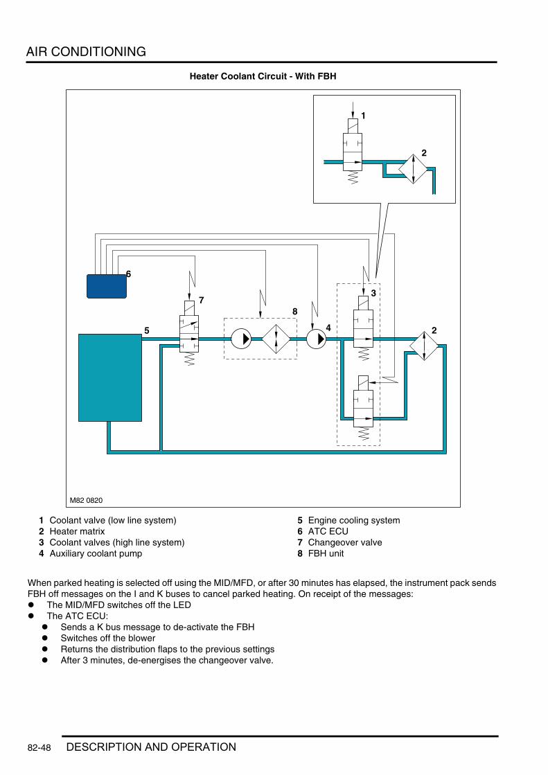
AIR CONDITIONING
Heater Coolant Circuit - With FBH
1 Coolant valve (low line system)2 Heater matrix3 Coolant valves (high line system)4 Auxiliary coolant pump
5 Engine cooling system6 ATC ECU7 Changeover valve8 FBH unit
When parked heating is selected off using the MID/MFD, or after 30 minutes has elapsed, the instrument pack sends FBH off messages on the I and K buses to cancel parked heating. On receipt of the messages:l The MID/MFD switches off the LEDl The ATC ECU:
l Sends a K bus message to de-activate the FBHl Switches off the blowerl Returns the distribution flaps to the previous settingsl After 3 minutes, de-energises the changeover valve.
M82 0820
5
6
78
3
2
1
2
4
82-48 DESCRIPTION AND OPERATION

AIR CONDITIONING
Remotely Selected Parked Heating
When parked heating is selected on with the remote handset, the request is received by the FBH receiver via the TV antenna and TV receiver. The FBH receiver relays the request as a hardwired signal to the FBH ECU. On receipt of the request, the FBH ECU sends a FBH on request to the ATC ECU on the K bus. Provided there are no system faults, the ATC ECU then:l Returns a FBH on request to the FBH ECU, which starts FBH operationl Energises the changeover valvel Operates the blower at low speedl Opens the windscreen distribution flaps in the heater assembly and closes the face and footwell flapsl Transmits the FBH status on the K bus to the instrument pack.
When the instrument pack receives the FBH status message, it outputs:l A FBH request to the MID/MFD on the I bus to operate the flashing LED on the MID/MFD panell Ambient and engine temperatures to the ATC ECU and BCU on the K busl A FBH request to the BCU on the K bus. If the ambient temperature is less than 5 °C (41 °F), the BCU activates
the door mirror heaters for 3 minutes.
Additional HeatingOn Td6 models, additional heating reduces the heater warm-up time and is also used to maintain heater performance throughout the drive cycle. On V8 models, additional heating is only used to reduce the heater warm-up time at the beginning of the drive cycle, and only occurs if parked heating is already active when the engine starts.
The ATC ECU activates the additional heating mode when the engine is running and the following conditions coexist:l The ambient temperature is less than 5 °C (41 °F)l The engine coolant temperature is less than 75 °C (167 °F)l The heater coolant temperature is less than 75 °C (167 °F)l The reference temperature is 100%l The blower is on.
To activate the additional heating mode, the ATC ECU energises the auxiliary coolant pump and sends K bus messages to the FBH unit to start/continue operation (the changeover valve remains de-energised).
The ATC ECU stops the FBH and de-energises the auxiliary coolant pump when any of the following occur:l The engine stopsl The ambient temperature increases to more than 15 °C (59 °F)l The engine coolant temperature increases to more than 75 °C (167 °F)l The heater coolant temperature increases to more than 75 °C (167 °F)l The reference temperature decreases to less than 90%l The blower is selected off.
FBH UnitOnce initiated by a message from the ATC ECU, FBH operation is controlled by the ECU in the FBH unit. The ECU controls the FBH unit at one of two heat output levels, 2.5 kW at part load combustion and 5 kW at full load combustion.
Start Sequence: At the beginning of the start sequence the ECU energises the glow plug function of the glow plug/flame sensor, to preheat the combustion chamber, starts the combustion air fan at slow speed and energises the coolant circulation pump. After approximately 30 seconds, the ECU energises the FBH fuel pump at the starting sequence speed. The fuel delivered by the FBH fuel pump evaporates in the combustion chamber, mixes with air from the combustion air fan and is ignited by the glow plug/flame sensor. The ECU then progressively increases the speed of the FBH fuel pump and the combustion air fan. Once combustion is established the ECU switches the glow plug/flame sensor from the glow plug function to the flame sensing function to monitor combustion. From the beginning of the start sequence to stable combustion takes approximately 90 seconds for a start to part load combustion and 150 seconds for a start to full load combustion.
DESCRIPTION AND OPERATION 82-49
AIR CONDITIONING
Coolant Temperature Control: When the ECU first enters the active mode, it initiates a start to full load combustion. Full load combustion continues until the heat exchanger casing temperature reaches 72 °C (162 °F), at this point the ECU decreases the speed of the FBH fuel pump and the combustion air fan to half speed, to produce part load combustion. The ECU maintains part load combustion while the heat exchanger casing temperature remains between 68 and 76 °C (154 °C and 169 °F). If the heat exchanger casing temperature decreases to 68 °C (154 °F), the ECU switches the system to full load combustion again. If the heat exchanger casing temperature increases to 76 °C (169 °F), the ECU enters a control idle phase of operation.
On entering the control idle phase, the ECU immediately switches the FBH fuel pump off, to stop combustion, and starts a timer for the combustion air fan. After a 2 minute cool down period, the ECU switches the combustion air fan off and then remains in the control idle phase while the heat exchanger casing temperature remains above 71 °C (160 °F). If the heat exchanger casing temperature decreases to 71 °C (160 °F), within 15 minutes of the ECU entering the control idle phase, the ECU initiates a start to part load combustion. If more than 15 minutes elapse before the heat exchanger casing temperature decreases to 71 °C (1608 °F), the ECU initiates a start to full load combustion.
In order to limit the build up of carbon deposits on the glow plug/flame sensor, the ECU also enters the control idle phase if the continuous part and/or full load combustion time exceeds 72 minutes. After the cool down period, if the heat exchanger casing is still in the temperature range that requires additional heat, the ECU initiates an immediate restart to part or full load combustion as appropriate.
Shutdown: When the ATC ECU sends a K bus message to de-activate the FBH operation, the ECU de-energises the FBH fuel pump to stop combustion, but continues operation of the combustion air fan and the circulation pump to cool down the FBH unit. The cool down time depends on the combustion load at the time the message is received.
Cool Down Times
Diagnostics: The ECU monitors the FBH system for faults. Any faults detected are stored in a volatile memory in the ECU, which can be interrogated by Testbook/T4. A maximum of three faults and associated freeze frame data can be stored at any one time. If a further fault is detected, the oldest fault is overwritten by the new fault.
The ECU also incorporates an error lockout mode of operation that inhibits system operation to prevent serious faults from causing further damage to the system. In the error lockout mode, the ECU immediately stops the FBH fuel pump, and stops the combustion air fan and circulation pump after a cool down time of approximately 2 minutes. Error lockout occurs for start sequence failures and/or combustion flameouts, heat exchanger casing overheat and out of limit input voltage. The error lockout mode can be cleared using Testbook, or by disconnecting the battery power supply for a minimum of 10 seconds.
Start Failure/Flameout: If a start sequence fails to establish combustion, or a flameout occurs after combustion is established, the ECU immediately initiates another start sequence. The start failure or flameout is also recorded by an event timer in the ECU. The event timer is increased by one after each start failure or flameout, and decreased by one if a subsequent start is successful. If the event timer increases to three (over any number of drive cycles), the ECU enters the error lockout mode.
Heat Exchanger Casing Overheat: To protect the system from excessive temperatures, the ECU enters the error lockout mode if the heat exchanger casing temperature exceeds 105 °C (221 °F).
Out of Limit Voltage: The ECU enters the error lockout mode if the battery or alternator power input is less than 10.5 ± 0.3V for more than 20 seconds, or more than 15.5 ± 0.5V for more than 6 seconds.
Combustion Load Cool Down Time, SecondsPart 100Full 175
82-50 DESCRIPTION AND OPERATION

WIPERS AND WASHERS
Deze pagina werd opzettelijk niet gebruikt
Cette page est intentionnellement vierge
Questa pagina è stata lasciata in bianco di proposito
Diese Seite ist leer
Esta página foi deixada intencionalmente em branco
Esta página fue dejada en blanco intencionalmente
This page is intentionally left blank
WIPERS AND WASHERSDESCRIPTION AND OPERATION
DESCRIPTION AND OPERATION 84-1

WIPERS AND WASHERS
Wiper and Washer System Component Location
RH drive specification shown, LH drive similar
84-2 DESCRIPTION AND OPERATION

WIPERS AND WASHERS
1 Wiper linkage and motor assembly2 Wiper arm assembly RH3 Wiper arm assembly LH4 Rear wiper, motor and control module
assembly5 Wiper control switch6 Rain sensor7 Body Control Unit (BCU)8 Headlamp wiper relay9 Front wiper relay
10 Washer reservoir and pumps assembly11 Headlamp wiper and motor assembly12 Washer jet (2 off)
DESCRIPTION AND OPERATION 84-3

WIPERS AND WASHERS
Wipers and Washers Control Diagram
A = Hardwired; B = K Bus; C = Diagnostic DS2 Bus; K = I Bus
M84 0413A
1819
9
6
7
3
25
24
23
22
21
20
4
2
1011
13
15
16
17
12
14
CA B K
5
8
1
84-4 DESCRIPTION AND OPERATION
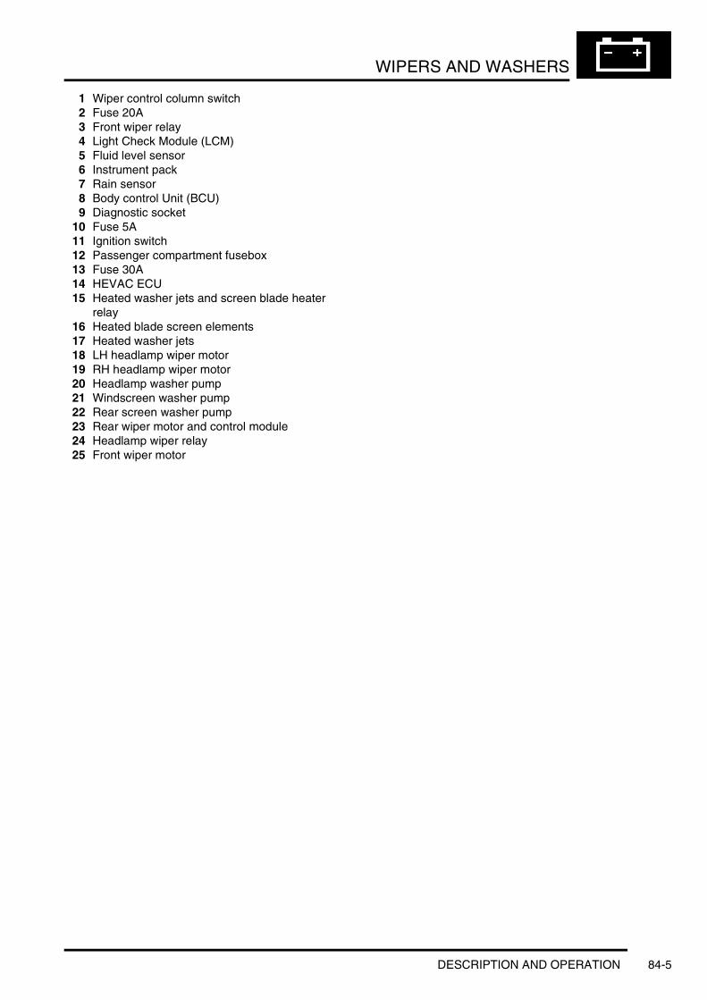
WIPERS AND WASHERS
1 Wiper control column switch2 Fuse 20A3 Front wiper relay4 Light Check Module (LCM)5 Fluid level sensor6 Instrument pack7 Rain sensor8 Body control Unit (BCU)9 Diagnostic socket
10 Fuse 5A11 Ignition switch12 Passenger compartment fusebox13 Fuse 30A14 HEVAC ECU15 Heated washer jets and screen blade heater
relay16 Heated blade screen elements17 Heated washer jets18 LH headlamp wiper motor19 RH headlamp wiper motor20 Headlamp washer pump21 Windscreen washer pump22 Rear screen washer pump23 Rear wiper motor and control module24 Headlamp wiper relay25 Front wiper motor
DESCRIPTION AND OPERATION 84-5

WIPERS AND WASHERS
Description
GeneralThe wipers and washers system is controlled by the Body Control Unit (BCU) on receipt of requests made by the driver or the rain sensor unit (if fitted). All wiper functions for the front and rear wipers are controlled from a multifunction wash/wipe switch assembly located on the right hand side of the steering column.
The wiper and washer system comprises:l Front and rear wiper motorsl A front wiper linkagel Two front and one rear wiper arms and bladesl Two front washer jets and one rear washer jet (incorporated with rear wiper arm)l A washer reservoir and three pumpsl A wash/wipe control column switch.
Other items are added to enhance the wiper system:l Heated front washer jetsl Headlamp wash/wipe systeml A rain sensor for automatic wiper control.
The wiper system can be optionally equipped with a rain sensor. The sensor, located below the interior rear view mirror, detects rain drops on the windscreen and automatically operates the wipers in the intermittent mode. The column stalk switch must be in the intermittent position for rain sensor controlled wiper operation.
The front wiper system has four wiper stages of operation and four intermittent wiper delay periods. The four wiper stages are as follows:l Flick wipel Intermittentl Normal (slow) speed continuousl Fast speed continuous.
The intermittent, normal and fast speeds are affected by road speed. The intermittent wiper delay periods change with the road speed, with the delay decreasing as the road speed increases. The normal continuous operation changes to intermittent operation when the vehicle is stationary. The fast speed operation changes to normal operation when the vehicle is stationary.
The wiper and washers operate with the ignition switch in positions I or II (aux or ign). Wiper functions are suspended during engine cranking to reduce battery power consumption under high load conditions. + BODY CONTROL UNIT, DESCRIPTION AND OPERATION, Description.
Diagnostic information for the wiper system is available and can be retrieved using TestBook/T4.
84-6 DESCRIPTION AND OPERATION

WIPERS AND WASHERS
Wiper Control Column Switch
1 Wash/wipe control column switch2 Intermittent delay rotary control3 Programme wash/wipe position4 Fast wipe position5 Normal wipe position
6 Intermittent wipe position7 Flick wipe position8 Programme wash/wipe position9 Rear wash/wipe position
10 Rear wipe position
The wiper control column switch is located on the right hand side of the steering column and controls all front and rear wiper functions.
Moving the switch up one position selects intermittent front wiper operation. The rotary potentiometer on the stalk selects one of four delay periods. When a rain sensor is incorporated into the system, the intermittent position also initiates wiper operation controlled by the rain sensor. The sensitivity of the rain sensor can be adjusted by rotating the rotary potentiometer to one of the four positions. Moving the switch up one further position selects normal (slow) continuous wiper operation. Moving the switch up to the last position selects fast continuous wiper operation.
Moving the switch down selects the flick wipe function. The front wipers will operate at normal speed for as long as the flick wipe switch position is operated and will stop at the park position when the switch is released.
Moving the switch rearwards, towards the driver, selects the programmed front wash/wipe function. The windscreen washer pump will operate for as long as the switch is held. A short operation operates the pump momentarily and the wipers complete three full cycles before stopping. When headlamp wash/wipe is fitted, the headlamp washers and wipers will operate if programmed wash/wipe is selected and the headlamps are on. The wash/wipe function can also be selected by depressing the button on the end of the stalk.
Moving the switch forwards to the first switch position selects the rear wiper on. The rear wiper will complete one full cycle and will then operate on an intermittent function until selected off. The intermittent delay between wipes can be adjusted by selecting the wiper on, then off and then on again. Moving the switch forward to the second position selects the programmed rear wash/wipe function. The wiper completes five full cycle with three automatic, short operations of the rear washer pump. The rear wiper then operates in the rear wiper on mode until selected off.
The rear wiper also operates continuously if reverse gear is selected and the front wipers are on.
The wiper control column switch comprises 8 switch positions and the intermittent rotary control. The switch positions each complete a combination of earth paths to three connections on the BCU. The BCU interprets the selected combination of switches and operates the respective function accordingly.
DESCRIPTION AND OPERATION 84-7

WIPERS AND WASHERS
Front WipersThe front wiper system comprises:l Wiper motor and linkage assemblyl Washer reservoir and pumpsl Wiper arms and blades.
Wiper Linkage
1 Wiper spindle cap (2 off)2 RH pivot housing assembly3 Link rod4 Tube5 Motor crank6 Link rod7 Crank8 LH pivot housing assembly
9 Bush10 Sleeve11 Bolt12 Sleeve13 Bush14 Motor assembly15 Bracket
The wiper linkage and motor assembly are available as separate components. The wiper linkage differs between LH and RH drive models. The wiper motor is common to LH and RH drive models.
The assembly is located below the plenum grill in the engine compartment and is secured with bushes, sleeves and bolts. The rubber bushes isolate the assembly from the body mountings.
The linkage assembly comprises a main tube, with a pivot housing at each end. A bracket is attached, offset along the tube length, which locates the motor assembly. A motor crank is positively attached to the motor output shaft. A link rod is connected to the motor crank and is connected at the opposite end to the RH pivot housing, via a crank. The RH link rod has a pivot attachment for the LH link rod, which is connected at its opposite end to the RH pivot housing, via a second crank.
The motor crank converts rotary motion from the motor output shaft into linear movement of the link rods. The cranks, connected between the each link rod and pivot housing, convert the linear motion back to rotary motion of the pivot housing. This rotary motion is passed to the wiper arms and blades causing the blades to wipe an arc across the windscreen.
84-8 DESCRIPTION AND OPERATION

WIPERS AND WASHERS
Wiper MotorThe motor assembly comprises a dc motor which drives a gear wheel via a worm drive attached to the motor spindle. The gear wheel has a central spigot which provides the attachment point for the motor crank.
The motor is connected electrically by a four pin connector. The connector supplies two battery voltage feeds to the motor. The motor has three sets of brushes with one brush connected to ground. One feed is direct to the motor brush opposite the ground brush and operates the motor at normal (slow) speed. The second feed is connected to a motor brush which is offset from the ground brush and operates the motor at fast speed. With the power supplied through this brush, the current flows through fewer coil windings. This results in a lower resistance to the current flow to the ground brush and gives a higher motor rotational speed.
Output control of the wiper motor is through a double contact relay. The relay is located in the engine compartment, adjacent to the transfer box ECU, behind the battery. The relay is a tan colour for identification.
The motor has an internal track which signals the BCU when the wipers have reached the park position. The park signal is an open circuit when the wipers are in the park position. When the wipers are switched off and the BCU receives the park position signal from the motor, the BCU shorts the motor via a relay bridge circuit. This short circuit has the effect of applying a brake to the motor, giving precise positioning of the wiper blades in the park position.
Wiper Arms
1 Blade locking clip2 Wiper arm collet3 Wiper arm4 Spindle cap5 Self locking nut
6 Wiper angle adjust shim7 Wiper angle adjuster8 Wiper blade9 Air deflector
DESCRIPTION AND OPERATION 84-9

WIPERS AND WASHERS
The wiper arms are positively located on tapered splines on the wiper linkage spindles. The arm is located on a curved wiper angle adjuster, which mates with the curved underside of the arm attachment. A curved slot in the arm attachment locates an adjustment shim and the three components are retained under compression on the spindle spline by a self locking nut.
The wiper angle adjuster and the angle adjust shim allow the approach angle of the wiper blade to be finely adjusted to its optimum wiping angle. The adjustment allows the approach angle of the blade to adjusted to 2° on each side of the spindle axis. This adjustment provides precise adjustment of the blade approach angle for maximum wiper performance. The wiper angle adjuster is pressed onto the spindle and requires a tool for removal. Once removed, the wiper angle adjuster must be discarded and new one fitted on re-assembly.
The wiper arm has a pivot point, midway between the spindle attachment and the blade. Two tension springs are connected to the wiper arm on each side of the pivot point and apply pressure to maintain the wiper blade in contact with the windscreen.
The wiper blades are attached to the wiper arms with clips that allow the blade to pivot. Each blade comprises a number of levers and yokes to which the rubber wiper blade is attached. The levers and yokes ensure that the pressure applied by the arm tension spring is distributed evenly along the full length of the blade and also allow the blade to adjust to the curvature and contour of the windscreen. The drivers side blade is fitted with an aerofoil which presses the blade onto the windscreen at high speed, improving the wiper performance.
84-10 DESCRIPTION AND OPERATION

WIPERS AND WASHERS
Washer Reservoir and Pumps
1 Breather tube2 Reservoir3 Rear washer pump4 Front washer pump
5 Headlamp washer pump6 Fluid level sensor7 Filler tube and cap
The windscreen washer system comprises a reservoir, a washer pump, two washer jets and hoses.
The plastic, moulded reservoir is located in the LH wheel arch, behind the liner and has a capacity of 8.8 pints (5 litres). It is secured to the body and front panel with bolts and washers. A boss on the reservoir locates in a slot in the front panel and provides additional support.
The reservoir has three recessed holes on its rear face which provide location for the front, rear and headlamp washer pumps. The pumps are push fitted into grommets which seal the pumps in their locations. A hole in the top of the reservoir allows for the fitment of a flexible filler tube. The hose is routed into the left hand side of the engine compartment and is sealed with a rubber cap. A breather hose is fitted into an elbow on the top of the reservoir and is routed alongside the filler and secured in a clip near the filler cap in the engine compartment.
A hole in the base of the reservoir provides the location for the fluid level sensor. The hole provides access to an internal tube in side the reservoir, into which the sensor is fitted. The sensor has two pegs which positively locate the sensor in the reservoir when turned through 90°.
DESCRIPTION AND OPERATION 84-11
WIPERS AND WASHERS
The sensor reacts to the influence of a magnetic field. A float, with integral magnet, is located around the tube, inside the reservoir. The sensor has two contacts, inside a glass tube, which are normally open. When the fluid level reduces, the magnetic float moves down the tube. When the magnet reaches the sensor contacts, the magnetic field closes the contacts. This completed circuit is sensed by the LCM which displays the low fluid level message in the instrument pack.
Heated Windscreen Washer JetsTwo windscreen washer jets are located in the rear trim panel on the bonnet outer surface. The washer fluid feed hose from the front screen pump is connected to a 'Y' piece connector located between the two jets. Two short lengths of hose connect the jets to the 'Y' piece. Each jet contains a non-return valve (NRV) to prevent washer fluid draining back to the reservoir and also to limit the amount of washer fluid which can be forced by gravity from the jet during cornering.
Each washer jet has two ball nozzles which can rotate in their housings to obtain the optimum fluid application onto the windscreen. Each washer jet contains a heater element which prevents the fluid freezing in the nozzles in very cold conditions. The jet heater elements are controlled by the Automatic Temperature Control (ATC) system, which energises the heater elements when the ambient temperature falls below a predetermined temperature.
Wiper Blade HeatingThe lower, black, portion of the windscreen contains six heating elements which run from one side of the screen to the other. These elements are designed to heat the area of the windscreen where the wiper blades rest to prevent freezing in cold conditions.
The blade heating elements are controlled by the ATC system, which energises the blade heating elements when the ambient temperature falls below a predetermined temperature. The operation of the blade heating elements is activated simultaneously with the heated washer jets.
84-12 DESCRIPTION AND OPERATION

WIPERS AND WASHERS
Rain Sensor
1 Transmitter diodes2 Retaining clip (2 off)3 Connector4 Receiver diodes
5 Light sensor6 Latch clip (4 off)7 Heater element8 Rain sensor body
The rain sensor is located at the upper edge of the windscreen, behind the interior rear view mirror. The sensor is mounted on an optical unit which is heat bonded to the inner surface of the windscreen during manufacture. If damage occurs to the optical unit or the windscreen, then a new windscreen will be required and fitment can only be performed by an authorised Land Rover dealer.
The rain sensor unit attaches to the optical unit via four clips which latch onto formed tags on the optical unit. Positive retention is achieved by two retaining clips which force the clips onto the tags. The retaining clips must be withdrawn to facilitate sensor removal.
The sensor provides information to the BCU, via the K bus, for the optimum wiper operation for the prevailing conditions to maintain the screen in a clear condition at all times. The rain sensor is an optical unit which operates on an infrared waveband. The sensor uses the principle of the laws of reflection on interfacing surfaces between materials with differing refraction indices.
DESCRIPTION AND OPERATION 84-13

WIPERS AND WASHERS
Rain Sensor Functionality
A. = Clean and dry windscreen; B. = Wet and dirty windscreen
1 Windscreen - Outside surface2 Optical unit3 Transmitter diodes (100% light transmitted)4 Rain sensor unit5 Receiver diodes (100% received)
6 Water droplets/film7 Receiver diodes (less than 100% light
received)8 Lost light
The rain sensor contains transmitter and receiver diodes which transmit and receive infrared light which is directed onto the windscreen via an optical unit. The light is directed at an angle so that the light is reflected 100% on the outside surface of the screen and is transmitted back into the optical unit. To receive a 100% reflection, the outer screen surface must be clean and dry.
The light is reflected four times from when it leaves the transmitter diodes to when it is picked up by the receiver diodes. If the windscreen is wet or dirty in the area of the optical unit, the clean conditions for 100% reflection means that some of the light reflected is lost. As the screen becomes dirtier or wetter, the received light is evaluated by the rain sensor and translated into a signal value. A micro-controller within the sensor monitors the change in signal and initiates the appropriate wipe cycle via K bus signals to the BCU.
The software can compensate for the long term effects of scratches and stone chips in the area of the optical unit and the short term effects of dirt or smears caused by worn wiper blades. A heater element is also contained within the rain sensor and uses ambient temperature K bus signals from the instrument pack to keep the optical unit clear of frost or condensation.
A light sensor is incorporated into the sensor and is used to increase the sensitivity of the sensor when light levels are low. This feature counteracts the effects of rain on the windscreen affecting the driver's vision during night time driving.
M84 0421
1
5A
4
32
4
6 1
32
8
7B
84-14 DESCRIPTION AND OPERATION

WIPERS AND WASHERS
Rear WiperThe rear wiper system comprises:l Wiper motor and control module assemblyl Rear washer pumpl Wiper arm and blade.
Wiper Motor
1 Harness connectors and control module2 Washer fluid hose connection3 Mounting bracket4 Non-return valve (NRV)
5 Motor6 Wiper blade7 Wiper arm8 Torx head screw (3 off)
The rear wiper and washers operation is controlled by the control module which is located with the rear wiper motor. The rear wiper operation is remote from the BCU control of the front wiper systems.
The rear wiper motor and control module assembly is located in the upper tail door, behind a trim panel. The assembly is secured to a bracket on the upper tail door with three, Torx head screws. Rubber bushes isolate the motor assembly from the bracket, which help reduce the transmission of motor operating noise to the tail door.
The assembly comprises the motor, mounting bracket and control module. The motor is located on a worm drive gearbox mechanism which converts the rotary motion of the motor output spindle into the required arc for the rear wiper blade. The control module is integral with the motor and has two plug sockets which accept two multiplugs from the harness. One multiplug has 2.5 mm diameter wires. Two of the wires supply permanent battery feed and ground connections for the motor and control module. The third wire in this plug supplies a power supply to the rear washer pump. The second multiplug has 0.35 mm diameter wires and carries signal data from the wash/wipe control stalk switch and the LCM and also a power input from the passenger compartment fusebox.
The rear washer feed hose is located at the rear of the motor spindle. The hose is connected to a 90° connector allowing the washer fluid to flow through the centre of the motor spindle. An NRV is located in the hose, near the motor, and prevents fluid returning to the reservoir.
DESCRIPTION AND OPERATION 84-15

WIPERS AND WASHERS
The motor spindle is a conventional design with a taper spline location for the wiper arm and a threaded shank to secure the arm to the spindle.
Wiper ArmThe wiper arm is similar in design to the front wiper arms. The arm attachment hole has tapered splines which mate with the splines on the wiper spindle. The arm is secured to the wiper motor spindle with a spring washer and nut. The wiper arm has a pivot point, close to the spindle attachment. A tension spring is connected to the wiper arm on each side of the pivot point and applies pressure to maintain the wiper blade in contact with the windscreen.
The wiper blade is attached to the wiper arm with a clip that allows the blade to pivot. The blade comprises a number of levers and yokes to which the rubber wiper blade is attached. The levers and yokes ensure that the pressure applied by the arm tension spring is distributed evenly along the full length of the blade and also allow the blade to adjust to the curvature and contour of the windscreen.
A plastic cap located on the arm pivot point, covers the spindle attachment nut. The cap also contains two, adjustable ball jets, which direct washer fluid onto the tail door window. The cap, when installed, connects with the hollow motor spindle, through which the washer fluid flows to the jets.
Headlamp Wipers
1 Wiper blade2 Electrical connector3 Mounting bracket4 Washer hose connection5 Motor assembly
6 Mounting bolt (2 off)7 Cover and jet8 Nut9 Wiper arm
84-16 DESCRIPTION AND OPERATION

WIPERS AND WASHERS
The headlamp wiper assembly is located below each headlamp. The assemblies are handed and therefore are not interchangeable. Each assembly is located on a bracket which is secured to the front panel and the headlamp. The motor is secured to the bracket with two bolts.
The headlamp wiper operation is controlled by the BCU via a headlamp wiper relay. The relay is located behind the fascia. The relay is attached to the air suspension ECU mounting bracket, above the passenger compartment fusebox and can be identified by its black colour.
A 90° connector at the rear of the motor allows for the attachment of the washer fluid hose from the headlamp washer pump. The washer fluid is directed through the centre of the motor drive spindle and supplies a washer jet in the spindle cover.
The motor drives a gearbox which drives the wiper blade across the headlamp in an arc. The motor spindle protrudes through a finisher below the headlamp. A tapered spline provides positive location for the wiper arm which is secured to the spindle by a nut.
The wiper arm attachment hole has tapered splines which mate with the splines on the motor spindle. The wiper arm has a pivot point, close to the spindle attachment. A tension spring is connected to the wiper arm on each side of the pivot point and applies pressure to maintain the wiper blade in contact with the headlamp lens.
A plastic cap, located on the arm pivot point, covers the spindle attachment nut. The cap also contains an adjustable ball jet, which directs washer fluid onto the headlamp lens. The cap, when installed, connects and seals onto the hollow motor spindle, through which the washer fluid flows to the jets.
The wiper blade is attached to the wiper arm with a clip that allows the blade to pivot. The blade comprises two yokes to which the rubber wiper blade is attached. The yokes ensure that the pressure applied by the arm tension spring is distributed evenly along the full length of the blade.
DESCRIPTION AND OPERATION 84-17

WIPERS AND WASHERS
Operation
Front WipersThe front wiper system has the following functionality:l Intermittent wipe and delay adjustmentl Normal (slow) speed wipel Fast speed wipel Programme wash/wipel Flick wipel Headlamp powerwash (if fitted)l Motor blocking protection.
IntermittentIntermittent wiper operation is selected on the wiper control column switch, by moving the switch vertically, to the first position. The intermittent delay period is adjustable using the rotary switch on the wiper control column switch. The delay period is also subject to vehicle speed, with the selected delay period decreasing with an increase in road speed.
The rotary potentiometer selects differing resistance values for each position. The potentiometer is connected into a voltage divider circuit, with a 6.8kΩ resistor located in the BCU. The power supply to the voltage divider circuit is limited to 6.5V. This reduced voltage is used by the BCU to determine the position of the rotary switch as follows:
The intermittent delay is also influenced by the road speed of the vehicle using a signal value derived from the ABS ECU on the K bus. The delay periods for the vehicle stationary and when moving at different vehicle speeds are shown in the following table:
The rotary switch positions also influence the operation of the rain sensor (when fitted) by adjusting its sensitivity. Refer to the following Rain Sensor operation section for details.
Normal (Slow) SpeedThe normal (slow) speed continuous wiper operation is selected by moving the switch vertically to the second detente position. The wipers will operate continuously when the vehicle is moving. When the vehicle is stationary (less than 4 mph (6 km/h)), the BCU operates the wipers in the intermittent mode, using a 3 second intermittent delay period for NAS and Australian market vehicles and a 5 second intermittent delay period for ROW vehicles.
Rotary Switch Position
Resistance VoltageMin Max Typical
Error - Ground <0.2kΩ - - <0.18V
1 2kΩ ± 750Ω 1.00V 1.89V 1.48V2 4kΩ ± 750Ω 2.08V 2.70V 2.41V3 6kΩ ± 750Ω 2.80V 3.27V 3.04V
4 8kΩ ± 750Ω 3.32V 3.69V 3.51VError - Positive >20kΩ - - 4.88V
Rotary Switch Position
Vehicle Speed mph (km/h)4
(6)4 - 19
(6 - 30)19 - 44
(30 - 70)44 - 62
(70 - 100)62 - 87
(100 - 140)>87
(140)>112 (180)
Time Delay (seconds)Error - Ground 20 6 5 4 3 3 3
1 26 19 17 15 15 13 132 17 12 11 10 9 7 7
3 10 6 6 5 4 3 34 5 3 3 2 2 2 2
Error - Positive 8 6 5 4 3 3 3
84-18 DESCRIPTION AND OPERATION

WIPERS AND WASHERS
Fast SpeedThe fast speed continuous wiper operation is selected by moving the switch vertically to the third detente position. The wipers will operate continuously at fast speed when the vehicle is moving. When the vehicle is stationary (less than 4 mph (6 km/h)), the BCU operates the wipers in normal (slow) speed mode
Rain SensorThe rain sensor is active when the wiper column control switch is in the intermittent position. The rain sensor suspends wiper operation when the area of the windscreen for the rain sensor is dry and operates the wipers continuously when the windscreen is subject to heavy rainfall.
If the ignition is switched off and the wiper column control switch remains in the intermittent position, the BCU will suspend rain sensor operation until intermittent operation is reselected, an adjustment of the rotary switch is made or programmed wash/wipe is selected.
The sensitivity of the rain sensor can be adjusted by the driver using the intermittent rotary switch on the wiper stalk. Four sensitivity levels of the sensor can be selected which has the effect of increasing or decreasing the wiper delay period, allow driver adjustment for the prevailing conditions. When several continuous wipe cycles have taken place, the sensor will maintain the continuous operation to avoid switching back to intermittent from a continuous wipe and back again.
The rain sensor receives vehicle speed information from the ABS ECU via the instrument pack on the K bus every two seconds. The sensor increases the sensitivity as the speed increases to optimise wiper operation. When the vehicle speed is reduced to less than 5 mph (8 km/h), the sensitivity is automatically reduced. Below this speed the wipers will only operate continuously in very heavy rain.
Wash/WipeWash/wipe is selected by moving the wiper column control switch rearwards. This switch position is non-latching and the windscreen washer pump is operated for as long as the switch is active. If the switch is only momentarily operated (less than 300 ms), only the washer pump operates. If the switch is activated for more than 300 ms, the BCU also powers the wiper motor after a 0.5 second delay. The BCU monitors the wash/wipe switch operation and after the switch is released, the BCU allows three full wipe cycles to clear the screen.
Reservoir Level SensorThe sensor cannot determine the precise amount of fluid in the reservoir, but can detect when the fluid level has fallen below a certain point. When the fluid level is low, the magnetic float closes the sensor contacts, completing a circuit through the sensor. This completed circuit is sensed by the Light Check Module (LCM), to which the sensor is directly connected.
The fluid level sensor is monitored continuously by the LCM. The LCM checks the fluid level sensor when the ignition is switched on to give the driver an early warning of the low fluid level. The LCM then monitors the sensor value over a 25 second period when the ignition is on to prevent invalid messages due to fluid 'sloshing' in the reservoir.
When the LCM determines a low fluid level signal, a telegram is transmitted on the I bus to the instrument pack to illuminate the “WASHER FLUID LOW” message in the instrument pack message centre. The first illumination of this message is accompanied by a 'gong' sound to alert the driver to the low fluid level.
DESCRIPTION AND OPERATION 84-19

WIPERS AND WASHERS
Heated Windscreen Washer JetsThe heated washer jets are controlled by the ATC system and a heated washer jet relay in the passenger compartment fusebox. The ATC receives ambient temperature from the instrument pack on the K bus.
When the ignition is switched on and the ATC system detects an ambient temperature of less than 3°C (37°F), the ATC system completes an earth path for the coil of the heated washer jet relay. This allows battery voltage to pass through the relay contacts and operate the heater elements. The ATC maintains the power to the heater elements for as long as the ignition remains on or the ambient temperature remains below 6°C (42°F). If the ambient temperature increases to 6°C (42°F) or above, the ATC system removes the earth for the relay coil, de-energising the heater elements.
The ATC system will also prevent heated washer jet operation if the battery voltage falls to below 11.4V. This is to relieve loads on the battery and alternator when electrical loads are high. Heated washer jet operation will be resumed when the battery voltage exceeds 12.2V.
Wiper Motor Blocking ProtectionThe wiper park signal is also used by the BCU for blocking protection of the front wiper motor. This feature protects the motor in the event of the wiper operation being obstructed.
If the BCU does not receive the wiper park signal for a period of 16 seconds, when the wiper motor is active, the BCU removes the power supply to the motor. The motor is disabled for a period of 3 minutes or until the ignition is switched off and on again. Even after the 3 minute period has elapsed, the BCU will not automatically switch the motor on, to prevent the risk of injury. The wiper switch must be moved off and then on to reactivate the wiper motor. The blocking protection is active in all wiper switch positions and can only be reset by turning the ignition off.
Rear WipersThe rear wiper has the following functionality:l Intermittent operationl Adjustable intermittent wipe periodl Continuous reverse wipe function.
Wiper OperationThe rear wiper is operated by the wiper column control switch. Pushing the switch forward to the first latching position switches on the rear wiper. Moving the switch forward again to the non-latching position operates the rear wash/wipe function.
When the rear wiper is selected on, the wiper is operated in an intermittent mode, performing one complete wipe cycle at regular intervals. When reverse gear is engaged the rear wiper control module receives a reverse signal from the LCM. If the rear wiper is on, the control module operates the rear wiper continuously. The continuous wipe will continue until, reverse gear is disengaged or the rear wiper is switched off.
When rear wash/wipe is selected, the control module powers the washer pump for as long as the switch is held. When the switch is released, the control module initiates five complete wipe cycles. The first three wipe cycles are each accompanied by a 0.5 second operation of the rear washer pump. The final two cycles are to clear the tail door window and do not have a washer pump operation. If intermittent remains selected, the rear wiper continues in intermittent mode.
Intermittent AdjustmentThe intermittent interval time of the rear wiper can be adjusted by the driver to wipe at between 1 and 30 second delays. Adjustment is performed by switching the rear wiper on for a short time and then off again. The next switching on of the rear wiper determines the delay period. The time lapse between the off and the next on signal is sensed by the control module which sets this period as the requested time interval between wipes. If the next on signal is more than 30 seconds after the off signal, the control module sets the time interval to the maximum 30 seconds.
Rear Wiper Motor Blocking ProtectionThe rear wiper control module contains similar logic to the BCU to protect the rear wiper motor in the event of the wiper operation being obstructed.
84-20 DESCRIPTION AND OPERATION

WIPERS AND WASHERS
Headlamp Wipers and WashersThe headlamp wipers and washers are only active when the headlamps are switched on and the ignition is on. The wipers and washers are controlled by the BCU which limits their operation to preserve washer fluid in the reservoir.
With the ignition and lights on, headlamp wash/wipe is activated on the first operation of the wiper column control switch in the wash/wipe position. The BCU then suspends headlamp wash/wipe activation for the next four operations of the wash/wipe switch, with the headlamp wipers and washer activated on the fifth operation of the switch.
The BCU monitors the operation of the wash/wipe switch and maintains a counter to restrict headlamp wiper and washer operation to every fifth operation of the wash/wipe switch. The BCU also maintains a timer which prevents a second operation of the headlamp wipers and washers within a 3 minute period. The counter and timer are reset when the ignition is switched off.
When headlamp wash/wipe is active, the BCU energises the washer pump twice per cycle. The headlamp washer pump is powered for a 0.5 second period, 300 ms before the wiper motor starts. The BCU then initiates a 2 second delay before powering the headlamp washer pump for a second 0.5 second period.
If the washer reservoir fluid level becomes low, the LCM, which monitors the fluid level, sends a message, via the I bus, instrument pack and K bus, to the BCU which suspends headlamp wash/wipe operation to preserve the remaining washer fluid.
Diagnostics
LHD model shown
1 Cover 2 Diagnostic socket
The diagnostic socket allows the transfer of information between the BCU, the rain sensor and TestBook/T4. The diagnostic socket is located in the fascia, in the driver's side stowage tray. The socket is secured in the fascia and protected by a hinged cover.
DESCRIPTION AND OPERATION 84-21
WIPERS AND WASHERS
The rain sensor can store fault codes which can be used to diagnose faults or non-function of the rain sensor. The faults are stored in a non-volatile memory which retains the logged fault codes even when the power supply is disconnected. If a rain sensor fault prevents the sensor from operating, the BCU will control wiper operation as if a rain sensor is not installed in the system.
The BCU monitors all inputs and outputs relative to the wiper system and other BCU controlled functions. If a fault is detected, a code applicable to that fault is stored in a fault log. Two fault logs are provided within the BCU for internal and external faults. The BCU is capable of detecting open and short circuits and also incorrect K bus messages.
84-22 DESCRIPTION AND OPERATION

CHARGING AND STARTING
CHARGING AND STARTINGDESCRIPTION AND OPERATIONCharging and Starting Component Location – Td6
1 Alternator 2 Starter motor
M86 5974
1
2
DESCRIPTION AND OPERATION 86-1-1

CHARGING AND STARTING
Charging and Starting Component Location – V8
1 Alternator 2 Starter motor
M86 5975
1
2
86-1-2 DESCRIPTION AND OPERATION

CHARGING AND STARTING
Description
Charging and Starting SystemThe starting system on the vehicle comprises a 12V starter motor which drives the engine to start the combustion process. The starter converts electrical energy into mechanical power. The vehicle electrical system must be capable of supplying sufficient power to enable the engine to be cranked.
The charging system comprises a battery and an alternator. The battery must be of sufficient capacity to operate the starter motor and operate the various vehicle electrical systems. The alternator charges the battery when the engine is running and increases its output as demand on the battery increases.
The instrument pack incorporates a charge warning lamp which illuminates if the there is a low output or no output from the alternator.
AlternatorThe alternators used on the Td6 and V8 engines are different in construction, but their principles of operation are similar. The alternator used on the V8 engine is located in a water cooled housing.
The alternators comprise a stator, a rotor, a rectifier pack and a regulator. A single output terminal is connected by a heavy duty cable to the battery positive terminal, via the starter motor battery connection terminal. The alternator is connected to earth via its mountings.
The rotor comprises a field winding, wound around an iron core and mounted on a shaft. The iron core has extensions at each end which form North and South poles as current flows through the field winding. The rotor is located inside the stator and is mounted on bearings for smooth running and to support the rotor due to the high side loading applied by the drive belt tension.
The stator has three sets of coils made from copper wire. The three coil windings are connected in a 'star' connection, where one end of the winding is connected to the other two windings. The output current is supplied from the opposite end of each winding. Rotation of the rotor causes ac current to be produced in the coils.
The rectifier converts the ac current produced in the stator coils into dc (rectified) current required by the vehicle electrical system. The rectifier comprises semi-conductor diodes mounted on a heatsink to dissipate heat. An equal number of the diodes are on the negative and positive side, with the remaining diodes staying neutral. The rectifier also prevents current flow from the battery to the alternator when the output voltage is less than the battery voltage.
The integrated regulator controls the output voltage from the alternator to prevent the battery from being overcharged and to prevent the vehicle electrical systems from excessive voltage. The regulator, which is temperature related to optimise battery charging, sets the maximum output voltage to a nominal 14.5V and varies the output voltage depending on the state of charge of the battery and the loads required by the vehicle electrical systems.
The regulator has transistors which rapidly switch on and off to regulate the voltage output according to the voltage sensed internally. The regulator also provides a signal output to the ECM which uses the signal to adjust the idle speed under varying electrical loads.
Initially, the ignition switch supply provides an excitation current to the rotor at low alternator speeds via brushes which contact slip rings at the end of the rotor shaft. As the alternator speed increases the alternator becomes self exciting.
DESCRIPTION AND OPERATION 86-1-3

CHARGING AND STARTING
Td6 Alternator
The alternator is located at the front LH side of the engine, below the steering pump. The alternator has an output of 90/150 Amps and is manufactured by Valeo. A polyvee belt drives the alternator pulley, which in turn is driven from the engine crankshaft pulley.
86-1-4 DESCRIPTION AND OPERATION

CHARGING AND STARTING
V8 Alternator
The alternator is located at the front LH side of the engine. The alternator has an output of 90/150 Amps and is manufactured by Bosch. A polyvee belt drives the alternator pulley, which in turn is driven from the engine crankshaft pulley.
DESCRIPTION AND OPERATION 86-1-5

CHARGING AND STARTING
Starter MotorThe starter motors used on the Td6 and V8 engine are different in their construction, but their principles of operation are similar.
Both starter motors are of conventional design with the motor in line with the drive pinion and the solenoid mounted above. Each starter motor is of the pre-engaged type and comprises of a series wound motor, an overunning clutch and an integral solenoid. The starter solenoid is energised by a signal from the immobilisation ECU when the ignition switch is moved to the crank position. When engine cranking is requested, the immobilisation ECU checks that a valid key code has been received before granting the crank request. The power for starter operation is supplied on a substantial single cable connected direct from the battery positive terminal. The cable is connected to the solenoid via a copper threaded stud and secured with a nut.
Td6 Starter Motor
The starter motor is located on the rear LH side of the engine block. The motor is secured to the block and protrudes through an aperture to drive the flywheel via a ring gear.
86-1-6 DESCRIPTION AND OPERATION

CHARGING AND STARTING
V8 Starter Motor
The starter motor is located on the rear RH side of the engine block. The motor is secured to the block and protrudes through an aperture to drive the flywheel via a ring gear.
BatteryThe battery is located between the bulkhead and the secondary bulkhead, on the passenger side. The battery is located in a tray and secured with clamp plates and bolts.
The battery terminal posts allow for the battery cables to be connected with clamp type connections. The battery positive terminal uses a pyrotechnic attachment which detaches the battery cable in the event of a crash of a severity to trigger the airbags. + RESTRAINT SYSTEMS, DESCRIPTION AND OPERATION, Description.
Battery Fitment Table
All models are fitted with lead-calcium, maintenance free battery. Each battery is identical in its construction with only the battery rating differing to compensate for the different output requirements for models variants.
The battery uses 'calcium expanded' technology which has both positive and negative plates with grids expanded from a strip lead-calcium alloy. This technology provides improved durability of the mechanical integrity of the plate packs and reduces water loss when compared to previous technologies.
The battery is fully sealed. Each casing has a vent to allow for thermal expansion and to vent oxygen and hydrogen gases which are produced should the battery become overcharged.
Battery Type V8 Models Td6 Models90Ah/720A Yes (with standard
equipment levels)No
95Ah/800A No Yes (with standard equipment levels)
110Ah/850A Yes (with optional equipment)
Yes (with optional equipment)
DESCRIPTION AND OPERATION 86-1-7

CHARGING AND STARTING
The battery incorporates an integral, temperature compensated hydrometer to provide a visual indication of the relative density and level of the electrolyte. The indicator shows different colours to show battery condition as follows:l GREEN – shows that the battery is charged and in a serviceable conditionl DARK (turning to black) – shows that the battery is in a low state of charge and requires rechargingl CLEAR or YELLOW – the battery is no longer serviceable and must be replaced.
If the battery shows CLEAR or YELLOW the battery has an internal fault. Do not attempt to charge or jump start the vehicle with the battery in this condition.
When removing the battery, ensure that the alarm is disarmed and that the ignition is switched off. Always disconnect the negative terminal first and then the positive terminal. When refitting the battery, always fit the positive terminal first followed by the negative terminal.
If the battery requires recharging, always use an approved constant current charger, designed for lead-calcium batteries. DO NOT use a fast charger, permanent damage to the battery may occur.
FuseboxesFuses are mounted in one of three fuse boxes:l The engine compartment fuseboxl The passenger compartment fuseboxl The rear fusebox.
Some additional fusible links are mounted in the engine compartment, on the bulkhead behind the battery.
The lighting circuits are not protected by conventional fuses. MOSFETS within the Light Check Module (LCM) protect the lighting circuits. + LIGHTING, DESCRIPTION AND OPERATION, Description.
Three different types of fuse are used on the vehicle:l Blade type fuse; Small, pull out, male fuse, used to protect circuits from 5 A to 30 A.l Maxi fuse; A larger version of the blade type fuse. Used to protect circuits at 50 A.l Fusible links; These are bolt down fuses used to protect circuits from 50 A to 100 A.
Engine Compartment FuseboxThe engine compartment fuse box contains blade type fuses only. The fusebox is a small, grey coloured box located within the E-box in the engine compartment.
Rear FuseboxThe rear fuse box contains blade type fuses and maxi-fuses. The fusebox is located in the right hand side of the luggage compartment, behind the removal trim panel. The fusebox also houses relays and provides locations for some ECU's.
Passenger Compartment FuseboxThe passenger compartment fusebox contains blade type fuses, maxi fuses and fusible links. The fusebox is located at the rear of the glovebox. A removable panel in the rear of the glovebox allows access to the blade type fuses and the maxi fuses. Access to the fusible links and relays, which are also located on the fusebox, requires the removal of the glovebox assembly.
Bulkhead Mounted Fusible LinksThree fusible links are located in a plastic box on the bulkhead behind the battery.
86-1-8 DESCRIPTION AND OPERATION

CHARGING AND STARTING
Relay LocationsThe relay locations are shown below.
Passenger Compartment Fusebox Relays
1 Heated washer jets and wiper heater relay2 Electric seats relay3 Not used
4 Horn relay5 Door/Approach lamps relay6 Steering wheel heater relay
Rear Fusebox Relays
1 Cigar lighter relay (where fitted)2 Rear blower relay3 Lower tail door release relay4 Air suspension supply unit relay
5 Fuel pump relay6 Rear seat heaters relay7 Heated rear window relay
DESCRIPTION AND OPERATION 86-1-9

CHARGING AND STARTING
Engine Compartment E-Box Relays and Fuses
1 Ignition coil relay (V8 only)2 Glow plugs relay (Td6 only)3 Secondary air injection pump relay (V8 only)
4 Engine compartment fusebox5 Main relay
86-1-10 DESCRIPTION AND OPERATION

CHARGING AND STARTING
Engine Compartment Bulkhead Relays and Fusible Links
1 Transfer box supply fusible link 2 Glow plug relay supply fusible link (Td6 only)3 Main relay supply fusible link (Td6 only)
4 Starter motor relay (V8 only)5 Windscreen wipers relay
DESCRIPTION AND OPERATION 86-1-11

CHARGING AND STARTING
Passenger Side Fascia Relays
1 Headlamp wash/wipe relay 2 Heated windscreen relay
ECU LocationsThe following table shows locations for the various electronic control units used on the vehicle.
Electronic Control Unit Location Handed Yes/NoEngine Control Module (ECM) In E-Box in engine compartment No
Electronic Automatic Transmission (EAT) ECU
In E-Box in engine compartment No
Transfer Box ECU On bulkhead in engine compartment, behind vehicle battery
Yes
Air Suspension ECU Behind passenger side of fascia YesAnti-lock Brake System (ABS) ECU
Left hand side of engine compartment No
Automatic Temperature Control (ATC) ECU
Part of heating control panel in centre of fascia
No
Steering Wheel Heating ECU Located in steering wheel, next to the airbag
No
Body control Unit (BCU) Under front passenger seat YesLight Check Module (LCM) Right hand 'A' post, behind trim panel No
86-1-12 DESCRIPTION AND OPERATION

CHARGING AND STARTING
Immobilisation ECU Next to transmission selector lever assembly on driver's side
Yes
Automatic Headlamp Levelling ECU
Base of left hand 'A' post No
Restraint system Diagnostic Control Unit (DCU)
Under centre console, next to handbrake No
Trailer Module On rear fusebox in right hand side of luggage compartment
No
Tyre Pressure Monitoring ECU Under front passenger seat, below BCU Yes
Park Distance Control ECU On rear fusebox in right hand side of luggage compartment
No
Fuel Burning Heater (FBH) ECU On fuel burning heater unit in rear of front wheel arch on passenger side
Yes
Navigation Computer On left hand side of luggage compartment
No
Seat Memory ECU On outside panel of driver's seat with switch pack
Yes
Rain Sensor On inside surface of windscreen, behind rear view mirror
No
Steering Angle Sensor On lower section of upper steering column assembly
Yes
Rear Wiper Module On rear wiper motor assembly NoVoice Recognition ECU On left hand side of luggage
compartment, under navigation computer
No
Telephone ECU On left hand side of luggage compartment
No
Instrument Pack In fascia, on driver's side YesDrivers Door Module In top of driver's door, behind trim panel YesPassenger Door Module In top of passenger door, behind trim
panelYes
Sunroof ECU Behind headlining with motor, at forward edge of sunroof
Xenon Headlamp Control Module Located on rear of each front Xenon headlamp unit
No
Electronic Control Unit Location Handed Yes/No
DESCRIPTION AND OPERATION 86-1-13

CHARGING AND STARTING
Harness RoutingThe following diagrams show the vehicle harnesses and routing.
1 Antenna harness2 Audio/Video/Navigation harness
3 Door harness – rear4 Door harness – front
M86 5870
1
2
34
86-1-14 DESCRIPTION AND OPERATION
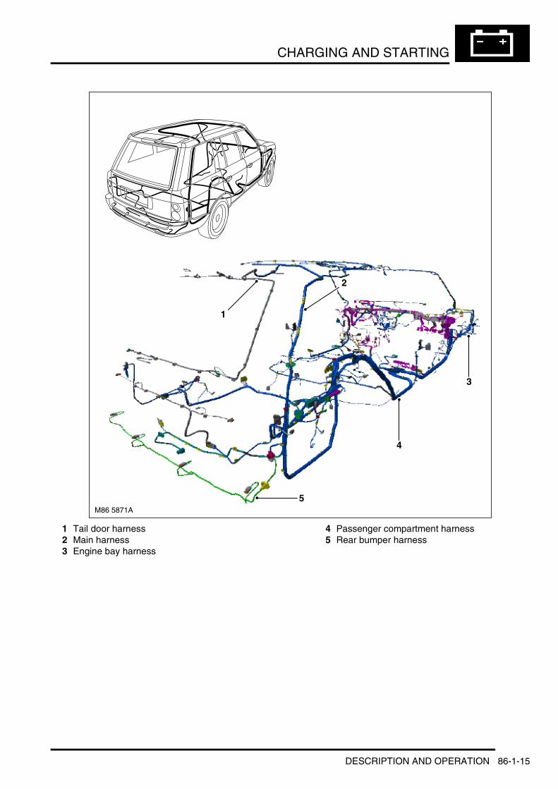
CHARGING AND STARTING
1 Tail door harness2 Main harness3 Engine bay harness
4 Passenger compartment harness5 Rear bumper harness
M86 5871A
1
2
3
4
5
DESCRIPTION AND OPERATION 86-1-15

CHARGING AND STARTING
1 Tail door harness2 Main harness3 Passenger compartment harness
4 Rear bumper harness5 Telephone harness
M86 5872A
12
34
5
86-1-16 DESCRIPTION AND OPERATION

LIGHTING
Deze pagina werd opzettelijk niet gebruikt
Cette page est intentionnellement vierge
Questa pagina è stata lasciata in bianco di proposito
Diese Seite ist leer
Esta página foi deixada intencionalmente em branco
Esta página fue dejada en blanco intencionalmente
This page is intentionally left blank
LIGHTINGDESCRIPTION AND OPERATION
DESCRIPTION AND OPERATION 86-2-1
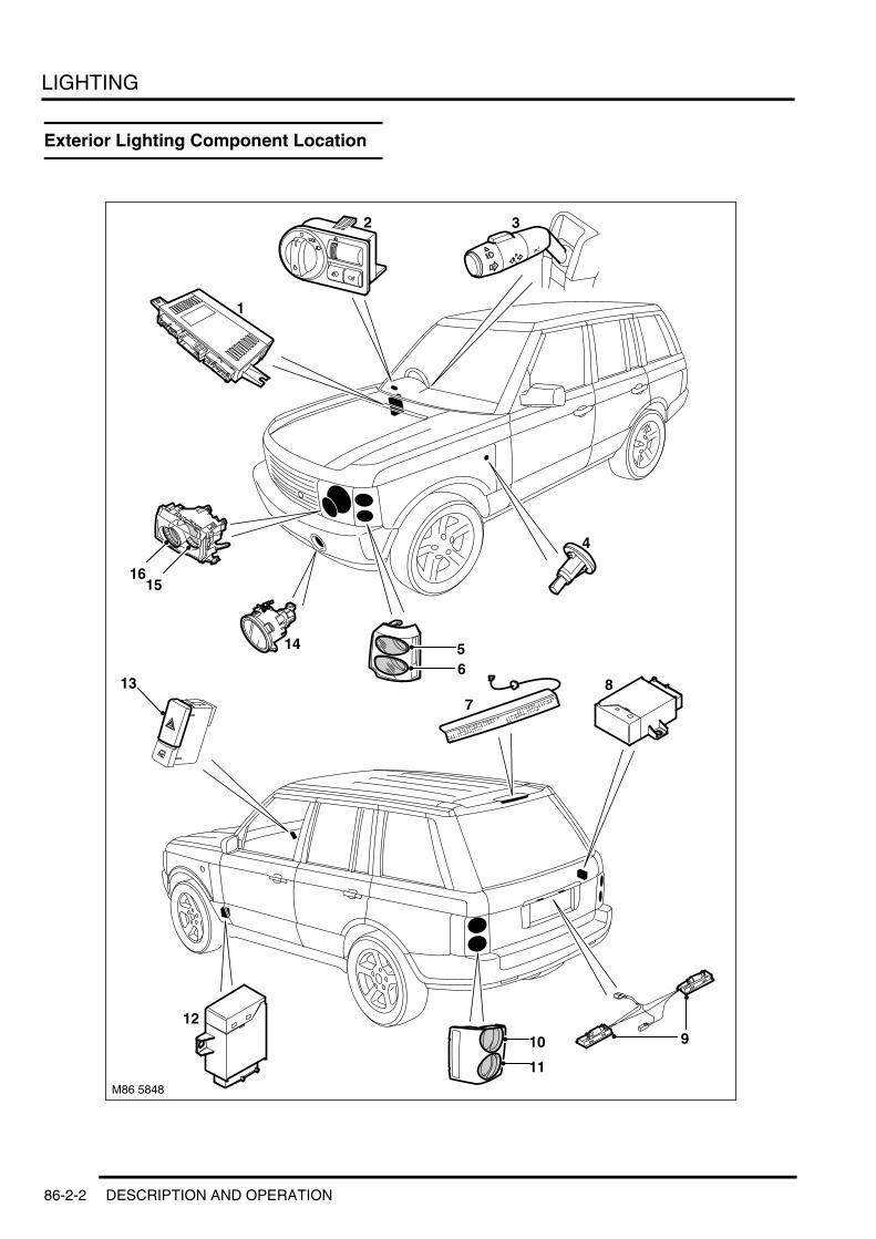
LIGHTING
Exterior Lighting Component Location
M86 5848
1
2 3
12
813
4
65
1615
14
7
10
11
9
86-2-2 DESCRIPTION AND OPERATION
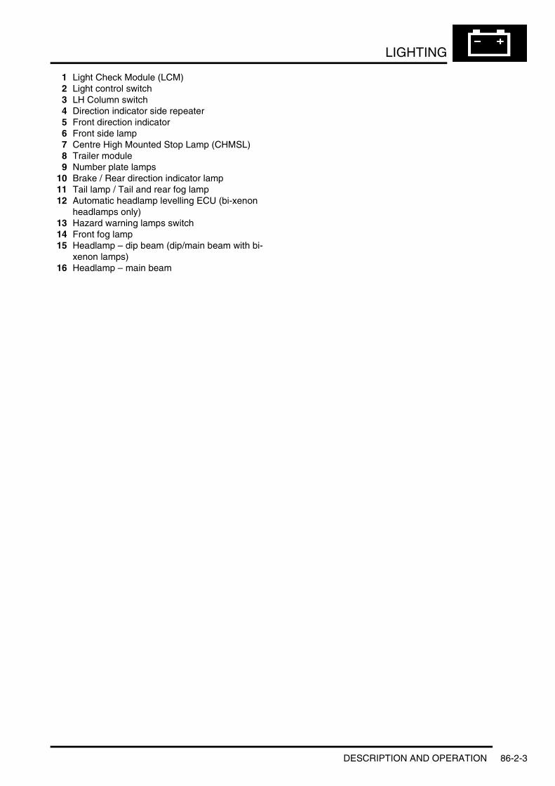
LIGHTING
1 Light Check Module (LCM)2 Light control switch3 LH Column switch4 Direction indicator side repeater5 Front direction indicator6 Front side lamp7 Centre High Mounted Stop Lamp (CHMSL)8 Trailer module9 Number plate lamps
10 Brake / Rear direction indicator lamp11 Tail lamp / Tail and rear fog lamp12 Automatic headlamp levelling ECU (bi-xenon
headlamps only)13 Hazard warning lamps switch14 Front fog lamp15 Headlamp – dip beam (dip/main beam with bi-
xenon lamps)16 Headlamp – main beam
DESCRIPTION AND OPERATION 86-2-3

LIGHTING
Exterior Lighting Control Diagram – Sheet 1 of 2
A = Hardwired; B = K Bus; K = I Bus
M86 5849 A B
1 2
3
4
5
7
8
9 10
6
11
1312
15
16
1718
20
19
22
21
25
26
14
24
23
K
86-2-4 DESCRIPTION AND OPERATION

LIGHTING
1 LH Bi-xenon control unit2 RH bi-xenon control unit3 Fuse 50A - Permanent battery supply4 Fuse 50A - Permanent battery supply5 Instrument pack6 Automatic headlamp levelling ECU (only with
bi-xenon lamps)7 Rear RH height sensor8 Front RH height sensor9 LH headlamp levelling motor (only with bi-
xenon lamps)10 RH headlamp levelling motor (only with bi-
xenon lamps)11 Anti-lock Brake System (ABS) ECU12 Fuse 5A - Ignition position I (AUX) feed13 Fuse 5A - Ignition position II (IGN) feed14 Ignition switch15 Electrochromic interior rear view mirror16 RH direction indicator side repeater lamp17 LH direction indicator side repeater lamp18 Number plate lamps19 RH dip beam headlamp20 RH main beam headlamp21 LH main beam headlamp22 LH dip beam headlamp23 Light Check Module (LCM)24 LH front fog lamp25 RH front fog lamp26 LH column switch
DESCRIPTION AND OPERATION 86-2-5

LIGHTING
Exterior Lighting Control Diagram – Sheet 2 of 2
A = Hardwired
M86 5876 A
16
23
22
21
19
20
1
5
6
7
8
9
10
11
1214
13
15
18 17
2 3
4
24
86-2-6 DESCRIPTION AND OPERATION

LIGHTING
1 LH rear tail lamp2 LH rear direction indicator lamp3 RH rear direction indicator lamp4 RH rear tail lamp5 Light control switch6 LH rear fog lamp7 RH rear fog lamp8 LH brake lamp9 Centre High Mounted Stop Lamp (CHMSL)
10 RH brake lamp11 Navigation ECU12 Rear wiper motor and control module assembly13 LH front direction indicator lamp14 LH front side lamp15 RH front side lamp16 RH front direction indicator lamp17 RH reverse lamp18 LH reverse lamp19 Trailer module20 Light Check Module (LCM)21 RH rear side marker lamp (NAS only)22 LH rear side marker lamp (NAS only)23 LH front side marker lamp (NAS only)24 RH front side marker lamp (NAS only)
DESCRIPTION AND OPERATION 86-2-7

LIGHTING
Description
GeneralThe exterior lighting is controlled by the Light Check Module (LCM). The LCM controls the following vehicle functions:l Control and monitoring of exterior lamps including direction indicators and hazard warning functionalityl Illumination dimmer control of instrument pack and all interior switch illuminationl Communication and control and monitoring of trailer lighting via the trailer ECUl Control of power supply to automatic headlamp levelling ECU (only with bi-xenon headlamps option)l Monitoring and evaluation of check control inputs from other system ECU's and output of applicable messages
in the instrument pack message centre.
The LCM is connected to the I Bus and communicates with other vehicle systems via the instrument pack. The LCM contains a microprocessor which performs the control, monitoring and evaluation functions.
Light Check Module (LCM)
The LCM is located on the RH 'A' post, behind the trim panel. The LCM is connected to the vehicle wiring harness with three multiplugs.
The LCM receives two permanent battery power supplies via the passenger compartment fusebox and power feeds from the ignition switch positions I (AUX) and II (IGN).
The lighting circuits are not protected by conventional fuses. The control circuitry within the LCM for each individual circuit can detect and isolate a problem circuit.
A monitoring system within the LCM can determine a bulb failure and indicate this to the driver via the instrument pack message centre. The following table shows the bulbs monitored by the LCM and their type and rating:
86-2-8 DESCRIPTION AND OPERATION

LIGHTING
Exterior Bulb Type/Rating Table
The bulbs are driven by MOSFETS within the LCM. The LCM provides a Pulse Width Modulation (PWM) output to the front parking lamp and the tail lamp bulbs to protect the bulbs. The PWM output is rapidly switched on and off to provide bulb emulation when a bulb fails.
Input Signals for Lamp ControlThe LCM receives inputs from the following switches:l Lighting switch for side lamps and headlampsl Momentary push switches for front and rear fog lampsl Steering column switch for direction indicators and main beam/headlamp flashl Brake switchl Momentary push switch for hazard warning.
The switches are supplied with a 10mA supply from the LCM and switch to ground when operated. The LCM detects that a switch has been operated (ON) when its closing resistance is less than 100Ω and is detected as OFF when its resistance is more than 10KΩ.
The LCM also receives ignition switch status via hardwired connections and also on the I and K Bus via the instrument pack.
A reverse gear engaged signal is also received on the I and K bus systems to enable the LCM to activate the reverse lamps. The trailer module also outputs a signal to inform the LCM that a trailer is or is not connected. If a trailer is connected, the LCM transfers control of the trailer reverse lamps and the rear fog lamp to the trailer module.
Via the bus systems the LCM receives a hazard warning lamp activation message from the DCU, via the BCU, in the event of a crash or from the BCU if the alarm system is triggered.
Bulb Type RatingHalogen headlamps – Dip beam Halogen H7U 55WBi-xenon headlamps – Dip beam Xenon DS2 35WHeadlamps – Main beam Halogen H7U 55W
Front fog lamps Halogen H7U 55WRear fog lamps Bayonet 21WDirection indicators – front Bayonet 21W
Direction indicators – side repeater Capless 5WDirection indicators – rear Bayonet 21WSide lamps – front Bayonet 5W
Tail lamps Bayonet (Twin filament) 21W/5WBrake lamps 19 LED's –Centre High Mounted Stop Lamp (CHMSL)
20 LED's –
Number plate lamps Festoon 5W
Reverse Lamps Bayonet 6WFront side marker lamp (NAS only) Capless 5WRear side marker lamp (NAS only) Capless 5W
DESCRIPTION AND OPERATION 86-2-9
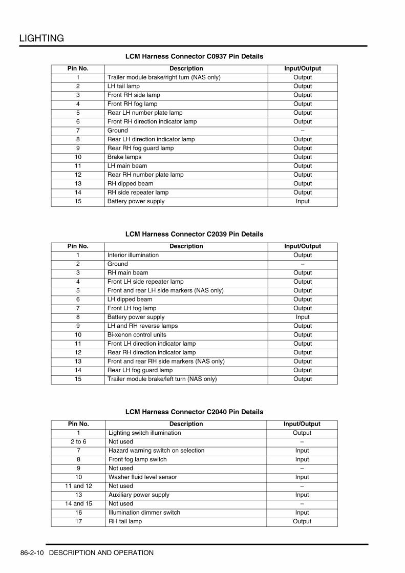
LIGHTING
LCM Harness Connector C0937 Pin Details
LCM Harness Connector C2039 Pin Details
LCM Harness Connector C2040 Pin Details
Pin No. Description Input/Output1 Trailer module brake/right turn (NAS only) Output2 LH tail lamp Output3 Front RH side lamp Output
4 Front RH fog lamp Output5 Rear LH number plate lamp Output6 Front RH direction indicator lamp Output
7 Ground –8 Rear LH direction indicator lamp Output9 Rear RH fog guard lamp Output
10 Brake lamps Output11 LH main beam Output12 Rear RH number plate lamp Output
13 RH dipped beam Output14 RH side repeater lamp Output15 Battery power supply Input
Pin No. Description Input/Output1 Interior illumination Output2 Ground –3 RH main beam Output
4 Front LH side repeater lamp Output5 Front and rear LH side markers (NAS only) Output6 LH dipped beam Output
7 Front LH fog lamp Output8 Battery power supply Input9 LH and RH reverse lamps Output
10 Bi-xenon control units Output11 Front LH direction indicator lamp Output12 Rear RH direction indicator lamp Output
13 Front and rear RH side markers (NAS only) Output14 Rear LH fog guard lamp Output15 Trailer module brake/left turn (NAS only) Output
Pin No. Description Input/Output1 Lighting switch illumination Output
2 to 6 Not used –7 Hazard warning switch on selection Input
8 Front fog lamp switch Input9 Not used –
10 Washer fluid level sensor Input
11 and 12 Not used –13 Auxiliary power supply Input
14 and 15 Not used –
16 Illumination dimmer switch Input17 RH tail lamp Output
86-2-10 DESCRIPTION AND OPERATION

LIGHTING
Circuit ProtectionOperation of the lamps is performed using overload proof Metal Oxide Semiconductor Field Effect Transistors (MOSFETs). The MOSFETs have a diagnostic output for bulb monitoring and can detect overload, load interruption with the lamps switched on and short circuit to positive with the lamps switched off.
The MOSFETs are protected against short circuits, removing the requirement for the lamps circuits to be protected by fuses. The MOSFETs respond to heat generated by increased current flow caused by a short circuit. Normally this would cause the fuse to blow. The MOSFETs react to the heat increase and cut the supply to the affected circuit. Once the fault has been rectified or the MOSFET has cooled, the MOSFET will automatically reset and operate the circuit normally.
If an overload occurs, the current flow is dependant on the temperature of the related MOSFET and can be up to 20 times the rated current of the lamp. The MOSFET heats up and deactivates the load applied to the circuit. When the MOSFET cools the circuit is once again reactivated. This thermal cycling occurs continuously in the event of an overload occurring.
The brake switch is also monitored by the LCM. If the LCM detects a short circuit to ground in the switch circuit it activates messages to the driver in the message centre. These messages will display switch defective and LH and RH stop lamp defective. The brake switch is also monitored when the ignition is in position II. The LCM checks the acceleration speed of the vehicle (via bus messages). If the vehicle is accelerating and the brake switch is still active after 10 seconds, the LCM starts a timer. If, after 2 minutes, the brake switch is still active and the vehicle is moving, the LCM activates defective switch messages in the instrument pack message centre.
18 Front LH side lamp Output
19 Hazard warning switch lamp Output20 to 23 Not used –
24 Engine coolant level sensor Input
25 Brake switch Input26 Reverse gear selected Output27 Headlamp levelling vertical aim control Output
28 Reverse gear selected Output29 Illumination dimmer switch supply Output30 Steering column lighting switch (left and right turn
selections)Input
31 Ignition power supply Input
32 Not used –33 Lighting switch headlamp selection Input34 Not used –
35 Trailer module serial interface Input/Output36 I bus Input/Output
37 and 38 Not used –
39 Reverse gear selected Output40 Not used –41 Brake fluid level switch Input
42 to 44 Not used –45 Rear fog guard lamp switch Input46 Not used –
47 HDC active signal Input48 and 49 Not used –
50 Steering column lighting switch, main/dipped beam and flash selection
Input
51 Lighting switch side lamp selection Input
52 Lighting switch ground –53 and 54 Not used –
Pin No. Description Input/Output
DESCRIPTION AND OPERATION 86-2-11

LIGHTING
Bulb MonitoringBulb failure monitoring is performed by the LCM processor. The lamps are cold and warm monitored by the MOSFETs in order to detect bulb failure.
The LCM processor outputs to each MOSFET. This output switches the MOSFET to supply the required output to power the lamp circuit. The microprocessor evaluates the lamp circuits by detecting the returned signals from the controlling MOSFET.
When the bulb is functioning normally, the output signal voltage from the controlling MOSFET is 0V. If a bulb in the circuit fails, an open circuit occurs and the MOSFET outputs a signal of 5V to the processor. The signal is interpreted as a bulb failure and generates a message which is output on the I Bus to the instrument pack. The instrument pack displays the applicable bulb failure message in the message centre to provide visual warning to the driver.
Warm monitoring is performed continuously when the lamps are switched on by evaluating the diagnostic output of the MOSFET switches. Cold monitoring is performed at 32 second intervals when the lamps are switched off. The MOSFETs briefly switch on the lamps for approximately 1 millisecond (this is insufficient to illuminate the bulb) and checks the bulb as per warm monitoring.
Cold monitoring is not possible for the dip beam headlamps of vehicles using xenon bulbs. On these vehicles the cold monitoring of the dip beam headlamps is switched off in the LCM. The LCM detects a failed xenon bulb via a reduction in current flow to the affected headlamp's xenon control module.
When a xenon bulb fails, the control module's current consumption falls to 60mA, which the LCM detects as unsuccessful bulb illumination. The xenon control modules have a diagnostic capability and can store fault related codes.
Alarm IndicationsThe LCM communicates on the I and K Buses with the BCU to display alarm visual indications for alarm arm, disarm and triggered conditions. + SECURITY, DESCRIPTION AND OPERATION, Description.
If the hazard warning lamps are active when a lock or unlock request is made, the hazard warning cycle is interrupted to allow the visual indication of the requested lock cycle. When visual indication is completed, the hazard warning operation will continue.
If the vehicle is involved in crash of a severity for the DCU to initiate deployment of the airbags, the DCU outputs a hazard warning lamps on request on the K bus to the instrument pack and on the I bus from the instrument pack to the LCM. The hazard warning lamps will be activated and will continue until the DCU outputs a message to deactivate the hazard warning lamps or until the hazard warning lamp switch is pressed.
Redundant Data StorageThe LCM stores data relating to the Vehicle Identification Number (VIN), total mileage and service interval indicator. This data is received by the LCM from the instrument pack and used as a back-up in the event of instrument pack replacement.
If the LCM is to be replaced, TestBook/T4 must be connected to the vehicle and the replace LCM procedure followed to ensure that the stored data is transferred to the new unit. + INSTRUMENTS, DESCRIPTION AND OPERATION, Description.
Low Voltage OperationIf the battery voltage falls below 11.2V, the LCM operates the minimum lighting to preserve the remaining battery charge.
86-2-12 DESCRIPTION AND OPERATION

LIGHTING
Lighting Control Switch
1 Light control rotary switch2 Off position3 Side lamps position4 Headlamps position
5 Instrument illumination dimmer rheostat6 Rear fog lamp switch7 Front fog lamp switch
The light control switch is located in the fascia between the steering column and the driver's door. The switch comprises a three position rotary switch for controlling side lamps and headlamps, a thumbwheel rheostat which manually controls the fascia and interior switch night illumination, and momentary push switches for front and rear fog lamps.
The rotary side and headlamp control switch has three connections to the LCM. One connection supplies a reference voltage to the switch contacts. The two remaining connections supply a combination of earth paths to the LCM for the side lamp or headlamp selection contacts.
The front and rear fog lamp switches operate in a similar way, completing earth paths to the LCM when the switch is pressed. The fog lamp switches are momentary, non-latching switches which briefly complete an earth path which is sensed by the LCM.
DESCRIPTION AND OPERATION 86-2-13

LIGHTING
Headlamp AssemblyTwo headlamps systems are available; Halogen or bi-xenon. The two types of headlamps share a common lens. NAS vehicles use a different lens to other markets but these are also common between the NAS specification halogen and bi-xenon lamps.
Halogen Headlamps
1 Lens retaining clips2 Bolts – headlamp assembly to front panel3 Halogen bulb 55W – main beam4 Main beam bulb access cover5 Halogen bulb 55W – dip beam6 Dip beam bulb access cover
7 Bolts – headlamp mounting bracket8 Screw9 Headlamp mounting bracket
10 Lens11 Gasket12 Headlamp assembly
86-2-14 DESCRIPTION AND OPERATION
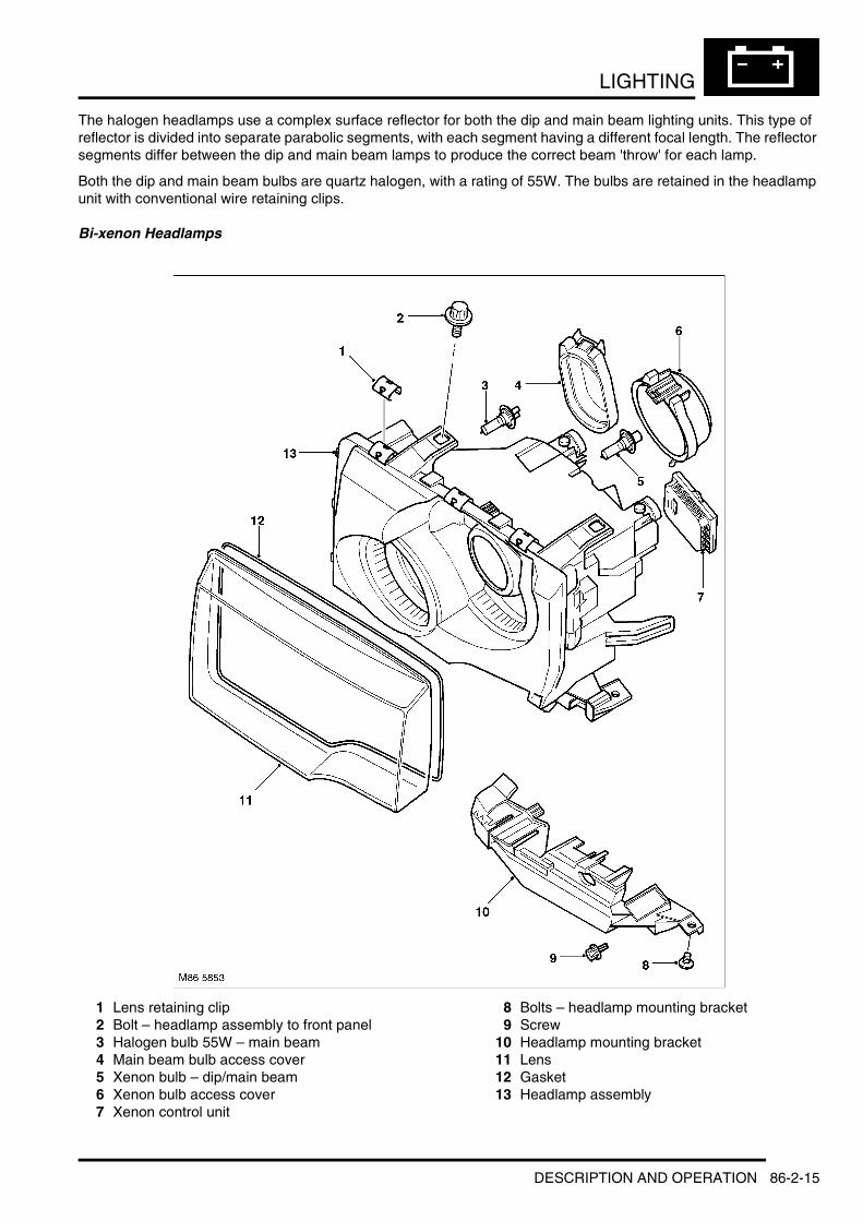
LIGHTING
The halogen headlamps use a complex surface reflector for both the dip and main beam lighting units. This type of reflector is divided into separate parabolic segments, with each segment having a different focal length. The reflector segments differ between the dip and main beam lamps to produce the correct beam 'throw' for each lamp.
Both the dip and main beam bulbs are quartz halogen, with a rating of 55W. The bulbs are retained in the headlamp unit with conventional wire retaining clips.
Bi-xenon Headlamps
1 Lens retaining clip2 Bolt – headlamp assembly to front panel3 Halogen bulb 55W – main beam4 Main beam bulb access cover5 Xenon bulb – dip/main beam6 Xenon bulb access cover7 Xenon control unit
8 Bolts – headlamp mounting bracket9 Screw
10 Headlamp mounting bracket11 Lens12 Gasket13 Headlamp assembly
DESCRIPTION AND OPERATION 86-2-15
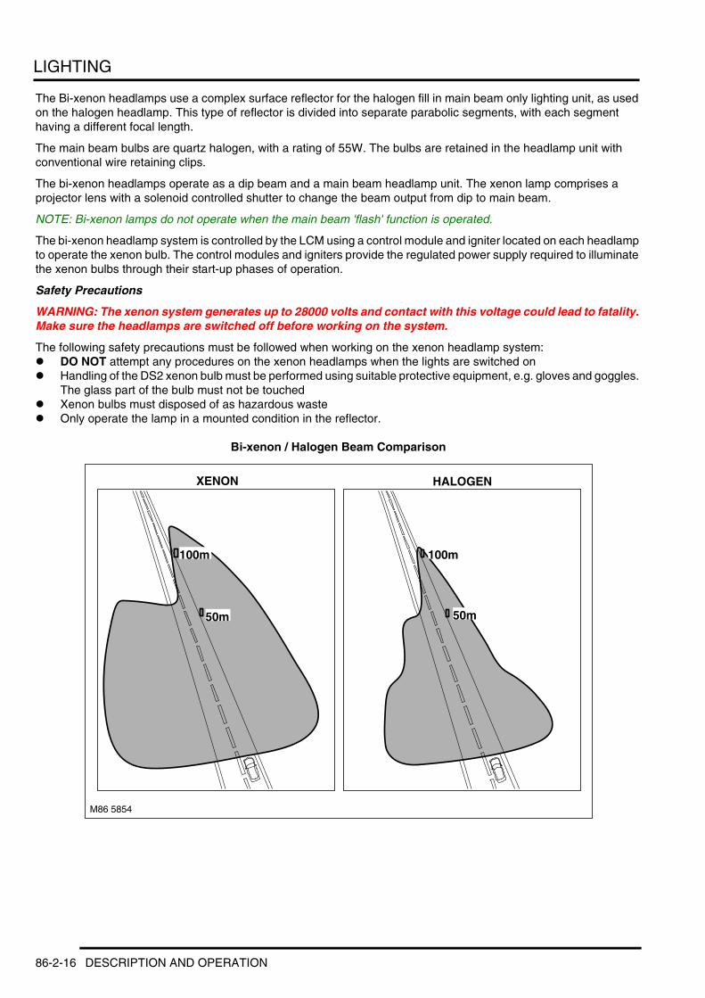
LIGHTING
The Bi-xenon headlamps use a complex surface reflector for the halogen fill in main beam only lighting unit, as used on the halogen headlamp. This type of reflector is divided into separate parabolic segments, with each segment having a different focal length.
The main beam bulbs are quartz halogen, with a rating of 55W. The bulbs are retained in the headlamp unit with conventional wire retaining clips.
The bi-xenon headlamps operate as a dip beam and a main beam headlamp unit. The xenon lamp comprises a projector lens with a solenoid controlled shutter to change the beam output from dip to main beam.
NOTE: Bi-xenon lamps do not operate when the main beam 'flash' function is operated.
The bi-xenon headlamp system is controlled by the LCM using a control module and igniter located on each headlamp to operate the xenon bulb. The control modules and igniters provide the regulated power supply required to illuminate the xenon bulbs through their start-up phases of operation.
Safety Precautions
WARNING: The xenon system generates up to 28000 volts and contact with this voltage could lead to fatality. Make sure the headlamps are switched off before working on the system.
The following safety precautions must be followed when working on the xenon headlamp system:l DO NOT attempt any procedures on the xenon headlamps when the lights are switched onl Handling of the DS2 xenon bulb must be performed using suitable protective equipment, e.g. gloves and goggles.
The glass part of the bulb must not be touchedl Xenon bulbs must disposed of as hazardous wastel Only operate the lamp in a mounted condition in the reflector.
Bi-xenon / Halogen Beam Comparison
50m
100m
M86 5854
XENON
50m
100m
HALOGEN
86-2-16 DESCRIPTION AND OPERATION
LIGHTING
The bi-xenon dip/main beam headlamps use ellipsoidal technology for the lens and reflector providing improved night time visibility compared with conventional halogen headlamps. The bi-xenon headlamps provide the following benefits when compared to halogen headlamps:l Longer bulb life – Approximately 3 to 5 times longer than a halogen bulbl Increased light output – Xenon headlamps output 2.5 to 3 times more lumens than halogen headlamps (lumens
is a measure of light energy emitted per second on a given area over a given distance)l Blue/white light which simulates natural daylight – Xenon bulbs produce a blue/white light compared to the yellow
light produced by a halogen bulb. l Improved night time driving visibility – Xenon lamps produce a wider and brighter beam in front of the vehicle
than conventional halogen bulbs.l Lower operating temperaturesl Lower power consumption.
DESCRIPTION AND OPERATION 86-2-17

LIGHTING
Xenon Headlamp Construction
1 Reflector2 Shutter controller3 Shutter4 Adapter ring5 Spring clip
6 Lens7 Foreign touring beam adjustment lever8 Xenon bulb9 Bulb retention ring
4 3 2
M86 5875
5
45,88
1
6
7
8
9
86-2-18 DESCRIPTION AND OPERATION

LIGHTING
The xenon headlamp unit is a self contained unit located within the headlamp assembly. The unit comprises a reflector, an adaptor ring, the lens, a shutter controller and the xenon bulb.
The lens is curved and provides the mounting for the xenon bulb. The bulb locates in two recesses to ensure correct alignment in the reflector and is secured with a retention ring. The retention ring locates over the bulb and is turned clockwise to lock the bulb in the holder. The bulb has a two pin connector which is also a push and turn to lock fitting.
The adapter ring is attached to the reflector and provides for the attachment of the lens. The lens is attached to the adapter ring with an internal spring clip.
The shutter controller is a solenoid which operates, via a lever mechanism, the shutter. The shutter is used to change the beam projection from dip beam to main beam and visa versa.
A beam adjustment mechanism is located between the reflector and the adapter ring. This mechanism rotates to blank off a portion of the beam spread to enable the vehicle to be driven in opposite drive hand markets without applying blanking decals to the headlamp lens. The beam is changed by removing the access cover at the rear of the lamp assembly and moving a small lever located near the bulb holder, at the side of the reflector.
Crash Signal ActivationIn the event of an accident of a severity to activate and deploy the airbags, the DCU requests various electrical operations to assist with the crash situation. The DCU requests via the bus systems to the LCM to activate the hazard warning lamps.
Security System ActivationIn the event of the security system being triggered, the BCU requests activation of the hazard warning lamps. In some markets the low beam and/or high beam headlamps can also be activated.
Headlamp Levelling (Xenon headlamps only)The automatic headlamp levelling system automatically adjusts the vertical positioning of the headlamps to provide the optimum headlamp beam position for maximum driving visibility and preventing glare to oncoming drivers.
The system is controlled by an automatic headlamp levelling ECU located at the bottom of the LH 'A' post. The ECU is connected to and receives information from the Hall effect front and rear height sensors which are also used by the air suspension system. The ECU also receives a signal from the ABS ECU for vehicle acceleration. The ECU has diagnostic capabilities and can communicate with TestBook/T4 via the K Bus, the instrument pack and the DS2 Bus.
The levelling system is a fast response system which reacts to changes of vehicle angle when driving. The ECU receives vehicle speed signals from the ABS ECU and a brake switch signal from the LCM. These two signals are used to adjust the headlamp position to compensate for changes in vehicle attitude due to acceleration or braking.
Stepper motors, located as part of the headlamp unit, drive a threaded rod which moves the lower edge of the headlamp forward or backwards to adjust the vertical position of the headlamp beam. The stepper motors are controlled by the ECU which, using the data from the height sensors, determines the attitude of the vehicle and compensates for load differences at the rear of the vehicle or changing driving conditions.
DESCRIPTION AND OPERATION 86-2-19
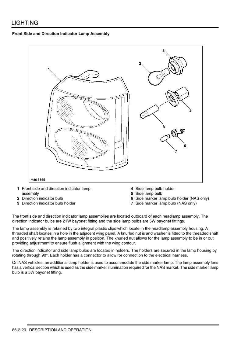
LIGHTING
Front Side and Direction Indicator Lamp Assembly
1 Front side and direction indicator lamp assembly
2 Direction indicator bulb3 Direction indicator bulb holder
4 Side lamp bulb holder5 Side lamp bulb6 Side marker lamp bulb holder (NAS only)7 Side marker lamp bulb (NAS only)
The front side and direction indicator lamp assemblies are located outboard of each headlamp assembly. The direction indicator bulbs are 21W bayonet fitting and the side lamp bulbs are 5W bayonet fittings.
The lamp assembly is retained by two integral plastic clips which locate in the headlamp assembly housing. A threaded shaft locates in a hole in the adjacent wing panel. A knurled nut is and washer is fitted to the threaded shaft and positively retains the lamp assembly in position. The knurled nut allows for the lamp assembly to be in or out providing adjustment to ensure flush alignment with the wing contour.
The direction indicator and side lamp bulbs are located in holders. The holders are secured in the lamp housing by rotating through 90°. Each holder has a connector to allow for connection to the electrical harness.
On NAS vehicles, an additional lamp holder is used to accommodate the side marker lamp. The lamp assembly lens has a vertical section which is used as the side marker illumination required for the NAS market. The side marker lamp bulb is a 5W bayonet fitting.
86-2-20 DESCRIPTION AND OPERATION

LIGHTING
Front Fog Lamps
1 Lamp assembly2 Halogen bulb
3 Bulb holder
The front fog lamps are located in the front bumper. Each lamp is secured to three lugs in the bumper and retained with self tapping screws and fasteners. Each lamp has two adjusting screws which provide for the vertical and horizontal alignment of the beam.
The 55W halogen bulb is located in a holder. The holders are secured in the lamp housing by rotating through approximately 10°. The holder has a connector to allow for connection to the electrical harness.
DESCRIPTION AND OPERATION 86-2-21

LIGHTING
Rear Side and Direction Indicator Lamp Assembly
1 Rear lamp holder2 Direction indicator bulb3 Direction indicator reflector4 Brake lamp LED assembly5 Tail lamp lens
6 Side marker lamp bulb (NAS only)7 Side marker lamp bulb holder (NAS only)8 Bulb – tail lamp twin filament9 Bulb – tail/rear fog lamp
The rear side and direction indicator lamp assemblies are located on the outer corner of each rear wing panel.
The lamp assembly is retained by two integral plastic clips which locate in corresponding clips secured to the body panel. The assembly is further retained by two self tapping screws which are accessed from inside the taildoor aperture. To remove the assembly, after removing the screws, the assembly must be prised at two indentations to release the clips. A non-metallic tool must be used with care to avoid damage to the paint finish.
The direction indicator, fog lamp and side lamp bulbs are located in a holder. The holders is secured in the lamp housing by two plastic clips. The holder has a connector to allow for connection to the electrical harness.
The upper lamp aperture is for the brake lamp and the direction indicator. The brake lamp comprises a plastic holder with contains 19 LED's. This illuminates through a circular prism lens in the centre of the lamp to display the brake lamp in a red colour. The direction indicator lamp is located behind the brake lamp LED unit. The bulb is located in a reflector unit which emits the direction indicator light around the outer diameter of the brake lamp LED assembly.
The lower lamp aperture is divided into two parts and provides for the tail lamp and the rear fog lamp The rear fog lamp uses a 21W bulb in the lower half of the aperture. This is also used for the tail lamp, operated by a PWM output from the LCM to produce a lower wattage output than the fog lamp. The upper half of the tail lamp aperture is used solely for the tail lamp and uses a 21W/5W bulb. Only the 5W filament is used for the tail lamp, with the 21W filament not used by any function.
86-2-22 DESCRIPTION AND OPERATION
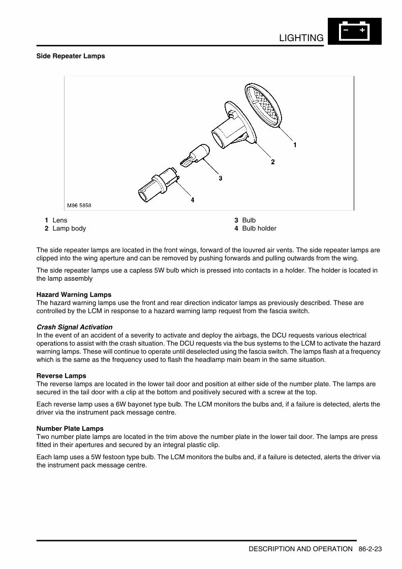
LIGHTING
Side Repeater Lamps
1 Lens2 Lamp body
3 Bulb4 Bulb holder
The side repeater lamps are located in the front wings, forward of the louvred air vents. The side repeater lamps are clipped into the wing aperture and can be removed by pushing forwards and pulling outwards from the wing.
The side repeater lamps use a capless 5W bulb which is pressed into contacts in a holder. The holder is located in the lamp assembly
Hazard Warning LampsThe hazard warning lamps use the front and rear direction indicator lamps as previously described. These are controlled by the LCM in response to a hazard warning lamp request from the fascia switch.
Crash Signal ActivationIn the event of an accident of a severity to activate and deploy the airbags, the DCU requests various electrical operations to assist with the crash situation. The DCU requests via the bus systems to the LCM to activate the hazard warning lamps. These will continue to operate until deselected using the fascia switch. The lamps flash at a frequency which is the same as the frequency used to flash the headlamp main beam in the same situation.
Reverse LampsThe reverse lamps are located in the lower tail door and position at either side of the number plate. The lamps are secured in the tail door with a clip at the bottom and positively secured with a screw at the top.
Each reverse lamp uses a 6W bayonet type bulb. The LCM monitors the bulbs and, if a failure is detected, alerts the driver via the instrument pack message centre.
Number Plate LampsTwo number plate lamps are located in the trim above the number plate in the lower tail door. The lamps are press fitted in their apertures and secured by an integral plastic clip.
Each lamp uses a 5W festoon type bulb. The LCM monitors the bulbs and, if a failure is detected, alerts the driver via the instrument pack message centre.
DESCRIPTION AND OPERATION 86-2-23

LIGHTING
Daylight Running Lamps (selected markets only)In markets which require daylight running lamps, the LCM is programmed with coding which activates the dip beam or dimmed main beam headlamps when the ignition is in position II.
Daylight running lamps can only be switched on or off using TestBook providing the LCM is not coded with a country specific code.
Canadian market vehicles use the main beam headlamps with a dimmed output of 5.5 to 6.0V, controlled by the LCM. Also, on Canadian vehicles with bi-xenon lamps, only the halogen main beam lamp is illuminated using a reduced voltage of 5.5 to 6.0V. All other countries using daylight running lamps (Finland, Norway and Sweden) use the full power dip beam headlamps.
Main Beam/Direction Indicator Column Control Switch
1 RH direction indicator2 Headlamp flash
3 LH direction indicator4 Headlamp main beam
The main beam/direction indicator column control switch is located on the left hand side of the steering column and controls the following functions:l Headlamp dip/main beaml Headlamp main beam flashl Left/right direction indicatorsl Trip computer functions.
+ INSTRUMENTS, DESCRIPTION AND OPERATION, Description.
The main beam on and flash functions are connected on a single wire to the LCM. The switch assembly contains resistors and the ground for each selection is passed through a different resistor for each selection. The same also applies to the direction indicators. The LCM senses the resistance on the ground wire and determines which function has been selected.
M86 5859
1
2
3
4
86-2-24 DESCRIPTION AND OPERATION
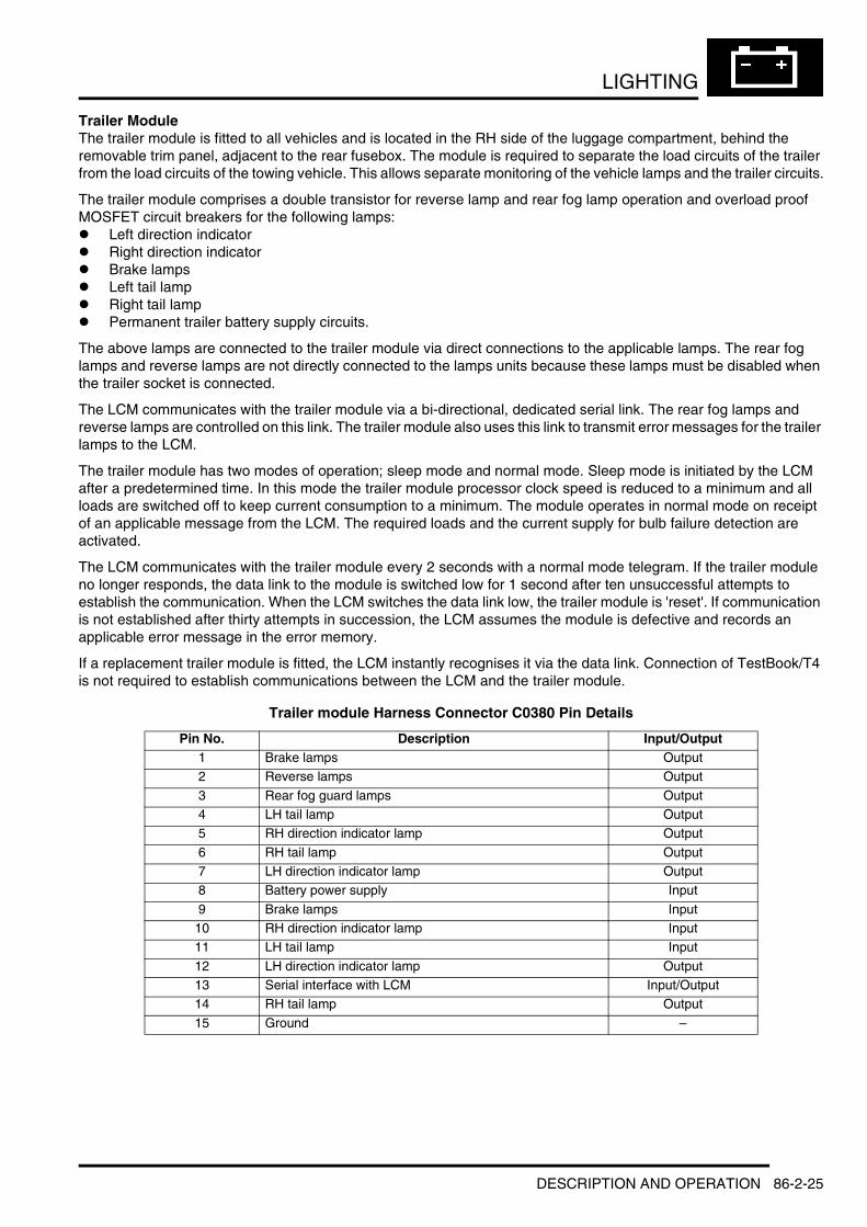
LIGHTING
Trailer ModuleThe trailer module is fitted to all vehicles and is located in the RH side of the luggage compartment, behind the removable trim panel, adjacent to the rear fusebox. The module is required to separate the load circuits of the trailer from the load circuits of the towing vehicle. This allows separate monitoring of the vehicle lamps and the trailer circuits.
The trailer module comprises a double transistor for reverse lamp and rear fog lamp operation and overload proof MOSFET circuit breakers for the following lamps:l Left direction indicatorl Right direction indicatorl Brake lampsl Left tail lampl Right tail lampl Permanent trailer battery supply circuits.
The above lamps are connected to the trailer module via direct connections to the applicable lamps. The rear fog lamps and reverse lamps are not directly connected to the lamps units because these lamps must be disabled when the trailer socket is connected.
The LCM communicates with the trailer module via a bi-directional, dedicated serial link. The rear fog lamps and reverse lamps are controlled on this link. The trailer module also uses this link to transmit error messages for the trailer lamps to the LCM.
The trailer module has two modes of operation; sleep mode and normal mode. Sleep mode is initiated by the LCM after a predetermined time. In this mode the trailer module processor clock speed is reduced to a minimum and all loads are switched off to keep current consumption to a minimum. The module operates in normal mode on receipt of an applicable message from the LCM. The required loads and the current supply for bulb failure detection are activated.
The LCM communicates with the trailer module every 2 seconds with a normal mode telegram. If the trailer module no longer responds, the data link to the module is switched low for 1 second after ten unsuccessful attempts to establish the communication. When the LCM switches the data link low, the trailer module is 'reset'. If communication is not established after thirty attempts in succession, the LCM assumes the module is defective and records an applicable error message in the error memory.
If a replacement trailer module is fitted, the LCM instantly recognises it via the data link. Connection of TestBook/T4 is not required to establish communications between the LCM and the trailer module.
Trailer module Harness Connector C0380 Pin Details
Pin No. Description Input/Output1 Brake lamps Output2 Reverse lamps Output
3 Rear fog guard lamps Output4 LH tail lamp Output5 RH direction indicator lamp Output
6 RH tail lamp Output7 LH direction indicator lamp Output8 Battery power supply Input
9 Brake lamps Input10 RH direction indicator lamp Input11 LH tail lamp Input
12 LH direction indicator lamp Output13 Serial interface with LCM Input/Output14 RH tail lamp Output
15 Ground –
DESCRIPTION AND OPERATION 86-2-25
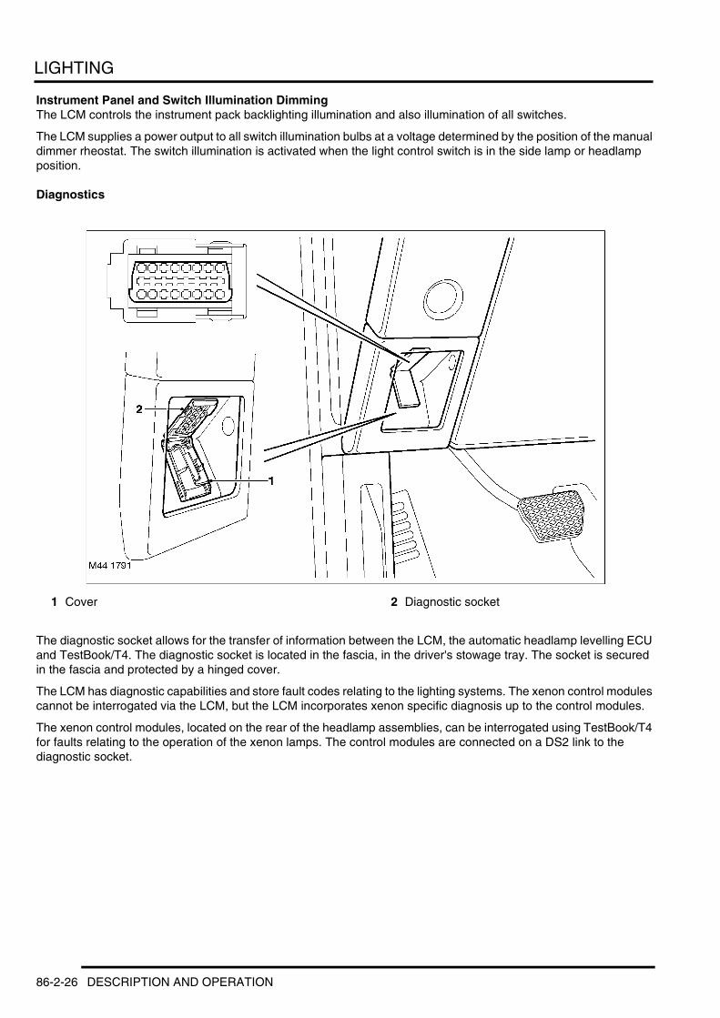
LIGHTING
Instrument Panel and Switch Illumination DimmingThe LCM controls the instrument pack backlighting illumination and also illumination of all switches.
The LCM supplies a power output to all switch illumination bulbs at a voltage determined by the position of the manual dimmer rheostat. The switch illumination is activated when the light control switch is in the side lamp or headlamp position.
Diagnostics
1 Cover 2 Diagnostic socket
The diagnostic socket allows for the transfer of information between the LCM, the automatic headlamp levelling ECU and TestBook/T4. The diagnostic socket is located in the fascia, in the driver's stowage tray. The socket is secured in the fascia and protected by a hinged cover.
The LCM has diagnostic capabilities and store fault codes relating to the lighting systems. The xenon control modules cannot be interrogated via the LCM, but the LCM incorporates xenon specific diagnosis up to the control modules.
The xenon control modules, located on the rear of the headlamp assemblies, can be interrogated using TestBook/T4 for faults relating to the operation of the xenon lamps. The control modules are connected on a DS2 link to the diagnostic socket.
86-2-26 DESCRIPTION AND OPERATION
LIGHTING
Operation
GeneralThe following section describe the functionality of the individual light circuits. The control of the circuits is performed by coding data in the LCM EEPROM. This coding is programmed on the production line and some coding for lamp functionality is country specific.
Direction Indicator and Hazard Warning LampsWith the ignition switch in position I or II, the direction indicators can be operated. When the column switch is moved to the left or right direction position the direction indicator lamps are activated with a pulse rate of 640 milliseconds and a pulse duty factor of 50:50. If the operation is in the illuminated phase and the direction indicator is switched off, the flashing phase will end. If the switch position is rapidly moved to from the left position to the right position (or visa versa), the applicable direction indicator lamps are switched over immediately.
If one of the vehicle or trailer direction indicator bulbs, with the exception of the side repeater lamps, is defective, the flashing frequency is doubled.
If the ignition is in position I or II and a left or right direction indicator is active, depressing the hazard warning switch will operate the hazard warning lamps, overriding the direction indicator function. when the hazard warning lamp switch is pressed a second time, the hazard warning lamp function is deactivated and the direction indicator operation reinstated, if still selected on.
If the ignition is in position I or II and the hazard warning lamps are active, operating the column switch for the left or right direction indicators will suspend the hazard warning lamp operation and activate the selected direction indicator. When the direction indicator column switch is moved to the off position, the hazard warning function will be reinstated.
If the hazard warning lamps have been activated by an I and K Bus message to the LCM in response to a crash detection, the hazard warning lamps can be switched off using the hazard warning lamp switch. If the hazard warning lamps have been activated by the BCU due to an anti-theft alarm trigger, the hazard warning lamps can only be switched off by a deactivate message from the BCU. The hazard warning lamps will also deactivate after 5.5 minutes.
The direction indicator warning lamps and the direction indicator sound are controlled by the instrument pack. They are activated by the instrument pack on receipt of a lamp status message from the LCM. The direction indicator warning lamps and the sounder are synchronised with this message with the direction indicator lamp illumination frequency.
Parking LampsThe parking lamp function is controlled using the direction indicator column switch. If the ignition is off and the direction indicator switch is moved to the left or right position, the selected parking lamps will be illuminated. The front parking lamp is illuminated, along with the top bulb in the rear tail lamp. On NAS vehicles the applicable side marker lamps are also illuminated. The number plate lamps and the lower bulb in the tail lamp for the selected side are deactivated. No instrument pack or fascia illumination is activated. If the ignition is on and the direction indicator switch is in the left or right position, the selected side lamps will not be activated when the ignition is subsequently switched off.
Side LampsIf the light control switch is in the side lamp or headlamp position, the front side lamps and rear tail lamps are activated. Both the upper and lower tail lamp bulbs are active along with the number plate lamps. On NAS vehicles, the side marker lamps are also active.
The instrument pack and fascia illumination remains illuminated at the brightness determined by the position of the dimmer control.
Light Control Switch IlluminationWhen the ignition is in position I or II, the switch legends on the light control switch are illuminated at maximum brightness when the light control switch is in the 'O' (off) position. when the light control switch is rotated to the side or headlamp position the legend illumination is dimmed.
DESCRIPTION AND OPERATION 86-2-27
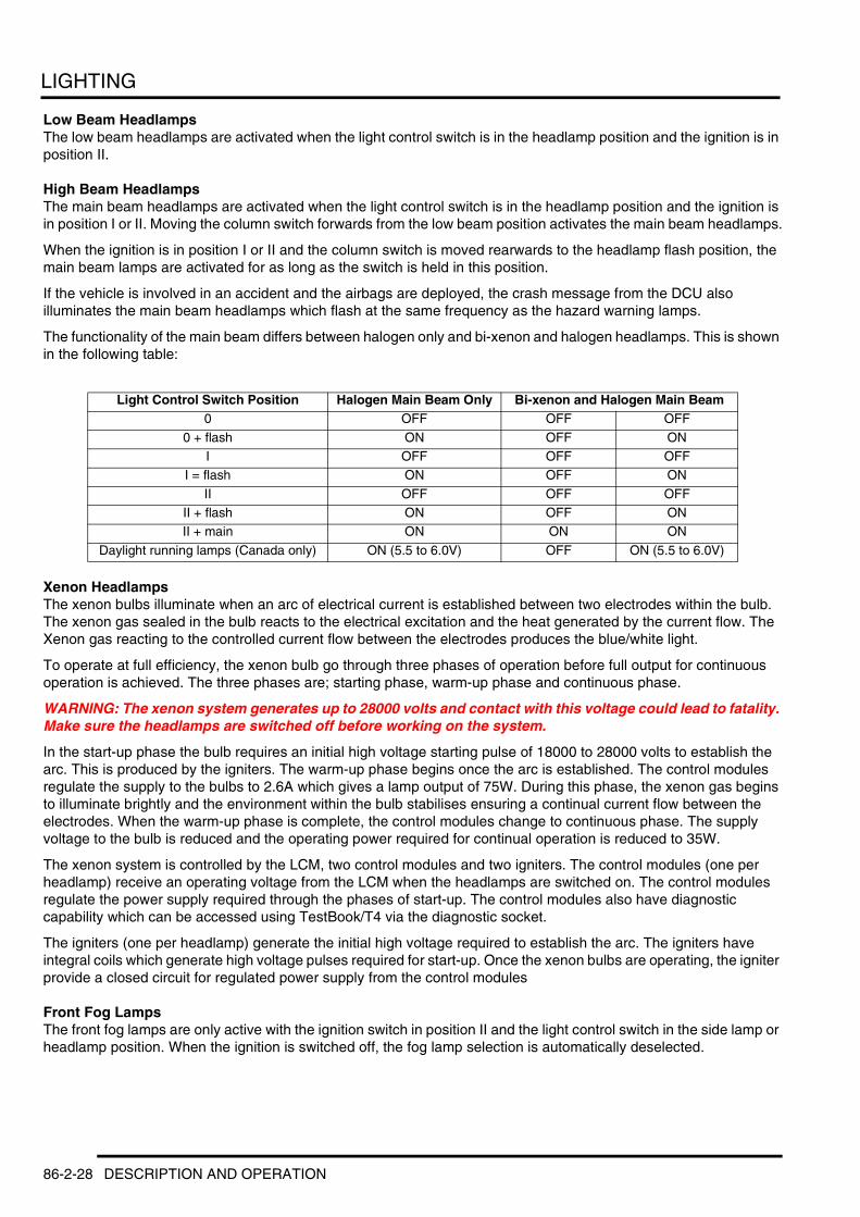
LIGHTING
Low Beam HeadlampsThe low beam headlamps are activated when the light control switch is in the headlamp position and the ignition is in position II.
High Beam HeadlampsThe main beam headlamps are activated when the light control switch is in the headlamp position and the ignition is in position I or II. Moving the column switch forwards from the low beam position activates the main beam headlamps.
When the ignition is in position I or II and the column switch is moved rearwards to the headlamp flash position, the main beam lamps are activated for as long as the switch is held in this position.
If the vehicle is involved in an accident and the airbags are deployed, the crash message from the DCU also illuminates the main beam headlamps which flash at the same frequency as the hazard warning lamps.
The functionality of the main beam differs between halogen only and bi-xenon and halogen headlamps. This is shown in the following table:
Xenon HeadlampsThe xenon bulbs illuminate when an arc of electrical current is established between two electrodes within the bulb. The xenon gas sealed in the bulb reacts to the electrical excitation and the heat generated by the current flow. The Xenon gas reacting to the controlled current flow between the electrodes produces the blue/white light.
To operate at full efficiency, the xenon bulb go through three phases of operation before full output for continuous operation is achieved. The three phases are; starting phase, warm-up phase and continuous phase.
WARNING: The xenon system generates up to 28000 volts and contact with this voltage could lead to fatality. Make sure the headlamps are switched off before working on the system.
In the start-up phase the bulb requires an initial high voltage starting pulse of 18000 to 28000 volts to establish the arc. This is produced by the igniters. The warm-up phase begins once the arc is established. The control modules regulate the supply to the bulbs to 2.6A which gives a lamp output of 75W. During this phase, the xenon gas begins to illuminate brightly and the environment within the bulb stabilises ensuring a continual current flow between the electrodes. When the warm-up phase is complete, the control modules change to continuous phase. The supply voltage to the bulb is reduced and the operating power required for continual operation is reduced to 35W.
The xenon system is controlled by the LCM, two control modules and two igniters. The control modules (one per headlamp) receive an operating voltage from the LCM when the headlamps are switched on. The control modules regulate the power supply required through the phases of start-up. The control modules also have diagnostic capability which can be accessed using TestBook/T4 via the diagnostic socket.
The igniters (one per headlamp) generate the initial high voltage required to establish the arc. The igniters have integral coils which generate high voltage pulses required for start-up. Once the xenon bulbs are operating, the igniter provide a closed circuit for regulated power supply from the control modules
Front Fog LampsThe front fog lamps are only active with the ignition switch in position II and the light control switch in the side lamp or headlamp position. When the ignition is switched off, the fog lamp selection is automatically deselected.
Light Control Switch Position Halogen Main Beam Only Bi-xenon and Halogen Main Beam0 OFF OFF OFF
0 + flash ON OFF ONI OFF OFF OFF
I = flash ON OFF ON
II OFF OFF OFFII + flash ON OFF ONII + main ON ON ON
Daylight running lamps (Canada only) ON (5.5 to 6.0V) OFF ON (5.5 to 6.0V)
86-2-28 DESCRIPTION AND OPERATION

LIGHTING
Rear Fog LampsThe rear fog lamps are only active with the ignition switch in position II. With the light control switch in the side lamp position, the rear fog lamps can only be selected on when the front fog lamps are active. If the front fog lamps are subsequently switched off, the rear fog lamps are automatically deselected.
With the light control switch in the headlamp position, the rear fog lamps can be activated individually, irrespective of the front fog lamp status.
Brake LampsThe brake lamps are active with the ignition switch in positions I or II. The LCM receives an input from the brake switch which is used as a signal to activate the brake lamps. When HDC is active, the ABS ECU outputs a signal on a separate hardwired connection to the LCM to activate the brake lamps when the HDC function is operating.
Reverse LampsThe reverse lamps will operate with the ignition switch in position II. The LCM activate the reverse lamps on receipt of an message on the I Bus that reverse gear has been engaged.
Main Beam/Direction Indicator Column Control SwitchMoving the switch rearwards, towards the driver, completes a ground path to the LCM. The ground path is completed through a 1.2kΩ resistor which is sensed by the LCM. On receipt of this signal, the LCM activates the main beam headlamps for as long as the switch is operated. This position is non-latching and operates with the ignition switch in position I, but without the side lamps or headlamps being switched on.
Moving the switch forwards, into a latching position, completes a ground path to the LCM. The ground path is completed through a 300Ω resistor which is sensed by the LCM. On receipt of this signal, the LCM activates the main beam headlamps. The main beam will remain active until the switch is moved rearwards again, removing the ground path. This function only operates when headlamps are selected on with the light control switch and the ignition switch is in position II.
Moving the switch upwards or downwards completes a ground path to the LCM. The ground path is completed through a 1.2kΩ resistor for the RH direction indicator or through a 300Ω resistor for the LH direction indicators which is sensed by the LCM. On receipt of this signal the LCM activates the RH or LH direction indicators. The switch is a latching switch, although the direction indicators can also be operated by lightly pushing the switch without engaging the latch. The direction indicators will remain active until the switch is moved to the central off position. The direction indicators operate with the ignition switch in position I.
With the ignition switched off, this switch position also operates the selected side parking lamps. Refer to 'Parking Lamps' operation earlier in this section for details.
Automatic Headlamp Levelling (Xenon headlamps only)The automatic headlamp levelling is only used on vehicle fitted with xenon headlamps. When the LCM detects that the ignition is in position II and the side lamps or headlamps have been selected on using the light control switch, the headlamp levelling control is activated. The headlamp levelling control is also activated when the LCM receives an 'engine running' signal on the I Bus, irrespective of the light control switch position.
When initially activated, the automatic headlamp levelling ECU cycles the stepper motors through their full range of adjustment and stops at a default position. The ECU monitors the air suspension height sensor signals to determine the vehicle angle and adjusts the headlamps accordingly. As the vehicle is driven, the ECU continuously monitors the signals from the front and rear RH level sensors and also uses the speed and brake signals to determine the operation. The ECU filters rapid changes of signals from the height sensors to prevent unnecessary adjustment.
DESCRIPTION AND OPERATION 86-2-29

LIGHTING
Headlamp DelayThe LCM controls a headlamp delay function which illuminates the driveway after leaving the vehicle. The headlamp delay will operate on dipped beam headlamps only regardless of the position of the column stalk switch.
The delay is operated when the ignition is switched off and the key removed with the headlamps switched on. The message centre displays a 'HEADLIGHTS ON' message accompanied by a chime from the sounder. When the light control switch is moved to the 'off' position, the message centre displays a 'HEADLIGHT DELAY' message and the dip beam headlamps are activated for a period of approximately 45 seconds. After the delay period, the LCM automatically switches off the delay function, extinguishing the headlamps.
Instrument Pack Warning Lamp IlluminationThe warning lamps in the instrument pack for left and right direction indicator, front and rear fog lamps and headlamp main beam are activated by the LCM via messages to the instrument pack on the I Bus. The synchronisation of the indicator warning lamps with the external lamp frequency is controlled by a cyclic transmission of the light status on the I Bus.
86-2-30 DESCRIPTION AND OPERATION
LIGHTING
Deze pagina werd opzettelijk niet gebruikt
Cette page est intentionnellement vierge
Questa pagina è stata lasciata in bianco di proposito
Diese Seite ist leer
Esta página foi deixada intencionalmente em branco
Esta página fue dejada en blanco intencionalmente
This page is intentionally left blank
DESCRIPTION AND OPERATION
DESCRIPTION AND OPERATION 86-2-31
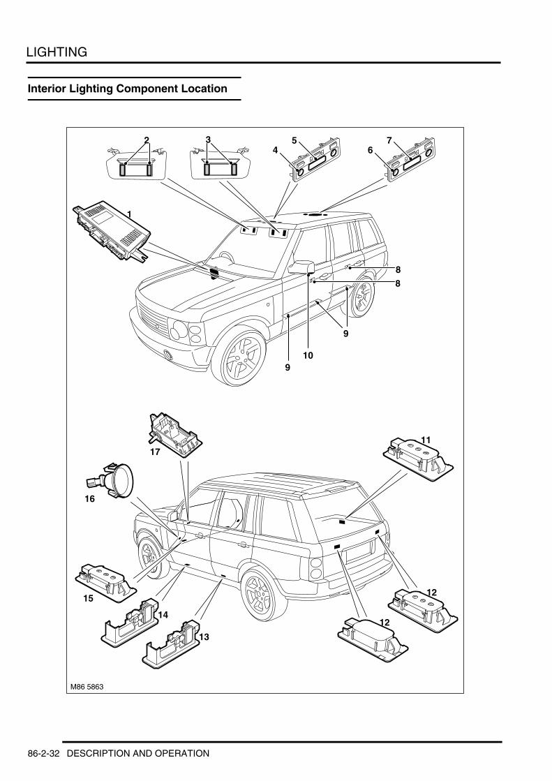
LIGHTING
Interior Lighting Component Location
M86 5863
9
8
1
4
11
56
7
12
12
13
14
15
16
17
2 3
8
109
86-2-32 DESCRIPTION AND OPERATION

LIGHTING
1 Light Check Module (LCM)2 LH vanity mirror illumination lamps3 RH vanity mirror illumination lamps4 Front map reading lamp (2 off)5 Front interior lamp6 Rear map reading lamp (2 off)7 Rear interior lamp8 Door handle illumination LED (4 off - 1 per door)9 Door pocket illumination (6 off - 2 per front door
and 1 per rear door)10 Door mirror approach lamps11 Luggage compartment lamp12 Upper tail door lamps13 Rear door puddle lamps14 Front door puddle lamps15 Footwell lamps (2 off)16 Sill lamps (2 off)17 Glovebox lamp
DESCRIPTION AND OPERATION 86-2-33
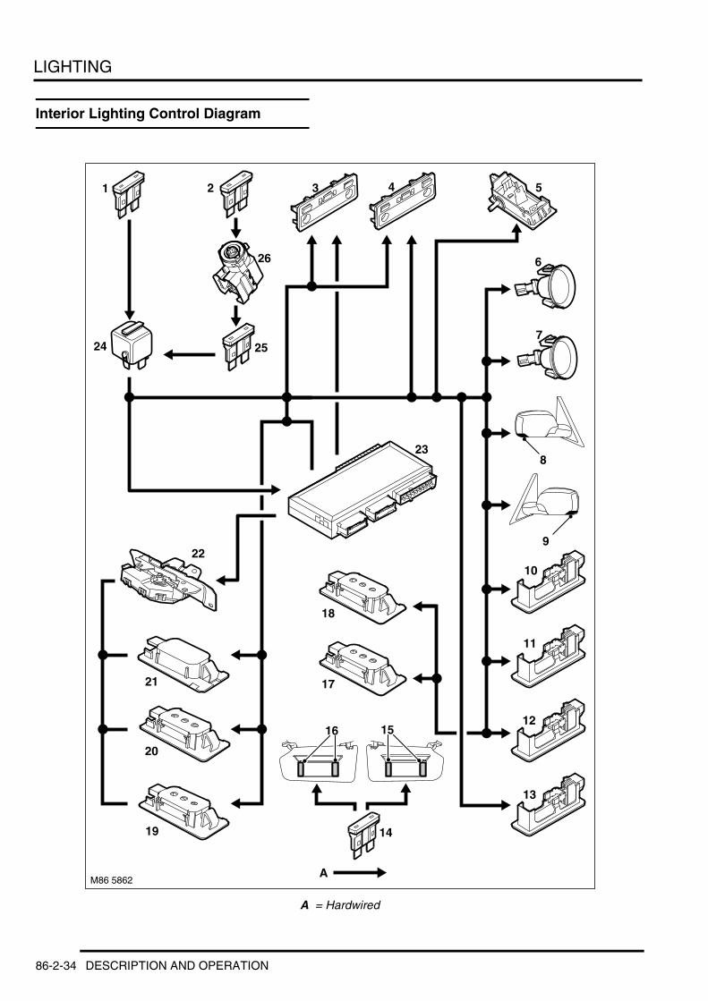
LIGHTING
Interior Lighting Control Diagram
A = Hardwired
9
M86 5862
1
A
2 3 4 5
6
7
8
10
11
12
13
18
17
19
20
21
22
23
14
16 15
24 25
26
86-2-34 DESCRIPTION AND OPERATION
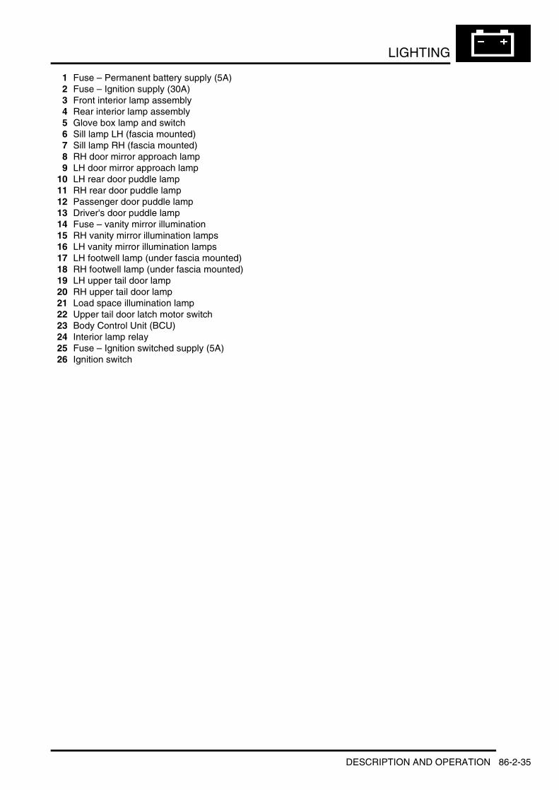
LIGHTING
1 Fuse – Permanent battery supply (5A)2 Fuse – Ignition supply (30A)3 Front interior lamp assembly4 Rear interior lamp assembly5 Glove box lamp and switch6 Sill lamp LH (fascia mounted)7 Sill lamp RH (fascia mounted)8 RH door mirror approach lamp9 LH door mirror approach lamp
10 LH rear door puddle lamp11 RH rear door puddle lamp12 Passenger door puddle lamp13 Driver's door puddle lamp14 Fuse – vanity mirror illumination15 RH vanity mirror illumination lamps16 LH vanity mirror illumination lamps17 LH footwell lamp (under fascia mounted)18 RH footwell lamp (under fascia mounted)19 LH upper tail door lamp20 RH upper tail door lamp21 Load space illumination lamp22 Upper tail door latch motor switch23 Body Control Unit (BCU)24 Interior lamp relay25 Fuse – Ignition switched supply (5A)26 Ignition switch
DESCRIPTION AND OPERATION 86-2-35

LIGHTING
Description
GeneralThe interior lighting is controlled by the Body Control Unit (BCU) which is located below the front passenger seat. The interior lighting comprises the following lamps:l Front interior lamp unitl Rear interior lamp unitl Upper tail door load space lamps (2 off)l Luggage compartment load space lampl Fascia mounted sill lamps (2 off)l Under fascia footwell lamps (2 off)l Door mirror approach lamps (2 off)l Puddle lamps (4 off).
The interior lamps have two modes of operation; automatic or manual. In the automatic mode the interior lamp functionality is controlled by the BCU on receipt of various input signals. In manual mode, the lamps can be switched on and off using the momentary button adjacent to the front interior lamp or can be disabled completely using the same switch.
NOTE: The LED illumination of the front door pockets and the front and rear interior door handles is a function of the LCM and only operates when the light control switch is in the side lamp or headlamp positions.
The following table shows the bulbs used for the interior lighting and their type and rating:
Front and Rear Interior Lamps and Map Reading LampsThe front and rear interior lamp assemblies are similar in design. The front interior lamp switch is connected directly to the BCU and controls the manual operation of the interior lamp functionality. The rear interior lamp switch is used only to switch the lamp on and off.
The map reading lights have a non-adjustable beam and are controlled via separate switches. Both the interior and map reading lamps use capless 5W bulbs.
Luggage Compartment LampsThe luggage compartment lamps comprise one lamp unit located on the RH side trim panel, adjacent to the auxiliary power socket, and two lamps located in the interior trim panel of the upper tail door. All of these lamps are of the same design and use capless 5W bulbs. The lamps are controlled by the BCU and operate on the automatic interior lamp functionality.
Glovebox LampThe glovebox lamp is located inside the glovebox, at the top, adjacent to the latch. The lamp comprises a festoon 5W bulb. The lamp housing also incorporates a plunger type switch which is activated to switch the lamp on when the glovebox lid is opened.
Bulb Type RatingFront and rear interior lamps Capless 6WFront and rear map reading lamps Capless 6W
Load space lamp Capless 5WLuggage compartment lamps (upper tail door) Capless 5WVanity mirror lamps Festoon 14V 0.1A (0.14W)
Door puddle lamps Capless 5WFascia sill lamps Capless 3WLower fascia footwell lamps Capless 5W
Door mirror approach lamps Capless 6WGlovebox lamp Festoon 5W
86-2-36 DESCRIPTION AND OPERATION
LIGHTING
Vanity Mirror Illumination LampsThe vanity mirror lamps are located behind a hinged cover, either side of the mirror glass. A festoon type bulbs fitted in contacts behind each lamp lens. The lamps are activated by a simple switch which operates when the mirror cover is lifted.
Footwell LampsTwo types of footwell lamps are fitted. Two directional sill lamps are located in the front of the fascia and illuminate the sill area. These lamps use 3W capless bulbs.
Two further footwell lamps are located in the lower fascia closing panels and illuminate the area below the fascia. These lamps use 5W capless bulbs. The lamps are controlled by the BCU and operate on the automatic interior lamp functionality.
Door Puddle LampsEach of the doors is fitted with a puddle lamp to illuminate the ground below the door when the door is open. The front door puddle lamps are located in the lower face of the door, facing the ground. The rear door puddle lamps are located in the bottom of the door trim panel.
The puddle lamps use a capless 5W bulb. The puddle lamps are controlled by the BCU and operate on the automatic interior lamp functionality.
Door Mirror Approach LampsThe exterior mirror housings are fitted with a lamp which illuminates the area below the front door. The approach lamps comprise a housing located inside the mirror and bulb holder with harness connector. The housing contains a plastic lens which directs a beam of light in the required area. The approach lamps use a capless 6W bulb.
The lamps are controlled by the BCU, via a dedicated relay which is located at the rear of the passenger compartment fusebox.
DiagnosticsDiagnostics for the interior lamps is limited to a check of the function of the front interior lamp switch. The BCU can be interrogated using TestBook/T4 to establish the correct operation of the front interior lamp switch, the door switches and the tail door switches. + BODY CONTROL UNIT, DESCRIPTION AND OPERATION, Description.
DESCRIPTION AND OPERATION 86-2-37
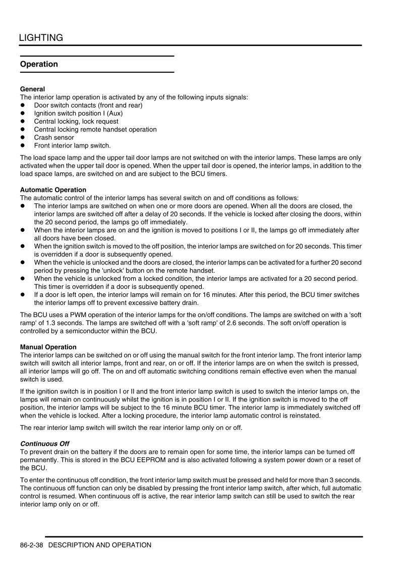
LIGHTING
Operation
GeneralThe interior lamp operation is activated by any of the following inputs signals:l Door switch contacts (front and rear)l Ignition switch position I (Aux)l Central locking, lock requestl Central locking remote handset operationl Crash sensorl Front interior lamp switch.
The load space lamp and the upper tail door lamps are not switched on with the interior lamps. These lamps are only activated when the upper tail door is opened. When the upper tail door is opened, the interior lamps, in addition to the load space lamps, are switched on and are subject to the BCU timers.
Automatic OperationThe automatic control of the interior lamps has several switch on and off conditions as follows:l The interior lamps are switched on when one or more doors are opened. When all the doors are closed, the
interior lamps are switched off after a delay of 20 seconds. If the vehicle is locked after closing the doors, within the 20 second period, the lamps go off immediately.
l When the interior lamps are on and the ignition is moved to positions I or II, the lamps go off immediately after all doors have been closed.
l When the ignition switch is moved to the off position, the interior lamps are switched on for 20 seconds. This timer is overridden if a door is subsequently opened.
l When the vehicle is unlocked and the doors are closed, the interior lamps can be activated for a further 20 second period by pressing the 'unlock' button on the remote handset.
l When the vehicle is unlocked from a locked condition, the interior lamps are activated for a 20 second period. This timer is overridden if a door is subsequently opened.
l If a door is left open, the interior lamps will remain on for 16 minutes. After this period, the BCU timer switches the interior lamps off to prevent excessive battery drain.
The BCU uses a PWM operation of the interior lamps for the on/off conditions. The lamps are switched on with a 'soft ramp' of 1.3 seconds. The lamps are switched off with a 'soft ramp' of 2.6 seconds. The soft on/off operation is controlled by a semiconductor within the BCU.
Manual OperationThe interior lamps can be switched on or off using the manual switch for the front interior lamp. The front interior lamp switch will switch all interior lamps, front and rear, on or off. If the interior lamps are on when the switch is pressed, all interior lamps will go off. The on and off automatic switching conditions remain effective even when the manual switch is used.
If the ignition switch is in position I or II and the front interior lamp switch is used to switch the interior lamps on, the lamps will remain on continuously whilst the ignition is in position I or II. If the ignition switch is moved to the off position, the interior lamps will be subject to the 16 minute BCU timer. The interior lamp is immediately switched off when the vehicle is locked. After a locking procedure, the interior lamp automatic control is reinstated.
The rear interior lamp switch will switch the rear interior lamp only on or off.
Continuous OffTo prevent drain on the battery if the doors are to remain open for some time, the interior lamps can be turned off permanently. This is stored in the BCU EEPROM and is also activated following a system power down or a reset of the BCU.
To enter the continuous off condition, the front interior lamp switch must be pressed and held for more than 3 seconds. The continuous off function can only be disabled by pressing the front interior lamp switch, after which, full automatic control is resumed. When continuous off is active, the rear interior lamp switch can still be used to switch the rear interior lamp only on or off.
86-2-38 DESCRIPTION AND OPERATION

LIGHTING
Crash Signal OperationThe BCU receives a crash signal on a hardwired connection from the DCU in the event of a crash of a severity to activate the airbags. On receipt of this signal, the BCU activates the interior lamps which are on permanently and not subject to the BCU timer.
The crash operation of the interior lamps can only be cancelled by operating the manual switch on the front interior lamp or by locking and unlocking the vehicle.
DESCRIPTION AND OPERATION 86-2-39

LIGHTING
86-2-40 DESCRIPTION AND OPERATION

BODY CONTROL UNIT
BODY CONTROL UNIT DESCRIPTION AND OPERATIONBCU Component Location
DESCRIPTION AND OPERATION 86-3-1
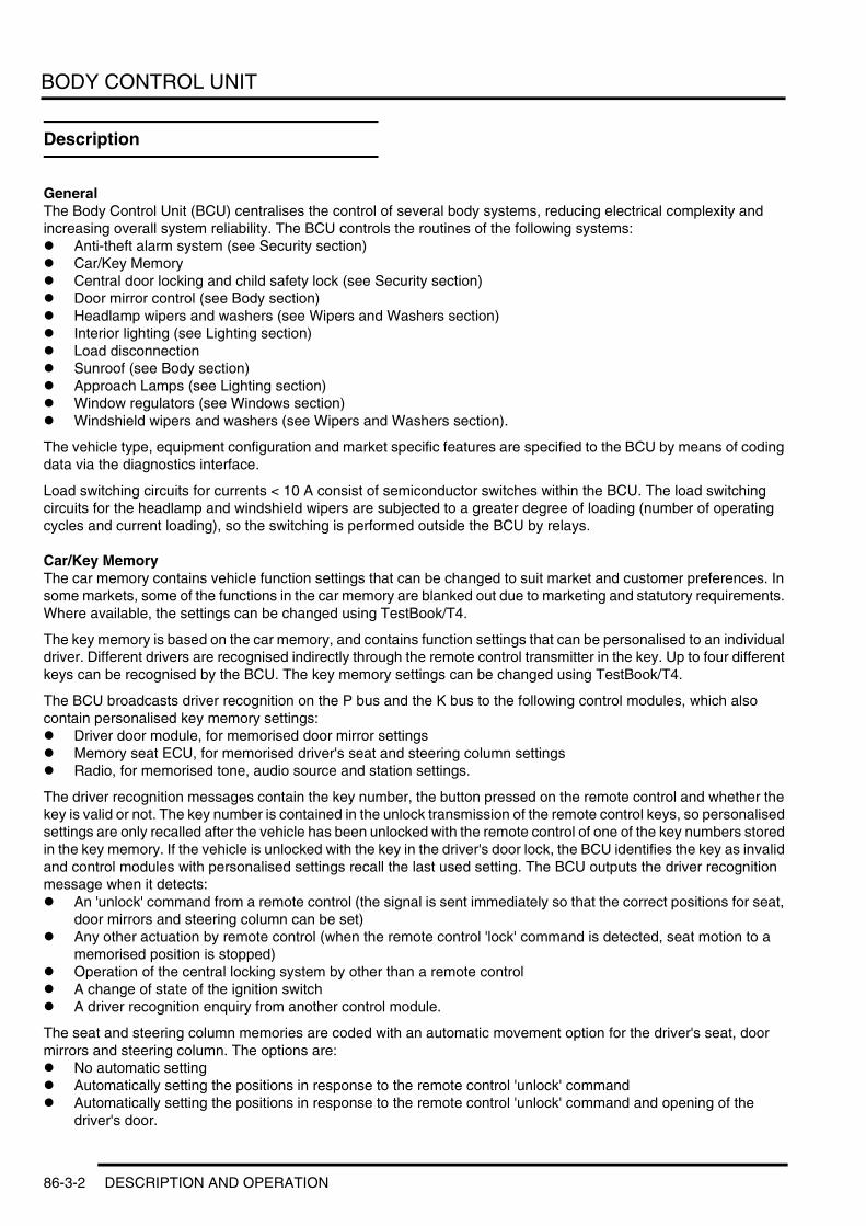
BODY CONTROL UNIT
Description
GeneralThe Body Control Unit (BCU) centralises the control of several body systems, reducing electrical complexity and increasing overall system reliability. The BCU controls the routines of the following systems:l Anti-theft alarm system (see Security section)l Car/Key Memoryl Central door locking and child safety lock (see Security section)l Door mirror control (see Body section)l Headlamp wipers and washers (see Wipers and Washers section)l Interior lighting (see Lighting section)l Load disconnectionl Sunroof (see Body section)l Approach Lamps (see Lighting section)l Window regulators (see Windows section)l Windshield wipers and washers (see Wipers and Washers section).
The vehicle type, equipment configuration and market specific features are specified to the BCU by means of coding data via the diagnostics interface.
Load switching circuits for currents < 10 A consist of semiconductor switches within the BCU. The load switching circuits for the headlamp and windshield wipers are subjected to a greater degree of loading (number of operating cycles and current loading), so the switching is performed outside the BCU by relays.
Car/Key MemoryThe car memory contains vehicle function settings that can be changed to suit market and customer preferences. In some markets, some of the functions in the car memory are blanked out due to marketing and statutory requirements. Where available, the settings can be changed using TestBook/T4.
The key memory is based on the car memory, and contains function settings that can be personalised to an individual driver. Different drivers are recognised indirectly through the remote control transmitter in the key. Up to four different keys can be recognised by the BCU. The key memory settings can be changed using TestBook/T4.
The BCU broadcasts driver recognition on the P bus and the K bus to the following control modules, which also contain personalised key memory settings:l Driver door module, for memorised door mirror settingsl Memory seat ECU, for memorised driver's seat and steering column settingsl Radio, for memorised tone, audio source and station settings.
The driver recognition messages contain the key number, the button pressed on the remote control and whether the key is valid or not. The key number is contained in the unlock transmission of the remote control keys, so personalised settings are only recalled after the vehicle has been unlocked with the remote control of one of the key numbers stored in the key memory. If the vehicle is unlocked with the key in the driver's door lock, the BCU identifies the key as invalid and control modules with personalised settings recall the last used setting. The BCU outputs the driver recognition message when it detects:l An 'unlock' command from a remote control (the signal is sent immediately so that the correct positions for seat,
door mirrors and steering column can be set)l Any other actuation by remote control (when the remote control 'lock' command is detected, seat motion to a
memorised position is stopped)l Operation of the central locking system by other than a remote controll A change of state of the ignition switchl A driver recognition enquiry from another control module.
The seat and steering column memories are coded with an automatic movement option for the driver's seat, door mirrors and steering column. The options are:l No automatic settingl Automatically setting the positions in response to the remote control 'unlock' commandl Automatically setting the positions in response to the remote control 'unlock' command and opening of the
driver's door.
86-3-2 DESCRIPTION AND OPERATION

BODY CONTROL UNIT
Automatic movement of the seat can be stopped by pressing the remote control 'lock' button or any of the seat adjustment or memory switches. Automatic movement can be restarted by pressing the remote control 'lock' button again. Pressing the 'unlock' buttons (for selective central locking) and 'unlocking the boot' does not stop automatic seat movement.
Storage of personalised settings is automatically updated for each setting change provided a valid remote control key has been detected (interruption of the automatic recall movement of the driver seat, door mirrors and steering column is not interpreted as a setting change). The last setting for the recognized driver is automatically stored in the key memory area of the corresponding control module. If no valid remote control key has been detected, setting changes are stored in a recall memory for retrieval when an invalid key is detected.
The following Table contains the car and key memory functions that can be changed (depending on market) using TestBook/T4.
Control Unit Function Parameter Memory TypeATC ECU Recirculation memory Active/ Inactive Car
Instrument pack Language of messages Canadian English; English; French; German; Gulf States; Italian; Japanese; Spanish; US English
Car
Instrument pack Time display (time of day, arrival, timer) 12 or 24 hours clock CarInstrument pack Consumption units Litres/100 km
mpg (UK)mpg (USA); km/litre
Car
Instrument pack Travel units (range, distance) km (km/h)miles (mph)
Car
Instrument pack Temperature unit Active/ Inactive CarInstrument pack Ignition key warning (door open and key
in ignition starter switch)Active/ Inactive Car
Light check module Daytime running lights Europe Active/ Inactive Car
Light check module Daytime running lights NAS Active/ Inactive CarLight check module Headlamp courtesy delay time duration
(ignition key removed and headlight flasher activated)
0 to 240 seconds at fixed intervals
Car
PDC PDC sounder volume (rear sounder) Levels 1 (quiet) to 6 (loud) CarRadio Tone, audio source and last station save Active/ Inactive CarDriver seat module Automatic assumption of last driver
specific positions for seat, steering column and exterior mirrors
InactiveAfter unlocking doorAfter unlocking and opening door
Car
BCU Alarm arming/ disarming Lock and remote controlOnly with remote control
Car
BCU Alarm armed acknowledgement, acoustic
Active/ Inactive Car
BCU Alarm disarmed acknowledgement, acoustic
Active/ Inactive Car
BCU Alarm armed acknowledgement, visual Active/ Inactive CarBCU Alarm disarmed acknowledgement,
visualActive/ Inactive Car
BCU Panic mode Active/ Inactive Car
BCU Visual acknowledgement of locking without arming alarm, by lock and remote control
Active/ Inactive Car
BCU Interior lamps on with multiple actuation central locking system
Active/ Inactive Car
BCU Soft On/Off Active/ Inactive Car
BCU Automatic locking 2 minutes after unlocking without opening
Active/ Inactive
BCU Automatic locking after driving off Active/ Inactive Car
DESCRIPTION AND OPERATION 86-3-3

BODY CONTROL UNIT
Load DisconnectionThe BCU supplies various electrical loads on the vehicle, such as the glovebox lamp, reading lamps, luggage compartment lamps, etc., that can be switched on and remain on when the vehicle is parked. A central load disconnection feature in the BCU ensures the battery is not discharged in the event these loads are switched on continuously. The trigger time after the ignition is switched off is 16 minutes and is independent of the sleep mode timer.
The BCU also disconnects the following loads while the engine cranks, to maximise the available power from the battery:l Wipersl Washer pumpl Headlamp cleaningl Window regulatorsl Sunroof.
If the one-touch function of a window or sunroof is active before the load disconnection, the function is not continued when engine cranking stops.
Sleep ModeTo conserve power, the entire BCU goes into a 'sleep' mode 16 minutes after signal activity ceases and the ignition is switched off. The typical current consumption of the BCU in sleep mode is 1.25 mA. In the sleep mode the BCU is in a limited operational mode from which it can be awakened by certain relevant wake-up signals. After being awakened, the BCU remains awake for 1 minute if no action is triggered. If an action is triggered, the BCU remains awake for at least 16 minutes.
BCU Automatic locking threshold speed after driving off
2.5 to 17.5 mph (4 to 28 km/h) at fixed intervals
Car
BCU Driver's window one-touch open function Active/Inactive Car
BCU Driver's window one-touch close function Active/Inactive CarBCU Front passenger window one-touch open
functionActive/Inactive Car
BCU Front passenger window one-touch close function
Active/Inactive Car
BCU Rear windows one-touch open function Active/Inactive CarBCU Rear windows one-touch close function Active/Inactive Car
BCU Window switch-off criterion EuropeNAS
Car
BCU Wiper reset (only without rain sensor) Active/Inactive CarBCU Comfort function via remote control,
open all windows and sunroofActive/Inactive Car
BCU Comfort function via remote control, close all windows and sunroof
Active/Inactive Car
BCU Sunroof one-touch slide open function Active/Inactive CarBCU Sunroof one-touch slide close function Active/Inactive Car
BCU Automatic locking after driving off Active/ Inactive KeyBCU Remote central locking actuation 1st press open driver's door, 2nd
press open all doors1st press open all doors
Key
Control Unit Function Parameter Memory Type
86-3-4 DESCRIPTION AND OPERATION
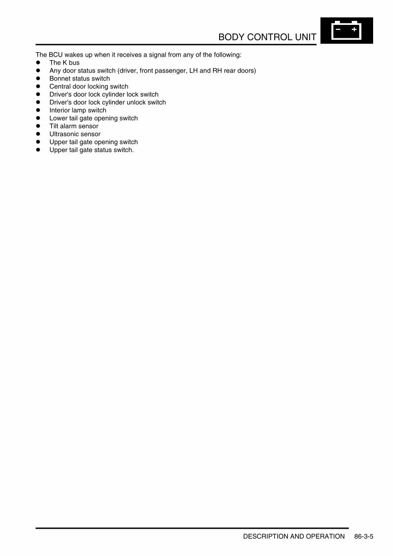
BODY CONTROL UNIT
The BCU wakes up when it receives a signal from any of the following:l The K busl Any door status switch (driver, front passenger, LH and RH rear doors)l Bonnet status switchl Central door locking switchl Driver's door lock cylinder lock switchl Driver's door lock cylinder unlock switchl Interior lamp switchl Lower tail gate opening switchl Tilt alarm sensorl Ultrasonic sensorl Upper tail gate opening switchl Upper tail gate status switch.
DESCRIPTION AND OPERATION 86-3-5

BODY CONTROL UNIT
BCU Harness Connectors
BCU Harness Connector C0660 Pin Details
Pin No. Description Input/Output1 Battery power supply Input
2 Front interior lamp switch Output3 Windscreen washer switch Input4 Windscreen wipers switch 2 Input
5 Windscreen wipers switch 1 Input6 LH (RHD) or RH (LHD) rear door open/close contacts Input7 RH (RHD) or LH (LHD) rear door open/close contacts Input
8 to 11 Not used –12 K bus Input/Output13 Central door locking remote control serial bus Input/Output
14 Ground –15 RH (RHD) or LH (LHD) rear window switch close selection Input16 Not used –
17 LH (RHD) or RH (LHD) rear window switch open selection Input18 LH (RHD) or RH (LHD) rear window switch close selection Input19 Upper tail door open/close contacts Input
20 Windscreen wipers reset switch Input21 Not used –22 Lower tail door release switch Input
23 Auxiliary power supply Input24 Central door locking switch Input25 P bus Input/Output
26 RH (RHD) or LH (LHD) rear window switch open selection Input
M86 5978C0661
C0662
C0660
86-3-6 DESCRIPTION AND OPERATION

BODY CONTROL UNIT
BCU Harness Connector C0661 Pin Details
BCU Harness Connector C0662 Pin Details
Pin No. Description Input/Output1 Not used –2 Bonnet switch Input3 Not used –
4 Rapid tyre deflation signal Input5 Alarm trigger from volumetric sensor Input
6 and 7 Not used –
8 Alarm trigger from tilt sensor Input9 Not used –
10 Upper tail door external release switch Input
11 Upper tail door internal release switch Input12 RH (RHD) or LH (LHD) rear window anti-trap sensor Input13 SRS crash signal Input
14 Not used –15 Windscreen wipers on Output16 Windscreen wipers stage 2 Output
17 Headlamp wash/wipe relay Output18 Not used –19 Alarm LED Output
20 Alarm arm/disarm signal Output21 Not used –22 Lower tail door release relay Output
23 Road speed Input24 LH (RHD) or RH (LHD) rear window anti-trap sensor Input25 Windscreen wipers delay switch Input
26 Ground –
Pin No. Description Input/Output1 Ground –2 RH (RHD) or LH (LHD) rear window motor open Output
3 Upper tail door release actuator Output4 Battery power supply Input5 LH (RHD) or RH (LHD) rear window motor open Output
6 Lock rear doors and fuel filler flap Output7 and 8 Not used –
9 Servotronic activation Output
10 Battery power supply Input11 Servotronic measurement resistor Input12 RH (RHD) or LH (LHD) rear window motor close Output
13 Superlock rear doors and fuel filler flap Output14 Unlock rear doors and fuel filler flap Output15 LH (RHD) or RH (LHD) rear window motor close Output
16 Not used –17 Alarm activation Output18 Windscreen washer pump Output
19 Load disconnection Output20 Interior lamps Output
DESCRIPTION AND OPERATION 86-3-7

BODY CONTROL UNIT
DiagnosticsDiagnostic monitoring is included in the operating software of the BCU and is performed on a continual basis. All of the input and output signals which are relevant for diagnostics can be read out and injected using TestBook/T4. Detected faults are stored in the non volatile memory (EEPROM) of the BCU.
All faults stored by the BCU are stored chronologically, with a fault counter, in a fault or information area of the memory. Faults which positively point to one or more defective components are stored in the fault area. Faults which do not positively point to a defective component are stored in the information area to provide information during troubleshooting. The BCU ignores faults detected within 32 seconds of power up or when battery voltage is less than 9 V.
A distinction is made between sporadic and static faults. Sporadic faults are those which have occurred at least once, and the cause of the fault message was no longer present at least one time. Static faults are faults which are still active at the time diagnostics are performed.
The BCU can store up to 30 faults at any one time. If further faults are detected following the 30th fault they are ignored. Faults can only be erased using TestBook/T4.
Up to 16 faults stored by the BCU are also stored in those modules connected to the BCU via the P bus, i.e. the driver and passenger door modules and the sunroof module. Faults stored in the peripheral modules cannot be accessed via the diagnostic socket. The faults in the peripheral modules are used for diagnosing modules after they are removed from the vehicle.
86-3-8 DESCRIPTION AND OPERATION
COMMUNICATION DATA BUSES
Deze pagina werd opzettelijk niet gebruikt
Cette page est intentionnellement vierge
Questa pagina è stata lasciata in bianco di proposito
Diese Seite ist leer
Esta página foi deixada intencionalmente em branco
Esta página fue dejada en blanco intencionalmente
This page is intentionally left blank
COMMUNICATION DATA BUSESDESCRIPTION AND OPERATION
DESCRIPTION AND OPERATION 86-4-1
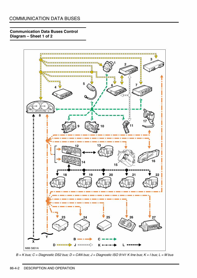
COMMUNICATION DATA BUSES
Communication Data Buses Control Diagram – Sheet 1 of 2
B = K bus; C = Diagnostic DS2 bus; D = CAN bus; J = Diagnostic ISO 9141 K line bus; K = I bus; L = M bus
M86 5801A
XL
B C
13
5 6 7
9 10 11
1415
17
16
18 19 20 21 22
25 26 27
12
Y
2
23 24
D
8
13
4
J K
86-4-2 DESCRIPTION AND OPERATION

COMMUNICATION DATA BUSES
1 ABS ECU2 EAT ECU (ZF shown)3 Air suspension ECU4 Td6 ECM5 Steering angle sensor6 V8 ECM7 Transfer box ECU8 Instrument pack9 LH xenon headlamp ECU
10 RH xenon headlamp ECU11 Diagnostic socket12 Low line ATC ECU13 Air distribution motor14 High line ATC ECU15 Steering column lock ECU16 Seat module17 FBH18 Face level air distribution motor19 Windscreen air distribution motor20 Footwell air distribution motor21 Rear face level temperature blend motor22 Ram air motor23 Headlamp levelling ECU24 Immobilisation ECU25 TPM ECU26 Rain sensor27 SRS DCU
DESCRIPTION AND OPERATION 86-4-3

COMMUNICATION DATA BUSES
Communication Data Buses Control Diagram – Sheet 2 of 2
B = K bus; K = I bus; M = P bus
M86 5802
X
K
5
6
12111097 8
13 14 15
16
22212019
1
Y
MB
17 18
423
86-4-4 DESCRIPTION AND OPERATION
COMMUNICATION DATA BUSES
1 BCU2 Front passenger door module3 Driver door module4 Sunroof ECU5 Multi information display6 ICE power amplifier7 Navigation computer – Europe8 Navigation computer – Japan9 Radio
10 Radio/Cassette player11 Video module12 Multi function display13 CD autochanger14 PDC ECU15 Light check module16 Rotary coupler17 Steering wheel LH switch pack18 Steering wheel RH switch pack19 Voice recognition ECU20 Telephone module (NAS)21 Telephone module (Non NAS)22 Telephone eject box
DESCRIPTION AND OPERATION 86-4-5

COMMUNICATION DATA BUSES
Description
GeneralA number of different types of data bus are incorporated into the vehicle wiring harnesses for the transmission of commands and information between ECU’s. The bus configuration installed on a particular vehicle depends on the model and equipment level:l Controller Area Network (CAN) bus. A network connected between the brake, powertrain, steering and
suspension related ECU’sl Diagnostic buses. Two networks that, directly and indirectly, connect the diagnostic socket to all of the of the
ECU’s installed on the vehiclel I bus. A network connected between ECU's of the 'Information' systemsl K bus. A network connected between ECU’s of the 'body' systemsl M bus. A network connected between the ATC ECU and motors on the heater assemblyl P bus. A network connected between the BCU and 'Peripheral' ECU's.
Serial interface circuits in the ECU’s transmit and receive commands and information on the buses as digital messages. ECU’s connected to the same bus use a common protocol (format) and baud rate (transmission speed) for the messages they transmit. The protocol and baud rate varies between bus networks. To enable messages to be exchanged between ECU’s from different bus networks, the instrument pack provides a communication gateway. A microprocessor in the instrument pack converts and/or re-transmits messages between bus networks.
The CAN bus is a high speed broadcast network where the ECU’s automatically transmit information on the bus every few microseconds. The other buses are low speed networks which are mainly event driven, i.e. an ECU outputs a message only in response to a request message from another ECU or a hard wired input from a switch or sensor.
A twisted pair of wires are used for the CAN bus and single wires are used for all of the other buses. Bus wires can be repaired using crimped connections. The unwound length of CAN bus wires must not exceed 40 mm (1.6 in).
Data Bus Types
The diagnostic socket is connected to all of the ECU’s on the bus networks either directly, via the diagnostic buses, or indirectly via the instrument pack. The diagnostic socket is located in a pocket in the fascia, next to the driver's side A post.
Bus Baud rate (kbit/s) ProtocolCAN 500 SAE J1850
Diagnostic DS2 9.6 Corporate for diagnostics + ISO keyword 2000*Diagnostic ISO 9141 K line 10.4 ISO keyword 2000 star + ISO keyword 2000 (for scan tools)
I 9.6 Corporate for body systemsK 9.6 Corporate for body systemsM 9.6 Corporate for body systems
P 9.6 Corporate for body systems
86-4-6 DESCRIPTION AND OPERATION

COMMUNICATION DATA BUSES
Diagnostic Socket
1 Hinged cover 2 Diagnostic socket
DESCRIPTION AND OPERATION 86-4-7

COMMUNICATION DATA BUSES
86-4-8 DESCRIPTION AND OPERATION
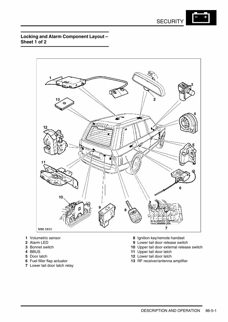
SECURITY
SECURITYDESCRIPTION AND OPERATIONLocking and Alarm Component Layout – Sheet 1 of 2
1 Volumetric sensor2 Alarm LED3 Bonnet switch4 BBUS5 Door latch6 Fuel filler flap actuator7 Lower tail door latch relay
8 Ignition key/remote handset9 Lower tail door release switch
10 Upper tail door external release switch11 Upper tail door latch12 Lower tail door latch13 RF receiver/antenna amplifier
DESCRIPTION AND OPERATION 86-5-1
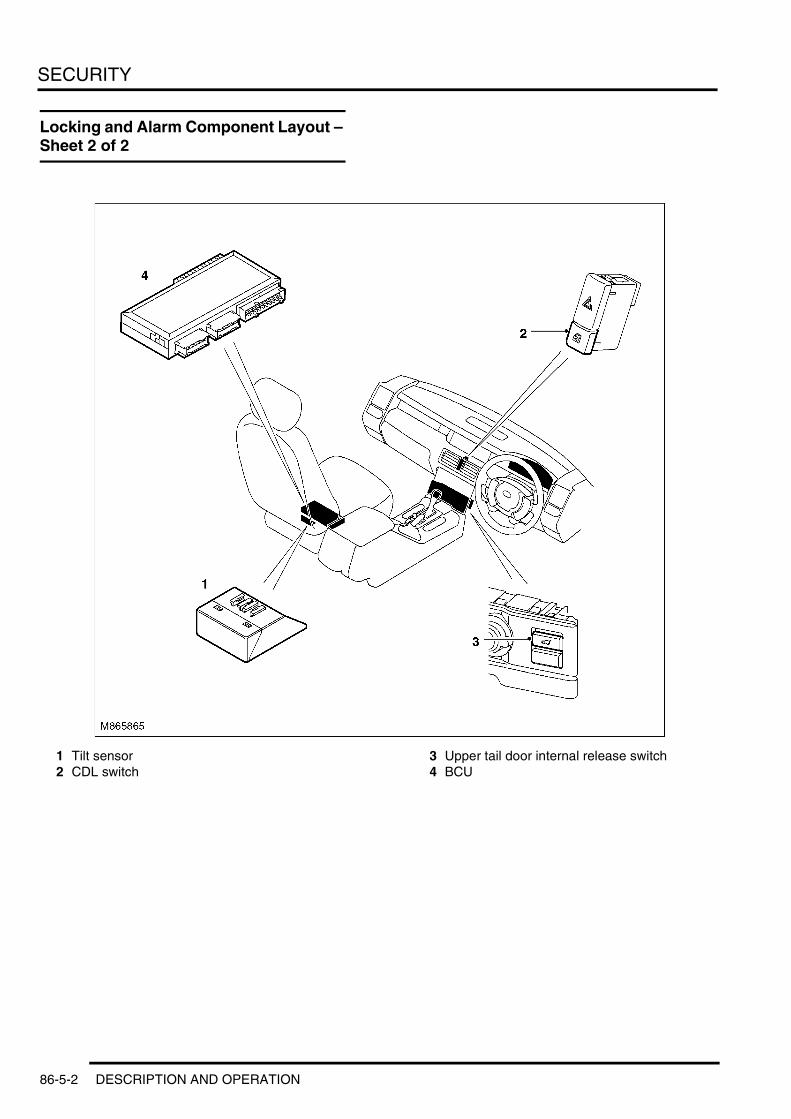
SECURITY
Locking and Alarm Component Layout – Sheet 2 of 2
1 Tilt sensor2 CDL switch
3 Upper tail door internal release switch4 BCU
86-5-2 DESCRIPTION AND OPERATION
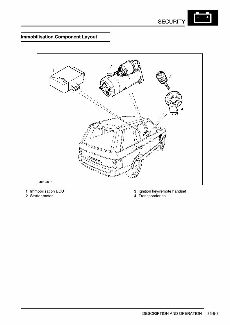
SECURITY
Immobilisation Component Layout
1 Immobilisation ECU2 Starter motor
3 Ignition key/remote handset4 Transponder coil
DESCRIPTION AND OPERATION 86-5-3

SECURITY
Description
GeneralThe security system is split into three elements: the locking system, the alarm system and the immobilisation system. The locking and alarm systems are controlled by the Body Control Unit (BCU). The immobilisation system is controlled by a dedicated ECU. The arming and disarming of the alarm system is linked to the activation of the locking system. The immobilisation system operation is independent of both the locking and the alarm systems.
Locking and Alarm SystemsAll vehicles incorporate a remote handset Central Door Locking (CDL) system and an alarm system with perimetric and volumetric protection functions. Specific features and modes of operation depend on the car/key memory settings in the BCU.
The CDL system controls the locking and unlocking of the side doors and fuel filler flap, and the opening of the tail doors. System features include automatic locking at a set vehicle speed and Single Point Entry (SPE).
The alarm system monitors for unauthorised entry, opening of doors and bonnet, vehicle movement and interference with the electrical system, and sounds an alarm if an event is detected. The alarm system can be configured to automatically arm and disarm with operation of the locking system. The locking and alarm systems incorporate:l Actuators and switches in the door latchesl A bonnet switchl A fuel filler flap actuatorl A CDL switchl Upper tail door internal release switchl Upper tail door external release switchl Lower tail door release switchl A lower tail door release relayl Remote handsetsl A Radio Frequency (RF) receiver (market dependant)l An infrared receiver (market dependant)l An alarm Light Emitting Diode (LED)l A Battery Backed Up Sounder (BBUS)l A volumetric sensorl A tilt sensor.
Door LatchesThe side door latches are sealed units that incorporate separate actuators for locking and superlocking the doors, and a Hall effect sensor to provide a door status signal for the BCU. The driver's door latch incorporates two additional Hall effect sensors to provide signals of lock and unlock selections made with the ignition key in the door lock. Turning the top of the ignition key rearwards sends a lock signal and turning the top of the ignition key forwards sends an unlock signal. The driver and front passenger door latches communicate with the BCU via their respective door modules and the P bus. The rear door latches are connected direct to the BCU.
The upper tail door latch incorporates a release actuator to open the upper tail door and a microswitch to provide an upper tail door status signal. A black manual release wire is attached to the upper tail door latch to allow the latch to be released in the event of actuator failure or loss of power. The end of the manual release wire is stowed in the inside trim at the bottom edge of the upper tail door and is concealed by the trailing edge of the parcel shelf when the upper tail door is closed.
Each lower tail door latch is connected to a release actuator mounted inside the tail door. A lever at the top of each latch housing allows the latches to be released in the event of actuator failure or loss of power. The levers are only accessible when the upper tail door is open.
86-5-4 DESCRIPTION AND OPERATION

SECURITY
Side Door Latch
Upper Tail Door Latch
1 Status microswitch 2 Release actuator
Bonnet SwitchThe bonnet switch is a plunger operated switch installed in the engine compartment on the driver's side secondary bulkhead. When the bonnet is closed, the bonnet presses the plunger into the switch housing and holds the switch open. When the bonnet opens, the spring loaded plunger extends, which allows the switch to close and connect a ground to the BCU. The switch can also be held open with the bonnet open, by pulling the switch up.
Fuel Filler Flap ActuatorThe fuel filler flap actuator extends and retracts a wire reinforced plastic pin to lock and unlock the fuel filler flap. A green manual release wire is attached to the pin to ensure the fuel filler flap can be released in the event of actuator failure or loss of power. The end of the manual release wire is stowed in the soundproofing behind the trim panel covering the rear fusebox.
DESCRIPTION AND OPERATION 86-5-5

SECURITY
CDL SwitchThe CDL switch is a non latching push switch installed between the centre face vents on the fascia, below the hazard warning switch. The CDL switch allows occupants to centrally lock the vehicle without arming the alarm. When the CDL switch is pressed, a battery voltage signal is connected to the BCU.
Upper Tail Door Internal Release SwitchThe internal upper tail door release switch is a non latching push switch installed on the centre console. The switch allows the tail door to be opened from inside the vehicle. When the switch is pressed a ground is connected to the BCU. The BCU only responds to the input when the CDL system is unlocked and the vehicle is stationary.
Upper Tail Door External Release SwitchThe external upper tail door release switch is a microswitch installed in the license plate lamp housing in the bottom edge of the upper tail door. The switch is operated by a lever connected to a rubber covered plate set into the outside surface of the license plate lamp housing. When the switch is activated it connects a ground to the BCU. The BCU only responds to the input when the CDL system is unlocked and the vehicle is stationary.
Lower Tail Door Release SwitchThe lower tail door release switch is a non latching push switch installed under a rubber cover in the top edge of the lower tail door. When the switch is pressed, a battery voltage signal is connected to the BCU. The BCU only responds to the input when the upper tail door is unlatched and the vehicle is stationary.
Lower Tail Door Release RelayThe lower tail door release relay is installed on the rear fusebox. When the BCU receives a valid input from the lower tail door release switch, it momentarily energises the relay to simultaneously activate the lower tail door release actuators.
Remote HandsetsThe remote handset is incorporated into the head of the ignition key. Up to four different remote handsets can be initialised for use on the same vehicle.
The type of transmitter is market dependent and is either a Radio Frequency (RF) transmitter, operating at 315 or 433 MHz, or an infrared transmitter. RF transmitters communicate with the vehicle through the radio antenna integrated into the rear window heater and have an operating range of 10 m (32.8 ft) minimum and up 30 m (98.4 ft) under optimum conditions. Infrared transmitters communicate with the vehicle through an infrared receiver integrated into the interior rear view mirror and have an operating range of 3 m (9.8 ft) minimum and up to 5 m (16.4 ft) under optimum conditions.
Each remote handset incorporates a signal processor, transmitter and power supply in a dustproof and waterproof housing. Buttons on the housing operate the remote functions. An LED on the housing flashes when a button is pressed to confirm operation to the user. If the LED does not flash when a button is pressed the battery needs recharging/replacing.
RF remote handsets have three operating buttons:l The lock button, for locking and superlocking of the vehicle and convenience closing of the windows and sunroofl The unlock button, for unlocking the vehicle and convenience opening of the windows and sunroofl The tail door open button, for opening the tail door while the rest of the vehicle remains locked and for panic alarm
activation.
Infrared remote handsets only have two operating buttons, a lock button and an unlock button.
86-5-6 DESCRIPTION AND OPERATION

SECURITY
RF Remote Handset
1 Tail door open button2 Lock button
3 Unlock button4 LED
The remote handset functions as follows:l One press of the lock button for superlockingl Two presses of the lock button for no volumetric protectionl Press and hold the tail door switch for panic mode.
The power supply in the remote handset is provided by a single button cell battery on RF systems and two button cell batteries on infrared systems. When the batteries need replacing the message 'KEY BATTERY LOW' will be displayed in the message centre. When the batteries are replaced, the old ones should be removed and the new ones installed within 1 minute or stored data will be lost and the remote handset will need to be re-initialised.
M86 5943
3
2 1
4
DESCRIPTION AND OPERATION 86-5-7

SECURITY
Battery Replacement on RF Remote Handset
1 Securing screw cover2 Securing screw3 Battery cover
4 Battery5 Remote handset
Every signal from the remote handset contains the transmitter identification code and a rolling code. The BCU checks the codes and only responds if the signal is from a valid transmitter. During vehicle production, the remote handsets supplied with the vehicle are initialised to set their individual transmitter identification codes and synchronise their respective rolling codes with the BCU. If a transmitter loses synchronisation with the BCU, or if a replacement or additional remote handset is to be used with the vehicle, the initialisation procedure must be repeated. During the procedure, all remote handsets for use with the vehicle must be initialised.
Initialisation Procedure1 Ensure the vehicle is unlocked and the driver and front passenger doors are closed.2 Install a key/remote handset in the ignition switch, then turn the ignition switch to position I and back to position
0 in less than 5 seconds to put the BCU into the initialisation mode. Continue the procedure within 30 seconds of turning the ignition switch to position 0.
3 Remove the key/remote handset from the ignition switch.4 Press and hold the unlock button for a maximum of 15 seconds. During this time, momentarily press the lock
button three times within 10 seconds.5 Release both buttons.6 Successful initialisation is indicated by the BCU locking then unlocking the vehicle. If this does not occur, repeat
step 4.7 Repeat steps 4 and 5 with all other remote handsets belonging to the vehicle (4 maximum). Begin the
initialisation of each remote handset within 30 seconds of completing the previous initialisation, or the BCU will drop out of the initialisation mode and the complete procedure will have to be started again.
RF Receiver (Where Fitted)The RF receiver converts the signals from the RF remote handset into digital messages and transmits them to the BCU. The RF receiver is integrated into the rear window antenna amplifier installed behind the inner trim on the top left edge of the upper tail door. Operation of the receiver is powered by a permanent battery feed from the rear fusebox.
M86 5944
1
2
3
5
4
86-5-8 DESCRIPTION AND OPERATION

SECURITY
Infrared Receiver (Where Fitted)The infrared receiver converts the signals from the infrared remote handset into digital messages and transmits them to the BCU. The infrared receiver is integrated into the interior rear view mirror, with the receiving diodes installed in the red knob on the underside of the mirror. Operation of the receiver is powered by a permanent battery feed from the passenger compartment fusebox.
Alarm LEDThe alarm LED is installed in the red knob on the underside of the interior rear view mirror to provide a visual indication of the alarm system status. Operation of the LED is controlled by the BCU.
Alarm System Status Indications
BBUSThe BBUS is installed in the rear corner of the engine compartment, on the driver's side, on a bracket attached to the front wing. Depending on the BCU configuration, the BBUS can be used to produce the audio acknowledgement for arming and disarming of the alarm system as well as the audio warning after an alarm has been triggered.
The BBUS is normally operated by a permanent battery feed from the passenger compartment fusebox. An integral 7.2 V rechargeable battery powers the BBUS if it is disconnected from the vehicle battery.
The BBUS sounds when it receives an alarm or acknowledgement signal from the BCU. While the alarm system is armed, the BBUS also monitors the battery power supply and the arm/disarm signal line from the BCU, and operates the sounder if the battery power supply or the arm/disarm signal line is disconnected. The BCU arms and disarms the BBUS together with the rest of the alarm system.
Once an alarm has been triggered, the BBUS cycles the sounder on for 30 seconds and off for 15 seconds, for 5 minutes or until it receives a disarm signal from the BCU. If the alarm trigger is still present, the 5 minutes of on/off cycles is repeated a further 2 times. The alarm output from the BBUS is either a constant tone or a modulated tone, depending on the market. The continuous tone has a nominal value of 113 dBA when powered by the vehicle battery and 108 dBA when powered by the integral battery. The modulated tone has a nominal value of 109 dBA when powered by the vehicle battery and 104 dBA when powered by the integral battery.
Alarm Mode Alarm LEDDisarmed OffArmed Flashes at 0.5 Hz (slow flashing)
Arming Rapid flashing for 10 seconds maximum, then begins flashing at 0.5 Hz.
Alarm triggered Rapid flashing for 5 minutes then continues flashing at 0.5 Hz.Re-arming less than 10 seconds after disarming On for 1 secondDisarming Off
Disarming after alarm Rapid flashing for 10 seconds then offEmergency disarming On for 10 minutesVehicle locked (alarm not coded in BCU) On for 10 seconds
Unauthorised engine start detected by immobilisation system Rapid flashing until immobilisation system deactivated
DESCRIPTION AND OPERATION 86-5-9

SECURITY
BBUS Harness Connector
BBUS Harness Connector C0666 Pin Details
Volumetric SensorThe volumetric sensor is installed behind openings in the rear interior lamp and monitors for intrusion into the passenger compartment when the alarm is armed.
The volumetric sensor consists of a microcontroller, two acoustic transmitters and two acoustic receivers. One transmitter/receiver pair faces forwards and one transmitter/receiver pair faces rearwards to ensure complete coverage of the passenger compartment. The front transmitter/receiver pair are in a rubber mounting attached to the microcontroller housing. The rear transmitter/receiver pair are in a remote rubber mounting and connected to the microcontroller housing by a four wire lead.
The volumetric sensor is powered by a permanent battery feed from the passenger compartment fusebox. The BCU activates and de-activates the volumetric sensor when it arms and disarms the alarm system. When the volumetric sensor is active it outputs ultrasonic pulses from the transmitters and checks the echoes picked up by the receivers for changes to the passenger compartment profile. If it detects a change of profile indicating movement in the passenger compartment the volumetric sensor reports the alarm to the BCU.
Each time the volumetric sensor is activated it performs a self test. If there are no faults the volumetric sensor sends an acknowledgement signal to the BCU. If the BCU does not receive the acknowledgement signal it de-activates the volumetric sensor.
Pin No. Description Input/Output1 Ground –2 Arm/Disarm signal Input
3 Battery power supply Input4 Alarm activation Input
M86 5979
C0666
86-5-10 DESCRIPTION AND OPERATION

SECURITY
Volumetric Sensor
1 Front transmitter/receiver pair 2 Rear transmitter/receiver pair
Volumetric Sensor Harness Connector
Volumetric Sensor Harness Connector C0359 Pin Details
Pin No. Description Input/Output1 Ground –2 Arm/Disarm signal Input3 Alarm indication Output
4 Battery power supply Input
DESCRIPTION AND OPERATION 86-5-11
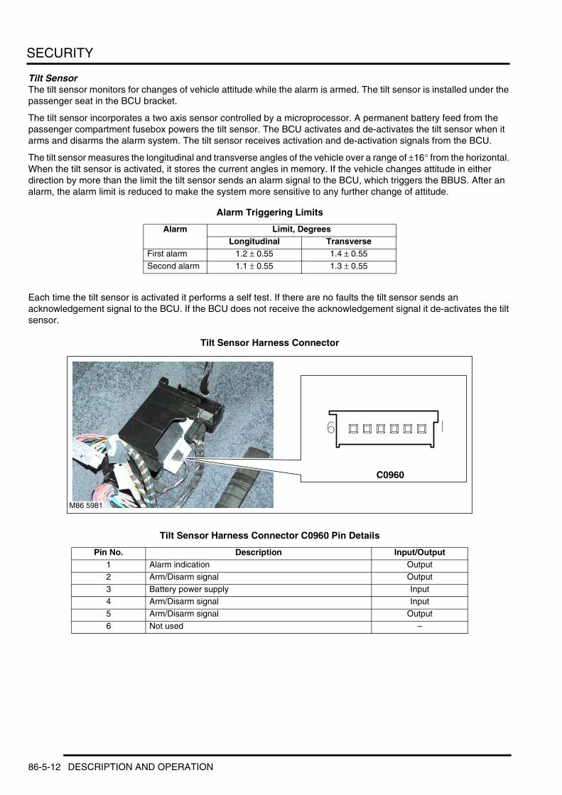
SECURITY
Tilt SensorThe tilt sensor monitors for changes of vehicle attitude while the alarm is armed. The tilt sensor is installed under the passenger seat in the BCU bracket.
The tilt sensor incorporates a two axis sensor controlled by a microprocessor. A permanent battery feed from the passenger compartment fusebox powers the tilt sensor. The BCU activates and de-activates the tilt sensor when it arms and disarms the alarm system. The tilt sensor receives activation and de-activation signals from the BCU.
The tilt sensor measures the longitudinal and transverse angles of the vehicle over a range of ±16° from the horizontal. When the tilt sensor is activated, it stores the current angles in memory. If the vehicle changes attitude in either direction by more than the limit the tilt sensor sends an alarm signal to the BCU, which triggers the BBUS. After an alarm, the alarm limit is reduced to make the system more sensitive to any further change of attitude.
Alarm Triggering Limits
Each time the tilt sensor is activated it performs a self test. If there are no faults the tilt sensor sends an acknowledgement signal to the BCU. If the BCU does not receive the acknowledgement signal it de-activates the tilt sensor.
Tilt Sensor Harness Connector
Tilt Sensor Harness Connector C0960 Pin Details
Alarm Limit, DegreesLongitudinal Transverse
First alarm 1.2 ± 0.55 1.4 ± 0.55
Second alarm 1.1 ± 0.55 1.3 ± 0.55
Pin No. Description Input/Output1 Alarm indication Output2 Arm/Disarm signal Output
3 Battery power supply Input4 Arm/Disarm signal Input5 Arm/Disarm signal Output
6 Not used –
M86 5981
C0960
86-5-12 DESCRIPTION AND OPERATION
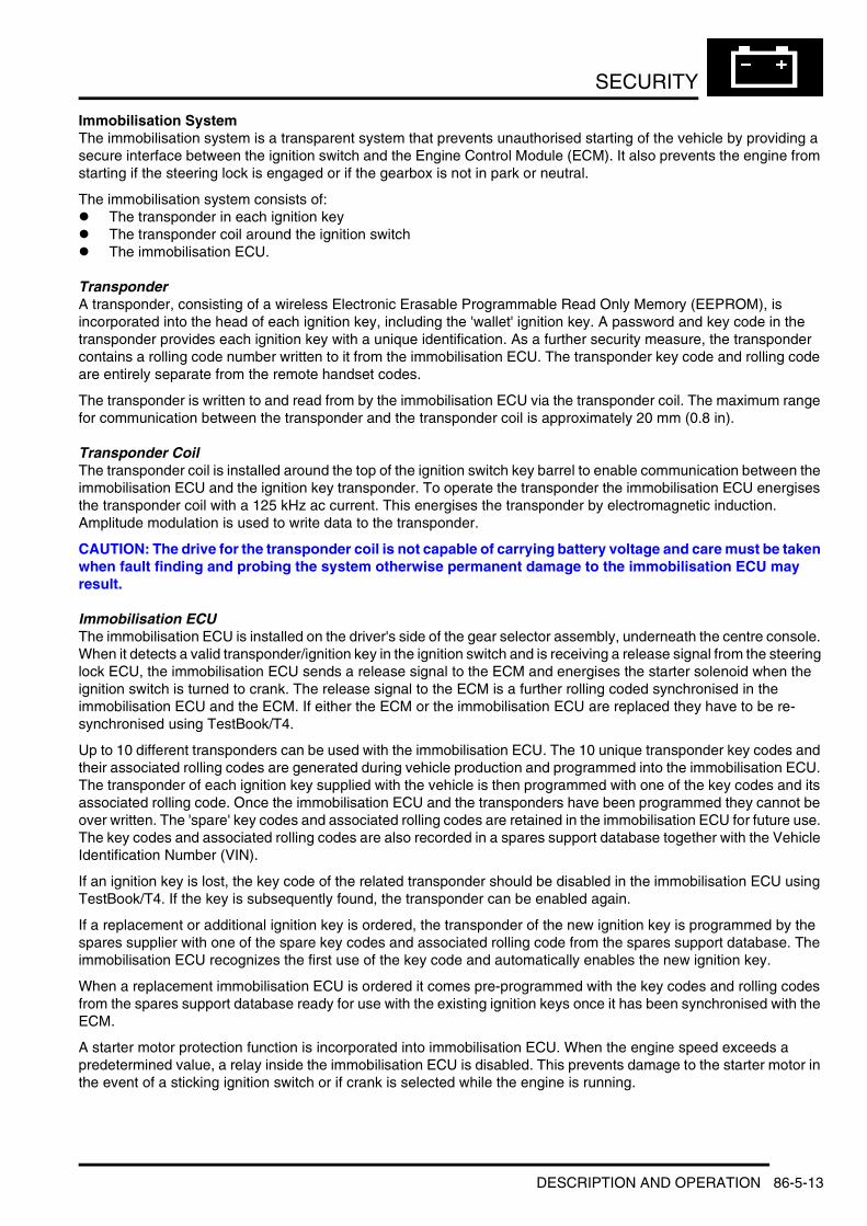
SECURITY
Immobilisation SystemThe immobilisation system is a transparent system that prevents unauthorised starting of the vehicle by providing a secure interface between the ignition switch and the Engine Control Module (ECM). It also prevents the engine from starting if the steering lock is engaged or if the gearbox is not in park or neutral.
The immobilisation system consists of:l The transponder in each ignition keyl The transponder coil around the ignition switchl The immobilisation ECU.
TransponderA transponder, consisting of a wireless Electronic Erasable Programmable Read Only Memory (EEPROM), is incorporated into the head of each ignition key, including the 'wallet' ignition key. A password and key code in the transponder provides each ignition key with a unique identification. As a further security measure, the transponder contains a rolling code number written to it from the immobilisation ECU. The transponder key code and rolling code are entirely separate from the remote handset codes.
The transponder is written to and read from by the immobilisation ECU via the transponder coil. The maximum range for communication between the transponder and the transponder coil is approximately 20 mm (0.8 in).
Transponder CoilThe transponder coil is installed around the top of the ignition switch key barrel to enable communication between the immobilisation ECU and the ignition key transponder. To operate the transponder the immobilisation ECU energises the transponder coil with a 125 kHz ac current. This energises the transponder by electromagnetic induction. Amplitude modulation is used to write data to the transponder.
CAUTION: The drive for the transponder coil is not capable of carrying battery voltage and care must be taken when fault finding and probing the system otherwise permanent damage to the immobilisation ECU may result.
Immobilisation ECUThe immobilisation ECU is installed on the driver's side of the gear selector assembly, underneath the centre console. When it detects a valid transponder/ignition key in the ignition switch and is receiving a release signal from the steering lock ECU, the immobilisation ECU sends a release signal to the ECM and energises the starter solenoid when the ignition switch is turned to crank. The release signal to the ECM is a further rolling coded synchronised in the immobilisation ECU and the ECM. If either the ECM or the immobilisation ECU are replaced they have to be re-synchronised using TestBook/T4.
Up to 10 different transponders can be used with the immobilisation ECU. The 10 unique transponder key codes and their associated rolling codes are generated during vehicle production and programmed into the immobilisation ECU. The transponder of each ignition key supplied with the vehicle is then programmed with one of the key codes and its associated rolling code. Once the immobilisation ECU and the transponders have been programmed they cannot be over written. The 'spare' key codes and associated rolling codes are retained in the immobilisation ECU for future use. The key codes and associated rolling codes are also recorded in a spares support database together with the Vehicle Identification Number (VIN).
If an ignition key is lost, the key code of the related transponder should be disabled in the immobilisation ECU using TestBook/T4. If the key is subsequently found, the transponder can be enabled again.
If a replacement or additional ignition key is ordered, the transponder of the new ignition key is programmed by the spares supplier with one of the spare key codes and associated rolling code from the spares support database. The immobilisation ECU recognizes the first use of the key code and automatically enables the new ignition key.
When a replacement immobilisation ECU is ordered it comes pre-programmed with the key codes and rolling codes from the spares support database ready for use with the existing ignition keys once it has been synchronised with the ECM.
A starter motor protection function is incorporated into immobilisation ECU. When the engine speed exceeds a predetermined value, a relay inside the immobilisation ECU is disabled. This prevents damage to the starter motor in the event of a sticking ignition switch or if crank is selected while the engine is running.
DESCRIPTION AND OPERATION 86-5-13
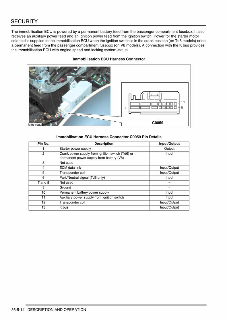
SECURITY
The immobilisation ECU is powered by a permanent battery feed from the passenger compartment fusebox. It also receives an auxiliary power feed and an ignition power feed from the ignition switch. Power for the starter motor solenoid is supplied to the immobilisation ECU when the ignition switch is in the crank position (on Td6 models) or on a permanent feed from the passenger compartment fusebox (on V8 models). A connection with the K bus provides the immobilisation ECU with engine speed and locking system status.
Immobilisation ECU Harness Connector
Immobilisation ECU Harness Connector C0059 Pin Details
Pin No. Description Input/Output1 Starter power supply Output2 Crank power supply from ignition switch (Td6) or
permanent power supply from battery (V8)Input
3 Not used –4 ECM data link Input/Output
5 Transponder coil Input/Output6 Park/Neutral signal (Td6 only) Input
7 and 8 Not used –
9 Ground –10 Permanent battery power supply Input11 Auxiliary power supply from ignition switch Input
12 Transponder coil Input/Output13 K bus Input/Output
M86 5982 C0059
86-5-14 DESCRIPTION AND OPERATION

SECURITY
Deze pagina werd opzettelijk niet gebruikt
Cette page est intentionnellement vierge
Questa pagina è stata lasciata in bianco di proposito
Diese Seite ist leer
Esta página foi deixada intencionalmente em branco
Esta página fue dejada en blanco intencionalmente
This page is intentionally left blank
DESCRIPTION AND OPERATION
DESCRIPTION AND OPERATION 86-5-15
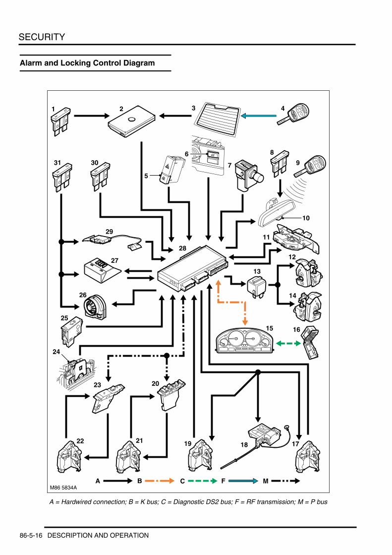
SECURITY
Alarm and Locking Control Diagram
A = Hardwired connection; B = K bus; C = Diagnostic DS2 bus; F = RF transmission; M = P bus
5
M86 5834A
1
A B
2 3 4
7
8
10
12
13
14
15 16
171819
20
2122
23
25
26
27
28
29
316
24
30
M
11
9
C F
86-5-16 DESCRIPTION AND OPERATION
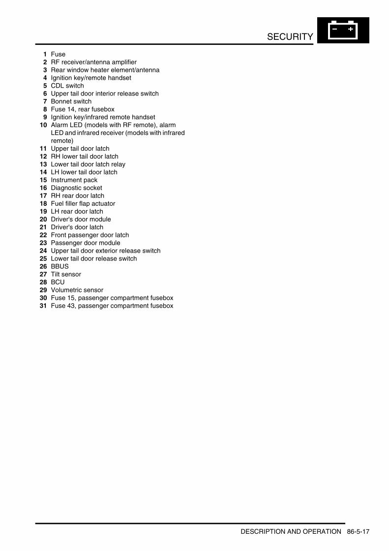
SECURITY
1 Fuse2 RF receiver/antenna amplifier3 Rear window heater element/antenna4 Ignition key/remote handset5 CDL switch6 Upper tail door interior release switch7 Bonnet switch8 Fuse 14, rear fusebox9 Ignition key/infrared remote handset
10 Alarm LED (models with RF remote), alarm LED and infrared receiver (models with infrared remote)
11 Upper tail door latch12 RH lower tail door latch13 Lower tail door latch relay14 LH lower tail door latch15 Instrument pack16 Diagnostic socket17 RH rear door latch18 Fuel filler flap actuator19 LH rear door latch20 Driver's door module21 Driver's door latch22 Front passenger door latch23 Passenger door module24 Upper tail door exterior release switch25 Lower tail door release switch26 BBUS27 Tilt sensor28 BCU29 Volumetric sensor30 Fuse 15, passenger compartment fusebox31 Fuse 43, passenger compartment fusebox
DESCRIPTION AND OPERATION 86-5-17
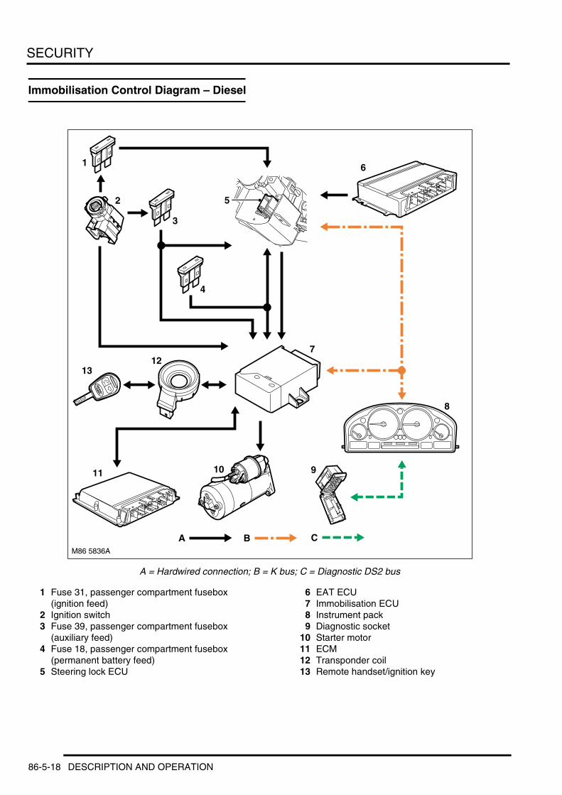
SECURITY
Immobilisation Control Diagram – Diesel
A = Hardwired connection; B = K bus; C = Diagnostic DS2 bus
1 Fuse 31, passenger compartment fusebox (ignition feed)
2 Ignition switch3 Fuse 39, passenger compartment fusebox
(auxiliary feed)4 Fuse 18, passenger compartment fusebox
(permanent battery feed)5 Steering lock ECU
6 EAT ECU7 Immobilisation ECU8 Instrument pack9 Diagnostic socket
10 Starter motor11 ECM12 Transponder coil13 Remote handset/ignition key
M86 5836A
A B
1
4
3
6
9
8
712
11
2
10
13
5
C
86-5-18 DESCRIPTION AND OPERATION

SECURITY
Immobilisation Control Diagram – Petrol
A = Hardwired connection; B = K bus; C = Diagnostic DS2 bus
1 Fuse 31, passenger compartment fusebox (ignition feed)
2 Ignition switch3 Fuse 39, passenger compartment fusebox
(auxiliary feed)4 Steering lock ECU5 EAT ECU6 Diagnostic socket7 Instrument pack
8 Starter motor9 Starter motor relay
10 ECM11 Immobilisation ECU12 Transponder coil13 Remote handset/ignition key14 Fusible link 2, passenger compartment fusebox15 Fuse 18, passenger compartment fusebox
(permanent battery feed)
M86 5837BA B
4
5
8
10
9
6
1211
13
7
1
3
2
15
C
14
DESCRIPTION AND OPERATION 86-5-19

SECURITY
Operation
Locking SystemThe locking system allows the doors and fuel filler flap to be centrally locked and unlocked using the CDL switch, the drivers door lock and the remote handset. The system has two locking states: locked and superlocked. Locking the vehicle from inside using the CDL switch puts the system into the locked state. Locking the vehicle from the outside using the driver's door lock or the remote handset puts the vehicle into the superlocked state.
When the vehicle is locked, the BCU:l Energises the lock actuators in the side door latches to disengage the external door handles from the latchesl Energises the fuel filler flap actuator to extend the locking pin to secure the filler flap (all except NAS)l Ignores inputs from upper tail door external release switch.
The BCU will lock the vehicle regardless of the position of the ignition switch and whether the key is in the ignition switch or not. The upper tail door internal release switch remains enabled and individual side doors can be unlocked using the internal door handle. From the locked state, the vehicle can be centrally unlocked using the CDL switch, the remote handset or the driver's door lock.
When the vehicle is superlocked, the BCU:l Energises the lock and the superlock actuators in the side door latches to disengage both the internal and the
external door handles from the latchesl Energises the fuel filler flap actuator to extend the locking pin to secure the filler flapl Ignores inputs from both the external and the internal release switches of the upper tail doorl Ignores inputs from the CDL switch.
The BCU will only superlock the vehicle after the ignition key has been removed from the ignition switch and the driver's door has opened. From the superlocked state, the vehicle can be centrally unlocked using the remote handset or the driver's door lock.
Tail Door OpeningWhen the vehicle is locked or superlocked, operating the tail door release button on the remote handset causes the BCU to actuate the upper tail door release actuator while leaving the remainder of the system in the locked/superlocked condition.
Volumetric protection is disabled when the taildoor is opened.
SPEWith the vehicle superlocked and SPE enabled, when the BCU receives a request from the remote handset or the driver's door lock it unlocks the driver's door and changes the rest of the system from the superlocked to the locked state. When it receives a second unlock request, from the remote handset, the driver's door lock or the CDL switch, the BCU unlocks the remainder of the system.
Automatic LockingThe BCU can be configured to automatically lock the system when the vehicle exceeds a set speed. The set speed is selectable between 2.5 and 17.5 mph (4 and 28 km/h) in 2.5 mph (4 km/h) increments.
To guard against accidental unlocking, the BCU can also be configured to automatically lock (not superlock) the system if no door switch, bonnet switch or CDL switch is activated within 2 minutes of unlocking the vehicle with the remote handset.
Automatic UnlockingIf a crash that triggers the airbags occurs, the SRS DCU outputs a crash signal to the BCU. On receipt of the crash signal the BCU outputs unlock signals to all the door latch actuators and the fuel filler flap actuator, irrespective of their current locked state. Subsequent attempts to lock the doors are inhibited until the BCU has received an unlock request.
86-5-20 DESCRIPTION AND OPERATION
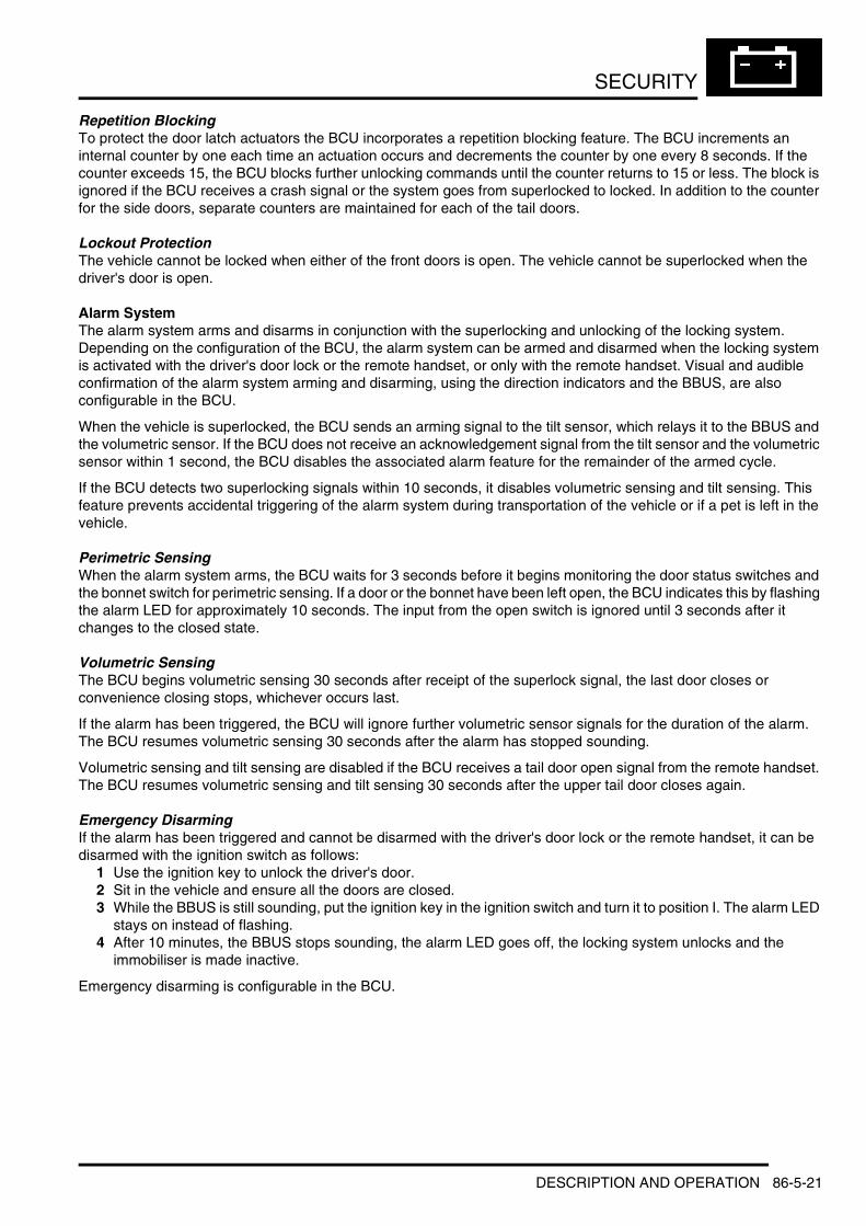
SECURITY
Repetition BlockingTo protect the door latch actuators the BCU incorporates a repetition blocking feature. The BCU increments an internal counter by one each time an actuation occurs and decrements the counter by one every 8 seconds. If the counter exceeds 15, the BCU blocks further unlocking commands until the counter returns to 15 or less. The block is ignored if the BCU receives a crash signal or the system goes from superlocked to locked. In addition to the counter for the side doors, separate counters are maintained for each of the tail doors.
Lockout ProtectionThe vehicle cannot be locked when either of the front doors is open. The vehicle cannot be superlocked when the driver's door is open.
Alarm SystemThe alarm system arms and disarms in conjunction with the superlocking and unlocking of the locking system. Depending on the configuration of the BCU, the alarm system can be armed and disarmed when the locking system is activated with the driver's door lock or the remote handset, or only with the remote handset. Visual and audible confirmation of the alarm system arming and disarming, using the direction indicators and the BBUS, are also configurable in the BCU.
When the vehicle is superlocked, the BCU sends an arming signal to the tilt sensor, which relays it to the BBUS and the volumetric sensor. If the BCU does not receive an acknowledgement signal from the tilt sensor and the volumetric sensor within 1 second, the BCU disables the associated alarm feature for the remainder of the armed cycle.
If the BCU detects two superlocking signals within 10 seconds, it disables volumetric sensing and tilt sensing. This feature prevents accidental triggering of the alarm system during transportation of the vehicle or if a pet is left in the vehicle.
Perimetric SensingWhen the alarm system arms, the BCU waits for 3 seconds before it begins monitoring the door status switches and the bonnet switch for perimetric sensing. If a door or the bonnet have been left open, the BCU indicates this by flashing the alarm LED for approximately 10 seconds. The input from the open switch is ignored until 3 seconds after it changes to the closed state.
Volumetric SensingThe BCU begins volumetric sensing 30 seconds after receipt of the superlock signal, the last door closes or convenience closing stops, whichever occurs last.
If the alarm has been triggered, the BCU will ignore further volumetric sensor signals for the duration of the alarm. The BCU resumes volumetric sensing 30 seconds after the alarm has stopped sounding.
Volumetric sensing and tilt sensing are disabled if the BCU receives a tail door open signal from the remote handset. The BCU resumes volumetric sensing and tilt sensing 30 seconds after the upper tail door closes again.
Emergency DisarmingIf the alarm has been triggered and cannot be disarmed with the driver's door lock or the remote handset, it can be disarmed with the ignition switch as follows:
1 Use the ignition key to unlock the driver's door.2 Sit in the vehicle and ensure all the doors are closed.3 While the BBUS is still sounding, put the ignition key in the ignition switch and turn it to position I. The alarm LED
stays on instead of flashing.4 After 10 minutes, the BBUS stops sounding, the alarm LED goes off, the locking system unlocks and the
immobiliser is made inactive.
Emergency disarming is configurable in the BCU.
DESCRIPTION AND OPERATION 86-5-21

SECURITY
Immobilisation SystemWhen the vehicle is unlocked, with the driver's door lock or the remote handset, the BCU outputs a 'vehicle unlocked' message on the K bus. The K bus message wakes the immobilisation ECU which energises the transponder coil around the ignition switch. When the ignition key is close to, or inserted into, the ignition switch, the immobilisation ECU reads the identity of the transponder. If the transponder/ignition key is valid, the immobilisation ECU outputs a 'valid key in ignition lock' message on the K bus.
When it detects the valid key in ignition lock message, the steering lock ECU disengages the steering column lock. After disengaging the steering lock, provided it is also receiving a Park/Neutral signal from the Electronic Automatic Transmission (EAT) ECU, the steering lock ECU sends a release signal to the immobilisation ECU. When the ignition switch is turned from position 0 to position I, the immobilisation ECU interrogates the transponder for the password and rolling code. If these are correct the immobilisation ECU sends the coded release signal to the ECM and, when the ignition switch turns to position III, energises the starter solenoid to crank the engine. The immobilisation ECU also writes a new rolling code to the transponder and verifies it to ensure it has been correctly received.
On petrol models, the immobilisation ECU energises the starter solenoid via the starter motor relay. The starter motor relay is controlled by the ECM to provide the comfort starting function, which allows the engine to be started by a momentary crank (position III) selection on the ignition switch. When the ignition switch turns to position III, the ECM energises the starter motor relay, which energises the starter solenoid, until engine speed exceeds approximately 500 rev/min, or for 20 seconds, whichever occurs first.
If the vehicle is unlocked and the ignition key is not put into the ignition switch, the immobilisation ECU de-energises the transponder coil and goes back into the sleep mode after approximately 60 seconds. When the ignition key is subsequently put into the ignition switch and turned through 10° to 20°, the steering lock senses the movement and sends a 'request electronic vehicle immobiliser status' message on the K bus. The message wakes the immobilisation ECU, which energises the transponder coil and commences the transponder/ignition key identification and engine mobilisation process as detailed above.
86-5-22 DESCRIPTION AND OPERATION

WINDOWS
WINDOWSDESCRIPTION AND OPERATIONWindows Component Layout
1 Rear window motor2 Rear window switch3 Front window motor4 Front passenger door module5 Rear window anti-trap sensor6 Front window anti-trap sensor
7 Driver door module8 Front window motor9 Rear window switch
10 Rear window motor11 BCU
DESCRIPTION AND OPERATION 86-6-1

WINDOWS
Description
GeneralElectric windows are installed in all four doors. The front windows are controlled by their respective door modules integrated into the window switch packs. The rear windows are controlled by the Body Control Unit (BCU). The BCU and the door modules communicate with each other on the P bus.
Window operating features are market dependent and include one-shot opening and closing, convenience opening and closing, and anti-trap. Market options for window operation are set centrally in the BCU.
Window SwitchesIndividual window switches are installed in each of the three passenger doors. Window switches for all of the windows, and a child lock switch to isolate the rear windows, are installed in the driver's door.
All of the window switches have two switching positions in each direction. The first switching position operates the window in the inching mode, where the window moves until the switch is released or until it reaches the fully open or closed position. The second switching position operates the window in the one-shot mode.
Door Module Harness Connectors C2016 and C2017 Pin Details
Door Module Harness Connectors C2057 and C2058 Pin Details
Anti-trap SensorsAn anti-trap sensor is installed along the top of each window aperture, just outside the travel path of the window glass. Each anti-trap sensor consists of a rubber covered contact strip connected to ground and to a power supply from the door module (front windows) or BCU (rear windows). When the anti-trap sensor is pressed the resistance across the contact strip is reduced. If a window is being closed and the door module/BCU detects a drop in resistance across the associated anti-trap sensor, it immediately (in less than 20 milliseconds) reverses the window.
Pin No. Description Input/Output1 Battery power supply Input2 Ground –3 Not used –
4 Window motor close Output5 Window motor open Output6 Not used –
Pin No. Description Input/Output1 P bus Input/Output2 Interior illumination Input3 Unlock signal from driver's door lock Input
4 Lock signal from driver's door lock Input5 Not used –6 Lock door actuator Output
7 Superlock door actuator Output8 Interior illumination for door handle and door pocket LED's Output9 Window anti-trap sensor Input
10 Not used –11 Door open/close contacts Input12 Unlock door actuator Output
86-6-2 DESCRIPTION AND OPERATION

WINDOWS
Window RegulatorsCable operated window regulators powered by an electric motor are installed in each of the doors.
Front Door Window Regulator
1 Window glass2 Fixing point3 Glass carrier4 Rear mounting frame
5 Cable6 Window motor7 Front mounting frame
DESCRIPTION AND OPERATION 86-6-3

WINDOWS
Rear Door Window Regulator
1 Fixing2 Mounting frame3 Glass carrier
4 Window glass5 Window motor
86-6-4 DESCRIPTION AND OPERATION

WINDOWS
Deze pagina werd opzettelijk niet gebruikt
Cette page est intentionnellement vierge
Questa pagina è stata lasciata in bianco di proposito
Diese Seite ist leer
Esta página foi deixada intencionalmente em branco
Esta página fue dejada en blanco intencionalmente
This page is intentionally left blank
DESCRIPTION AND OPERATION
DESCRIPTION AND OPERATION 86-6-5

WINDOWS
Windows Control Diagram
A = Hardwired connection; B = K bus; C = Diagnostic ISO 9141 K line bus; M = P bus
M86 5959A
1
3 4
5
6 7
9
10
11
12
14
16
17
1819
21 20
2
A M
13
15
8
B C
86-6-6 DESCRIPTION AND OPERATION

WINDOWS
1 Ignition switch2 Front passenger window anti-trap sensor3 Fuse 24, passenger compartment fusebox4 Fuse 11, passenger compartment fusebox5 Driver window anti-trap sensor6 Driver door module7 Driver window motor8 Fuse 60, passenger compartment fusebox9 Instrument pack
10 Diagnostic socket11 RH rear window motor12 RH rear window anti-trap sensor13 RH rear window switch14 LH rear window motor15 LH rear window anti-trap sensor16 LH rear window switch17 BCU18 RF receiver19 Fuse 41, passenger compartment fusebox20 Front passenger door module21 Front passenger window motor
DESCRIPTION AND OPERATION 86-6-7

WINDOWS
Operation
GeneralElectric window operation using the window switches is enabled while the ignition switch is in positions I and II, and for 16 minutes after switching from position I to position 0. Window operation is immediately disabled when a front door is opened
End of Travel Shut offEnd of travel shut off for the window motors is determined by monitoring the current draw of the motors. Each time it switches on a window motor, the door module or BCU measures the window motor current for 22 milliseconds, in 2 milliseconds intervals. The maximum value measured within that time is stored as the switch-on current, which must be 5 A minimum. When the window motor current next exceeds the switch-on current minus 2 A, the door module/BCU assumes the window has reached the end of its travel and, after 0.5 second, switches off the power supply to the window motor, even if a window switch is still being activated.
Measuring the switch-on current for each switching operation automatically compensates for changes of load with varying ambient conditions etc.
To protect the window motors from overheating if the end of travel shut off function fails, window motor activation in both directions is limited to 8 seconds.
One-shot Opening and ClosingOne shot opening and closing is activated by selecting the second switching positions on the window switch. One-shot opening and closing is enabled on all windows except on Australia models. On Australia models, all one-shot operation is disabled except for driver's window closing.
Anti-trapThe anti-trap function is enabled for window closing in both the inching and one-shot modes. If an anti-trap sensor is activated while a window is closing, the window motor is reversed for 0.5 second.
UK models feature a longer reversing time after a trap detection. The reversing time is proportionate to the preceding closing time and varies between 0.5 and 2.0 seconds.
In an emergency, e.g. if the anti-trap sensor is faulty, the anti-trap function can be overridden by holding the window switch in the one-shot closed position.
86-6-8 DESCRIPTION AND OPERATION

WINDOWS
Convenience Opening and ClosingConvenience opening and closing is enabled provided the ignition switch is not in position I or above. The windows and sunroof (where fitted) can be opened and closed in sequence, while unlocking and locking the vehicle, using the driver's door lock or the remote handset.
Convenience closing begins after a time delay of 1.5 seconds when the door lock is held in the lock position or the remote handset lock button is pressed and held. The anti-trap function is enabled during convenience closing. The closing operation also stops immediately the door lock is released from the lock position or the remote handset lock button is released. The window motors are switched in pairs, with the rear ones switched first followed 1 second later by the front ones. The sunroof begins closing when all of the windows are closed or 3.5 seconds after convenience closing started, whichever occurs first.
There is no convenience closing on NAS vehicles.
Convenience opening begins after a time delay of 2.5 seconds when the door lock is held in the unlock position or the remote handset unlock button is pressed and held. The opening operation stops immediately the door lock is released from the unlock position or the remote handset unlock button is released. The window motors are switched in pairs, with the front ones switched first followed 1 second later by the rear ones. The sunroof begins opening 3.5 seconds after convenience opening started.
Operating the windows and sunroof in sequence allows a degree of selective operation, e.g. the windows can be closed and the sunroof left open when locking the vehicle and using convenience closing.
Repetition BlockingTo prevent the window motors from overheating, the door modules and the BCU record the run time for each motor they control. The run time, in seconds, is added to a counter on completion of each activation, and one second is deducted from the counter for every three seconds the window motor is inactive. If the counter exceeds 60 seconds, no new activation for the window motor is accepted until the counter is below 60 seconds again. The only exception is a reversing operation triggered by the anti-trap function, which is always accepted regardless of the counter value.
DESCRIPTION AND OPERATION 86-6-9

WINDOWS
86-6-10 DESCRIPTION AND OPERATION

ENTERTAINMENT AND INFORMATION SYSTEMS
Deze pagina werd opzettelijk niet gebruikt
Cette page est intentionnellement vierge
Questa pagina è stata lasciata in bianco di proposito
Diese Seite ist leer
Esta página foi deixada intencionalmente em branco
Esta página fue dejada en blanco intencionalmente
This page is intentionally left blank
ENTERTAINMENT AND INFORMATION SYSTEMSDESCRIPTION AND OPERATION
DESCRIPTION AND OPERATION 86-8-1

ENTERTAINMENT AND INFORMATION SYSTEMS
MID Audio System Component Location
86-8-2 DESCRIPTION AND OPERATION

ENTERTAINMENT AND INFORMATION SYSTEMS
1 Side window aerial amplifier2 Rear screen aerial amplifier3 MID unit4 Cassette player and radio unit5 CD player and radio unit6 Mini disc player and radio7 Rotary coupler8 Steering wheel controls9 CD autochanger
10 Suppressor11 Suppressor12 Power amplifier13 DSP amplifier
DESCRIPTION AND OPERATION 86-8-3

ENTERTAINMENT AND INFORMATION SYSTEMS
MID Audio System Control Diagram
A = Hardwired connection
M86 5860 A
1 2
3
4
6
7
89
10
11
12 13 14
15
5
86-8-4 DESCRIPTION AND OPERATION

ENTERTAINMENT AND INFORMATION SYSTEMS
1 Steering wheel controls2 Rotary coupler3 MID unit4 Side window aerials5 Side window aerial amplifier6 Rear window aerial amplifier7 Rear window aerials8 Suppressor9 Suppressor
10 DSP amplifier11 Power amplifier12 Cassette player and radio unit13 Mini disc player and radio14 CD player and radio unit15 CD autochanger
DESCRIPTION AND OPERATION 86-8-5

ENTERTAINMENT AND INFORMATION SYSTEMS
Multi-Function Display Audio Component Location
86-8-6 DESCRIPTION AND OPERATION
ENTERTAINMENT AND INFORMATION SYSTEMS
1 Video module2 Television aerial amplifier3 Rear screen radio aerial amplifier4 Side screen radio diversity aerial amplifier5 Multi-Function Display unit6 Rotary coupler7 Steering wheel switches8 CD autochanger (optional)9 Television aerial amplifier
10 Suppressor11 Suppressor12 Radio unit13 Amplifier (optional)14 DSP (optional)
DESCRIPTION AND OPERATION 86-8-7

ENTERTAINMENT AND INFORMATION SYSTEMS
Multi-Function Display Audio Control Diagram
A = Hardwired connection
M86 5861 A
8
10
11
12
14
15
16
2
7
6
5
4
3
1
18
17
9
13
86-8-8 DESCRIPTION AND OPERATION

ENTERTAINMENT AND INFORMATION SYSTEMS
1 Steering wheel switches2 Video module3 Multi Function Display (MFD)4 Side window aerials5 Alternative side screen aerial amplifier for
parked heating6 Television aerial amplifier7 Television aerial amplifier8 Side screen television aerial and radio diversity
tuning radio aerial9 Side screen radio diversity tuning aerial
amplifier10 Rear screen aerial amplifier11 Rear screen12 Suppressor13 Suppressor14 DSP15 Power amplifier16 Radio module17 CD autochanger18 Rotary coupler
DESCRIPTION AND OPERATION 86-8-9
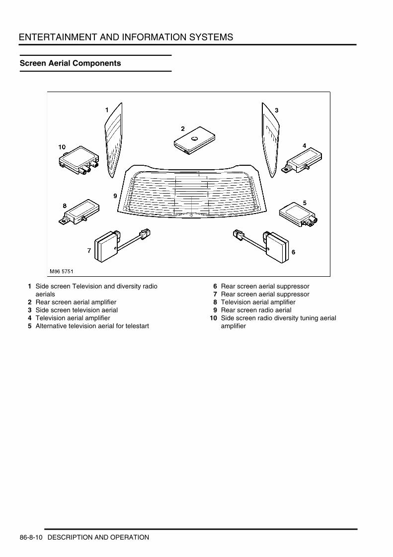
ENTERTAINMENT AND INFORMATION SYSTEMS
Screen Aerial Components
1 Side screen Television and diversity radio aerials
2 Rear screen aerial amplifier3 Side screen television aerial4 Television aerial amplifier5 Alternative television aerial for telestart
6 Rear screen aerial suppressor7 Rear screen aerial suppressor8 Television aerial amplifier9 Rear screen radio aerial
10 Side screen radio diversity tuning aerial amplifier
86-8-10 DESCRIPTION AND OPERATION

ENTERTAINMENT AND INFORMATION SYSTEMS
Speaker System Component Location
1 Front LH door low range unit2 Front LH door mid range unit3 Front LH tweeter4 Front centre speaker5 Front RH tweeter
6 Front RH door mid range unit7 Front RH door low range unit8 Rear RH low range door speaker9 Sub woofer
10 Rear LH low range door speaker
DESCRIPTION AND OPERATION 86-8-11

ENTERTAINMENT AND INFORMATION SYSTEMS
Base Speaker Control Diagram
A = Hardwired connection
1 CD radio unit2 Cassette radio unit3 Mini disc radio unit4 Radio unit5 Front RH low range speaker
6 Front RH mid range speaker7 Rear RH low range speaker8 Rear LH low range speaker9 Front LH mid range speaker
10 Front LH low range speaker
M86 5757
1 2 3
5
6
78
9
10
A
4
86-8-12 DESCRIPTION AND OPERATION

ENTERTAINMENT AND INFORMATION SYSTEMS
Deze pagina werd opzettelijk niet gebruikt
Cette page est intentionnellement vierge
Questa pagina è stata lasciata in bianco di proposito
Diese Seite ist leer
Esta página foi deixada intencionalmente em branco
Esta página fue dejada en blanco intencionalmente
This page is intentionally left blank
DESCRIPTION AND OPERATION 86-8-13
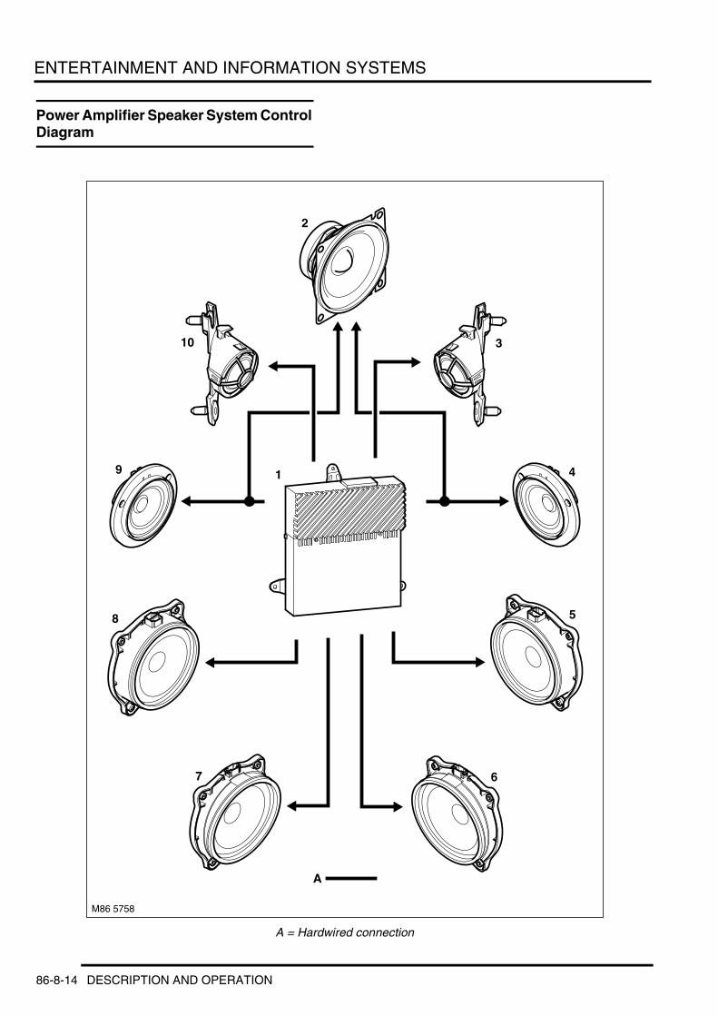
ENTERTAINMENT AND INFORMATION SYSTEMS
Power Amplifier Speaker System Control Diagram
A = Hardwired connection
M86 5758
1
2
3
4
5
67
8
9
10
A
86-8-14 DESCRIPTION AND OPERATION

ENTERTAINMENT AND INFORMATION SYSTEMS
1 Power amplifier2 Centre speaker3 Front RH tweeter4 Front RH mid range5 Front RH low range6 Rear LH low range7 Rear LH low range8 Front LH low range9 Front LH mid range
10 Front LH tweeter
DESCRIPTION AND OPERATION 86-8-15

ENTERTAINMENT AND INFORMATION SYSTEMS
DSP Amplifier Speaker System Control Diagram
A = Hardwired connection
M86 5759
1
2
3
4
5
68
9
10
11
7
A
86-8-16 DESCRIPTION AND OPERATION

ENTERTAINMENT AND INFORMATION SYSTEMS
1 DSP2 Centre speaker3 Front RH tweeter4 Front RH mid range5 Front RH low range6 Rear RH low range7 Sub-woofer8 Rear LH low range9 Front LH low range
10 Front LH mid range11 Front LH tweeter
DESCRIPTION AND OPERATION 86-8-17
ENTERTAINMENT AND INFORMATION SYSTEMS
Audio Systems
Introduction New Range Rover has two distinct types of audio system. One system is based around the Multi Information Display (MID) while the other is based around the Multi-Function Display (MFD).
It is also possible to specify extras to the audio system to extend its capabilities. These options include:l Telephonel CD autochangerl Amplifierl Digital signal processor (DSP)l Satellite navigation (MFD only)l Television / Teletext (MFD only)l Voice recognition system (navigation and telephone).
MID Audio SystemAs stated the low line audio system is based around the Multi information display unit. The system comprises:l MID unitl Cassette unit, mini disc unit or CD unitl CD auto changer (optional)l Radio unitl Telephone (optional)l Digital signal processor (DSP-optional)l Speakersl Amplifier (optional).
All the low line systems use the MID unit as a control panel for the whole system. The MID is located in the centre of the fascia. The MID unit incorporates a two line LCD display with controls that allow the user to control the radio, cassette player, CD player/auto changer, trip computer, telephone and amplifier (DSP). Depending upon the customers selection of options the MID has four different front panels to allow for control of the different options. These are as follows:l DSP and Phonel Phone No DSPl DSP No Phonel No DSP No Phone.
86-8-18 DESCRIPTION AND OPERATION

ENTERTAINMENT AND INFORMATION SYSTEMS
MID Controls
1 Tape, CD or Mini Disc slot2 Audio/DSP button3 Telephone operation button4 Computer/clock settings button5 Multi function toggle button6 Multi function toggle button
7 Multi function toggle button8 Multi function toggle button9 Multi function toggle button
10 On/off rotary volume control 11 Search and Memory button
Six rocker buttons are located below the MID. Each rocker button has a pressure point on the left and the right. There are effectively 12 switching levels for this button unit. Arranged to the right next to the display are the buttons for the selection of AUDIO, DSP, TELEPHONE, CLOCK and BC (on-board computer). The AUDIO button has one pressure point each on the left and right. In the case of versions with DSP, the left pressure point is assigned to AUDIO and the right to DSP. The buttons for TELEPHONE with the handset symbol and BC with the CLOCK are laid out as rocker buttons. To the left next to the display is a rocker button for the search and scan functions. The button for the manual search function is inserted in the centre of this rocker button. A rotary increment sensor is used to control AUDIO and the hands-free speaking feature of the telephone volume, as well as the ON / OFF switch for the AUDIO system. This is carried out by means of an increment sensor with an integrated push switch. The rotary controller has 36 incremental steps of 10° each.
The MID lighting is controlled by a photo-transistor sensor. The brightness of the lighting can also be influenced manually by the instrument lighting dimmer. When the vehicle lighting is switched off, the display brightness is governed exclusively via the sensor, this gives a daytime minimum brightness of 60 % of the control range is defined. When the instrument dimmer is switched on, the controlling range from the daytime minimum brightness onward is expanded by the dimension of the dimmer position. The dimmer position is taken from the "dimming" message. With "light off" the LED function indications are activated at the maximum level and with "light on" with the value of the day/night threshold, irrespective of the photo-transistor.
Control signals for the MID are sent along the I-bus.
MID Harness Connector C0241 Pin Details
M86 5755
Radio 1
*
1 2 FM RDS*AM
TONE
1 21 2 MODESC
9 8 7 6 5
1
10
432
11
12 m AUDIO DSP
TEL
BC
Pin No. Description Input/Output1 Ground –
2 Permanent power supply from battery Input3 Interior illumination Input4 I bus Input/Output
5 to 7 Not used –8 Auxiliary power supply Input
9 to 12 Not used –
DESCRIPTION AND OPERATION 86-8-19

ENTERTAINMENT AND INFORMATION SYSTEMS
DiagnosticsThe MID is capable of being subjected to diagnostics. The principle applies of finding the smallest replaceable unit via the diagnostics computer (TestBook/T4). The instrument pack serves as a gateway between the diagnostics bus and the I-bus. The messages from TestBook/T4 are converted by the instrument pack into the respective I-bus format. The MID detects the diagnostics mode by means of the diagnostics computer address. Normal operation is maintained during the diagnostics mode. MID diagnostics are subdivided into two categories:l Device identificationl Self-diagnostics with error storage.
Control unit identification is stored in the EEPROM of the MID and can be called up by means of the diagnostics tester. The data is programmed at the point of manufacturer.
Errors detected by the MID are stored in the EEPROM. The errors are stored in the order of their occurrence. Each error is assigned an error code. In order to avoid the entry of "false errors", the error memory is not written to in the first 500 ms after the power-on reset. The frequency counter is incremented with each detected error. The error type is set to "momentarily present". After the error is corrected, the error type is set to "sporadic (not momentarily present)". The error frequency counter stores a maximum of 31 errors. Once this limit is reached, the error type remains constantly on "momentarily present". Any fault codes can only be removed by the manufacturer.
Multi-Function Display Audio SystemThe High Line audio option comprises:l Multi-Function Display head unitl Radio unitl Speakersl Amplifier.
Multi-Function Display
Multi-Function Display Controls
1 Information button2 Cassette eject button3 Telephone button4 Clock/direction button5 Tone button6 Search button7 Menu access button
8 Right hand rotary controller9 Left hand rotary controller
10 Mode button11 Wave band change button12 Pre-set button13 Pre-set button14 Pre-set button
M86 5753 9
1011121314
1 2
34567
8
86-8-20 DESCRIPTION AND OPERATION

ENTERTAINMENT AND INFORMATION SYSTEMS
The Multi-Function Display forms the basis of the high line audio system. It communicates with the rest of the audio system on the I/K-Bus. The Multi-Function Display controls all the radio, CD changer (optional) and cassette functions. The cassette unit is located behind the display panel and is accessed by pressing the “tape eject button”. This causes the screen to move down and tilt slightly forward to reveal the cassette slot and eject the cassette. There is no option for a single slot CD player with the Multi-Function Display audio system. All other components of the audio system are the same as the low line system.
Diagnostics for the MFD are described in the navigation section.
MFD Harness Connector C0815 Pin Details
MFD Harness Connector C0816 Pin Details
Pin No. Description Input/Output1 Red video signal Input2 Red video ground –
3 Green video signal Input4 Green video ground –5 Blue video signal Input
6 Blue video ground –8 Permanent power supply from battery Input
Pin No. Description Input/Output1 Interior illumination Input
2 Ground –3 LH audio positive Output4 LH audio negative Output
5 Not used –6 I bus Input/Output7 Permanent power supply from battery Input
8 Not used –9 RH audio negative Output
10 RH audio positive Output
11 and 12 Not used –
DESCRIPTION AND OPERATION 86-8-21

ENTERTAINMENT AND INFORMATION SYSTEMS
Common ComponentsBoth systems share some common components, these are detailed bellow.
Radio ModuleThe radio unit for the 'Low' system is located in the cassette, CD or Mini disc player unit. The radio unit for the 'High' line audio system is separate from the head unit and is located in the left hand side of the luggage compartment.
Radio Module
Both radio systems offer the option of Business units or Professional. Both units offer six preset buttons allowing the presetting of 6 radio stations on FM, 6 radio stations on MW and 6 Radio stations on LW to the preset buttons on the Multi-function Display . The “Business” system provides standard AM/FM tuner capabilities (RDS Traffic information Etc.) while the “professional”system has two separate tuners built in to give improved radio reception through diversity tuning. This involves one of the tuners providing the selected programme while the other tuner continuously searches for a stronger signal for the selected broadcast station and for other RDS stations that can be received.
Radio Module Harness Connector C0818 Pin Details
Pin No. Description Input/Output1 RH rear audio positive Output2 RH front audio positive Output3 LH front audio positive Output
4 LH rear audio positive Output5 RH rear audio negative Output6 RH front audio negative Output
7 LH front audio negative Output8 LH rear audio negative Output9 I bus Input/Output
10 Telephone mute Input11 Not used –12 Ground –
13 Radio on signal Output14 Interior illumination Input15 Permanent power supply from battery Input
16 Auxiliary power supply Input
86-8-22 DESCRIPTION AND OPERATION

ENTERTAINMENT AND INFORMATION SYSTEMS
Radio Module Harness Connector C0991 Pin Details
Radio Module Harness Connector C1912 Pin Details
Pin No. Description Input/Output1 Not used –2 LH and RH audio negative Input
3 to 7 Not used –
8 LH audio positive Input9 RH audio positive Input
10 TV RH audio positive Input
11 TV LH audio positive Input12 TV LH and RH audio negative Input
Pin No. Description Input/Output1 LH audio positive Input
2 LH audio negative Input3 and 4 Not used –
5 Navigation audio positive Input
6 Not used –7 RH audio positive Input8 RH audio negative Input
9 and 10 Not used –11 Navigation audio negative Input12 Not used –
DESCRIPTION AND OPERATION 86-8-23

ENTERTAINMENT AND INFORMATION SYSTEMS
Screen Mounted Aerials
1 Side window television and radio diversity aerials
2 FM aerial amplifier3 Side window television aerial4 Television aerial amplifier
5 Television aerial amplifier with parked heating6 Suppressor7 Suppressor8 Television aerial amplifier9 Side window FM aerial diversity amplifier
The “RDS radio” system uses the heated rear screen element as the radio antenna. The signal is processed by an amplifier before being passed through to the head unit. This antenna and amplifier is also used receive and process signals from the remote handset to lock/unlock and arm/disarm the alarm. Because of this there are two types of amplifier to accommodate the different frequencies used with the remote in different markets. This standard amplifier is located in the tailgate at the top left hand corner.
The “RDS Hi Fi” system use a second antenna fitted in the left hand window of the luggage compartment to achieve the diversity function. The amplifier for this antenna is located left hand side of the luggage compartment behind the trim panel near the wheel arch.
86-8-24 DESCRIPTION AND OPERATION

ENTERTAINMENT AND INFORMATION SYSTEMS
CD Autochanger
Both systems are capable of controlling a six disc CD autochanger. The autochanger is controlled on the I/K Bus and is located at the rear of the passenger compartment glove box.
CD Autochanger Harness Connector C0941 Pin Details
CD Autochanger Harness Connector C1353 Pin Details
Pin No. Description Input/Output1 Ground –
2 Permanent power supply from battery Input3 I bus Input/Output
Pin No. Description Input/Output1 Left audio positive Output
2 Left and right audio negative Output3 Not used –4 Right audio positive Output
5 and 6 Not used –
DESCRIPTION AND OPERATION 86-8-25

ENTERTAINMENT AND INFORMATION SYSTEMS
Amplifiers
The basic audio system has no amplifier. The system drives two speakers, one in each rear door, and two speakers (one woofer and one tweeter) in each of the front doors.
The “Hi Fi” system has a conventional power amplifier located in the left hand side of the luggage compartment. The amplifier drives two speakers in each of the rear doors, three speakers in each of the front doors and a centre speaker connected across the two front mid-range speakers.
Amplifier Harness Connector C2077 Pin Details
Pin No. Description Input/Output1 LH rear door low range speaker negative Output
2 LH rear door low range speaker positive Output3 LH front door low range speaker negative Output4 LH front door low range speaker positive Output
5 Permanent power supply from battery Input6 and 7 Not used –
8 RH rear audio positive Input
9 RH front audio positive Input10 Radio on signal Input11 RH front tweeter positive Output
12 RH front tweeter negative Output13 RH rear door high range speaker positive Output
14 and 15 Not used –
16 RH rear audio negative Input17 RH front audio negative Input
18 and 20 Not used –
21 RH rear door high range speaker negative Output22 RH front door low range speaker negative Output23 RH front door low range speaker positive Output
24 RH rear door low range speaker negative Output25 RH rear door low range speaker positive Output26 Ground –
27 and 28 Not used –29 LH rear audio negative Input30 LH front audio negative Input
31 LH rear door high range speaker positive Output32 LH rear door high range speaker negative Output33 LH front tweeter positive Output
86-8-26 DESCRIPTION AND OPERATION

ENTERTAINMENT AND INFORMATION SYSTEMS
34 LH front tweeter negative Output
35 and 36 Not used –37 LH rear audio positive Input38 LH rear audio positive Input
39 LH front door mid range speaker negative Output40 LH front door mid range speaker positive Output41 RH front door mid range speaker negative Output
42 RH front door mid range speaker positive Output
Pin No. Description Input/Output
DESCRIPTION AND OPERATION 86-8-27

ENTERTAINMENT AND INFORMATION SYSTEMS
Digital Signal Processor
The top “Hi Fi” option has a digital signal processor (DSP) amplifier which is located in the left hand side of the luggage compartment. It drives two speakers in each of the rear doors, three speakers in each of the front doors, a centre speaker connected across the two front mid-range speakers and two dual voice-coil sub-woofers in the luggage compartment. It can also use digital signal processing techniques to simulate a Concert Hall, a Jazz Club, a Cathedral or one of three user defined settings. These functions are controlled from the Multi-Function Display via the DSP option.
DSP Harness Connector C0491 Pin Details
DSP Harness Connector C0492 Pin Details
Pin No. Description Input/Output1 Subwoofer 1 positive Output
2 Subwoofer 2 positive Output3 LH rear door low range speaker positive Output4 Radio on signal Input
5 RH rear door low range speaker negative Output6 Subwoofer 4 negative Output7 Subwoofer 3 negative Output
8 Permanent power supply from battery Input9 Subwoofer 1 negative Output
10 Subwoofer 2 negative Output
11 LH rear door low range speaker negative Output12 RH rear door low range speaker positive Output13 Subwoofer 4 positive Output
14 Subwoofer 3 positive Output15 Ground –
Pin No. Description Input/Output1 Not used –
2 Telephone audio negative Input3 and 4 Not used –
5 I bus Input/Output
6 and 7 Not used –8 RH front audio negative Input9 LH front audio negative Input
10 Not used –
86-8-28 DESCRIPTION AND OPERATION

ENTERTAINMENT AND INFORMATION SYSTEMS
DSP Harness Connector C0493 Pin Details
11 Telephone audio positive Input
12 to 14 Not used –15 Telephone on Input16 Not used –
17 RH front audio positive Input18 LH front audio positive Input
Pin No. Description Input/Output1 LH front door low range speaker positive Output2 LH front door low range speaker negative Output3 Not used –
4 RH front door mid range speaker negative Output5 LH front door mid range speaker positive Output
6 to 8 Not used –
9 RH front door mid range speaker positive Output10 LH front door mid range speaker negative Output11 RH rear door high range speaker + Output
12 RH front tweeter positive Output13 RH front door low range speaker positive Output14 LH front tweeter positive Output
15 LH front tweeter negative Output16 LH rear door high range speaker negative Output
17 and 18 Not used –
19 LH rear door high range speaker positive Output20 to 23 Not used –
24 RH rear door high range speaker negative Output
25 RH front tweeter negative Output26 RH front door low range speaker negative Output
Pin No. Description Input/Output
DESCRIPTION AND OPERATION 86-8-29

ENTERTAINMENT AND INFORMATION SYSTEMS
MID Audio OperationAll of the functions of the MID Audio are controlled by the switches around the MID unit. Additional control is available in the form of steering wheel mounted switches to alter the volume, change pre-set radio station, fast forward tape or CD tracks.
Steering Wheel Switches
Radio OperationThe radio is accessed by pressing the rotary controller on the MID. The radio can be tuned by pressing the arrow buttons on the left of the MID (right arrow tunes up the scale left tunes down the scale). The 'M' button in the middle of the arrow keys saves the tuned station to a memory.
Cassette OperationThe cassette is operated by inserting the tape into the tape slot. Once in the tape will start to play. The cassette player is an auto-reverse tape player and will continue to play the tape from one side to the next until the tape is ejected or the mode has changed to radio or CD player. To access a tape that is already in the cassette player from the radio or CD autochanger press the button marked “Mode” on the far right hand side of the MID.
Functions that are available while in the cassette mode are:l Sidel Dolbyl SCl Mode.
Using the side option changes the tape from the current side being played to the other side of the tape.
Pressing the SC option changes the display to SC*, this activates the intro scan function. The cassette player will play the introduction 10 seconds of each track on the tape. When the desired track is reached pressing this button again will stop scanning the intros and start playing the tape from that point.
The cassette player also has the option to switch Dolby™ noise reduction from Dolby C to B or off by toggling the switch labelled with Dolby in the MID.
The other functions (radio and CD player) are accessed by pressing the “Mode” button.
Mini Disc OperationOnce the Mini Disc (MD) is in the player, press the mode button to access the MD mode. The MID will display the track number and the time. There is a slight delay between starting the player and the audio beginning as the player has to read the audio data from the disc.
It is also possible to search for a specific track by pressing the direction key. A single press will advance the disc on a track. Holding the button in fast forwards/rewinds through the current track. Releasing the key resumes playing the track from that point.
The MD player has two special functions it can perform:l Track scan functionl Random play function
86-8-30 DESCRIPTION AND OPERATION

ENTERTAINMENT AND INFORMATION SYSTEMS
The scan function allows the user to listen to the first few seconds of all the tracks on the disc. The scan function is accessed by pressing the button on the MID marked SC. An asterix will display next to the SC symbol to denote that it is switched on. Once on the player will access each track in turn and play the first ten seconds then move on to the next. To interrupt this and play a selected track the user must press the SC button again.
The Random play function allows the user to play the contents of the MD in a completely random order. This is achieved by press the button on the MID marked RND. Again an asterix will appear next to the RND in the MID to denote that this function is active. Tracks can be searched for using the direction keys but selection will not be sequential, it will follow the random order in the units memory. De-selection of the random mode is achieved by pressing the RND button again.
Compact Disc (CD) Player OperationWith a CD in the player, press the mode button to access the CD mode. The MID will display the track number (01) and the time.
To search for a specific track, press the direction key forwards or backwards. A single press will advance the disc on a track.
The CD player has two special functions it can perform:l Track scan functionl Random play function.
The scan function allows the user to listen to the first few seconds of all the tracks on the disc. The scan function is accessed by pressing the button on the MID marked SC. An asterix will display next to the SC symbol to denote that it is switched on. Once on the player will access each track in turn and play the first ten seconds then move on to the next. To interrupt this and play a selected track the user must press the SC button again.
The Random play function allows the user to play the contents of the CD in a completely random order. This is achieved by pressing the button on the MID marked RND. Again an asterix will appear next to the RND in the MID to denote that this function is active. Tracks can be searched for using the direction keys but selection will not be sequential, it will follow the random order in the units memory. De-selection of the random mode is achieved by pressing the RND button again.
MID Function TestsThe MID offers an integrated function test for workshop testing purposes. The test menu is called up by simultaneously pressing the first and the last menu button while switching on the ignition. This menu is generated by the MID itself, and the tests are carried out by the MID. The display is disabled for the testing period, even in the event of a display request. The test is also possible without the I/K BUS connected.
The following are offered in the test menu (selection carried out via the MID rocker buttons):l DISPLAY: Display testl KEYS: Button functionsl VOLUME: Increment sensor testl LEDS: for LED function displays.
The test is concluded by switching the ignition off or after a time out of 5 seconds has elapsed after the last button actuation.
Display TestThe following are activated in succession on a 3 second cycle:l All characters with all DOTsl All characters with number symbol patternl All characters with "Z" patternl All special text labels: LIMIT, LIMITE, MEMO, STOPPUHR, All special text labels together.
DESCRIPTION AND OPERATION 86-8-31
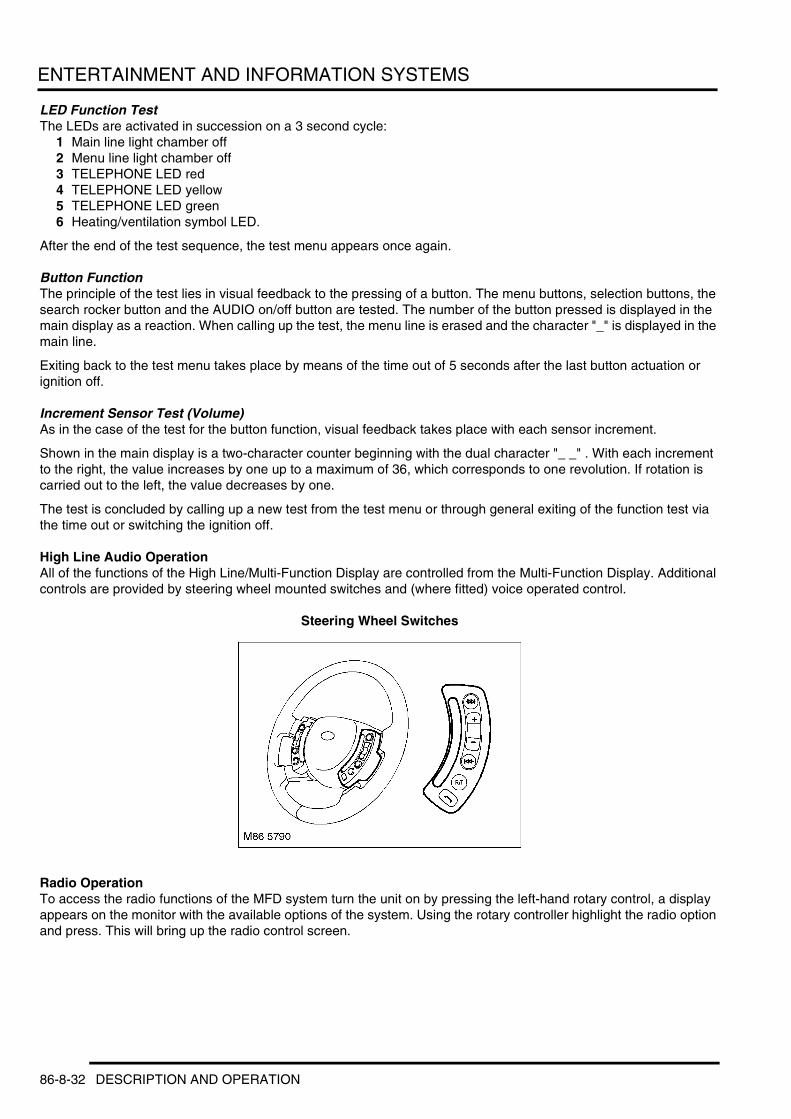
ENTERTAINMENT AND INFORMATION SYSTEMS
LED Function TestThe LEDs are activated in succession on a 3 second cycle:
1 Main line light chamber off2 Menu line light chamber off3 TELEPHONE LED red4 TELEPHONE LED yellow5 TELEPHONE LED green6 Heating/ventilation symbol LED.
After the end of the test sequence, the test menu appears once again.
Button FunctionThe principle of the test lies in visual feedback to the pressing of a button. The menu buttons, selection buttons, the search rocker button and the AUDIO on/off button are tested. The number of the button pressed is displayed in the main display as a reaction. When calling up the test, the menu line is erased and the character "_" is displayed in the main line.
Exiting back to the test menu takes place by means of the time out of 5 seconds after the last button actuation or ignition off.
Increment Sensor Test (Volume)As in the case of the test for the button function, visual feedback takes place with each sensor increment.
Shown in the main display is a two-character counter beginning with the dual character "_ _" . With each increment to the right, the value increases by one up to a maximum of 36, which corresponds to one revolution. If rotation is carried out to the left, the value decreases by one.
The test is concluded by calling up a new test from the test menu or through general exiting of the function test via the time out or switching the ignition off.
High Line Audio OperationAll of the functions of the High Line/Multi-Function Display are controlled from the Multi-Function Display. Additional controls are provided by steering wheel mounted switches and (where fitted) voice operated control.
Steering Wheel Switches
Radio OperationTo access the radio functions of the MFD system turn the unit on by pressing the left-hand rotary control, a display appears on the monitor with the available options of the system. Using the rotary controller highlight the radio option and press. This will bring up the radio control screen.
86-8-32 DESCRIPTION AND OPERATION

ENTERTAINMENT AND INFORMATION SYSTEMS
Radio Screen
l Name of radio stationl TP station (name of traffic programme station selected in background)l MFD Waveband selectedl P3 positions the radio station (if programmed into the memory)l RDS (Radio Data System) is switched on, station names are displayed and the strongest frequency on which the
station can be picked up is searched for automaticallyl Date/time displayl Radio screen display (showing radio stations that are available in the area)l Regional station function switched on.
If the radio is switched on and on-board computer functions appear on the monitor, the "Audio+OBC" function (on-board computer) is switched on. Switch off the function (see the computer section).
To change the waveband the “AM/FM” button must be pressed. Each time the button is pressed the waveband changes over as follows:l FM/FMD = VHF (very high frequency) l AM = MW (medium wave)/SW (short wave)/LW (long wave).
Manual Station SelectionIt is also possible to manually tune onto a radio station by name or frequency. This is achieved as follows.
1 Select the desired waveband2 Press the selection button to obtain the selection menu3 Turn right-hand rotary control until "m Manual station choice" is marked4 Press the direction arrows to tune the radio until the desired station is displayed.
To tune to the next station, press the tune button in the desired direction (up/down) the next available station will be searched for. You can select in advance whether to jump to the next possible station or the next stored station, this is achieved by the following process:
1 Press and hold in the “select key” until PRES ON or PRES OFF ("PRES" is short for PRE-SET) appears on the monitor
2 PRES ON: Jumps to the next memorised station PRES OFF: Jumps to the next station.
Automatic SearchIt is also possible to search and sample the available radio stations. With an Automatic search (SCAN) Stations with a sufficiently strong signal are heard automatically for a short time, one after the other. This can be achieved as follows:
1 Press the selection button to obtain the selection menu2 Turn right-hand rotary control until "SCAN Station sample" is highlighted3 Press the rotary controller to select this option and start the search4 Pressing the “select” button stops the search at the tuned station.
BBC R2
TMC30/07/2001 14:10Monday
BBC R3
BBC R4
Classic
Radio 1
FOX FM Reg0
FOX FM Reg0
BBC Oxfd
HEART FM
>>
BBC R492.7 MHz
TP-Station: BBC WMREGREG
TPTPFMDFMD
RDSRDS
H4102
DESCRIPTION AND OPERATION 86-8-33

ENTERTAINMENT AND INFORMATION SYSTEMS
It is also possible to search manually for stations and has two levels of sensitivity attached to it. These are: 1 Search run for weaker stations2 Search run for more powerful stations.
If no appropriate stations are found in the search, a second search run is made which includes the weaker stations.
The process for selecting this type of search is as follows:1 Turn right-hand rotary control until "II Search sensitive" is highlighted2 Press to confirm your selection3 Turn the right-hand rotary control until you hear the desired station.
It should be noted that if the inputs are not made within eight seconds, the procedure will have to be repeated.
Traffic Message ChannelThe radio tunes itself in the background to the Traffic Message Channel (TMC) station with the strongest signal. This is turned on in the navigation system. If it is desired to have a particular TP station in the background TMC will have to be deactivated in the navigation system. If RDS-TMC has been activated in the navigation system, only TP stations that also broadcast TMC traffic information can be activated in the background.
Programming Pre-set Radio StationsThe MFD can memorise up to 24 radio stations: 6 FM and 18 AM stations. The AM reception band is subdivided into separate MW, SW and LW memory ranges, to permit greater flexibility in storing stations. The process for tuning in and storing a radio station to a preset memory is as follows:
1 Select the waveband (FM, MW, SW and LW)2 Select the station (search for the correct one as described)3 Hold the desired memory key pressed in until the station is heard again after a brief interruption.
If the chosen location key is already occupied by a stored station, the station last stored is faded up briefly. If the key is released immediately, the process will be halted and the previously memorised station will not be lost. However if the key is held in the original tuned radio station will be lost and its place will be taken by the new radio station selection.
To access a preset station first ensure the waveband is correct (FM, MW, SW and LW) and then press the appropriate number key (1–6).
Regional StationsOn FM, certain stations may broadcast regional stations either all day or at certain times of day only. If it is desired to receive these stations, the regional function must be switched on as follows:
1 Press the “info” button2 Turn right-hand rotary control until "RDS" is highlighted3 Turn until "Region On/Off" is highlighted4 Press the rotary controller to activate/deactivate the regional function.
The phrase "REG" appears on the screen. If this function is selected this function and the transmitter switches to a regional station, this option will automatically be displayed on the monitor for selection.
Traffic Report StationsIt is possible to select a radio station with traffic reports and keep it in the background, so that it interrupts the radio station being listened to when a traffic report is broadcast. This is achieved as follows:
1 Press the “info” button and hold in until "Selected TP station" is displayed2 Turn right hand rotary controller until the desired traffic programme station is highlighted3 Press the right hand rotary controller to confirm your selection.
To cancel a background station:1 Press the “info” button and hold in until "Selected TP station" is displayed2 Turn right hand rotary controller until "Delete TP-Stat" is displayed, push to select3 Press the right hand rotary controller to confirm your selection.
The radio then broadcasts traffic reports even if the station you have selected does not do so. While traffic reports are being received, TV reception, radio reception, cassette and CD play are interrupted. The speech output of the navigation system, however, remains active.
86-8-34 DESCRIPTION AND OPERATION

ENTERTAINMENT AND INFORMATION SYSTEMS
To adjust the volume of a traffic report, turn the volume control to the desired level whilst a traffic report is being broadcast. This volume is then retained for traffic reports even when the volume has been changed for other audio sources.
Cassette OperationTo insert a cassette the eject button should be pressed, once pressed the front display panel will drop down to reveal the cassette slot. Once the tape is inserted it will begin to play automatically. If it is required to change from radio to cassette operation the mode change button should be pressed. The screen displays the Tape 1 or Tape 2, depending on which side of the tape was being played the last time cassette operation was accessed.
To fast forward or rewind the tape press the required direction key twice. Pressing one of the direction keys will cancel this operation and return to play mode.
To operate the track search function press the direction key once in the desired direction. The tape will advance until it reaches the next track where it will then commence playing. It should be noted that this function will only operate if there is at least a 4 second gap between tracks.
CD Autochanger OperationThe CD autochanger is located in the passenger compartment glove box. The changer is capable of holding 6 CDs which are loaded into a cartridge.
The CD player function is accessed by pressing the mode button until the display shows the CD screen. The screen will display the CD number and track number being played. The CD autochanger has several functions:l Track searchl Random playl Fast forward/reversel Track scan.
Track search is achieved by pressing the direction arrow key as often as required to reach the desired track.
Random play plays all the track on all the CDs in a random order. This is selected by pressing the select key until the appropriate screen is visible, turning the rotary controller to highlight the Random button and selecting.
Fast forward/reverse is selected by pressing and holding the direction key in the desired direction or by highlighting the double arrow button in the display using the rotary controller and selecting by pressing the rotary controller.
The track scan function is accessed by turning the rotary controller until 'Track scan' button is highlighted and pressing the rotary controller to select. Press the track select key starts the search. The player will play the first 10 seconds of each track until it is stopped at the required track by pressing the track select key.
Television OperationThe Television image is displayed only up to a speed of 3 km/h (approx. 2 mph), the accompanying television audio can be heard while the car is being driven. Television operation is selected from the menu screen. Once selected the screen displays the television programme last used or the last used selection. and the following menu screen:l Programmel Searchl Autostorel Setl Displayl Teletext.
ProgrammeSelecting programme from the menu allows the user to scroll through the available stored memory locations.
SearchSelecting the search option allows the user to search for a television station and to store that station to a memory location. This is achieved by selecting the search option and scrolling through the channels with the rotary controller and pressing the rotary controller to select. This will then bring up the location store option, turn the rotary controller until the required location is shown and press the rotary controller once to store the station at that memory location.
DESCRIPTION AND OPERATION 86-8-35

ENTERTAINMENT AND INFORMATION SYSTEMS
AutostoreAutostore is a convenient method of storing ten television channels to the memory quickly. To achieve this first select the autostore option from the menu, by turning the right-hand rotary controller. Turn the right-hand rotary controller until "Autostore" is marked and select to start an automatic station search and store. The first 10 stations are stored in memory locations 21 – 30.
SetThe set option allows the user to adjust the following television option.l Contrastl Brightnessl Colourl TV format.
To adjust each one turn the right-hand rotary controller to select the option required and press to select. Then use the rotary controller to adjust the slider up or down on the screen. In the case of the TV format it is possible to change the country of use. Again using the right-hand rotary controller select the TV format option and select by pressing. Using the rotary controller scroll through the countries until the required country is found and select by pressing the rotary controller.
DisplayThe display menu allows the user to change the screen format to one of the following.l 16:9 widescreen mode (default setting)l 4:3 normal television screen size, this will produce black bands down each side of the screenl Zoom this allows non wide screen format transmissions to be viewed as full screen (without the black bands).
TeletextThe teletext mode allows the user to read teletext pages as on normal television. Using the right-hand rotary controller select teletext form the menu. Again the right-hand rotary controller scroll to the page number required and press select to view the page (the page may take a while to load). The zoom option allows the display to be zoomed to make reading the text easier. If it is required to keep the page viewed rather than let it scroll over to the next page the hold button can be pressed to hold the current page. Turning the rotary controller releases the page. Selecting the TV option returns the screen back to the television function.
86-8-36 DESCRIPTION AND OPERATION

ENTERTAINMENT AND INFORMATION SYSTEMS
DESCRIPTION AND OPERATIONNavigation System Component Location (Except Japan)
1 GPS antenna2 Multi function display (MFD)3 Instrument pack
4 Television module5 Navigation computer
DESCRIPTION AND OPERATION 86-8-37

ENTERTAINMENT AND INFORMATION SYSTEMS
Navigation System Control Diagram (Except Japan)
A = Hardwired connection; C = Diagnostic DS2 bus; K = I bus
M86 5845A
1
A
2
3
4
5
6
7
8
910
11
12
13
14
KC
86-8-38 DESCRIPTION AND OPERATION

ENTERTAINMENT AND INFORMATION SYSTEMS
1 ABS ECU2 Diagnostic socket3 Instrument pack4 Television module5 Multi function display6 Global Positioning System (GPS) antenna7 Radio module8 Speakers9 Digital signal processor (DSP)
10 Power amplifier11 Microphone12 Voice recognition unit13 Navigation computer14 Light check module
DESCRIPTION AND OPERATION 86-8-39
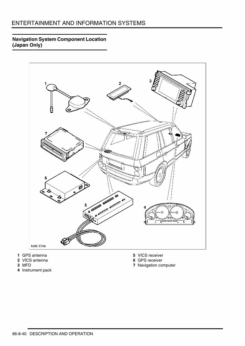
ENTERTAINMENT AND INFORMATION SYSTEMS
Navigation System Component Location (Japan Only)
1 GPS antenna2 VICS antenna3 MFD4 Instrument pack
5 VICS receiver6 GPS receiver7 Navigation computer
86-8-40 DESCRIPTION AND OPERATION

ENTERTAINMENT AND INFORMATION SYSTEMS
Deze pagina werd opzettelijk niet gebruikt
Cette page est intentionnellement vierge
Questa pagina è stata lasciata in bianco di proposito
Diese Seite ist leer
Esta página foi deixada intencionalmente em branco
Esta página fue dejada en blanco intencionalmente
This page is intentionally left blank
DESCRIPTION AND OPERATION 86-8-41

ENTERTAINMENT AND INFORMATION SYSTEMS
Navigation System Control Diagram (Japan Only)
A = Hardwired connection; C = Diagnostic DS2 bus; K = I bus
M86 5846
1
A
2 3
4
5
1112
15
16
6
7
10
14
13
8
9
KC
86-8-42 DESCRIPTION AND OPERATION

ENTERTAINMENT AND INFORMATION SYSTEMS
1 DSC ECU2 Diagnostic socket3 Instrument pack4 Television module5 Multi function display6 GPS receiver7 GPS antenna8 VICS receiver9 VICS antenna
10 Speaker11 DSP12 Power amplifier13 Radio module14 Telephone ECU (JBIT)15 Navigation computer16 Light check module
DESCRIPTION AND OPERATION 86-8-43

ENTERTAINMENT AND INFORMATION SYSTEMS
New Range Rover Navigation System
Introduction To The Global Positioning System (GPS)The system used to calculate the current position of the vehicle is called the Global Positioning System (GPS). The system utilises satellites which are owned by the United States Department of Defence (DoD). A total of 24 satellites circular orbit the earth every 12 hours at a height of 20,000 km (12500 miles), and between 5 and 11 of these satellites can be seen from a single point at any given time. The orbits are tilted to the earth's equator by 55 degrees to ensure coverage of polar regions. Each satellite transmits radio signals to provide information about the satellite position i.e. latitude, longitude, altitude, almanac data and an accurate time signal generated by an on-board atomic clock. Each satellite contains four atomic clocks
The vehicle needs to receive data from at least four different satellites to give a three dimensional fix on its current position.
As the vehicle moves, this information is continually being updated. The computer determines which satellites are 'visible' to the system and their current position and relationship to each other. Using this information the computer can account for positional deviations of the satellites and compensate to enhance the accuracy of the navigation system.
The GPS signal is also known as the Precision positioning signal (PPS). This is now the only GPS signal available, since the Selective positioning signal (a deliberately degraded signal) was turned of on the 2nd May 2000. The ensures that everyone can now use the higher accuracy available with PPS
SPS predictable accuracy was:l 100 metres horizontal accuracyl 156 metres vertical accuracyl 340 nanoseconds time accuracy.
PPS predictable accuracy is :l 22 metres horizontal accuracyl 27.7 metres vertical accuracyl 200 nanosecond time accuracy.
Each navigation system provides computer generated audible and visual route guidance information to enable the driver to reach a desired destination. The system allows the driver to choose the desired route using minor or major roads or motorways and the quickest or shortest route. Directions to hospitals, museums, monuments and hotels are also available. The computer uses map information stored on a CD-ROM to determine the best route for the journey and provide the driver with details of directions and approaching junctions.
The system uses almanac data to determine the vehicles position. Almanac data is the current status of the 24 satellites which orbit the earth. The computer determines which satellites are 'visible' to the system and their current position and relationship to each other. Using this information the computer can account for positional deviations of the satellites and compensate to enhance the accuracy of the navigation system. The navigation system requires the almanac data from at least four different satellites to calculate a three dimensional 'fix' on its location. As the vehicle moves the computer continually up dates this information so that at all times the computer knows the precise location of the vehicle.
New Range Rover Navigation SystemNew Range Rover navigation system provides on road navigation capabilities. On road navigation requires a CD based map to be inserted in the navigation computer. One map disc is supplied with the vehicle, subsequent updated discs can be obtained from Land Rover dealer-ships at additional cost. Discs are available for different countries and if road navigation is required whilst travelling abroad map discs will need to be changed for appropriate discs.
Navigation System ComponentsNew Range Rover Satellite navigation system comprises the following components (except Japan):l Multi-Function Displayl Navigation computerl GPS (Global Positioning System) antenna.
86-8-44 DESCRIPTION AND OPERATION
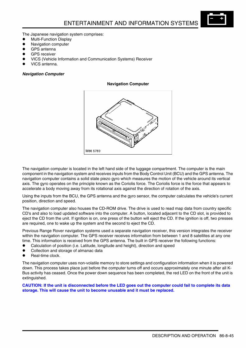
ENTERTAINMENT AND INFORMATION SYSTEMS
The Japanese navigation system comprises:l Multi-Function Displayl Navigation computerl GPS antennal GPS receiverl VICS (Vehicle Information and Communication Systems) Receiverl VICS antenna.
Navigation Computer
Navigation Computer
The navigation computer is located in the left hand side of the luggage compartment. The computer is the main component in the navigation system and receives inputs from the Body Control Unit (BCU) and the GPS antenna. The navigation computer contains a solid state piezo gyro which measures the motion of the vehicle around its vertical axis. The gyro operates on the principle known as the Coriolis force. The Coriolis force is the force that appears to accelerate a body moving away from its rotational axis against the direction of rotation of the axis.
Using the inputs from the BCU, the GPS antenna and the gyro sensor, the computer calculates the vehicle's current position, direction and speed.
The navigation computer also houses the CD-ROM drive. The drive is used to read map data from country specific CD's and also to load updated software into the computer. A button, located adjacent to the CD slot, is provided to eject the CD from the unit. If ignition is on, one press of the button will eject the CD. If the ignition is off, two presses are required, one to wake up the system and the second to eject the CD.
Previous Range Rover navigation systems used a separate navigation receiver, this version integrates the receiver within the navigation computer. The GPS receiver receives information from between 1 and 8 satellites at any one time. This information is received from the GPS antenna. The built in GPS receiver the following functions:l Calculation of position (i.e. Latitude, longitude and height), direction and speedl Collection and storage of almanac datal Real-time clock.
The navigation computer uses non-volatile memory to store settings and configuration information when it is powered down. This process takes place just before the computer turns off and occurs approximately one minute after all K-Bus activity has ceased. Once the power down sequence has been completed, the red LED on the front of the unit is extinguished.
CAUTION: If the unit is disconnected before the LED goes out the computer could fail to complete its data storage. This will cause the unit to become unusable and it must be replaced.
DESCRIPTION AND OPERATION 86-8-45

ENTERTAINMENT AND INFORMATION SYSTEMS
For the Japanese market the navigation computer is a different component. Although it looks identical the unit houses a DVD drive and the internal receiver is replaced by an external one. The system also has extra components for the VICS system (a receiver and an antenna). The VICS system receives allows the vehicle to receive information about traffic conditions from roadside transmitters and adjust the navigation instructions accordingly. The VICS information is received by both a radio link and an infra red link. For this reason the antenna is located behind the rear view mirror on the inside of the windscreen.
Navigation Computer Harness Connector C0897 Pin Details
Navigation Computer Harness Connector C0998 Pin Details
Navigation Computer Connector C0899 Pin Details
Pin No. Description Input/Output1 Reverse gear selected Input
2 to 9 Not used –
10 Road speed Input11 Not used –12 Transmit data, navigation and test interface Output
13 Send request to navigation and test interface Input14 Clear to send, navigation and test interface Output15 Navigation and test interface ground –
16 Receive data, navigation and test interface Input
Pin No. Description Input/Output1 Permanent power supply from battery Input2 Not connected –
3 I bus Input/Output4 Red video signal Output
5 to 7 Not used –
8 Green video and synchronisation signal Output9 Navigation audio positive Output
10 Ground –
11 and 12 Not used –13 Blue video signal Output14 Not used –
15 Blue video ground Output16 Not used –17 Video synchronisation signal Output
18 Navigation audio negative Output
Pin No. Description Input/Output1 Data signal Output2 Data signal Input
3 Permanent battery power supply Output4 Ground for antenna –5 Red video signal Output
6 Green video signal Output7 Blue video signal Output8 I bus Input/Output
9 Auxiliary power supply Input10 Permanent battery power supply Input11 Data signal, inverted Output
86-8-46 DESCRIPTION AND OPERATION
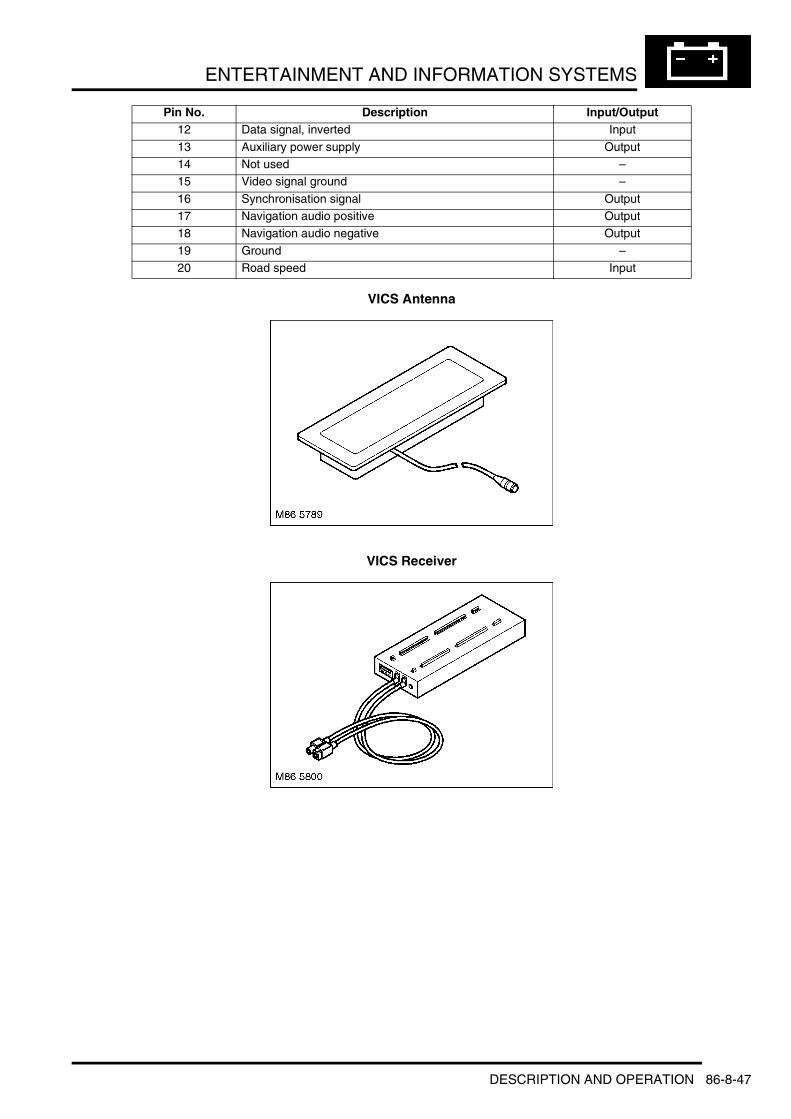
ENTERTAINMENT AND INFORMATION SYSTEMS
VICS Antenna
VICS Receiver
12 Data signal, inverted Input
13 Auxiliary power supply Output14 Not used –15 Video signal ground –
16 Synchronisation signal Output17 Navigation audio positive Output18 Navigation audio negative Output
19 Ground –20 Road speed Input
Pin No. Description Input/Output
DESCRIPTION AND OPERATION 86-8-47

ENTERTAINMENT AND INFORMATION SYSTEMS
GPS Antenna
GPS Antenna
The GPS antenna is located in the rear spoiler on the upper taildoor of the vehicle. The antenna is connected to the navigation computer via a single co-axial cable and passes signals received from the GPS satellites to the built in receiver for processing.
It is possible for the antenna to lose the signals from the satellites in hilly or tree lined areas, built up areas with tall buildings, multi storey car parks, garages, tunnels, bridges and during heavy rain/thunderstorms. When the signal is lost, the navigation computer will continue to give guidance using memory mapped data from the CD map until the signal is restored.
Multi-Function Display
Multi-Function Display
The Multi-Function Display (MFD) is the user interface for the navigation system. The MFD is also the interface for the radio, cassette, CD changer, trip computer and telephone functions of the audio system along with the auxiliary heating timer control, DSP functions, television and teletext. The unit comprises a wide screen format LCD monitor and associated control buttons. The unit houses a cassette mechanism hidden behind the screen which tilts down to load / eject the cassette.
86-8-48 DESCRIPTION AND OPERATION

ENTERTAINMENT AND INFORMATION SYSTEMS
Multi-Function Display Cassette Slot
The MFD communicates on the I bus with the navigation computer, the CD autochanger (where fitted), the radio unit, the telephone (where fitted), the instrument pack and the video module. The communication with the instrument pack is used for diagnostic communication via the diagnostic DS2 bus.
Multi-Function Display Controls
1 Information button2 Cassette eject button3 Telephone button4 Clock/direction button5 Tone button6 Search button7 Menu access button
8 Right hand rotary controller9 Left hand rotary controller
10 Mode button11 Wave band change button12 Pre-set button13 Pre-set button14 Pre-set button
Navigation System OperationThe navigation system is operated entirely from the MFD. The following describes the operation of the navigation system and assumes there is a correct map disc in the computer and that the ignition is in position II.
Entering a DestinationFrom the main menu screen select the GPS-navigation option using the right hand rotary controller (turn to highlight press to select).
M86 5754
1
M86 5753 9
1011121314
1 2
34567
8
DESCRIPTION AND OPERATION 86-8-49

ENTERTAINMENT AND INFORMATION SYSTEMS
Main Menu
This brings up the input destination screen.
Input Destination
If the name of a country appears on the monitor in white letters, data for more than one country is stored on the map CD. Using the rotary controller the country can be selected (if desired/possible) in the usual manner.
Once the correct country has been selected the destination city can be selected.
Input Road
Use the rotary controller to select the first letter of the city. The computer will bring up the first city in its database that has that letter as its first. If this is the correct city use the rotary controller to highlight the enter button to select the city. If however the city is not correct, select the next letter. This process is repeated until the city name is completed in full. Once the city name is correct select the enter button and press store to store the destination city.
Next the road has to be input followed by the house number. This is done in exactly the same manner as the city was input.
Guidance to DestinationOnce the complete destination address has been entered, the city, road and house number are displayed on the monitor; "Dest' guide" is highlighted.
MENU
GPS-navigation
TMC30.07.2001 14:10Monday
On-board computer
Telephone
Set
DSP
Television
Code
Monitor off
H4132
Road:
TMC30.07.2001 14:10Monday
UNITED KINGDOM
INPUT DESTINATION
ABINGDON Deletedestination
return
enter
H4133
Road:
TMC30.07.2001 14:10Monday
UNITED KINGDOM
INPUT DESTINATION
ABINGDOM Delete
deletespaceABCDEFGHIJKLMNOPQRSTUVWXYZXZ
destination
AUSTIN PLACE 81
return1 2 3 4 5 6 7 8 9 0
Index enter
H4135
86-8-50 DESCRIPTION AND OPERATION

ENTERTAINMENT AND INFORMATION SYSTEMS
Destination Guide
Press the right-hand rotary control to start destination guidance. While the navigation computer is calculating the route to the destination, the distance and direction to the destination as the crow flies are displayed at the top right hand corner of the screen.
Once the route has been calculated, the destination address that has been entered appears at the top left hand corner of the screen. The name of the road which the arrow instructs you to turn into is shown below it, together with the distance to the junction with that road. A change of direction is likewise indicated by the spoken instructions.
The distance to the next turning is shown at the top right hand corner of the screen. An arrow indicates the direction of the chosen destination as the crow flies. Your current position is shown at the bottom left: hand corner of the screen.
Should the area travelling through not be fully covered by the map CD, the arrow will display the direction in which the driver should be travelling.
To repeat an audible instruction use the rotary controller to highlight the “instruction” button and press.
Once programmed with a route it is not necessary for the display to stay on the navigation system. The radio, cassette or CD player can all be used. The navigation display and audible guidance will warn the driver prior to the next junction/direction change.
Route Display
Selection of the route display option will call up the route display screen. This screen displays a map view of the route to be driven along with an icon on the route show the vehicles current position on the route.
Navigation System DiagnosticsInformation can be accessed through the diagnostic line using TestBook/T4. Information which can be accessed includes the following:l Land Rover part numberl Hardware and software versionl Week and year of manufacturel LCD brightness l Read error memory/fault codes.
The button status function can be used to determine the correct functioning of the switch-pack. Sticking buttons can be observed on the TestBook/T4 screen as well as the correct functioning of all the keys as they are pressed.
Road:
TMC30.07.2001 14:10Monday
UNITED KINGDOM
INPUT DESTINATION
Deletedestination
On main route Traffic i
Dest. GuiInformation
GAYDON
H4136
H4206
Route map
300 yd
TMC30.07.2001 14:10
LEAMINGTON SPA2.0 mls
Monday
New route
Information
Instruction
Dest. Input
CHURCH ST.
A452, WARWICK
A452
DESCRIPTION AND OPERATION 86-8-51

ENTERTAINMENT AND INFORMATION SYSTEMS
Fault codesFault codes are stored in the memory of the system ECUs and are accessed using TestBook/T4. The following table 'ECU fault codes' lists the faults that can be stored by the navigation computer memory.
ECU fault codes
Service ModeTo enter service mode on the high line system, select SET on the menu screen and hold the menu button for eight seconds. This will then display the 'service mode' menu screen.l On-board monitorl NAVIGATION / GRAPHIC ELEMENTl Video modulel GPS l Sensor check.
On-board MonitorSelecting the 'On-board monitor' option displays the 'On-board monitor version' screen as follows.l SW levell HW levell DIAG indexl Bus indexl Encoding indexl Supplier.
If version is selected the 'ON BOARD MONITOR VERSION' screen will be displayed as described above.l Versionl Key functionl Brightness- the screen brightness can be adjusted by selecting this option.
Select the 'Key function' menu by rotating the LH rotary control and depressing it. The 'ON-BOARD MONITOR KEY FUNCTION' screen will be displayed. This allows each key on the display unit to be checked for operation. The screen also shows the following information:l Key, the screen will show FF if no keys are pressed or FEH if several keys are pressed. The KEY box will change
to reflect the button that has been pressedl OBM increm sensor- The 'OBM increm sensor' box changes its value as the RH rotary control is turnedl Radio increment sensor- The 'OBM increm sensor' box changes its value when the LH (audio) rotary control is
turned.
Navigation / Graphic ElementSelecting the Navigation / graphic element displays the following options:l SW levell HW levell DIAG indexl Bus indexl Encoding indexl Supplier.
Fault code Description01 Navigation computer error04 GPS sensor error
05 Temperature error06 Application software error07 Display error
08 Audio error09 CD error
86-8-52 DESCRIPTION AND OPERATION

ENTERTAINMENT AND INFORMATION SYSTEMS
Video ModuleSelecting 'Video module' will give the Video module information as follows:l SW levell HW levell DIAG indexl Bus indexl Encoding indexl Supplier.
GPSOn selecting GPS the following will be displayed:
GPS version information will appear asl Receiver versionl Receiver software date.
Selecting the functions box allows the selection of,l GPS versionl GPS statusl GPS tracking info.
Selecting 'GPS status' will display the following information.l Latitude - displays the current vehicle Latitudel Longitude - displays the current vehicle Longitudel Altitude - displays the current vehicle altitudel Date/time - displays the current date and timel G-speed/heading - displays the current vehicle speed and headingl Rec-stat/Pos-Src displays the current receiver status and position sourcel COMMERR - this tells us that there is a communication error between the GPS receiver and the navigation
computerl SEARCH - Denotes that the system is searching for satellitesl TRACK - Denotes that the system is tracking satellites but does not have enough information to determine a
position. It also shows that the system is functioning correctlyl POS This shows that the system is functioning correctly and is able to fix the position of the vehiclel PDOP (Position Dilation Of Precision), HDOP ( Height Dilation Of Precision) and VDOP (Velocity Dilation Of
Precision). These values tells us about the precision of geometric position. One is the best value whereas a value of ten would mean there is no GPS positioning possible.
Selecting 'GPS TRACKING INFO' displays the following information.l Ch PRN S/N-Displays the satellite being tracked on each channel and their signal strengthl Visible satellites- Displays the number of visible satellitesl Almanac- Displays YES or NO to show whether or not the system is receiving Almanac data.
DESCRIPTION AND OPERATION 86-8-53

ENTERTAINMENT AND INFORMATION SYSTEMS
Sensor CheckThis screen will display information to check that all the input sensors are functioning correctly.l Wheel sensors - These are used to calculate the vehicle speedl GPS satellites - Displays the number of satellites visible to the system at that timel GPS Status - Displays the number of satellites visible to the system and the GPS status There are four
possibilities for the status and they are as followsl GPS Error - Communication error between the GPS receiver and the navigation computer. This could be a
system failurel Satellite search - The system is searching for satellites. This may indicate a system failurel Satellite contact - The system is tracking a number of satellites but does not have enough information to
determine a positionl Position known - As the name suggests the system is tracking a number of satellites and has determined the
vehicle positionl Gyro - The navigation computer incorporates a gyro which determines any changes in vehicle direction. In this
screen it can be seen moving as the vehicle changes directionl Direction - This sensor determines whether the vehicle is travelling forwards or backwards and will display FWD
or BWD.
Exiting service mode is achieved by pressing the menu button on the control panel which returns the system to the main TV/Navigation screen.
86-8-54 DESCRIPTION AND OPERATION

ENTERTAINMENT AND INFORMATION SYSTEMS
DESCRIPTION AND OPERATIONTelephone System Component Location
1 Multi band antenna2 Microphone3 Multi Function Display (MFD)4 Multi Information Display (MID)5 Steering wheel controls
6 Cordless hand-set7 Eject box8 Hand-set antenna9 Telephone control unit
10 Voice recognition ECU
DESCRIPTION AND OPERATION 86-8-55

ENTERTAINMENT AND INFORMATION SYSTEMS
Telephone System Control Diagram
A = Hardwired connection; C = DS2 diagnostic bus; K = I bus
M86 5844 A
20
12
18
19
16
17
5
6
7
8
9
15
14
1 2
3
13
4
10
11
KC
86-8-56 DESCRIPTION AND OPERATION

ENTERTAINMENT AND INFORMATION SYSTEMS
1 Multi band antenna2 Cordless hand-set antenna3 Cordless hand-set4 Eject box5 Speaker6 Power amplifier7 DSP8 Radio unit9 Cassette/radio unit
10 CD/radio unit11 Mini disc/radio unit12 Instrument pack13 Diagnostic socket14 MFD15 MID16 Rotary coupler17 Steering wheel controls18 Microphone19 Speech recognition unit20 Telephone ECU
DESCRIPTION AND OPERATION 86-8-57

ENTERTAINMENT AND INFORMATION SYSTEMS
Telecommunication System
IntroductionNew Range Rover has the option to be supplied with a built in hands free telephone system. Both the Multi-Function Display (MFD) and the Multi Information Display (MID) are capable of supporting telephone operation. The system is based around a portable GSM phone which utilises a standard SIM card.
Telephone SystemThe telephone system comprises the following components:l Eject boxl Cordless handsetl Cordless handset antennal Telephone ECUl Multi band antennal Hands free microphone.
Three 'status' LEDs, fitted either on the lower right hand side of the MID or on the upper right hand side of the MFD, indicate the status of the telephone system as follows:
Eject Box
Eject Box
The eject box is located in the centre arm rest console. It holds the handset and also a SIM card reader. The SIM card reader requires the use of an adaptor to allow the use of standard small size SIM cards.
When the handset is in the Eject box the hand set battery will be charged if the ambient temperature is between 0 °C and 40 °C.
To release the hand set from the eject box the eject key located at the front of the box should be depressed. This raises the hand set approximately 15° out of the rest position. The eject key inscription is illuminated and this illumination is variable with the use of the instrument dimmer switch.
Lamp Status System StatusFlashing Red Phone not registered on a networkSteady Red Phone operation possible
Steady Yellow Phone logging on to another networkSteady Green Call in progress
86-8-58 DESCRIPTION AND OPERATION

ENTERTAINMENT AND INFORMATION SYSTEMS
Cordless Handset
The Cordless hand set has a graphic display on which a maximum of 4 lines each with 16 characters can be shown. In the first line, information concerning the mobile state ("Phone locked; "Connected") or the battery charge state is displayed. In the second and third lines there are various formats for inputting optional digits. In the fourth line only the softkey fields are displayed. Either as a symbol or as fixed text. On activating the menu key, the second and third line of the display is available for menu selections. When menu selection is concluded the display returns to normal. All texts can be displayed in upper or lower case. This includes both the mobile handset permanent text items (e.g. menu texts) and texts edited by the user (e.g. names in phone book) The following information is displayed in the handset switched-on state, however it is not necessarily displayed during menu navigation:l Permanent display of battery charge statel Permanent GSM signal strength.
With the batteries fully recharged, the handset can remain on stand-by for approximately 48 hours and has an air time of at approximately three hours. If the batteries are completely flat or if new batteries have been inserted, full charging will take approximately six hours. To charge the batteries, place the handset in the eject box. The batteries are also charged while the car is parked (ignition off).
The handset is connected with the base station in the car by radio link. This link can be switched off for workshop purposes or where it is a market requirement. When using the handset, ensure that this switch always remains in position "1" (to the right).
Eject Box Harness Connector C1252 Pin Details
Pin No. Description Input/Output1 Permanent power supply from battery Input
2 Ground –3 Interior illumination Input4 Telephone off signal Output
5 SIM card supply Input6 SIM card data Input
7 to 9 Not used –
10 SIM card reset signal Input11 Handset charging control signal Input12 SIM card inserted signal Output
13 Not used –14 SIM card data Output
15 to 18 Not used –
DESCRIPTION AND OPERATION 86-8-59

ENTERTAINMENT AND INFORMATION SYSTEMS
Cordless Handset Antenna
The cordless handset antenna is located in the left hand side of the luggage compartment. This antenna allows the cordless handset to communicate with the Telephone ECU.
Telephone Control Unit (TCU)
The TCU located in the left hand side of the luggage compartment. The TCU sends and receives signals from the cordless handset via the handset antenna. The TCU then sends and receives signals to the GSM antenna via a co-axial cable. If the unit needs replacing, it must be configured using TestBook/T4.
86-8-60 DESCRIPTION AND OPERATION

ENTERTAINMENT AND INFORMATION SYSTEMS
TCU Harness Connector
TCU Harness Connector C0947 Pin Details
Pin No. Description Input/Output1 Handset charging control signal Output2 SIM card data Output
3 to 11 Not used –12 Auxiliary power supply Input13 I bus Input/Output
14 to 16 Not used –17 Audio negative Output18 Audio positive Output
19 SIM card supply Output20 SIM card reset signal Output
21 to 23 Not used –
24 Ground –25 Permanent power supply from battery Input
26 to 28 Not used –
29 Mute signal Output30 Not used –31 Permanent power supply from battery Input
32 Permanent power supply from battery Input33 Ground –34 Ground –
35 and 36 Not used –37 SIM card inserted signal Input
DESCRIPTION AND OPERATION 86-8-61

ENTERTAINMENT AND INFORMATION SYSTEMS
Multi Band Antenna
The antenna is located in the rear tailgate spoiler and is the same component for most world markets.
38 SIM card data Input
39 to 41 Not used –42 Ground –43 Permanent power supply from battery Input
44 to 46 Not used –47 Amplifier control signal Output48 Telephone off signal Input
49 to 51 Not used –52 Microphone negative Input53 Microphone wiring screen ground –
54 Microphone positive Input
Pin No. Description Input/Output
86-8-62 DESCRIPTION AND OPERATION
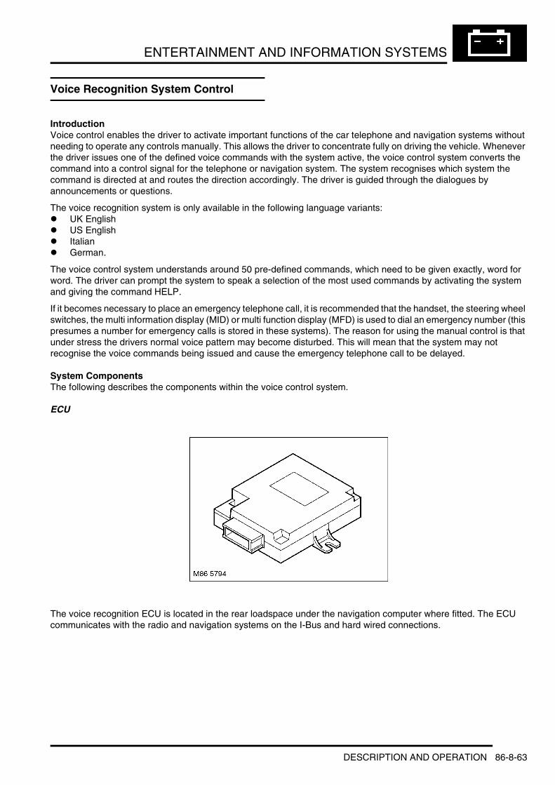
ENTERTAINMENT AND INFORMATION SYSTEMS
Voice Recognition System Control
IntroductionVoice control enables the driver to activate important functions of the car telephone and navigation systems without needing to operate any controls manually. This allows the driver to concentrate fully on driving the vehicle. Whenever the driver issues one of the defined voice commands with the system active, the voice control system converts the command into a control signal for the telephone or navigation system. The system recognises which system the command is directed at and routes the direction accordingly. The driver is guided through the dialogues by announcements or questions.
The voice recognition system is only available in the following language variants:l UK Englishl US Englishl Italianl German.
The voice control system understands around 50 pre-defined commands, which need to be given exactly, word for word. The driver can prompt the system to speak a selection of the most used commands by activating the system and giving the command HELP.
If it becomes necessary to place an emergency telephone call, it is recommended that the handset, the steering wheel switches, the multi information display (MID) or multi function display (MFD) is used to dial an emergency number (this presumes a number for emergency calls is stored in these systems). The reason for using the manual control is that under stress the drivers normal voice pattern may become disturbed. This will mean that the system may not recognise the voice commands being issued and cause the emergency telephone call to be delayed.
System ComponentsThe following describes the components within the voice control system.
ECU
The voice recognition ECU is located in the rear loadspace under the navigation computer where fitted. The ECU communicates with the radio and navigation systems on the I-Bus and hard wired connections.
DESCRIPTION AND OPERATION 86-8-63

ENTERTAINMENT AND INFORMATION SYSTEMS
Voice Recognition ECU Harness Connector
Voice Recognition ECU Harness Connector C2136
Pin No. Description Input/Output1 to 7 Not used –
8 Microphone negative Input
9 Microphone positive Input10 Microphone negative Output11 Microphone positive Output
12 Audio negative Output13 Audio positive Output
14 to 17 Not used –
18 Amplifier control signal Output19 and 20 Not used –
21 I bus Input/Output
22 Mute signal Output23 Telephone on signal Input24 Auxiliary power supply Input
25 Audio negative Input26 Audio positive Input
M86 5994C2136
86-8-64 DESCRIPTION AND OPERATION

ENTERTAINMENT AND INFORMATION SYSTEMS
Steering Wheel Switch Pack
The steering wheel switch pack contains several switches for operation of the audio navigation and cruise control.
The voice recognition system is activated using an I-bus telegram. Activation is achieved by pressing and holding the voice recognition key on the steering wheel switch pack until an acoustic signal is heard.
MicrophoneA single microphone is used for hands-free telephone operation and for the voice recognition system. The microphone has an integrated noise suppression system for hands-free telephone use.
If replaced the microphone must be correctly orientated. This is achieved by ensuring the arrow on the back of the microphone is facing the front of the vehicle.
Voice Recognition Microphone
Voice Recognition System OperationTo access voice control of the telephone system, press the key on the steering wheel switch pack.l A brief press the key (for longer than 750 ms) activates the normal telephone functionsl Holding the key pressed in (until the acoustic signal is heard) activates voice control.
A brief acoustic signal and the display "VOICE RECOGNITION" in the instrument pack message centre indicate that the system is now in the stand-by mode ready to receive voice commands. Any voice command can be interrupted by saying the word “CANCEL” or by pressing and holding the steering wheel switch until the system responds with the phrase “CANCEL”.
DESCRIPTION AND OPERATION 86-8-65

ENTERTAINMENT AND INFORMATION SYSTEMS
Making a Phone CallOnce the system is ready to receive voice commands to dial a telephone number the user has to speak clearly.
The system understands single digits from zero to nine. You can choose to say either Zero or Nought. Numbers such as ten, eleven, twelve, etc. are not recognised. To speed up input, it is a good idea to group together between three and five digits into a continuous string. However, you can also say each digit individually, or all digits continuously. Telephone numbers of up to 20 digits are acknowledged. If a longer number is given, the error message “The number is full” will be issued.
Voice Operation of the Navigation SystemTo access voice control of the navigation system, press the key on the steering wheel switch pack.l A brief press the key (for longer than 750 ms) activates the normal telephone functionsl Holding the key pressed in (until the acoustic signal is heard) activates voice control.
Once the system is active the driver has three main options (in navigation mode):1 Map mode2 Information on current position or destination3 Activation of destination guidance.
Map ModeOnce the system is accessed the command “ROUTE MAP” or “MAP”, will bring the map mode up on the MFD.
Once the map mode is accessed it is possible to change the map scale by issuing the command “SCALE ONE HUNDRED METRE “ to “SCALE ONE HUNDRED KILOMETRE”. Valid scales are as follows:l 100, 200, 500 metresl 1, 2, 5, 10, 20, 50, 100, kilometre.
Information on Current Position or DestinationInformation on current position or destination is accessed by issuing the command “PETROL STATION AT CURRENT LOCATION”. This causes all petrol stations in the vicinity of the vehicle to be displayed on the MFD. If a destination has been entered into the navigation system it is also possible to issue the command “PETROL STATION AT DESTINATION”. A full list of petrol stations at the destination is then displayed on the MFD. Selection and guidance to the chosen petrol station is achieved by tuning the rotary controller and selecting in the usual way.
Once the command has been issued the MFD displays petrol stations along the route.
The information displayed is not limited to petrol stations. Information can be displayed on:l Car parksl Hotelsl Restaurants.
To access these functions follow the procedure outline previously replacing the petrol station command with the required function.
Destination GuidanceTo access the destination guidance function the driver issues the command “DESTINATION GUIDE” or “DESTINATION GUIDANCE”. The computer will start to give voice and map guidance to the chosen destination.
Voice Command System Voice Output Message centre DisplayDial (telephone) number Please speak the number SPEAK NUMBER
Zero, eight, nine Zero, eight, nine, continue ? TEL 089Three, eight, two, four Three, eight, two, four, continue ? TEL 0893824One, six, eight One, six, eight, continue ? TEL 0893824168
Dial (number) The number is being dialled TEL 0893824168
86-8-66 DESCRIPTION AND OPERATION

DRIVING AIDS
DRIVING AIDSDESCRIPTION AND OPERATIONPark Distance Control Component Layout
1 Front park sensor2 PDC sounder3 PDC ECU
4 Rear park sensor5 Parking switch
DESCRIPTION AND OPERATION 86-10-1
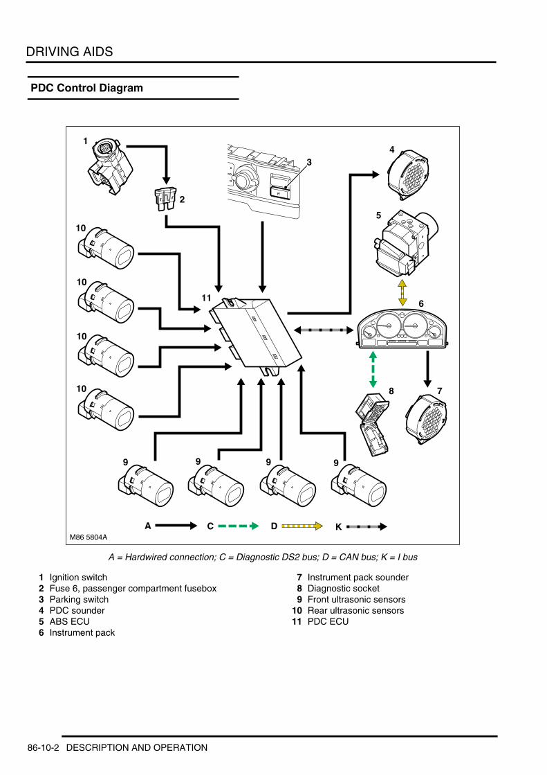
DRIVING AIDS
PDC Control Diagram
A = Hardwired connection; C = Diagnostic DS2 bus; D = CAN bus; K = I bus
1 Ignition switch2 Fuse 6, passenger compartment fusebox3 Parking switch4 PDC sounder5 ABS ECU6 Instrument pack
7 Instrument pack sounder8 Diagnostic socket9 Front ultrasonic sensors
10 Rear ultrasonic sensors11 PDC ECU
M86 5804A
14
6
8
9999
10
10
10
10
11
2
A
3
7
5
C D K
86-10-2 DESCRIPTION AND OPERATION

DRIVING AIDS
Description
GeneralThe Park Distance Control (PDC) provides an audible warning to the driver when any obstacles are in the path of the vehicle during forward and reverse parking manoeuvres. The system consists of four ultrasonic sensors in each bumper, an ECU, a sounder and a parking switch. The system also uses the sounder driven by the instrument pack.
At low speed, the PDC ECU uses the ultrasonic sensors to monitor the area around the bumpers, then outputs a warning on the PDC sounder or the instrument pack sounder if an object is detected within a monitored area. As well as detecting solid objects such as posts, walls and other vehicles, the system can also detect less solid objects such as a wire mesh fence. Objects close to the ground may escape detection but, because of their low height, will not foul the vehicle.
Ultrasonic SensorsThe ultrasonic sensors are transceivers which are installed in inserts in the bumpers. All eight sensors are identical and keyed to the inserts to ensure correct orientation.
When the system is active, the sensors transmit ultrasonic pulses. Any reflections from the pulses received by the transmitting and adjacent sensors are then converted to digital format and output to the PDC ECU.
PDC ECUThe PDC ECU is located next to the rear fusebox behind the trim in the RH side of the luggage compartment.
Inputs and OutputsThree connectors provide the interface between the PDC ECU and the vehicle wiring. The PDC ECU is powered by an ignition supply from the passenger compartment fusebox. In addition to hardwired connections with the ultrasonic sensors, PDC sounder and power supply, the PDC ECU communicates with the instrument pack on the I bus. I bus communication is used for TestBook/T4 diagnostics and for system operation. System operation related I bus messages include:
I Bus Messages
Message From ToRoad speed ABS ECU PDC ECUReverse gear status EAT ECU PDC ECUTrailer status Light check module PDC ECU
Ambient temperature Instrument pack PDC ECUInstrument pack sounder request PDC ECU Instrument pack
DESCRIPTION AND OPERATION 86-10-3

DRIVING AIDS
PDC ECU Harness Connectors
PDC ECU Harness Connector C0957 Pin Details
Pin No. Description Input/Output1 Ignition power supply Input2 PDC sounder +ve Output
3 Not used –4 I bus Input/Output5 Not used –
6 Ground –7 PDC switch LED Output8 PDC sounder –ve Input
9 Instrument pack sounder Output10 PDC switch Input11 Instrument pack sounder (rearward travel gong – Japan
only)Output
12 Not used –
86-10-4 DESCRIPTION AND OPERATION

DRIVING AIDS
PDC ECU Harness Connector C0958 Pin Details
PDC ECU Harness Connector C1457 Pin Details
PDC SounderThe PDC sounder produces the audible warnings with which the PDC ECU informs the driver of system status and objects detected at the rear of the vehicle. The PDC sounder is installed behind the trim in the RH side of the luggage compartment, on the underside of the shelf.
The chime produced on the PDC sounder has a lower tone than that produced on the instrument pack sounder (which is used to warn of objects detected at the front of the vehicle), to enable the driver to differentiate between the two.
Parking SwitchThe parking switch is a non latching push switch installed on the centre console for selecting the system on and off. When pressed, the switch connects a ground to the PDC ECU. An orange LED above the switch indicates when the PDC system is active. The LED is activated by a power feed from the PDC ECU.
Pin No. Description Input/Output1 Rear LH inner PDC sensor ground –2 Rear RH outer PDC sensor ground –3 Rear LH outer PDC sensor ground –
4 Rear RH inner PDC sensor supply Output5 Rear LH inner PDC sensor supply Output6 Rear RH outer PDC sensor supply Output
7 Rear RH inner PDC sensor supply Output8 Rear RH inner PDC sensor signal Input9 Rear LH inner PDC sensor signal Input
10 Rear RH outer PDC sensor signal Input11 Rear LH outer PDC sensor signal Input12 Rear LH outer PDC sensor supply Output
Pin No. Description Input/Output1 Front LH inner PDC sensor ground –2 Front RH outer PDC sensor ground –3 Front LH outer PDC sensor ground –
4 Front RH inner PDC sensor supply Output5 Front LH inner PDC sensor supply Output6 Front RH outer PDC sensor supply Output
7 Front RH inner PDC sensor ground –8 Front RH inner PDC sensor signal Input9 Front LH inner PDC sensor signal Input
10 Front RH outer PDC sensor signal Input11 Front LH outer PDC sensor signal Input12 Front LH outer PDC sensor supply Output
DESCRIPTION AND OPERATION 86-10-5

DRIVING AIDS
Operation
GeneralWhen the ignition switch is in position II and either reverse gear is selected or the parking switch is pressed, both sets of acoustic sensors are activated. The PDC ECU only activates the system if reverse is selected for more than 1 second, to avoid nuisance audible warnings when the gear selector lever is being moved between Drive and Park. The rear sensors are disabled when a trailer is connected to the vehicle.
Park Distance Control Detection Areas
A = Intermittent warning tone; B = Continuous warning tone
When it activates the system, the PDC ECU illuminates the indicator LED in the parking switch, switches on the ultrasonic sensors and generates a single chime on the PDC sounder and the instrument pack sounder to indicate the system is active. The PDC ECU then processes the distance readings from the ultrasonic sensors to determine if there are any objects within the detection areas.
If there are no objects in the detection areas, there are no further audible warnings. If an object is detected, repeated audible warnings are produced on the PDC sounder or the instrument pack sounder as appropriate. The time delay between the audible warning tones decreases as the distance between the detected object and the vehicle decreases until, at approximately 250 mm (10 in), the audible warning tone is continuous.
After the initial detection of an object, if there is no decrease in the distance between the object and the vehicle:l If the object is detected by one of the central acoustic sensors the time delay between audible warning tones
remains constant l If the object is detected by a corner transducer the audible warning tones stop after approximately 3 seconds.
The audible warning tones are discontinued when the gearbox selector lever is moved out of reverse, but will restart if the PDC ECU detects a decrease in the distance between the vehicle and an object.
System operation is cancelled when the parking switch is pressed or the ignition is switched off. System operation is also cancelled if the vehicle travels more than 50 m (164 ft) or forward speed exceeds 19 mph (30 km/h).
700mm (27.5in)
250mm (10in)
600mm (23.5in)
'Y' 'Y'
1500mm (59in)
250mm (10in)
'Y'-'Y'
M86 5805
A
B
600mm (23.5in)
'X'-'X'
'X' 'X'
86-10-6 DESCRIPTION AND OPERATION

DRIVING AIDS
The PDC ECU software incorporates routines that compensate for the effect of ice, frost and rain on the acoustic sensors. Ice compensation occurs if the ambient temperature is less than 6 °C (43 °F).
DiagnosticsThe PDC ECU performs self check routines and checks the system wiring for short and open circuits. While the system is active the PDC ECU also monitors the data from the acoustic sensors.
If a fault is detected, a related fault code is stored in the non volatile memory of the PDC ECU and either the front sensors, the rear sensors or the complete system is disabled, as appropriate. To advise the driver of the failure, the PDC ECU flashes the indicator LED at 2 Hz and sounds a continuous warning tone for 3 seconds, in place of the normal short tone, when the system is activated.
Fault codes can be accessed using TestBook/T4, which communicates with the PDC ECU via the instrument pack and the I bus.
DESCRIPTION AND OPERATION 86-10-7

DRIVING AIDS
DESCRIPTION AND OPERATIONTyre Pressure Monitoring Component Layout
1 Tyre sensor2 TPM reset switch
3 TPM antenna4 TPM ECU
86-10-8 DESCRIPTION AND OPERATION

DRIVING AIDS
Deze pagina werd opzettelijk niet gebruikt
Cette page est intentionnellement vierge
Questa pagina è stata lasciata in bianco di proposito
Diese Seite ist leer
Esta página foi deixada intencionalmente em branco
Esta página fue dejada en blanco intencionalmente
This page is intentionally left blank
DESCRIPTION AND OPERATION 86-10-9

DRIVING AIDS
TPM Control Diagram
A = Hardwired connection; B = K bus; C = Diagnostic DS2 bus; F = RF transmission
M86 5807A
1
2 3
5
6
7
8
9
9
9
8
9
10
8
8
A FB
9
4
C
86-10-10 DESCRIPTION AND OPERATION

DRIVING AIDS
1 Ignition switch2 Fuse 6, passenger compartment fusebox3 Fuse 16, passenger compartment fusebox4 TPM reset switch5 BCU6 Instrument pack7 Diagnostic socket8 TPM antenna9 Tyre sensor
10 TPM ECU
DESCRIPTION AND OPERATION 86-10-11
DRIVING AIDS
Description
GeneralThe Tyre Pressure Monitoring (TPM) system continuously monitors tyre pressures so long as vehicle battery power is available. If a low tyre pressure is detected, the system alerts the driver via the message centre when the ignition is on. The system monitors the tyre pressure of each road wheel and the full size spare wheel. The tyre pressure of a space saver spare wheel is not monitored.
The TPM system consists of the following components:l A reset switchl A tyre sensor in each monitored wheell An antenna in each wheelarchl An ECU.
The tyre sensors measure the air pressure and temperature in the tyres and transmit the readings in radio signals at a frequency of 433 MHz. The radio signals are received by the antennas and transferred to the TPM ECU, which compares the information from the tyre sensors with nominal pressures stored in memory, and alerts the driver if a tyre pressure decreases from the nominal pressure by more than the permitted limit.
The reset switch is used to initialise the TPM ECU. During initialisation the TPM ECU adopts the current tyre pressures as the nominal pressures.
TPM Reset SwitchThe TPM reset switch is a non latching push switch installed on the centre console below the A/C control panel. While pressed, the reset switch connects a ground to the TPM ECU.
Tyre SensorA tyre sensor is installed on the wheel rim of each monitored wheel, and connected to the tyre inflation valve. The tyre inflation valve and a Torx bolt secure the tyre sensor to the wheel.
The tyre sensor incorporates a pressure sensor, temperature sensor, signal processor, radio transmitter and a non serviceable 3.6 V battery. Nominal service life of the battery is seven years. Battery status can be checked using TestBook/T4.
The electronics of replacement tyre sensors are inactive until they have been subjected to a pressure of 1.5 bar (21.75 lbf/in2), i.e. installed on the wheel and the tyre inflated. To conserve power in service, the signal processor adopts different operating modes depending on the prevailing conditions:l Normal operating mode, for stable or slow changes of pressure, when the sensing rate is every 3.4 seconds and
transmission rate approximately once every 55 secondsl Emergency operating mode, adopted if the pressure decreases more than 0.2 bar (3 lbf/in2) in 30 seconds, when
both the sensing and transmission rates are once every 0.85 second. Reverts to normal operating mode after 218 seconds
l Deactivated mode, for temperatures in excess of 120 °C (248 °F) (making sensor readings and transmission unreliable), when sensing and transmission electronics are deactivated and the TYRE CONTROL INACTIVE warning is displayed. The electronics are re-activated when the temperature decreases to 110 °C (230 °F) for 218 seconds.
Each transmission from a tyre sensor contains:l A synchronisation bytel Pressure readingl Temperature readingl Identification numberl Remaining life of the battery, in monthsl Status information.
86-10-12 DESCRIPTION AND OPERATION

DRIVING AIDS
Tyre Sensor Assembly
1 Sensor body2 Torx bolt
3 Filter4 Inflation valve
TPM AntennaA TPM antenna is installed inside each wheel arch, behind the wheelarch liners. 'Twisted pair' wires connect each TPM antenna to the TPM ECU.
TPM ECUThe TPM ECU is installed below the front passenger seat, in a mounting bracket together with the Body Control Unit (BCU) and the security system tilt sensor. The TPM ECU incorporates a Radio Frequency (RF) receiver, to decode the radio signals from the antennas, and system electronics for control and diagnostics.
Power for system operation is provided by a permanent power feed and an ignition switched power feed from fuses in the passenger compartment fusebox. On a K bus connection with the instrument pack, the TPM ECU can:l Communicate with the diagnostic socketl Receive road speed and ambient temperature data from the instrument packl Send caution and warning messages to the instrument pack.
A hardwired connection with the BCU allows the TPM ECU to trigger the vehicle alarm if it detects rapid deflation of a tyre while the vehicle is parked.
DESCRIPTION AND OPERATION 86-10-13

DRIVING AIDS
TPM ECU Harness Connector C1537 Pin Details
Pin No. Description Input/Output1 I bus Input/Output2 Not used –3 TPM switch Input
4 Not used –5 Front LH TPM antenna6 Front LH TPM antenna screen –
7 Front RH TPM antenna8 Rear LH TPM antenna9 Rear LH TPM antenna screen –
10 Rear RH TPM antenna11 to 13 Not used –
14 TPM switch Output
15 Battery power supply Input16 Ground –17 Rapid tyre deflation signal Output
18 to 20 Not used –21 Front LH TPM antenna22 Front RH TPM antenna screen –
23 Front RH TPM antenna24 Rear LH TPM antenna25 Rear RH TPM antenna screen –
26 Rear RH TPM antenna27 to 30 Not used –
31 Ignition power supply Input
32 Not used –
86-10-14 DESCRIPTION AND OPERATION

DRIVING AIDS
Operation
InitialisationInitialisation is required so that the TPM ECU can learn the identity and position of the tyre sensors, and the nominal pressures of the associated tyres. Initialisation is invoked by pressing and holding the reset switch, with the ignition switch in position II and the engine off, until the SET TYRE PRESSURE message appears in the instrument pack message centre (approximately 4 seconds). When the switch is first pressed, a series of asterisks appear in the message centre to confirm that the TPM ECU has received the switch input. The SET TYRE PRESSURE message goes off after approximately 16 seconds.
NOTE: On later vehicles the wording of the message may be re-arranged to TYRE PRESSURE SET to reflect that the message is an acknowledgement and not a command.
Initialisation is required after:l A tyre pressure has been adjustedl A wheel has changed position, e.g. swapped axles or the spare installed as a road wheell A replacement tyre sensor or TPM ECU has been installed.
WARNING: Without initialisation tyre pressure monitoring is inaccurate and may not be able to detect an unsafe tyre pressure. Inflating tyres to the recommended pressure for the current vehicle load and driving conditions remains the responsibility of the driver.
NOTE: Vehicles are built with tyres at storage pressure. At PDI tyres must be inflated to the correct pressure and, where fitted, the TPM system must be initialised.
After being invoked by the reset switch, initialisation occurs during the subsequent drive cycle(s) when the vehicle is travelling at more than 2.5 mph (4 km/h). At lower speeds initialisation is suspended, then automatically continued when the speed goes above 2.5 mph (4 km/h) again. Initialisation is a transparent process that takes from 15 to 30 minutes and is conducted while driving to reduce the possibility of interference from outside RF transmission sources. There are two phases to the initialisation process: a wheel identification phase and a wheel position phase.
Wheel IdentificationWheel identification takes from 4 to 8 minutes. When the TPM ECU has received more than three transmissions from the same tyre sensor, it recognises that tyre sensor as belonging to the vehicle. The TPM ECU records up to five tyre sensor identities and their current pressure and temperature readings. From the pressure and temperature of each tyre, the TPM ECU calculates a theoretical pressure at 20 °C (68 °F) and uses this as the nominal pressure for monitoring.
The TPM ECU then begins to monitor the tyres for pressure loss and continues the initialisation process to determine the wheel position of the individual tyre sensors.
Wheel PositionThe wheel position phase takes from 3 to 15 minutes. The signals from each tyre sensor are received by all four antennas, so by monitoring the strength of the signals received by each antenna the TPM ECU determines the position of the individual tyre sensors and assigns them a wheel position, including, by inference, the spare wheel tyre sensor (where fitted).
The TPM ECU confirms the wheel positions from the tyre temperatures. When the vehicle is driven the temperature of the road wheels changes, while the temperature of the spare wheel remains relatively constant. When it detects a 4 °C (7.2 °F) change in temperature, the TPM ECU confirms a road wheel position for the related tyre sensor. When it detects a temperature increase of less than 4 °C (7.2 °F) then, provided only one wheel has a temperature increase of less than 4 °C (7.2 °F), the TPM ECU confirms the related tyre sensor in the spare wheel position. The fifth wheel can also be confirmed in the spare wheel position by default, after four road wheel positions have been confirmed.
After successful assignment and confirmation of the wheel positions, the TPM ECU checks the nominal tyre pressures to ensure they are within the following limits:l The nominal tyre pressures must not be less than 1.7 bar (24.65 lbf/in2)l The nominal tyre pressures of wheels on the same axle must be within 0.4 bar (6 lbf/in2) of each other.
DESCRIPTION AND OPERATION 86-10-15

DRIVING AIDS
If the nominal pressures are within the limits, the TPM ECU stores them in memory in place of the previous nominal pressures. Initialisation is successfully completed and the TPM ECU continues to monitor the current tyre pressures against the new nominal pressures.
If a new nominal pressure is outside the limits, the TPM ECU aborts the initialisation process and reverts to the previous nominal pressures for pressure monitoring. The TPM ECU also signals the instrument pack to display the CHECK TYRE PRESSURE message on the message centre for 40 seconds. While the ignition is on the message is repeated at 1 minute intervals until a valid initialisation is performed.
Occasionally the system may have difficulty assigning and confirming wheel positions, e.g. due to signal interference, if a spare wheel is masked by luggage, etc. If the TPM ECU cannot successfully complete the wheel position phase, it discontinues the initialisation process and reverts to the previous nominal pressures for pressure monitoring. At the start of the next ignition cycle, the TPM ECU also signals the instrument pack to display the CHECK TYRE PRESSURE message.
Wheel ConfirmationAt the beginning of each drive cycle, if the system is not being initialised the TPM ECU retrieves the stored wheel data from memory and checks it against the current identification and position of the tyre sensors to determine if the tyre sensor arrangement has changed without being initialised.
If it detects the same tyre sensors installed in different positions, the TPM ECU assigns and confirms the tyre sensors to their new wheel positions and retains their existing nominal pressures. At the start of the next ignition cycle, the TPM ECU signals the instrument pack to display the CHECK TYRE PRESSURE message as a reminder to check that the tyre pressures are correct for their wheel positions and to initialise the system.
If it detects a new tyre sensor on the vehicle, the TPM ECU signals the instrument pack to activate the TYRE CONTROL INACTIVE warning while it learns the identity, wheel position and nominal pressure of the new sensor in a similar manner to the initialisation process. Once the learning process is completed, the TPM ECU signals the instrument pack to de-activate the TYRE CONTROL INACTIVE warning.
If the confirmation process cannot be completed within 30 minutes, the TPM ECU signals the instrument pack to activate the TYRE CONTROL INACTIVE warning for the remainder of the drive cycle.
If the TPM ECU detects additional tyre sensors during confirmation, e.g. if additional spare wheels fitted with tyre sensors are being carried in the vehicle, it disables the system, stores a 'too many wheel sensors' message and signals the instrument pack to activate the TYRE CONTROL INACTIVE warning.
Pressure MonitoringThe TPM ECU continuously compares the current tyre pressures against the nominal pressures stored in memory. From each tyre's current pressure and temperature, the TPM ECU calculates the theoretical pressure at 20 °C (68 °F) and compares the result with the tyre's nominal pressure. If the current pressure varies from the nominal pressure by more than the preset limits, the TPM ECU signals the instrument pack to produce a caution or warning as appropriate.
CautionThe caution is produced when a tyre pressure is less than the optimum, but still within safe limits for driving, to advise the driver that tyre pressures should be checked at the next opportunity. The TPM ECU stores the event and outputs the caution to the instrument pack the next time the ignition is switched on. The caution consists of the CHECK TYRE PRESSURE message being displayed on the instrument pack message centre. The caution is produced when either of the following occurs:l A tyre pressure is between 0.2 and 0.4 bar (3 and 6 lbf/in2) below the nominal pressure for 10 signals in
successionl A tyre temperature is 20 °C (68 °F) or more below the initialisation temperature for approximately 14 days (known
as the 'autumn filter', this alerts the driver to check the tyre pressures to compensate for a seasonal drop in the mean ambient temperature).
The caution is cancelled when the system is re-initialised. If the system is not re-initialised, the caution is repeated every 60 seconds while the ignition is on.
86-10-16 DESCRIPTION AND OPERATION
DRIVING AIDS
WarningThe warning is produced when a tyre pressure is outside safe limits for driving, to advise the driver that tyre pressures should be checked immediately. The warning consists of a single chime on the instrument pack sounder and the TYRE DEFECT message being displayed on the instrument pack message centre. The TPM ECU outputs the warning immediately if it is detected while the ignition is on, and at the next ignition on if it is detected while the ignition is off. A warning is produced when one of the following occurs:l A tyre pressure is 0.4 bar (6 lbf/in2) or more below the nominal pressurel A tyre pressure is 16% or more below the absolute value of the nominal pressurel A current tyre pressure is less than 1.3 bar (18.85 lbf/in2)l The spare wheel tyre pressure decreases more than 0.2 bar (3 lbf/in2) between successive signals (this is an
additional safety feature in case a road wheel has been incorrectly assigned as the spare wheel)
The warning remains on while the ignition is on. The warning is cancelled when the tyre pressure is restored within limits or the system is re-initialised.
NOTE: The TYRE DEFECT message will be displayed if the ignition is switched on during replacement of a tyre.
Vandal MonitoringWhen the vehicle security system is armed, if the TPM ECU detects a sudden loss of pressure, e.g. when a tyre is slashed or the inflation valve removed, it signals the Body Control Unit (BCU) to trigger the vehicle alarm.
DiagnosticsThe TPM ECU performs self check routines and monitors the system wiring, tyre sensors and signal reception for faults.
If a fault is detected, a related fault code is stored in the non volatile memory of the TPM ECU. To advise the driver of the failure, the TYRE CONTROL INACTIVE message is displayed on the instrument pack message centre.
Fault codes can be accessed using TestBook/T4, which communicates with the TPM ECU via the instrument pack and K bus.
DESCRIPTION AND OPERATION 86-10-17

DRIVING AIDS
86-10-18 DESCRIPTION AND OPERATION

INSTRUMENTS
INSTRUMENTSDESCRIPTION AND OPERATIONInstrument Pack – Front View
RHD UK Td6 specification shown
1 Fuel level gauge2 Left turn indicator lamp3 Speedometer4 Main beam indicator lamp5 Tachometer6 Right turn indicator lamp7 Coolant temperature gauge8 Supplementary Restraint system (SRS)
warning lamp9 Anti-lock Brake System (ABS) warning lamp
10 General brake warning/brake assist warning lamp
11 Seat belt warning lamp12 Handbrake warning lamp13 Cruise control active lamp14 Check control button15 Low range indicator lamp
16 Gear position indicator17 External temperature display18 Message centre display19 Hill Descent Control (HDC) lamp20 Trip recorder display21 Dynamic Stability Control (DSC) lamp22 Glow plug active lamp (diesel models only)23 Odometer24 Service interval indicator25 Trip reset / Service interval reset button26 Phototransistor27 Low oil pressure warning lamp28 Malfunction Indicator Lamp (MIL)29 Battery charge indicator30 Rear fog lamp active lamp31 Front fog lamp active lamp32 Low fuel level warning lamp
M88 0342
1/21/2
1/11/1
MPH
3030
110130130
15010
90
50
70
21 3 4 5 6 7
8101113151214161719 1823 21 202425272831 92632 2230 29
DESCRIPTION AND OPERATION 88-1

INSTRUMENTS
Instrument Pack – Front View – NAS Only
1 Fuel level gauge2 Left turn indicator lamp3 Speedometer4 Main beam indicator lamp5 Tachometer6 Right turn indicator lamp7 Coolant temperature gauge8 Supplementary Restraint system (SRS)
warning lamp9 Anti-lock Brake System (ABS) warning lamp
10 General brake warning/brake assist warning lamp
11 Seat belt warning lamp12 Handbrake warning lamp13 Cruise control active lamp14 Check control button15 Low range indicator lamp
16 Gear position indicator17 External temperature display18 Message centre display19 Hill Descent Control (HDC) lamp20 Trip recorder display21 Dynamic Stability Control (DSC) lamp22 Not used23 Odometer24 Service interval indicator25 Trip reset / Service interval reset button26 Phototransistor27 Low oil pressure warning lamp28 Service Engine Soon (MIL) warning lamp29 Battery charge indicator30 Rear fog lamp active lamp31 Front fog lamp active lamp32 Low fuel level warning lamp
M88 0343
1/21/2
1/11/1
MPH
30
110130130
15010
90
50
70
21 3 4 5 6 7
8101113151214161719 1823 21 202425272831 92632 2230 29
88-2 DESCRIPTION AND OPERATION

INSTRUMENTS
Deze pagina werd opzettelijk niet gebruikt
Cette page est intentionnellement vierge
Questa pagina è stata lasciata in bianco di proposito
Diese Seite ist leer
Esta página foi deixada intencionalmente em branco
Esta página fue dejada en blanco intencionalmente
This page is intentionally left blank
DESCRIPTION AND OPERATION 88-3

INSTRUMENTS
Instrument Pack – Control Diagram
A = Hardwired; B = K Bus; C = Diagnostic DS2 bus; D = CAN Bus; K = I Bus
M88 0344A
1 23
4
5
6
7
8
10
9
11
12
13
1415
1718
19
20
21
22
23
24
2526
A
B D
16
C K
88-4 DESCRIPTION AND OPERATION
INSTRUMENTS
1 Fuse - Battery permanent supply2 Diagnostic socket3 Anti-lock Brake System (ABS) ECU4 Hand brake switch5 Supplementary Restraint System (SRS) DCU6 Brake fluid level switch7 Engine coolant level sensor8 Washer fluid level sensor9 Light Check Module (LCM)
10 Instrument pack11 Engine Control Module (ECM)12 Oil pressure sensor13 Ambient air temperature sensor14 Fuel tank level sensor LH15 Fuel tank level sensor RH16 Engine Coolant Temperature (ECT) sensor17 Sounder18 I Bus interface19 K Bus interface20 CAN interface21 Brake pad wear sensor - Rear RH22 Brake pad wear sensor - Front LH23 Body Control Unit (BCU)24 LH Column stalk switch25 Fuse - ignition feed26 Ignition switch
DESCRIPTION AND OPERATION 88-5

INSTRUMENTS
Description
GeneralThe instrument packs fitted to all New Range Rover models are similar and only differ in the following features:l mph or km/h speedometerl tachometer maximum rev/min band.l mph or km/h odometer and trip displayl message centre language displayl ambient temperature display °C or °F.
The instrument pack is a totally electronic device which receives analogue or digital signals via hardwired or bus systems for instrumentation operation.
The signals are processed by two microprocessors which transpose the data into analogue gauge indications or warning lamp illumination. The pack is connected to the vehicle electrical system by three connectors which provide all input and output connections for instrument pack operation.
No internal components of the instrument pack are serviceable, with the only changeable parts being five 1.5W bulbs, at the rear of the pack, which are used for LCD backlighting illumination.
The instrument pack has two main functions; to provide information to the driver of the vehicle status and to process and relay digital signals from and to other system controlling ECU's.
The instrument pack features the following displays:l Tachometer - large analogue displayl Speedometer - large analogue displayl Fuel gauge - small analogue displayl Engine coolant temperature gauge - small analogue displayl Engine service data - LED illuminatedl Gearbox/transfer box status indicator - LED illuminatedl Odometer - LCDl Trip meter - LCDl Ambient temperature - LCDl Message centre - LCD.
The instrument pack also features a number of warning lamps. The warning lamps illuminate in one of four colours which indicate the level of importance of the warning as follows:l Red = Warningl Amber = Cautionl Green = System operativel Blue = Headlamp main beam operative.
Warning LampsThe warning lamps are located in two groups at the left and right hand side of the pack. The direction indicators and main beam warning lamps are located at the top of the display and the glow plug, DSC and HDC warning lamps are located above the message centre, between the two large analogue gauges.
The warning lamps can be split into two groups; self controlled and externally controlled.
Self controlled lamps are dependant on software logic within the instrument pack for activation. The pack software controls the lamp check illumination at ignition on and all lamps whose operation is wholly controlled by the pack, the low fuel level warning lamp for example.
Externally controlled lamps are supplied with a current from another system controlling ECU or triggered by the pack on receipt of a bus message from another ECU.
Some lamps are activated by an external ECU, but the control logic is retained within the pack. For example, the direction indicator warning lamps are synchronised and controlled by the LCM, but the lamp illumination logic is retained within the pack. These lamps are shown in the following table as being self and externally controlled.
88-6 DESCRIPTION AND OPERATION
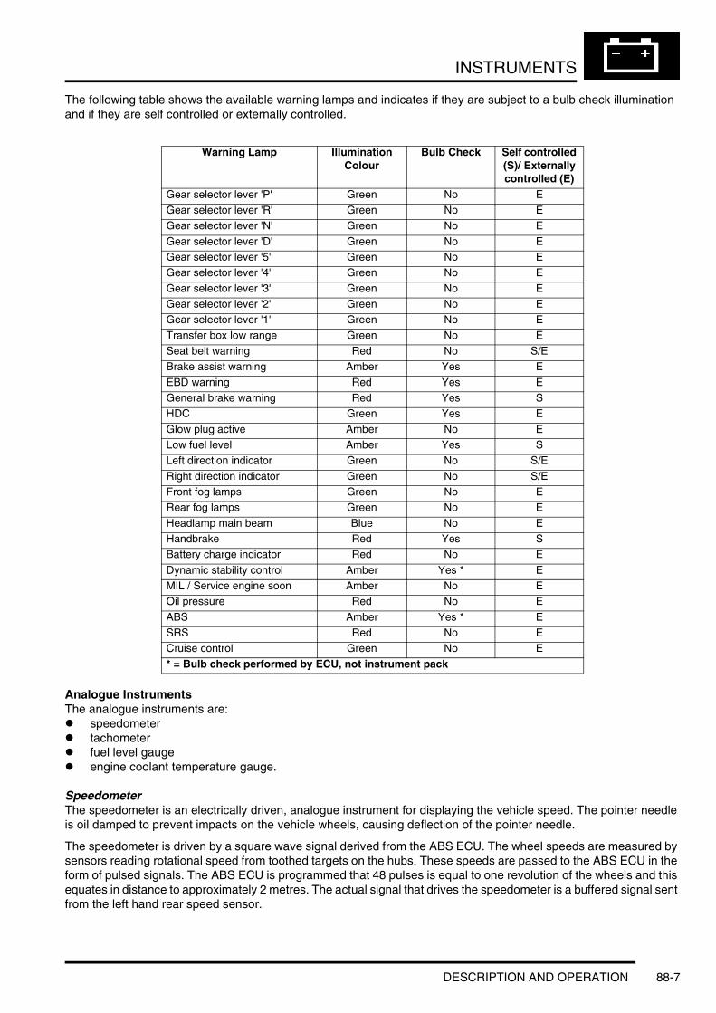
INSTRUMENTS
The following table shows the available warning lamps and indicates if they are subject to a bulb check illumination and if they are self controlled or externally controlled.
Analogue InstrumentsThe analogue instruments are:l speedometerl tachometerl fuel level gaugel engine coolant temperature gauge.
SpeedometerThe speedometer is an electrically driven, analogue instrument for displaying the vehicle speed. The pointer needle is oil damped to prevent impacts on the vehicle wheels, causing deflection of the pointer needle.
The speedometer is driven by a square wave signal derived from the ABS ECU. The wheel speeds are measured by sensors reading rotational speed from toothed targets on the hubs. These speeds are passed to the ABS ECU in the form of pulsed signals. The ABS ECU is programmed that 48 pulses is equal to one revolution of the wheels and this equates in distance to approximately 2 metres. The actual signal that drives the speedometer is a buffered signal sent from the left hand rear speed sensor.
Warning Lamp Illumination Colour
Bulb Check Self controlled (S)/ Externally controlled (E)
Gear selector lever 'P' Green No EGear selector lever 'R' Green No EGear selector lever 'N' Green No E
Gear selector lever 'D' Green No EGear selector lever '5' Green No EGear selector lever '4' Green No E
Gear selector lever '3' Green No EGear selector lever '2' Green No EGear selector lever '1' Green No E
Transfer box low range Green No ESeat belt warning Red No S/EBrake assist warning Amber Yes E
EBD warning Red Yes EGeneral brake warning Red Yes SHDC Green Yes E
Glow plug active Amber No ELow fuel level Amber Yes SLeft direction indicator Green No S/E
Right direction indicator Green No S/EFront fog lamps Green No ERear fog lamps Green No E
Headlamp main beam Blue No EHandbrake Red Yes SBattery charge indicator Red No E
Dynamic stability control Amber Yes * EMIL / Service engine soon Amber No EOil pressure Red No E
ABS Amber Yes * ESRS Red No ECruise control Green No E
* = Bulb check performed by ECU, not instrument pack
DESCRIPTION AND OPERATION 88-7

INSTRUMENTS
This information is passed from the ABS ECU, on a hardwired connection, to the instrument pack and is received by one of the microprocessors. The microprocessor applies a formula to the signal and calculates a numerical, 16 bit value for the signal. This signal is then used by the speedometer drive to display the current speed to the driver. A second digital signal output is also broadcast on the CAN, I and K buses for use by other systems.
To prevent incorrect readings due to spinning wheels, the microprocessor introduces a time delay on the output signal if the received speed signal increases too quickly. The delay ensures that only the true speed is displayed and transmitted on the bus systems.
Two versions of the speedometer display are used. One shows the speed in kilometres per hour and the other shows the speed in miles per hour as the main display and kilometres per hour as a secondary display.
TachometerThe tachometer is an electrically driven, analogue instrument for displaying the vehicle engine speed. The pointer needle is oil damped to prevent impacts on the vehicle wheels, causing deflection of the pointer needle.
The tachometer is driven by an engine speed signal transmitted on the CAN from the ECM. The signal is in the form of a square wave signal of variable frequency derived from the crankshaft position sensor. The signal is received by one of the microprocessors which processes the signal. The output signal from the microprocessor is then used to drive the tachometer.
Two versions of the tachometer are used for petrol and diesel engine variants. The petrol engine variants use a display which has a maximum engine speed reading of 7000 rev/min. The diesel engine variants use a display which has a maximum engine speed reading of 6000 rev/min.
Fuel Level GaugeThe fuel gauge is an electrically driven, analogue instrument for displaying the fuel tank contents. The pointer needle is oil damped to prevent impacts on the vehicle wheels, causing deflection of the pointer needle. When the ignition is off, the pointer returns to the empty position.
The instrument pack is connected to two tank level sensors. One sensor is located in each side of the saddle type fuel tank and uses a float operated potentiometer for measuring the tank contents. Each tank level sensor is supplied with a current from the instrument pack. The returned current, via the potentiometer of the sensor, is read by one of the microprocessors. The reduced current from both sensors is evaluated and converted into a signal to position the fuel gauge needle at the appropriate level reading. When the microprocessor determines that fuel tank contents have reached a predetermined level, the low fuel level warning lamp is illuminated and a chime is emitted from the sounder to alert the driver of the low fuel condition.
The following table shows potentiometer resistance values in relation to fuel tank contents and the fuel gauge display. The figures are shown as a guide only because an infinite number of left/right sensor resistance values can be obtained.
Two versions of the fuel level gauge are used. Markets with a kilometres only speedometer use a percentage gauge reading marked 0 - 100%, with graduations of 0, 25, 50, 75 and max. Markets using miles and kilometres speedometer readouts use an imperial fraction reading marked 0 - 1, with graduations of 0, 1/4,
1/2, 3/4 and 1.
Engine Coolant Temperature GaugeThe engine coolant temperature gauge is an electrically driven, analogue instrument for displaying the engine coolant temperature to the driver. The pointer needle is oil damped to prevent impacts on the vehicle wheels causing deflection of the pointer needle. When the ignition is off, the pointer returns to the cold position.
Tank Sensor Potentiometer Resistance Ω Left/Right
Gauge Needle Pointer Position
20 / 20 0146 / 121 25% / 1/4280 / 213 50% / 1/2396 / 323 75% / 3/4500 / 428 100% / 1/1
88-8 DESCRIPTION AND OPERATION
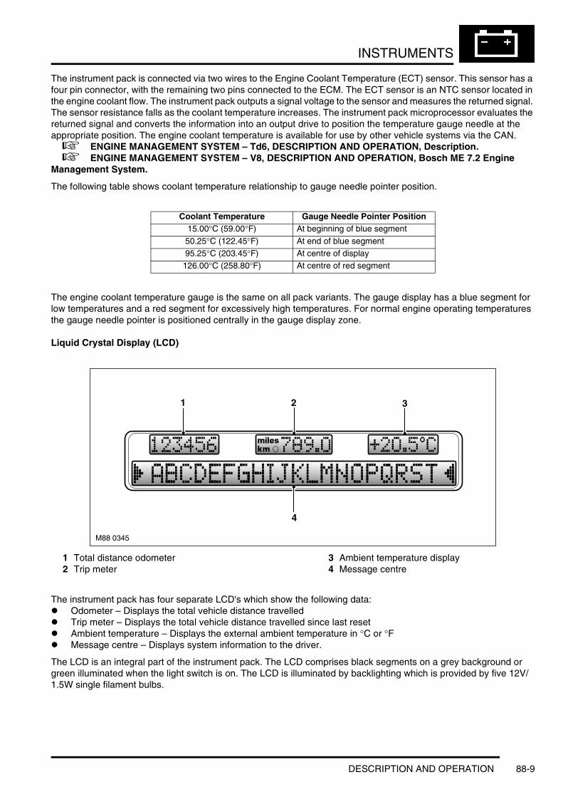
INSTRUMENTS
The instrument pack is connected via two wires to the Engine Coolant Temperature (ECT) sensor. This sensor has a four pin connector, with the remaining two pins connected to the ECM. The ECT sensor is an NTC sensor located in the engine coolant flow. The instrument pack outputs a signal voltage to the sensor and measures the returned signal. The sensor resistance falls as the coolant temperature increases. The instrument pack microprocessor evaluates the returned signal and converts the information into an output drive to position the temperature gauge needle at the appropriate position. The engine coolant temperature is available for use by other vehicle systems via the CAN. + ENGINE MANAGEMENT SYSTEM – Td6, DESCRIPTION AND OPERATION, Description. + ENGINE MANAGEMENT SYSTEM – V8, DESCRIPTION AND OPERATION, Bosch ME 7.2 Engine Management System.
The following table shows coolant temperature relationship to gauge needle pointer position.
The engine coolant temperature gauge is the same on all pack variants. The gauge display has a blue segment for low temperatures and a red segment for excessively high temperatures. For normal engine operating temperatures the gauge needle pointer is positioned centrally in the gauge display zone.
Liquid Crystal Display (LCD)
1 Total distance odometer2 Trip meter
3 Ambient temperature display4 Message centre
The instrument pack has four separate LCD's which show the following data:l Odometer – Displays the total vehicle distance travelledl Trip meter – Displays the total vehicle distance travelled since last resetl Ambient temperature – Displays the external ambient temperature in °C or °Fl Message centre – Displays system information to the driver.
The LCD is an integral part of the instrument pack. The LCD comprises black segments on a grey background or green illuminated when the light switch is on. The LCD is illuminated by backlighting which is provided by five 12V/1.5W single filament bulbs.
Coolant Temperature Gauge Needle Pointer Position15.00°C (59.00°F) At beginning of blue segment
50.25°C (122.45°F) At end of blue segment95.25°C (203.45°F) At centre of display
126.00°C (258.80°F) At centre of red segment
M88 0345
4
1 2 3
DESCRIPTION AND OPERATION 88-9
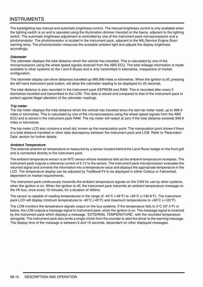
INSTRUMENTS
The backlighting has manual and automatic brightness control. The manual brightness control is only available when the lighting switch is on and is operated using the illumination dimmer rheostat on the fascia, adjacent to the lighting switch. The automatic brightness adjustment is controlled by one of the instrument pack microprocessors and a phototransistor. The phototransistor is located in the instrument pack, adjacent to the MIL/Service Engine Soon warning lamp. The phototransistor measures the available ambient light and adjusts the display brightness accordingly.
OdometerThe odometer displays the total distance which the vehicle has travelled. This is calculated by one of the microprocessors using the wheel speed signals received from the ABS ECU. The total mileage information is made available to other systems on the I and K Buses and is only transmitted in kilometres, irrespective of market configuration.
The odometer display can show distances travelled up 999,999 miles or kilometres. When the ignition is off, pressing the left hand instrument pack button, will allow the odometer reading to be displayed for 25 seconds.
The total distance is also recorded in the instrument pack EEPROM and RAM. This is recorded after every 2 kilometres travelled and transmitted to the LCM. This data is stored and compared to that of the instrument pack to protect against illegal alteration of the odometer readings.
Trip meterThe trip meter displays the total distance which the vehicle has travelled since the last trip meter reset, up to 999.9 miles or kilometres. This is calculated by one of the microprocessors using the wheel speed signals from the ABS ECU and is stored in the instrument pack RAM. The trip meter will restart at zero if the total distance exceeds 999.9 miles or kilometres.
The trip meter LCD also contains a small dot, known as the manipulation point. The manipulation point shows if there is a total distance travelled or other data discrepancy between the instrument pack and LCM. Refer to 'Redundant Data' section for further details.
Ambient TemperatureThe external ambient air temperature is measured by a sensor located behind the Land Rover badge on the front grill and is connected directly to the instrument pack.
The ambient temperature sensor is an NTC sensor whose resistance falls as the ambient temperature increases. The instrument pack outputs a reference current of 5.1V to the sensor. The instrument pack microprocessor evaluates the returned signal and converts the information into a temperature value and displays the appropriate temperature in the LCD. The temperature display can be adjusted by TestBook/T4 to be displayed in either Celsius or Fahrenheit, dependent on market requirements.
The instrument pack continuously transmits the ambient temperature signals on the CAN for use by other systems, when the ignition is on. When the ignition is off, the instrument pack transmits an ambient temperature message on the I/K bus, once every 10 minutes, for a duration of 400ms.
The sensor is capable of reading temperatures in the range of -45°C (-49°F) to +56°C (+132.8°F). The instrument pack LCD will display minimum temperatures to -40°C (-40°F) and maximum temperatures to +50°C (+122°F).
The LCM monitors the temperature signals output on the bus systems. If the temperature falls to 3°C (37.4°F) or below, the LCM outputs a message signal to instrument pack, when the ignition is on. The message signal is received by the instrument pack which displays a message, 'EXTERNAL TEMPERATURE', with the recorded temperature alongside. The instrument pack also emits a single chime from the sounder to alert the driver to the warning message. The display time of the message is between 6 and 15 seconds, dependant on other displayed messages.
88-10 DESCRIPTION AND OPERATION

INSTRUMENTS
Ambient Temperature Sensor Resistance/Temperature Values
Message CentreThe message centre is located at the bottom of the instrument pack. The message centre comprises an LCD, which has a 20 character text display. The majority of messages are generated by the LCM which monitors system status via the bus systems and displays system information messages as appropriate. Other system ECU's are also capable of generating messages to display system status. Most messages are accompanied by a chime, which is requested by the ECU generating the message and generated by the instrument pack via the sounder.
A check control button is located between the tachometer and the engine coolant temperature gauge. This button allows the driver to view system status messages which are current in the instrument pack RAM. Pressing and releasing the check control button, displays current messages in priority order or, if no messages are present, the message centre displays 'CHECK CONTROL OK'.
The messages are assigned priorities, depending on the effect on driving safety and driving ability of the vehicle. New messages are displayed and accompanied by a chime from the sounder. Messages are divided into priority groups P1, P2 and P3. The priority groups are as follows:l Priority Group P1
This group includes messages which have a direct affect on the driving ability and safety of the vehicle, “ENGINE OIL PRESSURE” for example. This message requires an urgent and immediate reaction from the driver in response to the message. P1 messages are also accompanied by appropriate flashing warning lamp symbols adjacent to the message centre. If more than one P1 message is present, each message is displayed in turn at 3 second intervals. P1 messages are displayed between the symbols “> <” which are flashing.
l Priority Group P2
This group includes messages which do not directly affect driving ability or safety of the vehicle, “CHECK NUMPLATE LIGHT” for example. This message must be noted by the driver and the cause rectified as soon as possible. Each message is indicated once for a maximum of 23 seconds. They can be recalled by pressing the check control, RH, button on the instrument pack. P2 messages are displayed between the symbols “> <”, which are permanently illuminated with the message.
l Priority Group P3
This group displays messages which relate to fluid levels, “LOW SCREEN WASH” for example. Depending on the message, some messages are only displayed at the end of a journey, to avoid irritation to the driver. P3 messages are displayed between the symbols “> <”, which are permanently illuminated with the message.
Two other groups are defined as 'End of Journey Messages' and 'Special Messages S and S1', as follows:l End of Journey Messages
Messages categorised as 'P1' and 'P2' error messages, are displayed again at the end of the journey. Error messages do not include messages such as “DOOR OPEN”. Messages in the 'P3' group are displayed after the 'P1' and 'P2' messages. New messages, which only occur at the end of a journey, “LIGHTS ON” for example, are displayed according to their priority.
l Special Messages S and S1
These messages have the highest priority and cannot be overridden by messages in groups 'P1', 'P2' and 'P3'. They immediately overwrite any currently displayed messages. If more than one special message is present, the message with the highest priority has priority, after the current displayed message has been shown for at least 1 second. S and S1 messages are not displayed between any symbols.
Temperature Resistance kΩ-40°C (-40°F) 168.250-30°C (-22°F) 88.500-20°C (-4°F) 48.535
-10°C (+14°F) 27.6650°C (+32°F) 16.325
+10°C (+50°F) 9.9500
+20°C (+68°F) 6.2450+30°C (+86°F) 4.0285
+40°C (+104°F) 2.6633
+50°C (+122°F) 1.8015
DESCRIPTION AND OPERATION 88-11

INSTRUMENTS
Most messages, especially S, S1 and P messages are accompanied by a chime from the sounder to alert the driver to their presence. At the end of a journey, a single chime precedes all end of journey messages.
For 3 minutes after the ignition is switched off, messages can be displayed using the check control RH button on the instrument pack. If more than one message is present, the button must be pressed again to display the next message. If no messages are present, 'CHECK CONTROL OK' will be displayed for as long as the button is pressed.
The messages are displayed in a language applicable to the vehicle market configuration and can be changed using TestBook/T4. The following list shows the possible messages which can be displayed.
Message Centre MessagesPRE-HEATING SLOW DOWN
FASTEN SEAT BELTS SELECT NEUTRALTIME 8:59 CHECK BRAKE LIGHTKEY IN IGNITION LOCK ENGINE FAILSAFE PROG
RELEASE HANDBRAKE TAILGATE OPENCHECK BRAKE FLUID CHECK FRONT LIGHTSTOP!ENGINE OILPRESS CHECK REAR LIGHT
COOLANT TEMPERATURE CHECK DIP BEAM LIGHTHDC TEMP. NOT AVAIL. CHECK SIDE LIGHTHDC INACTIVE CHECK TAIL LIGHT
NO HDC, SLOW DOWN CHECK FRONT FOGLIGHTLIGHTS ON CHECK REAR FOG LIGHTSPEED LIMIT CHECK NUMPLATE LIGHT
FUEL INJECT. SYSTEM CHECK TRAILER LIGHTAIR SUSP. INACTIVE+ MAX 60 km/h(Alternating)
CHECK MAINBEAM LIGHT
TRANSFERBOX NEUTRAL TRANS. FAILSAFE PROGHEADLIGHT DELAY CHECK BRAKE PADSTRANSMISS'N OVERHEAT CHECK REVERSE LIGHT
EXTERNAL TEMPERATURE X°C/F LOW SCREEN WASHAPPLY HANDBRAKE CHECK AIR SYSTEMEEPROM LCMC ACCESS MAXIMUM 40 km/h
DOOR OPEN OFF ROAD MAX 50 km/hDSC INACTIVE CHECK FUEL TANK CAPHIGH RANGE TYRECONTROL INACTIVE
LOW RANGE TYRE DEFECTCHECK COOLANT LEVEL CHECK TYRE PRESSUREMANUAL MODE TYRE PRESS
SPORT MODE SET TYRE PRESSUREKEY BATTERY LOW CHECK CONTROL OKTRAILER MODE
88-12 DESCRIPTION AND OPERATION

INSTRUMENTS
Service Interval Indicator
Service Interval Indicator Display
1 Information field - 'TIME INSPECTION'2 Information arrow
3 Information field - 'OIL SERVICE'4 Information field - 'INSPECTION'
The service interval indicator is located adjacent to the LCD and uses the odometer LCD to show distance to next service and date to next service. The indicator displays 'OIL SERVICE' or 'INSPECTION' to inform the driver of the type of service due.
The service interval indicator is controlled by one of the microprocessors and software in the instrument pack and the data stored in the EEPROM. The service interval is calculated on fuel consumption which represents the loads placed on the engine more accurately than distance travelled. Therefore, a vehicle which is driven aggressively will require a service earlier than a vehicle which is driven economically.
The service interval data is displayed in the odometer for 5 seconds, every time the ignition is switched on.
Remaining Distance Display
1 Distance display 2 Message centre LCD
When the ignition is switched on, the remaining distance to service is displayed for 5 seconds in the odometer LCD. Simultaneously, the next service type will also be displayed in the service interval indicator.
A minus sign preceding the remaining distance indicates that the service interval has been exceeded and the distance by which it is overdue.
M88 0348
1
2
3
4
M88 0346
2
1
DESCRIPTION AND OPERATION 88-13

INSTRUMENTS
Due Date Display
1 Date display 2 Message centre LCD
When the remaining distance is displayed, a second press of the instrument pack, LH button, within the 5 second display period, illuminates the 'TIME INSPECTION' clock symbol for an additional 5 seconds. The distance to service information displayed in the odometer LCD changes to the due date of the service by showing the month and year.
A decimal point is positioned between the month and the year. In the above example, the year is 2003 and the month is December.
If the LH instrument pack button is pressed again, within the 5 second period, the odometer LCD changes to the distance remaining.
Service Interval Indicator Reset ProcedureThe service interval can be reset with the following procedure using the instrument pack buttons. TestBook/T4 can also be used to reset the service interval indicator by connecting to the diagnostic socket and following the reset procedure.
NOTE: The distances and dates shown are examples only and not necessarily representative of actual messages displayed.
Check and Reset Procedure1 Ensure that the ignition is switched off.2 Press and hold the LH instrument pack button.3 With the button held, switch the ignition on to position I (AUX).4 Continue to hold the LH instrument pack button for a further 5 seconds, until the “SIA RESET” appears.5 The message centre will display the distance to service status as “RESET SIA: 3600km/mls” and the type of
service (OIL SERVICE or INSPECTION).6 Check that the reset distance limit has been reached.
a If yes, proceed to step 9.b If no, proceed to step 7.
7 Press the LH button once. The message centre will display the date to service status as “RESET SIA: 03.12”.8 Check that the reset date limit has been reached.
a If yes, proceed to step 11.b If no, proceed to step 10.
9 When the distance reset limit has been reached or exceeded, press and hold the LH button for 5 seconds. “RESET” flashes in the message centre five times.
a If the LH button is not pressed again before the fifth flash of “RESET”, the reset will not be performed. The message centre will display “END SIA: 3600 km/miles” for 5 seconds and the display will change to the service date “RESET SIA: 12.03”.
b If the LH button is pressed before the fifth flash of “RESET”, the service distance will be reset. The message centre will display the new service distance “END SIA: 25000 km/miles” for 5 seconds. The service date will then be displayed.
M88 0347
1
2
88-14 DESCRIPTION AND OPERATION
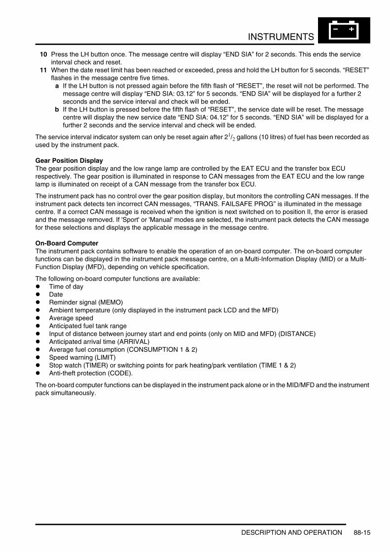
INSTRUMENTS
10 Press the LH button once. The message centre will display “END SIA” for 2 seconds. This ends the service interval check and reset.
11 When the date reset limit has been reached or exceeded, press and hold the LH button for 5 seconds. “RESET” flashes in the message centre five times.
a If the LH button is not pressed again before the fifth flash of “RESET”, the reset will not be performed. The message centre will display “END SIA: 03.12” for 5 seconds. “END SIA” will be displayed for a further 2 seconds and the service interval and check will be ended.
b If the LH button is pressed before the fifth flash of “RESET”, the service date will be reset. The message centre will display the new service date “END SIA: 04.12” for 5 seconds. “END SIA” will be displayed for a further 2 seconds and the service interval and check will be ended.
The service interval indicator system can only be reset again after 21/2 gallons (10 litres) of fuel has been recorded as used by the instrument pack.
Gear Position DisplayThe gear position display and the low range lamp are controlled by the EAT ECU and the transfer box ECU respectively. The gear position is illuminated in response to CAN messages from the EAT ECU and the low range lamp is illuminated on receipt of a CAN message from the transfer box ECU.
The instrument pack has no control over the gear position display, but monitors the controlling CAN messages. If the instrument pack detects ten incorrect CAN messages, “TRANS. FAILSAFE PROG” is illuminated in the message centre. If a correct CAN message is received when the ignition is next switched on to position II, the error is erased and the message removed. If 'Sport' or 'Manual' modes are selected, the instrument pack detects the CAN message for these selections and displays the applicable message in the message centre.
On-Board ComputerThe instrument pack contains software to enable the operation of an on-board computer. The on-board computer functions can be displayed in the instrument pack message centre, on a Multi-Information Display (MID) or a Multi-Function Display (MFD), depending on vehicle specification.
The following on-board computer functions are available:l Time of dayl Datel Reminder signal (MEMO)l Ambient temperature (only displayed in the instrument pack LCD and the MFD)l Average speedl Anticipated fuel tank rangel Input of distance between journey start and end points (only on MID and MFD) (DISTANCE)l Anticipated arrival time (ARRIVAL)l Average fuel consumption (CONSUMPTION 1 & 2)l Speed warning (LIMIT)l Stop watch (TIMER) or switching points for park heating/park ventilation (TIME 1 & 2)l Anti-theft protection (CODE).
The on-board computer functions can be displayed in the instrument pack alone or in the MID/MFD and the instrument pack simultaneously.
DESCRIPTION AND OPERATION 88-15

INSTRUMENTS
Computer Controls – MID
1 Multi Information Display (MID)2 Information button
3 Column stalk information button
M88 0353
1 2 3
88-16 DESCRIPTION AND OPERATION

INSTRUMENTS
Computer Controls – MFD
1 Multi Function Display (MFD)2 On-board computer menu selection
3 Column stalk information button
The on-board computer functions are selected in the MID by pressing the 'i' button for on-board computer functions or the clock symbol for clock timer functions. On the MFD, the on-board computer functions are selected from a menu on the LCD or by pressing the clock symbol for clock timer functions. The computer functions can be selected in the message centre by pressing the 'i' button on the LH column stalk switch.
The instrument pack message centre shows all the possible computer function messages in a scrolling display. The function displays can be scrolled through using the on-board computer button (i) on the LH column stalk switch. The column stalk button allows the resetting of certain functions in conjunction with the MID/MFD, and also the order in which the function displays are scrolled through. Three functions cannot be accessed using the column stalk button, they are; CODE, MEMO, EXTERNAL AIR TEMPERATURE and HEAT ON/OFF AIR ON/OFF. These functions are only available using the MID/MFD.
TMCTMC30/07/200130/07/2001 14:1014:10
1 3
M88 0354
MENU
GPS-navigation
TMC30/07/2001 14:10Monday
On-board computer
Telephone
Set
DSP
Television
Code
Monitor off
2
DESCRIPTION AND OPERATION 88-17

INSTRUMENTS
When the on-board computer is being accessed via the MID/MFD, these units communicate with the instrument pack message centre to display the function information in the display in the MID/MFD only. The MID/MFD also allow for the resetting and programming of certain on-board computer functions, such as the clock, date, speed limit and stop watch.
The on-board computer system of the instrument pack supplies the MID/MFD with data and commands on the I Bus. Some computer functions require an exchange of data between the Automatic Temperature Control (ATC) ECU and the Body Control Unit (BCU) which is carried out on the K Bus.
Operation of the buttons on the MID or selections on the LCD screen of the MFD are passed to the instrument pack software for calculation of the text and numerical values to be displayed. The MID/MFD are purely a user interface with regard to the on-board computer, with the instrument pack being the controlling component.
The MFD has one exception to this. Using data supplied by the instrument pack, the MFD self generates the text messages which appear on the LCD screen.
Security CodeThe security code function prevents unauthorised persons from starting the engine. This function is controlled from the MID/MFD. The driver can select and enter a code, without which subsequent starting of the engine is prevented. This function can be used if the vehicle is to left unattended for a long period of time, i.e. airport car park. Each time the code is activated, it is only valid until the next time the engine is started. If the code is not available or forgotten, emergency deactivation is possible.
The CODE is a four digit number which can be entered with the ignition at position I (AUX). If the vehicle is parked with the code armed, starting of the engine is inhibited until the correct code is entered to disarm the alarm. If the incorrect code is entered, the alarm horn is activated and the immobilisation ECU prevents starting. This is performed by messages sent on the K bus to the BCU. The BCU electrically controls the alarm horn and the immobilisation ECU functions.
The code can be selected on the MID and activated as follows:
Code Activationl Make sure the ignition is in position I. Press the i key on the MID panel.l Press the left side of the CODE SET key.l CODE - - - - is displayed in the main display. Enter the code using the number keys. If the code is incorrectly
input, press the left side of the CLR SET button and re-enter the code.l Press the right side of the CODE SET button to memorise the input and turn the ignition off.
Code De-activationl When the ignition is moved to position II, the MID display prompts for the code.l Using the numbered key buttons, enter the correct code. Once entered, press the right side of the CODE SET
button. If correctly entered the time display will appear and the engine will start.l If the code is incorrectly entered three times or three attempts to start the engine are performed, the BBUS will
sound for 30 seconds.
The code can be selected on the MFD and activated as follows:
Code Activationl Select CODE from the main menu.l Enter the code using the rotary control. Turn the rotary control until the required number appears and press to
confirm. Enter the remaining numbers in the same way. If the code is incorrectly input, select CHANGE and repeat the input procedure.
l Once the code is entered, it is activated by turning the ignition off.
Code De-activationl When the ignition is moved to position II, the MFD display prompts for the code.l Enter the code using the rotary control. Once the code is entered, select DEACTIVATE. If the code is incorrectly
input, select CHANGE and repeat the code input.
88-18 DESCRIPTION AND OPERATION

INSTRUMENTS
Emergency De-activationl Disconnect the vehicle battery. This will cause the alarm to sound. Wait for a period of more than 5 minutes and
re-connect the battery.l Turn the ignition to position I. The display will show a count down for 10 minutes. Once the 10 minutes has
expired, the engine can be started. If during the 10 minute period, the code becomes available, it can be input after pressing the CODE button.
On-Board Computer Functions with Column Stalk SwitchPressing the on-board computer button (i) on the LH column stalk, displays the first computer function in the sequence. With each subsequent press of the button, the next function is displayed. The sequence of displayed functions can be programmed by the driver and can be scrolled through continuously to reach the desired function display.
When all the functions have been scrolled through once, the message centre appears blank, signifying the end of the function display. When the on-board computer function display is subsequently requested, the message centre will display the first function in the sequence. If the function display is interrupted by a system message from the LCM, when the column stalk button is pressed or the check control button is pressed, the last displayed function will reappear in the message centre.
The on-board computer function will only be displayed if the LCM releases the message centre for function display. This will only occur if the LCM is not displaying any high priority messages at the time. The LCM registers the request for on-board computer function display and, if there are no messages or the displayed message is of a low priority, the on-board computer function is permitted use of the LCD message centre.
The following list shows the possible on-board computer functions and their standard sequence of display. This order will be reinstated after a system reset.l CLOCKl CONSUMPTION 1l CONSUMPTION 2l RANGEl LIMITl DISTANCEl ARRIVALl SPEEDl DATEl TIME 1 (only with park heating and/or park ventilation)l TIME 2 (only with park heating and/or park ventilation)l TIMER.
The following functions cannot be called up using the steering column button. These functions can only be selected with the MID or MFD.l HEAT ON/OFF (heating on/off)l AIR ON/OFF (ventilation output on/off)l OUTSIDE TEMPERATUREl CODE.
The sequence of function display is stored in the instrument pack RAM. This sequence can be changed and programmed by the driver using the MID/MFD, with the new sequence also stored in the RAM. The new sequence can be programmed as follows:
DESCRIPTION AND OPERATION 88-19

INSTRUMENTS
MFD Programming
MFD 'REMOTE CONTROL' Screen
1 Ensure that the ignition switch is in position I (AUX) or position II.2 Press and hold the column stalk 'i' button for 3 seconds. 'REMOTE CONTROL' screen is displayed in the MFD
with all computer functions shown. Simultaneously, 'PROG' is displayed in the message centre.3 To set the sequence, first deselect all functions using the RH control on the MFD panel. Select the function and
press the RH control to deselect that function. When deselected, the selection text will change colour.4 Using the RH control, navigate to the first required computer function and press the RH control to select. When
selected, the selection text will change colour.5 Continue selecting functions in the required order as required. If no functions are selected, there will be no
response from the 'i' button when pressed. All or just one function can be selected for display.6 When desired selections are made, navigate to the 'memorise' function and press the RH control. The selected
functions are stored in their selected order in the instrument pack RAM. The instrument message centre then displays the first selected function.
MID Programming
MID 'PROG 1' Display
1 Ensure that the ignition switch is in position I (AUX) or position II.2 Press and hold the 'i' button for 3 seconds. 'PROG 1' appears in the MID with all computer functions assigned
to the keys.
M88 0351
Ar r i va l t imeAr r i va l t ime
Range
D is tance
L im i t
C lock
Da te
Ave rage speedAve rage speed
Consump 2Consump 2
Consump 1Consump 1
T imer
T imer 2T imer 2
T imer 1T imer 1
memor i se
REMOTE CONTROLREMOTE CONTROL
TMC30 /07 /2001 14 :10
M88 0352
*
PROG 1RANGE SPEED LIMITDIST ARRCONSUM1 SET
88-20 DESCRIPTION AND OPERATION

INSTRUMENTS
3 To set the sequence, select the required functions in order required. If no functions are selected and the 'SET' button is pressed, all computer functions are selected and displayed in their standard sequence.
4 When the selections have been made, press the 'SET' button. The selected functions are stored in their selected order in the instrument pack RAM. The instrument pack message centre displays the first selected function.
Bus SystemsThe instrument pack has two controlling microprocessors which process software information and control input and output data for the instrument pack and other systems. The processors communicate with other systems on the vehicle via four interfaces: I Bus, K Bus, CAN and diagnostic DS2 Bus. An 8 Kbyte, non-volatile memory (EEPROM) is provided for the storage of vehicle and instrument data (eg; mileage reading, service interval status).
The instrument pack also features a self diagnostic feature and on-board diagnostics via communication with TestBook/T4.
Inputs are received as either analogue signals via conventional hardwired connections or as digital signals via multi-channel connections with the bus systems. These signals are filtered and evaluated by the processors and the data converted into actuation of the analogue gauges and indicator/warning lamps. The processors also function as a gateway for the bus systems, processing data from one system and passing it to another.
The instrument pack receives and transmits data on five bus systems as follows:
Redundant Data StorageIn the event of a new instrument pack having to be installed, certain information needs to be maintained to prevent data loss. This information is transferred continuously from the instrument pack on the I bus and is received and held in an EEPROM in the LCM. The data is also stored, along with other vehicle specification data, in the immobilisation ECU.
The data stored is as follows:l Vehicle Identification Number (VIN)l Total distance travelledl Service interval fuel volume and type of last servicel Service interval clock.
When a new instrument pack is installed, the LCM will update the instrument pack EEPROM with the stored data providing the following parameters are met:l The VIN in the instrument pack and the LCM matchl The total distance reading in the instrument pack EEPROM is less than 158 miles (255 km)l The total distance reading in the LCM EEPROM is less than 999,900 miles or kilometres or equal to or greater
than 0 miles or kilometresl The total distance recorded in the instrument pack EEPROM is less than the distance travelled stored in the LCM
EEPROM.
Vehicle coding data, such as engine type, market, etc., is stored in the immobilisation ECU and retrieved by TestBook/T4 and used to update the new instrument pack.
If the VIN in the instrument pack is set to 0, only service interval data is passed from the LCM EEPROM to the instrument pack RAM, it is not stored in the instrument pack EEPROM. The total distance displayed in the odometer LCD is frozen at the value stored in the instrument pack EEPROM.
If any of the stored data in the LCM EEPROM conflicts with the data within the instrument pack, a lamp, known as a manipulation point, is illuminated in the pack. The manipulation point is located in the trip meter LCD, below the 'Miles' text or next to the 'km' text.
Bus System Single/Dual Line Transmission/Baud Rate (Bd)I Bus 1 9,600 Bd
K Bus 1 9,600 BdCAN 2 500.0 kBd
DS2 Bus 1 9,600 Bd
K line 1 10,400 Bd
DESCRIPTION AND OPERATION 88-21
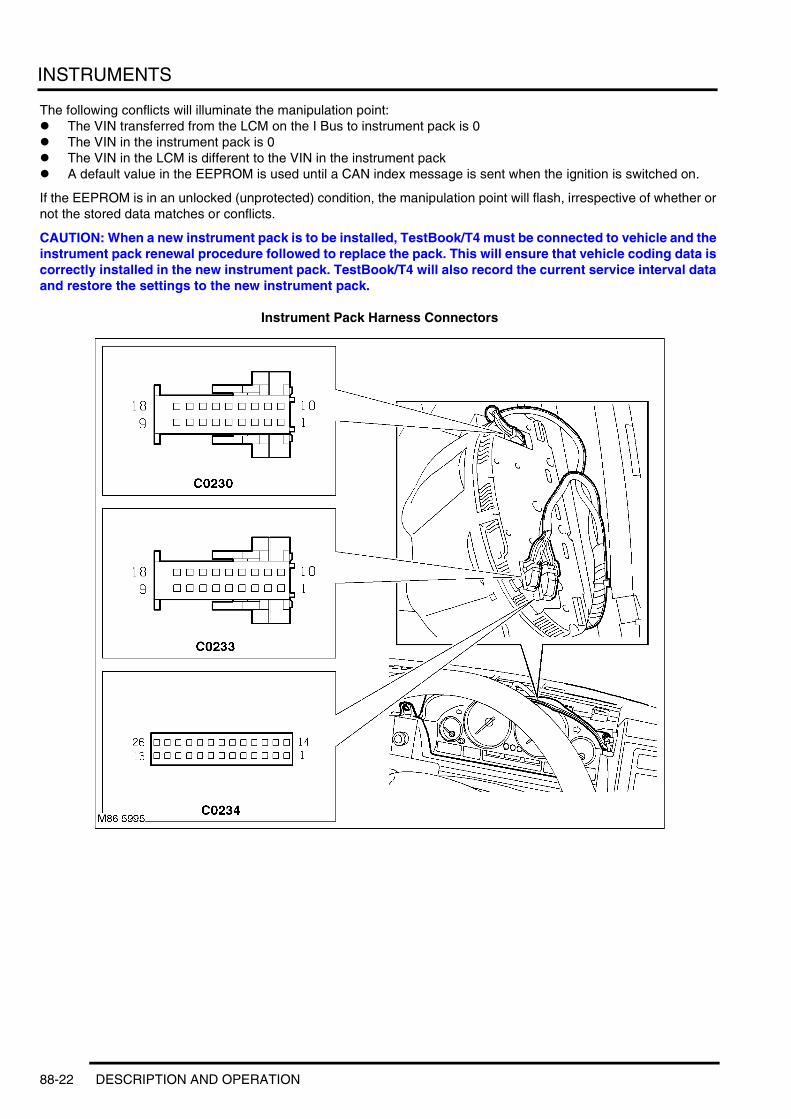
INSTRUMENTS
The following conflicts will illuminate the manipulation point:l The VIN transferred from the LCM on the I Bus to instrument pack is 0l The VIN in the instrument pack is 0l The VIN in the LCM is different to the VIN in the instrument packl A default value in the EEPROM is used until a CAN index message is sent when the ignition is switched on.
If the EEPROM is in an unlocked (unprotected) condition, the manipulation point will flash, irrespective of whether or not the stored data matches or conflicts.
CAUTION: When a new instrument pack is to be installed, TestBook/T4 must be connected to vehicle and the instrument pack renewal procedure followed to replace the pack. This will ensure that vehicle coding data is correctly installed in the new instrument pack. TestBook/T4 will also record the current service interval data and restore the settings to the new instrument pack.
Instrument Pack Harness Connectors
88-22 DESCRIPTION AND OPERATION
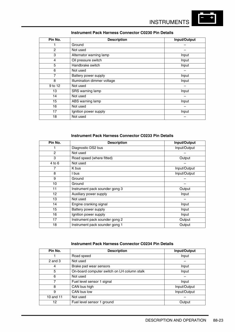
INSTRUMENTS
Instrument Pack Harness Connector C0230 Pin Details
Instrument Pack Harness Connector C0233 Pin Details
Instrument Pack Harness Connector C0234 Pin Details
Pin No. Description Input/Output1 Ground –2 Not used –3 Alternator warning lamp Input
4 Oil pressure switch Input5 Handbrake switch Input6 Not used –
7 Battery power supply Input8 Illumination dimmer voltage Input
9 to 12 Not used –
13 SRS warning lamp Input14 Not used –15 ABS warning lamp Input
16 Not used –17 Ignition power supply Input18 Not used –
Pin No. Description Input/Output1 Diagnostic DS2 bus Input/Output2 Not used –3 Road speed (where fitted) Output
4 to 6 Not used –7 K bus Input/Output8 I bus Input/Output
9 Ground –10 Ground –11 Instrument pack sounder gong 3 Output
12 Auxiliary power supply Input13 Not used –14 Engine cranking signal Input
15 Battery power supply Input16 Ignition power supply Input17 Instrument pack sounder gong 2 Output
18 Instrument pack sounder gong 1 Output
Pin No. Description Input/Output1 Road speed Input
2 and 3 Not used –
4 Brake pad wear sensors Input5 On-board computer switch on LH column stalk Input6 Not used –
7 Fuel level sensor 1 signal Input8 CAN bus high Input/Output9 CAN bus low Input/Output
10 and 11 Not used –12 Fuel level sensor 1 ground Output
DESCRIPTION AND OPERATION 88-23

INSTRUMENTS
DiagnosticsThe instrument pack provides an interface (gateway) for data transfer between TestBook/T4 and the vehicle ECU's. Individual ECU's subject their functional capabilities to self diagnostic checks. Any irregularities or malfunctions are stored in the ECU error memory.
The error memories can be interrogated by TestBook/T4 to establish and diagnose the cause of the error messages. The service interval indicator can be interrogated and reset using TestBook/T4, as an alternative to the instrument pack reset procedure.
The instrument pack RAM can be reset with TestBook/T4 or using the instrument pack test No. 21 (see following section). When this procedure is performed, all values stored in the RAM will be erased. Displayed values to the driver, such as trip meter reading and on-board computer sequence and values, will be erased and resume their default values or are reset to values of zero.
The instrument pack also performs a self diagnostic routine to check its function and monitoring of related components. Detected errors are written to the RAM initially and then transferred to the EEPROM when the ignition is switched off. The EEPROM will only store the five most recent errors. If five errors are stored, only further errors of the bus systems or instrument pack EEPROM errors will be memorised in their order of occurrence. Errors already present will be over written. Error messages can be retrieved and diagnosed with TestBook/T4. When the instrument pack is reset, errors stored in the EEPROM are transferred to the RAM and then erased.
Instrument Pack TestThe instrument pack has a test function to assist with testing, checking and trouble shooting if a repair is required. Test functions are only displayed in the instrument pack LCD.
There are two methods of entering the test mode:l The ignition switch must be position I (AUX) or II (IGN) and no messages must be displayed in the LCD. Press
and hold the check control button on the instrument pack for not less than 5 seconds.l Press and hold the check control button and switch the ignition on to position I (AUX).
When test mode is entered, 'TEST-NR.: 01' appears in the message centre.
13 Not used –
14 Ambient air temperature sensor Input15 Not used –16 Fuel level sensor 2 ground Output
17 Not used –18 ECT sensor ground Output19 ECT sensor Input
20 Brake pad wear sensors ground Output21 Not used –22 Ambient air temperature sensor ground Output
23 Fuel level sensor 2 signal Input24 Not used –25 Reverse gear signal Input
26 Not used –
Pin No. Description Input/Output
88-24 DESCRIPTION AND OPERATION

INSTRUMENTS
There are 21 test and reset functions available as shown in the following table:
Pressing the check control button moves the display to the next function in the sequence. When a selected function is reached, pressing the trip reset button enters the test function details.
All test functions, with the exception of tests No's. 1 and 2, are locked after the instrument pack is reset and must be unlocked using test No. 19. This locking feature is intended to make instrument pack test functions difficult for unauthorised persons to access. Refer to function test No. 19 for further details.
Once in the test function, scrolling through the tests sequentially is performed by pressing the check control button on the instrument pack. When a locked test function is encountered, pressing the trip reset button displays test No. 19 LOCK : ON to allow quick unlocking of the function.
In all markets, the text displayed in the message centre for the test functions is in German only.
The instrument pack test can be exited by turning the ignition off or by holding the check control button depressed for more than 2.5 seconds.
Test Function No.1 – Instrument Pack Identificationl Test function 1 is not locked and can be accessed immediately. Pressing the trip reset button scrolls through the
following individual information relating to instrument pack identification.l 'FGNSTNR: AB12345' – Vehicle Identification Number (VIN).l 'K: 4571' – Speedometer K Index (displayed in pulses per km or mile).l 'BMWTNR: 8373541' – Instrument pack identification number.l 'CI: 10 DI: 03 BI: 07' – Coding, diagnostics and bus index reference numbers.l 'DAT: 47/01:' – Date of manufacture week/year.l 'HW: 03 SW: 500/500' – Hardware/Software numbers.l 'ZYL: 6 M:3 S: 425' – Engine data (cylinders, engine factor, fuel supply system slope).l 'CAN: 01 AEND:23' – CAN and change index.
Test Number Function Description01 Instrument pack identification
02 System test03 Service interval indicator data04 Momentary fuel consumption values - l/100km and l/hour
05 Range consumption and range momentary value06 Tank content values and display value07 Momentary values for engine coolant temperature, engine speed and ambient
temperature08 Momentary values for effective and displayed speed in km/h
09 Battery voltage supply to instrument pack display in volts10 Read country code11 Read units display for on-board computer, clock and ambient temperature
12 Average speed for arrival time calculation and momentary arrival value13 Activation of the chime signals14 Read self diagnostic error bytes
15 Display of input/output port status16 Momentary value for engine oil temperature in °C17 Minute counter for last radio controlled clock reception
18 Dimming parameters19 Locking and unlocking of test functions20 Entry of a correction factor for fuel consumption
21 Instrument pack reset
DESCRIPTION AND OPERATION 88-25

INSTRUMENTS
Test Function No. 2 – System Testl Test function 2 is not locked and can accessed immediately. After selection the instrument pack automatically
activates all displays and analogue gauges. This test will only be performed with the ignition in positions I or II and the engine not running.
l The backlighting of all LCD's are activated.l All segments for the odometer, trip meter, ambient temperature and service interval indicator are illuminated.l All warning lamps are illuminated.l A pixel test of the message centre is alternately performed to display a 'chess board' pattern. The pixels are
alternately illuminated at intervals of 1.25 seconds. The trip meter display alternates between km and miles and the ambient temperature alternates between °F and °C.
l The general brake warning lamp alternates between an amber and red output.l All analogue gauges are activated and travel from the left stop to the right stop and back to the left stop.l When all gauges have returned to their left stop all displays remain illuminated. A second activation of the
analogue gauges follows, but this time the needle pointers stop before the right stop position. During this gauge cycle, the instrument pack performs self diagnostics on the gauge operation and records fault data if necessary. This diagnostic check of the gauges is only performed during test function 2 and the data can be retrieved using TestBook/T4.
l When the second gauge cycle is complete, normal instrument pack display is resumed.
Test Function No. 3 – Service Interval Indicator Datal This function is locked and needs to be unlocked via the procedure in Function Test No. 19. The following data
is displayed and can be scrolled through using the trip reset button.l 'SI-L: 1250' – SI litres used since the last service interval reset.l SI DAYS: 325' – SI time counter since last service interval reset.
Test Function No. 4 – Momentary Fuel Consumption Valuesl This function is locked and needs to be unlocked via the procedure in Function Test No. 19. The following data
is displayed and can be scrolled through using the trip reset button.l 'VBR: 14.3 L/100 KM – momentary consumption in l/100 km for calculation of consumption values.l VBR: 20.3 L/H – momentary consumption in litres per hour for consumption assessments when the vehicle
is stationary with the engine running.l The consumption values are calculated from PWM injector signals which correspond to the injected fuel volume.
Test Function No. 5 – Range Consumption and Range Momentary Valuel This function is locked and needs to be unlocked via the procedure in Function Test No. 19. The following data
is displayed and can be scrolled through using the trip reset button.
The value can be displayed in litres/100km or in MPG, dependant on market programming.l 'RW-VBR: 12.7 L/100KM' – average fuel consumption.l 'RW: 3238 KM' – range with remaining fuel tank volume.
l The internal fuel range consumption value displayed in the on-board computer is calculated using the figures for average tank contents and the distance travelled since the last reset. The fuel range value displayed is calculated using the same figures to show the available range with the remaining fuel in the tank.
Test Function No. 6 – Tank Content Values and Display Valuel This function is locked and needs to be unlocked via the procedure in Function Test No. 19. The following data
can be scrolled through using the trip reset button. The first display line shows the tank content from the left and right fuel tank level sensors and the overall tank content. The second display line shows the average overall tank content and the value after 'PHASE' relates to the procedure used to calculate the content value.
l 'TNK: 29.5/34.2/63.7L' – this shows content in left half of tank / content in right half of tank / momentary overall tank content.
l 'TNKANZ: 60.2L PHASE1' – average tank content and calculation method. The PHASE shows the calculation method as defined below.
l PHASE1 = Normal calculation procedure using both sensors with no errors.l PHASE2 = In the case of a tank level sensor failure, the calculation is performed using the injector PWM
signal available on the CAN.l PHASE3 = If a sensor failure has occurred and the injector PWM signal is not available, the fuel level
gauge will read empty and the low fuel warning lamp will be illuminated.
88-26 DESCRIPTION AND OPERATION

INSTRUMENTS
Test Function No. 7 – Momentary Values for Engine Coolant Temperature, Engine Speed and Ambient Temperaturel This function is locked and needs to be unlocked via the procedure in Function Test No. 19. The following data
can be scrolled through using the trip reset button.l 'KTMP: 105°C' – This shows the engine coolant temperature. If the ignition is in position II the temperature
signal is passed on the CAN to the instrument pack. If the ignition is in position I, the temperature signal is read from the analogue input from the engine coolant temperature sensor to the instrument pack.
l 'N: 248/0 U/min' – This shows the momentary engine speed received on the CAN from the ECM.l 'ATMP: +20.0°C' – This shows the ambient temperature received from the ambient air temperature sensor.
If error conditions exist, the following table shows the values which will be displayed.
Test Function No. 8 – Momentary Values for Effective and Displayed Speed in km/hl This function is locked and needs to be unlocked via the procedure in Function Test No. 19. The following data
can be scrolled through using the trip reset button.l 'V: 98 km/h' – shows the momentary effective speed.l 'VAnz: 101 km/h' – shows the displayed speed, compensated for speed signal input error.
Test Function No. 9 – Battery Voltage Supply to Instrument Pack in Voltsl This function is locked and needs to be unlocked via the procedure in Function Test No. 19. The following data
can be scrolled through using the trip reset button.
This function allows the operating voltage applied to the instrument pack to be checked. The value is calculated by measurement of the stabilized 5V internal voltage and monitoring of voltage drop internally within the instrument pack.
l 'UB: 13.2V' – Shows battery voltage.
Signal Error Condition Test Function displayEngine coolant temperature via direct connection to sensor
Short circuit of sensor input to battery voltage
KTMP: -128°C
Short circuit of sensor input to ground KTMP: -128°CEngine coolant temperature via CAN signal
Coolant temperature error KTMP: -128°C
Ambient temperature Short circuit of sensor input to battery voltage
ATMP: -40°C
Short circuit of sensor input to ground ATMP: -40°CEngine speed via CAN Engine speed = 0 N: 65535 U/MIN
DESCRIPTION AND OPERATION 88-27
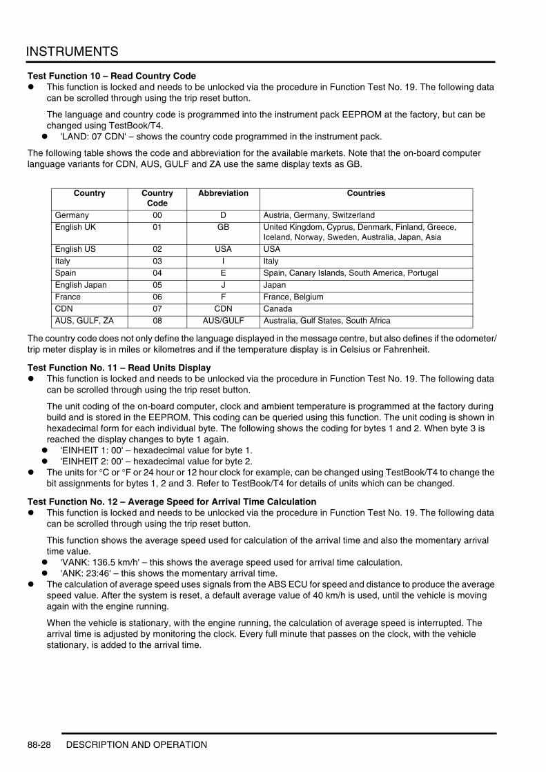
INSTRUMENTS
Test Function 10 – Read Country Codel This function is locked and needs to be unlocked via the procedure in Function Test No. 19. The following data
can be scrolled through using the trip reset button.
The language and country code is programmed into the instrument pack EEPROM at the factory, but can be changed using TestBook/T4.
l 'LAND: 07 CDN' – shows the country code programmed in the instrument pack.
The following table shows the code and abbreviation for the available markets. Note that the on-board computer language variants for CDN, AUS, GULF and ZA use the same display texts as GB.
The country code does not only define the language displayed in the message centre, but also defines if the odometer/trip meter display is in miles or kilometres and if the temperature display is in Celsius or Fahrenheit.
Test Function No. 11 – Read Units Displayl This function is locked and needs to be unlocked via the procedure in Function Test No. 19. The following data
can be scrolled through using the trip reset button.
The unit coding of the on-board computer, clock and ambient temperature is programmed at the factory during build and is stored in the EEPROM. This coding can be queried using this function. The unit coding is shown in hexadecimal form for each individual byte. The following shows the coding for bytes 1 and 2. When byte 3 is reached the display changes to byte 1 again.
l 'EINHEIT 1: 00' – hexadecimal value for byte 1.l 'EINHEIT 2: 00' – hexadecimal value for byte 2.
l The units for °C or °F or 24 hour or 12 hour clock for example, can be changed using TestBook/T4 to change the bit assignments for bytes 1, 2 and 3. Refer to TestBook/T4 for details of units which can be changed.
Test Function No. 12 – Average Speed for Arrival Time Calculationl This function is locked and needs to be unlocked via the procedure in Function Test No. 19. The following data
can be scrolled through using the trip reset button.
This function shows the average speed used for calculation of the arrival time and also the momentary arrival time value.
l 'VANK: 136.5 km/h' – this shows the average speed used for arrival time calculation.l 'ANK: 23:46' – this shows the momentary arrival time.
l The calculation of average speed uses signals from the ABS ECU for speed and distance to produce the average speed value. After the system is reset, a default average value of 40 km/h is used, until the vehicle is moving again with the engine running.
When the vehicle is stationary, with the engine running, the calculation of average speed is interrupted. The arrival time is adjusted by monitoring the clock. Every full minute that passes on the clock, with the vehicle stationary, is added to the arrival time.
Country Country Code
Abbreviation Countries
Germany 00 D Austria, Germany, SwitzerlandEnglish UK 01 GB United Kingdom, Cyprus, Denmark, Finland, Greece,
Iceland, Norway, Sweden, Australia, Japan, AsiaEnglish US 02 USA USA
Italy 03 I ItalySpain 04 E Spain, Canary Islands, South America, PortugalEnglish Japan 05 J Japan
France 06 F France, BelgiumCDN 07 CDN CanadaAUS, GULF, ZA 08 AUS/GULF Australia, Gulf States, South Africa
88-28 DESCRIPTION AND OPERATION

INSTRUMENTS
Test Function No. 13 – Activation of the Chime Signalsl This function is locked and needs to be unlocked via the procedure in Function Test No. 19.
This function provides for testing of the instrument pack sounder in the fascia closing panel, below the steering column. When the function is selected, 'CHIME?' appears in the message centre. Pressing the trip reset button once activates the three available chime signals as follows:
l Chime T1 – activated for 100 milliseconds with a 2.5 second pause. Used for the MEMO signal.l Chime T2 – activated for 100 milliseconds with a 2.5 second pause. Used for the Ambient temperature
warning.l Chime T1 and T2 – activated for 100 milliseconds with a 2.5 second pause. Used for LIMIT/CODE warning.l Chime T3 – Activated for 100 milliseconds with a 2.5 second pause. Used to indicate check control
messages.
Test Function No. 14 – Read Self Diagnostic Error Bytesl This function is locked and needs to be unlocked via the procedure in Function Test No. 19. Errors are stored in
the EEPROM in the form of bytes and are displayed in hexadecimal form. The maximum five errors can be scrolled through using the trip reset button and are displayed as follows:
l 'DIAG: 1 90 84 040' – the first number shows the error location number 1 - 5. The following numbers show error source code, type of error and frequency of error occurrence.
l TestBook/T4 must be used to interrogate the EEPROM and convert the hexadecimal values into meaningful error descriptions.
Test Function No. 15 – Display of Input/Output Port Statusl This function is locked and needs to be unlocked via the procedure in Function Test No. 19. The individual ports
can be scrolled through using the trip reset button.l 'PORT: A03 11010001' – shows the inputs and outputs for microprocessor 1 in binary format.l 'PORT: B01 01001110' – shows the inputs and outputs for microprocessor 2 in binary format.
l This function allows for rapid vehicle diagnostics by displaying the status of each microprocessor inputs and outputs in binary format. TestBook/T4 must be used to read the binary code and interpret the code meanings.
Test Function No. 16 – Momentary Value for Engine Oil Temperaturel This function is locked and needs to be unlocked via the procedure in Function Test No. 19.
This function shows the momentary value for the engine oil temperature which is updated every 200 milliseconds.l 'OELTMP: 83°C'
l The ignition must be in position II for the oil temperature to be displayed. The value is derived from a CAN message transmitted from the ECM. If an error occurs, the maximum displayable temperature of 207°C is displayed. The display is only available if set in the coding, if not, only dashes (- - -) are displayed.
Test Function No. 17 – Minute Counter for Radio Controlled Clockl This function is allocated for future use. Therefore the following blank message appears: 'RCC-EMPF.: - - - MIN'.
Test Function No. 18 – Dimming Parametersl This function is locked and needs to be unlocked via the procedure in Function Test No. 19. This display
comprises a block of six numbers which define the operating parameters of the instrument pack dimmer.
Test Function No. 19 – Lock/Unlockl The unlock code is known as a checksum of the VIN. The VIN can be obtained from Test Function No. 1. The
numbers of the VIN are added together and the resulting figure equals the checksum. For example, if the VIN is XA37295 the checksum will equal 26, which in turn equals the unlock code.
Enter the unlock as follows:l When test function No. 19 is entered, 'LOCK : ON' is displayedl Press the trip reset button once, 'LOCK : 00' is displayedl Press the trip reset button until the unlock checksum is reached, i.e. 26l Press the check control button once, all test functions will be unlocked.
NOTE: All test functions will remain unlocked, even when the ignition is switched off.l Relock the test functions as follows:
l Go to test function No. 19 and press the trip reset button, 'LOCK : OFF' is displayedl Press the trip reset button a second time, 'LOCK : ON' is displayedl Press the check control button or switch the ignition off to relock the test functions.
DESCRIPTION AND OPERATION 88-29

INSTRUMENTS
Test function No. 20 – Entry of Correction Factor for Fuel Consumptionl This function is locked and needs to be unlocked via the procedure in Function Test No. 19. This function allows
for the query and alteration of a correction factor for fuel consumption values. Display and entry of the correction value is a decimal form per thousand.
l 'KVBR: 0980' – this shows a correction factor of 980.l Entry of the correction factor is in the range of 750 to 1250. On production, the correction factor of 1000,
corresponding to 1.000, is programmed into the EEPROM.
Adjustment of the correction factor is possible using the trip reset button. Each press of the button decreases the factor by 1. When the minimum of 750 is reached, the display reverts to the maximum of 1250. If the trip reset button is pressed and held, the value is decreased in increments of 10 to shorten the setting time. When the desired correction value is reached, entry is achieved by pressing the check control button. The display moves to test function No. 21.
The new correction value is calculated from the actual average fuel consumption value and the currently displayed correction factor. The average fuel consumption is calculated by filling the fuel tank at a pump and dividing the litres used by the distance travelled on the fuel used. The correction factor must relate to units of L/100km.
The following formula must be used to calculate the correction value, where X = calculated fuel consumption, Y = fuel consumption recorded by on-board computer, Z = currently displayed correction factor:
(X ÷ Y) x Z = New correction value.
Test Function No. 21 – Software Resetl This function is locked and needs to be unlocked via the procedure in Function Test No. 19. This function
activates a reset of the software by the processor. This can also be performed using TestBook/T4.
When function 21 is entered the display shows 'RESET?'. If the trip reset button is depressed the system reset will be performed. If reset is not required, exit the test function by pressing the check control button or turning the ignition off.
88-30 DESCRIPTION AND OPERATION

INSTRUMENTS
Operation
Warning Lamp ActivationThe following warning lamps are illuminated directly by the instrument pack logic or by other control units connected to the instrument pack. The following table shows the warning lamp functionality.
Refer to table earlier in the instrument description section for warning lamp colour and bulb check applicability.
Function Active Parameters Reason for activation Activated ByHeadlamp main beam Ignition switch position II Main beam selected on LCM on the I BusLeft direction indicator Ignition switch position I or II Left indicator selected on LCM on the I Bus
Right direction indicator Ignition switch position I or II Right indicator selected on LCM on the I BusFront fog lamps Ignition switch position II and
headlamps onFront fog lamps selected on LCM on the I bus
Rear fog lamps Ignition switch position II and headlamps on
Rear fog lamps selected on LCM on the I bus
Seat belt warning Ignition switch position II Seat belt not fastened and ignition on in position II for 6 seconds
LCM on the I bus and instrument pack
Charge indicator lamp Ignition switch position II No charging output from alternator
Instrument pack hardwired connection or via CAN
Oil pressure warning Ignition switch position II Engine oil pressure low Instrument pack hardwired connection
General brake warning Ignition switch position II Brake fluid low LCM on the I busBrake pads worn Instrument pack hardwired
connectionElectronic brake proportioning failure
CAN message
Brake assist Ignition switch position II Brake booster failure CAN messageDynamic brake control failure CAN message
Brake booster monitoring failure
CAN message
Handbrake Ignition switch position II Handbrake on Instrument pack hardwired connection or instrument pack software
Anti-lock Brake System (ABS)
Ignition switch position II ABS failure Instrument pack hardwired connection
ASC-X (4 wheel all speed electronic traction control)
Ignition switch position II ASC-X controlling failure Instrument pack hardwired connection or via CAN message
Low fuel warning Ignition switch position II Tank reserve level reached Instrument pack softwareMIL (Check Engine Soon – NAS)
Ignition switch position II Engine management system malfunction
Instrument pack hardwired connection or via CAN
SRS warning Ignition switch position II Airbag malfunction Instrument pack hardwired connection
Cruise control Ignition switch position II Cruise control active Instrument pack hardwired connection or via CAN message
HDC (Hill Descent Control) Ignition switch position II HDC active Instrument pack hardwired connection or via CAN message
DESCRIPTION AND OPERATION 88-31

INSTRUMENTS
Warning Lamp Functionality
1 Glow plug warning lamp (diesel only)2 DSC active warning lamp3 HDC warning lamp4 SRS warning lamp5 ABS warning lamp6 General brake warning / brake assist warning
lamp7 Handbrake warning lamp
8 Engine oil pressure warning lamp9 Battery charge indicator
10 Rear fog lamp active warning lamp11 Front fog lamp active warning lamp12 MIL (Check Engine Soon – NAS)13 Cruise control active warning lamp14 Seat belt warning lamp
Functionality for each warning lamp is described below. Some warning lamps, when illuminated, are accompanied by a chime from the sounder and a message in the instrument pack message centre.
Glow Plug (Diesel models only)The glow plug warning lamp is illuminated by the ECM and the instrument pack software. The glow plug warning lamp illuminates in an amber colour when the ignition is moved to position II. There is no bulb check function for this lamp.
The lamp is illuminated by signals from the ECM which equate to the time which the glow plugs are energised. When the glow plug heating time is complete, the lamp is extinguished. The lamp illumination is accompanied by a message, 'PRE HEATING', in the message centre.
The glow plug warning lamp also serves a second function for the EDC system. If a major EDC system fault occurs when the engine is running, the glow plug warning lamp will be illuminated permanently and a message generated in the message centre. The driver must seek attention to the engine management system at a Land Rover dealer as soon as possible.
Dynamic Stability Control (DSC)The DSC warning lamp is controlled by the ABS ECU and the instrument pack software. The lamp illuminates briefly in an amber colour when the ignition is moved to position II. If DSC is selected off, the lamp remains illuminated.
When DSC is active, the lamp flashes to inform the driver that the system is regulating engine output and braking forces. If the warning lamp remains illuminated after the engine is started or illuminates when driving, the DSC system has a fault or DSC has been deselected using the fascia switch.
M88 034913
1 2 3
7 6 5 4
1412
10 811 9
88-32 DESCRIPTION AND OPERATION

INSTRUMENTS
If the vehicle battery has been disconnected, the DSC will be deactivated and the warning lamp will remain illuminated at ignition on when the battery is reconnected. The DSC can be reactivated by driving the vehicle a short distance or by turning the steering fully from lock to lock with the engine running. Reactivation is indicated by the warning lamp extinguishing.
Hill Descent Control (HDC)The HDC warning lamp is controlled by the ABS ECU and the instrument pack software. The lamp illuminates briefly in a green colour when the ignition is moved to position II. The lamp is also illuminated when HDC is selected on and the vehicle speed is less than 20 mph (35 km/h).
If HDC is selected on and the vehicle speed is faster than the operating speed, the lamp will flash and a message 'NO HDC, SLOW DOWN' will be displayed in the message centre.
If the use of HDC causes the brake discs to exceed their pre-determined temperature, the HDC initiates 'fade out'. The lamp flashes during 'fade out' and a message 'HDC TEMP.NOT AVAIL' will be displayed in the message centre. When the brake discs have cooled, HDC is reactivated, the lamp illuminates and the message is removed from the message centre.
Supplementary Restraint System (SRS)The SRS warning lamp is controlled by the SRS DCU and the instrument pack software. The lamp illuminates briefly in a red colour when the ignition is moved to position I (AUX). If a fault is detected in the SRS system, the DCU illuminates the SRS warning lamp continuously.
Anti-lock Brake system (ABS) The ABS warning lamp is controlled by the ABS ECU and the instrument pack software. The lamp illuminates briefly in an amber colour when the ignition is moved to position II. If the lamp remains illuminated or illuminates when driving, a fault with the ABS system has occurred.
If the vehicle battery has been disconnected, the ABS will be deactivated and the warning lamp will remain illuminated at ignition on when the battery is reconnected. The ABS can be reactivated by driving the vehicle a short distance or by turning the steering fully from lock to lock with the engine running. Reactivation is indicated by the warning lamp extinguishing.
General Brake Warning / Emergency Brake Assist WarningThis warning lamp displays a number of conditions to the driver as follows. The lamp can be illuminated in an amber or red colour depending on the existing fault condition. The lamp is illuminated, flashing alternately between an amber and red colour, for a brief period with the ignition in position II. If no fault conditions exist, the lamp is extinguished after the bulb check period.
The functions of the general brake warning lamp are assigned in priority. Fault conditions which use a red illumination have priority over amber illuminated faults.
Brake Pad Wearl The front brake pads are fitted with a wear indicator system. The LH and RH pads are wired in series to the
instrument pack which continuously monitors the circuit. When one or both pads wear to their allowed limit, the indicator circuit is broken and detected by the instrument pack software.
The instrument pack illuminates the general brake warning lamp in a red colour. The instrument pack simultaneously, transmits a message to the LCM which displays 'CHECK BRAKE PADS' in the message centre.
When the brake pads are replaced, the instrument pack withdraws the message and the warning lamp illumination when the ignition is in position II, the engine is not running and the vehicle is not moving for 30 seconds.
Electronic Brake Distribution (EBD) Warningl If a failure of the EBD function occurs, the ABS ECU passes a message to the instrument pack. The pack
software illuminates the general brake warning lamp in a red colour for as long as the fault condition exists.
DESCRIPTION AND OPERATION 88-33

INSTRUMENTS
Low Brake Fluid Warningl The brake fluid reservoir is fitted with a sensor which reports the fluid level to the LCM. When the ignition is
switched to position II, the LCM checks the fluid level immediately. To prevent false warnings when the vehicle is moving, the LCM then monitors the fluid level with a 25 second delay.
If the LCM detects a low brake fluid situation the LCM displays 'CHECK BRAKE FLUID' in the message centre. Simultaneously, a message is sent to the instrument pack which evaluates the message via the pack software and illuminates the general brake warning lamp in a red colour, accompanied by an intermittent chime from the sounder.
Emergency Brake Assist Warningl If a failure of the emergency brake assist function occurs, the ABS ECU issues a CAN message which is received
by the instrument pack. The instrument pack illuminates the general brake warning lamp in an amber colour for as long as the failure message is present on the CAN.
HandbrakeThe handbrake warning lamp is controlled by the LCM and the instrument pack software. The lamp is illuminated in a red colour briefly with the ignition in position II. If the handbrake is applied, the lamp remains illuminated, until the hand brake is released.
If the vehicle is driven with the handbrake applied, the LCM monitors the vehicle speed. When the speed reaches 3 mph (5 km/h), the LCM displays 'RELEASE HANDBRAKE' in the message centre, accompanied by an intermittent chime from the sounder for 20 seconds.
Engine Oil PressureThe lamp illuminates in a red colour at all times with the ignition in position II and the engine not running. If the lamp remains illuminated when the engine is started or illuminates when driving, the engine oil pressure is low and the engine must be stopped immediately to prevent serious damage to the engine internal components. When the lamp illuminates with the engine running, the instrument pack displays 'STOP! ENGINE OIL PRESS' in the message centre.
Battery Charge IndicatorThe battery charge indicator warning lamp is controlled by the ECM and the instrument pack software.
The battery charge indicator illuminates in a red colour with the ignition in position II and the engine not running. If the lamp remains illuminated when the engine is started or illuminates when driving, the alternator charge output has failed.
Rear Fog LampThe rear fog lamp operation is controlled by the LCM. The rear fog lamps can only be selected on when the ignition switch is in position II, the light switch is in the side lamp or headlamp position and the front fog lamps are selected on. The rear fog lamp warning lamp illuminates when the rear fog lamps are active. The warning lamp is extinguished if the rear fog lamps are selected off, the front fog lamps are selected off, the light switch is selected off or the ignition is switched off.
Front Fog LampThe front fog lamp operation is controlled by the LCM. The front fog lamps can only be selected on when the ignition switch is in position II and the light switch is in the side lamp or headlamp position. The front fog lamp warning lamp illuminates when the front fog lamps are active. The warning lamp is extinguished if the front fog lamp is selected off, the light switch is selected off or the ignition is switched off.
Malfunction Indicator Lamp (MIL) (Check Engine Soon – NAS)The MIL operation is controlled by the ECM and the instrument pack software. The lamp illuminates in an amber colour at all times with the ignition in position II and the engine not running. When the engine is started, the MIL is extinguished, providing that no OBD related faults are active. If the MIL remains illuminated or illuminates when driving, a fault is present and must be investigated as soon as possible.
88-34 DESCRIPTION AND OPERATION

INSTRUMENTS
Cruise ControlThe cruise control lamp is controlled by the ECM and the instrument pack software. The cruise control lamp is not illuminated as a bulb check when the ignition is in position II. The lamp illuminates to indicate to the driver that cruise control has been selected on. The lamp does not inform the driver of the status of the cruise control, i.e.; engaged or not engaged.
Seat BeltThe seat belt warning lamp is controlled by the SRS DCU, the LCM and instrument pack software.
On vehicles in markets where seat belt buckle switches are not required, the seat belt warning lamp is illuminated in a red colour briefly with the ignition in position II.
On vehicles in markets where seat buckle switches are required, the seat belt warning lamp is illuminated in a red colour with the ignition in position II. The lamp is only extinguished when the seat belt buckle switch contacts are broken by fastening of the seat belt. The illumination of the lamp is accompanied by 'FASTEN SEAT BELTS' displayed in the message centre and an intermittent chime from the sounder.
Low Fuel WarningThe low fuel warning lamp, located in the fuel gauge, is illuminated in an amber colour briefly with the ignition in position II. The warning lamp is controlled by the instrument pack software which measures the output signals from the tank level sensors. If the fuel level falls to or below 12 litres, on V8 models and 10 litres, on T6 models, the instrument pack illuminates the lamp to inform the driver of the low fuel level.
DESCRIPTION AND OPERATION 88-35

INSTRUMENTS
88-36 DESCRIPTION AND OPERATION