WORKSHOP MANUAL
312
TL150 Track Loader BOOK No. CT7E901 WORKSHOP MANUAL Serial No. 21500004~
-
Upload
khangminh22 -
Category
Documents
-
view
2 -
download
0
Transcript of WORKSHOP MANUAL
TL150Track Loader
BOOK No. CT7E901
WORKSHOP MANUAL
Serial No. 21500004~

0-2
FOREWORD
This manual is intended for persons who engage in maintenance operations, and explains procedures for dis-assembly and reassembly of the machine, check and maintenance procedures, maintenance reference values, troubleshooting and outline specifications, etc. Please use this manual as a reference in service activities to improve maintenance techniques.Further, please be advised that items contained in this manual are subject to change without notice due to design modifications, etc.
MACHINE FRONT AND REAR, LEFT AND RIGHTThe end where the bucket is mounted is the front and the end with the travel motors is the rear. Also the right and left sides of the operator when he is seated in the driver s seat are the right and left sides of the machine.
MACHINE SERIAL NUMBERThe machine serial number is stamped on the identification plate. When sending reports and inquiries, and when ordering parts, etc., be sure to include this number.
MANUAL CONTROLInformation on those to whom this manual is distributed is recorded in the ledger in the section in charge at this company, so please decide on a person to be in charge of it and control it. When there are updates or additions, etc., we will notify the person in charge.
SYMBOLS means “Please refer to the section quoted.”
Indicates the tightening torque at the specific section that requires special attention in designing.
Indicates the mass of a part or device.
0-3
I . GENERAL
II . SPECIFICATIONS
III . MACHINE CONFIGURATION
IV . HYDRAULIC UNITS
V . TROUBLESHOOTING
VI . ENGINE

0-4

I-1
I . GENERAL
GENERAL
I-2
CONTENTS
Safety Precautions ...................................................................................................................................................3Cautions during Disassembly and Assembly ..........................................................................................................9Cautions during Removal and Installation of the Hydraulic Units .........................................................................9Cautions during Removal and Installation of Piping ............................................................................................10Handling of Seals ..................................................................................................................................................10Tightening Torques ...............................................................................................................................................11
I-3
GENERAL
SAFETY PRECAUTIONS
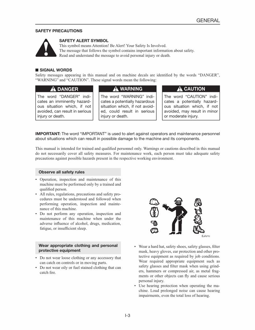
SAFETY ALERT SYMBOL
This symbol means Attention! Be Alert! Your Safety Is Involved.The message that follows the symbol contains important information about safety.Read and understand the message to avoid personal injury or death.
SIGNAL WORDS
Safety messages appearing in this manual and on machine decals are identified by the words “DANGER”, “WARNING” and “CAUTION”. These signal words mean the following:
The word “DANGER” indi-cates an imminently hazard-ous situation which, if not avoided, can result in serious injury or death.
DANGER
The word “WARNING” indi-cates a potentially hazardous situation which, if not avoid-ed, could result in serious injury or death.
WARNING
The word “CAUTION” indi-cates a potentially hazard-ous situation which, if not avoided, may result in minor or moderate injury.
CAUTION
IMPORTANT: The word “IMPORTANT” is used to alert against operators and maintenance personnel about situations which can result in possible damage to the machine and its components.
This manual is intended for trained and qualified personnel only. Warnings or cautions described in this manual do not necessarily cover all safety measures. For maintenance work, each person must take adequate safety precautions against possible hazards present in the respective working environment.
Observe all safety rules
• Operation, inspection and maintenance of this machine must be performed only by a trained and qualified person.
• All rules, regulations, precautions and safety pro-cedures must be understood and followed when performing operation, inspection and mainte-nance of this machine.
• Do not perform any operation, inspection and maintenance of this machine when under the adverse influence of alcohol, drugs, medication, fatigue, or insufficient sleep.
Wear appropriate clothing and personal
protective equipment
• Do not wear loose clothing or any accessory that can catch on controls or in moving parts.
• Do not wear oily or fuel stained clothing that can catch fire.
• Wear a hard hat, safety shoes, safety glasses, filtermask, heavy gloves, ear protection and other pro-tective equipment as required by job conditions. Wear required appropriate equipment such as safety glasses and filter mask when using grind-ers, hammers or compressed air, as metal frag-ments or other objects can fly and cause serious personal injury.
• Use hearing protection when operating the ma-chine. Loud prolonged noise can cause hearing impairments, even the total loss of hearing.

I-4
GENERAL
Provide a fire extinguisher and first aid
kit
• Know where a fire extinguisher and first aid kit are located and understand how to use them.
• Know how to contact emergency assistance and first aid help.
Attach a “DO NOT OPERATE” tag
Severe injury could result if an unauthorized person should start the engine or touch controls during inspection or maintenance.
• Stop the engine and remove the key before per-forming maintenance.
• Attach a “DO NOT OPERATE” tag to the starter switch or control lever.
Use the correct tools
Do not use damaged or weakened tools or tools de-signed for other purposes. Use tools suited for the operation at hand.
Replace important safety parts periodi-
cally
• Replace fuel hoses periodically. Fuel hoses be-come weaker over time, even if they appear to be in good shape.
• Replace important safety parts whenever an ir-regularity is found, even if it is before the normal time for replacement.
Anti-explosive lighting
Use anti-explosive electrical fixtures and lights when inspecting fuel, oil, coolant, battery fluid, etc. If lighting that is not anti-explosive should break, the substance could ignite, resulting in serious injury or death.
Do not allow unauthorized personnel in
the work area
Do not allow unauthorized personnel in the work area. Chips or other debris can fly off machine parts when grinding, welding or using a hammer.
Prepare the work area
• Select a firm, level work area. Make sure there is adequate light and, if indoors, ventilation.
• Clear obstacles and dangerous objects. Eliminate slippery areas.
I-5
GENERAL
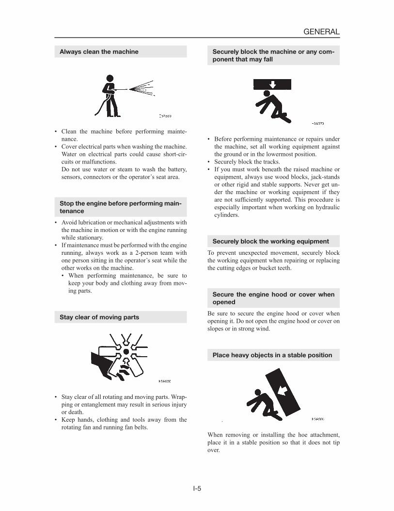
Always clean the machine
• Clean the machine before performing mainte-nance.
• Cover electrical parts when washing the machine. Water on electrical parts could cause short-cir-cuits or malfunctions.
Do not use water or steam to wash the battery, sensors, connectors or the operator s seat area.
Stop the engine before performing main-
tenance
• Avoid lubrication or mechanical adjustments with the machine in motion or with the engine running while stationary.
• If maintenance must be performed with the engine running, always work as a 2-person team with one person sitting in the operator s seat while the other works on the machine.• When performing maintenance, be sure to
keep your body and clothing away from mov-ing parts.
Stay clear of moving parts
• Stay clear of all rotating and moving parts. Wrap-ping or entanglement may result in serious injury or death.
• Keep hands, clothing and tools away from the rotating fan and running fan belts.
Securely block the machine or any com-
ponent that may fall
• Before performing maintenance or repairs under the machine, set all working equipment against the ground or in the lowermost position.
• Securely block the tracks.• If you must work beneath the raised machine or
equipment, always use wood blocks, jack-stands or other rigid and stable supports. Never get un-der the machine or working equipment if they are not sufficiently supported. This procedure is especially important when working on hydraulic cylinders.
Securely block the working equipment
To prevent unexpected movement, securely block the working equipment when repairing or replacing the cutting edges or bucket teeth.
Secure the engine hood or cover when
opened
Be sure to secure the engine hood or cover when opening it. Do not open the engine hood or cover on slopes or in strong wind.
Place heavy objects in a stable position
When removing or installing the hoe attachment, place it in a stable position so that it does not tip over.
I-6
GENERAL
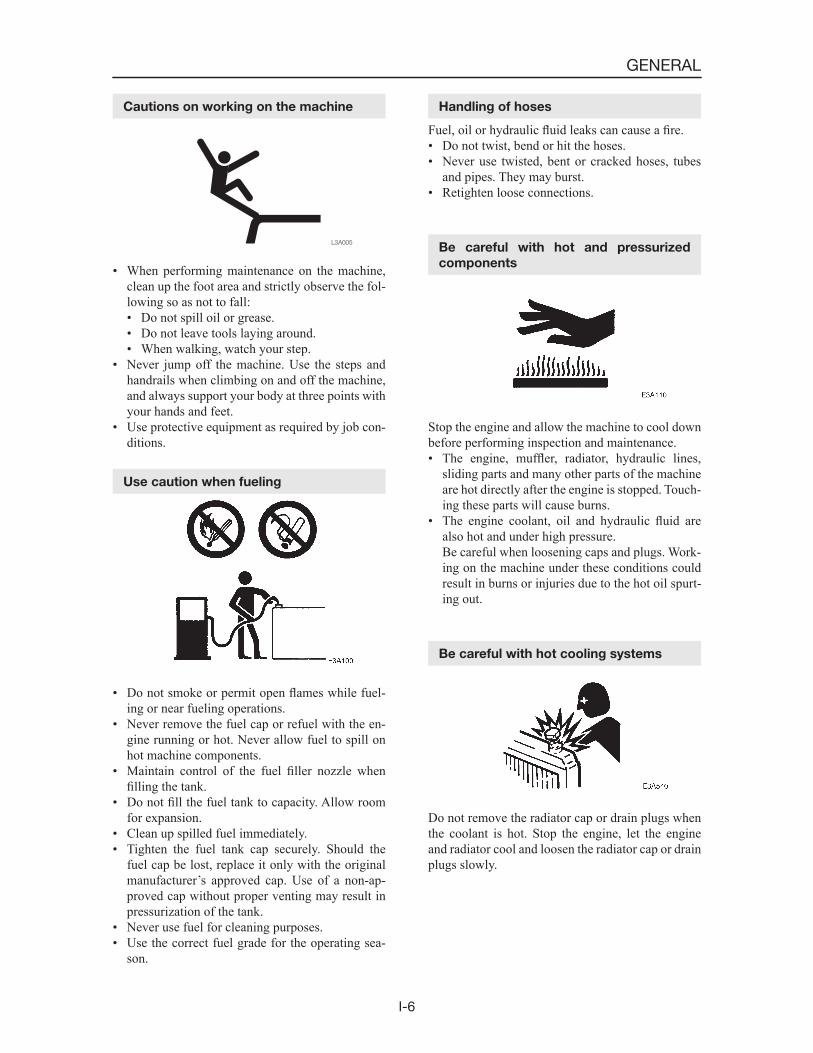
Cautions on working on the machine
• When performing maintenance on the machine, clean up the foot area and strictly observe the fol-lowing so as not to fall:• Do not spill oil or grease.• Do not leave tools laying around.• When walking, watch your step.
• Never jump off the machine. Use the steps and handrails when climbing on and off the machine, and always support your body at three points with your hands and feet.
• Use protective equipment as required by job con-ditions.
Use caution when fueling
• Do not smoke or permit open flames while fuel-ing or near fueling operations.
• Never remove the fuel cap or refuel with the en-gine running or hot. Never allow fuel to spill on hot machine components.
• Maintain control of the fuel filler nozzle when filling the tank.
• Do not fill the fuel tank to capacity. Allow room for expansion.
• Clean up spilled fuel immediately.• Tighten the fuel tank cap securely. Should the
fuel cap be lost, replace it only with the original manufacturer s approved cap. Use of a non-ap-proved cap without proper venting may result in pressurization of the tank.
• Never use fuel for cleaning purposes.• Use the correct fuel grade for the operating sea-
son.
Handling of hoses
Fuel, oil or hydraulic fluid leaks can cause a fire.• Do not twist, bend or hit the hoses.• Never use twisted, bent or cracked hoses, tubes
and pipes. They may burst.• Retighten loose connections.
Be careful with hot and pressurized
components
Stop the engine and allow the machine to cool down before performing inspection and maintenance.• The engine, muffler, radiator, hydraulic lines,
sliding parts and many other parts of the machine are hot directly after the engine is stopped. Touch-ing these parts will cause burns.
• The engine coolant, oil and hydraulic fluid are also hot and under high pressure.
Be careful when loosening caps and plugs. Work-ing on the machine under these conditions could result in burns or injuries due to the hot oil spurt-ing out.
Be careful with hot cooling systems
Do not remove the radiator cap or drain plugs when the coolant is hot. Stop the engine, let the engine and radiator cool and loosen the radiator cap or drain plugs slowly.
I-7
GENERAL
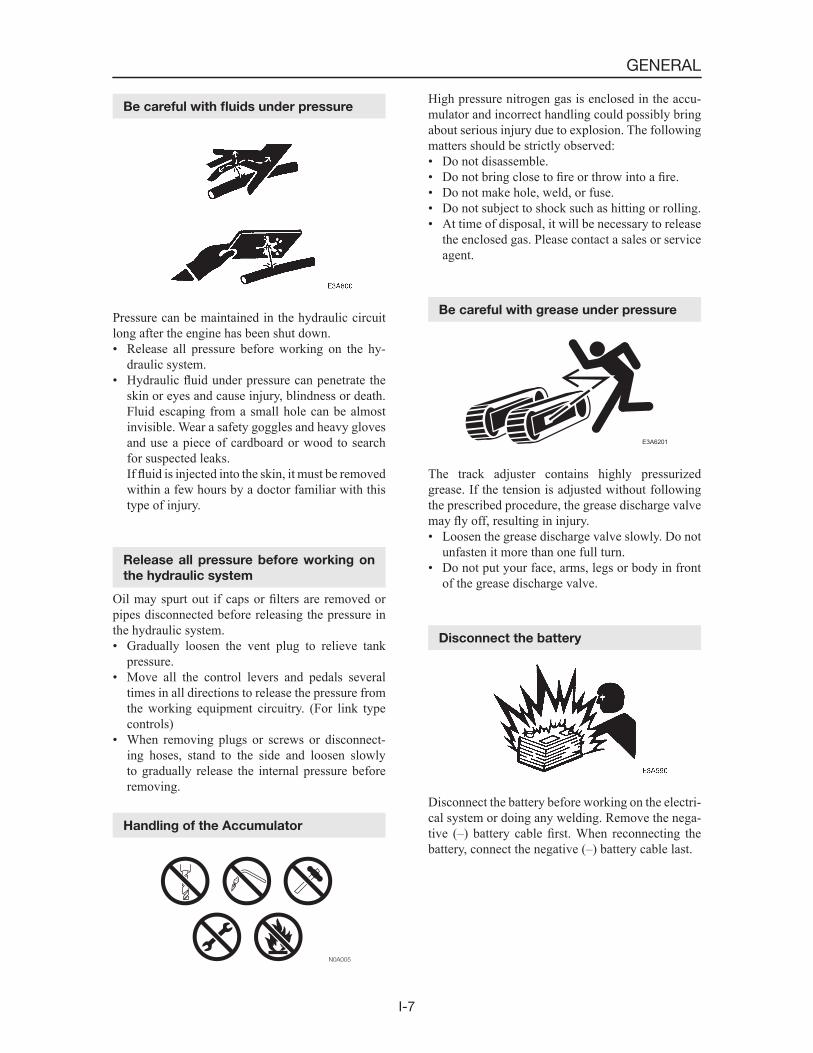
Be careful with fluids under pressure
Pressure can be maintained in the hydraulic circuit long after the engine has been shut down.• Release all pressure before working on the hy-
draulic system.• Hydraulic fluid under pressure can penetrate the
skin or eyes and cause injury, blindness or death. Fluid escaping from a small hole can be almost invisible. Wear a safety goggles and heavy gloves and use a piece of cardboard or wood to search for suspected leaks.
If fluid is injected into the skin, it must be removed within a few hours by a doctor familiar with this type of injury.
Release all pressure before working on
the hydraulic system
Oil may spurt out if caps or filters are removed or pipes disconnected before releasing the pressure in the hydraulic system.• Gradually loosen the vent plug to relieve tank
pressure.• Move all the control levers and pedals several
times in all directions to release the pressure from the working equipment circuitry. (For link type controls)
• When removing plugs or screws or disconnect-ing hoses, stand to the side and loosen slowly to gradually release the internal pressure before removing.
Handling of the Accumulator
High pressure nitrogen gas is enclosed in the accu-mulator and incorrect handling could possibly bring about serious injury due to explosion. The following matters should be strictly observed:• Do not disassemble.• Do not bring close to fire or throw into a fire.• Do not make hole, weld, or fuse.• Do not subject to shock such as hitting or rolling.• At time of disposal, it will be necessary to release
the enclosed gas. Please contact a sales or service agent.
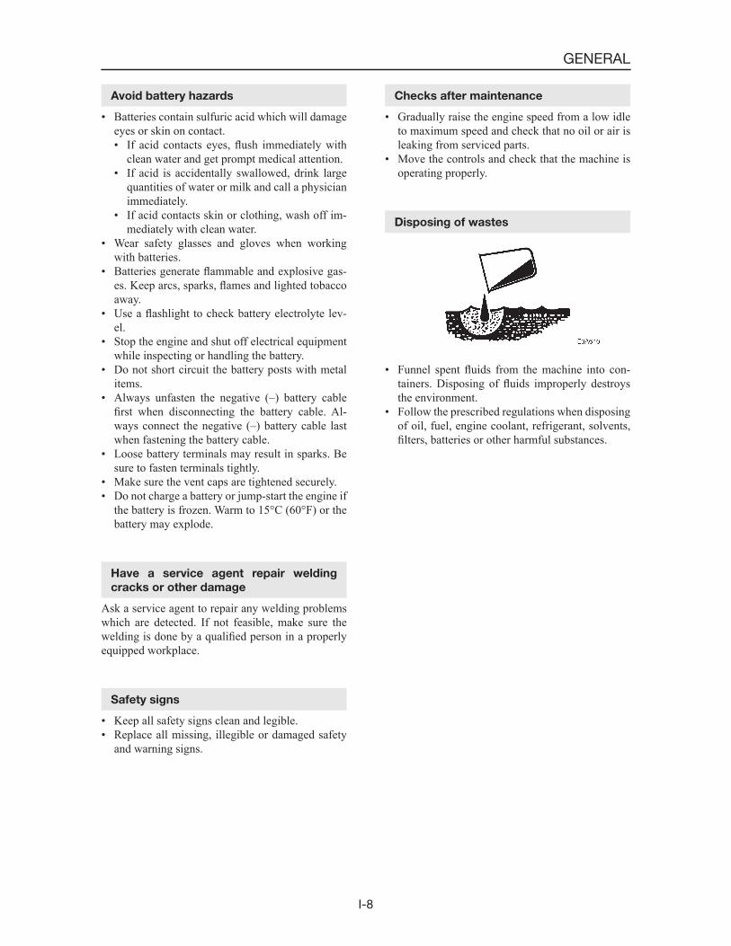
Be careful with grease under pressure
E3A6201
The track adjuster contains highly pressurized grease. If the tension is adjusted without following the prescribed procedure, the grease discharge valve may fly off, resulting in injury.• Loosen the grease discharge valve slowly. Do not
unfasten it more than one full turn.• Do not put your face, arms, legs or body in front
of the grease discharge valve.
Disconnect the battery
Disconnect the battery before working on the electri-cal system or doing any welding. Remove the nega-tive (–) battery cable first. When reconnecting the battery, connect the negative (–) battery cable last.
I-8
GENERAL
Avoid battery hazards
• Batteries contain sulfuric acid which will damage eyes or skin on contact.• If acid contacts eyes, flush immediately with
clean water and get prompt medical attention.• If acid is accidentally swallowed, drink large
quantities of water or milk and call a physician immediately.
• If acid contacts skin or clothing, wash off im-mediately with clean water.
• Wear safety glasses and gloves when working with batteries.
• Batteries generate flammable and explosive gas-es. Keep arcs, sparks, flames and lighted tobacco away.
• Use a flashlight to check battery electrolyte lev-el.
• Stop the engine and shut off electrical equipment while inspecting or handling the battery.
• Do not short circuit the battery posts with metal items.
• Always unfasten the negative (–) battery cable first when disconnecting the battery cable. Al-ways connect the negative (–) battery cable last when fastening the battery cable.
• Loose battery terminals may result in sparks. Be sure to fasten terminals tightly.
• Make sure the vent caps are tightened securely.• Do not charge a battery or jump-start the engine if
the battery is frozen. Warm to 15°C (60°F) or the battery may explode.
Have a service agent repair welding
cracks or other damage
Ask a service agent to repair any welding problems which are detected. If not feasible, make sure the welding is done by a qualified person in a properly equipped workplace.
Safety signs
• Keep all safety signs clean and legible.• Replace all missing, illegible or damaged safety
and warning signs.
Checks after maintenance
• Gradually raise the engine speed from a low idle to maximum speed and check that no oil or air is leaking from serviced parts.
• Move the controls and check that the machine is operating properly.
Disposing of wastes
• Funnel spent fluids from the machine into con-tainers. Disposing of fluids improperly destroys the environment.
• Follow the prescribed regulations when disposing of oil, fuel, engine coolant, refrigerant, solvents, filters, batteries or other harmful substances.
I-9
GENERAL
CAUTIONS DURING DISASSEMBLY AND
ASSEMBLY
1. Clean the machine before disassembly opera-tion.
2. Before disassembly, check the machine condi-tions and record them.• Model, Machine Serial Number, Hourmeter• Reason for Repairs, Repair History• Dirtiness of Filters• Fuel and Oil Conditions• Damage to each parts, etc.
3. To make reassembly operations easy, make matching marks at the necessary points.
4. Clean all disassembled parts and new parts, then arrange them in the proper sequence.
5. Be sure to replace all seals and cotter pins, etc., with new parts.
6. Keep parts which should not come in contact with oil and water separate from parts with oil on them.• Electrical Parts, Rubber, V-Belts, etc.
7. When installing bearings, bushings and oil seals, as a rule, use a press. When a hammer, etc., is used, it leaves bruises.
8. Wipe all joining surfaces clean so that there is no dirt or dust adhering to them.
9. Wrap seal tape from the front end, Wrapping it tight and leaving 1 or 2 threads bare, Overlap the tape by about 10 mm.
SEALING TAPE
LEAVE 1 OR 2 THREAD MARGIN
Y2-A102E
10. When fitting the snap rings, the bigger, rounder side of their circumferences should face the mating surfaces.
CAUTIONS DURING REMOVAL AND INSTALLA-
TION OF THE HYDRAULIC UNITS
1. Make sure that the temperature of the hydraulic oil has dropped.
2. To prevent a loss of flow of the hydraulic oil, the residual pressure in the piping and the in-ternal pressure in the hydraulic tank should be released.
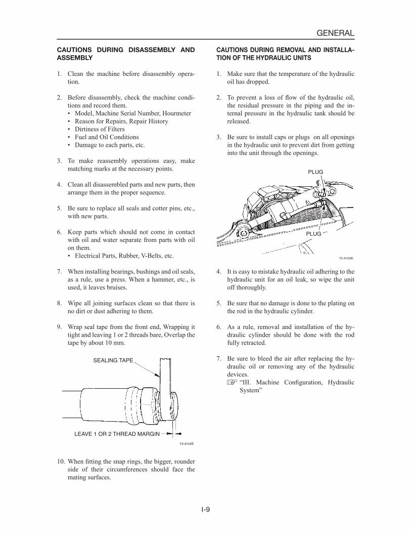
3. Be sure to install caps or plugs on all openings in the hydraulic unit to prevent dirt from getting into the unit through the openings.
Y2-A103E
PLUG
PLUG
4. It is easy to mistake hydraulic oil adhering to the hydraulic unit for an oil leak, so wipe the unit off thoroughly.
5. Be sure that no damage is done to the plating on the rod in the hydraulic cylinder.
6. As a rule, removal and installation of the hy-draulic cylinder should be done with the rod fully retracted.
7. Be sure to bleed the air after replacing the hy-draulic oil or removing any of the hydraulic devices.
“III. Machine Configuration, Hydraulic System”
I-10
GENERAL
CAUTIONS DURING REMOVAL AND IN-
STALLATION OF PIPING
1. When hydraulic hoses are installed, tighten them once to the prescribed torque, then loosen them slightly and retighten them to the prescribed torque.• Tighten the fittings after the installation sur-
faces fit snugly together.• Pieces wrapped with seal tape are excluded.
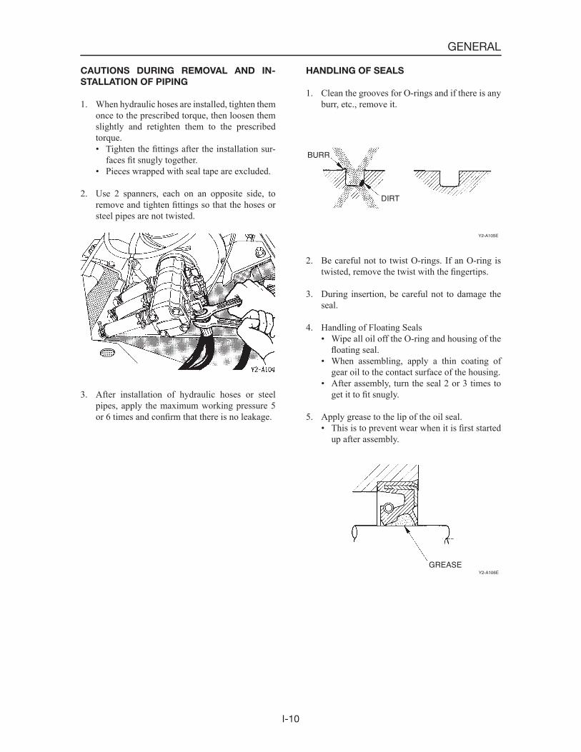
2. Use 2 spanners, each on an opposite side, to remove and tighten fittings so that the hoses or steel pipes are not twisted.
3. After installation of hydraulic hoses or steel pipes, apply the maximum working pressure 5 or 6 times and confirm that there is no leakage.
HANDLING OF SEALS
1. Clean the grooves for O-rings and if there is any burr, etc., remove it.
BURR
DIRT
Y2-A105E
2. Be careful not to twist O-rings. If an O-ring is twisted, remove the twist with the fingertips.
3. During insertion, be careful not to damage the seal.
4. Handling of Floating Seals• Wipe all oil off the O-ring and housing of the
floating seal.• When assembling, apply a thin coating of
gear oil to the contact surface of the housing.• After assembly, turn the seal 2 or 3 times to
get it to fit snugly.
5. Apply grease to the lip of the oil seal.• This is to prevent wear when it is first started
up after assembly.
Y2-A106E
GREASE
GENERAL
I-11
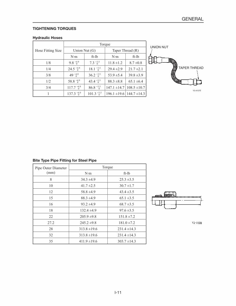
TIGHTENING TORQUES
Hydraulic Hoses
Bite Type Pipe Fitting for Steel Pipe
Pipe Outer Diameter(mm)
TorqueN·m ft-lb
8 34.3 ±4.9 25.3 ±3.510 41.7 ±2.5 30.7 ±1.712 58.8 ±4.9 43.4 ±3.515 88.3 ±4.9 65.1 ±3.516 93.2 ±4.9 68.7 ±3.518 132.4 ±4.9 97.6 ±3.522 205.9 ±9.8 151.8 ±7.2
27.2 245.2 ±9.8 181.0 ±7.228 313.8 ±19.6 231.4 ±14.332 313.8 ±19.6 231.4 ±14.335 411.9 ±19.6 303.7 ±14.3
Hose Fitting SizeTorque
Union Nut (G) Taper Thread (R)N·m ft-lb N·m ft-lb
1/8 9.8 +4.9 7.3 +3.5 11.8 ±1.2 8.7 ±0.81/4 24.5 +4.9 18.1 +3.5 29.4 ±2.9 21.7 ±2.13/8 49 +4.9 36.2 +3.5 53.9 ±5.4 39.8 ±3.91/2 58.8 +4.9 43.4 +3.5 88.3 ±8.8 65.1 ±6.43/4 117.7 +4.9 86.8 +3.5 147.1 ±14.7 108.5 ±10.71 137.3 +4.9 101.3 +3.5 196.1 ±19.6 144.7 ±14.3
0
0
0
0
0
0
0
0
0
0
0
0
UNION NUT
TAPER THREAD
Y2-A107E
GENERAL
I-12
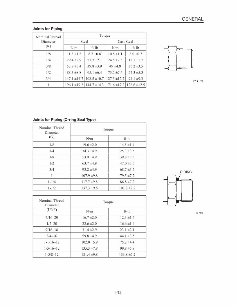
Joints for Piping
Joints for Piping (O-ring Seal Type)
Nominal ThreadDiameter
(R)
TorqueSteel Cast Steel
N·m ft-lb N·m ft-lb1/8 11.8 ±1.2 8.7 ±0.8 10.8 ±1.1 8.0 ±0.71/4 29.4 ±2.9 21.7 ±2.1 24.5 ±2.5 18.1 ±1.73/8 53.9 ±5.4 39.8 ±3.9 49 ±4.9 36.2 ±3.51/2 88.3 ±8.8 65.1 ±6.4 73.5 ±7.4 54.3 ±5.33/4 147.1 ±14.7 108.5 ±10.7 127.5 ±12.7 94.1 ±9.31 196.1 ±19.2 144.7 ±14.3 171.6 ±17.2 126.6 ±12.5
Nominal ThreadDiameter
(G)
Torque
N·m ft-lb1/8 19.6 ±2.0 14.5 ±1.41/4 34.3 ±4.9 25.3 ±3.53/8 53.9 ±4.9 39.8 ±3.51/2 63.7 ±4.9 47.0 ±3.53/4 93.2 ±4.9 68.7 ±3.51 107.9 ±9.8 79.5 ±7.2
1-1/4 117.7 ±9.8 86.8 ±7.21-1/2 137.3 ±9.8 101.2 ±7.2
Nominal ThreadDiameter
(UNF)
Torque
N·m ft-lb7/16–20 16.7 ±2.0 12.3 ±1.41/2–20 22.6 ±2.0 16.6 ±1.4
9/16–18 31.4 ±2.9 23.1 ±2.13/4–16 59.8 ±4.9 44.1 ±3.5
1-1/16–12 102.0 ±5.9 75.2 ±4.41-5/16–12 135.3 ±7.8 99.8 ±5.81-5/8–12 181.4 ±9.8 133.8 ±7.2
O-RING
Y2-A110
I-13
GENERAL
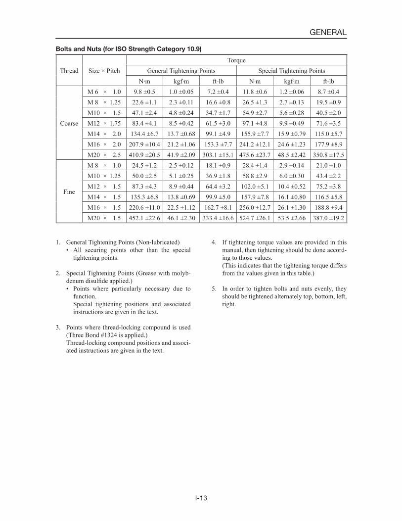
Bolts and Nuts (for ISO Strength Category 10.9)
1. General Tightening Points (Non-lubricated)• All securing points other than the special
tightening points.
2. Special Tightening Points (Grease with molyb-denum disulfide applied.)• Points where particularly necessary due to
function. Special tightening positions and associated
instructions are given in the text.
3. Points where thread-locking compound is used (Three Bond #1324 is applied.)
Thread-locking compound positions and associ-ated instructions are given in the text.
Thread Size × PitchTorque
General Tightening Points Special Tightening PointsN·m kgf·m ft-lb N·m kgf·m ft-lb
Coarse
M 6 × 1.0 9.8 ±0.5 1.0 ±0.05 7.2 ±0.4 11.8 ±0.6 1.2 ±0.06 8.7 ±0.4M 8 × 1.25 22.6 ±1.1 2.3 ±0.11 16.6 ±0.8 26.5 ±1.3 2.7 ±0.13 19.5 ±0.9M10 × 1.5 47.1 ±2.4 4.8 ±0.24 34.7 ±1.7 54.9 ±2.7 5.6 ±0.28 40.5 ±2.0M12 × 1.75 83.4 ±4.1 8.5 ±0.42 61.5 ±3.0 97.1 ±4.8 9.9 ±0.49 71.6 ±3.5M14 × 2.0 134.4 ±6.7 13.7 ±0.68 99.1 ±4.9 155.9 ±7.7 15.9 ±0.79 115.0 ±5.7M16 × 2.0 207.9 ±10.4 21.2 ±1.06 153.3 ±7.7 241.2 ±12.1 24.6 ±1.23 177.9 ±8.9M20 × 2.5 410.9 ±20.5 41.9 ±2.09 303.1 ±15.1 475.6 ±23.7 48.5 ±2.42 350.8 ±17.5
Fine
M 8 × 1.0 24.5 ±1.2 2.5 ±0.12 18.1 ±0.9 28.4 ±1.4 2.9 ±0.14 21.0 ±1.0M10 × 1.25 50.0 ±2.5 5.1 ±0.25 36.9 ±1.8 58.8 ±2.9 6.0 ±0.30 43.4 ±2.2M12 × 1.5 87.3 ±4.3 8.9 ±0.44 64.4 ±3.2 102.0 ±5.1 10.4 ±0.52 75.2 ±3.8M14 × 1.5 135.3 ±6.8 13.8 ±0.69 99.9 ±5.0 157.9 ±7.8 16.1 ±0.80 116.5 ±5.8M16 × 1.5 220.6 ±11.0 22.5 ±1.12 162.7 ±8.1 256.0 ±12.7 26.1 ±1.30 188.8 ±9.4M20 × 1.5 452.1 ±22.6 46.1 ±2.30 333.4 ±16.6 524.7 ±26.1 53.5 ±2.66 387.0 ±19.2
4. If tightening torque values are provided in this manual, then tightening should be done accord-ing to those values.
(This indicates that the tightening torque differs from the values given in this table.)
5. In order to tighten bolts and nuts evenly, they should be tightened alternately top, bottom, left, right.

I-14
GENERAL

II-1
II . SPECIFICATIONS
II-2
SPECIFICATIONS
In regard to Standard Values and Allowable Values
The terms used in the items “Servicing Standards” and “Standards for Judging Performance” have the following meanings.
Standard Value ............ This indicates the standard value for the new machine at the time of shipping from the factory. It should be used as the target value for maintenance work after operation.
Allowable Value .......... The dimensions of parts change during use because of wear and deformation. Also, the performance of pumps, motors, and other hydraulic equipment drops, and this is the estimated value indicating the use limit for the respective part. It is decided under refer-ence to the standard at the time of shipping, the results of various tests, etc. As the use conditions, the degree of repairs, etc., differ for each machine, these should be combined and used as reference for servicing standards and standards for judging performance.* Do not use the standard values and the allowable values as standards for customer
claims.
CONTENTS
Names of Components ............................................................................................................................................3Specification Diagrams ...........................................................................................................................................4Specifications Tables ...............................................................................................................................................6Mass Tables ...........................................................................................................................................................10Recommended Lubricants ....................................................................................................................................11Service Standards ..................................................................................................................................................12Standards for Judging Performance ......................................................................................................................19
Reference Value Table ....................................................................................................................................19Methods for Inspecting Performance .............................................................................................................20

II-3
SPECIFICATIONS
NAMES OF COMPONENTS
1. Lift Arm 2. Control Valve 3. Hydraulic Tank 4. Canopy 5. Safety Bar 6. Pilot Valve (L. H.) 7. Pilot Valve (R. H.) 8. HST Pump 9. Bucket Cylinder10. Fuel Tank
11. Arm Cylinder12. Travel Motor13. Track Roller14. Track15. Idler16. Quick-Hitch17. Bucket18. Control Valve (Sub)19. Self-Level Valve
T7B001
17
1610
15
14
13
18
811
19
12
3
24
5
1
7
6
9
NAMES OF COMPONENTS
II-4
SPECIFICATIONS
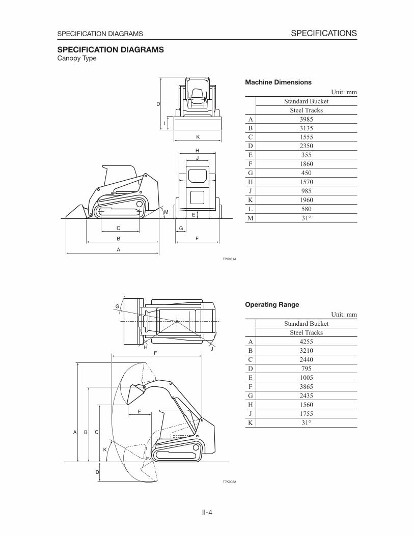
SPECIFICATION DIAGRAMSCanopy Type
Unit: mmStandard Bucket
Steel TracksA 3985B 3135C 1555D 2350E 355F 1860G 450H 1570J 985K 1960L 580M 31°
Machine Dimensions
L
M
D
J
H
K
C
F
G
A
E
B
T7K001A
D
H
K
C
F
A
E
B
J
G
T7K002A
Unit: mmStandard Bucket
Steel TracksA 4255B 3210C 2440D 795E 1005F 3865G 2435H 1560J 1755K 31°
Operating Range
SPECIFICATION DIAGRAMS

II-5
SPECIFICATIONS
Cab Type
Unit: mmStandard Bucket
Steel TracksA 3985B 3135C 1555D 2350E 355F 1860G 450H 1570J 985K 1960L 580M 31°
Machine Dimensions
L
M
D
J
H
K
C
F
G
A
E
B
T7K001A
D
H
K
C
F
A
E
B
J
G
T7K002A
Unit: mmStandard Bucket
Steel TracksA 4255B 3210C 2440D 795E 1005F 3865G 2435H 1560J 1755K 31°
Operating Range
SPECIFICATION DIAGRAMS

II-6
SPECIFICATIONSSPECIFICATIONS TABLES
SPECIFICATIONS TABLES
SPECIFICATIONS
Type CanopyStandard Bucket Capacity
Rated Capacity m3 0.579Struck Capacity m3 0.426
Machine Mass (not including operator) kg 5485Dimensions
Overall Lenght: with bucket mm 3985without bucket mm 3135
Overall Width: with bucket mm 1960without bucket mm 1860
Overall Height mm 2350Minimum Ground Clearance mm 355Front Clearance Radius: with bucket mm 2435
without bucket mm 1560Rear Clearance Radius mm 1755Overall Width of Crawler mm 1860Overall Length of Crawler mm 2150Bucket Width mm 1960Angle of Departure degree 31
Working RangeMaximum Lift Height to Bucket Pin mm 3210Maximum Dumping Height mm 2440Maximum Dump Angle Fully Raised degree 39Maximum Bucket Rollback at Ground Level degree 31Reach Fully Raised mm 1005
PerformanceBreakout Force kN 38.5Travel Speed 1st / 2nd km/h 5.8 / 8.3Gradeability degree 30Ground Pressure kPa 39.0Tipping Load kg 3300Cycle Time
Raise-Full Load (Lift Arm) Sec. 4.8Lower-No Load (Lift Arm) Sec. 3.1Dump-Full Load (Bucket) Sec. 3.3Curl-Full Load (Bucket) Sec. 2.4
II-7
SPECIFICATIONSSPECIFICATIONS TABLES
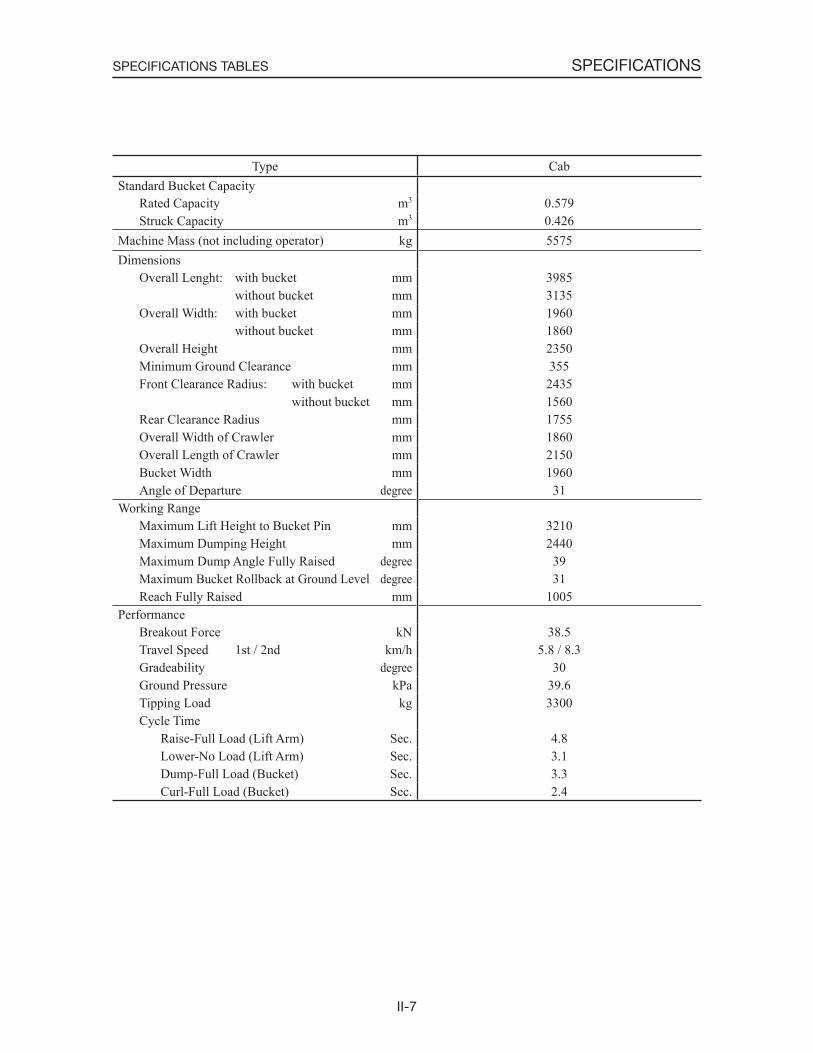
Type CabStandard Bucket Capacity
Rated Capacity m3 0.579Struck Capacity m3 0.426
Machine Mass (not including operator) kg 5575Dimensions
Overall Lenght: with bucket mm 3985without bucket mm 3135
Overall Width: with bucket mm 1960without bucket mm 1860
Overall Height mm 2350Minimum Ground Clearance mm 355Front Clearance Radius: with bucket mm 2435
without bucket mm 1560Rear Clearance Radius mm 1755Overall Width of Crawler mm 1860Overall Length of Crawler mm 2150Bucket Width mm 1960Angle of Departure degree 31
Working RangeMaximum Lift Height to Bucket Pin mm 3210Maximum Dumping Height mm 2440Maximum Dump Angle Fully Raised degree 39Maximum Bucket Rollback at Ground Level degree 31Reach Fully Raised mm 1005
PerformanceBreakout Force kN 38.5Travel Speed 1st / 2nd km/h 5.8 / 8.3Gradeability degree 30Ground Pressure kPa 39.6Tipping Load kg 3300Cycle Time
Raise-Full Load (Lift Arm) Sec. 4.8Lower-No Load (Lift Arm) Sec. 3.1Dump-Full Load (Bucket) Sec. 3.3Curl-Full Load (Bucket) Sec. 2.4
II-8
SPECIFICATIONSSPECIFICATIONS TABLES
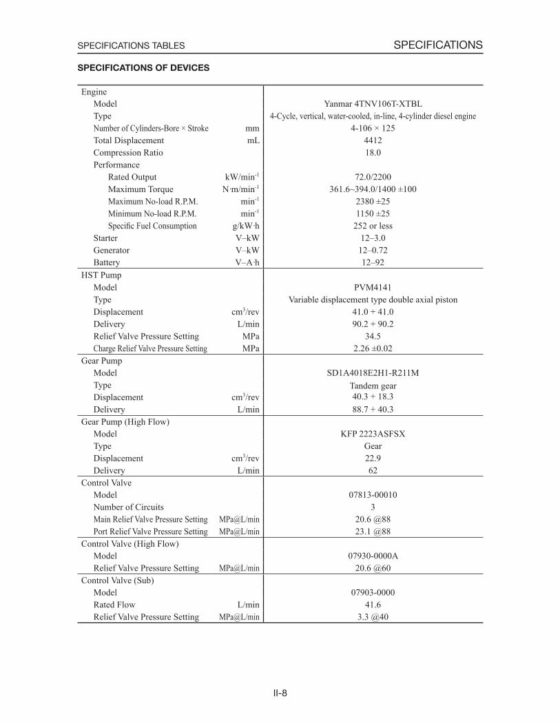
SPECIFICATIONS OF DEVICES
EngineModel Yanmar 4TNV106T-XTBLType 4-Cycle, vertical, water-cooled, in-line, 4-cylinder diesel engineNumber of Cylinders-Bore × Stroke mm 4-106 × 125Total Displacement mL 4412Compression Ratio 18.0Performance
Rated Output kW/min-1 72.0/2200Maximum Torque N·m/min-1 361.6~394.0/1400 ±100Maximum No-load R.P.M. min-1 2380 ±25Minimum No-load R.P.M. min-1 1150 ±25Specific Fuel Consumption g/kW·h 252 or less
Starter V–kW 12–3.0Generator V–kW 12–0.72Battery V–A·h 12–92
HST PumpModel PVM4141Type Variable displacement type double axial pistonDisplacement cm3/rev 41.0 + 41.0Delivery L/min 90.2 + 90.2Relief Valve Pressure Setting MPa 34.5Charge Relief Valve Pressure Setting MPa 2.26 ±0.02
Gear PumpModel SD1A4018E2H1-R211MType Tandem gear
40.3 + 18.3Displacement cm3/revDelivery L/min 88.7 + 40.3
Gear Pump (High Flow)Model KFP 2223ASFSXType GearDisplacement cm3/rev 22.9Delivery L/min 62
Control ValveModel 07813-00010Number of Circuits 3Main Relief Valve Pressure Setting MPa@L/min 20.6 @88Port Relief Valve Pressure Setting MPa@L/min 23.1 @88
Control Valve (High Flow)Model 07930-0000ARelief Valve Pressure Setting MPa@L/min 20.6 @60
Control Valve (Sub)Model 07903-0000Rated Flow L/min 41.6Relief Valve Pressure Setting MPa@L/min 3.3 @40
II-9
SPECIFICATIONSSPECIFICATIONS TABLES
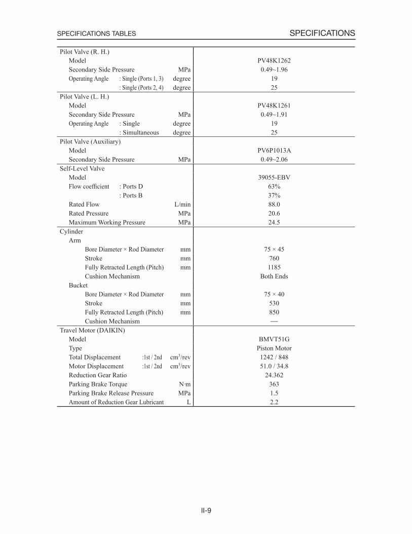
Pilot Valve (R. H.)Model PV48K1262Secondary Side Pressure MPa 0.49~1.96Operating Angle : Single (Ports 1, 3) degree 19
: Single (Ports 2, 4) degree 25Pilot Valve (L. H.)
Model PV48K1261Secondary Side Pressure MPa 0.49~1.91Operating Angle : Single degree 19
: Simultaneous degree 25Pilot Valve (Auxiliary)
Model PV6P1013ASecondary Side Pressure MPa 0.49~2.06
Self-Level ValveModel 39055-EBVFlow coefficient : Ports D 63%
: Ports B 37%Rated Flow L/min 88.0Rated Pressure MPa 20.6Maximum Working Pressure MPa 24.5
CylinderArm
Bore Diameter × Rod Diameter mm 75 × 45Stroke mm 760Fully Retracted Length (Pitch) mm 1185Cushion Mechanism Both Ends
BucketBore Diameter × Rod Diameter mm 75 × 40Stroke mm 530Fully Retracted Length (Pitch) mm 850Cushion Mechanism
Travel Motor (DAIKIN)Model BMVT51GType Piston MotorTotal Displacement :1st / 2nd cm3/rev 1242 / 848Motor Displacement :1st / 2nd cm3/rev 51.0 / 34.8Reduction Gear Ratio 24.362Parking Brake Torque N·m 363Parking Brake Release Pressure MPa 1.5Amount of Reduction Gear Lubricant L 2.2
II-10
SPECIFICATIONS
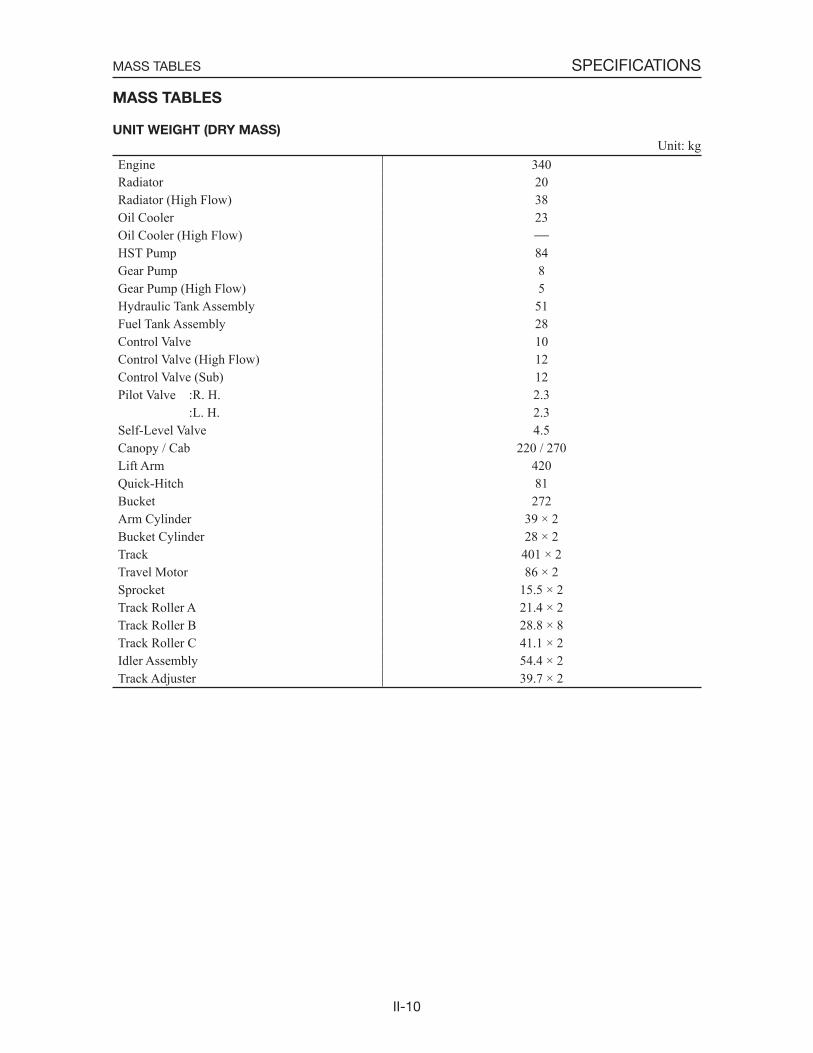
MASS TABLES
UNIT WEIGHT (DRY MASS)
Unit: kg
MASS TABLES
Engine 340Radiator 20Radiator (High Flow) 38Oil Cooler 23Oil Cooler (High Flow)HST Pump 84Gear Pump 8Gear Pump (High Flow) 5Hydraulic Tank Assembly 51Fuel Tank Assembly 28Control Valve 10Control Valve (High Flow) 12Control Valve (Sub) 12Pilot Valve :R. H. 2.3
:L. H. 2.3Self-Level Valve 4.5Canopy / Cab 220 / 270Lift Arm 420Quick-Hitch 81Bucket 272Arm Cylinder 39 × 2Bucket Cylinder 28 × 2Track 401 × 2Travel Motor 86 × 2 Sprocket 15.5 × 2Track Roller A 21.4 × 2Track Roller B 28.8 × 8Track Roller C 41.1 × 2Idler Assembly 54.4 × 2Track Adjuster 39.7 × 2
II-11
SPECIFICATIONS
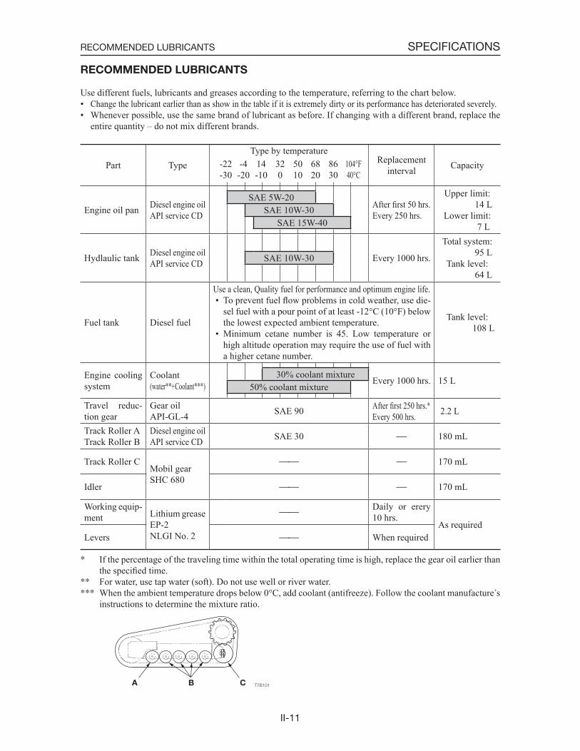
RECOMMENDED LUBRICANTS
Use different fuels, lubricants and greases according to the temperature, referring to the chart below.• Change the lubricant earlier than as show in the table if it is extremely dirty or its performance has deteriorated severely.• Whenever possible, use the same brand of lubricant as before. If changing with a different brand, replace the
entire quantity – do not mix different brands.
Part TypeType by temperature
Replacementinterval Capacity -22 -4 14 32 50 68 86 104°F
-30 -20 -10 0 10 20 30 40°C
Engine oil pan Diesel engine oil API service CD
After first 50 hrs.Every 250 hrs.
Upper limit: 14 L
Lower limit: 7 L
SAE 5W-20SAE 10W-30
SAE 15W-40
Hydlaulic tank Diesel engine oil API service CD Every 1000 hrs.
Total system: 95 L
Tank level: 64 L
SAE 10W-30
Fuel tank Diesel fuel
Use a clean, Quality fuel for performance and optimum engine life. • To prevent fuel flow problems in cold weather, use die-
sel fuel with a pour point of at least -12°C (10°F) below the lowest expected ambient temperature.
• Minimum cetane number is 45. Low temperature or high altitude operation may require the use of fuel with a higher cetane number.
Tank level: 108 L
Engine cooling system
Coolant(water +Coolant ) Every 1000 hrs. 15 L
30% coolant mixture50% coolant mixture
Travel reduc-tion gear
Gear oilAPI-GL-4 SAE 90 After first 250 hrs.
Every 500 hrs. 2.2 L
Track Roller ATrack Roller B
Diesel engine oil API service CD SAE 30 180 mL
Track Roller CMobil gearSHC 680
170 mL
Idler 170 mL
Working equip-ment Lithium grease
EP-2NLGI No. 2
Daily or erery 10 hrs.
As requiredLevers When required
If the percentage of the traveling time within the total operating time is high, replace the gear oil earlier than the specified time.
For water, use tap water (soft). Do not use well or river water. When the ambient temperature drops below 0°C, add coolant (antifreeze). Follow the coolant manufacture s
instructions to determine the mixture ratio.
RECOMMENDED LUBRICANTS
II-12
SPECIFICATIONSSERVICE STANDARDS
SERVICE STANDARDS
TRAVEL SYSTEM
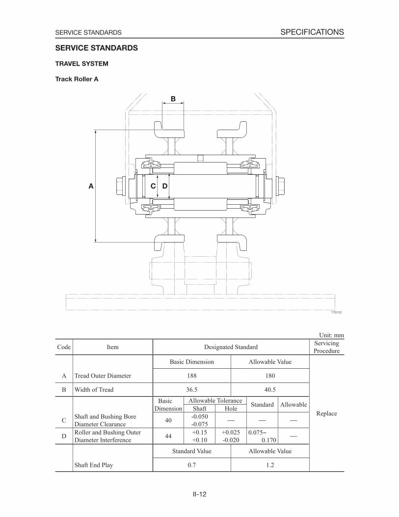
Track Roller A
Unit: mm
Code Item Designated Standard ServicingProcedure
Basic Dimension Allowable Value
Replace
A Tread Outer Diameter 188 180
B Width of Tread 36.5 40.5
Basic Dimension
Allowable Tolerance Standard AllowableShaft Hole
C Shaft and Bushing Bore Diameter Clearance 40 -0.050
-0.075
D Roller and Bushing Outer Diameter Interference 44 +0.15
+0.10+0.025-0.020
0.075~0.170
Standard Value Allowable Value
Shaft End Play 0.7 1.2

II-13
SPECIFICATIONSSERVICE STANDARDS
Track Roller B
Unit: mm
Code Item Designated Standard ServicingProcedure
Basic Dimension Allowable Value
Replace
A Tread Outer Diameter 188 180
B Width of Tread 37.5 45.5
Basic Dimension
Allowable Tolerance Standard AllowableShaft Hole
C Shaft and Bushing Bore Diameter Clearance 40 -0.050
-0.075
D Roller and Bushing Outer Diameter Interference 44 +0.15
+0.10+0.025-0.020
0.075~0.170
Standard Value Allowable Value
Shaft End Play 0.7 1.2
II-14
SPECIFICATIONSSERVICE STANDARDS
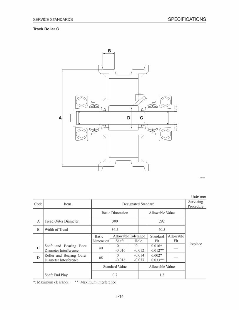
Track Roller C
Unit: mm
Code Item Designated Standard ServicingProcedure
Basic Dimension Allowable Value
Replace
A Tread Outer Diameter 300 292
B Width of Tread 36.5 40.5
Basic Dimension
Allowable Tolerance StandardFit
AllowableFitShaft Hole
C Shaft and Bearing Bore Diameter Interference 40 0
-0.016 0 -0.012
0.016 0.012
D Roller and Bearing Outer Diameter Interference 68 0
-0.016 -0.014 -0.033
0.002 0.033
Standard Value Allowable Value
Shaft End Play 0.7 1.2
*: Maximum clearance **: Maximum interference
II-15
SPECIFICATIONSSERVICE STANDARDS
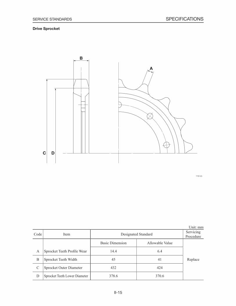
Drive Sprocket
Unit: mm
Code Item Designated Standard ServicingProcedure
Basic Dimension Allowable Value
Replace
A Sprocket Teeth Profile Wear 14.4 6.4
B Sprocket Teeth Width 45 41
C Sprocket Outer Diameter 432 424
D Sprocket Teeth Lower Diameter 378.6 370.6
II-16
SPECIFICATIONSSERVICE STANDARDS
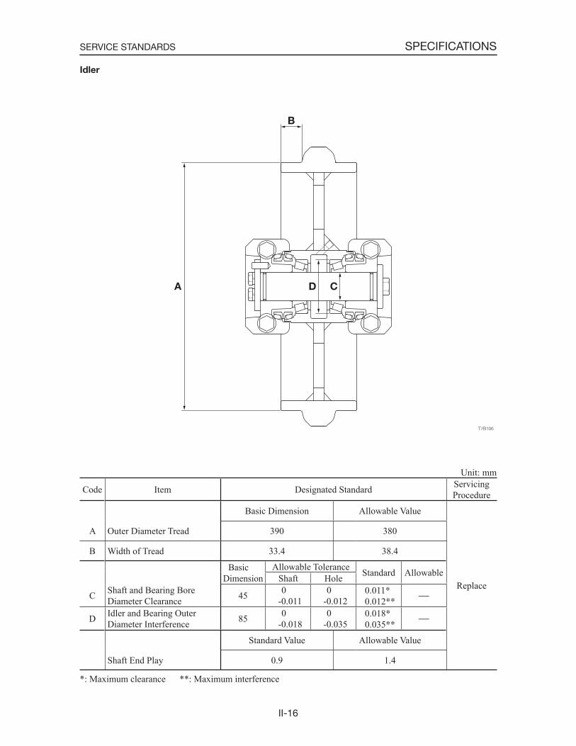
Idler
Unit: mm
Code Item Designated Standard ServicingProcedure
Basic Dimension Allowable Value
Replace
A Outer Diameter Tread 390 380
B Width of Tread 33.4 38.4
Basic Dimension
Allowable Tolerance Standard AllowableShaft Hole
C Shaft and Bearing Bore Diameter Clearance 45 0
-0.011 0 -0.012
0.011 0.012
D Idler and Bearing Outer Diameter Interference 85 0
-0.018 0 -0.035
0.018 0.035
Standard Value Allowable Value
Shaft End Play 0.9 1.4
*: Maximum clearance **: Maximum interference
II-17
SPECIFICATIONSSERVICE STANDARDS
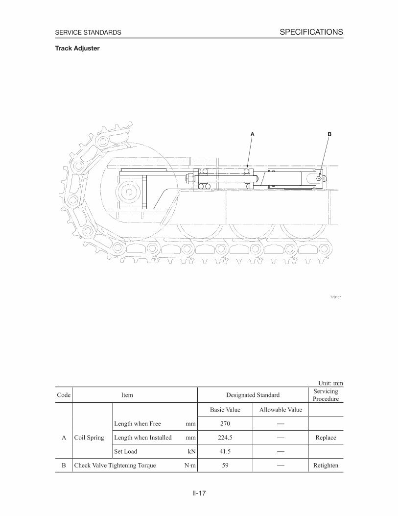
Track Adjuster
Unit: mm
Code Item Designated Standard ServicingProcedure
Basic Value Allowable Value
Length when Free mm 270
A Coil Spring Length when Installed mm 224.5 Replace
Set Load kN 41.5
B Check Valve Tightening Torque N·m 59 Retighten
II-18
SPECIFICATIONSSERVICE STANDARDS
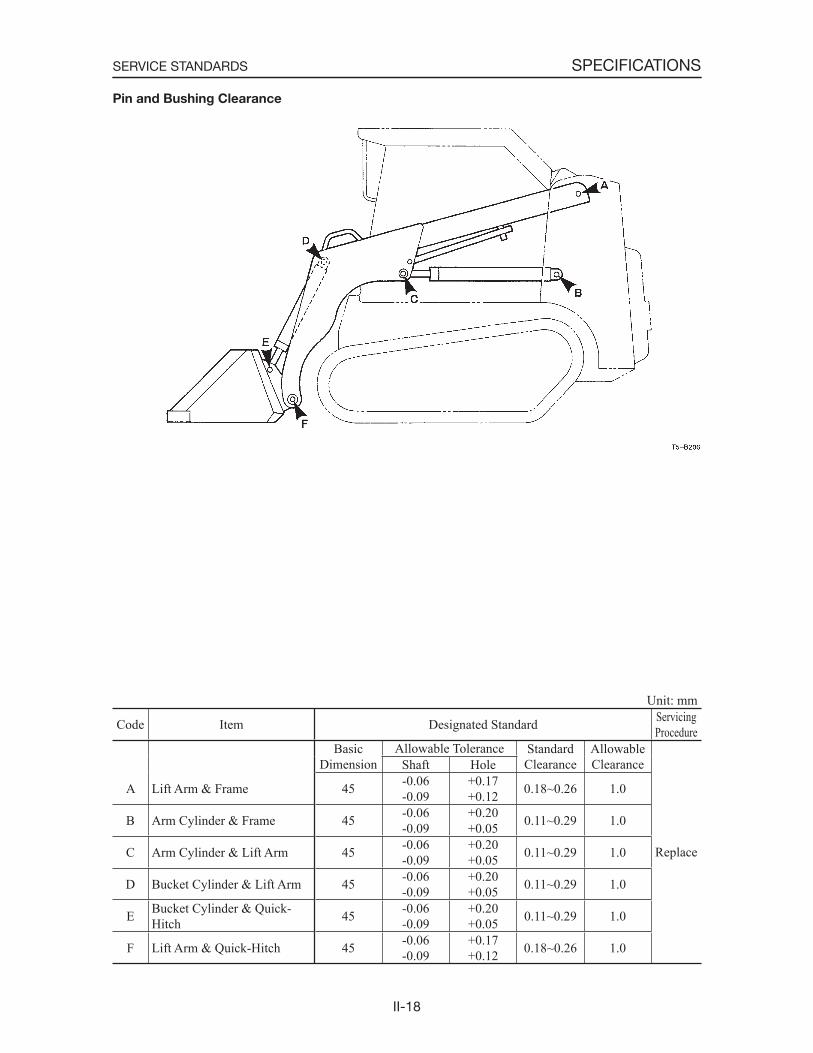
Unit: mm
Code Item Designated Standard ServicingProcedure
BasicDimension
Allowable Tolerance StandardClearance
AllowableClearance
Replace
Shaft Hole
A Lift Arm & Frame 45 -0.06-0.09
+0.17+0.12 0.18~0.26 1.0
B Arm Cylinder & Frame 45 -0.06-0.09
+0.20+0.05 0.11~0.29 1.0
C Arm Cylinder & Lift Arm 45 -0.06-0.09
+0.20+0.05 0.11~0.29 1.0
D Bucket Cylinder & Lift Arm 45 -0.06-0.09
+0.20+0.05 0.11~0.29 1.0
E Bucket Cylinder & Quick-Hitch 45 -0.06
-0.09+0.20+0.05 0.11~0.29 1.0
F Lift Arm & Quick-Hitch 45 -0.06-0.09
+0.17+0.12 0.18~0.26 1.0
Pin and Bushing Clearance
II-19
SPECIFICATIONSSTANDARDS FOR JUDGING PERFORMANCE
STANDARDS FOR JUDGING PERFORMANCE
REFERENCE VALUE TABLE
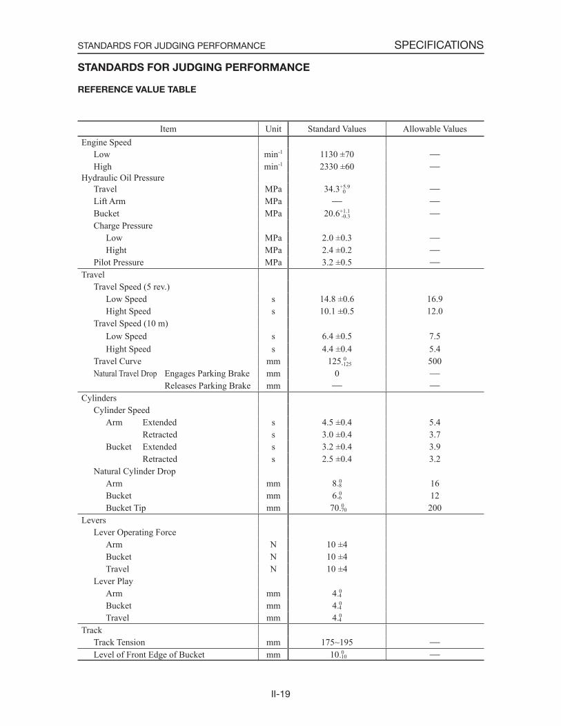
Item Unit Standard Values Allowable ValuesEngine Speed
Low min-1 1130 ±70High min-1 2330 ±60
Hydraulic Oil PressureTravel MPa 34.3+5.9
Lift Arm MPaBucket MPa 20.6+1.1
Charge PressureLow MPa 2.0 ±0.3Hight MPa 2.4 ±0.2
Pilot Pressure MPa 3.2 ±0.5Travel
Travel Speed (5 rev.)Low Speed s 14.8 ±0.6 16.9Hight Speed s 10.1 ±0.5 12.0
Travel Speed (10 m)Low Speed s 6.4 ±0.5 7.5Hight Speed s 4.4 ±0.4 5.4
Travel Curve mm 125 0 500Natural Travel Drop Engages Parking Brake mm 0
Releases Parking Brake mmCylinders
Cylinder SpeedArm Extended s 4.5 ±0.4 5.4
Retracted s 3.0 ±0.4 3.7Bucket Extended s 3.2 ±0.4 3.9
Retracted s 2.5 ±0.4 3.2Natural Cylinder Drop
Arm mm 8 0 16Bucket mm 6 0 12Bucket Tip mm 70 0 200
LeversLever Operating Force
Arm N 10 ±4Bucket N 10 ±4Travel N 10 ±4
Lever PlayArm mm 4 0
Bucket mm 4 0
Travel mm 4 0
TrackTrack Tension mm 175~195Level of Front Edge of Bucket mm 10 0
0
-0.3
-125
-8
-6
-70
-4
-4
-4
-10
II-20
SPECIFICATIONSSTANDARDS FOR JUDGING PERFORMANCE
METHODS FOR INSPECTING PERFOR-
MANCE
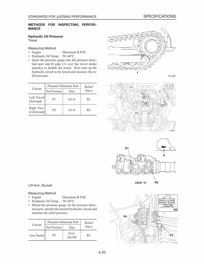
Hydraulic Oil Pressure
Travel
Measuring Method• Engine : Maximum R.P.M.• Hydraulic Oil Temp. : 50~60°C• Insert the pressure gauge into the pressure detec-
tion port and fit pipe (1) over the travel motor sprocket to disable the motor. Next start up the hydraulic circuit to be tested and measure the re-lief pressure.
CircuitPressure Detection Port Relief
ValvePort Position Size
Left Travel (forward) P1 G1/4 R1
Right Trav-el (forward) P2 G1/4 R2
Lift Arm, Bucket
Measuring Method• Engine : Maximum R.P.M.• Hydraulic Oil Temp. : 50~60°C• Mount the pressure gauge on the pressure detec-
tion port, operate the desired hydraulic circuit and measure the relief pressure.
CircuitPressure Detection Port Relief
ValvePort Position Size
Arm, bucket P3 9/16-18UNF R3
T7B007
C
P1
P2

II-21
SPECIFICATIONSSTANDARDS FOR JUDGING PERFORMANCE
Adjusting Method1. Loosen locknut (2), then begin adjusting pres-
sure by turning setting screw (1). Turning clockwise ............... raises the set pressure. Turning counterclockwise ... lowers the set pressure.2. In order to keep the setting screw from turning
after pressure has been adjusted, tighten the locknut while at the same time holding the set-ting screw firmly in place.
3. Operate the relief valve once more to confirmthat the pressure that has been set it stabilized.
Charge pressure
Measuring Method• Engine : Idling/Maximum R.P.M.• Hydraulic Oil Temp. : 50~60˚C• Insert the pressure gauge into the pressure detec-
tion port to measure the charge pressure.
Pressure Detection PortPort Position Size
C G1/4
Measuring the pilot pressure
Measuring Method• Engine : Maximum R.P.M.• Hydraulic Oil Temp : 50~60˚C• Mount the pressure gauge on the pressure detec-
tion port, operate the desired hydraulic circuit and measure the pilot pressure.
CircuitPressure Detection Port
Port Position SizeBucket dump P4 G1/4
T7B007
C
P1
P2
II-22
SPECIFICATIONSSTANDARDS FOR JUDGING PERFORMANCE
2DAA12Z
X
10m
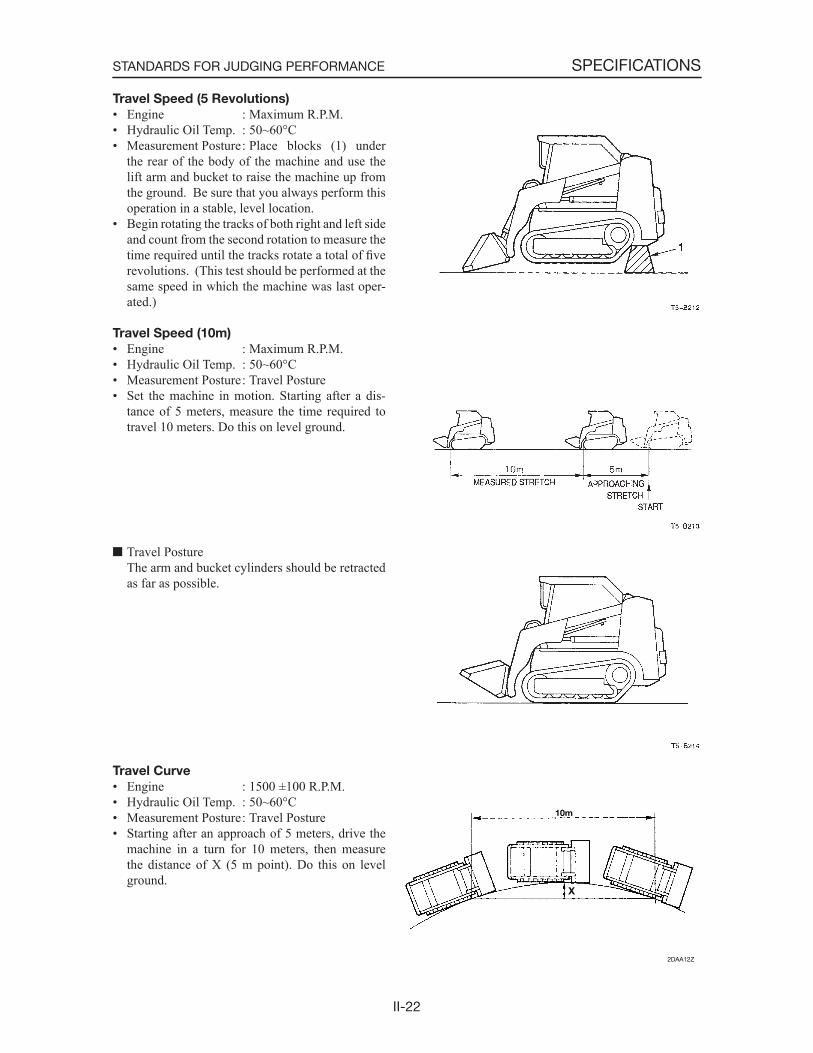
Travel Speed (5 Revolutions)
• Engine : Maximum R.P.M.• Hydraulic Oil Temp. : 50~60°C• Measurement Posture : Place blocks (1) under
the rear of the body of the machine and use the lift arm and bucket to raise the machine up from the ground. Be sure that you always perform this operation in a stable, level location.
• Begin rotating the tracks of both right and left side and count from the second rotation to measure the time required until the tracks rotate a total of fiverevolutions. (This test should be performed at the same speed in which the machine was last oper-ated.)
Travel Speed (10m)
• Engine : Maximum R.P.M.• Hydraulic Oil Temp. : 50~60°C• Measurement Posture : Travel Posture• Set the machine in motion. Starting after a dis-
tance of 5 meters, measure the time required to travel 10 meters. Do this on level ground.
Travel Posture The arm and bucket cylinders should be retracted
as far as possible.
Travel Curve
• Engine : 1500 ±100 R.P.M.• Hydraulic Oil Temp. : 50~60°C• Measurement Posture : Travel Posture• Starting after an approach of 5 meters, drive the
machine in a turn for 10 meters, then measure the distance of X (5 m point). Do this on level ground.
II-23
SPECIFICATIONSSTANDARDS FOR JUDGING PERFORMANCE
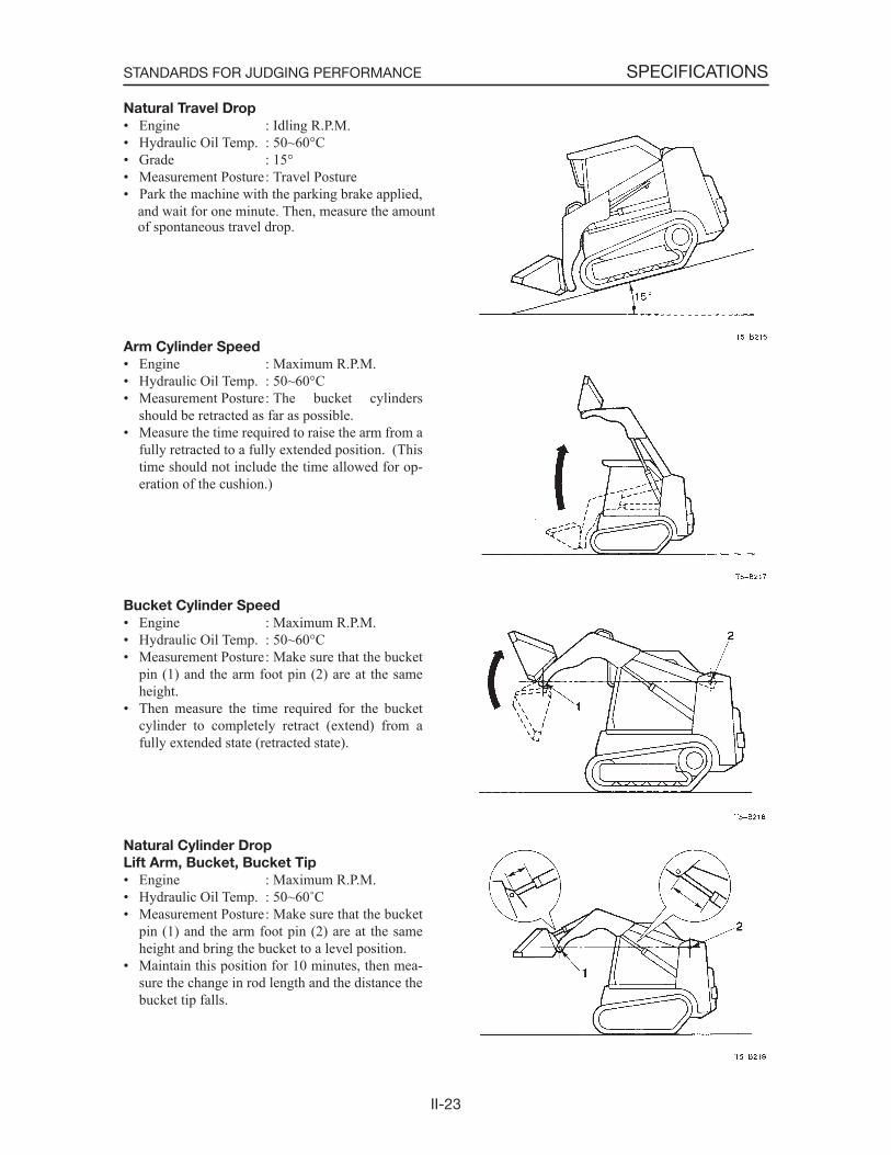
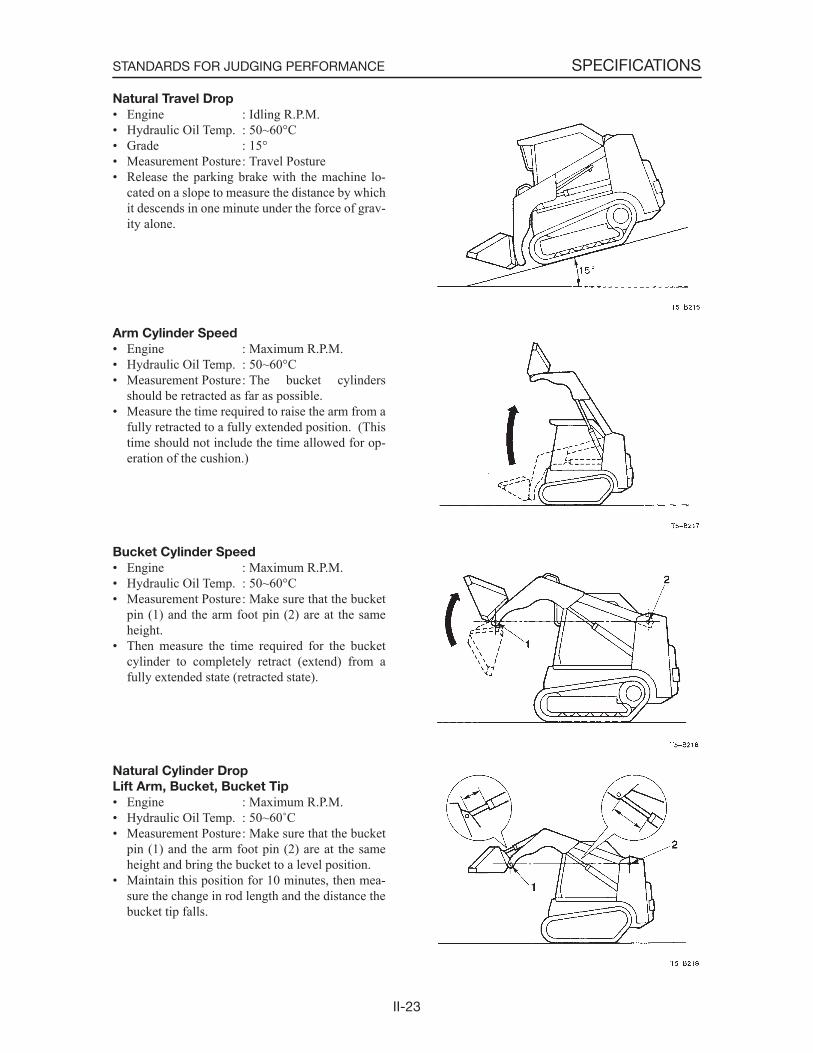
Natural Travel Drop
• Engine : Idling R.P.M.• Hydraulic Oil Temp. : 50~60°C• Grade : 15°• Measurement Posture : Travel Posture• Park the machine with the parking brake applied, and wait for one minute. Then, measure the amount of spontaneous travel drop.
Arm Cylinder Speed
• Engine : Maximum R.P.M.• Hydraulic Oil Temp. : 50~60°C• Measurement Posture : The bucket cylinders
should be retracted as far as possible.• Measure the time required to raise the arm from a
fully retracted to a fully extended position. (This time should not include the time allowed for op-eration of the cushion.)
Bucket Cylinder Speed
• Engine : Maximum R.P.M.• Hydraulic Oil Temp. : 50~60°C• Measurement Posture : Make sure that the bucket
pin (1) and the arm foot pin (2) are at the same height.
• Then measure the time required for the bucket cylinder to completely retract (extend) from a fully extended state (retracted state).
Natural Cylinder Drop
Lift Arm, Bucket, Bucket Tip
• Engine : Maximum R.P.M.• Hydraulic Oil Temp. : 50~60˚C• Measurement Posture : Make sure that the bucket
pin (1) and the arm foot pin (2) are at the same height and bring the bucket to a level position.
• Maintain this position for 10 minutes, then mea-sure the change in rod length and the distance the bucket tip falls.
II-23
SPECIFICATIONSSTANDARDS FOR JUDGING PERFORMANCE
Natural Travel Drop
• Engine : Idling R.P.M.• Hydraulic Oil Temp. : 50~60°C• Grade : 15°• Measurement Posture : Travel Posture• Release the parking brake with the machine lo-
cated on a slope to measure the distance by which it descends in one minute under the force of grav-ity alone.
Arm Cylinder Speed
• Engine : Maximum R.P.M.• Hydraulic Oil Temp. : 50~60°C• Measurement Posture : The bucket cylinders
should be retracted as far as possible.• Measure the time required to raise the arm from a
fully retracted to a fully extended position. (This time should not include the time allowed for op-eration of the cushion.)
Bucket Cylinder Speed
• Engine : Maximum R.P.M.• Hydraulic Oil Temp. : 50~60°C• Measurement Posture : Make sure that the bucket
pin (1) and the arm foot pin (2) are at the same height.
• Then measure the time required for the bucket cylinder to completely retract (extend) from a fully extended state (retracted state).
Natural Cylinder Drop
Lift Arm, Bucket, Bucket Tip
• Engine : Maximum R.P.M.• Hydraulic Oil Temp. : 50~60˚C• Measurement Posture : Make sure that the bucket
pin (1) and the arm foot pin (2) are at the same height and bring the bucket to a level position.
• Maintain this position for 10 minutes, then mea-sure the change in rod length and the distance the bucket tip falls.
II-24
SPECIFICATIONSSTANDARDS FOR JUDGING PERFORMANCE
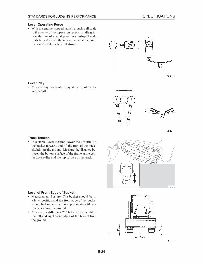
Lever Operating Force
• With the engine stopped, attach a push-pull scale to the center of the operation lever s handle grip, or in the case of a pedal, position a push-pull scale to its tip and record the measurement at the point the lever/pedal reaches full stroke.
Lever Play
• Measure any discernible play at the tip of the le-ver (pedal).
Track Tension
• In a stable, level location, lower the lift arm, tilt the bucket forward, and lift the front of the tracks slightly off the ground. Measure the distance be-tween the bottom surface of the frame at the cen-ter track roller and the top surface of the track.
Level of Front Edge of Bucket
• Measurement Posture: The bucket should be in a level position and the front edge of the bucket should be fixed so that it is approximately 20 cen-timeters above the ground.
• Measure the difference “C” between the height of the left and right front edges of the bucket from the ground.
III-1
III . MACHINE CONFIGURATION

III-2
MACHINE CONFIGURATION
CONTENTS
Drive System ...........................................................................................................................................................3Travel System .......................................................................................................................................................16Frame ....................................................................................................................................................................22Control System......................................................................................................................................................34Attachments ..........................................................................................................................................................37Hydraulic System ..................................................................................................................................................46Electrical System ..................................................................................................................................................51Air Conditioner System ........................................................................................................................................54
III-3
MACHINE CONFIGURATIONDRIVE SYSTEM
DRIVE SYSTEM
CONSTRUCTION
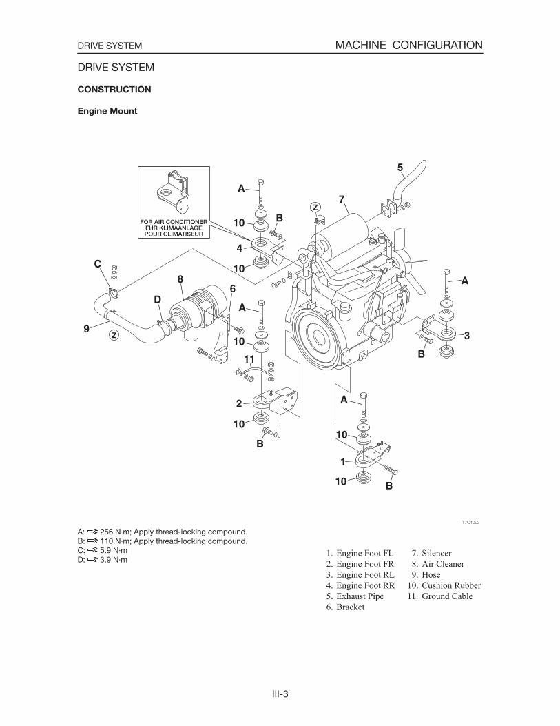
Engine Mount
A: 256 N·m; Apply thread-locking compound.B: 110 N·m; Apply thread-locking compound.C: 5.9 N·mD: 3.9 N·m
1. Engine Foot FL 2. Engine Foot FR 3. Engine Foot RL 4. Engine Foot RR 5. Exhaust Pipe 6. Bracket
7. Silencer 8. Air Cleaner 9. Hose10. Cushion Rubber11. Ground Cable
III-4
MACHINE CONFIGURATIONDRIVE SYSTEM
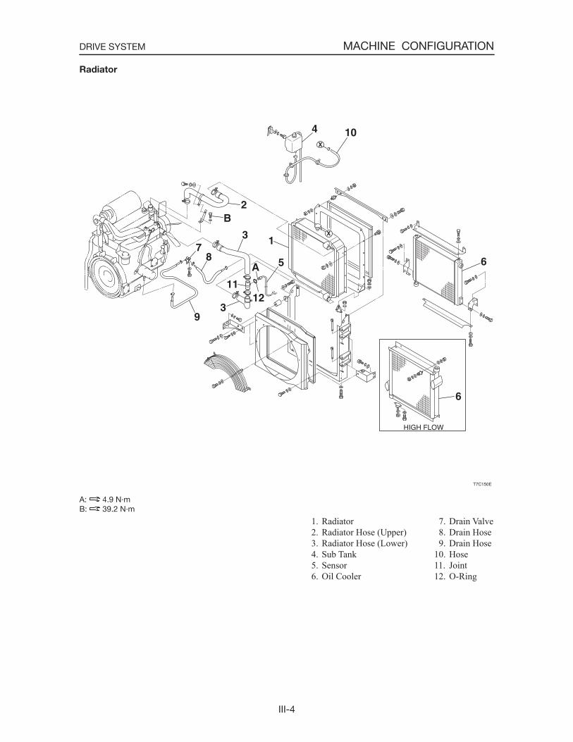
Radiator
A: 4.9 N·mB: 39.2 N·m
1. Radiator 2. Radiator Hose (Upper) 3. Radiator Hose (Lower) 4. Sub Tank 5. Sensor 6. Oil Cooler
7. Drain Valve 8. Drain Hose 9. Drain Hose10. Hose11. Joint12. O-Ring
III-5
MACHINE CONFIGURATIONDRIVE SYSTEM
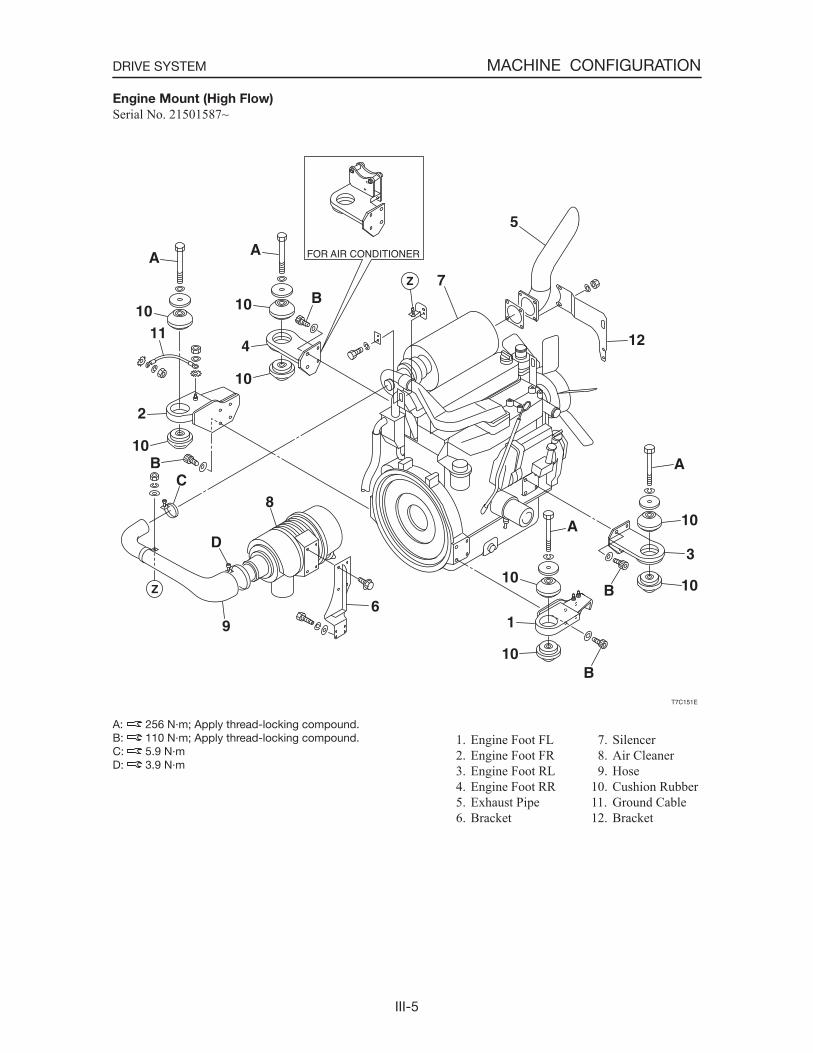
Engine Mount (High Flow)
Serial No. 21501587~
A: 256 N·m; Apply thread-locking compound.B: 110 N·m; Apply thread-locking compound.C: 5.9 N·mD: 3.9 N·m
1. Engine Foot FL 2. Engine Foot FR 3. Engine Foot RL 4. Engine Foot RR 5. Exhaust Pipe 6. Bracket
7. Silencer 8. Air Cleaner 9. Hose10. Cushion Rubber11. Ground Cable12. Bracket
III-6
MACHINE CONFIGURATIONDRIVE SYSTEM
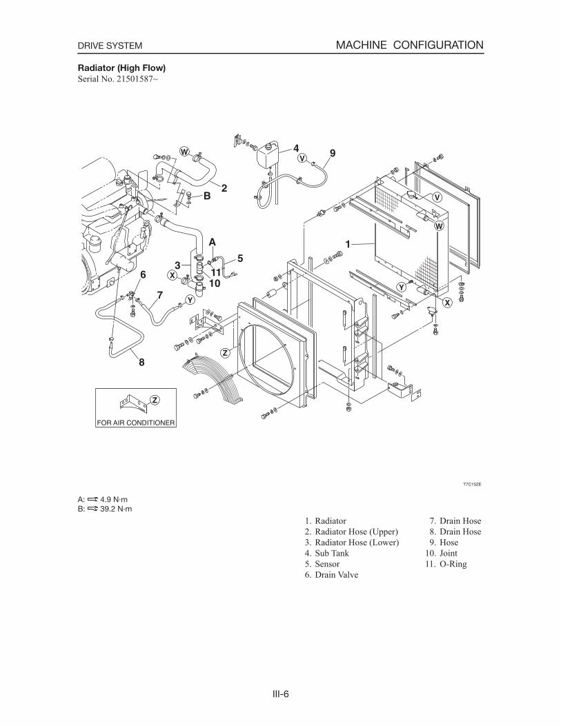
Radiator (High Flow)
Serial No. 21501587~
A: 4.9 N·mB: 39.2 N·m
1. Radiator 2. Radiator Hose (Upper) 3. Radiator Hose (Lower) 4. Sub Tank 5. Sensor 6. Drain Valve
7. Drain Hose 8. Drain Hose 9. Hose10. Joint11. O-Ring
III-7
MACHINE CONFIGURATIONDRIVE SYSTEM
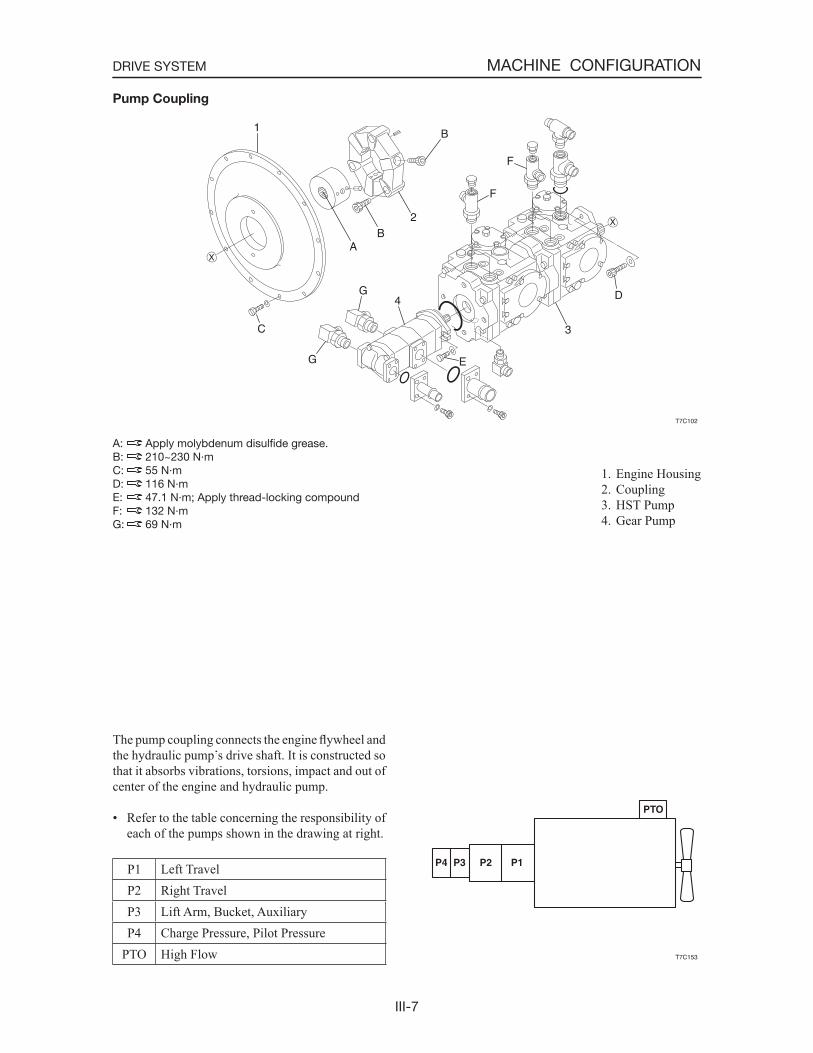
1. Engine Housing 2. Coupling 3. HST Pump 4. Gear Pump
Pump Coupling
A: Apply molybdenum disulfide grease.B: 210~230 N·mC: 55 N·mD: 116 N·mE: 47.1 N·m; Apply thread-locking compoundF: 132 N·mG: 69 N·m
The pump coupling connects the engine flywheel and the hydraulic pump s drive shaft. It is constructed so that it absorbs vibrations, torsions, impact and out of center of the engine and hydraulic pump.
• Refer to the table concerning the responsibility of each of the pumps shown in the drawing at right.
P1 Left TravelP2 Right TravelP3 Lift Arm, Bucket, AuxiliaryP4 Charge Pressure, Pilot Pressure
PTO High Flow
T7C102
X
X
1
C
G
G
4
E
3
D
F
F
B
B2
A
III-8
MACHINE CONFIGURATIONDRIVE SYSTEM
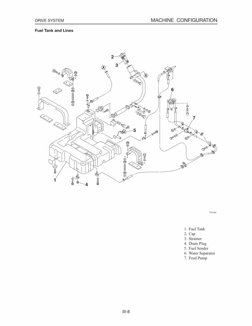
1. Fuel Tank 2. Cap 3. Strainer 4. Drain Plug 5. Fuel Sender 6. Water Separator 7. Feed Pump
Fuel Tank and Lines
III-9
MACHINE CONFIGURATIONDRIVE SYSTEM
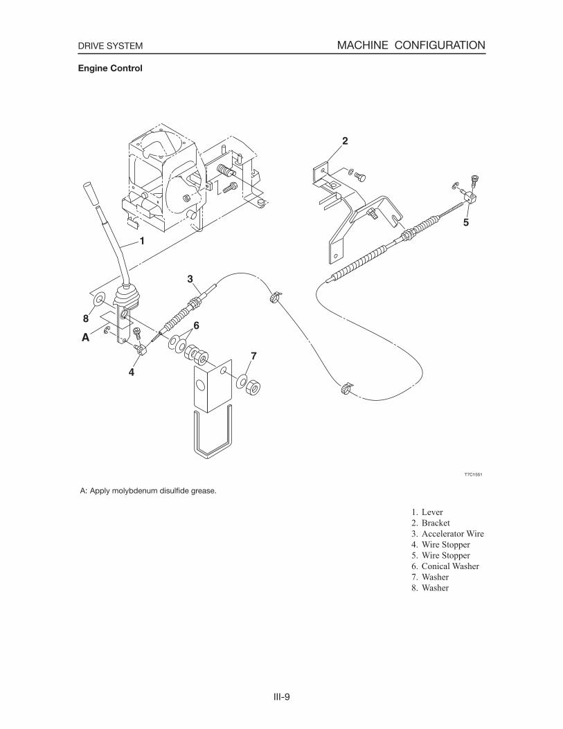
1. Lever 2. Bracket 3. Accelerator Wire 4. Wire Stopper 5. Wire Stopper 6. Conical Washer 7. Washer 8. Washer
Engine Control
A: Apply molybdenum disulfide grease.
III-10
MACHINE CONFIGURATIONDRIVE SYSTEM
DISASSEMBLY AND ASSEMBLY
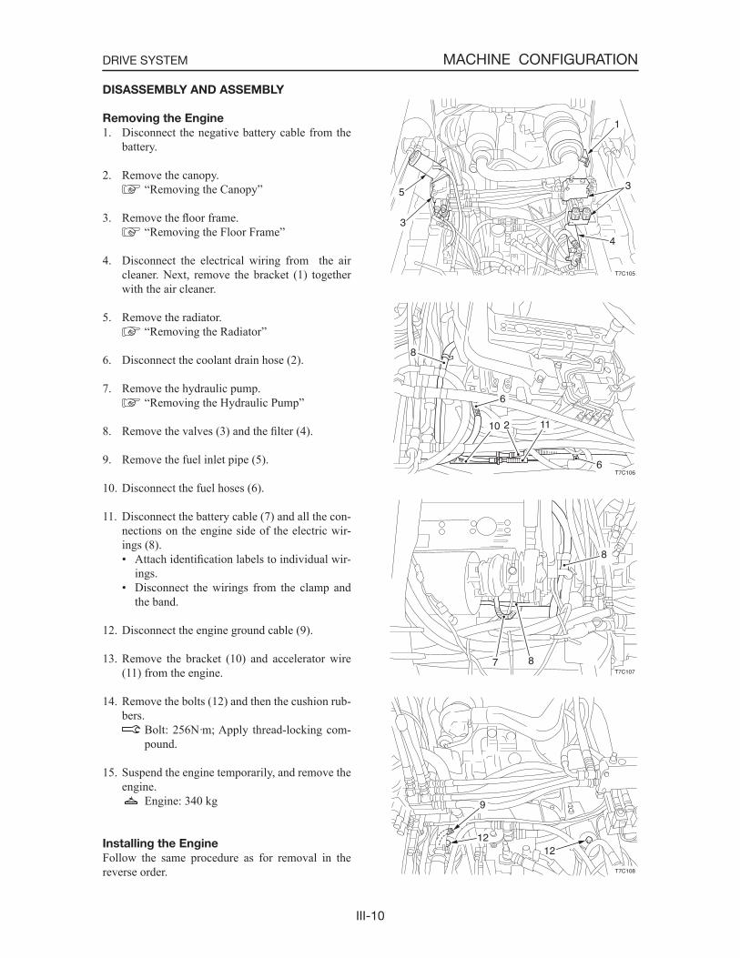
Removing the Engine
1. Disconnect the negative battery cable from the battery.
2. Remove the canopy. “Removing the Canopy”
3. Remove the floor frame. “Removing the Floor Frame”
4. Disconnect the electrical wiring from the air cleaner. Next, remove the bracket (1) together with the air cleaner.
5. Remove the radiator. “Removing the Radiator”
6. Disconnect the coolant drain hose (2).
7. Remove the hydraulic pump. “Removing the Hydraulic Pump”
8. Remove the valves (3) and the filter (4).
9. Remove the fuel inlet pipe (5).
10. Disconnect the fuel hoses (6).
11. Disconnect the battery cable (7) and all the con-nections on the engine side of the electric wir-ings (8).• Attach identification labels to individual wir-
ings.• Disconnect the wirings from the clamp and
the band.
12. Disconnect the engine ground cable (9).
13. Remove the bracket (10) and accelerator wire (11) from the engine.
14. Remove the bolts (12) and then the cushion rub-bers.
Bolt: 256N·m; Apply thread-locking com-pound.
15. Suspend the engine temporarily, and remove the engine.
Engine: 340 kg
Installing the Engine
Follow the same procedure as for removal in the reverse order.
T7C105
5
3
1
3
4
T7C1066
112
6
10
8
T7C1077 8
8
T7C108
9
1212
III-11
MACHINE CONFIGURATIONDRIVE SYSTEM
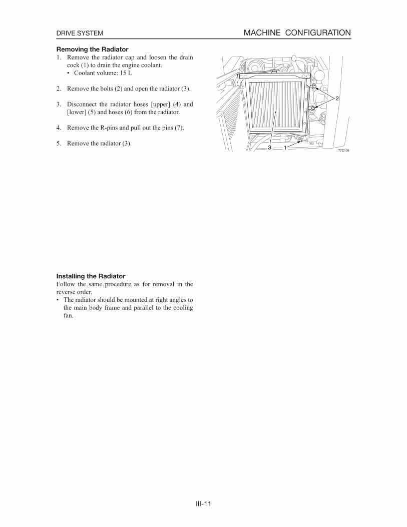
Removing the Radiator
1. Remove the radiator cap and loosen the drain cock (1) to drain the engine coolant.• Coolant volume: 15 L
2. Remove the bolts (2) and open the radiator (3).
3. Disconnect the radiator hoses [upper] (4) and [lower] (5) and hoses (6) from the radiator.
4. Remove the R-pins and pull out the pins (7).
5. Remove the radiator (3).
Installing the Radiator
Follow the same procedure as for removal in the reverse order.• The radiator should be mounted at right angles to
the main body frame and parallel to the cooling fan.
T7C1093 1
2
III-12
MACHINE CONFIGURATIONDRIVE SYSTEM
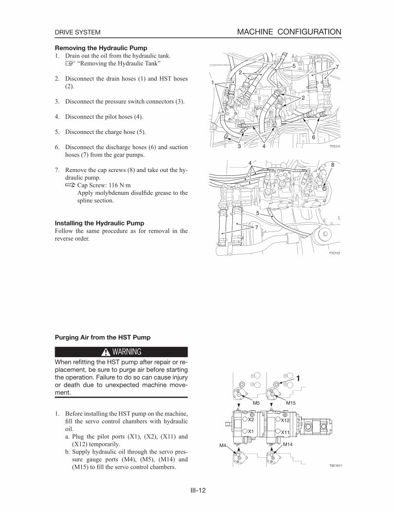
Removing the Hydraulic Pump
1. Drain out the oil from the hydraulic tank. “Removing the Hydraulic Tank”
2. Disconnect the drain hoses (1) and HST hoses (2).
3. Disconnect the pressure switch connectors (3).
4. Disconnect the pilot hoses (4).
5. Disconnect the charge hose (5).
6. Disconnect the discharge hoses (6) and suction hoses (7) from the gear pumps.
7. Remove the cap screws (8) and take out the hy-draulic pump.
Cap Screw: 116 N·m Apply molybdenum disulfide grease to the
spline section.
Installing the Hydraulic Pump
Follow the same procedure as for removal in the reverse order.
Purging Air from the HST Pump
WARNINGWhen refitting the HST pump after repair or re-placement, be sure to purge air before starting the operation. Failure to do so can cause injury or death due to unexpected machine move-ment.
1. Before installing the HST pump on the machine, fill the servo control chambers with hydraulic oil.a. Plug the pilot ports (X1), (X2), (X11) and
(X12) temporarily.b. Supply hydraulic oil through the servo pres-
sure gauge ports (M4), (M5), (M14) and (M15) to fill the servo control chambers.
T7C111
7
2
6
43
1
25
T7C112
84
7
5
III-13
MACHINE CONFIGURATIONDRIVE SYSTEM
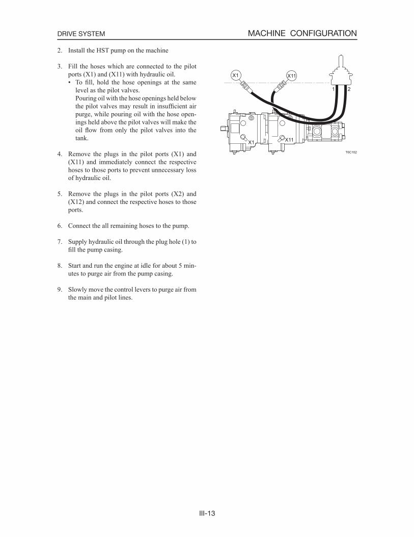
2. Install the HST pump on the machine
3. Fill the hoses which are connected to the pilot ports (X1) and (X11) with hydraulic oil.• To fill, hold the hose openings at the same
level as the pilot valves. Pouring oil with the hose openings held below
the pilot valves may result in insufficient air purge, while pouring oil with the hose open-ings held above the pilot valves will make the oil flow from only the pilot valves into the tank.
4. Remove the plugs in the pilot ports (X1) and (X11) and immediately connect the respective hoses to those ports to prevent unnecessary loss of hydraulic oil.
5. Remove the plugs in the pilot ports (X2) and (X12) and connect the respective hoses to those ports.
6. Connect the all remaining hoses to the pump.
7. Supply hydraulic oil through the plug hole (1) to fill the pump casing.
8. Start and run the engine at idle for about 5 min-utes to purge air from the pump casing.
9. Slowly move the control levers to purge air from the main and pilot lines.
T6C102
21
X1
X1
X11
X11
III-14
MACHINE CONFIGURATIONDRIVE SYSTEM
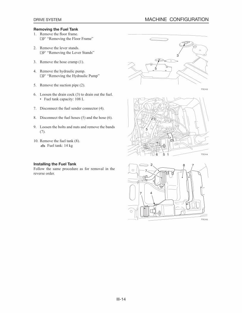
Removing the Fuel Tank
1. Remove the floor frame. “Removing the Floor Frame”
2. Remove the lever stands. “Removing the Lever Stands”
3. Remove the hose cramp (1).
4. Remove the hydraulic pump. “Removing the Hydraulic Pump”
5. Remove the suction pipe (2).
6. Loosen the drain cock (3) to drain out the fuel.• Fuel tank capacity: 108 L
7. Disconnect the fuel sender connector (4).
8. Disconnect the fuel hoses (5) and the hose (6).
9. Loosen the bolts and nuts and remove the bands (7).
10. Remove the fuel tank (8). Fuel tank: 14 kg
Installing the Fuel Tank
Follow the same procedure as for removal in the reverse order.
T7C113
3
5
T7C114
5
6 5 1
T7C115
7 4
7
2 8 7
III-15
MACHINE CONFIGURATIONDRIVE SYSTEM
INSPECTION AND ADJUSTMENT
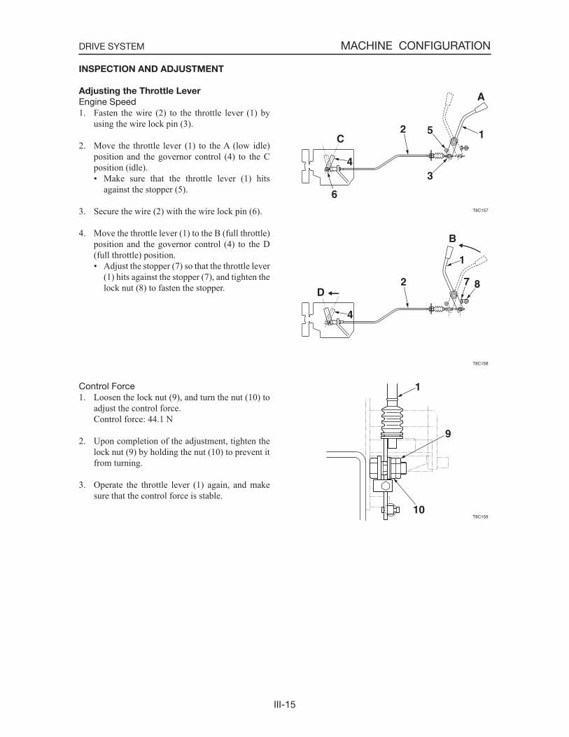
Adjusting the Throttle Lever
Engine Speed1. Fasten the wire (2) to the throttle lever (1) by
using the wire lock pin (3).
2. Move the throttle lever (1) to the A (low idle) position and the governor control (4) to the C position (idle).• Make sure that the throttle lever (1) hits
against the stopper (5).
3. Secure the wire (2) with the wire lock pin (6).
4. Move the throttle lever (1) to the B (full throttle) position and the governor control (4) to the D (full throttle) position.• Adjust the stopper (7) so that the throttle lever
(1) hits against the stopper (7), and tighten the lock nut (8) to fasten the stopper.
Control Force1. Loosen the lock nut (9), and turn the nut (10) to
adjust the control force. Control force: 44.1 N
2. Upon completion of the adjustment, tighten the lock nut (9) by holding the nut (10) to prevent it from turning.
3. Operate the throttle lever (1) again, and make sure that the control force is stable.

III-16
MACHINE CONFIGURATIONTRAVEL SYSTEM
TRAVEL SYSTEM
CONSTRUCTION
Track Roller A
1. Roller 2. Shaft 3. Cover 4. Floating Seal 5. Snap Ring 6. O-ring 7. Oil Filler Plug
A: 241 N·m; Apply thread-locking compound.
Track Roller B
1. Roller 2. Shaft 3. Cover 4. Floating Seal 5. Snap Ring 6. O-ring 7. Oil Filler Plug
A: 241 N·m; Apply thread-locking compound.
III-17
MACHINE CONFIGURATIONTRAVEL SYSTEM
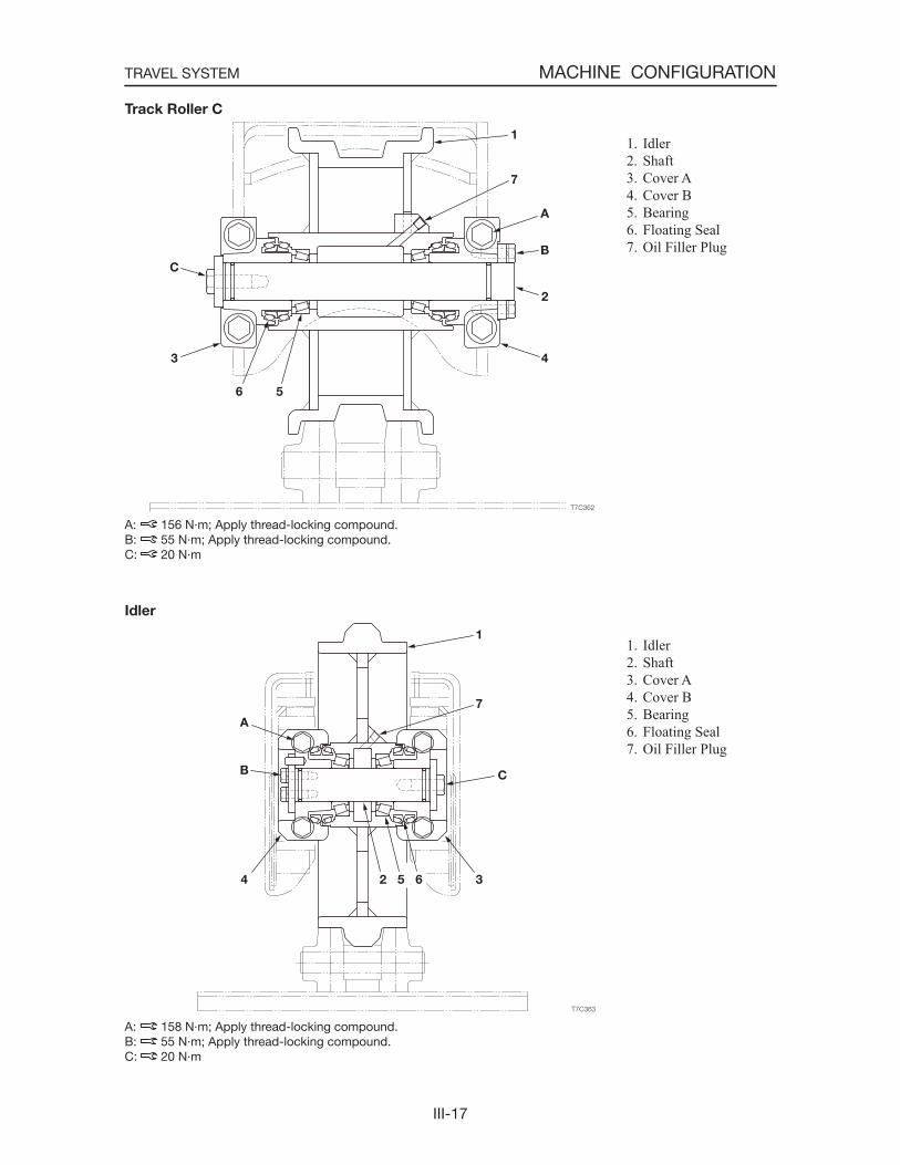
Track Roller C
1. Idler 2. Shaft 3. Cover A 4. Cover B 5. Bearing 6. Floating Seal 7. Oil Filler Plug
A: 156 N·m; Apply thread-locking compound.B: 55 N·m; Apply thread-locking compound.C: 20 N·m
Idler
1. Idler 2. Shaft 3. Cover A 4. Cover B 5. Bearing 6. Floating Seal 7. Oil Filler Plug
A: 158 N·m; Apply thread-locking compound.B: 55 N·m; Apply thread-locking compound.C: 20 N·m
III-18
MACHINE CONFIGURATIONTRAVEL SYSTEM
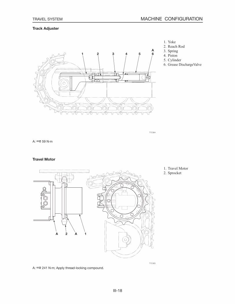
Track Adjuster
1. Yoke 2. Reach Rod 3. Spring 4. Piston 5. Cylinder 6. Grease DischargeValve
A: 59 N·m
Travel Motor
1. Travel Motor 2. Sprocket
A: 241 N·m; Apply thread-locking compound.

III-19
MACHINE CONFIGURATIONTRAVEL SYSTEM
DISASSEMBLY AND ASSEMBLY
Removing the Steel Track
Stop the machine so that the master links are positioned at the top of the idler.
1. Loosen the track tension. When loosening the grease discharge valve (1),
turn it slowly. Do not loosen it beyond the point where grease starts to ooze out. If it is difficultfor the grease to come out, move the machine forward and in reverse.
Grease discharge valve: 59 N·m
2. Remove the master bolts (2) and disconnect the master links (3).
3. Place the wooden blocks (4) with a height of 20 cm under the cutting edge of the bucket and tilt the bucket forward and lower the lift arms to raise the machine front.
4. Suspend the machine rear and place a block (5) under the machine rear.
5. Rotate the travel motor slowly in the reverse direction to remove the track
Track: 401 kg
Installing the Steel Track
1. Place the wooden blocks (3) with a height of 20 cm under the cutting edge of the bucket and tilt the bucket forward and lower the lift arms to raise the machine front.
2. Suspend the machine rear and place a block (4) under the machine rear.
3. Position the track beneath the frame.• Be careful not to mistake the installation di-
rection of the track.
4. Engage the links in the sprocket, then rotate the travel motor slowly in the forward direction to wrap the track around the frame.
5. When the master link reachs a point just to the top of the idler, stop rotating the sprocket and lower the machine to the ground.
6. Connect the master links and install the shoe plate and the master bolts.
Master bolt: 225±10 N·m
7. Adjust the track tension. “II. Specifications, Standards for Judging Performance”
III-20
MACHINE CONFIGURATIONTRAVEL SYSTEM
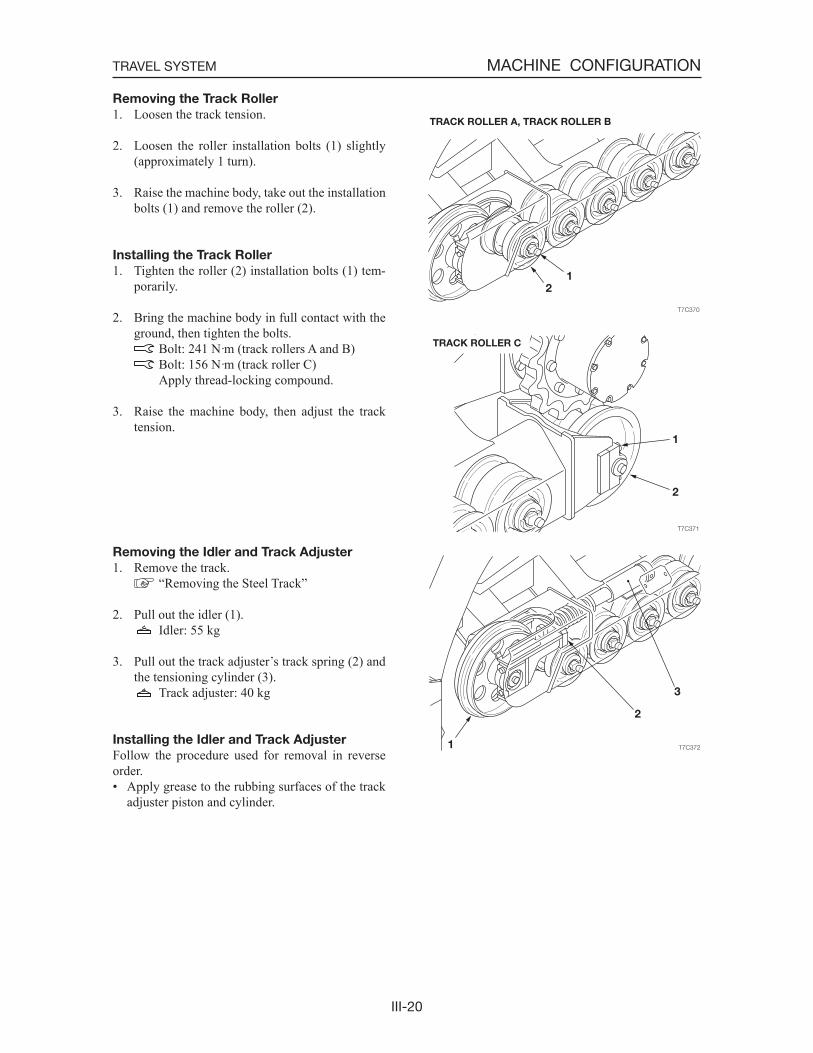
Removing the Track Roller
1. Loosen the track tension.
2. Loosen the roller installation bolts (1) slightly (approximately 1 turn).
3. Raise the machine body, take out the installation bolts (1) and remove the roller (2).
Installing the Track Roller
1. Tighten the roller (2) installation bolts (1) tem-porarily.
2. Bring the machine body in full contact with the ground, then tighten the bolts.
Bolt: 241 N·m (track rollers A and B) Bolt: 156 N·m (track roller C)
Apply thread-locking compound.
3. Raise the machine body, then adjust the track tension.
Removing the Idler and Track Adjuster
1. Remove the track. “Removing the Steel Track”
2. Pull out the idler (1). Idler: 55 kg
3. Pull out the track adjuster s track spring (2) and the tensioning cylinder (3).
Track adjuster: 40 kg
Installing the Idler and Track Adjuster
Follow the procedure used for removal in reverse order.• Apply grease to the rubbing surfaces of the track
adjuster piston and cylinder.
III-21
MACHINE CONFIGURATIONTRAVEL SYSTEM
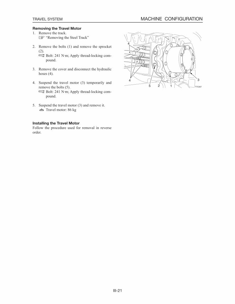
Removing the Travel Motor
1. Remove the track. “Removing the Steel Track”
2. Remove the bolts (1) and remove the sprocket (2).
Bolt: 241 N·m; Apply thread-locking com-pound.
3. Remove the cover and disconnect the hydraulic hoses (4).
4. Suspend the travel motor (3) temporarily and remove the bolts (5).
Bolt: 241 N·m; Apply thread-locking com-pound.
5. Suspend the travel motor (3) and remove it. Travel motor: 86 kg
Installing the Travel Motor
Follow the procedure used for removal in reverse order.
T7C307
3
125
4
4
III-22
MACHINE CONFIGURATIONFRAME
FRAME
CONSTRUCTION
Frame
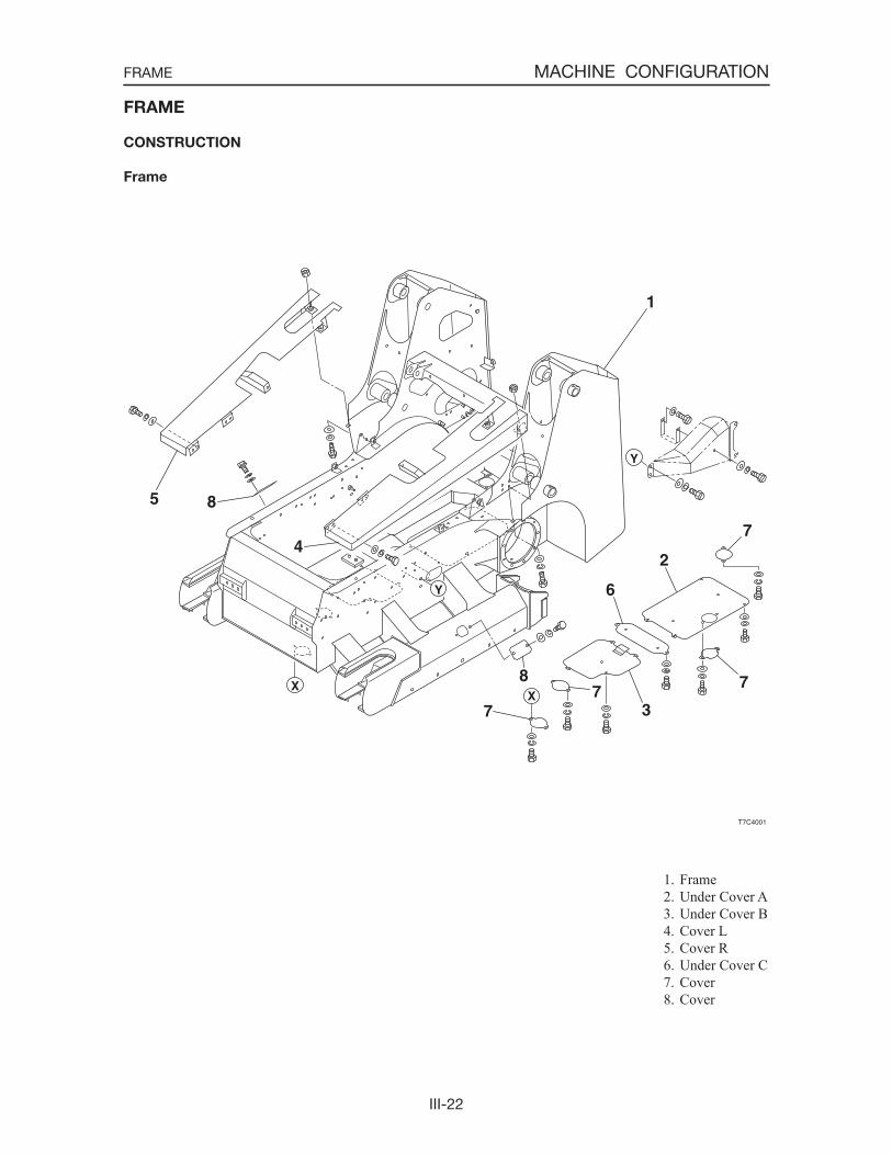
1. Frame 2. Under Cover A 3. Under Cover B 4. Cover L 5. Cover R 6. Under Cover C 7. Cover 8. Cover
III-23
MACHINE CONFIGURATIONFRAME
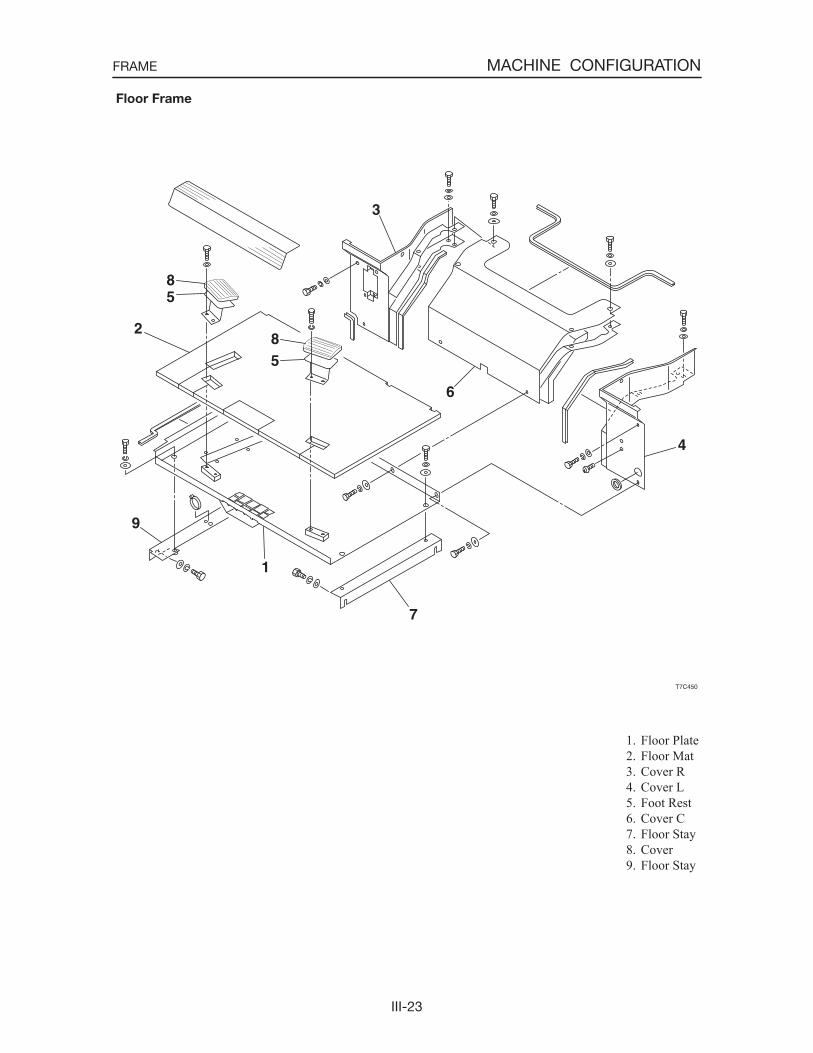
1. Floor Plate 2. Floor Mat 3. Cover R 4. Cover L 5. Foot Rest 6. Cover C 7. Floor Stay 8. Cover 9. Floor Stay
Floor Frame
III-24
MACHINE CONFIGURATIONFRAME
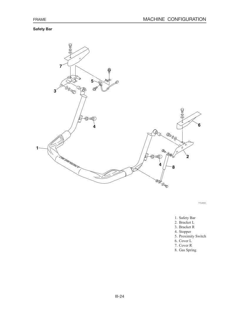
1. Safety Bar 2. Bracket L 3. Bracket R 4. Stopper 5. Proximity Switch 6. Cover L 7. Cover R 8. Gas Spring
Safety Bar
III-25
MACHINE CONFIGURATIONFRAME
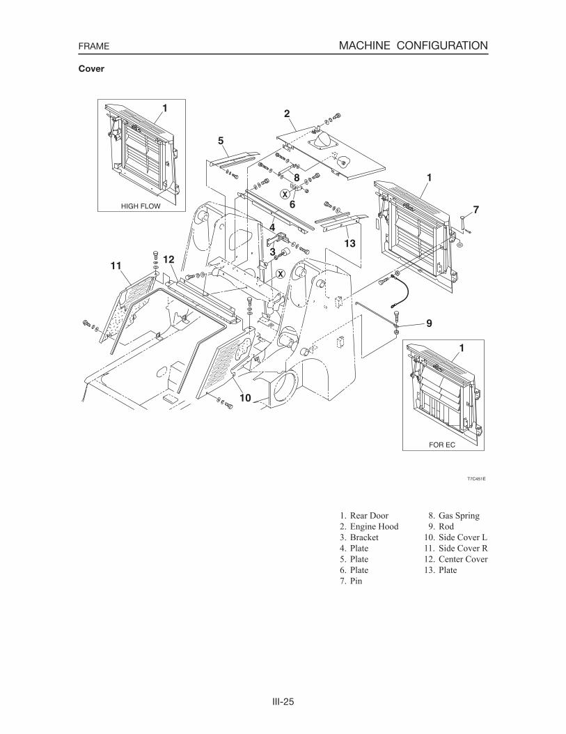
1. Rear Door 2. Engine Hood 3. Bracket 4. Plate 5. Plate 6. Plate 7. Pin
Cover
8. Gas Spring 9. Rod10. Side Cover L11. Side Cover R12. Center Cover13. Plate
III-26
MACHINE CONFIGURATIONFRAME
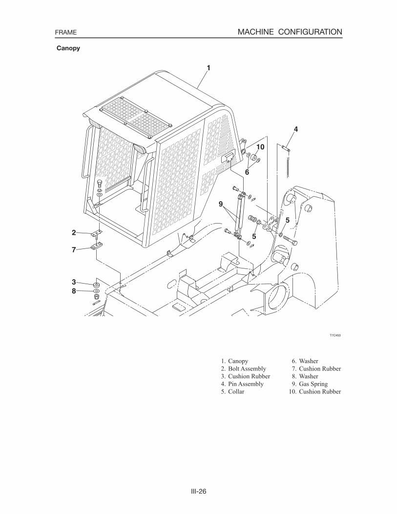
1. Canopy 2. Bolt Assembly 3. Cushion Rubber 4. Pin Assembly 5. Collar
Canopy
6. Washer 7. Cushion Rubber 8. Washer 9. Gas Spring10. Cushion Rubber
III-27
MACHINE CONFIGURATIONFRAME
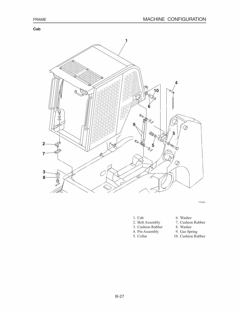
1. Cab 2. Bolt Assembly 3. Cushion Rubber 4. Pin Assembly 5. Collar
Cab
6. Washer 7. Cushion Rubber 8. Washer 9. Gas Spring10. Cushion Rubber
III-28
MACHINE CONFIGURATIONFRAME
T9C407
B A
B
T9C408
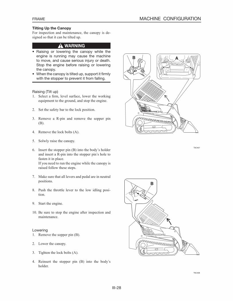
Tilting Up the Canopy
For inspection and maintenance, the canopy is de-signed so that it can be tilted up.
WARNING
• Raising or lowering the canopy while the engine is running may cause the machine to move, and cause serious injury or death. Stop the engine before raising or lowering the canopy.
• When the canopy is tilted up, support it firmly with the stopper to prevent it from falling.
Raising (Tilt up)1. Select a firm, level surface, lower the working
equipment to the ground, and stop the engine.
2. Set the safety bar to the lock position.
3. Remove a R-pin and remove the sopper pin (B).
4. Remove the lock bolts (A).
5. Solwly raise the canopy.
6. Insert the stopper pin (B) into the body s holder and insert a R-pin into the stopper pin s hole to fasten it in place.
If you need to run the engine while the canopy is raised follow these steps.
7. Make sure that all levers and pedal are in neutral positions.
8. Push the throttle lever to the low idling posi-tion.
9. Start the engine.
10. Be sure to stop the engine after inspection and maintenance.
Lowering1. Remove the sopper pin (B).
2. Lower the canopy.
3. Tighten the lock bolts (A).
4. Reinsert the stopper pin (B) into the body sholder.
III-29
MACHINE CONFIGURATIONFRAME
1
2
3
4
5
T7C405
T7C406
9
7
6
8
DISASSEMBLY AND ASSEMBLY
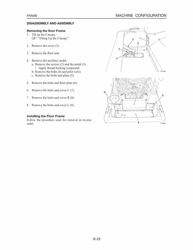
Removing the floor Frame
1. Tilt up the Canopy. “Tilting Up the Canopy”
2. Remove the cover (1).
3. Remove the floor mat.
4. Remove the auxiliary pedal.a. Remove the screws (2) and the pedal (3).
• Apply thread-locking compound.b. Remove the bolts (4) and pilot valve.c. Remove the bolts and plate (5).
5. Remove the bolts and floor plate (6).
6. Remove the bolts and cover C (7).
7. Remove the bolts and cover R (8).
8. Remove the bolts and cover L (9).
Installing the Floor Frame
Follow the procedure used for removal in reverse order.
III-30
MACHINE CONFIGURATIONFRAME
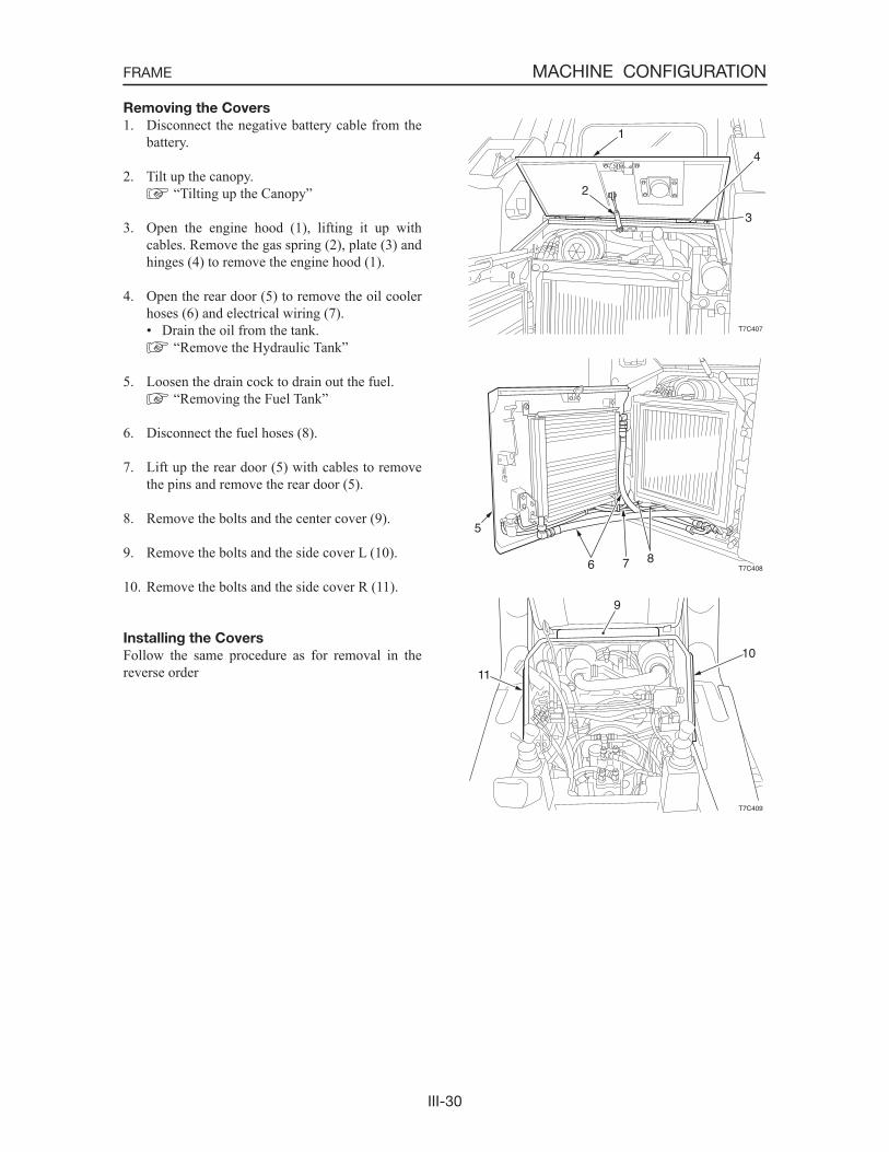
Removing the Covers
1. Disconnect the negative battery cable from the battery.
2. Tilt up the canopy. “Tilting up the Canopy”
3. Open the engine hood (1), lifting it up with cables. Remove the gas spring (2), plate (3) and hinges (4) to remove the engine hood (1).
4. Open the rear door (5) to remove the oil cooler hoses (6) and electrical wiring (7).• Drain the oil from the tank.
“Remove the Hydraulic Tank”
5. Loosen the drain cock to drain out the fuel. “Removing the Fuel Tank”
6. Disconnect the fuel hoses (8).
7. Lift up the rear door (5) with cables to remove the pins and remove the rear door (5).
8. Remove the bolts and the center cover (9).
9. Remove the bolts and the side cover L (10).
10. Remove the bolts and the side cover R (11).
Installing the Covers
Follow the same procedure as for removal in the reverse order
T7C407
1
2
4
3
T7C408
5
6 7 8
T7C409
9
11
10

III-31
MACHINE CONFIGURATIONFRAME
Removing the Canopy.
1. Disconnect the negative battery cable from the battery.
2. Raise the lift arms. “Lift Arm Stop”
3. Remove the fixing bolts on the 2 front positions (A).
4. Suspend the canopy.• Hook the suspender on the handrail ahead of
the canopy.
5. Disconnect the electric wiring (1) for the cano-py.
6. Remove the gas springs (2) and installation pins.
7. Lower the canopy and the lift arms to the ground.
8. Remove the fixing bolts on the 2 rear positions (B).
9. Suspend the canopy and remove it.• Re-hook the suspender on the center of the
canopy to suspend the canopy at level. Canopy: Approx. 150 kg
10. Remove the cushion rubber between the cano-py.
Installing the Canopy
Follow the same procedure as for removal in the reverse order.
T7C410
B
A
T7C411
21
T7C412
B

III-32
MACHINE CONFIGURATIONFRAME
Lift Arm Stop
WARNING
• If you must work beneath the raised lift arms, securely engage the lift arm stop. Never get under the lift arms and bucket if they are not sufficiently supported.
• Service the lift arm stop if damaged or if parts are missing. Using a damaged lift arm stop or with missing parts can cause the lift arms to drop causing injury or death.
Maintenance and service work can be done with the lift arms lowered. If the lift arms are raised, use the following procedures to engage and disengage an approved lift arm stop.
Engagement1. Park the machine on level ground and remove
the bucket.
2. Lower the lift arms to the ground and stop the engine.
3. Remove the rear R-pin (4) from the locking pin (1).
4. Support the lift arm stop (2) by hand and pull out the locking pin (1).
5. Check that the spring (3) moves freely (i.e., is disengaged from the hook (5)) and place the lift arm stop (2) on the cylinder.
6. Sit in the seat, fasten the seat belt, start the en-gine and lower the safety bar.
7. Raise the lift arms slowly until the lift arm stop (2) drops onto the cylinder rod.
8. Lower the lift arms slowly until the lift arm stop is held between the lift arm and the end of the cylinder tube.
9. Stop the engine.
10. Install the locking pin (1) into the rear of the lift arm stop (2) below the cylinder rod.
11. Install the R-pin (4) to the locking pin (1).
T9C409
12
3
4
T9C410
2
35
T9C411
1
24

III-33
MACHINE CONFIGURATIONFRAME
Disengagement1. Remove the rear R-pin (4) from the locking pin
(1).
2. Pull out the locking pin (1) from the lift arm stop (2).
3. Hook the end part of the spring (3) onto the hook (5) of the lift arm stop (2).
4. Sit in the seat, fasten the seat belt, start the en-gine and lower the safety bar.
5. Raise the lift arms slowly until the spring (3) will lift the lift arm stop (2) off the cylinder rod.
6. Lower the lift arms slowly to the ground and stop the engine.
7. Raise the lift arm stop (2) into storage position and insert the locking pin (1) through lift arm stop and bracket.
8. Install the R-pin (4) to the locking pin (1).
T9C412
12
3 4
5
T9C413
1
2
4
III-34
MACHINE CONFIGURATIONCONTROL SYSTEM
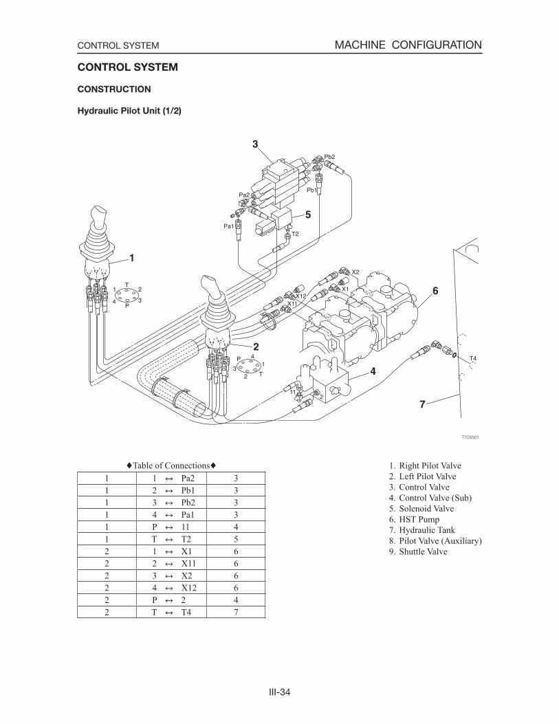
1. Right Pilot Valve 2. Left Pilot Valve 3. Control Valve 4. Control Valve (Sub) 5. Solenoid Valve 6. HST Pump 7. Hydraulic Tank 8. Pilot Valve (Auxiliary) 9. Shuttle Valve
CONTROL SYSTEM
CONSTRUCTION
Hydraulic Pilot Unit (1/2)
Table of Connections1 1 Pa2 31 2 Pb1 31 3 Pb2 31 4 Pa1 31 P 11 41 T T2 52 1 X1 62 2 X11 62 3 X2 62 4 X12 62 P 2 42 T T4 7
III-35
MACHINE CONFIGURATIONCONTROL SYSTEM
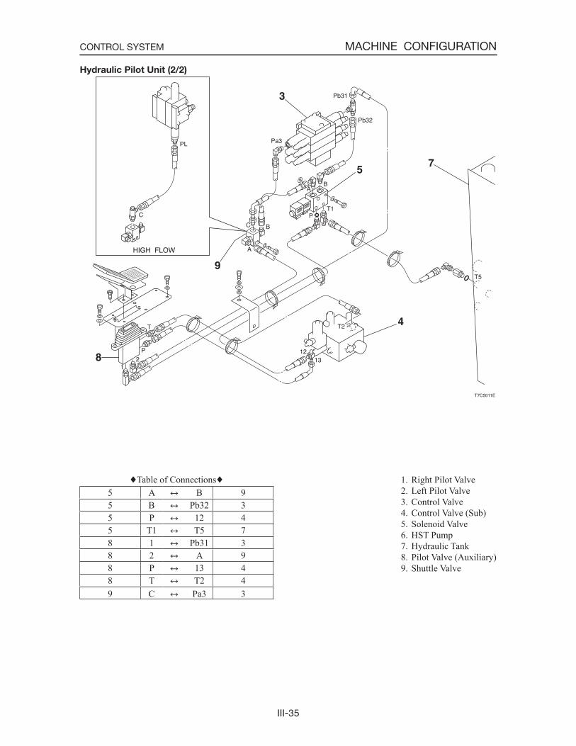
1. Right Pilot Valve 2. Left Pilot Valve 3. Control Valve 4. Control Valve (Sub) 5. Solenoid Valve 6. HST Pump 7. Hydraulic Tank 8. Pilot Valve (Auxiliary) 9. Shuttle Valve
Hydraulic Pilot Unit (2/2)
Table of Connections5 A B 95 B Pb32 35 P 12 45 T1 T5 78 1 Pb31 38 2 A 98 P 13 48 T T2 49 C Pa3 3

III-36
MACHINE CONFIGURATIONCONTROL SYSTEM
T7C502
1
23
4
T7C503
5
8
6
7
9
DISASSEMBLY AND ASSEMBLY
Removing the lever Stands
1. Tilt up the canopy. “Tilting Up the Canopy”
2. Remove the floor. “Removing the Floor Frame”
3. Remove the lever stand L.a. Remove the cover (1).b. Disconnect the hydraulic hoses (2) from the
pilot valve.• Attach identification labels to individual
hoses for correct reassembling.c. Disconnect the electric wiring (3).e. Remove the bolts and bracket L (4).
4. Remove the lever stand R.a. Remove the cover (5).b. Disconnect the electric wiring (6).c. Disconnect the hydraulic hoses (7) from the
pilot valve.• Attach identification labels to individual
hoses for correct reassembling.d. Disconnect the accelerator wire (8).e. Remove the bolts and bracket R (9).
Installing the Lever Stands
Follow the same procedure as for removal in the reverse order.
III-37
MACHINE CONFIGURATIONATTACHMENTS
ATTACHMENTS
CONSTRUCTION
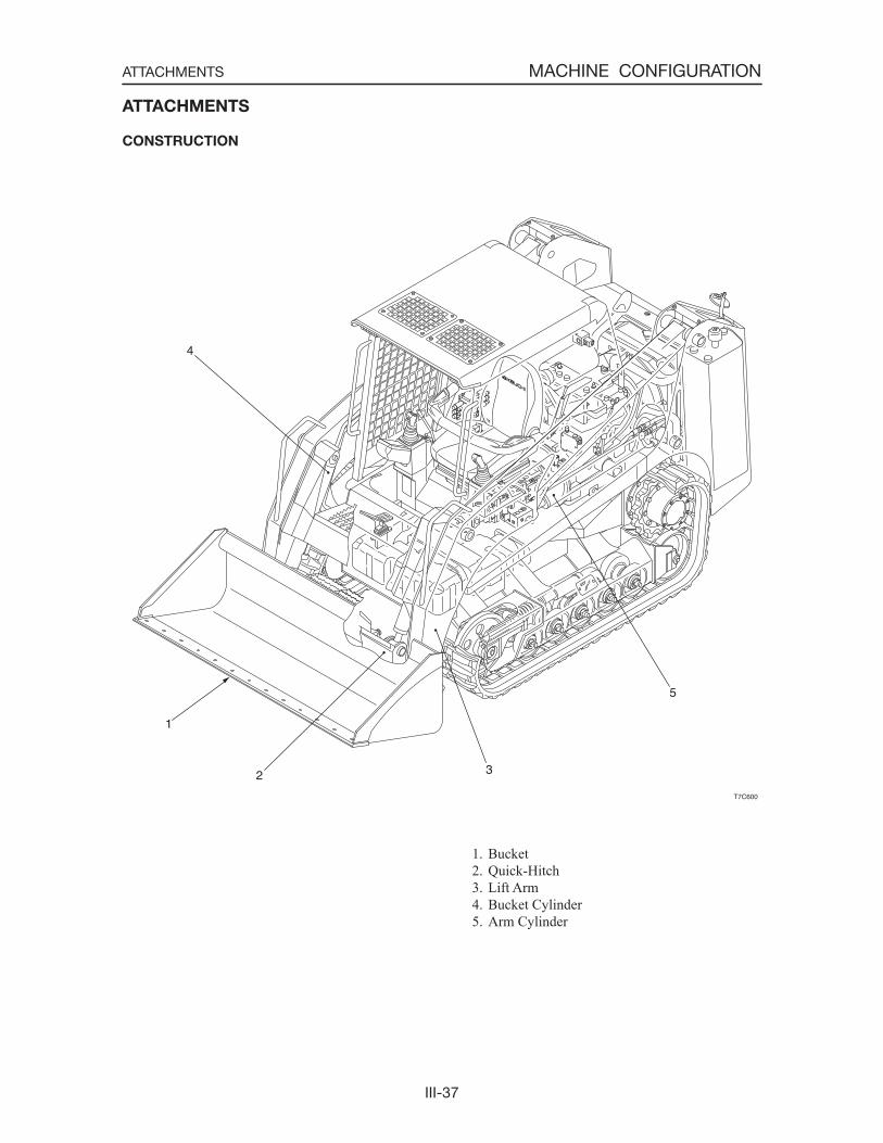
1. Bucket 2. Quick-Hitch 3. Lift Arm 4. Bucket Cylinder 5. Arm Cylinder
T7C600
5
32
1
4
III-38
MACHINE CONFIGURATIONATTACHMENTS
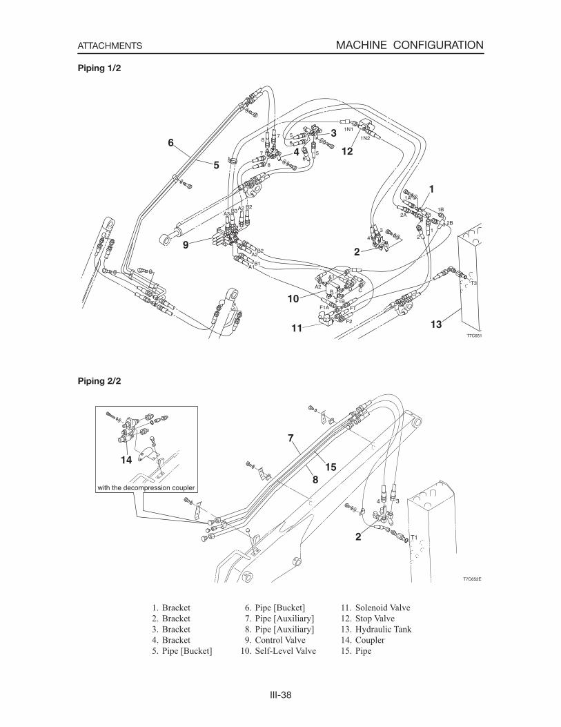
1. Bracket 2. Bracket 3. Bracket 4. Bracket 5. Pipe [Bucket]
Piping 1/2
Piping 2/2
6. Pipe [Bucket] 7. Pipe [Auxiliary] 8. Pipe [Auxiliary] 9. Control Valve10. Self-Level Valve
11. Solenoid Valve12. Stop Valve13. Hydraulic Tank14. Coupler15. Pipe

III-39
MACHINE CONFIGURATIONATTACHMENTS
1. Bracket 2. Bracket 3. Bracket 4. Bracket 5. Pipe [Bucket] 6. Pipe [Bucket]
Piping (High Flow) 1/2
Piping (High Flow) 2/2
7. Pipe [Auxiliary] 8. Pipe [Auxiliary] 9. Control Valve10. Self-Level Valve11. Solenoid Valve12. Stop Valve
13. Hydraulic Tank14. Control Valve (High Flow)15. Gear Pump (High Flow)16. Pipe
III-40
MACHINE CONFIGURATIONATTACHMENTS
T7C604
3
1 1
2 2
T7C605
6
4
5
0.5~1.0mmC4C601
DISASSEMBLY AND ASSEMBLY
General Cautions
• Always be sure to work on a stable, level sur-face.
• When disconnecting hydraulic hoses, be sure to bleed off any residual pressure in the hoses.
• Plug openings which are opened up when piping is disconnected to prevent dust and mud, etc. from getting in.
• During assembly, be sure to adjust all the parts with shims so that there will be no looseness in the mounts.
• When aligning pin hole positions, absolutely do not insert a finger in any pin holes.
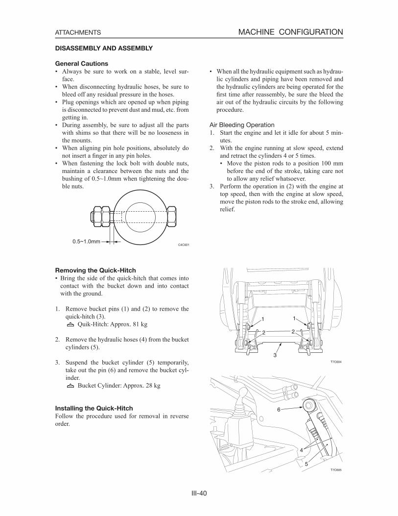
• When fastening the lock bolt with double nuts, maintain a clearance between the nuts and the bushing of 0.5~1.0mm when tightening the dou-ble nuts.
• When all the hydraulic equipment such as hydrau-lic cylinders and piping have been removed and the hydraulic cylinders are being operated for the first time after reassembly, be sure the bleed the air out of the hydraulic circuits by the following procedure.
Air Bleeding Operation1. Start the engine and let it idle for about 5 min-
utes.2. With the engine running at slow speed, extend
and retract the cylinders 4 or 5 times.• Move the piston rods to a position 100 mm
before the end of the stroke, taking care not to allow any relief whatsoever.
3. Perform the operation in (2) with the engine at top speed, then with the engine at slow speed, move the piston rods to the stroke end, allowing relief.
Removing the Quick-Hitch
• Bring the side of the quick-hitch that comes into contact with the bucket down and into contact with the ground.
1. Remove bucket pins (1) and (2) to remove the quick-hitch (3).
Quik-Hitch: Approx. 81 kg
2. Remove the hydraulic hoses (4) from the bucket cylinders (5).
3. Suspend the bucket cylinder (5) temporarily, take out the pin (6) and remove the bucket cyl-inder.
Bucket Cylinder: Approx. 28 kg
Installing the Quick-Hitch
Follow the procedure used for removal in reverse order.
III-41
MACHINE CONFIGURATIONATTACHMENTS
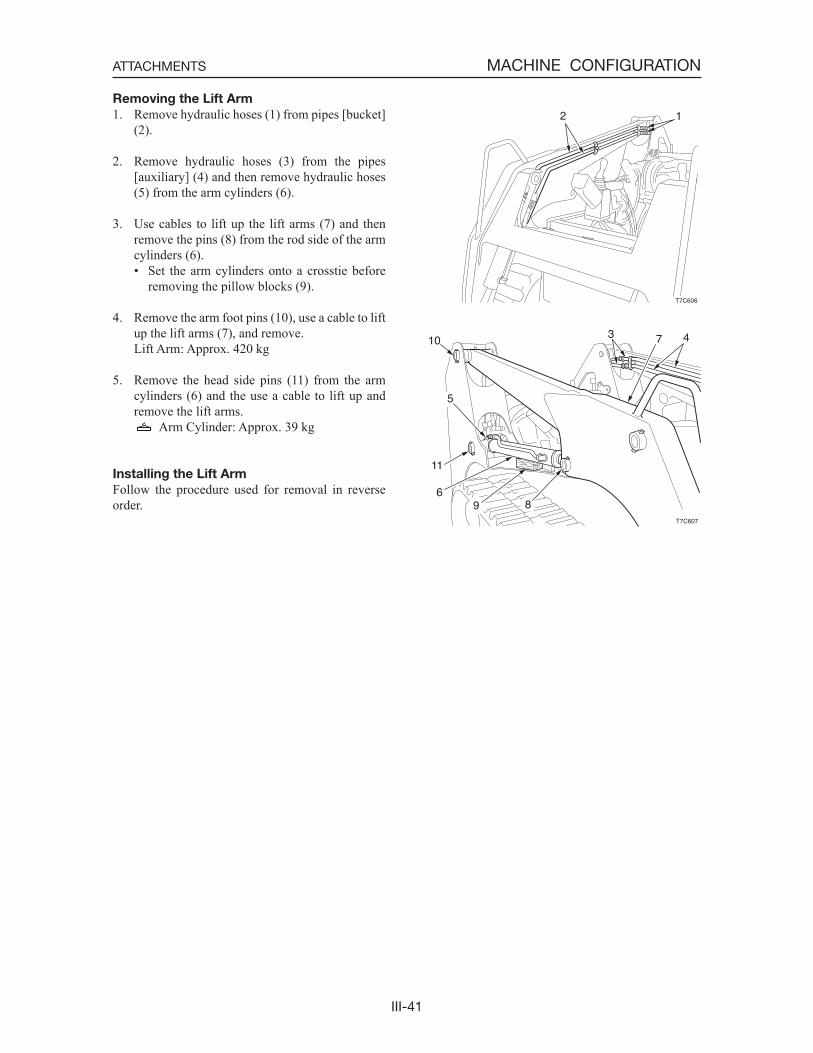
Removing the Lift Arm
1. Remove hydraulic hoses (1) from pipes [bucket] (2).
2. Remove hydraulic hoses (3) from the pipes [auxiliary] (4) and then remove hydraulic hoses (5) from the arm cylinders (6).
3. Use cables to lift up the lift arms (7) and then remove the pins (8) from the rod side of the arm cylinders (6).• Set the arm cylinders onto a crosstie before
removing the pillow blocks (9).
4. Remove the arm foot pins (10), use a cable to lift up the lift arms (7), and remove.
Lift Arm: Approx. 420 kg
5. Remove the head side pins (11) from the arm cylinders (6) and the use a cable to lift up and remove the lift arms.
Arm Cylinder: Approx. 39 kg
Installing the Lift Arm
Follow the procedure used for removal in reverse order.
T7C606
12
T7C607
47310
5
11
69 8
III-42
MACHINE CONFIGURATIONATTACHMENTS
INSPECTION AND ADJUSTMENT
Adjusting the Bucket Stopper
DANGER
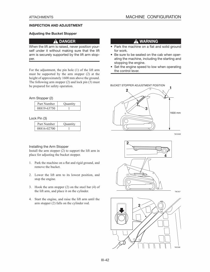
When the lift arm is raised, never position your-self under it without making sure that the lift arm is securely supported by the lift arm stop-per.
For the adjustment, the pin hole (1) of the lift arm must be supported by the arm stopper (2) at the height of approximately 1600 mm above the ground. The following arm stopper (2) and lock pin (3) must be prepared for safety operation.
Arm Stopper (2)
Part Number Quantity08819-63750 1
Lock Pin (3)
Part Number Quantity08816-02700 1
Installing the Arm StopperInstall the arm stopper (2) to support the lift arm in place for adjusting the bucket stopper.
1. Park the machine on a flat and rigid ground, and remove the bucket.
2. Lower the lift arm to its lowest position, and stop the engine.
3. Hook the arm stopper (2) on the steel bar (4) of the lift arm, and place it on the cylinder.
4. Start the engine, and raise the lift arm until the arm stopper (2) falls on the cylinder rod.
WARNING
• Park the machine on a flat and solid ground for work.
• Be sure to be seated on the cab when oper-ating the machine, including the starting and stopping the engine.
• Set the engine speed to low when operating the control lever.
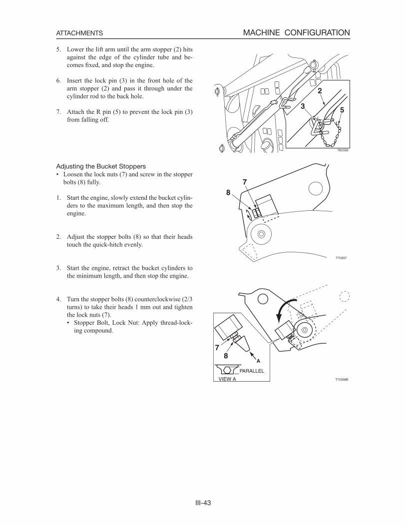
III-43
MACHINE CONFIGURATIONATTACHMENTS
5. Lower the lift arm until the arm stopper (2) hits against the edge of the cylinder tube and be-comes fixed, and stop the engine.
6. Insert the lock pin (3) in the front hole of the arm stopper (2) and pass it through under the cylinder rod to the back hole.
7. Attach the R pin (5) to prevent the lock pin (3) from falling off.
Adjusting the Bucket Stoppers• Loosen the lock nuts (7) and screw in the stopper
bolts (8) fully.
1. Start the engine, slowly extend the bucket cylin-ders to the maximum length, and then stop the engine.
2. Adjust the stopper bolts (8) so that their heads touch the quick-hitch evenly.
3. Start the engine, retract the bucket cylinders to the minimum length, and then stop the engine.
4. Turn the stopper bolts (8) counterclockwise (2/3 turns) to take their heads 1 mm out and tighten the lock nuts (7).• Stopper Bolt, Lock Nut: Apply thread-lock-
ing compound.
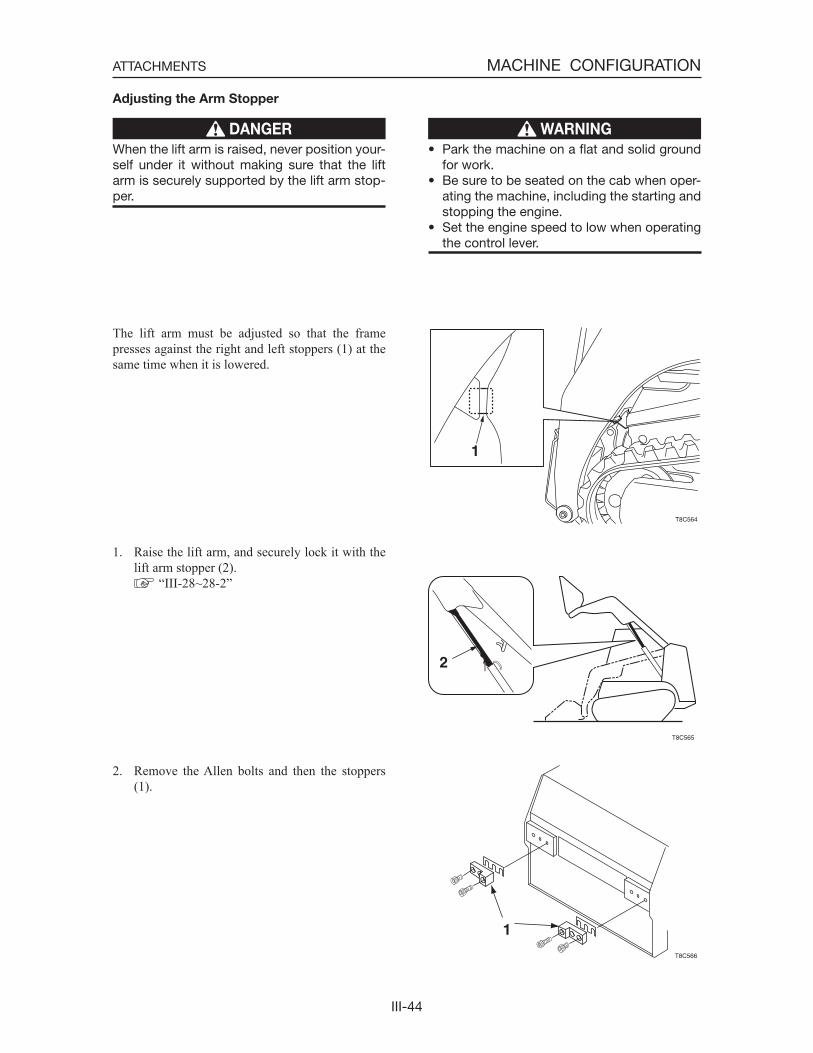
III-44
MACHINE CONFIGURATIONATTACHMENTS
Adjusting the Arm Stopper
DANGER
When the lift arm is raised, never position your-self under it without making sure that the lift arm is securely supported by the lift arm stop-per.
The lift arm must be adjusted so that the frame presses against the right and left stoppers (1) at the same time when it is lowered.
1. Raise the lift arm, and securely lock it with the lift arm stopper (2).
“III-28~28-2”
2. Remove the Allen bolts and then the stoppers (1).
WARNING
• Park the machine on a flat and solid ground for work.
• Be sure to be seated on the cab when oper-ating the machine, including the starting and stopping the engine.
• Set the engine speed to low when operating the control lever.
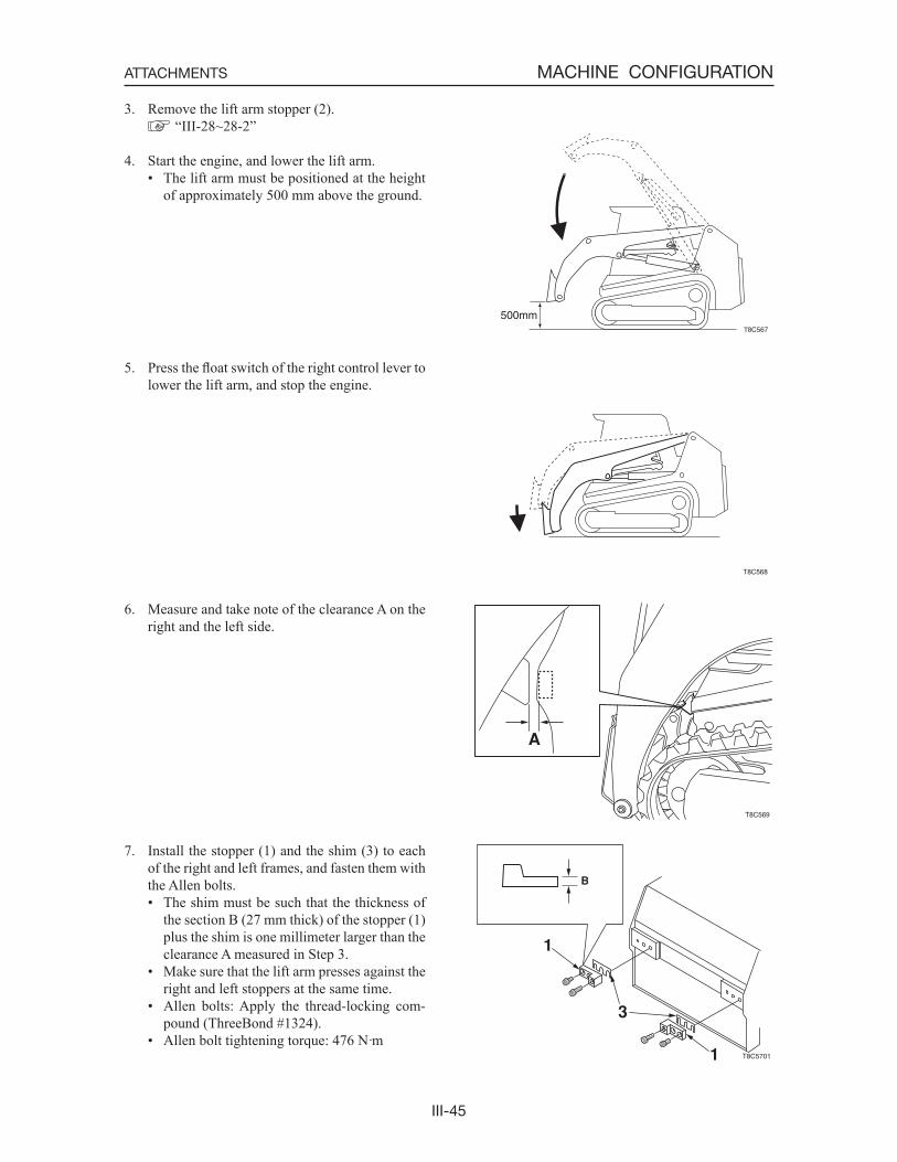
III-45
MACHINE CONFIGURATIONATTACHMENTS
3. Remove the lift arm stopper (2). “III-28~28-2”
4. Start the engine, and lower the lift arm.• The lift arm must be positioned at the height
of approximately 500 mm above the ground.
5. Press the float switch of the right control lever to lower the lift arm, and stop the engine.
6. Measure and take note of the clearance A on the right and the left side.
7. Install the stopper (1) and the shim (3) to each of the right and left frames, and fasten them with the Allen bolts.• The shim must be such that the thickness of
the section B (27 mm thick) of the stopper (1) plus the shim is one millimeter larger than the clearance A measured in Step 3.
• Make sure that the lift arm presses against the right and left stoppers at the same time.
• Allen bolts: Apply the thread-locking com-pound (ThreeBond #1324).
• Allen bolt tightening torque: 476 N·m
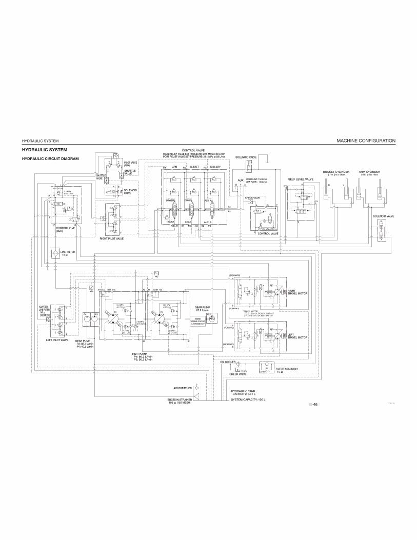
III-46
MACHINE CONFIGURATIONHYDRAULIC SYSTEM
HYDRAULIC SYSTEM
HYDRAULIC CIRCUIT DIAGRAM
μ
μ
μ
μ
ф ф
ф ф ф ф
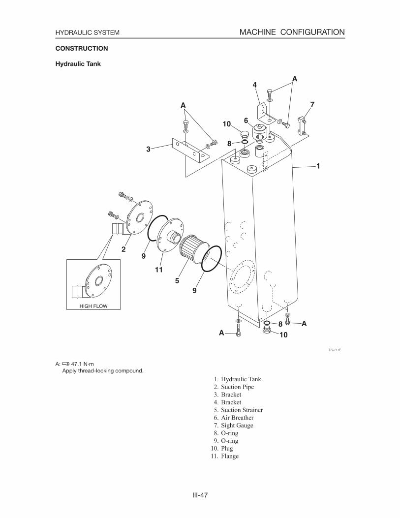
III-47
MACHINE CONFIGURATIONHYDRAULIC SYSTEM
CONSTRUCTION
Hydraulic Tank
1. Hydraulic Tank 2. Suction Pipe 3. Bracket 4. Bracket 5. Suction Strainer 6. Air Breather 7. Sight Gauge 8. O-ring 9. O-ring10. Plug11. Flange
A: 47.1 N·m Apply thread-locking compound.
III-48
MACHINE CONFIGURATIONHYDRAULIC SYSTEM
Function
1. This tank stores the quantity of hydraulic oil necessary to operate the cylinders and hydraulic motors.
2. It keeps air, moisture and dirt out of the hydrau-lic oil.
3. It dissipates heat and lowers the oil tempera-ture.
4. Volume of Hydraulic Oil. Check the oil level with the arm cylinders and
bucket cylinders fully retracted and with the bucket cutting edge lowered to the ground.
ReferenceIf the amount of hydraulic oil is insufficient, the dis-turbances in the flow of oil can not be calmed, and this will result in air bubbles getting in the hydraulic oil. If these bubbles are sucked into the hydraulic pumps, they could cause cavitation. Heat dissipation time would also become shorter and would result in a rise in the oil temperature.If more than the specified amount of hydraulic oil is supplied, the amount of air in the tank will become small and changes in the oil level could cause the pressure fluctuation in the tank to become severe.
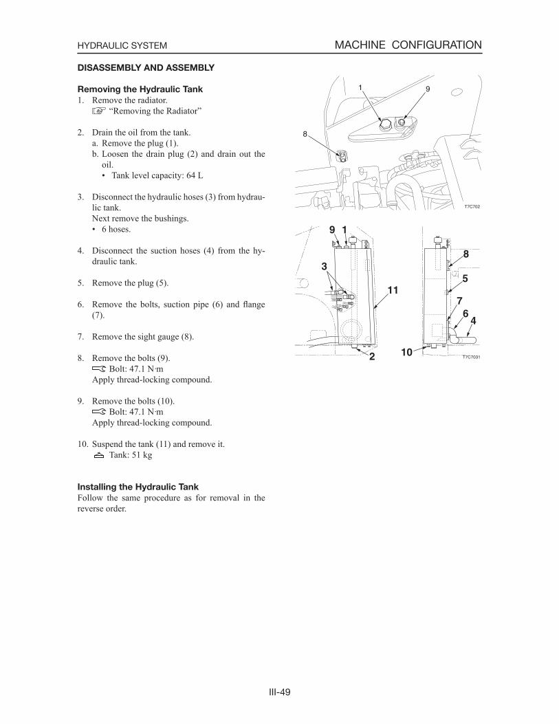
III-49
MACHINE CONFIGURATIONHYDRAULIC SYSTEM
DISASSEMBLY AND ASSEMBLY
Removing the Hydraulic Tank
1. Remove the radiator. “Removing the Radiator”
2. Drain the oil from the tank.a. Remove the plug (1).b. Loosen the drain plug (2) and drain out the
oil.• Tank level capacity: 64 L
3. Disconnect the hydraulic hoses (3) from hydrau-lic tank.
Next remove the bushings.• 6 hoses.
4. Disconnect the suction hoses (4) from the hy-draulic tank.
5. Remove the plug (5).
6. Remove the bolts, suction pipe (6) and flange(7).
7. Remove the sight gauge (8).
8. Remove the bolts (9). Bolt: 47.1 N·m
Apply thread-locking compound.
9. Remove the bolts (10). Bolt: 47.1 N·m
Apply thread-locking compound.
10. Suspend the tank (11) and remove it. Tank: 51 kg
Installing the Hydraulic Tank
Follow the same procedure as for removal in the reverse order.
T7C702
8
1 9

III-50
MACHINE CONFIGURATIONHYDRAULIC SYSTEM
Filling with Hydraulic Oil
The oil level changes according to the oil tempera-ture. Inspect the oil level in the hydraulic oil level inspection posture shown in the diagram.
Hydraulic oil level inspection posture1. Start the engine and run it at low speed.
2. Fully retract the lift arm and bucket cylinders and ground the bucket.
3. Stop the engine.
4. Inspect the oil level using the sight gauge (2).• When the oil temperature is about 20°C: The level should be halfway between the up-
per limit (H) and lower limit (L). If it is below the lower limit (L), replenish.• When the oil temperature is about 50 to
80°C: The level should be near the upper limit (H).
Bleeding the air
After replacing the hydraulic oil, bleed the air from the hydraulic circuit and hydraulic devic-es. Failure to do so may damage the hydraulic devices.
Hydraulic pump1. Tilt up the canopy.
2. Remove the plug (1) from the hydraulic pump.
3. Once hydraulic oil overflows from the plug hole, connect the plug (1).
Cylinders
1. Start the engine and run it at low idle for 10 min-utes.
2. Set the engine to a low idle, then extend and contract all the cylinders 4 or 5 times, without going to the stroke end.
3. Run the engine at high speed, then extend and contract all the cylinders 4 or 5 times, without going to the stroke end.
4. Set the engine back to a low idle, then extend and contract all the cylinders 4 or 5 times to the stroke ends.
T7G008A
H
L
2
T7G024A
1
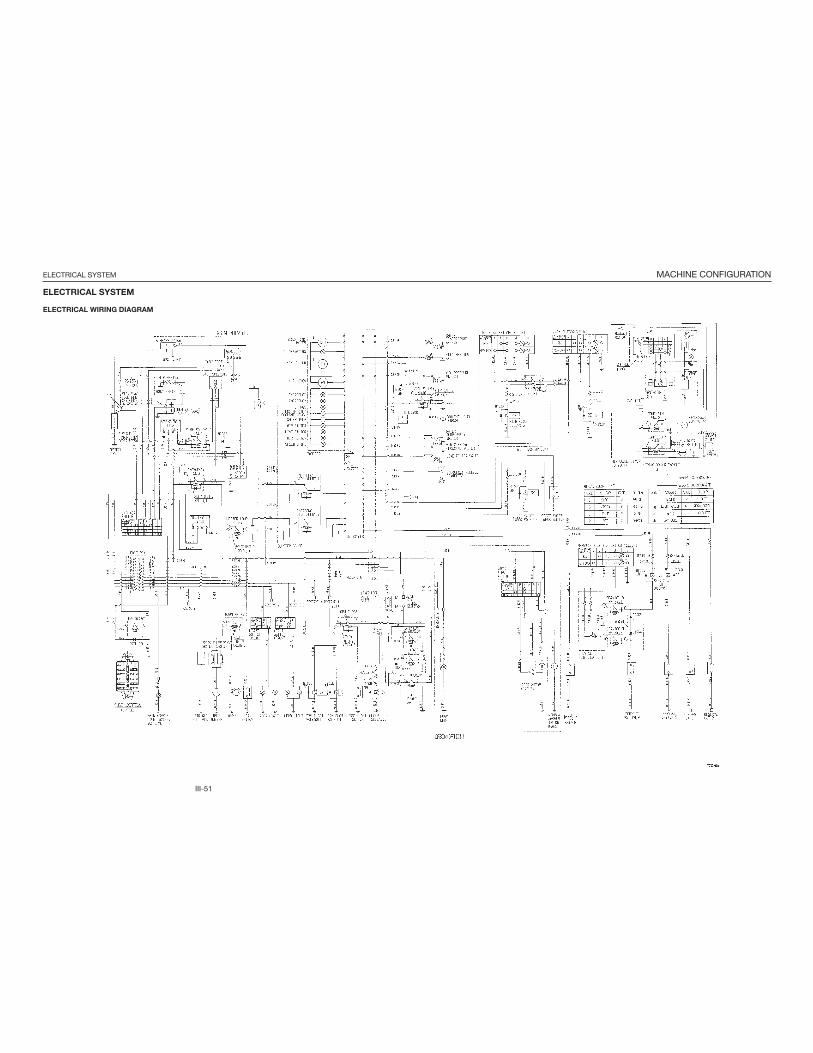
III-51
MACHINE CONFIGURATIONELECTRICAL SYSTEM
ELECTRICAL SYSTEM
ELECTRICAL WIRING DIAGRAM
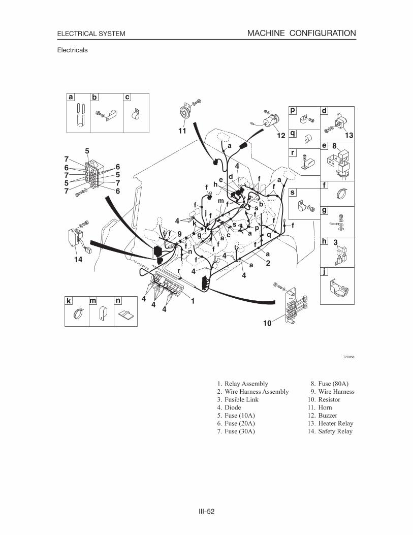
III-52
MACHINE CONFIGURATIONELECTRICAL SYSTEM
Electricals
1. Relay Assembly 2. Wire Harness Assembly 3. Fusible Link 4. Diode 5. Fuse (10A) 6. Fuse (20A) 7. Fuse (30A)
8. Fuse (80A) 9. Wire Harness10. Resistor11. Horn12. Buzzer13. Heater Relay14. Safety Relay
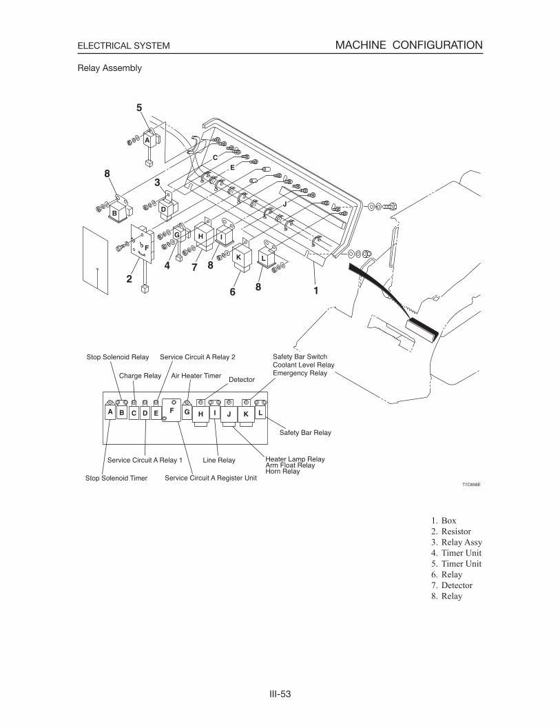
III-53
MACHINE CONFIGURATIONELECTRICAL SYSTEM
Relay Assembly
1. Box 2. Resistor 3. Relay Assy 4. Timer Unit 5. Timer Unit 6. Relay 7. Detector 8. Relay
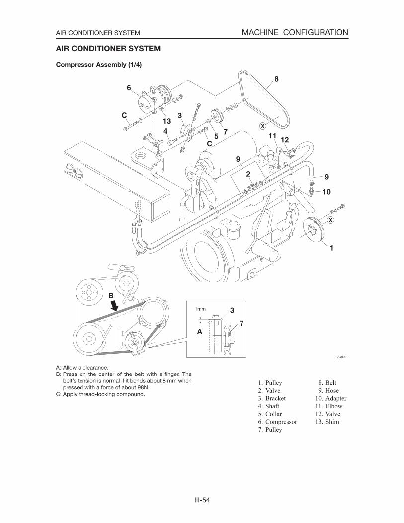
III-54
MACHINE CONFIGURATIONAIR CONDITIONER SYSTEM
AIR CONDITIONER SYSTEM
Compressor Assembly (1/4)
1. Pulley 2. Valve 3. Bracket 4. Shaft 5. Collar 6. Compressor 7. Pulley
A: Allow a clearance.B: Press on the center of the belt with a finger. The
belt’s tension is normal if it bends about 8 mm when pressed with a force of about 98N.
C: Apply thread-locking compound.
8. Belt 9. Hose10. Adapter11. Elbow12. Valve13. Shim
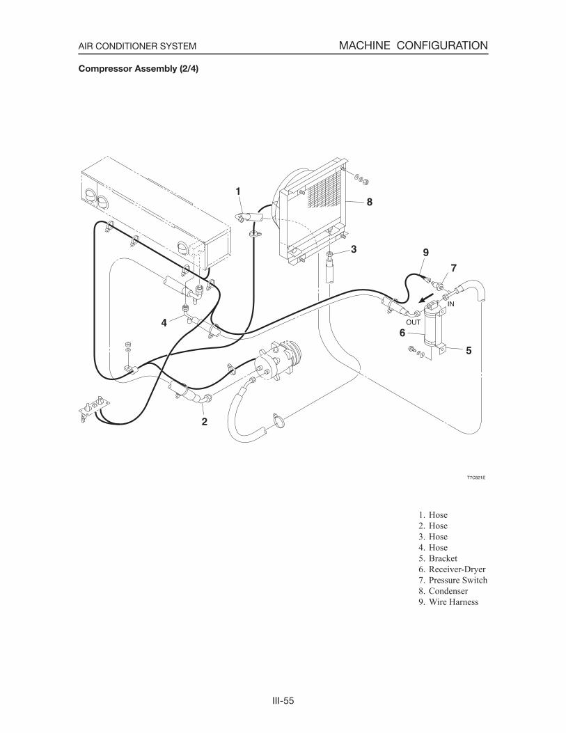
III-55
MACHINE CONFIGURATIONAIR CONDITIONER SYSTEM
1. Hose 2. Hose 3. Hose 4. Hose 5. Bracket 6. Receiver-Dryer 7. Pressure Switch 8. Condenser 9. Wire Harness
Compressor Assembly (2/4)
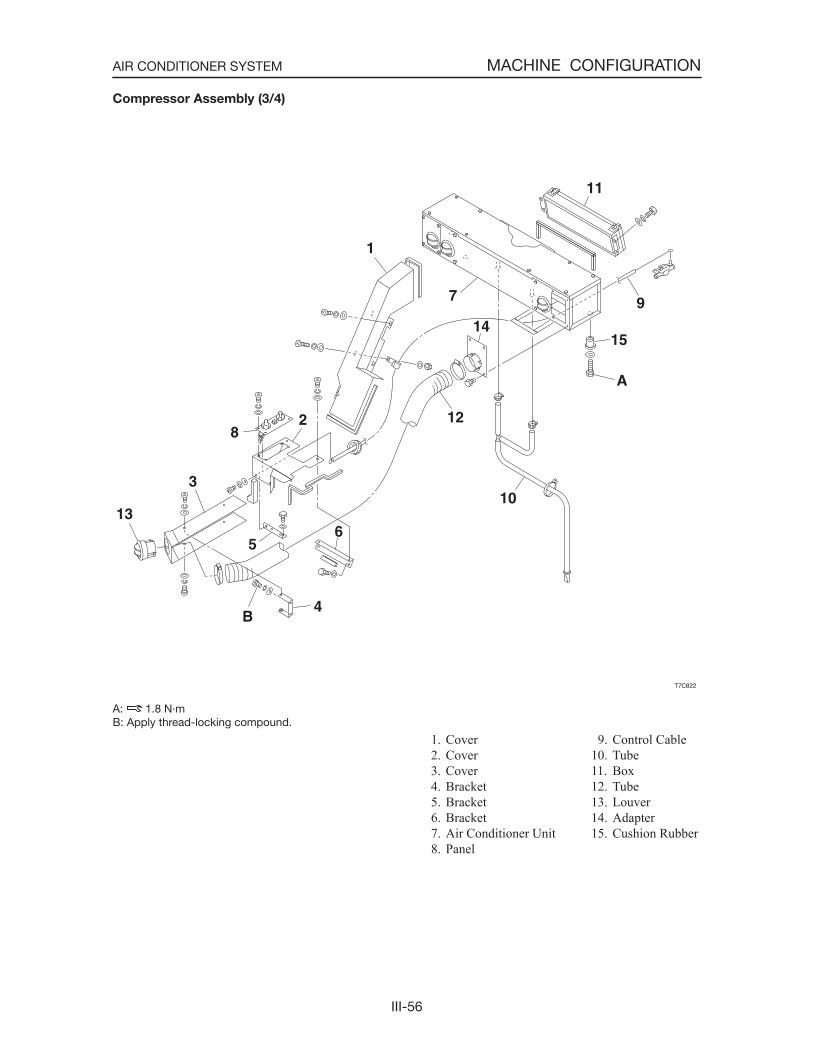
III-56
MACHINE CONFIGURATIONAIR CONDITIONER SYSTEM
1. Cover 2. Cover 3. Cover 4. Bracket 5. Bracket 6. Bracket 7. Air Conditioner Unit 8. Panel
Compressor Assembly (3/4)
A: 1.8 N·mB: Apply thread-locking compound.
9. Control Cable10. Tube11. Box12. Tube13. Louver14. Adapter15. Cushion Rubber
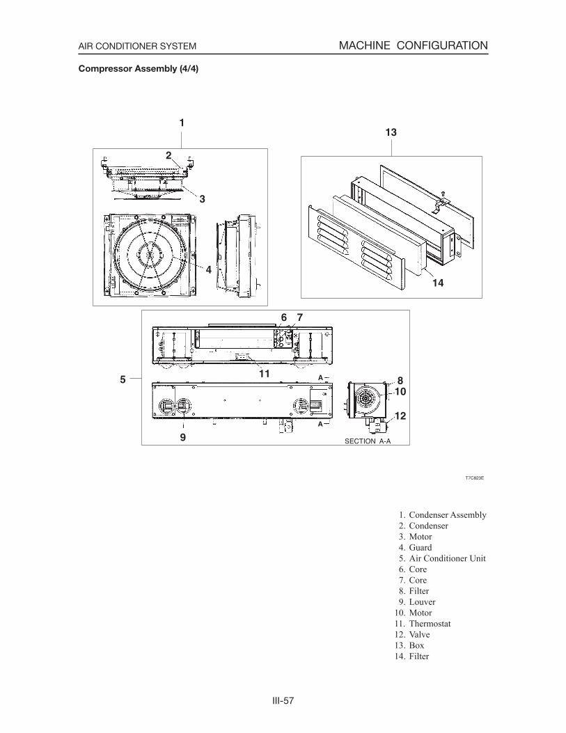
III-57
MACHINE CONFIGURATIONAIR CONDITIONER SYSTEM
1. Condenser Assembly 2. Condenser 3. Motor 4. Guard 5. Air Conditioner Unit 6. Core 7. Core 8. Filter 9. Louver10. Motor11. Thermostat12. Valve13. Box14. Filter
Compressor Assembly (4/4)
III-58
Overview of System Operation
• Truck and Heavy Equipment Systems
• Air Conditioner-System Operation
• Heater System Operation
• Environmental Effects on System Operation
• Chapter Review
Truck and Heavy Equipment Systems
A variety of HVAC systems are in use today, some old and some new. There are:• Vehicle manufacturer installed systems• Owner specified systems• Add-on systems• Retrofit systems
The system components come in different colors, shapes, and sizes. They may be mounted in or on the cab in varied locations. Owners or fleet maintenance people can modify systems by adding controls, auxiliary units or ducts. Major components are sometimes replaced due to damage or failure. All systems were, at least originally, designed and installed to meet the needs of an operator. Figure 2-1 includes illus-trations of various AC and Heater systems. They illustrate system advantages and disadvantages explained in the paragraphs that follow.
The HVAC system includes both heater and air conditioner components, usually a common control, and air ducts. The system cools the cab by removing heat energy. It removes moisture from damp air in the cab and adds fresh outside air to the cab. In this way, the operator can work comfortably in all kinds of weather.
A sleeper unit, built in or added on, increases the air volumes in the cab. The air conditioner or heater must circulate and cool or heat a larger amount of air. This is ac-complished by routing ducts and controls to the sleeper compartment as part of system design. Components may be increased in size to handle the larger cab air volume. A bigger heater core, air conditioning evaporator coil, condenser, blower or fan may be included. Often, on long haul trucks, auxiliary air conditioning and heater components and controls are added. The objective remains the same, to move heat energy and maintain occupant comfort.
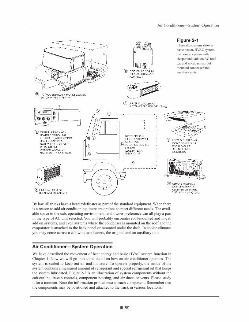
III-59
Air Conditioner—System Operation
By law, all trucks have a heater/defroster as part of the standard equipment. When there is a reason to add air conditioning, there are options to meet different needs. The avail-able space in the cab, operating environment, and owner preference can all play a part in the type of AC unit selected. You will probably encounter roof-mounted and in-cab add on systems, and even systems where the condenser is mounted on the roof and the evaporator is attached to the back panel or mounted under the dash. In cooler climates you may come across a cab with two heaters, the original and an auxiliary unit.
Air Conditioner—System Operation
We have described the movement of heat energy and basic HVAC system function in Chapter 1. Now we will go into some detail on how an air conditioner operates. The system is sealed to keep out air and moisture. To operate properly, the inside of the system contains a measured amount of refrigerant and special refrigerant oil that keeps the system lubricated. Figure 2-2 is an illustration of system components without the cab outline, in-cab controls, component housing, and air ducts or vents. Please study it for a moment. Note the information printed next to each component. Remember that the components may be positioned and attached to the truck in various locations.
Figure 2-1These illustrations show a basic heater, HVAC system, the combo system with sleeper unit, add on AC roof top and in cab units, roof mounted condenser and auxiliary units.
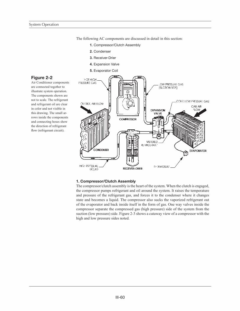
III-60
System Operation
The following AC components are discussed in detail in this section:
1. Compressor/Clutch Assembly
2. Condenser
3. Receiver-Drier
4. Expansion Valve
5. Evaporator Coil
1. Compressor/Clutch Assembly
The compressor/clutch assembly is the heart of the system. When the clutch is engaged, the compressor pumps refrigerant and oil around the system. It raises the temperature and pressure of the refrigerant gas, and forces it to the condenser where it changes state and becomes a liquid. The compressor also sucks the vaporized refrigerant out of the evaporator and back inside itself in the form of gas. One way valves inside the compressor separate the compressed gas (high pressure) side of the system from the suction (low pressure) side. Figure 2-3 shows a cutaway view of a compressor with the high and low pressure sides noted.
Figure 2-2Air Conditioner components are connected together to illustrate system operation.The components shown are not to scale. The refrigerant and refrigerant oil are clear in color and not visible in this drawing. The small ar-rows inside the components and connecting hoses show the direction of refrigerant flow (refrigerant circuit).
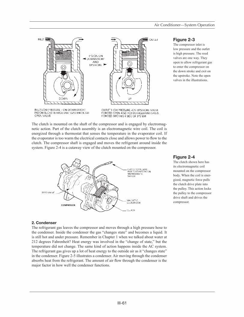
III-61
Air Conditioner—System Operation
The clutch is mounted on the shaft of the compressor and is engaged by electromag-netic action. Part of the clutch assembly is an electromagnetic wire coil. The coil is energized through a thermostat that senses the temperature in the evaporator coil. If the evaporator is too warm the electrical contacts close and allows power to flow to the clutch. The compressor shaft is engaged and moves the refrigerant around inside the system. Figure 2-4 is a cutaway view of the clutch mounted on the compressor.
2. Condenser
The refrigerant gas leaves the compressor and moves through a high pressure hose to the condenser. Inside the condenser the gas “changes state” and becomes a liquid. It is still hot and under pressure. Remember in Chapter 1 when we talked about water at 212 degrees Fahrenheit? Heat energy was involved in the “change of state,” but the temperature did not change. The same kind of action happens inside the AC system. The refrigerant gas gives up a lot of heat energy to the outside air as it “changes state” in the condenser. Figure 2-5 illustrates a condenser. Air moving through the condenser absorbs heat from the refrigerant. The amount of air flow through the condenser is the major factor in how well the condenser functions.
Figure 2-3The compressor inlet is low pressure and the outlet is high pressure. The reed valves are one way. They open to allow refrigerant gas to enter the compressor on the down stroke and exit on the upstroke. Note the open valves in the illustrations.
Figure 2-4The clutch shown here has its electromagnetic coil mounted on the compressor body. When the coil is ener-gized, magnetic force pulls the clutch drive plate into the pulley. This action locks the pulley to the compressor drive shaft and drives the compressor.
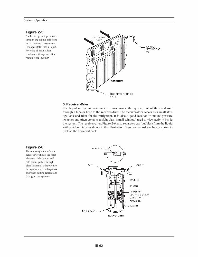
III-62
System Operation
3. Receiver-Drier
The liquid refrigerant continues to move inside the system, out of the condenser through a tube or hose to the receiver-drier. The receiver-drier serves as a small stor-age tank and filter for the refrigerant. It is also a good location to mount pressure switches and often contains a sight glass (small window) used to view activity inside the system. The receiver-drier, Figure 2-6, also separates gas (bubbles) from the liquid with a pick-up tube as shown in this illustration. Some receiver-driers have a spring to preload the desiccant pack.
Figure 2-5As the refrigerant gas moves through the tubing coil from top to bottom, it condenses (changes state) into a liquid. For ease of installation, condenser fittings are often routed close together.
Figure 2-6This cutaway view of a re-ceiver-drier shows the filterelements, inlet, outlet and refrigerant path. The sight glass is a small window into the system used in diagnosis and when adding refrigerant (charging the system).
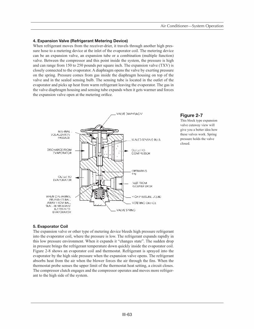
III-63
Air Conditioner—System Operation
4. Expansion Valve (Refrigerant Metering Device)
When refrigerant moves from the receiver-drier, it travels through another high pres-sure hose to a metering device at the inlet of the evaporator coil. The metering device can be an expansion valve, an expansion tube or a combination (multiple function) valve. Between the compressor and this point inside the system, the pressure is high and can range from 150 to 250 pounds per square inch. The expansion valve (TXV) is closely connected to the evaporator. A diaphragm opens the valve by exerting pressure on the spring. Pressure comes from gas inside the diaphragm housing on top of the valve and in the sealed sensing bulb. The sensing tube is located in the outlet of the evaporator and picks up heat from warm refrigerant leaving the evaporator. The gas in the valve diaphragm housing and sensing tube expands when it gets warmer and forces the expansion valve open at the metering orifice.
5. Evaporator Coil
The expansion valve or other type of metering device bleeds high pressure refrigerant into the evaporator coil, where the pressure is low. The refrigerant expands rapidly in this low pressure environment. When it expands it “changes state”. The sudden drop in pressure brings the refrigerant temperature down quickly inside the evaporator coil. Figure 2-8 shows an evaporator coil and thermostat. Refrigerant is sprayed into the evaporator by the high side pressure when the expansion valve opens. The refrigerant absorbs heat from the air when the blower forces the air through the fins. When the thermostat probe senses the upper limit of the thermostat heat setting, a circuit closes. The compressor clutch engages and the compressor operates and moves more refriger-ant to the high side of the system.
Figure 2-7This block type expansion valve cutaway view will give you a better idea how these valves work. Spring pressure holds the valve closed.
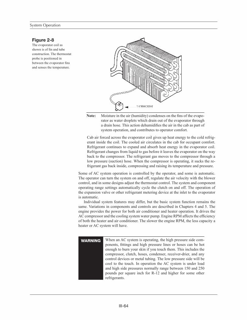
III-64
System Operation
Figure 2-8The evaporator coil as shown is of fin and tube construction. The thermostat probe is positioned in between the evaporator finsand senses the temperature.
Note: Moisture in the air (humidity) condenses on the fins of the evapo-rator as water droplets which drain out of the evaporator through a drain hose. This action dehumidifies the air in the cab as part of system operation, and contributes to operator comfort.
Cab air forced across the evaporator coil gives up heat energy to the cold refrig-erant inside the coil. The cooled air circulates in the cab for occupant comfort. Refrigerant continues to expand and absorb heat energy in the evaporator coil. Refrigerant changes from liquid to gas before it leaves the evaporator on the way back to the compressor. The refrigerant gas moves to the compressor through a low pressure (suction) hose. When the compressor is operating, it sucks the re-frigerant gas back inside, compressing and raising its temperature and pressure.
Some of AC system operation is controlled by the operator, and some is automatic. The operator can turn the system on and off, regulate the air velocity with the blower control, and in some designs adjust the thermostat control. The system and component operating range settings automatically cycle the clutch on and off. The operation of the expansion valve or other refrigerant metering device at the inlet to the evaporator is automatic.
Individual system features may differ, but the basic system function remains the same. Variations in components and controls are described in Chapters 4 and 5. The engine provides the power for both air conditioner and heater operation. It drives the AC compressor and the cooling system water pump. Engine RPM affects the efficiencyof both the heater and air conditioner. The slower the engine RPM, the less capacity a heater or AC system will have.
When an AC system is operating, the high pressure side com-ponents, fittings and high pressure lines or hoses can be hot enough to burn your skin if you touch them. This includes the compressor, clutch, hoses, condenser, receiver-drier, and any control devices or metal tubing. The low pressure side will be cool to the touch. In operation the AC system is under load and high side pressures normally range between 150 and 250 pounds per square inch for R-12 and higher for some other refrigerants.
WARNING
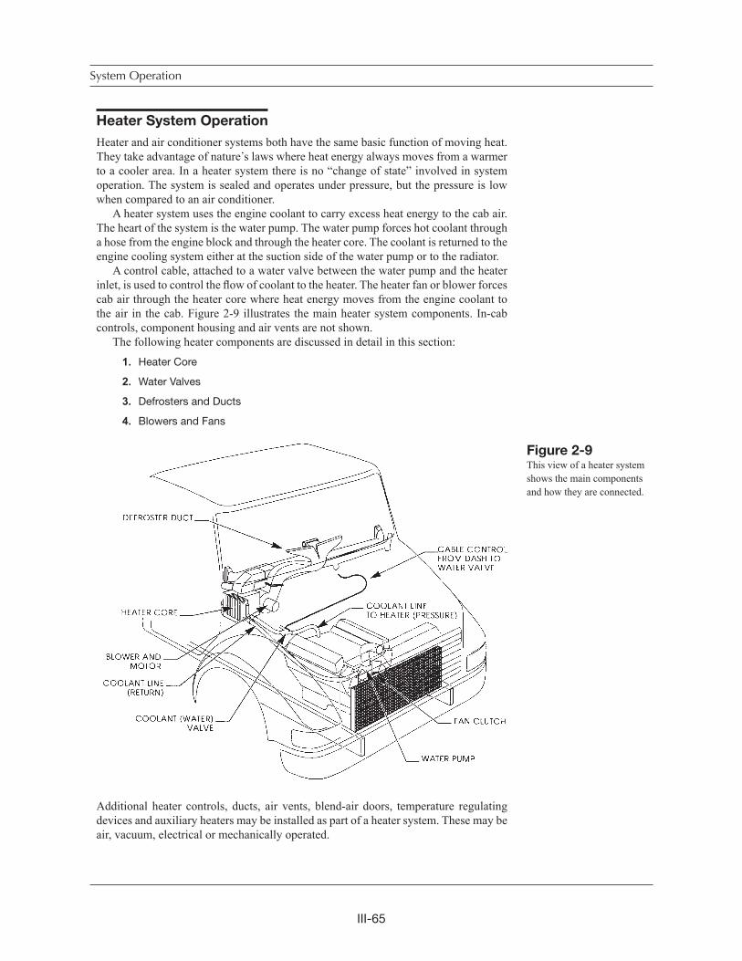
III-65
Heater System Operation
Heater and air conditioner systems both have the same basic function of moving heat. They take advantage of nature s laws where heat energy always moves from a warmer to a cooler area. In a heater system there is no “change of state” involved in system operation. The system is sealed and operates under pressure, but the pressure is low when compared to an air conditioner.
A heater system uses the engine coolant to carry excess heat energy to the cab air. The heart of the system is the water pump. The water pump forces hot coolant through a hose from the engine block and through the heater core. The coolant is returned to the engine cooling system either at the suction side of the water pump or to the radiator.
A control cable, attached to a water valve between the water pump and the heater inlet, is used to control the flow of coolant to the heater. The heater fan or blower forces cab air through the heater core where heat energy moves from the engine coolant to the air in the cab. Figure 2-9 illustrates the main heater system components. In-cab controls, component housing and air vents are not shown.
The following heater components are discussed in detail in this section:
1. Heater Core
2. Water Valves
3. Defrosters and Ducts
4. Blowers and Fans
Additional heater controls, ducts, air vents, blend-air doors, temperature regulating devices and auxiliary heaters may be installed as part of a heater system. These may be air, vacuum, electrical or mechanically operated.
System Operation
Figure 2-9This view of a heater system shows the main components and how they are connected.
III-66
1. Heater Core
Heater cores are like small radiators. The fin and tube construction is designed to route coolant flow for the best possible heat energy transfer from coolant to cab air. Hoses from and to the engine are connected to the core with clamps. The core outlet may be larger or the same size as the inlet.
2. Water Valves
Water valves may be cable, vacuum or air controlled. The valve can be either open, closed or set part way open. Some valves have a bypass design to return coolant to the engine. Most are manually controlled although electronic systems are now being installed.
3. Defrosters and Ducts
Defrosting is accomplished by directing heated dry air through ducts to the windshield. The heater system serves the dual purpose of defrosting and heating. Controls are used to route the air flow to the windshield and occupant areas by opening and closing duct doors. Controls may be manual, air or vacuum. Many vehicles use a “defrost interlock” system which utilizes the air condi-tioner to dry the defrost air and clear the cab windows more quickly.
4. Blowers and Fans
Blowers or fans are used in the system to move cab air through the heater core and evaporator. Air can be pushed or pulled through the core depending on sys-tem design. Blower or fan speed is usually selected by the operator.
Environmental Effects on System Operation
The environment outside the cab involves more than the weather. It may be hot and humid or cold and dry. That is only part of the condition the HVAC system must handle to maintain an ideal comfort range. A truck can be at idle, in traffic or moving along for hours on the Interstate at 65 M.P.H. The load condition on a trip can include going out full, coming home empty, or driving across the Rockies or Kansas plains during the day or night. The truck color and shape, the windows and angle of the sun are all variables that can increase or decrease the “load” on the system. The following are a few examples of environmental effect:
• A black cab-over (COE) with a dark color interior will be more dif-ficult to cool than the same vehicle with white paint and a light colored interior. The black cab picks up and holds the radiant heat from the sun more easily than the white one.
• In Florida or Houston the humidity in mid summer can be very high with the temperature in the high 90 s or low 100 s. The AC unit must remove a lot of moisture from the air in the cab as the air moves through the evaporator fins. The more moisture on the fins, the less effective the transfer of heat is to the refrigerant inside the evaporator coil.
Environmental Effects

III-67
• On a cold day the temperature can drop below zero. The engine may run cooler so the engine coolant is cooler when it circulates through the heater. The heat in the cab moves out of the cab faster (remember heat always moves to a cooler area until both are the same tempera-ture—nature s law). To maintain cab comfort you have to increase the flow of coolant through the heater, increase coolant temperature, and/or move more air through the heater core.
• On a hot day, an off-road vehicle experiences cooling at a slower rate than an on-road vehicle. This is a result of high sun-load, large window area and often less insulation.
It is important for you to keep environmental effects in mind when you are servicing or diagnosing heater or air conditioner systems. If you work in Denver the altitude will affect system function and pressure. In Houston the heat and humidity may lower heat transfer to the air at the condenser and increase system operating pressures.
Chapter Review
• HVAC systems range from simple cab heaters to multi-function com-bination systems. The multi-function system can heat and cool the cab and sleeper unit, and have separate auxiliary components and controls for driver and passenger comfort.
• Both heater (engine) coolant and air conditioner refrigerant circulate inside sealed, pressurized systems. The normal air conditioner operat-ing pressure ranges from 150 to 250 pounds per square inch, sometimes higher with a different refrigerant.
• Air conditioners have a high and a low pressure side within the system. The compressor is the starting point of the high side. Pressure drops at the expansion valve opening to the evaporator.
• The basic components of an AC system are the compressorclutch as-sembly, high pressure lines, condenser, receiver-drier, expansion valve, evaporator, thermostat, blower assembly, and suction lines. There may be other controls installed for more complex systems.
• The basic components of a heater system are the inlet and outlet hoses, a water valve and valve control, heater core and fan or blower assembly. There may be other controls for more complex systems.
• An air conditioner system uses the “change of state” of refrigerant inside the system to move heat from the cab air to the outside air. Refrigerant changes from a gas to a liquid in the condenser, and back to a gas in the evaporator.
• A heater system uses the heat from the engine, carried to the heater core by the action of the water pump, to warm the air in the cab. There is no change of state within the heater system.
• Environmental conditions affect how both heaters and air conditioners work. Weather, driving conditions, color of the vehicle are factors. All contribute to heat gain or loss inside a cab and how much heat energy must be moved to maintain occupant comfort.
System Operation

III-68
Inspection and Maintenance-
without gauges
• Discussion of Inspection & Maintenance Survey Results
• Visual Inspection - System Off
• Electrical System Inspection
• Performance Inspection - Engine Running
• Heater System Inspection
• Preventive Maintenance Worksheet
• Chapter Review
Discussion of Inspection & Maintenance Survey Results
There are three reasons for regular inspection and maintenance procedures:
1. They save money in the long run by reducing down time and often prevent more costly repairs.
2. They help to insure driver comfort and safety.3. They add to your store of knowledge about these systems and main-
tain your level of efficiency.
About half of all heavy duty vehicles have air conditioners. Surveys of AC system owners find that over 30% of the systems are serviced every six months or less, and another 62% are serviced at least once a year.
The survey also covered how often the different components required maintenance. Figure 7.1 below shows survey finding percentages. Failure of any of the AC compo-nents listed in the survey could cause a system to malfunction or stop cooling.
INSPECTION & MAINTENANCE SURVEY
Note: The above survey results may not apply to your situation. Actual operating conditions for the vehicles you service will determine or influence maintenance frequency and requirements.
The following inspection procedures should take about 15 to 20 minutes, longer if corrective steps, part replacement or adding refrigerant is necessary. There is a “Pre-ventive Maintenance Worksheet” you may use at the end of this chapter, Figure 7-9
Click on any of these sub-
ject headings to go directly
to the page
Figure 7-1This chart shows mainte-nance frequency, lists key parts and how often they require maintenance.
III-69
Visual Inspection - System Off
Your observations and the corrective measures you take may be different depending on circumstances. The following inspection procedures are explained in more detail below:
1. Observe the System
2. Inspect Parts
3. Check Hoses and Fittings
4. Check for Refrigerant Leaks
Use the following procedures as a general rule in performing a visual inspection with the AC system off:
1. Observe the System
Your first inspection step is to answer the following question if you can:• Has the vehicle just come in off the road and has the HVAC system
been in use?• Did the operator or work order explain or describe any problems
about the system?• Did someone else work on the system yesterday, 700 miles down the
road? Your first inspection step is to answer these questions if you can.
Even when someone has told you what is wrong with an HVAC system, you should perform a visual inspection. Always make a visual inspection before you hook up the manifold gauge set. Never add refrigerant to a system until you have made a com-plete visual and performance inspection.
2. Inspect Parts
Look at the system for what might come loose, leak, wear out or become dirty and not function the way it should. The main points for visual inspection of the system are emphasized in Figure 7-2.
Inspection & Maintenance
CAUTION
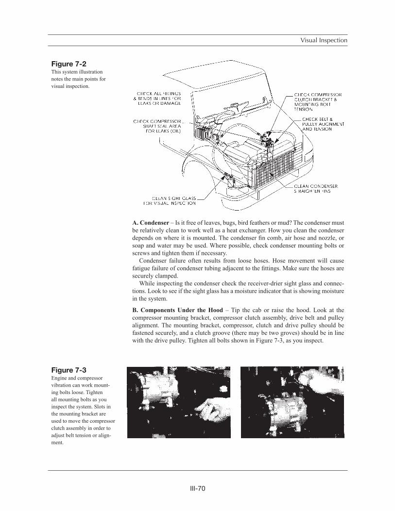
III-70
A. Condenser – Is it free of leaves, bugs, bird feathers or mud? The condenser must be relatively clean to work well as a heat exchanger. How you clean the condenser depends on where it is mounted. The condenser fin comb, air hose and nozzle, or soap and water may be used. Where possible, check condenser mounting bolts or screws and tighten them if necessary.
Condenser failure often results from loose hoses. Hose movement will cause fatigue failure of condenser tubing adjacent to the fittings. Make sure the hoses are securely clamped.
While inspecting the condenser check the receiver-drier sight glass and connec-tions. Look to see if the sight glass has a moisture indicator that is showing moisture in the system.
B. Components Under the Hood – Tip the cab or raise the hood. Look at the compressor mounting bracket, compressor clutch assembly, drive belt and pulley alignment. The mounting bracket, compressor, clutch and drive pulley should be fastened securely, and a clutch groove (there may be two groves) should be in line with the drive pulley. Tighten all bolts shown in Figure 7-3, as you inspect.
Visual Inspection
Figure 7-3Engine and compressor vibration can work mount-ing bolts loose. Tighten all mounting bolts as you inspect the system. Slots in the mounting bracket are used to move the compressor clutch assembly in order to adjust belt tension or align-ment.
Figure 7-2This system illustration notes the main points for visual inspection.
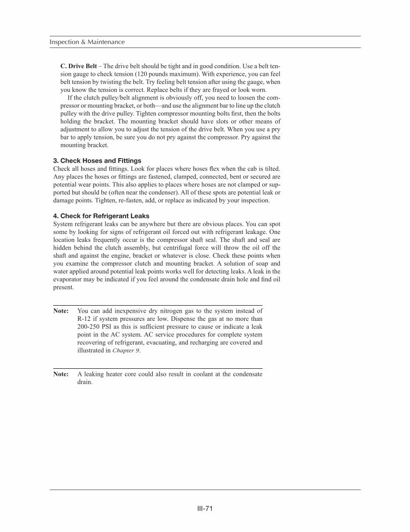
III-71
C. Drive Belt – The drive belt should be tight and in good condition. Use a belt ten-sion gauge to check tension (120 pounds maximum). With experience, you can feel belt tension by twisting the belt. Try feeling belt tension after using the gauge, when you know the tension is correct. Replace belts if they are frayed or look worn.
If the clutch pulley/belt alignment is obviously off, you need to loosen the com-pressor or mounting bracket, or both—and use the alignment bar to line up the clutch pulley with the drive pulley. Tighten compressor mounting bolts first, then the bolts holding the bracket. The mounting bracket should have slots or other means of adjustment to allow you to adjust the tension of the drive belt. When you use a pry bar to apply tension, be sure you do not pry against the compressor. Pry against the mounting bracket.
3. Check Hoses and Fittings
Check all hoses and fittings. Look for places where hoses flex when the cab is tilted. Any places the hoses or fittings are fastened, clamped, connected, bent or secured are potential wear points. This also applies to places where hoses are not clamped or sup-ported but should be (often near the condenser). All of these spots are potential leak or damage points. Tighten, re-fasten, add, or replace as indicated by your inspection.
4. Check for Refrigerant Leaks
System refrigerant leaks can be anywhere but there are obvious places. You can spot some by looking for signs of refrigerant oil forced out with refrigerant leakage. One location leaks frequently occur is the compressor shaft seal. The shaft and seal are hidden behind the clutch assembly, but centrifugal force will throw the oil off the shaft and against the engine, bracket or whatever is close. Check these points when you examine the compressor clutch and mounting bracket. A solution of soap and water applied around potential leak points works well for detecting leaks. A leak in the evaporator may be indicated if you feel around the condensate drain hole and find oil present.
Note: You can add inexpensive dry nitrogen gas to the system instead of R-12 if system pressures are low. Dispense the gas at no more than 200-250 PSI as this is sufficient pressure to cause or indicate a leak point in the AC system. AC service procedures for complete system recovering of refrigerant, evacuating, and recharging are covered and illustrated in Chapter 9.
Note: A leaking heater core could also result in coolant at the condensate drain.
Inspection & Maintenance
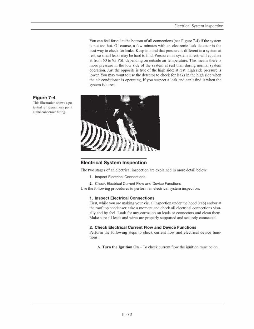
III-72
You can feel for oil at the bottom of all connections (see Figure 7-4) if the system is not too hot. Of course, a few minutes with an electronic leak detector is the best way to check for leaks. Keep in mind that pressure is different in a system at rest, so small leaks may be hard to find. Pressure in a system at rest, will equalize at from 60 to 95 PSI, depending on outside air temperature. This means there is more pressure in the low side of the system at rest than during normal system operation. Just the opposite is true of the high side; at rest, high side pressure is lower. You may want to use the detector to check for leaks in the high side when the air conditioner is operating, if you suspect a leak and can t find it when the system is at rest.
Electrical System Inspection
The two stages of an electrical inspection are explained in more detail below:
1. Inspect Electrical Connections
2. Check Electrical Current Flow and Device FunctionsUse the following procedures to perform an electrical system inspection:
1. Inspect Electrical Connections
First, while you are making your visual inspection under the hood (cab) and/or at the roof top condenser, take a moment and check all electrical connections visu-ally and by feel. Look for any corrosion on leads or connectors and clean them. Make sure all leads and wires are properly supported and securely connected.
2. Check Electrical Current Flow and Device Functions
Perform the following steps to check current flow and electrical device func-tions:
A. Turn the Ignition On – To check current flow the ignition must be on.
Electrical System Inspection
Figure 7-4This illustration shows a po-tential refrigerant leak point at the condenser fitting.
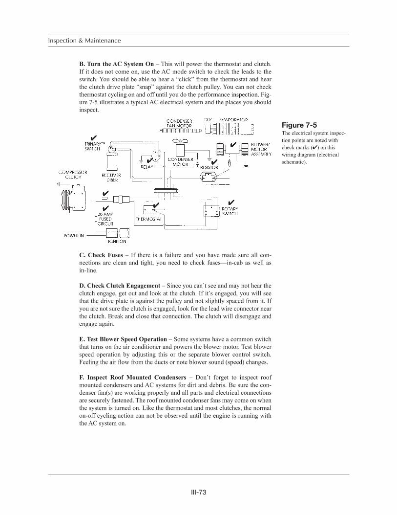
III-73
B. Turn the AC System On – This will power the thermostat and clutch. If it does not come on, use the AC mode switch to check the leads to the switch. You should be able to hear a “click” from the thermostat and hear the clutch drive plate “snap” against the clutch pulley. You can not check thermostat cycling on and off until you do the performance inspection. Fig-ure 7-5 illustrates a typical AC electrical system and the places you should inspect.
C. Check Fuses – If there is a failure and you have made sure all con-nections are clean and tight, you need to check fuses—in-cab as well as in-line.
D. Check Clutch Engagement – Since you can t see and may not hear the clutch engage, get out and look at the clutch. If it s engaged, you will see that the drive plate is against the pulley and not slightly spaced from it. If you are not sure the clutch is engaged, look for the lead wire connector near the clutch. Break and close that connection. The clutch will disengage and engage again.
E. Test Blower Speed Operation – Some systems have a common switch that turns on the air conditioner and powers the blower motor. Test blower speed operation by adjusting this or the separate blower control switch. Feeling the air flow from the ducts or note blower sound (speed) changes.
F. Inspect Roof Mounted Condensers – Don t forget to inspect roof mounted condensers and AC systems for dirt and debris. Be sure the con-denser fan(s) are working properly and all parts and electrical connections are securely fastened. The roof mounted condenser fans may come on when the system is turned on. Like the thermostat and most clutches, the normal on-off cycling action can not be observed until the engine is running with the AC system on.
Inspection & Maintenance
Figure 7-5The electrical system inspec-tion points are noted with check marks ( ) on this wiring diagram (electrical schematic).
III-74
Performance Inspection – Engine Running
The purpose of visual and electrical inspection is to detect obvious problems and assure AC system function for an accurate performance inspection. If you do the performance inspection first, you could be mislead. Problem areas discovered during the perfor-mance inspection can give you false clues or symptoms, and result in repair errors and come-backs. The following performance inspection procedures are explained in more detail below:
1. Inspect System Component Cycling and
Cab Temperature Levels
2. Check Clutch Cycling Under Load
3. Check Sight GlassThe performance inspection does not cover pressure and temperature sensitive safety devices (cutout switches, fan control, Trinary etc.). Testing these devices requires the use of the manifold gauge set for observation of internal system pressures during tests. These are explained in Chapter 8.
Use the following procedures as a general rule in a performance inspection:
1. Inspect System Component Cycling and Cab
Temperature Levels
A. Turn On the Engine and Air Conditioner – Inspect for system compo-nent cycling and cab temperature levels.
Note: System performance testing will be much faster if all doors and windows in the cab are closed.
The cab air must cool down to thermostat control setting lev-els before system components will cycle on and off, indicating correct function. This is called stabilizing the system and takes about five minutes of operation. In very hot weather the system may not cycle.
B. Check Thermometer Readings – In the cab you can use your thermom-eter to measure air temperature at the vents. When the evaporator is easy to reach with a thermometer probe without removing some of the dash or duct work, use the probe to measure evaporator temperature. When the AC unit is on and working correctly, you can see the thermometer dial needle move down to about 32 degrees, then rise six to ten degrees and move back down again. The movement up and down indicates that the cycling clutch and thermostat, or orifice tube and accumulator pressure switch (to the clutch) are functioning correctly. In systems with a non-cycling clutch, this move-ment indicates correct function of the refrigerant metering device.
The needle movement is called “temperature swing.” When you can ad-just the thermostat setting, the range of swing should change. For example, from full cooling (cold) to moderate (between cold and warm), the swing may change from 32-38 to 32-42 degrees.
Electrical System Inspection

III-75
These readings at the vents will be higher and temperature swing slower and not as obvious. Also blower speed will cause the temperature, levels to read higher (high air speed) or lower (low air speed) at the same thermostat setting. When you measure air temperature, an electronic thermometer/py-rometer is a great tool to have. You can easily measure cab air temperature at several locations quickly.
Swing temperatures vary depending on where you measure temperature, and on outside temperature, humidity and altitude. The chart in Figure 7-6, shows some examples of typical temperature variables. Don t forget that cab and sleeper area temperatures can vary within the same vehicle. Also, electronic controls used in newer HVAC systems often keep the tempera-ture spread within a narrower range.
2. Check Clutch Cycling Under Load
The following operating inspections, visual and by feel, are done outside the cab while you wait for the system to stabilize.
A. Lift hood – With the hood up (or cab tilted) observe the clutch cycling under load.
Note: If the condenser is hood mounted you may not have adequate air flow through it.
B. Touch suction and discharge lines – Soon after system start up you can safely feel the suction and discharge lines and note their change in tempera-ture. The discharge line will get hot (after a while it may be to hot to touch) and the suction line will get cooler.
3. Check Sight Glass
The sight glass is the only point where you can actually see inside the air condi-tioner during operation. Check the sight glass through the window on the top of the receiver-drier (or the separate in-line sight glass). If the system is functioning properly and cooling the cab adequately, the sight glass should be clear (you will not see anything in it). If it is not clear when the system is first turned on, wait a few minutes for the system to stabilize, then look again. Figure 7-7 illustrates and explains what you may observe in the sight glass. Roof mounted condenser fans may run continuously or cycle on and off. If you can t tell by sound you may have to climb a ladder and observe the fan blades.
Inspection & Maintenance
Figure 7-6The chart of AC system and cab temperature range shows you typical variables.
AIR TEMP.DEGREES F.
AIR QUALITY
CENTER OUTLETAIR TEMP.
DEGREES F.
OUTLET AIR TEMP.RANGE DEGREES F.
HUMID
70° 80° 90° 100°
DRY
43°to
47°
LEFT & RIGHT AIR OUTLET TEMPERATURE WILL VARY
40°to
41°
LEFT RIGHT LEFT RIGHT LEFT RIGHT LEFT RIGHT
HUMID DRY HUMID DRY HUMID DRY
40°to
44°
44°to
48°
40°to
44°
47°to
51°
40°to
44°
52°to
56°
41°to
45°
41°to
44°
41°to
45°
43°to
47°
46°to
52°
47°to
54°
48°to
55°
50°to
56°
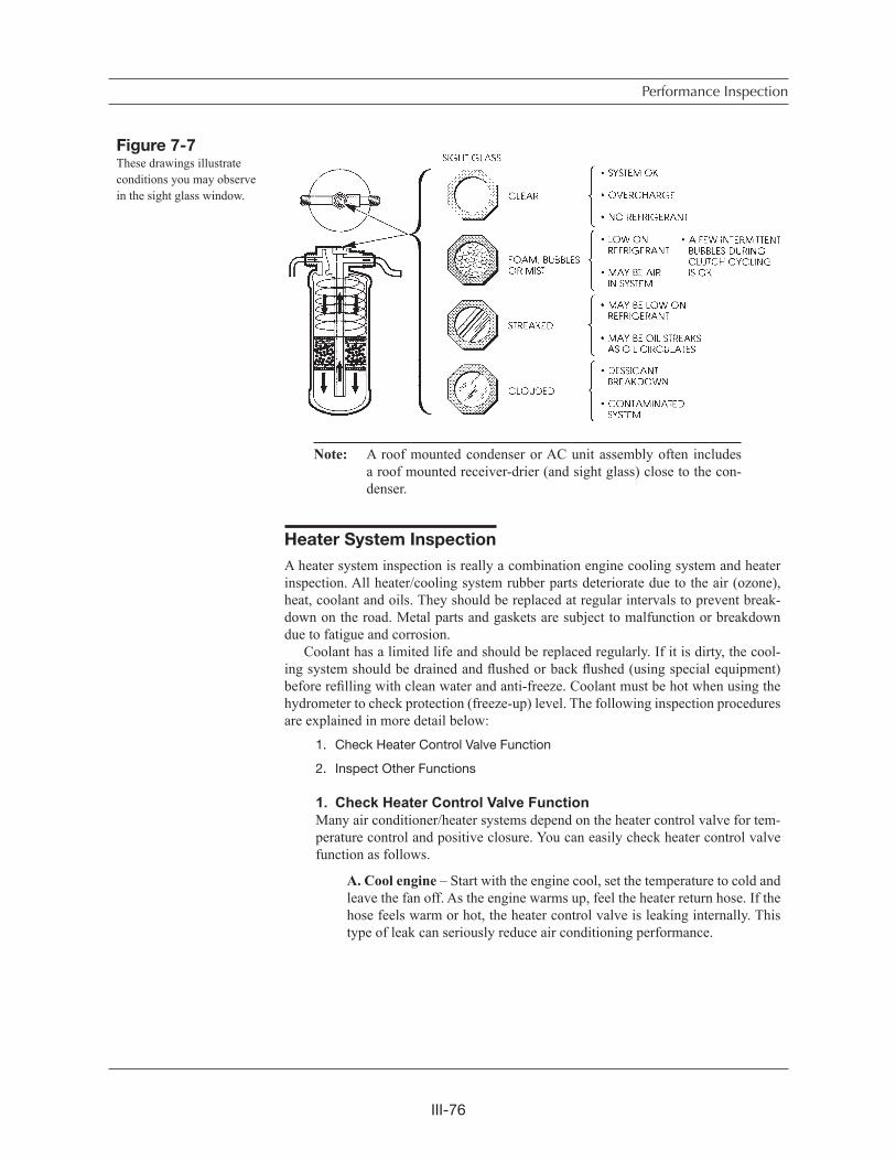
III-76
Note: A roof mounted condenser or AC unit assembly often includes a roof mounted receiver-drier (and sight glass) close to the con-denser.
Heater System Inspection
A heater system inspection is really a combination engine cooling system and heater inspection. All heater/cooling system rubber parts deteriorate due to the air (ozone), heat, coolant and oils. They should be replaced at regular intervals to prevent break-down on the road. Metal parts and gaskets are subject to malfunction or breakdown due to fatigue and corrosion.
Coolant has a limited life and should be replaced regularly. If it is dirty, the cool-ing system should be drained and flushed or back flushed (using special equipment) before refilling with clean water and anti-freeze. Coolant must be hot when using the hydrometer to check protection (freeze-up) level. The following inspection procedures are explained in more detail below:
1. Check Heater Control Valve Function
2. Inspect Other Functions
1. Check Heater Control Valve FunctionMany air conditioner/heater systems depend on the heater control valve for tem-perature control and positive closure. You can easily check heater control valve function as follows.
A. Cool engine – Start with the engine cool, set the temperature to cold and leave the fan off. As the engine warms up, feel the heater return hose. If the hose feels warm or hot, the heater control valve is leaking internally. This type of leak can seriously reduce air conditioning performance.
Performance Inspection
Figure 7-7These drawings illustrate conditions you may observe in the sight glass window.
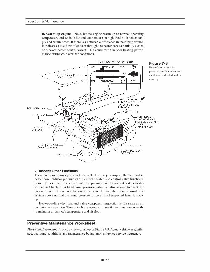
III-77
B. Warm up engine – Next, let the engine warm up to normal operating temperature and set both fan and temperature on high. Feel both heater sup-ply and return hoses. If there is a noticeable difference in their temperature, it indicates a low flow of coolant through the heater core (a partially closed or blocked heater control valve). This could result in poor heating perfor-mance during cold weather conditions.
2. Inspect Other Functions
There are some things you can t see or feel when you inspect the thermostat, heater core, radiator pressure cap, electrical switch and control valve functions. Some of these can be checked with the pressure and thermostat testers as de-scribed in Chapter 6. A hand pump pressure tester can also be used to check for coolant leaks. This is done by using the pump to raise the pressure inside the system above normal operating pressure to force small suspected leaks to show up. Heater/cooling electrical and valve component inspection is the same as air conditioner inspection. The controls are operated to see if they function correctly to maintain or vary cab temperature and air flow.
Preventive Maintenance Worksheet
Please feel free to modify or copy the worksheet in Figure 7-9. Actual vehicle use, mile-age, operating conditions and maintenance budget may influence service frequency.
Inspection & Maintenance
Figure 7-8Heater/cooling system potential problem areas and checks are indicated in this drawing.
III-78
Chapter Review
The purpose of these brief inspection procedures is for vehicle system maintenance and to determine if further, more detailed service is required. The uses of a manifold gauge set, system troubleshooting, recovery, flushing, evacuating and charging are explained in the next chapter.
High usage and operating condition variations are tough on air conditioning and heater components. You should establish and follow regular inspection and mainte-nance procedures to improve overall system function and component service life.
The typical inspection should not take more than 15 to 20 minutes unless com-ponent replacement and/or complete system evacuation and recharging is warranted. The survey results shown in Figure 7-1, indicate belts, compressor clutch assembly, condenser and the refrigerant lines are the most frequent problem areas. However, your own experience with service and maintenance may vary from survey results.
Inspection should first be visual and by feel. Some of your electrical system inspec-tion will be done as you inspect other components (checking leads, connections and for loose wires). When you check the electrical circuit, begin with the engine off but ignition on. A system performance inspection with the engine running and system on really combines electrical and AC or heater system function.
Chapter Review
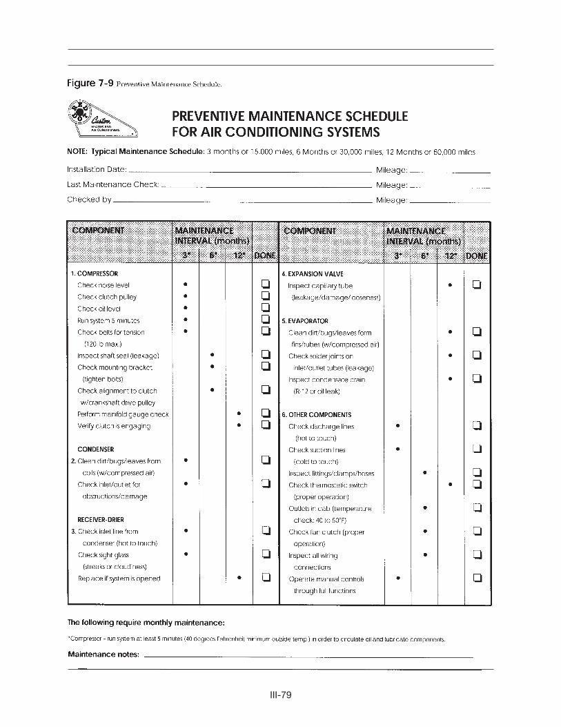
III-79
III-80
Troubleshooting
& Service Procedures• Troubleshooting Overview
• Understanding System Function
• A Troubleshooting Example
• Manifold Gauge Set Installation
• Troubleshooting by Manifold Gauge Set Readings
• Review of Frequent Problem Areas
• Conclusion
Can you fix an air conditioner or heater system without finding and correcting the cause of the problem? You bet you can! It happens every day and it s not good for business. Here is an example. A truck pulls in off the road and the operator asks to have his rig serviced in a hurry. He tells you the air conditioner isn t cooling like it should and dashes into the restaurant for lunch.
You tip the hood, and check the sight glass on top of the receiver-drier. You see bubbles, not a lot but a fairly constant stream of them. It is obvious the system is low on refrigerant so you hook up the manifold gauge set, purge the gauge set hoses of air, and add refrigerant until the sight glass clears. Then you check evaporator tem-perature and it s OK. The air conditioner is repaired right? Wrong! What you did is add refrigerant and the problem went away. You did not find and fix the cause of the problem.
Component failure in an air conditioning system may be the result of a problem elsewhere in the system. For example, a belt or clutch failure might be caused by a dirty condenser restricting air flow and increasing head pressures. High head pressures commonly create problems with other system components. Take time to look beyond the obvious for a potential hidden problem.
Troubleshooting Overview
Troubleshooting includes collecting enough information to locate the cause of the problem, then correcting the problem and its cause by replacement, adjustment, and/or repairing. You begin by gathering information from the most to the least important sources.
Starting with the most important:
1. Your personal knowledge and experience with AC systems.2. The vehicle operator's knowledge and experience—question him or her.3. The work order.4. Good test equipment and the HVAC system
The routine you follow when troubleshooting should proceed from the most to least productive way of locating the problem and fixing the cause.
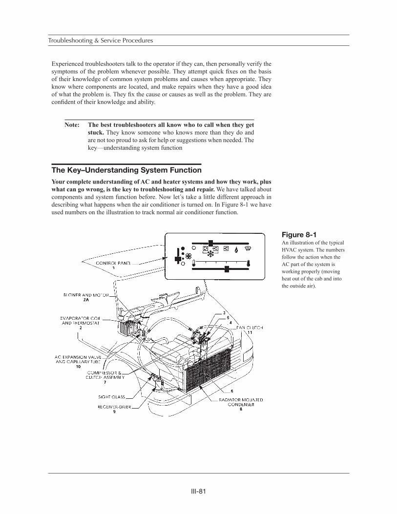
III-81
Experienced troubleshooters talk to the operator if they can, then personally verify the symptoms of the problem whenever possible. They attempt quick fixes on the basis of their knowledge of common system problems and causes when appropriate. They know where components are located, and make repairs when they have a good idea of what the problem is. They fix the cause or causes as well as the problem. They are confident of their knowledge and ability.
Note: The best troubleshooters all know who to call when they get stuck. They know someone who knows more than they do and are not too proud to ask for help or suggestions when needed. The key—understanding system function
The Key–Understanding System Function
Your complete understanding of AC and heater systems and how they work, plus what can go wrong, is the key to troubleshooting and repair. We have talked about components and system function before. Now let s take a little different approach in describing what happens when the air conditioner is turned on. In Figure 8-1 we have used numbers on the illustration to track normal air conditioner function.
Troubleshooting & Service Procedures
Figure 8-1An illustration of the typical HVAC system. The numbers follow the action when the AC part of the system is working properly (moving heat out of the cab and into the outside air).
III-82
When you turn on the air conditioner at the control panel (1), the thermostat (2), is supposed to sense a warm temperature at the evaporator. A circuit in the thermostat should close, allowing current to flow through the thermostat to the compressor clutch field coil (3). When this happens, the clutch field coil becomes an electromagnet and pulls the clutch drive plate (4) tight against the clutch pulley (5).
Note: The same AC switch (1) may also turn on the fan or blower motor (2a) to circulate air in the cab. The air feels warm at first but will cool quickly.
A belt connects the clutch pulley to a drive pulley (6) on the engine. The engine pro-vides the power to turn the clutch pulley and drive the compressor (7) when the clutch is engaged. When operating, the compressor compresses and pushes refrigerant gas to the condenser (8), through the receiver-drier (9), and to the expansion valve (10) orifice. When it does, it puts a lot of pressure on the gas. The compressor raises the temperature and pressure of the refrigerant inside the high side of the system.
At the same time, the compressor is also sucking in low pressure refrigerant gas from the expansion valve orifice, evaporator and through the low side of the system. The movement of the refrigerant inside the system transfers heat energy from the cab to the outside air for occupant comfort.
The automatic functions of the thermostat (or the pressure valve on some accumu-lators), and the expansion valve, help maintain pressures and temperatures inside the system at safe and efficient operating levels. Pressure and temperature are constantly changing due to compressor and expansion valve action, the amount of heat energy being moved and the environment or weather conditions.
The engine cooling system fan and clutch (11), and the evaporator blower motor (2a), move a sufficient amount of air through the condenser and evaporator. On the road, vehicle speed provides most of the (ram) air required for the condenser to work right. In a parked or slow moving vehicle the engine fan (or roof or remote mounted condenser and fans) moves sufficient air through the condenser fins.
Note: Clean refrigerant and refrigeration oil should be inside the system in the amount specified by the manufacturer. Moisture, sludge (moisture combined with refrigerant oil or desiccant), or desic-cant particles will prevent the correct performance of the system and may cause component damage.
A Troubleshooting Example
Remember the story at the beginning of this chapter? The vehicle operator pulled in off the road and asked you to repair the rig. He was in such a hurry he didn t tell you anything except that the air conditioner wasn t cooling. Here is the best way to handle that kind of situation.
Understanding System Function
III-83
Use your knowledge and experience. Ask yourself what could have caused a lack of cooling in that rig! Did the compressor drive belt break? Did a pressure switch or relief valve cutout the compressor because of high or low system pressure? Does the switch or valve in this type of system reset itself? Could there be a superheat switch and thermal limiter with a melted fuse. Did someone else service the system recently and put in too much refrigerant?
Could there be contaminants in the system blocking the expansion valve (expan-sion tube)? If there is a leak, why and how did refrigerant get out of the system? You know if refrigerant can get out, air and moisture may get inside as well, especially if the leak is on the suction side of the system. Could there be a restriction to refrigerant flow in one of the high pressure lines because of a kink? From your knowledge and experience, you already know about these possibilities and others when you talk to the operator (before he has the chance to leave).
The right kind of questions can speed up troubleshooting and your service work by pinpointing the problem(s) that needs fixing. Your conversation with the operator might be as follows:
• How long ago did the AC system stop cooling?Answer: About an hour ago.
• What steps did you take when you noticed the lack of cooling?Answer: I put it on maximum cool.
• Then what did you do?Answer: When it wouldn t cool, I opened the window and turned the air conditioner off.
• Is this problem new or has it happened before, and when?Answer: In the last few days I ve had problems with cooling off and on—this is the first time it s happened when I was close to a place that did AC service.
• Do you get any cooling at all?Answer: Yes but it seems to quit after a while.
• Do you still get air flow at the vents from the blower?Answer: Yes.
• When was your air conditioner checked thoroughly?Answer: Before I bought the rig last May (a year ago).
• Has the heater been used recently and did it work OK?Answer: Yes.
Troubleshooting & Service Procedures
III-84
• Have you had other service problems in the last few months?Answer: No.
• (If the answer was yes, you should ask—When? Where? What was fixed or replaced?).
• Finally, ask the operator if he or she has a wiring diagram for the system.
Now let s look at the information you have gathered from the operator and what you know from experience. He believes the problem is that the AC system quits cooling after it has been on for a while! You know that the AC system has not been maintained since the rig was purchased a year ago. Because of that, there could be several causes for the problem (lack of cooling) and there may be other potential problems about to develop.
It is possible that some refrigerant has leaked. Moisture and other contamination may be inside the system. You have been told there are no heater problems, but that doesn t mean there are none that might affect AC system operation. The AC system has quit cooling several times in the last few days. The problem may have become more severe than when it quit cooling the first time.
If enough refrigerant or oil has leaked out, a low pressure cutout switch may have cut the circuit to the clutch, protecting the compressor. Because the system has not been maintained in a year, there may be other components that should be serviced. You could fix the probable causes, and the system might work and then break down again as the rig drives out of your place. From your knowledge and what the operator has just told you, you know this may not be a quick fix problem.
It s up to you to describe the service situation to the operator. Tell him you need to do a complete system maintenance inspection to find and correct the problem or other potential problems. He can give you the go ahead for full service and repair now, wait till you have inspected the system to determine cause and cost, or delay repair until he has some down time available.
Normally when the operator can tell you what the problem is, you would first oper-ate the system to verify the problem. In this situation your troubleshooting (your own knowledge added to what the operator told you), indicates the next step. You need to do a complete maintenance inspection instead! Proceed as described in Chapter 7.Correct any obvious problems and check carefully for leaks. Leak testing should be visual, by feel and with a leak detector. Next, do your performance test with the engine running and the AC system on.
Note: Don t forget to check the heater system too! If the water valve is not closed, then hot engine coolant flowing through the heater core would warm the air at the same time the evaporator was trying to cool it. The result would be the appearance of an AC problem.
A Troubleshooting Example
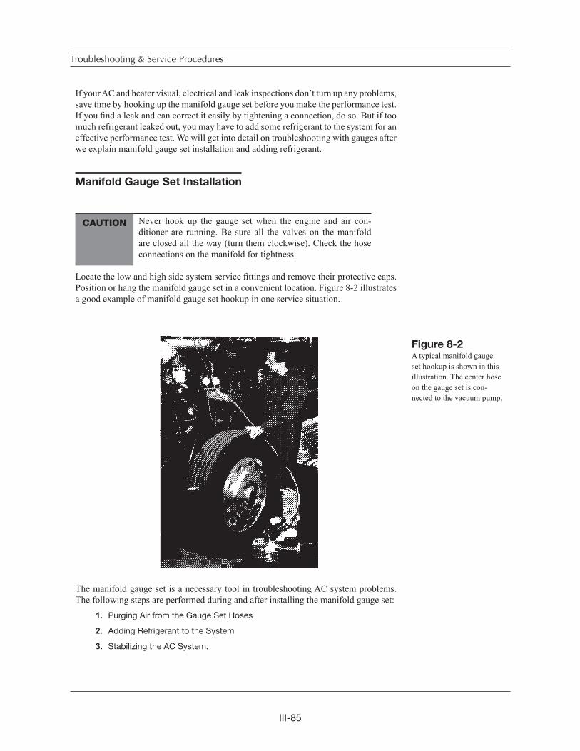
III-85
If your AC and heater visual, electrical and leak inspections don t turn up any problems, save time by hooking up the manifold gauge set before you make the performance test. If you find a leak and can correct it easily by tightening a connection, do so. But if too much refrigerant leaked out, you may have to add some refrigerant to the system for an effective performance test. We will get into detail on troubleshooting with gauges after we explain manifold gauge set installation and adding refrigerant.
Manifold Gauge Set Installation
Never hook up the gauge set when the engine and air con-ditioner are running. Be sure all the valves on the manifold are closed all the way (turn them clockwise). Check the hose connections on the manifold for tightness.
Locate the low and high side system service fittings and remove their protective caps. Position or hang the manifold gauge set in a convenient location. Figure 8-2 illustrates a good example of manifold gauge set hookup in one service situation.
The manifold gauge set is a necessary tool in troubleshooting AC system problems. The following steps are performed during and after installing the manifold gauge set:
1. Purging Air from the Gauge Set Hoses
2. Adding Refrigerant to the System
3. Stabilizing the AC System.
Troubleshooting & Service Procedures
CAUTION
Figure 8-2A typical manifold gauge set hookup is shown in this illustration. The center hose on the gauge set is con-nected to the vacuum pump.
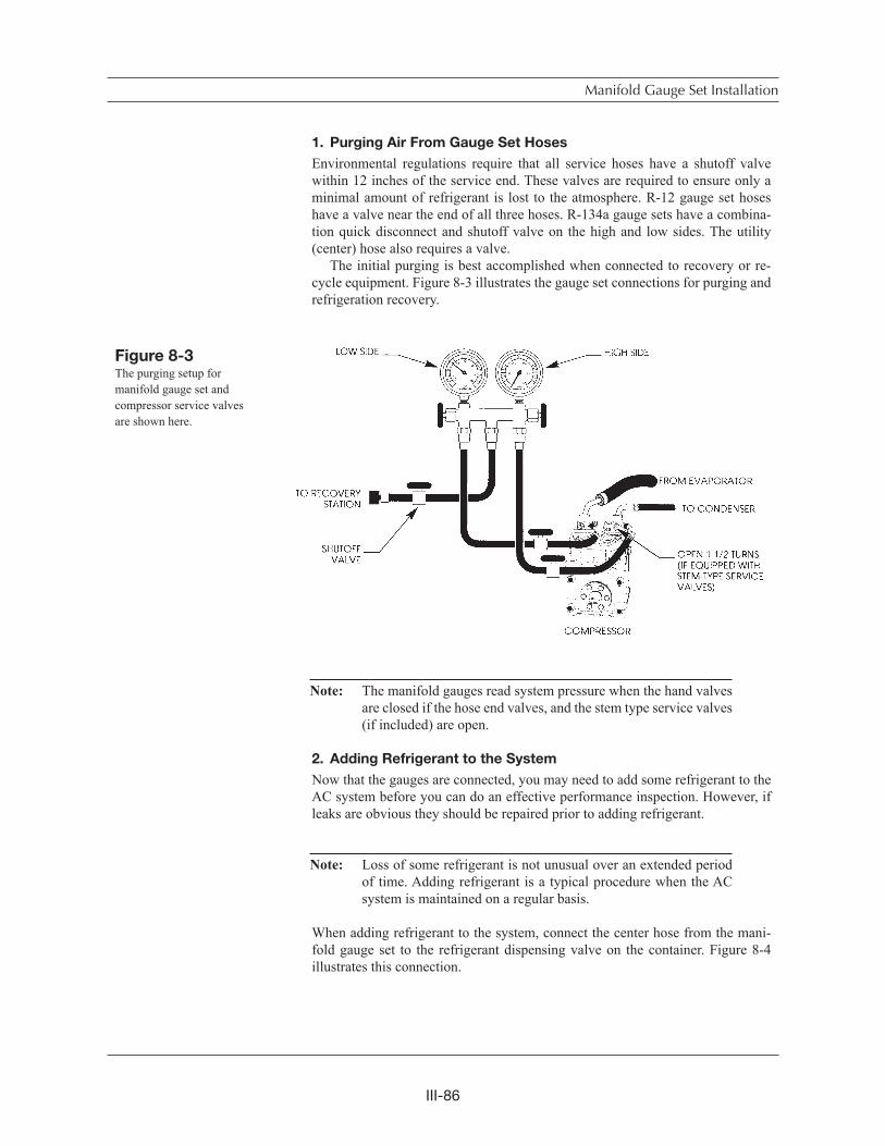
III-86
1. Purging Air From Gauge Set Hoses
Environmental regulations require that all service hoses have a shutoff valve within 12 inches of the service end. These valves are required to ensure only a minimal amount of refrigerant is lost to the atmosphere. R-12 gauge set hoses have a valve near the end of all three hoses. R-134a gauge sets have a combina-tion quick disconnect and shutoff valve on the high and low sides. The utility (center) hose also requires a valve. The initial purging is best accomplished when connected to recovery or re-cycle equipment. Figure 8-3 illustrates the gauge set connections for purging and refrigeration recovery.
Note: The manifold gauges read system pressure when the hand valves are closed if the hose end valves, and the stem type service valves (if included) are open.
2. Adding Refrigerant to the System
Now that the gauges are connected, you may need to add some refrigerant to the AC system before you can do an effective performance inspection. However, if leaks are obvious they should be repaired prior to adding refrigerant.
Note: Loss of some refrigerant is not unusual over an extended period of time. Adding refrigerant is a typical procedure when the AC system is maintained on a regular basis.
When adding refrigerant to the system, connect the center hose from the mani-fold gauge set to the refrigerant dispensing valve on the container. Figure 8-4 illustrates this connection.
Manifold Gauge Set Installation
Figure 8-3The purging setup for manifold gauge set and compressor service valves are shown here.
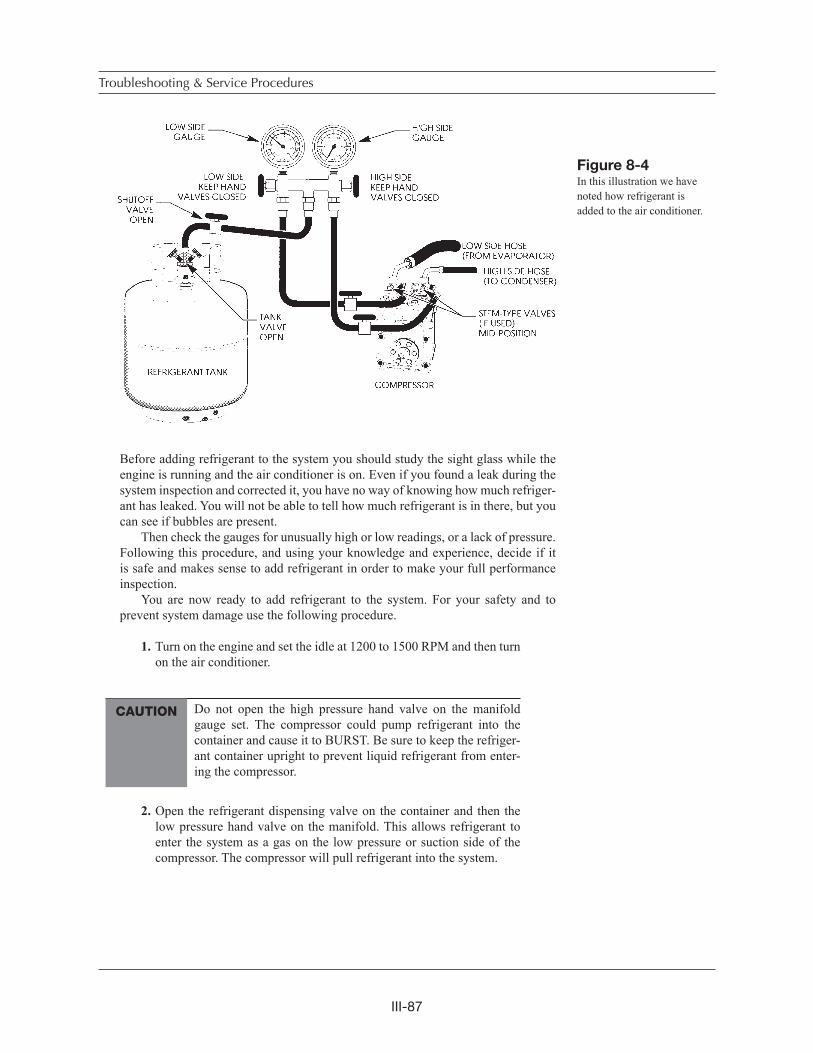
III-87
Before adding refrigerant to the system you should study the sight glass while the engine is running and the air conditioner is on. Even if you found a leak during the system inspection and corrected it, you have no way of knowing how much refriger-ant has leaked. You will not be able to tell how much refrigerant is in there, but you can see if bubbles are present.
Then check the gauges for unusually high or low readings, or a lack of pressure. Following this procedure, and using your knowledge and experience, decide if it is safe and makes sense to add refrigerant in order to make your full performance inspection.
You are now ready to add refrigerant to the system. For your safety and to prevent system damage use the following procedure.
1. Turn on the engine and set the idle at 1200 to 1500 RPM and then turn on the air conditioner.
Do not open the high pressure hand valve on the manifold gauge set. The compressor could pump refrigerant into the container and cause it to BURST. Be sure to keep the refriger-ant container upright to prevent liquid refrigerant from enter-ing the compressor.
2. Open the refrigerant dispensing valve on the container and then the low pressure hand valve on the manifold. This allows refrigerant to enter the system as a gas on the low pressure or suction side of the compressor. The compressor will pull refrigerant into the system.
Troubleshooting & Service Procedures
Figure 8-4In this illustration we have noted how refrigerant is added to the air conditioner.
CAUTION
III-88
3. Add refrigerant until the gauges read in the normal range and the sight glass appears clear. The sight glass may not be clear for a moment just before or after the clutch cycles on and off but should generally be clear. Gauge readings will fluctuate as the compressor cycles on and off.
Note: Pressures within the air conditioning system vary with ambient temperature. A normal pressure range is defined as follows:
Low side 15–30 PSIG High side 150–280 PSIG If R-134a is used in place of R-12 the high side readings will
be about 20 PSI higher. For this reason many OEMs are recom-mending an increase in condenser capacity when retrofitting to the new refrigerant, R-134a.
If the gauges show any abnormally high or low pressures as you are adding refrigerant, stop and investigate for probable cause. Never add more than one pound of refrigerant. If the system is low enough on refrigerant to require more than that amount you should stop and check again for leaks. Then re-cover all of the refrigerant, repair, evacuate and recharge the air conditioner. (See Chapter 9). You may want to add dry nitrogen gas to the AC system instead of R-12 if pressures are below normal and a leak is suspected. Nitrogen gas is sold in cylinders under high pressure, 1800 to 2000 PSI. Be sure the cylinder has a pressure regulating valve to control the pressure when dispensing nitrogen gas. Dispose the gas at no more than 200-250 psi, as this is sufficient pressure to cause or indicate a leak point. See note under Troubleshooting by Manifold Gauge Set Readings in this chapter.
4. When the gauges show normal, close the hand valve on the manifold, the hose end shutoff valve, and the valve on the refrigerant container. You can now proceed with the performance inspection.
3. Stabilizing The AC System
For reliable gauge readings as an aid in troubleshooting, the AC system must be stabilized.
Be sure your tools and test equipment are clear of all moving parts of the engine and air conditioner.
Manifold Gauge Set Installation
CAUTION
CAUTION
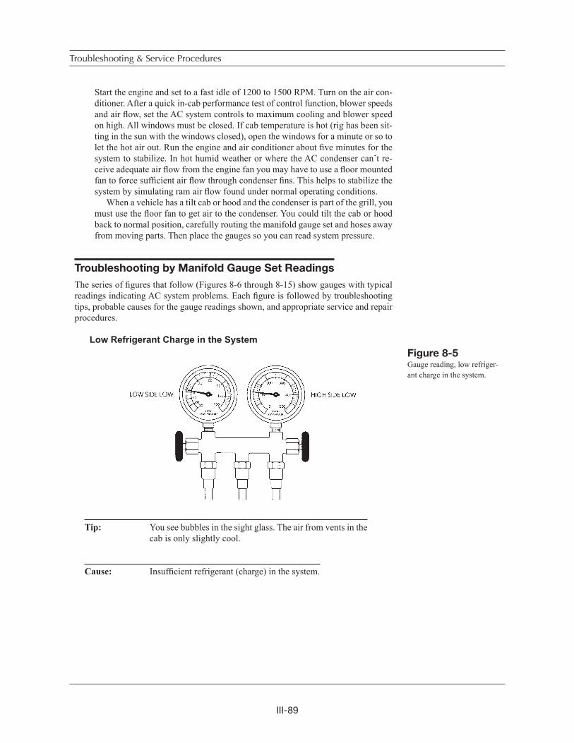
III-89
Start the engine and set to a fast idle of 1200 to 1500 RPM. Turn on the air con-ditioner. After a quick in-cab performance test of control function, blower speeds and air flow, set the AC system controls to maximum cooling and blower speed on high. All windows must be closed. If cab temperature is hot (rig has been sit-ting in the sun with the windows closed), open the windows for a minute or so to let the hot air out. Run the engine and air conditioner about five minutes for the system to stabilize. In hot humid weather or where the AC condenser can t re-ceive adequate air flow from the engine fan you may have to use a floor mounted fan to force sufficient air flow through condenser fins. This helps to stabilize the system by simulating ram air flow found under normal operating conditions. When a vehicle has a tilt cab or hood and the condenser is part of the grill, you must use the floor fan to get air to the condenser. You could tilt the cab or hood back to normal position, carefully routing the manifold gauge set and hoses away from moving parts. Then place the gauges so you can read system pressure.
Troubleshooting by Manifold Gauge Set Readings
The series of figures that follow (Figures 8-6 through 8-15) show gauges with typical readings indicating AC system problems. Each figure is followed by troubleshooting tips, probable causes for the gauge readings shown, and appropriate service and repair procedures.
Low Refrigerant Charge in the System
Tip: You see bubbles in the sight glass. The air from vents in the cab is only slightly cool.
Cause: Insufficient refrigerant (charge) in the system.
Troubleshooting & Service Procedures
Figure 8-5Gauge reading, low refriger-ant charge in the system.
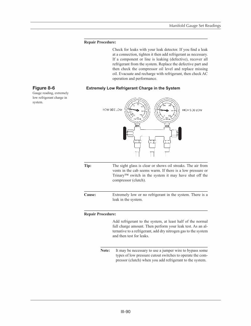
III-90
Repair Procedure:
Check for leaks with your leak detector. If you find a leak at a connection, tighten it then add refrigerant as necessary. If a component or line is leaking (defective), recover all refrigerant from the system. Replace the defective part and then check the compressor oil level and replace missing oil. Evacuate and recharge with refrigerant, then check AC operation and performance.
Extremely Low Refrigerant Charge in the System
Tip: The sight glass is clear or shows oil streaks. The air from vents in the cab seems warm. If there is a low pressure or Trinary™ switch in the system it may have shut off the compressor (clutch).
Cause: Extremely low or no refrigerant in the system. There is a leak in the system.
Repair Procedure:
Add refrigerant to the system, at least half of the normal full charge amount. Then perform your leak test. As an al-ternative to a refrigerant, add dry nitrogen gas to the system and then test for leaks.
Note: It may be necessary to use a jumper wire to bypass some types of low pressure cutout switches to operate the com-pressor (clutch) when you add refrigerant to the system.
Manifold Gauge Set Readings
Figure 8-6Gauge reading, extremely low refrigerant charge in system.
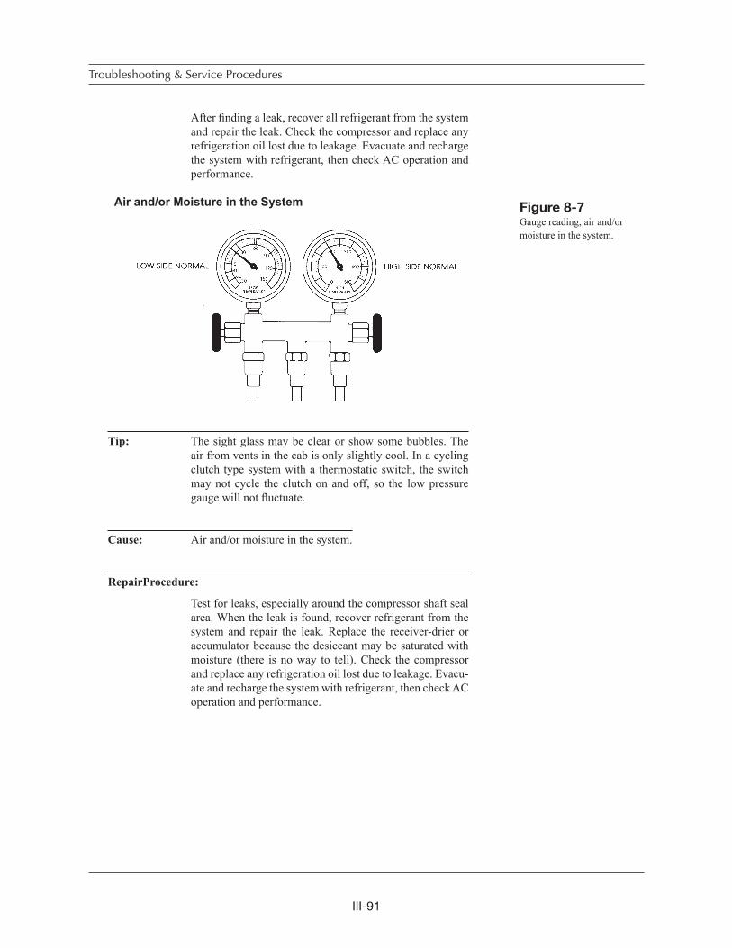
III-91
After finding a leak, recover all refrigerant from the system and repair the leak. Check the compressor and replace any refrigeration oil lost due to leakage. Evacuate and recharge the system with refrigerant, then check AC operation and performance.
Air and/or Moisture in the System
Tip: The sight glass may be clear or show some bubbles. The air from vents in the cab is only slightly cool. In a cycling clutch type system with a thermostatic switch, the switch may not cycle the clutch on and off, so the low pressure gauge will not fluctuate.
Cause: Air and/or moisture in the system.
RepairProcedure:
Test for leaks, especially around the compressor shaft seal area. When the leak is found, recover refrigerant from the system and repair the leak. Replace the receiver-drier or accumulator because the desiccant may be saturated with moisture (there is no way to tell). Check the compressor and replace any refrigeration oil lost due to leakage. Evacu-ate and recharge the system with refrigerant, then check AC operation and performance.
Troubleshooting & Service Procedures
Figure 8-7Gauge reading, air and/or moisture in the system.
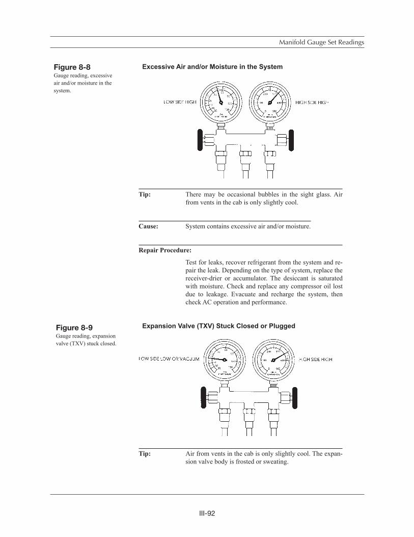
III-92
Excessive Air and/or Moisture in the System
Tip: There may be occasional bubbles in the sight glass. Air from vents in the cab is only slightly cool.
Cause: System contains excessive air and/or moisture.
Repair Procedure:
Test for leaks, recover refrigerant from the system and re-pair the leak. Depending on the type of system, replace the receiver-drier or accumulator. The desiccant is saturated with moisture. Check and replace any compressor oil lost due to leakage. Evacuate and recharge the system, then check AC operation and performance.
Expansion Valve (TXV) Stuck Closed or Plugged
Tip: Air from vents in the cab is only slightly cool. The expan-sion valve body is frosted or sweating.
Manifold Gauge Set Readings
Figure 8-9Gauge reading, expansion valve (TXV) stuck closed.
Figure 8-8Gauge reading, excessive air and/or moisture in the system.
III-93
Cause: An expansion valve malfunction could mean the valve is stuck in the closed position, the filter screen is clogged (block type expansion valves do not have filter screens), moisture in the system has frozen at the expansion valve orifice, or the sensing bulb is not operating. In vehicles where the TXV and sensing bulb are accessible, perform the following test. If not accessible, then proceed to RepairProcedure.
Test: 1. Warm diaphragm and valve body in your hand or care-fully with a heat gun. Activate system and watch to see if the low pressure gauge rises.
2. Next, carefully spray a little nitrogen, or any substance below 32 degrees Fahrenheit, on the capillary coil (bulb) or valve diaphragm. The low side gauge needle should drop and read at a lower (suction) pressure on the gauge. This indicates the valve was part way open and that your action closed it. Repeat the test, but first warm the valve diaphragm or capillary with your hand. If the low side gauge drops again, the valve is not stuck.
3. Clean the surfaces of the evaporator outlet and the cap-illary coil or bulb. Make sure the coil or bulb is securely clamped to the evaporator outlet tube and the insulation is in place. Next proceed with recovering refrigerant from the system.
Repair Procedure:
Inspect the expansion valve screen (except block type valves). To do this you must recover all refrigerant from the system. Disconnect the inlet hose fitting from the expan-sion valve. Remove, clean and replace the screen, then re-connect the hose. Any signs of contamination will requireflushing the system. Next, replace the receiverdrier. Then evacuate and recharge the system with refrigerant, and check AC operation and performance.
Troubleshooting & Service Procedures
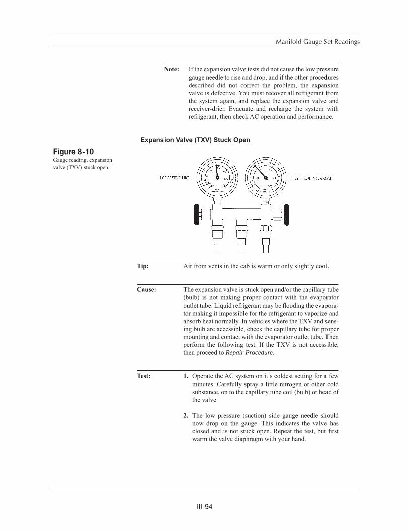
III-94
Note: If the expansion valve tests did not cause the low pressure gauge needle to rise and drop, and if the other procedures described did not correct the problem, the expansion valve is defective. You must recover all refrigerant from the system again, and replace the expansion valve and receiver-drier. Evacuate and recharge the system with refrigerant, then check AC operation and performance.
Expansion Valve (TXV) Stuck Open
Tip: Air from vents in the cab is warm or only slightly cool.
Cause: The expansion valve is stuck open and/or the capillary tube (bulb) is not making proper contact with the evaporator outlet tube. Liquid refrigerant may be flooding the evapora-tor making it impossible for the refrigerant to vaporize and absorb heat normally. In vehicles where the TXV and sens-ing bulb are accessible, check the capillary tube for proper mounting and contact with the evaporator outlet tube. Then perform the following test. If the TXV is not accessible, then proceed to Repair Procedure.
Test: 1. Operate the AC system on it s coldest setting for a few minutes. Carefully spray a little nitrogen or other cold substance, on to the capillary tube coil (bulb) or head of the valve.
2. The low pressure (suction) side gauge needle should now drop on the gauge. This indicates the valve has closed and is not stuck open. Repeat the test, but firstwarm the valve diaphragm with your hand.
Manifold Gauge Set Readings
Figure 8-10Gauge reading, expansion valve (TXV) stuck open.
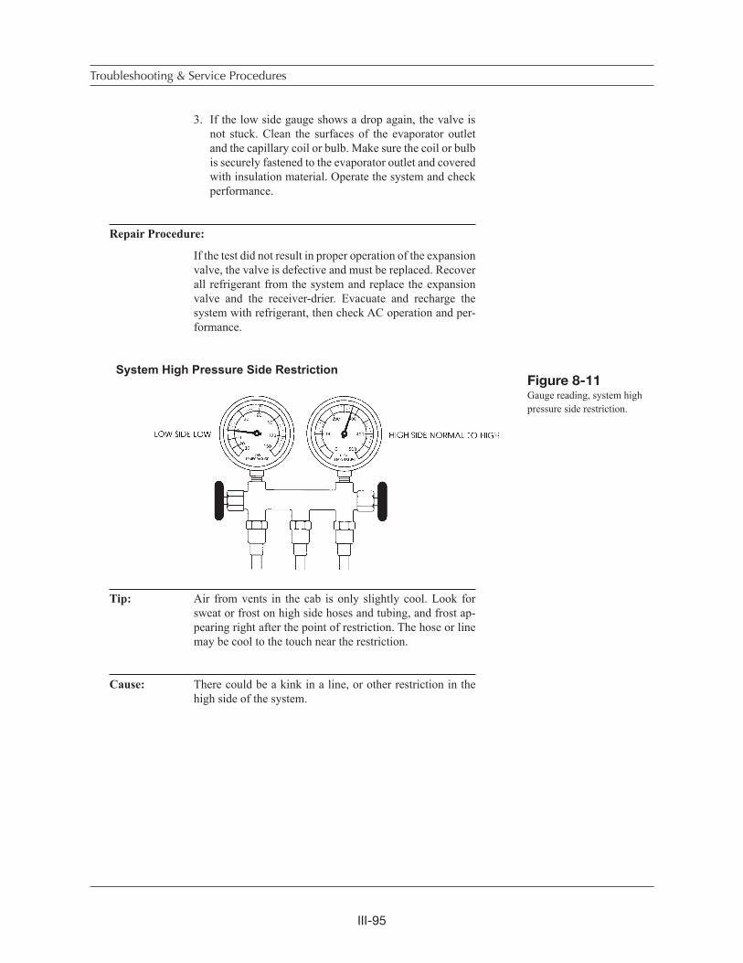
III-95
3. If the low side gauge shows a drop again, the valve is not stuck. Clean the surfaces of the evaporator outlet and the capillary coil or bulb. Make sure the coil or bulb is securely fastened to the evaporator outlet and covered with insulation material. Operate the system and check performance.
Repair Procedure:
If the test did not result in proper operation of the expansion valve, the valve is defective and must be replaced. Recover all refrigerant from the system and replace the expansion valve and the receiver-drier. Evacuate and recharge the system with refrigerant, then check AC operation and per-formance.
System High Pressure Side Restriction
Tip: Air from vents in the cab is only slightly cool. Look for sweat or frost on high side hoses and tubing, and frost ap-pearing right after the point of restriction. The hose or line may be cool to the touch near the restriction.
Cause: There could be a kink in a line, or other restriction in the high side of the system.
Troubleshooting & Service Procedures
Figure 8-11Gauge reading, system high pressure side restriction.
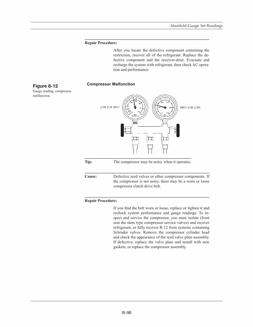
III-96
Repair Procedure:
After you locate the defective component containing the restriction, recover all of the refrigerant. Replace the de-fective component and the receiver-drier. Evacuate and recharge the system with refrigerant, then check AC opera-tion and performance.
Compressor Malfunction
Tip: The compressor may be noisy when it operates.
Cause: Defective reed valves or other compressor components. If the compressor is not noisy, there may be a worn or loose compressor clutch drive belt.
Repair Procedure:
If you find the belt worn or loose, replace or tighten it and recheck system performance and gauge readings. To in-spect and service the compressor, you must isolate (front seat the stem type compressor service valves) and recover refrigerant, or fully recover R-12 from systems containing Schrader valves. Remove the compressor cylinder head and check the appearance of the reed valve plate assembly. If defective, replace the valve plate and install with new gaskets, or replace the compressor assembly.
Manifold Gauge Set Readings
Figure 8-12Gauge reading, compressor malfunction.
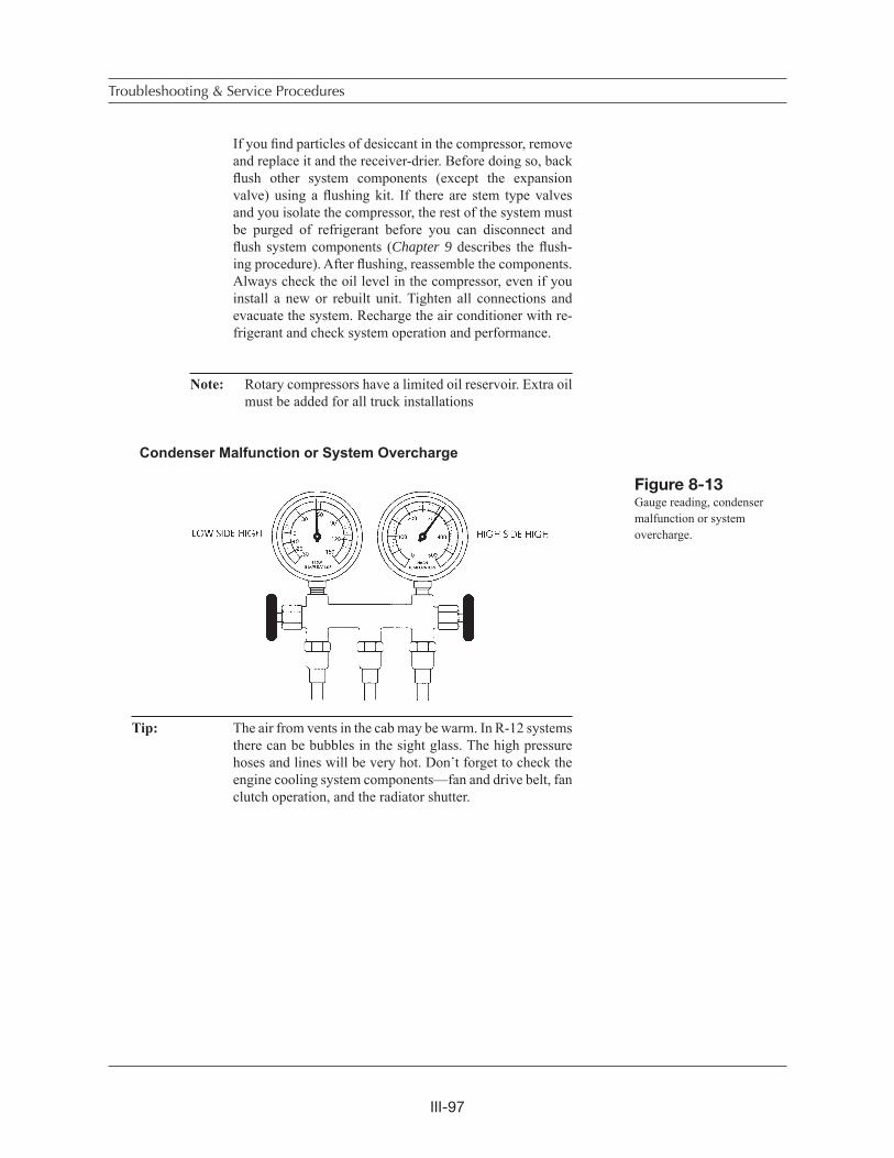
III-97
If you find particles of desiccant in the compressor, remove and replace it and the receiver-drier. Before doing so, back flush other system components (except the expansion valve) using a flushing kit. If there are stem type valves and you isolate the compressor, the rest of the system must be purged of refrigerant before you can disconnect and flush system components (Chapter 9 describes the flush-ing procedure). After flushing, reassemble the components. Always check the oil level in the compressor, even if you install a new or rebuilt unit. Tighten all connections and evacuate the system. Recharge the air conditioner with re-frigerant and check system operation and performance.
Note: Rotary compressors have a limited oil reservoir. Extra oil must be added for all truck installations
Condenser Malfunction or System Overcharge
Tip: The air from vents in the cab may be warm. In R-12 systems there can be bubbles in the sight glass. The high pressure hoses and lines will be very hot. Don t forget to check the engine cooling system components—fan and drive belt, fan clutch operation, and the radiator shutter.
Troubleshooting & Service Procedures
Figure 8-13Gauge reading, condenser malfunction or system overcharge.
III-98
Cause: The condenser is not functioning correctly or there may be an overcharge of refrigerant inside the system. Another possibility is lack of (ram) air flow through the condenser fins during testing. Engine cooling system component malfunction can cause high pressure by blocking air flow(radiator shutter) or not providing air flow (fan clutch) in sufficient quantity.
Repair Procedure:
Inspect the condenser for dirt, bugs or other debris and clean if necessary. Be sure the condenser is securely mounted and there is adequate clearance (about 1-1/2 inches) between it and the radiator. Check the radiator pressure cap and cooling system, including the fan, fan clutch, drive belts and radiator shutter assembly. Replace any defective parts and then recheck AC system operation, gauge readings and performance.
If the problem continues, the system may be over- charged (have too much refrigerant inside). Recover the system slowly until low and high pressure gauges read below nor-mal, and bubbles appear in the sight glass. Then add refrig-erant (charge the system) until pressures are normal and the bubbles disappear. Add another quarter to half pound of refrigerant and recheck AC system operation, gauge read-ings and performance.
If the high gauge readings do not change, you should recover all of the refrigerant and flush (it may be partially plugged) or replace the condenser. Also replace the receiver-drier or accumulator. Then connect the components and evacuate the system. Recharge the air conditioner with refrigerant and check system operation and performance.
Manifold Gauge Set Readings
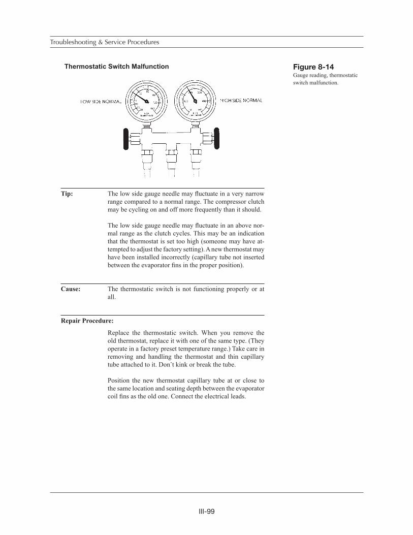
III-99
Thermostatic Switch Malfunction
Tip: The low side gauge needle may fluctuate in a very narrow range compared to a normal range. The compressor clutch may be cycling on and off more frequently than it should.
The low side gauge needle may fluctuate in an above nor-mal range as the clutch cycles. This may be an indication that the thermostat is set too high (someone may have at-tempted to adjust the factory setting). A new thermostat may have been installed incorrectly (capillary tube not inserted between the evaporator fins in the proper position).
Cause: The thermostatic switch is not functioning properly or at all.
Repair Procedure:
Replace the thermostatic switch. When you remove the old thermostat, replace it with one of the same type. (They operate in a factory preset temperature range.) Take care in removing and handling the thermostat and thin capillary tube attached to it. Don t kink or break the tube.
Position the new thermostat capillary tube at or close to the same location and seating depth between the evaporator coil fins as the old one. Connect the electrical leads.
Troubleshooting & Service Procedures
Figure 8-14Gauge reading, thermostatic switch malfunction.
III-100
Note: See the Thermostat section in Chapter 10. Fan clutch, ra-diator shutter, condenser, compressor, and the newer air and water valve control systems are covered in Chapter10.
Review of Frequent Problem Areas
In HVAC systems a limited number of things can go wrong. Moving parts of the com-pressor, clutch, and expansion valve or refrigerant metering device can malfunction or break down from metal fatigue, contamination, abnormal pressure or lack of lubrica-tion. Electrical connections may corrode, become disconnected or break. Fuses blow from shorts or overload. Belts slip or break.
Vibration from the engine or road surface can work bolts and air or vacuum lines loose, or rub and break or wear parts out. Motors may burn out. The inside of the system can become contaminated from moisture, air or desiccant material breakdown. Refrigerant may leak out of the system quickly or very slowly. Moisture in the system can combine with refrigerant to form acid and attack (corrode) metal parts from the inside. Moisture and refrigeration oil can combine to form sludge that may block re-frigerant flow.
The following problems are discussed in more detail in this section:
1. Belts and Compressor Clutch
2. Condenser
3. Refrigerant Lines, Hoses, and Fittings
4. Refrigerant Metering Valves
5. Other Problems
1. Belts and Compressor Clutch
Let s review problem areas listed at the beginning of Chapter 7. The most fre-quent repairs are replacing belts and servicing or replacing the compressor or clutch. Heavy duty vehicle operation puts a lot of stress on these parts. There are several main reasons.
There is often continuous operation for long periods of time. There may be frequent sudden RPM variations when shifting gears up or down. For this reason the AC clutches used in heavy duty systems usually have double row ball bear-ings. Vibration and road shock contribute to loose or broken mounting brackets, electrical connections and fittings. Belts, bearings and compressor reed valves wear out.
Various compressor clutch cutout switches are used because the AC designers know about compressor operating conditions. System leaks, high operating pres-sures, malfunctioning engine cooling system components—all cause compressor problems and failures. When refrigerant and refrigeration oil leaks out of a sys-tem or there is contamination blocking oil flow, the compressor will be starved for oil and seize.
Review of Frequent Problem Areas

III-101
2. Condenser
Condensers get dirty and the dirt reduces heat movement by insulating the con-denser. The fittings come loose or break from stress if the condenser or connecting hoses are not secured properly to keep the effects of vibration at a minimum.
Heat transfer efficiency and pressure in the condenser are affected by the amount of outside air flowing through condenser fins. A lack of air flow can mean the refrigerant doesn t give up enough heat energy to the outside air (it doesn tchange state). The refrigerant arrives at the evaporator as a gas and can t pick up any heat energy from cab air. In the cab, air from the vents is only slightly cool or warm.
One possible cause of condenser malfunction could be the engine cooling sys-tem. This is why fan clutches and radiator shutters are often controlled or over-ridden by AC switch function. In fact, we can add fan clutch, radiator shutters and also fan motors to condenser problems. If they don t function to allow sufficientair through the condenser, pressure inside the system may become dangerously high. A lack of air through the condenser fins can raise high side pressure and blow out the weakest point in a system, or damage the compressor.
3. Refrigerant Lines, Hoses and Fittings
Problems with these parts may be caused by normal deterioration, vibration dam-age, lack of maintenance or human error (improper installation or replacement). All rubber parts are attacked by ozone (oxygen) in the air. Rubber parts break down slowly and become more vulnerable to the effects of vibration with the passage of time.Heavy duty vehicle vibration causes stress on all lines, fittings and connections. Regular maintenance includes checking and tightening any suspect line, or hose retainers, or grommet position where the grommet is protecting a line or hose from abrasion. Any insulating material wrapped around hoses must be in place and securely fastened.
4. Refrigerant Metering Valves
When you consider valve problems there are obvious differences in valve con-struction and what can go wrong. If a valve is clogged with sludge or other obstruction, the result is a valve problem but the cause is contamination in the system. Valves get stuck open or closed, although most often closed when the gas charge is lost from the diaphragm housing in a traditional TXV. The capillary tube can vibrate loose from the evaporator outlet tube. The capillary can break and the small quantity of temperature sensitive gas can escape. The diagnosis of a valve as defective calls for replacement.
5. Other Problems—Leaks, Moisture, and Adding
Refrigerant
Before any refrigerant was put inside the AC system, someone used a vacuum pump to evacuate any air and moisture. Vacuum is really a force pulling against all hoses, fittings and components from the inside. When the system is charged with refrigerant, the pressure goes from minus (a vacuum) to plus pressure inside the hoses and all components. The refrigerant and refrigeration oil are trying to escape from the system at all times.
Troubleshooting & Service Procedures
III-102
Technicians frequently add refrigerant to a system, replacing refrigerant seep-age through system connections or fittings. If the system has been maintained regularly (every three to six months), adding a small amount of refrigerant may result in normal system function. However, the best procedure is to check all connections and look for, find and repair any leaks before adding refrigerant.
When your leak detector indicates the presence of a leak, you can t tell how long the system has been leaking. Finding one leak doesn t mean there are not others. Until you have some AC system work experience, it will be hard to guess how much refrigerant may have leaked. If you have to top a system off with a half pound of refrigerant or more, adding refrigerant is not the answer.
Find the leak. Recover all of the refrigerant and repair the system. The mois-ture absorbing capacity of any desiccant material is limited and cannot be mea-sured. For that reason, replace the receiver-drier or accumulator. Then evacuate the system for an hour and recharge with refrigerant.
When a compressor shaft seal has leaked oil and the refrigerant charge is a little low, the shaft seal may have leaked because the air conditioner was not used. The seal can get a little out of round from the weight of the crankshaft and leak above the shaft. Running the compressor may cause the seal to swell and close up the leak. The shaft rotation exerts force all around the seal and puts life back into it. To prevent this from happening, manufacturers recommend regular AC system operation a minimum of every couple of weeks even in cool weather.Keep in mind that the compressor can cause a vacuum inside the system if there is a restriction in the system. That means it can suck air and moisture inside under some conditions. It will pull these contaminants in through the same space where refrigerant and refrigerant oil has leaked out.
Conclusion
What could the air conditioning problem and it s cause have been at the beginning of this chapter? The operator was in a hurry, but you were able to start your troubleshoot-ing with the answers he gave you. Problems your inspection may have turned up are a very low refrigerant charge, a contaminated system or defective compressor. Those are not quick fix jobs.
On the other hand, you might have found enough debris on the condenser fin sur-face to boost high side pressures to an abnormal level during the hottest part of the day. So the Trinary™ or high pressure switch would cut out from high pressure—but reset itself. You cleaned the condenser, added a half pound of refrigerant and AC system pressures and function returned to normal. Service and repair took a half hour. But there was no way to tell without using your knowledge and experience. By now you are pretty familiar with AC system problems, the reasons for some of them, trouble-shooting and repair. In Chapter 9 we will describe complete system purging, evacua-tion, flushing and recharging.
Conclusion
MACHINE CONFIGURATION
III-103
IV-1
IV . HYDRAULIC UNITS
IV-2
HYDRAULIC UNITS
CONTENTS
HST Pump ...............................................................................................................................................................3Gear Pump ............................................................................................................................................................33Gear Pump (High Flow) ........................................................................................................................................40Control Valve ........................................................................................................................................................44Control Valve (High Flow) ...................................................................................................................................56Control Valve (Sub) ..............................................................................................................................................64Pilot Valve .............................................................................................................................................................71Pilot Valve (Auxiliary) ..........................................................................................................................................81Self-level Valve .....................................................................................................................................................85Cylinders ...............................................................................................................................................................92Travel Motor (Daikin) .........................................................................................................................................109

IV-3
HYDRAULIC UNITSHST PUMP
1. O-ring 2. Seal 3. Gasket 4. O-ring 5. O-ring 6. O-ring 7. O-ring 8. O-ring 9. Swash Plate10. Seal Carrier
HST PUMP
CONSTRUCTION
Pump Assembly (1/4)
11. Seal Carrier12. Cover13. Pin14. Gasket15. Plug16. Ring17. Cylinder Block18. Valve Plate19. Coupling20. Coupling
21. Shaft22. Pad A23. Pad B24. Shaft25. Ring26. Ring27. Bearing28. Bearing29. Bearing
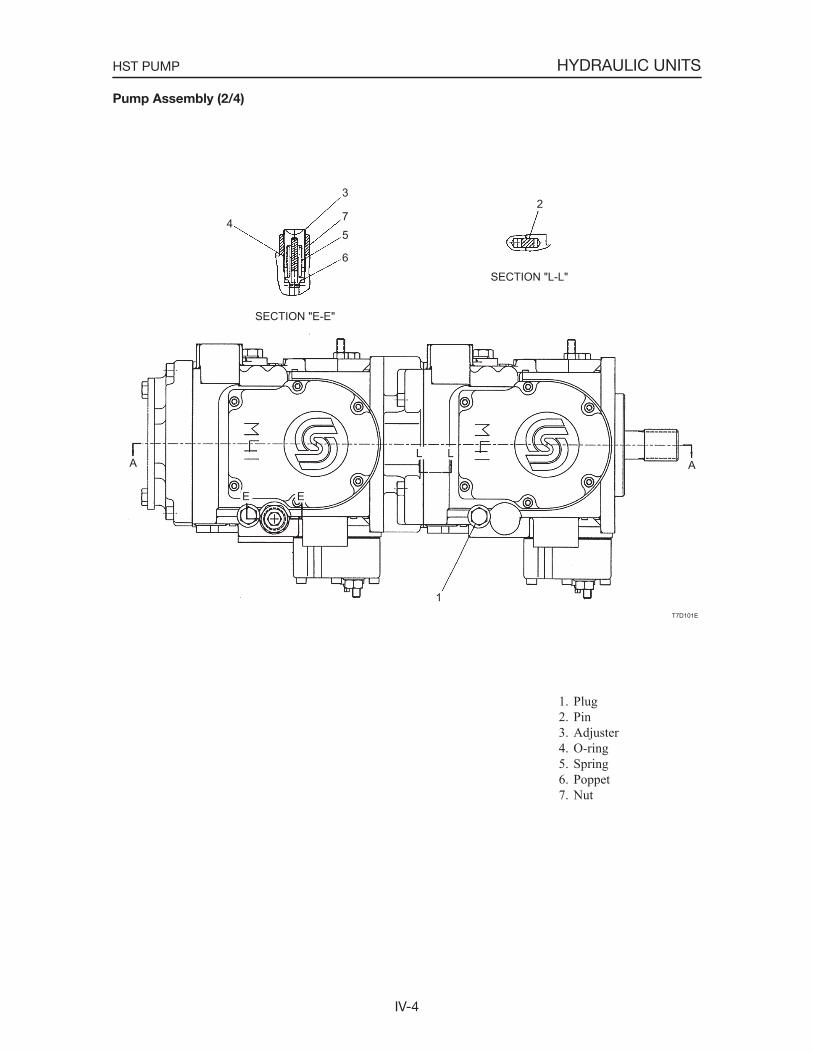
IV-4
HYDRAULIC UNITSHST PUMP
Pump Assembly (2/4)
1. Plug 2. Pin 3. Adjuster 4. O-ring 5. Spring 6. Poppet 7. Nut
T7D101E
23
75
6
4
A ALL
SECTION "L-L"
SECTION "E-E"
E E
1
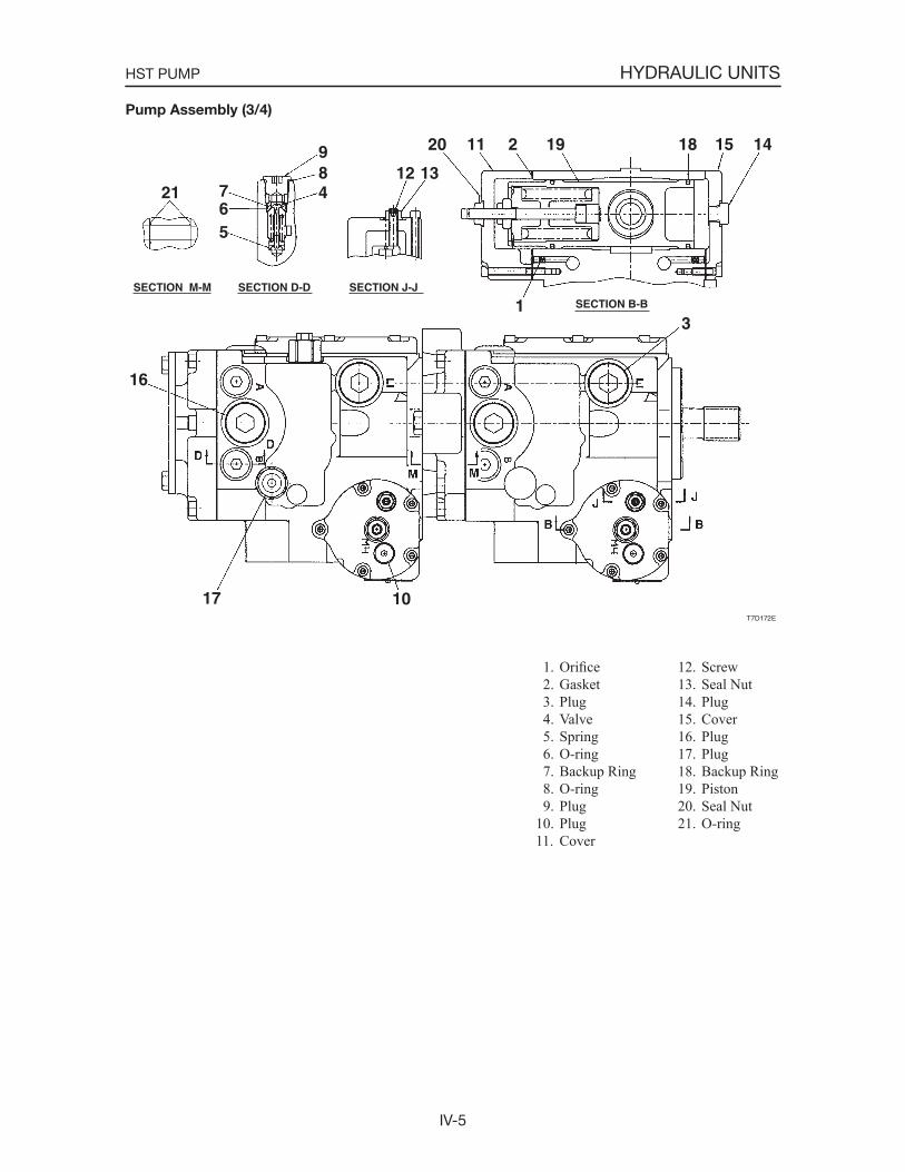
IV-5
HYDRAULIC UNITSHST PUMP
1. Orifice 2. Gasket 3. Plug 4. Valve 5. Spring 6. O-ring 7. Backup Ring 8. O-ring 9. Plug10. Plug11. Cover
Pump Assembly (3/4)
12. Screw13. Seal Nut14. Plug15. Cover16. Plug17. Plug18. Backup Ring19. Piston20. Seal Nut21. O-ring
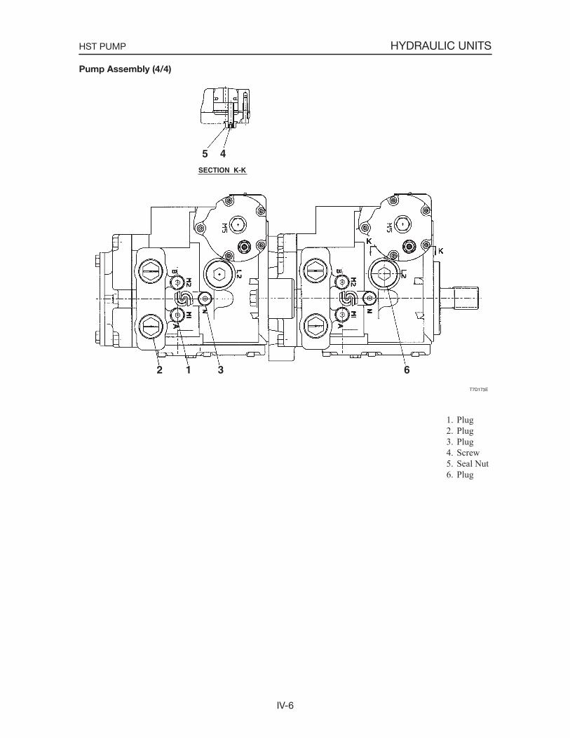
IV-6
HYDRAULIC UNITSHST PUMP
1. Plug 2. Plug 3. Plug 4. Screw 5. Seal Nut 6. Plug
Pump Assembly (4/4)
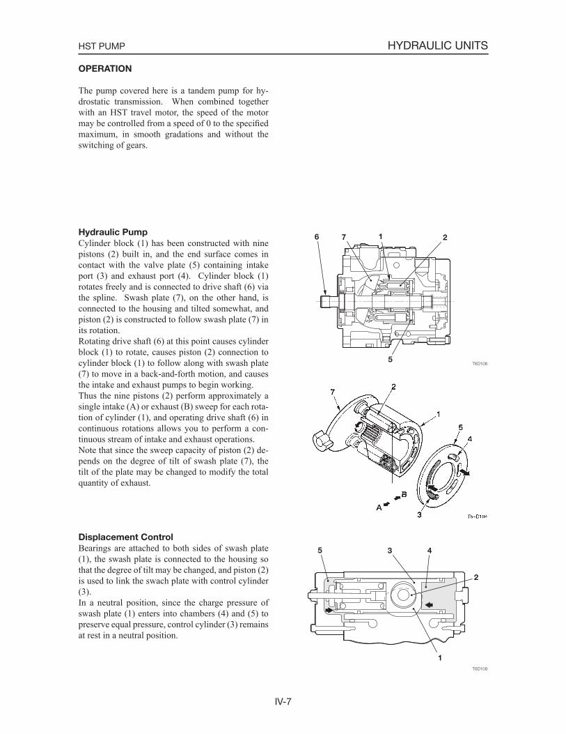
IV-7
HYDRAULIC UNITSHST PUMP
OPERATION
The pump covered here is a tandem pump for hy-drostatic transmission. When combined together with an HST travel motor, the speed of the motor may be controlled from a speed of 0 to the specifiedmaximum, in smooth gradations and without the switching of gears.
Hydraulic Pump
Cylinder block (1) has been constructed with nine pistons (2) built in, and the end surface comes in contact with the valve plate (5) containing intake port (3) and exhaust port (4). Cylinder block (1) rotates freely and is connected to drive shaft (6) via the spline. Swash plate (7), on the other hand, is connected to the housing and tilted somewhat, and piston (2) is constructed to follow swash plate (7) in its rotation.Rotating drive shaft (6) at this point causes cylinder block (1) to rotate, causes piston (2) connection to cylinder block (1) to follow along with swash plate (7) to move in a back-and-forth motion, and causes the intake and exhaust pumps to begin working.Thus the nine pistons (2) perform approximately a single intake (A) or exhaust (B) sweep for each rota-tion of cylinder (1), and operating drive shaft (6) in continuous rotations allows you to perform a con-tinuous stream of intake and exhaust operations.Note that since the sweep capacity of piston (2) de-pends on the degree of tilt of swash plate (7), the tilt of the plate may be changed to modify the total quantity of exhaust.
Displacement Control
Bearings are attached to both sides of swash plate (1), the swash plate is connected to the housing so that the degree of tilt may be changed, and piston (2) is used to link the swach plate with control cylinder (3).In a neutral position, since the charge pressure of swash plate (1) enters into chambers (4) and (5) to preserve equal pressure, control cylinder (3) remains at rest in a neutral position.
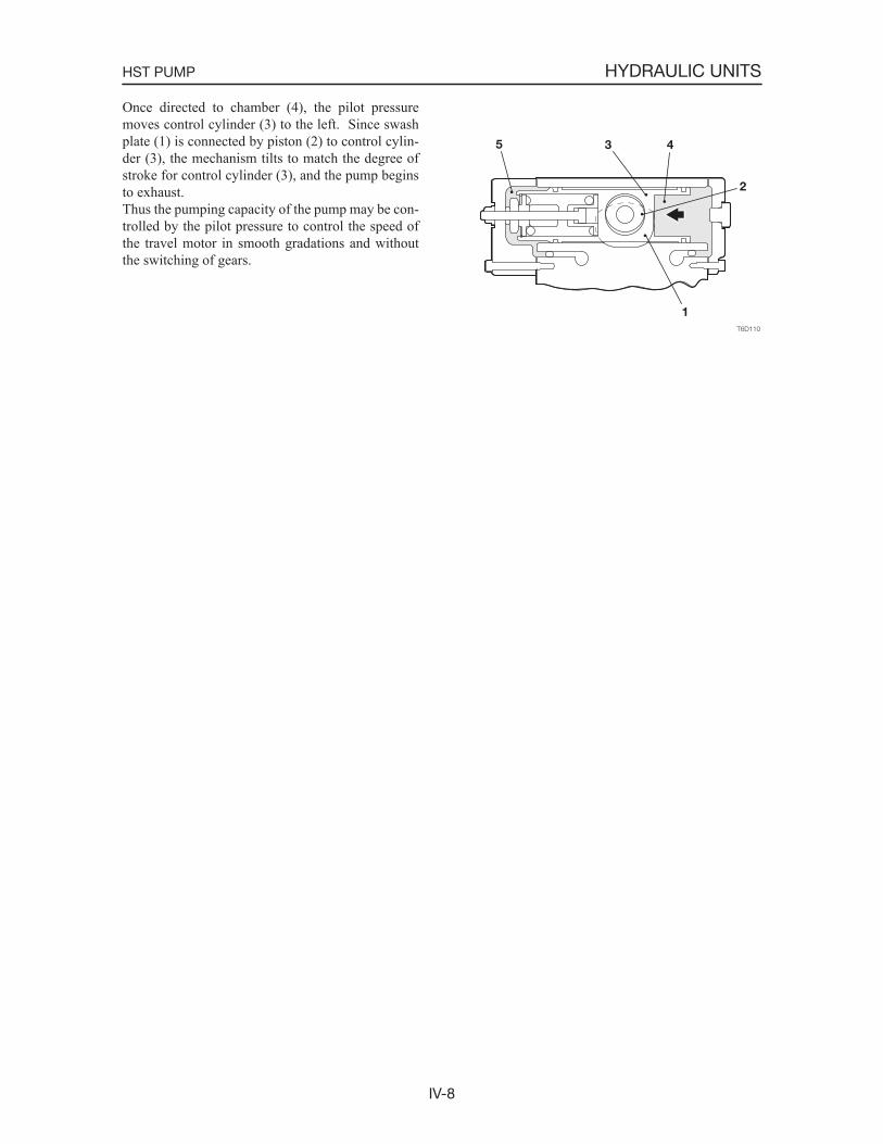
IV-8
HYDRAULIC UNITSHST PUMP
Once directed to chamber (4), the pilot pressure moves control cylinder (3) to the left. Since swash plate (1) is connected by piston (2) to control cylin-der (3), the mechanism tilts to match the degree of stroke for control cylinder (3), and the pump begins to exhaust.Thus the pumping capacity of the pump may be con-trolled by the pilot pressure to control the speed of the travel motor in smooth gradations and without the switching of gears.

IV-9
HYDRAULIC UNITSHST PUMP
T6D115
21 4
5
Charge Check and High Pressure Relief
Valve
This valve has two functions: a charge check valve and a high-pressure relief valve. The charge check valve function supplies the closed circuit with the oil from the charge pump to replenish the oil flushedinto the tank by the flushing valve. The high pressure relief valve function prevents the hydraulic circuit from being damaged by the increased pressure due to the oil supplied from the pump in succession and keeps the hydraulic circuit at an appropriate pres-sure.
Charge Check ValveIf the pressure in the charge circuit (1) becomes higher than that in the closed circuit (2), a gap is generated between the check valve (4) and the spring holder (3) and so the oil flows into the closed circuit (2).
High Pressure Relief ValveIf the pressure in the closed circuit (2) becomes higher than the force exerted by the spring (5), the check valve (4) is moved to the left and so the oil flows into the charge circuit (1).
Charge Relief Valve
The charge relief valve keeps the charge supplied from the charge pump at a steady and constant level. The oil from the charge pump reaches as high as chamber A. When the pressure in chamber A increases to the point where it exceeds the force exerted by spring (2) holding down relief valve (1), it moves relief valve (1) and the oil runs out of the tank.
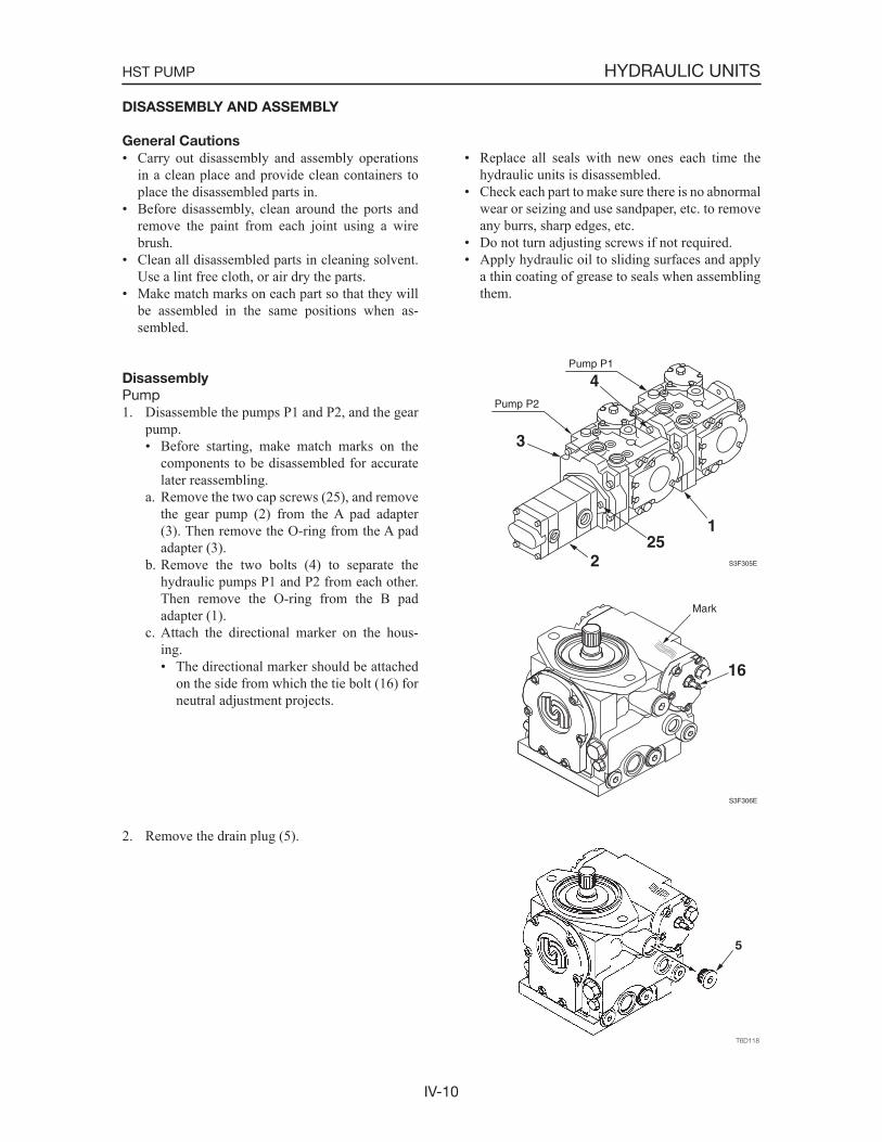
IV-10
HYDRAULIC UNITSHST PUMP
DISASSEMBLY AND ASSEMBLY
General Cautions
• Carry out disassembly and assembly operations in a clean place and provide clean containers to place the disassembled parts in.
• Before disassembly, clean around the ports and remove the paint from each joint using a wire brush.
• Clean all disassembled parts in cleaning solvent. Use a lint free cloth, or air dry the parts.
• Make match marks on each part so that they will be assembled in the same positions when as-sembled.
• Replace all seals with new ones each time the hydraulic units is disassembled.
• Check each part to make sure there is no abnormal wear or seizing and use sandpaper, etc. to remove any burrs, sharp edges, etc.
• Do not turn adjusting screws if not required.• Apply hydraulic oil to sliding surfaces and apply
a thin coating of grease to seals when assembling them.
Disassembly
Pump1. Disassemble the pumps P1 and P2, and the gear
pump.• Before starting, make match marks on the
components to be disassembled for accurate later reassembling.
a. Remove the two cap screws (25), and remove the gear pump (2) from the A pad adapter (3). Then remove the O-ring from the A pad adapter (3).
b. Remove the two bolts (4) to separate the hydraulic pumps P1 and P2 from each other. Then remove the O-ring from the B pad adapter (1).
c. Attach the directional marker on the hous-ing.• The directional marker should be attached
on the side from which the tie bolt (16) for neutral adjustment projects.
2. Remove the drain plug (5).
S3F305E
Pump P1
Pump P2
1
2
4
3
25
S3F306E
16
Mark
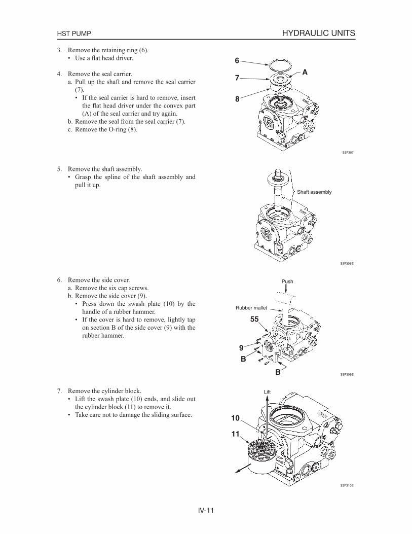
IV-11
HYDRAULIC UNITSHST PUMP
3. Remove the retaining ring (6).• Use a flat head driver.
4. Remove the seal carrier.a. Pull up the shaft and remove the seal carrier
(7).• If the seal carrier is hard to remove, insert
the flat head driver under the convex part (A) of the seal carrier and try again.
b. Remove the seal from the seal carrier (7).c. Remove the O-ring (8).
5. Remove the shaft assembly.• Grasp the spline of the shaft assembly and
pull it up.
6. Remove the side cover.a. Remove the six cap screws.b. Remove the side cover (9).
• Press down the swash plate (10) by the handle of a rubber hammer.
• If the cover is hard to remove, lightly tap on section B of the side cover (9) with the rubber hammer.
7. Remove the cylinder block.• Lift the swash plate (10) ends, and slide out
the cylinder block (11) to remove it.• Take care not to damage the sliding surface.
S3F307
6
7
8
A
S3F308E
Shaft assembly
S3F309E
Push
Rubber mallet
55
9B
B
S3F310E
Lift
10
11
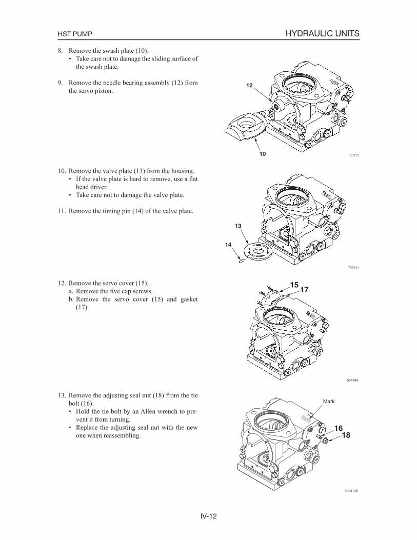
IV-12
HYDRAULIC UNITSHST PUMP
8. Remove the swash plate (10).• Take care not to damage the sliding surface of
the swash plate.
9. Remove the needle bearing assembly (12) from the servo piston.
10. Remove the valve plate (13) from the housing.• If the valve plate is hard to remove, use a flat
head driver.• Take care not to damage the valve plate.
11. Remove the timing pin (14) of the valve plate.
12. Remove the servo cover (15).a. Remove the five cap screws.b. Remove the servo cover (15) and gasket
(17).
13. Remove the adjusting seal nut (18) from the tie bolt (16).• Hold the tie bolt by an Allen wrench to pre-
vent it from turning.• Replace the adjusting seal nut with the new
one when reassembling.
S3F343
1517
S3F312E
16
Mark
18
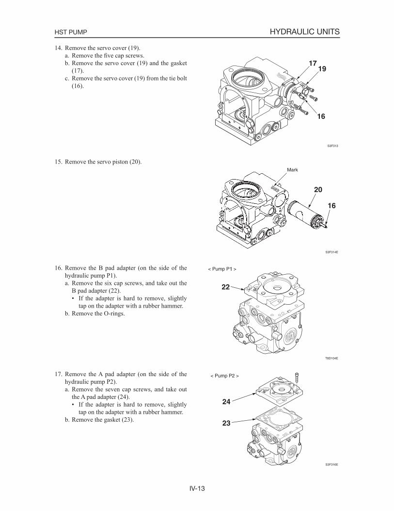
IV-13
HYDRAULIC UNITSHST PUMP
14. Remove the servo cover (19).a. Remove the five cap screws.b. Remove the servo cover (19) and the gasket
(17).c. Remove the servo cover (19) from the tie bolt
(16).
15. Remove the servo piston (20).
16. Remove the B pad adapter (on the side of the hydraulic pump P1).a. Remove the six cap screws, and take out the
B pad adapter (22).• If the adapter is hard to remove, slightly
tap on the adapter with a rubber hammer.b. Remove the O-rings.
17. Remove the A pad adapter (on the side of the hydraulic pump P2).a. Remove the seven cap screws, and take out
the A pad adapter (24).• If the adapter is hard to remove, slightly
tap on the adapter with a rubber hammer.b. Remove the gasket (23).
S3F313
1719
16
S3F314E
20
16
Mark
S3F316E
24
23
< Pump P2 >
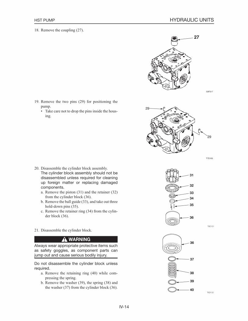
IV-14
HYDRAULIC UNITSHST PUMP
18. Remove the coupling (27).
19. Remove the two pins (29) for positioning the pump.• Take care not to drop the pins inside the hous-
ing.
20. Disassemble the cylinder block assembly. The cylinder block assembly should not be
disassembled unless required for cleaning up foreign matter or replacing damaged components.a. Remove the piston (31) and the retainer (32)
from the cylinder block (36).b. Remove the ball guide (33), and take out three
hold-down pins (35).c. Remove the retainer ring (34) from the cylin-
der block (36).
21. Disassemble the cylinder block.
WARNING
Always wear appropriate protective items such as safety goggles, as component parts can jump out and cause serious bodily injury.
Do not disassemble the cylinder block unless required.
a. Remove the retaining ring (40) while com-pressing the spring.
b. Remove the washer (39), the spring (38) and the washer (37) from the cylinder block (36).
S3F317
27
T7D105
29
29
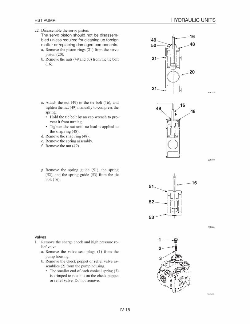
IV-15
HYDRAULIC UNITSHST PUMP
22. Disassemble the servo piston. The servo piston should not be disassem-
bled unless required for cleaning up foreign matter or replacing damaged components.a. Remove the piston rings (21) from the servo
piston (20).b. Remove the nuts (49 and 50) from the tie bolt
(16).
c. Attach the nut (49) to the tie bolt (16), and tighten the nut (49) manually to compress the spring.• Hold the tie bolt by an cap wrench to pre-
vent it from turning.• Tighten the nut until no load is applied to
the snap ring (48).d. Remove the snap ring (48).e. Remove the spring assembly.f. Remove the nut (49).
g. Remove the spring guide (51), the spring (52), and the spring guide (53) from the tie bolt (16).
Valves1. Remove the charge check and high pressure re-
lief valve.a. Remove the valve seat plugs (1) from the
pump housing.b. Remove the check poppet or relief valve as-
semblies (2) from the pump housing.• The smaller end of each conical spring (3)
is crimped to retain it on the check poppet or relief valve. Do not remove.
S3F318
16
48
20
4950
21
21
S3F319
4916
48
S3F320
1651
52
53

IV-16
HYDRAULIC UNITSHST PUMP
2. Remove the charge relief valve.• Before removing the screw adjustable relief
valve plug, mark the plug, lock nut (5), and housing so as to approximately maintain the original adjustment when assembling.
a. Remove the screw adjustable charge relief valve plug (6) by loosening the lock nut (5) and unscrewing the plug. Remove the O-ring from the plug (6).
b. Remove the spring (7) and poppet (8) from the housing.
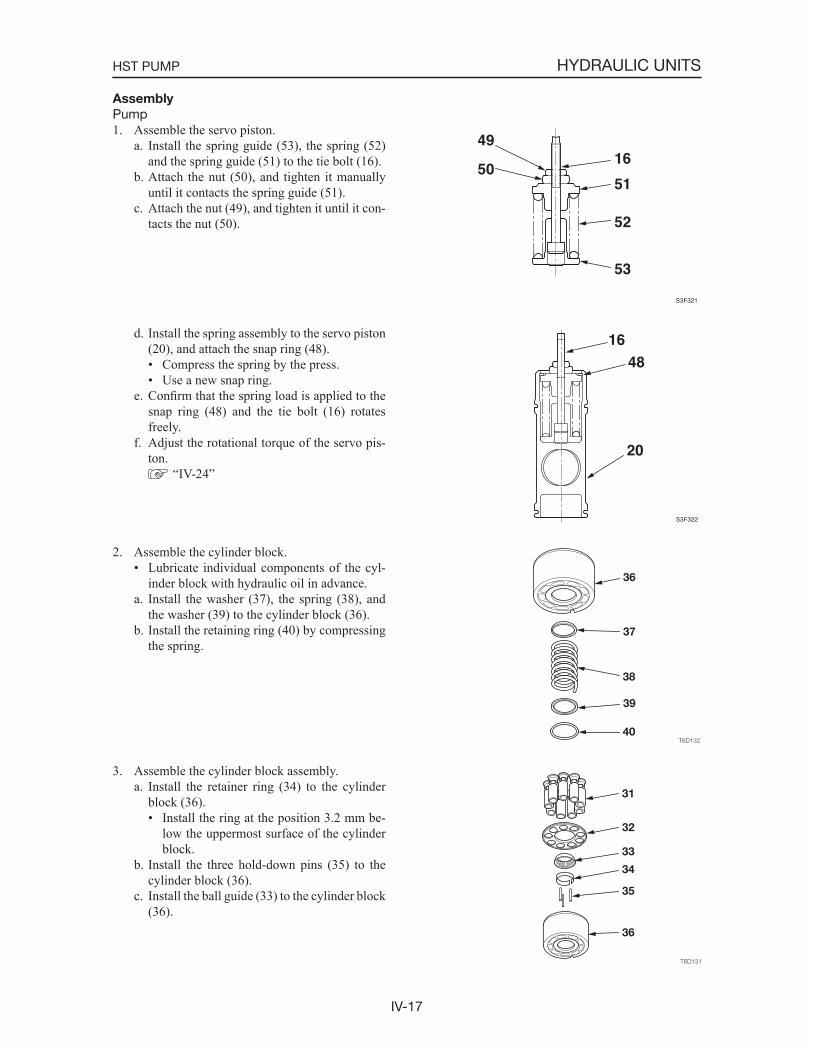
IV-17
HYDRAULIC UNITSHST PUMP
Assembly
Pump1. Assemble the servo piston.
a. Install the spring guide (53), the spring (52) and the spring guide (51) to the tie bolt (16).
b. Attach the nut (50), and tighten it manually until it contacts the spring guide (51).
c. Attach the nut (49), and tighten it until it con-tacts the nut (50).
d. Install the spring assembly to the servo piston (20), and attach the snap ring (48).• Compress the spring by the press.• Use a new snap ring.
e. Confirm that the spring load is applied to the snap ring (48) and the tie bolt (16) rotates freely.
f. Adjust the rotational torque of the servo pis-ton.
“IV-24”
2. Assemble the cylinder block.• Lubricate individual components of the cyl-
inder block with hydraulic oil in advance.a. Install the washer (37), the spring (38), and
the washer (39) to the cylinder block (36).b. Install the retaining ring (40) by compressing
the spring.
3. Assemble the cylinder block assembly.a. Install the retainer ring (34) to the cylinder
block (36).• Install the ring at the position 3.2 mm be-
low the uppermost surface of the cylinder block.
b. Install the three hold-down pins (35) to the cylinder block (36).
c. Install the ball guide (33) to the cylinder block (36).
S3F321
16
51
52
53
49
50
S3F322
20
4816
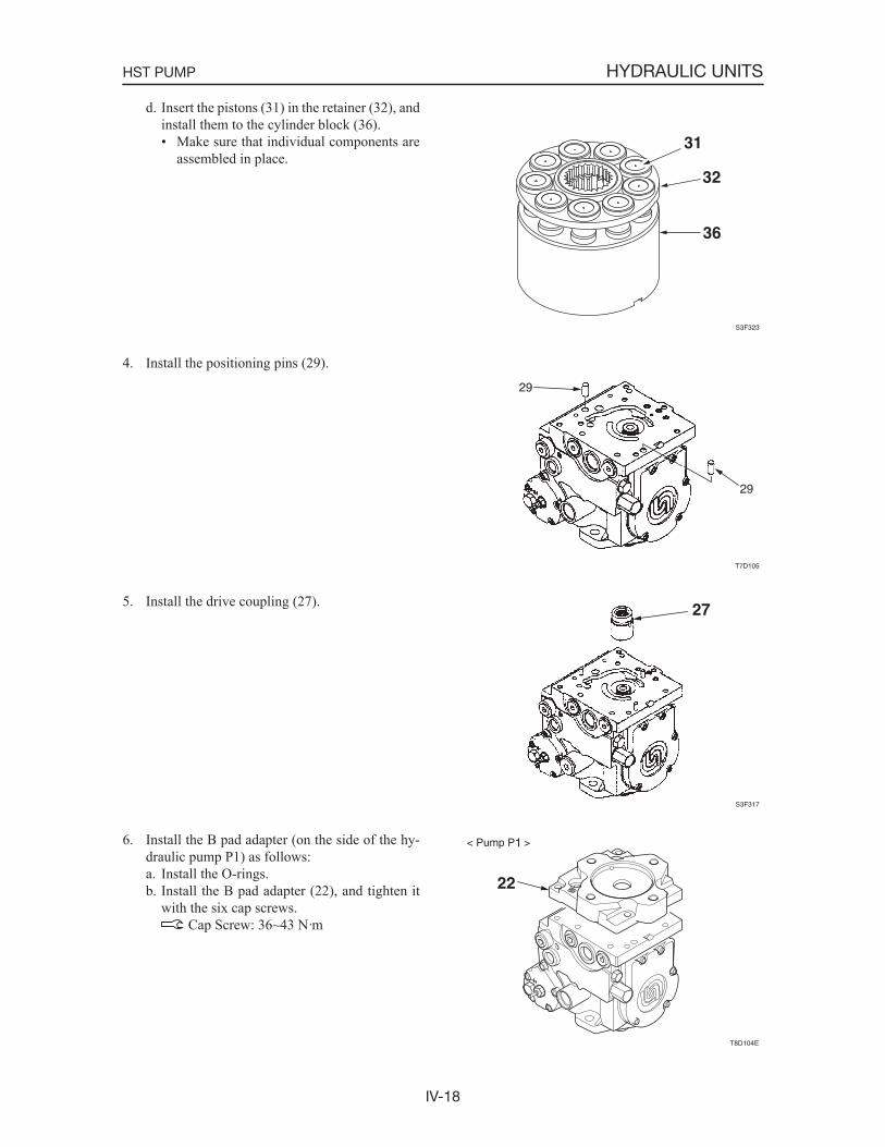
IV-18
HYDRAULIC UNITSHST PUMP
d. Insert the pistons (31) in the retainer (32), and install them to the cylinder block (36).• Make sure that individual components are
assembled in place.
4. Install the positioning pins (29).
5. Install the drive coupling (27).
6. Install the B pad adapter (on the side of the hy-draulic pump P1) as follows:a. Install the O-rings.b. Install the B pad adapter (22), and tighten it
with the six cap screws. Cap Screw: 36~43 N·m
S3F323
31
32
36
T7D105
29
29
S3F317
27
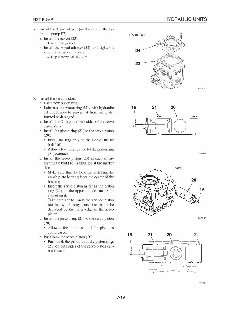
IV-19
HYDRAULIC UNITSHST PUMP
7. Install the A pad adapter (on the side of the hy-draulic pump P2).a. Install the gasket (23).
• Use a new gasket.b. Install the A pad adapter (24), and tighten it
with the seven cap screws. Cap Screw: 36~43 N·m
8. Install the servo piston.• Use a new piston ring.• Lubricate the piston ring fully with hydraulic
oil in advance to prevent it from being de-formed or damaged.
a. Install the O-rings on both sides of the servo piston (20)
b. Install the piston ring (21) to the servo piston (20).• Install the ring only on the side of the tie
bolt (16).• Allow a few minutes and let the piston ring
(21) contract.c. Install the servo piston (20) in such a way
that the tie bolt (16) is installed at the marker side.• Make sure that the hole for installing the
swash plate bearing faces the center of the housing.
• Insert the servo piston as far as the piston ring (21) on the opposite side can be in-stalled on it.
Take care not to insert the service piston too far, which may cause the piston be damaged by the inner edge of the servo piston.
d. Install the piston ring (21) to the servo piston (20).• Allow a few minutes until the piston is
compressed.e. Push back the servo piston (20).
• Push back the piston until the piston rings (21) on both sides of the servo piston can-not be seen.
S3F316E
24
23
< Pump P2 >
S3F324
16 21 20
S3F314E
20
16
Mark
S3F325
16 21 2120
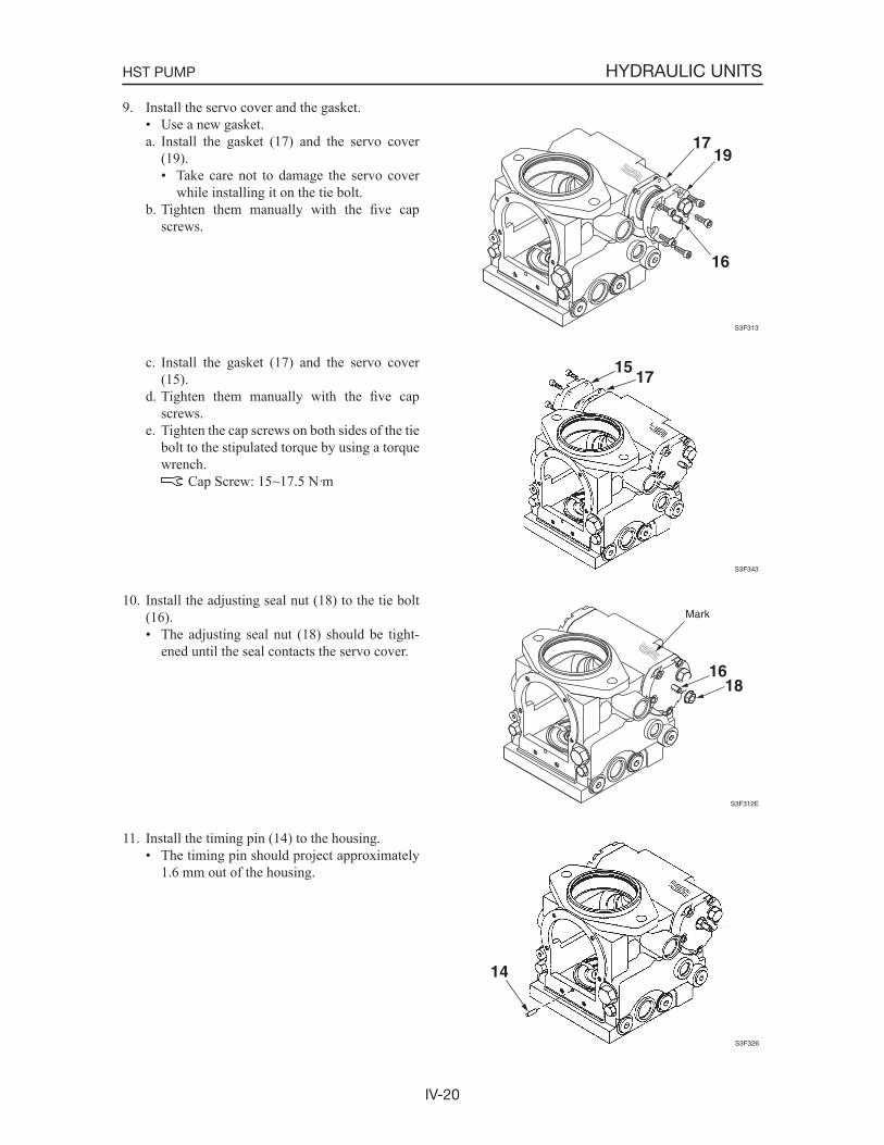
IV-20
HYDRAULIC UNITSHST PUMP
9. Install the servo cover and the gasket.• Use a new gasket.a. Install the gasket (17) and the servo cover
(19).• Take care not to damage the servo cover
while installing it on the tie bolt.b. Tighten them manually with the five cap
screws.
c. Install the gasket (17) and the servo cover (15).
d. Tighten them manually with the five cap screws.
e. Tighten the cap screws on both sides of the tie bolt to the stipulated torque by using a torque wrench.
Cap Screw: 15~17.5 N·m
10. Install the adjusting seal nut (18) to the tie bolt (16).• The adjusting seal nut (18) should be tight-
ened until the seal contacts the servo cover.
11. Install the timing pin (14) to the housing.• The timing pin should project approximately
1.6 mm out of the housing.
S3F313
1719
16
S3F343
1517
S3F312E
16
Mark
18
S3F326
14
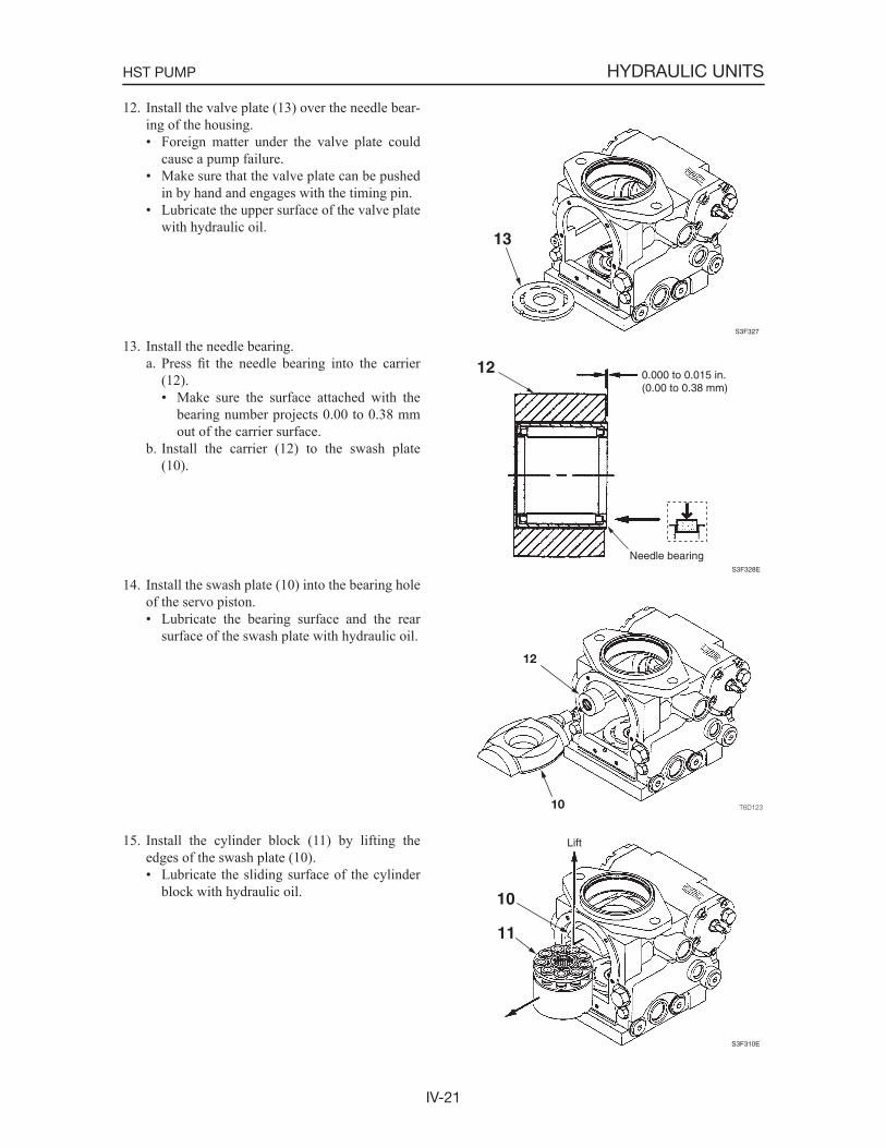
IV-21
HYDRAULIC UNITSHST PUMP
12. Install the valve plate (13) over the needle bear-ing of the housing.• Foreign matter under the valve plate could
cause a pump failure.• Make sure that the valve plate can be pushed
in by hand and engages with the timing pin.• Lubricate the upper surface of the valve plate
with hydraulic oil.
13. Install the needle bearing.a. Press fit the needle bearing into the carrier
(12).• Make sure the surface attached with the
bearing number projects 0.00 to 0.38 mm out of the carrier surface.
b. Install the carrier (12) to the swash plate (10).
14. Install the swash plate (10) into the bearing hole of the servo piston.• Lubricate the bearing surface and the rear
surface of the swash plate with hydraulic oil.
15. Install the cylinder block (11) by lifting the edges of the swash plate (10).• Lubricate the sliding surface of the cylinder
block with hydraulic oil.
S3F327
13
S3F328E
12 0.000 to 0.015 in.(0.00 to 0.38 mm)
Needle bearing
S3F310E
Lift
10
11
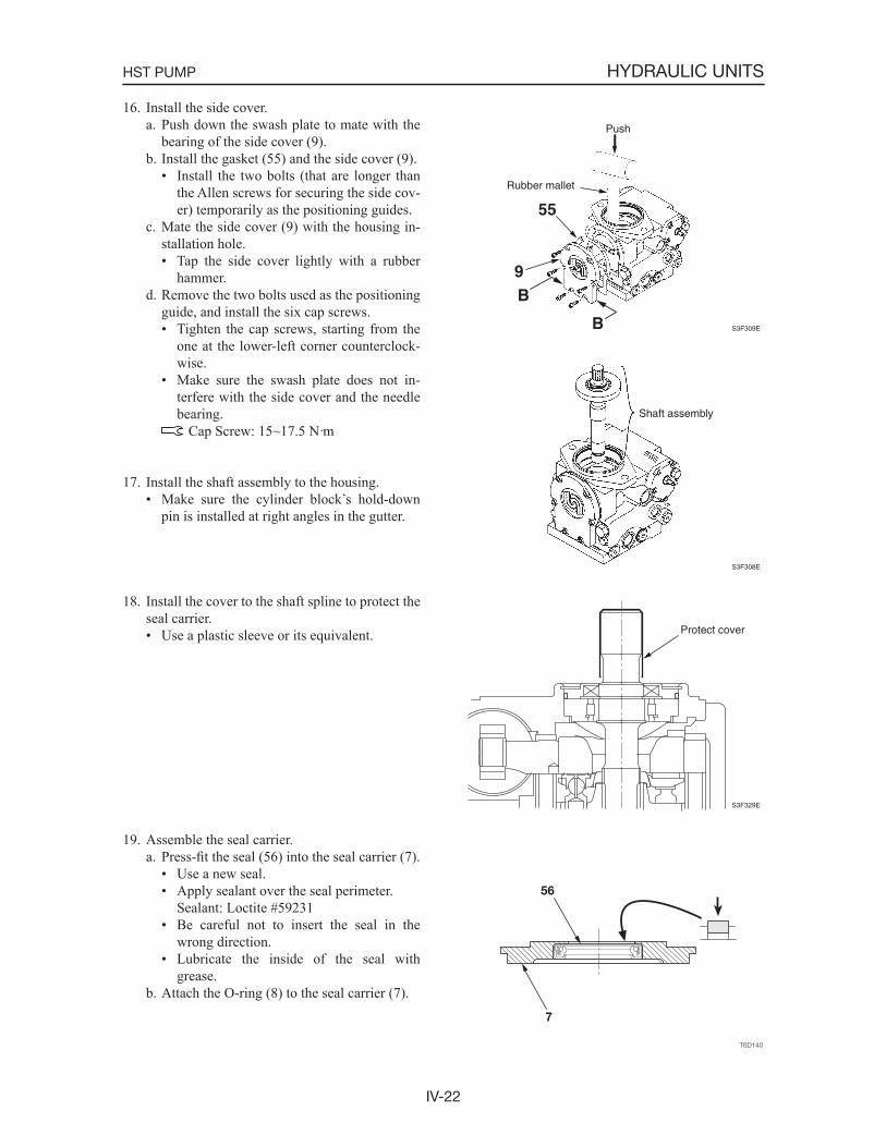
IV-22
HYDRAULIC UNITSHST PUMP
16. Install the side cover.a. Push down the swash plate to mate with the
bearing of the side cover (9).b. Install the gasket (55) and the side cover (9).
• Install the two bolts (that are longer than the Allen screws for securing the side cov-er) temporarily as the positioning guides.
c. Mate the side cover (9) with the housing in-stallation hole.• Tap the side cover lightly with a rubber
hammer.d. Remove the two bolts used as the positioning
guide, and install the six cap screws.• Tighten the cap screws, starting from the
one at the lower-left corner counterclock-wise.
• Make sure the swash plate does not in-terfere with the side cover and the needle bearing. Cap Screw: 15~17.5 N·m
17. Install the shaft assembly to the housing.• Make sure the cylinder block s hold-down
pin is installed at right angles in the gutter.
18. Install the cover to the shaft spline to protect the seal carrier.• Use a plastic sleeve or its equivalent.
19. Assemble the seal carrier.a. Press-fit the seal (56) into the seal carrier (7).
• Use a new seal.• Apply sealant over the seal perimeter. Sealant: Loctite #59231• Be careful not to insert the seal in the
wrong direction.• Lubricate the inside of the seal with
grease.b. Attach the O-ring (8) to the seal carrier (7).
S3F309E
Push
Rubber mallet
55
9B
B
S3F308E
Shaft assembly
S3F329E
Protect cover
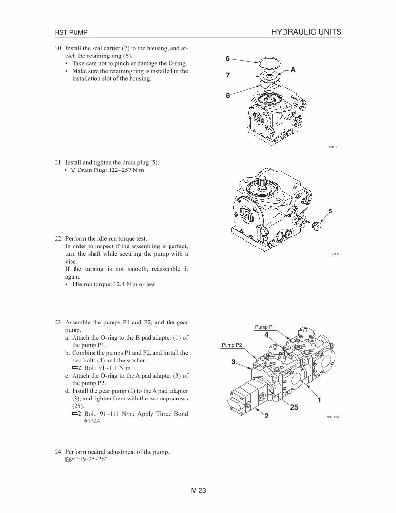
IV-23
HYDRAULIC UNITSHST PUMP
20. Install the seal carrier (7) to the housing, and at-tach the retaining ring (6).• Take care not to pinch or damage the O-ring.• Make sure the retaining ring is installed in the
installation slot of the housing.
21. Install and tighten the drain plug (5). Drain Plug: 122~257 N·m
22. Perform the idle run torque test. In order to inspect if the assembling is perfect,
turn the shaft while securing the pump with a vise.
If the turning is not smooth, reassemble it again.• Idle run torque: 12.4 N·m or less
23. Assemble the pumps P1 and P2, and the gear pump.a. Attach the O-ring to the B pad adapter (1) of
the pump P1.b. Combine the pumps P1 and P2, and install the
two bolts (4) and the washer. Bolt: 91~111 N·m
c. Attach the O-ring to the A pad adapter (3) of the pump P2.
d. Install the gear pump (2) to the A pad adapter (3), and tighten them with the two cap screws (25).
Bolt: 91~111 N·m; Apply Three Bond #1324
24. Perform neutral adjustment of the pump. “IV-25~26”
S3F307
6
7
8
A
S3F305E
Pump P1
Pump P2
1
2
4
3
25
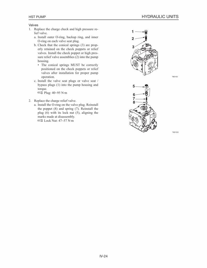
IV-24
HYDRAULIC UNITSHST PUMP
Valves1. Replace the charge check and high pressure re-
lief valve.a. Install outer O-ring, backup ring, and inner
O-ring on each valve seat plug.b. Check that the conical springs (3) are prop-
erly retained on the check poppets or relief valves. Install the check poppet or high pres-sure relief valve assemblies (2) into the pump housing.• The conical springs MUST be correctly
positioned on the check poppets or relief valves after installation for proper pump operation.
c. Install the valve seat plugs or valve seat / bypass plugs (1) into the pump housing and torque.
Plug: 40~95 N·m
2. Replace the charge relief valve.a. Install the O-ring on the valve plug. Reinstall
the poppet (8) and spring (7). Reinstall the plug (6) with its lock nut (5), aligning the marks made at disassembly.
Lock Nut: 47~57 N·m
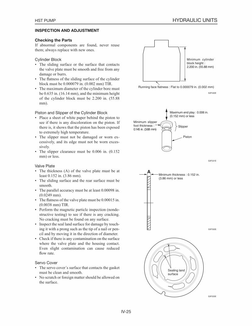
IV-25
HYDRAULIC UNITSHST PUMP
INSPECTION AND ADJUSTMENT
Checking the Parts
If abnormal components are found, never reuse them; always replace with new ones.
Cylinder Block• The sliding surface or the surface that contacts
the valve plate must be smooth and free from any damage or burrs.
• The flatness of the sliding surface of the cylinder block must be 0.000079 in. (0.002 mm) TIR.
• The maximum diameter of the cylinder bore must be 0.635 in. (16.14 mm), and the minimum height of the cylinder block must be 2.200 in. (55.88 mm).
Piston and Slipper of the Cylinder Block• Place a sheet of white paper behind the piston to
see if there is any discoloration on the piston. If there is, it shows that the piston has been exposed to extremely high temperature.
• The slipper must not be damaged or worn ex-cessively, and its edge must not be worn exces-sively.
• The slipper clearance must be 0.006 in. (0.152 mm) or less.
Valve Plate• The thickness (A) of the valve plate must be at
least 0.152 in. (3.86 mm).• The sliding surface and the rear surface must be
smooth.• The parallel accuracy must be at least 0.00098 in.
(0.0249 mm).• The flatness of the valve plate must be 0.00015 in.
(0.0038 mm) TIR.• Perform the magnetic particle inspection (nonde-
structive testing) to see if there is any cracking. No cracking must be found on any surface.
• Inspect the seal land surface for damage by touch-ing it with a prong such as the tip of a nail or pen-cil and by moving it in the direction of diameter.
• Check if there is any contamination on the surface where the valve plate and the housing contact. Even slight contamination can cause reduced flow rate.
Servo Cover• The servo cover s surface that contacts the gasket
must be clean and smooth.• No scratch or foreign matter should be allowed on
the surface.
S3F330E
Minimum cylinder block height :2.200 in. (55.88 mm)
Running face flatness : Flat to 0.000079 in. (0.002 mm)
S3F331E
Maximum end play : 0.006 in.(0.152 mm) or less
Slipper
Minimum slipper foot thickness :0.145 in. (3.68 mm)
Piston
S3F332E
Minimum thickness : 0.152 in. (3.86 mm) or less
A
S3F333E
Sealing land surface
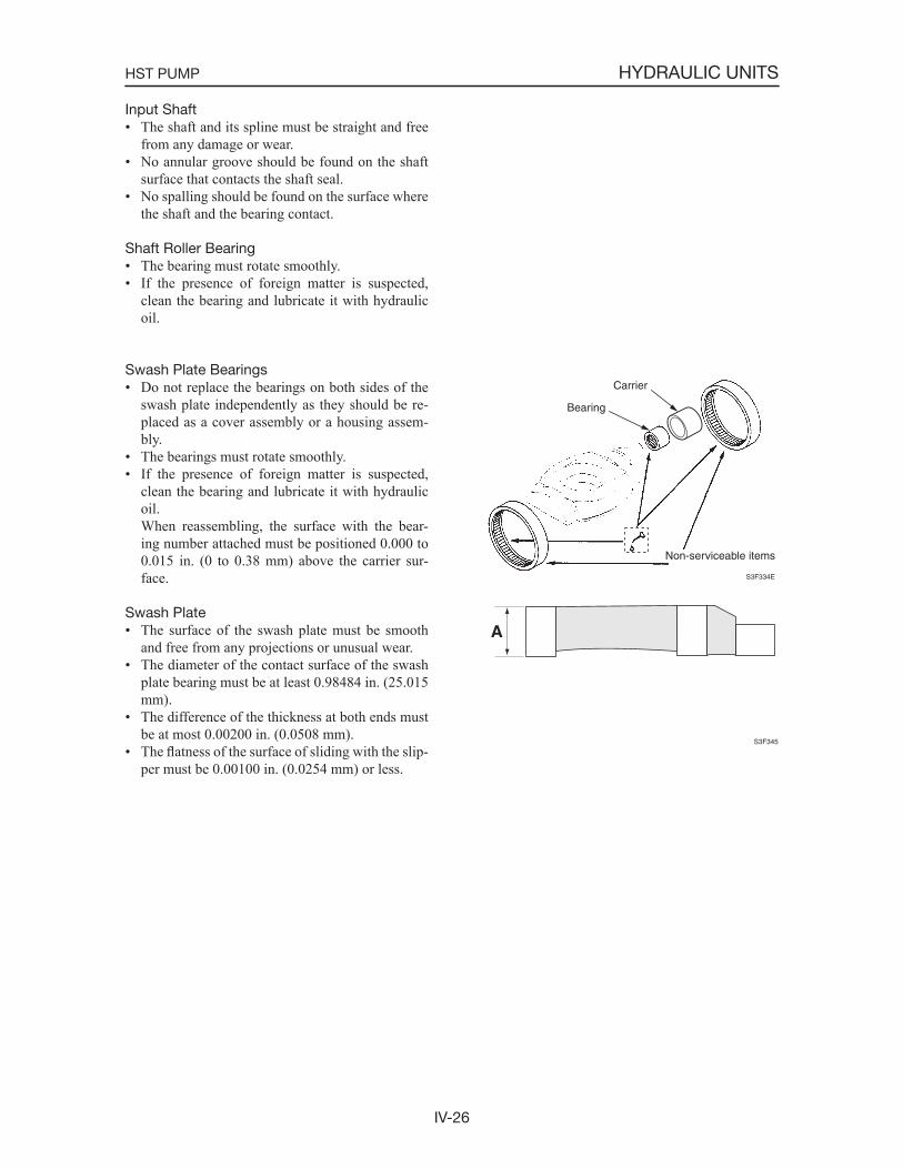
IV-26
HYDRAULIC UNITSHST PUMP
Input Shaft• The shaft and its spline must be straight and free
from any damage or wear.• No annular groove should be found on the shaft
surface that contacts the shaft seal.• No spalling should be found on the surface where
the shaft and the bearing contact.
Shaft Roller Bearing• The bearing must rotate smoothly.• If the presence of foreign matter is suspected,
clean the bearing and lubricate it with hydraulic oil.
Swash Plate Bearings• Do not replace the bearings on both sides of the
swash plate independently as they should be re-placed as a cover assembly or a housing assem-bly.
• The bearings must rotate smoothly.• If the presence of foreign matter is suspected,
clean the bearing and lubricate it with hydraulic oil.
When reassembling, the surface with the bear-ing number attached must be positioned 0.000 to 0.015 in. (0 to 0.38 mm) above the carrier sur-face.
Swash Plate• The surface of the swash plate must be smooth
and free from any projections or unusual wear.• The diameter of the contact surface of the swash
plate bearing must be at least 0.98484 in. (25.015 mm).
• The difference of the thickness at both ends must be at most 0.00200 in. (0.0508 mm).
• The flatness of the surface of sliding with the slip-per must be 0.00100 in. (0.0254 mm) or less.
S3F334E
Carrier
Bearing
Non-serviceable items
S3F345
A
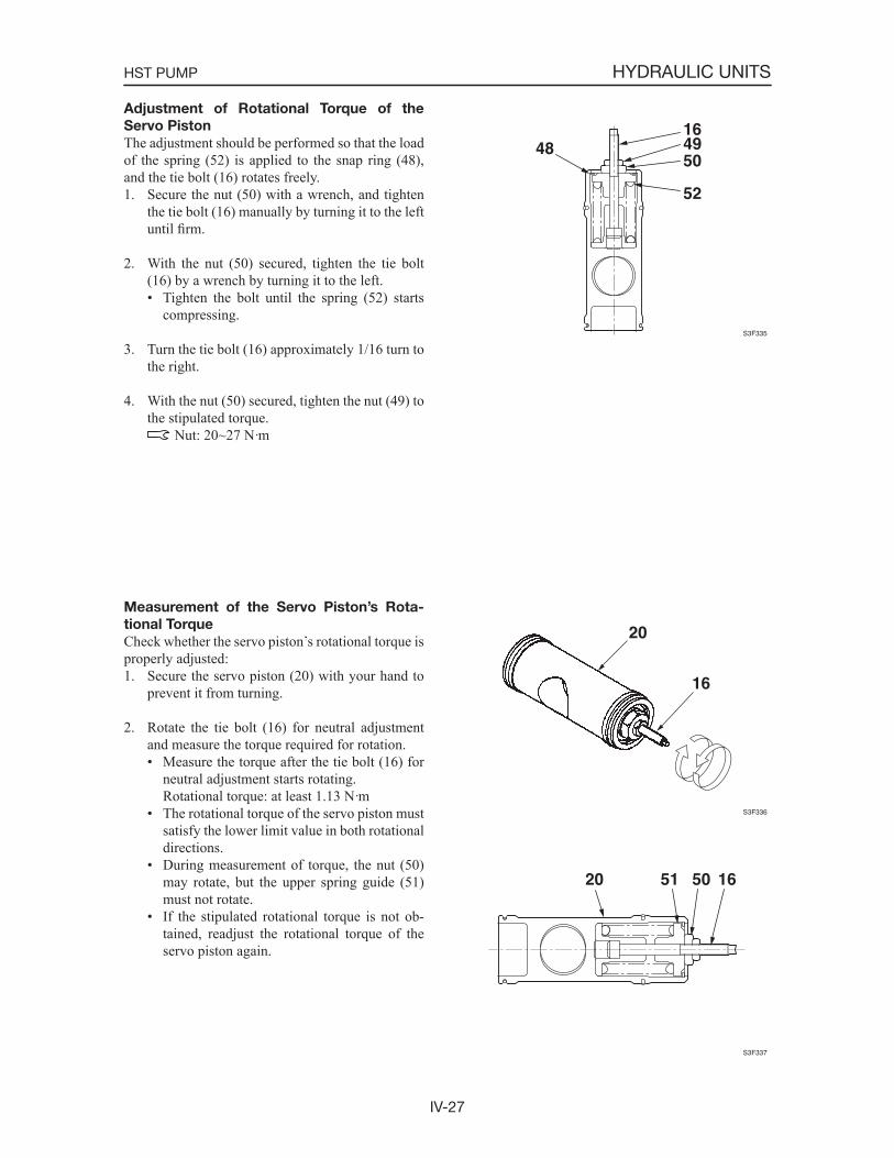
IV-27
HYDRAULIC UNITSHST PUMP
Adjustment of Rotational Torque of the
Servo Piston
The adjustment should be performed so that the load of the spring (52) is applied to the snap ring (48), and the tie bolt (16) rotates freely.1. Secure the nut (50) with a wrench, and tighten
the tie bolt (16) manually by turning it to the left until firm.
2. With the nut (50) secured, tighten the tie bolt (16) by a wrench by turning it to the left.• Tighten the bolt until the spring (52) starts
compressing.
3. Turn the tie bolt (16) approximately 1/16 turn to the right.
4. With the nut (50) secured, tighten the nut (49) to the stipulated torque.
Nut: 20~27 N·m
Measurement of the Servo Piston’s Rota-
tional Torque
Check whether the servo piston s rotational torque is properly adjusted:1. Secure the servo piston (20) with your hand to
prevent it from turning.
2. Rotate the tie bolt (16) for neutral adjustment and measure the torque required for rotation.• Measure the torque after the tie bolt (16) for
neutral adjustment starts rotating. Rotational torque: at least 1.13 N·m• The rotational torque of the servo piston must
satisfy the lower limit value in both rotational directions.
• During measurement of torque, the nut (50) may rotate, but the upper spring guide (51) must not rotate.
• If the stipulated rotational torque is not ob-tained, readjust the rotational torque of the servo piston again.
S3F335
164950
52
48
S3F336
16
20
S3F337
20 51 50 16

IV-28
HYDRAULIC UNITSHST PUMP
Neutral Adjustment of the Pump
WARNING
• Be sure to do these adjustments on the level ground.
• The hydraulic oil and the tank are hot and under pressure at operating temperature.
• Never adjust the pump immediately after the engine stops to prevent bodily injuly, be-cause all the components are hot.
• Do not allow hot oil and components to con-tact your skin.
• When removing the hydraulic hose, slowly loosen the hydraulic hose.
In this adjustment, the tie bolt of the controlling sec-tion should be adjusted so that the pressures on both sides of the turbo piston become equal.1. Connect the hydraulic hoses to the gauge ports
to make the pressures on both sides of the servo piston equal.• Hydraulic pump P1 ..... M4 and M5.• Hydraulic pump P2 ..... M14 and M15.
2. Install the pressure gauges to the ports to mea-sure the circuit pressure.• Hydraulic pump P1 ..... A1 and B1.• Hydraulic pump P2 ..... A2 and B2.
3. Start the engine and run it at the rated rotational speed.
4. Loosen the adjusting seal nut (18) of the hydrau-lic pump and turn the tie bolt (16).• Turn the tie bolt (16) until the readings of the
two pressure gauges become equal.
5. Turn the tie bolt (16) until the reading of one pressure gauge becomes higher than that of the other pressure gauge.• Record the position of the tie bolt.
6. Turn the tie bolt (16) until the reading of the other pressure gauge becomes higher than that increased in 5 above.• Record the position of the tie bolt.
S3F341
1618
IV-29
HYDRAULIC UNITSHST PUMP
7. Turn the tie bolt (16) until it is positioned at the middle of the two positions recorded in 5 and 6 above.• Make sure the readings on the two pressure
gauges are equal.
8. Tighten the tie bolt (16) by the adjusting seal nut (18).• Do not allow the tie bolt to rotate.
Adjusting seal nut: 28~51 N·m
9. Stop the engine, remove the hydraulic hoses connected with the gauge ports, and attach the plugs.
10. Disconnect the pressure gauges from the ports.
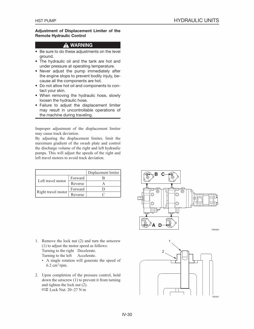
IV-30
HYDRAULIC UNITSHST PUMP
Adjustment of Displacement Limiter of the
Remote Hydraulic Control
WARNING
• Be sure to do these adjustments on the level ground.
• The hydraulic oil and the tank are hot and under pressure at operating temperature.
• Never adjust the pump immediately after the engine stops to prevent bodily injuly, be-cause all the components are hot.
• Do not allow hot oil and components to con-tact your skin.
• When removing the hydraulic hose, slowly loosen the hydraulic hose.
• Failure to adjust the displacement limiter may result in uncontrollable operations of the machine during traveling.
Improper adjustment of the displacement limiter may cause track deviation.By adjusting the displacement limiter, limit the maximum gradient of the swash plate and control the discharge volume of the right and left hydraulic pumps. This will adjust the speeds of the right and left travel motors to avoid track deviation.
Displacement limiter
Left travel motorForward BReverse A
Right travel motorForward DReverse C
1. Remove the lock nut (2) and turn the setscrew (1) to adjust the motor speed as follows:
Turning to the right Decelerate. Turning to the left Accelerate.
• A single rotation will generate the speed of 6.2 cm3/rpm.
2. Upon completion of the pressure control, hold down the setscrew (1) to prevent it from turning and tighten the lock nut (2).
Lock Nut: 20~27 N·mT6E007
2
1
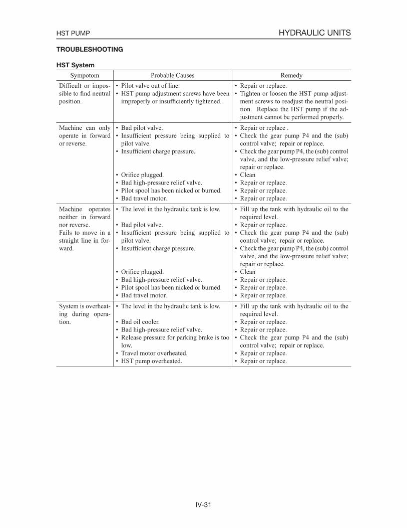
IV-31
HYDRAULIC UNITSHST PUMP
TROUBLESHOOTING
HST System
Sympotom Probable Causes RemedyDifficult or impos-sible to find neutral position.
• Pilot valve out of line.• HST pump adjustment screws have been
improperly or insufficiently tightened.
• Repair or replace.• Tighten or loosen the HST pump adjust-
ment screws to readjust the neutral posi-tion. Replace the HST pump if the ad-justment cannot be performed properly.
Machine can only operate in forward or reverse.
• Bad pilot valve.• Insufficient pressure being supplied to
pilot valve.• Insufficient charge pressure.
• Orifice plugged.• Bad high-pressure relief valve.• Pilot spool has been nicked or burned.• Bad travel motor.
• Repair or replace .• Check the gear pump P4 and the (sub)
control valve; repair or replace.• Check the gear pump P4, the (sub) control
valve, and the low-pressure relief valve; repair or replace.
• Clean• Repair or replace.• Repair or replace.• Repair or replace.
Machine operates neither in forward nor reverse.Fails to move in a straight line in for-ward.
• The level in the hydraulic tank is low.
• Bad pilot valve.• Insufficient pressure being supplied to
pilot valve.• Insufficient charge pressure.
• Orifice plugged.• Bad high-pressure relief valve.• Pilot spool has been nicked or burned.• Bad travel motor.
• Fill up the tank with hydraulic oil to the required level.
• Repair or replace.• Check the gear pump P4 and the (sub)
control valve; repair or replace.• Check the gear pump P4, the (sub) control
valve, and the low-pressure relief valve; repair or replace.
• Clean• Repair or replace.• Repair or replace.• Repair or replace.
System is overheat-ing during opera-tion.
• The level in the hydraulic tank is low.
• Bad oil cooler.• Bad high-pressure relief valve.• Release pressure for parking brake is too
low.• Travel motor overheated.• HST pump overheated.
• Fill up the tank with hydraulic oil to the required level.
• Repair or replace.• Repair or replace.• Check the gear pump P4 and the (sub)
control valve; repair or replace.• Repair or replace.• Repair or replace.
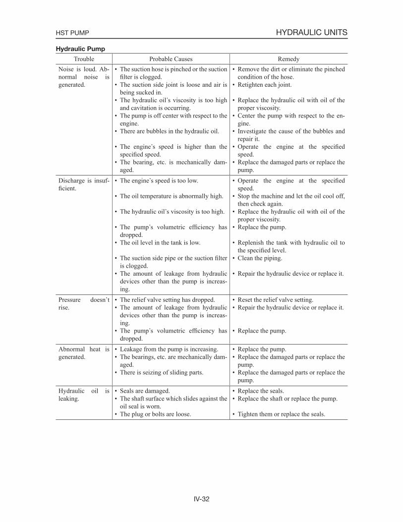
IV-32
HYDRAULIC UNITSHST PUMP
Hydraulic Pump
Trouble Probable Causes RemedyNoise is loud. Ab-normal noise is generated.
• The suction hose is pinched or the suction filter is clogged.
• The suction side joint is loose and air is being sucked in.
• The hydraulic oil s viscosity is too high and cavitation is occurring.
• The pump is off center with respect to the engine.
• There are bubbles in the hydraulic oil.
• The engine s speed is higher than the specified speed.
• The bearing, etc. is mechanically dam-aged.
• Remove the dirt or eliminate the pinched condition of the hose.
• Retighten each joint.
• Replace the hydraulic oil with oil of the proper viscosity.
• Center the pump with respect to the en-gine.
• Investigate the cause of the bubbles and repair it.
• Operate the engine at the specifiedspeed.
• Replace the damaged parts or replace the pump.
Discharge is insuf-ficient.
• The engine s speed is too low.
• The oil temperature is abnormally high.
• The hydraulic oil s viscosity is too high.
• The pump s volumetric efficiency has dropped.
• The oil level in the tank is low.
• The suction side pipe or the suction filteris clogged.
• The amount of leakage from hydraulic devices other than the pump is increas-ing.
• Operate the engine at the specifiedspeed.
• Stop the machine and let the oil cool off, then check again.
• Replace the hydraulic oil with oil of the proper viscosity.
• Replace the pump.
• Replenish the tank with hydraulic oil to the specified level.
• Clean the piping.
• Repair the hydraulic device or replace it.
Pressure doesn trise.
• The relief valve setting has dropped.• The amount of leakage from hydraulic
devices other than the pump is increas-ing.
• The pump s volumetric efficiency has dropped.
• Reset the relief valve setting.• Repair the hydraulic device or replace it.
• Replace the pump.
Abnormal heat is generated.
• Leakage from the pump is increasing.• The bearings, etc. are mechanically dam-
aged.• There is seizing of sliding parts.
• Replace the pump.• Replace the damaged parts or replace the
pump.• Replace the damaged parts or replace the
pump.Hydraulic oil is leaking.
• Seals are damaged.• The shaft surface which slides against the
oil seal is worn.• The plug or bolts are loose.
• Replace the seals.• Replace the shaft or replace the pump.
• Tighten them or replace the seals.
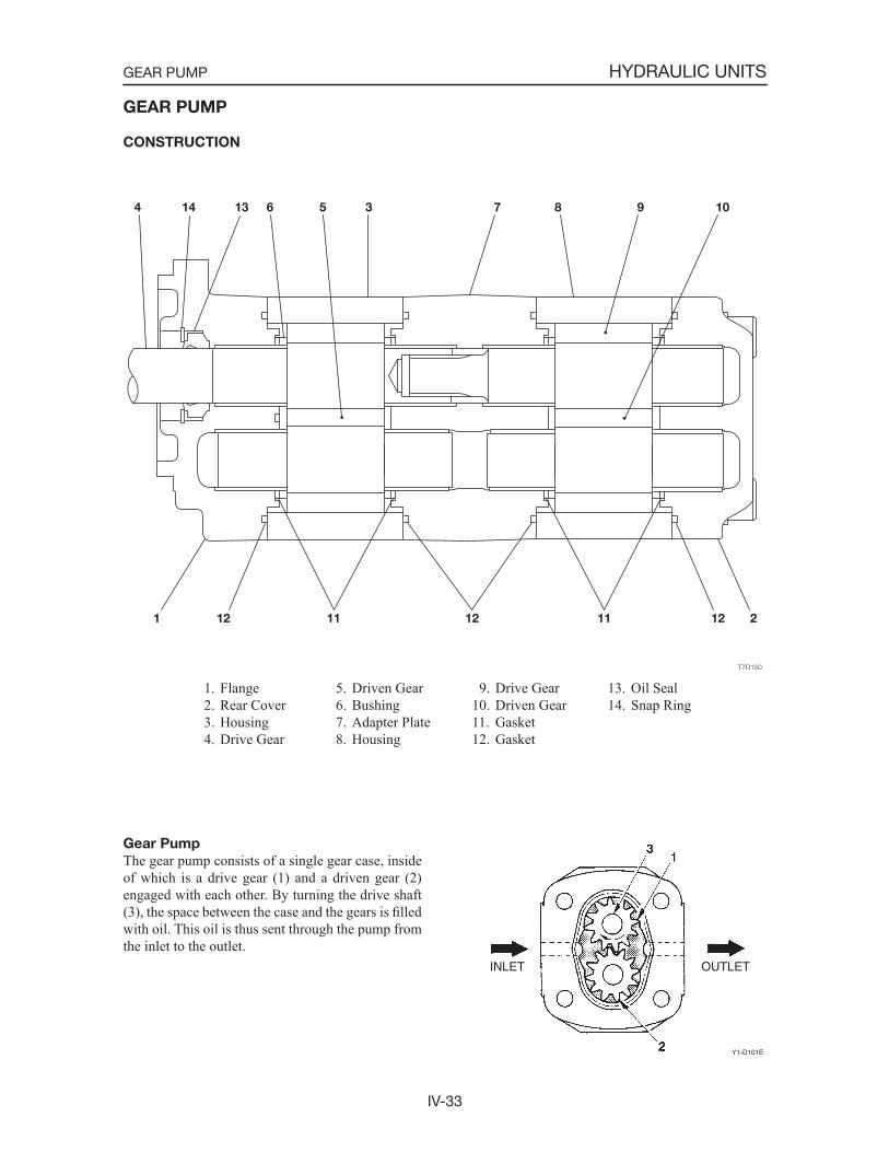
IV-33
HYDRAULIC UNITSGEAR PUMP
GEAR PUMP
CONSTRUCTION
1. Flange 2. Rear Cover 3. Housing 4. Drive Gear
Gear Pump
The gear pump consists of a single gear case, inside of which is a drive gear (1) and a driven gear (2) engaged with each other. By turning the drive shaft (3), the space between the case and the gears is filledwith oil. This oil is thus sent through the pump from the inlet to the outlet.
5. Driven Gear 6. Bushing 7. Adapter Plate 8. Housing
9. Drive Gear10. Driven Gear11. Gasket12. Gasket
INLET OUTLET
Y1-D101E
13. Oil Seal14. Snap Ring

IV-34
HYDRAULIC UNITSGEAR PUMP
DISASSEMBLY AND ASSEMBLY
General Cautions
• Carry out disassembly and assembly operations in a clean place and provide clean containers to place the disassembled parts in.
• Before disassembly, clean around the ports and remove the paint from each joint using a wire brush.
• Clean each of the disassembled parts with a clean-ing oil such as diesel fuel.
• Make match marks on each part so that they will be assembled in the same positions when as-sembled.
• Replace all seals with new ones each time the pump is disassembled, coating them lightly with grease.
• Check each part to make sure there is no abnormal wear or seizing and use sandpaper, etc. to remove any burrs, sharp edges, etc.
• Adjust adjustment screws only when required.
Following is an explanation of the gear pump disas-sembly procedure.Follow the procedure used to disassemble the gear pump in reverse order when reassembling it.
1. Remove the cap screws. Screw: 88~93 N·m
2. Remove the flange.
3. Remove gasket (2) from flange (1).
4. Remove snap ring (3) and oil seal (4) from flange(1).• Be careful not to scratch or otherwise damage
the flange.• When re-assembling, install the oil seal using
the jigs A and B.T7D151
21
4
3
T7D152
B
A
4 1
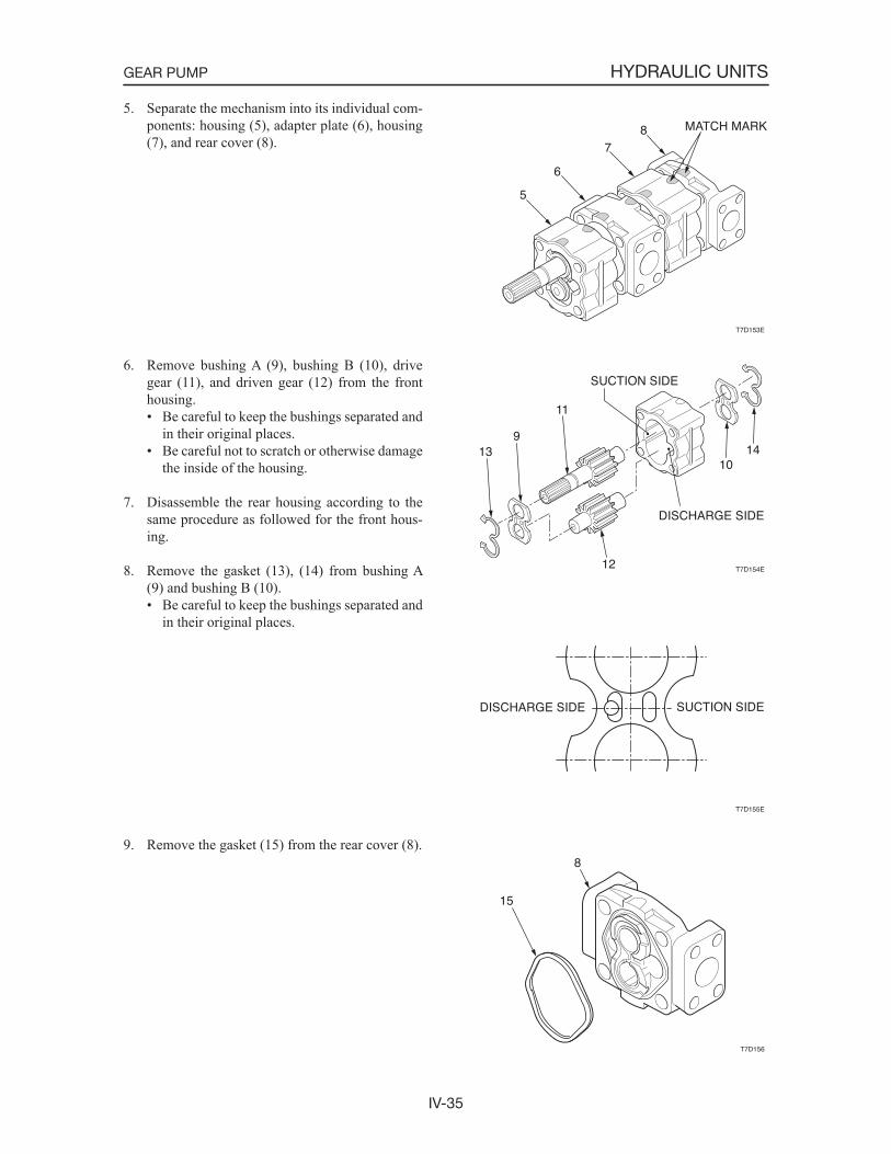
IV-35
HYDRAULIC UNITSGEAR PUMP
5. Separate the mechanism into its individual com-ponents: housing (5), adapter plate (6), housing (7), and rear cover (8).
6. Remove bushing A (9), bushing B (10), drive gear (11), and driven gear (12) from the front housing.• Be careful to keep the bushings separated and
in their original places.• Be careful not to scratch or otherwise damage
the inside of the housing.
7. Disassemble the rear housing according to the same procedure as followed for the front hous-ing.
8. Remove the gasket (13), (14) from bushing A (9) and bushing B (10).• Be careful to keep the bushings separated and
in their original places.
9. Remove the gasket (15) from the rear cover (8).
T7D153E
5
6
78 MATCH MARK
T7D154E
1410
11
12
913
DISCHARGE SIDE
SUCTION SIDE
T7D155E
DISCHARGE SIDE SUCTION SIDE
T7D156
8
15
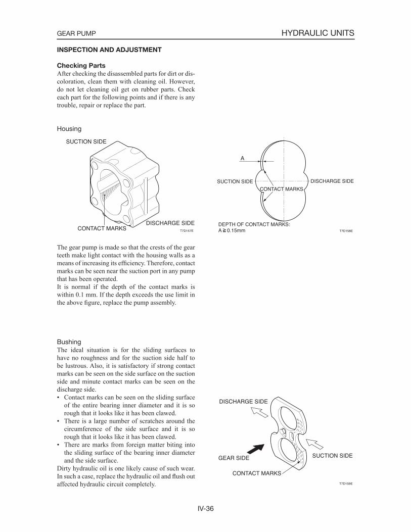
IV-36
HYDRAULIC UNITSGEAR PUMP
INSPECTION AND ADJUSTMENT
Checking Parts
After checking the disassembled parts for dirt or dis-coloration, clean them with cleaning oil. However, do not let cleaning oil get on rubber parts. Check each part for the following points and if there is any trouble, repair or replace the part.
Housing
The gear pump is made so that the crests of the gear teeth make light contact with the housing walls as a means of increasing its efficiency. Therefore, contact marks can be seen near the suction port in any pump that has been operated.It is normal if the depth of the contact marks is within 0.1 mm. If the depth exceeds the use limit in the above figure, replace the pump assembly.
BushingThe ideal situation is for the sliding surfaces to have no roughness and for the suction side half to be lustrous. Also, it is satisfactory if strong contact marks can be seen on the side surface on the suction side and minute contact marks can be seen on the discharge side.• Contact marks can be seen on the sliding surface
of the entire bearing inner diameter and it is so rough that it looks like it has been clawed.
• There is a large number of scratches around the circumference of the side surface and it is so rough that it looks like it has been clawed.
• There are marks from foreign matter biting into the sliding surface of the bearing inner diameter and the side surface.
Dirty hydraulic oil is one likely cause of such wear. In such a case, replace the hydraulic oil and flush out affected hydraulic circuit completely.
DISCHARGE SIDE
SUCTION SIDE
CONTACT MARKS T7D157E T7D158E
A
SUCTION SIDE DISCHARGE SIDE
CONTACT MARKS
DEPTH OF CONTACT MARKS:A 0.15mm
T7D159E
DISCHARGE SIDE
SUCTION SIDE
CONTACT MARKS
GEAR SIDE
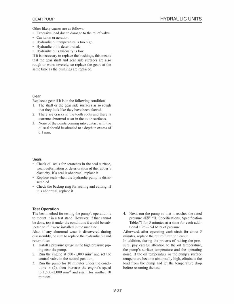
IV-37
HYDRAULIC UNITSGEAR PUMP
Other likely causes are as follows.• Excessive load due to damage to the relief valve.• Cavitaion or aeration.• Hydraulic oil temperature is too high.• Hydraulic oil is deteriorated.• Hydraulic oil s viscosity is low.If it is necessary to replace the bushings, this means that the gear shaft and gear side surfaces are also rough or worn severely, so replace the gears at the same time as the bushings are replaced.
GearReplace a gear if it is in the following condition.1. The shaft or the gear side surfaces ar so rough
that they look like they have been clawed.2. There are cracks in the tooth roots and there is
extreme abnormal wear in the tooth surfaces.3. None of the points coming into contact with the
oil seal should be abraded to a depth in excess of 0.1 mm.
Seals• Check oil seals for scratches in the seal surface,
wear, deformation or deterioration of the rubber selasticity. If a seal is abnormal, replace it.
• Replace seals when the hydraulic pump is disas-sembled.
• Check the backup ring for scaling and cutting. If it is abnormal, replace it.
Test Operation
The best method for testing the pump s operation is to mount it in a test stand. However, if that cannot be done, test it under the conditions it would be sub-jected to if it were installed in the machine.Also, if any abnormal wear is discovered during disassembly, be sure to replace the hydraulic oil and return filter.1. Install a pressure gauge in the high pressure pip-
ing near the pump.2. Run the engine at 500~1,000 min-1 and set the
control valve in the neutral position.3. Run the pump for 10 minutes under the condi-
tions in (2), then increase the engine s speed to 1,500~2,000 min-1 and run it for another 10 minutes.
4. Next, run the pump so that it reaches the rated pressure ( “II. Specifications, SpecificationTables”) for 5 minutes at a time for each addi-tional 1.96~2.94 MPa of pressure.
Afterward, after operating each ciruit for about 5 minutes, replace the return filter or clean it.In addition, during the process of raising the pres-sure, pay careful attention to the oil temperature, the pump s surface temperature and the operating noise. If the oil temperature or the pump s surface temperature become abnormally high, eliminate the load from the pump and let the temperature drop before resuming the test.
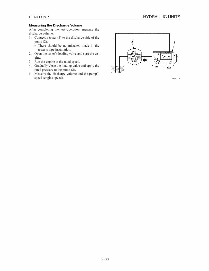
IV-38
HYDRAULIC UNITSGEAR PUMP
Measuring the Discharge Volume
After completing the test operation, measure the discharge volume.1. Connect a tester (1) to the discharge side of the
pump (2).• There should be no mistakes made in the
tester s pipe installation.2. Open the tester s loading valve and start the en-
gine.3. Run the engine at the rated speed.4. Gradually close the loading valve and apply the
rated pressure to the pump (2).5. Measure the discharge volume and the pump s
speed (engine speed).
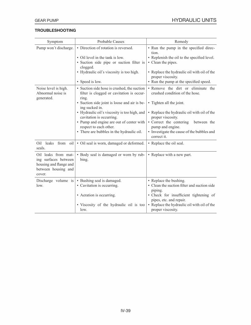
IV-39
HYDRAULIC UNITSGEAR PUMP
Symptom Probable Causes RemedyPump won t discharge. • Direction of rotation is reversed.
• Oil level in the tank is low.• Suction side pipe or suction filter is
clogged.• Hydraulic oil s viscosity is too high.
• Speed is low.
• Run the pump in the specified direc-tion.
• Replenish the oil to the specified level.• Clean the pipes.
• Replace the hydraulic oil with oil of the proper viscosity.
• Run the pump at the specified speed.Noise level is high.Abnormal noise is generated.
• Suction side hose is crushed, the suction filter is clogged or cavitation is occur-ring.
• Suction side joint is loose and air is be-ing sucked in.
• Hydraulic oil s viscosity is too high, and cavitation is occurring.
• Pump and engine are out of center with respect to each other.
• There are bubbles in the hydraulic oil.
• Remove the dirt or eliminate the crushed condition of the hose.
• Tighten all the joint.
• Replace the hydraulic oil with oil of the proper viscosity.
• Correct the centering between the pump and engine.
• Investigate the cause of the bubbles and correct it.
Oil leaks from oil seals.
• Oil seal is worn, damaged or deformed. • Replace the oil seal.
Oil leaks from mat-ing surfaces between housing and flange and between housing and cover.
• Body seal is damaged or worn by rub-bing.
• Replace with a new part.
Discharge volume is low.
• Bushing seal is damaged.• Cavitation is occurring.
• Aeration is occurring.
• Viscosity of the hydraulic oil is too low.
• Replace the bushing.• Clean the suction filter and suction side
piping.• Check for insufficient tightening of
pipes, etc. and repair.• Replace the hydraulic oil with oil of the
proper viscosity.
TROUBLESHOOTING
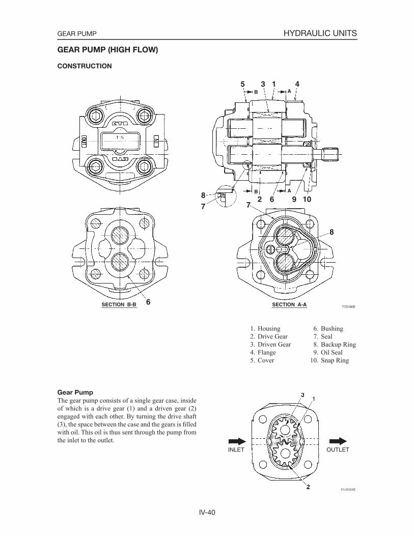
IV-40
HYDRAULIC UNITSGEAR PUMP
GEAR PUMP (HIGH FLOW)
CONSTRUCTION
Gear Pump
The gear pump consists of a single gear case, inside of which is a drive gear (1) and a driven gear (2) engaged with each other. By turning the drive shaft (3), the space between the case and the gears is filledwith oil. This oil is thus sent through the pump from the inlet to the outlet.
1. Housing 2. Drive Gear 3. Driven Gear 4. Flange 5. Cover
INLET OUTLET
Y1-D101E
6. Bushing 7. Seal 8. Backup Ring 9. Oil Seal10. Snap Ring
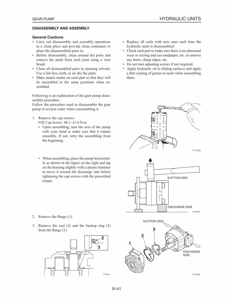
IV-41
HYDRAULIC UNITSGEAR PUMP
DISASSEMBLY AND ASSEMBLY
General Cautions
• Carry out disassembly and assembly operations in a clean place and provide clean containers to place the disassembled parts in.
• Before disassembly, clean around the ports and remove the paint from each joint using a wire brush.
• Clean all disassembled parts in cleaning solvent. Use a lint free cloth, or air dry the parts.
• Make match marks on each part so that they will be assembled in the same positions when as-sembled.
• Replace all seals with new ones each time the hydraulic units is disassembled.
• Check each part to make sure there is no abnormal wear or seizing and use sandpaper, etc. to remove any burrs, sharp edges, etc.
• Do not turn adjusting screws if not required.• Apply hydraulic oil to sliding surfaces and apply
a thin coating of grease to seals when assembling them.
Following is an explanation of the gear pump disas-sembly procedure.Follow the procedure used to disassemble the gear pump in reverse order when reassembling it.
1. Remove the cap screws. Cap Screw: 48.1~51.0 N·m
• Upon assembling, turn the axis of the pump with your hand to make sure that it rotates smoothly. If not, retry the assembling from the beginning.
• When assembling, place the pump horizontal-ly as shown in the figure on the right and tap on the housing slightly with a plastic hammer to move it toward the discharge side before tightening the cap screws with the prescribed torque.
2. Remove the flange (1).
3. Remove the seal (2) and the backup ring (3) from the flange (1).
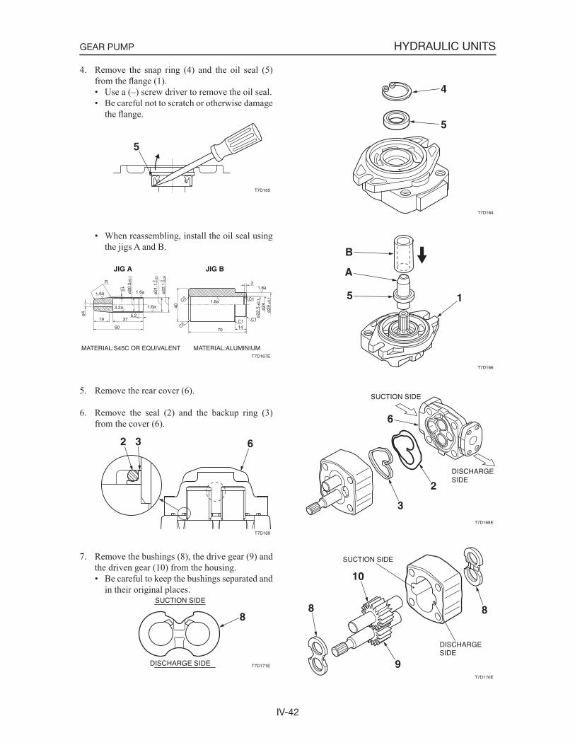
IV-42
HYDRAULIC UNITSGEAR PUMP
4. Remove the snap ring (4) and the oil seal (5) from the flange (1).• Use a (–) screw driver to remove the oil seal.• Be careful not to scratch or otherwise damage
the flange.
• When reassembling, install the oil seal using the jigs A and B.
5. Remove the rear cover (6).
6. Remove the seal (2) and the backup ring (3) from the cover (6).
7. Remove the bushings (8), the drive gear (9) and the driven gear (10) from the housing.• Be careful to keep the bushings separated and
in their original places.

IV-43
HYDRAULIC UNITSGEAR PUMP
INSPECTION AND ADJUSTMENT
“IV-36~38”
TROUBLESHOOTING
“IV-39”
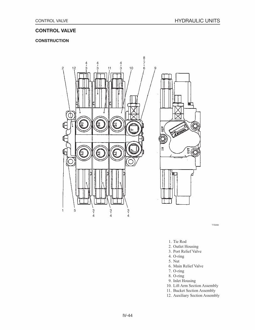
IV-44
HYDRAULIC UNITSCONTROL VALVE
1. Tie Rod 2. Outlet Housing 3. Port Relief Valve 4. O-ring 5. Nut 6. Main Relief Valve 7. O-ring 8. O-ring 9. Inlet Housing10. Lift Arm Section Assembly11. Bucket Section Assembly12. Auxiliary Section Assembly
CONTROL VALVE
CONSTRUCTION
T7D200
3
4
9
7
6
8
10
4
311
4
3
4
3122
3
4
3
4
51
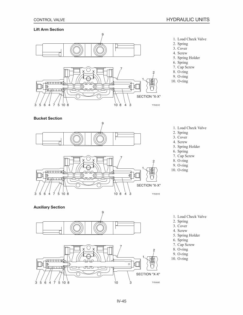
IV-45
HYDRAULIC UNITSCONTROL VALVE
SECTION "X-X"
XX
810574653
9
810 34
1
72
T7D201E
SECTION "X-X"
XX
810574653
9
810 34
1
72
T7D201E
SECTION "X-X"
XX
810574653
9
10 3
1
72
T7D203E
Lift Arm Section
Bucket Section
Auxiliary Section
1. Load Check Valve 2. Spring 3. Cover 4. Screw 5. Spring Holder 6. Spring 7. Cap Screw 8. O-ring 9. O-ring10. O-ring
1. Load Check Valve 2. Spring 3. Cover 4. Screw 5. Spring Holder 6. Spring 7. Cap Screw 8. O-ring 9. O-ring10. O-ring
1. Load Check Valve 2. Spring 3. Cover 4. Screw 5. Spring Holder 6. Spring 7. Cap Screw 8. O-ring 9. O-ring10. O-ring
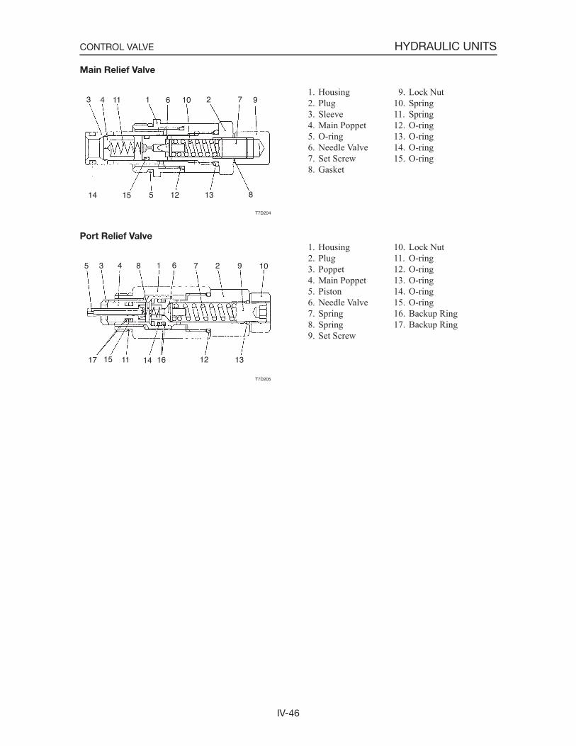
IV-46
HYDRAULIC UNITSCONTROL VALVE
Main Relief Valve
Port Relief Valve
1. Housing 2. Plug 3. Sleeve 4. Main Poppet 5. O-ring 6. Needle Valve 7. Set Screw 8. Gasket
T7D204
97210611143
14 15 5 12 13 8
T7D205
10927618435
17 15 11 14 16 12 13
9. Lock Nut10. Spring11. Spring12. O-ring13. O-ring14. O-ring15. O-ring
1. Housing 2. Plug 3. Poppet 4. Main Poppet 5. Piston 6. Needle Valve 7. Spring 8. Spring 9. Set Screw
10. Lock Nut11. O-ring12. O-ring13. O-ring14. O-ring15. O-ring16. Backup Ring17. Backup Ring
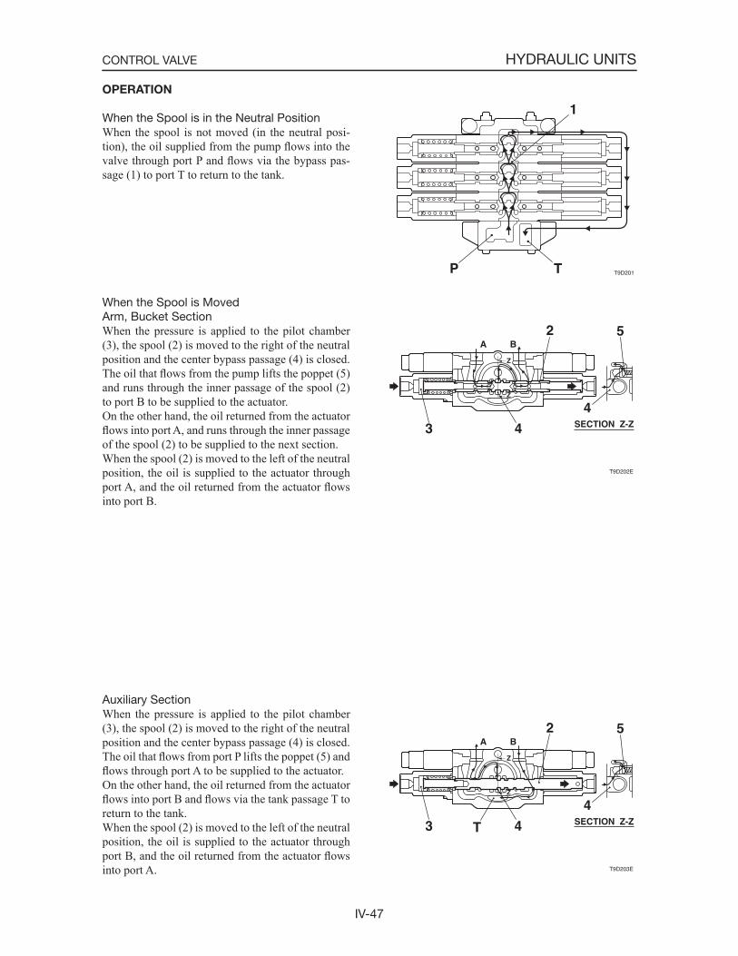
IV-47
HYDRAULIC UNITSCONTROL VALVE
T9D201P T
1
T9D202E
SECTION Z-Z
2
3
4
4
5A B
Z
Z
T9D203E
SECTION Z-Z
2
3
4
4T
5A B
Z
Z
OPERATION
When the Spool is in the Neutral PositionWhen the spool is not moved (in the neutral posi-tion), the oil supplied from the pump flows into the valve through port P and flows via the bypass pas-sage (1) to port T to return to the tank.
When the Spool is MovedArm, Bucket SectionWhen the pressure is applied to the pilot chamber (3), the spool (2) is moved to the right of the neutral position and the center bypass passage (4) is closed. The oil that flows from the pump lifts the poppet (5) and runs through the inner passage of the spool (2) to port B to be supplied to the actuator.On the other hand, the oil returned from the actuator flows into port A, and runs through the inner passage of the spool (2) to be supplied to the next section.When the spool (2) is moved to the left of the neutral position, the oil is supplied to the actuator through port A, and the oil returned from the actuator flowsinto port B.
Auxiliary SectionWhen the pressure is applied to the pilot chamber (3), the spool (2) is moved to the right of the neutral position and the center bypass passage (4) is closed. The oil that flows from port P lifts the poppet (5) and flows through port A to be supplied to the actuator.On the other hand, the oil returned from the actuator flows into port B and flows via the tank passage T to return to the tank.When the spool (2) is moved to the left of the neutral position, the oil is supplied to the actuator through port B, and the oil returned from the actuator flowsinto port A.
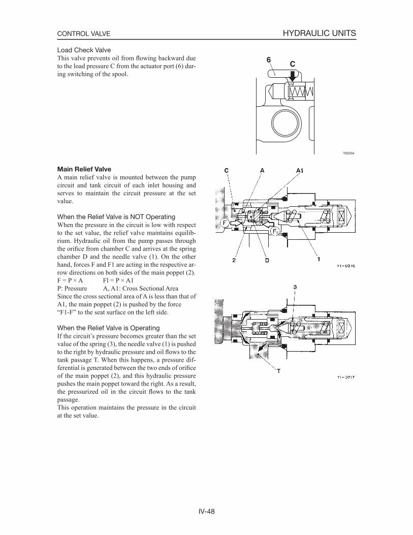
IV-48
HYDRAULIC UNITSCONTROL VALVE
Load Check ValveThis valve prevents oil from flowing backward due to the load pressure C from the actuator port (6) dur-ing switching of the spool.
Main Relief Valve
A main relief valve is mounted between the pump circuit and tank circuit of each inlet housing and serves to maintain the circuit pressure at the set value.
When the Relief Valve is NOT OperatingWhen the pressure in the circuit is low with respect to the set value, the relief valve maintains equilib-rium. Hydraulic oil from the pump passes through the orifice from chamber C and arrives at the spring chamber D and the needle valve (1). On the other hand, forces F and F1 are acting in the respective ar-row directions on both sides of the main poppet (2).F = P × A Fl = P × A1P: Pressure A, A1: Cross Sectional AreaSince the cross sectional area of A is less than that of A1, the main poppet (2) is pushed by the force“F1-F” to the seat surface on the left side.
When the Relief Valve is OperatingIf the circuit s pressure becomes greater than the set value of the spring (3), the needle valve (1) is pushed to the right by hydraulic pressure and oil flows to the tank passage T. When this happens, a pressure dif-ferential is generated between the two ends of orificeof the main poppet (2), and this hydraulic pressure pushes the main poppet toward the right. As a result, the pressurized oil in the circuit flows to the tank passage.This operation maintains the pressure in the circuit at the set value.
T9D204
C6
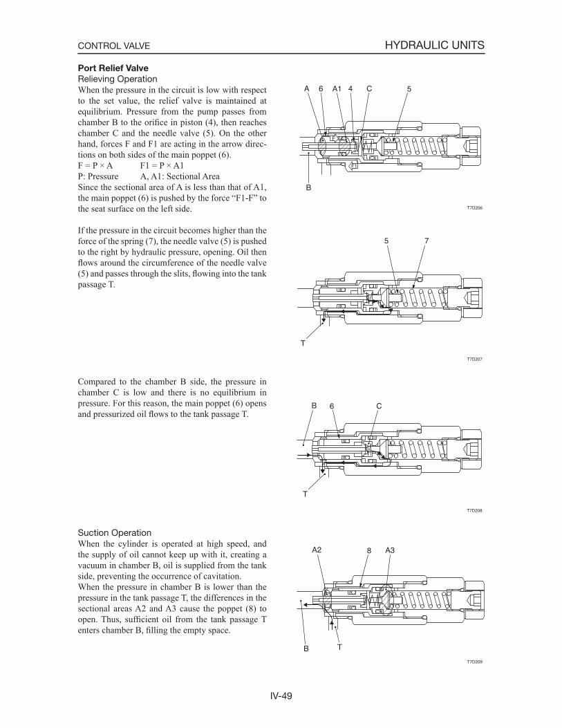
IV-49
HYDRAULIC UNITSCONTROL VALVE
T7D206
5C4A16A
B
F
F1
T7D208
C6
T
B
T7D209
A38A2
B T
T7D207
75
T
Port Relief Valve
Relieving OperationWhen the pressure in the circuit is low with respect to the set value, the relief valve is maintained at equilibrium. Pressure from the pump passes from chamber B to the orifice in piston (4), then reaches chamber C and the needle valve (5). On the other hand, forces F and F1 are acting in the arrow direc-tions on both sides of the main poppet (6).F = P × A F1 = P × A1P: Pressure A, A1: Sectional AreaSince the sectional area of A is less than that of A1, the main poppet (6) is pushed by the force “F1-F” to the seat surface on the left side.
If the pressure in the circuit becomes higher than the force of the spring (7), the needle valve (5) is pushed to the right by hydraulic pressure, opening. Oil then flows around the circumference of the needle valve (5) and passes through the slits, flowing into the tank passage T.
Compared to the chamber B side, the pressure in chamber C is low and there is no equilibrium in pressure. For this reason, the main poppet (6) opens and pressurized oil flows to the tank passage T.
Suction OperationWhen the cylinder is operated at high speed, and the supply of oil cannot keep up with it, creating a vacuum in chamber B, oil is supplied from the tank side, preventing the occurrence of cavitation.When the pressure in chamber B is lower than the pressure in the tank passage T, the differences in the sectional areas A2 and A3 cause the poppet (8) to open. Thus, sufficient oil from the tank passage T enters chamber B, filling the empty space.

IV-50
HYDRAULIC UNITSCONTROL VALVE
G4D223
DISASSEMBLY AND ASSEMBLY
General Cautions
• Since all parts in control valves are precision machined, carry out disassembly and assembly operations in a clean place.
• Before disassembly, clean the outside surfaces around the valves.
• Clean each of the disassembled parts and apply clean hydraulic oil to them.
• Apply hydraulic oil to sliding surfaces and apply a thin coating of grease to seals when assembling them.
• Replace all seals with new ones each time the valves are disassembled.
• Spools and section bodies are specially selected for a precise fit. Therefore, if any damage is found in either of these parts, replace the section assem-bly as a unit.
• Be sure to number each section and spool to avoid mistakes during assembly.
Following is an explanation of the control valve dis-assembly procedure.Follow the procedure used to disassemble the con-trol valve in reverse order when reassembling it.
Disassembly
Valve Assembly1. Loosen the nuts and remove the tie rods, then
remove the sections. Nut: 39.23 ±3.92 N·m
2. Remove the O-ring.• The mating surfaces are metal seals, so be
careful not to scratch, bruise or otherwise damage them.
3. Remove the main relief valves and the port relief valves, then remove the O-rings from the relief valves.• Do not disassemble the relief valves unless it
is necessary.• When using a spanner or adjustable wrench,
be sure to attach it in the place shown in the figure at right. Main relief valve: 58.84 ±5.88 N·m Port relief valve: 39.23 ±3.92 N·m

IV-51
HYDRAULIC UNITSCONTROL VALVE
4. Remove the load check valve.a. Remove the spring (3), then remove the pop-
pet (4).
Pilot Operated Section1. Take out the cap screw (5) and remove the cover
(15), then remove the O-ring (16) from the cover (15).
Cap screw: 3.92 ±0.98 N·m
2. Remove the spool from the section.
3. Take out the screw (17) and remove the spring holder (18), spring (19) and spring holder (18).
Screw: 10.79 ±0.98 N·m• Apply Locktite #242 to the screw.
K3D217
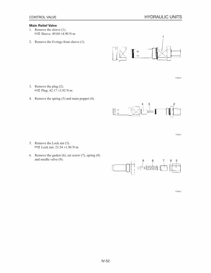
IV-52
HYDRAULIC UNITSCONTROL VALVE
Main Relief Valve
1. Remove the sleeve (1). Sleeve: 49.04 ±4.90 N·m
2. Remove the O-rings from sleeve (1).
3. Remove the plug (2). Plug: 42.17 ±3.92 N·m
4. Remove the spring (3) and main poppet (4).
5. Remove the Lock nut (5). Lock nut: 23.54 ±1.96 N·m
6. Remove the gasket (6), set screw (7), spring (8) and needle valve (9).
T7D210
1
T7D211
4 3 2
T7D212
9 8 7 6 5
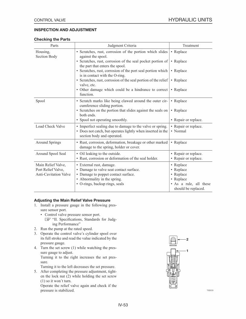
IV-53
HYDRAULIC UNITSCONTROL VALVE
Adjusting the Main Relief Valve Pressure
1. Install a pressure gauge in the following pres-sure sensor port.• Control valve pressure sensor port.
“II. Specifications, Standards for Judg-ing Performance”
2. Run the pump at the rated speed.3. Operate the control valve s cylinder spool over
its full stroke and read the value indicated by the pressure gauge.
4. Turn the set screw (1) while watching the pres-sure gauge to adjust.
Turning it to the right increases the set pres-sure.
Turning it to the left decreases the set pressure.5. After completing the pressure adjustment, tight-
en the lock nut (2) while holding the set screw (1) so it won t turn.
Operate the relief valve again and check if the pressure is stabilized.
INSPECTION AND ADJUSTMENT
Checking the Parts
Parts Judgment Criteria TreatmentHousing,Section Body
• Scratches, rust, corrosion of the portion which slides against the spool.
• Scratches, rust, corrosion of the seal pocket portion of the part that enters the spool.
• Scratches, rust, corrosion of the port seal portion which is in contact with the O-ring.
• Scratches, rust, corrosion of the seal portion of the relief valve, etc.
• Other damage which could be a hindrance to correct function.
• Replace
• Replace
• Replace
• Replace
• Replace
Spool • Scratch marks like being clawed around the outer cir-cumference sliding portion.
• Scratches on the portion that slides against the seals on both ends.
• Spool not operating smoothly.
• Replace
• Replace
• Repair or replace.Load Check Valve • Imperfect sealing due to damage to the valve or spring.
• Does not catch, but operates lightly when inserted in the section body and operated.
• Repair or replace.• Normal
Around Springs • Rust, corrosion, deformation, breakage or other marked damage to the spring, holder or cover.
• Replace
Around Spool Seal • Oil leaking to the outside.• Rust, corrosion or deformation of the seal holder.
• Repair or replace.• Repair or replace.
Main Relief Valve,Port Relief Valve,Anti-Cavitation Valve
• External rust, damage.• Damage to valve seat contact surface.• Damage to poppet contact surface.• Abnormality in the spring.• O-rings, backup rings, seals
• Replace• Replace• Replace• Replace• As a rule, all these
should be replaced.
IV-54
HYDRAULIC UNITSCONTROL VALVE
TROUBLESHOOTING
The following items are a list of all the problems that might occur individually, but in actual practice, 2 or 3 of these problems might occur simultaneously
Symptom Probable Causes RemedyOil leaks from spool seal.
• Seal is scratched or the seal lip is worn due to long use.
• Spool s seal sliding portion was dam-aged by some external cause (bruise, scratch, etc.).
• Seal bulged out and the cover was in-stalled in a warped state.
• Paint adhered to the sliding portion of the spool s seal portion during painting.
• Tank circuit s pressure became high and exceeded the pressure level that the seal was capable of withstanding.
• Replace with a new part.
• Repair or replace the spool.
• Return to the correct shape and check for eccentric wear of the seal lip.
• Remove paint with paint thinner or re-move it mechanically. However, at this time, be careful not to damage the spool surface or the seal lip.
• Eliminate the factors causing excessive flow resistance.
Spool s sliding is not smooth.
• Foreign matter is biting into the spool ssliding surface.
• Oil film between the spool and body disappears due to abnormally high oil temperature.
• Lubrication is improper due to deterio-rating oil.
• Spool is worn from long use or due to pressure bearing on one side only.
• Spool is bent from externally applied pressure.
• Entire valve is strained due to strain in the installation face.
• Valve was used at a pressure or a flowvolume which was out of specification.
• Bolts used to assemble the valve were tightened excessively.
• Oil is accumulating in the cover (the side with a spring or a detent) opposite the side where the spool operates.
• Overhaul and repair or replace.
• Use some method to lower the oil tem-perature or if the relief valve is operat-ing frequently, investigate the cause and reduce the frequency.
• This could be alleviated by simply replacing the hydraulic oil, or it could require an overhaul of the circuit.
• Check the spool s diameter and consider the necessity of replacement.
• Check the spool s straightness and other factors, then repair or replace.
• Loosen the installation bolts, then cut the installation face and edge and check.
• In the case of pressure, check with a pressure gauge. In the case of flow vol-ume, check by the actuator s speed of movement and the capacity.
• Check if the assembly bolts are tight-ened to the specified torque. If the torque deviates markedly from the specifiedtorque, tighten them again.
• The spool is leaking oil, so when the spool moves, oil leaks from the cover. After confirming this, replace the seal.
Cylinder drops while shifting to a lift opera-tion.
• Foreign matter is biting into the load check valve seat or large scratches were made by foreign matter biting into the valve s seat previously.
• Disassemble and check, then overhaul or replace.
to compound the trouble. It is therefore desirable to proceed so that the causes can be eliminated one at a time.
IV-55
HYDRAULIC UNITSCONTROL VALVE
Symptom Probable Causes RemedyCan t be held in the spool neutral position (cylinder drops).
• Could be mistaken for a great amount of leakage in the cylinder.
• The gap between the spool and body is large, so the amount of oil leaking from the spool is great.
• Spool won t return completely to the neutral position.
• Foreign matter is biting into the port relief valve seat or the anti-cavitation valve seat and oil is bypassing. Or a seat is damaged.
• Check if it isn t just the cylinder s natu-ral drop when the cylinder is held. If the problem is in the cylinder, disassemble and repair it.
• Replace the spool or replace the valve block assembly.
• Manually Operated : Check if there is something interfering
with the link mechanism. Pilot Operated: Check the pilot pressure.• Disassemble and check, then overhaul
or replace.
The load won t move. (Pressure won t in-crease.)
• Foreign matter is biting into the relief valve seat and oil is bypassing. Or the seat is damaged.
• The relief valve s adjustment screw is loose.
• Foreign matter is biting into the port relief valve seat or the anti-cavitation valve seat and oil is bypassing. Or a seat is damaged.
• Spool stroke is not the specified stroke.
• Pump is damaged and no oil is dis-charged.
• Disassemble and check, then overhaul or replace.
• Try tightening the adjustment screw. If it is loose, correct the setting and tighten the lock nut securely.
• Disassemble and check, then overhaul or replace.
• Manually Operated: Check if there is something interfering
with the link mechanism. Check if a pin or a pin hole in the link connection is worn.
Pilot Operated: Check the pilot pressure.• Check if the pump is abnormal or not.
If the pump is bad, replace it. Check if the cause of the abnormality is air being sucked in, deterioration of hydraulic oil or shafts not centered, etc.
Load doesn t move. (Pressure rises.)
• The load is too heavy.
• Mechanical resistance of connecting parts is great regardless of the hydraulic pressure in the operating unit.
• A large piece of foreign matter is trapped in the circuit or a pipe is bent, causing great resistance.
• Spool stroke is not the specified stroke.
• Compare with an object of the specifiedweight.
• Check and replenish hydraulic oil, etc., modify or repair.
• Find the affected place and repair it.
• Check if there is something interfering with the link mechanism. Check if a pin or a pin hole in the link connection is worn or not.
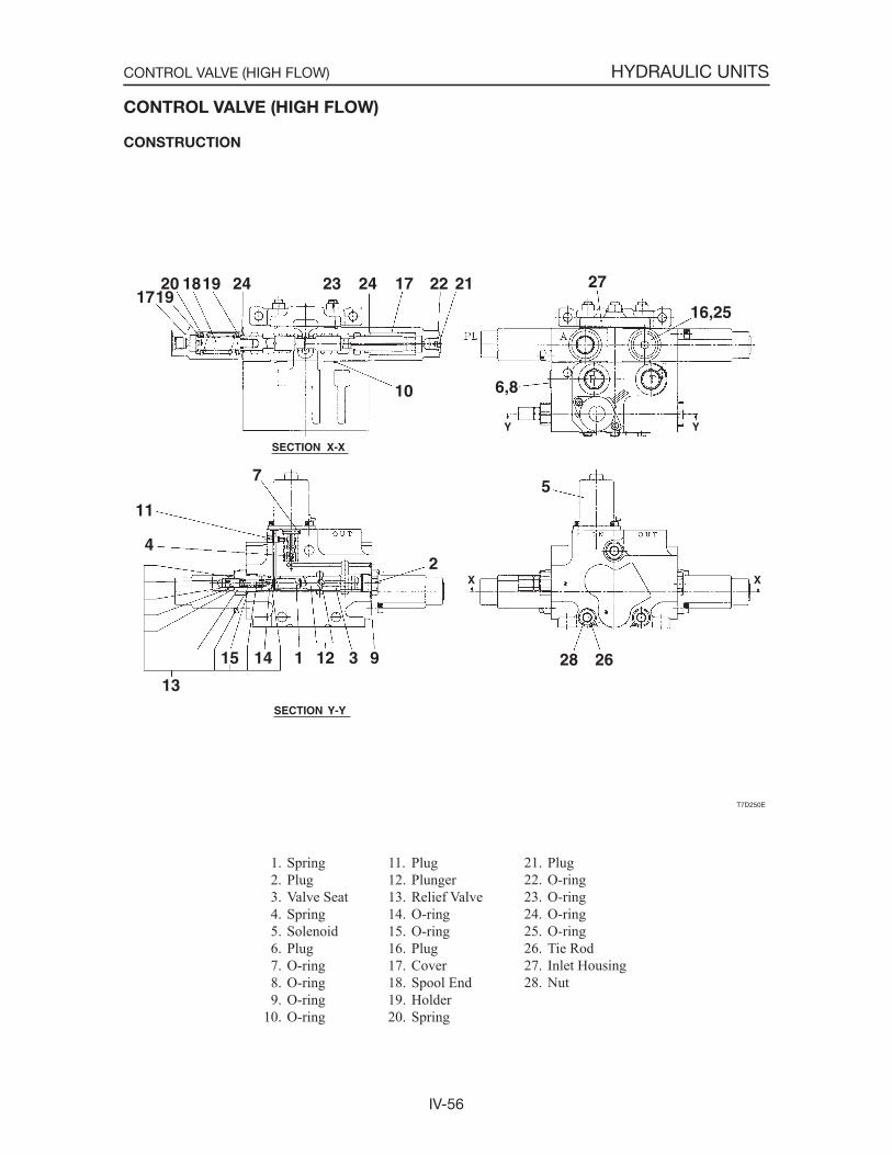
IV-56
HYDRAULIC UNITSCONTROL VALVE (HIGH FLOW)
1. Spring 2. Plug 3. Valve Seat 4. Spring 5. Solenoid 6. Plug 7. O-ring 8. O-ring 9. O-ring10. O-ring
CONTROL VALVE (HIGH FLOW)
CONSTRUCTION
11. Plug12. Plunger13. Relief Valve14. O-ring15. O-ring16. Plug17. Cover18. Spool End19. Holder20. Spring
21. Plug22. O-ring23. O-ring24. O-ring25. O-ring26. Tie Rod27. Inlet Housing28. Nut
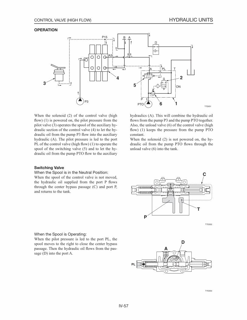
IV-57
HYDRAULIC UNITSCONTROL VALVE (HIGH FLOW)
OPERATION
When the solenoid (2) of the control valve (high flow) (1) is powered on, the pilot pressure from the pilot valve (3) operates the spool of the auxiliary hy-draulic section of the control valve (4) to let the hy-draulic oil from the pump P3 flow into the auxiliary hydraulic (A). The pilot pressure is led to the port PL of the control valve (high flow) (1) to operate the spool of the switching valve (5) and to let the hy-draulic oil from the pump PTO flow to the auxiliary
hydraulics (A). This will combine the hydraulic oil flows from the pump P3 and the pump PTO together. Also, the unload valve (6) of the control valve (high flow) (1) keeps the pressure from the pump PTO constant.When the solenoid (2) is not powered on, the hy-draulic oil from the pump PTO flows through the unload valve (6) into the tank.
Switching Valve
When the Spool is in the Neutral Position:When the spool of the control valve is not moved, the hydraulic oil supplied from the port P flowsthrough the center bypass passage (C) and port P, and returns to the tank.
When the Spool is Operating:When the pilot pressure is led to the port PL, the spool moves to the right to close the center bypass passage. Then the hydraulic oil flows from the pas-sage (D) into the port A.
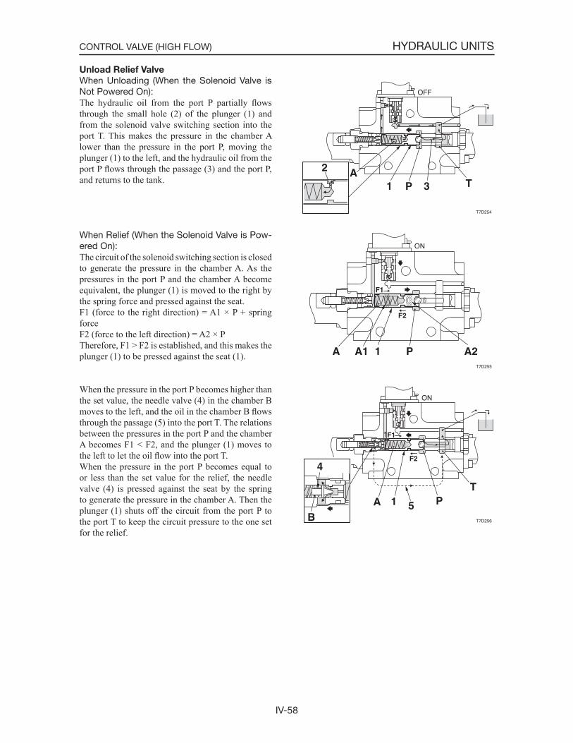
IV-58
HYDRAULIC UNITSCONTROL VALVE (HIGH FLOW)
Unload Relief Valve
When Unloading (When the Solenoid Valve is Not Powered On):The hydraulic oil from the port P partially flowsthrough the small hole (2) of the plunger (1) and from the solenoid valve switching section into the port T. This makes the pressure in the chamber A lower than the pressure in the port P, moving the plunger (1) to the left, and the hydraulic oil from the port P flows through the passage (3) and the port P, and returns to the tank.
When Relief (When the Solenoid Valve is Pow-ered On):The circuit of the solenoid switching section is closed to generate the pressure in the chamber A. As the pressures in the port P and the chamber A become equivalent, the plunger (1) is moved to the right by the spring force and pressed against the seat.F1 (force to the right direction) = A1 × P + spring forceF2 (force to the left direction) = A2 × PTherefore, F1 > F2 is established, and this makes the plunger (1) to be pressed against the seat (1).
When the pressure in the port P becomes higher than the set value, the needle valve (4) in the chamber B moves to the left, and the oil in the chamber B flowsthrough the passage (5) into the port T. The relations between the pressures in the port P and the chamber A becomes F1 < F2, and the plunger (1) moves to the left to let the oil flow into the port T.When the pressure in the port P becomes equal to or less than the set value for the relief, the needle valve (4) is pressed against the seat by the spring to generate the pressure in the chamber A. Then the plunger (1) shuts off the circuit from the port P to the port T to keep the circuit pressure to the one set for the relief.
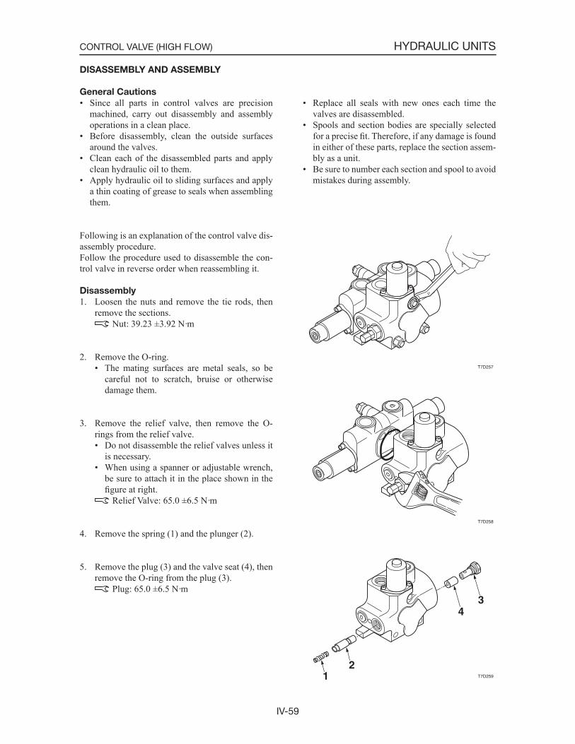
IV-59
HYDRAULIC UNITSCONTROL VALVE (HIGH FLOW)
DISASSEMBLY AND ASSEMBLY
General Cautions
• Since all parts in control valves are precision machined, carry out disassembly and assembly operations in a clean place.
• Before disassembly, clean the outside surfaces around the valves.
• Clean each of the disassembled parts and apply clean hydraulic oil to them.
• Apply hydraulic oil to sliding surfaces and apply a thin coating of grease to seals when assembling them.
• Replace all seals with new ones each time the valves are disassembled.
• Spools and section bodies are specially selected for a precise fit. Therefore, if any damage is found in either of these parts, replace the section assem-bly as a unit.
• Be sure to number each section and spool to avoid mistakes during assembly.
Following is an explanation of the control valve dis-assembly procedure.Follow the procedure used to disassemble the con-trol valve in reverse order when reassembling it.
Disassembly
1. Loosen the nuts and remove the tie rods, then remove the sections.
Nut: 39.23 ±3.92 N·m
2. Remove the O-ring.• The mating surfaces are metal seals, so be
careful not to scratch, bruise or otherwise damage them.
3. Remove the relief valve, then remove the O-rings from the relief valve.• Do not disassemble the relief valves unless it
is necessary.• When using a spanner or adjustable wrench,
be sure to attach it in the place shown in the figure at right. Relief Valve: 65.0 ±6.5 N·m
4. Remove the spring (1) and the plunger (2).
5. Remove the plug (3) and the valve seat (4), then remove the O-ring from the plug (3).
Plug: 65.0 ±6.5 N·m
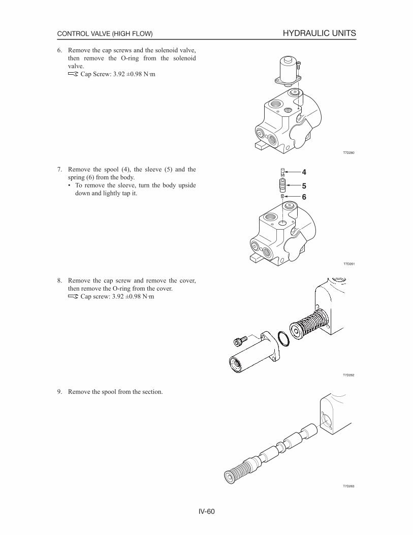
IV-60
HYDRAULIC UNITSCONTROL VALVE (HIGH FLOW)
6. Remove the cap screws and the solenoid valve, then remove the O-ring from the solenoid valve.
Cap Screw: 3.92 ±0.98 N·m
7. Remove the spool (4), the sleeve (5) and the spring (6) from the body.• To remove the sleeve, turn the body upside
down and lightly tap it.
8. Remove the cap screw and remove the cover, then remove the O-ring from the cover.
Cap screw: 3.92 ±0.98 N·m
9. Remove the spool from the section.
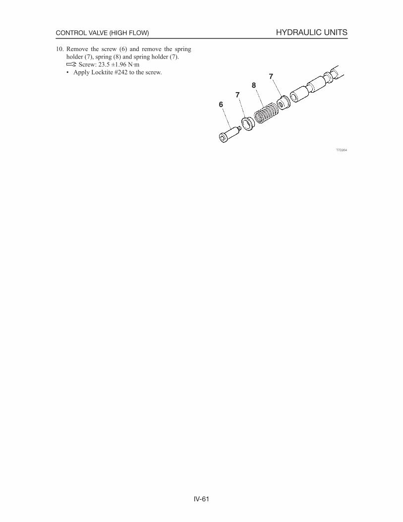
IV-61
HYDRAULIC UNITSCONTROL VALVE (HIGH FLOW)
10. Remove the screw (6) and remove the spring holder (7), spring (8) and spring holder (7).
Screw: 23.5 ±1.96 N·m• Apply Locktite #242 to the screw.

IV-62
HYDRAULIC UNITSCONTROL VALVE (HIGH FLOW)
Adjusting the Relief Valve Pressure
• Engine : Rated R.P.M.• Hydraulic Oil Temp. : 50~60°C• Mount the pressure gauge on the pressure detec-
tion port, operate the desired hydraulic circuit and measure the relief pressure.
CircuitPressure Detection Port Relief
ValvePort Position SizeAuxiliary
(High Flow) P G 1/2 R
1. Remove the cap screw (1), shim (3), lock nut (2) and shim (3) in this order.• The shims must be replaced for every adjust-
ment.
2. Make sure to record the dimension of the section A of the setscrew (4).
3. Adjust the set value by turning the setscrew (4). Turning clockwise .................raises the set pres-
sure. Turning counterclockwise .....lowers the set
pressure.• Change of pressure per turn: 9 MPa
4. In order to keep the setting screw from turning after pressure has been adjusted, tighten the locknut while at the same time holding the set-ting screw firmly in place.
5. Operate the relief valve once more to confirmthat the pressure that has been set it stabilized.
INSPECTION AND ADJUSTMENT
Checking the Parts
Parts Judgment Criteria TreatmentSolenoid coil • When the solenoid is burned, short-circuited, or has a wire
break• Wiring short-circuit or wire break
• Replace
• ReplaceBody • Scratches, rust, or corrosion at the sliding parts with the spool
• Scratches, rust, or corrosion of the seal part in contact with the O-ring
• Other damage considered to impair the normal functions
• Replace
• Replace• Replace
Spool, plunger • Damage on the outer circumference which catches a fingernail• No smooth movement
• Replace• Adjust or replace
Spring • Rust, corrosion, deformation, breakage, or other notable dam-age
• Replace
O-Ring • Replace
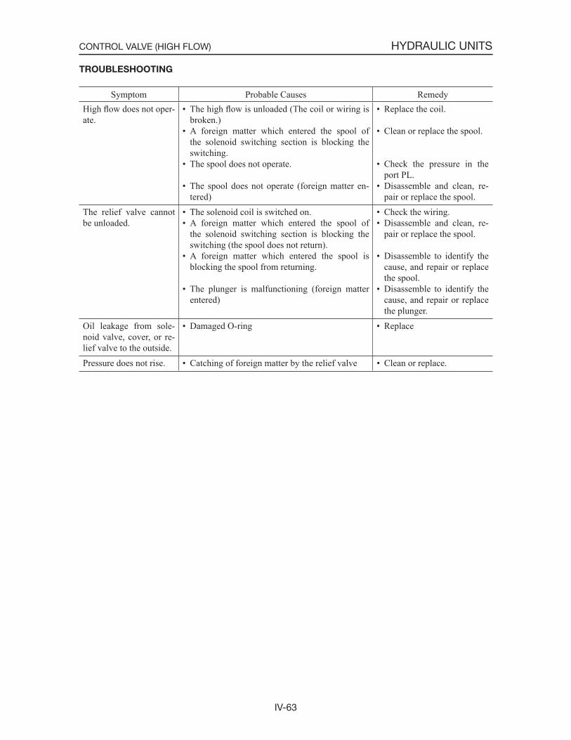
IV-63
HYDRAULIC UNITSCONTROL VALVE (HIGH FLOW)
TROUBLESHOOTING
Symptom Probable Causes RemedyHigh flow does not oper-ate.
• The high flow is unloaded (The coil or wiring is broken.)
• A foreign matter which entered the spool of the solenoid switching section is blocking the switching.
• The spool does not operate.
• The spool does not operate (foreign matter en-tered)
• Replace the coil.
• Clean or replace the spool.
• Check the pressure in the port PL.
• Disassemble and clean, re-pair or replace the spool.
The relief valve cannot be unloaded.
• The solenoid coil is switched on.• A foreign matter which entered the spool of
the solenoid switching section is blocking the switching (the spool does not return).
• A foreign matter which entered the spool is blocking the spool from returning.
• The plunger is malfunctioning (foreign matter entered)
• Check the wiring.• Disassemble and clean, re-
pair or replace the spool.
• Disassemble to identify the cause, and repair or replace the spool.
• Disassemble to identify the cause, and repair or replace the plunger.
Oil leakage from sole-noid valve, cover, or re-lief valve to the outside.
• Damaged O-ring • Replace
Pressure does not rise. • Catching of foreign matter by the relief valve • Clean or replace.
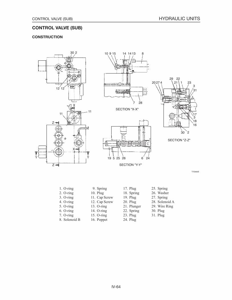
IV-64
HYDRAULIC UNITSCONTROL VALVE (SUB)
1. O-ring 2. O-ring 3. O-ring 4. O-ring 5. O-ring 6. O-ring 7. O-ring 8. Solenoid B
CONTROL VALVE (SUB)
CONSTRUCTION
T7D900E
Z
Z
X
YY
X
30 2
12 12
1111
20 27 429
2122
1 23331
1731816
30 2
19 5 25 26 6 24
7 28
10 9 15 14 13 814
SECTION "X-X"
SECTION "Y-Y"
SECTION "Z-Z"
9. Spring10. Plug11. Cap Screw12. Cap Screw13. O-ring14. O-ring15. O-ring16. Poppet
17. Plug18. Spring19. Plug20. Plug21. Plunger22. Spring23. Plug24. Plug
25. Spring26. Washer27. Spring28. Solenoid A29. Wire Ring30. Plug31. Plug
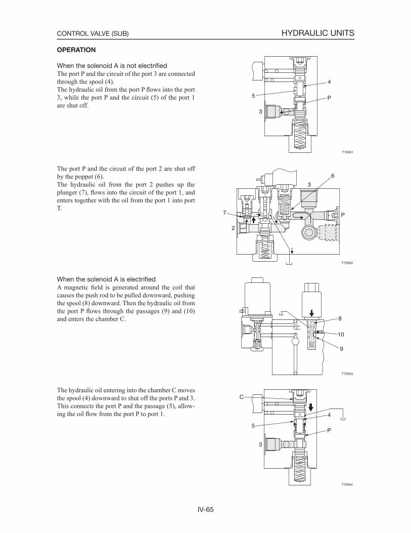
IV-65
HYDRAULIC UNITSCONTROL VALVE (SUB)
T7D901
4
P5
3
T7D902
6
3
P7
2
T7D903
8
10
9
T7D904
4
P5
C
3
OPERATION
When the solenoid A is not electrifiedThe port P and the circuit of the port 3 are connected through the spool (4).The hydraulic oil from the port P flows into the port 3, while the port P and the circuit (5) of the port 1 are shut off.
The port P and the circuit of the port 2 are shut off by the poppet (6).The hydraulic oil from the port 2 pushes up the plunger (7), flows into the circuit of the port 1, and enters together with the oil from the port 1 into port T.
When the solenoid A is electrifiedA magnetic field is generated around the coil that causes the push rod to be pulled downward, pushing the spool (8) downward. Then the hydraulic oil from the port P flows through the passages (9) and (10) and enters the chamber C.
The hydraulic oil entering into the chamber C moves the spool (4) downward to shut off the ports P and 3. This connects the port P and the passage (5), allow-ing the oil flow from the port P to port 1.
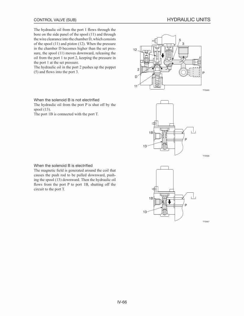
IV-66
HYDRAULIC UNITSCONTROL VALVE (SUB)
The hydraulic oil from the port 1 flows through the bore on the side panel of the spool (11) and through the wire clearance into the chamber D, which consists of the spool (11) and piston (12). When the pressure in the chamber D becomes higher than the set pres-sure, the spool (11) moves downward, releasing the oil from the port 1 to port 2, keeping the pressure in the port 1 at the set pressure.The hydraulic oil in the port 2 pushes up the poppet (5) and flows into the port 3.
When the solenoid B is not electrifiedThe hydraulic oil from the port P is shut off by the spool (13).The port 1B is connected with the port T.
When the solenoid B is electrifiedThe magnetic field is generated around the coil that causes the push rod to be pulled downward, push-ing the spool (13) downward. Then the hydraulic oil flows from the port P to port 1B, shutting off the circuit to the port T.
T7D905
35
P2
12
D
11
T7D906
13
1B
P
T7D907
13
1B
P
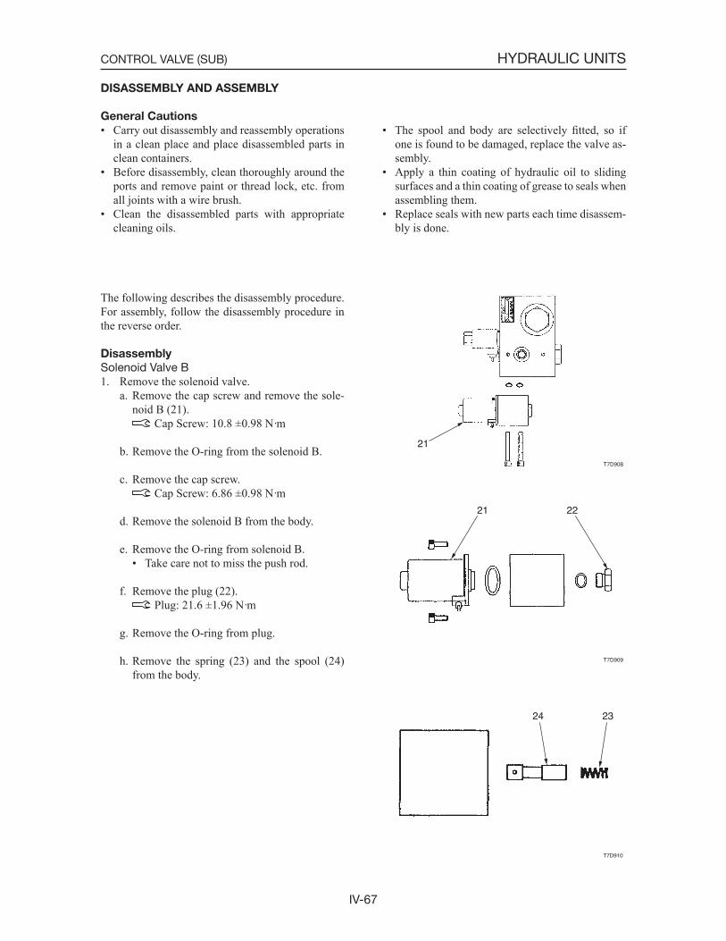
IV-67
HYDRAULIC UNITSCONTROL VALVE (SUB)
DISASSEMBLY AND ASSEMBLY
General Cautions
• Carry out disassembly and reassembly operations in a clean place and place disassembled parts in clean containers.
• Before disassembly, clean thoroughly around the ports and remove paint or thread lock, etc. from all joints with a wire brush.
• Clean the disassembled parts with appropriate cleaning oils.
T7D908
21
T7D909
21 22
T7D910
2324
• The spool and body are selectively fitted, so if one is found to be damaged, replace the valve as-sembly.
• Apply a thin coating of hydraulic oil to sliding surfaces and a thin coating of grease to seals when assembling them.
• Replace seals with new parts each time disassem-bly is done.
The following describes the disassembly procedure. For assembly, follow the disassembly procedure in the reverse order.
Disassembly
Solenoid Valve B1. Remove the solenoid valve.
a. Remove the cap screw and remove the sole-noid B (21).
Cap Screw: 10.8 ±0.98 N·m
b. Remove the O-ring from the solenoid B.
c. Remove the cap screw. Cap Screw: 6.86 ±0.98 N·m
d. Remove the solenoid B from the body.
e. Remove the O-ring from solenoid B.• Take care not to miss the push rod.
f. Remove the plug (22). Plug: 21.6 ±1.96 N·m
g. Remove the O-ring from plug.
h. Remove the spring (23) and the spool (24) from the body.
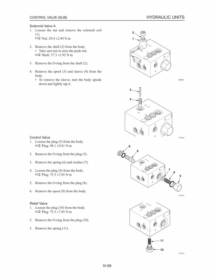
IV-68
HYDRAULIC UNITSCONTROL VALVE (SUB)
Solenoid Valve A1. Loosen the nut and remove the solenoid coil
(1). Nut: 29.4 ±2.94 N·m
2. Remove the shaft (2) from the body.• Take care not to miss the push rod.
Shaft: 37.3 ±3.92 N·m
3. Remove the O-ring from the shaft (2).
4. Remove the spool (3) and sleeve (4) from the body.• To remove the sleeve, turn the body upside
down and lightly tap it.
Control Valve1. Loosen the plug (5) from the body.
Plug: 98.1 ±9.81 N·m
2. Remove the O-ring from the plug (5).
3. Remove the spring (6) and washer (7).
4. Loosen the plug (8) from the body. Plug: 75.5 ±7.85 N·m
5. Remove the O-ring from the plug (8).
6. Remove the spool (9) from the body.
Relief Valve1. Loosen the plug (10) from the body.
Plug: 75.5 ±7.85 N·m
2. Remove the O-ring from the plug (10).
3. Remove the spring (11).
T6D901
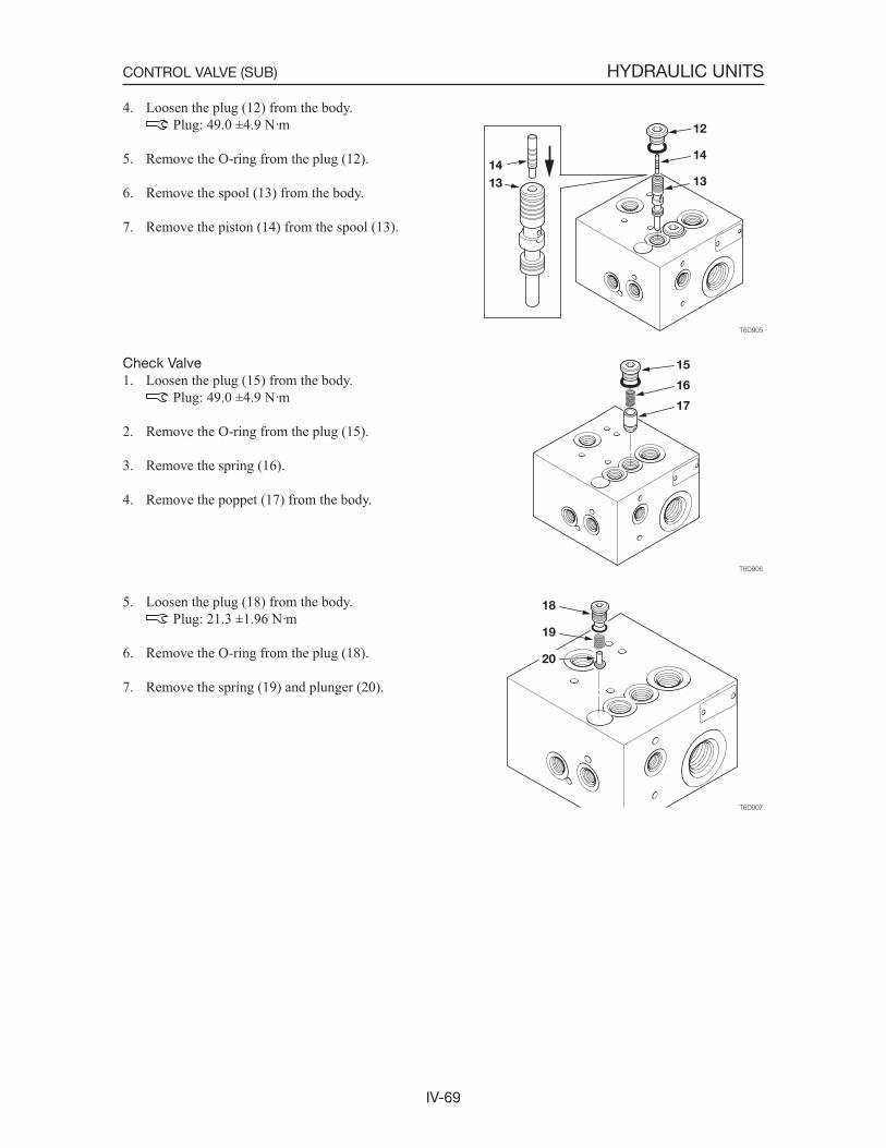
IV-69
HYDRAULIC UNITSCONTROL VALVE (SUB)
4. Loosen the plug (12) from the body. Plug: 49.0 ±4.9 N·m
5. Remove the O-ring from the plug (12).
6. Remove the spool (13) from the body.
7. Remove the piston (14) from the spool (13).
Check Valve1. Loosen the plug (15) from the body.
Plug: 49.0 ±4.9 N·m
2. Remove the O-ring from the plug (15).
3. Remove the spring (16).
4. Remove the poppet (17) from the body.
5. Loosen the plug (18) from the body. Plug: 21.3 ±1.96 N·m
6. Remove the O-ring from the plug (18).
7. Remove the spring (19) and plunger (20).
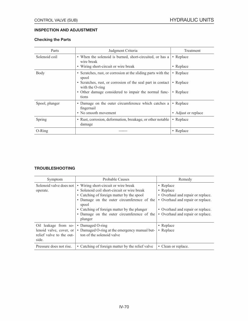
IV-70
HYDRAULIC UNITSCONTROL VALVE (SUB)
INSPECTION AND ADJUSTMENT
Checking the Parts
Parts Judgment Criteria TreatmentSolenoid coil • When the solenoid is burned, short-circuited, or has a
wire break• Wiring short-circuit or wire break
• Replace
• ReplaceBody • Scratches, rust, or corrosion at the sliding parts with the
spool• Scratches, rust, or corrosion of the seal part in contact
with the O-ring• Other damage considered to impair the normal func-
tions
• Replace
• Replace
• Replace
Spool, plunger • Damage on the outer circumference which catches a fingernail
• No smooth movement
• Replace
• Adjust or replaceSpring • Rust, corrosion, deformation, breakage, or other notable
damage• Replace
O-Ring • Replace
TROUBLESHOOTING
Symptom Probable Causes RemedySolenoid valve does not operate.
• Wiring short-circuit or wire break• Solenoid coil short-circuit or wire break• Catching of foreign matter by the spool• Damage on the outer circumference of the
spool• Catching of foreign matter by the plunger• Damage on the outer circumference of the
plunger
• Replace• Replace• Overhaul and repair or replace.• Overhaul and repair or replace.
• Overhaul and repair or replace.• Overhaul and repair or replace.
Oil leakage from so-lenoid valve, cover, or relief valve to the out-side.
• Damaged O-ring• Damaged O-ring at the emergency manual but-
ton of the solenoid valve
• Replace• Replace
Pressure does not rise. • Catching of foreign matter by the relief valve • Clean or replace.
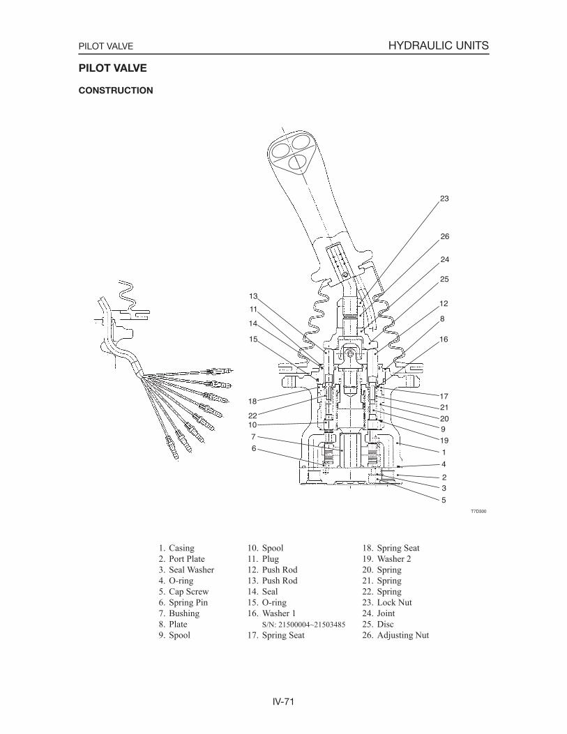
IV-71
HYDRAULIC UNITSPILOT VALVE
1. Casing 2. Port Plate 3. Seal Washer 4. O-ring 5. Cap Screw 6. Spring Pin 7. Bushing 8. Plate 9. Spool
PILOT VALVE
CONSTRUCTION
23
26
24
25
12
8
16
172120919
1
4
23
5
13
11
14
15
18
2210
7
6
T7D300
10. Spool11. Plug12. Push Rod13. Push Rod14. Seal15. O-ring16. Washer 1
S/N: 21500004~2150348517. Spring Seat
18. Spring Seat19. Washer 220. Spring21. Spring22. Spring23. Lock Nut24. Joint25. Disc26. Adjusting Nut
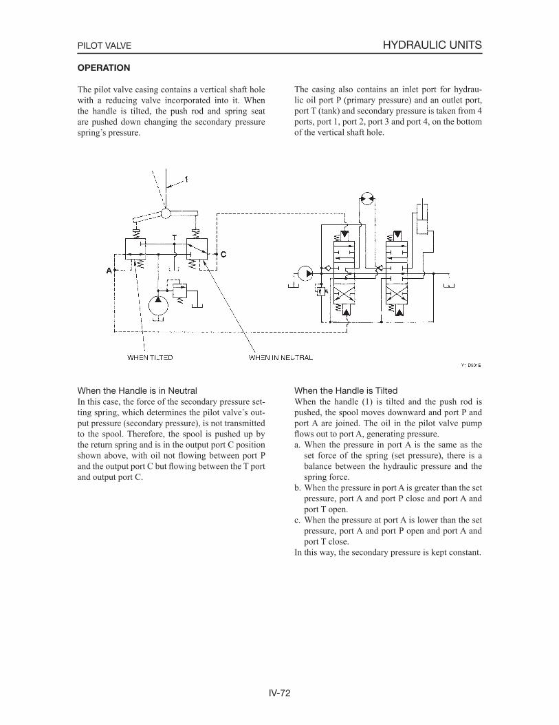
IV-72
HYDRAULIC UNITSPILOT VALVE
OPERATION
The pilot valve casing contains a vertical shaft hole with a reducing valve incorporated into it. When the handle is tilted, the push rod and spring seat are pushed down changing the secondary pressure spring s pressure.
The casing also contains an inlet port for hydrau-lic oil port P (primary pressure) and an outlet port, port T (tank) and secondary pressure is taken from 4 ports, port 1, port 2, port 3 and port 4, on the bottom of the vertical shaft hole.
When the Handle is in NeutralIn this case, the force of the secondary pressure set-ting spring, which determines the pilot valve s out-put pressure (secondary pressure), is not transmitted to the spool. Therefore, the spool is pushed up by the return spring and is in the output port C position shown above, with oil not flowing between port P and the output port C but flowing between the T port and output port C.
When the Handle is TiltedWhen the handle (1) is tilted and the push rod is pushed, the spool moves downward and port P and port A are joined. The oil in the pilot valve pump flows out to port A, generating pressure.a. When the pressure in port A is the same as the
set force of the spring (set pressure), there is a balance between the hydraulic pressure and the spring force.
b. When the pressure in port A is greater than the set pressure, port A and port P close and port A and port T open.
c. When the pressure at port A is lower than the set pressure, port A and port P open and port A and port T close.
In this way, the secondary pressure is kept constant.
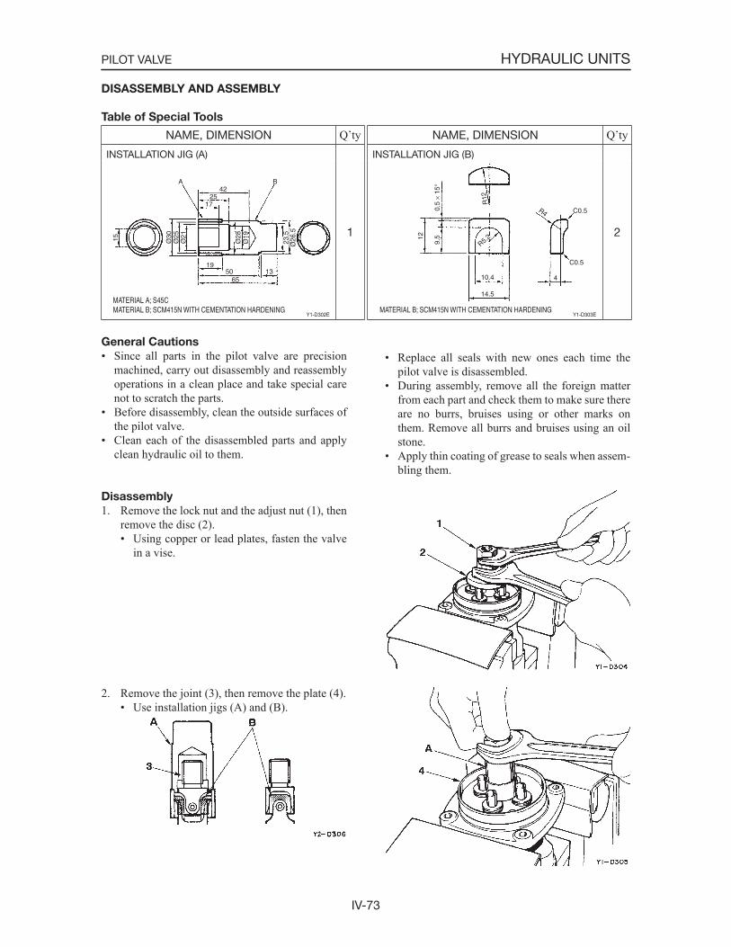
IV-73
HYDRAULIC UNITSPILOT VALVE
DISASSEMBLY AND ASSEMBLY
Table of Special Tools
General Cautions
• Since all parts in the pilot valve are precision machined, carry out disassembly and reassembly operations in a clean place and take special care not to scratch the parts.
• Before disassembly, clean the outside surfaces of the pilot valve.
• Clean each of the disassembled parts and apply clean hydraulic oil to them.
• Replace all seals with new ones each time the pilot valve is disassembled.
• During assembly, remove all the foreign matter from each part and check them to make sure there are no burrs, bruises using or other marks on them. Remove all burrs and bruises using an oil stone.
• Apply thin coating of grease to seals when assem-bling them.
Disassembly
1. Remove the lock nut and the adjust nut (1), then remove the disc (2).• Using copper or lead plates, fasten the valve
in a vise.
2. Remove the joint (3), then remove the plate (4).• Use installation jigs (A) and (B).
NAME, DIMENSION Q tyINSTALLATION JIG (A)
1
MATERIAL A; S45CMATERIAL B; SCM415N WITH CEMENTATION HARDENING
Y1-D302E
Ø21
Ø28
Ø19
23.5
Ø26
.5
Ø25
Ø3015
A B42
2517
1950 13
65
NAME, DIMENSION Q tyINSTALLATION JIG (B)
2
Y1-D303EMATERIAL B; SCM415N WITH CEMENTATION HARDENING
12
10.4
14.5
4
9.5
0.5
15
C0.5
C0.5R4
R5.2
R12
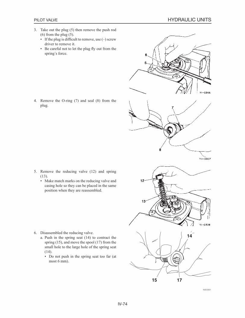
IV-74
HYDRAULIC UNITSPILOT VALVE
3. Take out the plug (5) then remove the push rod (6) from the plug (5).• If the plug is difficult to remove, use (–) screw
driver to remove it.• Be careful not to let the plug fly out from the
spring s force.
4. Remove the O-ring (7) and seal (8) from the plug.
5. Remove the reducing valve (12) and spring (13).• Make match marks on the reducing valve and
casing hole so they can be placed in the same position when they are reassembled.
6. Disassembled the reducing valve.a. Push in the spring seat (14) to contract the
spring (15), and move the spool (17) from the small hole to the large hole of the spring seat (14).• Do not push in the spring seat too far (at
most 6 mm).
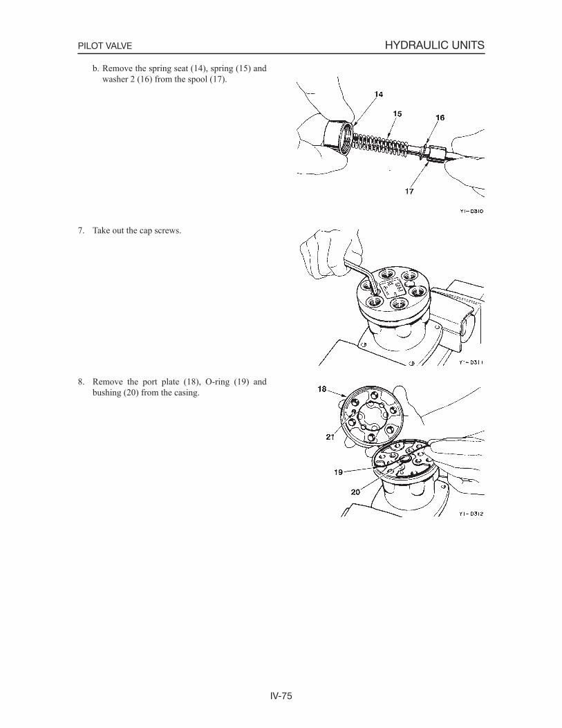
IV-75
HYDRAULIC UNITSPILOT VALVE
b. Remove the spring seat (14), spring (15) and washer 2 (16) from the spool (17).
7. Take out the cap screws.
8. Remove the port plate (18), O-ring (19) and bushing (20) from the casing.
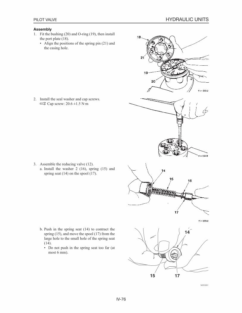
IV-76
HYDRAULIC UNITSPILOT VALVE
Assembly
1. Fit the bushing (20) and O-ring (19), then install the port plate (18).• Align the positions of the spring pin (21) and
the casing hole.
2. Install the seal washer and cap screws. Cap screw: 20.6 ±1.5 N·m
3. Assemble the reducing valve (12).a. Install the washer 2 (16), spring (15) and
spring seat (14) on the spool (17).
b. Push in the spring seat (14) to contract the spring (15), and move the spool (17) from the large hole to the small hole of the spring seat (14).• Do not push in the spring seat too far (at
most 6 mm).
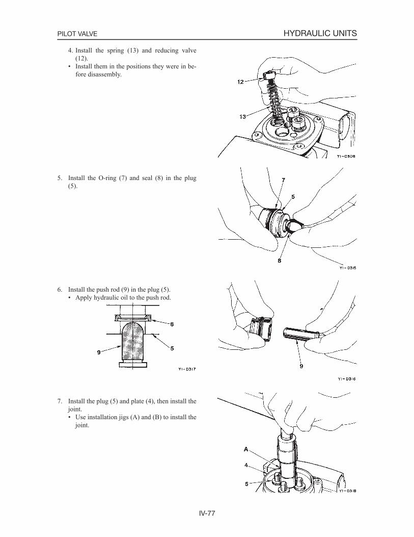
IV-77
HYDRAULIC UNITSPILOT VALVE
4. Install the spring (13) and reducing valve (12).
• Install them in the positions they were in be-fore disassembly.
5. Install the O-ring (7) and seal (8) in the plug (5).
6. Install the push rod (9) in the plug (5).• Apply hydraulic oil to the push rod.
7. Install the plug (5) and plate (4), then install the joint.• Use installation jigs (A) and (B) to install the
joint.

IV-78
HYDRAULIC UNITSPILOT VALVE
Joint: 47.1 ±2.9 N·m8. Install the disc (2), the adjust nut (1) and the
lock nut.• Tighten the adjust nut to the point where all 4
push rods are uniformly making contact.• During tightening, the disc should not be
moved. Adjust Nut: 68.6 ±4.9 N·m Lock Nut: 49 ±3.4 N·m
9. Apply grease to the contact surfaces of the joint

IV-79
HYDRAULIC UNITSPILOT VALVE
INSPECTION AND ADJUSTMENT
Checking the Parts
Parts Judgment Criteria TreatmentO-ring • Replace
Seal • Replace
Seal Washer • Replace
Spool • Wear on sliding portions is 10 m or greater compared to non-sliding portions
• Scratches on sliding portions• Spool doesn t move smoothly
• Replace
• Replace• Repair or replace
Push Rod • Front end is worn 1 mm or more
• Scratches in the sliding portion
• Replace
• ReplacePlug • Seal is imperfect due to damage • Repair or replaceOperating Portion • Tightening is loose at the pin, shaft or joint of the oper-
ating portion, with looseness of 2 mm or greater• Due to wear, etc. tightening is loose at the pin, shaft or
joint of the operating portion, with looseness of 2 mm or greater
• Tighten to the specifiedtorque
• Replace
Casing,Port Plate
• Scratches, rust or corrosion on the spool and sliding portion
• Scratches, rust or corrosion on seal portions which come in contact with the O-ring
• Replace
• Repair or replace
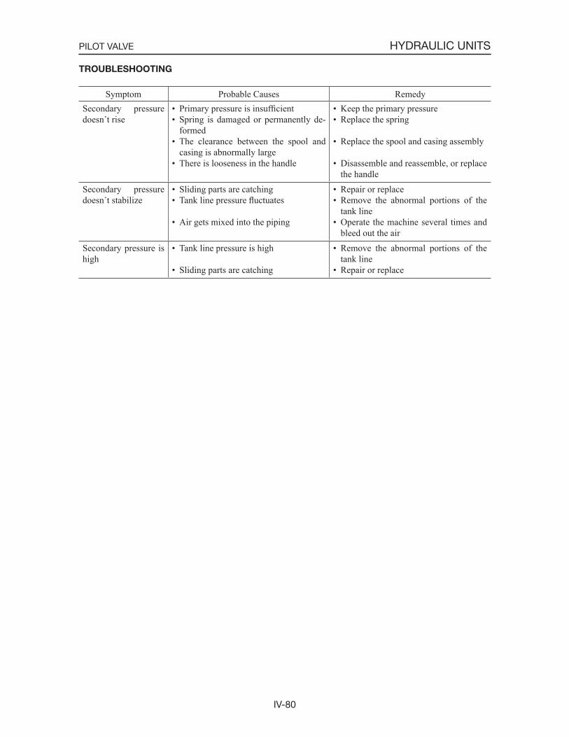
IV-80
HYDRAULIC UNITSPILOT VALVE
TROUBLESHOOTING
Symptom Probable Causes RemedySecondary pressure doesn t rise
• Primary pressure is insufficient• Spring is damaged or permanently de-
formed• The clearance between the spool and
casing is abnormally large• There is looseness in the handle
• Keep the primary pressure• Replace the spring
• Replace the spool and casing assembly
• Disassemble and reassemble, or replace the handle
Secondary pressure doesn t stabilize
• Sliding parts are catching• Tank line pressure fluctuates
• Air gets mixed into the piping
• Repair or replace• Remove the abnormal portions of the
tank line• Operate the machine several times and
bleed out the airSecondary pressure is high
• Tank line pressure is high
• Sliding parts are catching
• Remove the abnormal portions of the tank line
• Repair or replace
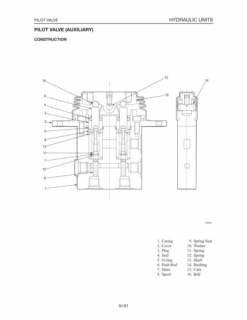
IV-81
HYDRAULIC UNITSPILOT VALVE
1. Casing 2. Cover 3. Plug 4. Seal 5. O-ring 6. Push Rod 7. Shim 8. Spool
PILOT VALVE (AUXILIARY)
CONSTRUCTION
L3D350
16
6
4
3
2
5
9
12
11
7
10
8
1
13
15
14
9. Spring Seat10. Washer11. Spring12. Spring13. Shaft14. Bushing15. Cam16. Ball
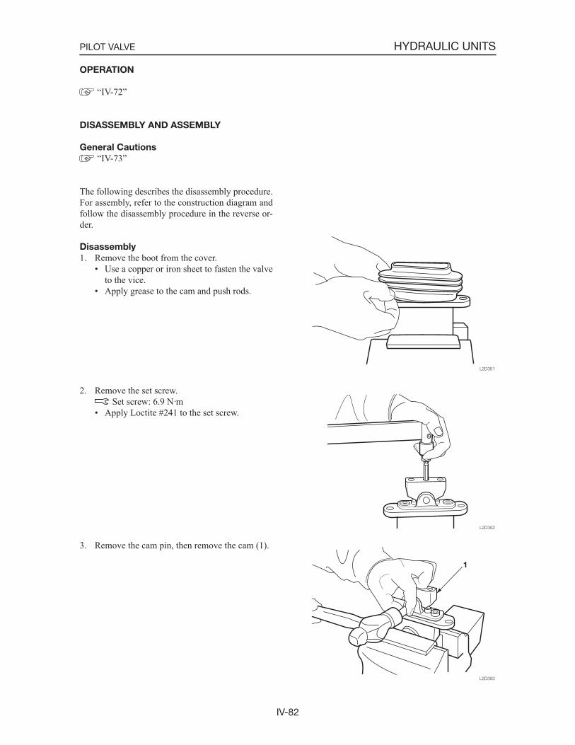
IV-82
HYDRAULIC UNITSPILOT VALVE
OPERATION
“IV-72”
DISASSEMBLY AND ASSEMBLY
General Cautions
“IV-73”
The following describes the disassembly procedure. For assembly, refer to the construction diagram and follow the disassembly procedure in the reverse or-der.
Disassembly
1. Remove the boot from the cover.• Use a copper or iron sheet to fasten the valve
to the vice.• Apply grease to the cam and push rods.
2. Remove the set screw. Set screw: 6.9 N·m
• Apply Loctite #241 to the set screw.
3. Remove the cam pin, then remove the cam (1).
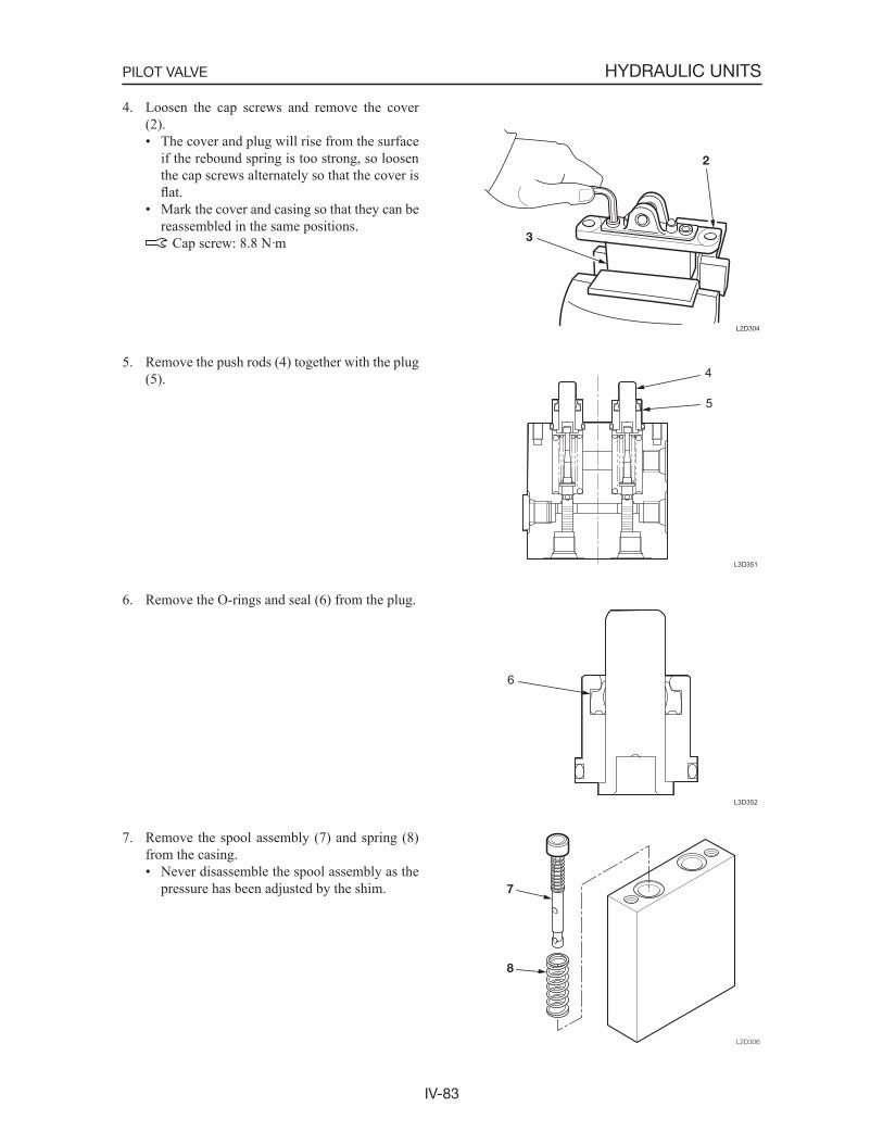
IV-83
HYDRAULIC UNITSPILOT VALVE
4. Loosen the cap screws and remove the cover (2).• The cover and plug will rise from the surface
if the rebound spring is too strong, so loosen the cap screws alternately so that the cover is flat.
• Mark the cover and casing so that they can be reassembled in the same positions. Cap screw: 8.8 N·m
5. Remove the push rods (4) together with the plug (5).
6. Remove the O-rings and seal (6) from the plug.
7. Remove the spool assembly (7) and spring (8) from the casing.• Never disassemble the spool assembly as the
pressure has been adjusted by the shim.
L3D351
4
5
L3D352
6
L2D304
IV-84
HYDRAULIC UNITSPILOT VALVE
INSPECTION AND ADJUSTMENT
“IV-79”
TROUBLESHOOTING
“IV-80”

IV-85
HYDRAULIC UNITSSELF-LEVEL VALVE
1. Valve Assembly 2. Ring 3. Cover 4. O-ring 5. O-ring 6. O-ring 7. O-ring 8. O-ring 9. O-ring
SELF-LEVEL VALVE
CONSTRUCTION
T7D950E
4 5
6
7
216
17
24
23 21 2220 12 13 14
19
25 1011
9
3
15
8
18
SECTION “A-A”
10. Spring11. Plunger12. Pin13. Cap14. Nut15. Set Screw16. Plug17. Plug18. Plug
19. Spring20. Plunger21. Plug22. Spring23. Housing24. Spool25. Spool
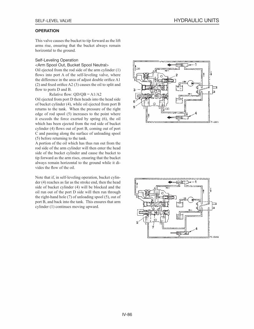
IV-86
HYDRAULIC UNITSSELF-LEVEL VALVE
OPERATION
This valve causes the bucket to tip forward as the lift arms rise, ensuring that the bucket always remain horizontal to the ground.
Self-Leveling Operation<Arm Spool Out, Bucket Spool Neutral>Oil ejected from the rod side of the arm cylinder (1) flows into port A of the self-leveling valve, where the difference in the area of adjust double orifice A1 (2) and fixed orifice A2 (3) causes the oil to split and flow to ports D and B. Relative flow: QD/QB = A1/A2Oil ejected from port D then heads into the head side of bucket cylinder (4), while oil ejected from port B returns to the tank. When the pressure of the right edge of rod spool (5) increases to the point where it exceeds the force exerted by spring (6), the oil which has been ejected from the rod side of bucket cylinder (4) flows out of port B, coming out of port C and passing along the surface of unloading spool (5) before returning to the tank.A portion of the oil which has thus run out from the rod side of the arm cylinder will then enter the head side of the bucket cylinder and cause the bucket to tip forward as the arm rises, ensuring that the bucket always remain horizontal to the ground while it di-vides the flow of the oil.
Note that if, in self-leveling operation, bucket cylin-der (4) reaches as far as the stroke end, then the head side of bucket cylinder (4) will be blocked and the oil run out of the port D side will then run through the right-hand hole (7) of unloading spool (5), out of port B, and back into the tank. This ensures that arm cylinder (1) continues moving upward.
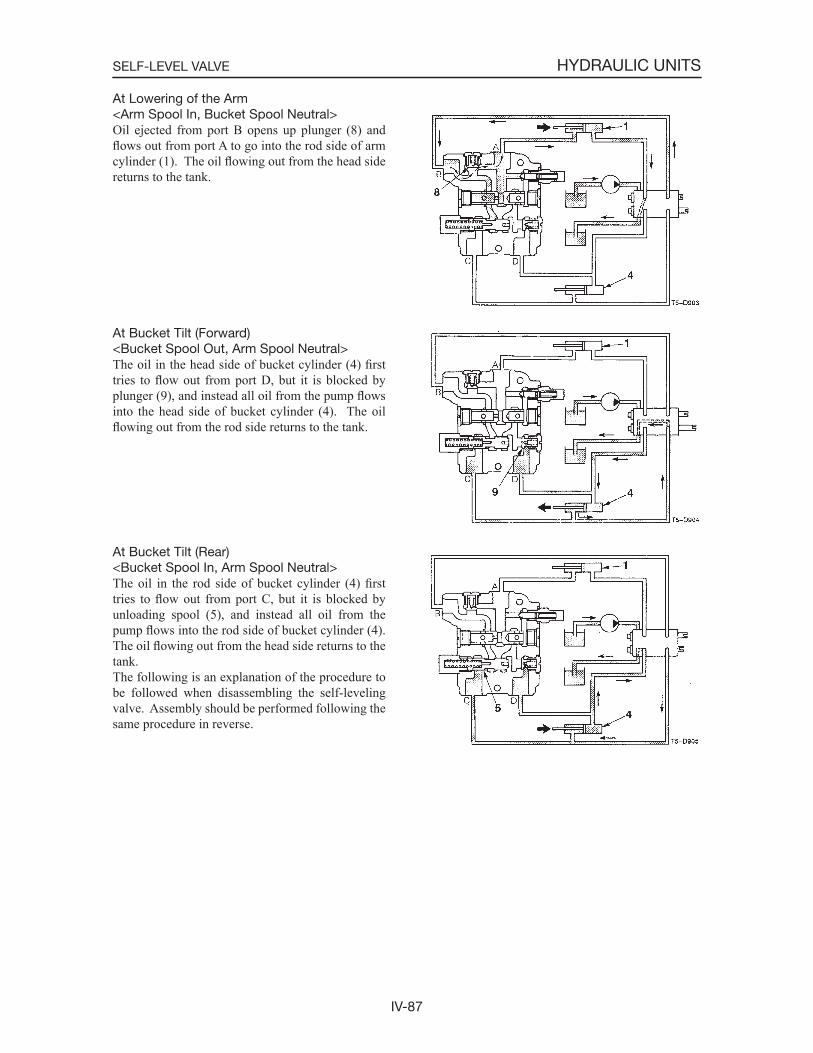
IV-87
HYDRAULIC UNITSSELF-LEVEL VALVE
At Lowering of the Arm<Arm Spool In, Bucket Spool Neutral>Oil ejected from port B opens up plunger (8) and flows out from port A to go into the rod side of arm cylinder (1). The oil flowing out from the head side returns to the tank.
At Bucket Tilt (Forward)<Bucket Spool Out, Arm Spool Neutral>The oil in the head side of bucket cylinder (4) firsttries to flow out from port D, but it is blocked by plunger (9), and instead all oil from the pump flowsinto the head side of bucket cylinder (4). The oil flowing out from the rod side returns to the tank.
At Bucket Tilt (Rear)<Bucket Spool In, Arm Spool Neutral>The oil in the rod side of bucket cylinder (4) firsttries to flow out from port C, but it is blocked by unloading spool (5), and instead all oil from the pump flows into the rod side of bucket cylinder (4). The oil flowing out from the head side returns to the tank.The following is an explanation of the procedure to be followed when disassembling the self-leveling valve. Assembly should be performed following the same procedure in reverse.

IV-88
HYDRAULIC UNITSSELF-LEVEL VALVE
DISASSEMBLY AND ASSEMBLY
General Cautions
• Carry out disassembly and reassembly operations in a clean place and place disassembled parts in clean containers.
• Before disassembly, clean thoroughly around the ports and remove paint or thread lock, etc. from all joints with a wire brush.
• Clean disassembled parts with light oil or other cleaning oil.
• Apply a thin coating of hydraulic oil to sliding surfaces and a thin coating of grease to seals when assembling them.
• Replace seals with new parts each time disassem-bly is done.
Following is an explanation of the self-level valve disassembly procedure. Follow the procedure used to disassemble the self-level valve in reverse order when assembling it.
1. Remove plug (1), spring (3), and spool (4) be-fore taking O-ring (2) off of plug (1).
Plug: 36.6~40.7 N·m
2. Remove plug (5) and spool (7) before taking O-ring (6) off of plug (5).
Plug: 36.6~40.7 N·m
3. Remove plug (11), spring (10) and plunger (9) before taking O-ring (2) off of plug (11).
Plug: 36.6~40.7 N·m

IV-89
HYDRAULIC UNITSSELF-LEVEL VALVE
4. Remove cover (18), nut (17), and set screw (16) from cap.• Make a record of the measurements for A (see
diagram below), and make sure that these measurements do not change during assem-bly. Nut: 5.4~7.8 N·m
5. Remove cap (15) and then take O-ring (14) off the cap.
Cap: 13.6~16.3 N·m
6 Remove pin (12) and then take O-ring (13) off the pin.

IV-90
HYDRAULIC UNITSSELF-LEVEL VALVE
INSPECTION AND ADJUSTMENT
Checking the Parts
Part Judgment Criteria TreatmentHousing • Scratches, rust, or corrosion at the sliding parts with the
spool.• Scratches, rust, or corrosion of the seal part in contact
with the O-ring.• Other damage considered to impair the normal func-
tions.
• Replace
• Replace
• Replace
Spool, Pin, Plunger • Damage on the outer circumference which catches a fingernal.
• No smooth movement
• Replace
• Adjust or replaceSpring • Rust, corrosion, deformation, breakage, or other notable
damage.• Replace
O-Ring • Replace

IV-91
HYDRAULIC UNITSSELF-LEVEL VALVE
TROUBLESHOOTING
Symptom Probable Causes RemedyArm delay at start of self-level or unstable self-level.
• Air in system. • Cycle Arm and bucket slowly to rid system of air.
Loaded bucket dumps or un-curls when control valve is in neutral.
• Unloading spool is leaking. • Remove and inspect unloading spool for damage.
Insufficient self-level. • Pin is out of adjustment.
• Broken unloading spool spring.• Flow divider spool stuck towards
adjustment pin side.
• Re-adjust pin to achieve proper flow split.
• Replace unloading spool spring.• Remove flow divider spool and
check for damage.Bucket dumps faster than Arm raises. Too much self-level.
• Pin is out of adjustment.
• Flow divider spool is stuck towards port B.
• Flow divider spool installed wrong.
• Re-adjust pin to achieve proper flow split.
• Remove flow divider spool and inspect for damage.
• Remove spool and install with in-ternal orifice towards port B.
With bucket dumped, Arm is slow in starting to raise.
• Dampening orifice in the unloading spool is plugged.
• Remove unloading spool and clean dampening orifice.
Bucket does not move in self-level.
• Pin is screwed in all the way.
• Dampening orifice in the unloading spool is plugged.
• Ports A and B plumbed backwards.
• Re-adjust pin to achieve proper flow split.
• Remove unloading spool and clean dampening orifice.
• Reverse hoses to ports A and B.Bucket Curls in self-level. • Ports C and D plumbed back-
wards.• Reverse hoses to ports C and D.
External leakage • Damaged O-ring. • Replace O-ring.
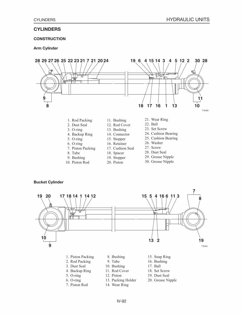
IV-92
HYDRAULIC UNITSCYLINDERS
CYLINDERS
CONSTRUCTION
Arm Cylinder
1. Rod Packing 2. Dust Seal 3. O-ring 4. Backup Ring 5. O-ring 6. O-ring 7. Piston Packing 8. Tube 9. Bushing10. Piston Rod
11. Bushing12. Rod Cover13. Bushing14. Connector15. Stopper16. Retainer17. Cushion Seal18. Spacer19. Stopper20. Piston
21. Wear Ring22. Ball23. Set Screw24. Cushion Bearing25. Cushion Bearing26. Washer27. Screw28. Dust Seal29. Grease Nipple30. Grease Nipple
Bucket Cylinder
1. Piston Packing 2. Rod Packing 3. Dust Seal 4. Backup Ring 5. O-ring 6. O-ring 7. Piston Rod
8. Bushing 9. Tube10. Bushing11. Rod Cover12. Piston13. Packing Holder14. Wear Ring
15. Snap Ring16. Bushing17. Ball18. Set Screw19. Dust Seal20. Grease Nipple
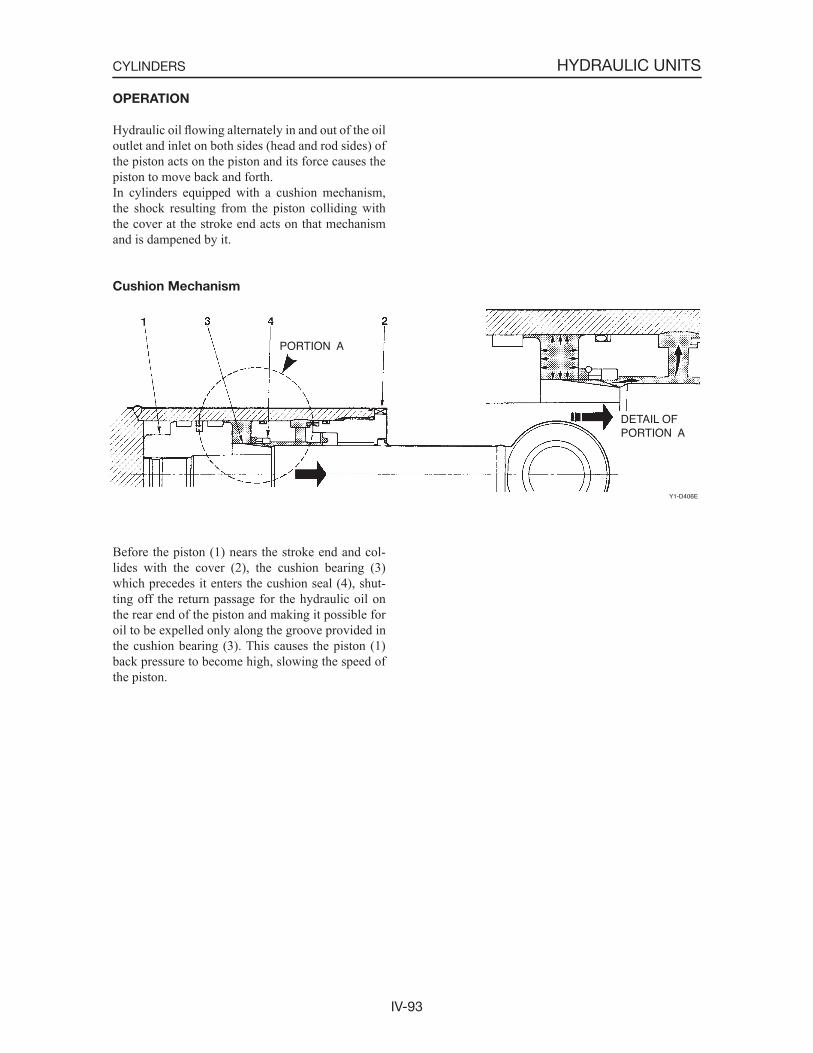
IV-93
HYDRAULIC UNITSCYLINDERS
OPERATION
Hydraulic oil flowing alternately in and out of the oil outlet and inlet on both sides (head and rod sides) of the piston acts on the piston and its force causes the piston to move back and forth.In cylinders equipped with a cushion mechanism, the shock resulting from the piston colliding with the cover at the stroke end acts on that mechanism and is dampened by it.
Cushion Mechanism
Before the piston (1) nears the stroke end and col-lides with the cover (2), the cushion bearing (3) which precedes it enters the cushion seal (4), shut-ting off the return passage for the hydraulic oil on the rear end of the piston and making it possible for oil to be expelled only along the groove provided in the cushion bearing (3). This causes the piston (1) back pressure to become high, slowing the speed of the piston.
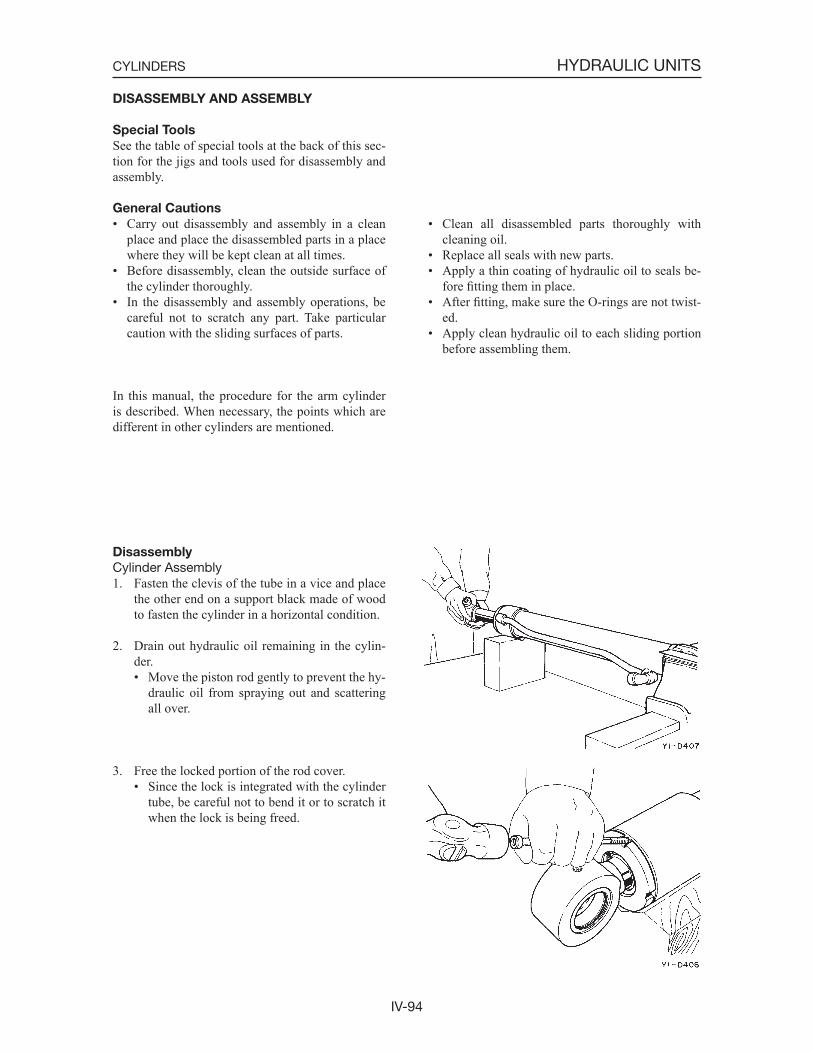
IV-94
HYDRAULIC UNITSCYLINDERS
DISASSEMBLY AND ASSEMBLY
Special Tools
See the table of special tools at the back of this sec-tion for the jigs and tools used for disassembly and assembly.
General Cautions
• Carry out disassembly and assembly in a clean place and place the disassembled parts in a place where they will be kept clean at all times.
• Before disassembly, clean the outside surface of the cylinder thoroughly.
• In the disassembly and assembly operations, be careful not to scratch any part. Take particular caution with the sliding surfaces of parts.
• Clean all disassembled parts thoroughly with cleaning oil.
• Replace all seals with new parts.• Apply a thin coating of hydraulic oil to seals be-
fore fitting them in place.• After fitting, make sure the O-rings are not twist-
ed.• Apply clean hydraulic oil to each sliding portion
before assembling them.
In this manual, the procedure for the arm cylinder is described. When necessary, the points which are different in other cylinders are mentioned.
Disassembly
Cylinder Assembly1. Fasten the clevis of the tube in a vice and place
the other end on a support black made of wood to fasten the cylinder in a horizontal condition.
2. Drain out hydraulic oil remaining in the cylin-der.• Move the piston rod gently to prevent the hy-
draulic oil from spraying out and scattering all over.
3. Free the locked portion of the rod cover.• Since the lock is integrated with the cylinder
tube, be careful not to bend it or to scratch it when the lock is being freed.
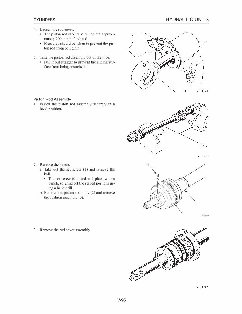
IV-95
HYDRAULIC UNITSCYLINDERS
4. Loosen the rod cover.• The piston rod should be pulled out approxi-
mately 200 mm beforehand.• Measures should be taken to prevent the pis-
ton rod from being hit.
5. Take the piston rod assembly out of the tube.• Pull it out straight to prevent the sliding sur-
face from being scratched.
Piston Rod Assembly1. Fasten the piston rod assembly securely in a
level position.
2. Remove the piston.a. Take out the set screw (1) and remove the
ball.• The set screw is staked at 2 place with a
punch, so grind off the staked portions us-ing a hand drill.
b. Remove the piston assembly (2) and remove the cushion assembly (3).
3. Remove the rod cover assembly.
E5D408
1
3
2
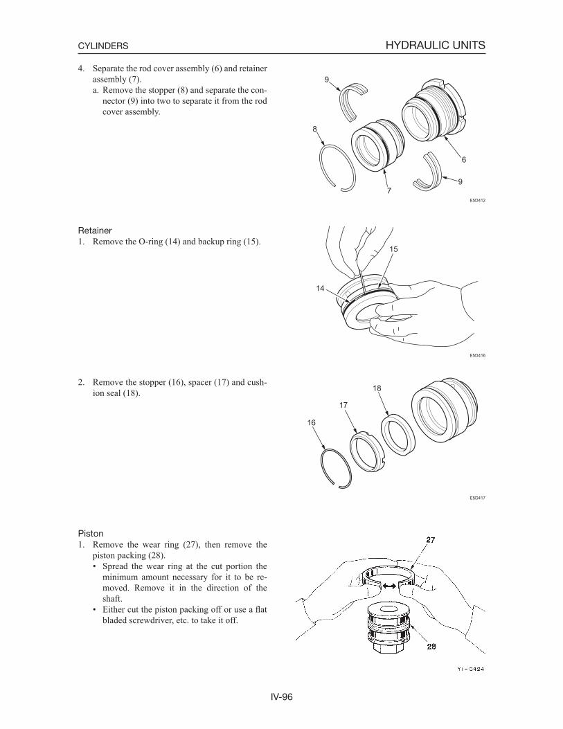
IV-96
HYDRAULIC UNITSCYLINDERS
4. Separate the rod cover assembly (6) and retainer assembly (7).a. Remove the stopper (8) and separate the con-
nector (9) into two to separate it from the rod cover assembly.
Retainer1. Remove the O-ring (14) and backup ring (15).
2. Remove the stopper (16), spacer (17) and cush-ion seal (18).
Piston1. Remove the wear ring (27), then remove the
piston packing (28).• Spread the wear ring at the cut portion the
minimum amount necessary for it to be re-moved. Remove it in the direction of the shaft.
• Either cut the piston packing off or use a flatbladed screwdriver, etc. to take it off.
E5D412
6
97
8
9
E5D416
14
15
E5D417
18
17
16
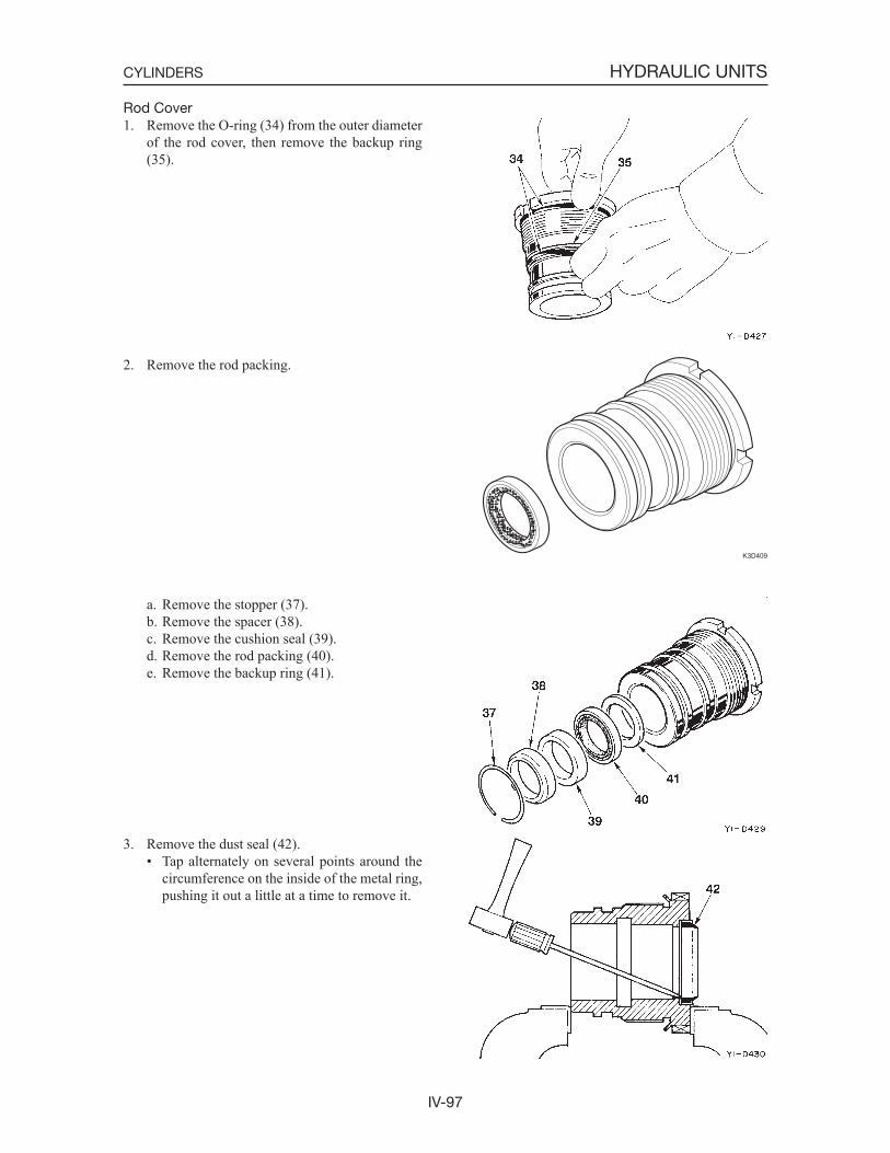
IV-97
HYDRAULIC UNITSCYLINDERS
Rod Cover1. Remove the O-ring (34) from the outer diameter
of the rod cover, then remove the backup ring (35).
2. Remove the rod packing.
a. Remove the stopper (37).b. Remove the spacer (38).c. Remove the cushion seal (39).d. Remove the rod packing (40).e. Remove the backup ring (41).
3. Remove the dust seal (42).• Tap alternately on several points around the
circumference on the inside of the metal ring, pushing it out a little at a time to remove it.
K3D409
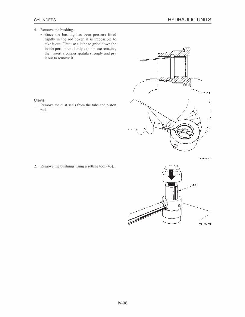
IV-98
HYDRAULIC UNITSCYLINDERS
4. Remove the bushing.• Since the bushing has been pressure fitted
tightly in the rod cover, it is impossible to take it out. First use a lathe to grind down the inside portion until only a thin piece remains, then insert a copper spatula strongly and pry it out to remove it.
Clevis1. Remove the dust seals from the tube and piston
rod.
2. Remove the bushings using a setting tool (43).
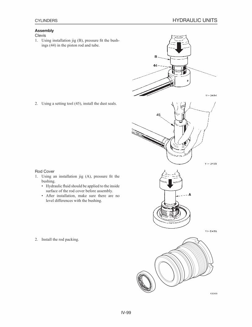
IV-99
HYDRAULIC UNITSCYLINDERS
Assembly
Clevis1. Using installation jig (B), pressure fit the bush-
ings (44) in the piston rod and tube.
2. Using a setting tool (45), install the dust seals.
Rod Cover1. Using an installation jig (A), pressure fit the
bushing.• Hydraulic fluid should be applied to the inside
surface of the rod cover before assembly.• After installation, make sure there are no
level differences with the bushing.
2. Install the rod packing.
K3D409
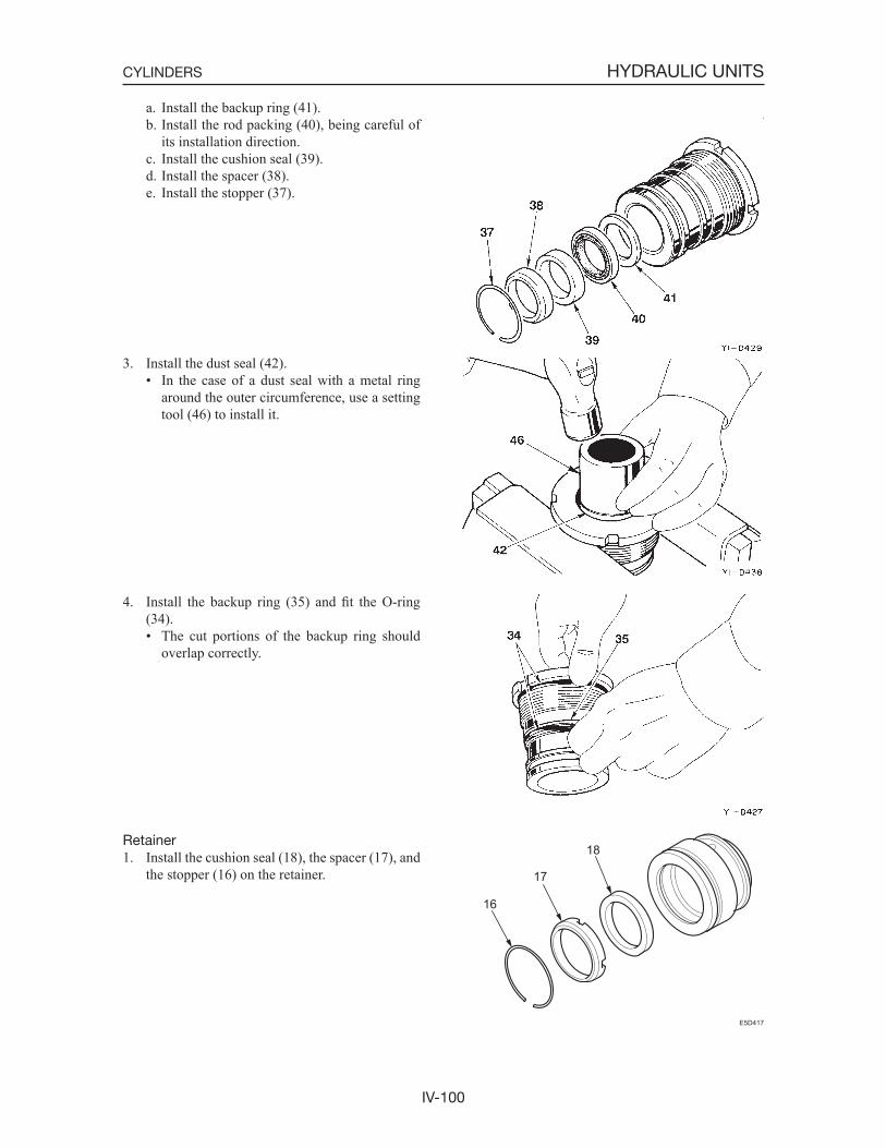
IV-100
HYDRAULIC UNITSCYLINDERS
a. Install the backup ring (41).b. Install the rod packing (40), being careful of
its installation direction.c. Install the cushion seal (39).d. Install the spacer (38).e. Install the stopper (37).
3. Install the dust seal (42).• In the case of a dust seal with a metal ring
around the outer circumference, use a setting tool (46) to install it.
4. Install the backup ring (35) and fit the O-ring (34).• The cut portions of the backup ring should
overlap correctly.
Retainer1. Install the cushion seal (18), the spacer (17), and
the stopper (16) on the retainer.
E5D417
18
17
16
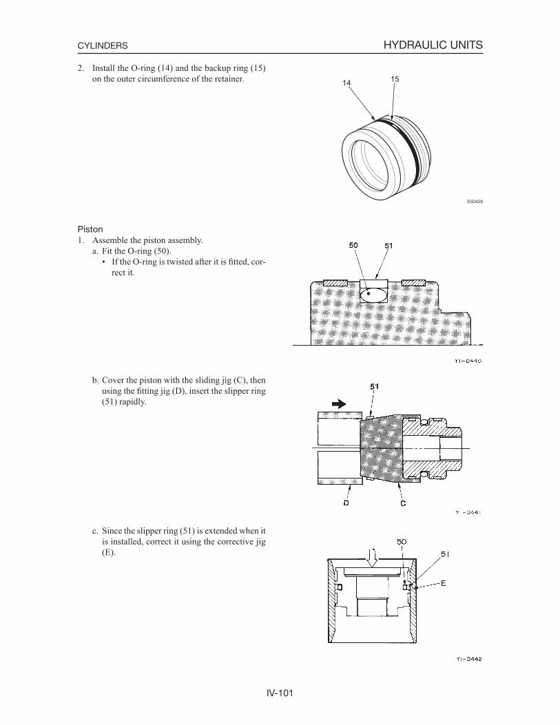
IV-101
HYDRAULIC UNITSCYLINDERS
2. Install the O-ring (14) and the backup ring (15) on the outer circumference of the retainer.
Piston1. Assemble the piston assembly.
a. Fit the O-ring (50).• If the O-ring is twisted after it is fitted, cor-
rect it.
b. Cover the piston with the sliding jig (C), then using the fitting jig (D), insert the slipper ring (51) rapidly.
c. Since the slipper ring (51) is extended when it is installed, correct it using the corrective jig (E).
E5D428
14 15
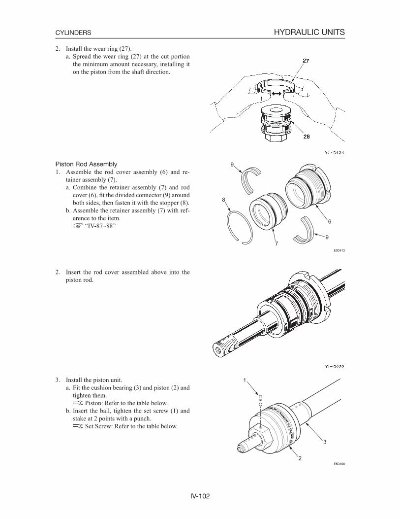
IV-102
HYDRAULIC UNITSCYLINDERS
2. Install the wear ring (27).a. Spread the wear ring (27) at the cut portion
the minimum amount necessary, installing it on the piston from the shaft direction.
Piston Rod Assembly1. Assemble the rod cover assembly (6) and re-
tainer assembly (7).a. Combine the retainer assembly (7) and rod
cover (6), fit the divided connector (9) around both sides, then fasten it with the stopper (8).
b. Assemble the retainer assembly (7) with ref-erence to the item.
“IV-87~88”
2. Insert the rod cover assembled above into the piston rod.
3. Install the piston unit.a. Fit the cushion bearing (3) and piston (2) and
tighten them. Piston: Refer to the table below.
b. Insert the ball, tighten the set screw (1) and stake at 2 points with a punch.
Set Screw: Refer to the table below.
E5D412
6
97
8
9
E5D408
1
3
2
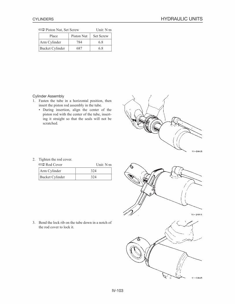
IV-103
HYDRAULIC UNITSCYLINDERS
Piston Nut, Set Screw Unit: N·mPlace Piston Nut Set Screw
Arm Cylinder 784 6.8Bucket Cylinder 687 6.8
Cylinder Assembly1. Fasten the tube in a horizontal position, then
insert the piston rod assembly in the tube.• During insertion, align the center of the
piston rod with the center of the tube, insert-ing it straight so that the seals will not be scratched.
2. Tighten the rod cover. Rod Cover Unit: N·m
Arm Cylinder 324Bucket Cylinder 324
3. Bend the lock rib on the tube down in a notch of the rod cover to lock it.
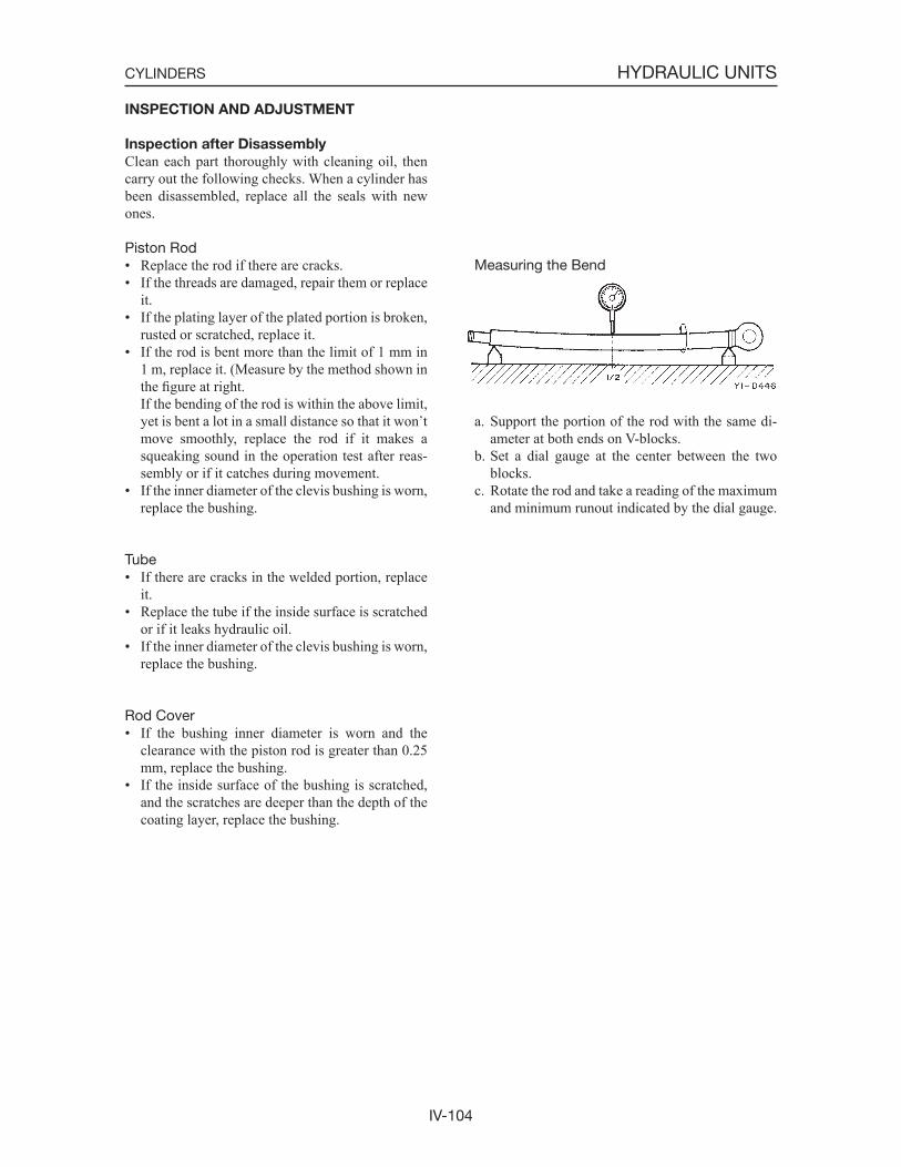
IV-104
HYDRAULIC UNITSCYLINDERS
INSPECTION AND ADJUSTMENT
Inspection after Disassembly
Clean each part thoroughly with cleaning oil, then carry out the following checks. When a cylinder has been disassembled, replace all the seals with new ones.
Piston Rod• Replace the rod if there are cracks.• If the threads are damaged, repair them or replace
it.• If the plating layer of the plated portion is broken,
rusted or scratched, replace it.• If the rod is bent more than the limit of 1 mm in
1 m, replace it. (Measure by the method shown in the figure at right.
If the bending of the rod is within the above limit, yet is bent a lot in a small distance so that it won tmove smoothly, replace the rod if it makes a squeaking sound in the operation test after reas-sembly or if it catches during movement.
• If the inner diameter of the clevis bushing is worn, replace the bushing.
Tube• If there are cracks in the welded portion, replace
it.• Replace the tube if the inside surface is scratched
or if it leaks hydraulic oil.• If the inner diameter of the clevis bushing is worn,
replace the bushing.
Rod Cover• If the bushing inner diameter is worn and the
clearance with the piston rod is greater than 0.25 mm, replace the bushing.
• If the inside surface of the bushing is scratched, and the scratches are deeper than the depth of the coating layer, replace the bushing.
Measuring the Bend
a. Support the portion of the rod with the same di-ameter at both ends on V-blocks.
b. Set a dial gauge at the center between the two blocks.
c. Rotate the rod and take a reading of the maximum and minimum runout indicated by the dial gauge.
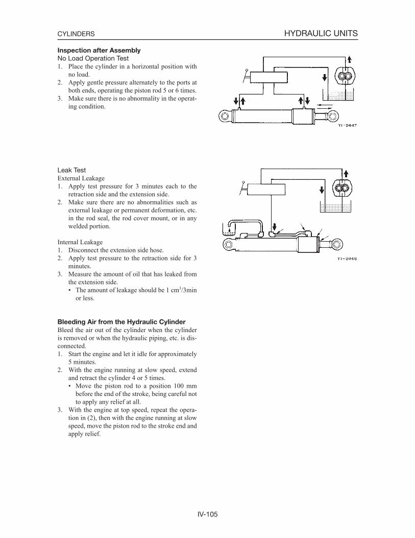
IV-105
HYDRAULIC UNITSCYLINDERS
Inspection after Assembly
No Load Operation Test1. Place the cylinder in a horizontal position with
no load.2. Apply gentle pressure alternately to the ports at
both ends, operating the piston rod 5 or 6 times.3. Make sure there is no abnormality in the operat-
ing condition.
Leak TestExternal Leakage1. Apply test pressure for 3 minutes each to the
retraction side and the extension side.2. Make sure there are no abnormalities such as
external leakage or permanent deformation, etc. in the rod seal, the rod cover mount, or in any welded portion.
Internal Leakage1. Disconnect the extension side hose.2. Apply test pressure to the retraction side for 3
minutes.3. Measure the amount of oil that has leaked from
the extension side.• The amount of leakage should be 1 cm3/3min
or less.
Bleeding Air from the Hydraulic Cylinder
Bleed the air out of the cylinder when the cylinder is removed or when the hydraulic piping, etc. is dis-connected.1. Start the engine and let it idle for approximately
5 minutes.2. With the engine running at slow speed, extend
and retract the cylinder 4 or 5 times.• Move the piston rod to a position 100 mm
before the end of the stroke, being careful not to apply any relief at all.
3. With the engine at top speed, repeat the opera-tion in (2), then with the engine running at slow speed, move the piston rod to the stroke end and apply relief.
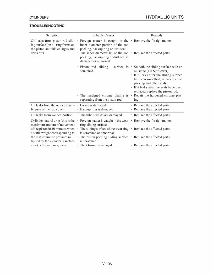
IV-106
HYDRAULIC UNITSCYLINDERS
TROUBLESHOOTING
Symptom Probable Causes RemedyOil leaks from piston rod slid-ing surface (an oil ring forms on the piston and this enlarges and drips off).
• Foreign matter is caught in the inner diameter portion of the rod packing, backup ring or dust seal.
• The inner diameter lip of the rod packing, backup ring or dust seal is damaged or abnormal.
• Remove the foreign matter.
• Replace the affected parts.
• Piston rod sliding surface is scratched.
• The hardened chrome plating is separating from the piston rod.
• Smooth the sliding surface with an oil stone (1.6 S or lower)
• If it leaks after the sliding surface has been smoothed, replace the rod packing and other seals.
• If it leaks after the seals have been replaced, replace the piston rod.
• Repair the hardened chrome plat-ing.
Oil leaks from the outer circum-ference of the rod cover.
• O-ring is damaged.• Backup ring is damaged.
• Replace the affected parts.• Replace the affected parts.
Oil leaks from welded portion. • The tube s welds are damaged. • Replace the affected parts.Cylinder natural drop (this is the maximum amount of movement of the piston in 10 minutes when a static weight corresponding to the maximum use pressure mul-tiplied by the cylinder s surface area) is 0.5 mm or greater.
• Foreign matter is caught in the wear ring sliding surface.
• The sliding surface of the wear ring is scratched or abnormal.
• The piston packing sliding surface is scratched.
• The O-ring is damaged.
• Remove the foreign matter.
• Replace the affected parts.
• Replace the affected parts.
• Replace the affected parts.
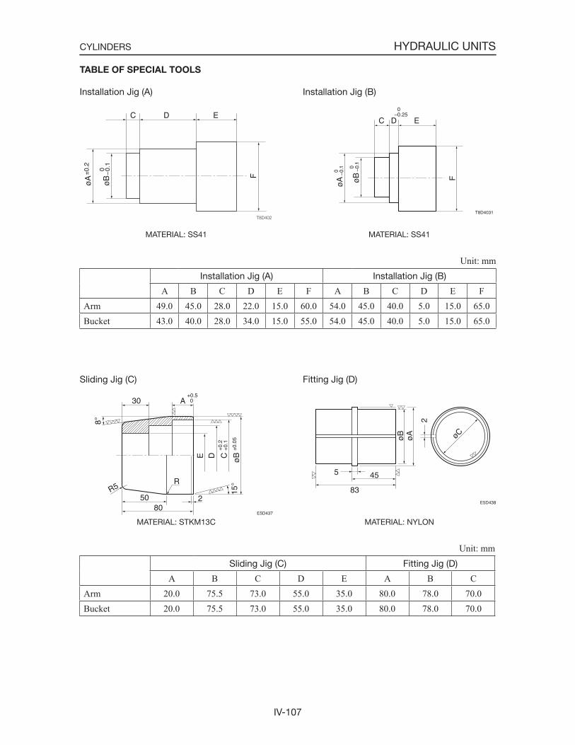
IV-107
HYDRAULIC UNITSCYLINDERS
TABLE OF SPECIAL TOOLS
Installation Jig (A)
MATERIAL: SS41
Installation Jig (B)
MATERIAL: SS41
Unit: mmInstallation Jig (A) Installation Jig (B)
A B C D E F A B C D E FArm 49.0 45.0 28.0 22.0 15.0 60.0 54.0 45.0 40.0 5.0 15.0 65.0Bucket 43.0 40.0 28.0 34.0 15.0 55.0 54.0 45.0 40.0 5.0 15.0 65.0
Sliding Jig (C)
MATERIAL: STKM13C
Fitting Jig (D)
MATERIAL: NYLON
Unit: mmSliding Jig (C) Fitting Jig (D)
A B C D E A B CArm 20.0 75.5 73.0 55.0 35.0 80.0 78.0 70.0Bucket 20.0 75.5 73.0 55.0 35.0 80.0 78.0 70.0
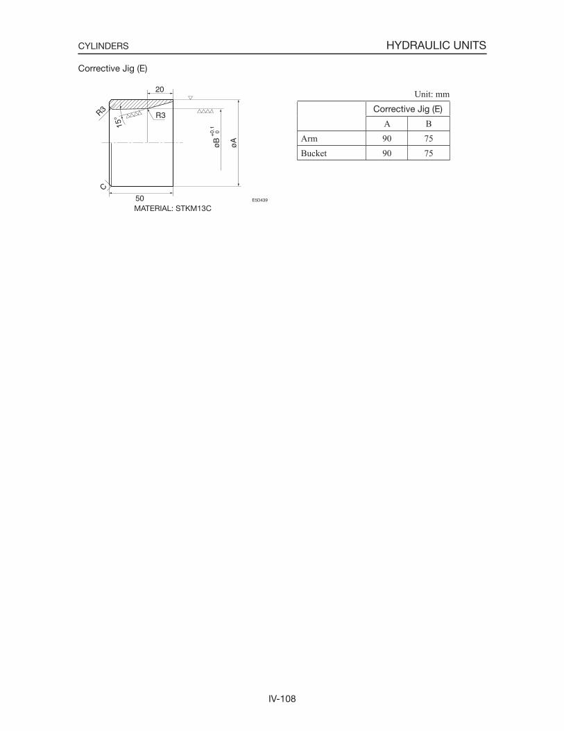
IV-108
HYDRAULIC UNITSCYLINDERS
Corrective Jig (E)
MATERIAL: STKM13C
Unit: mmCorrective Jig (E)
A BArm 90 75Bucket 90 75
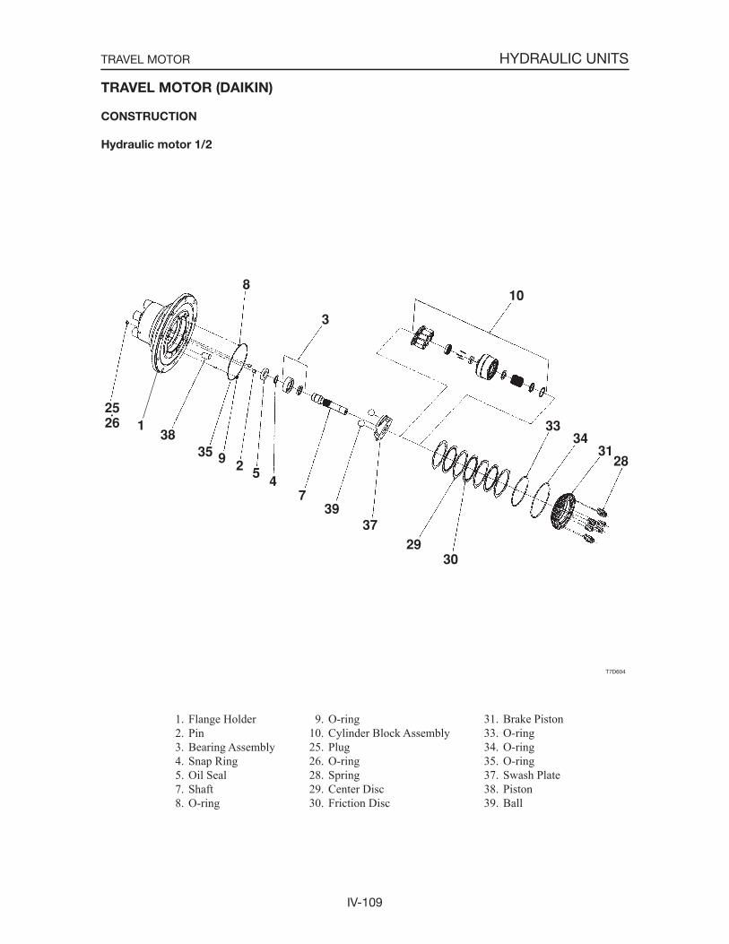
IV-109
HYDRAULIC UNITSTRAVEL MOTOR
TRAVEL MOTOR (DAIKIN)
CONSTRUCTION
Hydraulic motor 1/2
1. Flange Holder 2. Pin 3. Bearing Assembly 4. Snap Ring 5. Oil Seal 7. Shaft 8. O-ring
9. O-ring10. Cylinder Block Assembly25. Plug26. O-ring28. Spring29. Center Disc30. Friction Disc
31. Brake Piston33. O-ring34. O-ring35. O-ring37. Swash Plate38. Piston39. Ball
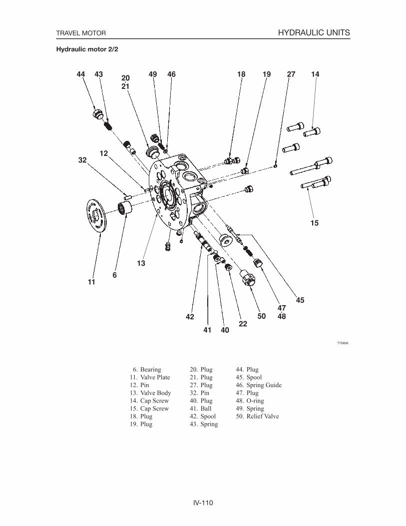
IV-110
HYDRAULIC UNITSTRAVEL MOTOR
Hydraulic motor 2/2
6. Bearing11. Valve Plate12. Pin13. Valve Body14. Cap Screw15. Cap Screw18. Plug19. Plug
20. Plug21. Plug27. Plug32. Pin40. Plug41. Ball42. Spool43. Spring
44. Plug45. Spool46. Spring Guide 47. Plug48. O-ring49. Spring50. Relief Valve
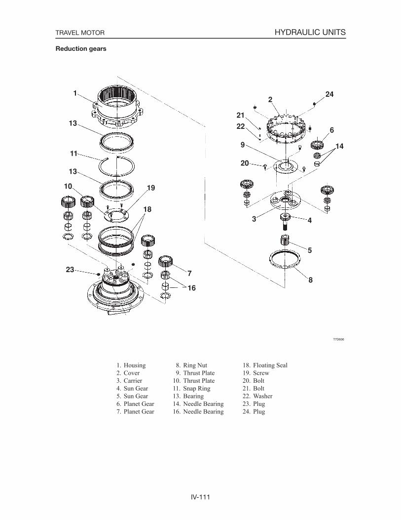
IV-111
HYDRAULIC UNITSTRAVEL MOTOR
Reduction gears
1. Housing 2. Cover 3. Carrier 4. Sun Gear 5. Sun Gear 6. Planet Gear 7. Planet Gear
8. Ring Nut 9. Thrust Plate10. Thrust Plate11. Snap Ring13. Bearing14. Needle Bearing16. Needle Bearing
18. Floating Seal19. Screw20. Bolt21. Bolt22. Washer23. Plug24. Plug
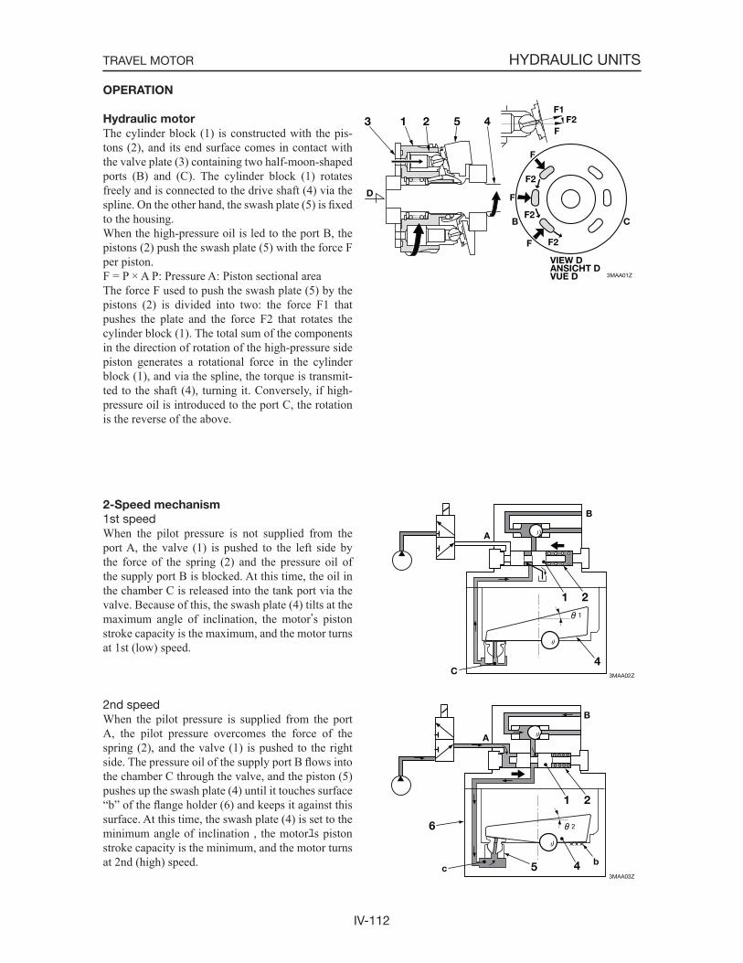
IV-112
HYDRAULIC UNITSTRAVEL MOTOR
3MAA01Z
VIEW DANSICHT DVUE D
B
F
F
F
F2
F2
F2
F
F1F2
D
C
1 23 45
3MAA02Z
A
B
C
1 2
4
3MAA03Z
1 2
45
6
A
c
B
b
OPERATION
Hydraulic motor
The cylinder block (1) is constructed with the pis-tons (2), and its end surface comes in contact with the valve plate (3) containing two half-moon-shaped ports (B) and (C). The cylinder block (1) rotates freely and is connected to the drive shaft (4) via the spline. On the other hand, the swash plate (5) is fixedto the housing.When the high-pressure oil is led to the port B, the pistons (2) push the swash plate (5) with the force F per piston.F = P × A P: Pressure A: Piston sectional areaThe force F used to push the swash plate (5) by the pistons (2) is divided into two: the force F1 that pushes the plate and the force F2 that rotates the cylinder block (1). The total sum of the components in the direction of rotation of the high-pressure side piston generates a rotational force in the cylinder block (1), and via the spline, the torque is transmit-ted to the shaft (4), turning it. Conversely, if high-pressure oil is introduced to the port C, the rotation is the reverse of the above.
2-Speed mechanism
1st speedWhen the pilot pressure is not supplied from the port A, the valve (1) is pushed to the left side by the force of the spring (2) and the pressure oil of the supply port B is blocked. At this time, the oil in the chamber C is released into the tank port via the valve. Because of this, the swash plate (4) tilts at the maximum angle of inclination, the motor’s piston stroke capacity is the maximum, and the motor turns at 1st (low) speed.
2nd speedWhen the pilot pressure is supplied from the port A, the pilot pressure overcomes the force of the spring (2), and the valve (1) is pushed to the right side. The pressure oil of the supply port B flows into the chamber C through the valve, and the piston (5) pushes up the swash plate (4) until it touches surface “b” of the flange holder (6) and keeps it against this surface. At this time, the swash plate (4) is set to the minimum angle of inclination , the motorユs piston stroke capacity is the minimum, and the motor turns at 2nd (high) speed.
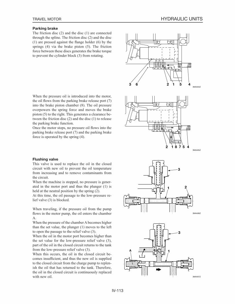
IV-113
HYDRAULIC UNITSTRAVEL MOTOR
Parking brake
The friction disc (2) and the disc (1) are connected through the spline. The friction disc (2) and the disc (1) are pressed against the flange holder (6) by the springs (4) via the brake piston (5). The friction force between these discs generates the brake torque to prevent the cylinder block (3) from rotating.
When the pressure oil is introduced into the motor, the oil flows from the parking brake release port (7) into the brake piston chamber (8). The oil pressure overpowers the spring force and moves the brake piston (5) to the right. This generates a clearance be-tween the friction disc (2) and the disc (1) to release the parking brake function.Once the motor stops, no pressure oil flows into the parking brake release port (7) and the parking brake force is operated by the spring (4).
Flushing valve
This valve is used to replace the oil in the closed circuit with new oil to prevent the oil temperature from increasing and to remove contaminants from the circuit.When the machine is stopped, no pressure is gener-ated in the motor port and thus the plunger (1) is held at the neutral position by the spring (2).At this time, the oil passage to the low-pressure re-lief valve (3) is blocked.
When traveling, if the pressure oil from the pump flows in the motor pump, the oil enters the chamber A.When the pressure of the chamber A becomes higher than the set value, the plunger (1) moves to the left to open the passage to the relief valve (3).When the oil in the motor port becomes higher than the set value for the low-pressure relief valve (3), part of the oil in the closed circuit returns to the tank from the low-pressure relief valve (3).When this occurs, the oil in the closed circuit be-comes insufficient, and thus the new oil is supplied to the closed circuit from the charge pump to replen-ish the oil that has returned to the tank. Therefore, the oil in the closed circuit is continuously replaced with new oil.
3MAA04Z123 456
3MAA05Z
12 4578
3MAA06Z
1 2
3
3MAA07Z
1
3
A
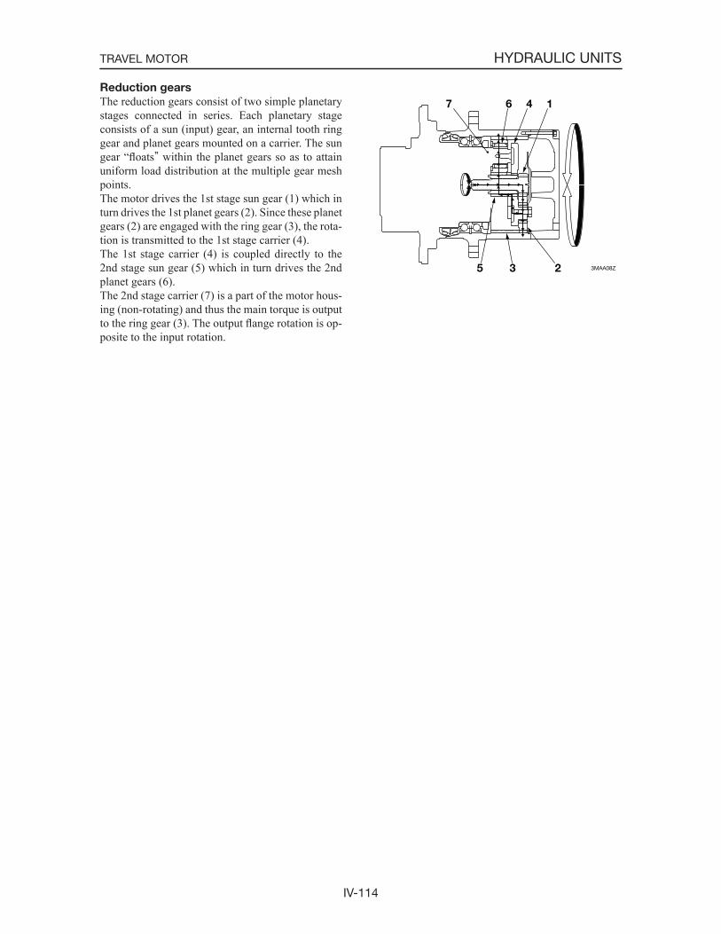
IV-114
HYDRAULIC UNITSTRAVEL MOTOR
Reduction gears
The reduction gears consist of two simple planetary stages connected in series. Each planetary stage consists of a sun (input) gear, an internal tooth ring gear and planet gears mounted on a carrier. The sun gear “floats” within the planet gears so as to attain uniform load distribution at the multiple gear mesh points.The motor drives the 1st stage sun gear (1) which in turn drives the 1st planet gears (2). Since these planet gears (2) are engaged with the ring gear (3), the rota-tion is transmitted to the 1st stage carrier (4).The 1st stage carrier (4) is coupled directly to the 2nd stage sun gear (5) which in turn drives the 2nd planet gears (6).The 2nd stage carrier (7) is a part of the motor hous-ing (non-rotating) and thus the main torque is output to the ring gear (3). The output flange rotation is op-posite to the input rotation.
3MAA08Z
1467
235

IV-115
HYDRAULIC UNITSTRAVEL MOTOR
DISASSEMBLY AND ASSEMBLY
Special tools
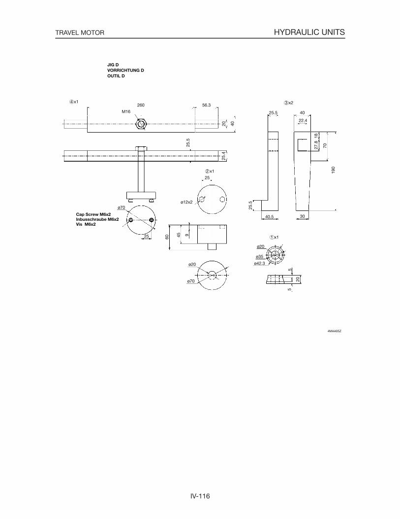
IV-116
HYDRAULIC UNITSTRAVEL MOTOR
4MAA05Z
Cap Screw M6x2Inbusschraube M6x2Vis M6x2
3 x2
2 x1
4 x1
1 x1
25.5 40
22.4
190
70
1827
.8
25.5
40.5 30
ø20
ø35
ø42.3
55
20
ø20
ø70
94560
ø12x2
25
ø70
25
260
M16
56.3
20 40
25.5
25.4
JIG DVORRICHTUNG DOUTIL D
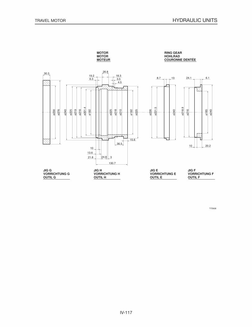
IV-117
HYDRAULIC UNITSTRAVEL MOTOR

IV-118
HYDRAULIC UNITSTRAVEL MOTOR
The part numbers contained in the “Disassembly and Assembly” section of this manual correspond to the numbers listed in the construction diagram. Work should be performed by referring to the diagram, as necessary.
Disassembly
Reduction gears1. Take out the plugs (24) and drain out the gear
oil.
2. Take out the bolts and remove the cover (2).• If it is hard to remove, lightly tap on the side
of the cover with a plastic hammer.
3. Take out the bolts and remove the thrust plate (9).
4. Remove the sun gear (4), and then remove the planet gears (6) and the carrier (3).• Remove the planet gears (6) together with the
needle bearing (14) mounted within.

IV-119
HYDRAULIC UNITSTRAVEL MOTOR
5. Take out the screws and remove the thrust plate (10).
6. Remove the planet gears (7).• Remove the planet gears (7) together with the
needle bearing (16) mounted within.
Hydraulic motor 1. Remove the relief valve (50).
2. Take out the cap screws (14) and (15), and then remove the valve body (13).
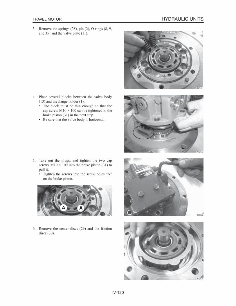
IV-120
HYDRAULIC UNITSTRAVEL MOTOR
T7D572
3. Remove the springs (28), pin (2), O-rings (8, 9, and 35) and the valve plate (11).
4. Place several blocks between the valve body (13) and the flange holder (1).• The block must be thin enough so that the
cap screw M10 × 100 can be tightened to the brake piston (31) in the next step.
• Be sure that the valve body is horizontal.
5. Take out the plugs, and tighten the two cap screws M10 × 100 into the brake piston (31) to pull it.• Tighten the screws into the screw holes “A”
on the brake piston.
6. Remove the center discs (29) and the friction discs (30).
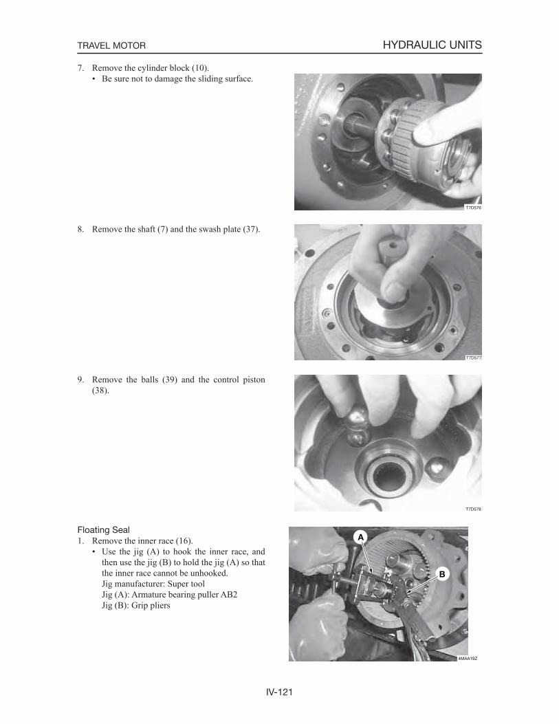
IV-121
HYDRAULIC UNITSTRAVEL MOTOR
4MAA19Z
A
B
7. Remove the cylinder block (10).• Be sure not to damage the sliding surface.
8. Remove the shaft (7) and the swash plate (37).
9. Remove the balls (39) and the control piston (38).
Floating Seal1. Remove the inner race (16).
• Use the jig (A) to hook the inner race, and then use the jig (B) to hold the jig (A) so that the inner race cannot be unhooked.
Jig manufacturer: Super tool Jig (A): Armature bearing puller AB2 Jig (B): Grip pliers
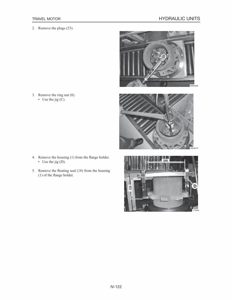
IV-122
HYDRAULIC UNITSTRAVEL MOTOR
4MAA20Z
4MAA21Z
2. Remove the plugs (23).
3. Remove the ring nut (8).• Use the jig (C).
4. Remove the housing (1) from the flange holder.• Use the jig (D).
5. Remove the floating seal (18) from the housing (1) of the flange holder.
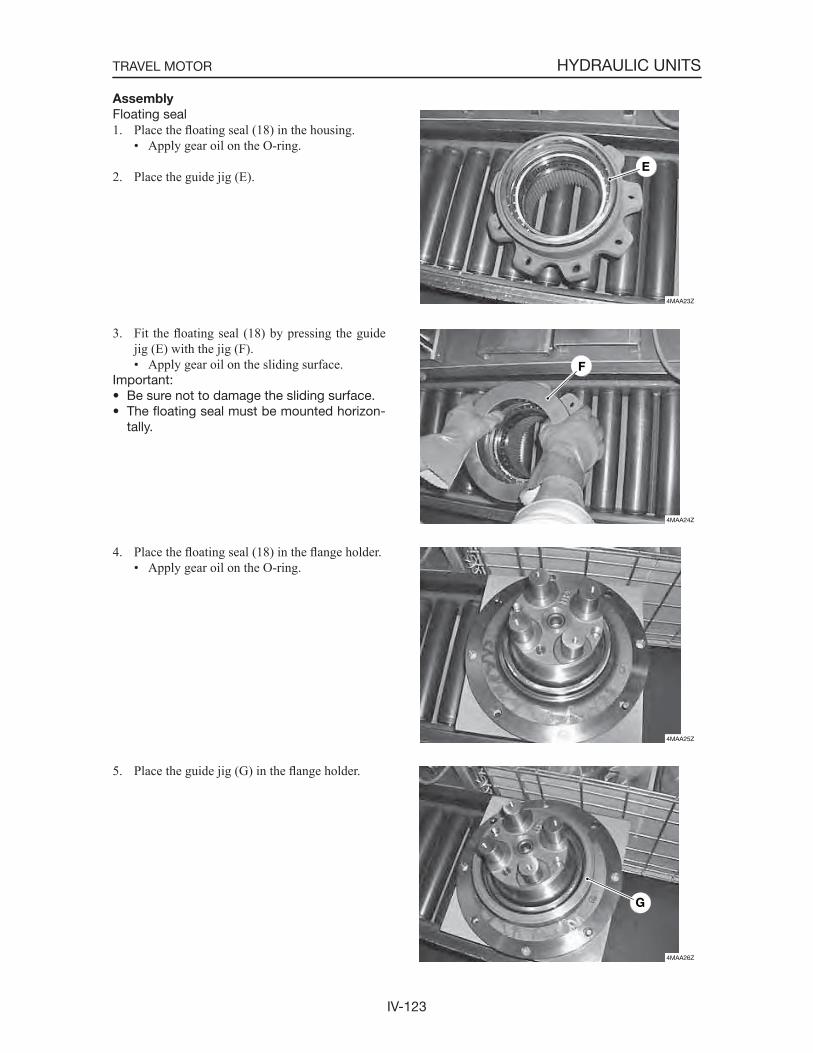
IV-123
HYDRAULIC UNITSTRAVEL MOTOR
Assembly
Floating seal1. Place the floating seal (18) in the housing.
• Apply gear oil on the O-ring.
2. Place the guide jig (E).
3. Fit the floating seal (18) by pressing the guide jig (E) with the jig (F).• Apply gear oil on the sliding surface.
Important:• Be sure not to damage the sliding surface.• The floating seal must be mounted horizon-
tally.
4. Place the floating seal (18) in the flange holder.• Apply gear oil on the O-ring.
5. Place the guide jig (G) in the flange holder.
4MAA23Z
E
4MAA24Z
F
4MAA25Z
4MAA26Z
G
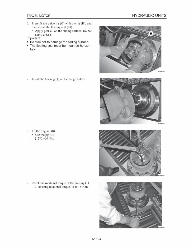
IV-124
HYDRAULIC UNITSTRAVEL MOTOR
6. Press-fit the guide jig (G) with the jig (H), and then install the floating seal (18).• Apply gear oil on the sliding surface. Do not
apply grease.Important:• Be sure not to damage the sliding surface.• The floating seal must be mounted horizon-
tally.
7. Install the housing (1) on the flange holder.
8. Fit the ring nut (8).• Use the jig (C).
280 ±60 N·m
9. Check the rotational torque of the housing (1). Housing rotational torque: 11 to 15 N·m
4MAA27Z
H
4MAA28Z
4MAA21Z
4MAA29Z
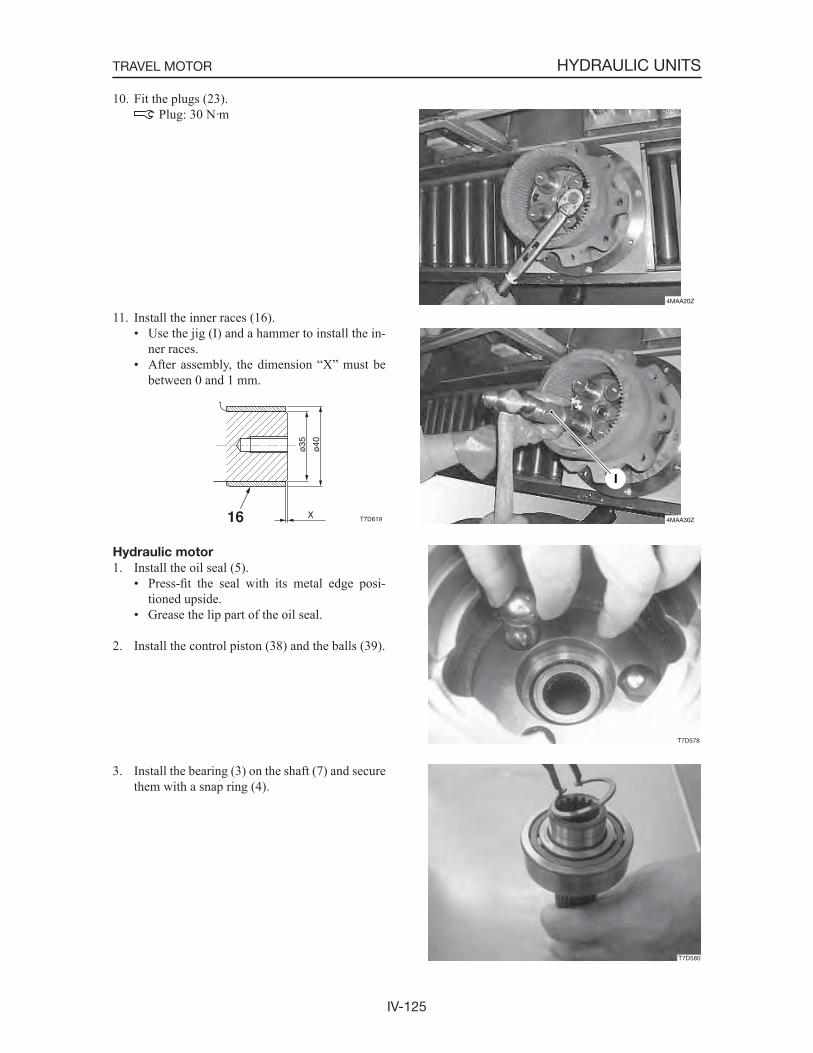
IV-125
HYDRAULIC UNITSTRAVEL MOTOR
10. Fit the plugs (23). Plug: 30 N·m
11. Install the inner races (16).• Use the jig (I) and a hammer to install the in-
ner races.• After assembly, the dimension “X” must be
between 0 and 1 mm.
Hydraulic motor
1. Install the oil seal (5).• Press-fit the seal with its metal edge posi-
tioned upside.• Grease the lip part of the oil seal.
2. Install the control piston (38) and the balls (39).
3. Install the bearing (3) on the shaft (7) and secure them with a snap ring (4).
4MAA20Z
4MAA30Z
I
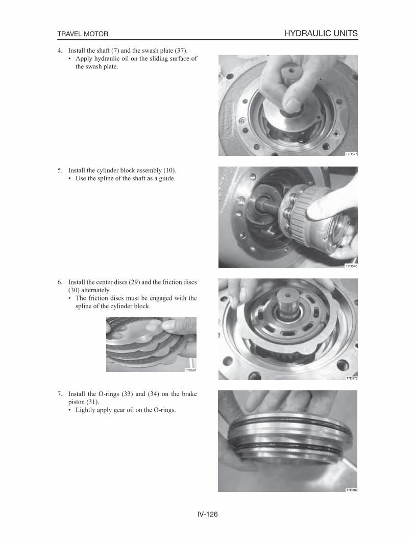
IV-126
HYDRAULIC UNITSTRAVEL MOTOR
4. Install the shaft (7) and the swash plate (37).• Apply hydraulic oil on the sliding surface of
the swash plate.
5. Install the cylinder block assembly (10).• Use the spline of the shaft as a guide.
6. Install the center discs (29) and the friction discs (30) alternately.• The friction discs must be engaged with the
spline of the cylinder block.
7. Install the O-rings (33) and (34) on the brake piston (31).• Lightly apply gear oil on the O-rings.
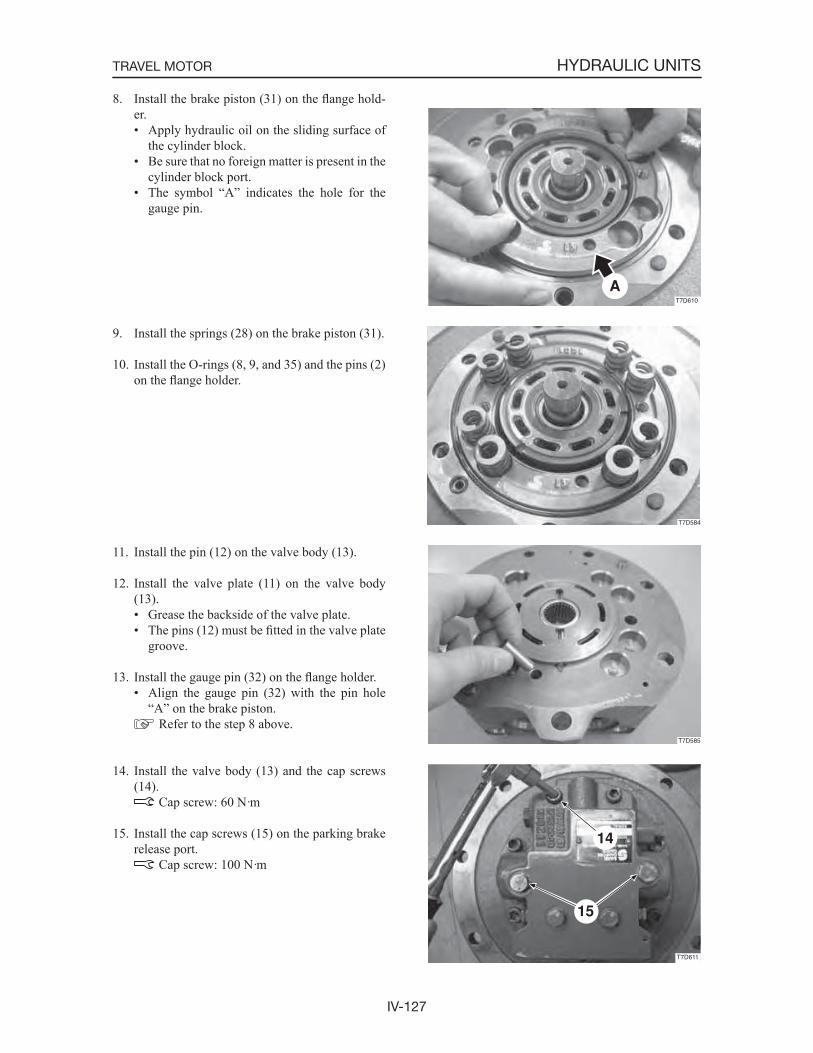
IV-127
HYDRAULIC UNITSTRAVEL MOTOR
8. Install the brake piston (31) on the flange hold-er.• Apply hydraulic oil on the sliding surface of
the cylinder block.• Be sure that no foreign matter is present in the
cylinder block port.• The symbol “A” indicates the hole for the
gauge pin.
9. Install the springs (28) on the brake piston (31).
10. Install the O-rings (8, 9, and 35) and the pins (2) on the flange holder.
11. Install the pin (12) on the valve body (13).
12. Install the valve plate (11) on the valve body (13).• Grease the backside of the valve plate.• The pins (12) must be fitted in the valve plate
groove.
13. Install the gauge pin (32) on the flange holder.• Align the gauge pin (32) with the pin hole
“A” on the brake piston. Refer to the step 8 above.
14. Install the valve body (13) and the cap screws (14).
Cap screw: 60 N·m
15. Install the cap screws (15) on the parking brake release port.
Cap screw: 100 N·m
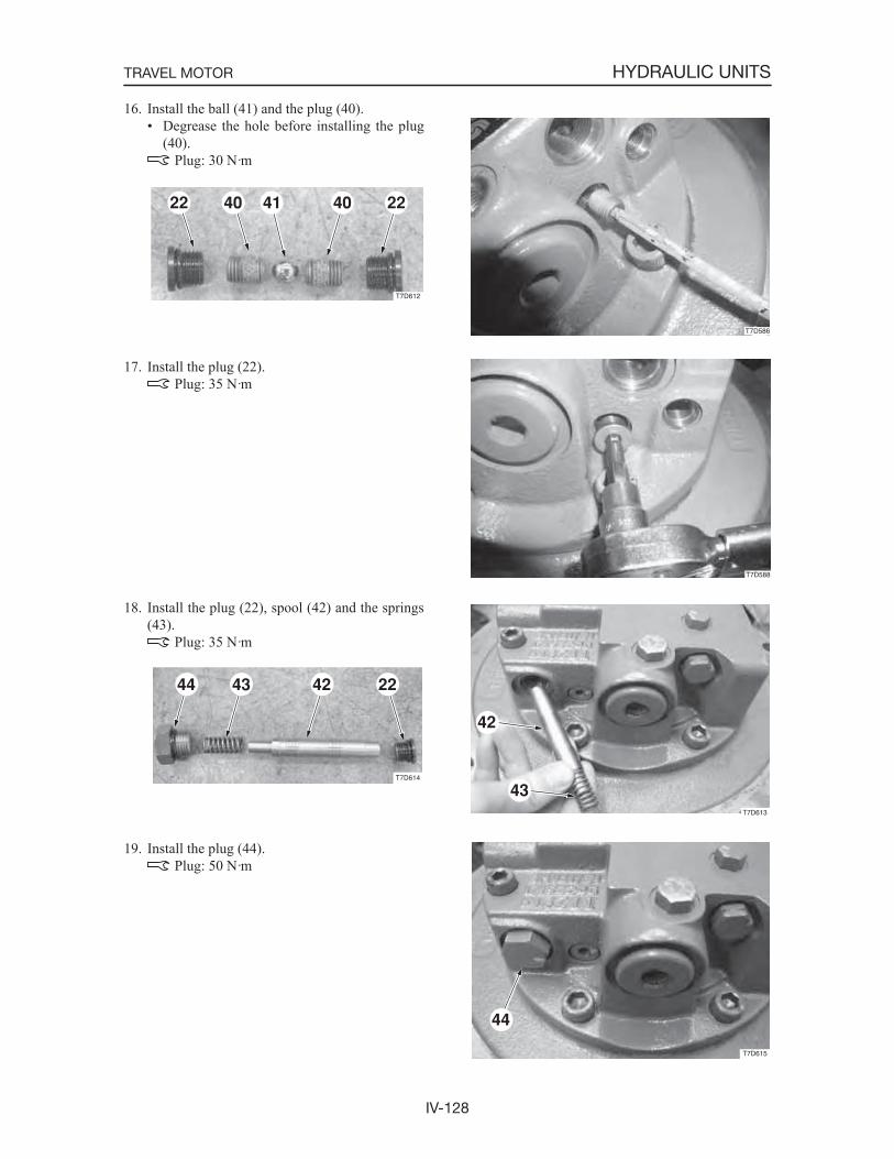
IV-128
HYDRAULIC UNITSTRAVEL MOTOR
16. Install the ball (41) and the plug (40).• Degrease the hole before installing the plug
(40). Plug: 30 N·m
17. Install the plug (22). Plug: 35 N·m
18. Install the plug (22), spool (42) and the springs (43).
Plug: 35 N·m
19. Install the plug (44). Plug: 50 N·m
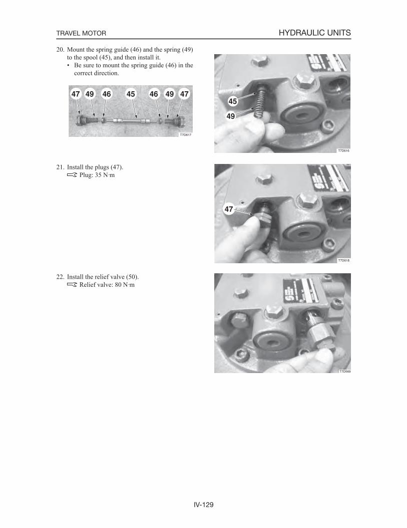
IV-129
HYDRAULIC UNITSTRAVEL MOTOR
20. Mount the spring guide (46) and the spring (49) to the spool (45), and then install it.• Be sure to mount the spring guide (46) in the
correct direction.
21. Install the plugs (47). Plug: 35 N·m
22. Install the relief valve (50). Relief valve: 80 N·m
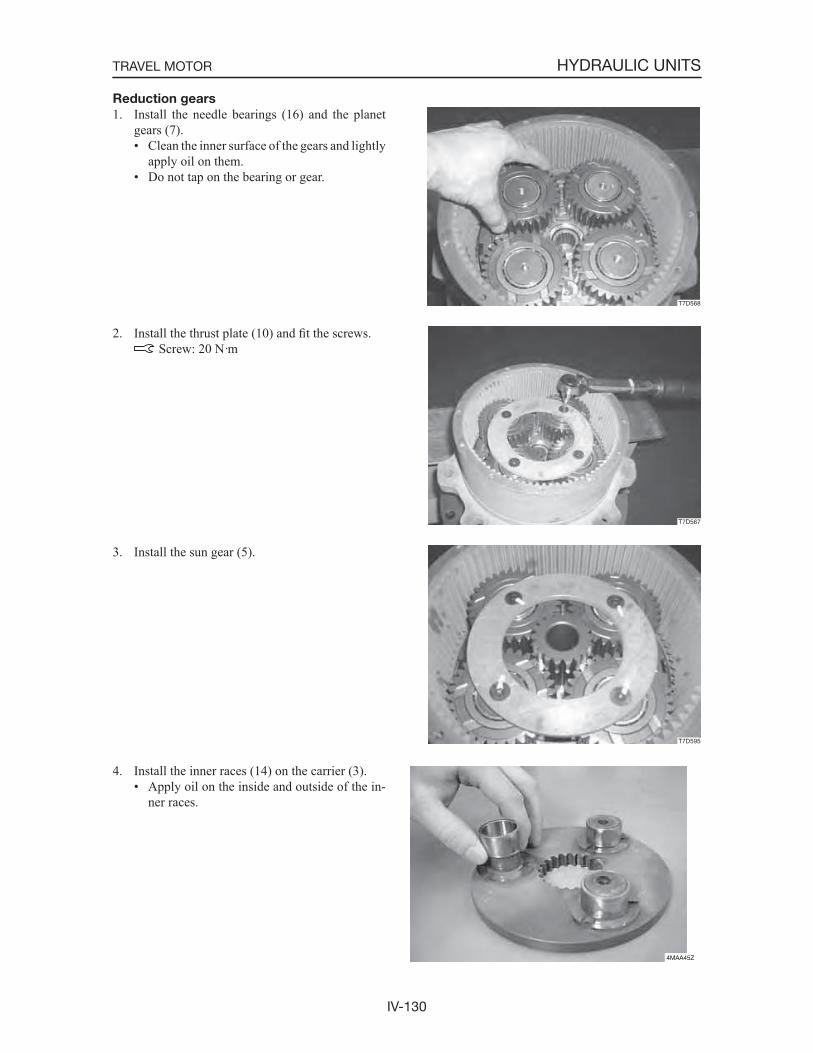
IV-130
HYDRAULIC UNITSTRAVEL MOTOR
Reduction gears
1. Install the needle bearings (16) and the planet gears (7).• Clean the inner surface of the gears and lightly
apply oil on them.• Do not tap on the bearing or gear.
2. Install the thrust plate (10) and fit the screws. Screw: 20 N·m
3. Install the sun gear (5).
4. Install the inner races (14) on the carrier (3).• Apply oil on the inside and outside of the in-
ner races.
T7D595
4MAA45Z
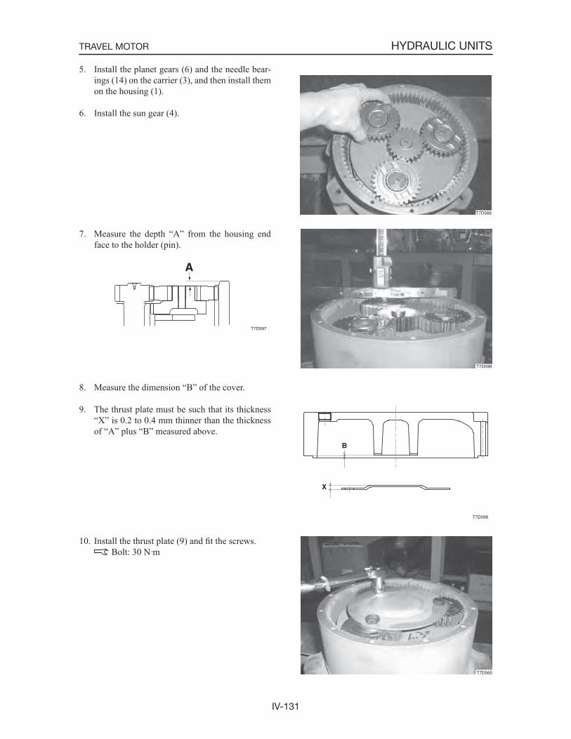
IV-131
HYDRAULIC UNITSTRAVEL MOTOR
5. Install the planet gears (6) and the needle bear-ings (14) on the carrier (3), and then install them on the housing (1).
6. Install the sun gear (4).
7. Measure the depth “A” from the housing end face to the holder (pin).
8. Measure the dimension “B” of the cover.
9. The thrust plate must be such that its thickness “X” is 0.2 to 0.4 mm thinner than the thickness of “A” plus “B” measured above.
10. Install the thrust plate (9) and fit the screws. Bolt: 30 N·m
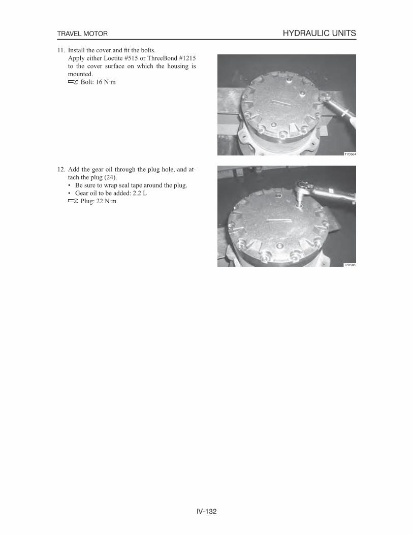
IV-132
HYDRAULIC UNITSTRAVEL MOTOR
11. Install the cover and fit the bolts. Apply either Loctite #515 or ThreeBond #1215
to the cover surface on which the housing is mounted.
Bolt: 16 N·m
12. Add the gear oil through the plug hole, and at-tach the plug (24).• Be sure to wrap seal tape around the plug.• Gear oil to be added: 2.2 L
Plug: 22 N·m
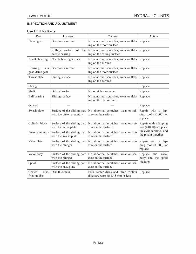
IV-133
HYDRAULIC UNITSTRAVEL MOTOR
INSPECTION AND ADJUSTMENT
Use Limit for Parts
Part Location Criteria ActionPlanet gear Gear tooth surface No abnormal scratches, wear or flak-
ing on the tooth surfaceReplace
Rolling surface of the needle bearing
No abnormal scratches, wear or flak-ing on the rolling surface
Replace
Needle bearing Needle bearing surface No abnormal scratches, wear or flak-ing on the surface
Replace
Housing, sun gear, drive gear
Gear tooth surface No abnormal scratches, wear or flak-ing on the tooth surface
Replace
Thrust plate Sliding surface No abnormal scratches, wear or flak-ing on the surface
Replace
O-ring — — ReplaceShaft Oil seal surface No scratches or wear ReplaceBall bearing Sliding surface No abnormal scratches, wear or flak-
ing on the ball or raceReplace
Oil seal — — ReplaceSwash plate Surface of the sliding part
with the piston assemblyNo abnormal scratches, wear or sei-zure on the surface
Repair with a lap-ping tool (#1000) or replace
Cylinder block Surface of the sliding part with the valve plate
No abnormal scratches, wear or sei-zure on the surface
Repair with a lapping tool (#1000) or replace the cylinder block and the piston together
Piston assembly Surface of the sliding part with the swash plate
No abnormal scratches, wear or sei-zure on the surface
Valve plate Surface of the sliding part with the plunger
No abnormal scratches, wear or sei-zure on the surface
Repair with a lap-ping tool (#1000) or replace
Valve body Surface of the sliding part with the plunger
No abnormal scratches, wear or sei-zure on the surface
Replace the valve body and the spool togetherSpool Surface of the sliding part
with the base plateNo abnormal scratches, wear or sei-zure on the surface
Center disc, friction disc
Disc thickness Four center discs and three friction discs are worn to 13.5 mm or less
Replace
IV-134
HYDRAULIC UNITSTRAVEL MOTOR
TROUBLESHOOTING
Hydraulic motor
Symptoms Major causes RemediesMotor fails to start • All the devices other than the motor and the
reduction gears are not working correctly
• Pressure oil is not flowing properly due to abnormal wear of the motor s sliding part
• Motor is faulty, as its main components are damaged
• Check whether the specified pressure is generated in the inlet port, and then check and repair each device.
• Replace the abnormally worn out part(s).
• Replace the damaged part(s).
Rated speed cannot be obtained
• Specified volume of flow is not supplied to the motor due to the faulty oil pump
• Motor volume efficiency becomes low
• Check whether the specified pressure is generated in the inlet port, and then check and repair each device.
• Check if there is abnormal wear on the sliding part; if so, repair or replace it.
Rotational fluctua-tions are large
• High-pressure oil is leaking from the drain port, because the motor s sliding part is worn out
• Bearing is worn out
• Replace the abnormally worn part, if any.
• Replace the abnormally worn part, if any.
Oil leak • Oil leak due to breakage of oil seal and O-ring
• Oil seal is broken by the internal pressure generated in the motor case due to the ab-normal wear of the sliding part of the mo-tor
• Pressure increase in the drain piping caused by the clogging of foreign matter resulted in breakage of oil seal
• Replace the oil seal and O-ring.
• Repair the motor and replace the oil seal.
• Clean the clogging in the drain piping and replace the oil seal.
2nd speed control
Symptoms Major causes RemediesStraight-ahead trav-eling level is low, switching to 2nd speed travel is dis-abled
Spool cannot be switched• Foreign matter is caught
• Spring is missing• Spring is damaged• Oil leak due to the abnormal wear of the
2nd speed control piston• 2nd speed control piston is missing• Ball is abnormally worn out
• Remove foreign matter and correct or replace the faulty part(s).
• Install the spring.• Replace the spring.• Replace the 2nd speed control piston.
• Install the 2nd speed control piston.• Replace the ball.
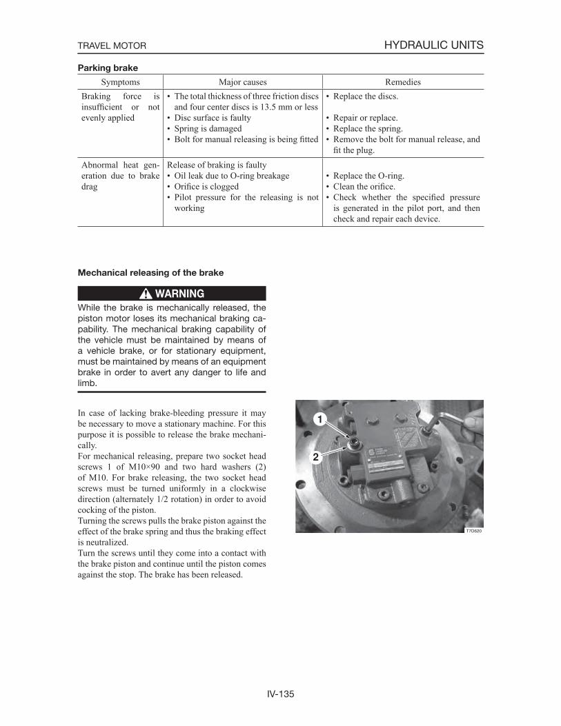
IV-135
HYDRAULIC UNITSTRAVEL MOTOR
Parking brake
Symptoms Major causes RemediesBraking force is insufficient or not evenly applied
• The total thickness of three friction discs and four center discs is 13.5 mm or less
• Disc surface is faulty• Spring is damaged• Bolt for manual releasing is being fitted
• Replace the discs.
• Repair or replace.• Replace the spring.• Remove the bolt for manual release, and
fit the plug.Abnormal heat gen-eration due to brake drag
Release of braking is faulty• Oil leak due to O-ring breakage• Orifice is clogged• Pilot pressure for the releasing is not
working
• Replace the O-ring.• Clean the orifice.• Check whether the specified pressure
is generated in the pilot port, and then check and repair each device.
Mechanical releasing of the brake
WARNING
While the brake is mechanically released, the piston motor loses its mechanical braking ca-pability. The mechanical braking capability of the vehicle must be maintained by means of a vehicle brake, or for stationary equipment, must be maintained by means of an equipment brake in order to avert any danger to life and limb.
In case of lacking brake-bleeding pressure it may be necessary to move a stationary machine. For this purpose it is possible to release the brake mechani-cally.For mechanical releasing, prepare two socket head screws 1 of M10×90 and two hard washers (2) of M10. For brake releasing, the two socket head screws must be turned uniformly in a clockwise direction (alternately 1/2 rotation) in order to avoid cocking of the piston.Turning the screws pulls the brake piston against the effect of the brake spring and thus the braking effect is neutralized.Turn the screws until they come into a contact with the brake piston and continue until the piston comes against the stop. The brake has been released.

IV-136
HYDRAULIC UNITSTRAVEL MOTOR

V-1
V . TROUBLESHOOTING
V-2
TROUBLESHOOTING
CAUTIONS IN TROUBLESHOOTING AND REPAIRS
(1) Do not begin disassembling the equipment immediately just because it has broken down. Conduct a thorough preliminary check before attempting disassembly.a. Ask the user the following questions.
• What were the conditions when the machine broke down?• Did anything abnormal happen before breakdown occurred?• Are there any other places which were functioning poorly other than the part that
broke down?• Are there any parts which have been repaired previous to the breakdown? What were
they?• Has the same thing happened before?
b. Run the machine yourself and confirm the breakdown conditions.• Judge whether the machine is really broken down or not following the judgment stan-
dards. The judgment on whether the machine has broken down may differ between individu-
als.
IMPORTANT: When running the machine, it is possible that moving the machine could make the breakdown worse than it already is, so do not forget to ask the user if there is anything to prevent your operating the machine.
c. Based on the information that you have gathered from the user and the information obtained from running the machine yourself, judge the cause of the trouble. Also keep in mind that it is difficult to reproduce the conditions of the breakdown again once the machine has been disassembled, and early disassembly may make it impossible to determine the true cause of the trouble. Therefore be sure to find the true cause of the trouble before attempting disassembly.
(2) When it is thought that the trouble has more than one cause, begin investigating from the simplest cause.
(3) Think over why the trouble could have occurred and try to correct the root cause of that problem.
V-3
TROUBLESHOOTING
CONTENTS
OVERALL MACHINEComplete failure of all systems. ..............................................................................................................................4All systems working, but with insufficient power. .................................................................................................7Lift arms and bucket fail to move/speed of operation poor. ...................................................................................9MACHINE TRAVELTravel train fault. ...................................................................................................................................................10Speed falls and machine veers to one side. ...........................................................................................................12The travel system is operating at an unusually high temperature. ........................................................................14Machine will not travel in second speed. ..............................................................................................................16LIFT ARMSLift arm cylinders fail to move. ............................................................................................................................18Movement of the lift arm cylinders is slow or lacks power. .................................................................................20Slowly pulling the control lever of the lift arms causes the lift arms to drop momentarily. .................................22The amount of lift arms natural drop is great. ......................................................................................................23BUCKETBucket cylinders fail to move. ..............................................................................................................................24Movement of the bucket cylinders is slow or lacks power. ..................................................................................26The amount of bucket natural drop is great. .........................................................................................................28AUXILIARY HYDRAULICSSwitching between 2-way flow and 1-way flow is impossible. ............................................................................29
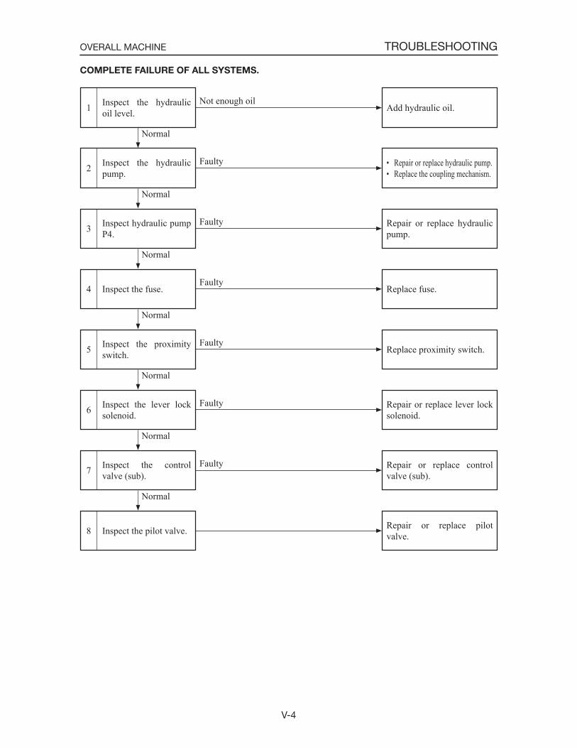
V-4
TROUBLESHOOTINGOVERALL MACHINE
COMPLETE FAILURE OF ALL SYSTEMS.
Inspect the proximity switch.5
Inspect the fuse.4
Inspect hydraulic pump P4.3
Inspect the hydraulic pump.2
Inspect the hydraulic oil level.1 Add hydraulic oil.
• Repair or replace hydraulic pump.• Replace the coupling mechanism.
Repair or replace hydraulic pump.
Replace fuse.
Replace proximity switch.
Normal
Normal
Normal
Faulty
Faulty
Faulty
Not enough oil
Normal
Faulty
Inspect the pilot valve.8
Inspect the control valve (sub).7
Inspect the lever lock solenoid.6 Repair or replace lever lock
solenoid.
Repair or replace control valve (sub).
Repair or replace pilot valve.
Normal
Normal
Normal
Faulty
Faulty
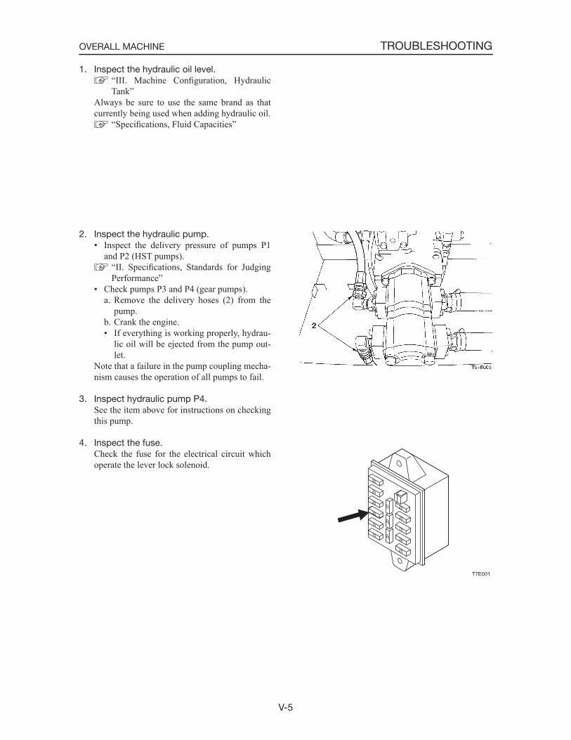
V-5
TROUBLESHOOTINGOVERALL MACHINE
1. Inspect the hydraulic oil level. “III. Machine Configuration, Hydraulic Tank”
Always be sure to use the same brand as that currently being used when adding hydraulic oil.
“Specifications, Fluid Capacities”
2. Inspect the hydraulic pump.• Inspect the delivery pressure of pumps P1
and P2 (HST pumps). “II. Specifications, Standards for Judging Performance”
• Check pumps P3 and P4 (gear pumps).a. Remove the delivery hoses (2) from the
pump.b. Crank the engine.• If everything is working properly, hydrau-
lic oil will be ejected from the pump out-let.
Note that a failure in the pump coupling mecha-nism causes the operation of all pumps to fail.
3. Inspect hydraulic pump P4. See the item above for instructions on checking
this pump.
4. Inspect the fuse. Check the fuse for the electrical circuit which
operate the lever lock solenoid.
T7E001
30
30
20
10
10
20
30
20
20
20
10
3020
10
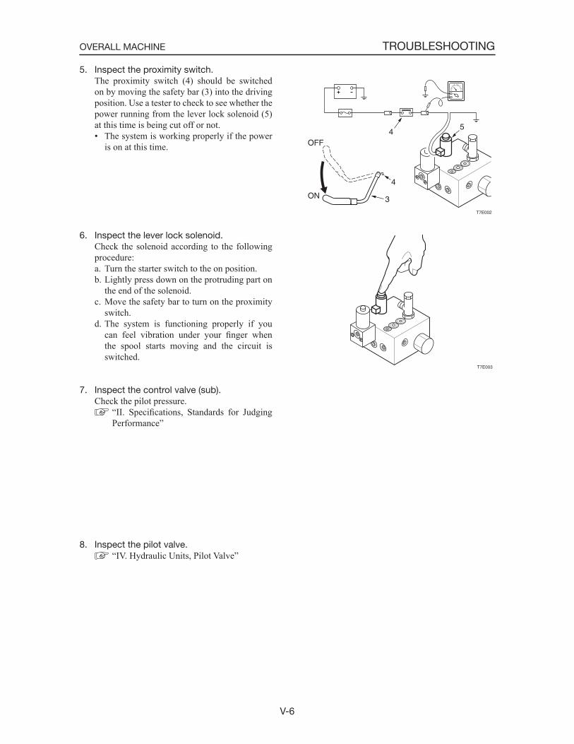
V-6
TROUBLESHOOTINGOVERALL MACHINE
5. Inspect the proximity switch. The proximity switch (4) should be switched
on by moving the safety bar (3) into the driving position. Use a tester to check to see whether the power running from the lever lock solenoid (5) at this time is being cut off or not.• The system is working properly if the power
is on at this time.
6. Inspect the lever lock solenoid. Check the solenoid according to the following
procedure:a. Turn the starter switch to the on position.b. Lightly press down on the protruding part on
the end of the solenoid.c. Move the safety bar to turn on the proximity
switch.d. The system is functioning properly if you
can feel vibration under your finger when the spool starts moving and the circuit is switched.
7. Inspect the control valve (sub). Check the pilot pressure.
“II. Specifications, Standards for Judging Performance”
8. Inspect the pilot valve. “IV. Hydraulic Units, Pilot Valve”
T7E002
45
3
4
ON
OFF
T7E003
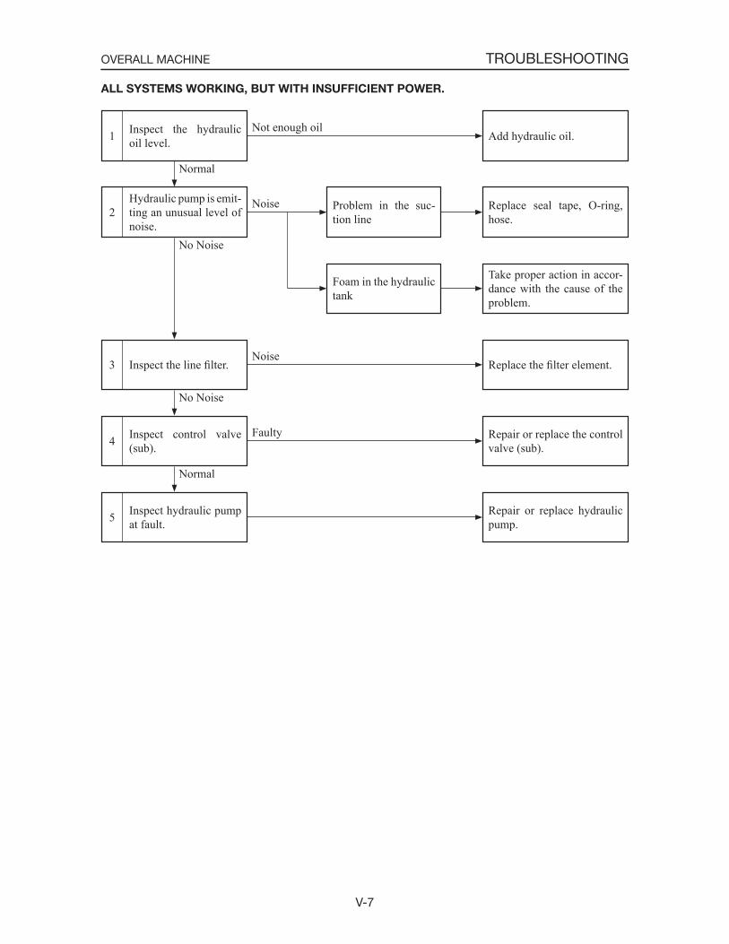
V-7
TROUBLESHOOTINGOVERALL MACHINE
ALL SYSTEMS WORKING, BUT WITH INSUFFICIENT POWER.
Inspect control valve (sub).4
Inspect the line filter.3
Hydraulic pump is emit-ting an unusual level of noise.
2
Inspect the hydraulic oil level.1
Replace seal tape, O-ring, hose.
Take proper action in accor-dance with the cause of the problem.
Replace the filter element.
Repair or replace the control valve (sub).
Normal
No Noise
No Noise
Noise
Noise
Not enough oil
Problem in the suc-tion line
Foam in the hydraulic tank
Inspect hydraulic pump at fault.5 Repair or replace hydraulic
pump.
Normal
Faulty
Add hydraulic oil.
V-8
TROUBLESHOOTINGOVERALL MACHINE
1. Inspect the hydraulic oil level. “III. Machine Configuration, Hydraulic Tank”
2. Hydraulic pump is emitting an unusual level of noise.
The cause of the problem is probably a fault in the suction line which has caused the pump to dry out. Check according to the following pro-cedure.a. Check the lines sucking the hydraulic oil.
• Apply grease or oil to the area which seems to be the cause of the problem and watch to see what happens. (Check to see if air is being drawn into the system.)
b. Check to see if the suction strainer is clogged.
3. Inspect the line filter. Remove the case, take out the filter element and
check to see if the filter is clogged.
4. Inspect the control valve (sub). “V-6”
5. Hydraulic pump at fault. When the inside of the pump is excessively
worn or has been damaged, the possibility exists that metal filings will work their way into the hydraulic oil. If this is the case, take the follow-ing action:• Replace the line filter and spin filter element.• Replace or flush the hydraulic oil (any oil of
NAS Grade 9 or above may be used).• When replacing the hydraulic oil, always be
sure to clean the inside of the hydraulic tank and the suction strainer. “III. Machine Configuration, Hydraulic Tank”
If the pump seal has been damaged, replace it. “IV. Hydraulic Units, Hydraulic Pump”
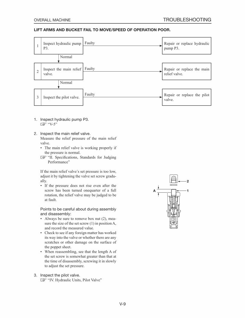
V-9
TROUBLESHOOTINGOVERALL MACHINE
LIFT ARMS AND BUCKET FAIL TO MOVE/SPEED OF OPERATION POOR.
Inspect the pilot valve.3
Inspect the main relief valve.2
Inspect hydraulic pump P3.1 Repair or replace hydraulic
pump P3.
Repair or replace the main relief valve.
Repair or replace the pilot valve.
Normal
Faulty
Faulty
1. Inspect hydraulic pump P3. “V-5”
2. Inspect the main relief valve. Measure the relief pressure of the main relief
valve.• The main relief valve is working properly if
the pressure is normal. “II. Specifications, Standards for Judging Performance”
If the main relief valve s set pressure is too low, adjust it by tightening the valve set screw gradu-ally.• If the pressure does not rise even after the
screw has been turned onequarter of a full rotation, the relief valve may be judged to be at fault.
Points to be careful about during assembly and disassembly:• Always be sure to remove box nut (2), mea-
sure the size of the set screw (1) in position A, and record the measured value.
• Check to see if any foreign matter has worked its way into the valve or whether there are any scratches or other damage on the surface of the poppet sheet.
• When reassembling, see that the length A of the set screw is somewhat greater than that at the time of disassembly, screwing it in slowly to adjust the set pressure.
3. Inspect the pilot valve. “IV. Hydraulic Units, Pilot Valve”
Faulty
Normal
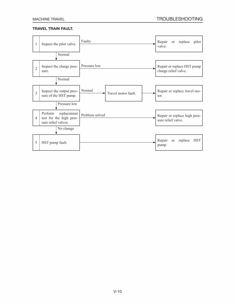
V-10
TROUBLESHOOTINGMACHINE TRAVEL
Inspect the charge pres-sure.2
Inspect the pilot valve.1
HST pump fault.5
Repair or replace HST pump charge relief valve.
Normal
Normal
Pressure low
Inspect the output pres-sure of the HST pump.3
Repair or replace HST pump.
Repair or replace travel mo-tor.Travel motor fault.
Repair or replace pilot valve.
Faulty
Perform replacement test for the high pres-sure relief valves.
4 Repair or replace high pres-sure relief valve.
Pressure low
Problem solved
No change
TRAVEL TRAIN FAULT.
Normal
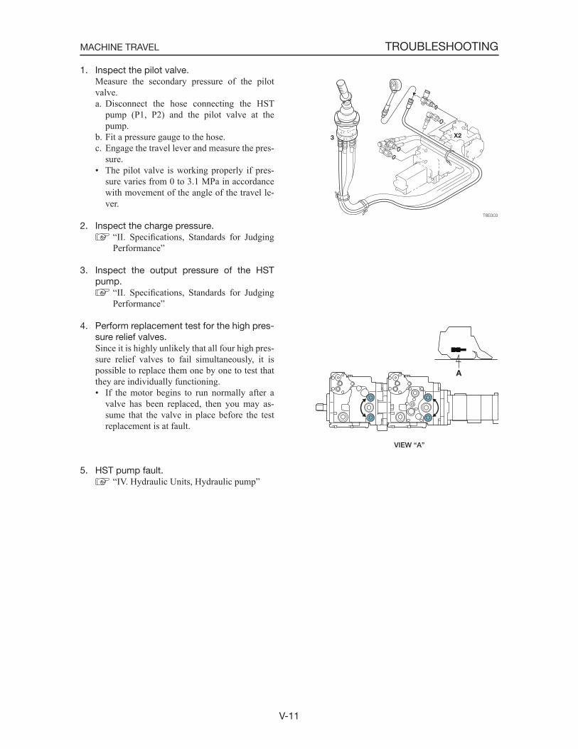
V-11
TROUBLESHOOTINGMACHINE TRAVEL
1. Inspect the pilot valve. Measure the secondary pressure of the pilot
valve.a. Disconnect the hose connecting the HST
pump (P1, P2) and the pilot valve at the pump.
b. Fit a pressure gauge to the hose.c. Engage the travel lever and measure the pres-
sure.• The pilot valve is working properly if pres-
sure varies from 0 to 3.1 MPa in accordance with movement of the angle of the travel le-ver.
2. Inspect the charge pressure. “II. Specifications, Standards for Judging Performance”
3. Inspect the output pressure of the HST pump.
“II. Specifications, Standards for Judging Performance”
4. Perform replacement test for the high pres-sure relief valves.
Since it is highly unlikely that all four high pres-sure relief valves to fail simultaneously, it is possible to replace them one by one to test that they are individually functioning.• If the motor begins to run normally after a
valve has been replaced, then you may as-sume that the valve in place before the test replacement is at fault.
5. HST pump fault. “IV. Hydraulic Units, Hydraulic pump”
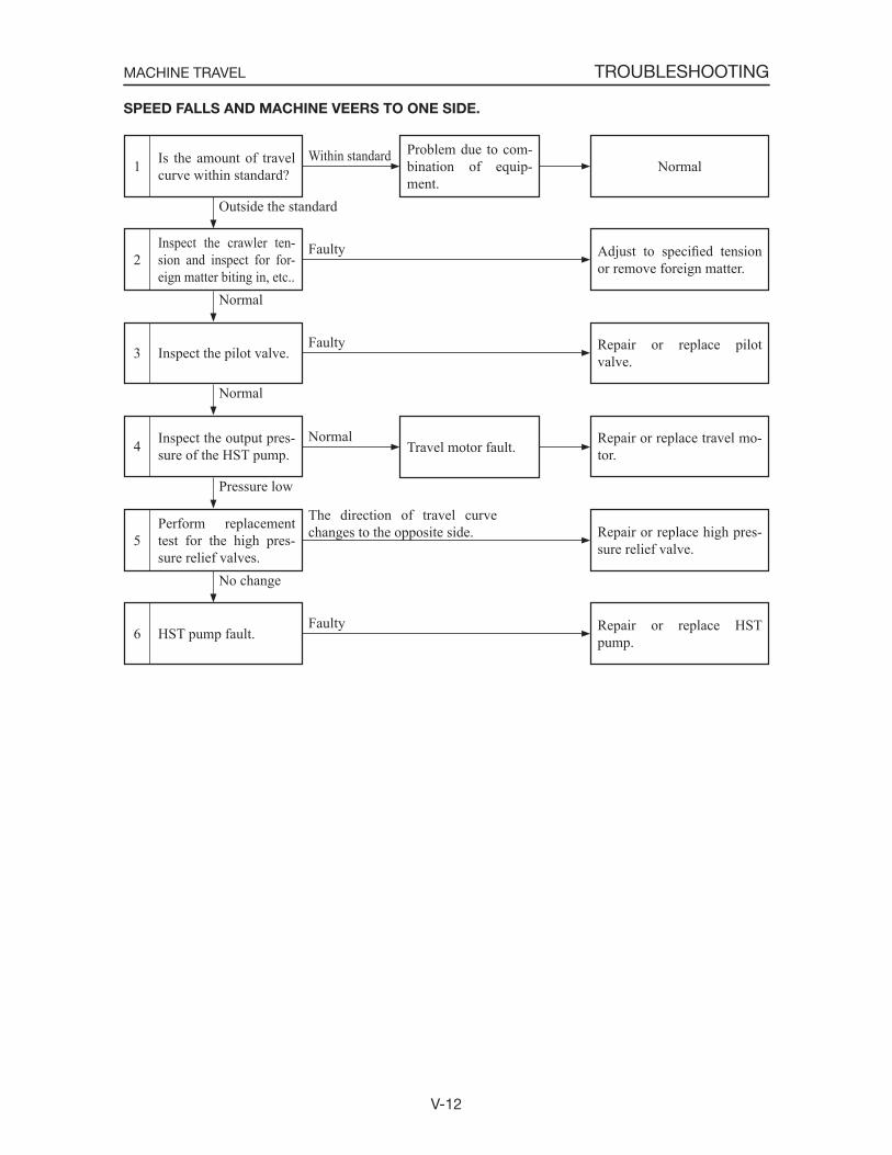
V-12
TROUBLESHOOTINGMACHINE TRAVEL
SPEED FALLS AND MACHINE VEERS TO ONE SIDE.
HST pump fault.6
Perform replacement test for the high pres-sure relief valves.
5
Inspect the pilot valve.3
Inspect the crawler ten-sion and inspect for for-eign matter biting in, etc..
2
Is the amount of travel curve within standard?1 Normal
Adjust to specified tension or remove foreign matter.
Repair or replace pilot valve.
Repair or replace high pres-sure relief valve.
Repair or replace HST pump.
Problem due to com-bination of equip-ment.
Outside the standard
Normal
Normal
No change
Within standard
Faulty
Faulty
The direction of travel curve changes to the opposite side.
Faulty
Inspect the output pres-sure of the HST pump.4 Repair or replace travel mo-
tor.Travel motor fault.
Pressure low
Normal
V-13
TROUBLESHOOTINGMACHINE TRAVEL
1. Is the amount of travel curve within stan-dard?
If the amount of travel curve is within standards, then operation is normal and the variation de-pends on the combination of equipment.
“II. Specifications, Standards for Judging Performance”
2. Inspect the crawler tension and inspect for foreign matter biting in, etc..
“II. Specifications, Standards for Judging Performance”
3. Inspect the pilot valve. “V-11”
4. Inspect the output pressure of the HST pump.
“II. Specifications, Standards for Judging Performance”
5. Perform replacement test for the high pres-sure relief valves.
“V-11”
6. HST pump fault. “IV. Hydraulic Units, Hydraulic Pump”
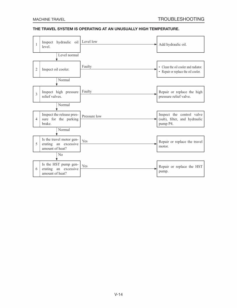
V-14
TROUBLESHOOTINGMACHINE TRAVEL
THE TRAVEL SYSTEM IS OPERATING AT AN UNUSUALLY HIGH TEMPERATURE.
Is the HST pump gen-erating an excessive amount of heat?
6
Is the travel motor gen-erating an excessive amount of heat?
5
Inspect the release pres-sure for the parking brake.
4
Inspect high pressure relief valves.3
Inspect oil cooler.2
Inspect hydraulic oil level.1 Add hydraulic oil.
• Clean the oil cooler and radiator.• Repair or replace the oil cooler.
Repair or replace the high pressure relief valve.
Inspect the control valve (sub), filter, and hydraulic pump P4.
Repair or replace the travel motor.
Repair or replace the HST pump.
Normal
Normal
Normal
No
Faulty
Faulty
Yes
Level low
Pressure low
Yes
Level normal
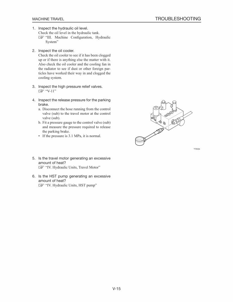
V-15
TROUBLESHOOTINGMACHINE TRAVEL
1. Inspect the hydraulic oil level. Check the oil level in the hydraulic tank.
“III. Machine Configuration, Hydraulic System”
2. Inspect the oil cooler. Check the oil cooler to see if it has been clogged
up or if there is anything else the matter with it. Also check the oil cooler and the cooling fan in the radiator to see if dust or other foreign par-ticles have worked their way in and clogged the cooling system.
3. Inspect the high pressure relief valves. “V-11”
4. Inspect the release pressure for the parking brake.a. Disconnect the hose running from the control
valve (sub) to the travel motor at the control valve (sub).
b. Fit a pressure gauge to the control valve (sub) and measure the pressure required to release the parking brake.
• If the pressure is 3.1 MPa, it is normal.
5. Is the travel motor generating an excessive amount of heat?
“IV. Hydraulic Units, Travel Motor”
6. Is the HST pump generating an excessive amount of heat?
“IV. Hydraulic Units, HST pump”
T7E004
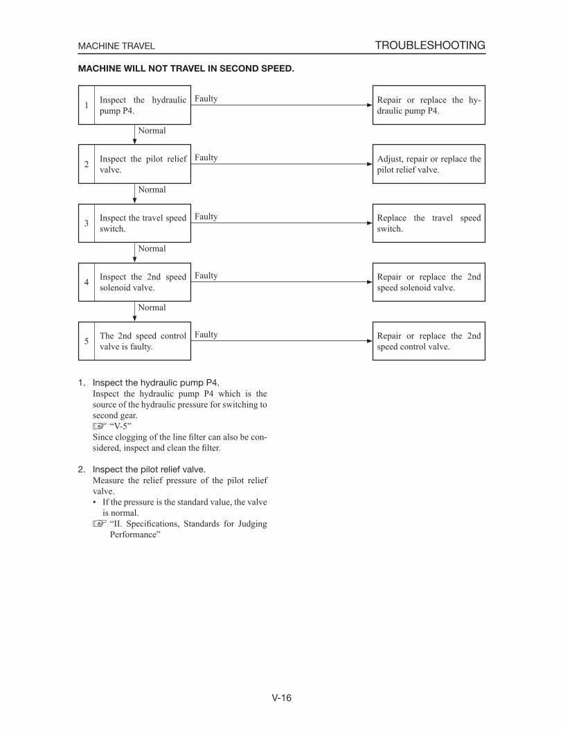
V-16
TROUBLESHOOTINGMACHINE TRAVEL
1. Inspect the hydraulic pump P4. Inspect the hydraulic pump P4 which is the
source of the hydraulic pressure for switching to second gear.
“V-5” Since clogging of the line filter can also be con-
sidered, inspect and clean the filter.
2. Inspect the pilot relief valve. Measure the relief pressure of the pilot relief
valve.• If the pressure is the standard value, the valve
is normal. “II. Specifications, Standards for Judging Performance”
MACHINE WILL NOT TRAVEL IN SECOND SPEED.
The 2nd speed control valve is faulty.5
Inspect the 2nd speed solenoid valve.4
Inspect the travel speed switch.3
Inspect the pilot relief valve.2
Inspect the hydraulic pump P4.1 Repair or replace the hy-
draulic pump P4.
Adjust, repair or replace the pilot relief valve.
Replace the travel speed switch.
Repair or replace the 2nd speed solenoid valve.
Repair or replace the 2nd speed control valve.
Normal
Normal
Normal
Faulty
Faulty
Faulty
Faulty
Faulty
Normal
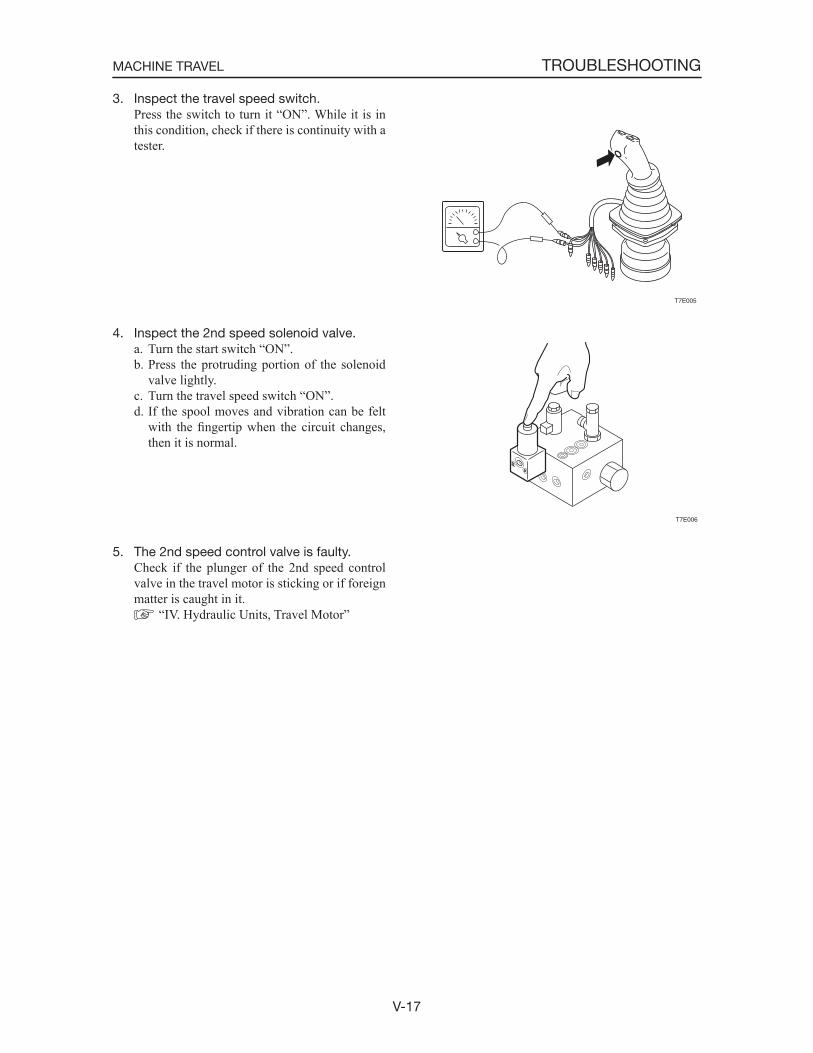
V-17
TROUBLESHOOTINGMACHINE TRAVEL
3. Inspect the travel speed switch. Press the switch to turn it “ON”. While it is in
this condition, check if there is continuity with a tester.
4. Inspect the 2nd speed solenoid valve.a. Turn the start switch “ON”.b. Press the protruding portion of the solenoid
valve lightly.c. Turn the travel speed switch “ON”.d. If the spool moves and vibration can be felt
with the fingertip when the circuit changes, then it is normal.
5. The 2nd speed control valve is faulty. Check if the plunger of the 2nd speed control
valve in the travel motor is sticking or if foreign matter is caught in it.
“IV. Hydraulic Units, Travel Motor”
T7E005
T7E006
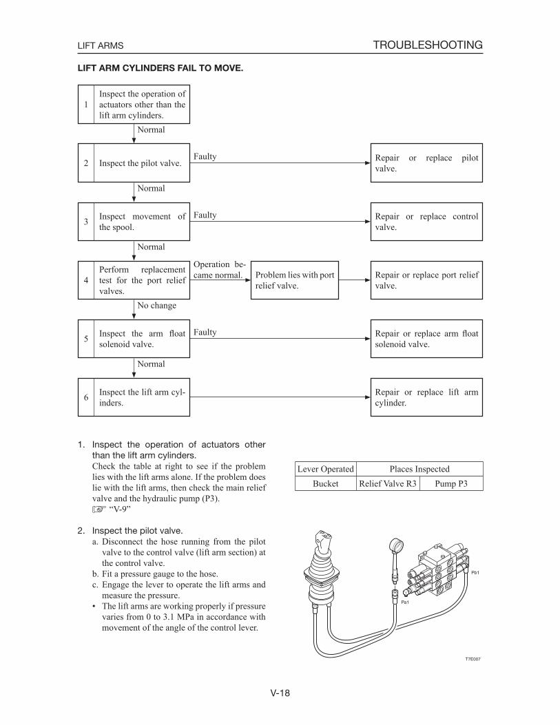
V-18
TROUBLESHOOTINGLIFT ARMS
LIFT ARM CYLINDERS FAIL TO MOVE.
Inspect movement of the spool.3
Inspect the pilot valve.2
Inspect the operation of actuators other than the lift arm cylinders.
1
Inspect the lift arm cyl-inders.6
Inspect the arm floatsolenoid valve.5
Repair or replace control valve.
Normal
Normal
Faulty
Perform replacement test for the port relief valves.
4
Repair or replace arm floatsolenoid valve.
Repair or replace lift arm cylinder.
Normal
Faulty
Repair or replace port relief valve.
No change
Operation be-came normal. Problem lies with port
relief valve.
Repair or replace pilot valve.
Normal
Faulty
1. Inspect the operation of actuators other than the lift arm cylinders.
Check the table at right to see if the problem lies with the lift arms alone. If the problem does lie with the lift arms, then check the main relief valve and the hydraulic pump (P3).
“V-9”
2. Inspect the pilot valve.a. Disconnect the hose running from the pilot
valve to the control valve (lift arm section) at the control valve.
b. Fit a pressure gauge to the hose.c. Engage the lever to operate the lift arms and
measure the pressure.• The lift arms are working properly if pressure
varies from 0 to 3.1 MPa in accordance with movement of the angle of the control lever.
Lever Operated Places InspectedBucket Relief Valve R3 Pump P3
T7E007
Pb1
Pa1
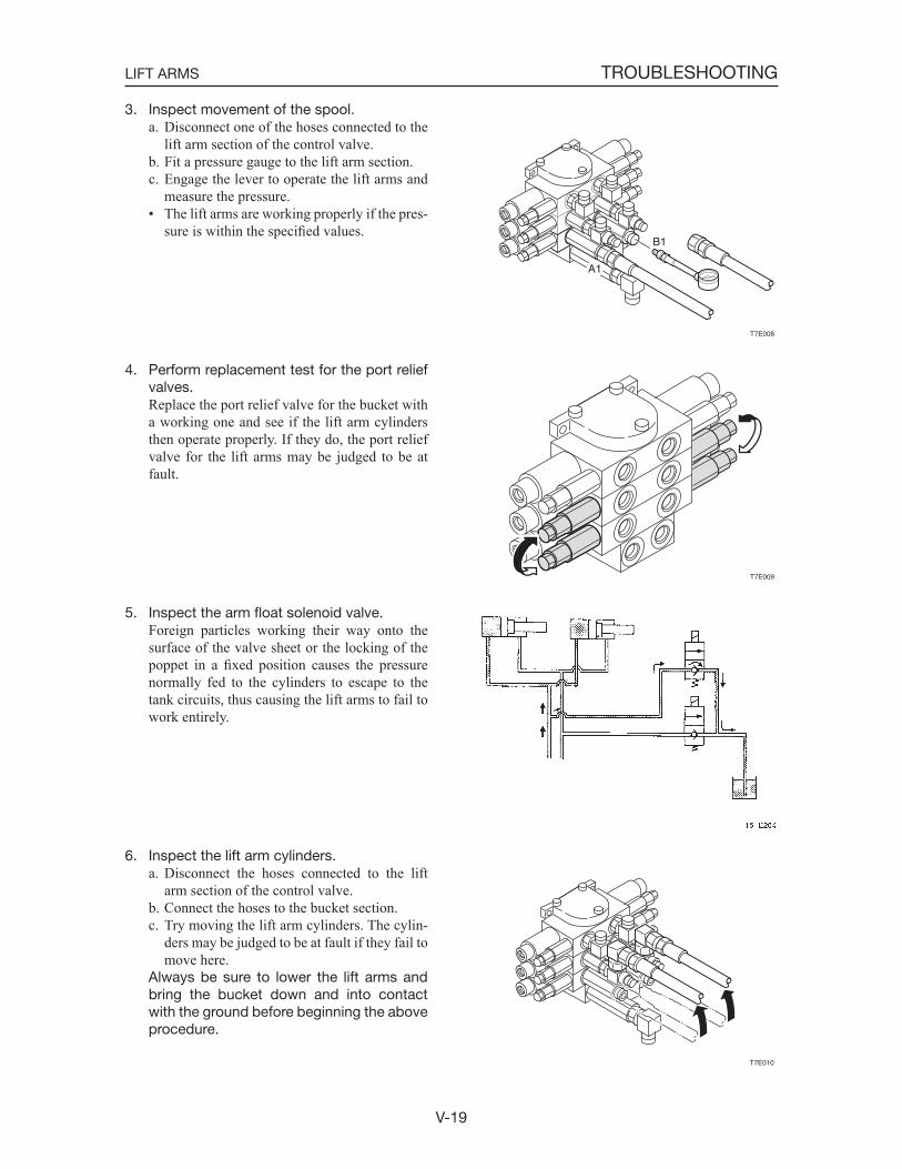
V-19
TROUBLESHOOTINGLIFT ARMS
3. Inspect movement of the spool.a. Disconnect one of the hoses connected to the
lift arm section of the control valve.b. Fit a pressure gauge to the lift arm section.c. Engage the lever to operate the lift arms and
measure the pressure.• The lift arms are working properly if the pres-
sure is within the specified values.
4. Perform replacement test for the port relief valves.
Replace the port relief valve for the bucket with a working one and see if the lift arm cylinders then operate properly. If they do, the port relief valve for the lift arms may be judged to be at fault.
5. Inspect the arm float solenoid valve. Foreign particles working their way onto the
surface of the valve sheet or the locking of the poppet in a fixed position causes the pressure normally fed to the cylinders to escape to the tank circuits, thus causing the lift arms to fail to work entirely.
6. Inspect the lift arm cylinders.a. Disconnect the hoses connected to the lift
arm section of the control valve.b. Connect the hoses to the bucket section.c. Try moving the lift arm cylinders. The cylin-
ders may be judged to be at fault if they fail to move here.
Always be sure to lower the lift arms and bring the bucket down and into contact with the ground before beginning the above procedure.
T7E008
B1
A1
T7E009
T7E010
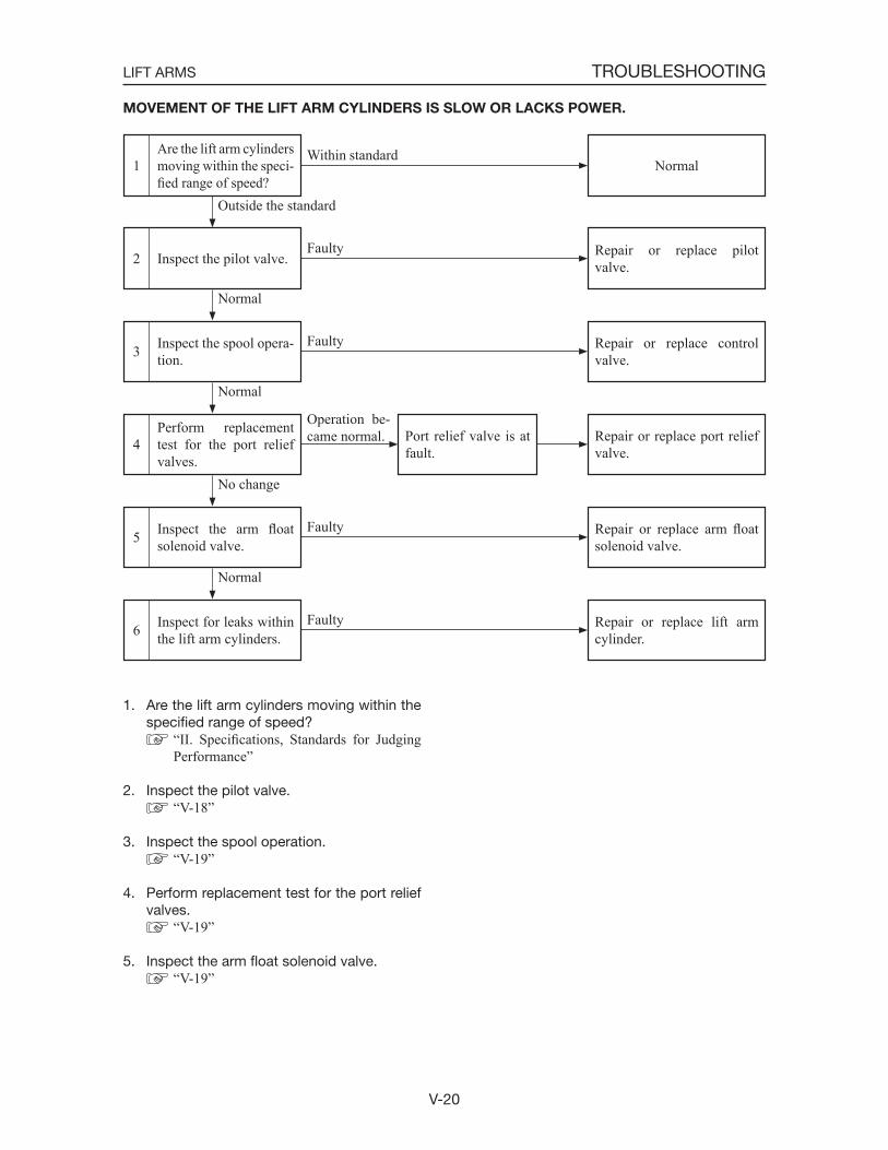
V-20
TROUBLESHOOTINGLIFT ARMS
MOVEMENT OF THE LIFT ARM CYLINDERS IS SLOW OR LACKS POWER.
Inspect the spool opera-tion.3
Inspect the pilot valve.2
Are the lift arm cylinders moving within the speci-fied range of speed?
1
Inspect for leaks within the lift arm cylinders.6
Inspect the arm floatsolenoid valve.5
Repair or replace control valve.
Normal
Normal
Faulty
Perform replacement test for the port relief valves.
4
Repair or replace arm floatsolenoid valve.
Repair or replace lift arm cylinder.
Normal
Faulty
Repair or replace port relief valve.
No change
Operation be-came normal. Port relief valve is at
fault.
Repair or replace pilot valve.
Outside the standard
Faulty
1. Are the lift arm cylinders moving within the specified range of speed?
“II. Specifications, Standards for Judging Performance”
2. Inspect the pilot valve. “V-18”
3. Inspect the spool operation. “V-19”
4. Perform replacement test for the port relief valves.
“V-19”
5. Inspect the arm float solenoid valve. “V-19”
NormalWithin standard
Faulty
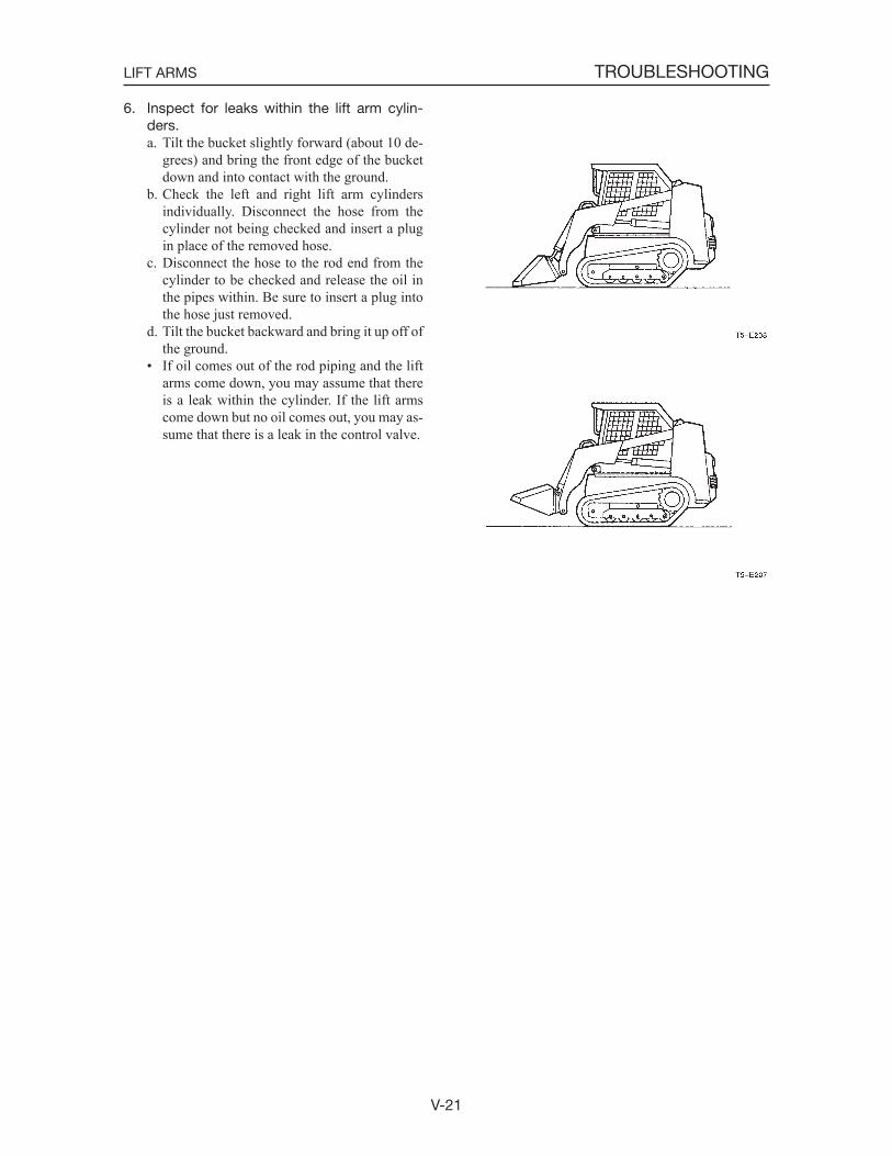
V-21
TROUBLESHOOTINGLIFT ARMS
6. Inspect for leaks within the lift arm cylin-ders.a. Tilt the bucket slightly forward (about 10 de-
grees) and bring the front edge of the bucket down and into contact with the ground.
b. Check the left and right lift arm cylinders individually. Disconnect the hose from the cylinder not being checked and insert a plug in place of the removed hose.
c. Disconnect the hose to the rod end from the cylinder to be checked and release the oil in the pipes within. Be sure to insert a plug into the hose just removed.
d. Tilt the bucket backward and bring it up off of the ground.
• If oil comes out of the rod piping and the lift arms come down, you may assume that there is a leak within the cylinder. If the lift arms come down but no oil comes out, you may as-sume that there is a leak in the control valve.
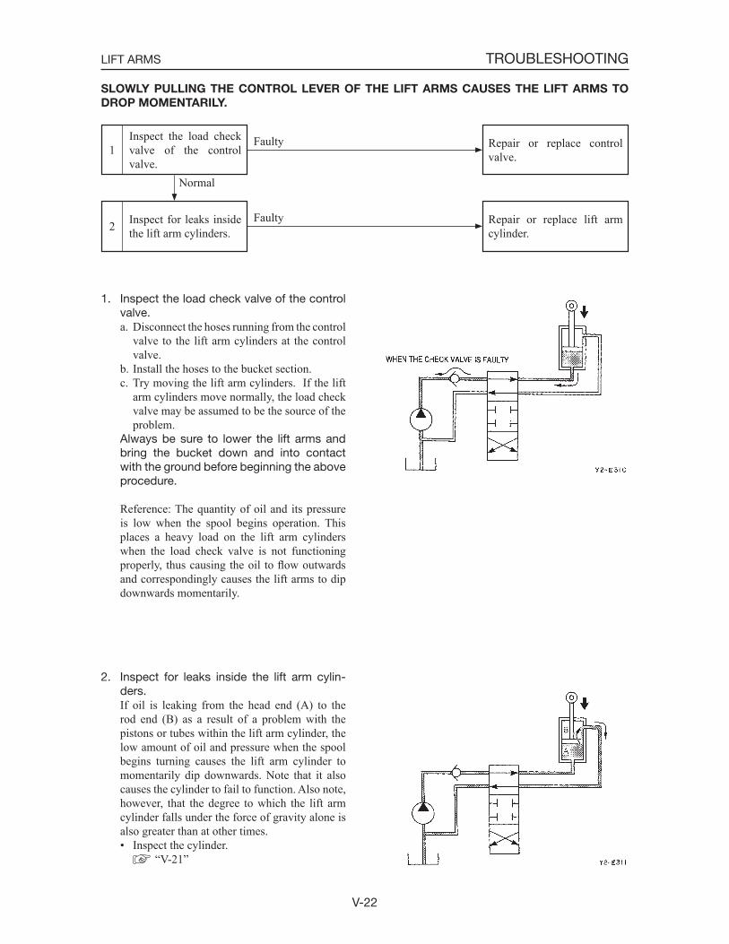
V-22
TROUBLESHOOTINGLIFT ARMS
SLOWLY PULLING THE CONTROL LEVER OF THE LIFT ARMS CAUSES THE LIFT ARMS TO
DROP MOMENTARILY.
Inspect for leaks inside the lift arm cylinders.2
Inspect the load check valve of the control valve.
1 Repair or replace control valve.
Repair or replace lift arm cylinder.
Faulty
1. Inspect the load check valve of the control valve.a. Disconnect the hoses running from the control
valve to the lift arm cylinders at the control valve.
b. Install the hoses to the bucket section.c. Try moving the lift arm cylinders. If the lift
arm cylinders move normally, the load check valve may be assumed to be the source of the problem.
Always be sure to lower the lift arms and bring the bucket down and into contact with the ground before beginning the above procedure.
Reference: The quantity of oil and its pressure is low when the spool begins operation. This places a heavy load on the lift arm cylinders when the load check valve is not functioning properly, thus causing the oil to flow outwards and correspondingly causes the lift arms to dip downwards momentarily.
2. Inspect for leaks inside the lift arm cylin-ders.
If oil is leaking from the head end (A) to the rod end (B) as a result of a problem with the pistons or tubes within the lift arm cylinder, the low amount of oil and pressure when the spool begins turning causes the lift arm cylinder to momentarily dip downwards. Note that it also causes the cylinder to fail to function. Also note, however, that the degree to which the lift arm cylinder falls under the force of gravity alone is also greater than at other times.• Inspect the cylinder.
“V-21”
Faulty
Normal

V-23
TROUBLESHOOTINGLIFT ARMS
THE AMOUNT OF LIFT ARMS NATURAL DROP IS GREAT.
Inspect the arm floatsolenoid valve.3
Inspect for leaks within the lift arm cylinders.2
Is the amount of natural drop within the stan-dard?
1
Repair or replace arm floatsolenoid valve.
Normal
Normal
Faulty
Perform replacement test for the port relief valves.
4
Replace control valve.
Repair or replace port relief valve.
No change
Operation be-came normal. Problem lies with port
relief valve.
Repair or replace lift arm cylinder.
Outside the standard
Faulty
1. Is the amount of natural drop within the standard?
“II. Specifications, Standards for Judging Performance”
2. Inspect for leaks within the lift arm cylin-ders.
“V-21”
3. Inspect the arm float solenoid valve. “V-19”
4. Perform replacement test for the port relief valves.
“V-19”
NormalWithin standard
Leak inside the control valve.
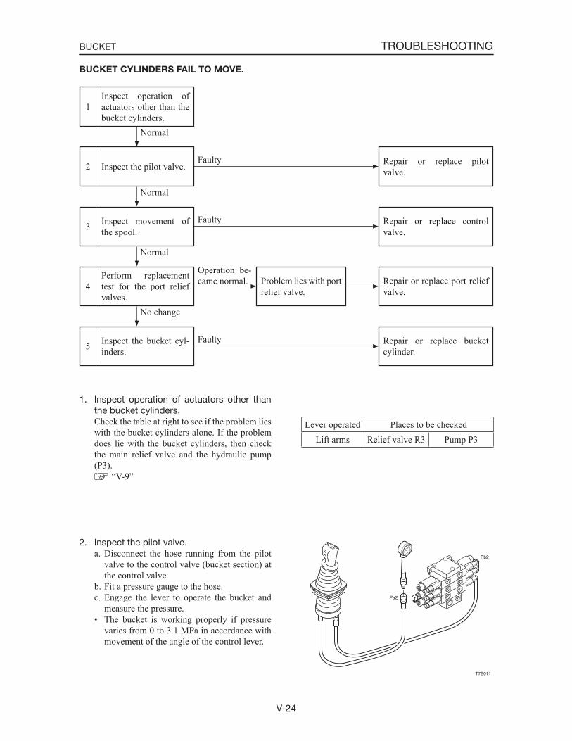
V-24
TROUBLESHOOTINGBUCKET
Inspect movement of the spool.3
Inspect the pilot valve.2
Inspect operation of actuators other than the bucket cylinders.
1
Repair or replace control valve.
Normal
Normal
Faulty
Perform replacement test for the port relief valves.
4 Repair or replace port relief valve.
Operation be-came normal. Problem lies with port
relief valve.
Repair or replace pilot valve.
Normal
Faulty
Inspect the bucket cyl-inders.5 Repair or replace bucket
cylinder.
No change
Faulty
BUCKET CYLINDERS FAIL TO MOVE.
1. Inspect operation of actuators other than the bucket cylinders.
Check the table at right to see if the problem lies with the bucket cylinders alone. If the problem does lie with the bucket cylinders, then check the main relief valve and the hydraulic pump (P3).
“V-9”
2. Inspect the pilot valve.a. Disconnect the hose running from the pilot
valve to the control valve (bucket section) at the control valve.
b. Fit a pressure gauge to the hose.c. Engage the lever to operate the bucket and
measure the pressure.• The bucket is working properly if pressure
varies from 0 to 3.1 MPa in accordance with movement of the angle of the control lever.
T7E011
Pb2
Pa2
Lever operated Places to be checkedLift arms Relief valve R3 Pump P3
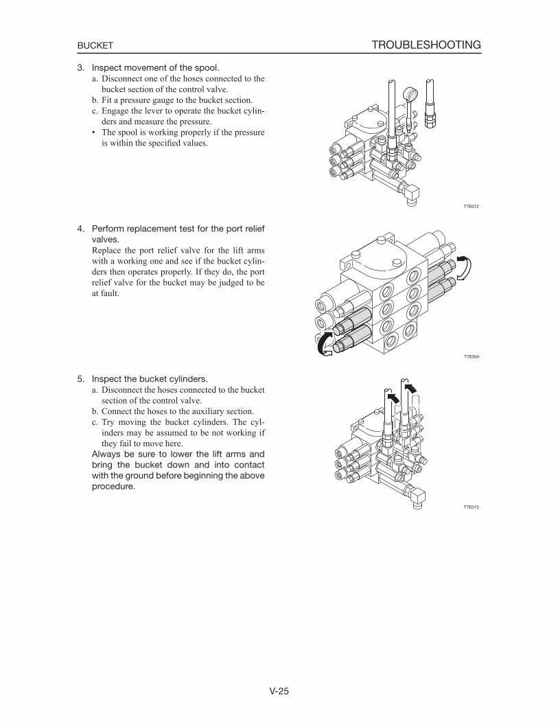
V-25
TROUBLESHOOTINGBUCKET
3. Inspect movement of the spool.a. Disconnect one of the hoses connected to the
bucket section of the control valve.b. Fit a pressure gauge to the bucket section.c. Engage the lever to operate the bucket cylin-
ders and measure the pressure.• The spool is working properly if the pressure
is within the specified values.
4. Perform replacement test for the port relief valves.
Replace the port relief valve for the lift arms with a working one and see if the bucket cylin-ders then operates properly. If they do, the port relief valve for the bucket may be judged to be at fault.
5. Inspect the bucket cylinders.a. Disconnect the hoses connected to the bucket
section of the control valve.b. Connect the hoses to the auxiliary section.c. Try moving the bucket cylinders. The cyl-
inders may be assumed to be not working if they fail to move here.
Always be sure to lower the lift arms and bring the bucket down and into contact with the ground before beginning the above procedure.
T7E012
T7E009
T7E013
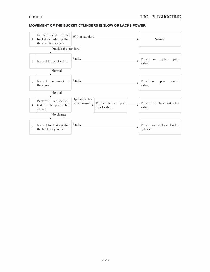
V-26
TROUBLESHOOTINGBUCKET
Inspect movement of the spool.3
Inspect the pilot valve.2
Is the speed of the bucket cylinders within the specified range?
1
Repair or replace control valve.
Normal
Normal
Faulty
Perform replacement test for the port relief valves.
4 Repair or replace port relief valve.
Operation be-came normal. Problem lies with port
relief valve.
Repair or replace pilot valve.
Outside the standard
Faulty
Inspect for leaks within the bucket cylinders.5 Repair or replace bucket
cylinder.
No change
Faulty
MOVEMENT OF THE BUCKET CYLINDERS IS SLOW OR LACKS POWER.
NormalWithin standard
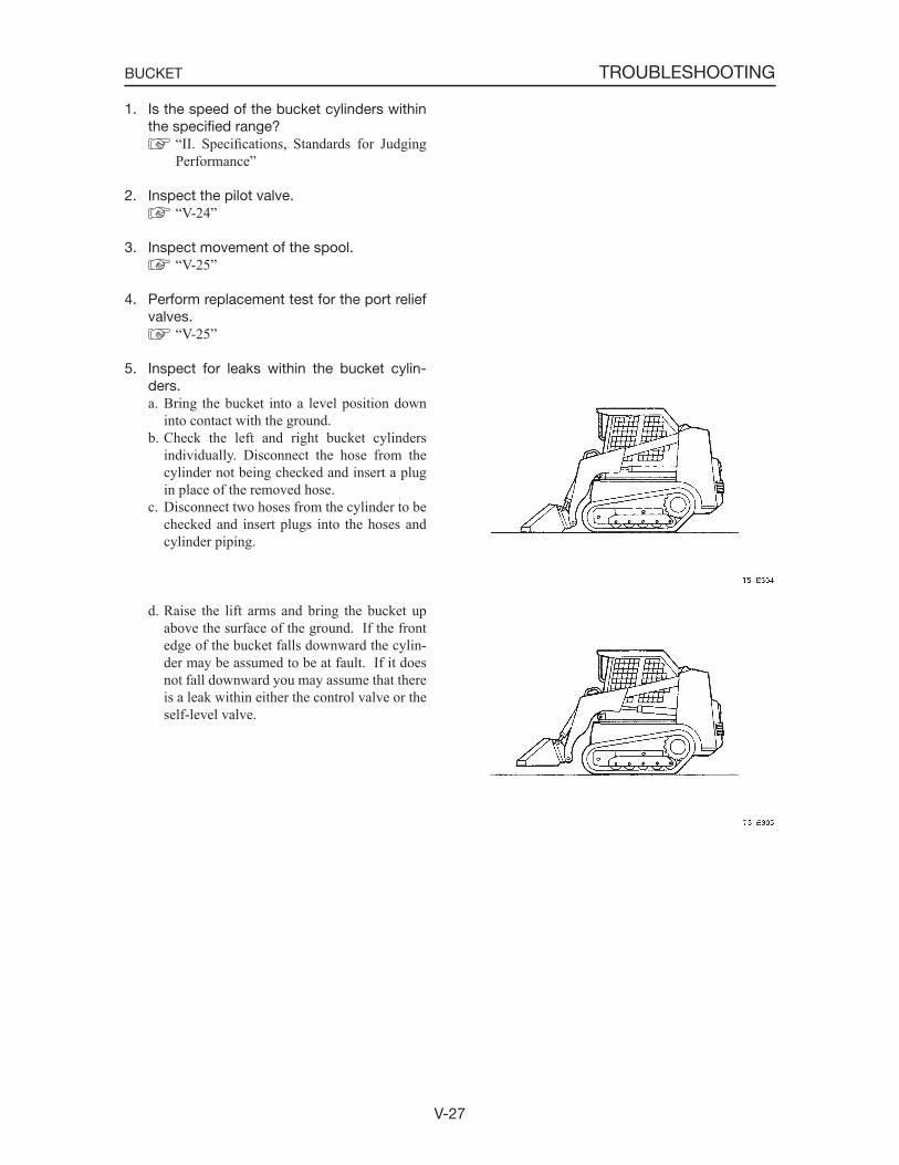
V-27
TROUBLESHOOTINGBUCKET
1. Is the speed of the bucket cylinders within the specified range?
“II. Specifications, Standards for Judging Performance”
2. Inspect the pilot valve. “V-24”
3. Inspect movement of the spool. “V-25”
4. Perform replacement test for the port relief valves.
“V-25”
5. Inspect for leaks within the bucket cylin-ders.a. Bring the bucket into a level position down
into contact with the ground.b. Check the left and right bucket cylinders
individually. Disconnect the hose from the cylinder not being checked and insert a plug in place of the removed hose.
c. Disconnect two hoses from the cylinder to be checked and insert plugs into the hoses and cylinder piping.
d. Raise the lift arms and bring the bucket up above the surface of the ground. If the front edge of the bucket falls downward the cylin-der may be assumed to be at fault. If it does not fall downward you may assume that there is a leak within either the control valve or the self-level valve.
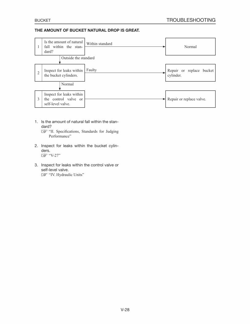
V-28
TROUBLESHOOTINGBUCKET
Inspect for leaks within the control valve or self-level valve.
3
Inspect for leaks within the bucket cylinders.2
Is the amount of natural fall within the stan-dard?
1
Repair or replace valve.
Normal
Repair or replace bucket cylinder.
Outside the standard
Faulty
1. Is the amount of natural fall within the stan-dard?
“II. Specifications, Standards for Judging Performance”
2. Inspect for leaks within the bucket cylin-ders.
“V-27”
3. Inspect for leaks within the control valve or self-level valve.
“IV. Hydraulic Units”
THE AMOUNT OF BUCKET NATURAL DROP IS GREAT.
NormalWithin standard
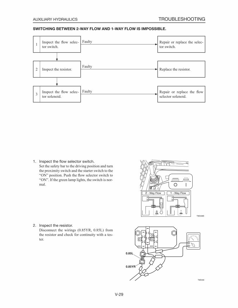
V-29
TROUBLESHOOTINGAUXILIARY HYDRAULICS
T9E008E
0.85YR
0.85L
T9E009
Inspect the flow selec-tor solenoid.3
Inspect the resistor.2
Inspect the flow selec-tor switch.1
Repair or replace the flowselector solenoid.
Faulty
Replace the resistor.Faulty
1. Inspect the flow selector switch. Set the safety bar to the driving position and turn
the proximity switch and the starter switch to the “ON” position. Push the flow selector switch to “ON”. If the green lamp lights, the switch is nor-mal.
2. Inspect the resistor. Disconnect the wirings (0.85YR, 0.85L) from
the resistor and check for continuity with a tes-ter.
SWITCHING BETWEEN 2-WAY FLOW AND 1-WAY FLOW IS IMPOSSIBLE.
Repair or replace the selec-tor switch.
Faulty

V-30
TROUBLESHOOTINGAUXILIARY HYDRAULICS
3. Inspect the flow selector solenoid.a. Turn the proximity switch and start switch
“ON”.b. Press the protruding portion of the solenoid
valve lightly.c. Turn the flow selector switch “ON”.d. If the spool moves and vibration can be felt
with the fingertip when the circuit changes, then it is normal.
T9E010