Operator's Manual - Frank's Hospital Workshop
114
Operator's Manual 0123 P/N 8501-00-1740 Revision A
-
Upload
khangminh22 -
Category
Documents
-
view
0 -
download
0
Transcript of Operator's Manual - Frank's Hospital Workshop

Operator's Manual
0123 P/N 8501-00-1740 Revision A

CAUTION!
Use of controls or adjustments or performance of procedures other than those specified herein may result in hazardous radiation exposure. Federal (USA) law restricts this device to sale by or on the order of a physician. Federal law also requires this device to be utilized under the direction of a physician and it should only be used by healthcare professionals authorized under state law to treat patients. All persons treating patients with this device should check to determine whether they are authorized healthcare professionals under the applicable state law.
(EC Authorized Representative)
Scanlan Group B.V. Tupolevlaan 32
1119 NZ Schiphol-Rijk The Netherlands
Phone: +31(0)20-653-0553 Fax: 31 20-653-3053
Candela Corporation 530 Boston Post Road
Wayland, MA 01778-1886 Telephone (508) 358-7637
Toll Free (800) 733-8550 (Technical Assistance) Toll Free (800) 73-LASER (Customer Service)
GentleLASE Candela Corporation
8501-00-1740 Revision A CONFIDENTIAL Page 1
Applications
Descriptions
Specifications
Section 1
GentleLASE Candela Corporation
8501-00-1740 Revision A CONFIDENTIAL Page 2
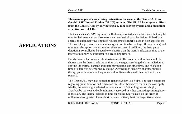
This manual provides operating instructions for users of the GentleLASE and GentleLASE Limited Edition (GL LE) systems. The GL LE laser system differs from the GentleLASE by only having a 12 mm delivery system and a maximum repetiti on rate of 1 Hz.
The Candela GentleLASE system is a flashlamp-excited, alexandrite laser that may be used for hair removal and also to treat dermatological vascular lesions. Pulsed laser energy at a nominal wavelength of 755 nanometers (nm) is used in both applications. This wavelength causes maximum energy absorption by the target (lesion or hair) and minimum absorption by surrounding skin structures. In addition, the laser pulse duration is controlled to be equal to or shorter than the thermal relaxation time of the target to minimize heat transfer to surrounding tissues.
Darkly colored hair responds best to treatment. The laser pulse duration should be shorter than the thermal relaxation time of the target absorbing the laser radiation, to confine the thermal damage and spare surrounding skin structures. The relaxation time of a target is determined by its size. According to selective photothermolysis theory, pulse durations as long as several milliseconds should be effective in hair removal.
The GentleLASE may also be used to remove Spider Leg Veins. The same conditions regarding pulse duration and relaxation time described above for hair removal apply. Ideally, the wavelength selected for eradication of Spider Leg Veins is highly absorbed by the vein and only minimally absorbed by other competing chromophores in the skin. The thermal relaxation time for Spider Leg Veins is on the order of milliseconds or greater. These short pulses effectively heat the target tissue while
APPLICATIONS
GentleLASE Candela Corporation
8501-00-1740 Revision A CONFIDENTIAL Page 3
limiting injury to surrounding skin structures.
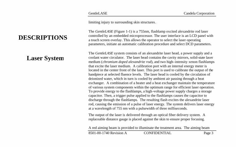
The GentleLASE (Figure 1-1) is a 755nm, flashlamp excited alexandrite rod laser controlled by an embedded microprocessor. The user interface is an LCD panel with a touch screen overlay. This allows the operator to select the laser operating parameters, initiate an automatic calibration procedure and select DCD parameters.
The GentleLASE system consists of an alexandrite laser head, a power supply and a coolant water circulator. The laser head contains the cavity mirrors, solid-state laser medium (chromium doped alexandrite rod), and two high-intensity xenon flashlamps that excite the laser medium. A calibration port with an internal energy meter is located in the center front of the laser. This port is used to calibrate the output of the handpiece at selected fluence levels. The laser head is cooled by the circulation of deionized water, which in turn is cooled by ambient air passing through a heat exchanger. A combination of a heater and a heat exchanger maintain the temperature of various system components within the optimum range for efficient laser operation. To provide energy to the flashlamps, a high-voltage power supply charges a storage capacitor. Then, a trigger pulse applied to the flashlamps causes the capacitor to discharge through the flashlamps. The resulting flash excites the alexandrite laser rod, causing the emission of a pulse of laser energy. The system delivers laser energy at a wavelength of 755 nm with a pulsewidth of three milliseconds.
The output of the laser is delivered through an optical fiber delivery system. A replaceable distance gauge is placed against the skin to ensure proper focusing. A red aiming beam is provided to illuminate the treatment area. The aiming beam
DESCRIPTIONS
Laser System

GentleLASE Candela Corporation
8501-00-1740 Revision A CONFIDENTIAL Page 4
and treatment beam are dimensionally identical, so the aiming beam can be used to accurately define the treatment pulse location. The aiming beam is illuminated when the laser enters the Ready State.
The laser system can be purchased with an optional skin cooling device referred to as the dynamic cooling device (DCD). The DCD consists of an electrically controlled spray nozzle located at the treatment end of the handpiece, a cryogen reservoir canister and associated electronic control circuitry located in the top of the system enclosure.
The cryogen, GentleCool™, is stored under pressure in the reservoir canister and brought to the solenoid valve via tubing. When the DCD system is on, depressing the trigger switch will cause a burst of cryogen spray to be applied to the skin prior to or after the laser pulse. Controls are provided on the laser front panel for the adjustment of the spray burst duration and for the timing delay between the spray burst and the laser pulse.
Dynamic CoolingDevice (DCD)

GentleLASE Candela Corporation
8501-00-1740 Revision A CONFIDENTIAL Page 5
FIGURE 1.1LASER SYSTEM
Handpiece Delivery System
Laser System
Independent Locking/Swivel Wheels
Control Panel

GentleLASE Candela Corporation
8501-00-1740 Revision A CONFIDENTIAL Page 6
Multiple handpiece delivery systems (6/8/10 mm Slider, 12/15/18 mm Slider, and for GL LE systems 12 mm only Slider) are offered with the laser system. Each delivery system (Figure 1.2) consists of a cable assembly, replaceable distance gauge and a handpiece assembly.
The cable assembly contains the fiberoptic, cryogen input line and valve control wires. The handpiece assembly contains the DCD spray nozzle, safety and detection electronics, focusing lenses, and an output window to protect the lenses from dust and debris. The spray nozzle is located near the distance gauge at the treatment end of the handpiece.
The GentleLASE is equipped with wheels, which both swivel and lock. All four wheels are capable of swiveling, which makes parking in tight spaces easy. The rear wheels’ swivel action may also be locked to enhance stability while transporting the GentleLASE.
The front swivel wheels contain levers which stop the wheels from rotating. To lock the laser in position, the front wheels must be locked. To lock the front wheels, depress the locking lever over each of the front wheels. To release, pull up on the lever.
The rear wheels have locking levers, but these levers when depressed stop the swivel action only, and do not stop wheel rotation. To lock the swivel action of the rear wheels, depress the locking levers. To enable the swivel action, pull the locking levers up.
Handpiece Delivery
System
Locking/Swivel Wheels

GentleLASE Candela Corporation
8501-00-1740 Revision A CONFIDENTIAL Page 7
FIGURE 1.2HANDPIECE
DELIVERY SYSTEM
LaserAperture &
Distance Gauge
Location Handpiece Assembly
Cable Assembly
Valve Control
Cryogen Line
Fiberoptic
GentleLASE Candela Corporation
8501-00-1740 Revision A CONFIDENTIAL Page 8
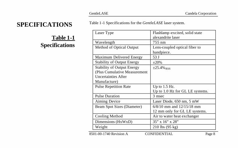
Table 1-1 Specifications for the GentleLASE laser system.
Laser Type Flashlamp -excited, solid state alexandrite laser
Wavelength 755 nm Method of Optical Output Lens-coupled optical fiber to
handpiece. Maximum Delivered Energy 53 J Stability of Output Energy ±20% Stability of Output Energy (Plus Cumulative Measurement Uncertainties After Manufacture)
±25.4%RSS
Pulse Repetition Rate Up to 1.5 Hz. Up to 1.0 Hz for GL LE systems.
Pulse Duration 3 msec Aiming Device Laser Diode, 650 nm, 5 mW Beam Spot Sizes (Diameter) 6/8/10 mm and 12/15/18 mm
12 mm only for GL LE systems. Cooling Method Air to water heat exchanger Dimensions (HxWxD) 35” x 16” x 28” Weight 210 lbs (95 kg)
Table 1-1Specifications
SPECIFICATIONS
GentleLASE Candela Corporation
8501-00-1740 Revision A CONFIDENTIAL Page 9
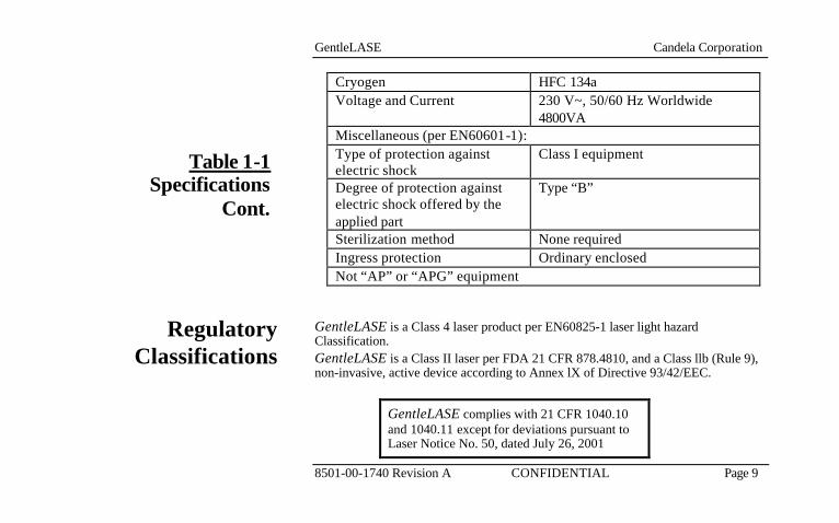
Cryogen HFC 134a Voltage and Current 230 V~, 50/60 Hz Worldwide
4800VA Miscellaneous (per EN60601-1): Type of protection against electric shock
Class I equipment
Degree of protection against electric shock offered by the applied part
Type “B”
Sterilization method None required Ingress protection Ordinary enclosed Not “AP” or “APG” equipment
GentleLASE is a Class 4 laser product per EN60825-1 laser light hazard Classification. GentleLASE is a Class II laser per FDA 21 CFR 878.4810, and a Class llb (Rule 9), non-invasive, active device according to Annex lX of Directive 93/42/EEC.
GentleLASE complies with 21 CFR 1040.10 and 1040.11 except for deviations pursuant to Laser Notice No. 50, dated July 26, 2001
Regulatory Classifications
Table 1-1Specifications
Cont.

GentleLASE Candela Corporation
8501-00-1740 Revision A CONFIDENTIAL Page 10
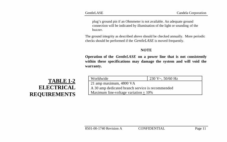
Table 1-2 (next page) lists Electrical Requirements for the GentleLASE. CAUTION! IF A PLUG NEEDS TO BE CHANGED, IT MUST BE DONE BY A QUALIFIED PERSON IN ACCORDANCE WITH THIS SECTION AND THE ELECTRICAL CODE OF THE INSTALLATION LOCALITY.
The GentleLASE is shipped with a locking NEMA L6-30P plug for connection to 230 V~, 50/60 Hz. The installation site requires a mating NEMA L6-30R power receptacle. The power receptacle must be within twelve feet (3.5 meters) of the intended laser system location, and must be earth-grounded.
The GentleLASE power connections internationally should be made with grounded, 2-conductor plug and receptacle pair. The pair must be rated for a minimum of 230V~, 30 Amp. The plug must be fitted onto the supplied line cord by an Electrician, or someone trained in electrical wiring.
Once the appropriate plug is installed on GentleLASE, the ground connection must be verified prior to use in one of two ways:
• Using the Ohms setting of a Volt-Ohm meter, set the scale to “x1”. Measure the resistance between the plug’s ground pin and any unpainted conductive surface on the GentleLASE chassis. This reading must fall between 0 - 0.1 Ohms.
• A battery & light or battery and buzzer combination may be alternatively used to verify a ground connection between any unpainted conductive surface and the
ELECTRICALREQUIREMENTS
GentleLASE Candela Corporation
8501-00-1740 Revision A CONFIDENTIAL Page 11
plug’s ground pin if an Ohmmeter is not available. An adequate ground connection will be indicated by illumination of the light or sounding of the buzzer.
The ground integrity as described above should be checked annually. More periodic checks should be performed if the GentleLASE is moved frequently.
NOTE
Operation of the GentleLASE on a power line that is not consistently within these specifications may damage the system and will void the warranty.
Worldwide 230 V~, 50/60 Hz 21 amp maximum, 4800 VA A 30 amp dedicated branch service is recommended Maximum line-voltage variation + 10%
TABLE 1-2ELECTRICAL
REQUIREMENTS

GentleLASE Candela Corporation
8501-00-1740 Revision A CONFIDENTIAL Page 12
Before installation of the GentleLASE, the intended site must be prepared as described in this section. The site must have sufficient space to accommodate the laser system, must provide the proper electrical power configuration and receptacles, and must meet the additional environmental specifications.
NOTE Installation of the GentleLASE system must be performed by a Candela Service Representative. Following installation, a Candela Nurse Consultant must instruct designated personnel on the basic operation and care of the laser. An in-depth clinical training is required of a physician to become proficient in the use of the GentleLASE .
ENVIRONMENTALREQUIREMENTS

GentleLASE Candela Corporation
8501-00-1740 Revision A CONFIDENTIAL Page 13
Sufficient floor space is required for the laser system. Approximately 15 inches (40 cm) of clearance is required between the rear panel and the wall, to allow room for the power cord and proper circulation of air from the cooling vents.
Humidity of 20% to 80% (non-condensing) should be maintained in the laser room.
Ensure that the atmosphere is non-corrosive, with no salts or acids in suspension in the air. Acids, corrosives, and volatile materials are likely to attack electrical wiring and the surfaces of optical components.
Keep air-borne dust particles to a minimum. Dust particles can cause permanent damage to optical surfaces. Metallic dust can be destructive to electrical equipment.
A temperature between 65° and 85°F (18° and 29°C) should be maintained in the laser room during operation.
Avoid placing the laser system near heating outlets or other sources of air currents that could cause uneven cooling in the laser system.
SPACEREQUIREMENTS
Humidity
Air Quality
AmbientTemperature

GentleLASE Candela Corporation
8501-00-1740 Revision A CONFIDENTIAL Page 14
Care should always be taken when moving the GentleLASE. Remove the footswitch tubing from the connector (located in the rear of the laser) before moving. Guide the GentleLASE by grasping the left and right side edges of the front bezel. Take special care when maneuvering over thresholds, elevator doors, ramps, and other uneven or sloping floor surfaces. A severe physical shock could cause the alignment of the laser head or the optical fiber to be disturbed resulting in personal injury or physical damage.
CAUTION!
TIP HAZARD! When moving the laser system, the rear wheels MUST be locked, and pointed forward and under the laser system; this will keep the laser upright.
If it becomes necessary to relocate the GentleLASE, call Candela Customer Service or your distributor for details. Failure to do so may result in damage to the system, and may void any warranty.
The GentleLASE is not designed for mobile use.
For transport and storage of GentleLASE, the temperature must be kept between 40° and 110° F (4.5° and 43° C), and humidity between 20% and 80% (non-condensing). Ambient atmospheric pressure is suitable with no restrictions.
Relocation
Mobile Use
Transport & Storage

GentleLASE Candela Corporation
8501-00-1740 Revision A CONFIDENTIAL Page 15
Section 2 Hazards Precautions Safety Features
GentleLASE Candela Corporation
8501-00-1740 Revision A CONFIDENTIAL Page 16
1. Identify the laser room clearly. Post appropriate warning signs in
prominent locations at all entrances to the laser room.
2. Cover all windows, portholes, etc. with opaque material to prevent unintended viewing or laser light escaping from the laser room.
3. When the GentleLASE is in operation, restrict entry and limit access to the laser room to those personnel both essential to the procedure and well trained in laser safety precautions.
4. Make sure that all laser room personnel are familiar with the laser system controls and know how to shut down the laser system instantly in an emergency.
LASER ROOM PRECAUTIONS

GentleLASE Candela Corporation
8501-00-1740 Revision A CONFIDENTIAL Page 17
CAUTION!
THE USE OF FLAMMABLE ANESTHETICS OR OXIDIZING GASES SUCH AS NITROUS OXIDE AND OXYGEN SHOULD BE AVOIDED. THE HIGH TEMPERATURE PRODUCED DURING NORMAL USE OF THE LASER EQUIPMENT MAY IGNITE SOME MATERIALS, FOR EXAMPLE COTTON OR GAUZE PADS WHEN SATURATED WITH OXYGEN. THE SO LVENTS OF ADHESIVES AND FLAMMABLE SOLUTIONS USED FOR CLEANING AND DISINFECTING SHOULD BE ALLOWED TO EVAPORATE BEFORE THE LASER EQUIPMENT IS USED. ATTENTION SHOULD ALSO BE DRAWN TO THE DANGER OF IGNITION OF ENDOGENOUS GASES.
Hair, gauze, masks, cannula and airway materials can be ignited by laser energy in an oxygen-enriched atmosphere even if thoroughly soaked with saline. The following scenario can lead to a flash fire during laser treatment:
1. Oxygen is administered via a mask, endotracheal tube, or nasal cannula. Leakage of oxygen generally occurs near the eye region where a tight seal of the mask is difficult to maintain, near the nasal area when a cannula is used, or near the mouth when an endotracheal tube is used.
FLASH FIRE HAZARDS

GentleLASE Candela Corporation
8501-00-1740 Revision A CONFIDENTIAL Page 18
2. An oxygen-rich atmosphere is created and dissipates over the face. Transient local concentrations of oxygen can greatly accelerate combustion.
3. During treatment, the laser beam strikes combustible material, which absorbs the laser energy, and the material is heated above its combustion point. This may occur simply by singeing the tip of a single dry hair.
4. This momentary, and possibly unnoticeable, ignition sets off a more significant flash fire. The fire then follows a path from the peripheral area of the oxygen enriched atmosphere to the oxygen source.
5. Other combustible substances are involved as a secondary effect of the initial ignition and may be related to hair, gauze, oxygen delivery devices, anesthesia gases, or byproducts of anesthesia in the oxygen enriched atmosphere. A burn may then occur where this secondary effect is present.

GentleLASE Candela Corporation
8501-00-1740 Revision A CONFIDENTIAL Page 19
CAUTION!
THE ELECTRICAL AND LASER RADIATION HAZARDS PRESENT DURING SERVICING OF THE GENTLELASE CAN BE EXTREMELY DANGEROUS AND SHOULD BE SERVICED ONLY BY THOSE QUALIFIED TECHNICIANS WHO HAVE RECEIVED APPROPRIATE TRAINING ON THE GENTLELASE FROM CANDELA.
CAUTION!
USE ONLY SAFETY EYEW EAR WITH AN OPTICAL DENSITY OF ≥5.8 @ 755 NM.
The laser beam emitted by the GentleLASE is capable of causing loss of vision. The laser operates at 755 nm, which falls within the invisible, near-infrared region of the electromagnetic spectrum. While not visible to the eye, it is still capable of inflicting damage. Remember this and take precautions to avoid inadvertent exposure. The cornea and lens of the eye are transparent to invisible light. Any energy emitted by the GentleLASE that enters the eye will be focused directly on the retina. Direct contact of the laser beam on the retina can cause temporarily clouded vision, retinal lesions, long-term scotoma (vision absence in an isolated area), long-term
OPTICALPRECAUTIONS
GentleLASE Candela Corporation
8501-00-1740 Revision A CONFIDENTIAL Page 20
photophobia (sensitivity to light) and/or loss of vision.
The laser aperture of the GentleLASE is at the distal end of the handpiece. The beam enlarges as distance from the handpiece increases. The Nominal Ocular Hazard Distance (NOHD) is the distance at which the beam is so big it is no longer dangerous to the unprotected eye. This distance along with the full angle beam divergence for each handpiece is shown in the following table.
To avoid vision hazards, everyone within the NOHD (see Table 2-1) of the GentleLASE must wear appropriate eye protection. Protective eyewear is supplied with each laser, and is available from a variety of vendors including Candela.

GentleLASE Candela Corporation
8501-00-1740 Revision A CONFIDENTIAL Page 21
CAUTION!
THE LASER BEAM EMITTED BY THE GENTLELASE SHOULD NEVER BE DIRECTED AT ANY PART OF THE BODY OTHER THAN THE INTENDED SITE OF TREATMENT OR TESTING.
HP Slider Spot Size Diameter, mm
Full Angle Beam Divergence, radians
NOHD, meters (per EN60825-1)
6 0.0937 104
8 0.0937 139
10 0.0937 150
12 0.1362 111
15 0.1362 120
18 0.1362 117
Table 2-1NOHD/ Handpiece
Comparison

GentleLASE Candela Corporation
8501-00-1740 Revision A CONFIDENTIAL Page 22
Follow these precautions to ensure optical safety:
1. Appoint one person responsible for the laser system controls during the procedure.
2. Ensure that all personnel wear appropriate safety eyewear whenever the laser system is on.
3. Never look directly into the laser beam even when wearing protective eyewear.
4. Never allow the laser beam to be directed at anything other than the targeted area or the calibration port.
5. Never permit reflective objects such as jewelry, instruments or mirrors to intercept the laser beam.
6. When the GentleLASE is not in use, place it in STANDBY state to prevent accidental pulsing.
7. When the GentleLASE is unattended, remove the key from the keyswitch to prevent unauthorized use.
Optical SafetyPrecautions
GentleLASE Candela Corporation
8501-00-1740 Revision A CONFIDENTIAL Page 23
The GentleLASE converts and amplifies the AC line voltage to produce extremely high voltages inside the laser system that may be lethal. It is possible for high-voltage components to retain a charge after the power supply has been turned off, and even after the GentleLASE has been disconnected from the line voltage. Therefore, no part of the exterior housing should be removed, except by a trained and authorized technician. The GentleLASE laser delivery system utilizes fiber optics that can be damaged if installed or subjected to excessive bending. To avoid damage to the optical fiber, limit bends to a radius of 6 inches (15 cm) or greater. Failure to follow recommended procedures may lead to damage to the fiber or delivery system and/or harm to the patient or user. To prevent the laser from moving, both front wheels must be locked. To lock the wheels, step down on the tabs on the front of the wheels. To unlock, pull up on the extending tab. The GentleLASE weighs approximately 210 pounds (95 kg) and may cause injury if proper care is not used when moving it. The system should always be moved carefully and slowly.
ELECTRICAL& MECHANICAL
HAZARDS
GentleLASE Candela Corporation
8501-00-1740 Revision A CONFIDENTIAL Page 24
There are no known chemical hazards associated with the GentleLASE system. The laser system uses a Hydroflourocarbon (HFC), cryogen, in the optional Dynamic Cooling Device (DCD). Inhalation: If high concentrations are inhaled, immediately move to fresh air. Keep person calm. If not breathing, give artificial respiration. If breathing is difficult, give oxygen. Call a physician. Skin Contact: If large amounts of cryogen contact the skin due to a leak or rupture in the cryogen system flush skin immediately with water and call a Physician to check for frostbite. Treat for frostbite if necessary by gently warming affected area. Eye Contact: In case of eye contact, immediately flush eyes with plenty of water for at least 15 minutes. Call a Physician. Ingestion: Ingestion is not considered a potential route of exposure.
NOTE to Physicians
Because of possible disturbances of cardiac rhythm, catecholamine drugs, such as epinephrine, should only be used with special caution in situations, of emergency life support.
CHEMICAL HAZARDS
Cryogen

GentleLASE Candela Corporation
8501-00-1740 Revision A CONFIDENTIAL Page 25
Treatment Area: Never use any flammable substance, such as alcohol or acetone, in the preparation of the skin for treatment. Use soap and water, if necessary.
Anesthetics: Anesthetics administered either by inhalation or topically must be approved as non-flammable.
Instruments: Since laser beams are reflected by most shiny surfaces, all instruments used in laser procedures should have brushed, burnished, or blackened, non-reflective surfaces.
Laser Fiber Fire Hazard: GentleLASE fibers carry significant laser energy. If the fiber were to break during laser pulsing, a sudden flash or flame may be observed at the break point. This flash or flame with each pulse will continue until pulsing is stopped. Individuals in contact with this flash or flame could receive a burn. Ignition of combustible materials (including clothing) in the proximity of the fiber break could also occur.
If a break, or a sudden flash or flame is observed in the fiber, discontinue pulsing immediately.
Because a break could occur suddenly, always position the fiber during each use such that it is in full view. For example, do not drape the fiber over the shoulder, leaving a
FIRE HAZARD
GentleLASE Candela Corporation
8501-00-1740 Revision A CONFIDENTIAL Page 26
portion of the fiber out of view during use.
Do not lay the fiber across combustible materials during use.
Do not drape the fiber over the shoulder or place it on combustible material.
Laser plume may contain viable tissue particulate. Please reference the American National Standard for Safe Use of Lasers (ANSI A136.3.-1996), section 7.3 Laser Generated Air Contaminants (LGAC).
Some mechanism for decreasing LGACs should be used. Based on the type of condition being treated by the laser, there may be a higher incidence of LGAC.
Reference the NIOSH Hazard Controls: Control of Smoke from Laser / Electrical Surgical Procedures bulletin (HC11) -- US Department of Health and Human Services, Public Health Service: National Institute for Occupational Safety and Health, September 1996.
NIOSH has shown that airborne contaminants generated by laser use can be effectively controlled by proper ventilation and work practices. (The thermal destruction of tissue creates smoke byproduct, which can contain a variety of gases, vapors, dead and live cellular material, including blood fragments.)
When removing hair, clip excess hair away before beginning laser treatment to reduce odor and char.
LASER GENERATED AIR CONTAMINANTS
(LGAC)
GentleLASE Candela Corporation
8501-00-1740 Revision A CONFIDENTIAL Page 27
The GentleLASE was designed to comply with IEC/EN 60601-1-2 (Group 1, Class A) "Electromagnetic Compatibility Requirements and Tests". Class A equipment is intended for use in commercial and industrial locations. A portion of IEC/EN 60601-1-2 deals with measurements of unwanted radio frequency emissions generated from a product. Both radiated emissions (radiated through the air) and conducted emissions (conducted into the AC Mains) are measured. Radiated and conducted emissions from a product have been known to interfere with the performance of other equipment in the vicinity. The emissions from GentleLASE have been reduced as far as practical without compromising functionality.
If interference from the GentleLASE is suspected, insure that the unit is plugged into an AC Mains that is not shared by the affected equipment. If the interference still exists, move the GentleLASE or the affected equipment into another room.
Refer to accompanying Declaration and Guidance document (part number 8501-00-1736) for additional information and guidance.
Keylock Switch
This key-operated switch controls electrical power to the laser system. The GentleLASE can be operated only with the key provided by Candela. The key should be removed from the keyswitch when the laser is not in use.
ELECTRO-MAGNETIC
INTERFERENCE
SAFETYFEATURES

GentleLASE Candela Corporation
8501-00-1740 Revision A CONFIDENTIAL Page 28
Laser Emergency Stop Switch
When the red switch with this labelSTOP
underneath (located on the lower left side of the control panel) is pressed, the GentleLASE is shut down immediately.
PFN Charged
An audible beep will be heard when the laser is ready to deliver a pulse of energy.
Lasing
An audible beep will be heard and the control panel flashes three Lasing Triangle symbols to indicate that the laser is pulsing.
Ready Lamp
The blue lamp mounted near the control panel is illuminated when the laser is in the Ready state.
STANDBY and READY Operating States
The system operates in one of two states: STANDBY or READY. In the STANDBY state, laser emission is disabled. The operator must put the system into the READY state in order to enable laser emission. In the READY state, laser pulses are generated by depressing the trigger switch. As a safety precaution, there is a delay of two seconds from the time that the system enters the READY state to the time that laser emission is enabled. When the laser system is not being used, it should be returned to

GentleLASE Candela Corporation
8501-00-1740 Revision A CONFIDENTIAL Page 29
the STANDBY state. The laser will automatically revert back to the STANDBY state after 2 minutes of inactivity in the READY state. The operator selects the operating state via the Display Panel. System state information is also displayed on the Display Panel. When the system is in the READY state, the blue lamp to the right of the Display Panel is illuminated.
Remote Interlock An external connector for a remote interlock switch is provided on the back of the system enclosure. This interlock switch can be connected to the doors of the laser room. If the door is opened and the GentleLASE is in the Ready state, the laser system completely shuts down. For more information on installation of a remote interlock, please call Candela Service.

GentleLASE Candela Corporation
8501-00-1740 Revision A CONFIDENTIAL Page 30
Residues that accumulate on the delivery system windows and distance gauge during normal use may contain infectious viable tissue particulate. Under certain conditions, contact with viable tissue particulate can put a user at risk for contracting disease. Therefore at the end of its useful life, the distance gauge, windows & cleaning materials should be disposed of in a way that minimizes risk of exposure. Such methods of disposal include, but are not limited to, disposal in a biohazard container (if available), incineration, or disposal as sealed waste in a plastic bag discarded with regular trash. Non-porous gloves should be worn during treatment and when servicing patient-contact parts to reduce risks associated with exposure. The gloves should be disposed of in the same manner as contact parts.
Other than patient-contact parts, all external components & accessories can be disposed of as regular trash. Most internal components that make up the laser system can also be disposed of as regular trash with the exception of the high voltage capacitor and an integrated battery located on the laser I/O pcb. The high voltage capacitor must be disposed of through a hazardous waste company because of two potential hazards:
1. Shock hazard – Once removed from the system the capacitor can accumulate a potentially lethal charge.
2. Dielectric oil – The oils used in the high voltage capacitor, silicon or soybean, are not considered hazardous, but must be disposed of in a manner consistent with local regulations.
Batteries: An IC located on the I/O pcb (beneath front cover) contains an integrated Lithium-
Disposal Hazards &
Guidance
ENVIRONMENTAL PROTECTION

GentleLASE Candela Corporation
8501-00-1740 Revision A CONFIDENTIAL Page 31
ion battery which is not replaceable or user-serviceable. The IC designated “U7” must be removed and disposed of separately from the laser system in accordance with local disposal laws regulating battery disposal.
The fluid in the coolant circulation system contains purified water and can be disposed of as regular water.
If disposal of the laser system or its accessories becomes a problem in your area, contact Candela for instruction.
Hazardous Material & Hazardous Waste
If the laser system includes a DCD option, the GentleCOOLTM canister is classified as “hazardous”. Refer to the following matrix:
Item Hazardous category Comments GentleCOOLTM canister
Pressure Must be disposed of as hazardous waste or shipped as hazardous material. A canister may be vented to empty and then be disposed of in the trash as “non hazardous”
Refer to associated Material Safety Data Sheets (MSDS) for further information on safety, handling, first aid and disposal.

GentleLASE Candela Corporation
8501-00-1740 Revision A CONFIDENTIAL Page 32
GentleLASE Candela Corporation
8501-00-1740 Revision A CONFIDENTIAL Page 33
System Operation Features
Section 3

GentleLASE Candela Corporation
8501-00-1740 Revision A CONFIDENTIAL Page 34
The GentleLASE control panel (Figure 3.1) located on the front of the laser system, consists of an On/Off Keylock switch, a Laser Stop (emergency off) push-button switch, Ready Lamp, Calibration Port, Handpiece Delivery System Receptacles, and a Touch Screen Display Panel (Display Panel). The Display Panel (Figure 3.2) provides a simple graphical user interface for the operator. The operator uses this interface to select the system operating state, laser operating parameters, DCD parameters and output energy calibration.
CONTROLPANEL
Display Panel
Laser Stop Switch
On/Off Keylock
Switch
Ready Lamp
Calibration Port
“Cal Port”
Valve Control Receptacle
Cryogen Line Receptacle
Fiberoptic Receptacle
Figure 3.1Control Panel

GentleLASE Candela Corporation
8501-00-1740 Revision A CONFIDENTIAL Page 35
Keylock Switch This key-operated switch controls electrical power to the laser system. The GentleLASE can be operated only with the key provided by Candela.
The keylock switch has three positions: “ ” (off), “ ” (on), and “ ” (start). To
start the laser, turn the key from the “ ” position to the “ ” position, then release.
The switch spring returns to the “ ’’ position. The laser system starts in a few
seconds and four quick audible beeps will sound.
Laser Stop Switch When the red Laser Stop switch is pressed, the laser system shuts down immediately.
To restart the system, turn the keylock switch to the “ ” position, and then release.
Laser Aperture The laser aperture is located at the distal end of the handpiece (see Figure
6.3).

GentleLASE Candela Corporation
8501-00-1740 Revision A CONFIDENTIAL Page 36
Figure 3.2Touch ScreenDisplay Panel
Main Screen
Ready Button
Laser State
Next Screen Button
Total Pulse and Pulse Count Button
Canister Counter
Calibrate Button
Standby Button
DCD Pre Spray Duration Button
Fluence Button
DCD Delay Button
Adjust Up Button
Adjust Down
Button
Repetition Rate Select
DCD Post Spray Duration Button Spotsize
Identification& PURGE
Button
GentleLASE Candela Corporation
8501-00-1740 Revision A CONFIDENTIAL Page 37
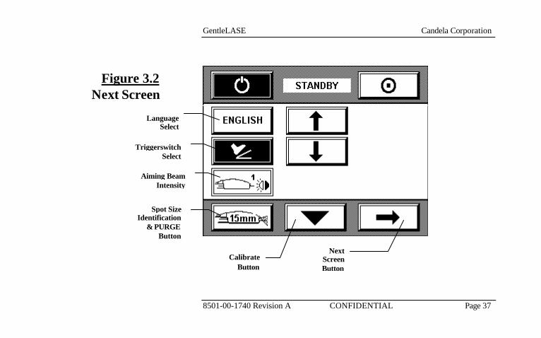
Figure 3.2Next Screen
Triggerswitch Select
Next Screen Button
Calibrate Button
Language Select
Spot Size Identification
& PURGE Button
Aiming Beam Intensity

GentleLASE Candela Corporation
8501-00-1740 Revision A CONFIDENTIAL Page 38
The system state status is located in the center, top section of the display. The system operates in one of two states: STANDBY or READY.
When in STANDBY, the high voltage power supply is turned off and laser emission is disabled. The operator selects the STANDBY state by pressing the STANDBY button. The background for the Standby button is set to BLACK to indicate that this state is selected. The word “STANDBY” is also displayed in the top portion of the Display Panel. The GentleLASE automatically enters STANDBY state following the initial warm-up period, which occurs when the laser system is first powered up. If the laser has been inactive in the READY STATE for two minutes or if a fault condition is detected, the system reverts to the STANDBY state automatically.
CAUTION!
DO NOT ENTER THE READY STATE WITHOUT A FIBER INSTALLED.
When in READY the high voltage power supply is turned on, the beam shutter is opened, the aiming beam is illuminated, and laser emission is enabled.
SYSTEM STATE
Standby
Ready
GentleLASE Candela Corporation
8501-00-1740 Revision A CONFIDENTIAL Page 39
This state is selected by pressing the READY button. The background for the title text of the READY button is set to BLACK to indicate that this stat e is selected. A two second delay is implemented before laser emission is enabled when the system state changes from STANDBY to READY as a safety precaution.
The blue Ready indicator, “ ”, located below the control panel display is illuminated when the laser is in the READY state. See Section 7 for the location of the Ready indicator. The window area below the System Status menu bar contains the buttons associated with the Main Menu. The laser operating parameters can each be set individually by the operator. To change a parameter, press the appropriate button and use the up or down arrows to adjust the value to the desired setting. The background for the selected parameter is set to black to indicate that their numeric settings can be modified.
The Fluence parameter is the amount of energy density delivered to the selected spot size. The setting is adjustable in various increments of J/cm2 for different spot sizes between the lower and upper values given in the following table 3.1 for each slider spot size: Corresponding Energy levels for each spot size fluence setting are in tables 3-2 and 3-3.
OPERATINGPARAMETERS
Fluence

GentleLASE Candela Corporation
8501-00-1740 Revision A CONFIDENTIAL Page 40
Fluence (J/cm2)
Energy Out Handpiece
(J)
Fluence (J/cm2)
Energy Out Handpiece
(J)
Fluence (J/cm2)
Energy Out Handpiece
(J)35.0 9.9 20.0 10.1 15.0 11.840.0 11.3 25.0 12.6 20.0 15.745.0 12.7 30.0 15.1 25.0 19.650.0 14.1 35.0 17.6 30.0 23.655.0 15.5 40.0 20.1 35.0 27.560.0 17.0 45.0 22.6 40.0 31.465.0 18.4 50.0 25.1 45.0 35.370.0 19.8 55.0 27.6 50.0 39.375.0 21.2 60.0 30.2 55.0 43.280.0 22.6 65.0 32.7 60.0 47.185.0 24.0 70.0 35.290.0 25.4 75.0 37.795.0 26.9 80.0 40.2100.0 28.3 85.0 42.7
90.0 45.295.0 47.8100.0 50.3
6 mm Spot 8 mm Spot 10 mm Spot
Table 3-1Fluence and
Energy Ranges for 6/8/10 mm
HP Slider

GentleLASE Candela Corporation
8501-00-1740 Revision A CONFIDENTIAL Page 41
Fluence (J/cm2)
Energy Out Handpiece
(J)
Fluence (J/cm2)
Energy Out Handpiece
(J)
Fluence (J/cm2)
Energy Out Handpiece
(J)10.0 11.3 6.0 10.6 6.0 15.312.0 13.6 7.0 12.4 7.0 17.814.0 15.8 8.0 14.1 8.0 20.416.0 18.1 9.0 15.9 9.0 22.918.0 20.4 10.0 17.7 10.0 25.520.0 22.6 12.0 21.2 12.0 30.522.0 24.9 14.0 24.7 14.0 35.624.0 27.1 16.0 28.3 16.0 40.726.0 29.4 18.0 31.8 18.0 45.828.0 31.7 20.0 35.3 20.0 50.930.0 33.9 22.0 38.932.0 36.2 24.0 42.434.0 38.5 26.0 45.936.0 40.7 28.0 49.538.0 43.0 30.0 53.040.0 45.2
15 mm Spot 18 mm Spot12 mm Spot
Table 3-2Fluence and
Energy Ranges for 12/15/18 mm
HP Slider
GentleLASE Candela Corporation
8501-00-1740 Revision A CONFIDENTIAL Page 42
To ensure that the selected energy density is delivered accurately, the laser will automatically require that a calibration procedure be performed if the Fluence parameter has been changed. The Fluence parameter last selected is retained in memory when the laser system is turned off.
NOTE
The following operating parameters will only be displayed when the optional Dynamic Cooling Device is installed. The DCD Pre Spray Adjust parameter adjusts the duration of the cryogen spray applied to the patient before the laser pulse. The DCD Pre Spray can be turned off (“O”) or set to a minimum (see below) duration up to 100 milliseconds in increments of 10 milliseconds. Minimum spray settings vary by spotsize as follows: 20 milliseconds for the 6, 8, 10, & 12 mm spotsizes, 30 milliseconds for the 15 mm and 40 milliseconds for the 18 mm spotsize. The DCD Delay Adjust parameter adjusts the duration of the time between the DCD cryogen spray and the laser pulse. The delay selectable range is 3, 5, 10-150 milliseconds, in increments of 10 milliseconds.
DCD Pre Spray
DCD Delay

GentleLASE Candela Corporation
8501-00-1740 Revision A CONFIDENTIAL Page 43
The DCD Post Spray Adjust parameter adjusts the duration of the cryogen spray applied to the patient after the laser pulse. The DCD Post Spray can be turned off (“O”) or set to a duration between 10 and 100 milliseconds, in increments of 10 milliseconds. When the DCD Pre or Post Spray Adjust parameters are changed, the canister counter is updated to reflect the change.
DCD Post Spray

GentleLASE Candela Corporation
8501-00-1740 Revision A CONFIDENTIAL Page 44
The Canister Counter is a decrement counter that keeps track of the number of cryogen spray pulses contained within a canister. The count decrements with each pulse of the laser if the DCD is in the “ON” state. When the count reaches zero, the message “REPLACE CANISTER” appears and the canister must be replaced. Use of a canister after the counter reaches zero may result in inadequate canister pressure, and therefore, inadequate cryogen spray. Any residual cryogen left in the canister is there as a margin of safety for both you and your client. Instructions for replacing the canister are shipped with each canister. Install only new, full cryogen canisters. Installation of a partially used canister will cause the canister count to be incorrect. Once the new canister is installed, the canister counter must be reset. This is done by holding the canister counter button down for several seconds until a new count appears. The canister counter is updated when spray duration is changed, and with each pulse of cryogen including purges. Canister counts for each of the combined Pre and Post Spray durations is shown in a table on the right.
GentleLASE Canister Count (1000 gram can) Combined
Spray Duration
Canister Count
10 ms 32464 20 ms 16232 30 ms 10,821 40 ms 8,116 50 ms 6,492 60 ms 5,410 70 ms 4,637 80 ms 4,058 90 ms 3,607
100 ms 3,246 110 ms 2951 120 ms 2705 130 ms 2497 140 ms 2318 150 ms 2164 160 ms 2029 170 ms 1909 180 ms 1803 190 ms 1708 200 ms 1623
Canister Counter/Reset

GentleLASE Candela Corporation
8501-00-1740 Revision A CONFIDENTIAL Page 45
CAUTION!
• FAILURE TO INSTALL THE APPROPRIATE SIZE CANISTER FOR YOUR LASER OR FAILURE TO REPLACE IT AS INSTRUCTED CAN LEAD TO ADVERSE PATIENT TREA TMENT RESULTS INCLUDING BURNS.
SUCH ADVERSE RESULTS MAY OCCUR AS A RESULT OF THE FOLLOWING:
• SIGNIFICANTLY REDUCED COOLING OF THE EPIDERMIS FOR A GIVEN LASER ENERGY
• INADEQUATE PRESSURE TO FILL A TREATMENT AREA
• DO NOT ATTEMPT TO US E THE CANISTER BEYOND THE FIRST OCCURRENCE OF THE “REPLACE CANISTER” MES SAGE.
• DO NOT RESET SYSTEM PULSE COUNTERS WITHO UT REPLACING THE CANISTER.
• DO NOT INSTALL PARTIALLY USED CANISTERS.
• YOUR SYSTEM HAS BEEN CONFIGURED FOR A SPECIFIC SIZE GENTLECOOLTM CANISTER. ONLY INSTALL THE APPROPRIATE SIZE CANISTER AS INDICATED BELOW:
Canister Size Candela P/N Laser Type 1000 gram 1600-00-0210 GentleLASE

GentleLASE Candela Corporation
8501-00-1740 Revision A CONFIDENTIAL Page 46
There are two pulse counters: Total Pulse Counter (upper button position) & Pulse Counter (lower button position). Both counters keep track of delivered pulses but only the Pulse Counter can be reset. The Total Pulse Counter is used to keep track of the total number of laser pulses delivered by the laser system. The Pulse Counter is used to keep track of the number of pulses used in a treatment session. Both pulse counts exclude pulses used during calibration.
The Pulse Count is reset to zero by pressing the PULSE COUNT button for approximately 3 seconds. The system acknowledges the selection by responding with a short beep tone and by setting the lower count value displayed within the PULSE COUNT button to zero. The Total Pulse Count can not be reset to zero.
The calibration procedure is initiated by pressing the CALIBRATE button. Note that the system will initiate the calibration procedure automatically if READY state is entered, a calibration is required, and the trigger switch is depressed. The handpiece must be fully inserted into the cal port during the calibrate routine.
After calibration, the system is in READY state and the trigger switch is enabled. The operator can switch between READY state and STANDBY state as needed without recalibrating provided that the fluence parameters have not been changed and no more than thirty minutes has elapsed since the last calibration.
The language select button displays messages in the selected language. Press the down or up arrow to select the desired language.
Pulse Count/Reset
SYSTEM COUNTERS
Calibrate Button
Language Select
GentleLASE Candela Corporation
8501-00-1740 Revision A CONFIDENTIAL Page 47
This dual purpose button displays the current delivery system spotsize, and when depressed delivers a cryogen PURGE pulse. The purge button is used to remove air from the handpiece assembly when a new canister or delivery system is installed. The system will prompt the user when a purge is necessary. This action must be done with the handpiece removed from the calibration port and pointed in a safe direction.
This button located on the second screen allows the user to select from 3 aiming beam intensities. The red aiming beam, which is visible only in the READY state, serves as a treatment area target as well as an emissions warning device. The aiming beam cannot be turned OFF.
The Repetition Rate can be selected from the front panel. There are four selections: “0” single pulse mode, “0.5” Hz pulsing mode, “1.0” Hz pulsing mode, “1.5” Hz pulsing mode. Single pulse mode will pulse once with each press of the triggerswitch. All other settings will pulse continuously while the triggerswitch is depressed. In the 1.5 Hz pulse mode, the laser may slow down at higher energies due to power limitations of the internal power source.
For the GL LE systems, there are three selections: “0” single pulse mode, “0.5” Hz pulsing mode and “1.0” Hz pulsing mode. Single pulse mode will pulse once with each press of the triggerswitch. In the 1.0 Hz pulse mode, the laser may slow down at higher energies due to power limitations of the internal power source.
This button is used to access available screens.
Spotsize Identification
& Purge Button
Aiming BeamButton
Repetition Rate
Next Screen Button

GentleLASE Candela Corporation
8501-00-1740 Revision A CONFIDENTIAL Page 48
Laser emission is generated by depressing the trigger switch, provided the system is in the READY state & calibrated.
When the trigger switch is pressed, DCD spray (if DCD Pre or Post Spray is on) and laser pulses are delivered at the distal end of the handpiece.
The fingerswitch or footswitch can be selected with this button. Depress this button and use the “UP” or “DOWN” arrows to choose the triggerswitch type. For safety reasons only one type of triggerswitch can be active at one time. For example, if the footswitch is selected the fingerswitch will be disabled.
The calibration port (Cal Port) is used to measure the laser output energy. The handpiece must be inserted into the calibration port in order to initiate this procedure.
The distance gauge must be removed, and the handpiece cleaned and dried before the handpiece is placed in the calibration port.
The remote interlock connector, located on the upper rear panel, may be connected to one or more switches on the laser room door(s). When the interlock is connected, the laser system shuts down if the laser room door(s) is opened. The switch must be connected so that with the door closed, the switch contacts are closed. When the door is open, the switch contacts must open. When remote interlock is not in use, the supplied jumper must be plugged into the interlock connector. The circuit requires a switch with a minimum rating of 24 VDC at 250 mA (1/4 Amp).
Calibration Port
Remote Interlock
Triggerswitch:Fingerswitch
Footswitch
OTHER CONTROLS

GentleLASE Candela Corporation
8501-00-1740 Revision A CONFIDENTIAL Page 49
The footswitch connector is located on the rear panel of the laser system. The footswitch connector is a rigid tube with a smooth taper. To install the footswitch, push the pneumatic footswitch hose over the connector (tube). Pull to remove. The length of the footswitch tubing can be shortened, if desired, using scissors.
The on/off mains switch is located on the rear panel of the laser system and must be in the ‘1’ (on) position for the laser system to operate. Always place the on/off mains switch in the ‘0’ (off) position when the laser is not in use.
Footswitch Connector
On/Off Mains Switch

GentleLASE Candela Corporation
8501-00-1740 Revision A CONFIDENTIAL Page 50
GentleLASE Candela Corporation
8501-00-1740 Revision A CONFIDENTIAL Page 51
System Start-Up Section 4

GentleLASE Candela Corporation
8501-00-1740 Revision A CONFIDENTIAL Page 52
1. Cover treatment room windows with an opaque material to prevent unintended
viewing. 2. Post laser warning signs at each entrance of the treatment room. 3. Ensure an adequate number of protective eyewear is available. Proper eyewear
will filter light at a wavelength of 755 nm with an O.D. of 5.8 or greater. 4. Plug the laser into the correct electrical outlet. Ensure that the main circuit
breaker on the upper rear panel is in the “ON” position. 5. Select and install the desired delivery system. Insure that the fiber connector at
the laser is secure.
6. Inspect and verify that the handpiece window is clean.
7. To start the laser system, turn the key from the position to the position, and then release. The system will now enter the warm-up state (approx. 25 min). After the warm-up is complete, the system will enter the STANDBY state.
8. Put on safety eyewear and enter the READY state. 9. Aim the handpiece at a white piece of paper and inspect the aiming laser for
circular uniformity and clarity. Note: If the aiming laser spot is not uniform, check for distance gauge
interference. Replace bent distance gauge if necessary. Important !
Do not operate laser if aiming beam is not present! This may be an indication of
LASER SYSTEMSTART-UP
GentleLASE Candela Corporation
8501-00-1740 Revision A CONFIDENTIAL Page 53
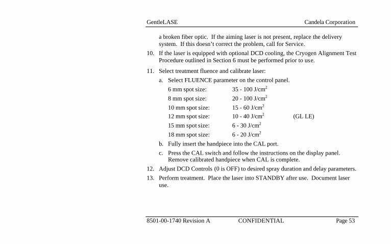
a broken fiber optic. If the aiming laser is not present, replace the delivery system. If this doesn’t correct the problem, call for Service.
10. If the laser is equipped with optional DCD cooling, the Cryogen Alignment Test Procedure outlined in Section 6 must be performed prior to use.
11. Select treatment fluence and calibrate laser: a. Select FLUENCE parameter on the control panel. 6 mm spot size: 35 - 100 J/cm2 8 mm spot size: 20 - 100 J/cm2 10 mm spot size: 15 - 60 J/cm2 12 mm spot size: 10 - 40 J/cm2 (GL LE) 15 mm spot size: 6 - 30 J/cm2 18 mm spot size: 6 - 20 J/cm2 b. Fully insert the handpiece into the CAL port. c. Press the CAL switch and follow the instructions on the display panel.
Remove calibrated handpiece when CAL is complete. 12. Adjust DCD Controls (0 is OFF) to desired spray duration and delay parameters. 13. Perform treatment. Place the laser into STANDBY after use. Document laser
use.
GentleLASE Candela Corporation
8501-00-1740 Revision A CONFIDENTIAL Page 54
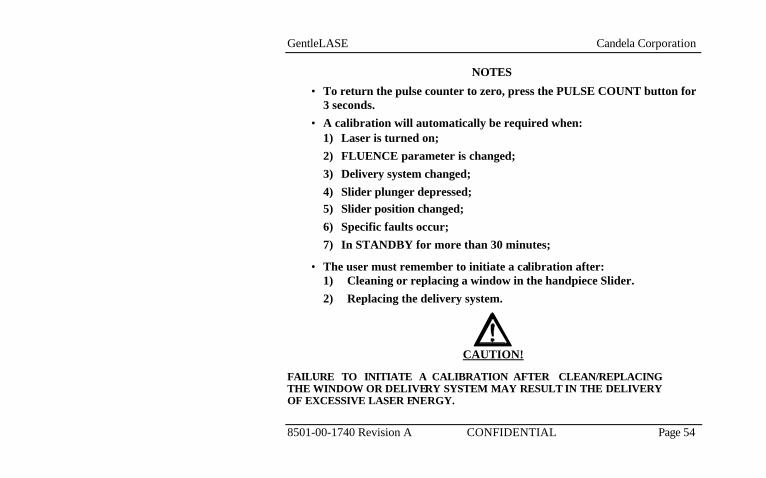
NOTES • To return the pulse counter to zero, press the PULSE COUNT button for
3 seconds. • A calibration will automatically be required when:
1) Laser is turned on; 2) FLUENCE parameter is changed; 3) Delivery system changed; 4) Slider plunger depressed; 5) Slider position changed; 6) Specific faults occur; 7) In STANDBY for more than 30 minutes;
• The user must remember to initiate a calibration after: 1) Cleaning or replacing a window in the handpiece Slider. 2) Replacing the delivery system.
CAUTION!
FAILURE TO INITIATE A CALIBRATION AFTER CLEAN/REPLACING THE WINDOW OR DELIVERY SYSTEM MAY RESULT IN THE DELIVERY OF EXCESSIVE LASER ENERGY.

GentleLASE Candela Corporation
8501-00-1740 Revision A CONFIDENTIAL Page 55
Calibration Procedure
Section 5

GentleLASE Candela Corporation
8501-00-1740 Revision A CONFIDENTIAL Page 56
CAUTION!
FAILURE TO PERFORM A CALIBRATION AFTER A HANDPIECE SLIDER WINDOW HAS BEEN CLEANED OR REPLACED, CAN RESULT IN DELIVERY OF FLUENCES GREATER THAN SPECIFIED ON THE CONTROL PANEL.
The GentleLASE requires that the laser be calibrated prior to each patient treatment. During calibration, the handpiece without the Distance Gauge is inserted into the Cal Port allowing an internal energy meter to measure the laser output energy delivered at the handpiece. The system adjusts itself until the desired output is obtained. Usually 3 - 15 laser pulses are required before calibration is complete.
• Inspect and verify that the handpiece Slider window is clean.
• Select the desired Delivery System. Make sure the Delivery System is properly connected and secured.
• Put on laser safety eyewear.
• Select the desired Fluence parameter values via the Display Panel.
• Remove the Distance Gauge from the handpiece.
CALIBRATEPROCEDURE

GentleLASE Candela Corporation
8501-00-1740 Revision A CONFIDENTIAL Page 57
• Fully insert the handpiece into the Cal Port.
• Press the CALIBRATE button on the Display Panel and follow the instructions provided in the calibration message window.
Pressing “X” allows the operator to return to the Main screen in Standby. The operator can then adjust the laser output parameters as needed before restarting the calibration procedure. After successful completion of the calibration procedure, remove the Delivery System from the Calport, install the Distance Gauge and begin treatments. During calibration the software performs a delivery system transmission check. If the delivery system transmission is below 75%, the software will display a message to clean the HP Slider window. The user can stop the calibration by pressing “YES” and clean the HP Slider window (see Section 6 for window cleaning procedure) or press “NO” to continue the calibration. The performance of the delivery system is improved by using a clean or new HP Slider window. Clean optics will increase the delivery systems life.
GentleLASE Candela Corporation
8501-00-1740 Revision A CONFIDENTIAL Page 58
NOTE
If the desired fluence cannot be reached, a FAULT will be displayed. If this occurs, decrease the fluence and perform another calibration. When this happens, the laser system is degraded and does not have sufficient energy to calibrate properly. A dirty window on the handpiece Slider may be the cause of the problem. Clean or change the window using the instructions in Section 6 (Maintenance and Troubleshooting section). If the problem cannot be corrected, the system may need a new delivery system or maintenance. Call Candela Service for more information.
If a higher fluence is desired immediately, change the delivery system to one with a smaller spot size.

GentleLASE Candela Corporation
8501-00-1740 Revision A CONFIDENTIAL Page 59
Section 6 Maintenance/ Troubleshooting

GentleLASE Candela Corporation
8501-00-1740 Revision A CONFIDENTIAL Page 60
CAUTION!
THE ELECTRICAL AND LASER RADIATION HAZARDS PRESENT WHILE SERVICING THE GENTLELASE CAN BE EXTREMELY DANGEROUS IF PROPER SAFETY PRECAUTIONS ARE NOT TAKEN.
THE GENTLELASE IS TO BE SERVICED ONLY BY QUALIFIED TECHNICIANS WHO HAVE RECEIVED APPROPRIATE TRAINING FROM CANDELA. ANY ATTEMP T BY AN UNAUTHORIZED PERSON TO PERFORM ANY SERVICE PROCEDURE MAY RESULT IN PERSONAL INJURY AND WILL VOID ANY WARRANTY ON THE LASER SYSTEM.
The GentleLASE laser delivery system utilizes fiber optics that can be damaged if subjected to excessive bending. To avoid damage to the optical fiber, limit bends to a radius of 6 inches (15 cm) or greater.
The delivery system should be checked before each procedure by observing aiming beam quality. The beam as viewed against a white sheet of paper should have a comfortable intensity, homogeneous distribution and a soft well defined circumference. If the aiming beam is non-existent discontinue immediately as the fiber may be broken. A dim aiming beam may also indicate a broken fiber or dirty or damaged windows. Clean or replace the distance gauge and slider windows before repeating this test. Use of a damaged fiber-optic delivery system is dangerous and must be avoided. If damage is suspected discontinue use immediately.
FIBER-OPTIC DELIVERY
SYSTEM

GentleLASE Candela Corporation
8501-00-1740 Revision A CONFIDENTIAL Page 61
Windows have been designed into the distance gauge and slider to protect the delivery system optics. Due to the nature of some procedures, the windows will require frequent cleaning and/or replacement to maintain proper system performance. Windows should be maintained in accordance with Candela procedure “8502-00-0847”. A copy of this procedure is included with GentleLASE. Assembly pictures and procedures specific to GentleLASE delivery systems are included in this section.
Caution: The coolant is heated to 65°C. Do not stick fingers into tank. Avoid splashing of heated coolant.
The system coolant is distilled water. The coolant level should be checked monthly if the system is used daily, and every 6-months if used weekly. The coolant tank is located within the box protruding from the rear of the laser. Turn the filler cap counter-clockwise to remove. Inspect level by looking into tank. Fill with distilled water if the level is below the base of the filler neck or if a system message indicates a fault code preceded by a “7”.
The exterior of the laser system should be cleaned weekly with a soft cloth slightly moistened with a solution of mild soap and water. Do not use harsh detergents. To disinfect the exterior of the laser system, use a soft cloth moistened with an alcohol solution. Ethyl or isopropyl alcohol with a strength of 70% - 90% makes a good general purpose disinfectant. To clean and disinfect the Delivery System handpiece: (figure 6.1) Immediately after each treatment session, wipe the exterior surface of the handpiece body with a gauze pad moistened with an alcohol solution (see last paragraph). Take
CLEANING AND DISINFECTING
Handpiece
WINDOWS
SYSTEM COOLANT

GentleLASE Candela Corporation
8501-00-1740 Revision A CONFIDENTIAL Page 62
care to avoid contaminating the internal optical surfaces of the handpiece. When cleaning the handpiece with an alcohol solution, dry the area thoroughly prior to beginning a laser procedure.
The distance gauge is the only part of the handpiece to contact the patient. Proper care of the handpiece distance gauge will result in improved laser performance. To Clean/Disinfect the Distance Gauge Assembly: (figure 6.1) • Clean by wiping with a gauze pad moistened with an alcohol solution and allow
to dry.
Distance Gauge
Figure 6.1Handpiece with Distance Gauge
Distance Gauge Handpiece Body
GentleLASE Candela Corporation
8501-00-1740 Revision A CONFIDENTIAL Page 63
CAUTION!
THE DISTANCE GAUGE O N THE END OF THE HANDPIECE MAY BECOME SOILED WITH NORMAL USAGE. TO ENSURE PROPER FLUENCE DELIVERY, IT IS IMPORTANT TO INSPECT AND CLEAN THE DISTANCE GAUGE WINDOW FREQUENTLY SO DEBRIS DOES NOT GET BURNED INTO THE WINDOW SURFACE. ALWAYS PUT THE LASER SYSTEM INTO “STANDB Y” OR “OFF”. WHEN A DELIVERY SYSTEM IS CHANGED OR A DISTANCE GAUGE WINDOW OR HANDPIECE SLIDER WINDOW IS CLEANED OR REPLACED. WHEN THE HANDPIECE SLIDER WINDOW OR THE DISTANCE GAUGE WINDOW BECOMES DIRTY OR BURNT, THE AMOUNT OF ENERGY DELIVERED TO THE PATIENT MAY BE REDUCED. AFTER REPLACING A DIRTY WINDOW OR BURNT DELIVERY SYSTEM, ALWAYS RECALIBRATE. AFTER REPLACING/CLEANING A DIRTY WINDOW, YOU MAY NEED TO REDUCE THE FLUENCE TO OBTAIN PRIOR RESPONSE.
Distance Gauge and HP Slider Window

GentleLASE Candela Corporation
8501-00-1740 Revision A CONFIDENTIAL Page 64
To clean or replace the Distance Gauge window: (figure 6.1) 1. Wear dustless gloves to prevent smudges or fingerprints on lens. 2. Put the laser in STANDBY and remove the distance gauge assembly from the
handpiece. 3. The Distance Gauge window is held in a groove in the rear (non stick side) end
of the assembly with an O-ring. A notched access in the groove allows easy removal of the O-ring and window.
4. With the assembly gauge stick pointing downwards, remove o-ring with tweezers, or poke a pointed object into the notch. Gently pull the O-ring toward the center of the window to free the O-ring from the groove.
5. Turn the assembly upside down, allowing the window to fall out onto a clean surface. (If needed, gently tap the side of the Distance Gauge with your finger).
6. (Used windows only) a. Clean the windows in an alcohol solution. Rinse thoroughly with clean
water, and dry with a lint free tissue. b. Re-inspect the window and if unacceptable, discard window and replace
with a new one. 7. Grasp the new or cleaned window by the edges and place it back into the
Distance Gauge assembly so it is resting flat on the ledge. 8. Reinsert the O-ring into the groove. Use the tip of the tweezers or a pointed
object to gently push the O-ring fully into the groove, being careful not to touch the window.
9. Perform a Calibration Procedure per section 5. Then slide the Distance Gauge

GentleLASE Candela Corporation
8501-00-1740 Revision A CONFIDENTIAL Page 65
back into the HP. To clean or replace the HP Slider window: (figure 6.2) 1. Wear dustless gloves to prevent smudges or fingerprints on lens. 2. Turn the laser OFF. Remove the Distance Gauge. Slide the HP Slider through
the front of the HP; exposing the slider window or remove the HP Slider entirely from the rear of the HP assembly. The window is held in a groove in the front end of the Handpiece Slider with an O-ring. A notched access in the groove allows easy removal of the O-ring and window.
3. With handpiece pointing upward, remove o-ring with tweezers, or poke a pointed object into the notch. Gently pull the O-ring toward the center of the window to free the O-ring from the groove. Then turn the handpiece slider upside down, allowing the window to fall out onto a clean surface. (If needed, gently tap the side of the handpiece slider with your finger).
4. (Used windows only) a. Clean the windows in an alcohol solution. Rinse thoroughly with clean
water, and dry with a lint free tissue. b. Re-inspect the window and if unacceptable, discard window and replace
with a new one. 5. Grasp the new or cleaned window by the edges and place it back into the
handpiece slider so it is resting flat on the ledge. 6. Reinsert the O-ring into the groove. Use the tip of the tweezers or a pointed
object to gently push the O-ring fully into the groove, being careful not to touch the window.
7. Slide the HP Slider back into the HP. Select a spot size. Then perform a
GentleLASE Candela Corporation
8501-00-1740 Revision A CONFIDENTIAL Page 66
Calibration Procedure per section 5.

GentleLASE Candela Corporation
8501-00-1740 Revision A CONFIDENTIAL Page 67
Figure 6.2Handpiece
Slider Close-up
O-ring Window Groove HP Slider

GentleLASE Candela Corporation
8501-00-1740 Revision A CONFIDENTIAL Page 68
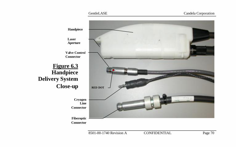
The handpiece delivery system should be replaced with the system turned off. Refer to figures 6.3 and 6.4 for installation and removal of the handpiece delivery system. When not in use, the delivery systems should be stored in the supplied plastic case with the plastic caps over the ends of the fiber. Removing the Delivery System: 1. Remove the Valve Control by grasping the connector near the red dot and
pulling straight back.
2. Remove the Cryogen Line, using two hands, by pushing the knurled Cryogen Line Receptacle toward the laser and pulling the Cryogen Line Connector away from the laser.
3. Remove the Fiber-optic by gently pulling the connector straight out of the receptacle.
4. Place delivery system into supplied storage case with plastic end caps on the fiber for protection. The case is designed to store two delivery systems.
HANDPIECEDELIVERY
SYSTEMREPLACEMENT

GentleLASE Candela Corporation
8501-00-1740 Revision A CONFIDENTIAL Page 69
Connecting the Handpiece Delivery System: 1. To install the Fiber-optic:
a. Carefully insert the Fiber-optic Connector into the Fiber-optic Receptacle until it clicks in or stops.
CAUTION!
IF THE FIBER IS NOT SEATED PROPERLY, DAMAGE TO THE FIBER COULD OCCUR. 2. Connect the Cryogen Line, using two hands, by pushing the knurled Cryogen
Line Receptacle and the Cryogen Line Connector toward the laser until it stops. Release the knurled connector.
3. Connect the Valve Control by aligning the RED DOT on the Valve Control Receptacle with the RED DOT on the Valve Control Connector and pushing in the connector until it stops.
GentleLASE Candela Corporation
8501-00-1740 Revision A CONFIDENTIAL Page 70
Figure 6.3Handpiece
Delivery System Close-up
Valve Control Connector
Handpiece
Fiberoptic Connector
Cryogen Line
Connector
RED DOT
Laser Aperture
GentleLASE Candela Corporation
8501-00-1740 Revision A CONFIDENTIAL Page 71
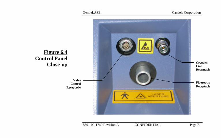
Figure 6.4Control Panel
Close-up
Fiberoptic Receptacle
Cryogen Line Receptacle
Valve Control
Receptacle

GentleLASE Candela Corporation
8501-00-1740 Revision A CONFIDENTIAL Page 72
CAUTION!
THE CONTENTS OF THE CRYOGEN CANISTER ARE UNDER PRESSURE. READ THE MATERIAL SAFETY DATA SHEET (MSDS) AND THE LABEL ON THE CANISTER BEFO RE HANDLING.
Follow the instructions shipped with each replacement canister.
Additionally, once the canister is installed, the canister count must be reset. If the newly installed canister is at room temperature or cooler, a 20 - 25 minute WARMUP period will be needed prior to use. The WARMUP screen will appear once the laser is switched to the READY state if additional warming is required.
The disposal of the canister can be achieved by contacting a waste disposal company or completely emptying, via the instructions with each canister, and disposing in the trash.
If a major cryogen leak occurs, disconnect the delivery system from the laser or remove the canister from the laser. Ventilate the room thoroughly and call Service to correct the problem.
For additional information, refer to the MSDS sheets supplied with each cryogen canister.
CRYOGEN CANISTER
REPLACEMENT
DISPOSAL
MAJOR CRYOGEN
LEAK

GentleLASE Candela Corporation
8501-00-1740 Revision A CONFIDENTIAL Page 73
The GentleLASE system incorporates a cryogen sensor as a backup safety feature that is used to verify that the cryogen is delivered during each pulse of the laser system, when the DCD Option is installed. The operation of this sensor should be checked anytime there is a question that the cryogen is working properly, the handpiece has been dropped, or every 6 months as follows: • Place the delivery system on a flat surface aimed away from any individuals. • Put on laser safety eyewear. • Place the system in the READY state. • Disconnect the Cryogen Input Connector (See Figure 6.3) and press the
connector against a flat surface, spraying the cryogen until the Purge fault appears. If the fault does not appear, call Service.
• Connect the Cryogen Input Connector.
Using the 12/15/18 mm Slider, 6/8/10 mm slider or 12 mm delivery system for GL LE set slider for 12 mm (or 10 mm for the 6/8/10) spot size and 20 J/cm2, aim handpiece at a glossy dark (non-white) surface. Set the DCD Pre Spray duration to 20 ms. Put on laser safety eyewear. Enter the Ready state. This will turn on the aiming laser beam. Take note of aiming laser position on the dark surface. Press the Purge button (bottom left button, also indicates spotsize) and insure that the cryogen spray completely fills the area that the aiming laser occupies. Repair or replace the delivery system if the cryogen spot and aiming laser are not in alignment.
CRYOGEN SENSOR TEST PROCEDURE
CRYOGEN ALIGNMENT
TEST PROCEDURE
CRYOGEN ALIGNMENT
TEST PROCEDURE

GentleLASE Candela Corporation
8501-00-1740 Revision A CONFIDENTIAL Page 74
The GentleLASE system incorporates a routine to calibrate the touchscreen of the laser. This touchscreen calibration should only be performed when the touchscreen is not responding correctly . The routine can be entered from the diagnostic menu of the laser by pressing the
touchscreen calibration button. . NOTE: To access the diagnostic menu:
Press and hold the next button for 3 seconds. When the touchscreen calibration is initiated the screen is cleared and the following appears:
1) Using a cotton swab or small blunt tipped instrument press the center of the flashing box until it disappears.
P 1
C e n t e r o f S c r e e n
TOUCHSCREEN CALIBRATION
PROCEDURE

GentleLASE Candela Corporation
8501-00-1740 Revision A CONFIDENTIAL Page 75
2) A similar box will appear in the opposite corner of the screen. Repeat step 1. 3) Two smaller boxes will appear when steps 1&2 have been completed. Press
both of these buttons until they disappear. 4) “TOUCHSCREEN Calibration Successful” will appear if the calibration is
complete. If the calibration is unsuccessful, the system will return to step 1. This process will repeat 2 times.
5) If the calibration is not successful, software will use default parameters that will
still allow use of your laser.
GentleLASE Candela Corporation
8501-00-1740 Revision A CONFIDENTIAL Page 76
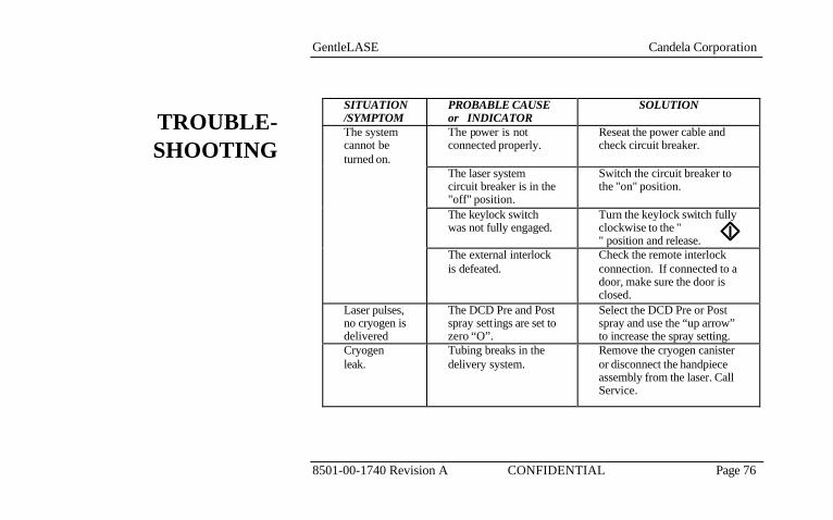
SITUATION/SYMPTOM
PROBABLE CAUSE or INDICATOR
SOLUTION
The system cannot be turned on.
The power is not connected properly.
Reseat the power cable and check circuit breaker.
The laser system circuit breaker is in the "off" position.
Switch the circuit breaker to the "on" position.
The keylock switch was not fully engaged.
Turn the keylock switch fully clockwise to the " " position and release.
The external interlock is defeated.
Check the remote interlock connection. If connected to a door, make sure the door is closed.
Laser pulses, no cryogen is delivered
The DCD Pre and Post spray settings are set to zero “O”.
Select the DCD Pre or Post spray and use the “up arrow” to increase the spray setting.
Cryogen leak.
Tubing breaks in the delivery system.
Remove the cryogen canister or disconnect the handpiece assembly from the laser. Call Service.
TROUBLE-SHOOTING

GentleLASE Candela Corporation
8501-00-1740 Revision A CONFIDENTIAL Page 77
SITUATION/SYMPTOM
PROBABLE CAUSE or INDICATOR
SOLUTION
Warm-up time has exceeded 60 minutes.
The water temperature control circuitry failed.
Call Service.
Ineffective fluence response.
System or Fiber is degraded.
Perform a calibration procedure per Section 5. Call Service if problem persists.
Replace Canister Message Appears
There is insufficient cryogen in the canister.
Replace the cryogen canister with a new canister supplied by Candela; Depress the Canister Count switch for 3 seconds to reset the canister count.
Purge Required
Bubbles have been detected in the cryogen line.
Press the purge switch until problem resolves. This must be done with the handpiece outside of the calibration port. If problem persists, call Service
Laser will not enter the READY state
Triggerswitch is depressed.
De-activate Triggerswitch
TROUBLE-SHOOTING

GentleLASE Candela Corporation
8501-00-1740 Revision A CONFIDENTIAL Page 78
SITUATION/SYMPTOM
PROBABLE CAUSE or INDICATOR
SOLUTION
Aiming beam missing in the READY state
• Damaged or broken fiber
• Bad aiming laser or driver circuit
• Replace delivery system Otherwise call for service.
Aiming beam appears dim
• Intensity set too low
• Dirty distance gauge and/or slider windows
• Dirty or damaged slider optics
• Failing aiming laser
• Set aiming beam intensity using button provided on “NEXT” screen
• Clean or replace windows Otherwise call for service.
Aiming beam appears non-uniform
• Dirty distance gauge and/or slider windows
• Dirty or damaged slider optics
• Clean or replace windows • Replace delivery system
TROUBLE-SHOOTING

GentleLASE Candela Corporation
8501-00-1740 Revision A CONFIDENTIAL Page 79
A fault message typically occurs due to a system malfunction. Sometimes clearing the fault and retrying the previous operation can be successfully accomplished without further faults occurring. If the fault message persists, call Candela Service and report the Fault Number. Fault processing automatically places the system into the Standby state.
FAULT DESCRIPTION ACTION Fault 1.1 HP Bubble Sensor Malfunction Change Delivery System. If problem
persists, call Service. Fault 1.2 Canister Bubble Sensor
Malfunction Call Service.
Fault 2 ROM Checksum Failure Call Service Fault 3 Shutter Malfunction Call Service. Fault 4 Not Used Not Used Fault 5.1 Fault 5.2
HVPS Tolerance Faults Reset fault and continue. If problem persists, call Service.
Fault 6.1 Fault 6.2 Fault 6.3 Fault 6.4
Calibration Faults Reset fault and continue. If problem persists, call Service.
FAULT / WARNING MESSAGES
FaultMessages

GentleLASE Candela Corporation
8501-00-1740 Revision A CONFIDENTIAL Page 80
Fault 7.1 Fault 7.2 Fault 7.3 Fault 7.4
Coolant Temperature and Pressure Faults
Clear fault and allow the system to continue. The system may reenter WARM UP prior to continuing. Check water level; if low add water. If problem persists, call Candela Service.
FAULT DESCRIPTION ACTION Fault 8.1 Fault 8.2
DCD Pressure Faults Fault 8.1 may indicate a room which is too cool, a displaced canister cover, empty cryogen canister or the result of a newly installed (cold) canister. Clear fault and allow system to complete its warm-up cycle. Fault 8.2 may indicate a room that is too warm, in which case the laser must be moved to a cooler room. If problems persist, call Candela service.
Fault 9 Warm-up Timeout Attempt to clear fault to reenter WARM UP, or cycle power to the system. If fault cannot be cleared, call Candela service.
Fault 10.1 Fault 10.4 Fault 10.5
Delivery system faults Attempt to clear fault. Change spot size (in Standby) or swap delivery system for a different HP Slider. If problem persists call Candela Service.
Fault 11 Not Used Not Used
FaultMessages

GentleLASE Candela Corporation
8501-00-1740 Revision A CONFIDENTIAL Page 81
Fault 12.1 Fault 12.2 Fault 12.3
Energy Out of Range Recalibrate the system. If fault persists, call Service
FAULT DESCRIPTION ACTION Fault 13 Trigger Switch Malfunction When pulsing the laser, firmly press
on the footswitch or fingerswitch until the laser pulses. If problem persists, call Service.
Fault 14 Not Used Not Used
Fault 15.1 Fault 15.2
Transmission Fault Replace delivery system. Check HP Slider window. If problem persists, call Service.
Replace Can Canister pulse count reaches
zero “0”, or when air detected at the canister.
Replace DCD canister & reset canister counter when ever this message appears.
Purge Air was detected in the cryogen lines.
With handpiece removed from the calibration port, depress the purge button until the message clears.
Exit to Clean Window
Delivery System Transmission is low.
Examine HP Slider window. If necessary, clean or replace window.
Candela will make available on request circuit diagrams, component part lists, descriptions, calibration instructions, or other necessary information which will assist the customer’s appropriately qualified technical personnel to repair those parts of equipment which are designated by Candela as repairable.
WarningMessages for
DCD Equipped Systems
FaultMessages
GentleLASE Candela Corporation
8501-00-1740 Revision A CONFIDENTIAL Page 82
GentleLASE Candela Corporation
8501-00-1740 Revision A CONFIDENTIAL Page 83
LabelingSymbols
Section 7

GentleLASE Candela Corporation
8501-00-1740 Revision A CONFIDENTIAL Page 84
The GentleLASE has been labeled in accordance with domestic and international agency standards. All laser operators should be familiar with the location and meaning of the labels.
The symbol
2 1 5 7 - 4 0 - 7 0 0 0 R E V
[ ] on the rear panel of the laser is placed there to draw the attention of the operator to the manual for further information concerning the on/off mains switch. The mains switch should be placed in the “0” position when the system is not being used. When the system is to be used, the mains switch must be moved to the “1” position.
See the following figures for label locations:
Label 1 Indicates to the user that precautions for handling “Electrostatic Sensitive” device are applicable for the nearby delivery system connector. This label is required by agencies to indicate static sensitive connections, where electrostatic discharge could potentially damage components of a labeled connection. The user should take anti-static precautions prior to accessing this connection. Such precautions include simply discharging one’s body to a known grounded point prior to making a connection to the delivery system connector. A good grounding point is the fiber receptacle. The label is located near the delivery system connections.
Label 2 Multi-combined label. Label is located near the delivery system connections.
LABELS

GentleLASE Candela Corporation
8501-00-1740 Revision A CONFIDENTIAL Page 85
A. The “Man” indicates that the delivery system is equipped with a “Type B” applied part.
B. Indicates the emission of laser energy from this device.
C. Indicates this is the laser aperture.
Label 3 The Emergency Laser Stop Red Push Button will turn off the laser quickly. Located on front display bezel.
Label 4 This label indicates that the protective panel encloses Class 4 laser light. Label located on rear side of top cover.
Label 5 Multi-combined label. Label is located on rear panel above AC input receptacle.
A. Indicates that accompanying documents contain electrical connection information. That information will be found in the Electrical Requirements section of this manual. Label is located on rear panel above AC input receptacle.
B. Indicates Footswitch control hose connection.
C. Indicates the location of the remote interlock circuit that can be connected to a door switch to shutdown the laser should a person enter the room during laser emission. The symbol illustrates that an OPEN connection at this point will inhibit the lasing function.
Label 6 Risk of electrical shock if serviced by unauthorized persons. There are

GentleLASE Candela Corporation
8501-00-1740 Revision A CONFIDENTIAL Page 86
lethal voltages inside the system enclosure. Label is located on rear panel.
Label 7 Indicates a hot surface when unit is powered. The hot surface warning applies strictly to the water in the water reservoir; which is only accessible when the water reservoir cap is removed. Label is located on top surface of the reservoir cover.
Label 8 Indicates that the reservoir is filled with water. The reservoir should be kept full to the base of the filler neck with distilled water. The label is located on top surface of the reservoir cover.
Label 9 Laser Identification label. This label is marked with the VA rating for the system, as well as the model number, serial number and date and place of manufacture. This label is located on the rear panel.
Label 10 Multi-combined label. Located on lower rear panel.
A. Indicates laser emission characteristics and classification per the IEC/EN standards.
B. Indicates that this device emits laser energy.
C. CE mark with registration number of Candela’s ISO Registrar. When present, this marking indicates compliance with the European Medical Device Directive. Refer to the Declaration contained inside the accessory kit for details of compliance.
D. Indicates compliance with a branch of the US FDA which regulates laser equipment. GentleLASE has one labeling deviation pursuant to Laser

GentleLASE Candela Corporation
8501-00-1740 Revision A CONFIDENTIAL Page 87
Notice No. 50, dated July 26, 2001, where the “Danger” label required by 21 CFR 1040.10 (g) was replaced with a label bearing the same technical content defined under IEC/EN 60825-1.
E. Indicates U.S. patents that may be covered on this laser system.
Label 11 If present, indicates that the laser is approved to UL or ETL standards.
Label 12 Indicates that the laser can be a mechanical tilt hazard; if the laser were not kept upright.
Label 13 (DCD option only) Indicates a hot surface when unit is powered. The hot surface warning applies strictly to the heater band, which is only accessible when the cryogen tank is removed. Accidental contact with the heater band will not cause a burn, but may cause an involuntary knee-jerk reaction resulting in an injury. Label is located on top cover near DCD opening.
Label 14 International symbol indicating that laser light will be exiting from the distal end of this cable. This label is wrapped around fiberoptic cable near system connections.
Label 15 Handpiece delivery system identification information. Wrapped around electrical cable near system connections.
Label 16 Safety ground symbol. This symbol located on the power cord entry box tab indicates the location of the primary system safety ground. The screw adjacent to this symbol should never be tampered with or removed.
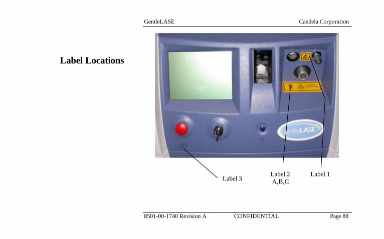
GentleLASE Candela Corporation
8501-00-1740 Revision A CONFIDENTIAL Page 88
Label Locations
Label 1
Label 2 A,B,C Label 3
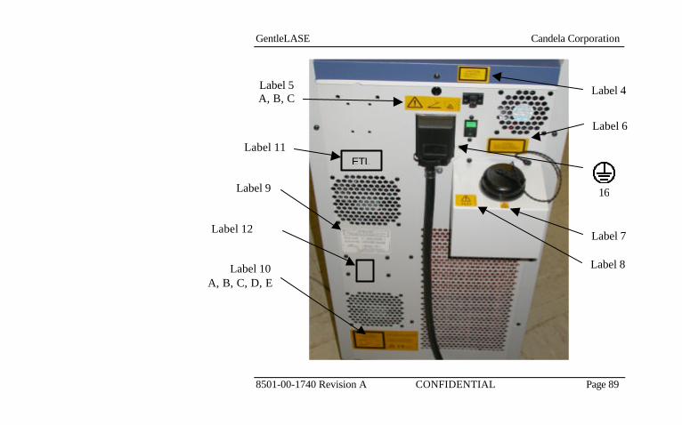
GentleLASE Candela Corporation
8501-00-1740 Revision A CONFIDENTIAL Page 89
Label 4
Label 6
Label 12 Label 7
Label 8
Label 5A, B, C
Label 11
Label 10 A, B, C, D, E
Label 9 16
ETL
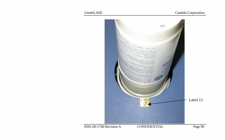
GentleLASE Candela Corporation
8501-00-1740 Revision A CONFIDENTIAL Page 90
Label 13

GentleLASE Candela Corporation
8501-00-1740 Revision A CONFIDENTIAL Page 91
Label Locations
Label 15 Label 14

GentleLASE Candela Corporation
8501-00-1740 Revision A CONFIDENTIAL Page 92
1
2-A,B,C
Label Identification
L A S E R
A P E R T U R E 2 1 5 7 - 4 0 - 8 0 6 1
R E V [ ]
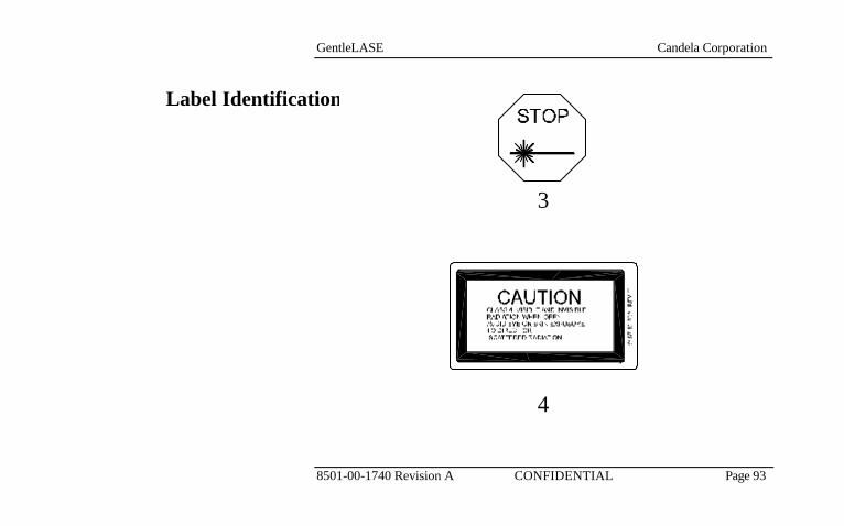
GentleLASE Candela Corporation
8501-00-1740 Revision A CONFIDENTIAL Page 93
3
4
Label Identification
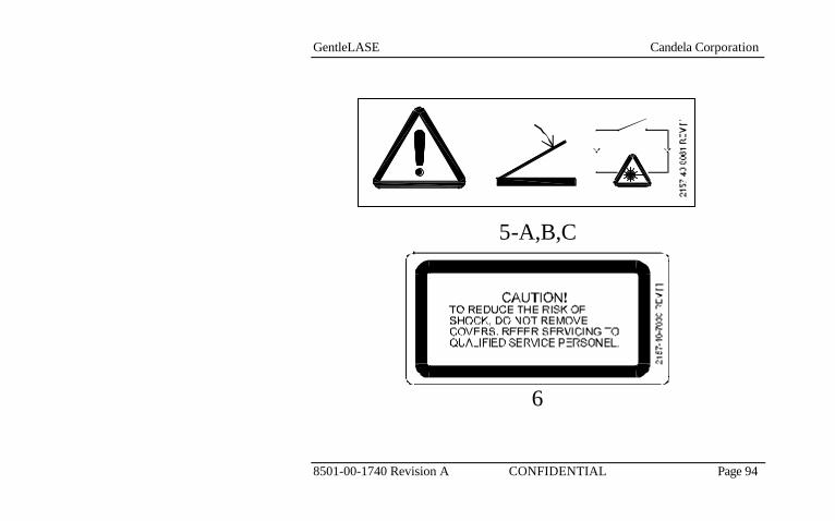
GentleLASE Candela Corporation
8501-00-1740 Revision A CONFIDENTIAL Page 94
5-A,B,C
6
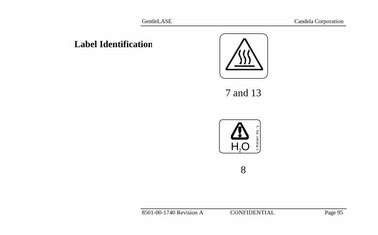
GentleLASE Candela Corporation
8501-00-1740 Revision A CONFIDENTIAL Page 95
7 and 13
8
Label Identification
H O2
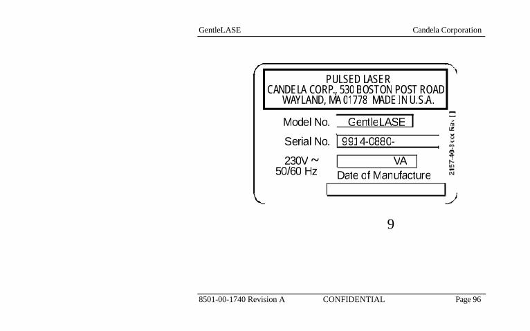
GentleLASE Candela Corporation
8501-00-1740 Revision A CONFIDENTIAL Page 96
9
V A
P U L S E D L A S E R
C A N D E L A C O R P . ,
5 3 0 B O S T O N
P O S T
R O A D
W A Y L A N D , M A 0 1 7 7 8
M A D E
I N U . S . A .
D a t e o f M a n u f a c t u r e
M o d e l N o .
S e r i a l N o .
2 3 0 V 5 0 / 6 0
H z
G e n t l e L A S E 9 9 1 4 - 0 8 8 0 -
~

GentleLASE Candela Corporation
8501-00-1740 Revision A CONFIDENTIAL Page 97
0123
10-A,B,C,D,E
Label Identification

GentleLASE Candela Corporation
8501-00-1740 Revision A CONFIDENTIAL Page 98
ETL LISTEDMEDICAL ELECTRICAL
EQUIPMENTPART 1; GENERALREQUIREMENTS
FOR SAFETY
CONFORMS TO UL STD 2601-1
IL ET DS
R
US
XXXXXXX
14 11
12
Label IdentificationLabel IdentificationLabel Identification

GentleLASE Candela Corporation
8501-00-1740 Revision A CONFIDENTIAL Page 99
15
16
Label Identification

GentleLASE Candela Corporation
8501-00-1740 Revision A CONFIDENTIAL Page 100
The mains power switch is Located on rear of the system and is marked with "¦ " and " O ". The "¦ " indicates the switch position in which the system is connected to the mains. The " O " indicates the switch position in which the system is disconnected from the mains.
The on the ID label indicates that the system operates on alternating current.
The keylock switch symbol means “off” only for a part of equipment. When the keylock switch is in this position, all circuits have been de-energized with the exception of the keylock switch circuit itself.
The keylock switch symbol means “on” only for a part of equipment. When the keylock switch is in this position, all circuits are energized and the device will be fully functional.
Mains Power Symbols
Keylock Switch Symbols

GentleLASE Candela Corporation
8501-00-1740 Revision A CONFIDENTIAL Page 101
The keylock switch symbol means “start”. This is a spring-loaded keylock switch position. It is used to initiate the system operation. This position does not initiate the release of laser energy.

GentleLASE Candela Corporation
8501-00-1740 Revision A CONFIDENTIAL Page 102

GentleLASE Candela Corporation
8501-00-1740 Revision A CONFIDENTIAL Page 103
Accessory List
Section 8

GentleLASE Candela Corporation
8501-00-1740 Revision A CONFIDENTIAL Page 104
Description Quantity
GentleLASE Laser System 1 Footswitch (15 foot) 1 Accessory Kit (includes) 1
• 6/8/10 mm Delivery System w/o DCD 1 • 12/15/18 mm Del System w/o DCD 1 • 12 mm (GL LE only) Del Sys w/o DCD 1 • Operator’s Manual 1 • Distance Gauge Kit (Qty 2) 1 • Replacement Window Kit (Qty 5) 1 • Delivery System Storage Case 1 • Physician Spectacle 1 • Physician Goggles 1 • Patient Goggle 1 • Key Ring w/Candela Tag 2 • Canister Empty Valve 1 • Laser Warning Sign 1 • Service Information Label 1 • CE Declaration of Conformity 1 • EC Certificate 1
Marketing Kit 1

GentleLASE Candela Corporation
8501-00-1740 Revision A CONFIDENTIAL Page 105
Options: DCD Option (includes)
• DCD Unit 1 • 6/8/10 mm DCD Delivery System 1 • 12/15/18 mm DCD Delivery System 1 • 12 mm (GL LE only) Del System 1 • Cryogen Canister 2
DCD Canister Warmer 1
GentleLASE Candela Corporation
8501-00-1740 Revision A CONFIDENTIAL Page 106
GentleLASE Candela Corporation
8501-00-1740 Revision A CONFIDENTIAL Page 107
Service Internal
Calibration Procedure
Section 9

GentleLASE Candela Corporation
8501-00-1740 Revision A CONFIDENTIAL Page 108
Note The procedures contained in this section are service procedures, to be performed by appropriately trained technicians. They are not to be performed by the user.
CAUTION!
THE ELECTRICAL AND LASER RADIATION HAZARDS PRESENT DURING SERVICING OF THE GENTLELASE CAN BE EXTREMELY DANGEROUS IF PROPER SAFETY PRECAUTIONS ARE NOT TAKEN. THE GENTLELASE IS TO BE SERVICED ONLY BY QUALIFIED TEC HNICIANS WHO HAVE RECEIVED APPROPRIATE TRAINING FROM CANDELA. ANY ATTEMPT BY AN UNAUTHORIZED PERSON TO PERFORM ANY SERVICE PROCEDURE WILL VOID ANY WARRANTY ON THE LASER SYSTEM.
The measurement circuits should be calibrated annually to insure accurate delivery of treatment energy. Measurement circuit calibration should be performed by a qualified Candela Service person as part of a “preventative maintenance” visit. During the visit, other subsystems of the laser system will be inspected, adjusted (if necessary) and/or repaired as required. Contact Candela Customer Service for details on “preventative maintenance” or a service contract (if available).
CALIBRATION SCHEDULE

GentleLASE Candela Corporation
8501-00-1740 Revision A CONFIDENTIAL Page 109
The Calibration procedure is provided for the user to calibrate the energy output of the laser system. During that procedure, the handpiece is inserted in the calibration port, the laser is pulsed, and the energy output of the handpiece is read by an internal laser energy meter. The system determines the high voltage level necessary to select each attainable energy density setting. The internal laser energy meter itself must be calibrated at least once a year by a qualified service technician. This calibration requires using an external laser energy meter whose calibration is traceable to the appropriate national standards agency. The external laser energy meter used must be appropriate for the specified output of the laser system, with an accuracy of ± 6% or better, and a resolution of 10mJ. This procedure is part of the normal preventive maintenance service procedure. 1. Energy meter (OPHIR with L40(150)A head) 2. Potentiometer adjustment tool. 3. Oscilloscope
Note Make sure all personnel in the area are wearing safety eyewear appropriate for the GentleLASE. The meter head must be 6” from the handpiece to prevent damage to the meter head.
PARTS LIST
PROCEDURE
PREFACE
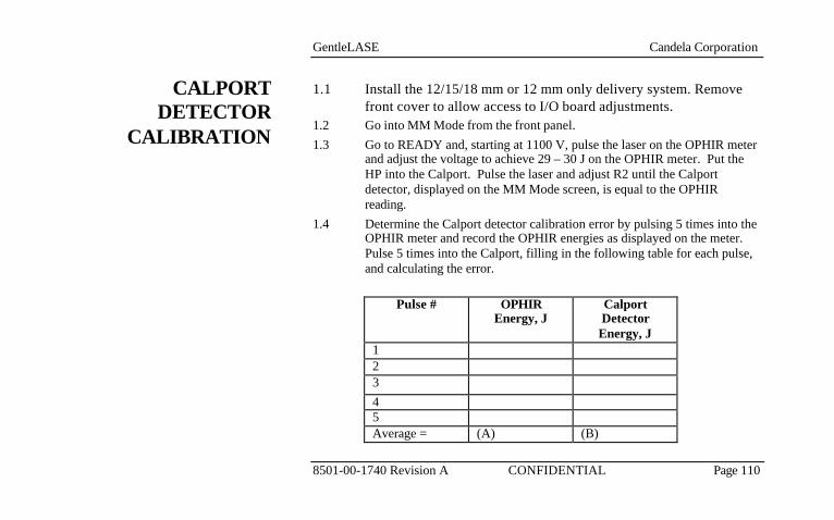
GentleLASE Candela Corporation
8501-00-1740 Revision A CONFIDENTIAL Page 110
1.1 Install the 12/15/18 mm or 12 mm only delivery system. Remove front cover to allow access to I/O board adjustments.
1.2 Go into MM Mode from the front panel. 1.3 Go to READY and, starting at 1100 V, pulse the laser on the OPHIR meter
and adjust the voltage to achieve 29 – 30 J on the OPHIR meter. Put the HP into the Calport. Pulse the laser and adjust R2 until the Calport detector, displayed on the MM Mode screen, is equal to the OPHIR reading.
1.4 Determine the Calport detector calibration error by pulsing 5 times into the OPHIR meter and record the OPHIR energies as displayed on the meter. Pulse 5 times into the Calport, filling in the following table for each pulse, and calculating the error.
Pulse # OPHIR
Energy, J Calport Detector Energy, J
1 2 3 4 5 Average = (A) (B)
CALPORT DETECTOR
CALIBRATION

GentleLASE Candela Corporation
8501-00-1740 Revision A CONFIDENTIAL Page 111
% error = (B/A - 1) x 100 = __________________% The error must be ± 2% or less. If not, repeat Steps 1.3 and 1.4. Completed________________ Install front panel.

GentleLASE Candela Corporation
8501-00-1740 Revision A CONFIDENTIAL Page 112