ATC-725 - Frank's Hospital Workshop
170
ATC 725 X-Ray Generator Installation, Operation & Service Manual P/N 8000-ATC-725 Revision: D, October 24, 2005 ATC-725
-
Upload
khangminh22 -
Category
Documents
-
view
1 -
download
0
Transcript of ATC-725 - Frank's Hospital Workshop
ATC 725 X-Ray Generator
Installation, Operation & Service Manual
P/N 8000-ATC-725
Revision: D, October 24, 2005
AT
C-725
Copyright 2005, Del Medical Systems. All rights reserved.
This document is the property of Del Medical Systems and contains confidential and proprietary information owned by Del Medical Systems. Any unauthorized copying, use or disclosure of it
without the prior written permission of Del Medical Systemsis strictly prohibited.
Attention: Consult Accompanying Documents - As Applicable
Del Medical Systems Group50B North Gary Avenue Phone:1-847-288-7000Roselle, IL 60172 Fax:1-847-288-7011USA Toll Free:1-800-800-6006 www.delmedical.com
GENDEX-DEL MEDICAL IMAGING ATC-725
ATC-725Page i
DAMAGE IN TRANSPORTATION
All packages should be closely examined at time of delivery. If damage is apparent, have notation of “Bad Order” placed by the delivery driver on all copies of the freight or express bill. If damage is of a concealed nature, notify the transportation agent as soon as possible to make an “Inspection report of damage” but in any event not later than 15 days after delivery. A transportation company usually will not pay a claim for concealed damage if an inspection is not requested within this 15 day period. The Company’s responsibility ceases when the transportation company accepts the shipment in good order, and the company assumes no liability for loss or damage after delivery to the carrier.
Telephone numbers
CUSTOMER SERVICE (847) 288-7000
TECHNICAL SUPPORT (847) 288-7032
FAX (847) 288-7011
Send all orders and correspondence to
GENDEX-DEL IMAGING CORP.
50B NORTH GARY AVENUE
ROSELLE, IL 60172
Copyright GENDEX-DEL IMAGING CORP. 1996
All Rights Reserved


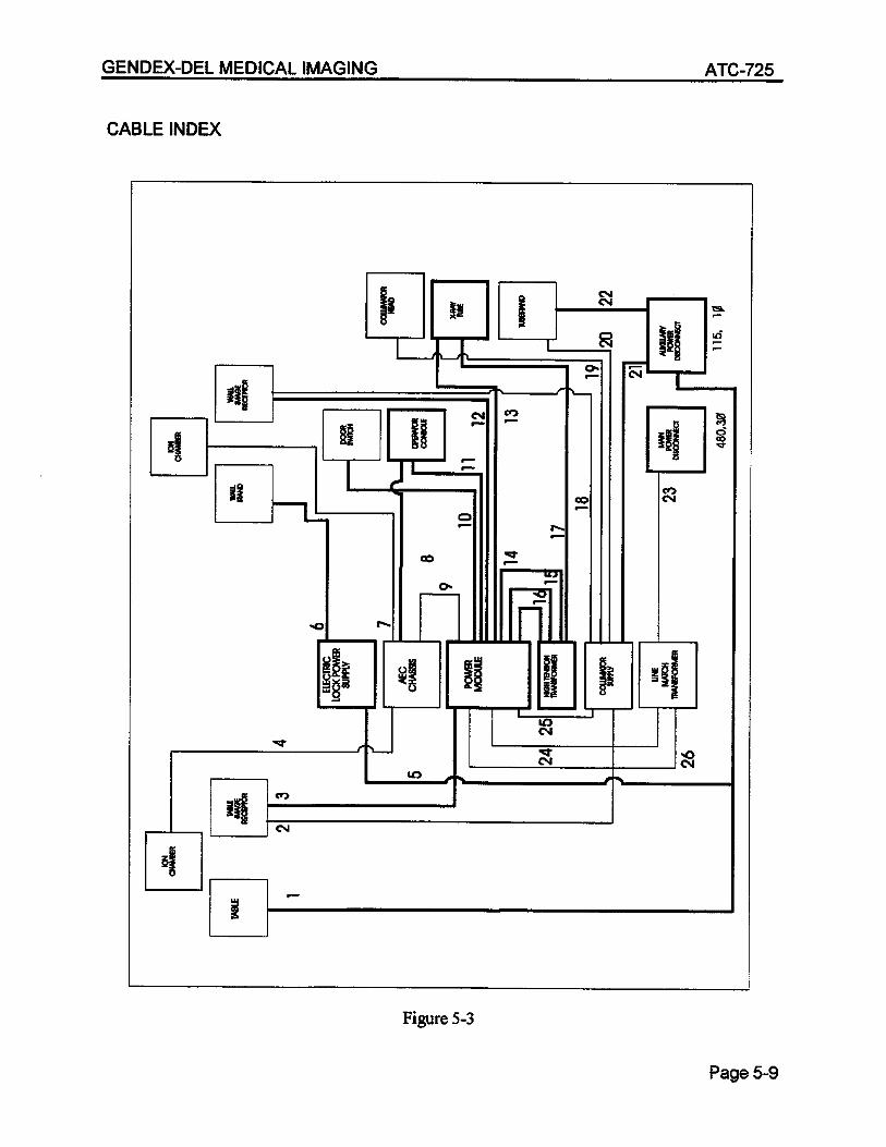


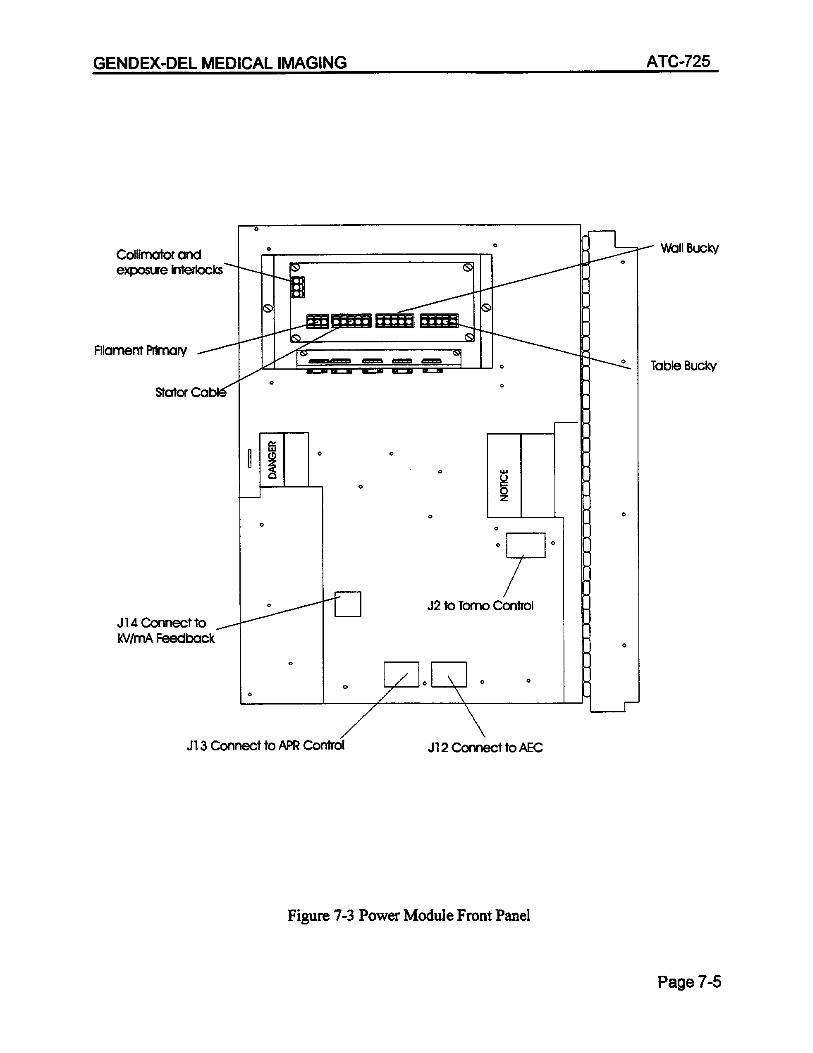
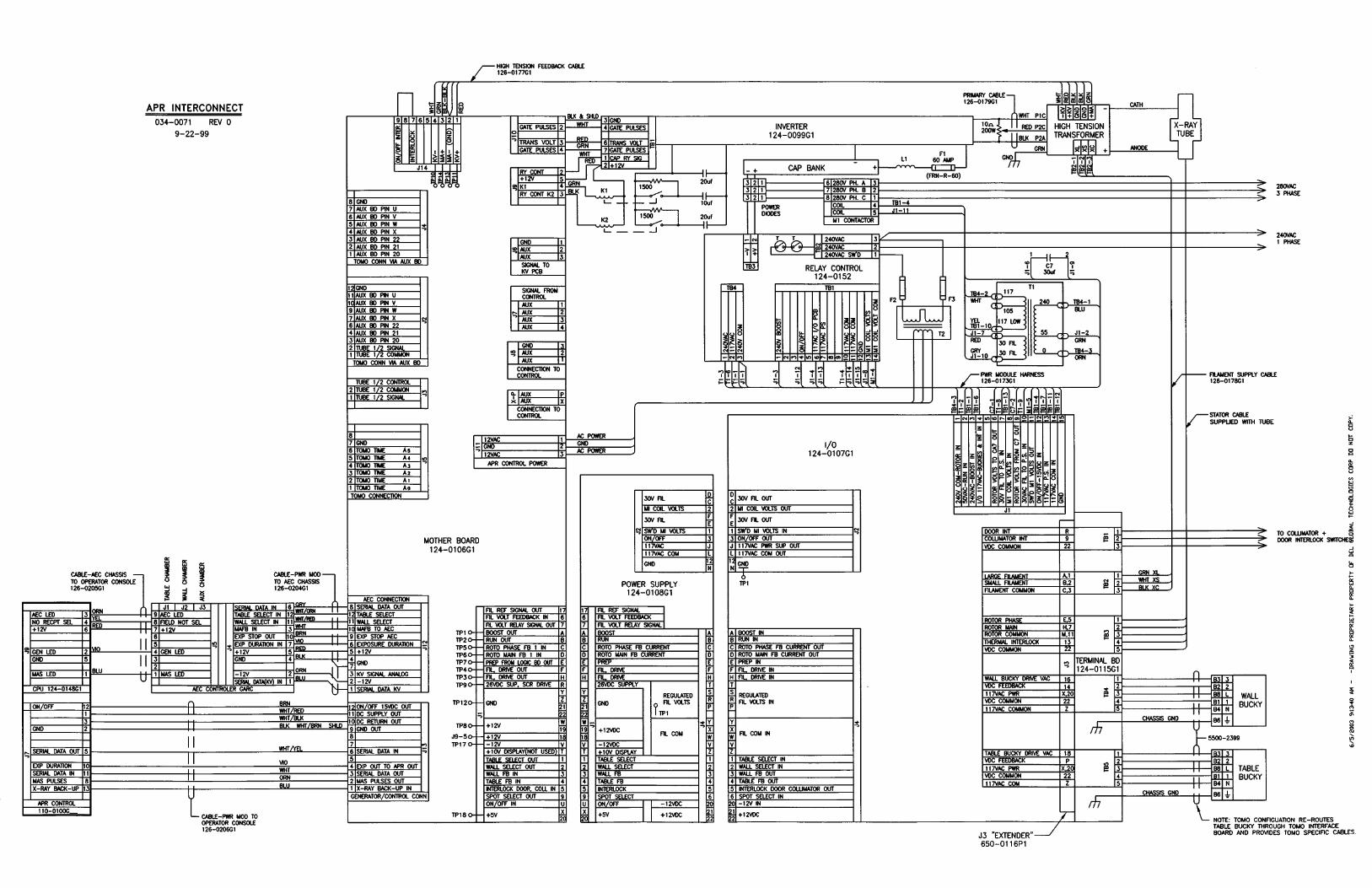
DEL MEDICAL IMAGING ATC-725 GENERATOR INTERCONNECTIONS Power Module Exposure Interlocks Each interlock switch must be an isolated set of contacts which closes in the exposure “Go” condition. TB1 - 1 to Door Interlock TB1 - 2 to Collimator Interlock TB1 - 3 to Common If no door or collimator interlocks are present, wire jumpers must be added to TB1 to allow an exposure. Plug Connections to Power Module J13-Connects to operator console CPU at J7
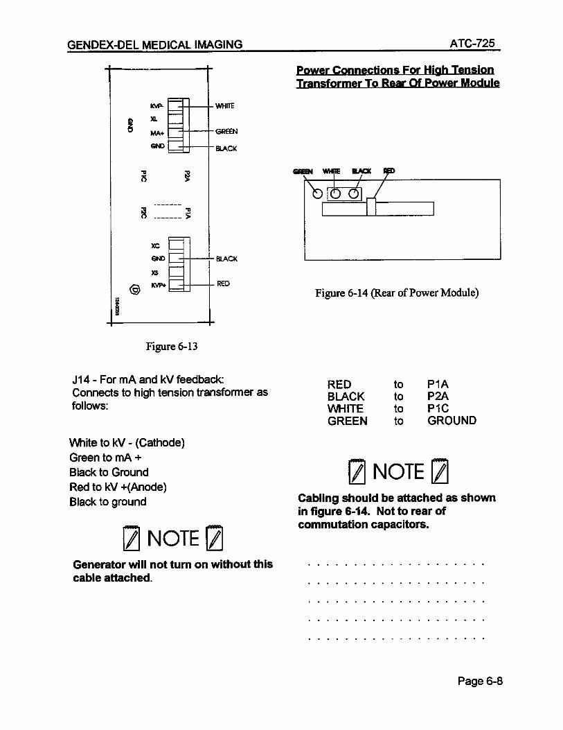
Filament Connections to High Tension Transformer (Cable #126-0178G1) (Large Filament) (Green Wire) to TB2-1 (Small Filament) (White Wire) to TB6-1 (Filament Common) (Black Wire) to TB2-3
TB6-1
TB2-1
TB2-3
Filament Connections
Page 6-7


60A+
-
~ 396 VDC
3500uF/400V
K4
+


8-bit uP
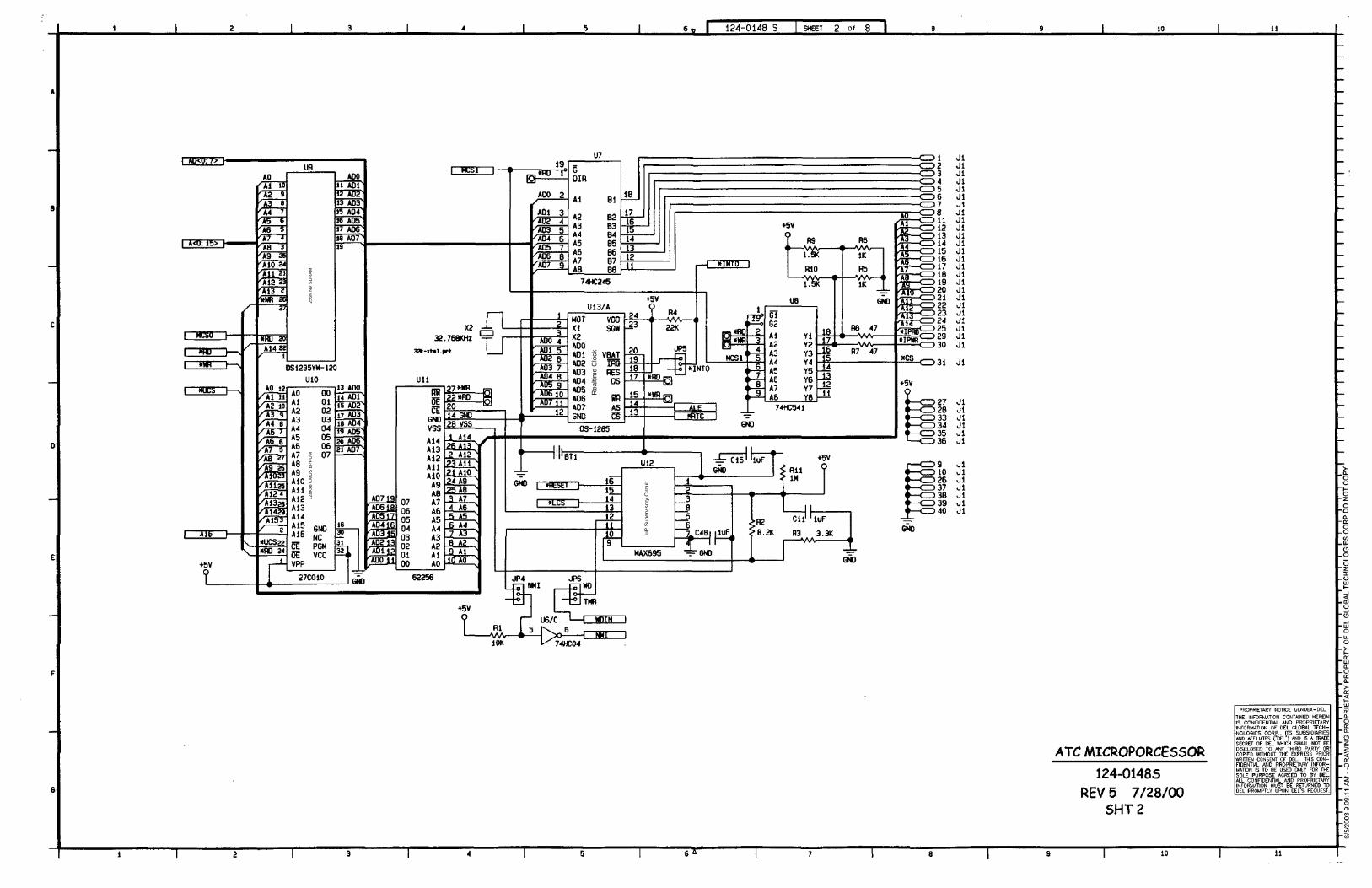
Rea
ltim
e C
lock
256K
NV
SD
RA
M12
8Kx8
CM
OS
EP
RO
M
uP S
uper
viso
ry C
ircui
t
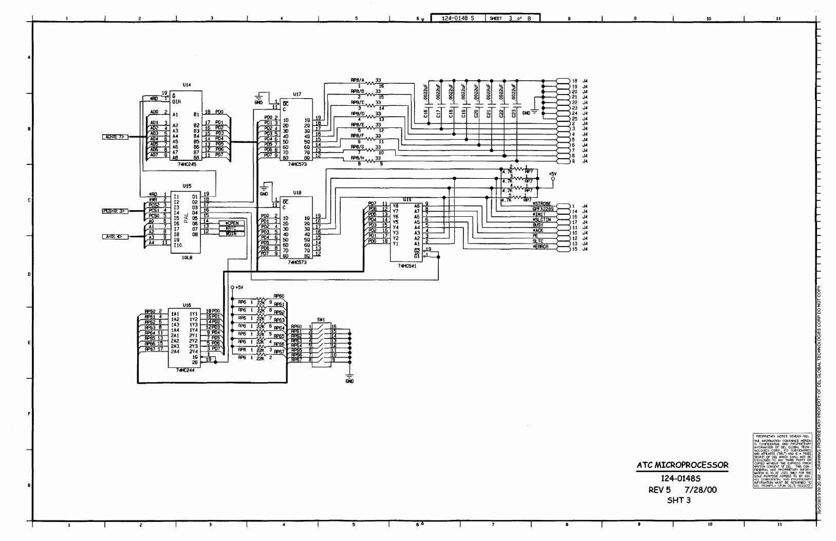
PA
L

CM
OS
DU
AR
TR
S23
2 D
river
/Rec
eive
rR
S23
2 D
river
/Rec
eive
r
RS
232
Driv
er/R
ecei
ver
RS
232
Driv
er/R
ecei
ver

4 C
hara
cter
Alp
hanu
mer
ic d
ispl
ay
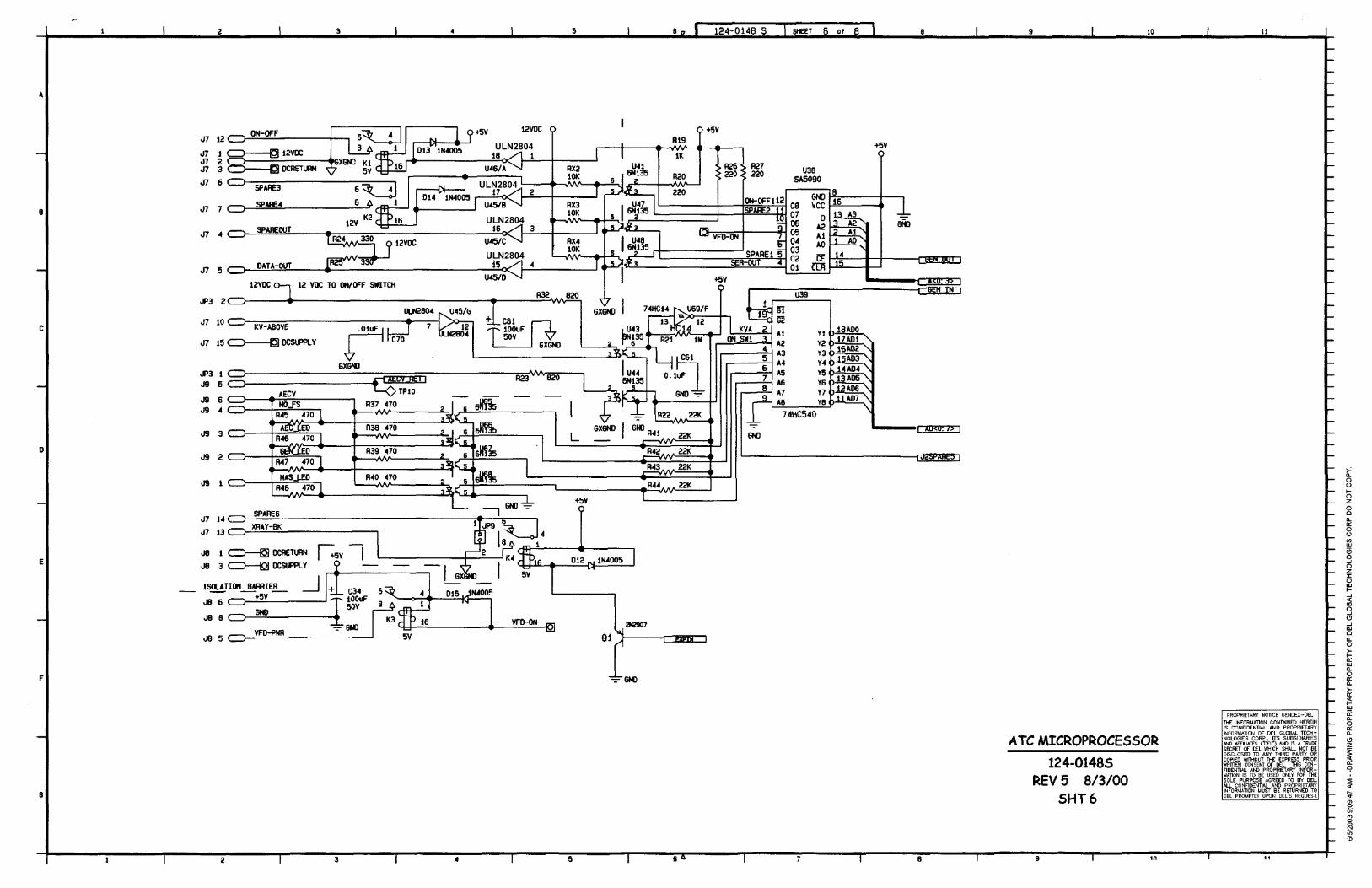
ULN2804
ULN2804
ULN2804
ULN2804

ULN2804


UP/DWN Switching Reg.
Vout
ErrorAmp
Vout
Vin
Comp
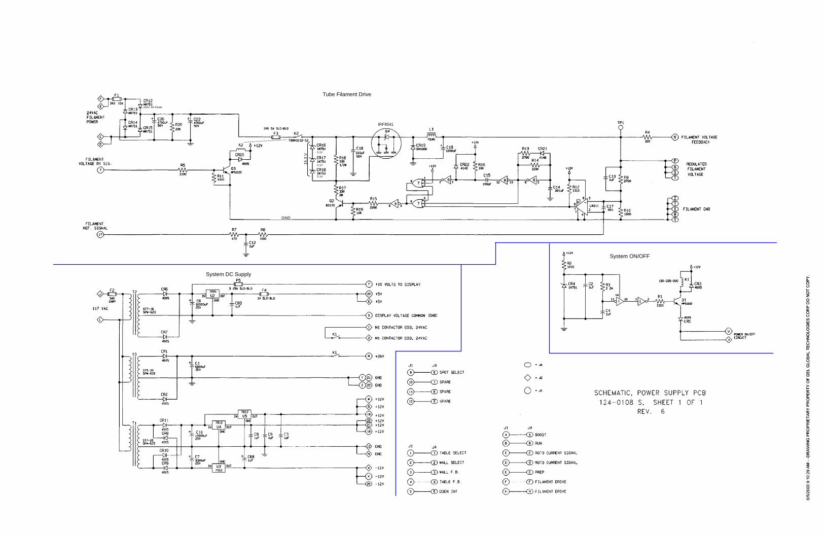
IRF9541
5.1V
5.1V
5.1V
15.3
V
GND
100V, 6A Diode
Tube Filament Drive
System DC Supply
System ON/OFF

From Inverter DC BUS
+DC BUS (GRY)
-DC BUS (WHT)
Capacitor bank discharge

HT Transformer Primary
P1C P2AP2C
T6071018B4
T6071018B4
T6071018B4
T6071018B4
2F50/10
2F50/102F50/10
2F50/10
+12VDC
Compensation Relay
P1 P2
WHTGRY
TB1
TB3-
2 B
US
+
TB3-
1 B
US
-
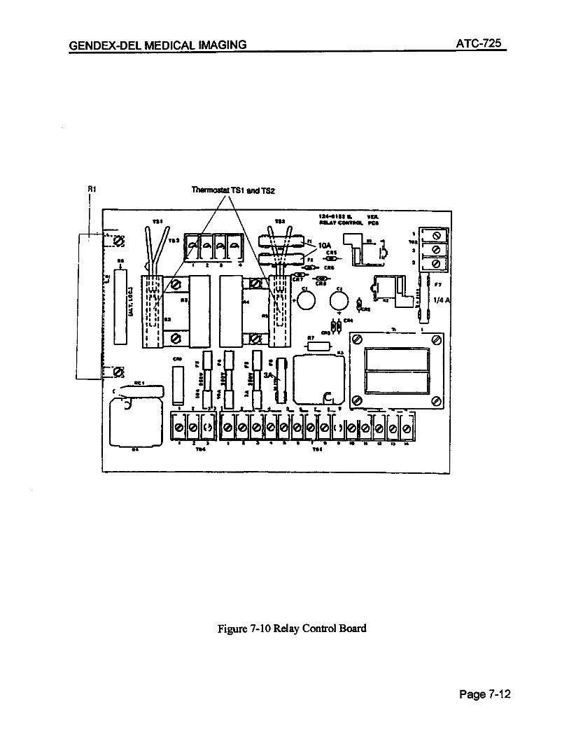
Rel
ay C
ontro
l Boa
rd
DC IN FROMDIODE ARRAY
Red
Blk
Wht
Wht
K2
K1
TB1
+12VDC (TB1-2)
Red J9-3
J9-4
20
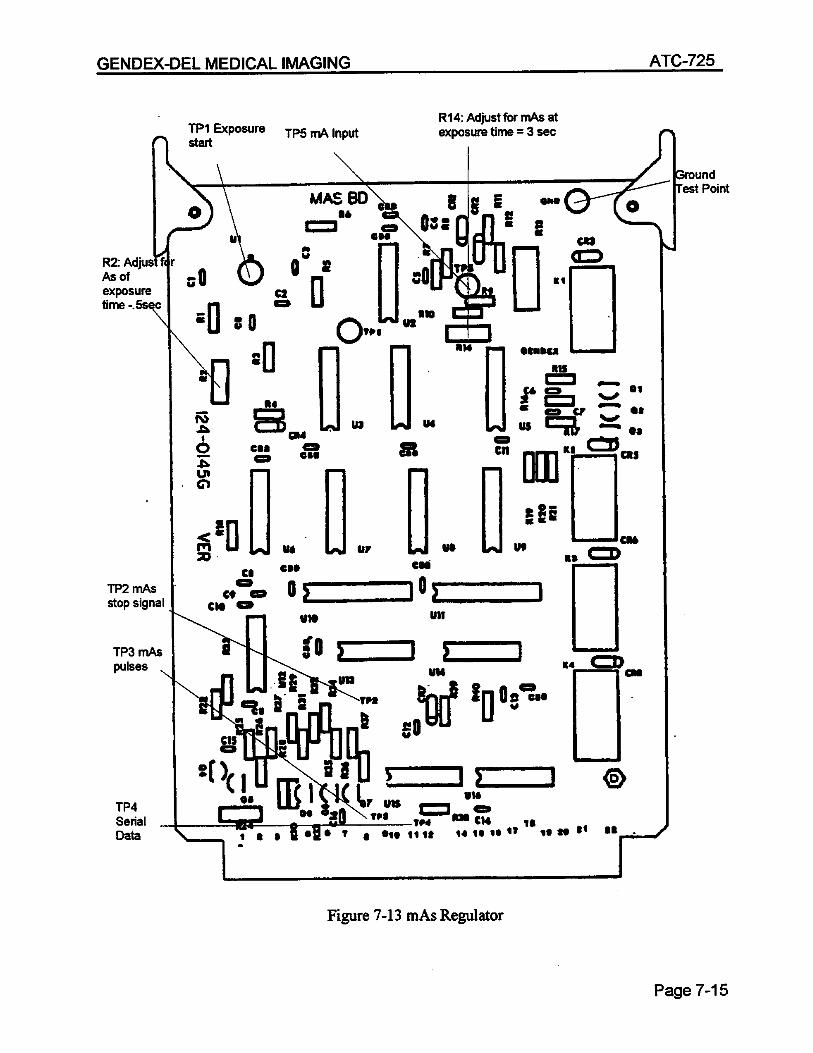
WMAS board
MotherboardP2 Capacitance
All Relays OFF: 14.87uF
K1 K2 Capacitance
0 01
1 1
014.87uF
24.87uF44.87uF
TB1

2N6039
2N603620.6V 20.6V
2N6039
2N6036
8.7V
8.7V
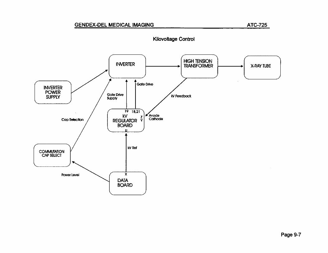
From Data Bd pin X
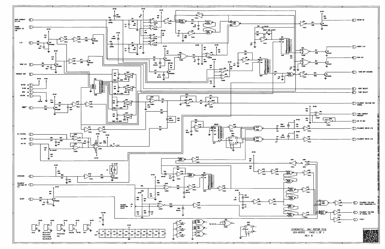
KV REF
KV FEEDBACK KV FEEDBACK


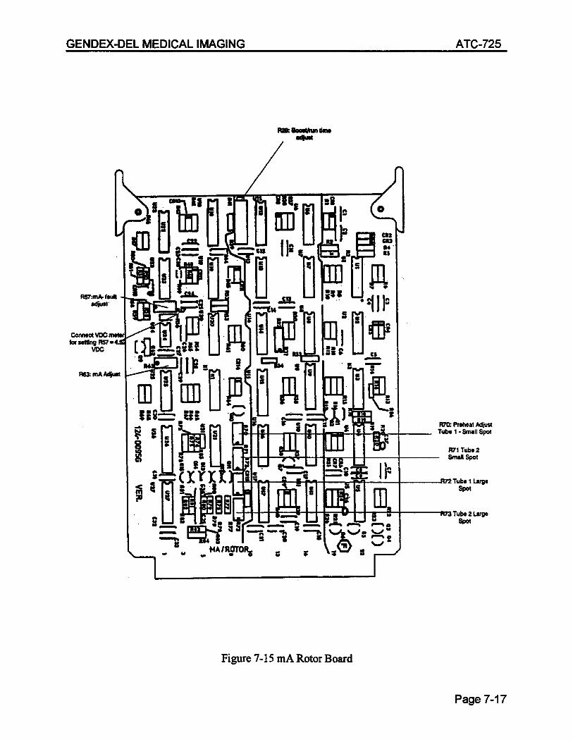
Tube
Rot
or

Board

(Noritake GU256X64-352)
(Bussman FRN-R-60)
(SCRN227R-F / 86D79206K80)
(SCRN224R-F / 86D79106K80)
20uF/600V Peak, SCR Capacitor
10uF/600V Peak, SCR Capacitor