INSTALLATION MANUAL - MARS
16
Johnson Controls Ducted Systems 5396713-BIM-D-0919 ELECTRIC FURNACE MODELS: EBE*/EUE* Downflow/Upflow INSTALLATION MANUAL ® For Installation in: 1. Manufactured (Mobile) Homes 2. Recreational Vehicles and Park Models 3. Modular Homes and Buildings LIST OF SECTIONS GENERAL . . . . . . . . . . . . . . . . . . . . . . . . . . . . . . . . . . . . . . . . . . . . . . 1 SAFETY . . . . . . . . . . . . . . . . . . . . . . . . . . . . . . . . . . . . . . . . . . . . . . . . 2 UNIT INSTALLATION . . . . . . . . . . . . . . . . . . . . . . . . . . . . . . . . . . . . . 3 ELECTRIC FURNACE INSTALLATION . . . . . . . . . . . . . . . . . . . . . . . 4 THERMOSTAT INSTALLATION . . . . . . . . . . . . . . . . . . . . . . . . . . . . 8 AIR CONDITIONING ACCESSORIES . . . . . . . . . . . . . . . . . . . . . . . . 8 WIRING DIAGRAMS . . . . . . . . . . . . . . . . . . . . . . . . . . . . . . . . . . . . 10 LIST OF FIGURES Furnace Dimensions . . . . . . . . . . . . . . . . . . . . . . . . . . . . . . . . . . . . . . 1 Alcove and Closet Clearances . . . . . . . . . . . . . . . . . . . . . . . . . . . . . . . 3 Upflow Closet Clearances . . . . . . . . . . . . . . . . . . . . . . . . . . . . . . . . . . 3 Duct Connector Depth (7990 Series) . . . . . . . . . . . . . . . . . . . . . . . . . . 4 Duct Connector Dimensions (7990 Series) . . . . . . . . . . . . . . . . . . . . . 4 Recommended Floor Cut-Out (7990 Series) . . . . . . . . . . . . . . . . . . . . 4 Duct Connector Screw Attachment (7990 Series) . . . . . . . . . . . . . . . . 5 Duct Connector Tab Attachment (7990 Series) . . . . . . . . . . . . . . . . . . 5 Installation of Furnace . . . . . . . . . . . . . . . . . . . . . . . . . . . . . . . . . . . . . 5 Field Wiring Shield . . . . . . . . . . . . . . . . . . . . . . . . . . . . . . . . . . . . . . . . 7 Control Box . . . . . . . . . . . . . . . . . . . . . . . . . . . . . . . . . . . . . . . . . . . . . 7 Thermostat Wiring . . . . . . . . . . . . . . . . . . . . . . . . . . . . . . . . . . . . . . . 8 EBE/EUE Furnace - Location of Components . . . . . . . . . . . . . . . . . . 8 EBE10*/EUE10* Wiring Diagram . . . . . . . . . . . . . . . . . . . . . . . . . . . 10 EBE12*/EUE12* Wiring Diagram . . . . . . . . . . . . . . . . . . . . . . . . . . . 11 EBE15*/EUE15* Wiring Diagram . . . . . . . . . . . . . . . . . . . . . . . . . . . 12 EBE17*/EUE17* Wiring Diagram . . . . . . . . . . . . . . . . . . . . . . . . . . . 13 EBE20*/EUE20* Wiring Diagram . . . . . . . . . . . . . . . . . . . . . . . . . . . 14 EBE23*/EUE23* Wiring Diagram . . . . . . . . . . . . . . . . . . . . . . . . . . . 15 LIST OF TABLES Duct Connector for Electric Furnaces . . . . . . . . . . . . . . . . . . . . . . . . . 4 Wiring Requirements . . . . . . . . . . . . . . . . . . . . . . . . . . . . . . . . . . . . . . 6 EBE/EUE Series Blower Performance . . . . . . . . . . . . . . . . . . . . . . . . 6 Physical and Electrical Data . . . . . . . . . . . . . . . . . . . . . . . . . . . . . . . . 7 SECTION I: GENERAL The following list includes important facts and information regarding the EBE/EUE furnace and its packaging inclusions: • Furnace is rated at 240 V, 60 Hz, single phase. • Filters are furnished with EBE model, and are the same for all EBE models - 16 x 20 x 1 in top and 20 x 20 x 1 in the louvered door. No filters are furnished with EUE models. External filter base and/or filter rack needed for field installation. • Furnace size is the same for all models. See Figure 1. • Four-wire thermostat operation for heating and cooling. • Coil cavity built into furnace. • All furnaces are equipped with an air conditioner blower and are A/C or Heat Pump ready. • Holding strap furnished on top rear of furnace. • The EBE furnace is designed for downflow application, and the EUE furnace is designed for upflow application. • This furnace must not be operated without the front panel installed. NOTICE This furnace and its components listed on the A/C and Heat Pump equipment sticker are listed in combination as a system by Under- writer's Laboratories for the United States and Canada. FIGURE 1: Furnace Dimensions 51-5/8” 19-5/8” OPTIONAL BOTTOM FIELD WIRING ENTRY A B C D E F H G J K L M N 1-7/8” 2-5/8” 3-1/2” 1” 5-1/16” 5-1/2” 1” 5-13/16” 1-3/4” 7-13/16” 8-5/8” 9-7/16” 16-1/2” J H C B A D E F G N M L K SUB-BASE, IF USED, ADDS 7/8” MORE TO TOTAL HEIGHT AND 3/8” TO WIDTH. THERMOSTAT WIRING ENTRY FIELD WIRING ENTRY A0552-001 24”
-
Upload
khangminh22 -
Category
Documents
-
view
0 -
download
0
Transcript of INSTALLATION MANUAL - MARS

ELECTRIC FURNACEMODELS: EBE*/EUE*Downflow/Upflow
INSTALLATION MANUAL®
For Installation in:1. Manufactured (Mobile) Homes2. Recreational Vehicles and Park Models3. Modular Homes and Buildings
LIST OF SECTIONSGENERAL . . . . . . . . . . . . . . . . . . . . . . . . . . . . . . . . . . . . . . . . . . . . . . 1SAFETY . . . . . . . . . . . . . . . . . . . . . . . . . . . . . . . . . . . . . . . . . . . . . . . . 2UNIT INSTALLATION . . . . . . . . . . . . . . . . . . . . . . . . . . . . . . . . . . . . . 3ELECTRIC FURNACE INSTALLATION . . . . . . . . . . . . . . . . . . . . . . . 4
THERMOSTAT INSTALLATION . . . . . . . . . . . . . . . . . . . . . . . . . . . . 8AIR CONDITIONING ACCESSORIES . . . . . . . . . . . . . . . . . . . . . . . . 8WIRING DIAGRAMS . . . . . . . . . . . . . . . . . . . . . . . . . . . . . . . . . . . . 10
LIST OF FIGURESFurnace Dimensions . . . . . . . . . . . . . . . . . . . . . . . . . . . . . . . . . . . . . . 1Alcove and Closet Clearances . . . . . . . . . . . . . . . . . . . . . . . . . . . . . . . 3Upflow Closet Clearances . . . . . . . . . . . . . . . . . . . . . . . . . . . . . . . . . . 3Duct Connector Depth (7990 Series) . . . . . . . . . . . . . . . . . . . . . . . . . . 4Duct Connector Dimensions (7990 Series) . . . . . . . . . . . . . . . . . . . . . 4Recommended Floor Cut-Out (7990 Series) . . . . . . . . . . . . . . . . . . . . 4Duct Connector Screw Attachment (7990 Series) . . . . . . . . . . . . . . . . 5Duct Connector Tab Attachment (7990 Series) . . . . . . . . . . . . . . . . . . 5Installation of Furnace . . . . . . . . . . . . . . . . . . . . . . . . . . . . . . . . . . . . . 5Field Wiring Shield . . . . . . . . . . . . . . . . . . . . . . . . . . . . . . . . . . . . . . . . 7
Control Box . . . . . . . . . . . . . . . . . . . . . . . . . . . . . . . . . . . . . . . . . . . . . 7Thermostat Wiring . . . . . . . . . . . . . . . . . . . . . . . . . . . . . . . . . . . . . . . 8EBE/EUE Furnace - Location of Components . . . . . . . . . . . . . . . . . . 8EBE10*/EUE10* Wiring Diagram . . . . . . . . . . . . . . . . . . . . . . . . . . . 10EBE12*/EUE12* Wiring Diagram . . . . . . . . . . . . . . . . . . . . . . . . . . . 11EBE15*/EUE15* Wiring Diagram . . . . . . . . . . . . . . . . . . . . . . . . . . . 12EBE17*/EUE17* Wiring Diagram . . . . . . . . . . . . . . . . . . . . . . . . . . . 13EBE20*/EUE20* Wiring Diagram . . . . . . . . . . . . . . . . . . . . . . . . . . . 14EBE23*/EUE23* Wiring Diagram . . . . . . . . . . . . . . . . . . . . . . . . . . . 15
LIST OF TABLESDuct Connector for Electric Furnaces . . . . . . . . . . . . . . . . . . . . . . . . . 4Wiring Requirements . . . . . . . . . . . . . . . . . . . . . . . . . . . . . . . . . . . . . . 6
EBE/EUE Series Blower Performance . . . . . . . . . . . . . . . . . . . . . . . . 6Physical and Electrical Data . . . . . . . . . . . . . . . . . . . . . . . . . . . . . . . . 7
SECTION I: GENERALThe following list includes important facts and information regarding theEBE/EUE furnace and its packaging inclusions:
• Furnace is rated at 240 V, 60 Hz, single phase.• Filters are furnished with EBE model, and are the same for all
EBE models - 16 x 20 x 1 in top and 20 x 20 x 1 in the louvereddoor. No filters are furnished with EUE models. External filterbase and/or filter rack needed for field installation.
• Furnace size is the same for all models. See Figure 1.• Four-wire thermostat operation for heating and cooling.• Coil cavity built into furnace.• All furnaces are equipped with an air conditioner blower and are
A/C or Heat Pump ready.• Holding strap furnished on top rear of furnace.• The EBE furnace is designed for downflow application, and the
EUE furnace is designed for upflow application.• This furnace must not be operated without the front panel
installed.
NOTICEThis furnace and its components listed on the A/C and Heat Pumpequipment sticker are listed in combination as a system by Under-writer's Laboratories for the United States and Canada.
FIGURE 1: Furnace Dimensions
51-5/8”
19-5/8”
OPTIONAL BOTTOM FIELD
WIRING ENTRY
A
B
C
D
E
F
H
G
J
K
L
M
N
1-7/8”
2-5/8”
3-1/2”
1”
5-1/16”
5-1/2”
1”
5-13/16”
1-3/4”
7-13/16”
8-5/8”
9-7/16”
16-1/2”
J
H
CB
AD
EFG
N
ML
K
SUB-BASE, IF
USED, ADDS
7/8” MORE TO
TOTAL HEIGHT
AND 3/8” TO
WIDTH.
THERMOSTAT
WIRING
ENTRY
FIELD
WIRING
ENTRY
A0552-001
24”
Johnson Controls Ducted Systems 5396713-BIM-D-0919

5396713-BIM-D-0919
SECTION II: SAFETYThis is a safety alert symbol. When you see this symbol onlabels or in manuals, be alert to the potential for personalinjury.
Understand and pay particular attention to the signal words DANGER,WARNING, or CAUTION.
DANGER indicates an imminently hazardous situation, which, if notavoided, will result in death or serious injury.
WARNING indicates a potentially hazardous situation, which, if notavoided, could result in death or serious injury.
CAUTION indicates a potentially hazardous situation, which, if notavoided may result in minor or moderate injury. It is also used toalert against unsafe practices and hazards involving only property dam-age.
• Install this electric furnace only in a location and position as spec-ified in SECTION III of these instructions.
• Always install the electric furnace to operate within the electricfurnace’s intended maximum outlet air temperature. Only connectthe air handler to a duct system that has an external static pres-sure within the allowable range, as specified on the EBE/EUE rat-ing plate.
• When an electric furnace is installed so supply ducts carry air cir-culated by the air handler to areas outside the space containingthe air handler, the return air must also be handled by ductssealed to the air handler casing and terminating outside thespace containing the air handler.
• The electric furnace is not to be used for temporary heating ofbuildings or structures under construction.
• The size of the unit must be based on an acceptable heat loss orgain calculation for the structure. ACCA, Manual J or otherapproved methods can be used.
SAFETY REQUIREMENTS• This electric furnace must be installed in accordance with all
national and local building/safety codes and requirements, localplumbing or wastewater codes, and other applicable codes.
• Refer to the unit rating plate for the EBE/EUE model number, andthen see the dimensions page of this instruction for supply air ple-num dimensions in Figure 3. The plenum must be installedaccording to the instructions.
• Provide clearances from combustible materials as listed underFURNACE CLEARANCE.
• Provide clearances for servicing, ensuring that service access isallowed for electric furnace elements and blower.
• Failure to carefully read and follow all instructions in this manualcan result in electric furnace malfunction, death, personal injury,and/or property damage.
• Check the rating plate and power supply to ensure that the elec-trical characteristics match.
• Electric furnace must be installed so the electrical componentsare protected from water.
• Installing and servicing heating/cooling equipment can be haz-ardous due to the electrical components. Only trained and quali-fied personnel must install, repair, or service heating/coolingequipment. Untrained service personnel can perform basic main-tenance functions such as cleaning and replacing the air filters.When working on heating/cooling equipment, observe precau-tions in the manuals and on the labels attached to the unit andother safety precautions that may apply.
• These instructions cover minimum requirements and conform toexisting national standards and safety codes. In some instances,these instructions exceed certain local codes and ordinances,especially those that do not reflect changing residential and non-HUD modular home construction practices. These instructionsare required as a minimum for safe installation.
INSPECTIONAs soon as a unit is received, it must be inspected for possible damageduring transit. If damage is evident, the extent of the damage must benoted on the carrier’s freight bill. A separate request for inspection bythe carrier’s agent must be made in writing. Before installation, the unitmust be checked for screws or bolts that may have loosened in transit.There are no shipping or spacer brackets to be removed.Check to ensure all accessories such as heater kits, suspension kits,and coils are available. Installation of these accessories or field conver-sion of the unit must be done before setting the unit in place or connect-ing any wiring, electric heat, ducts, or piping.
CODESThe electric furnace must be installed in accordance with the followingcodes:
• Standard for the Installation of Air Conditioning and VentilatingSystems (NFPA 90A)
• Standard for the Installation of Warm Air Heating and Air Condi-tioning Systems (NFPA 90B)
• National Electrical Code (NFPA 70)• Canadian Electrical Code, Part I (CSA C22.1)• All local codes (state/county/township)
WARNINGImproper installation may create a condition where the operation ofthe product could cause personal injury or property damage.Improper installation, adjustment, alteration, service or mainte-nance can cause injury or property damage. Refer to this manualfor assistance or for additional information, consult a qualified con-tractor, installer or service agency.
CAUTIONThis product must be installed in strict compliance with the installa-tion instructions and any applicable local, state, and national codesincluding, but not limited to building, electrical, and mechanicalcodes.
WARNINGFIRE OR ELECTRICAL HAZARDFailure to follow the safety warnings exactly could result in seriousinjury, death or property damage.A fire or electrical hazard may result causing property damage, per-sonal injury or loss of life.
!
!
!
NOTICEAll applicable codes take precedence over any recommendationmade in these instructions.
2 Johnson Controls Ducted Systems

5396713-BIM-D-0919
SECTION III: UNIT INSTALLATIONLOCATIONAccess for servicing is an important factor in the location of any furnace.Provide a minimum of 24 in. (61 cm) in front of the furnace for access tothe heating elements and controls. This access can be provided by acloset door or by locating the furnace 24 in. (61 cm) from a facing wallor partition.
FURNACE CLEARANCEThis furnace is approved for 0 in. clearance to combustible material onall or any part of the furnace exterior and the inlet or outlet duct workexcept as stated below. For furnaces installed in upflow application, there must be a minimumof 1 in. (2.54 cm) clearance from the bare surface of the outlet ductwork for a distance of 3 ft (91.4 cm) from the supply air opening. Thisrequirement is met if the duct is wrapped with an insulating material atleast 1 in. thick that has an R-value of at least R-4.
RETURN AIRIn order for the furnace to work properly, a closet or alcove must have acertain total free area opening for return air.
For Heating Only FurnaceA minimum of 200 sq in. (1290 sq cm) free area opening. Use anyreturn grille with a minimum of 200 sq in. free opening.
For Up to 4 Ton AC and HP Applications (Standard Blower)A minimum of 250 sq in. (1613 sq cm) free area opening. The standardblower assembly supplied with the furnace is capable of handling up 4ton AC applications. Use any return grille with a minimum of 250 sq in.(1613 sq cm) free area opening.
For 5 Ton AC Applications (Accessory Blower)A minimum of 350 sq in. (2129 sq cm) free area opening. Use 5 ton ACblower accessory 3500-7911. Use any return grille with a minimum of350 sq in. (2129 sq cm) free area opening with 5 ton AC blower acces-sory 3500-7911. The upflow return air box accessory 3500-8982 canalso be used with 5 ton AC blower accessory 3500-7911.
LocationFor downflow applications, the return air opening can be located in acloset front door, sidewall above the furnace casing, or louvered dooron the furnace. If the opening for the return air is located in the floor,sidewalls, or closet door anywhere below the furnace casing height, 6in. minimum clearance must be provided on the furnace side wherereturn is located to provide for proper airflow.For upflow installations, a closet that is 32 in. wide by 30 in. deep with a30-inch wide door is necessary. This is not required if there is a returngrille installed below furnace.The return air opening can be located in a closet front door, sidewallabove the furnace casing, or louvered door on the furnace. If theopening for the return air is located in the floor, sidewalls, or closetdoor anywhere below the furnace casing height, 6 in. (15.2 cm) mini-mum clearance must be provided on the furnace side where return islocated to provide for proper airflow. See Figure 2. The 6 in. (15.2 cm)minimum clearance is not required if there is a return grille installedabove the furnace height. This return grille cannot start more than 3 ftabove the furnace height. If the louvers in the closet door have asmuch airflow area as the EB louvered furnace door, only 1 in. clear-ance is required.
When installing the furnace in a separate closet or room that is accessi-ble only through an outside door, a minimum of 200 sq in. (1290 sq cm)free opening for return air must be provided. The supply and return airmust be ducted, securely attached, and sealed to the furnace casing ifthere are grilles in the outside door to the closet. Openings where ductspass through walls, the floor, or the ceiling must be sealed to prevent airleakage into or from the closet and the living area.
Provisions must be made to permit the return of circulating air from allrooms and living spaces, except the bathroom(s), to the circulating airsupply inlet of the furnace. Failure to comply may cause improper heat-ing and may cause the furnace to cycle on the limit.
DUCT SYSTEM DESIGNAn electric furnace is designed to operate at a given static pressure.To ensure proper airflow through the furnace, the distribution systemmust be designed so the static pressure external to the furnace doesnot exceed the static pressure rating shown on the furnace rating plate.The number, size, and placement of registers must be such that evendistribution of heat is provided throughout the home.
FIGURE 2: Alcove and Closet Clearances
FIGURE 3: Upflow Closet Clearances
23” MIN.
20”
20”
24” MIN.
There must be at least
2 feet of space available
in front of furnace for
servicing the furnace
when necessary.
A 6 inch clearance is
required if the space
between furnace and
enclosure is used for
return air.
A0844-001
30”
32”
30”
WIDE DOORCLOSET
25-1/2” OPENING WIDTHReturn air
pass through
frame width.
1-5/8” 2-3/8MIN., MAX.
A0877-001
NOTE:
Minimum required square
inch opening dictates the
height of the return air
opening as discussed
earlier in the section.
Johnson Controls Ducted Systems 3

5396713-BIM-D-0919
SECTION IV: ELECTRIC FURNACE INSTALLATION 7900 SERIES DUCT CONNECTOR FOR EBE DOWN-FLOWThe duct connector is designed to eliminate a sub-base requirement.Table 1 provides the part number of the duct connector needed.Provide adequate clearance for servicing:
• Locate the furnace conveniently away from wall facing or parti-tions to permit easy removal of components.
• Maintain a minimum space of 6 in. between the furnace andcloset door when the door is used for return air.
• Ensure 2 ft of space is available in front of the furnace for futureservicing (for example, blower, element, or furnace removal).
- Indicates connector above or below could be used, depending on toler-ance in floor to duct dimension.
- Indicates connector above could be used, depending on tolerance in floor to duct dimension.
- Indicates connector below could be used, depending on tolerance in floor to duct dimension.
DUCT CONNECTORS (7990 SERIES)
These duct connectors connect the furnace to an under the floor supplyduct system. The furnace can be installed on combustible flooring with-out a separate sub-base.
TABLE 1: Duct Connector for Electric Furnaces
FLOOR TO DUCT DIMENSIONS
FINGERED STYLE
SCREW TAB STYLE
1 in. (2.54 cm) 7990-6211 N/A2 in. (5.1 cm) 7990-6221 N/A3 in. (7.6 cm) N/A4 in. (10.2 cm) 7990-6241 N/A5 in. (12.7 cm) 6 in. (15.2 cm) 7990-6261 7990-60617 in. (17.8 cm) 7990-6271 7990-60718 in. (20.3 cm) 7990-6281 7990-60819 in. (22.8 cm)
10 in. (25.4 cm) 7990-6301 N/A11 in. (282 cm) N/A12 in. (30.5 cm) N/A N/A13 in. (33 cm) N/A N/A
NOTE: The duct adapter in the next size up or next size down is to be used, depending on tolerance in floor to duct dimension.
FIGURE 4: Duct Connector Depth (7990 Series)
DUCT CONNECTOR
DEPTH
FLOOR
FLOOR
JOIST
SUPPLY DUCT
A0867-001
FIGURE 5: Duct Connector Dimensions (7990 Series)
FIGURE 6: Recommended Floor Cut-Out (7990 Series)
12
13
11
14See
Chart
18-3/4
18-3/4
2-3/8
4-3/8
2-3/8
DUCT CONNECTORS FOR
SCREW ATTACHMENT
2-3/8
A0868-001
.
13
11
14 See
Chart
12DUCT
CUTOUT
DIMENSIONS
DUCT CONNECTORS FOR
TAB ATTACHMENT
18-3/4
2-3/8
18-3/4
2-3/8
4-3/8
A0869-001
2-3/8
2-3
/4M
IN.
23-1
/4
20-1
/2
9-7
/8
2-1/8
1-3/86-3/8
9-3/4
20
3-1/4
1-1/8
15
15
1
REAR WALL
OF ENCLOSURE
CEILING CUT-OUT
FOR ROOF JACK
FLOOR CUT-OUT
FOR DUCT
CONNECTOR
FURNACE
OUTLINE
OPTIONAL
ELECTRIC
ENTRANCE
FLOORFUTURE
REFRIGERANT
LINE ENTRANCE A0875-001
4 Johnson Controls Ducted Systems

5396713-BIM-D-0919
INSTALLATION OF SCREW ATTACHMENT DUCT CONNECTOR (7990 SERIES)1. Make floor cut out as shown in Figure 6.2. Determine the depth of the floor cavity from the surface of the floor
to the top of the supply air duct and select the appropriate ductconnector from the chart.
3. Place locating bracket (supplied with the duct connector) to theback edge of the floor opening. See Figure 7.
4. Apply a water based duct sealant to the 1/2 in. supply duct attach-ment flange of the duct connector.
5. Determine which of the four positions the duct connector best cen-ters over the supply duct and insert it through the floor cutout.
6. When properly aligned with the supply duct, secure the duct con-nector to the floor with nails, flat head screws, or staples.
7. Use screws as required to secure duct connector to supply duct.8. Cut out the opening to the supply duct. If sealant has not been
used, tape the mating flanges to provide a good air seal.
INSTALLATION OF TAB ATTACHMENT DUCT CONNECTOR (7990 SERIES)1. Make floor cut out as shown in Figure 6.2. Determine the depth of the floor cavity from the surface of the floor
to the top of the supply air duct and select the appropriate ductconnector from the chart.
3. Place locating bracket (supplied with the duct connector) to therear of the floor area for the furnace. See Figure 8.
4. Determine which of the four positions the duct connector best cen-ters over the supply duct and insert it through the floor cutout.
5. Mark cut-out location on the supply duct and remove the duct con-nector.
6. Cut out the opening to the supply duct.7. Bend tabs down through and back up under the supply duct.8. Secure the duct connector to the floor with nails, flat head screws,
or staples.The duct connector is designed for use on ducts down to 12 in. in width.When using the connector on smaller width ducts, there is insufficientclearance to bend the tabs on two sides of the duct connector. In such cases, the tabs can be attached to the sides of the duct byusing sheet metal screws or other suitable fasteners. Holes for sheetmetal screws are provided in three tabs on each side of the duct con-nector. If more than three tabs need to be used to provide a moresecure and air tight connection, the remaining tabs can also be fas-tened to the duct with screws after drilling the required screw holes.
INSTALLATION OF THE FURNACE1. Remove the front panels and set the furnace onto the duct con-
nector. Slide it back until the rear of the unit engages the locatorbracket.
2. Secure the front of the furnace with two screws at the providedmounting holes. See Figure 9.
3. Secure the top of the furnace to a structural member by screwingthrough the strap at the top of the furnace. The strap can bemoved to any of the holes located along the top back of the fur-nace. The installer may provide an equivalent method, such asscrews through the casing side.
WIRINGFurnace wiring is complete except for the power supply and the thermo-stat wires. See wiring diagrams (Figures 14 to 19) for wire and fusesize. See Table 2 for ground wire sizes. Thermostat wires connectthrough the side of the furnace and must be no smaller than 22 gauge.Power wires can enter through the side of the unit or through the auxil-iary entrance located in the bottom of the unit. (See Figure 1). Whenbringing wiring through the bottom of the furnace, cable connectorsmust be installed to hold wiring in place and relieve any strain on thewiring. These connectors also serve as a seal between the furnace andthe floor, so additional sealing is not required.
FIGURE 7: Duct Connector Screw Attachment (7990 Series)
NOTICEDuct sealant and tape must be classified as meeting HUD Standard3280.715, U.L. Standard 181A.
FIGURE 8: Duct Connector Tab Attachment (7990 Series)
LOCATOR BRACKET
NAILS, FLAT HEAD SCREWS,
OR STAPLES
SCREWS
FLOOR
SUPPLY DUCTA0872-001
LOCATOR BRACKET
NAILS, FLAT HEAD SCREWS,
OR STAPLES
(Bend tabs under duct
opening to secure to the
supply duct.)
FLOOR
SUPPLY DUCTA0873-001
FIGURE 9: Installation of Furnace
Furnace Seated
Against the
Locator Bracket
Secure Furnace
to Floor with Two
Nails or Screws
(Not Provided).
A0874-001
.
Johnson Controls Ducted Systems 5

5396713-BIM-D-0919
Refer to the National Electrical Code, Canadian Electrical Code, andlocal codes for wiring material requirements.
Models for EBE/EUE15*, EBE/EUE17*, EBE/EUE20*, and EBE/EUE23* can be connected to a single or dual branch circuit.These units are shipped from the factory set up for dual power supplyconnections. For single power supply connections, jumper bars (P/N3500-378P*) are required and are available from the factory. See Fig-ures 11 and 12.
1. Applications with static pressures higher than 0.3 in. are not recommended.2. A blower off delay of 60 seconds is built into the motor.3. For up to E(B,U)E15* models heating, use Low speed (1) for compliance with Fan Efficiency Rating test.4. For E(B,U)E17*, E(B,U)E20*, and E(B,U)E23* models heating, use Medium Low speed (2) for compliance with Fan Efficiency Rating test.5. For all models constant fan operation, use Low speed (1) for compliance with Fan Efficiency Rating test.
NOTICEThe furnaces are equipped with either one or two 60 amp circuitbreakers. These circuit breakers protect the wiring inside of the fur-nace in the event of a short circuit. Additionally, these breakers pro-vide a means of disconnecting the power to the unit. The circuitbreakers in the furnace are not meant to protect the branch circuitwiring between the furnace and the home's breaker panel. Generalwire and breaker sizes are shown in Table 2. If sheathed cable isused, refer to National Electrical Code, Canadian Electrical Codeand local codes for additional requirements concerning supply cir-cuit wiring. Electrical Data can be found in Table 4.
IMPORTANT: All installation on field wiring must be rated at 60ºCor higher.
TABLE 2: Wiring Requirements
MODELS1EBE10AEUE10A
1. Does not require a jumper
2EBE12AEUE12A
2. Jumper provided for Single Branch Circuit Only
3EBE15AEUE15A
3. Requires jumper bars (P/N 3500-378P)
3EBE17AEUE17A
3EBE20AEUE20A
3EBE23AEUE23A
Single Branch Circuit Service 2 Leads + 1 Ground CKT #1
Nominal Circuit Load - Amps 43.8 50.5 63.8 70.4 83.8 93.8Minimum Wire Size (90ºC) #8 #6 #4 #4 #3 #2Minimum Wire Size (75ºC) #6 #6 #4 #3 #2 #1Minimum Wire Size (60ºC) #6 #4 #3 #2 #1 #0Ground Wire Size + #10 #8 #8 #8 #6 #6Max. Fuse (or C.B.) - Amps 60 70 80 90 110 125Dual Branch Circuit Service
NOTAPPROVED
CKT #1 CKT #2 CKT #1 CKT #2 CKT #1 CKT #2 CKT #1 CKT #2Branch Circuit Load - Amps 43.8 20.0 47.1 23.3 43.8 40.0 47.1 46.7Branch Circuit Min. - Amps 54.8 25.0 58.9 29.1 54.8 50.0 58.9 58.4Minimum Wire Size (90ºC) #8 #10 #6 #10 #8 #8 #6 #6Minimum Wire Size (75ºC) #6 #10 #6 #10 #6 #8 #6 #6Minimum Wire Size (60ºC) #6 #10 #4 #10 #6 #6 #4 #4
Ground Wire Size 4
4. Refer to National Electrical Code (NEC). Table 250-122 for Non-Sheathed Conductor Ground Wire
#10 #10 #10 #10 #10 #10 #10 #10
Max. Fuse (or C.B.) - Amps 60 30 60 30 60 50 60 60NOTES:
TABLE 3: EBE/EUE Series Blower Performance
Static Pressure (in. W.C.) Speed 0.1 0.2 0.3 0.4 0.5 0.6 0.7 0.8
CFM (STD. Air) for all EBE/EUE Models
High (5) 1607 1563 1515 1477 1434 1406 1377 1345Medium High (4) 1390 1346 1298 1286 1253 1224 1201 1160
Medium (3) 1241 1192 1151 1115 1097 1074 1032 1000Medium Low (2) 1099 1051 1002 979 949 912 872 855
Low (1) 1006 950 923 896 860 826 800 728NOTES:
6 Johnson Controls Ducted Systems

5396713-BIM-D-0919
TABLE 4: Physical and Electrical Data
1MODEL NUMBER2,3EBE10A
EUE10A3,4EBE12A
EUE12A5EBE15AEUE15A
5EBE17AEUE17A
5EBE20AEUE20A
5EBE23AEUE23A
D.O.E.Output
240 VAC60 Hz,1 Phase
BTU 34,000 39,000 51,000 56,000 67,000 77,000kW 10.0 11.4 15.0 16.4 19.6 22.6
OUTPUTCAPACITY
230 VAC60 Hz,1 Phase
BTU 31,000 36,000 47,000 52,000 61,000 71,000kW 9.1 10.6 13.8 15.2 17.9 20.8
220 VAC60 Hz,1 Phase
BTU 29,000 33,000 43,000 48,000 57,000 65,000kW 8.5 9.7 12.6 14.1 16.7 19.1
Element Capacity@ 240 VAC
kW 9.6 11.2 14.4 16.0 19.2 21.6Amps 40.0 46.7 60.0 66.7 80.0 90.0
Motor Amps @ 240 V 4.0 MaximumCircuit Load Amps
@ 240 VCKT 1 43.8 50.55 43.8 47.1 43.8 47.1CKT 2 NA NA 20.0 23.3 40.0 46.7
Filter Size for EBE in top of unit only 16 x 20 x 1Filter Size for EBE in louvered door only 20 x 20 x 1
Shipping Weights 83 84 85 86 84 86NOTES:
1. Casing or cabinet must be permanently grounded in accordance with NEC or other applicable codes2. Does not require a jumper3. Approved for Single Branch Circuit Service Only4. Jumper provided for Single Branch Circuit Only5. Requires jumper bars (P/N 3500-378P)
WARNINGFor personal safety be sure to turn the electrical power OFF at thehousehold service box and at the furnace circuit breakers beforeattempting any service or maintenance operations. Homeownersshould never perform any maintenance which requires openingelectric box door.Furnace is equipped with a protective shield over field wiring con-nection. When field wiring is completed, shield must be replaced toprevent hazard of electrical shock when using furnace disconnect.(See Figure 10.)
!
FIGURE 10: Field Wiring Shield
CIRCUIT
BREAKERS
ELECTRIC
PANEL
FIELD WIRING
PROTECTIVE
SHIELD
BLOWER
A0871-001
FIGURE 11: Control Box
Johnson Controls Ducted Systems 7

5396713-BIM-D-0919
SECTION V: THERMOSTAT INSTALLATIONThe adjustable heat anticipator in the thermostat is pre-set at 0.4 amps.This setting must be checked at the time of installation.In some cases the thermostat may be a self-setting type, in which casethere is no amp setting on the thermostat, eliminating the need for anyfield adjustment.The thermostat must be located on an inside wall in an open area tomore closely regulate average room air, preferably, where there is airmovement back to furnace. Care must be used to locate the thermostataway from hot air discharge openings and lights, for example. Theheight of the thermostat location is important. The thermostat must belocated 52 in. to 66 in. (132 cm to 167.6 cm) above the floor. This issometimes called the comfort zone.If a condenser with its own transformer shares a Heat/Cool thermostatwith this furnace, use a thermostat with isolating contacts to preventinterconnection of Class II 24 V Systems.Cycle the furnace using the thermostat to make sure it operates cor-rectly.Maintenance and operating instructions are in the customer envelopeaccompanying the furnace. Give the customer envelope to the homeowner.
SECTION VI: AIR CONDITIONING ACCESSORIESEBE/EUE FURNACE MODELS
EBE and EUE furnaces are factory equipped with a blower, coil shelf,and control system for add-on air conditioning and heat pump. The coilshelf accessory 3500-8981 can be used to replace current and olderEBE and EUE coil shelfs.
With the factory-installed coil shelf, the coil cavity accepts coils as fol-lows:
• Up to 19-1/2 in. in height• Up to 18-1/4 in. in width• Up to 20-1/2 in. in depth
For coil applications with a height above 19-1/2 in., use extension cabi-net accessory 3500-8602.
CAUTIONWhen using separate thermostats, a thermostat interlock systemmust be provided to prevent simultaneous operation of the furnaceand air conditioner. Simultaneous operation can result in coachoverheating, equipment damage and energy waste. (See Figures14 to 19.)Do not connect Yellow wire to thermostat until an outdoor unit isinstalled.
FIGURE 12: Thermostat Wiring
!
COOLING
THERMOSTAT
HEATING
THERMOSTAT
TO
AIR CONDITIONER
TO
FURNACE
DOUBLE POLE
DOUBLE THROW SWITCH
A0876-001
FIGURE 13: EBE/EUE Furnace - Location of Components
FILTER
INDOOR COILCOMPARTMENT
INDOOR COIL(Not factory installed)
INDOOR COIL SHELF
BLOWER ASSEMBLY
ELECTRIC HEATERAND CONTROLSCOMPARTMENT
FIELD WIRINGCOMPARTMENT
THERMOSTATCONNECTIONS
EBE (DOWNFLOW CONFIGURATION)
EUE (UPFLOW CONFIGURATION)
THERMOSTATCONNECTIONS
FIELD WIRINGCOMPARTMENT INDOOR COIL SHELF
INDOOR COIL(Not factory installed)
INDOOR COILCOMPARTMENT
BLOWER ASSEMBLY
ELECTRIC HEATER AND CONTROLSCOMPARTMENT
A1285-001
NOTICEEUE furnaces are shipped with the coil shelf in the top orientation.This is not a defect. For application, turn the unit 180° vertically sothe coil shelf is in the bottom orientation.
NOTICEIf the controls are located at the top of the unit, the furnace is anupflow furnace and the airflow is forced up through the furnace andinto the airways.
8 Johnson Controls Ducted Systems

5396713-BIM-D-0919
HIGH PERFORMANCE BLOWER ACCESSORY PACKAGE
All electric furnaces are equipped with a blower and control system toadd on air conditioning and heat pumps to specified sizes. If therequirement is to achieve more airflow or cooling than specified, replacethe blower inside the furnace with accessory blower package 3500-7911. This accessory blower package delivers air conditioning up to 5tons. Apply accessory blower package 3500-7911 to EBE and EUEunits (downflow or upflow orientation) to achieve higher airflow.
CAUTIONAll areas around the line sets, drain hoses and other openings inthe coil shelf should be sealed air tight. Use some moldable com-pound or caulking to seal the area. Failure to do so may result inloss of performance and premature compressor failure.
!
Johnson Controls Ducted Systems 9

5396713-BIM-D-0919
SECTION VII: WIRING DIAGRAMS
FIGURE 14: EBE10*/EUE10* Wiring Diagram
.
D.O.E. OUTPUT CAPACITY - BTU 34,000
MAX. MOTOR-FLA 3.8
SINGLE BRANCHCIRCUIT SERVICE
2 LEADS +1 GROUND
NOMINAL CIRCUIT LOAD-AMPS 43.8
WIRE SIZE (75 C) COPPER #6
WIRE SIZE (60 C) COPPER #6
MAX. FUSE SIZE(OR CB) - AMPS 60
240 VAC.60Hz
1 PHASE
GND. LUG
240 VAC - 60 Hz - 1 PHASE
SHOCK HAZARDTHIS FURNACE MAY BE CONNECTED TO MORE THAN ONE POWER SUPPLY. TURN OFF ALL POWER TO THE FURNACE AT THE WALL BOX, AND LOCK IT OUT.
DO NOT OPEN THIS PANEL UNTIL ELECTRICAL POWER IS SHUTOFF AT HOUSEHOLD SERVICE BOX. CHECK WITH A VOLTMETER
OR OTHER PROPER INSTRUMENT.
- HAZARD OF ELECTRICAL SHOCK -SERVICE CONNECTION COVER MUST BE INSTALLED.
IF FILTERS ARE USED, CLEAN/REPLACE EACH SEASONOR MORE OFTEN AS NEEDED.
CAUTION
IMPORTANT -
HIGH VOLTAGE
WARNING
5395383-UWD-B-1017
LINE
LOAD
XFMR
3AFUSE
RED(8)
RED
(9)
Y
GW
HEAT/COOLT'STAT
BLK(1)
M3 M1
M2
H2
SEQUENCER
60 A
MP
CIRCUIT #1BREAKER
ECM ELECTRIC FURNACE - 10kW
CONDENSING UNITCONTACTOR
YEL(13)
WHT(11)
M4H1
YEL
IF ANY OF THE ORIGINAL WIRE SUPPLIED WITH THIS UNIT MUST BEREPLACED. IT MUST BE REPLACED WITH TYPE 105 C THERMOPLASTIC
WIRING MUST CONFORM TO LOCAL CODES
R
R
L
L
HEATELEMENTS
LIMITSWITCHES
NOTE:
YEL
YEL
ORG
BR
N
62
4 8
10
RELAY
YEL(7)O
RG
(5)
GRN(14)
(LOW)
(LOW/MED)
(MED)
(HIGH)C
L
G
N
1
2
3
4
5
1
2
3
4
BLOWER MOTOR
(MED/HIGH)
BLK(2)
YEL(6)
ORG (4)
BLK(3)
WHT (10)
YEL(13)
YEL (6)
ORG (4)
BLK (3)
YEL
LINE VOLTAGEFIELD SUPPLY POWERLOW VOLTAGEFIELD INSTALLED CONTROL
GRN(12)
R
GRN (12)
BRN
ORG
OR
G
OR
G
REPLACE FILTERWITH SAME SIZE
10 Johnson Controls Ducted Systems

5396713-BIM-D-0919
FIGURE 15: EBE12*/EUE12* Wiring Diagram
D.O.E. OUTPUT CAPACITY - BTU 39,000
MAX. MOTOR-FLA 3.8
SINGLE BRANCHCIRCUIT SERVICE
2 LEADS +1 GROUND
NOMINAL CIRCUIT LOAD-AMPS 50.5
WIRE SIZE (75 C) COPPER #6
WIRE SIZE (60 C) COPPER #4
MAX. FUSE SIZE(OR CB) - AMPS 70
240 VAC.60Hz
1 PHASE
GND. LUG
240 VAC - 60 Hz - 1 PHASE
SHOCK HAZARDTHIS FURNACE MAY BE CONNECTED TO MORE THAN ONE POWER SUPPLY. TURN OFF ALL POWER TO THE FURNACE AT THE WALL BOX, AND LOCK IT OUT.
DO NOT OPEN THIS PANEL UNTIL ELECTRICAL POWER IS SHUTOFF AT HOUSEHOLD SERVICE BOX. CHECK WITH A VOLTMETER
OR OTHER PROPER INSTRUMENT.
- HAZARD OF ELECTRICAL SHOCK -SERVICE CONNECTION COVER MUST BE INSTALLED.
IF FILTERS ARE USED, CLEAN/REPLACE EACH SEASONOR MORE OFTEN AS NEEDED.
CAUTION
IMPORTANT -
HIGH VOLTAGE
WARNING
5395384-UWD-B-1017
LINE
LOAD
XFMR
3AFUSE
RED(8)
RED
(9)
Y
GW
HEAT/COOLT'STAT
BLK(1)
M3 M1
M2
H2
SEQUENCER
60 A
MP
CIRCUIT #1BREAKER
60 A
MP
CIRCUIT #2BREAKER
ECM ELECTRIC FURNACE - 12kW
CONDENSING UNITCONTACTOR
YEL(13)
WHT(11)
M4H1
RED
IF ANY OF THE ORIGINAL WIRE SUPPLIED WITH THIS UNIT MUST BEREPLACED. IT MUST BE REPLACED WITH TYPE 105 C THERMOPLASTIC
WIRING MUST CONFORM TO LOCAL CODES
R
R
L
L
HEATELEMENTS
LIMITSWITCHES
NOTE:
REDYEL
ORG
REPLACE FILTERWITH SAME SIZE
BR
N
62
4 8
10
RELAY
YEL(7)
OR
G(5
)
GRN(14)
(LOW)
(LOW/MED)
(MED)
(HIGH)C
L
G
N
1
2
3
4
5
1
2
3
4
BLOWER MOTOR
(MED/HIGH)
BLK(2)
YEL(6)
ORG (4)
BLK(3)
WHT (10)
YEL(13)
YEL (6)
ORG (4)
BLK (3)
YEL
LINE VOLTAGEFIELD SUPPLY POWERLOW VOLTAGEFIELD INSTALLED CONTROL
GRN(12)
R
GRN (12)
BRN
BLK
BLKO
RG
Johnson Controls Ducted Systems 11
5396713-BIM-D-0919
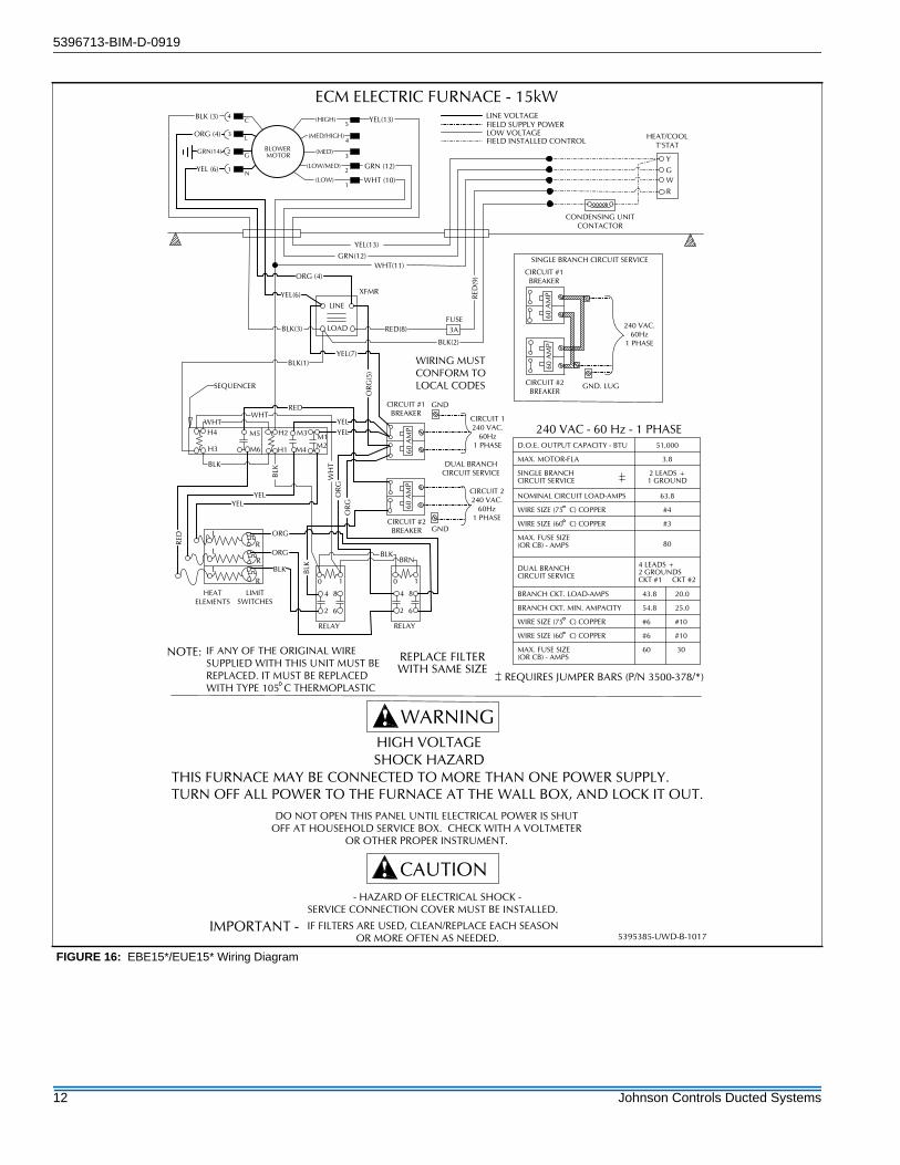
FIGURE 16: EBE15*/EUE15* Wiring Diagram
D.O.E. OUTPUT CAPACITY - BTU 51,000
MAX. MOTOR-FLA 3.8
SINGLE BRANCHCIRCUIT SERVICE
2 LEADS +1 GROUND
NOMINAL CIRCUIT LOAD-AMPS 63.8
WIRE SIZE (75 C) COPPER #4
WIRE SIZE (60 C) COPPER #3
MAX. FUSE SIZE(OR CB) - AMPS 80
DUAL BRANCHCIRCUIT SERVICE
4 LEADS +2 GROUNDSCKT #1 CKT #2
BRANCH CKT. LOAD-AMPS 43.8 20.0
BRANCH CKT. MIN. AMPACITY 54.8 25.0
WIRE SIZE (75 C) COPPER #6 #10
WIRE SIZE (60 C) COPPER #6 #10
MAX. FUSE SIZE(OR CB) - AMPS
60 30
SHOCK HAZARDTHIS FURNACE MAY BE CONNECTED TO MORE THAN ONE POWER SUPPLY. TURN OFF ALL POWER TO THE FURNACE AT THE WALL BOX, AND LOCK IT OUT.
DO NOT OPEN THIS PANEL UNTIL ELECTRICAL POWER IS SHUTOFF AT HOUSEHOLD SERVICE BOX. CHECK WITH A VOLTMETER
OR OTHER PROPER INSTRUMENT.
- HAZARD OF ELECTRICAL SHOCK -SERVICE CONNECTION COVER MUST BE INSTALLED.
IF FILTERS ARE USED, CLEAN/REPLACE EACH SEASONOR MORE OFTEN AS NEEDED.
CAUTION
IMPORTANT -
HIGH VOLTAGE
WARNING
5395385-UWD-B-1017
60 A
MP
CIRCUIT #1BREAKER
60 A
MP
240 VAC.60Hz
1 PHASE
CIRCUIT #2BREAKER
GND. LUG
SINGLE BRANCH CIRCUIT SERVICE
240 VAC - 60 Hz - 1 PHASE
REQUIRES JUMPER BARS (P/N 3500-378/*)
LINE
LOAD
XFMR
3AFUSE
RED(8)
RED
(9)
Y
GW
HEAT/COOLT'STAT
BLK(1)
M3 M1M2
H2M5
M6
H4
H3
WHT
BLK
SEQUENCER
60 A
MP
CIRCUIT 1240 VAC.
60Hz1 PHASE
CIRCUIT #1BREAKER
GND60
AM
P
CIRCUIT 2240 VAC.
60Hz1 PHASECIRCUIT #2
BREAKER
DUAL BRANCHCIRCUIT SERVICE
YEL
GND
ECM ELECTRIC FURNACE - 15kW
CONDENSING UNITCONTACTOR
YEL(13)
WHT(11)
M4H1
RED
IF ANY OF THE ORIGINAL WIRE SUPPLIED WITH THIS UNIT MUST BEREPLACED. IT MUST BE REPLACED WITH TYPE 105 C THERMOPLASTIC
WIRING MUST CONFORM TO LOCAL CODES
R
R
R
L
L
L
HEATELEMENTS
LIMITSWITCHES
NOTE:
RED
YELYEL
ORG
ORG
BLK
REPLACE FILTERWITH SAME SIZE
WH
T
BLK
OR
GO
RG
62
4 8
10
RELAY
62
4 8
10
RELAY
BRNBLK
BLK
YEL(7)
OR
G(5
)
GRN(14)
(LOW)
(LOW/MED)
(MED)
(HIGH)C
L
G
N
1
2
3
4
5
1
2
3
4
BLOWER MOTOR
(MED/HIGH)
BLK(2)
YEL(6)
ORG (4)
BLK(3)
WHT (10)
YEL(13)
YEL (6)
ORG (4)
BLK (3)
WHTYEL
LINE VOLTAGEFIELD SUPPLY POWERLOW VOLTAGEFIELD INSTALLED CONTROL
GRN(12)
R
GRN (12)
12 Johnson Controls Ducted Systems

5396713-BIM-D-0919
FIGURE 17: EBE17*/EUE17* Wiring Diagram
D.O.E. OUTPUT CAPACITY - BTU 56,000
MAX. MOTOR-FLA 3.8
SINGLE BRANCHCIRCUIT SERVICE
2 LEADS +1 GROUND
NOMINAL CIRCUIT LOAD-AMPS 70.4
WIRE SIZE (75 C) COPPER #3
WIRE SIZE (60 C) COPPER #2
MAX. FUSE SIZE(OR CB) - AMPS 90
DUAL BRANCHCIRCUIT SERVICE
4 LEADS +2 GROUNDSCKT #1 CKT #2
BRANCH CKT. LOAD-AMPS 47.1 23.3
BRANCH CKT. MIN. AMPACITY 58.9 29.1
WIRE SIZE (75 C) COPPER #6 #10
WIRE SIZE (60 C) COPPER #4 #10
MAX. FUSE SIZE(OR CB) - AMPS
60 30
60 A
MP
CIRCUIT #1BREAKER
60 A
MP
240 VAC.60Hz
1 PHASE
CIRCUIT #2BREAKER
GND. LUG
SINGLE BRANCH CIRCUIT SERVICE
240 VAC - 60 Hz - 1 PHASE
REQUIRES JUMPER BARS (P/N 3500-378/*)
SHOCK HAZARDTHIS FURNACE MAY BE CONNECTED TO MORE THAN ONE POWER SUPPLY. TURN OFF ALL POWER TO THE FURNACE AT THE WALL BOX, AND LOCK IT OUT.
DO NOT OPEN THIS PANEL UNTIL ELECTRICAL POWER IS SHUTOFF AT HOUSEHOLD SERVICE BOX. CHECK WITH A VOLTMETER
OR OTHER PROPER INSTRUMENT.
- HAZARD OF ELECTRICAL SHOCK -SERVICE CONNECTION COVER MUST BE INSTALLED.
IF FILTERS ARE USED, CLEAN/REPLACE EACH SEASONOR MORE OFTEN AS NEEDED.
CAUTION
IMPORTANT -
HIGH VOLTAGE
WARNING
5395387-UWD-A-0717
LINE
LOAD
XFMR
3AFUSE
RED(8)
RED
(9)
Y
GW
HEAT/COOLT'STAT
BLK(1)
M3 M1M2
H2M5
M6
H4
H3
WHT
BLK
SEQUENCER
60 A
MP
CIRCUIT 1240 VAC.
60Hz1 PHASE
CIRCUIT #1BREAKER
GND
60 A
MP
CIRCUIT 2240 VAC.
60Hz1 PHASECIRCUIT #2
BREAKER
DUAL BRANCHCIRCUIT SERVICE
YEL
GND
ECM ELECTRIC FURNACE - 17kW
CONDENSING UNITCONTACTOR
YEL(13)
WHT(11)
M4H1
RED
IF ANY OF THE ORIGINAL WIRE SUPPLIED WITH THIS UNIT MUST BEREPLACED. IT MUST BE REPLACED WITH TYPE 105 C THERMOPLASTIC
WIRING MUST CONFORM TO LOCAL CODES
R
R
R
L
L
L
HEATELEMENTS
LIMITSWITCHES
NOTE:
RED
YELYEL
ORG
ORG
BLK
REPLACE FILTERWITH SAME SIZE
WH
T
BLK
OR
GO
RG
62
4 8
10
RELAY
62
4 8
10
RELAY
BRNBLK
BLK
YEL(7)
OR
G(5
)
GRN(14)
(LOW)
(LOW/MED)
(MED)
(HIGH)C
L
G
N
1
2
3
4
5
1
2
3
4
BLOWER MOTOR
(MED/HIGH)
BLK(2)
YEL(6)
ORG (4)
BLK(3)
WHT (10)
YEL(13)
YEL (6)
ORG (4)
BLK (3)
WHTYEL
LINE VOLTAGEFIELD SUPPLY POWERLOW VOLTAGEFIELD INSTALLED CONTROL
GRN(12)
R
GRN (12)
Johnson Controls Ducted Systems 13

5396713-BIM-D-0919
FIGURE 18: EBE20*/EUE20* Wiring Diagram
D.O.E. OUTPUT CAPACITY - BTU 67,000
MAX. MOTOR-FLA 3.8
SINGLE BRANCHCIRCUIT SERVICE
2 LEADS +1 GROUND
NOMINAL CIRCUIT LOAD-AMPS 83.8
WIRE SIZE (75 C) COPPER #2
WIRE SIZE (60 C) COPPER #1
MAX. FUSE SIZE(OR CB) - AMPS 110
DUAL BRANCHCIRCUIT SERVICE
4 LEADS +2 GROUNDSCKT #1 CKT #2
BRANCH CKT. LOAD-AMPS 43.8 40.0
BRANCH CKT. MIN. AMPACITY 54.8 50.0
WIRE SIZE (75 C) COPPER #6 #8
WIRE SIZE (60 C) COPPER #6 #6
MAX. FUSE SIZE(OR CB) - AMPS
60 50
240 VAC - 60 Hz - 1 PHASE
REQUIRES JUMPER BARS (P/N 3500-378/*)
SHOCK HAZARDTHIS FURNACE MAY BE CONNECTED TO MORE THAN ONE POWER SUPPLY. TURN OFF ALL POWER TO THE FURNACE AT THE WALL BOX, AND LOCK IT OUT.
DO NOT OPEN THIS PANEL UNTIL ELECTRICAL POWER IS SHUTOFF AT HOUSEHOLD SERVICE BOX. CHECK WITH A VOLTMETER
OR OTHER PROPER INSTRUMENT.
- HAZARD OF ELECTRICAL SHOCK -SERVICE CONNECTION COVER MUST BE INSTALLED.
IF FILTERS ARE USED, CLEAN/REPLACE EACH SEASONOR MORE OFTEN AS NEEDED.
CAUTION
IMPORTANT -
HIGH VOLTAGE
WARNING
5395388-UWD-A-0717
LINE
LOAD
XFMR
3AFUSE
RED(8)
RED
(9)
Y
GW
HEAT/COOLT'STAT
BLK(1)
M3M1M2
H2M5
M6
H4
H3
WHT
BLK
SEQUENCER
60 A
MP
CIRCUIT 1240 VAC.
60Hz1 PHASE
CIRCUIT #1BREAKER
GND60
AM
P
CIRCUIT 2240 VAC.
60Hz1 PHASECIRCUIT #2
BREAKER
DUAL BRANCHCIRCUIT SERVICE
YEL
60 A
MP
CIRCUIT #1BREAKER
60 A
MP
240 VAC.60Hz
1 PHASE
CIRCUIT #2BREAKER
GND. LUG
SINGLE BRANCH CIRCUIT SERVICE
GND
ECM ELECTRIC FURNACE - 20kW
CONDENSING UNITCONTACTOR
YEL(13)
WHT(11)
M4H1
RED
IF ANY OF THE ORIGINAL WIRE SUPPLIED WITH THIS UNIT MUST BEREPLACED. IT MUST BE REPLACED WITH TYPE 105 C THERMOPLASTIC
WIRING MUST CONFORM TO LOCAL CODES
R
R
R
L
L
L
HEATELEMENTS
LIMITSWITCHES
NOTE:
RED
YELYEL
ORG
ORG
BLK
REPLACE FILTERWITH SAME SIZE
WH
T
BLK
OR
GO
RG
62
4 8
10
RELAY
62
4 8
10
RELAY
BRNBLK
BLK
YEL(7)
OR
G(5
)
GRN(14)
(LOW)
(LOW/MED)
(MED)
(HIGH)C
L
G
N
1
2
3
4
5
1
2
3
4
BLOWER MOTOR
(MED/HIGH)
BLK(2)
YEL(6)
ORG (4)
BLK(3)
WHT (10)
YEL(13)
YEL (6)
ORG (4)
BLK (3)
WHTYEL
RED
R
L
RED
M8
M7
BLK
BLK
LINE VOLTAGEFIELD SUPPLY POWERLOW VOLTAGEFIELD INSTALLED CONTROL
GRN(12)
R
GRN (12)
14 Johnson Controls Ducted Systems

5396713-BIM-D-0919
FIGURE 19: EBE23*/EUE23* Wiring Diagram
D.O.E. OUTPUT CAPACITY - BTU 77,000
MAX. MOTOR-FLA 3.8
SINGLE BRANCHCIRCUIT SERVICE
2 LEADS +1 GROUND
NOMINAL CIRCUIT LOAD-AMPS 93.8
WIRE SIZE (75 C) COPPER #1
WIRE SIZE (60 C) COPPER #0
MAX. FUSE SIZE(OR CB) - AMPS 125
DUAL BRANCHCIRCUIT SERVICE
4 LEADS +2 GROUNDS CKT #1 CKT #2
BRANCH CKT. LOAD-AMPS 47.1 46.7
BRANCH CKT. MIN. AMPACITY 58.9 58.4
WIRE SIZE (75 C) COPPER #6 #6
WIRE SIZE (60 C) COPPER #4 #4
MAX. FUSE SIZE(OR CB) - AMPS
60 60
LINE
LOAD
XFMR
3AFUSE
RED(8)
RED
(9)
Y
GW
HEAT/COOLT'STAT
BLK(1)
M3M1M2
H2M5
M6
H4
H3
WHT
BLK
SEQUENCER
60 A
MP
CIRCUIT 1240 VAC.
60Hz1 PHASE
CIRCUIT #1BREAKER
GND
60 A
MP
CIRCUIT 2240 VAC.
60Hz1 PHASECIRCUIT #2
BREAKER
DUAL BRANCHCIRCUIT SERVICE
YEL
60 A
MP
CIRCUIT #1BREAKER
60 A
MP
240 VAC.60Hz
1 PHASE
CIRCUIT #2BREAKER
GND. LUG
SINGLE BRANCH CIRCUIT SERVICE
GND
ECM ELECTRIC FURNACE - 23kW
CONDENSING UNITCONTACTOR
240 VAC - 60 Hz - 1 PHASE
REQUIRES JUMPER BARS (P/N 3500-378/*)
YEL(13)
WHT(11)
M4H1
RED
SHOCK HAZARDTHIS FURNACE MAY BE CONNECTED TO MORE THAN ONE POWER SUPPLY. TURN OFF ALL POWER TO THE FURNACE AT THE WALL BOX, AND LOCK IT OUT.
DO NOT OPEN THIS PANEL UNTIL ELECTRICAL POWER IS SHUTOFF AT HOUSEHOLD SERVICE BOX. CHECK WITH A VOLTMETER
OR OTHER PROPER INSTRUMENT.
- HAZARD OF ELECTRICAL SHOCK -SERVICE CONNECTION COVER MUST BE INSTALLED.
IF FILTERS ARE USED, CLEAN/REPLACE EACH SEASONOR MORE OFTEN AS NEEDED.
CAUTION
IMPORTANT -
HIGH VOLTAGE
WARNING
IF ANY OF THE ORIGINAL WIRE SUPPLIED WITH THIS UNIT MUST BEREPLACED. IT MUST BE REPLACED WITH TYPE 105 C THERMOPLASTIC
WIRING MUST CONFORM TO LOCAL CODES
R
R
R
L
L
L
HEATELEMENTS
LIMITSWITCHES
NOTE:
RED
YELYEL
ORG
ORG
BLK
REPLACE FILTERWITH SAME SIZE
WH
T
BLK
OR
GO
RG
5395389-UWD-A-0717
62
4 8
10
RELAY
62
4 8
10
RELAY
BRNBLK
BLK
YEL(7)
OR
G(5
)
GRN(14)
(LOW)
(LOW/MED)
(MED)
(HIGH)C
L
G
N
1
2
3
4
5
1
2
3
4
BLOWER MOTOR
(MED/HIGH)
BLK(2)
YEL(6)
ORG (4)
BLK(3)
WHT (10)
YEL(13)
YEL (6)
ORG (4)
BLK (3)
WHTYEL
RED
R
L
RED
M8
M7
BLK
BLK
LINE VOLTAGEFIELD SUPPLY POWERLOW VOLTAGEFIELD INSTALLED CONTROL
GRN(12)
R
GRN (12)
Johnson Controls Ducted Systems 15
NOTES
Subject to change without notice. Published in U.S.A. 5396713-BIM-D-0919Copyright © 2019 by Johnson Controls. All rights reserved. Supersedes: 5396713-BIM-C-0319
York International Corp.5005 York Drive
Norman, OK 73069