
PowerCommand iWatcht Installation Manual
69
Printed in U.S.A. 900−0538 8-2005 PowerCommand iWatcht Installation Manual The Power of One Remote Network Monitoring Redistribution or publication of this document by any means, is strictly prohibited.
-
Upload
khangminh22 -
Category
Documents
-
view
3 -
download
0
Transcript of PowerCommand iWatcht Installation Manual

Printed in U.S.A. 900−0538 8-2005
PowerCommand iWatch�Installation Manual
The Power of One
Remote Network Monitoring
Redistribution or publication of this documentby any means, is strictly prohibited.

Notices
The information in this document is subject to change without notice. Cummins Power Generation makes nowarranty of any kind with regard to this manual including, but not limited to, the implied warranties of merchant-ability and fitness for particular purpose. Cummins Power Generation shall not be liable for errors containedherein or incidental consequential damages in conjunction with furnishing, performance, or use of this manual.
This document contains proprietary information which is protected by copyright. All rights are reserved. Nopart of this document may be photocopied or otherwise reproduced without consent of Cummins Power Gen-eration.
Copyright 2005 by Cummins Power Generation. Published in a limited copyright sense, and all rights, in-cluding trade secrets, are reserved.
Document Edition:
First 6/2005
The following are products of Cummins Power Generation:
PowerCommand Pulse PowerCommand iWatch
The following are products of Advantech:
Advantech Studio Advantech WebLink 2059 Advantech TPC-1260
PowerCommand iWatch is a trademark of Cummins Inc.Cummins and PowerCommand are registered trademarks of Cummins Inc.The Power of One is a trademark of Cummins Inc.Microsoft and Windows are registered trademarks of Microsoft Corporation.WebLink is a registered trademark of Advantech Inc.LonMaker is a registered trademark of Echelon Corporation.
Redistribution or publication of this documentby any means, is strictly prohibited.
Table of Contents
SECTION TITLE PAGE
i
SAFETY PRECAUTIONS v . . . . . . . . . . . . . . . . . . . . . . . . . . . . . . . . . . . . . . . . . . . . . . . . . . . . . . .
1. INTRODUCTION 1-1 . . . . . . . . . . . . . . . . . . . . . . . . . . . . . . . . . . . . . . . . . . . . . . . Welcome 1-1 . . . . . . . . . . . . . . . . . . . . . . . . . . . . . . . . . . . . . . . . . . . . . . . . . . . Who Should Use This Manual? 1-2 . . . . . . . . . . . . . . . . . . . . . . . . . . . . . . . . Writing Conventions 1-2 . . . . . . . . . . . . . . . . . . . . . . . . . . . . . . . . . . . . . . . . . .
2. CONFIGURATION TOOL 2-1 . . . . . . . . . . . . . . . . . . . . . . . . . . . . . . . . . . . . . . . . Introduction 2-1 . . . . . . . . . . . . . . . . . . . . . . . . . . . . . . . . . . . . . . . . . . . . . . . . . Installation 2-2 . . . . . . . . . . . . . . . . . . . . . . . . . . . . . . . . . . . . . . . . . . . . . . . . . . Application Overview 2-8 . . . . . . . . . . . . . . . . . . . . . . . . . . . . . . . . . . . . . . . . . Site Configuration 2-9 . . . . . . . . . . . . . . . . . . . . . . . . . . . . . . . . . . . . . . . . . . . . RAS Entry Configuration 2-12 . . . . . . . . . . . . . . . . . . . . . . . . . . . . . . . . . . . . . . ModLon Gateway Configuration 2-14 . . . . . . . . . . . . . . . . . . . . . . . . . . . . . . . Device Configuration 2-16 . . . . . . . . . . . . . . . . . . . . . . . . . . . . . . . . . . . . . . . . . Deleting Sites/ModLon Gateways/Devices 2-19 . . . . . . . . . . . . . . . . . . . . . . Downloading WebLink Applications 2-19 . . . . . . . . . . . . . . . . . . . . . . . . . . . . Modifying WebLink Login Security 2-25 . . . . . . . . . . . . . . . . . . . . . . . . . . . . .
3. OPC MULTIPLEXOR 3-1 . . . . . . . . . . . . . . . . . . . . . . . . . . . . . . . . . . . . . . . . . . . Introduction 3-1 . . . . . . . . . . . . . . . . . . . . . . . . . . . . . . . . . . . . . . . . . . . . . . . . . Installation 3-1 . . . . . . . . . . . . . . . . . . . . . . . . . . . . . . . . . . . . . . . . . . . . . . . . . . User Interface 3-1 . . . . . . . . . . . . . . . . . . . . . . . . . . . . . . . . . . . . . . . . . . . . . . . OPC Server 3-6 . . . . . . . . . . . . . . . . . . . . . . . . . . . . . . . . . . . . . . . . . . . . . . . . . Historical Data/Alarm Storage and Forwarding 3-7 . . . . . . . . . . . . . . . . . . .
APPENDIX A. MODLON GATEWAY REGISTER MAPS A-1 . . . . . . . . . . . . . . . . . . . . . . . . . .
Redistribution or publication of this documentby any means, is strictly prohibited.
List of Figures
FIGURE TITLE PAGE
ii
Figure 1-1 The Remote Network Monitoring System 1-1 . . . . . . . . . . . . . . . . . . . . . . . . . . Figure 1-2 Open Dialog 1-2 . . . . . . . . . . . . . . . . . . . . . . . . . . . . . . . . . . . . . . . . . . . . . . . . . . .
Figure 2-1 Initial Installation Dialog 2-2 . . . . . . . . . . . . . . . . . . . . . . . . . . . . . . . . . . . . . . . . . Figure 2-2 Second Installation Dialog 2-2 . . . . . . . . . . . . . . . . . . . . . . . . . . . . . . . . . . . . . . . Figure 2-3 Main Installation Dialog 2-3 . . . . . . . . . . . . . . . . . . . . . . . . . . . . . . . . . . . . . . . . . . Figure 2-4 License Agreement 2-3 . . . . . . . . . . . . . . . . . . . . . . . . . . . . . . . . . . . . . . . . . . . . . Figure 2-5 Installation Information 2-4 . . . . . . . . . . . . . . . . . . . . . . . . . . . . . . . . . . . . . . . . . . Figure 2-6 Installation Customization Option 2-4 . . . . . . . . . . . . . . . . . . . . . . . . . . . . . . . . . Figure 2-7 Installation Customization 2-5 . . . . . . . . . . . . . . . . . . . . . . . . . . . . . . . . . . . . . . . Figure 2-8 Final Installation Checkpoint 2-5 . . . . . . . . . . . . . . . . . . . . . . . . . . . . . . . . . . . . . Figure 2-9 Installation Progress 2-6 . . . . . . . . . . . . . . . . . . . . . . . . . . . . . . . . . . . . . . . . . . . . Figure 2-10 Installation Complete! 2-6 . . . . . . . . . . . . . . . . . . . . . . . . . . . . . . . . . . . . . . . . . . . Figure 2-11 Reboot System Dialog 2-7 . . . . . . . . . . . . . . . . . . . . . . . . . . . . . . . . . . . . . . . . . . Figure 2-12 Launching RNMConfig 2-7 . . . . . . . . . . . . . . . . . . . . . . . . . . . . . . . . . . . . . . . . . . Figure 2-13 Configuration Tool User Interface 2-8 . . . . . . . . . . . . . . . . . . . . . . . . . . . . . . . . . Figure 2-14 Adding a Site 2-8 . . . . . . . . . . . . . . . . . . . . . . . . . . . . . . . . . . . . . . . . . . . . . . . . . . Figure 2-15 Site Information Dialog 2-9 . . . . . . . . . . . . . . . . . . . . . . . . . . . . . . . . . . . . . . . . . . Figure 2-16 Save Changes 2-11 . . . . . . . . . . . . . . . . . . . . . . . . . . . . . . . . . . . . . . . . . . . . . . . . . Figure 2-17 Right Mouse Click on Site 2-11 . . . . . . . . . . . . . . . . . . . . . . . . . . . . . . . . . . . . . . . Figure 2-18 RAS Configuration − Type of Connection 2-12 . . . . . . . . . . . . . . . . . . . . . . . . . . Figure 2-19 RAS Configuration − Phone Number 2-12 . . . . . . . . . . . . . . . . . . . . . . . . . . . . . . Figure 2-20 RAS Configuration − Phone Number 2-13 . . . . . . . . . . . . . . . . . . . . . . . . . . . . . . Figure 2-21 RAS Configuration − RAS Entry Properties 2-13 . . . . . . . . . . . . . . . . . . . . . . . . Figure 2-22 ModLon Gateway Configuration 2-14 . . . . . . . . . . . . . . . . . . . . . . . . . . . . . . . . . . Figure 2-23 ModLon Gateway − Configuration Options 2-14 . . . . . . . . . . . . . . . . . . . . . . . . . Figure 2-24 ModLon Details 2-15 . . . . . . . . . . . . . . . . . . . . . . . . . . . . . . . . . . . . . . . . . . . . . . . . Figure 2-25 ModLon Entry Right Mouse Click 2-15 . . . . . . . . . . . . . . . . . . . . . . . . . . . . . . . . . Figure 2-26 Device Selection 2-16 . . . . . . . . . . . . . . . . . . . . . . . . . . . . . . . . . . . . . . . . . . . . . . . Figure 2-27 Device Selection Default Values 2-16 . . . . . . . . . . . . . . . . . . . . . . . . . . . . . . . . . . Figure 2-28 Device Details 2-17 . . . . . . . . . . . . . . . . . . . . . . . . . . . . . . . . . . . . . . . . . . . . . . . . . . Figure 2-29 Tag Details 2-17 . . . . . . . . . . . . . . . . . . . . . . . . . . . . . . . . . . . . . . . . . . . . . . . . . . . . Figure 2-30 Tag Detail − Relay/Input Descriptions 2-18 . . . . . . . . . . . . . . . . . . . . . . . . . . . . . Figure 2-31 Delete Confirmation 2-19 . . . . . . . . . . . . . . . . . . . . . . . . . . . . . . . . . . . . . . . . . . . . . Figure 2-32 Advantech Web Studio 6.0 Icon 2-19 . . . . . . . . . . . . . . . . . . . . . . . . . . . . . . . . . . Figure 2-33 Advantech Studio 6.0 Start Menu 2-19 . . . . . . . . . . . . . . . . . . . . . . . . . . . . . . . . . Figure 2-34 Advantech Studio − Open Project 2-20 . . . . . . . . . . . . . . . . . . . . . . . . . . . . . . . . Figure 2-35 Advantech Studio − Execution Environment 2-20 . . . . . . . . . . . . . . . . . . . . . . . Figure 2-36 Execution Environment Dialog 2-20 . . . . . . . . . . . . . . . . . . . . . . . . . . . . . . . . . . . Figure 2-37 Execution Environment Dialog − Connected 2-21 . . . . . . . . . . . . . . . . . . . . . . . Figure 2-38 Execution Environment Dialog − Application Tab 2-21 . . . . . . . . . . . . . . . . . . . Figure 2-39 Execution Environment Dialog − Stopped Application 2-21 . . . . . . . . . . . . . . .
Redistribution or publication of this documentby any means, is strictly prohibited.
List of Figures (Continued)
FIGURE TITLE PAGE
iii
Figure 2-40 Send to Target Dialog 2-22 . . . . . . . . . . . . . . . . . . . . . . . . . . . . . . . . . . . . . . . . . . . Figure 2-41 Sending Files to Target Dialog 2-22 . . . . . . . . . . . . . . . . . . . . . . . . . . . . . . . . . . . Figure 2-42 Sending Files to Target 2-22 . . . . . . . . . . . . . . . . . . . . . . . . . . . . . . . . . . . . . . . . . . Figure 2-43 Run Application 2-23 . . . . . . . . . . . . . . . . . . . . . . . . . . . . . . . . . . . . . . . . . . . . . . . . Figure 2-44 Target Status 2-23 . . . . . . . . . . . . . . . . . . . . . . . . . . . . . . . . . . . . . . . . . . . . . . . . . . Figure 2-45 Security Login 2-23 . . . . . . . . . . . . . . . . . . . . . . . . . . . . . . . . . . . . . . . . . . . . . . . . . . Figure 2-46 Main Navigation Screen in Web Browser 2-24 . . . . . . . . . . . . . . . . . . . . . . . . . . Figure 2-47 Exiting Advantech Studio 2-24 . . . . . . . . . . . . . . . . . . . . . . . . . . . . . . . . . . . . . . . . Figure 2-48 Configuring Advantech Studio Security 2-25 . . . . . . . . . . . . . . . . . . . . . . . . . . . . Figure 2-49 Security − Group Account Dialog 2-25 . . . . . . . . . . . . . . . . . . . . . . . . . . . . . . . . . Figure 2-50 Security − Enter Group Name 2-26 . . . . . . . . . . . . . . . . . . . . . . . . . . . . . . . . . . . . Figure 2-51 Security − Group Account Selection 2-26 . . . . . . . . . . . . . . . . . . . . . . . . . . . . . . Figure 2-52 Security − User Account Dialog 2-26 . . . . . . . . . . . . . . . . . . . . . . . . . . . . . . . . . . Figure 2-53 Security − New User Account 2-27 . . . . . . . . . . . . . . . . . . . . . . . . . . . . . . . . . . . . Figure 2-54 Security − User Password 2-27 . . . . . . . . . . . . . . . . . . . . . . . . . . . . . . . . . . . . . . .
Figure 3-1 OPC Multiplexor Main Dialog 3-2 . . . . . . . . . . . . . . . . . . . . . . . . . . . . . . . . . . . . . Figure 3-2 Connected Site Information 3-2 . . . . . . . . . . . . . . . . . . . . . . . . . . . . . . . . . . . . . . Figure 3-3 OPC Multiplexor − Site Connected 3-3 . . . . . . . . . . . . . . . . . . . . . . . . . . . . . . . . Figure 3-4 OPC Multiplexor − OPC Client Component 3-3 . . . . . . . . . . . . . . . . . . . . . . . . Figure 3-5 OPC Multiplexor − Disconnected Client 3-4 . . . . . . . . . . . . . . . . . . . . . . . . . . . . Figure 3-6 OPC Multiplexor − Reconnected Client 3-5 . . . . . . . . . . . . . . . . . . . . . . . . . . . . Figure 3-7 OPC Server General Folder 3-6 . . . . . . . . . . . . . . . . . . . . . . . . . . . . . . . . . . . . . . Figure 3-8 OPC Server Device Folders 3-6 . . . . . . . . . . . . . . . . . . . . . . . . . . . . . . . . . . . . . . Figure 3-9 Site Configuration Dialog 3-7 . . . . . . . . . . . . . . . . . . . . . . . . . . . . . . . . . . . . . . . .
Redistribution or publication of this documentby any means, is strictly prohibited.
List of Tables
TABLE TITLE PAGE
iv
Table 2-1 Site Configuration Field Definitions 2-10 . . . . . . . . . . . . . . . . . . . . . . . . . . . . . . .
Table 3-1 OPC Server General Tags 3-6 . . . . . . . . . . . . . . . . . . . . . . . . . . . . . . . . . . . . . . . Table 3-2 Configuration Database Tables 3-7 . . . . . . . . . . . . . . . . . . . . . . . . . . . . . . . . . . .
Table A-1 ModLon Register Mapping Information − Option 1Single PowerCommand Genset A-2 . . . . . . . . . . . . . . . . . . . . . . . . . . . . . . . . . .
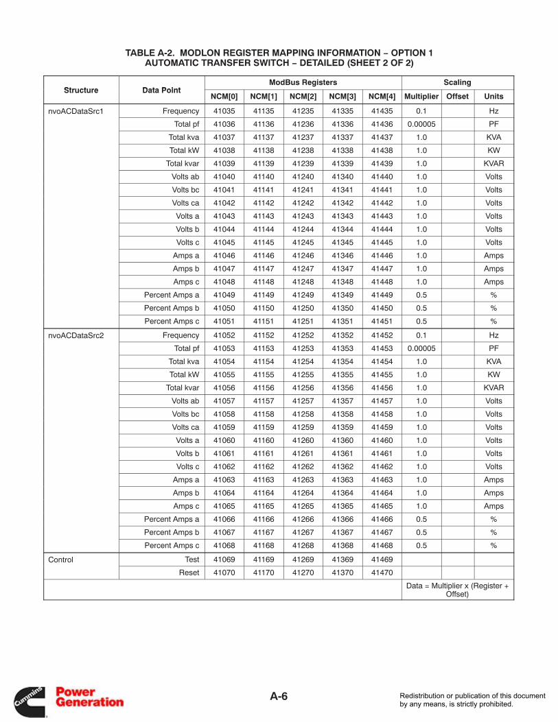
Table A-2 ModLon Register Mapping Information − Option 1Automatic Transfer Switch − Detailed A-5 . . . . . . . . . . . . . . . . . . . . . . . . . . . . .
Table A-3 ModLon Register Mapping Information − Option 1Digital I/O Module (DIM) A-8 . . . . . . . . . . . . . . . . . . . . . . . . . . . . . . . . . . . . . . . . .
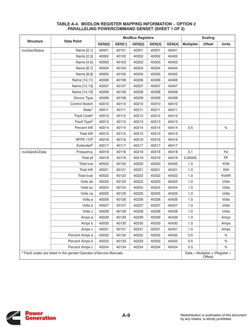
Table A-4 ModLon Register Mapping Information − Option 2Paralleling PowerCommand Genset A-9 . . . . . . . . . . . . . . . . . . . . . . . . . . . . . .
Table A-5 ModLon Register Mapping Information − Option 2Automatic Transfer Switch − Simple A-13 . . . . . . . . . . . . . . . . . . . . . . . . . . . . . . .
Table A-6 ModLon Register Mapping Information − Option 2Digital I/O Module (DIM) A-15 . . . . . . . . . . . . . . . . . . . . . . . . . . . . . . . . . . . . . . . . .
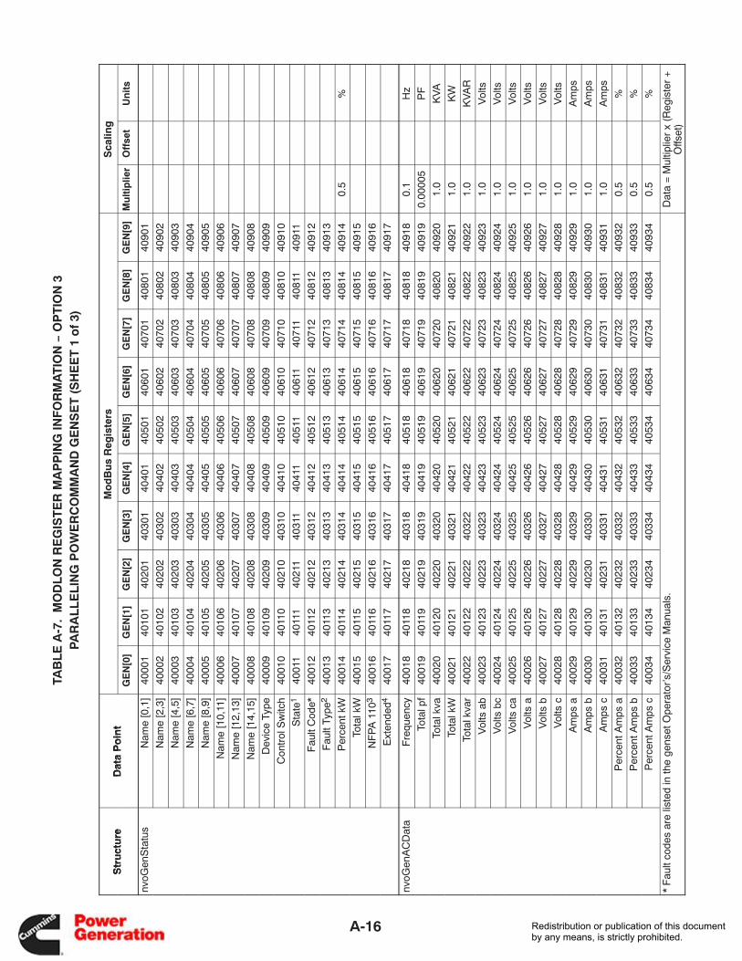
Table A-7 ModLon Register Mapping Information − Option 3Paralleling PowerCommand Genset A-16 . . . . . . . . . . . . . . . . . . . . . . . . . . . . . .
Table A-8 ModLon Register Mapping Information − Option 3Automatic Transfer Switch − Detailed A-20 . . . . . . . . . . . . . . . . . . . . . . . . . . . . .
Redistribution or publication of this documentby any means, is strictly prohibited.

PCN−1
v
Safety Precautions
The PowerCommand Network can be used to re-motely operate power transfer equipment (e.g.,transfer switches, paralleling systems) and startand stop generator sets. All of the safety precau-tions for that equipment must observed. Refer to theOperator’s Manual for the equipment that is beingmonitored and controlled by the network for impor-tant safety precautions.
The following symbols, found throughout thismanual, alert you to potentially dangerous condi-tions to the operator, service personnel, or theequipment.
DANGER This symbol warns of immediatehazards which will result in severe personal in-jury or death.
WARNING This symbol refers to a hazard orunsafe practice which can result in severe per-sonal injury or death.
CAUTION This symbol refers to a hazard orunsafe practice which can result in personal in-jury or product or property damage.
MOVING PARTS CAN CAUSE SEVEREPERSONAL INJURY OR DEATH
• Keep your hands, clothing, and jewelry awayfrom moving parts.
• Before starting work on the generator set, dis-connect battery charger from its AC source,then disconnect starting batteries, negative (-)cable first. This will prevent accidental starting.
• Make sure that fasteners on the generator setare secure. Tighten supports and clamps, keepguards in position over fans, drive belts, etc.
• Do not wear loose clothing or jewelry in the vi-cinity of moving parts, or while working on elec-trical equipment. Loose clothing and jewelrycan become caught in moving parts. Jewelrycan short out electrical contacts and causeshock or burning.
• If adjustment must be made while the unit isrunning, use extreme caution around hot man-ifolds, moving parts, etc.
ELECTRICAL SHOCK CAN CAUSESEVERE PERSONAL INJURY OR DEATH
• Remove electric power before removing pro-tective shields or touching electrical equip-ment. Use rubber insulative mats placed on drywood platforms over floors that are metal orconcrete when around electrical equipment.Do not wear damp clothing (particularly wetshoes) or allow skin surface to be damp whenhandling electrical equipment.
• Use extreme caution when working on electri-cal components. High voltages can cause inju-ry or death. DO NOT tamper with interlocks.
• Follow all applicable state and local electricalcodes. Have all electrical installations per-formed by a qualified licensed electrician. Tagand lock open switches to avoid accidental clo-sure.
• Jewelry is a good conductor of electricity andshould be removed before working on electri-cal equipment.
Redistribution or publication of this documentby any means, is strictly prohibited.
vi
MEDIUM VOLTAGE GENERATOR SETS
(601V to 15kV)
• Medium voltage acts differently than low volt-age. Special equipment and training is requiredto work on or around medium voltage equip-ment. Operation and maintenance must bedone only by persons trained and qualified towork on such devices. Improper use or proce-dures will result in severe personal injury ordeath.
• Do not work on energized equipment. Unau-thorized personnel must not be permitted nearenergized equipment. Due to the nature of me-dium voltage electrical equipment, inducedvoltage can remain even after the equipment isdisconnected from the power source. Plan thetime for maintenance with authorized person-nel so that the equipment can be de-energizedand safely grounded.
TRANSFER SWITCHES
• AC and DC voltages in the transfer switch com-ponents present serious shock hazards thatcan result in severe personal injury or death.Read and follow these instructions.
• Keep the transfer switch cabinet closed andlocked. Make sure only authorized personnelhave cabinet and operational keys.
• Due to the serious shock hazard from mediumvoltages within the cabinet, all service and ad-justments to the transfer switch must be per-formed only by an electrician or authorized ser-vice representative.
• If the cabinet must be opened for any reason:
1. Move the operation selector switch on thegenerator set to Stop.
2. Disconnect battery charger from its ACsource. Disconnect the starting batteriesof the generator set. (Remove the nega-tive [−] lead first to prevent arcing from ig-niting explosive battery gas.)
3. Remove AC power to the automatic trans-fer switch. If the instructions require other-wise, use extreme caution due to the dan-ger of shock hazard.
GENERAL SAFETY PRECAUTIONS
• The PowerCommand Network allows remoteoperation of equipment. PowerCommand Soft-ware for Windows can remotely start and stop agenset or exercise a transfer switch. Networkmodules can independently control other net-work modules and operate other electrical de-vices such as fans or pumps etc. Make certainthat all appropriate personnel are notified be-fore remotely operating equipment and makethem aware of any equipment that can be ener-gized automatically.
• Do not work on this equipment when mentallyor physically fatigued, or after consuming anyalcohol or drug that makes the operation ofequipment unsafe.
• Use only the latest physical and logical connec-tion diagrams for installing and maintaining thePowerCommand Network. If changes aremade to the physical or logical network con-nections, make sure the site connection dia-grams are updated. Create a new CSV file if thenumber or type of modules changes or if thebindings change.
Redistribution or publication of this documentby any means, is strictly prohibited.
1-1
1. Introduction
P o we rCommand Pulse
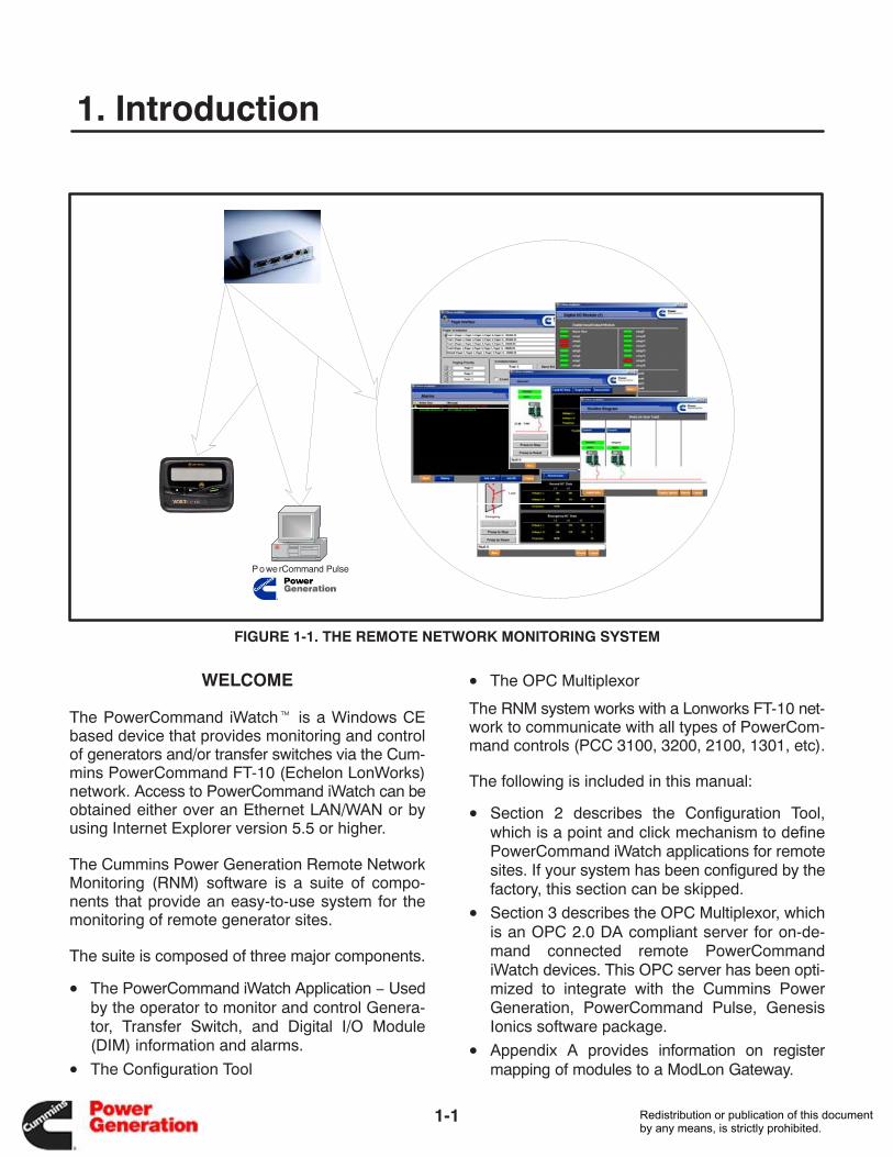
FIGURE 1-1. THE REMOTE NETWORK MONITORING SYSTEM
WELCOME
The PowerCommand iWatch� is a Windows CEbased device that provides monitoring and controlof generators and/or transfer switches via the Cum-mins PowerCommand FT-10 (Echelon LonWorks)network. Access to PowerCommand iWatch can beobtained either over an Ethernet LAN/WAN or byusing Internet Explorer version 5.5 or higher.
The Cummins Power Generation Remote NetworkMonitoring (RNM) software is a suite of compo-nents that provide an easy-to-use system for themonitoring of remote generator sites.
The suite is composed of three major components.
• The PowerCommand iWatch Application − Usedby the operator to monitor and control Genera-tor, Transfer Switch, and Digital I/O Module(DIM) information and alarms.
• The Configuration Tool
• The OPC Multiplexor
The RNM system works with a Lonworks FT-10 net-work to communicate with all types of PowerCom-mand controls (PCC 3100, 3200, 2100, 1301, etc).
The following is included in this manual:
• Section 2 describes the Configuration Tool,which is a point and click mechanism to definePowerCommand iWatch applications for remotesites. If your system has been configured by thefactory, this section can be skipped.
• Section 3 describes the OPC Multiplexor, whichis an OPC 2.0 DA compliant server for on-de-mand connected remote PowerCommandiWatch devices. This OPC server has been opti-mized to integrate with the Cummins PowerGeneration, PowerCommand Pulse, GenesisIonics software package.
• Appendix A provides information on registermapping of modules to a ModLon Gateway.
Redistribution or publication of this documentby any means, is strictly prohibited.
1-2
WHO SHOULD USE THIS MANUAL?
This manual is designed to be used by system inte-grators and distributors.
Before using this manual, a network must be prop-erly set up (see FT-10 Network Installation and Op-eration Manual 900−0529) and the PowerCom-mand iWatch control assembly must be installed(see Instruction Sheet C661). To install and config-ure an PowerCommand iWatch control, personnelmust be trained and experienced in setting upFT-10 networks and familiar with LonMaker for Win-dows software.
WRITING CONVENTIONS
The following conventions are used in writing thismanual:
• Boldface type indicates an item that requiresspecific attention. This is used for note blocks asshown in next column.
NOTE:This is an example of a note block. Specialattention should be given to the instructions inthis form.
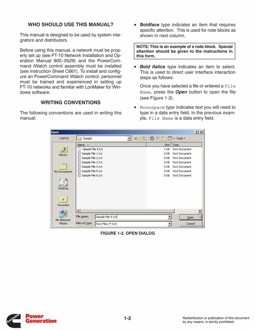
• Bold Italics type indicates an item to select.This is used to direct user interface interactionsteps as follows:
Once you have selected a file or entered a FileName, press the Open button to open the file(see Figure 1-2).
• Monospace type indicates text you will need totype in a data entry field. In the previous exam-ple, File Name is a data entry field.
FIGURE 1-2. OPEN DIALOG
Redistribution or publication of this documentby any means, is strictly prohibited.
2-1
2. Configuration Tool
INTRODUCTION
The Configuration Tool is a stand alone applicationthat is used to configure the list of devices and typesthat are associated with remote generator sites.The site configuration can then be used to generateAdvantech Studio WebLink� applications. Thisgreatly reduces the effort by a system integrationengineer in creating a unique site configuration tomatch a specific site’s devices.
NOTE:For systems configured by the factory, thissection can be skipped.
Individual parameters of the site application and de-vice tags can be customized prior to creating the ap-
plication to download to the device. The site optionsthat are configurable are:
• Name
• IP Address
• Remote Access Server (RAS) Login Security
• Units of Measure
• Paging System Repeat Frequency
• Storing and Forwarding Alarm and HistoricalData
The device tag level options available are:
• Digital I/O Module (DIM) input and relay naming
• Historical Logging
• Alarming
Redistribution or publication of this documentby any means, is strictly prohibited.
2-2
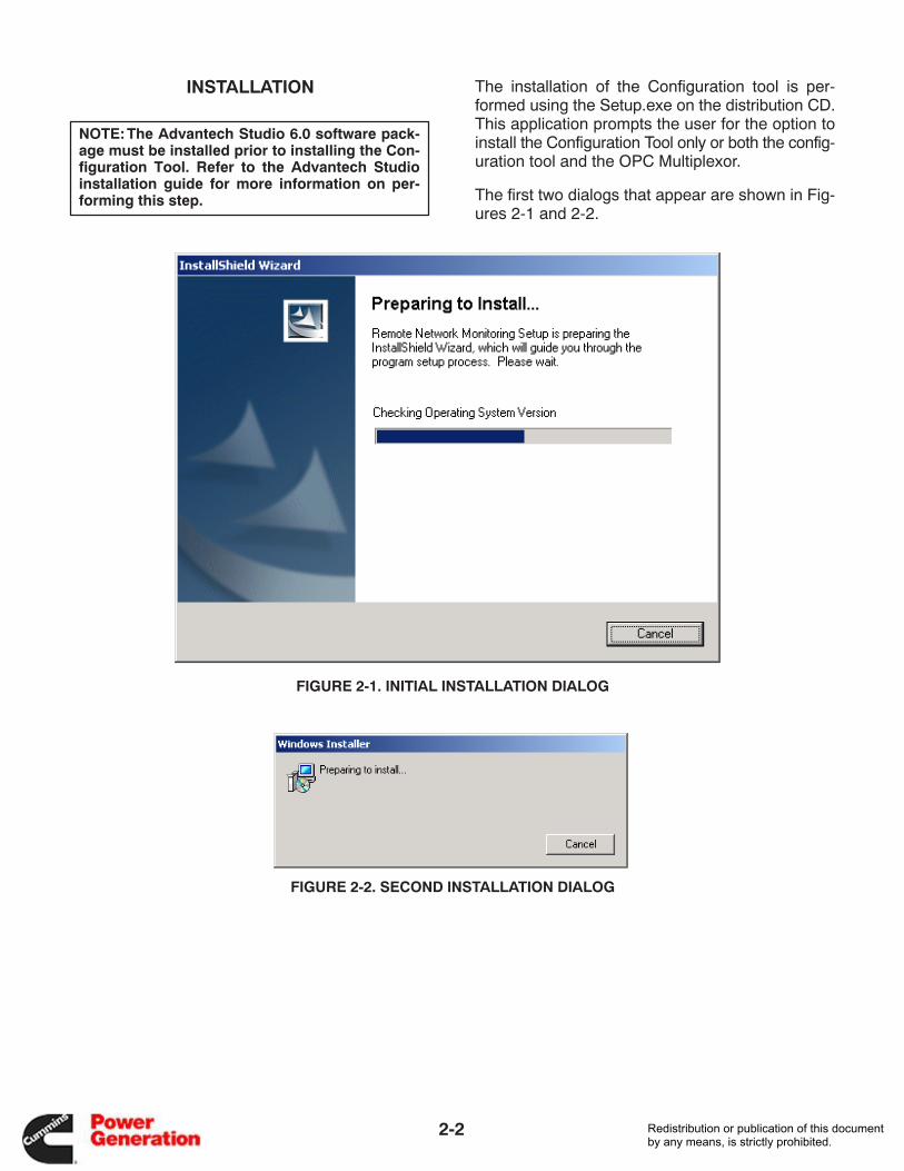
INSTALLATION
NOTE:The Advantech Studio 6.0 software pack-age must be installed prior to installing the Con-figuration Tool. Refer to the Advantech Studioinstallation guide for more information on per-forming this step.
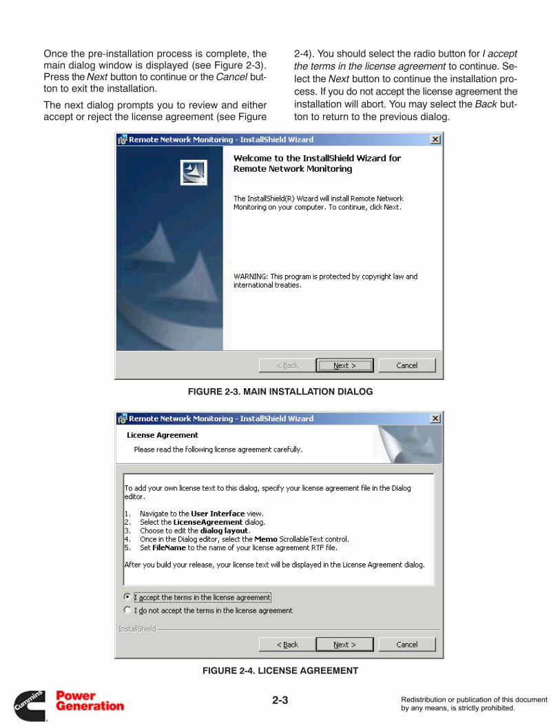
The installation of the Configuration tool is per-formed using the Setup.exe on the distribution CD.This application prompts the user for the option toinstall the Configuration Tool only or both the config-uration tool and the OPC Multiplexor.
The first two dialogs that appear are shown in Fig-ures 2-1 and 2-2.
FIGURE 2-1. INITIAL INSTALLATION DIALOG
FIGURE 2-2. SECOND INSTALLATION DIALOG
Redistribution or publication of this documentby any means, is strictly prohibited.
2-3
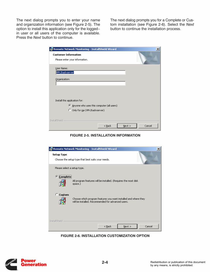
Once the pre-installation process is complete, themain dialog window is displayed (see Figure 2-3).Press the Next button to continue or the Cancel but-ton to exit the installation.
The next dialog prompts you to review and eitheraccept or reject the license agreement (see Figure
2-4). You should select the radio button for I acceptthe terms in the license agreement to continue. Se-lect the Next button to continue the installation pro-cess. If you do not accept the license agreement theinstallation will abort. You may select the Back but-ton to return to the previous dialog.
FIGURE 2-3. MAIN INSTALLATION DIALOG
FIGURE 2-4. LICENSE AGREEMENT
Redistribution or publication of this documentby any means, is strictly prohibited.
2-4
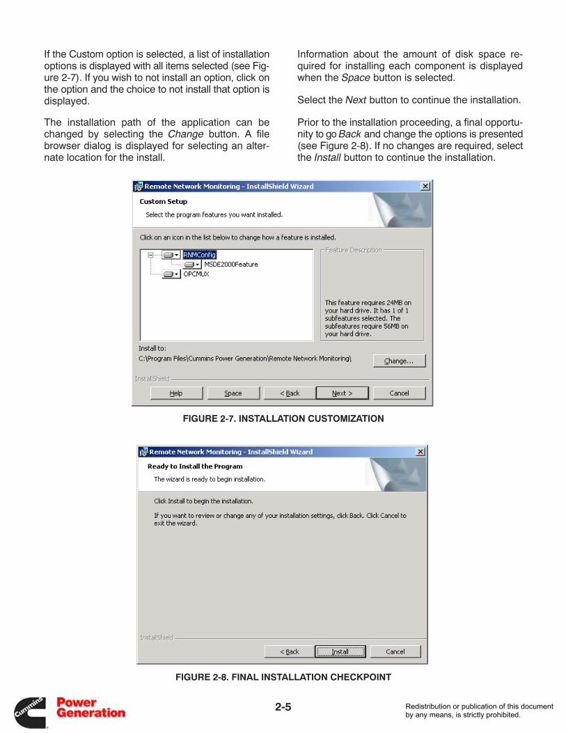
The next dialog prompts you to enter your nameand organization information (see Figure 2-5). Theoption to install this application only for the logged−in user or all users of the computer is available.Press the Next button to continue.
The next dialog prompts you for a Complete or Cus-tom installation (see Figure 2-6). Select the Nextbutton to continue the installation process.
FIGURE 2-5. INSTALLATION INFORMATION
FIGURE 2-6. INSTALLATION CUSTOMIZATION OPTION
Redistribution or publication of this documentby any means, is strictly prohibited.
2-5
If the Custom option is selected, a list of installationoptions is displayed with all items selected (see Fig-ure 2-7). If you wish to not install an option, click onthe option and the choice to not install that option isdisplayed.
The installation path of the application can bechanged by selecting the Change button. A filebrowser dialog is displayed for selecting an alter-nate location for the install.
Information about the amount of disk space re-quired for installing each component is displayedwhen the Space button is selected.
Select the Next button to continue the installation.
Prior to the installation proceeding, a final opportu-nity to go Back and change the options is presented(see Figure 2-8). If no changes are required, selectthe Install button to continue the installation.
FIGURE 2-7. INSTALLATION CUSTOMIZATION
FIGURE 2-8. FINAL INSTALLATION CHECKPOINT
Redistribution or publication of this documentby any means, is strictly prohibited.
2-6
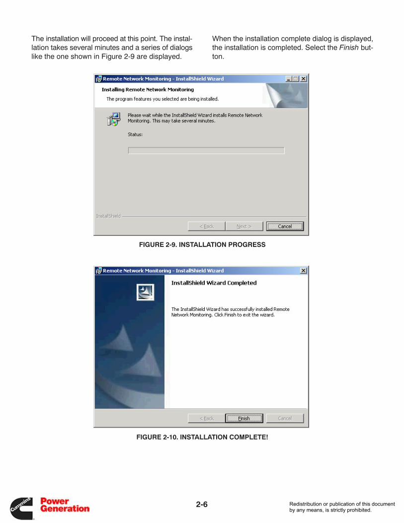
The installation will proceed at this point. The instal-lation takes several minutes and a series of dialogslike the one shown in Figure 2-9 are displayed.
When the installation complete dialog is displayed,the installation is completed. Select the Finish but-ton.
FIGURE 2-9. INSTALLATION PROGRESS
FIGURE 2-10. INSTALLATION COMPLETE!
Redistribution or publication of this documentby any means, is strictly prohibited.
2-7
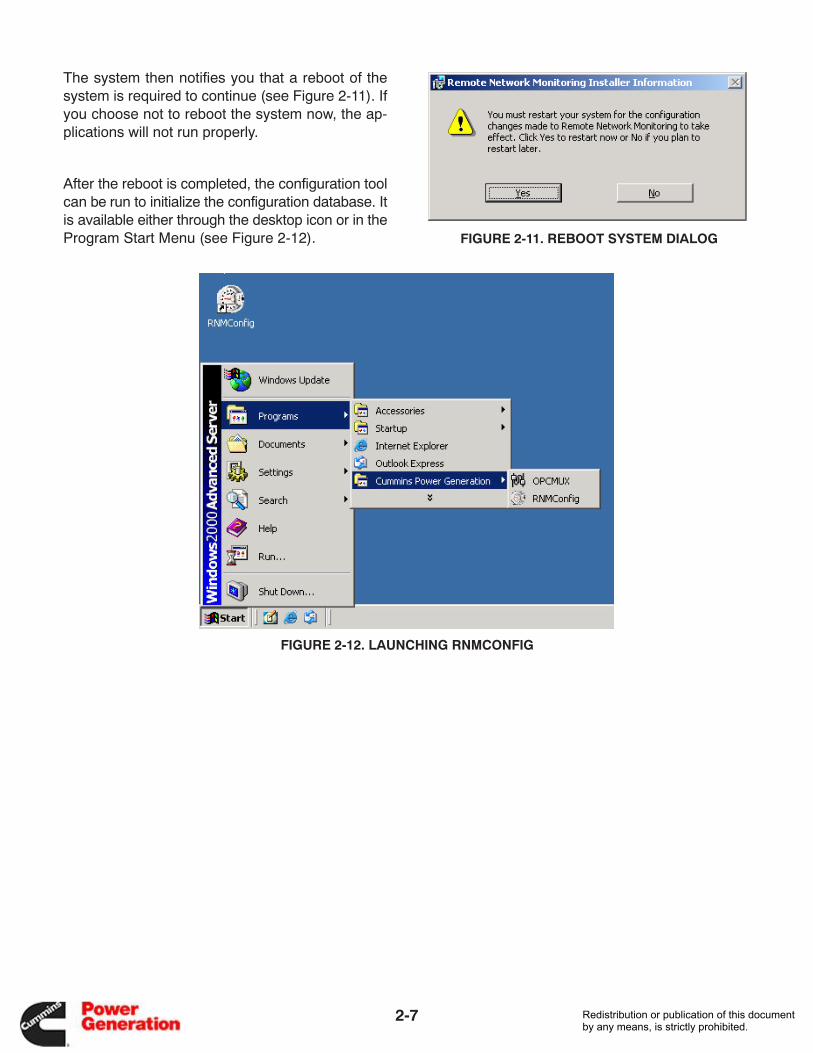
The system then notifies you that a reboot of thesystem is required to continue (see Figure 2-11). Ifyou choose not to reboot the system now, the ap-plications will not run properly.
After the reboot is completed, the configuration toolcan be run to initialize the configuration database. Itis available either through the desktop icon or in theProgram Start Menu (see Figure 2-12). FIGURE 2-11. REBOOT SYSTEM DIALOG
FIGURE 2-12. LAUNCHING RNMCONFIG
Redistribution or publication of this documentby any means, is strictly prohibited.
2-8
APPLICATION OVERVIEW
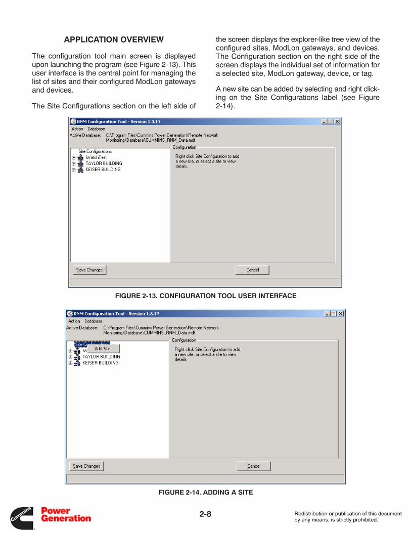
The configuration tool main screen is displayedupon launching the program (see Figure 2-13). Thisuser interface is the central point for managing thelist of sites and their configured ModLon gatewaysand devices.
The Site Configurations section on the left side of
the screen displays the explorer-like tree view of theconfigured sites, ModLon gateways, and devices.The Configuration section on the right side of thescreen displays the individual set of information fora selected site, ModLon gateway, device, or tag.
A new site can be added by selecting and right click-ing on the Site Configurations label (see Figure2-14).
FIGURE 2-13. CONFIGURATION TOOL USER INTERFACE
FIGURE 2-14. ADDING A SITE
Redistribution or publication of this documentby any means, is strictly prohibited.
2-9
SITE CONFIGURATION
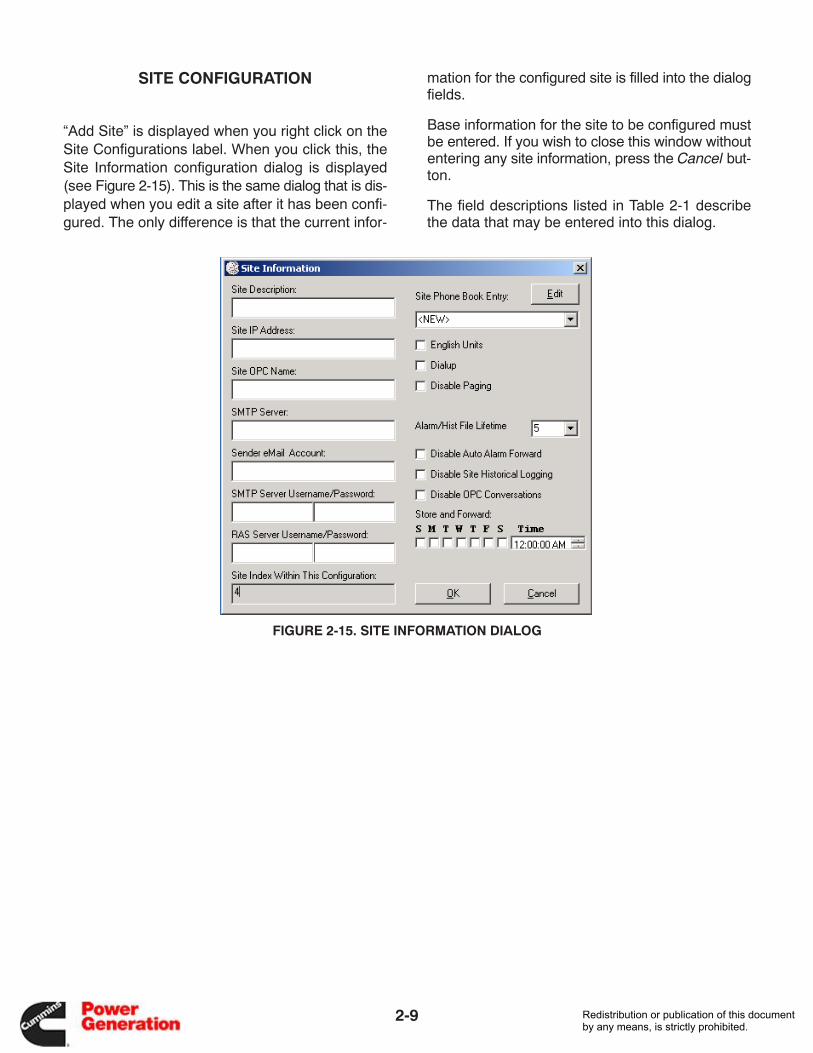
“Add Site” is displayed when you right click on theSite Configurations label. When you click this, theSite Information configuration dialog is displayed(see Figure 2-15). This is the same dialog that is dis-played when you edit a site after it has been confi-gured. The only difference is that the current infor-
mation for the configured site is filled into the dialogfields.
Base information for the site to be configured mustbe entered. If you wish to close this window withoutentering any site information, press the Cancel but-ton.
The field descriptions listed in Table 2-1 describethe data that may be entered into this dialog.
FIGURE 2-15. SITE INFORMATION DIALOG
Redistribution or publication of this documentby any means, is strictly prohibited.
2-10
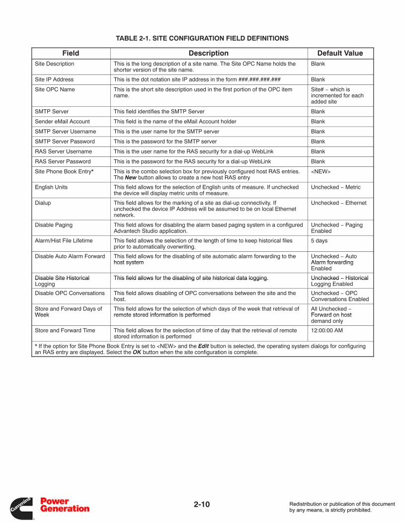
TABLE 2-1. SITE CONFIGURATION FIELD DEFINITIONS
Field Description Default ValueSite Description This is the long description of a site name. The Site OPC Name holds the
shorter version of the site name.Blank
Site IP Address This is the dot notation site IP address in the form ###.###.###.### Blank
Site OPC Name This is the short site description used in the first portion of the OPC itemname.
Site# − which isincremented for eachadded site
SMTP Server This field identifies the SMTP Server Blank
Sender eMail Account This field is the name of the eMail Account holder Blank
SMTP Server Username This is the user name for the SMTP server Blank
SMTP Server Password This is the password for the SMTP server Blank
RAS Server Username This is the user name for the RAS security for a dial-up WebLink Blank
RAS Server Password This is the password for the RAS security for a dial-up WebLink Blank
Site Phone Book Entry* This is the combo selection box for previously configured host RAS entries.The New button allows to create a new host RAS entry
<NEW>
English Units This field allows for the selection of English units of measure. If uncheckedthe device will display metric units of measure.
Unchecked − Metric
Dialup This field allows for the marking of a site as dial-up connectivity. Ifunchecked the device IP Address will be assumed to be on local Ethernetnetwork.
Unchecked − Ethernet
Disable Paging This field allows for disabling the alarm based paging system in a configuredAdvantech Studio application.
Unchecked − PagingEnabled
Alarm/Hist File Lifetime This field allows the selection of the length of time to keep historical filesprior to automatically overwriting.
5 days
Disable Auto Alarm Forward This field allows for the disabling of site automatic alarm forwarding to thehost system
Unchecked − AutoAlarm forwardinghost system Alarm forwardingEnabled
Disable Site Historical This field allows for the disabling of site historical data logging. Unchecked − HistoricalDisable Site HistoricalLogging
This field allows for the disabling of site historical data logging. Unchecked − HistoricalLogging Enabled
Disable OPC Conversations This field allows disabling of OPC conversations between the site and thehost.
Unchecked − OPCConversations Enabled
Store and Forward Days ofWeek
This field allows for the selection of which days of the week that retrieval ofremote stored information is performed
All Unchecked −Forward on hostWeek remote stored information is performed Forward on hostdemand only
Store and Forward Time This field allows for the selection of time of day that the retrieval of remotestored information is performed
12:00:00 AM
* If the option for Site Phone Book Entry is set to <NEW> and the Edit button is selected, the operating system dialogs for configuringan RAS entry are displayed. Select the OK button when the site configuration is complete.
Redistribution or publication of this documentby any means, is strictly prohibited.
2-11
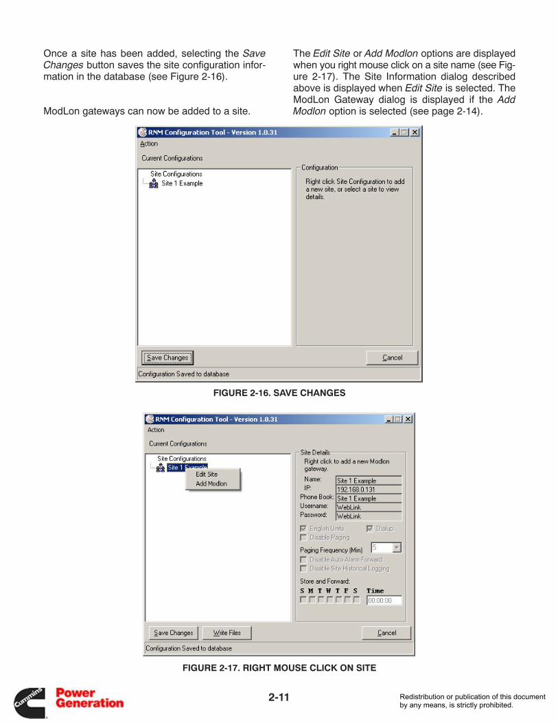
Once a site has been added, selecting the SaveChanges button saves the site configuration infor-mation in the database (see Figure 2-16).
ModLon gateways can now be added to a site.
The Edit Site or Add Modlon options are displayedwhen you right mouse click on a site name (see Fig-ure 2-17). The Site Information dialog describedabove is displayed when Edit Site is selected. TheModLon Gateway dialog is displayed if the AddModlon option is selected (see page 2-14).
FIGURE 2-16. SAVE CHANGES
FIGURE 2-17. RIGHT MOUSE CLICK ON SITE
Redistribution or publication of this documentby any means, is strictly prohibited.
2-12
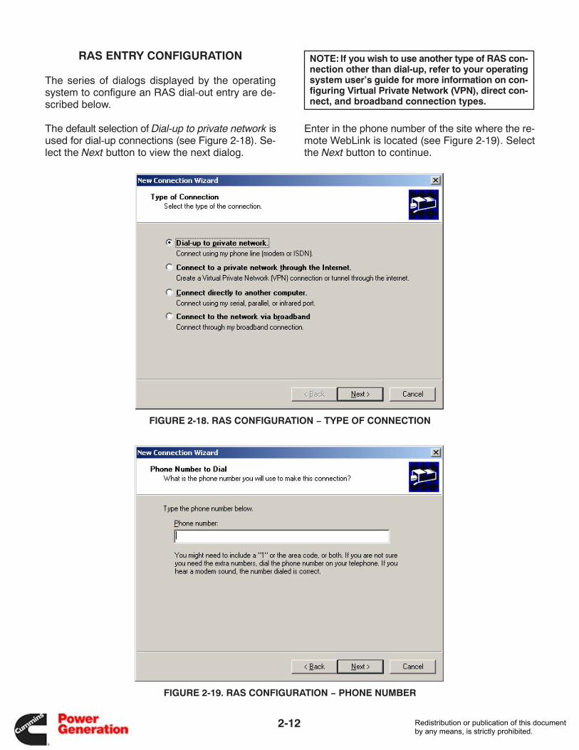
RAS ENTRY CONFIGURATION
The series of dialogs displayed by the operatingsystem to configure an RAS dial-out entry are de-scribed below.
The default selection of Dial-up to private network isused for dial-up connections (see Figure 2-18). Se-lect the Next button to view the next dialog.
NOTE: If you wish to use another type of RAS con-nection other than dial-up, refer to your operatingsystem user’s guide for more information on con-figuring Virtual Private Network (VPN), direct con-nect, and broadband connection types.
Enter in the phone number of the site where the re-mote WebLink is located (see Figure 2-19). Selectthe Next button to continue.
FIGURE 2-18. RAS CONFIGURATION − TYPE OF CONNECTION
FIGURE 2-19. RAS CONFIGURATION − PHONE NUMBER
Redistribution or publication of this documentby any means, is strictly prohibited.
2-13
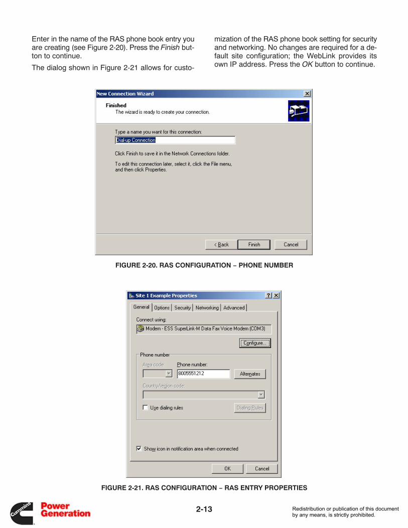
Enter in the name of the RAS phone book entry youare creating (see Figure 2-20). Press the Finish but-ton to continue.
The dialog shown in Figure 2-21 allows for custo-
mization of the RAS phone book setting for securityand networking. No changes are required for a de-fault site configuration; the WebLink provides itsown IP address. Press the OK button to continue.
FIGURE 2-20. RAS CONFIGURATION − PHONE NUMBER
FIGURE 2-21. RAS CONFIGURATION − RAS ENTRY PROPERTIES
Redistribution or publication of this documentby any means, is strictly prohibited.
2-14
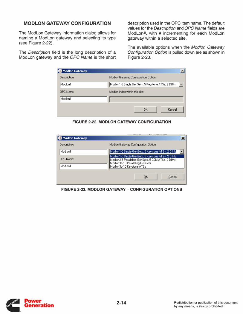
MODLON GATEWAY CONFIGURATION
The ModLon Gateway information dialog allows fornaming a ModLon gateway and selecting its type(see Figure 2-22).
The Description field is the long description of aModLon gateway and the OPC Name is the short
description used in the OPC item name. The defaultvalues for the Description and OPC Name fields areModLon#, with # incrementing for each ModLongateway within a selected site.
The available options when the Modlon GatewayConfiguration Option is pulled down are as shown inFigure 2-23.
FIGURE 2-22. MODLON GATEWAY CONFIGURATION
FIGURE 2-23. MODLON GATEWAY − CONFIGURATION OPTIONS
Redistribution or publication of this documentby any means, is strictly prohibited.
2-15
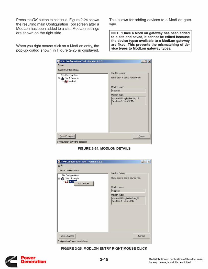
Press the OK button to continue. Figure 2-24 showsthe resulting main Configuration Tool screen after aModLon has been added to a site. ModLon settingsare shown on the right side.
When you right mouse click on a ModLon entry, thepop-up dialog shown in Figure 2-25 is displayed.
This allows for adding devices to a ModLon gate-way.
NOTE:Once a ModLon gateway has been addedto a site and saved, it cannot be edited becausethe device types available to a ModLon gatewayare fixed. This prevents the mismatching of de-vice types to ModLon gateway types.
FIGURE 2-24. MODLON DETAILS
FIGURE 2-25. MODLON ENTRY RIGHT MOUSE CLICK
Redistribution or publication of this documentby any means, is strictly prohibited.
2-16
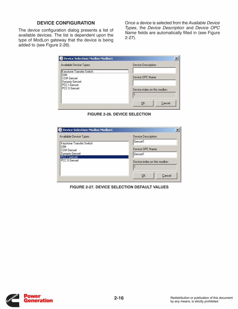
DEVICE CONFIGURATION
The device configuration dialog presents a list ofavailable devices. The list is dependent upon thetype of ModLon gateway that the device is beingadded to (see Figure 2-26).
Once a device is selected from the Available DeviceTypes, the Device Description and Device OPCName fields are automatically filled in (see Figure2-27).
FIGURE 2-26. DEVICE SELECTION
FIGURE 2-27. DEVICE SELECTION DEFAULT VALUES
Redistribution or publication of this documentby any means, is strictly prohibited.
2-17
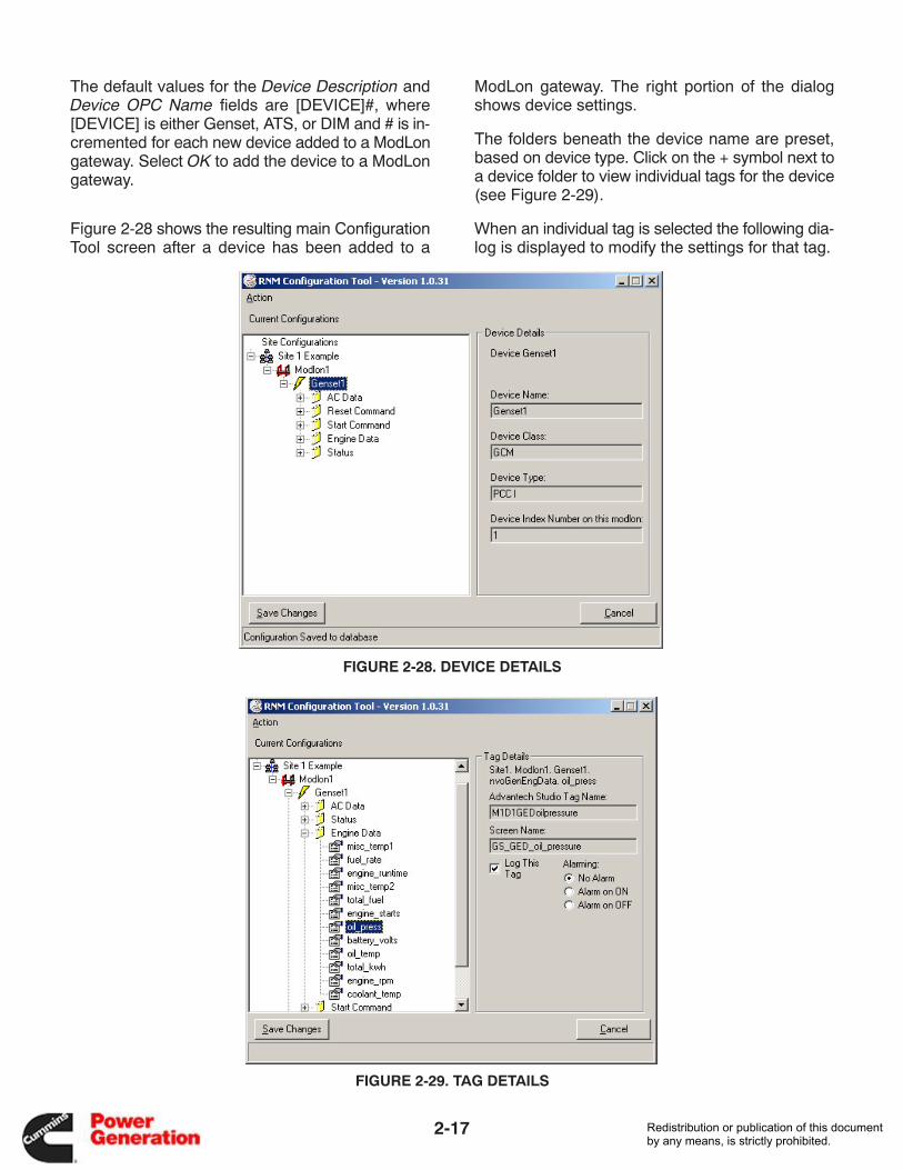
The default values for the Device Description andDevice OPC Name fields are [DEVICE]#, where[DEVICE] is either Genset, ATS, or DIM and # is in-cremented for each new device added to a ModLongateway. Select OK to add the device to a ModLongateway.
Figure 2-28 shows the resulting main ConfigurationTool screen after a device has been added to a
ModLon gateway. The right portion of the dialogshows device settings.
The folders beneath the device name are preset,based on device type. Click on the + symbol next toa device folder to view individual tags for the device(see Figure 2-29).
When an individual tag is selected the following dia-log is displayed to modify the settings for that tag.
FIGURE 2-28. DEVICE DETAILS
FIGURE 2-29. TAG DETAILS
Redistribution or publication of this documentby any means, is strictly prohibited.
2-18
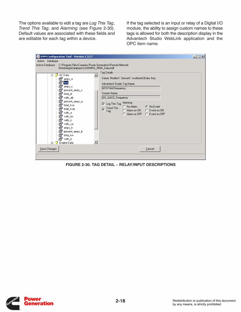
The options available to edit a tag are Log This Tag,Trend This Tag, and Alarming (see Figure 2-30).Default values are associated with these fields andare editable for each tag within a device.
If the tag selected is an input or relay of a Digital I/Omodule, the ability to assign custom names to thesetags is allowed for both the description display in theAdvantech Studio WebLink application and theOPC item name.
FIGURE 2-30. TAG DETAIL − RELAY/INPUT DESCRIPTIONS
Redistribution or publication of this documentby any means, is strictly prohibited.
2-19
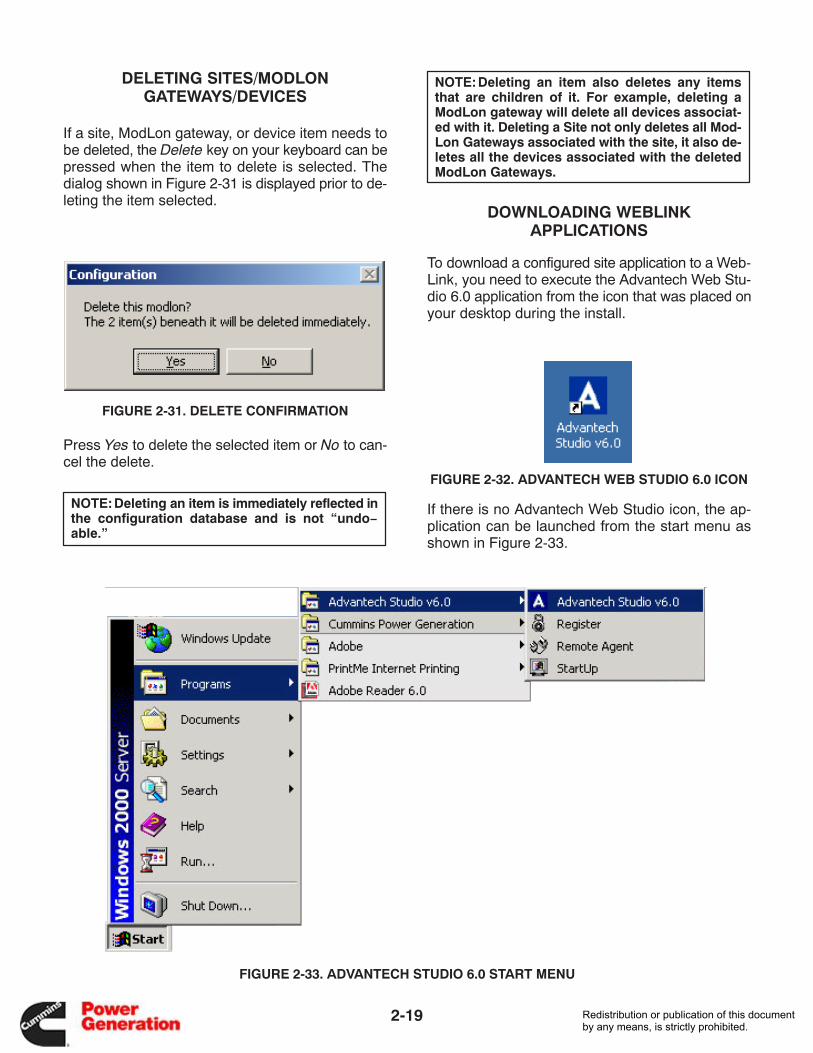
DELETING SITES/MODLONGATEWAYS/DEVICES
If a site, ModLon gateway, or device item needs tobe deleted, the Delete key on your keyboard can bepressed when the item to delete is selected. Thedialog shown in Figure 2-31 is displayed prior to de-leting the item selected.
FIGURE 2-31. DELETE CONFIRMATION
Press Yes to delete the selected item or No to can-cel the delete.
NOTE:Deleting an item is immediately reflected inthe configuration database and is not “undo−able.”
NOTE:Deleting an item also deletes any itemsthat are children of it. For example, deleting aModLon gateway will delete all devices associat-ed with it. Deleting a Site not only deletes all Mod-Lon Gateways associated with the site, it also de-letes all the devices associated with the deletedModLon Gateways.
DOWNLOADING WEBLINKAPPLICATIONS
To download a configured site application to a Web-Link, you need to execute the Advantech Web Stu-dio 6.0 application from the icon that was placed onyour desktop during the install.
FIGURE 2-32. ADVANTECH WEB STUDIO 6.0 ICON
If there is no Advantech Web Studio icon, the ap-plication can be launched from the start menu asshown in Figure 2-33.
FIGURE 2-33. ADVANTECH STUDIO 6.0 START MENU
Redistribution or publication of this documentby any means, is strictly prohibited.
2-20
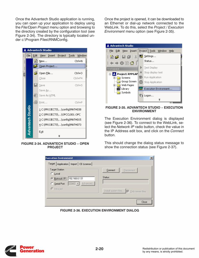
Once the Advantech Studio application is running,you can open up your application to deploy usingthe File/Open Project menu option and browsing tothe directory created by the configuration tool (seeFigure 2-34). The directory is typically located un-der c:\Program Files\RNMConfig.
FIGURE 2-34. ADVANTECH STUDIO − OPENPROJECT
Once the project is opened, it can be downloaded toan Ethernet or dial-up network connected to theWebLink. To do this, select the Project / ExecutionEnvironment menu option (see Figure 2-35).
FIGURE 2-35. ADVANTECH STUDIO − EXECUTIONENVIRONMENT
The Execution Environment dialog is displayed(see Figure 2-36). To connect to the WebLink, se-lect the Network IP radio button, check the value inthe IP Address edit box, and click on the Connectbutton.
This should change the dialog status message toshow the connection status (see Figure 2-37).
FIGURE 2-36. EXECUTION ENVIRONMENT DIALOG
Redistribution or publication of this documentby any means, is strictly prohibited.
2-21
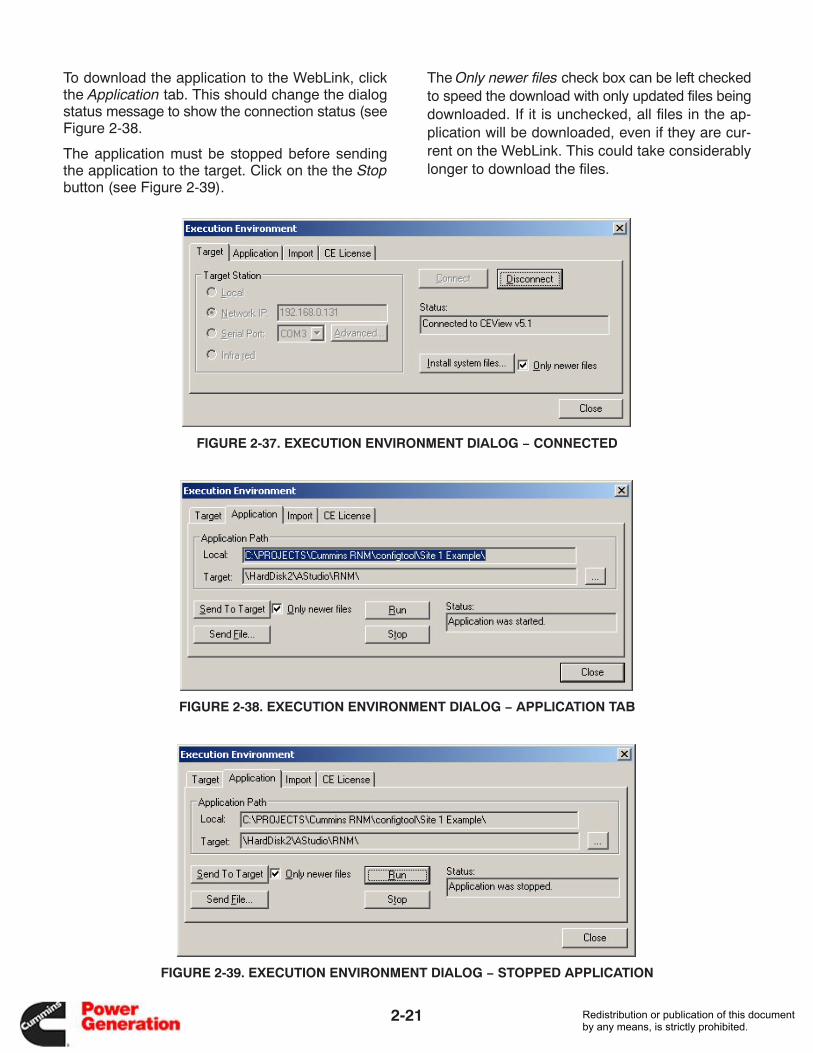
To download the application to the WebLink, clickthe Application tab. This should change the dialogstatus message to show the connection status (seeFigure 2-38.
The application must be stopped before sendingthe application to the target. Click on the the Stopbutton (see Figure 2-39).
The Only newer files check box can be left checkedto speed the download with only updated files beingdownloaded. If it is unchecked, all files in the ap-plication will be downloaded, even if they are cur-rent on the WebLink. This could take considerablylonger to download the files.
FIGURE 2-37. EXECUTION ENVIRONMENT DIALOG − CONNECTED
FIGURE 2-38. EXECUTION ENVIRONMENT DIALOG − APPLICATION TAB
FIGURE 2-39. EXECUTION ENVIRONMENT DIALOG − STOPPED APPLICATION
Redistribution or publication of this documentby any means, is strictly prohibited.
2-22
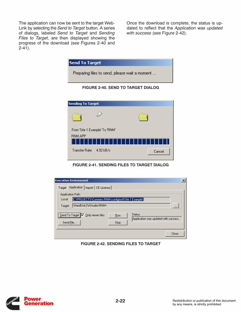
The application can now be sent to the target Web-Link by selecting the Send to Target button. A seriesof dialogs, labeled Send to Target and SendingFiles to Target, are then displayed showing theprogress of the download (see Figures 2-40 and2-41).
Once the download is complete, the status is up-dated to reflect that the Application was updatedwith success (see Figure 2-42).
FIGURE 2-40. SEND TO TARGET DIALOG
FIGURE 2-41. SENDING FILES TO TARGET DIALOG
FIGURE 2-42. SENDING FILES TO TARGET
Redistribution or publication of this documentby any means, is strictly prohibited.
2-23
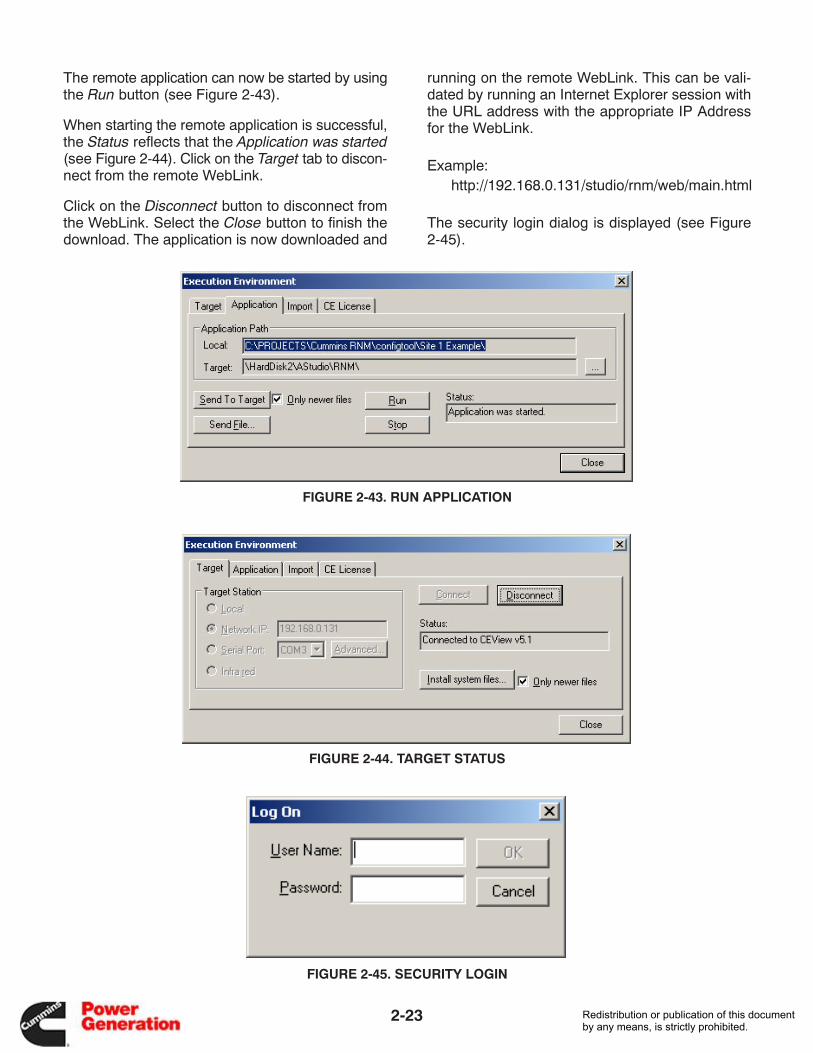
The remote application can now be started by usingthe Run button (see Figure 2-43).
When starting the remote application is successful,the Status reflects that the Application was started(see Figure 2-44). Click on the Target tab to discon-nect from the remote WebLink.
Click on the Disconnect button to disconnect fromthe WebLink. Select the Close button to finish thedownload. The application is now downloaded and
running on the remote WebLink. This can be vali-dated by running an Internet Explorer session withthe URL address with the appropriate IP Addressfor the WebLink.
Example:http://192.168.0.131/studio/rnm/web/main.html
The security login dialog is displayed (see Figure2-45).
FIGURE 2-43. RUN APPLICATION
FIGURE 2-44. TARGET STATUS
FIGURE 2-45. SECURITY LOGIN
Redistribution or publication of this documentby any means, is strictly prohibited.
2-24
FIGURE 2-46. MAIN NAVIGATION SCREEN IN WEB BROWSER
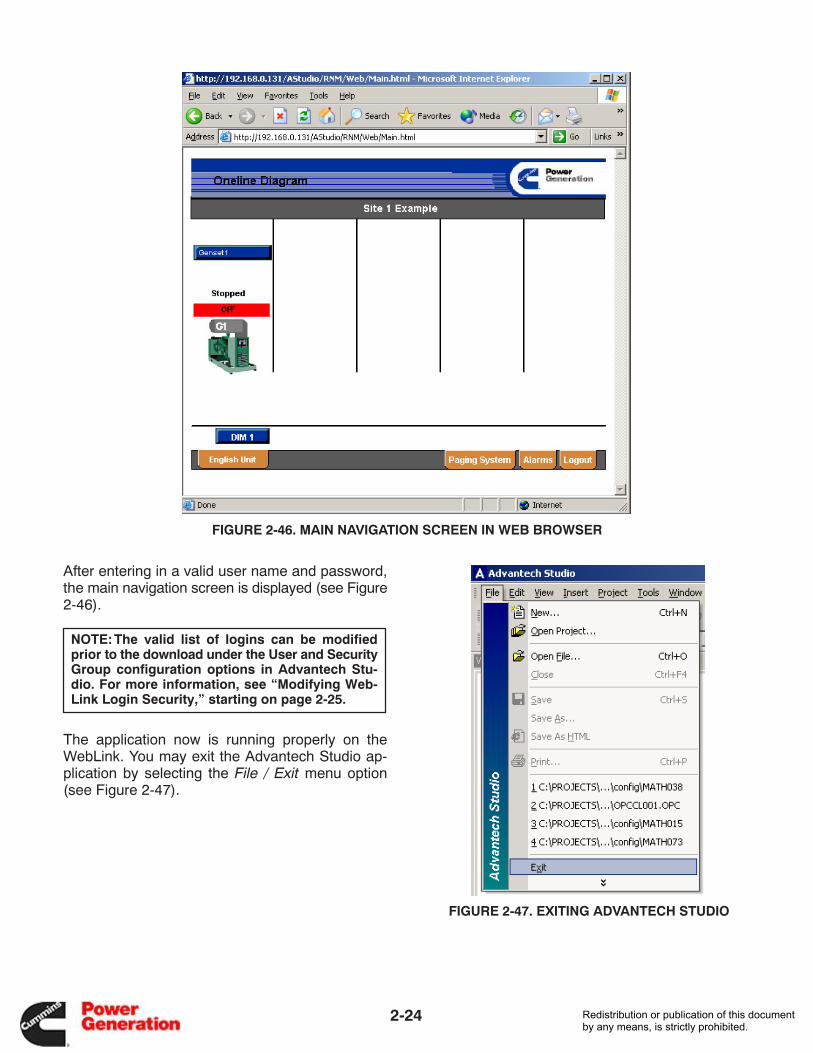
After entering in a valid user name and password,the main navigation screen is displayed (see Figure2-46).
NOTE:The valid list of logins can be modifiedprior to the download under the User and SecurityGroup configuration options in Advantech Stu-dio. For more information, see “Modifying Web-Link Login Security,” starting on page 2-25.
The application now is running properly on theWebLink. You may exit the Advantech Studio ap-plication by selecting the File / Exit menu option(see Figure 2-47).
FIGURE 2-47. EXITING ADVANTECH STUDIO
Redistribution or publication of this documentby any means, is strictly prohibited.
2-25
MODIFYING WEBLINK LOGIN SECURITY
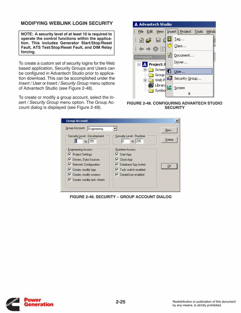
NOTE: A security level of at least 10 is required tooperate the control functions within the applica-tion. This includes Generator Start/Stop/ResetFault, ATS Test/Stop/Reset Fault, and DIM Relayforcing.
To create a custom set of security logins for the Webbased application, Security Groups and Users canbe configured in Advantech Studio prior to applica-tion download. This can be accomplished under theInsert / User or Insert / Security Group menu optionsof Advantech Studio (see Figure 2-48).
To create or modify a group account, select the In-sert / Security Group menu option. The Group Ac-count dialog is displayed (see Figure 2-49).
FIGURE 2-48. CONFIGURING ADVANTECH STUDIOSECURITY
FIGURE 2-49. SECURITY − GROUP ACCOUNT DIALOG
Redistribution or publication of this documentby any means, is strictly prohibited.
2-26
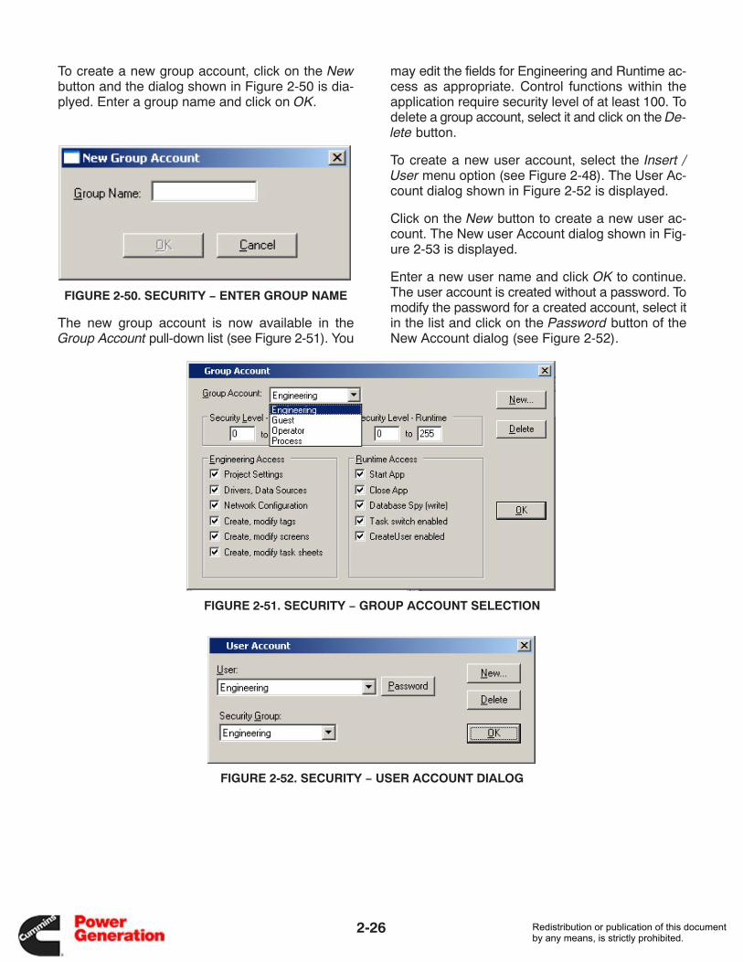
To create a new group account, click on the Newbutton and the dialog shown in Figure 2-50 is dia-plyed. Enter a group name and click on OK.
FIGURE 2-50. SECURITY − ENTER GROUP NAME
The new group account is now available in theGroup Account pull-down list (see Figure 2-51). You
may edit the fields for Engineering and Runtime ac-cess as appropriate. Control functions within theapplication require security level of at least 100. Todelete a group account, select it and click on the De-lete button.
To create a new user account, select the Insert /User menu option (see Figure 2-48). The User Ac-count dialog shown in Figure 2-52 is displayed.
Click on the New button to create a new user ac-count. The New user Account dialog shown in Fig-ure 2-53 is displayed.
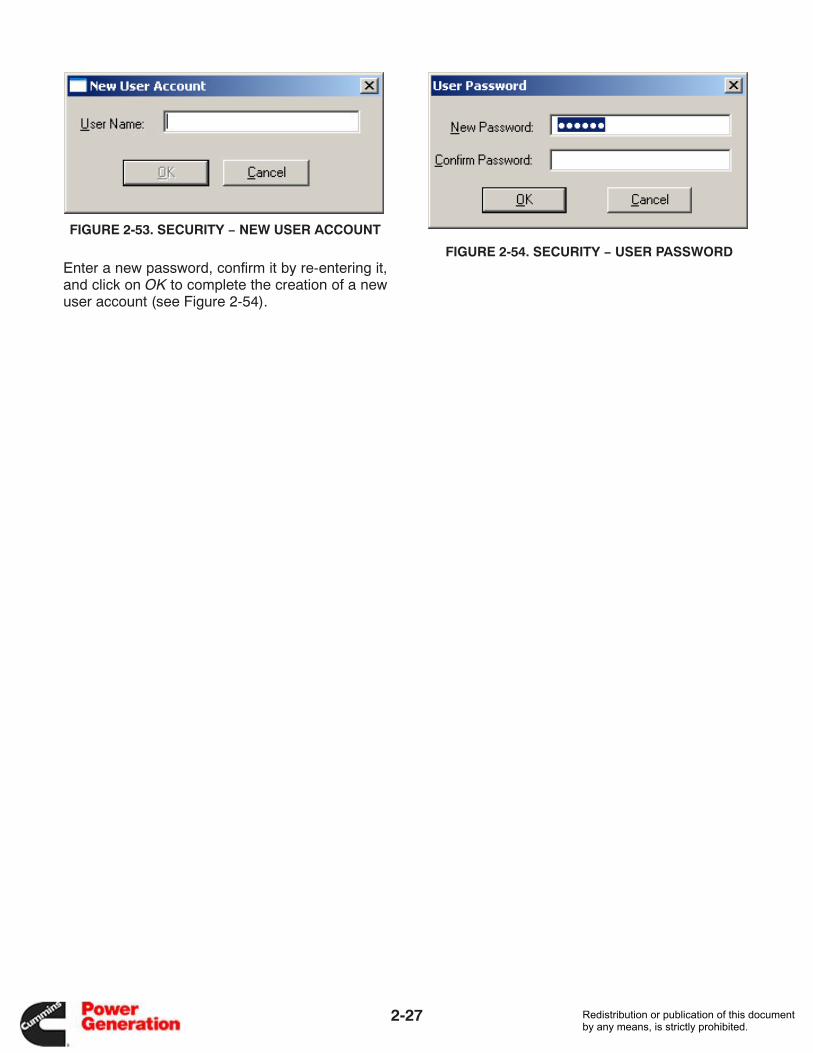
Enter a new user name and click OK to continue.The user account is created without a password. Tomodify the password for a created account, select itin the list and click on the Password button of theNew Account dialog (see Figure 2-52).
FIGURE 2-51. SECURITY − GROUP ACCOUNT SELECTION
FIGURE 2-52. SECURITY − USER ACCOUNT DIALOG
Redistribution or publication of this documentby any means, is strictly prohibited.
2-27
FIGURE 2-53. SECURITY − NEW USER ACCOUNT
Enter a new password, confirm it by re-entering it,and click on OK to complete the creation of a newuser account (see Figure 2-54).
FIGURE 2-54. SECURITY − USER PASSWORD
Redistribution or publication of this documentby any means, is strictly prohibited.

2-28
THIS PAGE INTENTIONALLY BLANK
Redistribution or publication of this documentby any means, is strictly prohibited.
3-1
3. OPC Multiplexor
INTRODUCTION
The OLE for Process Control (OPC) provides astandard mechanism for communicating to smartfield devices.
NOTE: Object Linking and Embedding (OLE) is amethod for sharing information among MicrosoftWindows-based applications.
The OPC Multiplexor is a series of application com-ponents that handle the following tasks in a remotenetworking architecture:
• On-demand OPC Client connectivity to remoteWebLink sites
• Remote Access Service (RAS) connection initia-tion to remote WebLink sites
• OPC 2.0 Data Access (DA) compliant server
• Retrieval mechanism for storing and forwardinghistorical alarm and data files from remote Web-Link sites
INSTALLATION
NOTE:The Configuration Tool must be installedprior to installing the OPC Multiplexor. Please seeSection 2 in this manual for more information oninstalling the Configuration Tool.
The installation of the OPC Multiplexor is performedusing the Setup.exe on the distribution CD. This ap-plication prompts the user for the option to install theConfiguration Tool only or install both the configura-tion tool and the OPC Multiplexor.
The installation path is required to locate where theAdvantech Studio software is installed. The defaultpath is displayed. If you installed the software in adifferent location, use the Browse button to select adifferent path.
USER INTERFACE
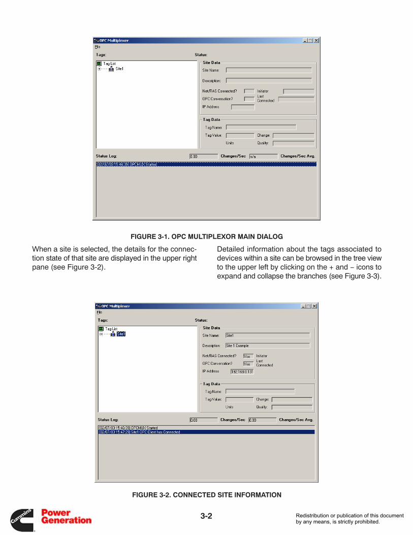
The OPC Multiplexor dialog (see Figure 3-1) hasthree main user interface components:
• Upper Left − Tree view of sites/ModLon gate-ways/devices/tags
• Upper Right − Detail information on sites or indi-vidual tags
• Lower − Status log of connection/conversationevents handled by the OPC Multiplexor
Redistribution or publication of this documentby any means, is strictly prohibited.
3-2
FIGURE 3-1. OPC MULTIPLEXOR MAIN DIALOG
When a site is selected, the details for the connec-tion state of that site are displayed in the upper rightpane (see Figure 3-2).
Detailed information about the tags associated todevices within a site can be browsed in the tree viewto the upper left by clicking on the + and − icons toexpand and collapse the branches (see Figure 3-3).
FIGURE 3-2. CONNECTED SITE INFORMATION
Redistribution or publication of this documentby any means, is strictly prohibited.
3-3
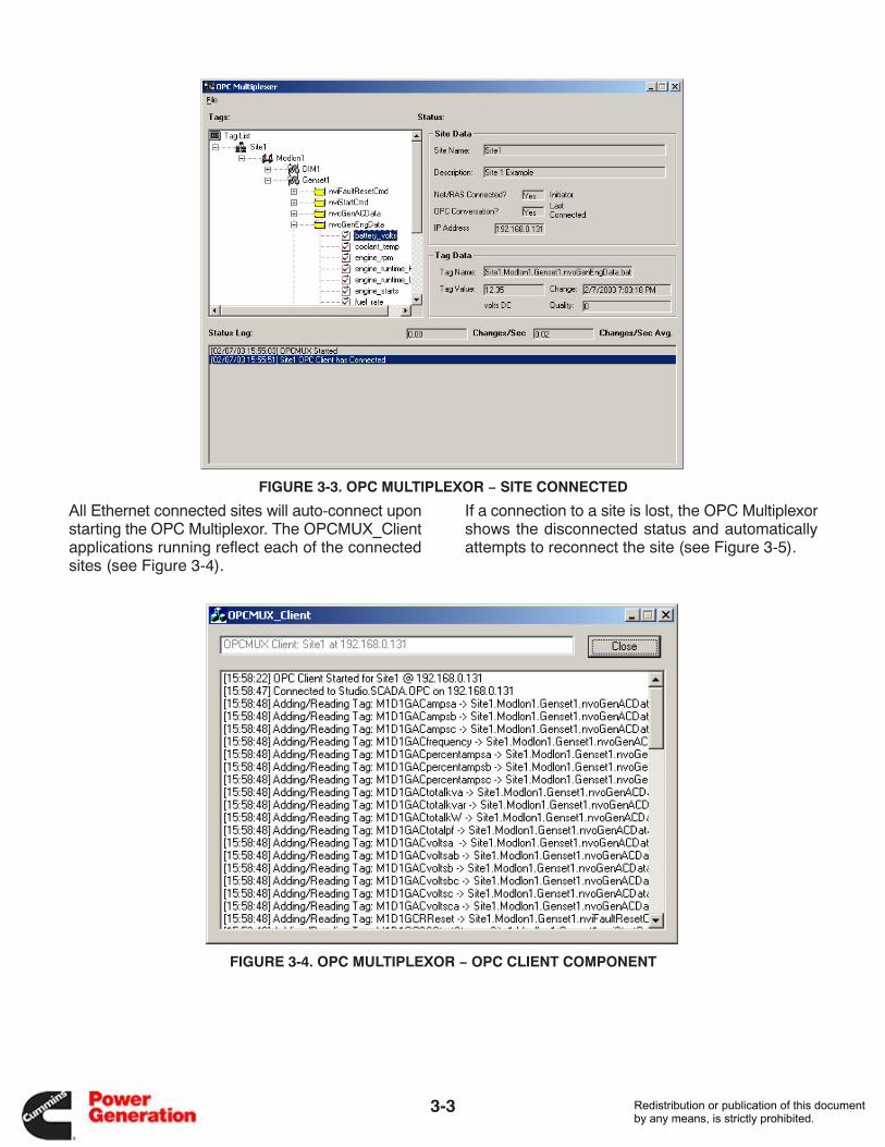
FIGURE 3-3. OPC MULTIPLEXOR − SITE CONNECTED
All Ethernet connected sites will auto-connect uponstarting the OPC Multiplexor. The OPCMUX_Clientapplications running reflect each of the connectedsites (see Figure 3-4).
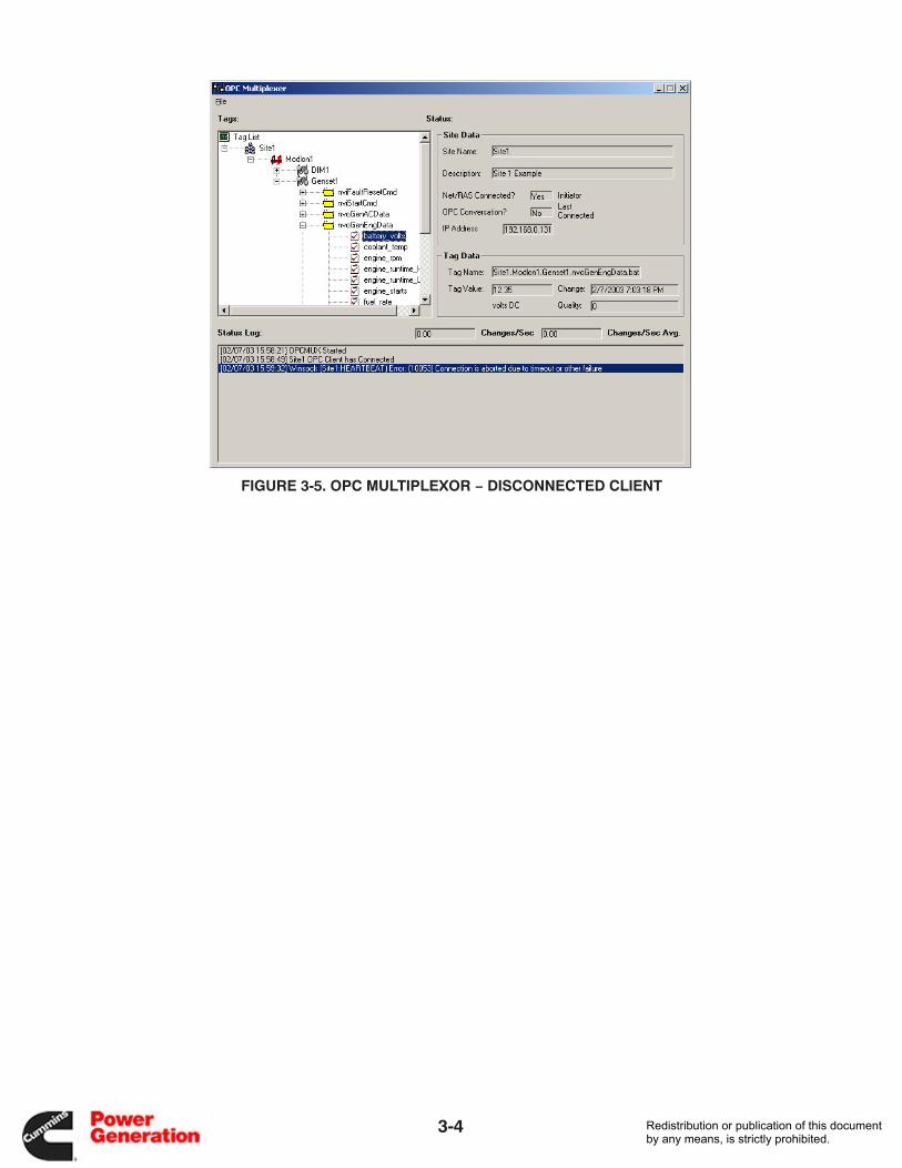
If a connection to a site is lost, the OPC Multiplexorshows the disconnected status and automaticallyattempts to reconnect the site (see Figure 3-5).
FIGURE 3-4. OPC MULTIPLEXOR − OPC CLIENT COMPONENT
Redistribution or publication of this documentby any means, is strictly prohibited.
3-4
FIGURE 3-5. OPC MULTIPLEXOR − DISCONNECTED CLIENT
Redistribution or publication of this documentby any means, is strictly prohibited.

3-5
Once the site is reconnected, a new OPCMUX_Cli-ent session starts and the status is reflected in the
OPC Multiplexor Status Log and Tag Data sections(see Figure 3-6).
FIGURE 3-6. OPC MULTIPLEXOR − RECONNECTED CLIENT
Redistribution or publication of this documentby any means, is strictly prohibited.
3-6
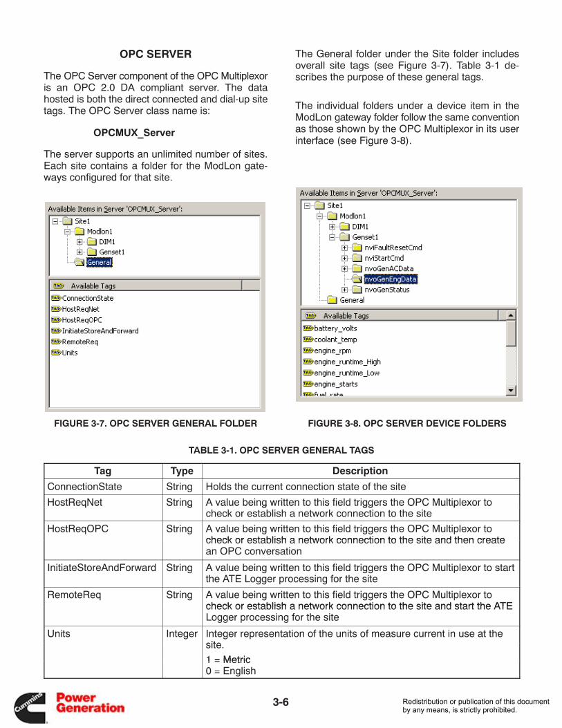
OPC SERVER
The OPC Server component of the OPC Multiplexoris an OPC 2.0 DA compliant server. The datahosted is both the direct connected and dial-up sitetags. The OPC Server class name is:
OPCMUX_Server
The server supports an unlimited number of sites.Each site contains a folder for the ModLon gate-ways configured for that site.
FIGURE 3-7. OPC SERVER GENERAL FOLDER
The General folder under the Site folder includesoverall site tags (see Figure 3-7). Table 3-1 de-scribes the purpose of these general tags.
The individual folders under a device item in theModLon gateway folder follow the same conventionas those shown by the OPC Multiplexor in its userinterface (see Figure 3-8).
FIGURE 3-8. OPC SERVER DEVICE FOLDERS
TABLE 3-1. OPC SERVER GENERAL TAGS
Tag Type Description
ConnectionState String Holds the current connection state of the site
HostReqNet String A value being written to this field triggers the OPC Multiplexor toHostReqNet String A value being written to this field triggers the OPC Multiplexor tocheck or establish a network connection to the site
HostReqOPC String A value being written to this field triggers the OPC Multiplexor tocheck or establish a network connection to the site and then createcheck or establish a network connection to the site and then createan OPC conversation
InitiateStoreAndForward String A value being written to this field triggers the OPC Multiplexor to startthe ATE Logger processing for the site
RemoteReq String A value being written to this field triggers the OPC Multiplexor tocheck or establish a network connection to the site and start the ATEcheck or establish a network connection to the site and start the ATELogger processing for the site
Units Integer Integer representation of the units of measure current in use at thesitesite.
1 = Metric1 = Metric0 = English
Redistribution or publication of this documentby any means, is strictly prohibited.
3-7
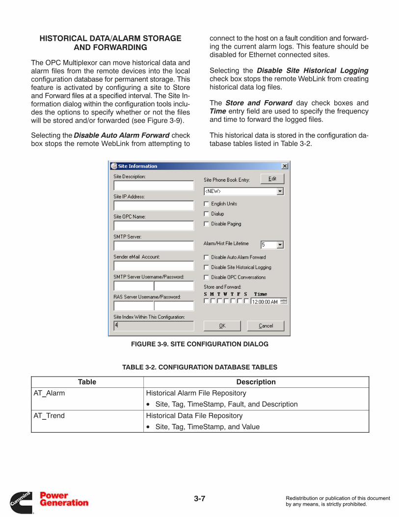
HISTORICAL DATA/ALARM STORAGEAND FORWARDING
The OPC Multiplexor can move historical data andalarm files from the remote devices into the localconfiguration database for permanent storage. Thisfeature is activated by configuring a site to Storeand Forward files at a specified interval. The Site In-formation dialog within the configuration tools inclu-des the options to specify whether or not the fileswill be stored and/or forwarded (see Figure 3-9).
Selecting the Disable Auto Alarm Forward checkbox stops the remote WebLink from attempting to
connect to the host on a fault condition and forward-ing the current alarm logs. This feature should bedisabled for Ethernet connected sites.
Selecting the Disable Site Historical Loggingcheck box stops the remote WebLink from creatinghistorical data log files.
The Store and Forward day check boxes andTime entry field are used to specify the frequencyand time to forward the logged files.
This historical data is stored in the configuration da-tabase tables listed in Table 3-2.
FIGURE 3-9. SITE CONFIGURATION DIALOG
TABLE 3-2. CONFIGURATION DATABASE TABLES
Table Description
AT_Alarm Historical Alarm File Repository_ p y
• Site, Tag, TimeStamp, Fault, and Description
AT_Trend Historical Data File Repository_ p y
• Site, Tag, TimeStamp, and Value
Redistribution or publication of this documentby any means, is strictly prohibited.

3-8
THIS PAGE INTENTIONALLY BLANK
Redistribution or publication of this documentby any means, is strictly prohibited.

A-1
Appendix A. ModLon Gateway Register Maps
This appendix includes information on register map-ping of the following modules to a ModLon Gatewayused in FT-10 networks.
• Single PowerCommand Genset
• Paralleling PowerCommand Genset
• Automatic Transfer Switch (ATS) − Simple
• ATS − Detailed
• Digital I/O Module (DIM)
Redistribution or publication of this documentby any means, is strictly prohibited.
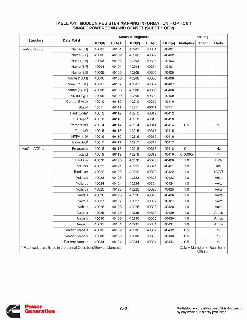
A-2
TABLE A-1. MODLON REGISTER MAPPING INFORMATION − OPTION 1SINGLE POWERCOMMAND GENSET (SHEET 1 OF 2)
Structure Data PointModBus Registers Scaling
Structure Data PointGEN[0] GEN[1] GEN[2] GEN[3] GEN[4] Multiplier Offset Units
nvoGenStatus Name [0,1] 40001 40101 40201 40301 40401
Name [2,3] 40002 40102 40202 40302 40402
Name [4,5] 40003 40103 40203 40303 40403
Name [6,7] 40004 40104 40204 40304 40404
Name [8,9] 40005 40105 40205 40305 40405
Name [10,11] 40006 40106 40206 40306 40406
Name [12,13] 40007 40107 40207 40307 40407
Name [14,15] 40008 40108 40208 40308 40408
Device Type 40009 40109 40209 40309 40409
Control Switch 40010 40110 40210 40310 40410
State1 40011 40111 40211 40311 40411
Fault Code* 40012 40112 40212 40312 40412
Fault Type2 40013 40113 40213 40313 40413
Percent kW 40014 40114 40214 40314 40414 0.5 %
Total kW 40015 40115 40215 40315 40415
NFPA 1103 40016 40116 40216 40316 40416
Extended4 40017 40117 40217 40317 40417
nvoGenACData Frequency 40018 40118 40218 40318 40418 0.1 Hz
Total pf 40019 40119 40219 40319 40419 0.00005 PF
Total kva 40020 40120 40220 40320 40420 1.0 KVA
Total kW 40021 40121 40221 40321 40421 1.0 KW
Total kvar 40022 40122 40222 40322 40422 1.0 KVAR
Volts ab 40023 40123 40223 40323 40423 1.0 Volts
Volts bc 40024 40124 40224 40324 40424 1.0 Volts
Volts ca 40025 40125 40225 40325 40425 1.0 Volts
Volts a 40026 40126 40226 40326 40426 1.0 Volts
Volts b 40027 40127 40227 40327 40427 1.0 Volts
Volts c 40028 40128 40228 40328 40428 1.0 Volts
Amps a 40029 40129 40229 40329 40429 1.0 Amps
Amps b 40030 40130 40230 40330 40430 1.0 Amps
Amps c 40031 40131 40231 40331 40431 1.0 Amps
Percent Amps a 40032 40132 40232 40332 40432 0.5 %
Percent Amps b 40033 40133 40233 40333 40433 0.5 %
Percent Amps c 40034 40134 40234 40334 40434 0.5 %
* Fault codes are listed in the genset Operator’s/Service Manuals. Data = Multiplier x (Register +Offset)
Redistribution or publication of this documentby any means, is strictly prohibited.
A-3
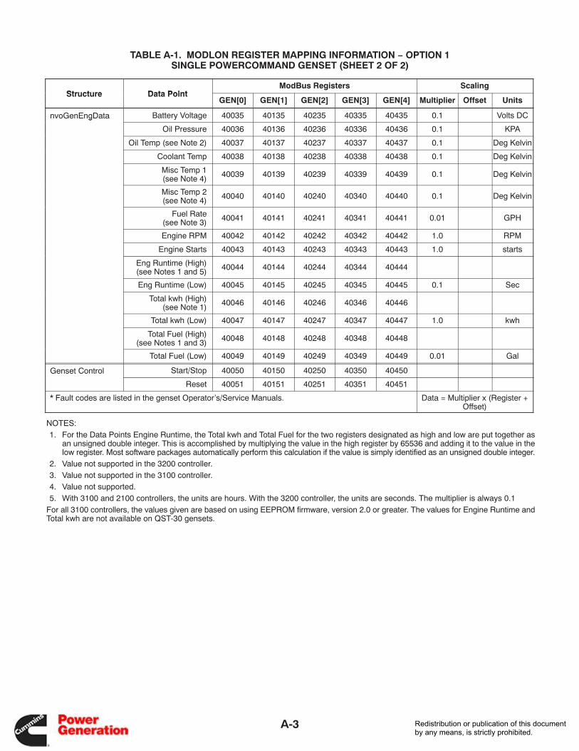
TABLE A-1. MODLON REGISTER MAPPING INFORMATION − OPTION 1SINGLE POWERCOMMAND GENSET (SHEET 2 OF 2)
Structure Data PointModBus Registers Scaling
Structure Data PointGEN[0] GEN[1] GEN[2] GEN[3] GEN[4] Multiplier Offset Units
nvoGenEngData Battery Voltage 40035 40135 40235 40335 40435 0.1 Volts DCg
Oil Pressure 40036 40136 40236 40336 40436 0.1 KPA
Oil Temp (see Note 2) 40037 40137 40237 40337 40437 0.1 Deg Kelvin
Coolant Temp 40038 40138 40238 40338 40438 0.1 Deg Kelvin
Misc Temp 1(see Note 4) 40039 40139 40239 40339 40439 0.1 Deg Kelvin
Misc Temp 2(see Note 4) 40040 40140 40240 40340 40440 0.1 Deg Kelvin
Fuel Rate(see Note 3) 40041 40141 40241 40341 40441 0.01 GPH
Engine RPM 40042 40142 40242 40342 40442 1.0 RPM
Engine Starts 40043 40143 40243 40343 40443 1.0 starts
Eng Runtime (High)(see Notes 1 and 5) 40044 40144 40244 40344 40444
Eng Runtime (Low) 40045 40145 40245 40345 40445 0.1 Sec
Total kwh (High)(see Note 1) 40046 40146 40246 40346 40446
Total kwh (Low) 40047 40147 40247 40347 40447 1.0 kwh
Total Fuel (High)(see Notes 1 and 3) 40048 40148 40248 40348 40448
Total Fuel (Low) 40049 40149 40249 40349 40449 0.01 Gal
Genset Control Start/Stop 40050 40150 40250 40350 40450
Reset 40051 40151 40251 40351 40451
* Fault codes are listed in the genset Operator’s/Service Manuals. Data = Multiplier x (Register +Offset)
NOTES: 1. For the Data Points Engine Runtime, the Total kwh and Total Fuel for the two registers designated as high and low are put together as
an unsigned double integer. This is accomplished by multiplying the value in the high register by 65536 and adding it to the value in thelow register. Most software packages automatically perform this calculation if the value is simply identified as an unsigned double integer.
2. Value not supported in the 3200 controller. 3. Value not supported in the 3100 controller. 4. Value not supported. 5. With 3100 and 2100 controllers, the units are hours. With the 3200 controller, the units are seconds. The multiplier is always 0.1For all 3100 controllers, the values given are based on using EEPROM firmware, version 2.0 or greater. The values for Engine Runtime andTotal kwh are not available on QST-30 gensets.
Redistribution or publication of this documentby any means, is strictly prohibited.
A-4
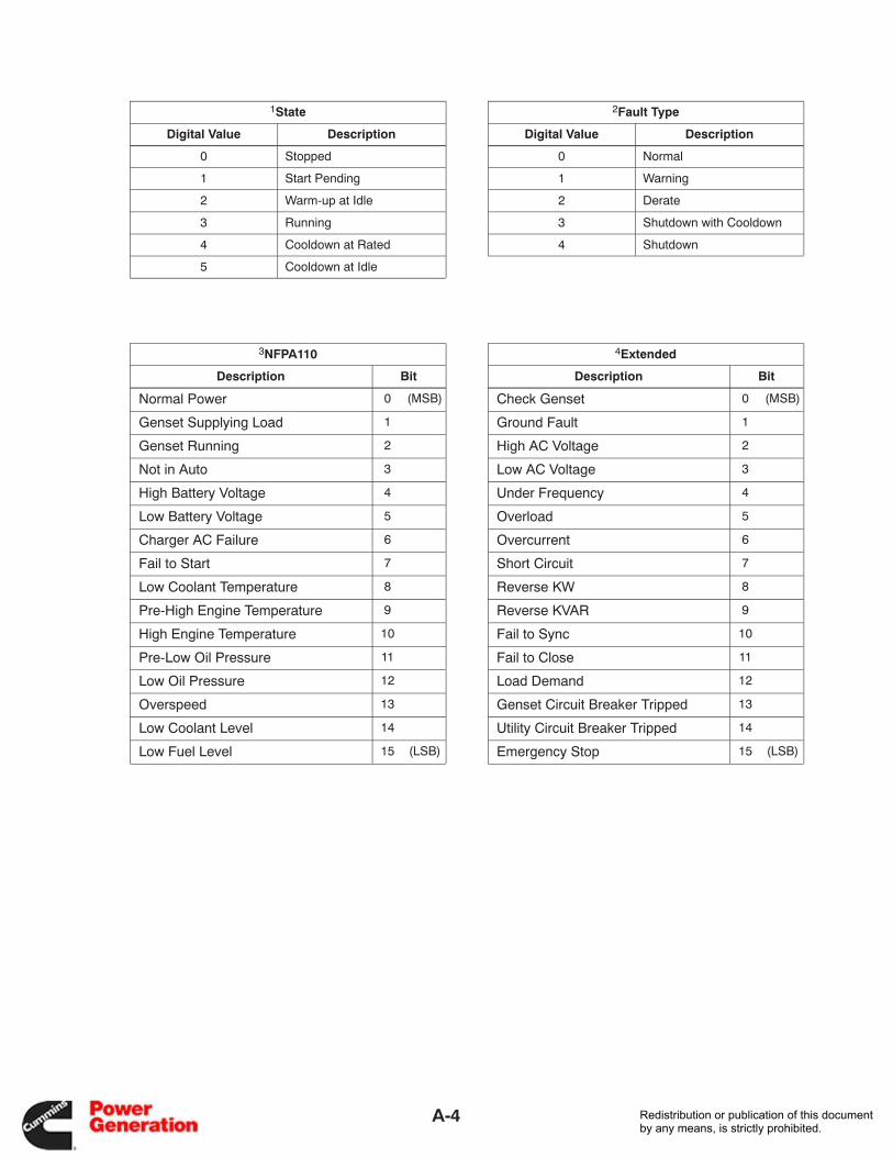
1State 2Fault Type
Digital Value Description Digital Value Description
0 Stopped 0 Normal
1 Start Pending 1 Warning
2 Warm-up at Idle 2 Derate
3 Running 3 Shutdown with Cooldown
4 Cooldown at Rated 4 Shutdown
5 Cooldown at Idle
3NFPA110 4Extended
Description Bit Description Bit
Normal Power 0 (MSB) Check Genset 0 (MSB)
Genset Supplying Load 1 Ground Fault 1
Genset Running 2 High AC Voltage 2
Not in Auto 3 Low AC Voltage 3
High Battery Voltage 4 Under Frequency 4
Low Battery Voltage 5 Overload 5
Charger AC Failure 6 Overcurrent 6
Fail to Start 7 Short Circuit 7
Low Coolant Temperature 8 Reverse KW 8
Pre-High Engine Temperature 9 Reverse KVAR 9
High Engine Temperature 10 Fail to Sync 10
Pre-Low Oil Pressure 11 Fail to Close 11
Low Oil Pressure 12 Load Demand 12
Overspeed 13 Genset Circuit Breaker Tripped 13
Low Coolant Level 14 Utility Circuit Breaker Tripped 14
Low Fuel Level 15 (LSB) Emergency Stop 15 (LSB)
Redistribution or publication of this documentby any means, is strictly prohibited.
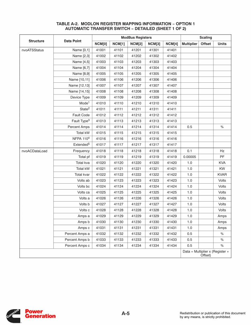
A-5
TABLE A-2. MODLON REGISTER MAPPING INFORMATION − OPTION 1AUTOMATIC TRANSFER SWITCH − DETAILED (SHEET 1 OF 2)
Structure Data PointModBus Registers Scaling
Structure Data PointNCM[0] NCM[1] NCM[2] NCM[3] NCM[4] Multiplier Offset Units
nvoATSStatus Name [0,1] 41001 41101 41201 41301 41401
Name [2,3] 41002 41102 41202 41302 41402
Name [4,5] 41003 41103 41203 41303 41403
Name [6,7] 41004 41104 41204 41304 41404
Name [8,9] 41005 41105 41205 41305 41405
Name [10,11] 41006 41106 41206 41306 41406
Name [12,13] 41007 41107 41207 41307 41407
Name [14,15] 41008 41108 41208 41308 41408
Device Type 41009 41109 41209 41309 41409
Mode1 41010 41110 41210 41310 41410
State2 41011 41111 41211 41311 41411
Fault Code 41012 41112 41212 41312 41412
Fault Type3 41013 41113 41213 41313 41413
Percent Amps 41014 41114 41214 41314 41414 0.5 %
Total kW 41015 41115 41215 41315 41415
NFPA 1104 41016 41116 41216 41316 41416
Extended5 41017 41117 41217 41317 41417
nvoACDataLoad Frequency 41018 41118 41218 41318 41418 0.1 Hz
Total pf 41019 41119 41219 41319 41419 0.00005 PF
Total kva 41020 41120 41220 41320 41420 1.0 KVA
Total kW 41021 41121 41221 41321 41421 1.0 KW
Total kvar 41022 41122 41222 41322 41422 1.0 KVAR
Volts ab 41023 41123 41223 41323 41423 1.0 Volts
Volts bc 41024 41124 41224 41324 41424 1.0 Volts
Volts ca 41025 41125 41225 41325 41425 1.0 Volts
Volts a 41026 41126 41226 41326 41426 1.0 Volts
Volts b 41027 41127 41227 41327 41427 1.0 Volts
Volts c 41028 41128 41228 41328 41428 1.0 Volts
Amps a 41029 41129 41229 41329 41429 1.0 Amps
Amps b 41030 41130 41230 41330 41430 1.0 Amps
Amps c 41031 41131 41231 41331 41431 1.0 Amps
Percent Amps a 41032 41132 41232 41332 41432 0.5 %
Percent Amps b 41033 41133 41233 41333 41433 0.5 %
Percent Amps c 41034 41134 41234 41334 41434 0.5 %
Data = Multiplier x (Register +Offset)
Redistribution or publication of this documentby any means, is strictly prohibited.
A-6
TABLE A-2. MODLON REGISTER MAPPING INFORMATION − OPTION 1AUTOMATIC TRANSFER SWITCH − DETAILED (SHEET 2 OF 2)
Structure Data PointModBus Registers Scaling
Structure Data PointNCM[0] NCM[1] NCM[2] NCM[3] NCM[4] Multiplier Offset Units
nvoACDataSrc1 Frequency 41035 41135 41235 41335 41435 0.1 Hz
Total pf 41036 41136 41236 41336 41436 0.00005 PF
Total kva 41037 41137 41237 41337 41437 1.0 KVA
Total kW 41038 41138 41238 41338 41438 1.0 KW
Total kvar 41039 41139 41239 41339 41439 1.0 KVAR
Volts ab 41040 41140 41240 41340 41440 1.0 Volts
Volts bc 41041 41141 41241 41341 41441 1.0 Volts
Volts ca 41042 41142 41242 41342 41442 1.0 Volts
Volts a 41043 41143 41243 41343 41443 1.0 Volts
Volts b 41044 41144 41244 41344 41444 1.0 Volts
Volts c 41045 41145 41245 41345 41445 1.0 Volts
Amps a 41046 41146 41246 41346 41446 1.0 Amps
Amps b 41047 41147 41247 41347 41447 1.0 Amps
Amps c 41048 41148 41248 41348 41448 1.0 Amps
Percent Amps a 41049 41149 41249 41349 41449 0.5 %
Percent Amps b 41050 41150 41250 41350 41450 0.5 %
Percent Amps c 41051 41151 41251 41351 41451 0.5 %
nvoACDataSrc2 Frequency 41052 41152 41252 41352 41452 0.1 Hz
Total pf 41053 41153 41253 41353 41453 0.00005 PF
Total kva 41054 41154 41254 41354 41454 1.0 KVA
Total kW 41055 41155 41255 41355 41455 1.0 KW
Total kvar 41056 41156 41256 41356 41456 1.0 KVAR
Volts ab 41057 41157 41257 41357 41457 1.0 Volts
Volts bc 41058 41158 41258 41358 41458 1.0 Volts
Volts ca 41059 41159 41259 41359 41459 1.0 Volts
Volts a 41060 41160 41260 41360 41460 1.0 Volts
Volts b 41061 41161 41261 41361 41461 1.0 Volts
Volts c 41062 41162 41262 41362 41462 1.0 Volts
Amps a 41063 41163 41263 41363 41463 1.0 Amps
Amps b 41064 41164 41264 41364 41464 1.0 Amps
Amps c 41065 41165 41265 41365 41465 1.0 Amps
Percent Amps a 41066 41166 41266 41366 41466 0.5 %
Percent Amps b 41067 41167 41267 41367 41467 0.5 %
Percent Amps c 41068 41168 41268 41368 41468 0.5 %
Control Test 41069 41169 41269 41369 41469
Reset 41070 41170 41270 41370 41470
Data = Multiplier x (Register +Offset)
Redistribution or publication of this documentby any means, is strictly prohibited.
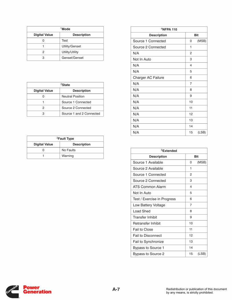
A-7
1Mode
Digital Value Description
0 Test
1 Utility/Genset
2 Utility/Utility
3 Genset/Genset
2State
Digital Value Description
0 Neutral Position
1 Source 1 Connected
2 Source 2 Connected
3 Source 1 and 2 Connected
3Fault Type
Digital Value Description
0 No Faults
1 Warning
4NFPA 110
Description Bit
Source 1 Connected 0 (MSB)
Source 2 Connected 1
N/A 2
Not In Auto 3
N/A 4
N/A 5
Charger AC Failure 6
N/A 7
N/A 8
N/A 9
N/A 10
N/A 11
N/A 12
N/A 13
N/A 14
N/A 15 (LSB)
5Extended
Description Bit
Source 1 Available 0 (MSB)
Source 2 Available 1
Source 1 Connected 2
Source 2 Connected 3
ATS Common Alarm 4
Not In Auto 5
Test / Exercise in Progress 6
Low Battery Voltage 7
Load Shed 8
Transfer Inhibit 9
Retransfer Inhibit 10
Fail to Close 11
Fail to Disconnect 12
Fail to Synchronize 13
Bypass to Source 1 14
Bypass to Source 2 15 (LSB)
Redistribution or publication of this documentby any means, is strictly prohibited.

A-8
TABLE A-3. MODLON REGISTER MAPPING INFORMATION − OPTION 1DIGITAL INPUT/OUTPUT MODULE (DIM)
Structure Data PointModBus Register
Structure Data PointDIM[0] DIM[1]
nvoNodeStatus Relay 1 42001 42101o odeStatusRelay 2 42002 42102
Relay 3 42003 42103
Relay 4 42004 42104
Relay 5 42005 42105
Relay 6 42006 42106
Relay 7 42007 42107
Relay 8 42008 42108
Relay 9 42009 42109
Relay 10 42010 42110
Relay 11 42011 42111
Relay 12 42012 42112
Relay 13 42013 42113
Relay 14 42014 42114
Relay 15 42015 42115
Relay 16 42016 42116
Input 1 42017 42117
Input 2 42018 42118
Input 3 42019 42119
Input 4 42020 42120
Input 5 42021 42121
Input 6 42022 42122
Input 7 42023 42123
Input 8 42024 42124
Control nvi16RelayA 42025 42125
Redistribution or publication of this documentby any means, is strictly prohibited.
A-9
TABLE A-4. MODLON REGISTER MAPPING INFORMATION − OPTION 2PARALLELING POWERCOMMAND GENSET (SHEET 1 OF 2)
Structure Data PointModBus Registers Scaling
Structure Data PointGEN[0] GEN[1] GEN[2] GEN[3] GEN[4] Multiplier Offset Units
nvoGenStatus Name [0,1] 40001 40101 40201 40301 40401
Name [2,3] 40002 40102 40202 40302 40402
Name [4,5] 40003 40103 40203 40303 40403
Name [6,7] 40004 40104 40204 40304 40404
Name [8,9] 40005 40105 40205 40305 40405
Name [10,11] 40006 40106 40206 40306 40406
Name [12,13] 40007 40107 40207 40307 40407
Name [14,15] 40008 40108 40208 40308 40408
Device Type 40009 40109 40209 40309 40409
Control Switch 40010 40110 40210 40310 40410
State1 40011 40111 40211 40311 40411
Fault Code* 40012 40112 40212 40312 40412
Fault Type2 40013 40113 40213 40313 40413
Percent kW 40014 40114 40214 40314 40414 0.5 %
Total kW 40015 40115 40215 40315 40415
NFPA 1103 40016 40116 40216 40316 40416
Extended4 40017 40117 40217 40317 40417
nvoGenACData Frequency 40018 40118 40218 40318 40418 0.1 Hz
Total pf 40019 40119 40219 40319 40419 0.00005 PF
Total kva 40020 40120 40220 40320 40420 1.0 KVA
Total kW 40021 40121 40221 40321 40421 1.0 KW
Total kvar 40022 40122 40222 40322 40422 1.0 KVAR
Volts ab 40023 40123 40223 40323 40423 1.0 Volts
Volts bc 40024 40124 40224 40324 40424 1.0 Volts
Volts ca 40025 40125 40225 40325 40425 1.0 Volts
Volts a 40026 40126 40226 40326 40426 1.0 Volts
Volts b 40027 40127 40227 40327 40427 1.0 Volts
Volts c 40028 40128 40228 40328 40428 1.0 Volts
Amps a 40029 40129 40229 40329 40429 1.0 Amps
Amps b 40030 40130 40230 40330 40430 1.0 Amps
Amps c 40031 40131 40231 40331 40431 1.0 Amps
Percent Amps a 40032 40132 40232 40332 40432 0.5 %
Percent Amps b 40033 40133 40233 40333 40433 0.5 %
Percent Amps c 40034 40134 40234 40334 40434 0.5 %
* Fault codes are listed in the genset Operator’s/Service Manuals. Data = Multiplier x (Register +Offset)
Redistribution or publication of this documentby any means, is strictly prohibited.
A-10
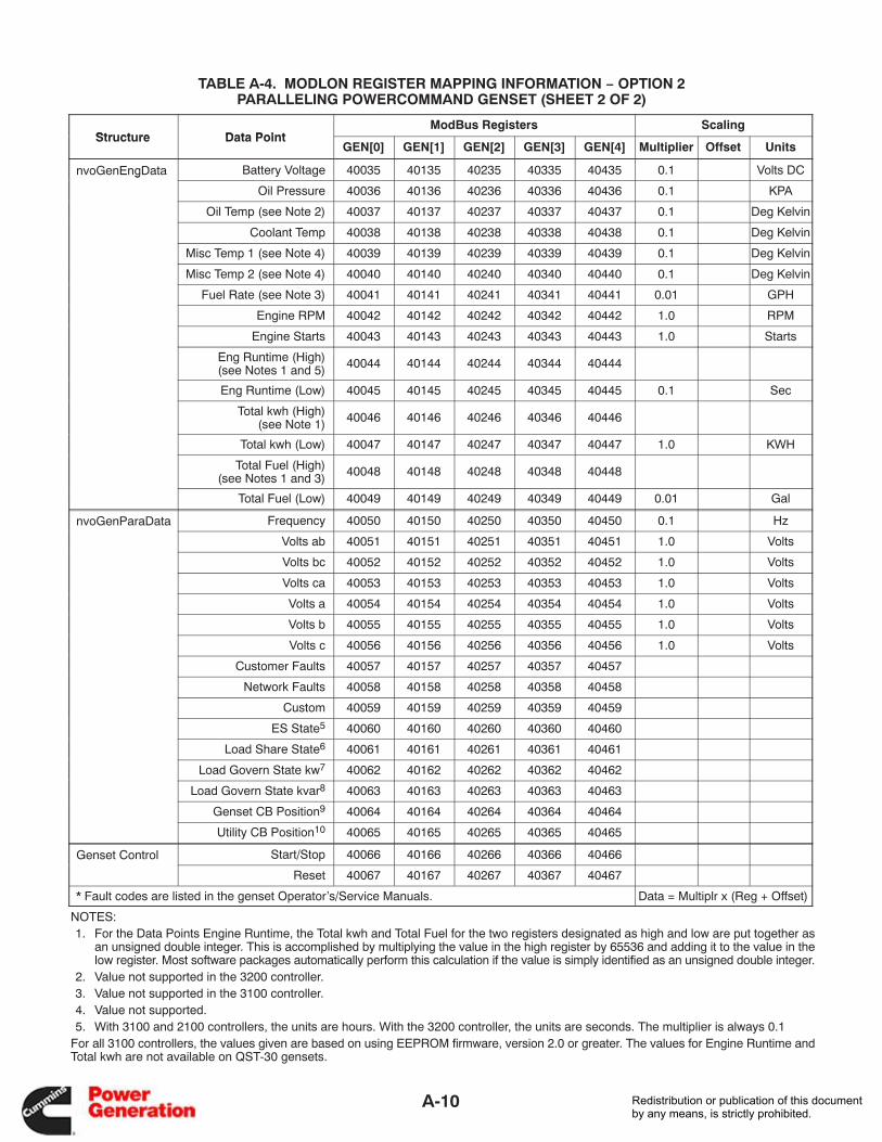
TABLE A-4. MODLON REGISTER MAPPING INFORMATION − OPTION 2PARALLELING POWERCOMMAND GENSET (SHEET 2 OF 2)
Structure Data PointModBus Registers Scaling
Structure Data PointGEN[0] GEN[1] GEN[2] GEN[3] GEN[4] Multiplier Offset Units
nvoGenEngData Battery Voltage 40035 40135 40235 40335 40435 0.1 Volts DCg
Oil Pressure 40036 40136 40236 40336 40436 0.1 KPA
Oil Temp (see Note 2) 40037 40137 40237 40337 40437 0.1 Deg Kelvin
Coolant Temp 40038 40138 40238 40338 40438 0.1 Deg Kelvin
Misc Temp 1 (see Note 4) 40039 40139 40239 40339 40439 0.1 Deg Kelvin
Misc Temp 2 (see Note 4) 40040 40140 40240 40340 40440 0.1 Deg Kelvin
Fuel Rate (see Note 3) 40041 40141 40241 40341 40441 0.01 GPH
Engine RPM 40042 40142 40242 40342 40442 1.0 RPM
Engine Starts 40043 40143 40243 40343 40443 1.0 Starts
Eng Runtime (High) (see Notes 1 and 5) 40044 40144 40244 40344 40444
Eng Runtime (Low) 40045 40145 40245 40345 40445 0.1 Sec
Total kwh (High)(see Note 1) 40046 40146 40246 40346 40446
Total kwh (Low) 40047 40147 40247 40347 40447 1.0 KWH
Total Fuel (High) (see Notes 1 and 3) 40048 40148 40248 40348 40448
Total Fuel (Low) 40049 40149 40249 40349 40449 0.01 Gal
nvoGenParaData Frequency 40050 40150 40250 40350 40450 0.1 Hz
Volts ab 40051 40151 40251 40351 40451 1.0 Volts
Volts bc 40052 40152 40252 40352 40452 1.0 Volts
Volts ca 40053 40153 40253 40353 40453 1.0 Volts
Volts a 40054 40154 40254 40354 40454 1.0 Volts
Volts b 40055 40155 40255 40355 40455 1.0 Volts
Volts c 40056 40156 40256 40356 40456 1.0 Volts
Customer Faults 40057 40157 40257 40357 40457
Network Faults 40058 40158 40258 40358 40458
Custom 40059 40159 40259 40359 40459
ES State5 40060 40160 40260 40360 40460
Load Share State6 40061 40161 40261 40361 40461
Load Govern State kw7 40062 40162 40262 40362 40462
Load Govern State kvar8 40063 40163 40263 40363 40463
Genset CB Position9 40064 40164 40264 40364 40464
Utility CB Position10 40065 40165 40265 40365 40465
Genset Control Start/Stop 40066 40166 40266 40366 40466
Reset 40067 40167 40267 40367 40467
* Fault codes are listed in the genset Operator’s/Service Manuals. Data = Multiplr x (Reg + Offset)
NOTES: 1. For the Data Points Engine Runtime, the Total kwh and Total Fuel for the two registers designated as high and low are put together as
an unsigned double integer. This is accomplished by multiplying the value in the high register by 65536 and adding it to the value in thelow register. Most software packages automatically perform this calculation if the value is simply identified as an unsigned double integer.
2. Value not supported in the 3200 controller. 3. Value not supported in the 3100 controller. 4. Value not supported. 5. With 3100 and 2100 controllers, the units are hours. With the 3200 controller, the units are seconds. The multiplier is always 0.1For all 3100 controllers, the values given are based on using EEPROM firmware, version 2.0 or greater. The values for Engine Runtime andTotal kwh are not available on QST-30 gensets.
Redistribution or publication of this documentby any means, is strictly prohibited.
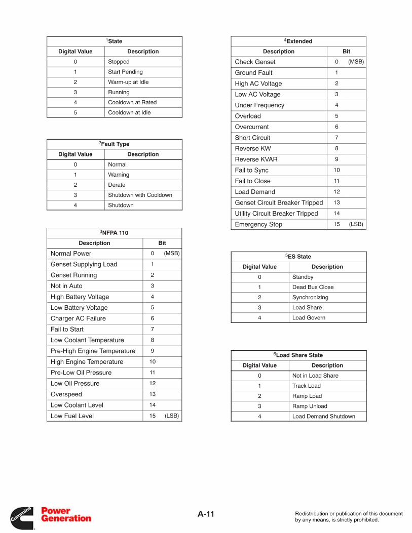
A-11
1State
Digital Value Description
0 Stopped
1 Start Pending
2 Warm-up at Idle
3 Running
4 Cooldown at Rated
5 Cooldown at Idle
2Fault Type
Digital Value Description
0 Normal
1 Warning
2 Derate
3 Shutdown with Cooldown
4 Shutdown
3NFPA 110
Description Bit
Normal Power 0 (MSB)
Genset Supplying Load 1
Genset Running 2
Not in Auto 3
High Battery Voltage 4
Low Battery Voltage 5
Charger AC Failure 6
Fail to Start 7
Low Coolant Temperature 8
Pre-High Engine Temperature 9
High Engine Temperature 10
Pre-Low Oil Pressure 11
Low Oil Pressure 12
Overspeed 13
Low Coolant Level 14
Low Fuel Level 15 (LSB)
4Extended
Description Bit
Check Genset 0 (MSB)
Ground Fault 1
High AC Voltage 2
Low AC Voltage 3
Under Frequency 4
Overload 5
Overcurrent 6
Short Circuit 7
Reverse KW 8
Reverse KVAR 9
Fail to Sync 10
Fail to Close 11
Load Demand 12
Genset Circuit Breaker Tripped 13
Utility Circuit Breaker Tripped 14
Emergency Stop 15 (LSB)
5ES State
Digital Value Description
0 Standby
1 Dead Bus Close
2 Synchronizing
3 Load Share
4 Load Govern
6Load Share State
Digital Value Description
0 Not in Load Share
1 Track Load
2 Ramp Load
3 Ramp Unload
4 Load Demand Shutdown
Redistribution or publication of this documentby any means, is strictly prohibited.
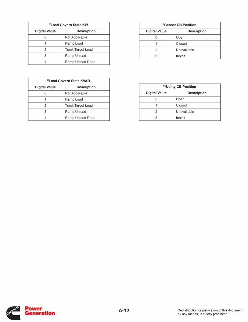
A-12
7Load Govern State KW
Digital Value Description
0 Not Applicable
1 Ramp Load
2 Track Target Load
3 Ramp Unload
4 Ramp Unload Done
8Load Govern State KVAR
Digital Value Description
0 Not Applicable
1 Ramp Load
2 Track Target Load
3 Ramp Unload
4 Ramp Unload Done
9Genset CB Position
Digital Value Description
0 Open
1 Closed
2 Unavailable
3 Inhibit
10Utility CB Position
Digital Value Description
0 Open
1 Closed
2 Unavailable
3 Inhibit
Redistribution or publication of this documentby any means, is strictly prohibited.
A-13
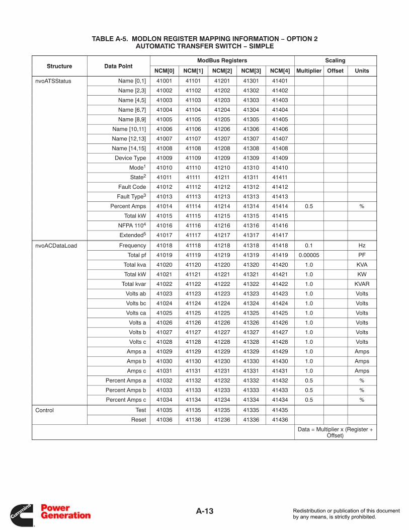
TABLE A-5. MODLON REGISTER MAPPING INFORMATION − OPTION 2AUTOMATIC TRANSFER SWITCH − SIMPLE
Structure Data PointModBus Registers Scaling
Structure Data PointNCM[0] NCM[1] NCM[2] NCM[3] NCM[4] Multiplier Offset Units
nvoATSStatus Name [0,1] 41001 41101 41201 41301 41401
Name [2,3] 41002 41102 41202 41302 41402
Name [4,5] 41003 41103 41203 41303 41403
Name [6,7] 41004 41104 41204 41304 41404
Name [8,9] 41005 41105 41205 41305 41405
Name [10,11] 41006 41106 41206 41306 41406
Name [12,13] 41007 41107 41207 41307 41407
Name [14,15] 41008 41108 41208 41308 41408
Device Type 41009 41109 41209 41309 41409
Mode1 41010 41110 41210 41310 41410
State2 41011 41111 41211 41311 41411
Fault Code 41012 41112 41212 41312 41412
Fault Type3 41013 41113 41213 41313 41413
Percent Amps 41014 41114 41214 41314 41414 0.5 %
Total kW 41015 41115 41215 41315 41415
NFPA 1104 41016 41116 41216 41316 41416
Extended5 41017 41117 41217 41317 41417
nvoACDataLoad Frequency 41018 41118 41218 41318 41418 0.1 Hz
Total pf 41019 41119 41219 41319 41419 0.00005 PF
Total kva 41020 41120 41220 41320 41420 1.0 KVA
Total kW 41021 41121 41221 41321 41421 1.0 KW
Total kvar 41022 41122 41222 41322 41422 1.0 KVAR
Volts ab 41023 41123 41223 41323 41423 1.0 Volts
Volts bc 41024 41124 41224 41324 41424 1.0 Volts
Volts ca 41025 41125 41225 41325 41425 1.0 Volts
Volts a 41026 41126 41226 41326 41426 1.0 Volts
Volts b 41027 41127 41227 41327 41427 1.0 Volts
Volts c 41028 41128 41228 41328 41428 1.0 Volts
Amps a 41029 41129 41229 41329 41429 1.0 Amps
Amps b 41030 41130 41230 41330 41430 1.0 Amps
Amps c 41031 41131 41231 41331 41431 1.0 Amps
Percent Amps a 41032 41132 41232 41332 41432 0.5 %
Percent Amps b 41033 41133 41233 41333 41433 0.5 %
Percent Amps c 41034 41134 41234 41334 41434 0.5 %
Control Test 41035 41135 41235 41335 41435
Reset 41036 41136 41236 41336 41436
Data = Multiplier x (Register +Offset)
Redistribution or publication of this documentby any means, is strictly prohibited.

A-14
1Mode
Digital Value Description
0 Test
1 Utility/Genset
2 Utility/Utility
3 Genset/Genset
2State
Digital Value Description
0 Neutral Position
1 Source 1 Connected
2 Source 2 Connected
3 Source 1 and 2 Connected
3Fault Type
Digital Value Description
0 No Faults
1 Warning
4NFPA 110
Description Bit
Source 1 Connected 0 (MSB)
Source 2 Connected 1
N/A 2
Not In Auto 3
N/A 4
N/A 5
Charger AC Failure 6
N/A 7
N/A 8
N/A 9
N/A 10
N/A 11
N/A 12
N/A 13
N/A 14
N/A 15 (LSB)
5Extended
Description Bit
Source 1 Available 0 (MSB)
Source 2 Available 1
Source 1 Connected 2
Source 2 Connected 3
ATS Common Alarm 4
Not In Auto 5
Test / Exercise in Progress 6
Low Battery Voltage 7
Load Shed 8
Transfer Inhibit 9
Retransfer Inhibit 10
Fail to Close 11
Fail to Disconnect 12
Fail to Synchronize 13
Bypass to Source 1 14
Bypass to Source 2 15 (LSB)
Redistribution or publication of this documentby any means, is strictly prohibited.
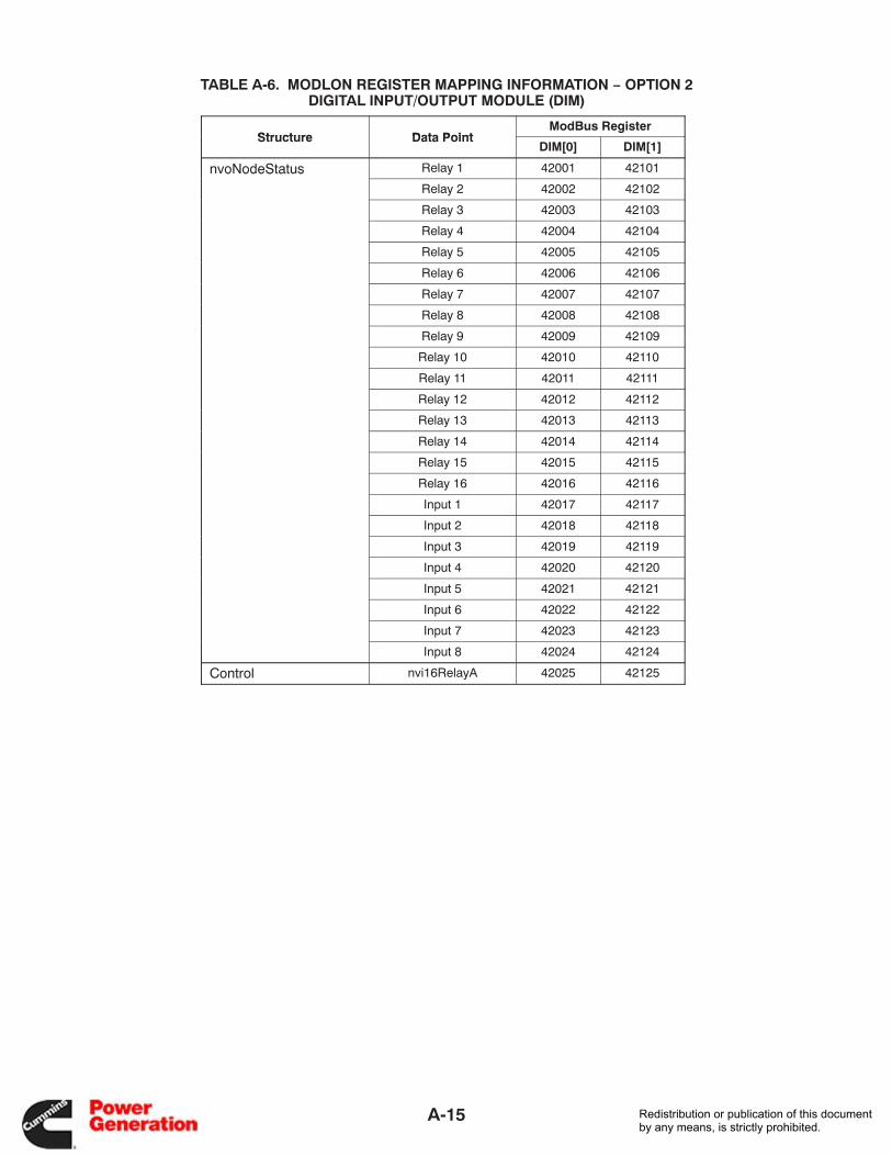
A-15
TABLE A-6. MODLON REGISTER MAPPING INFORMATION − OPTION 2DIGITAL INPUT/OUTPUT MODULE (DIM)
Structure Data PointModBus Register
Structure Data PointDIM[0] DIM[1]
nvoNodeStatus Relay 1 42001 42101o odeStatusRelay 2 42002 42102
Relay 3 42003 42103
Relay 4 42004 42104
Relay 5 42005 42105
Relay 6 42006 42106
Relay 7 42007 42107
Relay 8 42008 42108
Relay 9 42009 42109
Relay 10 42010 42110
Relay 11 42011 42111
Relay 12 42012 42112
Relay 13 42013 42113
Relay 14 42014 42114
Relay 15 42015 42115
Relay 16 42016 42116
Input 1 42017 42117
Input 2 42018 42118
Input 3 42019 42119
Input 4 42020 42120
Input 5 42021 42121
Input 6 42022 42122
Input 7 42023 42123
Input 8 42024 42124
Control nvi16RelayA 42025 42125
Redistribution or publication of this documentby any means, is strictly prohibited.
A-16
TAB
LE
A-7
. M
OD
LO
N R
EG
IST
ER
MA
PP
ING
INF
OR
MA
TIO
N −
OP
TIO
N 3
PAR
AL
LE
LIN
G P
OW
ER
CO
MM
AN
D G
EN
SE
T (
SH
EE
T 1
of
3)
Str
uct
ure
Dat
a P
oin
tM
od
Bu
s R
egis
ters
Sca
ling
Str
uct
ure
Dat
a P
oin
tG
EN
[0]
GE
N[1
]G
EN
[2]
GE
N[3
]G
EN
[4]
GE
N[5
]G
EN
[6]
GE
N[7
]G
EN
[8]
GE
N[9
]M
ult
iplie
rO
ffse
tU
nit
s
nvoG
enS
tatu
sN
ame
[0,1
]40
001
4010
140
201
4030
140
401
4050
140
601
4070
140
801
4090
1
Nam
e [2
,3]
4000
240
102
4020
240
302
4040
240
502
4060
240
702
4080
240
902
Nam
e [4
,5]
4000
340
103
4020
340
303
4040
340
503
4060
340
703
4080
340
903
Nam
e [6
,7]
4000
440
104
4020
440
304
4040
440
504
4060
440
704
4080
440
904
Nam
e [8
,9]
4000
540
105
4020
540
305
4040
540
505
4060
540
705
4080
540
905
Nam
e [1
0,11
]40
006
4010
640
206
4030
640
406
4050
640
606
4070
640
806
4090
6
Nam
e [1
2,13
]40
007
4010
740
207
4030
740
407
4050
740
607
4070
740
807
4090
7
Nam
e [1
4,15
]40
008
4010
840
208
4030
840
408
4050
840
608
4070
840
808
4090
8
Dev
ice
Type
4000
940
109
4020
940
309
4040
940
509
4060
940
709
4080
940
909
Con
trol
Sw
itch
4001
040
110
4021
040
310
4041
040
510
4061
040
710
4081
040
910
Sta
te1
4001
140
111
4021
140
311
4041
140
511
4061
140
711
4081
140
911
Fau
lt C
ode*
4001
240
112
4021
240
312
4041
240
512
4061
240
712
4081
240
912
Fau
lt Ty
pe2
4001
340
113
4021
340
313
4041
340
513
4061
340
713
4081
340
913
Per
cent
kW
4001
440
114
4021
440
314
4041
440
514
4061
440
714
4081
440
914
0.5
%
Tota
l kW
4001
540
115
4021
540
315
4041
540
515
4061
540
715
4081
540
915
NF
PA
110
340
016
4011
640
216
4031
640
416
4051
640
616
4071
640
816
4091
6
Ext
ende
d440
017
4011
740
217
4031
740
417
4051
740
617
4071
740
817
4091
7
nvoG
enA
CD
ata
Fre
quen
cy40
018
4011
840
218
4031
840
418
4051
840
618
4071
840
818
4091
80.
1H
z
Tota
l pf
4001
940
119
4021
940
319
4041
940
519
4061
940
719
4081
940
919
0.00
005
PF
Tota
l kva
4002
040
120
4022
040
320
4042
040
520
4062
040
720
4082
040
920
1.0
KV
A
Tota
l kW
4002
140
121
4022
140
321
4042
140
521
4062
140
721
4082
140
921
1.0
KW
Tota
l kva
r40
022
4012
240
222
4032
240
422
4052
240
622
4072
240
822
4092
21.
0K
VA
R
Vol
ts a
b40
023
4012
340
223
4032
340
423
4052
340
623
4072
340
823
4092
31.
0V
olts
Vol
ts b
c40
024
4012
440
224
4032
440
424
4052
440
624
4072
440
824
4092
41.
0V
olts
Vol
ts c
a40
025
4012
540
225
4032
540
425
4052
540
625
4072
540
825
4092
51.
0V
olts
Vol
ts a
4002
640
126
4022
640
326
4042
640
526
4062
640
726
4082
640
926
1.0
Vol
ts
Vol
ts b
4002
740
127
4022
740
327
4042
740
527
4062
740
727
4082
740
927
1.0
Vol
ts
Vol
ts c
4002
840
128
4022
840
328
4042
840
528
4062
840
728
4082
840
928
1.0
Vol
ts
Am
ps a
4002
940
129
4022
940
329
4042
940
529
4062
940
729
4082
940
929
1.0
Am
ps
Am
ps b
4003
040
130
4023
040
330
4043
040
530
4063
040
730
4083
040
930
1.0
Am
ps
Am
ps c
4003
140
131
4023
140
331
4043
140
531
4063
140
731
4083
140
931
1.0
Am
ps
Per
cent
Am
ps a
4003
240
132
4023
240
332
4043
240
532
4063
240
732
4083
240
932
0.5
%
Per
cent
Am
ps b
4003
340
133
4023
340
333
4043
340
533
4063
340
733
4083
340
933
0.5
%
Per
cent
Am
ps c
4003
440
134
4023
440
334
4043
440
534
4063
440
734
4083
440
934
0.5
%
* F
ault
code
s ar
e lis
ted
in th
e ge
nset
Ope
rato
r’s/S
ervi
ce M
anua
ls.
Dat
a =
Mul
tiplie
r x
(Reg
iste
r +
Offs
et)
Redistribution or publication of this documentby any means, is strictly prohibited.
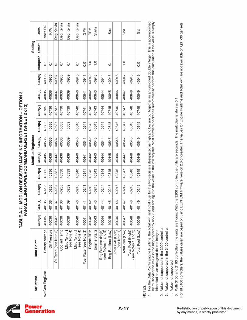
A-17
TAB
LE
A-7
. M
OD
LO
N R
EG
IST
ER
MA
PP
ING
INF
OR
MA
TIO
N −
OP
TIO
N 3
PAR
AL
LE
LIN
G P
OW
ER
CO
MM
AN
D G
EN
SE
T (
SH
EE
T 2
of
3)
Str
uct
ure
Dat
a P
oin
tM
od
Bu
s R
egis
ters
Sca
ling
Str
uct
ure
Dat
a P
oin
tG
EN
[0]
GE
N[1
]G
EN
[2]
GE
N[3
]G
EN
[4]
GE
N[5
]G
EN
[6]
GE
N[7
]G
EN
[8]
GE
N[9
]M
ult
iplie
rO
ffse
tU
nit
s
nvoG
en E
ngD
ata
Bat
tery
Vol
tage
4003
540
135
4023
540
335
4043
540
535
4063
540
735
4083
540
935
0.1
Vol
ts D
Cg
Oil
Pre
ssur
e40
036
4013
640
236
4033
640
436
4053
640
636
4073
640
836
4093
60.
1K
PA
Oil
Tem
p (s
ee N
ote
2)40
037
4013
740
237
4033
740
437
4053
740
637
4073
740
837
4093
70.
1D
eg K
elvi
n
Coo
lant
Tem
p40
038
4013
840
238
4033
840
438
4053
840
638
4073
840
838
4093
80.
1D
eg K
elvi
n
Mis
c Te
mp
1(s
ee N
ote
4)40
039
4013
940
239
4033
940
439
4053
940
639
4073
940
839
4093
90.
1D
eg K
elvi
n
Mis
c Te
mp
2(s
ee N
ote
4)40
040
4014
040
240
4034
040
440
4054
040
640
4074
040
840
4094
00.
1D
eg K
elvi
n
Fue
l Rat
e (s
ee N
ote
3)40
041
4014
140
241
4034
140
441
4054
140
641
4074
140
841
4094
10.
01G
PH
Eng
ine
RP
M40
042
4014
240
242
4034
240
442
4054
240
642
4074
240
842
4094
21.
0R
PM
Eng
ine
Sta
rts
4004
340
143
4024
340
343
4044
340
543
4064
340
743
4084
340
943
1.0
Sta
rts
Eng
Run
time
(Hig
h)(s
ee N
otes
1 a
nd 5
)40
044
4014
440
244
4034
440
444
4054
440
644
4074
440
844
4094
4
Eng
Run
time
(Low
)40
045
4014
540
245
4034
540
445
4054
540
645
4074
540
845
4094
50.
1S
ec
Tota
l kw
h (H
igh)
(see
Not
e 1)
4004
640
146
4024
640
346
4044
640
546
4064
640
746
4084
640
946
Tota
l kw
h (L
ow)
4004
740
147
4024
740
347
4044
740
547
4064
740
747
4084
740
947
1.0
KW
H
Tota
l Fue
l (H
igh)
)(s
ee N
otes
1 a
nd 3
)40
048
4014
840
248
4034
840
448
4054
840
648
4074
840
848
4094
8
Tota
l Fue
l (Lo
w)
4004
940
149
4024
940
349
4044
940
549
4064
940
749
4084
940
949
0.01
Gal
NO
TE
S:
1.
For
the
Dat
a P
oint
s E
ngin
e R
untim
e, th
e To
tal k
wh
and
Tota
l Fue
l for
the
two
regi
ster
s de
sign
ated
as
high
and
low
are
put
toge
ther
as
an u
nsig
ned
doub
le in
tege
r. T
his
is a
ccom
plis
hed
by m
ultip
lyin
g th
e va
lue
in th
e hi
gh r
egis
ter
by 6
5536
and
add
ing
it to
the
valu
e in
the
low
reg
iste
r. M
ost s
oftw
are
pack
ages
aut
omat
ical
ly p
erfo
rm th
is c
alcu
latio
n if
the
valu
e is
sim
ply
iden
tifie
d as
an
unsi
gned
dou
ble
inte
ger.
2.
Val
ue n
ot s
uppo
rted
in th
e 32
00 c
ontr
olle
r. 3
.V
alue
not
sup
port
ed in
the
3100
con
trol
ler.
4.
Val
ue n
ot s
uppo
rted
. 5
.W
ith 3
100
and
2100
con
trol
lers
, the
uni
ts a
re h
ours
. With
the
3200
con
trol
ler,
the
units
are
sec
onds
. The
mul
tiplie
r is
alw
ays
0.1
For
all
3100
con
trol
lers
, the
val
ues
give
n ar
e ba
sed
on u
sing
EE
PR
OM
firm
war
e, v
ersi
on 2
.0 o
r gr
eate
r. T
he v
alue
s fo
r E
ngin
e R
untim
e an
d To
tal k
wh
are
not a
vaila
ble
on Q
ST-
30 g
ense
ts.
Redistribution or publication of this documentby any means, is strictly prohibited.
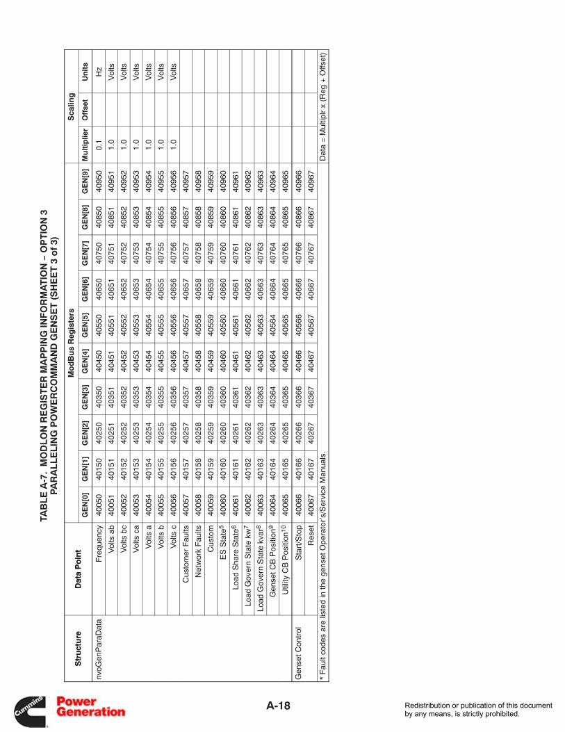
A-18
TAB
LE
A-7
. M
OD
LO
N R
EG
IST
ER
MA
PP
ING
INF
OR
MA
TIO
N −
OP
TIO
N 3
PAR
AL
LE
LIN
G P
OW
ER
CO
MM
AN
D G
EN
SE
T (
SH
EE
T 3
of
3)
Str
uct
ure
Dat
a P
oin
tM
od
Bu
s R
egis
ters
Sca
ling
Str
uct
ure
Dat
a P
oin
tG
EN
[0]
GE
N[1
]G
EN
[2]
GE
N[3
]G
EN
[4]
GE
N[5
]G
EN
[6]
GE
N[7
]G
EN
[8]
GE
N[9
]M
ult
iplie
rO
ffse
tU
nit
s
nvoG
enP
araD
ata
Fre
quen
cy40
050
4015
040
250
4035
040
450
4055
040
650
4075
040
850
4095
00.
1H
z
Vol
ts a
b40
051
4015
140
251
4035
140
451
4055
140
651
4075
140
851
4095
11.
0V
olts
Vol
ts b
c40
052
4015
240
252
4035
240
452
4055
240
652
4075
240
852
4095
21.
0V
olts
Vol
ts c
a40
053
4015
340
253
4035
340
453
4055
340
653
4075
340
853
4095
31.
0V
olts
Vol
ts a
4005
440
154
4025
440
354
4045
440
554
4065
440
754
4085
440
954
1.0
Vol
ts
Vol
ts b
4005
540
155
4025
540
355
4045
540
555
4065
540
755
4085
540
955
1.0
Vol
ts
Vol
ts c
4005
640
156
4025
640
356
4045
640
556
4065
640
756
4085
640
956
1.0
Vol
ts
Cus
tom
er F
aults
4005
740
157
4025
740
357
4045
740
557
4065
740
757
4085
740
957
Net
wor
k F
aults
4005
840
158
4025
840
358
4045
840
558
4065
840
758
4085
840
958
Cus
tom
4005
940
159
4025
940
359
4045
940
559
4065
940
759
4085
940
959
ES
Sta
te5
4006
040
160
4026
040
360
4046
040
560
4066
040
760
4086
040
960
Load
Sha
re S
tate
640
061
4016
140
261
4036
140
461
4056
140
661
4076
140
861
4096
1
Load
Gov
ern
Sta
te k
w7
4006
240
162
4026
240
362
4046
240
562
4066
240
762
4086
240
962
Load
Gov
ern
Sta
te k
var8
4006
340
163
4026
340
363
4046
340
563
4066
340
763
4086
340
963
Gen
set C
B P
ositi
on9
4006
440
164
4026
440
364
4046
440
564
4066
440
764
4086
440
964
Util
ity C
B P
ositi
on10
4006
540
165
4026
540
365
4046
540
565
4066
540
765
4086
540
965
Gen
set C
ontr
olS
tart
/Sto
p40
066
4016
640
266
4036
640
466
4056
640
666
4076
640
866
4096
6
Res
et40
067
4016
740
267
4036
740
467
4056
740
667
4076
740
867
4096
7
* F
ault
code
s ar
e lis
ted
in th
e ge
nset
Ope
rato
r’s/S
ervi
ce M
anua
ls.
Dat
a =
Mul
tiplr
x (R
eg +
Offs
et)
Redistribution or publication of this documentby any means, is strictly prohibited.
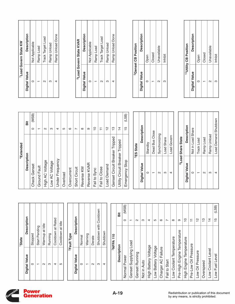
A-19
1 Sta
te
Dig
ital
Val
ue
Des
crip
tio
n
0S
topp
ed
1S
tart
Pen
ding
2W
arm
up a
t Idl
e
3R
unni
ng
4C
oold
own
at R
ated
5C
oold
own
at Id
le
2 Fau
lt T
ype
Dig
ital
Val
ue
Des
crip
tio
n
0N
orm
al
1W
arni
ng
2D
erat
e
3S
hutd
own
with
Coo
ldow
n
4S
hutd
own
3 NF
PA 1
10
Des
crip
tio
nB
it
Nor
mal
Pow
er0
(MS
B)
Gen
set S
uppl
ying
Loa
d1
Gen
set R
unni
ng2
Not
in A
uto
3
Hig
h B
atte
ry V
olta
ge4
Low
Bat
tery
Vol
tage
5
Cha
rger
AC
Fai
lure
6
Fai
l to
Sta
rt7
Low
Coo
lant
Tem
pera
ture
8
Pre
-Hig
h E
ngin
e Te
mpe
ratu
re9
Hig
h E
ngin
e Te
mpe
ratu
re10
Pre
-Low
Oil
Pre
ssur
e11
Low
Oil
Pre
ssur
e12
Ove
rspe
ed13
Low
Coo
lant
Lev
el14
Low
Fue
l Lev
el15
(LS
B)
4 Ext
end
ed
Des
crip
tio
nB
it
Che
ck G
ense
t0
(MS
B)
Gro
und
Fau
lt1
Hig
h A
C V
olta
ge2
Low
AC
Vol
tage
3
Und
er F
requ
ency
4
Ove
rload
5
Ove
rcur
rent
6
Sho
rt C
ircui
t7
Rev
erse
KW
8
Rev
erse
KV
AR
9
Fai
l to
Syn
c10
Fai
l to
Clo
se11
Load
Dem
and
12
Gen
set C
ircui
t Bre
aker
Trip
ped
13
Util
ity C
ircui
t Bre
aker
Trip
ped
14
Em
erge
ncy
Sto
p15
(LS
B)
5 ES
Sta
te
Dig
ital
Val
ue
Des
crip
tio
n
0S
tand
by
1D
ead
Bus
Clo
se
2S
ynch
roni
zing
3Lo
ad S
hare
4Lo
ad G
over
n
6 Lo
ad S
har
e S
tate
Dig
ital
Val
ue
Des
crip
tio
n
0N
ot in
Loa
d S
hare
1Tr
ack
Load
2R
amp
Load
3R
amp
Unl
oad
4Lo
ad D
eman
d S
hutd
own
7 Lo
ad G
ove
rn S
tate
KW
Dig
ital
Val
ue
Des
crip
tio
n
0N
ot A
pplic
able
1R
amp
Load
2Tr
ack
Targ
et L
oad
3R
amp
Unl
oad
4R
amp
Unl
oad
Don
e
8 Lo
ad G
ove
rn S
tate
KVA
R
Dig
ital
Val
ue
Des
crip
tio
n
0N
ot A
pplic
able
1R
amp
Load
2Tr
ack
Targ
et L
oad
3R
amp
Unl
oad
4R
amp
Unl
oad
Don
e
9 Gen
set
CB
Po
siti
on
Dig
ital
Val
ue
Des
crip
tio
n
0O
pen
1C
lose
d
2U
nava
ilabl
e
3In
hibi
t
10U
tilit
y C
B P
osi
tio
n
Dig
ital
Val
ue
Des
crip
tio
n
0O
pen
1C
lose
d
2U
nava
ilabl
e
3In
hibi
t
Redistribution or publication of this documentby any means, is strictly prohibited.
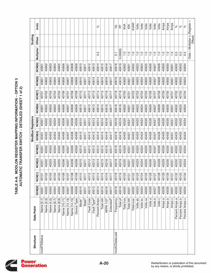
A-20
TAB
LE
A-8
. M
OD
LO
N R
EG
IST
ER
MA
PP
ING
INF
OR
MA
TIO
N −
OP
TIO
N 3
AU
TOM
AT
IC T
RA
NS
FE
R S
WIT
CH
− D
ETA
ILE
D (
SH
EE
T 1
of
2)
Str
uct
ure
Dat
a P
oin
tM
od
Bu
s R
egis
ters
Sca
ling
Str
uct
ure
Dat
a P
oin
tN
CM
[0]
NC
M[1
]N
CM
[2]
NC
M[3
]N
CM
[4]
NC
M[5
]N
CM
[6]
NC
M[7
]N
CM
[8]
NC
M[9
]M
ult
iplie
rO
ffse
tU
nit
s
nvoA
TS
Sta
tus
Nam
e [0
,1]
4000
140
101
4020
140
301
4040
140
501
4060
140
701
4080
140
901
Nam
e [2
,3]
4000
240
102
4020
240
302
4040
240
502
4060
240
702
4080
240
902
Nam
e [4
,5]
4000
340
103
4020
340
303
4040
340
503
4060
340
703
4080
340
903
Nam
e [6
,7]
4000
440
104
4020
440
304
4040
440
504
4060
440
704
4080
440
904
Nam
e [8
,9]
4000
540
105
4020
540
305
4040
540
505
4060
540
705
4080
540
905
Nam
e [1
0,11
]40
006
4010
640
206
4030
640
406
4050
640
606
4070
640
806
4090
6
Nam
e [1
2,13
]40
007
4010
740
207
4030
740
407
4050
740
607
4070
740
807
4090
7
Nam
e [1
4,15
]40
008
4010
840
208
4030
840
408
4050
840
608
4070
840
808
4090
8
Dev
ice
Type
4000
940
109
4020
940
309
4040
940
509
4060
940
709
4080
940
909
Mod
e140
010
4011
040
210
4031
040
410
4051
040
610
4071
040
810
4091
0
Sta
te2
4001
140
111
4021
140
311
4041
140
511
4061
140
711
4081
140
911
Fau
lt C
ode
4001
240
112
4021
240
312
4041
240
512
4061
240
712
4081
240
912
Fau
lt Ty
pe3
4001
340
113
4021
340
313
4041
340
513
4061
340
713
4081
340
913
Per
cent
Am
ps40
014
4011
440
214
4031
440
414
4051
440
614
4071
440
814
4091
40.
5%
Tota
l kW
4001
540
115
4021
540
315
4041
540
515
4061
540
715
4081
540
915
NF
PA
110
440
016
4011
640
216
4031
640
416
4051
640
616
4071
640
816
4091
6
Ext
ende
d540
017
4011
740
217
4031
740
417
4051
740
617
4071
740
817
4091
7
nvoA
CD
ataL
oad
Fre
quen
cy40
018
4011
840
218
4031
840
418
4051
840
618
4071
840
818
4091
80.
1H
z
Tota
l pf
4001
940
119
4021
940
319
4041
940
519
4061
940
719
4081
940
919
0.00
005
PF
Tota
l kva
4002
040
120
4022
040
320
4042
040
520
4062
040
720
4082
040
920
1.0
KV
A
Tota
l kW
4002
140
121
4022
140
321
4042
140
521
4062
140
721
4082
140
921
1.0
KW
Tota
l kva
r40
022
4012
240
222
4032
240
422
4052
240
622
4072
240
822
4092
21.
0K
VA
R
Vol
ts a
b40
023
4012
340
223
4032
340
423
4052
340
623
4072
340
823
4092
31.
0V
olts
Vol
ts b
c40
024
4012
440
224
4032
440
424
4052
440
624
4072
440
824
4092
41.
0V
olts
Vol
ts c
a40
025
4012
540
225
4032
540
425
4052
540
625
4072
540
825
4092
51.
0V
olts
Vol
ts a
4002
640
126
4022
640
326
4042
640
526
4062
640
726
4082
640
926
1.0
Vol
ts
Vol
ts b
4002
740
127
4022
740
327
4042
740
527
4062
740
727
4082
740
927
1.0
Vol
ts
Vol
ts c
4002
840
128
4022
840
328
4042
840
528
4062
840
728
4082
840
928
1.0
Vol
ts
Am
ps a
4002
940
129
4022
940
329
4042
940
529
4062
940
729
4082
940
929
1.0
Am
ps
Am
ps b
4003
040
130
4023
040
330
4043
040
530
4063
040
730
4083
040
930
1.0
Am
ps
Am
ps c
4003
140
131
4023
140
331
4043
140
531
4063
140
731
4083
140
931
1.0
Am
ps
Per
cent
Am
ps a
4003
240
132
4023
240
332
4043
240
532
4063
240
732
4083
240
932
0.5
%
Per
cent
Am
ps b
4003
340
133
4023
340
333
4043
340
533
4063
340
733
4083
340
933
0.5
%
Per
cent
Am
ps c
4003
440
134
4023
440
334
4043
440
534
4063
440
734
4083
440
934
0.5
%
Dat
a =
Mul
tiplie
r x
(Reg
iste
r +
Offs
et)
Redistribution or publication of this documentby any means, is strictly prohibited.
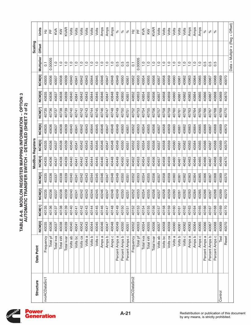
A-21
TAB
LE
A-8
. M
OD
LO
N R
EG
IST
ER
MA
PP
ING
INF
OR
MA
TIO
N −
OP
TIO
N 3
AU
TOM
AT
IC T
RA
NS
FE
R S
WIT
CH
− D
ETA
ILE
D (
SH
EE
T 2
of
2)
Str
uct
ure
Dat
a P
oin
tM
od
Bu
s R
egis
ters
Sca
ling
Str
uct
ure
Dat
a P
oin
tN
CM
[0]
NC
M[1
]N
CM
[2]
NC
M[3
]N
CM
[4]
NC
M[5
]N
CM
[6]
NC
M[7
]N
CM
[8]
NC
M[9
]M
ult
iplie
rO
ffse
tU
nit
s
nvoA
CD
ataS
rc1
Fre
quen
cy40
035
4013
540
235
4033
540
435
4053
540
635
4073
540
835
4093
50.
1H
z
Tota
l pf
4003
640
136
4023
640
336
4043
640
536
4063
640
736
4083
640
936
0.00
005
PF
Tota
l kva
4003
740
137
4023
740
337
4043
740
537
4063
740
737
4083
740
937
1.0
KV
A
Tota
l kW
4003
840
138
4023
840
338
4043
840
538
4063
840
738
4083
840
938
1.0
KW
Tota
l kva
r40
039
4013
940
239
4033
940
439
4053
940
639
4073
940
839
4093
91.
0K
VA
R
Vol
ts a
b40
040
4014
040
240
4034
040
440
4054
040
640
4074
040
840
4094
01.
0V
olts
Vol
ts b
c40
041
4014
140
241
4034
140
441
4054
140
641
4074
140
841
4094
11.
0V
olts
Vol
ts c
a40
042
4014
240
242
4034
240
442
4054
240
642
4074
240
842
4094
21.
0V
olts
Vol
ts a
4004
340
143
4024
340
343
4044
340
543
4064
340
743
4084
340
943
1.0
Vol
ts
Vol
ts b
4004
440
144
4024
440
344
4044
440
544
4064
440
744
4084
440
944
1.0
Vol
ts
Vol
ts c
4004
540
145
4024
540
345
4044
540
545
4064
540
745
4084
540
945
1.0
Vol
ts
Am
ps a
4004
640
146
4024
640
346
4044
640
546
4064
640
746
4084
640
946
1.0
Am
ps
Am
ps b
4004
740
147
4024
740
347
4044
740
547
4064
740
747
4084
740
947
1.0
Am
ps
Am
ps c
4004
840
148
4024
840
348
4044
840
548
4064
840
748
4084
840
948
1.0
Am
ps
Per
cent
Am
ps a
4004
940
149
4024
940
349
4044
940
549
4064
940
749
4084
940
949
0.5
%
Per
cent
Am
ps b
4005
040
150
4025
040
350
4045
040
550
4065
040
750
4085
040
950
0.5
%
Per
cent
Am
ps c
4005
140
151
4025
140
351
4045
140
551
4065
140
751
4085
140
951
0.5
%
nvoA
CD
ataS
rc2
Fre
quen
cy40
052
4015
240
252
4035
240
452
4055
240
652
4075
240
852
4095
20.
1H
z
Tota
l pf
4005
340
153
4025
340
353
4045
340
553
4065
340
753
4085
340
953
0.00
005
PF
Tota
l kva
4005
440
154
4025
440
354
4045
440
554
4065
440
754
4085
440
954
1.0
KV
A
Tota
l kW
4005
540
155
4025
540
355
4045
540
555
4065
540
755
4085
540
955
1.0
KW
Tota
l kva
r40
056
4015
640
256
4035
640
456
4055
640
656
4075
640
856
4095
61.
0K
VA
R
Vol
ts a
b40
057
4015
740
257
4035
740
457
4055
740
657
4075
740
857
4095
71.
0V
olts
Vol
ts b
c40
058
4015
840
258
4035
840
458
4055
840
658
4075
840
858
4095
81.
0V
olts
Vol
ts c
a40
059
4015
940
259
4035
940
459
4055
940
659
4075
940
859
4095
91.
0V
olts
Vol
ts a
4006
040
160
4026
040
360
4046
040
560
4066
040
760
4086
040
960
1.0
Vol
ts
Vol
ts b
4006
140
161
4026
140
361
4046
140
561
4066
140
761
4086
140
961
1.0
Vol
ts
Vol
ts c
4006
240
162
4026
240
362
4046
240
562
4066
240
762
4086
240
962
1.0
Vol
ts
Am
ps a
4006
340
163
4026
340
363
4046
340
563
4066
340
763
4086
340
963
1.0
Am
ps
Am
ps b
4006
440
164
4026
440
364
4046
440
564
4066
440
764
4086
440
964
1.0
Am
ps
Am
ps c
4006
540
165
4026
540
365
4046
540
565
4066
540
765
4086
540
965
1.0
Am
ps
Per
cent
Am
ps a
4006
640
166
4026
640
366
4046
640
566
4066
640
766
4086
640
966
0.5
%
Per
cent
Am
ps b
4006
740
167
4026
740
367
4046
740
567
4066
740
767
4086
740
967
0.5
%
Per
cent
Am
ps c
4006
840
168
4026
840
368
4046
840
568
4066
840
768
4086
840
968
0.5
%
Con
trol
Test
4006
940
169
4026
940
369
4046
940
569
4066
940
769
4086
940
969
Res
et40
070
4017
040
270
4037
040
470
4057
040
670
4077
040
870
4097
0
Dat
a =
Mul
tiplr
x (R
eg +
Offs
et)
Redistribution or publication of this documentby any means, is strictly prohibited.
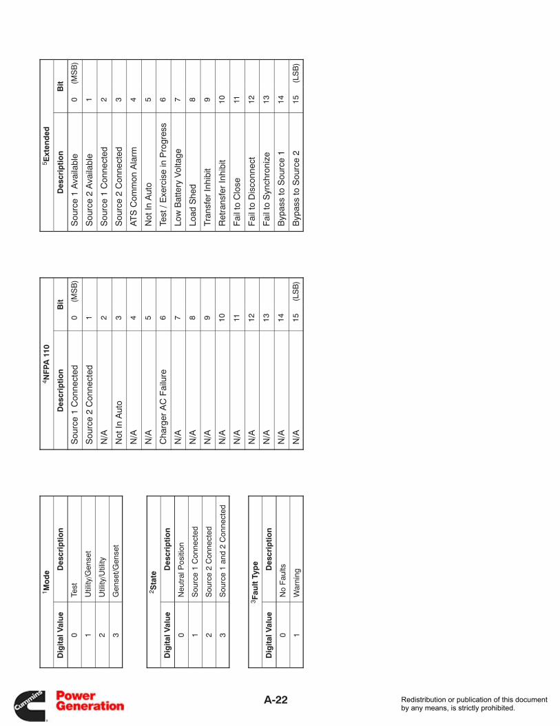
A-22
1 Mo
de
Dig
ital
Val
ue
Des
crip
tio
n
0Te
st
1U
tility
/Gen
set
2U
tility
/Util
ity
3G
ense
t/Gen
set
2 Sta
te
Dig
ital
Val
ue
Des
crip
tio
n
0N
eutr
al P
ositi
on
1S
ourc
e 1
Con
nect
ed
2S
ourc
e 2
Con
nect
ed
3S
ourc
e 1
and
2 C
onne
cted
3 Fau
lt T
ype
Dig
ital
Val
ue
Des
crip
tio
n
0N
o F
aults
1W
arni
ng
4 NF
PA 1
10
Des
crip
tio
nB
it
Sou
rce
1 C
onne
cted
0(M
SB
)
Sou
rce
2 C
onne
cted
1
N/A
2
Not
In A
uto
3
N/A
4
N/A
5
Cha
rger
AC
Fai
lure
6
N/A
7
N/A
8
N/A
9
N/A
10
N/A
11
N/A
12
N/A
13
N/A
14
N/A
15(L
SB
)
5 Ext
end
ed
Des
crip
tio
nB
it
Sou
rce
1 A
vaila
ble
0(M
SB
)
Sou
rce
2 A
vaila
ble
1
Sou
rce
1 C
onne
cted
2
Sou
rce
2 C
onne
cted
3
AT
S C
omm
on A
larm
4
Not
In A
uto
5
Test
/ E
xerc
ise
in P
rogr
ess
6
Low
Bat
tery
Vol
tage
7
Load
She
d8
Tra
nsfe
r In
hibi
t9
Ret
rans
fer
Inhi
bit
10
Fai
l to
Clo
se11
Fai
l to
Dis
conn
ect
12
Fai
l to
Syn
chro
nize
13
Byp
ass
to S
ourc
e 1
14
Byp
ass
to S
ourc
e 2
15(L
SB
)
Redistribution or publication of this documentby any means, is strictly prohibited.

Cummins Power Generation1400 73rd Avenue N.E.Minneapolis, MN 554321-800-888-6626763-574-5000 International UseFax: 763-528-7229
Redistribution or publication of this documentby any means, is strictly prohibited.