
Sclairpipe - Marine Pipeline Installation - Engineered Pipe ...
Upload
khangminh22Category
view
1download
0
Marine Installation Manual
X72-BIssue 2020-06

© 2020 Winterthur Gas & Diesel Ltd. — All rights reserved
No part of this publication may be reproduced or copied in any form or by any means (electronic, mechanical, graphic, photo-copying, recording, taping or other information retrieval systems) without the prior written permission of the copyright holder. Winterthur Gas & Diesel Ltd. makes no representation, warranty (express or implied) in this publication and assumes no re-sponsibility for the correctness, errors or omissions of information contained herein. Information in this publication is subjectto change without notice.
NO LIABILITY, WHETHER DIRECT, INDIRECT, SPECIAL, INCIDENTAL OR CONSEQUENTIAL, IS ASSUMED WITH RESPECT TO THE INFORMATION CONTAINED HEREIN. THIS PUBLICATION IS INTENDED FOR INFORMATION PURPOSES ONLY.

Marine Installation Manual 2020-06 1
List of ChangesX72-B
List of Changes
The following tables reflect the changes and updates to the contents of this document.Minor changes in layout or language are not taken into consideration.
Revision: 02 Date of issue: 2020-06
Location of change Subject
PrefaceIntroductionMarine Installation Drawing Set
WinGD MDO/MGO definition clarifiedRemark added to DG 9730
1 Engine Description— Introduction— WinGD Engine Control System
Fuel specification changed from ‘MDO’ to ‘MGO’Engine Control System ‘UNIC’: trade name changed to function name
1.3 Components and sizes of the engineDesign features This section removed, overview table added on page 1-1 instead
1.4 Engine tuning Section renamed, updated and restructured
1.5 The Flex system Figure 1-10, Engine Control System ‘UNIC’: trade name changed to function name
2.2.4 Power rangeLight running margin (LR) Section rewritten
2.2.5 Power range limits Section rewritten and updated
2.2.6 Power range limits with ME driven generator for FPP Section title changed; section rewritten and updated
2.2.7 Prohibited operation area Section title changed; section rewritten and updated
2.2.8 CPP requirements for Propulsion Control System New section added with updated content from former section 2.2.7
2.5 Electrical power requirement Table 2-4: - footnote ‘Preliminary’ removed from auxiliary blowers data- Engine Control System ‘UNIC’: trade name changed to function name
3.1 Dimensions and masses Table 3-1: crane capacities for double-jib crane and DF-ready configuration addedNew paragraph replaces former table 3-2
3.5.1 Assembly of subassemblies Note added
3.9.2 Earthing devicePosition of earthing device on shaft Note added
4.2 Cooling water system Whole section updated and restructured
4.3.2 Main lubricating oil systemLubrication of crosshead bearings New paragraph specifies application of booster pump for crosshead lubrication
4.4 Fuel oil system Section partly revised
4.5.2 System specificationStarting air compressorsStarting air receivers
Delivery gauge pressure defined more preciselyWorking gauge pressure defined more precisely
4.8 Engine room ventilation Whole section restructured; content updated
4.10 PTO, PTI, PTH and primary generator applications Whole section updated
5 Engine AutomationWhole chapter Engine Control System ‘UNIC’: trade name changed to function name
5.4 Propulsion Control Systems Table 5-1 updated

Marine Installation Manual 2020-06 2
List of ChangesX72-B
5.4.2 Recommended manoeuvring characteristicsIntroductionFPP manoeuvring steps and warm-up timesCPP manoeuvring steps and warm-up time
Paragraph addedFigure 5-6 addedFigure 5-7 added
5.6 Alarm sensors and safety functions Section rewritten
5.7 WinGD Integrated Digital Expert New section added
6 Engine Dynamics Whole chapter restructured; content updated
7.2 Engine noise Introduction updated
9.1 Classification societies Table 9-1: footnote removed
9.2 List of acronyms Updated
Revision: 02 Date of issue: 2020-06
Location of change Subject

Marine Installation Manual 2020-06 3
List of ChangesX72-B
Revision: 01 Date of issue: 2018-11
Location of change Subject
1.1 Power / speed range Figure 1-1 updated
1.2 Primary engine data Table 1-1: guide feed rate of cylinder oil stated more precisely
1.4.7 Tuning for de-rated engines Figure 1-8 updated
2.1 Pressure and temperature ranges Paragraph rewritten and link name updated
2.2 Engine rating field and power range Whole section updated and restructured
2.3.1 Reference conditions Value for coolant temperature before SAC corrected
2.5 Electrical power requirement Table 2-4 updated
3.1.1 Dismantling heights for piston and cylinder liner Links to external documents added
3.1.4 Content of fluids in the engine Table 3-3 completed
3.2 Engine outline views Links to external documents added
3.3.1 Drawings Paragraph rewritten
3.10 Fire protection Table 3-4: table head rewritten for clarification
4.1 Twin-engine installation Section restructured; more detailed information added
4.2.2 Cooling water treatment Link to external document: document name and link name updated
4.2.4 Freshwater generatorCalculation for freshwater production Examples for alternatives ‘A’ and ‘B’ corrected
4.3.1 Lubricating oil requirements Link to external document: document name and link name updated
4.3.5 Cylinder lubricating oil systemAlternatives to finished cylinder oils Link to external document: document name and link name updated
4.4.1 Fuel oil system componentsDiesel oil cooler Table: formula corrected
4.4.4 Fuel oil treatmentCentrifugal fuel oil separators Example for throughput capacity calculation corrected
4.4.6 Fuel oil specification Paragraph updated
4.9.1 Pipe connections Links to external documents added
5.4.2 Recommended manoeuvring characteristicsFPP manoeuvring steps and warm-up times
CPP manoeuvring steps and warm-up times
Paragraph reworded for clarificationTable 5-2: table caption changedParagraph reworded for clarificationTable 5-3: table caption changed
5.6.2 Signal processing Link to external document changed
6.7 Countermeasures for dynamic effects New link to external document replaces former tables 6-1 & 6-2
7.1.2 Selective catalytic reductionHigh-pressure SCR Link to Concept Guidance added
9 Appendix9.2 List of acronyms
RestructuredUpdated

Marine Installation Manual 2020-06 4
List of ChangesX72-B
Revision: -- Date of issue: 2018-05
Location of change Subject
--- First edition

Marine Installation Manual 2020-05 i
Table of ContentsX72-B
Table of Contents
List of Changes . . . . . . . . . . . . . . . . . . . . . . . . . . . . . . . . . . . . . . . . . . . . . . . . . . 0-1
0 Preface . . . . . . . . . . . . . . . . . . . . . . . . . . . . . . . . . . . . . . . . . . . . . . . . . . . . . . . . 0-1Introduction . . . . . . . . . . . . . . . . . . . . . . . . . . . . . . . . . . . . . . . . . . . . . . . . . . . . . 0-1Marine Installation Drawing Set . . . . . . . . . . . . . . . . . . . . . . . . . . . . . . . . . . . . . 0-2Explanation of symbols used in this manual . . . . . . . . . . . . . . . . . . . . . . . . . . . . 0-3
1 Engine Description . . . . . . . . . . . . . . . . . . . . . . . . . . . . . . . . . . . . . . . . . . . . . . 1-11.1 Power/speed range . . . . . . . . . . . . . . . . . . . . . . . . . . . . . . . . . . . . . . . . . 1-21.2 Primary engine data . . . . . . . . . . . . . . . . . . . . . . . . . . . . . . . . . . . . . . . . . 1-31.3 Components and sizes of the engine . . . . . . . . . . . . . . . . . . . . . . . . . . . . 1-41.4 Engine tuning . . . . . . . . . . . . . . . . . . . . . . . . . . . . . . . . . . . . . . . . . . . . . . 1-51.4.1 BSFC and NOx emission . . . . . . . . . . . . . . . . . . . . . . . . . . . . . . . . . . . 1-61.4.2 Standard tuning . . . . . . . . . . . . . . . . . . . . . . . . . . . . . . . . . . . . . . . . . . 1-71.4.3 Delta tuning . . . . . . . . . . . . . . . . . . . . . . . . . . . . . . . . . . . . . . . . . . . . . 1-71.4.4 Delta bypass tuning . . . . . . . . . . . . . . . . . . . . . . . . . . . . . . . . . . . . . . . 1-7
Exhaust gas waste gate. . . . . . . . . . . . . . . . . . . . . . . . . . . . . . . . . . . . 1-8Exhaust gas temperature. . . . . . . . . . . . . . . . . . . . . . . . . . . . . . . . . . . 1-9Steam production. . . . . . . . . . . . . . . . . . . . . . . . . . . . . . . . . . . . . . . . . 1-9
1.4.5 Low load tuning . . . . . . . . . . . . . . . . . . . . . . . . . . . . . . . . . . . . . . . . . . 1-101.4.6 Steam production control (SPC) . . . . . . . . . . . . . . . . . . . . . . . . . . . . . 1-101.4.7 Low torsional vibration tuning (LowTV) . . . . . . . . . . . . . . . . . . . . . . . . 1-121.4.8 Tuning for de-rated engines. . . . . . . . . . . . . . . . . . . . . . . . . . . . . . . . . 1-131.4.9 Dual tuning. . . . . . . . . . . . . . . . . . . . . . . . . . . . . . . . . . . . . . . . . . . . . . 1-141.5 The Flex system . . . . . . . . . . . . . . . . . . . . . . . . . . . . . . . . . . . . . . . . . . . . 1-15
2 General Engine Data . . . . . . . . . . . . . . . . . . . . . . . . . . . . . . . . . . . . . . . . . . . . . 2-12.1 Pressure and temperature ranges . . . . . . . . . . . . . . . . . . . . . . . . . . . . . . 2-12.2 Engine rating field and power range . . . . . . . . . . . . . . . . . . . . . . . . . . . . . 2-22.2.1 Introduction . . . . . . . . . . . . . . . . . . . . . . . . . . . . . . . . . . . . . . . . . . . . . 2-22.2.2 Engine rating field . . . . . . . . . . . . . . . . . . . . . . . . . . . . . . . . . . . . . . . . 2-2
Rating points . . . . . . . . . . . . . . . . . . . . . . . . . . . . . . . . . . . . . . . . . . . . 2-32.2.3 Propeller diameter and influence of propeller revolutions . . . . . . . . . . 2-32.2.4 Power range. . . . . . . . . . . . . . . . . . . . . . . . . . . . . . . . . . . . . . . . . . . . . 2-4
Propeller curves and operational points. . . . . . . . . . . . . . . . . . . . . . . . 2-4Sea trial power . . . . . . . . . . . . . . . . . . . . . . . . . . . . . . . . . . . . . . . . . . . 2-5Sea margin (SM) . . . . . . . . . . . . . . . . . . . . . . . . . . . . . . . . . . . . . . . . . 2-5Light running margin (LR) . . . . . . . . . . . . . . . . . . . . . . . . . . . . . . . . . . 2-6Continuous service rating (CSR) . . . . . . . . . . . . . . . . . . . . . . . . . . . . . 2-6Engine margin (EM) . . . . . . . . . . . . . . . . . . . . . . . . . . . . . . . . . . . . . . . 2-6Contracted maximum continuous rating (CMCR) . . . . . . . . . . . . . . . . 2-6
2.2.5 Power range limits . . . . . . . . . . . . . . . . . . . . . . . . . . . . . . . . . . . . . . . . 2-72.2.6 Power range limits with main-engine driven generator for FPP. . . . . . 2-10
PTO incorporation of Method 1 . . . . . . . . . . . . . . . . . . . . . . . . . . . . . . 2-10PTO incorporation of Method 2 . . . . . . . . . . . . . . . . . . . . . . . . . . . . . . 2-12
2.2.7 Power range limits with controllable pitch propeller (CPP) . . . . . . . . . 2-13Prohibited operation area for different speed rated engines . . . . . . . . 2-15
2.2.8 CPP requirements for Propulsion Control System. . . . . . . . . . . . . . . . 2-182.3 Operating conditions . . . . . . . . . . . . . . . . . . . . . . . . . . . . . . . . . . . . . . . . . 2-19

Marine Installation Manual 2020-05 ii
Table of ContentsX72-B
2.3.1 Reference conditions . . . . . . . . . . . . . . . . . . . . . . . . . . . . . . . . . . . . . . 2-192.3.2 Design conditions. . . . . . . . . . . . . . . . . . . . . . . . . . . . . . . . . . . . . . . . . 2-192.4 Ancillary system design parameters . . . . . . . . . . . . . . . . . . . . . . . . . . . . . 2-202.5 Electrical power requirement . . . . . . . . . . . . . . . . . . . . . . . . . . . . . . . . . . 2-212.6 GTD - General Technical Data . . . . . . . . . . . . . . . . . . . . . . . . . . . . . . . . . 2-22
3 Engine Installation . . . . . . . . . . . . . . . . . . . . . . . . . . . . . . . . . . . . . . . . . . . . . . 3-13.1 Dimensions and masses. . . . . . . . . . . . . . . . . . . . . . . . . . . . . . . . . . . . . . 3-13.1.1 Dismantling heights for piston and cylinder liner . . . . . . . . . . . . . . . . . 3-23.1.2 Crane requirements . . . . . . . . . . . . . . . . . . . . . . . . . . . . . . . . . . . . . . . 3-23.1.3 Thermal expansion at turbocharger expansion joints . . . . . . . . . . . . . 3-33.1.4 Content of fluids in the engine . . . . . . . . . . . . . . . . . . . . . . . . . . . . . . . 3-43.2 Engine outline views . . . . . . . . . . . . . . . . . . . . . . . . . . . . . . . . . . . . . . . . . 3-53.3 Platform arrangement . . . . . . . . . . . . . . . . . . . . . . . . . . . . . . . . . . . . . . . . 3-63.3.1 Drawings . . . . . . . . . . . . . . . . . . . . . . . . . . . . . . . . . . . . . . . . . . . . . . . 3-63.3.2 Minimum requirements for escape routes . . . . . . . . . . . . . . . . . . . . . . 3-63.4 Seating . . . . . . . . . . . . . . . . . . . . . . . . . . . . . . . . . . . . . . . . . . . . . . . . . . . 3-73.5 Assembly . . . . . . . . . . . . . . . . . . . . . . . . . . . . . . . . . . . . . . . . . . . . . . . . . 3-83.5.1 Assembly of subassemblies. . . . . . . . . . . . . . . . . . . . . . . . . . . . . . . . . 3-83.5.2 Installation of a complete engine . . . . . . . . . . . . . . . . . . . . . . . . . . . . . 3-93.5.3 Installation of an engine from assembled subassemblies . . . . . . . . . . 3-93.5.4 Installation of an engine in ship on slipway . . . . . . . . . . . . . . . . . . . . . 3-93.6 Engine and shaft alignment . . . . . . . . . . . . . . . . . . . . . . . . . . . . . . . . . . . 3-103.6.1 Instructions and limits . . . . . . . . . . . . . . . . . . . . . . . . . . . . . . . . . . . . . 3-103.6.2 Tools . . . . . . . . . . . . . . . . . . . . . . . . . . . . . . . . . . . . . . . . . . . . . . . . . . 3-103.7 Engine coupling . . . . . . . . . . . . . . . . . . . . . . . . . . . . . . . . . . . . . . . . . . . . 3-113.7.1 Design . . . . . . . . . . . . . . . . . . . . . . . . . . . . . . . . . . . . . . . . . . . . . . . . . 3-113.7.2 Machining and fitting of coupling bolts . . . . . . . . . . . . . . . . . . . . . . . . . 3-113.7.3 Tightening . . . . . . . . . . . . . . . . . . . . . . . . . . . . . . . . . . . . . . . . . . . . . . 3-113.7.4 Installation drawing . . . . . . . . . . . . . . . . . . . . . . . . . . . . . . . . . . . . . . . 3-113.8 Engine stays . . . . . . . . . . . . . . . . . . . . . . . . . . . . . . . . . . . . . . . . . . . . . . . 3-123.9 Propulsion shaft earthing . . . . . . . . . . . . . . . . . . . . . . . . . . . . . . . . . . . . . 3-133.9.1 Preventive action . . . . . . . . . . . . . . . . . . . . . . . . . . . . . . . . . . . . . . . . . 3-133.9.2 Earthing device . . . . . . . . . . . . . . . . . . . . . . . . . . . . . . . . . . . . . . . . . . 3-133.10 Fire protection . . . . . . . . . . . . . . . . . . . . . . . . . . . . . . . . . . . . . . . . . . . . . . 3-16
4 Ancillary Systems . . . . . . . . . . . . . . . . . . . . . . . . . . . . . . . . . . . . . . . . . . . . . . . 4-14.1 Twin-engine installation . . . . . . . . . . . . . . . . . . . . . . . . . . . . . . . . . . . . . . 4-24.2 Cooling water system . . . . . . . . . . . . . . . . . . . . . . . . . . . . . . . . . . . . . . . . 4-54.2.1 Low-temperature circuit . . . . . . . . . . . . . . . . . . . . . . . . . . . . . . . . . . . . 4-6
Low-temperature circuit components. . . . . . . . . . . . . . . . . . . . . . . . . . 4-74.2.2 High-temperature circuit. . . . . . . . . . . . . . . . . . . . . . . . . . . . . . . . . . . . 4-9
High-temperature circuit components . . . . . . . . . . . . . . . . . . . . . . . . . 4-94.2.3 Cooling water treatment. . . . . . . . . . . . . . . . . . . . . . . . . . . . . . . . . . . . 4-124.2.4 General recommendations for design . . . . . . . . . . . . . . . . . . . . . . . . . 4-134.2.5 Freshwater generator. . . . . . . . . . . . . . . . . . . . . . . . . . . . . . . . . . . . . . 4-134.2.6 Pre-heating . . . . . . . . . . . . . . . . . . . . . . . . . . . . . . . . . . . . . . . . . . . . . 4-14
Pre-heating from cooling water systems . . . . . . . . . . . . . . . . . . . . . . . 4-14Pre-heating by direct water circulation. . . . . . . . . . . . . . . . . . . . . . . . . 4-14
4.3 Lubricating oil systems . . . . . . . . . . . . . . . . . . . . . . . . . . . . . . . . . . . . . . . 4-164.3.1 Lubricating oil requirements. . . . . . . . . . . . . . . . . . . . . . . . . . . . . . . . . 4-164.3.2 Main lubricating oil system. . . . . . . . . . . . . . . . . . . . . . . . . . . . . . . . . . 4-16

Marine Installation Manual 2020-05 iii
Table of ContentsX72-B
Main lubricating oil system components . . . . . . . . . . . . . . . . . . . . . . . 4-17System oil . . . . . . . . . . . . . . . . . . . . . . . . . . . . . . . . . . . . . . . . . . . . . . 4-19
4.3.3 Flushing the lubricating oil system. . . . . . . . . . . . . . . . . . . . . . . . . . . . 4-194.3.4 Lubrication for turbochargers . . . . . . . . . . . . . . . . . . . . . . . . . . . . . . . . 4-194.3.5 Cylinder lubricating oil system . . . . . . . . . . . . . . . . . . . . . . . . . . . . . . . 4-19
Service tank and storage tank . . . . . . . . . . . . . . . . . . . . . . . . . . . . . . . 4-20Electrical trace heating for cylinder lubricating oil piping . . . . . . . . . . . 4-20
4.3.6 Maintenance and treatment of lubricating oil . . . . . . . . . . . . . . . . . . . . 4-214.3.7 Drain tank. . . . . . . . . . . . . . . . . . . . . . . . . . . . . . . . . . . . . . . . . . . . . . . 4-224.4 Fuel oil system . . . . . . . . . . . . . . . . . . . . . . . . . . . . . . . . . . . . . . . . . . . . . 4-274.4.1 Fuel oil system components . . . . . . . . . . . . . . . . . . . . . . . . . . . . . . . . 4-27
Feed pump — Low-pressure fuel oil . . . . . . . . . . . . . . . . . . . . . . . . . . 4-28Pressure regulating valve . . . . . . . . . . . . . . . . . . . . . . . . . . . . . . . . . . 4-29Mixing unit . . . . . . . . . . . . . . . . . . . . . . . . . . . . . . . . . . . . . . . . . . . . . . 4-29Booster pump — High-pressure fuel oil . . . . . . . . . . . . . . . . . . . . . . . . 4-31End-heater . . . . . . . . . . . . . . . . . . . . . . . . . . . . . . . . . . . . . . . . . . . . . . 4-31Viscometer . . . . . . . . . . . . . . . . . . . . . . . . . . . . . . . . . . . . . . . . . . . . . . 4-32MDO/MGO heat exchanger . . . . . . . . . . . . . . . . . . . . . . . . . . . . . . . . . 4-32Fuel oil filters — Arrangement ‘A’ . . . . . . . . . . . . . . . . . . . . . . . . . . . . 4-33Fuel oil filter — Arrangement ‘B’ . . . . . . . . . . . . . . . . . . . . . . . . . . . . . 4-38
4.4.2 Flushing the fuel oil system . . . . . . . . . . . . . . . . . . . . . . . . . . . . . . . . . 4-384.4.3 Fuel oil treatment . . . . . . . . . . . . . . . . . . . . . . . . . . . . . . . . . . . . . . . . . 4-39
Settling tanks . . . . . . . . . . . . . . . . . . . . . . . . . . . . . . . . . . . . . . . . . . . . 4-39Service tanks . . . . . . . . . . . . . . . . . . . . . . . . . . . . . . . . . . . . . . . . . . . . 4-39Centrifugal fuel oil separators . . . . . . . . . . . . . . . . . . . . . . . . . . . . . . . 4-39
4.4.4 Pressurised fuel oil system . . . . . . . . . . . . . . . . . . . . . . . . . . . . . . . . . 4-414.4.5 Fuel oil specification. . . . . . . . . . . . . . . . . . . . . . . . . . . . . . . . . . . . . . . 4-414.4.6 Fuel oil viscosity-temperature dependency . . . . . . . . . . . . . . . . . . . . . 4-424.5 Starting and control air system . . . . . . . . . . . . . . . . . . . . . . . . . . . . . . . . . 4-434.5.1 Capacities of air compressor and receiver. . . . . . . . . . . . . . . . . . . . . . 4-444.5.2 System specification . . . . . . . . . . . . . . . . . . . . . . . . . . . . . . . . . . . . . . 4-44
Starting air compressors . . . . . . . . . . . . . . . . . . . . . . . . . . . . . . . . . . . 4-44Starting air receivers . . . . . . . . . . . . . . . . . . . . . . . . . . . . . . . . . . . . . . 4-44
4.5.3 Control air . . . . . . . . . . . . . . . . . . . . . . . . . . . . . . . . . . . . . . . . . . . . . . 4-454.5.4 Service and working air . . . . . . . . . . . . . . . . . . . . . . . . . . . . . . . . . . . . 4-454.6 Leakage collection system and washing devices . . . . . . . . . . . . . . . . . . . 4-464.6.1 Draining of exhaust uptakes . . . . . . . . . . . . . . . . . . . . . . . . . . . . . . . . 4-474.6.2 Air vents . . . . . . . . . . . . . . . . . . . . . . . . . . . . . . . . . . . . . . . . . . . . . . . . 4-474.7 Exhaust gas system . . . . . . . . . . . . . . . . . . . . . . . . . . . . . . . . . . . . . . . . . 4-484.8 Engine room ventilation . . . . . . . . . . . . . . . . . . . . . . . . . . . . . . . . . . . . . . 4-494.8.1 Ventilation requirements . . . . . . . . . . . . . . . . . . . . . . . . . . . . . . . . . . . 4-494.8.2 Ventilation arrangement. . . . . . . . . . . . . . . . . . . . . . . . . . . . . . . . . . . . 4-50
Arrangement 1 — Engine room ventilation system . . . . . . . . . . . . . . . 4-51Arrangement 2 — Direct engine ventilation system. . . . . . . . . . . . . . . 4-52
4.8.3 Air intake quality. . . . . . . . . . . . . . . . . . . . . . . . . . . . . . . . . . . . . . . . . . 4-534.8.4 Outside ambient air temperature . . . . . . . . . . . . . . . . . . . . . . . . . . . . . 4-554.9 Piping . . . . . . . . . . . . . . . . . . . . . . . . . . . . . . . . . . . . . . . . . . . . . . . . . . . . 4-564.9.1 Pipe connections . . . . . . . . . . . . . . . . . . . . . . . . . . . . . . . . . . . . . . . . . 4-564.9.2 Flow rates and velocities . . . . . . . . . . . . . . . . . . . . . . . . . . . . . . . . . . . 4-564.10 PTO, PTI, PTH and primary generator applications . . . . . . . . . . . . . . . . . 4-574.10.1 Requirements. . . . . . . . . . . . . . . . . . . . . . . . . . . . . . . . . . . . . . . . . . . . 4-574.10.2 Arrangements for PTO, PTI, PTH and primary generator . . . . . . . . . . 4-57

Marine Installation Manual 2020-05 iv
Table of ContentsX72-B
4.10.3 Application constraints . . . . . . . . . . . . . . . . . . . . . . . . . . . . . . . . . . . . . 4-594.10.4 Service conditions . . . . . . . . . . . . . . . . . . . . . . . . . . . . . . . . . . . . . . . . 4-61
5 Engine Automation . . . . . . . . . . . . . . . . . . . . . . . . . . . . . . . . . . . . . . . . . . . . . . 5-15.1 DENIS . . . . . . . . . . . . . . . . . . . . . . . . . . . . . . . . . . . . . . . . . . . . . . . . . . . 5-15.2 DENIS concept . . . . . . . . . . . . . . . . . . . . . . . . . . . . . . . . . . . . . . . . . . . . . 5-25.2.1 Interface definition . . . . . . . . . . . . . . . . . . . . . . . . . . . . . . . . . . . . . . . . 5-25.2.2 Approved Propulsion Control Systems . . . . . . . . . . . . . . . . . . . . . . . . 5-25.3 DENIS Specification . . . . . . . . . . . . . . . . . . . . . . . . . . . . . . . . . . . . . . . . . 5-35.3.1 DENIS Interface Specification . . . . . . . . . . . . . . . . . . . . . . . . . . . . . . . 5-35.3.2 DENIS Propulsion Control Specification . . . . . . . . . . . . . . . . . . . . . . . 5-35.4 Propulsion Control Systems . . . . . . . . . . . . . . . . . . . . . . . . . . . . . . . . . . . 5-45.4.1 PCS functions . . . . . . . . . . . . . . . . . . . . . . . . . . . . . . . . . . . . . . . . . . . 5-6
Remote Control System. . . . . . . . . . . . . . . . . . . . . . . . . . . . . . . . . . . . 5-6Safety System . . . . . . . . . . . . . . . . . . . . . . . . . . . . . . . . . . . . . . . . . . . 5-6Telegraph System . . . . . . . . . . . . . . . . . . . . . . . . . . . . . . . . . . . . . . . . 5-6Local manual control . . . . . . . . . . . . . . . . . . . . . . . . . . . . . . . . . . . . . . 5-6ECR manual control panel . . . . . . . . . . . . . . . . . . . . . . . . . . . . . . . . . . 5-6Options. . . . . . . . . . . . . . . . . . . . . . . . . . . . . . . . . . . . . . . . . . . . . . . . . 5-7
5.4.2 Recommended manoeuvring characteristics. . . . . . . . . . . . . . . . . . . . 5-85.5 Alarm and Monitoring System. . . . . . . . . . . . . . . . . . . . . . . . . . . . . . . . . . 5-115.5.1 Integrated solution . . . . . . . . . . . . . . . . . . . . . . . . . . . . . . . . . . . . . . . . 5-115.5.2 Split solution. . . . . . . . . . . . . . . . . . . . . . . . . . . . . . . . . . . . . . . . . . . . . 5-115.6 Alarm sensors and safety functions . . . . . . . . . . . . . . . . . . . . . . . . . . . . . 5-125.6.1 Signal processing. . . . . . . . . . . . . . . . . . . . . . . . . . . . . . . . . . . . . . . . . 5-125.6.2 Requirements from WinGD and classification societies . . . . . . . . . . . 5-125.7 WinGD Integrated Digital Expert . . . . . . . . . . . . . . . . . . . . . . . . . . . . . . . . 5-135.7.1 Data Collection and Monitoring . . . . . . . . . . . . . . . . . . . . . . . . . . . . . . 5-135.7.2 Engine Diagnostic System . . . . . . . . . . . . . . . . . . . . . . . . . . . . . . . . . 5-145.7.3 WiDE installation process . . . . . . . . . . . . . . . . . . . . . . . . . . . . . . . . . . 5-15
6 Engine Dynamics . . . . . . . . . . . . . . . . . . . . . . . . . . . . . . . . . . . . . . . . . . . . . . . 6-16.1 External mass forces and moments . . . . . . . . . . . . . . . . . . . . . . . . . . . . . 6-26.1.1 Balancing of mass forces and moments . . . . . . . . . . . . . . . . . . . . . . . 6-26.1.2 Countermeasures for second order vertical mass moments . . . . . . . . 6-3
Integrated electrical balancer (iELBA) . . . . . . . . . . . . . . . . . . . . . . . . . 6-3Electrically driven compensator (external compensator) . . . . . . . . . . . 6-4Power related unbalance . . . . . . . . . . . . . . . . . . . . . . . . . . . . . . . . . . 6-5
6.2 External lateral forces and moments . . . . . . . . . . . . . . . . . . . . . . . . . . . . 6-66.2.1 Lateral vibration types . . . . . . . . . . . . . . . . . . . . . . . . . . . . . . . . . . . . . 6-7
H-type vibration . . . . . . . . . . . . . . . . . . . . . . . . . . . . . . . . . . . . . . . . . . 6-7X-type vibration . . . . . . . . . . . . . . . . . . . . . . . . . . . . . . . . . . . . . . . . . . 6-7
6.2.2 Reduction of lateral vibration . . . . . . . . . . . . . . . . . . . . . . . . . . . . . . . . 6-8Lateral hydraulic stays . . . . . . . . . . . . . . . . . . . . . . . . . . . . . . . . . . . . . 6-8Electrically driven compensator . . . . . . . . . . . . . . . . . . . . . . . . . . . . . . 6-9
6.3 Longitudinal vibration (pitching) . . . . . . . . . . . . . . . . . . . . . . . . . . . . . . . . 6-10Reduction of longitudinal vibration (5-cylinder engines) . . . . . . . . . . . . . . 6-10
6.4 Torsional vibration. . . . . . . . . . . . . . . . . . . . . . . . . . . . . . . . . . . . . . . . . . . 6-126.4.1 Reduction of torsional vibration . . . . . . . . . . . . . . . . . . . . . . . . . . . . . . 6-12
Low-energy vibrations . . . . . . . . . . . . . . . . . . . . . . . . . . . . . . . . . . . . . 6-13High-energy vibrations . . . . . . . . . . . . . . . . . . . . . . . . . . . . . . . . . . . . . 6-13
6.4.2 PTO/PTI systems effect on torsional vibration . . . . . . . . . . . . . . . . . . 6-14

Marine Installation Manual 2020-05 v
Table of ContentsX72-B
6.5 Axial vibration . . . . . . . . . . . . . . . . . . . . . . . . . . . . . . . . . . . . . . . . . . . . . . 6-15Reduction of axial vibration. . . . . . . . . . . . . . . . . . . . . . . . . . . . . . . . . . . . 6-15
6.6 Whirling vibration . . . . . . . . . . . . . . . . . . . . . . . . . . . . . . . . . . . . . . . . . . . 6-166.7 Hull vibration . . . . . . . . . . . . . . . . . . . . . . . . . . . . . . . . . . . . . . . . . . . . . . . 6-176.8 Countermeasures for dynamic effects . . . . . . . . . . . . . . . . . . . . . . . . . . . 6-186.8.1 External mass moments and vibrations . . . . . . . . . . . . . . . . . . . . . . . . 6-186.8.2 Synchro-Phasing System in twin engines . . . . . . . . . . . . . . . . . . . . . . 6-19
Concept . . . . . . . . . . . . . . . . . . . . . . . . . . . . . . . . . . . . . . . . . . . . . . . . 6-19Components and control . . . . . . . . . . . . . . . . . . . . . . . . . . . . . . . . . . . 6-20Operating modes and restrictions . . . . . . . . . . . . . . . . . . . . . . . . . . . . 6-21
6.9 Order forms for vibration calculation & simulation. . . . . . . . . . . . . . . . . . . 6-22
7 Engine Emissions . . . . . . . . . . . . . . . . . . . . . . . . . . . . . . . . . . . . . . . . . . . . . . . 7-17.1 Exhaust gas emissions . . . . . . . . . . . . . . . . . . . . . . . . . . . . . . . . . . . . . . . 7-17.1.1 Regulation regarding NOx emissions . . . . . . . . . . . . . . . . . . . . . . . . . 7-17.1.2 Selective catalytic reduction. . . . . . . . . . . . . . . . . . . . . . . . . . . . . . . . . 7-2
Low-pressure SCR. . . . . . . . . . . . . . . . . . . . . . . . . . . . . . . . . . . . . . . . 7-2High-pressure SCR . . . . . . . . . . . . . . . . . . . . . . . . . . . . . . . . . . . . . . . 7-3
7.2 Engine noise . . . . . . . . . . . . . . . . . . . . . . . . . . . . . . . . . . . . . . . . . . . . . . . 7-47.2.1 Air-borne noise. . . . . . . . . . . . . . . . . . . . . . . . . . . . . . . . . . . . . . . . . . . 7-47.2.2 Exhaust noise . . . . . . . . . . . . . . . . . . . . . . . . . . . . . . . . . . . . . . . . . . . 7-67.2.3 Structure-borne noise . . . . . . . . . . . . . . . . . . . . . . . . . . . . . . . . . . . . . 7-8
8 Engine Dispatch . . . . . . . . . . . . . . . . . . . . . . . . . . . . . . . . . . . . . . . . . . . . . . . . 8-18.1 Engines to be transported as part assemblies . . . . . . . . . . . . . . . . . . . . . 8-18.2 Protection of disassembled engines . . . . . . . . . . . . . . . . . . . . . . . . . . . . . 8-18.3 Removal of rust preventing oils after transport . . . . . . . . . . . . . . . . . . . . . 8-18.3.1 Internal parts . . . . . . . . . . . . . . . . . . . . . . . . . . . . . . . . . . . . . . . . . . . . 8-18.3.2 External parts. . . . . . . . . . . . . . . . . . . . . . . . . . . . . . . . . . . . . . . . . . . . 8-1
9 Appendix . . . . . . . . . . . . . . . . . . . . . . . . . . . . . . . . . . . . . . . . . . . . . . . . . . . . . . 9-19.1 Classification societies . . . . . . . . . . . . . . . . . . . . . . . . . . . . . . . . . . . . . . . 9-19.2 List of acronyms . . . . . . . . . . . . . . . . . . . . . . . . . . . . . . . . . . . . . . . . . . . . 9-29.3 SI dimensions for internal combustion engines . . . . . . . . . . . . . . . . . . . . 9-49.4 Approximate conversion factors . . . . . . . . . . . . . . . . . . . . . . . . . . . . . . . . 9-6

Marine Installation Manual 2020-05 vi
List of TablesX72-B
List of Tables
1-1 Principal engine features . . . . . . . . . . . . . . . . . . . . . . . . . . . . . . . . . . . . . . . 1-1
1-2 Rating points . . . . . . . . . . . . . . . . . . . . . . . . . . . . . . . . . . . . . . . . . . . . . . . . . 1-3
1-3 Overall sizes and masses . . . . . . . . . . . . . . . . . . . . . . . . . . . . . . . . . . . . . . . 1-4
1-4 Available tuning options . . . . . . . . . . . . . . . . . . . . . . . . . . . . . . . . . . . . . . . . 1-5
2-1 Line 5 coefficients . . . . . . . . . . . . . . . . . . . . . . . . . . . . . . . . . . . . . . . . . . . . . 2-8
2-2 Line 6 coefficients . . . . . . . . . . . . . . . . . . . . . . . . . . . . . . . . . . . . . . . . . . . . . 2-9
2-3 Line 10 coefficients . . . . . . . . . . . . . . . . . . . . . . . . . . . . . . . . . . . . . . . . . . . . 2-11
2-4 Electrical power requirement . . . . . . . . . . . . . . . . . . . . . . . . . . . . . . . . . . . . 2-21
3-1 Engine dimensions and masses (preliminary) . . . . . . . . . . . . . . . . . . . . . . 3-1
3-2 Fluid quantities in the engine . . . . . . . . . . . . . . . . . . . . . . . . . . . . . . . . . . . . 3-4
3-3 Recommended quantities of fire extinguishing medium . . . . . . . . . . . . . . 3-16
4-1 Common and independent systems in twin-engine installations . . . . . . . 4-2
4-2 Recommended parameters for raw water . . . . . . . . . . . . . . . . . . . . . . . . . . 4-12
4-3 Minimum inclination angles for full operability of the engine (1) . . . . . . . 4-24
4-4 Minimum inclination angles for full operability of the engine (2) . . . . . . . 4-25
4-5 Minimum inclination angles for full operability of the engine (3) . . . . . . . 4-26
4-6 Specification of automatic self-cleaning filter in feed system. . . . . . . . . . 4-35
4-7 Specification of automatic self-cleaning filter in booster system . . . . . . . 4-36
4-8 Specification of duplex filter in booster system . . . . . . . . . . . . . . . . . . . . . 4-37
4-9 Control air flow capacities . . . . . . . . . . . . . . . . . . . . . . . . . . . . . . . . . . . . . . 4-45
4-10 Guidance for air filtration . . . . . . . . . . . . . . . . . . . . . . . . . . . . . . . . . . . . . . . 4-53
4-11 PTO/PTI/PTH arrangements for X72-B . . . . . . . . . . . . . . . . . . . . . . . . . . . . 4-59
4-12 Possible options for X72-B . . . . . . . . . . . . . . . . . . . . . . . . . . . . . . . . . . . . . . 4-59
4-13 Influence of options on engineering . . . . . . . . . . . . . . . . . . . . . . . . . . . . . . 4-60
5-1 Suppliers of Remote Control Systems. . . . . . . . . . . . . . . . . . . . . . . . . . . . . 5-4
5-2 Recommended manoeuvring steps and warm-up times for FPP . . . . . . . 5-9
5-3 Recommended manoeuvring steps and warm-up times for CPP . . . . . . 5-10

Marine Installation Manual 2020-05 vii
List of TablesX72-B
5-4 Additional Class requirements for alarm sensors and safety functions . 5-12
6-1 Countermeasures for external mass moments . . . . . . . . . . . . . . . . . . . . . . 6-18
6-2 Countermeasures for lateral and longitudinal vibrations . . . . . . . . . . . . . 6-18
6-3 Countermeasures for torsional and axial vibrations of the shafting . . . . 6-18
9-1 List of classification societies . . . . . . . . . . . . . . . . . . . . . . . . . . . . . . . . . . . 9-1
9-2 List of acronyms . . . . . . . . . . . . . . . . . . . . . . . . . . . . . . . . . . . . . . . . . . . . . . 9-2
9-3 SI dimensions . . . . . . . . . . . . . . . . . . . . . . . . . . . . . . . . . . . . . . . . . . . . . . . . . 9-4
9-4 Conversion factors . . . . . . . . . . . . . . . . . . . . . . . . . . . . . . . . . . . . . . . . . . . . 9-6
Marine Installation Manual 2020-05 viii
List of FiguresX72-B
List of Figures
1-1 Power/speed range of WinGD diesel engines . . . . . . . . . . . . . . . . . . . . . . 1-2
1-2 Cross section . . . . . . . . . . . . . . . . . . . . . . . . . . . . . . . . . . . . . . . . . . . . . . . . . 1-4
1-3 Typical BSFC curves in relation to engine power. . . . . . . . . . . . . . . . . . . . 1-6
1-4 Steam production power diagram . . . . . . . . . . . . . . . . . . . . . . . . . . . . . . . . 1-7
1-5 Functional principle of an exhaust gas waste gate . . . . . . . . . . . . . . . . . . 1-8
1-6 Exhaust gas temperature increase with DBT . . . . . . . . . . . . . . . . . . . . . . . 1-9
1-7 Steam production of Delta bypass tuning with variable bypass . . . . . . . . 1-11
1-8 Vibration amplitudes - Achievements with default LowTV tuning . . . . . . 1-12
1-9 Application area for tuning options . . . . . . . . . . . . . . . . . . . . . . . . . . . . . . . 1-13
1-10 Flex system parts . . . . . . . . . . . . . . . . . . . . . . . . . . . . . . . . . . . . . . . . . . . . . . 1-15
2-1 Rating field for X72-B. . . . . . . . . . . . . . . . . . . . . . . . . . . . . . . . . . . . . . . . . . . 2-2
2-2 Propeller curves and operational points . . . . . . . . . . . . . . . . . . . . . . . . . . . 2-5
2-3 Power range limits . . . . . . . . . . . . . . . . . . . . . . . . . . . . . . . . . . . . . . . . . . . . . 2-7
2-4 Power range diagram of an engine with main-engine driven generator. . 2-10
2-5 Power range limits for PTO operation — Method 1 . . . . . . . . . . . . . . . . . . 2-11
2-6 Power range limits for PTO operation — Method 2 . . . . . . . . . . . . . . . . . . 2-12
2-7 Prohibited engine operation area (CMCR speed = R1—R2) . . . . . . . . . . . 2-13
2-8 Calculating prohibited operation area for CMCR speed . . . . . . . . . . . . . . 2-15
2-9 Prohibited engine operation area (CMCR speed = 85% of R1—R2) . . . . . 2-16
2-10 Prohibited engine operation area (CMCR speed = R3—R4) . . . . . . . . . . . 2-17
3-1 Engine dimensions . . . . . . . . . . . . . . . . . . . . . . . . . . . . . . . . . . . . . . . . . . . . 3-1
3-2 Thermal expansion, dim. X, Y, Z . . . . . . . . . . . . . . . . . . . . . . . . . . . . . . . . . . 3-3
3-3 Minimum requirements for headroom . . . . . . . . . . . . . . . . . . . . . . . . . . . . . 3-6
3-4 Typical shaft earthing arrangement . . . . . . . . . . . . . . . . . . . . . . . . . . . . . . . 3-14
3-5 Typical shaft earthing with condition monitoring facility . . . . . . . . . . . . . 3-15
4-1 LT cooling water system for twin-engine installation . . . . . . . . . . . . . . . . 4-3
4-2 Cylinder LO system for twin-engine installation. . . . . . . . . . . . . . . . . . . . . 4-4
Marine Installation Manual 2020-05 ix
List of FiguresX72-B
4-3 Separate HT cooling water circuit . . . . . . . . . . . . . . . . . . . . . . . . . . . . . . . . 4-5
4-4 LT cooling water circuit . . . . . . . . . . . . . . . . . . . . . . . . . . . . . . . . . . . . . . . . . 4-6
4-5 HT cooling water circuit . . . . . . . . . . . . . . . . . . . . . . . . . . . . . . . . . . . . . . . . 4-9
4-6 Pre-heating power requirement per cylinder. . . . . . . . . . . . . . . . . . . . . . . . 4-15
4-7 Lubricating oil system . . . . . . . . . . . . . . . . . . . . . . . . . . . . . . . . . . . . . . . . . . 4-16
4-8 Dimensioning and filling process of lubricating oil drain tank . . . . . . . . . 4-22
4-9 Arrangement of vertical lubricating oil drains for 6-cylinder engines . . . 4-23
4-10 Fuel oil system . . . . . . . . . . . . . . . . . . . . . . . . . . . . . . . . . . . . . . . . . . . . . . . . 4-27
4-11 Mixing unit . . . . . . . . . . . . . . . . . . . . . . . . . . . . . . . . . . . . . . . . . . . . . . . . . . . 4-30
4-12 Mesh size difference between absolute and nominal. . . . . . . . . . . . . . . . . 4-33
4-13 Fuel oil filter arrangement ‘A’ . . . . . . . . . . . . . . . . . . . . . . . . . . . . . . . . . . . . 4-34
4-14 Fuel oil filter arrangement ‘B’ . . . . . . . . . . . . . . . . . . . . . . . . . . . . . . . . . . . . 4-38
4-15 Fuel oil viscosity-temperature diagram . . . . . . . . . . . . . . . . . . . . . . . . . . . . 4-42
4-16 Starting and control air system . . . . . . . . . . . . . . . . . . . . . . . . . . . . . . . . . . 4-43
4-17 Sludge oil trap . . . . . . . . . . . . . . . . . . . . . . . . . . . . . . . . . . . . . . . . . . . . . . . . 4-46
4-18 Arrangement of automatic water drain . . . . . . . . . . . . . . . . . . . . . . . . . . . . 4-47
4-19 Determination of exhaust pipe diameter . . . . . . . . . . . . . . . . . . . . . . . . . . . 4-48
4-20 Ventilation system arrangement 1 — Engine room ventilation system . . 4-51
4-21 Ventilation system arrangement 2 — Direct engine ventilation system . . 4-52
4-22 Air filter size (example for 8-cyl. engine) . . . . . . . . . . . . . . . . . . . . . . . . . . . 4-54
4-23 Arrangements for PTO, PTI, PTH . . . . . . . . . . . . . . . . . . . . . . . . . . . . . . . . . 4-58
4-24 FPP with mandatory frequency converter . . . . . . . . . . . . . . . . . . . . . . . . . . 4-61
4-25 CPP in combination with an optional frequency converter . . . . . . . . . . . . 4-62
4-26 CPP in constant speed operation without frequency converter . . . . . . . . 4-62
4-27 CPP with two fixed operation speeds without frequency converter . . . . . 4-63
5-1 Engine automation architecture . . . . . . . . . . . . . . . . . . . . . . . . . . . . . . . . . . 5-1
5-2 Engine management and automation concept . . . . . . . . . . . . . . . . . . . . . . 5-2
5-3 Remote Control System . . . . . . . . . . . . . . . . . . . . . . . . . . . . . . . . . . . . . . . . 5-5

Marine Installation Manual 2020-05 x
List of FiguresX72-B
5-4 Propulsion Control. . . . . . . . . . . . . . . . . . . . . . . . . . . . . . . . . . . . . . . . . . . . . 5-7
5-5 Manoeuvring speed/power settings for FPP/CPP installations . . . . . . . . 5-8
5-6 Full sea load steps in FPP load-up program . . . . . . . . . . . . . . . . . . . . . . . . 5-9
5-7 Full sea load steps in CPP load-up program . . . . . . . . . . . . . . . . . . . . . . . . 5-10
5-8 WiDE system . . . . . . . . . . . . . . . . . . . . . . . . . . . . . . . . . . . . . . . . . . . . . . . . . 5-13
5-9 WiDE installation process map. . . . . . . . . . . . . . . . . . . . . . . . . . . . . . . . . . . 5-15
6-1 External mass forces and moments. . . . . . . . . . . . . . . . . . . . . . . . . . . . . . . 6-2
6-2 Major components and details of the iELBA . . . . . . . . . . . . . . . . . . . . . . . . 6-3
6-3 Locating an electrically driven compensator . . . . . . . . . . . . . . . . . . . . . . . 6-4
6-4 Forces through the engine . . . . . . . . . . . . . . . . . . . . . . . . . . . . . . . . . . . . . . 6-6
6-5 Lateral vibration — X-type and H-type . . . . . . . . . . . . . . . . . . . . . . . . . . . . . 6-7
6-6 General arrangement of hydraulic stays for one-side installation . . . . . . 6-8
6-7 General arrangement of hydraulic stays for both-side installation . . . . . 6-9
6-8 Arrangement of longitudinal stays . . . . . . . . . . . . . . . . . . . . . . . . . . . . . . . . 6-10
6-9 Vibration dampers (spring type and viscous type). . . . . . . . . . . . . . . . . . . 6-13
6-10 Example of axial vibration damper . . . . . . . . . . . . . . . . . . . . . . . . . . . . . . . 6-15
6-11 Resulting vibration from SPS combinations . . . . . . . . . . . . . . . . . . . . . . . . 6-19
6-12 Synchro-Phasing system . . . . . . . . . . . . . . . . . . . . . . . . . . . . . . . . . . . . . . . 6-20
7-1 Speed dependent maximum allowable average of NOx emissions . . . . . 7-1
7-2 Low-pressure SCR — Arrangement . . . . . . . . . . . . . . . . . . . . . . . . . . . . . . . 7-2
7-3 High-pressure SCR — Arrangement . . . . . . . . . . . . . . . . . . . . . . . . . . . . . . 7-3
7-4 Sound pressure level at 1m distance from engine . . . . . . . . . . . . . . . . . . . 7-5
7-5 Exhaust noise reference point . . . . . . . . . . . . . . . . . . . . . . . . . . . . . . . . . . . 7-6
7-6 Sound pressure level at funnel top of exhaust gas system. . . . . . . . . . . . 7-7
7-7 Structure-borne noise level at engine feet vertical . . . . . . . . . . . . . . . . . . . 7-8

Marine Installation Manual 2020-06 0-1
0 Preface X72-B
0 PrefaceIntroduction
The present Marine Installation Manual (MIM) is for use by project and designpersonnel. Each chapter contains detailed information for design engineers andnaval architects, enabling them to optimise plant items and machinery space,and to carry out installation design work.
The manual is not to be considered as a specification. The build specification issubject to the laws of the legislative body of the country of registration and therules of the classification society selected by the owners.Furthermore, system components are not the responsibility of WinGD. Guide-lines for installation and operation from the makers’ side must be observed. Ad-ditionally, the engine requirements and any third-party maker requirements mustbe fulfilled.
The content of this document is subject to the understanding that we have pre-pared the data and information herein with care and to the best of our knowl-edge. However, these data and information are subject to revision without notice. Wedo not assume any liability with regard to unforeseen variations in accuracythereof or for any consequences arising therefrom.
The MIM is only designed for persons dealing with this engine.
Attention is drawn to thefollowing:
— All data are related to engines compliant with the regulations of:• Revised MARPOL Annex VI• NOx Technical code 2008
— Engine performance data (rating R1) refer to General Technical Data (GTD).
— The engine performance data (BSEC, BSEF and tEaT) and other data can beobtained from the GTD application, which can be downloaded from theWinGD Customer Portal or from the corporate webpage.
Tier II certified The engine is Tier II certified and operates with heavy fuel oil (HFO) that has aviscosity of up to 700cSt, or with distillate fuels (MDO (DMB, DFB grades) andMGO (DMA, DFA, DMZ, DFZ grades) in accordance with the ISO 8217:2017specification.

Marine Installation Manual 2020-06 0-2
0 Preface X72-B
Marine Installation Drawing Set
The Marine Installation Drawing Set (MIDS) is part of the documentation for li-censees, shipyards and operators.It includes drawings and guidelines for engine installation and operation, pro-viding:— Engine-ship interface specifications— General installation /system proposals
Engine design groups The MIDS covers design groups (DG) 97xx:
9707 Engine Alignment Record Sheets
9709 Engine Alignment
9710 Engine Seating / Foundation
9710-01 Tool Engine Alignment
9715 Engine Stays
9721 Cooling Water Systems
9722 Lubricating Oil Systems
9723 Fuel Oil System
9724 Leakage Collection / Washing System
9725 Starting and Control Air System
9726 Exhaust System
9730 Various Installation Items 1)
Links to completedrawing packages
The latest versions of drawing packages relevant for the present MIM are pro-vided on the WinGD corporate webpage under the following links:
— Marine installation drawings:MIDS - Complete package
— Shipyard installation instructions and system concept guidance:Concept guidance and instructions - Complete package
1) A key for MIDS Piping Symbols is included in the design group ‘Various InstallationItems’ (DG 9730) for reference.

Marine Installation Manual 2020-06 0-3
0 Preface X72-B
Explanation of symbols used in this manual
Cross references Cross references are written in blue. They lead to another section or a table orfigure in this manual and can be activated by mouseclick.They consist of the number of the respective figure or table, or the section title,followed by the page symbol introducing the page number.Example: Table 4-4, 4-25
Notes They give additional information considered important, or they draw thereader’s attention to special facts.Example:
Weblinks Weblinks are written in blue italics. They are preceded by the following symbolsand refer to:
— Drawings of the Marine Installation Drawing Set MIDS, which is providedon the WinGD corporate webpage. Example: MIDS
— Documents like concept guidance, instructions, which are provided on theWinGD corporate webpage. Example: Fuel oil treatment
— General Technical Data GTD. This is an application provided on theWinGD corporate webpage.Link: GTD
NOTE The illustration does not necessarily represent the actual configuration or the stage of development of the engine concerned.

Marine Installation Manual 2020-06 1-1
1 Engine Description X72-B
1 Engine DescriptionThe WinGD X72-B engine is a camshaftless low-speed, reversible and rigidly di-rect-coupled two-stroke engine featuring common-rail injection.
This engine type is designed for running on a wide range of fuels, from marinediesel oil (MGO) to heavy fuel oils (HFO) of different qualities.
WinGD EngineControl System
Electronic control of the key engine functions such as exhaust valve drives, en-gine starting and cylinder lubrication are managed by the WinGD Engine Con-trol System, which also ensures control of the fuel injection.
Table 1-1 Principal engine features
Bore:Stroke:Number of cylinders:
720 mm3,086mm5 to 8
Power (MCR):Speed (MCR):Mean effective pressure:Stroke/bore ratio:
3,920kW/cyl89rpm21.0 bar4.29
Engine features MIM section
Tier III compliance available with low and high-pressure SCR 7.1.2
Different engine tunings available, best fitting to operating profile, incl. steam production optimisation option 1.4
Low torsional vibration tuning built-in 1.4.7
Rail unit: Common rail injection and exhaust valve actuation controlled by quick-acting solenoid valves 1.3
Supply unit: High-efficiency fuel pumps feeding the high-pressure fuel rail. Adaptive injector cut-off at lower loads optimises the combustion and fuel consumption at lower engine loads
4.4.1
Pulse Jet Lubricating System (PLS) for high-efficiency cylinder lubrication with optimised cylinder lubricating oil consumption
4.3
Piston with crown, cooled by combined jet-shaker oil cooling 4.3.2
Fully electronically controlled engine 5
Data collection and monitoring (WiDE) 5.7
Synchro-Phasing System (SPS) for twin-engine installations available, if contracted 6.8.2
Engine integrated second order longitudinal vibration compensator (iELBA) available 6.1.2

Marine Installation Manual 2020-06 1-2
1 Engine Description1.1 Power/speed rangeX72-B
1.1 Power/speed range
Figure 1-1 Power /speed range of WinGD diesel engines
SM-0008
60502000
3000
4000
6000
8000
10 000
20 000
30 000
40 000
50 000
60 000
70 000
80 000
70 80 90 100 120 140 160 180Engine speed [rpm]
Output [kW]
RT-flex58T-E
RT-flex50-E
RT-flex50-D
X92X92-B
X82-2.0
X82-B
X72
X62-BX62-S2.0
X62
X52-S2.0
X52
X40-B
X35-B
X72-B

Marine Installation Manual 2020-06 1-3
1 Engine Description1.2 Primary engine dataX72-B
1.2 Primary engine data
Table 1-2 Rating points
Bore x stroke: 720 x 3,086 [mm]
No. ofcyl.
R1 R2 R3 R4
Power [kW]
5 19,600 14,300 14,550 10,600
6 23,520 17,160 17,460 12,720
7 27,440 20,020 20,370 14,840
8 31,360 22,880 23,280 16,960
Speed [rpm]
All cyl. 89 89 66 66
Brake specific diesel fuel consumption (BSFC) [g/kWh] 100% power
All cyl. 166.8 159.3 166.8 159.3
Mean effective pressure (MEP) [bar]
All cyl. 21.0 15.4 21.0 15.4
Lubricating oil consumption (for fully run-in engines under normal operating conditions)
System oil approx. 6 kg/cyl per day
Cylinder oil guide feed rate 0.6 g/kWh (for low sulphur content only)
BSFC data are quoted for fuel of lower calorific value 42.7 MJ/kgAll other reference conditions refer to ISO standard (ISO 3046-1)
For BSFC the following tolerances are to be taken into account:+5% for 100-85 % engine power+6% for <85-65 % engine power+7% for <65-50 % engine power
The data given in this table refer to Standard tuning.

Marine Installation Manual 2020-06 1-4
1 Engine Description1.3 Components and sizes of the engineX72-B
1.3 Components and sizes of the engine
Figure 1-2 Cross section
Table 1-3 Overall sizes and masses
No. ofcyl. Length [mm] Piston dismantling height F1 a)
(crank centre - crane hook) [mm]
a) For F2 and F3 (piston removal with double-jib crane) see Table 3-1, 3-1.
Dry weight [t]
5 8,085
13,750
481
6 9,375 561
7 10,665 642
8 11,960 716
SM-0001
**
10
11
5
6
3
1
4
13
2
8
9
12
14
7
This cross section is considered as general information only.
123456789
1011121314
BedplateColumnCrankshaftBottom-end bearingsCrossheadConnecting rodCylinder coverCylinder linerPistonTurbocharging systemScavenging systemPuls lubricating system Supply unitRail unitDirection of rotation:clockwise as standard
*

Marine Installation Manual 2020-06 1-5
1 Engine Description1.4 Engine tuningX72-B
1.4 Engine tuningAs the Flex system (see section 1.5, 1-15) allows selection of injection and ex-haust valve control parameters — specifically variable injection timing (VIT) andvariable exhaust closing (VEC) — it can be used in special tuning options to op-timise the brake specific fuel consumption (BSFC) at individual engine loads.
Compliance withIMO Tier II and III
All tuning options comply with the IMO Tier II regulations for NOx emissions.For Tier III emission compliance, an exhaust gas treatment is required as de-scribed in 7.1.2 Selective catalytic reduction, 7-2.
Combinations of tuning and exhaust gas treatment methods can be obtainedfrom the GTD application.
Engine tuning options The following table gives an overview of the available tuning options with theirapplication and the required engine components. Tuning options need to bespecified at a very early stage of the project.
Table 1-4 Available tuning options
Data for these tuning options as well as de-rating and part-load performance dataare obtainable from the GTD application.
LowTV tuningsee section 1.4.7, 1-12
Low torsional vibration tuning (LowTV) comes as standard for the 5-, 6- and 7-cylinder engines (see 6.4 Torsional vibration, 6-12). This tuning method iscombined with the available tuning options listed in Table 1-4.
Tuning Description Application Additional components
Standard tuning(Std) High-load tuning When ship operates most of the time
above 90% engine power None
Delta tuning(Delta) Part-load tuning When ship operates most of the time
between 75 and 90 % engine power None
Delta bypass tuning (DBT)
Part-load tuning with increased steam power production
For increased steam production between 50 and 100 % engine powerAllows reducing economiser size and minimising use of auxiliary boiler
Exhaust gas waste gate
Low load tuning(LLT)
Lowest possible BSFC in the operating range of 40-70 % engine power
When ship operates most of the time at less than 75% engine power
Exhaust gas waste gate
NOTE The tuning options must be predefined along with any engine order.

Marine Installation Manual 2020-06 1-6
1 Engine Description1.4 Engine tuningX72-B
The following figure shows the BSFC curves for the available tuning options.
Figure 1-3 Typical BSFC curves in relation to engine power
BSFC data for Standard tuning are given in Table 1-2, 1-3.
BSFC data for the other tuning options can be obtained from the GTD applica-tion.
1.4.1 BSFC and NOx emission
The parameters controlling the fuel injection and exhaust valve timing are mod-ified with the engine tuning process. This ensures full tuning potential by suitablybalancing the design related limitations, BSFC and NOx.
There is a trade-off between BSFC and NOx emissions, where low BSFC resultsin high NOx emissions and vice versa. To ensure that IMO regulations are met,any associated increase in NOx emissions at specific load ranges must be com-pensated with a reduction in other load ranges.
SM-0315 Engine power [%]
Fuel
con
sum
ptio
n [g
/kW
h]
156
158
160
162
164
166
168
170
172
174
20 30 40 50 60 70 80 90 100
Standard tuningDelta tuningDelta bybass tuningLow load tuning
NOTE The reliability of the engine is by no means impaired by applying a tuning option. All mechanical stresses and thermal loads are well within limits irrespective of engine tuning.

Marine Installation Manual 2020-06 1-7
1 Engine Description1.4 Engine tuningX72-B
1.4.2 Standard tuning
Standard tuning is based on camshaft controlled engines. Although the Flextechnology seldom uses the Standard tuning option, it is still used as a referencefor the more advantageous Delta, DBT and LLT.
1.4.3 Delta tuning
The Delta tuning option is used to reduce the BSFC in the part-load range by tai-loring the firing pressure and the firing compression ratio of the engine to max-imum efficiency below 90 % load. However, this is offset with a reduction inefficiency towards full load.
1.4.4 Delta bypass tuning
Delta bypass tuning is an engine tuning option designed to increase the exhaustgas temperature and steam production power (SPP), therefore allowing for a re-duction in auxiliary boilers use. This increase occurs at loads of more than 50 %,while still complying with all existing emission legislations.
The following figure shows the SPP curves for the available tuning options.
Figure 1-4 Steam production power diagram
Besides the appropriately adjusted engine parameters related to fuel injectionand exhaust valve control, the DBT concept combines a specifically designed tur-bocharger system setup with the use of an exhaust gas waste gate (with a 50%power switch-point).
SM-0316 Engine power [%]
Stea
m p
rodu
ctio
n po
wer
[kW
]
0
1000
2000
3000
4000
5000
6000
7000
20 30 40 50 60 70 80 90 100
Standard tuningDelta tuningDelta bybass tuningLow load tuning

Marine Installation Manual 2020-06 1-8
1 Engine Description1.4 Engine tuningX72-B
Exhaust gas waste gateDBT requires the fitting of an exhaust gas waste gate on the exhaust gas receiverbefore the turbocharger turbine (as seen in Figure 1-5). Exhaust gas passingthrough this valve bypasses the turbocharger, flowing to the main exhaust up-take.
Figure 1-5 Functional principle of an exhaust gas waste gate
Working range The exhaust gas waste gate works as so:
• Below 50% engine power → Waste gate is closedAll exhaust gas flows into the turbocharger, this increases combustion pres-sure due to increased scavenge air pressure. As a consequence, the BSFC isreduced at low load compared to Delta tuning.
• Above 50% engine power → Waste gate is openA small percentage of the exhaust gas bypasses the turbocharger. This re-duces the mass flow rate of the turbocharger and the pressure of the scav-enge air. As a consequence, the exhaust temperature rises, allowing for anincrease in the steam production by means of an economiser.
SM-0318
Waste gate
Exhaust gas receiver
Scavenge air receiver
Engine
NOTE Since the exhaust gas waste gate is controlled by the scavenge air pressure, the indicated power is an approximation only.
Marine Installation Manual 2020-06 1-9
1 Engine Description1.4 Engine tuningX72-B
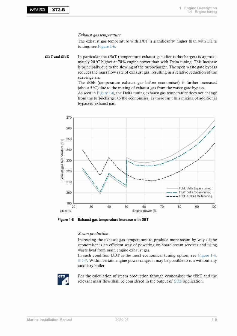
Exhaust gas temperatureThe exhaust gas temperature with DBT is significantly higher than with Deltatuning; see Figure 1-6.
tEaT and tEbE In particular the tEaT (temperature exhaust gas after turbocharger) is approxi-mately 20°C higher at 70% engine power than with Delta tuning. This increaseis principally due to the slowing of the turbocharger. The open waste gate bypassreduces the mass flow rate of exhaust gas, resulting in a relative reduction of thescavenge air. The tEbE (temperature exhaust gas before economiser) is further increased(about 5°C) due to the mixing of exhaust gas from the waste gate bypass.As seen in Figure 1-6, the Delta tuning exhaust gas temperature does not changefrom the turbocharger to the economiser, as there isn’t this mixing of additionalbypassed exhaust gas.
Figure 1-6 Exhaust gas temperature increase with DBT
Steam productionIncreasing the exhaust gas temperature to produce more steam by way of theeconomiser is an efficient way of powering on-board steam services and usingwaste heat from main engine exhaust gas. In such condition DBT is the most economical tuning option; see Figure 1-4, 1-7. Within certain engine power ranges it may be possible to run without anyauxiliary boiler.
For the calculation of steam production through economiser the tEbE and therelevant mass flow shall be considered in the output of GTD application.
SM-0317
190
200
210
220
230
240
250
260
270
20 30 40 50 60 70 80 90 100Engine power [%]
Exha
ust g
as te
mpe
ratu
re [o C
]
TEaT Delta bypass tuningTEbE Delta bypass tuning
TEbE & TEaT Delta tuning

Marine Installation Manual 2020-06 1-10
1 Engine Description1.4 Engine tuningX72-B
1.4.5 Low load tuning
The Low load tuning option is used to reduce the BSFC in the lower part-loadrange by optimising the engine and turbocharger to match for this low load oper-ation. However, this is offset with a reduction in efficiency towards full load.
Like DBT, LLT must consider engine parameters related to fuel injection and ex-haust valve control, combining a specifically designed turbocharger system setupwith the use of an exhaust gas waste gate (with a 85% power switch-point);see Exhaust gas waste gate, 1-8.
Working range The exhaust gas waste gate works as so:
• Below 85% engine power → Waste gate is closedAll exhaust gas flows into the turbocharger, this increases combustion pres-sure due to increased scavenge air pressure. As a consequence, the BSFC isreduced at low load.
• Above 85% engine power → Waste gate is openAs the turbocharger is optimised for lower part-load operation, at higherloads there is a surplus of available exhaust gas energy. This needs to be re-leased via the open waste gate to protect against turbocharger overspeed.
The higher scavenge air pressure in lower part load results in lower thermal loadand better combustion over the entire part-load range.
1.4.6 Steam production control (SPC)
The SPC system consists of an analogue controlled valve that enables theopening and closing of the exhaust gas waste gate (see Exhaust gas waste gate, 1-8), regulating the bypass of the turbocharger from the main engine. By in-creasing the bypass rate it reduces the mass flow rate of the turbocharger, this inturn increases the exhaust gas heat, which is used to produce steam as needed.
The SPC option can be applied to DBT and LLT, as the tuning options are al-ready equipped with an exhaust waste gate (see Exhaust gas waste gate, 1-8).Without the SPC this waste gate valve is either open or closed according to a setengine power percentage. The SPC constantly reacts, restricting the bypass flowto an optimum level. This is achieved by adjusting the valve according to realtime steam pressure values, enabling the SPC system to maintain a set steam re-quirement.
NOTE Since the exhaust gas waste gate is controlled by the scavenge air pressure, the indicated power is an approximation only.
Marine Installation Manual 2020-06 1-11
1 Engine Description1.4 Engine tuningX72-B
Connection toexternal systems
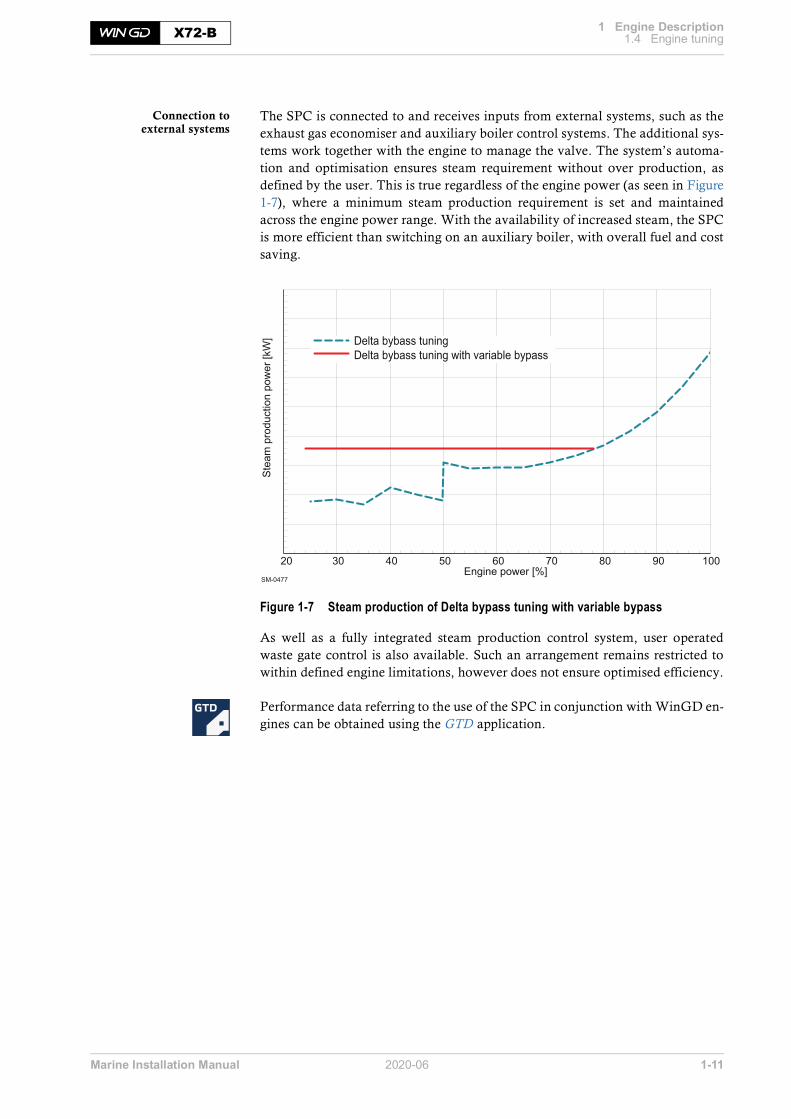
The SPC is connected to and receives inputs from external systems, such as theexhaust gas economiser and auxiliary boiler control systems. The additional sys-tems work together with the engine to manage the valve. The system’s automa-tion and optimisation ensures steam requirement without over production, asdefined by the user. This is true regardless of the engine power (as seen in Figure1-7), where a minimum steam production requirement is set and maintainedacross the engine power range. With the availability of increased steam, the SPCis more efficient than switching on an auxiliary boiler, with overall fuel and costsaving.
Figure 1-7 Steam production of Delta bypass tuning with variable bypass
As well as a fully integrated steam production control system, user operatedwaste gate control is also available. Such an arrangement remains restricted towithin defined engine limitations, however does not ensure optimised efficiency.
Performance data referring to the use of the SPC in conjunction with WinGD en-gines can be obtained using the GTD application.
SM-0477
20 30 40 50 60 70 80 90 100Engine power [%]
Stea
m p
rodu
ctio
n po
wer
[kW
] Delta bybass tuningDelta bybass tuning with variable bypass

Marine Installation Manual 2020-06 1-12
1 Engine Description1.4 Engine tuningX72-B
1.4.7 Low torsional vibration tuning (LowTV)
LowTV tuning is applied to the X72-B, on the 5-, 6- and 7-cylinder engines, inmany cases negating the need for a costly torsional vibration damper.For the X72-B, this additional tuning option is included as standard with all en-gine tuning options.
Figure 1-8 shows a comparison in regard to torsional vibration when LowTVtuning is applied. At a certain engine speed, the measured torsional vibration am-plitudes decreased by nearly 30%.
Figure 1-8 Vibration amplitudes - Achievements with default LowTV tuning
NOTE LowTV tuning does not impair the engine performance.
SM-0322
Ampl
itude
FE
[o ]
Without LowTV tuning
With LowTV tuning
20 30 40 50 60 70 80Speed [rpm]
0
0.2
0.4
0.6
0.8
1
1.2
1.4
1.6
1.8
-28%

Marine Installation Manual 2020-06 1-13
1 Engine Description1.4 Engine tuningX72-B
1.4.8 Tuning for de-rated engines
The tuning options are applicable over the entire rating field as illustrated inFigure 1-9.
Figure 1-9 Application area for tuning options
95SM-0311
R3
R4
R2
R1
Engine speed[%]
70 75 80 90 100
Engine power[%]
100
90
80
70
60
55
65 8553
All tuning options within the whole
layout field applicable

Marine Installation Manual 2020-06 1-14
1 Engine Description1.4 Engine tuningX72-B
1.4.9 Dual tuning
The WinGD 2-stroke engines can be built and certified with ‘dual tuning’, i.e.Delta tuning and LLT or DBT and LLT. Each tuning method has its own advantages in terms of specific fuel consump-tion or exhaust gas flow and temperatures.
Changeover betweentuning regimes
Changing over from one tuning to the other when the engine is in service is along-term consideration, since the following modifications are to be carried outon the engine:
• Exchange of turbocharger nozzle ring (and diffuser)
• ECS software parameter change
• Installation/removal of blind flange for exhaust gas bypass (not needed forDBT and LLT)
• Change of orifice size in exhaust gas bypass
An engine cannot be operated with both tuning regimes at the same time, asswitching from one tuning to the other when the engine is in operation is not inaccordance with the IMO MARPOL Annex VI NOx regulation. Since for NOxcertification the Technical Files and EIAPP certificates will be approved sepa-rately for each tuning, the NOx emissions need to be measured on the testbed forboth tuning regimes.
Considerations to bemade when choosing
dual tuning
The following must be considered before ordering an engine with dual tuning:
• GTD ancillary system data must be selected for the tuning with higher re-quirements concerning pump and cooler capacity.
• The torsional vibration calculation (TVC) must be carried out for both tun-ings. However, only the calculation for the tuning showing worse torsionalstresses in the shafting shall be submitted for Class approval.
• The engine interface drawings must correspond to the tuning method withexhaust gas bypass (LLT or DBT).
• The sea trial programme (engine related tests) must be discussed with theshipyard. It should be defined beforehand with which tuning the speed trialof the vessel is to be performed.

Marine Installation Manual 2020-06 1-15
1 Engine Description1.5 The Flex systemX72-B
1.5 The Flex systemThe X72-B engine is equipped with WinGD’s common rail fuel injection tech-nology, allowing flexible fuel injection. The flexibility provided by this tech-nology is reflected in the naming Flex system.
Figure 1-10 Flex system parts
Major benefits • Adaptation to different operating modes• Adaptation to different fuels• Optimised part-load operation• Optimised fuel consumption• Precise speed regulation, in particular at very slow steaming• Smokeless operation at all engine loads• Benefits in terms of operating costs, maintenance requirement and compli-
ance with emissions regulations
SM-0277
2 3 4 5 6Cylinder No. 1 - n
Engine control system
Rail unit (common rail)Fuel
Supply unit
ECS

Marine Installation Manual 2020-06 2-1
2 General Engine Data2.1 Pressure and temperature rangesX72-B
2 General Engine DataSelecting a suitable main engine to meet the power demands of a given project in-volves proper tuning in respect of load range and influence of operating condi-tions which are likely to prevail throughout the entire life of the ship. This chapter explains the main principles in selecting a WinGD 2-stroke marinediesel engine.
2.1 Pressure and temperature ranges
Please refer to the document ‘Usual values and safeguard settings’, which isprovided by WinGD under the following link:Usual values and safeguard settings
For signal processing see also 5.6.1 Signal processing, 5-12.

Marine Installation Manual 2020-06 2-2
2 General Engine Data2.2 Engine rating field and power rangeX72-B
2.2 Engine rating field and power range
2.2.1 Introduction
It is critical that a ship’s propulsion system is correctly matching the main enginecharacteristics to ensure reliable operation in a variety of conditions includingdesign and off design situations. The below sections outline the specifics to aid inthis process.
2.2.2 Engine rating field
The rating field shown in Figure 2-1 is the area of selectable engine design powerand engine design speed. In this area, the contracted maximum continuousrating (CMCR) of an engine can be positioned individually to give the desiredcombination of propulsive power and rotational speed. Engines within thislayout field are tuned for maximum firing pressure and best efficiency.
Figure 2-1 Rating field for X72-B
The rating field serves to determine the specific fuel consumption, exhaust gasflow and temperature, fuel injection parameters, turbocharger and scavenge aircooler specifications at the selected rating.
Percentage values The engine speed is given on the horizontal axis and the engine power on the ver-tical axis of the rating field. Both are expressed as a percentage [%] of the respec-tive engine’s nominal R1 parameters. Percentage values are being used so thatthe same diagram can be applied to various engine arrangements.
SM-0163
50
60
70
80
90
100
60 70 80 90 100
Engine speed[%]
Engine power[%]
The contracted maximum continuous rating (Rx) may befreely positioned within the rating field for that engine
Rating linefulfilling a ship’spower requirementfor a constant speed
Nominal propeller characteristic (1)
Nominal propeller characteristic (2)
R1
R2R3
R4
Rx1Rx2

Marine Installation Manual 2020-06 2-3
2 General Engine Data2.2 Engine rating field and power rangeX72-B
Rating pointsThe rating points (R1, R2, R3, R4) for WinGD engines are the corner points ofthe engine rating field (Figure 2-1, 2-2). The rating field is limited by two con-stant MEP (mean effective pressure) lines R1—R3 and R2—R4 and by two con-stant engine speed lines R1—R2 and R3—R4.
The point R1 represents the nominal maximum continuous rating (MCR). It isthe maximum power/speed combination which is available for a particular en-gine.
Any rating point (Rx) can be selected within the entire rating field to meet the re-quirements of each particular project. Such rating points require specific engineadaptations.
2.2.3 Propeller diameter and influence of propeller revolutionsInfluence of propeller
revolutions on the powerrequirement
At constant ship speed and for a given propeller type, a lower propeller speedcombined with a larger propeller diameter increases the total propulsive effi-ciency. Less power is needed to propel the vessel at a given speed.
The relative change of required power in function of the propeller revolutionscan be approximated by the following relation:
Formula 2-1
where:
PXj ............ = propulsive power at propeller revolution nj
nj ............... = propeller speed corresponding with propulsive power PXj
α ............... = 0.15 for tankers and general cargo ships up to 10,000dwt, or= 0.20 for tankers and bulk carriers from 10,000 to 30,000dwt, or= 0.25 for tankers and bulk carriers larger than 30,000dwt, or= 0.17 for reefers and container ships up to 3,000 TEU, or= 0.22 for container ships larger than 3,000 TEU
This relation is used in the engine selection procedure to compare different en-gine alternatives and to select an optimum propeller speed within the selected en-gine rating field. Usually, the number of revolutions depends on the maximumpermissible propeller diameter.
Maximum propellerdiameter
The maximum propeller diameter is often determined by operational require-ments, such as:
• Design draught and ballast draught limitations• Class recommendations concerning propeller/hull clearance (pressure im-
pulse induced on the hull by the propeller)
2 2
1 1
PX n
PX n
aæ ö÷ç ÷ç= ÷ç ÷÷çè ø

Marine Installation Manual 2020-06 2-4
2 General Engine Data2.2 Engine rating field and power rangeX72-B
The selection of a main engine in combination with the optimum propeller (effi-ciency) is an iterative procedure where also commercial considerations (engineand propeller prices) are playing an important role.
According to the above approximation, when a required power/speed combina-tion is known — for example point Rx1 in Figure 2-1, 2-2 — a CMCR line canbe drawn which fulfils the ship’s power requirement for a constant speed. Theslope of this line depends on the ship’s characteristics (coefficient α). Any otherpoint on this line represents a new power/speed combination, for example Rx2,and requires a specific propeller adaptation.
2.2.4 Power range
Propeller curves and operational pointsTo establish the proper propeller curves, it is necessary to know the ship’s speedto power response.
Determining power/pro-peller speed relationships
Normally, the curves can be determined by using full-scale trial results from sim-ilar ships, algorithms developed by maritime research institutes, or model tankresults. With this information and by applying propeller series, the power/speedrelationships can be established and characteristics developed.
The relation between absorbed power and propeller speed for a fixed pitch pro-peller (FPP) can be approximated by the following cubic relation:
Formula 2-2
where:
P .............. = propeller power
n .............. = propeller speed
3
CMCR CMCR
P nP n
æ ö÷ç ÷ç= ÷ç ÷÷çè ø

Marine Installation Manual 2020-06 2-5
2 General Engine Data2.2 Engine rating field and power rangeX72-B
Figure 2-2 Propeller curves and operational points
Figure 2-2 outlines the various engine limits, propeller curves and margins re-quired for engine optimisation. By incorporating the margins listed below, thevarious operational points and subsequently the CMCR point can be deter-mined. For detailed descriptions of the various line limits refer to section 2.2.5, 2-7.
Sea trial powerThe sea trial power must be specified. Figure 2-2 shows the sea trial power to bethe power required for reaching service speed, marked as point A, on the pro-peller curve with a light running margin (Line 8).
Sea margin (SM)The increase in power to maintain a given ship’s speed achieved in calm weather(point A in Figure 2-2) under average service condition (point B) is defined as ‘seamargin’. This margin can vary depending on owner’s and charterer’s expecta-tions, routes, season and schedules of the ship.
The location of reference point A and the magnitude of the sea margin are part ofthe new building contract and are determined between shipbuilder and owner.Typically, the sea margin is specified in the range of 10 to 25% of the sea trialpower.
SM-0026
Contracted maximumcontinuous rating
CMCR (Rx)
Continuous service rating
Sea trial power
Ship speed [% service speed] Engine speed [% CMCR rpm]
Engi
ne p
ower
[% C
MC
R p
ower
]
EM
SM
LR
3 4
5 77 88
ABCEMLRSMLine 3Line 4Line 5Line 7Line 8
Power and ship speed during sea-trials - Light running and ideal sea conditionShip design point / Continuous service rating (CSR)Recommended point for adaptation of propeller pitch under sea-trial conditionEngine marginLight running marginSea marginMaximum engine speed limit for continuous operationMaximum engine overspeed limit during sea-trialsAdmissible torque limitNominal engine characteristic curvePropeller curve with a light running margin
100
100 100
100Maximum continuous power
Continuous service power
Sea trial power
Serv
ice
spee
d
Serv
ice
rpm
CM
CR
rpm
Sea
trial
rpm
Sea
trial
spe
ed
A
B C
A
B C

Marine Installation Manual 2020-06 2-6
2 General Engine Data2.2 Engine rating field and power rangeX72-B
Light running margin (LR)The light running margin (‘LR’ in Figure 2-2, 2-5) is the expected change inspeed to relative power, caused by fouling and deterioration of the vessel overtime. The light running margin is agreed between shipyard and ship owner, de-pending on hull and propeller cleaning interval and operation route (that will af-fect the rate of deterioration e.g. speed, location, shallow water, etc.).
Typically, the light running margin is specified in the range of 4 to 7%. However,additional power/engine speed allowance must be provided for shaft generator/PTO installations (see section 2.2.6, 2-10).
Continuous service rating (CSR)- Also known as NOR or NCRPoint A represents the power and propeller speed of a ship operating at contrac-tual service speed in calm seas with a new clean hull and propeller. On the otherhand, the same ship at same speed under service condition with aged hull andunder average weather conditions requires a power/speed combination ac-cording to point B. In that case, B is the CSR point.
Engine margin (EM)Most owners specify the contractual ship’s loaded service speed at 85 to 90%power of the contracted maximum continuous rating. Different selections arepossible. The remaining e.g. 10 to 15% power can then be used to catch up withdelays in schedule.This margin is deducted from the CMCR. Therefore, the 100% power line isfound by dividing the power at point B by the selected CSR power percentage,e.g. 85 to 90%. The graphic approach to find the level of CMCR is illustrated inFigure 2-2, 2-5.
Contracted maximum continuous rating (CMCR)- Also known as Rx or SMCRThe contracted maximum continuous rating is the point obtained by applyingthe margins (SM and EM) to the propeller curves. The calculated CMCR pointcan be selected freely within the entire engine rating field.
NOTE It is the shipbuilder’s responsibility to determine a light running margin large enough so that the power range limits on the left side of the nom-inal propeller characteristic (Line 7) are not reached in any service con-dition (see Figure 2-3, 2-7).

Marine Installation Manual 2020-06 2-7
2 General Engine Data2.2 Engine rating field and power rangeX72-B
2.2.5 Power range limits
Once an engine is optimised at CMCR (Rx), the working range of the engine islimited by the following border lines (refer to Figure 2-3).
Figure 2-3 Power range limits
Line 1100% Torque Limit
Constant mean effective pressure (MEP) or torque line through CMCR from100 % (speed and power) down to 96% (speed and power).
Line 2Overload Limit
Available for testbed operation and emergency operation according to SOLASRegulation II-1/3.6. It is a constant MEP line, connecting point P07 (102.3%power and 96% speed) to point P08 (110% power and 103.2% speed). P08 is thepoint of intersection between Line 7 and 110% power.
Line 3Speed Limit
Maximum speed limit for continuous engine running, set to 104% of CMCRspeed. However, for a reduced Rx speed (nCMCR ≤ 0.98nMCR) this limit can beextended to 106% (Line 3a) provided that the specified torsional vibration limitsare not exceeded.
Line 4Overspeed Limit
The overspeed range between Line 3 (104% or 106%) and 108% speed is onlypermissible during sea trials if needed for demonstration. This may only be car-ried out in the presence of authorised engine builder representatives, with theship’s speed at CMCR power and a light running propeller. However, the speci-fied torsional vibration limits must not be exceeded.
Line 5Engine Operation
Power Limit
Admissible power limit for engine operation. The line is separated by the break-points listed in Figure 2-3.
SM-0323
0
10
20
30
40
50
60
70
80
90
100
110
0 10 20 30 40 50 60 70 80 90 100 110Engine speed [% Rx]
Engi
ne p
ower
[% R
x]
8
7
65
4
21P09
P07
P06
P05
P04(CMCR)
P03
P02
P01
P01P02P03
P04 (CMCR)P05P06P07P08P09
406096100406096
103.2108
203696
1002440
102.3110110
Breakpoints EngineSpeed [%Rx]
EnginePower [%Rx]
P08
9
13
33a

Marine Installation Manual 2020-06 2-8
2 General Engine Data2.2 Engine rating field and power rangeX72-B
Line 6Transient Operation
Power Limit
Maximum power limit for transient operation. The line is separated by the break-points listed in Figure 2-3, 2-7.
Line 7Nominal Engine
Characteristic
Nominal engine characteristic curve that passes through the CMCR point is de-fined by the propeller law:
Formula 2-3
Line 8Light Running
Propeller Curve
Propeller curve with a light running margin (typically between 4% and 7%). The curve is defined by the propeller law with a constant, governed by the se-lected light running margin (Formula 2-4).
Formula 2-4
where:
PLR ........... = propeller power at selected light running margin [kW]
PCMCR ....... = CMCR engine power [kW]
n ............... = selected engine speed [rpm]
nCMCR ....... = CMCR engine speed [rpm]
C .............. = constant
LR ............ = light running margin [%]
Line 9CMCR Power
Maximum power for continuous operation.
Line 13110% CMCR Power
Constant power overload limit, available in diesel mode for testbed operationand emergency operation according to SOLAS Regulation II-1/3.6.
Engine OperationPower Range
Line 5, Line 1 and Line 9 form the curve for the engine’s operation power rangelimit, as defined by Formula 2-5, 2-9. Each component is governed by differentcoefficients, as seen in Table 2-1.
Table 2-1 Line 5 coefficients
3
CMCR CMCR
P nP n
æ ö÷ç ÷ç= ÷ç ÷÷çè ø
3LR
CMCR CMCR
P nC
P n
æ ö÷ç ÷ç= ⋅ ÷ç ÷÷çè ø
31
1C
LR=
+
æ ö÷ç ÷ç ÷ç ÷çè ø
Line no. Range (n /nCMCR) C2 C1 C0
Line 5 0.00 - 0.40 0.000 0.500 0.000
0.40 - 0.60 0.500 0.300 0.000
0.60 - 0.96 1.111 -0.067 0.000
Line 1 0.96 - 1.00 0.000 1.000 0.000
Line 9 1.00 - 1.08 0.000 0.000 1.000

Marine Installation Manual 2020-06 2-9
2 General Engine Data2.2 Engine rating field and power rangeX72-B
Formula 2-5
where:
P ............... = selected engine power [kW]
PCMCR ....... = CMCR engine power [kW]
n ............... = selected engine speed [rpm]
nCMCR ....... = CMCR engine speed [rpm]
C2/C1/C0 .. = coefficients/constants
The area formed by Lines 1, 3, 5 and 9 is the range within which the engineshould be operated.
The area limited by Line 7, Line 9 and Line 3 is recommended for continuous op-eration.
The area between Line 7 and Line 5 is reserved for acceleration, shallow waterand normal operational flexibility. If a main-engine driven generator (PTO) is in-stalled, then the operating characteristics of the engine will differ. Refer to sec-tion 2.2.6, 2-10 for further details regarding PTO characteristics.
Overload Power Range Line 6, Line 2 and Line 13 form the curve for the engine’s overload power limit,as defined by Formula 2-5. Each component is governed by different coefficientsas seen in Table 2-2.
Table 2-2 Line 6 coefficients
The area above Lines 1 and 9 is the overload range. It is only allowed to operateengines in that range for a maximum duration of one hour in diesel mode, duringsea trials in the presence of authorised representatives of the engine builder.The area between Lines 1, 5 and 6 (Figure 2-3, 2-7), called ‘service range withoperational time limit’, is only applicable to transient conditions in diesel mode,i.e. sea trial or during emergency fast acceleration. The engine can only be oper-ated in this area for limited periods of time, in particular 1 hour per 24 hours.
2
2 1 0CMCR CMCR CMCR
P n nC C C
P n n
æ ö æ ö÷ ÷ç ç÷ ÷ç ç= + +÷ ÷ç ç÷ ÷÷ ÷ç çè ø è ø
Line no. Range (n /nCMCR) C2 C1 C0
Line 6 0.00 - 0.40 0.000 0.600 0.000
0.40 - 0.60 0.330 0.468 0.000
0.60 - 0.96 1.110 0.000 0.000
Line 2 0.96 - 1.032 0.000 1.066 0.000
Line 13 1.032 - 1.08 0.000 0.000 1.100

Marine Installation Manual 2020-06 2-10
2 General Engine Data2.2 Engine rating field and power rangeX72-B
2.2.6 Power range limits with main-engine driven generator for FPP
The addition of a main-engine driven generator (PTO) alters the working rangeand operating characteristics of the engine. Two methods of incorporating thePTO are outlined in the following sections. WinGD recommend to followMethod 1.
PTO considerations • The PTO is used for generating the navigation electric power.• The PTO is connected with frequency converter system.• The PTO is not engaged in heavy sea conditions.• Mechanical power absorption of the PTO must be considered.
PTO incorporation of Method 1
CMCR - Method 1 This first method considers the PTO as an addition to the previously defined pro-peller power requirements, therefore increasing the CMCR of the engine.
Figure 2-4 Power range diagram of an engine with main-engine driven generator
Line 7a in Figure 2-4 shows the power needed for the propeller, where Line 7bshows the power needed for the propeller combined with a constant power re-quirement from the main-engine driven generator, the PTO.
SM-0029
(Line 7) = Nominal engine characteristic(Line 7a) = Nominal propeller characteristic without PTO(Line 7b) = Nominal propeller characteristic with PTO
0
10
20
30
40
50
60
70
80
90
100
110
40 50 60 70 80 90 100 110
Engine speed [% Rx]
Engi
ne p
ower
[% R
x]
876 5
43
3a
7b 7a
LR margin
EM
PTO
SM
B
B’
A
Point A = Light running in ideal sea conditions (sea trial)Point B = CSRPoint B’ = Continuous service without PTO power

Marine Installation Manual 2020-06 2-11
2 General Engine Data2.2 Engine rating field and power rangeX72-B
With the addition of a constant nominal generator power across the engine loadrange, the engine curve is optimised, so no longer directly related to a propellercharacteristic. In the example of Figure 2-4, 2-10, the main-engine driven gen-erator is assumed to absorb 15% of nominal engine power. The CSR point in-cludes the PTO power demand, this is shown in Figure 2-4, 2-10 betweenpoints B’ and B. The CMCR point is selected from this propeller curve. Thiscurve defines the nominal engine characteristic.
This approach allows for practical and flexible PTO operation, only limited inthe lower engine speed range by the PTO required minimum speed (as defined bythe PTO device supplier) and the PTO layout limit Line 10 (only relevant if a sig-nificant percentage of the installed engine power is utilised for PTO).
Line 10PTO Layout Limit
The PTO layout limit line (Line 10 in Figure 2-5) defines the power limit for theresulting combination of the propeller and PTO.Considering Line 10 as PTO layout limit provides a margin for normal powerload fluctuation and acceleration.
Figure 2-5 Power range limits for PTO operation — Method 1
The breakpoints of Line 10 are listed in Figure 2-5. Line 10 is a curve defined byFormula 2-5, 2-9. The different components have a different coefficient,forming the entire curve. Refer to Table 2-3 for the individual coefficients.
Table 2-3 Line 10 coefficients
SM-0351
00
10
20
30
40
50
60
70
80
90
100
110
10 20 30 40 50 60 70 80 90 100 110Engine speed [% Rx]
Engi
ne p
ower
[% R
x]
P04 (CMCR)P11P12
1006096v
10028.892.2
Breakpoints EngineSpeed [%Rx]
EnginePower [%Rx]
8
7
6
54
21 9
13
33a
P11
10
PTO operationrange (Method 1)
P12P04
7a7b
B
Line no. Range (n /nCMCR) C2 C1 C0
Line 10 0.60 - 0.96 1.336 -0.321 0.000
0.96 - 1.00 0.000 1.941 -0.941

Marine Installation Manual 2020-06 2-12
2 General Engine Data2.2 Engine rating field and power rangeX72-B
PTO incorporation of Method 2
CMCR - Method 2 With this second method, the engine’s CMCR is determined by the propellerpower only. The PTO uses the available engine power that isn’t absorbed by thepropeller.
As seen in Figure 2-6, the available power for PTO application is between Line 8and Line 10. Therefore, the available PTO power depends on the available LightRunning margin at the current time.
When considering this method, a LR margin in the range of 8% is recom-mended.
Figure 2-6 Power range limits for PTO operation — Method 2
The PTO power must be controlled by the Ship Power Management System,which ensures that the engine operating point will not exceed Line 10.
Further information The following disadvantages must be observed for Method 2:
• With the reduction of the LR margin (as a consequence of the ageing hulland propeller) the available PTO power will be reduced and must be limitedby the Ship Power Management System.
• The PTO is typically engaged between approx. 60% - 96.5% of enginespeed. Final lower limit must be defined with the supplier of the generator.Final upper limit must be set to the project related CSR engine speed.
• Operation above the engine characteristic Line 7 can lead to increased DCCactivation.
If the requested PTO power is higher than the limits defined by Method 2, an in-crease in CMCR power is necessary.
SM-0350
00
10
20
30
40
50
60
70
80
90
100
110
10 20 30 40 50 60 70 80 90 100 110Engine speed [% Rx]
Engi
ne p
ower
[% R
x]
P04 (CMCR)P11P12
1006096
10028.892.2
Breakpoints EngineSpeed [%Rx]
EnginePower [%Rx]
PTO operationrange (Method 2)
8
7
6
5
4
21 9
13
33a
P11
P04P12
10
B

Marine Installation Manual 2020-06 2-13
2 General Engine Data2.2 Engine rating field and power rangeX72-B
2.2.7 Power range limits with controllable pitch propeller (CPP)
Within the higher speed range of the engine there is a prohibited operation areadefined by a minimum engine power requirement. During normal operation, in-cluding CPP at zero pitch operation, the engine will not enter this prohibitedarea. However, if the propeller is disconnected from the engine it would be ca-pable of entering the prohibited zone; this is strictly forbidden.
Figure 2-7 Prohibited engine operation area (CMCR speed = R1—R2)
As seen in Figure 2-7, 2-13, the prohibited operation area of an engine is de-fined by an engine tuned to an R1—R2 speed. At this speed rating the restrictionexists between 70 % and 100% speed, with a required minimum engine power atthese points of 5.8 % and 17% respectively. These values are governed by the For-mula 2-6 for Line 11. If the CMCR speed rating of the engine is less than the R1—R2 speed, the re-quired minimum power at this point is also calculated by the Line 11 equation.
[% R1 - R2] 40 50 60 70 80 90 100[rpm]
110
100
90
80
70
60
50
40
30
20
10
0
5 7 8
Field A
Prohibited operation area
17 [% Rx]
CMCR [Rx]
Engine power [% Rx]
Engine speed
5.8 [% Rx]11
12
E
F
44.535.6 53.4 62.3 71.2 80.1 89
X72-B
SM-0285

Marine Installation Manual 2020-06 2-14
2 General Engine Data2.2 Engine rating field and power rangeX72-B
Line 11 The lowest operational power limit, between 70% of R1—R2 speed and 100%CMCR speed, is defined with the following equation:
Formula 2-6
As defined by this equation and shown in Figure 2-7, 2-13, at 70% of R1—R2speed the minimum engine power equals approximately 6% of CMCR power(point E). The minimum power requirement at 100% CMCR speed (point F)must be calculated depending on the engine rating. Examples of this calculationare shown further on.
Line 12 While operating at 100% CMCR speed, the allowed engine power can range be-tween the minimum required power (point F) and 100% CMCR power.
Field A The available design range of the engine is defined by Line 7, Line 11 and Line12.For test purposes (e.g. for shaft generator adjustment), the engine may run at lowload, within the prohibited area. This is for a maximum time period of 30 min-utes during testing and sea trials, and only in the presence of authorised repre-sentatives of the engine builder. Further requests must be agreed by WinGD.
3
1 2
11 0.17 CMCR
R R
nLine
n -
æ ö÷ç ÷ç= ÷ç ÷÷çè ø⋅
NOTE The operational design range must respect the BSR limits from tor-sional vibration.

Marine Installation Manual 2020-06 2-15
2 General Engine Data2.2 Engine rating field and power rangeX72-B
Prohibited operation area for different speed rated engines
As the prohibited operating area of the engine is between 70% and 100% of theR1—R2 speed, the prohibited area is smaller when the speed rating of the engineis lowered.
Figure 2-8 Calculating prohibited operation area for CMCR speed
Figure 2-8 shows an engine with a CMCR rated at 85% of R1—R2 speed andtherefore is only affected by a portion of the prohibited area of the R1—R2 speedrange. The final graph for a CMCR at this speed is shown in Figure 2-9, 2-16.
SM-0523
11
12
EF
40 50 60 70 80 90 100
40
30
20
10
0
5 78
Field A
Prohibitedoperation area
Engine speed
Engine power [% Rx]
[% R1 - R2]
[% CMCR] 50 60 70 80 90 100

Marine Installation Manual 2020-06 2-16
2 General Engine Data2.2 Engine rating field and power rangeX72-B
Power/speed range forCMCR [Rx] =
85% R1—R2 speed
In Figure 2-9, the engine’s CMCR speed is rated at 85% of the R1—R2 speed. Atthis speed, a minimum engine power (point F) of 10.4% is required. Below this isthe prohibited area of operation for a disconnected propeller.
Point E is always defined at 70% of the R1—R2 speed and has a minimumpower of 5.8%, however in Figure 2-9 this equates to approximately 82% CMCRspeed.
Figure 2-9 Prohibited engine operation area (CMCR speed = 85 % of R1—R2)
40 50 60 70 80 90 100[rpm]
110
100
90
80
70
60
50
40
30
20
10
0
5 7 8
CMCR [Rx]
Field A
Engine speed
Engine power [% Rx]
[% Rx]
E
F
11
12
Prohibited operation area
10.4 [% Rx]
37.830.3 45.4 53.0 60.5 68.1 75.7
X72-B
SM-0284

Marine Installation Manual 2020-06 2-17
2 General Engine Data2.2 Engine rating field and power rangeX72-B
Power/speed range forCMCR [Rx] =R3—R4 speed
In Figure 2-10, the engine’s CMCR speed is rated at the R3—R4 speed. At thisspeed, a minimum engine power (point F) of 6.9% is required. Below this is theprohibited area of operation for a disconnected propeller.
Figure 2-10 Prohibited engine operation area (CMCR speed = R3—R4)
40 50 60 70 80 90 100[rpm]
110
100
90
80
70
60
50
40
30
20
10
0
5 7 8
CMCR [Rx]
Field A
Engine speed
Engine power [% Rx]
[% Rx]
6.9 [% Rx]11
12
E F
Prohibitedoperation area
33.026.4 39.6 46.2 52.8 59.4 66
X72-B
SM-0286

Marine Installation Manual 2020-06 2-18
2 General Engine Data2.2 Engine rating field and power rangeX72-B
2.2.8 CPP requirements for Propulsion Control System
WinGD advise to include CPP control functions in an engine remote controlsystem from an approved supplier. This ensures, amongst others, that the re-quirements of the engine builder are strictly followed.
The following operating modes shall be included in the Propulsion ControlSystem:
• Combinator mode 1Combinator mode for operation without shaft generator, or with shaft gen-erator and frequency control system. Any combinator curve including asuitable light running margin can be set in field A.
• Combinator mode 2Optional mode used in connection with shaft generators. During manoeu-vring the combinator curve is freely selected in Field A. At sea, the engineis operated at constant speed on Line 12, between point F and CMCR.
For manual and emergency operation, separate set-points for speed and pitch areusually provided. At any location allowing such operation, a plate must beplaced with the following warning:
The pitch value (xx) is to be defined according to installation data.
For additional information about CPP application in the Propulsion ControlSystem, refer to section 5.4.2 Recommended manoeuvring characteristics, 5-8.
Operation inprohibited area
In addition, if the engine is operated for more than 3minutes in the prohibitedoperation area, an alarm must be provided in either the ME safety system or thevessel’s Alarm and Monitoring System. If the engine is operated for more than 5 minutes in the prohibited operation area,then the speed must be reduced below 62rpm.
Engine must not be operated continuously at apitch lower than xx % at any speed above 62 rpm.

Marine Installation Manual 2020-06 2-19
2 General Engine Data2.3 Operating conditionsX72-B
2.3 Operating conditionsThe engine can be operated without any restrictions in the ambient conditionrange ‘winter’, as permissible by GTD, up to design conditions. Operation out-side these limits is possible, but further measures might need to be taken and thepower output might be limited. For project-specific support please contactWinGD.
2.3.1 Reference conditions
Engine performance data — like BSEC, BSEF, tEaT and others — are based onreference conditions. These conditions are specified in ISO standard 15550 (corestandard) and, for marine application, in ISO standard 3046 (satellite standard)as follows:
2.3.2 Design conditions
The capacities of ancillaries are specified according to ISO standard 3046-1(clause 11.4) following the International Association of Classification Societies(IACS) and are defined as design conditions:
Air temperature before blower:Engine room ambient air temperature:Coolant temperature before SAC:Barometric pressure:Relative humidity:
25°C25°C25°C1,000mbar30%
Air temperature before blower:Engine room ambient air temperature:Coolant temperature before SAC:Barometric pressure:Relative humidity:
45°C45°C36°C1,000mbar60%

Marine Installation Manual 2020-06 2-20
2 General Engine Data2.4 Ancillary system design parametersX72-B
2.4 Ancillary system design parametersThe layout of the engine’s ancillary systems is based on the rated performance(rating point Rx, CMCR). The given design parameters must be considered inthe plant design to ensure a proper function of the engine and its ancillary sys-tems:
The engine power is independent of ambient conditions as found in marine ap-plications. The cylinder water outlet temperature and the oil temperature beforeengine are system-internally controlled and have to remain at the specified level.
Cylinder cooling water outlet temperature:Oil temperature before engine:Exhaust gas back pressure at rated power (Rx):
90°C45°C30mbar
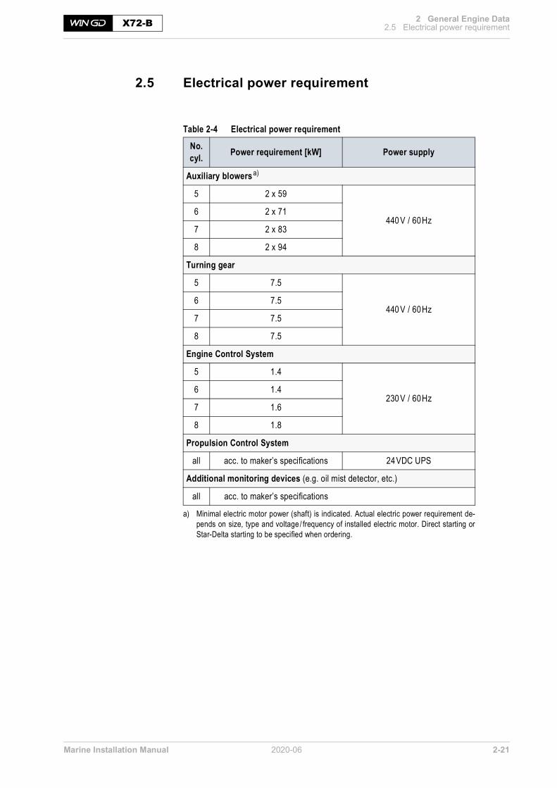
Marine Installation Manual 2020-06 2-21
2 General Engine Data2.5 Electrical power requirementX72-B
2.5 Electrical power requirement
Table 2-4 Electrical power requirement
No. cyl. Power requirement [kW] Power supply
Auxiliary blowers a)
a) Minimal electric motor power (shaft) is indicated. Actual electric power requirement de-pends on size, type and voltage / frequency of installed electric motor. Direct starting orStar-Delta starting to be specified when ordering.
5 2 x 59
440 V / 60Hz6 2 x 71
7 2 x 83
8 2 x 94
Turning gear
5 7.5
440 V / 60Hz6 7.5
7 7.5
8 7.5
Engine Control System
5 1.4
230 V / 60Hz6 1.4
7 1.6
8 1.8
Propulsion Control System
all acc. to maker’s specifications 24VDC UPS
Additional monitoring devices (e.g. oil mist detector, etc.)
all acc. to maker’s specifications

Marine Installation Manual 2020-06 2-22
2 General Engine Data2.6 GTD - General Technical DataX72-B
2.6 GTD - General Technical DataGTD is an application for the calculation and output of general technical datawhich are relevant for planning a marine propulsion plant. All data in this appli-cation are relating to the entire 2-stroke engine portfolio.
Engine performance data The GTD application allows calculation of the performance data (BSEC, BSEF,tEaT, etc.) for any engine power.
GTD output Beside the output of characteristic parameters in the whole rating field of an en-gine, the GTD application delivers data on the capacities of coolers, pumps,starting air bottles and air compressors. It also provides information on engineradiation, on the power requirement for ancillary systems, and outputs data suit-able for estimating the size of ancillary equipment. Furthermore, data about the available components and options depending onspecification and engine rating can be output. In addition to the standard outputfor ISO reference and design conditions, further operating conditions for whichinformation is required can be defined.
The GTD application is accessible on Internet at the WinGD Customer Portal orfrom the WinGD corporate webpage using the following link:https://www.wingd.com/en/media/general-technical-data
SM-0302

Marine Installation Manual 2020-06 3-1
3 Engine Installation3.1 Dimensions and massesX72-B
3 Engine InstallationThe purpose of this chapter is to provide information to assist in the installationof the engine. It is for guidance only and does not supersede current instructions.
3.1 Dimensions and masses
Figure 3-1 Engine dimensions
Table 3-1 Engine dimensions and masses (preliminary)
E
D
C
BA
G
F2 /
F3
F1
SM-0110
No. cyl.
Dimension in mm with a tolerance of approx. ±10mm Net eng. massa)
a) Without oil /water; net engine mass estimated according to nominal dimensions given in drawings, including turbocharger and SAC, pipingand platforms
A B C D E F1 b)
b) Min. height for vertical removal of piston with standard crane
F2 c)
c) Min. height for vertical removal of piston with double-jib crane
F3d)
d) Min. height for tilted removal of piston with double-jib crane
G [tonnes]
5 8,085
4,780 1,575 11,790
Dim
. dep
endin
gon
TC
type
13,750 13,6750 12,820 2,455
481
6 9,375 561
7 10,665 642
8 11,960 716
Min. capacity of bridge crane: 7,750 kg (not DF-ready: 7,500kg)Min. capacity of double-jib crane e): 2 x 4,175kg (not DF-ready: 2 x 4,050kg)
e) In cases of double-jib crane application, both hooks are used in parallel; special lifting tools are requiredWhen selecting the double-jib lifting method, it must be considered that maintenance work will demand additional time and effort, espe-cially for tilted removal (F3), compared to standard procedure (F1). Availability of the special lifting tools needs to be considered in the pro-ject schedule.

Marine Installation Manual 2020-06 3-2
3 Engine Installation3.1 Dimensions and massesX72-B
Project-specific dimensions and masses for main components to be requestedfrom engine builder.
3.1.1 Dismantling heights for piston and cylinder liner
Dimensions F1, F2, F3 in Figure 3-1, 3-1 and the corresponding table are forguidance only and may vary depending on crane dimension, handling tools anddismantling tolerances.However, please contact WinGD or any of their representatives if these valuescannot be maintained or if more detailed information is required.
For details see also drawings ‘Dismantling Dimensions’ (DG 0812) provided onthe WinGD corporate webpage under the following links:5-cyl. engine6-cyl. engine7-cyl. engine8-cyl. engine
3.1.2 Crane requirements
• An overhead travelling crane is to be provided for normal engine mainte-nance. (Crane capacity see Table 3-1, 3-1.)
• The crane is to conform to the requirements of the classification society.
NOTE The dimensions given in above table are not binding. For prevailing data refer to the relevant drawings, which are updated on a regular basis.
NOTE As a general guidance WinGD recommend a two-speed hoist with pen-dent control, which allows selecting either high or low speed, i.e. high speed 6.0m/minute, low speed 0.6-1.5m/minute.

Marine Installation Manual 2020-06 3-3
3 Engine Installation3.1 Dimensions and massesX72-B
3.1.3 Thermal expansion at turbocharger expansion joints
Before making expansion pieces, enabling connections between the engine andexternal engine services, the thermal expansion of the engine has to be taken intoaccount. The expansions are defined (from ambient temperature 20 °C to servicetemperature 55°C) as follows (see also Figure 3-2):
Figure 3-2 Thermal expansion, dim. X, Y, Z
Calculating thermalexpansion
Δx (Δy, Δz) = X (Y, Z) • α • ΔT
where:
Δx, Δy, Δz .. = thermal expansion
X, Y, Z ...... = distance as per relevant pipe connection plan and outline drawing
α .............. = 1.15 • 10-5 (coefficient of thermal expansion)
ΔT ............ = difference between service temp. and ambient temp. [°C]
Expansion Distance from ...
Transverse expansion (X) ... crankshaft centreline to centre of gas outlet flange
Vertical expansion (Y) ... bottom edge of bedplate to centre of gas outlet flange
Longitudinal expansion (Z) ... engine bedplate aft edge to centre of gas outlet flange
a) a)
Z
X
Y
a) Gas outlet flangeDimensions X, Y, Z SM-0054

Marine Installation Manual 2020-06 3-4
3 Engine Installation3.1 Dimensions and massesX72-B
3.1.4 Content of fluids in the engine
Table 3-2 Fluid quantities in the engine
No. of cyl.
Lubricating oil Fuel oil Cylinder cooling water
Freshwater in SAC a)
a) The given water content is approximate.
[kg] [kg] [kg] [kg]
5 3,100 20 1,150 550
6 3,500 28 1,375 575 b) / 1,200c)
b) Values for executions with 1 scavenge air cooler.c) Values for executions with 2 scavenge air coolers.
7 3,850 28 1,625 575 b) / 1,350c)
8 4,250 28 1,850 1,450

Marine Installation Manual 2020-06 3-5
3 Engine Installation3.2 Engine outline viewsX72-B
3.2 Engine outline viewsThe latest versions of the Engine Outline Drawings (DG 0812) are provided onthe WinGD corporate webpage under the following links:5-cyl. engine6-cyl. engine7-cyl. engine8-cyl. engine

Marine Installation Manual 2020-06 3-6
3 Engine Installation3.3 Platform arrangementX72-B
3.3 Platform arrangement
3.3.1 Drawings
For platform arrangement see the links given in section 3.2, 3-5.
3.3.2 Minimum requirements for escape routes
The platforms shown in the relevant drawings are arranged in such a way as toensure safe escape routes for the crew. The minimum sizes required by the clas-sification societies are met.
Figure 3-3 Minimum requirements for headroom
Important! • The minimum sizes are to be taken into account when installing the engine.Special attention is to be given to the minimum distance between the ship’splatform and the lower engine platform, to ensure sufficient headroom (seeFigure 3-3).
• No dead ends may be created on the platforms by shipboard installations. Ifa dead end cannot be avoided, then a passage leading to the ship’s platformhas to be cleared before the dead end (distance from dead end: max.2,000mm).
See also the links to drawings in section 3.2, 3-5.
SM-0115
Ship’s platform
Lower platform
h = min. 2000 mm
600 mm
2000
mm
Reference frame

Marine Installation Manual 2020-06 3-7
3 Engine Installation3.4 SeatingX72-B
3.4 SeatingEngine seating is integral with the double-bottom structure and has to be of suf-ficient strength to support the weight of the engine, transmit the propeller thrustand withstand external couples and stresses related to propeller and engine reso-nance.
• Before any seating work can be performed, make sure the engine is alignedwith the intermediate propeller shaft.
• The longitudinal beams situated under the engine are to protrude from theengine room bulkhead by at least half the length of the engine, and aft as faras possible.
• The maximum allowable rake is 3° to the horizontal.
More details about engine seating can be found in the relevant Fitting Instruc-tion (DG 9710) on the WinGD corporate webpage under the following link: Fitting instruction - Engine seating and foundation
The latest version of the Marine Installation Drawing Set relevant for engineseating and foundation (DG 9710) is provided on the WinGD corporate web-page under the following link: MIDS

Marine Installation Manual 2020-06 3-8
3 Engine Installation3.5 AssemblyX72-B
3.5 AssemblyEngines may be installed as complete units or assembled from subassemblies inthe vessel, which may be afloat, in dry dock, or on the slipway.
3.5.1 Assembly of subassemblies
When the engine seating has been approved, the bedplate is lowered onto blocksplaced between the chocking points. The thickness of the blocks depends on thefinal alignment of the engine. Engine bedplates comprise fabricated sections withtapped holes for the jacking screws for engine alignment, and drilled holes toallow the passing of the holding-down bolts.
For checking thedimensions optical
devices or lasersmay be used
• Proceed with the preliminary alignment of the bedplate using wedges orjacking screws.
• Position the engine coupling flange to the intermediate shaft couplingflange.
• Ensure that the gap between both flanges is close to the calculated figuresand that both flanges are exactly parallel on the horizontal plane (max. de-viation 0.05mm).
• In the vertical plane, set the engine coupling flange 0.4-0.6mm higher thanthe calculated figures.
• Place the bearing caps in position and install the turning gear.• Ensure that the crankshaft deflections are as recorded in the ‘Engine As-
sembly Records’.• Check the bedplate level in longitudinal and diagonal directions with a taut-
wire measuring device provided by the engine builder.• Compare the readings with those recorded at works.
All final dimensions are to be witnessed by the representatives of the enginebuilder and the classification society, and recorded on appropriate log sheets.Crankshaft deflections at this stage are to correspond with the values recorded atworks.
• Temporarily secure the bedplate against unexpected movement.• Continue engine assembly by mounting the columns, cylinder blocks, run-
ning gear and scavenge air receiver.• Ensure that the bearing caps are loose before tensioning the tie rods.• Make periodic checks of the crankshaft deflections to observe and correct
any possible engine distortions.• Carry out careful adjustments of the wedges or the jacking screws to re-es-
tablish the preliminary alignment setting.
Once the engine assembly is completed, the final alignment and chocking is car-ried out with the vessel afloat.
NOTE The process of using jacking screws and wedges is defined in MIDS and must be followed.

Marine Installation Manual 2020-06 3-9
3 Engine Installation3.5 AssemblyX72-B
3.5.2 Installation of a complete engine
In the event that the engine is shipped in part deliveries and assembled at theshipyard before installation in the vessel, the shipyard is to undertake assemblywork in accordance with the demands of a representative of the engine builderand the classification society.
Please observe: • Engine mounting is to be carried out systematically.• The measurement readings have to be recorded on appropriate log sheets
and compared for correctness with the data in the ‘Engine Assembly Re-cords’ completed after test run in the manufacturer’s works.
• The engine is to be lowered onto blocks placed between the chockingpoints.
• The blocks are to be set in such a manner that the engine is slightly higherthan the final position, because less effort is required to lower the enginethan to raise it for alignment.
• For movements in the horizontal plane, both in lateral or longitudinal di-rections, the shipyard is to construct appropriate anchor points for the useof hydraulic jacks. Such movements have to be carried out with great careto avoid stresses and distortions to the bedplate.
• Regular crankshaft deflection readings have to be taken to observe the ef-fects, and any noticed deviation has to be rectified immediately.
3.5.3 Installation of an engine from assembled subassemblies
Subassemblies of the engine may be assembled ashore before installation in theship. One such assembly may comprise the following components:
• Bedplate• Main and thrust bearings• Crankshaft• Turning gear• Flywheel
The placing on blocks and alignment to shafting is analogue to that described insection 3.5.1, 3-8.
3.5.4 Installation of an engine in ship on slipway
Installing a complete or partially assembled engine in a ship under constructionon an inclined slipway is possible when careful attention is paid to the following:
• Large components suspended to take account of the incline• Tie rods centred and exactly perpendicular to the bedplate before tight-
ening.• Side, fore and aft arresters temporarily fitted to prevent the engine from
moving during launching of the ship• Additional temporary stays attached at upper platform level to steady the
engine during launching
NOTE • Strict attention is to be paid to the removal of anti-corrosion coatings and the subsequent application of rust preventing oil where required.
• The alignment tools are to be clean and ready for use.

Marine Installation Manual 2020-06 3-10
3 Engine Installation3.6 Engine and shaft alignmentX72-B
3.6 Engine and shaft alignmentAlignment and chocking of the engine should be carried out in accordance withour recommendations and is subject to test and inspection by the relevant classi-fication society.
Each stage of engine mounting is to be checked by qualified personnel and themeasurements cross-checked with the design figures. In the event of discrepan-cies the responsible parties (e.g. shipyard) are to advise the representative of theengine builder or WinGD.
3.6.1 Instructions and limits
Alignment can be done with either jacking screws or wedges.
For detailed alignment procedures refer to the latest version of Engine Align-ment Documents (DG 9709) provided on the WinGD corporate webpage underthe following link:Engine alignment
3.6.2 Tools
For Engine Alignment Tools (DG 9710-01) refer to the latest version of the re-spective drawings, which are provided on the WinGD corporate webpage underthe following link:Tool engine alignment

Marine Installation Manual 2020-06 3-11
3 Engine Installation3.7 Engine couplingX72-B
3.7 Engine coupling
3.7.1 Design
The design of coupling bolts and holes for the flange connection of crankshaft/propulsion shafts as provided by design group 3114 is included in the engine de-sign approval by all major classification societies.
3.7.2 Machining and fitting of coupling bolts
• Before fitting the coupling bolts ensure that the mating flanges are concen-tric. Close the gap between the flanges completely by means of min. 4 tem-porary (non-fitted) bolts evenly distributed over the pitch hole diameter.
• Carry out drilling and reaming of engine and shaft couplings by means of acomputer controlled drilling machine or an accurately centred jig.
• In the case of non-matching holes or damaged holes apply joint cylindricalreaming to an oversize hole and then fit an individually machined bolt.
• The bolts have to be available for inserting in the holes on completion ofreaming. Each bolt is to be stamped with its position in the coupling, withthe same mark stamped adjacent to the hole. The following tolerances haveto be met:— bolt hole tolerance: H7— bolt tolerance: g6 (clearance fit)
• If there is any doubt that a fitted bolt is too slack or too tight, refer to theclassification society surveyor and a representative of the engine builder.
3.7.3 Tightening
• When tightening the coupling bolts it is essential to work methodically. Per-form crosswise tightening, taking up the threads on opposite bolts to hand-tight, followed by sequential torque tightening. Finally ensure the sameproper tightening for all bolts.
• Mark each bolt head in turn (1, 2, 3, etc.) and tighten opposite nuts in turnaccording to the Tightening Instructions, making sure that the bolt head issecurely held and unable to rotate with the nut.
• Lock castellated nuts according to Class requirements with either lockingwires or split pins. Use feeler gauges during the tightening process to ensurethat the coupling faces are properly mated with no clearance.
3.7.4 Installation drawing
The latest version of the drawing, relevant for the Connection Crank/PropellerShaft (DG 3114), is provided on the WinGD corporate webpage under the fol-lowing link:Connection crank/propeller shaft

Marine Installation Manual 2020-06 3-12
3 Engine Installation3.8 Engine staysX72-B
3.8 Engine staysShip vibrations and engine rocking caused by the engine behaviour (see chapter6 Engine Dynamics, 6-1) are reduced by fitting lateral stays (refer to section6.2 External lateral forces and moments, 6-6) and longitudinal stays (refer to6.3 Longitudinal vibration (pitching), 6-10).
The latest version of the Marine Installation Drawing Set relevant for enginestays (DG 9715) is provided on the WinGD corporate webpage under the fol-lowing link:MIDS

Marine Installation Manual 2020-06 3-13
3 Engine Installation3.9 Propulsion shaft earthingX72-B
3.9 Propulsion shaft earthingElectric current flows when a potential difference exists between two materials.The creation of a potential difference is associated with thermoelectric by the ap-plication of heat, tribo-electric between interactive surfaces, electrochemical whenan electrolytic solution exists, and electromagnetic induction when a conductingmaterial passes through a magnetic field.
Tracking or leakage currents are created in machinery by any of the above meansand — if they are not adequately directed to earth — can lead to component fail-ures, or in some cases result in fires and interference with control and monitoringinstrumentation.
3.9.1 Preventive action
Using earthing brushes in contact with slip rings and bonding the chassis bybraided copper wire are common ways of protecting electric machines. Whereoperating loads and voltages are comparatively low, the supply is isolated fromthe machine by an ‘isolating transformer’, often with handheld power tools. Thebuild specification dictates the earthing procedure to be followed and the classi-fication society is to approve the final installation. On vessels with star-wound alternators the neutral is considered to be earth, andelectrical devices are protected by automatic fuses.
Isolation ofinstrument wiring
Ensure that instrument wiring meets the building and classification society spec-ifications and that it is shielded and isolated to prevent induced signal errors andshort circuits. In certain cases large items of machinery are isolated from their foundations, andcouplings are isolated to prevent current flow, for instance when electric motorsare connected to a common gear box.
Retrospective fitting of earthing devices is not uncommon, but due considerationis to be given at design stage to adequate shielding of control equipment andearthing protection where tracking and leakage currents are expected. Magneticinduction and polarisation are to be avoided and degaussing equipment incorpo-rated if there is likely to be a problem.
3.9.2 Earthing device
Figure 3-4, 3-14 shows a typical shaft earthing device. The slip ring (1) is supplied as matched halves to suit the shaft, and secured bytwo tension bands (2) using clamps (12). The slip ring mating faces are finishedflush and butt jointed with solder. The brushes (4) are housed in the twin holder(3) clamped to a stainless steel spindle (6), and there is a monitoring brush (11) ina single holder (10) clamped to an insulated spindle (9). Both spindles are at-tached to the mounting bracket (8).
Conducting materialfor slip rings
Different combinations of conducting material are available for the constructionof slip rings. However, alloys with a high silver content are found to be efficientand hard wearing.

Marine Installation Manual 2020-06 3-14
3 Engine Installation3.9 Propulsion shaft earthingX72-B
Figure 3-4 Typical shaft earthing arrangement
Position of earthing device on shaft
The earthing device has to be arranged as close as possible to the engine. In casea shaft generator/motor is installed, the earthing device has to be arranged onthe front side of the generator/motor, as close a possible to the engine.
Connectingelectric cables
The electric cables are connected as shown in Figure 3-5, 3-15 with the op-tional voltmeter. This instrument is at the discretion of the owner, but it is usefulto observe that the potential to earth does not rise above 100mV.
Typical arrangement for the propeller shaft
AA
123456789
101112
Slip ringTension bandsTwin holderBrushesConnection to the ship’s hullSteel spindleConnection to the voltmeterMounting bracketInsulated spindleSingle holderMonitoring brushClamps
View on ‘A’ (brush gear omitted)
SM-0058
9112
26
8
1
2
3
4
5 6
78
9
10
11
12
Section A-A
NOTE For detailed information please contact the earthing device supplier.

Marine Installation Manual 2020-06 3-15
3 Engine Installation3.9 Propulsion shaft earthingX72-B
Figure 3-5 Typical shaft earthing with condition monitoring facility
Shaft monitoring
Propeller shaft
35 mm2
2.5 mm2
Insulated spindle
Hull/structure earthsto be separately connected
Slip ring condition voltmeter
SM-0056
PM+
PH-
50 mV
50250
250 mV
00
Shaft earth (hull)Additional terminals are providedas necessary for multi-shaft vessels.2.5 mm2

Marine Installation Manual 2020-06 3-16
3 Engine Installation3.10 Fire protectionX72-B
3.10 Fire protectionFires may develop in areas such as scavenge air receiver /piston underside. Theengine is fitted with a piping system which leads the fire extinguishing agent intothe critical areas.
Where fire protection is required, the final arrangement of the fire extinguishingsystem is to be submitted for approval to the relevant classification society.
Extinguishing agents Various extinguishing agents can be considered for fire fighting purposes. Theyare selected either by the shipbuilder or the ship owner in compliance with therules of the classification society involved.
Steam as an alternative fire extinguishing medium is permissible for the scavengeair spaces of the piston underside, but may cause corrosion if countermeasuresare not taken immediately after its use.These countermeasures comprise:— Opening scavenge spaces and removing oil and carbon deposits— Drying all unpainted surfaces and applying rust protection (i.e. LO)
Table 3-3 Recommended quantities of fire extinguishing medium
NOTE If steam is used for the scavenge spaces, a water trap is recommended to be installed at each entry to the engine and assurance obtained that steam shut-off valves are tight when not in use.
Piston underside and scavenge air receiver Bottle
Number of cylinders
5 6 7 8
Volume [m3/cyl]
Mass [kg/cyl]
Size[kg] Extinguishing medium Quantity of fire
extinguishing bottles
8 29 45 Carbon dioxide (CO2) 4 4 5 6

Marine Installation Manual 2020-06 4-1
4 Ancillary Systems X72-B
4 Ancillary SystemsSizing the ancillary systems of the engine, i.e. for freshwater cooling, lubricatingoil, fuel oil, etc., depends on the contracted maximum engine power. If the ex-pected system design is out of the scope of this manual, then contact our repre-sentative or WinGD directly.
The GTD application provides data for estimating the size of ancillary equipmentand enables all engine and system data at any Rx rating within the engine ratingfield to be obtained. However, for convenience or final confirmation when opti-mising the plant, WinGD provide a computerised calculation service.
All pipework systemsto be flushed and
proved clean beforecommissioning!
All pipework systems and fittings are to conform to the requirements laid downby the legislative council of the vessel’s country of registration and the classifica-tion society selected by the owners. They are to be designed and installed to ac-commodate the quantities, velocities, flow rates and contents identified in thismanual, set to work in accordance with the build specification as approved bythe classification society and protected at all times from ingress of foreign bodies.

Marine Installation Manual 2020-06 4-2
4 Ancillary Systems4.1 Twin-engine installationX72-B
4.1 Twin-engine installationA vessel equipped with two separate main propulsion engines is considered atwin-engine installation. The installation of two WinGD 2-stroke engines allowscombining individual engine auxiliary systems.
In Table 4-1 WinGD provide information based on engines’ requirements. Class and other binding rules might overrule.
Table 4-1 Common and independent systems in twin-engine installations
System Independent system for each engine required
Common system possible
Remarks
LT cooling water system(see Figure 4-1, 4-3)
XPlease note: Parallel independent LT cooling water supply per engine to the scavenge air coolers from common LT cooling water circuit
XPlease note: Parallel independent LT cooling water supply per engine to the LO cooler and HT cooling water cooler from common LT cooling water circuit
HT cooling water system X
Main LO system X
Cylinder LO system(see Figure 4-2, 4-4)
X Day tanks for high- resp. low BN lubricating oil
X Rising pipe
X Separate distribution to each engine
Fuel oil systemX Feed system
X Booster circuit systems
Starting air system X
Control air X Supply system
Leakage collection system and washing devices X
Exhaust gas system X
Engine venting pipes X

Marine Installation Manual 2020-06 4-3
4 Ancillary Systems4.1 Twin-engine installationX72-B
Figure 4-1 LT cooling water system for twin-engine installation
SM-0191
1 Scavenge air cooler (SAC)2 HT cooling water cooler (engine 1)3 Lubricating oil cooler (engine 1)4 HT cooling water cooler (engine 2)5 Lubricating oil cooler (engine 2)6 Ancillary plants7 Central seawater cooler8 Temperature control valve9 Pumps
MainEngine 2
8 (set-point: 25 °C)
MainEngine 1
SAC
SAC
9
7
1
2
3 5
6
4
1

Marine Installation Manual 2020-06 4-4
4 Ancillary Systems4.1 Twin-engine installationX72-B
Figure 4-2 Cylinder LO system for twin-engine installation
ME2
LUB
HIGH BNSERVICE TANK
LOW BNSERVICE TANK
ME1
LUB
ME – Main engineLUB – Lubricator
Min
. sta
tic h
eigh
t ac
cord
ing
to th
e sp
ecifi
catio
n in
MID
S
MM
MM
TRACE HEATING
CHANGEOVER VALVES(close to engine inlet)
SM-0193
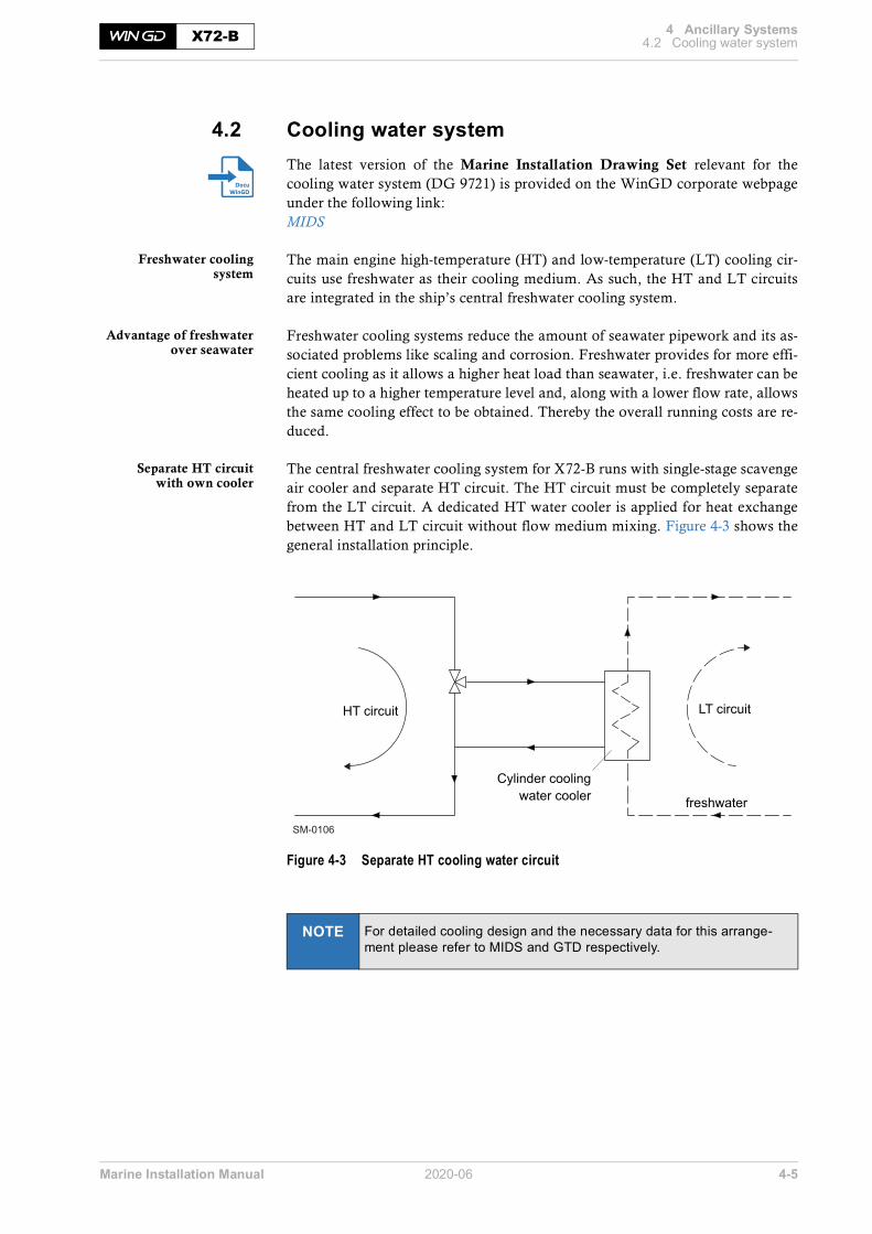
Marine Installation Manual 2020-06 4-5
4 Ancillary Systems4.2 Cooling water systemX72-B
4.2 Cooling water systemThe latest version of the Marine Installation Drawing Set relevant for thecooling water system (DG 9721) is provided on the WinGD corporate webpageunder the following link:MIDS
Freshwater coolingsystem
The main engine high-temperature (HT) and low-temperature (LT) cooling cir-cuits use freshwater as their cooling medium. As such, the HT and LT circuitsare integrated in the ship’s central freshwater cooling system.
Advantage of freshwaterover seawater
Freshwater cooling systems reduce the amount of seawater pipework and its as-sociated problems like scaling and corrosion. Freshwater provides for more effi-cient cooling as it allows a higher heat load than seawater, i.e. freshwater can beheated up to a higher temperature level and, along with a lower flow rate, allowsthe same cooling effect to be obtained. Thereby the overall running costs are re-duced.
Separate HT circuitwith own cooler
The central freshwater cooling system for X72-B runs with single-stage scavengeair cooler and separate HT circuit. The HT circuit must be completely separatefrom the LT circuit. A dedicated HT water cooler is applied for heat exchangebetween HT and LT circuit without flow medium mixing. Figure 4-3 shows thegeneral installation principle.
Figure 4-3 Separate HT cooling water circuit
NOTE For detailed cooling design and the necessary data for this arrange-ment please refer to MIDS and GTD respectively.
SM-0106
HT circuit LT circuit
freshwater
Cylinder coolingwater cooler

Marine Installation Manual 2020-06 4-6
4 Ancillary Systems4.2 Cooling water systemX72-B
4.2.1 Low-temperature circuit
The LT cooling water circuit for the main engine provides cooling for SAC, LOcooler and MDO/MGO cooler.
Setting of automatictemperature control valve
for cooling water
For the main engine SAC, the set-point of the automatic temperature controlvalve can be between 10 and 36°C. Low cooling water temperature results in lowscavenge air temperature and consequently low BSFC and BSEC. Therefore,WinGD recommend a set-point of 25°C.
In cold seawater, the automatic temperature control valve restricts the flow to theseawater and its cooling effect to maintain the freshwater at the set temperature.If the seawater is warmer, it may be unable to reduce the freshwater to this settemperature, even when the automatic temperature control valve is fully open. Insuch cases, the freshwater will be cooled down to a temperature 4°C above thatof seawater, for example, to 36°C when the seawater temperature is 32°C.
Basic layout of LTcooling water circuit
Figure 4-4 shows the basic layout of the LT cooling water circuit with the auto-matic temperature control valve of the central freshwater cooling system set to25°C (WinGD recommendation).
Figure 4-4 LT cooling water circuit
SM-0190
MainEngine
3
5 (set-point: 25 °C)74
6
SAC
1 2
1 Scavenge air cooler (SAC)2 HT cooling water cooler3 Lubricating oil cooler4 Ancillary plants
5 Automatic temp. control valve6 LT cooling water pump7 Central seawater cooler

Marine Installation Manual 2020-06 4-7
4 Ancillary Systems4.2 Cooling water systemX72-B
Low-temperature circuit components
Seawatercirculating pump
The seawater circulating pump delivers seawater from the high and low seachests to the central seawater cooler.
Seawater strainer Simplex or duplex strainers to be fitted at each sea chest and arranged to enablemanual cleaning without interrupting the flow. The strainer mesh size (max.6mm) must prevent the passage of large particles and debris that could damagethe pumps and impair the heat transfer across the coolers.
Central seawater cooler
Pump type Centrifugal
Capacity According to GTD: The seawater flow capacity covers the need of the engine only and is to be within a tolerance of 0 to +10 % of the GTD value
Delivery pressure Determined by system layout
Working temperature According to ship specification
Cooler type Plate or tubular
Cooling medium Seawater
Cooled medium Freshwater
Design criterion Keeping max. 36 °C LT while seawater temp. is 32°C
Margin for fouling 10-15% to be added
Heat dissipation
Refer to GTDFreshwater flow
Seawater flow
Temperatures

Marine Installation Manual 2020-06 4-8
4 Ancillary Systems4.2 Cooling water systemX72-B
Automatictemperature control valve
As stated above, the automatic temperature control valve for the cooling watercan be set between 10 and 36°C. WinGD recommend a set-point of 25°C, how-ever, the shipyard can determine this with consideration of the other equipmentin the central cooling system.
Freshwater pumps
Valve type Electrically or electro-pneumatically actuated three-way type (butterfly valves are not adequate) having a linear characteristic
Design pressure 5bar
Test pressure Refer to specification laid down by classification society
Press. drop across valve Max. 0.5 bar
Controller Proportional plus integral (PI)
Temperature sensor According to control valve manufacturer's specification; fitted in engine outlet pipe
Pump type Centrifugal
Capacity According to GTD: The freshwater flow capacity covers the need of the engine only and is to be within a tolerance of 0 to +10% of the GTD value
Delivery head The final delivery head is determined by the layout of the system and must ensure that the inlet pressure to the scavenge air cooler(s) is within the range of summarised data
Working temperature According to ship specification

Marine Installation Manual 2020-06 4-9
4 Ancillary Systems4.2 Cooling water systemX72-B
4.2.2 High-temperature circuit
Figure 4-5 shows the basic HT cooling water circuit arrangement.
Figure 4-5 HT cooling water circuit
Air separator An air separator is required to be arranged in the ship side cooling circuit afterthe engine outlet, i.e at the highest possible point of the cooling piping. The airseparator separates air from water and vents the air out. Removal of air from thecooling water is essential to maintain an optimal cooling effect of the engine cyl-inder liner.
High-temperature circuit components
Automatictemperature control valve
SM-0292
MainEngine
2
1
5
8
6
6
73 4
1 HT pumps2 Pre-heating pump (optional)3 Pre-heater for ME4 HT cooler (HTC)
5 Automatic temp. control valve6 Throttling disc7 Fresh water generator8 HT water expansion tank
Valve type Electrically or electro-pneumatically actuated three-way type (butterfly valves are not adequate) having a linear characteristic
Design pressure 5bar
Test pressure Refer to specification laid down by classification society
Press. drop across valve Max. 0.5 bar
Controller Proportional plus integral (PI), known as proportional plus reset for steady state error of max. ±2°C and transient condition error of max. ±4°C
Temperature sensor According to control valve manufacturer's specification; fitted in engine outlet pipe

Marine Installation Manual 2020-06 4-10
4 Ancillary Systems4.2 Cooling water systemX72-B
HT cooling water pump
To supply the cooling water system with the desired static pressure and compen-sate for the cooling water volume change during engine operation, WinGD pro-pose two possible solutions, namely installing either an expansion tank or abuffer unit.
Expansion tank To ensure that the required static head is applied to the cylinder cooling water(CCW) system, the expansion tank is to be fitted at least 3.5m above the highestpoint of the engine’s cooling water piping. The tank is to be connected by a bal-ance pipe to the CCW pump suction.
Buffer unit The installation of a buffer unit is an alternative solution. The buffer unit has theadvantage of variable static pressure settings and location flexibility. However, itdoes require an additional water supply pump.
Pump type Centrifugal, preferably with a steep head curve a)
a) As a guide, the minimum advisable curve steepness can be defined as follows:For a pressure increase from 100 to 107 %, the pump capacity should not decrease by more than10 %.
Pump capacity According to GTD: The flow capacity is to be within a tolerance of -10 to + 20% of the GTD value
Delivery head b)
b) The pump delivery head (pp) will be:
[bar]
where:pei = pressure at engine inlet [bar]pst = static pressure* at pump inlet [bar]Δp = pressure losses over piping between pump outlet and engine inlet [bar]h = height difference between pump outlet and engine inlet [m]
* If an expansion tank is used, pst equals the static pressure head from the change in height betweenexpansion tank and pump inlet.If a buffer unit is used, pst equals the buffer unit pressure plus the pressure head from the changein height between buffer unit and pump inlet.
The pressure (pei) at engine inlet must be 2.0-4.0bar(g).
To be determined according to the total pressure losses (resist-ance) of the actual piping installation arrangement
Working temperature 95 °C
10.2p ei sth
p p p p= - +D +

Marine Installation Manual 2020-06 4-11
4 Ancillary Systems4.2 Cooling water systemX72-B
Main components and functionalities of the buffer unit:
• Control air shut-off valve (DN15), solenoid type, controlled by the signalfrom level switch low (LSL). This valve is normally open but to be shut offwhen the signal from LSL is triggered and water feeding is started.
• Control air pressure regulating valve (DN15), with pressure reduction andair release function. This valve reduces the control air pressure to the de-sired buffer unit pressure. It enables air to be released to maintain the pres-sure when the buffer unit water volume is increasing (refill or waterexpansion). The pressure setting of the buffer unit is targeted to ensure thatthe cooling water pressure at ME fulfils the WinGD specification require-ment.
• Safety valve (DN32), to be set at approximately 0.5bar above the bufferunit set pressure.
• LSH and LSL, high-level switch and low-level switch:º The LSL is set at approximately 35% of the total volume of the buffer
unit. When the LSL is triggered, a signal is emitted simultaneously tothe control air shut-off valve and the buffer unit supply pump to start.
º The LSH is set at approximately 65% of the total volume of the bufferunit. When the LSH is triggered, a signal is emitted to stop the bufferunit supply pump.
º The volume difference between the LSH and the LSL should be approx-imately 150 litres.
• LAH and LAL, high-level alarm and low-level alarm:º The LAH shall be set at approximately 70% of the total volume of the
buffer unit.º The LAL shall be set at approximately 30% of the total volume of the
buffer unit.
Buffer unit supply pump The buffer unit supply pump compensates for losses in the CCW system. Thispump is automatically controlled by the water level in the buffer unit. It is also advisable to monitor the running period of the supply pump. Moni-toring of the pump running period will warn when the running period exceeds apre-set value, indicating unusual water losses in the system. Spare parts for thesupply pump must be available according to classification societies' require-ments.
Pump type Centrifugal or positive displacement
Capacity 0.5m3/h
Delivery head 4bar (can be adjusted depending on project-specific design)

Marine Installation Manual 2020-06 4-12
4 Ancillary Systems4.2 Cooling water systemX72-B
4.2.3 Cooling water treatment
Correct treatment of the cooling freshwater is essential for safe engine operation.Only demineralised water or condensate according to the following specificationmust be used as raw water. In the event of an emergency, tap water may be usedfor a limited period, but afterwards the entire cylinder cooling water system is tobe drained off, flushed, and recharged with demineralised water.
Table 4-2 Recommended parameters for raw water
Corrosion inhibitors In addition, the water used must be treated with a suitable corrosion inhibitor toprevent corrosive attack, sludge formation and scale deposits. (For details referto the chemical supply companies.) Monitoring the level of the corrosion inhib-itor and water softness is essential to prevent down-times due to component fail-ures resulting from corrosion or impaired heat transfer.
For further information about permissible cooling water additives please refer tothe document Cooling water and additives, which is provided on the WinGDcorporate webpage under the following link:Cooling water and additives
Parameter Value
Min. pH 6.5
Max. dH 10° (corresponds to 180mg/l CaCO3) a)
a) In the case of higher values the water must be softened.
Max. chloride 80mg/l
Max. sulphates 150 mg/l
NOTE No internally galvanised steel pipes should be used in connection with treated freshwater, since most corrosion inhibitors have a nitrite base.Nitrites attack the zinc lining of galvanised piping and create sludge.
Marine Installation Manual 2020-06 4-13
4 Ancillary Systems4.2 Cooling water systemX72-B
4.2.4 General recommendations for design
• The number of valves in the system must be kept to a minimum to reducethe risk of incorrect setting.
• Valves are to be locked in the set position and labelled to eliminate incorrecthandling.
• After the system commissioning is completed, it is prohibited to manuallyinterfere with the cooling water flow in different branches of the MEcooling water system by adjusting the valves or the orifice.
• Under normal operation of the cylinder cooling water system, the pump de-livery head and the total flow rate are to remain constant, even when thefreshwater generator is started up or shut down.
• The cylinder cooling water system is to be totally separated from steam sys-tems. Under no circumstances must there be any possibility of steam en-tering the cylinder cooling water system, e.g. via a freshwater generator.
• The installation of equipment affecting the controlled temperature of cyl-inder cooling water (CCW) is to be examined carefully before being added.Uncontrolled increases or decreases in CCW temperature may lead tothermal shock of engine components and scuffing of pistons. Thermalshock is to be avoided, and the temperature gradient of the cooling waterwhen starting and shutting down additional equipment is not to exceed twodegrees per minute (2°C/min) at engine inlet.
• The design pressure and temperature of all the component parts such aspipes, valves, expansion tank, fittings, etc. are to meet the requirements ofthe classification society.
4.2.5 Freshwater generator
A freshwater generator, using heat from the cylinder cooling system to distil sea-water, can be used to meet the demand for washing and potable water. The ca-pacity of the freshwater generator is limited by the amount of heat available,which in turn is dependent on the service power rating of the engine.
The latest version of the Concept Guidance for freshwater generator installation(DG 9721) is provided on the WinGD corporate webpage under the followinglink: Freshwater generator installation
NOTE It is crucial in the design stage to ensure that there are sufficient safe-guards to protect the main engine from thermal shock when the fresh-water generator is started.To reduce such risk, it will be of advantage to use valves (for instance butterfly valves), which are linked and actuated with a large reduction ratio, at the freshwater generator inlet and in the bypass line.

Marine Installation Manual 2020-06 4-14
4 Ancillary Systems4.2 Cooling water systemX72-B
4.2.6 Pre-heating
To prevent corrosive liner wear when not in service or during short stays in port,it is important that the ME is kept warm. Warming-through can be provided bya dedicated heater, using boiler raised steam or hot water from the diesel auxilia-ries, or by direct circulation from the diesel auxiliaries.
Pre-heating from cooling water systemsIf the requirement for warming-up is from the cooling water systems of the dieselauxiliaries, it is essential that the amount of heat available at normal load is suf-ficient to warm the main engine. If the main and auxiliary engines have a cooling water system which can becross-connected, it has to be ensured that, when the cross-connection is made,any pressure drop across the main engine does not affect the cooling water pres-sure required by the auxiliaries. If the cooling water systems are apart, then a dedicated heat exchanger is re-quired to transfer the heat to the main CCW system.
Pre-heating by direct water circulationUse of main cylindercooling water pump
If the main CCW pump is used to circulate water through the engine duringpre-heating, then the heater is to be arranged parallel with the CCW system, andon/off control is to be provided by a dedicated temperature sensor at the CCWoutlet of the engine. The flow through the heater is set by throttling discs, but notby valves.
Use of separatepre-heating pump
If the requirement is for a separate pre-heating pump, a small unit with 10% ofthe main pump capacity and an additional non-return valve between CCW pumpand heater are to be installed. In addition, the pumps are to be electrically inter-locked to prevent two pumps running at the same time.
Recommendedtemperature
The recommended temperature to start and operate the engine is 60 °C at CCWoutlet. If the engine is started below the recommended temperature, enginepower must not exceed 80% of CMCR until the water temperature has reached60°C.
The ambient engine room temperature and warm-up time are key parameters toestimate the heater power capacity required to achieve the target temperature of60°C. The shipyard or ship designer should determine the ambient engine roomtemperature and the warm-up time (which may also be specified by the shipowner) on the basis of their own experience.
Warm-up time The graph in Figure 4-6, 4-15 shows the warm-up time needed in relation tothe ambient engine room temperature to arrive at the heat amount required percylinder. The graph covers the warming-up of engine components per cylinder,taking also the radiation heat into account. The readable figure is then multiplied by the number of cylinders to show theheater capacity required for the engine.

Marine Installation Manual 2020-06 4-15
4 Ancillary Systems4.2 Cooling water systemX72-B
Figure 4-6 Pre-heating power requirement per cylinder
All figures are related to requirements of the engine and should only be used fora first concept layout of the heater capacity. However, during pre-heater selec-tion the shipyard or ship designer must also consider further aspects such as heatlosses in the external piping system, water volume inside the system, pipelengths, volume of ancillary equipment, etc.
SM-0049 Heating-up time [h]
Appr
ox. e
ngin
e he
atin
g de
man
d [k
W/c
yl]
0
20
40
60
80
100
120
140
0 6 12 18 24 30 36 42 48
Pre-heating and heat losses of piping system to be added
0°C E/R temp.
5°C E/R temp.10°C E/R temp.(recommended for layout)20°C E/R temp.
30°C E/R temp.
Recommendedpre-heating time range

Marine Installation Manual 2020-06 4-16
4 Ancillary Systems4.3 Lubricating oil systemsX72-B
4.3 Lubricating oil systemsThe latest version of the Marine Installation Drawing Set relevant for the lubri-cating oil system (DG 9722) is provided on the WinGD corporate webpageunder the following link:MIDS
4.3.1 Lubricating oil requirements
The validated lubricating oils were selected in co-operation with the oil suppliers.In their respective product lines the products are considered as appropriate lubri-cants for the application indicated. WinGD do not accept any liability for the quality of the supplied lubricating oilor its performance in actual service.
The validated cylinder and system oils are published in the document Lubricantsprovided on the WinGD corporate webpage under the following link:Lubricants
4.3.2 Main lubricating oil systemField of application Lubrication of the main bearings, thrust bearings, bottom-end bearings, together
with piston cooling, is carried out by the main lubricating oil system.The main bearing oil is also used to cool the piston crown and to lubricate andcool the torsional and axial vibration dampers.Figure 4-7 shows the general installation principle.
Lubrication ofcrosshead bearings
The crosshead bearings are lubricated by an additional crosshead pump (specifi-cation see Booster pump for crosshead lubrication, 4-18).
Figure 4-7 Lubricating oil system
SM-0205
5
1
2
6
3
Main
Engine
1 Lubricating oil drain tank
2 Lubricating oil pump
3 Lubricating oil cooler
4 Automatic temperature control valve
5 Automatic lubricating oil filter, with
5 sludge checker
6 Crosshead lubricating oil pump
4
(Set-point: 45 °C)

Marine Installation Manual 2020-06 4-17
4 Ancillary Systems4.3 Lubricating oil systemsX72-B
Main lubricating oil system components
Lubricating oil pump Positive displacement screw pumps with built-in safety valves, or centrifugalpumps (for pump capacities refer to GTD):
Lubricating oil cooler
Type: Positive displacement screw pump
The flow rate is to be within a tolerance of 0 to + 10% of the GTD value, plus:- back-flushing flow of automatic self-cleaning filter, if such
filter is installed- oil flow to torsional vibration damper, if such damper is
installed
Type: Centrifugal pump The flow rate is to be within a tolerance of - 10 to + 10 % of the GTD value, plus: - back-flushing flow of automatic self-cleaning filter, if such
filter is installed- oil flow to torsional vibration damper, if such damper is
installed
Delivery head The final delivery head to be determined is subject to the actual piping layout.
Working temperature 60 °C
Oil type SAE30, 50 cSt at working temperature; when sizing the pump motor the maximum viscosity to be allowed for is 400 cSt.
Type Plate or tubular
Cooling medium Freshwater
Cooling water flow Refer to GTD.
Cooling water temperature 36 °C
Heat dissipation Refer to GTD.
Margin for fouling 10-15% to be added
Oil flow Refer to GTD.
Oil viscosity at cooler inlet 50 cSt at 60°C
Oil temperature at inlet Approx. 60°C
Oil temperature at outlet 45 °C
Working pressure oil side 6bar
Working pressure water side Approx. 3 bar

Marine Installation Manual 2020-06 4-18
4 Ancillary Systems4.3 Lubricating oil systemsX72-B
Full-flow filter The drain from the filter is to be sized and fitted to allow free flow into the lubri-cating oil drain tank. The output required for the main lubricating oil pump to ‘back-flush’ the filterwithout interrupting the flow is to be taken into account when estimating thepump capacity (see Lubricating oil pump, 4-17).
Booster pump forcrosshead lubrication
Type a)
a) Optional: change-over duplex filter designed for in-service cleaning, with differential pressure gaugeand high-differential pressure alarm contacts
Automatic back-flushing filter with differential pressure gauge and high-differential pressure alarm contacts.Designed to clean itself automatically using reverse flow or compressed air techniques.Back-flushing oil treatment by sludge checker.
Oil flow Refer to GTD.
Working viscosity 95 cSt, at working temperature
Working pressure 6bar
Test pressure Specified by classification society
Diff. pressure, clean filter Max. 0.2 bar
Diff. pressure, dirty filter Max. 0.6 bar
Diff. pressure, alarm Max. 0.8 barNote: Real operational settings could be less according to filter maker’s recommendation.
Mesh size Sphere passing max. 0.035mm
Filter material Stainless steel mesh
Filter inserts bursting press. Max. 3 bar differential across filter
Type Positive displacement screw or gear types with built-in safety valves
Capacity According to GTD: The flow rate is to be within a tolerance of 0 to 10 % of the GTD value.
Delivery head Refer to GTD.
Working temperature Approx. 45°C
Oil type SAE 30, 95 cSt at working temperature; when sizing the pump motor the maximum viscosity to be allowed for is 400 cSt.

Marine Installation Manual 2020-06 4-19
4 Ancillary Systems4.3 Lubricating oil systemsX72-B
System oil
The pistons of the WinGD X72-B engine feature highly efficient jet-shaker oilcooling. The crankcase oils used as system oil are specified as follows:
• SAE 30• Minimum BN of 5.0mg KOH/g and detergent properties• Load carrying performance in FZG gear machine test method A/8, 3/90
according to ISO 14635-1, failure load stage 11 as a minimum1)
• Good thermal stability• Antifoam properties• Good demulsifying performance
The consumption of system oil is given in Table 1-2, 1-3.
4.3.3 Flushing the lubricating oil system
For flushing of the lubricating oil system refer to the latest version of the relevantInstruction (DG 9722), which is provided on the WinGD corporate webpageunder the following link:Instruction for flushing - Lubricating oil system
4.3.4 Lubrication for turbochargers
For lubricating oil for turbochargers equipped with separate lubricating oil sys-tems the recommendations given by the supplier must be observed.
4.3.5 Cylinder lubricating oil system
Cylinder lubrication is carried out by a separate system, working with theonce-through principle. A hydraulically actuated dosage pump feeds cylinder lu-bricating oil to the surface of the cylinder liner through quills in the liner. The oilsupply rate is adjustable and metered to suit the age and running condition ofpiston rings and liners.
For cylinder lubricating oil consumption refer to Table 1-2, 1-3.
Cylinder oil For normal operating conditions, a high-alkaline marine cylinder oil of SAE 50viscosity grade with a minimum kinematic viscosity of 18.5cSt (mm2/s) at100 °C is recommended. The alkalinity of the oil is indicated by its Base Number(BN)2).
Cylinder lubricants of intermediate BN (50 < BN < 60 mg/KOH/g) may be usedif the performance is regularly monitored and the lubricating oil feed rate is ad-justed to avoid a low piston underside BN. Residual BN which is too low canlead to excessive corrosive wear and scuffing.
1) The FZG gear machines located at the FZG Institute, Munich/Germany shall be thereference test apparatus and will be used in the event of any uncertainty about test re-peatability and reproducibility.
2) The Base Number is expressed in mg KOH/g as determined by test method ASTMD2896.

Marine Installation Manual 2020-06 4-20
4 Ancillary Systems4.3 Lubricating oil systemsX72-B
Recommendedresidual BN
The following values are recommended when operating on fuel with a sulphurcontent in the range of 0.5 to 3.5% m/m:
• The safe piston underside residual BN to avoid piston ring and liner corro-sion is higher than 25mg KOH/g but lower than 50 mg KOH/g
• The alert limit for piston underside residual BN to avoid excessive corro-sion is between 10 and 25 mg KOH/g
• The danger limit is less than 10mg KOH/g piston underside residual BNand is likely to lead to excessive corrosion and early piston ring and linerwear if not corrected. It often leads to scuffing, premature failure of pistonrings and excessive corrosive liner wear.
Base number ofcylinder lubricating oil
The base number (BN) of the cylinder lubricating oil must be selected dependingon the total sulphur content of the fuel burnt. The higher the sulphur content inthe fuel, the higher BN for cylinder lubricating oil is required.Consequently, for low-sulphur fuel operation, low BN cylinder lubricating oilneeds to be supplied, whereas high BN cylinder lubricating oil is required whenthe engine is running on HFO.
Alternatives to finishedcylinder oils
The cylinder lubricating oil can also be blended/mixed on board. Multiple con-cepts for blending/mixing cylinder oil on board are available.
The validated additives and oils which can be used for this purpose can be foundin the document Lubricants, which is provided on the WinGD corporate web-page under the following link:LubricantsFor additional information please contact the oil supplier.
Another solution to have the needed BN value available is to mix lubricating oilsof different BN values.
Service tank and storage tankThe arrangement of service tank and storage tank can be changed by locating thestorage tank in place of the service tank. If this arrangement is preferred, thestorage tank must be placed at the same height as the service tank to provide thenecessary head. Furthermore, the storage tank must be of similar design, with asloping floor.
Electrical trace heating for cylinder lubricating oil pipingThe cylinder lubricating oil piping on ship side shall be electrically trace heatedand insulated to ensure an oil temperature of approx. 40°C at main engine inlet.WinGD have introduced a trace heating cable and insulation for the ME internalcylinder LO piping and provided a power connection box on the engine. Theshipyards can arrange the trace heating cable on the piping on ship side and con-nect the cable to the ME power connection box. For details of the power connection box and trace heating cable please refer tothe drawings of the relevant design group.

Marine Installation Manual 2020-06 4-21
4 Ancillary Systems4.3 Lubricating oil systemsX72-B
4.3.6 Maintenance and treatment of lubricating oil
It is essential that engine lubricating oil is kept as clean as possible. Water andsolid contaminants held in suspension are to be removed using centrifugal sep-arators which operate in bypass to the engine lubricating system. Great care has to be taken of the separators and filters to ensure that they workcorrectly. The separators are to be set up as purifiers and completely isolatedfrom the fuel oil treatment systems; there must be no possibility of cross-contam-ination.
Oil separator
Oil samples To ensure that representative samples of lubricating oil can be taken, dedicatedsampling points (cocks) are provided on engine side. Such cocks need also to beinstalled on system side according to the relevant system proposal drawing inMIDS.
Type Self-cleaning centrifugal separator
Min. throughput capacity [l/h] Refer to GTD.
Rated separator capacity The rated or nominal capacity of the separator is to be ac-cording to the separator manufacturer’s recommendations.
Separation temperature 90-95°C; refer to manufacturer’s instructions.

Marine Installation Manual 2020-06 4-22
4 Ancillary Systems4.3 Lubricating oil systemsX72-B
4.3.7 Drain tank
The engine is designed to operate with a dry sump: the oil returns from the bear-ings, flows to the bottom of the crankcase and through strainers into the lubri-cating oil drain tank. The drain connections from the crankcase to the drain tankare arranged vertically.
The drain tank is to be located beneath the engine and equipped with the fol-lowing:
• Depth sounding pipe• Pipe connections for lubricating oil purifiers• Heating coil adjacent to pump suction• Air vents with flame protection
There is to maintain adequate drainage under sea conditions resulting in pitchingand rolling. The amount of lubricating oil required for an initial charge of thedrain tank is indicated in Figure 4-8. The total tank size is normally 5-10%greater than the amount of lubricating oil required for an initial filling.
Figure 4-8 Dimensioning and filling process of lubricating oil drain tank
NOTE The classification societies require that all drain pipes from the crank-case to the drain tank are taken as low as possible below the free sur-face of the oil to prevent aeration and foaming; they have to remain below the oil surface at all times. Strict attention has to be paid to this specification.
SM-0037
d
DN
h2h h1
Suction area Distance between suction pipe and bottom of tank
*1)
First filling
h1
h2
LO pump stopped
hx
h2
After systemcommissioning
LO pump stopped
Second filling
h1
h2
LO pump stopped LO pump in operation
h2
oper
atin
g le
vel
Engine in operation
Level after filling of external system.Volume and level in the lub. oil drain tank depend on capacity of pipes, coolers, filters, etc.The oil volume in tank contains part of the oil quantity which drains back when the pumpsare stopped.
*1)

Marine Installation Manual 2020-06 4-23
4 Ancillary Systems4.3 Lubricating oil systemsX72-B
Arrangement of verticallubricating oil drains
Figure 4-9 Arrangement of vertical lubricating oil drains for 6-cylinder engines
Inclination angles
NOTE The illustration above does not necessarily represent the actual config-uration or the stage of development, nor the type of the engine con-cerned. For all relevant and prevailing information see MIDS drawings, 4-16.
SM-0038
1 2 3 4 5 6
*2)
*1) *1)
Driv
ing
end
Free
end
Proposal to determine final position in accordance with shipyard*1)Alternatively the oil drains may also be arranged symmetrically onport/fuel pump side.
*2)
Athwartships and fore-and-aft inclinations may occur simultaneously.
Trim (static) and pitching (dynamic)
Heel (static)
Rolling (dynamic)
SM-0065

Marine Installation Manual 2020-06 4-24
4 Ancillary Systems4.3 Lubricating oil systemsX72-B
Table 4-3 Minimum inclination angles for full operability of the engine (1)
NOTE The data in the following tables represent the state of data as of the year 2019 and earlier. To obtain the latest data please contact the rele-vant classification society.
Classification societies (overview see Appendix, Table 9-1, 9-1)
Year of latest update by ClassABS2019
BV2018
CCS2018
CRS2018
Main and auxiliary engine
Abbreviation 4/1/1/7.9 C/1/1/2.4 3/1/1/1.2.1 7/1/1.6/1.6.2
Heel to each side 15° 15° 15° 15°
Rolling to each side 22.5° 22.5° 22.5° 22.5°
Trim by the head a) 5° 5° 5° 5°
Trim by the stern a) 5° 5° 5° 5°
Pitching ±7.5° ±7.5° ±7.5° ±7.5°
Emergency sets
Abbreviation 4/1/1/7.9 C/1/1/2.4 3/1/1/1.2.1 7/1/1.6/1.6.2
Heel to each side 22.5° c) 22.5° 22.5° c) 22.5° c)
Rolling to each side 22.5° c) 22.5° 22.5° c) 22.5° c)
Trim 10° 10° 10° 10°
Pitching ±10° ±10° ±10° ±10°
Electrical installation
Abbreviation 4/1/1/7.9 C/1/1/2.4 4/1/2/1.2.1 7/1/1.6/1.6.2
Heel to each side 22.5° b) 22.5° b) c) 15° c) 22.5° b)
Rolling to each side 22.5° b) 22.5° b) c) 22.5° c) 22.5° b)
Trim 10° 10° b) 5° 10° b)
Pitching ±10° ±10° b) ±7.5° ±10° b)
a)Where the ship’s length exceeds 100m, the fore-and-aft static angle of inclination may be taken as500/L degrees. (where L = length of ship in metres)
b)Up to an inclination angle of 45 degrees, switches and controls are to remain in their last set position as no undesired switching operations or operational changes may occur.
c)For ships carrying liquefied gases or chemicals the arrangement is to be such that the emergency power supply also remains operable with the ship flooded to a final athwartships inclination up to 30 degrees.

Marine Installation Manual 2020-06 4-25
4 Ancillary Systems4.3 Lubricating oil systemsX72-B
Table 4-4 Minimum inclination angles for full operability of the engine (2)
Classification societies (overview see Appendix, Table 9-1, 9-1)
Year of latest update by ClassDNV2016
DNV-GL2018
GL2016
IRS2018
KR2018
Main and auxiliary engine
Abbreviation 4/1/3/B 200 4/1/3/2.2/2.2.1 I-1-2/1/C/C.1.1 4/1/1/1.7/1.7.1 5/1/103./1.
Heel to each side 15° 15° 15° 15° 15°
Rolling to each side 22.5° 22.5° 22.5° 22.5° 22.5°
Trim by the head a) 5° 5° 5° 5° 5°
Trim by the stern a) 5° 5° 5° 5° 5°
Pitching ±7.5° ±7.5° ±7.5° ±7.5° ±7.5°
Emergency sets
Abbreviation 4/1/3/B 200 4/1/3/2.2/2.2.1 I-1-2/1/C/C.1.1 4/1/1/1.7/1.7.1 5/1/103./1.
Heel to each side 22.5° c) 22.5° c) 22.5° c) 22.5° c) 22.5° c)
Rolling to each side 22.5° c) 22.5° c) 22.5° c) 22.5° c) 22.5° c)
Trim 10° a) 10° a) 10° 10° 10°
Pitching ±10° ±10° ±10° ±10° ±10°
Electrical installation
Abbreviation 4/8/3/B 100 4/1/3/2.2/2.2.1 I-1-2/1/C/C.1.1 4/1/1/1.7/1.7.1 5/1/103./1.
Heel to each side 22.5° b) c) 22.5° b) c) 22.5° b) c) 22.5° b) c) 22.5° b) c)
Rolling to each side 22.5° b) c) 22.5° b) c) 22.5° b) c) 22.5° b) c) 22.5° b) c)
Trim 10° a) b) 10° a) b) 10° b) 10° b) 10° b)
Pitching ±10° b) ±10° b) ±10° b) ±10° b) ±10° b)
a)Where the ship’s length exceeds 100m, the fore-and-aft static angle of inclination may be taken as 500/L degrees. (where L = length of ship in metres)
b)Up to an inclination angle of 45 degrees, switches and controls are to remain in their last set position as no undesired switching operations or operational changes may occur.
c)For ships carrying liquefied gases or chemicals the arrangement is to be such that the emergency power supply also remains operable with the ship flooded to a final athwartships inclination up to 30 degrees.

Marine Installation Manual 2020-06 4-26
4 Ancillary Systems4.3 Lubricating oil systemsX72-B
Table 4-5 Minimum inclination angles for full operability of the engine (3)
Classification societies (overview see Appendix, Table 9-1, 9-1)
Year of latest update by ClassLR
2018NK
2018PRS2019
RINA2018
RS2019
Main and auxiliary engine
Abbreviation 5/1/3/3.7 D/1.3.1/6 VI/1/1.6.1 C/1/1/2.4 VII/2/2.3
Heel to each side 15° 15° 15° 15° 15°
Rolling to each side 22.5° 22.5° 22.5° 22.5° 22.5°
Trim by the head a) 5° 5° 5° 5° 5°
Trim by the stern a) 5° 5° 5° 5° 5°
Pitching ±7.5° ±7.5° ±7.5° ±7.5° ±7.5°
Emergency sets
Abbreviation 5/1/3/3.7 D/1.3.1/6 VI/1/1.6.1 C/1/1/2.4 VII/2/2.3
Heel to each side 22.5° c) 22.5° b) c) 22.5° c) 22.5° c) 22.5° c)
Rolling to each side 22.5° c) 22.5° b) c) 22.5° c) 22.5° c) 22.5° c)
Trim 10° 10° b) 10° 10° 10°
Pitching ±10° ±10° b) ±10° ±10° ±10°
Electrical installation
Abbreviation 6/2/1/1.10 H/1/1.1.7 VIII/2/2.1.2.2 C/2/2/1.6 XI/2/2.1.2.2
Heel to each side 15° 15° c) 15° 22.5° b) 15° c)
Rolling to each side 22.5° 22.5° c) 22.5° 22.5° b) 22.5° c)
Trim 5° a) 5° a) 5° 10° b) 5° c)
Pitching ±7.5° ±7.5° ±10° ±10° b) ±10° c)
a)Where the ship’s length exceeds 100m, the fore-and-aft static angle of inclination may be taken as 500/L degrees. (where L = length of ship in metres)
b)Up to an inclination angle of 45 degrees, switches and controls are to remain in their last set position as no undesired switching operations or operational changes may occur.
c)For ships carrying liquefied gases or chemicals the arrangement is to be such that the emergency power supply also remains operable with the ship flooded to a final athwartships inclination up to 30 degrees.

Marine Installation Manual 2020-06 4-27
4 Ancillary Systems4.4 Fuel oil systemX72-B
4.4 Fuel oil systemThe latest version of the Marine Installation Drawing Set relevant for the fueloil system (DG 9723) is provided on the WinGD corporate webpage under thefollowing link:MIDS
Figure 4-10 shows the installation principle for maximum fuel flexibility.
Figure 4-10 Fuel oil system
Further information about MDO/MGO fuels is available in the separate Con-cept Guidance (DG 9723). This considers additional design options for the fueloil system, as well as optional heat exchangers for better viscosity regulationwhen changing between HFO/LSHFO and MDO/MGO. This is provided on the WinGD corporate webpage under the following link:Concept Guidance Distillate Fuels
Fuel consumption Data of fuel consumption should be taken from the project-specific GTD datasheet.
4.4.1 Fuel oil system components
The following components are associated with a fuel oil system of maximum fuelflexibility, i.e. operation on heavy fuel oils and distillates, as indicated in Figure4-10. Therefore, the following section considers a fuel oil viscosity of 700cSt at50°C.
SM-0300
MainEngine
1 HFO/LSHFO settling, storage and separation system2 MDO/MGO settling, storage and separation system3 Automatic fuel changeover unit4 Feed pump - Low pressure5 Automatic self-cleaning filter6 Flow meter
FM
m
HFO/LSHFO pipingMDO/MGO pipingCommon piping
4
75
8
10
6
31 2
12 m9
LT Cooling water system
7 Fuel oil mixing unit8 Booster pump - High pressure 9 Fuel oil end-heater10 MDO/MGO heat exchanger11 Viscometer12 Duplex filter
HFO/LSHFO MDO/MGO
PRV
5 V11

Marine Installation Manual 2020-06 4-28
4 Ancillary Systems4.4 Fuel oil systemX72-B
Feed pump — Low-pressure fuel oil
Formula for deliverygauge pressure
pv + 1 + p1 + p2 [bar]
where:
pv .............. = water vapour gauge pressure at the required system temp. [bar](see viscosity-temperature diagram in section 4.4.6, 4-42)
p1 ........... = max. pressure losses between feed pumps and mixing unit [bar]
p2 ........... = max. pressure change difference across the pressure regulatingvalve of the feed system between min. and max. flow
(see Pressure regulating valve, 4-29)
Example HFO of 700cSt at 50 °C, required system temperature 145°C:
pv .............. = 3.2bar
p1 ........... = 0.5bar
p2 ........... = 0.6bar
Delivery gauge pressure = 3.2 + 1 + 0.5 + 0.6 = 5.3 bar
Type Positive displacement screw pump with built-in safety valve
Capacity According to GTD: The capacity is to be within a tolerance of 0 to +20% of the GTD value, plus back-flushing flow of automatic self-cleaning filter, if such filter is installed.
Delivery pressure The feed pump must provide a required pressure in the downstream mixing unit to prevent water in the system from vaporising into steam. The pump, whilst considering system pressure drop, must provide a minimum of 1 bar above the water vapour pressure and al-ways be above a 3 bar value. The water vapour pressure is a result of the system temperature and pressure for a given fuel type. Heavier oils need more heat and higher temperatures to maintain them at the correct viscosity compared to lighter oils.(Refer to the formula and example below.)
Electric motor The electric motor driving the fuel oil feed pump shall be sized for the maximum pressure head (difference between inlet and outlet pressure), maximum fuel oil viscosity (100cSt), and the maximum required flow.
Working temp. Below 100°C
Fuel oil viscosity Depending on the fuel oil system’s heat control, viscosity at working temperature will often differ. It will not be more than 100 cSt, how-ever can be considerably less (as low as 2 cSt with lower viscosity fuel like MDO/MGO or possibly LSHFO, see viscosity-temperature diagram - Figure 4-15, 4-42).The manufacturer's specification must comply with the fuel viscosity range. For system options with additional temperature regulation, see Concept Guidance Distillate Fuels.

Marine Installation Manual 2020-06 4-29
4 Ancillary Systems4.4 Fuel oil systemX72-B
Pressure regulating valve
The pressure regulating valve returns the excess fuel oil that is not required by themain engine, recirculating more when the engine is at lower power. To avoidheating-up of the fuel by recirculation, the return pipe is designed with coolingribs.It also works to ensure that the pressure downstream of the low-pressure feedpump remains 1 bar above the evaporation pressure of the water and there pre-vents entrained water within the fuel oil system from flashing off into steam.
The pressure regulating valve should have a flat steady-state characteristic acrossthe fuel oil recirculation flow range.
Mixing unit
The mixing unit equalises the temperature between the hotter fuel oil returningfrom the engine and the colder fuel oil from the service tank. The temperaturedifference between these sources is particularly high when changing over fromHFO to MDO/MGO and vice versa.
Due to the small amount of fuel consumed, especially in part-load operation,only a small mixing unit is required. It is recommended that the tank contains nomore than approx. 100 litres. This is to avoid the changeover from HFO toMDO/MGO or vice versa taking too long.
Type Self-operated or pilot-operated, with a manual emergency control. Either direct hydraulically or pneumatically actuated. However, when using a pneumatically actuated valve, use a combined spring type to close the valve in case of air supply failure.
Maximum capacity According to GTD: Refer to feed pump capacity.
Minimum capacity Approx. 20% of that of the fuel oil feed pump
Service pressure Max. 10bar
Pressure setting range 2-6bar
Inlet pressure change The inlet pressure may vary by up to 0.8bar depending on the flow in the range of 20% to 100%.
Working temperature Below 100°C
Fuel oil viscosity Depending on the fuel oil system’s heat control, viscosity at working temperature will often differ. It will not be more than 100cSt, however can be considerably less (as low as 2 cSt with lower viscosity fuel like MDO/MGO or possibly LSHFO, see viscosity-temperature diagram - Figure 4-15, 4-42).The manufacturer's specification must comply with the fuel viscosity range. For system options with additional tempera-ture regulation, see Concept Guidance Distillate Fuels.

Marine Installation Manual 2020-06 4-30
4 Ancillary Systems4.4 Fuel oil systemX72-B
For changing over between heavy fuel oil and marine diesel oil (MDO/MGO)and vice versa, as well as for operation on distillate fuel, refer to the separateConcept Guidance (DG 9723), which is provided on the WinGD corporate web-page under the following link:Concept Guidance Distillate Fuels
Figure 4-11 Mixing unit
Type Cylindrical steel fabricated pressure vessel as shown in Figure 4-11
Capacity Refer to GTD.
Dimensions See MIDS.
Service pressure 10bar
Test pressure According to classification society
Working temperature Up to 150 °C
2
SM-0068
1
3
4
5
6
7
8
1
2
3
4
5
6
7
8
Outlet
Inlet, return pipe
Inlet from feed pump
Vent
Drain
Heating coil
Insulation
Mounting brackets

Marine Installation Manual 2020-06 4-31
4 Ancillary Systems4.4 Fuel oil systemX72-B
Booster pump — High-pressure fuel oil
The fuel oil booster pump delivers the fuel to the engine via a fuel oil end-heaterfor HFO operation.
End-heater
Operation is regulated with either the temperature or the viscosity (default mode)of the fuel oil. The viscosity is measured by the viscometer.
Type Positive displacement screw pump with built-in safety valve
CapacityAccording to GTD: The flow rate is to be within a tolerance of 0 to +20% of the GTD value, plus back-flushing flow of auto-matic self-cleaning filter, if such filter is installed.
Inlet pressure Up to 6bar
Delivery head Final delivery pressure according to actual piping layout.Refer to GTD.
Electric motor The electric motor driving the HP booster pump shall be sized large enough for the power absorbed by the pump at maximum pressure head (difference between inlet and outlet pressure), maximum fuel oil viscosity (70cSt), and the re-quired flow.
Working temperature Up to 150 °C
Type Tubular or plate type heat exchanger, suitable for heavy oils up to 700cSt at 50 °C (or as project is defined)
Heating source Steam, electricity, or thermal oil
Consumption of saturated steam
At 7bar gauge pressure [kg/h]:1.32 • 10-6 • CMCR • BSFC • (T1 - T2)where:— BSFC = brake specific fuel consumption at contracted
maximum continuous rating (CMCR)— T1 = temperature of fuel oil at viscometer a)
— T2 = temperature of fuel oil from service tank
a) The viscosity is maintained by regulating the fuel temperature after the end-heater.
Heating capacity [kW] 0.75 • 10-6 • CMCR • BSFC • (T1 - T2)
Working pressure Max. 12bar, pulsating on fuel oil side
Working temperature Up to 150 °C, outlet temperature on fuel oil side

Marine Installation Manual 2020-06 4-32
4 Ancillary Systems4.4 Fuel oil systemX72-B
Viscometer
The viscometer regulates the fuel oil end-heater, enabling the fuel oil viscosity tobe kept at preferable engine conditions. When using HFO/LSHFO the ideal is13-17cSt, and between 10-20cSt is acceptable. Although there is no activecooling required to keep the minimum limit of 10cSt, the absolute minimum vis-cosity is 2cSt. When using low-viscosity fuels, the end-heater must not be active and theMDO/MGO heat exchangers will be required to maintain these limits.
MDO/MGO heat exchanger
For MDO/MGO operation, the fuel might need to be cooled to stay above aminimum viscosity of 2cSt at engine inlet. This fuel oil heat exchanger (and anyoptional heat exchanger that is included, as shown in Concept Guidance DistillateFuels) uses low-temperature cooling water.
A chiller unit (cooling from refrigeration) is not required if the fuel properties arein line with the latest ISO 8217:2017 specification. Such a unit would only beneeded for off-spec fuels that are not supported by WinGD.
Type Tubular or plate type heat exchanger, suitable for diesel oils
Cooling medium LT cooling waterAlternatively: glycol-water mixture delivered from chiller unit
Cooling capacity [kW]
where:Q [kW]BSFC [g/kWh]
P [kW]T1 [°C]T2 [°C]
= cooler heat dissipation at 100 % engine load= specific fuel consumption at design conditions
and 100 % engine load= engine power at 100% CMCR= temp. of distillate fuel supplied to engine = temp. of distillate fuel required at engine inlet
Working pressure Max. 12bar, pulsating on fuel oil side
( )1 26
0.34 25.65
10
BSFC P T TQ
⋅ ⋅ ⋅ - +=
SM-0187
From the engine
Distillate fuel supplyTo the engine T1
T2 MDO/MGO
heat exchanger

Marine Installation Manual 2020-06 4-33
4 Ancillary Systems4.4 Fuel oil systemX72-B
Fuel oil filters — Arrangement ‘A’
Filtration grading The grade of filter mesh is relative to the size of particles it captures, however,there are different ratings for filtration efficiencies and the rating parameters varyamong manufacturers.
For simplicity, it is assumed that particles are spherical, therefore the size is de-fined by an equivalent diameter. A filter’s grading size is associated with thisequivalent diameter but can vary depending on whether an absolute or nominalgrading system is used.
Figure 4-12 Mesh size difference between absolute and nominal
Absolute Filtration GradeThis value indicates the largest equivalent diameter capable of passing throughthe filter. This value equals the size of the mesh coarseness and can therefore bereferred to as the absolute sphere passing mesh size. Approximately all particleslarger than the specified size will be trapped on or within the filter.
Nominal Filtration GradeThis value is typically smaller than the absolute value and refers to an equivalentdiameter where most particles will be trapped. Generally, this is interpreted as a85% to 90% filtration for particles larger than the nominal value but this canrange (from 60% to 90% approximately). Because of the complication this vari-ation can cause, the nominal grade for filtration is not used in the following.
Arrangement ‘A’ of fuel oil filters (see Figure 4-13, 4-34) comprises:
• An automatic self-cleaning filter of maximum 10m abs., installed either inthe 'cold' feed system (see Option 1, 4-35) or in the 'hot' booster systemclose to engine inlet (see Option 2, 4-36).
• A duplex filter of recommended maximum 25m abs., installed down-stream of the engine inlet booster system (see Duplex filter, 4-37).
NOTE WinGD provides all filter mesh sizes in absolute (abs.) values.
D
Absolute NominalSM-0528
D

Marine Installation Manual 2020-06 4-34
4 Ancillary Systems4.4 Fuel oil systemX72-B
Figure 4-13 Fuel oil filter arrangement ‘A’
The automatic self-cleaning filter of maximum 10m abs. is used to protect theengine against serious damage. It captures the catalytic fines which were not re-moved by the fuel oil separator. In addition, the filter provides a good indicationof the separator's efficiency.
NOTE The self-cleaning performance must be suitable for the required filter fineness.
SM-0206
MainEngine
1 HFO/LSHFO settling, storage and separation system2 MDO/MGO settling, storage and separation system3 Automatic fuel changeover unit4 Feed pump - Low pressure5 Automatic self-cleaning filter6 Flow meter
FM
PRV
m
5 (Option 2)
5 (Option 1)
7
4
8
10
6
31 2
12m
m9
Only 1 automatic self-cleaning filter to be installed: either before the engine inlet (hot side), or after the low-pressure feed pump (cold side)
LT Cooling water system
7 Fuel oil mixing unit8 Booster pump - High pressure9 Fuel oil end-heater10 MDO/MGO heat exchanger11 Viscometer12 Duplex filter
Option 1 & Option 2:
HFO/LSHFO pipingMDO/MGO pipingCommon piping
HFO/LSHFO MDO/MGO
V11

Marine Installation Manual 2020-06 4-35
4 Ancillary Systems4.4 Fuel oil systemX72-B
The 10m abs. filter can be installed in two different locations:
Option 1 Filter installation in the feed system:In this position the maximum 10m abs. filter can be designed for a lower flowrate compared to the installation in the booster system. However, higher resist-ance due to higher fuel viscosity needs to be considered.
Advantage and disadvantage of this filter position:
Table 4-6 Specification of automatic self-cleaning filter in feed system
Advantage Booster pump is protected against abrasive catfines
Disadvantage Engine is not optimally protected against booster pump wear particles
Working viscosity 100cSt, for HFO of 700cSt at 50°C
Flow rate According to GTD. The capacities cover the needs of the en-gine only. The feed pump capacity must be increased by the quantity needed for back-flushing of the filter.
Service pressure after feed pumps
10bar at filter inlet
Test pressure Specified by classification society
Permitted differential press. at 100 cSt
— clean filter: max. 0.2bar— dirty filter: max. 0.6bar— alarm setting: max. 0.8barNote: Real operational settings could be less according to filter maker’s recommendation.
Minimum bursting press.of filter insert
Max. 3bar differential across filter
Mesh size Max. 10m abs.
Mesh size bypass filter Max. 25 m abs.
Filter insert material Stainless steel mesh (CrNiMo)

Marine Installation Manual 2020-06 4-36
4 Ancillary Systems4.4 Fuel oil systemX72-B
Option 2 Filter installation in the booster circuit:The maximum 10 m abs. filter is installed in the booster circuit close to engineinlet. The filter needs to be laid out for a maximum working temperature of150 °C.
Advantage and disadvantage of this filter position:
Table 4-7 Specification of automatic self-cleaning filter in booster system
Advantage Optimum engine protection from fuel oil catfines and other abrasive particles from system wear
Disadvantage Booster pump is not ideally protected against catfines
Working viscosity 10-20cSt required for HFO (13-17 cSt recommended)
Flow rate According to GTD. The capacities cover the needs of the engine only. If a filter of automatic back-flushing type is in-stalled, the feed and booster pump capacities must be in-creased by the quantity needed for back-flushing of the filter.
Service pressure Max. 12bar at filter inlet
Test pressure Specified by classification society
Permitted differential press. at 17 and 20cSt
— clean filter: max. 0.2bar— dirty filter: max. 0.6bar— alarm setting: max. 0.8barNote: Real operational settings could be less according to filter maker’s recommendation.
Minimum bursting press. of filter insert
Max. 3bar differential across filter
Mesh size Max. 10m abs.
Mesh size bypass filter Max. 25m abs.
Filter insert material Stainless steel mesh (CrNiMo)
Working temperature Up to 150 °C

Marine Installation Manual 2020-06 4-37
4 Ancillary Systems4.4 Fuel oil systemX72-B
Duplex filter The second filter in Arrangement ‘A’ is a duplex filter of recommended max-imum 25m abs. A coarser filter is also acceptable. The duplex filter is of manualcleaning type and is installed in the booster system close to engine inlet. Thisfilter type is sufficient as most particles are already removed by the 10 m filter asoutlined in Option 1, 4-35 and Option 2, 4-36.
Table 4-8 Specification of duplex filter in booster system
Working viscosity 10-20cSt required for HFO (13-17 cSt recommended)
Flow rate According to GTD. The capacities cover the needs of the engine only. If a filter of automatic back-flushing type is in-stalled, the feed and booster pump capacities must be in-creased by the quantity needed for back-flushing of the filter.
Service pressure Max. 12bar at filter inlet
Test pressure Specified by classification society
Permitted differential press. at 17 and 20cSt
— clean filter: max. 0.2bar— dirty filter: max. 0.6bar— alarm setting: max. 0.8barNote: Real operational settings could be less according to filter maker’s recommendation.
Minimum bursting press. of filter insert
Max. 3bar differential across filter
Mesh size Max. 25m abs.
Filter insert material Stainless steel mesh (CrNiMo)
Working temperature Up to 150 °C
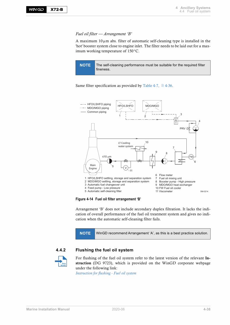
Marine Installation Manual 2020-06 4-38
4 Ancillary Systems4.4 Fuel oil systemX72-B
Fuel oil filter — Arrangement ‘B’
A maximum 10 m abs. filter of automatic self-cleaning type is installed in the'hot' booster system close to engine inlet. The filter needs to be laid out for a max-imum working temperature of 150 °C.
Same filter specification as provided by Table 4-7, 4-36.
Figure 4-14 Fuel oil filter arrangement ‘B’
Arrangement ‘B’ does not include secondary duplex filtration. It lacks the indi-cation of overall performance of the fuel oil treatment system and gives no indi-cation when the automatic self-cleaning filter fails.
4.4.2 Flushing the fuel oil system
For flushing of the fuel oil system refer to the latest version of the relevant In-struction (DG 9723), which is provided on the WinGD corporate webpageunder the following link:Instruction for flushing - Fuel oil system
NOTE The self-cleaning performance must be suitable for the required filter fineness.
NOTE WinGD recommend Arrangement ‘A’, as this is a best practice solution.
SM-0214
Main
Engine
LT Cooling
water system
1 HFO/LSHFO settling, storage and separation system2 MDO/MGO settling, storage and separation system3 Automatic fuel changeover unit4 Feed pump - Low pressure5 Automatic self-cleaning filter
6 Flow meter7 Fuel oil mixing unit8 Booster pump - High pressure9 MDO/MGO heat exchanger10 FW Fuel oil cooler11 Viscometer
FM
PRV
5
7
4
8
10
6
31 2
m
9
HFO/LSHFO MDO/MGOHFO/LSHFO pipingMDO/MGO pipingCommon piping
V11

Marine Installation Manual 2020-06 4-39
4 Ancillary Systems4.4 Fuel oil systemX72-B
4.4.3 Fuel oil treatment
The latest version of the Concept Guidance for fuel oil treatment (DG 9723) isprovided on the WinGD corporate webpage under the following link:Fuel oil treatment
Settling tanks
Gravitational settling of water and sediment from modern heavy fuel oils is anextremely slow process due to the small difference in densities. The time requiredfor the settling to occur depends on the depth of the tank, as well as on the vis-cosity, temperature and density difference. Tanks that are shallower with a widerdiameter enable better separation than thinner, taller tanks.Further design features consider a level monitoring device and remote closingdischarge valves to the separator(s) and engine systems, a connection to an over-flow tank, and a self-closing cock just above the bottom of the tank for removal ofthe sludge and water.
Service tanks
Most of the service tank design features are similar to the settling tanks, however,there is no direct connection to the overflow tank. Instead a recirculating line,with an inlet just above the bottom of the service tank, leads back to the settlingtanks.Diesel oil service tanks are similar to heavy oil service tanks, with the possibleexception of tank heating, although this may be incorporated for vessels con-stantly trading in cold climates.
Water in fuel Due to condensation or heating coil leakage, water may be present in the fuelafter the separators. This can be manually removed by a self-closing cock. In ad-dition, the recirculation connection close to the bottom of the tank ensures thatcontaminated fuel is recirculated to the settling tank.
Cleaning of fuel The fuel is cleaned from the settling tank to the service tank. Ideally, when themain engine is operating at CMCR, the fuel oil separator(s) should be able tomaintain a continual overflow from the service tank to the settling tank. Thecock, used to remove sludge and water, is to be operated at regular intervals toobserve the presence of water, a significant indication for the condition of theseparator(s) and heating coils.
Centrifugal fuel oil separators
There are two types of oil separators:• Type 1 — Separators with gravity discs• Type 2 — Separators without gravity discs
NOTE Separators with gravity discs represent outdated technology and are therefore not supported by WinGD.

Marine Installation Manual 2020-06 4-40
4 Ancillary Systems4.4 Fuel oil systemX72-B
Separators withoutgravity discs
These separators are self-adjusting to the fuel properties and self-cleaning. Sep-arators without gravity discs operate as combined purifiers-clarifiers; thus waterand sediment separation is integrated in one unit. The manufacturers claim ex-tended periods between overhaul. Compared to the outdated separators withgravity discs, the reliability is greatly improved, enabling unattended onboardoperation. As it is usual to install a standby separator as a back-up, it is of advan-tage to use both units in parallel to improve the separation result.
For further details and information regarding the separators please refer to themanufacturer’s instructions.
Separation efficiency The separation efficiency is a measure of the separator's capability to removespecified test particles. The separation efficiency is defined as follows:
where:
n ............... = separation efficiency [%]
Cout ........... = number of test particles in cleaned test oil
Cin ............ = number of test particles in test oil before separator
Certified Flow Rate To express the performance of separators according to a common standard, theterm Certified Flow Rate (CFR) has been introduced. CFR is defined as the flowrate in litres/hour, 30 minutes after sludge discharge, at which the separation ef-ficiency is 85% when using defined test oils and test particles. CFR is defined forequivalent fuel oil viscosities of 380 and 700cSt at 50°C. More information can be found in the CEN document CWA 15375:2005 (E) ofthe European Committee for Standardization.
Throughput capacity The required minimum effective throughput capacity (litres/hour) of the separa-tors is determined by the formula 1.2 • CMCR • BSFC • 10-3 [litres/hour] as shownin the following example. The nominal separator capacity and the installationare to comply with the recommendations of the separator manufacturer. (The MDO separator capacity can be estimated using the same formula.)
Example • 8-cyl. engine• CMCR/R1: 31,360kW• BSFC/R1: 166.8 g/kWh • Throughput: 1.2 • 31,360 • 166.8 • 10-3 = 6,277 litres/hour
Oil samples To ensure that representative samples of fuel oil can be taken, dedicated sam-pling points (cocks) are provided on engine side. Such cocks need also to be in-stalled on system side according to the relevant system proposal drawing inMIDS.
100 1 out
in
Cn
C
æ ö÷ç ÷ç= ⋅ - ÷ç ÷÷çè ø

Marine Installation Manual 2020-06 4-41
4 Ancillary Systems4.4 Fuel oil systemX72-B
4.4.4 Pressurised fuel oil system
The fuel is supplied from the heated heavy fuel oil service tank or the unheateddiesel oil service tank to the low-pressure feed system.
Fuel changeover For changing over from one fuel type to the other it was common to have asimple, manually operated three-way valve. This arrangement is not recom-mended any longer, as with the introduction of different Emission Control Areas(ECA), fuel changeover is quite frequently required, even at high engine load. (In the past it was needed in rare cases only, for instance due to maintenance orbefore stopping the engine, i.e. at relatively low loads.)
Automaticchangeover unit
Consequently, a well proven automatic changeover unit is nowadays recom-mended, which ensures:
• A maximum temperature gradient of 2K/min during changeover
• A maximum viscosity of 20cSt
• A minimum viscosity of 2cSt; this minimum limit is most challengingduring changeover from HFO to distillate fuel.Attention: Not all changeover units guarantee keeping the minimum vis-cosity limit, as viscosity is not controlled.
• A best-practice automatic control of diesel oil cooler activation
4.4.5 Fuel oil specification
The validated fuel oil qualities are published in the document Diesel enginefuels provided on the WinGD corporate webpage under the following link:Fuel qualities

Marine Installation Manual 2020-06 4-42
4 Ancillary Systems4.4 Fuel oil systemX72-B
4.4.6 Fuel oil viscosity-temperature dependency
The fuel oil viscosity depends on its temperature. This dependency is shown asgraph in Figure 4-15.
Figure 4-15 Fuel oil viscosity-temperature diagram
SM-0215
-10 0 10 20 30 40 50 60 70 80 90 100 110 120 130 140 150 160
100 00050 000
20 000
10 000
5 000
2 000
1 000
500400300
200
100
5040
30
20
17
13
10987
6
5
4
333
35
40
45
60
70
80
100
150
200
300
4005006008001 000
1 5002 000
3 0004 0005 000
10 000
20 000
50 000
100 000
200 000400 000400 000
200 000
100 000
50 000
20 000
10 000
5 000
3 000
2 0001 500
1 000800600
400
300
200150
100
80
70
60
50
45
40
36
Seco
nds
Sayb
olt
Uni
vers
al
Seco
nds
Red
woo
dN
o.1
Kine
mat
ic v
isco
sity
[mm
2 /s
(cSt
)]
-10 0 10 20 30 40 50 60 70 80 90 100 110 120 130 140 150 160 170
0 10 20 30 40 50 60 70 80 90 100 110 120 130 140 150 160 170 180 190 200 220 240 260 280 300 320 340
[°C]
[°F]
Recommended viscosity range for HFO before fuel injection pumps
Fuel oil temperature
Example To obtain the recommended viscosity before fuel injection pumpsa fuel oil of 380 mm2/s (cSt) at 50 °C must be heated up to 130 °C to 140 °C.
Oils can be pumped only with difficultyor not at all
30
60
100
Marine Gas Oil
(typical)
Marine Diesel Oil
(typical)
30
60
100
180
600
50
Bunker Fuel Oil
380380
Required viscosity range for HFO before fuel injection pumps
700 mm 2/s at 50 °C

Marine Installation Manual 2020-06 4-43
4 Ancillary Systems4.5 Starting and control air systemX72-B
4.5 Starting and control air systemThe latest version of the Marine Installation Drawing Set relevant for thestarting air system (DG 9725) is provided on the WinGD corporate webpageunder the following link:MIDS
Compressed air is required for engine starting and control, exhaust valve airsprings, the washing plant for scavenge air cooler(s), and general services.
The starting and control air system shown in Figure 4-16 comprises two air com-pressors, two air receivers, and systems of pipework and valves connected to theengine starting air manifold.
Figure 4-16 Starting and control air system
SM-0034
PI PI
Drain Drain
Automaticdrain
DrainClean and dry instrument air,7...9 bar, supplied from board
Pipes on engine
Starting air feed pipesControl air pipesAncillary equipment pipes
Starting air receiver
Starting air compressor
Control air inletfor control system and air spring
Starting air inlet
Distribution pipewith automatic starting air shut-off valve
Main engine
Pipe connectionsPressure indicatorPI

Marine Installation Manual 2020-06 4-44
4 Ancillary Systems4.5 Starting and control air systemX72-B
4.5.1 Capacities of air compressor and receiver
The capacity of the air compressor and receiver depends on the total inertia (Jtot)of the propulsion system’s rotating parts.
• Total inertia = engine inertia + shafting and propeller inertia1):
• Engine inertia (Jeng): refer to GTD2)
• Relative inertia:
4.5.2 System specification
Starting air compressors
The discharge air temperature must not exceed 90°C and the air supply to thecompressors is to be as clean as possible without oil vapour.
Starting air receivers
1) Propeller inertia includes the part of entrained water.2) The GTD application enables the capacities of compressors and air receivers to be op-
timised for the inertia of the engine and shaft line.
tot eng S PJ J J += +
totrel
eng
JJ
J=
Capacity Refer to GTD.
Delivery gauge pressure 25 or 30 bar
Type Fabricated steel pressure vessels with domed ends and inte-grated pipe fittings for isolating valves, automatic drain valves, pressure reading instruments and safety valves
Capacity Refer to GTD.
Working gauge pressure 25 or 30 bar

Marine Installation Manual 2020-06 4-45
4 Ancillary Systems4.5 Starting and control air systemX72-B
4.5.3 Control air
Control air system supply Control air is supplied from the board instrument air supply system (see Figure4-16, 4-43) providing air at 8bar gauge pressure (within a range of 7.0-9.0bar).The air quality should comply with the compressed air purity class 2-4-2 ac-cording to ISO 8573-1 (2010-04-15).
Control air consumption With the development of engine technology the WinGD RT-flex and X/X-DFengines consume much less control air than conventional engines. The requiredcontrol air flow capacities are shown in Table 4-9. These data can be used forsizing the relevant engine external piping and facilities.
Table 4-9 Control air flow capacities
4.5.4 Service and working air
Service and working air for driving air powered tools and assisting in thecleaning of the scavenge air cooler(s) is also provided by the board instrument airsupply system.
No. of cyl.
Control air flow capacity [Nm3/h]
5 12.0
6 14.4
7 16.8
8 19.2

Marine Installation Manual 2020-06 4-46
4 Ancillary Systems4.6 Leakage collection system and washing devicesX72-B
4.6 Leakage collection system and washing devicesThe latest version of the Marine Installation Drawing Set relevant for theleakage collection and washing system (DG 9724) is provided on the WinGDcorporate webpage under the following link:MIDS
Sludge oil trap Dirty oil collected from the piston underside is led under a pressure of approx.2.8bar to the sludge oil trap and then to the sludge oil tank. The purpose of the sludge oil trap (see Figure 4-17) is to retain the large amountof solid parts contained in dirty oil and to reduce the pressure by means of an or-ifice or throttling disc fitted at its outlet, so that the sludge oil tank is under at-mospheric pressure. Design and dimensions of the sludge oil trap are given in the MIDS.
Figure 4-17 Sludge oil trap
SM-0035
Externalheating coil
Insulation
Drain to sludge oil tank
To sludge oil tank
A B
A BTest valve sludge oil levelTest valve air flow
AB

Marine Installation Manual 2020-06 4-47
4 Ancillary Systems4.6 Leakage collection system and washing devicesX72-B
From the piston rod stuffing box, dirty oil consisting of waste system oil, cylinderoil, metallic particles and small amounts of combustion products is led directly tothe sludge oil tank. Condensate from scavenge air is formed when the vessel is operating in a humidclimate. To avoid excessive piston ring and liner wear, the condensate is to becontinually drained from the scavenge air receiver.
4.6.1 Draining of exhaust uptakes
Engine exhaust uptakes can be drained automatically using a system as shown inFigure 4-18.
Figure 4-18 Arrangement of automatic water drain
4.6.2 Air vents
The air vent pipes of the ancillary systems have to be fully functional at all incli-nation angles of the ship at which the engine must be operational. This is nor-mally achieved if the vent pipes have an uninterrupted inclination of min. 5%.Such arrangement enables the vapour to separate into its air and fluid compo-nents, discharging the air to atmosphere and returning the fluid to its source.
SM-0081
1234
wl
Filling funnelPipe bracketTest cockCleaning doorMinimum water level
Sectional detail for view A
1
Ø108 x 5
1700
Ø368 x 8
1130
530
100
A
2
wl
3
4 Proposal fordesign and dimensions

Marine Installation Manual 2020-06 4-48
4 Ancillary Systems4.7 Exhaust gas systemX72-B
4.7 Exhaust gas systemThe drawings relevant for the exhaust system (DG 9726) are provided on theWinGD corporate webpage under the following link:MIDS
Flow velocities For an optimised exhaust gas system the following velocities are recommendedfor pipes A, B and C shown in Figure 4-19:
Pipe A ....... = 40 m/s
Pipe B ....... = 25 m/s
Pipe C ....... = 35 m/s
For the pipe diameters please refer to the GTD application.
Figure 4-19 Determination of exhaust pipe diameter
dB
dAdAdA dA
dA
*1) d
SM-0109
dC
The purpose for this by-pass is to allowengine operation after a turbocharger failure.During normal operation it is blinded off.The by-pass can be omitted if agreed with
*1)
Blinded portOpen port
Approx. 10 mm thick
*2)
can be designed as shown.*2)

Marine Installation Manual 2020-06 4-49
4 Ancillary Systems4.8 Engine room ventilationX72-B
4.8 Engine room ventilationSpecial attention for the engine room ventilation is essential to ensuretrouble-free operation of all equipment. It is important that the ventilation re-quirements, ventilation arrangement, air quality and outside ambient air temper-ature are taken into consideration.
4.8.1 Ventilation requirements
Engine room ventilation is to conform to the requirements specified by the legis-lative council of the vessel’s country of registration and the classification societyselected by the ship owner.
Calculation methods for combustion air flow requirements and for avoiding ex-cessive heating of the machinery spaces are provided in the internationalstandard ISO 8861 ‘Shipbuilding — Engine-room ventilation in diesel-enginedships — Design requirements and basis of calculations’.
The engine’s combustion air is considered, and typically provided, as part of theoverall engine room ventilation system. Approximately 50% of the overall en-gine room ventilation air is for the main engine’s combustion, while the otherhalf is used for the auxiliary engines, the boilers, and to provide sufficient coolingfor equipment in the engine room. It is therefore vitally important that the venti-lation system for the engine room has sufficient capacity to supply the necessaryair flow for all engine room needs.
The heat emissions, required air flow and estimated power for the layout of en-gine room ventilation can be obtained from the GTD application. These valuesconsider the ISO 8861 standard, however, in some circumstances the results aredifferent from the standard calculations. In these cases, WinGD has provided thespecific engine values and these should be considered before ISO 8861.
It should be considered that the engine requires less combustion air when notrunning at full load. This then provides a potential energy save, by reducing thefrequency of the ventilation fans when demand is low. This process can be auto-mated, interfacing with the engine, if requested.

Marine Installation Manual 2020-06 4-50
4 Ancillary Systems4.8 Engine room ventilationX72-B
4.8.2 Ventilation arrangement
It is important to follow the best practice methods for supplying the combustionair for main engine as described in this section. However, the final layout of theengine room ventilation is at the discretion of the shipyard.
Two differentventilation arrangements
Experience shows that the air flow in the engine room, from the ventilationsystem outlet to the turbocharger inlets, should be as direct as possible. This in-creases the amount of air directly supplied to the turbocharger, limiting heattransfer to the air flow and therefore providing the best possible engine perfor-mance, especially during tropical conditions. Alternatively, a ventilation system with a direct air suction layout can be ar-ranged, where the ventilation system connects the outside ambient air directly tothe engine.
These two different arrangements are discussed as follows:
• Arrangement 1 — Engine room ventilation system (Figure 4-20, 4-51)The ventilation system draws air from the outside ambient air into the en-gine room, where it is sucked into the turbocharger inlet.
• Arrangement 2 — Direct engine ventilation system (Figure 4-21, 4-52)The ventilation system outlet is connected to the turbocharger inlet. There-fore, the outside ambient air is sucked directly into the turbochargerwithout passing through the engine room.
NOTE In both arrangements, the ventilation inlets must be located and de-signed to ensure that water spray, rain water, dust and exhaust gases cannot enter the system nor the engine room.

Marine Installation Manual 2020-06 4-51
4 Ancillary Systems4.8 Engine room ventilationX72-B
Arrangement 1 — Engine room ventilation systemFunctional principle The ventilation system draws air from outside the vessel using ventilation fans at
the inlet. Ventilation inlets are typically protected with a weather hood and lou-vres to minimise the amount of water and other particles entering the system.The air travels to the engine room where it leaves the ventilation outlets and en-ters the engine.
Layout The engine room ventilation should be arranged in such a way that the main en-gine combustion air is delivered directly to the turbocharger inlet, locating theventilation outlet and turbocharger inlet as close as possible, and directly facingto each other, ensuring a smooth and direct flow of air.
Figure 4-20 Ventilation system arrangement 1 — Engine room ventilation system
By ensuring that the air flow from the ventilation outlet to the turbocharger inletis as direct as possible, the air intake is at its coolest. The ventilation arrangementshould limit air from the engine room, mixing with the inlet air and entering theturbocharger. Limiting this heating effect will keep the engine’s specific fuel con-sumption low as a consequence.
TC with filter The turbocharger is fitted with a filter silencer that reduces noise and preventslarge items from entering the turbocharger. Most turbocharger manufacturerssupply an optional secondary fibre or mat filter that can further remove particlesand oil mist. This can reduce the effort required for scavenge air cooler cleaning.
SM-0511
Mainengine
Auxiliarygenerator Turbocharger
inlets
Ventilationoutlets
Ventilation fans
Ventilation inletWeather hood, louvres etc.
Ventilation system
NOTE WinGD recommend selecting the optional secondary filter to further as-sist with removing fine particles and oil mist that may be present in the engine room.

Marine Installation Manual 2020-06 4-52
4 Ancillary Systems4.8 Engine room ventilationX72-B
Arrangement 2 — Direct engine ventilation systemLayout In this arrangement, the ventilation outlets are coupled with the turbocharger in-
lets. As the turbochargers directly receive all the outside ambient air drawn viathe ventilation system, there is little chance for the temperature to increase. As aresult, this arrangement delivers cooler air to the engine than in ‘Arrangement 1’,reducing the engine’s brake specific fuel consumption.
Figure 4-21 Ventilation system arrangement 2 — Direct engine ventilation system
The outside ambient air is drawn through the ventilation system by the turbo-chargers, and therefore there is no need for ventilation fans in this arrangement.However, it is still essential that the ventilation inlet is protected, typically witha weather hood and louvres. A separate filter unit, if required, can also be fittedhere, within the inlet housing.
Requirements The engine room ventilation system is provided with separate ventilation fansand ducting. It should be appropriately sized to provide comfortable workingconditions in the engine room, supply the necessary combustion air for auxiliarygenerator(s) and the boiler, and to prevent heat-sensitive apparatus from over-heating.
As the main engine combustion air is no longer provided for by the engine roomventilation system, the energy demand of the ventilation fans is reduced com-pared to ‘Arrangement 1’.
SM-0512
Mainengine
Auxiliarygenerator
Ventilation outletsdirectly coupled toTurbocharger inlet
Ventilation inletWeather hood, louvres etc.
Ventilation system

Marine Installation Manual 2020-06 4-53
4 Ancillary Systems4.8 Engine room ventilationX72-B
4.8.3 Air intake quality
Air intake quality can vary depending on the circumstances of the vessel. For ex-ample, suction air is expected to have a dust content of 0.5mg/m3 or higher if avessel is carrying dusty or dust creating cargoes, such as iron ore and bauxite, orif it is often in port, trading in coastal waters and desert areas. In these cases, theair must be filtered before it enters the engine (see Table 4-10).
Dust filters The necessity for installing a dust filter and the choice of filter type dependsmainly on the concentration and composition of dust in the suction air. Thenormal air filters fitted as standard to the turbochargers are intended mainly as si-lencers but not to protect the engine against dust. If the air supply to machineryspaces has a dust content exceeding 0.5mg/m3, there is a risk of increased wearto the piston rings and cylinder liners.
Table 4-10 Guidance for air filtration
All filters’ surfaces must be sized correctly to ensure full functionality of the fil-tration. This is dependent on the engine’s maximum power output as is seenbelow in Figure 4-22, 4-54.
NOTE WinGD advise to install a filtration unit on vessels regularly transporting dust creating cargoes, or trading in areas of atmospheric dust.
Dust concentration in ambient air
Normal Normal shipboard requirement Alternatives necessary in very special circumstances
Most frequent particle sizes
Short period < 5% of running time,< 0.5 mg/m3
Frequently to permanently ≥ 0.5mg/m3
Permanently > 0.5mg/m3
> 5 μm Standard TC filter sufficient Oil wetted or roller screen filter
Inertial separator and oil wetted filter
< 5 μm Standard TC filter sufficient Oil wetted or panel filter
Inertial separator and oil wetted filter
--- Normal requirement for the vast majority of installations
These alternatives apply most likely to only very few extreme cases, e.g. ships carrying bauxite or similar dusty cargoes, or ships routinely trading along desert coasts.

Marine Installation Manual 2020-06 4-54
4 Ancillary Systems4.8 Engine room ventilationX72-B
Figure 4-22 Air filter size (example for 8-cyl. engine)
6 10 12 4025 35304 53 8 14 16 207 9
4
3
5
5045
25
20
35
40
30
12
10
6
8
14
16
Req
uire
d fil
trat
ion
area
ena
blin
g a
pres
sure
dro
p <
20 m
bar
Engine power [MW]SM-0113
Inertia
l sep
arator
Roller
scree
n filte
r
Panel
filter
or
oil w
etted
filter
Oil wett
ed fil
ter an
d
pane
l filte
r in se
ries
8X72-B: MCR = 31.36 MW
Filter surface[m2]

Marine Installation Manual 2020-06 4-55
4 Ancillary Systems4.8 Engine room ventilationX72-B
4.8.4 Outside ambient air temperature
The intake air temperature can vary greatly depending on the area of operation,and as the engine may operate over a wide range of ambient air temperatures, hotand cold limits should be considered.
Depending on the engine tuning option, the acceptable range of ‘Air temperaturebefore compressor’ (as titled by the GTD application) will vary. Please consultthe condition values provided by the GTD for the maximum and minimumnormal operating temperatures.
When operating within the normal range (as defined by the GTD application)the engine does not require any special measures. This includes pre-heating atlow temperature, even when operating on heavy fuel oil at part load, idling andstart-up. Because of this, there is no need for a separate scavenge air heater.
If the engine is required to operate outside of the temperature range defined bythe GTD application, contact WinGD for special measures and requirements.
NOTE No special measures are required for engine operation within the wide temperature range as defined in the GTD application.

Marine Installation Manual 2020-06 4-56
4 Ancillary Systems4.9 PipingX72-B
4.9 Piping
4.9.1 Pipe connections
The latest versions of the Pipe Connection Plans (DG 8020) are provided on theWinGD corporate webpage under the following links:5-cyl. engine6-cyl. engine7-cyl. engine8-cyl. engine
4.9.2 Flow rates and velocities
For the different media in piping, WinGD recommend flow rates and velocitiesas stated in the document ‘Various Installation Items’. Note that the given values are guidances figures only and that national standardsmay also be applied.
The latest version of the document ‘Various Installation Items’ (DG 9730) isprovided on the WinGD corporate webpage under the following link:Various Installation Items

Marine Installation Manual 2020-06 4-57
4 Ancillary Systems4.10 PTO, PTI, PTH and primary generator applicationsX72-B
4.10 PTO, PTI, PTH and primary generator applicationsWinGD propose various power take-off (PTO) and power take-in (PTI) arrange-ments that improve the efficiency and usability of the vessel’s propulsion chain.Some of the proposals are even suitable as power take-home devices (PTH),which enable the vessel to immobilise the main engine while staying capable tomove. Furthermore, the primary generator enables the vessel to generate electricpower by the main engine without running the propeller.
Depending on engine design the PTO solution can be applied either in the shaftline or at engine’s free end.
4.10.1 Requirements
After selecting the engine:
1) Define the shaft power and the shaft speed.2) Estimate the electric power demand for propulsion purpose.3) Evaluate which of the PTO/PTI systems is the most suitable.4) Select suitable electrical components like frequency converter, etc.
4.10.2 Arrangements for PTO, PTI, PTH and primary generator
Figure 4-23, 4-58 illustrates the different arrangements for PTO, PTI, PTH andprimary generator.
NOTE All given alternatives are subject to a detailed project-specific study and definition. Please consult WinGD via their licensee.
NOTE The type of the PTO/PTI system has an influence on the execution of the main engine. Thus, changing from one system type to another is possible in the project stage but not after having ordered the engine.

Marine Installation Manual 2020-06 4-58
4 Ancillary Systems4.10 PTO, PTI, PTH and primary generator applicationsX72-B
Figure 4-23 Arrangements for PTO, PTI, PTH
ACAC[7]
ACAC[8]
ACAC[1]
ACAC[9]
ACAC
[6]
ACAC[5]
ACAC
ACAC[2]
ACAC
ACAC[10]
ACAC[11][3]
12
ACAC[13]
ACAC[14]
ACAC[12][4]
12
CPP ClutchGearbox
Tunnelgear box 1
2
2-speedtunnelgear box
FPP
ACAC
GeneratorMachine
Torsional/
coupling
Frequency convertergrey:depending oncombinator orconstant speed mode
Torsionalelasticcoupling
bendingelastic
Clutch,thrust transmittingin open condition
SM-0200
ACAC[16]
ACAC[15]

Marine Installation Manual 2020-06 4-59
4 Ancillary Systems4.10 PTO, PTI, PTH and primary generator applicationsX72-B
The following table itemises the arrangements corresponding to the numbers inFigure 4-23, 4-58.
Table 4-11 PTO/PTI /PTH arrangements for X72-B
4.10.3 Application constraints
The feasibility of project-specific PTO /PTI/PTH and primary generator needsto be studied in any case. An overview about impacts is given in Table 4-13, 4-60.
Table 4-12 Possible options for X72-B
Permanent Magnet In cases where ‘Permanent Magnet’ type generators or electric motors are in-stalled, special attention must be given to the alignment issue. Due to the lowrotor mass in relation to the magnetic forces, a potential risk of unloaded shaftbearings may exist. In addition, bearing load measurements may be falsified bythe influence of the permanent-magnetic pull force.
[1] [2] [3] [4] [5] [6] [7] [8] [9] [10] [11] [12] [13] [14] [15] [16]
(X) (X) (X) (X) X X X X X X (X) (X) X X X X
X(X)
= the arrangement is possible= the arrangement may not be possible (too high nominal generator / el. motor torque due to too
low nominal engine speed and/or high generator / el. motor power)
NOTE In any case please check the application of arrangements for the selected engine with WinGD via their licensee.Project dependent options can also be considered.
Arrangements (see Figure 4-23, 4-58)
Option [1] [2] [3] [4] [5] [6] [7] [8] [9] [10] [11] [12] [13] [14] [15] [16]
PTO X X X X X X X X X X X X X X X X
PTI X X X X X X X X X X X X X X X X
PTH O O O X O O X X O O O O O O O O
Primary generator O O O O O O O O (X) X O O O O (X) X
Remarks a)
a) If the lowest torsional natural frequency is <1.5 Hz, special care has to be taken regarding possible engine speed fluctuations.
a)b)
b) In case the electric generator /motor is operated at variable speed (CPP combinator mode), a frequency converter is needed.
a)b)
a)b)
c)
c) With de-clutched propeller and pure generator operation, the minimum engine load requirement has to be obeyed.
c) a)a)b)
c) c)
X(X)O
= the option is possible= the option is possible, however uncommon= the option is not possible

Marine Installation Manual 2020-06 4-60
4 Ancillary Systems4.10 PTO, PTI, PTH and primary generator applicationsX72-B
Table 4-13 Influence of options on engineering
Extended TVC The added components have a considerable influence on the related project-spe-cific torsional vibration calculation. Proper case dependent countermeasuresneed to be taken depending on the results of the detailed TVC. For further de-tails, refer to section 6.4.2 PTO/PTI systems effect on torsional vibration, 6-14.
Misfiring detection Depending on the results of the TVC, a misfiring detection device (MFD) mightbe needed to protect the elastic coupling and the gear-train (if present) from inad-missible torsional vibrations in case of misfiring.
Impact on ECS The PTO/PTI/PTH application has to be analysed via the licensee with thePropulsion Control System supplier and with WinGD for the Engine ControlSystem.
Shaft alignment study The added components can have an influence on the alignment layout. The shaftbearing layout has to be properly selected and adjusted to comply with the givenalignment rules. For further details, refer to 3.6 Engine and shaft alignment, 3-10.
Bearing loaddue to external load
The added components increase the bending moment and the related bearingloads. The bearing loads have to be checked for compliance with the given rules.
Dynamic conditionsdue to external load
The components attached to the free end have to be checked for any influence onthe axial and radial movements of the extension shaft caused by the dynamics ofthe engine.
Arrangements (see Figure 4-23, 4-58)
Engineering [1] [2] [3] [4] [5] [6] [7] [8] [9] [10] [11] [12] [13] [14] [15] [16]
Extended TVC X X X X X X X X X X X X X X X X
Misfiring detection (X) (X) (X) (X) O O O O O O (X) (X) (X) (X) (X) (X)
Impact on ECS (X) (X) (X) (X) (X) (X) (X) (X) (X) (X) (X) (X) (X) (X) (X) (X)
Shaft alignment study (X) (X) (X) (X) X X X X X X (X) (X) (X) (X) X X
Bearing load due to external load (X) (X) (X) (X) X X X X X X (X) (X) X X X X
Dynamic condition due to external load O O O O O O O O O O X X X X X X
X(X)O
= the arrangement has an influence on this engineering aspect= the arrangement might have an influence on this engineering aspect= the arrangement has no influence on this engineering aspect

Marine Installation Manual 2020-06 4-61
4 Ancillary Systems4.10 PTO, PTI, PTH and primary generator applicationsX72-B
4.10.4 Service conditions
The service condition depends on the selected PTO/PTI/PTH option. De-pending on engine type there are one or several cases, which are illustratedbelow.
Operation areaand prohibited area
The following illustrations indicate how the engine generator unit can be oper-ated. The prohibited operation area is defined in section 2.2.7, 2-13.
Figure 4-24 FPP with mandatory frequency converter
100%
0%0% 100%
speed
power
powercurve
Valid for FPP with afrequency converter(mandatory).Applicable to options:1, 5, 7, 9, 11, 13
operation areaprohibited operation areaSM-0201

Marine Installation Manual 2020-06 4-62
4 Ancillary Systems4.10 PTO, PTI, PTH and primary generator applicationsX72-B
Figure 4-25 CPP in combination with an optional frequency converter
Figure 4-26 CPP in constant speed operation without frequency converter
SM-0202
100%
0%0% 100%
speed
power
powercurve
Valid for CPP with afrequency converter.Applicable to options:2, 6, 8, 10, 12, 14
operation areaprohibited operation area
SM-0203
Valid for CPP without afrequency converter. Applicable to options:2, 6, 8, 10, 12, 14
100%
0%0% 100%
power
speed
prohibited operation area operation area

Marine Installation Manual 2020-06 4-63
4 Ancillary Systems4.10 PTO, PTI, PTH and primary generator applicationsX72-B
Figure 4-27 CPP with two fixed operation speeds without frequency converter
SM-0204
prohibited operation area operation area
Valid for CPP without afrequency converter incombination with a two-speed tunnel gear.Applicable to options:3, 4
speed
powercurve
100%
0%0% 100%
power

Marine Installation Manual 2020-06 5-1
5 Engine Automation5.1 DENISX72-B
5 Engine AutomationThe Engine Control System (ECS) provides data bus connection to the Propul-sion Control System (PCS) and the Alarm and Monitoring System (AMS). TheAMS is usually provided by the shipyard.
The leading suppliers of Propulsion Control Systems approved by WinGD en-sure complete adaption to engine requirements.
Figure 5-1 Engine automation architecture
5.1 DENIS WinGD’s standard electrical interface is DENIS, which is in line with approvedPropulsion Control Systems.
DENIS The DENIS (Diesel Engine CoNtrol and optImizing Specification)interface contains specifications for the engine management of allWinGD two-stroke marine diesel engines.
ECS WinGD provide a fully integrated Engine Control System, whichtakes care of all Flex system-specific control functions, e.g. fuel in-jection, exhaust valve control, cylinder lubrication, crank anglemeasurement, and speed/load control. The system uses modernbus technologies for safe transmission of sensor- and other signals.
SM-0444
Propulsion Control System
Engine Control System(ECS)
Remote Control System
Engine Safety System
Alarm and Monitoring System
DENISSpecification

Marine Installation Manual 2020-06 5-2
5 Engine Automation5.2 DENIS conceptX72-B
Figure 5-2 Engine management and automation concept
5.2 DENIS conceptThe concept of DENIS offers the following features to ship owners, shipyardsand engine builders:
5.2.1 Interface definition
The WinGD interface defines the division of responsibilities between enginebuilder and PCS and AMS supplier, enabling the authorised suppliers to adapttheir systems to the common rail system engines. The data bus connection pro-vides clear signal exchange.
5.2.2 Approved Propulsion Control Systems
Propulsion Control Systems including Remote Control, Safety and TelegraphSystems are available from suppliers approved by WinGD (see Table 5-1, 5-4).This cooperation ensures that the systems fully comply with the specifications ofthe engine designer.
DENISEngineControlSystem
EngineParts
DatasetCBM
ServiceAgreement
RemoteControl
AlarmSystem
SafetySystem
EngineControl
EngineOperation
Support
Spares &MaintenanceManagement
Support &Tools
SM-0281
MaintenanceVideo
ServiceBulletin
OperationManual

Marine Installation Manual 2020-06 5-3
5 Engine Automation5.3 DENIS SpecificationX72-B
5.3 DENIS SpecificationThe DENIS Specification describes the signal interface between the Engine Con-trol System and the PCS and AMS. It does not include any hardware, but sum-marises all data exchanged and defines the control functions required by theengine. The DENIS Specification consists of two sets of documents:
5.3.1 DENIS Interface Specification
This signal interface specification is made available to engine builders and ship-yards. Besides the description of engine-built components for control, alarm andindication, the specification contains the following:
• List of alarm and display functions to be realised in the vessel’s AMS• Control diagram of the engine• Signal list including a minimum of functional requirements• Information related to the electrical wiring on the engine
5.3.2 DENIS Propulsion Control Specification
This document contains a detailed functional specification of the PropulsionControl System.
The intellectual property rights of this specification remain with WinGD. Hencethe document is licensed only to the partner companies of WinGD developingPropulsion Control Systems. These companies offer systems which are built ex-actly according to the engine designer’s specifications and are finally tested andapproved by WinGD.
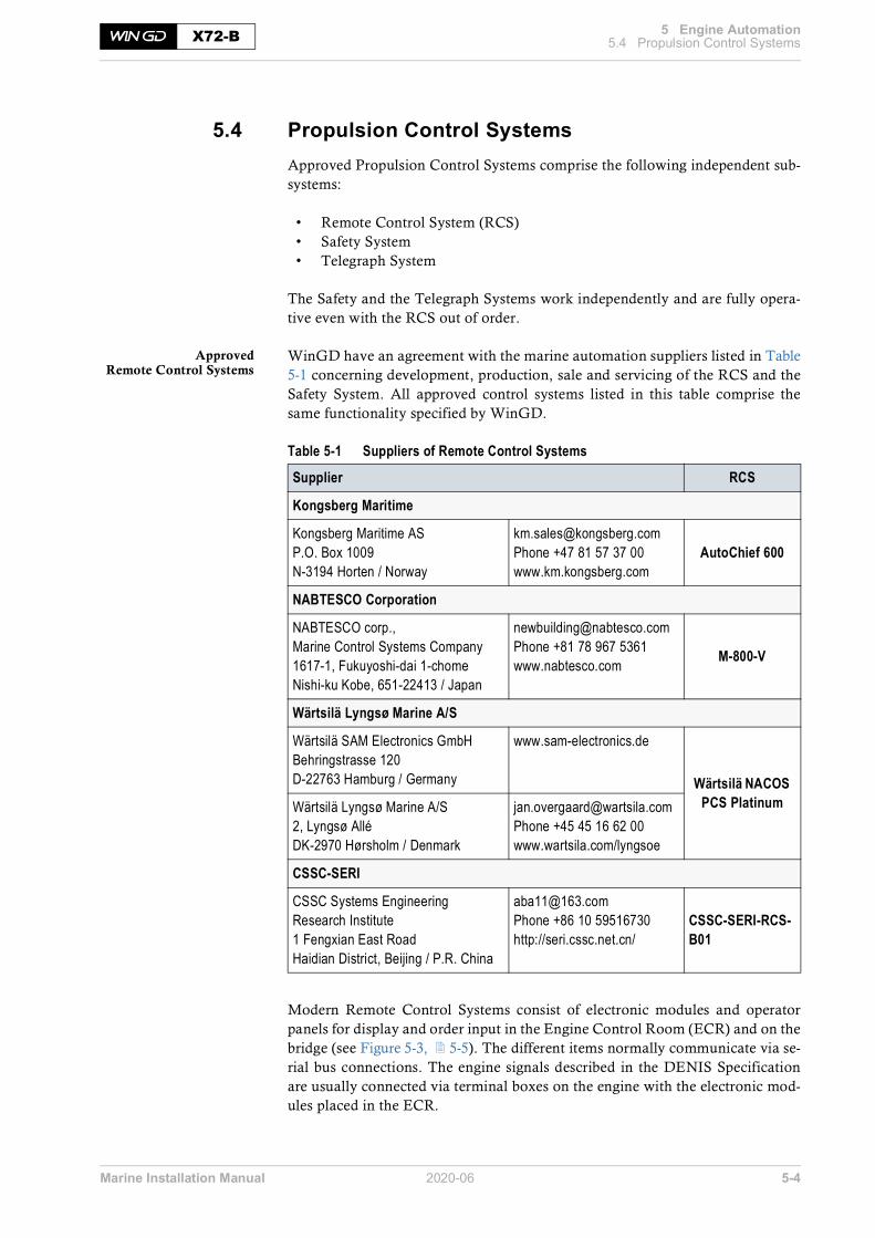
Marine Installation Manual 2020-06 5-4
5 Engine Automation5.4 Propulsion Control SystemsX72-B
5.4 Propulsion Control SystemsApproved Propulsion Control Systems comprise the following independent sub-systems:
• Remote Control System (RCS)• Safety System• Telegraph System
The Safety and the Telegraph Systems work independently and are fully opera-tive even with the RCS out of order.
ApprovedRemote Control Systems
WinGD have an agreement with the marine automation suppliers listed in Table5-1 concerning development, production, sale and servicing of the RCS and theSafety System. All approved control systems listed in this table comprise thesame functionality specified by WinGD.
Table 5-1 Suppliers of Remote Control Systems
Modern Remote Control Systems consist of electronic modules and operatorpanels for display and order input in the Engine Control Room (ECR) and on thebridge (see Figure 5-3, 5-5). The different items normally communicate via se-rial bus connections. The engine signals described in the DENIS Specificationare usually connected via terminal boxes on the engine with the electronic mod-ules placed in the ECR.
Supplier RCS
Kongsberg Maritime
Kongsberg Maritime ASP.O. Box 1009N-3194 Horten / Norway
[email protected] +47 81 57 37 00www.km.kongsberg.com
AutoChief 600
NABTESCO Corporation
NABTESCO corp.,Marine Control Systems Company1617-1, Fukuyoshi-dai 1-chomeNishi-ku Kobe, 651-22413 / Japan
[email protected] +81 78 967 5361www.nabtesco.com M-800-V
Wärtsilä Lyngsø Marine A/S
Wärtsilä SAM Electronics GmbHBehringstrasse 120D-22763 Hamburg / Germany
www.sam-electronics.de
Wärtsilä NACOS PCS PlatinumWärtsilä Lyngsø Marine A/S
2, Lyngsø AlléDK-2970 Hørsholm / Denmark
[email protected] +45 45 16 62 00www.wartsila.com/lyngsoe
CSSC-SERI
CSSC Systems Engineering Research Institute1 Fengxian East RoadHaidian District, Beijing / P.R. China
[email protected] +86 10 59516730http://seri.cssc.net.cn/
CSSC-SERI-RCS-B01

Marine Installation Manual 2020-06 5-5
5 Engine Automation5.4 Propulsion Control SystemsX72-B
Figure 5-3 Remote Control System
The electronic modules are in most cases built to be placed either inside the ECRconsole, or in a separate cabinet to be located in the ECR. The operator panelsare to be inserted in the ECR console’s surface.
SM-0282
Ship AlarmSystem
Local panel
Remote Control& Safety Control
Engine Control System
Engine room
Control room
Bridge wing (option) Bridge wing (option)Bridge
Remote Control System
WinGD

Marine Installation Manual 2020-06 5-6
5 Engine Automation5.4 Propulsion Control SystemsX72-B
5.4.1 PCS functions
Remote Control SystemMain functions • Start, stop, reversing
• Speed setting• Automatic speed program
Indications • The RCS is delivered with control panels for local, ECR and bridge control,including all necessary order input elements and indications, e.g. pushbuttons/switches and indication lamps or alternatively a respective dis-play.
• The following conditions in the engine are specified by the DENIS standardto be indicated as a minimum:º In the control room:
- Starting air pressure- Engine speed- Revolutions- Operating hours- Load- Turbocharger speed- Scavenge air pressure in air receiver
º On the bridge:- Starting air pressure- Engine speed
º In addition to these indications, the RCS applied to the common railsystem engine includes displaying the primary values from the ECS, likefuel pressure, servo oil pressure, etc.
Safety SystemMain functions • Emergency stop
• Overspeed protection• Automatic shut-down• Automatic slow-down
Telegraph System• Order communication between the different control locations
Local manual control• Local manual control of the engine is performed from a control panel lo-
cated on the engine. The panel includes elements for manual order inputand indication for the Safety System, Telegraph System and ECS.
• The local control box with the local manual control panel is included in thepackage delivered by approved RCS suppliers.
ECR manual control panel• A manual control panel delivered together with the PCS and fitted in the
ECR console allows operating the engine manually and independently ofthe Remote Control System.
• The functions of the ECR manual control are identical to the control func-tions on the engine’s local control panel.

Marine Installation Manual 2020-06 5-7
5 Engine Automation5.4 Propulsion Control SystemsX72-B
Options• Bridge wing control• Command recorder
Figure 5-4 Propulsion Control
A
AEH
D
ASTERN
STOP
SLOW
HALF
FULL
FULL
HALF
SLOW
DEADSLOW
DEADSLOW
SM-0099

Marine Installation Manual 2020-06 5-8
5 Engine Automation5.4 Propulsion Control SystemsX72-B
5.4.2 Recommended manoeuvring characteristics
The vessel speed is adjusted by the engine telegraph. Manoeuvring, e.g. forleaving a port, is available from full astern to full ahead. For regular full sea op-eration, the engine power can be further increased up to 100% CMCR power.
To protect the engine, any increase or decrease in power is limited by a rate ofchange, considering the warm-up respectively cool-down times. Therefore, de-pending on the magnitude of any change in power, it takes time to reach the re-quired engine output; see the following graphs and tables.
Figure 5-5 Manoeuvring speed /power settings for FPP /CPP installations
SM-0213
60 - 70
For FPP installations:Recommended values forthe manoeuvring positions
in percentage of CMCR speed
FULL
HALF
SLOW
DEAD
AHEA
DAS
TER
N
SLOW
STOP
SLOW
FULL
HALF
DEADSLOW
45 - 55
35 - 45
25 - 35
25 - 35
35 - 45
45 - 55
60 - 70
22 - 34
For CPP installations:Recommended values forthe manoeuvring positions
in percentage of CMCR power
FULL
HALF
SLOW
DEAD
AHEA
DAS
TER
N
SLOW
STOP
SLOW
FULL
HALF
DEADSLOW
9 - 17
4 - 9
1.5 - 4.5
1.5 - 4.5
4 - 9
9 - 17
22 - 34

Marine Installation Manual 2020-06 5-9
5 Engine Automation5.4 Propulsion Control SystemsX72-B
FPP manoeuvring stepsand warm-up times
The recommended manoeuvring steps and warm-up times for engine speed in-crease are indicated in Table 5-2. The engine speed-up/down program is includedin the ECS.
Table 5-2 Recommended manoeuvring steps and warm-up times for FPP
Load reduction is possible in half the time of values mentioned in Table 5-2.
Figure 5-6 Full sea load steps in FPP load-up program
Manoeuvring position
Recommended CMCR speed
[%]
Corresponding power
[%]
Recommended warm-up time per load step
[min]
Min. warm-up time per load step
[min]
DEAD SLOW 25 - 35 1.5 - 4.5 0 0
SLOW 35 - 45 4 - 9 0 0
HALF 45 - 55 9 - 17 0.1 0.1
FULL 60 - 70 22 - 34 0.5 0.5
FULL SEA 1 92 78 40 30
FULL SEA 2 100 100 50 38
SM-0538
0 10 3020 40 50 60 70 80 90 100
80
85
90
95
100
75
70
65
60[min]
Minimum warm-up time
CMCR speed
[%]
Warm-up time - FPPMinimum
Recommended
FULL
FULL SEA 1
FULL SEA 2

Marine Installation Manual 2020-06 5-10
5 Engine Automation5.4 Propulsion Control SystemsX72-B
CPP manoeuvring stepsand warm-up times
The recommended manoeuvring steps and warm-up times for engine power in-crease are shown in Table 5-3. The shipyard needs to include the engine power-up/down program in the PCS.
Table 5-3 Recommended manoeuvring steps and warm-up times for CPP
Load reduction is possible in half the time of values mentioned in Table 5-3.
Figure 5-7 Full sea load steps in CPP load-up program
Manoeuvring position
Recommended CMCR power
[%]
Recommended warm-up time per load step
[min]
Min. warm-up time per load step
[min]
DEAD SLOW 1.5 - 4.5 0 0
SLOW 4 - 9 0 0
HALF 9 - 17 0.1 0.1
FULL 22 - 34 0.5 0.5
FULL SEA 1 78 40 30
FULL SEA 2 100 50 38
SM-0537
0 10 3020 40 50 60 70 80 90 100
60
70
80
90
100
50
40
30
20[min]
Minimum warm-up time
CMCR power
[%]
Warm-up time - CPPMinimum
Recommended
FULL
FULL SEA 1
FULL SEA 2

Marine Installation Manual 2020-06 5-11
5 Engine Automation5.5 Alarm and Monitoring SystemX72-B
5.5 Alarm and Monitoring SystemTo monitor common rail system-specific circuits of the engine, sensors withhardwired connections are fitted. In addition to that, the Engine Control Systemprovides alarm values and analogue indications via data bus connection to theship’s Alarm and Monitoring System.
5.5.1 Integrated solutionPCS and AMS
from same supplier• PCS and AMS are connected to the ECS through one redundant bus line
(CANopen or Modbus, depending on automation maker).• The integrated solution allows an extended presentation of relevant param-
eters and easy access to alterable user parameters backed by the graphicaluser interface functions available in the AMS.
• With the AutoChief 600 Alarm and Monitoring System by Kongsberg Mar-itime even the conventional sensors and additional Flex system-specificsensors can be connected via data bus lines, and the data acquisition unitscan be mounted on the engine in the same boxes used as terminal boxes forany other AMS. These boxes are usually provided by the shipyard and haveto be delivered to the engine builder for mounting on the engine and con-necting to the sensors.
• The integrated solution facilitates commissioning and testing of the alarmsignals set on the engine maker’s testbed and limits the wiring at the ship-yard to a few power cables and bus communication.
5.5.2 Split solutionPCS and AMS
from different suppliers• The PCS is connected to the ECS through two redundant bus lines (CAN-
open or Modbus, depending on automation maker).
• For the separate AMS an additional redundant Modbus connection is avail-able.Requirements for any AMS to be fulfilled in a split solution:º Possibility to read values from a redundant Modbus line according to
standard Modbus RTU protocolº Ability to display analogue Flex system values (typically 20 values) and
add alarm values provided by the ECS to the standard alarm list (300-800 alarms depending on engine type and number of cylinders)
With this solution the HMI is split as well:
• The Remote Control System includes the following functions:º Changing of parameters accessible to the operatorº Displaying the parameters relevant for engine operation
• The Alarm and Monitoring System includes the display of:º Flex system parameters, like fuel pressure, servo oil pressure, etc.º Flex system alarms provided by the ECS
• WinGD provide Modbus lists specifying the display values and alarm con-ditions as part of the DENIS Specification.

Marine Installation Manual 2020-06 5-12
5 Engine Automation5.6 Alarm sensors and safety functionsX72-B
5.6 Alarm sensors and safety functionsTo ensure safe operation the engine is provided with alarm sensors and safetyfunctions.
5.6.1 Signal processing
Signal processing has to be performed in the Alarm and Monitoring System.WinGD provide a separate document named ‘Usual values and safeguard set-tings’, which lists the signal indication values. This includes the alarm functionand alarm level with corresponding setting and response time.
The document Usual values and safeguard settings for X72-B can be foundunder the following link:Usual values and safeguard settings
Please note that the signalling time delays given in this document are maximumvalues. They may be reduced at any time according to operational requirements.When decreasing the values for slow-down times, the delay times for the respec-tive shut-down functions are to be adjusted accordingly.
5.6.2 Requirements from WinGD and classification societies
The scope of delivery of alarm and safety sensors has to cover the requirementsof the respective classification society, WinGD, the shipyard and the owner.(List of classification societies see Appendix, section 9.1, 9-1.)
The alarm sensors and safety functions listed in the document Usual values andsafeguard settings are mandatory for an unattended machinery space and reflectthe minimum requirements by WinGD. Additional requirements from the clas-sification societies see Table 5-4.
Table 5-4 Additional Class requirements for alarm sensors and safety functionsTable under preparation
NOTE The delay values are not to be increased without the written consent of WinGD.
NOTE In case the engine has been configured for attended machinery space, please consult the respective classification society.

Marine Installation Manual 2020-06 5-13
5 Engine Automation5.7 WinGD Integrated Digital ExpertX72-B
5.7 WinGD Integrated Digital ExpertThe WinGD Integrated Digital Expert (WiDE) is a comprehensive system thatenables engine monitoring and assistance.
The DCM (Data Collection Monitoring) system collects large amounts of datafrom engine’s onboard sensors and signals, while EDS (Engine DiagnosticSystem) analyses these data, monitoring the engine performance, predictingcomponent malfunctions and supporting the crew with live troubleshooting anddiagnostic.
Figure 5-8 WiDE system
5.7.1 Data Collection and Monitoring
WiDE uses the DCM unit to collect data from the engine and other ship systems.These data are displayed and stored, both on board the ship and remotely. Usinga secure communication channel, DCM allows data to be sent to an externalserver of the customer’s choice. All the data are stored for the engine lifetime andare accessible for the customer by a protected user account.
With the permission of the customer, DCM enables WinGD to review ship com-pany data when required, allowing the first step towards remote support collab-oration.
The DCM system is included in the standard engine scope.
Onshore / Online
Remote Services
WiDE
DCM
Collecting Data
EDSAnalyse & Predict
Support
SM-0496

Marine Installation Manual 2020-06 5-14
5 Engine Automation5.7 WinGD Integrated Digital ExpertX72-B
5.7.2 Engine Diagnostic System
WiDE uses the EDS to analyse and compare data against predefined references,identifying any discrepancies between ‘reference’ and ‘actual’ data. The findingsare then consolidated, and any predicted issues or required actions are high-lighted to the crew. This allows for improved planning and automation of subse-quent supporting processes like troubleshooting, maintenance, spare partshandling and identification.
Analysis EDS analyses the DCM data to obtain a full engine diagnostic by using severalmethods:
• The ‘digital twin’, an engine thermodynamic model which is calibrated atthe engine’s shop test and sea trial, receives and simulates real-time engineparameter inputs. This provides an ongoing performance assessment bymeasuring any deviations between the simulated model and the real engine.
• An algorithm rule set is used to monitor, analyse and diagnose the sub-system components. It encapsulates WinGD’s expert knowledge by consid-ering calculations, documentation and investigations.
• Data trends are recognised from a combination of DCM monitoring andhistorical sample data that is uploaded to the EDS during installation, ena-bling progressive performance improvement.
Prediction andtroubleshooting
This ongoing analysis is consolidated to a final output, allowing for EDS to makepredictions. If a potential ‘critical’ fault is diagnosed the crew is notified, ena-bling them to decide on immediate action. However, if no action is taken EDSwill proceed with the troubleshooting process in the following sequence:
• At the initial stage all proposed actions largely follow the directions of theengine Operating Manual.
• Followed by recommendation procedures defined by the MaintenanceManual, EDS may also connect to the Planned Maintenance System(PMS), updating the Maintenance Plan and the Spare Parts List.
• If required, EDS will connect to external help and support, potentially en-gaging with human experts through on-line and remote troubleshooting.
• Once the risk is resolved, EDS collects all the available feedback and createsrelevant reports archiving it for future references.
Support As well as the actions mentioned above, when EDS responses to single-case in-stances or potential issues, it also provides ongoing supports other ways:
• The troubleshooting module keeps track of current issues, collecting anddisplaying data.

Marine Installation Manual 2020-06 5-15
5 Engine Automation5.7 WinGD Integrated Digital ExpertX72-B
• The remaining life expectancy of components is tracked from performance,operation and maintenance data. This means that the maintenance sched-uling becomes dynamic, updating and preparing before failure.
• Planned maintenance and associated Spare Parts Lists are clearly displayedin the spare parts modules. With the integrated WinGD Spare Parts Cata-logue, component information and creating orders is simplified.
Software availability WinGD provide the EDS software for a limited ‘free-trial’ period on all their en-gines. If there are any questions regarding this, please contact the WinGD repre-sentative.
5.7.3 WiDE installation process
The process map below shows the steps towards installation of DCM and EDSagainst various testing points.
The process order map seen in Figure 5-9 ensures effective installation. TheDCM is installed before shop test as the data it collects provides the informationneeded for the EDS tuning. This process order ensures that the WiDE system isfully operational by the time of the vessel’s maiden voyage.
Figure 5-9 WiDE installation process mapSM-0497
EDSSoftware Built
EDSTuning
EDSTuning
Vessel Order
NormalOperation
MaidenVoyage
SeaTrial
Shop Test
DCMInstallation
DCMCommissioning
DCM Final Installation& Commissioning

Marine Installation Manual 2020-06 6-1
6 Engine Dynamics X72-B
6 Engine DynamicsIt is critical that vibration is minimised throughout the design and constructionstage of any engine installations. The assessment and reduction of vibration aresubject to continuous development and research, requiring expert knowledge.For successful design, vibration behaviour calculations are required over thewhole operating range of the engine and the propulsion system. As such,WinGD have developed extensive computer software, analytical procedures andmeasuring techniques.
Forces and momentscausing vibrations
Within the engine, various forces and moments are generated by the recipro-cating and rotating masses. Often these cyclical forces and moments are neutral-ised by counterbalancing within the engine. However, if this is not achieved theengine will experience the sum of these forces and moment as external responses,reacting around its own axis and causing vibrations outside of the engine. Vibra-tions are problematic, especially if a vibration frequency forces a resonance,causing an amplitude to pass acceptable limits. This section highlights the impor-tance of dynamic consideration, the causes and relevance.
After considering the external forces and moments types, this section exploresthe resulting vibration, along with recommended considerations and counter-measures relevant to engine type and other associated systems and design fea-tures.
Types of vibration The vibration types considered in this section are as follows:
• External mass forces and moments• External lateral forces and moments (Lateral engine vibration or 'rocking')• Longitudinal engine vibration• Torsional vibration of the shafting• Axial vibration of the shafting• Whirling vibration of the shafting• Hull vibration
Dynamic characteristicsdata
The external forces and moments generated by a specific engine defines its dy-namic characteristics. These must be considered throughout the design processof the vessel to avoid adverse impact on the vessel.
In the document External forces and moments WinGD provide a complete listof the external forces and moments for each engine type. The latest version ofthis document is provided on the WinGD corporate webpage under the fol-lowing link:External forces and moments
The external forces and moments for engines not tuned to an R1 rating are avail-able on request.
NOTE WinGD provide additional support services to assist with system dy-namics and vibration analysis. See section 6.9, 6-22 for info about forms and links.

Marine Installation Manual 2020-06 6-2
6 Engine Dynamics6.1 External mass forces and momentsX72-B
6.1 External mass forces and moments The external mass forces and moments are the resulting forces and moments pro-duced by reciprocating and rotating masses of the running gear (i.e. the engine'smain oscillating masses) that are transmitted to the surrounding vessel via thefoundation. This therefore doesn't consider forces and moments that are pro-duced by combustion forces — see section 6.2, 6-6. The external mass forcesand moments depend on the design of a specific engine and the engine speed.The engine power and tuning has no influence on the external mass forces andmoments.
Figure 6-1 External mass forces and moments
Figure 6-1 shows the mass forces and moments generated by the engine. How-ever, where possible these are neutralised. If not, cyclical generation of the ex-ternal mass forces and moments may lead to unwanted and disturbing vibrationsthroughout the vessel. This highlights the importance of using countermeasuresthat balance out the generated mass forces and moments where possible.
6.1.1 Balancing of mass forces and momentsForces With a regular firing order of evenly distributed crank angles, an engine will in-
herently balance the summation of all vertical (FV) and horizontal (FH) freeforces. Sometimes the firing order is designed to be irregular, i.e. unevenly dis-tributed crank angles, to optimise the overall vibration characteristic of a specificengine type. Regardless, the resulting mass forces are considered to be negligible.
First order moments First order mass moments (M1V and M1H) can be reduced to acceptable levels byintroducing standard counterweights, fitted to the ends of the crankshaft. In spe-cial cases non-standard counterweights can be used to reduce either vertical(M1V) or horizontal (M1H) first order mass moments as required.
Standard counterweights fitted to the ends of the crankshaft reduce the first ordermass moments to acceptable limits. However, in special cases non-standardcounterweights can be used to reduce either M1V or M1H.
SM-0030
Resulting first order vertical mass forceResulting first order horizontal mass forceResulting second order vertical mass forceResulting fourth order vertical mass forceFirst order vertical mass momentFirst order horizontal mass momentSecond order vertical mass momentFourth order vertical mass moment
F1VF1HF2VF4VM1VM1HM2VM4V
+
F1V, F2V, F4V
F1H
M1V, M2V, M4V
M1H+-

Marine Installation Manual 2020-06 6-3
6 Engine Dynamics6.1 External mass forces and momentsX72-B
Second andfourth order moments
Second (M2V) and fourth (M4V) order vertical mass moments are also generated,although these magnitudes will vary depending on engine type, tuning, andnumber of cylinders. Unless a problematic vessel design leads to unfavourable vi-bration, there is normally no cause for concern for engines with 7 cylinders ormore. However, 5 and 6-cylinder engines are known to generate high magnitudesof unbalanced second order vertical mass moments (M2V) and should thereforebe carefully considered. Consequently, for 5 and 6-cylinder engines WinGDstrongly recommend that the impact of the second order vertical mass momenton the vessel is carefully checked. In cases where the investigation reveals a pos-sible problem, WinGD recommend to consider the installation of one of the fol-lowing countermeasures, designed to reduce the effects of second order verticalmass moments to acceptable values.
6.1.2 Countermeasures for second order vertical mass moments
WinGD strongly recommend the use of either of the following countermeasuresfor 5 and 6-cylinder engines:
• Engine-fitted electric balancer(s) (iELBA)• An electrically driven compensator, fitted to the ship’s structure
These countermeasures should also be considered for other cylinder number en-gines if the second order vertical mass moments (M2V) surpass the necessarylimits. However, suitability will vary for different engines and vessel design, aswell as the status of the project, i.e. still in design phase, or retrofitting.
Integrated electrical balancer (iELBA)
The iELBA is structure integrated into the engine and is installed on the free endand/or driving end. Each iELBA is comprised of two shafts with counter-weights, connected with gear wheels and driven by one electric motor. A fre-quency converter electronically controls the electric motor. This frequencyconverter and the control system are installed in an electrical cabinet in the con-trol room. Alternatively, these items can be installed in the engine room.
Figure 6-2 Major components and details of the iELBA
SM-0272
A 1 Gear wheel2 Counterweight3 Electic motor4 Shaft5 Bearing 6 Housing
12
2 1
4
4
A-A 3
6
A
5

Marine Installation Manual 2020-06 6-4
6 Engine Dynamics6.1 External mass forces and momentsX72-B
If the mode shapes of the vertical hull girder vibrations are known, it might bepossible to install only one iELBA on one of the engine sides. The calculation ofthe vertical hull girder frequencies, the corresponding mode shapes and conse-quently the decision on the number of iELBA systems to be installed is in the re-sponsibility of the shipyard.
Electrically driven compensator (external compensator)
Alternatively, or if the ship’s vibration pattern is not known at an early stage, anelectrically driven compensator can be installed or retrofitted if disturbing secondorder vibrations should occur. As seen in Figure 6-3, such a compensator is usu-ally installed in the steering gear compartment. It is tuned to the engine operatingspeed and controlled accordingly.
Figure 6-3 Locating an electrically driven compensator
NOTE The iELBA system cannot be retrofitted to the engine. The iELBA must be ordered, designed and implemented on engine before manufactur-ing commences.
SM-0031
F2V
M2V = F2V × L
L
M2V
Electrically driven2nd order
compensator

Marine Installation Manual 2020-06 6-5
6 Engine Dynamics6.1 External mass forces and momentsX72-B
Power related unbalance
The power related unbalance (PRU) values can be used to estimate the risk of un-acceptable levels of hull vibrations caused by external mass moments of first andsecond order. The PRU is calculated with the following formula:
Formula 6-1 Power related unbalance calculation
where:
PRU .......... = power related unbalance
Mx ............. = M2V (typically), M1H & M1V (considered as well)
The Mx and the resulting PRU values of an engine are dependent on the numberof cylinders and tuning option.
The resulting PRU values are graphically displayed in the link below, along withthe likelihood of needing a compensator.
External forces and moments
The link provides dynamic characteristics data for engines tuned at R1 rating.For other engine speeds, the corresponding external mass moments are calcu-lated with the following formula:
Formula 6-2 External mass moments calculation for Rx rating
where:
Mx(CMCR) ... = resulting moments for a specific engine’s CMCR
Mx(R1) ........ = moments for engine at R1 rating
nCMCR ....... = speed of engine for a specific engine’s CMCR
nR1 ............ = speed of engine at R1 rating
( )( )
= xM NmPRU
Engine Power kW
( ) ( )
2
11
CMCRCMCR R
Rx x
nM M
n
æ ö÷ç ÷= ⋅ç ÷ç ÷çè ø

Marine Installation Manual 2020-06 6-6
6 Engine Dynamics6.2 External lateral forces and momentsX72-B
6.2 External lateral forces and momentsThe external lateral forces and moments (lateral engine vibrations resulting in‘rocking’) are generated by the combustion process and to a small extent by thereciprocating masses of the running gear. The lateral forces depend on theCMCR, tuning, and engine speed.
Figure 6-4 Forces through the engine
The forces between the piston and the connecting rod reaction cause a lateralforce to act on the crosshead guide rails. The lateral forces at the guide rails aretransmitted to the engine block and to the foundation.
The resulting lateral forces and moments may excite resonances of the combinedengine and foundation system. In addition, hull resonances or local vibrations inthe engine room may be generated.
SM-0514
FT
FL
FR
FG
FP
FC
FG = Gas force
FP = Piston force
FC = Connecting rod force
FL = Lateral force
FR = Radial force
FT = Tangential force

Marine Installation Manual 2020-06 6-7
6 Engine Dynamics6.2 External lateral forces and momentsX72-B
6.2.1 Lateral vibration types
The resulting lateral forces and moments generate two different modes of lateralengine vibration, the H-type and X-type vibration; refer to Figure 6-5.
The table of H-type and X-type vibration values is also provided in the linkbelow:External forces and moments
Figure 6-5 Lateral vibration — X-type and H-type
H-type vibration
H-type lateral vibrations are characterised by a mode shape where both sides ofthe top of the engine, the driving and free end, vibrate together, in phase. The lat-eral guide forces (FL) result in a lateral moment, expressed as resulting lateral H-type moment (MLH).
X-type vibration
X-type lateral vibrations are characterised by a mode shape where at the top ofthe engine, the driving and free ends vibrate in counter-phase to each other. Asthese resulting lateral guide forces create opposing axial moments at the two endsof the engine, the X-type lateral vibrations are expressed as a moment around thevertical axis, the resulting lateral X-type moment (MLX).
SM-0032
Resulting lateral X-type momentMLX=
MLX
Resulting guide forcesFL=
Resulting lateral H-type momentMLH=
MLH
+
-FL
+
-FL
+-FL

Marine Installation Manual 2020-06 6-8
6 Engine Dynamics6.2 External lateral forces and momentsX72-B
6.2.2 Reduction of lateral vibration
The amplitudes of the vibrations transmitted to the hull depend on the design ofengine seating, frame stiffness and exhaust pipe connections. As the amplitude ofthe vibrations cannot be predicted with absolute accuracy, the support to theship’s structure and the space needed to install stays should be considered in theearly design stages of the engine room structure. This is true for both lateral andlongitudinal vibrations, which is further discussed along with relative reductionmethods in the following sections.
Lateral hydraulic stays
If needed, lateral stays must be fitted between the upper engine platform and theship hull to avoid harmful resonance conditions. The main effect of lateral staysis to shift the resonance frequency sufficiently above nominal speed. In addition,some damping effect is provided by the hydraulic stays. Such hydraulic stays canbe either for both-side or one-side installation.
• Hydraulic stays for one-side installation have two oil chambers (one oneach side of the piston) and provide in this regard a ‘damping effect’ in bothdirections.
• Hydraulic stays for both-side installation (defined by WinGD design) havean oil chamber on one side of the piston and an air chamber on the otherside. The air chamber provides little to no damping effect.
The two general arrangements for both stay types are shown in Figure 6-6 belowand Figure 6-7, 6-9.
Figure 6-6 General arrangement of hydraulic stays for one-side installation
NOTE WinGD recommend a stiff engine foundation design in the longitudinal and lateral directions, as this is always best practice in minimising hull vibrations.
NOTE The shipyard must have confirmation from the hydraulic stay makeracknowledging its suitability for one-side installation on the engine.
on exhaust side stays amount acc.
to the requirements
OR
SM-0098
on fuel side stays amount acc.
to the requirements

Marine Installation Manual 2020-06 6-9
6 Engine Dynamics6.2 External lateral forces and momentsX72-B
Figure 6-7 General arrangement of hydraulic stays for both-side installation
Hydraulic stays ofWinGD design
WinGD provide instructions for both-side installation when using WinGD typestays. Please refer to the Assembly Instruction (DG 9715), which can be foundon the WinGD corporate webpage under the following link:
Assembly instruction - Hydraulic lateral device
Electrically driven compensator
If lateral stays cannot be installed, the following can be used to reduce lateral en-gine vibrations:
• For H-type mode, one electrically driven compensator can be installed onthe upper platform in the longitudinal centre point of the engine. This re-duces the lateral engine vibrations and the effect on the ship’s superstruc-ture. Alternatively, two compensators, one fitted at each end of the engineupper platform, can be applied, synchronised in phase.
• For X-type vibration, two compensators, one fitted at each end of the en-gine upper platform, are necessary and are synchronised in counter-phase.
It must be noted that electrically driven compensators can only compensate oneharmonic excitation frequency at a time.
two stayson exhaust side
two stayson fuel side
and
SM-0097
NOTE The use of friction type lateral stays is no longer supported by WinGD.

Marine Installation Manual 2020-06 6-10
6 Engine Dynamics6.3 Longitudinal vibration (pitching)X72-B
6.3 Longitudinal vibration (pitching)Strong axial vibrations in the shafting, transmitted from the thrust bearing to theengine structure and foundation, can excite inadmissible longitudinal vibrationsat the engine top and as a consequence in the superstructure (refer to section 6.5, 6-15). In any case, to prevent such vibrations, the double-bottom structureshould be as stiff as possible in the longitudinal direction.
Reduction of longitudinal vibration (5-cylinder engines)
In general, longitudinal stays are only especially needed on 5-cylinder engineswhen a shafting layout has a main torsional critical speed above the nominalspeed, resulting in strong longitudinal engine vibrations at the top of the engineblock. This tends to only occur by using intermediate shafts with oversized diam-eters, which is no longer common today.
Longitudinal staysto prevent vibration
in superstructure
However, there can be installations where it might be beneficial to install longi-tudinal stays. This is not because of inadmissible longitudinal vibrations at theengine top but because of possible disturbing longitudinal vibrations in the super-structure, close to nominal speed. By fitting longitudinal stays the disturbing res-onance can be shifted above nominal speed.
The decision if longitudinal stays are needed or not has to be made by the ship-yard based on a global ship vibration investigation, or on vibration measure-ments taken at the top of the engine block and in the superstructure (on the firstvessel of a series).They are arranged as shown in Figure 6-8.
Figure 6-8 Arrangement of longitudinal stays
The following types of longitudinal stays can be applied:
Hydraulic type stays Hydraulic stays can be installed to either the free end or the driving end side ofthe engine according to the design and requirements of WinGD or third-partysuppliers, as defined in the MIDS drawing (DG 9715) seen below.
SM-0211
Driving
EndFree
End
Fuel Side
1n
OR

Marine Installation Manual 2020-06 6-11
6 Engine Dynamics6.3 Longitudinal vibration (pitching)X72-B
Friction type stays Friction stays can be installed according to WinGD design or third-party makerdesign, to either the engine free end or driving end side.The layout of friction type stays must conform to the drawing ‘Engine stays/friction type’ and the associated friction stays drawings (see below link to MIDSdrawing). Deviations are not acceptable, especially the friction coefficient of theshim and the disc spring properties, which must follow exact specification.
For the assembly of friction type stays please observe the latest version of theWinGD Assembly Instruction for WinGD friction type stays (DG 9715), whichis provided on the WinGD corporate webpage under the following link: Assembly instruction - Friction type stays
The layout of friction type and hydraulic type stays must be as shown in thedrawing ‘Engine stays’ in the MIDS (DG 9715).

Marine Installation Manual 2020-06 6-12
6 Engine Dynamics6.4 Torsional vibrationX72-B
6.4 Torsional vibrationTorsional vibrations are generated by gas and inertia forces as well as by the ir-regularity of the propeller torque. It does not cause hull vibration (except in veryrare cases) and is not perceptible in service, but produces additional dynamicstresses in the shafting system.
The shafting system comprises of the crankshaft, propulsion shafting, propeller,engine running gear, flexible couplings, and power take-off (PTO). The completeassembly of the shafting system must be considered when determining the tor-sional loads in the system components.
Torsional vibrationcalculation (TVC)
The torsional loads in the system components are determined by performing atorsional vibration calculation (TVC). The TVC must be done in the early stagefor every project.Across the engine's speed range, all system components must remain within theircorresponding torsional vibration load limits. If in a component, the torsionalloads exceed the corresponding limit, appropriate countermeasures have to beapplied.The calculation normally requires approval by the relevant classification societyand may require verification by measurement on board ship during sea trials. Alldata required for torsional vibration calculations should be made available to theengine supplier in an early design stage (see section 6.9, 6-22).
Barred speed range (BSR) At a certain speed range the torsional vibration stresses in the shafting may ex-ceed the limits for continuous operation. If this occurs, a barred speed range(BSR) must be defined. The width of the BSR is defined by the classification so-ciety. The BSR must be passed through rapidly and some classification societieshave defined rules about the maximum permissible passage time through theBSR. In general, the target is to have a maximum passage time of 30seconds. In order to guarantee a rapid passage of the BSR, a minimum power margin of10% at the upper boundary of the BSR must be present. The power margin is de-fined as the margin between the bollard pull curve and the engine torque limit.In any case, within the BSR the torsional shaft stress must not exceed the tran-sient limit, otherwise other appropriate countermeasures have to be taken.
6.4.1 Reduction of torsional vibration
Excessive torsional vibration can be reduced by optimising the shaft diameters,selecting a different (heavier) flywheel, adding a front disc (tuning wheel) to thefree end of the crankshaft or adding a torsional vibration damper to the free endof the crankshaft. A torsional vibration damper reduces the torsional stresses byabsorbing part of the vibration energy.

Marine Installation Manual 2020-06 6-13
6 Engine Dynamics6.4 Torsional vibrationX72-B
Low-energy vibrationsViscous damper Where low-energy torsional vibrations have to be reduced, a viscous damper can
be installed; refer to Figure 6-9. In some cases, the torsional vibration calculationshows that an additional oil-spray cooling for the viscous damper is needed. Insuch cases the layout must be in accordance with the recommendations of thedamper manufacturer and WinGD design department. The viscosity of the sili-cone oil in the viscous damper must be checked periodically. The interval is spec-ified by the damper manufacturer. For more information, refer to the OperationManual.
High-energy vibrationsFor high-energy torsional vibrations that may occur e.g. on 5 and 6-cylinder en-gines, a spring type damper with its tuning and damping effect may be consid-ered; refer to Figure 6-9.
Spring damper The spring type damper must be supplied with oil from the engine’s lubricatingoil system. Depending on the torsional vibration energy to be absorbed, it candissipate up to 180kW energy (depends on number of cylinders).
The oil flow to the damper is approx. 35m3/h. An accurate value will be givenafter the results of the torsional vibration calculation are known.
For spring type damper installation, the application of a damper monitoringsystem is mandatory.
Figure 6-9 Vibration dampers (spring type and viscous type)
SM-0095
Cover
Inertia ring
Casing
Silicone fluid
SpringsIntermediate parts
Lub oil supply Viscous typeSpring type

Marine Installation Manual 2020-06 6-14
6 Engine Dynamics6.4 Torsional vibrationX72-B
6.4.2 PTO/PTI systems effect on torsional vibration
A propulsion plant may include a main-engine driven generator (PTO, powertake-off), a shaft-line connected electric motor (PTI, power take-in), or both.These elements are connected to the engine or shafting by clutches, gears, shaftsand/or elastic couplings. See Figure 4-23, 4-58 for the different arrangements.
Installations with PTO or PTI require special attention in the early stages of aproject. These systems may cause torsional vibrations and alignment challenges.
Risk of instableengine speed
For many PTO/PTI systems that use elastic couplings, the lowest torsional nat-ural frequency can be problematic if it is below approximately 1.5Hz. Here, thereis a risk of engine speed instability where the engine constantly adjusts its speedto compensate the rotating vibration; this must be considered and compensatedfor in the engine speed control system.
Installation of MFD In addition, such PTO/PTI systems are very sensitive to misfiring as varyingfiring loads can cause inadmissible torsional vibrations. To protect the elasticcouplings and gears from any misfiring, a misfiring detection device (MFD) mustbe installed. This indicates either partial or total misfiring, allowing for appro-priate countermeasures (e.g. speed reduction, de-clutching of PTO/PTI branch)to be applied automatically, protecting the PTO/PTI components.
For additional consideration about PTO/PTI application refer to section 4.10, 4-57, and for support regarding system layout, please contact WinGD.

Marine Installation Manual 2020-06 6-15
6 Engine Dynamics6.5 Axial vibrationX72-B
6.5 Axial vibrationThe axial vibrations mainly depend on the dynamical axial system of the crank-shaft, the mass of the torsional vibration damper, and any free-end installationsor flywheel fitted to the crankshaft. Additionally, axial vibrations can be consid-erably influenced by torsional vibrations. This influence is called coupling effect.
It is recommended that axial vibration calculations are carried out at the sametime as torsional vibration calculations. To consider the coupling effect of tor-sional vibrations on axial vibrations, it is necessary to apply a suitable coupledaxial vibration calculation method.
As the shafting system is made up of masses and elastic connections, it is capableof vibrating and resonating at several frequencies. This would result in excessivestress in the crankshaft and in some cases can lead to excessive vibration of theupper part of the engine.
Reduction of axial vibrationAxial vibration damper To limit the influence of axial excitations and reduce the level of vibration, all
present WinGD engines are equipped with an integrated axial vibration damper.In most cases, this lowers the axial vibrations in the crankshaft to acceptablevalues, meaning no further countermeasures are required. No excessive axial vi-brations occur, neither in the crankshaft, nor in the upper part of the engine.
Figure 6-10 Example of axial vibration damper
The integrated axial vibration damper is mounted at the free end of the crank-shaft. It is connected to the main lubricating oil circuit. An integrated oil pressuremonitoring system continuously checks the correct operation of the axial vibra-tion damper.
Main bearing
Crankshaft flange
Axial vibration damper
SM-0096

Marine Installation Manual 2020-06 6-16
6 Engine Dynamics6.6 Whirling vibrationX72-B
6.6 Whirling vibrationWhirling vibrations are generated when the shaft rotates and goes into transverseoscillations. If the shaft is out of balance, the resulting centrifugal forces will in-duce the shaft to vibrate. This vibration is commonly known as whirling vibration,bending vibration or lateral shaft vibration.
Whirling vibrations are in most cases not relevant in propulsion shafting with di-rectly coupled low-speed 2-stroke engines. Typically, whirling vibrations areonly relevant in 2-stroke installations having a very long shaft line (longer than60m).
Many classification societies do not require whirling vibration calculations forinstallations with low-speed 2-stroke engines. In general, only the naturalwhirling frequencies are calculated. The number and position of the shaft bear-ings have a significant influence on the natural frequencies. As such, the whirlingvibration calculation must be performed after or together with the alignment cal-culation.Alignment Guidelines for Layout Calculation

Marine Installation Manual 2020-06 6-17
6 Engine Dynamics6.7 Hull vibrationX72-B
6.7 Hull vibrationThe hull and accommodation area are susceptible to vibration caused by the pro-peller, machinery and sea conditions. Controlling hull vibration from engine ex-citation is achieved by a number of different means and may require the fitting ofsecond order mass moment compensators, lateral/ longitudinal stays, electricalH-type or X-type compensators and/or torsional vibration dampers.
Avoiding problematic hull vibrations cannot be achieved in isolation and re-quires consideration and cooperation from propeller manufacturer, naval archi-tect, shipyard, and engine builder. WinGD can provide, on request, a simplified FE engine model to enable theshipyard or design institute to predict the influence of the engine forces and mo-ments on the ship hull.

Marine Installation Manual 2020-06 6-18
6 Engine Dynamics6.8 Countermeasures for dynamic effectsX72-B
6.8 Countermeasures for dynamic effects
6.8.1 External mass moments and vibrations
The following tables indicate where dynamic effects and the countermeasures re-quired to reduce them are to be given special attention.
Where installations incorporate PTO arrangements (see Figure 4-23, 4-58),further investigation is required and WinGD should be contacted.
Table 6-1 Countermeasures for external mass moments
Table 6-2 Countermeasures for lateral and longitudinal vibrations
Table 6-3 Countermeasures for torsional and axial vibrations of the shafting
No. of cyl. Second order compensator
5-6 Balancing countermeasure is likely to be needed
7-8 Balancing countermeasure is not relevant
No. of cyl. Lateral stays Longitudinal stays
5 A C / A a)
a) ‘A’ for installations having the main torsional critical above nominal speed (installations with in-creased shaft diameters)
6 B C
7 C b) / B c)
b) ‘C’ for ncmcr ≤ 84 rpmc) ‘B’ for ncmcr > 84 rpm
C
8 A C
A = The countermeasure indicated is needed.B = The countermeasure indicated may be needed and provision for the corresponding
countermeasure is recommended.C = The countermeasure indicated is usually not needed.
No. of cyl. Torsional vibration Axial vibration
5-8 Detailed calculations have to be carried out for every installation; countermeasures to be selected accordingly (shaft diameters, cri-tical or barred speed range, flywheel, tuning wheel, torsional vibration damper).
An integrated axial vibration damper is fitted as standard to reduce the axial vibration in the crankshaft. However, the effect of the coupled axial vibration on the propulsion shafting components should be checked by calculation.

Marine Installation Manual 2020-06 6-19
6 Engine Dynamics6.8 Countermeasures for dynamic effectsX72-B
6.8.2 Synchro-Phasing System in twin engines
An available countermeasure for vibration reduction in twin engine vessels isWinGD’s Synchro-Phasing System (SPS). By changing the relative phase differ-ence of the two engines operating with the same speed, it is possible to neutralisevibrations of a selected frequency and the resulting resonance on the ship’s hullor structure. Synchro-Phasing can be an effective way of reducing vibrations without modifi-cations to the ship’s structure and with limited cost.
Concept
As discussed previously in this section, it is important that vibrations of the en-gine or propeller are minimised. Some specific vibrations will be problematic ifthey cause resonance in the surrounding vessel structure.
Alteration of phase angles With twin-engine vessels the resulting vibration amplitude is equal to the sum ofboth engines and is therefore dependent on the phase difference of the engines.The phase difference of any two vibrations is the relative difference (of angle ortime) between any matching points of their vibrational cycles.
It is shown in Figure 6-11 that if the vibrations are in phase (0° phase difference)the resultant amplitude can reach double that of a single vibration. However, to-wards a phase difference of 180° the amplitude is reduced from the vibrationsneutralising each other.
Figure 6-11 Resulting vibration from SPS combinations
By correctly altering the phase angles between two crankshafts, a vibration canbe reduced and possibly eliminated, limiting vibrations distribution in the ship’shull and superstructure.
1st engine vibration
2nd engine vibration
Resulting vibration combination
In phase - 0˚
Out of phase - 90˚
Out of phase - 180˚
SM-0515

Marine Installation Manual 2020-06 6-20
6 Engine Dynamics6.8 Countermeasures for dynamic effectsX72-B
SPS is used to compensate one of the following:
• Second order vertical mass moments (M2V) discussed in section 6.1, 6-2• Lateral H-type guide moments discussed in section 6.2, 6-6• Excitations generated by the blade frequency of the propellers
Components and control
The speed and the crank angle of both engines are measured by control units,which are installed on the engines. These signals are continuously transmitted tothe Synchro-Phasing main controller, where the relative position and speed be-tween the two engines is measured.
Figure 6-12 Synchro-Phasing system
Main controller anduser interface in ECR
The main controller is installed in the engine control room along with the user in-terface, where the relative phase difference angle (provided by WinGD vibrationexperts) can be entered. This enables the system to implement a closed loop con-trol of the set-points, which are a function of the difference between the referencephase angle and current phase angle. To adjust the phase angle between the twoengines, the speed of only one (slave) engine is adapted.
The additional components required are:
• Control unit (x2)• Synchro-Phasing main controller (x1)• User interface (x1)
NOTE The compensation is only capable of neutralising one selected fre-quency at a time.
SM-0516
Synchronisation
Engine Control Room
Engine 1 Engine 2
ECSECS
PCS 1 PCS 2User
InterfaceSynchro-Phasing
Main Controller
Control
Units
Control
Units

Marine Installation Manual 2020-06 6-21
6 Engine Dynamics6.8 Countermeasures for dynamic effectsX72-B
Operating modes and restrictions
There are three operating modes:
• Control OnFully operational. This can be selected when the release conditions are ful-filled (see in the following).
• Estimate OnlyThe speed of each engine and the relative phase angle between them is indi-cated and continuously updated, but not controlled. This can be selectedwhen the release conditions are fulfilled (see below).
• OffAll control parameters of Synchro-Phasing control are reduced and reset toinitial value (zero). This can be selected at any time.
Release conditions The following conditions must be fulfilled to activate the Control On and Esti-mate Only modes. These conditions are:
• Both engines are running in ahead direction in normal operational condi-tion and unrestricted operation conditions (no protective actions of the en-gine or major failures)
• Both engines are operated within the speed conditions of the Synchro-Phasing system
• Heavy Sea Mode is not active on either engine
• No major failure of phase angle control system is active
• Both engines have the same speed set-point and have completed the loadup/down programs to reach this speed set-point
Deactivation of the Control On and Estimate Only modes will occur if required.Synchro-Phasing is also overruled and reset if engine limitations are reached.After deactivation, Off will be automatically active.
NOTE Any phase angle value entered into the user interface must be previ-ously approved by WinGD’s Dynamics experts, as incorrect settings can lead to excessive vibrations.

Marine Installation Manual 2020-06 6-22
6 Engine Dynamics6.9 Order forms for vibration calculation & simulationX72-B
6.9 Order forms for vibration calculation & simulationWinGD provide additional support services to assist with system dynamics andvibration analysis. All questionnaires and forms can be downloaded from theWinGD corporate webpage under the following link:Questionnaires for shaft calculations
Forms should be filled in and submitted via e-mail to the following e-mail ad-dress, along with any further questions: [email protected]
Winterthur Gas & Diesel Ltd.Dept. 21336 Engine Dynamics & Structural AnalysisSchützenstrasse 3PO Box 414CH-8401 Winterthur

Marine Installation Manual 2020-06 7-1
7 Engine Emissions7.1 Exhaust gas emissionsX72-B
7 Engine EmissionsIn 1973 an agreement on the International Convention for the Prevention of Pol-lution from Ships was reached. It was modified in 1978 and is now known asMARPOL 73/78.
Annex VI to MARPOL 73/78, entered into force in 2005, contains regulationslimiting or prohibiting certain types of emissions from ships, including limita-tions with respect to air pollution. Following the entry into force of the annex, areview process was started, resulting in an amended Annex IV, which wasadopted by the International Maritime Organization (IMO) in October 2008 andentered into force in July 2010. This amended Annex IV includes provisions for the further development of emis-sions regulations until 2020.
7.1 Exhaust gas emissions
7.1.1 Regulation regarding NOx emissions
Regulation 13 of Annex IV specifies a limit for the nitrogen oxides (NOx) emis-sions of engines installed on ships, which has a direct implication on the designof propulsion engines. Depending on the rated speed of the engine and the date of keel-laying of thevessel, the weighted average NOx emission of that engine must not exceed themaximum allowable value as indicated by the respective curves in the followingdiagram.
Figure 7-1 Speed dependent maximum allowable average of NOx emissions
NOx Technical Code The rules and procedures for demonstrating and verifying compliance with thisregulation are laid down in the NOx Technical Code, which is part of Annex VIand is largely based on the latest revision of ISO 8178.
SM-0084
00
2
4
6
8
10
12
14
16
18
20
200
A
B
C
400 600 800 1000 1200 1400 1600 1800 2000Engine speed [rpm]
NO
X em
issi
on [g
/kW
h]
ABC
Tier I: 1st January 2000 global
Tier II: 1st January 2011 global. After 2016 outside emission control areas
Tier III: 2016 in emission control areas

Marine Installation Manual 2020-06 7-2
7 Engine Emissions7.1 Exhaust gas emissionsX72-B
7.1.2 Selective catalytic reduction
Selective catalytic reduction systems (SCR) are used on board ships to ensurethat the exhaust gas emissions comply with the Tier III NOx regulations stipu-lated by the International Maritime Organization (IMO).
SCR technology is based on the reduction of nitrogen oxides (NOx) by means ofa reductant (typically ammonia, generated from urea) at the surface of a catalystsituated in a reactor.
The drawings relevant for the SCR system (DG 9726) are provided on theWinGD corporate webpage under the following link:MIDS
Low-pressure SCRThe SCR reactor is located on the low-pressure side, after the turbine. For low-pressure SCR applications WinGD have developed a 2-stroke engine in-terface specification that complies with the known low-pressure SCR system pro-viders. Low-pressure SCR is typically larger in volume than high-pressure SCR,but more flexible in installation position, as any after-turbocharger position is ac-ceptable.
Figure 7-2 Low-pressure SCR — Arrangement
SM-0253
Exhaust receiver
Scavenge air receiver
SCR
113
8
9
6
10
12
11
5
4
3
7
2
1 Exhaust receiver2 Turbocharger3 SAC4 Scavenge air receiver5 Auxiliary blower6 SCR7 Burner
8 Decomposition unit9 Urea dosing unit10 Reactor inlet valve11 Reactor outlet valve12 SCR bypass valve13 Turbine bypass valve

Marine Installation Manual 2020-06 7-3
7 Engine Emissions7.1 Exhaust gas emissionsX72-B
High-pressure SCRThe SCR reactor is located on the high-pressure side, before the turbine.Integrating the SCR reactor before the turbine allows the reactor to be designedin the most compact way due to the higher density of the exhaust gas.
WinGD have developed and is systematically deploying high-pressure SCR solu-tions for the complete 2-stroke engine portfolio with single- and multi-turbo-charger applications. Furthermore, WinGD allow high-pressure SCR suppliersto interface third-party branded products to the engine, provided that interfacespecifications are met.
Figure 7-3 High-pressure SCR — Arrangement
The Concept Guidance for HP-SCR installation (DG 8159) is provided on theWinGD corporate webpage under the following link:SCR piping guide
SM-0251
Exhaust receiver
Scavenge air receiver
SCR
1 108
76
1211
9
5
4
3
2
1 Exhaust receiver2 Turbocharger3 SAC4 Scavenge air receiver5 Auxiliary blower6 SCR
7 Urea dosing unit8 Reactor inlet valve9 Reactor outlet valve10 SCR bypass valve11 Turbine bypass valve12 Pressure relief valve

Marine Installation Manual 2020-06 7-4
7 Engine Emissions7.2 Engine noiseX72-B
7.2 Engine noiseAs the ship’s crew /passengers must be protected from the effects of machineryspace noise, the maximum acceptable noise levels are defined by rules. In gen-eral, for new building projects, the latest IMO Resolution MSC.337 ‘Code ofNoise Levels Onboard Ships’ is applied.
The main change introduced by the new IMO MSC.337, compared to the pre-vious Resolution A468(XII), is that in large rooms with many measurement po-sitions, the individual positions must be compared to the maximum admissiblelimit.
7.2.1 Air-borne noise
Figure 7-4, 7-5 shows the average surface sound pressure level. The data in thegraph are related to:
• Distance of 1m from engine• Average values Lp in dB, in comparison with ISO NR-Curves• Overall average values LpA in dB(A) and expected maximal overall single
point values• Free field conditions
Near the turbocharger (air intake), the maximum measured noise level will nor-mally be 3-5dB(A) higher than the average noise level of the engine.
Standard noise reduction& additional
noise reduction
The present document includes the expected maximum overall value for a singlepoint. Figure 7-4, 7-5 distinguishes between standard noise reduction and ad-ditional noise reduction on turbocharger air side. The turbocharger suppliers arecurrently developing different silencer solutions to comply with the new noiselimit regulation of 110dB(A) for single point.
NOTE The noise level graphs in Figure 7-4, 7-5, Figure 7-6, 7-7 and Figure 7-7, 7-8 show typical values for MCR. As the rating and tuning dependency is marginal, the values can be used for all ratings.
NOTE The single point noise limit of 110dB(A) for machinery spaces may be exceeded if standard silencers are applied.

Marine Installation Manual 2020-06 7-5
7 Engine Emissions7.2 Engine noiseX72-B
Figure 7-4 Sound pressure level at 1m distance from engine
SM-0138
31.5 63 125 250 500 1k 2k 4k 8k
120
110
100
90
80
70
Octave band centre frequency in [Hz]
Lp [dB]
NR80
90
110
120
40 50 NR706030
1) 8X72-B2) 5X72-B
31.5 63 125 250 500 1k 2k 4k 8k
120
110
100
90
80
70
Octave band centre frequency in [Hz]
Lp [dB]
NR80
110
120
40 50 NR706030
100
Overallaverage
LpA in dB(A)
LpA in dB(A)
1) 2)
1)2)
1)2)
1) 2)
1)2)
1)2)
1) 8X72-B2) 5X72-B
Max. overallsingle point
Airborne sound pressure levelswith standard noise reduction
Overallaverage
Max. overallsingle point
Airborne sound pressure levelswith additional noise reduction

Marine Installation Manual 2020-06 7-6
7 Engine Emissions7.2 Engine noiseX72-B
7.2.2 Exhaust noise
In the engine exhaust gas system, the sound pressure level at funnel top (seeFigure 7-6, 7-7) is related to:
• Distance of 1m from edge of exhaust gas pipe opening (uptake)• Angle of 30° to gas flow direction (see Figure 7-5)• Average values Lp in dB, in comparison with ISO NR-Curves• Overall average values LpA in dB(A)• Without boiler, silencer, exhaust gas bypass
Each doubling of the distances from the centre of the duct reduces the noise levelby about 6dB.
Figure 7-5 Exhaust noise reference point
Installation of silencer Depending on the actual noise level allowed on the bridge wing — which is nor-mally between 60 and 70dB(A) — a simple flow silencer of the absorption typemay be placed after the exhaust gas boiler, if the noise reduction of the boiler isnot sufficient.
For installations with exhaust gas bypass, a silencer in the main engine exhaustline may be considered.
The silencers are to be dimensioned for a gas velocity of approx. 35m/s with apressure loss of approx. 2mbar at specified CMCR.
SM-0239
30°
1 m
reference
positionFu
nn
el
r
2r: -6 dB
d: duct diameter
r: distance point to
sound sourced

Marine Installation Manual 2020-06 7-7
7 Engine Emissions7.2 Engine noiseX72-B
Figure 7-6 Sound pressure level at funnel top of exhaust gas system
SM-0139
NR60
70
100
80
110
120
130
31.5 63 125 250 500 1k 2k 4k 8k
130
120
110
100
90
80
70
60
50
Octave band centre frequency in [Hz]
140Lp [dB]
Overall averageLpA in dB(A)
20 30 40 50
8X72-B
5X72-B
8X72-B
5X72-B

Marine Installation Manual 2020-06 7-8
7 Engine Emissions7.2 Engine noiseX72-B
7.2.3 Structure-borne noise
The vibrational energy is propagated via engine structure, bedplate flanges andengine foundation to the ship’s structure, which starts to vibrate and thus emitsnoise.
The sound pressure levels in the accommodations can be estimated with the aidof standard empirical formulas and the vibration velocity levels.
Figure 7-7 Structure-borne noise level at engine feet vertical
SM-0140
31.5 63 125 250 500 1k 2k 4k 8k
100
90
80
70
60
50
40
30
Octave band centre frequency in [Hz]16k
Lv, r
e 5E
-8 m
/s [d
/B]
Structure borne noise level Lv in dB at nominal MCR
8X72-B5X72-B

Marine Installation Manual 2020-06 8-1
8 Engine Dispatch8.1 Engines to be transported as part assembliesX72-B
8 Engine DispatchThis chapter describes the provisions to be made for transporting the engine fromthe engine builder to the shipyard or final destination.
Engines are transported complete or as part assemblies, depending on the termsof contract.
8.1 Engines to be transported as part assemblies• Engines to be transported as part assemblies have to be systematically dis-
assembled and cleaned using dry cloths.
• Each item is to be clearly identified with ‘paint ball’ pen, similar indeliblemarker ink, or figure and letter stamps.
• To ensure correct reassembly and eliminate the risk of parts from one cyl-inder unit being fitted to another by mistake, it is indispensable that bear-ings and running gear are clearly marked cylinder by cylinder.
8.2 Protection of disassembled enginesAll parts have to be protected against damage by careful crating and from corro-sion by applying rust preventing oils or paper.
For further details refer to the latest version of the relevant Guideline (DG 0345),which is provided on the WinGD corporate webpage under the following link:Guideline for engine protection
8.3 Removal of rust preventing oils after transport
8.3.1 Internal parts
The rust preventing oils applied to the internal parts of an assembled engine haveproperties similar to lubricating oils. As they do not contain thickening agents ofwax type they will wash off easily and mix without causing harm to the engine orits systems.
8.3.2 External parts
Wax type rust preventing oils applied to exposed surfaces of engine componentscontain thickening agents of wax, forming an anti-corrosion coating when ap-plied. This coating has to be washed off with gas oil, kerosene or white spirit.

Marine Installation Manual 2020-06 9-1
9 Appendix9.1 Classification societiesX72-B
9 AppendixThe Appendix gives an overview of the relevant classification societies and listsacronyms mentioned throughout this document in alphabetical order. Tables ofSI dimensions and conversion factors can also be found here.
9.1 Classification societies
Table 9-1 List of classification societies
IACS International Association of Classification Societies
ABS American Bureau of Shipping KR Korean Register
BV Bureau Veritas LR Lloyd’s Register
CCS Chinese Classification Society NK Nippon Kaiji Kyokai
CRS Croatian Register of Shipping PRS Polski Rejestr Statkow
DNV-GL DNV-GL RINA Registro Italiano Navale
IRS Indian Register of Shipping RS Russian Maritime Register of Shipping

Marine Installation Manual 2020-06 9-2
9 Appendix9.2 List of acronymsX72-B
9.2 List of acronyms
Table 9-2 List of acronyms
ALM Alarm EEDI Energy efficiency design index
AMS Alarm and Monitoring System EIAPP Engine International Air Pollution Prevention
BFO Bunker fuel oil EM Engine margin
BN Base number EMA Engine management & automation
BSEC Brake specific energy consumption FPP Fixed pitch propeller
BSEF Brake specific exhaust gas flow FQS Fuel quality setting
BSFC Brake specific fuel consumption FW Freshwater
BSR Barred speed range GTD General Technical Data (application)
CCR Conradson carbon HFO Heavy fuel oil
CCW Cylinder cooling water HMI Human-machine interface
CEN European Committee for Standardizationwww.cen.eu
HP High pressure
CFR Certified flow rate HT High temperature
CMCR Contracted maximum continuous rating (Rx) IACS Int. Association of Classification Societieswww.iacs.org.uk
CPP Controllable pitch propeller iELBA Integrated electrical balancer
CSR Continuous service rating(also designated NOR or NCR)
IMO International Maritime Organizationwww.imo.org
DAH Differential pressure alarm, high ISO International Organization for Standardizationwww.iso.org
DBT Delta bypass tuning LAH Level alarm, high
DCM Data Collection Monitoring LAL Level alarm, low
Delta Delta tuning LCV Lower calorific value
DENIS Diesel engine control and optimising specifica-tion
LDU Local display unit
DFO Diesel fuel oil, covering MDO (DMB, DFB) and MGO (DMA, DFA, DMZ, DFZ)
LFO Light fuel oil
DG Design group LHV Lower heating value
DMB, DFB/DMA, DFA, DMZ, DFZ
Diesel oil quality grades as per ISO 8217 LLT Low load tuning
ECA Emission control area LO Lubricating oil
ECR Engine Control Room LowTV Low torsional vibrations
ECS Engine Control System LP Low pressure
EDS Engine Diagnostic System LR Light running margin

Marine Installation Manual 2020-06 9-3
9 Appendix9.2 List of acronymsX72-B
LSL Level switch, low SAC Scavenge air cooler
LT Low temperature SAE Society of Automotive Engineerswww.sae.org
MARPOL International Convention for the Prevention of Pollution from Ships
SCR Selective catalytic reduction
MCR Maximum continuous rating (R1) SG Shaft generator
MDO Marine diesel oil (DMB, DFB) SHD Shut-down
MEP Mean effective pressure SLD Slow-down
MFD Misfiring detection device SM Sea margin
MGO Marine gas oil (DMA, DFA, DMZ, DFZ) SMCR Specified maximum continuous rating
MIDS Marine Installation Drawing Set SOLAS Int. Convention for the Safety of Life at Sea
MIM Marine Installation Manual SPC Steam production control
NAS National Aerospace Standard SPP Steam production power
NCR Nominal continuous rating SPS Synchro-phasing system
NOR Nominal operation rating SSU Saybolt seconds, universal
NOx Nitrogen oxides Std Standard tuning
NR-Curve ISO noise rating curve SW Seawater
OM Operational margin TBO Time between overhauls
PAL Pressure alarm, low TC Turbocharger
PCS Propulsion Control System tEaT Temperature exhaust gas after turbocharger
PI Proportional plus integral tEbE Temperature exhaust gas before economiser
PLS Pulse Lubricating System (cylinder liner) TVC Torsional vibration calculation
PMS Planned Maintenance System ULO Used lubricating oil
PRU Power related unbalance VEC Variable exhaust closing
PTH Power take-home VI Viscosity index
PTI Power take-in VIT Variable injection timing
PTO Power take-off WECS WinGD Engine Control System
PTO-G Power take-off gear WHR Waste heat recovery
PUR Rigid polyurethane WiDE WinGD Integrated Digital Expert
RCS Remote Control System WinGD Winterthur Gas & Diesel Ltd.

Marine Installation Manual 2020-06 9-4
9 Appendix9.3 SI dimensions for internal combustion enginesX72-B
9.3 SI dimensions for internal combustion engines
Table 9-3 SI dimensions
Symbol Definition SI-Units Other units
a Acceleration m/s2
A Area m2, cm2, mm2
BSFC Brake specific fuel consumption kg/J, kg/(kWh), g/(kWh)
c Specific heat capacity J/(kgK)
C, S Heat capacity, entropy J/K
e Net calorific value J/kg, J/m3
E Modulus of elasticity N/m2, N/mm2
F Force N, MN, kN
f, v Frequency Hz, 1/s
I Current A
I, J Moment of inertia (radius) kgm2
l, L Length m, cm, mm
la, lp Second moment of area m4
K Coefficient of heat transfer W/(m2K)
L Angular momentum Nsm
L(A)TOT Total A noise pressure level dB
L(LIN)TOT Total LIN noise pressure level dB
LOKTAverage spatial noise level overoctave band dB
m Mass t, kg, g
M, T Torque moment of force Nm
N, n Rotational frequency 1/min, 1/s rpm
p Momentum Nm
p Pressure N/m2, bar, mbar, kPa 1bar = 100kPa100 mmWG = 1kPa
P Power W, kW, MW
qm Mass flow rate kg/s
qv Volume flow rate m3/s
t Time s, min, h, d
T, Θ, t, θ Temperature K, °C
U Voltage V
V Volume m3, dm3, l, cm3
v, c, w, u Velocity m/s, km/h Kn

Marine Installation Manual 2020-06 9-5
9 Appendix9.3 SI dimensions for internal combustion enginesX72-B
W, E, A, Q Energy, work, quantity of heat J, kJ, MJ, kWh
Z, W Section modulus m3
ΔT, ΔΘ, ... Temperature interval K, °C
α Angular acceleration rad/s2
α Linear expansion coefficient 1/K
α, β, γ, δ, φ Angle rad, °
γ, σ Surface tension N/m
η Dynamic viscosity Ns/m2
λ Thermal conductivity W/(mK)
ν Kinematic viscosity m2/s cSt, RW1
ρ Density kg/m3, kg/dm3, g/cm3
σ, τ Stress N/m2, N/mm2
ω Angular velocity rad/s
Symbol Definition SI-Units Other units

Marine Installation Manual 2020-06 9-6
9 Appendix9.4 Approximate conversion factorsX72-B
9.4 Approximate conversion factors
Table 9-4 Conversion factors
Length
1 in = 25.4 mm
1 ft = 12 in = 304.8 mm
1 yd = 3 feet = 914.4 mm
1 statute mile = 1760 yds = 1609.3 m
1 nautical mile = 6080 feet = 1853 m
Mass
1 oz = 0.0283 kg
1 lb = 16 oz = 0.4536 kg
1 long ton = 1016.1 kg
1 short ton = 907.2 kg
1 tonne = 1000 kg
Volume (fluids)
1 Imp. pint = 0.568 l
1 U.S. pint = 0.473 l
1 Imp. quart = 1.136 l
1 U.S. quart = 0.946 l
1 Imp. gal = 4.546 l
1 U.S. gal = 3.785 l
1 Imp. barrel = 36 Imp. gal = 163.66 l
1 barrel petroleum = 42 U.S. gal = 158.98 l
Force 1 lbf (pound force) = 4.45 N
Pressure 1 psi (lb/sq in) = 6.899 kPa (0.0689 bar)
Velocity1 mph = 1.609 km/h
1 knot = 1.853 km/h
Acceleration 1mphps = 0.447 m/s2
Temperature 1 °C = 0.55 x (°F -32)
Energy1 BTU = 1.06 kJ
1 kcal = 4.186 kJ
Power1 kW = 1.36 bhp
1 kW = 860 kcal/h
Volume
1 in3 = 16.4 cm3
1 ft3 = 0.0283 m3
1 yd3 = 0.7645 m3

Marine Installation Manual 2020-06 9-7
9 Appendix9.4 Approximate conversion factorsX72-B
Area
1 in2 = 6.45 cm2
1 ft2 = 929 cm2
1 yd2 = 0.836 m2
1 acre = 4047 m2
1 sq mile (of land) = 640 acres = 2.59 km2

Winterthur Gas & Diesel in brief
Winterthur Gas & Diesel Ltd. (WinGD) is a leading developer of low-speed gas and diesel engines used for propulsion power in merchant shipping. WinGD sets the industry standard for environmental sustainability, reliability, efficiency and safety. WinGD provides designs, training and technical support to engine manufacturers, shipbuilders and ship operators worldwide. Headquartered in Winterthur, Switzerland, since its inception as the Sulzer Diesel Engine busi-ness in 1893, it carries on the legacy of excellence in design.
www.wingd.com
Copyright © 2022 FDOKUMEN