Dometic Interact Installation Manual
22
REVISION A | Form No. 3317465.000 07/2020 | ©2020 Dometic Corporation WARNING Cancer and Reproductive Harm www.P65Warnings.ca.gov POWER AND CONTROLS CONTROL Dometic Interact Installation Manual . . . . . . . . . . . . . . . . . . . 2 EN
-
Upload
khangminh22 -
Category
Documents
-
view
0 -
download
0
Transcript of Dometic Interact Installation Manual
REVISION A | Form No. 3317465.000 07/2020 | ©2020 Dometic Corporation
WARNING
Cancer and Reproductive Harmwww.P65Warnings.ca.gov
POWER AND CONTROLSCONTROL
Dometic Interact Installation Manual . . . . . . . . . . . . . . . . . . . 2
EN
Contents Dometic Interact
2 EN
Service Center & Dealer Locations
Visit: www.dometic.com
Read these instructions carefully. These instructions MUST stay with this product.
Contents1 Explanation of Symbols
and Safety Instructions . . . . . . . . . . . . . . . . . . . .3
1.1 Recognize Safety Information . . . . . . . . . . . . . . .3
1.2 Understand Signal Words . . . . . . . . . . . . . . . . . .3
1.3 Supplemental Directives . . . . . . . . . . . . . . . . . . .3
1.4 General Safety Messages . . . . . . . . . . . . . . . . . .3
2 General Information. . . . . . . . . . . . . . . . . . . . . . .3
2.1 Intended Use . . . . . . . . . . . . . . . . . . . . . . . . . . . .4
2.2 Required Tools and Equipment. . . . . . . . . . . . . .4
2.3 Component Overviews . . . . . . . . . . . . . . . . . . . .4
2.3.1 PCD5501 LCD Display . . . . . . . . . . . . . .5
2.3.2 DB-100 DC Distribution Board . . . . . . . .5
2.3.3 DB-201 H-Bridge Driver Board . . . . . . . .5
2.3.4 LR-125 Wi-Fi Server Module . . . . . . . . . .6
2.3.5 TM-502A Inverter Interface. . . . . . . . . . .6
2.3.6 TM-2021 HVAC Load Box. . . . . . . . . . . .6
2.3.7 TM-180 Tank Dump. . . . . . . . . . . . . . . . .7
2.3.8 SeeLevel II Tank Monitor . . . . . . . . . . . . .7
2.4 RVC Communications Network Overview . . . . .7
2.4.1 RVC Distribution Boards . . . . . . . . . . . . .8
2.4.2 RVC Load Boxes . . . . . . . . . . . . . . . . . . .9
3 Installation . . . . . . . . . . . . . . . . . . . . . . . . . . . . . .9
3.1 Setting Up the Power Supply. . . . . . . . . . . . . . . 9
3.2 Installing the Distribution Board . . . . . . . . . . . .10
3.3 Installing the DB-100 . . . . . . . . . . . . . . . . . . . . . 11
3.4 Installing the DB-201 . . . . . . . . . . . . . . . . . . . . .12
3.5 Installing the Inverter . . . . . . . . . . . . . . . . . . . . .13
3.6 Installing the TM-2021 HVAC Load Box . . . . . .14
3.7 Installing the TM-180 . . . . . . . . . . . . . . . . . . . . .15
3.8 Installing the SeeLevel II . . . . . . . . . . . . . . . . . . .16
3.9 Installing the Touch-screen Display . . . . . . . . . .17
4 Configuration . . . . . . . . . . . . . . . . . . . . . . . . . . . 17
4.1 OmniScope Overview . . . . . . . . . . . . . . . . . . . .17
4.2 OmniScope Connection and Use . . . . . . . . . . .18
5 Maintenance . . . . . . . . . . . . . . . . . . . . . . . . . . . . 18
5.1 Care and Cleaning . . . . . . . . . . . . . . . . . . . . . . .18
5.2 Preventive Maintenance. . . . . . . . . . . . . . . . . . .18
6 Troubleshooting . . . . . . . . . . . . . . . . . . . . . . . . 19
7 Disposal . . . . . . . . . . . . . . . . . . . . . . . . . . . . . . . . 21
LIMITED ONE-YEAR WARRANTY. . . . . . . . . . . . . . 21

Dometic Interact Explanation of Symbols and Safety Instructions
3EN
1 Explanation of Symbolsand Safety InstructionsThis manual has safety information and instructions to help you eliminate or reduce the risk of accidents and injuries.
1.1 Recognize Safety Information
1.2 Understand Signal Words
A safety symbol and/or signal word identify safety messages and indicate the hazard severity.
NOTICE: Used to address practices not related to physical injury.
1.3 Supplemental Directives
To reduce the risk of accidents and injuries, please observe the following directives before proceeding to operate this appliance:
• Read and follow all safety information and instructions.
• Read and understand these instructions before operating this product.
• The installation must comply with all applicable local or national codes, including the latest edition of the following standards:
U.S.A.
– ANSI/NFPA70, National Electrical Code (NEC)
– ANSI/NFPA 1192, Recreational Vehicles Code
– ANSI Z21.57, Recreational Vehicles Code
Canada
– CSA C22.1, Parts l & ll, Canadian Electrical Code
– CSA Z240 RV Series, Recreational Vehicles
1.4 General Safety Messages
• Use only Dometic replacement parts and components that are specifically approved for use with the appliance.
• Use care when diagnosing and/or adjusting components on a powered unit.
• Do not modify this product in any way. Modifications can be extremely hazardous.
• Do not allow children to play with this product or with fixed controls (if applicable).
2 General InformationDometic Interact (DI) provides a central control and monitoring hub for the appliances in your recreational vehicle (RV). DI allows all of the liquid crystal displays (LCDs) in the RV to communicate continuously with each other over the RV communications (RVC) bus, so that when one LCD is down, the others can continue to operate. The system has a mobile application control option.
D This is the safety alert symbol.It is used to alert you to potential physical injury hazards. Obey all safety messages that follow this symbol to avoid possible injury or death.
D DANGER!Indicates a hazardous situation that, if not avoided, will result in death or serious injury.
! WARNING:Indicates a hazardous situation that, if not avoided, could result in death or serious injury.
! CAUTION:Indicates a hazardous situation that, if not avoided, could result in minor or moderate injury.
I Indicates additional information that is not related to physical injury.
! WARNING: FIRE, IMPACT, AND/OR EXPLOSION HAZARD.Failure to obey the following warnings could result in death or serious injury:
I The images used in this document are for reference purposes only. Components and component locations may vary according to specific product models. Measurements may vary ±0.38 in. (10 mm).
General Information Dometic Interact
4 EN
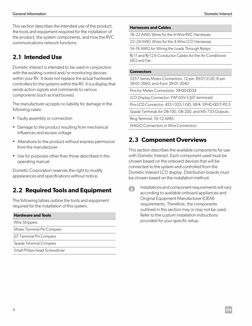
This section describes the intended use of the product, the tools and equipment required for the installation of the product, the system components, and how the RVC communications network functions.
2.1 Intended Use
Dometic Interact is intended to be used in conjunction with the existing control and/or monitoring devices within your RV. It does not replace the actual hardware controllers for the systems within the RV. It is a display that sends action signals and commands to various components (such as load boxes).
The manufacturer accepts no liability for damage in the following cases:
• Faulty assembly or connection
• Damage to the product resulting from mechanical influences and excess voltage
• Alterations to the product without express permission from the manufacturer
• Use for purposes other than those described in the operating manual
Dometic Corporation reserves the right to modify appearances and specifications without notice.
2.2 Required Tools and Equipment
The following tables outline the tools and equipment required for the installation of this system.
2.3 Component Overviews
This section describes the available components for use with Dometic Interact. Each component used must be chosen based on the onboard devices that will be connected to the system and controlled from the Dometic Interact LCD display. Distribution boards must be chosen based on the installation method.
Hardware and Tools
Wire Strippers
Molex Terminal Pin Crimpers
JST Terminal Pin Crimpers
Spade Terminal Crimpers
Small Philips-head Screwdriver
Harnesses and Cables
18–22 AWG Wires for the 4-Wire RVC Harnesses
22–24 AWG Wires for the 4-Wire LCD Harnesses
14–18 AWG for Wiring the Loads Through Relays
RJ-11 and RJ-12 6-Conductor Cables for the Air Conditioner (AC) and Fan
Connectors
5557 Series Molex Connectors: 12-pin 39-01-2120, 6-pin 39-01-2060, and 4-pin 39-01-2040
Pins for Molex Connectors: 39-00-0039
LCD Display Connector: PAP-05V-S (JST terminals)
Pins LCD Connector: 455-1325-1-ND, Mf #: SPHD-001T-P0.5
Spade Terminals for DB-100, DB-200, and MS-733 Outputs
Ring Terminal: 10–12 AWG
WAGO Connectors or Wire Connectors
I Installations and component requirements will vary according to available onboard appliances and Original Equipment Manufacturer (OEM) requirements. Therefore, the components outlined in this section may or may not be used. Refer to the custom installation instructions provided for your specific setup.
Dometic Interact General Information
5EN
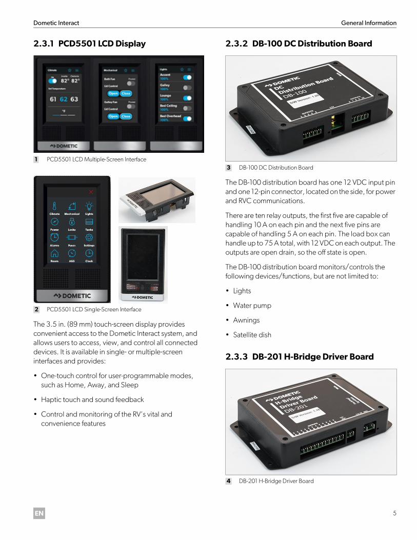
2.3.1 PCD5501 LCD Display
1 PCD5501 LCD Multiple-Screen Interface
2 PCD5501 LCD Single-Screen Interface
The 3.5 in. (89 mm) touch-screen display provides convenient access to the Dometic Interact system, and allows users to access, view, and control all connected devices. It is available in single- or multiple-screen interfaces and provides:
• One-touch control for user-programmable modes, such as Home, Away, and Sleep
• Haptic touch and sound feedback
• Control and monitoring of the RV’s vital and convenience features
2.3.2 DB-100 DC Distribution Board
3 DB-100 DC Distribution Board
The DB-100 distribution board has one 12 VDC input pin and one 12-pin connector, located on the side, for power and RVC communications.
There are ten relay outputs, the first five are capable of handling 10 A on each pin and the next five pins are capable of handling 5 A on each pin. The load box can handle up to 75 A total, with 12 VDC on each output. The outputs are open drain, so the off state is open.
The DB-100 distribution board monitors/controls the following devices/functions, but are not limited to:
• Lights
• Water pump
• Awnings
• Satellite dish
2.3.3 DB-201 H-Bridge Driver Board
4 DB-201 H-Bridge Driver Board
General Information Dometic Interact
6 EN
The DB-201 driver board uses H-bridge outputs. They are typically in a pair, but you can use two individual outputs on each pair. The off state for the DB-201 outputs are ground.
The DB-201 driver board controls/monitors the following devices/functions, but are not limited to:
• Lights
• Locks
• Slide-outs
• Generator
• Parking brake
• Ignition
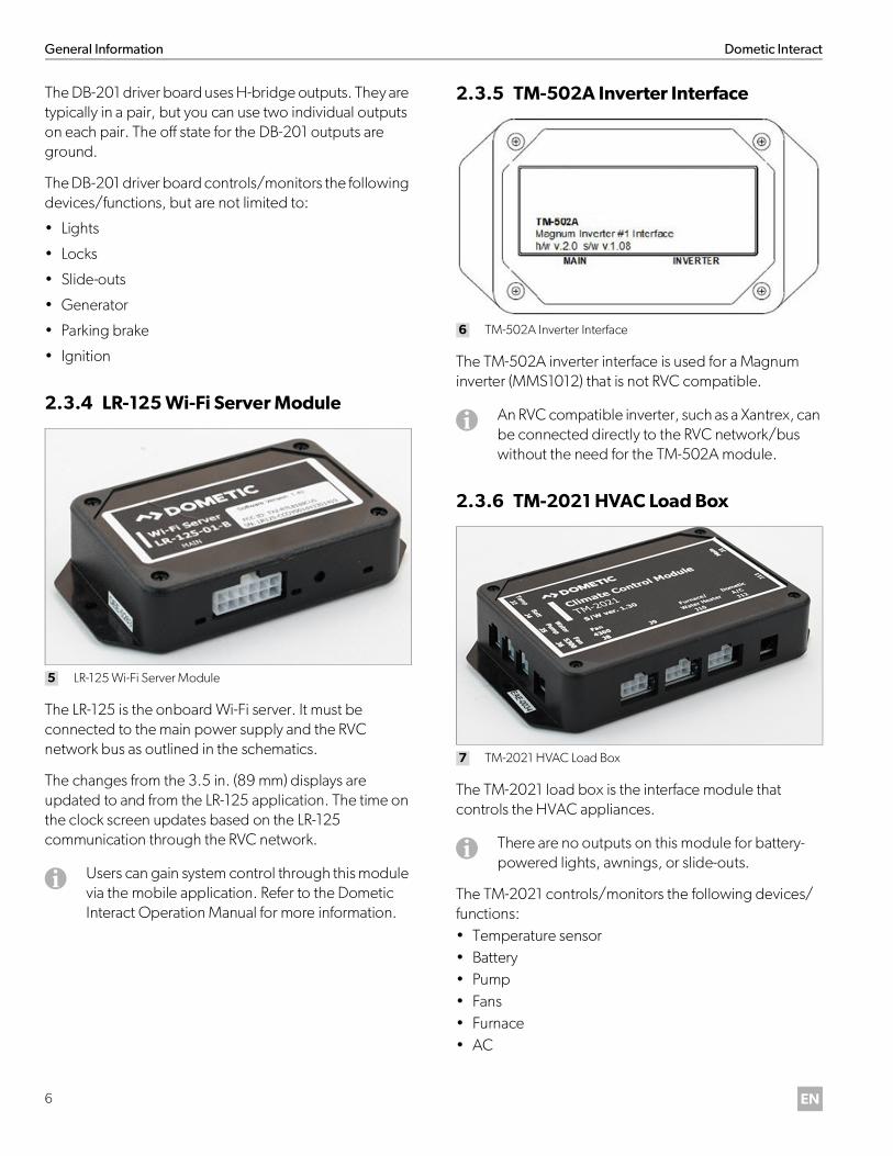
2.3.4 LR-125 Wi-Fi Server Module
5 LR-125 Wi-Fi Server Module
The LR-125 is the onboard Wi-Fi server. It must be connected to the main power supply and the RVC network bus as outlined in the schematics.
The changes from the 3.5 in. (89 mm) displays are updated to and from the LR-125 application. The time on the clock screen updates based on the LR-125 communication through the RVC network.
2.3.5 TM-502A Inverter Interface
6 TM-502A Inverter Interface
The TM-502A inverter interface is used for a Magnum inverter (MMS1012) that is not RVC compatible.
2.3.6 TM-2021 HVAC Load Box
7 TM-2021 HVAC Load Box
The TM-2021 load box is the interface module that controls the HVAC appliances.
The TM-2021 controls/monitors the following devices/functions:• Temperature sensor• Battery• Pump• Fans• Furnace• AC
I Users can gain system control through this module via the mobile application. Refer to the Dometic Interact Operation Manual for more information.
I An RVC compatible inverter, such as a Xantrex, can be connected directly to the RVC network/bus without the need for the TM-502A module.
I There are no outputs on this module for battery-powered lights, awnings, or slide-outs.

Dometic Interact General Information
7EN
2.3.7 TM-180 Tank Dump
8 TM-180 Tank Dumps
The TM-180 module supports the following functions:
• Dump Valve Control: This allows manual control of two waste dump valves, automatic dumping when a tank level reaches a programmed level, or automatic dumping when the valves automatically close due to an empty tank.
• Valve Interlocks: Valves automatically close upon vehicle movement. Only one valve will be open at a time. If an automatic command to dump a tank is received when the other tank is open, it is queued for later processing. If a manual command is received, the other valve is closed first.
• Sanicon: The Sanicon can run while either waste valve is open. It continues to run for a programmed length of time after closing the valve. While the dump valves have an indicator circuit to indicate when they are closed, the TM-180 hardware does not have the ability to read this input. The unit always closes the valves on startup, and then keeps track of the valve status internally from there.
• Additive Pump: The TM-180 module supports an additive pump. The additive is supplied in proportion to the amount of waste in the black tank, disbursed in increments of configurable size. The module also supports a reservoir empty sensor.
2.3.8 SeeLevel II Tank Monitor
9 SeeLevel II Tank Monitor
The SeeLevel II interface module monitors the battery level, as well as the fresh, gray, and black water tanks. Some models also monitor LPG gas levels.
2.4 RVC Communications Network Overview
RVC is a controlled area network (CAN)-based communication profile for RVs. It was developed by the Recreation Vehicle Industry Association (RVIA).
The Dometic Interact system of devices uses RVC data networking, utilizing a twisted pair of wires terminated at each end of the network with 120-Ohm resistors. Terminating resistors are also populated on the distribution boards.
Refer to “RVC Distribution Boards” on page 8 for choosing the right distribution board for your application.
Every device on the network digitally transmits the RV systems data via the RVC data pair, which is distributed by the distribution boards and harnesses.
I You can connect only one fresh water, one gray water, and one black water tank to the module, with one sensor each.
I You can combine two sensor strips together for taller tanks. Refer to the Garnet manual for sensor integration information.

General Information Dometic Interact
8 EN
Here is an example of a typical wireframe RVC communication network:
10 Typical Wireframe RV Communication Network
2.4.1 RVC Distribution Boards
The RVC distribution boards used with this system enable central distribution points for communication and power for all the devices. They can be 3-way, 6-way, or 12-way, both with and without terminating resistors (which are installed on the boards themselves).
This provides a simple way to increase the network size while allowing for flexibility in locating devices.
Make sure to choose a distribution board with 120 ohm resistors on both ends of the bus. If you look at the drawing below, the distribution board in the middle does not need a 120 ohm resistor.
Here are some examples of the distribution boards, which are chosen based on the OEM installation requirements:
11 Example Distribution Boards

Dometic Interact Installation
9EN
2.4.2 RVC Load Boxes
The RVC load boxes used in this system act as the drivers that control the appliances, interfacing between all onboard appliances, such as lights, fans, AC units, furnaces, awnings, and slide-outs.
The load box type chosen is based on the load type, as per the OEM requirements.
3 Installation
This section provides general installation information for the components that can be used with the Dometic Interact system. Refer to “Component Overviews” for more information about the compatible components and the devices that they control.
Ensure that you have the following experience and knowledge before attempting to install the Dometic Interact system:
• Experience with electrical wiring
• Knowledge of onboard appliances (Dometic or others)
• Understanding of electrical drawings
• Basic understanding of RVC/CAN networks
• Experience with manufacturing/repairing RVs
• Completed Dometic Interact Product Overview online or class training
3.1 Setting Up the Power Supply
To operate properly, the Dometic Interact system must receive power from the shore, a generator, or another alternative source.
Both shore and generator power supplies should be wired to the automatic transfer switch so that it allows only one power-out line. The 120 VAC power from the switch is fed to the inverter input terminal. The 12 VDC rectified power then charges the RV battery.
When there is no shore or generator power present, the inverter changes the DC power to AC and feeds it to the outlets from the inverter AC output terminal. For inverter wiring information, refer to the inverter installation and/or operation manual.
When shore or generator power is present, the inverter receives the AC voltage and generates the AC output while bypassing the inverting process. It also charges the battery in parallel. Refer to Fig. 15 on page 13.
If you have other renewable resources of energy, like solar panels, you can directly charge the RV battery. Send the energy collected from the solar panels to the charger controller first. The 12 VDC power from the charger controller then charges the RV battery and monitors the battery level so that it does not become overcharged.
! WARNING: ELECTRICAL SHOCK, FIRE, AND/OR EXPLOSION HAZARD.Use care when installing components onto a powered RV system. Failure to obey this warning could result in death or serious injury.
I Due to the nature of the product and the variations of onboard appliances, each installation comes with a customized set of installation instructions. All wiring diagrams included in this section are provided for example purposes only. Detailed wiring diagrams and installation schematics are provided with the custom installation instructions for your specific setup.
I A current RVIA certification for technicians is not required, but it is helpful.
I For more details, refer to the manual provided with the solar panels.

Installation Dometic Interact
10 EN
3.2 Installing the Distribution Board
The diagram below shows one possible configuration of the system components installed on the distribution board.
12 System Configuration Example
The diagram above shows one possible configuration of the system components installed on the distribution board. Connect the RVC devices in any sequence.
Use any length of connection between the distribution boards, but the length of the twisted pair wires between a distribution board and a device should be less than 6 ft (183 cm) in order to gain the proper RVC communication.
1Pin Designation
12VDCGROUND
RVC -RVC +
Communication
GROUND
Distribution Board Plugs
Communication
Input/Output (Type)12VDC
432
GREY
741
DIAGNOSTIC PLUG
369
All Connections AreWire Side View
4 3
2 1
BATT FRESH BLACK LPG
120 Ohm
MADE IN CANADAGARNET INSTRUMENTS LTD.
LEVEL IN PERCENT
SEELEVEL II TANK MONITOR
10
All Connections AreWire Side View
6 5 4 3 2 1
12 11 9 78
10 2 146 358 7912 111416 131518 1720 19
All Connections Are Wire Side View
All Connections AreWire Side View
4 3
2 1
Xantrex Freedom XC Pro 2000
CIRCUITSCIRCUITS
120 Ohm
2
Pin1
Input/Output (Type)
InputInput
FUSED 12VDC FROM DC PANELDesignation12VDCGROUND
DC Distribution BoardDB100S/W Version V1.25
1 2 3 4 5 6 7 8 9 10
12VOutputs Outputs
H- Bridge Driver BoardDB200S/W Version v1.18
Outputs
Climate Control ModuleTM-2021S/W Version v1.30
Wi-Fi Server ModuleLR125S/W Version v1.10
Outputs
3.5" Display
I Refer to RVC Communications Network Overview for more information.

Dometic Interact Installation
11EN
3.3 Installing the DB-100
13 DB-100 Installation Example
To install the DB-100 distribution board:
1. Connect the 12 VDC positive wire to the 12V-IN port on the box using a 75 A fuse.
2. Connect the positive (red/hot) wires for the lights, water pump, and satellite dish to the appropriate output pins as shown in your drawings.
3. Connect the negative (black) wires to the ground terminal.
4. Use an MS-733 relay for the awnings:
a. Connect the 12 VDC and ground wires on the input side of the relay.
b. Connect the awning extend and retract wires from the outputs of the load boxes to the middle pins of the relay, as shown in the drawings.
c. Connect the two wires of the mechanical awning motor to the output side of the relay.
5. Ensure the DB-100 is compatible with Truma:
a. Confirm the DB-100 software is version 1.27 and above.
b. Confirm the DB-100 software is version 1.32 and above to support new features like anti-freeze (which requires an additional antifreeze strip to be installed).
6. To control the Truma Water Heater (Comfort Plus Model) from the DB-100:
c. Wire the Pin-3 on the remote bus connectors to the Pin-2 on the DB-100 main connector.
d. Wire the Pin-5 on the remote bus connector to the ground.
Installation Dometic Interact
12 EN
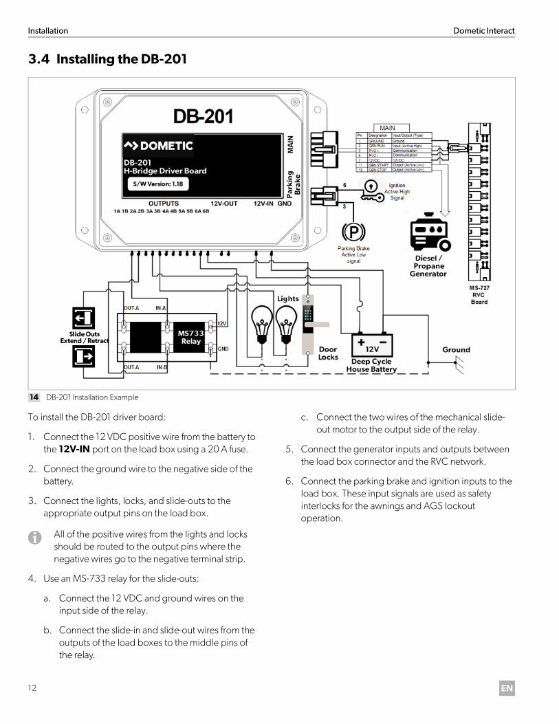
3.4 Installing the DB-201
14 DB-201 Installation Example
To install the DB-201 driver board:
1. Connect the 12 VDC positive wire from the battery to the 12V-IN port on the load box using a 20 A fuse.
2. Connect the ground wire to the negative side of the battery.
3. Connect the lights, locks, and slide-outs to the appropriate output pins on the load box.
4. Use an MS-733 relay for the slide-outs:
a. Connect the 12 VDC and ground wires on the input side of the relay.
b. Connect the slide-in and slide-out wires from the outputs of the load boxes to the middle pins of the relay.
c. Connect the two wires of the mechanical slide-out motor to the output side of the relay.
5. Connect the generator inputs and outputs between the load box connector and the RVC network.
6. Connect the parking brake and ignition inputs to the load box. These input signals are used as safety interlocks for the awnings and AGS lockout operation.
I All of the positive wires from the lights and locks should be routed to the output pins where the negative wires go to the negative terminal strip.
Dometic Interact Installation
13EN
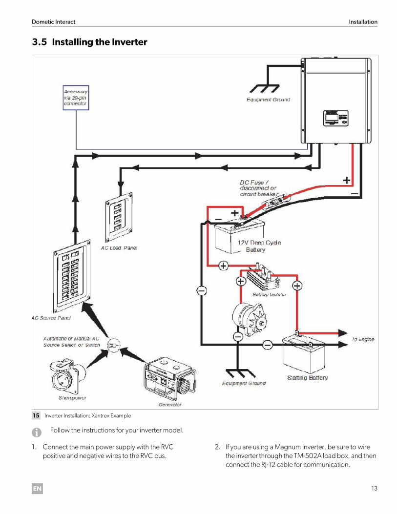
3.5 Installing the Inverter
15 Inverter Installation: Xantrex Example
1. Connect the main power supply with the RVC positive and negative wires to the RVC bus.
2. If you are using a Magnum inverter, be sure to wire the inverter through the TM-502A load box, and then connect the RJ-12 cable for communication.
I Follow the instructions for your inverter model.

Installation Dometic Interact
14 EN
3.6 Installing the TM-2021 HVAC Load Box
16 TM-2021 HVAC Load Box Installation Example
To install the TM-2021:
1. Connect the ground wire from the negative terminal of the battery to one end of the water pump switch.
2. Connect the other end of the water pump switch through the Molex connector to the J5 port.
3. Connect the positive 12 VDC wire from the chassis battery through the Molex connector to the J4 port.
4. Connect the Fan-5300 to the J6 port on the left side of the load box using an RJ-12 6-conductor cable to communicate between the fan and the load box (over RVC).
5. Connect the Fan-4100 to the J8 port.
6. Connect the signal wire from the furnace to pin 4 of the furnace connector J10 port. If there is a water heater included in your application, refer to those drawings.
7. Connect the telephone cable to the J9 port on the bottom right of the load box. Connect the RJ-12 6-conductor cable from the AC controller to the load box.
8. Connect the main power 12 VDC and the RVC wires from the load box to the RVC network.
I There must be three signals from the box: fan open, fan close, and fan motor. These come from pins 4, 5, and 6. Use a relay to connect the Fan-4100.

Dometic Interact Installation
15EN
3.7 Installing the TM-180
17 TM-180 Installation Example
The TM-180 receives its power and communication from the RVC distribution boards. Refer to your custom installation instructions and schematics for more information about how to install the TM-180.
I If you are using Dometic load boxes, be sure all the load boxes are updated with any software revisions, and be sure each load box is configured for your application based on the type of loads connected to the load box.
Installation Dometic Interact
16 EN
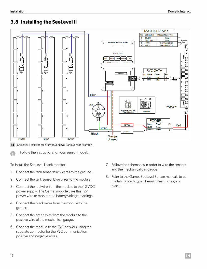
3.8 Installing the SeeLevel II
18 SeeLevel II Installation: Garnet SeeLevel Tank Sensor Example
To install the SeeLevel II tank monitor:
1. Connect the tank sensor black wires to the ground.
2. Connect the tank sensor blue wires to the module.
3. Connect the red wire from the module to the 12 VDC power supply. The Garnet module uses this 12V power wire to monitor the battery voltage readings.
4. Connect the black wires from the module to the ground.
5. Connect the green wire from the module to the positive wire of the mechanical gauge.
6. Connect the module to the RVC network using the separate connector for the RVC communication positive and negative wires.
7. Follow the schematics in order to wire the sensors and the mechanical gas gauge.
8. Refer to the Garnet SeeLevel Sensor manuals to cut the tab for each type of sensor (fresh, gray, and black).
I Follow the instructions for your sensor model.
Dometic Interact Configuration
17EN
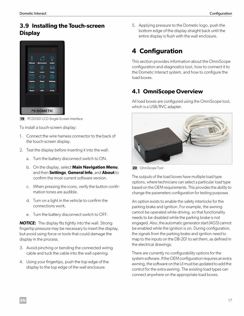
3.9 Installing the Touch-screen Display
19 PCD5501 LCD Single-Screen Interface
To install a touch-screen display:
1. Connect the wire harness connector to the back of the touch-screen display.
2. Test the display before inserting it into the wall.
a. Turn the battery disconnect switch to ON.
b. On the display, select Main Navigation Menu, and then Settings, General Info, and About to confirm the most current software version.
c. When pressing the icons, verify the button confir-mation tones are audible.
d. Turn on a light in the vehicle to confirm the connections work.
e. Turn the battery disconnect switch to OFF.
NOTICE: The display fits tightly into the wall. Strong fingertip pressure may be necessary to insert the display, but avoid using force or tools that could damage the display in the process.
3. Avoid pinching or bending the connected wiring cable and tuck the cable into the wall opening.
4. Using your fingertips, push the top edge of the display to the top edge of the wall enclosure.
5. Applying pressure to the Dometic logo, push the bottom edge of the display straight back until the entire display is flush with the wall enclosure.
4 ConfigurationThis section provides information about the OmniScope configuration and diagnostics tool, how to connect it to the Dometic Interact system, and how to configure the load boxes.
4.1 OmniScope Overview
All load boxes are configured using the OmniScope tool, which is a USB/RVC adapter.
20 OmniScope Tool
The outputs of the load boxes have multiple load type options, where technicians can select a particular load type based on the OEM requirements. This provides the ability to change the parameters configuration for testing purposes
An option exists to enable the safety interlocks for the parking brake and ignition. For example, the awning cannot be operated while driving, so that functionality needs to be disabled while the parking brake is not engaged. Also, the automatic generator start (AGS) cannot be enabled while the ignition is on. During configuration, the signals from the parking brake and ignition need to map to the inputs on the DB-201 to set them, as defined in the electrical drawings.
There are currently no configurability options for the system software. If the OEM configuration requires an extra awning, the software on the UI must be updated to add the control for the extra awning. The existing load types can connect anywhere on the appropriate load boxes.
Maintenance Dometic Interact
18 EN
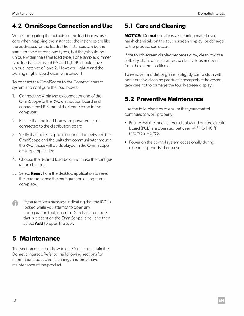
4.2 OmniScope Connection and Use
While configuring the outputs on the load boxes, use care when mapping the instances; the instances are like the addresses for the loads. The instances can be the same for the different load types, but they should be unique within the same load type. For example, dimmer type loads, such as light-A and light-B, should have unique instances: 1 and 2. However, light-A and the awning might have the same instance: 1.
To connect the OmniScope to the Dometic Interact system and configure the load boxes:
1. Connect the 4-pin Molex connector end of the OmniScope to the RVC distribution board and connect the USB end of the OmniScope to the computer.
2. Ensure that the load boxes are powered up or connected to the distribution board.
3. Verify that there is a proper connection between the OmniScope and the units that communicate through the RVC; these will be displayed in the OmniScope desktop application.
4. Choose the desired load box, and make the configu-ration changes.
5. Select Reset from the desktop application to reset the load box once the configuration changes are complete.
5 MaintenanceThis section describes how to care for and maintain the Dometic Interact. Refer to the following sections for information about care, cleaning, and preventive maintenance of the product.
5.1 Care and Cleaning
NOTICE: Do not use abrasive cleaning materials or harsh chemicals on the touch-screen display, or damage to the product can occur.
If the touch-screen display becomes dirty, clean it with a soft, dry cloth, or use compressed air to loosen debris from the external orifices.
To remove hard dirt or grime, a slightly damp cloth with non-abrasive cleaning product is acceptable; however, take care not to damage the touch-screen display.
5.2 Preventive Maintenance
Use the following tips to ensure that your control continues to work properly:
• Ensure that the touch-screen display and printed circuit board (PCB) are operated between -4 °F to 140 °F (-20 °C to 60 °C).
• Power on the control system occasionally during extended periods of non-use.
I If you receive a message indicating that the RVC is locked while you attempt to open any configuration tool, enter the 24-character code that is present on the OmniScope label, and then select Add to open the tool.
Dometic Interact Troubleshooting
19EN
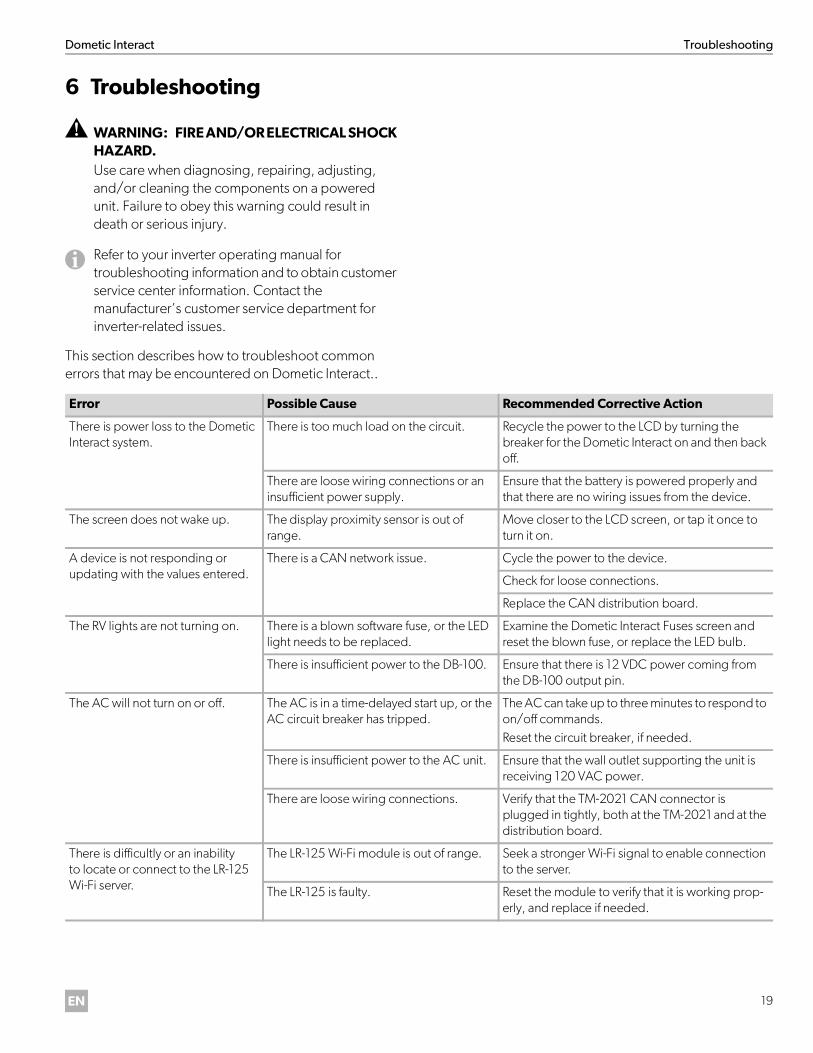
6 Troubleshooting
This section describes how to troubleshoot common errors that may be encountered on Dometic Interact..
! WARNING: FIRE AND/OR ELECTRICAL SHOCK HAZARD.Use care when diagnosing, repairing, adjusting, and/or cleaning the components on a powered unit. Failure to obey this warning could result in death or serious injury.
I Refer to your inverter operating manual for troubleshooting information and to obtain customer service center information. Contact the manufacturer’s customer service department for inverter-related issues.
Error Possible Cause Recommended Corrective Action
There is power loss to the Dometic Interact system.
There is too much load on the circuit. Recycle the power to the LCD by turning the breaker for the Dometic Interact on and then back off.
There are loose wiring connections or an insufficient power supply.
Ensure that the battery is powered properly and that there are no wiring issues from the device.
The screen does not wake up. The display proximity sensor is out of range.
Move closer to the LCD screen, or tap it once to turn it on.
A device is not responding or updating with the values entered.
There is a CAN network issue. Cycle the power to the device.
Check for loose connections.
Replace the CAN distribution board.
The RV lights are not turning on. There is a blown software fuse, or the LED light needs to be replaced.
Examine the Dometic Interact Fuses screen and reset the blown fuse, or replace the LED bulb.
There is insufficient power to the DB-100. Ensure that there is 12 VDC power coming from the DB-100 output pin.
The AC will not turn on or off. The AC is in a time-delayed start up, or the AC circuit breaker has tripped.
The AC can take up to three minutes to respond to on/off commands. Reset the circuit breaker, if needed.
There is insufficient power to the AC unit. Ensure that the wall outlet supporting the unit is receiving 120 VAC power.
There are loose wiring connections. Verify that the TM-2021 CAN connector is plugged in tightly, both at the TM-2021 and at the distribution board.
There is difficultly or an inability to locate or connect to the LR-125 Wi-Fi server.
The LR-125 Wi-Fi module is out of range. Seek a stronger Wi-Fi signal to enable connection to the server.
The LR-125 is faulty. Reset the module to verify that it is working prop-erly, and replace if needed.

Troubleshooting Dometic Interact
20 EN
The furnace is not functioning properly.
The furnace is in Auto mode. The furnace may take some time to respond to commands while in Auto mode. Reset the circuit breaker, if needed.
There are loose wiring connections. Verify that there is 12 VDC power coming from pins 4 and J10 of the TM-2021.
The incorrect heating equipment is selected in Settings.
Change the Heat mode to Furnace on the Set-tings screen.
There is a water pump failure. There is a blown software fuse. Examine the Dometic Interact Fuses screen and reset the blown fuse, if applicable.
There is a loose wiring connection or power issue.
Verify that the voltage is correct on the 12 VDC connector for the pump on the TM-2021, and ensure that the water pump switch is wired correctly.
There is a satellite dish failure. There is a blown software fuse, or the satel-lite dish is disabled.
Examine the Dometic Interact Fuses screen and reset the blown fuse, or enable the satellite dish in the Settings screen.
The touch-screen is unresponsive. The system might be frozen. Reboot the system by interrupting the power sup-ply for ten seconds.
There is audio trouble. The audio level is set too low. Increase the default audio level in the Settings screen, or reboot the system.
The tank level readings are inaccurate.
The RV is not level or stationary. Bring the RV to a complete stop and ensure that it is level.
There are faulty sensors. Check the tank sensors and replace as needed.
The generator fails to exercise. The AGS is turned off, the ignition safety interlock is enabled, or the settings are incorrect.
Turn on the AGS, remove the key from the vehicle ignition, or adjust the time settings.
The awning is not working properly.
The parking brake is not engaged. Ensure that the parking brake is engaged.
There is a blown software fuse. Examine the Dometic Interact Fuses screen and reset the blown fuse, if applicable.
There is insufficient power to the DB-100. Ensure that there is 12 VDC power coming from the DB-100 extend/retract pins.
The fan will not turn on, the fan lid will not open or close, or the fan lid closes by itself.
The system is frozen, or the rain sensor made the lids close and the fan turn off.
Reboot the system by interrupting the power sup-ply for ten seconds.
Check to see if the fan has a rain sensor (Fan-Tastic fan model 7350 only).
There are loose wiring connections or power issues.
Verify that there is 12 VDC power on the MS-733 relay out A and B when the lid is opened or closed, and on the other relay when the motor is on.
Ensure that there are correct voltage readings on the TM-2021.
Check all wiring connections and correct any loose connections as needed.
Error Possible Cause Recommended Corrective Action

Dometic Interact Disposal
21EN
7 Disposal
LIMITED ONE-YEAR WARRANTYLIMITED ONE-YEAR WARRANTY AVAILABLE AT WWW.DOMETIC.COM/WARRANTY.
IF YOU HAVE QUESTIONS, OR TO OBTAIN A COPY OF THE LIMITED WARRANTY FREE OF CHARGE, CONTACT:
DOMETIC CORPORATIONCUSTOMER SUPPORT CENTER5155 VERDANT DRIVEELKHART, INDIANA, USA 465161-800-544-4881 OPT 1
M Place the packaging material in the appropriaterecycling waste bins, whenever possible. Consult a local recycling center or specialist dealer for details about how to dispose of the product in accordance with all applicable national and local regulations.
dometic.com
Mobile living made easy.
YOUR LOCAL DEALER
dometic.com/dealer
YOUR LOCAL SUPPORT
dometic.com/contact
YOUR LOCAL SALES OFFICES
dometic.com/sales-offices