Development of an automated passive wrist movement device ...
159
Development of an automated passive wrist movement device for 4D CT scans appendix Delft University of Technology Industrial Design Engineering Integrated Product Design Medisign Specialization Delft, The Netherlands May 2020 Job Pieter van der Linden
-
Upload
khangminh22 -
Category
Documents
-
view
3 -
download
0
Transcript of Development of an automated passive wrist movement device ...

Development of an automated passive wrist movement device for 4D CT scansappendix
Delft University of TechnologyIndustrial Design EngineeringIntegrated Product DesignMedisign Specialization
Delft, The NetherlandsMay 2020
Job Pieter van der Linden

Content A Graduation Brief
B Expert profiles
C Product user test
D State of the Art CPM devices
E Product aspects
F Movement mechanism concepts
G Comparison movement mechanism concepts
H Component prototypes
I Fixation products market research
J Other fixation types
K Forearm fixation options
L Forearm fixation concepts and -selection
M Definition body parameters
N Measurements and variation body parameters
O Hand fixation options
P Hand fixation concepts and -selection
Q Radiation dose
R Load cell calculation
S Type of actuator
T Type of electric actuator
U Motor performance test
V Stepper driver details and comparison
W Cable elongation
X Operating system concepts
Y Comparison operating system concepts
Z Assumptions cable tension measurement
AA Timing belt length test
BB Electronic prototypes
CC Stability test (patient bed)
DD Control panel user test
EE Market research comfort
FF Comfort material comparison
GG Comfortability test hand fixation
HH Pugh’s checklist
II Product component models (files)
JJ Desired hardware setup
KK Price quotation 3D printed parts
LL Material (MDF) required
MM Selection transmission movement mechanism C1
NN Data sets anthropometric measurements

B – Expert profiles During the project there are multiple different experts which were consulted repeatedly. Below a
profile of these experts is given.
Dr. Ir. Johan Molenbroek (TU Delft)
Function: Associate professor applied ergonomics.
Fields of expertise: Ergonomics and anthropometry, product adaption to users and overall design
process.
MSc. Tessa Essers (TU Delft)
Function: Research & teaching support staff 3D printing.
Fields of expertise: 3D printing, prototyping (mechanics, electronics) and overall design process.
Dr. Stan Buckens (RadboudUMC)
Function: Radiologist.
Fields of expertise: CT scanners and –scanning, human wrist anatomy, product adaption to context.
Dr. Stefan Hummelink (RadboudUMC) Function: Technical physician and research coordinator. Fields of expertise: product mechanics and electronics, product adaption to context.
Dr. Brigitte van der Heijden (RadboudUMC) Function: Plastic-, reconstructive and hand surgeon. Fields of expertise: human wrist anatomy.
Ing. Martin Verwaal (TU Delft) Function: Technical support in the Applied Labs. Fields of expertise: Electronics and Arduino.

C – Product user test During the project a user test was conducted to learn more about the fit and fixation of the arm in the
product. In total around ten participants were fixated in the product with the use of the forearm
fixations, both males and females without making a distinction between age groups. For the participants
it was attempted to pick both people with small- and large arms, in order to see how the different sizes
could be fixated in the product. Attention was paid to how (position) the participant’s arm was fixated
and how well it was fixated. In figure C1 – C10 five of the participants can be seen, while being fixated in
the product.
The main outcomes of this test were that it became clear that the arm could not be perfectly centered
on the arm standard (and also not in relation to the wrist standard) in every case. In most cases the arm
could only be positioned close to the middle, but not perfectly in it. Also, the forearm fixations had to be
adjusted in position for this all the time, which took a lot of extra time.
Secondly, the one velcro strap attachement system did not work properly to keep the participant’s
forearm fixated to prevent it from moving. When the participants relaxed their arm and letting the
weight of it rest on the fixations, the slider part (of the fixation) moved to the side. This resulted in more
space for the forearm, making it able to move (resulting in motion artefacts in the end).
Figure C1. Participant 1 fixated in the product.
Figure C2. Participant 2 fixated in the product.

Figure C3. Participant 3 fixated in the product.
Figure C4. Participant 3 fixated in the product.

Figure C5. Participant 4 fixated in the product.
Figure C6. Participant 4 fixated in the product.

Figure C7. Participant 4 fixated in the product.

Figure C8. Participant 5 fixated in the product.
Figure C9. Participant 5 fixated in the product.

Figure C10. Participant 5 fixated in hand fixation.

D – State of the Art CPM devices In the recent years some companies, universities and other institutions have researched passive
moment of the wrist. Devices like hand braces or robotic hand exoskeletons were developed, which
could facilitate continuous passive movement (CPM) of the wrist. All products which were found, are
meant for wrist rehabilitation (i.e. improving range of motion (ROM) of the wrist). The most relevant
examples can be found below. While reviewing these existing products there has been focused on a set
of criteria, which can be seen below. The variables are not listed in order of importance.
Five of the criteria are based on the focus areas of the project (subchapter 1.4 – Focus areas). The three
remaining criteria were also considered to be important. Criteria 3 because also for this product the
dimensions are important, as it has to fit in the central aperture. Criteria 6 because the price is also
important for this product, as the product is designed for a hospital and these do not have much credit
for projects and developments. Criteria 8 because there may be special features a device has which may
also be useful and applicable in this product.
- V1: Movement
Is the product able to make the desired movements of wrist flexion and –extension, and radial-
and ulnar deviation?
- V2: Usability
How complex is (operating) the product? Can it be easily integrated in the current daily working
routine of the radiologists?
- V3: Size
Is the product large or small; i.e. would it fit in the central aperture?
- V4: Adaptability
Is the product adjustable in size, thus adaptable to different patients to increase comfort?
- V5: Hygiene
Is the product easy to clean in order to meet the hospital hygiene standards?
- V6: Price
How expensive is the product?
- V7: Safety
Is the product safe or does it bring any risks on injuries?
- V8: Additional
Are there any other points which are positive or negative about this product?
Each existing product was evaluated on all criteria. An overview of all the existing products which were
evaluated (with each a short description) can be seen below (figure D1 – D6).

Existing products
Kinetic Maestra
The Kinetec Maestra Continuous Passive Motion (CPM) (figure D1) is designed for post-operative
rehabilitation and provides a solution for every hand and wrist pathology (Kinetec, 2016).
Figure D1. Kinetec Maestra. Source: (Kinetec, 2016).
6000X WaveFlex Hand CPM The 6000X WaveFlex Hand CPM device (figure D2) consists of an anatomic hand CPM that helps patients
to achieve a full composite fist (at 270°) (QAL Medical (b), n.d.).
Figure D2. 6000X WaveFlex Hand CPM. Source: (QAL Medical (b), n.d.).
W2 Wrist CPM The W2 Wrist CPM device (figure D3 and figure D4) is a lightweight portable wrist device, designed to
increase mobility of the wrist joint in flexion and extension and ulnar- and radial deviation (QAL Medical
(a), n.d.).
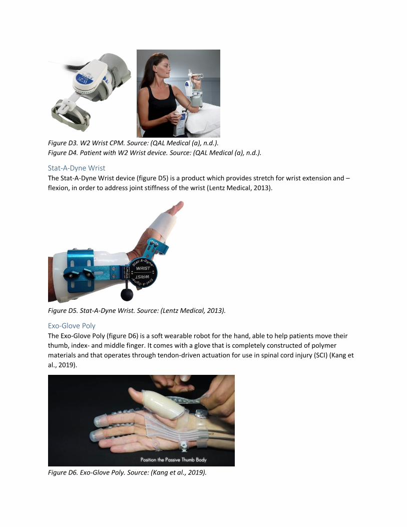
Figure D3. W2 Wrist CPM. Source: (QAL Medical (a), n.d.).
Figure D4. Patient with W2 Wrist device. Source: (QAL Medical (a), n.d.).
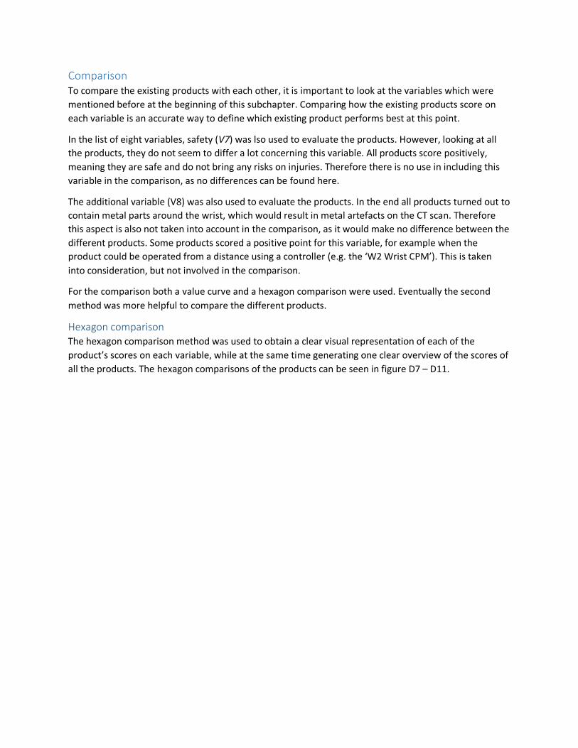
Stat-A-Dyne Wrist The Stat-A-Dyne Wrist device (figure D5) is a product which provides stretch for wrist extension and –
flexion, in order to address joint stiffness of the wrist (Lentz Medical, 2013).
Figure D5. Stat-A-Dyne Wrist. Source: (Lentz Medical, 2013).
Exo-Glove Poly The Exo-Glove Poly (figure D6) is a soft wearable robot for the hand, able to help patients move their
thumb, index- and middle finger. It comes with a glove that is completely constructed of polymer
materials and that operates through tendon-driven actuation for use in spinal cord injury (SCI) (Kang et
al., 2019).
Figure D6. Exo-Glove Poly. Source: (Kang et al., 2019).
Comparison To compare the existing products with each other, it is important to look at the variables which were
mentioned before at the beginning of this subchapter. Comparing how the existing products score on
each variable is an accurate way to define which existing product performs best at this point.
In the list of eight variables, safety (V7) was lso used to evaluate the products. However, looking at all
the products, they do not seem to differ a lot concerning this variable. All products score positively,
meaning they are safe and do not bring any risks on injuries. Therefore there is no use in including this
variable in the comparison, as no differences can be found here.
The additional variable (V8) was also used to evaluate the products. In the end all products turned out to
contain metal parts around the wrist, which would result in metal artefacts on the CT scan. Therefore
this aspect is also not taken into account in the comparison, as it would make no difference between the
different products. Some products scored a positive point for this variable, for example when the
product could be operated from a distance using a controller (e.g. the ‘W2 Wrist CPM’). This is taken
into consideration, but not involved in the comparison.
For the comparison both a value curve and a hexagon comparison were used. Eventually the second
method was more helpful to compare the different products.
Hexagon comparison The hexagon comparison method was used to obtain a clear visual representation of each of the
product’s scores on each variable, while at the same time generating one clear overview of the scores of
all the products. The hexagon comparisons of the products can be seen in figure D7 – D11.

Figure D7. Kinetec Maestra. Figure D8. 6000X WaveFlex.
Figure D9. W2 Wrist CPM. Figure D10. Stat-A-Dyne.

Figure D11. Exo-Glove Poly.
Positive
Looking at the figures, there are both positive and negative points to be seen. The main positive point is
that two of the products (Kinetec Maestra and W2 Wrist CPM) can make all the desired (continuous)
passive movements (flexion, extension and radial- and ulnar deviation). In both cases, and this also
applies to the rest of the products, this is done with the use of an actuator.
Secondly, the majority of the products contained soft parts with adjustable straps to optimize comfort
and fit of the product for different users.
Thirdly, and this was especially the case for the last product (grey line), some parts of the products were
washable and therefore easy to clean. In the case of this last product there was molded a silicon-like
material around the electronic parts, which made it possible to wash and clean the product without
damaging any of the components.
Finally the size was also a positive point for most of the products. While some products still worked with
a (quite) big battery or power supply, the part which was attached to the forearm and hand were most
of the time fairly compact and lightweight.
Negative
On the contrary side there were also some negative points to be identified, points which should be
taken into account and improved in the design of this device. Firstly in all the products metal
components were used around the wrist, which would result in metal artefacts on the CT scans.

Therefore the metal components should be replaced with components of another material (e.g. plastic)
or otherwise be moved to an area further from the wrist, so that they are not located in the scanning
region. For the driving of the product (the motor) this has serious consequences, as this part is mostly
positioned in line of action of the wrist, as this is necessary to realize the desired wrist movement.
Secondly, for at least the three products of which it was known, the price was too high. The least
expensive product still was more than €3600, while the most expensive product was even more than
€7000.
Finally, while this was also a positive point, most of the products consisted of parts which were not easy
to clean. In this case it is important that parts can be cleaned and dried easily and quickly, as multiple
patients probably have to use the device throughout the day, to meet the hospital’s hygiene standards
and regulations.
Overall
Looking overall, the Wrist W2 CPM comes closest to the desired product for this project. It scores quite
well on the first four criteria, especially because it can realize all the desired wrist movements, it works
relatively easy and it is fairly adaptable to different users. Points of improvement are mainly related to
the price and the presence of metal parts near the wrist.

E – Product aspects
Radiation dose In case of CT scanning, the scanner has some start-up time at the beginning of every scan. Therefore it is
preferred to scan both movements (flexion/extension and radial-/ulnar deviation) all in one go, in order
to reduce the total radiation dose for the patient in the end. Whether this is possible is dependent on
the available scanning time (how many seconds the scanner can make a consecutive 4D scan in one go)
and on the speed of the movement. If the hand is moved too fast by the product, motion artefacts will
start to occur (figure 1.1.1, chapter 1). Therefore it is important that the speed of the passive
movements facilitated by the product can be tweaked, in order to find the perfect balance between
image quality and radiation dose (for the patient).
Concerning the scanning time, the aim was to make scans of 10 [s], in order to keep the radiation dose
relatively low. However, this can still be increased to a scanning time of 16 [s] according to S. Buckens
(personal communication, November 21, 2019). In this way there is more time available to facilitate the
movements during the scan, which makes it able to reduce the speed of the movement and prevent
occurrence of motion artefacts. Still then, it has to be tested if it is possible to scan both movements
(and in both directions) in one go and if there is no occurrence of motion artefacts.
Range of motion (ROM) For both (active and passive) movements the comfortable range of motion (ROM) should be measured,
as this can give an indication for potential wrist pathology. In the case of active movement this can
simply be done with the use of a goniometer (figure E1) (B. van der Heijden, personal communication,
November 21, 2019). In the case of passive movement, which is desired but not mandatory, this could
be measured by an electronic part which transfers that information to the code output on the
computer. Here it is important that the computer automatically remembers the maximum angle, as this
number is most interesting for the physicians.
According to B. van der Heijden (2019) and S. Buckens (2019) for both measurements it is sufficient to
have a precision of 5°. When for example 40° is measured as angle, it is okay for the actual angle to be
within 35-45°.
Figure E1. Goniometer. Source: (Doccheck, n.d.).

Scan resolution The CT scanner is capable of making four rotations per second, with one image per half rotation. This
results in a scanning resolution of 8 frames (images) per second. In the end this number has to be taken
into account with the wrist movement, to make sure that the movement can be captured on the CT
images as fluently and clearly as possible.
Remotely controllable For the device it is important that the initiation of the movement is perfectly timed with the initiation of
the CT scan. In this way it is made sure that the entire motion of the wrist is scanned, while also
preventing the scenario of scanning a static wrist. In the end this results in a lower radiation dose for the
patients, as they are exposed to the radiation for the minimum amount of time which is needed to make
the scan. Perfectly timing the initiation of both the scan and the movement could be done by connecting
the two devices to each other.

F – Movement mechanism concepts In this chapter of the Appendix the movement mechanism concepts are explained. Concept 2 was
already explained in the report (subchapter 3.2).
Connection arm (Concept 1) The first concept for the movement mechanism is based on the existing CPM devices described in
subchapter 2.3. All of these devices realize the wrist movements by having the rotation point of the
movement in line of action with the wrist. As the hand needs to be held neutral the entire time (see
2.3.3) this would result in two motors with each their rotation point aligned with the wrist, but in
another plane.
In figure F1 the flexion and extension movement can be seen, with R2 being the rotation point for the
movement, which is in line (x- and y-axis) with the wrist. The red box with ‘03B’ on it, represents the
motor responsible for this movement.
In figure F2 the deviation movement can be seen, with R1 being the rotation point for the movement,
which is in line (x- and z-axis) with the wrist. The red box with ‘03A’ on it, represents the motor
responsible for this movement.
Figure F1. Flexion and extension. Figure F2. Radial- and ulnar deviation.

Actuation and transmission As the motors need to be positioned outside the gantry, there has to be a transmission from the motor
to the rotation point. The best option for this would be gears in combination with a belt drive (figure
F3). The other options and the selection of this option can be found in Appendix NN.
Figure F3. Gears and a belt drive.
From the rotation points of these motors there need to be ‘connection arms’ to the fixation at the hand.
These arms need to be rigid in order to accurately transfer and therewith imitate the (anatomically
correct) movements of the wrists. As the desired movements take place in two different planes, two
different ‘connection arms’ (one for each motor) are needed. While moving the wrist in the desired
directions, only one ‘connection arm’ at the time can be connected to the hand fixation, otherwise they
are hindering each other’s movements. This means that in between the two movements the ‘connection
arm’ responsible for the first movement has to be disconnected, after which the ‘connection arm’ of the
second movement can be connected.
The setup for the flexion- and extension movement can be seen in figure F4 – F6. The setup for the
radial- and ulnar deviation movement can be seen in figure F7 – F9.
Figure F4. Neutral position for flexion- and extension movement.

Figure F5. Extension movement (front view).
Figure F6. Extension movement (top view).
Figure F7. Neutral position for radial- and ulnar deviation movement.

Figure F8. Radial deviation movement.
Figure F9. Ulnar deviation movement.
Adjustability Another important aspect about the ‘connection arms’ is that they need to be adjustable, in order to
adapt to the different arm- and hand sizes of the patients. See figure F10. For the passive movement it is
crucial that the connection part fits perfectly between the line of action of rotation point R1 (vertical
blue dashed line) and the hand fixation, to make sure the movement is exercised anatomically correct.
Therefore, the motor-to-hand connection part should be adjustable in the X-direction.

Figure F10. Adjustability of the motor-to-hand connection.
Feedback system Within the system it is important to have some kind of feedback on how much torque the motor is
exerting to make its rotation and eventually the wrist movement. This is necessary as the exerted torque
of the motor is not allowed to exceed a certain limit, in order to prevent the motor from pushing the
patient through their comfortable ROM and maybe even injuring the patient in the end. In this system
this torque could be measured by using a so-called ‘spring return potentiometer’ (figure F11). The
rotating shaft of the motor could in this case be connected to this potentiometer. The rotating shaft of
the connection arm (the ones through R1 or R2) are not an option, as it is also important that this metal
part is positioned outside the gantry. The potentiometer has, as the name suggests, a spring integrated
in it, which makes the potentiometer return to its neutral position. When rotating the shaft, and thus
the potentiometer, the latter is able to measure how much torque is applied in order to move the
‘connection arm’ and therewith the hand (in the desired direction). There are multiple versions of this
component with different values for the resistance; therefore more research should be done into that
which of the different resistance values is most suitable for this specific scenario.
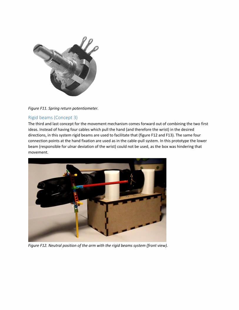
Figure F11. Spring return potentiometer.
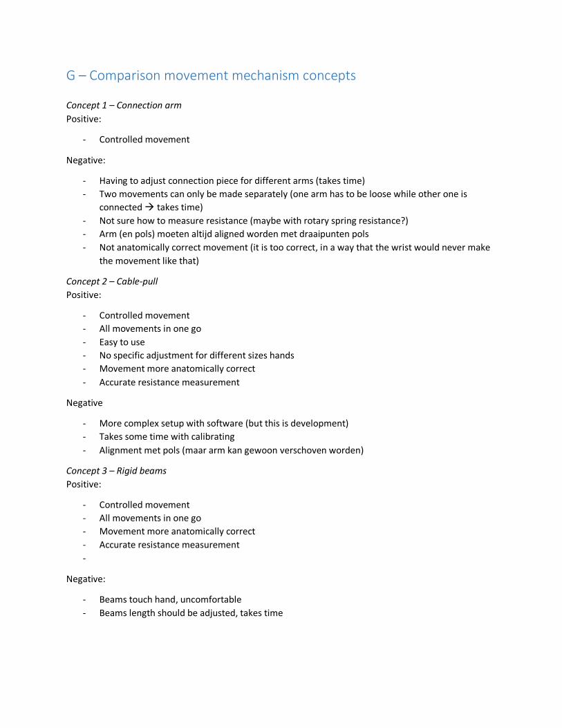
Rigid beams (Concept 3) The third and last concept for the movement mechanism comes forward out of combining the two first
ideas. Instead of having four cables which pull the hand (and therefore the wrist) in the desired
directions, in this system rigid beams are used to facilitate that (figure F12 and F13). The same four
connection points at the hand fixation are used as in the cable-pull system. In this prototype the lower
beam (responsible for ulnar deviation of the wrist) could not be used, as the box was hindering that
movement.
Figure F12. Neutral position of the arm with the rigid beams system (front view).

Figure F13. Neutral position of the arm with the rigid beams system (top view).
Actuation and transmission In principle the system works similarly to the cable-pull system. Each one of the rigid beams is
connected to a motor, of which their rotary movement is eventually transferred to the pulling
movement of the rigid beam. Again the two (red) side beams are responsible for the flexion and
extension of the wrist (movement in x-y plane). The two beige beams (at the bottom and top) are
responsible for the radial- and ulnar deviation of the wrist (movement in x-z plane). When moving in one
plane, by moving the two beams responsible for that movement, the other two beams (responsible for
the movement in the other plane), should be locked. However, in this system the beams are connected
to the hand fixation all the time, meaning they do have to rotate along with the wrist in order to prevent
them from hindering the movement. This could be done by having the beam connected to something
like a hinge (figure F14) at both sides.
Figure F14. Hinges.
Moving the rigid beams could for example be done with a system that guides the hinge through a path,
which results in movement of the beam in the end. An idea of such a system can be seen in figure F15
and F16. Layer 1 (figure F16) has P1 attached to it; P1 is also attached to the hinge which is connected to
the rigid beam. Layer 2 lies on top of layer 1 and has the movement path cut out, which is meant for

guiding P1. The motor responsible for the movement facilitates a rotary movement of layer 1, which
results in P1 being forced to follow the path of layer 2. In this way the rotary movement of the motor is
transferred to a linear (pulling) movement of the rigid beam.
Figure F15. Hinge path-guiding system (overall).
Figure F16. Two layers of hinge path-guiding system.
For this system it is the case that the distance from the hinge of the hand fixation to the hinge on the
other side of the rigid beam might differ when taking into account different arm- and hand sizes. In
order to cope with this variety, the rigid beams should be adjustable in length, which is similar to the
parts of the ‘connection arms’ which were also adjustable in length. Therefore, the same system as for
these ‘connection arms’ could be used.
Guidance point Furthermore, in this system the same problem arises as with the cable-pull system. If the guidance
point, which is in this case the hinge at the end of the beam (at the side away from the hand), is not
aligned with the wrist, the movements will be influenced by that. Similar to the cable-pull system, in
case of flexion and extension of the wrist, the hand will slightly move upwards the more the wrist is
flexed (or extended). This is because the length of the beam stays the same, while it should extend in
order to be able to follow the same movement, and has a different middle point for its rotation than the
wrist. As can be seen in figure F17 the length of the beam should extend (with ‘x’) in order to let the
extension of the wrist be executed correctly. However, this is not possible, which is why the hand is
forced to move upwards (figure F18) as the length of the beam stays the same. To conclude here, the
hinge at the end of the beam (at the side away from the hand) should be aligned with the wrist.
However, this is still not possible, as the rigid beams (and thus the position of this particular hinge),

changes in order to move the hand and wrist. Therefore, in the end the hand will always follow a path
which looks something like in figure F18 (right).
Figure F17. Required length extension of rigid beam when extending the wrist.
Figure F18. Desired flexion and extension movement path (left) and actual movement path (right) of the
wrist.
Movement hinder Next to this, especially in case of flexion and extension of the wrist (as the movement results of this
movement are significantly larger), another problem arises. Depending on how the beams are
positioned related to the hand, when the wrist is flexed 60° or more, the beam responsible for extension
of the wrist touches and scrubs against the side of the hand (figure F19). In the case of extension, it
would be the other way around.

Figure F19. Rigid beam (lower, red) touches hand while extending the wrist.
Feedback system Finally, just like with the other two ideas for the movement mechanisms, there should be integrated
some sort of a feedback system to see how much torque the motor is exerting to make its rotation and
eventually the wrist movement. Within this system the same method could be used as with the cable-
pull system, only in this case the strain gauge is attached to two pieces of the rigid beam, instead of two
pieces of cable.
G – Comparison movement mechanism concepts
Concept 1 – Connection arm
Positive:
- Controlled movement
Negative:
- Having to adjust connection piece for different arms (takes time)
- Two movements can only be made separately (one arm has to be loose while other one is
connected takes time)
- Not sure how to measure resistance (maybe with rotary spring resistance?)
- Arm (en pols) moeten altijd aligned worden met draaipunten pols
- Not anatomically correct movement (it is too correct, in a way that the wrist would never make
the movement like that)
Concept 2 – Cable-pull
Positive:
- Controlled movement
- All movements in one go
- Easy to use
- No specific adjustment for different sizes hands
- Movement more anatomically correct
- Accurate resistance measurement
Negative
- More complex setup with software (but this is development)
- Takes some time with calibrating
- Alignment met pols (maar arm kan gewoon verschoven worden)
Concept 3 – Rigid beams
Positive:
- Controlled movement
- All movements in one go
- Movement more anatomically correct
- Accurate resistance measurement
-
Negative:
- Beams touch hand, uncomfortable
- Beams length should be adjusted, takes time

H – Component prototypes In this chapter the development of the different prototypes of all the product’s components can be
seen. For each new prototype the modifications and improvements are described.
As also shown in subchapter 2.3.2, below an overview can be seen of the different components of the
product (figure H1). The majority of these components was also already explained in subchapter 2.3. For
the figure an image of the cable-pull mechanism is used.
Figure H1. Overview of product’s components.
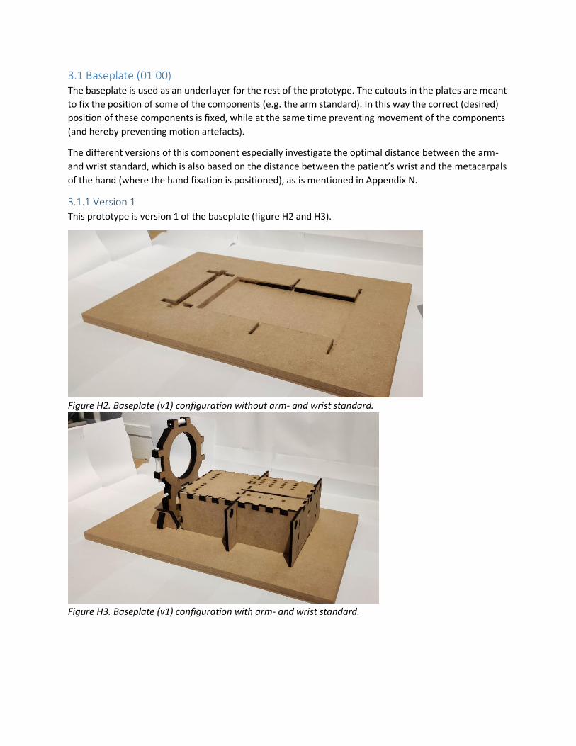
3.1 Baseplate (01 00) The baseplate is used as an underlayer for the rest of the prototype. The cutouts in the plates are meant
to fix the position of some of the components (e.g. the arm standard). In this way the correct (desired)
position of these components is fixed, while at the same time preventing movement of the components
(and hereby preventing motion artefacts).
The different versions of this component especially investigate the optimal distance between the arm-
and wrist standard, which is also based on the distance between the patient’s wrist and the metacarpals
of the hand (where the hand fixation is positioned), as is mentioned in Appendix N.
3.1.1 Version 1
This prototype is version 1 of the baseplate (figure H2 and H3).
Figure H2. Baseplate (v1) configuration without arm- and wrist standard.
Figure H3. Baseplate (v1) configuration with arm- and wrist standard.

3.1.2 Version 2
This prototype is version 2 of the baseplate (figure H4 and H5).
Previous version:
Wrist standard positioned too far from arm standard (too much space between fixation and wrist)
Modifications:
Arm standard against wrist standard (closer to each other)
Figure H4. Baseplate (v2) configuration with arm- and wrist standard.
Figure H5. Baseplate (v2) configuration without arm- and wrist standard.

3.1.3 Version 3
This prototype is version 3 of the baseplate (figure H6 and H7).
Previous version:
Wrist standard too close to arm standard (too little space between fixation and wrist)
Modifications:
More distance between wrist- and arm standard
Figure H6. Baseplate (v3) configuration with arm- and wrist standard.
Figure H7. Baseplate (v3) configuration without arm- and wrist standard.
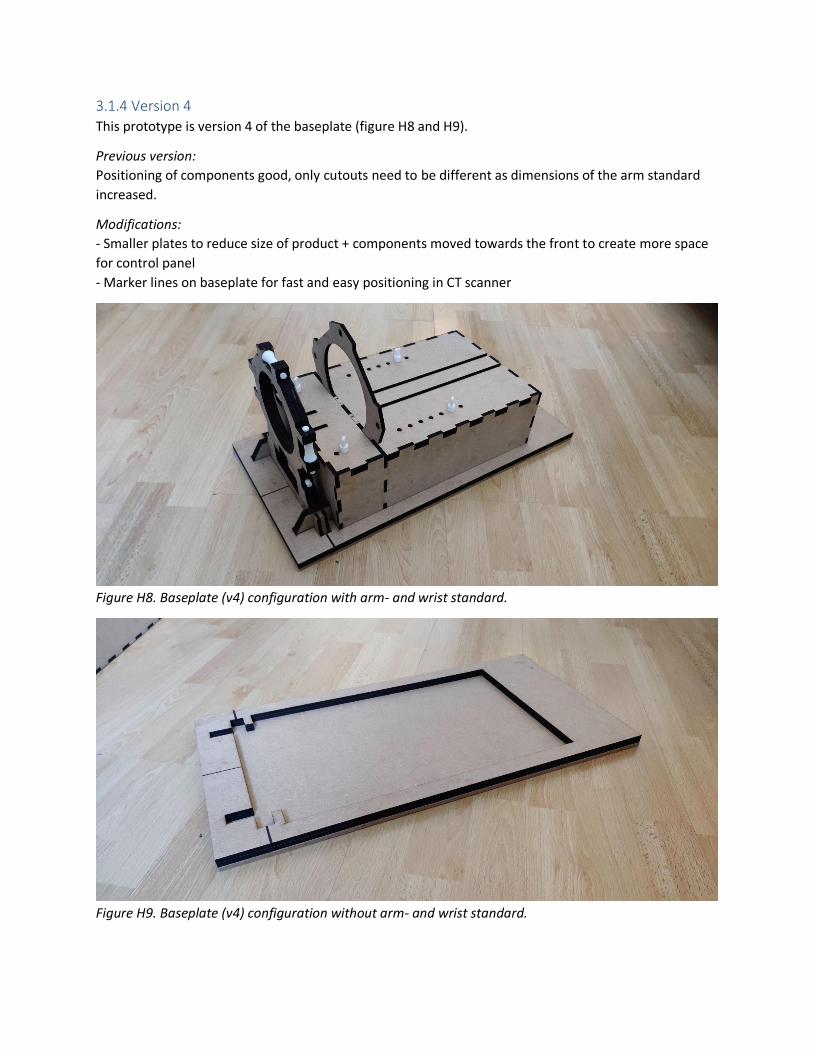
3.1.4 Version 4
This prototype is version 4 of the baseplate (figure H8 and H9).
Previous version:
Positioning of components good, only cutouts need to be different as dimensions of the arm standard
increased.
Modifications:
- Smaller plates to reduce size of product + components moved towards the front to create more space
for control panel
- Marker lines on baseplate for fast and easy positioning in CT scanner
Figure H8. Baseplate (v4) configuration with arm- and wrist standard.
Figure H9. Baseplate (v4) configuration without arm- and wrist standard.

3.2 Arm standard (02 00) The arm standard is a box which is used to let the patients rest their arm on. The forearm fixations (04
00), the components who fixate the forearm in the right position, are placed on top of this box. On top
of the box there are designated holes (and trails) for these forearm fixations to be positioned.
The different versions of this component especially investigate the optimal dimensions of the
component and the optimal way of positioning the forearm fixations on it.
3.2.1 Version 1
This prototype is version 1 of the arm standard (figure H10 and H11).
Figure H10. Arm standard (v1) 3D view.
Figure H11. Arm standard (v1) top view.

3.2.2 Version 2
This prototype is version 2 of the arm standard (figure H12 and H13).
Modifications:
- Longer and wider, resulting in more space for the arm to rest on. In the end this helps the
patients to be able to completely relax their arm and hereby have passive movement caused by
the device.
- A different top surface for adjustment purposes of the forearm fixations.
- Two top layers fit in box and have been switched
- Two extra side panels for elbow support
- Holes in side panels to guide lower cable to the back
Figure H12. Arm standard (v2) 3D view.
Figure H13. Top part of arm standard (v2) side view.

3.2.3 Version 3
This prototype is version 3 of the arm standard (figure H14 and H15).
Modifications:
- An extra row of holes has been added on the top surface to position the forearm fixation,
hereby increasing the chance that the arm (and wrist) are positioned perfectly in the middle.
- Side panels for elbow support removed
Figure H14. Arm standard (v3) 3D view.
Figure H15. Arm standard (v3) top view.

3.2.4 Version 4
This prototype is version 4 of the arm standard (figure H16 and H17).
Modifications:
- Adapted to the new (symmetrical) forearm fixation
o Wider
o Different top surface
- Extra side panels for cable guidance
Figure H16. Arm standard (v4) top view.
Figure H17. Arm standard (v4) 3d front- (left) and rear view (right).

3.2.5 Version 5
This prototype is version 5 of the arm standard (figure H18 and H19).
Modifications:
- Longer and wider to fit components of operating system (two cable-pulley)
- One side panel removed, cable guidance with Bowden cables
- Smaller holes for side panel which guides lower cable, to fit Bowden cable
Figure H18. Arm standard (v5) front view (on baseplate).
Figure H19. Arm standard (v5) 3D-view (on baseplate).

3.3 Wrist standard (03 00) The wrist standard is, as explained in subchapter 3.1.2, used as a guidance point for the cables to make
sure the tension on them remains equal. Because of this reason, it is made sure the movements are
executed correctly.
The different versions of this component especially investigate the optimal dimensions of the
component and the optimal shape and size for the pulleys to facilitate the cable transmission.
3.3.1 Version 1
This prototype is version 1 of the wrist standard (figure H20 and H21).
Figure H20. Wrist standard (v1) 3D-view.
Figure H21. 3D-printed pulley and axis.

3.3.2 Version 2
This prototype is version 3 of the wrist standard (figure H22 – H24).
Modifications:
- Optimized pulleys and axes, integrated into the standard
- Shape of standard has changed (due to integration of pulleys and axes in the standard)
- Thicker, instead of one plate of 6 [mm], now three plates are used adding up to 18 [mm]
- Support pieces have been made wider to optimize support (more stable wrist standard)
- Middle hole has been made bigger and more rounded (more space for hand to move)
Figure H22. Wrist standard (v2) 3D-view (left) and front view (right).
Figure H23. Support pieces (left) and fixed position on baseplate (right).
Figure H24. Pulley with axle integrated into wrist standard (v2).
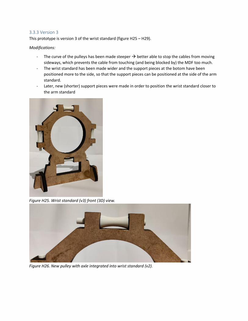
3.3.3 Version 3
This prototype is version 3 of the wrist standard (figure H25 – H29).
Modifications:
- The curve of the pulleys has been made steeper better able to stop the cables from moving
sideways, which prevents the cable from touching (and being blocked by) the MDF too much.
- The wrist standard has been made wider and the support pieces at the botom have been
positioned more to the side, so that the support pieces can be positioned at the side of the arm
standard.
- Later, new (shorter) support pieces were made in order to position the wrist standard closer to
the arm standard
Figure H25. Wrist standard (v3) front (3D) view.
Figure H26. New pulley with axle integrated into wrist standard (v2).

Figure H27. Wider wrist standard with support pieces positioned more to the sides.
Figure H28. New (shorter) support pieces for the wrist standard.
Figure H29. Wrist standard positioned closer to the arm standard.

3.4 Forearm fixation (04 00) The forearm fixation is meant to fixate the forearm on the arm standard, so that the patient’s arm is
held in the desired position and cannot move. In the end this prevents occurrence of motion artefacts.
The different versions of this component especially investigate the optimal shape, dimensions and
mechanism to fixate the different arm sizes of the patients. Also, aspects concerning adjustability and
comfort are taken into account.
At the beginning of the project first multiple ideas were transformed into concepts for the forearm
fixation. Of these three concepts one was chosen to continue with. The initial three concepts and the
selection (process) of the most suitable concept can be found in Appendix L. In this subchapter the
development of the selected forearm fixation is shown. Every version has two fixations which differ
slightly: one is for near the wrist and the other one is for near the elbow.
3.4.1 Version 1
This prototype is version 1 of the forearm fixation (figure H30 – H33).
Elbow
Figure H30. Concept 3 (V1 - elbow) prototype disassembled (left) and assembled (right).
Figure H31. Concept 3 (V1 - elbow) prototype assembled with strap.

Wrist
Figure H32. Concept 3 (V1 - elbow) prototype disassembled (left) and assembled (right).
Figure H33. Concept 3 (V1 - elbow) prototype assembled with strap.

3.4.2 Version 2
This prototype is version 2 of the forearm fixation (figure H34 – H37).
Modifications:
- The extra material on the left side of the body (of both the elbow- and wrist part) has been
removed as it was no longer of any use.
- The strap slots of the body parts have been made horizontal instead of vertical.
- The rectangular shape at the bottom has been extended, resulting in more holes for attachment
on the arm standard
Elbow
Figure H34. Concept 3 (V2 - elbow) prototype disassembled (left) and assembled (right).
Figure H35. Concept 3 (V2 - elbow) prototype assembled with strap.
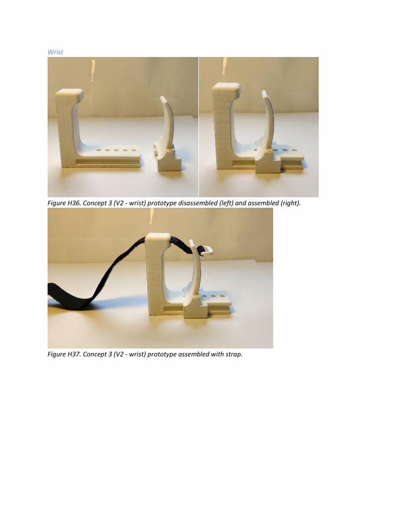
Wrist
Figure H36. Concept 3 (V2 - wrist) prototype disassembled (left) and assembled (right).
Figure H37. Concept 3 (V2 - wrist) prototype assembled with strap.

3.4.3 Version 3
This prototype is version 3 of the forearm fixation (figure H38 – H41).
Modifications:
- The inside curved shape of both body parts have been made less rounded at the top, to account
better for the variation in arm size and shape. For the same reason more strap slots were
integrated on both parts (body and slider) of both models.
- The rectangular shape at the bottom has been extended, resulting in more holes for attachment
at the arm standard.
Elbow
Figure H38. Concept 3 (V3 - elbow) prototype disassembled (left) and assembled (right).
Figure H39. Concept 3 (V3 – elbow) prototype assembled with strap.

Wrist
Figure H40. Concept 3 (V3 - wrist) prototype disassembled (left) and assembled (right).
Figure H41. Concept 3 (V3 - wrist) prototype assembled with strap.

3.4.4 Version 4
This prototype is version 4 of the forearm fixation (figure H42 – H45).
Modifications:
- On both body parts there has been integrated a piece of sticking velcro with which the long
piece of velcro, and in the end the forearm, can be fixated.
- There has been added material (with attachment holes) on the left side of both bodies (needed
to prevent rotational movement of the parts as it otherwise only would have been attached at
one point).
- There has been added a blocking piece at the bottom of the elbow body part. This was not
mentioned in the previous section (V3), but in the end this was necessary to prevent the part
from moving upwards. The blocking piece also works fine to easily adjust the position of the
elbow part, as it follows a pre-defined trail on the top surface of the box.
Elbow
Figure H42. Concept 3 (V4 - elbow) prototype disassembled (left) and assembled (right).
Figure H43. Concept 3 (V4 – elbow) prototype assembled with strap loose (left) and fastened (right).

Wrist
Figure H44. Concept 3 (V4 – wrist) prototype disassembled (left) and assembled (right).
Figure H45. Concept 3 (V4 – wrist) prototype assembled with strap loose (left) and fastened (right).

3.4.5 Version 5
This prototype is version 5 of the forearm fixation (figure H46 – H60).
Modifications:
- Symmetrical sliders, new mechanism to center the arm and hand on the arm standard
- Double blocking piece at bottom for sliding + preventing movement upwards
- Holes for quick pin attachment at both sides
- Higher sliders for new adjustment mechanism
- New adjustment mechanism with double velcro strap
Figure H46. Bottom half of lower body part, with spur gear integrated in the middle.
Figure H47. Bottom half of lower body part with slider (and rack gear) and spur gear.

Figure H48. Top half of lower body part (bottom view).
Figure H49. Top half of lower body part (top view).
Figure H50. Lower body part with rails and attachment holes (bottom view).
Figure H51. Lower body part with rails and attachment holes (top view).

Figure H52. Cross-sectional view of lower body part (rails).
Elbow
Figure H53. Sliders with rack gear (front and side view).

Figure H54. Close-up of sliders (front and rear view).
Figure H55. Concept 4 – V1 prototype (elbow) with straps.
Figure H56. Concept 4 – V1 prototype (elbow) with straps and attachment pins.

Figure H57. Small pins used to fix the position of the lower body part on the arm standard.
Figure H58. Extra surface on small pins used to grab the pins.
Wrist
Figure H59. Concept 4 – V1 prototype (wrist) with straps (bottom-front view).
Figure H60. Concept 4 – V1 prototype (wrist) with straps (top-front view).

3.5 Hand fixation (05 00) The hand fixation is meant to fixate the hand of the patient, so that the patient’s hand is held in a fixed
(desired) position and cannot move (preventing occurrence of motion artefacts). Also the hand fixation
is the connection point of the actuation (and operating system) of the product.
The different versions of this component especially investigate the optimal shape and dimensions to
fixate the different hand sizes of the patients. Also, aspects concerning adjustability and comfort are
taken into account.
At the beginning of the project first multiple ideas were transformed into concepts for the hand fixation.
Of these multiple concepts one was chosen to continue with. The initial concepts and the selection
(process) of the most suitable concept can be found in Appendix P. In this subchapter the development
of the selected hand fixation is shown.
3.5.1 Version 1
This prototype is version 1 of the hand fixation (figure H61 – H63).
Figure H61. Concept 2 (V1) prototype. Figure H62. Concept 2 (V1) prototype with hand (open).
Figure H63. Concept 2 (V1) prototype with hand (closed).

3.5.2 Version 2
This prototype is version 2 of the hand fixation (figure H64 – H67).
Modifications:
- Strap slots added to insert a strap and fixate the hand
Figure H64. Concept 2 (V2) prototype. Figure H65. Prototype with hand (open).
Figure H66. Prototype with strap fastened. Figure H67. Hand and fingers fastened.

3.5.3 Version 3
This prototype is version 3 of the hand fixation (figure H68 and H69).
Modifications:
- Attachment points added at body and sliders to establish cable connection
- Different slots for velcro strap attachment to account for hand thickness variation
- Small piece of velcro to fasten the velcro
- More rounded edges to prevent discomfort
Figure H68. Concept 2 – V3 prototype with sliders and strap loose (left, middle) and fastened (right).
Figure H69. Concept 2 – V3 with sliders and strap loose around the hand.

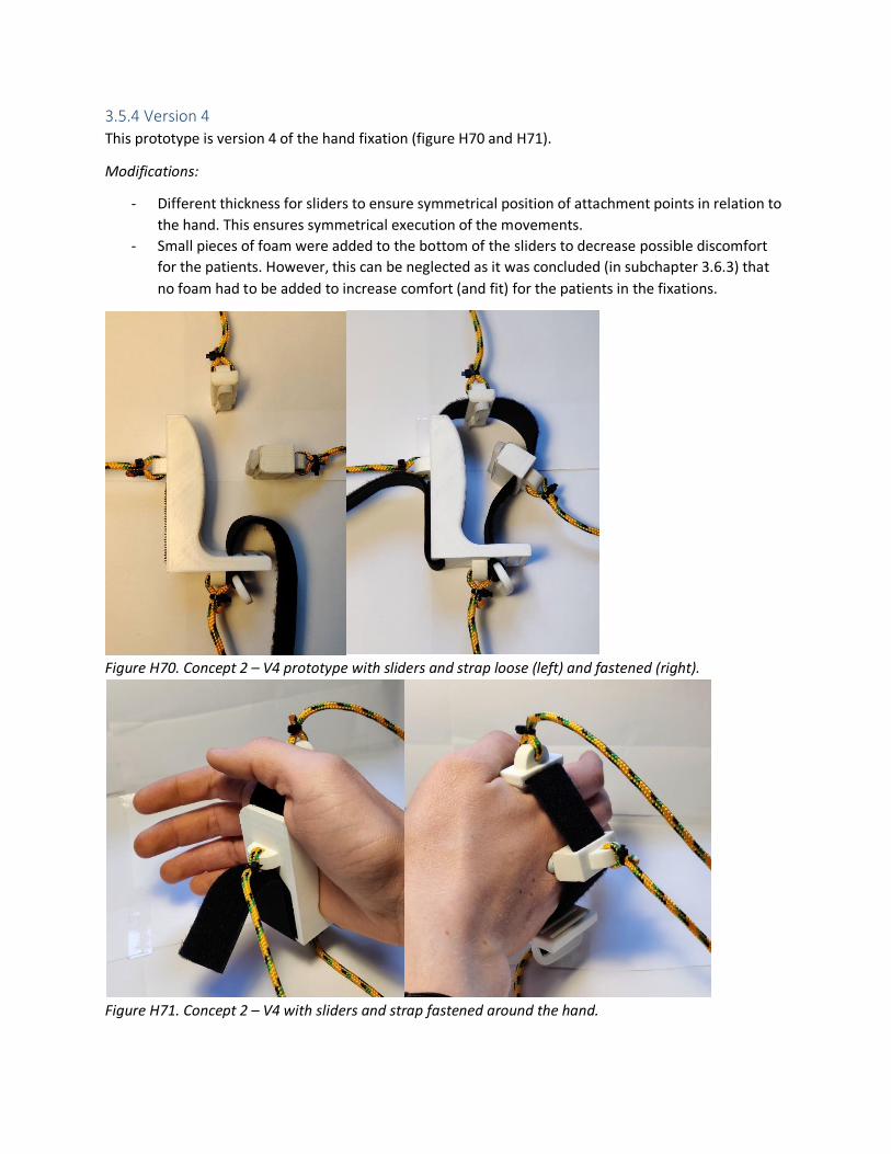
3.5.4 Version 4
This prototype is version 4 of the hand fixation (figure H70 and H71).
Modifications:
- Different thickness for sliders to ensure symmetrical position of attachment points in relation to
the hand. This ensures symmetrical execution of the movements.
- Small pieces of foam were added to the bottom of the sliders to decrease possible discomfort
for the patients. However, this can be neglected as it was concluded (in subchapter 3.6.3) that
no foam had to be added to increase comfort (and fit) for the patients in the fixations.
Figure H70. Concept 2 – V4 prototype with sliders and strap loose (left) and fastened (right).
Figure H71. Concept 2 – V4 with sliders and strap fastened around the hand.

3.6 Actuation and transmission (06 00) The actuation and transmission of the product are meant to facilitate the automated movements of the
patient’s wrist, facilitated by the actuators and the operating system. Only the electronics are described
here, as the rest was already described in the report.
Electronics One of the goals of this project was to end up with a working prototype, meaning electronic
components have to be integrated which are operated by programming software. For this part of the
prototype Arduino was selected to use, as this is an open-source electronic prototyping platform for
both beginners and experienced people, which is widely used (also during the bachelor and master
program on the faculty of IDE) to create interactive electronic prototypes.
The final prototype is not made in one go, but developed out of multiple smaller prototypes. These
different prototypes are described below.
Prototype 1: Push button motor control
The setup of this prototype can be seen in figure H72 – H75.
- Motor rotation direction control
- Positioning of hand
- Required components
o Arduino Uno/Mega
o NEMA 17 Stepper motor
o TB6600 Stepper driver
o Push button (2x) (one clockwise, one counter-clockwise)
o Breadboard and jumper wires
Figure H72. Setup of electronic prototype 1 (overview).

Figure H73. Push buttons for stepper motor control.
Figure H74. Connections of electronic components with Arduino Uno/Mega.
Figure H75. TB6600 stepper driver connections.

Prototype 2: Load cell calibration
The setup of this prototype can be seen in figure H76.
- Load cells have to be calibrated to make sure they measure similar values
- Put known weight on load cell and define scale factor
- The scale factors turned out to be 424 (load cell 1) and 431 (load cell 2).
- Required components:
o Arduino Uno/Mega
o Load cell (5 [kg])
o HX711 Amplifier sensor
o Box (load cell attachment)
o Smartphone (as known weight)
o Breadboard and jumper wires
Figure H76. Setup of electronic prototype 2.

I – Fixation products market research At this point there are already multiple existing products which are related to support or fixation of the
arm and hand. Existing products focused on fixation of either the forearm or hand (or both) are taken
into account. All of these products (shown in figure I1) can be used for inspiration for the design of the
final product.
Looking at all existing products with a forearm- (or hand) fixation, there is a set of positive aspects,
which could be used in the design of this product’s fixations. These aspects are:
- Existing products which fixate the forearm typically consist of three parts: a splint, a glove and
straps or elastic bands.
- The splint is rigid and is used to fixate the body part, so movement of that particular body part is
minimized or even impossible. The splint goes partly or completely around the body part which
has to be fixated.
- This part is mostly made out of plastic (e.g. polyethylene (PE)), as this is affordable to
manufacture. However, a plastic splint is less durable, which is why a metal splint (even though
it’s more expensive) could be an alternative. The downside of this material is that it results in
metal artefacts on the CT scans.
- In the case of a splint for the forearm, it starts approximately 2 or 3 [cm] away (distal) from the
elbow, to leave some space for movement of the elbow, which was confirmed by B. van der
Heijden (personal communication, November 21, 2019). In case of passive wrist movement, also
the wrist region needs to be free, so that the wrist can still move in all desired directions.
Therefore, the splint also needs to end approximately 2 or 3 [cm] away (proximal) from the
wrist.
- For the hand the splint is always positioned at the metacarpal bones, or sometimes even a bit
further up the hand (proximal- and middle finger bones). This was also recommended by B. van
der Heijden, as in this way the hand stays straight and in a neutral position during the entire
movement.
- The glove-part is used around the splint, covers it and thereby optimizes fit and comfort for the
users. Typically these gloves are made of Cordura, neoprene, nylon or leather, which are all
durable materials. In the glove an extra padding can be integrated to increase comfort; this
could be done using EVA foam.
- In every splint straps are used for tightening and adaption to different user sizes. Typically these
are velcro straps (nylon) or elastic straps (rubber material).

Figure I1. Overview of existing products with some sort of fixation. Sources: 1. (Mercado Libre, 2018); 2.
(DJO, n.d.); 3. (Allen Medical, n.d.); 4. (Walmart, n.d.); 5. (Human Protection, n.d.); 6. (Amazon, n.d.).

J – Other fixation types Besides the fixations mentioned in the previous chapter, there are still other possibilities to fixate the
arm and hand. These options are discussed in this chapter. Three possibilities are shown, one of the
fixation types (clamping mechanism) was already explained in the report.
Air With the use of air the forearm could be fixated as well. As can be seen in figure J1, a plastic cover (PVC)
goes over the arm. Subsequently, it is filled with air from the inside which results in the space inside
getting smaller and the pressure increasing. This goes on until the cover presses against the arm and
hand, fixating them in the cover. In this way the different patient sizes can easily be adapted to, as the
air-filling only stops when the arm and hand are fixated tightly enough.
The only problem with this technique is the filling with air. The product can be made self-inflatable, but
these are typically used as temporary fixations. Also, they can be punctured, deflated and the plastic
may be uncomfortable to the skin (First Aid Supplies, 2019). Another option is adding a hole through
which someone can fill the fixation with air. Of course this is also not the solution, because this takes
way too long and most probably causes problems regarding the hygiene regulations. Concerning the
hygiene there could also be used an automatic pump, but this will also not ideal as such a device is large
and makes a lot of noise. Because of these reasons this technique is not further taken into account.
Figure J1. Fixation of arm with air. Source: (Amazon, n.d.).
Grains As can also be seen at the ‘Disposable arm splint’ in the previous subchapter, the forearm can also be
fixated with the use of plastic (polystyrene (PS)) grains (figure J2). The grains are then surrounded by a
cushion-like cover, which prevents the grains from falling out. These grains can adapt to the form or
shape of the arm, but then still the size of the cover needs to come in different sizes in order to adapt to
the different patient sizes. Tightening or loosening the cover and thus the fixation will not be sufficient
here, as the differences in forearm circumference are simply too large to account for that variation.
Therefore, this fixation technique is also not further taken into account.
Figure J2. Polystyrene grains. Source: (EFP, 2019).

Smart materials Using smart materials like shape memory alloys (figure J3) would allow the physician to bend the
material in its cold state into a form which connects to the patient’s arm seamlessly. When finished and
the fixation is no longer needed, the material can be heated after which it returns to its initial
memorized shape (GCSE, n.d.). However, a major drawback of this technique is that the material needs
to be cooled and heated all the time, which requires quite a lot of time and effort. Therefore this
technique is not further taken into account.
Figure J3. Shape memory alloy. Source: (GCSE, 2015).

K – Forearm fixation options As mentioned in subchapter 2.4.1, the forearm has to be fixated, otherwise the muscles might be able to
compensate and therewith (partly) mask potentially significant pathology when moving the wrist (S.
Buckens, personal communication, September 26, 2019). Besides this, the forearm has to be fixated as
this prevents occurring of motion artefacts on the CT scans caused by movements of the forearm.
Fixation options For the fixation of the forearm there needs to be some space (around 3 [cm]) left at both the elbow- and
wrist region, to make sure these are still able to move freely (B. van der Heijden, personal
communication, November 21, 2019). Furthermore, the forearm (and hand) need to be held in a neutral
position during all scans, as mentioned in subchapter 2.4.1.
This results in the forearm (and hand) being able to move in three directions: left, right and downwards
(figure K1, left). Of course the hand is also able to move upwards, but this cannot happen when the
hand is held still. Because of this reason the forearm should always be supported at the bottom, as it
otherwise falls down due to the effect of gravity. However, when only supported at the bottom, the
forearm is still able to move and/or tilt sideways (figure K1, right). To fix this there are multiple options:
the forearm could be fixated in an entire cylinder-like shape, but also by using only two or three plates
(figure K2).
Figure K1. Movement freedom of forearm.
Figure K2. Fixation options for the forearm.

Fixation of the forearm could be facilitated in various ways (figure K3). It could for example be one part
which covers (the largest part of) the forearm. On the other hand, it could also consist of two or more
parts which cover smaller parts of the forearm and therewith prevent motion. This second method
imitates the way S. Buckens performs his active wrist reviews, where he grabs the patient’s forearm at
almost the exact same spots as illustrated. These options and their benefits were also explored later on
in the prototyping phase.
Figure K3. Fixation options.
Cross-section With fixation of the forearm the shape and cross-section of the forearm should also be taken into
account. Looking at the cross-sections of the forearm there are differences along the length of it (figure
K4). As also verified by S. Buckens (personal communication, December 12, 2019), near the elbow region
the cross-section is higher and more rounded, while the cross-section near the wrist region is somewhat
smaller and narrower.
Figure K4. Cross-sections of the forearm.

L – Forearm fixation concepts and -selection In total there were three concepts for the forearm fixation. Multiple pictures of all concepts can be seen
below. In the end more information is given about the comparison of the different concepts and the
selection of the most suitable one.
Concept 1 This concept (figure L1 – L4) consists of three parts with two velcro straps. The bottom part is slightly
wider as this supports the bottom and thus a larger part of the arm.
Figure L1. Forearm fixation concept 1, bottom part.
Figure L2. Forearm fixation concept 1.
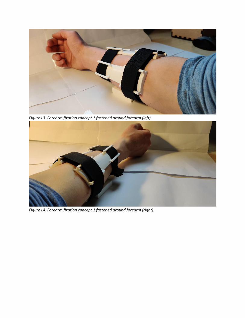
Figure L3. Forearm fixation concept 1 fastened around forearm (left).
Figure L4. Forearm fixation concept 1 fastened around forearm (right).

Concept 2 This concept (figure L5 – L9) consists of two large parts, which cover a large surface of the forearm. The
two parts are able to slide into each other, hereby able to account for the variation in arm size. Two
straps are used to fix the parts’ position and to fixate the forearm.
Figure L5. Forearm fixation concept 2, parts separated.
Figure L6. Forearm fixation concept 2, parts combined.

Figure L7. Forearm fixation concept 2 with velcro straps.
Figure L8. Forearm fixation concept 2 fastened around forearm (left).
Figure L9. Forearm fixation concept 2 fastened around forearm (right).

Concept 3 This concept (figure L10 – L14) consists of four parts, two pairs of a ‘body’ and a ‘slider’ part. One pair
fixates the forearm near the elbow, while the other fixates the forearm near the wrist. Per combination
one strap is used to fix the body’s- and slider’s position and to fixate the forearm.
Figure L10. Forearm fixation concept 3, parts separated.
Figure L11. Forearm fixation concept 3, parts combined.

Figure L12. Forearm fixation concept 3 with strap.
Figure L13. Forearm fixation concept 3 fastened around forearm (left).
Figure L14. Forearm fixation concept 3 fastened around forearm (right).

Comparison In order to select the best concept for the forearm fixation, for each of the concepts the positive and
negative points are described. Based on the positive- and negative aspects of all concept, eventually
concept 3 was selected to use and integrate in the product.
Concept 1 (V3):
- The curve is too specific for the variation in arm shape.
- The pointy edges stick into the patient’s arm.
- The parts are too long, the shape of the forearm changes too much along the length of it.
Concept 2 (V3):
- The slider system works good.
- The shape of the fixation is too long. The arm circumference varies too much, especially
between different patients.
Concept 3 (V2):
- The slider system works well to secure and fixate the forearm.
- Fixating a smaller part of the arm worked better, as there is no (or a very small) change in the
shape (circumference) of the forearm.
- This concept works best for fixating all different sizes of arms.
- For the two fixations at the elbow and the wrist there should be a slight difference between the
inside curve, to account for the difference in cross-sectional shape along the arm (more oval
around the wrist and more rounded around the elbow).

M – Definition body parameters Looking at the product there are seven body parameters (figure M1) which are important for the design,
all of which are related to either the forearm or the hand of the patient.
- P1 represents the length of the forearm, measured from the elbow cavity to the wrist. As
mentioned in subchapter 2.4.1, there needs to be some space (2-3 [cm]) left in the elbow- and
wrist region, so that these are still able to move freely. Therefore also in the figure some space is
left on both sides of the forearm. The distance of P1 is used to define the length of the forearm
fixation.
- P2 represents the circumference of the forearm. P2-1 is measured near the elbow; P2-2 near the
wrist. This distance is used to define the circumference (and for adjustability purposes) of the
forearm fixation.
- P3 represents the distance from the wrist to the metacarpal region just beyond the thumb. As
mentioned in subchapter 2.4.1, the hand needs to be supported and fixated at the metacarpals
in order to make sure it stays straight and in neutral position during the entire movement. The
distance of P3 is used to obtain an idea of the distance between the forearm fixation and the
hand fixation and between the wrist and the hand fixation.
- P4 represents the length of the metacarpal region beyond the thumb. This distance is used to
define the length of the hand fixation.
- P5 represents the width of the hand without the thumb. This distance is used to define the
height of the hand fixation.
- P6 represents the thickness of the hand at the metacarpal level. The distance P6 is used to
define the width of the hand fixation.
- P7 represents the width (P7-1) and height (P7-2) of the wrist. This distance is used to define the
dimensions of the (middle hole of the) wrist standard and the space required to move the hand
in all desired directions.
Figure M1. Important parameters for the arm and hand.

N – Measurements and variation body parameters In this subchapter the variation of the parameters within the target group population is analyzed.
Eventually for each of those parameters a range of length is determined, which is used for the design of
the concerned parts. For the analyses of variation, percentile values of P5 and P95 were used, to
account for the majority of the target group population. For some parameters there is described how
they are relevant concerning the adjustability of the product.
For most data the Dined 1D database (Molenbroek et al, 2017) was consulted. However, some
measurements which were required, were not available there, which is why these are measured
manually by myself. Both datasets can be found in Appendix NN.
P1 – Length of the forearm To determine the variation of this parameter within the population the Dined 1D database (Molenbroek
et al., 2017) was used. The populations of “Dutch adults, dined2004” was used, in which both females
(20-60 and 60+) and males (20-60 and 60+) were selected. In this way the target group of the product,
being adults of both genders, is accurately represented.
Unfortunately the length of the forearm is not a parameter which was measured in the database;
therefore it had to be calculated using other parameters (figure N1). This can be done with the following
equation:
𝑃1 = 29 − 43 − (40
π),
with number 29 being the elbow-finger tip length, number 43 being the hand length and number 40
being the upper arm circumference. All data of these parameters can be found in Appendix NN.
Unfortunately for the upper arm circumference there was no data for adults in Dined, which is why a
source from the internet was consulted. According to Boldt (2019) the arm circumference can be used
to calculate a person’s Body Mass Index (BMI). A measure below 235 [mm] indicates that the person
may be underweight, which is why this value is assumed for P5. On the other hand, a measure above
320 [mm] indicates that the person might have obesity, which is why this value is assumed for P95.
Figure N1. Relevant parameters.
See figure N2. For the range of P1 the set of smallest (P5) and largest (P95) measurements (for all
parameters) were taken. For the smallest value for P1 this resulted in 163 [mm]; for the largest value

this resulted in 220 [mm]. However, as mentioned before in both the elbow- and wrist region some
extra space is needed to keep the elbow and wrist able to move freely. Therefore, another 3 [cm] is
subtracted on both sides, resulting in P1 values of 103 [mm] (P5) and 160 [mm] (P95) respectively.
Figure N2. Calculation of P1: P5 (left) and P95 (right).
This difference of 57 [mm] is considered too small to make the forearm fixation adjustable for that.
Therefore, in consultation with ergonomics expert J. Molenbroek (personal communication, December
2, 2019) it was decided to take the smallest value of P1 for the length of the forearm fixation, so that all
patients’ arms fit and are fixated. Of course, this value is a maximum value for the length of the forearm
fixation, meaning the forearm fixation could for example also consist of two smaller parts (both adding
up to a maximum of 103 [mm]).
Eventually, the smallest value for P1 turned out to be rather small in reality, probably because for every
parameter used in the calculation of P1, the smallest value was taken. A forearm fixation with a length
of 103 [mm] was too small for relatively large arms, but also even quite small for smaller arms.
Therefore, the length of the forearm fixation was increased throughout the design process of the
forearm fixation.

P2 – Circumference forearm Unfortunately for this parameter no data could be found in Dined, anthropometric related books or
other sources on the internet. However, knowing and using the forearm circumference is not necessary;
by integrating adjustable parts like straps the variation in forearm circumference can be compensated.
Still it is valuable to have an idea about the variation, which is why own measurements were made
where both genders of different ages were included. All measurements can found in Appendix NN.
For this small measurement study in total 25 people were measured. Nineteen people were Dutch and
the rest were other nationalities; fourteen were male and eleven female. The differences between
Dutch people and other nationalities were almost negligible, which is why also the measurements of the
other nationalities are taken into account (and this could also be the case in the hospital). The average
age of all people was 26.6 years. The forearm circumference was measured on two spots, 1) P2-1: 3 [cm]
distally from the elbow and 2) P2-2: 3 [cm] proximally from the wrist. The measurements can be seen in
table N1.
Table N1. Measurements in [mm] for forearm circumference (P2-1 and P2-2).
No. Variation Average measurements
Min Max Overall Male Female
P2-1 210 285 254.0 269.3 234.5
P2-2 145 180 159.2 168.6 147.3
As can be seen in table N1, the total variation for the forearm circumference is 75 [mm] for the elbow,
and 35 [mm] for the wrist. As mentioned before this variation does not have to be taken into account
for the dimensions of the forearm fixation, because by integrating adjustable parts like straps the
variation can be compensated. Furthermore, as this variation is quite large, it would have been difficult
to come up with a design which covers the entire range of variation.

P3 – Wrist to metacarpal region (beyond thumb) This parameter is important to get an idea about the distance between the wrist and the hand fixation.
As mentioned in subchapter 3.1.2, the wrist needs to be aligned with the standard (with the pulleys).
With different sizes of arms and hands, the distance between the wrist and the hand fixation will also
differ. In the end this distance is important for the setup of the different parts of the cable-pull
mechanism, as the wrist needs to be aligned with the standard, while at the same time there needs to
be enough space between the standard the arm rests on (with the forearm fixation) and the wrist
standard.
Unfortunately, also for this parameter no data could be found in Dined, anthropometric related books or
other sources on the internet. Therefore own measurements were made where both genders of
different ages were included. All measurements can be found in Appendix NN. This measurement was
also part of the study mentioned above; the results can be seen in table N2.
Table N2. Measurements in [mm] for wrist to metacarpal (P3).
No. Variation Average measurements
Min Max Overall Male Female
P3 60 75 64.9 66.8 62.5
As can be seen in table N2, the total variation for the distance of the wrist to the metacarpals is 15
[mm]. As mentioned before, this value can be used for the setup of the different parts of the cable-pull
mechanism.
P4 – Length metacarpal region As mentioned before this parameter is important for the length of the hand fixation. It is important that
the hand is fixated properly, to make sure it doesn’t move during the passive movement. Otherwise,
when the hand is still able to move slightly, motion artefacts can start to occur on the CT scans.
However, how well the hand is fixated is mainly based on the thickness of the hand (P6). Because of this
reason there is no need for different lengths for the hand fixation. In this case it is most important that
the one size hand fixation fits all hands properly; not too big for small hands and not too small for big
hands.
Unfortunately for this parameter no data could be found in Dined, anthropometric related books or
other sources on the internet. Therefore own measurements were made where both genders of
different ages were included. All measurements can be found in Appendix NN.
Table N3. Measurements in [mm] length metacarpals (P4).
No. Variation Average measurements
Min Max Overall Male Female
P4 40 50 43.6 45.9 40.7
As can be seen in table N3, the total variation for the length of the metacarpals is 10 [mm]. Considering
the fact that the patients also need to form a fist with their hand (see subchapter 2.4.1) the length of
the hand fixation should not be too large, as otherwise smaller hands are not able to make a fist
anymore. By taking the smallest measurement for the length of the hand fixation (being 40 [mm]), all

the other measurements automatically also fit in. Still it has to be tested whether all hand sizes are
fixated properly by the hand fixation.
P5 – Hand width (without thumb) This parameter is important for defining the height of the hand fixation. The hand fixation has to be high
enough so that the hand is never able to fall out of the fixation. Also in this case the different hand sizes
are important to take into account, as the hand fixation will fit completely different with a P5 hand than
with a P95 hand.
To determine the variation of this parameter within the population the Dined 1D database (Molenbroek
et al., 2017) was used. The populations of “Dutch adults, dined2004” was used, in which both females
(20-60 and 60+) and males (20-60 and 60+) were selected. In this way the target group of the product,
being adults of both genders, is accurately represented.
Table N4. Dined measurements in [mm] width hand (P5).
No. Variation
Min Max
P5 73 99
See table N4. For the smallest value for P5 a measurement of 73 [mm] was found, which was for a P5
female in the age category of 20-60 years old. For the largest value a measurement of 99 [mm] was
found, which was for a P95 male in the age category of 20-60 years old. All data can be found in
Appendix NN.
As can be seen, the difference between the smallest and largest hand width is relatively small, only 26
[mm]. As mentioned before, P5 is used to define the height of the hand fixation; the fixation has to be
high (large) enough to make sure the hand cannot fall sideways (out of the fixation). On the other hand
the fixation should not be too high, to leave some space for another kind of adjustment (e.g. straps).
This is to tighten the fixation to the patient’s hand, to make sure the hand cannot shift up. This is
especially important in case of ulnar deviation, when the hand needs to be pushed down.
When looking at the two measurements of 73 [mm] and 99 [mm], there are four variations (figure N3):
combinations of small and large hands with small and large hand supports (fixations). It can be seen that
when the support is too high (version 3), there is no room left for the extra adjustment (like straps)
mentioned before. Therefore, the large support cannot be used, as it is significantly too large for the
smaller hands. This leaves us with the small support, which fits perfectly with the small hands. In case of
the larger hands it seems too small at first, but the remaining (open) space at the top can be fixed with
straps or another kind of adjustment to keep the hand in the support. Because of this reason, a height
for the hand fixation of 73 [mm] is chosen to continue with.

Figure N3. Four variations for the hand support.
As was mentioned in subchapter 3.2.3, the horizontal attachment points of the hand fixation should be
positioned according to the average (P50) distance from the bottom of the hand to the (middle of the)
middle finger. This distance can be calculated by using the (average) width of the hand and subtracting
one and a half times the (average) width of the forefinger. According to Dined (2017), the P50 for the
width of the hand (‘Dutch adults 20-60, mixed’) is 85 [mm]. In the same database, the P50 for the
forefinger width is 17 [mm]. This results in the horizontal attachment points being positioned at a
distance of: 85 – 17 – (17/2) = 60 [mm] from the bottom of the hand (where it makes contact with the
hand fixation).
P6 – Thickness hand As mentioned before this parameter is important for the width of the hand fixation. It is important that
the hand is fixated properly, to make sure it doesn’t move during the passive movement. Otherwise,
when the hand is still able to move slightly, motion artefacts can start to occur on the CT scans. The
thickness of the hand and thereby the width of the hand fixation determines how well the hand is
fixated, making this parameter an important one.
Looking at the cross-section of the hand at metacarpal level, it is not straight but a certain curve can be
noticed (figure N4, blue line). As the hand needs to be kept neutral as well, the inside width of the hand
fixation cannot be made for a straight hand but the shape needs to be adapted to the curve. However,
still the measurements of the thickness of the hand can be used to determine (a range of) dimensions
for the inside of the hand fixation.

Figure N4. Cross-section of the hand at metacarpal level.
For this parameter data could be found in Dined, but also own measurements were made; both genders
of different ages were included.
Table N5. Measurements in [mm] thickness hand (P6).
No. Variation
Min Max
P6 (Dined) 19 35
P6 (Own) 22 32
As can be seen in table N5, the total variation for the thickness of the hand is 16 [mm] for Dined and 10
[mm] for my own measurements. In this case it is best to take into account the largest variation, so that
as many people as possible are included. Therefore the variation range of 19 – 35 [mm] is chosen to
continue with. As this is quite some difference, the width of the hand fixation needs to be adjustable or
otherwise be compensated by for example foam-like material. More about this can be read in
subchapter 3.2.3.
As was mentioned in subchapter 3.2.3, the vertical attachment points of the hand fixation should be
positioned according to the average (P50) thickness of the hand. According to Dined (2017), the P50 for
thickness of the hand (both male and female, 20-60 years old) is 26 [mm]. Therefore, the vertical
attachment points should be positioned at a distance of 13 [mm] from the contact surface of the hand
(with the hand fixation).
P7 – Width- and height of the wrist As mentioned before these parameters are important for the dimensions of the middle hole of the wrist
standard. There needs to be enough space to move the hand in all directions, as they are otherwise
hindered and the movements are not entirely executed.
Unfortunately for this parameter no data could be found in Dined, anthropometric related books or
other sources on the internet. Therefore own measurements were made where both genders of
different ages were included. All measurements can be found in Appendix NN.
Table N6. Measurements in [mm] wrist width and height (P7-1 and P7-2 respectively).
No. Variation Average measurements
Min Max Overall Male Female

P7-1 35 50 42.0 42.3 44.9
P7-2 60 80 69.8 69.4 70.4
As can be seen in table N6, the total variation for P7-1 (wrist width) is 15 [mm] and for P7-2 (wrist
height) is 20 [mm]. This makes sense, as near the wrist the forearm is shaped more like an oval (higher
and narrower). As the total variation for both parameters is quite small, the average of both parameters
is used for defining the dimensions of the middle hole of the wrist standard. In this way all arms (and
wrists) will fit properly while having fixed dimensions. For P7-1 this results in 42.5 [mm], while for P7-2
this results in 70 [mm].

O – Hand fixation options When looking closely at the position of the hand and the movements which are made, it can be
determined which parts of the hand need to be supported in order to realize the desired passive
movements. The arm and hand need to be held in a neutral position during all scans, which results in the
hand being able to move in three directions: left, right and downwards (figure O1-1). Of course the hand
is also able to move upwards, but this cannot happen when the hand is held still. Firstly, in every
situation the hand should be supported at the bottom (figure O1-2) to make sure the hand does not fall
down due to the effect of gravity. Secondly, the hand should also be supported at the sides, as it
otherwise will tilt sideways (figure O1-2). With one bottom support and two side supports the hand can
be kept in the desired neutral position, however it is then still preferred to secure the hand in the
fixation, so that it cannot move upwards for some reason. This can for example be done by adding a
strap or an elastic band at the top (figure O1-3). One of the side supports could also be replaced with a
strap or an elastic band (figure O1-4), as the hand is then still able to lean against one (rigid) size. In this
scenario the hand is still secured and is not able to move.
Figure O1. Movement freedom of hand and contact points for the hand fixation.

P – Hand fixation concepts and -selection In total there were three concepts for the hand fixation. Multiple pictures of all concepts can be seen
below. In the end more information is given about the comparison of the different concepts and the
selection of the most suitable one.
Concept 1 This concept (figure P1 – P4) consists of a U-profile, where the hand is enclosed from the sides and
supported at the bottom.
Figure P1. Hand fixation concept 1 with strap.
Figure P2. Hand fixation concept 1 with hand and strap.

Figure P3. Hand fixation concept 1 with hand fastened and fingers around strap.
Figure P4. Hand fixation concept 1 with hand fastened and fingers underneath strap.

Concept 2 This concept (figure P5 – P9) of an L-profile, where the hand is supported at one side and supported at
the bottom.
Figure P5. Hand fixation concept 2 with strap.
Figure P6. Hand fixation concept 2 with hand and strap (left).

Figure P7. Hand fixation concept 2 with hand and strap (right).
Figure P8. Hand fixation concept 2 with hand fastened and fingers around strap.
Figure P9. Hand fixation concept 2 with hand fastened and fingers underneath strap.

Concept 3 This concept (figure P10 – P14) consists of two parts, a so-called ‘body’ part and a ‘slider’ part. The slider
is used to account for the variation in hand thickness, enclosing the hand from both sides and
supporting it at the bottom.
Figure P10. Hand fixation concept 3, parts separated.
Figure P11. Hand fixation concept 3, parts combined and with strap.

Figure P12. Hand fixation concept 3 with hand fastened with fingers around strap.
Figure P13. Hand fixation concept 3 with hand fastened with fingers underneath strap.
Figure P14. Hand fixation concept 3 with hand fastened (right).
Comparison In order to select the best concept for the forearm fixation, for each of the concepts the positive and
negative points are described. Based on the positive- and negative aspects of all concept, eventually
concept 2 was selected to use and integrate in the product.
Concept 1:
- The curve works well, it matches the natural curve of the hand.
- The width of the fixation is not adjustable, making it harder to fixate different hand sizes well.
Concept 2 (V3):
- The curve works well, it matches the natural curve of the hand.
- The strap works well to fixate the hand.
- Also multiple hand sizes can be fixated, however this could be improved by having multiple strap
slots.
Concept 3 (V2):
- The curve works well, it matches the natural curve of the hand.
- The slider system works well to secure and fixate the hand.
- Because there are two parts the concept is significantly larger than the other two concepts. It is
therefore also harder to work with, resulting in more time needed to fixate the hand.

Q – Radiation dose As mentioned in subchapter 2.2.3 with CT scanning beams of x-ray are used to obtain detailed images of
the human body (NIH, 2016). According to Newman and Morrison (2018) the x-rays used with CT
scanning can cause mutations in human’s DNA, possibly leading to cancer later on. Therefore, with CT
scans radiologists are encouraged to keep the radiation dose for the patient as low as possible (Litin,
2020).
According to S. Buckens (personal communication, February 20, 2020) the amount of radiation depends
on the scanning time and active length of the detector strip, which are defined in the end by the
radiologist. Also the amount of radiation the patient ‘catches’ depends on where the patients is
positioned in relation to the CT scanner (as mentioned in subchapter 2.2).
Still it is best for the patients to ‘catch’ as little radiation as possible. Because of this reason and for extra
safety reasons it might be necessary in some situations for patients to wear a lead apron (figure Q1) (S.
Buckens, personal communication, February 20, 2020). This measure applies next to the lead curtain,
which was mentioned in subchapter 2.1.
According to Buckens, the lead of the apron is so dense that the x-ray radiation is not able to penetrate
through it, hereby protecting the patient from catching too much radiation. During the CT scans the
radiologist will decide for every patient if it is necessary to wear a lead apron. For the design of the
device this is therefore not of any relevance anymore.
Figure Q1. Lead apron used to prevent patients from ‘catching’ too much radiation.

R – Load cell calculation There are different versions of the load cells, each one representing a different maximum amount of
kilograms they are able to withstand. The one on the picture for example is able to carry a maximum
load of 1 [kg]. For the product the load cell version should also be considered, as it needs to be able to
carry all forces working on it caused by the cable tension. Also, selecting a load cell which is able to carry
a load of 50 [kg] would not be suitable, as the measurement range is not proportional with the actual
forces working on the load cell. Therefore, these forces have to be calculated by looking at the weight of
a person’s hand. According to Tözeren (2006) the weight of a hand equals to approximately 0.66% of the
total body weight. For a P95 male (Dutch adults (2004), 20-60 years old) with a body weight of 104 [kg]
(Dined, 2020), this would result in a hand weight of: (104 / 100) * 0.66 = 0.69 [kg]. While a part of this
weight is also called by the forearm (and rests on the arm standard), this weight also increases when
reaching the end of the ROM. The wrist will then resist against the movement, hereby increasing the
cable tension and thus the load working on the load cell. Because of this reason and as was advised by
M. Verwaal (personal communication, January 21, 2020) a load cell able to carry a load of 5 [kg] is
chosen to use and integrate in the product.

S – Type of actuator An actuator is a kind of motor which is able to control or move mechanisms or systems. Depending on
the type of actuator it takes electric current or other sources of power, of which the energy is converted
to realize the desired motion (The Green Book, 2013).
Actuators are able to control a set of variables, such as load, force and speed. Speed is key in this
matter, as with CPM an actuator is used to control the speed (and direction) of the movement. The
speed of the movement has to be tweaked in order to obtain the optimal balance between CT image
quality (no motion artefacts) and the lowest radiation dose for the patient. Also the speed of the
movement has to be proportional, meaning the wrist should always be moved with the same speed for
every direction of the movement, in order to make sure the entire movement can be scanned properly
and compared effectively afterwards.
In total there are four main types of actuators: hydraulic, pneumatic, electric and mechanical. All types
are analyzed and explained below.
Hydraulic Hydraulic actuators (figure S1) consist of a motor (cylinder or fluid) that utilizes hydraulic power to
facilitate mechanical processes (The Green Book, 2013). The mechanical motion which is facilitated can
be linear, rotary or oscillatory. Because liquids are nearly incompressible, they take longer to reach a
certain speed and power and also to slow back down. However, they can exert great forces and the
hydraulic actuator allows for precise control of the output movement. Because of these great forces, all
systems involving high loads are often operated by hydraulic actuators (Karan, 2019).
Figure S1. Hydraulic actuator.
Pneumatic Pneumatic actuators (figure S2) are based on the same concept as hydraulic actuators except
compressed gas is used instead of liquid (The Green Book, 2013). In this case energy (compressed gas), is
converted into linear or rotary motion, depending on the type of actuator. Pneumatic energy is more
desirable for main engine controls because it can quickly respond in starting and stopping as the power
source does not need to be stored in reserve for operation. Also, pneumatic actuators are preferred in
places where cleanliness is important, since the fluid in hydraulic actuators might leak and contaminate
the surroundings (The Green Book, 2013).

Figure S2. Pneumatic actuator.
Electric Electric actuators (figure S3) are devices powered by motors that convert electrical energy to
mechanical torque (The Green Book, 2013). The electrical energy is used to create motion in equipment
that require multi-turn valves like gate or globe valves. Since no oil is involved, electrical actuators are
considered to be one of the cleanest and readily available forms of actuators.
Figure S3. Electric actuator.
Mechanical Mechanical actuators (figure S4) function through converting rotary motion to linear motion. Devices
such as gears, rails, pulley, chain and others are used to help convert the motion.
Figure S4. Mechanical actuator.
Selection Looking at the different actuators there are three points which are important to take into account. First
of all the speed of movement, which needs to be accurately and precisely controlled by the actuator.
The movement of the wrist has to be proportional and the speed of the movement has to be adjustable,
so that it perfectly matches the scanning frequency. All actuators seem to fulfill this need. However,
hydraulic- and pneumatic actuators are usually used for operating engines or systems involving high
loads (The Green Book, 2013). From this perspective, electric- and mechanical actuators would be more
suitable.
Secondly, hygiene and safety are important factors. As the device is going to be applied and used in
hospitals, it needs to comply with all kind of regulations regarding hygiene and safety. With hydraulic
actuators liquids are used, which could result in problems regarding this regulations. The fluids in
hydraulic actuators might leak and contaminate the surroundings (The Green Book, 2013). Therefore
hydraulic actuators are not suitable for this product.
Finally, costs is also an important aspect to take into account. According to Aaron Dietrich (2015) from
Tolomatic, the costs over time are higher for pneumatic actuators than for electric actuators. Especially
because the device only covers a small field of application, choosing for the more affordable option is
important. Because of these reasons pneumatic and hydraulic actuators are not taken into account.
At this point only electric and mechanical actuators are left. Looking at the existing CPM products, all of
them make use of an electric actuator (for example also by a CPM wrist device invented by Kaiser et al.
(1995)). This is because it is able to facilitate the movement precisely and automated, it is hygienic, safe
and affordable. Next to this, mechanical actuators often have to be driven by a human, hereby lacking
the automated aspect and often increasing the chance on failures (Karan, 2019). Because of these
reasons, electric actuators are selected to continue with.
An important thing to mention here, is that in this case in the CT scanning region no metal parts are
allowed, as these result in metal artefacts on the CT images. Electric actuators consist of multiple metal
parts, which is why there should be a transmission from the actuator outside the central aperture, to
the hand fixation inside the central aperture. With the selection of the movement mechanism, four
cables are used to facilitate this transmission.
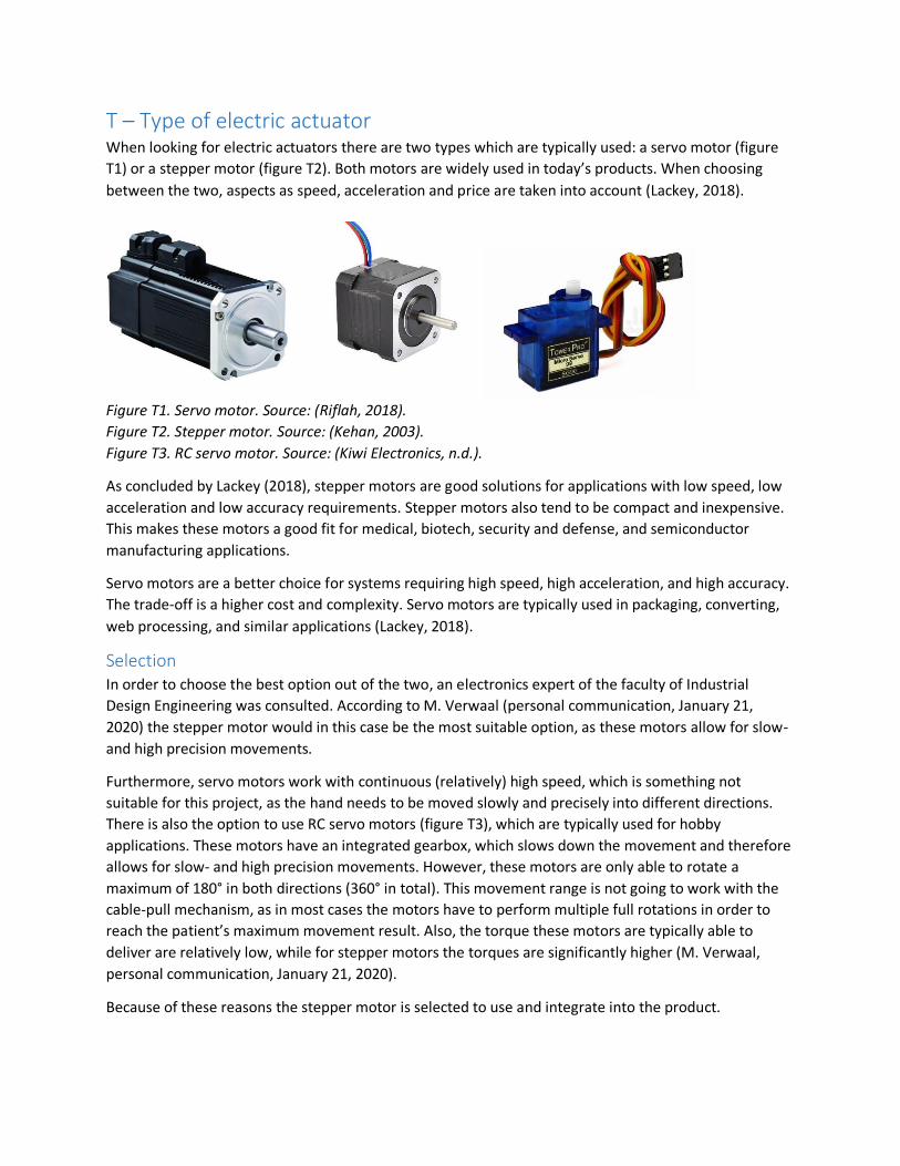
T – Type of electric actuator When looking for electric actuators there are two types which are typically used: a servo motor (figure
T1) or a stepper motor (figure T2). Both motors are widely used in today’s products. When choosing
between the two, aspects as speed, acceleration and price are taken into account (Lackey, 2018).
Figure T1. Servo motor. Source: (Riflah, 2018).
Figure T2. Stepper motor. Source: (Kehan, 2003).
Figure T3. RC servo motor. Source: (Kiwi Electronics, n.d.).
As concluded by Lackey (2018), stepper motors are good solutions for applications with low speed, low
acceleration and low accuracy requirements. Stepper motors also tend to be compact and inexpensive.
This makes these motors a good fit for medical, biotech, security and defense, and semiconductor
manufacturing applications.
Servo motors are a better choice for systems requiring high speed, high acceleration, and high accuracy.
The trade-off is a higher cost and complexity. Servo motors are typically used in packaging, converting,
web processing, and similar applications (Lackey, 2018).
Selection In order to choose the best option out of the two, an electronics expert of the faculty of Industrial
Design Engineering was consulted. According to M. Verwaal (personal communication, January 21,
2020) the stepper motor would in this case be the most suitable option, as these motors allow for slow-
and high precision movements.
Furthermore, servo motors work with continuous (relatively) high speed, which is something not
suitable for this project, as the hand needs to be moved slowly and precisely into different directions.
There is also the option to use RC servo motors (figure T3), which are typically used for hobby
applications. These motors have an integrated gearbox, which slows down the movement and therefore
allows for slow- and high precision movements. However, these motors are only able to rotate a
maximum of 180° in both directions (360° in total). This movement range is not going to work with the
cable-pull mechanism, as in most cases the motors have to perform multiple full rotations in order to
reach the patient’s maximum movement result. Also, the torque these motors are typically able to
deliver are relatively low, while for stepper motors the torques are significantly higher (M. Verwaal,
personal communication, January 21, 2020).
Because of these reasons the stepper motor is selected to use and integrate into the product.

U – Motor performance test With the final prototype the NEMA 17 stepper motors which were used in the prototype could be
tested. It was important to check if these stepper motors were powerful enough to move a person’s
wrist into all directions through the entire ROM. In the end the NEMA 17 stepper motors were able to
move the participant’s wrist into all four directions (figure U1 and U2). However, it is important that this
same test is repeated but with more participants. In this way it can be checked whether larger and
heavier hands can also be passively moved into all four directions.
Figure U1. Passive flexion of the wrist, facilitated by the integrated NEMA 17 motor.
Figure U2. Passive extension, ulnar deviation and radial deviation (fom left to right) of the wrist,
facilitated by the integrated NEMA 17 motors.

V – Stepper driver details and comparison In order to be able to control and operate a stepper motor with Arduino, a stepper drive should be used.
A stepper motor makes a certain amount of steps per revolution (of 360°), for example the NEMA 17
rotates 1.8° per step, meaning it makes 200 steps per revolution. By using a stepper driver a technique
called microstepping can be integrated, where every step of the motor gets divided into microsteps (M.
Verwaal, personal communication, January 21, 2020). Some drivers have microstep resolutions ranging
down to 1/8-step, which results in: 200 * 8 = 1600 steps per 360°. Other drives have microstep
resolutions ranging down to 1/32-step, which results in: 200 * 32 = 6400 steps per 360°. The higher the
amount of steps per 360°, the more precise the stepper motor can be controlled, which is beneficial in
this case as the wrist movements also need to be controlled precisely.
Looking at drivers used for the NEMA stepper motors, there are three drivers which are often used. The
A4988 driver (figure V1, left) and the DRV8825 driver (figure V1, middle) are comparable in size, price
and features. These small drivers are compact, cheap, often have a standard current they can deliver
(around 1 [A]) and often come with small cooling blocks meant to prevent overheating. The drivers have
five different microstep resolutions, ranging down to 1/16-step. This can be changed by using a screw
driver and turning the adjustment screw.
The TB6600 (figure V1, right) is a more expensive and larger stepper driver. The driver has a variable
current ranging from 0.5 to 3.5 [A], which can be easily adjusted using the switches. Also, the driver has
different microstep resolution options ranging down to 1/32-step. The higher price is mainly caused by
the integrated cooling block (to prevent overheating) and the higher quality of the connections and
integrated switches to adjust the current and microstepping.
Figure V1. Stepper motors from left to right: A4988, DRV8825 and TB6600. Sources (from left to right):
(Banggood, n.d.); (Martoparts, n.d.); (Makerlab, n.d.).
For the choice of the most suitable stepper driver an electronics expert from the faculty of Industrial
Design Engineering was consulted. According to M. Verwaal (personal communication, January 21,
2020) the TB6600 is most suitable for this project because of three reasons. First of all the driver simply
offers more microstep resolutions, meaning the stepper motors can be controlled more precise with this
driver.
Secondly, the current the smaller drivers can deliver is simply too low for the motor’s function in the
product. The motors might have to work quite hard in order to reach the full ROM of the patient’s wrist,
also requiring a higher current. A current of 1 [A] would in that situation be too low to realize that.

Thirdly, in this product’s context (hospital) a more professional operating unit is required. When using
one of the two cheaper drivers the chances are high the drivers get overheated (fast). As this product is
going to be used multiple times per day and it has to function within a clean and safe environment,
overheating is something which is simply not tolerated in the usage process.
Because of this reasons the TB6600 stepper driver is selected to use and integrate in the product.

W – Cable elongation While the motors and pulleys of the operating system are working, eventually the cable is the part which
is pulling on the hand fixation to facilitate the desired wrist movements. In the process of pulling the
wrist in a specific direction, the tension on the cable (responsible for that movement) is increasing. For
the cable it is in this case important that it elongates as little as possible while the tension on it
increases. This is important to make sure that the cable tension is measured as accurately as possible by
the load cells. In this way the system receives accurate feedback of the real-time cable tension, resulting
in the system exactly knowing on which moment to stop the movement (as the cable tension threshold
is exceeded).
The cable (rope) used in the prototype (figure W1) is 4 [mm] thick and made of nylon. In a later
prototype it could be beneficial to use another cable
Figure W1. Rope used in the prototype.
For the elongation test two scenarios with the cable are analyzed: 1) with a load of 2.5 [kg]; 2) with a
load of 1.25 [kg]. In both scenarios the cable’s length is measured with- and without the load. In this way
the elongation caused by the load working on the cable can be measured. The piece of cable at the end
which was used to hold the cable was marked with a black marker, so that this point was the same in
every scenario.
Scenario 1: Load of 2.5 [kg]
In both measurements of this scenario the load was already attached to the cable, to make sure the
exact same piece of cable was used to measure the elongation. First, the length of the cable without the
load working on it was measured (figure W2, left); the length which was measured was 215 [mm]. Then,
the length of the cable with the load working on it was measured (figure W2, right); the length which
was measured was 230 [mm]. The total elongation of the cable caused by the load of 2.5 [kg] working on
it is: 230 – 215 = 15 [mm].
Scenario 2: Load of 1.25 [kg]
Also in these two measurements of this scenario the load was already attached to the cable. First, the
length of the cable without the load working on it was measured (figure W3, left); the length which was
measured 260 [mm]. Then, the length of the cable with the load working on it was measured (figure W3,
right); the length which was measured was 267.5 [mm]. The total elongation of the cable caused by the
load of 1.25 [kg] working on it is: 267.5 – 260 = 7.5 [mm].

Figure W2. Scenario 1 (load = 2.5 [kg]). Figure W3. Scenario 2 (load = 1.25 [kg]).
Looking at both scenarios, a proportional relationship can be seen between the load working on the
cable and the cable itself. When the load is doubled, also the elongation of the cable (as a result of this
load working on the cable) doubles.
As is described in the book ‘Human Body Dynamics: Classical Mechanics and Human Movement’ by Adin
Tözeren (2006), the weight of the hand is on average 0.66% of the weight of the human body. However,
this can slightly differ between males and females. To get an overview of the range of the weight of the
patients’ hands, Dined was consulted (figure W4). A target group of 20-60 and 60+ years old was
selected, where males and females were analyzed separately. This resulted in a range from 50 [kg]
(female, P5, 20-60) to 104 [kg] (male, P95, 20-60). Eventually this results in a weight of the hand of 0.33
[kg] (330 [g]) and 0.686 [kg] (686 [g]) respectively.
Figure W4. Different percentile values of human body weight (m/f, 20-60, 60+) (Dined, 2020).
In this way the load required to elongate the cable 1 [mm] can be calculated. This can be done as
follows: (2.5 / 15) = 0.167 [kg]. In other words, when applying approximately 167 [g] the cable
elongation will be around 1 [mm]. Looking at the hand weights above, this will result in:
- (330 / 167) = 1.98 [mm] cable elongation for a P5 female (20-60 years old);
- (686 / 167) = 4.11 [mm] cable elongation for a P95 male (20-60 years old).
However, this elongation increases when the hand is pulled into the different directions, as the hand
itself (although it is relaxed) will resist slightly due to its limited ROM. Therefore, it is important later to
test whether this cable elongation is a problem in the process of passively facilitating the wrist
movements. This is described in subchapter 7.2.

X - Operating system concepts
Concept 1: Four cable system
Components The first concept makes use of four cables which are all connected to ‘their own’ motor. Each of the four
attachment points of the hand fixation is connected to one cable; every cable is at the back connected
to one motor and one load cell (figure X1). From the hand fixation, eventually every cable is lead
downwards to the back, at the correct height in relation to the stepper motor. This can be done with the
use of bowden cables. In the system every cable is operated separately and the cable tension is
therefore also measured on every cable separately.
Tension measurement The measurement of the cable tension is realized by connecting the motor with the use of a rigid
connection piece to the load cell. When the motor winds up its cable, the motor tends to move away
from the load cell. This movement results in a force working on the connection piece and eventually on
the load cell. Finally, the load cell is able to measure this force and therefore (indirectly) the tension on
the cable connected to it.
Figure X1. Setup four cable system.
Working Controlling the cables of this system is done with the control panel (figure X2). Each of the cables is
connected to one motor and therefore responsible for one movement.
In the beginning the hand of the patient has to be maneuvered into the correct neutral (calibration)
position. This can be done by tightening or loosening specific cables. For example, when the hand has to
be moved slightly to the left, motor 2 needs to loosen its cable, while motor 4 needs to tighten its cable.

In the end the radiologist or laboratory technician will decide whether the patient’s hand is in the right
position.
When the hand is in the correct starting position, the movement sequence can be started. By pushing
the ‘START’ button the hand is automatically moved into the four directions, resulting in flexion,
extension, radial- and ulnar deviation. When moving in one plane (e.g. in the case of flexion) motor 4
needs to tighten cable 4, while motor 2 needs to loosen cable 2. The movement is carried out until the
cable tension threshold (measured by the load cell) is reached. At this point, the motors maneuver the
hand back in the initial starting position, after which the next movement is carried out. At the end, when
the entire movement sequence is completed and the hand is back in the starting position, all cables
need to be loosened to create space for the patients to remove their hand from the device.
Figure X2. Cables and control panel.
Difficulties Looking at this concept, there are two difficulties which arise. Firstly, when moving into one direction,
two motors have to rotate simultaneously. In this process, one motor is winding its cable, while the
opposite motor needs to unwind its cable at exactly the same speed. Here it is important that the one
motor gives exactly the same amount of cable the other motor is taking, as the movement is then not
blocked (because of one motor giving too little cable).
The situation in figure X3 (left) is desired, however this is hard to accomplish, as the (un)winding of the
cable around the axis of the motor is something hard to control. Therefore the chances are high that the
cable is going to (un)wind like in figure X3 (right), where the cable is (un)winding over itself. At some
points the motor will then take more cable when making a rotation, resulting in the motor winding more
cable than the amount of cable the opposite motor is giving. In the end this will result in the opposite
cable blocking the movement.

Figure X3. Cable winding.
This was also tested with the prototype, by simulating the flexion and extension movement (figure X4
and X5). As there was no setup with motors yet, this was simulated using K’NEX parts. Looking at figure
X6 and X7, it becomes clear that during flexion- and extension of the wrist, the cable is (un)winded
differently by the two ‘motors’. As mentioned above this will result in the one motor blocking the
movement of the other. According to mechanics expert D. Bosboom (personal communication, March
12, 2020) this issue would be quite challenging to solve within the software, as the exact cable behavior
cannot be controlled (precisely).
Figure X4. 3D view of test setup for flexion- and extension movement.
Figure X5. Top view of test setup for flexion- and extension movement.
Figure X6. Motor winding simulation parts.

Figure X7. Cable winding of both motor simulation parts.
This would be the same in case of a special pulley, where the two cables are always (un)winded
symmetrically (figure X8). In this case there are always still small irregularities within the cable, resulting
in the wrist movements being blocked. Next to that, with this pulley it would not be possible to wind up
the cable, as the slots (where the cable is supposed to fall in) continually move. This movement is
upwards for the lower half and downwards for the upper half.
Figure X8. Symmetrical pulley (un)winding system.

The second difficulty has to do with the load cells. The setup with the load cells connected to motors (via
the connection piece) is not quite accurate. The cable, the motor unit, the connection piece and the
attachment point of the load cell are not aligned, causing small momentums to occur (figure X9).
Because of these small vertical distances (A and B) (and momentums) the actual force working on the
load cell is not representative for the tension (force) on the cable.
Figure X9. Load cell and cable not in same line of action.

Concept 2: Two cable-lever system
Components
The second concept makes use of four cables which are (in pairs of two) connected to one motor. For
movement in each plane there are two pieces of cable, one motor and one load cell, meaning there are
four pieces of cable, two motors and two load cells in total. At the back of the device there is something
like a lever (or puppet) system, where two cables are connected to both ends of a beam (figure X10).
Both beams are driven by their own motor, however this is not visualized in this figure. More about the
motor drive is explained later in ‘Working’. The horizontal beam facilitates the horizontal (flexion and
extension) movement (figure X11), while the vertical beam facilitates the vertical (radial- and ulnar
deviation) movement (figure X12).
Figure X10. Setup two cable-lever system.

Figure X11. Horizontal beam facilitates wrist flexion and –extension.
Figure X12. Vertical beam facilitates radial- and ulnar deviation.

In this concept the cables have a fixed length, which are perfectly adjusted so that the hand fixation is
positioned in the correct starting position (i.e. in the middle of both planes). For the patient to start in
the correct position with the right amount of tension on the cables, it is important to position the arm
(and hand) of the patient correctly in relation to the cables. In other words, the arm and hand of the
patient need to be pushed far enough through the forearm fixations and wrist standard.
While facilitating the passive movements, it is important that the patient’s arm stays in this position the
entire time, in order to keep the right amount of tension on the cables. Because of this, an elbow
support should be integrated in the concept. This component should be positioned at the back of the
upper arm of the patient (around the elbow) (figure X13). The support prevents the arm from sliding
backwards and therefore keeps it in the correct initial position. Moving forwards is already impossible,
as the circumference of the arm increases towards the back and therefore won’t fit through the forearm
fixations.
Figure X13. Elbow support at the back of the arm to prevent moving backwards.
Tension measurement The measurement of the cable tension is realized by having one load cell attached at one side of each
beam. On the other side of the beam there is a similar piece of material (preferably the same
dimensions and material as the load cell) to make sure the movement is carried out symmetrically. The
screw hole positioned at the end of the load cell can be used to attach the cable. If the beam is rotating
to facilitate the desired wrist movement, the cable is (in)directly pulling (and therefore deforming) the
load cell, making it possible for the load cell to measure the tension on the cable. In this scenario only
one load cell is necessary for one beam, as the forces are simply transmitted through the beam.
However, there is one complexity caused by this way of measuring the cable tension. With load cells it is
important to exert the force perpendicular to the surface, as the component is only capable to measure
that straight deflection. If the position and orientation of the load cell changes, the line of action of the

cable pulling on the load cell also changes. Therefore, during the wrist movement the angle (α) between
the load cell’s line of action and the cable changes (figure X14), resulting in the force exerted by the
cable being measured wrongly by the load cell. In the calculation of the deflection of the load cell (and
thus the cable tension) the varying angle α should therefore be taken into account. This could for
example be done by adding something like a potentiometer at the rotation axis of the beam, so that the
angle α can be measured directly.
Figure X14. Cable pull angle on load cell.
Working As mentioned before each beam is driven by one motor. Still these motors can be ‘installed’ in two
different ways. The first option is to have the motor shaft directly connected to the rotation axis of the
beams (figure X15). The benefit of this option is that no further transmission from the motor to the
beam is required, which makes it quite simple to set up. On the other hand, having the motor shaft in
line with the rotation point (and axis) of the beam, results on a large torque working on the motor. In
this setup the distance from the motor shaft to the cable attachment points is largest, meaning the
motor has to deliver quite a large torque in order to be able to facilitate the desired wrist movements.
Figure X15. Motor shafts connected to rotation points of horizontal- and vertical beam.

The second option is to connect the motor shaft to a different point on the beam, further from the
rotation point (figure X16). In this case motors with a shaft with screw thread (figure X17) can be used in
combination with a special nut (golden-like colour), to facilitate the controlled movement. For this the
nut should be integrated in the beam and the (screw thread) motor shaft should go through it. Also, the
motor shaft needs to perfectly align with the beam: z-axis for the horizontal beam and y-axis for the
vertical beam. The motor shaft rotating clockwise will pull the nut towards it, while the motor shaft
rotating counter-clockwise will push the nut further away from it (figure X18).
Figure X16. Motor shafts connected to nut in beam.
Figure X17. Stepper motor with shaft with screw thread. Source: (Shopee, n.d.).
With this method the torque which the motor has to deliver is significantly lower, as the distance from
the line of action of the motor to the rotation point of the beam is higher. However, there are some
other difficulties which occur with this option. First of all, the nut integrated in the beam should be able
to rotate, as its orientation related to the motor shaft continually changes (figure X18). This would result
in a difficult system where the nut’s position in the beam is fixed, while its orientation can still change
(by making it able to rotate around its own axis). Also, as is also shown in figure X18 below, the motor
should be fixed but still able to rotate slightly, in order to be able to follow the path the nut is moving.
Figure X18. Nut orientation changes when beam rotates.
Apart from which motor drive is chosen, the system can be controlled in a similar way to the ‘four cable
system’. Controlling the cables of this system is done with the control panel (figure X19). Pairs of two
cables are connected to each other and therefore responsible for movement in one plane.

In the beginning the hand of the patient has to be maneuvered into the correct neutral (calibration)
position. This can be done by firstly pushing the arm and hand of the patient far enough through the
forearm fixations and wrist standard. Subsequently, the arm and hand need to be fixated so that the
desired tension on the cable is achieved. The arm can be fixed with the use of the elbow support.
Moving the hand into the right position can still be done by pushing one of the buttons to move the
hand left or right. In the end the radiologist or laboratory technician will decide whether the patient’s
hand is in the right position.
When the hand is in the correct starting position, the movement sequence can be started. By pushing
the ‘START’ button the hand is automatically moved into the four directions, resulting in flexion,
extension, radial- and ulnar deviation. When moving in one plane (e.g. in the case of flexion) the motor
connected to the horizontal beam is working. The movement is carried out until the cable tension
threshold (measured by the load cell) is reached. At this point, the motors maneuver the hand back in
the initial starting position, after which the next movement is carried out. At the end, when the entire
movement sequence is completed and the hand is back in the starting position, all cables need to be
loosened to create space for the patients to remove their hand from the device.
Figure X19. Cables and control panel.

Difficulties Looking at this concept, there are four difficulties which arise. First of all, there is a certain range for the
beam for which it gives cable and a certain range for which it takes cable. From the connection point of
the cable through the rotation point of the beam, there can be drawn two axes (L1 and L2, figure X20).
By also drawing a horizontal and vertical axis through the middle point of the beam, eight quadrants
occur (Q1-Q8). In case of wrist extension (left) the one side of the beam gives more cable to cable 4 (in
Q6), while the other side of the beam takes more cable from cable 2 (in Q2). The beam cannot go any
further, as otherwise the lower side of the beam will start to take (instead of give) cable from cable 4.
The same but the opposite is the case for wrist flexion (right).
Figure X20. Cable giving and -taking.
Secondly, related to the first point, the beams have to be quite large in order to be able to facilitate the
wrist movements through the entire ROM. This is especially the case with wrist flexion and extension,
where the maximum movement result is 90° in some cases (subchapter 3.1.1).
To get an idea of how large the beams should be, the amount of cable needed to facilitate the full ROM
of every movement has to be measured. Wrist flexion has the highest movement result, which is why
this movement is used to define the cable length. In this case I used my own hand, which is above
average in terms of length. Still, it has to be kept in mind that there are people with larger hands, also
resulting in larger beams. The measured cable length necessary to complete full wrist flexion (around
70°) for my hand was approximately 12 [cm] (figure X21). Again, it has to be kept in mind that there are
people with a larger movement result for wrist flexion (e.g. 90°).
Figure X21. Measuring required cable length for full wrist flexion movement (=12 [cm]).
As can be seen (or measured) from figure X22, the maximum angle the beam can rotate for one
movement is about 50° (in this setup). If the beam is positioned further away from the arm standard,
this angle becomes larger. However, the available space at the back of the device also needs to be kept

in mind, which is why this setup is assumed for this calculation. According to the calculation (figure X22)
the beam length would be around 32 [cm]. This is quite large to have at the back of the device and
would take a lot of space to store and move. This length probably has to be even larger, as in this
calculation not the largest hand and largest movement result is taken into account.
Figure X22. Beam length calculation.
Thirdly, as mentioned above, measuring the cable tension with the load cell in this setup is quite hard.
This is because the angle of the cable in relation to the load cell (line of action) continually changes.
Therefore, this angle should be measured and integrated into the software part of calculating the cable
tension.
Finally, in this concept the cables have a fixed length. However, when the patients need to align their
wrist with the wrist standard, the rest of their hand is going to be positioned behind the standard. Still
there exist differences between people in their distance from wrist to the metacarpals (where the hand
fixation is positioned), which is P3 described in Appendix N. This could be a problem as with this concept
this distance is fixed. However, when looking at the variation in measurements of parameter P3, it is
only 15 [mm] (see Appendix N). For the final cable length, it is therefore best to take the average of P3,
which would result in a distance from wrist to the metacarpals (beginning of the hand fixation) of 67.5
[mm].

Concept 3: Two cable-pulley system The most information about this concept can be found in the report (subchapter 3.4.5).
Tension measurement At this point the assumption is made that the cable tension is equal for the whole cable, meaning only
one load cell is required per cable to accurately measure the cable tension. This is assumed because
while the cable pulls the one side of the hand fixation (point A) towards one side, the other side (point
B, with cable) is automatically also pulled into that direction (figure X23). Because of this reason the
cable tension on the one side (A) of the hand fixation is equal to the cable tension on the other side (B)
of the hand fixation.
Figure X23. Equal cable tension on both sides of hand fixation.
However, this assumption still has to be tested, because within this measuring system it may be that per
cable two load cells are needed. This is because the tension on the cable can slightly differ between the
part of the cable which is being pulled and the part which is being ‘pushed’ (figure X24). However, for
now the assumption is made that the cable tension is equal along the entire cable, meaning only one
load cell is needed per cable. The test related to this issue can be found in chapter 3.

Figure X24. Difference in cable tension between ‘pulling’ and ‘pushing’ part.
Working In the beginning the hand of the patient has to be maneuvered into the correct neutral (calibration)
position. This can be done by firstly pushing the arm and hand of the patient far enough through the
forearm fixations and wrist standard. Subsequently, the arm and hand need to be fixated so that the
desired tension on the cable is achieved. The arm can be fixed with the use of the elbow support.
See figure X25. Moving the hand into the right position can still be done by pushing one of the buttons
to move the cables and move the hand left or right. In the end the radiologist or laboratory technician
will decide whether the patient’s hand is in the right position.
When the hand is in the correct starting position, the movement sequence can be started. By pushing
the ‘START’ button the hand is automatically moved into the four directions, resulting in flexion,
extension, radial- and ulnar deviation. When moving in one plane (e.g. in the case of flexion) the motor
connected to the horizontal beam is working. The movement is carried out until the cable tension
threshold (measured by the load cell) is reached. At this point, the motors maneuver the hand back in
the initial starting position, after which the next movement is carried out. At the end, when the entire
movement sequence is completed and the hand is back in the starting position, all cables need to be
loosened to create space for the patients to remove their hand from the device.
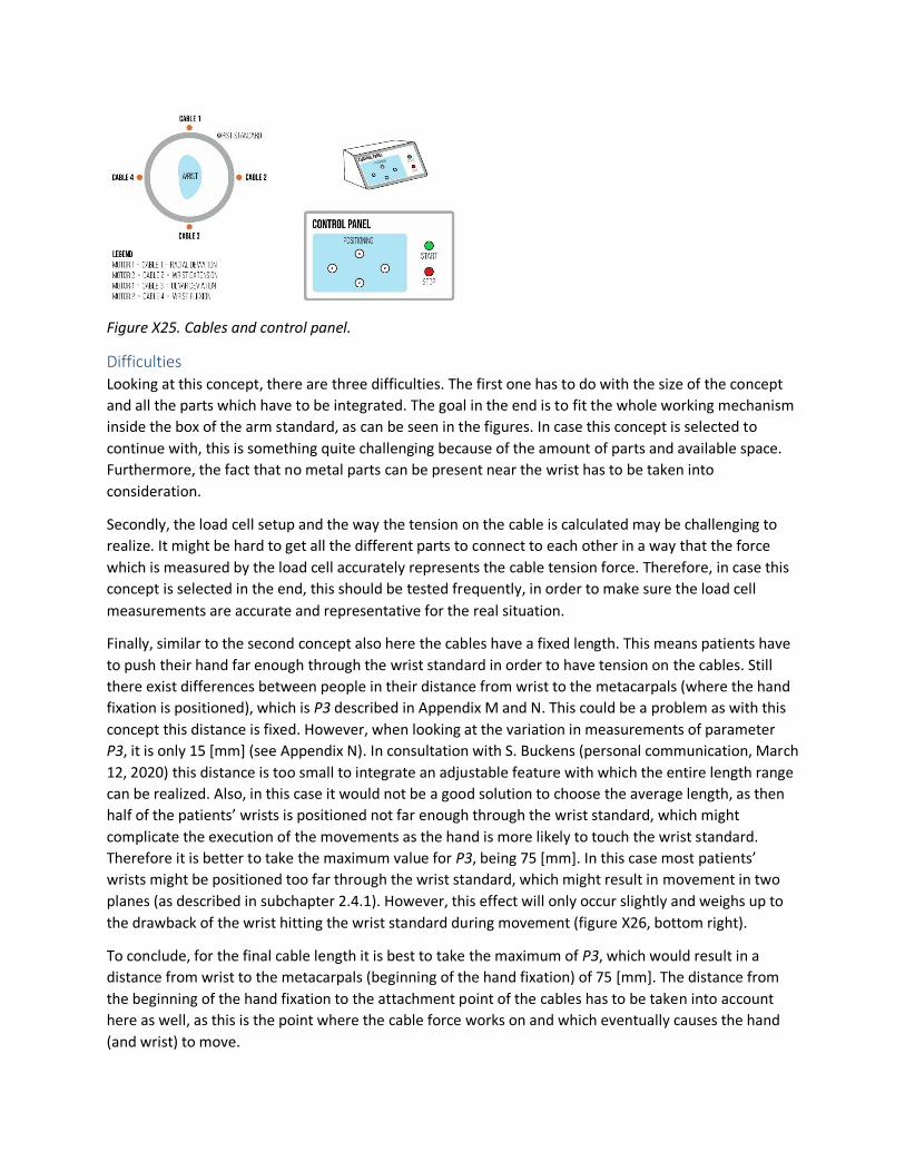
Figure X25. Cables and control panel.
Difficulties Looking at this concept, there are three difficulties. The first one has to do with the size of the concept
and all the parts which have to be integrated. The goal in the end is to fit the whole working mechanism
inside the box of the arm standard, as can be seen in the figures. In case this concept is selected to
continue with, this is something quite challenging because of the amount of parts and available space.
Furthermore, the fact that no metal parts can be present near the wrist has to be taken into
consideration.
Secondly, the load cell setup and the way the tension on the cable is calculated may be challenging to
realize. It might be hard to get all the different parts to connect to each other in a way that the force
which is measured by the load cell accurately represents the cable tension force. Therefore, in case this
concept is selected in the end, this should be tested frequently, in order to make sure the load cell
measurements are accurate and representative for the real situation.
Finally, similar to the second concept also here the cables have a fixed length. This means patients have
to push their hand far enough through the wrist standard in order to have tension on the cables. Still
there exist differences between people in their distance from wrist to the metacarpals (where the hand
fixation is positioned), which is P3 described in Appendix M and N. This could be a problem as with this
concept this distance is fixed. However, when looking at the variation in measurements of parameter
P3, it is only 15 [mm] (see Appendix N). In consultation with S. Buckens (personal communication, March
12, 2020) this distance is too small to integrate an adjustable feature with which the entire length range
can be realized. Also, in this case it would not be a good solution to choose the average length, as then
half of the patients’ wrists is positioned not far enough through the wrist standard, which might
complicate the execution of the movements as the hand is more likely to touch the wrist standard.
Therefore it is better to take the maximum value for P3, being 75 [mm]. In this case most patients’
wrists might be positioned too far through the wrist standard, which might result in movement in two
planes (as described in subchapter 2.4.1). However, this effect will only occur slightly and weighs up to
the drawback of the wrist hitting the wrist standard during movement (figure X26, bottom right).
To conclude, for the final cable length it is best to take the maximum of P3, which would result in a
distance from wrist to the metacarpals (beginning of the hand fixation) of 75 [mm]. The distance from
the beginning of the hand fixation to the attachment point of the cables has to be taken into account
here as well, as this is the point where the cable force works on and which eventually causes the hand
(and wrist) to move.

Figure X26. Different setups for distance from wrist to metacarpals, tested with small and large patients
(arms and hands).

Y – Comparison operating system concepts For each of the three concepts both the positive and negative aspects are listed down. Eventually a
visual (hexagon) comparison is made, where all concepts are rated on five different criteria (figure Y1).
More about this hexagon comparison is described in the report (subchapter 3.4.5).
Concept 1 Looking at this concept, it has both positive and negative points.
Positive
- Because each of the cables is connected to its own motor, the radiologist or laboratory
technician has a lot of control over the movements.
- Because all cables can be loosened and more space can be created around the hand fixation, it is
easier for patients to get their hand through the wrist standard and in the hand fixation.
- The cables are directed to the side (and bottom) and do not hinder the arm because of that.
Negative
- The setup with the cables connected to four motors and four load cells takes quite some extra
space at the back of the device. However, the system could maybe also be integrated into the
arm standard.
- Winding and unwinding of the motor’s cable cannot be properly controlled, resulting in the
cables possibly blocking each other’s movement.
- The load cell configuration to measure the tension on the cables is not that accurate, because of
small momentums caused by the small vertical distances between the different components.
- Because all cables can and need to be controlled separately, it also takes more time to set up
the hand in the calibration position.
- The high amount of buttons might make it hard for the radiologist or laboratory technician to
operate the device.
Concept 2 Looking at this concept, it has both positive and negative points.
Positive
- Having the fixed cable length makes setting up the patient’s hand in the calibration position
faster and easier.
- Having two motors instead of four simplifies the software control of the entire system. Also two
instead of four load cells is beneficial for this.
- Controlling the system with the use of the control panel is easier for the radiologist or
laboratory technician because of the different (less complex) interface.
Negative
- The system requires quite some space behind the device and the arm in order to be able to
facilitate all movements. The beams (the horizontal in particular) needs to be quite large in
order to be able to facilitate the wrist movements. Also the top cable might interfere with the
arm of the patient.

- The system needs an extra support to make sure it works as desired, namely the elbow support.
- Multiple components, like the motor and the nut, need to be rotatable as mentioned before.
This makes the system mechanically more complex.
Concept 3 Looking at this concept, it has both positive and negative points.
Positive
- Having the fixed cable length makes setting up the patient’s hand in the calibration position
faster and easier.
- Having two motors instead of four simplifies the software control of the entire system. Also two
instead of four load cells is beneficial for this.
- Controlling the system with the use of the control panel is easier for the radiologist or
laboratory technician because of the different (less complex) interface.
- All cables can be directed to the side (and downwards) with the use of Bowden cables, hereby
making sure they do not interfere with the arm.
Negative
- In the beginning there is less space for the hand to attach the hand fixation, as the cables have a
fixed length.
- The system needs an extra support to make sure it works as desired, namely the elbow support.
- Calculation of the cable tension is something which has to be tested to make sure it accurately
represents the real situation.
- Integrating all components in the arm standard might be challenging because of the amount of
parts and the relatively small available space.
Calculation of the cable tension is more complex because of the changing angle of the cable in relation
to the load cell line of action.
Figure Y1. Hexagon comparison(on five criteria) of three operating system concepts.

Z - Assumptions cable tension measurement For the measurement of the cable tension by the load cells, as described in subchapter 3.4.5 of the
report, there have been made a few assumptions.
First of all the friction between the cable and the inside of the rubber Bowden tube has been neglected.
Because the cable has to be led to a spot at the back of the product, Bowden tubes are used to guide the
cables to these specific spots. However, when the cable flows through this rubber tube, there is a
friction force working on the cable, resulting in an increasing motor force (or torque) needed to pull the
cable into the desired direction. However, when defining the optimal safety factor with which the cable
force may increase (up until the cable tension threshold), this still has to be taken into consideration.
Secondly, the weight of the cable and the gravity force caused by this is neglected. The cable practically
weighs nothing, which is why the gravity force is also so small it does not influence the force
measurement by the load cell.
Thirdly, and this is not an assumption, the angle between the two cables and the line of action in which
the load cell is able to measure forces, has to be taken into consideration. Depending on how the load
cell is positioned in relation to the two cables it measures a different force.

AA – Timing belt length test To get an idea of how long the timing belt should be, the amount of cable needed to facilitate the full
ROM of every movement has to be measured. Wrist flexion has the highest movement result, which is
why this movement is used to define the cable length (figure AA1). In this case I used my own hand,
which is above average in terms of length. The measured cable length necessary to complete full wrist
flexion (around 80°) for my hand was approximately 12 [cm]. Again, it has to be kept in mind that there
are people with a larger movement result for wrist flexion (e.g. 90°). Therefore, the required length for
the timing belt is assumed to be 15 [cm].
Figure AA1. Measuring required cable length for full wrist flexion movement (=12 [cm]).

BB – Electronic prototypes
Prototype 1: Push button motor control The setup of this prototype can be seen in figure H72 – H75.
- Motor rotation direction control
- Positioning of hand
- Required components
o Arduino Uno/Mega
o NEMA 17 Stepper motor
o TB6600 Stepper driver
o Push button (2x) (one clockwise, one counter-clockwise)
o Breadboard and jumper wires
Figure H72. Setup of electronic prototype 1 (overview).
Figure H73. Push buttons for stepper motor control.

Figure H74. Connections of electronic components with Arduino Uno/Mega.
Figure H75. TB6600 stepper driver connections.
Prototype 2: Load cell calibration The setup of this prototype can be seen in figure H76.
- Load cells have to be calibrated to make sure they measure similar values
- Put known weight on load cell and define scale factor
- The scale factors turned out to be 424 (load cell 1) and 431 (load cell 2).
- Required components:
o Arduino Uno/Mega
o Load cell (5 [kg])
o HX711 Amplifier sensor
o Box (load cell attachment)
o Smartphone (as known weight)
o Breadboard and jumper wires

Figure H76. Setup of electronic prototype 2.

CC – Stability test (patient bed) To see how the product could be placed on the patient bed of the CT scanner, a small test was
conducted in a CT room of the Radboud UMC (February 20, 2020). During the test the product prototype
was placed on the patient bed (with the cushion still on top of it) and a participant was fixated in the
device (figure CC1 – CC6). The conclusion from the test was that the product could actually just be
placed and stay stable on top of the patient bed, without having it to attach to it (e.g. with a strap). As
the product was relatively heavy, nothing happened when the participant moved his arm.|
Figure CC1. Participant fixated in prototype on CT patient bed (position 1).
Figure CC2. Participant fixated in prototype on CT patient bed (position 1).

Figure CC3. Participant fixated in prototype on CT patient bed (position 1).
Figure CC4. Participant fixated in prototype on CT patient bed (position 2).
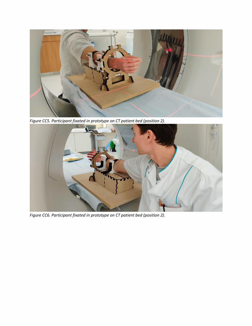
Figure CC5. Participant fixated in prototype on CT patient bed (position 2).
Figure CC6. Participant fixated in prototype on CT patient bed (position 2).

DD – Control panel user test During this test (April 29, 2020) different concepts of different categories for the control panel were
tested. In total three categories were tested: 1) position of the buttons; 2) position of the tags; 3) text
style of the titles. For category 1 there were three concepts (figure DD1), for 2 there were two concepts
(figure DD2) and for 3 there were three concepts (figure DD3).
Figure DD1. Category 1 (position) concepts.
Figure DD2. Category 2 (buttons and tags) concepts.
Figure DD3. Category 3 (text) concepts.
All participants were shown the concepts of each category. After each category they were asked which
concept they preferred and for what reason.
Participant 1 The first participant was S. Hummelink, a technical physician and research coordinator from the
RadboudUMC.
- Category 1
Concept 3 is preferred because it is logical to have the ‘start’ and ‘stop’ button above each
other.
- Category 2
Concept 2 is preferred because it looks more natural and feels more intuitive.
- Category 3
Concept 1 is preferred, however maybe only the ‘stop’ button should be bold.
Participant 2 The second participant was S. Buckens, a radiologist from the RadboudUMC.

- Category 1
Concept 3 is preferred because it feels more intuitive to have the ‘start’ and ‘stop’ button close
to each other. In this way the product can be easily operated with two hands (left hand for the
‘positioning’ buttons and right hand for the ‘start’/’stop’ button).
- Category 2
Concept 2 is preferred because it simply feels more intuitive.
- Category 3
Concept 1 is preferred because the ‘positioning’ text has to be a header in comparison with the
tags for the buttons (left, right, etc.). Also, the ‘start’ and ‘stop’ button are more important and
therefore have to be bold to attract more attention.
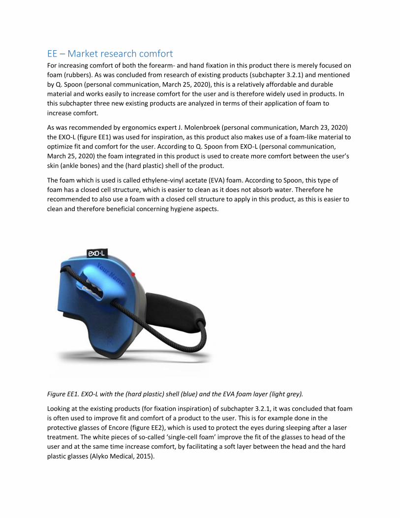
EE – Market research comfort For increasing comfort of both the forearm- and hand fixation in this product there is merely focused on
foam (rubbers). As was concluded from research of existing products (subchapter 3.2.1) and mentioned
by Q. Spoon (personal communication, March 25, 2020), this is a relatively affordable and durable
material and works easily to increase comfort for the user and is therefore widely used in products. In
this subchapter three new existing products are analyzed in terms of their application of foam to
increase comfort.
As was recommended by ergonomics expert J. Molenbroek (personal communication, March 23, 2020)
the EXO-L (figure EE1) was used for inspiration, as this product also makes use of a foam-like material to
optimize fit and comfort for the user. According to Q. Spoon from EXO-L (personal communication,
March 25, 2020) the foam integrated in this product is used to create more comfort between the user’s
skin (ankle bones) and the (hard plastic) shell of the product.
The foam which is used is called ethylene-vinyl acetate (EVA) foam. According to Spoon, this type of
foam has a closed cell structure, which is easier to clean as it does not absorb water. Therefore he
recommended to also use a foam with a closed cell structure to apply in this product, as this is easier to
clean and therefore beneficial concerning hygiene aspects.
Figure EE1. EXO-L with the (hard plastic) shell (blue) and the EVA foam layer (light grey).
Looking at the existing products (for fixation inspiration) of subchapter 3.2.1, it was concluded that foam
is often used to improve fit and comfort of a product to the user. This is for example done in the
protective glasses of Encore (figure EE2), which is used to protect the eyes during sleeping after a laser
treatment. The white pieces of so-called ‘single-cell foam’ improve the fit of the glasses to head of the
user and at the same time increase comfort, by facilitating a soft layer between the head and the hard
plastic glasses (Alyko Medical, 2015).

Such a protective foam layer is also used in for example shin protection for hockey players (figure EE3).
Here the softer layer of so-called ‘shock-absorbing foam’ (black on the inside) provides extra comfort to
the user, as the outer PVC layer is relatively hard and therefore is likely to feel uncomfortable for the
user.
Unfortunately, the exact type of foam used in these two products is not known, however the materials
look and sound similar to the EVA foam mentioned above.
Figure EE2. Encore protective glasses with foam. Figure EE3. Hockey shin protection.

FF – Comfort material comparison In order to find a suitable foam to apply in the product, multiple types of foam were tested. In this
subchapter all these foams are compared to each other, of which one is eventually chosen to use and
integrate in the product.
Criteria All foams were compared on two criteria, the hardness and the cell structure. The hardness represents
how hard (or soft) the foam is, where a low hardness (and thus a soft foam) is preferred. The softer the
foam, the more comfortable it will feel for the patient. However, the foam should not be too soft that it
gets flattened easily. For the selection the hardness of every foam is compared based on a scale from 1
(very soft) to 7 (very hard).
Concerning the cell structure there are two types of foam to distinguish: open cell foam and closed cell
foam. The open cell foam has tiny cells which are not completely closed and are filled with air;
influencing the way the foam feels and behaves (Foam Factory, 2017). The closed cell foam has cells
which are closed so that air is not able to get inside the structure (Foam Factory, 2017).
The main difference between the two types of foam is that closed cell foam feels harder (and sturdier)
while open cell foam is softer (and less sturdy). Because of this the closed cell foam is less bouncy
(springy) while the open cell foam has this more (due to the air inside the cells) (Foam Factory, 2017).
For the product a suitable midway has to be found, as the material should not be too hard
(uncomfortable for the patient), nor too soft (offers no damping thus no comfort to the patient).
However, a cell foam which is somewhat more closed is preferred, as this is easier to clean and
therefore beneficial concerning hygiene aspects (as was also recommended by Q. Spoon, mentioned
above).
For the materials the thickness (and dimensions) is of course also relevant, as this influences the effort it
takes to bend and compress the material. However for this comparison this aspect has not been taken
into account as: 1) it was hard to obtain different foam pieces of the same thickness; 2) the required
information can already be derived from the two criteria (hardness and cell structure) mentioned above.
Next to that, when using and integrating the selected material in the product, the optimal thickness of it
can be tested.
Materials
TPU Thermoplastic polyurethane (TPU) (figure FF1) was the only non-foam material, to see if such a material
could also maybe be used to optimize fit (and comfort) for the patient. This material is a rubber and no
foam, meaning it has neither a closed nor an open cell structure.
The small sheet was 3D printed in two thin pieces (1 [mm] and 2 [mm] thick). The material turned out to
be quite hard and sturdy and was therefore also hard to bend (figure FF2) and compress (figure FF3).
While compressing the material could not be pushed in, meaning it would also not offer any damping for
the patient.

Figure FF1. TPU pieces: 2 [mm] (left) and 1 [mm] (right), top view and front view.
Figure FF2. Bending the TPU (2 [mm]) piece.

Figure FF3. Compressing the TPU (2 [mm]) piece.
Single-cell foam This single-cell foam (figure FF4) was removed from a similar protective glasses as mentioned above.
Therefore the exact material is unfortunately unknown. The material turned out to be rather soft and
squishy and was therefore also easy to bend (figure FF5) and compress (figure FF6). While compressing
the material could be pushed in, meaning it would offer damping for the patient (and therewith increase
comfort). Looking closely at the material, small holes could be spotted which indicate this material has
an open cell structure.
Figure FF4. Single-cell foam piece.

Figure FF5. Bending the single-cell foam piece.
Figure FF6. Compressing the single-cell foam piece.
Polyether (SG35) This foam material is called polyether (SG35) (figure FF7), where the SG indicates the specific weight of
the material. A higher specific weight of the material means that it also is more durable, more resilient
and has a higher weight (Ten Caat, 2018). A specific weight of 35 is relatively low, considering there are
also foam (rubbers) with a specific weight of 260 or higher. Therefore, this material is quite soft (even
significantly more than the single-cell foam) and was therefore also extremely easy to bend (figure FF8)
and compress (figure FF9). As the material was so easy to compress, it would in the end also not offer
any damping for the patient. Looking at the material a lot of small holes could be seen (figure FF7),
indicating this material has an open cell structure.

Figure FF7. Small piece of polyether SG35.
Figure FF8. Bending the piece of polyether SG35.

Figure FF9. Compressing the piece of polyether SG35.
Moss (foam rubber) This moss foam rubber (figure FF10) turned out to be quite the average material. This material was
medium hard and also felt somewhat stiff. Therefore it only took a bit of effort to bend (figure FF12) and
compress (figure FF13) it. While compressing the material could be pushed in slightly (less than the
single-cell foam), meaning it would offer damping for the patient (and therewith increase comfort).
Looking at the material there was something strange to see, as the material seemed to have both an
open- and a closed cell structure (figure FF11). The inside of the material consisted of an open cell
structure, while the outside was closed.
Figure FF10. Moss foam rubber piece (top view and front view).

Figure FF11. Close-up of inside of moss foam rubber piece.
Figure FF12. Bending the moss foam rubber piece.
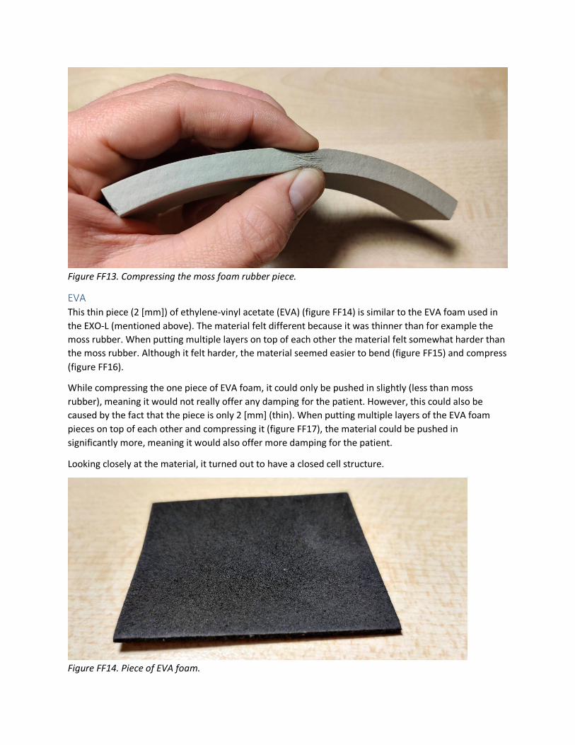
Figure FF13. Compressing the moss foam rubber piece.
EVA This thin piece (2 [mm]) of ethylene-vinyl acetate (EVA) (figure FF14) is similar to the EVA foam used in
the EXO-L (mentioned above). The material felt different because it was thinner than for example the
moss rubber. When putting multiple layers on top of each other the material felt somewhat harder than
the moss rubber. Although it felt harder, the material seemed easier to bend (figure FF15) and compress
(figure FF16).
While compressing the one piece of EVA foam, it could only be pushed in slightly (less than moss
rubber), meaning it would not really offer any damping for the patient. However, this could also be
caused by the fact that the piece is only 2 [mm] (thin). When putting multiple layers of the EVA foam
pieces on top of each other and compressing it (figure FF17), the material could be pushed in
significantly more, meaning it would also offer more damping for the patient.
Looking closely at the material, it turned out to have a closed cell structure.
Figure FF14. Piece of EVA foam.

Figure FF15. Bending the EVA foam piece.
Figure FF16. Compressing the EVA foam piece.
Figure FF17. Compressing multiple layers of EVA foam.

Selection For the selection of the most suitable foam for use and integration in the product, an overview has been
made concerning all types of foam and the two criteria mentioned above (table FF1).
Table FF1. Overview of foam types and criteria.
Type of foam Hardness Cell structure
TPU 7 -
Single-cell foam 2 Open cell structure
Polyether (SG35) 1 Open cell structure
Moss foam rubber 3 Both (inside: open cell, outside: closed cell)
EVA 3 Closed cell structure
Looking at table FF1, already two of the five materials fall off, which are the ‘single-cell foam’ and the
‘polyether (SG35)’. This is due to the fact that they have an open cell structure, while at the beginning it
was concluded that a closed cell structure was preferred as this is easier to clean and therefore
beneficial concerning hygiene aspects. Furthermore, a material was preferred which was medium soft.
Therefore the material TPU also falls of, as this material is way too hard to offer any damping for the
patient (and increase comfort).
Then only the moss foam rubber and the EVA foam remain. The cell structure is eventually the same for
both materials, as long as the moss foam rubber always has the closed cell structure at the outside. In
terms of hardness they are similar, only the EVA foam has the benefit that the thickness (and hardness)
can be adjusted quite easily by putting more or less layers on top of each other. In the end the amount
of damping (and thus comfort for the user) can also be optimized by this. Eventually a choice was made
based on a comfortability test with both materials (subchapter 3.6.3).

GG – Comfortability test hand fixation For the hand fixation the same test was done as for the forearm fixation (described in subchapter 3.6.3),
only with one participant instead of three. First, a first aid stocking was put around the metacarpals of
the participant’s hand. Subsequently, the hand fixation was fixated with different pieces of foam.
Figure GG1. First aid stocking and hand fixation around metacarpals of hand.
For the EVA foam two thicknesses were tested: 1) equally thick as the moss (rubber) foam (EVA (6)); 2)
half as thick as the moss foam rubber (EVA (3)). Also, the comfortability was tested without any of the
materials (indicated with a ‘-‘), to see how this was perceived in comparison with the materials. In total
this resulted in four tests; per test the participant was fixated for one minute. After one minute they
were asked to rate the comfortability of the fixation using a scale ranging from 1 (very uncomfortable)
to 7 (very comfortable). After all tests the scores could be revised as at that point it was possible to
compare all the situations. For the results of the test see table GG1.
Table GG1. Results of comfortability test. Scores represent the perceived comfortability, ranging from 1
(very uncomfortable) to 7 (very comfortable).
Material
Participant EVA (3) EVA (6) Moss foam rubber -
1 5 4 4 6
Looking at table GG1, all scores are actually quite close to each other. One thing which came clear from
the test is that in case of the EVA (6) and the moss foam rubber, the sliders became significantly thicker.
In the end this would result in a different distance from the left side of the hand to its attachment point
than from the right side of the hand to its attachment point. Therefore these two variations could
already not be used, as this would result in an asymmetrical execution of the wrist movements (as the
attachment points need to be positioned at a similar distance from each other to the hand).
Finally, the EVA (3) had really no real benefits in comparison with the scenario where no material was
used. Therefore, in the end the choice was made to not use any of the materials, as this is easier and
cheaper to integrate.

HH – Pugh’s checklist For setting up the program of requirements Pugh’s checklist (figure HH1) has been used.
Figure HH1. Pugh’s checklist. Source: (Delft Design Guide, 2014).

II – Product component models (files) The files of the product components are excluded from both the report and the Appendix. These files
contain:
- Baseplate (01 00) Adobe Illustrator models.
- Arm standard (02 00) Adobe Illustrator models.
- Wrist standard (03 00) Adobe Illustrator models and SolidWorks models.
- Forearm fixation (04 00) SolidWorks models.
- Hand fixation (05 00) SolidWorks models.
- Actuation and transmission (06 00): two cable-pulley operating system SolidWorks models.
- Electronics: Arduino software (working) codes.

JJ – Desired hardware setup The hardware setup of the desired final electronic model can be seen in figure JJ1.
Figure JJ1. Electronic hardware setup of desired final model.

KK – Price quotation 3D printed parts As described in subchapter 5.4.3 a price quotation was requested at a 3D printing company (3D hubs,
2020). Screenshots of the price quotation can be seen in figure KK1 – KK7.
Figure KK1. Price quotation: part 1.
Figure KK2. Price quotation: part 2.

Figure KK3. Price quotation: part 3.
Figure KK4. Price quotation: part 4.

Figure KK5. Price quotation: part 5.
Figure KK6. Price quotation: part 6.
Figure KK7. Price quotation: part 7.

LL – Material (MDF) required All product parts which had to be laser cut were put into Adobe Illustrator on a 1000x1000 [mm] sheet.
All parts covered the entire first sheet and approximately 40-50% of the second sheet. Therefore, it was
assumed that for the laser cut parts approximately 1.5 [m2] of MDF is required.
Figure KK1. Sheet 1.
Figure KK2. Sheet 2.

MM – Selection transmission movement mechanism C1 In the case of concept 1 of the movement mechanism, mechanical actuators are used to transfer the
rotary motion facilitated by the electric actuator (motor) to a rotary motion at the rotation axis of the
wrist, after which the wrist is moved in the desired direction.
For the motion transfer there are two options, namely: (1) gears and a transmission belt (figure LL1) , (2)
pulleys and a belt (figure LL2) and (3) gears with a chain drive (figure LL3). Option 3 is in most cases not
an option as the chain is often made of metal, which would result in metal artefacts on the CT scan.
However, there is still the option to 3D-print the chain, which would solve the problem of the metal
artefacts.
Comparing the three options, it becomes clear that with option 2 frequently slip and creep occur, while
with option 1 and 3 this is not the case. While option 2 is therefore a non-positive drive, option 1 and 3
turn out to be a positive drive, meaning they are drives that offer constant velocity ratio during the
operation (Difference Box, 2018). Things as slip and creep tend alter the rotational speed and therefore
affect this velocity ratio. In this case it is desired to always have a constant velocity, as then the wrist can
be moved proportionally across the entire range of motion, resulting in the optimal CT scan in the end.
For this reason option 2 is less suitable for this product and therefore not chosen to continue with.
Comparing option 1 and 3, it becomes clear that the main difference is that the chain drive is powered
by a chain loop, and the belt drive by a belt. Also the material is different, while the chain drive is often
made of metal (but it can also be plastic), the belt drive is often made out of synthetic materials. The
downside of chain drives is that they require lubrication in order to run smoothly and seamlessly, and
the fact that the chain gets stuck between the links or mangle itself while running (Thompson, 2017).
Another drawback of the chain drive is that it runs louder, which could have a negative effect on the
patient (e.g. frightening). Especially the first thing would be a major problem in relation to the strict
hygiene regulations of the hospital. These problems do not occur with option 1, which makes this a
significantly better option for the final product. Therefore, option 1 is chosen for the final product to
continue with.
This motion transfer can be facilitated using gears and a transmission belt (figure LL1). Still, the gears
which are used should be made out of plastic, as metal gears will result in metal artefacts on the images
of the CT scans. Using a small gear at the output of the motor and a large gear at the rotation point of
the wrist, will result in a precise movement of the wrist.
Figure LL1. Gears and a transmission belt. Figure LL2. Pulleys and a belt.

Figure LL3. Chain drive.

NN – Data sets anthropometric measurements For the data sets a distinction has been made between data acquired from Dined (figure MM1) and own
raw data (figure MM2) measurements (figure MM3). As some of the relevant body parameters were not
available in Dined, own measurements were conducted. For this students and employees within the
faculty of Industrial Design Engineering were consulted. All measurements were made with the use of a
flexible measuring tape (figure MM4). For each of the participants the gender, age and nationality were
written down.
Figure MM1. Dined data for body parameters.
Figure MM2. Raw data of measurements for body parameters.
Figure MM3. Variation of measurements for body parameters.

Figure MM4. Flexible measuring tape. Source: (Amazon, n.d.).