REMOTE AREA CLEARENCE DEVICE
31
REMOTE AREA CLEARENCE DEVICE By Bjorn Oberg Rahul Sachdeva Final Report for ECE 445, Senior Design, Spring 2018 TA: Nicholas Ratajczyk 02 May 2018 Project No. 40
-
Upload
khangminh22 -
Category
Documents
-
view
1 -
download
0
Transcript of REMOTE AREA CLEARENCE DEVICE

REMOTEAREACLEARENCEDEVICE
By
BjornOberg
RahulSachdeva
FinalReportforECE445,SeniorDesign,Spring2018
TA:NicholasRatajczyk
02May2018
ProjectNo.40

ii
Abstract
Thisreportsummarizesthemotivation,designing,andresearchfindingsoftheRemoteAreaClearanceDevice(RACE).RACEisaBluetoothcontrolledroboticcarthatcomesequippedwithametaldetector,adepthcamera,andaretrievalunitthatallowstheusertosafelydisposeofsmallobjectsontheground.ThemetaldetectorisbasedontheColpittsOscillatordesign,andusestheprinciplesofinductanceandmagneticpermeabilityofobjects.Theretrievalunitiscomposedofabrushandscoopingsystemconnectedtothecarbyaroboticarmpoweredbyadigitalservomotor.Thescoopingsystemisa3DprintedcontainerequippedwithaDCmotortopowerthebushsystemTheresultsshowthatthemetaldetectionsystemworkswellforlargerobjects,butneedstoberesearchedmorebeforeitcanbemadereliablyused.

iii
Contents
1.Introduction.............................................................................................................................................1
2Design........................................................................................................................................................2
2.1PowerModule....................................................................................................................................2
2.2MetalDetectorModule......................................................................................................................3
2.2.1ColpittsOscillator........................................................................................................................4
2.2.2DetectorCoil................................................................................................................................5
2.3ControlUnit........................................................................................................................................5
2.3.1BluetoothModule.......................................................................................................................5
2.3.2Microcontroller...........................................................................................................................6
2.4NavigationUnit...................................................................................................................................7
2.5RetrievalUnit......................................................................................................................................8
2.5.1TheScoopSystem........................................................................................................................8
2.5.2TheBrushSystem........................................................................................................................9
2.6SoftwareControl................................................................................................................................9
3Verification..............................................................................................................................................10
3.1PowerModule..................................................................................................................................10
3.2MetalDetectorModule....................................................................................................................10
3.2.1ColpittsOscillator......................................................................................................................10
3.2.2DetectorCoil..............................................................................................................................11
3.3RetrievalUnit....................................................................................................................................12
3.4ControlUnit......................................................................................................................................13
3.4.1BluetoothModule.....................................................................................................................13
3.4.2Microcontroller.........................................................................................................................13
3.5NavigationUnit.................................................................................................................................14
3.6SoftwareControl..............................................................................................................................14
4.Costs.......................................................................................................................................................15
5.Conclusion..............................................................................................................................................16
5.1Accomplishments.............................................................................................................................16
5.2Ethicalconsiderations......................................................................................................................16

iv
5.3Futurework......................................................................................................................................16
References..................................................................................................................................................17
AppendixA RequirementandVerificationTable................................................................................18

1
1.IntroductionImprovisedExplosiveDevices(IED)andminesposesignificantthreattotheUnitedStatesArmy,withregardtoengineeringoperationsandmaneuversupport[1].Thisprojectwasaimedataddressingthisissue,bydevelopingarobotthatcandetectmetallicobjects,andperformsometaskondetection.Thesecondaspectofthisresearch,whichwassupportedbytheUSArmyConstructionResearchLaboratory,wastofindwhetheraColpittsOscillatorDesigncanbeusedtodeterminethemetallicpropertiesofanobject.Asafirststep,webuiltaBluetoothcontrolledcarthatcandetectmetalobjectsandretrievethemusingabrushandscoopmechanism.ByusingaservomotortoloweracontainerandaDCmotortospinabrushwhichpushesobjectsintothiscontainer,wewereabletobuildafunctioningretrievalsystem.However,wetheresultsshowthattheColpittsOscillatordesignistoounreliabletobeusedalone.
2
2Design
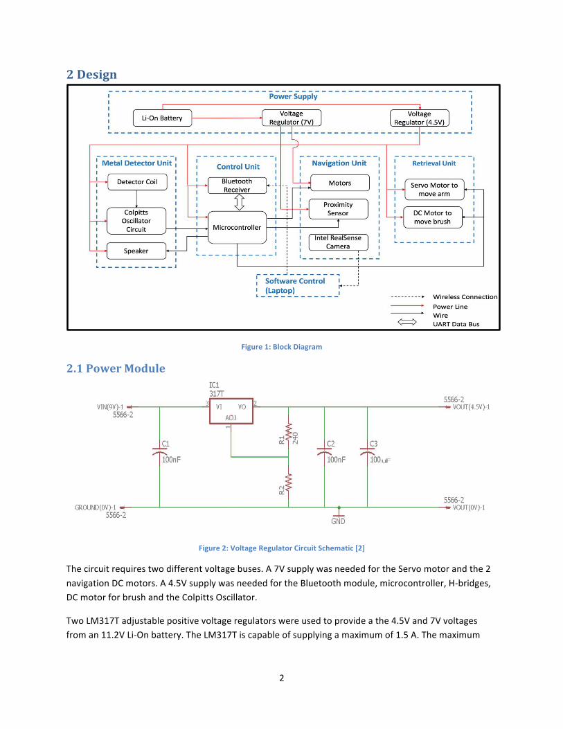
Figure1:BlockDiagram
2.1PowerModule
Figure2:VoltageRegulatorCircuitSchematic[2]
Thecircuitrequirestwodifferentvoltagebuses.A7VsupplywasneededfortheServomotorandthe2navigationDCmotors.A4.5VsupplywasneededfortheBluetoothmodule,microcontroller,H-bridges,DCmotorforbrushandtheColpittsOscillator.
TwoLM317Tadjustablepositivevoltageregulatorswereusedtoprovideathe4.5Vand7Vvoltagesfroman11.2VLi-Onbattery.TheLM317Tiscapableofsupplyingamaximumof1.5A.Themaximum

3
currentdrawfortherobot,whenallmotorswereoperationalwas0.64A.Thebatteryholdsanenergychargeof2200mAh.Thisensuresatleast3.4hrsofoperation,whichiswellaboveourrequirements.
Figure2showsthecircuitdesignforthevoltageregulator.ThereferencevoltageacrossresistorR1isconstantat1.25V.Theadjustmentterminalcurrentis100𝜇A,whichcorrespondstoaminimumvalueof120ΩforresistorR1.Theoutputvoltageiscalculatedas
V012 = 1.25× 1 +R8R9
(2.1)
UsingEquation(2.1),thevalueofresistorR8wascalculatedtobe624Ωforthe4.5Vregulator,and1104Ωforthe7Vregulator.
ThevalueforresistorR9waschosenas240Ωtoprovideforbetterstability.Stabilityisessentialforthe4.5Vregulator,tominimizethefluctuationinfrequencyproducedbytheColpittsOscillator.Theadditionalcapacitorsaidinthestabilityoftheregulator,andhelpsmoothouttheinherentripplecontentgivingitagoodtransientresponse[2].
2.2MetalDetectorModule
Figure3:MetalDetectorCircuitSchematic
ThemetaldetectionmoduleutilizesaColpittsOscillatorandadetectorcoil.TheColpittsOscillatorwasusedtoproduceafixedfrequencyof100kHzusingacombinationofcapacitorsandaninductor.Thisfrequencyiscontinuouslyfedintothemicrocontroller.Whenthedetectorcoilisbroughtneatametallicobject,itsinductancechangeswhichcausesashiftinthefrequency.Thischangeisdetectedbythemicrocontroller,whichthensendstheuseranalertthroughBluetooth.

4
Thespeakerwasremovedfromtheproposeddesign.Itwasdeterminedthataspeakerisnotthemostreliablewaytoalerttheuserinanoisyandoutdoorsetting.ItwasalsoredundantsincethechannelofcommunicationthroughBluetoothwasalreadyimplemented.
2.2.1ColpittsOscillatorTheColpittsOscillatorusesacapacitivevoltagedividernetworkasitsfeedbacksourceandasinglebipolartransistoramplifier(2N2222)asthegainelementwhichproducesthesinusoidaloutput.Figure3showsthecircuitschematicforthemetaldetectormodule.TheinductorisconnectedinparalleltocapacitorsC4andC5inseries,toformthetankcircuit.Oncepowerisapplied,thecapacitorschargeanddischargethroughtheinductor.ThevoltagedevelopedacrosscapacitorC5providestheregenerativefeedbackrequiredforsustainedoscillations[3].Theoscillationsappearamplifiedatthecollectoroutputofthetransistor,andarefedintothecounterpinofthemicrocontroller.ResistorsR4andR5providethestabilizingDCbias.CapacitorC6preventsDCcurrentsfromgoingintothetankcircuit[3].Thetransistorandthecapacitivefeedbackeachprovideaphaseshiftof180°toachieveatotalphaseshiftof360°,anessentialconditionforoscillations[3].
ThisdesignwaschosenoverothervariantssuchastheHartleyoscillatorbecausethisconfigurationresultsinlessselfandmutualinductancewithinthetankcircuit,thusimprovingthestabilitywithintheoscillator[4].
AhigherfrequencywaschosenbecauseitisbetteratinducingEddycurrentsinnon-ferrousobjects,whichdecreasetheinductanceandhencemakesitmoresuitablefordetectingsmallerobjects[4].Whileahigherfrequencyhasasmallerrange,ourprojectonlyrequiredarangeof2 − 3cmtofunction.
Thefrequencyoftheoscillationsis
F =1
2×π× L×C2 (2.2)
where𝐿istheinductanceand𝐶E isthecapacitanceofthetankcircuit.Toproduceafrequencyof100kHz,thecapacitanceandinductancewerecalculatedas5nFand0.506mHrespectivelyusingEquation2.2.
Thevaluesofthecapacitanceofthetankcircuitisgivenby
C2 =CJ×CKCJ + CK
(2.3)
whereCJandCKarethetwocapacitorsinthetankcircuit(seefigure3).Thefeedbackfractionisgivenby
CJCK% (2.4)
Alargeamountoffeedbackreturnedthecircuitcancausethesinewavetobecomedistorted,andasmallamountwillpreventtheoscillationfromgettingstarted[4].ComparingEquations(2.3)and(2.4),CJandCJwerebothcalculatedas10nf.

5
2.2.2DetectorCoilThedetectorcoilisaninductormadeupof24AWGwirewrappedaroundahollow,non-conductivespool.Theinductanceofthecoiliscalculatedas
𝐿 =𝑁8×𝜇×𝐴
𝑙
(2.5)
where𝑁isthenumberofturnsincoil,𝐴istheareaofthecoil,𝑙isthelengthofthecoiland𝜇isthepermeabilityoffreespace.UsingEquation2.5,thenumberofturnswasfoundtobe50,radiustobe5.08cmandthelengthtobe2.032cm.
Whenametalwithhighconductivity(suchassilver)isbroughtnearthecoil,itsmagneticpermeabilityincreaseswhichcausesanincreaseinitsinductance[5].Whenametaloflowconductivityisbroughtnearthecoil,Eddycurrentsareinducedinthemetal,whichopposetheelectricfieldoftheinductor[5].Thiscausesadecreaseininductance,whichincreasesthefrequencyproducedbytheColpittsOscillator[4].
Thisdesignworkedforlargerobjects,butthechangeinfrequencywastoosmalltodetectforsmallerobjects.Thus,anewinductorwasbuiltwhichhadamagneticfield4timesasstrongastheoriginalone,andaninductanceof10mH(thecapacitorsvaluesinthetankcircuitwereadjustedtokeepthefrequencyconstant).Themagneticfieldofaninductorisgivenby
𝐵 =𝑁×𝜇×𝐼
𝐿 (2.6)
where𝑁isthenumberofturnsinthecoil,𝜇isthemagneticpermeabilityoffreespace,𝐼isthecurrentintheinductorand𝐿isthelengthoftheinductor.Thisinductor’sdimensionswerecalculatedbycomparingtheEquation(2.6)and(2.5).
2.3ControlUnitThecontrolunitisusedtocontroltheoperationoftherobot’sfunctions.ItconsistsofaBluetoothModuleandaMicrocontrollerchip.
2.3.1BluetoothModuleTheBluetoothmoduleisusedtowirelesslysenddatatothemicrocontrollersothattherobot’sfunctionscanberemotelycontrolled.TheHC-05Bluetoothtransceiverwaschosenduetoitsexcellentrangeofover40ft,anditsrelativelycheapcost.TheBluetoothmodulereceivesdatafromanandroidapp,andcommunicateswiththemicrocontrolleroverUARTinterfaceatabaudrateof9600bps.Asweonlysendasinglebyteofinformationatatime,speedofdatatransferwasnotaconcern.
HC-05hascantolerateamaximuminputsignalof3.3V,whichislowerthantheoutputsignaloftheATmega328microcontroller.Thus,avoltagedividermadeuptworesistorsofvalues1000Ωand2000ΩwasusedtoconnecttheRXpinofthemoduletotheTXpinofthemicrocontroller.Figure4showsthecircuitschematicfortheBluetoothmodule.

6
TheHC-05BluetoothmodulecannotconnecttoAppledevices.Wesearchedforothermodules,butfoundoutthatAppledevicescanonlyconnecttoBluetoothdevicesregisteredwiththefirm.Wewereunabletofindanyinexpensivestand-aloneBluetoothmodulethatcanconnecttoAppledevices.
Figure4:BluetoothModuleCircuitSchematic
2.3.2MicrocontrollerATMega328P-Uwaschosentobeourrobot’smicrocontrollerduetoitsinexpensivecost.ThemicrocontrollerreceivesthedatafromtheBluetoothmodule,decodesit,andperformstheappropriatefunctionononeofthemotors.ThemicrocontrollercontrolsthetwoDCmotorsfornavigation,theupwardsanddownwardsmovementoftheServomotor,andtheDCmotorforthebrush.
TheSignalinputoftheServomotorwasconnectedtoPortB,asitrequiresaPWMwaveinordertohaveprecisecontroloverthedegreeofrotation.
Additionally,themicrocontrollercontinuouslyreadsthefrequencyoftheColpittsOscillator,andcomparesitwiththefixedfrequencyof100kHz.Whenthefrequencychangesbymorethantheaveragefluctuation,amessageissenttotheappthroughBluetoothtoalerttheuserthatmetalhasbeendetected.

7
2.4NavigationUnit
Figure5:NavigationUnitCircuitSchematic
ThenavigationunitcontrolsthemotionoftherobotusingtwoDCmotorsforthetwowheeltracks.SinceDCmotorsareaninductiveload,themotorsweredrivenusingtheL293DH-bridgeasthepinsoftheATMega328canhandleamaximumcurrentof40mA.ThepositiveandnegativepinsofthebothmotorswereconnectedtotheHbridge,whichreceivesitsinputfromthePortBoftheMicrocontroller.Thus,eachmotorcanbedrivenforwardandbackwards.Therobotisabletoturnleftandrightbymovingthemotorsintheoppositedirection.Figure5showsthecircuitschematicofthenavigationmodule.
ThenavigationunitalsohasanIntelRealSensecamera,whichismountedontherobot.Thepurposeofthecameraistoaidinnavigationbyprovidingrealtimevideofeedbacktotheuser.ThecamerasendsthevideostreamoveritsownWi-Finetwork,whichcanbeviewedintheapp.Thiscamerawaschosenduetoitsadvancedfunctionalitiessuchasdepthanalysisandfacialrecognition.Thenextstepintheprojectistousethesecapabilitiestoimplementsemi-autonomousnavigation.

8
2.5RetrievalUnitTheretrievalunitisusedtoretrievesmallobjectsfromtheground.TheunitconsistsofaServomotor,twowoodenarms,a3Dprintedcontainer,abrushandaDCmotortorotatethebrush.Figure6showsthePhysicalCADDesignoftheretrievalunit.
Intheinitialdesign,thecoilwasinfrontoftheretrievalunit,onthesamesideofthecar(seeFigure6).However,thisorientationcausedanimbalanceinweightwhichcausedtherobottotipover.Thus,thedetectorcoilwasplaceatthebackoftherobottobalancetheweight.
Figure6:CADDesignoftheRobotwiththeRetrievalUnit
2.5.1TheScoopSystemThe3Dprintedcontaineris9cmwideandisconnectedtothetwowoodenarmswhichareconnectedtotheServomotor.Themicrocontrollerrotatestheservomotor,whichenablesittolowerthecontaineruntilitlaysflatontheground.Toprovidesomeflexibilitytothecontainerandtoaddrobustness,springsandstopperswereaddedtothebackofthecontaineratitsconnectionpointwiththearms.Thisallowedthecontainertoadjusttosmallvariancesinthegradientoftheterrain.Theserubberstoppersalsopreventthecontainerfromsmashingtoohardontheground,thusreducingtheriskofthesystembreakingapart.
Thepositionoftheservomotorisupdatedby1degreeatatime,inordertoprovideacontinuous,jerk-freemotion.Thisreducesthepossibilityoftheobjectdroppingfromthecontainerwhenitisbeingscoopedup.
Keepinginmindthatwewoulddesignabiggerretrievalunitinthefuture,ahightorqueServomotorofTorque20kg-cmwaschosensothatlargerobjectscouldbepickedup.

9
2.5.2TheBrushSystemThecontainerhasahorizontallypositionedbrushattachedinfrontofitwhichisconnectedtoaDCmotor.Thismotorspinsthebrush,whichpushesanobjectintothecontainer.Abrushwiththickplastichairwaschosensothatitcanpushtheobjectwithastrongerforce.Thebrushhangs1.3cmfromthebaseofthecontainer.Thus,themaximumheightoftheobjectsthatcanberetrievedis1.3cm.
Initially,theDCmotorchosenwashighspeedmotor.Itdrew1.2Aofcurrent,andwouldcausethenavigationmotorstoslowdownifoperatedsimultaneously.Italsohadalowtorque,andwouldgetstuckiftheobjectwasheavy.ThismotorwasreplacedwithahightorqueDCmotor,whichranat10000RPM.Thenewmotorwasabletoprovidetheobjectwithenoughmomentumtoovercomethefrictionalforceactingonit.
Inordertopreventtheobjectsfromfallingdownwhenthecontainerwasbeingliftedup,asmallbumperwasbuiltonthebaseofthecontaineratasmallincline.Thisinclinedidnotstoptheobjectfromenteringthecontainer,butpreventedthemfromfallingout.Thebaseofthecontainerwasmadeasthinaspossible(1mmthick)whilemaintainingthestructuralintegrity,toallowthesystemtopickupflatobjectssuchaskeys.
2.6SoftwareControlInordertocontrolthefunctionsoftherobot,anandroidappwasdeveloped.Thisappusedthephone’sBluetoothclienttoconnecttotheHC-05Bluetoothmodule.Therearefourpushdownbuttonstocontrolthenavigationsystemanddrivetherobotforward,backward,leftandright.Therewerefouronclickbuttonstocontroltheretrievalunit;twotorotatetheservomotorupanddown,andtheothertwotostartandstopthebrush.
Ourproposeddesigndidnotincludeamobileapplication.Therobotwasmeanttobecontrolledthroughalaptop.Wedidnotthinkitwasfeasibletocontroltherobotwithalaptopastherobothasarangeofover30feet.Thus,anandroidappwasdevelopedtoprovideabetteruserexperience.

10
3Verification
3.1PowerModuleTheresultsforthetwovoltageregulatorsareshowninTable1.
Table1:VoltageRegulatorResultsRegulator Observed
VoltageMaximumFluctuationovera
Periodof30minutes4.5V 4.52V 0.44%7V 7.1V 1.12%
3.2MetalDetectorModule
3.2.1ColpittsOscillatorAfrequencyof98.614kHzwasobservedwithanerrormarginof0.57%usingtheinitialdesign.Thissignalwassustainable,andremainedinthisrangeforatleastthirtyminutes.Thiswaswithinouracceptablelimits.Figure7showstheOscilloscopereadingofthesignal.Figure8showsthesamesignalwhentheinductorisclosetoametallicobjectofVolume110.12𝑐𝑚8.
Figure7:OscilloscopeReadingof98kHzsignal

11
Figure8:SignalWaveonOscilloscopewhentheobjectisnearametallicobject
3.2.2DetectorCoilWiththeinitialdesign,thesmallestobjectthatcouldbedetectedwasacuboidoflength3cm,width1.5cmandheight2.7cm.Thiswasbiggerthantheminimumsizerequirementsforourdesign.Thus,anewinductorwasbuiltwithamagneticfieldfourtimesasstrongasthepreviousone.Alongwiththis,differentfrequenciesweretested,theresultsofwhichareshowninTable2.
Table2TheChangeinfrequencyforDifferentFrequenciesInductance
(𝐦𝐇)Capacitance
(𝐧𝐅)ObservedFrequency
(kHz)
FluctuationPercentage
PercentageChangeduetobrassobject
ofVolume𝟒. 𝟗𝟐𝒄𝒎𝟐
PercentageChangeduetobrassobject
ofVolume𝟏𝟏𝟎. 𝟏𝟐𝒄𝒎𝟐
0.546 5 98.6 0.57 - 1.920.546 2.5 143.4 0.88 1.02 2.3810 5 21.8 0.49 - 1.1410 2.5 36.2 0.66 - 1.3410 0.235 94.4 0.84 1.17 2.37
Thenewinductordidnotsatisfythedesignrequirementsoftheminimumobjectsizeeither.Theresultsshowthatwhileastrongermagneticfieldincreasesthechangeinfrequency,theincreaseinaccuracyismarginal.Frequencyplaysabiggerroleindeterminingtheminimumsizeoftheobjectthatcanbedetected.
Atesttocomparethechangeinfrequencyatdifferentdistancesfromtheinductorwasalsoconductedforthetwoobjects.Thefirstobjectwasacuboidbrassobjectofvolume4.92cm8.Thesecondobjectwasabrasscylinderofvolume110.12cm8.ThesearereferredtoasObject1andObject2respectivelyinFigure9,whichshowsthefrequencyagainstthedistanceoftheobjectfromtheinductor.Wefoundthatthelargeobject(Object2)couldbedetectedatamaximumdistanceof4cm,whereasthesmallerobject(Object1)wasabletobedetectedatamaximumdistanceof1cm.

12
Figure9:Relationshipbetweenchangeinfrequencyanddistancefrominductor
3.3RetrievalUnitTheretrievalunitwastestedwithseveralobjectsofdifferentshapesandsizes.Table3showsthedifferentobjectswhichwereusedastestcases.Eachoftheseobjectswastested15times.TheresultsfortheretrievalunitareshowninFigure10.Thesystemworkedverywellfornailsandbolts,whichwastherequirementinourproposeddesign.ThesystemstruggledtopickuplargecubicalobjectssuchasLegopieces,astheywouldsometimesgetstuckunderthebrushdependingontheangleofapproach.
Table3:TestCasesfortheRetrievalUnit
ObjectName Shape DimensionsWasher Thinandflat Height=0.3cm,Radius=1.7cm
HouseKey(withsmallkeyring)
Thinandflat Thickness=0.3cm,length=3.1cm
Bolt Round–abletoroll
DiameterofHead=1.27cm,length=1.9cm
Screw Round–abletoroll
DiameterofHead=0.9cm,length=5.8cm
Legoblock Cube–notabletoroll
Side=1.2cm
CarKey Misc.–notabletoroll
Height=2.2cm,Length=5cm,Width=3cm
96
98
100
102
104
106
108
110
Infinity 5 4 3 2 1 Insidethecore
Freq
uency(kHz
)
DistanceFromCore(cm)
Frequencyv/sDistance
Object2 Object1 BaseFrequency+MaximumError

13
Figure10:ResultsFortheScoopingandLiftingofVariousObjects
3.4ControlUnit
3.4.1BluetoothModuleSeriesofdatawassenttothemicrocontrollerwhichwasbeingdisplayedontheSerialMonitor.Itwasverifiedthatthecorrectdatawasreceived.TherangeoftheBluetoothModulewasverifiedtobeatleast35feet.
3.4.2MicrocontrollerTheMicrocontrollerwasabletocontrolthenavigationunit,andcommunicatewiththeBluetoothmodule.
SincethedesignoftheColpittsOscillatorwasnotfinisheduntilmuchlaterinthecourse,thecodetoreadthefrequencycorrectlyintothemicrocontrollerwastestedusingasinewavegeneratedbyafunctiongenerator.ThefunctionwasalsodisplayedontheoscilloscopeanditwasverifiedthatthefrequencywasbeingreadcorrectlybytheAtMega328.
ThissamecodedidnotworkwiththeColpittsOscillator.Duetothetimeconstraints,wewerenotabletofixthiserror.Webelievethatthecauseofthiserrorwasthefactthatthesignalwasnotsampledcorrectly,thusresultinginanincorrectreferenceDCvoltage.Thewavegeneratedbythefunctiongeneratorisclosetoaperfectsinewave,whichiswhythiserrorwasnotseenintheinitialtests.InthecaseofaColpittsOscillator,thewaveisnotaperfectsinewave,andincorrectsamplingcouldbethepotentialcauseoftheerrors.
02468101214
Washer HouseKey(withasmall
ring)
Bolt Screw LegoBlock CarKey
PerformanceofRetrievalUnit(15Tries)
Scooped ScoopedandLifted

14
3.5NavigationUnitWeverifiedthatthecarcoulddriveforward,backward,leftandrightataspeedofatleast2.5inches/sec,withthefullweightoftheretrievalunitandthemetaldetector.
3.6SoftwareControlItwasverifiedthattheAppcouldconnecttotheBluetoothModuleandcontrolalloperationsoftherobot.

15
4.CostsOurlaborcostisestimatedatanhourlyrateof$35perhour,12hoursperweekfortwopeople.Theprojectwas12weekslong.Thetotallaborcostsaregivenby
𝑇𝑜𝑡𝑎𝑙𝐶𝑜𝑠𝑡 = 2×$35ℎ𝑜𝑢𝑟
×12ℎ𝑜𝑢𝑟𝑠𝑤𝑒𝑒𝑘
×12𝑤𝑒𝑒𝑘𝑠×2.5 = $25,200(4.1)
Table4showsthecostofthepartsusedinmakingtheproject.
Table4:CostAnalysisofPartsPart Manufacturer Quantity RetailCost
($)Bulk
PurchaseCost($)
TotalPrototypeCost($)
ChassisandMotors MountainArk 1 49.99 44.99 49.99Servo LewanSoul 1 21.99 20.99 21.99
BluetoothHC-05 DSDTech 1 9.99 7.99 9.99ATMega238-PU Atmel 1 2.28 1.68 2.28LiPoBatteryPack Turnigy 1 10.99 10.99 10.99
LM317T TexasInstruments 2 2.03 1.38 4.0624AWGWire Remington
Industries75feet 0.05 0.03 3.42
2N2222ANPNTransistor MclglcM 2 0.19 0.03 0.38IntelRealSenseD415 Intel 1 149.99 149.99 149.99AssortedComponents(Resistors,Capacitors,
etc.)
KOASpeer 1 9.99 9.99 9.99
PCB PCBWay 1 5.6 0.87 5.63DPrinting CERL 1 7.00 7.00 7.00
Total 275.68Ourtotalcostofpartfortheprototypeis$275.68.Thusthetotalcostofdevelopmentofaprototypeis$275.68 + $25,200 = $25,475.68.

16
5.Conclusion
5.1AccomplishmentsOurprojectworkedasintendedforthemostpart.Thetwomajorcomponentsofoursystem;retrievalandmetaldetectionunitworked,eventhoughtheirperformancewasnotasgoodasexpected.Wewereabletobuildaplatformwhichhasaneasilyexpandablemodulardesign.Thetechniqueswehavetestedcanbemademorerobustthroughfurtherresearchandexperimentation.
5.2Ethicalconsiderations
Oneoftheethicalchallengesposedbyourprojectisthewayitisused.Sinceitisarobotcarthatcanbecontrolledwirelessly,apotentialissueoftrespassingpropertyarises.TheIEEECodeofEthicsstatesthatoneshouldavoidtoinjureotherpeopleandtheirproperty[6].Thecarcouldalsopossiblyinjurepeopleifitisnotinthesightoftheuserduringoperation.Wehaveequippedthecarwithacamera,sothattheusercanoperatethecarevenitisnotintheirsight.Topreventthemisuseofthisrobot,wehavedecidedtouseaBluetoothreceiverwithlimitedrangeofabout40feet.Inordertopreventpossibleinjuriestopeopleanddamagetoproperty,wehaveusedmotorsthatlimitthespeedofthecarto2.5inchespersecond.
Thecarusesalithiumionbattery,whichposesapotentialsafetyhazard.Topreventthebatteryfrommovingaroundduringtheoperationofthecar,itissecurelyplacedonthechassisofthecar.
Ourprojecthastwomovingarms,andarotatingbrush.Topreventpossibleinjuries,wehavelimitedthetorqueproducedbytheservomotor.Thebrushisrotatedatalimitedspeedof1degreepersecondsothatitmaynotinjureanyone.Further,toensurethatnodamagetopropertyisdone,theretrievalsystemisequippedwithrubberstopperssothatthecontainerdoesnotsmashintotheground.
Wearealsoresponsibleforbeinghonestabouttheclaimswemakeabouttheproject[6].Toadheretothisguideline,wewillbeverycarefulaboutthesuggestedusageofourproduct.Untilitcanmeettheminimumaccuracyguidelinesfordetectinglandmines,thesuggestedusagewouldbestrictlyforhomeandrecreationaluse.
TheIEEECodealsostatesthatonemustholdparamountthesafetyofthepublic[6].Webelievethatwehavemadeanexcellentcosteffectiveplatform,thatcanpossiblyhelppeopleinwartornregions.Whileitssuggesteduseisinhomes,itsfeaturescanbeexpandeduponastheproductisagreatplatform.
5.3FutureworkThenextstepinthisprojectistofullyintegratethemetaldetectorcircuitwehavebuiltintooursystem,eventhoughitdoesnotworkasweinitiallyexpected.WewouldthenusetheDepthAnalysisfeatureoftheIntelCamerainconjunctionwithproximitysensorsinordertoimplementsemi-autonomousnavigation,sothattherobotcanlookforobjectsitselfwithlimitedhumancontrol.
Wewouldalsoliketobuildamorerobustretrievalunitbyexperimentingwithvacuumpumps,electromagnets,verticalbrushes,androboticarmstopickobjectsup.Finally,we’dliketotestalternatemetaldetectiontechniques,suchascapacitivesensing,beatfrequencyoscillatorsetc.

17
References[1] Siegel,R.(2002).Landminedetection-IEEEJournals&Magazine.[online]Ieeexplore.ieee.org.
Availableat:http://ieeexplore.ieee.org/document/1048979/[Accessed6Feb.2018].
[2]Electronics-Tutorials.(n.d.).VariableVoltagePowerSupply.[online]Availableat:https://www.electronics-tutorials.ws/MiscellaneousCircuits/variablevoltage-voltage-power-supply.html[Accessed19Feb.2018].
[3]Vlab.amrita.edu.(2011).ColpittsOscillator:harmonicMotionandWavesVirtualLab.[online]Availableat:http://vlab.amrita.edu/?sub=1&brch=201&sim=1142&cnt=1[Accessed20Feb.2018].
[4]Electronics-Tutorials.(n.d.).TheColpittsOscillator.[online]Availableat:https://www.electronics-tutorials.ws/oscillator/colpitts.html[Accessed18Feb.2018].
[5]Electronics-Tutorials.(2018).InductanceofaCoil.[online]Availableat:https://www.electronics-tutorials.ws/inductor/inductance.html[Accessed19Feb.2018].
[6]Ieee.org,"IEEECodeofEthics",2018.[Online].Availableat:http://www.ieee.org/about/corporate/governance/p7-8.html.[Accessed24March.2018].

18
AppendixA RequirementandVerificationTable
Table5:RetrievalUnit:RequirementandVerifications
Sub-Module
Requirements Status
ScoopSystem
1. Thelowerpositionofthearmsshouldlaythecontainerflatontheground.
2. Thestoppershouldbeabletostopthearmswhenitreachestheground,andpreventitfrombumpingintotheinductor’sholderwhilegoingup.
1. Item1:Verified.
2. Item2:Verified.
BrushSystem
1. Thebrushshouldbeabletospinwhilehangingabovethebottomedgeofthescoopsystemby0.5" ± 5%.
2. Thesystemshouldbeabletopickupanythingwithdimensionsof(𝑊×𝐷×𝐻)3”×1”×0.5”withanaccuracyofatleast75%.
3. Thesystemshouldpreventobjectsfromfallingoutofthecontainerwithasuccessrateof80%.
1. Item1:Verified.
2. Item2:Verified.
3. Item3:Verified.

19
Table6:PowerModule:RequirementandVerifications
Sub-Module
Requirements Verification Status
Li-OnBattery
1. Thebatterymustbeabletostoreenoughchargetoprovideatleast640mAcurrentat9V-11V,foratleasttwohours.
1. VerificationProcessforItem1:a. UseaVoltmetertoverify
thataLi-Onbatterysuppliesbetween9-11V.
b. Applyaconsistentdrawof640mAagainstthebatterypackfortwohours,andensurethatthatthevoltageoutputiswithintherange9Vto11V.
1. Item1:Verified.
VoltageRegulator-4.5V
1. Theregulatorshouldprovide4.5V±5%froman9-11Vsource.
1. VerificationProcessforItem1:a. InputVoltage:Thecircuit
wasconnectedtothepowergenerator,whichwassetat11V.TheinputvoltageacrosswasmeasuredusingamultimeterinDCvoltagesetting.Thisvoltagewasreadtobe11V.
b. OutputVoltage:TheoutputvoltagewasmeasuredusingamultimeterinDCvoltagesetting.Thisvoltagewasstableat4.52V.
c. Stability–Theoutputvoltagewasmeasuredwhiletheinputvoltagefromthepowergeneratorwasreducedto9V.Thereadingwasstable
1. Item1:Verified

20
VoltageRegulator-7V
1. Theregulatorshouldprovide7V±5%froman9-11Vsource.
1. VerificationProcessforItem1:d. InputVoltage:Thecircuit
wasconnectedtothepowergenerator,whichwassetat11V.TheinputvoltageacrosswasmeasuredusingamultimeterinDCvoltagesetting.Thisvoltagewasreadtobe11V.
e. OutputVoltage:TheoutputvoltagewasmeasuredusingamultimeterinDCvoltagesetting.Thisvoltagewasstableat7.1V.
f. Stability–Theoutputvoltagewasmeasuredwhiletheinputvoltagefromthepowergeneratorwasreducedto8V.Thereadingwasstable.
1. Item1:Verified

21
Table7:NavigationUnit:RequirementandVerifications
Sub-Module Requirements Verification Status
Motors 1. The DC motors must be able to operate at 7V±5%. The microcontroller must be able to control the movement of each DC motor. This includes turning it on/off, driving it forward and driving it backward.
2. They must be able to move the full weight of the car and the metal detector circuit, at a speed in the range of 2 to 2.5 inches per second.
1. Verification Process for Item 1: a. Power was applied to
the circuit and the microcontroller was programmed to send the following signals to Pin 14, Pin 15, Pin 16 and Pin 17: LLLL - Both motors off HLLL – Left DC Motor forward LHLL – Left DC motor Backward LLHL – Right DC Motor Forward LLLH – Right DC Motor Backward
2. Verification Process for Item 2: a. Using an inch tape,
mark a distance of 5 ft., clearly marking the start and the end lines.
b. The robot car, with all the modules attached, should be able to reach the endpoint from the start point in 24-30 seconds.
c. Adjust the amount of voltage applied by changing the resistor values for the 7V regulator, until the speed is within the tolerance level.
1. Item 1:
Verified.
2. Item 2: Verified.
IntelRealSense
1. The camera should be able to create its own Wi-Fi network, and
1. Verification Process for Item 2: a. Configure the camera
1. Item 1: Verified.

22
Camera connect to a laptop with a range of at least 30 ft.
2. The camera should be able to transmit data over this Wi-Fi connection.
to create its own Wi-Fi network.
b. Ensure that a laptop can connect to this network.
c. Move the laptop at least 30 feet away from the camera. Ensure that the laptop can still connect the Wi-Fi network.
2. Verification process for Item 3: a. Connect the camera to
a laptop, and turn its video feed on.
2. Item 2: Verified.

23
Table8:MetalDetectorUnit:RequirementandVerifications
Sub-Module
Requirements Verification Status
DetectorCoil
1. Themagneticfieldareacreatedbytheinductorcoilshouldbebigenoughtogiveitarangeof3-5cm.
1. VerificationProcessforItem1:a. Placeascrewnailof
size8Dwithaheaddiameterof0.28inchesatadistanceof4-5cmawayfromthecoil,whilethecircuitisbeingpowered.
b. Connectthecollectorpinoftheamplifiertotheoscilloscope.
c. Thechangeinfrequencyduetothemetallicobjectmustbegreaterthanathresholdfrequency,whichwillbefoundthroughexperimentation.
1. Item1:Failed.Nochangeinfrequencywasobservedduetosmallmetallicobjectssuchasnails,ringsetc.Alargermetallicobjectcausedanincreaseinfrequencyof2kHz.
ColpittsOscillatorCircuit
1. Theoscillatorcircuitmustprovideasteadyoscillationinthe100kHz±5%rangewhennometalisneartheinductioncoil.
1. VerificationProcessforItem1:a. Connectthecollector
pinoftheamplifiertotheoscilloscope.
b. Apply4.5Vofpowertothecircuit,whileensuringthatthereisnometallicobjectwithin20cmoftheinductorcoil.
c. Thefrequencyoftheresultantsinusoidalsignalshouldbe100kHz±5%.
d. Adjustthecapacitorvaluesandthenumberofturnsinthecoilto
1. Item1:Verified.

24
2. Theoscillationshouldbesustainableforatleasttwohours.
gettheresultwithintolerance.
2. VerificationProcessforItem2:e. Connecttheoutput
signalfromtheoscillatorcircuittoafrequencycounter.
f. Apply4.5Vofpowertothecircuit,whileensuringthatthereisnometallicobjectwithin20cmoftheinductorcoil.
g. Thereadingonthefrequencycountershouldstaywithin5%of100kHzforatleasttwohours.
2. Item2:Verified

25
Table9:ControlUnit:RequirementandVerifications
BluetoothModule
1. The Bluetooth receiver must be able to transfer data to and from the microcontroller over UART
2. It must have a range of
at least 25 ft.
1. Verification process for Item 1: a. Configure the
Bluetooth module with the microcontroller using the UART connection, by connecting the TXD and RXD pins to port D of the microcontroller.
b. Set the baud rate to 9600 bps (default).
c. Connect the Bluetooth module to a laptop.
d. Send test data from the laptop.
e. Verify that the test data was received correctly by the microcontroller.
2. Verification Process for Item 2: a. Connect the module to
a laptop. The status LED should turn on.
b. Move the laptop at least 25ft. away from the module. The LED should remain on.
1. Item 1: Verified.
2. Item 2: Verified.

26
Microcontroller 1. The microcontroller must be able to receive data from the Bluetooth receiver over UART.
2. The microcontroller must be able continuously compare the measured frequency and the fixed frequency, and trigger the speaker when the difference is greater than the threshold.
1. Verification process for Item 1: a. Configure the
Bluetooth module with the microcontroller using the UART connection, by connecting the TXD and RXD pins to port D of the microcontroller.
b. Set the baud rate to 9600 bps (default).
c. Connect the Bluetooth module to a laptop.
d. Send test data from the laptop.
e. Verify that the test data was received correctly by the microcontroller.
2. Verification process for Item 2: a. Store an experimental
threshold frequency (10kHz) and a fixed frequency (100kHz) in the microcontroller.
b. Connect the port D of the microcontroller to the function generator in the sine wave mode.
c. Configure the sine wave generator to generate a wave of 100kHz.
d. Connect the speaker and configure the software so that the microcontroller triggers the speaker if the difference between the fixed frequency and the measured frequency is greater
1. Item 1: Verified.
Item 2: Verified

27
than the threshold. e. Now power the
microcontroller chip. f. After 5 minutes,
decrease the output of the function generator by 10kHz. The speaker should turn on.