
Securing a Remote Terminal Application with a Mobile Trusted Device
Upload
khangminh22Category
view
1download
0
A
R emote T erminal U nit
User’s Guide Technical specifications & cabling

Version: 1.06 2
Disclaimer Every effort has been made to ensure the accuracy of the information in this guide. However, Techno Trade S.A. assumes no responsibility for the accuracy of the information. Product information is subject to change without notice. TWinSoft and A are registered trademark of Techno Trade s.a. Windows '95, '98, NT, 2000, XP are trademark of Microsoft Corp. Internet Explorer is a trademark of Microsoft Corp. Copyright © 2004-2006 by Techno Trade SA Edition: February 7, 2006

Version: 1.06 3
TABLE OF CONTENTS
PRESENTATION ................................................................................................................ 7
1. HOW TO USE THIS MANUAL? ..............................................................................10 1.1. What is in the manual? ......................................................................................... 10 1.2. What is not in the manual? ................................................................................... 10
2. THE HARDWARE CONCEPT ................................................................................11 2.1. The Racks............................................................................................................ 11 2.2. The Cards ............................................................................................................ 12
HARDWARE..................................................................................................................... 13
3. INSTALLATION OF THE RACK..............................................................................14 3.1. Installation of the Rack on a DIN rail ..................................................................... 14 3.2. Installation of the Rack in a 19’’ cabinet................................................................. 15
4. INSERTION OF CARDS IN THE RACK ....................................................................16 4.1. The Power supply................................................................................................. 16 4.2. Placing the Power Supply Card .............................................................................. 17 4.3. Working without Power Supply Card...................................................................... 18 4.4. Hardware vs. Software Address of Cards ............................................................... 19 4.5. Powering ............................................................................................................. 22
TWINSOFT - GETTING STARTED .................................................................................... 25
5. INSTALLATION OF TWINSOFT............................................................................26 5.1. System requirements............................................................................................ 26 5.2. Installation of the CD-ROM ................................................................................... 27 5.3. Programs of ‘TWinSoft Suite’................................................................................. 29
6. STARTING TWINSOFT......................................................................................30 6.1. Wizard................................................................................................................. 31 6.2. Communicating with TBox MS ............................................................................... 32 6.3. PC Communication Set up..................................................................................... 32 6.4. Testing communication......................................................................................... 34 6.5. Global reset of TBox MS........................................................................................ 35 6.6. LED « RUN »........................................................................................................ 35 6.7. Saving and Sending a Program.............................................................................. 36
6.7.1. Saving a document ..................................................................................................36 6.7.2. Compiling a document..............................................................................................36 6.7.3. Sending a document ................................................................................................37

Version: 1.06 4
TWINSOFT - PROGRAMMING.........................................................................................39
7. INTRODUCTION .............................................................................................. 40
8. RTU PROPERTIES ........................................................................................... 41 8.1. General properties ................................................................................................ 42 8.2. Drivers................................................................................................................. 43 8.3. Security ............................................................................................................... 43 8.4. Info properties ..................................................................................................... 44 8.5. Advanced............................................................................................................. 44
8.5.1. Startup ................................................................................................................... 44 8.5.2. Alarms.................................................................................................................... 45 8.5.3. Sampling Tables ...................................................................................................... 47 8.5.4. Temperature ........................................................................................................... 48 8.5.5. Remote Tags........................................................................................................... 48 8.5.6. TCP/IP.................................................................................................................... 48 8.5.7. Environment variables.............................................................................................. 50
9. RESOURCES ................................................................................................... 51 9.1. The CPU-16 card .................................................................................................. 51
9.1.1. Communication ports of the CPU .............................................................................. 52 9.2. Adding Cards........................................................................................................ 53
9.2.1. Adding an I/O card .................................................................................................. 55 9.2.2. Adding a ‘Modem’ Card ............................................................................................ 56 9.2.3. Adding a ‘GSM / GPRS’ Card ..................................................................................... 57
9.3. Communication Variables ...................................................................................... 62 9.3.1. Digital Communication Variable................................................................................. 62 9.3.2. Analog Communication Variable................................................................................ 63
9.4. System variables .................................................................................................. 64 9.4.1. Digital System Variables ........................................................................................... 64 9.4.2. Analog System Variables .......................................................................................... 66
9.5. Timers & Counters................................................................................................ 67
10. TAGS....................................................................................................... 68 10.1. Physical I/O ...................................................................................................... 69 10.2. Internal Variables (Registers)............................................................................. 70
10.2.1. Digital Internal Variable............................................................................................ 70 10.2.2. Analog Internal Variable........................................................................................... 72
10.3. ModBus address................................................................................................ 74 10.3.1. ModBus address of System Variables......................................................................... 74
10.4. Tags - Presentation / Write................................................................................ 75
11. IP PARAMETERS........................................................................................ 76 11.1. ISP configuration .............................................................................................. 77 11.2. FTP Host .......................................................................................................... 79 11.3. SMTP Server..................................................................................................... 80
Version: 1.06 5
11.3.1. About Redundancy...................................................................................................81 11.4. NTP Server....................................................................................................... 82
11.4.1. Time accuracy .........................................................................................................82 11.5. TCP/IP Debugging ............................................................................................ 83
12. ALARMS ...................................................................................................86 12.1. Introduction ..................................................................................................... 86 12.2. Digital Alarm Condition...................................................................................... 87 12.3. Analog Alarm Condition..................................................................................... 89 12.4. Recipients ........................................................................................................ 91 12.5. Group of Recipients .......................................................................................... 93 12.6. Messages ......................................................................................................... 94 12.7. Alarms table ..................................................................................................... 95
12.7.1. Columns description.................................................................................................96
13. DATALOGGING...........................................................................................97 13.1. Introduction ..................................................................................................... 97 13.2. The chronologies .............................................................................................. 99
13.2.1. Digital chronologies..................................................................................................99 13.2.2. Analog chronologies .................................................................................................99
13.3. The sampling tables.........................................................................................100
14. REMOTE TAGS .........................................................................................101 14.1. Introduction ....................................................................................................101 14.2. Creating a Remote Device ................................................................................102 14.3. Creating Remote Tag .......................................................................................103 14.4. Remote Tags through modem ..........................................................................105 14.5. Timing configuration of Remote Tags................................................................105
15. PERIODIC EVENTS....................................................................................106
16. HIGH SPEED TAGS ...................................................................................108 16.1. Processor time for executing High Speed Tag....................................................109
17. ACCESS SECURITY ....................................................................................110 17.1. RTU configuration............................................................................................111
17.1.1. RTU Properties ......................................................................................................111 17.1.2. Modem and Serial Port Properties............................................................................111
17.2. Password utility ...............................................................................................112 17.3. Login/Logout ...................................................................................................113
17.3.1. With TWinSoft .......................................................................................................113 17.3.2. With Internet Explorer............................................................................................114
17.4. Deactivating protection ....................................................................................115

Version: 1.06 6
TECHNICAL SPECIFICATIONS - CABLING ....................................................................117
18. RACKS & CARDS ..................................................................................... 118 18.1. Racks ............................................................................................................. 118 18.2. Power Supplies ............................................................................................... 119 18.3. CPU-16 bits .................................................................................................... 125
18.3.1. Lithium Battery...................................................................................................... 128 18.3.2. MultiMedia card..................................................................................................... 129 18.3.3. Button (Working modes) ........................................................................................ 129
18.4. I/O Simulation ................................................................................................ 134 18.5. 16 x digital Inputs........................................................................................... 135 18.6. 16 x digital Outputs......................................................................................... 139 18.7. 16 x digital Inputs/Outputs .............................................................................. 142 18.8. COMBO (Multiple I/O) ..................................................................................... 148 18.9. 8 x Analog Inputs ........................................................................................... 155 18.10. 8 x Temperature Inputs................................................................................... 158 18.11. 4 x Analog Outputs ......................................................................................... 161 18.12. 8 x Relay Outputs ........................................................................................... 165 18.13. 4 x Analog inputs isolated................................................................................ 168 18.14. PSTN modem.................................................................................................. 171 18.15. GSM / GPRS modem ....................................................................................... 173 18.16. GPS - Timing .................................................................................................. 175 18.17. Serial Ports ..................................................................................................... 178
APPENDIXES.................................................................................................................183
APPENDIX A. LICENSES .................................................................................... 184 A.1. The Evaluation mode............................................................................................. 184 A.2. The Dongle ........................................................................................................... 184 A.3. The Code (License) ............................................................................................... 184 A.4. The TWinSoft LITE ................................................................................................ 184
APPENDIX B. TIME IN RTU ............................................................................... 185 B.1. Time in TBox MS ................................................................................................... 185 B.2. Data logging ......................................................................................................... 186 B.3. Special registers associated.................................................................................... 186
INDEX ...........................................................................................................................188

Version: 1.06 7
PPPRRREEESSSEEENNNTTTAAATTTIIIOOONNN
Version: 1.06 8
The unique ‘all in one’ TBOX MS includes the best of 3 Worlds:
Telemetry +
Internet +
Automation

Version: 1.06 9
Overview of TBOX MS possibilities
Programming: locally or remotely
Consulting process through
HTML pages
Sending of Alarms
Communication to a remote site
Retrieving data locally
Retrieving data and consulting the process
remotely

Version: 1.06 10
1. How to use this manual?
1.1. What is in the manual? This manual represents the essential of TBOX MS documentation. It first introduces to the hardware concept including nice pictures
Installation of Racks: chapter 3 Insertion of Cards: chapter 4
Then it brings you to the programming of TBOX MS using TWinSoft. All features are explained using plenty of snapshots for an easy understanding
Starting TWinSoft: chapter 6 Properties of TBOX MS: chapter 8 Adding a card: chapter 9 Tags: chapter 10 IP configuration: chapter 11 Alarms: chapter 12 Datalogging: chapter 13 Remote Tags: chapter 14 Periodic events: chapter 15
All technical specifications of the cards and the different cablings are explained at the end of this manual. Information related to Licenses is available in the Appendix A.
1.2. What is not in the manual? One major topic you will not find in this manual concerns the ‘Programming’. TBOX MS supports BASIC and Ladder languages for developing any advanced process. Those languages are detailed in another manual: BASIC and LADDER for TBOX Another important feature, which is not presented into this manual, concerns the development of HTML pages, to use TBOX MS as web server. This matter is explained in details in another manual: WEBFORM STUDIO – Getting Started Another software part of the TWinSoft Suite is Report Studio, for creating e-mail report or files to send. It is explained in the ‘On line’ help of Report Studio.
All along this manual, I inform you with Notes and Remarks: “What a nice manual!”
All along this manual, I warn you: “Read the manual!”

Version: 1.06 11
2. The Hardware Concept TBOX MS is a Modular System. TBOX MS is built using Racks and Cards.
Depending on your needs in communication(s) and in Inputs/Outputs, you select the elements required.
2.1. The Racks
Racks are made in aluminium alodined, giving a very good electrical conductivity and equipotentiality
There are 4 models of Racks:
5 slots
10 slots
15 slots
20 slots

Version: 1.06 12
2.2. The Cards Cards are formed of a PCB mounted in aluminium enclosure which assures the best shielding against receiving and emitting noise (radio emission, electromagnetic interference, …) Bare aluminium inside the enclosure and on the edges assures a good contact of the ‘ground’ signal of the PCB between the Card and the Rack.
There are several models of Card: Power supply CPU Communication ports o Modem o RS232/RS485 o Ethernet o …
Input/output o Digital inputs, outputs o Analog input 14 bits o Analog outputs 12 bits o Combination of
digital/analog I/O o …

Version: 1.06 13
HHHAAARRRDDDWWWAAARRREEE

Version: 1.06 14
3. Installation of the Rack
3.1. Installation of the Rack on a DIN rail Each edge of the Rack is equipped with springs for DIN rail fixing
Place the springs of the Rack under the bottom side of the DIN rail and pull-up the Rack
Push the Rack against the DIN rail

Version: 1.06 15
3.2. Installation of the Rack in a 19’’ cabinet The Rack 15 slots can be mounted directly in the 19’’ cabinet. The height of the Rack is of 150 mm and adapted for a 4U cabinet (177.8 mm). You have then enough room for cabling the Cards. Special Sides must be fixed to the edges of the Rack

Version: 1.06 16
4. Insertion of Cards in the Rack The Rack has a side UP and a side DOWN. When the direction of the Rack is correct, the logo A must be at the right side and the slot numbering readable. Example with the Rack 10 Each slot has a unique index number, starting at ‘0’ from the left side.
4.1. The Power supply There are 2 possibilities of Powering TBOX MS. You have to choose one or the other:
With a Power supply Card (230 VAC, 24 VDC or –48 VDC) This power supply supports 3 A on the BUS, includes a battery charger and provides an external 24 VDC. This is required when driving many Cards or when a backup battery is mandatory to maintain the TBOX MS running even when the main power has broken down. With the CPU Card
The CPU includes a small power supply, providing maximum 1 A on the BUS. It does not include a battery charger and is not isolated. This situation is sufficient to non-critical application that does not require Telecontrol, for instance handling few I/O cards, when only little power is required. Check the consumption of the cards with the table at the end of the manual.
UP
DOWN
LEFT
RIG
HT

Version: 1.06 17
4.2. Placing the Power Supply Card When using a power supply card, it is always placed at the first position in the Rack. It is important for thermal issue. The CPU is placed at the second position. The communication cards and/or the I/O cards are placed in any following slots.
Next to ‘Power Supply’ and ‘CPU’ cards, you can leave slots empty

Version: 1.06 18
4.3. Working without Power Supply Card If a power supply card is not required, the one from the CPU can be used. In this case the CPU is placed at the first position in the Rack The communication ports and/or the I/O cards are placed in any following slot.
Next to the ‘CPU’ card, you can leave slots empty
If you intend to use later a ‘Power Supply’ card and don’t want to re-arrange all the cards, you can also leave the first slot empty (slot ‘0’)

Version: 1.06 19
4.4. Hardware vs. Software Address of Cards With the following set of Cards on a Rack 10:
Slot (hard)
Address (soft)
Card Description
0 1 Power Supply – 230 AVC 1 0 CPU 16 2 2 Modem PSTN 3 3 16 Digital Input 4 4 16 Digital Input 5 5 16 Digital Output 6 - empty 7 7 Combo (combination Input/Output) 8 - empty 9 - empty
Later in this document, we will see how to use the software TWinSoft, the tool for programming TBOX MS. But as we mention slot index of the Rack, it is important to relate it to the corresponding software address.

Version: 1.06 20
The corresponding TWinSoft configuration:
The CPU has always address 0 The Power supply (when used) has always address 1 The I/O and Communication cards must de defined with the address corresponding to their position on the Rack.

Version: 1.06 21
With the following set of Cards on a Rack 5:
Slot (hard)
Address (soft)
Card Description
0 0 CPU 16 1 1 Modem PSTN 2 2 16 Digital Input 3 3 16 Digital Output 5 - empty
The corresponding TWinSoft configuration:

Version: 1.06 22
4.5. Powering Working with a Power supply, cabling of the Power supply:
See description of LED next page
Example: 230 Vac Power Supply
(ref MS-PS230V)
RS 232 : for programming
RS 485 : for communicating to other Racks / devices
Ethernet : for communicating to other Racks / devices
Button: STOP – RUN - RESET
DO : Output for synchronization DI : Input for synchronization
Line
Line
earth
Card detected by the CPU
Card in error
Main voltage present
Battery +
Battery -
Power supply of CPU: NO connection when using a Power Supply Card
For electrical security reason, you have to manipulate connectors with power switched OFF.

Version: 1.06 23
Working without Power supply, cabling of the CPU:
0 V
+6 .. +30 VDC
Example: -CPU16 with Ethernet
(ref MS-CPU16E)
Main voltage present
‘Sync.’ output active
‘Sync.’ input active
RS 232 : for programming
RS 485 : for communicating to other Racks / devices
Ethernet : for programming, communicating to other Racks / devices
Button: STOP - RUN - RESET
DO : Output for synchronization DI : Input for synchronization
ON: 100 Mbps - OFF: 10 Mbps
ON: Link - Flash: Communication
Full Duplex
8 hz: sending alarm
2 hz: RUN - 0.5 hz: STOP
CPU in default
RS232: receiving data
RS232: transmitting data
RS485: receiving data
RS485: transmitting data
More information about cabling and technical specifications is available at the end of this manual

Version: 1.06 24

Version: 1.06 25
TTTWWWIIINNNSSSOOOFFFTTT ---
GGGEEETTTTTTIIINNNGGG SSSTTTAAARRRTTTEEEDDD
Version: 1.06 26
5. Installation of TWinSoft
5.1. System requirements
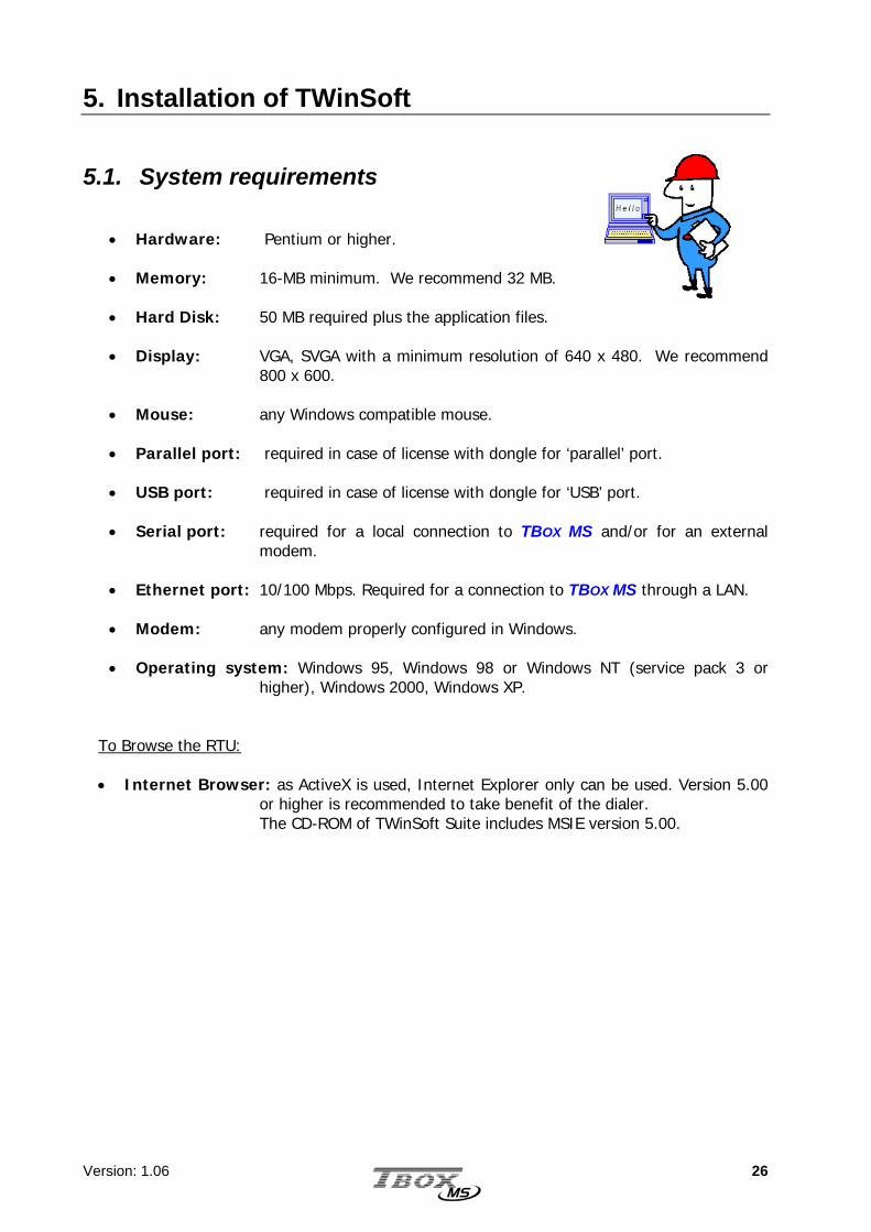
• Hardware: Pentium or higher. • Memory: 16-MB minimum. We recommend 32 MB. • Hard Disk: 50 MB required plus the application files. • Display: VGA, SVGA with a minimum resolution of 640 x 480. We recommend
800 x 600. • Mouse: any Windows compatible mouse. • Parallel port: required in case of license with dongle for ‘parallel’ port. • USB port: required in case of license with dongle for ‘USB’ port. • Serial port: required for a local connection to TBOX MS and/or for an external
modem. • Ethernet port: 10/100 Mbps. Required for a connection to TBOX MS through a LAN. • Modem: any modem properly configured in Windows. • Operating system: Windows 95, Windows 98 or Windows NT (service pack 3 or
higher), Windows 2000, Windows XP.
To Browse the RTU:
• Internet Browser: as ActiveX is used, Internet Explorer only can be used. Version 5.00 or higher is recommended to take benefit of the dialer. The CD-ROM of TWinSoft Suite includes MSIE version 5.00.
Version: 1.06 27
5.2. Installation of the CD-ROM
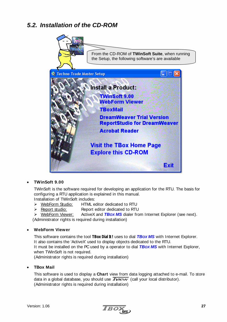
• TWinSoft 9.00
TWinSoft is the software required for developing an application for the RTU. The basis for configuring a RTU application is explained in this manual. Installation of TWinSoft includes: WebForm Studio: HTML editor dedicated to RTU Report studio: Report editor dedicated to RTU WebForm Viewer: ActiveX and TBOX MS dialer from Internet Explorer (see next).
(Administrator rights is required during installation)
• WebForm Viewer
This software contains the tool TTBBooxx DDiiaall IItt !! uses to dial TBOX MS with Internet Explorer. It also contains the ‘ActiveX’ used to display objects dedicated to the RTU. It must be installed on the PC used by a operator to dial TBOX MS with Internet Explorer, when TWinSoft is not required. (Administrator rights is required during installation)
• TBox Mail
This software is used to display a Chart view from data logging attached to e-mail. To store data in a global database, you should use T (call your local distributor). (Administrator rights is required during installation)
From the CD-ROM of TWinSoft Suite, when running the Setup, the following software’s are available

Version: 1.06 28
• DreamWeaver Trial version • Report Studio for DreamWeaver
Dreamweaver is a standard HTML editor. It can be used with the plug-in ‘Report Studio for Dreamweaver’ to develop standard HTML pages that do not use the ActiveX.
• Acrobat Reader
Software needed to read our documentation. • Explore this CD-ROM
You will find on the CD-ROM many information related to TBOX MS and accessories: datasheets, manuals, …

Version: 1.06 29
5.3. Programs of ‘TWinSoft Suite’ During installation of TWinSoft, a group of programs is created where TWinSoft can be started.
Other programs and menus: • Accessories: group containing the utility ‘Password generator’ and ‘Reset User
preferences’: reset of registry information to restore the default configuration of TWinSoft.
• Documentation: group containing the various documents associated to TWinSoft and
RTU. • Samples: group with TWinSoft documents installed as example. • TBox drivers: when 'C' custom drivers have been installed. The ‘on line’ help of the
driver configuration is available in this folder. • Report Studio: to create reports dedicated to TBOX MS. • TWinSoft: to start TWinSoft. • WebForm Studio: to start the HTML editor, dedicated to TBOX MS when it is used as a
Web Server.

Version: 1.06 30
6. Starting TWinSoft
I am the Wizard of TWinSoft! When you start TWinSoft the first time, or when you create a new document, I help you with some basic configurations.
The use of TWinSoft is free, but sending of a program to TBox MS is protected. For more info about Licenses go to Appendix A. at the end of this manual.
Version: 1.06 31
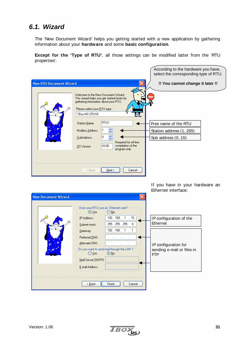
6.1. Wizard The ‘New Document Wizard’ helps you getting started with a new application by gathering information about your hardware and some basic configuration. Except for the ‘Type of RTU’, all those settings can be modified latter from the ‘RTU properties’.
If you have in your hardware an Ethernet interface:
According to the hardware you have, select the corresponding type of RTU.
!! You cannot change it later !!
Free name of the RTU
Station address (1..255) Sub address (0..15)
IP configuration of the Ethernet
IP configuration for sending e-mail or files in FTP

Version: 1.06 32
6.2. Communicating with TBox MS Once you have opened a document, either a new one created with the Wizard or an existing one, you can establish the connection with your TBOX MS. The possible communications are serial, Ethernet or modem, according to the media used to connect to TBOX MS.
Serial: check the Baudrate you have given to the serial port in your application (by default 9600,N). See chapter 9.1.1.
Ethernet: check the IP address you have given to your TBOX MS (see chapter 9.1.1) and that it is in the same subnet of the PC or accessible to the PC.
Modem: check the tel. Number of TBOX MS. See chapter 8.1.
6.3. PC Communication Set up To communicate with the TBOX MS, you need to select a communication media on the PC. From the main menu of TWinSoft: Communication PC Setup:
Example with a RS232 connection: default Baudrate of TBox MS : 9600,N
Version: 1.06 33
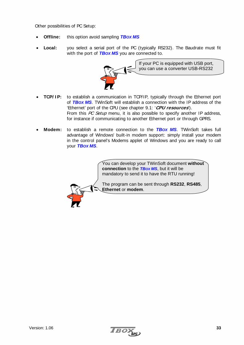
Other possibilities of PC Setup: • Offline: this option avoid sampling TBOX MS • Local: you select a serial port of the PC (typically RS232). The Baudrate must fit
with the port of TBOX MS you are connected to.
• TCP/IP: to establish a communication in TCP/IP, typically through the Ethernet port of TBOX MS. TWinSoft will establish a connection with the IP address of the ‘Ethernet’ port of the CPU (see chapter 9.1: ‘CPU resources’). From this PC Setup menu, it is also possible to specify another IP address, for instance if communicating to another Ethernet port or through GPRS.
• Modem: to establish a remote connection to the TBOX MS. TWinSoft takes full
advantage of Windows' built-in modem support: simply install your modem in the control panel's Modems applet of Windows and you are ready to call your TBOX MS.
If your PC is equipped with USB port, you can use a converter USB-RS232
You can develop your TWinSoft document without connection to the TBOX MS, but it will be mandatory to send it to have the RTU running! The program can be sent through RS232, RS485, Ethernet or modem.

Version: 1.06 34
6.4. Testing communication Once you have selected the media on the PC, you can test the communication. From the main menu of TWinSoft: Communication RTU identification:
Available information:
- Name of the RTU - Type of Hardware - Version of Operating System - Status of the process - ModBus address of the Station - Subaddress of the Station - IP address of the modem - IP configuration of the Ethernet - Access level of the current user - Date and Time in the RTU
- General information about the program
- Process cycle time
- Unique ID of the RTU
The Status bar of TWinSoft displays the status of the connection:
The media of the PC is indicated and the access level of your connection (see chapter 17: ‘Security’) If a connection cannot be established with the TBOX MS, it might be because the configuration of its port does not fit with the PC setup you use (different Baudrate, different IP address, protocol other than ModBus, …). To set the TBOX MS to a default configuration, you have to do a global reset. (see next)

Version: 1.06 35
6.5. Global reset of TBox MS The Global Reset is used to set TBOX MS in a default, well-known configuration, in case it does not communicate anymore. This is very useful when you take a CPU from the stock and you have no idea how the port you want to communicate with is configured. The global reset is achieved using the button on the front side of the CPU Procedure:
• Push and maintain the button to the ‘Reset’ side • Let the LED flashes 3 times • Release the button
Global reset configuration: The global reset mode is indicated by the LED flashing at 0.5 hz (instead of 2 hz in RUN mode). In this mode, the TBOX MS is configured like following: Port Baudrate Protocol Station
address IP
address
COM1 (RS232) 9600,N,8,1 ModBus 1 - COM2 (RS485) 9600,N,8,1 ModBus 1 - COM3 (Ethernet) - - 1 maintained MS-PSTN; MS-GSM - ModBus 1 - RS232 - modem maintained ModBus 1 - RS232 - local 9600,N,8,1 ModBus 1 -
6.6. LED « RUN » This LED, next to the “Reset” button indicates the status of the CPU:
Program runs 2 Hz Program stopped 0.5 Hz Operating System stopped 8 Hz
More information about working modes of TBOX MS in the technical specifications at the end of this manual
The Global Reset does not erase the current program. Doing an ordinary Reset will restart the program.

Version: 1.06 36
6.7. Saving and Sending a Program Like any Windows program, TWinSoft creates ‘Documents’. One document corresponds to one TBOX MS application. Each of them must be saved using the Windows standard.
6.7.1. Saving a document Possibilities for saving a document:
• Use the icon of the main tool bar • From the main menu use: ‘File’ ‘Save’ • Use the accelerator keys <CTRL + S>
During the development of the application, it can be sent at any time to TBOX MS, for testing the program. When sending an application to TBOX MS, it is first compiled and then sent, in the same sequence.
6.7.2. Compiling a document Compilation converts the document into microprocessor code. You can execute it:
• Use the icon of the main tool bar • Use the accelerator key <F9>
The result of the compilation is available in the Results window. This windows automatically pops up when there is a problem but it can be opened manually:
• from the main menu: ‘View’ ‘Results’ • using the accelerator keys <ALT + 2>
The Results window provides useful data:
Information: indicated in black Warning: indicated in bold dark green Error: indicated in bold red
Test of memory still available The result window also displays memory still available: CPU ROM: Application RAM: Application RAM: Databases
CPU-16 Max. 32768 bytes Max: 32768 bytes Max. 73728 bytes
CPU-32

Version: 1.06 37
6.7.3. Sending a document In order to have the TBOX MS running with the program you have developed with TWinSoft, you have to send it. You can use any media to achieve it (RS232, modem, Ethernet, …). Possibilities for sending a program:
• Use the icon of the main tool bar • From the main menu use: ‘Communication’ ‘Send program’ • Use the accelerator keys <CTRL + F9>
The sequence for sending is Compiling + Sending. If a problem occurs during compiling, the sequence is stopped and the ‘Results’ window pops-up (see above)
If you interrupt the sending of the program or an error happens before the end of sending, TBOX MS will not restart, even after a reset. The reason is that the program is composed of several modules; when starting, TBOX MS checks the integrity of those modules. When they do not correspond to the same sending the program does not start, even after a reset. You have then to re-send the program. The good news is that TBOX MS keeps its original settings before it was stopped.

Version: 1.06 38

Version: 1.06 39
TTTWWWIIINNNSSSOOOFFFTTT ---
PPPRRROOOGGGRRRAAAMMMMMMIIINNNGGG

Version: 1.06 40
7. Introduction TWinSoft uses the standard look and feel of ‘Windows Explorer’, with at the left side a list of folders and at the right side the content of the folder selected. Each Folder consists in a list of items. For instance the list of Tags, or in the ‘Alarms’ folder the list of ‘Recipients’ or in the ‘Datalogging’ folder the list of ‘Sampling tables’, …
The programming of a TBOX MS application will be done in different steps:
Configuring the RTU properties Adding of the cards and Remote device from the Resources Creating Tags Creating Programs using automation language Ladder and/or BASIC Creating Alarms Creating Datalogging If you have a Remote device, creating Remote Tags, to exchange data
The sequence in which those tasks are executed is not fixed, but at least RTU properties, Resources and Tags should be configured first, as being required for all other programming. All those configurations are explained in the following chapters.

Version: 1.06 41
8. RTU properties
Setting the properties of the TBOX MS has never been so easy thanks to a set of comprehensive dialog boxes, available from the main tool bar.
The RTU properties are divided into:
• General the type of the RTU, telephone number, size of the chronologies, … • Drivers configuration of external software modules written in ‘C’, used to
execute specific task or to communicate with other protocol than standard ones.
• Info to type any info about your program, its different versions, … • Advanced for some features, some advanced parameters are available: for
alarms, sampling tables, …
RTU properties can be accessed easily by clicking this icon.
Communication ports are configured from the ‘Resources’. General TCP/IP configuration is done from the ‘Workspace’ and folder IP parameters.

Version: 1.06 42
8.1. General properties
RTU Type: The type of RTU you have selected with the Wizard (see chapter 6.1). It
cannot be changed! Name: type a free name for the TBOX MS. It will be displayed when doing a
‘RTU identification’ and used by the supervisory T. Maximum 8 characters.
ModBus address: with ModBus protocol, each device must have a Station number. It is its ModBus address. Enter a number between 1 and 255 (default=1).
Sub address: if more than 255 TBOX MS must be installed in one project, you need to
define a Sub address. As this is not ModBus standard, it is only supported by ‘TComm.dll’ based software (TWinSoft, T, … please call your distributor for further information). Enter a number between 0 and 15 (default=0).

Version: 1.06 43
OS version: when working Offline, it is the OS used to simulate the compilation. By default it is the OS version associated to version of TWinSoft. Telephone number: Configuration used by TWinSoft when it needs to dial TBOX MS. Sizes: Number of records of Digital and Analog chronologies. The
chronologies are the ‘on event’ method of recording data in TBOX MS (see chapter 13: Data logging). Enter a number between 0 and 4000 (Default=100).
Time zone: The Time Zone where the TBOX MS is installed.
This information is used to create the time stamps when retrieving data from TBOX MS according to its location. TBOX MS uses Universal Coordinated Time (UTC) as internal time stamp. The conversion is carried out when retrieving the data.
Summer/Winter: Allows automatic management of winter/summer time. This selection has to be made according to the location where the TBOX MS is installed.
See Appendix B : Time in the RTU
8.2. Drivers A driver is a module written in ‘C’ that executes a specific task, non-standard. Typically, it is communication to equipment not supporting standard protocol of TBOX MS. There is no driver at the moment.
8.3. Security Access security is discussed at chapter 17.

Version: 1.06 44
8.4. Info properties
You can enter a version number, the name of the programmer and a description of your program. This information is not sent to TBOX MS.
8.5. Advanced 8.5.1. Startup
By Startup we mean:
Reset of RTU (hardware or software) Sending of Program
Under those conditions two mechanisms of the RTU can be customized. Reset all physical outputs: when active, at startup the RTU reinitializes the
outputs to ‘0’. After that the outputs are monitored according to the process.
When not active, at startup the outputs are maintained to their last status. After that the outputs are monitored according to the process.
Wait start of condition: this feature relates to alarm condition. The mechanism of generating alarm is based on transition:
the changing of a digital Tag or the overstepping of an analog threshold.
This option allows changing this rule at startup: With ‘Wait start of condition’ active: With ‘Wait start of condition’ not active: if the alarm condition is true at startup, an internal
‘start of alarm - auto-ack’ is generated. When the alarm condition disappears, the alarm is generated.
startup
Alarm Alarm time
time
startup
Alarm Alarm
Internal Alarm
Alarm
Version: 1.06 45
8.5.2. Alarms
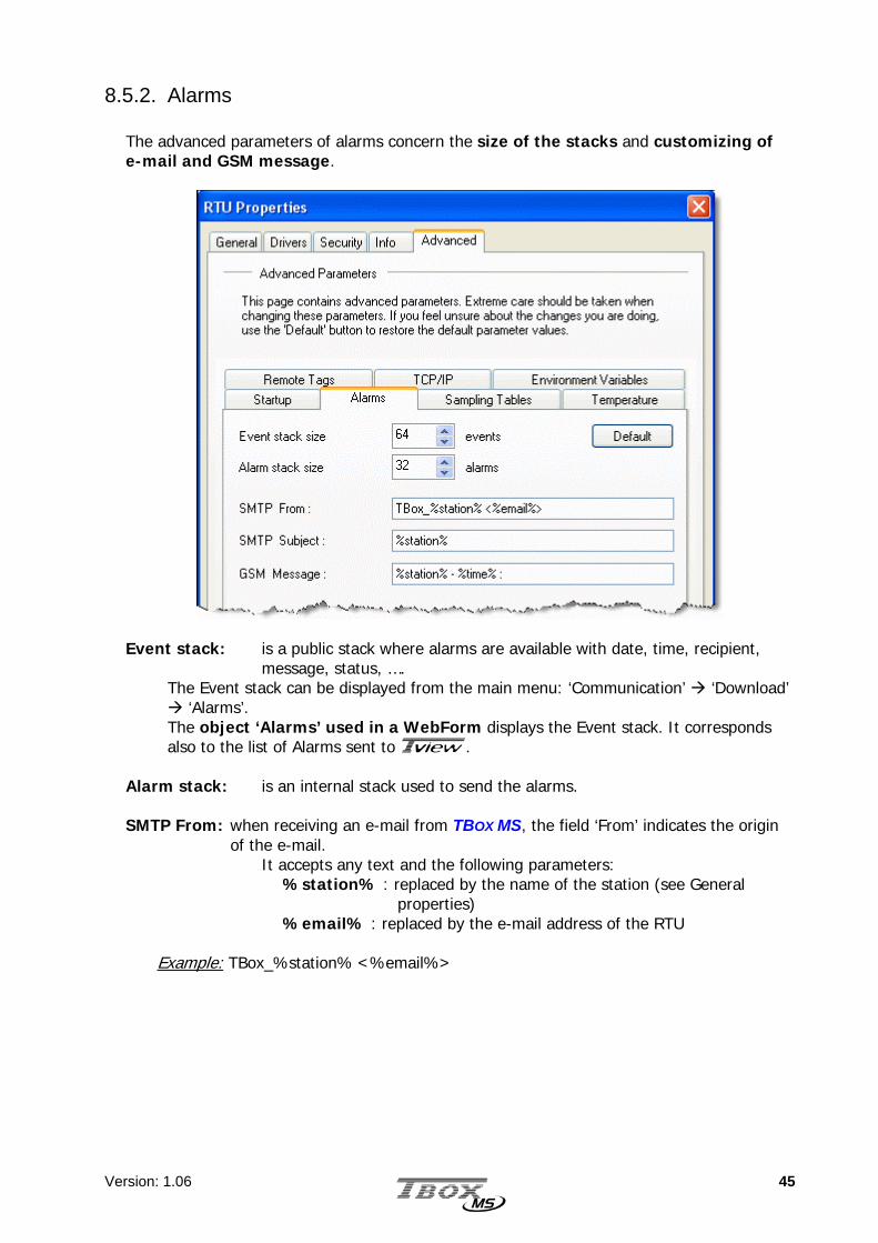
The advanced parameters of alarms concern the size of the stacks and customizing of e-mail and GSM message.
Event stack: is a public stack where alarms are available with date, time, recipient,
message, status, …. The Event stack can be displayed from the main menu: ‘Communication’ ‘Download’
‘Alarms’. The object ‘Alarms’ used in a WebForm displays the Event stack. It corresponds also to the list of Alarms sent to T.
Alarm stack: is an internal stack used to send the alarms. SMTP From: when receiving an e-mail from TBOX MS, the field ‘From’ indicates the origin
of the e-mail. It accepts any text and the following parameters:
%station% : replaced by the name of the station (see General properties)
%email% : replaced by the e-mail address of the RTU
Example: TBox_%station% <%email%>

Version: 1.06 46
SMTP subject: when receiving an e-mail from TBOX MS, the field ‘Subject’ contains the message or the title of the report (see Report Studio).
It accepts any text and the following parameters: %station% : replaced by the name of the station (see General
properties) %email% : replaced by the e-mail address of the RTU %time% : the time of the RTU when the e-mail was generated
Example: Report TBox %station% - %time% :
GSM message: when TBOX MS sends a SMS, you can add information to the message. This information is sent in front of the message. You can type any text and the following parameters:
%station% : replaced by the name of the station (see General properties)
%time% : the time of the RTU when the e-mail was generated
Check the total length of SMS message does not exceed 160 characters
Do not use accent

Version: 1.06 47
8.5.3. Sampling Tables
This menu gives access to the parameters for long period recording in Sampling tables. (See chapter 13.3: ‘Sampling tables’) Those configurations concern all sampling tables.
Daily: When ‘daily’ is selected in sampling table, it is the time of the day the recording is executed.
Weekly: When ‘weekly’ is selected in sampling table, it is the day of the week and the time
the recording is executed. Monthly: When ‘monthly’ is selected in sampling table, it is the day of the month and the
time the recording is executed.

Version: 1.06 48
8.5.4. Temperature For Temperature analog input (PT100 or PT1000), you can define a unit: Celsius, Fahrenheit or Kelvin.
8.5.5. Remote Tags Reset the device Trigger only if success When communicating as ‘Master’ using
‘Remote Tags’, a Trigger is associated to the device the RTU communicate with (see Remote Tags).
This Trigger activates the communication according to a ‘State’ or ‘Edge’. Working with ‘Edge’, the RTU restores automatically the Tag after the transaction(s).
- With this option active: the Trigger is restored only when communication has been done successfully.
- Without this option: the Trigger is restored when all Remote Tags associated to the device have been executed, with or without error.
8.5.6. TCP/IP
The unit is the same for all inputs

Version: 1.06 49
TCP Ports Numbers. Each TCP/IP service has its own unique TCP port. It provides a logical location for the delivery of TCP data. TCP Port number complies to a standard defined by the IANA to be sure everyone using a TCP service uses the same TCP ports according to protocols used. When working with TBOX MS, in some cases, you might want to change this port number. HTTP: port used to access TBOX MS as WebServer. ModBus/TCP-Slave: port used by a ‘Master’ to access TBOX MS as ‘Slave’. ModBus/TCP-Master: port used by TBOX MS as ‘Master’. MTU. The MTU determines the maximum size of a TCP frames, by default 1500 bytes. 1500 bytes is the maximum. Some intermediate equipment (router, switch, …) does not support this value. It can then be reduced. TCP/IP addresses for incoming calls. Range of addresses used during incoming calls. TBOX MS uses the first address of the range and applies the following to the remote equipment. Typically, this information is needed when TBOX MS is used as a Web Server, dialed from Internet Explorer and TTBBooxx DDiiaall IItt !!. The utility TTBBooxx DDiiaall IItt !! , used to dial TBOX MS automatically, detects the IP address and uses it as URL.
Avoid using addresses in the same range as the IP address defined for the LAN card of the PC used as Browser.
1. Changing the TCP port does not affect access fromTWinSoft. This is always possible.
2. The changing of TCP port is automatically applied to 'WebForms' when building the HTML pages using WebForm Studio.

Version: 1.06 50
8.5.7. Environment variables The environment variables are used when particular configuration might be needed in external software.
Variable Value Description
TViewPath \path The path in which the station will be created when importing data in T. The path is the relative path from the Project workspace of T. Example: with the Value: \Lines\10 Result in T :
Longname
Type any long name
The name typed here will be used in T, instead of the one declared in the ‘General’ properties, which is limited to 8 characters

Version: 1.06 51
9. Resources The resources represent the list of the hardware that your TBOX MS has to its disposal.
• The CPU card, with its communication ports (see chapter 9.1: ‘The CPU card’) • The hardware can be composed of Cards fixed in the same Rack as the CPU. It can be
I/O cards or Communication cards (see chapter 9.2: ‘Adding Cards’) • If the CPU needs to communicate in ‘ModBus Master’ to another device (CPU, or an
external ModBus device), the latter must be declared as a Remote I/O card (see chapter 14: ‘Remote Tags’)
• The Resources also contain 2 lists with System variables. Systems variables have pre-defined function (see chapter 9.4: ‘System variables’)
9.1. The CPU-16 card When starting a new document, TWinSoft creates automatically the CPU card; the minimum for a TBox MS project ! The communication ports of the CPU with their associated configuration and the I/O of the CPU are available from the ‘Resources’:
The CPU card is divided in several groups:
Group 0 : communication ports Group 1 : 2 digital inputs - 1 digital output (Sync. Input, Sync. Output, STOP input,) Group 2 : 1 Analog input - 2 digital inputs (Power supply voltage, temperature
warnings)

Version: 1.06 52
9.1.1. Communication ports of the CPU
By selecting the Group 0 Communication ports in the workspace, you access each port separately.
To enter the configuration of the communication port, double click the port.
Example with COM1 – RS232 Depending on the type of communication port (RS232. RS485, modem or Ethernet), different tabs are available: Parameters: general parameters (local or modem, Baudrate, Protocol).
DCV: Digital Communication Variables. Special variables with a pre-defined function (communication error, modem online, …). (see chapter 9.3)
ACV: Analog Communication Variables. Special variables with a pre-defined function (time-out, user ID, …). (see chapter 9.3)
Advanced: mainly ‘timing’ parameters required when CPU is ‘Master’ or ‘Slave’ in a ModBus communication.
TCP/IP: TCP IP configuration dedicated to the communication port, when available.

Version: 1.06 53
9.2. Adding Cards All cards other than the CPU must be added in the ‘Resources’ folder: I/O cards as well as communication cards.
Starting a new document, the only card available is the CPU. You will add all cards corresponding to your hardware into this list.
TWinSoft does not detect the Cards automatically. You have to add the Cards manually using the menu ‘Add a card’

Version: 1.06 54
Example: Adding a Power Supply card:
Id number of the cards in TWinSoft vs. Slot in the Rack:
Type of Card Slot used in the Rack Address in TWinSoft
Power Supply (if used) Always 0 1 CPU 0: when used without Power Supply
1: when used with a Power supply or alone in prevision of using a Power Supply
Always 0
I/O card Communication card Any slot following the CPU Same as the slot index
Example:

Version: 1.06 55
9.2.1. Adding an I/O card The Hardware is represented in TWinSoft with a hierarchy of 3 levels:
CARD : CPU card, 16 DI card, COMBO card, Modem card, …
GROUP : when there are several types of I/O on a Card, they are separated into Groups: group of DI, group of DO, group of AI, …
CHANNEL : each physical connection, within a Group, corresponds to a channel.
See technical specifications of all I/O cards at the end of the manual.
GROUP
CARD
CHANNEL
When connected to a TBOX MS, the column ‘Value’ displays the current value, when the channel has been declared as a Tag.
(see chapter 10 : ‘Tags’)
When adding a Card, its Id number must correspond to its position on the Rack. Check the slot index written in the Rack.
See examples in chapter 4.4.

Version: 1.06 56
9.2.2. Adding a ‘Modem’ Card A modem card (PSTN or GSM) is composed of a modem and a serial port (RS232 or RS485). Technical specifications are available at the end of the manual. Once created, a ‘modem’ provides one Group 0 with communication ports.
To enter the configuration of the modem, double click the ‘modem’ port in the list
Example with COM4 – PSTN modem Modem type: It cannot be changed. It corresponds to the modem of the card. Initialization: The initialization string is sent at power up of the modem and after
each connection. If changed, it is saved in the TWinSoft document.
The numbering of communication port starts at COM4 (the previous ports are used by of the CPU). The numbering is automatically incremented at each insertion of communication card.

Version: 1.06 57
Outside line prefix: if TBOX MS is placed behind a telephone switch (PABX), it is the number to get the outside line. This prefix will be applied automatically each time TBOX MS dials out.
Auto Answer: Number of rings after which the modem will go off hook.
Tab DCV: Digital Communication Variables Special variables with a pre-defined function (communication error, modem online, …) (see chapter 9.3).
Tab ACV: Analog Communication Variables Special variables with a pre-defined function (time-out, user ID, …) (see chapter 9.3).
Tab Advanced Mainly ‘timing’ parameters required when modem is ‘Master’ or ‘Slave’ in a ModBus communication.
9.2.3. Adding a ‘GSM / GPRS’ Card
In addition to configuration described here above, a GSM modem can be used in 2 modes: as a GSM data modem in GPRS mode
In addition to standard modem configuration, some parameters are specific to GSM. The main option ‘GPRS’ determine the working mode of the card: GSM data OR GPRS
Default Initialization and prefix can be modified from the file ‘ModemProfiles.xml’. Changes will be applied to all new document created.

Version: 1.06 58
GSM-data settings
Initialization: should not be changed PIN Code: If the SIM card you have inserted uses a PIN code, type it at the place
of the letter n. Example: with the PIN code 4896, you should have in the field: AT+CPIN=“4896”
If the SIM card you have does not require a PIN code, you can leave the field as it is or erase it.
Auto Answer: number of RINGS before the modem picks-up the line.
Dialing to a GSM-data
The SIM card of a GSM has three telephone numbers: VOICE (the one you use to speak), DATA and FAX. To dial to TBOX MS, you have to be sure that data service is activated and you dial the DATA number (please call your GSM operator).
About sending e-mail or Files with GSM-data
Some ISP requires specific telephone number for connecting through GSM (please check with your ISP).
In some countries, like in US for instance, GSM operators do not provide DATA service. DATA communication is then only available in GPRS mode (see below)
If you type the wrong PIN code, or you type a PIN code when the SIM card does not require one, you risk blocking the SIM card. It must then be restored with the PUK code using a mobile.

Version: 1.06 59
GPRS settings
Once you have declared a MS-GSM card, you have to activate the GPRS mode.
When selecting GPRS, TWinSoft automatically adapts Initialization and Operator Phone number fields (see next). If the connection requires a login, select the option ‘The server requires authentication’. If you receive a fixed IP address, declare it in ‘TCP/IP’ tab.
Initialization: You have to add in the initialization string the APN. Replace in the string
the apn with the URL you receive from your GSM operator. Example with Mobistar: AT+CGDCONT=1,“IP”,“WEB.PRO.BE”.
PIN Code: If the SIM card you have inserted uses a PIN code, type it at the place
of the letter n. Example: with the PIN code 4896, you should have in the field: AT+CPIN=“4896”
If the SIM card you have does not require a PIN code, you can leave the field as it is or erase it.
Operator Phone number: special number to establish the GPRS connection. Typically, the number is *99***1#. Check with your operator
and type it following the command ATD. Example with Mobistar, Proximus, SFR, AllIP, …: ATD*99***1# Connection at start up: when this option is selected (by default) TBOX MS handles
the modem to keep the connection permanently. when this option is removed, TBOX MS handles the
connection according to communication variables: GPRSCon (see below)
You have to choose either ‘GSM-Data’ mode OR ‘GPRS’ mode. It is not possible to use the modem in both modes.

Version: 1.06 60
Communication Variables dedicated to GPRS
Some communication variables allow manual handling of GPRS and give information on the status.
Digital Communication Variable
COMx.GPRSCon * GPRS: Handles the GPRS connection. Working in manual connection, writing ‘1’ forces a connection; writing ‘0’ forces a disconnection. When working with automatic connection, if you reset this variable the connection will stop, but after maximum 5 minutes, it will be automatically restarted.
Analog Communication Variable
COMx.GPRSState - GPRS: indicates the status of the GPRS connection. Value=0 : disconnected Value=1 : currently connecting Value=2 : connected Value=3 : currently disconnecting
COMx.IPAddress - GPRS: this register gives the IP address used by TBOX MS during its GPRS connection. The information is available in a DWORD, but in the list of Tags, you can display it as an IP address: from the list of Tags, right click the Tag Display as IP address. This information is very important when working with dynamic IP address. It can be sent for instance by e-mail (see Report Studio), to inform on IP address changing.

Version: 1.06 61
About sending alarms with GPRS
With GPRS, you are able to send e-mail or files using FTP. You create recipient(s) associated to the SMTP or FTP server you have associated to the GSM/GPRS. Working with a manual connection, first the RTU establishes the connection and sends the mail and/or files. Then it stops the connection. If the connection was already established, the RTU maintains the connection. Working with an automatic connection, the mail and/or files are sent immediately and the connection is maintained.
GPRS IP settings
GPRS represents a TCP/IP connection using GSM network. It then requires a TCP/IP configuration.
Obtain IP address automatically: You work with dynamic IP address which is provided by the Operator at the connection. Use IP address: You work with fix IP address; it corresponds to the SIM card you use. Obtain DNS server addresses auto.: The Operator provides you with DNS. Use DNS Server addresses: You want to use specific DNS addresses.

Version: 1.06 62
9.3. Communication Variables
Communication variables are dedicated registers to status of the communication. It is very useful for controlling the connection and the access level authority. Those variables are divided into 2 tabs, the Digital Communication Variables (DCV) and the Analog Communication Variables (ACV). When you need one, you double click it from the list and declare it as a Tag. It becomes then available in any feature of TBOX MS.
9.3.1. Digital Communication Variable
According to its function a Communication variable is Read/Write or Read only. In the following table, the column R/W indicates: - : Read only. 0 : Write ‘0’ only. 1 : Write ‘1’ only. * : Write ‘0’ or ‘1’.
Example with COM6 – GSM modem
Name R/W Description COMx.NoReply 0 Communication: SET by TBOX MS in case of communication
error. The possible errors are: - Timeout. - ModBus: Unknown address, wrong quantity, CRC error. - TCP/IP: wrong closing of socket.
Must be RESET by the user. COMx.OffHook * Modem: Reading ‘1’, indicates the modem has picked-up the line
and it connecting to another modem. The success of the connection can be checked from the next ‘Connect’ variables. Writing ‘0’ or ‘1’ forces the modem to hang-up.
COMx.Call - Modem: Reading ‘1’ indicates the modems are synchronized with TBOX MS ‘Calling’
COMx.Answer - Modem: Reading ‘1’ indicates the modems are synchronized with TBOX MS ‘Answering’
COMx.NoDial 0 Modem: Reading ‘1’ indicates that no dial tone has been detected when the modem has picked-up the line. Must be RESET by the user.
COMx.GPRSCon * GSM: Indicates the status of the GPRS connection. Writing ‘1’ forces a connection; writing ‘0’ forces a disconnection (see above for more details).

Version: 1.06 63
COMx.ModBusResp 0 Communication: Reading ‘1’ indicates the port is transmitting. At
each transmission, TBOX MS SET this register. To check TBOX MS is transmitting, you RESET this register and test whether it is SET again (using Ladder or BASIC)
9.3.2. Analog Communication Variable
According to its function a Communication variable is Read/Write or Read only. In the following table, the column R/W indicates: - : Read only. * : Writable.
Example with COM6 – GSM modem
Name R/W Description COMx.Level * Access Control: access level of the user currently logged (see
chapter 17). COMx.UserId * Access Control: user Id of the user currently logged (see chapter
17). The user Id and the authority level correspond to those you have defined with the utility ' PASSWORD '. The values returns to 0 when the user has disconnected. Values can be written to those registers. Example: when a user is connected you can modify its level access by writing a value in the register COMx.level (level available: 0, 1, 2 or 3).
Those values can be stored in analog chronology for keeping a history on the access. When a user disconnects (Logout), the register returns to '0
COMx.Timeout * Modem: global time-out for hanging-up the modem when there is no communication. Correspond to the ‘Inactivity time-out’ in the ‘Advanced properties’ of the modem.
COMx.GPRSState - GPRS: indicates the status of the GPRS connection. Value=0 : disconnected Value=1 : currently connecting Value=2 : connected Value=3 : currently disconnecting (see above for more details)
COMx.IPAddress - GPRS: this register gives the IP address used by TBOX MS during its GPRS connection. The information is available in a DWORD. To be interpreted, you should compute this Tag with mask to read the 4 bytes composing the IP address.

Version: 1.06 64
9.4. System variables The system variables have pre-defined functions. They are very useful to check or to act on features of TBOX MS. They are divided into ‘Digital’ and ‘Analog’.
9.4.1. Digital System Variables According to its function a register is Read/Write or Read only. In the following table, the column R/W indicates:
- : Read only. 0 : Write ‘0’ only. 1 : Write ‘1’ only. * : Write ‘0’ or ‘1’.
When the action (SET) is specified, it means that the TBOX MS maintains the variable at 1 to be sure it is detected. With such a variable, you need then to reset it using BASIC or Ladder programming Index Name R/W Description
0 TikSec 0 Tik Second: Changes of state every second. Useful for counting time.
1 PrgRun - Program run: At each starting of TBOX MS , this register changes to 1 and stays at 1 as long as the BASIC/Ladder program runs. This register is used in BASIC/Ladder to execute operations only at the start of the program, with the help of a positive edge trigger function.
2 NewPro - New program: Start of a program flag. Changes to 1 if TBOX MS has started after having received a new program. Changes to 0 after a reset of the TBOX MS.
3 Reboot 1 Reboot: complete restart of TBOX MS. It is equivalent to hardware reset.
4 RstWat * Reset Watchdog: the watchdog checks the cycle time of BASIC/Ladder program. In case it is longer than 1 second, it resets TBOX MS. This Watchdog can be reset to reinitialize the 1 second timer in case of cycle time longer.
5 Ala_On 0 Alarm on: this register indicates that alarm is active (not ack.). Writing 0 in this register causes a global acknowledgment of all alarms. Corresponds to a reset of the Alarms stack
6 Alaerr 0 Alarm in error: TBOX MS SETs this register when an alarm failed to be sent. This means that after the number of tries, the alarm has been auto-acknowledged. Must be RESET by the user.
7 RstAla 1 Reset Alarm: Not used. See ‘Ala_On’ here above.
8 EnaDCr * Digital Chronology: General enable of recording in digital chronology.
9 EnaACr * Analog Chronology: General enable of recording in analog chronology.
10 EnaSam * Sampling Tables: General enable of recording in sampling tables.
11 EnaAla * Enable Alarm: General enable of generating alarms.
12 DisCrd * Flag digital chronology: can be associated to any digital chronology configuration to inhibit recording. When at value ‘1’, inhibits recording in Database.

Version: 1.06 65
Index Name R/W Description
13 DisCra * Flag analog chronology: can be associated to any analog chronology configuration to inhibit recording. When at value ‘1’, inhibits recording in Database.
14 DisSam - (Not used)
15 DisAla - Flag sending alarm: can be associated to any Alarm condition. When at value ‘1’, inhibits the sending of alarm.
16 DaySav - Time: 1 = summer time (the ASPE ZoneBias = + 3600 seconds). 0 = wintertime.
17 PrgEnb * Program Enable: when reset to ‘0’, allows stopping the execution of BASIC/Ladder program. It can be useful to execute the program manually (see next).
18 PrgOnc 1 Program Once: when set to ‘1’, executes the cycle of BASIC/Ladder program once. Useful for debugging the program. TBOX MS resets the variable automatically.
19 TcpIpLog * TCP Logging: Setting this register activates the Debugging of TCP/IP connection. Very useful to trace problems when sending e-mail or FTP. (see chapter 11.5) When this option has been activated, the information is available from TWinSoft main menu: ‘Communication’ ‘Download’ ‘TCP/IP debugging’.
20 ALAovf *
Alarm Overflow: overflow in the stack of alarms. The size of the stack of alarms can be adjusted from the ‘Advanced’ properties of the RTU
21 ComErr 0 Communication error: general communication error flag. It means that one of the communication port (of the CPU or of a communication card) used as ‘Master’ has encounter a communication error. (SET)
22 SmtpEr 0 Smtp Error: an error occurred while sending an e-mail. (SET)
23 FtpErr 0 Ftp Error: an error occurred while sending files. (SET)
24 NTPErr 0 NTP Error: an error occurred while setting time of TBOX MS. (SET)
25 GpsVF - GPS: GPS validity. GPS returns a valid signal. Validity of the signal. When changes to one, it indicates the GPS receives sufficient signals to calculate its position (from minimum 3 satellites). When changing from 0 to 1, the time of TBOX MS is set to the time of GPS, with correction in regards to GMT according to the location of TBox. If you want to update the time manually, you reset the variable
26 GPRSErr 0 GPRS Error: an error occurred during GPRS connection. TBOX MS does not succeed to connect (not supported yet) (SET)
27 ModemLog * ModemLog: authorizes the modem connection to be logged into chronology. The communication port is declared in the ASV.24 [PortIdLog]. The ASV.25 [EventLog] must be tagged also. The information is available in from the communication Download
TraceLog (not supported yet) 28 SystemEr 0 SystemErr: the RTU detected an error during starting. Typically a
problem with a card (not supported yet) (SET)

Version: 1.06 66
9.4.2. Analog System Variables According to its function a variable is Read/Write or Read only. In the following table, the column R/W indicates: - : Read only.
* : Writable. Index Name R/W Description
0 Second * Time: Second in TBOX MS. 1 Minute * Time: Minute in TBOX MS. 2 Hours * Time: Hour in TBOX MS. 3 Date * Time: Day of the month in TBOX MS. 4 Month * Time: Month in TBOX MS. 5 Year * Time: Year in four digit in TBOX MS. 6 DayOfw * Time: Day of the week in TBOX MS. (Mo=1; Tu=2; We=3; …) 7 AlaCnt * Alarm quantity: Amount of alarms in the alarms stack. It means
the quantity of alarms that have not been generated already. The size of the Alarm stack can be adjusted in the ‘Advanced RTU properties’).
8 AlaID * Alarm last index: Absolute index of the last alarm generated (number between 0 and 65535).
9 ALACur * Alarm current index: Absolute index of the alarm being currently handled (number between 0 and 65535). Can be used to acknowledge an alarm by writing its index.
10 ALARec * Alarm recipient: gives the index of the recipient of the current alarm. Can be used to acknowledge all alarms of a Recipient by writing its index (see index in the list of Recipient).
11 SamQty * Sampling Table: Quantity of sampling tables defined. 12 UtcTim - Time: Universal Coordinated Time (UTC). It is the number of
seconds since 01/01/1970, GMT time. It is used as time-stamp reference for datalogging.
13 ZonBia * Time: Time difference in seconds with GMT. 14 ZonID * Time: ID of the zone where TBOX MS has been installed. It uses
Regional Settings of PC, therefore it is important that you configure PC according to the location where TBOX MS is installed.
15 WeYear * Time: week of the year. 16 CycTim * Time: time for one cycle of the program (BASIC and Ladder). This
register is refreshed after each cycle. Within the program, you could compute this register to memorize the highest value.
17 AAcond - Alarms: Quantity of alarm conditions, which are still active. 18 LevId - Events: absolute number of the last event (0…65535). 19 AppVer - Application version: according to the ‘version’ indicated in the
‘Info’ of the RTU properties. This register returns a version in a WORD format: 0…65535
20 OsVer - Operating System version: running in TBOX MS

Version: 1.06 67
Index Name R/W Description
21 OsBuil - Operating System build: build number of the OS running in TBOX MS
22 LoaVer - Loader version: Loader version running in TBOX MS 23 LoaBui - Loader build: build number of the loader running in TBOX MS 24 PortIdLog * Selection of the port for TCP debugging (see chapter 11.5) 25 EventLog - Contains internal codes used for TCP debugging
(see chapter 11.5) 26 MilliS - TIME:
With CPU-16: 10 milliseconds tik With CPU-32: 1 millisecond tik (not available yet)
27 GpsLat - GPS: current latitude given by the MS-GPS. Latitude in degrees multiplied by 1000000 (example: 50123456 means 50 degrees + 0.123456 degree). Resolution : 11 cm. Precision 15 meters
28 GpsLong * GPS: current longitude given by the MS-GPS. Longitude in degrees multiplied by 1000000 (example: 7123456 means 7 degrees + 0.123456 degree). Resolution : 11 cm. Precision 15 meters
29 GpsAlt - GPS: current altitude given by the MS-GPS. Altitude in meters. Resolution, 1 meter. Precision: depends on the quantity of satellites. Poor precision
30 GpsSats - GPS: quantity of satellites detected by the MS-GPS. Must be of minimum 3, or even 4 to expect a good precision.
9.5. Timers & Counters
Timers and Counters are described in the manual BASIC & Ladder for TBox

Version: 1.06 68
10. Tags
A Tag is essential for any programming
• An alarm is conditioned from a Tag. • The Datalogging mechanism records values of Tags. • BASIC/Ladder programming executes a process by handling Tags. • …
Any variable of the TBOX MS that you want to use in any configuration, you have to declare it as a Tag.
There are 3 types of variables: • The Physical I/O (DI, DO, AI, AO) • The System Variables (predefined analog and digital functions) • The Internal variables, digital and analog (aka Registers)
The Tags are gathered in the folder Tags of the Project Workspace:
The Tags can be sorted into Groups of Tags. From the list of Tags, right click. From the Context menu, select ‘New → Group’. You can then move/create Tags into the Group.
GROUP of Tags

Version: 1.06 69
10.1. Physical I/O The physical I/O’s are the signals available on I/O cards. They can be easily accessed from the ‘Resources’ (see chapter 9: ‘The Resources’) To create a Tag of a variable from the Resources:
select it into the list and double click it change its name and description click <OK>
If you are connected to a TBOX MS when the Tag is created, you will see ***** appearing in the column ‘Value’. This is because the ModBus address of the Tag needs to be sent to TBOX MS (see chapter 10.3: ‘ModBus addresses’) Once the program has been sent, the value appears.
You can send the program with this icon.
Version: 1.06 70
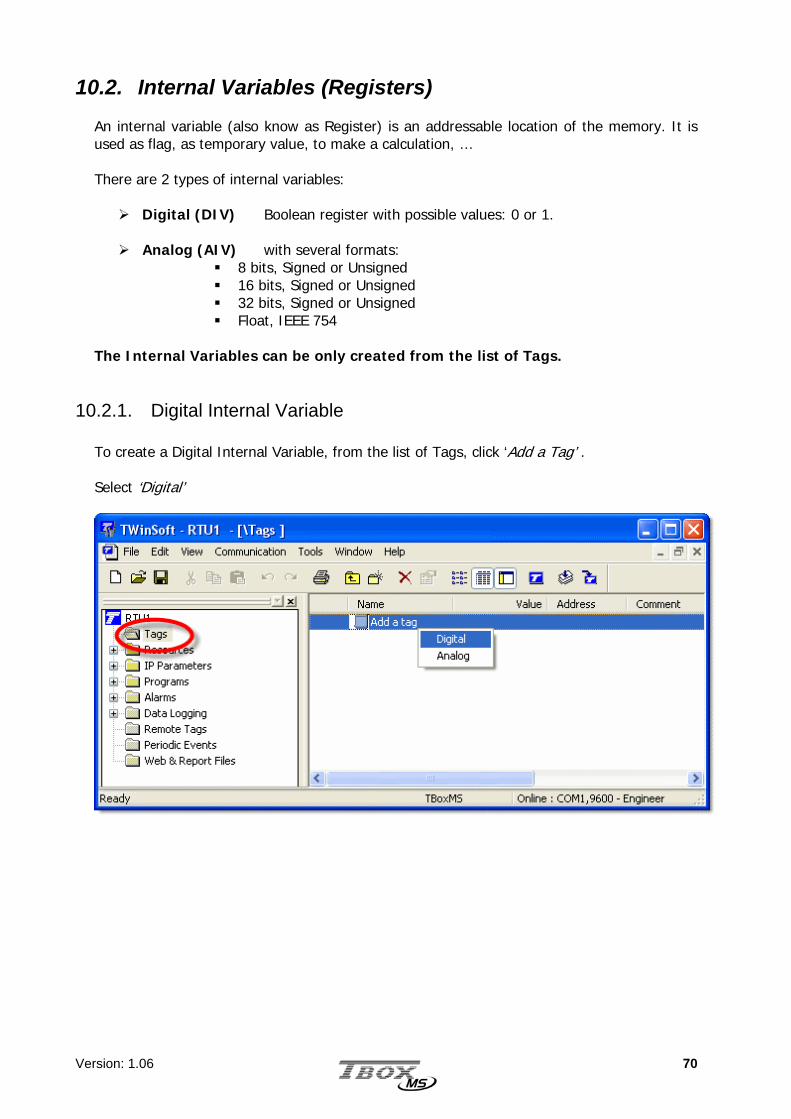
10.2. Internal Variables (Registers) An internal variable (also know as Register) is an addressable location of the memory. It is used as flag, as temporary value, to make a calculation, … There are 2 types of internal variables:
Digital (DIV) Boolean register with possible values: 0 or 1.
Analog (AIV) with several formats: 8 bits, Signed or Unsigned 16 bits, Signed or Unsigned 32 bits, Signed or Unsigned Float, IEEE 754
The Internal Variables can be only created from the list of Tags.
10.2.1. Digital Internal Variable To create a Digital Internal Variable, from the list of Tags, click ‘Add a Tag’ . Select ‘Digital’

Version: 1.06 71
The Definition menu pops up:
You type a Tag Name, a Comment and select as Type: ‘Internal Variable’ The initial value is the value the Tag will have at the start up of TBOX MS. If you select ‘None’ the value is maintained at start up.
ModBus Address is discussed in chapter 10.3

Version: 1.06 72
10.2.2. Analog Internal Variable To create an Analog Internal Variable (also known as Register), from the list of Tags, click ‘Add a Tag’ . Select ‘Analog’
The Definition menu pops up:
Example with a ’32 bits – Unsigned’ internal variable

Version: 1.06 73
You type a Tag Name, a Comment and select as Type: ‘Internal Register’ For each Analog Register, the formats available are:
o 8 bits (Signed or Unsigned) o 16 bits (Signed or Unsigned) o 32 bits (Signed or Unsigned) o Float (IEEE 754)
The initial value is the value the Tag will have at the start up of TBOX MS. If you leave the field empty, the value is maintained at start up.
ModBus Address is discussed in chapter 10.3
By default, TWinSoft creates Analog Internal Variable in format ‘Float’. Check it fits with the use you intend to have with the variable.

Version: 1.06 74
10.3. ModBus address
The ModBus address is the link to the outside world. When equipment must sample Tags in TBOX MS, it uses its ModBus addresses; like T, SCADA or TWinSoft. Each Tag has a unique ModBus address. By default TWinSoft proposes a ModBus address. You can change it if you want.
10.3.1. ModBus address of System Variables With System Variables it is a little bit different; they have two ModBus addresses:
One internal and fixed ModBus address that you don’t know. That explains why when you are connected to TBOX MS, even without sending a program, you still can see values from the Resources. One user ModBus address that you are allowed to modify if you want. When you
create a Tag of system variable, you can change its default ModBus address. In case you wish to access the Tag, you declare this user ModBus address.
While being On-line, the value of the Tag can be displayed only when TWinSoft has sent the program to TBOX MS. The Tag is then available for the outside world at the ModBus address you have declared.
Other Tabs of the Tag configuration refer to menu where the Tag can be declared:
For Alarms, see chapter 12 For Datalogging, see chapter 13 For Remote Tags, see chapter 14 About Presentation-write, see next chapter

Version: 1.06 75
10.4. Tags - Presentation / Write This tab contains configuration used when the Tag is declared in a Report or in a WebForm.
Report: file edited with ‘Report Studio’ and used for instance as text body when sending e-mail. (Start ‘Report Studio’ from ‘Windows’ and the group of Programs of Techno Trade or from the ‘Project Workspace’ and the list of ‘Web and Report files’)
WebForm: file edited with ‘WebForm studio’. Used to display values of Tags in a
HTML page. (Start ‘WebForm Studio’ from ‘Windows’ and the group of Programs of Techno Trade or from the ‘Project Workspace’ and the list of ‘Web and Report files’)
Presentation: makes the following information available to ‘Report’ and ‘WebForm’. Description: in a Report, text displayed as ‘Header’ in sampling table or as Tag
information in chronologies when the data is retrieved.
Units: text displayed as ‘Unit’ in datalogging when the data is retrieved. It can also be displayed when selecting as format ‘Value + unit’ in the report or WebForm.
# decimal: the quantity of decimals of the value displayed
Write allowed: if the Tag is declared in a WebForm, allows defining a writing access to the
Tag, within a specific range.

Version: 1.06 76
11. IP Parameters IP parameters consist in the global configuration for:
connecting to an ISP sending files (FTP) sending e-mail (SMTP) Time synchronization (NTP)
All IP parameters are defined in this Folder, available from the ‘Resources’.
The FTP Host, SMTP Server and NTP configurations correspond to connections to the appropriate servers. It is done for once, and called when creating a recipient of alarms. This makes creating alarm recipients very easy ! Example with alarm for sending e-mail: The Recipient is an ‘e-mail’ address which refers to a SMTP server. This SMTP server refers to an ISP In other way round, when TBOX MS generates an e-mail, it sequences the configuration like following:
connection to an ISP connection to a SMTP Server sending to a recipient (e-mail address)
Concerning IP configuration of Ethernet card, refer to the corresponding card in the ‘Resources’. Concerning IP configuration for incoming calls
(WebServer), see advanced RTU properties TCP/IP

Version: 1.06 77
11.1. ISP configuration ISP stands for Internet Service Provider. An ISP represents the entrance to Internet. It is the company you call to access an Internet service, like sending e-mail or files (FTP). Some among the most well-known: Hotmail, AT&T, Scarlet, … When you want TBOX MS to send e-mail or send files to a FTP site, you subscribe an account to an ISP.
Name: It is the name of the provider.
Phone number: It is the phone number of the provider the TBOX MS must dial to send an e-mail or files.
Dial Prefix: The default dial prefix to connect to an ISP (ATDT). It should not be
changed unless the modem needs a particular configuration. If TBOX MS is placed behind a telephone switch, the ‘outside line prefix’ is
defined in the modem properties; it should not be added to the dial prefix (see chapter 9.2.2)
User name: It is the name of your account needed to access Internet (usually it is given
by the ISP).
Password: It is the password of your account needed to access Internet (usually it is given by the ISP).
Using the button ‘Import…’ gives you access to an existing ISP configuration you have tested successfully on the PC. A good piece of advice

Version: 1.06 78
DNS: A DNS converts names in IP address. It is needed by the TBOX MS to establish the connection with the Mail Provider in case the e-mail Server is indicated in 'text' and not with an IP address.
More and more ISP support dynamic DNS, they provide the DNS addresses when connecting.
When it is not the case, they provide you with a ‘Preferred’ and ‘Alternate’ DNS address
You can declare several ISP entries! Then they can be used in redundancy through the sending of e-mails. You are allowed to define several SMTP Servers (see next), associated to different ISP’s. Creating the alarm recipient, you can select the ‘Redundancy’ option

Version: 1.06 79
11.2. FTP Host FTP stands for File Transfer Protocol. When subscribing an account to an ISP, usually you have some Mbytes to your disposal for sending files. The FTP host represents the target when sending files. The directory where the files are sent is defined in the Recipient (see chapter 11). First, TBOX MS connects to Internet (through an ISP connection) and then sends the files.
Host Name: It is a free name, to recall when you create the alarm recipient.
Host address: text and IP address are accepted.
Connection: You select the ISP you have previously created (see above).
Login: Depending on the account you have subscribed, you have a login or work with ‘Anonymous login’.
This is the basic configuration to connect to the ‘FTP site’. You do not declare a directory in this configuration, but when declaring the ‘Recipient’ (see chapter 12.4. The Recipients). This allows creating any combination: - several ‘FTP recipients’ to one FTP site - several ‘FTP recipients’ to different FTP sites. - …

Version: 1.06 80
11.3. SMTP Server SMTP stands for Simple Mail Transfer Protocol. It is usually the main reason for subscribing an account to an ISP, for sending and reading e-mail. The SMTP Server represents the mail server used for sending e-mail (typically the one of the ISP where we have subscribed an account). First, TBOX MS connects to Internet (through an ISP connection) and then to the SMTP Server.
Name: It is a free name, to recall when you create the alarm recipient. Mail Server (SMTP): It is the IP address (or the name) of the outgoing e-mail Server. It
is the unique mail Server needed. The POP3 address, for incoming e-mail, is not needed, as TBOX MS cannot receive e-mail.
E-mail address: It is the e-mail address of the TBOX MS. You can usually choose it when you
subscribe an account. This address will appear in the 'From:' when receiving the mail.
.
In order to protect the mail server (and you) against spamming, the ISP might to refuse sending e-mail if the address of the originator is not known. Therefore, be careful to indicate here the e-mail address you have received from your ISP.
Concerning e-mail, TBOX MS is able to send e-mail and not to read e-mail. That explains why we speak only of SMTP and not POP3 (used for reading e-mail)
Version: 1.06 81
The Server requires Authentication: Depending on your ISP and on the way you send e-mail, authentication might be needed to send e-mail. Usually, when you have subscribed the e-mail account at your ISP it is not required. To be sure, if you have created this account on a PC, check its configuration otherwise contact your ISP.
11.3.1. About Redundancy If you create more than one SMTP Server, they can be used in redundancy in accordance to their order in the list. You decide to work with redundancy when creating the e-mail recipient (see chapter 12.4).

Version: 1.06 82
11.4. NTP Server NTP stands for Network Time Protocol, an Internet standard protocol (built on top of TCP/IP) that assures accurate synchronization to the millisecond. The NTP Server represents a server dedicated to time synchronization. First, TBOX MS connects to Internet (through an ISP connection) and then to the NTP Server.
Example with a connection to Windows server through Ethernet Examples of Servers:
time.windows.com europe.pool.ntp.org
You will find valuable information, like lists of Servers with open access at:
www.ntp.org public time server list The organization pool.ntp.org proposes servers using DNS round robin, which make a random selection from a pool of open access time servers. This is good enough when working with TBOX MS. Round Robin DNS technique is used when the number of access to a server is unpredictable, to balance the use of IP addresses (load balancing technique).
11.4.1. Time accuracy When setting time, TBOX MS takes into account the propagation delay. This is particularly important when connecting to the server via modem. The precision is of 1 second.
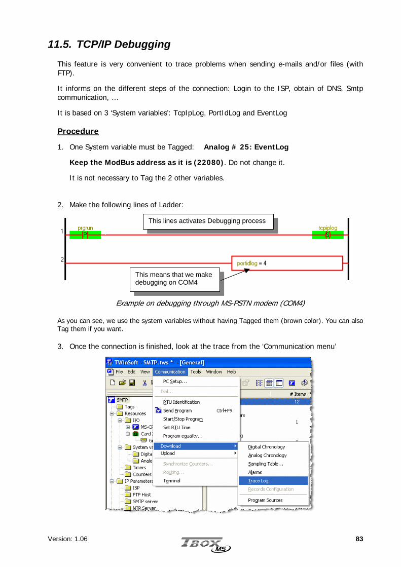
Version: 1.06 83
11.5. TCP/IP Debugging This feature is very convenient to trace problems when sending e-mails and/or files (with FTP).
It informs on the different steps of the connection: Login to the ISP, obtain of DNS, Smtp communication, …
It is based on 3 ‘System variables’: TcpIpLog, PortIdLog and EventLog Procedure
1. One System variable must be Tagged: Analog # 25: EventLog
Keep the ModBus address as it is (22080). Do not change it.
It is not necessary to Tag the 2 other variables.
2. Make the following lines of Ladder:
Example on debugging through MS-PSTN modem (COM4) As you can see, we use the system variables without having Tagged them (brown color). You can also Tag them if you want. 3. Once the connection is finished, look at the trace from the ‘Communication menu’
This means that we make debugging on COM4
This lines activates Debugging process

Version: 1.06 84
4. Example of TraceLog when sending e-mail works fine:
Agreement on options supported
Authentication (PAP or CHAP)
Agreement on options supported
Obtain DNS from ISP
SMTP (e-mail) dialog
Closing connection
TBOX MS uses the ‘Analog Chronologies’ to store debugging data:
1. Check whether the size is sufficient (from the RTU properties General)
2. If you retrieve data, for instance with T, you might receive strange data!
Modem connected

Version: 1.06 85
5. Example of TraceLog when sending Files (FTP) works fine:
Agreement on options supported
Authentication (PAP or CHAP)
Agreement on options supported
Obtain DNS from ISP
FTP (sending files) dialog
Closing connection
Modem connected

Version: 1.06 86
12. Alarms
12.1. Introduction Alarm module of TBOX MS is the gate to the outside world. An alarm consists in a communication event, not only for sending warning messages but to establish a connection, like we will see. Via alarms, you are able to call a SCADA, send SMS or message to Pagers, send e-mail, send files to a FTP site, dial another TBOX MS or send a report to a printer. Alarms can be used also to send historical data on regular base using e-mail or FTP. The historical data is sent as the attached file of a report, developed using Report Studio (see from ‘Windows’ the group of programs of ‘Techno Trade’). TView, the supervisory software can then be used to collect data from a mail box or a FTP site. The initiation of alarms in the TBOX MS relies on the variation of digital or analog Tags. For example, an intrusion contact or a flow level generates a call. There are two ways of activating an alarm: By a condition: an edge on a digital Tag or the value of an analog Tag that passes
below a minimum threshold or above a maximum threshold, with adjustable hysteresis. By the Ladder diagram: a complex Ladder sequence generates an alarm through a
specific function. The first option affords a simple and quick way to create alarms (a state change of a digital Tag or the variation of an analog Tag value to activate the alarm). The Ladder diagram allows you to create a complex automated alarm condition by using (for example) priorities or a set of analog or Boolean conditions. Each new alarm is immediately entered into a 32-alarms queue (adjustable) and processed, according to its severity level. Alarms are generated one by one. The alarm queue represents an internal buffer of alarms: if several alarms happen at the same time or if a communication port is not available when the alarm happens. The Events stack, gives information about alarms status (Started – Stopped – Acknowledged).
The Events stack is discussed at chapter 12.7

Version: 1.06 87
To access the definition of Conditions, click the folder ‘Alarms’ in the Project workspace and select ‘Conditions’. According to the Tag you select, you define a digital alarm condition or an analog alarm condition.
12.2. Digital Alarm Condition
Tagname: The Tag selected to generate the alarm. Type: The edge on which the alarm is going to be started (rising, falling or both). Message or Report: text or file associated to the alarm.
Depending on the type recipient associated, you can send a message or a report. It is the SMS message sent to a GSM, the message/report sent as e-mail, the message/report printed, or the file sent by FTP …
It also appears in the table of alarms, to distinguish them (see chapter 12.7).
If the alarm condition sends an e-mail, it can be of 2 kinds: Message: a text message is sent and it appears in the ‘object’ field of the e-mail Report: sending of a report created with Report Studio. The report can be
created from the Project Workspace and the list of ‘Web & Report files’.
Recipient: Select a Recipient or a group of recipients. The ‘person’ you wish to contact
in case of alarm (see ‘Recipients’ below). In case you select a group of Recipients, TBOX MS executes a chain: it calls the first one in the group; in case the alarm cannot be acknowledged after the number of tries, TBOX MS automatically calls the next Recipient in the group. It is the equivalence to ‘Chain’ with previous generation of RTU, the A.
Filter: The time in hour:minute:second during which the condition must stay TRUE, before the call is generated.
Version: 1.06 88
Handling: The handling option allows blocking each alarm condition, manually or automatically.
Enabled: alarm condition always active. Disabled: alarm condition always de-activated. PowerF: alarm condition disabled when there is a main power failure. DisAla: alarm condition de-activated when the system variable ‘DisAla’ is at 1.
Severity: Each alarm can be assigned a level of severity: Low, Normal or High. When
several alarms are still present in the queue and then not processed yet, TBOX MS generates the calls according to the highest severity.
End of Alarm: When the alarm condition is finished, an alarm is automatically sent to the
same recipient with the same message. Example: for a ‘positive edge’ alarm, it is when the Tag returns to ‘0’. It is also useful when the alarm condition is active when TBOX MS starts up.
When ‘end of alarm’ is checked, an alarm is automatically generated when the alarm condition disappears (see illustration chapter 12.7: Alarms table)
Call all Recipients: In case you select a group of Recipients, TBOX MS executes a
link between recipients: it calls all Recipients one after each other.

Version: 1.06 89
12.3. Analog Alarm Condition
Tagname: The Tag selected to generate the alarm. Type: Maximum or Minimum.
The threshold for which the alarm will be started. If the value of the analog Tag passes under (minimum) or over (maximum) this threshold, the alarm is started. If an alarm must be generated for both a maximum and a minimum threshold, 2 conditions must be declared with the same Tag.
Value: The threshold value, depending on the format defined when creating the Tag
(see chapter 10. The Tags). Hysteresis: The amount that the level must fall or rise below or above the Max. or Min.
value before an alarm can be re-started Recipient: Select a Recipient or a group of recipients. The ‘person’ you wish to contact
in case of alarm (see ‘Recipients’ below). In case you select a ‘group of Recipients’, TBOX MS calls the first one in the group. In case the alarm cannot be acknowledged after the number of tries, TBOX MS automatically calls the next Recipient in the group. It is the equivalence to ‘Chain’ with previous generation of RTU, the A.

Version: 1.06 90
Message or Report: text or file associated to the alarm. Depending on the recipient associated, it is the SMS sent to a GSM, or the message/report sent as e-mail or the text printed, or the file sent by FTP … It also appears in the table of alarms, to distinguish them (see chapter 12.7). If the alarm condition sends an e-mail, it can be of 2 kinds: Message: a text message is sent and it appears in the ‘object’ field of the e-mail Report: sending of a report created with ‘Report Studio’. The report can be
created from the Project Workspace and the list of ‘Web & Report files’.
Filter: The time in hour:minute:second during which the condition must stay TRUE,
before the call is generated. Handling: The handling option allows blocking each alarm condition, manually or
automatically. Enabled: alarm condition always active. Disabled: alarm condition always de-activated. PowerF: alarm condition disabled when there is a main power failure. DisAla: alarm condition de-activated when the system variable ‘DisAla’ is at 1.
Severity: Each alarm can be assigned a level of severity: Low, Normal or High. When
several alarms are still present in the queue and not processed yet, TBOX MS generates the calls according to the highest severity.
End of Alarm: When the alarm condition is finished, an alarm is automatically sent to the
same recipient with the same message. Example: for a ‘maximum’ alarm, it is when the value returns below
maximum - hysteresis. It is also useful when the alarm condition is active when TBOX MS starts up.
When ‘end of alarm’ is checked, an alarm is automatically generated when the condition of alarm disappears (see illustration chapter 12.7: Alarms table)
Call all Recipients: In case you select a group of Recipients, TBOX MS executes a
link between recipients: it calls all Recipients one after each other.

Version: 1.06 91
12.4. Recipients To access the definition of Recipients, click the folder ‘Alarms’ in the Project workspace and select ‘Recipients’. The types of recipients supported are: Internal: the alarm is saved in the stack of events and no call is generated.
It can be used to memorize a particular event without generating an alarm or to test an alarm condition.
ModBus: it can be Master or Slave.
It is used to establish a ModBus connection to another ModBus device or a SCADA (for instance T). The difference between Master and Slave concerns the handling of the modem connection and acknowledgement. A ‘Slave’ connection means that TBOX MS dials an equipment and doesn’t do anything else. The dialed equipment will sample, acknowledge and hang-up. Typically used for instance when dialing T. A ‘Master’ connection means that TBOX MS dials a ModBus equipment and will also sample this equipment (with Remote Tags). TBOX MS will then be also responsible of acknowledgement (see chapter 9.4: System variables) and hanging-up (see ‘Advanced’ properties of the communication port used)
Pager/SMS: to send SMS to a mobile or message to a Pager.
Select the Service corresponding to the pager or mobile and a Modem. Type the Phone Number of the Pager or Mobile. The default Dial prefix is ATDT. It should not be changed unless the modem needs a particular configuration. If TBOX MS is placed behind a telephone switch, the ‘outside line prefix’ is defined in the modem properties (see chapter 9.2.2)

Version: 1.06 92
Printer: sending of message(s) or report to a local printer. E-mail: If you have subscribed an e-mail account (see chapter 11.3. SMTP Server),
the TBOX MS is able to send an e-mail. You only have to specify the e-mail address of the recipient.
FTP: TBOX MS is able to send files to a FTP Host (see chapter 11.2. FTP Host). In the recipient configuration you only need to indicate the directory where
you want to send the files. NTP: TBOX MS is able to synchronize its clock with an external NTP server.
In the recipient, you only select a server you have created in the list of NTP Servers (see chapter 11.4. NTP Server).
Sending of e-mail supports Redundancy. If you have created several SMTP Servers and you select ‘Redundancy’ instead of a Server, TBOX MS will use the first one in the list (see chapter 11.3. SMTP Servers. If it fails, it will try with the second one and so on…

Version: 1.06 93
12.5. Group of Recipients A group of recipients is composed of several recipients, which can be of different types (SMS, e-mail, …). You can declare several groups. Then previous to creating groups of recipients, you have to create the recipients (see above).
You can then associate an Alarm condition to a ‘recipient’ or a ‘group of recipients’. Working with groups of recipients offers 2 possibilities: 1. You select the option ‘Call all recipients’: the alarm is sent to all recipients, one after
each other ( equivalent to the ‘Link’ with previous generation of RTU, the A).
2. You don’t select the option ‘Call all recipients’: the alarm is sent to the first one in the list then if it fails to the second then if it fails to the third … When it succeeds the sending stops. ( equivalent to the ‘Chain’ with previous generation of RTU, the A).

Version: 1.06 94
12.6. Messages To access the definition of Alarm messages, click the folder 'Alarms' in the Project workspace and select 'Messages'.
Message number : indicates the index of message corresponding to its position in the list
of messages. Type a message of maximum 120 characters. This message is user specific: - If it is for a Digital Pager, it will consist only of numbers. - If it is for a Text Pager or for a GSM, it will not contain accent (ü, é, à, ...)
The Following is not available yet In all cases, a message can contain the value of a Tag. The syntax is the following:
~Xyyyyy ~
~ : The first character indicates that what follows is the value of a ModBus address. The value sent is the value from the moment of the call.
X : represents the type of the variable:
Type Description
I Integer (-32768.. 32768) W Word (0.. 65535) C Choice (for example edges: POS, NEG or DEL) S Text (comments, TEL number, scaled value of Terminal/.Minitel Tags,…) R Real (only Factor an Offset of Terminal/Minitel Tags) B Byte (0.. 255, represented as 3 ASCII characters) t Time (represented as 2 ASCII characters) j Day of the week m month 0 (zero) Byte represented in binary format f Floating point D Double word - Character string d Digital state (represented as 0/1) o (small letter) Digital state (represented as ON/OFF) # Digital state (represented as --------/########) 1.. 9, a.. f Digital state (according to the definition of digital states, only valid from 1 to
15) h Time: hh:mm

Version: 1.06 95
yyyyy: represents the ModBus address of the variable. It can be checked from the list of Tags (see chapter 10.3. ModBus address)
Examples of message Messages sent
ANA0=~B64~too high ANA0=234 too high Register AIR0=~W20480~ Register AIR0=24563
Motor is ~o32~ Motor is OFF
12.7. Alarms table The Alarms table displays the Events stack of TBOX MS. The Events stack is the visible part of the handling of alarms in TBOX MS. The internal alarms queue is not accessible. You access the Alarms table from the main menu: Communication Download Alarms
The Alarms table does not only display alarms generated in TBOX MS, but also system events like start-up of the program, Reset of the TBOX MS, …
Date/Time of the start of the condition
Message Acknowledg. Status of the
Start
Recipient Date/Time of the end of the condition
Acknowledg. Status of the
End
Version: 1.06 96
12.7.1. Columns description Start Timestamp: Date and Time when the alarm condition appears (‘Start’ condition)
Message: Message (or name of the file) associate with the alarm. System events appear between brackets.
Start: Acknowledgement status of the ‘Start’ condition. The possibilities are:
- Not ack.: the alarm is still in process. - Ack’ed: the alarm has been successfully processed. - Auto ack.: the alarm has not been processed successfully.
In case of ‘system events’, it is always the case as it is not an alarm but an event
Recipient: The name of the Recipient (from the list of Recipient). The name is listed only when the sending of the alarm
succeeded. This allows, when chaining recipients, to know the one who as been used. In case of ‘system events’, there is no name.
End Timestamp: Date and Time when the alarm condition disappears (‘End’
condition).
End: Acknowledgement status of the ‘End’ condition. When creating an alarm condition, there is an option ‘Notify end of
alarm’. This option will automatically generate an alarm when the condition generating the alarm disappears.
The possibilities are: - Not ack.: there is a ‘Notify end of alarm’ condition and the alarm is
still in process. - Ack’ed: the ‘end of alarm’ has been successfully processed. - Auto ack.: the ‘end of alarm’ has not been processed successfully.
When there is no ‘end of alarm’, it is immediately indicated as ‘Auto ack.’

Version: 1.06 97
13. Datalogging
13.1. Introduction
Datalogging relies on the database inside TBOX MS. Datalogging allows memorizing events of your process, in order to visualize its history.
TBOX MS contains 72 Kbytes of memory for recording events; the latter is what we call the database of TBOX MS. There are two categories of databases:
The Chronologies
Chronologies are 'On event' recordings, by mean of changes in Tags. Each event is recorded with the time, date, Tag and its status or value (see important note about timestamp next page).
Example of ‘digital event’:
The changing of status of the Tag represents the events.
Example of ‘analog events’:
The variation of the Tag represents the events. TBOX MS stores chronologies in 2 tables: one for digital events and one for analog events.
t 0
1
t
20
40
60
80
100
120
140
160
180
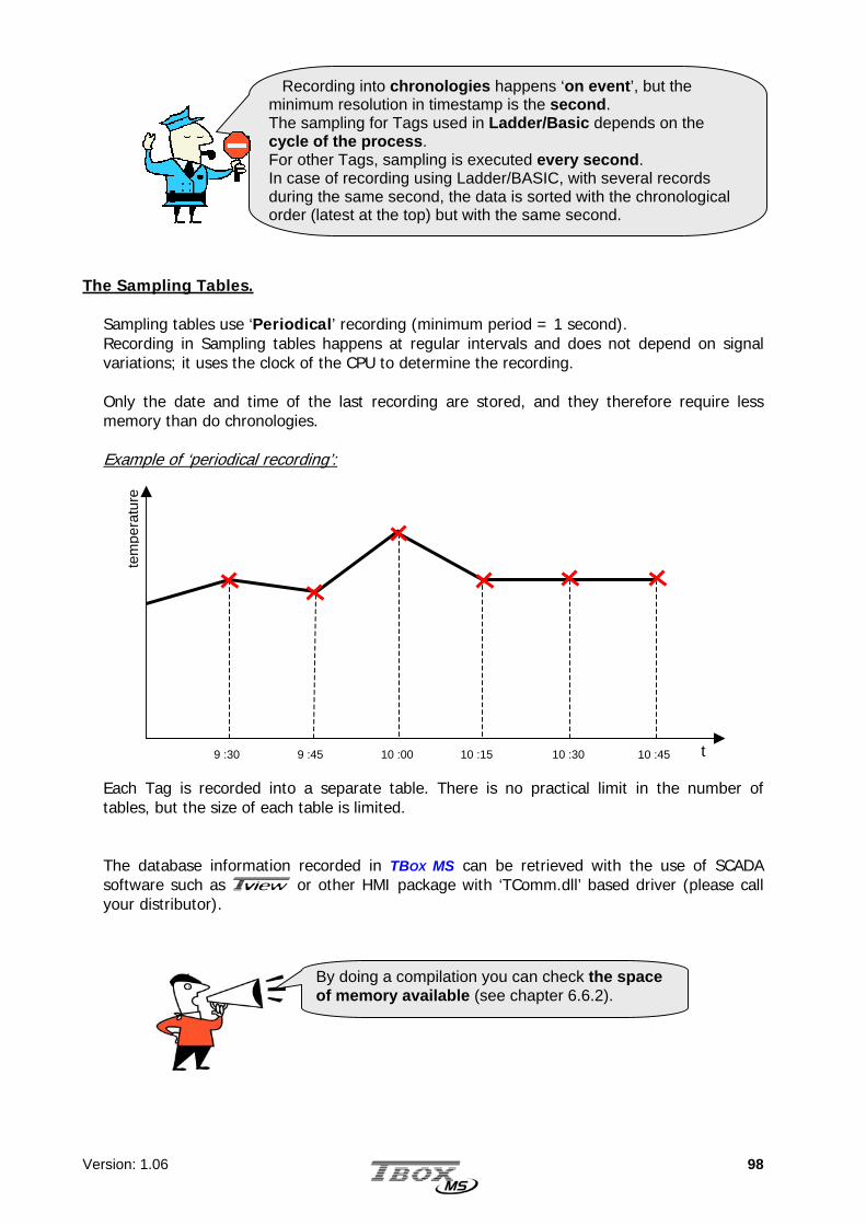
Version: 1.06 98
The Sampling Tables.
Sampling tables use ‘Periodical’ recording (minimum period = 1 second). Recording in Sampling tables happens at regular intervals and does not depend on signal variations; it uses the clock of the CPU to determine the recording. Only the date and time of the last recording are stored, and they therefore require less memory than do chronologies. Example of ‘periodical recording’: Each Tag is recorded into a separate table. There is no practical limit in the number of tables, but the size of each table is limited. The database information recorded in TBOX MS can be retrieved with the use of SCADA software such as T or other HMI package with ‘TComm.dll’ based driver (please call your distributor).
tem
pera
ture
9 :30 9 :45 10 :00 10 :15 10 :30 10 :45 t
By doing a compilation you can check the space of memory available (see chapter 6.6.2).
Recording into chronologies happens ‘on event’, but the minimum resolution in timestamp is the second. The sampling for Tags used in Ladder/Basic depends on the cycle of the process. For other Tags, sampling is executed every second. In case of recording using Ladder/BASIC, with several records during the same second, the data is sorted with the chronological order (latest at the top) but with the same second.

Version: 1.06 99
13.2. The chronologies
13.2.1. Digital chronologies
Example of an entry in Digital chronology: Recording of the starting and stopping of a ‘Pump_1’.
Edges: Recording on positive and (or) negative edge. Handling:
Enabled: always recorded. Disabled: never recorded. PowerF: recording disabled in case of main power failure. DisCRD: recording disabled when the system variable ‘DisCRD’ is at 1.
13.2.2. Analog chronologies
Example of an entry in Analog chronology: Recording of a variation of 2.5 bars in
‘Pressure_Pipe1’ input.
Variation: Recording in case of variation (higher or lower) in comparison with the previous
recording. The unit is expressed according to the format selected in the Tag definition (see chapter 10.2.2: Analog Tags).
Handling:
Enabled: always recorded. Disabled: never recorded. PowerF: recording disabled in case of main power failure. DisCRA: recording disabled when the system variable ‘DisCRA’ is at 1.

Version: 1.06 100
13.3. The sampling tables
Type: TBOX MS is able to execute calculations on a minimum time-base of 1 second.
The result of the calculation is written in the sampling table after the period selected (see next). This value can be:
- Minimum : minimum value during the period. - Maximum : maximum value during the period. - Average : average value calculated during the period. For each period a
new average is calculated. It is not possible to record average value with 32 bits variables. - Instantaneous : value at the moment of the recording. - Incremental : TBOX MS records the difference between the current value and
the value at the moment of previous recording.
Example of incremental recording:
Value of the Tag 865 878 902 905 965 985
Incremental value recorded
… 13 24 3 60 20
Period Period Period Period Period Period

Version: 1.06 101
14. Remote Tags
14.1. Introduction Remote Tags allow exchanging information between two or more ModBus stations via any communication ports. Typically, it is a TBOX MS connected to another TBOX MS, either local (through RS485 or Ethernet) or remote, by modem. One often speaks of 'Master Network' because it is a Master/Slave communication: the Master executes reading and writing in slave(s). TBOX MS, being ‘Master’, reads and writes the variables with all other devices using the ModBus protocols (ModBus-RTU or ModBus/TCP, according to the kind of communication) Each Remote Tag corresponds to one transaction (reading or writing) with 1 slave. When there are several stations, TBOX MS executes the different transactions of one station at a time, then transactions of the following station, and so on …
Any communication port can be used to execute Remote Tags: RS232, RS485, modem PSTN, modem GSM, Ethernet. When a modem port is used to execute Remote Tags, TBOX MS needs first to establish the connection using an Alarm of type ‘ModBus’ (see chapter 12.4. Recipients)

Version: 1.06 102
Previous to create Remote Tags you have to create the equipment you are going to communicate with.
14.2. Creating a Remote Device From the Project Workspace, select ‘Resources’ ‘I/O’. Click ‘I/O’ and in the list of I/O, click ‘Add an I/O card’. Remote TBox: a A (CPU-3) ModBus device: a TBOX MS, TBox-LT or any ModBus device
Example with a remote TBOX MS.
Name: You type any name. It will be
available in a list of available equipment when creating ‘Remote Tags’ (see next).
Address: It is the ModBus address of the Remote equipment. It must be different of the TBOX MS and of possible other equipment on the same network.
RTU Port: The communication port used by TBOX MS to communicate with the remote equipment.
Trigger: Select a digital Tag that will trigger the communication, according to a
‘Condition’ (see next). Working with several equipment, you can declare different Tags and then monitor differently the communication to each equipment. The Trigger must be a digital variable (DIV).
Condition: Condition of Tag ‘Trigger’ to start communication. Typically, you will work with a permanent connection (Trigger in High or Low state). Or you can decide to execute one-shot communication, on edge changing of the Tag Trigger. The changing of state of the Tag can be controlled by BASIC, Ladder, or Periodic events.

Version: 1.06 103
14.3. Creating Remote Tag
Example: reading of 8 ‘floating’ variables in TBox#2 at address 32
Tag: Select an existing Tag by clicking the button. Be sure you select a Tag of the same type of the address you want to access in the ‘Slave’ (Byte, Word or Float). If the Tag does not exist, you can create it after having clicked the button. It is the Tag of the Master; it contains the value you want to write in a Slave or it is a register that contains the value that Master reads in a Slave. In case of block communication (with a quantity > 1), this Tag is the one of first ModBus address.
Operation :
Operations MASTER (Tag) SLAVE (Address) READ WRITE
Read : the Master executes a reading in the Slave. Write : the Master executes writing in the Slave.
Quantity : Quantity of variables of successive addresses that are read (or written) in the
Slave. It depends on the External source, the types of variable and the ModBus function used (see tables below).
ModBus protocol handles only words (16 bits). When working with 32 bits, TWinSoft adapts the quantity to double the number of words. 32 bits are handled with: <Hi word1><Lo word1><Hi word2><Lo word2>…

Version: 1.06 104
External Source. All the following parameters concern the Slave station: Device: select an existing external device from the ‘Resources’. You can create one
clicking the button Type: select the type of the external variable. According to the external source, the
choices are: With External source ‘ModBus device’ (TBOX MS, TBOX LITE, any ModBus device)
Operations
Types ModBus Functions
Quantity (max.)
Read Digital Digital Input 2 2000 (see Warning below) Read Digital Coil 1 2000 (see Warning below) Read Analog Analog Input 4 125 Read Analog Holding Register 3 125 Write Single Digital Coil 5 1 Write Single Analog Holding Register 6 1 Write Multiple Digital Coil 15 800 (see Warning below) Write Multiple Analog Holding Register 16 100
With External source ‘Remote TBox’ ( A CPU-3)
Description
Operations Tag types Quantity (max.)
Digital I/O Read/Write IOD, T4m 16 Analog I/O Read/Write IOW, I4M 8 Digital registers Read/Write DIR, STD 1600 (see Warning below) Analog registers (8 bits) Read/Write STB 8 Analog registers (16 bits) Read/Write AIR, STO 100 Analog registers (32 bits) Read/Write TOT 8 Analog registers (32 bits) Read/Write FLT 8 Timers Read/Write ATP, ATV, DTI 16 Counters Read/Write ACP, ACV, DCN 16 Special Registers Read/Write DSPE, ASPE 16 Register ‘Sampling Table’ Read/Write ECH 16
Address : The ModBus address must be typed according to the indication of the user’s
guide of the Remote device. Communicating to TBOX MS, you have to refer to the TWinSoft application and its configuration of Tags.
Working with digital variables (DIV, DIR, …), you have to work with multiple of 8 for: quantity, address of the Tag and Address in External Source

Version: 1.06 105
14.4. Remote Tags through modem With a remote device accessed by modem, the connection must be first established using an Alarm. The sequence is the following:
• Create an Alarm Recipient of type ‘ModBus - Master’, with the telephone number of the remote device.
• Create a ‘Remote Device’, associated to the communication port of the modem and to a Trigger – DIV (digital register).
• Create the Remote tags associated to this device. • The alarm is conditioned by a situation requiring communication with another TBOX
MS leading to a Tag which is the condition of the alarm. • When modems are connected (can be checked with Digital Communication
Variable DCV ‘COMx.Call’), you activate the Trigger of the TBOX MS you are connected to. This action executes Remote Tags associated to this station.
• Acknowledge the alarm, for instance using the special analog variable ‘AlaRec’. • Stop connection by writing ‘0’ to the Communication Variable
‘COMx.ModemOffHook’, or the communication will be automatically stopped after 1 minute.
14.5. Timing configuration of Remote Tags Several timings can be adjusted when communication through Remote Tags. They are available from the tab ‘Advanced’ of the communication port properties.
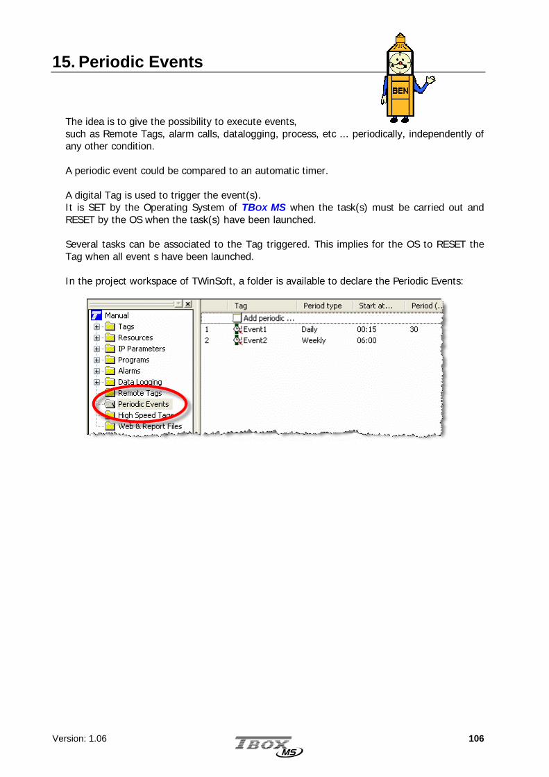
Version: 1.06 106
15. Periodic Events The idea is to give the possibility to execute events, such as Remote Tags, alarm calls, datalogging, process, etc ... periodically, independently of any other condition. A periodic event could be compared to an automatic timer. A digital Tag is used to trigger the event(s). It is SET by the Operating System of TBOX MS when the task(s) must be carried out and RESET by the OS when the task(s) have been launched. Several tasks can be associated to the Tag triggered. This implies for the OS to RESET the Tag when all event s have been launched. In the project workspace of TWinSoft, a folder is available to declare the Periodic Events:

Version: 1.06 107
Example of a ‘daily event’:
The Tag ‘event1’ (a DIV) will be automatically SET every 30 minutes, at each xx:15:00 and xx:45:00. The action(s) configured with ‘Event1’ will be generated every 30 minutes. Example of a ‘weekly event’:
The Tag ‘event2’ (a DIV) will be automatically SET every day at 6:00:00 AM. The action(s) configured with ‘Event2’ will be generated at that moment.

Version: 1.06 108
16. High Speed Tags The high-speed Tags were designed to receive pulses on digital inputs, with handling independent from the process cycle. If the delay between two successive pulses is smaller than the cycle time of the process, it will not be possible, for instance, to make counting from the program. Then you can use the High Speed Tags. This feature is available for maximum 1 group of 8 digital inputs and the maximum frequency of pulses is limited to 25 Hz with a duty cycle of 50 %. When a pulse is detected, it is handled on processor interrupt.
Tag: Select an existing Digital Tag by clicking the button. If the Tag does not exist, you can create it after having clicked the button.
Action: Action taken to the Target Tag (see next) during a change of status of the
digital Tag defined above. The choices are:
- Rising Edge -> Set (DIV): each rising edge of the digital Tag, performs a SET action on the Target Tag which must be an internal variable DIV.
- Falling Edge -> Set (DIV): each falling edge of the digital Tag, performs a SET action on the Target Tag which must be an internal variable DIV.
- Rising Edge -> Inc (AIV): each rising edge of the digital Tag, increments the Target Tag which must be an internal variable AIV.
- Falling Edge -> Inc (AIV): each falling edge of the digital Tag, increments the Target Tag which must be an internal variable AIV.
Target Tag: It is the internal variable (DIV or AIV) on which the action is taken (see
above). Divisor: Division Factor that allows the action (SET or increment) to occur once every x
pulses (x being the factor of division).
Weight: You can give a weight to the pulses, after the computing according to the Divisor (see above).
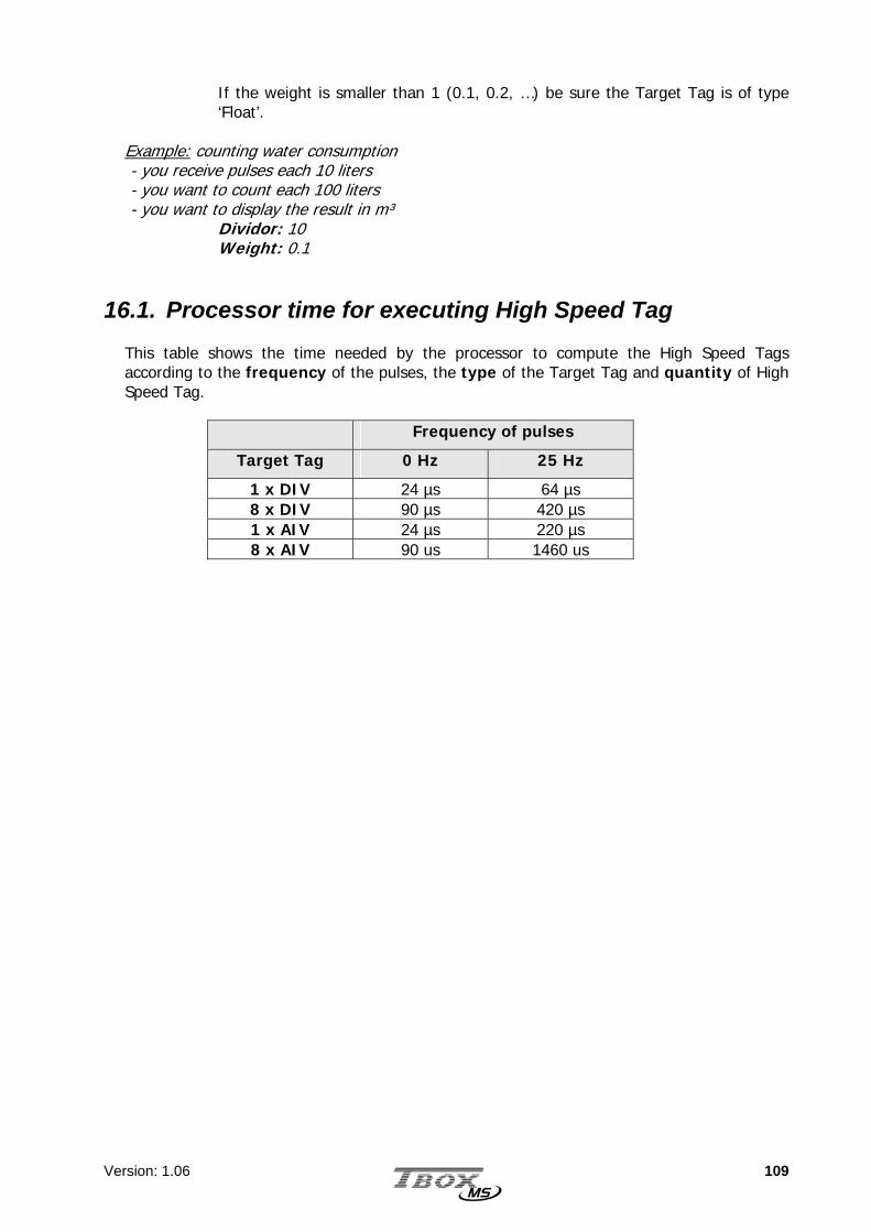
Version: 1.06 109
If the weight is smaller than 1 (0.1, 0.2, …) be sure the Target Tag is of type ‘Float’.
Example: counting water consumption - you receive pulses each 10 liters - you want to count each 100 liters - you want to display the result in m³ Dividor: 10 Weight: 0.1
16.1. Processor time for executing High Speed Tag This table shows the time needed by the processor to compute the High Speed Tags according to the frequency of the pulses, the type of the Target Tag and quantity of High Speed Tag.
Frequency of pulses
Target Tag 0 Hz 25 Hz
1 x DIV 24 µs 64 µs 8 x DIV 90 µs 420 µs 1 x AIV 24 µs 220 µs 8 x AIV 90 us 1460 us

Version: 1.06 110
17. Access security This (optional) access security of the TBOX MS prevents non-authorized persons from accessing the RTU. If the Access security option is activated, each port of the TBOX MS can be independently protected. The standard protection concerns ‘ModBus’ protocol, on serial and modem ports. A protection on Ethernet connection is not available yet. The protection is based on a four-digit hexadecimal global code that is saved in the TBOX MS. This code allows different logins related to different users with different access levels to the TBOX MS. Three access levels are available:
• Level 1: Surveillance mode or VISUALIZATION MODE. The operator can view all
TBOX MS values (local or remote), but cannot execute any command.
• Level 2: COMMAND MODE, the operator can view all the values and execute commands (locally or remotely). Also known as READ/WRITE MODE.
• Level 3: ENGINEER MODE, the operator can view all the values, execute commands and send new application (locally or remotely).
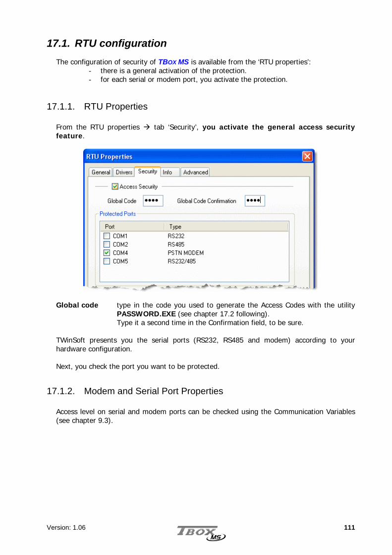
Version: 1.06 111
17.1. RTU configuration
The configuration of security of TBOX MS is available from the ‘RTU properties’: - there is a general activation of the protection. - for each serial or modem port, you activate the protection.
17.1.1. RTU Properties
From the RTU properties tab ‘Security’, you activate the general access security feature.
Global code type in the code you used to generate the Access Codes with the utility
PASSWORD.EXE (see chapter 17.2 following). Type it a second time in the Confirmation field, to be sure.
TWinSoft presents you the serial ports (RS232, RS485 and modem) according to your hardware configuration. Next, you check the port you want to be protected.
17.1.2. Modem and Serial Port Properties Access level on serial and modem ports can be checked using the Communication Variables (see chapter 9.3).

Version: 1.06 112
The utility program Password generates access codes.
17.2. Password utility
When installing TWinSoft Suite a password-creation program named PASSWORD is installed in the same directory as TWinSoft. It can be started from the 'Start' button of Windows and is located in the group of programs “Techno Trade” “Accessories” created while installing TWinSoft. This program generates a password that will be necessary to Login to the TBOX MS (see next). This password is composed of 4 hexadecimal characters in response to information’s related to the user. It is based on a complex algorithm using the global code, the user’s name and the access level. A 5-digit number that identifies persons who have accessed the TBOX MS accompanies the password. This information can be used to trace users for example by inserting this number into a database, with the help of Analog Communication Variables (see chapter 8.3).
Global code This hexadecimal code of 4 characters is the basis for password generation. It is typed in the ‘RTU Properties’ (see above) of TWinSoft and sent to the TBOX MS. When a user logs in, TBOX MS checks whether NAME and PASSWORD fit with the global code. This means that if different users with different access levels must communicate with TBOX MS, the global code used to generate passwords must be the same.
User name The NAME you use as login.

Version: 1.06 113
Access level Three access levels are available:
Level 1: Surveillance mode or VISUALIZATION MODE. The operator can view all TBOX MS values (local or remote), but can not execute any command.
Level 2: COMMAND MODE, the operator can view all the values and execute commands (locally or remotely).
Level 3: ENGINEER MODE, the operator can view all the values and execute commands and alter or send new TWinSoft documents (locally or remotely).
When this information has been entered, click on the button "Get password". Two codes have been created:
The PASSWORD: this PASSWORD must be used together with the NAME when logging.
The USER ID: this number is available in an Analog Communication Variable when a user is connected to a port of TBOX MS that is protected.
17.3. Login/Logout 17.3.1. With TWinSoft
The Login feature of TWinSoft allows connecting to a protected port of the TBOX MS according to an access level. When a port is not protected, access level is automatically 3: Engineer. The Login/Logout is executed from the main menu bar 'Tools'. Login When connected to a port of TBOX MS that is protected, you need to Login to get an access level.
You type the Name you used in the ‘Password’ utility and the Password that was created (see previous). According to those, you are in:
Read only mode Read/write mode Engineer
The access level is displayed in the Status bar.

Version: 1.06 114
If 'Save password' is checked and TWinSoft is connected to a protected port: when TWinSoft starts, it uses the access level corresponding to the password saved (see the status line). If it is not checked and TWinSoft is connected to a protected port: TWinSoft starts in 'Read only' mode. You need to do a Login to get your access level.
Logout If the TWinSoft is connected to a protected port, the Logout sets TWinSoft in 'Read only' mode.
17.3.2. With Internet Explorer
Through a modem connection, you can access TBOX MS as Web Server. From Internet Explorer, you use the tool TTBBooxx DDiiaall IItt !! to dial TBOX MS directly. TBOX MS is then considered first as an ISP and then a Web Server. To connect to an ISP you need to login.
You type the NAME and PASSWORD you have used with password utility (see above)
Even if TBOX MS is not protected, type a NAME and PASSWORD. Depending on Windows and IE version, they will not allow connecting without login.

Version: 1.06 115
17.4. Deactivating protection
There are two methods of deactivating TBOX MS access protection: Global reset (see chapter 6.5) The first method is by performing a global reset, which must be done on site. When the program has stopped, the local port is no longer protected. Sending an unprotected TWinSoft document The second method involves modifying the TWinSoft document and deactivating the Access Security option. The document must then be sent to the TBOX MS after having done a Login as 'Engineer'.
If a card ‘modem’ has been declared protected, it will still be protected even after a global reset. To deactivate protection, an unprotected TWinSoft document must be sent to TBOX MS (see below).

Version: 1.06 116

Version: 1.06 117
TTTEEECCCHHHNNNIIICCCAAALLL SSSPPPEEECCCIIIFFFIIICCCAAATTTIIIOOONNNSSS ---
CCCAAABBBLLLIIINNNGGG

Version: 1.06 118
18. Racks & Cards 18.1. Racks
References: MS-RACK5 MS-RACK10 MS-RACK15
Racks used as base for the Cards. Exist in 4 versions: Rack 5 slots Rack 10 slots Rack 15 slots Rack 20 slots
TECHNICAL SPECIFICATIONS
General Speed Maximum: 1 Mbytes / second PCB 6 layers Component NO component. Bus Passive Fixing DIN rail Dimensions: BUS 5 Without card Height x Length x Depth: 150 x 150 x 30 mm Weight 600 gr. Dimensions: BUS 10 Without card Height x Length x Depth: 150 x 300 x 30 mm Weight 1200 gr. Dimensions: BUS 15 Without card Height x Length x Depth: 150 x 450 x 30 mm Weight 1800 gr. Dimensions: BUS 20 Without card Height x Length x Depth: 150 x 600 x 30 mm Weight 2400 gr.
Insertion of cards in the Rack is explained chapter 4

Version: 1.06 119
18.2. Power Supplies
References: MS-PS230V MS-PSDCN MS-PS48VN
230 V -48 …+ 24 VDC - 48 VDC

Version: 1.06 120
T E C H N I C A L S P E C I F I C A T I O N S
230 VAC
Input Voltage input: - AC - DC
85..265 Vac (47..440 hz) 90..375 Vdc
Power Input Power at I out max. Maximum: 20 W Input Power in over load or short-circuit Maximum: 50 W Efficiency Minimum: 60% at 2 A Output Power Maximum: 15 W Output Battery charger: - Mode - Voltage - Current
Constant current / limited voltage Maximum: 13.8 V Typical: 90 mA
Output connections: +BAT +UPS nc +24 V Gnd
• to the Battery (+12V) • Backup power supply to another rack MS: +24VCC when the “main” voltage present otherwise +8V to +13.8V • No connection • +24VCC when “main” is present • Ground and 0V of Battery
Output current on the BUS (3.3V) 3 A Total current used by all secondary outputs: battery charger, BUS, 24 V output. I out (on 24 V)
Maximum: 0.625 A
Protection Test Automatic test of the access of the card by the CPU
(see LED ‘CS’ below) EMC protection Over load and short-circuit Maximum 1 second every minute
Above this time, risk of permanent damage (output line is opened) FUSE primary voltage Soldered Fuse of 1.25 A. Not replaceable by user. FUSE battery Standard Glass Fuse of 2A fast (5x20). Replaceable by user. Isolation No isolation Between GND and Earth Temperature Storage -20 to 70 °C Working (ambient) Standard: 0 to 50°C
Ruggedized: -20 °C to 70 °C Internal temperature Indicated by 2 digital input variables:
>= 70°C >= 85°C
Hygrometry 15 to 95 % without condensation LED Main Input Voltage present CS Card Selection: the card corresponds to a card declared in
TWinSoft. ER Error: The type of the card does not correspond to the one
declared in TWinSoft. Input Active Power Supply Digital input = 1 when power supply active (used in redundancy) Power Fail Digital input = 1 when ‘main’ power breaks down Temperature See above Dimensions Without connector Height x Length x Depth: 150 x 83 x 29 mm Weight (w/o connector) 350 g

Version: 1.06 121
24 VDC
Input Voltage input: - either +24V - either -48V
+8 .. +30 VCC -60 .. -24 VCC
Power Input power at maximum current Maximum: tbd Input power with short-circuit (or over load) Maximum: tbd Efficiency Minimum: tbd Output power Maximum: 15 W Output Battery charger: - Mode - Voltage - Current
Constant current / limited voltage Maximum: 13.8 V Typical: 90 mA
Output connections: +BAT +UPS nc +24 V Gnd
• to the Battery (+12V) • Backup output power supply to another rack MS: +24VCC when the “main” voltage present otherwise +8V to +13.8V • No connection • +24VCC when “main” is present • Ground and 0V of Battery
Output current on the BUS (3.3V) 3 A Total current used by all secondary outputs: battery charger, BUS, 24 V output. I out (on 24 V)
Maximum: 0.625 A
Protection Test Automatic test of the access of the card by the CPU
(see LED ‘CS’ below) EMC protection Over load and short-circuit Maximum 1 second every minute
Above this time, risk of permanent damage (output line is opened) FUSE battery Standard Glass Fuse (5x20). Replaceable by user Isolation Input between Earth and secondary Isolation reinforced according to IEC60950 standard.
3000 Vrms during 1 minute Temperature Storage -20 à 70 °C Working (ambient) Standard: -5°C à 50°C
Ruggedized (option) : -20 °C à 70 °C Internal temperature Indicated by 2 digital input variables:
>= 70°C >= 85°C
Hygrometry 15 à 95 % sans condensation LEDs Main Input Voltage present CS Card Selection: the card corresponds to a card declared in
TWinSoft. ER Error: The type of the card does not correspond to the one
declared in TWinSoft. Input Active Power Supply Digital input = 1 when power supply active (used in redundancy) Power Fail Digital input = 1 when ‘main’ power breaks down Temperature See above Dimensions mm Without connector Height x Length x Depth: 150 x 83 x 29 mm Weight (w/o connector) 350 g

Version: 1.06 122
- 48 VDC
Voltage / Current V in -60 to –24 VDC Output current on the BUS (3.3V) 2 A Consumption 10 mA Power Input Power at I out=2 A Maximum: 12 W Input Power in over load or short-circuit Maximum: 65 W Efficiency Minimum: 60% at 2 A Protection Test Automatic test of the access of the card by the CPU
(see LED ‘CS’ below) Input voltage inversion Maximum: 60 VDC EMC protection Over load and short-circuit Maximum 1 second every minute
Above this time, risk of permanent damage (output line is opened)
Isolation No isolation Between Input and Output GND No isolation Between GND and Earth Temperature Storage -40 to 70 °C Working (inside the card) Standard: -40°C to 85°C Working (ambient) Standard: -5°C to 50°C
Ruggedized: -20°C to 70°C Hygrometry 15 to 95 % without condensation LED Main Input Voltage present CS Card Selection: the card corresponds to a card declared in
TWinSoft. ER Error: The type of the card does not correspond to the one
declared in TWinSoft. Input / Output Temperature input Use: measurement of the card internal temperature
Internal input Precision: 5 °C
Voltage input Use: measurement of the Input voltage Internal input Precision: 1 %
Dimensions Without connector Height x Length x Depth: 150 x 83 x 29 mm Weight 245 gr.

Version: 1.06 123
C A B L I N G
230 Vac Power supply Description: Power Supply 230 VAC
Connector: POWER UNIT
SCREW CONNECTOR (3 X 7.68 MM)
Description: Power Supply 110 VAC
Connector: POWER UNIT
SCREW CONNECTOR (3 X 7.68 MM)
Description: Power Supply 110 VDC
Connector: POWER UNIT
SCREW CONNECTOR (3 X 7.68 MM)
Description: Battery
Connector: POWER UNIT
SCREW CONNECTOR (5 X 5.08)
1 ~230 Vac - L2
3 ~earth
230 Vac - N
12
34
+Bat Battery
5
+24V
Gnd
12/24 V backup
24 VGnd
UPS
1 ~110 Vac - L
2 3 ~
earth
110 Vac - N
1 ~110 Vdc
2 3 ~
earth
0 V
For electrical security reason, you have to manipulate connectors with power switched OFF.

Version: 1.06 124
24 Vdc Power supply Description: Power Supply 24 VDC
Connector: POWER UNIT Screw connector (4 x 5.08 mm)
Description: Power Supply - 48 VDC
Connector: POWER UNIT Screw connector (4 x 5.08 mm)
Description: Battery
Connector: POWER UNIT
SCREW CONNECTOR (5 X 5.08)
- 48 Vdc Power supply
Description: Power Supply – 48 VDC
Connector: POWER UNIT Screw connector (4 x 5.08 mm)
12
34
Gnd 0 V
-60 .. -24 VDCearth
V-
1 2
34
Gnd
+24V
Earth
Gnd +8 .. +30 VCC
-48V
Terre 1
23
4
Gnd
+24V
Earth Gnd
-60 .. –24 VCC
-48V
Terre
1 2
34
+Bat Battery
5
+24V
Gnd
12/24 V backup
24 VGnd
UPS
For electrical security reason, you have to manipulate connectors with power switched OFF.

Version: 1.06 125
18.3. CPU-16 bits
References: MS-CPU16
Hardware on all models:
Power supply input
Button for selection of the mode of working
RS232 RS485
I/O for synchronization
Internal temperature measurement
Input voltage measurement
Ethernet
T E C H N I C A L S P E C I F I C A T I O N S General Processor 16 bits, 7.37 Mips Clock Real Time Clock, backed-up (see schema following) Button Push button : RUN - STOP - RESET Power Supply Voltage 6 .. 30 VDC Supply Current Maximum: 1 A (on 3.3 Volts of the BUS) Consumption 200 mA

Version: 1.06 126
Internal Battery (see schema following)
Voltage 3 V Use Backup of Clock and RAM (datalogging) Lifetime
CPU under voltage: 10 years CPU stopped and plugged on the Rack: - Typical 265 days - Minimum: 29 days WARNING: After this time, the battery must be replaced to maintain the clock and datalogging.
Memory Flash Internal: 256 kbytes
- OS: 192 kbytes - application: 32 kbytes - program (BASIC/Ladder): 16 kbytes - loader: 16 kbytes External: 512 kbytes: Web Files, Report
RAM Internal: 20 kbytes External (backed up): 128 kbytes - datalogging: 72 kbytes - application: 32 kbytes - buffer TCP: 24 kbytes
RS 232 Connector 9 pin Sub-D (male) Cabling
(see schema next) DTE model (same as PC) 4 Wires: TxD, RxD, RTS, CTS
Protocol ModBus-RTU ‘Slave’ LED RxD: ON when receiving
TxD: ON when transmitting RS 485 Connector Screw connector (3 x 5.08mm) Cabling
(see schema next) 2 Wires + GND
Protocol ModBus-RTU ‘Master’ and ‘Slave’ LED RxD: ON when receiving
TxD: ON when transmitting Isolation No isolation between signal and Power Supply Number of slaves 256 (if RS485 technology of slaves allows it too) Termination Termination not required.
Failsafe bias resistors included: pullup and pulldown resistors which assures a logical level TRUE when A and B are opened or in short-circuit.
Ethernet Model 100 BASE-TX (4 wires)
Full Duplex Auto-negociation
Connector RJ-45 Cabling
To a Hub, …: with straight pinned CAT5 cable To a PC: with a Crossover CAT5 cable (see cabling following)
Speed 10/100 Mbits Protocols ModBus/TCP ‘Master’ and ‘Slave’, SMTP, FTP, HTTP, Ping LED 100: ON when connected at 100 Mhz – OFF when connected at 10 Mhz
Lk: ON when linked – FLASH when communicating FD: ON when in Full Duplex

Version: 1.06 127
Input/Output Synchronization I/O Multipoint connection between CPU
Use: synchronize actions on several CPU in the same cabinet Synchronization Input Use: to receive ‘Synchronization Output’ from other CPU
Vin: 0 5.5 V Protection: Over voltage: max. 33 V Inversion: max. 29 V
Synchronization Output Use: to connect to ‘Synchronization Input’ of other CPU Type: Current sinking Voltage: max. 50V Current: max. 45mA Resistance: max. 60 ohms NO PROTECTION
Temperature input Use: measurement of the card internal temperature Internal input Precision: 5 °C
Voltage input Use: measurement of the Input voltage Internal input Precision: 1 V
Temperature Storage -20 to 70 °C Working Standard: -5°C to 50 °C
Ruggedized: -20 °C to 70 °C Hygrometry 15 to 95 % without condensation Dimensions Without connector Height x length x Depth: 150 x 83 x 29 mm Weight 272 gr

Version: 1.06 128
Battery and MultiMedia card implementation: 18.3.1. Lithium Battery
The CPU is equipped with a Lithium battery (3 V). This battery is used to maintain the clock and datalogging when the CPU is out of power. This battery is in use when:
- the CPU is placed on a Rack - the CPU has been powered once - the CPU is out of power
When the CPU is removed from the Rack, the battery is disconnected, to avoid consuming when the CPU is in stock. The battery jumper allows keeping the battery connected even when removed from the rack (see in above specification the life time of the battery). Advised procedures: 1. Standard : the jumper is left opened.
On this way, the battery is used when the CPU is placed on the rack to maintain clock and datalogging when the main power has broken down.
2. Permanent : you systematically place the jumper, before you start using the CPU. On this way, the battery is used when the CPU has been powered at least once, to maintain clock and datalogging when the main power has broken down, but also when the CPU is removed from the rack (check the life time of the battery in the technical specifications)
Lithium battery
Battery Jumper
MultiMedia Card
RS 485 RS 232 POWER ETHERNET

Version: 1.06 129
18.3.2. MultiMedia card To use the MultiMedia Card, remove the CPU from the Rack and insert the MultiMedia cards in the appropriate socket. The MultiMedia card can be used to initialize TBOX MS. For the moment, the only initialization available concerns the IP configuration of the Ethernet port. Initialization is done using a file called ‘System.xml’, placed in the root of the MultiMedia Card. IP configuration
Example of System.xml: <?xml version="1.0"?> <System> <ComPort> <PortName>COM4</PortName> <IPconfig> <IP>192.168.1.75</IP> <Subnet>255.255.255.0</Subnet> <Gateway>192.168.1.1</Gateway> <PrimaryDNS>192.168.1.1</PrimaryDNS> </IPconfig> </ComPort> </System>
<PortName> Communication port of TBOX MS (COM4 = Ethernet) <IP> IP address of the port selected <Subnet> IP address of the Subnet mask of the port selected <Gateway> IP address of the equipment used as Gateway on the
Network <PrimaryDNS> IP address of the DNS Server (only primary DNS handled at
the moment)
18.3.3. Button (Working modes) On the front side of the CPU, a button allows changing the Working mode of the CPU: STOP - RUN - RESET
RUN All features of TBOX MS runs RESET Pressing Reset, restart the program, erase the alarms and the
datalogging STOP Not supported yet
See also chapter 6.5. Global Reset of TBOX MS
When an IP configuration is defined in the MultiMedia Card, it has priority on the one declared for the Ethernet port of the CPU.
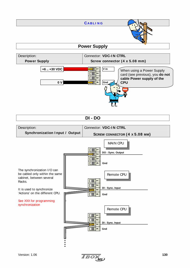
Version: 1.06 130
C A B L I N G
Power Supply Description: Power Supply
Connector: VDC-IN CTRL Screw connector (4 x 5.08 mm)
DI - DO Description: Synchronization Input / Output
Connector: VDC-IN CTRL
SCREW CONNECTOR (4 X 5.08 MM) The synchronization I/O can be cabled only within the same cabinet, between several Racks. It is used to synchronize ‘Actions’ on the different CPU. See XXX for programming synchronization
1 2
340 V
+6 .. +30 VDC
Gnd
V in
12
34
1 2
34
DO : Sync. Output
MAIN CPU
12
34
Remote CPU
Remote CPU
Gnd
Gnd
Gnd
DI : Sync. Input
DI : Sync. Input
When using a Power Supply card (see previous), you do not cable Power supply of the CPU
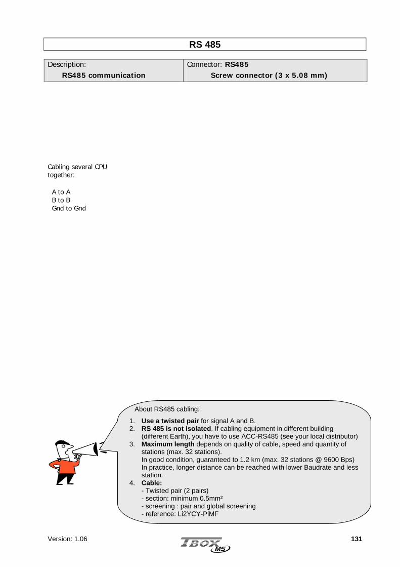
Version: 1.06 131
RS 485 Description: RS485 communication
Connector: RS485 Screw connector (3 x 5.08 mm)
Cabling several CPU together: A to A B to B Gnd to Gnd
About RS485 cabling:
1. Use a twisted pair for signal A and B. 2. RS 485 is not isolated. If cabling equipment in different building
(different Earth), you have to use ACC-RS485 (see your local distributor)3. Maximum length depends on quality of cable, speed and quantity of
stations (max. 32 stations). In good condition, guaranteed to 1.2 km (max. 32 stations @ 9600 Bps) In practice, longer distance can be reached with lower Baudrate and less station.
4. Cable: - Twisted pair (2 pairs) - section: minimum 0.5mm² - screening : pair and global screening - reference: Li2YCY-PiMF

Version: 1.06 132
RS 232
Description: RS232
Connector: RS232 9 Pin Sub D
Pin out:
1. 2. RxD (input) 3. TxD (output) 4. 5. Gnd 6. 7. RTS (Output) 8. CTS (input) 9.
Cabling to a PC
TBOX MS - COM1 PC - DB 9
RxD 2 2 RxD
TxD 3 3 TxD
GND 5 5 GND
RTS 7 7 RTS
CTS 8 8 CTS Cabling to a Printer (RS232)
Without Flow Control With Flow Control
TBOX MS – COM1 Printer – DB 25
RxD 2 2 TxD
TxD 3 3 RxD
GND 5 7 GND
RTS 7 4 RTS
CTS 8 5 CTS
TBOX MS - COM1 Printer - DB 25
RxD 2 2 TxD
TxD 3 3 RxD
GND 5 7 GND
RTS 7 4 RTS
CTS 8 5 CTS
1
59
6

Version: 1.06 133
Ethernet
Description: Ethernet
Connector: RJ45
Pin out:
1. Tx+ 2. Tx- 3. Rx+ 4. not used 5. not used 6. Rx- 7. not used 8. not used
Cross over cabling To cable TBOX MS directly to a PC, without HUB or Switch, you can use a X-over cable:
TBOX MS – COM4 RJ45
PC – Ethernet RJ45
Tx + 1 1 Tx +
Tx - 2 2 Tx -
Rx + 3 3 Rx +
n.u. 4 4 n.u.
n.u. 5 5 n.u.
Rx - 6 6 Rx -
n.u. 7 7 n.u.
n.u. 8 8 n.u.
Even if pin 4, 5, 7, 8 are not used, they must be cabled.

Version: 1.06 134
18.4. I/O Simulation
References: MS-IO-SIMUL
8 digital inputs: available with switches
8 digital outputs: available with LEDs (ON/OFF)
4 analog inputs: available with potentiometer
4 analog outputs: available with LEDs (brightness variation)
MS-IO-SIMUL is the ideal card for making test and demonstrate TBOX MS.

Version: 1.06 135
18.5. 16 x digital Inputs
References: MS-16DI
2 groups of 8 digital inputs
isolation by group of 8 inputs
T E C H N I C A L S P E C I F I C A T I O N S General Quantity 16 inputs Replacement Hot insertable/removable. There is no risk to damage hardware,
but a reset is required. Compatibility Concerning voltages, with type 1 and 2 of IEC61131-2 LED Individual LED corresponding to the activation of each digital input.
By software, possibility to disable the LED to save energy CS Card Selection: the card corresponds to a card declared in
TWinSoft. ER Error: The type of the card does not correspond to the one declared
in TWinSoft.

Version: 1.06 136
16 x Digital Inputs (next)
Isolation 2 groups isolated Isolation by group of 8 inputs From the Ground Isolation from the CPU ground and the earth Level of isolation 1500 Vrms
- between group - between Inputs and ground - between Inputs and earth
Protection Test Automatic test of the access of the card by the CPU
(see LED ‘CS’ above) RC filter 1592 Hz Voltage inversion Up to 55 VDC Protection EMC Voltage at input Typical 24 VDC Maximum for a LOW level 5 VDC Minimum for a HIGH level 11 VDC Maximum 60 VDC Current Maximum at the input 2.0 mA at 30 VDC
4.5 mA at 60 VDC Resistance Typical: 12 k Consumption of the card 40 mA Sampling Minimum period LOW – HIGH 20 msec – 20 msec. (10msec for hardware and 10 msec for software) Frequency (software) At each cycle of BASIC / Ladder Temperature Storage -40° to 70 °C Working (ambient) Standard: -5°C to 50°C
Ruggedized: -20 °C to 70 °C Hygrometry 15 to 95 % without condensation Dimensions Without connector Height x length x Depth: 150 x 83 x 29 mm Weight 254 gr

Version: 1.06 137
16 x Digital Inputs (next)
C A B L I N G Description: Cabling of inputs
Connector: Screw connector
Pin Out:
1 NC 2 Input 0 3 Input 1 4 Input 2 5 Input 3 6 Input 4 7 Input 5 8 Input 6 9 Input 7 10 V-
1 NC 2 Input 8 3 Input 9 4 Input 10 5 Input 11 6 Input 12 7 Input 13 8 Input 14 9 Input 15 10 V-
12
34
56
78
9100 V
+12 .. 60 VDC1
23
4 5
67
89
100 V
+12 .. 60 VDC
Group A
Group B

Version: 1.06 138
16 x Digital Inputs (next)
Cabling to Dry contact Cabling to NPN transistor Cabling to PNP transistor (or OPTO) Cabling to Voltage sensor
Sensor
V -
Input x
Input x
V-
V+
V-
Input x
V -
R
R : 1 k (12 VDC) 10 k (24 VDC)
V+
V-
Input x
V -
V+
V-

Version: 1.06 139
18.6. 16 x digital Outputs
References: MS-16DO
2 groups of 8 digital outputs
isolation by group of 8 outputs
T E C H N I C A L S P E C I F I C A T I O N S General Quantity 16 outputs Type Current Sourcing (PNP transistor) Replacement Hot insertable/removable. There is no risk to damage hardware,
but a reset is required. LED Individual LED corresponding to the activation of each output.
By software, possibility to disable the LED to save energy CS Card Selection: the card corresponds to a card declared in
TWinSoft. ER Error: The type of the card does not correspond to the one declared
in TWinSoft.
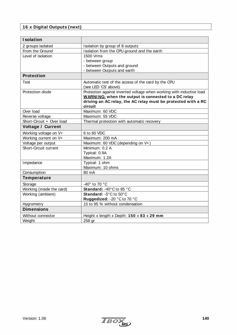
Version: 1.06 140
16 x Digital Outputs (next)
Isolation 2 groups isolated Isolation by group of 8 outputs From the Ground Isolation from the CPU ground and the earth Level of isolation 1500 Vrms
- between group - between Outputs and ground - between Outputs and earth
Protection Test Automatic test of the access of the card by the CPU
(see LED ‘CS’ above) Protection diode Protection against inverted voltage when working with inductive load
WARNING: when the output is connected to a DC relay driving an AC relay, the AC relay must be protected with a RC circuit
Over load Maximum: 60 VDC Reverse voltage Maximum: 55 VDC Short-Circuit + Over load Thermal protection with automatic recovery Voltage / Current Working voltage on V+ 6 to 60 VDC Working current on V+ Maximum: 200 mA Voltage per output Maximum: 60 VDC (depending on V+) Short-Circuit current Minimum: 0.2 A
Typical: 0.9A Maximum: 1.2A
Impedance Typical: 1 ohm Maximum: 10 ohms
Consumption 80 mA Temperature Storage -40° to 70 °C Working (inside the card) Standard: -40°C to 85 °C Working (ambient) Standard: -5°C to 50°C
Ruggedized: -20 °C to 70 °C Hygrometry 15 to 95 % without condensation Dimensions Without connector Height x length x Depth: 150 x 83 x 29 mm Weight 258 gr

Version: 1.06 141
16 x Digital Outputs (next)
C A B L I N G Description: Cabling of outputs
Connector: Screw connector
Pin Out:
1 V+ 2 Output 0 3 Output 1 4 Output 2 5 Output 3 6 Output 4 7 Output 5 8 Output 6 9 Output 7 10 V-
1 V+ 2 Output 8 3 Output 9 4 Output 10 5 Output 11 6 Output 12 7 Output 13 8 Output 14 9 Output 15 10 V-
12
34
56
78
9100 V
+6 .. 60 VDC
Group A
12
3 4
56
78
9100 V
+6 .. 60 VDC
Group B

Version: 1.06 142
18.7. 16 x digital Inputs/Outputs
References: MS-16DI0
2 groups of 8 digital inputs/outputs
isolation by group of 8 inputs/outputs
each channel can be cabled as an input or an output

Version: 1.06 143
16 x Digital Inputs/Outputs (next)
T E C H N I C A L S P E C I F I C A T I O N S General Quantity 16 channels. Each can be cabled as Input or Output Replacement Hot insertable/removable. There is no risk to damage hardware,
but a reset is required. Consumption of the card Tbd Test Automatic test of the access of the card by the CPU
(see LED ‘CS’ below) LED Individual LED corresponding to the activation of each input or output.
By software, possibility to disable the LED to save energy CS Card Selection: the card corresponds to a card declared in TWinSoft. ER Error: The type of the card does not correspond to the one declared
in TWinSoft. Isolation 2 groups isolated Isolation by group of 8 inputs Isolation from the Ground Isolation from the CPU ground and the earth Level of isolation 1500 Vrms
- between group - between Inputs and ground - between Inputs and earth
Temperature Storage -20 to 70 °C Working (ambient) Standard: -5°C to 50°C
Ruggedized: -20 °C to 70 °C Hygrometry 15 to 95 % without condensation Dimensions Without connector Height x length x Depth: 150 x 83 x 29 mm Weight 258 gr

Version: 1.06 144
16 x Digital Inputs/Outputs (next)
Inputs
Voltage at input Typical 24 VDC Maximum for a LOW level 5 VDC Minimum for a HIGH level 11 VDC Maximum 60 VDC Compatibility with type 1 and 2 of IEC61131-2 Current Maximum at the input 2.0 mA at 30 VDC
4.5 mA at 60 VDC Resistance 12 k Sampling Minimum period LOW – HIGH 20 msec – 20 msec. Frequency (software) At each cycle of BASIC / Ladder Protection RC filter 1592 Hz Voltage inversion Up to 55 VDC Protection EMC
Outputs Voltage / Current Working voltage on V+ 12 to 60 VDC: to read back outputs to corresponding DI.
6 to 60 VDC: without read back. Working current on V+ Maximum: 200 mA Voltage per output Maximum: 60 VDC (depending on V+) Short-Circuit current Minimum: 0.2 A
Typical: 0.9A Maximum: 1.2A
Impedance Typical: 1 ohm Maximum: 10 ohms
Protection Protection diode Protection against inverted voltage when working with inductive load
WARNING: when the output is connected to a DC relay driving an AC relay, the AC relay must be protected with a RC circuit
Over load Maximum: 60 VDC Reverse voltage Maximum: 55 VDC Short-Circuit + Over load Thermal protection with automatic recovery

Version: 1.06 145
16 x Digital Inputs/Outputs (next)
C A B L I N G - I N P U T S Description: Cabling of inputs
Connector: Screw connector
Pin Out:
1 NC 2 Input 0 3 Input 1 4 Input 2 5 Input 3 6 Input 4 7 Input 5 8 Input 6 9 Input 7 10 V-
1 NC 2 Input 8 3 Input 9 4 Input 10 5 Input 11 6 Input 12 7 Input 13 8 Input 14 9 Input 15 10 V-
12
34
56
78
9100 V
+12 .. 60 VDC1
23
4 5
67
89
100 V
+12 .. 60 VDC
Group A
Group B
Each channel can be cabled individually as Input or as Output

Version: 1.06 146
16 x Digital Inputs/Outputs (next)
Cabling to Dry contact Cabling to NPN transistor Cabling to PNP transistor (or OPTO) Cabling to Voltage sensor Cabling both Input and Output
This type of cabling can be used in 2 cases: 1. Manual activation of the Output: as long as the button is pressed, the output is forced 2. Activation of the Output during a time determined in the Program. You maintain the
button until it is detected by the program and has switched the output.
Sensor
V -
Input x
Input x
V-
V+
V-
Input x
V -
R
R : 1 k (12 VDC) 10 k (24 VDC)
V+
V-
Input x
V -
V+
V-
V -
Input/Output x
V+
V-
V +
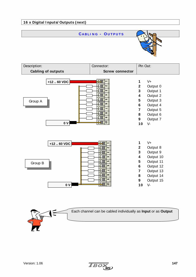
Version: 1.06 147
16 x Digital Inputs/Outputs (next)
C A B L I N G - O U T P U T S Description: Cabling of outputs
Connector: Screw connector
Pin Out:
1 V+ 2 Output 0 3 Output 1 4 Output 2 5 Output 3 6 Output 4 7 Output 5 8 Output 6 9 Output 7 10 V-
1 V+ 2 Output 8 3 Output 9 4 Output 10 5 Output 11 6 Output 12 7 Output 13 8 Output 14 9 Output 15 10 V-
Each channel can be cabled individually as Input or as Output
12
34
56
78
9100 V
+12 .. 60 VDC
Group A
12
3 4
56
78
9100 V
+12 .. 60 VDC
Group B

Version: 1.06 148
18.8. COMBO (Multiple I/O)
References: MS-COMBO-1
1 group isolated of 8 digital inputs
1 group isolated of 4 digital outputs
1 group non isolated of 3 analog inputs

Version: 1.06 149
COMBO (next)
T E C H N I C A L S P E C I F I C A T I O N S General Quantity 8 digital inputs
4 digital outputs 3 analog inputs (14 bits)
Replacement Hot insertable/removable. There is no risk to damage hardware, but a reset is required.
Consumption 40 mA Test Automatic test of the access of the card by the CPU
(See LED ‘CS’ below) LED Individual LED corresponding to the activation of each digital input or output.
By software, possibility to disable the LED to save energy CS Card Selection: the card corresponds to a card declared in TWinSoft. ER Error: The type of the card does not correspond to the one declared
in TWinSoft. Isolation 2 groups isolated: Level of isolation:
Group of 8 inputs and group of 4 outputs isolated 1500 Vrms - between group - between Inputs and ground - between Inputs and earth
1 group not isolated Group of 3 analog inputs non isolated Temperature Storage -40° to 70 °C Working (ambient) Standard: -5°C to 50°C
Ruggedized: -20 °C to 70 °C Hygrometry 15 to 95 % without condensation Dimensions Without connector Height x length x Depth: 150 x 83 x 29 mm Weight 254 gr

Version: 1.06 150
COMBO (next)
8 x Digital Inputs
Voltage at input Typical 24 VDC Maximum for a LOW level 5 VDC Minimum for a HIGH level 11 VDC Maximum 60 VDC Compatibility with type 1 and 2 of IEC61131-2 Current Maximum at the input 2.0 mA at 30 VDC
4.5 mA at 60 VDC Resistance 12 k Sampling Minimum period LOW – HIGH 20 msec – 20 msec. Frequency (software) At each cycle of BASIC / Ladder Protection RC filter 1592 Hz Voltage inversion Up to 55 VDC Protection EMC
4 x Digital Outputs Voltage / Current Working voltage on V+ 12 to 60 VDC Working current on V+ Maximum: 200 mA Voltage per output Maximum: 60 VDC (depending on V+) Short-Circuit current Minimum: 0.2 A
Typical: 0.9A Maximum: 1.2A
Impedance Typical: 1 ohm Maximum: 10 ohms
Protection Protection diode Protection against inverted voltage when working with inductive load Over load Maximum: 60 VDC Reverse voltage Maximum: 55 VDC Short-Circuit + Over load Thermal protection with automatic recovery

Version: 1.06 151
COMBO (next)
3 x Analog Inputs
General Model 4..20 mA ; passive Mode 4..20 mA Range Typical: 4 mA to 24 mA
Minimum: 4 mA to 22 mA Impedance Minimum: 21 ohms
Typical: 23.9 ohms Maximum: 26.4 ohms
Value for LSB Typical: 2.935 µA Digital Input Validity input associated to each analog input
Returns ‘0’ when signal < 2.4mA and > 21.6mA Returns ‘1’ when the signal is valid.
Protection Double RC filter fc=723 Hz and 135.6 Hz Against voltage inversion Maximum: 30 V Against over surge Maximum: 100 mA Against short-circuit of the sensor
Maximum: 30 V
Precision ADC converter 14 bits with successive approximations (13 bits + sign) Error at 25 °C Maximum: +/- 0.47% Full Scale Integral linearity Typical: +/- 2 LSB
Maximum: +/- 4 LSB Differential linearity Typical: +/- 0.5 LSB
Maximum: +/- 2 LSB Cabling Twisted pair cable Maximum: 50 m

Version: 1.06 152
COMBO (next)
C A B L I N G – D I G I T A L I N P U T S Description: Cabling of inputs
Connector: Screw connector
Pin Out:
1 NC 2 Input 0 3 Input 1 4 Input 2 5 Input 3 6 Input 4 7 Input 5 8 Input 6 9 Input 7 10 V-
Cabling to Dry contact Cabling to Voltage sensor Cabling to NPN transistor Cabling to PNP transistor (or OPTO)
12
34
56
78
9100 V
+12 .. 60 VDC
Group A
Sensor
V -
Input x
Input x
V-
V+
V-
Input x
V -
R
R : 1 k (12 VDC) 10 k (24 VDC)
V+
V-
Input x
V -
V+
V-

Version: 1.06 153
COMBO (next)
C A B L I N G – D I G I T A L O U T P U T S Description: Cabling of Outputs
Connector: Screw connector
Pin Out:
1 V+ 2 Output 0 3 Output 1 4 Output 2 5 Output 3 6 V-
Group B 1
23
45
67
89
10
0 V
+12 .. 60 VDC

Version: 1.06 154
COMBO (next)
C A B L I N G – A N A L O G I N P U T S Description: Cabling of 4..20ma sensors
Connector: Screw connector
Pin Out:
7 Input 0 8 Input 1 9 Input 2 10 Gnd
Cabling to 2 Wires sensor
Cabling to 4 Wires sensor
Group C 1
23
45
67
89
100 V
4..20 mA 4..20 mA
4..20 mA
IN x
GND
- + Measure
10 Ω
ProtectionSENSOR
IN x
GND -
+
Measure
10 Ω
Protection
SENSOR
Gnd is not isolated from the Gnd of Power supply. Gnd of the power supply is connected to the earth

Version: 1.06 155
18.9. 8 x Analog Inputs
References: MS-8 AIVC
1 group of 8 analog inputs
8 x -10..+10V; -20..+20mA
2 x Pt100, Pt1000 instead of 2 linear inputs

Version: 1.06 156
8 ANAIN (next)
T E C H N I C A L S P E C I F I C A T I O N S General Quantity 8 analog inputs Signals: - for the 8 inputs - for 2 of the 8 inputs
Choice between: –10..+10V OR –20..+20mA (see cabling) Supplementary choice between Pt100 OR Pt1000 2 wires (see cabling) No hardware or software configuration is required
Resolution 14 bits Mode Bipolar Model (for current/voltage) Passive input: sensor and input stage powered by an ext. power supply Precision: - Current - Voltage - Temperature
5 µA 2.5 mV 1 °C
Time of measurement: - Current - Voltage
1 msec 1 msec
Input Impedance: - Current - Voltage
Maximum: 26.4 Ω Minimum: 100 kΩ
Consumption Tbd Replacement Hot insertable/removable. There is no risk to damage hardware, but
a reset is required. Test Automatic test of the access of the card by the CPU
(See LED ‘CS’ below) Protection Current input Protection against voltage (max. 30 VDC) Voltage input No specific protection. High impedance is a protection Temperature input NO protection. Be careful not to apply voltage. Isolation 1 group isolated Isolation by group of 8 inputs From the Ground Isolation from the CPU ground and the earth Level of isolation 1500 Vrms
between group; between Inputs and ground; between Inputs and earth Digital Input Validity input associated to each analog input 4..20mA
Returns ‘0’ when signal < 2.4mA and > 21.6mA Returns ‘1’ when the signal is valid.
LED CS Card Selection: the card corresponds to a card declared in TWinSoft. ER Error: The type of the card does not correspond to the one declared in
TWinSoft. Temperature Storage -20°C to 70°C Working (ambient) Standard: -5°C to 50°C
Ruggedized: -20°C to 70°C Hygrometry 15 to 95 % without condensation Dimensions Without connector Height x Length x Depth: 150 x 83 x 29 mm Weight 300 g

Version: 1.06 157
8 ANAIN (next)
C A B L I N G – A N A L O G I N P U T S Description: Cabling of 4..20ma sensors
Connector: Screw connector
Pin Out:
1 Input 0 - Temperature 2 Input 0 - Voltage 3 Input 0 - Current 4 Input 1 - Voltage 5 Input 1 - Current 6 Input 2 - Voltage 7 Input 2 - Current 8 Input 3 - Voltage 9 Input 3 - Current 10 V-
Description: Cabling of 4..20ma sensors
Connector: Screw connector
Pin Out:
1 Input 0 - Temperature 2 Input 0 - Voltage 3 Input 0 - Current 4 Input 1 - Voltage 5 Input 1 - Current 6 Input 2 - Voltage 7 Input 2 - Current 8 Input 3 - Voltage 9 Input 3 - Current 10 V-
1 2
34
56
78
910
Group A
0 V (of sensors)
1 2
34
56
78
910
Group B
0 V (of sensors)
Isolation is global. It means both V- are connected together and must be cabled to the same reference.

Version: 1.06 158
18.10. 8 x Temperature Inputs Not available yet
References: MS-8 RTD
2 groups of 8 analog inputs
Temperature inputs : Pt100, Pt1000, Ni100, Ni1000
2 or 3 wires

Version: 1.06 159
8 RTD (next)
T E C H N I C A L S P E C I F I C A T I O N S General Quantity 8 temperature inputs Signals
Choice between Pt100, Pt1000, Ni100, Ni1000 2 wires or 3 wires The selection of the probe is done by the cabling used. No hardware or software configuration is required
Resolution 15 bits Precision - Ni100, Pt100 - Ni1000, Pt1000
0.1 °C 0.1 °C
Filter 1 sec Maximum length of cable 100 m Maximum resistance of the cable
20 Ω
Replacement Hot insertable/removable. There is no risk to damage hardware, but a reset is required.
Test Automatic test of the access of the card by the CPU (See LED ‘CS’ below)
LED CS Card Selection: the card corresponds to a card declared in TWinSoft. ER Error: The type of the card does not correspond to the one declared in
TWinSoft. Isolation Between channel Non isolated Channel to Ground/Earth Non isolated Temperature Storage -20°C to 70°C Working (ambient) Standard: -5°C to 50°C
Ruggedized: -20°C to 70°C Hygrometry 15 to 95 % without condensation Dimensions Without connector Height x Length x Depth: 150 x 83 x 29 mm Weight 300 g

Version: 1.06 160
8 RTD (next)
C A B L I N G – A N A L O G I N P U T S Description: Cabling Probes 2 Wires
Description: Cabling Probes 3 Wires
Group A
Group B
There is no isolation. It means Gnd are connected together and the Earth.
12
34
56
78
910
Gnd
Gnd
12
34
56
78
910
Gnd
Gnd
12
34
56
78
910
Gnd
Gnd
12
34
56
78
910
Gnd
Gnd

Version: 1.06 161
18.11. 4 x Analog Outputs
References: MS-4 AOVC
4 analog output isolated one by one
each output: 4..20 ma or –10V..+10V

Version: 1.06 162
4 ANAOUT (next)
T E C H N I C A L S P E C I F I C A T I O N S General Quantity 4 analog outputs Signals - for each output
Choice between 4..20ma OR –10V..+10V The selection of the signal is done by the cabling used. No hardware or software configuration is required
ADC converter 12 bits, bipolar Mode - Current
Active mode. Supplies a nominal voltage of 24 VDC.
Full Range - Current - Voltage
0 to 20mA -10V to +10V
Resolution - Current - Voltage
12 bits 11 bits + sign
Precision - Current - Voltage
5 µA 5 mV
Reactivity - Current - Voltage
25 msec 1 msec
Load impedance limit - Current - Voltage
Resistance of the actuator: ≤ 1000 Ω : gives a drop of 20 V, maximum allowed. > 3000 Ω : gives a current of 3.33 mA, maximum allowed.
Consumption Tbd Replacement Hot insertable/removable. There is no risk to damage hardware, but
a reset is required. Test Automatic test of the access of the card by the CPU
(See LED ‘CS’ below) Digital Input Validity input associated to each analog output 4..20mA
Returns ‘0’ when signal < 2.4mA and > 21.6mA Returns ‘1’ when the signal is valid.
LED CS Card Selection: the card corresponds to a card declared in TWinSoft. ER Error: The type of the card does not correspond to the one declared in
TWinSoft. Isolation 4 channels isolated Isolation one by one From the Ground Isolation from the CPU ground and the earth Level of isolation 500 Vrms between each output
1500 Vrms between each output and earth Temperature Storage -20°C to 70°C Working (ambient) Standard: -5°C to 50°C
Ruggedized: -20°C to 70°C Hygrometry 15 to 95 % without condensation Dimensions Without connector Height x Length x Depth: 150 x 83 x 29 mm Weight 300 g
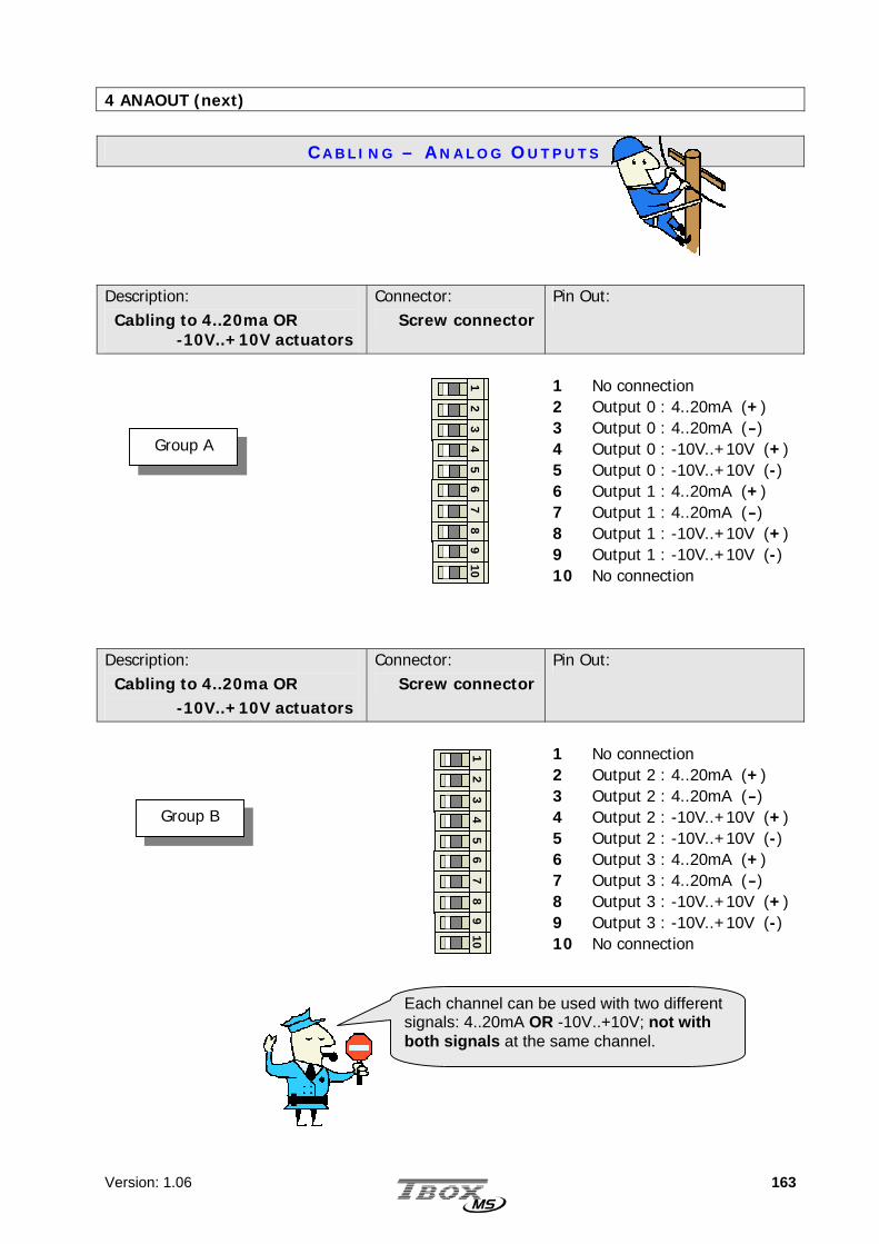
Version: 1.06 163
4 ANAOUT (next)
C A B L I N G – A N A L O G O U T P U T S Description: Cabling to 4..20ma OR -10V..+10V actuators
Connector: Screw connector
Pin Out:
1 No connection 2 Output 0 : 4..20mA (+) 3 Output 0 : 4..20mA (-) 4 Output 0 : -10V..+10V (+) 5 Output 0 : -10V..+10V (-) 6 Output 1 : 4..20mA (+) 7 Output 1 : 4..20mA (-) 8 Output 1 : -10V..+10V (+) 9 Output 1 : -10V..+10V (-) 10 No connection
Description: Cabling to 4..20ma OR -10V..+10V actuators
Connector: Screw connector
Pin Out:
1 No connection 2 Output 2 : 4..20mA (+) 3 Output 2 : 4..20mA (-) 4 Output 2 : -10V..+10V (+) 5 Output 2 : -10V..+10V (-) 6 Output 3 : 4..20mA (+) 7 Output 3 : 4..20mA (-) 8 Output 3 : -10V..+10V (+) 9 Output 3 : -10V..+10V (-) 10 No connection
Each channel can be used with two different signals: 4..20mA OR -10V..+10V; not with both signals at the same channel.
12
34
56
78
910
Group A
12
34
56
78
910
Group B

Version: 1.06 164
Cabling to ‘Current’ actuator Cabling to ‘Voltage’ actuator
OUT-
Actuator
+
-
Feedback
OUT+
24 V
OUT-
Actuator
+
-
OUT+

Version: 1.06 165
18.12. 8 x Relay Outputs
References: MS-RELAY
8 relay outputs isolated one by one

Version: 1.06 166
8 Relay Outputs (next)
T E C H N I C A L S P E C I F I C A T I O N S General Quantity 8 outputs Consumption Tbd Replacement Hot insertable/removable. There is no risk to damage hardware, but
a reset is required. Test Automatic test of the access of the card by the CPU
(See LED ‘CS’ below) LED CS Card Selection: the card corresponds to a card declared in TWinSoft. ER Error: The type of the card does not correspond to the one declared in
TWinSoft. Voltage With DC Max: 30 Vdc at 3A With AC Max: 250 Vac Current DC 3 A AC 3 A Operating live At full resistive load 100000 operations Protection To an external relay When the relay drives an external relay, the latter must be protected
with a diode (if DC relay) or a RC circuit (if AC relay) Isolation Individual Each relay is totally isolated from the rack and other relays .
Voltage of isolation: 3 KV Temperature Storage -20°C to 70°C Working (ambient) Standard: -5°C to 50°C
Ruggedized: -20 °C to 70 °C Hygrometry 15 to 95 % without condensation Dimensions Without connector Height x Length x Depth: 150 x 83 x 29 mm Weight 300 g

Version: 1.06 167
8 Relay Outputs (next)
C A B L I N G – R E L A Y O U T P U T S Description:
Connector: Screw connector
Pin Out:
1 Load 0 2 Load 0
1 Load 1 2 Load 1
1 Load 2 2 Load 2
1 Load 3 2 Load 3
Description:
Connector: Screw connector
Pin Out:
1 Load 4 2 Load 4
1 Load 5 2 Load 5
1 Load 6 2 Load 6
1 Load 7 2 Load 7
Group A
Group B
12
12
12
12
12
12
12
12

Version: 1.06 168
18.13. 4 x Analog inputs isolated
References: MS-4AI420
4 analog inputs isolated one by one 4..20 mA

Version: 1.06 169
4 Analog Input Isolated (next)
T E C H N I C A L S P E C I F I C A T I O N S
General Quantity 4 analog inputs Signal 4..22 mA Resolution 14 bits Mode unipolar Precision Tbd Time of measurement 1 msec Input Impedance Maximum: 26.4 Ω Input Voltage on input Maximum: 6 VDC Consumption Tbd Replacement Hot insertable/removable. There is no risk to damage hardware, but
a reset is required. Test Automatic test of the access of the card by the CPU
(See LED ‘CS’ below) Digital Input Validity input associated to each analog input
Returns ‘0’ when signal < 2.4mA and > 21.6mA Returns ‘1’ when the signal is valid.
LED CS Card Selection: the card corresponds to a card declared in TWinSoft. ER Error: The type of the card does not correspond to the one declared in
TWinSoft. Isolation Each input Isolation one by one From the Ground Isolation from the CPU ground and the earth Level of isolation 500 Vrms
- between group - between Inputs and ground - between Inputs and earth
Protection Polarity Protection against inversion of polarity Voltage Protection against voltage applied at input (MAX: 30 VDC – 50 mA) Temperature Storage -20°C to 70°C Working (ambient) Standard: -5°C to 50°C
Ruggedized: -20 °C to 70 °C Hygrometry 15 to 95 % without condensation Dimensions Without connector Height x Length x Depth: 150 x 83 x 29 mm Weight 300 g

Version: 1.06 170
4 Analog Input Isolated (next)
C A B L I N G – I S O L A T E D A I Description:
Connector: Screw connector
Pin Out:
1 input 0: 4..20m (+) 2 input 0: 4..20m (-)
1 input 1: 4..20m (+) 2 input 1: 4..20m (-)
1 input 2: 4..20m (+) 2 input 2: 4..20m (-)
1 input 3: 4..20m (+) 2 input 3: 4..20m (-)
12
12
12
12

Version: 1.06 171
18.14. PSTN modem
Reference: MS-PSTN
Modem PSTN (Public Switched Telephone Network)
Mode V21, V22, V22bis, V23, V32, V32bis, V34, V90
Data compression V42bis
Caller Id
ITU-T and CRT21 conformity
Baudrate from 300 bps to 56 Kbps
1 port RS232/RS485 non isolated
RS485 / RS232 cabling is the same as for RS232 and RS485 of MS-SERIAL (see chapter 18.17)

Version: 1.06 172
Modem PSTN (next)
T E C H N I C A L S P E C I F I C A T I O N S General
Consumption Tbd Replacement Hot insertable/removable. There is no risk to damage hardware, but
a reset is required. Test Automatic test of the access of the card by the CPU
(See LED ‘CS’ below) LED CS Card Selection: the card corresponds to a card declared in TWinSoft. ER Error: The type of the card does not correspond to the one declared in
TWinSoft. Modem PSTN
Description Modem for Switched Telephone Network (public or private) WARNING: does not work on galvanic lines, or lines without power.
Speed 300 bps … 56.000 bps Mode ITU-T : V21, V23, V22, V22bis, V32, V32bis, V34, V90
Bell 103 and Bell 212A Compression 42bis LAPM, MNP2-5 Standards Conform to CTR21 Other characteristics Caller ID
Line detection (test if other communication active on the line) Auto fallback
Connectors RJ12 or screw connector Isolation 1500 Vrms Protection Against overvoltage
Warning : an external surge protector is still required RS232 – RS485
Mode RS232 or RS485 (no simultaneous use of both modes) Isolation No isolation. Gnd is linked to earth by internal connection RS232 Signals: RxD, TxD, CTS, RTS, DTR, DSR, DCD, RI
Connector: 9 pin Sub-D (male) RS485 • 2 wires (A+ and B-) for multi-points connection
• No need for termination resistor (failsafe bias resistors included: pullup and pulldown resistors which assures a logical level TRUE when A and B are open or in short circuit)
• Number of slaves: 256 (if RS485 technology of slaves allows it too) • Screw connector: female with a step of 5.08 mm
LEDs RxD (common to 2 ports) TxD
Indicate reception of data Indicate transmission of data
Temperature Storage -20°C to 70°C Working (ambient) Standard: -5°C to 55°C
Ruggedized: -20°C to 70°C Hygrometry 15 to 95 % without condensation Dimensions Without connector Height x Length x Depth: 150 x 83 x 29 mm Weight 300 g

Version: 1.06 173
18.15. GSM / GPRS modem
Reference: MS-GSM
Tri Band (900 Mhz, 1800 Mhz, 1900 Mhz)
1 port RS232/RS485 non isolated
RS485 / RS232 cabling is the same as for RS232 and RS485 of MS-SERIAL (see chapter 18.17)

Version: 1.06 174
Modem GSM/GPRS (next)
T E C H N I C A L S P E C I F I C A T I O N S General
Consumption Tbd Replacement Hot insertable/removable. There is no risk to damage hardware, but
a reset is required. Test Automatic test of the access of the card by the CPU
(See LED ‘CS’ below) LED CS Card Selection: the card corresponds to a card declared in TWinSoft. ER Error: The type of the card does not correspond to the one declared in
TWinSoft. Modem GSM/GPRS
Frequencies TRI-BAND : EGSM900 / DCS1800 / PCS1900 MHz
GPRS
Class 10 (4+1/3+2) with support PBCCH , SMS and DATA
Emitting power CLASS 4 (2W) pour EGSM900 CLASS 1 (1W) pour DCS1800 et PCS1900
LEDs Network On Line RxD TxD
Indicates that the GSM/GPRS is connected to the network Indicates that the GSM/GPRS is communicating Indicates that the GSM/GPRS is receiving data Indicates that the GSM/GPRS is transmitting data
Antenna connector Screw connector, type FME Plug RS232 – RS485
Mode RS232 or RS485 (no simultaneous use of both modes) Isolation No isolation. Gnd is linked to earth by internal connection RS232 Signals: RxD, TxD, CTS, RTS, DTR, DSR, DCD, RI
Connector: 9 pin Sub-D (male) RS485 • 2 wires (A+ and B-) for multi-points connection
• No need for termination resistor (failsafe bias resistors included: pullup and pulldown resistors which assures a logical level TRUE when A and B are open or in short circuit)
• Number of slaves: 256 (if RS485 technology of slaves allows it too) • Screw connector: female with a step of 5.08 mm
LEDs RxD (common to 2 ports) TxD
Indicate reception of data Indicate transmission of data
Temperature Storage -20° to 70 °C Working (ambient) Standard: -5°C to 50°C
Ruggedized: -20°C à 65 °C -10 °C à 55 °C : fully operational -20 °C à 65 °C : functional without risk for the network
Hygrometry 15 to 95 % without condensation Dimensions Without connector Height x Length x Depth: 150 x 83 x 29 mm Weight 300 g

Version: 1.06 175
18.16. GPS - Timing
Reference: MS-GPS
GPS receiver Provides an clock with absolute value (UTC) with high
precision (<1ms), without drift of time. Allows synchronizing in datalogging. Allows vertical and horizontal positioning of a mobile equipment.
Port RS232 / RS485 non isolated
RS485 / RS232 cabling is the same as for RS232 and RS485 of MS-SERIAL (see chapter 18.17)

Version: 1.06 176
GPS - Timing (next) T E C H N I C A L S P E C I F I C A T I O N S
General Consumption Tbd Replacement Hot insertable/removable. There is no risk to damage hardware, but
a reset is required. Test Automatic test of the access of the card by the CPU
(See LED ‘CS’ below) LED CS Card Selection: the card corresponds to a card declared in TWinSoft. ER Error: The type of the card does not correspond to the one declared in
TWinSoft. GPS Receiver General L1 (1575 MHz), C/A code, 12 channels, continuous tracking receiver Precision: position clock
3 m CEP (SA off) 500 ns (SA On)
Acquisition: Cold start Warm start
< 60 sec < 3 sec
Antenna connector Active antenna: SMA compatible Power delivered by the card : 3 to 3.6 VCC
Synchronization Internal Generates an internal clock signal every 1 ms (precision 200 µs) Output Open collector, to synchronize to other TBOX MS
Frequency : 1 sec. Precision : 200 µs.
To CPU-16 Synchronization from the digital input Tick of the CPU-16 : 10 ms (used for time stamping) Global precision : 25 ms
To CPU-32 Synchronization from the BUS Tick of the CPU-32 : 1 ms (used for time stamping) Global precision : 1 ms
LED RxD, TxD, Lock (validity of the GPS signal received) Output 1 Hz
RS232 – RS485 Mode RS232 or RS485 (no simultaneous use of both modes) Isolation No isolation. Gnd is linked to earth by internal connection RS232 Signals: RxD, TxD, CTS, RTS, DTR, DSR, DCD, RI
Connector: 9 pin Sub-D (male) RS485 • 2 wires (A+ and B-) for multi-points connection
• No need for termination resistor (failsafe bias resistors included: pullup and pulldown resistors which assures a logical level TRUE when A and B are open or in short circuit)
• Number of slaves: 256 (if RS485 technology of slaves allows it too) • Screw connector: female with a step of 5.08 mm
LEDs RxD (common to 2 ports) TxD
Indicate reception of data Indicate transmission of data
Temperature Storage -20°C to 70°C Working (ambient) Standard: -5°C to 50°C
Ruggedized: -20°C to 70°C Hygrometry 15 to 95 % without condensation Dimensions Without connector Height x Length x Depth: 150 x 83 x 29 mm Weight 300 g

Version: 1.06 177

Version: 1.06 178
18.17. Serial Ports
Reference: MS-SERIAL
2 x Serial Ports
each port : RS232 or RS485

Version: 1.06 179
Serial Ports (next) T E C H N I C A L S P E C I F I C A T I O N S
General Consumption Tbd Replacement Hot insertable/removable. There is no risk to damage hardware, but
a reset is required. Test Automatic test of the access of the card by the CPU
(See LED ‘CS’ below) LED CS Card Selection: the card corresponds to a card declared in TWinSoft. ER Error: The type of the card does not correspond to the one declared in
TWinSoft. RS232 – RS485
Quantity 2 ports Mode RS232 or RS485 (no simultaneous use of both modes) Baudrates (bps) 300, 600, 1200, 2400, 4800, 9600, 19200, 38400, 57600, 115200 Data bits 7, 8 Parity none, even, odd, mark (parity bit=1), space (parity bit=0) Stop bits 1, 1.5, 2 Isolation No isolation. Gnd is linked to earth by internal connection RS232 Signals: RxD, TxD, CTS, RTS, DTR, DSR, DCD, RI
Connector: 9 pin Sub-D (male) RS485 • 2 wires (A+ and B-) for multi-points connection
• No need for termination resistor (failsafe bias resistors included: pullup and pulldown resistors which assures a logical level TRUE when A and B are open or in short circuit)
• Number of slaves: 256 (if RS485 technology of slaves allows it too) • Screw connector: female with a step of 5.08 mm
LEDs RxD (common to RS232 and RS485) TxD
Indicate reception of data Indicate transmission of data
Temperature Storage -20°C to 70°C Working (ambient) Standard: -5°C to 50°C
Ruggedized: -20°C to 70°C Hygrometry 15 to 95 % without condensation Dimensions Without connector Height x Length x Depth: 150 x 83 x 29 mm Weight 300 g

Version: 1.06 180
Serial Port (next) C A B L I N G
RS 485 Description: RS485 communication
Connector: RS485 Screw connector (3 x 5.08 mm)
Cabling several CPU together: A to A B to B Gnd to Gnd
Gnd
A+
B-
Gnd
A+
B-
Gnd
A+
B-
1 2
3 1
23
12
3
About RS485 cabling:
1. Use a twisted pair for signal A and B. 2. RS 485 is not isolated. If cabling equipment in different building (different
Earth), you have to use ACC-RS485 (see your local distributor) 3. Maximum length depends on quality of cable, speed and quantity of
stations (max. 32 stations). In good condition, guaranteed to 1.2 km (max. 32 stations @ 9600 Bps) In practice, longer distance can be reached with lower Baudrate and less station.
4. Cable: - Twisted pair (2 pairs) - section: minimum 0.5mm² - screening : pair and global screening
- reference: Li2YCY-PiMF

Version: 1.06 181
RS 232
Description: RS232
Connector: RS232 9 Pin Sub D
Pin out:
1. DCD (input) 2. RxD (input) 3. TxD (output) 4. DTR (output) 5. Gnd 6. DSR (input) 7. RTS (output) 8. CTS (input) 9.
Cabling to a PC
TBOX MS - COM1 PC - DB 9
RxD 2 2 RxD
TxD 3 3 TxD
GND 5 5 GND
RTS 7 7 RTS
CTS 8 8 CTS
1
59
6

Version: 1.06 182

Version: 1.06 183
AAAPPPPPPEEENNNDDDIIIXXXEEESSS

Version: 1.06 184
Appendix A. Licenses The software itself is not protected; it can be installed on any PC and used to develop TWinSoft document (Online or Offline) and to monitor TBOX MS. The only operation protected is the sending of an application to TBOX MS. In order to find the best way for you we offer different possibilities:
A.1. The Evaluation mode You don't need any software or hardware dongle. You are able to develop a complete TBOXMS project without any restriction, but when you send the application to TBOX MS, it will stop after 2 hours. This is a good solution for testing programs or creating a demo.
A.2. The Dongle It is a hardware device placed on your PC. The dongle can be ordered for parallel port or for USB port. TWinSoft regularly checks the presence of it. It allows you to send applications to as many TBOX MS as you want, with any PC.
A.3. The Code (License) Available from the menu ‘Help’ ‘License Register.’ Using information of the PC (the Company name, the User name, a Serial Number), we create a code that you enter in the 'License' field. Once entered, you can send any application as if you had a dongle (see previous). The only restriction is that it must always be on the same PC. If you wish to use another PC, you have the possibility to remove registration on the first PC and register back on the second.
A.4. The TWinSoft LITE Available from the menu ‘Help’ ‘TWinSoft Lite configuration.’ This protection mode is ideal for users having one or two TBOX MS units. The dongle or a license might be too expensive. TWinSoft LITE code is linked to one TBOX MS; it allows you sending an application to the TBOX MS for which you have the code.

Version: 1.06 185
Appendix B. Time in RTU One of the biggest issues in Telemetry and data logging equipment is the handling of time. In order to have a universal solution, wherever the TBOX MS is used, TWinSoft, OS of the RTU and ‘Windows’ collecting data, shares the mechanism of time management. It is based on UTC time.
B.1. Time in TBox MS The RTC (Real Time Clock)
The TBOX MS is equipped with a RTC chip (Real Time Clock). The RTC is used to manage all internal time. Functions of the RTC: • it is a calendar Y2000 compatible. • it updates the UTC time (see next). • it communicates with OS to handle the UTC time, used for data logging. The RTC time is used at start-up of TBOX MS to update the UTC. UTC Time
UTC time is based on the number of seconds since 1/1/1970 at Greenwich latitude. It is used as internal timestamp to each event (alarm, chronology, …) The UTC time is converted in Special Analog Registers to give access to time information: second, minute, hour, day, month, year. Changing UTC time automatically updates the RTC. When time information is sent (in a report, as header of an e-mail, in the Analog special register), it is always computed using the UTC time, according to the time settings in the ‘General’ RTU properties. TBox MS Time setting
In order to set TBOX MS to PC time, an option is available in the 'Communication' menu of the main menu bar. When connected to TBOX MS (locally or remotely), the option is available. By clicking the option, the RTU is set to the time of the PC. Check afterwards in the 'RTU Identification' option, also part of the 'Communication' menu.

Version: 1.06 186
Winter/Summer time When installed in regions using winter/summer time, the TBOX MS is able to manage automatically the changing. It means that the RTC and Analog special register [hour] are automatically updated when the time changes.
B.2. Data logging Chronologies In chronologies, the time is recorded for each log of data. The time recorded is the UTC time. When retrieving the data, the PC reads the UTC time and converts it according to the local time of the PC, depending on the Time settings of the PC. When a winter/summer time changing happens, the TBOX MS is informed of it and updates automatically all timestamps following the changing. Sampling tables
In sampling tables, the TBOX MS records the timestamp of the last record only. The other timestamps are built up when retrieving the data. A choice had to be made between: either having always the same period of recording or having always the same 'hour' of recording. The latter has been chosen. When a changing winter/summer time happens, the target time is automatically updated for sampling tables having a period > 1 hour. Example: If recording a value once a day at 6.00 in the morning, the recording will always happen at 6.00, but when changing from winter to summer, the period will be of 23 hours and when changing from summer to winter the period will be of 25 hours. Periodic events
When a periodic event is defined with a period > 1 hour, its target time is automatically adjusted when a changing winter/summer happens.
B.3. Special registers associated Some Special Registers of TBOX MS are associated to the Time. They can be used in BASIC programming to execute specific operations: Type Variable Comment Analog Second,
Minutes, … 6 Registers giving the time in hour, minute, second, day, month and year.
Analog UTCUTim Time in UTC format (number of seconds since 1/1/1970 at Greenwich latitude)
Analog ZonBia Time difference in seconds between the local time and time UTC Analog Zonid ID of the zone where the RTU is installed. It uses regional
settings of the PC

Version: 1.06 187

Version: 1.06 188
IIINNNDDDEEEXXX
A
Access levels ......................................... 113 Access Security ..................................... 110 Alarm stack ........................................ 45, 86 Alarms...................................................... 86
advanced parameters........................... 45 analog condition ................................... 89 chain............................................... 87, 89 digital condition..................................... 87 display list of......................................... 95 e-mail.................................................... 92 FTP....................................................... 92 group of recipients................................ 93 link .................................................. 88, 90 message............................................... 94 ModBus ................................................ 91 NTP ...................................................... 92 printer ................................................... 92 recipients .............................................. 91 SMS...................................................... 91
B
Battery lithium................................................. 128
Button..................................................... 129
C
Cabling 16 DI................................................... 137 16 DIO ................................................ 145 16 DO ................................................. 141 4 AI420 ............................................... 170 4 AO ................................................... 163 8 AIVC ................................................ 157 8 RELAYS .......................................... 167 CPU-16............................................... 130 power supplies ................................... 119 serial port ................................................ 180
Chain.................................................. 87, 89 Chronologies...................................... 97, 99 Clock ...................................................... 185 Communication ........................................ 32
CPU...................................................... 52 testing with TWinSoft............................ 34 variables ............................................... 62
Compiling Program .................................. 36 Counters .................................................. 67 CPU-16 ............................................ 51, 125
communication ports ............................ 52
D
Datalogging ..............................................97 chronologies..........................................99 sampling tables ...................................100
Debugging TCP/IP....................................83 Dongle ....................................................184 Drivers ......................................................43
E
e-mail ......................................75, 87, 90, 92 SMTP from............................................45 SMTP subject........................................46
Event stack ...................................45, 86, 95
F
FTP.....................................................79, 92
G
Global code ............................................112 Global Reset .............................................35 GPRS .......................................................59
communication variables.......................60 IP settings .............................................61
GPS Timing card ....................................175 Group of recipients ...................................93 Group of Tags...........................................68 GSM - data ...............................................58 GSM message
header...................................................46 GSM/GPRS
configuration .........................................57 modem card ........................................173
H
Hardware card insertion ........................................16 rack installation .....................................14 racks ...................................................118 vs. Software (addressing) .....................19
Hardware concept.....................................11 High Speed Tags....................................108 Historical data...........................................86
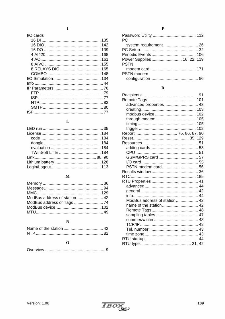
Version: 1.06 189
I
I/O cards 16 DI ................................................... 135 16 DIO ................................................ 142 16 DO ................................................. 139 4 AI420 ............................................... 168 4 AO.................................................... 161 8 AIVC ................................................ 155 8 RELAYS DIO ................................... 165 COMBO .............................................. 148
I/O Simulation......................................... 134 Info ........................................................... 44 IP Parameters .......................................... 76
FTP....................................................... 79 ISP........................................................ 77 NTP....................................................... 82 SMTP.................................................... 80
ISP............................................................ 77
L
LED run .................................................... 35 License................................................... 184
code.................................................... 184 dongle ................................................. 184 evaluation ........................................... 184 TWinSoft LITE .................................... 184
Link..................................................... 88, 90 Lithium battery........................................ 128 Login/Logout........................................... 113
M
Memory .................................................... 36 Message................................................... 94 MMC....................................................... 129 ModBus address of station....................... 42 ModBus address of Tags ......................... 74 ModBus device....................................... 102 MTU.......................................................... 49
N
Name of the station .................................. 42 NTP .......................................................... 82
O
Overview .................................................... 9
P
Password Utility ..................................... 112 PC
system requirement .............................. 26 PC Setup.................................................. 32 Periodic Events ...................................... 106 Power Supplies .......................... 16, 22, 119 PSTN
modem card ....................................... 171 PSTN modem
configuration......................................... 56
R
Recipients ................................................ 91 Remote Tags ......................................... 101
advanced properties............................. 48 creating............................................... 103 modbus device ................................... 102 through modem .................................. 105 timing.................................................. 105 trigger ................................................. 102
Report .................................... 75, 86, 87, 90 Reset................................................ 35, 129 Resources................................................ 51
adding cards......................................... 53 CPU...................................................... 51 GSM/GPRS card .................................. 57 I/O card................................................. 55 PSTN modem card............................... 56
Results window ........................................ 36 RTC........................................................ 185 RTU Properties ........................................ 41
advanced.............................................. 44 general ................................................. 42 info........................................................ 44 ModBus address of station................... 42 name of the station............................... 42 Remote Tags........................................ 48 sampling tables .................................... 47 summer/winter ...................................... 43 TCP/IP.................................................. 48 Tel. number .......................................... 43 time zone.............................................. 43
RTU startup.............................................. 44 RTU type............................................ 31, 42

Version: 1.06 190
S
Sampling tables advanced properties............................. 47
Sampling Tables .............................. 98, 100 Security .................................................. 110 Sending Program ..................................... 37 Serial Ports : .......................................... 178 SMTP ....................................................... 80
redundancy........................................... 81 Stack
alarms............................................. 45, 86 events............................................. 45, 86
Startup ..................................................... 44 System Requirement ............................... 26 System Variables ..................................... 64
analog................................................... 66 digital .................................................... 64
System.xml ............................................ 129
T
Tags ......................................................... 68 analog variable ..................................... 72 digital variable ...................................... 70 group .................................................... 68 high speec Tag................................... 108 I/O......................................................... 69 internal variables .................................. 70 ModBus address .................................. 74 presentation.......................................... 75 write...................................................... 75
TBox Dial It! ............................................. 27 TBox Mail ................................................. 27 TCP ports................................................. 49 TCP/IP ..................................................... 48
debugging............................................. 83 TCP/IP address
incoming call......................................... 49 Technical Specifications
16 DI................................................... 135 16 DIO ................................................ 142 16 DO ................................................. 139
Technical Specifications (suite) 4 AI420................................................168 4 AO....................................................161 8 AIVC.................................................155 8 RELAYS...........................................165 COMBO ..............................................148 CPU-16 ...............................................125 GPS Timing.........................................175 GSM/GPRS modem............................173 I/O SIMUL ...........................................134 power supplies ....................................119 PSTN modem......................................171 rack .....................................................118 serial ports ..........................................178
Temperature units ....................................48 Time........................................................185
automatic setting...................................82 winter/summer...............................43, 186
Timers.......................................................67 TView........................................................86 TWinSoft
starting ..................................................30 TWinSoft Communication
testing ...................................................34 TWinSoft Suite
installation .............................................27 programs...............................................29 system requirement...............................26
U
UTC time ................................................185
V
Variables communication......................................62 internal registers....................................70 system...................................................64
W
WebForm..................................................75 WebForm Viewer......................................27 Wizard ......................................................31

Version: 1.06 191

Version: 1.06 192
Copyright © 2022 FDOKUMEN