D-M-E Mold Components - DMERU, SYSTEM
316
D-M-E Mold Components
-
Upload
khangminh22 -
Category
Documents
-
view
0 -
download
0
Transcript of D-M-E Mold Components - DMERU, SYSTEM

D-M-E Mold Components

U.S. 800-626-6653 n Canada 800-387-6600 n www.dme.net
Table of Contents
Mold Components
Slide Action Components
Molding Undercuts
Plate and Pin Control
Cavity and Core Components
��Angle Pins . . . . . . . . . . . . . . . . . . . . . . . . . . . . . . . . . . . . . . . . . . . . . . . . 14-15Slide Retainers . . . . . . . . . . . . . . . . . . . . . . . . . . . . . . . . . . . . . . . . . . . . 16-21Wear Plates . . . . . . . . . . . . . . . . . . . . . . . . . . . . . . . . . . . . . . . . . . . . . . . 22-24Gib Assemblies . . . . . . . . . . . . . . . . . . . . . . . . . . . . . . . . . . . . . . . . . . . . 25-28
VectorForm Lifter Systems . . . . . . . . . . . . . . . . . . . . . . . . . . . . . . . . . . 31-42Hydraulic Unscrewing Device . . . . . . . . . . . . . . . . . . . . . . . . . . . . . . . 43-52Multiform Collapsible Cores . . . . . . . . . . . . . . . . . . . . . . . . . . . . . . . . . 53-57Collapsible Cores . . . . . . . . . . . . . . . . . . . . . . . . . . . . . . . . . . . . . . . . . . 58-59Expandable Cavity Systems . . . . . . . . . . . . . . . . . . . . . . . . . . . . . . . . . 60-69
Multi-Parting Line Systems . . . . . . . . . . . . . . . . . . . . . . . . . . . . . . . . . . 73-76Helical Gear Stack Mold Components . . . . . . . . . . . . . . . . . . . . . . . . 77-82 2-Stage Ejectors . . . . . . . . . . . . . . . . . . . . . . . . . . . . . . . . . . . . . . . . . . . 83-102 Precision Control of Mold Plate Operation . . . . . . . . . . . . . . . . . . . . 103-132
�M
old
Com
pone
nts
| T
able
of C
onte
nts
New D-M-E Products . . . . . . . . . . . . . . . . . . . . . . . . . . . . . . . . . . . . . . . 6-7Terms and Conditions of Sale . . . . . . . . . . . . . . . . . . . . . . . . . . . . . . . . 8Sales and Ordering Information . . . . . . . . . . . . . . . . . . . . . . . . . . . . . . 9Your Essential Resource . . . . . . . . . . . . . . . . . . . . . . . . . . . . . . . . . . . . 10
Internal Latch Lock Accelerated Knock-OutsAccelerated EjectorsEarly Ejector Return AssemblyLatch Locks
Toggle-LokJiffy-JectorEjector Return CouplingsLimit SwitchesInterlocks
Mold Dating Inserts . . . . . . . . . . . . . . . . . . . . . . . . . . . . . . . . . . . . . . . . 156-159Sintered Vents . . . . . . . . . . . . . . . . . . . . . . . . . . . . . . . . . . . . . . . . . . . . . 160-161Air Poppet Valves . . . . . . . . . . . . . . . . . . . . . . . . . . . . . . . . . . . . . . . . . . 162-163Cashew Gate Inserts . . . . . . . . . . . . . . . . . . . . . . . . . . . . . . . . . . . . . . . 164-165 Runner Shut-Off Inserts . . . . . . . . . . . . . . . . . . . . . . . . . . . . . . . . . . . . . 166-167Recycling Inserts . . . . . . . . . . . . . . . . . . . . . . . . . . . . . . . . . . . . . . . . . . 168

U.S. 800-626-6653 n Canada 800-387-6600 n www.dme.net
Table of Contents
Mold Components�
Mold Cooling
Mold Components
Pins, Sleeves and Blades
Mold Assembly
Mold�Cooling�� . . . . . . . . . . . . . . . . . 171-188 Brass Pressure Plugs Jiffy-Tite® Connectors, Plugs Jiffy-Lok® Connector Sockets Jiffy-Tite® Connector Seals, Tool Kit, Wrenches Coolant Bridges
Bubbler Tubes, Brass Plugs and Rods Cascade Water Junctions Straight and Spiral Baffles Heat Pipes Insulator Sheets and Locating Rings
INCH� . . . . . . . . . . . . . . . . . . . . . . . . . 191-218 Guide Pins Shoulder & Straight Bushings Self-Lubricating Bushings Bronze-Plated Bushings Guided Ejection Guide Pins & Bushings Mold Parts for 34R Assemblies Support Pillars and Stop Pins Sprue Bushings Locating Rings 3-Plate Extension Bushings Special Guide Pins Fax Form
Euro-Series . . . . . . . . . . . . . . . . . . . . 219-238 Guide Pins Angle Pins Guide Pin Bushings Self-Lubricating Bushings Locating Sleeves Tubular Dowels Sprue Bushings Support Pillars Dowel Pins Screws Lock Washers, Stop Disk
INCH�–�Pins,�Sleeves,�Blades� . . . 241-262 Ejector Pins – Straight Ejector Pins – Shoulder Ejector Sleeves Ejector Blades Core Pins Return and Sprue Puller Pins Comparison Chart
DIN�–�Pins,�Sleeves,�Blades . . . . . 263-276 Ejector Pins Shoulder Ejector Pins Ejector Sleeves Ejector Blades Core Pins
JIS�–�Pins,�Sleeves,�Blades� . . . . . 277-280 Ejector Pins Ejector Sleeves Ejector Blades
Special�Pins�and�Sleeves . . . . . . . 281-285
Mold�Assembly�� . . . . . . . . . . . . . . . 289-314 Bolts, Screws and Lock Washers Keys and Key Kits Set Screws Tubular Dowels and Dowels Mold and Die Springs Belleville Washers Hoist Rings
Mold Com
ponents | Table of Contents

U.S. 800-626-6653 n Canada 800-387-6600 n www.dme.net
�
Index
Adapter......................................................... see Sprue BushingAdapter with Screw, FW 1851 .............................................102Air Poppet Valves ...........................................................162-163Angle Pins .......................................................................14, 225Arburg Locating Rings ...........................................................213Arburg Sprue Bushing ...........................................................209Baffle Bars ............................................................................119Base Plates, for Gib Assemblies ............................................25Belleville Washers (Disc Springs), METRIC .........................307Brass Diverting Plugs & Rods ...............................................181Brass Plug Baffles, Spiral .....................................................185Brass Plug Baffles, Straight ..................................................184Brass Pressure Plugs .............................................................173Bubbler .........................................see Cascade Water JunctionBubbler Tubes........................................................................181Bumper Pin .......................................................... see Return PinBushings, 3-Plate Extension ..........................................214-215Bushings, Bronze-Plated .......................................................199Bushings, Guide Pin (with Collar) .........................................228Bushings, Guide Pin (without Collar) ....................................229Bushings, Guided Ejection ....................................................201Bushings, Self-Lube Guide Pin (with Collar).........................228Bushings, Self-Lube Guide Pin (without Collar) ...................229Bushings, Self-Lubricating ....................................................198Bushings, Shoulder ...............................................................196Bushings, Shoulder 2”, 2.5”, 3” Diameter............................197Bushings, Straight .................................................................196Button ..................................................................... see Stop PinCam Pin ................................................................ see Angle PinCascade Water Junctions .....................................................183Cascade Water Junctions, Jiffy-Tite ....................................182Centering Bushing, Locating Sleeves ...................................230Close Tolerance Ejector Pins, INCH M-2 ..............................248Collapsible Core ......................................................................58Collapsible Mini-Core .............................................................59Column ...........................................................see Support PillarCoolant Bridges, Jiffy-Matic .................................................180Coolant Bridges, Jiffy-Tite ....................................................180Core Pins, DIN Hardened ......................................................272Core Pins, DIN Performance .................................................273Core Pins, INCH High Hardness ............................................255Core Pins, INCH Standard Hardness ....................................254Custom Pins & Sleeves Faxable Quote Form .......................262Detent Plate .............................................see Smart Lock 18-19D-M-E Ejector and Core Pin Diameters Table ...............286-288Dowel ............................................................see Tubular DowelDowel Pins ............................................................................235Dowel Pins (Pull Dowels) with Internal Thread ...................301Dowel Pins, INCH ..................................................................300Dowel Pins, METRIC .............................................................301Dowel Pins, Pull Dowels (with Internal Thread) ..................235Early Ejector Return Assembly ......................................115-116Ejector Blades, DIN Hardened ..............................................271Ejector Blades, DIN Nitrided ................................................270
Ejector Blades, INCH ......................................................252-523Ejector Blades, JIS ................................................................280Ejector Pins, DIN Hardened ..................................................265Ejector Pins, DIN Nitrided .....................................................264Ejector Pins, INCH EX Shoulder ............................................245Ejector Pins, INCH EX Straight .............................................244Ejector Pins, INCH Keyed ......................................................247Ejector Pins, INCH THX Straight ...........................................246Ejector Pins, JIS Straight ......................................................278Ejector Return Couplings ......................................................132Ejector Sleeves, DIN Hardened ............................................269Ejector Sleeves, DIN Nitrided ...............................................268Ejector Sleeves, INCH Nitrided OD ......................................250Ejector Sleeves, INCH Nitrided OD, ID .................................251Ejector Sleeves, JIS ..............................................................279Ejectors, Accelerated .....................................................113-114Expandable Cavity Systems ...............................................60-70Eyebolt................................................................. see Hoist RingFlat Head Screws ..................................................................237Flat Head Screws, METRIC ...................................................296Fountains ......................................see Cascade Water JunctionGate Inserts, Cashew .....................................................164-165Gib Assemblies, Self-Lubricating ...........................................25Guide Pins, 2”, 2.5”, 3” Diameter.........................................197Guide Pins, for special mold tooling.....................................216Guide Pins, Guided Ejection .................................................200Guide Pins, Hardened ...........................................................194Guide Pins, with Collar ..................................................222-224Guide Pins, without Collar .............................................226-227Guide Post ...........................................................see Guide PinsGuided Ejection Systems ...............................................202-203Hardness Conversion Table & Hardness Data .....................261Heat Pipes ......................................................................186-187Helical Gear Stack Mold Components ..............................77-82Hoist Rings, INCH ..........................................................308-309Hoist Rings, METRIC .............................................................310Hollow Dowel ...............................................see Tubular DowelHorn Pin ................................................................ see Angle PinHydraulic Unscrewing Device ............................................43-52Insulator Sheets, High Temperature .....................................188Interlocks, Black and Gold Side ............................................150Interlocks, Black and Gold Top .............................................151Interlocks, IN2 Side ........................................................139-140Interlocks, Parting Line ..................................................144-145Interlocks, Straight-Side .......................................................141Interlocks, Tapered Rectangular ...........................................149Interlocks, Tapered Round .............................................146-147Interlocks, Tapered Round Metric .........................................148Interlocks, X-Style ..........................................................142-143Internal Latch Lock .........................................................105-120Jiffy Latch-Lok ................................................................117-118Jiffy-Jector .....................................................................129-131Jiffy-Lok Connector Sockets .................................................178Jiffy-Matic Connectors ..................................................176-177
Mol
d Co
mpo
nent
s |
Inde
xMold Components

U.S. 800-626-6653 n Canada 800-387-6600 n www.dme.net
�
Index
Jiffy-Tite Cascade Water Junctions .....................................182Jiffy-Tite Connector Seals ....................................................179Jiffy-Tite Connectors .............................................................174Jiffy-Tite Plugs & Extension Plugs ........................................175Jiffy-Tite Seal Removal Tool Kit ...........................................179Jiffy-Tite Wrenches ..............................................................179Keys and Key Kits, INCH .......................................................294Keys, METRIC ........................................................................295Knock-Out Rod .................................................... see Return PinKnock-Outs, Accelerated ......................................................112Latch Locks .....................................................................119-120Leader Pins ..........................................................see Guide PinsL-Gibs ......................................................................................26L-Gibs, Bronze-Plated ..............................................................27L-Gibs, Self-Lubricating ..........................................................27Lifting Holes ..........................................................................311Limit Bolts .................................................... see Shoulder BoltsLimit Switch .......................................................................18-19Locating Rings ................................................................212-213Locating Rings, METRIC ........................................................232Locating Rings (for use with Insulator Sheets) ....................188Lock Washers, METRIC .........................................................293Lock Washers/Spring Washers ............................................236Metric Angle Pins ...................................................................15Metric Equivalents and Conversions ............................218, 238Minimum Recommended Additional Assembly SHCS ..312-313Mold and Die Springs, Extra Heavy Duty Green ..................306Mold and Die Springs, Heavy Duty Gold ..............................305Mold and Die Springs, Medium Duty Blue ..........................303Mold and Die Springs, Medium Heavy Duty Red ................304Mold Components Euro-Series ......................................219-238Mold Components – Inch ..............................................191-218Mold Dating Insert, Dual-Ring ..............................................157Mold Dating Insert, Front Removable ...........................158-159Mold Dating Insert, Indexable .......................................158-159Mold Parts, 34R Mold Assemblies .......................................204Mold Parts, Shoulder Guide Pins & Bushings ......................205MoldBasics Inch Ejector Pins, Straight ................................249MUD Quick-Change Components .........................................314Multiform Collapsible Cores ..............................................53-57Multi-Parting Line Systems ...............................................73-76O-Ring....................................................................173, 179, 180Performance Core Pins ...................................................256-257Pillow..............................................................see Support PillarPins Comparison Chart ..........................................................260Pins Faxable Quote Form, DIN ..............................................275Post......................................................................see Guide PinsPuller Pin .................................................... see Sprue Puller PinPush Back Pin ...................................................... see Return PinQuick Custom Pins ................................................................284Quick Custom Pins Faxable Quote Form ...............................285Recycling Inserts ...................................................................168Rest Button ............................................................ see Stop PinReturn Pins, INCH .................................................................258
Runner Shut-Off Inserts .................................................166-167Set Screws with Dog Point (Allen Head), METRIC ..............299Set Screws with Flat Point (Grub Screw), METRIC ..............299Set Screws with Spring Loaded Ball Plunger, METRIC ........298Set Screws with Spring Loaded Plunger, METRIC ...............297Shoulder Bolts, METRIC ........................................................295Shoulder Ejector Pins, DIN Hardened ...................................267Shoulder Ejector Pins, DIN Nitrided .....................................266Shoulder Guide Pins, Hardened ............................................195Shoulder Screw ............................................ see Shoulder BoltsSintered Vents ................................................................160-161Sleeves Faxable Quote form, DIN ........................................276Slide Retainer, SmartLock ..................................................18-19Slide Retainers ...................................................................20-21Slide Retainers, Mini-Might ..............................................16-17Smartflow Thinswitch Limit Switch .....................................136Socket Head Cap Screw, INCH .............................................292Socket Head Cap Screws .....................................................236Socket Head Stripper Bolts, INCH ........................................294Socket Heat Cap Screw, METRIC .........................................293Special Guide Pins Faxable Quote Form...............................217Special Pins and Sleeves ...............................................282-283Spring Washers............................................. see Lock WashersSprue Bushings ..............................................................208-209Sprue Bushings, Hardened, METRIC ....................................233Sprue Bushings, Performance ........................................210-211Sprue Ejector Pin ........................................ see Sprue Puller PinSprue Puller Pins, INCH ........................................................259Square Gibs, Self-Lubricating .................................................28Stop Button ............................................................ see Stop PinStop Disk (for Ejector Plates), METRIC .................................296Stop Disk for Ejector Plates ..................................................237Stop Pins ...............................................................................207Stripper Bolt ................................................. see Shoulder BoltsSucker Pin .............................................................. see Core PinSupport Pillars ........................................................206-207, 234Thinswitch Limit Switch ................................................134-135Toggle-Lok ......................................................................121-128Tubular Dowels, METRIC ..............................................231, 302Tubular Dowels, INCH ...........................................................300Two-Stage Ejector, FW 1800 ................................................101Two-Stage Ejectors ..........................................................83-102Two-Stage Single-Stroke Ejector, FW 1850 .........................102VectorForm Lifter Systems .................................................31-42Washer, Disk for Tubular Dowels .........................................231Washer/Tubular Dowel, METRIC ..........................................302Wear Plates, Bronze-Plated ....................................................22Wear Plates, Self-Lubricating .................................................23Wear Ways, Self-Lubricating .................................................24
Mold Com
ponents | IndexMold Components

U.S. 800-626-6653 n Canada 800-387-6600 n www.dme.net
�
New D-M-E Products
D-M-E Mold Components Offer Wide Range of BenefitsTo help you meet the unprecedented demands you have for speed, cost reduction and performance, D-M-E continually strives to be an essential resource, and a provider that contributes to your success every step of the way . These recent new mold component introductions represent a renewed commitment to delivering the exceptional service, support, knowledge and reach that have been the hallmarks of D-M-E for seven decades .
Mol
d Co
mpo
nent
s |
New
D-M
-E P
rodu
cts
D-M-E simplifies stack-mold design and fabrication with the industry’s first off-the-shelf packages for Helical Gear, Stack Mold Centering Systems . Including all necessary components as part of a pre-engineered system, the systems save moldmakers the time and expense previously required to design, engineer, and source from multiple suppliers . For more information on Stack Molds and other Multi-Parting Line (MPL) systems, visit www .dme .net/MPL .
D-M-E�Helical�Gear,�Stack�Mold�Centering�Devices�are�Industry’s�First�Off-the-Shelf�Systems
MoldBasics™�Ejector�Pins�Offer�Industry’s�Lowest�Prices�
D-M-E has again reduced the costs on basic mold components, this time with the industry’s lowest prices on American standard inch-type nitrided ejector pins . The MoldBasics line of products provides D-M-E-assured quality with globally competitive prices .
The new line of pins complement D-M-E’s MoldBasics family of value-priced mold products that was created to bring greater competitiveness and flexibility to global customers .
�Industry’s�Smallest�Size�Compact�Dual-Ring�Mold�Dating�Insert
D-M-E saves space and complexity in dating plastic parts by combining month and date rings in the industry’s smallest dual-ring, multi-dating, indexable mold dating insert (MDI) . At just 10mm diameter x 12mm high, the new D-M-E Dual-Ring MDI is noticeably
smaller than competitive offerings . The miniaturized unit features a 12-month outer ring and a six-year inner ring . The product also features D-M-E’s patented “snap-in-place” design to ensure that the inner insert remains fixed in the proper indexed position .
Unprecedented�Tolerances�for�New�D-M-E�CT�Pins
D-M-E’s new Close Tolerance series of ejector pins — featuring an unprecedented 0 .0002-inch dimensional tolerance — are made of hardened M2 tool steel, improving their ability to
absorb deflection without damage . Known as close tolerance through-hard ejector pins (CT pins), they are popular for any application where close tolerance is critical .
D-M-E�Expands�Euro-Series�Metric�Components�Line
D-M-E now offers North American molders and mold builders a comprehensive range of metric components, along with the same fast delivery and expert support they expect from D-M-E . In response to the continued growth of metric molds and components in North
America, more than 4,000 Euro-Series components are now available, including ejector and guide pins, bushings, and locating rings .
Mold Components

U.S. 800-626-6653 n Canada 800-387-6600 n www.dme.net
�
New D-M-E Products
Mold Com
ponents | New D-M
-E Products
Wide�Variety�of�Inch�Ejector�Blades�Introduced
Off-the-shelf ejector blades are now available from D-M-E in a huge array of blade thicknesses, widths and lengths to accommo-date more applications than ever . Precision-made of
quality M2 high-speed tool steel and through-hardened for superior wear resistance, each blade features strong, one-piece construction held to a close tolerance (+ .0000/- .0003) for the most exacting application .
Keyed�Ejector�Pins�Ideal�for��High�Temperature�Applications
Featuring a precision-machined flat on head to prevent the pin from rotating, these pins are constructed
from a superior shock-resistant hotwork steel . Ideal for high-temperature applications, the Keyed Ejector Pin from D-M-E provides a core hardness of 50-55 HRC and annealed hot-forged heads for uniform grain flow and easier machining .
VectorForm™�Lifter�Systems�Double�the�Undercut��
D-M-E doubles undercut capability in plastic molds with the new VectorForm™ Lifter System . While most lifter systems recommend a maximum angle of 15°, the VectorForm, with its sliding base, can easily accommodate angles of
30° and more . Offering unprecedented design flexibility to OEMs and mold designers, the VectorForm Lifter System allows application designers to incorporate undercuts into their designs that are twice as deep as previously possible .
D-M-E�2-Stage�Ejectors�Offer��Unique�Design�Solutions
Combining cut-to-length adaptability for different mold base sizes and plate thicknesses with internal installation to avoid interferences with water line connectors and externally mounted components,
D-M-E 2-Stage Ejectors are made of hardened steel for long life . With two available styles of ejection — Bottom Last (BL) and Top Last (TL) — the product is available in three diameters — 20mm, 26mm and 32mm — to accommodate most metric- or inch-standard D-M-E mold bases .
New, patented interchangeable wear surfaces on D-M-E Company’s IN2™ Innovative Interlocks reduce maintenance time and cost for plastic molders and moldmakers . The replaceable inserts eliminate the need to remove the interlock set during maintenance, resulting in significant time and cost savings . The unique off-the-shelf mold interlock offers 100% interchangeability . The new IN2™ design features an inexpensive wear insert of graphitic steel that is easily replaced when a mold is down for routine maintenance .
IN2™�Innovative�Interlocks�Reduce�Costs,�Save�Time�
Mold Components
New�Smartflow®�Thinswitch®�Liquid-Resistant�Limit�Switch
Designed to verify ejector plate return in areas where occasional water or oil spray is present . The new Smartflow Thinswitch Liquid Resistant Limit Switch helps prevent accidental mold closure in injection molding applications by providing a position switch that is tied to the injection molding machine control .

U.S. 800-626-6653 n Canada 800-387-6600 n www.dme.net
�
Terms and Conditions of Sale
Mol
d Co
mpo
nent
s |
Ter
ms
and
Cond
ition
s of
Sal
eMold Components
1 .� FOB�POINT�/�PRICES:� Products are sold F .O .B . point of origin . Any taxes are in addition to the prices and may be invoiced later .
2 .� SHIPPING�SCHEDULE: The shipping schedule is our current estimate of delivery dates and we agree to use reasonable efforts to comply with the schedule .
3 .� WARRANTY: (a) Any D-M-E trademarked or tradenamed product or part thereof
manufactured by or for us which, under normal operating conditions in the plant of the Buyer thereof, proves defective in material or workmanship, as determined by our inspection, within 12 months from the date of shipment will be replaced or repaired free of charge to Buyer .
This warranty is contingent upon the following conditions: that we promptly receive notice of the defect; that Buyer establish that the product has been properly installed, maintained, and operated within the limits of related and normal usage as specified by us; and that, upon our request, Buyer will return to us at our expense the defective product or part thereof.
(b) The terms of this warranty do not in any way extend to any product or part thereof which have a life, under normal usage, inherently shorter than 12 months .
(c) The conditions of actual production in each end user’s plant vary considerably . Therefore, descriptions of the production or performance capabilities of any product or software materials are estimates only and are not warranted .
4 .� EXCLUSIONS�OF�WARRANTIES: THE WARRANTIES TO REPAIR OR REPLACE DEFECTIVE PRODUCTS OR PARTS AS SET FORTH IN PARAGRAPH 3, AND ANY ADDITIONAL WARRANTY EXPRESSLY STATED TO BE A WARRANTY AND SET FORTH IN WRITING AS PART OF THESE TERMS HEREIN ARE IN LIEU OF ALL OTHER WARRANTIES, EXPRESS OR IMPLIED, INCLUDING BUT NOT LIMITED TO, ANY IMPLIED WARRANTY OF MERCHANTABILITY OR FITNESS FOR A PARTICULAR PURPOSE .
5 .� LIMITATION�OF�REMEDIES�AND�LIABILITIES: UNDER NO CIRCUMSTANCES SHALL WE OR ANY AFFILIATE OF OURS HAVE ANY LIABILITY WHATSOEVER FOR INCIDENTAL OR CONSEQUENTIAL DAMAGES HOWSOEVER CAUSED OR ARISING (INCLUDING CONTRACT, NEGLIGENCE, STRICT LIABILITY OR OTHERWISE), such as, but not limited to, loss of profit or revenue; loss of use of the product, part thereof; cost of capital; cost of replacement equipment; or claims resulting from contracts between Buyer, its customers and/or suppliers . Unless expressly provided for herein, in no event shall we or any affiliate of ours assume responsibility or liability for (a) penalties, penalty clauses or liquidated damages clauses of any description, (b) certifications or (c) indemnification of Buyer or others for costs, damages or expenses arising out of or related to the product or part thereof .
6 .� CANCELLATION: Unless otherwise agreed, Buyer may cancel all or any part of the order by written notice received by us before our completion of the order or applicable portion of the order . On receipt of such notice, all work on the order or part thereof canceled will be stopped as promptly as is reasonably possible . Buyer will then be invoiced for and will pay to us a cancellation charge . For completed items, the charge will be equal to their established prices . For items not completed, the charge will be equal to our full cost plus a premium in addition to a charge for any packing and storage and less a credit for the balance of the material as scrap .
7 .� PAYMENT�TERMS: Payment is due in accordance with any applicable progress, advance or other agreed upon payment schedule, or, if no such schedule has been agreed to, upon Acceptance as specified in Paragraph 8, but in no event later than 30 days from the date of invoice . No cash discount is provided . If, in our judgment, Buyer’s financial condition changes, we may stop work until financial arrangements satisfactory to us are made .
8 .� ACCEPTANCE�OF�PRODUCT: Each such product shall be deemed to be accepted within seven days after delivery of the product to the Buyer, unless we receive written notification of rejection for cause from Buyer within the seven day period .
“Returned�Goods”: No goods are returnable without prior approval, prepaid transportation and an issued RMA number . All items are subject to our inspection before credit will be allowed . Special mold bases or steel, items involving custom work, or items not shown in our catalog are considered non-returnable . A minimum service charge of 10% will be made on all returned goods . NO GOODS ARE RETURNABLE LATER THAN THIRTY DAYS AFTER RECEIPT OF MERCHANDISE .
9 .� PATENT�INDEMNITY: We shall defend any suit or proceeding brought against Buyer and pay all costs and damages awarded against Buyer provided that:
(a) The suit or proceeding is based upon a claim that the product or part thereof is an infringement of any claim of a presently existing U .S . patent;
(b) The claim of infringement is not based, directly or indirectly, upon (i) the manufacture, use, or sale of any product furnished by us which has been modified without our consent; or, (ii) the manu-facture, use, or sale of any combination of a product furnished by us with products not furnished by us; or (iii) performance of a patented process using a product furnished by us or production thereby of a patented product; and,
(c) We are notified promptly and given information and assistance (at our expense) and the authority to defend the suit or proceeding . We shall not be responsible hereunder for any settlement made without our written consent nor shall we be responsible for costs or expenses incurred without our written consent . If our product is adjudicated to be an infringement and its use in the U .S . by Buyer is enjoined, we shall, at our own expense, either:
(i) procure for Buyer the right to continue using our product; (ii) replace it with a noninfringing product; (iii) modify it so it becomes noninfringing; (iv) remove the product or part thereof and refund Buyer’s net book value and transportation costs attributable to it . The foregoing states our entire liability with respect to any patent
infringement by our products or any parts thereof . To the extent that our product or any part thereof is supplied according to specifica-tions and designs furnished by Buyer, Buyer agrees to indemnify us in the manner and to the extent set forth above insofar as the terms thereof are appropriate .
10 .�FORCE�MAJEURE: We shall not be liable for any delay in perfor-mance or nonperformance which is due to war, fire, flood, acts of God, acts of third parties, acts of governmental authority or any agency or commission thereof, accident, breakdown of equipment, differences with employees or similar or dissimilar causes beyond our reasonable control, including but not limited to, those interfering with production, supply or transportation of products, raw materials or components or our ability to obtain, on terms we deem reason-able, material, labor, equipment or transportation .
11 .�ACCEPTANCE�OF�ORDERS:� Buyer agrees that all orders, including any arising from our Proposal, shall include these terms and condi-tions only, notwithstanding any different or additional terms that may be embodied in Buyer’s order . All orders are subject to our acceptance and we reserve the right to reject orders as, in our sole judgement, mandated by business conditions . We reserve the right to not proceed with any order until all necessary information is received from Buyer .
12 .�MERGER�CLAUSE: This Agreement entirely supersedes any prior oral representations, correspondence, proposal, quotation, or agreement . This writing constitutes the final and total expression of such agreement between the parties, and it is a complete and exclusive statement of the terms of that agreement .
13 .�ASSIGNMENT: Neither party may assign this Agreement without the written consent of the other party, except that we may assign this Agreement to a third party that acquires substantially all of our assets or we may assign the flow of funds arising out of this Agreement .
14 .�GOVERNING�LAW: This Agreement shall be governed by and construed in accordance with the laws of the State of Michigan .

U.S. 800-626-6653 n Canada 800-387-6600 n www.dme.net
�M
old Components | Sales and Ordering Inform
ationMold Components
Sales and Ordering Information
U.S.A.TERMS�AND�CONDITIONS�OF�SALE: See previous page.
PHONE�ORDERS�–�TOLL�FREE:�800-626-6653 . D-M-E’s Customer Service Dept. operates Monday through Friday from 8 a.m. to 8 p.m. E.S.T. Calls can be made from anywhere in the continental U.S. and Puerto Rico (Puerto Rico: use “137” prefix instead of “1”). Our Customer Service Representatives will be happy to answer your questions on D-M-E products or services, provide on-the-spot feedback on product availability and shipping details, or take any messages you wish relayed to your local D-M-E sales, manufacturing or technical service representatives.
MAIL�ORDERS: If you prefer to order by mail, please address your order to:
n D-M-E Company, 29111 Stephenson Highway, Madison Heights, Michigan 48071-2330
ATTN: Customer Service Dept.
FAX: You may fax your order to:
n D-M-E Customer Service 248-398-6174 • 888-808-4363
CHECKS�OR�MONEY�ORDERS: When paying invoices by check or money order, please make payable to D-M-E Company. Include remittance copy of invoice and mail to:
n D-M-E Company, Department Lock Box 78242, P.O. Box 78000, Detroit, Michigan 48278-0242
WALK-IN�ORDERS,�PICK-UPS�AND�RETURNS: If desired, ordered products in stock at your nearest D-M-E Service Center can be picked up rather than shipped. Walk-in orders at Service Center locations can also be processed while you wait. Products being returned for repair or exchange should be processed through Customer Service prior to being returned.
SPECIAL�MACHINING�SERVICES: Prints for quotation on special machining work can be sent by EDI to [email protected] or mailed to the Estimating Department of the D-M-E manufacturing location nearest you. Call our toll-free number if desired to clarify location which serves your area.
Estimating locations are:
n 70 East Hillis Street, Youngwood, Pa 15697, FAX: 724-925-2424
n 1117 Fairplains Street, Greenville, MI 48338, Tel. 616-754-4601, FAX: 616-225-3924
n 3275 Deziel Drive, Windsor, Ont N8W 5A5, Tel. 519-948-5001, FAX: 519-948-4652
n 464-466 Windy Point Drive, Glendale Heights, IL 60139, Tel. 630-469-4280, FAX: 630-469-4740 (estimating only)
Please add “D-M-E Company” and “Attn: Estimating Dept.” to above addresses when mailing prints. To obtain prices and delivery on special mold base orders or to check status of special work in progress please contact Customer Service.
CANADATERMS�AND�CONDITIONS�OF�SALE: See previous page.
PHONE�ORDERS: Contact our Mississauga, Ontario office at 800-387-6600, FAX: 800-461-9965.
MAIL�ORDERS: Send to: D-M-E of Canada, Ltd., 6210 Northwest Drive, Mississauga, Ontario L4V 1J6.
CHECK�OR�MONEY�ORDERS: Make payable to D-M-E of Canada, Ltd. Include remittance copy of invoice and mail to Mississauga address above.
WALK-IN�ORDERS,�PICK-UPS,�RETURNS,�AND�SPECIAL�MACHINING: Contact our Mississauga office.
U.S. 800-626-6653 n Canada 800-387-6600 n www.dme.net
10Mold Components
D-M-E — Your Essential Mold Components Resource
Mol
d Co
mpo
nent
s |
D-M
-E —
You
r Ess
entia
l Mol
d Co
mpo
nent
s Re
sour
ce
For seven decades, D-M-E Company has been a mold technologies leader, innovator, global partner and preferred supplier to thousands of companies around the world. From its first innovation in 1942 of creating mold bases in standard sizes to its current standing as the leading provider of regional mold base standards in processing plants around the world, D-M-E is the brand that more plastics professionals depend upon than any other.
With extensive lines of products in several categories, including mold bases, mold components, moldmaking and molding equipment and supplies, hot runner systems and components, mold control systems and technical services, D-M-E has the world’s most complete range of mold technology products.
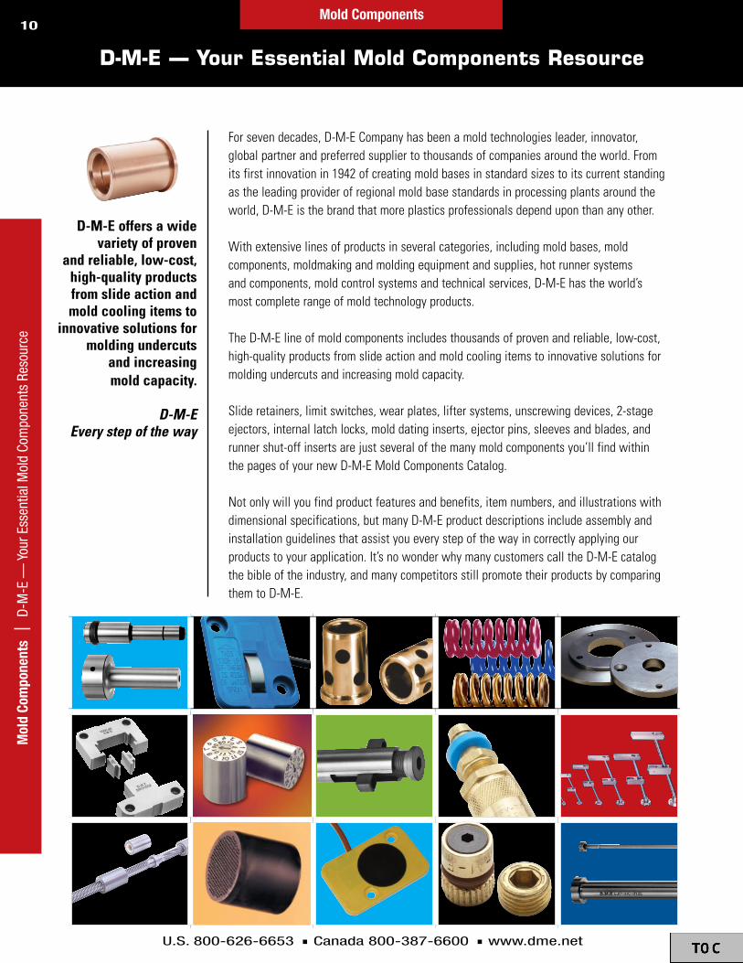
The D-M-E line of mold components includes thousands of proven and reliable, low-cost, high-quality products from slide action and mold cooling items to innovative solutions for molding undercuts and increasing mold capacity.
Slide retainers, limit switches, wear plates, lifter systems, unscrewing devices, 2-stage ejectors, internal latch locks, mold dating inserts, ejector pins, sleeves and blades, and runner shut-off inserts are just several of the many mold components you’ll find within the pages of your new D-M-E Mold Components Catalog.
Not only will you find product features and benefits, item numbers, and illustrations with dimensional specifications, but many D-M-E product descriptions include assembly and installation guidelines that assist you every step of the way in correctly applying our products to your application. It’s no wonder why many customers call the D-M-E catalog the bible of the industry, and many competitors still promote their products by comparing them to D-M-E.
D-M-E�offers�a�wide��variety�of�proven��
and�reliable,�low-cost,�high-quality�products�from�slide�action�and�mold�cooling�items�to�
innovative�solutions�for�molding�undercuts��
and�increasing��mold�capacity .
D-M-EEvery step of the way

D-M-E Slide Action Components
Facilitating greater molding productivity through slide
action innovation
Slide Action Com
ponents

Angle Pins ....................................................14 to 15Supplied with a pre-machined spherical radius on the head to eliminate angle grinding
Slide Retainers ...........................................16 to 21Mini-Might™ and Smart-Lock® designed to be small in size yet strong in holding capacity
Wear Plates .................................................22 to 24Bronze-plated, self-lubricating wear surfaces for long-lasting results
Gib Assemblies ...........................................25 to 28Self-lubricating, bronze-plated base plates
Go to www.dme.net/prices for the latest pricing guide.Online Price Guide
Table of ContentsSl
ide
Actio
n Co
mpo
nent
s |
Tabl
e of
Con
tent
s
Slide Action Components12
U.S. 800-626-6653 n Canada 800-387-6600 n www.dme.net
Slid
e A
ctio
n Co
mpo
nent
s

U.S. 800-626-6653 n Canada 800-387-6600 n www.dme.net
13
AnglePInS
AnglePins . . . . . . . . . . . . . . . . . . . . . . . . . . . . . . . . . . . . . . . 14
MetricAnglePins(gUiDePins) . . . . . . . . . . . . . . . . . . 15
SlIderetAInerS
Mini-Might™sliDeretAiners . . . . . . . . . . . . . . . . . . . . . 16-17sMArt-lock®AnDliMitswitch . . . . . . . . . . . . . . . . . . 18-19
sliDeretAinerAsseMblies . . . . . . . . . . . . . . . . . . . . . . 20
sliDeretAinerinstAllAtiongUiDelines . . . . . . . . . 21
weArPlAteS
bronze-PlAteDweArPlAtes . . . . . . . . . . . . . . . . . . . . . 22self-lUbricAtingweArPlAtes . . . . . . . . . . . . . . . . . . . 23
self-lUbricAtingweArwAys . . . . . . . . . . . . . . . . . . . . 24
gIbASSemblIeS
self-lUbricAtinggibAsseMblies . . . . . . . . . . . . . . . . 25
bAsePlAtesforgibAsseMblies . . . . . . . . . . . . . . . . . 25
l-gibsforgibAsseMblies . . . . . . . . . . . . . . . . . . . . . . . 26
bronze-PlAteDl-gibs . . . . . . . . . . . . . . . . . . . . . . . . . . . . 27
self-lUbricAtingl-gibs . . . . . . . . . . . . . . . . . . . . . . . . . 27
self-lUbricAtingsqUAregibs . . . . . . . . . . . . . . . . . . . 28
Table of Contents
Slide Action Components | Table of Contents
Slide Action Components
AnglePin(HornPin)APd . . . . . . . . . . . .14-15
wearPlatewPb,SlP . . . . . . .22-23
mini-mightAssemblyPSr . . . . . . . . . . . .16-17
mOldClOSed
mOldOPen

U.S. 800-626-6653 n Canada 800-387-6600 n www.dme.net
14
M AND P DIMENSIONS SPECIFYPRESS FIT AREA ON ANGLE PINS
+.0000 –.0005
+.0000 –.0005
P
R
M
+.50 –.00
LLENGTH
+.000 –.005
K
+.000–.010
Ø H
DIA
MAX
Ø D
Ø D C’BORE
B ANGLE C
Ø A
+.010–.000
+.001 –.000
+.0005–.0000
D-M-E Angle Pins are supplied with a pre-machined spherical radius on the head to eliminate angle grinding usually required on the pin head.
moldmachiningandInstallationdimensions
Installationnotes1 . ØAdimensionsspecifiedforholewillprovideapproximately
.000to .001clearancewiththeØPorpressfitareaoftheanglepins .MoldmakertoadjustØAholedimensionstoobtainspecificfitrequired .
2 . cutanglepintolengthasrequiredtoachievedesiredtravelonslide .typically,asphericalradiusorconeshapewithasphericalradiusismachinedonendofanglepin(oppositethehead) .
3 . sphericalradiusonheadissuitableforanglesuptoandincluding20° .
Additionalmachiningandinstallationdataisavailable .contactD-M-e .
*refertoinstallationnote#1 .
AnglePins–APdMaterial:h-13typesteel,65-74hrcnitridedsurface,30-35hrccore
seeD-M-estandardAnglePininserts,pre-machinedfor10°,15°or20°angles .
Itemnumber Ød
llength
mMAx ØH
khDthk ØP
rsPhrAD
APD-0305 .3740
5 .00 .87 .500 .250 .3765 .375
APD-0307 7 .00 1 .37
APD-0405
.4990
5 .00 .87
.625 .250 .5015 .500APD-0407 7 .00 1 .37
APD-0410 10 .00 1 .37
APD-0505
.6240
5 .00 .87
.750 .250 .6265 .625APD-0507 7 .00 1 .37
APD-0510 10 .00 1 .37
APD-0607
.7490
7 .00 1 .37
.875 .312 .7515 .750APD-0610 10 .00 1 .37
APD-0614 14 .00 1 .37
APD-0807
.9990
7 .00 1 .37
1 .125 .312 1 .0015 1 .000APD-0810 10 .00 1 .37
APD-0814 14 .00 1 .37
Itemnumber ØA* b C Ød
APD-0305AnD
APD-0307* .3765
10° .256
.56215° .264
20° .275
APD-0405thrU
APD-0410* .5015
10° .258
.68815° .268
20° .283
APD-0505thrU
APD-0510* .6265
10° .260
.81215° .273
20° .291
APD-0607thrU
APD-0614* .7515
10° .324
.93815° .339
20° .361
APD-0807thrU
APD-0814*1 .0015
10° .328
1 .18815° .348
20° .377
Angle Pins
Slid
e Ac
tion
Com
pone
nts
| A
ngle
Pin
s
*
Allitemsinstock.
HOW tO Order: Use Item Numbers in charts for ordering.
Slide Action Components

U.S. 800-626-6653 n Canada 800-387-6600 n www.dme.net
15
Metric Angle Pins (Guide Pins)
Ød ØH k n l Itemnumber
10 12 3 5
40 APD10-4060 APD10-6080 APD10-80
100 APD10-100110 APD10-110120 APD10-120
12 16 6 5
40 APD12-4060 APD12-6080 APD12-80
100 APD12-100110 APD12-110120 APD12-120140 APD12-140160 APD12-160
14 18 8 6
40 APD14-4060 APD14-6080 APD14-80
100 APD14-100110 APD14-110120 APD14-120140 APD14-140160 APD14-160180 APD14-180200 APD14-200210 APD14-210220 APD14-220230 APD14-230
16 20 8 7
40 APD16-4060 APD16-6080 APD16-80
100 APD16-100110 APD16-110120 APD16-120140 APD16-140160 APD16-160180 APD16-180200 APD16-200210 APD16-210220 APD16-220230 APD16-230
Canbeusedasangle(CAm)pinsorasstraightleaderpins.
noMinAlsize(MM) tolerAnce(MM)
over to g6 h8 k6 m6 H5 H70 3 - .002 - .008 0 - .014 + .006 0 + .008 + .002 + .004 0 + .010 03 6 - .004 - .012 0 - .018 + .009 + .001 + .012 + .004 + .005 0 + .012 06 10 - .005 - .014 0 - .022 + .010 + .001 + .015 + .006 + .006 0 + .015 010 18 - .006 - .017 0 - .027 + .012 + .001 + .018 + .007 + .008 0 + .018 018 30 - .007 - .020 0 - .033 + .015 + .002 + .021 + .008 + .009 0 + .021 030 50 - .009 - .025 0 - .039 + .018 + .002 + .025 + .009 + .011 0 + .025 050 80 - .010 - .029 0 - .046 + .021 + .002 + .030 + .011 + .013 0 + .030 080 120 - .012 - .034 0 - .054 + .025 + .003 + .035 + .013 + .015 0 + .035 0
120 180 - .014 - .039 0 - .063 + .028 + .003 + .040 + .015 + .018 0 + .040 0
metricISOtolerances
K N
Ø Dg6
60 ± 2 HRC
(Ref. Only ~27±5 HRC)800-1100 N/mm
R1.
R4
6
L js15
Ø H
2
Ra3.2 Ra0.8
15°
Ød ØH k n l Itemnumber
24 28 15 8
140 APD24-140160 APD24-160180 APD24-180200 APD24-200210 APD24-210220 APD24-220230 APD24-230240 APD24-240270 APD24-270
30 34 15 8
180 APD30-180200 APD30-200210 APD30-210220 APD30-220240 APD30-240270 APD30-270300 APD30-300
34 38 15 8
100 APD34-100120 APD34-120170 APD34-170190 APD34-190210 APD34-210250 APD34-250
40 48 15 10
160 APD40-160200 APD40-200240 APD40-240300 APD40-300
42 48 15 10
160 APD42-160200 APD42-200240 APD42-240300 APD42-300
50 58 15 10
160 APD50-160200 APD50-200240 APD50-240300 APD50-300360 APD50-360
Ød ØH k n l Itemnumber
18 22 8 8
40 APD18-4060 APD18-6080 APD18-80
100 APD18-100110 APD18-110120 APD18-120140 APD18-140160 APD18-160180 APD18-180200 APD18-200210 APD18-210220 APD18-220230 APD18-230
20 24 8 8
60 APD20-6080 APD20-80
100 APD20-100110 APD20-110120 APD20-120140 APD20-140160 APD20-160180 APD20-180200 APD20-200210 APD20-210220 APD20-220230 APD20-230
22 26 15 8
80 APD22-80100 APD22-100110 APD22-110120 APD22-120140 APD22-140160 APD22-160180 APD22-180200 APD22-200210 APD22-210220 APD22-220230 APD22-230
24 28 15 8
80 APD24-80100 APD24-100110 APD24-110120 APD24-120
Allitemsinstock.
HOW tO Order: Use Item Numbers in charts for ordering.
material:Din1 .7131(Aisi5115type)steeltype:APD
Slide Action Components | M
etric Angle Pins (Guide Pins)Slide Action Components

U.S. 800-626-6653 n Canada 800-387-6600 n www.dme.net
16
Mini-Might™ Slide Retainers
Slid
e Ac
tion
Com
pone
nts
| M
ini-M
ight
™ S
lide
Reta
iner
s
n Three sizes with retaining ratings for 10, 20 and 40 lbs.
n Small in size yet strong holding capacity
n Product design facilitates easy installation
n Slide can be removed without removing the slide retainer from the mold
n Self-contained design
n Line contact engagement
InstallationdimensionsformachiningV-grooveinSlide
dimensionalInformationformini-might™Slideretainers–PSr
.060 RADIUSTYP
90˚SLIDE
+.005 -.000 V-GROOVE DEPTH (TO THEORETICAL SHARP CORNER)
USE .060RADIUS MAXIN BOTTOM OFV-GROOVE
NOTE:see“PocketDimensions”foradditionalinformation .
NOTE:see“PocketDimensions”foradditionalinformation .
Ø .69
.250
boDy
retAiningkey
PlUnger
sPringsPAcer retAiningringsPring
J
CA
b*
FflAt
Øe
Ød
ØH
.187
.669
#10-24x .50longf .h .s .
*v-grooveinslidewillcompressplungerapproximately .01to .03
(U .s .Patentno .5,397,226)
Itemnumber
v-grooveDePth
Psr1000 .091
Psr2000 .153
Psr4000 .194
Item†
number
MAxiMUMrecoMMenDeD
holDingweight
Psr1000 10PoUnDs
Psr2000 20PoUnDs
Psr4000 40PoUnDs
†eachincludes:slideretainerassembly,retainingkeyand#10-24x .50longflatheadscrew .replacementpartsarespecialorder .
Itemnumber A b C Ød Øe
FflAt ØH
JPlUnger
Psr1000 1 .08 .072 .795 .620 .630 .375 .866 .188
Psr2000 1 .32 .121 1 .035 .740 .748 .420 .984 .250
Psr4000 1 .26 .149 .975 .870 .866 .468 1 .102 .312
material:hardenedh-13steel(bodyandPlunger)
Allitemsinstock.
HOW tO Order: Use Item Numbers in charts for ordering.
Slide Action Components

U.S. 800-626-6653 n Canada 800-387-6600 n www.dme.net
17
Mini-Might™ Slide Retainers
.38 RAD
±.005N
RETAINING KEY WEAR PLATE
#10-24 TAP x .50 DEEP (FOR FLAT HEAD SCREW)
+.005 –.000
+.002–.000
Ø L
.500 THICK WEAR PLATE
.020 RMAX
.674
WEAR PLATE
.250 THICK WEAR PLATE
+.005 –.000
+.005 –.000
Ø K
Ø M
.472
NOTES:
1 .lubricateallmetal-to-metalcontactareasbeforefirstuseandevery100,000cycles(ormorefrequentlyasrequired) .Useagoodgradeofmoldmakers’non-meltingtypegreaseratedfortheoperatingtemperaturetobeencountered .
2replacecompressionspringevery1,000,000cyclesorasrequired .
3 .donotoperateattemperaturesexceeding250°F.
typicalApplication
Pocketdimensionsformini-might™Slideretainers–PSr
Itemnumber Øk Øl Øm
nDiM
Psr1000 .625 .869 .94 .670
Psr2000 .750 .987 1 .06 .715
Psr4000 .875 1 .105 1 .19 .763
ANGLE PIN INSERT*
ANGLE PIN* (HORN PIN)
HEEL BLOCK
SLIDE
Y = X +.010 TO +.020
STOP BLOCK WEAR PLATE* RETAINING KEY*
MINI-MIGHT ASSEMBLY*
*AVAILABLE FROM D-M-E
Z
X
X = SLIDE TRAVEL CAUSED BY ANGLE PIN Z = V-GROOVE LOCATION IN SLIDE FROM CENTERLINE OF SLIDE RETAINER X = Z Y = STOP BLOCK LOCATION
MOLD CLOSED
MOLD OPEN
NOTE: .500thickwearplatecanalsobeusedtokeyandretainMini-Mightslideretainerinsteadofretainingkey .Moldmakertomachinetosuit .
NOTE: Use .028thickspacerunderretainingkeywhenmoldhasbeenmachinedfor .500thickwearplate .Moldmakertomachinetosuit .
+ .000– .005
Allitemsinstock.
HOW tO Order: Use Item Numbers in charts for ordering.
Slide Action Components | M
ini-Might ™
Slide RetainersSlide Action Components

U.S. 800-626-6653 n Canada 800-387-6600 n www.dme.net
18
SmartLock® Slide Retainer and Limit Switch
Slid
e Ac
tion
Com
pone
nts
| S
mar
tLoc
k® S
lide
Reta
iner
and
Lim
it Sw
itch
4mm/0 .157incenterofPlUngertocenterofswitchAsseMbly
sliDe sMArtlocklockingPlUnger
sMArtlockswitch
AsseMbly
sliDetrAvel
AnglePin(tyPicAl)
AsseMbly
(U .s .Patentno .6,126,429)
Slidelocked Slideunlocked
The SmartLock® slide retainer and limit switch is designed for injection molders to provide switching and a slide detent in one unique package. The SmartLock locking function prevents premature slide movement during molded part ejection while the SPDT switch is simultaneously actuated.
The SmartLock slide retainer and limit switch has been tested for reliability over 10 million cycles without failure. Two or more switches may be used for larger molds, or molds with multiple slides. Increased safety and prevention of mold damage result when the SmartLock slide lock and limit switch is installed in a mold.
n Prevents damage caused by premature slide movementn 17 to 27 pounds holding force – adjustable for optimum operationn 175°F (79.4°C) standard temperature rating enables use
for most molding applicationsn Quality tested over 10 million cycles to provide long, dependable servicen Flush-mounted switch is shielded from damage by mounting inside
a protective milled pocketn Stripped and tinned 6 ft. wire leads make the switch ready to install
without modificationn Mounting screws and wire clips supplied for neat and easy installation
NOTE:PleasecontactD-M-eforhigh-temperatureapplications .
SmartlockSlideretainerandlimitSwitch–SlS2220
sPecificAtions
breAk-AwAyforce
17to27lbs .(UserADJUstAble)
electricAl 250vAc/28vDc4AMPsinDUctive5AMPsresistivereqUires3-PinconnectorwithMiniMUMrAtingslisteDAbove
oPerAtingteMPerAtUre
175°fMAx .(79 .4°cMAx .)
switching sPDt
MAteriAls
switchAsseMblyboDy
fiberglAss-reinforceDnylon
lockingPlAte hArDeneDsteel
lockingPlUngerAsseMbly
hArDeneDsteel
wireleADs 22gAstrAnDeD,3conDUctor,shielDeDcAble,6ft .(1 .8M)long,enDsstriPPeDAnDtinneD
Allitemsinstock.
Slide Action Components
Itemnumber
sls2220
HOW tO Order: Use Item Numbers in charts
for ordering.

U.S. 800-626-6653 n Canada 800-387-6600 n www.dme.net
19
SmartLock® Slide Retainer and Limit Switch
19 .1mm/0 .75in
28 .7mm/1 .13in
15 .1mm/0 .594in
Ø4 .1mm/0 .16inholethrUforflAtheADscrew(sUPPlieD)
4 .0mm/0 .157in
4 .8mm/0 .19in14 .3mm/0 .56in
30 .2mm/1 .18in
4 .1mm/0 .16in
18 .3mm/0 .72in
10 .2mm/0 .40in
9 .1mm/0 .36in
ADJUstMentscrew
lockingPlAte
15 .5mm/0 .61in
18 .5mm/0 .73in
11 .1mm/0 .44in
sPring
switchActUAtor
norMAllyoPen(blAck)
norMAllycloseD(reD)
coMMon(white)
scheMAticDiAgrAM
The SmartLock switch is designed for use in very low power mold protection control circuits. It is not intended to switch heavy loads in power applications.
DescriPtion qty DescriPtion qty
switchAsseMbly 1 wireclAMPs( .5”x .82”x .15”with .213”MoUntinghole)
2
switchMoUntingscrews(#6-32x3/8”flAtheAD)
2 wireclAMPscrews(#10-24x1/2”bUttonheAD)
2
lockingPlUngerAsseMbly
1 instrUctionsheet 1
MillPocketintoverticAlholeforwirecleArAnce
rADiUsshArPcornerstoeliMinAtewireDAMAge
oPtion#1Drill11/32thrUtoPocket
oPtion#2MillwirechAnnel .25bAllenDMillby .25DeePtowireoUtlet
.81 .63
.73
.375
Drill17/64toDePthreqUireD
.750
(2)DrillAnDtAP6-32x .30DeeP
(4)r .250
.210± .005
.156 – .000+ .002
1 .138 – .000+ .004
1 .202– .000+ .004
.596 – .000+ .002
– .000+ .002
.420 – .000+ .010
(4)r .125+ .002– .000
suggestedmachiningandwirerouting .
AMPs °f °c
5 .0 85 29 .4
4 .0 120 49 .0
3 .0 155 68 .3
2 .0 175 79 .4
ratedCurrentvs.Steeltemperature–SlS2220
SwitchAssembly lockingPlungerAssembly
smartlockincludes2wireclamps .
Slide Action Components | Sm
artLock® Slide Retainer and Lim
it Switch
Slide Action Components
PartsIncludedinSmartlockSlideretainerandlimitSwitch–SlS2220

U.S. 800-626-6653 n Canada 800-387-6600 n www.dme.net
20
Slide Retainer Assemblies
Slid
e Ac
tion
Com
pone
nts
| S
lide
Reta
iner
Ass
embl
ies
The D-M-E Slide Retainer provides a compact and economical means of slide retention, which makes obsolete the cumbersome external spring or hydraulic methods. Its simple and positive operation makes it equally suitable for new tooling design or retrofitting existing molds. Available in three sizes with increasing weight-holding capacities, the Slide Retainers can be used individually or in multiples for larger or heavier slides.
Generally mounted behind and below the slide (see drawing at right), the D-M-E Slide Retainer is a compact unit that can be entirely contained within the mold. Interference with machine tie bars or safety gates is no longer a problem. (It can even be installed completely underneath the slide if space is limited.)
As the mold opens, the dowel pin installed in the slide positively locks into the retainer until disengaged by the mold’s closing action. The custom-designed spring placed crosswise in the retainer maintains the force required to keep the dowel pin in the jaws when the mold is open.
The Slide Retainer is designed with a generous lead-in at the jaw opening so the dowel pin will enter the jaws even if there is a slight misalignment between the retainer and the pin.
Ad
Sx45(4)PlAces
F*
e
bcentrAl
P(2)
.12rADiUs(2)Positioning
gUiDes
ncentrAl
Øt
u
C
DowelPin coMPressionsPring–cUstoMDesign
toP–JAwPlAtebottoM–JAwPlAte
shoUlDerscrew–withthreADlockingeleMent
Item†
number
MAxiMUMrecoMMenDeD
holDingweight
Psl0001 22PoUnDs
Psl0002 44PoUnDs
Psl0003 88PoUnDs
†includestopandbottomjawplate,compressionspring,shoulderscrewwiththreadlockingelementanddowelpin .
* Dimensionf,thedistancefromdowelpincenterlineatendofslidetravelandcenterlineofshoulderscrew,isimportant .overtravelofdowelpinbeyondclearanceprovidedatbackofjawareacouldresultindamagetoretainer .
SlideretainerAssemblies–PSl
NOTE:topreventthedowelpinfromcontactingandapplyingpressureagainstthebackoftheretainerjaw(whichcouldcausebendingorshearingofthedowelpinorhold-downshoulderscrew)theinstallationdimensionsshownonthesepagesarerecommended .
F*
Z = X PLUS .010 TO .015 FORSLIDE RETAINER LOCATION
Y = X PLUS .005 TO .010 FORSTOP BLOCK LOCATION
Y
X X = SLIDE TRAVEL CAUSED BY ANGLE PIN
SLIDE RETAINERASSEMBLY
STOP BLOCK (MUST BE PROPERLY LOCATED AS INDICATED BY DIMENSION Y)
HEEL BLOCK
ANGLE PIN(HORN PIN)
GIB
SLIDE
MOLDEDPART
DOWEL PIN PRESSED INTO SLIDE AND LOCKED IN PLACE WITH SET SCREWS AS REQUIRED
Itemnumber A b C d e F* n P S t u
Psl0001 1 .50 .76 .63 .27 1 .23 .980 .94 .61 .14 .250 1 .25
Psl0002 2 .13 1 .26 .79 .44 1 .69 1 .375 1 .44 .88 .25 .312 1 .50
Psl0003 3 .38 1 .76 1 .18 .75 2 .63 2 .125 1 .94 1 .57 .38 .375 2 .25
material:investmentcastfrom8620steelHardness:case-hardened58-62hrc
Allitemsinstock.
U .s .Patentno .4,961,702
Slide Action Components
HOW tO Order: Use Item Numbers in charts
for ordering.

U.S. 800-626-6653 n Canada 800-387-6600 n www.dme.net
21
Slide Retainer Installation Guidelines
NOTES:1 . Dimensionf,thedistancefromdowelpincenterlineatendofslidetravelandcenterline
ofshoulderscrew,isimportant .overtravelofdowelpinbeyondclearanceprovidedatbackofjawareacouldresultindamagetoretainer .
2 . lubricateallmetal-to-metalcontactareasbeforefirstuseandevery100,000cycles(ormorefrequentlyasrequired) .Useagoodgradeofmoldmakers’non-meltingtypegreaseratedfortheoperatingtemperaturetobeencountered .
3 . donotoperateattemperaturesexceeding225°F.4 . iftwoormoreretainersareused,mountthemuniformlytoprovideabalancedoperation .
retainersizesshouldnotbemixedinamultipleretainerapplication .5 . surfacetowhichretainerismountedshouldnotpreventretainerfrompivotingfreely .6 . replaceretainerassemblyand/ordowelpinwhentotalwearinjawareaorondowelpin
exceeds .010 .7 . replacecompressionspringevery1,000,000cyclesorasrequired,followingprocedures
packagedwithretainer .
Itemnumber F P g H J
rrAD
ktAPPeDholeAnDtAPDePthbelowc’bore
lc’bore
mc’boreDePth
Psl0001 0 .980 0 .61 1 .35 .39 1 .00 .31 #10-24x .50DeeP .2490 .310
Psl0002 1 .375 0 .88 1 .81 .56 1 .50 .37 1/4-20x .56DeeP .3115 .430
Psl0003 2 .125 1 .57 2 .75 .88 2 .00 .50 5/16-18x .62DeeP .3740 .580 P
B B
C
K TAPPED HOLE
TAPPED HOLE MUST NOT BE COUNTERSUNK
T**REF
ONLY
L C’BORE
M
+.001 –.000
+.000 –.005
A
B
**Dimensiontisforreferenceonly .seechartsandapplicationdrawingstodeterminespecificinstallationdimensions .
retrofitdataformoldswithPreviousdesignSlideretainers
Pocketdimensions/Installationguidelines(SlideretentionApplicationShown)
NOTES:A .existingpocketandtappedholefor
previousslideretainer(Mrt-22,44or88) .b .Drilling,tappingandcounterboringfor
shoulderscrewatnewlocationisrequiredperdrawingandchartdimensions .
c .existingpocketmustprovidesupportforretainerpositioningguidesinareasdesignatedbydimensionPorcenteringguideblocksmustbeadded .
Sectionb-b
SectionA-A
Itemnumber
ktAPPeDholeAnDtAPDePthbelow
c’borel
c’bore
mc’boreDePth P
t**ref
only
forrePlAceMentofsliDeretAiner
Itemnumber
Psl0001 #10-24x .50DeeP .2490 .310 .61 .620 Mrt-22
Psl0002 1/4-20x .56DeeP .3115 .430 .88 .875 Mrt-44
Psl0003 5/16-18x .62DeeP .3740 .580 1 .57 1 .325 Mrt-88
SLIDE(OR
PLATE)
+.000–.005
+.001–.000
.06 APPROX.USE SET SCREWTO LOCK DOWELPIN IN PLACEAS REQUIRED
.06 MIN. CLEARANCE BELOW SLIDE (OR PLATE)
TAPPED HOLE MUSTNOT BE COUNTERSUNK
CLEARANCE MUST ALWAYS BE MAINTAINEDUNDER THE HEAD OF THE SHOULDER SCREW.AFTER INSTALLATION WITH SHOULDER SCREWFIRMLY TIGHTENED, CHECK TO BE SURE SLIDERETAINER IS COMPLETELY FREE TO PIVOT.
A POSITIVE STOP BLOCK MUST BE INSTALLED ANDPROPERLY LOCATED TO PREVENT DOWEL PIN FROMAPPLYING PRESSURE AGAINST BACK OF JAW AREA
POCKET MUST PROVIDE SUPPORT FORSLIDE RETAINER POSITIONING GUIDESIN AREAS SPECIFIED BY DIMENSION PON BOTH SIDES OF SLIDE RETAINER. (IFNOT, OR IF RETAINER IS SURFACE MOUNTED,CENTERING GUIDE BLOCKS MUST BE ADDEDTO PROVIDE SUPPORT IN THESE AREAS.)
CLEARANCESLOT FOR DOWEL
PIN TRAVEL
DOWEL PIN PRESSEDINTO SLIDE(OR PLATE)
HG
PF
M
A A
R RADIUS
K TAPPED HOLE
JCENTRAL
LC’BORE
Allitemsinstock. HOW tO Order: Use Item Numbers in charts for ordering.
Slide Action Components | Slide Retainer Installation Guidelines
Slide Action Components

U.S. 800-626-6653 n Canada 800-387-6600 n www.dme.net
22
Bronze-Plated Wear Plates
Slid
e Ac
tion
Com
pone
nts
| B
ronz
e-Pl
ated
Wea
r Pla
tes
AwiDth
+ .000- .060
tthickness1/8–3/8
1/8
weightlbs .Per
inch* 3/16
weightlbs .Per
inch* 1/4
weightlbs .Per
inch* 5/16
weightlbs .Per
inch* 3/8
weightlbs .Per
inch*
1 .00 wPb-0205 0 .035 wPb-0305 0 .053 wPb-0405 0 .071 wPb-0505 0 .088 wPb-0605 0 .106
1 .25 wPb-0206 0 .044 wPb-0306 0 .066 wPb-0406 0 .089 wPb-0506 0 .111 wPb-0606 0 .133
1 .50 wPb-0207 0 .053 wPb-0307 0 .080 wPb-0407 0 .106 wPb-0507 0 .133 wPb-0607 0 .160
1 .75 wPb-0209 0 .062 wPb-0309 0 .093 wPb-0409 0 .124 wPb-0509 0 .155 wPb-0609 0 .186
2 .00 wPb-0210 0 .071 wPb-0310 0 .106 wPb-0410 0 .142 wPb-0510 0 .177 wPb-0610 0 .213
2 .50 wPb-0212 0 .089 wPb-0312 0 .133 wPb-0412 0 .177 wPb-0512 0 .221 wPb-0612 0 .266
3 .00 wPb-0215 0 .106 wPb-0315 0 .159 wPb-0415 0 .213 wPb-0515 0 .265 wPb-0615 0 .319
3 .50 wPb-0217 0 .124 wPb-0317 0 .186 wPb-0417 0 .248 wPb-0517 0 .310 wPb-0617 0 .372
4 .00 wPb-0220 0 .142 wPb-0320 0 .212 wPb-0420 0 .284 wPb-0520 0 .354 wPb-0620 0 .425
4 .50 wPb-0222 0 .160 wPb-0322 0 .239 wPb-0422 0 .319 wPb-0522 0 .398 wPb-0622 0 .479
5 .00 wPb-0225 0 .177 wPb-0325 0 .265 wPb-0425 0 .355 wPb-0525 0 .442 wPb-0625 0 .532
6 .00 wPb-0230 0 .213 wPb-0330 0 .318 wPb-0430 0 .425 wPb-0530 0 .531 wPb-0630 0 .638
8 .00 wPb-0340 0 .424 wPb-0440 0 .567 wPb-0540 0 .708 wPb-0640 0 .851
10 .00 wPb-0450 0 .709 wPb-0550 0 .885 wPb-0650 1 .064
12 .00 wPb-0460 0 .851 wPb-0560 1 .062 wPb-0660 1 .276
AwiDth
+ .000- .060
tthickness1/2–1"
1/2
weightlbs .Per
inch* 5/8
weightlbs .Per
inch* 3/4
weightlbs .Per
inch* 1"
weightlbs .Per
inch*
1 .00 wPb-0805 0 .142 wPb-1005 0 .177 wPb-1205 0 .213 wPb-1605 0 .284
1 .25 wPb-0806 0 .177 wPb-1006 0 .222 wPb-1206 0 .266 wPb-1606 0 .355
1 .50 wPb-0807 0 .213 wPb-1007 0 .266 wPb-1207 0 .319 wPb-1607 0 .425
1 .75 wPb-0809 0 .248 wPb-1009 0 .310 wPb-1209 0 .372 wPb-1609 0 .496
2 .00 wPb-0810 0 .284 wPb-1010 0 .355 wPb-1210 0 .425 wPb-1610 0 .567
2 .50 wPb-0812 0 .355 wPb-1012 0 .443 wPb-1212 0 .532 wPb-1612 0 .709
3 .00 wPb-0815 0 .425 wPb-1015 0 .532 wPb-1215 0 .638 wPb-1615 0 .851
3 .50 wPb-0817 0 .496 wPb-1017 0 .620 wPb-1217 0 .744 wPb-1617 0 .993
4 .00 wPb-0820 0 .567 wPb-1020 0 .709 wPb-1220 0 .851 wPb-1620 1 .134
4 .50 wPb-0822 0 .638 wPb-1022 0 .798 wPb-1222 0 .957 wPb-1622 1 .276
5 .00 wPb-0825 0 .709 wPb-1025 0 .886 wPb-1225 1 .064 wPb-1625 1 .418
6 .00 wPb-0830 0 .851 wPb-1030 1 .064 wPb-1230 1 .276 wPb-1630 1 .702
8 .00 wPb-0840 1 .134 wPb-1040 1 .418 wPb-1240 1 .702 wPb-1640 2 .269
10 .00 wPb-0850 1 .418 wPb-1050 1 .773 wPb-1250 2 .127 wPb-1650 2 .836
12 .00 wPb-0860 1 .702 wPb-1060 2 .127 wPb-1260 2 .552 wPb-1660 3 .403
D-M-E Bronze-Plated Wear Plates provide a long-lasting wear surface for Bronze- Plated molds requiring slides, cams or flat surfaces where frictional wear is a factor.
n Bronze plating of .008 to .010 thickness applied to the top surface of flat steel plates
n Close tolerance on thickness of +.000/-.002n Easy to machine, saving time and toolsn No pre-drilled holes – allows flexibility in mounting patterns
*tocalculateweight,multiplytheweightperinchbythenumberofinches(length)desired .
NOTE:wearPlatelengthsareavailableinone-inchincrements,withaminimumorderlengthof6"required .fullbarlengthis96" .cutlengthisprovidedwithanadditional1/16to1/8inchinlengthformachining .Minimumcutlengthis3inches .
WHeN OrderINg, please specIfy:1. Item Numbers
from charts2. plate length 3. Number of pieces 4. Method of shipment
Slide Action Components
bronze-PlatedwearPlates–wPb
Allitemsinstock.
A
t
l

U.S. 800-626-6653 n Canada 800-387-6600 n www.dme.net
23
Self-Lubricating Wear Plates
D-M-E Self-Lubricating Wear Plates provide a long-lasting wear surface for molds requiring slides, cams or flat surfaces where frictional wear is a factor.
n Low coefficient of friction
n No pre-drilled holes – allows flexibility in mounting patterns
n Standard plug pattern designed for maximum surface lubrication
n Close tolerance to ease installation
tthickness1/4( .250± .001)
Itemnumber
AwiDth
llength
slP0404 1 .00 4 .00slP0405 1 .00 5 .00slP0406 1 .00 6 .00slP0408 1 .00 8 .00slP0410 1 .00 10 .00slP0412 1 .00 12 .00slP0414 1 .50 4 .00slP0415 1 .50 5 .00slP0416 1 .50 6 .00slP0418 1 .50 8 .00slP0420 1 .50 10 .00slP0422 1 .50 12 .00slP0424 2 .00 4 .00slP0425 2 .00 5 .00slP0426 2 .00 6 .00slP0428 2 .00 8 .00slP0430 2 .00 10 .00slP0432 2 .00 12 .00slP0434 2 .50 4 .00slP0435 2 .50 5 .00slP0436 2 .50 6 .00slP0438 2 .50 8 .00slP0440 2 .50 10 .00slP0442 2 .50 12 .00slP0444 3 .00 4 .00slP0445 3 .00 5 .00slP0446 3 .00 6 .00slP0448 3 .00 8 .00slP0450 3 .00 10 .00slP0452 3 .00 12 .00slP0454 4 .00 4 .00slP0455 4 .00 5 .00slP0456 4 .00 6 .00slP0458 4 .00 8 .00slP0460 4 .00 10 .00slP0462 4 .00 12 .00
tthickness3/8( .375± .001)
Itemnumber
AwiDth
llength
slP0504 1 .00 4 .00slP0505 1 .00 5 .00slP0506 1 .00 6 .00slP0508 1 .00 8 .00slP0510 1 .00 10 .00slP0512 1 .00 12 .00slP0514 1 .50 4 .00slP0515 1 .50 5 .00slP0516 1 .50 6 .00slP0518 1 .50 8 .00slP0520 1 .50 10 .00slP0522 1 .50 12 .00slP0524 2 .00 4 .00slP0525 2 .00 5 .00slP0526 2 .00 6 .00slP0528 2 .00 8 .00slP0530 2 .00 10 .00slP0532 2 .00 12 .00slP0534 2 .50 4 .00slP0535 2 .50 5 .00slP0536 2 .50 6 .00slP0538 2 .50 8 .00slP0540 2 .50 10 .00slP0542 2 .50 12 .00slP0544 3 .00 4 .00slP0545 3 .00 5 .00slP0546 3 .00 6 .00slP0548 3 .00 8 .00slP0550 3 .00 10 .00slP0552 3 .00 12 .00slP0554 4 .00 4 .00slP0555 4 .00 5 .00slP0556 4 .00 6 .00slP0558 4 .00 8 .00slP0560 4 .00 10 .00slP0562 4 .00 12 .00
tthickness1/2( .500± .001)
Itemnumber
AwiDth
llength
slP0603 1 .50 3 .00slP0604 1 .50 4 .00slP0605 1 .50 5 .00slP0606 1 .50 6 .00slP0608 1 .50 8 .00slP0610 1 .50 10 .00slP0612 1 .50 12 .00slP0613 2 .00 3 .00slP0614 2 .00 4 .00slP0615 2 .00 5 .00slP0616 2 .00 6 .00slP0618 2 .00 8 .00slP0620 2 .00 10 .00slP0622 2 .00 12 .00slP0623 2 .50 3 .00slP0624 2 .50 4 .00slP0625 2 .50 5 .00slP0626 2 .50 6 .00slP0628 2 .50 8 .00slP0630 2 .50 10 .00slP0632 2 .50 12 .00slP0633 3 .00 3 .00slP0634 3 .00 4 .00slP0635 3 .00 5 .00slP0636 3 .00 6 .00slP0638 3 .00 8 .00slP0640 3 .00 10 .00slP0642 3 .00 12 .00slP0654 4 .00 4 .00slP0655 4 .00 5 .00slP0656 4 .00 6 .00slP0658 4 .00 8 .00slP0660 4 .00 10 .00slP0662 4 .00 12 .00
tthickness5/8( .625± .001)
Itemnumber
AwiDth
llength
slP0703 1 .50 3 .00slP0704 1 .50 4 .00slP0705 1 .50 5 .00slP0706 1 .50 6 .00slP0708 1 .50 8 .00slP0710 1 .50 10 .00slP0712 1 .50 12 .00slP0723 2 .00 3 .00slP0724 2 .00 4 .00slP0725 2 .00 5 .00slP0726 2 .00 6 .00slP0728 2 .00 8 .00slP0730 2 .00 10 .00slP0732 2 .00 12 .00slP0733 2 .50 3 .00slP0734 2 .50 4 .00slP0735 2 .50 5 .00slP0736 2 .50 6 .00slP0738 2 .50 8 .00slP0740 2 .50 10 .00slP0742 2 .50 12 .00slP0743 3 .00 3 .00slP0744 3 .00 4 .00slP0745 3 .00 5 .00slP0746 3 .00 6 .00slP0748 3 .00 8 .00slP0750 3 .00 10 .00slP0752 3 .00 12 .00slP0754 4 .00 4 .00slP0755 4 .00 5 .00slP0756 4 .00 6 .00slP0758 4 .00 8 .00slP0760 4 .00 10 .00slP0762 4 .00 12 .00
Allitemsinstock.
HOW tO Order: Use Item Numbers in charts for ordering.
Material: AluminumbronzewithgraphitePlugsHardness: 179bhn
Slide Action Components | Self-Lubricating W
ear PlatesSlide Action Components
Self-lubricatingwearPlates–SlP
A
t
l

U.S. 800-626-6653 n Canada 800-387-6600 n www.dme.net
24
tl=40 .00+- .001
A± .010
n Well-suited for custom applications
n Standard plug pattern facilitates cutting to a variety of lengths
n No pre-drilled holes – allows flexibility in mounting patterns
D-M-E Self-Lubricating Wear Ways are supplied in 40-inch lengths. The plug pattern is consistent throughout the surface of the Wear Way, so that the Wear Way may be cut to a variety of lengths. Mounting holes are not supplied so that they may be drilled to suit custom applications.
Typical mounting procedure is to machine out the plug location to use for mounting screws. (See “Suggestions for Fastening” below.)
NOTE:AllD-M-eself-lubricatingwearwaysaresuppliedin40"lengths .
NOTE:for3/8"thicknesses,thesuggestedscrewisa1/4flatheadscrew(or1/4socketheadscrewmax) .
SuggestionsforFasteningTypical mounting procedure is to use plug location for screw location.
NOTE:for1/2",5/8",3/4"thicknesses,thesuggestedscrewisa3/8socketheadscrewmax .
Itemnumber
tthickness
AwiDth
slw0515 .375 1 .50
slw0520 .375 2 .00
slw0525 .375 2 .50
slw0530 .375 3 .00
slw0615 .500 1 .50
slw0620 .500 2 .00
slw0625 .500 2 .50
slw0630 .500 3 .00
slw0640 .500 4 .00
slw0720 .625 2 .00
slw0730 .625 3 .00
slw0740 .625 4 .00
slw0820 .750 2 .00
slw0830 .750 3 .00
slw0840 .750 4 .00
slw0850 .750 5 .00
Self-Lubricating Wear Ways
Slid
e Ac
tion
Com
pone
nts
| S
elf-
Lubr
icat
ing
Wea
r Way
s
material:AluminumbronzewithgraphitePlugsHardness:179bhn
Slide Action Components
Self-lubricatingwearways–Slw
WHeN OrderINg, please specIfy:1. Item Numbers from charts2. Quantity 3. Method of shipment
Allitemsinstock.

U.S. 800-626-6653 n Canada 800-387-6600 n www.dme.net
25
Self-Lubricating Gib Assemblies | Base Plates for Assemblies
l
CdA
b
e H
.375
+ .001- .000
± .001
The Gib Assembly includes three components: two L-Gibs and a Base Plate. The L-Gibs are provided with screw holes and are spot-drilled for dowels; the Base Plate includes thru holes to allow for easy assembly.
n Standardized assembly
n Wide variety of applications
n Easily installed in pre-machined pocket
n Reduces design and assembly time
Itemnumber H A l b C d e
slA1001 1 .12 2 .62 2 .00 .312 1 .12 1 .50 .75
slA1002 1 .12 2 .62 3 .00 .312 1 .12 1 .50 .75
slA1003 1 .12 2 .62 4 .00 .312 1 .12 1 .50 .75
slA2001 1 .12 3 .12 3 .00 .375 1 .12 1 .62 .75
slA2002 1 .12 3 .12 4 .00 .375 1 .12 1 .62 .75
slA2003 1 .12 3 .12 5 .00 .375 1 .12 1 .62 .75
slA3001 1 .25 4 .12 3 .00 .500 1 .62 2 .36 .88
slA3002 1 .25 4 .12 4 .00 .500 1 .62 2 .36 .88
slA3003 1 .25 4 .12 5 .00 .500 1 .62 2 .36 .88
slA3004 1 .25 4 .12 6 .00 .500 1 .62 2 .36 .88
slA4001 1 .62 4 .62 4 .00 .750 1 .62 2 .62 1 .25
slA4002 1 .62 4 .62 5 .00 .750 1 .62 2 .62 1 .25
slA4003 1 .62 4 .62 6 .00 .750 1 .62 2 .62 1 .25
material:AluminumbronzewithgraphitePlugsHardness:179bhn
Slide Action Components | Self-Lubricating Gib Assem
blies; Base Plates for Assemblies
Slide Action Components
Self-lubricatinggibAssemblies–SlA
FOR ITEM NO. SBP1001HOLE LOCATIONS ONLY
.375±.001
M
N
A/2
D RAD.TYP.
.28 DIA. THRU HOLEFOR S.H.C.S. (4) PLACES
FOR SBP1002 & SBP1003.28 DIA. THRU HOLE S.H.C.S. HOLE QTY. SEE CHARTFOR SBP2001 THRU SBP4003.34 DIA. THRU HOLE S.H.C.S. HOLE QTY. SEE CHART
HJG.380
FA
.26 x 45˚TYP. (4)L
B C
.26 x 45˚TYP. (4)L
B C
M
N
A/2
D RAD.TYP.
A
NOTES:1 .tolerancesnotnotedare± .010, holelocationsare± .005 .2 .graphicplugpatternvariesby productsize .
Itemnumber A l b C d F g H J m n
MoUntingholeqty
sbP1001 2 .620 2 .00 .69 1 .31 .38 1 .50 .740 1 .62 1 .260 .280 2 .340 4
sbP1002 2 .620 3 .00 .88 2 .12 .38 1 .50 — 2 .620 — .280 2 .340 4
sbP1003 2 .620 4 .00 1 .00 3 .00 .38 1 .50 2 .000 3 .620 — .280 2 .340 6
sbP2001 3 .120 3 .00 .88 2 .12 .38 1 .68 — 2 .620 — .370 2 .750 4
sbP2002 3 .120 4 .00 1 .00 3 .00 .38 1 .68 2 .000 3 .620 — .370 2 .750 6
sbP2003 3 .120 5 .00 1 .12 3 .88 .38 1 .68 2 .500 4 .620 — .370 2 .750 6
sbP3001 4 .120 3 .00 1 .00 2 .00 .50 2 .25 — 2 .620 — .495 3 .625 4
sbP3002 4 .120 4 .00 1 .12 2 .88 .50 2 .25 2 .000 3 .620 — .495 3 .625 6
sbP3003 4 .120 5 .00 1 .25 3 .75 .50 2 .25 2 .500 4 .620 — .495 3 .625 6
sbP3004 4 .120 6 .00 1 .50 4 .50 .50 2 .25 2 .000 5 .620 4 .000 .495 3 .625 8
sbP4001 4 .620 4 .00 1 .12 2 .88 .50 2 .41 2 .000 3 .620 — .560 4 .060 6
sbP4002 4 .620 5 .00 1 .25 3 .75 .50 2 .41 2 .500 4 .620 — .560 4 .060 6
sbP4003 4 .620 6 .00 1 .50 4 .50 .50 2 .41 2 .000 5 .620 4 .000 .560 4 .060 8
material:AluminumbronzewithgraphitePlugsHardness:179bhn
basePlatesforgibAssemblies–SbP
WHeN OrderINg, please specIfy:1. Item Numbers from charts2. Quantity 3. Method of shipment
Allitemsinstock.

U.S. 800-626-6653 n Canada 800-387-6600 n www.dme.net
26
L-Gibs for Gib Assemblies
Slid
e Ac
tion
Com
pone
nts
| L
-Gib
s fo
r Gib
Ass
embl
ies
H
b
+ .001- .000
A
.26x45˚
m I lJgk .380± .005
F
e
d
DrilleD&c'boreDfor5/16socketheADcAPscrews(excePtiteMnUMberssgA1001,sgA1002AnDsgA1003whichAreDrilleDAnDc'boreDfor1/4s .h .c .s .)
Ø9/32sPotDrillforØ1/4Dowel(2)PlAces
for5/16shcs= .38for1/4shcs= .28
Itemnumber H A l b d e F g I J k m
MoUntingholeqty
sgA1001 .75 .750 2 .00 .312 .188 .28 .56 — — 1 .26 .79 1 .74 2
sgA1002 .75 .750 3 .00 .312 .188 .28 .56 — 2 .620 — .88 2 .12 2
sgA1003 .75 .750 4 .00 .312 .188 .28 .56 2 .00 3 .620 — .88 3 .12 3
sgA2001 .75 1 .000 3 .00 .375 .250 .38 .75 — 2 .620 — .88 2 .12 2
sgA2002 .75 1 .000 4 .00 .375 .250 .38 .75 2 .00 3 .620 — .88 3 .12 3
sgA2003 .75 1 .000 5 .00 .375 .250 .38 .75 2 .50 4 .620 — .88 4 .12 3
sgA3001 .88 1 .250 3 .00 .500 .375 .38 .88 — 2 .620 — .88 2 .12 2
sgA3002 .88 1 .250 4 .00 .500 .375 .38 .88 2 .00 3 .620 — .88 3 .12 3
sgA3003 .88 1 .250 5 .00 .500 .375 .38 .88 2 .50 4 .620 — .88 4 .12 3
sgA3004 .88 1 .250 6 .00 .500 .375 .38 .88 2 .00 5 .620 4 .000 .88 5 .12 4
sgA4001 1 .25 1 .500 4 .00 .750 .500 .44 1 .00 2 .00 3 .620 — .88 3 .12 3
sgA4002 1 .25 1 .500 5 .00 .750 .500 .44 1 .00 2 .50 4 .620 — .88 4 .12 3
sgA4003 1 .25 1 .500 6 .00 .750 .500 .44 1 .00 2 .00 5 .620 4 .000 .88 5 .12 4
material:AluminumbronzewithgraphitePlugsHardness: 179bhn
NOTES:1 .tolerancesnotnotedare± .010, holelocationsare± .005 .2 .graphicplugpatternvariesby productsize .
Slide Action Components
l-gibsforgibAssemblies–SgA
WHeN OrderINg, please specIfy:1. Item Numbers from charts2. Quantity 3. Method of shipment
Allitemsinstock.

U.S. 800-626-6653 n Canada 800-387-6600 n www.dme.net
27
Bronze-Plated L-Gibs | Self-Lubricating L-Gibs
Slide Action Components | Bronze-Plated L-Gibs; Self-Lubricating L-Gibs
Slide Action Components
BRONZE PLATED
SURFACES
L
D
A
B C
Itemnumber
AwiDth
bheight
C+ .001– .000
d+ .001– .000
llength
APProxweight(lbs)
lgb-1001 .750 .485 .3125 .1875 8 .75 0 .75
lgb-2001 1 .000 .610 .375 .250 10 .00 1 .50
lgb-3001 1 .250 .860 .500 .375 12 .50 3 .20
lgb-4001 1 .500 1 .235 .750 .500 15 .00 6 .30
lgb-5001 2 .000 1 .470 .875 .625 24 .00 16 .25
lgb-6001 2 .500 1 .970 1 .250 .750 32 .00 36 .25
lgb-7001 3 .000 2 .470 1 .500 1 .000 48 .00 80 .50
MOLDED PART
WEAR PLATE
L-GIB
HEELBLOCK
STOPBLOCKWEAR
PLATE
SLIDE
ANGLE PIN (HORN PIN)
SLIDE
HEELBLOCK
ANGLE PIN(HORN PIN)
L-GIB
WEARPLATE
bronze-Platedl-gibs–lgb
C d
b
H
Arefl
+ .001- .000
D-M-E Self-Lubricating L-Gibs provide a long-lasting wear surface for high-production molds using slides and cams. L-Gibs are easy to machine and can be shaped to any configuration, requiring no special tools.
They are supplied with no pre-drilled holes, providing the designer with flexibility in mounting patterns. This allows the designer to work around water lines and other components in the mold.
NOTES:1 .tolerancesare± .010unlessotherwiseindicated .2 .graphicplugpatternvariesbyproductsize .
Itemnumber H A l b C d
slg1001 .75 .75 5 .25 .312 .187 .56
slg1002 .75 .75 7 .00 .312 .187 .56
slg1003 .75 .75 8 .75 .312 .187 .56
slg2001 .75 1 .00 6 .00 .375 .250 .75
slg2002 .75 1 .00 8 .00 .375 .250 .75
slg2003 .75 1 .00 10 .00 .375 .250 .75
slg3001 .88 1 .25 6 .00 .500 .375 .88
slg3002 .88 1 .25 7 .50 .500 .375 .88
slg3003 .88 1 .25 10 .00 .500 .375 .88
slg3004 .88 1 .25 12 .50 .500 .375 .88
slg4001 1 .25 1 .50 6 .00 .750 .500 1 .00
slg4002 1 .25 1 .50 9 .00 .750 .500 1 .00
slg4003 1 .25 1 .50 12 .00 .750 .500 1 .00
slg4004 1 .25 1 .50 15 .00 .750 .500 1 .00
slg5001 1 .50 2 .00 8 .00 .875 .625 1 .37
slg5002 1 .50 2 .00 12 .00 .875 .625 1 .37
slg5003 1 .50 2 .00 16 .00 .875 .625 1 .37
slg6001 2 .00 2 .50 12 .00 1 .25 .750 1 .75
slg6002 2 .00 2 .50 18 .00 1 .25 .750 1 .75
slg6003 2 .00 2 .50 24 .00 1 .25 .750 1 .75
slg7001 2 .50 3 .00 12 .00 1 .50 1 .000 2 .00
slg7002 2 .50 3 .00 18 .00 1 .50 1 .000 2 .00
slg7003 2 .50 3 .00 24 .00 1 .50 1 .000 2 .00
n Low coefficient of friction n No pre-drilled holes –
allows flexibility in mounting patterns
n Close tolerance
material:AluminumbronzewithgraphitePlugsHardness:179bhn
Self-lubricatingl-gibs–Slg
typicalApplicationsofl-gibsandwearPlates
WHeN OrderINg, please specIfy:1. Item Numbers from charts2. Quantity 3. Method of shipment
Allitemsinstock.

U.S. 800-626-6653 n Canada 800-387-6600 n www.dme.net
28
Self-Lubricating Square Gibs
Slid
e Ac
tion
Com
pone
nts
| S
elf-
Lubr
icat
ing
Squa
re G
ibs
Slide Action Components
m
r1 .00tyPicAl(2)PlUgAreA
ontwosUrfAces
g
DrilleD&c’boreDfornsocketheADcAPscrews
tyPicAlsqUAregibAPPlicAtion
t b
A
C d e F
l
H
NOTES:1 .tolerancesare± .010unlessotherwiseindicated .2 .graphicplugpatternvariesbyproductsize .
Itemnumber t A l b C d e F g H m n
ssg1001 .750 1 .00 4 .00 1 .00 3 .00 — — — — .39 .625 3 /8
ssg1002 .750 1 .00 5 .00 1 .00 2 .50 4 .00 — — — .39 .625 3 /8
ssg1003 .750 1 .00 6 .00 1 .00 3 .00 5 .00 — — — .39 .625 3 /8
ssg1004 .750 1 .00 8 .00 1 .00 3 .00 5 .00 7 .00 — — .39 .625 3 /8
ssg1005 .750 1 .00 10 .00 1 .00 3 .00 5 .00 7 .00 9 .00 — .39 .625 3 /8
ssg1006 .750 1 .00 12 .00 1 .00 3 .00 5 .00 7 .00 9 .00 11 .00 .39 .625 3 /8
ssg2001 1 .00 1 .25 4 .00 1 .00 3 .00 — — — — .62 .875 3 /8
ssg2002 1 .00 1 .25 5 .00 1 .00 2 .50 4 .00 — — — .62 .875 3 /8
ssg2003 1 .00 1 .25 6 .00 1 .00 3 .00 5 .00 — — — .62 .875 3 /8
ssg2004 1 .00 1 .25 8 .00 1 .00 3 .00 5 .00 7 .00 — — .62 .875 3 /8
ssg2005 1 .00 1 .25 10 .00 1 .00 3 .00 5 .00 7 .00 9 .00 — .62 .875 3 /8
ssg2006 1 .00 1 .25 12 .00 1 .00 3 .00 5 .00 7 .00 8 .00 11 .00 .62 .875 3 /8
ssg3001 1 .50 2 .00 8 .00 1 .50 4 .00 6 .50 — — — .86 1 .25 5 /8
ssg3002 1 .50 2 .00 10 .00 1 .25 3 .75 6 .25 8 .75 — — .86 1 .25 5 /8
ssg3003 1 .50 2 .00 12 .00 1 .50 4 .50 7 .50 10 .50 — — .86 1 .25 5 /8
material:AluminumbronzewithgraphitePlugsHardness:179bhn
Self-lubricatingSquaregibs–SSg
WHeN OrderINg, please specIfy:1. Item Numbers from charts2. Quantity 3. Method of shipment
Allitemsinstock.
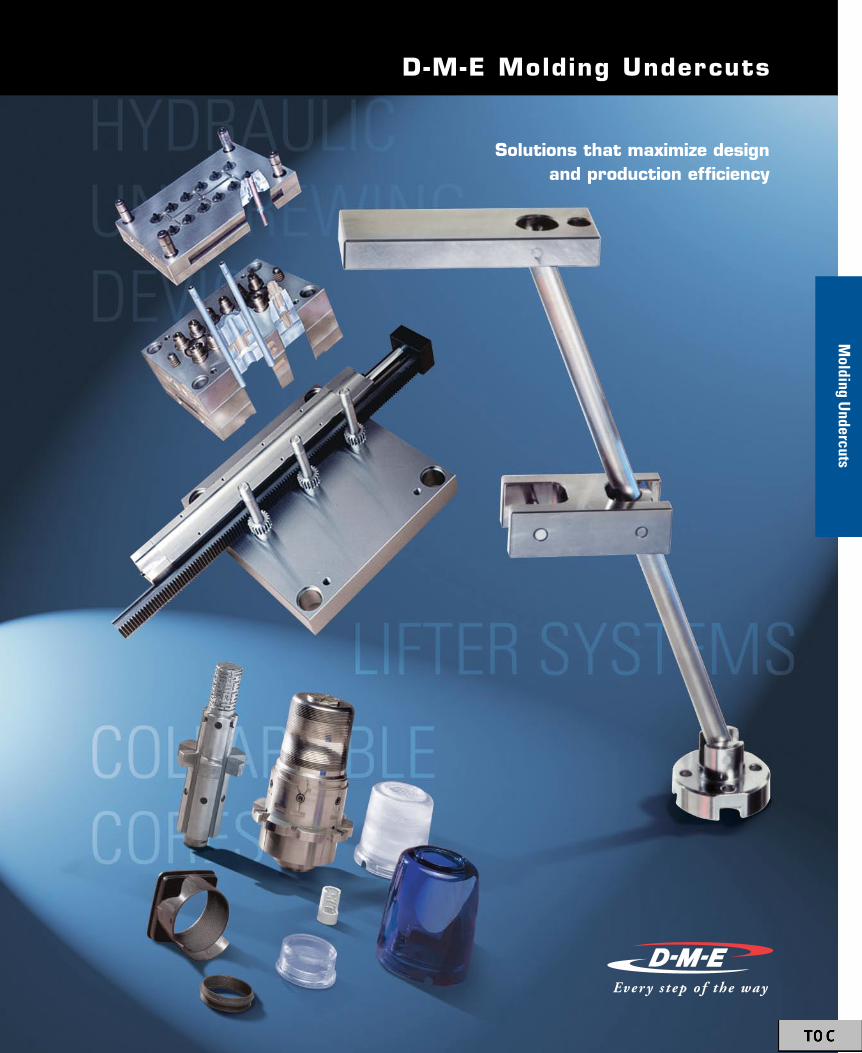
Molding U
ndercutsSolutions that maximize design
and production efficiency
D-M-E Molding Undercuts
Molding U
ndercuts

VectorForm Lifter Systems .........................32 to 42Taking lifter systems to the next level
Hydraulic Unscrewing Device .................43 to 52Standardized system for molding internal threads
Multiform Collapsible Cores ....................53 to 57Efficiently mold plastic parts requiring internal threads, undercuts, protrusions or cut-outs
Collapsible Cores .......................................58 to 59Helps produce plastic parts with internal protrusions, dimples and uninterrupted threads
Expandable Cavity Systems .....................60 to 70Proven technology for molding external threads, grooves and undercuts
Go to www.dme.net/prices for the latest pricing guide.Online Price Guide
Table of Contents
Molding Undercuts30
U.S. 800-626-6653 n Canada 800-387-6600 n www.dme.net
Mol
ding
Und
ercu
ts

Hydraulic Unscrewing D
eviceVectorForm
Lifter Systems
D-M-E VectorForm Lifter Systems
taking lifter systems
to the next level
Table of ContentsVectorForm Overview ..........................................32-34Design Guidelines .....................................................35Advanced Applications .........................................36-37Component Specifications ...................................38-41Ordering Information ................................................42

U.S. 800-626-6653 n Canada 800-387-6600 n www.dme.net
32
Overview
Vect
orFo
rm L
ifter
Sys
tem
s |
Ove
rvie
wVectorForm Lifter Systems
VectorForm Lifter Advantagesn 30˚+Angle–Halfthestrokeforthesameundercut
n Simpleplatemachining
n Easyinstallation
n Maybeganged–Multiplesystemsmaybe“ganged” toliftalargeliftercore–Asinglesystemcanliftmultipleliftercores
n Accelerateordeceleratethemotionoftheliftercorerelativetotheejectorplate
n Coolingmaybeadded
n Designflexibilityisimproved
(0.5° MIN)
Universal
UniversalSlideBaseshownintypicalejectorplateinstallation.
AngledSlideBaseinstallationmaybeusedtoaccelerateordeceleratetheactionoftheVectorFormLifterSystem.Inthisexample,theVectorFormLifterSystemmovementisdeceleratedrelativetothemovementoftheejectorplate.
(0.5° MIN)(0.5° MIN)
Standard
Generalinstallation.StandardSlideBaseintypicalejectorplateinstallationshown.
Joint
View a VectorForm Lifter animation at www.dme.net/vectorform
VectorForm Lifter Systems Design and Assembly Guide available upon request or at www.dme.net/vectorform
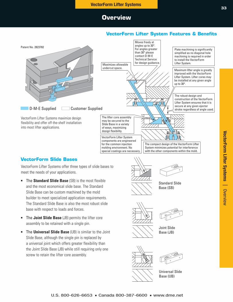
U.S. 800-626-6653 n Canada 800-387-6600 n www.dme.net
33VectorForm Lifter Systems
Overview
VectorForm Lifter System
s | Overview
Maximizes allowableundercut space.
Plate machining is significantly simplified as no diagonal hole machining is required in order to install the VectorForm Lifter System.
The compact design of the VectorForm LifterSystem minimizes potential for interference with the other components within the mold.
The lifter core assemblymay be secured to the Slide Base in a variety of ways, maximizing design flexibility.
VectorForm Lifter System components are engineered for the common injection molding environment. No special coatings are necessary.
Moves freely at angles up to 30°. For angles greater than 30° please contact D-M-E Technical Service for design guidance.
Maximum lifter angle is greatly improved with the VectorForm Lifter System. Lifter cores may be installed at any given angle up to 30°.
The robust design and construction of the VectorForm Lifter System ensures that it is secure at any given ejectorstroke regardless of angle used.
VectorForm Lifter System Features & Benefits
VectorForm Slide BasesVectorFormLifterSystemsofferthreetypesofslidebasestomeettheneedsofyourapplications.
n The Standard Slide Base (SB)isthemostflexibleandthemosteconomicalslidebase.TheStandardSlideBasecanbecustommachinedbythemoldbuildertomeetspecializedapplicationrequirements.TheStandardSlideBaseisalsothemostrobustslidebasewithrespecttoloadsandforces.
n The Joint Slide Base (JB)permitstheliftercoreassemblytoberetainedwithasinglepin.
n The Universal Slide Base (UB)issimilartotheJointSlideBase,althoughthesinglepinisreplacedbyauniversaljointwhichoffersgreaterflexibilitythantheJointSlideBase(JB)whilestillrequiringonlyonescrewtoretaintheliftercoreassembly.
VectorFormLifterSystemsmaximizedesignflexibilityandofferoff-the-shelfinstallationintomostlifterapplications.
Standard SlideBase (SB)
Joint SlideBase (JB)
Universal SlideBase (UB)
Patent No. 2823782
D-M-E Supplied Customer Supplied

U.S. 800-626-6653 n Canada 800-387-6600 n www.dme.net
34
STROKE
GUIDE PLATE
GUIDE ROD
GP
GR
HB
SB
The lifter core (supplied by moldmaker)may be a single-piece component or anassembly of several components includinga modified Guide Rod.
SLIDEBASE
HOLDERBUSHING
LIFTER CORE TRAVEL =STROKE x TAN OF ANGLE “A”
C I
J
“A” (CAVITY) PLATE
“B” (CORE) PLATE
SUPPORT PLATE
1
2
4
5
6
7
8
3
EJECTOR BOX SIDE RAIL
BOTTOM CLAMP PLATE
TOP (STATIONARY)CLAMP PLATE
EJECTOR RETAINER PLATE
EJECTOR PLATE
EJECTOR RETAINERPLATE HEIGHT
EJECTOR BOX HEIGHT
BOTTOM CLAMPPLATE HEIGHT
A°
VectorForm Lifter Systems
Overview
Vect
orFo
rm L
ifter
Sys
tem
s |
Ove
rvie
w
Mold Base Overview VectorForm Lifter Overview
VectorForm Lifter Operating Sequence
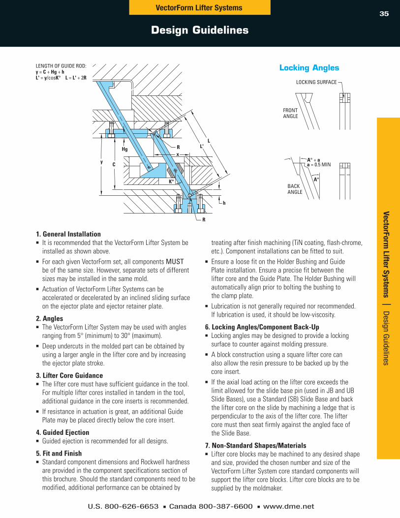
U.S. 800-626-6653 n Canada 800-387-6600 n www.dme.net
35VectorForm Lifter Systems
Design Guidelines
VectorForm Lifter System
s | Design Guidelines
R
R L'L
K°
xy C
h
Hg
LENGTH OF GUIDE ROD:y = C + Hg + hL' = y/cosK° L = L' + 2R
A° + a
LOCKING SURFACE
FRONTANGLE
BACKANGLE
A°
a = 0.5 MIN
1. General Installationn ItisrecommendedthattheVectorFormLifterSystembe
installedasshownabove.n ForeachgivenVectorFormset,allcomponentsMUST
beofthesamesize.However,separatesetsofdifferentsizesmaybeinstalledinthesamemold.
n ActuationofVectorFormLifterSystemscanbeacceleratedordeceleratedbyaninclinedslidingsurfaceontheejectorplateandejectorretainerplate.
2. Anglesn TheVectorFormLifterSystemmaybeusedwithangles
rangingfrom5°(minimum)to30°(maximum).n Deepundercutsinthemoldedpartcanbeobtainedby
usingalargerangleintheliftercoreandbyincreasingtheejectorplatestroke.
3. Lifter Core Guidancen Theliftercoremusthavesufficientguidanceinthetool.
Formultipleliftercoresinstalledintandeminthetool,additionalguidanceinthecoreinsertsisrecommended.
n Ifresistanceinactuationisgreat,anadditionalGuidePlatemaybeplaceddirectlybelowthecoreinsert.
4. Guided Ejectionn Guidedejectionisrecommendedforalldesigns.
5. Fit and Finishn StandardcomponentdimensionsandRockwellhardness
areprovidedinthecomponentspecificationssectionofthisbrochure.Shouldthestandardcomponentsneedtobemodified,additionalperformancecanbeobtainedby
treatingafterfinishmachining(TiNcoating,flash-chrome,etc.).Componentinstallationscanbefittedtosuit.
n EnsurealoosefitontheHolderBushingandGuidePlateinstallation.EnsureaprecisefitbetweentheliftercoreandtheGuidePlate.TheHolderBushingwillautomaticallyalignpriortoboltingthebushingtotheclampplate.
n Lubricationisnotgenerallyrequirednorrecommended.Iflubricationisused,itshouldbelow-viscosity.
6. Locking Angles/Component Back-Upn Lockinganglesmaybedesignedtoprovidealocking
surfacetocounteragainstmoldingpressure.n Ablockconstructionusingasquareliftercorecan
alsoallowtheresinpressuretobebackedupbythecoreinsert.
n Iftheaxialloadactingontheliftercoreexceedsthelimitallowedfortheslidebasepin(usedinJBandUBSlideBases),useaStandard(SB)SlideBaseandbacktheliftercoreontheslidebymachiningaledgethatisperpendiculartotheaxisoftheliftercore.TheliftercoremustthenseatfirmlyagainsttheangledfaceoftheSlideBase.
7. Non-Standard Shapes/Materialsn Liftercoreblocksmaybemachinedtoanydesiredshape
andsize,providedthechosennumberandsizeoftheVectorFormLifterSystemcorestandardcomponentswillsupporttheliftercoreblocks.Liftercoreblocksaretobesuppliedbythemoldmaker.
Locking Angles
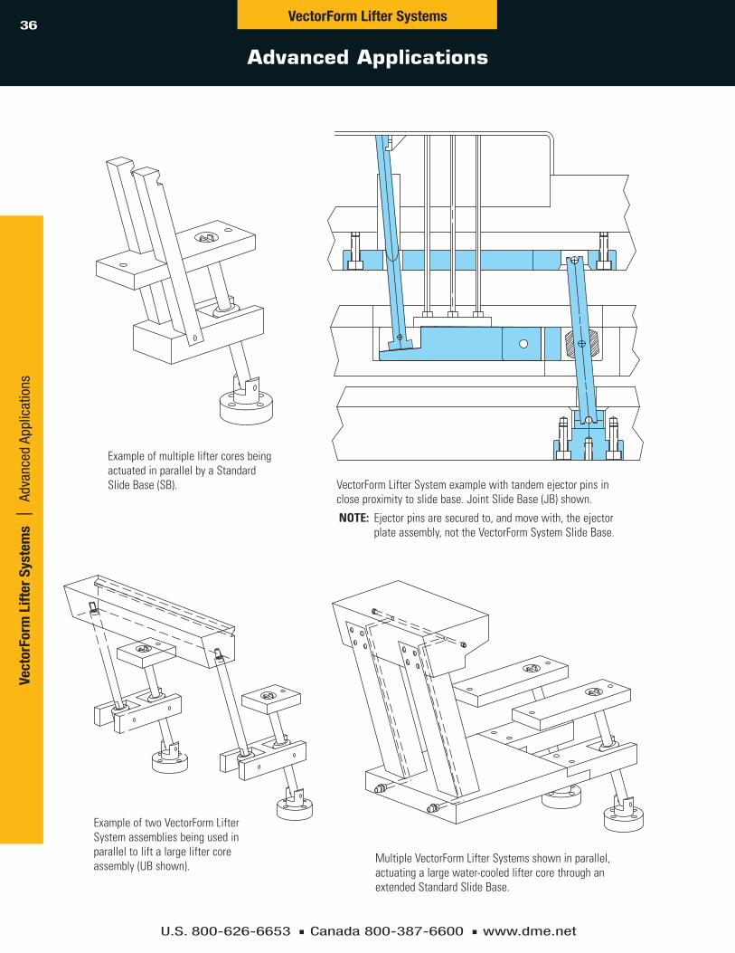
U.S. 800-626-6653 n Canada 800-387-6600 n www.dme.net
36VectorForm Lifter Systems
Advanced Applications
Vect
orFo
rm L
ifter
Sys
tem
s |
Adv
ance
d Ap
plic
atio
ns
ExampleofmultipleliftercoresbeingactuatedinparallelbyaStandardSlideBase(SB).
ExampleoftwoVectorFormLifterSystemassembliesbeingusedinparalleltoliftalargeliftercoreassembly(UBshown).
MultipleVectorFormLifterSystemsshowninparallel,actuatingalargewater-cooledliftercorethroughanextendedStandardSlideBase.
VectorFormLifterSystemexamplewithtandemejectorpinsincloseproximitytoslidebase.JointSlideBase(JB)shown.
NOTE: Ejectorpinsaresecuredto,andmovewith,theejectorplateassembly,nottheVectorFormSystemSlideBase.

U.S. 800-626-6653 n Canada 800-387-6600 n www.dme.net
37VectorForm Lifter Systems
Advanced Applications
VectorForm Lifter System
s | Advanced Applications
S
Deepundercutattainedbyincreasingtheshiftangleandbyhavingsufficientstroke“S”.StandardSlideBase(SB)shown.
Avoidinterferencewiththeadjacentcomponentsbyusingasmallsectionliftercoreandbyusingreverseinstallation.UniversalSlideBase(UB)shown.
MultipleVectorFormLifterSystemscanbeoperatedintandembyasingleGuideRodassemblywiththeuseofasimpleextensioncoupledwithastandardslideplate.JointSlideBase(JB)shown.
Incasesofhighejectionresistance,serialtandemguidancecanbeaidedbyusingtwoormoreGuideRodassemblies.JointSlideBase(JB)shown.
S

U.S. 800-626-6653 n Canada 800-387-6600 n www.dme.net
38VectorForm Lifter Systems
VectorForm Component Specifications
Vect
orFo
rm L
ifter
Sys
tem
s |
Vec
torF
orm
Com
pone
nt S
peci
ficat
ions
L
F
W
TH
L
F
W
S
Ø M
V
TH
Standard Slide Base – SBMaterial: SCM-440 / DIN-1.7225 / AISI-4140 Hardness: 29-34 HRC
Joint Slide Base – JBMaterial: SCM-440 / DIN-1.7225 / AISI-4140 Hardness: 29-34 HRC
Joint Pin material: SKH-51 / DIN-1.1213 / AISI-1050Hardness: 60-66 HRCTempering temperature: 600°C
L
F
W
TH
L
F
W
S
Ø M
V
TH
g
e
G
E
STANdArd SIzE OF GUIdE STEP E e G g 06 16 2.0 9 4 08 20 2.5 11 4 10 26 3.0 14 6 13 33 3.5 17 8 16 42 4.0 22 8 20 50 5.0 28 12
g
e
G
E
STANdArd SIzE OF GUIdE STEP E e G g 06 16 2.0 9 4 08 20 2.5 11 4 10 26 3.0 14 6 13 33 3.5 17 8 16 42 4.0 22 8 20 50 5.0 28 12
NOTE: Dimensionsforretainingsteptobemachinedbymoldmakerasnecessary.
NOTE: Dimensionsforretainingsteptobemachinedbymoldmakerasnecessary.
Additional Machining:n Retainingbolt
installationonliftercorerodorassembly
n Groovesasshowntofarleftoffigure(foralignment)ifrequired
Heat Treatment:n Gasnitridingis
permissibleafteradditionalmachininghasbeenperformed
Additional Machining:None
Attachment: JointPin
Heat Treatment:n Gasnitridingis
permissiblen Duringnitriding,use
apinfiner(-0.01)thantheattachedjointpin

U.S. 800-626-6653 n Canada 800-387-6600 n www.dme.net
39VectorForm
Lifter Systems | VectorForm
Component Specifications
VectorForm Component Specifications
VectorForm Lifter Systems
Slide Base Ordering Information
Universal Slide Base – UBMaterial: SCM-440 / DIN-1.7225 / AISI-4140 Hardness: 29-34 HRCHeat Treatment: Nitriding is permissible
Additional Machining: NoneAttachment: None
SIzES 06 08 10 13 16 20 SB – STANDARD
SLIDE BASE VF 06 SB VF 08 SB VF 10 SB VF 13 SB VF 16 SB VF 20 SB
JB – JOINT SLIDE BASE VF 06 JB VF 08 JB VF 10 JB VF 13 JB VF 16 JB VF 20 JB
UB – UNIVERSAL SLIDE BASE VF 06 UB VF 08 UB VF 10 UB VF 13 UB VF 16 UB VF 20 UB
dIMENSIONS
06 08 10 13 16 20 SYMBOL I 13 15 20 25 30 35 J 20 25 30 35 40 50 C 50-120 50-150 70-200 100-250 120-300 120-400 T 13 15 20 25 30 40 F 20 25 32 40 50 60 L 40 50 60 80 100 130 d 10.5 13.5 17 22 27 33 S 15 20 25 30 40 50 H 6.5 7.5 10 12.5 15 20 W 7.5 10 12.5 15 20 25 N Ø2 Ø3 Ø4 Ø5 Ø6 Ø7 V* 25 30 35 50 60 80 M* Ø3 Ø4 Ø5 Ø6 Ø8 Ø10
0 –0.02
0 –0.02
0 –0.03
0 –0.03
0 –0.05
0 –0.05
0 –0.02
0 –0.02
0 –0.03
0 –0.03
0 –0.05
0 –0.05
*AppliestoJBandUBonly.
g
e
G
E
STANdArd SIzE OF GUIdE STEP E e G g 06 16 2.0 9 4 08 20 2.5 11 4 10 26 3.0 14 6 13 33 3.5 17 8 16 42 4.0 22 8 20 50 5.0 28 12
SIzESSYMBOL
g
e
G
E
T
WV
F
L
H
NOTE: Dimensionsforretainingsteptobemachinedbymoldmakerasnecessary.
I
J
C
INSTALLATIONCLASSIFICATION
ITEM NUMBEr
dIMENSIONS

U.S. 800-626-6653 n Canada 800-387-6600 n www.dme.net
40
VectorForm Component Specifications
VectorForm Lifter SystemsVe
ctor
Form
Lift
er S
yste
ms
| V
ecto
rFor
m C
ompo
nent
Spe
cific
atio
ns
g6Ø AR R
L
L'
R
K
Ø O
Ø P
T
L
F
T
L'L
S
Guide Plate – GPMaterial: S-5O-C / DIN-1.1213 / AISI-1050 Hardness: 30-33 HRCHeat Treatment: Gas nitriding is permissible after additional machining has been performed
Guide rod – GrMaterial: S-UJ-2 / DIN-1.3505 / AISI-52100 Hardness: 56-62 HRCHeat Treatment: Induction hardening completed; heat treat is not required
NOTE: Moldmakertoaddgroovesandchamfersperspecificationsshown.
Additional Machining:n Centerdistance:
L’=L-2Rn Alldimensionsshown
aretobeheldafteranyadditionalmachininghasbeenperformed
n Non-designatedtolerance:+/-0.1
n Non-designatedchamfer“C”tolerance:0.5~1.0
Additional Machining:n Liftercore
holeorslotn Asrequiredto
accommodatetheliftercoreassembly

U.S. 800-626-6653 n Canada 800-387-6600 n www.dme.net
41VectorForm Lifter Systems
VectorForm Component Specifications
VectorForm Lifter System
s | VectorForm Com
ponent Specifications
Ø O
Ø P
T
L
F
T
L'L
S
Holder Bushing – HBMaterial: S-50-C / DIN-1.1213 / AISI-1050 Hardness: 13-22 HRCHeat Treatment: Not required
Additional Machining: None
SIzESSYMBOL
06 08 10 13 16 20
I 13 15 20 25 30 35 J 20 25 30 35 40 50 C 50-120 50-150 70-200 100-250 120-300 120-400
Gr – GUIdE rOd VF 06 Gr VF 08 Gr VF 10 Gr VF 13 Gr VF 16 Gr VF 20 Gr
Ag6 Ø6 Ø8 Ø10 Ø13 Ø16 Ø20
L 150 190 250 310 370 500 L' L' L' L' L' L' L'
K° Same as the shift angle of the lifter core (30° MAX) r 1.0 1.5 2.0 2.5 3.0 3.5
GP – GUIdE PLATE VF 06 GP VF 08 GP VF 10 GP VF 13 GP VF 16 GP VF 20 GP
T 8 10 12 15 20 25
F 20 25 32 40 50 60 L 60 70 90 120 150 180 L' 50 60 75 105 130 155 S Ø10 Ø13 Ø16 Ø20 Ø25 Ø30
HB – HOLdEr BUSHING VF 06 HB VF 08 HB VF 10 HB VF 13 HB VF 16 HB VF 20 HB
P Ø13 Ø16 Ø20 Ø25 Ø32 Ø40
L 20 25 30 35 40 50 O Ø27 Ø34 Ø42 Ø51 Ø65 Ø80 T 8 10 12 15 18 22
Guide Rod, Guide Plate, Holder Bushing Ordering Information
– 0.004– 0.012
– 0.005– 0.014
– 0.005– 0.014
– 0.006– 0.017
– 0.006– 0.017
– 0.007– 0.020
0– 0.02
0– 0.02
0– 0.03
0– 0.03
0– 0.05
0– 0.05
0– 0.02
0– 0.02
0– 0.03
0– 0.03
0– 0.05
0– 0.05
0– 0.04
0– 0.04
0– 0.06
0– 0.06
0– 0.1
0– 0.1
0– 0.05
0– 0.05
0– 0.07
0– 0.07
0– 0.1
0– 0.1
0– 0.2
0– 0.2
0– 0.3
0– 0.3
0– 0.5
0– 0.5
– 0.1– 0.2
– 0.1– 0.2
– 0.1– 0.3
– 0.1– 0.3
– 0.1– 0.5
– 0.1– 0.5
+ 0.02 0
+ 0.02 0
+ 0.03 0
+ 0.03 0
+ 0.05 0
+ 0.05 0
I
J
C
INSTALLATIONCLASSIFICATION
dIMENSIONS PEr LIFTEr SIzE

U.S. 800-626-6653 n Canada 800-387-6600 n www.dme.net
42Ve
ctor
Form
Lift
er S
yste
ms
| O
rder
ing
Info
rmat
ion
Ordering Information
VectorForm Lifter Systems
VectorForm Lifter Sets include:(1)HolderBushing–HB(1)GuideRod–GR(1)GuidePlate–GP(1)SlideBase(Standard–SB,Joint–JB,orUniversal–UB)
VectorForm Lifter Set Ordering Information SIzES 06 08 10 13 16 20 SS – STANDARD SET VF 06 SS VF 08 SS VF 10 SS VF 13 SS VF 16 SS VF 20 SS JS – JOINT SET VF 06 JS VF 08 JS VF 10 JS VF 13 JS VF 16 JS VF 20 JS US – UNIVERSAL SET VF 06 US VF 08 US VF 10 US VF 13 US VF 16 US VF 20 US

Hydraulic Unscrewing D
evice
standardized systems
for molding
internal threads
D-M-E Hydraulic Unscrewing Devices
Hydraulic Unscrewing D
evices
Table of ContentsHydraulic Unscrewing Device Components ........44-47Calculations/Specifications ..................................48-50Applications ......................................................... 51-52

U.S. 800-626-6653 n Canada 800-387-6600 n www.dme.net
44
ZBFLANGE
ZHUEND CAPS - OUT
ZGBASE CONSTRUCTIONHYDRAULIC CYLINDER
ZFGUIDEWAY
ZSALIGNMENT
PLATE
ZHIEND CAPS - IN
NOTE:End caps 1A and 1B,Internal Seals ZD, and NPT PipeThread Adapters are includedin Base Construction.
ZZMETRIC
RACKOR
S.A.E. RACK
ZLCAM RISER
FOR METRIC RACKOR
CAM RISER FORS.A.E. RACK
Components
Hydr
aulic
Uns
crew
ing
Dev
ice
| C
ompo
nent
sHydraulic Unscrewing Device
1 Base Construction – ZG
HydraulicCylinder
II IR
O
P
HHGQ
K
L
P F
D
E2 EE
E1 EE
MN
F
C = STROKEB
A
J
NOTE:“A”istheboresizeoftheZGBaseConstructionHydraulicCylinder.
ITEM NO A B C d E E1 E2 F G H J K L M N O P Q r
Metric ThreadsI II
ZG-25-300ZG-25-400ZG-25-500
Ø .984 Ø .63011.81115.74819.685
16.69320.63024.567
3x3.1503x3.1505x3.150
2.2054.1732.992
2.5984.5673.386
1.811 .787 .138 1.339 .709 .846 1.693 1.142 .433 1/4” BSPT .354 .236 M 8x1.25x20 SM 5x.80x10
ZG-40-300ZG-40-400ZG-40-500
Ø 1.575 Ø .86611.81115.74819.685
17.00820.94524.882
3x3.1503x3.1505x3.150
2.2054.1732.992
2.5984.5673.386
2.205 1.181 .138 1.732 .866 1.339 2.087 1.063 .512 1/2” BSPT .354 .315 M 10x1.5x30 SM 5x.80x10
ZG-63-400ZG-63-500 Ø 2.480 Ø 1.417 15.748
19.68521.89025.827
3x3.1505x3.150
4.4883.307
4.8823.701 3.780 1.969 .315 2.756 1.496 .984 2.047 1.378 .630 3/4”
BSPT .866 .472 M 16x2.0x45 SM 8x1.25x16

U.S. 800-626-6653 n Canada 800-387-6600 n www.dme.net
45
Components
Hydraulic Unscrewing DeviceHydraulic Unscrew
ing Device | Com
ponents
Standardized system formolding internal threadsn SAE-rackdesign
n Off-the-shelfreplacementparts
n Simplifiesmolddesign
n Applicabletodifferentdesignstyles
n Technicalandapplicationsupport
n Racksizedtoprovidemaximumstrokelengths
b
Ø G
M6*
NOTE:Two required perHydraulic Cylinder.
a
LL
F
Y
Y
L
Z
* I IS THETHREADDIMENSIONVERSION 3VERSION 2VERSION 1
I*
X
L LL
X X XX
X
ITEM Metric Threads NO A X Y F z L I Version ZB-25-1 2 qty. M 8x1.25x20 Vers. 1 ZB-25-2 Ø.984 1.063 .492 1.811 .787 .413 3 qty. M 8x1.25x20 Vers. 2 ZB-25-3 4 qty. M 8x1.25x20 Vers. 3 ZB-40-1 2 qty. M 10x1.5x30 Vers. 1 ZB-40-2 Ø1.575 1.339 .787 2.205 1.181 .433 3 qty. M 10x1.5x30 Vers. 2 ZB-40-3 4 qty. M 10x1.5x30 Vers. 3 ZB-63-1 1 qty. M 12x1.75x40 / 1 qty. M 16x2.0x45 Vers. 1 ZB-63-2 Ø2.480 2.165 1.181 3.780 1.575 .591 2 qty. M 12x1.75x40 / 1 qty. M 16x2.0x45 Vers. 2 ZB-63-3 3 qty. M 12x1.75x40 / 1 qty. M 16x2.0x45 Vers. 3
2 Flange – ZB
6 Alignment Plate – ZS
ITEM NO A G a b ZS-25 Ø.984 .787 1.575 .236 ZS-40 Ø1.575 1.181 1.969 .236 ZS-63 Ø2.480 1.969 3.150 .591
*M6Metricsocketheadscrewincluded.NOTE: “A”istheboresizeoftheZGBaseConstructionHydraulicCylinder.
*MetricsocketheadcapscrewsincludedwithFlange(seeI). NOTE: “A”istheboresizeoftheZGBaseConstructionHydraulicCylinder.

U.S. 800-626-6653 n Canada 800-387-6600 n www.dme.net
46
Components
Hydraulic Unscrewing DeviceHy
drau
lic U
nscr
ewin
g D
evic
e |
Com
pone
nts
H
T
S
Drilled and TappedDiametral Pitch (D.P.)
Pitch Lineof Rack toCenter ofHydraulicCylinder
Q
G
UXF/2
S.A.E. ITEM diametral Metric NO A F/2 G H Q Pitch S T U X I ZZ2501 Ø.984 .906 .772 .118 48 12 .551 .250 1.500 1.063 M 8x1.25x20 ZZ4001 Ø1.575 1.102 1.166 .118 48 12 .945 .250 1.750 1.339 M 10x1.5x30 ZZ6301 Ø2.480 1.890 1.953 .295 48 12 1.654 .312 2.625 2.165 M 12x1.75x40
Q
NOTE: Appropriate angle to be put on by moldmaker.G
H
T Distance toCenter ofHydraulicCylinder
V
XF/2
S
3B S.A.E. Rack – ZZ
(forusewithS.A.E.Racks)
4B CAM Riser – ZL
NOTE: MatingGeartobesuppliedbymoldmaker.
20DegreePressureAngleGearTeeth
ITEM Metric NO A F/2 G H Q S T V X I ZL2501 Ø.984 .906 .772 .118 48 .551 .177 1.949 1.063 M 8x1.25x20 ZL4001 Ø1.575 1.102 1.166 .118 48 .945 .177 2.539 1.339 M 10x1.5x30 ZL6301 Ø2.480 1.890 1.953 .295 48 1.654 .256 3.937 2.165 M 12x1.75x40
NOTE: “A” is the bore size of the ZG Base Construction Hydraulic Cylinder.
NOTE: “A”istheboresizeoftheZGBaseConstructionHydraulicCylinder.
Q
NOTE: Appropriate angle to be put on by moldmaker.G
H
T Distance toCenter ofHydraulicCylinder
V
XF/2
S
H
T
S
Drilled and TappedDiametral Pitch (D.P.)
Pitch Lineof Rack toCenter ofHydraulicCylinder
Q
G
UXF/2

U.S. 800-626-6653 n Canada 800-387-6600 n www.dme.net
47
Components
Hydraulic Unscrewing DeviceHydraulic Unscrew
ing Device | Com
ponents
II
E3E3 E EE E
S
JF
TE
ITEM Metric NO A C E E3 F J S T II ZF0001 Ø.984 19.685 5x3.150 2.599 1.811 1.339 .551 .188 SM 5x.80x10 ZF0001 Ø1.575 19.685 5x3.150 2.599 2.205 1.732 .945 .188 SM 5x.80x10 ZF0002 Ø2.480 19.685 5x3.150 1.913 3.780 2.756 1.654 .250 SM 8x1.25x16
ITEM NO L Q P S ZHU-25 .846 .354 1/4" BSPT 2.047 ZHU-40 1.339 .354 1/2" BSPT 2.441 ZHU-63 .984 .866 3/4" BSPT 2.913
MAINTENANCE rEPLACEMENT PArTS ONLY
ITEM NO O r P T ZHI-25 .433 .236 1/4" BSPT 1.378 ZHI-40 .512 .315 1/2" BSPT 1.378 ZHI-63 .630 .472 3/4" BSPT 1.850
NOTE: BSPT=BritishStandardPipeTaper M=MetricSocketHeadCapScrew Ø=DiameterinInches SM=MetricFlatHeadSocketCapScrew
NOTE: Allotherdimensionsininchesunlessotherwisespecified.
B
A
JR
O
P
HHG
L
QP
ST
F
I
F
Seal Kit – ZD
AdapterconvertsmaleBSPTtofemaleNPT.
NOTES:
1. TwoguidewaysarerequiredperRackorperCamRiser.2. Onlyonelengthisstockedandmustbecuttolengthtofitfor
shorterHydraulicCylinders.3. MetricflatheadscrewsareincludedwithGuideway(seeII).
ITEM NO ZD-25 ZD-40 ZD-63
5 Guideway – ZF
1a End Caps (out) – ZHU 1B End Caps (in) – ZHI
Pipe Thread Adapters – ZG
ITEM NO CONVErSION ZG2501 1/4" BSPT = 1/4" NPT ZG4001 1/2" BSPT = 1/2" NPT ZG6301 3/4" BSPT = 3/4" NPT
NOTE:“A”istheboresizeoftheZGBaseConstructionHydraulicCylinder.

U.S. 800-626-6653 n Canada 800-387-6600 n www.dme.net
48
Calculations/Specifications
Hydraulic Unscrewing DeviceHy
drau
lic U
nscr
ewin
g D
evic
e |
Cal
cula
tions
/Spe
cific
atio
ns
ThreadLead=1/(Threadsperinch)=1/Pitch=Inches/ThreadThreadLength=Lengthofthreadstoberemovedfromthecap
A. Stroke (Inches)NOTE: Limit switches should be used if possible to limit full cylinder travel. This will extend the seal life inside the hydraulic cylinder.
a) required revolutions (thread core) ThreadLength = +Safety(.5revolutionsminimum) ThreadLead
b) 1. required stroke – Inches = GearPitchDiameterxπxRequiredRevolutions Ifrequiredstrokeistoolong,acogwheeltransmissionshouldbeused. 2. Length of rack
b2=x+y+b
1
c) Stripper stroke (Inches) =CylinderStroke–RequiredRackStroke
PITCH CIRCLE– PITCH DIA. x PI SPUR GEAR
Y = MAXIMUM PRODUCT SPACING(MULTIPLE CAVITIES CAN BE LOCATED BETWEEN)
BACK VIEW,THREADED CORES
EXTEND FROM OTHER SIDE OF THE SPUR GEAR
UNUSABLE SPACE REQUIRED STROKE TO UNSCREW CAPS
ATTACHED TO MOLD
STATIONARY HYDRAULIC CYLINDER
MOVING RACK
X
b2
> PITCH DIA. PERIMETER x REVOLUTIONSb1

U.S. 800-626-6653 n Canada 800-387-6600 n www.dme.net
49
Calculations/Specifications
Hydraulic Unscrewing DeviceHydraulic Unscrew
ing Device | Calculations/Specifications
STROKE
STATIONARY HYDRAULICCYLINDER BODY
MOVING HYDRAULIC
CYLINDER PUSHESCAM AND RACK
MAIN STRIPPER PLATE
BUMPLIFTANTI-ROTATIONAL
STRIPPER PLATE
BUMPMOVES MAIN
STRIPPER PLATE
ßBETA
ALPHA
CLOSED
CAM
FULL OPEN POSITIONANTI-ROTATIONAL STRIPPER PLATE"OR BUMP" MOVES UP AT A FASTERRATE DUE TO ANGLE BETA ANDSEPARATES FROM THE MAINSTRIPPER PLATE MOVING ATRATE DUE TO ANGLE ALPHA
CLOSED POSITIONBOTH STRIPPERPLATES MOVE UPTOGETHER AT THESAME RATE DUETO ANGLE ALPHA
O.D. OF THREADS(MAJOR THREAD DIA OF THE CORE)
THREAD LEAD
ANTI-ROTATIONALSTRIPPER PLATE
MAIN STRIPPER PLATE
STRIPPER PLATES PUSHED UP BY CAM ANGLES
THREADS GET ROTATED
SPUR GEAR
CAM
THREAD HT.
PITCH DIA.B
RACKA
OPEN
B. Control Cam Calculation
d) Moving Cam ( ) NOTE: Moves Main Stripper Plate in sync. with unscrewing thread.
ThreadLead tan=__________________ GearPitchDiameterx
e) Stripper Cam ( ) NOTE: Moves Anti-Rotational Stripper Plate or provides “BUMP” to shake part off.
StripperHeight tan= StripperStroke
C. Unscrewing ForceThesefiguresshouldonlybeusedasaguideline,asmanyotherfactorswillaffectthecalculation(material,variationofdimensions,materialshrinkage,coresurfacearea,temperature,lubricants,friction,etc.).
f) residual Pressure (PSI) =1/100ofmaximuminjectionpressure
g) Effective core surface area (Square Inches or in2, Outer Core Cylinder Shell) Flatendofthreadedcoreneglected,x2valuefor45°trianglethreadshape =majorthreaddia.ofthecorexxthreadheightx2
h) Unscrewing torque (in-lbf) =ResidualPressurexEffectivecoresurfaceareaxmajorthreadradiusofcore
i) Unscrewing force rack (lbf) UnscrewingTorque = xnumberofcavities Gearpitchradius
k) Hydraulic force (lbf) NOTE: x 1.5 is 50% Safety Factor, if x 1.0 there would be no safety factor.
=UnscrewingForcex1.5

U.S. 800-626-6653 n Canada 800-387-6600 n www.dme.net
50Hydraulic Unscrewing Device
Hydr
aulic
Uns
crew
ing
Dev
ice
| C
alcu
latio
ns/S
peci
ficat
ions
Calculations/Specifications
lbf
PSI
Working Cylinder StrokeUnscrewingforceavailableatdifferenthydraulicpressures(PSI)
Returning Cylinder StrokeForceavailableatdifferenthydraulicpressures(PSI)
PSI
lbf
A (piston) B (shaft) 1,160 PSI 1,450 PSI 1,740 PSI 2,030 PSI 2,175 PSI Ø.984" Ø.630" 517 lbf 652 lbf 787 lbf 922 lbf 989 lbf
Ø1.575" Ø.866" 1,574 lbf 1,978 lbf 2,361 lbf 2,743 lbf 2,967 lbf Ø2.480" Ø1.417" 3,777 lbf 4,721 lbf 5,665 lbf 6,587 lbf 7,081 lbf
A (piston) B (shaft) 1,160 PSI 1,450 PSI 1,740 PSI 2,030 PSI 2,175 PSI Ø.984" Ø.630" 887 lbf 1,102 lbf 1,326 lbf 1,529 lbf 1,664 lbf
Ø1.575" Ø.866" 2,248 lbf 2,810 lbf 3,395 lbf 3,957 lbf 4,204 lbf Ø2.480" Ø1.417" 5,598 lbf 6,992 lbf 8,409 lbf 9,802 lbf 10,476 lbf
Working Stroke
Return Back
NOTE: “A”istheboresizeoftheZGBaseConstructionHydraulicCylinder.
NOTE:“A”istheboresizeoftheZGBaseConstructionHydraulicCylinder.

U.S. 800-626-6653 n Canada 800-387-6600 n www.dme.net
51
Applications
Hydraulic Unscrewing DeviceHydraulic Unscrew
ing Device | Applications
APPLICATIONS required d-M-E Component List
Application AItem No Qty descriptionZG-xx-yyy 1 Hydraulic CylinderZS-xx 2 Alignment PlateZB-xx-y 1 Flange-Version 3ZZ-xx-yy 2 S.A.E. RackZL-xx-yy 1 Cam RiserZF-yyyy 6 Guideways for Racks & Cam
Application BItem No Qty descriptionZG-xx-yyy 1 Hydraulic CylinderZS-xx 4 Alignment PlateZB-xx-y 1 Flange-Version 1ZZ-xx-yy 1 S.A.E. RackZF-yyyy 2 Guideways for Rack
Application CItem No Qty descriptionZG-xx-yyy 2 Hydraulic CylinderZS-xx 4 Alignment PlateZB-xx-y 2 Flange-Version 1ZZ-xx-yy 2 S.A.E. RackZF-yyyy 4 Guideways for Racks
Application dItem No Qty descriptionZG-xx-yyy 1 Hydraulic CylinderZS-xx 2 Alignment PlateZB-xx-y 1 Flange-Version 2ZZ-xx-yy 1 Cam RiserZF-yyyy 2 Guideways for Cam
NOTE:Moldmakershouldprovidelimitswitchesforfullyclosedandforcylinderextended.Fullcylinderextensionshouldbeavoidedtoimproveinternalcylinderseallife.
Application AWithout guiding thread with cam
Application BWith guiding thread
Safety Protection Box fabricated by moldmaker completely covers full movement of Unscrewing device.
A complete Engineering Design Guide, plus separate example, are available at www.dme.net/hud

U.S. 800-626-6653 n Canada 800-387-6600 n www.dme.net
52Hy
drau
lic U
nscr
ewin
g D
evic
e |
App
licat
ions
Applications
Hydraulic Unscrewing Device
Application CWith guiding thread
Application dLong guiding cores
Safety Protection Box fabricated by moldmaker completely covers full movement of Unscrewing device.
Safety Considerations: Moldmakermustfabricateboxesovertherackareaswhichmovetoprotectagainstinjurytopersonnel.Moldmakermustalsousesafetyinterlockstopreventmovementofunscrewingdeviceiftheseprotectionboxesareremovedforanyreason.Also,sheetmetalshouldbeusedtocoverareaswherethegearsare,topreventdamagefromloosedebrisfallingbetweenthegearsandracks.

D-M-E Multiform, Collapsible Core and Expandable Cavity Systems
efficiently mold
plastic parts requiring
internal threads, undercuts,
protrusions or cut-outs
Multiform
, Collapsible Core and Expandable Cavity Systems

U.S. 800-626-6653 n Canada 800-387-6600 n www.dme.net
54
Go to www.dme.net/prices for the latest pricing guide.
Multiform Collapsible CoresApplication Examples ........................................ 55Features and Benefits .........................................56Undercut Ratios .................................................56Installation/Motion Sequence .............................57
Online Price Guide
Table of Contents
Mul
tifor
m, C
olla
psib
le C
ore,
Exp
anda
ble
Cavi
ty S
yste
ms
| T
able
of C
onte
nts
Collapsible CoresFeatures and Benefits .........................................58 Ordering Information ..........................................58
Collapsible Mini-CoresFeatures and Benefits .........................................59Ordering Information ..........................................59
Expandable Cavity SystemsFeatures and Benefits .........................................60Typical Molded Parts ...........................................61Components .......................................................62Typical Applications .............................................63Plastic Part Design ..............................................64Cavity/Striker Insert Design ................................65Operating Sequence ..........................................66Typical Mold Layouts ..........................................67Application Guidelines ........................................68Quote Request Form ..........................................69
Multiform, Collapsible Core, ECS

U.S. 800-626-6653 n Canada 800-387-6600 n www.dme.net
55M
ultiform Collapsible Cores | Application Exam
ples
Application Examples
Application Examples for Multiform Collapsible Cores
Ø 122
M 120 X 3Ø 134
Ø 112
65
29
Ø 24.8
G 3/4"
Ø 28Ø 35
90
Ø 64
THREADTR 60 X 8 P4
92 100
Ø 53Ø 60
Ø 53
Tr 30x3
88Ø 36.5
Ø 33.5
Ø38Ø36 Ø34
Ø36
Ø 122
M 120 X 3Ø 134
Ø 112
65
29
Ø 24.8
G 3/4"
Ø 28Ø 35
90
Ø 64
THREADTR 60 X 8 P4
92 100
Ø 53Ø 60
Ø 53
Tr 30x3
88Ø 36.5
Ø 33.5
Ø38Ø36 Ø34
Ø36
Ø 122
M 120 X 3Ø 134
Ø 112
65
29
Ø 24.8
G 3/4"
Ø 28Ø 35
90
Ø 64
THREADTR 60 X 8 P4
92 100
Ø 53Ø 60
Ø 53
Tr 30x3
88Ø 36.5
Ø 33.5
Ø38Ø36 Ø34
Ø36
Ø 122
M 120 X 3Ø 134
Ø 112
65
29
Ø 24.8
G 3/4"
Ø 28Ø 35
90
Ø 64
THREADTR 60 X 8 P4
92 100
Ø 53Ø 60
Ø 53
Tr 30x3
88Ø 36.5
Ø 33.5
Ø38Ø36 Ø34
Ø36
32.2
M27 X 1.5
Ø 27.6Ø 30Ø 36
93
33
30
90
Ø 26Ø 27
THREADM33 P 0.5
THREAD M31 P 0.5
Ø 27Ø 24.5
23
31
55.5
1625
15°
R 25142.5
125
149
R 15R 11.75
2.5
2.5
102 110
32.2
M27 X 1.5
Ø 27.6Ø 30Ø 36
93
33
30
90
Ø 26Ø 27
THREADM33 P 0.5
THREAD M31 P 0.5
Ø 27Ø 24.5
23
31
55.5
1625
15°
R 25142.5
125
149
R 15R 11.75
2.5
2.5
102 110
32.2
M27 X 1.5
Ø 27.6Ø 30Ø 36
93
33
30
90
Ø 26Ø 27
THREADM33 P 0.5
THREAD M31 P 0.5
Ø 27Ø 24.5
23
31
55.5
1625
15°
R 25142.5
125
149
R 15R 11.75
2.5
2.5
102 110
32.2
M27 X 1.5
Ø 27.6Ø 30Ø 36
93
33
30
90
Ø 26Ø 27
THREADM33 P 0.5
THREAD M31 P 0.5
Ø 27Ø 24.5
23
31
55.5
1625
15°
R 25142.5
125
149
R 15R 11.75
2.5
2.5
102 110
Ø 122
M 120 X 3Ø 134
Ø 112
65
29
Ø 24.8
G 3/4"
Ø 28Ø 35
90
Ø 64
THREADTR 60 X 8 P4
92 100
Ø 53Ø 60
Ø 53
Tr 30x3
88Ø 36.5
Ø 33.5
Ø38Ø36 Ø34
Ø36
Multiform Collapsible Cores

U.S. 800-626-6653 n Canada 800-387-6600 n www.dme.net
56
Multiform Collapsible Cores – Features and Benefits
Mul
tifor
m C
olla
psib
le C
ores
|
Feat
ures
and
Ben
efits
n Fromdiameter10to200mm
n Canbeusedforround,squareorovalparts
n Variouscoatingoptions
n Canbeusedwithallthermo-plasticsusedininjectionmolding
n Alsosuitablefordiecastingandthermosets
n Separatesegmentsareexactlyadjustedtomatchperfectlytogether
n Forundercutsupto12%
n Highdegreeoftemperaturecontrolasofdiameter14mm
The Multiform Collapsible Core and its Possibilities
n WiththisMultiformCollapsibleCore,internalundercutsonplasticordie-castitemsarenolongeraproblem.
n Internalundercuts–allthewayroundorjustpartially–onround,squareorovalpartscannowbecarriedoutwithoutanyproblems.
n Partsnolongerhavetobeseparatedintotwopieces.Theproceduresforgluing,ultrasonicwelding,screwingormechanicalreworkingarenolongerrequired.
n Partswithsingleormultistartthreads(alsoacombinationofright-andleft-handedthreads).
n BymeansoftheD-M-EMultiformCollapsibleCore,non-looseningwater-tightsnap-onconnectionscanbecreated.Threadedcomponents,suchasscrewcaps,canbeproducedatreducedcost,asthecoreallowsthewallthicknesstobereducedtoaminimum.ThedimensionalstabilityofpartsmanufacturedusingD-M-EMultiformCollapsibleCoresmeetsthehighestrequirements.Forexample,anaccuracyof±0.015mmisachievedforflatnessandroundness.Sincenoejectiondraftlineisrequired,preciselyshaped,cylindricalpartswithauniformwallthicknesscanbeproduced.
Possible Undercut ratios
Thesizeofthemaximumundercutratiodependsontheinternallength(L).Foreachitem’scontour,thebestpossibledesignconditionsarecalculated,sothatthebestdiameterandinternallengthratiosareachievedforeachapplication.
Forpre-selection,thesmalldiameter(d)foragivenlargediameter(D)andagiveninternallength(L)canbecalculatedusingthefollowingformulas:
For small internal lengths: For large internal lengths:
Example:
internallengthL
largediameterD<2
d=Dx(0.866+Lx0.0328)D
internallengthL
largediameterD≥2
d=Dx(0.9316+(L–2)x0.017)D
d=Dx(0.866+Lx0.0328)=128mmx(0.866+0.6x0.0328)
d=113.64mmThesmalldiameterdcanbeaminimumof113.64mm.
D
internallengthL=76.8mmlargediameterD=128.0mm
RatioL=76.8mm=0.6➝ smallinternallength(formula1)
D 128mm
d=smalldiameterD=largediameterL=internallength
Ordering Information
MultiformCollapsibleCoresaresuppliedtocustomerspecification.Ifyouwouldliketoplaceanorder,pleasecontactD-M-E.Tocalculatethecore’sgeometry,adrawingshowingtheitemisrequired.
Multiform Collapsible Cores

U.S. 800-626-6653 n Canada 800-387-6600 n www.dme.net
57M
ultiform Collapsible Cores | Installation and M
otion Sequence
Installation and Motion Sequence
D
d
L
d1
d D
L
D
L
d d
D
L
D
L
d
D
d
L
Structure
Normally,theD-M-EMultiformCollapsibleCoreconsistsofaninnercoreandsixexternalsegments.Thesegmentsarearrangedontheinnercoreinvariouspreciselycalculatedbevelledplanes.Duringejection,thesegmentsslideacrosstheinnercore(dovetail)andperformaradialmovement,whichallowstheinternalundercuttodemold.
Theinternalundercutiscomprisedofthesmallerdiameter“d”andthebiggerdiameter“D.”ForamathematicalcalculationoftheMultiformCollapsibleCore,theinternallength“L”isalsoofgreatimportance.ThelargertheratioofLtoD,thesmallerthepossibleundercutratio.
Inordertoachieveanexcellentundercutratioforlargeitemlengthswheretheinternalundercutisattheitem’sfrontpart,itispossibletoflangeastationarycoreinfrontoftheD-M-EMultiformCollapsibleCore.
Installation Instructions
Motion Sequence (with flanged stationary core)
1 2 3
Thecoolingtimehasexpired–themoldopenscompletely.
Ejectionmovementforwarduntilthesegments’axialmovementhasbeencompleted;undercutisreleased.
Ejectormovementcompleted;partisejected.
H5 H4 H2H6
2. Stroke
COOLING
3. Stroke 1. Stroke
Stroke 3
Stroke 2+3
Stroke 1 max
P3
D7 d D D2D6D5D4
P2 P1
LH1
COOL
ING
d-M-E Multiform Collapsible Core (flanged on the side)
ThisexampleillustratesthattheD-M-EMultiformCollapsibleCorecanbefittedintothetoolinthedirectionofthesplitlineorobliquely.Itisactuatedusingahydrauliccylinder.
D=largediameterd=smalldiameterD2=strippingdiameterL=internallengthP1=strippingplateP2=segmentretainingplateP3=clampingplateD4=max.externaldiameter
1.Stroke=moldopens2.Stroke=axialsegment
movement(segmentlift)3.Stroke=stripping
Stroke2addedtoStroke3=ejectionstroke
H5 H4 H2H6
2. Stroke
COOLING
3. Stroke 1. Stroke
Stroke 3
Stroke 2+3
Stroke 1 max
P3
D7 d D D2D6D5D4
P2 P1
LH1
COOL
ING
H7
D9D8
P5 P4
COOLING
2.Stroke
2. Stroke 3. Stroke 1. Stroke
H7
D9D8
P5 P4
COOLING
2.Stroke
2. Stroke 3. Stroke 1. Stroke
H7
D9D8
P5 P4
COOLING
2.Stroke
2. Stroke 3. Stroke 1. Stroke
Multiform Collapsible Cores

U.S. 800-626-6653 n Canada 800-387-6600 n www.dme.net
58
Collapsible Cores – Features and Benefits
Colla
psib
le C
ores
| F
eatu
res
and
Bene
fits
Economically producecomplex plastic partsThe Collapsible Core is a major breakthrough for molding plastic parts requiring internal threads, undercuts, protrusions or cut-outs. The patented design incorporates only three moving parts, which utilize conventional mold movements.
The Collapsible Core’s automatic operation makes it possible for you to produce parts that, previously, had been considered impossible to mold. Parts with internal protrusions, dimples, interrupted threads and cut-outs can now be economically produced on a high- or low-volume basis.
For conventional threaded parts, the Collapsible Core could cut your cycle time up to 30% when compared with unscrewing or other complex actuating mechanisms.
Full technical details, including basic stripper plate mold construction, core grinding instructions, and core and mold machining dimensions are included in the Collapsible Core and Collapsible Mini-Core Design & Assembly Guide – contact D-M-E for a copy.
*�*To�determine�maximum�dimension�of�moldable�undercut,�reduce�the�amount�of�collapse�per�side�shown�in�the�table�above�by�.020�per�inch�of�part�height�requiring�collapse.
NOTE:� Special�Collapsible�Cores�with�molding�lengths,�special�diameters��� or�collapse�other�than�shown�in�table�above�will�be�quoted�on�request.
�*Cores�having�slightly�greater�collapse,�as�shown�above,�are�usually�available�from�stock�–�contact�D-M-E.
�†�Shorter�overall�length�Collapsible�Cores�for�any�application,�and�particularly�where�mold�shut�height�is�limited.
ROOT DIAMETER OF THREAD
MOLDED CAP CAVITY INSERT
COLLAPSED UNCOLLAPSED
SHUT-OFF L
O.A.L.
COLLAPSIBLE CORE
COLLAPSING SEGMENTS
STRIPPER INSERT
COOLING HOLE
CENTER PIN
POSITIVE COLLAPSE SLEEVE (INCLUDED)
EJECTOR PLATE ASSEMBLY
CENTER PIN INSTALLED IN CLAMP PLATE
AB
C
U.S.�Patent�Nos.�3,247,548;�3,660,001�Foreign�Patents�Issued
ITEM NuMbEr
AMAX O.D.
OF THrEAD Or CONFIG
BMIN I.D.
OF THrEADOr CONFIG
CENTEr PINDIAMETEr
(AT TOP OF COrE)
LMAX MOLDED
LENGTH(INCL MOLD SHuT-OFF)
CCOLLAPSE PEr SIDEAT TOP OF COrE**
O.A.L.OVErALL LENGTHOF COLLAPSIbLE
COrE (ONLY)
inch mm inch mm inch mm inch mm inch mm *inch *mm inch mm
CC-125-PC .720 18.29 .620 15.75 .490 12.45 .800 20.32 .027 .69 .032 .81 5.605 142.37CC-150-PC .850 21.59 .700 17.78 .580 14.73 1.000 25.40 .037 .94 .042 1.07 6.615 168.02CC-175-PC .970 24.64 .760 19.30 .640 16.26 1.000 25.40 .043 1.09 .048 1.21 6.615 168.02CC-200-PC 1.270 32.25 .910 23.11 .785 19.93 1.150 29.21 .043 1.09 .048 1.21 7.315 185.80
†CC-250-PC 1.270 32.25 .910 23.11 .785 19.93 1.150 29.21 .043 1.09 .048 1.21 5.440 138.17CC-202-PC 1.390 35.30 1.010 25.65 .885 22.47 1.150 29.21 .055 1.39 .064 1.62 7.315 185.80
†CC-252-PC 1.390 35.30 1.010 25.65 .885 22.47 1.150 29.21 .055 1.39 .064 1.62 5.440 138.17CC-302-PC 1.740 44.19 1.270 32.25 1.105 28.06 1.400 35.56 .068 1.72 .083 2.10 7.315 185.80
†CC-352-PC 1.740 44.19 1.270 32.25 1.105 28.06 1.400 35.56 .068 1.72 .083 2.10 6.065 154.05CC-402-PC 2.182 55.42 1.593 40.46 1.388 35.25 1.700 43.18 .090 2.28 .103 2.61 7.815 198.50CC-502-PC 2.800 71.12 2.060 52.32 1.750 44.45 1.900 48.26 .115 2.92 .125 3.17 9.625 244.47CC-602-PC 3.535 89.78 2.610 66.29 2.175 55.24 2.400 60.96 .140 3.55 .148 3.75 11.250 285.75CC-652-PC 3.800 96.52 2.890 73.41 2.450 62.23 2.400 60.96 .150 3.81 .160 4.06 11.250 285.75CC-702-PC 4.225 107.31 3.350 85.09 2.875 73.02 2.400 60.96 .165 4.19 .170 4.32 11.250 285.75
Collapsible Cores

U.S. 800-626-6653 n Canada 800-387-6600 n www.dme.net
59Collapsible M
ini-Cores | Features and BenefitsCollapsible Mini-Cores – Features and Benefits
* To determine maximum dimension of moldable undercut, reduce the amount of collapse per side shown in the table above by .020 per inch of part height requiring collapse.
NOTES: 1. Cores listed above include core, center pin, positive collapse sleeve, clamping ring and a special, non-bladed center pin arbor required for proper core grinding.
2. Collapsible Mini-Cores with longer molding lengths, special diameters, collapse or number of segments will be quoted on request. For larger diameters (up to 3.535"), see Collapsible Cores.
O.A.L. 5.940in
(150.88mm)
A B
CCOLLAPSING SEGMENTS (3)
NON-COLLAPSING CENTER PIN BLADES (3)
ROOT DIAMETER OF THREAD OR UNDERCUT
MOLDED CAP
COLLAPSEDUNCOLLAPSED
SHUT-OFF L
COLLAPSING SEGMENTS (3)
STRIPPER INSERT IN STRIPPER PLATE
NON-COLLAPSING CENTER PIN BLADES (3)
CORE SLEEVE WITH (3) COLLAPSING SEGMENTS
CENTER PIN WITH (3) NON-COLLAPSING BLADES
EJECTOR PLATE ASSEMBLY
COOLING HOLE IN CENTER PIN
ALIGNMENT FLATS ON CORE SLEEVE AND CENTER PIN
POSITIVE COLLAPSE SLEEVE (INCLUDED)
Patent Pending
ITEM NUMBEr
FOr CLOSUrE
dIAMETEr rANGE
AMAX O.d.
OF THrEAd Or CONFIG
BMIN I.d.
OF THrEAdOr CONFIG
CENTEr PINdIAMETEr
(AT TOP OF COrE)
WIdTH OF (3)NON-COLLAPSING
CENTEr OF PIN BLAdES(AT TOP OF COrE)
LMAX MOLdEd LENGTH (INCL MOLd SHUT-OFF)
CCOLLAPSE PEr SIdE
AT TOP OF COrE*
mm inch mm inch mm inch mm inch mm inch mm inch mm
CCM-0001 13-16 .645 16.38 .425 10.80 .300 7.62 .170 4.32 .850 21.59 .052 1.32
CCM-0002 17-20 .805 20.45 .560 14.22 .420 10.67 .190 4.83 .850 21.59 .057 1.45
CCM-0003 21-24 .965 24.51 .710 18.03 .560 14.22 .200 5.08 1.000 25.40 .059 1.50
Easily mold parts withclosures as small as 13mmTheCollapsibleMini-Corebroadenstheapplicationsofcollapsiblecoremoldsforclosuresassmallas13mm.Duetothesmallerdiametersinvolved,theseMini-Coresemploythreelargercollapsingsegmentscombinedwiththreenarrow,non-collapsingblades,whichareanintegralpartofthecenterpin.
Asaresult,upto80%fullthreadsorundercutscanbemolded.Thefunctionofthecollapsingcorealsopermitsthreadstostopatanypointalongthemoldedlength–threadsneednotrunouttothetopofthecoreaswithunscrewingmolds.Ifasealisrequiredinthetopoftheclosure,anundercutcanbemoldedintotheparttoholdsuchasealinplace.
Thecollapsingactionalsopermitsalongerthreadedareatobeformed,withoutaddingtothecycletimeorrequiringlongrackandpinionmechanisms.Inadditiontothreads,otherconfigurationssuchasdimples,cut-outsorprotrusionsbeyondthecapabilitiesofunscrewingmoldscanbesuccessfullymolded.ThreestandardsizesofCollapsibleMini-Coresareavailable,for13-16,17-20and21-24mmclosures.
Full technical details on core grinding and stripper plate mold construction are included in the Collapsible Core and Collapsible Mini-Core design & Assembly Guide – contact d-M-E for a copy.
Collapsible Mini-Cores
View Collapsible Core animation at www.dme.net/cc

U.S. 800-626-6653 n Canada 800-387-6600 n www.dme.net
60
Broad range of benefits
Simple design
Therevolutionarydesignandengineeringof
theExpandableCavitysavesstepsandsolves
problemsthathavecomplicatedplasticsmolding
foryears.Inadditiontosimplifyingnewtooling
design,itcanberetrofittoexistingmolds.
More reliableCompletereliabilityoftheExpandableCavity
isassured,notonlybythesimplicityofthe
design,butalsobytheuseofsuperiormaterials
andprovenproprietaryprocessingtechniques.
Youcancountonminimaldowntimeandhigher
productivity.TheExpandableCavityhasbeen
fieldtestedoverseveralmillioncycles.
More compactUsingtheD-M-EExpandableCavityallows
youtodesignmorecavitiesineachmold.
Speeds molding processTheExpandableCavityconcepteliminates
theneedforside-actionmechanismsandthe
additionalmachiningstepstheyrequire.Various
partejectionmethodscanbeemployed.
Speeds developmentTheExpandableCavityconceptsimplifiesthe
engineeringrequiredtodesignandmanufacture
anewcavity.Thismeansthatyournewproducts
gointoproductioninlesstimethanwas
previouslypossible.
As the mold opens, segments are released automatically to the expanded position, and the part is released.
The Expandable Cavity is maintained under compression during molding.
U.S. Patent Numbers5,387,389 D 356,320
Lowers development and processing costs
TheExpandableCavitysavesmoneyateverystep—
frominitialtoolingtoprocessingtomaintenance.
Intelligentengineeringreducesoreliminatesmany
costlyfactorssuchascomplexdesigndetails,
coreslidesandrequiredmechanicalcomponents,
addedmaintenanceandreplacementofhigh-wear
itemsoftenfoundintraditionalslideactionmolds.
Expandable Cavity System – Features and Benefits
Expa
ndab
le C
avity
Sys
tem
|
Feat
ures
and
Ben
efits
Expandable Cavity System
View Expandable Cavity animation at www.dme.net/ec

U.S. 800-626-6653 n Canada 800-387-6600 n www.dme.net
61Expandable Cavity System
| Typical Molded Parts
Typical Molded Parts
Typical parts molded with the Expandable Cavity SystemTheExpandableCavitywasdevelopedformoldingtheexternalprofileofcircularandotherpartswithundercuts
suchasthreads,dimples,andprotrusions.Typicalmoldedpartsinclude:
n Bottlecaps n Hosecouplings
n Plumbingsupplies n Industrialflangesandvalves
n SnapO-ringcaps n Electricalfixtures
n Automotiveparts n Cosmeticpackaging
n Medicalpartsandpackaging
BOTTLE TOPS
BARB CONNECTIONS
LUER CONNECTIONS
SNAP FIT COVERS/LENSES
O-RING GROOVES
BOTTLE TOPS
BARB CONNECTIONS
LUER CONNECTIONS
SNAP FIT COVERS/LENSES
O-RING GROOVES
BOTTLE TOPS
BARB CONNECTIONS
LUER CONNECTIONS
SNAP FIT COVERS/LENSES
O-RING GROOVES
BOTTLE TOPS
BARB CONNECTIONS
LUER CONNECTIONS
SNAP FIT COVERS/LENSES
O-RING GROOVES
BOTTLE TOPS
BARB CONNECTIONS
LUER CONNECTIONS
SNAP FIT COVERS/LENSES
O-RING GROOVES
Expandable Cavity System

U.S. 800-626-6653 n Canada 800-387-6600 n www.dme.net
62Ex
pand
able
Cav
ity S
yste
m
| Co
mpo
nent
s
Components
General maintenance
After100-200initialshots,theExpandableCavityshouldberecheckedtoensurepropermechanicalfunction.
AroutinemaintenanceprogramofyourExpandableCavitySystemisrecommendedafter50,000to100,000cycles.Thoroughlydegreaseanddemagnetizesystemcomponents.Observeforsignsofabnormalwear.AlightlubricantsuchasaP.T.F.E.shouldthenbeappliedtotheStrikerInsert,CenterPinandtheExpandableCavity.Thiswillincreasethelifeofthesystemcomponents.Neveruseaheavygrease.Re-installExpandableCavitySystem.
Ifthismaintenanceprocedureisperformedasdescribedabove,severalmillioncyclesareeasilyobtainable.
Expandable Cavity TheExpandableCavityistypicallymadeofA-2toolsteel,hardenedto54-58Rockwell“C”.Thetypicaltoolhasfoursegmentswhichexpandradiallyaway,undertheirownspringforce,fromthecenteraxisofthetool.Intheclosedmoldingposition,theprecisionfitbetweeneachsegmentpermitsflash-freemolding.
Striker insertThestrikerinsertismadefromdifferenttypesoftoolsteel.Itistypicallyhardenedto32-45Rockwell“C”scale,dependingontheapplication.ThestrikerinserthasalowerhardnessthantheExpandableCavitytoensuretheeventualwearwilloccuronthestrikerinsertandnotthedetailedExpandableCavity.Dependingonthepartconfiguration,thestrikerinsertcanbeusedinthe“A”or“B”sideofthemold(seeFigs.1and2fordetails).
ThestrikerinsertmustbecloselyfittotheExpandableCavitytoensurethatinthemold closedpositionthesegmentsarecompletelysealedagainstoneanother.Thetoleranceonthisfitmustbeheldto±0.0005inchtoensureflash-freemolding.
Interchangeable center pinThesolidcentermandrelisthemostcommontypeofcenterpin.Itmayhaveaninnercoolingchanneldependingonitssize.Thecenterpinprovidesaninternalshut-offwiththeExpandableCavity.
Ejector sleeveAnejectorsleeveiscommonlyusedtoensurepartejectionfromthecavity.Thesleeveridesforwardoverthecenterpin,oncethemoldisopenedandthecavityexpanded.Manytimestheexpansionneededisdependentonleavingclearancefortheejectorsleeve.
Expansion limiter sleeveIfpartdesignissuchthatitcouldtendtostickinthe"A"sideofthemoldwhentheExpandableCavityopens,anexpansionlimitersleevecanbeused.Thissleevewillrestrictexpansionandretainthepartuntilactivationofastripperplateallowsadditionalexpansionpriortopartejection(seeFig.3).
Typical Expandable Cavity for “B” Side Striker Insert
Typical Expandable Cavity for “A” Side Striker Insert
Expandable Cavity System

U.S. 800-626-6653 n Canada 800-387-6600 n www.dme.net
63Expandable Cavity System
| Typical ApplicationsTypical Applications
“A” SIDE STRIKER
COOLING CHANNEL
MOLDED PART, LUER CAPEXPANDABLE CAVITY
CENTER PIN
EJECTOR SLEEVE
CENTER PIN
MOLDED PART, BARB
“B” SIDE STRIKER
“A” SIDE STRIKER
EXPANSIONLIMITER SLEEVE
STRIPPER PLATE
EJECTOR SLEEVE
With “A” Side Striker Insert
Fig. 1
MOLD OPEN MOLD CLOSED
With “B” Side Striker Insert
Fig. 2
MOLD OPEN MOLD CLOSED
With “A” Side Striker Insertand Expansion Limiter Sleeve
Fig. 3
Expandable Cavity System

U.S. 800-626-6653 n Canada 800-387-6600 n www.dme.net
64Ex
pand
able
Cav
ity S
yste
m
| Pl
astic
Par
t Des
ign
Plastic Part Design
NOTE:Demoparthasfour(4)differentquadrantsofdetail(callD-M-Eforasample).
TheExpandableCavitywasdesignedtoproduceexternaldetails.Allcommonlyusedthermoplasticmoldingpolymers,includingfilledmaterialsandengineeringpolymers,havebeensuccessfullymoldedwiththeExpandableCavity.WhenusingacorrosivepolymersuchasPVC,theExpandableCavitymustbesurfacetreatedwithaprotectivecoating.TopreventlossofexpansionpropertiesintheExpandableCavity,thesurfacetreatmentprocessshouldnotexceedatemperatureof600°F.
Goodplasticdesignpracticeshouldbeobservedtoavoidsuchconditionsasdistortion,sinkmarks,etc.Theseproblemsandtheirsolutionsareidenticaltothosefoundinconventionalmoldings.
Allundercuts,protrusions,windows,etc.willtypicallyincludetwotofivedegreesofdraft.Thebottomedgeofthepartmustalsohaveapproximatelytwotofivedegreesofdraft.Also,ifmoldingisrequiredonthetopoftheExpandableCavity,twotofivedegreesofdraftneedstobeincluded.Thisisnecessarybecausethesegmentsflexradiallyawayfromthemoldingpositioninanarc.Thedraftallowsthesegmentstoexpandfreely.
NOTE:Theamountofdraftvarieswithtooldesign.Changesintooldesign(length,bodydiameter,etc.)canminimizedraftrequirements.
D-M
-E
QUADRANT 1O-RING GROOVES
QUANDRANT 4D-M-E
QUADRANT 2PROJECTED SHAPES
QUADRANT 31 3/16-16 THREAD
0.125 x 0.125 x 0.052° to 5° DRAFT
1 3/16 -16 THREADMAJOR DIAMETER 1.20”MINOR DIAMETER 1.10”
2° to 5° DRAFT
2° to 5° DRAFT ON ALLPROTRUSIONS AND UNDERCUTS
D-M-EEXPANDABLE
CAVITY SYSTEM
Expandable Cavity System

U.S. 800-626-6653 n Canada 800-387-6600 n www.dme.net
65Expandable Cavity System
| Expandable Cavity and Striker Insert Design
Expandable Cavity and Striker Insert Design
MOLDINGLENGTH
(M.L.)
0.200 SHUT-OFF
STRIKERINSERT
7/8(M.L. +
SHUT-OFF)
LOSS OF EXPANSION
2° to 3° TYPICAL
MOLDING LENGTH
TheExpandableCavitycanmoldafull360degreesaround.Themostcommonconfigurationisfour(4)segmentsthatmold90degreeseach.TheExpandableCavitycanalsobedesignedasasymmetrical,suchastwosegmentsthatmold90degreeseachandthreesegmentsthatmold60degreeseach.(ContactD-M-EApplicationsEngineeringfordetails.)Theamountofexpansionvariesaccordingtothepartrequirementsandclearancesneeded.
The general calculations for total expansion necessary are:
1. Calculate the critical expansion per side
Thecriticalexpansion(CE)neededtoreleasetheundercutisnottheradialdifferencebetweenmajordiameter(D)andminordiameter(d).ForatypicalfoursegmentExpandableCavity,theformulaforcalculatingcriticalexpansionis(seeFig.4):
2. Calculate the loss of expansion
Lossofexpansion=moldinglengthx.050in
Thelossofexpansionistheamountofexpansionthetoollosesasyoumovebackfromthecavity’sface.Thisisduetothefactthatthesegmentsexpandradiallyoutwardfromfixedpointsonthecommonbase.Theoutwardbendofatypicalsegmentisabout2to3degrees.Thetooltypicallyloses0.050inchperinchasyoumoveintotheExpandableCavityfromthetool’sface(seeFig.5).
3. Calculate the total expansion
Totalexpansion=criticalexpansionperside+lossofexpansion+0.005clearance
Whenthemoldisclosed,theexterioroftheExpandableCavitymustbesupportedbytheStrikerInsertatleast7/8ofthemoldinglengthplustheshut-off,toensurenoflashconditions.Allowfor0.200inchofshut-offlengthbelowthemoldinglength—anymoreisexcessive(seeFig.6).
D 2 – (d 2/2) 2 x dCE = – 2 4
CE (CRITICAL EXPANSION)
MAJOR DIAMETERD
MINOR DIAMETERd
Fig. 4
Fig. 5
Fig. 6
Expandable Cavity System

U.S. 800-626-6653 n Canada 800-387-6600 n www.dme.net
66Ex
pand
able
Cav
ity S
yste
m
| Ty
pica
l Ope
ratin
g Se
quen
ce
Typical Operating Sequence
Mold Closed
Mold Open, Cavity Expanded
Ejector Forward, Part Ejected
Expandable Cavity System

U.S. 800-626-6653 n Canada 800-387-6600 n www.dme.net
67
Typical Mold Layouts
Expandable Cavity System | Typical M
old Layouts
Mold Layout with Conventional Slide Mold reduced Mold Size with Expandable Cavity
Go from this … to this …
radial Mold Layout with Expandable Cavity
Nest Mold Layout with Expandable Cavity
Expandable Cavity System

U.S. 800-626-6653 n Canada 800-387-6600 n www.dme.net
68
Application Guidelines
Expa
ndab
le C
avity
Sys
tem
|
Appl
icat
ion
Guid
elin
es
detailing
MostExpandableCavitydetailsareusuallygroundorEDM’d.Itisimportantwhengrindingtofloodtoolwithsuitablecoolantforhardenedtoolsteels.Donotgrindwithaloadedwheel(dresswheelfrequently).Thewheelmustbeofasoftgrade(60J,46J,etc.).WhengrindingmakesuretheExpandableCavityiscompletelyclosedinatruecirclebyusingthegrindingringsupplied,asshownhere.
Afterallfinishgrinding,polishingandEDM’ingwork,besuretodemagnetizetheExpandableCavitytopreventadhesionofanymetalparticlesthatmightfindtheirwayintothecavityduringmolding.
NOTE:D-M-E does not provide the part configuration detailing or machining. We can direct you to an appropriate source for this service if required.
How to order
TheExpandableCavityisdesignedandconstructedbasedonpartconfigurationandmolddesignrequirements.Foraquotation,copyandfillouttheQuoteRequestFormonthefacingpageandmailorfaxtotheaddressorfaxnumbershownontheform.Ifyoualsoincludeapartprintand/ormolddesign,D-M-EcanassistyouindeterminingthefeasibilityofmoldingwiththeExpandableCavityandreviewyouroverallmolddesign.
n SizeRange:TheExpandableCavityistypicallydesignedforpartswithoutsidedimensionsof1/32to3inches,butmorecustomdesignsarealsoavailabletosuityouroverallpartsizeorundercutrequirements
n Canbedesignedforretrofittoexistingmolds
n CanbedesignedforuseincombinationwithD-M-ECollapsibleCores,CollapsibleMini-Cores,unscrewingcoresorstraightpulloutsforinteriorofpart
n Canbedesignedininchormetricsizes
The Expandable Cavity System may be subject to restrictions
in its use for the molding of plastic tamper-indication
closures in threaded caps under U.S. Patent No. 5,281,385
of Sunbeam Plastics Corporation. roehr Tool disclaims any
damages or responsibility for the use of its core when used in
the method of such patent.
GRINDING RING
Expandable Cavity System
The possibilities are almost limitless

U.S. 800-626-6653 n Canada 800-387-6600 n www.dme.net
69
Applications Engineering Quote Request Form
Expandable Cavity System | Applications Engineering Q
uote Request Form
POLYMEr SPECIFICATIONS:
A. What is the material to be molded?
B. What is the process temperature ? q Filled q Unfilled q Glass q Mineral
dIMENSIONS OF EXPANdABLE CAVITY: (Part print is required)
A. Specify largest diameter to be molded
B. Specify smallest diameter to be molded
C. Specify major diameter of undercut or thread
d. Specify minor diameter of undercut or thread
MOLdEd PArT LENGTH:
A. Molding Length: (Within the Expandable Cavity)
B. Mold Shut-off: .200 (Shut-off land below part)
EXPANSION rEQUIrEMENTS: (See Expandable Cavity and Striker Insert design)
A. Critical Expansion per side:
B. Loss of expansion (.050in/in) : Multiply molding length (Distance from top of Expandable Cavity to bottom of last undercut) by .050in
C. Clearance (Air) between plastic and steel upon expansion: .005
MOLd LAYOUT
A. Distance from gate (center to center):
B. Number of cavities: q Retrofit q New Mold
Expandable Cavity requirementsI.
II.
III.
IV.
V.
AE019 08/04
Expandable Cavity System
Company name: d-M-E account #:
Contact name: P.O. #:
Phone: FAX:
Address: E-mail:
City: State/Province:
zIP/Postal Code: Country:
QUOTE FAX HOTLInES AVAILABLE or visit www.dme.net
United States 888-808-4363 • Canada 800-461-9965 • International 248-398-7394
Shipping method:n UPS Ground n UPS 2nd day Air n UPS Next day n FedEx n Other _________

U.S. 800-626-6653 n Canada 800-387-6600 n www.dme.net
70M
ultif
orm
, Col
laps
ible
Cor
e, E
xpan
dabl
e Ca
vity
Sys
tem
|
Addi
tiona
l Pro
duct
s
Additional Products
Additional d-M-E products compatible with Collapsible Core applications
2-Stage Ejectors — positive control of stroke sequence and distance in two-stage ejectionD-M-E2-StageEjectorsadapttoanumberofmoldbasesizesandplatethicknessesandareavailableintwoejectionsequences:TopLast(TL)andBottomLast(BL).EachejectionsequenceisavailableinthreesizestoaccommodatemoststandardD-M-Emoldbases.Thestrokerangeforeachejectionstageisdeterminedandfixedbythecustomerinasimpleprocedureandonceinstalled,cannotbetamperedwithoraccidentallychanged.Featuringinternallyinstalledcomponents,theD-M-E2-StageEjectoravoidsinterferencewithwaterlineconnectorsandexternallymountedcomponents.
Internal Latch Lock — precise control of mold plate latching operation D-M-E’sInternalLatchLockallowsmeasuredcontrolofthemoldplateopeningsequenceonmoldbaseswithstripperplates.Itenablesoneplateorgroupofplatestobelatchedtogetherwhilethefirstpartinglineopeningoccurs.Afterapredeterminedamountoftravel,thelatchlockreleasesthelatchedplatesfortheremainingpartinglineorlinestoopen.
ToaccommodatemoststandardD-M-Estripperplatemoldbases,thelatchlockisavailableinthreesizes—28mm,34mm,and45mm—withtwotravelrangesandtwocenterpullerpinlengths.Likethe2-StageEjector,onceinstalledtheInternalLatchLockcannotbeaccidentallychangedanddoesnotinterferewithwaterlineconnectorsorexternallymountedcomponents.
Patent No. 6.575.730 and 6.106.271 (additional patents pending)
Patent No. 5,494,435
Multiform, Collapsible Core, ECS

D-M-E Plate and Pin Control
Optimizing part appearance through
tighter mold alignment
Plate and Pin Control

U.S. 800-626-6653 n Canada 800-387-6600 n www.dme.net
Go to www.dme.net/prices for the latest pricing guide.Online Price Guide
Multi-Parting Line Systems ........................................ 73 to 76Cost-effective solution for increasing capacity with less capital investment
Helical Gear Stack Mold Components ..................... 77 to 82Greater productivity through simplification of design and standardization of components
2-Stage Ejectors.......................................................... 83 to 102Positive, precision control of two-stage ejection — available in two ejection sequences
Precision Control of Mold Plate Operation ......... 103 to 132
Limit Switches .......................................................... 133 to 136Prevent accidental mold closure in injection molding applications
Interlocks ................................................................... 137 to 152A variety of standard interlock styles to suit any application
72Pl
ate
and
Pin
Cont
rol
Plate and Pin Control
Table of Contents
Internal Latch LockAccelerated Knock-OutsAccelerated EjectorsEarly Ejector Return Assembly
Jiffy Latch-Lok & Latch LocksToggle-LokJiffy-JectorEjector Return Couplings

D-M-E Multi -Parting Line Systems
COST-EFFECTIVE SOLUTION
FOR INCREASING CAPACITY
Multi-Parting Line System
s

U.S. 800-626-6653 n Canada 800-387-6600 n www.dme.net
74
Comprehensive Options
Comprehensive Options for High Productivity
Today’s plastics processor has to do more with less – less labor, less capital investment, less floor space, and less time. Multi-Parting Line (MPL) systems double the cavitation of a standard single-face mold without an increase in machine tonnage. Key benefits of MPL systems include:
n Cost-effective solution for increasing capacity
n Optimum use of shop floor space and machine capacity
n Expanded molding capacity without capital expenditures
n More output per unit of shop floor labor – higher productivity in your operation
Multi Parting Line systems are ideally suited for automotive, housewares, caps and closures, cutlery, and electronic parts.
D-M-E, in collaboration with Milacron, offers an industry-leading range of MPL systems, including the following centering devices:
n Stack Molds
– Rack & Gear (pre-engineered design)
– Helical Gear (pre-engineered design assemblies and standard off-the-shelf components)
– Harmonic Arms (custom and engineered to suit your requirements)
n Injection molding presses specifically designed for MPL mold systems
n Design Services – design assistance or complete system design
We can deliver:
n Mold bases
n Complete hot runner systems,
their components and temperature
controllers
n Functional subassemblies such as
centering devices, center supports
and their components
n Flexibility and scalability in
assisting in your program
n System assembly
n Engineering expertise and
design service
n Outstanding, unparalleled service
When you choose D-M-E as your partner for MPL Systems, you are choosing a total solution.
Mul
ti-Pa
rtin
g Li
ne S
yste
ms
|
Com
preh
ensi
ve O
ptio
nsMulti-Parting Line Systems

U.S. 800-626-6653 n Canada 800-387-6600 n www.dme.net
75
Comprehensive Options
With D-M-E MPL systems – the choice is yours. Our systems feature complete flexibility – built around a family of product standards that simplify implementation. Only D-M-E gives you this wide range of choices. And, because they’re from D-M-E, you can expect reliability, advanced engineering, and outstanding performance.
D-M-E delivers critical expertise with mold technology, while Milacron offers high-performance injection molding machinery when the application demands it. The combination is unbeatable.
Turnkey Systems Deliver a Total Solution
When you choose D-M-E as your partner for MPL systems, you’re choosing a total solution. How big that solution is, will be your choice. We can deliver a turnkey molding system (excluding the cores and cavities) including a molding machine.
Our turnkey systems may include:
n Mold bases
n Hot runner systems and controllers
n Components – including centering and actuation devices
n System assembly
n Injection molding machines
Centering DevicesUsed for synchronizing two or more
parting line openings.
Helical Gear Shaft and Nutsn Available in 28mm and 38mm
nominal gear diameters
Rack and Gearn Available in 160mm and 120mm
nominal gear diameters
Hot Runner SystemsTo deliver the plastics from the machine
barrel to the cavities. They include
sprue bars, stack manifolds, and nozzles
optimized to your application.
Center SupportsTo support the center portion of the stack
mold while the mold is open. Adjustable
to compensate for misalignment and
wear, they can transfer the weight of the
mold center portion to the:
n Top tie bars
n Bottom tie bars
n Both top and bottom tie bars
n Machine ways
D-M-E offers the following pre-engineered subassemblies for your MPL systems:
Multi-Parting Line System
s | Comprehensive O
ptionsMulti-Parting Line Systems
View D-M-E Stack Molds animation at www.dme.net/stackmolds

U.S. 800-626-6653 n Canada 800-387-6600 n www.dme.net
76
Comprehensive Options
Engineering Expertise Ensures Success
The D-M-E design and engineering team delivers over six decades of experience with injection molding, and injection mold design. Our engineering services can quickly scale to meet the specific needs of your program. Our designers can assist in the choice and application of our rigorously engineered and proven MPL Components and Hot Runner Systems. We can offer the hot runner package alone, or we can handle the entire stack mold design, configuration, and assembly – including the mold base, centering and actuating components, hot runner system, and temperature controller.
Stack Systems
Only D-M-E offers a choice of three centering actuation systems to suit your requirements – including Rack & Gear, Helical Gear, and Harmonic Arms. We also offer a choice of center support configurations – including support on the tie bars (top, bottom, or both), on the machine ways, or on both the ways and tie bars. Ejection can be accomplished via machine knock-outs (moving platen only), or using hydraulic, pneumatic, or mechanical actuation. In addition, D-M-E has extensive experience in hot runner systems and offers different types of stack mold melt-delivery systems.
Mul
ti-Pa
rtin
g Li
ne S
yste
ms
| C
ompr
ehen
sive
Opt
ions
Multi-Parting Line Systems
Our designers
can assist in
the choice and
application of
our rigorously
engineered and
proven MPL
Components
and Hot Runner
Systems.

D-M-E Helical Gear Stack Mold Components
GREATER PROdUCTIVITY
ThROUGh SImPLIFICATION
ANd STANdARdIzATION
Helical Gear Stack Mold Com
ponents
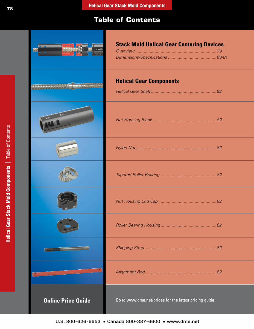
U.S. 800-626-6653 n Canada 800-387-6600 n www.dme.net
78
Go to www.dme.net/prices for the latest pricing guide.
Stack Mold Helical Gear Centering DevicesOverview ..................................................................79Dimensions/Specifications ........................................80-81
Helical Gear Components
Nut Housing Blank .....................................................82
Shipping Strap ...........................................................82
Alignment Rod ...........................................................82
Online Price Guide
Helical Gear Shaft ......................................................82
Nut Housing End Cap ................................................82
Nylon Nut ...................................................................82
Tapered Roller Bearing ...............................................82
Roller Bearing Housing ..............................................82
Table of Contents
Helic
al G
ear
Stac
k M
old
Com
pone
nts
| T
able
of C
onte
nts
Helical Gear Stack Mold Components

U.S. 800-626-6653 n Canada 800-387-6600 n www.dme.net
79
D-M-E Design and Engineering Expertise
Decades of Design and Engineering Expertise at Your Service
D-M-E has decades of design and engineering expertise to assist you in design and development of stack molds.
Our Helical Gears are the industry standard with decades of proven applications in a wide variety of applications and plastic resins. Our Helical Gear housings and assemblies greatly simplify the design and development of stack molds, leaving you more time to concentrate on the core and cavity details.
Off-the-shelf components are available when you need them.
D-M-E quality ensures reliability and inter-changeability of all components.
D-M-E engineers and designers are available to assist you with your questions whether you are building your first stack mold or challenging multi-level stack molds with complex mold actions.
D-M-E even offers complete design services (up to the cores and cavities) for those needing to off-load design and engineering during peak workloads.
With D-M-E, you can order individual components, complete assemblies ready for installation, or complete systems including design and engineering.
D-M-E is with you every step of the way!
Send your request or question to D-M-E Applications Engineering: [email protected], and we will take it from there.
Mold closed
Mold open
Helical Gear Stack Mold Centering Devices ensure that both parting lines open the same distance simultaneously.
D-M-E Helical Gear housings and assemblies
greatly simplify the design and development
of stack molds — leaving you more time
to concentrate on core and cavity details.
Helical Gear Stack Mold Com
ponents | D-M
-E Design and Engineering Expertise
Helical Gear Stack Mold Components
Helical Gear Stack Mold Centering Device Set-up and Maintenance Guide available upon request or at www.dme.net/hgguide

U.S. 800-626-6653 n Canada 800-387-6600 n www.dme.net
80
(OPENING PER SIDE)
(TOP OF SUPPORT PLATE TO CENTER OF MOLD)
A17 (MAX)
A2 (MIN), A3 (MAX)
(PLATE THICKNESS)
S5TD2
TD2 S5
S5
S5
C2 (LENGTH OF NUT HOUSING)
A12A11A10
A4
A6
A7
A9
B1 (TOTAL SHUT HEIGHT)
A15
A8 (MIN)
A9
A9A9
B4
RELIEF AREA
S2
B3
A15
A13 A14
B2
STRIPPER PLATE CAVITY PLATE
MOVING SIDE
PART
ING
LINE
#2
A5A18 (MIN)A19 (MIN)
A16 (MIN)
CENT
EROF
MOL
D
TD1TD2 S5
S5S2
TD2TD1
TD1S2
TD1S2
1.00 RELIEFSEECROSSHATCHEDAREAS
CORE BACKING PLATEOR EJECTOR BOX
CORE RET.PLATE
HOT RUNNER SYSTEM
A1 (MAX)
S5 S5
S5 S5
TD2
TD2
C1 (LENGTH OF HELICAL GEAR SHAFT)
RELIEF AREA
CAVITY PLATE STRIPPER PLATE
STATIONARY SIDE
PART
ING
LINE
#1
CENT
EROF
MOL
D
TD1S2
TD1S2
CORE RET.PLATE
CORE BACKING PLATEOR EJECTOR BOX
Stack Mold Helical Gear Centering Devices
HG28 HG38
S2 Socket HeaD cap Screw M10 x 75mm (part # M1075SH) M12 x 110mm (part # M12110SH)S5 Socket HeaD cap Screw M10 x 75mm (part # M1075SH) M12 x 110mm (part # M12110SH)
TD1 tubular Dowel Ø14mm x 10mm (part # pH1410) Ø18mm x 12mm (part # pH1812)TD2 tubular Dowel Ø14mm x 10mm (part # pH1410) Ø18mm x 12mm (part #pH1812)
Mounting Screws and Dowels
Helic
al G
ear
Stac
k M
old
Com
pone
nts
| S
tack
Mol
d He
lical
Gea
r Cen
terin
g D
evic
esHelical Gear Stack Mold Components

U.S. 800-626-6653 n Canada 800-387-6600 n www.dme.net
81
Stack Mold Helical Gear Centering Devices
configuration calculation Sheet available from D-M-e applications engineering to help determine the lengths of the Helical Gear Shaft and Nut Housing based on mold size, and required parting line openings per side.
HG28-1000 HG38-1200 HG38-1500
a1 1000 1200 1500a2 245 296 296a3 436 520 670a4 12 15 15a5 5 5 5a6 47 60 60a7 37 48 48a8 60 75 75a9 22 29 29
a10 70 90 90a11 55 70 70a12 15 20 20a13 35 45 45a14 45 57 57a15 95 120 120a16 124 155 155a17 376 445 595a18 5 5 5a19 5 5 5
Constant Dimensions
RESTRiCTiONSIF: b4 1/2 x b1tHeN: Impossible configuration.
Decrease b4 or increase b1.
IF: b3 < a6tHeN: Impossible configuration. Increase b3.
IF: b2 1/2 x b1tHeN: Impossible configuration. Decrease b2.
HG28 HG38
b1b2b3b4
input Data
C1 = 2 x (A16 + B2)IF: c1 > (b1 – 10) tHeN: Gear Shaft is too long.
Increase b1 (total shut height).
C2 = (B4 + A10) – (A4 + A5 + A6)IF: c2 < a2 tHeN: Nut Housing is too short.
Increase b1 (total shut height).IF: c2 > a3tHeN: Need special Nut Housing, longer than a3.IF: c2 > 1/2 x b1 – (a4 + a5 + a6 + a19)tHeN: Nut Housing is too long.
Increase b1 (total shut height).
HG28 HG38
c1c2
Calculated Dimensions
(OPENING PER SIDE)
(TOP OF SUPPORT PLATE TO CENTER OF MOLD)
A17 (MAX)
A2 (MIN), A3 (MAX)
(PLATE THICKNESS)
S5TD2
TD2 S5
S5
S5
C2 (LENGTH OF NUT HOUSING)
A12A11A10
A4
A6
A7
A9
B1 (TOTAL SHUT HEIGHT)
A15
A8 (MIN)
A9
A9A9
B4
RELIEF AREA
S2
B3
A15
A13 A14
B2
STRIPPER PLATE CAVITY PLATE
MOVING SIDE
PART
ING
LINE
#2
A5A18 (MIN)A19 (MIN)
A16 (MIN)
CENT
EROF
MOL
D
TD1TD2 S5
S5S2
TD2TD1
TD1S2
TD1S2
1.00 RELIEFSEECROSSHATCHEDAREAS
CORE BACKING PLATEOR EJECTOR BOX
CORE RET.PLATE
HOT RUNNER SYSTEM
A1 (MAX)
S5 S5
S5 S5
TD2
TD2
C1 (LENGTH OF HELICAL GEAR SHAFT)
RELIEF AREA
CAVITY PLATE STRIPPER PLATE
STATIONARY SIDE
PART
ING
LINE
#1
CENT
EROF
MOL
D
TD1S2
TD1S2
CORE RET.PLATE
CORE BACKING PLATEOR EJECTOR BOX
roller bearING HouSING
HelIcal Gear SHaFt (uncut and special)tapereD roller
bearING
Helical Gear Stack Mold Com
ponents | Stack Mold Helical Gear Centering D
evicesHelical Gear Stack Mold Components

U.S. 800-626-6653 n Canada 800-387-6600 n www.dme.net
82
Helical Gear Components
Nut HouSING eND cap
Nut HouSING blaNk
Nylon insert provides lubricity and an engineered fail-safe. the nylon insert will strip from the steel outer sleeve should the stack mold seize. this minimizes the potential of costly damage to the mold.Note: It is recommended that a set of
spare nylon nuts be kept on hand.
NyloN Nut (left)NyloN Nut (right)Material: outer Sleeve – Steel Nylon Insert – High-strength nylon
Nut HouSING blaNkMaterial: aircraft aluminum Variable length; cut to match your application.
Nut HouSING eND capMaterial: aircraft aluminum
SHIppING StrapMaterial: Steel
HelIcal Gear SHaFtMaterial: pre-Hardened SteelVariable length; cut to match your application.
iTEM NUMBERSHelIcal Gear SHaFt
HG28SH1000 HG38SH1200— HG38SH1500Nut HouSING blaNk
HG28NH1000bl HG38NH1200bl— HG38NH1500blNut HouSING eND cap
HG28NHc HG38NHcNyloN Nut
HG28NNl (left) HG38NNl (left)HG28NNr (right) HG38NNr (right)
roller bearING HouSINGHG28rbH HG38rbH
tapereD roller bearINGHG28rb HG38rb
alIGNMeNt roDHG28ar HG38ar
SHIppING StrapHG28St HG38St
NyloN Nut(left and right)
0.3900
alIGNMeNt roDMaterial: Steel
roller bearING HouSINGMaterial: aircraft aluminum
tapereD roller bearING
Material: Industry Standard
Helical Gear Components
Helic
al G
ear
Stac
k M
old
Com
pone
nts
| H
elic
al G
ear C
ompo
nent
sHelical Gear Stack Mold Components

D-M-E 2-Stage Ejectors
POSITIVE, PRECISION CONTROL
OF TwO-STAGE EjECTION
2-Stage Ejectors
Benefits ............................................................. 84 Selection Guidelines.......................................... 85 Sequencing .................................................. 86-87 Application Examples ................................... 88-90 Assembly & Installation, Top Last ................. 91-92 Component Information, Top Last ................ 93-94 Assembly & Installation, Bottom Last .......... 95-96 Component Information, Bottom Last ......... 97-99 Component Information .................................. 100 2-Stage Ejection Installation .............................101 2-Stage Single-Stroke Ejector .......................... 102 Adapter with Screw ........................................ 102
Table of Contents

U.S. 800-626-6653 n Canada 800-387-6600 n www.dme.net
84
Benefits
2-St
age
Ejec
tors
| B
enef
its2-Stage Ejectors
Positive, Precise Plate Control
D-M-E 2-Stage Ejectors (TS) adapt to a number of mold base
sizes and plate thicknesses. They are available in two ejection
sequences: Top Last (TL) and Bottom Last (BL). Each ejection
sequence is available in three sizes to accommodate most
standard D-M-E mold bases. The stroke range for each ejection
stage is determined and fixed by the customer by cutting the
Center Rod to the desired length (both TL and BL types)
and by also cutting the Travel Sleeve to the desired length
(BL type only). Once installed, the D-M-E 2-Stage Ejector
ensures positive, precise control of the sequence and distance
of each stroke of the two ejector plates. Once installed, there
are no adjustments that can be accidentally changed.
Benefits
n Both the first stage and second stage strokes are set independently
n Easy set-up and installation
n Fixed strokes cannot be tampered with or accidentally modified
n Internal installation – avoids interferences with water line connectors and externally mounted components
n Utilizes latching mechanism similar to D-M-E Internal Latch Lock for smooth operation and guidance
n Three sizes to choose from for each style, to accommodate most standard D-M-E mold bases
n Hardened steel components for long life
Top Last Subcomponents
NOTE: puller pins are not shown. puller pins must be purchased separately.
Bottom Last Subcomponents
TRAVEL SLEEVE
BODY FOR CAM FINGERSCENTER ROD
TRAVEL SLEEVE
BODY FOR CAM FINGERS
CENTER ROD
LOCKING RING

U.S. 800-626-6653 n Canada 800-387-6600 n www.dme.net
2-Stage Ejectors 85
2-Stage Ejectors | Size and Quantity Selection Guidelines
Size and Quantity Selection Guidelines
n Select 20mm diameter (small), 26mm diameter (medium), or 32mm diameter (large) 2-Stage Ejector based on the width of the mold base (large molds, thick plates or heavy load applications may require the next size assembly).
n Determine the travel range for each ejection stroke (first and second), being careful not to exceed the maximum stroke specified for the chosen 2-Stage Ejector style and size. This selection is based on the specific application.
n In general, a minimum of two 2-Stage Ejectors are required. For larger molds, thick plates, or an application where loads are near maximum, additional assemblies and/or larger assemblies may be required. An application must never exceed the maximum recommended load values.
n A balanced load must be maintained to avoid cocking and binding which could cause severe overloading. Only one size of 2-Stage Ejectors should be used in each mold base.
2-StaGe MaXIMuM ejector baSIc recoMMeNDeD recoMMeNDeD aSSeMbly ceNter Stroke 1 Stroke 2 MaXIMuM loaD ValueS (per aSS’y) iTEM NUMBER roD DIa MINIMuM MaXIMuM MINIMuM MaXIMuM MolD baSe wIDtH StatIc DyNaMIc
tS tl 20 a 20mm (Small)
1.0 79.0 4.0 79.0
up to 200mm, 1 tl-20 mm up to 450mm, 2 tl-20 5.8 kN 0.58 kN
.04 3.11 .16 3.11
up to 8", 1 tl 20 in
up to 18", 2 tl 20 1300 lbf 130.0 lbf
tS tl 26 a 26mm (Medium)
1.0 84.0 6.0 84.0
up to 450mm, 1 tl 26 mm
up to 600mm, 2 tl 26 10.8 kN 1.08 kN
.04 3.31 .24 3.31
up to 18", 1 tl 26 in
up to 26", 2 tl 26 2428 lbf 242.8 lbf
tS tl 32 a 32mm (large)
1.0 92.0 8.0 92.0
up to 600mm, 1 tl 32 mm
up to 900mm, 2 tl 32 19.6 kN 1.96 kN
.04 3.62 .31 3.62
up to 26", 1 tl 32 in
up to 35.5", 2 tl 32 4406 lbf 440.6 lbf
tS bl-20 a 20mm (Small)
8.0 82.0 12.0 82.0
up to 200mm, 1 bl-20 mm
up to 450mm, 2 bl-20 5.8 kN 0.58 kN
.32 3.23 .47 3.23
up to 8", 1 bl-20 in
up to 18", 2 bl-20 1300 lbf 130.0 lbf
tS bl-26 a 26mm (Medium)
10.0 92.0 18.0 92.0
up to 450mm, 1 bl-26 mm
up to 600mm, 2 bl-26 10.8 kN 1.08 kN
.40 3.62 .71 3.62
up to 18", 1 bl-26 in up to 26", 2 bl-26 2428 lbf 242.8 lbf
tS bl-32 a 32mm (large)
12.0 102.0 24.0 102.0
up to 600mm, 1 bl-32 mm
up to 900mm, 2 bl-32 19.6 kN 1.96 kN
.47 4.02 .95 4.02
up to 26", 1 bl-32 in
up to 35.5", 2 bl-32 4406 lbf 440.6 lbf
2-STAGE EJECTOR TOP LAST (TS TL)
2-STAGE EJECTOR BOTTOM LAST (TS BL)
*puller pins are not included with bl assemblies and must be ordered separately.
*
*
*
View a 2-Stage Ejectors animation at www.dme.net/2stage

U.S. 800-626-6653 n Canada 800-387-6600 n www.dme.net
2-Stage Ejectors 86
Top Last Sequencing
2-St
age
Ejec
tors
|
Top
Last
Seq
uenc
ing
SUPPORT PLATE
2. First Ejector Stroke After a predetermined amount of travel, the latch mechanism latches onto the Center Rod, thereby fixing the position of the bottom (moving platen side) ejector plate assembly.
3. Second Ejector Stroke The top (stationary platen side) ejector plate assembly continues to move through the “second” (or remaining) stroke until the top ejector plate assembly contacts the bottom of the support plate.
1. Ejector Plates Back
Patent No. 6.575.730 Patent No. 6.106.271 (Additional patents pending)

U.S. 800-626-6653 n Canada 800-387-6600 n www.dme.net
2-Stage Ejectors 87
Bottom Last Sequencing
2-Stage Ejectors | Bottom Last Sequencing
1. Ejector Plates Back
2. First Ejector Stroke After a predetermined amount of travel, the latch mechanism latches onto the Center Rod, thereby fixing the position of the top (stationary platen side) ejector plate assembly.
3. Second Ejector Stroke The bottom (moving platen side)
ejector plate assembly continues to move through the “second” (or remaining) stroke until the bottom ejector plate assembly contacts the top ejector plate assembly.
Patent No. 6.575.730 Patent No. 6.106.271 (Additional patents pending)

U.S. 800-626-6653 n Canada 800-387-6600 n www.dme.net
2-Stage Ejectors 88
2-St
age
Ejec
tors
|
Appl
icat
ion
Exam
ples
Application Examples
1. Ejector Plates Back 2. First Ejector Stroke 3. Second Ejector Stroke
1. Ejector Plates Back 2. First Ejector Stroke 3. Second Ejector Stroke
2-Stage Ejector Bottom Last Application Example 11. First ejector stroke lifts cavity plate and ejector sleeve. Center pin remains back. Part is free to be ejected.
2. Second stroke moves the ejector sleeve, releasing the part from cavity. This configuration is recommended for parts with outside details with smooth or round edges.
2-Stage Ejector Bottom Last Application Example 21. First ejector stroke pulls the central core pin and sleeve forward. Part is released from cavity.
2. Second stroke pulls the center pin and part forward. Because of plastic elasticity the part is stripped from core. Recommended for parts with an inner undercut – a circular detail placed on the edge (for example, inward undercut).

U.S. 800-626-6653 n Canada 800-387-6600 n www.dme.net
89
Application Examples
2-Stage Ejectors | Application Examples
2-Stage Ejectors
1. Ejector Plates Back 2. First Ejector Stroke 3. Second Ejector Stroke
1. Ejector Plates Back 2. First Ejector Stroke 3. Second Ejector Stroke
2-Stage Ejector Bottom Last – TSBL Application Example 31. First ejector stroke moves forward the cavity plate with inner plate. This movement is forcing the edge to move inward.
At the end of the stroke the edge clears the inner undercut.
2. Second stroke actuates the ejector pin. This releases the part from the core. This configuration is recommended for parts with non-circular deep undercut details.
2-Stage Ejector Bottom Last – TSBL Application Example 41. First ejector stroke lifts the collapsible core off the center pin. Collapse segments retract. After a certain traveling distance,
when puller pin is clearing the inner side of segments, the positive collapse sleeve is actuated for positive collapse.
2. Second stroke moves the stripper plate past the end of the core so the part can be ejected from the mold. This configuration is recommended for complex undercuts, collapsible core applications.

U.S. 800-626-6653 n Canada 800-387-6600 n www.dme.net
90
Application Examples
2-St
age
Ejec
tors
|
Appl
icat
ion
Exam
ples
2-Stage Ejectors
1. Ejector Plates Back 2. First Ejector Stroke 3. Second Ejector Stroke
1. Ejector Plates Back 2. First Ejector Stroke 3. Second Ejector Stroke
2-Stage Ejector Bottom Last – TSBLApplication Example 51. First ejector stroke moves the angle slide up. As a result the horizontal slide with the exterior detail pulls away
from the part.
2. Second stroke actuates the ejector pin. Part is lifted behind the inner cavity. This configuration is recommended for outside deep details and thru holes.
2-Stage Ejector Top Last – TSTLApplication Example
1. First ejector stroke lifts part, central pin and ejector bushing out of “B” plate.
2. Second stroke actuates the ejector bushing and the part is pushed out of the central pin core. This configuration is recommended for inner undercuts with round, smooth edges.

U.S. 800-626-6653 n Canada 800-387-6600 n www.dme.net
91
Assembly and Installation Information – Top Last
2-Stage Ejectors | Assembly and Installation Inform
ation – Top Last2-Stage Ejectors
S3
CENTER ROD LENGTH (TO BE CUT BY MOLDMAKER)
STROKE 1 (H1)
L26
(L5–L7) +0.01/.0004S2
BOTTOM CLAMP PLATE
BOTTOM EJECTOR PLATE (BEP)
TOP EJECTOR PLATE (TEP)
+0.01/.0004
+0.01/.0004
MOVING PLATEN SIDE
TOP EJECTOR RETAINER (TER)
BOTTOM EJECTOR RETAINER (BER)
D8+1.0/.039+0.8/.031
D4 +0.01/.0004
D2 +0.01/.0004
S1
STROKE 1 (H1) + STROKE 2 (H2)
D8 +0.01/.0004
S4 +0.01/.0004
STATIONARY PLATEN SIDE
SUPPORT PLATE
D20 +1.0/.039 +0.8/.031
D8 +0.6/.024 +0.4/.066
S5 +0.01/.0004
+0.01/.0004
n tolerances depicted here are installation tolerances
n See component detail drawings for specific component tolerancesn refer to applicable tables for nominal dimension

U.S. 800-626-6653 n Canada 800-387-6600 n www.dme.net
2-Stage Ejectors 92
Assembly and Installation Information – Top Last
2-St
age
Ejec
tors
|
Asse
mbl
y an
d In
stal
latio
n In
form
atio
n –
Top
Last
iTEM ceNter ceNter H1 – Stroke 1(2) H2 – Stroke 2 (3)
NUMBER roD DIa roD leNGtH MINIMuM MaXIMuM MINIMuM MaXIMuM
tS tl-20 a
20mm 262.96 1.0 79.0 4.0 79.0 mm
(Small) 10.353 .04 3.11 .16 3.11 in
tS tl-26 a
26mm 285.32 1.0 84.0 6.0 84.0 mm
(Medium) 11.233 .04 3.31 .24 3.31 in
tS tl-32 a
32mm 316.68 1.0 92.0 8.0 92.0 mm
(large) 12.468 .04 3.62 .31 3.62 in
2-STAGE EJECTOR TOP-LAST (TS-TL)
n All 2-Stage Ejectors in a mold must be cut to the same strokes.
n It is recommended that guided ejection be used.
n Ejector speed must be controlled, ensuring that
excessive shock loading does not occur.
n 2-Stage Ejectors are not suitable for severe load conditions.
n 2-Stage Ejectors must not be exposed to temperatures that
exceed 150°C (300°F) at any time.
n Lubricate all metal-to-metal contact areas initially and
periodically as required. A good grade of moldmakers
non-melting type grease for the appropriate temperature
should be used.
Assembly and installation Guidelinesn At end of first stroke, Body for Cam Fingers must seat firmly
against Center Rod flange.
n The Body must not apply full static pressure against Cam Fingers
at end of first stroke.
n The moldmaker must cut and/or grind the Center Rod to the
required length prior to installation of the 2-Stage Ejector
assembly into the mold base. Do not cut off more than the minimum
stroke (H2). The recommended tolerance on the Center Rod length
after the customer has cut the Center Rod is +0/-0.02mm or less.
n Stroke 1 (H1) is reduced by cutting and/or grinding the moving
platen end of the Center Rod.
n Stroke 2 (H2) is reduced by cutting and/or grinding the stationary
platen end of the Center Rod. Minimum H2 specified in table does
not include additional stop pins to stationary-side spacer plate.
To reduce H2 even further than what is specified in table, add
stop pins.
iTEM ceNter NUMBER roD DIa BEP BER TEP TER S1 S2 S3 S4 S5
tS tl-20 a
20mm 25.40 12.70 25.40 12.70 8.00 8.00 8.00 3.00 4.76 mm
(Small) 1.000 .500 1.000 .500 .315 .315 .315 .118 .188 in
tS tl-26 a
26mm 28.58 12.70 28.58 12.70 10.00 10.00 10.00 4.00 4.76 mm
(Medium) 1.125 .500 1.125 .500 .394 .394 .394 .157 .188 in
tS tl-32 a
32mm 28.58 15.88 28.58 15.88 15.00 12.00 12.00 4.00 4.76 mm
(large) 1.125 .625 1.125 .625 .591 .472 .472 .157 .188 in
2-STAGE EJECTOR TOP-LAST (TS-TL)
Top Last – TSTL

U.S. 800-626-6653 n Canada 800-387-6600 n www.dme.net
2-Stage Ejectors 93
Component Information – Top Last
2-Stage Ejectors | Component Inform
ation – Top Last
Center Rod – CR
L2L3
L1
D2D17
L22
C1
D1
R
D2
aSSeMbly ceNter coMpoNeNt D1 D2 D17 L1* L2 L3 L22** C1 R iTEM NUMBER roD DIa iTEM NUMBER DIa DIa DIa leNGtH tHIck leNGtH leNGtH cHaMFer raDIuS
tS-tl-20 20mm tS-tl-20-cr
33.0 20.0 –0.01 5.0 265 10.0 18.74 72.0 1.5 .4 mm
(Small) 1.30 0.787 –.0004 .20 10.43 .39 .738 2.83 .06 .02 in
tS-tl-26 26mm tS-tl-26-cr 42.0 26.0 –0.01 6.0 290 12.0 22.93 76.0 2.0 .8 mm (Medium) 1.65 1.024 –.0004 2.4 11.42 .47 .903 2.99 .08 .03 in
tS-tl-32 32mm tS-tl-32-cr 53.0 32.0 –0.01 6.0 320 15.0 28.25 82.0 2.5 .8 mm (large) 2.09 1.260 –.0004 .24 12.60 .59 1.112 3.23 .10 .03 in
*cutoff on both ends of center rod only per installation data.** Final length must have tolerance of –0.02mm (–0.001in) after moldmaker has cut the center rod to the desired length.
aSSeMbly ceNter coMpoNeNt D8 D9 D20 L10 L25 L26 C4 iTEM NUMBER roD DIa iTEM NUMBER DIa DIa DIa leNGtH leNGtH tHIck cHaMFer
tS-tl-20 20mm tS-tl-20-tS 43.0–0.03 34.0 50.8 79.96 12.70 6.00 –0.01 .5 mm (Small) 1.693–0.001 1.34 2.00 3.148 .500 .236 –.0004 .02 in
tS-tl-26 26mm tS-tl-26-tS 54.0–0.03 43.0 63.0 85.32 12.70 8.00 –0.01 .5 mm (Medium) 2.126 –0.001 1.69 2.48 3.359 .500 .315 –.0004 .02 in
tS-tl-32 32mm tS-tl-32-tS 68.0–0.03 54.0 78.0 93.68 15.88 10.00 –0.01 .5 mm (large) 2.677 –0.001 2.13 3.07 3.688 .625 .394 –.0004 .02 in
Travel Sleeve – TS
C4 x 45°
L10
L25L26
D20 D8 (2 places)D9
D8
NOTES: all dimensions shown for components are intended for drawing layout purposes only and in some cases have been rounded off. also, where the same diameter dimension is shown for parts that fit together, the tolerances create the appropriate clearance or fit.

U.S. 800-626-6653 n Canada 800-387-6600 n www.dme.net
2-Stage Ejectors 94
Component Information – Top Last
2-St
age
Ejec
tors
|
Com
pone
nt In
form
atio
n –
Top
Last
30º
30º
C3 x 45°
L5
D6 D7 D4
D17
L23D18
L7
L24
L24
L24 L24
D19
aSSeMbly ceNter coMpoNeNt D4 D6 D7 D17 D18 D19 iTEM NUMBER roD DIa iTEM NUMBER DIa DIa DIa DIa DIa DIa
tS-tl-20 20mm tS-tl-20-bD 66.00 –0.03 34.0 20.0 10.6 6.4 53.0 mm (Small) 2.598 –0.001 1.34 .79 .42 .25 2.09 in
tS-tl-26 26mm tS-tl-26-bD 84.00 –0.03 43.0 26.0 13.8 8.7 67.0 mm (Medium) 3.307 –0.001 1.69 1.02 .54 .34 2.64 in
tS-tl-32 32mm tS-tl-32-bD 105.00 –0.03 54.0 32.0 16.8 10.8 85.0 mm (large) 4.134 –0.001 2.13 1.26 .66 .43 3.35 in
aSSeMbly ceNter coMpoNeNt L5 L7 L23 L24 C3 iTEM NUMBER roD DIa iTEM NUMBER leNGtH leNGtH leNGtH leNGtH cHaMFer
tS-tl-20 20mm tS-tl-20-bD 104.0 94.0 6.1 30.0 .5 mm (Small) 4.09 3.70 .24 1.18 .02 in
tS-tl-26 26mm tS-tl-26-bD 116.0 103.0 8.2 37.0 .5 mm
(Medium) 4.57 4.06 .32 1.46 .02 in
tS-tl-32 32mm tS-tl-32-bD 131.0 113.4 10.2 47.0 .6 mm
(large) 5.16 4.46 .40 1.85 .02 in
NOTES: all dimensions shown for components are intended for drawing layout purposes only and in some cases have been rounded off. also, where the same diameter dimension is shown for parts that fit together, the tolerances create the appropriate clearance or fit.
Cam Finger Replacement Kit – KTWith (6) Cam Fingers, and (8) Locking Pins
BLIND SLOT FOR LOCKING PIN
aSSeMbly ceNter kIt iTEM NUMBER roD DIa iTEM NUMBER
tS-tl-20 20mm tS-tl-20-kt
(Small)
tS-tl-26 26mm tS-tl-26-kt
(Medium)
tS-tl-32 32mm tS-tl-32-kt
(large)
Cam Fingers Locking Pin – LP
Body for Cam Fingers – BD (Body only without Cam Fingers)

U.S. 800-626-6653 n Canada 800-387-6600 n www.dme.net
2-Stage Ejectors 95
Assembly and Installation Information – Bottom Last
2-Stage Ejectors | Assembly and Installation Inform
ation – Bottom Last
n tolerances depicted here are installation tolerances
n See component detail drawings for specific component tolerancesn refer to applicable tables for nominal dimension
D4
MOVING PLATEN SIDE
STATIONARY PLATEN SIDE
T4
STROKE 1(H1)
BOTTOM EJECTOR RETAINER (BER)
STROKE 2(H2)
S3 +0.01/.0004
CENTER RODLENGTH
(TO BE CUT BYMOLDMAKER)
D8 +0.01/.0004
+0.01/.0004S2
D2 +0.01/.0004S1 +0.01/.0004
D1 +0.01/.0004
SUPPORT PLATE
+0.01/.0004
D8+1.0/.039+0.8/.031
TOP EJECTOR PLATE (TEP)
TOP EJECTOR RETAINER (TER)
D5 +0.6/.024 +0.4/.016
BOTTOM EJECTOR PLATE (BEP )
BOTTOM CLAMP PLATE
L6
L7 +0.01/.0004
D11+1.0/.04+0.5/.02
S4
D8+1.0/.039+0.8/.031
+0.01/.0004
S5 +0.01/.0004

U.S. 800-626-6653 n Canada 800-387-6600 n www.dme.net
2-Stage Ejectors 96
Assembly and Installation Information – Bottom Last
2-St
age
Ejec
tors
|
Asse
mbl
y an
d In
stal
latio
n In
form
atio
n –
Botto
m L
ast
iTEM ceNter NUMBER roD DIa BEP BER TEP TER T4 S1 S2 S3 S4 S5
iTEM ceNter ceNter traVel H1 – STROKE 1(3) H2 – STROKE 2 (4)
NUMBER roD DIa roD leNGtH SleeVe leNGtH MINIMuM MaXIMuM MINIMuM MaXIMuM
tS bl-20 a
20mm 277.96 86.00 8.0 82.0 12.0 82.0 mm
(Small)
10.943 3.386 .32 3.23 .47 3.23 in
tS bl-26 a
26mm 311.32 94.00 10.0 92.0 18.0 92.0 mm
(Medium)
12.257 3.701 .39 3.62 .71 3.62 in
tS bl-32 a
32mm 352.21 105.00 12.0 102.0 24.0 102.0 mm
(large)
13.867 4.134 .47 4.02 .94 4.02 in
2-STAGE EJECTOR BOTTOM LAST (TS BL)
tS bl-20 a
20mm 25.40 12.70 25.40 12.70 M6 11.00 8.00 10.00 4.76 4.00 mm
(Small)
1.000 .500 1.000 .500 M6 .433 .315 .394 1.86 .157 in
tS bl-26 a
26mm 28.58 12.70 28.58 12.70 M8 14.00 10.00 12.00 4.76 4.00 mm
(Medium)
1.125 .500 1.125 .500 M8 .551 .394 .472 1.86 .157 in
tS bl-32 a
32mm 28.58 15.88 28.58 15.88 M10 17.00 12.00 14.00 6.29 6.00 mm
(large)
1.125 .625 1.125 .625 M10 .669 .472 .551 .248 .238 in
2-STAGE EJECTOR BOTTOM LAST (TS BL)
n Ejector speed must be controlled, ensuring that excessive
shock loading does not occur.
n 2-Stage Ejectors are not suitable for severe load conditions.
n 2-Stage Ejectors must not be exposed to temperatures that
exceed 150°C (300°F) at any time.
n Lubricate all metal-to-metal contact areas initially and
periodically as required. A good grade of moldmakers
non-melting type grease for the appropriate temperature
should be used.
n A minimum of (4) Puller Pins should be used with each mold.
Larger molds may require additional Puller Pins.
n The moldmaker must cut and/or grind the Puller Pins to the
required length.
n Puller Pins are not included with Bottom Last Assemblies
and must be ordered separately.
Assembly and installation Guidelinesn At end of second stroke, Body for Cam Fingers must seat firmly
against Center Rod head or spacer plate.
n The moldmaker must cut and/or grind the Center Rod to the
required length prior to installation of the 2-Stage Ejector assembly
into the mold base. The recommended tolerance on the Center Rod
length after the customer has cut the Center Rod is +0/-0.02mm or
less.
n The moldmaker must cut and/or grind the Travel Sleeve to
the required length prior to installation of the 2-Stage Ejector
assembly into the mold base.
n Stroke 1 (H1) is reduced by cutting and/or grinding the moving platen
end of the Center Rod.
n Stroke 2 (H2) is reduced by cutting and/or grinding the moving
platen end of both the Center Rod and the Travel Sleeve.
n All 2-Stage Ejectors in a mold must be cut to the same strokes.
n It is recommended that guided ejection be used.
Bottom Last – TSBL

U.S. 800-626-6653 n Canada 800-387-6600 n www.dme.net
2-Stage Ejectors 97
Component Information – Bottom Last
2-Stage Ejectors | Component Inform
ation – Bottom Last
Center Rod – CR
C1 x 45°
D1
L3
L1
L2
D2D17
L21Wrench
Flats
aSSeMbly ceNter coMpoNeNt D1 D2 D17 L1* L2 L3 L21 C1 iTEM NUMBER roD DIa iTEM NUMBER DIa DIa DIa leNGtH tHIck leNGtH FlatS cHaMFer
tS-bl-20 20mm
tS-bl-20-cr 34.0 –0.01 20.0 –0.01 6.0 280.0 10.0+0.02 93.66 16.0 1.0 mm
(Small) 1.339 –.0004 .787 –.0004 .24 11.02 .394+.001 3.687 .63 .04 in
tS-bl-26
26mm tS-bl-26-cr
44.0 –0.01 26.0 –0.01 6.0 314.0 12.0+0.02 105.67 20.0 1.0 mm (Medium) 1.732 –.0004 1.024 –.0004 .24 12.36 .472+.001 4.160 .79 .04 in
tS-bl-32
32mm tS-bl-32-cr
58.0 –0.01 32.0 –0.01 8.0 354.0 14.0+0.02 118.80 27.0 1.5 mm (large) 2.283 –.0004 1.260 –.0004 .31 13.94 .551+.001 4.677 1.06 .06 in
*cutoff on small diameter end only per installation data.
NOTES: all dimensions shown for components are intended for drawing layout purposes only and in some cases have been rounded off. also, where the same diameter dimension is shown for parts that fit together, the tolerances create the appropriate clearance or fit.
Travel Sleeve – TSL10
D8 D9 T1
aSSeMbly ceNter coMpoNeNt D8 D9 L10* T1 iTEM NUMBER roD DIa iTEM NUMBER DIa DIa leNGtH tHreaD
tS-bl-20 20mm tS-bl-20-tS 43.00 –0.03 34.0 86.0 M43.2 mm (Small) 1.693 –0.001 1.34 3.39 x 1.25 in
tS-bl-26 26mm tS-bl-26-tS 54.00 –0.03 43.0 94.0 M54.2 mm (Medium) 2.126 –0.001 1.69 3.70 x 1.25 in
tS-bl-32 32mm tS-bl-32-tS 68.00 –0.03 54.0 105.0 M68.25 mm (large) 2.677 –0.001 2.13 4.13 x 1.5 in
* Supplied to provide maximum travel with no cutoff. to reduce travel in Stroke 2 (H2), cut threaded end per installation data.

U.S. 800-626-6653 n Canada 800-387-6600 n www.dme.net
2-Stage Ejectors 98
Component Information – Bottom Last
2-St
age
Ejec
tors
|
Com
pone
nt In
form
atio
n –
Botto
m L
ast
Body for Cam Fingers – BD (Body only without Cam Fingers)
0.5 x 45˚(.02)
R1
D4D5
L5
L6L7
D6
D7
aSSeMbly ceNter coMpoNeNt D4 D5 D6 D7 L5 L6 L7 R1 iTEM NUMBER roD DIa iTEM NUMBER DIa DIa DIa DIa leNGtH tHIck tHIck raDIuS
tS bl 20 20mm tS bl-20-bD 58.20 –0.03 50.8 –0.2 34.00 20.00 106.46 22.70 6.0 –0.01 .4 mm
(Small) 2.291 –0.001 2.00 –.008 1.339 .787 4.191 .894 .236 –.0004 .02 in
tS bl 26 26mm tS bl-26-bD 70.00 –0.03 62.6 –0.2 43.00 26.00 121.22 22.70 6.0 –0.01 .4 mm (Medium) 2.756 –0.001 2.46 –.008 1.693 1.024 4.772 .894 .236 –.0004 .02 in
tS bl 32 32mm tS bl-32-bD 87.00 –0.03 78.0 –0.2 54.00 32.00 139.70 28.88 7.0 –0.01 .4 mm (large) 3.425 –0.001 3.07 –.008 2.126 1.260 5.500 1.137 .276 –.0004 .02 in
NOTES: all dimensions shown for components are intended for drawing layout purposes only and in some cases have been rounded off. also, where the same diameter dimension is shown for parts that fit together, the tolerances create the appropriate clearance or fit.
30°
150°
15°
D13 (BOLT DIAMETER)
L16
D12T3
D15
D14
L17
BOLT SUPPLIED WITH LOCKING CLAMP
aSSeMbly ceNter coMpoNeNt D12 D13 D14 D15 L16 L17 T3 iTEM NUMBER roD DIa iTEM NUMBER DIa DIa DIa DIa leNGtH leNGtH tHreaD
tS-bl-20 20mm tS-bl-20-lr 72.0 57.4 10.5 6.4 10.0 6.0 M43.2 mm
(Small) 2.83 2.26 .41 .25 .39 .24 x 1.25 in
tS-bl-26 26mm tS-bl-26-lr 90.0 72.0 13.8 8.6 13.0 8.1 M54.2 mm
(Medium) 3.54 2.83 .54 .34 .51 .32 x 1.25 in
tS-bl-32 32mm tS-bl-32-lr 112.0 90.0 16.8 10.8 16.0 10.1 M68.25 mm
(large) 4.41 3.54 .66 .43 .63 .40 x 1.5 in
Locking Ring – LR

U.S. 800-626-6653 n Canada 800-387-6600 n www.dme.net
2-Stage Ejectors 99
Component Information – Bottom Last
2-Stage Ejectors | Component Inform
ation – Bottom Last
Cam Finger Replacement Kit – KT With (6) Cam Fingers, and (8) Locking Pins
NoteS: all dimensions shown for components are intended for drawing layout purposes only and in some cases have been rounded off. also, where the same diameter dimension is shown for parts that fit together, the tolerances create the appropriate clearance or fit.
Cam Fingers Locking Pin – LP
BLIND SLOT FOR LOCKING PIN
D10
L12
L13
L14L15 T3
D11L22Wrench
Flats
Note: a minimum of (4) puller pins should be used with each mold. larger molds may require additional puller pins. puller pins are not included with bl assemblies and must be ordered separately.
aSSeMbly ceNter kIt iTEM NUMBER roD DIa iTEM NUMBER
tS-bl-20 20mm tS-bl-20-kt
(Small)
tS-bl-26 26mm tS-bl-26-kt
(Medium)
tS-bl-32 32mm tS-bl-32-kt
(large)
aSSeMbly ceNter coMpoNeNt D10 D11 L12 L13 L14 L15 L22 T3 iTEM NUMBER roD DIa iTEM NUMBER DIa DIa leNGtH leNGtH leNGtH leNGtH FlatS tHreaD
tS-bl-20 20mm tS-bl-20-pp 29.0 18.0 136.0 125.0 107.0 30.0 26.0 M10
mm (Small) 1.14 .71 5.35 4.92 4.21 1.18 1.02 in
tS-bl-26 26mm tS-bl-26-pp 34.0 21.0 153.0 139.0 120.0 40.0 30.0 M12
mm
(Medium) 1.34 .83 6.02 5.47 4.72 1.57 1.18 in
tS-bl-32 32mm tS-bl-32-pp 43.0 26.0 171.0 154.0 138.0 50.0 36.0 M16
mm (large) 1.69 1.02 6.73 6.06 5.43 1.97 1.42 in
aSSeMbly ceNter caM FINGer iTEM roD ceNter traVel boDy For lockING replaceMeNt puller NUMBER DIa roD SleeVe caM FINGerS rING kIt pIN*
tS-bl-20 a 20mm
tS-bl-20-cr tS-bl-20-tS tS-bl-20-bD tS-bl-20-lr tS-bl-20-kt tS-bl-20-pp (Small)
26mm tS-bl-26-cr tS-bl-26-tS tS-bl-26-bD tS-bl-26-lr tS-bl-26-kt tS-bl-26-pp
tS-bl-26-a
(Medium)
32mm tS-bl-32-cr tS-bl-32-tS tS-bl-32-bD tS-bl-32-lr tS-bl-32-kt tS-bl-32-pp tS-bl-32 a
(large)
Bottom Last Replacement Component item Numbers
*puller pins are not included with bl assemblies and must be ordered separately.
aSSeMbly ceNter caM FINGer iTEM roD ceNter traVel boDy For replaceMeNt NUMBER DIa roD SleeVe caM FINGerS kIt
tS-tl-20 a 20mm tS-tl-20 cr tS-tl-20-tS tS-tl-20-bD tS-tl-20-kt
(Small)
26mm tS-tl-26-cr tS-tl-26-tS tS-tl-26-bD tS-tl-26-kt
tS-tl-26 a-
(Medium)
32mm tS-tl-32-cr tS-tl-32-tS tS-tl-32-bD tS-tl-32-kt tS-tl-32 a
(large)
Top Last Replacement Component item Numbers
Puller Pin – PP

U.S. 800-626-6653 n Canada 800-387-6600 n www.dme.net
2-Stage Ejectors 100
Component Information
2-St
age
Ejec
tors
|
Com
pone
nt In
form
atio
n
TL & BL 2-Stage Ejectors – Cam Finger Removal Guide
top last (tl)pIece oF colD-rolleD low carboN Steel
lockING pINcolD-rolleD low carboN Steel puNcH
caM FINGer
STEP 1punch is struck firmly and quickly with a hammer.
The illustrations below show one 2-Stage Ejector assembly that has been centrally located on the ejector plates.
Alternate ConfigurationsSystem Configuration for Central Ejector Rod Location
TL Assembly
BL Assembly
bottom last (bl)
NOTES:• cold rolled, low carbon steel
must be used as a removal punch to avoid damaging the cam Fingers and/or body.
• the contact surface of the punch (where it rests against the cam Finger) should be profiled with a curved surface that matches the exposed surface of the cam Finger.
• ensure that body for cam Fingers is firmly retained before attempting cam Finger removal.
STEP 2cam Finger is knocked toward the inside diameter region of the body for cam Fingers. the cam Finger pushes against the locking pin.
STEP 3a portion of locking pin breaks cleanly away and travels with the moving cam Finger toward the inside diameter of the body for cam Fingers.
STEP 4both the cam Finger and broken piece of locking pin drop into the inside diameter of the body for cam Fingers.

U.S. 800-626-6653 n Canada 800-387-6600 n www.dme.net
101
Two-Stage Ejectors – Installation
2-Stage Ejectors | Installation2-Stage Ejectors
Two-Stage Ejector – FW 1800
Fitting:1. Mount ejector rod #1 together with ejector plate.
For safety please use LOCTITE C 242.
2. Move over parts #2, 3 and 4 together and tighten up part #3 (SW2 see chart).
3. Tighten up adjusting bush #3 with assembly flange #4.
4. Fix assembly flange.
Recommended lubricants: C 135, C 160, C 170, etc.
Stroke(*)
reF d d1 d2 d3 d4 d5 d6 d7 d8 d9 *i0 i i1 i2 i3 i4 i5 i6 h1 h2 h3 k1 k2 k3 k4 k5 k6 SW1 SW2 A mm2
Fw 1800 M32X1.5 16 M12X1 M22X1 60 46 M5 32 20.6 M10 160 200 30 101 11 56 20 16 5-30 50 80 16 5 9.0 5 8 24 13 20 56
Fw 1800 M42X1.5 22 M16X1.5 M30X1.5 80 62 M6 42 28.0 M14 200 266 40 132 16 75 30 22 10-40 70 110 20 6 9.0 6 10 30 17 27 100
Fw 1800 M52X1.5 28 M20X1.5 M38X1.5 90 72 M8 53 36.0 M16 350 285 45 134 16 75 35 22 10-40 80 120 22 6 10.5 8 12 30 22 35 152
Fw 1800 M62X1.5 37 M24X1.5 M48X1.5 120 80 M8 63 44.0 M20 500 300 50 140 16 80 40 22 10-40 80 120 22 6 10.5 8 12 30 30 44 215
installation instructions:
This device is preferably screwed together with the hydraulic machine ejector. The required internal or external thread of part #1 has to be made adequately. The ejector rod #1 may not be shortened by more than length k1, if the total stroke h3, including a possible deeper run in of part #1 into part #2, is not maintained. By rotating adjustment of bush #3 the first stroke h1 is continuously adjusted. With stroke h1 both ejector pin plates are moved simultaneously. On the following stroke h2 only the second ejector pin plate movement is continued. Choose the thickness of the spacer ring #7 so that there is at least 0.05mm clearance between the ejector pin plates (see Fig. 1).
1. Ejector rod
2. Ejector sleeve
3. Adjusting bush
4. Assembly flange
5. Segments
6. Stopring
7. Spacer
*I0: length of ejector plate
d6
SW1 SW2
I
1°0
(*)(*)
MIN. 0.05
Fig. 1
d1
d7
k3
k5 k6
d4 f8
d5 3 x 120°
k4
k1
k2
I2
I4I3I6 I1
I5
d3 d8 d2
d
h2 h1
h3
1
1
1(*)
2(*)
2
HRC-60 HRC-35
SW1
d1 d9
(*)
(*)
6 2 3 4 5 7
SW1k1
Fig. 2
1
1(*)
(*)Fig. 3
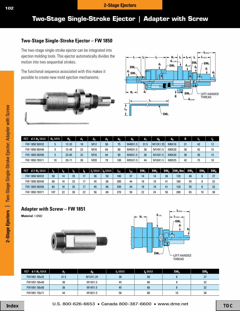
U.S. 800-626-6653 n Canada 800-387-6600 n www.dme.net
102
Two-Stage Single-Stroke Ejector | Adapter with Screw
Two-Stage Single-Stroke Ejector – FW 1850
reF d X H1 MaX H1 MIN H2 d1 d2 d3 d4 d6 d7 d8 d9 R i1 i2Fw 1850 50X32 5 12-32 18 M12 56 75 M40X1.5 31.5 M12X1.25 M6X16 31 42 12
Fw 1850 58X40 5 15-40 22 M16 64 90 M45X1.5 36 M14X1.5 M8X20 36 42 15
Fw 1850 58X56 5 25-65 22 M16 64 90 M45X1.5 36 M14X1.5 M8X20 36 58 15
Fw 1850 70X71 10 20-71 26 M20 79 100 M55X1.5 44 M16X1.5 M8X25 42 75 18
The two-stage single-stroke ejector can be integrated into ejection molding tools. This ejector automatically divides the motion into two sequential strokes.
The functional sequence associated with this makes it possible to create new mold ejection mechanisms.
reF d X H1 MaX i3 i4 i5 i6 i7 MaX i8 MaX i11 i12 SW1 SW2 SW3 SW3 Nm SW4 SW5 SW6
Fw 1850 50X32 58 14 25 17 36 50 180 37 14 14 36 120 46 6 27
Fw 1850 58X40 68 16 25 17 45 66 200 44 18 18 41 160 55 8 32
Fw 1850 58X56 84 16 25 17 45 66 250 44 18 18 41 120 55 8 32
Fw 1850 70X71 107 22 30 22 56 80 270 50 22 24 50 200 65 10 38
I1 H1
H2 d2
d3
d1 d8
I12
I11
d7d6
d4 -0.05
d-0.05
d9 4x90°
I2 I5 I6
I8 MAX
I7 MAXI4I3
SW3SW2
SW1
SW5
SW5
RLEFT-HANDEDTHREAD
SW6SW4
Adapter with Screw – FW 1851Material: 1.6582
reF d X H1 MaX d7 d8 i7 MaX i8 MaX SW5 SW6
Fw1851 50x32 31.5 M12X1.25 36 50 6 27
Fw1851 58x40 36 M14X1.5 45 66 8 32
Fw1851 58x56 36 M14X1.5 45 66 8 32
Fw1851 70x71 44 M16X1.5 56 80 10 38
SW6
SW5 LEFT-HANDED THREAD
H1
d7
d-0.05
I8 MAX
I7 MAX
d8
2-St
age
Ejec
tors
|
Two-
Stag
e Si
ngle
-Str
oke
Ejec
tor;
Adap
ter w
ith S
crew
2-Stage Ejectors

D-M-E Internal Latch Lock, Toggle -Lok, Jiffy -Jector
PRECISION CONTROL
OF mOLd PLATE OPERATION
Internal Latch Lock, Toggle-Lok, Jiffy-Jector

U.S. 800-626-6653 n Canada 800-387-6600 n www.dme.net
104
Jiffy-JectorBenefits & Ordering Information ...............................129Design Guidelines ......................................................130Operating Sequence & Installation Dimensions .......131Ejector Return Couplings ...........................................132
Toggle-LokOperating Sequence .................................................121Assembly Specifications ...........................................122Design Guidelines .....................................................123Components .............................................................124-126Special Order ............................................................127Ordering Information .................................................128
internal Latch LockBenefits .....................................................................105Selection Table ...........................................................105Application Design Guidelines ...................................106Set-Up Information ....................................................107Component Information ............................................108-110Optional Guided Ejection & Return Sleeve ...............111Accelerated Knock-Outs ............................................112Accelerated Ejectors ..................................................113-114Early Ejector Return Assembly .................................115-116Jiffy Latch-Lok™ Assemblies .....................................117-118Latch Locks & Baffle Bars .........................................119-120
Table of Contents
Go to www.dme.net/prices for the latest pricing guide.Online Price Guide
Inte
rnal
Lat
ch L
ock,
Tog
gle-
Lok,
Jiff
y-Je
ctor
| T
able
of C
onte
nts
Int. Latch Lock, Toggle-Lok, Jiffy-Jector

U.S. 800-626-6653 n Canada 800-387-6600 n www.dme.net
105
Benefits and Selection Table
D-M-E’s unique internally-mounted latch lock mechanism adapts to a number of mold base sizes and plate thicknesses. It is available in three sizes to accommodate most standard D-M-E stripper plate mold bases. Two travel ranges and two center puller pin lengths are available for each of the three latch lock sizes. Once installed, D-M-E’s internal latch locks control the sequence of one parting line opening after the first parting line has traveled a predetermined distance. After installation there are no adjustments that can be accidentally changed. The internal latch locks are most commonly used on D-M-E AX-Series stripper plate mold bases but can be used on other D-M-E stripper plate mold bases as well.
n Three diameter sizes to choose from – 28mm, 34mm, and 45mm – depending on the size of the mold and the application
n Two travel ranges and two center puller pin lengths to choose from for each of the three sizes
n Hardened steel components for longer life
n Latching mechanism has built-in travel limitation
n When latch is released, latching cams hold released stripper plate in fully traveled position
n Easy set-up of timing for latching mechanism
n Internal installation avoids interferences with water line connectors and externally mounted components
D-M-E’s internal latch lock allows control of the mold plate opening sequence on mold bases with stripper plates. It enables one plate or group of plates to be latched together while the first parting line opening occurs. Then, after a predetermined amount of travel, the latch lock releases the latched plate or group of plates for the remaining parting line or parting lines to open.
D-M-E’s internal Latch Lock Allows Precision Control of Mold Plate Latching Operation
BasicLatchSize
internal LatchLock Assemblyitem Number
Center Puller PinLength Options
Recommended MaximumStandard D-M-E
Mold Base Width
Maximum RecommendedLoad Values (Per Ass'y.)
"T" Travel Range
Minimummm in mm in
MaximumStatic Dynamic
28mmDkl-2811 5 30 140
11-7/8 in 10 kN
20 kN
30 kN
100 kg
200 kg
380 kg
DIa Dkl-2812 250
(Small) Dkl-282130 55
140Dkl-2822 250
34mmDkl-3411
6 41160
16-1/2 inDIa Dkl-3412 280(Medium) Dkl-3421
41 76160
Dkl-3422 280
45mmDkl-4511
12 58200
23-3/4 inDIaDkl-4512 310
(large) Dkl-452158
.197
1.181
.236
1.614
.472
2.283 104
1.181
2.165
1.614
2.992
2.283
4.094200
Dkl-4522 310
5.5129.8435.5129.8436.299
11.0246.299
11.0247.874
12.2057.874
12.205
mm in
See page 111 for informationregarding an additional option thatprovides guided ejection and returnof the ejector assembly with guidedejection and return sleeves.
Supplied to provide maximumtravel with no cutoff. To reducetravel between maximum andminimum, cut off slotted travellimiting sleeve on threaded endonly per installation data.
Center puller pin lengthordered must be slightlylonger than applicationrequires. Moldmaker thencuts off as required. Seeinstallation data.
A minimum of four assemblies are recommended per mold. However,for larger molds, thick plates, or an application where loads are nearmaximum, additional assemblies and/or next largest size assembliesmay be required. An application must never exceed the maximumrecommended load values. A balanced load must be maintained toavoid cocking and binding, which could cause severe overloading.Only one size latch lock assembly should be used in each mold base.
iNTERNAL LATCH LOCK SELECTiON CHART
Internal Latch Lock | Benefits and Selection TableInternal Latch Lock
u.S. patent No. 5,494,435

U.S. 800-626-6653 n Canada 800-387-6600 n www.dme.net
106
Typical Application Design Guidelines
1. Select the appropriate internal latch lock size – 28mm diameter (small), 34mm diameter (medium), or 45mm diameter (large) based on the width of the mold base, as indicated in the chart on page 105. However, large molds, thick plates or heavy load applications may require the next largest size assembly than is specified.
2. Select the appropriate travel range from the two choices for each size in the table on page 105. This selection is based on the specific application requirements for the amount of travel that must occur at one parting line prior to the latch being released. The total travel requirements are based on the amount needed for the application as explained above, plus 3mm (.12") minimum additional allowance. This added 3mm minimum will make sure the full required travel has occurred before the latch lock starts its releasing action.
3. Select the appropriate length for the center puller pin from the two choices for each size in the chart. The length of the pin is determined by the specific application including the mold base plate thicknesses, where the pin will be mounted, etc. If possible, the center puller pin should be mounted in the support plate. However, some applications require the center puller pin to be mounted in the bottom clamping plate. This will depend on the travel or the length of the split sleeve component which controls the travel and the plate thicknesses in the mold base.
4. The answers to the above items (1-3) should establish a specific item number assembly from the table on page 105.
5. A minimum of four assemblies are recommended per mold. However, for larger molds, thick plates, or an application where loads are near maximum, additional assemblies and/or next largest size assemblies may be required. An application must never exceed the maximum recommended load values. A balanced load must be maintained to avoid cocking and binding which could cause severe overloading. Only one size latch lock assembly should be used in each mold base.
6. The center puller pin should be counterbored into its mounting plate 4mm (.157") minimum for most applications, as shown in the drawings at right. This counterbore aligns the center puller pin with the other components in the assembly.
7. The most common applications for the latch locks are for the D-M-E AX-Series stripper plate mold bases. However, many other types of stripper plate mold bases can also be used with this internal plate latching mechanism. It is important to make sure that the leader pin lengths in all applications are long enough to fully engage the stripper plate through its full travel. The latch lock mechanism latches two plates together but is not intended to provide guidance. Instead, it relies on the leader pins in the mold for proper alignment and support of the actuated stripper plates.
8. In the fully latched position the internal latch lock mechanism will allow movement of approximately 0.4mm (.016") for the 28mm diameter and 34mm diameter assemblies and approximately 0.5mm (.020") for the 45mm diameter assemblies.
9. Injection molding machine mold opening speed may have to be reduced in order to make sure that excessive shock loading does not occur.
10. The internal latch lock is not recommended for severe load applications.
11. The internal latch lock must not be exposed to temperatures that exceed 150°C (300°F) at any time.
12. Lubricate all metal-to-metal contact areas initially and periodically as required. A good grade of moldmakers non-melting type grease for the appropriate temperature should be used.
13. An optional sleeve can be added to the latch lock that provides two additional functions. However, this optional sleeve is not required for the latch lock function. The optional sleeve can be added to incorporate guided ejection and/or normal ejector assembly return functions in the mold. Refer to page 111 for specific information regarding this sleeve option.
Inte
rnal
Lat
ch L
ock
| T
ypic
al A
pplic
atio
n D
esig
n Gu
idel
ines
Internal Latch Lock
Basic Selection and Application Design Guidelines
Internal latch lock application with center puller pin mounted in the bottom clamping plate. This is typically done in applications where the travel is longer and/or when mold plates are thinner. (Some applications may require a thicker than standard bottom clamping plate.) D-M-E AX-Series mold base is shown in this typical application.
u.S. patent No. 5,494,435
Internal latch lock application with center puller pins mounted in the support plate. This is typically done in applications where the travel is shorter and/or when mold plates are thicker. D-M-E AX-Series mold base is shown in this typical application.

U.S. 800-626-6653 n Canada 800-387-6600 n www.dme.net
107
Set-Up Dimensional Information
Internal Latch Lock | Set-Up Dim
ensional Information
Internal Latch Lock
positive Stop
W Y
BCP Bplate
Aplate
TCPSupport plateC
zL8
2nd parting line openingoccurs when latch releases
top end of center puller pin
1st parting lineopening forbuilt-in travel
4 mm(.157")Minimum
D-M-E AX-Series stripper plate mold base is shown
T travelfor latch body
T travelfor X-1 Stripper plate
X-1Stripper plate
Basic internal Latch “T”(1) L8 W(2) Y(3) z(4)
Latch Lock AssemblyBody for Cam Fingers
Length DimensionTravel Range Center Puller Pin
Set-Up DimensionsMounting Plate
Thickness RangeC'Bore Depth inMounting Plate
Size item Number mm in mm in mm in
28mm Dkl-2811.866to
1.378
22to35
1.063to
1.875
27to
47.6
1.375to
2.375
35to60
DIa Dkl-2812 40 23 10(Small) Dkl-28211.575
Dkl-2822
.906 .3937
34mm Dkl-3411
DIa Dkl-3412 51 32 12(Medium) Dkl-3421 2.008
Dkl-34221.260 .4724
45mm Dkl-4511
DIa Dkl-4512 68 43 16(large) Dkl-45212.677
Dkl-45221.693 .6299
mm in
(1) Supplied to provide maximum travel with no cutoff. To reduce travel between maximum and minimum, cut off slotted travel limiting sleeve on threaded end only per installation data. Cut off to no less than minimum travel; maintain close tolerances per installation data.
(2) This set-up dimension is critical and must be maintained as specified to properly locate pin and cam body to latch. Dimension W is from top ofX-1 stripper plate to top end of center puller pin. See installation data for additional information.
(3) “Y” mounting plate dimension will be the “A” plate for AX-Series stripper plate mold bases.
(4) This counterbore depth is critical and must be maintained as specified to locate split sleeve, cam body, and pin to latch.
iMPORTANT SET-UP DiMENSiONS(Refer to Drawing Above)
0.1 .004
0.1 .004
0.1 .004
+0.04-0
+.0016-.0000
+0.04-0
+.0016-.0000
+0.04-0
+.0016-.0000
Minimummm in mm in
Maximum
5 30
30 55
6 41
41 76
12 58
58
.197
1.181
.236
1.614
.472
2.283 104
1.181
2.165
1.614
2.992
2.283
4.094
D-M-E AX-Series stripper plate mold base is shown

U.S. 800-626-6653 n Canada 800-387-6600 n www.dme.net
108
Component Dimensional Information
Inte
rnal
Lat
ch L
ock
| C
ompo
nent
Dim
ensi
onal
Info
rmat
ion
Internal Latch Lock
NOTE:all dimensions shown for components are intended for drawing layout purposes only and in some cases have been rounded off. these dimensions are not intended to be used for the manufacturing of any components. also, where the same diameter dimension is shown for parts that fit together, the tolerances create the appropriate clearance or fit.
Assembly Retaining Screw
F1 HexacrossFlats
L1
L3
L2
Ø D2 Ø D1Ø D3
Basic internal LatchLatch Lock Assembly Component D1 D2 D3 L1 L2 L3 F1 HexSize item Number item No DiA Thread DiA Length Length Length Across Flats
28mm DIa Dkl-2811, Dkl-2812,Dkl-2011
28 M22x1.25 13.5 34 5 26 10(Small) Dkl-2821 & Dkl-2822 1.102 .531 1.339 .197 1.024 .394
34mm DIa Dkl-3411, Dkl-3412,Dkl-3011
33 M26x1.5 16 46 6 35 12(Medium) Dkl-3421 & Dkl-3422 1.299 .630 1.811 .236 1.378 .472
45mm DIa Dkl-4511, Dkl-4512,Dkl-4011
42 M34x1.5 18.4 59 10 42 14(large) Dkl-4521 & Dkl-4522 1.654
None
None
None .724 2.323 .394 1.654 .551
Cut-off length on thread end only per installation data
ASSEMBLY RETAiNiNG SCREW
mmin
mmin
mmin
Basic internal LatchLatch Lock Assembly Component D4 D5 D6 D7 L4 L5 L6 L7 F2 HEX.Size item Number item No DiA Thread DiA DiA Length Length Length Length Across Flats
28mm DIa Dkl-2811, Dkl-2812,Dkl-2021
12.6 M16x1NoneM19x1NoneM24x1None
6.8 2.6 18 7 7 15 11(Small) Dkl-2821 & Dkl-2822 .496 .268 .102 .709 .276 .276 .591 .433
mmin
mmin
mmin
34mm DIa Dkl-3411, Dkl-3412,Dkl-3021
15 8.3 3 21 8 8 17 13(Medium) Dkl-3421 & Dkl-3422 .591 .327 .118 .827 .315 .315 .669 .512
45mm DIa Dkl-4511, Dkl-4512,Dkl-4021
17.2 10 3.5 25 10 9 21 15(large) Dkl-4521 & Dkl-4522 .677 .394 .138 .984 .394 .354 .827 .591
SPRiNG RETAiNER
Basic internal LatchLatch Lock Assembly Component D8 D9 D10 L8 L9 L12 L14 L15 R1
Mounting Holes & D13 SHCS
Size item Number item No DiA DiA Thread Length Length Length Length Width Radius DrillDiA
C’BoreDiA
C’BoreDepth
D13SHCS
28mm DIa Dkl-2811, Dkl-2812,Dkl-2031
54 20.6 M16x1 40 13 7 40 12.6 2.5 6.8 10.4 6.8 M6x11/4-20(Small) Dkl-2821 & Dkl-2822 2.126 .811 1.575 .512 .276 1.575 .496 .098 .268 .409 .268
34mm DIa Dkl-3411, Dkl-3412,Dkl-3031
60 24.4 M19x1 51 15 8 46 12.6 2.5 6.8 10.4 6.8 M6x11/4-20(Medium) Dkl-3421 & Dkl-3422 2.362 .961 2.008 .591 .315 1.811 .496 .098 .268 .409 .268
45mm DIa Dkl-4511, Dkl-4512,Dkl-4031
78 32.4 M24x1 68 20 10 60 17 4 8.4 13.7 8.5 M8x1.255/16-18(large) Dkl-4521 & Dkl-4522 3.071 1.276 2.677
None
None
None .787 .394 2.362 .669 .157 .331 .539 .335
Do not alter body in any way Use either metric or inchsocket head cap screws
BODY FOR CAM FiNGERS
mmin
mmin
mmin
L4
L7
Ø D4
F2 Hexacross Flats
L5 L6
Ø D5thread Ø D6
Ø D7
Spring Retainer
L9
L12
L8
Ø D10thread
Ø D9Ø D8 Ø D8
L14L14 30mm
L15width
L15width
Drilled and counterboredfor D13 DIa S.H.c.S.
(2) places
DKL-3031 & DKL-4031[No necked down area.]
10.6
40°
40°
40°
40°
R1radius
R1radius
34°
Body for Cam Fingers (body only without cam Fingers)

U.S. 800-626-6653 n Canada 800-387-6600 n www.dme.net
109
Component Dimensional Information
Internal Latch Lock | Component D
imensional Inform
ationInternal Latch Lock
Ø D16 Ø D17
Ø D18
L19L20
L21
Holding Pin for Cams
Spring for Holding Pin
L18Free length
(approx)
Ø D15
Slotted Travel Limiting Sleeve
Basic internal LatchLatch Lock Assembly Component D15 L18Size item Number item No Free LengthDiA
28mm DIa Dkl-2811, Dkl-2812, Dkl-20416.5 56
(Small) Dkl-2821 & Dkl-2822 .256 2.20
34mm DIa Dkl-3411, Dkl-3412,Dkl-3041
8 70(Medium) Dkl-3421 & Dkl-3422 .315 2.76
45mm DIa Dkl-4511, Dkl-4512, Dkl-40419.7 90
(large) Dkl-4521 & Dkl-4522 .382 3.54
SPRiNG FOR HOLDiNG PiN
mmin
mmin
mmin
Basic internal LatchLatch Lock Assembly Component D16 D17 L19 L20Size item Number item No DiA DiA Length Length
28mm DIa Dkl-2811, Dkl-2812,Dkl-2051
12.3 12.9 15 3(Small) Dkl-2821 & Dkl-2822 .484 .508 .591 .118
34mm DIa Dkl-3411, Dkl-3412,Dkl-3051
14.4 15.4 23 5(Medium) Dkl-3421 & Dkl-3422 .567 .606 .906 .197
45mm DIa Dkl-4511, Dkl-4512,Dkl-4051
19.4 20.4 32 7(large) Dkl-4521 & Dkl-4522 .764 .803 1.260
D18 DiA
6.8.2688.3.32710
.394 .276
L21Length
12.47219.5.76828
1.102
HOLDiNG PiN FOR CAMS
mmin
mmin
mmin
Basic internal Latch Latch Lock Assembly Component “T” Travel Range – Minimum to Maximum L22 LengthSize item Number item No
28mm DIa Dkl-2811 & Dkl-2812 Dkl-2071(Small) Dkl-2821 & Dkl-2822 Dkl-2072
34mm DIa Dkl-3411 & Dkl-3412 Dkl-3071(Medium) Dkl-3421 & Dkl-3422 Dkl-3072
45mm DIa Dkl-4511 & Dkl-4512 Dkl-4071(large) Dkl-4521 & Dkl-4522 Dkl-4072
Supplied to provide maximum travel with nocutoff. To reduce travel between maximumand minimum, cut off on threaded end onlyper installation data.
SLOTTED TRAVEL LiMiTiNG SLEEVE
mm mmin in
5 to 30 .197 to 1.18130 to 55 1.181 to 2.1656 to 4141 to 7612 to 5858 to 104
1.614 to 2.992.472 to 2.2832.283 to 4.094
.236 to 1.614
86 3.386111 4.370111 4.370146 5.748152 5.984198 7.795
Basic internal Latch Latch Lock Assembly Component D19 D20 DiA D24 L23 L24 L25 L28Size item Number item No DiA Thread DiA Length Length Length Slot
28mm DIa Dkl-2811, Dkl-2812, Dkl-2071 & 28 M22x1.25 16 37 31.5 6 10.8(Small) Dkl-2821 & Dkl-2822 Dkl-2072 1.1024 .630 1.457 1.240 .236 .425
34mm DIa Dkl-3411, Dkl-3412, Dkl-3071 & 34 M26x1.5 19 49 41 7 12.8(Medium) Dkl-3421 & Dkl-3422 Dkl-3072 1.3386 .748 1.929 1.614 .276 .504
45mm DIa Dkl-4511, Dkl-4512, Dkl-4071 & 45 M34x1.5None
None
None
26 65 56 10 17.3(large) Dkl-4521 & Dkl-4522 Dkl-4072 1.7717 1.024 2.559 2.205 .394 .681
SLOTTED TRAVEL LiMiTiNG SLEEVE
mmin
mm
inmmin
NOTE:all dimensions shown for components are intended for drawing layout purposes only and in some cases have been rounded off. these dimensions are not intended to be used for the manufacturing of any components. also, where the same diameter dimension is shown for parts that fit together, the tolerances create the appropriate clearance or fit.
L22
L28 Slotwidth
L23L24
L25
“t” travel
Ø D20thread
Ø D19D24
45°typ end of body in
latched position

U.S. 800-626-6653 n Canada 800-387-6600 n www.dme.net
110
internalLatch LockAssembly
itemNo. Component
item No.Component
item No“T” Travel RangeL17 Length
mm in
Slotted TravelLimiting SleeveCenter Puller PinBasic
LatchSize
28mm Dkl-2811 Dkl-20715 to30
.197 to1.181
30 to55
1.181 to2.165
6 to41
.236 to1.614
41 to76
1.614 to2.992
12 to58
.472 to2.283
58 to104
2.283 to4.094
Dkl-2081 140Dkl-2812
Dkl-2072
Dkl-2082 250DIa
Dkl-2821 Dkl-2081 140(Small)
Dkl-2822 Dkl-2082 250
34mm Dkl-3411 Dkl-3071Dkl-3081 160Dkl-3412
Dkl-3072
Dkl-3082 280DIa. Dkl-3421 Dkl-3081 160
(Medium) Dkl-3422 Dkl-3082 280
45mm Dkl-4511 Dkl-4071Dkl-4081 200Dkl-4512
Dkl-4072
Dkl-4082 310DIa Dkl-4521 Dkl-4081 200
(large) Dkl-4522 Dkl-4082 310
5.5129.8435.5129.8436.299
11.0246.299
11.0247.874
12.2057.874
12.205
mm in
AssemblyRetaining
Screw
SpringRetainer
Body forCam Fingers
WithoutCam Fingers
Body forCam Fingers
With (4)Cam Fingers
Component item Numbers
CamFinger
ReplacementKit
Springfor
HoldingPin
HoldingPinfor
Cams
Dkl-2011 Dkl-2021 Dkl-2031 Dkl-2032 Dkl-2062 Dkl-2041 Dkl-2051
Dkl-3011 Dkl-3021 Dkl-3031 Dkl-3032 Dkl-3062 Dkl-3041 Dkl-3051
Dkl-4011 Dkl-4021 Dkl-4031 Dkl-4032 Dkl-4062 Dkl-4041 Dkl-4051
Body for Cam Fingers with Cam Fingers installed includes: (1) body, (4) cam fingers, (4) locking pins, and (4) rubber springs
Cam Finger Replacement Kit includes:(4) cam fingers, (6) locking pins, and(6) rubber springs (two extra lockingpins and rubber springs are included).
Replacement Components
L17
1.1mm (.043") Diablind Hole forlocking pin andrubber Spring
CAMFiNGERS
40°
40°
(Shown outof position)
L16
L30
Ø D25 Ø D26
Ø D27
L29
F3wrench
Flats
L31L32
typ.33°
Center Puller Pin
Cam Finger Replacement Kit With (4) Cam Fingers, (6) Locking Pins, and (6) Rubber Springs*
Basic internal Latch CENTER PULLER PiN Latch Lock Assembly Component L29 Length
mm inSize item Number item No
28mm DIa Dkl-2811 & Dkl-2821 Dkl-2081(Small) Dkl-2812 & Dkl-2822 Dkl-2082
34mm DIa Dkl-3411 & Dkl-3421 Dkl-3081(Medium) Dkl-3412 & Dkl-3422 Dkl-3082
45mm DIa Dkl-4511 & Dkl-4521 Dkl-4081
140250
5.5129.843
160280
6.29911.024
200310
7.87412.205(large) Dkl-4512 & Dkl-4522 Dkl-4082
Cutoff on large diameter endonly per installation data
Basic internal Latch CENTER PULLER PiN Latch Lock Assembly D25 D26 D27 L30 L31 L32 F3 D28
Tap – Rec.Size item Number DiA DiA DiA Length Length Length Across Flats
28mm DIa Dkl-2811, Dkl-2812, 16 12.4 9.8 21 4 6.7 13 M8x1.255/16-18(Small) Dkl-2821 & Dkl-2822 .6299 .488 .386 .827 .157 .264 .512
34mm DIa Dkl-3411, Dkl-3412, 19 14.5 11.7 24 4.6 7.6 15 M10x1.53/8-16(Medium) Dkl-3421 & Dkl-3422 .7480 .571 .461 .945 .181 .299 .591
45mm DIa Dkl-4511, Dkl-4512, 26 19.5 15.9 31 5.5 9.5 22 M12x1.751/2-13(large) Dkl-4521 & Dkl-4522 1.0236 .768 .626 1.220 .217 .374 .866
Use either metric or inch tap and socket head cap screw (tap after pin cutoff)
mmin
mmin
mmin
Componentitem No
Dkl-2081 &Dkl-2082
Dkl-3081 &Dkl-3082
Dkl-4081 &Dkl-4082
Basic internal LatchLatch Lock Assembly Component Set L16 L17Size item Number item No Width Thick
28mm DIa Dkl-2811, Dkl-2812,Dkl-2062
5.8 4.2(Small) Dkl-2821 & Dkl-2822 .228 .165
34mm DIa Dkl-3411, Dkl-3412,Dkl-3062
7.2 4.8(Medium) Dkl-3421 & Dkl-3422 .283 .189
45mm DIa Dkl-4511, Dkl-4512,Dkl-4062
9 6(large) Dkl-4521 & Dkl-4522 .354 .236
CAM FiNGER REPLACEMENT KiT
mmin
mmin
mmin
NOTE:
all dimensions shown for components are intended for drawing layout purposes only and in some cases have been rounded off. these dimensions are not intended to be used for the manufacturing of any components. also, where the same diameter dimension is shown for parts that fit together, the tolerances create the appropriate clearance or fit.
*Two extra locking pins and rubber springs are included.
Component Dimensional Information
Inte
rnal
Lat
ch L
ock
| C
ompo
nent
Dim
ensi
onal
Info
rmat
ion
Internal Latch Lock

U.S. 800-626-6653 n Canada 800-387-6600 n www.dme.net
111
Optional Guided Ejection and Return Sleeves
Internal Latch Lock | Optional Guided Ejection and Return Sleeves
Internal Latch Lock
Add Guided Ejection and Return Pin Functions to internal Latch Lock Mechanism with the Optional Sleeve
The optional Guided Ejection and Return Sleeves, although not required for the Internal Latch Lock, can add two functions to the mold base that are typically required in most molds. These optional sleeves can add guided ejection and ejector assembly return functions to the mold base. Additionally, these added functions fall within the space requirements of the plate latching mechanism. However, these optional sleeves do not create an early ejection return system that is occasionally required in some applications.
n Sleeves can add guided ejection function to mold base along with plate latching mechanism
n Sleeves can replace function of return pins in mold base for most applications using the plate latching mechanism
n Sleeves fit around the center puller pin of the plate latch-ing mechanism and are mounted in the ejector assembly, thus eliminating the need for additional mold space usually required for the guided ejection and return pin functions
L35
L40L39
Ø D28Ø D28
L37
L38L36
Ø D29
cut off only on this end;refer to note 1 below
Ø D30
Ø D30
Ø D28Ø D30
+0.02+0
+0.9+0.6
+0.02+0
-0.01-0.03
+1.6+1
L41MIN
Basic internal Latch OPTiONAL SLEEVES – GUiDED EJECTiON AND RETURN SLEEVE DiMENSiONS Latch Lock Assembly Component L35 Length D28 DiA D29 DiA D30 DiA L36 Length L37 Thickness L38 Length L39 Length L40 Length L41 Min Size item Number item No mm in mm in mm in mm in mm in mm in mm in mm in mm in mm in
28mm DIa Dkl-2811, Dkl-2812, Dkl-2101 90 3.543 24 .9449 30 1.181 16 .630 12 .472 5 .197 14 .55 40 1.57 30 1.18 12 .472
(Small) Dkl-2821 & Dkl-2822 Dkl-2102 140 5.512
34mm DIa Dkl-3411, Dkl-3412, Dkl-3101 110 4.331 28 1.1024 35 1.378 19 .748 14 .551 6 .236 16 .63 50 1.97 35 1.38 15 .591
(Medium) Dkl-3421 & Dkl-3422 Dkl-3102 160 6.299
45mm DIa Dkl-4511, Dkl-4512, Dkl-4101 140 5.512 38 1.4961 46 1.811 26 1.024 18 .709 8 .315 20 .79 70 2.76 40 1.57 20 .787
(large) Dkl-4521 & Dkl-4522 Dkl-4102 200 7.874
NOTES:1. choose the appropriate length sleeve so that it can be cut off to a length
that will fully return the ejector assembly. See installation data.2. the center puller pins must support and guide the sleeves, as well as the
ejector assembly. the pins must have sufficient bearing surface contact as specified by dimension “l41” minimum.
3. additional bearing surface contact for the center puller pins may require a thicker bottom clamping plate or the addition of another plate to the bottom of the mold for some applications. See installation data.
4. a minimum of four assemblies are typically recommended per mold. However, for larger molds, thick plates, or an application where loads are near maximum, additional assemblies and/or next largest size assemblies may be required. an application must never exceed the maximum recommended load values. a balanced load must be maintained to avoid cocking and binding which could cause severe overloading. only one size latch lock assembly should be used in each mold base.
u.S. patent No. 5,494,435

U.S. 800-626-6653 n Canada 800-387-6600 n www.dme.net
112
Accelerated Knock-Outs – Typical Application
Acce
lera
ted
Knoc
k-Ou
ts
| Ac
cele
rate
d Kn
ock-
Out
s –
Typi
cal A
pplic
atio
nAccelerated Knock-Outs
7/8 7/8
NOTE: KEY EJECTORPIN AND LIMIT POSSIBLEOVER TRAVEL OF PINAS REQUIRED
CUSTOMER TO SUPPLY
TYPICAL APPLICATIONS
SECTION B-B APPLICATION 1
SECTION B-B APPLICATION 2
VIEW C-C
SECTION A-A
A
B
B
C C
A
1/2
21/32
23/32 17/32
1/2 5/8
5/8
7/8
3/8 DIA DOWEL
1/4
1/2 20°
11/8
11/8
11/2
21/8
11/8
11/8
1 23/32 1 7/32
DRILLED & C’BORED FOR 1/4 S.H.C.S. (4)
iTEM NUMBER
ako-1
Typical Applications
The D-M-E Accelerated Knock-Outs are simple in design, using a pivot-type motion for accelerated ejection. Mechanical advantage is 1:1. They will accommodate ejector pins up to 3/8" in diameter. (Pins with head diameters greater than 5/8" can be ground down to fit.)
Simplicity of design permits D-M-E Accelerated Knock-Outs either to be inserted into the ejector plate (as shown below) or top-mounted, depending on space available for the ejection movement.

U.S. 800-626-6653 n Canada 800-387-6600 n www.dme.net
113
Accelerated Ejectors – General Information
Accelerated Ejectors | Accelerated Ejectors – General Information
Accelerated Ejectors
iTEMNUMBER DeScrIptIoN
uSeD wItH plate tHIckNeSS ejector pINDIaMeter(MaXIMuM)ejector plate ejector retaINer plate
aep-10 pIN type – SMall 1" 1/2 1/4
aep-20 pIN type – reGular 11/8 1/2 or 5 /8 1/2
aeb-10 buMper type – SMall 1" 1/2 —
aeb-20 buMper type – reGular 11/8 1/2 or 5 /8 —
MOLDED PART READYTO BE EJECTED
PINION
RACKS BUMPER STUD
ACTUATINGSTUD
ACCELERATEDEJECTORASSEMBLY
PART READY TODROP AT END OFACCELERATED STROKE
EJECTORTRAVEL
TOTAL TRAVEL INCLUDINGACCELERATED STROKE
PARTS READY TODROP AT END OFACCELERATEDSTROKE
EJECTOR TRAVEL
TOTAL TRAVEL INCLUDING ACCELERATED STROKE
MOLDED PARTS READYTO BE EJECTED
ACTUATING STUD
PINION
RACKS ACCELERATED
EJECTOR ASSEMBLY BUMPER STUD
u.S. patent No. 3,893,644
D-M-E Accelerated Ejectors use a rack and pinion mechanism to provide up to 5/8" additional ejector stroke. Their simple, linear movement can be used to increase the speed and stroke of ejector pins, ejector sleeves or entire ejector assemblies. The flanges and rounded corners on these units facilitate instal-lation within the ejector assembly. The rectangular cross-section of the racks prevents them from rotating. Included with each unit is a bumper stud, which ensures positive return of the racks when the ejector assembly is fully returned.
D-M-E Accelerated Ejectors are available in two sizes (small or regular) and two types (pin or bumper). The pin type units are used for individual ejector pin acceleration (one unit per pin). Bumper type units are used for accelerating the entire upper ejector assembly in a dual ejector assembly mold (a minimum of four units are normally used in this application).
MOLDED PART READYTO BE EJECTED
PINION
RACKS BUMPER STUD
ACTUATINGSTUD
ACCELERATEDEJECTORASSEMBLY
PART READY TODROP AT END OFACCELERATED STROKE
EJECTORTRAVEL
TOTAL TRAVEL INCLUDINGACCELERATED STROKE

U.S. 800-626-6653 n Canada 800-387-6600 n www.dme.net
114
Accelerated Ejectors – General Information
Acce
lera
ted
Ejec
tors
| A
ccel
erat
ed E
ject
ors
– Ge
nera
l Inf
orm
atio
nAccelerated Ejectors
Z BB RADIUS
CC RADIUS
GG HEX FLATAA
HEXFLAT
Y
C
H REF
G
J
.125 TYP
3/16 TYP
R
REFX
M K L
A B
Q
DD
EE
FF THREAD
PIN TYPE
P
N
PIN NUT
S
3/16 REF
27/32 REFAPPROX
PIN RACK
PINION
T U THREAD
V DIA(CLEARANCE HOLE
AS PURCHASED)
.250TYP
EJECTOR RETAINER PLATE
EJECTOR PLATE
EJECTOR HOUSING
E HH
F
AEP-20 PIN TYPE/ AEB-20 BUMPER TYPE
AEP-10 PIN TYPE/ AEB-10 BUMPER TYPE
PINION – 16 PITCH 1.000 P.D. – 16 TEETH
20° PRESSURE ANGLE
PINION – 20 PITCH .700 P.D. – 14 TEETH
20° PRESSURE ANGLE
TEETH
REFW
iTEM NUMBER A B C E F G H J K L M N P Q R
aep-10 • pIN type +.000–.002
2.125
+.000–.002
1.062
+.000–.002
1.1259 /16 1.600 1.100 1/2
±.002
.125.510 1.103 1/2 1/2 1.030 1.783
2.025
aeb-10 • buMper type —
aep-20 • pIN type +.000–.004
2.875
+.000–.002
1.437
+.000–.002
1.62513 /16 17/8 11/4 5 /8
±.002
.1875 /8 15 /8 3 /4 3 /4 1.016 21/16
23 /8
aeb-20 • buMper type —
iTEM NUMBER S T U V W X Y z AA BB CC DD EE FF GG HH
aep-10 • pIN type .550 .425 5 /8-18 1/8 .491.551 .250 1.625
15 /161/4 1/4 3 /4 3 /8
5 /16-18
3 /8 5 /8aeb-10 • buMper type — — — — — —
aep-20 • pIN type .680 1/211/8-12
1/4 5 /813 /16 .250 2.375
13 /83 /16 1/4 .72 1/2 3 /8-16 9 /16 11/8
aeb-20 • buMper type — — — — — —
SUPPORT PLATEIN MOLD
SPRING
BODYRETAINING RING
BUMPER STUD
BUMPER TYPE
BUMPER RACK
ACTUATING RACK
ACTUATING STUD(NOT SUPPLIED)
Accelerated Ejector Dimensions
n Stroke for all units = 5/8 maximumn Keep pinion lubricatedn Do not use with opposing spring pressure
Bumper Type
Pin Type

U.S. 800-626-6653 n Canada 800-387-6600 n www.dme.net
115
Early Ejector Return Assembly – General Information
Early Ejector Return Assembly | Early Ejector Return Assem
bly – General Information
Early Ejector Return Assembly
P L
VIEW 1
VIEW 2
EARLY EJECTOR RETURN OPERATION SEQUENCENormal Installation in Mold Base
A
B
MOLD FULL OPEN – PRESS K.O. ROD HASPUSHED EJECTOR PLATE FORWARD ANDCAM FINGERS HAVE SLIPPED INWARDLYFROM C’BORE IN BUSHING ALLOWINGEJECTOR PLATE TO MOVE FORWARD.
MOLD CLOSED INMOLDING POSITION
TOP CLAMP PLATE
A PLATE
B PLATE
SUPPORT PLATE
EJECTOR RETAINER PLATE
EJECTOR PLATE EJECTOR HOUSING
C
VIEW 3
MOLD CLOSING –EARLY EJECTORRETURN CAMFINGERS HAVEJUST CONTACTEDACTUATOR PIN.
D
VIEW 4
MOLD CONTINUES CLOSING –EJECTOR PLATE HAS BEENPUSHED ALL THE WAY BACK.CAM FINGERS HAVE SLIPPEDOUTWARD INTO COUNTERBOREIN BUSHING ALLOWINGACTUATOR PIN TO SLIP BY.MOLD CONTINUES CLOSINGUNTIL COMPLETELY CLOSEDAS IN VIEW 1.
1.606 PIN EX-37 X 14 (INCLUDED)
EARLY EJECTOR RETURN UNIT ASSEMBLY
BUSHING
.124
POST
*CAN BE SHORTENED TO ACCOMMODATE THE 1/2" INCREMENT “C” DIMENSIONS IN D-M-E STANDARD MOLD BASES. .250 1.372
1.244
.500
REF*3.809
CAM FINGERS
3.100
REF1.359
1 51/64
1.623
iTEM NUMBER
er-101
iTEM NUMBER
er-101-rk
D-M-E Early Ejector Return assemblies are designed to save you time and money. Unique design permits simple, low-cost internal installation. Internal installation also helps control your maintenance costs as there are no outside projections to break or bend or to interfere with water line connections or slide movements. All wear surfaces are hardened to provide long life. The drawings below illustrate the simple, positive operation.
For returning ejector plate before mold is closed
u.S. patent No. 3,516,302
Early EjectorReturn Unit Assembly
Early Ejector Return Operation SequenceNormal installation in Mold Base
Early EjectorReturn Assembly
Replacement Parts KitKit consists of: 1 set of cam fingers 1 guide washer 1 snap ring (lower) 1 snap ring (upper)

U.S. 800-626-6653 n Canada 800-387-6600 n www.dme.net
116
Early Ejector Return Assembly – Installation
Earl
y Ej
ecto
r Re
turn
Ass
embl
y |
Ear
ly E
ject
or R
etur
n As
sem
bly
– In
stal
latio
nEarly Ejector Return Assembly
E
C
TOP CLAMP PLATE
A PLATE
B PLATE
SUPPORT PLATE
EJECTOR RETAINER
PLATE
EJECTOR PLATE
EJECTOR HOUSING
108A THRU 1123A STANDARD MOLD BASE
1212A THRU 1329A STANDARD MOLD BASE 1518A THRU 2435A
STANDARD MOLD BASE
E
C
E
C
STRIPPER PLATEMOVES FORWARDUNTIL CAM FINGERSSLIP OUTWARDLY INTOC’BORE IN BUSHINGAND EJECTOR PLATECONTINUES TOTRAVEL
STRIPPERPLATE
SUPPORTPLATE
EJECTORPLATE
EJECTORHOUSING
“B” PLATE
C
MolD baSe SIze
C
108a tHru 1123a 1212a tHru 1329a 1518a tHru 2435a
* E * E * E
21/2 2.500 1.309 — — — — 21/2
3 2.000 1.809 2.000 1.809 1.500 2.309 3
31/2 1.500 2.309 1.500 2.309 1.000 2.809 31/2
4 1.000 2.809 1.000 2.809 .500 3.309 4
41/2 .500 3.309 .500 3.309 .000 3.809 41/2
installation for Ejector Pin Travel Beyond Stripper Plate
NOTES:1. care should be taken to ensure that the ejection assembly is evenly loaded. It is
recommended that Guided ejection be used.2. Four (4) early ejector return assemblies are recommended per mold. larger molds
may require additional assemblies.3. timing of all units to be within ±.005 inch.
When mold design or components restrict the use of an internally installed return assembly, please refer to D-M-E’s externally mounted Toggle-Lok.
Determining Post Length
*remove this amount of stock from bottom end of post.

U.S. 800-626-6653 n Canada 800-387-6600 n www.dme.net
117
Jiffy Latch-Lok™ Assemblies – General Information
Jiffy Latch-Lok™
Assemblies | Jiffy Latch-Lok
™ Assem
blies – General Information
Jiffy Latch-Lok™ Assemblies
.593 .984
.475
1.692
(REF)LATCH BAR
ROCKER(REF)
.748DIA
2 HOLES FOR 5/16 S.H.C.S. 2 HOLES FOR 3/16 DOWEL
3/16 3/16
5/8
3/4
5/8
.980
.980
1.880 1.485
1.980DIA
1"
3.495
.775
2.775
(REF)LATCH BAR
ROCKER(REF)
1.230DIA
25/64 R
2 HOLES FOR 1/2 S.H.C.S.
2 HOLES FOR 1/2 S.H.C.S.
2 HOLES FOR 3/8 DOWEL
2 HOLES FOR 3/8 DOWEL
3/8
3/8
27/64
3/8
3/8 11/16
11/16
15/8
5/8
5/8
3/4 3/4 115/32
115/32 11/4
11/16
11/16
15/8
11/4
C Y
(RIGHT ANGLE-EJECTOR PLATE TYPE) (SAME AS LL-101 EXCEPT MOUNTING HOLES ROTATED 90° AS SHOWN)
(REF)LATCHBAR
ROCKER(REF)
4 HOLES FOR 1/2 S.H.C.S.
2 HOLES FOR 1/2 DOWEL
ITEM NO. LL-101
ITEM NO. LL-151
ITEM NO. LL-201
ITEM NO. LL-050
iTEMNUMBER
boDy latcH bar releaSe bar Spacer
A B C Y E FG1
NoMG2
NoM Hi
NoMJ
raD KL
raD M P QR
NoM S T U V W
ll-050 3 13 /16 15 /16 .535 7 .285 .585 .590 .070 .30 .375 .103 .018 7 .230 .590 1/8 3 /8 1/2 13 /4 .295 1/2
ll-1015 115 /16 17/16 7/8 10 .475 .967 .977 .115 1/2 .615 .170 .03 10 .355 .977 3 /16 5 /8 .825 3 .488 7/8
ll-151
ll-201 6 215 /16 27/16 11/2 16 .975 1.465 1.475 .187 5 /8 .989 .130 .04 16 .475 1.475 .275 7/8 1.255 41/2 .995 11/2
u.S. patent No. 3,706,116
A Simple, Easy-to-install Device to Mechanically Float Plates
The D-M-E Jiffy Latch-Lok™ provides new freedom in design to mechanically float plates. There is no need for electric switches, pneumatic controls or timing devices with delicate adjustments. The action of the Jiffy Latch-Lok is positive.
Once properly installed, the Latch-Lok eliminates the possibility of smashing the mold because there are no adjustments that can change, or connections that can be accidentally knocked off. The Jiffy Latch-Lok is available in sizes for regular or heavy-duty operation. It also comes in regular or 90° (right angle) designs to provide maximum installation flexibility.
A minimum of four assemblies required per mold. Large molds may require additional assemblies.
Replacement parts are available.
RECOMMENDED USAGE BASED ON MOLD BASE WiDTH
10" ll-050
11" to 15" ll-101 or ll-151
> 16" ll-201
H
r
boDy(ll-050 & ll-101)
Spacer
a
e
releaSe bar
latcH bar
u
V
w
M
p
F
c
y
b
G1
l
I
t
G2
S
45°30°
Q
15°
j
k

U.S. 800-626-6653 n Canada 800-387-6600 n www.dme.net
118
Jiffy Latch-Lok™ Assemblies – Application Information
Jiff
y La
tch-
Lok™
Ass
embl
ies
| J
iffy
Latc
h-Lo
k™ A
ssem
blie
s –
Appl
icat
ion
Info
rmat
ion
Jiffy Latch-Lok™ Assemblies
DeScrIptIoN
For latcH-lok ll-050 For latcH-lok ll-101 For latcH-lok ll-151 For latcH-lok ll-201
iTEM NUMBER iTEM NUMBER iTEM NUMBER iTEM NUMBER
rocker ll-052 ll-102 ll-102 ll-202
latcH bar ll-053 ll-103 ll-103 ll-203
releaSe bar ll-054 ll-104 ll-104 ll-204
To Control Stripper Plate Cycle time is often wasted waiting for the press knock-out bar to function. With the application of the D-M-E Jiffy Latch-Lok, as illustrated to the right, the stripper plate is moved in a secondary action of the mold opening without the aid of the press knock-out bar.
The Jiffy Latch-Lok permits you to shorten the ejection stroke, improve cycle time and increase the number of parts per shift.
To Float “X-1” Plate Away from “A” Plate while Locking “X-1” and “B” Plates In this application of the Jiffy Latch-Lok, the “X-1” plate is floated away from the “A” plate in the first mold opening sequence. At a predetermined opening (you determine the distance) the “X-1” plate is released from the “B” plate for the second mold opening. This application of the Jiffy Latch-Lok is particularly effective on “AX” or three-plate top runner molds.
To Float “A” Plate Away from Top Clamp Plate while Locking “A” and “B” PlatesIn the D-M-E Latch-Lok application illustrated here, the “A” plate moves away from the top clamp plate in the first mold opening. During this portion of the cycle, the “A” and “B” plates are locked. As the release bar passes the rocker, the “A” and “B” plates part in the second mold opening.
Actuation of Ejector Assembly Without Aid of Press Knock-Out Bar (LL-151 only)For those mold applications where a shorter press stroke is required, the D-M-E Jiffy Latch-Lok is extremely effective.
You can activate the Jiffy Latch-Lok at any time after the mold begins to open, and pull the ejector assembly forward. This simple action shortens cycle time and increases part production.
D-M-E Jiffy Latch-Lok
Replacement Parts
MolD opeNINGpartING
lINe
StrIpperMoVeMeNt
ejectorHouSING
t.c.p.
“aX”plate
“X”StrIpper
plate
“bX”plate
Supportplate
1St MolDopeNING
2ND MolDopeNING
ejectorHouSING
Supportplate
t.c.p.
“a”plate
“X-1”plate
“b”plate
ejectorHouSING
Supportplate
t.c.p.
“b”plate “a”
plate
1St MolDopeNING
2ND MolDopeNING
ejectorHouSING
Supportplate
t.c.p.
“a”plate
“b”plate
Can also be used for “Reverse” Ejection from the Stationary Side of the Mold.

U.S. 800-626-6653 n Canada 800-387-6600 n www.dme.net
119
Latch Locks – General Information
Latch Locks | Latch Lock – General Information
Latch Locks
KU: Latch Locks – Baffle BarsKU 1-1-…appropriate for KL 1-1-70 KL 1-2-…
20 20
12
12 12
6.5
7 15
10
2(MM) PITCH
I I1
7.5-0.3
MIN. I2 /MAX. I3 MIN. I4 /MAX. I5
21.5
18.5
M5 30
M5
19.5
M8x35Ø6x40
10 20
M8x35
~980 N/mm
~58 HRC
M6x15*Ø4x20*
Ø6x40
M6x20*
20 16 24 7.5 1
h
I
a a1 I1
I2 h1
*Bore hole as per customer’s requirements
KU 1-2-…appropriate for KL 1-1-70 KL 1-2-… KL 1-3-…KU 2-2-…appropriate for KL 2-2-256
iTEM NUMBER i1 i2 i3 i4 i5ku 11140 120 20 100 20 104ku 11204 184 20 164 20 168ku 11254 234 20 214 20 218
iTEM NUMBER a a1 h h1 i1 i2ku 12200 7 15 20 7 170 30 35ku 12250 7 15 20 7 220 30 35ku 12300 7 15 20 7 270 30 35ku 22400 10 19.5 30 8 360 50 40
Spare partSFor:
KF: SprINGS KK: HeaDS KV: wearING barS
iTEM NUMBER iTEM NUMBER iTEM NUMBER iTEM NUMBERkl 1170 kF 1270 kk 1112 kV 1122kl 1290 kF 1290 kk 1112 kV 1122
kl 12170 kF 12170 kk 1112 kV 1122kl 12220 kF 12220270 kk 1112 kV 1122kl 12270 kF 12220270 kk 1112 kV 1122kl 13110 wz 8030 M1 — kV 1122kl 13170 wz 8030 M1 — kV 1122kl13220 wz 8030 M1 — kV 1122kl 22256 kF 22256 kk 22 kV 1122
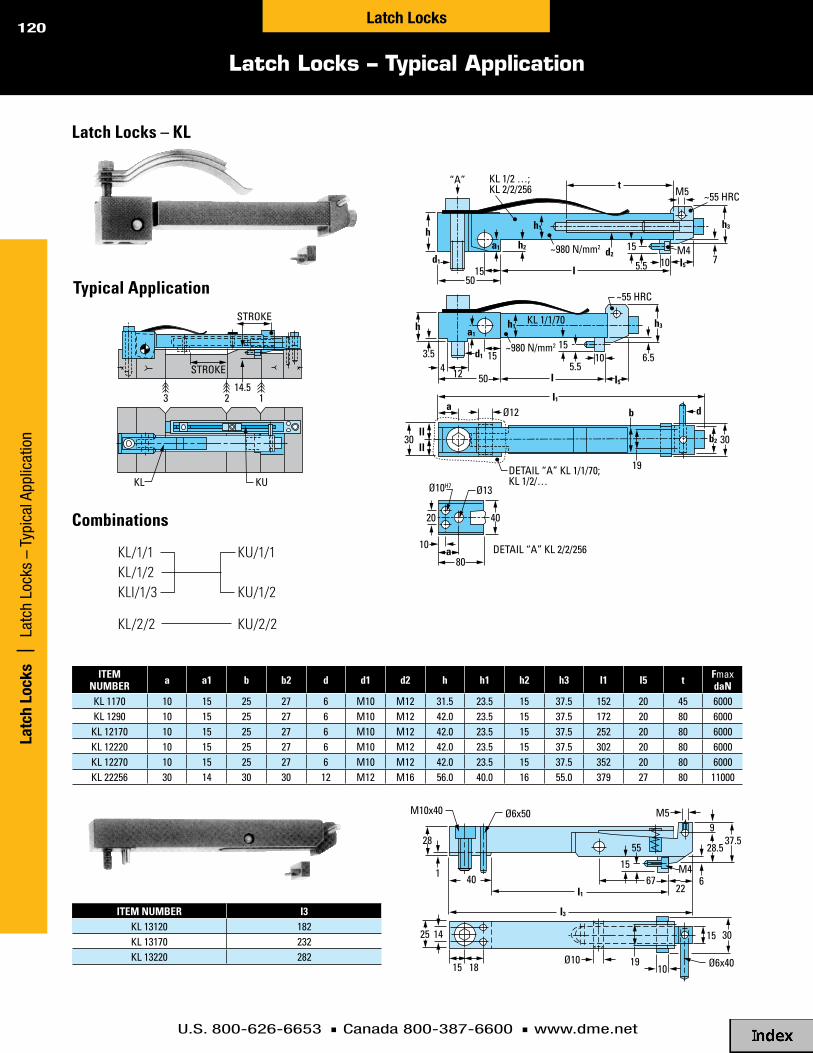
U.S. 800-626-6653 n Canada 800-387-6600 n www.dme.net
120
Latch Locks – Typical Application
Latc
h Lo
cks
| L
atch
Loc
ks –
Typ
ical
App
licat
ion
Latch Locks
KU
1 2
STROKE
STROKE
14.5 3
KL
20
10 a
80
Ø13 Ø10H7
40
10
10
30 30
15
5.5
15 M4
M5
5.5
6.5
7
b
19
a Ø12
DETAIL “A” KL 1/1/70; KL 1/2/…
DETAIL “A” KL 2/2/256
d
~55 HRC
~55 HRC
~980 N/mm2
~980 N/mm2
50
50
12
15
15
d1
d1 d2
h2
b2
I5
I5
I1
llll
I
I
h3
h3
h1 a1
4
h
h
t “A”
3.5
KL 1/1/70
KL 1/2 …; KL 2/2/256
a1
h1
28
14 25 15
22
9
6
28.5 37.5
M4
M5
55
15 67
30
Ø10 10
19 15 18
I1
I3
40
M10x40 Ø6x50
Ø6x40
1
Latch Locks – KL
Typical Application
Combinations
iTEM NUMBER a a1 b b2 d d1 d2 h h1 h2 h3 i1 i5 t Fmax
daNkl 1170 10 15 25 27 6 M10 M12 31.5 23.5 15 37.5 152 20 45 6000kl 1290 10 15 25 27 6 M10 M12 42.0 23.5 15 37.5 172 20 80 6000kl 12170 10 15 25 27 6 M10 M12 42.0 23.5 15 37.5 252 20 80 6000kl 12220 10 15 25 27 6 M10 M12 42.0 23.5 15 37.5 302 20 80 6000kl 12270 10 15 25 27 6 M10 M12 42.0 23.5 15 37.5 352 20 80 6000kl 22256 30 14 30 30 12 M12 M16 56.0 40.0 16 55.0 379 27 80 11000
iTEM NUMBER i3kl 13120 182kl 13170 232kl 13220 282
KL/1/1KL/1/2KLI/1/3
KL/2/2
KU/1/1
KU/1/2
KU/2/2

U.S. 800-626-6653 n Canada 800-387-6600 n www.dme.net
121
Positive Early Ejector Return
Toggle-Lok | Positive Early Ejector ReturnToggle-Lok
C
B
STANDARDSUPPORTPLATE
W
CS
B
STANDARDSUPPORTPLATE
GUIDE BLOCK(CUSTOMERTO SUPPLY)
W
CS
B
STANDARDSUPP. PLATE
GUIDE BLOCKS(CUSTOMER TO SUPPLY)
W
Style X
C
B
STANDARDSUPPORTPLATE
W
CS
B
STANDARDSUPPORTPLATE
GUIDE BLOCK(CUSTOMERTO SUPPLY)
W
CS
B
STANDARDSUPP. PLATE
GUIDE BLOCKS(CUSTOMER TO SUPPLY)
W
Style Y
C
B
STANDARDSUPPORTPLATE
W
CS
B
STANDARDSUPPORTPLATE
GUIDE BLOCK(CUSTOMERTO SUPPLY)
W
CS
B
STANDARDSUPP. PLATE
GUIDE BLOCKS(CUSTOMER TO SUPPLY)
W
Style z
The D-M-E Toggle-Lok is an externally mounted device used to positively return the ejector assembly before the mold completely closes. Employed when ejector pins or other moving components interfere with normal mold closure, the Toggle-Lok returns and locks the ejector assembly firmly in place, preventing expensive mold damage. It uses a positive cam linkage and activator lever rather than springs, pneumatics, hydraulics or other more cumbersome methods. Since it is mounted externally, the Toggle-Lok allows more space for cavities, slides or other required mold components. It is available in three styles to suit a broad variety of applications. Each style is available in a Toggle-Lok Package, which corresponds to a specific mold base requirement.
Operating SequenceUpper photo shows mold in open position, with ejector assembly fully forward. Before the mold has fully closed, the Toggle-Lok levers engage and move the arms to return the ejector assembly.
1 2 3 4 5
STYLE X PACKAGE iNCLUDES:1. (4) arms with: (4) Shoulder Screws (tlSS-12) (4) retainers (tlr-10) (4) button-Head Screws2. (4) joints3. (4) Side Mounts (standard) or top Mounts (if specified) with: (4) cover plates (4) Socket Head cap Screws (8) Dowels4. (2) levers with: (2) lever Spacers (tlS-20) (4) Socket Head cap Screws (4) Dowels5. (1) Hole location template
STYLE Y PACKAGE: Same as Style X, with half the quantities listed in items 1, 2 and 3.
STYLE z PACKAGE: Same as Style X, with twice the quantities listed in item 4.
each Standard toggle-lok package includes components and hardware necessary to equip both ends of the mold.
u.S. patent No. 3,226,771
1. Mount and cover plate
2. joint3. arm4. Shoulder
Screw5. lever

U.S. 800-626-6653 n Canada 800-387-6600 n www.dme.net
122
Assembly Specifications
Togg
le-L
ok
| As
sem
bly
Spec
ifica
tions
Toggle-Lok
toGGle-lok packaGeS MolD baSe reQuIreMeNtS DIMeNSIoNS packaGe INcluDeS
iTEMNO Style
W DIM(MolD baSe
wIDtH)C
DIM
S DIM(MaX
ejectIoN Stroke)
B DIM(MIN plate tHIckNeSS) F G H J K
arMS joINtS MouNtS leVerS teMplate
(Qty)iTEM NO
(Qty)iTEM NO
(Qty)iTEM NO
(Qty)iTEM NO
(Qty)iTEM NO
tl-825 y 77/8 21/2 13 /16 7/8 .81 0 3.86 .28 1.28 (2) tla-20 (2) tlj-20 (2) tlSM-125 (2) tll-20-S tlt-10
tl-830 y 77/8 3 111/16 13 /8 .75 0 4.84 .28 1.59 (2) tla-30 (2) tlj-20 (2) tlSM-125 (2) tll-20-S tlt-11
tl-835 y 77/8 31/2 23 /16 13 /8 .84 0 5.32 .28 1.59 (2) tla-30 (2) tlj-24 (2) tlSM-125 (2) tll-20-S tlt-12
tl-840 y 77/8 4 211/16 17/8 2.17 0 5.92 .28 1.22 (2) tla-40 (2) tlj-24 (2) tlSM-125 (2) tll-20-S tlt-13
tl-845 y 77/8 41/2 33 /16 17/8 2.13 0 6.44 .28 1.25 (2) tla-40 (2) tlj-30 (2) tlSM-125 (2) tll-20-S tlt-14
tl-1025 X 97/8 21/2 13 /16 7/8 2.99 1.99 4.13 .50 .735 (4) tla-20 (4) tlj-20 (4) tlSM-200 (2) tll-15 tlt-15
tl-1030 X 97/8 3 15 /16 13 /8 2.99 2.24 4.76 .50 .735 (4) tla-24 (4) tlj-20 (4) tlSM-200 (2) tll-15 tlt-16
tl-1035 X 97/8 31/2 113 /16 13 /8 3.11 2.24 5.19 .50 .735 (4) tla-24 (4) tlj-24 (4) tlSM-200 (2) tll-15 tlt-17
tl-1040 y 97/8 4 25 /16 17/8 1.50 0 6.59 .50 1.53 (2) tla-40 (2) tlj-24 (2) tlSM-200 (2) tll-20-S tlt-18
tl-1045 y 97/8 41/2 213 /16 17/8 3.03 .66 6.87 .50 .41 (2) tla-40 (2) tlj-30 (2) tlSM-200 (2) tll-20-S tlt-19
tl-1125 X 107/8 21/2 13 /16 13 /8 3.55 1.99 4.17 .50 .735 (4) tla-24 (4) tlj-20 (4) tlSM-200 (2) tll-15 tlt-20
tl-1130 X 107/8 3 15 /16 7/8 3.55 2.24 4.61 .50 .735 (4) tla-24 (4) tlj-24 (4) tlSM-200 (2) tll-15 tlt-21
tl-1135 X 107/8 31/2 113 /16 17/8 3.51 2.64 5.66 .50 .98 (4) tla-30 (4) tlj-24 (4) tlSM-200 (2) tll-20-D tlt-22
tl-1140 y 107/8 4 25 /16 17/8 1.50 0 6.59 .50 1.53 (2) tla-40 (2) tlj-24 (2) tlSM-200 (2) tll-20-S tlt-18
tl-1145 y 107/8 41/2 213 /16 17/8 2.00 0 6.93 .50 1.33 (2) tla-40 (2) tlj-30 (2) tlSM-200 (2) tll-20-S tlt-23
tl-1230 X 117/8 3 13 /16 7/8 3.92 1.99 4.52 .62 .735 (4) tla-30 (4) tlj-20 (4) tlSM-200 (2) tll-15 tlt-24
tl-1235 X 117/8 31/2 111/16 7/8 3.92 1.99 5.04 .62 .735 (4) tla-30 (4) tlj-24 (4) tlSM-200 (2) tll-15 tlt-25
tl-1240 y 117/8 4 23 /16 13 /8 .88 0 5.81 .62 1.53 (2) tla-30 (2) tlj-24 (2) tlSM-200 (2) tll-20-S tlt-26
tl-1245 y 117/8 41/2 211/16 17/8 1.41 0 7.07 .50 1.64 (2) tla-40 (2) tlj-30 (2) tlSM-200 (2) tll-20-S tlt-27
tl-1330 X 133 /8 3 11/16 13 /8 2.99 2.49 4.46 .75 .735 (4) tla-20 (4) tlj-24 (4) tlSM-200 (2) tll-15 tlt-28
tl-1335 X 133 /8 31/2 19 /16 13 /8 3.11 2.49 5.08 .75 .735 (4) tla-24 (4) tlj-24 (4) tlSM-200 (2) tll-15 tlt-29
tl-1340 X 133 /8 4 21/16 13 /8 4.59 2.41 6.09 .50 .98 (4) tla-40 (4) tlj-24 (4) tlSM-200 (2) tll-20-D tlt-30
tl-1345 X 133 /8 41/2 29 /16 13 /8 4.58 2.51 6.60 .50 .98 (4) tla-40 (4) tlj-30 (4) tlSM-200 (2) tll-20-D tlt-31
tl-1530 X 147/8 to177/8
3 11/16 7/8 2.99 2.24 4.03 .75 .735 (4) tla-20 (4) tlj-20 (4) tlSM-200 (2) tll-15 tlt-32
tl-1535 X 147/8 to177/8
31/2 19 /16 13 /8 2.99 2.99 5.48 .75 .735 (4) tla-24 (4) tlj-30 (4) tlSM-200 (2) tll-15 tlt-33
tl-1540 X 147/8 4 21/16 7/8 4.58 2.74 5.96 .62 .98 (4) tla-40 (4) tlj-24 (4) tlSM-200 (2) tll-20-D tlt-34
tl-1545 X 147/8 41/2 29 /16 7/8 4.62 2.71 6.48 .62 .98 (4) tla-40 (4) tlj-30 (4) tlSM-200 (2) tll-20-D tlt-35
tl-1640 X 157/8 to177/8
4 21/16 13 /8 3.61 2.29 6.21 .62 .98 (4) tla-30 (4) tlj-30 (4) tlSM-200 (2) tll-20-D tlt-36
tl-1645 X 157/8 41/2 29 /16 7/8 5.22 2.91 6.46 .62 1.48 (4) tla-40 (4) tlj-30 (4) tlSM-200 (2) tll-30 tlt-37
tl-1745* X* 161/2 41/2 29 /16 13 /8 4.60* 2.79* 6.47 .62* .98* (4) tla-40* (4) tlj-30* (4) tlSM-200* (2) tll-20-D* tlt-38*
tl-1845 X 177/8 41/2 29 /16 13 /8 4.60 2.79 6.47 .62 .98 (4) tla-40 (4) tlj-30 (4) tlSM-200 (2) tll-20-D tlt-38
tl-1930 z 191/2 &wIDer 3 11/16 13 /8 2.25 1.50 4.03 .75 to
SuIt (4) tla-20 (4) tlj-20 (4) tlSM-200 (4) tll-20-S tlt-32
tl-1935 z 191/2 &wIDer 31/2 19 /16 13 /8 2.25 2.25 5.48 .75 to
SuIt (4) tla-24 (4) tlj-30 (4) tlSM-200 (4) tll-20-S tlt-33
tl-1940 z 191/2 &wIDer 4 21/16 13 /8 2.63 1.31 6.21 .62 to
SuIt (4) tla-30 (4) tlj-30 (4) tlSM-200 (4) tll-20-S tlt-36
tl-1945 z 191/2 &wIDer 41/2 29 /16 13 /8 3.62 1.81 6.47 .62 to
SuIt (4) tla-40 (4) tlj-30 (4) tlSM-200 (4) tll-20-S tlt-38
NOTE: all dimensions are nominal reference dimensions. use the hole location template, which is included with each assembly, to establish hole locations on the mold.
* the centerline of the lever is offset 1" from the centerline of the mold. the centerline of the lever on the other end of the mold must also be offset 1", but in the opposite direction from the mold centerline for balanced operation.
when ordering, please specify:1. item number of Toggle-lok package2. Quantity3. “Top Mount,” if required (no charge)4. “special lever with fitting spacer,” if required (special order only) 5. Method of shipment

U.S. 800-626-6653 n Canada 800-387-6600 n www.dme.net
123
Basic Design Guidelines for Standard Mold Bases
Toggle-Lok | Basic Design Guidelines for Standard M
old BasesToggle-Lok
1. It is recommended that guided ejection be used.
2. The side mount should be used when the ejector plate is approximately flush with the end of the mold; either the standard or small side mount should be used as specified in the chart. The top mount should be used when the ejector plate extends beyond the end of the mold, since it is designed to be mounted on top of the ejector plate.
3. When the ejector plate is recessed inside the mold, spacers must be used so the mounts will clear the support plate by 0.016". Customer to supply spacers to suit mold requirements (see drawings, Styles X, Y or Z).
4. Be sure the levers do not interfere with part ejection. If there is insufficient mold open stroke, it may be necessary to rotate the mold 90° from its normal position so the levers will not interfere with ejecting parts.
5. Locate all levers so they will push evenly and return the ejector plate without cocking.
6. When the lever is offset from the centerline of the mold (Style X) or when the mount is offset from the centerline (Style Y), their locations on the other end of the mold must also be offset. The offset distance on each end of the mold should be the same, but in opposite directions from the mold centerline for balanced operation.
7. When using Styles Y or Z, hardened lever support blocks are required. These support blocks prevent the levers from deflecting when they contact the arms in the full ejection forward position. Customer to supply hardened support blocks to suit mold requirements (see drawings, Styles Y and Z).
8. The ejector assembly will normally return within .010" to .020" of complete return, although this will depend on how carefully the installation is made.
9. If it is necessary to return the ejector assembly closer than .010" to .020", levers with fitting spacers should be ordered. These are available on special order.
10. Edges of the ejector plate must be finished square before installing side mounts.
11. Be sure to provide a clearance slot in the ejector plate for the lever when necessary.
12. Locate lever mounting holes (two 3/8 S.H.C.S. and two 3/8 dowels) to avoid interference with leader pins, water lines and other mold components.
13. Be sure there is no interference between the Toggle-Lok components and other elements of the mold.
14. The knockout rods in the press must not interfere with the full return of the ejector assembly.
15. The levers must not interfere with the platens of the press when the mold is completely closed.
16. For packages TL-840, TL-845 and special applications only: If the joints are entirely below the bottom of the support plate in the mold closed position, the retainers must be attached to the joints rather than the arms. This will prevent the joints from sliding under the support plate where they would interfere with normal ejection forward movement.
Follow installation instructions Packaged with the D-M-E Toggle-Lok Assembly.

U.S. 800-626-6653 n Canada 800-387-6600 n www.dme.net
124
Toggle-Lok Components
Togg
le-L
ok
| To
ggle
-Lok
Com
pone
nts
Toggle-Lok
SHOULDER SCREW LOCATION
SIDE MOUNT SCREW LOCATION
LEVE
R
EJECTOR PLATE
iTEM NUMBER N
tlj-20 2.00
tlj-24 2.50
tlj-30 3.00
Joints – TLJ
Retainer – TLRMount on arm with button head screw to retain joint
Typical Hole Location Template – TLT
Shoulder Screw
iTEM NUMBER L
tla-20 2.00
tla-24 2.50
tla-30 3.00
tla-40 4.00
iTEM NUMBER
tlr-10
iTEM NUMBER
5858Sb
D-M-e toGGle-lok teMplateiTEM NUMBER
tlt-32
.61 .67 R
.19
.44 L
.22 .22 29° 31°
.625 DIA .625 DIA
.625 R
.06 R
#10-32 TAP THRU
N
.61
.62
.31 .01 R TYP
.62TYP
.625 DIA (2)
.06
.19 DIA
.94 DIA
.31 HEX
.88 DIA
.38
.62
.625 DIA
1/2-13 THREAD
.75
Arms – TLA

U.S. 800-626-6653 n Canada 800-387-6600 n www.dme.net
125
Toggle-Lok Components
Toggle-Lok | Toggle-Lok Components
Toggle-Lok
Standard Side Mount – TLSM Lever Spacer – TLSiTEM NUMBER
tlSM-200
Small Side Mount – TLSM iTEM NUMBER
tlSM-125
Top Mount – TLTM
Cover Plate for Standard Side Mount – TLCP
Cover Plate for Small Side Mount – TLCP
Cover Plate for Top Mount – TLCP
iTEM NUMBER
tlS-20
iTEM NUMBER
tlcp-100
iTEM NUMBER
tlcp-125
iTEM NUMBER
tlcp-200
iTEM NUMBER
tltM-100
.02
1.47
1.96
CUT OFF TO SUIT INSTALLATION
1.50
.16
.05
.41 DIA 1"
.50
2"
.01 R TYP
.88 .16
.05
.81
.28 DIA
.28
1.75
.01 R TYP
.31
.31
.72
.61
.01 R
.05
.28 DIA (2)
1.75
2.37
.04
.625 DIA
FOR 3/8" DIADOWEL (2)
.17
.59
1.06
1.19
.50
2"
2"
1"
.62
.41 DIA FOR 3/8" S.H.C.S.
.22
.625 DIA
FOR 1/4" DIA DOWEL (2)
.06
.87
60°
1.25
1.25
.59
.28
.62
.22
1.75"
.94
.62
.28 DIA FOR 1/4" S.H.C.S.
.81
.22
.625 DIA
FOR 1/4" DIA DOWEL
60°
2.37
1.19
.69
.69
.38
.62
.22
1.75
.62
DRILLED & C’BOREDFOR 1/4" S.H.C.S. (2).31
.31
1"

U.S. 800-626-6653 n Canada 800-387-6600 n www.dme.net
126
Toggle-Lok Components
Togg
le-L
ok |
Tog
gle-
Lok
Com
pone
nts
Toggle-Lok
Levers – Double Angle
Lever – Single Angle
NOTE: all dimensions are nominal reference dimensions. use the hole location template, which is included with each assembly, to establish hole locations on the mold.
iTEM NUMBER E M P U
tll-15 1.47 14.25 30° 1.15
tll-20-D 1.96 18" 30° 1.57
tll-30 2.96 18" 45° 1.58
INITIAL POINT OF FULL RETURN
7"ALL SIDES CASE HARDENED HRC 55-62
.25 APPROXIMATE TO SHARP CORNER
IF INSTALLATION REQUIRES THE ARM TO HAVE CONTACT WITH THE LEVER BEYOND THE CASE HARDENED AREA, A SPECIAL LEVER IS REQUIRED.
.61 M
E
U
CUT OFF TO SUIT INSTALLATION
R
R
P TYP
INITIAL POINT OF FULL RETURN
7"ALL SIDES CASE HARDENED HRC 55-62
.25 APPROXIMATE TO SHARP CORNER
IF INSTALLATION REQUIRES THE ARM TO HAVE CONTACT WITH THE LEVER BEYOND THE CASE HARDENED AREA, A SPECIAL LEVER IS REQUIRED.
.61
.19 x 45°
18"
1.96
1.71
CUT OFF TO SUIT INSTALLATION
R
R
45°
iTEM NUMBER
tll-20-S

U.S. 800-626-6653 n Canada 800-387-6600 n www.dme.net
127
Toggle-Lok Special Order Components
Toggle-Lok | Toggle-Lok Special Order Com
ponentsToggle-Lok
Levers – Double Angle with Fitting Spacers
Lever – Single Angle with Fitting Spacer
NOTE: all dimensions are nominal reference dimensions. use the hole location template, which is included with each assembly, to establish hole locations on the mold.
iTEM NUMBER E M P T U W
tll-15-FS 1.47 14.25 30° .90 1.75 5.25
tll-20-D-FS 1.96 18.00 30° 1.32 2.25 5.75
tll-30-FS 2.96 18.00 45° 1.33 2.25 5.75
NOTE: all dimensions are nominal reference dimensions. use the hole location template, which is included with each assembly, to establish hole locations on the mold.
INITIAL POINT OF FULL RETURN
7.00ALL SIDES CASE HARDENED HRC 55-62
APPROXIMATE TO SHARP CORNER
MAXIMUM POINT OF CONTACT WITH ARM IN MOLD CLOSED POSITION
.61
M
E
U
CUT OFF TO SUIT
INSTALLATION
RR
R
4.00
1.50 .50
.29
.25
CUSTOMER TO SUPPLY SPACERS OF EQUAL THICKNESS TO ADJUST FIT
#10-32 LOW HEAD SCREW (6)
1.50
W
T .12
PTYP
.30
INITIAL POINT OF FULL RETURN
APPROXIMATE TO SHARP CORNER
MAXIMUM POINT OF CONTACT WITH ARM IN MOLD CLOSED POSITION
.61
4.00
1.50 .50
1.46
2.25
5.75
1.50
.12
.30
.29
.25
.19 x 45°
CUSTOMER TO SUPPLY SPACER TO ADJUST FIT
R
R
#10-32 LOW HEAD SCREW (3)
7.00ALL SIDES CASE HARDENED HRC 55-62
18.00
1.96
CUT OFF TO SUIT
INSTALLATION
R
45°

U.S. 800-626-6653 n Canada 800-387-6600 n www.dme.net
128
Toggle-Lok Ordering Information
Togg
le-L
ok
| To
ggle
-Lok
Ord
erin
g In
form
atio
nToggle-Lok
iTEM NUMBER type
tlSM-200 StaNDarD SIDe
tlSM-125 SMall SIDe
tlSM-100 top
iTEM NUMBER
tla-20
tla-24
tla-30
tla-40
iTEM NUMBER
5858Sb
iTEM NUMBER
tlj-20
tlj-24
tlj-30
iTEM NUMBER uSeD wItH MouNt
tlcp-200 tlSM-200
tlcp-125 tlSM-125
tlcp-100 tlSM-100
iTEM NUMBER type
tll-15 Double aNGle
tll-20-D Double aNGle
tll-30 Double aNGle
tll-20-S SINGle aNGle
toGGle-lok packaGeS MolD baSe reQuIreMeNtS
iTEM NUMBER Style
wMolD baSe
wIDtH
crISer
HeIGHt
bMINIMuM
plate tHIckNeSS
SMaXIMuM ejectIoN Stroke
tl-825 y 77/8 21/2 7/8 13 /16
tl-830 y 77/8 3 13 /8 111/16
tl-835 y 77/8 31/2 13 /8 23 /16
tl-840 y 77/8 4 17/8 211/16
tl-845 y 77/8 41/2 17/8 33 /16
tl-1025 X 97/8 21/2 7/8 13 /16
tl-1030 X 97/8 3 13 /8 15 /16
tl-1035 X 97/8 31/2 13 /8 113 /16
tl-1040 y 97/8 4 17/8 25 /16
tl-1045 y 97/8 41/2 17/8 213 /16
tl-1125 X 107/8 21/2 13 /8 13 /16
tl-1130 X 107/8 3 7/8 15 /16
tl-1135 X 107/8 31/2 17/8 113 /16
tl-1140 y 107/8 4 17/8 25 /16
tl-1145 y 107/8 41/2 17/8 213 /16
tl-1230 X 117/8 3 7/8 13 /16
tl-1235 X 117/8 31/2 7/8 111/16
tl-1240 y 117/8 4 13 /8 23 /16
tl-1245 y 117/8 41/2 17/8 211/16
tl-1330 X 133 /8 3 13 /8 11/16
tl-1335 X 133 /8 31/2 13 /8 19 /16
tl-1340 X 133 /8 4 13 /8 21/16
tl-1345 X 133 /8 41/2 13 /8 29 /16
tl-1530 X 147/8 to 177/8 3 7/8 11/16
tl-1535 X 147/8 to 177/8 31/2 13 /8 19 /16
tl-1540 X 147/8 4 7/8 21/16
tl-1545 X 147/8 41/2 7/8 29 /16
tl-1640 X 157/8 to 177/8 4 13 /8 21/16
tl-1645 X 157/8 41/2 7/8 29 /16
tl-1745* X* 161/2 41/2 13 /8 29 /16
tl-1845 X 177/8 41/2 13 /8 29 /16
tl-1930 z 191/2 & wIDer 3 13 /8 11/16
tl-1935 z 191/2 & wIDer 31/2 13 /8 19 /16
tl-1940 z 191/2 & wIDer 4 13 /8 21/16
tl-1945 z 191/2 & wIDer 41/2 13 /8 29 /16
NOTE: If it is necessary to return the ejector assembly closer than .010" to .020" of complete return, levers with fitting spacers should be ordered. contact D-M-e for details.
Toggle-Lok Component Parts
ArmsIncludes retainer (tlr-10) and button head screw required for installation.
Shoulder Screw
Joints
Mounts (side and top)
Cover Plates
Levers (double and single angle)
Includes socket head cap screws and dowels required for installation.
Includes lever spacer, socket head cap screws and dowels required for installation.
* the centerline of the lever is offset 1" from the centerline of the mold. the centerline of the lever on the other end of the mold must also be offset 1", but in the opposite direction from the mold centerline for balanced operation.
when ordering, please specify:1. Quantity and item numbers from charts2. if the ejector plate extends beyond the ends
of the mold, please specify “Top Mount” as part of the Toggle-lok package, and add “TM” to end of item number; e.g., Tl-825-TM (no additional charge)
3. Method of shipment

U.S. 800-626-6653 n Canada 800-387-6600 n www.dme.net
129
Jiffy-Jector Benefits and Ordering Information
Jiffy-Jector | Jiffy-Jector Benefits and Ordering Inform
ationJiffy-Jector
u.S. patent No. 4,162,886
Each Jiffy-Jector Package includes:n Actuator Housing Assemblyn Actuator Pin Assemblyn Air Logic Manifold Assemblyn Manifold Bracketn Thrust Insertn Dual Air Filtration Systemn Polyurethane Tubing (1/8 I.D. x 9 feet long)
n Installation Instructions
Runner hang-ups in 3-plate molds are both costly and time consuming. When a runner hangs up, the machine stops, disrupting the cycle. Mold damage may also occur. The D-M-E Jiffy-Jector prevents runner hang-up problems.
The pneumatically controlled and operated Jiffy-Jector is compact and powerful. It moves the runner system away from the X-1 Plate and then, by means of a short positive stroke and a blast of compressed air, ejects the runner system down and out of the mold – putting an end to costly hang-up problems.
The basic requirement for proper operation of the Jiffy-Jector is a clear, unobstructed path out of the mold for the runner system.
The Jiffy-Jector is adaptable to most 3-plate molds. It can be designed into new molds or retrofitted to existing molds.
The Jiffy-Jector increases the production efficiency of the mold, and helps boost your profits by cutting downtime.
Prevent runner hang-ups in your 3-plate molds. Use the D-M-E Jiffy-Jector.
M
L L
THRUST INSERT
ACTUATOR HOUSING
ASSEMBLY
.500DIA
.14APPROX
ACTUATOR PIN ASSEMBLY (ONLY)
ACTUATOR PIN ASSEMBLY (INSTALLED IN HOUSING) .07 APPROX
STROKE
1" MINIMUM FROM TOP OF
MOLD TO BOTTOM OF THRUST INSERT
iTEMNUMBER L M
ap-332 2.00 3.32
ap-432 3.00 4.32
ap-532 4.00 5.32
ap-632 5.00 6.32
iTEMNUMBER L
jj-102 2.00
jj-103 3.00
jj-104 4.00
jj-105 5.00
Jiffy-Jector Packages Actuator Pin Assembly (only)
NOTES:actuator pin assemblies are interchangeable for replacement purposes or for subsequent applications where a longer or shorter pin is required.
For best results, it is recommended that the end of the actuator pin be located as close to the sprue as possible, especially when molding flexible resins. (Select actuator pin length accordingly.)
For complete design and application guidelines, contact D-M-e.
Jiffy-Jector Benefits:n Prevents hang-ups in 3-plate moldsn Increases production efficiencyn Adaptable to most 3-plate moldsn Works well in new molds and can be retrofitted to existing molds

U.S. 800-626-6653 n Canada 800-387-6600 n www.dme.net
130
Jiffy-Jector Design and Application Guidelines
Jiff
y-Je
ctor
| J
iffy-
Ject
or D
esig
n an
d Ap
plic
atio
n Gu
idel
ines
Jiffy-Jector
D-M-E Jiffy-Jector Typical Application 1
(Preferred)
D-M-E Jiffy-Jector Application 2
1. For best results, locate the actuator pin as close to the sprue as possible, especially when molding flexible resins (see Typical Application 1). Mold, runner or part design may require a longer distance between the actuator pin and sprue (see Application 2).
2. Design actuator pin shutoff into the split line between the X-1 and X-2 Plates. The bored or reamed hole is usually located on the centerline of the mold.
3. Locate two 5/16-18 tapped holes in the X-1 Plate for mounting the actuator housing (see assembly drawing).
4. Locate two 5/16-18 tapped holes in the “A” clamping plate (A.C.P.) for manifold bracket (see assembly drawing).
5. Provide 1" additional mold opening between the X-1 and X-2 Plates (1st parting line). This allows the actuator pin to move 1" away from the X-1 Plate and still have adequate clearance for runner ejection.
6. When retrofitting a mold with the Jiffy-Jector:
a. Provide 1" longer stripper bolts between the X-1 and X-2 Plates.
b. Be sure the leader pins are long enough to allow 1" additional movement of the X-2 Plate – use longer leader pins if necessary.
c. Provide clearance for the longer stripper bolts and leader pins (without interfering with water lines or other mold components).
7. The Jiffy-Jector does not eliminate the need for sucker pins or normal 3-plate mold components or sequences.
8. Allow sufficient stroke between the X-1 Plate and the A.C.P. (3rd parting line) to strip the runners from the sucker pins and break the sprue from the nozzle.
9. To minimize clearance required for runner system ejection, sprueless design is recommended – such as the D-M-E T-Series Straight-Shot Hot Sprue Bushing.
10. It is important the runner system have a clear path out of the mold. Leader pins, water hoses, fittings and other mold components must not obstruct the ejection path.
11. An air pressure range of 55 psi minimum, to 100 psi maximum, is required.
12. Be sure the mounting holes and the bored or reamed hole for the actuator pin assembly do not interfere with leader pins, water lines or other mold components.
13. The manifold bracket is supplied with elongated slots for adjustment. Adjust the position of the Jiffy-Jector manifold assembly on this bracket so the pneumatic limit switch will be actuated near the end of the X-1 Plate travel (refer to assembly drawing).
14. If a standard actuator pin is too long, mount the actuator housing and manifold bracket on spacers to reduce the distance the pin extends into the mold (refer to assembly drawing and actuator pin assembly chart).

U.S. 800-626-6653 n Canada 800-387-6600 n www.dme.net
131
Jiffy-Jector Operating Sequence |Installation Dimensions for “T” Series Mold Bases
X2 PLATE
X1 PLATE
ACP 1 2
X2 PLATE
X1 PLATE
ACP
1 3 2
X2 PLATE
X1 PLATE
ACP
1 3 2
D-M-E Jiffy-Jector Operating SequenceSTEP 1n Parting lines 1 and 2 open.
STEP 2n Parting line 3 opens and actuates the pneumatic limit switch.
n Air cylinder moves actuator pin assembly and runner system away from the X-1 Plate.
STEP 3n Near the end of the 1" air cylinder stroke, the depressed ball
gives the valve a short positive stroke, loosening the runner system from the actuating pin. Simultaneously, a blast of compressed air is released, ejecting the runner system down and out of the mold.
n After the adjustable time delay valve times out, the air cylinder returns the actuator pin assembly to the X-1 Plate.
n The mold begins the normal mold close sequence.
X2 PLATE
X1 PLATE
ACP 1 2
X2 PLATE
X1 PLATE
ACP
1 3 2
X2 PLATE
X1 PLATE
ACP
1 3 2
X2 PLATE
X1 PLATE
ACP 1 2
X2 PLATE
X1 PLATE
ACP
1 3 2
X2 PLATE
X1 PLATE
ACP
1 3 2
Jiffy-Jector | Jiffy-Jector Operating Sequence
Jiffy-Jector
L DIM
LOCATION OF THRUST INSERTTO SUIT ACTUATOR PIN LENGTH
AND MOLD REQUIREMENTS(.50 MINIMUM)
VIEW C-C
FOR JJ-102 THRU JJ-105(CONTACT D-M-E FOR JJ-101
INSTALLATION INSTRUCTIONS)
TOP VIEW OF MOLD
C C
.562
FRACTIONS .00 .000 ANGLES
±.015±.010±.005±1°
.562
.875
TOLERANCES UNLESS NOTED
1.751
.501
.08 CLEARANCE FROM END OF VALVE PIN TO BOTTOM OF RADIUS
+.001 –.000
+.001 –.000
+.001 –.000
+.00 –.03
.251
R
.187 R(4)
1/4-20 TAP (2) FOR THRUST INSERT
1.00 3.12
.44 (2)
A.C.P. (1-7/8 MIN)
.31 MIN (REF)
*TRAVEL Z IS X-1 PLATE TRAVEL
TRAVEL Z* 2.56 MINUS TRAVEL Z*
(FOR .50 TO .88 Z) 5/16-18 TAP (2) FOR ACTUATOR HOUSING
5/16-18 TAP (2) FOR MOUNTING BRACKET
X-2 PLATE
CENTERLINE OF MOLD
X-1 PLATE (7/8 OR 1-3/8)
1.469 1.469
.501 .500 DIA HOLEON SPLIT LINE OFX-1 AND X-2 PLATES
+.002 –.000 +.001
–.000
installation Dimensions for “T” Series Mold Bases

U.S. 800-626-6653 n Canada 800-387-6600 n www.dme.net
132
Ejector Return Couplings – General Information
Ejec
tor
Retu
rn C
oupl
ings
| E
ject
or R
etur
n Co
uplin
gs –
Gen
eral
Info
rmat
ion
Ejector Return Couplings
Economicaln Shortens mold changeover timesn Only one unit required per injection
molding machine
Universaln Can be put into existing molds to
save time and moneyn Hydraulic return by means of fixed couplingn Pulsating ejection possible
Quick Action Ejector Return Couplings for Presses with Hydraulic Ejection
reF a b c ±0.02 D e M N o +0.05+0.02 p MIN. Q MIN. kN
ar01 38 43 18 43.5 M16 23 18 7 48 c +1 40ar02 43 73 24 70.5 M20 42 32 80 c +1 140
E
B AR 01 Ø38AR 02 Ø67
Ø15 AR 01 Ø30 AR 02
AR 01 Ø24 AR 02 Ø42
C D
A
Ø14.7 AR 01Ø29.5 AR 02
M12 (AR 01) M16 (AR 02)
Ø11 Ø14
7 –> AR 01 8 –> AR 02
Ø17.4 AR 01 Ø29.4 AR 02
Ø22.5 AR 01 Ø40 AR 02
reF typear01 reSp. 02 QuIck returN couplING (INjectIoN preSS)
ar01 reSp. 02 p coNNectING pluG (MolD)
Quick return coupling (incl. connecting plug) Connecting plug
L
EJECTOR CYLINDERROD
AR 01-L+30MMAR 02-L+50MM
O
NP
Q
M
C
installation1. Move the ejector plate to the
molding position (mold closed).2. Move also the ejector cylinder rod
to the fully retracted position. It is important to check by hand, that the rod is fully pushed back to the fully retracted position before measuring.
3. Measure the distance between the coupling and the ejector cylinder rod.
4. Extend the ejector cylinder rod with an extra knock-out rod of the measured length + 30mm for AR-01 and 50mm for AR-02.
5. Move the mold ejector plates to the forward position (mold open).
6. Lock both the extra knock-out rod and at the other end the quick coupling.
7. Move the mold ejector plates back to the mold closed position and make the coupling between ejector plate and ejector cylinder rod. Make sure that the ejector plate and ejector cylinder rod are both in the mold closed position as soon as the coupling is made. If not, adjust.
Do not use with quick-change mold systems.
Ejector Return Couplings – AR

Hydraulic Unscrewing D
evice
Limit Switches
QUALITY TESTEd TO
PROVIdE LONG,
dEPENdABLE SERVICE
Limit Sw
itches

U.S. 800-626-6653 n Canada 800-387-6600 n www.dme.net
134Li
mit
Switc
hes
| T
hins
witc
h® L
imit
Switc
h
Thinswitch® Limit Switch
Limit Switches
tHINSwItcH lIMIt SwItcH cataloG #tSw2220
SpecIFIcatIoNS MaterIalS
electrIcal: boDy FIberGlaSS-reINForceD NyloN250Vac 5 aMpS reSIStIVe SprING StaINleSS Steel
4 aMpS INDuctIVe back coVer polyeSter FIlM28VDc (Sea leVel) 5 aMpS reSIStIVe wIre leaDS 22Ga StraNDeD,
4 aMpS INDuctIVe 3-coNDuctor, SHIelDeD cable,operatING teMperature 175°F MaX 6 Ft. (1.8M) loNG,
(79.4°c MaX) eNDS StrIppeD aND tINNeDSwItcHING SpDt
rateD curreNt VS. Steel teMperaturetSw 2220
aMpS °F °c
5.0 85 29.4
4.0 120 49.0
3.0 155 68.3
2.0 175 79.4
u.S. patent No. 5,446,252
The Thinswitch® limit switch is specially designed to verify ejector plate return before permitting the mold to close in injection molding machines. Thin enough to fit inside the ejector housing, it can also be used for core slides, or any place space is limited.
The Thinswitch limit switch has been tested for reliability in more than 10 million cycles without failure. Two switches can be used in series for larger molds to ensure the ejector plate returns, preventing costly mold damage.
n Prevents costly damage by ensuring the ejector assembly is fully returned
n Adjustable operating point allows actuation between .187" and .250" from the base
n 3/16" thick design fits snugly behind the ejector plate in the space provided by the rest buttons
n Included mounting hardware installs the Thinswitch Limit Switch easily
n Stripped and tinned 6 ft. wire leads make the switch ready to install without modification
n 175°F (79.4°C) standard temperature rating enables use for most molding applications
n Quality tested over 10 million cycles to provide long, dependable service
n Linear adjustment set screw can be set within .005 to .0025
n Premature spring and switch failure may result by adjusting the operating point more than .020” (.5mm) before the end of the ejector plate stroke
n In stock to provide same day delivery
NOTE: please contact D-M-e for high- temperature applications.
The Thinswitch Limit Switch is designed for use in very low power mold protection control circuits. It is not intended to switch heavy loads in power applications.
NOTE: pressure required to activate the switch: 1 oz. min., 5 oz. max.

U.S. 800-626-6653 n Canada 800-387-6600 n www.dme.net
135
Thinswitch® Limit SwitchLim
it Switches | Thinsw
itch® Lim
it Switch
Limit Switches
CABLE
SPRING
DRILL AND TAP #10-24 x 3/8" DP TO ACCEPT#10 BUTTON HEAD SCREWS INCLUDED WITHTHINSWITCH® LIMIT SWITCH
38.1mm/1.50in
25.4mm/1.00in6.4mm/0.25in
9.5mm/0.38in
31.8mm/1.25in
NORMALLY CLOSED (RED)
NORMALLY OPEN (BLACK)
COMMON (WHITE)
SCHEMATIC DIAGRAM
50.8mm/2.00in
54.6mm/2.15in
10.0mm/.394in
4.8mm/0.18in
partS INcluDeD
DeScrIptIoN Qty
tHINSwItcH lIMIt SwItcH 1
4-40 alleN wreNcH (For HeIGHt aDjuStMeNt) 1
ScrewS (#10-24 X 1/2" buttoN HeaD) 4
wIre claMpS (.5" X .82" X .5" wItH .213" MouNtING Hole) 2
INStructIoN SHeet 1 thinswitch includes 2 wire clamps.
Two- and three-dimensional part files are available from the D-M-E web site at www.dme.net.
Rest Button
Ejector Housing Base
6.4mm/.250in MaxActuation Height
4.8mm/.188in MinActuation Height
Thinswitch Spring Under Dome
®

U.S. 800-626-6653 n Canada 800-387-6600 n www.dme.net
136Li
mit
Switc
hes
| S
mar
tflow
® T
hins
witc
h® L
iqui
d-Re
sist
ant L
imit
Switc
h
NEW! Smartflow® Thinswitch® Liquid-Resistant Limit Switch
Limit Switches
u.S. patents 5,446,252 and 6,982,392
General Description
Smartflow® Thinswitch® Liquid-Resistant Limit Switch is designed to verify ejector plate return in areas where occasional water or oil spray is present. The Thinswitch helps prevent accidental mold close in injection molding applications by providing a position switch that is tied to the injection molding machine control. The liquid resistant switch uses the same mounting hole locations as the original Thinswitch.
The Thinswitch has been tested for reliability over 10 million cycles without failure. Two switches can be used in series for larger molds to ensure the ejector plate return, preventing costly mold damage.
Features and Benefits
n Over 10 million cycle life
n 175°F (79.4°C) standard temperature rating
n 250°F (121°C) high-temperature unit for higher temperature needs
n Adjustable actuation between .187" and .250" from the mold base
n 3/16" thick design fits snugly behind the ejector plate between the rest buttons
n Stripped and tinned 6 ft. wire leads
n Mounting screws and wire clips included
The Thinswitch® Limit Switch is designed for use in very low power mold protection control circuits. It is not intended to switch heavy loads in power applications.
NOTE: Design and specifications are subject to change without notice.
Rest Button
Ejector Housing Base
6.4mm/.250in MaxActuation Height
4.8mm/.188in MinActuation Height
Thinswitch Spring Under Dome
®
DRILL AND TAP #10-24 x 3/8"DEEP TO ACCEPT #10 BUTTONHEAD SCREWS INCLUDED WITHTHINSWITCH® LIQUID RESISTANTLIMIT SWITCH
4.8mm/0.18in
CABLE
6.4mm/0.25in
59.9mm/2.36in
31.8mm/1.25in
9.5mm/0.375in
38.1mm/1.50in25.4mm/
1.00in
NOTE: Premature spring and switch failure may result by adjusting the operating point more than .020" (.5mm) before the end of the ejector plate stroke.
specificaTions
Part Number/Operating Temperature: t-222-lr Standard Model, 175°F max. (79.4°c max.)Ht-291-lr High temp Model, 250° max. (121°c max.)Switching: SpDtElectrical: 250Vac – 5 amps resistive, 4 amps inductive (max) 28VDc (sea level) – 5 amps resistive, 4 amps inductive (max)
MaTerials
Body: Fiberglass-reinforced nylonDome: polyurethaneBack Cover: polyester FilmWire Leads: 22ga stranded, 3-conductor, shielded cable, 6 ft. (18m) long, ends stripped and tinned
T-222-LR 175°F (79.4°C) operating temperatureHT-291-LR 250°F (121°C) operating temperature
rateD curreNt (reSIStIVe) VS. operatING Steel teMperature
t-222-lr Ht-291-lr
aMpS °F °c aMpS °F °c
5.0 85 29.4 5.0 100 37.7
4.0 120 49.0 4.5 155 68.3
3.0 155 68.3 4.0 210 98.8
2.0 175 79.4 3.5 250 121.1

D-M-E Innovative Mold Interlocks
COST-EFFECTIVE
INTERChANGEABLE
wEAR SURFACES
D-M
-E Innovative Mold Interlocks

U.S. 800-626-6653 n Canada 800-387-6600 n www.dme.net
138
Go to www.dme.net/prices for the latest pricing guide.Online Price Guide
Table of Contents
iN2 Mold interlocksBenefits ....................................................................139Interlock Dimensions .................................................140Ordering Information .................................................140
Parting Line and Tapered interlocksParting Line ................................................................144-145Tapered Round ...........................................................146-147Tapered Round, Metric ..............................................148Shoulder Plates for Tapered Interlocks ......................148Tapered Rectangular .................................................149
Straight-Side interlocksInterlock Dimensions .................................................141
X-Style interlocksInterlock Dimensions ................................................142Machining Pockets .....................................................143
Inno
vativ
e M
old
Inte
rloc
ks |
Tab
le o
f Con
tent
sInnovative Mold Interlocks
Black & Gold Mold interlocksSide Interlocks ...........................................................150Top Interlocks .............................................................151Overview ...................................................................152

U.S. 800-626-6653 n Canada 800-387-6600 n www.dme.net
139
Mold Interlock Benefits
D-M-E Side interlocks provide:n Accurate alignment
of mold halves
n Easy installation
n Easy and cost-effective maintenance
n Industry-compatible sizes
installation
n Install four (4) IN2 Side Interlocks per mold (one per side)
n Install IN2 Side Interlocks on the Center Line of each side of the mold
n Replace IN2 Interchangeable Inserts as desired
Precision tolerancing, precision manufacturing means off-the-shelf interchangeability
D-M-E IN2tM Mold Interlocks are manufactured to exacting standards. Precise dimensional and geometrical tolerances ensure interchangeability. Interchangeability that no one else in the industry matches — no one. Precision tolerancing and manufacturing ensures that all D-M-E IN2 Mold Interlock components are interchangeable — off-the-shelf. Replace any D-M-E IN2 Mold Interlock component independently — no need to replace the entire set. No one else offers this level of interchangeability — no one.
The D-M-E Standard of Interchangeable Interlock Components sets D-M-E apart from the industry.
And now … D-M-E offers another innovation: IN2 Innovative Interlocks with Interchangeable Inserts. Interchangeable Inserts offer you simple, cost-effective maintenance. No need to replace the entire set when you use IN2 Innovative Interlocks with Interchangeable Inserts.
patent No. u.S. 6,921,256 b2
Innovative Mold Interlocks | M
old Interlock BenefitsInnovative Mold Interlocks

U.S. 800-626-6653 n Canada 800-387-6600 n www.dme.net
140
IN2 Side Interlocks
Side interlock Dimensions
Side interlock Ordering information – SiS, SiiMaterial – Male interlock: High-Speed tool Steel Hardness: 61-65 HrcMaterial – interlock inserts: Graphitic tool Steel Hardness: 48-52 Hrc
* Sets include one (1) female, one (1) male, two (2) inserts, four (4) SHcS.
A
S
T
MALE
FEMALE
W
T S
R
INSERTS (2)
W
S
B
S
R
P
E
** replacement Interchangeable Inserts are sold as pairs.
INterlock Set*
iTEM NUMBER
WINterlock
wIDtH
replaceMeNtINtercHaNGeable INSertS**
iTEM NUMBER
SIS150023 1.500 SII15003
SIS200023 2.000 SII20003
SIS300023 3.000 SII30003
WwIDtH
AHeIGHtFeMale
BHeIGHtMale
EINterlock
HeIGHt
PINterlock
wIDtHT
tHIckNeSSR
raDII
SScrew
locatIoNSSHcSSIze
1.500 .875 .875 .490 .450 .500 .26 .250 #8-32 X .62
2.000 1.375 .875 .640 .750 .500 .26 .312 #10-32 X .62
3.000 1.875 .875 .920 1.250 .750 .39 .375 1/4-20 X .88Inno
vativ
e M
old
Inte
rloc
ks |
Inn
ovat
ive
Side
Inte
rlock
sInnovative Mold Interlocks

U.S. 800-626-6653 n Canada 800-387-6600 n www.dme.net
141
Straight-Side Interlocks
C
E
L .06
45°
M
H
G
B
K
J
.03 x 45° ALL CORNERS
R .06
.031 .031
P
P
A +.0000 –.0004
±.004
+.0000 –.0002
+.0002 –.0000
DRILLED AND COUNTERBORED FOR SOCKET HEAD CAP SCREW F (4 PLACES)
n Provides positive alignment for molds with interlocking cavities and cores
NOTES:1. recommend four (4) per mold.2. Mount on centerline on all four sides to avoid problems with heat expansion.
iTEM NUMBER
ANoMINal B C
PNoMINal E F* G H J K L M
plM-00011.5000 .870 1.18 .5000 .870 1/4-20 X 3 /4 .281 .281 .437 .281 .620 .19
plF-0001plM-0002
2.0000 .870 1.18 .6800 .870 1/4-20 X 3 /4 .375 .375 .437 .375 .620 .19plF-0002plM-0003
3.0000 1.360 1.910 1.0000 1.370 3 /8-16 X 1 .688 .375 .688 .375 .745 .19plF-0003plM-0004
4.0000 1.870 2.640 1.3750 1.870 3 /8-16 X 1 .875 .625 .875 .625 .745 .50plF-0004plM-0005
5.0000 1.870 2.640 1.7500 1.870 1/2-13 X 11/4 .875 .750 .875 .750 1.120 .50plF-0005
Material: 8620 Steel-carburized, Hardened and Ground Hardness: plM: 50-55 Hrc, plF: 55-60 Hrc
*(2) F-size S.H.c.S included with each interlock.
PLM
PLF
Innovative Mold Interlocks | Straight-Side Interlocks
Innovative Mold Interlocks
Straight-Side interlocks – PLM, PLF

U.S. 800-626-6653 n Canada 800-387-6600 n www.dme.net
142
X-Style Straight-Side Interlocks
iTEM NUMBERX plate
tHIckNeSSA
NoMINal B CP
NoMINal E F G H J K L M NU
DIaFeMale X-Style
plF-0001(2 reQ’D)
pXM-1001 .8751.5000
.850 1.470.5000 .870 1/4-20 X 3 /4 .281 .281
.425.281 .620 .19 .310
.2500(1/4 DIa X
1" lG Dwl) pXM-2001 1.375 1.350 1.970 .675
plF-0002(2 reQ’D)
pXM-1002 .8752.0000
.850 1.470.6800 .870 1/4-20 X 3 /4 .375 .375
.425.375 .620 .19 .310
.2500(1/4 DIa X
1" lG Dwl) pXM-2002 1.375 1.350 1.970 .675
plF-0003(2 reQ’D)
pXM-1003 .8753.0000
.850 1.9501.0000 1.370 3 /8-16 X 1 .688 .375
.425.375 .745 .19 .550
.3750(3 /8 DIa X
11/4 lG Dwl) pXM-2003 1.375 1.350 2.450 .675
plF-0004(2 reQ’D)
pXM-2004 1.3754.0000
1.350 2.8901.3750 1.870 3 /8-16 X 1 .875 .625
.675.625 .745 .50 .770
.3750(3 /8 DIa X
11/4 lG Dwl) pXM-3004 1.875 1.850 3.390 .925
plF-0005(2 reQ’D)
pXM-2005 1.3755.0000
1.350 2.8901.7500 1.870 1/2-13 X 11/4 .875 .750
.675.750 1.120 .50 .770
.5000(1/2 DIa X
2" lG Dwl) pXM-3005 1.875 1.850 3.390 .925
X PLATE THICKNESS
OF MOLD &INTERLOCKS
C
A
C
BCENT
N
.06 TYP
J
E
+.0000 -.0004 P
+.0000-.0002 +.0002
-.0000
.06R U’CUT RELIEF TYP.
M 45°
P
G
L
H
K
DRUKKED & C’BORED FOR SOCKET HEAD CAP SCREWS F (2) PLACES EACH COMPONENT
HOLE FOR U DIADOWEL S.F.
n Provides positive alignment between three adjacent plates when mold has two parting line openings, providing close alignment for interlock cavities and cores in stripper plate-type molds
n Used with AX-Series (floating plate) and X-Series (stripper plate) mold bases, as well as other mold bases with floating plates
n Interchangeable male PXM and female PLF details can be purchased individually
NOTE: (2) socket head cap screws and (1) dowel of the size and length indicated in the chart are included with each X-Style interlock. additionally, (2) socket head cap screws of the size and length indicated in the chart are included with each female interlock.
Material: aISI 8620 Steel-carburized, Hardened and Ground Hardness: pXM: 50-55 Hrc, plF: 55-60 Hrc
PLF
PXM
PLF
Inno
vativ
e M
old
Inte
rloc
ks |
X-S
tyle
Str
aigh
t-Si
de In
terlo
cks
Innovative Mold Interlocks
X-Style Straight-Side interlocks – PLF, PXM

U.S. 800-626-6653 n Canada 800-387-6600 n www.dme.net
143
X-Style Straight-Side Interlocks
The D-M-E X-Style straight-side interlocks are designed for use on molds with floating plates when the two parting lines must be closely aligned with each other. The X-Style straight-side interlocks are designed to be used, and to mate with two of the equivalent size D-M-E female straight-side interlocks. The X-Style interlocks are typically used on “X” and “AX” series mold bases, as well as other mold bases with floating plates.
Typical application is for use on a mold base with a stripper or floating plate. (4) X-Style interlocks and (8) female interlocks are used per mold assembly. One set is used on centerline of each end and one set on centerline of each side.
NOTE: (2) socket head cap screws and (1) dowel of the size and length indicated in the chart are included with each X-Style interlock. additionally, (2) socket head cap screws of the size and length indicated in the chart are included with each female interlock.
Moldmaker to adjust fit to suit as needed for specific application. Please contact D-M-E for complete installation instructions for the X-Style Interlocks.
Basic Dimensions for Machining Pockets for X-Style and Female interlocks on Centerlines of the Closed and Clamped Mold Assembly
iTEM NUMBERX plate
tHIckNeSSA
ceNt B C D ET
tap Ø U WR
raDFeMale X-Style
plF-0001(2 reQ’D)
pXM-1001 .8751.5000 .875 .625 .281 .469
1/4-20 uNc X .56 Deep(1/4-20 X 3 /4 lG S.H.c.S.)
.2500(1/4 DIa X 1" lG Dwl) .50 .12
pXM-2001 1.375
plF-0002(2 reQ’D)
pXM-1002 .8752.0000 .875 .625 .375 .625
1/4-20 uNc X .56 Deep(1/4-20 X 3 /4 lG S.H.c.S.)
.2500(1/4 DIa X 1" lG Dwl) .50 .12
pXM-2002 1.375
plF-0003(2 reQ’D)
pXM-1003 .8753.0000 1.375 .750 .688 1.125
3 /8-16 uNc X .88 Deep(3 /8-16 X 1" lG S.H.c.S.)
.3750(3 /8 DIa X 11/4 lG Dwl) .62 .12
pXM-2003 1.375
plF-0004(2 reQ’D)
pXM-2004 1.3754.0000 1.875 .750 .875 1.375
3 /8-16 uNc X .88 Deep(3 /8-16 X 1" lG S.H.c.S.)
.3750(3 /8 DIa X 11/4 lG Dwl) .62 .38
pXM-3004 1.875
plF-0005(2 reQ’D)
pXM-2005 1.3755.0000 1.875 1.125 .875 1.750
1/2-13 uNc X 1.00 Deep(1/2-13 X 11/4 lG S.H.c.S.)
.5000(1/2 DIa X 2" lG Dwl) 1.00 .38
pXM-3005 1.875
CENTERLINE OF MOLD AND INTERLOCKS (ON ALL FOUR SIDES)
MAINTAIN .005 MINCLEARANCEBETWEEN INTERLOCKSIN THIS AREA TYP
FEMALE STRAIGHT SIDE INTERLOCK
FEMALE STRAIGHT SIDE INTERLOCK
X-STYLE STRAIGHT SIDE INTERLOCK
X
OF MOLD & INTERLOCKS C
OF MOLD & INTERLOCKS C
R RAD
U DIA FOR DWL
T TAP A
CENTRAL
A CENTRAL
T TAP
T TAP
R RAD
D
B
X STRIPPER OR FLOATING PLATE THICKNESS
+.005 –.000
+.0002 –.0000
+.0002 –.0000
B +.005 –.000
C
W
VIEW OF POCKET ON CENTERLINE OF MOLD
SECTION Z-Z THRU CENTER OF X PLATE
+.005 –.000
±.005
±.005 ±.001
E ±.005
E ±.005
E ±.005
D
Z Z 1/2 X
±.005
Innovative Mold Interlocks | X-Style Straight-Side Interlocks
Innovative Mold Interlocks

U.S. 800-626-6653 n Canada 800-387-6600 n www.dme.net
144
Parting Line Interlocks
J
H
F (2)
A
+.0000 -.0004
CENTER MALE INTERLOCK
G RAD(2)
.03 x 45°TYP
C
MREF
+.000 -.010
K DIA DRILL THRUL DIA C’BORE – M DEEP(2) HOLES
N
.02 RADMAX
B
E
+.000 -.005
iTEM NUMBER
AwIDtH
BleNGtH C E F G H J K L M N
pll-1001 .4998 1.000 .85 .030 .250 .19 .250 .500 .219 .344 .22 .36
pll-1002 .9998 1.500 1.35 .060 .500 .25 .312 .875 .281 .406 .28 .61
pll-1003 1.4998 2.000 1.72 .060 .750 .38 .438 1.125 .406 .594 .41 .73
pll-1004 1.9998 2.500 2.10 .060 1.000 .50 .562 1.375 .531 .781 .53 .86
n For accurate alignment between mold halves
n All machining can be done from the parting line … saving set-up time and machining costs
n Components can be purchased individually
Center Male interlock – PLL
See next page for right- and left-hand gibs for parting line interlocks.
Typical Application
The male interlock is typically installed in the ejector half of the mold. Left- and right-hand gibs are typically installed in the stationary half of the mold.
Mold machining and installation data are available. Contact D-M-E.
Material: S7 Steel, 52-58 Hrc, titanium Nitrided 80-85 Hrc for wear and lubricity
Left-Hand Gib
Center Male interlock
Right-Hand Gib
Inno
vativ
e M
old
Inte
rloc
ks |
Par
ting
Line
Inte
rlock
sInnovative Mold Interlocks

U.S. 800-626-6653 n Canada 800-387-6600 n www.dme.net
145
Parting Line Interlocks
iTEM NUMBER
AwIDtH
BleNGtH C E F G H J K L
leFt-HaNDGIbS
rIGHt-HaNDGIbS
pll-3001 pll-2001 .5000 1.000 .500 .19 .250 .500 .219 .344 .22 .250
pll-3002 pll-2002 .7500 1.500 .750 .25 .312 .875 .281 .406 .28 .375
pll-3003 pll-2003 1.0000 2.000 1.000 .38 .438 1.125 .406 .594 .41 .500
pll-3004 pll-2004 1.2500 2.500 1.250 .50 .562 1.375 .531 .781 .53 .625
B G
F
L(2)
A
+.0000 -.0004
+.000 -.005
LEFT-HAND GIB INTERLOCK
RIGHT-HAND GIB INTERLOCK SIDE VIEW
OF GIBS
E RAD
H DIA DRILL THRUJ DIA C’BORE – K DEEP(2) HOLES EACH GIB
.03 x 45°TYP
C
KREF
+.000 -.005
NOTE: Left- and right-hand gibs
are dimensionally identical.
NOTES:1. Select center, right and left interlock components
that are the same length (size) to make one set (e.g., pll-1002, pll-2002 and pll-3002).
2. Four sets of interlocks should be used in each application. they must be installed on the center line of each side of the mold.
3. each component includes two socket head cap screws with nylon-type thread locking element.
See previous page for center male parting line interlock.
Gibs (left and right) – PLL
Material: H-13 steel, 40-45 Hrc, melanite coated for wear and lubricity
Innovative Mold Interlocks | Parting Line Interlocks
Innovative Mold Interlocks

U.S. 800-626-6653 n Canada 800-387-6600 n www.dme.net
146
Tapered Interlocks (Round)
D-M-E Tapered Interlocks provide positive metal-to-metal mold registry to align mold halves, mold plates or individual cavities and cores. The larger sizes are generally used with large molds or plates. The 1/2 and 3/4 sizes are generally used with small molds or to align cavities and cores. At least two sets are recommended for small molds or inserts, four for medium-size molds and six or more for large molds.
To obtain accurate registry, the installation holes or pockets must be accurately aligned. For this reason, through construction is recommended because the two plates can be clamped together and line-bored. Combination construction can also be line-bored or at least partially line-bored to create a pilot for the blind pocket. Blind pocket construction in both plates is the most difficult installation. Close attention is required to make certain the two pockets line up.
There is stock allowance at the back of both male and female details to permit fitting at assembly to match a specific mold plate thickness or pocket depth. There is also additional stock allowance on the front face of the female detail. The interlocks may be installed to locate metal-to-metal on the tapered diameters by grinding the excess stock from the front face of the female until there is a slight clearance between the faces of the male and female when assembled. By precision fitting, the front face of the female detail can be ground so the interlocks will locate on both the tapered diameters and faces simultaneously.
Through
Combination
BlindInno
vativ
e M
old
Inte
rloc
ks |
Tap
ered
Inte
rlock
s (R
ound
)Innovative Mold Interlocks

U.S. 800-626-6653 n Canada 800-387-6600 n www.dme.net
147
Tapered Interlocks (Round)
L
O.D. I.D. 10° 10°
FEMALE M
MALE M
I.D.
TAP SIZE TAP SIZE
K
H DRILLED &COUNTERSUNK FORFLAT HEAD SCREW .50 LONG(INCLUDED)
Female Tapered interlocks – FT (Round) Male Tapered interlocks – MT (Round)
Shoulder Plates – SP (Must be ordered separately)
O.D. +.0000-.0005 i.D. +.0002
-.0000TAPSizE M +.015
+.020iTEM
NUMBER
1/2 5 /16 10-24
11/16 Ft04-117/8 Ft04-14
13 /16 Ft04-1913 /8 Ft04-22
3 /4 1/2 1/4-20
11/16 Ft06-117/8 Ft06-14
13 /16 Ft06-1913 /8 Ft06-22
1" 5 /8 1/4-20
11/16 Ft08-117/8 Ft08-14
13 /16 Ft08-1913 /8 Ft08-22
11/2 1" 5 /16-1811/8 Ft12-1813 /8 Ft12-2215 /8 Ft12-26
2" 11/2 5 /16-1811/8 Ft16-1813 /8 Ft16-2215 /8 Ft16-26
O.D. +.0000-.0005 i.D. +.0000
-.0002 LTAPSizE M +.010
+.015iTEM
NUMBER
1/2 5 /16 1/4 10-24
11/16 Mt04-117/8 Mt04-14
13 /16 Mt04-1913 /8 Mt04-22
3 /4 1/2 9 /32 1/4-20
11/16 Mt06-117/8 Mt06-14
13 /16 Mt06-1913 /8 Mt06-22
1" 5 /8 11/32 1/4-20
11/16 Mt08-117/8 Mt08-14
13 /16 Mt08-1913 /8 Mt08-22
11/2 1" 1/2 5 /16-1811/8 Mt12-1813 /8 Mt12-2215 /8 Mt12-26
2" 11/2 1/2 5 /16-1811/8 Mt16-1813 /8 Mt16-2215 /8 Mt16-26
Male or FeMaleO.D. Ø H K +.000
-.002 JiTEM
NUMBER1/2 11/16 3 /16 10-24 Sp-043 /4 1" 3 /16 1/4-20 Sp-061" 13 /16 3 /16 1/4-20 Sp-08
11/2 111/16 1/4 5 /16-18 Sp-122" 23 /16 1/4 5 /16-18 Sp-16
Innovative Mold Interlocks | Tapered Interlocks (Round)
Innovative Mold Interlocks

U.S. 800-626-6653 n Canada 800-387-6600 n www.dme.net
148
Tapered Interlocks (Round) – Metric
Tapered interlocks – FT
reF L M d1 D d2
Ft 12-15 15 M5 7 12 7Ft 20-21 21
M6 13 209
Ft 20-31 31 19Ft 25-21 21
M6 16 258
Ft 25-31 31 18Ft 25-41 41 28Ft 32-30 30
M8 20 3214
Ft 32-50 50 34Ft 42-30 30
M8 30 4212
Ft 42-50 50 32
reF d1 d2 +0.05K 0.00 For
aGS 12 5.5 165
Ft12 Mt12aGS 20 6.6 25 Ft20 Mt20aGS 25 6.6 30 Ft25 Mt25aGS 32 9 37
6Ft32 Mt32
aGS 42 9 47 Ft42 Mt42
Tapered interlocks – MT
reF L L1 M d1 D
Mt 12-15 15 7 M5 7 12Mt 20-21 21
11 M6 13 20Mt 20-31 31Mt 25-21 21
12 M6 16 25Mt 25-31 31Mt 25-41 41Mt 32-30 30
15 M8 20 32Mt 32-50 50Mt 42-30 30
17 M8 30 42Mt 42-50 50
Shoulder Plates for Tapered interlocks – AGS
AGS: Typical Application* Measure actual height of assembled pair FT + MT and mill counterbore accordingly.
Ød120°
ØD k6
2°4
L2
0.8
0.80.
8
0.8
L+0.15+0.05
M Ød1 20°ØD k6
2°4
L1
0.8
0.8
0.8
M
L+0.15+0.05
Ød190°Ød2
K
±0.1
+0.05+0
* *
Material: DIN 1.7131 58-62 Hrc Material: DIN 1.7131 58-62 Hrc
Material: DIN 1.7131 58-62 Hrc
Inno
vativ
e M
old
Inte
rloc
ks |
Tap
ered
Inte
rlock
s (R
ound
) – M
ETRI
CInnovative Mold Interlocks

U.S. 800-626-6653 n Canada 800-387-6600 n www.dme.net
149
Tapered Interlocks (Rectangular)
W
MALE FEMALE
L
C B
10°
.20 x 45°
FOR S.H.C.S. 2 HOLES 10-4 AND 12-6 ONLY
E
G
FOR S.H.C.S. 1 HOLE CENTRAL 08-2 ONLY
“A” TAPPED TO FACILITATEEASY REMOVAL2 HOLES
Female Tapered interlocks – FTR (Rectangular)
Male Tapered interlocks – MTR (Rectangular)
D-M-E Standard Rectangular Tapered Interlocks provide positive, metal-to-metal alignment between mold or die halves, between plates or between individual cavities and cores. These Tapered Interlocks will maintain proper alignment while permitting thermal expansion between the mold or die halves. Mating sets are mounted in-line and/or perpendicular to one another (never parallel).
D-M-E Rectangular Tapered Interlocks are made of shock-resisting S-7 tool steel, and are hardened and ground to precision tolerances, which permit interchangeability.
installation Guidelines
Each mounting pocket must be accurately aligned with the pocket for the mating interlock in the other half of the mold or die. The width of each pocket serves as a precision keyway to maintain the steadfast position of each interlock.
Each pocket must be flat and parallel to the parting line. The mating interlocks should be fitted with a slight preload to ensure metal-to-metal engagement.
The pocket lengths should be long enough to provide clearance.
NOTE: Male and female lengths must match.
E ±.005 L ±.010 W +.000-.001 B ±.005 A G
uSeSS.H.c.S.
iTEMNUMBER
— 1.980 .999 .312 1/4-20 1.50 No. 10-24 Mtr-08-2
2.500 3.980 1.249 .375 1/4-20 3.38 1/4-20 Mtr-10-4
4.000 5.980 1.499 .500 5 /16-18 5.25 5 /16-18 Mtr-12-6
E ±.005 L ±.010 W +.000-.001 C ±.005 A G
uSeSS.H.c.S.
iTEMNUMBER
— 1.980 .999 .69 1/4-20 1.50 No. 10-24 Ftr-08-2
2.500 3.980 1.249 .87 1/4-20 3.38 1/4-20 Ftr-10-4
4.000 5.980 1.499 1.00 5 /16-18 5.25 5 /16-18 Ftr-12-6
Innovative Mold Interlocks | Tapered Interlocks (Rectangular)
Innovative Mold Interlocks

U.S. 800-626-6653 n Canada 800-387-6600 n www.dme.net
150
Black and Gold Side Interlocks
Inno
vativ
e M
old
Inte
rloc
ks |
Bla
ck a
nd G
old
Side
Inte
rlock
sInnovative Mold Interlocks
A
H
S2
MALE
FEMALE
W
T
S1
B
C
R
F
iTEMNUMBER
W+.000-.004
A+.000-.002
B+.000-.002 e
F.0001 / .0002
clearaNce per SIDe
T+.000-.002
RpocketraDIuS
S±.01
SHcSSIze
bGS1500 1.500 .875 .875 .56 .563 .500 .187 .250 #8-32 x 5 /8"bGS2000 2.000 1.375 .875 .66 .750 .500 .187 .312 #10-32 x 5 /8"bGS3000 3.000 1.875 .875 1.13 1.50 .750 .250 .375 1/4-20 x 3 /4"bGS4000 4.000 2.375 1.375 1.25 1.500 1.000 .500 .500 3 /8-16 x 1"bGS5000 5.000 2.875 1.375 1.63 2.000 1.250 .500 .625 1/2-13 x 1-1/4"
D-M-E Side interlocks provide:n Accurate alignment of mold halvesn Easy installationn Industry-compatible sizes
installationn Install four (4) Side Interlocks per mold (one per side)n Install Side Interlocks on the Center Line of each side of the mold
Female interlock – Material: aISI 8620 Steel Heat Treat: core Hardened to 58-62 Hrc Surface Treatment: tin – tinanium Nitride coatedMale interlock – Material: aISI H-13 Steel Heat Treat: 40-44 Hrc Surface Treatment: Melonited (SbN)
Black and Gold Side interlocks – BGS

U.S. 800-626-6653 n Canada 800-387-6600 n www.dme.net
151Innovative Mold Interlocks
Innovative Mold Interlocks | Black and Gold Top Interlocks
Black and Gold Top Interlocks
T
S1
S2
A
R
W
B
F
E
iTEMNUMBER
W+.000-.002
A+.000-.002
B+.000-.002
E±.01
F.0001 / .0002
clearaNce per SIDe
T+.000-.002
RpocketraDIuS
S1±.01
S2±.01
SHcS SIzeS
bGt1250 1.250 .625 .500 .41 .438 .625 .250 .312 .875 M: #6-32 x 5 /8" F: #6-32 x 3 /4"bGt1500 1.500 .875 .750 .53 .500 .875 .250 .437 1.000 M: #8-32 x 7/8" F: #8-32 x 1"bGt2000 2.000 1.125 .750 .66 .750 .750 .375 1.000 1.375 M: #10-32 x 1" F: #10-32 x 1-1/8"bGt3000 3.000 1.500 .750 .78 1.125 1.125 .500 .562 2.250 M: 1/4-20 x 7/8" F: 1/4-20 x 1-5 /8"
bGt3000S 3.000 1.250 .875 .75 1.125 1.750 .500 .875 2.250 M: 5/16-18 x 1" F: 5/16-18 x 1-1/4"
CENTER OFMOLD &
INTERLOCKS
Female interlock – Material: aISI 8620 Steel Heat Treat: core Hardened to 58-62 Hrc Surface Treatment: tin – tinanium Nitride coatedMale interlock – Material: aISI H-13 Steel Heat Treat: 40-44 Hrc Surface Treatment: Melonited (SbN)
Black and Gold Top interlocks – BGT
D-M-E Top interlocks provide:n Accurate alignment of mold halvesn Easy installationn Industry-compatible sizes
installationn Install four (4) Top Interlocks per mold (one per side)n Install Top Interlocks on the Center Line of each side of the mold
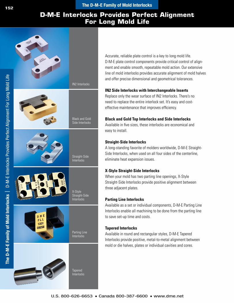
U.S. 800-626-6653 n Canada 800-387-6600 n www.dme.net
152The D-M-E Family of Mold Interlocks
The
D-M
-E F
amily
of M
old
Inte
rloc
ks |
D-M
-E In
terlo
cks
Prov
ides
Per
fect
Alig
nmen
t For
Lon
g M
old
Life
D-M-E Interlocks Provides Perfect Alignment For Long Mold Life
Accurate, reliable plate control is a key to long mold life. D-M-E plate control components provide critical control of align-ment and enable smooth, repeatable mold action. Our extensive line of mold interlocks provides accurate alignment of mold halves and offer precise dimensional and geometrical tolerances.
iN2 Side interlocks with interchangeable insertsReplace only the wear surface of IN2 Interlocks. There’s no need to replace the entire interlock set. It’s easy and cost- effective maintenance that improves efficiency.
Black and Gold Top interlocks and Side interlocksAvailable in five sizes, these interlocks are economical and easy to install.
Straight-Side interlocksA long-standing favorite of molders worldwide, D-M-E Straight-Side Interlocks, when used on all four sides of the centerline, eliminate heat expansion issues.
X-Style Straight-Side interlocksWhen your mold has two parting line openings, X-Style Straight-Side Interlocks provide positive alignment between three adjacent plates.
Parting Line interlocksAvailable as a set or individual components, D-M-E Parting Line Interlocks enable all machining to be done from the parting line to save set-up time and costs.
Tapered interlocksAvailable in round and rectangular styles, D-M-E Tapered Interlocks provide positive, metal-to-metal alignment between mold or die halves, plates or individual cavities and cores.
IN2 Interlocks
Black and Gold Side Interlocks
Straight-Side Interlocks
Parting Line Interlocks
Tapered Interlocks
X-Style Straight-Side Interlocks

Comprehensive line of space-saving
mold components
D-M-E Cavity and Core Components
Cavity and Core Components

Go to www.dme.net/prices for the latest pricing guide.
New!Dual-Ring Mold Dating Insert ................................................... 157
Sintered Vents ........................................................................... 160-161
Online Price Guide
Runner Shut-Off Inserts ............................................................ 166-167
Front Removable Spring ............................................................ 158
Indexable Inserts ...................................................................... 1584mm (New!), 6, 8, 10, 12, 16, 20mm
Front Removable Inserts .......................................................... 158-1596, 8, 10, 12, 16, 20mm
Recycling Inserts ...................................................................... 168
A Comprehensive Line of Standard Components ..................... 169-170
Table of Contents
Air Poppet Valves ...................................................................... 162-163
Cavi
ty a
nd C
ore
Com
pone
nts
| Ta
ble
of C
onte
nts
Cavity and Core Components
Cashew Gate Inserts ................................................................. 164-165
154
U.S. 800-626-6653 n Canada 800-387-6600 n www.dme.net
Cavi
ty a
nd C
ore
Com
pone
nts

U.S. 800-626-6653 n Canada 800-387-6600 n www.dme.net
155
Table of Contents
Molddatinginserts
InsertfamIlygroups . . . . . . . . . . . . . . . . . . . . . . . . . . . . 156
DualrIngwIthorDerInformatIon . . . . . . . . . . . . . 157
InDexable . . . . . . . . . . . . . . . . . . . . . . . . . . . . . . . . . . . . . . . . 158
frontremovableanDItsreplacementrIng . . . . 158
orDerInformatIonfor InDexableanDfrontremovable . . . . . . . . . . . . . 159
sinteredvents
forplastIcsInjectIonmolDIng . . . . . . . . . . . . . . . . 160
forgravItyanDlow-pressureDIecastIng . . . . . . 161
airpoppetvalves
applIcatIonInformatIon . . . . . . . . . . . . . . . . . . . . . . . . 162
InstallatIonanDoperatIngInformatIon . . . . . . 163
gateinserts
rounDorsquarecashewgateInsert . . . . . . . . . . 164
rounDorsquarecashewgateInsert . . . . . . . . . . 165
runnershut-offinserts
InsertanDapplIcatIonInformatIon . . . . . . . . . . . 166
InstallatIon,machInIng anDoperatIngInformatIon . . . . . . . . . . . . . . . . . . 167
recyclinginserts
InsertInformatIon . . . . . . . . . . . . . . . . . . . . . . . . . . . . . 168
Cavity and Core Components | Table of Contents
Cavity and Core Components
Molddatinginsertsdualring-Md . . . . . . . . . . 157indexable-uyM,etc . . . . . 158frontremovable-fyM,etc . . . . . . . . . 158
sinteredventsusv . . . . . .160-161
recyclinginserts-MetricMri . . . . . . . . . .168
airpoppetvalvesva . . . . . . . . . . .162-163
runnershut-offinsertsMrs . . . . . . . . . .166-167
cashewgateinsertsgir,gis . . . . . .164-165

U.S. 800-626-6653 n Canada 800-387-6600 n www.dme.net
156
Mold Dating Insert Family
D-M-E family of mold dating inserts.
featuresandBenefitsofMolddatinginserts
dual-ringMolddatinginsertn Doubleindexable:botharrowsindependently
“clickintoposition”n Allinsertsremainflushwhenrotated
indexableMolddatinginsertsn Providesindexablesnap-in-placealignmentofarrown Uniquedesignkeepsinnerinsertflush
forthreefullturnsn 4mmdiameteravailableinIndexableInsertonly
indexableinsertsandfrontremovableinsertsn Providesproducttraceabilityrequiredin
partqualityprogramsn Allowsplacementofyear,month,day,shiftor
numerals(0-9)onpartforbatchidentificationorproductqualitycontrol
n Easilyadjustableinnerinsertisremovableusingascrewdriver
n Date-sensitiveinnerinsertscanbechangedatthepartinglinewithoutremovingouterinsertfromthemold
n Offersabroadvarietyofinsertdatingcombinationsn Availablein6mm,8mm,10mm,12mm,16mm
and20mmdiametersn Choosefromtwostylestosuityourapplication:
indexableandfrontremovable
Indexable inserts are availablein seven sizes: 4, 6, 8, 10, 12, 16 & 20mm.
Dual-Ring Mold Dating Insert
Front removable inserts are availablein six sizes: 6, 8, 10, 12, 16 & 20mm.
Cavity and Core ComponentsCa
vity
and
Cor
e Co
mpo
nent
s |
Mol
d D
atin
g In
sert
Fam
ily

U.S. 800-626-6653 n Canada 800-387-6600 n www.dme.net
157
Dual-Ring Mold Dating Insert
±0.02
Ø D
Ø E
INNER RING - INDEXABLE (WITH ARROW)
OUTER RING - BODY
INNER INSERT - INDEXABLE (WITH ADUSTING ARROW)
Ø F
.5 x L
Ø D
L
Ø DH7
m6
(RELIEF)
12
6
11 1
7 5 09
10
122 13
8 11
10 4
089
3
L
dual-ringMolddatinginsertofferstheultimateindateinsertflexibility
patentedindexableMolddateinserttechnologyThenewDual-RingMoldDatingInsertfromD-M-EfeaturesadateinsertvalidforsixyearsandisbasedonIndexableMoldDateInserttechnology.
TheDual-RingInserteliminatestheneedtoinstalltwodateinsertsorchangetheinnerinserteachyear.Thiseasy-to-useindexableinsertprovidestheflexibilityyouneedtokeepyourmolddatingcurrent,especiallyasthelifetimeofmoldsbecomesshorter.nOuterring:12months,months1through12nInnerring:6years+arrow(arrowpointstomonth)nCenterinsert:arrow(pointstoyear&adjustspositionofbotharrows)
featuresandBenefitsn Doubleindexable:botharrowsindependently“clickintoposition”n Changepositionseasilywithonlyascrewdriverusingarrowininnerinsert •Turnclockwisetochange“year”arrow(6years)
•Turncounter-clockwisetochange“month”arrow(12months)n Allinsertsremainflushwhenrotatedn Dual-RingInsertmaybeinterchangedforthe10mm,8mmto6mm
diameterIndexableandFrontRemovableinserts
Pocket for installation(hold pocket depth as required by the application)
patentpending
installationandMachiningn Press-fitinstallationrequiredn Maintainaclosetolerancepressfit.Too
looseafitcouldallowtheinserttomoveoutofposition,whiletootightapressfitmightpreventtheinnerinsertandinnerringfromrotatingwhenrequired
n AccuratelymeasuretheØdforeachpartandmachineholetoprovideabout0.005mm(.0002”)pressfit
note:InnerInsert&Innerringarenotreplaceable .Ød
tolerance
m6 h7
10 +0 .015to+0 .006 0 .000to-0 .015
8 +0 .006to+0 .015 0 .000to+0 .015
6 +0 .004to+0 .012 0 .000to+0 .012
dual-ringMolddatinginsert–Mddimensionsandassembly
iteMnuMBer Ød Øe Øf l
length
mD1020_*_ 10 6 .4 3 .2 12
mD0820_*_ 8 5 .3 2 .5 10
mD0620_*_ 6 3 .8 1 .8 10
*whenordering,adddigitsofengravedyearrequiredwhereasterisks(_*_)areshowninitemnumber(e .g .,mD1020_*_:mD102007;mD1020_*_:mD102012) .
inforMationKey:d=outsideDiametere=outsideDiameter ofInnerringf=outsideDiameter ofInnerInsertg=holeDiameterl=length
Material:corrosion-resistantstainlesssteelhardness:53±3hrcMax.temp:150°c(300°f)dimensions:alldimensionsareinmm,exceptasnoted
Cavity and Core Components | D
ual-Ring Mold D
ating InsertCavity and Core Components

U.S. 800-626-6653 n Canada 800-387-6600 n www.dme.net
158
Indexable and Front Removable Mold Dating Inserts
9 0 Ø F
Ø D
L
Ø D(RELIEF)
h7m6
.5 x L
±.02
Ø G
L
OUTER INSERT INDEXABLE
INNERINSERT
INDEXABLE
indexableinsertsu .s .patentno .5,788,872
frontremovableinserts
dimensionsandtolerancesofindexableandfrontremovableinserts
alldimensionsandtolerancesareinmm .
.6 x L
Ø D m6
OUTER INSERT
SPRING
INNER INSERT
L
Ø F 9 0±.02
Ø D(RELIEF)
h7
Ø G
L
featuresofindexableandfrontremovableinsertsn Designedforplasticsinjectionmoldsn Maximumoperatingtemperatureis150°C(300°F)n Numeralsare0.2mmdeepandarrowis0.4mmdeepn Arrowisadjustmentslot
note:springsareforfrontremovableInsertsonly .
frontremovablesprings
iteMnuMBer(packageof5) Ød
Dfq9006 6
Dfq9008 8
Dfq9010 10
Dfq9012 12
Dfq9016 16
Dfq9020 20
Ødtolerance
lØf
InDexableInDex
Øffront
removablem6 h7
4 +0 .012to+0 .004 0to-0 .012 8 2 .4 —
6 +0 .012to+0 .004 0to-0 .012 8 3 .7 3 .1
8 +0 .015to+0 .006 0to-0 .015 10 5 .0 4 .4
10 +0 .015to+0 .006 0to-0 .015 12 6 .3 5 .2
12 +0 .018to+0 .007 0to-0 .018 14 7 .5 6 .2
16 +0 .018to+0 .007 0to-0 .018 14 11 .0 8 .2
20 +0 .021to+0 .008 0to-0 .021 16 13 .2 11
inforMationKey:d= outsideDiameter ofouterInsertf = outsideDiameter ofInnerInsertg= holeDiameterl = lengthMaterial:stainlesssteelhardness:50-55hrcMax.temp:150°c(300°f)dimensions:alldimensionsareinmm,exceptasnoted
installationandMachiningforBothinsertstylesn Press-fitinstallationrequiredn Maintainaclosetolerancepressfit.Toolooseafitcouldallow
theinserttomoveoutofposition,whiletootightapressfitmightpreventtheinnerinsertfromrotatingwhenrequired
n AccuratelymeasuretheØdforeachpartandmachineØgholetoprovideabout0.005mm(.0002”)pressfit
note:Indexablespringsarebuiltin .
n Reliefonbottomofinsertwillaligninsertintohole.
n AnaluminumrodshouldbeplacedagainstthefaceoftheinsertwiththerodlargerindiameterthantheOuterInsert.Thealuminumrodshouldbetappedwithahammertomovetheinserttoitsflushposition.
n Innerinsertmustbeflushorbelowflushduringinstallation.
n Reliefonbottomofinsertwillaligninsertintohole.
n AnaluminumrodshouldbeplacedagainstthefaceoftheinsertwiththerodlargerindiameterthantheOuterInsert.Thealuminumrodshouldbetappedwithahammertomovetheinserttoitsflushposition.
n Innerinsertmustbeflushorbelowflushduringinstallation.
Cavi
ty a
nd C
ore
Com
pone
nts
| In
dexa
ble
and
Fron
t Rem
ovab
le M
old
Dat
ing
Inse
rts
Cavity and Core Components
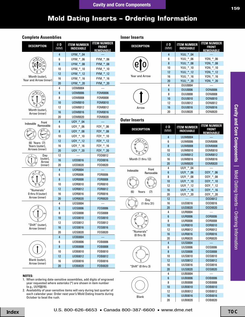
U.S. 800-626-6653 n Canada 800-387-6600 n www.dme.net
159
Mold Dating Inserts – Ordering Information
completeassemblies
description Ød(mm)
—fym_*_06fym_*_08fym_*_10fym_*_12fym_*_16fym_*_20
—fom0006fom0008fom0010fom0012fom0016fom0020
—foy_*_06foy_*_08foy_*_10foy_*_12foy_*_16foy_*_20foD0012foD0016foD0020
—for0006for0008for0010for0012for0016for0020
—fos0006fos0008fos0010fos0012fos0016fos0020
—fob0006fob0008fob0010fob0012fob0016fob0020
468101216204681012162046810121620121620468101216204681012162046810121620
uym_*_04uym_*_06uym_*_08uym_*_10uym_*_12uym_*_16uym_*_20uom0004uom0006uom0008uom0010uom0012uom0016uom0020uoy_*_04uoy_*_06uoy_*_08uoy_*_10uoy_*_12uoy_*_16uoy_*_20
—uoD0016uoD0020uor0004uor0006uor0008uor0010uor0012uor0016uor0020uos0004uos0006uos0008uos0010uos0012uos0016uos0020uob0004uob0006uob0008uob0010uob0012uob0016uob0020
month(outer),yearandarrow(inner)
month(outer),arrow(inner)
Day(outer),arrow(inner)
“shift”(outer),arrow(inner)
“numerals”0thru9(outer)arrow(inner)
blank(outer),arrow(inner)
innerinserts
descriptioniteMnuMBerindexaBle
iteMnuMBerfront
reMovaBle
iteMnuMBerindexaBle
iteMnuMBerfront
reMovaBle
iteMnuMBerindexaBle
iteMnuMBerfront
reMovaBle
—yon_*_06yon_*_08yon_*_10yon_*_12yon_*_16yon_*_20
—oon0006oon0008oon0010oon0012oon0016oon0020
Ød(mm)
4681012162046810121620
yuu_*_04yuu_*_06yuu_*_08yuu_*_10yuu_*_12yuu_*_16yuu_*_20ouu0004ouu0006ouu0008ouu0010ouu0012ouu0016ouu0020
yearandarrow
arrow
notes:1 .whenorderingdate-sensitiveassemblies,adddigitsofengraved
yearrequestedwhereasterisks(*)areshowninitemnumber(e .g .,uuy0916) .
2 .availabilityofyear-sensitiveitemswillvaryduringlastquarterofeachcalendaryear .ordernextyear’smoldDatingInsertsduringoctobertobeattherush .
outerinserts
description
—oom0006oom0008oom0010oom0012oom0016oom0020
—ooy_*_06ooy_*_08ooy_*_10ooy_*_12ooy_*_16ooy_*_20ooD0012ooD0016ooD0020
—oor0006oor0008oor0010oor0012oor0016oor0020
—oos0006oos0008oos0010oos0012oos0016oos0020
—oob0006oob0008oob0010oob0012oob0016oob0020
Ød(mm)
4681012162046810121620121620468101216204681012162046810121620
uum0004uum0006uum0008uum0010uum0012uum0016uum0020uuy_*_04uuy_*_06uuy_*_08uuy_*_10uuy_*_12uuy_*_16uuy_*_20
—uuD0016uuD0020uur0004uur0006uur0008uur0010uur0012uur0016uur0020uus0004uus0006uus0008uus0010uus0012uus0016uus0020uub0004uub0006uub0008uub0010uub0012uub0016uub0020
month(1thru12)
Day(1thru31)
(6) years (7)
(6)years(7)years(outer),
arrows(inner)
Indexable frontremovable
09
1308
11
12
10
09
1408
11
13
1012 09
1308
11
12
10
09
1408
11
13
1012
09
1308
11
12
10
09
1408
11
13
1012 09
1308
11
12
10
09
1408
11
13
101209
1308
11
12
10
09
1408
11
13
1012 09
1308
11
12
10
09
1408
11
13
1012
“shift”(0thru3)1
5
1015 20
251212
345 6 7 8
910
11
98
1212345 6 7 8
910
11
06
0405 07
2
0
13
0
1
2
3
15
1015 20
251212
345 6 7 8
910
11
1234
5 6789
0
1212345 6 7 8
910
11
049899
0001 02
0304
0
1
2
3
1234
5 6789
0
15
1015 20
251212
345 6 7 8
910
11
98
1212345 6 7 8
910
11
06
0405 07
2
0
13
0
1
2
3
15
1015 20
251212
345 6 7 8
910
11
1234
5 6789
0
1212345 6 7 8
910
11
049899
0001 02
0304
0
1
2
3
1234
5 6789
0
“numerals”(0thru9)
15
1015 20
251212
345 6 7 8
910
11
98
1212345 6 7 8
910
11
06
0405 07
2
0
13
0
1
2
3
15
1015 20
251212
345 6 7 8
910
11
1234
5 6789
0
1212345 6 7 8
910
11
049899
0001 02
0304
0
1
2
3
1234
5 6789
0
15
1015 20
251212
345 6 7 8
910
11
98
1212345 6 7 8
910
11
06
0405 07
2
0
13
0
1
2
3
15
1015 20
251212
345 6 7 8
910
11
1234
5 6789
0
1212345 6 7 8
910
11
049899
0001 02
0304
0
1
2
3
1234
5 6789
0
09
09
15
1015 20
251212
345 6 7 8
910
11
98
1212345 6 7 8
910
11
06
0405 07
2
0
13
0
1
2
3
15
1015 20
251212
345 6 7 8
910
11
1234
5 6789
0
1212345 6 7 8
910
11
049899
0001 02
0304
0
1
2
3
1234
5 6789
0
blank
15
1015 20
251212
345 6 7 8
910
11
98
1212345 6 7 8
910
11
06
0405 07
2
0
13
0
1
2
3
15
1015 20
251212
345 6 7 8
910
11
1234
5 6789
0
1212345 6 7 8
910
11
049899
0001 02
0304
0
1
2
3
1234
5 6789
0
15
1015 20
251212
345 6 7 8
910
11
98
1212345 6 7 8
910
11
06
0405 07
2
0
13
0
1
2
3
15
1015 20
251212
345 6 7 8
910
11
1234
5 6789
0
1212345 6 7 8
910
11
049899
0001 02
0304
0
1
2
3
1234
5 6789
0
15
1015 20
251212
345 6 7 8
910
11
98
1212345 6 7 8
910
11
06
0405 07
2
0
13
0
1
2
3
15
1015 20
251212
345 6 7 8
910
11
1234
5 6789
0
1212345 6 7 8
910
11
049899
0001 02
0304
0
1
2
3
1234
5 6789
0
15
1015 20
251212
345 6 7 8
910
11
98
1212345 6 7 8
910
11
06
0405 07
2
0
13
0
1
2
3
15
1015 20
251212
345 6 7 8
910
11
1234
5 6789
0
1212345 6 7 8
910
11
049899
0001 02
0304
0
1
2
3
1234
5 6789
0
15
1015 20
251212
345 6 7 8
910
11
98
1212345 6 7 8
910
11
06
0405 07
2
0
13
0
1
2
3
15
1015 20
251212
345 6 7 8
910
11
1234
5 6789
0
1212345 6 7 8
910
11
049899
0001 02
0304
0
1
2
3
1234
5 6789
0
1212345 6 7 8
910
11
09
Indexable frontremovable
Cavity and Core Components | M
old Dating Inserts – O
rdering Information
Cavity and Core Components

U.S. 800-626-6653 n Canada 800-387-6600 n www.dme.net
160
Sintered Vents – For Plastics Injection Molding
featuresandBenefitsofsinteredvents–usvn Ventingofairorgasreducesoccurrenceof
shortshotsandburnedpartsn Self-containedstandardizedventssavetime
indesign,installationandmaintenancen Widevarietyofoff-the-shelf
standardsizesavailablen Fastandeasyreplacementorcleaning
ofsinteredventsimprovesproductivityn Fieldtestedtoensureproductreliability
sinteredventsforplasticsinjectionMoldingapplicationsventMaterial:ironalloy
venttype
iteMnuMBer
outsidedia
(mm)
fulllength
(mm)
no.ofpores
poredia
(mm)
porosity%of
effectivedia
effectivedia
(mm)
effectivelength
(mm)
b
usv0027 10 10 880 0 .10 29 5 .5 5
usv0028 8 10 880 0 .10 29 5 .5 5
usv0029 10 10 880 0 .05 18 3 .5 5
usv0030 8 10 880 0 .05 18 3 .5 5
usv0031 6 10 880 0 .05 18 3 .5 5
usv0032 10 10 880 0 .03 13 2 .5 5
usv0033 8 10 880 0 .03 13 2 .5 5
usv0034 6 10 880 0 .03 13 2 .5 5
sinteredventsforplasticsinjectionMoldingapplicationsventMaterial:stainlesssteel
venttype
iteMnuMBer
outsidedia
(mm)
fulllength
(mm)
no.ofpores
poredia
(mm)
porosity%of
effectivedia
effectivedia
(mm)
effectivelength
(mm)
a
usv0035 2 10 280 0 .03 25 1 10
usv0036 3 10 630 0 .03 25 1 .5 10
usv0038 2 10 250 0 .05 25 1 .7 10
usv0039 3 10 400 0 .05 25 2 10
usv0040 4 10 400 0 .05 25 2 10
b
usv0041 6 10 400 0 .05 25 2 3
usv0042 8 10 1600 0 .05 25 4 3
usv0043 10 10 3600 0 .05 25 6 3
usv0044 12 10 6400 0 .05 25 8 3
usv0045 15 10 10000 0 .05 25 10 4
usv0046 5 10 76 0 .10 19 2 3
usv0047 6 10 76 0 .10 19 2 3
usv0048 8 10 300 0 .10 19 4 3
usv0049 10 10 690 0 .10 19 6 3
usv0050 12 10 1200 0 .10 19 8 3
Sinteredventsareauniqueventingplugcomposedofalargenumberofstraight,parallelanduniformporesmadethroughapowderedmetallurgyprocess.Theporesallowtrappedairorgastoescapefromthemoldcavityduringtheinjectionmoldingordiecastingprocess,therebyreducingtheoccurrenceofdefectiveparts.
applicationrecommendations
plasticsinjectionmoldingA0.03mmventdiametershouldbeusedwithpolymerssuchaspolyethyleneorpolypropylene.Useaventwithaporediameterof0.05mmforlow-flowpolymerssuchaspolycarbonate,nylon,orABS.Whenmoldinghighlyviscousmaterial(verylow-flowproperties),useaventwitha0.10mmporediameter.
StainlessSteelsinteredventsarerecommendedforplasticmaterialsthatareparticularlygaseousorcorrosive,suchasPVC.StainlessSteelsinteredventsarealsorecommendedforplasticmaterialscontainingflame-retardants.
Cavi
ty a
nd C
ore
Com
pone
nts
| S
inte
red
Vent
s –
For P
last
ics
Inje
ctio
n M
oldi
ngCavity and Core Components
alldimensionsandtolerancesareinmm .

U.S. 800-626-6653 n Canada 800-387-6600 n www.dme.net
161
Sintered Vents – For Gravity & Low-Pressure Diecasting
FULL LENGTH
EFFECTIVELENGTH
EFFECTIVEDIA
OUTSIDEDIA
POREFULL
LENGTH
OUTSIDEDIA
EFFECTIVEDIA
venttype“B”venttype“a”
sinteredventsforgravityandloW-pressurediecastingapplications
ventMaterial:ironalloy
venttype
iteMnuMBer
outsidedia
(mm)
fulllength
(mm)
no.ofpores
poredia
(mm)
porosity%
a
usv0001 4 10 39 0 .5 55
usv0002 6 10 61 0 .5 40
usv0003 6 15 61 0 .5 40
usv0004 8 10 89 0 .5 35
usv0005 8 15 89 0 .5 35
usv0006 10 10 200 0 .5 34
usv0007 10 15 200 0 .5 34
usv0008 12 10 200 0 .5 31
usv0009 12 15 200 0 .5 31
usv0010 14 15 340 0 .5 35
usv0011 16 15 340 0 .5 32
usv0012 18 15 553 0 .5 34
usv0013 20 15 550 0 .5 33
usv0014 28 15 970 0 .5 30
usv0015 5 10 89 0 .3 30
usv0016 5 15 89 0 .3 30
usv0017 6 10 89 0 .3 29
usv0018 6 15 89 0 .3 29
usv0019 8 10 200 0 .3 28
usv0020 8 15 200 0 .3 28
usv0021 10 10 340 0 .3 31
usv0022 10 15 340 0 .3 31
usv0023 12 10 340 0 .3 28
usv0024 12 15 340 0 .3 28
usv0025 14 15 550 0 .3 27
usv0026 10 10 880 0 .2 35
applicationrecommendations
gravityandlow-pressurediecastingDiecastersshoulduseventswithporediametersof0.5mm,0.3mm,or0.2mm,dependingonpressure.
installationinformationforallsinteredventsn Therecommendedpress-fitis0.01to0.02mmfor
outsidediametersof10mmorless,and0.015mmto0.035mmforoutsidediametersover10mm
n Useaplasticorwoodenhammerforinstallation.Donottaptheporesurfaceofthesinteredventwithametallicorhardtool.Theuseofhardtoolswillresultincloggingorchippingofthevents
n Donotgrind,machine,orcuttheporesurfaces
ultrasoniccleaningn Useultrasoniccleaningtoperiodicallyclean
poresinthesinteredvents,asrequired
alldimensionsareinmm .
Cavity and Core Components | Sintered Vents – For Gravity &
Low-Pressure D
iecastingCavity and Core Components

U.S. 800-626-6653 n Canada 800-387-6600 n www.dme.net
162
Air Poppet Valves – Applications
BODY VALVE SPRING
SPRING HOUSING
L
K T MAX APPROX VALVE TRAVEL
A
A
Ø F Ø D Ø E
AIR LINE (PRESSURE OFF) AIR LINE (PRESSURE ACTIVATED)
airpoppetvalves–vafeaturesandBenefitsn Preventsmolddamageduetoejectionproblems
withdeep-draworthin-walledpartsn Moredurableandprecision-madethancompetitiveunits
Theseprecision-engineeredvalvesaredesignedtoremedythevacuumproblemoftenencounteredduringthemoldingofdeep-draw(e.g.,buckets)orthin-walledparts.Airflow,timedtocoincidewiththeejectioncycle,opensthevalvetobreakthevacuumandfacilitatepartejection.Aprecision-groundvalveseathelpspreventflashfromenteringtheassemblyduringinjection.Eachvalveismatchedtothebodytofurtherassurereliableperformance.
iteMnuMBer Ød Øf
(approx)
KboDy
length
loveralllength
Øet
maxtravel
va01 8 6 .6 11 24 6 1 .2
va02 12 9 .7 18 34 8 1 .9
va03 18 14 .8 22 45 .5 12 2 .5
BODY VALVE SPRING
SPRING HOUSING
L
K T MAX APPROX VALVE TRAVEL
A
A
Ø F Ø D Ø E
AIR LINE (PRESSURE OFF) AIR LINE (PRESSURE ACTIVATED)
typicalapplication
Mold Closed Mold Open
alldimensionsshownareinmm .
inforMationKey:d=outsideDiametere=housingDiameterf=approx .valveDiameterg=holeDiameterh=holeDiameterK=bodylengthl=overalllengthn=Depth
t=maxvalvetravelBodyMaterial:stainlesssteelBodyhardness:53±3hrcvalveMaterial:stainlesssteelvalvesurfacetreatment:titaniumnitridedMax.temp:120°c(250°f)operatingairpressure:58psImin . 87psImaxdimensions:alldimensionsareinmm
Cavi
ty a
nd C
ore
Com
pone
nts
| A
ir Po
ppet
Val
ves
– Ap
plic
atio
nsCavity and Core Components
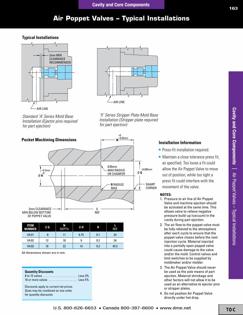
U.S. 800-626-6653 n Canada 800-387-6600 n www.dme.net
163
Air Poppet Valves – Typical Installations
AIR LINE
AIR LINE
2mm MINCLEARANCERECOMMENDED
SHARPCORNER
LREF
Ø HØ G
N
±0.005mm
+0–0.03mm
+0.2mm–0
R RADIUSMAX
0.05mmMAX RADIUSOR CHAMFER
2mm CLEARANCEMIN BELOW BOTTOM
OF POPPET VALVE
AIR LINE
AIR LINE
2mm MINCLEARANCERECOMMENDED
SHARPCORNER
LREF
Ø HØ G
N
±0.005mm
+0–0.03mm
+0.2mm–0
R RADIUSMAX
0.05mmMAX RADIUSOR CHAMFER
2mm CLEARANCEMIN BELOW BOTTOM
OF POPPET VALVE
AIR LINE
AIR LINE
2mm MINCLEARANCERECOMMENDED
SHARPCORNER
LREF
Ø HØ G
N
±0.005mm
+0–0.03mm
+0.2mm–0
R RADIUSMAX
0.05mmMAX RADIUSOR CHAMFER
2mm CLEARANCEMIN BELOW BOTTOM
OF POPPET VALVE
notes:1 .pressuretoairlineofairpoppet
valveandmachineejectionshouldbeactivatedatthesametime .thisallowsvalvetorelievenegativepressurebuild-up(vacuum)inthecavityduringpartejection .
2 .theairflowtothepoppetvalvemustbefullyrelievedtotheatmosphereaftereachcycletoensurethatthepoppetvalveclosesbeforethenextinjectioncycle .materialinjectedintoapartiallyopenpoppetvalvecouldcausedamagetothevalveand/orthemold .controlvalvesandlimitswitchestobesuppliedbymoldmakerand/ormolder .
3 .theairpoppetvalveshouldneverbeusedasthesolemeansofpartejection .materialshrinkageandotherfactorswillnotallowittobeusedasanalternativetoejectorpinsorstripperplates .
4 .Donotpositionairpoppetvalvedirectlyunderhotdrop .
typicalinstallations
alldimensionsshownareinmm .
Standard ‘A’ Series Mold Base Installation (Ejector pins required for part ejection)
‘X’ Series Stripper Plate Mold Base Installation (Stripper plate required for part ejection)
iteMnuMBer Øg n
Depth Øh r lref
va01 8 11 6 .75 0 .1 24
va02 12 18 9 0 .2 34
va03 18 22 14 0 .3 45 .5
pocketMachiningdimensions
Quantitydiscounts8to15valves . . . . . . . . . . . . . . . . . . . . . . . . less3%16ormorevalves . . . . . . . . . . . . . . . . . . . . less5%
Discountsapplytocurrentnetprices .sizesmaybecombinedononeorderforquantitydiscounts .
installationinformationn Press-fitinstallationrequired.n Maintainaclosetolerancepressfit,
asspecified.ToolooseafitcouldallowtheAirPoppetValvetomoveoutofposition,whiletootightapressfitcouldinterferewiththemovementofthevalve.
Cavity and Core Components | Air Poppet Valves – Typical Installations
Cavity and Core Components

U.S. 800-626-6653 n Canada 800-387-6600 n www.dme.net
164Cavity and Core Components
Cashew Gate Inserts
Cavi
ty a
nd C
ore
Com
pone
nts
| C
ashe
w G
ate
Inse
rts
cashewgateinsertBenefitsinclude:n Improvesproductsurfacequalityn Enablessmallerdiametersinthegatearean Providesautomaticseparation
ofrunnerfrompartn Suitableforflatorthin-walled
partapplicationsn Availableoff-the-shelftoreduce
moldbuildtimeandcostsn Easytoreplace,allowingmaximum
molduptime
cashewgatefeaturesinclude:n Precisionmachinedforaccuracyn Highlypolishedgatedetailn Hardenedto54HRCforreliable
performancen AvailableinRoundorSquareinsertstylesn 24sizestosuitmostapplicationsn Recommendedforunfilledmaterials,
includingPS,PP,TPEandABS
roundgateinsertRoundwith
roundedtunnel
squaregateinsertSquarewith
roundedtunnel
4 to 7 x d
2 to 5 x d
d
d H7
thedistancefromthespruepullerpintothegateshouldbe4to7xddependingontheviscosityoftheplasticmaterial.
alongerguidedrunner(approx.length2to5xd)withretainingundercutisrequiredforthespruepullerpin.
Material:1 .2767steelhardness:54±2hrcdimensions:showninmillimeters(mm)

U.S. 800-626-6653 n Canada 800-387-6600 n www.dme.net
165Cavity and Core Components
Cavity and Core Components | Cashew
Gate Inserts
Cashew Gate Inserts
t3
d3
I4
t2
t4
h2
h1+0.02
0
d2
f1
I5
d1 h6
d4
b3b2
I1 h6
b1 h6
b4
d3
t2
t4
h2
h1
+0.020
d1
f1
d1 h6
roundgateinsert–gir
squaregateinsert–gis
iteMnuMBer d1 h1 d2 h2 i5 i4 d4 d3 t4 t3 t2 r1gIr061704 6 17- 0 .4
0 .8 2 5 .5 2 .6 m4 2 5 10 1 .5gIr061706 6 17- 0 .6gIr061708 6 17- 0 .8gIr082206 8 22- 0 .6
0 .8 3 .5 7 .5 2 .8 m4 2 5 10 2gIr082208 8 22- 0 .8gIr082210 8 22- 1gIr102706 10 27- 0 .6
0 .8 4 9 3 m5 2 .25 7 12 2 .25gIr102708 10 27- 0 .8gIr102710 10 27- 1gIr122708 12 27- 0 .8
0 .8 4 .5 11 3 .5 m6 2 .5 7 12 2 .5gIr122710 12 27- 1gIr122712 12 27- 1 .2
iteMnuMBer I1 b1 h1 d1 h2 d3 b4 b3 b2 t4 t2 r1gIs08061204 8 6 17- 0 .4
0 .8 m4 3 .7 1 .3 2 .6 2 10 1 .5gIs08061706 8 6 17- 0 .6gIs08061708 8 6 17- 0 .8gIs10082206 10 8 22- 0 .6
0 .8 m4 4 1 .4 2 .8 2 10 2gIs10082208 10 8 22- 0 .8gIs10082210 10 8 22- 1gIs12102706 12 10 27- 0 .6
0 .8 m5 4 .5 1 .5 3 2 .25 12 2 .25gIs12102708 12 10 27- 0 .8gIs12102710 12 10 27- 1gIs15122708 15 12 27- 0 .8
0 .8 m6 5 1 .75 3 .5 2 .5 12 2 .5gIs15122710 15 12 27- 1gIs15122712 15 12 27- 1 .2

U.S. 800-626-6653 n Canada 800-387-6600 n www.dme.net
166
Runner Shut-Off Inserts – Applications
HOLE FOR SPRING PIN
Ø D*
L
DO NOT ADJUST SPRING PLUNGER.IT HAS BEEN SUPPLIED INSTALLEDTO THE CORRECT POSITION.
* MEASURE Ø D IN THIS AREA ONLY. TOP AND BOTTOM OF INSERT HAVE A VERY SLIGHT RELIEF FOR PROPER INSTALLATION AND OPERATION.
AA
BRASS ROD RECOMMENDED
SCREWDRIVER ENDOF BRASS ROD MUSTFIT IN THE CENTERCORE RUNNER SLOTONLY – DO NOTROTATE THEOUTER RING
OUTER RING
CENTER CORE
LOCATING GROOVE
LOWER BODY
SPRING PLUNGER
SECTION A A
u .s .patentno .5,208,053 D-M-ERunnerShut-OffInsertsprovideaprecisemethodofblockingordirectingmaterialflowtooneormorecavitiesinmulti-cavityorfamilymolds.n Saferandmorepositivethantheuseofbrassorejectorpinsn Savesmaterialn Reducesscrapandsortingn ImprovescycletimeInsertsaresuppliedunmachinedasshowninbackgroundofphoto.Foregroundshowssamplerunnermachining,typicallydonewithinsertinstalledinmold.
note:springplungerinrunnershut-offInsertengagesalocatinggrooveinthecentercore .thisholdsthecentercoreinpositionateach90°rotationofthecentercore,thusprovidingseveralcombinationsofrunnershut-offpositions .
byrotatingthecentercoreoftherunnershut-offInsert90°or180°withthescrewdriverendofabrassrod,materialflowtooneorseveralcavitiescanbeshutoff,asshownabove .
alldimensionsareininchesexceptforseveralparentheticalreferencedimensionsinmillimeters .
iteMnuMBer Ød l
length
mrs0013 .5118(13mm)
.885(22 .5mm)
mrs0016 .6299(16mm)
.885(22 .5mm)
mrs0026 1 .0236(26mm)
1 .260(32mm)
runnershut-offinserts–MrsinforMationKey:c=Depthofrunnerd=Diameterl=lengthr=radiusW=widthofrunnerMaterial:stainlesssteelhardness:50±3hrcMax.temp:120°c(250°f)dimensions:alldimensionsareininches,exceptasnoted
runnershut-offInsertsareshownaboveintheopenposition,whichallowsmaterialtoflowtoallcavities .
typicalapplicationsshuttingofftherunnertooneorseveralcavities
Cavi
ty a
nd C
ore
Com
pone
nts
| R
unne
r Shu
t-O
ff In
sert
s –
Appl
icat
ions
Cavity and Core Components

U.S. 800-626-6653 n Canada 800-387-6600 n www.dme.net
167
Runner Shut-Off Inserts – Machining Information
recoMMendedrunnersizes
useInsertiteMnuMBer
Wmax
cmax
rraDIus
equIvDIa
areasqIn
mrs0013(mrs0016&26)
.099 .091 .040 .095 .007
.126 .120 .050 .123 .012
mrs0016(mrs0026)
.150 .131 .062 .141 .016
.168 .144 .070 .156 .019
.186 .157 .078 .172 .023
.206 .175 .086 .191 .029
mrs0026
.260 .218 .109 .239 .045
.298 .250 .125 .274 .059
.334 .281 .140 .308 .074
.372 .312 .156 .342 .092
.410 .343 .172 .377 .112
.446 .375 .187 .411 .133
(Ø 13mm)
.875* MIN
Ø .22
.020 RMAX
+.002 –.000
.875
+.0000 –.0002 Ø .5118
.020 RMAX
(Ø 16mm) +.0000 –.0002 Ø .6299
Ø .34
+.002 –.000
.875
.020 RMAX
(Ø 26mm) +.0000 –.0002 Ø 1.0236
1.375 MIN
+.002 –.000
1.250
Ø .59
HOLE FOR SPRING PIN MUST BE LOCATED AWAY FROM AREA WHERE RUNNERS ARE TO BE MACHINED, AS SHOWN
.035 MIN. LAND BETWEEN EDGEOF RUNNER AND EDGE OFHOLE FOR SPRING PIN
SPRING PIN HOLDS INSERT COMPONENTS IN POSITION FOR MACHINING RUNNERS
SHARP CARBIDE CUTTERSARE RECOMMENDED FORMACHINING RUNNERS
CENTERLINE OF INSERT
WMAX
CMAX
10°TYP
R
dimensionsforMachiningpocketforrunnershut-offinsertsn Pocketsaretypicallyboredinsoftsteelandjiggroundinhardenedsteeln Maintainaclosetolerancepressfit,asspecified.Toolooseafitcouldallowtheinserttomoveoutofposition, whiletootightapressfitmightpreventthecentercorefromrotatingwhenrequired
*whenusinga7/8thickplatewiththemrs0013ormrs0016inserts,machinethe .5118or .6299diametersthroughtheplate .Insertsmustseatagainstasupportingplatebeforeanygrindingormachiningisdoneandduringthemoldingprocess .
Mrs0013
dimensionsforMachiningrunners
note:allrunnersshouldbemachinedalongthecenterlineoftheinsertandat90°tothecenterline .Ifthisisnotdonetherunnerswillnotaligncloselywhenrotated90°or180°toshut-offmaterialflowtoacavity .allrunnersshouldbemachinedwithinsertsinstalledinthemold .
Mrs0016 Mrs0026
MoldandrunnerMachining/installationdataAdditionalmachiningandinstallationdataavailable.ContactD-M-E.
alldimensionsareininchesexceptforafewmetricreferencedimensionsthatareinmillimetersandareshowninparentheses .
Cavity and Core Components | Runner Shut-O
ff Inserts – Machining Inform
ationCavity and Core Components

U.S. 800-626-6653 n Canada 800-387-6600 n www.dme.net
168
Recycling Inserts
Ø D
L
LOGO SIZE
SHARP
ENGRAVINGDEPTH
.5 x L
±0.02
+0.0–0.018+0.018
+0.007 Ø D(RELIEF)
recyclinginserts(Metric)–Mri
u .s .patentno .D324,392 Benefitsofrecyclinginsertsn Savesoutsourcingand
engravingcostsn Easilyinstalledn Easilyinterchangedn ComplieswithSPIstandards
installationn Pressfitinstallationrequired.n Maintainaclosetolerance
pressfit.Toolooseafitcouldallowtheinserttomoveoutofposition.
n AccuratelymeasuretheØdforeachpartandmachineholetoprovideabout0.005mm(.0002”)pressfit.
iteMnuMBer
materIalcoDes
(spIstanDarD)
materIal harDness engraveDletterIng
materIalIDentIfIcatIon Ød l engraving
depthlogosize
mrI0102 2
420staInless
steel48-52hrc
hDpe hIghDensItypolyethelene
10 12 0 .3 6mrI0105 5 pp polypropylene
mrI0107 7 other allotherresIns
mrI0100 — arrowsymbolonly —
mrI0202 2 hDpe hIghDensItypolyethelene
16 14 0 .3 10mrI0205 5 pp polypropylene
mrI0207 7 other allotherresIns
mrI0200 — arrowsymbolonly —
mrI0602 2
7075-7651alumInum
145-155brInell
hDpe hIghDensItypolyethelene
20 16 0 .3 12mrI0605 5 pp polypropylene
mrI0607 7 other allotherresIns
mrI0600 — arrowsymbolonly —
note:additionalmaterialcodesareavailable .contactD-m-eforquote .
inforMationKey:d=outsideDiameterl=overalllengthengravingdepthlogosizeMaterial:seechartbelowhardness:seechartbelowdimensions:alldimensionsare inmm
Cavi
ty a
nd C
ore
Com
pone
nts
| R
ecyc
ling
Inse
rts
Cavity and Core Components

U.S. 800-626-6653 n Canada 800-387-6600 n www.dme.net
169
A Comprehensive Line of Standard Components
Cavity and Core Components
d-M-estandardcomponents:ahallmarkoftheplasticsindustry
It’snotuncommonforamolddesigner,moldmaker,ormoldertoengineeraspecializedcomponentthatisavailableasastandard,off-the-shelfproduct.D-M-E,aworldwideleaderwithitsbroadofferingofstandardizedmoldcomponents,frequentlyinventsnewtechnologies,suchasInnovativeIN2Interlockswiththeirinterchangeablewearsurfaces,andtheDual-RingMold-DatingInsertwithitspatented‘click-into-position’indexablemolddatingtechnology.Moreoptionsandfasterdeliveryofbasiccomponents,suchasadvancedmoldactionproductslikeD-M-EVectorFormLifterSystems,havebecomeahallmarkoftoday’smoldingindustry.
ThewiderangeofstandardcomponentsavailablefromD-M-Ehasonecommontheme:allareproblem-solvingdevicesthatmakelifeeasierforthemolddesigner,moldmaker,andmolder.Eachcomponentwasoriginallycreatedbyacraftspersoninthefield,butthankstoindustriousingenuity,therestofusdon’thavetoreinventthewheel.
Followingareafewofthelatestindustryinnovationsthatwerecreatedtomeetrisingmoldingchallenges.
Cavity and Core Components | A Com
prehensive Line of Standard Components
euro-standardMoldBases&components.thereismorethanonestandardaroundtheworldwhenitcomestomoldbases .moldsbuiltineuropeuseastandardquitedifferentfromtheInchstandardcommonlyusedinnorthamerica .asmoldingprogramsaccelerateintheirfrequencytomovefromoneregionoftheworldtoanother,D-m-erecognizestheimportanceofhavingeasyaccesstothemoldcomponentsthatfitthemoldthatyouareworkingontoday .weoffereuro-seriesmoldbasesandmorethan4,000euro-seriesmoldcomponents,aswellasstandardDInandjIsproducts .See the Mold Components section of this catalog for a myriad of product selections.
dual-rodliftersystems.mostoff-the-shelfliftersystemstodayarebaseduponthesimple,single-rodliftersystem .thedual-purpose(guidingandlifting)single-rodofasingle-rodliftersystemintroducesaninordinatebendingmomentuponthedual-purposesingle-rod .thisresultsinthewell-documentedlimitationsofthesingle-rodsystems:limitedliftangles(generally15˚orless),inabilitytoliftlargeliftercores,inabilitytoliftverysmallcores,difficultyinchangingthespeedoftheliftercore,andinadequatecooling .ontheotherhand,adual-rod,liketheD-m-evectorformliftersystem,separatestheliftingandguidingmotions,dramaticallyreducingthebendingmomentandallbuteliminatestheaforementionedlimitations .See the Molding Undercuts section of this catalog for solutions to molding products with threads, dimples, undercuts, protrusions or cut-outs.
platecontroldevices.manyoftoday’smoldshavemultipleplatesmovingduringthemoldopenandclosesequence .ensuringthattheseplatemovementsarecoordinatedandtimedtoavoidmoldcrashingisimperative .apositiveandprecisemechanismisgenerallypreferredtootherlessoptimalsolutionssuchassprings .springswearwithuse,anddonotprovidethepositiveprecisionofmechanicalplatecontroldevices .springscanallowplatestotiltduringmovement,placingunduestressandwearonthemoldanditsplatealignmentcomponents .See the Plate and Pin Control section of this catalog for solutions, including Helical Gear Stack Mold Components, the Internal Latch Lock, and the Toggle-Lok.

U.S. 800-626-6653 n Canada 800-387-6600 n www.dme.net
170Cavity and Core Components
A Comprehensive Line of Standard Components
two-stageejectors.complexmoldscommonlyhavemultipleejectorplates .timingmultipleejectorplatescanbeaccomplishedbyavarietyofmethods,includingsprings .two-stageejectorshavebeenusedineuropefordecades .theyoffersimplifieddesignandinstallationintoamold,aswellastheabilitytoprovidelonglasting,positive,precisepositioningofejectorplates .D-m-e2-stageejectorscanbeoffsetfromthemoldcenter,encouragingtheiruseinmoldsbuiltinnorthamerica .See the Plate and Pin Control section for 2-Stage Ejectors.
Moldinterlocks.originallyofferedinrectangularorroundarrangementsthatwereinsertedfromthepartingline,moldinterlocksthatmountonthesideofthemoldarenowavailable .thesesideinterlockshavetheadvantageofmaximizingtheareainsideofthemold .additionally,anewD-m-einnovation—In2Interlockswithinterchangeablewearsurfaces—hasrecentlybeenintroducedthatoffersuperiormaterialsandtheabilitytointerchangethewearsurfacesratherthantheentireinterlocksetduringmoldmaintenance .See the Plate and Pin Control section for a wide offering of D-M-E interlocks.
runnershut-offs.Itissometimesdesirabletohavetheabilitytoselectivelyshut-offdifferentcavitiesinamulti-cavitymold .runnershut-offinsertsareasimplewaytoachievecontrolofwhichcavitiesaretobeactiveandwhicharetobeidleinmulti-cavitymolds .simpletoinstallandeveneasiertooperate,thesedevicesareavailableinavarietyofsizesandareeasilycustomizabletovirtuallyanystyleofcoldrunners .See this Cavity and Core Components section for D-M-E Runner Shut-Off Inserts.
venting.It’safact—whenplasticfillsacavity,trappedairmustgosomewhere .burningandflowrestrictionsarethemostcommonsymptomsofthisproblem .Inthepastventingwasaccomplishedbymachiningslotsoppositethegate,orbyputtingflatsontheleaderpins—resultinginnonuniformventingandcomplicatedremachiningintheeventofarepair .advancesinpowdermetallurgyhaveenabledthecreationofstandardizedsintered,porousmetallicvents .theseventingplugsarecomposedofalargenumberofstraight,parallel,uniformporesthatallowtrappedairorgastoescapethecavity .See D-M-E Sintered Vents in this Cavity and Core Components section for your venting solutions.
slideretainers.whenthecampinmovesoutoftheslideuponmoldopening,amethodmustbeemployedtoensurethattheslidedoesnotmovebacktoitsmold-closedpositionanddamagethemold .somemolddesignsemployasimplespringorahomemadecomponenttopreventtheslidefrommovingback .however,simplespringsandhomemadecomponentsmaywearorbreakunpredictably.D-M-E Slide Retainers, in the Slide Action Components section, make obsolete the cumbersome external spring or hydraulic methods.
Cavi
ty a
nd C
ore
Com
pone
nts
| A
Com
preh
ensi
ve L
ine
of S
tand
ard
Com
pone
nts

Reducing cycle time through cooling innovation
D-M-E Mold Cooling
Mold Cooling

Go to www.dme.net/prices for the latest pricing guide.
Inch Brass Pressure Plugs .................................................173
Bubbler Tubes and Brass Diverting Plugs & Rods .............181
Straight and Spiral Baffles ..........................................184-185
Jiffy-Tite Connector Seals, Seal Removal Tool Kit & Wrenches ...................................179
Jiffy-Tite Connectors, Plugs, Extension Plugs ...........................................................174-175
Jiffy-Lok® Connectors Sockets ................................... 176-178
Heat Pipes ..................................................................186-187
Coolant Bridges .................................................................180
Jiffy-Tite Cascade Water Junctions,Cascade Water Junctions ...........................................182-183M
old
Cool
ing
| T
able
of C
onte
nts
172
U.S. 800-626-6653 n Canada 800-387-6600 n www.dme.net
Table of Contents
Mold CoolingM
old
Cool
ing
Online Price Guide

U.S. 800-626-6653 n Canada 800-387-6600 n www.dme.net
173
Brass Pressure Plugs
D
Threadless Brass Pressure Plugs
LS
O-RING
Brass Pressure
Plugs
TYPICAL APPLICATIONS
S
HIGH-PRESSURE SEAL Dryseal thread form with 7/8 taper per foot. Install in standard 3/4 TPF tapped hole.
L
Threadless Brass Pressure Plugs (Inch) – TBPn Sealseveninroughorcorrodedholesn Notappingrequiredn Withstandspressuresupto72psi
D-M-EThreadlessBrassPressurePlugsemployatime-savingexpandableO-ringdesign.Astheplug’ssocketheadscrewistightened,theO-ringexpandstoprovideapositiveseal.Notappingisrequiredandinstallationorremovalisquickandeasy.Thesmallerdiametersareidealforuseincavityinsertsorslideblockswherespaceislimited. (Not recommended for use in oil lines.)
NoTe: O-ring material is suitable for use with temperatures up to 300°F.
ITem NumBer
nOminal size
lengthl
hex size
S
drillsize
d
VitOnreplacement
O-rings(pkg. OF 10)
tBp-10 1/8 .50 5 /64 11/32 rcV0009
tBp-10-0s 1/8 .50 5 /64 23 /64 rcV0009
tBp-20 1/4 .56 1/8 7/16 rcV0011
tBp-20-0s 1/4 .56 1/8 29 /64 rcV0011
tBp-40 3 /8 .62 1/8 9 /16 rcV0110
tBp-40-0s 3 /8 .62 1/8 37/64 rcV0110
tBp-60 1/2 .62 1/8 11/16 rcV0112
tBp-60-0s 1/2 .62 1/8 45 /64 rcV0112
Brass Pressure Plugs (Inch) – BPn Forsteam,wateroroillinesn Positivetaperedsealn Withstandspressuresupto600psi
D-M-EBrassPressurePlugsgiveahigh-pressuresealthroughadeliberatedifferenceoftaperbetweentheplugandthetappedhole.Flushseatingisachievedthroughclosercontrolofthreadforms,sizesandtaper.
ITem NumBer
nOminal size (npt)
lengthl
hex size
S
threadstap
inchtap
drill
Bp-10 1/8 .250 3 /16 27 21/64
Bp-20 1/4 .406 1/4 18 27/64
Bp-40 3 /8 .406 5 /16 18 9 /16
Bp-60 1/2 .531 3 /8 14 11/16
Bp-100 3 /4 .531 9 /16 14 57/64
Bp-140 1 .656 5 /8 111/2 11/8
Brass Pressure Plugs (metric) – AN
ITem NumBer r l SW
an-8 1/8" Bspt 8 5
an-4 1/4" Bspt 10 7
an-3 3/8" Bspt 10 8
an-10 m 10 x 1 8 5
an-2 1/2" Bspt 10 10
R
1:16
SWL
QuANTITY dISCouNTS: threadless and threaded Brass pressure plugs. sizes may be mixed for quantity discounts. discounts apply to current net prices. 50 to 99 less 15%; 100 or more less 20%
Mold Cooling | Brass Pressure Plugs
Mold Cooling
R
1:16
SWL

U.S. 800-626-6653 n Canada 800-387-6600 n www.dme.net
174
Jiffy-Tite® Connectors
D-M-EJiffy-TiteplugsusedwithD-M-EJiffy-Tite(flow-thrutype)SocketsandD-M-EJiffy-Matic(automaticshut-offtype)Socketsaredesignedforusewithplasticsmoldsanddie-castdiesinwater,airoroillines.Theyfeatureacombinationbrassandstainlesssteelleakproofconstruction;haveamaximumratedcapacityof200psi;andwithstandtemperaturesupto400°F,withsuppliedVitonseals.D-M-EJiffy-TiteandJiffy-MaticSocketscanbeusedinterchangeablywiththesameJiffy-TitePlugsalreadyinyourmoldordie.ComparablesizesofbothtypesocketshavethesameO.D.,permittinginterchangeabilityevenwhentheplugsareflushmounted.
d-m-e Jiffy-tite sockets have a large thru hole to provide unrestricted flow. these quick-connection couplers are available with either straight, 45° or 90° hose stems, or standard female or male npt threads.
d-m-e Jiffy-tite and Jiffy-matic sockets have the same O.d., permitting complete interchangeability with Jiffy-tite plugs installed in your mold or die.
the Jiffy-tite or Jiffy-matic sockets can be used with either male, female or extension plugs.
Jiffy-Tite® Sockets – JS(Flow-Thru Type)
VALVE OPEN
VALVE CLOSED
Jiffy-matic® Sockets – JS (Automatic Shut-off Type)
d-m-e Jiffy-matic sockets open automatically when connected and shut off automatically when disconnected. Unlike most valve-type connectors, Jiffy-matic sockets are designed to keep flow restriction to a minimum.
JiFFy-tite sOckets JiFFy-matic sOckets
descriptiOnITem
NumBerFits hOse i.d.
Or pipe threadhOse stem i.d. Or thrU hOle
Used with stdmale, Female Or extensiOn plUgs
ITemNumBer descriptiOn
straight stem
Js-204 1/4 3 /16 Jp-(F/B) 250 tO 253 Js-204-V
straight stem
Js-205 5 /16 1/4 Jp-(F/B) 250 tO 253 Js-205-VJs-206 3 /8 1/4 Jp-(F/B) 250 tO 253 Js-206-VJs-306 3 /8 1/4 Jp-(F/B) 351 tO 354 Js-306-VJs-308 1/2 3 /8 Jp-(F/B) 351 tO 354 Js-308-VJs-504 1/2 3 /8 Jp-(F) 553 tO 556 Js-504-VJs-506 3 /4 5 /8 Jp-(F) 553 tO 556 Js-506-V
90° stem
Js-214 1/4 3 /16 Jp-(F/B) 250 tO 253 Js-214-V
90° stem
Js-215 5 /16 1/4 Jp-(F/B) 250 tO 253 Js-215-VJs-216 3 /8 1/4 Jp-(F/B) 250 tO 253 Js-216-VJs-316 3 /8 1/4 Jp-(F/B) 351 tO 354 Js-316-VJs-318 1/2 3 /8 Jp-(F/B) 351 tO 354 Js-318-VJs-514 1/2 3 /8 Jp-(F) 553 tO 556 Js-514-VJs-516 3 /4 9 /16 Jp-(F) 553 tO 556 Js-516-V
45° stem
Js-224 1/4 3 /16 Jp-(F/B) 250 tO 253 Js-224-V
45° stem
Js-225 5 /16 1/4 Jp-(F/B) 250 tO 253 Js-225-VJs-226 3 /8 1/4 Jp-(F/B) 250 tO 253 Js-226-VJs-326 3 /8 1/4 Jp-(F/B) 351 tO 354 Js-326-VJs-328 1/2 3 /8 Jp-(F/B) 351 tO 354 Js-328-VJs-524 1/2 3 /8 Jp-(F) 553 tO 556 Js-524-VJs-526 3 /4 9 /16 Jp-(F) 553 tO 556 Js-526-V
Female npt thread
Js-200 1/8 npt 1/4 Jp-(F/B) 250 tO 253 Js-200-V
Female npt threadJs-300 1/4 npt 3 /8 Jp-(F/B) 351 tO 354 Js-300-VJs-500 1/2 npt 5 /8 Jp-(F) 553 tO 556 Js-500-V
male npt thread
Js-201-m 1/8 npt 1/4 Jp-(F/B) 250 tO 253 Js-201-mV
male npt threadJs-302-m 1/4 npt 3 /8 Jp-(F/B) 351 tO 354 Js-302-mVJs-504-m 1/2 npt 9 /16 Jp-(F) 553 tO 556 Js-504-mV
QuANTITY dISCouNTS: Jiffy sockets or plugs. discounts apply to current net prices. see list price adjustment. standard sizes may be combined on one order for quantity discounts. 50 to 99 less 15%; 100 or more less 20%
Mol
d Co
olin
g |
Jiff
y-Ti
te® C
onne
ctor
sMold Cooling
SOCkET Plug

U.S. 800-626-6653 n Canada 800-387-6600 n www.dme.net
175
Jiffy-Tite® Plugs and Extension Plugs
ITem NumBer npt hex size A B C h Jp-250 1/16 7/16 11/16 11/16 1" 5 /8
Jp-251 1/8 7/16 11/16 11/16 1" 5 /8
Jp-252-(sV) 1/4 9 /16 27/32 15 /16 13 /16 7/8
Jp-253-(sV) 3 /8 11/16 1.000 15 /16 11/4 29 /32
Jp-351 1/8 9 /16 1.000 15 /16 11/4 7/8
Jp-352-(sV) 1/4 9 /16 1.000 13 /32 17/16 11/32
Jp-353-(sV) 3 /8 11/16 1.000 11/8 17/16 11/16
Jp-354-(sV) 1/2 7/8 13 /16 11/4 19 /16 13 /16
Jp-553 3 /8 7/8 11/4 13 /16 15 /8 11/8
Jp-554 1/2 7/8 11/4 11/2 113 /16 17/16
Jp-556 3 /4 11/8 11/2 19 /16 17/8 11/2
H
A
CB
FLUSH MOUNTED PLUG
EXTERNALLY MOUNTED PLUG
Jiffy-Tite® Plugs – JPmale Plug mounting Information
Jiffy-Tite® extension Plugs* – JPBFor use with Jiffy-Tite or Jiffy-matic Sockets (Including SV Series)
Jiffy-Tite male – JP and Female Plugs – JPFFor use with Jiffy-Tite or Jiffy-matic Sockets (Including SV Series)
** designed for use with existing or new npt tapered pipe-tapped hole in mold or die. straight threaded area allows easy length adjustment. cut to suit. no tapering or re-tapping necessary.
all male plugs (including sV-series) and extension plugs are now supplied with Jiffy-seal™ thread sealant. eliminating the initial need for joint tape or compound, the sealant will withstand temperatures up to 400°F and pressures up to 200 psi.
descriptiOn length l pipe thread Ø hOle hex size ITem NumBer Used with sOckets
male plUg(Brass)
59 /64 1/16 npt 3 /16 7/16 Jp-250 Js-204-(V/sV)tO
Js-226-(V/sV)
59 /64 1/8 npt 1/4 7/16 Jp-25115 /32 1/4 npt 1/4 9 /16 Jp-25213 /16 3 /8 npt 1/4 11/16 Jp-25313 /16 1/8 npt 1/4 9 /16 Jp-351 Js-306-(V/sV)
tOJs-328-(V/sV)
125 /64 1/4 npt 3 /8 9 /16 Jp-352125 /64 3 /8 npt 3 /8 11/16 Jp-353137/64 1/2 npt 3 /8 7/8 Jp-35419 /16 3 /8 npt 7/16 7/8 Jp-553 Js-504-(V)
tOJs-526-(V)
13 /4 1/2 npt 5 /8 7/8 Jp-55413 /4 3 /4 npt 5 /8 11/8 Jp-556
Female plUg**
(Brass)
1" 1/16 npt 1/4 1/2 JpF-0250 Js-204-(V/sV)tO
Js-226-(V/sV)
1" 1/8 npt 1/4 1/2 JpF-025119 /32 1/4 npt 1/4 5 /8 JpF-0252113 /32 3 /8 npt 1/4 3 /4 JpF-025319 /32 1/8 npt 11/32 5 /8 JpF-0351 Js-306-(V/sV)
tOJs-328-(V/sV)
131/64 1/4 npt 3 /8 5 /8 JpF-0352137/64 3 /8 npt 3 /8 3 /4 JpF-0353149 /64 1/2 npt 3 /8 15 /16 JpF-0354111/16 3 /8 npt 9 /16 15 /16 JpF-0553 Js-504-(V)
tOJs-526-(V)
149 /64 1/2 npt 5 /8 15 /16 JpF-0554149 /64 3 /4 npt 5 /8 11/8 JpF-0556
LMALEPLUG
(BRASS)
LFEMALE
PLUG(BRASS)
LMALEPLUG
(BRASS)
LFEMALE
PLUG(BRASS)
pipethread*
hexsize O.a.l.
ITemNumBer
Used withsOckets
1/8 7/16 4" JpB-2514
Js-204-(V/sV)
tO
Js-226-(V/sV)
1/8 7/16 6" JpB-25161/8 7/16 8" JpB-25181/4 9 /16 4" JpB-25241/4 9 /16 6" JpB-25261/4 9 /16 8" JpB-25283 /8 11/16 4" JpB-25343 /8 11/16 6" JpB-25363 /8 11/16 8" JpB-25381/8 9 /16 4" JpB-3514
Js-306-(V/sV)
tO
Js-328-(V/sV)
1/8 9 /16 6" JpB-35161/8 9 /16 8" JpB-35181/4 9 /16 4" JpB-35241/4 9 /16 6" JpB-35261/4 9 /16 8" JpB-35283 /8 11/16 4" JpB-35343 /8 11/16 6" JpB-35363 /8 11/16 8" JpB-3538
O.a.l.
2-3/8
male Plug
Female Plug
threaded area with Jiffy-seal thread sealant pre-applied.
QuANTITY dISCouNTS: Jiffy sockets or plugs. discounts apply to current net prices. see list price adjustment. standard sizes may be combined on one order for quantity discounts. 50 to 99 less 15%; 100 or more less 20%
Mold Cooling | Jiffy-Tite
® Plugs and Extension PlugsMold Cooling

U.S. 800-626-6653 n Canada 800-387-6600 n www.dme.net
176
SV-Series Jiffy-Matic® Connectors
VALVES OPEN
VALVES CLOSED
VALVE OPEN
VALVE CLOSED
the d-m-e sV-series Jiffy-matic male plugs feature an automatic shut-off stemmed valve. this plug design adds the capability of automatic shut-off at the mold. the plug’s shut-off stemmed valve minimizes mold coolant loss, thereby decreasing clean-up time and the possibility of rust occurring on the mold surface. the sV-series Jiffy-matic male plug can Only be used with the sV-series Jiffy-matic socket.
operating Combinations
*the sV-series Jiffy-matic male plugs can only be used for two-way shut-offs and must be used with the sV-series Jiffy-matic sockets.
SV-Series Jiffy-matic® male Plugs(Automatic Shut-off Type with Stemmed Valve)
SV-Series Jiffy-matic® Sockets(Automatic Shut-off Type with Stemmed Valve)
the d-m-e sV-series Jiffy-matic sockets feature an automatic shut-off stemmed valve that is designed to work with the sV-series Jiffy-matic male plugs, as well as the standard male, female and extension plugs. the sockets open automatically when connected and shut-off automatically when disconnected. the sV-series Jiffy-matic sockets are designed to keep flow restriction to a minimum and are available with either straight, 45° or 90° hose stems.
SV-Series Jiffy-matic® Connectors – JSTwo-Way Automatic Shut-off Type
TheD-M-ElineofSV-SeriesJiffy-MaticConnectorsfeaturesamaleplugandsocket,eachwithanautomaticshut-offsteamedvalve.Theseconnectorsaredesignedforusewithplasticmoldsanddie-castdiesinwater,airorheattransferoillines.Theyfeatureacombinationofbrassandstainlesssteelinaleakproofconstruction,haveamaximumratedcapacityof200psiandwillwithstandtemperaturesupto400°FwithsuppliedVitonseals.
TheSV-SeriesJiffy-MaticMalePlugsaddsthecapabilityofautomaticshut-offatthemold,therebyminimizingcoolantloss.
D-M-ESV-SeriesJiffy-MaticSocketscanbeusedinterchangeablywiththeJiffy-Titeplugsalreadyinyourmoldordie.However,theSV-SeriesJiffy-MaticMalePlugscanONlYbeusedwiththeSV-SeriesJiffy-MaticSockets.ComparablesizesofbothtypesofsocketsandplugshavethesameO.D.,permittinginterchangeabilityevenwhentheplugsareflush-mounted.
TheSV-SeriesMalePlugsarenowsuppliedwithJiffySeal®threadsealant.Eliminatingtheinitialneedforjointtapeorcompound,thesealantwillwithstandtemperaturesupto400°Fandpressuresupto200psi.
SV-SerIeS*mAle PlugS WITh
SV-SerIeSSoCkeTS
(eQuIVAleNT SIze)
Two-Way Shut-off*STd. mAle, FemAle
or exTeNSIoN PlugS
WIThSV-SerIeSSoCkeTS
(eQuIVAleNT SIze)
one-Way Shut-off
STEMMED VALVE (SV)STEMMED VALVE (SV) STEMMED VALVE (SV)STEMMED VALVE (SV)
SOCkET Plug
Mol
d Co
olin
g |
SV-
Serie
s Ji
ffy-M
atic
® C
onne
ctor
sMold Cooling

U.S. 800-626-6653 n Canada 800-387-6600 n www.dme.net
177
SV-Series Jiffy-Matic® Connectors
descriptiOnlength
lpipe
threadØ
hOlehexsize
ITem NumBer
Used with sOckets*
(Brass)
15 /32 1/4 npt 1/4 9 /16 Jp-252-sV Js-204-sV tOJs-226-sV13 /16 3 /8 npt 1/4 11/16 Jp-253-sV
125 /64 1/4 npt 3 /8 9 /16 Jp-352-sV**Js-306-sV tO
Js-328-sV125 /64 3 /8 npt 3 /8 11/16 Jp-353-sV
137/64 1/2 npt 3 /8 7/8 Jp-354-sV
L(BRASS)
descriptiOnITem
NumBerFits hOse i.d.
Or pipe threadhOse stem i.d. Or thrU hOle
Used with sV-male, std male, Female Or extensiOn plUgs
straight stem
Js-204-sV 1/4 3 /16 Jp-(F/B) 250 tO 253 (sV)
Js-205-sV 5 /16 1/4 Jp-(F/B) 250 tO 253 (sV)
Js-206-sV 3 /8 1/4 Jp-(F/B) 250 tO 253 (sV)
Js-306-sV 3 /8 1/4 Jp-(F/B) 351 tO 354 (sV)
Js-308-sV 1/2 3 /8 Jp-(F/B) 351 tO 354 (sV)
90° stem
Js-214-sV 1/4 3 /16 Jp-(F/B) 250 tO 253 (sV)
Js-215-sV 5 /16 1/4 Jp-(F/B) 250 tO 253 (sV)
Js-216-sV 3 /8 1/4 Jp-(F/B) 250 tO 253 (sV)
Js-316-sV 3 /8 1/4 Jp-(F/B) 351 tO 354 (sV)
Js-318-sV 1/2 3 /8 Jp-(F/B) 351 tO 354 (sV)
45° stem
Js-224-sV 1/4 3 /16 Jp-(F/B) 250 tO 253 (sV)
Js-225-sV 5 /16 1/4 Jp-(F/B) 250 tO 253 (sV)
Js-226-sV 3 /8 1/4 Jp-(F/B) 250 tO 253 (sV)
Js-326-sV 3 /8 1/4 Jp-(F/B) 351 tO 354 (sV)
Js-328-sV 1/2 3 /8 Jp-(F/B) 351 tO 354 (sV)
Female npt thread
Js-200-sV 1/8 npt 1/4 Jp-(F/B) 250 tO 253 (sV)
Js-300-sV 1/4 npt 3 /8 Jp-(F/B) 351 tO 354 (sV)
male npt thread
Js-201-msV 1/8 npt 1/4 Jp-(F/B) 250 tO 253 (sV)
Js-302-msV 1/4 npt 3 /8 Jp-(F/B) 351 tO 354 (sV)
SV-Series Jiffy-matic Sockets – JS(Automatic Shut-off Type with Stemmed Valve)
90° and 45° NPT elbows(For Female and male NPT Sockets only)
descriptiOn ITem NumBer pipe thread thrU hOle Used with sOckets
90° npt elBOw
200-90 1/8 npt 7/32 Js-200 (-V/sV) tO Js-201m (V/sV)
300-90 1/4 npt 5 /16 Js-300 (-V/sV) tO Js-302m (V/sV)
500-90 1/2 npt 9 /16 Js-500 (-V) tO Js-504m (-V)
45° npt elBOw
200-45 1/8 npt 7/32 Js-200 (-V/sV) tO Js-201m (-V/sV)
300-45 1/4 npt 5 /16 Js-300 (-V/sV) tO Js-302m (-V/sV)
500-45 1/2 npt 9 /16 Js-500 (-V) tO Js-504m (-V)
SV-Series Jiffy-matic male Plugs* – JS(Automatic Shut-off Type with Stemmed Valve)
90° NPT ELBOW
45° NPT ELBOW
these 90° and 45° npt elbows can be used with either Jiffy-tite or Jiffy-matic, V or sV, female or male npt sockets only.
** the sV-series Jiffy-matic male plugs operate only with the sV-series Jiffy-matic sockets. all sV-series Jiffy-matic male plugs are supplied with Viton seals for use in water, air and heat transfer oil applications that do not exceed 400°F and 200 psi.
** the Jp-352-sV male plug has a stepped valve-seat due to the internal space limitations of the 1/4 npt thread. even so, it has a greater flow rate than the Jp-252-sV male plug, which also has the 1/4 npt thread.
90° NPT ELBOW
45° NPT ELBOW
Mold Cooling | SV-Series Jiffy-M
atic® Connectors
Mold Cooling
SOCkET Plug
QuANTITY dISCouNTS: Jiffy sockets or plugs. discounts apply to current net prices. see list price adjustment. standard sizes may be combined on one order for quantity discounts. 50 to 99 less 15%; 100 or more less 20%

U.S. 800-626-6653 n Canada 800-387-6600 n www.dme.net
178
Jiffy-Lok® Connector Sockets
With Clampless hose Stems for use with “Push-To-lock” Type hose
n Forusewith“Push-to-lock”typehoseonly
n Savesset-uptimebyeliminatingtheneedforhoseclamps
n Hosestembarbsmatewith“Push-to-lock”stylerubberhose
n PopularsizesforinterchangeabilitywithexistingJiffy-Tite,Jiffy-MaticandJiffy-MaticSVSockets
n Morecompactandconsistentlysizedthancompetitivesockets
n leakproofbrassandstainlesssteelconstruction
n Replaceablesealsandvalvesforlongservicelife
n SocketconnectorsealsareViton
NoTe: Use “push-to-lock” type hose only. Jiffy-lok connector sockets are for use with water and water-based coolants only. although Jiffy-lok connector sockets are suitable for temperatures to 400°F, observe the temperature ratings of your “push-to-lock” hose. most “push-to-lock” hose has a temperature rating of 175°F or less. never exceed 200 psi.
* sV-series male plugs must be used to obtain two-way shutoff. installation data available. contact d-m-e.
descriptiOnITem
NumBer
Fits hOse
i.d.
hOse stem
i.d.
Used with: std. male, Female Or extensiOn plUgs
straight stem
Jsl0204 1/4 3 /16 Jp-(F/B) 250 tO 253Jsl0206 3 /8 1/4 Jp-(F/B) 250 tO 253Jsl0306 3 /8 1/4 Jp-(F/B) 351 tO 354Jsl0308 1/2 3 /8 Jp-(F/B) 351 tO 354Jsl0504 1/2 3 /8 Jp-(F) 553 tO 556Jsl0506 3 /4 5 /8 Jp-(F) 553 tO 556
90° stem
Jsl0214 1/4 3 /16 Jp-(F/B) 250 tO 253Jsl0216 3 /8 1/4 Jp-(F/B) 250 tO 253Jsl0316 3 /8 1/4 Jp-(F/B) 351 tO 354Jsl0318 1/2 3 /8 Jp-(F/B) 351 tO 354Jsl0514 1/2 3 /8 Jp-(F) 553 tO 556Jsl0516 3 /4 5 /8 Jp-(F) 553 tO 556
45° stem
Jsl0224 1/4 3 /16 Jp-(F/B) 250 tO 253Jsl0226 3 /8 1/4 Jp-(F/B) 250 tO 253Jsl0326 3 /8 1/4 Jp-(F/B) 351 tO 354Jsl0328 1/2 3 /8 Jp-(F/B) 351 tO 354Jsl0524 1/2 3 /8 Jp-(F) 553 tO 556Jsl0526 3 /4 5 /8 Jp-(F) 553 tO 556
Jiffy-lok Flow-Thru Style (Jiffy-Tite)
Jiffy-lok one-Way Valve Style (Jiffy-matic)
descriptiOnITem
NumBer
Fits hOse
i.d.
hOse stem
i.d.
Used with: sV-male, std. male, Female Or
extensiOn plUgs
straight stem
Jsl0204-sV 1/4 3 /16 Jp-(F/B) 250 tO 253 (sV)Jsl0206-sV 3 /8 1/4 Jp-(F/B) 250 tO 253 (sV)Jsl0306-sV 3 /8 1/4 Jp-(F/B) 351 tO 354 (sV)Jsl0308-sV 1/2 3 /8 Jp-(F/B) 351 tO 354 (sV)
90° stem
Jsl0214-sV 1/4 3 /16 Jp-(F/B) 250 tO 253 (sV)Jsl0216-sV 3 /8 1/4 Jp-(F/B) 250 tO 253 (sV)Jsl0316-sV 3 /8 1/4 Jp-(F/B) 351 tO 354 (sV)Jsl0318-sV 1/2 3 /8 Jp-(F/B) 351 tO 354 (sV)
45° stem
Jsl0224-sV 1/4 3 /16 Jp-(F/B) 250 tO 253 (sV)Jsl0226-sV 3 /8 1/4 Jp-(F/B) 250 tO 253 (sV)Jsl0326-sV 3 /8 1/4 Jp-(F/B) 351 tO 354 (sV)Jsl0328-sV 1/2 3 /8 Jp-(F/B) 351 tO 354 (sV)
Jiffy-lok SV-Series Valve Style* – JSl
descriptiOnITem
NumBer
Fits hOse
i.d.
hOse stem
i.d.
Used with: std. male, Female Or extensiOn plUgs
straight stem
Jsl0204-V 1/4 3 /16 Jp-(F/B) 250 tO 253Jsl0206-V 3 /8 1/4 Jp-(F/B) 250 tO 253Jsl0306-V 3 /8 1/4 Jp-(F/B) 351 tO 354Jsl0308-V 1/2 3 /8 Jp-(F/B) 351 tO 354Jsl0504-V 1/2 3 /8 Jp-(F) 553 tO 556Jsl0506-V 3 /4 5 /8 Jp-(F) 553 tO 556
90° stem
Jsl0214-V 1/4 3 /16 Jp-(F/B) 250 tO 253Jsl0216-V 3 /8 1/4 Jp-(F/B) 250 tO 253Jsl0316-V 3 /8 1/4 Jp-(F/B) 351 tO 354Jsl0318-V 1/2 3 /8 Jp-(F/B) 351 tO 354Jsl0514-V 1/2 3 /8 Jp-(F) 553 tO 556Jsl0516-V 3 /4 5 /8 Jp-(F) 553 tO 556
45° stem
Jsl0224-V 1/4 3 /16 Jp-(F/B) 250 tO 253Jsl0226-V 3 /8 1/4 Jp-(F/B) 250 tO 253Jsl0326-V 3 /8 1/4 Jp-(F/B) 351 tO 354Jsl0328-V 1/2 3 /8 Jp-(F/B) 351 tO 354Jsl0524-V 1/2 3 /8 Jp-(F) 553 tO 556Jsl0526-V 3 /4 5 /8 Jp-(F) 553 tO 556
QuANTITY dISCouNTS: Jiffy sockets or plugs. discounts apply to current net prices. standard sizes may be combined on one order for quantity discounts. 50 to 99 less 15%; 100 or more less 20%
Mol
d Co
olin
g |
Jiff
y-Lo
k® C
onne
ctor
Soc
kets
Mold Cooling

U.S. 800-626-6653 n Canada 800-387-6600 n www.dme.net
179
Jiffy-Tite® Connector Seals, Seal Removal Tool Kit & Wrenches
Jiffy-Tite® Connector SealsFor replacement in either Jiffy-Tite or Jiffy-matic SocketsJiffy-TiteandJiffy-MaticSocketsaresuppliedwithVitonsealsforusewithair,waterorheattransferoilapplicationsthatdonotexceed400°Fand200psi.Sealsshouldbereplacedperiodicallyasrequiredtoensureleak-freeconnections.
Jiffy-Tite® Seal removal Tool kit – JSTk
TheJiffy-TiteSealRemovalToolkitcanbeusedforremovalofconnectorsealsfromJiffy-MaticSockets(includingSVSeries).CanalsobeusedwithJiffy-TiteSocketstoprovideeasiersealremoval.
*Packs of 10 (sold in packs of 10 only).
maximUm Operating temperatUre/pressUre = 400°F/200 psi
FOr Use with
seal material
(i.d. cOlOr)ITem
NumBer* Used with sOckets
air, water Or heat
transFer Oil
VitOn(green)
p200-8 Js-204-(V/sV) tO 226-(V/sV)
p300-8 Js-306-(V/sV) tO 328-(V/sV)
p500-8 Js-504-(V) tO 526-(V)
includes handle, interchangeable tools for all socket sizes, seal pick and vinyl storage pouch.
ITem NumBer
Jstk-235
NoTe: this tool kit is not required for “the original” or current line of Jiffy-matic sockets with removable hose stems.
Jiffy-Tite® Wrenches – SJPFor Jiffy-Tite male, Female and extension Plugs and Jiffy-matic SV Series male PlugsD-M-EJiffy-Titewrenchesareaccuratelymadefromselectedalloysteel,heat-treatedandchrome-plated.Theyarespeciallydesignedforservicingflush-mountedplugs.
JiFFy-tite wrenchesFOr male and extensiOn plUgs
hex sizesqUare
driVeITem
NumBer Fits plUgs7/16 3 /8 sJp-251 Jp(B)-250, 251
9 /16 3 /8 sJp-252 Jp(B)-252(sV) Jp(B)-351, 352(sV)
11/16 3 /8 sJp-253 Jp(B)-253(sV) Jp(B)-353(sV)
7/8 3 /8 sJp-354 Jp-354(sV)7/8 1/2 sJp-554 Jp-553, 554
11/8 1/2 sJp-556 Jp-556
JiFFy-tite wrenchesFOr Female plUgs
hex sizesqUare
driVeITem
NumBer Fits plUgs1/2 3 /8 sJp-251F JpF-0250, 0251
5 /8 3 /8 sJp-252F JpF-0252 JpF-0351, 0352
3 /4 3 /8 sJp-253F JpF-0253JpF-0353
15 /16 1/2 sJp-554F JpF-0354JpF-0553, 0554
11/8 1/2 sJp-556F JpF-0556
Mold Cooling | JIffy-Tite
® Connector Seals, Seal Removal Tool Kit &
Wrenches
Mold Cooling

U.S. 800-626-6653 n Canada 800-387-6600 n www.dme.net
180
Jiffy-Tite® and Jiffy-Matic® Coolant Bridges
L
I.D. O.D.
O-RING
CB
A
USE CENTERLINE OF CUT-LINE GROOVE
FOR ACCURATE BRASS TUBE LENGTH SIZING
For Compact mold Connection of Adjacent Plugs without use of Conventional hose loop
n Providesmorecompactport-to-portconnectionsthanconventionalhosemethods
n CoolantBridgesocketadaptersallowquickconnectionstoJiffy-Tite(flowthru)orJiffy-Matic(one-ortwo-wayshutoff)plugs
n Socketadaptermarkedwithcut-linegrooveforquicksizingofbrasstubelength
n leakproofsocketadaptershavereplaceablesealsandvalvesforlongservicelife
n SocketconnectorsealsandO-ringsealsareViton
NoTeS: 1. coolant Bridge consists of two socket adapters (including O-rings)
and one chamfered brass tube.
2. coolant Bridge socket adapters and tubes to be ordered separately.
3. tubes are 18" long. cut to suit for specific application using cut-line grooves. then, chamfer and deburr tube as indicated in installation data.
4. coolant Bridge Jiffy-matic socket adapters will provide one-way shutoff when used with standard male, female and extension plugs and two-way shutoff when used with sV-series male plugs.
5. maximum temperature rating is 400°F. maximum psi rating is 200.
*sV-series male plugs must be used to obtain two-way shutoff.
cOOlant Bridge sOcket adapters (twO reqUired per assemBly) Brass tUBe 18" lOng
styleITem
NumBer A B C l
Used withstd. male, Female Or
extensiOn plUgsITem
NumBer i.d. O.d.
JiFFy-tite FlOw-thrU
JcB0200 1.74 1.47 1.20 18" max. Jp(F/B)-250 tO 253 JBt0450 .214 .312
JcB0300 2.26 1.94 1.63 18" max. Jp(F/B)-351 tO 354 JBt0570 .307 .437
JiFFy-matic One- Or twO-way*
shUtOFF
JcB0200-sV 1.74 1.47 1.20 18" max. Jp(F/B)-250 tO 253 (sV) JBt0450 .214 .312
JcB0300-sV 2.26 1.94 1.63 18" max. Jp(F/B)-351 tO 354 (sV) JBt0570 .307 .437
replacement O-rings FOr sOcket adapters
ITem NumBer descriptiOn Bag
JcB0011 VitOn O-ring FOr 200 series sOcket adapter 10/pkg.
JcB0013 VitOn O-ring FOr 300 series sOcket adapter 10/pkg.
Mol
d Co
olin
g |
Jiff
y-Ti
te® a
nd J
iffy-
Mat
ic® C
oola
nt B
ridge
sMold Cooling
Jiffy-Tite® and Jiffy-matic® Coolant Bridges – JCB, JBT
installation data available. contact d-m-e.
18"sUpplied length

U.S. 800-626-6653 n Canada 800-387-6600 n www.dme.net
181
Bubbler Tubes and Brass Diverting Plugs & Rods
I.D.O.D.THREAD
18"
1/4 2 PLACES
OUTIN
Typical Applications
Bubbler Tubes
Availableinbrassor304stainlesssteel
D-M-EBubblerTubesareusedforcoolingcoresinmoldsordies.Theyaresuppliedthreadedatbothends,thuspermittingtwothreadedtubestobecutfromthe18"lengthsupplied.TheycanbeusedasreplacementtubesinCascadeWaterJunctions.
Typical Application
Brass diverting Plugs and rod for Steam and Waterlines
Brass Bubbler Tubes – BT
304 Stainless Steel Bubbler Tubes – BTS
Brass diverting Plugs – BF
Brass rod – BFr(1/8 dia. x 18" long)
D-M-EBrassDivertingPlugsandRodsareusedtoredirectwaterflowthroughwaterlinesdrilledinamoldordie.
Theplugsarepushedintothewaterline,andtherodsarecuttoappropriatelengthstoserveasspacersorstopsbetweentheplugs.Allplugsareproportionatelylongerthantheirdiametertoensurethattheywillpassbyintersectingwaterlineswithouttwistingintothem.
*press fit
ITem NumBer
BFr-18
ITem NumBer O.d. i.d. thread
Ø channel
Bt-105 .125 .069 nO. 5-44 .144
Bt-210 .190 .126 nO. 10-32 .228
Bt-340 .250 .170 1/4-28 .302
Bt-450 .312 .214 5 /16-24 .377
Bt-570 .437 .307 7/16-20 .531
ITem NumBer O.d. i.d. thread
Ø channel
Bts-100 .093 .078 nOne* .120
Bts-105 .125 .069 nO. 5-44 .144
Bts-210 .190 .126 nO. 10-32 .228
Bts-340 .250 .170 1/4-28 .302
Bts-450 .312 .214 5 /16-24 .377
Bts-570 .437 .307 7/16-20 .531
ITem NumBer
dia±.002 length
BF-50 5 /16 .62
BF-70 7/16 .62
BF-90 9 /16 .75
BF-110 11/16 .87
BF-150 15 /16 1.25
Mold Cooling | Bubbler Tubes and Brass D
iverting Plugs & Rods
Mold Cooling
+.000-.004
+.000-.004
+.000-.005+.000-.006+.000-.006
+.000-.004
+.000-.004
+.000-.004+.000-.005+.000-.006+.000-.006

U.S. 800-626-6653 n Canada 800-387-6600 n www.dme.net
182
Jiffy-Tite® Cascade Water Junctions
ND
L
HC T
SLOT FOR ROTATION
J
K
OUT
IN
OUT
IN
OUT IN
OUT
IN
n Compactdesign
n 360°seal–leakproof
n Accuratepredeterminationofportlocations
n Easy“one-piece”installationandremoval
Forcascade-typecoolingapplications,theJiffy-TiteCascadeWaterJunctionsprovidetheutmostinversatilityandeaseofuse.Theircompactdesignmakesthemidealforcoolinginsertedcoresorspotcoolinginhardtoreachareasofmoldsordies.Theycanberotatedafull360°withoutaffectingtheirpositiveJiffy-Titesealandareeasilyconnectedanddisconnected–evenwheninstalledinternally.
FinallocationoftheportsonthebodyoftheWaterJunctioncanbeaccuratelypredetermined,thusensuringproperlateralalignmentwithpipeclearanceholes.WaterlinesmaybeconnectedtothesamesideoropposingsidesoftheWaterJunction.AslotontheendoftheWaterJunctionbodyindicatesportpositionandcanbeturnedwithascrewdrivertoaligntheportswithpipeclearanceholes.
Thebrasstubehastherigiditytomaintainuniformspacinginsidethewaterchannelandisthreadedintothebodyforfirmsupport.
NoTeS: 1. Bubbler tubes may be used as replacements in water Junctions above.
2. the 200, 300 and 500 series water Junctions are equipped with 200, 300 and 500 series Viton seals respectively, rated at 200 psi and suitable for temperatures up to 400°F.
ITemNumBer d l C h
Nn.p.t.
(3 places)
T 18" lOng tUBe sUpplied
O.d. i.d. thread
Jw-220 .70 2.12 .69 .77 1/8 .190 .126 nO. 10-32
Jw-320 .96 2.38 .69 1.03 1/8 .250 .170 1/4-28
Jw-321 .96 2.69 1.00 1.03 1/8 .250 .170 1/4-28
Jw-541 1.19 3.13 1.00 1.28 1/4 .437 .307 7/16-20
reFerence dimensiOns FOr pOrt lOcatiOn
water JUnctiOn item nO
mating JiFFy-tite
plUg J k
Jw-220
Jp-251 .99 .21
Jp-252 1.24 .46
Jp-253 1.28 .50
Jw-320and
Jw-321
Jp-352 1.48 .42
Jp-353 1.51 .45
Jp-354 1.63 .56
Jw-541Jp-554 1.96 .66
Jp-556 2.02 .72
Typical Applications
Mol
d Co
olin
g |
Jiff
y-Ti
te® C
asca
de W
ater
Jun
ctio
nsMold Cooling
Jiffy-Tite® Cascade Water Junctions (JW)

U.S. 800-626-6653 n Canada 800-387-6600 n www.dme.net
183
Cascade Water Junctions
OUT IN
OUT IN
OUTIN
Typical Applications
STD PIPE TAP (3 PLACES)
1"
18" 1/4 NPT x 2" GALPIPE NIPPLE �
1/4 O.D.-.040 WALLBRASS TUBE �
1/4-28-UNF �
B
M
ACE
L
BM
MATES WITH JIFFY-TITEPLUGS JP-352(F), JP-353(F)OR JP-354(F).
D-M-ECascadeWaterJunctionsareidealforcoolingplasticsmoldsanddie-castdieswheredrilledwaterlinesthroughtheblockarenotpossibleduetointerferencewithejectorpins,spruepullerpins,etc.
Thebrasstubehastherigiditytomaintainuniformspacinginsidethewaterchannelandisthreadedintothebodyforfirmsupport.Waterlinesmaybeconnectedtothesamesideoropposingsidesofthebrasshexagonalbody.
TheNippleTypeWaterJunctionprovideslow-costrigidinstallation.The2"longpipenipplecanbereplacedwithalongerpipenippletosuittheapplication.
TheJiffy-TiteSocketTypeismoreeasilyconnectedanddisconnectedwhenmoldisset-up,transportedorstored.ThesocketisequippedwithinternalVitonseals(P300-8).
NoTe: Bubbler tubes may be used as replacements in water Junctions.
nipple typestd. pipe tap
(3 places) m e A B C l
JiFFy-tite sOcket type
ITem NumBer ITem NumBer
dc-131 1/8 1.34 .33 .33 .22 .69 — —
dc-131-a 1/4 1.34 .33 .33 .22 .69 3.29 Jsc-304
dc-132 1/8 1.84 .34 .50 .25 1.00 — —
dc-132-a 1/4 1.84 .34 .50 .25 1.00 3.82 Jsc-314
dc-136-a* 1/4 1.84 .34 .50 .25 1.00 — —
Nipple Type – dC (Includes pipe nipple and brass bubbler tube)
Jiffy-Tite Socket Type – JSC (Includes brass bubbler tube)
STD PIPE TAP (3 PLACES)
1"
18" 1/4 NPT x 2" GALPIPE NIPPLE �
1/4 O.D.-.040 WALLBRASS TUBE �
1/4-28-UNF �
B
M
ACE
L
BM
MATES WITH JIFFY-TITEPLUGS JP-352(F), JP-353(F)OR JP-354(F).
Mold Cooling | Cascade W
ater JunctionsMold Cooling
NiPPlETYPE
JiFFY-TiTESOCkETTYPE
*speciFicatiOns for dc-136-a (see drawing above): 1 5/16-24 UnF 2 3/8 npt x 2” 3 5/16 O.d. - .040 wall

U.S. 800-626-6653 n Canada 800-387-6600 n www.dme.net
184
Straight Brass Plug Baffles
S
Slot indicates Baffle Position
APPROX.CLEARANCE
“C”
D-M-EBrassPlugBaffles,availableinbothstraightandspiralstyles,areconstructedentirelyofhigh-qualitybrasswithbladesbrazedtotheplugsforlong,dependableservice.Theyprovideahigh-pressuresealthroughadeliberatedifferenceoftaperbetweentheplugandthetappedhole.
Thefunctionofthebaffleistosplitthedrilledwaterlineintotwoequalchannels.Astheheatingorcoolingmediumenters,thebaffledivertstheflowtotraveluptoandovertheendofthebaffleanddowntheotherside.
Clearancemustbeprovidedbetweentheendofthebaffleandtheendofthedrilledchanneltoprovideadequateflow.SeeDimension“C”forapproximateclearances.
Straight Baffles
Straight Brass Plug Baffles (Inch) – BB
hex Size
Typical Applications
Thread Sizethread lengths
nOminal plUg size
thread +.000length -.015
1/16 & 1/8 .2501/4 & 3 /8 .4061/2 & 3 /4 .531
1" .656
ITem NumBer
nOminalplUg size
hex size
S
nOminal length OVerall
BaFFle thickness
BaFFle width
-.005-.015
drill size C
BB-05-4 1/16 5 /32 4" .050 1/4 1/4 .10BB-05-8 1/16 5 /32 8" .050 1/4 1/4 .10BB-10-4 1/8 3 /16 4" 1/16 5 /16 5 /16 .12BB-10-8 1/8 3 /16 8" 1/16 5 /16 5 /16 .12BB-20-5 1/4 1/4 5" 3 /32 7/16 7/16 .17BB-20-10 1/4 1/4 10" 3 /32 7/16 7/16 .17BB-40-6 3 /8 5 /16 6" 3 /32 9 /16 9 /16 .21BB-40-12 3 /8 5 /16 12" 3 /32 9 /16 9 /16 .21BB-60-8 1/2 3 /8 8" 3 /32 11/16 11/16 .26BB-60-16 1/2 3 /8 16" 3 /32 11/16 11/16 .26BB-100-12 3 /4 9 /16 12" 1/8 15 /16 15 /16 .35BB-100-20 3 /4 9 /16 20" 1/8 15 /16 15 /16 .35BB-140-16 1 5 /8 16" 1/8 11/8 11/8 .42BB-140-24 1 5 /8 24" 1/8 11/8 11/8 .42
ITem NumBer r SW B l l1 T d
BB-100-18 1/8" Bsp 5 8.2 100 8 2.0 8.5
BB-200-18 1/8" Bsp 5 8.2 200 8 2.0 8.5
BB-125-14 1/4" Bsp 6 11.2 125 10 2.5 11.5
BB-250-14 1/4" Bsp 6 11.2 250 10 2.5 11.5
BB-150-38 3/8" Bsp 8 14.7 150 10 2.5 15.0
BB-300-38 3/8" Bsp 8 14.7 300 10 2.5 15.0
BB-200-12 1/2" Bsp 10 18.2 200 10 2.5 18.5
BB-400-12 1/2" Bsp 10 18.2 400 10 2.5 18.5
BB-300-34 3/4" Bsp 12 23.2 300 12 3.0 23.5
BB-500-34 3/4" Bsp 12 23.2 500 12 3.0 23.5
NoTe: a drilled hole (finish dh13) is adequate. don’t ream the hole.
BR
2 TB
L
1:16
SW
2
L1
A
A0.1 B0.1
0.1
Straight Brass Plug Baffles (metric) – BB
Mol
d Co
olin
g |
Str
aigh
t Bra
ss P
lug
Baffl
esMold Cooling

U.S. 800-626-6653 n Canada 800-387-6600 n www.dme.net
185
Spiral Brass Plug Baffles
ITem NumBer r g SW B l l1 T d1
BBs-100-116 1/16” 51 4 6.5 101 8 1.6 6.8
BBs-200-116 1/16” 102 4 6.5 203 8 1.6 6.8
BBs-100-18 1/8” 51 5 8.5 101 8 1.6 8.8
BBs-200-18 1/8” 102 5 8.5 203 8 1.6 8.8
BBs-125-14 1/4” 51 7 11.5 127 10 2.4 11.8
BBs-250-14 1/4” 102 7 11.5 254 10 2.4 11.8
BBs-150-38 3/8” 51 8 15.0 152 10 2.4 15.3
BBs-300-38 3/8” 102 8 15.0 305 10 2.4 15.3
BBs-200-12 1/2” 76 10 18.5 203 10 2.4 18.8
BBs-400-12 1/2” 127 10 18.5 406 10 2.4 18.8
BBs-300-34 3/4” 102 12 23.5 305 12 3.2 23.8
BBs-500-34 3/4” 153 12 23.5 508 12 3.2 23.8
BBs-400-1 1” 127 12 28.5 406 12 3.2 28.8
BBs-600-1 1” 203 12 28.5 610 12 3.2 28.8
NoTe: a drilled hole (finish d1h13) is adequate. don’t ream the hole.
BR
2 TB
L
1:16
SW
2
L1±0.2
G
A
A0.1 B0.1
0.1
Spiral Baffles
Spiral Brass Plug Baffles (Inch) – BBS
ITem NumBer
nOminalplUg size
hex size
S
nOminal length OVerall
straight length
BaFFle thickness
BaFFle width
-.005-.015
drill size C
BBs-05-04 1/16 5 /32 4" 2" .050 1/4 1/4 .10BBs-05-08 1/16 5 /32 8" 4" .050 1/4 1/4 .10BBs-10-04 1/8 3 /16 4" 2" 1/16 5 /16 5 /16 .12BBs-10-08 1/8 3 /16 8" 4" 1/16 5 /16 5 /16 .12BBs-20-05 1/4 1/4 5" 2" 3 /32 7/16 7/16 .17BBs-20-10 1/4 1/4 10" 4" 3 /32 7/16 7/16 .17BBs-40-06 3 /8 5 /16 6" 2" 3 /32 9 /16 9 /16 .21BBs-40-12 3 /8 5 /16 12" 4" 3 /32 9 /16 9 /16 .21BBs-60-08 1/2 3 /8 8" 3" 3 /32 11/16 11/16 .26BBs-60-16 1/2 3 /8 16" 5" 3 /32 11/16 11/16 .26BBs-100-12 3 /4 9 /16 117/8 4" 1/8 15 /16 15 /16 .35BBs-100-20 3 /4 9 /16 197/8 6" 1/8 15 /16 15 /16 .35BBs-140-16 1 5 /8 157/8 5" 1/8 11/8 11/8 .42BBs-140-24 1 5 /8 237/8 8" 1/8 11/8 11/8 .42
straight length
Spiralbafflesimprovecoolingbalancebycreatingturbulentactioninthechannel,reducinglaminarorstraight-layeredflowpatternsandprovidingefficientcoolantmovement.
Spiral Brass Plug Baffles (metric) – BBS
Mold Cooling | Spiral Brass Plug Baffles
Mold Cooling

U.S. 800-626-6653 n Canada 800-387-6600 n www.dme.net
186
Heat Pipes
how and where heat pipes workTheD-M-EHeatPipeisaheattransferdevicespecificallydesignedforoptimalperformanceinplasticinjectionmolds.itconsistsofavacuum-tightcoppertubecontainingawickandanon-toxicworkingfluid.Oneendoftheheatpipeisanevaporator,theoppositeendisacondenser.Thermalenergyisgatheredattheevaporatorend,vaporizingtheworkingfluid.ThisvaporthentravelsthroughtheHeatPipetothecondenserend.Atthecondenserendthevaporcondensatesbackintoaliquid,givingupitslatentheatintheprocess.Tocompletethecyclethecondensedliquidthentravelsalongthewick,viacapillaryaction,backtotheevaporatorsection.Thisprocessrepeatsitselfcontinuously,transferringheatmanytimesfasterthanpurecopper.
how heat pipes are usedAvailableinavarietyofstandardlengthsanddiameters,D-M-EHeatPipesareusedincores,coreslides,cavitiesandotherareasofamoldordierequiringcoolingorcontrolledtemperatures.Commonlyusedinplaceofbubblers,baffles,fountainsorblades,HeatPipestransferheatrapidlytothecoolant,ratherthanrequiringthecoolanttoflowintotheheatedarea.Theyarealsousedtotransferheattoacoolerportionofthemold(whichservesasaheatsink)ortoopenair,therebypermittingcoolingofotherwiseinaccessibleareasandeliminatingpotentialcoolantleakage.
Standard injection molding heat pipes
ThestandardlineofHeatPipesforinjectionmoldingincludesbothalow-temperature(TPl)andahigh-temperature(TPH)series.TheTPlSeriesworksmostefficientlybetweenthetemperaturesof40°and200°Fwithacoolanttemperatureofapproximately60°to80°F,andtheTPHSeriesbetween150°and400°Fwithacoolanttemperatureofapproximately90°to110°F.Thesealedendofeachheatconductoriscolor-coded(BlACkfortheTPlSeriesandWHiTEfortheTPHSeries).Selectionoftheappropriateseriesisbasedontheapplication’smelt,moldsurfaceandcoolanttemperaturestowhichtheHeatPipewillbesubjected.
Benefits of heat pipesCool molds faster and reduce cycle timeTheHeatPipe’sabilitytocoolmoldsfasterandthusreducecycletimeisduetoanumberoffactors.First,waterlinesthroughouttheentiremoldcanbelargerindiameter,permittingahighercoolantvelocity,whichtransfersheatfaster.Second,thelargervolumeoffluidflowingthroughthewaterlineresultsinaloweroverallcoolanttemperaturerise,sothatthelastHeatPipeinthesystemwilltransferheatasefficientlyasthefirst.Third,theextensionoftheHeatPipeintothewaterlinepromotesturbulentflow,whichtransfersheatfasterthanlaminarflow.Fourth,theabilitytotransferheatawayfrominaccessibleareasimprovestheoverallcoolingrateandreducescycletime,evenifextensionintoaremotewaterlineisimpracticalorimpossible.
Improve Part QualityAstheHeatPipetransfersheattothecoolant,airormoldcom-ponent,italsodissipatesheatevenlyalongitsentirelength.Thisisothermalactionprovidesfasterandmoreuniformcooling,thuseliminatinghotspots,whichcausesinkmarks,pullingandspotting.
Simplify mold design and lower CostsWithHeatPipes,waterlinedesignisgreatlysimplifiedsincecoolantflowintotheheatedareaofthemoldisnotrequired.inaddition,theabilitytolocateheatconductorsinareasinaccessibletoothercoolingdevicescanfurthersimplifytheoverallmolddesign.inmostcases,themachiningandconstructiontimerequiredforthemoldisreduced,loweringmoldmakingcosts.
EVAPORATOREND
HEAT IN
CONDENSEREND
HEAT OUT
WICK
LIQUID VAPOR
HEAT
TRA
NSFE
R
INTERNAL OPERATING TEMPERATUREOF HEAT PIPE
mAxImIzINg eFFICIeNCY WITh WArm CoolANTheat pipes work best when the coolant is between 60° and 110°F, and sometimes higher. the graph illustrates how the heat pipe’s heat transfer capability is dependent upon its internal operating temperature. it is best to start with the coolant temperature high, then reduce it if necessary.
Mol
d Co
olin
g |
Hea
t Pip
esMold Cooling

U.S. 800-626-6653 n Canada 800-387-6600 n www.dme.net
187
Heat Pipes
reduce maintenance and operating CostsTheincreasedwaterlinediameter,coolantvelocityandheatcapacityeffectivelyeliminatescaleformation,calciumdepositsandthepluggingupofsmallwaterlinesandports.inaddition,HeatPipesoperateinanycoolantwithoutcorroding.
upgrade existing molds and diesHeatPipeseffectivelysolvecooling,cycletimeorpartqualityproblemsinexistingmolds.Theycanberetrofittedasreplacementsforbubblersorbafflesandtoprovideheattransferinpreviouslyuncooledareas.
Salvage damaged molds and diesincertainapplications,HeatPipescanevenbeusedtosalvageorrepairmoldsthatwouldotherwisehavetobescrappedorextensivelyreworked.
TAMP RINGS
“O” RINGS
WATER FLOW
A
.125''MIN
length(inches)
tpl & tph diameter & item nUmBer
1/8 3/16 1/4 5/16 3/8 1/2
3 4-300 6-300 8-300 10-300 12-300 16-300
4 4-400 6-400 8-400 10-400 12-400 16-400
5 4-500 6-500 8-500 — — —
6 4-600 6-600 8-600 10-600 12-600 16-600
7 4-700 6-700 8-700 — — —
8 4-800 6-800 8-800 10-800 12-800 16-800
10 — — — 10-1000 12-1000 16-1000
12 — — — — — 16-1200
Selecting the right size, shape and temperature rangeThestandarddiameters,lengthsandtemperaturerangesofTPlandTPHSeriesHeatPipeswillsatisfymostapplications.
NoTe: heat pipes cannot be used as ejector pins and parts cannot be
molded or cast against them. also, heat pipes cannot be cut, machined, bent or plated. if a special size is required, contact d-m-e to discuss your application.
TPl and TPh heat pipes for injection moldingForlow-temperatureHeatPipes(40°-200°F)useTPl(color-codedBlACk)asaprefixinfrontofitemnumberinthechartbelow.Forhigh-temperatureHeatPipes(150°-400°F)useTPH(color-codedWHiTE)astheprefix.Examples:TPl8-600;TPH6-500.
Silver heat transfer compound* – hTC-06SFor TPl and TPh Series heat Pipes
Containsmicronicparticlesofsilvertoprovideathermalresistanceof4.75°Cin/watt.Thecompoundissuppliedina5ccplasticsyringe.(D-M-ErecommendstheSilverHeatTransferCompoundbecauseithaseighttimeslowerthermalresistancethanthecopperequivalent.)
Copper heat transfer compound* – hTC-30CFor TPl and TPh Series heat Pipes
Containsmicronicparticlesofcoppertoprovideathermalresistanceof38°Cin/watt.Thecompoundissuppliedina5ccplasticsyringe.
* For .125" diameter heat pipes, do not use applicator tube supplied with heat transfer compound. apply desired amount of compound directly into core hole.
Tamp ring sets – TArSEachsetincludes32silveralloytamprings(enoughforinstalling16HeatPipes)andonehollowtampingtube.Selecttherequiredtampringsetbyitsi.D.tomatchtheO.D.oftheHeatPipebeingused.
ITemNumBer
tars- 04
tars- 06
tars- 08
tars- 10
tars- 12
tars- 16
ring i.d. 1/8 3/16 1/4 5/16 3/8 1/2
tpl & tph series tOlerances
diameter (O.d.) ±.004
length ±.020
QuANTITY dISCouNTS:discounts for all heat pipe sizes and series apply to current net prices.
8 to 20 . . . . . . . . . . . . . less 5%21 to 35 . . . . . . . . . . . less 10%36 to 60 . . . . . . . . . . . less 15%71 or more quoted by request
QuANTITY dISCouNTS:(heat transfer compounds)discounts apply to current net prices.
2 to 5 . . . . . . . . . . . . . . less 5%6 to 9 . . . . . . . . . . . . . less 10%10 or more . . . . . . . . . less 15%
Quantities of silver and copper compound may be combined for discounts.
Mold Cooling | Heat Pipes
Mold Cooling
ITem NumBer
htc-06s
ITem NumBer
htc-30c

U.S. 800-626-6653 n Canada 800-387-6600 n www.dme.net
188
High-Temperature Insulator Sheets and Locating Rings
high-Temperature Insulator Sheets (hTIS) for Plastics molds and die-Cast dies
n Asbestos-freematerialn Highcompressionstrengthn Machinablewithhigh-speedcuttingtools
D-M-EHigh-TemperatureinsulatorSheetsareusedonmoldsanddiesbetweenthetopclampingplateandthestationaryplaten,andbetweenthebottomoftheejectorhousingandthemovableplaten.Thethermalinsulatingpropertiesofthisuniqueasbestos-free,glass-reinforcedpolymercompositeinhibitheattransferfromthemoldtotheplaten,orfromtheplatentothemold(dependingontheapplication),whichhelpsconserveenergyandprolongmachinelife.Thesesheetshaveexcellentnon-deformationcharacteristicsandacompressivestrength,*whichishigherthanasbestosandmicamaterials.Compressionmoldedforhighimpactstrength,theyaresuppliedmicro-finishedtopandbottom,parallelwithin±.002.
*49,400 psi at 75°F
cOmpressiVe strength (astm d-229)
49,400 psi at 75°F27,200 psi at 300°F18,000 psi at 400°F17,100 psi at 500°F15,000 psi at 550°F
mOdUlUs OF elasticity in cOmpressiOn (astm d-229 1.8 x 10⁶ psi at 75°F
2.9 x 10⁶ psi at 425°F
water aBsOrptiOn (astm d-229) 0.2%
thermal cOndUctiVity(k FactOr), (BtU/hr/Ft2/in/°F) (astm c-177) 1.9 at 75°F
2.1 at 425°F
Flame resistance (Ul sUBJect 94) 94V-0
expansiOn acrOss thicknessexpansiOn acrOss sUrFace
6.43 x 10⁻⁵ in/in/°F1.24 x 10-5 in/in/°F
maximUm recOmmended serVice temperatUre 550°F
energy saVings1/4 thick = 27,508 BtU/hr1/2 thick = 31,004 BtU/hr
NoTe: special sizes available on special order: max. length = 96", max thickness = 1", max. width = 48", min. thickness = 1/8
installation: Use 1/4-20 flat head screws. drill and tap base to suit.
thickness±.002
length±.06
width±.06
ITemNumBer
netweight
1/4 36"
18" htis-1836-2 12
24" htis-2436-2 16
36" htis-3636-2 241/4 96" 48" htis-4896-2 105
1/2 36"
18" htis-1836-4 24
24" htis-2436-4 32
36" htis-3636-4 48
high-Temperature Insulator Sheets – hTIS
locating rings (6541, 6544) for use with Insulator Sheets
ThesethickerlocatingRingsareusedwithinsulatorSheets1/4and1/2thick.TheyextendbeyondtheinsulatorSheetfarenoughtoensuremorethan5/16pilotengagementwiththelocatingholeinthemachineplaten.
NoTe: includes two 5 /16-18 socket head cap screws.
ITemNumBer Ø d descriptiOn
6541 3.990 standard series
6544 3.990 clamp type
general data
ITem No. 6541Ø d = 3.990
(STANdArd SerIeS)
ITem No. 6544Ø d = 3.990
(ClAmP TYPe)
4" 2" Ø D Ø D
7/32
1 1/8
1/4 OR 1/2INSULATORSHEET
2 3/8 4" 2"
7/32
1 1/8
1/4 OR 1/2INSULATORSHEET
2 3/81 3/41/4
+.003-.000
Mol
d Co
olin
g |
Hig
h-Te
mpe
ratu
re In
sula
tor S
heet
s an
d Lo
catin
g Ri
ngs
Mold Cooling

The world’s first line of regional components
for global molds
D-M-E Mold Components
Mold Com
ponents

U.S. 800-626-6653 n Canada 800-387-6600 n www.dme.net
Go to www.dme.net/prices for the latest pricing guide.Online Price Guide
Mold Components – INCH .....................................191 to 218A comprehensive line of standard inch mold components including:
Guide Pins Shoulder Guide Pins Shoulder and Straight Bushings Self-Lubricating Bushings for Guide Pins Bronze-Plated Bushings Guided Ejection Systems Mold Parts for 34R Mold Assemblies Support Pillars Sprue Bushings Locating Rings 3-Plate Extension Bushings
Mold Components – Euro-Series .........................219 to 238A comprehensive line of more than 4,000 Euro-Series mold components including:
Guide Pins Angle Pins Guide Pin Bushings Locating Rings Support Pillars Centering Bushings Tubular Dowels Sprue Bushings Bolts, Screws and Lock Washers Stop Disks
190M
old
Com
pone
nts
Mold Components
Table of Contents

Featuring high-quality
guide pins, bushings,
support pillars, and more
Mold Com
ponents – INCH
D-M-E Mold Components – INCH

U.S. 800-626-6653 n Canada 800-387-6600 n www.dme.net
192
Go to www.dme.net/prices for the latest pricing guide.
Guide Pins – Hardened and Precision Ground ..................... 194
Bushings – Shoulder and Straight ................................. 196-197Bushings – Self-Lubricating .................................................. 198Bushings – Bronze-Plated ..................................................... 199
3-Plate Extension Bushings ........................................... 214-215
Special Guide Pins ................................................................ 216Special Guide Pins – Faxable Quote Form ........................... 217Metric Equivalents and Conversions .................................... 218
Online Price Guide
Shoulder Guide Pins – Hardened and Precision Ground ...... 195
Support Pillars and Stop Pins .........................................206-207
Guided Ejection Guide Pins ..................................................200Guided Ejection Bushings .................................................... 201Guided Ejection Systems ..............................................202-203
Mold Parts for 34R Series Mold Base ..................................204Guide Pins and Bushings for Other Mold Assemblies .........205
Locating Rings for Plastic Molds ................................... 212-213
A comprehensive line of Standard Mold Components
Mol
d Co
mpo
nent
s –
INCH
|
A co
mpr
ehen
sive
line
of S
tand
ard
Mol
d Co
mpo
nent
sMold Components – INCH
Sprue Bushings .............................................................208-209Sprue Bushings – Performance ......................................210-211

U.S. 800-626-6653 n Canada 800-387-6600 n www.dme.net
193Region Series, Am
erican Standard Mold Com
ponents | Self-Lubricating Bushings for Guide Pins
MOld cOMPOnents
Guide Pins ............................................................................... 194 shoulder Guide Pins ......................................................... 195 shoulder BushinGs and straiGht BushinGs ..... 196 Guide Pins and shoulder BushinGs ......................... 197 self-luBricatinG BushinGs for Guide Pins ......... 198 Bronze-Plated shoulder and straiGht BushinGs .............................................. 199 Guided ejection Guide Pins .......................................... 200 Guided ejection BushinGs ............................................ 201 Guided ejection systems .............................................. 202-203 mold Parts for 34r mold assemBlies.................... 204
Table of Contents
shoulder Guide Pins and BushinGs for 45r, 56n & 58n, 56u & 58u and 68sh mold assemBlies ......... 205 suPPort Pillars and stoP Pins ................................. 206-207 sPrue BushinGs ................................................................... 208-209 Performance sPrue BushinGs® ................................. 210-211 locatinG rinGs for Plastic molds .......................... 212-213 3-Plate extension BushinGs ....................................... 214-215 Guide Pins for sPecial mold toolinG needs ....... 216 faxaBle Quote form – sPecial Guide Pins ............ 217 conversion chart – inch to mm ................................ 218
Mold Com
ponents – INCH | Table of Contents
Mold Components – INCH
Guide Pins 194, 195, 197
shoulder Bushing 196-197
locating Ring 212-213
sprue Bushing 208-209
Guided ejection Pin 200
Guided ejection Bushing 201
support Pillar 206-207
stop Pin 207

U.S. 800-626-6653 n Canada 800-387-6600 n www.dme.net
194
Guide Pins – Hardened and Precision Ground
L
S
Ø H Ø D
Ø E
KGeneral dimensions
nOte: Grooved guide pins also available on special order.
nominaldia Ø d +.0000
-.0005 Ø H +.000-.030 K Ø e +.0005
-.0000
3 /4 .749 .990 3 /16 .7517/8 .874 1.115 1/4 .876
1" .999 1.240 1/4 1.001
11/4 1.249 1.490 5 /16 1.251
11/2 1.499 1.740 5 /16 1.501
llenGth
+.00-.06
Ø d = 3 /4 dia
.749 +.0000 -.0005
Ø d = 7/8 dia
.874 +.0000-.0005
Ø d = 1" dia
.999 +.0000-.0005
Ø d = 11/4 dia
1.249 +.0000-.0005
Ø d = 11/2 dia
1.499 +.0000-.0005
llenGth
+.00-.06s
iteMnuMBeR s
iteMnuMBeR s
iteMnuMBeR s
iteMnuMBeR s
iteMnuMBeR
13 /4 7/8 5000-Gl 7/8 5099-Gl 7/8 5198-Gl — — — — 13 /4
21/4 7/8 5001-Gl 7/8 5100-Gl 7/8 5199-Gl — — — — 21/4
23 /4 7/8 5002-Gl 7/8 5101-Gl 7/8 5200-Gl 7/8 5300-Gl — — 23 /4
31/4 7/8 5003-Gl 7/8 5102-Gl 7/8 5201-Gl 7/8 5301-Gl — — 31/4
33 /4 7/8 5004-Gl 7/8 5103-Gl 7/8 5202-Gl 7/8 5302-Gl 13 /8 5402-Gl 33 /4
41/4 13 /8 5005-Gl 13 /8 5104-Gl 13 /8 5203-Gl 7/8 5303-Gl 13 /8 5403-Gl 41/4
43 /4 13 /8 5006-Gl 13 /8 5105-Gl 13 /8 5204-Gl 13 /8 5304-Gl 13 /8 5404-Gl 43 /4
51/4 13 /8 5007-Gl 13 /8 5106-Gl 13 /8 5205-Gl 13 /8 5305-Gl 13 /8 5405-Gl 51/4
53 /4 17/8 5008-Gl 13 /8 5107-Gl 13 /8 5206-Gl 13 /8 5306-Gl 13 /8 5406-Gl 53 /4
61/4 17/8 5009-Gl 17/8 5108-Gl 13 /8 5207-Gl 13 /8 5307-Gl 13 /8 5407-Gl 61/4
63 /4 17/8 5010-Gl 17/8 5109-Gl 17/8 5208-Gl 17/8 5308-Gl 13 /8 5408-Gl 63 /4
71/4 17/8 5011-Gl 17/8 5110-Gl 17/8 5209-Gl 17/8 5309-Gl — — 71/4
73 /4 17/8 5012-Gl 17/8 5111-Gl 17/8 5210-Gl 17/8 5310-Gl 17/8 5410-Gl 73 /4
81/4 — — 17/8 5112-Gl 17/8 5211-Gl 17/8 5311-Gl — — 81/4
83 /4 — — 17/8 5113-Gl 17/8 5212-Gl 17/8 5312-Gl 17/8 5412-Gl 83 /4
91/4 17/8 5015-Gl — — 17/8 5213-Gl 17/8 5313-Gl — — 91/4
93 /4 — — — — 17/8 5214-Gl 17/8 5314-Gl 17/8 5414-Gl 93 /4
101/4 — — — — 17/8 5215-Gl 17/8 5315-Gl — — 101/4
103 /4 — — 17/8 5117-Gl 17/8 5216-Gl 17/8 5316-Gl 17/8 5416-Gl 103 /4
111/4 — — — — 17/8 5217-Gl 17/8 5317-Gl — — 111/4
113 /4 — — — — 17/8 5218-Gl 17/8 5318-Gl 17/8 5418-Gl 113 /4
121/4 — — 17/8 5120-Gl 17/8 5219-Gl 17/8 5319-Gl — — 121/4
123 /4 — — — — — — 17/8 5320-Gl 17/8 5420-Gl 123 /4
133 /4 — — — — — — 17/8 5322-Gl 17/8 5422-Gl 133 /4
143 /4 — — — — — — 17/8 5324-Gl 17/8 5424-Gl 143 /4
153 /4 — — — — — — 17/8 5326-Gl 17/8 5426-Gl 153 /4
All items in stock.
QuAntitY discOunts: leader Pins and Bushings. discounts apply to current net Prices. any combination of pins and bushings may be mixed for quantity discounts. 16 to 27 less 10%; 28 or more less 15%
Mol
d Co
mpo
nent
s –
INCH
| G
uide
Pin
sMold Components – INCH
Guide Pins – Gl Hardened and Precision Ground
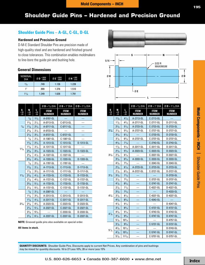
U.S. 800-626-6653 n Canada 800-387-6600 n www.dme.net
195
Shoulder Guide Pins – Hardened and Precision Ground
N
L
S
Ø H Ø D
3/32 RMAXIMUM
Ø E
5/16
General dimensions
nominaldia Ø d +.0000
-.0005 Ø e +.0005-.0000 Ø H +.000
-.010
3 /4 .749 1.126 1.228
1" .999 1.376 1.510
11/4 1.249 1.626 1.791
s+.00-.03
n+.00-.03
l+.00-.06
Ø d = 3 /4 dia Ø d = 1" dia Ø d = 11/4 dia
iteMnuMBeR
iteMnuMBeR
iteMnuMBeR
7/8
7/8 13 /4 a-0707-Gl — —13 /8 21/4 a-0713-Gl c-0713-Gl —17/8 23 /4 a-0717-Gl c-0717-Gl —23 /8 31/4 a-0723-Gl — —27/8 33 /4 a-0727-Gl c-0727-Gl —
13 /8
7/8 21/4 a-1307-Gl c-1307-Gl —13 /8 23 /4 a-1313-Gl c-1313-Gl d-1313-Gl17/8 31/4 a-1317-Gl c-1317-Gl —23 /8 33 /4 a-1323-Gl c-1323-Gl d-1323-Gl27/8 41/4 a-1327-Gl c-1327-Gl —33 /8 43 /4 a-1333-Gl c-1333-Gl d-1333-Gl
17/8
7/8 23 /4 a-1707-Gl c-1707-Gl —13 /8 31/4 a-1713-Gl c-1713-Gl d-1713-Gl17/8 33 /4 a-1717-Gl c-1717-Gl d-1717-Gl23 /8 41/4 a-1723-Gl c-1723-Gl d-1723-Gl27/8 43 /4 a-1727-Gl c-1727-Gl d-1727-Gl33 /8 51/4 a-1733-Gl c-1733-Gl d-1733-Gl37/8 53 /4 a-1737-Gl c-1737-Gl d-1737-Gl
23 /8
7/8 31/4 a-2307-Gl — —13 /8 33 /4 a-2313-Gl c-2313-Gl d-2313-Gl17/8 41/4 a-2317-Gl c-2317-Gl d-2317-Gl23 /8 43 /4 a-2323-Gl c-2323-Gl d-2323-Gl27/8 51/4 a-2327-Gl c-2327-Gl d-2327-Gl33 /8 53 /4 — c-2333-Gl d-2333-Gl37/8 61/4 a-2337-Gl c-2337-Gl d-2337-Gl
s+.00-.03
n+.00-.03
l+.00-.06
Ø d = 3 /4 dia Ø d = 1" dia Ø d = 11/4 dia
iteMnuMBeR
iteMnuMBeR
iteMnuMBeR
27/8
13 /8 41/4 a-2713-Gl c-2713-Gl —17/8 43 /4 a-2717-Gl c-2717-Gl d-2717-Gl23 /8 51/4 a-2723-Gl c-2723-Gl d-2723-Gl27/8 53 /4 a-2727-Gl c-2727-Gl d-2727-Gl33 /8 61/4 — c-2733-Gl d-2733-Gl37/8 63 /4 a-2737-Gl c-2737-Gl d-2737-Gl43 /8 71/4 — c-2743-Gl d-2743-Gl
33 /8
17/8 51/4 a-3317-Gl c-3317-Gl d-3317-Gl23 /8 53 /4 a-3323-Gl c-3323-Gl d-3323-Gl27/8 61/4 — c-3327-Gl d-3327-Gl33 /8 63 /4 a-3333-Gl c-3333-Gl d-3333-Gl43 /8 73 /4 — c-3343-Gl d-3343-Gl
37/8
23 /8 61/4 a-3723-Gl c-3723-Gl d-3723-Gl27/8 63 /4 a-3727-Gl c-3727-Gl d-3727-Gl33 /8 71/4 — — d-3733-Gl37/8 73 /4 — c-3737-Gl d-3737-Gl47/8 83 /4 — c-3747-Gl d-3747-Gl
43 /8
27/8 71/4 — c-4327-Gl d-4327-Gl33 /8 73 /4 — — d-4333-Gl37/8 81/4 — c-4337-Gl d-4337-Gl43 /8 83 /4 — c-4343-Gl —47/8 91/4 — — d-4347-Gl
47/8
37/8 83 /4 — c-4737-Gl d-4737-Gl43 /8 91/4 — c-4743-Gl d-4743-Gl47/8 93 /4 — c-4747-Gl d-4747-Gl57/8 103 /4 — — d-4757-Gl
57/8
37/8 93 /4 — c-5737-Gl d-5737-Gl43 /8 101/4 — — d-5743-Gl47/8 103 /4 — c-5747-Gl d-5747-Gl57/8 113 /4 — c-5757-Gl d-5757-Gl
nOte: Grooved guide pins also available on special order.
All items in stock.
Mold Com
ponents – INCH | Shoulder Guide Pins
Mold Components – INCH
QuAntitY discOunts: shoulder Guide Pins. discounts apply to current net Prices. any combination of pins and bushings may be mixed for quantity discounts. 16 to 27 less 10%; 28 or more less 15%
shoulder Guide Pins – A-Gl, c-Gl, d-Gl
Hardened and Precision GroundD-M-E Standard Shoulder Pins are precision made of high-quality steel and are hardened and finished ground to close tolerances. This combination enables moldmakers to line-bore the guide pin and bushing hole.

U.S. 800-626-6653 n Canada 800-387-6600 n www.dme.net
196
Shoulder Bushings and Straight Bushings Hardened and Precision Ground
straight Bushings
General dimensions2 X I.D.
Ø D Ø HØ E
3/16
L
L
Ø D Ø H
2 X I.D.
Ø D Ø HØ E
3/16
L
L
Ø D Ø H
nominali.d. Ø d +.0005
-.0000 Ø e +.0005-.0000 Ø H +.000
-.030
3 /4 .7505 1.1255 1.3027/8 .8755 1.2505 1.427
1" 1.0005 1.3755 1.552
11/4 1.2505 1.6255 1.802
11/2 1.5005 2.0005 2.177
llenGth
+.00-.06
Ø d = 3 /4 dia
.7505 +.0005-.0000
Ø d = 7/8 dia
.8755 +.0005-.0000
Ø d = 1" dia
1.0005 +.0005-.0000
Ø d = 11/4 dia
1.2505 +.0005-.0000
Ø d = 11/2 dia
1.5005 +.0005-.0000
llenGth
+.00-.06
iteMnuMBeR
iteMnuMBeR
iteMnuMBeR
iteMnuMBeR
iteMnuMBeR
7/8 5700 5710 5730 5750 5770 7/8
13 /8 5701 5711 5731 5751 5771 13 /8
17/8 5702 5712 5732 5752 5772 17/8
23 /8 5703 5713 5733 5753 5773 23 /8
27/8 5704 5714 5734 5754 5774 27/8
33 /8 5705 5715 5735 5755 5775 33 /8
37/8 5706 5716 5736 5756 5776 37/8
43 /8 5707 5717 5737 5757 5777 43 /8
47/8 5708 5718 5738 5758 5778 47/8
57/8 5709 5720 5740 5760 5780 57/8
nominali.d. Ø d +.0005
-.0000l +.00
-.06lenGth Ø H +.0005
-.0000iteM
nuMBeR
3 /4 .75057/8 1.1255 5500
13 /8 1.1255 55017/8 .8755 13 /8 1.2505 5502
1" 1.0005 13 /8 1.3755 5503
11/4 1.250513 /8 1.6255 5504
17/8 1.6255 5505
11/2 1.500513 /8 2.0005 5506
17/8 2.0005 5507
2" 2.0005 37/8 2.5005 5508
21/2 2.5005 47/8 3.2505 5509
3" 3.0005 47/8 3.7505 5510
shoulder Bushings
All items in stock.
QuAntitY discOunts: shoulder and straight Bushings. discounts apply to current net Prices. any combination of pins and bushings may be mixed for quantity discounts. 16 to 27 less 10%; 28 or more less 15%
Mol
d Co
mpo
nent
s –
INCH
|
Shou
lder
and
Str
aigh
t Bus
hing
sMold Components – INCH
surface treatment: case-hardened .030 to .040 deep
surface treatment: case-hardened .030 to .040 deep
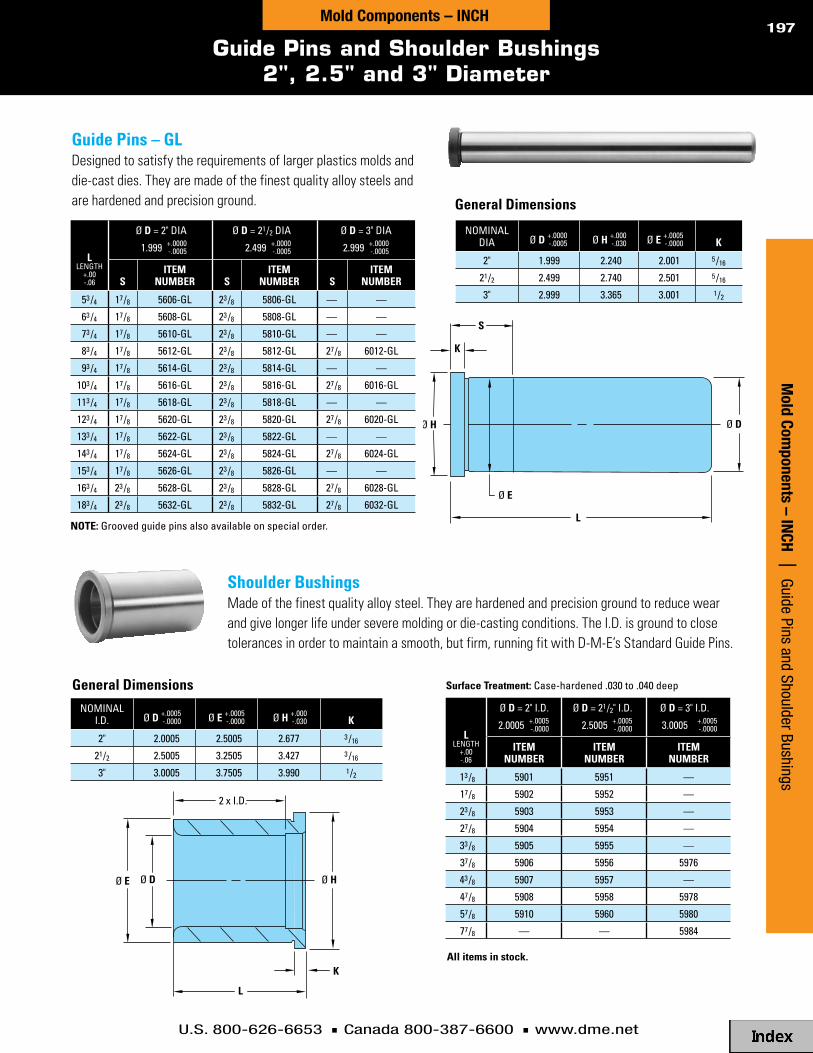
U.S. 800-626-6653 n Canada 800-387-6600 n www.dme.net
197
Guide Pins and Shoulder Bushings2", 2.5" and 3" Diameter
shoulder BushingsMade of the finest quality alloy steel. They are hardened and precision ground to reduce wear and give longer life under severe molding or die-casting conditions. The I.D. is ground to close tolerances in order to maintain a smooth, but firm, running fit with D-M-E’s Standard Guide Pins.
General dimensions
General dimensions
Guide Pins – GlDesigned to satisfy the requirements of larger plastics molds and die-cast dies. They are made of the finest quality alloy steels and are hardened and precision ground.
nOte: Grooved guide pins also available on special order.
nominaldia Ø d +.0000
-.0005 Ø H +.000-.030 Ø e +.0005
-.0000 K
2" 1.999 2.240 2.001 5 /16
21/2 2.499 2.740 2.501 5 /16
3" 2.999 3.365 3.001 1/2
llenGth
+.00-.06
Ø d = 2" dia
1.999 +.0000-.0005
Ø d = 21/2 dia
2.499 +.0000-.0005
Ø d = 3" dia
2.999 +.0000-.0005
siteM
nuMBeR siteM
nuMBeR siteM
nuMBeR
53 /4 17/8 5606-Gl 23 /8 5806-Gl — —
63 /4 17/8 5608-Gl 23 /8 5808-Gl — —
73 /4 17/8 5610-Gl 23 /8 5810-Gl — —
83 /4 17/8 5612-Gl 23 /8 5812-Gl 27/8 6012-Gl
93 /4 17/8 5614-Gl 23 /8 5814-Gl — —
103 /4 17/8 5616-Gl 23 /8 5816-Gl 27/8 6016-Gl
113 /4 17/8 5618-Gl 23 /8 5818-Gl — —
123 /4 17/8 5620-Gl 23 /8 5820-Gl 27/8 6020-Gl
133 /4 17/8 5622-Gl 23 /8 5822-Gl — —
143 /4 17/8 5624-Gl 23 /8 5824-Gl 27/8 6024-Gl
153 /4 17/8 5626-Gl 23 /8 5826-Gl — —
163 /4 23 /8 5628-Gl 23 /8 5828-Gl 27/8 6028-Gl
183 /4 23 /8 5632-Gl 23 /8 5832-Gl 27/8 6032-Gl
llenGth
+.00-.06
Ø d = 2" i.d.
2.0005 +.0005-.0000
Ø d = 21/2" i.d.
2.5005 +.0005-.0000
Ø d = 3" i.d.
3.0005 +.0005-.0000
iteMnuMBeR
iteMnuMBeR
iteMnuMBeR
13 /8 5901 5951 —
17/8 5902 5952 —
23 /8 5903 5953 —
27/8 5904 5954 —
33 /8 5905 5955 —
37/8 5906 5956 5976
43 /8 5907 5957 —
47/8 5908 5958 5978
57/8 5910 5960 5980
77/8 — — 5984
2 x I.D.
Ø D Ø HØ E
K
L
L
S
Ø H Ø D
Ø E
K
2 x I.D.
Ø D Ø HØ E
K
L
L
S
Ø H Ø D
Ø E
K
nominali.d. Ø d +.0005
-.0000 Ø e +.0005-.0000 Ø H +.000
-.030 K
2" 2.0005 2.5005 2.677 3 /16
21/2 2.5005 3.2505 3.427 3 /16
3" 3.0005 3.7505 3.990 1/2
All items in stock.
Mold Com
ponents – INCH | Guide Pins and Shoulder Bushings
Mold Components – INCH
surface treatment: case-hardened .030 to .040 deep

U.S. 800-626-6653 n Canada 800-387-6600 n www.dme.net
198Re
gion
Ser
ies,
Am
eric
an S
tand
ard
Mol
d Co
mpo
nent
s |
Sel
f-Lu
bric
atin
g Bu
shin
gs fo
r Gui
de P
ins
Self-Lubricating Bushings for Guide Pins
Mol
d Co
mpo
nent
s –
INCH
|
Self-
Lubr
icat
ing
Bush
ings
for G
uide
Pin
s
nominali.d. Ø d +.0005
-.0000l +.00
-.06lenGth Ø H +.0005
-.0000iteM
nuMBeR
3 /4 .75057/8 1.1255 GBs-06-07
13 /8 1.1255 GBs-06-137/8 .8755 13 /8 1.2505 GBs-07-13
1" 1.0005 13 /8 1.3755 GBs-08-13
11/4 1.250513 /8 1.6255 GBs-10-13
17/8 1.6255 GBs-10-17
11/2 1.500513 /8 2.0005 GBs-12-13
17/8 2.0005 GBs-12-17
2" 2.0005 37/8 2.5005 GBs-16-37
21/2 2.5005 47/8 3.2505 GBs-20-47
3" 3.0005 47/8 3.7505 GBs-24-47
Ø D Ø H
L
n Aluminum-bronze alloy with oil-impregnated graphite plugs
n Saves design and moldmaking costs for lubrication and fittings
n Reduces wear and gallingn Lowers maintenance and repair costsn Eliminates contamination…
ideal for “clean-room” environments
self-lubricating straight Bushings – GBs
D-M-E Self-Lubricating Bushings can save time and money in the design, construction and operation of injection molds. They are ideal for clean-room conditions or any applications where the parts being molded prohibit the use of external lubricants, such as medical, electronic and food-related products. Their built-in lubrication capability also makes them a good choice for fast-cycling, high-production molds.
General dimensions
llenGth
+.00-.06
Ø d = 3 /4 i.d.
.7505 +.0005-.0000
Ø d = 7/8 i.d.
.8755 +.0005-.0000
Ø d = 1" i.d.
1.0005 +.0005-.0000
Ø d = 11/4 i.d.
1.2505 +.0005-.0000
Ø d = 11/2 i.d.
1.5005 +.0005-.0000
Ø d = 2" i.d.
2.0005 +.0005-.0000
Ø d = 21/2 i.d.
2.5005 +.0005-.0000
Ø d = 3" i.d.
3.0005 +.0005-.0000
llenGth
+.00-.06
iteMnuMBeR
iteMnuMBeR
iteMnuMBeR
iteMnuMBeR
iteMnuMBeR
iteMnuMBeR
iteMnuMBeR
iteMnuMBeR
7/8 GBf-06-07 GBf-07-07 GBf-08-07 GBf-10-07 GBf-12-07 — — — 7/8
13 /8 GBf-06-13 GBf-07-13 GBf-08-13 GBf-10-13 GBf-12-13 GBf-16-13 GBf-20-13 — 13 /8
17/8 GBf-06-17 GBf-07-17 GBf-08-17 GBf-10-17 GBf-12-17 GBf-16-17 GBf-20-17 — 17/8
23 /8 GBf-06-23 GBf-07-23 GBf-08-23 GBf-10-23 GBf-12-23 GBf-16-23 GBf-20-23 — 23 /8
27/8 GBf-06-27 GBf-07-27 GBf-08-27 GBf-10-27 GBf-12-27 GBf-16-27 GBf-20-27 — 27/8
33 /8 GBf-06-33 GBf-07-33 GBf-08-33 GBf-10-33 GBf-12-33 GBf-16-33 GBf-20-33 — 33 /8
37/8 GBf-06-37 GBf-07-37 GBf-08-37 GBf-10-37 GBf-12-37 GBf-16-37 GBf-20-37 GBf-24-37 37/8
43 /8 GBf-06-43 GBf-07-43 GBf-08-43 GBf-10-43 GBf-12-43 GBf-16-43 GBf-20-43 — 43 /8
47/8 GBf-06-47 GBf-07-47 GBf-08-47 GBf-10-47 GBf-12-47 GBf-16-47 GBf-20-47 GBf-24-47 47/8
57/8 GBf-06-57 GBf-07-57 GBf-08-57 GBf-10-57 GBf-12-57 GBf-16-57 GBf-20-57 GBf-24-57 57/8
77/8 — — — — — — — GBf-24-77 77/8
nominali.d. Ø e +.0005
-.0000 Ø H +.000-.030 K
3 /4 1.1255 1.302
3 /16
7/8 1.2505 1.427
1" 1.3755 1.552
11/4 1.6255 1.802
11/2 2.0005 2.177
2" 2.5005 2.677
21/2 3.2505 3.427
3" 3.7505 3.990 1/2
self-lubricating shoulder Bushings – GBF
Ø E Ø D Ø H
K
L
All items in stock.
Shoulder Style
Straight Style
QuAntitY discOunts: self-lubricating Bushings. discounts apply to current net Prices. any combination of pins and bushings may be mixed for quantity discounts. 16 to 27 less 10%; 28 or more less 15%
Mold Components – INCH
nOte: these bushings are interchangeable with comparably sized d-m-e steel or bronze-plated bushings.

U.S. 800-626-6653 n Canada 800-387-6600 n www.dme.net
199
Bronze-Plated Shoulder and Straight Bushings
Bronze-Plated shoulder Bushings – lBB
Precision GroundD-M-E Standard Shoulder and Straight Bushings feature internal oil grooves and bronze-plating for smooth, non-galling operation.
llenGth
+.00-.03
Ø d = 3 /4 i.d.
.7505 +.0005-.0000
Ø d = 7/8 i.d.
.8755 +.0005-.0000
Ø d = 1" i.d.
1.0005 +.0005-.0000
Ø d = 11/4 i.d.
1.2505 +.0005-.0000
Ø d = 11/2 i.d.
1.5005 +.0005-.0000
Ø d = 2" i.d.
2.0005 +.0005-.0000
Ø d = 21/2 i.d.
2.5005 +.0005-.0000
Ø d = 3" i.d.
3.0005 +.0005-.0000
iteMnuMBeR
iteMnuMBeR
iteMnuMBeR
iteMnuMBeR
iteMnuMBeR
iteMnuMBeR
iteMnuMBeR
iteMnuMBeR
7/8 lBB-06-07 lBB-07-07 lBB-08-07 lBB-10-07 lBB-12-07 — — —
13 /8 lBB-06-13 lBB-07-13 lBB-08-13 lBB-10-13 lBB-12-13 lBB-16-13 lBB-20-13 —
17/8 lBB-06-17 lBB-07-17 lBB-08-17 lBB-10-17 lBB-12-17 lBB-16-17 lBB-20-17 —
23 /8 lBB-06-23 lBB-07-23 lBB-08-23 lBB-10-23 lBB-12-23 lBB-16-23 lBB-20-23 —
27/8 lBB-06-27 lBB-07-27 lBB-08-27 lBB-10-27 lBB-12-27 lBB-16-27 lBB-20-27 —
33 /8 lBB-06-33 lBB-07-33 lBB-08-33 lBB-10-33 lBB-12-33 lBB-16-33 lBB-20-33 —
37/8 lBB-06-37 lBB-07-37 lBB-08-37 lBB-10-37 lBB-12-37 lBB-16-37 lBB-20-37 lBB-24-37
43 /8 lBB-06-43 lBB-07-43 lBB-08-43 lBB-10-43 lBB-12-43 lBB-16-43 lBB-20-43 —
47/8 lBB-06-47 lBB-07-47 lBB-08-47 lBB-10-47 lBB-12-47 lBB-16-47 lBB-20-47 lBB-24-47
57/8 lBB-06-57 lBB-07-57 lBB-08-57 lBB-10-57 lBB-12-57 lBB-16-57 lBB-20-57 lBB-24-57
77/8 — — — — — — — lBB-24-77
nominali.d. Ø e +.0005
-.0000 Ø H +.000-.030 K
3 /4 1.1255 1.302
3 /16
7/8 1.2505 1.427
1" 1.3755 1.552
11/4 1.6255 1.802
11/2 2.0005 2.177
2" 2.5005 2.677
21/2 3.2505 3.427
3" 3.7505 3.990 1/2
nominali.d. Ø d +.0005
-.0000l +.00
-.03lenGth Ø H +.0005
-.0000iteM
nuMBeR
3 /4 .75057/8 1.1255 stB-06-07
13 /8 1.1255 stB-06-137/8 .8755 13 /8 1.2505 stB-07-13
1" 1.0005 13 /8 1.3755 stB-08-13
11/4 1.250513 /8 1.6255 stB-10-13
17/8 1.6255 stB-10-17
11/2 1.500513 /8 2.0005 stB-12-13
17/8 2.0005 stB-12-17
2" 2.0005 37/8 2.5005 stB-16-37
21/2 2.5005 47/8 3.2505 stB-20-47
3" 3.0005 47/8 3.7505 stB-24-47
Ø E Ø D Ø H
K
L
Ø D Ø H
L
Bronze-Plated straight Bushings – stBPrecision Ground
All items in stock.
QuAntitY discOunts: Bronze-Plated shoulder and straight Bushings. discounts apply to current net Prices. any combination of pins and bushings may be mixed for quantity discounts. 16 to 27 less 10%; 28 or more less 15%
Mold Com
ponents – INCH | Bronze-Plated Shoulder and Straight Bushings
Mold Components – INCH
General dimensions

U.S. 800-626-6653 n Canada 800-387-6600 n www.dme.net
200
Guided Ejection Guide Pins
llenGth
+.00-.06
Ø d = 3 /4 i.d.
.749 +.0000-.0005
Ø d = 7/8 i.d.
.874 +.0000-.0005
Ø d = 1" i.d.
.999 +.0000-.0005
Ø d = 11/4 i.d.
1.249 +.0000-.0005
Ø d = 11/2 i.d.
1.499 +.0000-.0005
s iteM
nuMBeR siteM
nuMBeR siteM
nuMBeR siteM
nuMBeR siteM
nuMBeR
33 /4 7/8 5004-Gl 7/8 5103-Gl 7/8 5202-Gl 7/8 5302-Gl 13 /8 5402-Gl
41/4 7/8 Pf-5005-Gl 7/8 Pf-5104-Gl 7/8 Pf-5203-Gl 7/8 5303-Gl 13 /8 5403-Gl
43 /4 7/8 Pf-5006-Gl 7/8 Pf-5105-Gl 7/8 Pf-5204-Gl 13 /8 5304-Gl 13 /8 5404-Gl
51/4 7/8 Pf-5007-Gl 7/8 Pf-5106-Gl 7/8 Pf-5205-Gl 13 /8 5305-Gl 13 /8 5405-Gl
53 /4 7/8 Pf-5008-Gl 7/8 Pf-5107-Gl 7/8 Pf-5206-Gl 13 /8 5306-Gl 13 /8 5406-Gl
61/4 — — — — — — 13 /8 5307-Gl 13 /8 5407-Gl
nominaldia Ø d +.0000
-.0005Ø H
(max) K Ø e +.0005-.0000
3 /4 .749 .990 3 /16 .7517/8 .874 1.115 1/4 .876
1" .999 1.240 1/4 1.001
11/4 1.249 1.490 5 /16 1.251
11/2 1.499 1.740 5 /16 1.501
S
K
Ø H
Ø E
L
Ø D
n Short press fit lengths for use in guided ejection applications
n Pins are hardened and precision ground
nOtes: 1. select corresponding bronze-plated guided ejection bushings or self-lubricating guided ejection bushings in proper diameter for the application.
2. d-m-e Guided ejection systems are available installed in standard mold bases. for additional information and prices, contact d-m-e.
GUIDEPIN
EJECTOR HOUSING
EJECTOR RETAINER PLATE
EJECTOR PLATE
SUPPORT PLATE
GUIDEPIN
EJECTOR HOUSING
EJECTOR RETAINER PLATE
EJECTOR PLATE
SUPPORT PLATE
system 1 system 2
All items in stock.
QuAntitY discOunts: Guide Pins. discounts apply to current net Prices. any combination of pins and bushings may be mixed for quantity discounts. 16 to 27 less 10%; 28 or more less 15%
Mol
d Co
mpo
nent
s –
INCH
|
Guid
ed E
ject
ion
Guid
e Pi
nsMold Components – INCH
Guided ejection Guide Pins – Gl
When pins are installed in the support plate, ejector housing can be removed from mold without removing ejector plates, permitting easy access to service the ejector system.
Pins installed in the ejector housing permit fast, low-cost installation. When ejector housing is removed from mold base, the complete ejector assembly is removed.
It is recommended that a minimum of four pins and bushings be installed. Size of the pins and bushings should be determined by the size of the mold. The Guided Ejection System is an inexpensive method to protect against wear and costly damage to a mold in production.
Properly installed, the D-M-E Guided Ejection System holds the ejector assembly in alignment and supports the weight of the ejector assembly throughout the entire machine cycle. This greatly reduces wear on ejection components and prevents possible cocking of the ejector plates.
General dimensions

U.S. 800-626-6653 n Canada 800-387-6600 n www.dme.net
201
Guided Ejection Bushings
nominali.d. Ø d +.0005
-.0000 Ø e +.0005-.0000 Ø A +.000
-.001 Ø H +.000-.030 l +.00
-.06 BiteM
nuMBeR
3 /4 .751 1.1255 1.1240 1.302 1.50 1.00 GBe-07507/8 .876 1.2505 1.2490 1.427 1.50 1.00 GBe-0875
1" 1.001 1.3755 1.3740 1.552 1.75 1.12 GBe-1000
11/4 1.251 1.6255 1.6240 1.802 1.75 1.12 GBe-1250
11/2 1.501 2.0005 1.9990 2.177 1.75 1.12 GBe-1500
2" 2.001 2.5005 2.4990 2.687 2.25 1.62 GBe-2000
nominali.d.
Ø d+.0005-.0000
Ø e+.0005-.0000
Ø A+.000-.001
Ø H+.000-.010
l+.00-.03 B K
iteMnuMBeR
3 /4 .751 1.1255 1.1240 1.302 1.50 1.00 .56 GeB-7507/8 .876 1.2505 1.2490 1.427 1.50 1.00 .56 GeB-875
1" 1.001 1.3755 1.3740 1.552 1.75 1.12 .62 GeB-100
11/4 1.251 1.6255 1.6240 1.802 1.75 1.12 .62 GeB-125
11/2 1.501 2.0005 1.9990 2.177 1.75 1.12 .62 GeB-150
n Holds the ejector assembly in alignment
n Supports the weight of the ejector assembly throughout the entire cycle
n Reduces wear on ejection components
n Prevents cocking of the ejector plates
B
Ø DØ E
L
Ø A
3/16
Ø H
B
Ø DØ E
L
K
Ø A
3/16
Ø H
D-M-E Guided Ejection Systems are available installed in standard mold
bases. For additional information and prices, contact D-M-E.
nOte: select corresponding guide pin in proper diameter and length for application.
Bronze-Plated Guided ejection Bushings – GeB
The Bronze-Plated Guided Ejection Bushings feature the strength of steel plus the nonscoring lubricity of bronze plating. Internal oil grooves and a lubrication hole help to ensure smoother mold operation.
It is recommended that a minimum of four bushings be installed. The size of the bushings should be determined by the size of the mold. The Guided Ejection System is inexpensive protection against wear and possible costly damage to a mold in production.
It is recommended that a minimum of four bushings be installed. Bushing size should be determined by the size of the mold. The Guided Ejection System is inexpensive protection against wear and possible costly damage to a mold in production.
nOtes:1. select corresponding guide pin in
proper diameter and length for application.
2. these bushings are interchangeable with comparably sized d-m-e bronze- plated guided ejection bushings. 2" i.d. size (GBe-2000) is available only in self-lubricating style.
All items in stock.
QuAntitY discOunts: Guided ejection Bushings. discounts apply to current net Prices. any combination of pins and bushings may be mixed for quantity discounts. 16 to 27 less 10%; 28 or more less 15%
Mold Com
ponents – INCH | Guided Ejection Bushings
Mold Components – INCH
self-lubricating Guided ejection Bushings – GBe

U.S. 800-626-6653 n Canada 800-387-6600 n www.dme.net
202M
old
Com
pone
nts
– IN
CH
| Gu
ided
Eje
ctio
n Sy
stem
s
Guided Ejection Systems
Mold Components – INCH
Guided Ejection Systems hold the ejector assembly in alignment and support the weight of the ejector assembly throughout the molding cycle – greatly reducing wear on ejection components and preventing cocking of the ejector assembly.
sYsteM 1
When pins are installed in the support plate, the ejector housing can be removed from the mold without removing ejector plates. This permits easy access to service the ejector system.
sYsteM 2
Pins installed in the ejector housing permit fast installation. When the ejec-tor housing is removed from the mold base, the complete ejector assembly is removed.
Guided ejection system type
❑ System 1
❑ System 2
Quantity (2 or 4): _________
Guided ejection Bushing type
❑ Bronze-Plated Steel Bushings
❑ Self-Lubricating Bushings
sYsteM 1 sYsteM 2
leader Pin leader Pin
ejector housing
ejector Plate
ejector retainer Plate
support Plate
ejector housing
ejector Plate
ejector retainer Plate
support Plate
sYsteM 1 sYsteM 2
leader Pin leader Pin
ejector housing
ejector Plate
ejector retainer Plate
support Plate
ejector housing
ejector Plate
ejector retainer Plate
support Plate
Guided ejection
Position:
❑ std ❑ specify
Recommended position from table provided standard (see opposite page). If a different position is required, specify below.
GEx____________
GEy____________
diameter:
❑ std ❑ specify
Recommended diameter from table provided standard. If a different diameter is required, it will require a positioningchange; specify below.
Available diameters:
❑ 0.750
❑ 0.875
❑ 1.000
❑ 1.250
FOR QuOtinG OR ORdeRinG, sPeciFY:
SST
ANDA
RD
SHIPPIN
G
5 5-DA
YSHIPPIN
G
7 7-DA
YSHIPPIN
G
11-D
AYSHIPPIN
G

U.S. 800-626-6653 n Canada 800-387-6600 n www.dme.net
203Mold Components – INCH
Guided Ejection Systems
Mold Com
ponents – INCH | Guided Ejection System
s
Guided ejection Positions
“B” HAlF OF MOldFOR 88, 812 & 108 MOld BAse
size OnlY
“B” HAlF OF MOldFOR 1012 – 2435 BAses
Ge-x (2)
”w”
”l”
Ge dia. leader pinfor guided ejection (2) places as shown
Ge dia. leader pinfor guided ejection (4) places as shown
Ge-x (4)
Ge-y (4)
offset (1)offset (1)
”w”
”l”
Pin diameter (recommended)
Base size Gex Gey
0.750
88 3.000 center812 5.000 center108 3.062 center
1012 5.000 1.0001016 7.062 1.0001020 9.062 1.0001112 5.062 1.6251114 6.062 1.6251118 8.062 1.6251123 10.812 1.625
0.875
212 5.000 1.7501215 6.500 1.7501220 9.000 1.7501223 10.750 1.7501315 6.500 2.3751318 8.000 2.3751321 9.375 2.3751323 10.750 2.3751326 12.000 2.3751329 13.750 2.375
Pin diameter (recommended)
Base size Gex Gey
1.000
1518 7.875 2.3751524 10.812 2.3751529 13.688 2.3751616 6.938 2.8751620 8.938 2.8751623 10.688 2.8751626 11.938 2.8751629 13.688 2.8751635 16.688 2.8751724 10.812 3.1251729 13.688 3.1251818 7.938 3.8751820 8.938 3.8751823 10.688 3.8751826 11.038 3.8751829 13.688 3.8751835 16.688 3.8751924 10.812 4.6251929 13.688 4.6251935 16.688 4.625
1.2502424 10.688 6.1252429 13.562 6.1252435 16.562 6.125

U.S. 800-626-6653 n Canada 800-387-6600 n www.dme.net
204
Mold Parts for 34R Mold Assemblies
L
Ø DØ H
RETAINING RING
11/32
Ø 1/2
3/8-16 THREAD
3/162 15/325/32
1/4-20 x 1" LG S.H.C.S.
1/4-20 JAM NUT
locating RingsThe large diameter of the locating ring is ground to close tolerances to mate with the platens of the Arburg C/4b Press.
Adjustable Knock-Out Rods
iteM nuMBeR
6534
tubular dowels – for 34R Mold BasesHardened and precision ground to close tolerances.
Guide Pins and shoulder BushingsDesigned specifically to suit the 34R Series Mold Base. They are made of the finest quality steels and are hardened and precision ground.
Guide Pins
shoulder Bushings
21/32
Ø 1/2 Ø 1.574Ø 1.0005
11/32
1/32 R MAXIMUM
Ø .3752±.0002
Ø .26
L
1/32
1/8
3/4
–.0000+.0005
RETAINING RING
L
Ø .5620
Ø .376 Ø .631MAXIMUM
21/32
Ø 1/2 Ø 1.574Ø 1.0005
11/32
1/32 R MAXIMUM
Ø .3752±.0002
Ø .26
L
1/32
1/8
3/4
–.0000+.0005
RETAINING RING
L
Ø .5620
Ø .376 Ø .631MAXIMUM
21/32
Ø 1/2 Ø 1.574Ø 1.0005
11/32
1/32 R MAXIMUM
Ø .3752±.0002
Ø .26
L
1/32
1/8
3/4
–.0000+.0005
RETAINING RING
L
Ø .5620
Ø .376 Ø .631MAXIMUM
Ø d +.0003-.0000
Ø H(max) l +.00
-.03iteM
nuMBeR
.375
.610 13 /8 4900
.610 15 /8 4901
.610 2" 4902
.610 21/4 4903
.610 21/2 4904
.610 3" 4906
.500 .740 13 /8 4922
l +.00-.03
iteMnuMBeR
7/8 4802
11/8 4804
13 /8 4806
nominaldia l
3 /8
3 /8
7/8
iteM nuMBeR
K-10
L
Ø DØ H
RETAINING RING
11/32
Ø 1/2
3/8-16 THREAD
3/162 15/325/32
1/4-20 x 1" LG S.H.C.S.
1/4-20 JAM NUT
Mol
d Co
mpo
nent
s –
INCH
|
Mol
d Pa
rts
for 3
4R M
old
Asse
mbl
ies
Mold Components – INCH
when ordering, please specify:1. Quantity2. nominal diameter 3. length

U.S. 800-626-6653 n Canada 800-387-6600 n www.dme.net
205
Shoulder Guide Pins and Bushings for 45R, 56N, 58N, 56U, 58U and 68SH Mold Assemblies
Made of the finest quality steel, hardened and precision ground to reduce wear and give longer life.
shoulder Guide PinsShoulder diameter is of the same size and tolerance to match with the O.D. of Standard D-M-E Shoulder Bushings listed below.
General dimensions
shoulder Bushings
straight Bushings
General dimensions
B
L
A
Ø H Ø D
3/32 RMAXIMUM
Ø E
3/16
1"
Ø D Ø HØ E
3/16
L
L
Ø D Ø H
B
L
A
Ø H Ø D
3/32 RMAXIMUM
Ø E
3/16
1"
Ø D Ø HØ E
3/16
L
L
Ø D Ø H
B
L
A
Ø H Ø D
3/32 RMAXIMUM
Ø E
3/16
1"
Ø D Ø HØ E
3/16
L
L
Ø D Ø H
nominaldia Ø d +.0000
-.0005 Ø e +.0005-.0000
Ø H(max)
1/2 .499 .751 .85317/32 .530 .751 .853
nominali.d. Ø d +.0005
-.0000 Ø e +.0005-.0000
Ø H(max)
1/2 .500 .7505 .85317/32 .531 .7505 .853
A+.00-.03
B+.00-.03
l+.00-.06
Ø d = 1/2 dia Ø d = 17/32 dia
iteMnuMBeR
iteMnuMBeR
7/8
7/8 13 /4 s-0707Gl t-0707Gl
13 /8 21/4 s-0713Gl t-0713Gl
17/8 23 /4 s-0717Gl t-0717Gl
23 /8 31/4 s-0723Gl t-0723Gl
13 /8
7/8 21/4 s-1307Gl t-1307Gl
13 /8 23 /4 s-1313Gl t-1313Gl
17/8 31/4 s-1317Gl t-1317Gl
17/8
7/8 23 /4 s-1707Gl t-1707Gl
13 /8 31/4 s-1713Gl t-1713Gl
17/8 33 /4 s-1717Gl t-1717Gl
23 /8
7/8 31/4 s-2307Gl t-2307Gl
— — — —
27/813 /8 41/4 s-2713Gl t-2713Gl
— — — —
l+.00-.06
Ø d = 1/2 dia Ø d = 17/32 dia
iteMnuMBeR
iteMnuMBeR
7/8 s-5690 t-5690
13 /8 s-5691 t-5691
17/8 s-5692 t-5692
23 /8 s-5693 t-5693
l+.00-.06
Ø d = 1/2 dia Ø d = 17/32 dia
iteMnuMBeR
iteMnuMBeR
7/8 s-5498 t-5498
13 /8 s-5499 t-5499
Mold Com
ponents – INCH | Pins &
Bushings for Other M
old Assemblies
Mold Components – INCH

U.S. 800-626-6653 n Canada 800-387-6600 n www.dme.net
206
Support Pillars and Stop Pins
Support pillars should be used liberally since they greatly increase the capacity of the mold to support the projected area of the cavities, runner and sprue. By providing additional support, they prevent deflection of the mold. The absolute necessity of using support pillars is demonstrated by using standard strength of materials formulas. For example, an 117/8 x 15" mold base without support pillars and with a maximum permissible load on the support plate, will permit 14 square inches of cavity area without deflecting enough to cause flash. The use of one row of support pillars on center will quadruple this permissible cavity area to 56 square inches. Two rows will give nine times the area or 126 square inches. Please refer to the drawings below.
No support pillars
LOAD
One row of support pillarsincreases the permissible
cavity area 4 timesLOAD
Two rows of support pillarsincrease the permissible
cavity area 9 timesLOAD
G – S.H.C.S
F – TAPPED HOLE
E
C
3/8 DIA x 1" LGTHREADED LOCATING PINITEM NO. TLP-38
3/8-16 TAPPED HOLE
5/8 3/8
J – SOCKETSET SCREW
F – TAPPED HOLE
Ø D
E H
Ø D Ø D
C C
support Pillarss.A.e. 1040 steel Pillar height (C dimension) is finished flat and parallel.
C CC
CAP SCREW APPLICATION THREADED LOCATING PIN APPLICATION SOCKET SET SCREW APPLICATION
cap screw Application
Ø d e FH
(aPProx)J
socKet set screw
1", 11/4, 11/2, 2" 5 /8 3 /8 – 16 1/2 item no. sss-381143", 4" 11/4 5 /8 – 11 3 /8 item no. sss-582
nOte: order s.h.c.s. separately.
Mol
d Co
mpo
nent
s –
INCH
|
Supp
ort P
illar
s an
d St
op P
ins
Mold Components – INCH
threaded locating Pin Application
C CC
CAP SCREW APPLICATION THREADED LOCATING PIN APPLICATION SOCKET SET SCREW APPLICATION
socket set screw Application
C CC
CAP SCREW APPLICATION THREADED LOCATING PIN APPLICATION SOCKET SET SCREW APPLICATION
G – S.H.C.S
F – TAPPED HOLE
E
C
3/8 DIA x 1" LGTHREADED LOCATING PINITEM NO. TLP-38
3/8-16 TAPPED HOLE
5/8 3/8
J – SOCKETSET SCREW
F – TAPPED HOLE
Ø D
E H
Ø D Ø D
C C
G – S.H.C.S
F – TAPPED HOLE
E
C
3/8 DIA x 1" LGTHREADED LOCATING PINITEM NO. TLP-38
3/8-16 TAPPED HOLE
5/8 3/8
J – SOCKETSET SCREW
F – TAPPED HOLE
Ø D
E H
Ø D Ø D
C C
No support pillars
LOAD
One row of support pillarsincreases the permissible
cavity area 4 timesLOAD
Two rows of support pillarsincrease the permissible
cavity area 9 timesLOAD
No support pillars
LOAD
One row of support pillarsincreases the permissible
cavity area 4 timesLOAD
Two rows of support pillarsincrease the permissible
cavity area 9 timesLOAD
Material: s.a.e. 1040 steel

U.S. 800-626-6653 n Canada 800-387-6600 n www.dme.net
207
Support Pillars and Stop Pins
support PillarsSupport pillars are universally adaptable for cap screw, threaded locating pin, or socket set screw applications.
Order pillars from chart at left and required “fasteners” as listed below.
cap screw (s.H.c.s.) Applications3/8-16 or 5/8-11 socket head cap screws can be ordered in length required.
threaded locating Pin ApplicationsLocating pins unavailable for 3" and 4" diameter pillars.
socket set screw ApplicationsOrder pins and screws in package lots only.
Ø d +.000-.060
diameterc +.001
-.000heiGht
iteMnuMBeR
1"
2.500 6090
3.000 6091
3.500 6092
4.000 6093
4.500 6094
11/4
2.500 6130
3.000 6131
3.500 6132
4.000 6133
4.500 6134
5.000 6135
6.000 6136
11/2
2.500 6140
3.000 6141
3.500 6142
4.000 6143
4.500 6144
5.000 6145
6.000 6146
2"
2.500 6150
3.000 6151
3.500 6152
4.000 6153
4.500 6154
5.000 6155
6.000 6156
3"
5.000 6235
6.000 6236
8.000 6238
4"
5.000 6245
6.000 6246
8.000 6248
Ø d Pillar
iteM nuMBeR
1" to 2" tlP-38
Ø d Pillar
iteM nuMBeR
Qty PerPacKaGe
1" to 2" sss-38114 10
3" and 4" sss-582 5
iteMnuMBeR
Qty PerPacKaGe
7100 50
3/16
Ø D
C
Ø 5/16 Ø 5/8
5/8 13/64*
stop Pins
Although every D-M-E Mold Base assembly has flat stop pins welded to the underside of the ejector plate, many moldmakers require these dowel-type Stop Pins for special assemblies.
* head thickness .020 oversize to permit fitting at assembly.
Order pins in package lots only.
typical installation
QuAntitY discOunts: support Pillars. discounts apply to current net Prices. sizes may be mixed for quantity discounts. 9 to 16 less 10%; 17 or more less 20%
Mold Com
ponents – INCH | Support Pillars and Stop Pins
Mold Components – INCH
Material: s.a.e. 1040 steel

U.S. 800-626-6653 n Canada 800-387-6600 n www.dme.net
208
Sprue Bushings
L
Ø 1.000
7/32 R
“LN” SERIES
A 1 5/32
Ø 2"
O
1/2 TAPER PER FOOT (INCLUDED ANGLE)
L
Ø 1.000
7/32 R
“AR” SERIES
A 5/8
Ø 2"
O
1/2 TAPER PER FOOT (INCLUDED ANGLE)
L
Ø 1.000
7/32 R
“A” SERIES
A 5/8
Ø 2"
O
R1/2 TAPER PER FOOT (INCLUDED ANGLE)
3/16
L
Ø 1.000
7/32 R
“B” SERIES
A 7/8
Ø 2"
O
1/2 TAPER PER FOOT (INCLUDED ANGLE)
3/16
R
iteMnuMBeR A lB-6600 29 /32 125 /32
B-6601 113 /32 29 /32
B-6602 129 /32 225 /32
B-6603 213 /32 39 /32
B-6604 229 /32 325 /32
B-6605 313 /32 49 /32
B-6606 329 /32 425 /32
B-6607 413 /32 59 /32
B-6608 429 /32 525 /32
B-6610* 529 /32 625 /32
B-6612* 629 /32 725 /32
iteMnuMBeR A lln-6600 29 /32 21/16
ln-6601 113 /32 29 /16
ln-6602 129 /32 31/16
ln-6603 213 /32 39 /16
ln-6604 229 /32 41/16
ln-6605 313 /32 49 /16
iteMnuMBeR A la-6600 13 /16 113 /16
a-6601 111/16 25 /16
a-6602 23 /16 213 /16
a-6603 211/16 35 /16
a-6604 33 /16 313 /16
a-6605 311/16 45 /16
a-6606 43 /16 413 /16
iteMnuMBeR A lar-6600 13 /16 113 /16
ar-6601 111/16 25 /16
ar-6602 23 /16 213 /16
L
Ø 1.000
7/32 R
“LN” SERIES
A 1 5/32
Ø 2"
O
1/2 TAPER PER FOOT (INCLUDED ANGLE)
L
Ø 1.000
7/32 R
“AR” SERIES
A 5/8
Ø 2"
O
1/2 TAPER PER FOOT (INCLUDED ANGLE)
L
Ø 1.000
7/32 R
“A” SERIES
A 5/8
Ø 2"
O
R1/2 TAPER PER FOOT (INCLUDED ANGLE)
3/16
L
Ø 1.000
7/32 R
“B” SERIES
A 7/8
Ø 2"
O
1/2 TAPER PER FOOT (INCLUDED ANGLE)
3/16
R
L
Ø 1.000
7/32 R
“LN” SERIES
A 1 5/32
Ø 2"
O
1/2 TAPER PER FOOT (INCLUDED ANGLE)
L
Ø 1.000
7/32 R
“AR” SERIES
A 5/8
Ø 2"
O
1/2 TAPER PER FOOT (INCLUDED ANGLE)
L
Ø 1.000
7/32 R
“A” SERIES
A 5/8
Ø 2"
O
R1/2 TAPER PER FOOT (INCLUDED ANGLE)
3/16
L
Ø 1.000
7/32 R
“B” SERIES
A 7/8
Ø 2"
O
1/2 TAPER PER FOOT (INCLUDED ANGLE)
3/16
R
Available with O 5/32, 7/32, 9/32 or 11/32 R 1/2 or 3/4* B-6610: O 5 /32 R 3 /4* B-6612: O 5 /32 R 3 /4 available on special order.
Available with O 5/32, 7/32, 9/32 or 11/32 R 1/2 or 3/4
nOte: 1/2" taper per foot = 2° 23' 13" included angle.
Available with O 5/32, 7/32 or 9/32 R No spherical radius Available with O 5/32 or 7/32 R No spherical radius
O 11/32 available on special order.
O 9/32 available on special order.
“B” series
“A” series
“ln” series “AR” series
Mol
d Co
mpo
nent
s –
INCH
|
Spru
e Bu
shin
gsMold Components – INCH
sprue Bushings – A, B, ln and ARs.A.e. 6145 steel Hardened, Ground and Polished(HRC 43-45, except “LN” Series – carburized .050-.060 deep to HRC 60-62, drillable with carbide-tipped drill.)
when ordering sprUe BUshings, please specify:1. Quantity2. item number3. “0” and “R” dimensions3. Method of shipment

U.S. 800-626-6653 n Canada 800-387-6600 n www.dme.net
209
Sprue Bushings
iteMnuMBeR A l
u-6600 29 /32 125 /32
u-6601 113 /32 29 /32
u-6602 129 /32 225 /32
u-6603 213 /32 39 /32
u-6604 229 /32 325 /32
iteMnuMBeR A l
ur-6600 29 /32 125 /32
ur-6601 113 /32 29 /32
ur-6602 129 /32 225 /32
ur-6603 213 /32 39 /32
ur-6604 229 /32 325 /32
L
Ø .750
1/8 R
“U” SERIES NEWBURY AND STANDARD
A
3/16
7/8
Ø 2"
R
O
1/2 TAPER PER FOOT (INCLUDED ANGLE)
L
Ø .750
1/8 R
“UV” SERIES VAN DORN AND MOSLO
A
3/16
1 5/16
Ø 2"
R
O
1/2 TAPER PER FOOT (INCLUDED ANGLE)
L
Ø 1.000
7/32 R
“L” SERIES
A
1/2
1 5/32
Ø 2"
R
O
1/2 TAPER PER FOOT (INCLUDED ANGLE)
L
Ø .750
1/8 R
“UR” SERIES ARBURG
A 7/8
Ø 2"
O
1/2 TAPER PER FOOT (INCLUDED ANGLE)
sprue Bushings – u, uV, uR and ls.A.e. 6145 steel, HRc 43-45 Hardened, Ground and PolishedThe wide range of Standard D-M-E Sprue Bushings allows mold to be installed in a variety of injection molding machines. The accuracy and interchangeability permit easy replacement if the mold is being transferred to another machine. It’s wise to standardize … on D-M-E Sprue Bushings.
nOte: “w” series sprue bushings (watson-stillman) available on special order. other special sprue bushings will be quoted on request per your specifications.
iteMnuMBeR A l
uv-6600 29 /32 27/32
uv-6601 113 /32 223 /32
uv-6602 129 /32 37/32
uv-6603 213 /32 323 /32
uv-6604 229 /32 47/32
L
Ø .750
1/8 R
“U” SERIES NEWBURY AND STANDARD
A
3/16
7/8
Ø 2"
R
O
1/2 TAPER PER FOOT (INCLUDED ANGLE)
L
Ø .750
1/8 R
“UV” SERIES VAN DORN AND MOSLO
A
3/16
1 5/16
Ø 2"
R
O
1/2 TAPER PER FOOT (INCLUDED ANGLE)
L
Ø 1.000
7/32 R
“L” SERIES
A
1/2
1 5/32
Ø 2"
R
O
1/2 TAPER PER FOOT (INCLUDED ANGLE)
L
Ø .750
1/8 R
“UR” SERIES ARBURG
A 7/8
Ø 2"
O
1/2 TAPER PER FOOT (INCLUDED ANGLE)
L
Ø .750
1/8 R
“U” SERIES NEWBURY AND STANDARD
A
3/16
7/8
Ø 2"
R
O
1/2 TAPER PER FOOT (INCLUDED ANGLE)
L
Ø .750
1/8 R
“UV” SERIES VAN DORN AND MOSLO
A
3/16
1 5/16
Ø 2"
R
O
1/2 TAPER PER FOOT (INCLUDED ANGLE)
L
Ø 1.000
7/32 R
“L” SERIES
A
1/2
1 5/32
Ø 2"
R
O
1/2 TAPER PER FOOT (INCLUDED ANGLE)
L
Ø .750
1/8 R
“UR” SERIES ARBURG
A 7/8
Ø 2"
O
1/2 TAPER PER FOOT (INCLUDED ANGLE)
Available with O 5/32, 7/32 or 9/32 R 1/2 or 3/4
Available with O 5/32, 7/32 or 9/32 R 1/2 R 3/4 available on special order
iteMnuMBeR A l
l-6600 29 /32 21/16
l-6601 113 /32 29 /16
l-6602 129 /32 31/16
l-6604 229 /32 41/16
l-6606 329 /32 51/16
l-6612* 629 /32 81/16
Available with O 5/32, 7/32 or 9/32 R No spherical radius
*l-6612: O 5 /32 available on special order
Available with O 5/32, 7/32 or 9/32 R 1/2 O 11/32 available on
special order
R 3/4 available on special order
“u” series – newbury and standard
“uV” series – Van dorn and Moslo
“uR” series – Arburg “l” series
Mold Com
ponents – INCH | Sprue Bushings
Mold Components – INCH

U.S. 800-626-6653 n Canada 800-387-6600 n www.dme.net
210
Performance Sprue Bushings®
High-conductivity, corrosion-resistant, copper-based alloy bushing body with hardened 420 stainless steel nozzle seat insert
u.s. Patent no. 4,950,154
Performance sprue Bushings® is a registered trademark of
Performance alloys & services, inc.
iteMnuMBeR A l O R
PsB-0251 129 /32 225 /32 5 /32 1/2
PsB-0253 129 /32 225 /32 5 /32 3 /4
PsB-0271 129 /32 225 /32 7/32 1/2
PsB-0273 129 /32 225 /32 7/32 3 /4
PsB-0291 129 /32 225 /32 9 /32 1/2
PsB-0293 129 /32 225 /32 9 /32 3 /4
PsB-0451 229 /32 325 /32 5 /32 1/2
PsB-0453 229 /32 325 /32 5 /32 3 /4
PsB-0471 229 /32 325 /32 7/32 1/2
PsB-0473 229 /32 325 /32 7/32 3 /4
PsB-0491 229 /32 325 /32 9 /32 1/2
PsB-0493 229 /32 325 /32 9 /32 3 /4
PsB-0651 329 /32 425 /32 5 /32 1/2
PsB-0653 329 /32 425 /32 5 /32 3 /4
PsB-0671 329 /32 425 /32 7/32 1/2
PsB-0673 329 /32 425 /32 7/32 3 /4
PsB-0691 329 /32 425 /32 9 /32 1/2
PsB-0693 329 /32 425 /32 9 /32 3 /4
PsB-0851 429 /32 525 /32 5 /32 1/2
PsB-0853 429 /32 525 /32 5 /32 3 /4
PsB-0871 429 /32 525 /32 7/32 1/2
PsB-0873 429 /32 525 /32 7/32 3 /4
PsB-0891 429 /32 525 /32 9 /32 1/2
PsB-0893 429 /32 525 /32 9 /32 3 /4
nOte: all dimensions are specified in inches.
L
Ø 1.000
7/32 R
STAINLESS STEEL NOZZLE SEAT INSERT
A3/16
7/8
Ø 2"
R
O
1/2 TAPER PER FOOT (INCLUDED ANGLE)
iteMnuMBeR A l O R
Psu-0251 129 /32 225 /32 5 /32 1/2
Psu-0253 129 /32 225 /32 5 /32 3 /4
Psu-0271 129 /32 225 /32 7/32 1/2
Psu-0273 129 /32 225 /32 7/32 3 /4
Psu-0291 129 /32 225 /32 9 /32 1/2
Psu-0293 129 /32 225 /32 9 /32 3 /4
Psu-0451 229 /32 325 /32 5 /32 1/2
Psu-0453 229 /32 325 /32 5 /32 3 /4
Psu-0471 229 /32 325 /32 7/32 1/2
Psu-0473 229 /32 325 /32 7/32 3 /4
Psu-0491 229 /32 325 /32 9 /32 1/2
Psu-0493 229 /32 325 /32 9 /32 3 /4
Psu-0651 329 /32 425 /32 5 /32 1/2
Psu-0653 329 /32 425 /32 5 /32 3 /4
Psu-0671 329 /32 425 /32 7/32 1/2
Psu-0673 329 /32 425 /32 7/32 3 /4
Psu-0691 329 /32 425 /32 9 /32 1/2
Psu-0693 329 /32 425 /32 9 /32 3 /4
Psu-0851 429 /32 525 /32 5 /32 1/2
Psu-0853 429 /32 525 /32 5 /32 3 /4
Psu-0871 429 /32 525 /32 7/32 1/2
Psu-0873 429 /32 525 /32 7/32 3 /4
Psu-0891 429 /32 525 /32 9 /32 1/2
Psu-0893 429 /32 525 /32 9 /32 3 /4
nOte: all dimensions are specified in inches.
L
Ø .750
1/8
STAINLESS STEEL NOZZLE SEAT INSERT
A3/16
7/8
Ø 2"
R
O
1/2 TAPER PER FOOT (INCLUDED ANGLE)
“PsB” series with a 1.000" diameter stem ( interchangeable with
d-M-e “B” series sprue Bushings)
“Psu” series with a .750" diameter stem ( interchangeable with
d-M-e “u” series sprue Bushings)
n Reduces sprue cooling time and cycle timen Helps prevent sprue sticking or break-off within bushingn Stainless steel nozzle seat provides wear resistance and
insulates to reduce transference of heat from machine nozzle to the sprue area
n PSB Series is directly interchangeable with existing D-M-E “B” Series steel sprue bushings
n PSU Series is directly interchangeable with existing D-M-E “U” Series steel sprue bushings
n Reduces the need for water lines in the sprue arean Reduces scrap caused by contact between hot sprue and
finished parts on conveyor belt or drop chute arean Provides a more rigid sprue for robotic part removal
Mol
d Co
mpo
nent
s –
INCH
|
Perf
orm
ance
Spr
ue B
ushi
ngs®
Mold Components – INCH
when ordering, please specify:1. Quantity2. item number (which
indicates “0” and “R” dimensions)
3. Method of shipment

U.S. 800-626-6653 n Canada 800-387-6600 n www.dme.net
211
Consistently recommended by a wide range of resin manufacturers, molders, moldmakers, designers and engineers, Performance Sprue Bushings® have a long-standing reputation as a product that exceeds expectations. Many users are so pleased with the overall performance of this product that Performance Sprue Bushings are now specified in all of the molds they build.
Here are several benefits of the Performance Sprue Bushing that users rave about:
n Reduced sprue cooling and overall cycle time Mold cycles are often limited or controlled by the length of time needed for solidification of the plastic sprue since it must be cool enough not to break or tear as the mold opens. This cycle limiting condition changes by using the Performance Sprue Bushing – without any other changes to the mold.
n Helps prevent sprue sticking, break-off and corrosion With conventional steel sprue bushings, many plastic resins, additives, colorants and combinations lead to corrosion and sticking problems. The inherent corrosion resistance and release properties of the copper alloy used in the Performance Sprue Bushing results in a significant increase in performance and product life compared to conventional steel sprue bushings.
n Yields more rigid sprues with reduced sprue cool time for robotic removal of parts The sprue is often used as the grab point in robotic removal of parts, sprues and runners. This requires that the sprue be rigid enough to resist the pressure of the robot fingers as well as the extraction forces. With conventional steel sprues, this often means added cooling time to the mold cycle. The Performance Sprue Bushing reducing sprue cool time, again without any other changes to the mold.
n Molding problems caused by sprues are eliminated Molders that use Performance Sprue Bushings in a variety of
mold and resin applications say that they are able to control many sprue-related problems. As one molder who uses the product said, “I no longer struggle with sprue problems.”
Performance Sprue Bushings are available in a number of popular standard sizes (see table
on facing page), and as non-standards with quick delivery. Contact D-M-E with your next application to reduce sprue cooling and cycle time.
Performance Sprue Bushings®
Mold Com
ponents – INCH | Perform
ance Sprue Bushings®
Mold Components – INCH
MAteRiAl
tHeRMAl cOnductiVitY
at 68°fBtu/(ft_hr_°f)
tHeRMAl diFFusiVitY at 68°f ft2/hr
coPPer alloy 150 2.32P20 tool steel 20 0.39h13 tool steel 17 0.31
When High Performance is Mandatory, Performance sprue Bushings® are in the Mold
Property comparisons: Performance sprue Bushings’ copper Alloy and steel sprue Bushings Materials

U.S. 800-626-6653 n Canada 800-387-6600 n www.dme.net
212
Locating Rings for Plastic Molds
5/16REF
17/32
7/32
4" 2" Ø D
7/32REF
7/16
7/32
4" 2" Ø D
5/16REF
17/32
7/32
4" 2" Ø D
7/32
4" 2" Ø D
5/16REF
17/32
7/32
4" 2" Ø D
5/16REF
17/32
7/32
4" 2" Ø D
7/32REF
7/16
7/32
4" 2" Ø D
5/16REF
17/32
7/32
4" 2" Ø D
5/16REF
17/32
7/32
4" 2" Ø D1 3/4
ITEM NO. 6500Ø D = 2.615
ITEM NO. 6501Ø D = 3.990 (STD. SERIES)
ITEM NO. 6501LNØ D = 3.990 (LN SERIES)
ITEM NO. 6502Ø D = 4.990
ITEM NO. 6504Ø D = 3.990 (CLAMP TYPE)
ITEM NO. 6505LNØ D = 5.990 (LN SERIES)
ITEM NO. 6510Ø D = 7.995
ITEM NO. 6511Ø D = 2.990
ITEM NO. 6503Ø D = 2.000
Locating Rings 6521 and 6524 are supplied with two 5/16-18 Socket Head Cap Screws. All other Locating Rings supplied with two 5/16-18 Flat Head Screws.
Mol
d Co
mpo
nent
s –
INCH
|
Loca
ting
Ring
s fo
r Pla
stic
Mol
dsMold Components – INCH

U.S. 800-626-6653 n Canada 800-387-6600 n www.dme.net
213
Locating Rings for Plastic Molds
ITEM NO. 6537Ø D = 4.331 (BOTTOM RING)
17/32REF
1"
7/32
4" 2" 2 3/81 3/4 Ø D
ITEM NO. 6520 Ø D = 3.990(EXTENSION NOZZLE TYPE)
ITEM NO. 6522 Ø D = 3.990(EXTENSION NOZZLE TYPE
EXTRA LEAD IN)
ITEM NO. 6521 Ø D = 3.990(STANDARD SERIES
EXTRA LEAD IN)
ITEM NO. 6524 Ø D = 3.990(CLAMP TYPE
EXTRA LEAD IN)
5/16REF
17/32
7/32
4" 2" 3" Ø D
ITEM NO. 6535Ø D = 3.541
ITEM NO. 6536Ø D = 4.331 (TOP RING)
5/16REF
17/32
7/32
4" 2" 3" Ø D
5/16REF
17/32
7/32
4"1 1/8Ø D
1/4
30°
17/32REF
1"
7/32
4" 2" 2 3/8 Ø D
30°
5/16REF
17/32
7/32
5 1/2 3 1/4 Ø D
17/32REF
1"
7/32
5 1/2 3 1/4 Ø D
30°
5/16-18 TAPPED THRU (EXCEPT 6535 NO TAPPED HOLES)
7/32 DEEP x 4" DIA C’BORE(EXCEPT 6520 & 6522 5 1/2 DIA C’BORE)
DRILLED & C’SUNKFOR 5/16 DIA FLATHEAD SCREW (2)(EXCEPT 6521 & 6524DRILLED & C’BOREDFOR 5/16 DIA. S.H.C.S. [2])
1 21/32 R(EXCEPT 6520
& 6522 2 5/16 R)
iteMnuMBeR Ø d descRiPtiOn6500 2.6156501 3.990 standard series6501 ln 3.990 ln series6502 4.9906503 2.0006504 3.990 clamP tyPe6505 ln 5.990 ln series6510 7.9956511 2.9906520 3.990 extension nozzle tyPe6521 3.990 standard series6522 3.990 extension nozzle tyPe6524 3.990 clamP tyPe6534** 1.574 toP and Bottom rinG6535 3.5416536 4.331 toP rinG6537 4.331 Bottom rinG6541* 3.990 standard series6542* 3.990 clamP tyPe
dimensions as mounted on standard molds
Mold Com
ponents – INCH | Locating Rings for Plastic M
oldsMold Components – INCH
* for use with high-temperature insulator sheets.
locating Ring Options
** for use with 3.5 x 3.75 arburg mold Bases.

U.S. 800-626-6653 n Canada 800-387-6600 n www.dme.net
214
3-Plate Extension Bushings
Ø 2.750 Ø 3.932Ø 1.250
1.625
.390
.905
1.625
.015 APPROXSTOCK FOR
FITTING IN ASSEMBLY
DRILLED & C’BOREDFOR #10-24 S.H.C.S.(2) PLACES TYP*
*#10-24 x 1/2 LONG S.H.C.S. (2) INCLUDED
LARGE BUSHINGS MOUNTING HOLE DETAIL
.375 E
FG
.015APPROXSTOCK
FORFITTING INASSEMBLY
R L
Ø B
Ø CØ 1.250
Ø .156+5°/SIDE
H
LØ A
J REF
Ø 3.990
DRILLED & C’BOREDFOR K S.H.C.S.(2) PLACES TYP
iteMnuMBeR
RsPh rad Ø A Ø B Ø c e F G H J K l
teB-0002 1/2
4.490 2.375 3.120 .375
2.265 1.3771.875
2.640#10-24 x 7/8 lonG
(2) included 1.781teB-0003 3 /4 1.812
teB-0004 1/22.765 1.877
2.3753.140
teB-0005 3 /4 2.312
teB-0006 1/2
5.490 3.250 3.932 .750
2.765 1.8772.375
3.1405 /16-18 x 7/8 lonG
(2) included 2.312teB-0007 3 /4 2.312
teB-0008 1/23.265 2.377
2.8753.640
teB-0009 3 /4 2.812
For use with “t-series” 3-Plate Mold Bases
These 3-plate extension bushings can save material, reduce cycle time and help prevent runner hang-ups in 3-plate molds.
n Reduces sprue length to save material, reduce cycle time and aid in the ejection of the runner from the mold
n Easier, faster installation than competitive bushings … all grinding for final fit is on flat surfaces with no I.D. or O.D. angles to grind
n More sizes than competitive bushings to suit more applications
n Made from AISI 4140 steel, hardened to 28-32 HRC
nOtes: 1. stripper plate bushing teB-0001 is used with all small and large extension nozzle bushings.2. appropriate s.h.c.s. are included with all bushings (teB-0001 thru teB-0009).3. select small or large bushing based on “a” clamping plate (a.c.P.) thickness, x-1 stripper plate
thickness, machine nozzle spherical radius and machine nozzle clearance requirements.
extension nozzle BushingsiteM nO. teB-0002 thru teB-0009
Ø 2.750 Ø 3.932Ø 1.250
1.625
.390
.905
1.625
.015 APPROXSTOCK FOR
FITTING IN ASSEMBLY
DRILLED & C’BOREDFOR #10-24 S.H.C.S.(2) PLACES TYP*
*#10-24 x 1/2 LONG S.H.C.S. (2) INCLUDED
LARGE BUSHINGS MOUNTING HOLE DETAIL
.375 E
FG
.015APPROXSTOCK
FORFITTING INASSEMBLY
R L
Ø B
Ø CØ 1.250
Ø .156+5°/SIDE
H
LØ A
J REF
Ø 3.990
DRILLED & C’BOREDFOR K S.H.C.S.(2) PLACES TYP
Runner stripper Plate Bushing
iteM nO. teB-0001
small BushingsteB-0002 thru teB-0005
large BushingsteB-0006 thru teB-0009
Mol
d Co
mpo
nent
s –
INCH
|
3-Pl
ate
Exte
nsio
n Bu
shin
gsMold Components – INCH

U.S. 800-626-6653 n Canada 800-387-6600 n www.dme.net
215
3-Plate Extension Bushings – Machining Dimensions
WITH 7/8 THICK
X-1 STRIPPER PLATE
WITH 1 3/8 THICK X-1 STRIPPER PLATE (RUNNER STRIPPER PLATE BUSHING RECESSED APPROX .500")
.500APPROX
suggested Mold Base Machining dimensions
refer to installation data provided with product. additional machining and installation data available. contact d-m-e.
typical installations
*HOLE DIA AND TOLERANCE PROVIDEAPPROX FROM .0006 INTERFERENCE TO.0006 CLEARANCE, ADJUST TO OBTAINFIT REQUIRED
.875 ±.001
DETERMINED AT INSTALLATION
1.625
1.625
Ø 3.950Ø 2.7500*
.02 RADMAX
.06 X 45° CHAMF
+.005-.000
+.0005 -.0000
.150 DIA DRILL (#25)
.41 DEEP MAX TO TIP OF POINT#10-24 UNC CLASS 2BBOTTOM TAP – .37 DEEP(2) PLACES TYP(DRILL MUST NOT BREAK THRU,MUST LEAVE .09 MIN STEEL)
1.375 OR 1.875±.001 ±.001
1.781
1.781
Ø 4.492Ø 3.138
.02 RADMAX
.06 X 45° CHAMF
±.001 +.005-.000
.150 DIA DRILL (#25)
.56 DEEP#10-24 UNC CLASS 2B TAP.38 DEEP(2) PLACES TYP
.375 +.001 -.000
1.875 ±.001
2.312
2.312
Ø 5.492Ø 3.950
.02 RADMAX
.06 X 45° CHAMF
±.001 +.005 -.000
.260 DIA DRILL (G)
.81 DEEP5/16-18 UNC CLASS 2B TAP.62 DEEP(2) PLACES TYP
.750 +.001 -.000
For Runner stripper Plate BushingteB-0001 in X-1 stripper Plate
*HOLE DIA AND TOLERANCE PROVIDEAPPROX FROM .0006 INTERFERENCE TO.0006 CLEARANCE, ADJUST TO OBTAINFIT REQUIRED
.875 ±.001
DETERMINED AT INSTALLATION
1.625
1.625
Ø 3.950Ø 2.7500*
.02 RADMAX
.06 X 45° CHAMF
+.005-.000
+.0005 -.0000
.150 DIA DRILL (#25)
.41 DEEP MAX TO TIP OF POINT#10-24 UNC CLASS 2BBOTTOM TAP – .37 DEEP(2) PLACES TYP(DRILL MUST NOT BREAK THRU,MUST LEAVE .09 MIN STEEL)
1.375 OR 1.875±.001 ±.001
1.781
1.781
Ø 4.492Ø 3.138
.02 RADMAX
.06 X 45° CHAMF
±.001 +.005-.000
.150 DIA DRILL (#25)
.56 DEEP#10-24 UNC CLASS 2B TAP.38 DEEP(2) PLACES TYP
.375 +.001 -.000
1.875 ±.001
2.312
2.312
Ø 5.492Ø 3.950
.02 RADMAX
.06 X 45° CHAMF
±.001 +.005 -.000
.260 DIA DRILL (G)
.81 DEEP5/16-18 UNC CLASS 2B TAP.62 DEEP(2) PLACES TYP
.750 +.001 -.000
For extension nozzle Bushings in “A” clamping Plate (A.c.P.)
teB-0002 thru teB-0005(small Bushings)
teB-0006 thru teB-0009(large Bushings)
Mold Com
ponents – INCH | 3-Plate Extension Bushings – M
achining Dim
ensionsMold Components – INCH

U.S. 800-626-6653 n Canada 800-387-6600 n www.dme.net
216
Guide Pins for Special Mold Tooling Needs
D-M-E Special Straight and Shoulder Guide Pins can be custom-ordered in a wide range of diameters and lengths to suit almost any mold tooling requirement. Made with case-hardened steel for dependable performance and long service life, D-M-E Special Guide Pins feature:
n Diameters up to 3"
n Lengths up to 33-1/2"
n Case-hardened steel (HRC 58-64)
n Close tolerances of .0005" on critical diameters
D-M-E operates a state-of-the-art manufacturing facility to ensure that your quality and delivery goals are met. Extensive resources and efficient processes provide rapid order fulfillment. Advanced manufacturing techniques and trained, dedicated personnel ensure quality.
Contact D-M-E for your special guide pin needs. We can quote your application and process your order immediately (see faxable quote form on next page).
K
s
Ø e
Ø H Ø d
l
3/16" r
Press fit diameter
A B
Ø e
Ø dØ H
l
1/8" r
Press fit diameter
3/32" rmaximum
K
straight Guide Pins
shoulder Guide Pins
shoulder Guide Pins
straight Guide Pins
Mol
d Co
mpo
nent
s –
INCH
|
Guid
e Pi
ns fo
r Spe
cial
Mol
d To
olin
g N
eeds
Mold Components – INCH

U.S. 800-626-6653 n Canada 800-387-6600 n www.dme.net
217
Special Guide Pins – Faxable Quote Form
K
s
Ø e
Ø H Ø d
l
3/16" r
Press fit diameter
straight Guide Pins standard inch dimensions Requested tolerances (circle yes or no) dimensions* (standard)
Ø d yes no
Ø e yes no
s yes no
Ø H yes no
l yes no
K yes no
A B
Ø e
Ø dØ H
l
1/8" r
Press fit diameter
3/32" rmaximum
K
shoulder Guide Pins
Quantity: ________ Pieces
Quantity: ________ Pieces
*all requested dimensions must be specified for quoting.
*all requested dimensions must be specified for quoting.
standard inch dimensions Requested tolerances (circle yes or no) dimensions* (standard)
Ø d yes no
Ø e yes no
A yes no
B yes no
Ø H yes no
l yes no
K yes no
+.0000 –.0005 +.0005 –.0000 +.00 –.06 +.00 –.03 +.00 –.06 +.003 –.005
+.0000 –.0005 +.0005 –.0000 +.00 –.03 +.00 –.03 +.00 –.01 +.00 –.06 +.003 –.005
Mold Com
ponents – INCH | Special Guide Pins – Faxable Q
uote FormMold Components – INCH
Quote FAX HotlineS or visit www.dme.net
united States 888-808-4363 • Canada 800-461-9965 • international 248-398-7394
company name: d-M-e account #:
contact name: P.O. #:
Phone: FAX:
Address: e-mail:
city: state/Province:
ziP/Postal code: country:
shipping method:n uPs Ground
n uPs 2nd day Air
n uPs next day
n Fedex
n Other ___________

U.S. 800-626-6653 n Canada 800-387-6600 n www.dme.net
218
Metric Equivalents and Conversions
Mol
d Co
mpo
nent
s –
INCH
|
Met
ric E
quiv
alen
ts a
nd C
onve
rsio
ns
inches millimeters inches millimeters
1 25.4 34 863.62 50.8 35 889.03 76.2 36 914.44 101.6 37 939.85 127.0 38 965.26 152.4 39 990.67 177.8 40 1016.08 203.2 41 1041.49 228.6 42 1066.810 254.0 43 1092.211 279.4 44 1117.612 304.8 45 1143.013 330.2 46 1168.414 355.6 47 1193.815 381.0 48 1219.216 406.4 49 1244.617 431.8 50 1270.018 457.2 51 1295.419 482.6 52 1320.820 508.0 53 1346.221 533.4 54 1371.622 558.8 55 1397.023 584.2 56 1422.424 609.6 57 1447.825 635.0 58 1473.226 660.4 59 1498.627 685.8 60 1524.028 711.2 61 1549.429 736.6 62 1574.830 762.0 63 1600.231 787.4 64 1625.632 812.8 65 1651.033 838.2 66 1676.4
inches millimeters
1/64 0.015625 0.3968751/32 0.031250 0.7937503/64 0.046875 1.1906251/16 0.062500 1.5875005/64 0.078125 1.9843753/32 0.093750 2.3812507/64 0.109375 2.7781251/8 0.125000 3.175000
9/64 0.140625 3.5718755/32 0.156250 3.96875011/64 0.171875 4.3656253/16 0.187500 4.76250013/64 0.203125 5.1593757/32 0.218750 5.55625015/64 0.234375 5.9531251/4 0.250000 6.350000
17/64 0.265625 6.7468759/32 0.281250 7.14375019/64 0.296875 7.5406255/16 0.312500 7.93750021/64 0.328125 8.33437511/32 0.343750 8.73125023/64 0.359375 9.1281253/8 0.375000 9.525000
25/64 0.390625 9.92187513/32 0.406250 10.31875027/64 0.421875 10.7156257/16 0.437500 11.11250029/64 0.453125 11.50937515/32 0.468750 11.90625031/64 0.484375 12.3031251/2 0.500000 12.700000
inches millimeters
33/64 0.515625 13.09687517/32 0.531250 13.49375035/64 0.546875 13.8906259/16 0.562500 14.287500
37/64 0.578125 14.68437519/32 0.593750 15.08125039/64 0.609375 15.4781255/8 0.625000 15.875000
41/64 0.640625 16.27187521/32 0.656250 16.66875043/64 0.671875 17.06562511/16 0.687500 17.46250045/64 0.703125 17.85937523/32 0.718750 18.25625047/64 0.734375 18.6531253/4 0.750000 19.050000
49/64 0.765625 19.44687525/32 0.781250 19.84375051/64 0.796875 20.24062513/16 0.812500 20.63750053/64 0.828125 21.03437527/32 0.843750 21.43125055/64 0.859375 21.8281257/8 0.875000 22.225000
57/64 0.890625 22.62187529/32 0.906250 23.01875059/64 0.921875 23.41562515/16 0.937500 23.81250061/64 0.953125 24.20937531/32 0.968750 24.60625063/64 0.984375 25.003125
1 1.000000 25.400000
inches millimeters inches millimeters inches millimeters
0.001 0.0254 0.01 0.254 0.1 2.54
0.002 0.0508 0.02 0.508 0.2 5.08
0.003 0.0762 0.03 0.762 0.3 7.62
0.004 0.1016 0.04 1.016 0.4 10.16
0.005 0.1270 0.05 1.270 0.5 12.70
0.006 0.1524 0.06 1.524 0.6 15.24
0.007 0.1778 0.07 1.778 0.7 17.78
0.008 0.2032 0.08 2.032 0.8 20.32
0.009 0.2286 0.09 2.286 0.9 22.86
multiPly By
from to multiPly Byto from
0.03937 inch millimeter 25.40.0016 inch2 millimeter2 645.160.061 inch3 centimeter3 16.38710.2642 gallon (U.S.) liter 3.7854
0.03527 oz. (avdp.) gram 28.34952.2044 pound kilogram 0.453662.43 lbs/ft3 g/cm3 0.01600.145 psi kPa 6.8948
14.2247 psi kg/cm2 0.07031.8˚C + 32 ˚F ˚C (˚F-32)/1.8
Mold Components – INCH
Equivalents: Inch, fraction, decimal, millimeter
Equivalents: Decimal, millimeter Measurement conversions

D-M-E Mold Components – Euro -Series
Featuring high-quality
guide pins, bushings,
support pillars, etc.
Mold Com
ponents – Euro-Series

U.S. 800-626-6653 n Canada 800-387-6600 n www.dme.net
220
Go to www.dme.net/prices for the latest pricing guide.
Guide Pins .....................................................222-224, 226-227
Guide Pin Bushings .......................................228-229
Sprue Bushings .............................................233
Bolts, Screws & Lock Washers .....................236
Online Price Guide
Centering Bushings, Tubular Dowels & Dowels .............................230-231, 235
Angle Pins .....................................................225
Support Pillars ...............................................234
A comprehensive line of Euro-Series Mold Components
Locating Rings ...............................................232
Stop Disk .......................................................237
Mol
d Co
mpo
nent
s –
Euro
-Ser
ies
| A
com
preh
ensi
ve li
neMold Components – Euro-Series

U.S. 800-626-6653 n Canada 800-387-6600 n www.dme.net
221
Table of Contents
Guide Pins
GdP-ec (with collar) ..................................................... 222-224 GdP-es (without collar) ............................................. 226-227
lOcAtinG RinGs
dhr21 (with mountinG holes) .................................. 232
Guide Pin BusHinGs
GdB-ecs (with collar) .................................................. 228 GdB-ecl (self-luBe with collar) .............................. 228 GdB-ess (without collar) ........................................... 229 GdB-esl (self-luBe without collar) ...................... 229
AnGle Pins
aPd (anGle Pin) ................................................................. 225
suPPORt PillARs
fw28 (with drilled & counterBore hole) ........................................ 234 fw29 (with taPPed hole & hole for dowel)............................................... 234
centeRinG BusHinGs, tuBulAR dOWels & dOWels
r05 (centerinG BushinG) ............................................. 230 r09 (tuBular dowel) ..................................................... 231 r091 (washer tuBular dowel) ................................. 231 dP (dowel Pin) ................................................................. 235 wz7005 (dowel Pin with internal thread) ........................................... 235
sPRue BusHinGs
dhr74 (no radius) ........................................................... 233 dhr76 (15.5mm radius) ................................................... 233 dhr78 (40.0mm radius) ................................................... 233
BOlts, scReWs & lOcK WAsHeRs
m (socKet head caP screw) ...................................... 236 r54 (locK washer – sPrinG washer) .................... 236 sm (flat head screw) ................................................... 237
stOP disK (FOR eJectOR PlAtes)
r18 (stoP disK) .................................................................. 237
Mold Com
ponents – Euro-Series | Table of ContentsMold Components – Euro-Series
locating Rings 232
sprue Bushings 233Flat Head screws
237
dowel Pins 235
Angle Pins 225
tubular dowels 231
lock Washer 236
socket Head cap screws 236
stop disk 237
Guide Pins 222-224
Guide PinBushings 228-229
Guide PinBushings with collar 228-229
support Pillars 234
centering Bushings 230

U.S. 800-626-6653 n Canada 800-387-6600 n www.dme.net
222
Guide Pins (with Collar)
Ø H
TS N
Ø D g6Ø E
K
4 (Ø D = 9-15)
k6
Ø Ee7
60 ± 2 HRC
-0.5-1
(Ref. Only ~27±5 HRC)800-1100 N/mm 2inforMation Key:d = Pin Body diametere = shoulder diameterH = head diameterK = head thicknessn = Pin Body lengths = shoulder lengtht = collar lengthstandard: euro-seriesMaterial: 1.7131 (aisi 5115 type) steel surface treatment: case hardened dimensions: shown in millimeters (mm)
* “(r02)” is only a cross-reference to current d-m-e europe catalog item prefix numbers.
iteMPReFiX d e H K t s
n020 025 030 035 045 050 055 060 065 070 075 085 090 095 105 110 125 135 145 150 155 165
GdP-ec(r02)*
09or10
14 16 3 3
012017022027036046056
GdP-ec(r02)*
14or15
20 25 6 9
017022027036046056066076086096116
Example:
prefix d s nGDP-EC-09-027-020
Example:
prefix d s nGDP-EC-14-066-055
Items in stock
2-3 week delivery
Contact D-M-E for quote
Key to chart how to order: specify item number with prefix, d diameter, s length, and n length. include zeros and dashes but omit decimals, as shown.
prefix d s n gdp-ec - - -
Pernos guia con collar | Guias principais | colonnes de guidage (avec épaulement) | führungsbolzen (mit Bund)
Mol
d Co
mpo
nent
s –
Euro
-Ser
ies
| G
uide
Pin
s (w
ith C
olla
r)Mold Components – Euro-Series
Guide Pins (with collar) – GdP-ec

U.S. 800-626-6653 n Canada 800-387-6600 n www.dme.net
223
Guide Pins (with Collar)
Ø H
TS N
Ø D g6Ø E
K
7 (Ø D = 18-42)
k6
Ø Ee7
60 ± 2 HRC
-0.5-1
(Ref. Only ~27±5 HRC)800-1100 N/mm 2inforMation Key:d = Pin Body diametere = shoulder diameterH = head diameterK = head thicknessn = Pin Body lengths = shoulder lengtht = collar lengthstandard: euro-seriesMaterial: 1.7131 (aisi 5115 type) steel surface treatment: case hardened dimensions: shown in millimeters (mm)
how to order: specify item number with prefix, d diameter, s length, and n length. include zeros and dashes but omit decimals, as shown.
prefix d s n gdp-ec - - -
Example:
prefix d s nGDP-EC-18-056-035
Example:
prefix d s nGDP-EC-22-116-155
Items in stock
2-3 week delivery
Contact D-M-E for quote
Key to chart
* “(r02)” is only a cross-reference to current d-m-e europe catalog item prefix numbers.
iteMPReFiX d e H K t s
n035 045 055 065 075 085 095 105 115 120 125 130 135 145 155 165 205 225 245 255 285
GdP-ec(r02)*
18or20
26 31 6 9
017022027036046056066076086096116136
GdP-ec(r02)*
22or24
30 35 6 9
017022027036046056066076086096116136156
Pernos guia con collar | Guias principais | colonnes de guidage (avec épaulement) | führungsbolzen (mit Bund)
Mold Com
ponents – Euro-Series | Guide Pins (with Collar)
Mold Components – Euro-Series
Guide Pins (with collar) – GdP-ec

U.S. 800-626-6653 n Canada 800-387-6600 n www.dme.net
224
Guide Pins (with Collar)
Ø H
TS N
Ø D g6Ø E
K
7 (Ø D = 18-42)
k6
Ø Ee7
60 ± 2 HRC
-0.5-1
(Ref. Only ~27±5 HRC)800-1100 N/mm 2inforMation Key:d = Pin Body diametere = shoulder diameterH = head diameterK = head thicknessn = Pin Body lengths = shoulder lengtht = collar lengthstandard: euro-seriesMaterial: 1.7131 (aisi 5115 type) steel surface treatment: case hardened dimensions: shown in millimeters (mm)
* “(r02)” is only a cross-reference to current d-m-e europe catalog item prefix numbers.
how to order: specify item number with prefix, d diameter, s length, and n length. include zeros and dashes but omit decimals, as shown.
prefix d s n gdp-ec - - -
Example:
prefix d s nGDP-EC-30-096-075
Example:
prefix d s nGDP-EC-42-246-245
Items in stock
2-3 week delivery
Contact D-M-E for quote
Key to chart
iteMPReFiX d e H K t s
n045 055 065 075 085 095 105 115 125 135 155 165 175 185 195 205 215 225 235 245 285 295
GdP-ec(r02)*
30or32
42 47 6 9
027036046056066076086096116136156196046
GdP-ec(r02)*
40or42
54 60 10 12
056066076086096116136156196246
Pernos guia con collar | Guias principais | colonnes de guidage (avec épaulement) | führungsbolzen (mit Bund)
Mol
d Co
mpo
nent
s –
Euro
-Ser
ies
| G
uide
Pin
s (w
ith C
olla
r)Mold Components – Euro-Series
Guide Pins (with collar) – GdP-ec

U.S. 800-626-6653 n Canada 800-387-6600 n www.dme.net
225
Angle Pins
K N
Ø Dg6
60 ± 2 HRC
(Ref. Only ~27±5 HRC)800-1100 N/mm
R1.
R4
6
L js15
Ø H
2
Ra3.2 Ra0.8
15°
inforMation Key:d = Pin Body diameterH = head diameterK = head thicknessl = Pin lengthn = lead in taper lengthstandard: din typeMaterial: 1.7131 (aisi 5115 type) steel surface treatment: case hardened dimensions: shown in millimeters (mm)
how to order: specify item number with prefix, d diameter and l length. include zeros as shown, but omit all spaces (spaces are only shown here for easier reading).
prefix d l apd
Example:
prefix d l APD10040
Example:
prefix d l APD50360
Items in stock
2-3 week delivery
Contact D-M-E for quote
Key to chart
iteMPReFiX d H K n
l040 060 080 100 120 140 160 180 200 210 220 230 240 250 270 300 360
aPd
10 12 3 512 16 6 514 18 8 616 20 8 718 22 8 820 24 8 822 26 15 824 28 15 830 34 15 840 48 15 1050 58 15 10
Angle Pins – AdPPernos de ángulo | Guias de movimentos | epingles anglees | winkelstifte
Mold Com
ponents – Euro-Series | Angle PinsMold Components – Euro-Series

U.S. 800-626-6653 n Canada 800-387-6600 n www.dme.net
226
Guide Pins (without Collar)
inforMation Key:d = Pin Body diametere = shoulder diameterH = head diameterK = head thicknessn = Pin Body lengths = shoulder lengthstandard: euro-seriesMaterial: 1.7131 (aisi 5115 type) steel surface treatment: case hardened dimensions: shown in millimeters (mm)
Ø H
S N
4 (Ø D = 9-15) 7 (Ø D = 18-42)
Ø D g6 Ø E
K
k6
60 ± 2 HRC
-0.5 -1
(Ref. Only ~27±5 HRC)800-1100 N/mm 2
how to order: specify item number with prefix, d diameter, s length, and n length. include zeros and dashes but omit decimals, as shown.
prefix d s n gdp-es - - -
Example:
prefix d s nGDP-ES-14-036-035
Example:
prefix d s nGDP-ES-18-046-165
iteMPReFiX d e H K s
n020 025 030 035 040 045 050 055 060 065 070 075 080 085 090 095 105 110 115 125 135 165
GdP-es(ro1)*
09or10
14 16 3
017022027036046
GdP-es(ro1)*
14or15
20 25 6
022027036046056066076086
GdP-es(ro1)*
18or20
26 31 6
022027036046056066076086096116
* “(r01)” is only a cross-reference to current d-m-e europe catalog item prefix numbers.
Items in stock
2-3 week delivery
Contact D-M-E for quote
Key to chart
Guide Pins (without collar ) – GdP-esPernos guia | Guias | colonnes de guidage (sans épaulement) | führungsbolzen (ohne Bund)
Mol
d Co
mpo
nent
s –
Euro
-Ser
ies
| G
uide
Pin
s (w
ithou
t Col
lar)
Mold Components – Euro-Series

U.S. 800-626-6653 n Canada 800-387-6600 n www.dme.net
227
Guide Pins (without Collar)
inforMation Key:d = Pin Body diametere = shoulder diameterH = head diameterK = head thicknessn = Pin Body lengths = shoulder lengthstandard: euro-seriesMaterial: 1.7131 (aisi 5115 type) steel surface treatment: case hardened dimensions: shown in millimeters (mm)
Ø H
S N
7 (Ø D = 18-42)
Ø D g6 Ø E
K
k6
60 ± 2 HRC
-0.5 -1
(Ref. Only ~27±5 HRC)800-1100 N/mm 2
how to order: specify item number with prefix, d diameter, s length, and n length. include zeros and dashes but omit decimals, as shown.
prefix d s n gdp-es - - -
Example:
prefix d s nGDP-ES-22-027-045
Example:
prefix d s nGDP-ES-40-115-156
* “(r01)” is only a cross-reference to current d-m-e europe catalog item prefix numbers.
iteMPReFiX d e H K s
n025 045 050 055 060 065 070 075 080 085 095 105 115 125 135 155 165 175 195 215 235
GdP-es(ro1)*
22or24
30 35 6
027036046056066076086096116136
GdP-es(ro1)*
30or32
42 47 6
027036046056066076086096116136156196
GdP-es(ro1)*
40or42
54 60 10
056066076086096116136156196
Guide Pins (without collar) – GdP-esPernos guia | Guias | colonnes de guidage (sans épaulement) | führungsbolzen (ohne Bund)
Items in stock
2-3 week delivery
Contact D-M-E for quote
Key to chart
Mold Com
ponents – Euro-Series | Guide Pins (without Collar)
Mold Components – Euro-Series
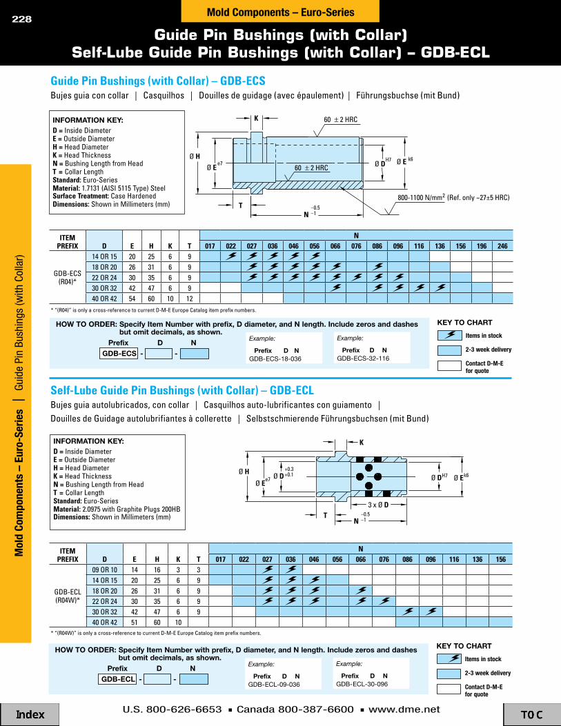
U.S. 800-626-6653 n Canada 800-387-6600 n www.dme.net
228
Guide Pin Bushings (with Collar)Self-Lube Guide Pin Bushings (with Collar) – GDB-ECL
Ø H
T
K
Ø EØ E k6
Ø DH7
e7
800-1100 N/mm (Ref. only ~27±5 HRC)
60 ± 2 HRC
60 ± 2 HRC
N–0.5–1
2
inforMation Key:d = inside diametere = outside diameterH = head diameterK = head thicknessn = Bushing length from headt = collar lengthstandard: euro-seriesMaterial: 2.0975 with Graphite Plugs 200hBdimensions: shown in millimeters (mm)
* “(r04)” is only a cross-reference to current d-m-e europe catalog item prefix numbers.
how to order: specify item number with prefix, d diameter, and n length. include zeros and dashes but omit decimals, as shown.
prefix d n gdB-ecs - -
Example:
prefix d nGDB-ECS-18-036
Example:
prefix d nGDB-ECS-32-116
Items in stock
2-3 week delivery
Contact D-M-E for quote
Key to chart
* “(r04w)” is only a cross-reference to current d-m-e europe catalog item prefix numbers.
how to order: specify item number with prefix, d diameter, and n length. include zeros and dashes but omit decimals, as shown.
prefix d n gdB-ecl - -
Example:
prefix d nGDB-ECL-09-036
Example:
prefix d nGDB-ECL-30-096
Items in stock
2-3 week delivery
Contact D-M-E for quote
Key to chart
inforMation Key:d = inside diametere = outside diameterH = head diameterK = head thicknessn = Bushing length from headt = collar lengthstandard: euro-seriesMaterial: 1.7131 (aisi 5115 type) steelsurface treatment: case hardeneddimensions: shown in millimeters (mm)
Ø H
Ø Ee7 Ø D
+0.3+0.1
K
Ø DH7 Ø Ek6
3 x Ø D
N–0.5–1
T
iteMPReFiX d e H K t
n017 022 027 036 046 056 066 076 086 096 116 136 156 196 246
GdB-ecs(r04)*
14 or 15 20 25 6 918 or 20 26 31 6 922 or 24 30 35 6 930 or 32 42 47 6 940 or 42 54 60 10 12
iteMPReFiX d e H K t
n017 022 027 036 046 056 066 076 086 096 116 136 156
GdB-ecl(r04w)*
09 or 10 14 16 3 314 or 15 20 25 6 918 or 20 26 31 6 922 or 24 30 35 6 930 or 32 42 47 6 940 or 42 51 60 10
self-lube Guide Pin Bushings (with collar) – GdB-eclBujes guia autolubricados, con collar | casquilhos auto-lubrificantes con guiamento | douilles de Guidage autolubrifiantes à collerette | selbstschmierende führungsbuchsen (mit Bund)
Guide Pin Bushings (with collar) – GdB-ecsBujes guia con collar | casquilhos | douilles de guidage (avec épaulement) | führungsbuchse (mit Bund)
Mol
d Co
mpo
nent
s –
Euro
-Ser
ies
| G
uide
Pin
Bus
hing
s (w
ith C
olla
r)Mold Components – Euro-Series

U.S. 800-626-6653 n Canada 800-387-6600 n www.dme.net
229
Guide Pin Bushings (without Collar)Self-Lube Guide Pin Bushings (without Collar)
3 x Ø D
L–0.5–1
Ø DH7 Ø E k6Ø HØ D
+0.3+0.1
K
inforMation Key:d = inside diametere = outside diameterH = head diameterK = head thicknessl = Bushing lengthstandard: euro-seriesMaterial: 1.7131 (aisi 5115 type) steel surface treatment: case hardeneddimensions: shown in millimeters (mm)
inforMation Key:d = inside diametere = outside diameterH = head diameterK = head thicknessl = Bushing lengthstandard: euro-seriesMaterial: 2.0975 with Graphite Plugs 200hB dimensions: shown in millimeters (mm)
Ø H
L
K
Ø D H7 Ø E k6
2
60 ± 2 HRC
60 ± 2 HRC
–0.5–1
800-1100 N/mm (Ref. only ~27±5 HRC)
* “(r03)” is only a cross-reference to current d-m-e europe catalog item prefix numbers.
* “(r03w)” is only a cross-reference to current d-m-e europe catalog item prefix numbers.
Example:
prefix d lGDB-ESL-10-036
Example:
prefix d lGDB-ESL-32-096
how to order: specify item number with prefix, d diameter, and l length. include zeros and dashes but omit decimals, as shown.
prefix d l gdB-esl - -
Items in stock
2-3 week delivery
Contact D-M-E for quote
Key to chart
iteMPReFiX d e H K
l009 012 017 022 027 036 046 056 066 076 086 096 116 136 156 246
GdB-ess(r03)*
09 or 10 14 16 614 or 15 20 25 618 or 20 26 31 622 or 24 30 35 630 or 32 42 47 640 or 42 54 60 10
iteMPReFiX d e H K
l017 022 027 036 046 056 066 076 086 096 116 136
GdB-esl(r03w)*
09 or 10 14 16 314 or 15 20 25 618 or 20 26 31 622 or 24 30 35 630 or 32 42 47 640 or 42 54 60 10
Example:
prefix d lGDB-ESS-09-022
Example:
prefix d lGDB-ESS-32-136
how to order: specify item number with prefix, d diameter, and l length. include zeros and dashes but omit decimals, as shown.
prefix d l gdB-ess - -
Items in stock
2-3 week delivery
Contact D-M-E for quote
Key to chart
Guide Pins Bushings (without collar ) – GdB-ess
self-lube Guide Pin Bushings (without collar) – GdB-esl
Bujes guia | casquilhos | douilles de guidage (sans épaulement) | führengsbuchse (ohne Bund)
Bujes guia autolubricados | casquilhos auto-lubrificantes | douilles de Guidage autolubrifiantes sans collerette | selbstschmierende führungsbuchsen (ohne Bund)
Mold Com
ponents – Euro-Series | Guide Pin Bushings (without Collar)
Mold Components – Euro-Series

U.S. 800-626-6653 n Canada 800-387-6600 n www.dme.net
230
Centering Bushing – Locating Sleeves
Ø G
2.5
Ø Dg6
L
N
Ø DK6Ø F
-0.5-1
60 ± 2 HRCinforMation Key:d = outside diameterF = inside diameterG = inside clearance diameterl = lengthn = inside lengthstandard: euro-seriesMaterial: 1.7131 (aisi 5115 type) steelsurface treatment: case hardeneddimensions: shown in millimeters (mm)
how to order: specify item number with prefix, d diameter and l length. include zeros as shown, but omit all spaces (spaces are only shown here for easier reading).
prefix d l r05
Example:
prefix d l R0520040
Example:
prefix d l R0542140
Items in stock
2-3 week delivery
Contact D-M-E for quote
Key to chart
iteMPReFiX d F G n
l020 030 040 050 060 070 080 100 120 140 160 180 200 240 280 300
r05
14 6 11 820 8 16 1326 10 21 1330 12 25 1342 16 33 1354 20 43 13
Buje centrador | casquilho central | fourrure au centre | mittelbuchse
Mol
d Co
mpo
nent
s –
Euro
-Ser
ies
| C
ente
ring
Bush
ing
– Lo
catin
g Sl
eeve
sMold Components – Euro-Series
centering Bushing (locating sleeves) – R05

U.S. 800-626-6653 n Canada 800-387-6600 n www.dme.net
231
Tubular Dowels Washer – Disk for Tubular Dowels
K js12
Ø D-0.2-0.4
Ø G
60 ± 2 HRC
L+0.5+0.3
Ø Dg6Ø G
60 ± 2 HRCinforMation Key:d = outside diameterG = inside diameterl = lengthstandard: euro-seriesMaterial: 1.7131 (aisi 5115 type) steel surface treatment: case hardeneddimensions: shown in millimeters (mm)
inforMation Key:d = outside diameterG = inside diameterK = thicknessstandard: euro-seriesMaterial: 1.7131 (aisi 5115 type) steelsurface treatment: case hardeneddimensions: shown in millimeters (mm)
how to order: specify item number with prefix, d diameter and l length. include zeros as shown, but omit all spaces (spaces are only shown here for easier reading).
prefix d l r09
Example:
prefix d l R0910040
Example:
prefix d l R0930180
Items in stock
2-3 week delivery
Contact D-M-E for quote
Key to chart
K js12
Ø D-0.2-0.4
Ø G
60 ± 2 HRC
L+0.5+0.3
Ø Dg6Ø G
60 ± 2 HRC
iteMnuMBeR d K G AVAilABilitYr091 14 3 14 003 6.2r091 18 4 18 004 8.5r091 24 5 24 005 10.5r091 30 6 30 006 13.0r091 40 8 40 008 17.0
iteMPReFiX d G
l020 030 040 050 060 070 080 100 120 140 160 180 200 240 300
r09
10 6.214 8.518 10.524 1330 17
how to order: specify item number. include zeros as shown, but omit all spaces (spaces are only shown here for easier reading).
prefix d K ro91
Items in stock
2-3 week delivery
Contact D-M-E for quote
Key to chart
Example:
prefix d K R09114003
Example:
prefix d K R09140008
Washer (disk for tubular dowel) – R091
tubular dowels – R09registro tubular | cavilha tubular | douaires tubulaires | Paßhülsen
arandela – registro tubular | anilhas – para cavilha tubular | cachetage cylindrique – douaires tubulaires | scheibe – Paßhülsen
Mold Com
ponents – Euro-Series | Tubular Dow
els; Washer
Mold Components – Euro-Series

U.S. 800-626-6653 n Canada 800-387-6600 n www.dme.net
232
Locating Rings
how to order: specify item number with prefix, d diameter, and h height. include zeros where shown, but omit all spaces (spaces are only shown here for easier reading).
prefix d h dhr21
Example:
prefix d h DHR2106019
Example:
prefix d h DHR2112015
Items in stock
2-3 week delivery
Contact D-M-E for quote
Key to chart
how to order: specify item number with prefix, d diameter, and h height. include zeros where shown, but omit all spaces (spaces are only shown here for easier reading).
prefix d h r20
Example:
prefix d h R2010015
Example:
prefix d h R2012019
Items in stock
2-3 week delivery
Contact D-M-E for quote
Key to chart
H
T
Ø Df8
Ø Gf8
H
Ø Df8
H
T
Ø Gf8Ø F
Ø Df8
Ø 71
DRILLED & COUNTERSUNKFOR M6 THREAD FLAT HEAD SCREW (2)
DRILLED & COUNTERBOREDFOR M8 THREADSOCKET HEAD CAP SCREW (2)
Ø 71Ø 57
Ø 57
Ø GØ FM6
THREAD (2)
THREAD (2) TM8
45°
45°
locating Ring (solid) – R20
H
T
Ø Df8
Ø Gf8
H
Ø Df8
H
T
Ø Gf8Ø F
Ø Df8
Ø 71
DRILLED & COUNTERSUNKFOR M6 THREAD FLAT HEAD SCREW (2)
DRILLED & COUNTERBOREDFOR M8 THREADSOCKET HEAD CAP SCREW (2)
Ø 71Ø 57
Ø 57
Ø GØ FM6
THREAD (2)
THREAD (2) TM8
45°
45°
inforMation Key:d = Platen-side diameterF = inside diameterG = mold-side diameterH = overall heightt = mold-side step heightstandard: euro-seriesMaterial: 1.1730 steel dimensions: shown in millimeters (mm)
inforMation Key:d = Platen-side diameterG = mold-side diameterH = overall heightt = mold-side step heightstandard: euro-seriesMaterial: 1.1730 steel dimensions: shown in millimeters (mm)
iteMPReFiX G F d
H12 15 17 19
t4 7 9 11
dhr21
90 36 08090 36 10090 36 11090 36 120
90 36 160
90 36 175
iteMPReFiX G d
H8 12 15 17 19
t4 4 7 9 11
r20
90 10090 11090 12090 125
90 160
90 175
anillo centrador | anéis de centragem | rondelles de placement | centrierflansche
anillo centrador | anéis de centragem | rondelles de placement | centrierflansche
Mol
d Co
mpo
nent
s –
Euro
-Ser
ies
| L
ocat
ing
Ring
sMold Components – Euro-Series
locating Ring with Mounting Holes – dHR21
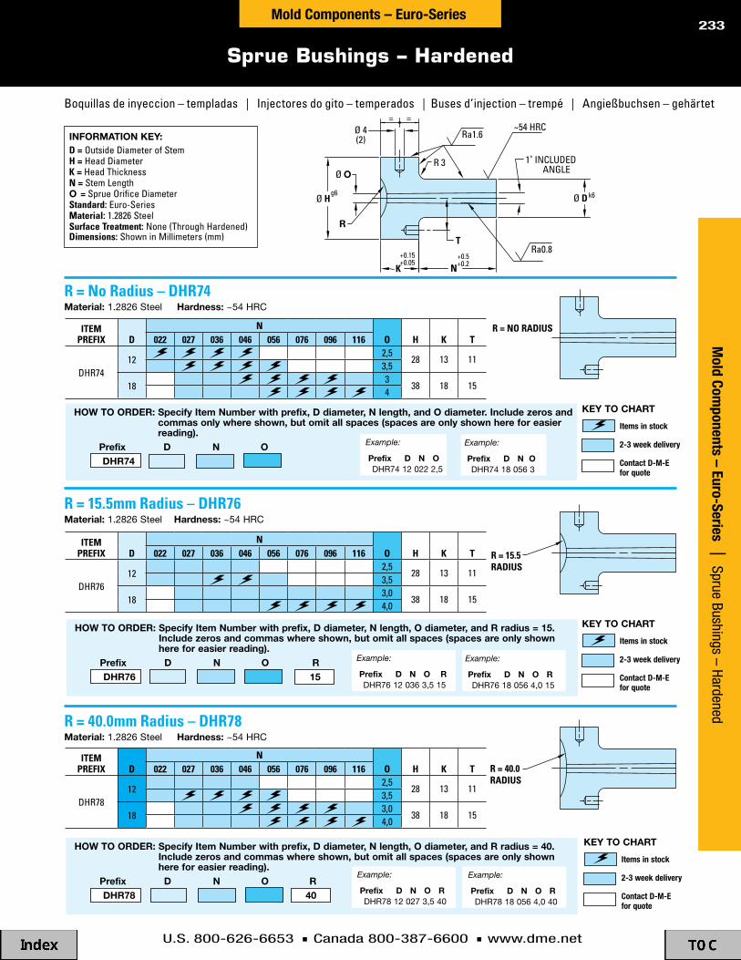
U.S. 800-626-6653 n Canada 800-387-6600 n www.dme.net
233
Sprue Bushings – Hardened
Ø D k6
N+0.5+0.2K
+0.15+0.05
Ø 4(2)
= =
Ø Hg6
Ø O
Ra0.8
Ra1.6
1˚ INCLUDED ANGLE
T
R
R 3
R = NO RADIUS
R = 15.5RADIUS
R = 40.0RADIUS
~54 HRC
R = no Radius – dHR74 Material:1.2826Steelhardness:~54HRC
R = 15.5mm Radius – dHR76 Material:1.2826Steelhardness:~54HRC
R = 40.0mm Radius – dHR78 Material:1.2826Steelhardness:~54HRC
inforMation Key:d = outside diameter of stemH = head diameterK = head thicknessn = stem lengtho = sprue orifice diameterstandard: euro-seriesMaterial: 1.2826 steelsurface treatment: none (through hardened)dimensions: shown in millimeters (mm)
Ø D k6
N+0.5+0.2K
+0.15+0.05
Ø 4(2)
= =
Ø Hg6
Ø O
Ra0.8
Ra1.6
1˚ INCLUDED ANGLE
T
R
R 3
R = NO RADIUS
R = 15.5RADIUS
R = 40.0RADIUS
~54 HRC
how to order: specify item number with prefix, d diameter, n length, and o diameter. include zeros and commas only where shown, but omit all spaces (spaces are only shown here for easier reading).
prefix d n o dhr74
Example:
prefix d n o DHR74120222,5
Example:
prefix d n o DHR74180563
how to order: specify item number with prefix, d diameter, n length, o diameter, and r radius = 15. include zeros and commas where shown, but omit all spaces (spaces are only shown here for easier reading).
prefix d n o r dhr76 15
Example:
prefix d n o r DHR76120363,515
Example:
prefix d n o r DHR76180564,015
how to order: specify item number with prefix, d diameter, n length, o diameter, and r radius = 40. include zeros and commas where shown, but omit all spaces (spaces are only shown here for easier reading).
prefix d n o r dhr78 40
Example:
prefix d n o r DHR78120273,540
Example:
prefix d n o r DHR78180564,040
iteMPReFiX d
nO H K t022 027 036 046 056 076 096 116
dhr7412
2,528 13 11
3,5
183
38 18 154
iteMPReFiX d
nO H K t022 027 036 046 056 076 096 116
dhr7612
2,528 13 11
3,5
183,0
38 18 154,0
iteMPReFiX d
nO H K t022 027 036 046 056 076 096 116
dhr7812
2,528 13 11
3,5
183,0
38 18 154,0
Items in stock
2-3 week delivery
Contact D-M-E for quote
Key to chart
Items in stock
2-3 week delivery
Contact D-M-E for quote
Key to chart
Items in stock
2-3 week delivery
Contact D-M-E for quote
Key to chart
Boquillas de inyeccion – templadas | injectores do gito – temperados | Buses d’injection – trempé | angießbuchsen – gehärtet
Mold Com
ponents – Euro-Series | Sprue Bushings – Hardened Mold Components – Euro-Series

U.S. 800-626-6653 n Canada 800-387-6600 n www.dme.net
234
Support Pillars
Ø D–0.2
K
L+0.15+0.05
Ø GØ H
Ra0.8Ra0.8
Ø F
N
Ø D– 0.2
H7
M
Ø G
Ra0.8
L+0.15+0.05
L
L
0
640 N/mm (Ref. only ~91 HRB)2
640 N/mm (Ref. only ~91 HRB)2
0
Ra0.8
• no support pillars• sin pilares de apoyo• sans colonnes de support• sem colunas de suporte• ohne stutzbolzen
load • carga • charge • carga • druck
load • carga • charge • carga • druck
load • carga • charge • carga • druck
• two rows of support pillars increase the permissible cavity area 9 times.
• una fila de pilares de apoyo aumenta el area permisible de la cavidad nueve veces.
• deux rangees de colonnes de support augmentent la surface d’empreinte admissible de 9 fois.
• duas fileiras de colunas de suporte aumentam em 9 vezes a area de cavidade permitida.
• zwei reihen stutzbolzen erhohen die Belastbarkeit der Kavitatsflache um das 9-fache.
• one row of support pillars increases the permissible cavity area 4 times.
• una fila de pilares de apoyo aumenta el area permisible de la cavidad cuatro veces.
• une rangee de colonnes de support augmente la surface d’empreinte admissible de 4 fois.
• uma fileira de colunas de suporte aumenta em 4 vezes a area de cavidade permitida.
• eine reihe stutzbolzen erhoht die Belastbarkeit der Kavitatflache um das 4-fache.
support Pillars with tapped Hole and Hole for dowel – FW29
inforMation Key:d = outside diameterG = through hole diameterH = counterbore diameterK = counterbore depthl = lengthstandard: din typeMaterial: 1.1730 steelsurface treatment: none dimensions: shown in millimeters (mm)
inforMation Key:d = outside diameterF = tap diameterG = dowel locating hole diameterl = lengthM = locating hole depth (minimum)n = tap depth (minimum)standard: din typeMaterial: 1.1730 steelsurface treatment: nonedimensions: shown in millimeters (mm)
support Pillars with drilled & counterbored Hole – FW28
Ø D–0.2
K
L+0.15+0.05
Ø GØ H
Ra0.8Ra0.8
Ø F
N
Ø D– 0.2
H7
M
Ø G
Ra0.8
L+0.15+0.05
L
L
0
640 N/mm (Ref. only ~91 HRB)2
640 N/mm (Ref. only ~91 HRB)2
0
Ra0.8
Ø D–0.2
K
L+0.15+0.05
Ø GØ H
Ra0.8Ra0.8
Ø F
N
Ø D– 0.2
H7
M
Ø G
Ra0.8
L+0.15+0.05
L
L
0
640 N/mm (Ref. only ~91 HRB)2
640 N/mm (Ref. only ~91 HRB)2
0
Ra0.8
how to order: specify item number with prefix, d diameter and l length. include zeros as shown, but omit all spaces (spaces are only shown here for easier reading).
prefix d l
Example:
prefix d l FW2832076
Example:
prefix d l FW2963096
Items in stock
2-3 week delivery
Contact D-M-E for quote
Key to chart
Items in stock
2-3 week delivery
Contact D-M-E for quote
Key to chartiteMPReFiX d G H K
l046 056 076 096 116 136
fw28
32 9 15 940 11 18 1150 13 20 1363 13 20 13
iteMPReFiX d G M F n
l046 056 076 096 116
fw29
32 8 14 m8 1440 10 18 m10 1850 10 18 m10 1863 10 18 m10 18
Pilares de apoyo | suportes | colonnes de support | stützbolzen
Pilares de apoyo | suportes | colonnes de support | stützbolzen
Mol
d Co
mpo
nent
s –
Euro
-Ser
ies
| S
uppo
rt P
illar
sMold Components – Euro-Series

U.S. 800-626-6653 n Canada 800-387-6600 n www.dme.net
235
Dowel PinsDowel Pins with Internal Thread – Pull Dowels
Ø Dm6
15°
L
L
Ø F Ø Dm6
N15°
~60 HRC
650-750 HV30 (Ref. Only ~60 ± 2 HRC)
Ø Dm6
15°
L
L
Ø F Ø Dm6
N15°
~60 HRC
650-750 HV30 (Ref. Only ~60 ± 2 HRC)
inforMation Key:d = Pin outside diameterl = lengthstandard: din 6325, iso 8734Material: Per din and iso specifications dimensions: shown in millimeters (mm)
inforMation Key:d = Pin outside diameterF = tap diameterl = lengthn = tap depthstandard: din en 28735 – type aMaterial: Per din specificationdimensions: shown in millimeters (mm)
how to order: specify item number with prefix, d diameter and l length. include zeros as shown, but omit all spaces (spaces are only shown here for easier reading).
prefix d l wZ7005
Example:
prefix d l WZ700506020
Example:
prefix d l WZ700512040
how to order: specify item number with prefix, d diameter and l length. include zeros as shown, but omit all spaces (spaces are only shown here for easier reading).
prefix d l dp
Example:
prefix d l DP28
Example:
prefix d l DP2060
Items in stock
2-3 week delivery
Contact D-M-E for quote
Key to chart
Items in stock
2-3 week delivery
Contact D-M-E for quote
Key to chart
iteMPReFiX d
l6 8 10 12 14 16 18 20 24 28 32 36 40 50 60 80 100 120 140
dP
23456810121620
iteMPReFiX d F n
l020 024 028 032 036 040 050 060 080 100
wz7005
06 m4 608 m5 810 m6 1012 m6 1214 m8 1216 m8 1620 m10 20
dowel Pins with internal thread (Pull dowels) – Wz7005
dowel Pins – dPclavija | cavilhas | Goupilles cylindriques | zylinderstifte
clavija con cuerda interna | cavilhas | Goupilles cylindriques | zylinderstifte
Mold Com
ponents – Euro-Series | Dow
el Pins, Pull Dow
elsMold Components – Euro-Series

U.S. 800-626-6653 n Canada 800-387-6600 n www.dme.net
236
Socket Head Cap ScrewsLock Washers – Spring Washers
inforMation Key:d = thread diameterH = head diameterK = head heightl = lengthn = thread lengtht = hex socket size (across flats)standard: din 912-12.9Material: Per din specification dimensions: shown in millimeters (mm)
T
Ø F Ø PØ D
inforMation Key:d = for screw diameterF = inside diameterP = outside diametert = thicknessstandard: din 7980 Material: Per din specificationdimensions: shown in millimeters (mm)
how to order: specify item number. include zeros and commas but omit decimals and all spaces (spaces are only shown here for easier reading).
how to order: specify d diameter and l length. include zeros as shown, but omit all spaces (spaces are only shown here for easier reading).
d l
Example:
d l M630
Example:
d l M20200
Ø H Ø D
TK
LN
Items in stock
2-3 week delivery
Contact D-M-E for quote
Key to chart
Items in stock
2-3 week delivery
Contact D-M-E for quote
Key to chart
iteMnuMBeR d F P t AVAilABilitYr54 08 2 08 8.1 12.7 2.0
r54 10 2,5 10 10.2 16 2.5r54 12 2,5 12 12.5 18 2.5
d n H K tl
8 10 12 16 20 25 30 40 50 60 70 80 90 100 110 120 130 140 150 160 180 200 220 240 260m4 12 7 4 3m6 18 10 6 5m8 22 13 8 6
m10 25 16 10 8m12 28 18 12 10m16 38 24 16 14m16 44 24 16 14m16 57 21 10 14m20 52 30 20 17m20 65 30 20 17
lock Washers (spring Washers) – R54
socket Head cap screws – Mtornillos cabeza allen | Parafuso de cabeça sextavada | vis 6-pans téte cylindrique | zylinderkopfschrauben
rondanas de Presion | freios | rondelles de retenue | sicherungsscheibe (federscheibe)
Mol
d Co
mpo
nent
s –
Euro
-Ser
ies
| S
.H.C
.S.,
Lock
Was
hers
Mold Components – Euro-Series

U.S. 800-626-6653 n Canada 800-387-6600 n www.dme.net
237
Flat Head ScrewsStop Disk for Ejector Plates
L
Ø H
KT
Ø D
3±0.01
Ø 18
DRILLED & COUNTERSUNKFOR M4 THREAD FLAT HEAD SCREW
inforMation Key:d = thread diameterH = head diameterK = head heightl = lengtht = hex socket size (across flats)standard: din 7991-10.9Material: Per din specification dimensions: shown in millimeters (mm)
inforMation Key:standard: euro-seriesMaterial: 1.1191 (aisi 1045 type) steel dimensions: shown in millimeters (mm)
use with sm4 8 flat head screw (m4 thread x 8mm long) which must be purchased separately. see flat head screws above.
how to order: specify item number with prefix and l length. include zeros as shown, but omit all spaces (spaces are only shown here for easier reading).
prefix l
Example:
prefix l SM310
Example:
prefix l SM816
Items in stock
2-3 week delivery
Contact D-M-E for quote
Key to chart
how to order: specify item number. omit spaces (spaces are only shown here for easier reading).Items in stock
2-3 week delivery
Contact D-M-E for quote
Key to chart
iteMnuMBeR AVAilABilitY
r18 18
iteMPReFiX H K t d
l8 10 12 16 20 25 30 35 40 45 50
sm3 6 2.5 1.7 m3sm4 8 3 2.3 m4sm5 10 4 2.8 m5sm6 12 5 3.3 m6sm8 16 6 4.4 m8sm10 20 8 5.5 m10sm12 24 10 6.5 m12
stop disk for ejector Plates – R18
Flat Head screws – sMtornillo de cabeza plana avellanada | Parafusos de cabeça cónica | vis creuses | senkkopfschrauben
arandela de tope | anilhas de encosto | repos d’épaisseur pour plaques d’éjection | distanzscheibe für auswerferplatte
Mold Com
ponents – Euro-Series | Flat Head Screws, Stop D
isksMold Components – Euro-Series
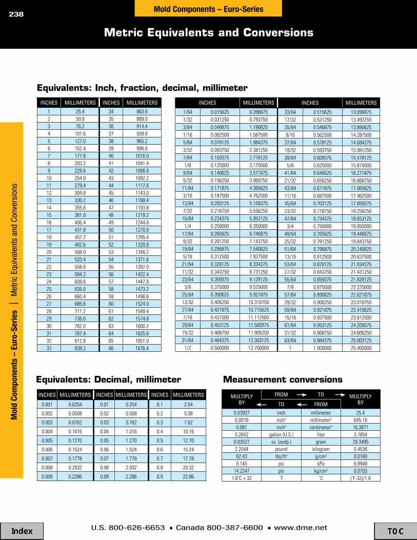
U.S. 800-626-6653 n Canada 800-387-6600 n www.dme.net
238
Metric Equivalents and Conversions
Mol
d Co
mpo
nent
s –
Euro
-Ser
ies
| M
etric
Equ
ival
ents
and
Con
vers
ions
Mold Components – Euro-Series
inches millimeters inches millimeters
1 25.4 34 863.62 50.8 35 889.03 76.2 36 914.44 101.6 37 939.85 127.0 38 965.26 152.4 39 990.67 177.8 40 1016.08 203.2 41 1041.49 228.6 42 1066.810 254.0 43 1092.211 279.4 44 1117.612 304.8 45 1143.013 330.2 46 1168.414 355.6 47 1193.815 381.0 48 1219.216 406.4 49 1244.617 431.8 50 1270.018 457.2 51 1295.419 482.6 52 1320.820 508.0 53 1346.221 533.4 54 1371.622 558.8 55 1397.023 584.2 56 1422.424 609.6 57 1447.825 635.0 58 1473.226 660.4 59 1498.627 685.8 60 1524.028 711.2 61 1549.429 736.6 62 1574.830 762.0 63 1600.231 787.4 64 1625.632 812.8 65 1651.033 838.2 66 1676.4
inches millimeters
1/64 0.015625 0.3968751/32 0.031250 0.7937503/64 0.046875 1.1906251/16 0.062500 1.5875005/64 0.078125 1.9843753/32 0.093750 2.3812507/64 0.109375 2.7781251/8 0.125000 3.175000
9/64 0.140625 3.5718755/32 0.156250 3.96875011/64 0.171875 4.3656253/16 0.187500 4.76250013/64 0.203125 5.1593757/32 0.218750 5.55625015/64 0.234375 5.9531251/4 0.250000 6.350000
17/64 0.265625 6.7468759/32 0.281250 7.14375019/64 0.296875 7.5406255/16 0.312500 7.93750021/64 0.328125 8.33437511/32 0.343750 8.73125023/64 0.359375 9.1281253/8 0.375000 9.525000
25/64 0.390625 9.92187513/32 0.406250 10.31875027/64 0.421875 10.7156257/16 0.437500 11.11250029/64 0.453125 11.50937515/32 0.468750 11.90625031/64 0.484375 12.3031251/2 0.500000 12.700000
inches millimeters
33/64 0.515625 13.09687517/32 0.531250 13.49375035/64 0.546875 13.8906259/16 0.562500 14.287500
37/64 0.578125 14.68437519/32 0.593750 15.08125039/64 0.609375 15.4781255/8 0.625000 15.875000
41/64 0.640625 16.27187521/32 0.656250 16.66875043/64 0.671875 17.06562511/16 0.687500 17.46250045/64 0.703125 17.85937523/32 0.718750 18.25625047/64 0.734375 18.6531253/4 0.750000 19.050000
49/64 0.765625 19.44687525/32 0.781250 19.84375051/64 0.796875 20.24062513/16 0.812500 20.63750053/64 0.828125 21.03437527/32 0.843750 21.43125055/64 0.859375 21.8281257/8 0.875000 22.225000
57/64 0.890625 22.62187529/32 0.906250 23.01875059/64 0.921875 23.41562515/16 0.937500 23.81250061/64 0.953125 24.20937531/32 0.968750 24.60625063/64 0.984375 25.003125
1 1.000000 25.400000
inches millimeters inches millimeters inches millimeters
0.001 0.0254 0.01 0.254 0.1 2.54
0.002 0.0508 0.02 0.508 0.2 5.08
0.003 0.0762 0.03 0.762 0.3 7.62
0.004 0.1016 0.04 1.016 0.4 10.16
0.005 0.1270 0.05 1.270 0.5 12.70
0.006 0.1524 0.06 1.524 0.6 15.24
0.007 0.1778 0.07 1.778 0.7 17.78
0.008 0.2032 0.08 2.032 0.8 20.32
0.009 0.2286 0.09 2.286 0.9 22.86
multiPly By
from to multiPly Byto from
0.03937 inch millimeter 25.40.0016 inch2 millimeter2 645.160.061 inch3 centimeter3 16.38710.2642 gallon (U.S.) liter 3.7854
0.03527 oz. (avdp.) gram 28.34952.2044 pound kilogram 0.453662.43 lbs/ft3 g/cm3 0.01600.145 psi kPa 6.8948
14.2247 psi kg/cm2 0.07031.8˚C + 32 ˚F ˚C (˚F-32)/1.8
Equivalents: Inch, fraction, decimal, millimeter
Equivalents: Decimal, millimeter Measurement conversions

D-M-E INCH, DIN, JIS
INCH
, DIN
, JIS

U.S. 800-626-6653 n Canada 800-387-6600 n www.dme.net
INCH Pins, Sleeves, Blades ......................241-262A comprehensive line of INCH ejector products
DIN Pins, Sleeves, Blades ........................263-276A comprehensive line of DIN ejector products
JIS Pins, Sleeves, Blades .........................277-280A comprehensive line of JIS ejector products
Special Pins and Sleeves .........................281-285Rapid delivery, cost-effective solutions
Go to www.dme.net/prices for the latest pricing guide.Online Price Guide
240IN
CH, D
IN, J
ISINCH, DIN, JIS
Table of Contents

D-M-E INCH Pins, Sleeves, Blades
Featuring high-quality
ejector pins, sleeves, Blades,
core pins, return pins,
and sprue puller pins
INCH Pins, Sleeves, Blades

U.S. 800-626-6653 n Canada 800-387-6600 n www.dme.net
242
Go to www.dme.net/prices for the latest pricing guide.
Ejector PinsNitrided, Through-Hardened, Close Tolerance .............244-248
Shoulder Ejector Pins Nitrided, Through-Hardened, Close Tolerance .............245
Ejector Blades M2 ......................................................252-253
Core Pins Standard, High-Hardness, Performance .....................254-257
Online Price Guide
Return Pins ................................................................258
Ejector Sleeves Nitrided O.D., Nitrided O.D. & I.D. ..............................250-251
Keyed Ejector Pins ...................................................... 247
MoldBasics Inch Ejector Pins .....................................249
Sprue Puller Pins ........................................................259
A comprehensive line of Inch Ejector Products
INCH Pins, Sleeves, BladesIN
CH P
ins,
Sle
eves
, Bla
des
| A
com
preh
ensi
ve li
ne o
f Inc
h Ej
ecto
r Pro
duct
s

U.S. 800-626-6653 n Canada 800-387-6600 n www.dme.net
243
Table of Contents
EjEctOr PINS – StraIGht
ex inch ejector pins – straiGht. . . . . . . . . . . . . . . 244
thx inch throuGh-hardened ejector pins . . . . 246
thxK Keyed ejector pins. . . . . . . . . . . . . . . . . . . . . . . 247
ejp-imh close tolerance m-2 ejector pins. . . . 248
mb-ejp-ihn moldbasics inch ejector pins . . . . 249
EjEctOr PINS – ShOuldEr
ex inch ejector pins – (nitrided)
1/2” shoulder. . . . . . . . . . . . . . . . . . . . . . . . . . . . . . . . 245
2” shoulder . . . . . . . . . . . . . . . . . . . . . . . . . . . . . . . . . 245
ejp-imh close tolerance m2 ejector pins . . . . 248
EjEctOr SlEEVES
s inch ejector sleeves – nitrided o.d.. . . . . . . . . 250
snd inch ejector sleeves – nitrided o.d. & i.d. 251
EjEctOr BladES
inch ejector blades. . . . . . . . . . . . . . . . . . . . . . . . . . . 252-253
cOrE PINS
c inch core pins – standard hardness . . . . . . . 254 cx inch core pins – hiGh hardness. . . . . . . . . . . . 255
pcl performance core pins – hiGh conductivity . . . . . . . . . . . . . . . . . . . . . . . . . . 256-257
rEturN & SPruE PullEr PINS
return pins . . . . . . . . . . . . . . . . . . . . . . . . . . . . . . . . . . . 258
sprue puller pins . . . . . . . . . . . . . . . . . . . . . . . . . . . . . 259
aPPENdIcES
comparison chart . . . . . . . . . . . . . . . . . . . . . . . . . . . . 260
hardness conversion table . . . . . . . . . . . . . . . . . . 261
d-m-e hardness data . . . . . . . . . . . . . . . . . . . . . . . . . . 261
inch fax order form . . . . . . . . . . . . . . . . . . . . . . . . . . 262
INCH Pins, Sleeves, Blades | Table of Contents
INCH Pins, Sleeves, Blades
Ejector Pins – StraightEX. . . . . . . . . . . . . .244thX . . . . . . . . . . . .246thXK . . . . . . . . . . .247EjP-IMh . . . . . . . .248MB-EjP-IhN . . . .249
core Pinsc . . . . . . . . . . . . . . .254cX. . . . . . . . . . . . . .255Pcl. . . . . . . . . . . . .256-257
Ejector Pins – ShoulderEX. . . . . . . . . . . . . .245EjP-IMh . . . . . . . .248
Ejector BladesInch . . . . . . . . . . . .252-253
Ejector SleevesS . . . . . . . . . . . . . . .250SNd . . . . . . . . . . . .251
return Pins & Sprue Puller Pins . . . . . .258-259

U.S. 800-626-6653 n Canada 800-387-6600 n www.dme.net
244
Ø H Ø D†
K
.031 R MAXIMUM
L
n PrecisionmadeofsuperiorqualityH13typethermalshockresistinghotworkdiesteel
n Hot-forgedheadsprovideuniformgrainflow,highertensilestrength
n Corehardness40-45HRCn Outsidediameternitridedto65-74HRC
hardnessandfinishedtominimizewearn Headsannealedforeasymachiningn CenterlessgroundDdiameter
INCH Ejector Pins – H13 Nitrided – Straight
*HOW tO Order: Specify Item Number by combining Item Number Prefix with the length (L dimension) desired. n Omit spaces and dashes, as shown. Examples: EX9M10, EX33M10 n Add “OS” at end of Item Number for .005" oversize diameters. Examples: EX3M6NSOS, EX25M14OS, EX33M10OS
NOTE: NS suffix shown in chart for No Shoulder for items EX3M through EX8M. Examples: EX3M6NS, EX7M10NS
Items in stock2-3 week deliveryContact D-M-E for quote
key tO cHArt
l = lenGth
ItEMNuMBEr
PrEFIXØ d
pin dia
Ø d†
pin diatol
Ø hhead dia
KheadthK
6 10 14 18 25 36 45
dstd
d.005
over siZe
dstd
d.005
over siZe
dstd
d.005
over siZe
dstd
d.005
over siZe
-.0003 -.0008
dstd
dstd
dstd
ex3m _*_ns 3/64 (.0468)
-.000-.001
.250 .125ex5m _*_ns 1/16 (.0625) .250 .125ex6m _*_ns 5/64 (.0781) .250 .125ex7m _*_ns 3/32 (.0937) .250 .125ex8m _*_ns 7/64 (.1093) .250 .125
ex9m _*_ 1/8 (.1250)
-.0003-.0006
.250 .125 ex10m _*_ 9/64 (.1406) .250 .125ex11m _*_ 5/32 (.1562) .281 .156ex12m _*_ 11/64 (.1718) .343 .187ex13m _*_ 3/16 (.1875) .375 .187ex14m _*_ 13/64 (.2031) .375 .187ex15m _*_ 7/32 (.2187) .406 .187ex16m _*_ 15/64 (.2343) .406 .187ex17m _*_ 1/4 (.2500) .437 .187ex18m _*_ 17/64 (.2656) .437 .250ex19m _*_ 9/32 (.2812) .437 .250ex20m _*_ 19/64 (.2968) .500 .250ex21m _*_ 5/16 (.3125) .500 .250ex22m _*_ 21/64 (.3281) .562 .250ex23m _*_ 11/32 (.3437) .562 .250ex24m _*_ 23/64 (.3593) .625 .250ex25m _*_ 3/8 (.3750) .625 .250ex26m _*_ 25/64 (.3906) .625 .250ex27m _*_ 13/32 (.4062) .687 .250
ex28m _*_ 27/64 (.4218) .687 .250
ex29m _*_ 7/16 (.4375) .687 .250ex30m _*_ 29/64 (.4531) .687 .250ex31m _*_ 15/32 (.4687) .750 .250ex32m _*_ 31/64 (.4843) .750 .250ex33m _*_ 1/2 (.5000)
-.0003-.0008
.750 .250ex34m _*_ 17/32 (.5312) .750 .250ex35m _*_ 9/16 (.5625) .812 .250ex37m _*_ 5/8 (.6250) .875 .250ex39m _*_ 11/16 (.6875) .937 .250ex41m _*_ 3/4 (.7500) 1.000 .250ex45m _*_ 7/8 (.8750) 1.125 .250ex47m _*_ 1” (1.0000) 1.250 .250
Ø dpin dia tol
INCH
Pin
s, S
leev
es, B
lade
s |
IN
CH E
ject
or P
ins
– H1
3 N
itrid
ed –
Str
aigh
tINCH Pins, Sleeves, Blades
INch Ejector Pins – EX

U.S. 800-626-6653 n Canada 800-387-6600 n www.dme.net
245
INCH Ejector Pins – H13 Nitrided – Shoulder
.031 R MAXIMUM Ø .125
.125.25 R
.50
L
Ø .250
Ø D+.000–.001
+.000–.001 n Precisionmadeofsuperiorquality
H13typethermalshockresistinghotworkdiesteel
n Hot-forgedheadsprovideuniformgrainflow,highertensilestrength
n Corehardness40-45HRCn Outsidediameternitridedto
65-74HRChardnessandfinishedtominimizewear
n Headsannealedforeasymachiningn CenterlessgroundDdiameter
*HOW tO Order: Specify Item Number by combining Item Number Prefix and the length (L dimension) desired. n Omit spaces and dashes, as shown. Examples: EX2M6, EX8M14 n Add “OS” for .005" oversize diameters. Examples: EX2M6OS, EX5M10OS, EX8M10OS
NOTE: For 2" Shoulder, no suffix is used. Examples: EX3M6, EX7M10
1/2" Shoulder length – EX l = lenGth
ItEMNuMBEr PrEFIX
Ø dpin dia
6 10 14
dstd
d.005
over siZe
dstd
d.005
over siZe
dstd
ex2m_*_12sh 1/32 (.0312) ex3m_*_12sh 3/64 (.0468)ex5m_*_12sh 1/16 (.0625)ex6m_*_12sh 5/64 (.0781)ex7m_*_12sh 3/32 (.0937)ex8m_*_12sh 7/64 (.1093)
2" Shoulder length – EX
note: for 2" shoulder length, no suffix should be used (see example below).
l = lenGth
ItEMNuMBEr PrEFIX
Ø dpin dia
6 10 14
dstd
d.005
over siZe
dstd
d.005
over siZe
dstd
ex2m_*_ 1/32 (.0312) ex3m_*_ 3/64 (.0468)ex5m_*_ 1/16 (.0625)ex6m_*_ 5/64 (.0781)ex7m_*_ 3/32 (.0937)ex8m_*_ 7/64 (.1093)
.031 R MAXIMUM Ø .125
.125.25 R
L
Ø .250
Ø D+.000–.001
+.000–.001
2.0
*HOW tO Order: Specify Item Number by combining Item Number Prefix and the length (L dimension) desired. n Omit spaces and dashes, as shown. Examples: EX2M612SH, EX8M1412SH n Add “OS” for .005" oversize diameters. Examples: EX3M612SHOS, EX3M612SHOS
NOTE: 12SH suffix shown in chart for 1/2" Shoulder length. Examples: EX3M612SH, EX7M1012SH
QuaNtItY dIScOuNtS:ejector pins, core pins, return pins and sprue puller pins. discounts apply to current net prices. standard sizes may be combined on one order for quantity discounts.
300 to 599 . . . . . . . . . . less 5%600 or more . . . . . . . less 10%
INCH Pins, Sleeves, Blades | IN
CH Ejector Pins – H13 Nitrided – Shoulder
INCH Pins, Sleeves, Blades
Items in stock2-3 week deliveryContact D-M-E for quote
key tO cHArt
Items in stock2-3 week deliveryContact D-M-E for quote
key tO cHArt

U.S. 800-626-6653 n Canada 800-387-6600 n www.dme.net
246
INCH High-Hardness Ejector Pins –H13 Nitrided – Straight
n HighercorehardnessmakestheTHXpinsidealforuseindiecastdiesorotherhightemperatureapplications
n Corehardnessof50-55HRCminimizesnicking,dishingandbendingn Non-chippingsurfacetreatmentof65-74HRCalleviatesflashingn Annealedandfinishedheadspermiteasymachiningn CenterlessgroundDdiametern Finalfinishminimizeswearandprolongspinlife
Ø H Ø D
K
.031 R MAXIMUM
L
†
*HOW tO Order: Specify Item Number by combining Item Number Prefix and the length (L dimension) desired. n Omit spaces & dashes, as shown. Examples: THX0910, THX4118 n Precede 6" length with a zero. Examples: THX0906, THX3306 n Add “OS” for .005" oversize diameters. Examples: THX0306NSOS, THX0906OS, THX2514OS, THX3310OS
NOTE: NS suffix shown in chart for No Shoulder for items THX03 through THX08. Examples: THX306NS, THX710NS
ItEMNuMBEr
PrEFIXØ d
pin dia
d†
pin dia tolerances
h head dia
K head thicK
l = lenGth06 10 14 18
dstd
d.005
over-siZe
dstd
d.005
over-siZe
dstd
d.005
over-siZe
dstd
thx03_*_ns 3/64 (.0468)
–.000–.001
.250 .125thx05_*_ns 1/16 (.0625) .250 .125thx06_*_ns 5/64 (.0781) .250 .125thx07_*_ns 3/32 (.0937) .250 .125thx08_*_ns 7/64 (.1093) .250 .125
thx09_*_ 1/8 (.1250)
–.0003–.0006
.250 .125thx10_*_ 9/64 (.1406) .250 .125thx11_*_ 5/32 (.1562) .281 .156thx12_*_ 11/64 (.1718) .343 .187thx13_*_ 3/16 (.1875) .375 .187thx14_*_ 13/64 (.2031) .375 .187thx15_*_ 7/32 (.2187) .406 .187thx16_*_ 15/64 (.2343) .406 .187thx17_*_ 1/4 (.2500) .437 .187thx18_*_ 17/64 (.2656) .437 .250thx19_*_ 9/32 (.2812) .437 .250thx20_*_ 19/64 (.2968) .500 .250thx21_*_ 5/16 (.3125) .500 .250thx22_*_ 21/64 (.3281) .562 .250thx23_*_ 11/32 (.3437) .562 .250thx24_*_ 23/64 (.3593) .625 .250thx25_*_ 3/8 (.3750) .625 .250thx26_*_ 25/64 (.3906) .625 .250thx27_*_ 13/32 (.4062) .687 .250thx28_*_ 27/64 (.4218) .687 .250thx29_*_ 7/16 (.4375) .687 .250thx30_*_ 29/64 (.4531) .687 .250thx31_*_ 15/32 (.4687) .750 .250thx32_*_ 31/64 (.4843) .750 .250thx33_*_ 1/2 (.5000)
–.0003–.0008
.750 .250thx34_*_ 17/32 (.5312) .750 .250thx35_*_ 9/16 (.5625) .812 .250thx37_*_ 5/8 (.6250) .875 .250thx39_*_ 11/16 (.6875) .937 .250thx41_*_ 3/4 (.7500) 1.000 .250thx45_*_ 7/8 (.8750) 1.125 .250thx47_*_ 1” (1.0000) 1.250 .250
INCH
Pin
s, S
leev
es, B
lade
s |
IN
CH H
igh-
Hard
ness
Eje
ctor
Pin
s –
H13
Nitr
ided
– S
trai
ght
INCH Pins, Sleeves, Blades
INch high-hardness Ejector Pins – thX
Items in stock2-3 week deliveryContact D-M-E for quote
key tO cHArt

U.S. 800-626-6653 n Canada 800-387-6600 n www.dme.net
247
Keyed Ejector Pins
INCH Pins, Sleeves, Blades | Keyed Ejector Pins
INCH Pins, Sleeves, Blades
Ø d pin diameter
frac./dec.
Ø dtolerance
ItEMNuMBEr
llenGth
Ø hheaddia
Ø Khead
thicKness
(1/8) .1250 -.0003-.0006
thxK0906 6.00.250 .125
thxK0914 14.00
(9/64) .1406 -.0003-.0006 thxK1014 14.00 .250 .125
(5/32) .1562 -.0003-.0006 thxK1114 14.00 .281 .156
(3/16) .1875 -.0003-.0006
thxK1306 6.00.375 .187
thxK1314 14.00
(7/32) .2187 -.0003-.0006 thxK1514 14.00 .406 .187
(1/4) .2500 -.0003-.0006
thxK1706 6.00.437 .187
thxK1714 14.00
(5/16) .3125 -.0003-.0006
thxK2106 6.00.500 .250
thxK2114 14.00
(3/8) .3750
-.0003-.0006
thxK2506 6.00
.625 .250thxK2514 14.00-.0003-.0008 thxK2525 25.00
(7/16) .4375 -.0003-.0006 thxK2914 14.00 .687 .250
(1/2) .5000 -.0003-.0008 thxK3314 14.00 .750 .250
(5/8) .6250 -.0003-.0008 thxK3714 14.00 .875 .250
(3/4) .7500 -.0003-.0008
thxK4114 14.001.000 .250
thxK4125 25.00
(1”) 1.000 -.0003-.0008
thxK4714 14.001.250 .250
thxK4725 25.00
Ø H Ø D
K
.031 RMAXIMUM 50-55 HRC .004
FLAT ON HEAD FROM Ø D
±.002
L
INfOrmAtION key:d = pin diameterh = head diameterK = head thicknessl = lengthMaterial: h-13 / 1.2344 / sKd61Surface treatment: nitridedSurface hardness: 65 min. hrc core hardness: 50-55 hrc
n Precision-machinedflatonheadkeepspinfromrotating
n Madefromsuperiorqualitythermalshock-resistinghotworksteel
n Corehardnessof50-55HRCmakesthesepinsidealforuseindie-castdiesorotherhightemperatureapplications
n Annealedhot-forgedheadsprovideuniformgrainflowwhileallowingforeasiermachining
Keyed Ejector Pins – thXK
Ø H Ø D
K
.031 RMAXIMUM 50-55 HRC .004
FLAT ON HEAD FROM Ø D
±.002
L

U.S. 800-626-6653 n Canada 800-387-6600 n www.dme.net
248
INCH Close Tolerance M-2 Through-Hardened Ejector Pins
INCH
Pin
s, S
leev
es, B
lade
s |
INCH
Clo
se T
oler
ance
M-2
Thr
ough
-Har
dene
d Ej
ecto
r Pin
sINCH Pins, Sleeves, Blades
Ø H Ø D
K
.031 RMAXIMUM
L
–.0003 –.0005
58-62 HRC
n Industry-leading .0002" tolerance band
n CenterlessgroundDdiameter
n PrecisionmadeofsuperiorqualityM-2high-speedtoolsteel
n Superiorwearresistance
n Exceptionalperformanceatelevatedtemperatures
n Hot-forgedheadsprovideuniformgrainflow,highertensilestrength
INfOrmAtION key:
d = pin body diameterh = head diameterK = head thicknessl = lengthS = shoulder lengthtolerance on Ø d: -.0003/-.0005Material: m2 / 1.3343 / sKh51heat treat: hardened 58-62 hrcSurface treatment: none (through-hard)
Straight Ejector Pins – EjP-IMhItEM NuMBEr
PrEFIX(With diameter)
Ø dpin bodydiameter
Ø hhead
diameter
Khead
thicKness
l = 06lenGth(inches)
l = 10lenGth(inches)
ejp-imh-0062-_*_ 1/16 (0.0625) .250 .125
ejp-imh-0093-_*_ 3/32 (0.0937) .250 .125
ejp-imh-0125-_*_ 1/8 (0.1250) .250 .125
ejp-imh-0187-_*_ 3/16 (0.1875) .375 .187
ejp-imh-0250-_*_ 1/4 (0.2500) .437 .187
2" Shoulder Ejector Pins – EjP-IMh
ItEM NuMBEr(With diameter, lenGth
& shoulder lenGth)
Ø dpin bodydiameter
l = 06lenGth(inches)
S shoulder
lenGth
ejp-imh-0062-06-200 1/16 (0.0625) 2.00
ejp-imh-0078-06-200 5/64 (0.0781) 2.00
ejp-imh-0093-06-200 3/32 (0.0937) 2.00
All dimensions are specified in inches.
.031 RMAXIMUM
Ø .125
.125 .25 R
S
L = 06
Ø .250
Ø D
58-62 HRC –.0003 –.0005
+.0000–.0010
"
*HOW tO Order: Specify Item Number including zeros and dashes, as shown. Examples: EJP-IMH-0062-06-200; EJP-IMH-0093-06-200
*HOW tO Order: Specify Item Number by adding L length in inches (06 or 10) after Item Number Prefix. n Include zeros and dashes, as shown.
Examples: EJP-IMH-0062-06; EJP-IMH-0125-10; EJP-IMH-0250-10
QuaNtItY dIScOuNtS:ejector pins, core pins, return pins and sprue puller pins. discounts apply to current net prices. standard sizes may be combined on one order for quantity discounts.
300 to 599 . . . . . . . . . . less 5%600 or more . . . . . . . less 10%
Items in stock2-3 week deliveryContact D-M-E for quote
key tO cHArt
Items in stock2-3 week deliveryContact D-M-E for quote
key tO cHArt

U.S. 800-626-6653 n Canada 800-387-6600 n www.dme.net
249
Ø D
L
K
Ø H
+.000–.004
Manufacturedfromsuperiorquality,thermalshock-resistanthotworksteel.Pinheadsarehotforgedandannealedfortoughness.Thepinsurfaceisnitridedforwearresistance.
Fabricadosenacerodecalidadsuperiorresistenteachoquetermico.Lascabezassonforjadasencalienteyaleadasparamejorresistencia.Lasuperficedelpernoesnitruradapararesistenciaaldesgaste.
ItEM NuMBEr PrEFIX (With diameter)prefijo número (con diámetro)
d(inch)
h(inch)
K(inch)
l = lenGth (inch)
06 10 14 18
mb-ejp-ihn-0062-_*_ 0.0625 (1/16) 0.250 0.125
mb-ejp-ihn-0078-_*_ 0.0781 (5/64) 0.250 0.125
mb-ejp-ihn-0093-_*_ 0.0937 (3/32) 0.250 0.125
mb-ejp-ihn-0125-_*_ 0.1250 (1/8) 0.250 0.125
mb-ejp-ihn-0156-_*_ 0.1562 (5/32) 0.281 0.156
mb-ejp-ihn-0187-_*_ 0.1875 (3/16) 0.375 0.187
mb-ejp-ihn-0250-_*_ 0.2500 (1/4) 0.437 0.187
mb-ejp-ihn-0312-_*_ 0.3125 (5/16) 0.500 0.250
mb-ejp-ihn-0375-_*_ 0.3750 (3/8) 0.625 0.250
mb-ejp-ihn-0500-_*_ 0.5000 (1/2) 0.750 0.250
mb-ejp-ihn-0625-_*_ 0.6250 (5/8) 0.875 0.250
mb-ejp-ihn-0750-_*_ 0.7500 (3/4) 1.000 0.250
ejector pin specification
Ø d body diameterdiámetro perno
–0.0002–0.0008
Ø h head diameterdiámetro cabeZa
|↔| Khead thicKness espesor cabeZa
|↔| llenGth
lonGitud
m materialmaterial sKd61/2344/h13
h heat treatmenttratamiento termico
hardened hrc 40-45
s surface treatmenttratamiento superficie
nitrided hrc 65 minimum
MoldBasics Inch Ejector Pins – Straight – Nitrided Pernos Expulsores rectos Nitrurados – (MB-EjP-IhN
*HOW tO Order: Specify Item Number starting with the Item Number Prefix (with diameter), then add L length. Include zeros and dashes.
Examples: MB-EJP-IHN-0062-06, MB-EJP-IHN-0500-14
*PArA OrdeNAr: especifique el número del articulo empezando con el número del prefijo, d diámetro, y L Longitud, incluya ceros y guiones.
Examples: MB-EJP-IHN-0062-06, MB-EJP-IHN-0500-14
INCH Ejector Pins – Straight – Nitrided
INCH Pins, Sleeves, Blades | M
oldBasics™
INCH Ejector Pins – Straight – N
itridedINCH Pins, Sleeves, Blades
QuaNtItY dIScOuNtS:ejector pins, core pins, return pins and sprue puller pins. discounts apply to current net prices. standard sizes may be combined on one order for quantity discounts.
300 to 599 . . . . . . . . . . less 5%600 or more . . . . . . . less 10%
Items in stock2-3 week deliveryContact D-M-E for quote
key tO cHArt

U.S. 800-626-6653 n Canada 800-387-6600 n www.dme.net
250
ItEMNuMBEr
PrEFIXØ di.d.
Ø Eo.d.
Ø hheaddia
KheadthicK
l = lenGth
3 4 5 6 7 8 9 10 11 12 14†s13m_*_ 3/32 (.0937) 3/16 (.1875) .375 .187†s15m_*_ 1/8 (.1250) 7/32 (.2187) .406 .187s17m_*_ 5/32 (.1562) 1/4 (.2500) .437 .187s21m_*_ 3/16 (.1875) 5/16 (.3125) .500 .250s23m_*_ 7/32 (.2187) 11/32 (.3437) .562 .250s25m_*_ 1/4 (.2500) 3/8 (.3750) .625 .250s29m_*_ 5/16 (.3125) 7/16 (.4375) .687 .250s33m_*_ 3/8 (.3750) 1/2 (.5000) .750 .250s37m_*_ 7/16 (.4375) 5/8 (.6250) .875 .250s39m_*_ 1/2 (.5000) 11/16 (.6875) .937 .250s41m_*_ 9/16 (.5625) 3/4 (.7500) 1.000 .250s45m_*_ 5/8 (.6250) 7/8 (.8750) 1.125 .250s47m_*_ 3/4 (.7500) 1 (1.0000) 1.250 .250
†s13 and s15 have a 1.75 bearing length.all sleeves are for use with d-m-e inch ejector pins.
EX/THX/MBPIN
EX/THX/MBPIN
Fig. a Fig. BFigureAshowsatypicalEjectorSleeveapplicationforplasticsmoldingordiecastingwherethesleeveisusedtoejectthepiecepart.
FigureBshowsanapplicationwherethesleeveservesasabushingfortheejectorpin.Thisallowsreplacementwithoutmachiningifwearoccurs.Thispracticeisalsodesirablewheretheejectorpinislocatedbetweencavityinserts.Usingasleeveasabushingprovidesafullbearingdiameterforthepin.
.031 R MAXIMUM
Ø H
K
.50
2.25Ø D + .015
Ø D
Ø E
L
GENEROUS LEAD-INAPPROXIMATELY 1º/SIDE
.047 x 45º CHAMFER +.0000–.0010
+.0005+.0000
†
n Precisionmadeofsuperiorqualitythermalshockresistinghotworkdiesteel
n Hot-forgedheadsprovideuniformgrainflow,highertensilestrength
n Outsidediameternitridedto65-74HRChardnessandfinishedtominimizewear
n Centerlessgroundandpolishedouterdiameter
n Insidebearingdiameteris30-35HRChardnessandfinishedhoned
n Lead-intaperdesignedtoallowinterference-freeentryoftheejectorpinintothesleeve
Ejector sleeve applications
Note generous lead-in for interference-free entry.
*HOW tO Order: combine Item Prefix and the length (L dimension) desired. Examples: S15M6, S39M10
INCH Ejector Sleeves – Nitrided O.D.
INCH
Pin
s, S
leev
es, B
lade
s |
IN
CH E
ject
or S
leev
es –
Nitr
ided
O.D
.INCH Pins, Sleeves, Blades
INch Ejector Sleeves – S
QuaNtItY dIScOuNtS:ejector pins, sleeves, core pins, return pins and sprue puller pins. discounts apply to current net prices. standard sizes may be combined on one order for quantity discounts.
300 to 599 . . . . . . . . . . less 5%600 or more . . . . . . . less 10%
Items in stock2-3 week deliveryContact D-M-E for quote
key tO cHArt

U.S. 800-626-6653 n Canada 800-387-6600 n www.dme.net
251
ItEMNuMBEr
PrEFIXØ dI.d.
Ø EO.d.
Ø hheaddia
KheadthicK
l = lenGth
3 4 5 6 7 8 9 10 11 12†snd13_*_ 3/32 (.0937) 3/16 (.1875) .375 .187†snd15_*_ 1/8 (.1250) 7/32 (.2187) .406 .187snd17_*_ 5/32 (.1562) 1/4 (.2500) .437 .187snd21_*_ 3/16 (.1875) 5/16 (.3125) .500 .250snd23_*_ 7/32 (.2187) 11/32 (.3437) .562 .250snd25_*_ 1/4 (.2500) 3/8 (.3750) .625 .250snd29_*_ 5/16 (.3125) 7/16 (.4375) .687 .250snd33_*_ 3/8 (.3750) 1/2 (.5000) .750 .250snd37_*_ 7/16 (.4375) 5/8 (.6250) .875 .250snd39_*_ 1/2 (.5000) 11/16 (.6875) .937 .250snd41_*_ 9/16 (.5625) 3/4 (.7500) 1.000 .250snd45_*_ 5/8 (.6250) 7/8 (.8750) 1.125 .250snd47_*_ 3/4 (.7500) 1 (1.0000) 1.250 .250
†s13 and s15 have a 1.75 bearing length.all sleeves are for use with d-m-e inch ejector pins.
.031 R MAXIMUM
Ø H
K
.50
2.25Ø D + .015
Ø D
Ø E
L
GENEROUS LEAD-INAPPROXIMATELY 1º/SIDE
.047 x 45º CHAMFER +.0000–.0010
+.0005+.0000
†
n Precisionmadeofsuperiorqualitythermalshockresistinghotworkdiesteel
n Hot-forgedheadsprovideuniformgrainflow,highertensilestrength
n Outsidediameternitridedto65-74HRChardnessandfinishedtominimizewear
n Centerlessgroundandpolishedouterdiameter
n Insidebearingdiameterisnitridedto65-74HRChardnessandfinishedhoned
n Lead-intaperdesignedtoallowinterference-freeentryoftheejectorpinintothesleeve
n SNDsleeveI.D.isnitridedforprolongedwearresistanceandimprovedlubricity
*HOW tO Order: combine Item Prefix and the length (L dimension) desired. n Precede single digit lengths with a zero.
Examples: SND2506, SND1710
INCH Ejector Sleeves – Nitrided O.D. & I.D.
INCH Pins, Sleeves, Blades | IN
CH Ejector Sleeves – Nitrided O
.D. &
I.D.
INCH Pins, Sleeves, Blades
INch Ejector Sleeves – SNd
QuaNtItY dIScOuNtS:ejector pins, sleeves, core pins, return pins and sprue puller pins. discounts apply to current net prices. standard sizes may be combined on one order for quantity discounts.
300 to 599 . . . . . . . . . . less 5%600 or more . . . . . . . less 10%
Items in stock2-3 week deliveryContact D-M-E for quote
key tO cHArt
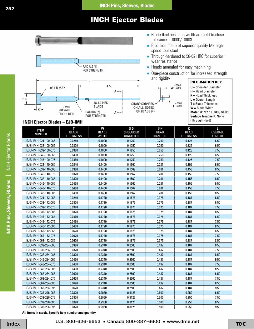
U.S. 800-626-6653 n Canada 800-387-6600 n www.dme.net
252
INCH Ejector Blades
ItEM NuMBEr
tblade
thicKness
WbladeWidth
Ø dshoulderdiameter
Ø hhead
diameter
Khead
thicKness
loveralllenGth
ejb-imh-024-100-065 0.0240 0.1000 0.1250 0.250 0.125 6.50ejb-imh-032-100-065 0.0320 0.1000 0.1250 0.250 0.125 6.50ejb-imh-032-100-075 0.0320 0.1000 0.1250 0.250 0.125 7.50ejb-imh-046-100-065 0.0460 0.1000 0.1250 0.250 0.125 6.50ejb-imh-046-100-075 0.0460 0.1000 0.1250 0.250 0.125 7.50ejb-imh-024-140-065 0.0240 0.1400 0.1562 0.281 0.156 6.50ejb-imh-032-140-065 0.0320 0.1400 0.1562 0.281 0.156 6.50ejb-imh-046-140-075 0.0320 0.1400 0.1562 0.281 0.156 7.50ejb-imh-032-140-085 0.0320 0.1400 0.1562 0.281 0.156 8.50ejb-imh-046-140-065 0.0460 0.1400 0.1562 0.281 0.156 6.50ejb-imh-046-140-075 0.0460 0.1400 0.1562 0.281 0.156 7.50ejb-imh-046-140-085 0.0460 0.1400 0.1562 0.281 0.156 8.50ejb-imh-024-172-065 0.0240 0.1720 0.1875 0.375 0.187 6.50ejb-imh-032-172-065 0.0320 0.1720 0.1875 0.375 0.187 6.50ejb-imh-032-172-075 0.0320 0.1720 0.1875 0.375 0.187 7.50ejb-imh-032-172-085 0.0320 0.1720 0.1875 0.375 0.187 8.50ejb-imh-046-172-065 0.0460 0.1720 0.1875 0.375 0.187 6.50ejb-imh-046-172-075 0.0460 0.1720 0.1875 0.375 0.187 7.50ejb-imh-046-172-085 0.0460 0.1720 0.1875 0.375 0.187 8.50ejb-imh-062-172-065 0.0620 0.1720 0.1875 0.375 0.187 6.50ejb-imh-062-172-075 0.0620 0.1720 0.1875 0.375 0.187 7.50ejb-imh-062-172-085 0.0620 0.1720 0.1875 0.375 0.187 8.50ejb-imh-032-234-065 0.0320 0.2340 0.2500 0.437 0.187 6.50ejb-imh-032-234-075 0.0320 0.2340 0.2500 0.437 0.187 7.50ejb-imh-032-234-085 0.0320 0.2340 0.2500 0.437 0.187 8.50ejb-imh-046-234-065 0.0460 0.2340 0.2500 0.437 0.187 6.50ejb-imh-046-234-075 0.0460 0.2340 0.2500 0.437 0.187 7.50ejb-imh-046-234-085 0.0460 0.2340 0.2500 0.437 0.187 8.50ejb-imh-062-234-065 0.0620 0.2340 0.2500 0.437 0.187 6.50ejb-imh-062-234-075 0.0620 0.2340 0.2500 0.437 0.187 7.50ejb-imh-062-234-085 0.0620 0.2340 0.2500 0.437 0.187 8.50ejb-imh-062-234-095 0.0620 0.2340 0.2500 0.437 0.187 9.50ejb-imh-032-296-065 0.0320 0.2960 0.3125 0.500 0.250 6.50ejb-imh-032-296-075 0.0320 0.2960 0.3125 0.500 0.250 7.50ejb-imh-032-296-085 0.0320 0.2960 0.3125 0.500 0.250 8.50ejb-imh-032-296-095 0.0320 0.2960 0.3125 0.500 0.250 9.50
A
A
SHARP CORNERS ON ALL EDGES
OF BLADE (4)RADIUS (2)FOR STRENGTH
58-62 HRCBLADE
.031 R MAX
RADIUS (2)FOR STRENGTH
4.50
K
Ø H
SHOULDERØD
–.0003–.0008
L
T+.0000–.0003
W+.0000–.0003
all items in stock. Specify item number and quantity.
n Bladethicknessandwidthareheldtoclosetolerance:+.0000/-.0003
n PrecisionmadeofsuperiorqualityM2high-speedtoolsteel
n Through-hardenedto58-62HRCforsuperiorwearresistance
n Headsannealedforeasymachiningn One-piececonstructionforincreasedstrength
andrigidityINfOrmAtION key:
d = shoulder diameterh = head diameterK = head thicknessl = overall lengtht = blade thicknessW = blade WidthMaterial: m2 / 1.3343 / sKh51Surface treatment: none (through-hard)
INCH
Pin
s, S
leev
es, B
lade
s |
IN
CH E
ject
or B
lade
sINCH Pins, Sleeves, Blades
INch Ejector Blades – EjB-IMh

U.S. 800-626-6653 n Canada 800-387-6600 n www.dme.net
253
INCH Ejector Blades
ItEMNuMBEr
tblade
thicKness
WbladeWidth
Ø dshoulderdiameter
Ø hhead
diameter
Khead
thicKness
loveralllenGth
ejb-imh-046-296-065 0.0460 0.2960 0.3125 0.500 0.250 6.50ejb-imh-046-296-075 0.0460 0.2960 0.3125 0.500 0.250 7.50ejb-imh-046-296-085 0.0460 0.2960 0.3125 0.500 0.250 8.50ejb-imh-046-296-095 0.0460 0.2960 0.3125 0.500 0.250 9.50ejb-imh-062-296-065 0.0620 0.2960 0.3125 0.500 0.250 6.50ejb-imh-062-296-075 0.0620 0.2960 0.3125 0.500 0.250 7.50ejb-imh-062-296-085 0.0620 0.2960 0.3125 0.500 0.250 8.50ejb-imh-062-296-095 0.0620 0.2960 0.3125 0.500 0.250 9.50ejb-imh-078-296-065 0.0780 0.2960 0.3125 0.500 0.250 6.50ejb-imh-078-296-075 0.0780 0.2960 0.3125 0.500 0.250 7.50ejb-imh-078-296-085 0.0780 0.2960 0.3125 0.500 0.250 8.50ejb-imh-078-296-095 0.0780 0.2960 0.3125 0.500 0.250 9.50ejb-imh-032-359-065 0.0320 0.3590 0.3750 0.625 0.250 6.50ejb-imh-032-359-075 0.0320 0.3590 0.3750 0.625 0.250 7.50ejb-imh-032-359-085 0.0320 0.3590 0.3750 0.625 0.250 8.50ejb-imh-032-359-095 0.0320 0.3590 0.3750 0.625 0.250 9.50ejb-imh-046-359-065 0.0460 0.3590 0.3750 0.625 0.250 6.50ejb-imh-046-359-075 0.0460 0.3590 0.3750 0.625 0.250 7.50ejb-imh-046-359-085 0.0460 0.3590 0.3750 0.625 0.250 8.50ejb-imh-046-359-095 0.0460 0.3590 0.3750 0.625 0.250 9.50ejb-imh-062-359-065 0.0620 0.3590 0.3750 0.625 0.250 6.50ejb-imh-062-359-075 0.0620 0.3590 0.3750 0.625 0.250 7.50ejb-imh-062-359-085 0.0620 0.3590 0.3750 0.625 0.250 8.50ejb-imh-062-359-095 0.0620 0.3590 0.3750 0.625 0.250 9.50ejb-imh-078-359-065 0.0780 0.3590 0.3750 0.625 0.250 6.50ejb-imh-078-359-075 0.0780 0.3590 0.3750 0.625 0.250 7.50ejb-imh-078-359-085 0.0780 0.3590 0.3750 0.625 0.250 8.50ejb-imh-078-359-095 0.0780 0.3590 0.3750 0.625 0.250 9.50ejb-imh-094-422-065 0.0940 0.4220 0.4375 0.687 0.250 6.50ejb-imh-094-422-075 0.0940 0.4220 0.4375 0.687 0.250 7.50ejb-imh-094-422-085 0.0940 0.4220 0.4375 0.687 0.250 8.50ejb-imh-094-422-095 0.0940 0.4220 0.4375 0.687 0.250 9.50ejb-imh-078-484-065 0.0780 0.4840 0.5000 0.750 0.250 6.50ejb-imh-078-484-075 0.0780 0.4840 0.5000 0.750 0.250 7.50ejb-imh-078-484-085 0.0780 0.4840 0.5000 0.750 0.250 8.50ejb-imh-078-484-095 0.0780 0.4840 0.5000 0.750 0.250 9.50ejb-imh-094-484-065 0.0940 0.4840 0.5000 0.750 0.250 6.50ejb-imh-094-484-075 0.0940 0.4840 0.5000 0.750 0.250 7.50ejb-imh-094-484-085 0.0940 0.4840 0.5000 0.750 0.250 8.50ejb-imh-094-484-095 0.0940 0.4840 0.5000 0.750 0.250 9.50ejb-imh-078-547-065 0.0780 0.5470 0.5625 0.812 0.250 6.50ejb-imh-078-547-075 0.0780 0.5470 0.5625 0.812 0.250 7.50ejb-imh-078-547-085 0.0780 0.5470 0.5625 0.812 0.250 8.50ejb-imh-078-547-095 0.0780 0.5470 0.5625 0.812 0.250 9.50ejb-imh-094-547-065 0.0940 0.5470 0.5625 0.812 0.250 6.50ejb-imh-094-547-075 0.0940 0.5470 0.5625 0.812 0.250 7.50ejb-imh-094-547-085 0.0940 0.5470 0.5625 0.812 0.250 8.50ejb-imh-094-547-095 0.0940 0.5470 0.5625 0.812 0.250 9.50ejb-imh-078-609-065 0.0780 0.6090 0.6250 0.875 0.250 6.50ejb-imh-078-609-075 0.0780 0.6090 0.6250 0.875 0.250 7.50ejb-imh-078-609-085 0.0780 0.6090 0.6250 0.875 0.250 8.50ejb-imh-078-609-095 0.0780 0.6090 0.6250 0.875 0.250 9.50ejb-imh-094-609-065 0.0940 0.6090 0.6250 0.875 0.250 6.50ejb-imh-094-609-075 0.0940 0.6090 0.6250 0.875 0.250 7.50ejb-imh-094-609-085 0.0940 0.6090 0.6250 0.875 0.250 8.50ejb-imh-094-609-095 0.0940 0.6090 0.6250 0.875 0.250 9.50
INCH Pins, Sleeves, Blades | IN
CH Ejector BladesINCH Pins, Sleeves, Blades

U.S. 800-626-6653 n Canada 800-387-6600 n www.dme.net
254
ItEMPrEFIX
Ø dpin dia
Ø hheaddia
KheadthicK
l = lenGth
3† 6 10 14c7m_*_ 3/32 (.0937) .250 .125c8m_*_ 7/64 (.1093) .250 .125c9m_*_ 1/8 (.1250) .250 .125c10m_*_ 9/64 (.1406) .250 .125c11m_*_ 5/32 (.1562) .281 .156c12m_*_ 11/64 (.1718) .343 .187c13m_*_ 3/16 (.1875) .375 .187c14m_*_ 13/64 (.2031) .375 .187c15m_*_ 7/32 (.2187) .406 .187c17m_*_ 1/4 (.2500) .437 .187c19m_*_ 9/32 (.2812) .437 .250c21m_*_ 5/16 (.3125) .500 .250c23m_*_ 11/32 (.3437) .562 .250c25m_*_ 3/8 (.3750) .625 .250c27m_*_ 13/32 (.4062) .687 .250c29m_*_ 7/16 (.4375) .687 .250c31m_*_ 15/32 (.4687) .750 .250c33m_*_ 1/2 (.5000) .750 .250c35m_*_ 9/16 (.5625) .812 .250c37m_*_ 5/8 (.6250) .875 .250c41m_*_ 3/4 (.7500) 1.000 .250
† heads of 3"-length pins are not annealed. if annealed heads on 3"-length pins are required, they must be special ordered. (alternately, you may purchase 6" pins and cut to required length.)
Typical application
hardness checking guidelines
150 Kg. c scale load.
60 Kg. a scale load.
if checking hardness of core pins, do not use method “no” above, since it will provide an inaccurately low reading. the preferred method is to stand the pin on its head and check the cut end using the a scale, 60 Kg. load as shown above.PrEcautIONS:the cut end must be parallel to head end, with stem length of 2" minimum. use cutting fluid to avoid overheating and localized annealing. position indentation in middle of pin diameter.
NO YES
n Precisionmadeofsuperiorqualityhotworkdiesteelstandardhardness30-35HRC
n Headsarehot-forgedforuniformgrainflow,highertensilestrength,thenannealedtopermiteasiermachiningandstamping
n +.0008"/+.0003"toleranceonpindiameterensuresaclosefitforcoringpurposes
n Pinbodyandheadarefinishgroundn Centerlessgroundandpolishedouterdiameter
Ø H Ø D
K
L
+.0008+.0003
.031 R MAXIMUM
*HOW tO Order: combine Item Number Prefix and the length (L dimension) desired. Examples: C9M3, C33M10
INCH Core Pins – H13 – Standard Medium Hardness
INCH
Pin
s, S
leev
es, B
lade
s |
IN
CH C
ore
Pins
– H
13 –
Sta
ndar
d M
ediu
m H
ardn
ess
INCH Pins, Sleeves, Blades
INch core Pins – c
Items in stock2-3 week deliveryContact D-M-E for quote
key tO cHArt
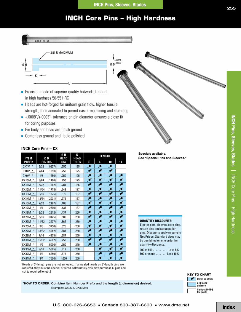
U.S. 800-626-6653 n Canada 800-387-6600 n www.dme.net
255
n Precisionmadeofsuperiorqualityhotworkdiesteelinhighhardness50-55HRC
n Headsarehot-forgedforuniformgrainflow,highertensilestrength,thenannealedtopermiteasiermachiningandstamping
n +.0008"/+.0003"-toleranceonpindiameterensuresaclosefitforcoringpurposes
n Pinbodyandheadarefinishgroundn Centerlessgroundandliquidpolished
Ø H Ø D
K
L
+.0008+.0003
.031 R MAXIMUM
ItEMPrEFIX
Ø dpin dia
Ø hheaddia
KheadthicK
lENGth
3† 6 10 14cx7m_*_ 3/32 (.0937) .250 .125cx8m_*_ 7/64 (.1093) .250 .125cx9m_*_ 1/8 (.1250) .250 .125cx10m_*_ 9/64 (.1406) .250 .125cx11m_*_ 5/32 (.1562) .281 .156cx12m_*_ 11/64 (.1718) .343 .187cx13m_*_ 3/16 (.1875) .375 .187cx14m_*_ 13/64 (.2031) .375 .187cx15m_*_ 7/32 (.2187) .406 .187cx17m_*_ 1/4 (.2500) .437 .187cx19m_*_ 9/32 (.2812) .437 .250cx21m_*_ 5/16 (.3125) .500 .250cx23m_*_ 11/32 (.3437) .562 .250cx25m_*_ 3/8 (.3750) .625 .250cx27m_*_ 13/32 (.4062) .687 .250cx29m_*_ 7/16 (.4375) .687 .250cx31m_*_ 15/32 (.4687) .750 .250cx33m_*_ 1/2 (.5000) .750 .250cx35m_*_ 9/16 (.5625) .812 .250cx37m_*_ 5/8 (.6250) .875 .250cx41m_*_ 3/4 (.7500) 1.000 .250
† heads of 3"-length pins are not annealed. if annealed heads on 3"-length pins are required, they must be special ordered. (alternately, you may purchase 6" pins and cut to required length.)
*HOW tO Order: combine Item Number Prefix and the length (L dimension) desired. Examples: CX9M3, CX33M10
INCH Core Pins – High Hardness
QuaNtItY dIScOuNtS:ejector pins, sleeves, core pins, return pins and sprue puller pins. discounts apply to current net prices. standard sizes may be combined on one order for quantity discounts.
300 to 599 . . . . . . . . . . less 5%600 or more . . . . . . . less 10%
INCH Pins, Sleeves, Blades | IN
CH Core Pins – High HardnessINCH Pins, Sleeves, Blades
INch core Pins – cXSpecials available. See “Special Pins and Sleeves.”
Items in stock2-3 week deliveryContact D-M-E for quote
key tO cHArt

U.S. 800-626-6653 n Canada 800-387-6600 n www.dme.net
256
n Reducescycletimes
n Tentimesbetterconductivitythansteel
n Moldstar150®(C18000)beryllium-freecopper-basedalloy
n Hardnessof90-98RockwellB
n Availablein21diametersandfourlengths
D-M-E’sPerformanceCorePins®areprecisionmadeusingahigh-strength,beryllium-freecopperalloy,ratherthantraditionalsteelsusedincorepins.Thisalloyprovidesseveraladvantages,includingbetterconductivity,increasedstrength,reducedwearandresistancetorusting.PerformanceCorePinsareidealforuseinhigh-volumeapplicationswherepartquality,fitandfinisharecritical.
reduced cycle timeItisoftendifficultorexpensivetoadequatelycooltheareasurroundingthecorepininamold,especiallywhenmoldingthick-walledparts.Dependingonthedesignofthemold,itmayevenbeimpossibletorunwaterlinesnearthepin,thusgreatlyincreasingcycletimes.
Thecopper-basedalloyusedinPerformanceCorePinscansignificantlyreducemoldcycletimesbyincreasingtherateofheattransfer.ThePerformanceCorePin,whenusedinplaceoftraditionalC-orCX-typepins,willprovideupto10timestherateofheattransfer.Heatistransferredattwicetherateofpinsmadeofaberyllium-copperalloy.
Inaddition,thelow-adhesioncharacteristicsofthepinsmakepartejectionfasterandeasier.Alloftheseadvantagescom-binetoreducetheoverallcycletimeandincreaseproductivity.
Improved part qualityTheexcellentthermaldiffusivityofthepinsprovideahomogenoustemperatureprofilethroughoutthecoresurface.Uniformtemperaturesresultinreducedpost-moldshrinkageandwarpage,improvingthequalityofthepart.Also,becauseofthelow-adhesioncharacteristicsofthepin,partsarenotdamagedbyadhesiontothepinduringpartejection.
lower machining costsThehighthermalconductivityofPerformanceCorePinsreducestheneedforcomplexcoolingdesignsthatcanrequirehoursofadditionalmachining.Plus,thepinsrequirenoadditionalheattreatmentandcanbemachinedusingconventionalmethodsorEDM.
longer service lifePerformanceCorePinshaveahighresistancetothermalstress,wearandabrasion.Thisassureslonglifeundervirtuallyanymoldingconditions.Withappropriatealtera-tiontopindiameter,theycanbeusedinconjunctionwithstandardejectorsleeves.Thedissimilarmetalsandcom-patiblecoefficientoffrictionwillreducemetal-to-metalpickupandwear.
Wide range of sizesPerformanceCorePinsareavailablein18pindiametersfrom3/32-to3/4-and3-,6-,14-or20-inchlengths.
Typical Moldas shown in the pie chart, mold cooling comprises the largest part of the mold cycle. performance core pins can significantly reduce this mold cooling portion to reduce overall cycle time!
Mold Packing 10%
Mold Filling 5%
Mold Open 15%
Mold Cooling 70%
Performance Core Pins® – High Conductivity Pins
INCH
Pin
s, S
leev
es, B
lade
s |
Per
form
ance
Cor
e Pi
ns® –
Hig
h Co
nduc
tivity
Pin
sINCH Pins, Sleeves, Blades

U.S. 800-626-6653 n Canada 800-387-6600 n www.dme.net
257
ItEMPrEFIX
Ø dpin dia
Ø hheaddia
KheadthicK
l = lenGth
3 6 14 20pcl07_*_ 3/32 (.0937) .250 .125pcl09_*_ 1/8 (.1250) .250 .125pcl11_*_ 5/32 (.1562) .281 .156pcl12_*_ 11/64 (.1718) .343 .187pcl13_*_ 3/16 (.1875) .375 .187pcl14_*_ 13/64 (.2031) .375 .187pcl15_*_ 7/32 (.2187) .406 .187pcl17_*_ 1/4 (.2500) .437 .187pcl19_*_ 9/32 (.2812) .437 .250pcl21_*_ 5/16 (.3125) .500 .250pcl23_*_ 11/32 (.3437) .562 .250pcl25_*_ 3/8 (.3750) .625 .250pcl27_*_ 13/32 (.4062) .687 .250pcl29_*_ 7/16 (.4375) .687 .250pcl33_*_ 1/2 (.5000) .750 .250pcl35_*_ 9/16 (.5625) .812 .250pcl37_*_ 5/8 (.6250) .875 .250pcl41_*_ 3/4 (.7500) 1.000 .250
Performance Core Pins® are produced by Performance Alloys & Services, Inc. under U.S. Patent Number 5,020,770.
Issue date June 4, 1991. Foreign patents pending.
*HOW tO Order: combine Item Number Prefix and the length (L dimension) desired. n Precede single digit lengths with a zero
Examples: PCL2514, PCL0703, PCL2520
Ø H Ø D
K
L
+.0010–.0000
.031 R MAXIMUM
n Moldstar150®(C18000)beryllium-freecopper-basedalloy
n Tentimesbetterconductivitythansteel
n Reducescycletimes
n Hardnessof90-98RockwellB
n Specialsarealsoavailableuponrequest
Performance Core Pins® – High Conductivity Pins
QuaNtItY dIScOuNtS:ejector pins, sleeves, core pins, return pins and sprue puller pins. discounts apply to current net prices. standard sizes may be combined on one order for quantity discounts.
300 to 599 . . . . . . . . . . less 5%600 or more . . . . . . . less 10%
INCH Pins, Sleeves, Blades | Perform
ance Core Pins® – High Conductivity Pins
INCH Pins, Sleeves, Blades
Pcl Performance core Pins – Pcl
Items in stock2-3 week deliveryContact D-M-E for quote
key tO cHArt

U.S. 800-626-6653 n Canada 800-387-6600 n www.dme.net
258
ItEMNuMBEr
Ø dpindia
Ø hheaddia
lpin
lenGth7410
.500 .750
3.5637411 4.0637412 4.5637413 5.0637414 5.5637415 6.0637416 6.563
for longer lengths, use ex33 ejector pins.
ItEMNuMBEr
Ø dpindia
Ø hheaddia
lpin
lenGth7510
.625 .875
4.0637511 4.5637512 5.0637513 5.5637514 6.0637515 6.5637516 7.0637517 7.5637518 8.063
for longer lengths, use ex37 ejector pins.
ItEMNuMBEr
Ø dpindia
Ø hheaddia
lpin
lenGth7610
.750 1.000
4.9387611 5.4387612 5.9387613 6.4387614 6.9387615 7.4387616 7.9387617 8.4387618 8.9387619 9.438
for longer lengths, use ex41 ejector pins.
n Precisionmadeofsuperiorqualitythermalshockresistinghotworkdiesteel
n Hot-forgedheadsprovideuniformgrainflow,highertensilestrength
n Outsidediameternitridedto65-74HRChardnessandfinishedtominimizewear
n Centerlessgroundandpolishedouterdiameter
Ø H Ø D
1/4
L
+.000–.001
.031 R MAXIMUM
Use Item Number in charts above for ordering. All items in stock.
INCH Return Pins
.500 (1/2”) diameter Series .625 (5/8”) diameter Series .750 (3/4”) diameter Series
INCH
Pin
s, S
leev
es, B
lade
s |
IN
CH R
etur
n Pi
nsINCH Pins, Sleeves, Blades

U.S. 800-626-6653 n Canada 800-387-6600 n www.dme.net
259
ItEMNuMBEr
Ø dpindia
Ø hheaddia
KheadthicK
lpin
lenGth7110
.250 .437 .187
3.447111 3.947112 4.447113 4.947114 5.447115 5.947116 6.44
for longer lengths, use ex17 ejector pins.
ItEMNuMBEr
Ø dpindia
Ø hheaddia
KheadthicK
lpin
lenGth7210
.375 .625 .250
3.887211 4.387212 4.887213 5.387214 5.887215 6.387216 6.887217 7.387218 7.887219 8.387220 8.887221 9.38
for longer lengths, use ex25 ejector pins.
Ø D
K
.031 R MAXIMUM
L
+.000–.001
Ø H
n Precisionmadeofsuperiorqualitythermalshockresistinghotworkdiesteel
n Hot-forgedheadsprovideuniformgrainflow,highertensilestrength
n Outsidediameternitridedto65-74HRChardnessandfinishedtominimizewear
n Headsannealedforeasymachining
n Centerlessgroundandpolishedouterdiameter
INCH Sprue Puller Pins
.250 (1/4”) diameter Series .375 (3/8”) diameter Series INCH Pins, Sleeves, Blades | IN
CH Sprue Puller PinsINCH Pins, Sleeves, Blades
QuaNtItY dIScOuNtS:ejector pins, sleeves, core pins, return pins and sprue puller pins. discounts apply to current net prices. standard sizes may be combined on one order for quantity discounts.
300 to 599 . . . . . . . . . . less 5%600 or more . . . . . . . less 10%
Use Item Number in charts above for ordering. All items in stock.

U.S. 800-626-6653 n Canada 800-387-6600 n www.dme.net
260
BOdY hEad dEScrIPtION dIaMEtEr MatErIal hardNESS cONdItION cONdItION
ex ejector pins +.0003 surface 65-74 hrc nitrided ex2 (1/32) through ex8 (7/64) –.0006 h13 core 40-45 hrc minimum .001 deep annealed
ex ejector pins ex9 (1/8) through ex32 (31/64) –.0003 surface 65-74 hrc nitrided lengths – 6" through 18" –.0006 h13 core 40-45 hrc minimum .001 deep annealed
ex ejector pins ex9 (1/8) through ex32 (31/64) –.0003 surface 65-74 hrc nitrided lengths – 25" through 36" –.0008 h13 core 40-45 hrc minimum .001 deep annealed
ex ejector pins –.0003 surface 65-74 hrc nitrided ex33 (1/2) through ex47 (1") –.0008 h13 core 40-45 hrc minimum .001 deep annealed
thx ejector pins –.000 surface 65-74 hrc nitrided thx03 (3/64) through thx08 (7/64) –.001 h13 core 50-55 hrc minimum .001 deep annealed
thx ejector pins thx09 (1/8) through thx32 (31/64) –.0003 surface 65-74 hrc nitrided lengths – 6" through 18" –.0006 h13 core 50-55 hrc minimum .001 deep annealed
thx ejector pins –.0003 surface 65-74 hrc nitrided thx33 (1/2) through thx47 (1") –.0008 h13 core 50-55 hrc minimum .001 deep annealed
Keyed ejector pins –.0003 h13 surface 65 min hrc nitrided annealed –.0008 core 50-55 hrc
ejp-imh close tolerance –.0003 ejector pins –.0005 m2 core 58-62 hrc annealed
moldbasics ejector pins –.0002 core 65 hrc min –.0008 h13 40-45 hrc
+.0000 o.d. –.0010 +.0005 o.d. 65-74 hrc nitrided o.d. s ejector sleeves i.d.+.0000 h13 i.d. 30-35 hrc minimum .001 deep annealed
+.0000 o.d. –.0010 +.0005 o.d. 65-74 hrc nitrided o.d. & i.d. snd nitrided i.d. ejector sleeves i.d. +.0000 h13 i.d. 65-74 hrc minimum .001 deep annealed
ejector blades m2 58-62 hrc annealed
3" length – hard +.0008 6"-14" lengths – c core pins –.0003 h13 core 30-35 hrc through hardened annealed
3" length – hard +.0008 6"-14" lengths – cx high hardness core pins –.0003 h13 core 50-55 hrc through hardened annealed
moldstar pcl performance high +.0010 150® 90-98 hrb conductivity core pins –.0000 (c18000) not applicable not applicable
+.0000 surface 65-74 hrc nitrided return pins –.001 h13 core 40-55 hrc minimum .001 deep annealed
+.000 surface 65-74 hrc nitrided sprue puller pins –.001 h13 core 40-45 hrc minimum .001 deep annealed
Comparison Chart
INCH
Pin
s, S
leev
es, B
lade
s |
Com
paris
on C
hart
INCH Pins, Sleeves, Blades
–.0003–.0006

U.S. 800-626-6653 n Canada 800-387-6600 n www.dme.net
261
hardNESS raNGE OF
d-M-E StaNdardS
BrINEll3000 Kg
rOcKWEllShOrE
SclErO-ScOPE
NO.
tENSIlEStrENGth(aPPrOX.
P.S.I.)
c150 KglOad
B100 KglOad
15-NSuPEr-FIcIal
80 96.5
78 96.0
76 95.5
ex, thxejector
pins
Surfacehardness
74 95.0
72 94.5
70 94.0
69 93.5 96
67 93.0 95
66 92.5 92
65 92.0 91
64 88
63 91.5 87
ejp-imhejector pins
ejb-imhejector blade
corehardness
62 91.0 85
61 90.5 83
614 60 90.0 81
600 59 89.5 80
587 58 78
573 57 89.0 76
560 56 88.5 75
cxcore pins,
thxej. pins,
Keyed ej. pins
corehardness
547 55 88.0 74 301,000
534 54 87.5 72 291,000
522 53 87.0 71 282,000
509 52 86.5 69 273,000
496 51 86.0 68 264,000
484 50 85.5 67 255,000
472 49 85.0 66 246,000
460 48 84.5 64 237,000
448 47 84.0 63 229,000
437 46 83.5 62 221,000
exejector pins
corehardness
426 45 83.0 60 214,000
415 44 82.5 58 207,000
404 43 82.0 57 200,000
393 42 81.5 56 194,000
382 41 81.0 55 188,000
372 40 80.5 54 182,000
hardNESS raNGE OF
d-M-E StaNdardS
BrINEll3000 Kg
rOcKWEllShOrE
SclErO-ScOPE
NO.
tENSIlEStrENGth(aPPrOX.
P.S.I.)
c150 KglOad
B100 KglOad
15-NSuPEr-FIcIal
362 39 80.0 52 177,000
352 38 79.5 51 171,000
342 37 79.0 50 166,000
332 36 78.5 49 162,000
ccorepins
322 35 78.0 48 157,000
313 34 77.0 47 153,000
305 33 76.5 46 148,000
297 32 76.0 44 148,000
290 31 75.5 43 140,000
283 30 75.0 42 136,000
276 29 74.5 41 132,000
270 28 74.0 — 129,000
265 27 73.5 40 126,000
260 26 72.5 38 123,000
255 25 72.0 — 120,000
250 24 71.5 37 117,000
245 23 100 71.0 36 115,000
240 22 99 70.5 35 112,000
pclperfor-mance
core pins
235 20 98 69.5 34 108,000
230 20 98 69.5 34 108,000
201 94 31 98,000
197 93 30 95,000
192 92 29 93,000
187 91 — 90,000
183 90 28 89,000
179 89 27 87,000
174 88 27 87,000
170 87 26 83,000
167 86 — 81,000
163 85 25 79,000
156 83 24 76,000
149 81 23 73,000
143 79 22 71,000
137 76 21 67,000
131 74 — 65,000
Hardness Conversion Table and D-M-E Hardness Data
INCH Pins, Sleeves, Blades | Hardness Conversion Table and D
-M-E Hardness D
ataINCH Pins, Sleeves, Blades

U.S. 800-626-6653 n Canada 800-387-6600 n www.dme.net
262
Ø H:
K:
Ø H:
K:
*
Tapered Lead-In *1mm per Side
Minimum Wall Thickness Recommended
*1mm per Side Minimum Wall Thickness Recommended (2) Places
*
Tapered Lead-In
*
Ø H: Ø E:
Ø G:
R: Ø D:
Ø D:
Ø H: Ø D:
K:
K:
L:
L:
L:
L:
S:
Ø E:
Ø G: Ø F:
Ø E: R:
S:
N:
Ø D:
N:
Ø H:
K:
Ø H:
K:
*
Tapered Lead-In *1mm per Side
Minimum Wall Thickness Recommended
*1mm per Side Minimum Wall Thickness Recommended (2) Places
*
Tapered Lead-In
*
Ø H: Ø E:
Ø G:
R: Ø D:
Ø D:
Ø H: Ø D:
K:
K:
L:
L:
L:
L:
S:
Ø E:
Ø G: Ø F:
Ø E: R:
S:
N:
Ø D:
N:
Ø H:
K:
Ø H:
K:
*
Tapered Lead-In *1mm per Side
Minimum Wall Thickness Recommended
*1mm per Side Minimum Wall Thickness Recommended (2) Places
*
Tapered Lead-In
*
Ø H: Ø E:
Ø G:
R: Ø D:
Ø D:
Ø H: Ø D:
K:
K:
L:
L:
L:
L:
S:
Ø E:
Ø G: Ø F:
Ø E: R:
S:
N:
Ø D:
N:
Custom PinsQuantity:Chooseapintype:n EX (35-43HRCcorehard-
nesswith65-70HRCcasehardness)
n thX (50HRC-55HRCcorehardnesswith65-70HRCcasehardness)
n cX (50-55HRCthroughhard)
n c (30-35HRCthroughhard)
MaterialH-13n
Other
Hardness RC
Nitrided Yesn Non
Comments
Custom SleevesQuantity:
n NitrideonOD(S)
n NitrideonOD+ID(SND)
MaterialH-13n
Other
Hardness RC
Comments
Ø H:
K:
Ø H:
K:
*
Tapered Lead-In *1mm per Side
Minimum Wall Thickness Recommended
*1mm per Side Minimum Wall Thickness Recommended (2) Places
*
Tapered Lead-In
*
Ø H: Ø E:
Ø G:
R: Ø D:
Ø D:
Ø H: Ø D:
K:
K:
L:
L:
L:
L:
S:
Ø E:
Ø G: Ø F:
Ø E: R:
S:
N:
Ø D:
N:
Quote FAX HotlineS or visit www.dme.netunited States: 888-808-4363 • Canada: 800-461-9965 • international: 248-398-7394
Custom Pins and Sleeves – Faxable Quote Form
INCH
Pin
s, S
leev
es, B
lade
s |
Cus
tom
Pin
s an
d Sl
eeve
s –
Faxa
ble
Quo
te F
orm
INCH Pins, Sleeves, Blades
Straight Pin
Step Pin
Sleeve
Step Sleeve
company name: d-M-E account #:
contact name: P.O. #:
Phone: FaX:
address: E-mail:
city: State/Province:
ZIP/Postal code: country:
Shipping method:n uPS Ground
n uPS 2nd day air
n uPS Next day
n FedEx
n Other __________

D-M-E DIN Pins, Sleeves, Blades
a coMprehensive line
oF din ejector products
DIN
Pins, Sleeves, Blades
EjEctOr PINS
ejp-ehn (nitrided) . . . . . . . . . . . . . . . . . . . . . . . . . . . . 264
ejp-elh (hardened). . . . . . . . . . . . . . . . . . . . . . . . . . . 265
ShOuldEr EjEctOr PINS
ejp-ehn (nitrided) . . . . . . . . . . . . . . . . . . . . . . . . . . . . 266 ejp-elh (hardened). . . . . . . . . . . . . . . . . . . . . . . . . . . 267
EjEctOr SlEEVES
ejs-ehn (nitrided). . . . . . . . . . . . . . . . . . . . . . . . . . . . . 268
ejs-elh (hardened) . . . . . . . . . . . . . . . . . . . . . . . . . . . 269
EjEctOr BladES
ejb-ehn (nitrided) . . . . . . . . . . . . . . . . . . . . . . . . . . . . 270
ejb-elh (hardened) . . . . . . . . . . . . . . . . . . . . . . . . . . . 271
cOrE PINS
crp-ehh (hardened) . . . . . . . . . . . . . . . . . . . . . . . . . . 272 crp-ecs (performance) . . . . . . . . . . . . . . . . . . . . . . . 273
FaX OrdEr FOrM – SPEcIal dIN PINS & SlEEVES
faxable quote request form. . . . . . . . . . . . . . . . . . 275-276

U.S. 800-626-6653 n Canada 800-387-6600 n www.dme.net
264
information KEY:
D = Pin Body DiameterH = Head DiameterK = Head ThicknessL = LengthStandard: DIN/ISO TypeMaterial: 1.2344 (AISI H13 Type) SteelSurface Treatment: Nitrided Max. Temp.: 500˚-550˚C (932˚-1022˚F)Dimensions: Shown in Millimeters (mm)
Ra0. 8
L K
Ø H
45 ± 5 HRC (Heads Annealed)
+2 0
Ø D g6
MIN 1400 MPa (Ref. Only ~44 HRC)
MIN 950 HV 0.3 (Ref. Only ~68 HRC)
Example: Prefix D LEJP-EHN-120-0630
Example: Prefix D LEJP-EHN-030-0160
HoW to orDEr: specify item number with prefix, D diameter, and L length. include zeros and dashes but omit decimals, as shown.
Prefix D L EJP-EHn - -
* “(EA)” is only a cross-reference to current D-M-E Europe Catalog item prefix numbers.
iTeMprefix D H K
L0100 0125 0160 0200 0250 0315 0400 0500 0630 0800 1000
EJP-EHN(EA)*
01.2 3 1.501.5 3 202.0 4 202.2 4 202.5 5 202.7 5 303.0 6 303.2 6 303.5 7 303.7 7 304.0 8 304.2 8 304.5 8 305.0 10 305.2 10 305.5 10 306.0 12 506.2 12 506.5 12 507.0 12 508.0 14 508.2 14 508.5 14 509.0 14 510.0 16 510.2 16 510.5 16 511.0 16 512.0 18 712.2 18 712.5 18 714.0 22 716.0 22 718.0 24 720.0 26 825.0 32 1032.0 40 10
DIN Ejector Pins – Nitrided
Expulsores I Extractores I Ejecteurs Epingles I Auswerferstifte
DIN
Pin
s, S
leev
es, B
lade
s |
DIN
Eje
ctor
Pin
s –
Nitr
ided
DIN Pins, Sleeves, Blades
DiN ejector pins – eJp-eHN
Items in stock2-3 week deliveryContact D-M-E for quote
KEY to cHart

U.S. 800-626-6653 n Canada 800-387-6600 n www.dme.net
265
INfOrmAtION key:
d = pin body diameterh = head diameterK = head thicknessl = lengthStandard: din/iso typeMaterial: 1.2210 (aisi l2 type) steelSurface treatment: none (through-hardened) Max. temp.: 250˚c (482˚f)dimensions: shown in millimeters (mm)
Ra0. 4
K
60 ± 2 HRC
45 ± 5 HRC (Heads Annealed)
L +2
0
Ø D g6
Ø H
Example: Prefix d L EJP-ELH-050-0100
Example: Prefix d L EJP-ELH-015-0200
HOW tO Order: Specify Item Number with prefix, d diameter, and L length. Include zeros and dashes but omit decimals, as shown.
Prefix d L eJP-eLH - -
ItEMPrEFIX d h K
l0040 0080 0100 0125 0160 0200 0250 0315 0400
ejp-elh(ah)*
01.5 3 1.501.6 3 1.501.7 3 1.501.8 3 1.502.0 4 202.2 4 202.5 5 202.7 5 203.0 6 303.2 6 303.5 7 303.7 7 304.0 8 304.2 8 304.5 8 304.7 8 305.0 10 305.2 10 305.5 10 306.0 12 506.2 12 506.5 12 507.0 12 508.0 14 508.2 14 508.5 14 509.0 14 510.0 16 510.2 16 510.5 16 511.0 16 512.0 18 712.2 18 712.5 18 714.0 22 716.0 22 718.0 24 720.0 26 8
* “(ah)” is only a cross-reference to current d-m-e europe catalog item prefix numbers.
DIN Ejector Pins – Hardened
expulsores i extractores i ejecteurs epingles i auswerferstifte
DIN
Pins, Sleeves, Blades | DIN
Ejector Pins – HardenedDIN Pins, Sleeves, Blades
dIN Ejector Pins – EjP-Ehh
Items in stock2-3 week deliveryContact D-M-E for quote
key tO cHArt

U.S. 800-626-6653 n Canada 800-387-6600 n www.dme.net
266
INfOrmAtION key:d = pin body diameterE = shoulder diameterh = head diameterK = head thicknessl = lengthS = shoulder lengthStandard: din/iso typeMaterial: 1.2344 (aisi h13 type) steelSurface treatment: nitrided Max. temp.: 500°-550°c (932°-1022°f)dimensions: shown in millimeters (mm)
60˚
Ra0.8
L
K
Ø H
Ø E Ra0.8
MIN 950 HV0.3
45 ± 5 HRC (Heads Annealed)
S
00.7
00.8
00.9
01.0
01.1
01.2
01.3
01.4
01.5
01.6
01.7
01.8
01.9
02.0
02.1
02.2
02.4
02.5
02.703.0
03.2
03.5
2
2
2
2
2
2
2
2
3
3
3
3
3
3
3
3
3
3
34
4
4
2
2
2
2
2
2
2
2
3
3
3
3
3
3
3
3
3
3
33
3
3
4
4
4
4
4
4
4
4
6
6
6
6
6
6
6
6
6
6
68
8
8
0035 0050 0050 0050 0075 0075 0075
0080 0100 0125 0160 0160 0200 0250ITEMPREFIX
D E K
0- 0.1
H
+20
L
-1-2
S
(C)*
Ø D g6
EJP-EHN
MIN 1400 MPa (Ref. Only ~44 HRC)
(Ref. Only ~68 HRC)
Example:
Prefix d L S EJP-EHN-010-0160-0050
Example:
Prefix d L SEJP-EHN-025-0200-0075
ItEMPrEFIX
d E h K
l0080 0100 0125 0160 0160 0200 0250
S0035 0050 0050 0050 0075 0075 0075
ejp-ehn(c)*
00.7 2 4 200.8 2 4 200.9 2 4 201.0 2 4 201.1 2 4 201.2 2 4 201.3 2 4 201.4 2 4 201.5 3 6 301.6 3 6 301.7 3 6 301.8 3 6 301.9 3 6 302.0 3 6 302.1 3 6 302.2 3 6 302.4 3 6 302.5 3 6 302.7 3 6 303.0 4 8 303.2 4 8 303.5 4 8 3
* “(c)” is only a cross-reference to current d-m-e europe catalog item prefix numbers.
DIN Shoulder Ejector Pins – Nitrided
expulsores con hombro i extractores i ejecteurs epingles i auswerferstifte
HOW tO Order: Specify Item Number with prefix, d diameter, L length, and S length. Include zeros and dashes but omit decimals, as shown.
Prefix d L S eJP-eHN - - -
DIN
Pin
s, S
leev
es, B
lade
s |
DIN
Sho
ulde
r Eje
ctor
Pin
s –
Nitr
ided
DIN Pins, Sleeves, Blades
dIN Shoulder Ejector Pins – EjP-EhN
Items in stock2-3 week deliveryContact D-M-E for quote
key tO cHArt

U.S. 800-626-6653 n Canada 800-387-6600 n www.dme.net
267
DIN Shoulder Ejector Pins – Hardened
INfOrmAtION key:d = pin body diameterE = shoulder diameterh = head diameterK = head thicknessl = lengthS = shoulder lengthStandard: din/iso typeMaterial: 1.2210 (aisi l2 type) steelSurface treatment: none (through-hardened) Max. temp.: 250˚c (482˚f)dimensions: shown in millimeters (mm)
(CH)*
60˚
Ra0.8
K
Ø H
Ra0.4
60 ± 2 HRC
45 ± 5 HRC (Heads Annealed)
00.8
00.9
01.0
01.1
01.2
01.3
01.4
01.5
01.6
01.7
01.8
01.9
02.0
02.1
02.2
02.3
02.4
02.5
2
2
2
2
2
2
2
3
3
3
3
3
3
3
3
3
3
3
2
2
2
2
2
2
2
3
3
3
3
3
3
3
3
3
3
3
4
4
4
4
4
4
4
6
6
6
6
6
6
6
6
6
6
6
0060 0080 0100 0125 0200 0250
0025 0035 0050 0050 0075 0100
ITEMPREFIX
D E KH
L
S
L
Ø E
S
0- 0.1
+20
-1-2
Ø D g6
EJP-ELH
* “(cH)” is only a cross-reference to current d-m-e europe catalog item prefix numbers.
HOW tO Order: Specify Item Number with prefix, d diameter, L length and S length. Include zeros and dashes but omit decimals, as shown.
Prefix d L S eJP-eLH - - -
Example:
Prefix d L S EJP-ELH-010-0100-0050
Example:
Prefix d L S EJP-ELH-025-0125-0050
ItEMPrEFIX d E h K
0080 0100 0125 0200 0250
0035 0050 0050 0075 0100
ejp-elh(ch)*
00.8 2 4 200.9 2 4 201.0 2 4 201.1 2 4 201.2 2 4 201.3 2 4 201.4 2 4 201.5 3 6 301.6 3 6 301.7 3 6 301.8 3 6 301.9 3 6 302.0 3 6 302.1 3 6 302.2 3 6 302.3 3 6 302.4 3 6 302.5 3 6 3
expulsores con hombro i extractores i ejecteurs epingles i auswerferstifte
DIN
Pins, Sleeves, Blades | DIN
Shoulder Ejector Pins – HardenedDIN Pins, Sleeves, Blades
dIN Shoulder Ejector Pins – EjP-Elh
Items in stock2-3 week deliveryContact D-M-E for quote
key tO cHArt

U.S. 800-626-6653 n Canada 800-387-6600 n www.dme.net
268
DIN Ejector Sleeves – Nitrided
INfOrmAtION key:d = inside diameterE = outside diameterh = head diameterK = head thicknessl = lengthN = bearing lengthStandard: din/iso typeMaterial: 1.2344 (aisi h13 type) steelSurface treatment: nitrided Max. temp.: 500°-550°c (932°-1022°f)dimensions: shown in millimeters (mm)
* “(S)” is only a cross-reference to current d-m-e europe catalog item prefix numbers.
Example: Prefix d L EJS-EHN-120-0250
Example: Prefix d L EJS-EHN-020-0075
HOW tO Order: Specify Item Number with prefix, d diameter, and L length. Include zeros and dashes but omit decimals, as shown.
Prefix d L eJS-eHN - -
Ø D+0.4Ra0.8
L
K
Ø H
MIN 950 HV0.3
Ra0.2
45 ± 5 HRC (Heads Annealed)
(Ref. Only ~68 HRC)
(Ref. Only ~68 HRC)
N
01.5
01.7
02.0
02.2
02.5
02.7
03.0
03.2
03.5
03.7
04.0
04.2
04.5
05.0
05.2
06.0
06.2
06.5
08.0
08.2
08.5
10.0
10.5
11.0
12.0
12.5
14.0
16.0
18.0
03.0
03.0
04.0
04.0
05.0
05.0
05.0
05.0
06.0
06.0
06.0
08.0
08.0
08.0
08.0
10.0
10.0
10.0
12.0
12.0
12.0
14.0
14.0
14.0
16.0
16.0
18.0
20.0
22.0
6
6
8
8
10
10
10
10
12
12
12
14
14
14
14
16
16
16
18
18
18
22
22
22
22
22
24
26
28
3
3
3
3
3
3
3
3
5
5
5
5
5
5
5
5
5
5
7
7
7
7
7
7
7
7
9
9
9
35
35
35
35
35
45
45
45
45
45
45
45
45
45
45
45
45
45
45
45
45
45
55
55
55
55
55
55
55
0075 0100 0125 0150 0175 0200 0225 0250 0275 0300 0350ITEM
PREFIX D E H K N
+20
L
EJS-EHN(S)*
Ø D H5 Ø E g6
MIN 950 HV0.3
ItEMPrEFIX d E h K N
l0075 0100 0125 0150 0175 0200 0225 0250 0275 0300 0350
ejs-ehn(s)*
01.5 03.0 6 3 3501.7 03.0 6 3 3502.0 04.0 8 3 3502.2 04.0 8 3 3502.5 05.0 10 3 3502.7 05.0 10 3 4503.0 05.0 10 3 4503.2 05.0 10 3 4503.5 06.0 12 5 4503.7 06.0 12 5 4504.0 06.0 12 5 4504.2 08.0 14 5 4504.5 08.0 14 5 4505.0 08.0 14 5 4505.2 08.0 14 5 4506.0 10.0 16 5 4506.2 10.0 16 5 4506.5 10.0 16 5 4508.0 12.0 18 7 4508.2 12.0 18 7 4508.5 12.0 18 7 4510.0 14.0 22 7 4510.5 14.0 22 7 5511.0 14.0 22 7 5512.0 16.0 22 7 5512.5 16.0 22 7 5514.0 18.0 24 9 5516.0 20.0 26 9 5518.0 22.0 28 9 55
mangas expulsoras i extractores tubulares i ejecteurs tubulaires i auswerferhülsen
DIN
Pin
s, S
leev
es, B
lade
s |
DIN
Eje
ctor
Sle
eves
– N
itrid
edDIN Pins, Sleeves, Blades
dIN Ejector Sleeves – EjS-EhN
Items in stock2-3 week deliveryContact D-M-E for quote
key tO cHArt

U.S. 800-626-6653 n Canada 800-387-6600 n www.dme.net
269
DIN Ejector Sleeves – Hardened
Ø D+0.4Ra0.4
K
Ø H
60 ± 2 HRC
Ra0.2
45 ± 5 HRC (Heads Annealed)
N
01.5
01.7
02.0
02.2
02.5
02.7
03.0
03.2
03.5
03.7
04.0
04.2
04.5
05.0
05.2
05.5
06.0
06.2
06.5
08.0
08.2
08.5
10.0
10.5
11.0
12.0
12.5
14.0
16.0
18.0
03.0
03.0
04.0
04.0
05.0
05.0
05.0
05.0
06.0
06.0
06.0
08.0
08.0
08.0
08.0
08.0
10.0
10.0
10.0
12.0
12.0
12.0
14.0
14.0
14.0
16.0
16.0
18.0
20.0
22.0
6
6
8
8
10
10
10
10
12
12
12
14
14
14
14
14
16
16
16
18
18
18
22
22
22
22
22
24
26
28
3
3
3
3
3
3
3
3
5
5
5
5
5
5
5
5
5
5
5
7
7
7
7
7
7
7
7
9
9
9
35
35
35
35
35
45
45
45
45
45
45
45
45
45
45
45
45
45
45
45
45
45
45
55
55
45
55
55
55
55
0075 0100 0125 0150 0175 0200 0225 0250 0275 0300 0350 0400 0450 0500ITEM
PREFIX D E H K NL
EJS-ELH(KS)*
Ø D H5 Ø E g6
L+2
0
INfOrmAtION key:d = inside diameterE = outside diameterh = head diameterK = head thicknessl = lengthN = bearing lengthStandard: din/iso typeMaterial: 1.2210 (aisi l2 type) steelSurface treatment: none (through-hardened) Max. temp.: 250°c (482°f)dimensions: shown in millimeters (mm)
* “(kS)” is only a cross-reference to current d-m-e europe catalog item prefix numbers.
HOW tO Order: Specify Item Number with prefix, d diameter, and L length. Include zeros and dashes but omit decimals, as shown.
Prefix d L eJS-eLH - -
Example: Prefix d L EJS-ELH-120-0150
Example: Prefix d L EJS-ELH-020-0125
ItEMPrEFIX d E h K N
l0075 0100 0125 0150 0175 0200 0225 0250 0275 0300 0350 0400 0450 0500
ejs-elh(Ks)*
01.5 03.0 6 3 3501.7 03.0 6 3 3502.0 04.0 8 3 3502.2 04.0 8 3 3502.5 05.0 10 3 3502.7 05.0 10 3 4503.0 05.0 10 3 4503.2 05.0 10 3 4503.5 06.0 12 5 4503.7 06.0 12 5 4504.0 06.0 12 5 4504.2 08.0 14 5 4504.5 08.0 14 5 4505.0 08.0 14 5 4505.2 08.0 14 5 4505.5 08.0 14 5 4506.0 10.0 16 5 4506.2 10.0 16 5 4506.5 10.0 16 5 4508.0 12.0 18 7 4508.2 12.0 18 7 4508.5 12.0 18 7 4510.0 14.0 22 7 4510.5 14.0 22 7 5511.0 14.0 22 7 5512.0 16.0 22 7 4512.5 16.0 22 7 5514.0 18.0 24 9 5516.0 20.0 26 9 5518.0 22.0 28 9 55
mangas expulsoras i extractores tubulares i ejecteurs tubulaires i auswerferhülsen
DIN
Pins, Sleeves, Blades | DIN
Ejector Sleeves – HardenedDIN Pins, Sleeves, Blades
dIN Ejector Sleeves – EjS-Elh
Items in stock2-3 week deliveryContact D-M-E for quote
key tO cHArt

U.S. 800-626-6653 n Canada 800-387-6600 n www.dme.net
270
DIN Ejector Blades – Nitrided
01.0
01.2
01.0
01.2
01.0
01.2
01.5
01.0
01.2
01.5
02.0
01.2
01.5
02.0
01.5
01.8
02.0
02.0
02.5
02.0
02.5
02.0
02.5
03.5
03.5
03.8
03.8
04.5
04.5
04.5
05.5
05.5
05.5
05.5
07.5
07.5
07.5
09.5
09.5
09.5
11.5
11.5
12.0
12.0
15.5
15.5
4
4
4.2
4.2
5
5
5
6
6
6
6
8
8
8
10
10
10
12
12
12.5
12.5
16
16
8
8
8
8
10
10
10
12
12
12
12
14
14
14
16
16
16
18
20
18
18
22
22
3
3
3
3
3
3
3
5
5
5
5
5
5
5
5
5
5
7
7
7
7
7
7
0060 0080 0100 0125 0160 0200 0250 0315 0400
30 40 50 63 80 100 125 160 200
ITEMPREFIX
T W D KH
L
S
EJB-EHN(FW)*
Ra0.8
L
K
Ø H W
T
Ø D
Ra0.8Ra0.8
MIN 950 HV0.3
45 ± 5 HRC (Heads Annealed)
S
0-0 .015
0-0.015
0-0.1
+20
-1-2
MIN 1400 MPa (Ref. Only ~44 HRC)
(Ref. Only ~68 HRC)
INfOrmAtION key:d = shoulder diameterh = head diameterK = head thicknessl = lengthS = shoulder lengtht = blade thicknessW = blade WidthStandard: din/iso typeMaterial: 1.2344 (aisi h13 type) steelSurface treatment: nitridedMax. temp.: 500°-550°c (932°-1022°f)dimensions: shown in millimeters (mm)
* “(fW)” is only a cross-reference to current d-m-e europe catalog item prefix numbers.
HOW tO Order: Specify Item Number with prefix, t thickness, W width, and L length. Include zeros and dashes but omit decimals, as shown.
Prefix t W L eJB-eHN - - -
Example:
Prefix t W LEJB-EHN-010-038-0125
Example:
Prefix t W LEJB-EHN-020-115-0200
ItEMPrEFIX t W d h K
l
0060 0080 0100 0125 0160 0200 0250 0315 0400
S
30 40 50 63 80 100 125 160 200
ejb-ehn(fW)*
01.0 03.5 4 8 301.0 03.8 4.2 8 301.0 04.5 5 10 301.0 05.5 6 12 501.2 03.5 4 8 301.2 03.8 4.2 8 301.2 04.5 5 10 301.2 05.5 6 12 501.2 07.5 8 14 501.5 04.5 5 10 501.5 05.5 6 12 501.5 07.5 8 14 501.5 09.5 10 16 301.8 09.5 10 16 502.0 05.5 6 12 502.0 07.5 8 14 502.0 09.5 10 16 502.0 11.5 12 18 702.0 12.0 12.5 18 702.0 15.5 16 22 702.5 11.5 12 20 702.5 12.0 12.5 18 702.5 15.5 16 22 7
expulsores planos i extractores laminares i ejecteurs lames i auswerferklingen
DIN
Pin
s, S
leev
es, B
lade
s |
DIN
Eje
ctor
Bla
des
– N
itrid
edDIN Pins, Sleeves, Blades
dIN Ejector Blades – EjB-EhN
Items in stock2-3 week deliveryContact D-M-E for quote
key tO cHArt

U.S. 800-626-6653 n Canada 800-387-6600 n www.dme.net
271
DIN Ejector Blades – Hardened
Ra0.4
L
K
Ø H W
T
Ø D
Ra0.4Ra0.4
60 ± 2 HRC
45 ± 5 HRC (Heads Annealed)
S
0060 0080 0100 0125 0160 0200 0250 0315 0400
30 40 50 63 80 100 125 160 200
ITEMPREFIX
T D K
-00.1
0-0.015
H
01.0
01.0
01.2
01.0
01.2
01.5
01.0
01.2
01.5
02.0
01.2
01.5
02.0
01.5
02.0
02.0
02.5
02.0
02.5
4
4.2
4.2
5
5
5
6
6
6
6
8
8
8
10
10
12
12
16
16
8
8
8
10
10
10
12
12
12
12
14
14
14
16
16
18
18
22
22
3
3
3
3
3
3
5
5
5
5
5
5
5
5
5
7
7
7
7
+20
L
-1-2
S
EJB-ELH(FK)*
W
0-0.015
03.5
03.8
03.8
04.5
04.5
04.5
05.5
05.5
05.5
05.5
07.5
07.5
07.5
09.5
09.5
11.5
11.5
15.5
15.5
INfOrmAtION key:d = shoulder diameterh = head diameterK = head thicknessl = lengthS = shoulder lengtht = blade thicknessW = blade WidthStandard: din/iso typeMaterial: 1.2210 (aisi l2 type) steelSurface treatment: none (through-hardened) Max. temp.: 250°c (482°f)dimensions: shown in millimeters (mm)
* “(fk)” is only a cross-reference to current d-m-e europe catalog item prefix numbers.
HOW tO Order: Specify Item Number with prefix, t thickness, W width, and L length. Include zeros and dashes but omit decimals, as shown.
Prefix t W L eJB-eLH - - -
Example:
Prefix t W LEJB-ELH-010-035-0060
Example:
Prefix t W LEJB-ELH-020-115-0200
ItEMPrEFIX t W d h K
l0060 0080 0100 0125 0160 0200 0250 0315 0400
S30 40 50 63 80 100 125 160 200
ejb-elh(fK)*
01.0 03.5 4 8 301.0 03.8 4.2 8 301.0 04.5 5 10 301.0 05.5 6 12 501.2 03.8 4.2 8 301.2 04.5 5 10 301.2 05.5 6 12 501.2 07.5 8 14 501.5 04.5 5 10 301.5 05.5 6 12 501.5 07.5 8 14 501.5 09.5 10 16 502.0 05.5 6 12 502.0 07.5 8 14 502.0 09.5 10 16 502.0 11.5 12 18 702.0 15.5 16 22 702.5 11.5 12 18 702.5 15.5 16 22 7
expulsores planos i extractores laminares i ejecteurs lames i auswerferklingen
DIN
Pins, Sleeves, Blades | DIN
Ejector Blades – HardenedDIN Pins, Sleeves, Blades
dIN Ejector Blades – EjB-Elh
Items in stock2-3 week deliveryContact D-M-E for quote
key tO cHArt

U.S. 800-626-6653 n Canada 800-387-6600 n www.dme.net
272
DIN Core Pins – Hardened
INfOrmAtION key:d = pin body diameterh = head diameterK = head thicknessl = lengthStandard: din/iso typeMaterial: 1.2344 (aisi h13 type) steelSurface treatment: none (through-hardened) Max. temp.: 500°-550°c (932°-1022°f)dimensions: shown in millimeters (mm)
* “(AHX)” is only a cross-reference to current d-m-e europe catalog item prefix numbers.
Example: Prefix d L CRP-EHH-250-0315
Example: Prefix d L CRP-EHH-020-0200
HOW tO Order: Specify Item Number with prefix, d diameter, and L length. Include zeros and dashes but omit decimals, as shown.
Prefix d L crP-eHH - -
ItEMPrEFIX d h K
l0080 0100 0125 0160 0200 0250 0315 0400 0500 0630 0800 1000
crp-ehh(ahx)*
02.0 4 202.2 4 202.5 5 202.7 5 203.0 6 303.2 6 303.5 7 303.7 7 304.0 8 304.2 8 304.5 8 305.0 10 305.2 10 305.5 10 306.0 12 506.2 12 506.5 12 507.0 12 508.0 14 508.2 14 508.5 14 509.0 14 510.0 16 510.2 16 510.5 16 511.0 16 512.0 18 712.2 18 712.5 18 714.0 22 716.0 22 718.0 24 720.0 26 825.0 32 1032.0 40 10
Ra0.8
LK
Ø H Ø D
+20
MIN 1400 MPa (Ref. Only ~44 HRC)
g6
45 ± 5 HRC (Heads Annealed)
pernos moldeadores i pernos moldantes i epingles au centre i Kernstifte
DIN
Pin
s, S
leev
es, B
lade
s |
DIN
Cor
e Pi
ns –
Har
dene
dDIN Pins, Sleeves, Blades
dIN core Pins – crP-Ehh
Items in stock2-3 week deliveryContact D-M-E for quote
key tO cHArt

U.S. 800-626-6653 n Canada 800-387-6600 n www.dme.net
273
DIN Core Pins – Performance
94 ± 4 HRBRa0.8
LK
Ø H Ø D+0.025
0
+10
hIGh thErMal cONductIVItY PINS
advantages:• reduced cycle time• 5 times better conductivity than steel• improved part quality• lower machining costs• longer service life
INfOrmAtION key:d = pin body diameterh = head diameterK = head thicknessl = lengthStandard: din/iso typeMaterial: beryllium-free copper based alloySurface treatment: noneMax. temp.: 350°c (662°f)dimensions: shown in millimeters (mm)
* “(Pcm)” is only a cross-reference to current d-m-e europe catalog item prefix numbers.
Example: Prefix d L CRP-ECS-120-0315
Example: Prefix d L CRP-ECS-030-0160
HOW tO Order: Specify Item Number with prefix, d diameter, and L length. Include zeros and dashes but omit decimals, as shown.
Prefix d L crP-ecS - -
ItEMPrEFIX d h K
l0100 0160 0250 0315
crp-ecs(pcm)*
01.5 3 1.502.0 4 202.5 5 203.0 6 303.5 7 304.0 8 304.5 8 305.0 10 306.0 12 507.0 12 508.0 14 510.0 16 512.0 18 714.0 22 716.0 22 7
pernos moldeadores i pernos moldantes i epingles au centre i Kernstifte
DIN
Pins, Sleeves, Blades | DIN
Core Pins – Performance
DIN Pins, Sleeves, Blades
dIN core Pins – crP-EcS
Items in stock2-3 week deliveryContact D-M-E for quote
key tO cHArt

U.S. 800-626-6653 n Canada 800-387-6600 n www.dme.net
274
DIN Pins and Sleeves for Special Applications
Contact D-M-E for pads of faxable quote request forms. (See next page)
Complexpartgeometries,thin-wallmolding,familymolds,high-cavitationmolds,increasinglylargeparts–everyday,challengingnewapplicationsandmaterialsareforcingmoldmakerstodevelopcreativenewtoolingsolutions.D-M-Eisheretohelp,withcomprehensivecapabilitiesformanufacturingspecialpinsandsleeves–quicklyandcost-effectively.Weofferawiderangeofcustomfeatures,including:
Manufacturing expertise
Extensiveresourcesandefficientprocessesguaranteerapidorderfulfillmentandpromptdelivery.Advancedmanufacturingtechniquesandtrained,dedicatedpersonnelensurequality.
Quality you can count on
D-M-Estartswithonlythebestmaterialsforitspinsandsleeves.Ourproprietaryhot-forgingtechnologyandin-housenitridingguaranteesthefinestfinishedcomponents.Theindustry’sfinestsurfacefinishprovideslow-frictionperformanceforlongservicelife.
Need innovation? Choose D-M-E
Formorethansevendecades,moldmakers,moldersanddesignershavetrustedD-M-Eforinnovative,reliablesolutionstotheirneeds.NobodybeatsD-M-Eforqualityproducts,qualityserviceandquickdelivery.D-M-Edeliversyourspecialpinandsleeveneeds.
DIN
Pin
s, S
leev
es, B
lade
s |
DIN
Pin
s an
d Sl
eeve
s fo
r Spe
cial
App
licat
ions
DIN Pins, Sleeves, Blades

U.S. 800-626-6653 n Canada 800-387-6600 n www.dme.net
275
Special DIN Pins – Faxable Quote Form
(unless otherwise specified) ____________hardness: ❐ standard ❐ other _____________ hrc
nitrided: ❐ yes ❐ no
Special Pinsquantity: ______________________
type of pin: ___________________
material: ❐ 1.2344 (aisi h13 type) steel ❐ 1.2210 (aisi l2 type) steel ❐ other ________________
(specify item prefix)(specify)
(as specified by item prefix)
heads are annealed
desired delivery: _____________
tolerances: ❐ as indicated in item drawing ❐ other (specify on drawing)
DIN
Pins, Sleeves, Blades | Special DIN
Pins – Faxable Quote Form
DIN Pins, Sleeves, Blades
Step Pin
Ø H:
K:
Ø H:
K:
*
Tapered Lead-In *1mm per Side
Minimum Wall Thickness Recommended
*1mm per Side Minimum Wall Thickness Recommended (2) Places
*
Tapered Lead-In
*
Ø H: Ø E:
Ø G:
R: Ø D:
Ø D:
Ø H: Ø D:
K:
K:
L:
L:
L:
L:
S:
Ø E:
Ø G: Ø F:
Ø E: R:
S:
N:
Ø D:
N:
Ø H:
K:
Ø H:
K:
*
Tapered Lead-In *1mm per Side
Minimum Wall Thickness Recommended
*1mm per Side Minimum Wall Thickness Recommended (2) Places
*
Tapered Lead-In
*
Ø H: Ø E:
Ø G:
R: Ø D:
Ø D:
Ø H: Ø D:
K:
K:
L:
L:
L:
L:
S:
Ø E:
Ø G: Ø F:
Ø E: R:
S:
N:
Ø D:
N:
Quote FAX HotlineS or visit www.dme.netunited States: 888-808-4363 • Canada: 800-461-9965 • international: 248-398-7394
company name: d-M-E account #:
contact name: P.O. #:
Phone: FaX:
address: E-mail:
city: State/Province:
ZIP/Postal code: country:
Shipping method:n uPS Ground
n uPS 2nd day air
n uPS Next day
n FedEx
n Other __________
Straight Pin

U.S. 800-626-6653 n Canada 800-387-6600 n www.dme.net
276
Special DIN Sleeves – Faxable Quote Form
hardness: ❐ standard ❐ other _____________ hrc
nitrided o.d.: ❐ yes ❐ no
nitrided i.d.: ❐ yes ❐ no
Special Sleevesquantity: ______________________
type of sleeve: _______________
material: ❐ 1.2344 (aisi h13 type) steel ❐ 1.2210 (aisi l2 type) steel ❐ other ________________
(specify item prefix)(specify)
(as specified by item prefix)
heads are annealed
desired delivery: _____________
tolerances: ❐ as indicated in item drawing ❐ other (specify on drawing)
DIN
Pin
s, S
leev
es, B
lade
s |
Spe
cial
DIN
Sle
eves
– F
axab
le Q
uote
For
mDIN Pins, Sleeves, Blades
Ø H:
K:
Ø H:
K:
*
Tapered Lead-In *1mm per Side
Minimum Wall Thickness Recommended
*1mm per Side Minimum Wall Thickness Recommended (2) Places
*
Tapered Lead-In
*
Ø H: Ø E:
Ø G:
R: Ø D:
Ø D:
Ø H: Ø D:
K:
K:
L:
L:
L:
L:
S:
Ø E:
Ø G: Ø F:
Ø E: R:
S:
N:
Ø D:
N:
Ø H:
K:
Ø H:
K:
*
Tapered Lead-In *1mm per Side
Minimum Wall Thickness Recommended
*1mm per Side Minimum Wall Thickness Recommended (2) Places
*
Tapered Lead-In
*
Ø H: Ø E:
Ø G:
R: Ø D:
Ø D:
Ø H: Ø D:
K:
K:
L:
L:
L:
L:
S:
Ø E:
Ø G: Ø F:
Ø E: R:
S:
N:
Ø D:
N:
Sleeve
Step Sleeve
Quote FAX HotlineS or visit www.dme.netunited States: 888-808-4363 • Canada: 800-461-9965 • international: 248-398-7394
company name: d-M-E account #:
contact name: P.O. #:
Phone: FaX:
address: E-mail:
city: State/Province:
ZIP/Postal code: country:
Shipping method:n uPS Ground
n uPS 2nd day air
n uPS Next day
n FedEx
n Other __________

D-M-E JIS Pins, Sleeves, Blades
a coMprehensive line
oF jis ejector products
JIS Pins, Sleeves, Blades
jIS EjEctOr PINS
straiGht ejector pins. . . . . . . . . . . . . . . . . . . . . . . . . . . 278
jIS EjEctOr SlEEVES
ejector sleeves . . . . . . . . . . . . . . . . . . . . . . . . . . . . . . . . . 279
jIS EjEctOr BladES
ejector blades . . . . . . . . . . . . . . . . . . . . . . . . . . . . . . . . . . 280

U.S. 800-626-6653 n Canada 800-387-6600 n www.dme.net
278
Ø D
L
K
Ø H
R 0.5 MAX.
+4 +1
-0.05 -0.15
Ø dpindia
Ø hheaddia
KheadthK
ItEM NuMBEr (lenGth l)
l=100 l=150 l=200 l=250 l=300 l=350 l=400 l=450 l=500 l=550 l=600
1.0 5 4 jfx010100 jfx010150 1.5 5 4 jfx015100 jfx015150 jfx0152002 5 4 jfx020100 jfx020150 jfx020200 jfx020250
2.5 6 4 jfx025100 jfx025150 jfx025200 jfx025250 jfx025300 jfx025350 jfx025400 jfx025450 jfx025500 jfx025550 jfx0256003 6 4 jfx030100 jfx030150 jfx030200 jfx030250 jfx030300 jfx030350 jfx030400 jfx030450 jfx030500 jfx030550 jfx030600
3.5 7 4 jfx035100 jfx035150 jfx035200 jfx035250 jfx035300 jfx035350 jfx035400 jfx035450 jfx035500 jfx035550 jfx0356004 8 6 jfx040100 jfx040150 jfx040200 jfx040250 jfx040300 jfx040350 jfx040400 jfx040450 jfx040500 jfx040550 jfx040600
4.5 8 6 jfx045100 jfx045150 jfx045200 jfx045250 jfx045300 jfx045350 jfx045400 jfx045450 jfx045500 jfx045550 jfx0456005 9 6 jfx050100 jfx050150 jfx050200 jfx050250 jfx050300 jfx050350 jfx050400 jfx050450 jfx050500 jfx050550 jfx050600
5.5 10 6 jfx055100 jfx055150 jfx055200 jfx055250 jfx055300 jfx055350 jfx055400 jfx055450 jfx055500 jfx055550 jfx0556006 10 6 jfx060100 jfx060150 jfx060200 jfx060250 jfx060300 jfx060350 jfx060400 jfx060450 jfx060500 jfx060550 jfx060600
6.5 11 6 jfx065100 jfx065150 jfx065200 jfx065250 jfx065300 jfx065350 jfx065400 jfx065450 jfx065500 jfx065550 jfx0656007 11 6 jfx070100 jfx070150 jfx070200 jfx070250 jfx070300 jfx070350 jfx070400 jfx070450 jfx070500 jfx070550 jfx0706008 13 8 jfx080100 jfx080150 jfx080200 jfx080250 jfx080300 jfx080350 jfx080400 jfx080450 jfx080500 jfx080550 jfx0806009 15 8 jfx090100 jfx090150 jfx090200 jfx090250 jfx090300 jfx090350 jfx090400 jfx090450 jfx09050010 15 8 jfx100100 jfx100150 jfx100200 jfx100250 jfx100300 jfx100350 jfx100400 jfx100450 jfx100500 jfx100550 jfx10060012 17 8 jfx120100 jfx120150 jfx120200 jfx120250 jfx120300 jfx120350 jfx120400 jfx120450 jfx120500 jfx120550 jfx12060015 20 8 jfx150100 jfx150150 jfx150200 jfx150250 jfx150300 jfx150350 jfx150400 jfx150450 jfx150500 jfx150550 jfx150600
Ø dpindia
Ø hheaddia
KheadthK
ItEM NuMBEr (lenGth l)
l=650 l=700 l=750 l=800 l=900 l=1000 l=1200
2.5 6 4 jfx0256503 6 4 jfx030650 jfx030700
3.5 7 4 jfx035650 jfx035700 jfx0357504 8 6 jfx040650 jfx040700 jfx040750
4.5 8 6 jfx045650 jfx045700 jfx0457505 9 6 jfx050650 jfx050700 jfx0507506 10 6 jfx060650 jfx060700 jfx060750 jfx0608007 11 6 jfx070650 jfx070700 jfx070750 jfx0708008 13 8 jfx080650 jfx080700 jfx080750 jfx080800 jfx080900 jfx0801000 jfx080120010 15 8 jfx100650 jfx100700 jfx100750 jfx100800 jfx100900 jfx1001000 jfx100120012 17 8 jfx120650 jfx120700 jfx120750 jfx120800 jfx120900 jfx1201000 jfx120120015 20 8 jfx150650 jfx150700 jfx150750 jfx150800 jfx150900 jfx1501000 jfx1501200
jis tolerances
pindiaØ d
Ø d tol1.01.5
-0.005-0.012
2to15
-0.01-0.02
headthicK
K
thi tol
4 -0 -0.020
6to8
-0-0.030
NOtE: all dimensions are in mm.
Items in stock
Contact D-M-E for quote
key tO cHArt
JIS Ejector Pins – Straight
HOW tO Order: Use Item Number in charts above for ordering.
INfOrmAtION key:d = pin body diameterh = head diameterK = head thicknessl = lengthStandard: jisMaterial: sKd61 (h-13)Surface treatment: nitridedSurface hardness: 70-72 rc (hv 1000 ± 100) core hardness: 40 hrc±2
JIS
Pins
, Sle
eves
, Bla
des
| J
IS E
ject
or P
ins
– St
raig
htJIS Pins, Sleeves, Blades
jIS Ejector Pins – jFX

U.S. 800-626-6653 n Canada 800-387-6600 n www.dme.net
279
R 0.5 MAX Ø D +0.5mm Ø D
Ø E
NL
K
Ø H-0.05 -0.15
-0.010 -0.020
+3.0+0.5
+3.0+0.5
-0 -0.03
†
NOtE: all dimensions are in mm.
Ø d†
i.d.Ø Eo.d.
Ø hheaddia
KheadthK
ItEM NuMBEr (lenGth l)l=80 l=100 l=125 l=150 l=175 l=200 l=225 l=250 l=275 l=300 l=325 l=350N=30 N=40 N=50 N=60 N=70 N=80
1.5 4 8 6 jfs0101 jfs0201 jfs0301
2.0
4 8 6 jfs0102 jfs0202 jfs0302 jfs04024.5 8 6 jfs0203 jfs0303 jfs04035 9 6 jfs0204 jfs0304 jfs0404 jfs0504 jfs06046 10 6 jfs0205 jfs0305 jfs0405 jfs0505 jfs0605
2.55 9 6 jfs0206 jfs0306 jfs0406 jfs0506 jfs0606 jfs07066 10 6 jfs0207 jfs0307 jfs0407 jfs0507 jfs0607 jfs0707 jfs0807
6.5 11 6 jfs0208 jfs0308 jfs0408 jfs0508 jfs0608 jfs0708 jfs0808
3.0
5 9 6 jfs0209 jfs0309 jfs0409 jfs0509 jfs06096 10 6 jfs0210 jfs0310 jfs0410 jfs0510 jfs0610 jfs0710 jfs0810 jfs0910 jfs1010
6.5 11 6 jfs0211 jfs0311 jfs0411 jfs0511 jfs0611 jfs0711 jfs0811 jfs0911 jfs10117 11 6 jfs0212 jfs0312 jfs0412 jfs0512 jfs0612 jfs0712 jfs0812 jfs0912 jfs1012
3.56 10 6 jfs0213 jfs0313 jfs0413 jfs0513 jfs0613 jfs0713 jfs0813
6.5 11 6 jfs0214 jfs0314 jfs0414 jfs0514 jfs0614 jfs0714 jfs0814 jfs0914 jfs10147 11 6 jfs0215 jfs0315 jfs0415 jfs0515 jfs0615 jfs0715 jfs0815 jfs0915 jfs1015 jfs1115 jfs1215
4.0
6 10 6 jfs0216 jfs0316 jfs0416 jfs0516 jfs06166.5 11 6 jfs0217 jfs0317 jfs0417 jfs0517 jfs0617 jfs0717 jfs08177 11 6 jfs0218 jfs0318 jfs0418 jfs0518 jfs0618 jfs0718 jfs0818 jfs0918 jfs1018 jfs1118 jfs12188 13 8 jfs0219 jfs0319 jfs0419 jfs0519 jfs0619 jfs0719 jfs0819 jfs0919 jfs1019 jfs1119 jfs1219
4.57 11 6 jfs0220 jfs0320 jfs0420 jfs0520 jfs0620 jfs0720 jfs08208 13 8 jfs0221 jfs0321 jfs0421 jfs0521 jfs0621 jfs0721 jfs0821 jfs0921 jfs1021 jfs1121 jfs1221
5.08 13 8 jfs0222 jfs0322 jfs0422 jfs0522 jfs0622 jfs0722 jfs0822 jfs0922 jfs1022 jfs1122 jfs122210 15 8 jfs0223 jfs0323 jfs0423 jfs0523 jfs0623 jfs0723 jfs0823 jfs0923 jfs1023 jfs1123 jfs1223
5.58 13 8 jfs0224 jfs0324 jfs0424 jfs0524 jfs0624 jfs0724 jfs082410 15 8 jfs0225 jfs0325 jfs0425 jfs0525 jfs0625 jfs0725 jfs0825 jfs0925 jfs1025 jfs1125 jfs1225
6.010 15 8 jfs0226 jfs0326 jfs0426 jfs0526 jfs0626 jfs0726 jfs0826 jfs0926 jfs1026 jfs1126 jfs122612 17 8 jfs0227 jfs0327 jfs0427 jfs0527 jfs0627 jfs0727 jfs0827 jfs0927 jfs1027 jfs1127 jfs1227
6.510 15 8 jfs0228 jfs0328 jfs0428 jfs0528 jfs0628 jfs0728 jfs0828 jfs0928 jfs1028 jfs1128 jfs122812 17 8 jfs0229 jfs0329 jfs0429 jfs0529 jfs0629 jfs0729 jfs0829 jfs0929 jfs1029 jfs1129 jfs1229
8.0 12 17 8 jfs0230 jfs0330 jfs0430 jfs0530 jfs0630 jfs0730 jfs0830 jfs0930 jfs1030 jfs1130 jfs12308.5 12 17 8 jfs0231 jfs0331 jfs0431 jfs0531 jfs0631 jfs0731 jfs0831 jfs0931 jfs1031 jfs1131 jfs1231
†jis tolerances
Ø dsleeve
i.d.
Ø d i.d. tol
Ø Esleeve
i.d.
Ø E i.d. tol
1.5 to 3 +0.010+0
all siZes
-0.010-0.0203.5 to 5 +0.012
+0
5.5 to 8.5 +0.015+0
Items in stock
Contact D-M-E for quote
key tO cHArt
JIS Ejector Sleeves
HOW tO Order: Use Item Number in charts above for ordering.
INfOrmAtION key:d = pin inner diameterE = pin body diameterh = head diameterK = head thicknessl = lengthN = id bearing lengthStandard: jisMaterial: sKd61 (h-13)Surface treatment: nitridedSurface hardness: 70-72 rc (hv 1000 ± 100) core hardness: 32 hrc ±2
JIS Pins, Sleeves, Blades | JIS Ejector SleevesJIS Pins, Sleeves, Blades
jIS Ejector Sleeves – jFS

U.S. 800-626-6653 n Canada 800-387-6600 n www.dme.net
280
R = 2
N
Ø G
L
K
Ø H-0.05-0.15
-0 -0.03
W-0 -0.01
T-0 -0.01
NOtE: all dimensions are in mm.
KheadthicK
Ø hheaddia
Ø dpindia
WbladeWidth
tbladethicK
ItEM NuMBEr (lenGth l)l=100N=40
l=125N=50
l=150N=60
l=175N=70
4
5 21.2 0.4 jeb120402 jeb120403
1.50.4 jeb150402 jeb1504030.5 jeb150502 jeb150503
6 2.5 20.4 jeb200402 jeb2004030.5 jeb200502 jeb2005030.6 jeb200602 jeb200603
7 3.5
3
0.6 jeb350602 jeb350603 jeb3506040.8 jeb350802 jeb350803 jeb3508041.0 jeb351002 jeb351003 jeb3510041.2 jeb351202 jeb351203 jeb351204
6
8 4
0.6 jeb300602 jeb300603 jeb3006040.8 jeb300802 jeb300803 jeb3008041.0 jeb301002 jeb301003 jeb3010041.2 jeb301202 jeb301203 jeb301204
9 5 4
0.8 jeb400802 jeb400803 jeb400804 jeb4008051.0 jeb401002 jeb401003 jeb401004 jeb401005 ItEM NuMBEr (lenGth l)1.2 jeb401203 jeb401204 jeb401205 l=200 l=250 l=3001.5 jeb401503 jeb401504 jeb401505 N=80 N=100 N=120
10 6 5
0.8 jeb500803 jeb500804 jeb500805 jeb5008061.0 jeb501003 jeb501004 jeb501005 jeb5010061.2 jeb501203 jeb501204 jeb501205 jeb5012061.5 jeb501503 jeb501504 jeb501505 jeb5015061.8 jeb501803 jeb501804 jeb501805 jeb5018062.0 jeb502003 jeb502004 jeb502005 jeb502006
11 7 6
0.8 jeb600803 jeb600804 jeb600805 jeb6008061.0 jeb601003 jeb601004 jeb601005 jeb6010061.2 jeb601203 jeb601204 jeb601205 jeb6012061.5 jeb601503 jeb601504 jeb601505 jeb6015061.8 jeb601803 jeb601804 jeb601805 jeb6018062.0 jeb602003 jeb602004 jeb602005 jeb602006
8
15 10 8
0.8 jeb800803 jeb800804 jeb800805 jeb800806 jeb8008081.0 jeb801003 jeb801004 jeb801005 jeb801006 jeb801008 jeb8010101.2 jeb801203 jeb801204 jeb801205 jeb801206 jeb801208 jeb8012101.5 jeb801503 jeb801504 jeb801505 jeb801506 jeb801508 jeb8015101.8 jeb801803 jeb801804 jeb801805 jeb801806 jeb801808 jeb8018102.0 jeb802003 jeb802004 jeb802005 jeb802006 jeb802008 jeb802010
17 12 10
1.0 jeb101004 jeb101005 jeb101006 jeb101008 jeb1010101.2 jeb101204 jeb101205 jeb101206 jeb101208 jeb1012101.5 jeb101504 jeb101505 jeb101506 jeb101508 jeb1015101.8 jeb101804 jeb101805 jeb101806 jeb101808 jeb1018102.0 jeb102004 jeb102005 jeb102006 jeb102008 jeb102010
Items in stock
Contact D-M-E for quote
key tO cHArt
JIS Ejector Blades
HOW tO Order: Use Item Number in charts above for ordering.
jis tolerances
Ø Gpindia
Ø G tol
2 to 2.5 -0.008-0.018
3.5 to 5 -0.010-0.020
6 to 7 -0.015-0.025
10 to 12 -0.020-0.030
INfOrmAtION key:d = pin body diameterh = head diameterK = head thicknessl = lengthN = id bearing lengtht = blade thicknessW = blade WidthMaterial: sKs21Surface treatment: nitridedSurface hardness: 58 hrc ±2
JIS
Pins
, Sle
eves
, Bla
des
| J
IS E
ject
or B
lade
sJIS Pins, Sleeves, Blades
jIS Ejector Blades – jEB

D-M-E Special Pins and Sleeves
rapid delivery,
cost-eFFective
solutions
Special Pins and Sleeves

U.S. 800-626-6653 n Canada 800-387-6600 n www.dme.net
282
Everyday,challengingnewapplicationsandmaterialsareforcingmoldmakerstodevelopcreativenewtoolingsolutions.D-M-Eisheretohelp,withcomprehensivecapabilitiesformanufacturingspecialpinsandsleeves–quicklyandcost-effectively.Weofferawiderangeofcustomfeatures,including:
•Customdiameters(upto3”)andlengths(upto72”)•Steps•Profiles•Customshoulders•O-ringgrooves•Non-standardcorehardness•Flats•ThreadedI.D.orO.D.•Non-standardmaterials(nonH-13)•Surfacecoatings–morethan100available,including
titaniumnitriding,chromium,etc.•Andmanyotheroptions
Quick custom pinsOurnewQuickCustompinsprogramcoversawiderangeofcustompinconfigurationswithstandardheadsinanypindiameter.TheD-M-EQuickCustomprogramincludesover7,500options(themostcommoncustompins)andfeaturesimmediate pricing and shipment in 5 working days or less.Newapplicationsarebeingaddeddaily,sopleasecontactD-M-EdirectlytolearnmoreabouttheofferingsintheQuickCustomprogram.
Full custom pins and sleevesIfyourneedsaremorecomplex,orifyouneedspecialsleeves,contactD-M-EforaFullCustomquote.EvenwhenyouselectaFullCustompinorsleeve,youstillgettheindustry’sfastest pricing and deliveryatacompetitiveprice.
Industry-leading delivery lead timesYoucancountonD-M-Edeliveryforyourspecialpinandsleeveneeds.QuickCustompinsship in 5 working days or less.ForFullCustompinsandsleeves,yourD-M-Erepresentativecanprovideyouwithaprecisecompletiondateforyourproject–adateD-M-Eguarantees.
Pins and Sleeves for Special Applications
Spec
ial P
ins
and
Slee
ves
| P
ins
and
Slee
ves
for S
peci
al A
pplic
atio
nsSpecial Pins and Sleeves

U.S. 800-626-6653 n Canada 800-387-6600 n www.dme.net
283
Complexpartgeometries,thin-wallmolding,familymolds,high-cavitationmolds,increasinglylargeparts–everyday,challengingnewapplicationsandmaterialsareforcingmoldmakerstodevelopcreativenewtoolingsolutions.D-M-Eofferscomprehensivecapabilitiesformanufacturingspecialpinsandsleeves–quicklyandcost-effectively.
Quality you can count onD-M-Estartswithonlythebestmaterialsforitspinsandsleeves.Ourproprietaryhotforgingtechnologyandnitridingguaranteesthefinestfinishedcomponents.Theindustry’sfinestsurfacefinishprovideslow-frictionperformanceforlongservicelife.
Need innovation? choose d-M-E.Foroversevendecades,moldmakers,moldersanddesignershavetrustedD-M-Eforinnovative,reliablesolutionstotheirneeds.NobodybeatsD-M-Eforqualityproducts,qualityserviceandquickdelivery.D-M-Edeliversyourspecialpinandsleeveneeds.
Pins and Sleeves for Special Applications
Special Pins and Sleeves | Pins and Sleeves for Special ApplicationsSpecial Pins and Sleeves

U.S. 800-626-6653 n Canada 800-387-6600 n www.dme.net
284
D-M-E Quick Custom Pins
cover a wide range of applications with shipment in 5 working days or lessD-M-E'sQuickCustomseriesofpinsmeettheneedsofmanycommonspecialpinapplications–withtheshortestleadtimeintheindustry.TheQuickCustompinsprogramcoversanextensivecollectionofourmostfrequentlyrequestedspecialpins.ToseeifyourapplicationisofferedintheD-M-EQuickCustompinprogram,justcheckthelistbelow.ThencontactD-M-Eandwecanquoteyourapplicationandtakeyourorderimmediately.
Straight pins•Ldimensionsfrom2"to14"(overalllength)•ØDdimensionsfrom.0320"to1"(pindiameter)•AllstandardHdimensions(headdiameter)•AllstandardKdimensions(headthickness)•H-13material
-StandardD-M-ECpinmaterial-StandardD-M-ECXpinmaterial-StandardD-M-EEXpinmaterial-StandardD-M-ETHXpinmaterial
Step pins•Edimensionof.125"(shoulderdiameter)•AllstandardHdimensions(headdiameter)•AllstandardKdimensions(headthickness)•Sdimensions–standard1/2"or2",orcustomerspecifiedshoulderlength•Ldimensionsfrom2"to14"(overalllength)•ØDdimensionsfrom.0320"to.1094"(pindiameter)•H-13material
-StandardD-M-ECpinmaterial-StandardD-M-ECXpinmaterial-StandardD-M-EEXpinmaterial-StandardD-M-ETHXpinmaterial
Spec
ial P
ins
and
Slee
ves
| D
-M-E
Qui
ck C
usto
m P
ins
Special Pins and Sleeves

U.S. 800-626-6653 n Canada 800-387-6600 n www.dme.net
285
Quick Custom Pins – Faxable Quote Form
Special Pins and Sleeves | Quick Custom
Pins – Faxable Quote Form
Special Pins and Sleeves
Ø H:
K:
Ø H:
K:
*
Tapered Lead-In *1mm per Side
Minimum Wall Thickness Recommended
*1mm per Side Minimum Wall Thickness Recommended (2) Places
*
Tapered Lead-In
*
Ø H: Ø E:
Ø G:
R: Ø D:
Ø D:
Ø H: Ø D:
K:
K:
L:
L:
L:
L:
S:
Ø E:
Ø G: Ø F:
Ø E: R:
S:
N:
Ø D:
N:
Ø H:
K:
Ø H:
K:
*
Tapered Lead-In *1mm per Side
Minimum Wall Thickness Recommended
*1mm per Side Minimum Wall Thickness Recommended (2) Places
*
Tapered Lead-In
*
Ø H: Ø E:
Ø G:
R: Ø D:
Ø D:
Ø H: Ø D:
K:
K:
L:
L:
L:
L:
S:
Ø E:
Ø G: Ø F:
Ø E: R:
S:
N:
Ø D:
N:
Ø H:
K:
Ø H:
K:
*
Tapered Lead-In *1mm per Side
Minimum Wall Thickness Recommended
*1mm per Side Minimum Wall Thickness Recommended (2) Places
*
Tapered Lead-In
*
Ø H: Ø E:
Ø G:
R: Ø D:
Ø D:
Ø H: Ø D:
K:
K:
L:
L:
L:
L:
S:
Ø E:
Ø G: Ø F:
Ø E: R:
S:
N:
Ø D:
N:
Custom PinsQuantity:Chooseapintype:n EX (35HRC-43HRCcore
hardnesswith65HRC-70HRCcasehardness)
n thX (50HRC-55HRCcorehardnesswith65HRC-70HRCcasehardness)
n cX (50HRC-55HRCthroughhard)
n c (30HRC-35HRCthroughhard)
MaterialH-13n
Other
Hardness RC
Nitrided Yesn Non
Comments
Custom SleevesQuantity:
n NitrideonOD
n NitrideonOD+ID
MaterialH-13n
Other
Hardness RC
Comments
Ø H:
K:
Ø H:
K:
*
Tapered Lead-In *1mm per Side
Minimum Wall Thickness Recommended
*1mm per Side Minimum Wall Thickness Recommended (2) Places
*
Tapered Lead-In
*
Ø H: Ø E:
Ø G:
R: Ø D:
Ø D:
Ø H: Ø D:
K:
K:
L:
L:
L:
L:
S:
Ø E:
Ø G: Ø F:
Ø E: R:
S:
N:
Ø D:
N:
Quote FAX HotlineS or visit www.dme.netunited States: 888-808-4363 • Canada: 800-461-9965 • international: 248-398-7394
Straight Pin
Step Pin
Sleeve
Step Sleeve
company name: d-M-E account #:
contact name: P.O. #:
Phone: FaX:
address: E-mail:
city: State/Province:
ZIP/Postal code: country:
Shipping method:n uPS Ground
n uPS 2nd day air
n uPS Next day
n FedEx
n Other __________

U.S. 800-626-6653 n Canada 800-387-6600 n www.dme.net
286
PINdIa
FractIONOr
MEtrIcSIZE
EjEctOr cOrE
ItEMNuMBEr
StaNdard lENGthS: inch or mm
ItEMNuMBEr
lENGthS: inch or mm
.0312 1/32 ex2-1/2 sh 6 — —
.0312 1/32 ex2 (2 sh) 6 — —
.0315 0.8mm ec-0.8 80, 100, 125, 160 — —
.0354 0.9mm ec-0.9 80, 100, 125, 160 — —
.0362 1/32 os ex2-1/2 sh os 6 — —
.0362 1/32 os ex2 os (2sh) 6 — —
.0394 1mm ec-1 80, 100, 125, 160, 200
— —
.0394 1.1mm jfx-010 100, 150 — —
.0433 3/64 ec-1.1 80, 100, 125, 160 — —
.0469 3/64 ex3 ns 6 — —
.0469 3/64 ex3-1/2 sh 6, 10, 14 — —
.0469 3/64 ex3 (2sh) 6, 10, 14 — —
.0469 1.2mm thx03 6 — —
.0469 1.3mm ec-1.2 80, 100, 125, 160 — —
.0472 3/64 os ec-1.3 80, 100, 125, 160 — —
.0512 3/64 os ex3 ns os 6 — —
.0519 3/64 os ex3-1/2 sh os 10 — —
.0519 3/64 os ex3 os (2 sh) 10 — —
.0519 1.4mm thx03 os 6 — —
.0519 1.5mm ec-1.4 80, 100, 125, 160 — —
.0551 1.5mm ec-1.5 80, 100, 125, 160, 200, 250
ah-1.5 100, 125, 160
.0591 1/16 jfx-015 100, 150, 200 — —
.0591 1/16 ex5 ns 6 — —
.0625 1/16 ex5-1/2 sh 6, 10, 14 — —
.0625 1/16 ex5 (2 sh) 6, 10, 14 — —
.0625 1/16 thx05 6 — —
.0625 1/16 ct5 ns 6 — —
.0625 1/16 ct5 (2 sh) 6 — —
.0630 1.6mm ec-1.6 80, 100, 125, 160, 200
ah-1.6 40, 60, 80, 100, 125, 160, 200
.0669 1.7mm ec-1.7 80, 100, 125, 160, 200
— —
.0675 1/16 os ex5 ns os 6 — —
.0675 1/16 os ex5-1/2 sh os 10 — —
.0675 1/16 os ex5 os (2 sh) 10 — —
.0675 1/16 os thx05 os 6 — —
.0709 1.8mm ec-1.8 80, 100, 125, 160, 200
— —
.0748 1.9mm ec-1.9 80, 100, 125, 160, 200
— —
.0781 5/64 ex6 ns 6, 10 — —
.0781 5/64 ex6-1/2 sh 6, 10, 14 — —
.0781 5/64 ex6 (2 sh) 6, 10, 14 — —
PINdIa
FractIONOr
MEtrIcSIZE
EjEctOr cOrE
ItEMNuMBEr
StaNdard lENGthS: inch or mm
ItEMNuMBEr
lENGthS: inch or mm
.0781 5/64 thx06 6, 10 — —
.0781 5/64 ct6 ns 6 — —
.0781 5/64 ct6 (2 sh) 6 — —
.0787 2mm e-2 160, 250 ah-2 40, 60, 80, 100, 125, 160,
200, 250.0787 2mm ec-2 80, 100, 125, 160,
200, 250— —
.0787 2mm jfx-020 100, 150, 200, 250 — —
.0831 5/64 os ex6 ns 0s 10 — —
.0831 5/64 os ex6-1/2 sh os 10 — —
.0831 5/64 os ex6 os (2 sh) 10 — —
.0831 5/64 os thx06 os 10 — —
.0866 2.2mm e-2.2 160 ah-2.2 100, 125, 160, 200, 250
.0866 2.2mm ec-2.2 80, 100, 125, 160, 200
— —
.0938 3/32 ex7 ns 6, 10 c/cx-7 3, 6, 10
.0938 3/32 ex7-1/2 sh 6, 10, 14 — —
.0938 3/32 ex7 (2 sh) 6, 10, 14 — —
.0938 3/32 thx07 6, 10 — —
.0938 3/32 ct7 ns 6 — —
.0938 3/32 ct7 (2 sh) 6 — —
.0984 2.5mm e-2.5 160, 250, 315 ah-2.5 40, 60, 80, 100, 125, 160,
200, 250.0984 2.5mm ec-2.5 100, 125, 160,
200, 250— —
.0984 2.5mm jfx-025 100 throuGh 650 — —
.0988 3/32 os ex7 ns os 6, 10 — —
.0988 3/32 os ex7-1/2 sh os 10 — —
.0988 3/32 os ex7 os (2 sh) 10 — —
.0988 3/32 os thx07 os 6, 10 — —
.1063 2.7mm e-27 160 — —
.1094 7/64 ex8 ns 6, 10 c/cx-8 3, 6, 10
.1094 7/64 ex8-1/2 sh 6, 10, 14 — —
.1094 7/64 ex8 (2 sh) 6, 10 — —
.1094 7/64 thx08 6, 10 — —
.1094 7/64 ct8 ns 6 — —
.1094 7/64 ct8 (2 sh) 6 — —
.1144 7/64 os ex8 ns os 10 — —
.1144 7/64 os ex8-1/2 sh os 10 — —
.1144 7/64 os thx08 os 10 — —
.1181 3mm e-3 160, 250, 315, 400, 500
ah-3 40, 60, 80, 100, 125, 160,
200, 250.1181 3mm jfx-030 100 throuGh 700 ahx-3 100, 200, 315.125 1/8 ex9 6, 10, 14 c/cx-9 3, 6, 10, 14
description of Pin abbreviations:1/2 sh = 1/2" shoulder2 sh = 2" shoulderns = no shoulderthx = no shoulderos = oversize
Ejector Pins – INch:ex = hotwork ejector pinsthx = through-hardened
ejector pinsct = close-tolerance
through-hardened ejector pins
Ejector Pins – dIN:e = din ejector pinsec = din ejector pins;
shoulderjfx = din ejector pins;
jis standard
core Pins – INch & dIN:c = core pins; standard hardnesscx = core pins; high hardnessahx = din core pins;
standard through-hardenedah = din core pins;
high through-hardened
D-M-E Ejector and Core Pin Diameters Table
Refe
renc
e |
D-M
-E E
ject
or a
nd C
ore
Pins
Dia
met
ers
Tabl
eReference

U.S. 800-626-6653 n Canada 800-387-6600 n www.dme.net
287
PINdIa
FractIONOr
MEtrIcSIZE
EjEctOr cOrE
ItEMNuMBEr
StaNdard lENGthS: inch or mm
ItEMNuMBEr
lENGthS: inch or mm
.125 1/8 thx09 6, 10, 14 — —
.125 1/8 ct9 6 — —.1260 3.2mm e-3.2 160, 250, 315, 400 ah-3.2 100, 125, 160,
200, 250.130 1/8 os ex9 os 6, 10, 14 — —.130 1/8 os thx09 os 6, 10, 14 — —.1378 3.5mm e-3.5 160, 250, 315, 400 ah-3.5 100, 125, 160,
200, 250.1378 3.5mm jfx-035 100 throuGh 750 — —.1406 9/64 ex10 10, 14 c/cx-10 3, 6, 10, 14.1406 9/64 thx10 10, 14 — —.1456 9/64 os ex10 0s 10 — —.1456 9/64 os thx10 os 10 — —.1457 3.7mm e-3.7 160, 250, 315, 400 ah-3.7 100, 125, 160,
200, 250.1562 5/32 ex11 6, 10, 14, 18 c/cx-11 3, 6, 10 14.1562 5/32 thx11 6, 10, 14 — —.1562 5/32 ct11 6 — —.1575 4mm e-4 160, 250, 315, 400,
500ah-4 40, 60, 80,
100, 125, 160, 200, 250, 315
.1575 4mm jfx-040 100 throuGh 750 ahx-4 100, 200, 315
.1612 5/32 os ex11 os 6, 10, 14 — —
.1612 5/32 os thx11 os 6, 10, 14 — —
.1654 4.2mm e-4.2 160, 250, 315, 400 ah-4.2c/ cx-12
100, 125, 160, 200, 250, 315
.1719 11/64 ex12 10, 14 — 3, 6, 10, 14
.1719 11/64 thx12 10, 14 — —
.1769 11/64 os ex12 os 10 — —
.1769 11/64 os thx12 os 10 ah-4.5 —
.1772 4.5mm e-4.5 160, 250, 315, 400 — 100, 125, 160, 200
.1772 4.5mm jfx-045 100 throuGh 750 c/cx-13 —
.1875 3/16 ex13 6, 10, 14, 18, 25 — 3, 6, 10, 14
.1875 3/16 thx13 6, 10, 14 — —
.1925 3/16 os ex13 os 6, 10, 14 — —
.1925 3/16 os thx13 os 6, 10, 14 ah-5 —
.1969 5mm e-5 160, 250, 315, 400, 500, 630
ahx-5 40, 60, 80, 100, 125, 160 200, 250, 315
.1969 5mm jfx-050 100 throuGh 750 c/cx-14 100, 200, 315
.2031 13/64 ex14 10, 14 — 3, 6, 10, 14
.2031 13/64 thx14 10, 14 ah-5.2 —
.2047 5.2mm e-5.2 160, 250, 315, 400, 500
— 100, 125, 160, 200, 250, 315
.2081 13/64 os ex14 os 10 — —
.2081 13/64 os thx14 os 10 — —
.2165 5.5mm e-5.5 160, 250, 315, 400, 500
ah-5.5 —
.2165 5.5mm jfx-055 100 throuGh 600 c/cx-15 100, 125, 160, 200
.2188 7/32 ex15 6, 10, 14, 25 — 3, 6, 10, 14
.2188 7/32 thx15 6, 10, 14 — —
.2238 7/32 os ex15 os 6, 10, 14 — —
.2238 7/32 os thx15 os 6, 10, 14 — —
.2344 15/64 ex16 10, 14 — —
.2344 15/64 thx16 10, 14 ah-6 —
.2362 6mm e-6 160, 250, 315, 400, 500, 630
ahx-6 40, 60, 80, 100, 125, 160, 200, 250, 315
.2362 6mm jfx-060 100 throuGh 800 — 100, 200, 315
.2394 15/64 os ex16 os 10 — —
PINdIa
FractIONOr
MEtrIcSIZE
EjEctOr cOrE
ItEMNuMBEr
StaNdard lENGthS: inch or mm
ItEMNuMBEr
lENGthS: inch or mm
.2394 15/64 os thx16 os 10 — —
.2441 6.2mm e-6.2 160, 250, 315, 400, 500
ah-6.2 100, 125, 160, 200, 250, 315
.250 1/4 ex17 6, 10, 14, 18, 25 c/cx-17 3, 6, 10, 14
.250 1/4 thx17 6, 10, 14, 18 — —
.255 1/4 os ex17 os 6, 10, 14, 18 — —
.255 1/4 os thx17 os 6, 10, 14 — —.2559 6.5mm e-6.5 160, 250, 315, 400,
500ah-6.5 100, 125, 160,
200, 250.2559 6.5mm jfx-065 100 throuGh 600 — —.2656 17/64 ex18 10, 14, 25 — —.2656 17/64 thx18 10, 14 — —.2706 17/64 os ex18 os 10 — —.2706 17/64 os thx18 os 10 — —.2756 7mm e-7 160, 250, 315, 400,
500ah-7 100, 125, 160,
200, 250.2756 7mm jfx-070 100 throuGh 800 — —.2812 9/32 ex19 6, 10, 14, 18, 25 c/cx-19 3, 6, 10, 14.2812 9/32 thx19 6, 10, 14 — —.2862 9/32 os ex19 os 6, 10, 14 — —.2862 9/32 os thx19 os 6, 10, 14 — —.2969 19/64 ex20 10, 14 — —.2969 19/64 thx20 10, 14 — —.3019 19/64 os ex20 os 10 — —.3019 19/64 os thx20 os 10 — —.3125 5/16 ex21 6, 10, 14, 18, 25 c/cx-21 3, 6, 10, 14.3125 5/16 thx21 6, 10, 14, 18 — —.3150 8mm e-8 160, 250, 315, 400,
500, 630, 800ah-8 60, 80, 100,
125, 160, 200, 250, 315
.3150 8mm jfx-080 100 throuGh 1200 ahx-8 100, 200, 315
.3175 5/16 os ex21 os 6, 10, 14, 18 — —
.3175 5/16 os thx21 os 6, 10, 14 — —
.3228 8.2mm e-8.2 160, 250, 315, 400, 500, 630
ah-8.2 100, 125, 160, 200, 250, 315
.3281 21/64 ex22 10, 14, 25 — —
.3281 21/64 thx22 10, 14 — —
.3331 21/64 os ex22 os 10 — —
.3331 21/64 os thx22 os 10 — —
.3346 8.5mm e-8.5 160, 250, 315, 400, 500, 630
— —
.3438 11/32 ex23 6, 10, 14, 25 c/cx-23 3, 6, 10, 14
.3438 11/32 thx23 6, 10, 14 — —
.3488 11/32 os ex23 os 10, 14 — —
.3488 11/32 os thx23 os 10, 14 — —
.3543 9mm e-9 160, 250, 315, 400, 500, 630
— —
.3543 9mm jfx-090 100 throuGh 500 — —
.3594 23/64 ex24 10, 14 — —
.3594 23/64 thx24 10, 14 — —
.3644 23/64 os ex24 os 10 — —
.3644 23/64 os thx24 os 10 — —.375 3/8 ex25 6, 10, 14, 18, 25, 36 c/cx-25 3, 6, 10, 14.375 3/8 thx25 6, 10, 14, 18 — —.380 3/8 os ex25 os 6, 10, 14, 18 — —.380 3/8 os thx25 os 6, 10, 14 — —.3906 25/64 ex26 10 — —
D-M-E Ejector and Core Pin Diameters Table
Reference | D-M
-E Ejector and Core Pins Diam
eters TableReference

U.S. 800-626-6653 n Canada 800-387-6600 n www.dme.net
288
PINdIa
FractIONOr
MEtrIcSIZE
EjEctOr cOrE
ItEMNuMBEr
StaNdard lENGthS: inch or mm
ItEMNuMBEr
lENGthS: inch or mm
.3906 25/64 thx26 10 — —
.3937 10mm e-10 160, 250, 315, 400, 500, 630, 800,
1000
ah-10 80, 100, 125, 160, 200, 250,
315.3937 10mm jfx-100 100 throuGh
1200ahx-10 100, 200, 315
.3956 25/64 os ex26 os 10 — —
.3956 25/64 os thx26 os 10 — —
.4016 10.2mm e-10.2 160, 250, 315, 400, 500, 630
ah-10.2 100, 125, 160, 200, 250, 315
.4062 13/32 ex27 6, 10, 14, 18, 25 c/cx-27 3, 6, 10, 14
.4062 13/32 thx27 6, 10, 14 — —
.4112 13/32 os ex27 os 10, 14 — —
.4112 13/32 os thx27 os 10, 14 — —
.4134 10.5mm e-10.5 160, 250, 315, 400, 500, 630
ah-10.5 100, 125, 160, 200, 250, 315
.4219 27/64 ex28 10 — —
.4219 27/64 thx28 10 — —
.4269 27/64 os ex28 os 10 — —
.4269 27/64 os thx28 os 10 — —
.4331 11mm e-11 160, 250, 315, 400, 500, 630
— —
.4375 7/16 ex29 6, 10, 14, 18, 25, 36 c/cx-29 3, 6, 10, 14
.4375 7/16 thx29 6, 10, 14 — —
.4425 7/16 os ex29 os 6, 10, 14 — —
.4425 7/16 os thx29 os 6, 10, 14 — —
.4531 29/64 ex30 10 — —
.4531 29/64 thx30 10 — —
.4581 29/64 os ex30 os 10 — —
.4581 29/64 os thx30 os 10 — —
.4688 15/32 ex31 6, 10, 14, 18, 25 3, 6, 10, 14
.4688 15/32 thx31 6, 10, 14 — —
.4724 12mm ex-12 160, 250, 315, 400, 500, 630
c/cx-31 80, 100, 125, 160, 200, 250,
315.4724 12mm jfx-120 100 throuGh
1200ah-12 100, 200, 315
.4738 15/32 os ex31 os 10 — —
.4803 12.2mm e-12.2e 160, 250, 315, 400 — —
.4844 31/64 x32 10, 14 — —
.4844 31/64 thx32 10, 14 — —
.4894 31/64 os ex32 os 10 — —
.4894 31/64 os thx32 os 10 — —
.4921 12.5mm e-12.5 160, 250, 315, 400, 500, 630, 800
ah-12.5 100, 125, 160, 200, 250, 315
PINdIa
FractIONOr
MEtrIcSIZE
EjEctOr cOrE
ItEMNuMBEr
StaNdard lENGthS: inch or mm
ItEMNuMBEr
lENGthS: inch or mm
.500 1/2 ex33 6, 10 14, 18, 25, 36 c/cx-33 3, 6, 10, 14
.500 1/2 thx33 6, 10, 14, 18 — —
.505 1/2 os ex33 os 10, 14 — —
.505 1/2 os thx33 os 10, 14 — —.5312 17/32 ex34 6, 10, 14 — —.5312 17/32 thx34 6, 10, 14 — —.5512 14mm e-14 160, 250, 315, 400,
500, 630, 800, 1000ah-14 100, 125, 160,
200, 250, 315.5625 9/16 ex35 6, 10, 14, 18, 25 c/cx-35 6, 10, 14.5625 9/16 thx35 6, 10, 14 — —.5906 15mm jfx-150 100 throuGh
1200— —
.625 5/8 ex37 6, 10, 14, 18, 25, 36 c/cx-37 6, 10, 14
.625 5/8 thx37 6, 10, 14, 18 — —.6299 16mm e-16 160, 250, 315, 400,
500, 630, 800, 1000ah-16 100, 125, 160,
200, 250, 315.6875 11/16 ex39 6, 10, 14, 18, 25 — —.6875 11/16 thx39 6, 10, 14 — —.7087 18mm e-18 160, 250, 315, 400,
500, 630— —
.750 3/4 ex41 6, 10, 14, 18, 25, 36 c/cx-41 6, 10, 14
.750 3/4 thx41 6, 10, 14, 18 — —.7874 20mm e-20 160, 250, 315, 400,
500, 630, 800, 1000— —
.875 7/8 ex45 6, 10, 14, 18, 25 — —
.875 7/8 thx45 6, 10, 14 — —.9843 25mm e-25 250, 315, 400, 500,
630, 800, 1000— —
1.000 1” ex47 6, 10, 14, 18, 25, 36 — —1.000 1” thx47 10, 14, 18 — —1.2598 32mm e-32 250, 315, 400, 500,
630, 800, 1000— —
description of Pin abbreviations:1/2 sh = 1/2" shoulder2 sh = 2" shoulderns = no shoulderthx = no shoulderos = oversize
Ejector Pins – INch:ex = hotwork ejector pinsthx = through-hardened
ejector pinsct = close-tolerance
through-hardened ejector pins
Ejector Pins – dIN:e = din ejector pinsec = din ejector pins;
shoulderjfx = din ejector pins;
jis standard
core Pins – INch & dIN:c = core pins; standard hardnesscx = core pins; high hardnessahx = din core pins;
standard through-hardenedah = din core pins;
high through-hardened
D-M-E Ejector and Core Pin Diameters Table
Refe
renc
e |
D-M
-E E
ject
or a
nd C
ore
Pins
Dia
met
ers
Tabl
eReference

D-M-E Mold Assembly
Standardized components for
specialized mold assembly
Mold A
ssembly

U.S. 800-626-6653 n Canada 800-387-6600 n www.dme.net
Go to www.dme.net/prices for the latest pricing guide.
INCH Socket Head Cap Screws .................................292
Metric Lock Washers ..................................................293
Mold and Die Springs .................................................303-306
Belleville Washers .......................................................307
Online Price Guide
INCH Tubular Dowels ..................................................300
Metric Set Screw with Spring Loaded Plunger ..........297-298
Metric Set Screw with Dog Point (Allen Head) ..........299
Hoist Rings .................................................................308-310
INCH Socket Head Stripper Bolts ...............................294
290M
old
Ass
embl
yMold Assembly
Table of Contents

U.S. 800-626-6653 n Canada 800-387-6600 n www.dme.net
291
bolts,screws&lockwashers
socketheadcapscrews–inch . . . . . . . . . . . . . . . . 292socketheadcapscrew–metric . . . . . . . . . . . . . . . 293
Lockwasher–springwasher–metric . . . . . . . . 293
socketheadstripperboLts–inch . . . . . . . . . . . . . 294
shouLderboLts(stripperboLts)–metric . . . . . . 295
fLatheadscrews–metric . . . . . . . . . . . . . . . . . . . . . 296
stopdisk(forejectorpLates)–metric . . . . . . . . 296
keys&keykits
keysandkeykits–inch . . . . . . . . . . . . . . . . . . . . . . . . 294
metrickeys . . . . . . . . . . . . . . . . . . . . . . . . . . . . . . . . . . . . . 295
setscrews
setscrewswithspringLoadedpLunger– metric . . . . . . . . . . . . . . . . . . . . . . . . . . . . . . . . . . . . . . . . 297
setscrewswithspringLoadedpLunger– reguLar–metric . . . . . . . . . . . . . . . . . . . . . . . . . . . . . 298
setscrewswithspringLoadedpLunger– hightemperature–metric . . . . . . . . . . . . . . . . . . 298
setscrewswithfLatpoint(grubscrews)– metric . . . . . . . . . . . . . . . . . . . . . . . . . . . . . . . . . . . . . . . . 299
setscrewswithdogpoint(aLLenhead)– metric . . . . . . . . . . . . . . . . . . . . . . . . . . . . . . . . . . . . . . . . 299
tubulardowels&dowels
doweLpins–inch . . . . . . . . . . . . . . . . . . . . . . . . . . . . . . 300tubuLardoweLs–inch . . . . . . . . . . . . . . . . . . . . . . . . . 300doweLpins–metric . . . . . . . . . . . . . . . . . . . . . . . . . . . . 301doweLpinswithinternaLthread . . . . . . . . . . . . . 301
tubuLardoweLs . . . . . . . . . . . . . . . . . . . . . . . . . . . . . . . . 302
washer–tubuLardoweL . . . . . . . . . . . . . . . . . . . . . . 302
springs
moLdanddiesprings–mediumduty . . . . . . . . . . 303
moLdanddiesprings–mediumheavyduty . . . 304
moLdanddiesprings–heavyduty . . . . . . . . . . . . 305
moLdanddiesprings–extraheavyduty . . . . . 306
bellevillewashers
beLLeviLLewashers(discsprings) . . . . . . . . . . . . . 307
hoistrings&liftingholes
inchhoistrings . . . . . . . . . . . . . . . . . . . . . . . . . . . . . . . . 308-309
metrichoistrings . . . . . . . . . . . . . . . . . . . . . . . . . . . . . 310
LiftinghoLes . . . . . . . . . . . . . . . . . . . . . . . . . . . . . . . . . . . 311
appendices
min .recommendedadditionaLshcs . . . . . . . . . . . 312-313
Table of Contents
Mold Assem
bly | Table of ContentsMold Assembly
flatheadscrew296
dowelpins300-301
socketheadstripperbolts294
setscrewwithspringloadedplunger297-298
hoistrings308-309
ballplunger298
tubulardowels300,302
lockwashers/springwashers293
socketheadcapscrews292-293
stopdisks296
Moldsprings303-306

U.S. 800-626-6653 n Canada 800-387-6600 n www.dme.net
292
Socket Head Cap Screws – Inch
upto12"longHigh-grade alloy steel, heat treated to 38-45 HRC. Tensile strength: 180,000 psi minimum.
d=diameterofscrews
no .6 no .8 no .10 1/4 5 /16 3 /8 1/2 5 /8 3 /4 1
decimaLequivaLent .138 .164 .190 .250 .3125 .375 .500 .625 .750 1 .000 decimaLequivaLent
threadsperinchnationaLcoarse 32 32 24 20 18 16 13 11 10 8 threadsperinch
nationaLcoarse
l=
Len
gth
unde
rth
ehe
ad
1 /4 ● ● 1/4
l=Lengthun
derthehead
3 /8 ● ● ● ● ● 3 /8
1/2 ● ● ● ● ● ● ● 1/2
5 /8 ● ● ● ● ● ● ● 5 /8
3 /4 ● ● ● ● ● ● ● 3 /4
7/8 ● ● ● ● ● ● ● 7/8
1 ● ● ● ● ● ● ● ● 1
11/4 ● ● ● ● ● ● ● 11/4
11/2 ● ● ● ● ● ● ● 11/2
13 /4 ● ● ● ● ● ● 13 /4
2 ● ● ● ● ● ● ● ● 2
21/4 ● ● ● ● ● ● 21/4
21/2 ● ● ● ● ● ● ● 21/2
23 /4 ● ● ● ● ● ● 23 /4
3 ● ● ● ● ● ● ● 3
31/4 ● ● ● ● ● 31/4
31/2 ● ● ● ● ● ● 31/2
4 ● ● ● ● ● 4
41/2 ● ● ● ● 41/2
5 ● ● ● ● ● 5
51/4 ● 51/4
51/2 ● ● ● ● 51/2
53 /4 ● 53 /4
6 ● ● ● ● ● 6
61/2 ● ● ● ● 61/2
7 ● ● ● ● 7
71/2 ● ● 71/2
8 ● ● ● ● 8
9 ● 9
10 ● ● ● 10
12 ● ● ● 12
maxheaddiameter .226 .270 5 /16 3 /8 15 /32 9 /16 3 /4 5 /16 11/8 11/2 maxheaddiameter
maxheadheight .138 .164 .190 1/4 5 /16 3 /8 1/2 5 /8 3 /4 1 maxheadheight
sizeofhexhoLe 7/64 9 /64 5 /32 3 /16 1/4 5 /16 3 /8 1/2 5 /8 3 /4 sizeofhexhoLe
Mol
d As
sem
bly
| S
ocke
t Hea
d Ca
p Sc
rew
s –
Inch
Mold Assembly
d
l
●=instock

U.S. 800-626-6653 n Canada 800-387-6600 n www.dme.net
293
Socket Head Cap Screws – MetricLock Washers (Spring Washers) – Metric
information KEY:d=threaddiameterh=headdiameterk=headheightl=Lengthn=threadLengtht=hexsocketsize(acrossflats)standard:din912-12 .9Material:perdinspecificationdimensions:showninmillimeters(mm)
lockwashers/springwashers–r54rondanasdepresion|freios|rondellesderetenue|sicherungsscheibe(federscheibe)
T
Ø F Ø P
AVAILABILITYITEMNUMBER D F P
8.1 12.71618
T
2.52.0
2.5
081012
10.212.5
R54 08 2R5410 2,5R5412 2,5
Ø D
information KEY:d=forscrewdiameterF=insidediameterp=outsidediametert=thicknessstandard:din7980Material:perdinspecificationdimensions:showninmillimeters(mm)
HoW to ordEr: specify item number. include zeros and commas but omit decimals and all spaces (spaces are only shown here for easier reading).
HoW to ordEr: specify d diameter and L length. include zeros as shown, but omit all spaces (spaces are only shown here for easier reading).
d L
Example:
d L M630
Example:
d L M20200
(Ref. Only ~36±2 HRC)1100-1200 N/mm 2
S
Ø H Ø F
T K
N
+0.1
0
J
Ø D h8
Ra0.8
Ø H Ø D
T K
L N
socketheadcapscrews–Mtornilloscabezaallen|parafusodecabeçasextavada|vis6-panstétecylindrique|zylinderkopfschrauben
d n h k tl
8 10 12 16 20 25 30 40 50 60 70 80 90 100 110 120 130 140 150 160 180 200 220 240 260m4 12 7 4 3m6 18 10 6 5m8 22 13 8 6
m10 25 16 10 8m12 28 18 12 10m16 38 24 16 14m16 44 24 16 14m16 57 21 10 14m20 52 30 20 17m20 65 30 20 17
iteMnuMber d F p t availability
r54082 08 8 .1 12 .7 2 .0r54102,5 10 10 .2 16 2 .5r54122,5 12 12 .5 18 2 .5
Items in stock
2-3 week delivery
Contact D-M-E for quote
KEY to cHart
Items in stock
2-3 week delivery
Contact D-M-E for quote
KEY to cHart
Mold Assem
bly | Metric: Socket Head Cap Screw
s ; Lock Washers (Spring W
ashers)Mold Assembly

U.S. 800-626-6653 n Canada 800-387-6600 n www.dme.net
294
These Socket Head Stripper Bolts (Shoulder Screws) are made from high-grade alloy steel, heat treated to 36 HRC minimum. Tensile strength: 160,000 psi.
keysandkeykits–kk,lak
The .050 to 3/8 keys are sold in a 13-piece kit; 1/2 to 3/4 keys are sold individually as detailed at right.
capscrew
stripperboLt
press .pLug a b c item
number
no .0 .050 2 .844 .531
kk-13
(13-piecekit, .050to3/8across
fLatsasdetaiLed)
no .1 1/16 3 .000 .562
no .2&3 5 /64 3 .188 .609
no .4&5 3 /32 3 .375 .656
no .6 7/64 3 .562 .703
1/4 1/8 3 .750 .750
no .8 9 /64 3 .960 .796
no .10 5 /16 5 /32 4 .125 .8441/4 3 /8 1/8 3 /16 4 .500 .938
7/32 4 .875 1 .0315 /16 1/2 1/4 1/4 5 .250 1 .1253 /8 5 /8 3 /8 5 /16 6 .000 1 .2501/2 3 /4 1/2 3 /8 6 .750 1 .3755 /8 1/2 8 .250 1 .625 Lak-12
3 /4 9 /16 9 .000 1 .750 Lak-9163 /4 1" 5 /8 9 .750 1 .875 Lak-58
1" 3 /4 11 .250 2 .125 Lak-34
lshouLder
Length
shouLderdia .g
1/4 5 /16 3 /8 1/2 5 /8 3 /4
1 ● ● ● ●
11/4 ● ● ● ● ●
11/2 ● ● ● ● ● ●
13 /4 ● ● ● ● ●
2 ● ● ● ● ●
21/4 ● ● ● ●
21/2 ● ● ● ●
23 /4 ● ● ● ●
3 ● ● ● ●
31/4 ● ● ● ●
31/2 ● ● ● ●
33 /4 ● ● ● ●
4 ● ● ● ●
41/4 ● ● ●
41/2 ● ● ●
43 /4 ● ● ●
5 ● ● ●
51/2 ● ●
6 ● ●
7 ●
gshouLderdiameter 1/4 5 /16 3 /8 1/2 5 /8 3 /4
dthread no .10-24 1/4-20 5 /16-18 3 /8-16 1/2-13 5 /8-11
ethreadLength 3 /8 7/16 1/2 5 /8 3 /4 7/8
hheaddiameter 3/8+ .000
- .0187/16
+ .000- .019
9/16+ .000
- .0193/4
+ .000- .021
7/8+ .000
- .022 1"+ .000- .023
kheadheight 3/16+ .000
- .0067/32
+ .000- .006
1/4+ .000
- .0065/16
+ .000- .006
3/8+ .000
- .0071/2
+ .000- .008
hexhoLeacrossfLats 1/8 5 /32 3 /16 1/4 5 /16 3 /8
Ø G
L K E
Ø H Ø D
A
B C
n Concentricity between diameters G and H is within .005" T.I.R.
n Tolerance of Ø G is -.002
-.004
Socket Head Stripper Bolts – InchKeys and Key Kits – Inch
socketheadstripperbolts
Mol
d As
sem
bly
| In
ch: S
ocke
t Hea
d St
rippe
r Bol
ts; K
eys
and
Key
Kits
Mold Assembly
●=instock

U.S. 800-626-6653 n Canada 800-387-6600 n www.dme.net
295
(Ref. Only ~36±2 HRC)1100-1200 N/mm 2
S
Ø H Ø F
T K
N
+0.1
0
J
Ø D h8
Ra0.8
Ø H Ø D
T K
L N
information KEY:D = Shoulder DiameterF = Thread DiameterH = Head DiameterJ = Socket DepthK = Head ThicknessN = Thread LengthS = Shoulder LengthT = Socket Hex Size (Across Flats)Standard: AFNOR E 27-192 Class 12.9Material: AFNOR 35 NC 6 (AISI 3135 Type) SteelDimensions: Shown in Millimeters (mm)
HoW to ordEr: specify item number with prefix and s length. include zeros as shown, but omit all spaces (spaces are only shown here for easier reading).
Prefix s
Example:
Prefix s PM820
Example:
Prefix s PM24120
Shoulder Bolts/Stripper Bolts – PMTornillos de hombro | Parafusos limitador | Vis épaulées | Paßschrauben
Items in stock
2-3 week delivery
Contact D-M-E for quote
KEY to cHart
ITEMPREFIx H K N e T J F
S6 8 10 12 14 16 20 25 30 40 50 60 70 80 90 100 110 120 140 160 200 250
PM5 9 4 8 6 3 2.5 M5PM6 11 5 10 8 4 3 M6PM8 14 6 12 10 5 4 M8
PM10 18 8 16 12 6 5 M10PM12 22 10 20 16 8 6 M12PM16 28 12 25 20 10 8 M16PM20 36 16 32 25 14 11 M29PM24 45 20 40 32 17 12 M24
REF s i1 i2 DIN 912 DIN 913-915 DIN 7991SE 630 2 100 16 M2.5 M4SE 630 3 126 20 M4 M6 M5SE 630 4 140 25 M5 M8 M6SE 630 5 160 28 M6 M10 M8SE 630 6 180 32 M8 M12-M14 M10SE 630 8 200 36 M10 M16 M12
SE 630 10 224 40 M12 M18-M20 M14-M16SE 630 12 250 45 M14 M22-M24 M18-M20SE 630 14 280 55 M16-M18 M22-M24
s
I1
I2
Keys – MetricShoulder Bolts (Stripper Bolts) – Metric
Metric Keys – Se630Extra long hexagon socket screw keys – chrome plated | Sechskant-Stiftschlüssel, Lange Ausführung – chromatisiert Extra lange inbussleutels – verchroomd | Clés mâles coudées pour vis à six pans creux extra longues – chromés
Mold Assem
bly | Keys – Metric; Shoulder Bolts (Stripper Bolts) – M
etricMold Assembly
Material: 50 CrV4 – DIN 911

U.S. 800-626-6653 n Canada 800-387-6600 n www.dme.net
296
L
Ø H
K T
Ø D
Flatheadscrews–sMtornillodecabezaplanaavellanada|parafusosdecabeçacónica|viscreuses|senkkopfschrauben
3±0.01
Ø 18
DRILLED & COUNTERSUNK FOR M4 THREAD FLAT HEAD SCREW
stopdiskforejectorplates–r18arandeladetope|anilhasdeencosto|reposd'épaisseurpourplaquesd'éjection|distanzscheibefürauswerferplatte
information KEY:d=threaddiameterh=headdiameterk=headheightl=Lengtht=hexsocketsize(acrossflats)standard:din7991-10 .9Material:perdinspecificationdimensions:showninmillimeters(mm)
information KEY:standard:euro-seriesMaterial:1 .1191(aisi1045type)steeldimensions:showninmillimeters(mm)
HoW to ordEr: specify item number with prefix and L length. include zeros as shown, but omit all spaces (spaces are only shown here for easier reading).
Prefix L
Example:
Prefix L SM310
Example:
Prefix L SM816
Use with SM4 8 Flat Head Screw (M4 thread x 8mm long) which must be purchased separately. See Flat Head Screws above.
HoW to ordEr: specify item number. omit spaces (spaces are only shown here for easier reading).
Flat Head Screws – MetricStop Disk (for Ejector Plates) – Metric
iteMnuMber availability
r1818
iteMpreFix h k t d
l8 10 12 16 20 25 30 35 40 45 50
sm3 6 2 .5 1 .7 m3sm4 8 3 2 .3 m4sm5 10 4 2 .8 m5sm6 12 5 3 .3 m6sm8 16 6 4 .4 m8sm10 20 8 5 .5 m10sm12 24 10 6 .5 m12
Items in stock
2-3 week delivery
Contact D-M-E for quote
KEY to cHart
Items in stock
2-3 week delivery
Contact D-M-E for quote
KEY to cHart
Mol
d As
sem
bly
| M
etric
: Fla
t Hea
d Sc
rew
s; S
top
Disk
(for
Eje
ctor
Pla
tes)
Mold Assembly

U.S. 800-626-6653 n Canada 800-387-6600 n www.dme.net
297
setscrewswithspringloadedplunger–FMtornillosdepresiónconresorte(embolo)|pernosroscadosdecilindro|butéesàressort|federndedruckstifte
information KEY:d=threaddiametere=plungerenddiameterl=bodyLengthn=plungermaximumtravelF1=initialendforce(forceinnewtons)F2=finalendforce(forceinnewtons)Material:1 .0716steelMax.temp.:250°c(482°f)dimensions:othermetricunitsofmeasure
HoW to ordEr: specify item number. omit spaces (spaces are only shown here for easier reading).
L
Ø D Ø E
N
F1
F2 (Final End Force at Travel N)
(Initial End Force)
Items in stock
2-3 week delivery
Contact D-M-E for quote
KEY to cHartitemnumber avaiLabiLity d l e n F1(initiaL) F2(finaL)fm0409 m4 9 1 .8 1 .5 6 16fm0512 m5 12 2 .4 2 6 17fm0614 m6 14 2 .7 2 7 18fm0816 m8 16 4 2 20 35fm1019 m10 19 4 .5 2 .5 20 45fm1222 m12 22 6 3 .5 25 60fm1624 m16 24 8 .5 4 .5 50 95fm2030 m20 30 10 6 .5 80 140fm2434 m24 34 12 8 100 180
Set Screws with Spring Loaded Plunger – Metric
Mold Assem
bly | Metric: Set Screw
s with Spring Loaded Plunger
Mold Assembly
ANGLE PIN INSERT*
ANGLE PIN*(HORN PIN)
HEEL BLOCK
SLIDE
Y = X +.010 TO +.020
STOP BLOCKWEAR PLATE*RETAINING KEY*
SPRING LOADEDPLUNGER
*AVAILABLE FROM D-M-E
Z
X
X = SLIDE TRAVEL CAUSED BY ANGLE PINZ = V-GROOVE LOCATION IN SLIDE FROM CENTERLINE OF SLIDE RETAINERX = ZY = STOP BLOCK LOCATION
MOLD CLOSED
MOLD OPEN
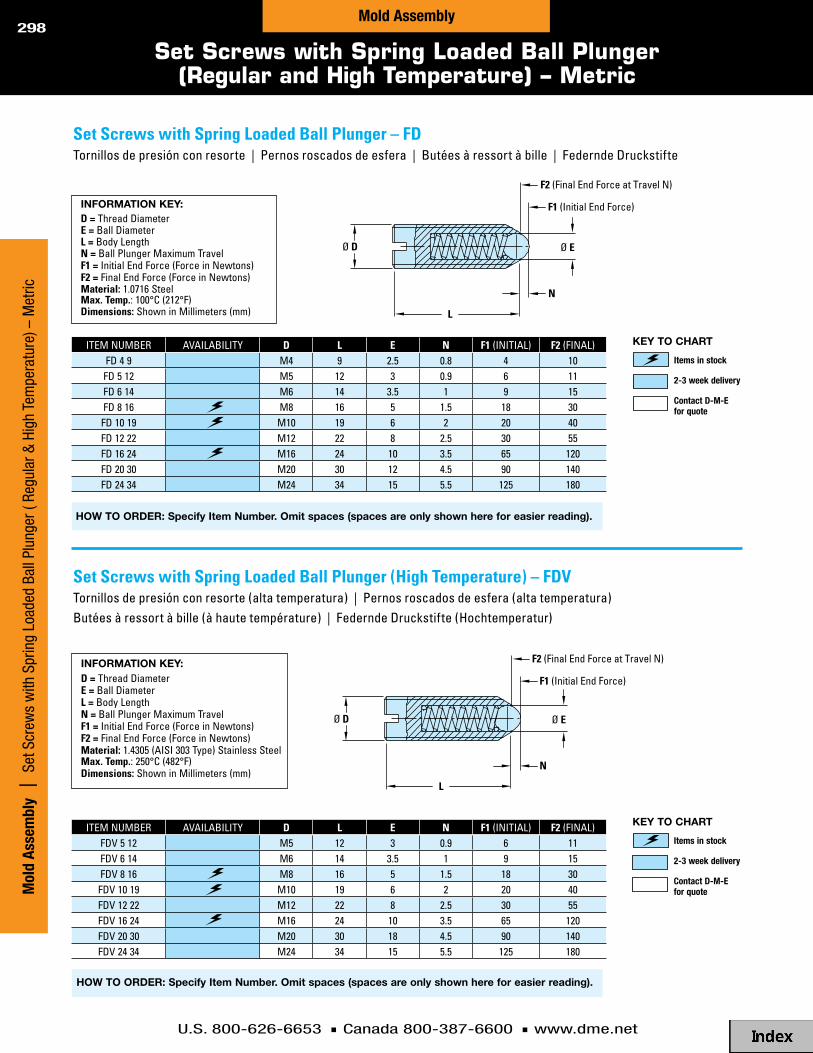
U.S. 800-626-6653 n Canada 800-387-6600 n www.dme.net
298
setscrewswithspringloadedballplunger–Fdtornillosdepresiónconresorte|pernosroscadosdeesfera|butéesàressortàbille|federndedruckstifte
setscrewswithspringloadedballplunger(hightemperature)–Fdvtornillosdepresiónconresorte(altatemperatura)|pernosroscadosdeesfera(altatemperatura)butéesàressortàbille(àhautetempérature)|federndedruckstifte(hochtemperatur)
information KEY:d=threaddiametere=balldiameterl=bodyLengthn=ballplungermaximumtravelF1=initialendforce(forceinnewtons)F2=finalendforce(forceinnewtons)Material:1 .0716steelMax.temp.:100°c(212°f)dimensions:showninmillimeters(mm)
information KEY:d=threaddiametere=balldiameterl=bodyLengthn=ballplungermaximumtravelF1=initialendforce(forceinnewtons)F2=finalendforce(forceinnewtons)Material:1 .4305(aisi303type)stainlesssteelMax.temp.:250°c(482°f)dimensions:showninmillimeters(mm)
HoW to ordEr: specify item number. omit spaces (spaces are only shown here for easier reading).
HoW to ordEr: specify item number. omit spaces (spaces are only shown here for easier reading).
Ø E Ø D
N
L
Ø E Ø D
N
L
F1 (Initial End Force)
F2 (Final End Force at Travel N)
F1 (Initial End Force)
F2 (Final End Force at Travel N)
Ø E Ø D
N
L
Ø E Ø D
N
L
F1 (Initial End Force)
F2 (Final End Force at Travel N)
F1 (Initial End Force)
F2 (Final End Force at Travel N)
itemnumber avaiLabiLity d l e n F1(initiaL) F2(finaL)fd49 m4 9 2 .5 0 .8 4 10
fd512 m5 12 3 0 .9 6 11fd614 m6 14 3 .5 1 9 15fd816 m8 16 5 1 .5 18 30
fd1019 m10 19 6 2 20 40fd1222 m12 22 8 2 .5 30 55fd1624 m16 24 10 3 .5 65 120fd2030 m20 30 12 4 .5 90 140fd2434 m24 34 15 5 .5 125 180
itemnumber avaiLabiLity d l e n F1(initiaL) F2(finaL)fdv512 m5 12 3 0 .9 6 11fdv614 m6 14 3 .5 1 9 15fdv816 m8 16 5 1 .5 18 30
fdv1019 m10 19 6 2 20 40fdv1222 m12 22 8 2 .5 30 55fdv1624 m16 24 10 3 .5 65 120fdv2030 m20 30 18 4 .5 90 140fdv2434 m24 34 15 5 .5 125 180
Set Screws with Spring Loaded Ball Plunger (Regular and High Temperature) – Metric
Items in stock
2-3 week delivery
Contact D-M-E for quote
KEY to cHart
Items in stock
2-3 week delivery
Contact D-M-E for quote
KEY to cHart
Mol
d As
sem
bly
| S
et S
crew
s w
ith S
prin
g Lo
aded
Bal
l Plu
nger
( Re
gula
r & H
igh
Tem
pera
ture
) – M
etric
Mold Assembly

U.S. 800-626-6653 n Canada 800-387-6600 n www.dme.net
299
Set Screws with Flat Point (Grub Screws) – MetricSet Screws with Dog Point (Allen Head) – Metric
setscrewswithFlatpoint(grubscrews)–gs913tornillosincabeza|pernosroscados|visderéglagesanstête|gewindestifte
L
Ø D Ø G
M T
Ø D
L T
N
90 °
information KEY:d=threaddiameterl=Lengthn=hexsocketdeptht=hexsocketsize(acrossflats)standard:din913-45hMaterial:perdinspecificationdimensions:showninmillimeters(mm)
HoW to ordEr: specify item number with prefix, d diameter and L length. include zeros as shown, but omit all spaces (spaces are only shown here for easier reading).
Prefix d L Gs913
Example:
Prefix d L GS913M08016
Example:
Prefix d L GS913M12050
setscrewswithdogpoint(allenhead)–gs915tornillosincabeza|parafusosderegulagem–cabeçaallen|visderéglagesanstête|gewindestiftemitzapfen
L
Ø D Ø G
M T
Ø D
L T
N
90 °
information KEY:d=threaddiameterg=dogpointdiameterl=LengthM=dogpointLengtht=hexsocketsize(acrossflats)standard:din915-45hMaterial:perdinspecificationdimensions:showninmillimeters(mm)
HoW to ordEr: specify item number with prefix, d diameter and L length. include zeros as shown, but omit all spaces (spaces are only shown here for easier reading).
Prefix d L Gs915
Example:
Prefix d L GS915MO6016
Example:
Prefix d L GS915M12050
itemprefix t n d
l004 005 006 008 010 012 016 020 025 030 040 050
gs913
1 .5 2 .5 m032 2 .5 m04
2 .5 3 m053 3 .5 m064 5 m085 6 m106 8 m126 10 m16
itemprefix t g M d
l010 016 020 025 030 040 050 060
gs915
2 2 .5 3 m043 4 3 .5 m064 5 .5 5 m085 7 5 .5 m106 8 .5 7 m128 12 9 m16
Items in stock
2-3 week delivery
Contact D-M-E for quote
KEY to cHart
Items in stock
2-3 week delivery
Contact D-M-E for quote
KEY to cHart
Mold Assem
bly | Set Screws w
ith Flat Point – Metric; Set Screw
s with Dog Point – M
etricMold Assembly

U.S. 800-626-6653 n Canada 800-387-6600 n www.dme.net
300
Dowel Pins and Tubular Dowels – Inch
Length
diameter
Length1/8 3 /16 1/4 5 /16 3 /8 1/2 5 /8 3 /4 13 /8 ● — — — — — — — — 3 /8
1/2 ● ● ● — — — — — — 1/2
3 /4 ● ● ● — ● ● — — — 3 /4
1 ● ● ● ● ● ● — — — 1
11/4 — — ● ● ● ● — — — 11/4
11/2 — ● ● ● ● ● ● — — 11/2
2 ● ● ● ● ● ● ● ● ● 2
21/2 — — ● — ● ● ● ● — 21/2
3 — — — — ● ● ● ● ● 3
4 — — — — — ● ● ● ● 4
5 — — — — — — ● ● ● 5
dowelpins
D-M-E Dowel Pins are made from high-grade alloy steel, hardened and precision ground.
nom .dia
o.d.± .0002 i.d.
lstandardLengths(priceeach)3 /8 1/2 7/8 13 /8 17/8 23 /8 27/8
3 /8 .3752 .260 ● — ● — — — —
5 /8 .6252 .385 — ● — ● ● ● —
3 /4 .7502 .510 ● ● — ● ● ● ●
7/8 .8752 .635 — ● — — — ● ●
tubulardowels
D-M-E Tubular Dowels are hardened and precision ground. They are used in D-M-E mold base assemblies to accurately align the “B” plate, support plate and the ejector housing.
The use of D-M-E Tubular Dowels allows more room for waterlines by superimposing the dowel pin and cap screw as shown at the right.
asusedinMoldbaseasseMblies
O.D.
L
I.D.
1/32
“B” PLATE
SUPPORT PLATE
EJECTOR HOUSING
TUBULAR DOWEL
S.H.C.S.
O.D.
L
I.D.
1/32
“B” PLATE
SUPPORT PLATE
EJECTOR HOUSING
TUBULAR DOWEL
S.H.C.S.
Mol
d As
sem
bly
| D
owel
Pin
s an
d Tu
bula
r Dow
els
– In
chMold Assembly
WHEn ordErinG, PLEasE sPEcifY:1. Quantity2. diameter 3. Length
●=instock
●=instock

U.S. 800-626-6653 n Canada 800-387-6600 n www.dme.net
301
Dowel Pins – MetricDowel Pins with Internal Thread (Pull Dowels)
dowelpins–dpclavija|cavilhas|goupillescylindriques|zylinderstifte
Ø D m6
15 °
L
L
Ø F Ø D m6
N 15 °
~60 HRC
650-750 HV30 (Ref. Only ~60 ± 2 HRC)
dowelpinswithinternalthread/pulldowels–wZ7005clavijaconcuerdainterna|cavilhas|goupillescylindriques|zylinderstifte
information KEY:d=pinoutsidediameterl=Lengthstandard:din6325,iso8734Material:perdinandisospecificationsdimensions:showninmillimeters(mm)
information KEY:d=pinoutsidediameterF=tapdiameterl=Lengthn=tapdepthstandard:dinen28735–typeaMaterial:perdinspecificationdimensions:showninmillimeters(mm)
Ø D m6
15 °
L
L
Ø F Ø D m6
N 15 °
~60 HRC
650-750 HV30 (Ref. Only ~60 ± 2 HRC)
HoW to ordEr: specify item number with prefix, d diameter and L length. include zeros as shown, but omit all spaces (spaces are only shown here for easier reading).
Prefix d L dP
Example:
Prefix d L DP28
Example:
Prefix d L DP2060
HoW to ordEr: specify item number with prefix, d diameter and L length. include zeros as shown, but omit all spaces (spaces are only shown here for easier reading).
Prefix d L WZ7005
Example:
Prefix d L WZ700506020
Example:
Prefix d L WZ700512040
iteMpreFix d F n
l020 024 028 032 036 040 050 060 080 100
wz7005
06 m4 608 m5 810 m6 1012 m6 1214 m8 1216 m8 1620 m10 20
iteMpreFix d
l6 8 10 12 14 16 18 20 24 28 32 36 40 50 60 80 100 120 140
dp
23456810121620
Items in stock
2-3 week delivery
Contact D-M-E for quote
KEY to cHart
Items in stock
2-3 week delivery
Contact D-M-E for quote
KEY to cHart
Mold Assem
bly | Dowel Pins – M
etric; Dowel Pins w
ith Internal Thread (Pull Dowels)
Mold Assembly

U.S. 800-626-6653 n Canada 800-387-6600 n www.dme.net
302
tubulardowels–r09registrotubular|cavilhatubular|douairestubulaires|paßhülsen
K js12
Ø D -0.2 -0.4
Ø G
60 ± 2 HRC
L +0.5 +0.3
Ø D g6Ø G
60 ± 2 HRC
washer/tubulardowel(diskfortubulardowels)–r091arandela–registrotubular|anilhas–paracavilhatubularcachetagecylindrique–douairestubulaires|scheibe–paßhülsen
information KEY:d=outsidediameterg=insidediameterl=Lengthstandard:euro-seriesMaterial:1 .7131(aisi5115type)steelsurfacetreatment:casehardeneddimensions:showninmillimeters(mm)
information KEY:d=outsidediameterg=insidediameterk=thicknessstandard:euro-seriesMaterial:1 .7131(aisi5115type)steelsurfacetreatment:casehardeneddimensions:showninmillimeters(mm)
HoW to ordEr: specify item number. include zeros as shown, but omit all spaces (spaces are only shown here for easier reading).
Prefix d K ro91
Example:
Prefix d K R09114003
Example:
Prefix d K R09140008
HoW to ordEr: specify item number with prefix, d diameter and L length. include zeros as shown, but omit all spaces (spaces are only shown here for easier reading).
Prefix d L r09
Example:
Prefix d L R0910040
Example:
Prefix d L R0930180
K js12
Ø D -0.2 -0.4
Ø G
60 ± 2 HRC
L +0.5 +0.3
Ø D g6Ø G
60 ± 2 HRC
Tubular Dowels; Washer/Tubular Dowel (Disk for Tubular Dowels) – Metric
iteMpreFix d g
l020 030 040 050 060 070 080 100 120 140 160 180 200 240 300
r09
10 6 .214 8 .518 10 .524 1330 17
iteMnuMber d k g availability
r091143 14 003 6 .2r091184 18 004 8 .5r091245 24 005 10 .5r091306 30 006 13 .0r091408 40 008 17 .0
Items in stock
2-3 week delivery
Contact D-M-E for quote
KEY to cHart
Items in stock
2-3 week delivery
Contact D-M-E for quote
KEY to cHart
Mol
d As
sem
bly
| T
ubul
ar D
owel
s; W
ashe
r – T
ubul
ar D
owel
(Dis
k) –
Met
ricMold Assembly

U.S. 800-626-6653 n Canada 800-387-6600 n www.dme.net
303
Maximumdeflection:50%ofFreelengthefficientoperatingrange:25%to35%ofFreelength
hoLedia
roddia
iteMnuMber
freeLength
approxLoadat
1/10"defLec .(Lbs)
Loadat50%defLec .
(Lbs)inch mm
3 /89 .5mm
3 /164 .7mm
smd1004 1 .00 25 .40 6 .0 30 .0smd1005 1 .25 31 .75 5 .4 33 .8smd1006 1 .50 38 .10 4 .0 30 .0smd1007 1 .75 44 .45 3 .4 29 .8smd1008 2 .00 50 .80 2 .8 28 .0smd1010 2 .50 63 .50 2 .4 30 .0
wire .039x .070
smd1012 3 .00 76 .20 2 .1 31 .5smd1048 12 .00 304 .80 0 .6 36 .0
1/213mm
9 /327mm
smd2004 1 .00 25 .40 11 .0 55 .0smd2005 1 .25 31 .75 8 .2 51 .3smd2006 1 .50 38 .10 6 .8 51 .0smd2007 1 .75 44 .45 6 .0 52 .5smd2008 2 .00 50 .80 5 .5 55 .0smd2010 2 .50 63 .50 4 .5 56 .3smd2012 3 .00 76 .20 3 .5 52 .5smd2014 3 .50 88 .90 3 .0 52 .5smd2018 4 .50 114 .30 2 .5 56 .3smd2022 5 .50 139 .70 2 .1 57 .8smd2026 6 .50 165 .10 1 .4 45 .5
wire .052x .093
smd2030 7 .50 190 .50 1 .2 45 .0smd2048 12 .00 304 .80 0 .7 42 .0
5 /816mm
11/328 .7mm
smd3004 1 .00 25 .40 16 .4 82 .0smd3005 1 .25 31 .75 12 .8 80 .0smd3006 1 .50 38 .10 10 .8 81 .0smd3007 1 .75 44 .45 9 .6 84 .0smd3008 2 .00 50 .80 8 .8 88 .0smd3010 2 .50 63 .50 6 .0 75 .0smd3012 3 .00 76 .20 5 .6 84 .0smd3014 3 .50 88 .90 4 .8 84 .0
wire .069x .109
smd3016 4 .00 101 .60 4 .4 88 .0smd3048 12 .00 304 .80 1 .6 96 .0
3 /419 .5mm
3 /89 .5mm
smd4004 1 .00 25 .40 31 .2 156 .0smd4005 1 .25 31 .75 25 .6 160 .0smd4006 1 .50 38 .10 20 .0 150 .0smd4007 1 .75 44 .45 17 .6 154 .0smd4008 2 .00 50 .80 14 .4 144 .0smd4010 2 .50 63 .50 12 .0 150 .0smd4012 3 .00 76 .20 9 .6 144 .0smd4014 3 .50 88 .90 8 .0 140 .0smd4016 4 .00 101 .60 7 .2 144 .0smd4018 4 .50 114 .30 6 .4 144 .0smd4020 5 .00 127 .00 6 .0 150 .0smd4022 5 .50 139 .70 5 .5 151 .3smd4024 6 .00 152 .40 5 .0 150 .0smd4026 6 .50 165 .10 4 .5 146 .3
wire .075x .165
smd4030 7 .50 190 .50 3 .8 142 .5smd4048 12 .00 304 .80 2 .4 144 .0
125 .5mm
1/213mm
smd5004 1 .00 25 .40 55 .0 275 .0smd5005 1 .25 31 .75 45 .0 281 .3smd5006 1 .50 38 .10 35 .0 262 .5smd5007 1 .75 44 .45 30 .0 262 .5smd5008 2 .00 50 .80 26 .0 260 .0smd5010 2 .50 63 .50 20 .0 250 .0
hoLedia
roddia
iteMnuMber
freeLength
approxLoadat
1/10"defLec .(Lbs)
Loadat50%defLec .
(Lbs)inch mm
1"25 .5mm
1/213mm
smd5012 3 .00 76 .20 16 .5 247 .5smd5014 3 .50 88 .90 15 .0 262 .5smd5016 4 .00 101 .60 12 .0 240 .0smd5018 4 .50 114 .30 10 .4 234 .0smd5020 5 .00 127 .00 9 .6 240 .0smd5022 5 .50 139 .70 8 .8 242 .0smd5024 6 .00 152 .40 8 .0 240 .0smd5028 7 .00 177 .80 7 .2 252 .0
wire .100x .215
smd5032 8 .00 203 .20 6 .0 240 .0smd5048 12 .00 304 .80 4 .0 240 .0
11/432mm
5 /816mm
smd6006 1 .50 38 .10 49 .6 372 .0smd6007 1 .75 44 .45 42 .4 371 .0smd6008 2 .00 50 .80 35 .2 352 .0smd6010 2 .50 63 .50 28 .8 360 .0smd6012 3 .00 76 .20 24 .0 360 .0smd6014 3 .50 88 .90 20 .0 350 .0smd6016 4 .00 101 .60 17 .6 352 .0smd6018 4 .50 114 .30 16 .0 360 .0smd6020 5 .00 127 .00 13 .6 340 .0smd6022 5 .50 139 .70 12 .8 352 .0smd6024 6 .00 152 .40 12 .0 360 .0smd6028 7 .00 177 .80 10 .4 364 .0smd6032 8 .00 203 .20 8 .8 352 .0
wire .115x .285
smd6040 10 .00 254 .00 7 .2 360 .0smd6048 12 .00 304 .80 6 .0 360 .0
11/238 .5mm
3 /419 .5mm
smd7008 2 .00 50 .80 53 .0 530 .0smd7010 2 .50 63 .50 45 .0 562 .5smd7012 3 .00 76 .20 36 .0 540 .0smd7014 3 .50 88 .90 30 .0 525 .0smd7016 4 .00 101 .60 27 .0 540 .0smd7018 4 .50 114 .30 23 .0 517 .5smd7020 5 .00 127 .00 21 .0 525 .0smd7022 5 .50 139 .70 18 .5 508 .8smd7024 6 .00 152 .40 17 .0 510 .0smd7028 7 .00 177 .80 14 .5 507 .5smd7032 8 .00 203 .20 12 .8 512 .0
wire .135x .345
smd7040 10 .00 254 .00 10 .0 500 .0smd7048 12 .00 304 .80 8 .0 480 .0
251mm
125 .5mm
smd8010 2 .50 63 .50 100 .0 1250 .0smd8012 3 .00 76 .20 83 .0 1245 .0smd8014 3 .50 88 .90 64 .8 1134 .0smd8016 4 .00 101 .60 60 .0 1200 .0smd8018 4 .50 114 .30 53 .0 1192 .5smd8020 5 .00 127 .00 47 .0 1175 .0smd8022 5 .50 139 .70 39 .2 1078 .0smd8024 6 .00 152 .40 39 .0 1170 .0smd8028 7 .00 177 .80 31 .2 1092 .0smd8032 8 .00 203 .20 28 .5 1140 .0
wire .195x .468
smd8040 10 .00 254 .00 20 .8 1040 .0smd8048 12 .00 304 .80 17 .5 1050 .0
ROD HOLE
FREE LENGTH
Manufactured by Raymond® from a special rectangular-shaped, round-cornered chromium alloy. Provides high resistance to shock loads, increased deflection, wider operating temperatures and longer life. Color-coded by work range to simplify selection and specification.
(LBS x .454 = kg)
Mold and Die SpringsMedium Duty (Color-Coded Blue)
Mold Assem
bly | Mold and Die Springs – M
edium Duty (Blue)
Mold Assembly
MediumdutyMoldanddiesprings(blue)–sMd
QUANTITY DISCOUNTS: discountsavailableat25,50and100pieces .contactd-m-eforprices .

U.S. 800-626-6653 n Canada 800-387-6600 n www.dme.net
304
Maximumdeflection:37%ofFreelengthefficientoperatingrange:20%to25%ofFreelength
hoLedia
roddia
iteMnuMber
freeLength
approxLoadat
1/10"defLec .(Lbs)
Loadat37%defLec .
(Lbs)inch mm
3 /89 .5mm
3 /164 .7mm
smh1004 1 .00 25 .40 9 .0 33 .3smh1005 1 .25 31 .75 7 .3 33 .8smh1006 1 .50 38 .10 6 .7 37 .2smh1007 1 .75 44 .45 5 .8 37 .6smh1008 2 .00 50 .80 5 .0 37 .0smh1010 2 .50 63 .50 4 .2 38 .9
wire .046x .073
smh1012 3 .00 76 .20 3 .0 33 .3smh1048 12 .00 304 .80 0 .9 40 .0
1/213mm
9 /327mm
smh2004 1 .00 25 .40 16 .8 62 .2smh2005 1 .25 31 .75 13 .0 60 .1smh2006 1 .50 38 .10 9 .5 52 .7smh2007 1 .75 44 .45 8 .5 55 .0smh2008 2 .00 50 .80 7 .5 55 .5smh2010 2 .50 63 .50 6 .0 55 .5smh2012 3 .00 76 .20 5 .7 63 .3
wire .061x .093
smh2014 3 .50 88 .90 4 .0 51 .8smh2048 12 .00 304 .80 1 .2 53 .3
5 /816mm
11/328 .7mm
smh3004 1 .00 25 .40 30 .0 111 .0smh3005 1 .25 31 .75 21 .5 99 .4smh3006 1 .50 38 .10 19 .0 105 .5smh3007 1 .75 44 .45 16 .8 108 .8smh3008 2 .00 50 .80 14 .8 109 .5smh3010 2 .50 63 .50 11 .5 106 .4smh3012 3 .00 76 .20 10 .0 111 .0smh3014 3 .50 88 .90 8 .5 110 .1
wire .081x .123
smh3016 4 .00 101 .60 7 .6 112 .5smh3048 12 .00 304 .80 2 .7 119 .9
3 /419 .5mm
3 /89 .5mm
smh4004 1 .00 25 .40 50 .0 185 .0smh4005 1 .25 31 .75 38 .0 175 .8smh4006 1 .50 38 .10 32 .0 177 .6smh4007 1 .75 44 .45 28 .8 186 .5smh4008 2 .00 50 .80 24 .8 183 .5smh4010 2 .50 63 .50 19 .2 177 .6smh4012 3 .00 76 .20 14 .4 159 .8smh4014 3 .50 88 .90 12 .8 165 .8smh4016 4 .00 101 .60 12 .0 177 .6smh4018 4 .50 114 .30 11 .2 186 .5smh4020 5 .00 127 .00 9 .0 166 .5smh4022 5 .50 139 .70 8 .0 162 .8
wire .093x .156
smh4024 6 .00 152 .40 7 .5 166 .5smh4048 12 .00 304 .80 3 .6 159 .8
1"25 .5mm
1/213mm
smh5004 1 .00 25 .40 76 .0 281 .2smh5005 1 .25 31 .75 62 .4 288 .6smh5006 1 .50 38 .10 49 .6 275 .3smh5007 1 .75 44 .45 44 .0 284 .9smh5008 2 .00 50 .80 40 .0 296 .0smh5010 2 .50 63 .50 31 .0 286 .8smh5012 3 .00 76 .20 25 .0 277 .5smh5014 3 .50 88 .90 21 .6 279 .7smh5016 4 .00 101 .60 18 .4 272 .3smh5018 4 .50 114 .30 17 .0 283 .1smh5020 5 .00 127 .00 14 .4 266 .4smh5022 5 .50 139 .70 12 .8 260 .5smh5024 6 .00 152 .40 12 .0 266 .4smh5028 7 .00 177 .80 10 .0 259 .0
wire .115x .218
smh5032 8 .00 203 .20 8 .8 260 .5smh5048 12 .00 304 .80 6 .2 275 .3
ROD HOLE
FREE LENGTH
Manufactured by Raymond® from a special rectangular-shaped, round-cornered chromium alloy. Provides high resistance to shock loads, increased deflection, wider operating temperatures and longer life. Color-coded by work range to simplify selection and specification.
theword“raymond”andthegold,red,greenandbluecolorcodingofmoldanddiespringsintheheavyduty,mediumheavyduty,extraheavydutyandmediumdutyloadranges,respectively,areregisteredtrademarksofthebarnesgroup,inc .
(LBS x .454 = kg)
Mold and Die SpringsMedium Heavy Duty (Color-Coded Red)
Mol
d As
sem
bly
| M
old
and
Die
Sprin
gs –
Med
ium
Hea
vy D
uty
(Red
)Mold Assembly
MediumheavydutyMoldanddiesprings(red)–sMh
hoLedia
roddia
iteMnuMber
freeLength
approxLoadat
1/10"defLec .(Lbs)
Loadat37%defLec .
(Lbs)inch mm
11/432mm
5 /816mm
smh6006 1 .50 38 .10 114 .4 634 .9smh6007 1 .75 44 .45 100 .8 652 .7smh6008 2 .00 50 .80 86 .4 639 .4smh6010 2 .50 63 .50 62 .4 577 .2smh6012 3 .00 76 .20 51 .2 568 .3smh6014 3 .50 88 .90 44 .0 569 .8smh6016 4 .00 101 .60 36 .8 544 .6smh6018 4 .50 114 .30 32 .0 532 .8smh6020 5 .00 127 .00 29 .0 536 .5smh6022 5 .50 139 .70 26 .4 537 .2smh6024 6 .00 152 .40 25 .0 555 .0smh6028 7 .00 177 .80 20 .0 518 .0smh6032 8 .00 203 .20 18 .4 544 .6
wire .156x .281
smh6040 10 .00 254 .00 14 .5 536 .5smh6048 12 .00 304 .80 12 .4 550 .6
11/238 .5mm
3 /419 .5mm
smh7008 2 .00 50 .80 108 .0 799 .2smh7010 2 .50 63 .50 85 .6 791 .8smh7012 3 .00 76 .20 62 .4 692 .6smh7014 3 .50 88 .90 52 .8 683 .8smh7016 4 .00 101 .60 48 .0 710 .4smh7018 4 .50 114 .30 43 .2 719 .3smh7020 5 .00 127 .00 36 .8 680 .8smh7022 5 .50 139 .70 34 .4 700 .0smh7024 6 .00 152 .40 30 .4 674 .9smh7028 7 .00 177 .80 26 .4 683 .8smh7032 8 .00 203 .20 22 .0 651 .2
wire .187x .312
smh7040 10 .00 254 .00 17 .6 651 .2smh7048 12 .00 304 .80 14 .4 639 .4
251mm
125 .5mm
smh8010 2 .50 63 .50 118 .4 1095 .2smh8012 3 .00 76 .20 96 .0 1065 .6smh8014 3 .50 88 .90 80 .0 1036 .0smh8016 4 .00 101 .60 66 .4 982 .7smh8018 4 .50 114 .30 60 .0 999 .0smh8020 5 .00 127 .00 56 .0 1036 .0smh8022 5 .50 139 .70 50 .4 1025 .6smh8024 6 .00 152 .40 47 .2 1047 .8smh8028 7 .00 177 .80 40 .0 1036 .0smh8032 8 .00 203 .20 35 .2 1041 .9
wire .225x .437
smh8040 10 .00 254 .00 26 .0 962 .0smh8048 12 .00 304 .80 22 .4 994 .6
QUANTITY DISCOUNTS: discountsavailableat25,50and100pieces .contactd-m-eforprices .

U.S. 800-626-6653 n Canada 800-387-6600 n www.dme.net
305
Mold and Die SpringsHeavy Duty (Color-Coded Gold)
Maximumdeflection:30%ofFreelengthefficientoperatingrange:15%to20%ofFreelength
hoLedia
roddia
iteMnuMber
freeLength
approxLoadat
1/10"defLec .(Lbs)
Loadat30%defLec .
(Lbs)inch mm
3 /89 .5mm
3 /164 .7mm
shd1004 1 .00 25 .40 11 .0 33 .0shd1005 1 .25 31 .75 9 .8 36 .8shd1006 1 .50 38 .10 8 .0 36 .0shd1007 1 .75 44 .45 8 .4 44 .1shd1008 2 .00 50 .80 7 .2 43 .2shd1010 2 .50 63 .50 5 .5 41 .3
wire .054x .072
shd1012 3 .00 76 .20 4 .2 37 .8shd1048 12 .00 304 .80 1 .2 43 .2
1/213mm
9 /327mm
shd2004 1 .00 25 .40 23 .6 70 .8shd2005 1 .25 31 .75 18 .6 69 .8shd2006 1 .50 38 .10 15 .5 69 .8shd2007 1 .75 44 .45 13 .8 72 .5shd2008 2 .00 50 .80 11 .0 66 .0shd2010 2 .50 63 .50 8 .4 63 .0shd2012 3 .00 76 .20 7 .4 66 .6
wire .072x .095
shd2014 3 .50 88 .90 6 .0 63 .0shd2048 12 .00 304 .80 1 .6 57 .6
5 /816mm
11/328 .7mm
shd3004 1 .00 25 .40 42 .4 127 .2shd3005 1 .25 31 .75 29 .6 111 .0shd3006 1 .50 38 .10 27 .2 122 .4shd3007 1 .75 44 .45 24 .0 126 .0shd3008 2 .00 50 .80 20 .8 124 .8shd3010 2 .50 63 .50 17 .0 127 .5shd3012 3 .00 76 .20 14 .4 129 .6shd3014 3 .50 88 .90 12 .2 128 .1
wire .093x .125
shd3016 4 .00 101 .60 10 .8 129 .6shd3048 12 .00 304 .80 3 .0 108 .0
3 /419 .5mm
3 /89 .5mm
shd4004 1 .00 25 .40 108 .0 324 .0shd4005 1 .25 31 .75 88 .0 330 .0shd4006 1 .50 38 .10 65 .6 295 .2shd4007 1 .75 44 .45 60 .0 315 .0shd4008 2 .00 50 .80 49 .6 297 .6shd4010 2 .50 63 .50 40 .0 300 .0shd4012 3 .00 76 .20 34 .0 306 .0shd4014 3 .50 88 .90 28 .0 294 .0shd4016 4 .00 101 .60 25 .0 300 .0shd4018 4 .50 114 .30 22 .0 297 .0shd4020 5 .00 127 .00 19 .5 292 .5shd4022 5 .50 139 .70 17 .0 280 .5
wire .125x .165
shd4024 6 .00 152 .40 16 .0 288 .0shd4048 12 .00 304 .80 8 .0 288 .0
125 .5mm
1/213mm
shd5004 1 .00 25 .40 208 .0 624 .0shd5005 1 .25 31 .75 171 .2 642 .0shd5006 1 .50 38 .10 118 .4 532 .8shd5007 1 .75 44 .45 104 .0 546 .0shd5008 2 .00 50 .80 90 .0 540 .0shd5010 2 .50 63 .50 68 .0 510 .0shd5012 3 .00 76 .20 54 .4 489 .6shd5014 3 .50 88 .90 45 .6 478 .8shd5016 4 .00 101 .60 40 .0 480 .0shd5018 4 .50 114 .30 35 .2 475 .2shd5020 5 .00 127 .00 31 .2 468 .0shd5022 5 .50 139 .70 28 .8 475 .2shd5024 6 .00 152 .40 25 .6 460 .8shd5028 7 .00 177 .80 22 .4 470 .4
wire .158x .225
shd5032 8 .00 203 .20 19 .2 460 .8shd5048 12 .00 304 .80 12 .0 432 .0
hoLedia
roddia
iteMnuMber
freeLength
approxLoadat
1/10"defLec .(Lbs)
Loadat30%defLec .
(Lbs)inch mm
11/432mm
5 /816mm
shd6006 1 .50 38 .10 212 .0 954 .0shd6007 1 .75 44 .45 181 .6 953 .4shd6008 2 .00 50 .80 149 .6 897 .6shd6010 2 .50 63 .50 117 .6 882 .0shd6012 3 .00 76 .20 95 .2 856 .8shd6014 3 .50 88 .90 75 .2 789 .6shd6016 4 .00 101 .60 66 .4 796 .8shd6018 4 .50 114 .30 58 .4 788 .4shd6020 5 .00 127 .00 53 .0 795 .0shd6022 5 .50 139 .70 47 .2 778 .8shd6024 6 .00 152 .40 42 .4 763 .2shd6028 7 .00 177 .80 36 .8 772 .8shd6032 8 .00 203 .20 32 .8 787 .2
wire .200x .295
shd6040 10 .00 254 .00 25 .6 768 .0shd6048 12 .00 304 .80 20 .8 748 .8
11/238 .5mm
3 /419 .5mm
shd7008 2 .00 50 .80 190 .4 1142 .4shd7010 2 .50 63 .50 155 .0 1162 .5shd7012 3 .00 76 .20 130 .0 1170 .0shd7014 3 .50 88 .90 106 .4 1117 .2shd7016 4 .00 101 .60 91 .2 1094 .4shd7018 4 .50 114 .30 78 .4 1058 .4shd7020 5 .00 127 .00 71 .2 1068 .0shd7022 5 .50 139 .70 64 .0 1056 .0shd7024 6 .00 152 .40 58 .4 1051 .2shd7028 7 .00 177 .80 49 .6 1041 .6shd7032 8 .00 203 .20 43 .2 1036 .8
wire .225x .350
shd7040 10 .00 254 .00 34 .4 1032 .0shd7048 12 .00 304 .80 28 .8 1036 .8
251mm
125 .5mm
shd8010 2 .50 63 .50 260 .0 1950 .0shd8012 3 .00 76 .20 200 .0 1800 .0shd8014 3 .50 88 .90 170 .0 1785 .0shd8016 4 .00 101 .60 150 .0 1800 .0shd8018 4 .50 114 .30 120 .0 1620 .0shd8020 5 .00 127 .00 110 .0 1650 .0shd8022 5 .50 139 .70 100 .0 1650 .0shd8024 6 .00 152 .40 94 .0 1692 .0shd8028 7 .00 177 .80 82 .0 1722 .0shd8032 8 .00 203 .20 73 .0 1752 .0
wire .280x .470
shd8040 10 .00 254 .00 55 .0 1650 .0shd8048 12 .00 304 .80 42 .0 1512 .0
ROD HOLE
FREE LENGTH
(LBS x .454 = kg)
Manufactured by Raymond® from a special rectangular-shaped, round-cornered chromium alloy. Provides high resistance to shock loads, increased deflection, wider operating temperatures and longer life. Color-coded by work range to simplify selection and specification.
theword“raymond”andthegold,red,greenandbluecolorcodingofmoldanddiespringsintheheavyduty,mediumheavyduty,extraheavydutyandmediumdutyloadranges,respectively,areregisteredtrademarksofthebarnesgroup,inc .
Mold Assem
bly | Mold and Die Springs – Heavy Duty (Gold)
Mold Assembly
heavydutyMoldanddiesprings(gold)–shd
QUANTITY DISCOUNTS: discountsavailableat25,50and100pieces .contactd-m-eforprices .

U.S. 800-626-6653 n Canada 800-387-6600 n www.dme.net
306
Maximumdeflection:25%ofFreelengthefficientoperatingrange:15%ofFreelength
hoLedia
roddia
iteMnuMber
freeLength
approxLoadat
1/10"defLec .(Lbs)
Loadat25%defLec .
(Lbs)inch mm
3 /89 .5mm
3 /164 .7mm
seh1004 1 .00 25 .40 22 .0 55 .0seh1005 1 .25 31 .75 16 .0 50 .0seh1006 1 .50 38 .10 12 .5 46 .9seh1007 1 .75 44 .45 11 .5 50 .3seh1008 2 .00 50 .80 9 .0 45 .0seh1010 2 .50 63 .50 7 .0 43 .8
wire .059x .080
seh1012 3 .00 76 .20 6 .5 48 .8seh1048 12 .00 304 .80 1 .5 45 .0
1/213mm
9 /327mm
seh2004 1 .00 25 .40 32 .0 80 .0seh2005 1 .25 31 .75 24 .0 75 .0seh2006 1 .50 38 .10 20 .0 75 .0seh2007 1 .75 44 .45 17 .0 74 .4seh2008 2 .00 50 .80 14 .0 70 .0seh2010 2 .50 63 .50 11 .5 71 .9seh2012 3 .00 76 .20 9 .0 67 .5
wire .084x .097
seh2014 3 .50 88 .90 8 .0 70 .0seh2048 12 .00 304 .80 2 .5 75 .0
5 /816mm
11/328 .7mm
seh3004 1 .00 25 .40 63 .0 157 .5seh3005 1 .25 31 .75 47 .0 146 .9seh3006 1 .50 38 .10 38 .0 142 .5seh3007 1 .75 44 .45 32 .0 140 .0seh3008 2 .00 50 .80 29 .0 145 .0seh3010 2 .50 63 .50 22 .0 137 .5seh3012 3 .00 76 .20 19 .0 142 .5seh3014 3 .50 88 .90 16 .0 140 .0
wire .110x .126
seh3016 4 .00 101 .60 13 .5 135 .0seh3048 12 .00 304 .80 4 .5 135 .0
3 /419 .5mm
3 /89 .5mm
seh4004 1 .00 25 .40 140 .0 350 .0seh4005 1 .25 31 .75 110 .0 343 .8seh4006 1 .50 38 .10 89 .0 333 .8seh4007 1 .75 44 .45 75 .0 328 .1seh4008 2 .00 50 .80 68 .0 340 .0seh4010 2 .50 63 .50 50 .0 312 .5seh4012 3 .00 76 .20 40 .5 303 .8seh4014 3 .50 88 .90 34 .5 301 .9seh4016 4 .00 101 .60 30 .0 300 .0seh4018 4 .50 114 .30 26 .5 298 .1seh4020 5 .00 127 .00 23 .5 293 .8seh4022 5 .50 139 .70 21 .5 295 .6
wire .135x .165
seh4024 6 .00 152 .40 19 .5 292 .5seh4048 12 .00 304 .80 9 .5 285 .0
1"25 .5mm
1/213mm
seh5006 1 .50 38 .10 160 .0 600 .0seh5008 2 .00 50 .80 116 .0 580 .0seh5010 2 .50 63 .50 89 .6 560 .0seh5012 3 .00 76 .20 73 .6 552 .0seh5014 3 .50 88 .90 62 .4 546 .0seh5016 4 .00 101 .60 55 .2 552 .0seh5018 4 .50 114 .30 48 .8 549 .0seh5020 5 .00 127 .00 43 .2 540 .0
wire .188x .225
seh5024 6 .00 152 .40 36 .0 540 .0seh5048 12 .00 304 .80 17 .6 528 .0
hoLedia
roddia
iteMnuMber
freeLength
approxLoadat
1/10"defLec .(Lbs)
Loadat25%defLec .
(Lbs)inch mm
11/432mm
5 /816mm
seh6008 2 .00 50 .80 192 .0 960 .0seh6010 2 .50 63 .50 144 .0 900 .0seh6012 3 .00 76 .20 118 .4 888 .0seh6014 3 .50 88 .90 100 .8 882 .0seh6016 4 .00 101 .60 84 .0 840 .0seh6018 4 .50 114 .30 78 .4 882 .0seh6020 5 .00 127 .00 68 .0 850 .0seh6024 6 .00 152 .40 56 .0 840 .0seh6032 8 .00 203 .20 41 .6 832 .0
wire .225x .295
seh6040 10 .00 254 .00 33 .6 840 .0seh6048 12 .00 304 .80 26 .4 792 .0
11/238 .5mm
3 /419 .5mm
seh7008 2 .00 50 .80 376 .0 1880 .0seh7010 2 .50 63 .50 294 .4 1840 .0seh7012 3 .00 76 .20 231 .2 1734 .0seh7014 3 .50 88 .90 196 .0 1715 .0seh7016 4 .00 101 .60 171 .2 1712 .0seh7018 4 .50 114 .30 148 .0 1665 .0seh7020 5 .00 127 .00 136 .0 1700 .0seh7024 6 .00 152 .40 110 .4 1656 .0seh7032 8 .00 203 .20 80 .8 1616 .0
wire .300x .350
seh7040 10 .00 254 .00 67 .2 1680 .0seh7048 12 .00 304 .80 54 .4 1632 .0
251mm
125 .5mm
seh8010 2 .50 63 .50 381 .6 2385 .0seh8012 3 .00 76 .20 312 .0 2340 .0seh8014 3 .50 88 .90 254 .4 2226 .0seh8016 4 .00 101 .60 220 .0 2200 .0seh8018 4 .50 114 .30 188 .8 2124 .0seh8020 5 .00 127 .00 172 .8 2160 .0seh8024 6 .00 152 .40 141 .6 2124 .0seh8032 8 .00 203 .20 100 .0 2000 .0
wire .365x .460
seh8040 10 .00 254 .00 84 .0 2100 .0seh8048 12 .00 304 .80 71 .2 2136 .0
ROD HOLE
FREE LENGTH
(LBS x .454 = kg)
Manufactured by Raymond® from a special rectangular-shaped, round-cornered chromium alloy. Provides high resistance to shock loads, increased deflection, wider operating temperatures and longer life. Color-coded by work range to simplify selection and specification.
theword“raymond”andthegold,red,greenandbluecolorcodingofmoldanddiespringsintheheavyduty,mediumheavyduty,extraheavydutyandmediumdutyloadranges,respectively,areregisteredtrademarksofthebarnesgroup,inc .
Mold and Die SpringsExtra Heavy Duty (Color-Coded Green)
Mol
d As
sem
bly
| M
old
and
Die
Sprin
gs –
Ext
ra H
eavy
Dut
y (G
reen
)Mold Assembly
extraheavydutyMoldanddiesprings(green)–seh
QUANTITY DISCOUNTS: discountsavailableat25,50and100pieces .contactd-m-eforprices .

U.S. 800-626-6653 n Canada 800-387-6600 n www.dme.net
307
bellevillewashers(discsprings)–wZ8050rondanasbeleville|rondellesbellevilleanilhasbelleville|tellerfedern
Ø D
Ø G
H
S
J
T
6 J 3 J J 2J 3J 4J
3F
2F
F
F3 3 x F1
F2 2 x F1
F1
� Length of deflection � Federweg � Veerweg � Flèche
� Length of deflection � Federweg � Veerweg � Flèche
� L
oad
Forc
e �
Fed
erkr
aft
� B
elas
ting
� C
harg
e
� L
oad
Forc
e �
Fed
erkr
aft
� B
elas
ting
� C
harg
e
� Applications � Anwendungsbeispeile � Toepassingen � Applications
� Applications � Anwendungsbeispeile � Toepassingen � Applications
1
2
3
1
2
3
2 3 5 J 1
3
springloadversusdeflectiondata
information KEY:d=outsidediameterF=Loadforceinnewtons(atspecified"s"deflections)g=insidediameterh=overallheight(ofoneunloadedwasher)J=maximumtheoreticaldeflectiontoflats=deflection(shownfor%ofmaximumtheoretical
deflectionj)t=thicknessstandard:din2093Material:din50crv4(aisi6150type)steelMax.temp.:300°c(572°f)dimensions:showninmillimeters(mm)
HoW to ordEr: specify item number. omit spaces (spaces are only shown here for easier reading).
6 J 3 J J 2J 3J 4J
3F
2F
F
F3 3 x F1
F2 2 x F1
F1
� Length of deflection � Federweg � Veerweg � Flèche
� Length of deflection � Federweg � Veerweg � Flèche
� L
oad
Forc
e �
Fed
erkr
aft
� B
elas
ting
� C
harg
e
� L
oad
Forc
e �
Fed
erkr
aft
� B
elas
ting
� C
harg
e
� Applications � Anwendungsbeispeile � Toepassingen � Applications
� Applications � Anwendungsbeispeile � Toepassingen � Applications
1
2
3
1
2
3
2 3 5 J 1
3
(Progressive Type Application)
iteMnuMber Ød Øg t h Js=0 .25xJ s=0 .5xJ s=0 .75xJ
avaiLs F s F s Fwz8050160082090 16 .0 08 .2 0 .90 1 .25 0 .35 0 .087 363 0 .175 697 0 .262 1013wz8050180092100 18 .0 09 .2 1 .00 1 .40 0 .4 0 .1 451 0 .2 865 0 .3 1254wz8050200102110 20 .0 10 .2 1 .10 1 .55 0 .45 0 .112 548 0 .225 1050 0 .337 1521wz8050250122090 25 .0 12 .2 0 .90 1 .60 0 .7 0 .175 367 0 .35 644 0 .525 862wz8050315163125 31 .5 16 .3 1 .25 2 .15 0 .9 0 .225 791 0 .45 1409 0 .675 1913wz8050400204225 40 .0 20 .4 2 .25 3 .15 0 .9 0 .225 2336 0 .45 4481 0 .675 6500wz8050500254250 50 .0 25 .4 2 .50 3 .90 1 .4 0 .35 3473 0 .7 6437 1 .05 9063wz8050500254300 50 .0 25 .4 3 .00 4 .10 1 .1 0 .275 4255 0 .55 8214 0 .825 11,976
Belleville Washers (Disc Springs) – Metric
Items in stock
2-3 week delivery
Contact D-M-E for quote
KEY to cHart
Mold Assem
bly | Belleville Washers (Disc Springs) – M
etricMold Assembly

U.S. 800-626-6653 n Canada 800-387-6600 n www.dme.net
308
See what happens when heavy side loads are applied to a conventional eyebolt.
The same load applied to a D-M-E Hoist Ring is translatedinto a primary tension load atthe bolt and normal tothe bolt axis.
EXCESSIVE SIDE LOADS CAN CAUSE BOLT FAILURE.
HIGH-TENSION LOADS AREWELL WITHIN THE DESIGNEDSAFETY LIMITS OF THESTRESSED HOIST RING.
Whether you're hoisting an 800-pound mold base or a 15,000-pound piece of molding room equipment, D-M-E Hoist Rings can add a margin of performance and convenience to the job at hand. The inherent danger posed by conventional static eyebolts (side-load breakage and hook disengagement) combined with stricter safety regulations make D-M-E Hoist Rings an important addition to any mold shop or molding plant. Unlike eyebolts, these Hoist Rings will not yield to heavy side loads within their rated capacity and can pivot 180° and swivel 360° to compensate for pitch, roll and sway when lifting heavy, unbalanced loads. As with all mechanical devices, regular inspection for wear, and strict adherence to installation and operating guidelines is necessary to prevent failure due to misuse.
n Safer and stronger than conventional eyeboltsn Pivots and swivels to compensate for pitch, roll and sway
when lifting heavy or unbalanced loadsn Prevents accidents caused by eyebolt breakage or
lifting hook disengagementn Will not yield to heavy side loads when used in accordance
with manufacturer’s instructionsn Manufactured from high-quality alloy steel
(certified heat treatment)n Meets or exceeds MIL-STD-1365 (OR-11) and MIL-STD-209Cn Seven sizes to handle loads from 800 to 15,000 pounds
n Safety factor is 5 times the rated load capacity in any direction
Hoist Rings – Inch
180° PIVOT 360° SWIVEL
Mol
d As
sem
bly
| H
oist
Rin
gs –
Inch
Mold Assembly
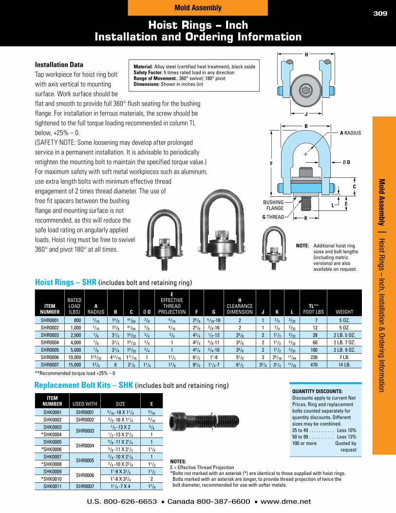
U.S. 800-626-6653 n Canada 800-387-6600 n www.dme.net
309
Hoist Rings – InchInstallation and Ordering Information
iteMnuMber
ratedLoad(Lbs)
aradius b c Ød
eeffective
threadprojection F g
hcLearancedimension J k l
tl**footLbs weight
shr0001 800 7/16 15 /8 41/64 3 /8 9 /16 25 /8 5 /16-18 2 1 3 /4 3 /32 7 5oz .shr0002 1,000 7/16 15 /8 41/64 3 /8 9 /16 25 /8 3 /8-16 2 1 3 /4 3 /32 12 5oz .shr0003 2,500 7/8 31/4 15 /32 3 /4 3 /4 43 /4 1/2-13 35 /8 2 11/2 3 /32 28 2Lb .5oz .shr0004 4,000 7/8 31/4 15 /32 3 /4 1 43 /4 5 /8-11 35 /8 2 11/2 3 /32 60 2Lb .7oz .shr0005 5,000 7/8 31/4 15 /32 3 /4 1 43 /4 3 /4-10 35 /8 2 11/2 3 /32 100 2Lb .9oz .shr0006 10,000 113 /32 413 /16 111/16 1 11/2 61/2 1"-8 51/8 3 25 /16 17/64 230 7Lb .shr0007 15,000 13 /4 6 21/8 11/4 17/8 83 /4 11/4-7 61/2 33 /4 31/4 11/32 470 14Lb .
iteMnuMber usedwith size e
shk0001 shr0001 5 /16-18x11/4 9 /16
shk0002 shr0002 3 /8-16x11/4 9 /16
shk0003shr0003
1/2-13x2 3 /4
*shk0004 1/2-13x21/4 1shk0005
shr00045 /8-11x21/4 1
*shk0006 5 /8-11x21/2 11/4
shk0007shr0005
3 /4-10x21/4 1*shk0008 3 /4-10x23 /4 11/2
shk0009shr0006
1"-8x31/4 11/2
*shk0010 1"-8x33 /4 2shk0011 shr0007 11/4-7x4 17/8
replacementboltkits–shk(includesboltandretainingring)
**recommendedtorqueload+25%–0
notes: e=effectivethreadprojection*boltsnotmarkedwithanasterisk(*)areidenticaltothosesuppliedwithhoistrings .
boltsmarkedwithanasteriskarelonger,toprovidethreadprojectionoftwicetheboltdiameter,recommendedforusewithsoftermetals .
installationdataTap workpiece for hoist ring bolt with axis vertical to mounting surface. Work surface should be flat and smooth to provide full 360° flush seating for the bushing flange. For installation in ferrous materials, the screw should be tightened to the full torque loading recommended in column TL below, +25% – 0. (SAFETY NOTE: Some loosening may develop after prolonged service in a permanent installation. It is advisable to periodically retighten the mounting bolt to maintain the specified torque value.) For maximum safety with soft metal workpieces such as aluminum, use extra length bolts with minimum effective thread engagement of 2 times thread diameter. The use of free fit spacers between the bushing flange and mounting surface is not recommended, as this will reduce the safe load rating on angularly applied loads. Hoist ring must be free to swivel 360° and pivot 180° at all times. note: additionalhoistring
sizesandboltlengths(includingmetricversions)arealsoavailableonrequest .
H
J
Ø D
G THREAD
BUSHING FLANGE
B
F
C
L E
K
A RADIUS
Quantitydiscounts:discountsapplytocurrentnetprices .ringandreplacementboltscountedseparatelyforquantitydiscounts .differentsizesmaybecombined .25to49 . . . . . . . . . . . Less10%50to99 . . . . . . . . . . . Less13%100ormore quotedby request
Mold Assem
bly | Hoist Rings – Inch, Installation & Ordering Information
Mold Assembly
hoistrings–shr(includesboltandretainingring)
Material:alloysteel(certifiedheattreatment),blackoxidesafetyFactor:5timesratedloadinanydirectionrangeofMovement.:360°swivel;180°pivotdimensions:shownininches(in)

U.S. 800-626-6653 n Canada 800-387-6600 n www.dme.net
310
Hoist Rings – Metric
fEaturEs– Pivotsandswivelstocompensatefor
pitch,rollandswaywhenliftingheavyorunbalancedloads.
– High-strengthalloysteelwithminimumtensilestrengthof1,250MPa(125kg/mm2).
– Certifiedheattreatmentwith100%Magnafluxinspection.
– Corrosion-resistantplating.– Maximumoperatingtemperature200°C(392°F).– Safetyfactoris5timestheratedloadinany
direction.*notE– Standardtolerance±0.8mm.– E=theuseofspacersbetweenbushingflange
andmountingsurfaceisnotrecommendedasthiswillreducethesafetyloadrating.
– tL=recommendedtorqueload+25%-0.– P=rated.– W=weight(ofHoistRingAssembly)
caractErísticas– Giraypivoteaparacompensarla
inclinación,elrodajeylaoscilaciónallevantarcargaspesadasosinequilibrio.
– Aleacióndeacerodegranresistenciaconfuerzaelásticamínimade1,250MPa(125kg/mm2).
– TratamientodecalorcertificadoconinspecciónMagnafluxdel100%.
– Enchapadoresistentealacorrosión.– Temperaturamáximadeoperacion:200°C.– Elfactordeseguridades5veceslacarga
calificadaencualquierdireccion.*nota– Toleranciaestándar±0.8mm.– E=elusodeespaciadoresentre
elrebordedelcojineteylasuperficiedemontajenoserecomiendayaqueestoreducirálacalificacióndeseguridaddelacarga.
– tL=cargadetorsiónrecomendada+25%-0.
– P=carganominal.– W=peso.
mErKmaLE– Gleichmäßigesanhebenvonschwerenoder
einseitigenLastendurchDrehgelenkeundAbstandsausgleichung.KeineAbweichungnachderschwerenLastseite.
– LegierterSpezialstahlmitmin.Streckgrenzevon1.250MPa(125Kg/mm2)
– BeglaubigteWärmebehandlungmit100%igerMagnaflux.
– KontrolleKorrosionsbeständigerOberflächenschutz.
– AlleMaterialangabengeltenbiszueinerTemp.bismax.200°C.
– AlleHeberingesindinallenRichtungenmit5-facherSicherheitausgelegt.
*BEmErKunGEn– AllgemeineToleranzen±0.8mm.– E=zwischenFlanschundMontageoberfläche
keineDistanzscheibeeinlegen:dadurchwirddieSicherheitderHebeleistungreduziert.
– tL=empfohleneDrehmomentbelastung.– P=Nennlast.– W=Gewicht.
caractéristiQuEs– Ilspivotentettournentpouramortirle
balancementdeschargeslourdesoudeséquilibrées.Résistentauxchargeslatérales.
– Acieralliéavecunerésistancede1.250MPa(125kg/mm2).
– UnetrempegarantieparuneinspectionMagnafluxde100%.
– Résisteàlacorrosiongrâceàuntraitementdesurface.
– Températuredefonctionnement200°C.– Coefficientdesécurité5:1quellequesoit
l’orientationdelacharge.*notE– Tolérancestandard±0.8mm.– E=L’emploid’unerondellederéglageentre
l’anneauetlasurfaced’appuiestàdéconseiller.Elleréduiraitlecoefficientdesécurité.
– tL=coupledeserrage+25%-0.– P=chargemaximum.– W=Poidsenkg.
caractErísticas– Elessearticulamegiramparacompensar
ainclinação,rolagemebalançodecargaspesadasoudesequilibradas.
– Ligadeaçodealtaresistenciade1.250MPa(125kg/mm2).
– Tratamentoacalor,certificadoporinspeção100%Magnaflux.
– Revestimentoresistenteàcorrosão.– Temperaturamáximaoperacional
de200°C.– Coeficientedesegurançade5vezes
acarganominal,emqualquerdireção.*nota– Toleranciapadrão:±0.8mm.– E=naoserecomendaousodeespaçadores
entreoflangedabuchaeasuperficiedemontagem,poisistoreduziriaovalordacarganominaldesegurança.
– tL=cargarecomendadadetorque+25%-0.
– P=carganominal.– W=peso.
Ø D F
E
A
H
B
180˚
Ø G Ø K
360˚ information KEY:a=u-barinsideradiusb=insideu-barclearanced=u-bardiametere=threadLengthprojectionF=u-barheightg=threaddiameterandpitchh=dimensionoverpinsk=flangediameterMaterial:seefeaturesbelowMax.temp.:200°c(392°f)dimensions:showninmillimeters(mm)
notE: all hoist ring assemblies and replacement kits listed in chart are in stock. (no specials available.)HoW to ordEr: specify item number. omit spaces (spaces are only shown here for easier reading).
hoistringassembLy repLacementkititeM
nuMber a b d e F g h ktl*
(kgm)p*
(kg)w*(kg)
iteMnuMber g
shm0001 10 .9 32 .0 9 .7 12 .5 67 .8 m8x1 .25 46 .7 19 .0 1 .0 400 0 .17 shmr0001 m8x1 .25shm0002 10 .9 30 .0 9 .7 17 .5 67 .8 m10x1 .50 46 .7 19 .0 1 .7 450 0 .17 shmr0002 m10x1 .50shm0003 22 .4 60 .5 19 .0 19 .0 121 .4 m12x1 .75 89 .4 38 .1 3 .8 1050 1 .08 shmr0003 m12x1 .75shm0004 22 .4 56 .5 19 .0 29 .0 121 .4 m16x2 .00 89 .4 38 .1 8 .2 1900 1 .12 shmr0004 m16x2 .00shm0005 22 .4 52 .5 19 .0 34 .0 121 .4 m20x2 .50 89 .4 38 .1 13 .6 2150 1 .19 shmr0005 m20x2 .50shm0006 35 .6 69 .0 25 .4 37 .0 165 .6 m24x3 .00 130 .6 58 .7 31 .0 4200 3 .10 shmr0006 m24x3 .00shm0007 44 .5 107 .4 31 .7 41 .9 221 .7 m30x3 .50 165 .1 81 .0 60 .0 7000 6 .30 shmr0007 m30x3 .50shm0009 57 .2 166 .5 44 .4 63 .5 316 .7 m36x4 .00 217 .2 106 .4 100 .0 11000 15 .50 shmr0009 m36x4 .00shm0010 57 .2 160 .5 44 .4 68 .0 316 .7 m42x4 .50 217 .2 106 .4 100 .0 12500 16 .00 shmr0010 m42x4 .50shm0011 57 .2 154 .5 44 .4 82 .4 316 .7 m48x5 .00 217 .2 106 .4 100 .0 13500 16 .80 shmr0011 m48x5 .00shm0012 76 .2 210 .0 57 .15 101 .6 419 .1 m64x6 .00 297 .6 146 .0 290 .0 22500 40 .0 shmr0012 m64x6 .00
repLacementkitincLudesscrewandretainingring
hoistrings–shM,shMranilloselevadores|olhaisdesuspensãoarticulados|anneauxdelevagearticulés|sicherheitsringschrauben
Mol
d As
sem
bly
| H
oist
Rin
gs –
Met
ricMold Assembly

U.S. 800-626-6653 n Canada 800-387-6600 n www.dme.net
311
Lifting Holes
Mold Assem
bly | Lifting HolesMold Assembly
Lifting Holes can be used to install hoist rings for ease of handling. Mold base can be configured only with Lifting Holes which are appropriate for the specific mold base size. Refer to the preceding pages for a comprehensive selection of hoist rings.
liftingholesLifting holes can be selected up to three per plate edge. They are available in top clamp plate, A-plate, B-plate, support plate, and bottom clamp plate.
Note that for safety reasons, only the recommended hole diameters (or larger) shown in the table are offered.
Diameter _______________
Quantity in each plate ______
Plates with lift holes _______
______________________
______________________
______________________
______________________ (Prints required if not on center)
threadsiZe s tMax.
1/2-13 1 .00 1 .38
5/8-11 1 .25 1 .75
3/4-10 1 .50 2 .00
1"-8 2 .00 2 .62
liftingholediameters
liftingholes
basesiZeplatethickness
0.875 1.375
88-1118 1/2-13unc 1/2-13unc
1123-1524 5/8-11unc 5/8-11unc
1529-1829 5/8-11unc 3/4-10unc
1835-2429 5/8-11unc 1"-8unc
2435 n/a 1"-8unc
S
STAN
DAR
DSHIPPIN
G
5 5-DA
YSHIPPIN
G
7 7-DA
YSHIPPIN
G
11-D
AYSHIPPIN
GForQuotingorordering,speciFy:

U.S. 800-626-6653 n Canada 800-387-6600 n www.dme.net
312
Minimum Recommended Additional Assembly SHCS
Mol
d As
sem
bly
| M
inim
um R
ecom
men
ded
Addi
tiona
l Ass
embl
y SH
CSMold Assembly
NOTeS:1 .bluecolorconfigurationsrequireadditionalassemblyscrews .2 .numbersofadditionalassemblyscrewssuggestedareminimumrequired .3 .nosafetyfactorconsidered .themoldmakerisentirelyresponsibleforthechosenconfiguration .
Mold existing MoldingMachineForce(tons)/MoldopeningForce(lbs.)base aplate totalnuMber 15through400 425 450 475 500 525 550 575 600 625 650siZe thickness oFshcs 3000through80,000 85,000 90,000 95,000 100,000 105,000 110,000 115,000 120,000 125,000 130,000
88 .0875 4 0 +1 +1 +1 +1 +1 +2 +2 +2 +2 +21 .375to5 .875 4 0 0 0 0 0 +1 +1 +1 +1 +1 +2
812 .0875 4 0 +1 +1 +1 +1 +1 +2 +2 +2 +2 +21 .375to5 .875 4 0 0 0 0 0 +1 +1 +1 +1 +1 +2
108 .0875 4 0 +1 +1 +1 +1 +1 +2 +2 +2 +2 +21 .375to5 .875 4 0 0 0 0 0 +1 +1 +1 +1 +1 +2
1012 .0875 4 0 +1 +1 +1 +1 +1 +2 +2 +2 +2 +21 .375to5 .875 4 0 0 0 0 0 +1 +1 +1 +1 +1 +2
1016 .0875 4 0 +1 +1 +1 +1 +1 +2 +2 +2 +2 +21 .375to5 .875 4 0 0 0 0 0 +1 +1 +1 +1 +1 +2
1020 .0875 4 0 +1 +1 +1 +1 +1 +2 +2 +2 +2 +21 .375to5 .875 4 0 0 0 0 0 +1 +1 +1 +1 +1 +2
1112 .0875 4 0 +1 +1 +1 +1 +1 +2 +2 +2 +2 +21 .375to5 .875 4 0 0 0 0 0 +1 +1 +1 +1 +1 +2
1114 .0875 4 0 +1 +1 +1 +1 +1 +2 +2 +2 +2 +21 .375to5 .875 4 0 0 0 0 0 +1 +1 +1 +1 +1 +2
1118 .0875 4 0 +1 +1 +1 +1 +1 +2 +2 +2 +2 +21 .375to5 .875 4 0 0 0 0 0 +1 +1 +1 +1 +1 +2
1123 .0875 8 0 0 0 0 0 0 0 0 0 0 01 .375to5 .875 8 0 0 0 0 0 0 0 0 0 0 0
1212 .0875 4 0 +1 +1 +1 +1 +1 +2 +2 +2 +2 +21 .375to5 .875 4 0 0 0 0 0 +1 +1 +1 +1 +1 +2
1215 .0875 4 0 +1 +1 +1 +1 +1 +2 +2 +2 +2 +21 .375to5 .875 4 0 0 0 0 0 +1 +1 +1 +1 +1 +2
1220 .0875 4 0 +1 +1 +1 +1 +1 +2 +2 +2 +2 +21 .375to5 .875 4 0 0 0 0 0 +1 +1 +1 +1 +1 +2
1223 .0875 8 0 0 0 0 0 0 0 0 0 0 01 .375to5 .875 8 0 0 0 0 0 0 0 0 0 0 0
1315 .0875 4 0 +1 +1 +1 +1 +1 +2 +2 +2 +2 +21 .375to5 .875 4 0 0 0 0 0 +1 +1 +1 +1 +1 +2
1318 .0875 4 0 +1 +1 +1 +1 +1 +2 +2 +2 +2 +21 .375to5 .875 4 0 0 0 0 0 +1 +1 +1 +1 +1 +2
1321 .0875 4 0 +1 +1 +1 +1 +1 +2 +2 +2 +2 +21 .375to5 .875 4 0 0 0 0 0 +1 +1 +1 +1 +1 +2
1323 .0875 8 0 0 0 0 0 0 0 0 0 0 01 .375to5 .875 8 0 0 0 0 0 0 0 0 0 0 0
1326 .0875 8 0 0 0 0 0 0 0 0 0 0 01 .375to5 .875 8 0 0 0 0 0 0 0 0 0 0 0
1329 .0875 8 0 0 0 0 0 0 0 0 0 0 01 .375to5 .875 8 0 0 0 0 0 0 0 0 0 0 0
1518 .0875 4 0 +1 +1 +1 +1 +1 +2 +2 +2 +2 +21 .375to5 .875 4 0 0 0 0 0 +1 +1 +1 +1 +1 +2
1524 .0875 8 0 0 0 0 0 0 0 0 0 0 01 .375to5 .875 8 0 0 0 0 0 0 0 0 0 0 0
1529 .0875 8 0 0 0 0 0 0 0 0 0 0 01 .375to5 .875 8 0 0 0 0 0 0 0 0 0 0 0
1616 .0875 4 0 +1 +1 +1 +1 +1 +2 +2 +2 +2 +21 .375to5 .875 4 0 0 0 0 0 +1 +1 +1 +1 +1 +2
1620 .0875 4 0 +1 +1 +1 +1 +1 +2 +2 +2 +2 +21 .375to5 .875 4 0 0 0 0 0 +1 +1 +1 +1 +1 +2
1623 .0875 8 0 0 0 0 0 0 0 0 0 0 01 .375to5 .875 8 0 0 0 0 0 0 0 0 0 0 0
1626 .0875 8 0 0 0 0 0 0 0 0 0 0 01 .375to5 .875 8 0 0 0 0 0 0 0 0 0 0 0
1629 .0875 8 0 0 0 0 0 0 0 0 0 0 01 .375to5 .875 8 0 0 0 0 0 0 0 0 0 0 0
1635 .0875 12 0 0 0 0 0 0 0 0 0 0 01 .375to5 .875 12 0 0 0 0 0 0 0 0 0 0 0
1724 .0875 8 0 0 0 0 0 0 0 0 0 0 01 .375to5 .875 8 0 0 0 0 0 0 0 0 0 0 0
1729 .0875 8 0 0 0 0 0 0 0 0 0 0 01 .375to5 .875 8 0 0 0 0 0 0 0 0 0 0 0
1818 .0875 4 0 +1 +1 +1 +1 +1 +2 +2 +2 +2 +21 .375to5 .875 4 0 0 0 0 0 +1 +1 +1 +1 +1 +2
1820 .0875 4 0 +1 +1 +1 +1 +1 +2 +2 +2 +2 +21 .375to5 .875 4 0 0 0 0 0 +1 +1 +1 +1 +1 +2
1823 .0875 8 0 0 0 0 0 0 0 0 0 0 01 .375to5 .875 8 0 0 0 0 0 0 0 0 0 0 0
1826 .0875 8 0 0 0 0 0 0 0 0 0 0 01 .375to5 .875 8 0 0 0 0 0 0 0 0 0 0 0
1829 .0875 8 0 0 0 0 0 0 0 0 0 0 01 .375to5 .875 8 0 0 0 0 0 0 0 0 0 0 0
1835 .0875 12 0 0 0 0 0 0 0 0 0 0 01 .375to5 .875 12 0 0 0 0 0 0 0 0 0 0 0
1924 .0875 8 0 0 0 0 0 0 0 0 0 0 01 .375to5 .875 8 0 0 0 0 0 0 0 0 0 0 0
1929 .0875 8 0 0 0 0 0 0 0 0 0 0 01 .375to5 .875 8 0 0 0 0 0 0 0 0 0 0 0
1935 .0875 12 0 0 0 0 0 0 0 0 0 0 01 .375to5 .875 12 0 0 0 0 0 0 0 0 0 0 0
2424 .0875 8 0 0 0 0 0 0 0 0 0 0 01 .375to5 .875 8 0 0 0 0 0 0 0 0 0 0 0
2429 .0875 8 0 0 0 0 0 0 0 0 0 0 01 .375to5 .875 8 0 0 0 0 0 0 0 0 0 0 0
2435 .0875 12 0 0 0 0 0 0 0 0 0 0 01 .375to5 .875 12 0 0 0 0 0 0 0 0 0 0 0
keY: =noadditionalassemblyscrewsrequired =addscrewsasnoted(+) =notavailable/notrecommendedn/a

U.S. 800-626-6653 n Canada 800-387-6600 n www.dme.net
313
Minimum Recommended Additional Assembly SHCS
Mold AssemblyM
old Assembly | M
inimum
Recomm
ended Additional Assembly SHCS
Mold existing MoldingMachineForce(tons)/MoldopeningForce(lbs.)base aplate totalnuMber 675 700 725 750 775 800 825 850 875 900 925 950 975 1000siZe thickness oFshcs 135,000 140,000 145,000 150,000 155,000 160,000 165,000 170,000 175,000 180,000 185,000 190,000 195,000 200,000
88 .0875 4 +4 +4 +4 +4 +4 +4 +4 +4 +4 +4 +4 n/a n/a n/a1 .375to5 .875 4 +2 +2 +2 +2 +4 +4 +4 +4 +4 +4 +4 +4 +4 +4
812 .0875 4 +4 +4 +4 +4 +4 +4 +4 +4 +4 +4 +4 n/a n/a n/a1 .375to5 .875 4 +2 +2 +2 +2 +4 +4 +4 +4 +4 +4 +4 +4 +4 +4
108 .0875 4 +4 +4 +4 +4 +4 +4 +4 +4 +4 +4 +4 n/a n/a n/a1 .375to5 .875 4 +2 +2 +2 +2 +4 +4 +4 +4 +4 +4 +4 +4 +4 +4
1012 .0875 4 +4 +4 +4 +4 +4 +4 +4 +4 +4 +4 +4 n/a n/a n/a1 .375to5 .875 4 +2 +2 +2 +2 +4 +4 +4 +4 +4 +4 +4 +4 +4 +4
1016 .0875 4 +4 +4 +4 +4 +4 +4 +4 +4 +4 +4 +4 n/a n/a n/a1 .375to5 .875 4 +2 +2 +2 +2 +4 +4 +4 +4 +4 +4 +4 +4 +4 +4
1020 .0875 4 +4 +4 +4 +4 +4 +4 +4 +4 +4 +4 +4 n/a n/a n/a1 .375to5 .875 4 +2 +2 +2 +2 +4 +4 +4 +4 +4 +4 +4 +4 +4 +4
1112 .0875 4 +4 +4 +4 +4 +4 +4 +4 +4 +4 +4 +4 n/a n/a n/a1 .375to5 .875 4 +2 +2 +2 +2 +4 +4 +4 +4 +4 +4 +4 +4 +4 +4
1114 .0875 4 +4 +4 +4 +4 +4 +4 +4 +4 +4 +4 +4 n/a n/a n/a1 .375to5 .875 4 +2 +2 +2 +2 +4 +4 +4 +4 +4 +4 +4 +4 +4 +4
1118 .0875 4 +4 +4 +4 +4 +4 +4 +4 +4 +4 +4 +4 n/a n/a n/a1 .375to5 .875 4 +2 +2 +2 +2 +4 +4 +4 +4 +4 +4 +4 +4 +4 +4
1123 .0875 8 0 0 0 0 0 0 0 0 0 0 0 +2 +2 +21 .375to5 .875 8 0 0 0 0 0 0 0 0 0 0 0 0 0 0
1212 .0875 4 +4 +4 +4 +4 +4 +4 +4 +4 +4 +4 +4 +6 +6 +61 .375to5 .875 4 +2 +2 +2 +2 +4 +4 +4 +4 +4 +4 +4 +4 +4 +4
1215 .0875 4 +4 +4 +4 +4 +4 +4 +4 +4 +4 +4 +4 +6 +6 +61 .375to5 .875 4 +2 +2 +2 +2 +4 +4 +4 +4 +4 +4 +4 +4 +4 +4
1220 .0875 4 +4 +4 +4 +4 +4 +4 +4 +4 +4 +4 +4 +6 +6 +61 .375to5 .875 4 +2 +2 +2 +2 +4 +4 +4 +4 +4 +4 +4 +4 +4 +4
1223 .0875 8 0 0 0 0 0 0 0 0 0 0 0 +2 +2 +21 .375to5 .875 8 0 0 0 0 0 0 0 0 0 0 0 0 0 0
1315 .0875 4 +4 +4 +4 +4 +4 +4 +4 +4 +4 +4 +4 +6 +6 +61 .375to5 .875 4 +2 +2 +2 +2 +4 +4 +4 +4 +4 +4 +4 +4 +4 +4
1318 .0875 4 +4 +4 +4 +4 +4 +4 +4 +4 +4 +4 +4 +6 +6 +61 .375to5 .875 4 +2 +2 +2 +2 +4 +4 +4 +4 +4 +4 +4 +4 +4 +4
1321 .0875 4 +4 +4 +4 +4 +4 +4 +4 +4 +4 +4 +4 +6 +6 +61 .375to5 .875 4 +2 +2 +2 +2 +4 +4 +4 +4 +4 +4 +4 +4 +4 +4
1323 .0875 8 0 0 0 0 0 0 0 0 0 0 0 +2 +2 +21 .375to5 .875 8 0 0 0 0 0 0 0 0 0 0 0 0 0 0
1326 .0875 8 0 0 0 0 0 0 0 0 0 0 0 +2 +2 +21 .375to5 .875 8 0 0 0 0 0 0 0 0 0 0 0 0 0 0
1329 .0875 8 0 0 0 0 0 0 0 0 0 0 0 +2 +2 +21 .375to5 .875 8 0 0 0 0 0 0 0 0 0 0 0 0 0 0
1518 .0875 4 +4 +4 +4 +4 +4 +4 +4 +4 +4 +4 +4 +6 +6 +61 .375to5 .875 4 +2 +2 +2 +2 +4 +4 +4 +4 +4 +4 +4 +4 +4 +4
1524 .0875 8 0 0 0 0 0 0 0 0 0 0 0 +2 +2 +21 .375to5 .875 8 0 0 0 0 0 0 0 0 0 0 0 0 0 0
1529 .0875 8 0 0 0 0 0 0 0 0 0 0 0 +2 +2 +21 .375to5 .875 8 0 0 0 0 0 0 0 0 0 0 0 0 0 0
1616 .0875 4 +4 +4 +4 +4 +4 +4 +4 +4 +4 +4 +4 +6 +6 +61 .375to5 .875 4 +2 +2 +2 +2 +4 +4 +4 +4 +4 +4 +4 +4 +4 +4
1620 .0875 4 +4 +4 +4 +4 +4 +4 +4 +4 +4 +4 +4 +6 +6 +61 .375to5 .875 4 +2 +2 +2 +2 +4 +4 +4 +4 +4 +4 +4 +4 +4 +4
1623 .0875 8 0 0 0 0 0 0 0 0 0 0 0 +2 +2 +21 .375to5 .875 8 0 0 0 0 0 0 0 0 0 0 0 0 0 0
1626 .0875 8 0 0 0 0 0 0 0 0 0 0 0 +2 +2 +21 .375to5 .875 8 0 0 0 0 0 0 0 0 0 0 0 0 0 0
1629 .0875 8 0 0 0 0 0 0 0 0 0 0 0 +2 +2 +21 .375to5 .875 8 0 0 0 0 0 0 0 0 0 0 0 0 0 0
1635 .0875 12 0 0 0 0 0 0 0 0 0 0 0 0 0 01 .375to5 .875 12 0 0 0 0 0 0 0 0 0 0 0 0 0 0
1724 .0875 8 0 0 0 0 0 0 0 0 0 0 0 +2 +2 +21 .375to5 .875 8 0 0 0 0 0 0 0 0 0 0 0 0 0 0
1729 .0875 8 0 0 0 0 0 0 0 0 0 0 0 +2 +2 +21 .375to5 .875 8 0 0 0 0 0 0 0 0 0 0 0 0 0 0
1818 .0875 4 +4 +4 +4 +4 +4 +4 +4 +4 +4 +4 +4 +6 +6 +61 .375to5 .875 4 +2 +2 +2 +2 +4 +4 +4 +4 +4 +4 +4 +4 +4 +4
1820 .0875 4 +4 +4 +4 +4 +4 +4 +4 +4 +4 +4 +4 +6 +6 +61 .375to5 .875 4 +2 +2 +2 +2 +4 +4 +4 +4 +4 +4 +4 +4 +4 +4
1823 .0875 8 0 0 0 0 0 0 0 0 0 0 0 +2 +2 +21 .375to5 .875 8 0 0 0 0 0 0 0 0 0 0 0 0 0 0
1826 .0875 8 0 0 0 0 0 0 0 0 0 0 0 +2 +2 +21 .375to5 .875 8 0 0 0 0 0 0 0 0 0 0 0 0 0 0
1829 .0875 8 0 0 0 0 0 0 0 0 0 0 0 +2 +2 +21 .375to5 .875 8 0 0 0 0 0 0 0 0 0 0 0 0 0 0
1835 .0875 12 0 0 0 0 0 0 0 0 0 0 0 0 0 01 .375to5 .875 12 0 0 0 0 0 0 0 0 0 0 0 0 0 0
1924 .0875 8 0 0 0 0 0 0 0 0 0 0 0 +2 +2 +21 .375to5 .875 8 0 0 0 0 0 0 0 0 0 0 0 0 0 0
1929 .0875 8 0 0 0 0 0 0 0 0 0 0 0 +2 +2 +21 .375to5 .875 8 0 0 0 0 0 0 0 0 0 0 0 0 0 0
1935 .0875 12 0 0 0 0 0 0 0 0 0 0 0 0 0 01 .375to5 .875 12 0 0 0 0 0 0 0 0 0 0 0 0 0 0
2424 .0875 8 0 0 0 0 0 0 0 0 0 0 0 +2 +2 +21 .375to5 .875 8 0 0 0 0 0 0 0 0 0 0 0 0 0 0
2429 .0875 8 0 0 0 0 0 0 0 0 0 0 0 +2 +2 +21 .375to5 .875 8 0 0 0 0 0 0 0 0 0 0 0 0 0 0
2435 .0875 12 0 0 0 0 0 0 0 0 0 0 0 0 0 01 .375to5 .875 12 0 0 0 0 0 0 0 0 0 0 0 0 0 0
NOTeS:1 .bluecolorconfigurationsrequireadditionalassemblyscrews .2 .numbersofadditionalassemblyscrewssuggestedareminimumrequired .3 .nosafetyfactorconsidered .themoldmakerisentirelyresponsibleforthechosenconfiguration .
keY: =noadditionalassemblyscrewsrequired =addscrewsasnoted(+) =notavailable/notrecommendedn/a

U.S. 800-626-6653 n Canada 800-387-6600 n www.dme.net
Quick-Change™ Components for Mold Frames & Inserts
MUD® Quick-Change frames and companion insert mold series are available with a full range of components. These components permit tailoring MUD frames and insert molds to every injection molding machine up to 500 tons. This makes the cost-saving benefits and time-saving advantages of the Master Unit Die Concept available to virtually every mold maker and plastic molder in the industry.
See the MUD Quick-Change Systems catalog for all of the standard parts installed in the MUD basic Quick-Change frames and companion insert molds. U, H and Double H frame components include sprue bushings, locating rings and guide posts. Components for T style and standard style insert molds include leader pins and bushings, ejector plates and ear plates.
Customize MUD frames and insert molds with a full range of components
Mol
d As
sem
bly
| M
UD Q
uick
-Cha
nge
Com
pone
nts
for M
old
Fram
es &
Inse
rts
MUD Quick-Change™ Components
Mold Assembly314

U.S. 800-626-6653 n Canada 800-387-6600 n www.dme.net
315
D-M-E: Your Complete Mold Technologies Provider
D-M-E Mold Technology CatalogsD-M
-E Mold Technology Catalogs | D-M
-E: Your Complete M
old Technologies Provider
checkoutallofthed-M-eMoldtechnologycatalogsandyou’llseewhywe’reanessentialresourcetothousandsofcustomersworldwide!
d-M-eMoldbases&platesChoose from the world’s widest selection of mold bases from uniquely featured, off-the-shelf solutions to full-featured, custom-configured offerings. An array of standard and specially machined mold plate sizes gives you unlimited options.
d-M-ehotrunnersystemsMoldmakers, molders and mold designers worldwide look to the D-M-E Hot Runner Systems Catalog for essential hot runner solutions. From best-in-class components to complete, fully-functioning hot half systems, D-M-E has the broadest range of hot runner products and services.
d-M-eequipmentandsuppliesFrom high-speed cutting tools and finishing and polishing systems to a vast array of maintenance, repair and operation-related products, the D-M-E Equipment and Supplies Catalog is an invaluable resource for mold technology professionals.
MudQuick-changesystemsFromd-M-eReduce downtime by as much as 75 percent with an innovative approach to fast production changeovers. Master Unit Die is the leader in quick-change systems and the MUD Catalog offers many systems that will maximize your production volume.
d-M-econtrolsystemsPowerful. Flexible. Affordable. That’s what molders want from today’s generation of hot runner, valve gate, and process controls, and D-M-E delivers with a broad line of controllers sure to fit the most demanding application.
catalog: 308 Pages catalog: 156 Pages
catalog: 76 Pagescatalog: 174 Pages
catalog: 76 Pages
d-M-etechnicalservicesFrom powerful, online resources available 24/7, to our team of trained, experienced experts committed to helping customers achieve maximum productivity, reliable operation, and better performance, D-M-E’s goal is simple: to be an essential resource for your molding challenges every step of the way.catalog: 68 Pages

worldheadquartersd-M-ecompany29111 Stephenson HighwayMadison Heights, MI 48071800-626-6653 toll-free tel248-398-6000 tel888-808-4363 toll-free faxwww.dme.net [email protected] e-mail
d-M-eofcanada,ltd.6210 Northwest DriveMississauga, Ontario Canada L4V 1J6800-387-6600 toll-free tel 905-677-6370 tel800-461-9965 toll-free [email protected] e-mail
d-M-eeuropec.v.b.a.Industriepark NoordB-2800 Mechelen Belgium32-15-215011 tel 32-15-218235 [email protected] e-mail
D-M-E, an essential resource to the customers it serves worldwide, offers the industry’s broadest range of market-leading products, unsurpassed knowledge and expertise, a global logistics infrastructure that ensures speed and accuracy, and a support organization unrivaled for its ability to assist customers when and where they need it. A complete line of hot runner systems, control systems, mold bases, MUD quick-change mold systems, mold components, moldmaking and molding equipment supplies, and technical services helps customers compete every step of the way.
©copyright2008d-m-ecompanyallrightsreserved .a Milacron Company printedinu .s .a .
d-M
-e
Moldtechnologycatalogs
www.dme.net
MOLD TECHNOLOGYCATALOGS
© Copyright 2008 D-M-E Company All Rights Reserved. Printed in the U.S.A.
alsoavailableoncdroM
dow
nloa
dd-M
-ecadFilesatwww
.dme.net
alsoavailableoncdroM