Engine Components eBook.pptx
104
(Including Procedures for Inspection and Calibration) www.marineinsight.com
-
Upload
khangminh22 -
Category
Documents
-
view
0 -
download
0
Transcript of Engine Components eBook.pptx
(Including Procedures for Inspection and Calibration)
www.marineinsight.com
A Guide to 2-Stroke Marine Engine Components Publication date: December 2013 Author: Chief Engineer- Bimal Roy; Second Engineer- Anish Wankhede www.marineinsight.com Editor: Raunek Kantharia Design: Anish Wankhede © Copyright 2013 Marine Insight NOTICE OF RIGHTS All rights reserved. No part of this book may be rewritten, reproduced, stored in a retrieval system, transmitted or distributed in any form or means, without prior written permission of the publisher. NOTICE OF LIABILITY The authors and editors have made every effort possible to ensure the accuracy of the information provided in the book. Neither the authors and Marine Insight, nor editors or distributors, will be held liable for any damages caused either directly or indirectly by the instructions contained in this book, or the equipment, tools, or methods described herein.
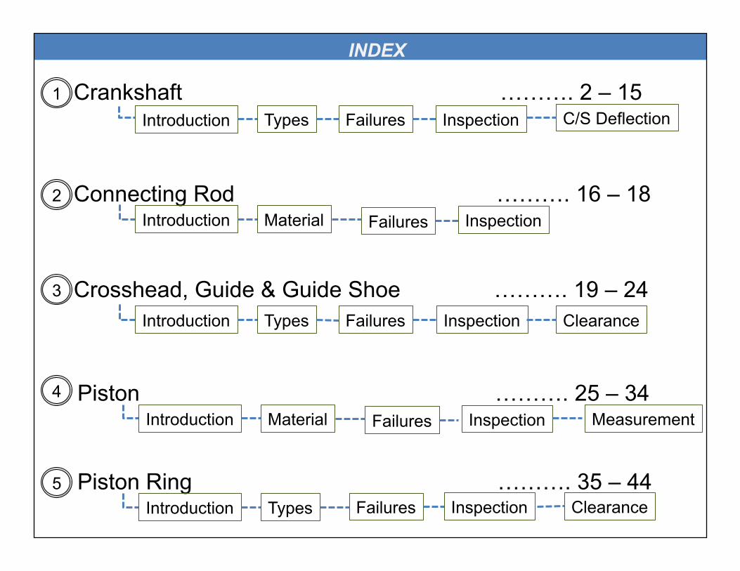
Crankshaft ………. 2 – 15 Introduction Types Failures Inspection C/S Deflection
Connecting Rod ………. 16 – 18 Introduction Material Failures Inspection
Crosshead, Guide & Guide Shoe ………. 19 – 24 Introduction Types Failures Inspection Clearance
Piston ………. 25 – 34 Introduction Material Failures Inspection
Piston Ring ………. 35 – 44 Introduction Types Failures Inspection Clearance
Measurement
1
2
3
4
5
INDEX

Liner ………. 45 – 55 Introduction Types Failures Inspection Calibration
Cylinder Head ………. 56 – 60 Introduction Types Failures Inspection
Exhaust Valve ………. 61 – 70 Introduction Types Failures Inspection Clearances
Engine Bearing ………. 71 – 87 Main Crosshead
Miscellaneous ………. 88 – 99 Camshaft Fuel Pumps
Crankpin Thrust
6
7
8
9
10
INDEX
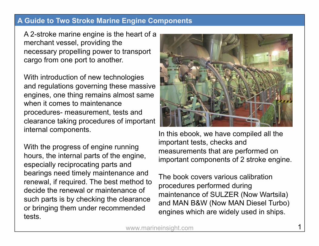
A 2-stroke marine engine is the heart of a merchant vessel, providing the necessary propelling power to transport cargo from one port to another. With introduction of new technologies and regulations governing these massive engines, one thing remains almost same when it comes to maintenance procedures- measurement, tests and clearance taking procedures of important internal components. With the progress of engine running hours, the internal parts of the engine, especially reciprocating parts and bearings need timely maintenance and renewal, if required. The best method to decide the renewal or maintenance of such parts is by checking the clearance or bringing them under recommended tests.
A Guide to Two Stroke Marine Engine Components
In this ebook, we have compiled all the important tests, checks and measurements that are performed on important components of 2 stroke engine. The book covers various calibration procedures performed during maintenance of SULZER (Now Wartsila) and MAN B&W (Now MAN Diesel Turbo) engines which are widely used in ships.
1 www.marineinsight.com

1

Crankshaft is the backbone of a 2-stroke engine. Technically, it’s a long and heavy part which undergoes severe fluctuating loads because of the gas pressure generated in the combustion chamber and high bending and torsional loads from heavy moving objects (piston, connecting rod etc.) The crankshaft is built such that the crank angle of one unit lies at an angle
A Guide to Two Stroke Marine Engine Components
different than that of the adjacent unit. The difference in angles depends on the number of units and strokes of the engine.
Types of Crankshaft Following are four main types of crankshafts used in marine engines depending on the construction methods: Fully Forged: In this method, the full crankshaft is a single piece, forged in a casting. The disadvantage of such type of crankshaft is the chance of twisting or bending. Fully Built: In this type, all the components of the crankshaft i.e. crank pin web and journal pin are manufactured separately in steel casting. They are then 3 www.marineinsight.com

shrink-fitted together to form a single unit. Semi Built: Instead of all components, only journal pin and crank throw are manufactured separately and then shrink-fitted as a unit. This type of crankshaft has better fatigue resistance and grain strength. Moreover,
A Guide to Two Stroke Marine Engine Components
less number of shrink-fits are used and it is cheaper than the fully built crankshaft. Fully Welded: As the name suggests, the crankshaft is built by continuous feed submerged arc welding for joining journal pin and webs.
4
Fully Built Crankshaft
Semi-Built Crankshaft
www.marineinsight.com
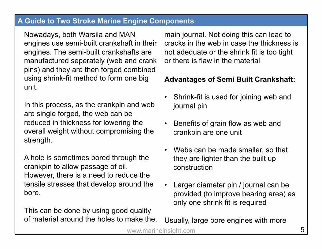
Nowadays, both Warsila and MAN engines use semi-built crankshaft in their engines. The semi-built crankshafts are manufactured seperately (web and crank pins) and they are then forged combined using shrink-fit method to form one big unit. In this process, as the crankpin and web are single forged, the web can be reduced in thickness for lowering the overall weight without compromising the strength. A hole is sometimes bored through the crankpin to allow passage of oil. However, there is a need to reduce the tensile stresses that develop around the bore. This can be done by using good quality of material around the holes to make the.
A Guide to Two Stroke Marine Engine Components
main journal. Not doing this can lead to cracks in the web in case the thickness is not adequate or the shrink fit is too tight or there is flaw in the material Advantages of Semi Built Crankshaft: • Shrink-fit is used for joining web and
journal pin • Benefits of grain flow as web and
crankpin are one unit • Webs can be made smaller, so that
they are lighter than the built up construction
• Larger diameter pin / journal can be provided (to improve bearing area) as only one shrink fit is required
Usually, large bore engines with more 5 www.marineinsight.com
than 5 or 6 cylinders have crankshafts in two parts. This helps during maintenance work and reduces stresses. This type of crankshaft is coupled at the center and provided with generous radius at the flange.
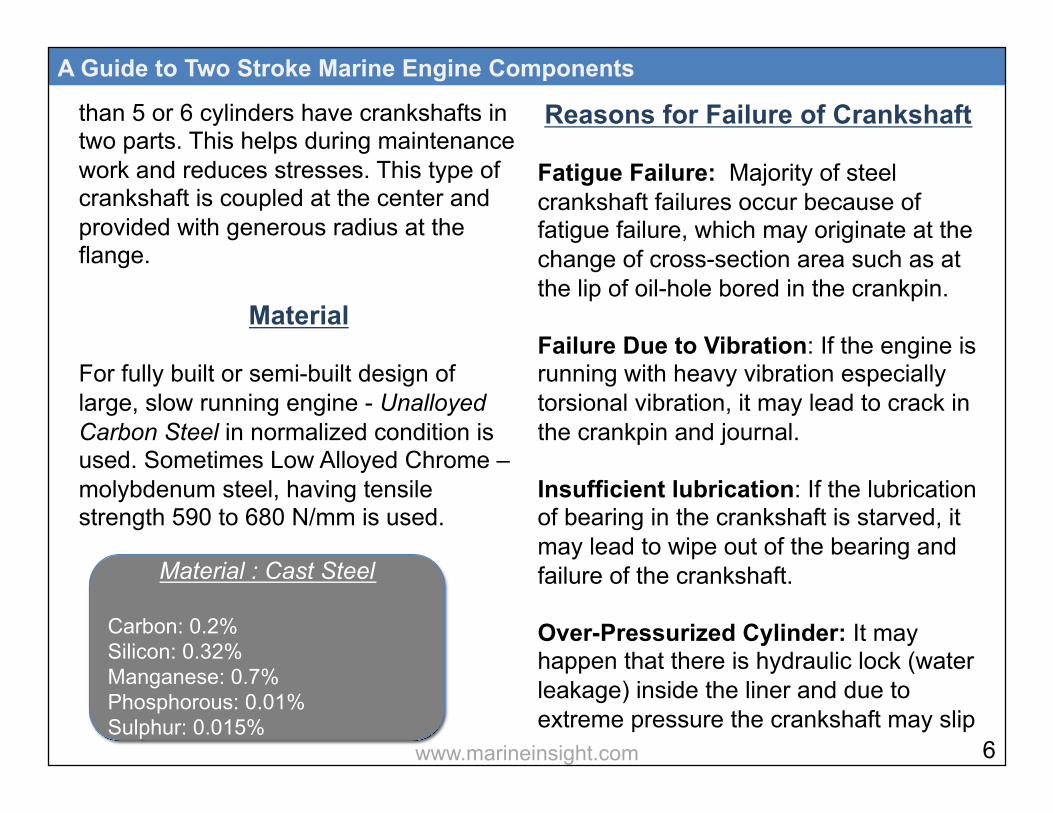
Material For fully built or semi-built design of large, slow running engine - Unalloyed Carbon Steel in normalized condition is used. Sometimes Low Alloyed Chrome – molybdenum steel, having tensile strength 590 to 680 N/mm is used.
A Guide to Two Stroke Marine Engine Components
Reasons for Failure of Crankshaft Fatigue Failure: Majority of steel crankshaft failures occur because of fatigue failure, which may originate at the change of cross-section area such as at the lip of oil-hole bored in the crankpin. Failure Due to Vibration: If the engine is running with heavy vibration especially torsional vibration, it may lead to crack in the crankpin and journal. Insufficient lubrication: If the lubrication of bearing in the crankshaft is starved, it may lead to wipe out of the bearing and failure of the crankshaft. Over-Pressurized Cylinder: It may happen that there is hydraulic lock (water leakage) inside the liner and due to extreme pressure the crankshaft may slip
6
Material : Cast Steel Carbon: 0.2% Silicon: 0.32% Manganese: 0.7% Phosphorous: 0.01% Sulphur: 0.015%
www.marineinsight.com

or even bent (if safety valve of that unit is not working). Cracks: Cracks can develop at the fillet between the journal and the web, particularly between the position corresponding to 10 o’clock and 2 o’clock when the piston is at T.D.C. Reasons for Crankshaft Misalignment: Crankshaft is a massive component when all its parts are assembled together in the marine engine. Initially, the complete crankshaft is aligned in a straight line (Connection drawn from the center of the crankshaft makes a straight line) before setting it on the top of main bearings. But with time due to various factors, the straight line may deviate and misalign.
A Guide to Two Stroke Marine Engine Components
A degree of misalignment within limit is acceptable but if the value goes beyond that rated by the manufacturer; it may lead to damage or even breakage of the crankshaft. Following are the reasons for misalignment of crankshaft- • Damage or wipe-out of the main
bearing
• Loose engine foundation bolt leading to vibrations
• Deformation of ship’s hull
• Cracks in the bearing saddle
• Loose main bearing bolt, leading to damage of main bearing
7 www.marineinsight.com
• Very high bending moment on the crankshaft due to excessive force from the piston assembly
• Grounding of the ship
• Crankcase explosion or fire
• A defective or worn out stern tube or intermediate shaft bearings
• Loose/ broken chokes in foundation
• Cracked Bearing pockets
• Bedplate deformed – transverse girder damaged
• Slacken tie bolts or broken
• Weakening of structure due to corrosion
A Guide to Two Stroke Marine Engine Components
Crankshaft Inspection Crankshaft should be frequently inspected to make sure that no cracks have been developed. It should never be secured or lifted without proper support along its length as its rigidity is mainly due to the support of the main bearings in the bedplates of the engine. Crankshaft should be checked for cracks giving special attention to the points mentioned below: • Working surface of journals and pins
to be examined for signs of corrosion or pitting caused by water or acid contamination of the lubricating oil
• Shrink-fit reference marks should be checked
8 www.marineinsight.com

• Crank web deflection to be taken
• Tightness of coupling bolts should be checked
• Locking of coupling bolts to be examined
• Tightness of oil pipes and bearing locking devices should be checked
• Oil holes must be cleaned
• Balance weights securing arrangement to be checked and inspection for cracks to be carried out
• Plug in oil holes and check oil tightness
• Check crankpin bearing and main bearing clearances
A Guide to Two Stroke Marine Engine Components
Crankshaft Deflection Crankshaft deflection is an important methods to check the condition of the main bearing and alignment of the crankshaft.
9 www.marineinsight.com

The crankshaft deflection results will also highlight the condition of the following: • Wear down in the lower half of the
main bearing or its saddle
• Structural hull deformation in and around engine room area due to imporper loading, ballasting and grounding
• Slackness in main engine foundation bolts, wear down of chalks, or shifted bedplate
Before taking the crankshaft deflection, following things to be kept in mind: • As the readings taken are compared
with original (initial) readings, ensure that the vessel is in light-ship condition
A Guide to Two Stroke Marine Engine Components
• Stop main enginen lube oil pump
• Do not take crankshaft reading if the vessel is out of water (Dry dock)
• Do not carry out crankshaft deflection if any of the running gear is removed for maintenance
• Ensure that the outside sea and wind
conditions are calm • Ship is at zero list or trim • Reading must not be taken if the
cargo operation is going on
• Before rotating the crankshaft for reading by turning gear, ensure that the indicating cocks are in open position
10 www.marineinsight.com
• Rotate the crankshaft via turning gear in the working direction of the engine
• Ease the pressure in the turning gear assembly by slightly pressing the ‘reverse turn’ direction button in the turning gear remote
• Ensure tie rod bolts are correctly
tightened
• If the vessel is at tropical area with sunshine (high temperature) on one side of the vessel, taking measurement should be avoided as thermal deformation of hull and structure will affect the readings
• All holding down bolts should be in
proper tight condition • Immobalisation certificate must be
A Guide to Two Stroke Marine Engine Components
taken from port and crankcase should be properly ventilated before entry Crankshaft Deflection Procedure: When taking crankshaft deflection, keep the deflection gauge over the engine for sometime so that it adjusts to the surrouding temperature of the main engine. The crank web of each unit is provided with a punch mark where the deflection gauge is to be set for measurement. Clean the oil from the web and place the gauge in the marks. For additional precaution, tie the gauge with a thin rope to avoid it from falling into the sump. Turn the engine to BDC and then set the guage to “0” with slight pre-tension
11 www.marineinsight.com
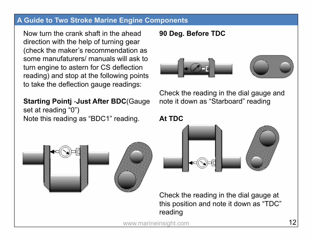
Now turn the crank shaft in the ahead direction with the help of turning gear (check the maker’s recommendation as some manufaturers/ manuals will ask to turn engine to astern for CS deflection reading) and stop at the following points to take the deflection gauge readings: Starting Pointj -Just After BDC(Gauge set at reading “0”) Note this reading as “BDC1” reading.
A Guide to Two Stroke Marine Engine Components
90 Deg. Before TDC Check the reading in the dial gauge and note it down as “Starboard” reading At TDC Check the reading in the dial gauge at this position and note it down as “TDC” reading
12 www.marineinsight.com

90 Deg. After TDC Just before BDC Note down the dial gauge reading as “Port” reading. Just Before BDC Note down this reading as “BDC 2”
A Guide to Two Stroke Marine Engine Components
The two readings taken either side of BDC i.e reading “BDC1 and “BDC2” are averaged to get the BDC reading. The deflection gauge reading should be recorded in the gauging sheet (provided with the ebook). • TDC - BDC readings give vertical
deflection, and
• Port - Starboard readings give horizontal deflection of the crankshaft.
The recorded readings are then interpreted in a graph and compared to the original graph to point out the worn-out or defective bearings which are causing crankshaft misalignment.
Last unit reading might be higher due to overhanging of the flywheel
13 www.marineinsight.com
A Guide to Two Stroke Marine Engine Components
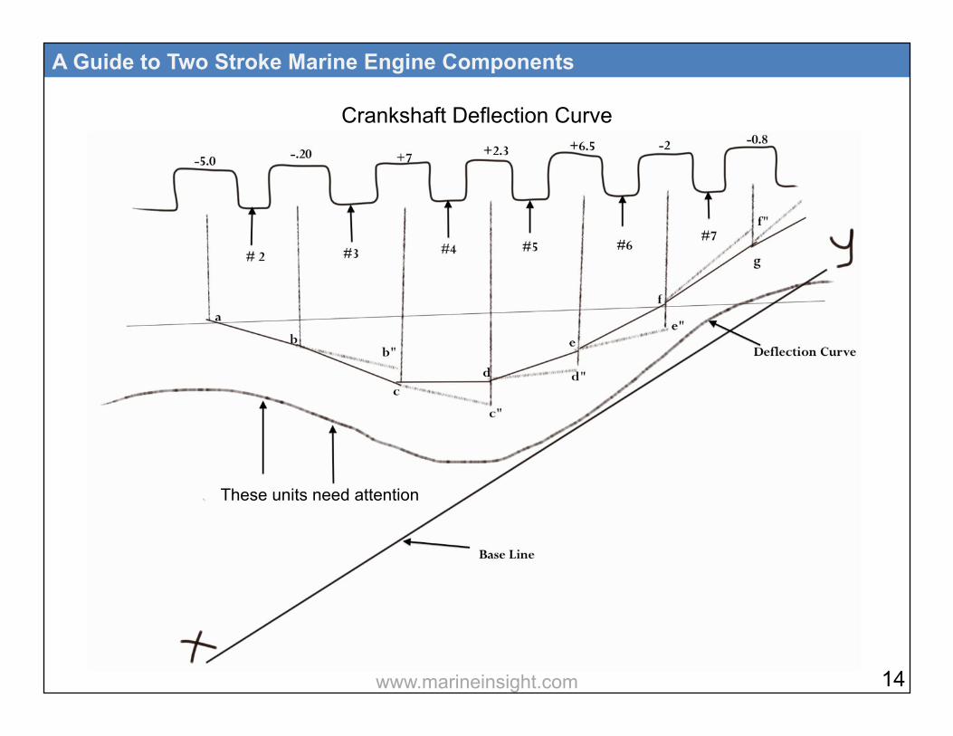
Crankshaft Deflection Curve
These units need attention
14 www.marineinsight.com

Curve Plotting: A straight line is drawn parallel to crankshaft and then perpendicular lines from each unit are drawn towards this parallel line. The values derived after taking the crankshaft deflection of each unit is noted above every unit of crank web in the above graph. Plot the distance -5.0 mm, which is the first deflection reading, downwards (downwards for negative value and upwards for positive value) from the reference line on the center line of unit and make the line “ab” which is at an angle proportional to the deflection at ‘a’. This line is extended to intersect the center line of the next unit. The next step
A Guide to Two Stroke Marine Engine Components
is to measure the deflection from this point of intersection and join the point from the previous point, which gives rise to the line “bc”. This step is repeated till the last unit. Plot a smooth curve between these points and compare the position of this curve with respect to the base line XY. In the above graph, the curve drawn from the readings of bearings of unit 1 and 2 is are too far away from the base line as compared to rest of the curve and hence need attention.
15 www.marineinsight.com

2
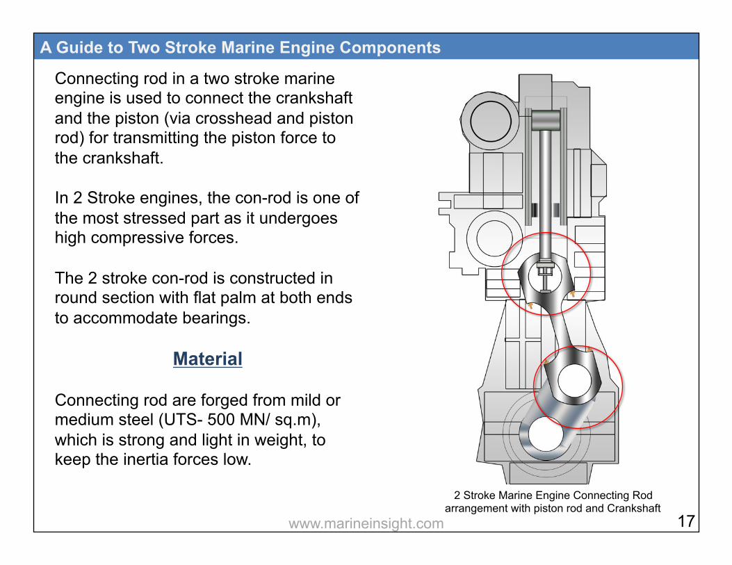
Connecting rod in a two stroke marine engine is used to connect the crankshaft and the piston (via crosshead and piston rod) for transmitting the piston force to the crankshaft. In 2 Stroke engines, the con-rod is one of the most stressed part as it undergoes high compressive forces. The 2 stroke con-rod is constructed in round section with flat palm at both ends to accommodate bearings.
Material Connecting rod are forged from mild or medium steel (UTS- 500 MN/ sq.m), which is strong and light in weight, to keep the inertia forces low.
A Guide to Two Stroke Marine Engine Components
2 Stroke Marine Engine Connecting Rod arrangement with piston rod and Crankshaft
17 www.marineinsight.com
Reasons Behind Failure of Connecting Rod
As connecting rod is one of the most stessed components in the marine engine, the failure of connecting rod can be due to: • Very high peak pressure inside the
combustion chamber
• Water inside the cylinder while starting the engine
• Crankpin bearing seizure
• Piston or liner seizure due to lack of lubrication or cooling
• Wrong or loose assembly of connecting rod parts
A Guide to Two Stroke Marine Engine Components
Inspection of Con- Rod When doing the inspection of connecting rod, check for the following: • Cracks in the body of connecting rod
• Connecting rod bolts locking arrangement
• Fracture sign in the body
• Buckling of con-rod
18 www.marineinsight.com

3

Crosshead is attached on the upper part of the connecting rod, which connects the con-rod to the piston rod. The guide and the guide shoe runs on the guide rail to support the crosshead pin and to transfer the side thrust of the crosshead to the engine frame. In some old MAN B&W engines and SULZER RND engines, the piston rod passes through a bore in the crosshead and is bolted from the bottom by means of fine threaded nut. In the new design engines such as MAN SMC/ ME and SULZER RTA/ RT flex, the pison rod palm rests on the crosshead flat surface and four hydraulic bolts are used to tie them together. Guide and guide shoe, along with the connecting rod and crosshead, is an
A Guide to Two Stroke Marine Engine Components
important arrangement as the guide directs the guide shoe in reciprocating direction while absorbing the side thrust produced during the motion of the connecting rod. The guide comprises of guide rail (normally integrated/ bolted with the frame) and guide plates, in which, the guide shoe moves up and down.
20 www.marineinsight.com

Material Crosshead: The crosshead bracket is made up of steel casting in which the pin is shrink-fitted to form complete crosshead unit. Crosshead pin- The crosshead pin is made of high strength nitride steel with excellent surface finish which helps in lubrication of crosshead bearing. Guide Plate: Guide plates are made up of cast iron. Sometimes shims are provided for adjustment of guide plates. Guide Shoes: Guide shoes which are accommodated in the A frame, and fitted both forward and aft of crosshead, are normally made of white metal lining with slipper surface. Lubricating oil grooves are cut into the guides for lubrication.
A Guide to Two Stroke Marine Engine Components
The crosshead pin is fitted with a loose fitting pin which allows a small degree of movement (about 1mm) between the guide shoe and the pin, giving better alignment. Also, two long studs pass through the crosshead pins horizontally and secure the pins to the brackets at the back. The telescopic pipes for lubricating and cooling oil are supported by the crosshead brackets at the front of the piston rods and the guide shoes are bolted to these brackets at the back. Each side crosshead is made up of steel casting, into which the crosshead pin is shrunk fitted, with the side rod screwed into the top of the casting. 21 www.marineinsight.com

Inspection
• Check the lubrication oil flow in the crosshead
• Check the telescopic or articulated pipe connections and securing arrangement
• Check for any leakage from telescopic pipe
• Check all the locking plates and locking screw in the crosshead securing nuts
• Check the near edge area of piston palm over crosshead for any distortion
• Check clearance of crosshead bearing
• Check guide and rail clearances
A Guide to Two Stroke Marine Engine Components
• Check for any squeezed out white metal between bearing and pin
• Check the lube oil hole between crosshead and piston rod for chocking or deposits
• Check for scratching marks on the
crosshead pin
• Check the surface finish of crosshead pin
• Check the surface of guide rail for any breakage of rail path
• Check condition of guides for any white metal flakes
• Check the oil wedges provided in the guide shoes for deposits and any breakage
22 www.marineinsight.com
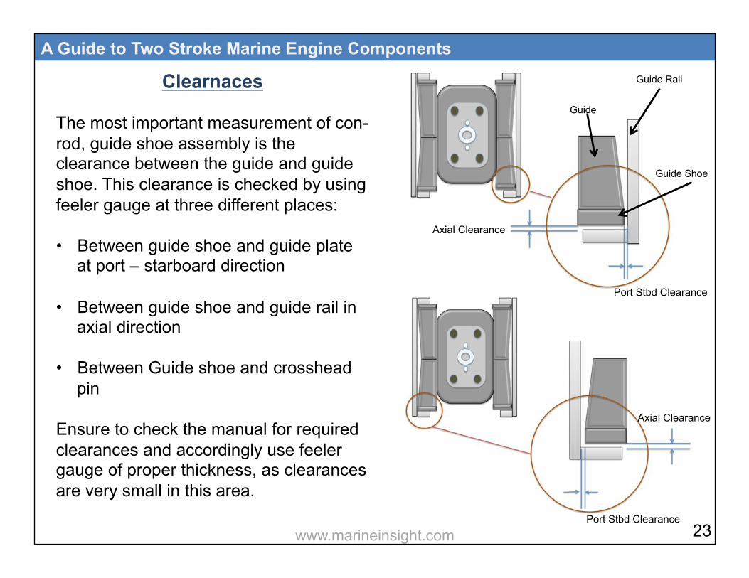
Clearnaces The most important measurement of con-rod, guide shoe assembly is the clearance between the guide and guide shoe. This clearance is checked by using feeler gauge at three different places: • Between guide shoe and guide plate
at port – starboard direction • Between guide shoe and guide rail in
axial direction • Between Guide shoe and crosshead
pin Ensure to check the manual for required clearances and accordingly use feeler gauge of proper thickness, as clearances are very small in this area.
A Guide to Two Stroke Marine Engine Components Guide Rail
Guide
Guide Shoe
Axial Clearance
Port Stbd Clearance
Port Stbd Clearance
Axial Clearance
23 www.marineinsight.com
A Guide to Two Stroke Marine Engine Components
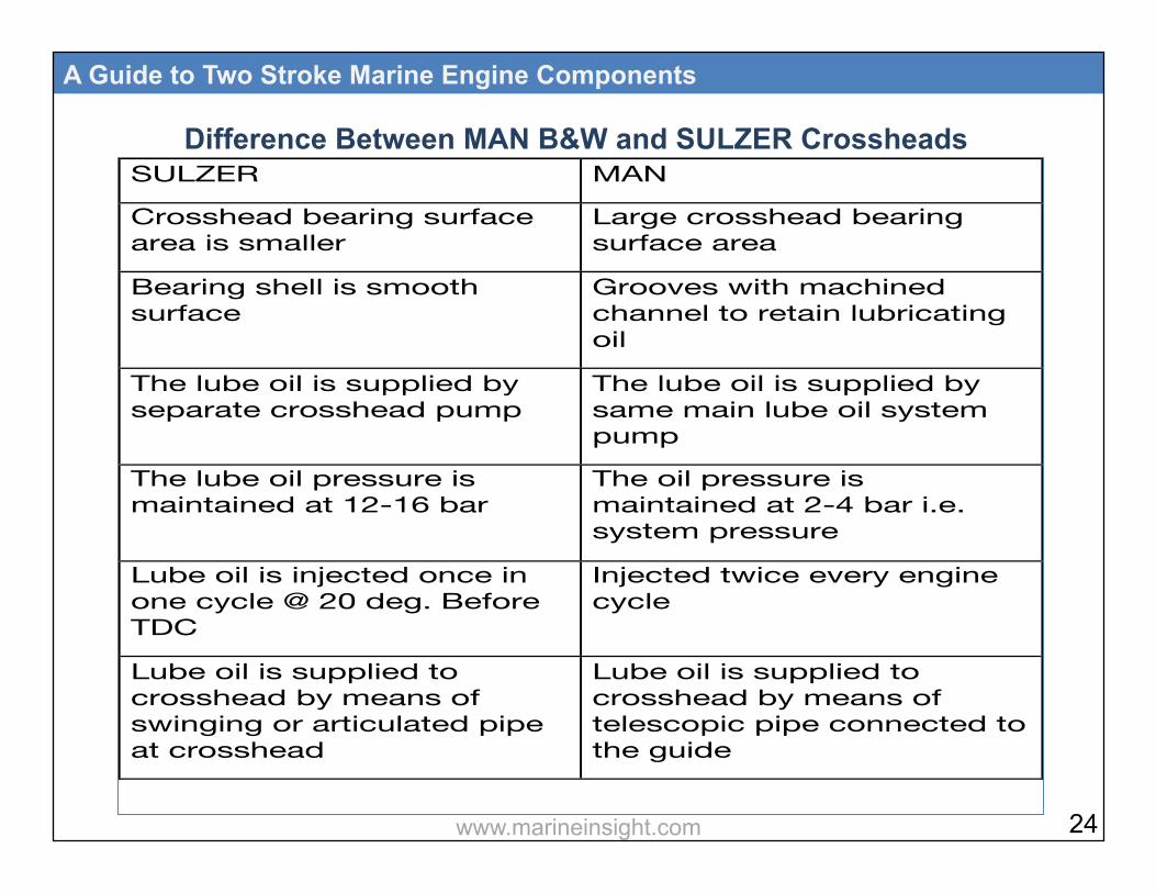
SULZER MAN
Crosshead bearing surface area is smaller
Large crosshead bearing surface area
Bearing shell is smooth surface
Grooves with machined channel to retain lubricating oil
The lube oil is supplied by separate crosshead pump
The lube oil is supplied by same main lube oil system pump
The lube oil pressure is maintained at 12-16 bar
The oil pressure is maintained at 2-4 bar i.e. system pressure
Lube oil is injected once in one cycle @ 20 deg. Before TDC
Injected twice every engine cycle
Lube oil is supplied to crosshead by means of swinging or articulated pipe at crosshead
Lube oil is supplied to crosshead by means of telescopic pipe connected to the guide
!
Difference Between MAN B&W and SULZER Crossheads
24 www.marineinsight.com
4
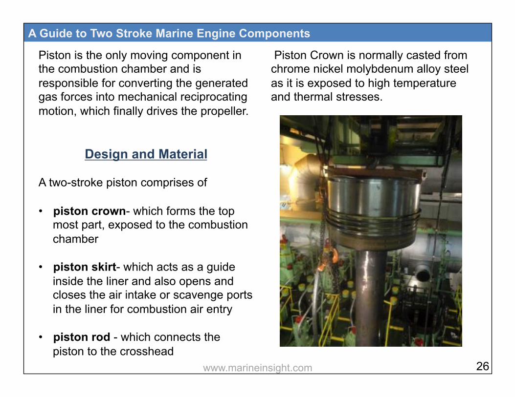
Piston is the only moving component in the combustion chamber and is responsible for converting the generated gas forces into mechanical reciprocating motion, which finally drives the propeller.
Design and Material A two-stroke piston comprises of • piston crown- which forms the top
most part, exposed to the combustion chamber
• piston skirt- which acts as a guide inside the liner and also opens and closes the air intake or scavenge ports in the liner for combustion air entry
• piston rod - which connects the piston to the crosshead
A Guide to Two Stroke Marine Engine Components
Piston Crown is normally casted from chrome nickel molybdenum alloy steel as it is exposed to high temperature and thermal stresses.
26 www.marineinsight.com

The top land of the piston is designed in convex or concave shape as it makes a hemispherical combustion chamber in conjunction with the cylinder head, resulting in higher efficiency. The top land is sometimes coated with temperature resistant material to protect the crown from overheating. Piston Rod is made up of forged steel.
A Guide to Two Stroke Marine Engine Components
Nowadays, Sulzer and MAN engine pistons have chromium-coated grooves for long operating life. Both these engine pistons are equipped with two or more bronze band rings integrated in the skirt part, for assisting the piston in running-in phase. Cooling Method: The main engine piston is cooled by one of the two cooling mediums- oil or water. Water-cooled pistons were mainly used in old MAN engines and Sulzer RND engines. Nowadays both MAN and Sulzer engines prefer oil cooling to conventional water-cooling piston as the former reduces the risk of lube oil contamination in case of leakage. 27 www.marineinsight.com
In MAN engine: The cooling oil comes from main bearing to the crosshead pin and then reaches the crown through the bores provided in the piston rod. A return line bore is also provided in the rod, which connects to crosshead pin sides and the oil goes to the sump. In SULZER engine: The cooling oil comes to the piston from an articulated or swinging arm supplying lube oil at system pressure. A separate manifold runs throughout the engine, from which oil is supplied to the articulated arm of each unit.
Types of 2 Stroke Piston Every engine maker, especially the big players such as MAN and Sulzer are introducing new piston designs to
A Guide to Two Stroke Marine Engine Components
improve the overall efficiency of the combustion space and to increase the working life of the piston. SULZER Piston: The new SULZER piston with concave crown comes with Jet-Shaker cooling design, wherein the jet nozzles are attached to the cooling passage of piston rod. The piston crown design which comprises of bores and nozzles ( for supplying cooling oil with high pressure), provides better uniform cooling and reduces crown thickness and overall piston weight. This is known as jet shaker method as during downward movement of piston, the nozzle sprays the oil jet inside the bore and when the piston
28 www.marineinsight.com

A Guide to Two Stroke Marine Engine Components
moves upward, the oil inside the piston crown shakes for efficient cooling. MAN B&W Piston: The new MAN engine uses simple bore cooling piston and jet nozzels, which comprises of oil passage within the piston crown for uniform cooling. The MAN engine also uses a top layer thermal coating over the crown, known as INCONEL 625 coat, which is 8mm thick and protects the crown surface from overheating.
INCONEL coating Conventional Bore Cooling
29 www.marineinsight.com
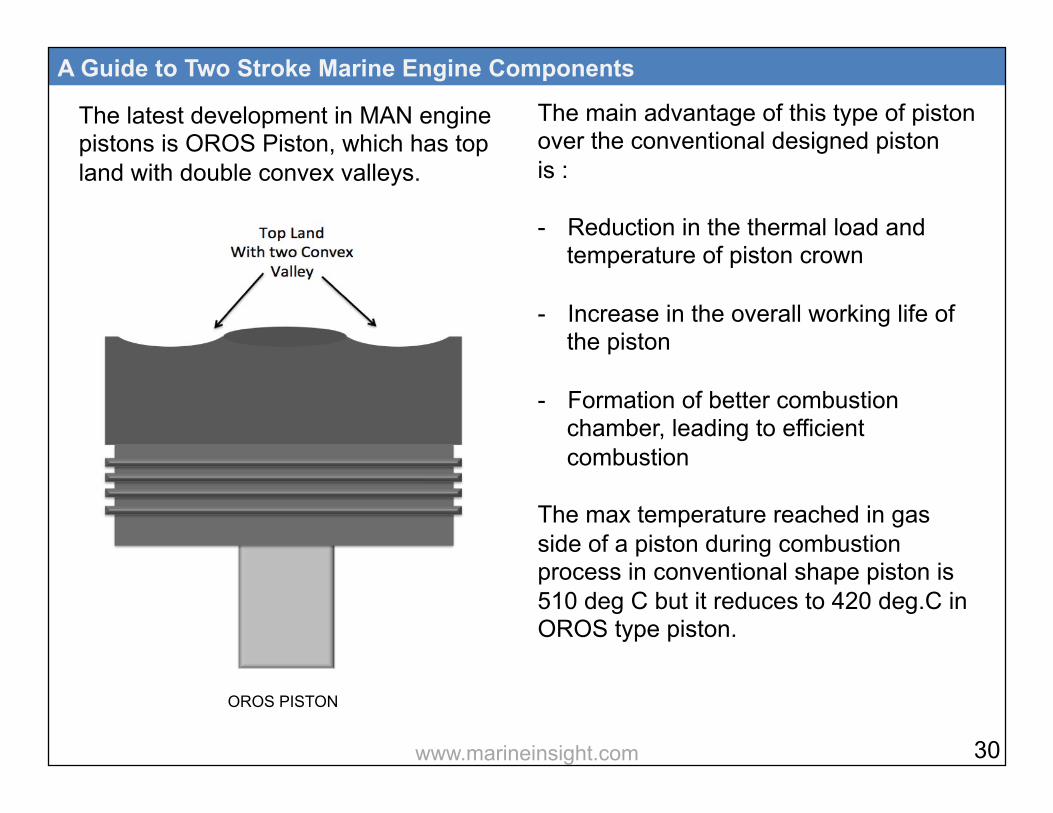
The latest development in MAN engine pistons is OROS Piston, which has top land with double convex valleys.
A Guide to Two Stroke Marine Engine Components
The main advantage of this type of piston over the conventional designed piston is : - Reduction in the thermal load and
temperature of piston crown - Increase in the overall working life of
the piston
- Formation of better combustion chamber, leading to efficient combustion
The max temperature reached in gas side of a piston during combustion process in conventional shape piston is 510 deg C but it reduces to 420 deg.C in OROS type piston.
OROS PISTON
30 www.marineinsight.com

Common Problems in Piston The most common problems experienced in a marine engine piston are: • Cracks on the surface
• Deformation of piston crown top
• Burning off of piston crown top
• High temperature of piston while running
• Scuffing of piston
• Worn-out piston ring grooves
A Guide to Two Stroke Marine Engine Components
Main reasons for problems: • Inadequate circulation of coolant
• Excessive deposits inside the cooling space
• No or poor water treatment
• Poor cylinder lubrication
• Faulty piston ring
• Liner distortion
• Piston wrongly aligned
• Overloading during combustion
• Excessive water in fuel • Insufficient air 31 www.marineinsight.com

• Late fuel injection • Faulty fuel injector leading to more
penetration of fuel
• Wrong running-in after major overhaul
• Scavenge fire • Thermal stresses due to cold starting
or low temperature of scavenge air
Inspection of Piston Check the following while doing piston inspection: • Carbonaceous deposits on the crown
and sides
• Crown top surface-for burning and cracking damage
A Guide to Two Stroke Marine Engine Components
• Top ring groove & side wall - for
crack / deformation and wear
• Other ring grooves - for distortion / wear
• Cooling passage - for scaling / chocking
• Skirt - for wear / rubbing marks
• Wear ring / rubbing ring for scuffing
Measurement and Test Measurement of piston top land: The piston top land is prone to burn-outs due to direct contact with high temperature combustion and malfunctioning of the injectors, resulting in longer penetration of fuel which deforms the piston top.
32 www.marineinsight.com

The piston top land wear down is measured with the help of a template which is fitted on top of the piston crown and the clearance between the template
A Guide to Two Stroke Marine Engine Components
and top land is measured with the help of feeler gauge. Pressure Test of Piston: It is important to pressure test the piston, which has been taken out from the unit and cleaned for reuse. Following Procedure is to be followed: • Invert the piston so that the base of
the piston palm is facing up
• Fill the piston with water and keep an air hose ready
• Fit the pressure testing tool at the palm of the piston and ensure no water leaks from the connection
• Connect the air hose to testing tool and supply air pressure up to 7 bar
Max. Permissible burn-away
MAN MC-C - Standard piston top: 20mm - Inconel piston top: 8mm SULZER RTflex 96C - Standard piston top:10mm
33 www.marineinsight.com

• Check crown for any crack or water
• Keep the piston pressure charged for 2-3 hours and check that the pressure is stagnant which indicates no leakage
A Guide to Two Stroke Marine Engine Components
Difference Between SULZER and MAN Piston
• Shut the air and isolate the piston in this condition
• Check for any leakages from all contact surfaces and sealing rings
SULZER MAN
Crosshead bearing surface area is smaller
Large crosshead bearing surface area
Bearing shell is of smooth surface
Bearing shell has grooves with machined channel to retain lubricating oil
The lube oil is supplied by separate crosshead pump
The lube oil is supplied by main lube oil system pump
The lube oil pressure is maintained at 12-16 bar
The oil pressure is maintained at 2-4 bar i.e. system pressure
Lube oil is injected once per cycle @ 20 deg. Before TDC
Lube oil is injected twice every engine cycle
Lube oil is supplied to crosshead by means of swinging or articulated pipe attached to the crosshead
Lube oil is supplied to the crosshead by means of telescopic pipe connected to the guide
! 34 www.marineinsight.com

5

The main function of piston rings inside the combustion chamber is to seal the space and prevent the escape of gases into the lower portion of the engine i.e. under piston area and crankcase. If the rings are sealing the combustion chamber properly, then it will assist the piston to compress the air fuel mixture efficiently.
A Guide to Two Stroke Marine Engine Components
Other important functions of piston rings are- • To help the cylinder oil spread properly
on the liner surface
• To prevent the cylinder oil entry inside the combustion space
Types
Compression ring or pressure ring: • Seals the gases above the piston and
prevents gas leakage
Scraper or oil control ring:
• Controls the amount of lube oil passing up or down the cylinder wall, and evenly spreads oil around the cylinder
36 Piston rings sealing with Liner
www.marineinsight.com

Types of Piston Ring According to End Joint: a) Butt (Vertical cut) Joint • Gives a robust joint for top rings b) Scarfed (Diagonal/Angle cut) Joint • Better gas seal
• Less robust c) Lap / Bayonet Joint
A Guide to Two Stroke Marine Engine Components
• Good gas seal
• Vulnerable to breakage d) Controlled Pressure Relief Ring • Upper piston ring with “s” seal end
joint
• Provided with 6 pressure relieve grooves around its circumference
• Allows even heat distribution in the lower ring
• Has long ring operating life
37 www.marineinsight.com
Construction of Piston Rings Grey cast iron piston rings of marine engines are made with the help of pot casting method. In this method, a short cylinder of oval cross section is made and the piston rings are then cut and machined from the cylinder. With this method, a homogeneous and balanced casting is formed around the entire circumference of the ring. The piston rings should have tension properties with which the sealing effect is produced. In olden days, the tensile strength was produced by hammering around the circumference of the circular ring. Today, this tension is achieved by two methods:
A Guide to Two Stroke Marine Engine Components
1. Thermally Tensioned Ring
2. Oval Pot Cam Turning Method
Thermally Tensioned Ring: The thermally tensioned ring is one of the cheapest methods to induce tension in the piston rings but it is restricted to smaller engines. In this method the piston ring is machined from the circular pot to the required cylinder diameter. After making the ring, a gap is cut and a metal piece is inserted in the gap, which expands the ring and induces a tension in the ring. After expanding, the ring and the distance piece is placed inside the oven to relieve any stresses induced during the process. The major disadvantage of
38 www.marineinsight.com

this process is that the ring loses its tension because of the heat of the engine. Oval Pot Cam Turning Method: The oval pot cam turning method is expensive but the rings produced from this method retain their tension while working in the heat of the engine. The rings are machined in a cam turning lathe. By changing the cam shape and the oval form, the pressure distribution around the ring is changed and a tension is induced. After the pot has been machined, a gap of about 7-13% diameter is cut in the ring and rings are grounded on the flanks to ensure good sealing in the piston ring grooves.
A Guide to Two Stroke Marine Engine Components
The piston rings used in the marine engines should be harder than the liner material in which they are used. To provide additional strength to the piston rings, some materials such as chromium, molybdenum, vanadium, titanium, nickel and copper are added to them. Surface Treatment: Chrome plating is one of the most common methods of surface treatment. It is generally used on the running surface of the piston rings and on the landing surfaces i.e. in ring grooves. Chromium has the advantage of high wear resistance, low friction and corrosion resistance properties. The coating done should be of high quality and be able to operate under all conditions inside the engine without damaging or peeling off or breaking.
39 www.marineinsight.com
Plasma Coating: It is also one of the methods used for plating the rings. In this method, a gas mixture is passed through an arc generated between the tungsten electrode and water-cooled copper tube. A very high temperature is thus generated and the gas molecules start to disintegrate. In this plasma state level, carbides and ceramic are sprayed as fine powder, which melts and coats the ring surface. This plasma coating provides better properties than those provided by the chrome plating. The disadvantage of chrome and plasma coating is that the thickness of coating and the bonding to parent metal is
A Guide to Two Stroke Marine Engine Components
limited. A new method of laser hardening treatment is also being used. This produces a wear resistant layer, which is several times thicker than that of the conventional coatings. Sometimes, copper is plated directly over the chrome layer of the ring. The plating thickness is very thin and the life of this is long enough to cater for running in period. Plasma coated rings are graphite coated to cater with the running-in periods.
40 www.marineinsight.com
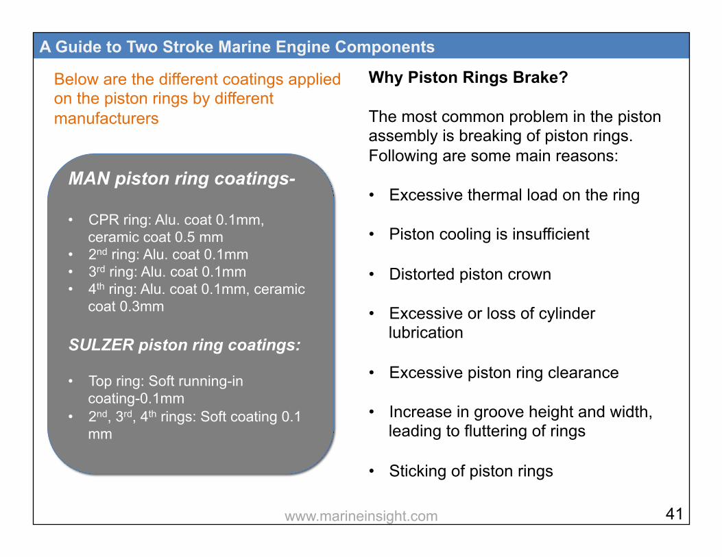
Below are the different coatings applied on the piston rings by different manufacturers
A Guide to Two Stroke Marine Engine Components
Why Piston Rings Brake? The most common problem in the piston assembly is breaking of piston rings. Following are some main reasons: • Excessive thermal load on the ring
• Piston cooling is insufficient
• Distorted piston crown
• Excessive or loss of cylinder lubrication
• Excessive piston ring clearance
• Increase in groove height and width, leading to fluttering of rings
• Sticking of piston rings
MAN piston ring coatings- • CPR ring: Alu. coat 0.1mm,
ceramic coat 0.5 mm • 2nd ring: Alu. coat 0.1mm • 3rd ring: Alu. coat 0.1mm • 4th ring: Alu. coat 0.1mm, ceramic
coat 0.3mm
SULZER piston ring coatings: • Top ring: Soft running-in
coating-0.1mm • 2nd, 3rd, 4th rings: Soft coating 0.1
mm
41 www.marineinsight.com

Inspection of Piston Rings The piston ring can be inspected when the piston is out of the cylinder. When the piston in inside the cylinder, rings can be inspected from inside the scavenge trunk and through the scavenge ports of the liner. Following things are to be checked in the piston rings: Sound of ring by tapping it with mallet and hammer- if the sound is damped, it may indicate breakage of the ring Check butt of the rings for any damage or shear off Check cracks in the piston ring surface Check general appearance of the ring
A Guide to Two Stroke Marine Engine Components
Bright appearance and edge without burrs- indicate good condition If the brightness has disappeared and edges have burrs- it indicates piston ring seizure Check scratch marks in the ring surface- It indicates bad fuel quality and blow past
Piston Ring Inspection from Scavenge Port
42 www.marineinsight.com
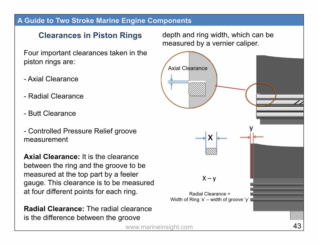
Clearances in Piston Rings Four important clearances taken in the piston rings are: - Axial Clearance - Radial Clearance - Butt Clearance - Controlled Pressure Relief groove measurement Axial Clearance: It is the clearance between the ring and the groove to be measured at the top part by a feeler gauge. This clearance is to be measured at four different points for each ring. Radial Clearance: The radial clearance is the difference between the groove
A Guide to Two Stroke Marine Engine Components
depth and ring width, which can be measured by a vernier caliper.
Radial Clearance = Width of Ring ‘x’ – width of groove ‘y’
Axial Clearance
43 www.marineinsight.com
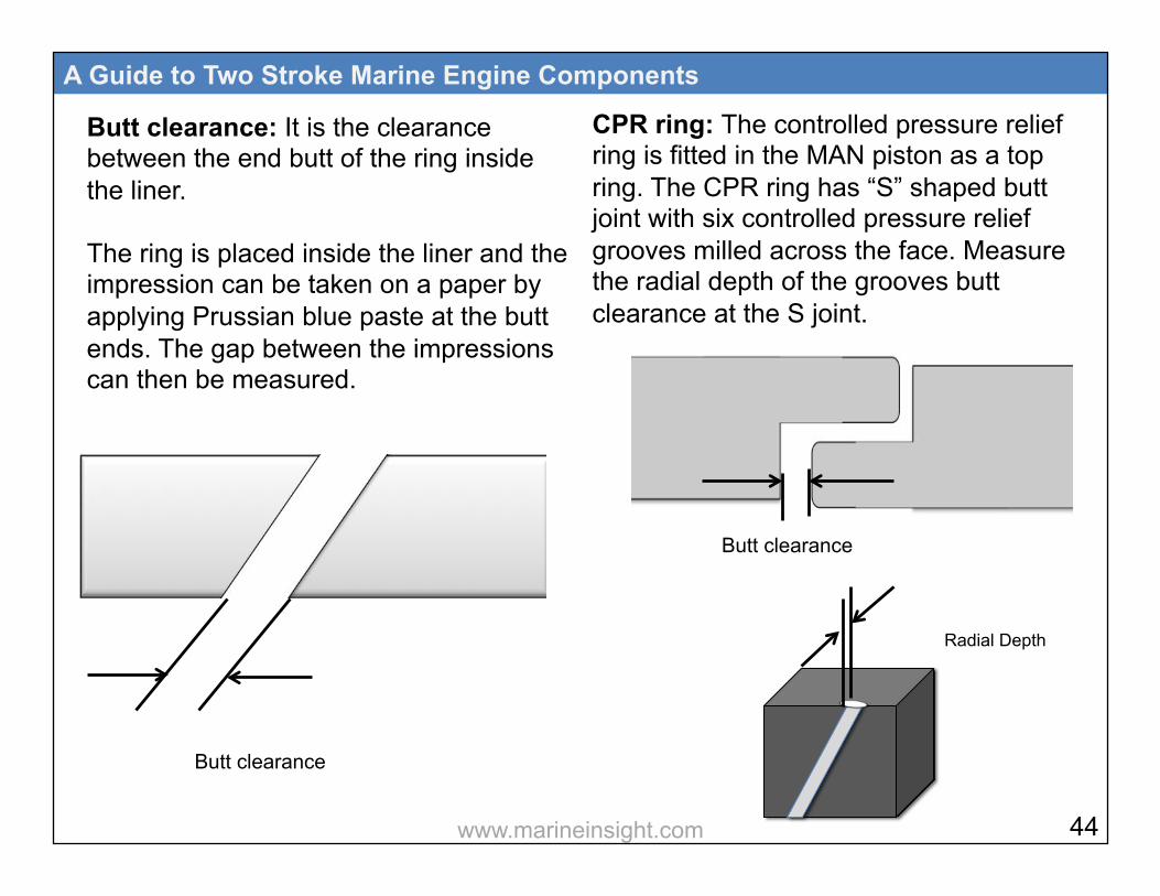
Butt clearance: It is the clearance between the end butt of the ring inside the liner. The ring is placed inside the liner and the impression can be taken on a paper by applying Prussian blue paste at the butt ends. The gap between the impressions can then be measured.
A Guide to Two Stroke Marine Engine Components
CPR ring: The controlled pressure relief ring is fitted in the MAN piston as a top ring. The CPR ring has “S” shaped butt joint with six controlled pressure relief grooves milled across the face. Measure the radial depth of the grooves butt clearance at the S joint.
Butt clearance
Butt clearance
Radial Depth
44 www.marineinsight.com
6
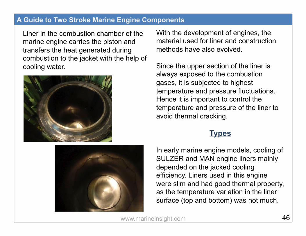
Liner in the combustion chamber of the marine engine carries the piston and transfers the heat generated during combustion to the jacket with the help of cooling water.
A Guide to Two Stroke Marine Engine Components
With the development of engines, the material used for liner and construction methods have also evolved. Since the upper section of the liner is always exposed to the combustion gases, it is subjected to highest temperature and pressure fluctuations. Hence it is important to control the temperature and pressure of the liner to avoid thermal cracking.
Types In early marine engine models, cooling of SULZER and MAN engine liners mainly depended on the jacked cooling efficiency. Liners used in this engine were slim and had good thermal property, as the temperature variation in the liner surface (top and bottom) was not much.
46 www.marineinsight.com

With use of turbocharger and increase in engine power the mechanical stresses on this slim liner resulted in cracks and other mechanical failures. The 2nd generation liner comprises of cooling passages or cooling bores drilled
A Guide to Two Stroke Marine Engine Components
at an angle, which carries cooling water within the liner and then to the cylinder head. This design allows to increase thickness of the liner without increase in thermal stresses and also assist in stable lubrication.
Liner Material The most common materials used in construction of a two stroke marine engine liners are: • Cast Iron with alloys of nickel
• Chromium
• Molybdenum
• Vanadium
47 www.marineinsight.com
• Copper
• Titanium Various engine makers use different materials due to increased demands for higher outputs:
A Guide to Two Stroke Marine Engine Components
Materials preference as per manufacturers:
Wartsila NSD RTA: Lamellar or vermicular graphite cast iron Wartsila NSD 32/46 : Grey cast iron alloy MAN-B&W MC : Tarkalloy, a lamellar graphite cast iron with boron and phosphorous
Problems in Liner The wear in the cylinder liner is mainly because of following problems: • Friction
• Corrosion
• Abrasion
• Scuffing or Adhesion
• Lacquering Frictional Wear: Whenever two surfaces slide over each other, friction is produced which leads to wearing down of both the surfaces. In liner wear the surfaces are piston rings sliding over the cylinder liner. The frictional wear depends upon various
48 www.marineinsight.com
factors such as speed of movement between the surfaces, material involved, temperature, load on engine, pressure, maintenance, lubrication, and combustion efficiency. Corrosion: The wear due to corrosion is caused due to the burning of heavy fuel oil in the combustion space. This happens because heavy fuel oil contains high sulphur content. During combustion, acids formed inside the space should be neutralized by cylinder oil, which is alkaline in nature. The production of acids will be more if the sulfur content is more, leading to the formation of sulphuric acid. Sulphuric acid is formed due to absorption of the condensate or moisture present inside the combustion space.
A Guide to Two Stroke Marine Engine Components
Sulphuric acid corrosion is found more in the lower part of the liner as the temperature of jacket water is very low. Corrosion due to sulphur will be high because of the presence of water in fuel and condensate in the air. This wear is generally seen between the quills.
The wear near the quills enlarge and gives a characteristic of the clover leaf shape to the wear pattern. This phenomenon is called clover leafing Abrasion: This type of wear is due to the hard particles present and formed during combustion. Catalytic fines in the fuel and the ash formed during the combustion causes abrasive wear. Adhesion or Scuffing: This is a form of local welding between the particles of
49 www.marineinsight.com
piston rings and the liner surface. As the piston is moving inside the liner, the welding that has occurred breaks and leads to the formation of abrasive material. The abrasive material will increase the rate of wear of the liner. This is generally caused by insufficient lubrication due to which large amount of heat is produced and microscopic welding of rings and liner surface takes place. Due to this type of wear, the liner losses its properties to adhere cylinder oil to the surface. One more reason for this phenomenon is polishing of the surface by scuffing, giving liners a mirror finish. Lacquering: Lacquering is caused due to organic and inorganic salts, which result in calcium deposits built up in the
A Guide to Two Stroke Marine Engine Components
honing grooves of the liner. These salts can result in smooth or glazed liner surface which in-turn increases the oil consumption rate significantly. If unchecked, these calcium deposits, along with carbon deposits, may lead to scoring or polishing of the liner. Apart from the above listed problems, the liner top surface is subjected to maximum wear because of the following reasons: • High temperature exposure due to hot
combustion gases
• Loss of lubrication until oil reaches the top portion
• Corrosion is maximum in this area
Calcium PPM in ISO 8217 fuel oil specification is 30 ppm
50 www.marineinsight.com
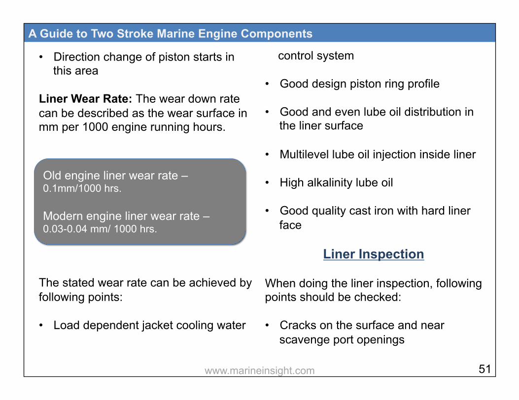
• Direction change of piston starts in this area
Liner Wear Rate: The wear down rate can be described as the wear surface in mm per 1000 engine running hours. The stated wear rate can be achieved by following points: • Load dependent jacket cooling water
A Guide to Two Stroke Marine Engine Components
control system
• Good design piston ring profile
• Good and even lube oil distribution in the liner surface
• Multilevel lube oil injection inside liner
• High alkalinity lube oil
• Good quality cast iron with hard liner face
Liner Inspection When doing the liner inspection, following points should be checked: • Cracks on the surface and near
scavenge port openings
Old engine liner wear rate – 0.1mm/1000 hrs. Modern engine liner wear rate – 0.03-0.04 mm/ 1000 hrs.
51 www.marineinsight.com

• Sharp edgy surface of scavenge ports
• Ridge formation at TDC position
• Mechanical friction wear marks and abrasive wear on the liner surface
• Dark areas of liner indicating blow-by
• Corrosion in liner surface – Acidic and cold corrosion
• Scuffing and scoring marks of liner surface
• Clover leafing - corrosive wear between the lubricator ports if the cylinder oil cannot neutralize the acid products of combustion
• Cracks and damage at lubrication openings
A Guide to Two Stroke Marine Engine Components
• Glazing of liner surface (mirror finish)
• Flow of oil from lubrication ports
• Liner calibration to check the liner ovality and wear
a- cracks due to
excessive tightening
b- hoop stress cracks
c- wear ridge Circumferential cracks
d- star shaped crack due to flame impingement
e- Cracks due to jacket water leakage near quill
f- Cracks near scavenge area
g- Clover leafing near lube oil quill injection
52 www.marineinsight.com
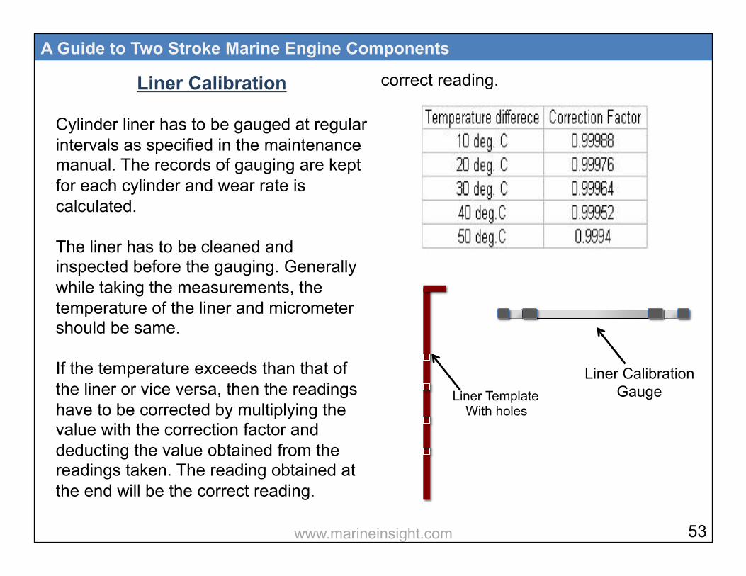
Liner Calibration Cylinder liner has to be gauged at regular intervals as specified in the maintenance manual. The records of gauging are kept for each cylinder and wear rate is calculated. The liner has to be cleaned and inspected before the gauging. Generally while taking the measurements, the temperature of the liner and micrometer should be same. If the temperature exceeds than that of the liner or vice versa, then the readings have to be corrected by multiplying the value with the correction factor and deducting the value obtained from the readings taken. The reading obtained at the end will be the correct reading.
A Guide to Two Stroke Marine Engine Components
correct reading.
Liner Template With holes
Liner Calibration Gauge
53 www.marineinsight.com

The cylinder liner wear is measured by a standard template, which consists of strategically positioned holes, wherein the micrometer is placed and the readings are taken.
A Guide to Two Stroke Marine Engine Components
The readings are taken for both port- starboard and forward-aft positions. If the wear is not same in both directions, the ovality of liner is checked The wear rate will be different along the length of the liner. The wear will be more in the top one-third part because of high combustion temperature and pressure. An approximate normal wear rate of the liner is about 0.1 mm/ 1000 running hours. The wear rate increases if the engine is overloaded. Generally the liner has to be replaced when the wear is about 0.6-0.8% of the bore diameter or as per the manufacturer’s recommendation.
template
Calibration tool
FWD AFT PORT
STBD
54 www.marineinsight.com
A Guide to Two Stroke Marine Engine Components
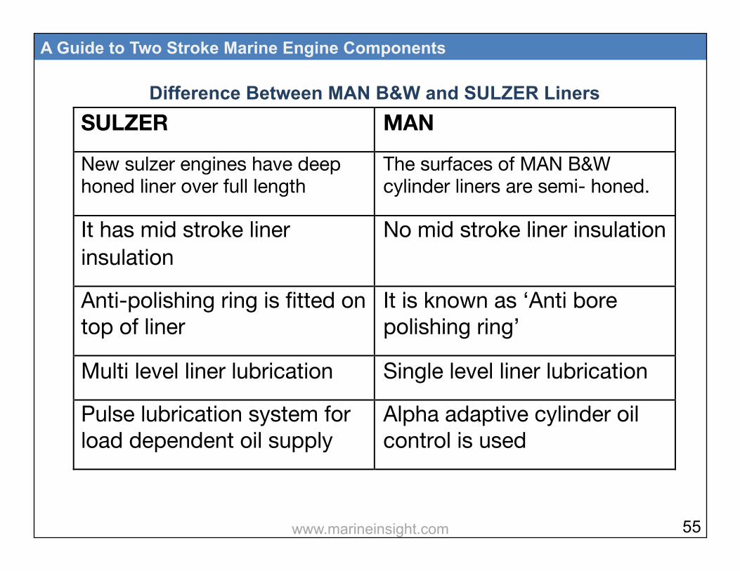
SULZER MAN New sulzer engines have deep honed liner over full length
The surfaces of MAN B&W cylinder liners are semi- honed.
It has mid stroke liner insulation
No mid stroke liner insulation
Anti-polishing ring is fitted on top of liner
It is known as ‘Anti bore polishing ring’
Multi level liner lubrication Single level liner lubrication
Pulse lubrication system for load dependent oil supply
Alpha adaptive cylinder oil control is used
!
Difference Between MAN B&W and SULZER Liners
55 www.marineinsight.com
7

One of the major functions of the cylinder head is to seal the combustion chamber and to accommodate other auxiliary parts such as fuel injector, air start valve, exhaust valve etc., to assist in the combustion process. The cylinder cover of marine engine is subjected to high combustion temperature.
A Guide to Two Stroke Marine Engine Components
To tackle this condition, the cylinder head is provided with cooling water bore wherein pre-heated water is circulated to avoid thermal stresses. The gas load produced during power stroke is transferred by means of cylinder head studs to the engine structure and then to ship’s hull via tie rods and foundation bolts.
Types of Heads MAN and SULZER engines have single piece, solid steel cylinder heads with bore cooling concept and centrally fitted exhaust valves. Other fitting holes are also provided in the cover (Fuel valve, start air valve, relief valve etc.).
57 www.marineinsight.com

Some SULZER engine (RTA series) models also have two piece cylinder cover - Inner and outer pieces. This design was introduced to tackle cracks in the cover body, especially in the uncooled space due to thermal expansion. Inner piece is also known as cylinder skirt, which is made up of cast iron and outer cylinder is made of cast steel; both are tied together to form a single piece. Now the latest Rtflex series engine uses advanced design single piece cylinder cover. Some MAN engine cylinder covers have special head studs with elastic property. These stud expands in case of overpressure of the cylinder and releases the excess pressure from the area between the liner and the head, which
A Guide to Two Stroke Marine Engine Components
opens up when the head lifts. No relief valve is fitted in such type of cylinder cover. SULZER and MAN engine covers with high KW ratings use three fuel valves mounted on the top of the cylinder cover forming a triangle.
Fuel Valves
Exhaust Valve
58 www.marineinsight.com
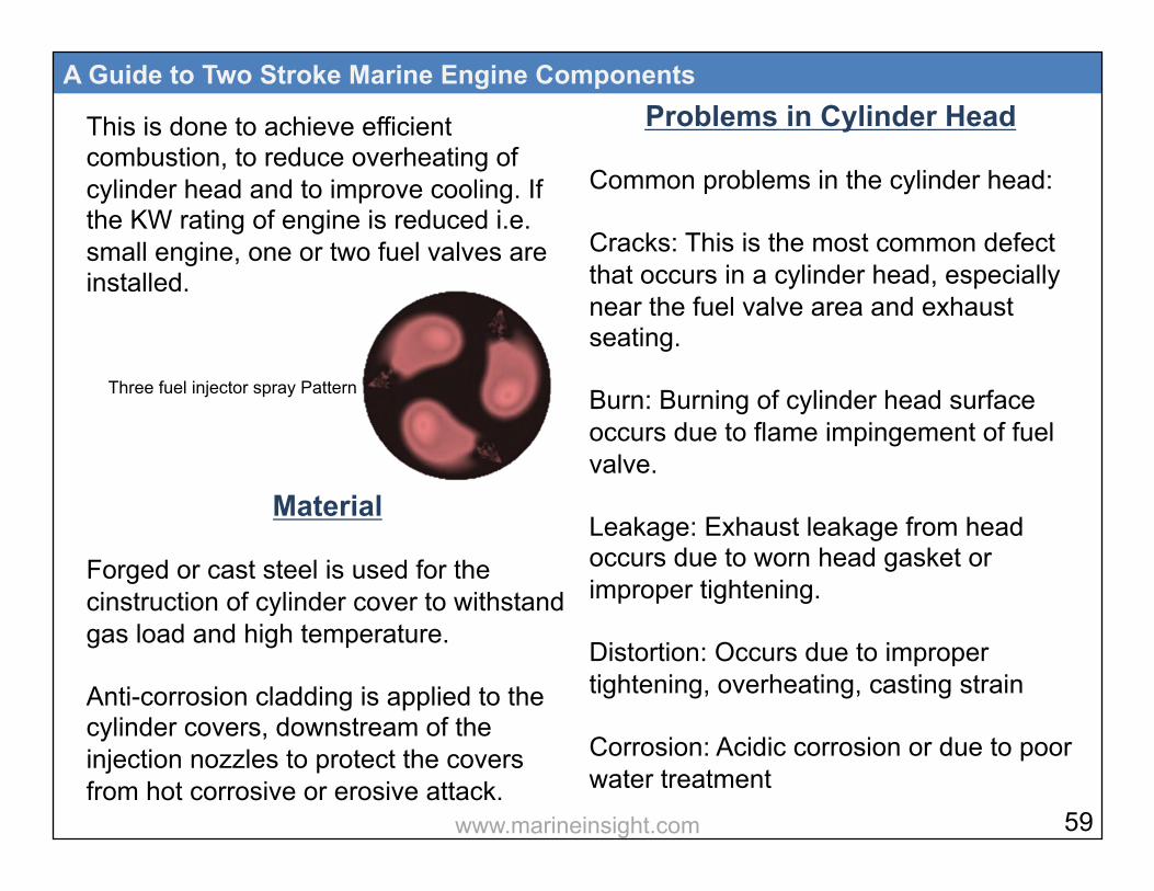
This is done to achieve efficient combustion, to reduce overheating of cylinder head and to improve cooling. If the KW rating of engine is reduced i.e. small engine, one or two fuel valves are installed.
Material Forged or cast steel is used for the cinstruction of cylinder cover to withstand gas load and high temperature. Anti-corrosion cladding is applied to the cylinder covers, downstream of the injection nozzles to protect the covers from hot corrosive or erosive attack.
A Guide to Two Stroke Marine Engine Components
Problems in Cylinder Head Common problems in the cylinder head: Cracks: This is the most common defect that occurs in a cylinder head, especially near the fuel valve area and exhaust seating. Burn: Burning of cylinder head surface occurs due to flame impingement of fuel valve. Leakage: Exhaust leakage from head occurs due to worn head gasket or improper tightening. Distortion: Occurs due to improper tightening, overheating, casting strain Corrosion: Acidic corrosion or due to poor water treatment
Three fuel injector spray Pattern
59 www.marineinsight.com
• Carbon Deposit: Occurs due to improper combustion and poor fuel treatment
Inspection of Cylinder Head Inspect the following when checking the cylinder head: • Check cooling water space for
deposits
• Check starting air valve pocket and seat for scoring or cracks
• Check fuel valve pocket and seat
• Check the combustion side of the head for deposits, overheating, and cracks
A Guide to Two Stroke Marine Engine Components
• Check exhaust passage for scoring and burnout
• Pressure test the cylinder head water side
• Check the condition of cylinder head gasket
• Check condition of relief valve and ensure it is not leaking
• Check all the studs are properly tightened to engine frame
60 www.marineinsight.com

8
The Exhaust Valve of a 2 stroke marine engine is centrally installed over the top of cylinder head to allow all the exhaust generated inside the chamber during combustion process to be transferred to the exhaust trunk. The exhaust valve can be divided in 3 important parts: Exhaust valve body: The outer body of the exhaust valve comprises of bores for passage of cooling water, guide for spindle of valve, cage for valve seat and other attachments for valve operation. It also comprises of compartments for power piston, which is operated by hydraulic and air pressure. The body generally is made up of cast iron, which has good manufacturing property along with strength. The valve
A Guide to Two Stroke Marine Engine Components
guide is made up of perlite cast iron. Exhaust valve with spindle: The valve with spindle can be separated from the body in order to grind and recondition after a period of time or when required. The spindle is provided with rotary vanes attached above the valve in the stem. When exhaust gases pass through these vanes, it rotates the valve to avoid local distortion of the valve and valve seat. The modern age exhaust valve is made from nickel-based alloy, precipitated hardened steel, austenitic steel or silicon-chrome steel. For big engines, normally Nimonic spindle and a steel bottom piece with a surface-hardened seat to match the greater hardness of the Nimonic spindle
62 www.marineinsight.com
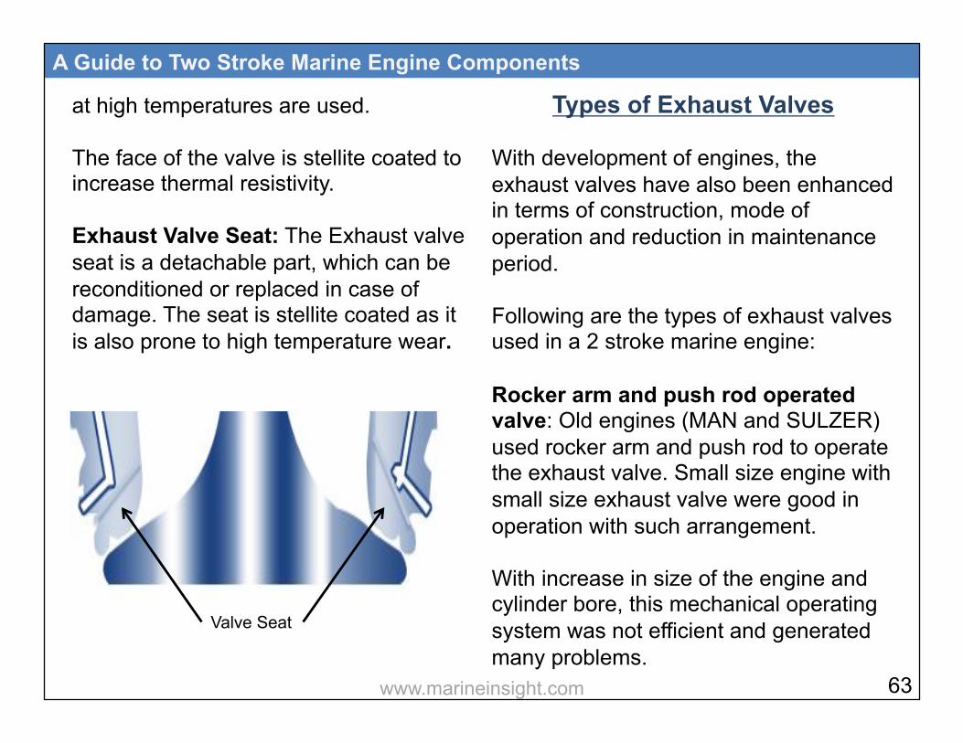
at high temperatures are used. The face of the valve is stellite coated to increase thermal resistivity. Exhaust Valve Seat: The Exhaust valve seat is a detachable part, which can be reconditioned or replaced in case of damage. The seat is stellite coated as it is also prone to high temperature wear.
A Guide to Two Stroke Marine Engine Components
Types of Exhaust Valves With development of engines, the exhaust valves have also been enhanced in terms of construction, mode of operation and reduction in maintenance period. Following are the types of exhaust valves used in a 2 stroke marine engine: Rocker arm and push rod operated valve: Old engines (MAN and SULZER) used rocker arm and push rod to operate the exhaust valve. Small size engine with small size exhaust valve were good in operation with such arrangement. With increase in size of the engine and cylinder bore, this mechanical operating system was not efficient and generated many problems.
Valve Seat
63 www.marineinsight.com
A Guide to Two Stroke Marine Engine Components
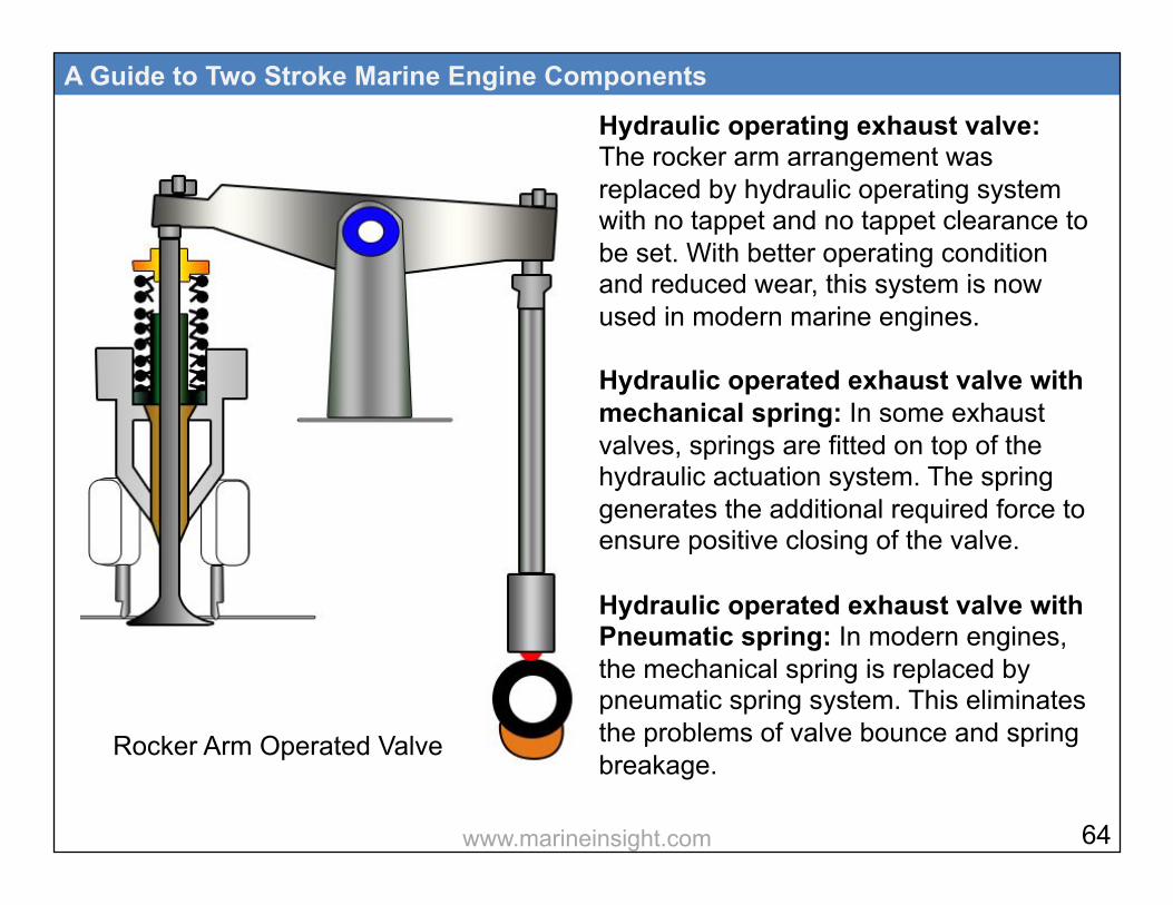
Hydraulic operating exhaust valve: The rocker arm arrangement was replaced by hydraulic operating system with no tappet and no tappet clearance to be set. With better operating condition and reduced wear, this system is now used in modern marine engines. Hydraulic operated exhaust valve with mechanical spring: In some exhaust valves, springs are fitted on top of the hydraulic actuation system. The spring generates the additional required force to ensure positive closing of the valve. Hydraulic operated exhaust valve with Pneumatic spring: In modern engines, the mechanical spring is replaced by pneumatic spring system. This eliminates the problems of valve bounce and spring breakage.
Rocker Arm Operated Valve
64 www.marineinsight.com
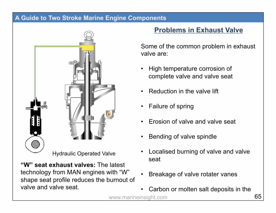
“W” seat exhaust valves: The latest technology from MAN engines with “W” shape seat profile reduces the burnout of valve and valve seat.
A Guide to Two Stroke Marine Engine Components
Problems in Exhaust Valve
Some of the common problem in exhaust valve are: • High temperature corrosion of
complete valve and valve seat
• Reduction in the valve lift
• Failure of spring
• Erosion of valve and valve seat
• Bending of valve spindle
• Localised burning of valve and valve seat
• Breakage of valve rotater vanes
• Carbon or molten salt deposits in the
Hydraulic Operated Valve
65 www.marineinsight.com
exhaust passage and valve surface
• Poor cooling of valve cage
• Reseating failure leading to exhaust leakage
• Banging of valve while closing
One of the most common problems in exhaust valves is knocking while running. Following are some main resons for the same –
Deficiency in the Oil System: The knocking can be due to problems arising in the hydraulic oil system which is responsible for the operation of the valve:
• Air in oil or air being drawn at pump suction side
• Supply pressure of oil is too low
A Guide to Two Stroke Marine Engine Components
• Oil temperature is high leading to reduction is viscosity.
Deficiency in the air system:
• Incorrect spring air supply pressure
• Defective or malfuctioning drain valve in the air chamber
• Defective or malfuctioning of safety valve in the air chamber
Leakage in hight pressure oil system:
• Wrongly adjusted or defective throttle screw
• Oil cylinder piston ring in the exhaust valve leaking
66 www.marineinsight.com

• Oil cylinder safety valve on cam side leaking
• High pressure pipe is damaged
• Leakage in vent valve at the top
Inspection of Exhaust Valve
Check the following while inspecting exhaust valves: • Before fitting the exhaust valve, check
the operation of “closing” by lifting the valve with engine room crane. Once it is clear off the ground, the valve will be in the open position. Connect air hose with compressed air supply to pneumatic piston inlet and open the air supply. This will close/ shut the valve.
A Guide to Two Stroke Marine Engine Components
• Once the valve is closed, shut off the air supply and keep it in that postion for 15 minutes and check that it does not open. This means that the air piston does not have leakage.
• Open the vent plug screw located on the air cylinder- this will bring the valve
in open condition • Check for burnout marks in the valve
face and seat
• Check for cracks and breakage of rotary vanes attached to the valve spindle
• Check scoring mark in the valve seat and valve face. This indicates valve rotator is not working and is leading to localised burning or leakage
67 www.marineinsight.com

• Check condition of thrust pads in the exhaust valve
• Check the actuator for marks on the sealing surface
• Check the surface of hydraulic pipe connecting face for surface deformation, indicating leakage or incorrect tightness
Latest Technology and
Development
“W” Seat- The seat of the valve is made in “W” shape, wherein air gets trapped during the compression stroke and provides a cooling effect, reducing thermal stresses. It is made of solid low alloy steel prepared by induction hardening. The
A Guide to Two Stroke Marine Engine Components
main advantage of this seat is that it’s cheaper to manufacture and provides a Time Between Overhaul (TBO) of approx- 30,000 hrs (15 years). Dura Spindle: In this type of exhaust valve spindle, reselient ni-cr alloy welded on stainless steel spindle and hardened with ten tonnes of force in special rolling process to 500HV is used. This gives
Air traps in this area
68 www.marineinsight.com

better hardness and ductlility than stellite or nimonic coated spindles. The TBO is 50% more than conventional spindles. Variable Exhaust Valve Closing: In this system the valve closing timing is altered without disturbing the lift of the valve. This is done to optimize the exhaust valve operation over the normal load range, where the closing point of the exhaust valve is changed over 70-85% of MCR. During Variable Exhaust Closing operation if the exhaust valve is closed early, it means that the compression stroke of the piston is increased. This will lead to higher compression pressures and temperatures.
A Guide to Two Stroke Marine Engine Components
Clearances in Exhaust Valve
With the help of a feeler gauge, check clearance between the valve and the seat. A 1mm feeler gauge should go up to 15 mm deep. This is to ensure that there is clearance between the outer parts of the seating faces of valve housing and spindle. Clearance
69 www.marineinsight.com
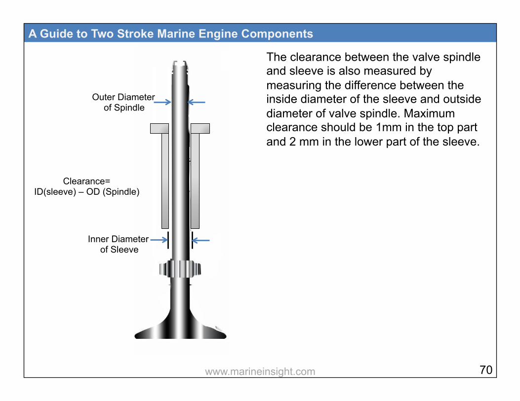
The clearance between the valve spindle and sleeve is also measured by measuring the difference between the inside diameter of the sleeve and outside diameter of valve spindle. Maximum clearance should be 1mm in the top part and 2 mm in the lower part of the sleeve.
A Guide to Two Stroke Marine Engine Components
Clearance= ID(sleeve) – OD (Spindle)
Inner Diameter of Sleeve
Outer Diameter of Spindle
70 www.marineinsight.com
9
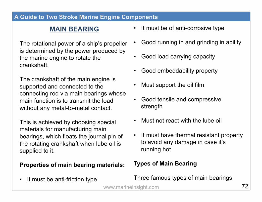
MAIN BEARING The rotational power of a ship’s propeller is determined by the power produced by the marine engine to rotate the crankshaft. The crankshaft of the main engine is supported and connected to the connecting rod via main bearings whose main function is to transmit the load without any metal-to-metal contact. This is achieved by choosing special materials for manufacturing main bearings, which floats the journal pin of the rotating crankshaft when lube oil is supplied to it. Properties of main bearing materials: • It must be anti-friction type
A Guide to Two Stroke Marine Engine Components
• It must be of anti-corrosive type
• Good running in and grinding in ability
• Good load carrying capacity
• Good embeddability property
• Must support the oil film
• Good tensile and compressive strength
• Must not react with the lube oil
• It must have thermal resistant property to avoid any damage in case it’s running hot
Types of Main Bearing Three famous types of main bearings
72 www.marineinsight.com
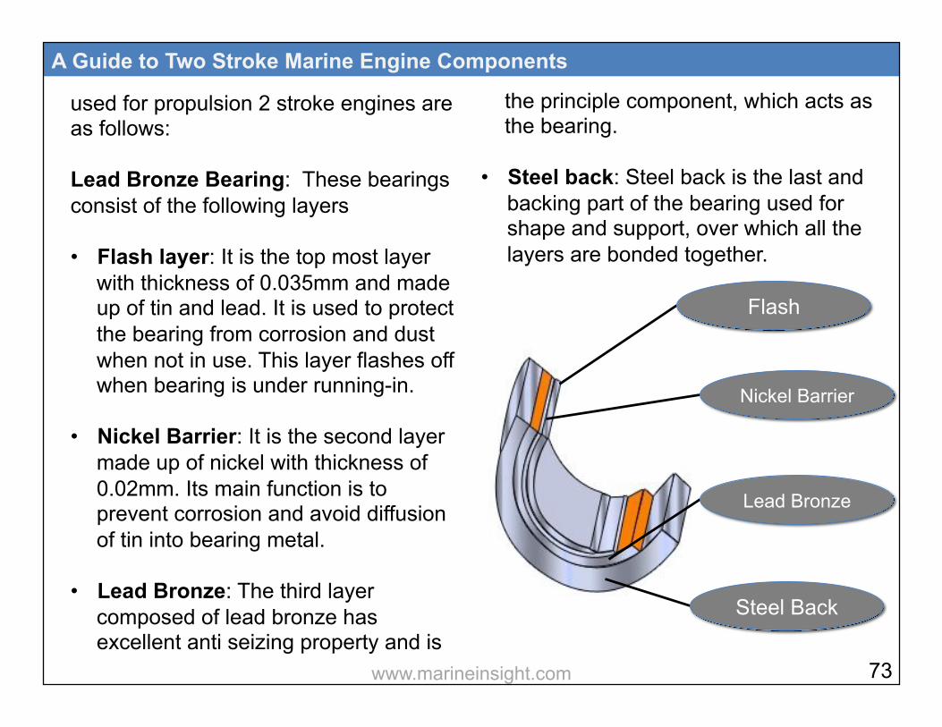
used for propulsion 2 stroke engines are as follows: Lead Bronze Bearing: These bearings consist of the following layers • Flash layer: It is the top most layer
with thickness of 0.035mm and made up of tin and lead. It is used to protect the bearing from corrosion and dust when not in use. This layer flashes off when bearing is under running-in.
• Nickel Barrier: It is the second layer made up of nickel with thickness of 0.02mm. Its main function is to prevent corrosion and avoid diffusion of tin into bearing metal.
• Lead Bronze: The third layer composed of lead bronze has excellent anti seizing property and is
A Guide to Two Stroke Marine Engine Components
the principle component, which acts as the bearing.
• Steel back: Steel back is the last and backing part of the bearing used for shape and support, over which all the layers are bonded together.
Flash
Nickel Barrier
Lead Bronze
Steel Back
73 www.marineinsight.com
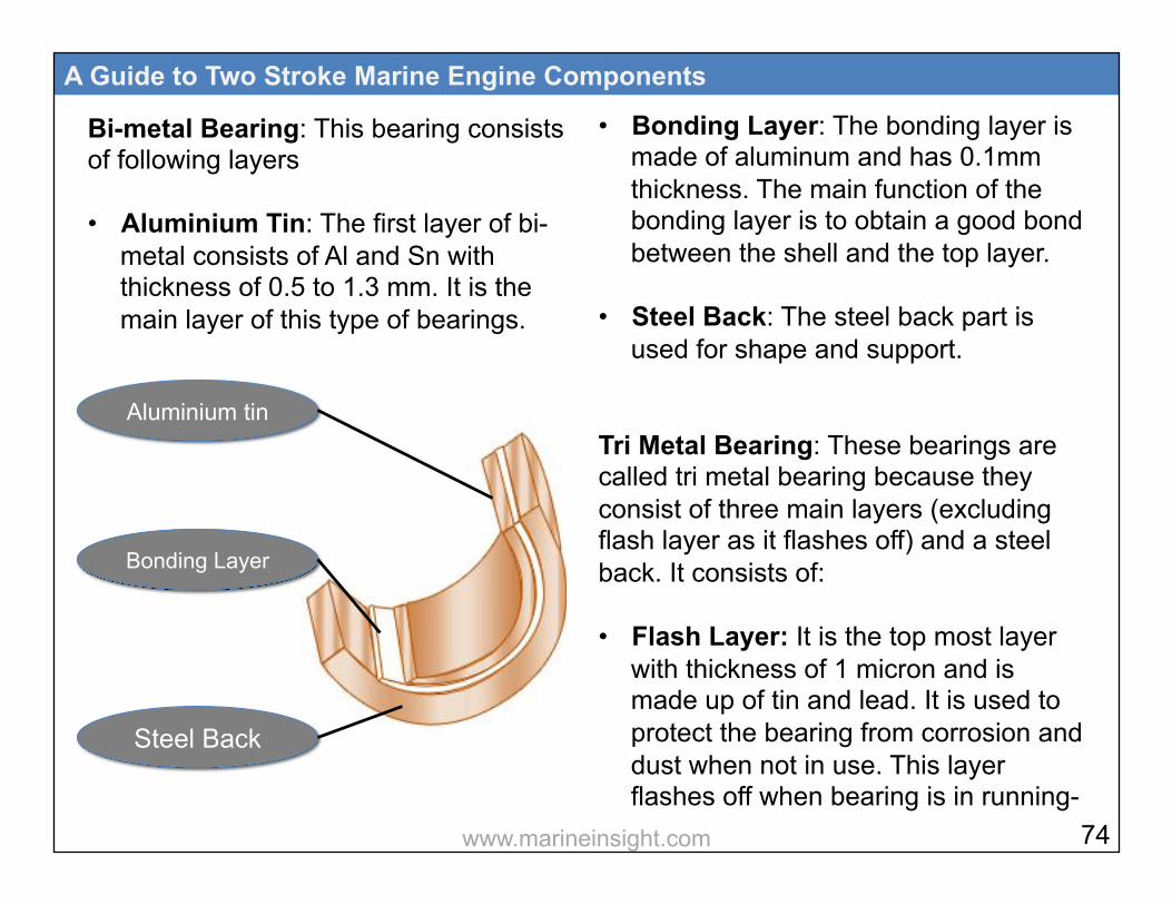
Bi-metal Bearing: This bearing consists of following layers • Aluminium Tin: The first layer of bi-
metal consists of Al and Sn with thickness of 0.5 to 1.3 mm. It is the main layer of this type of bearings.
A Guide to Two Stroke Marine Engine Components
• Bonding Layer: The bonding layer is made of aluminum and has 0.1mm thickness. The main function of the bonding layer is to obtain a good bond between the shell and the top layer.
• Steel Back: The steel back part is used for shape and support.
Tri Metal Bearing: These bearings are called tri metal bearing because they consist of three main layers (excluding flash layer as it flashes off) and a steel back. It consists of: • Flash Layer: It is the top most layer
with thickness of 1 micron and is made up of tin and lead. It is used to protect the bearing from corrosion and dust when not in use. This layer flashes off when bearing is in running-
Aluminium tin
Bonding Layer
Steel Back
74 www.marineinsight.com
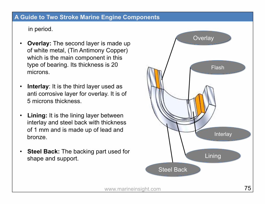
in period.
• Overlay: The second layer is made up of white metal, (Tin Antimony Copper) which is the main component in this type of bearing. Its thickness is 20 microns.
• Interlay: It is the third layer used as anti corrosive layer for overlay. It is of 5 microns thickness.
• Lining: It is the lining layer between interlay and steel back with thickness of 1 mm and is made up of lead and bronze.
• Steel Back: The backing part used for shape and support.
A Guide to Two Stroke Marine Engine Components
Overlay
Flash
Interlay
Lining
Steel Back
75 www.marineinsight.com

Measuring Main Bearing Clearance: A marine engine comprises of several types of bearings, which support the rotating and reciprocating crankshaft, camshaft, and crosshead of the engine. It is extremely important to maintain good quality and quantity of lubricating oil to all these bearings in order to avoid breakdown of the engine. The main bearing of a marine engine supports the long running crankshaft throughout the engine length. This makes it imperative to check the condition of the bearing at regular intervals of time. The clearance measurement of the main bearing determines the amount of wear down, which the bearing has been subjected to. There are various types of
A Guide to Two Stroke Marine Engine Components
methods adopted by different marine engine manufacturers to measure the clearances of the main bearing of marine engine. Following are some of the most prominent methods used onboard ships to measure the clearance of main bearing: 1) Bridge with Depth Gauge This method is used in SULZER 2 stroke marine engines where the bearing‘s shell is removed along with the keep (the bearing shell is lined with the keep). After that a bridge is fitted over the top of the journal pin, from port to starboard, making a bridge over the crankshaft with two ends supported on the cross girder. A simple vernier type depth gauge is then inserted in the hole provided on the bridge and the scale of depth gauge is
76 www.marineinsight.com
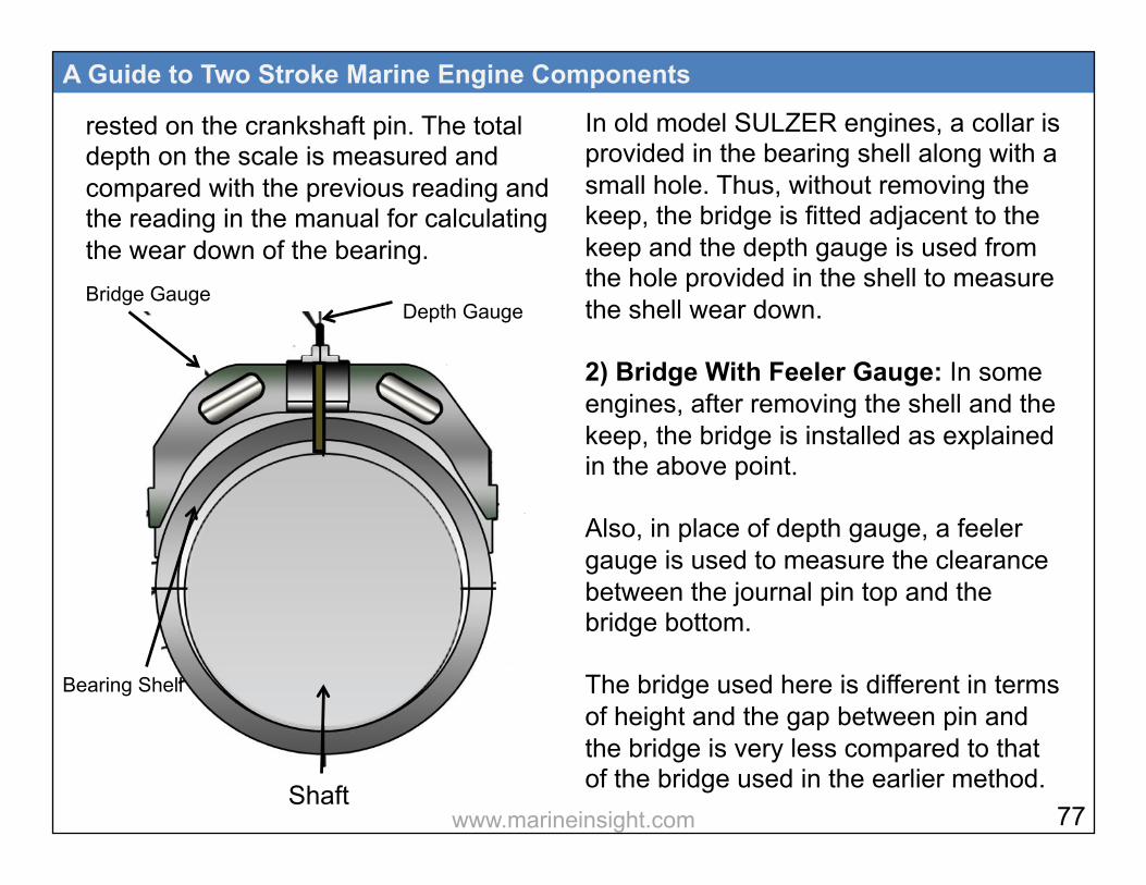
rested on the crankshaft pin. The total depth on the scale is measured and compared with the previous reading and the reading in the manual for calculating the wear down of the bearing.
A Guide to Two Stroke Marine Engine Components
In old model SULZER engines, a collar is provided in the bearing shell along with a small hole. Thus, without removing the keep, the bridge is fitted adjacent to the keep and the depth gauge is used from the hole provided in the shell to measure the shell wear down. 2) Bridge With Feeler Gauge: In some engines, after removing the shell and the keep, the bridge is installed as explained in the above point. Also, in place of depth gauge, a feeler gauge is used to measure the clearance between the journal pin top and the bridge bottom. The bridge used here is different in terms of height and the gap between pin and the bridge is very less compared to that of the bridge used in the earlier method.
Bridge Gauge Depth Gauge
Shaft
Bearing Shell
77 www.marineinsight.com
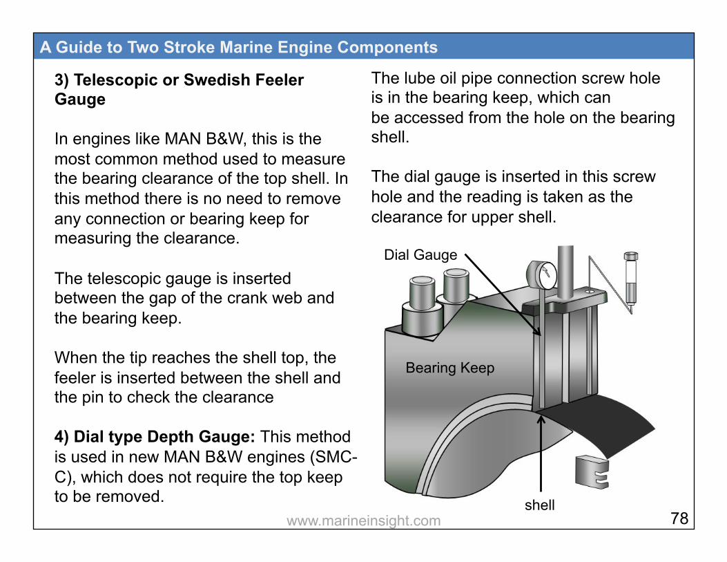
3) Telescopic or Swedish Feeler Gauge In engines like MAN B&W, this is the most common method used to measure the bearing clearance of the top shell. In this method there is no need to remove any connection or bearing keep for measuring the clearance. The telescopic gauge is inserted between the gap of the crank web and the bearing keep. When the tip reaches the shell top, the feeler is inserted between the shell and the pin to check the clearance 4) Dial type Depth Gauge: This method is used in new MAN B&W engines (SMC-C), which does not require the top keep to be removed.
A Guide to Two Stroke Marine Engine Components
The lube oil pipe connection screw hole is in the bearing keep, which can be accessed from the hole on the bearing shell. The dial gauge is inserted in this screw hole and the reading is taken as the clearance for upper shell.
Dial Gauge
shell
Bearing Keep
78 www.marineinsight.com

A Guide to Two Stroke Marine Engine Components
Difference Between SULZER and MAN Main Bearings
SULZER MAN
In some models, jack bolts are used to hold the bearing cap
Waisted stud bolts are used to hold the main bearing cap
Upper half of the keep is lined with white metal
A separate shell is installed in the upper half
White metal thin shell bearing is used
Tri metal thin shell bearing is used
Locating dowel is provided for holding the lower bearing shell
Counter sunk screw is provided to hold the lower shell
!79 www.marineinsight.com

Crosshead bearing The crosshead bearing design in latest engines depends on the pressure of the lube oil supplied to them. In MAN engine, the crosshead lube oil pressure is same as that of main lube oil system. This is due to the design of the lower shell of the crosshead bearing which has machined wedges to hold oil in them and to support the hydrodynamic lubrication of crosshead pin. The top shell consists of a cut out part where the piston palm passes and connected to the crosshead pin. In MAN engine, the lube oil is supplied to the crosshead from telescopic pipe, which is attached to the crosshead face.
A Guide to Two Stroke Marine Engine Components
IN SULZER engine, the old type model comprises of forked crosshead i.e. the piston rod passes right through the crosshead and is secured underneath with means of piston nut. The crosshead bearing has machined grooves to support oil and lubrication.
80 www.marineinsight.com
A Guide to Two Stroke Marine Engine Components
Clearance The top clearance between the journal and the new bearing shell is a result of a summation of the production tolerances of the bearing assemblies. Following points to be considered while taking the clearance of crosshead bearing. • Stop lube oil pump and allow
crankcase to cool down
• Open the crankcase door at the relevant cylinder
• Ensure the crankcase is properly ventilated
• Turn the crankshaft so that the web is 90 deg. before BDC towards the exhaust side
In latest SULZER engine, only the lower shell is present which is continuous in nature and the upper bearing housing is lined with white metal. The oil pressure for crosshead is maintained at 10-12 bar by means of separate crosshead booster pump, which increases the main lube oil pressure. Material In MAN engine, the lower shell with grooves is made from SnAL40 and the upper shell is of white metal. While in SULZER, the bearing shell is thin walled made of white metal for high load bearing capacity.
81 www.marineinsight.com

• Measure the clearance in crosshead bearings through the inspection hole of the thrust piece by inserting a feeler gauge at top of upper bearing shell
A Guide to Two Stroke Marine Engine Components
• When checking the clearance, the discrepancy between the actual and measured values is noted and if it exceeds 0.1 mm, crosshead bearing must be inspected.
Crosshead bearing of MAN engine should be replaced when the groove width ‘X’, channeled in the surface is reduced by half.
Crosshead Bearing Clearance
Crank web: 90 Deg. before BDC
82 www.marineinsight.com
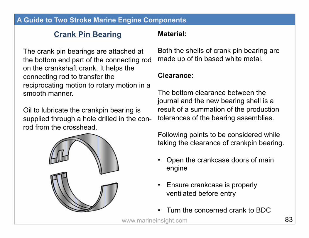
Crank Pin Bearing The crank pin bearings are attached at the bottom end part of the connecting rod on the crankshaft crank. It helps the connecting rod to transfer the reciprocating motion to rotary motion in a smooth manner. Oil to lubricate the crankpin bearing is supplied through a hole drilled in the con- rod from the crosshead.
A Guide to Two Stroke Marine Engine Components
Material: Both the shells of crank pin bearing are made up of tin based white metal. Clearance: The bottom clearance between the journal and the new bearing shell is a result of a summation of the production tolerances of the bearing assemblies. Following points to be considered while taking the clearance of crankpin bearing. • Open the crankcase doors of main
engine
• Ensure crankcase is properly ventilated before entry
• Turn the concerned crank to BDC 83 www.marineinsight.com

• Measure the clearance in the crankpin bearing by inserting a feeler gauge at the bottom of the bearing shell on both sides
• When checking the clearance, the discrepancy between the actual and measured value is noted and if it exceeds 0.1 mm, crosshead bearing must be inspected
• The wear limit for the crankpin bearing shells is based on an evaluation of the bearing condition at the time of inspection. An average wear rate of 0.01 mm per 10,000 hours is regarded as normal
In modern shell bearings, the clearance is manufactured into the shells. When the clearance has reached a maximum value
A Guide to Two Stroke Marine Engine Components
as laid down in the instruction manual, the bearing has to be changed. Thick wall shell bearings fitted in some engines have the clearance adjusted by fitting shims between the bearing halves. The shims are of equal thickness on both sides of the bearing housing. Crank pin measurement: Heavy loading of engine may lead to wear down of main bearing or deformation of crank pin of the crankshaft. The crank pin ovality may result in increase in the bearing clearance, hence lube oil may not be retained and which can cause bearing wipe out. Crank pin measurement is done by outside micrometer at three different
84 www.marineinsight.com

A Guide to Two Stroke Marine Engine Components
Thrust Bearing When the crank throw is loaded by the gas pressure through the connecting rod mechanism, the arms of the crank throw deflect in the axial direction of the crankshaft, generating axial vibrations. These vibrations may be transferred to the ship’s hull through the thrust bearing. The thrust bearing is incorporated in the aft end of the bedplate as differential expansion of the shaft and hull is minimum at the aft due to fuel heating in tanks. The aft-most cross girder is therefore designed with ample stiffness to transmit the variable thrust from the thrust collar to the engine seating. It is advised to align the thrust bearing
positions along the length of the pin. The measurement is taken at Port-Starboard and Top-Bottom positions. Handle the micrometer carefully to avoid scratching the pin while taking measurement.
Top
Bottom
Stbd
Port
Crankpin
Crankpin Bearing Clearance
Crankpin Measurement
85 www.marineinsight.com
when main bearing alignment is carried out to achieve accuracy. Material Michell type pads bearing arrangement consists of a steel forged thrust shaft, a bearing support, and segments of cast iron with white metal. The thrust shaft is connected to the crankshaft and the intermediate shaft with fitted bolts. The thrust shaft has a collar for transfer of the ‘thrust’ through the segments to the bedplate. Lubrication of the thrust bearing takes place from the system oil of the engine. At the bottom of the bearing there is an oil sump with an outlet to the oil pan.
A Guide to Two Stroke Marine Engine Components
Clearance The clearance in the thrust bearing is measured during test bed trials of the engine. For a new engine the clearance is 0.5-1.0 mm, and for an engine in service it must not exceed 2.0 mm. Dismount the foremost segment stopper On top of the thrust segment, a wear groove of 1mm is provided (a segment with thermometer). To measure the wear, push the thrust pad with crowbar against thrust cam to eliminate any gap at the back While Inserting feeler gauge in the groove, if 0.1 mm is not able to enter, it indicates wear is more then 0.9 mm and the bearings need to be overhauled.
86 www.marineinsight.com
A Guide to Two Stroke Marine Engine Components
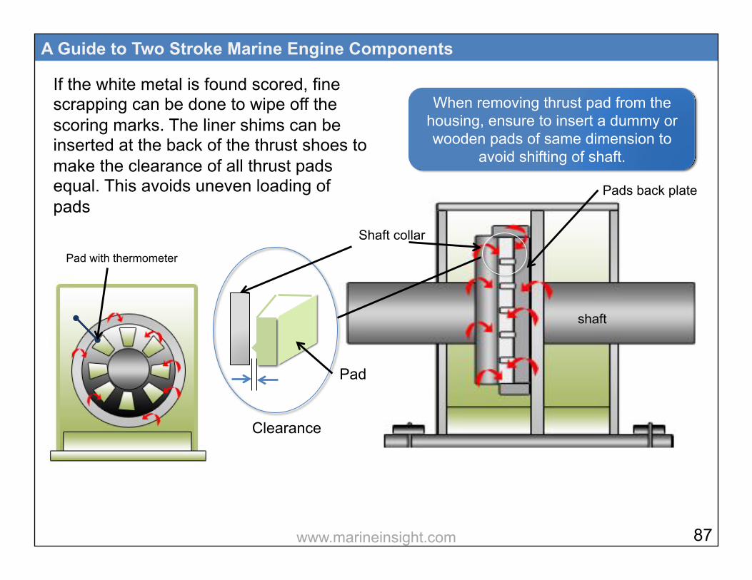
If the white metal is found scored, fine scrapping can be done to wipe off the scoring marks. The liner shims can be inserted at the back of the thrust shoes to make the clearance of all thrust pads equal. This avoids uneven loading of pads
Shaft collar
shaft
Pads back plate
When removing thrust pad from the housing, ensure to insert a dummy or wooden pads of same dimension to
avoid shifting of shaft.
Pad with thermometer
Clearance
Pad
87 www.marineinsight.com
10
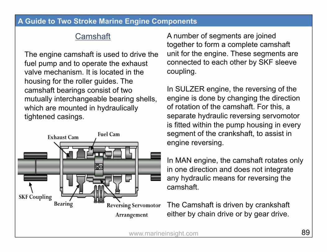
Camshaft The engine camshaft is used to drive the fuel pump and to operate the exhaust valve mechanism. It is located in the housing for the roller guides. The camshaft bearings consist of two mutually interchangeable bearing shells, which are mounted in hydraulically tightened casings.
A Guide to Two Stroke Marine Engine Components
A number of segments are joined together to form a complete camshaft unit for the engine. These segments are connected to each other by SKF sleeve coupling. In SULZER engine, the reversing of the engine is done by changing the direction of rotation of the camshaft. For this, a separate hydraulic reversing servomotor is fitted within the pump housing in every segment of the crankshaft, to assist in engine reversing. In MAN engine, the camshaft rotates only in one direction and does not integrate any hydraulic means for reversing the camshaft. The Camshaft is driven by crankshaft either by chain drive or by gear drive.
89 www.marineinsight.com

MAN engine uses chain drive and SULZER uses gear drive. These driving mechanisms (gear or chain drive) are located either at the end or at the center of the engine, depending upon the number of units. System oil is used as lube oil in the camshaft for lubricating the bearings. Cam Profiles and Types: The most important part of the camshaft is the CAM, which controls or operates the exhaust valve and the fuel pump. The cam consists of two parts, a profile and a base circle. The curvature shaped cam profile drives the follower and regulates the injection time of the oil. Base circle, which acts as the base, is the smallest circle of the cam
A Guide to Two Stroke Marine Engine Components
profile. When the follower is over the base circle, no operation of exhaust valve or fuel pump takes place. Following are the different types of CAMs used in Marine engines: • Single lobe cam
• External cam
• Regular Cam
90 www.marineinsight.com
A Guide to Two Stroke Marine Engine Components
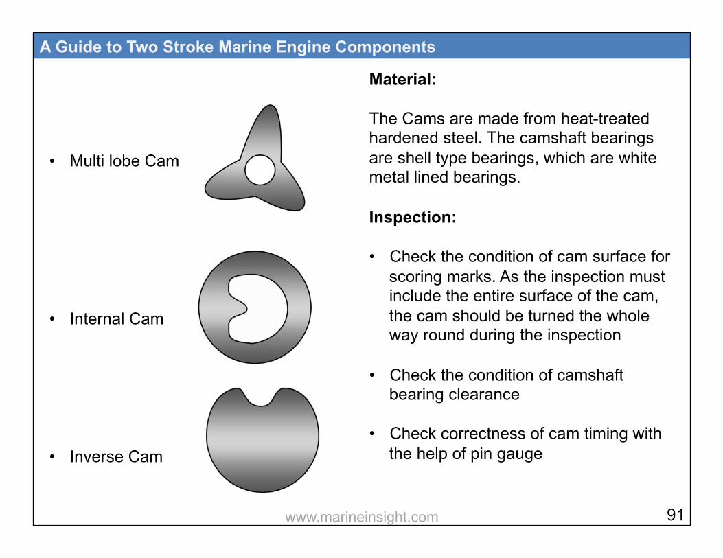
Material: The Cams are made from heat-treated hardened steel. The camshaft bearings are shell type bearings, which are white metal lined bearings. Inspection: • Check the condition of cam surface for
scoring marks. As the inspection must include the entire surface of the cam, the cam should be turned the whole way round during the inspection
• Check the condition of camshaft
bearing clearance
• Check correctness of cam timing with the help of pin gauge
91
• Multi lobe Cam
• Internal Cam
• Inverse Cam
www.marineinsight.com

Checking Camshaft Timing (MAN engine): • Ensure that the main lube oil pump is
isolated well in advance
• Bring the No.1 unit to Top Dead Centre (TDC). Ensure this position by checking the flywheel marking
• There are markings provided in the camshaft housing and at the center of each cam.
• With the help of pin gauge, check the deviation from the marking. If the
values are outside maximum permissible lead angle corresponding to the housing markings, adjusting of camshaft is required
• Clear the cams by lifting the exhaust
A Guide to Two Stroke Marine Engine Components
valve and fuel cam roller
• Remove the shield covering the coupling flange from the camshaft, which is nearest to the chain drive
• Remove the oil tray from the bottom
• Dismount the plug in the coupling flange and mount a ‘three snap-on connector”
• Connect a hydraulic jack and pump to the connectors
• Apply light oil pressure to vent the system. Once venting is done, tight the coupling
• A special spanner is provided to rotate the cam, mount the same
92 www.marineinsight.com
• Apply high pressure oil until oil seeps shaft, below the coupling flange
• Rotate the camshaft by means of a tool till the mark matches both the sides of the pin gauge
Fuel Pump
The fuel pumps of a 2 stroke marine engine are high pressure supply pumps that control the quantity and timing of fuel injected in the combusion chamber. The most common types of fuel pumps used on 2 stroke engines are: Suction-spill valve control pump: This pump is popularly used in SULZER engines. In this type of pump, the closing of suction valve ensures delivery of fuel
A Guide to Two Stroke Marine Engine Components
and opening of spill valve indicates end of the delivery. Jerk type helix type port control pump: This pump is used by MAN engines where the helix groove in the plunger port decides the end of injection and closing of the suction port by the plunjer indicates delivery of high pressure fuel. The most important thing which is checked in the fuel pump is the timing. “Timing” here describes the point at which the pump will deliver the fuel to the fuel valve. If the timing is not correct, then there may be inefficient combustion or over pressurisation inside the cylinder.
93 www.marineinsight.com
As described above, due to two different types of pumps, we use two different methods to check the delivery stroke of the fuel pump i.e effective stroke of the fuel pump. Suction spill control valve type fuel pump Timing Check: Before opening the fuel pump for checking the timing, ensure to change over the engine from heavy oil to diesel oil and take prior permission from the company and port authority for immmobilisation. Procedure for checking fuel pump timing: • Keep the main and crosshead lube oil
pumps running
• Put local reversing lever in ahead direction
A Guide to Two Stroke Marine Engine Components
• Shut starting air valve to main engine and inlet air valve to distributor
• Open indicator cocks and engage the
turning gear
• Now put the local fuel lever to the max fuel notch position. This will vent the cylinder in the governor and also activate the shut down servomotor i.e. rack is free to move from ‘0’ to ‘maximum’ position( Once the engine is stopped, the shut-down servomotor gets de-activated i.e. air vented and it keeps the fuel rack locked in the zero postion).
• Measure the VIT rack distance and note it down. Set it to zero and lock it with spacer and nut
• Fuel quality lever to be set at ‘0’ 94 www.marineinsight.com
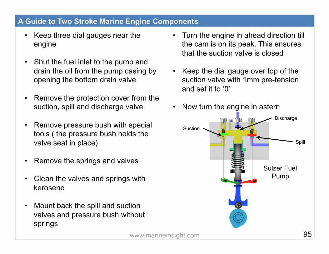
• Keep three dial gauges near the engine
• Shut the fuel inlet to the pump and drain the oil from the pump casing by opening the bottom drain valve
• Remove the protection cover from the
suction, spill and discharge valve
• Remove pressure bush with special tools ( the pressure bush holds the valve seat in place)
• Remove the springs and valves
• Clean the valves and springs with kerosene
• Mount back the spill and suction valves and pressure bush without springs
A Guide to Two Stroke Marine Engine Components
• Turn the engine in ahead direction till the cam is on its peak. This ensures that the suction valve is closed
• Keep the dial gauge over top of the suction valve with 1mm pre-tension and set it to ‘0’
• Now turn the engine in astern
Suction
Discharge
Spill
95
Sulzer Fuel Pump
www.marineinsight.com

direction till the cam is on the base circle, which indicates spill valve is closed • Put dial gauge over top of the spill
valve with 1mm pre-tension and set it to ‘0’
• Keep the third dial gauge over the plunger of discharge side with 1mm pretension and set it to ‘0’
• Now turn the engine in ahead direction till the dial gauge on suction valve shows 0.02 mm deflection. Check and note the reading of plunger dial gauge and mark it as ‘a’
• Keep turning the engine till the dial gauge on the spill valve shows 0.02mm deflection. Note the reading
A Guide to Two Stroke Marine Engine Components
• of plunger dial gauge and mark it as ‘b’
Effective stroke of the fuel pump= ‘b’ – ‘a’ Jerk type/ Helix Port Controlled Pump: In jerk type helix port controlled fuel pump, the timing is measured by taking the fuel pump lead. The fuel pump lead is the distance from the top of fuel pump plunger when lifted above the upper edge of the upper cut-off holes of the fuel pump barrel,when the same unit’s piston is at TDC. Following procedure is to be used for finding out fuel pump lead:
96 www.marineinsight.com
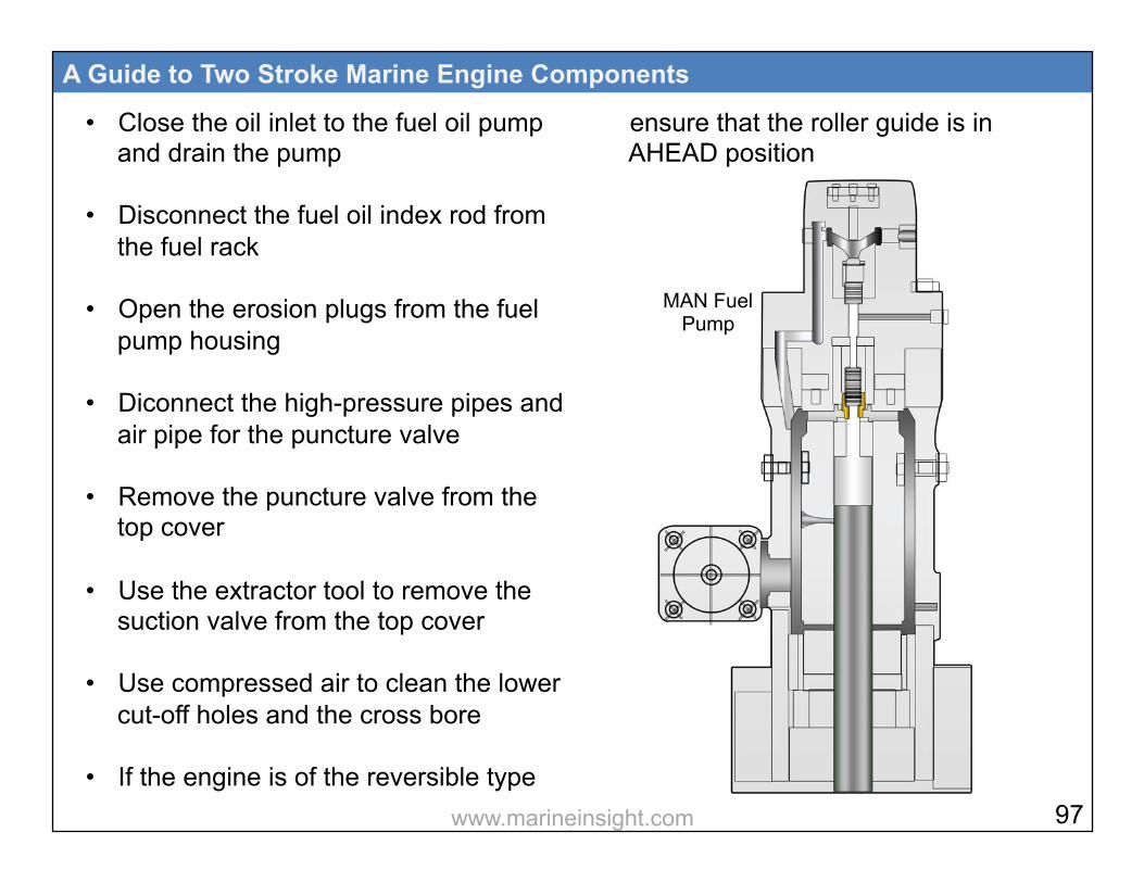
• Close the oil inlet to the fuel oil pump and drain the pump
• Disconnect the fuel oil index rod from the fuel rack
• Open the erosion plugs from the fuel pump housing
• Diconnect the high-pressure pipes and air pipe for the puncture valve
• Remove the puncture valve from the top cover
• Use the extractor tool to remove the
suction valve from the top cover
• Use compressed air to clean the lower cut-off holes and the cross bore
• If the engine is of the reversible type
A Guide to Two Stroke Marine Engine Components
ensure that the roller guide is in AHEAD position
97
MAN Fuel Pump
www.marineinsight.com
• Turn AHEAD until the cross bore in the plunger is aligned with the lower cut-off holes
• Ensure that the plunger is in delivery stroke to obtain the correct alignment of plunger and cut off holes
• Push the measuring pin right down against the bottom of the hole in the plunger
• Verify that the cross bore and the lower cut-off holes are in alignment by flashing a torch through the cut-off holes
• Turn AHEAD until the lower edge of the cross bore in the plunger reaches the exact position at which it closes off the upper edge of the lower cut-off holes
A Guide to Two Stroke Marine Engine Components
• If the exact position is difficult to determine due to fuel oil deposits in the plunger/barrel assembly, use compressed air to clean the lower cut-off holes
• Now mount the measuring tool on top of the fuel pump cover
• Adjust the bracket of the measuring tool until the plunger of the dial gauge is almost at its bottom position. Adjust the scale to 0 (zero)
• Turn AHEAD until the piston of the cylinder concerned is at TDC
• When the exact position of the piston has been confirmed to be at TDC, either by checking the position of the crankthrow or the marks on the turning wheel, note down the reading
98 www.marineinsight.com

on the dial gauge and calculate the deviation “x” between the “0” position and the present position The fuel pump lead “a” is then calculated as follows: “a = x + Y (correction factor)” The adjustment factor “Y” is a correction factor. It is basically the distance between the plunger top and upper cut-off holes top, when the plunger top reaches the exact position at which the light cannot be seen through the lower cut off holes in the barrel and plunger.
A Guide to Two Stroke Marine Engine Components
99
Conclusion Maintenance of 2 stroke marine engine components is all about precision and accuracy. Inspection, calibration and tests form an integral part of any maintenance procedure of marine engine. The methods used for measurements depend a lot on the type, size and making of the engine. Understanding the design, construction and working of each component is the key to carry out accurate inspection procedures off marine engine components. If you have questions on any of the topic mentioned in this book, please feel free to email us at [email protected]
www.marineinsight.com

Important Marine Engineering eBooks
To download these eBooks, visit our store at www.marineinsight.com/guides