
Introni.it - Components Handbook
638
-
Upload
khangminh22 -
Category
Documents
-
view
2 -
download
0
Transcript of Introni.it - Components Handbook


LL
MASSACHUSETTS INSTITUTE OF TECHNOLOGY tt
13ADIATION LABORATORY SERIES
Boardof llditors
LOUIS ~. RXDENOUR, Editor-in-Chief ..GEOR(:E H. COLLINS, DcputvEditor-in-Chief
llRIr~ONC HA NcE,S.. $. GO(L, s~tIT, R. (i. HERB, HIEEwr}l.JA}lEs,JIL1.*N ~.~N1l>r’,
.J.\MEs L. LAWSON, LEON B. LINFORD, CAROL G. MONTGOMERY, C. NEWTON, ALBERT
11, STONE, LOITS A. TrRNER, GEORGE IZ. VALLEY, JR,, HERFIERT H. WHEATON
1.
.2,
3,
4.
5.
6.
7.
8.
9.
10.
11.
12.
13.
14.
15.
16.
17.
18.
1!4.
20,
21.
u.
2:<.
‘M.
2.5.
26.
27.
28.
RAi)Arf Sywrmi b:N(;ISEtiRIN<;--HidenOUrRADAR .\rDs TO NAVIGATION -Ha/l
RADAR BEA{ONS --Rok/.x
LORAN--PiWW, .l[cli’euzie, CMI W“rrodward
PC,LSE GEN EEATO RS -Glaww arLd I.ehmqz
>IIcROwAvE Ii’IA,;NETROX. .-C0112/(S
~LYS~RONS ANI) 311(;rL0wAvk; TRIODEh Hut,lilLorL, lirLipp, (LtLdKMper
PRINCIPLES OF MICROWAVE (.’IRc(IIT+ – ilfOJLtqOl)Lerf;, f)ic!w, and Purcell
MICROWAVE TRANSMISSION (’IRCUITS RIJOUN
WAVE~UIDE H.A.NT)BOOK Jla, cwitz
‘rEcHNIQUE OF .M1CROWAVE }IEAsLREMENT+ .Ilonl!lonwrv
MICROWAVE ANTENNA THEORY AND I)ESI,;X -S,lw,
PROPAGATION OF SHORT R.ADICI WAVES—Kf’r’f
MICROWAVE ~LTPLExERs—s?n7( ~~in and ~ontgfrmlerg
CRYSTAL Rectifiers—Terre.y and JVhifmer
MICROWAVE M1xERs—Pound
COMPONENTS HANDBoOK—BkzckhurF{
VACUUMTUBEAMPLIF’IERS-vat@/and JVdman
WAVEFORMS—chanGt?, Huqhes, hfac.Vichol, Sa!lre, and li’zlliams
ELECTRONIC TIME MEASURE~ENT:—(’haNCP, Hukizcr, .lJac.Vi.hoi,
a)~d JVzllianls
ELECTRONIC I NSTRV MENTh —Gwenuwwi, Ho/duIII, und M uclr!ae
(’ATHODE RAY T[BE I) KrLAYs-SOW,, S/firr, and I-alle?/
311CROWAVE RECEIVERS— l“a71 VoorhLs
‘rHRESHOL1) SIG NALS—LaUMOn onff Uhknki
‘~NEoriY OF SERVOMECHANIS~S-Ja~GS, .Yichok, WLd PhilLip.*
RAi, IN SCANNERS INLI RAr)oM~s-Cad~, h-arelitz, and Turner
~OMPUTING h~ECH.ANISMSANDhNK.4GEs—&ohadaINrrEx-Henney
.
.
#.
,
4
i
COMPONENTS HANDBOOK!1{
EDITORIAL STAFF
GEORGE E. VALLEY, JR.
JOHN F. BLACKBURN
BARBARA D. COTfi
CONTRIBUTING AUTHORS
F. N. BARRY S. N. GOLEMBE
J. F. BLACKBURN W. F. GOODELL, JR.
P. F. BROWN E. A. HOLMES, III
F. E. DOLE M. M. HUBBARD
G. EHRENFRIED H. B. HUNTINGTON
M. D. FAGEN H. E. KALLMAN
S. FRANKEL T. B. MORSE
I
I


COMPONENTSHANDBOOK
Editedby
JOHN F. BLACKBURNMASSACHUSETTS INSTITIJTE OF TECHNOLOGY
OFFICE OF SCIENTIFIC RESEARCH AND DEVELOPMENT
NATIONAL DEFENSE RESEARCH COMMITTEE
FIRSTEDI-ITON
NEW YORK TORONTO.LONDON
McGRAW-HILL BOOK COMPANY, INC.
1949

.,,/’
COMPONENTS HANDBOOK
COPYRIGHT, 194$),BY THE -
JICGRAW-HILL BOOK C.onm.my, Ixc.
PRINTED I&- THE UXITED STATES OF .4MERICA
.411 rights rescrvd. This book, or
purtsthereoj, maynotbc Reproduced
in any-form without permission of
the p?[blishers,
THE MAPLE PRESS cOMPANY, YORK, PA,
Foreword
THE tremendous research and development effort that went into thedevelopment of radar and related techniques during World War II
resulted not only in hundreds of radar sets for military (and some forpossible peacetime) use but also in a great body of information and newtechniques in the electronics and high-frequency fields. Because thisbasic material may be of great value to science and engineering, it seemedmost important to publish it as soon as security permitted.
The Radiation Laboratory of MIT, which operated under the super-vision of the National Defense Research Committee, undertook the greattask of preparing these volumes. The work described herein, however, isthe collective result of work done at many laboratories, Army, Navy,university, and industrial, both in this country and in England, Canada,and other Dominions.
The Radiation Laboratory, once its proposals were approved andfinances provided by the Office of scientific Research and Development.chose Louis Pi’. Ridenour as Editor-in-Chief to lead and direct the entireproject. An editorial staff was then selected of those best qualified forthis type of task. Finally the authors for the various volumes or chaptersor sections were chosen from among those experts who were intimatelyfamiliar with the various fields, and who were able and willing to writethe summaries of them. This entire staff agreed to remain at work atMIT for six months or more after the work of the Radiation Laboratorywas complete. These volumes stand as a monument to this group. “
These volumes serve as a memorial to the unnamed hundreds andthousands of other scientists, engineers, and others who actually carriedon the research, development, and engineering work the results of whichare herein described. There were so many involved in this work and theyworked so closely together even though often in widely separated labora-tories that it is impossible to name or even to know those who contributedto a particular idea or development. Only certain ones who wrote reportsor articles have even been mentioned. But to all those who contributedin any way to this great cooperative development enterprise, both in thiscountry and in England, these volumes are dedicated.
L. A. DUBRIDGE.
I
Preface
THIS volume is intended primarily as a companion and referencework for Vols. 18 through 23 of the Radiation Laboratory Series. It
contains data on a number of classes of electrical rind electronic com-ponents which are of principal interest to the designer of receiving andtest equipment. In so far as possible it emphasizes the componentswhich were developed by or under the sponsorship of the Radiation Lab-oratory, or were of primary importance in its work. In order to avoida one-sided presentation, however, this material has been supplementedwith other data so that in most cases an individual chapter approximatesa survey of current practice in its particular field.
The title “ Components Handbook” is undoubtedly too inclusive forthe volume as published, since the circumstances under which it waswritten have unfortunately prevented the inclusion of chapters onseveral important classes of components and have also had some effecton the contents of those that were included. The most serious omissionis probably that of fixed condensers. Chapters were also projected onair-core inductors, on mechanical components, and on several other sub-jects. Credit is due the authors who contributed to these chapters; theomission of their work was due neither to any faults of the work itselfnor to a lack of interest in the subject matter, but solely to the fact thatthe termination of the Office of Publications caused these chapters to beleft out. Their omission is a serious if unavoidable defect.
The completeness of coverage of a particular field depends in largemeasure upon the amount of time which the individual author was ableto devote to it. The necessity for the immediate acceptance of postwarjobs, usually far from Cambridge, made it impossible for most of theauthors to check their work in final manuscript form. In such cases theeditor hopes that the collation and condensation of the original draftshave not resulted in serious errors of fact or in undue distortion of thepresentation.
In order to make the volume useful both to the academic researchworker and to the engineer in the industrial laboratory the editor hastried in most cases to combine the generalized “survey-of-a-field” form

viPHEFA Ch’
with a reasonable amount of specific data, largely in tabular form. Fordiscussions of the accuracy and balance of several of the chapters indebt-edness is expressed to their authors or to others equally familiar with thesubjects. These discussions have considerably improved the book.
It is a pleasant task to record appreciation of the help of the manypeople, both in the Office of Publications of the Radiation Laboratory andoutside, who have had a hand in the preparation of this volume. Thelack of space prevents the listing of names, but this omission has beenrectified as far as possible by the inclusion of credit lines to sources out-side the Laboratory and by the following list of sources of the individualsections.
In a book such as this one it is difficult to apportion credit fairlybecause many of the chapters are the result of a process of synthesis andrearrangement that left little of the original reactants. The names listedat the heads of the chapters are those of authors who are responsible formajor portions of those chapters; a somewhat more detailed list of creditsfollows: O. Abbiati, Sees. 12.9 through 12.11; F. N. Barry, Chap. 14;P. F. Brown, Sees. 5.1 and 5“2; F. E. Dole, Chap. 8; G. Ehrenfried, Chap.2 and Sees. 3.14, 3.15 and parts of Sees. 3.9 and 3.10; M. D. Fagen, Sees.1.1 through 1.11, 3.1 through 3.8, and part of Sec. 3.11; S. Frankel,Sees. 5.3 through 5.5; S. N. Golembe, parts of all sections of Chap. 4;W. F. Goodell, Jr., Sees. 101 through 10”16; E. A. Holmes, III, Chap. 9;M. M. Hubbard, Sees. 12.5, 12.6, 12.8, and 12.12; M. M. Hubbard andP. C. Jacobs, Jr., Sees. 12.3, 12.4, and 12.7; H. B. Huntington, Chap. 7;H. E. Kallman, Sec. 1.12 and Chap. 6; T. B. Morse, Chap. 11.
The volume editor is responsible for the remainder of the book andfor numerous interpolations in the texts of some of the authors above.For advice and for miscellaneous data in connection with these interpola-tions, credit is due to a number of members of the Radiation Laboratory,including the following: H. F. Brockschmidt and D. N. Summerfield, fordata on engine-driven generator sets in Sees. 12.3, 12.4, and 125; C. E.Foster, for reviewing Chaps. 10 and 13 and for additional data for thesechapters; C. E. Foster and E. R. Perkins, for original rough draft ofChap. 10; M. M. Hubbard, for reviewing Chaps. 4, 11, and 12; J. M.McBean, for data on the electronic line-voltage stabilizer of Sec. 12”13;R. J. Sullivan, for reviewing Chap. 8, and for additional data; C. A.Wmhburn, for data on high-v~ltage power-supply transformers ofSec. 4“3, and for data on M-106O regulator tube in Sec. 14.2.
It may seem invidious to single out an individual for credit when somany have helped, but the editor cannot refrain from expressing grati-tude to Mr. F. N. Barry, who performed the laborious task of compilingthe tables of receiving tubes and who wrote the accompanying text forChap. 14. Most of this work was done after his termination from the

I I’IL?IJF.4CE
~
!Laboratory and his acceptance of another job, and at considerable per-sonal sacrifice.
The editor is also deeply indebted to Mrs. Barbara D. Cot6 for herfaithful and efficient services as editorial and production assistant, and tohis wife, Harriet, for aid in typing and proofreading.
IJOHN F. BLACKBURN.
(:AMBRI~GE,~l~ss.,october, 1947.
I


Contents
FOREWORDBYL. A. DUBRIDGE vii
PREFACE, . . . . . . . . . . . . . . . . . . . . . . . . . . . . . .ix
CHAP.1. WIRES AND CABLES ..,...., . . . . . . . . . . . . 1
HooK-uPWIEE. . . . . . . . . . . . . . . . . . . . . . . . . . . 1
1.11.21.31.41.5
CAKLES
1.61.71.81.9
The Conductor. . . . . . . . . . . . . . . . . . . . ...2The PrimaryInsulation. 5The OuterCovering. . . . . . . . . . . . . . . . . ...7PhysicalPropertiesof the FinishedWire. 9ElectricalPropertiesof the FinishedWire 12
. . . . . . . . . 15
The Conductor . . . . . . . . . . . . . . . . . . . ...16The Primary Insulation..,.. . . . . . 21The Metal Braid. . . . . . . . . . . . . . . . . . ...22The OuterCovering. . . . . . . . . . . . . . . . . . ...22
1.10 Physical Properties-ofthe FinishedCable 231.11 ElectricalPropertiesof the FinishedCable. 241.12 H]gh-impedanceCable.. 27
CHAP. 2. FIXED COMPOSITION RESISTORS 33
2.1 The Choiceofa Resistor . . . . . . . . . 332.22.32.42.52.62.72.82.9
Standardsand Specifications;Coding and LabelingStandardResistanceValuesConstructionof CompositionResistorsRatings. . . . . . . . . . . . . .Resistance-temperatureCharacteristicsNoise, . . . . . . . . . . . . .High-frequencyProperties.Stability. . . . . . . . . . . . . .,, ,.,
34.,. ,. 38
39434649
.,. 51.,, 60
CHAP.3. FIXED WIRE-WOUND AND MISCELLANEOUSRESISTORS 65
POWER-TYPEWIRE-WOUNDRESISmRE, 65
3.1 StandardTypes . . . . . . . . . . . . . . . . . . . ...653.2 Construction. . . . . . . . . . . . . . . . . . . . . ...71

xCON TENT’S
3.3 ResistanceValues; Tolerancesand Variations3,4 Ratings. . . . . . . . .3.5 Alternating-currentCharacteristics
ACCURATEWIRE-WOUNDRESISTORS.
3,6 StandardTypes37 Construction.38 ElectricalCharacteristics
SpECrAEPURpOSEANDMISCELLANEOUSRESISTORS.
3.9 High-voltageResistors3.10 High-stabilityCompositionResistors3.11 Metal-filmResistors3.12 Varistorsand Thermistors.3.13 1$’ire-woundR-f Resistors.3.14 High-frequencyResistors3.15 Ultrahigh-frequencyResistors
CHAP,4. IRON-CORE INDUCTORS .‘
DESIGNOFIRON-COREINDUCTORS.
4.1 DesignFormulas42Reactors . . . . . .43 PowerTransformers4.4 BroadbandTransformers
CONSTRUCTIONOFIRON-COREINDUCTORS.
4.5 Cares, . . . . . . . .4.6 Coils . . . . . . . . . .4.7 Coil Processing.4.8 Shielding . . . . . . . . . .4.9 Mountings, Enclosures,and Terminals
CHAP. 5. PIEZOELECTRIC DEVICES
QUARTZ-CRYSTALFREQUENCYSTANDARDS.
5.1 Useof Quartz Crystalsin Radar5.2 SpecialQuartz Cuts.
SUPERSONICCRYSTALTRANSDUCERS.
5.3 The PiezoelectricCrystal5.4 The Crystal Cartridge.5.5 The Reflector . . . . . . .
CHAP.6. ELECTROMAGNETIC DELAY LINES
6.1 Distributed-parameterDelay Lines.6.2 Equalizingthe Time-delay Characteristic6.3 Lumped-parameterDelay Lines
CHAP.7. SUPERSONIC DELAY LINES. ,
778082
87
879091
95
959799
,.. 100109110
... 112
115
115
115126130141
145
145150163166167
175
175
176177
180
181182189
.,. 191
.,. 192199209
,., ,., 218

1
1
7.17.27.37.47.57.6
CONTENTS
Summaryof SupersonicDelay-lineFormulas.CrystalDesignProblemsLine-designProblemsCalculationof InsertionLoss.Assemblyand MaintenanceCompilationof Delay-lineSpecifications
CHAP.8. POTENTIOMETERS,
8.1 The ResistanceElement.82 Mountingsand Enclosures.8.3 Leadsand Attachments.8.4 Contacts . . . . . . . .8.5 NonlinearPotentiometers
POTENTIOMETERCHARACTERISTICS.
8.6 Linearityand Noise.8.7 OtherCharacteristics8.8 Test Methodsand Equipment8.9 CommercialPotentiometers
CHAP. 9. SPECIAL VARIABLE CONDENSERS
9.1 Phase-shifting Condensers9.2 “Sweep-scanning” Condensers.
CHAP. 10. ROTARY INDUCTORS
10.1 Introduction,
SYNCHItOS . . . . . . . . . . .
10.2 Nomenclature10.3 Definitions . . . . . . .10.4 Theory and Construction of Units10,5 Common Synchro Systems.10.6 Synchro. Capacitors.107Torque . . . . . . .10.8 Synchro-generator bad Capacities10.9 Errors . . . . . . . . . .10.10 Zeroing . . . . . . . . .10.11 Miscellaneous Specifications
RESOLVERS. . . . . . . . . .
10.12 Definition .10.13 Single-frequency Systems10.14 Use of Synchros with Nonsinusoidal Voltages
MISCELLANEOUS ROTARY INDUCTORS.
10.15 Magnesyns . . . . . . .10.16 Telegons.10.17 The D-c Selsyn.
.,, 218221229235236239
,.. 243
243252254255261
266
266268271276
288
288298
.,. 310
,,, 310
310
310313314324327328330330331336
340
340341343
345
345350353

CONTENTS
CHAF. 11. INSTRUMENT MOTORS AND TACHOMETERS
THE CHOICE OF AMOTOR
11.1 Motor Characteristics
11.2 Miscellaneous Features
TYFES OF MOTORS, . . . . . .
11.3 Direct-current Motors11.4 Alternating-current Motors11.5 Special Types of Motors.11.6 Motor Attachments and Auxiliaries.
CHAF. 12. POWER SUI’PLIES
12.1 Choice of a Power Supply.
PRLME POWER SUPPLIES . . . .
122Batteries . . . . . . . .12,313ngines . . . . . . . . ., .,.,.,.,,12,4 Selection of an Engine-driven Generator Set.
GENERATORS
12.5 Generator Specifications
12.6 Aircraft-engine Generators.
CONVERTERS, ,. ...,,..
12.7 Motor-generators and Dynamotors12.8 Inverters12.9 Vibrator Power Supplies12.10 Vibrator Construction12,11 Vibrator Circuits.
REGULATORS .,.......
12.12Generator-voltage Regulators12.13 Line-voltage Regulators.
CHAP. 13. RELAYS AND RELATED DEVICES
13.1 Contacts . . . . . .13.2 Coils and Magnetic Structures13.3 Operate and Release Time13.4 Other Aspects of Relay Design .,13.5 Special Types of Relays.13.6 Devices Related to Relays13.7 Relay Tests at the Radiation Laboratory
CHAP. 14. RECEIVING TUBES
14.1 Receiving Tubes....14.2 Diodes . . . . . . . . . .14.3 Triodes . . . . . . .
356
356
358363
370
371377384387
396
396
399
399401403
408
408413
417
417420431433
,.. 438
445
445454
467
467472479483490495500
517
517,,. 533.,, 549

, #d
XIL.L
II 14.4I 14.5
14.6
INDEX
CONTENTS
~etrodea and~entdea . . . . . . . . . . . . . . . . ...570Converters and Mixers 599Gas-611ed Tubes . . . . . . ‘.~j;:::”” 610
. . . . . . ,., ,, 615
t

CHAPTER 1
WIRES AND CABLES
BY M. D. FAGEN AND H. E. KALLMANN
This chapterwill be concernedonly with two main classesof conductorsfor whichjoint Army-Navy (JAN) Specificationshave been issued. These includethe types ofinsulatedwire ordinarily used in internal chassis wiring and in interconnectionsbetweenchassis where the frequency, voltage, and power levels permit, hereafterreferredto as wires, and the recentlydevelopedlow-loss flexiblecoaxial cablesgener-allyusedfor the transmissionof triggers,gates,i-f andvideo signals,andhigh-voltagemodulatorpulses. Data on magnet wire will be found in Chap. 4and on resistancewirein Chap, 8 of this volume.
HOOK-UP WIRE
The class of wires used for hook-up and cabling purposes normallyconsists of a solid or stranded tinned copper conductor, in sizes AWGNo. 24 to AWG No. 6, covered by a primary insulation of a naturalrubber compound, a synthetic rubber like But yl or Buna S, or one ofthe plastic elastomers like Vinylite or Polyethylene. Over this insulatoris an outer covering of a textile braid made of cotton, fiber glass, nylon,or rayon. The primary insulation may be applied by extrusion, bydipping or spraying, or in the form of several layers of tape, subsequentlyamalgamated or cured to form a continuous tube adhering to the con-ductor. The outer covering is a closely woven braid, colored and oftencarrying a contrasting tracer for identification, and treated with multiplecoatings of transparent flexible lacquer to impart a smooth finish. Eachof the many possible combinations of primary insulations and outercoverings has characteristics and properties that suit it particularly forsome special conditions of operation but there is no single type thatmeets every requirement. The properties of the various insulationscommonly used and of the finished wires commercially obtainable willbe discussed drawing freely from the limited amount of published infor-mation available, 1 and from pertinent joint Army-Navy Specificationszand Components Lists. 3
‘J. M. Caller,“ Characteristicsof Radio Wireand Cable,” Radio,28, hTo.5, 25-28,58 (May 1944),and No. 6, 28–31,64, 66 (June1944); E. D. Youmans,“ PlasticInsula-tionfor Conductors,” Elec. World,CXX,457–459(August1943)and 812–815(Septem-ber 1943); Tablesof DielectricMaterials, I and II, Laboratoryfor InsulationResearch,MassachusettsInstitute of Technology.
2Joint Army-Navy Specification JAN-C-76, Cable (Hook-up Wire), Electric,Insulated,Radio and Instrument,Aug. 191945.
aStandardComponentsList, Number 5. Availablefrom Army-Navy ElectronicsStandards.@ency, Red Bank, N. J.
1
—

2 WIRES AND CABLES [SEC. 11
A list of hook-up wires may be found in the Army-Navy ElectronicsStandards Agency Standard Components List as issued May 5, 1945 andJuly 20, 1945. These have been approved either by the Signal Corpsunder Specification 71-4943 or by the Army-Navy Electronics StandardsAgency under Joint Specification JAN-C-76, wire type WL (general pur-pose applications, thermoplastic insulation for use at 600 volts rms orless.)
For convenience of reference, the JAN type designation is built IIpas follows:
1.2.
3.
4.
5.
letters representing the type of wire, as WI.;numbers giving the approximate cross section of the conductor inthousands of circular roils, as WL-1~ for 1500 circular roils;a number in parentheses designating the minimum number ofstrands, as WL-1+ (1) for solid wire, or WL-lij (7) for strandedwire made up of 7 strands;numbers representing the AWC wire size, as W’L-l+ (7) 18 forNo. 18 stranded wire;numbers representing the color code, as WL- 1* (7) 18-96 forwhite wire with a blue tracer.
1.1. The Conductor.—The conductor used in hook-up wire is softannealed round copper, stranded or solid, and almost always tinned.The reasons for the choice of copper are well recognized: low cost, goodconductivity, low temperature coefficient, high ductility, and good resist-ance to corrosion and fatigue. Stranded wire is almost invariably usedfor hook-up and interconnection purposes because of its greater flexibilityunder the shock and vibration conditions present in mobile installationsof electronic equipment. There is a strong feeling, based on some evi-dence, that solid conductors used for hook-up purposes in sizes smallerthan AWG No. 22 may “crystallize” under sustained vibration such asis encountered, for example, in aircraft service. Recommendations forsuch applications are that stranded wire be used wherever practicable,and solid wire be limited to jumper connections or to r-f circuits wherethe conductor may be rigidly held in place to limit its motion. Otherreasons for the choice of stranded wire are the following:
1.
2.
3. .
A slight nick on the surface of a solid conductor, such as mightoccur during the removal of insulation, can easily become a pointat which, upon subsequent flexing of the wire, breakage willoccur.Stranded wire can easily be bent and formed into a neat wiringharness for chassis assembly.Unsoldering and resoldering of a stranded-wire connection are less
9

SEC.1.1] THE CONDUCTO& 3
likely to cause breakage of the wire due to the bending and twist-,
ing usually imposed in the operation.
Mechanical and Electrical Properties.-After it has been drawn,annealed, and tin coated, the copper wire should have tensile strengthand elongation limits as given in Table 1.1.
TABLE1,1.—TENSILESTRENGTHANDELONGATIONLIMITSOFTINNEDCOPPERWIRE
Diameter, Tensilestrength(maximum),
I
Elongation, lo-in. test piecein. lb per in.~ (minimum), %
, l—o.oo3too. oll 40,000 10o.o12t00.020 39,000 15o.021too.lo2 38,500 20
Splices are permitted in the individual strands of a stranded con-ductor if they are of the butt-type, brazed with a silver-alIoy solder.For wires in sizes No. 28 AWG and smaller, the splice may be twisted.
TABLE1.2.-STRANDEDHoox-rm WIREDATA
Standardcopperstrandsizes
b AWGsize Nominal
diameter,in.
40 0.0031
39 0.0035
38 0.004037 0.004536 0.005034 0,006333 0.007132 0.0080
r 31 0.008930 0.010029 0.011328 0.012627 0.014226 0.015925 0.017924 0.020122 0.025420 0.032019 0.035918 0.040317 0.045316 0,050815 0.057114 0.0641
Calculatedliameter,in.
0.0031450.0035310.0039650,0044530.0050000.0063050.007080.0079500.0089280.010030.011260.012640.014200.015940,017900.020100.025350.031960.035890.040300.045260.05082“o.057070.06408
Area,Cir. roils
101316202540506380
101127160202254320404642
102212901620205025W332604110
Weightper ft oflength,lb
0.00002990.00003770.00004760.00006000.00007570.0001200.0001520,00024130.00019130.0003040.0003820.0004840,0006100.0007690,0009690.001220.001940.003090.003900.004920,006200.007820.009860.0124
Maximumresistanceper 1000ftt25”C,ohms
1,240985780620490304239188149116927257.545.235.828.417,711,18.786.945.494.343.442.73

4 WIRES AND CABLES [SEC. 1.1
Data on tinned copper wire as used in the manufacture of strandedhook-up wire are given in Table 1.2.
A stranded conductor is formed by twisting individual wires in one ofthe three following patterns.
1. Concentric stranding; one wire forms the central core and is sur-rounded by one or more layers of helically laid wires. The pitchof the outer layer of conductors is referred to as the lay of thestranding.
2.’ Bunch stranding; the required number of individual conductors aresimply twisted together without regard to geometrical arrangement.
3. Rope stranding; groups of concentric stranded or bunched con-ductors are assembled in the same fashion as the individual con-ductors described under (1) above.
The concentric pattern is preferable because it yields a conductoressentially circular in cross section so that uniform wall thicknees isobtained with extruded types of insulation. In addition, the individualwires do not separate when the irkwlation is stripped for soldering.
Some physical characteristics for tinned copper conductors as used inthe manufacture of AN specification hook-up wire, solid and stranded,are given in Table 1.3.
TARLE1.3.—PHYSKCALC~ARACTEEISTICSOF TINNEDCOPPER CONDUCTORS
Army-Navy sizedesigna-
tion
~(l){(7)g(l)~(7)
1(1)1(7)
11(1)1*(7*2+(1)2J(19)i(l)4(19)6(19)9(37)17(133)27(133)
AWGsise
2424222220Xl181816161414121086
Iinimumnumberstrands
solid7solid7solid7solid7mlid19solid191937133133
faximunlay,in.
0.50
0.75
0.875
0:875
1,00
1:4”2.002.002.252.60
Nominalstrand
iiameterminimumstrand-ing), in.
0.02010,00800.02540.01000.03200.01260.04030.01590.05080,01130.06410.01420.01790.01590.01130.0142
lameterwercon-ductor,
in.
0.0200,0250.0250,0310.0320.0390.0400.0490.051O,otxl0.0640.0720.0900.1090.1690.213
Nominalarea,
cir roils
404442642642
1,0221,0201,6241,6242,5832,4074,1073,8286,0889,402
16,82426,800
Iaximumesistanceer1000ft]t 25”C,ohms
28.428.418.0119.011.3311.937.167.524.484,732.823.131.921.270.7320.454

SEC. 1.2] THE PRIMARY INSULATION 5
1.2. The Primary Insulation.-There is a wide variety of insulatingmaterials that may be used for coating solid and stranded tinned copperwire. The suitability of any particular type must be determined bycareful examination of the electrical conditions of operation and thephysical environment in which each operation is to take place. Theelectrical properties of the insulation will establish the dielectric strength,insulation resistance, loss factor, and dielectric constant. The physicalproperties will determine the upper and lower limits of operating tem-perature; resistance to moisture, flame, sunlight, oils, acids, alkalies,fungus, oxidation; effects of aging, abrasion, vibration, shock; flexibility,toughness, and mechanical strength. To some extent, these qualitieswill be controlled by the nature of the outer covering used over theprimary insulation, a discussion of which will be given in Sec. 1.3.
The primary insulations most generally used are:
1. Thermoplastic Polymers.A. Vinyl Resins.
a. Plasticized copolymers of vinyl chloride and vinyl acetate(Vinylite, Geon).
b. Plasticized vinyl chloride polymers (Koroseal).B. Cellulose Derivatives.
a. Cellulose acetate-butyrate compound, used in the form oftape applied over. the conductor (Tenite II).
b. Ethyl cellulose.C. Polyethylene (Polythene).D. Polyisobutylene (Polybutene, Vistanex).
2. Synthetic Rubbers.A. Butyl rubber, a copolymer of isobutylene and a small amount
of butadiene or isoprene.B. Buna S, sometimes referred to as GR-S, a copolymer of buta-
diene and styrene.3. Natural Rubber Compounds.
A general qualitative summary of some of the characteristics of thesematerials is given in Table 1.4. More detailed quantitative informationon the electrical characteristics of the types of dielectrics commonly usedmay be obtained from the “Tables of Dielectric Materials” of theLaborato~ for Insulation Research of M. I.T.l
An examination of these data indicates that the vinyl resins andcellulose derivatives have great utility for general-purpose hook-up wire.They have good dielectric strength and excellent moisture resistance,stability, and aging characteristics. They are noninflammable and
1Tables of Dielectric Materials, I and II. Laboratory for Insulation ReBearch,M.I.T.

614’IR
I+;SA
.VI)
CA
IJIA
MS
[s,,(.12
.-..-
.-..
.,

SEC. 1.3] THE OUTER COVERING 7
resistant to oils and most acids and alkalies. Alimiting factor in theiruse is that like many other thermoplastics they soften at high tempera-tures and stiffen at very low temperatures, although the low liiit hasbeen extended to – 50”C by recent improvements. Their relatively highdielectric constant and power factor make them undesirable for use atradio frequencies, where polyethylene is almost exclusively employed.
The synthetic rubbers, Butyl and Buna S, have dielectric propertiessomewhat better than the vinyl and cellulose materials but their resist-ance to solvents, particularly oils, is not as good. The natural-rubbercompounds are little used at present for wire insulation. Technicaldevelopments during the years 1938 to 1945, intensified by war shortagesof natural rubber, have resulted in large quantity production of thermo-plastic polymers which are greatly superior to the rubber compoundswhich previously were standard, particularly with respect to the effectsof heat, sunlight, weather, and oils.
1.3. The Outer Covering.-An outer covering is applied to act as asupport for the primary insulation. It permits Klgher temperature ofoperation than would otherwise be possible, and also improves theabrasion resistance of the wire. The covering is one of two types: aclosely woven braid of cotton, Fiberglas, nylon, or rayon; or an extrudedjacket of nylon. The braid is colored for identification and coding,frequently carrying a tracer of contrasting color. If Fiberglas is used,
a colored textile tracer provides the marking. The braid is treated withmultiple coatings of transparent, flexible lacquer to make a smoothfinish. It is necessary that the braid thus treated be noncorrosive,nontoxic, flexible, and resistant to moisture, flame, and fungus.
Lacquered cotton braid is superior to glass with respect to abrasionresistance, ease of color coding, and corona properties. Glass braid hasthe advantages of being inherently noninflammable and resistant tofungus, but some difficulty has been experienced with its tendency tofray at the point where insulation is stripped from the wire. This fray-ing, in addition to affecting the appearance of the wire, tends to transmitmoisture by ticking action. For some purposes, it is of interest toexamine the effect of the various coverings on the ove~ll diameter ofthe wire. Table 1.5 is a comparison of glass and cotton braid overacetate-butyrate tape and vinylite for stranded No. 22 and No. 14 wire.More complete data is given in Fig. 1.1. It is seen from Table 1.5 andFig. 1.1 that cotton braid adds to the over-all dkneter by an amountthat might be significant in a wiring harness of 10 or 12 wires which isto be used in a crowded chassis.
Nylon and rayon are other possible choices for outer coverings.Nylon is applied in the form of an extmded coating approximately0.005 in. in thickness. It has excellent abrasion resistance and wires

The maximum over-all diameter permitted for solid and strandedbraid-covered or jacketed wires classified as type WI. (general purpose
. .apphcatlons, thermoplastic ms~llation, 600 volts rms or less) is ~iven i])
Table 1.6.
8 M“I ttES A ,VD CA 131..!js [SEC. 13
have been made with it which pass all the JAN specifications for flameand solvent resistance, cold bend, and insulation resistance. Rayonbraids, in general, do not have abrasion resistance equal to cotton ornylon and are less widely used.
0.250 :e
bz~ 0.200.s.Ee.-%~ 0.150 a
gE: 0.100.=3$
0.050
0No.22221816 No.14 No.12 No,10 k. 8012345678910 1112131415161718
Conductorareainthousandsof circularroilsFIG, 1.l.—Outsidediametersof radio hook-upwire: (a) bare strandedconductor;
(b) butyrate-tapeinsulated,glassbraided;(c) vinyliteinsulated;(d) vinyliteinsulated,glassbraided;(e) Yinyliteinsulated,cottonbraided. (y,). :30.A}YGstrandingof all wiresfor 750\.oltsront]nuolwsemice,!
Over-alldiameter,inIusulation
So. 22 Jvire 3“0. 14wireI
Barestrandedconductor ., 0,03 0.075Wireplus butyratetape plus glasshrald o 068 0 110Wireplus vinylite, ., 0 071 0,119Wireplus vinylite plus glassbraid. 0079 I 0.128Wire plus vinylite plus cotton I,rairi. 0.090 I 0.141

sk;,. 1.4] PH k’SICAL PtiOPh’it TIES OF THE FINISHED WIitE 9
‘rABLE 1.6.—hfAxmmr&1OVER-ALL DIAMETER PERMIT-TED FOR TYPE Ml WIRE
Type (JAN-C-76)
,
WL+(l)-24WL~ (7)-24WQ?(l)-22wL~(7)-22WL1(l)-20VVL1(7)-20WLl~(l)-18VVLl~(7)-18
Diameteroveroutercovering,in.
0,0800.0800,09000900.100O.lcm0,1150.115
Type (JAN-C-76)
WL2; (1)-16WL2+(19)-16WL4(1)-14WL-4(19)-14WL6(19)-12WL9(37)-1!3WL-17(133)-8WL27(133)-6
Diameteroveroutercovering,in.
0.1300.1300.1500 1500.1700.2000.2550.310
Colors available for hook-up wire covering are limited to the following:
O Black 5 Green1 Brown 6 Blue2 Red 7 Violet (purple)3 Orange 8 Gray (slate)4 Yellow 9 White
Two colors may be used: the first as the base color, the second as acontrasting tracer. The digit accompanying the color is used as part ofthe wire specification. For example, a white wire with a blue tracer hasthe number 96 as the final two numbers of its type designation.
1.4. Physical Properties of the Finished Wue. High Temperature.r
To a large extent, the thermal properties of the finished wire determineits usefulness. At high temperatures, some insulations deterioraterapidly, others soften and deform. At very low temperatures, theybecome brittle and may easily be damaged by flexing or vibration. Theprinciples of maximum temperature rating for insulations are well formu-lated in one of the AIEE Standards.’ They are briefly given here.
1.
2.
3.
Insulation does not fail by immediate breakdown at a criticaltemperature, but by gradual mechanical deterioration \vith time.The question of what maximum temperature is safe can beanswered only on the basis of how long the insulation is expectedto last.How long an insulation will last electrically depends not only onthe class of insulation but also on the effectiveness of the physicalsupport for the insulation.Insulation life is dependent to a considerable extent on the accessof oxygen, moisture, dirt, or chemicals.
1AIEE StandardsNo. 1, “ GeneralPrinciplesUpon W’hicllTemperatureI,imitstireBasedin Tho Rating of k;lectricalMachineryand Apparatus,”

10 WIRES AND CABLES [SEC. 14
4. Physical deterioration of insulation, under the influence of timeand temperature, increases rapidly with temperature.
Maximum temperature limits have been assigned in accordance withthe above principles. Forthetypes ofinsulation used inmost hook-upwires, this is the Class A “hottest-spot” maximum of 105”C. Class Ainsulation consists of
1. Cotton, silk, paper, and similar organic materials when eitherimpregnated or immersed in a liquid dielectric.
2. Molddor lmkatdmatetials with cellulow filler, phenolic resins,and other resins of similar properties.
3. Filrnsand sheets of cellulose acetate andother cellulose derivativesof similar properties.
4. Varnishes (enamel) asapplied to conductors.
In electronic apparatus, the lhniting temperature may be reachednot by temperature rise in the wire due to its own 12R loss but solelyby increase in temperature of the chassis interior due to vacuum-tubeand resistor dissipation. It is not at all unusual to find a temperaturerise of 40”C over ambient in a compact piece of equipment designed forairborne use. If the ambient temperature is 55”C, as is generally estab-lished in Army-Navy service specifications, a temperature of 95°C isattained apart from any rise contributed by the wire itself. If, inaddition to this, filament or power conductors are considered it is evidentthat some thought must be given to the currer+carrying capacity ofinsulated wires.
The AN high-temperature test calls for 24 hr of heating to 120°C,cooling to room temperature, tightly coiling the wire for five turns arounda mandrel three times the outer diameter of the wire, immersing the coilin water for 1 hr, and finally applying a 60 cps test voltage. The generalpurpose wire (WL) must withstand 2000 volts rms for 1 min. High-voltage wire (SRHV) must withstand 6000 volts rms.
Low Temperature.-At very low temperatures the brittleness of thewire may impose serious limitations on its use, particularly in inter-connecting cables where some flexing may be required or where vibrationconditions are to be met. Present-day thermoplastic polymers as com-pounded for wire insulation should pass the following cold-bend test.The wire is cooled to – 40”C, then tightly wrapped around a l-in.mandrel (for wire sizes No. 24 to No. 16) for at least five turns, unwrappedand rewrapped in the opposite direction, immersed in tap water at roomtemperature and given a 60 cps voltage test as in the preceding paragraph.
Abrasion.-The abrasion resistance of insulated wire is important indetermining how well it will stand up when used with other wires in

SEC. 1.4] PHYSICAL PROPERTIES OF THE FINISHED WIRE 11
,bound wiring harnesses or in flexible conduit to form interconnectingcables. The AN test describes a machine for stroking the wire withNo. 3/0 120 sandpaper under specified conditions of length of travel,tautness of wire, rate, etc. General-purpose hook-up wire type WL mustwithstand a minimum of 200 strokes without exposing the conductor.
Solvents.—In mobile and industrial applications of electronic equip-ment there is always the possibility of contact with water, gasoline,motor oil, antifreeze solutions, alcohol, and in the case of marine equip-ment, salt water. Tests are prescribed for solvent resistance specifyingimmersion for 24 hr at room temperature, one sample in each of theliquids mentioned. At the end of this time the wire is wiped clean,immersed in water for 1 hr, and given the dielectric test described in thepreceding paragraphs.
Flumm.ability.-1t is to be expected that at some time during the lifeof equipment, there ivill be failure of vacuum tubes or other componentswhich may result in excessive current in some of the equipment wiringor in the components that may be close to a wiring harness. Inflammableinsulation or protective lacquer may then become a dangerous fire hazard.The AN test specifies that the rate of burning be not more than 1 in./minafter a Bunsen burner flame is applied for 30 sec to one end of a horizontallength of wire in a draft-free chamber and that burning particles shallnot fall from the wire.
FuWus.—Under tropical conditions of high temperature and highhumidity there is likely to be extensive failure of insulations because ofmoisture and fungus growth. The Signal Corps Ground Signal Agencyhas been energetically pursuing a program to improve the performanceand reliability of equipment intended for tropical service by investiga-tions of inherently resistant materials, and of fungicides suitable forsurface treatment of components for incorporation into lacquer andvarnishes. With regard to radio hook-up wires, three types of fungjcidehave been found suitable for incorporation into the saturants and lacquersused to impregnate the woven outer covering. These are 15 per centsalicylanilide, 1 10 per cent pentachlorophenol, 2 and 1 per cent phenylmercuric salicylate.
The AN specification requires a test in which the wire is exposed to acomposite of four types of fungus organisms in a spore suspension forten days at 95 per cent relative humidity and room temperature. Atthe end of this time there is to be no fungus growth on the wire covering.
Moisture.—The effect of sustained high moisture content in the..atmosphere is particularly insidious in electronic equipment where,fundamentally, input impedances are high and electrical leakage must
IDu Pent Company “ ShirlanExtra,”2Dow ChemicalCo. “ Dow No. 7“; MonsantoChemicalCo. “Santophen No. 20.””

1
12 WIRES AND CABLES [SEC. 1.5
be kept to a minimum. This is particularly true when equipment isnonoperative for part of the time and where day-night air temperaturecycles may result in condensation of vapor on the insulation. Hook-upwire should withstand 95 per cent relative humidity at 65°C for tendays, with temperature cycling to room temperature; 95 per cent relativehumidity and – 10”C for several hours of each 24-hr period. Morecomplete information on a recommended humidity-temperature cyclefor moisture resistance tests is contained in specification JAN-C-76.For general-purpose hook-up wire it is required that after exposure tothe moisture test the insulation resistance between adjacent cabled wiresshould be at least 100 megohms, the dielectric strength should be at least4000 volts rms (60 cps) and that between wrapped electrodes 1 in. apart onthe surface of the wire, 2500 volts rms can be applied without flashover.
1.6. Electrical Properties of the Finished Wire.-The electricalproperties of wire cannot be completely separated from its physical
CurrentInamperesFIG. 1.2.—Temperature rise VS. current.
properties since, as can be seen fromthe preceding sections, electricaltests must be applied to determinethe effects of temperature, humidity,and solvents. Moreover, an elec-trical property like current-carryingcapacity is almost entirely deter-mined by the temperature limita-tions of the insulation.
Current-carrying Capacity and
Voltage Drop. —There is little infor-mation availabld on the current-carryin~ capacity of the wire sizesgenerally used for radio hook-upapplications, sizes AWG No. 14 toAWG No. 24. A considerableamount of standardization has beendone by the AIEE on wire sizes used
for commercial and house wiring, but the available tables are not carriedto sizes smaller than AWG No. 14. This data is of some use, however,for calculations of conductors for filamemt or primary power if largenumbers of tubes are utilized. Table 1.7 gives safe currenticarryingcapacities based on 30°C ambient temperature for wires insulated withpolyvinyl chloride (National Electrical Code type SN, or JAN types WL,SRIR, SRHV). Some information has been obtained on smaller-sizewires, 1 but only for a single conductor under conditions of semirestricted
1J, M, caller) (ICharacteristicsof Radio Wire and Cable,” WW, 98, No. 5) PP.26-28, p. 58; Radio, 28, No. 6, pp. 28-31, p. 64, p. 66.

,
SEC. 1.5] ELECTRICAL PROPERTIES 13
ventilation. The data is shown in Table 1.8 and applies to wire in-sulated with 0.025-in. wall extruded polyvinyl chloride. The data doesnot cover other insulating materials and liberal safety factors should beapplied where conditions of reduced heat radiation are to be met, as incabling, or due to enclosure in conduits. These factors can be estimatedfrom Table 17.
TABLE 1.7.—CURRENT-CARRYING (3A~ACITY OF RADIOHOOK-UPWIREInsulation,Polyvinyl Chloride;Ambient Temperature,300C
Size,AWG
14121086
Dielectricthickness,in.
0.0310.0310.0310.0470.063
Current-carryingcapacity, amp
FreeairThreeconductors Eight conductors
in cable in cable
24 18 1331 23 1642 31 2258 41 2978 54 38
TABLE 18.-CIURRENT-CARRYING CAPACITY OF SMALLER-SIZE WIRE*
Current,Amp
Tempera- AWG AWG AWG ,4~7G .4WG .4WG .4WGturerice, “C ~~, 14 N~ 16 No. 1/3 No. 20 No. 22 Ko. 24 ~0, 26— —
10 15 11 8 6 4.5 3.3 2.520 21.5 15,5 11,5 8,5 6.5 4.8 3.530 27.5 20 15 11 8.5 6,3 4.5
* See Fig, 1.2.
AWGNO.28
1.82.63,4
Voltage-drop calculations may be necessary for filament and primarypower conductors. The values in Table 1.3 are maximum resistancesper 1000 ft for solid and stranded wires up to size AWG No. 14 and forstranded wires from No. 14 to No. 6. It is to be noted that these valueshold at 25°C and that for temperatures differing from this value overthe range normally encountered a correction factor [1 + a(t – 250)] mustbe applied. For soft annealed copper of 98 per cent conductivity, a at25°C is 0.00378. Some uncertainties arise in determining the value of tfor an insulated conductor since the thermal characteristics of the insu-lation affect the temperature of the wire itself. The refinement of suchcalculations fortunately is not often required.
Voltuge Raling.-Three classifications of general-purpose hook-upwire based on maximum rms operating voltage are given in the JAN-C-76specification:

14 WIRES AND CABLES [SEC, 1.1
Type Volts rmsWE. . . . . . . . . . . . . . . . . . . . . . . . . . . . . . . . . . . . . . . . . . . . . . . . 6000rlezsSIR. . . . . . . . . . . . . . . . . . 1000orleseSRHV. . . . . . . . . . . . . . . . . . . . . . . . . . . . . . . . . . . . . . . . . . . ..2500 or less
In Table 1.9 comparative diameters, dielectric-strength test voltages andspark test voltages are given for the standard range of wire sizes.
TABLE1.9.—COMPARATIVE DIAMETERS, SPARK AND DIELECTRIC-STRENGTH TEST
Wiresize
AWC
242220181614121086
Diameter● OD, in,
W-LI
0.0800.0900.1000.1150,1300.1500.1700.2000.2550,310
SRIR
0.0550.0660.0740.0890.1010.1270.1570.1900.2390.283
3RHV
0.0650.0760.0840.0990.1110.1370.1670.2000.2490.293
VOLTAGESI
Dielectricstrength,v, ~parktestt 60cpsrms,v 60 cps rms
WL
5000500050005000500060005000500050005000
SRIR
5000500050005000500075007500750075007500
— —3RHV WL— —7,500 20007,500 20007,500 2000
10,OOO 200010,OOO 200015,000 200015,000 200015,000 200015,000 200015,000 2000
.—SRIR
3000300030003000300030003000300030003000
SRHV
6000600060006000moo60006000600060006000
● For type WL, the OD k measuredover the braided or extmded wter c.verimz. The other LVIEShave only p~imary ins”lstion,
. .
t The spark testis run in a chain-eiectrode device that s“bject~ the irmulaticmto irnp”lms of “ot lEZWthan 0.2 see duratiom
$ The dielectric-~trength tit is run with 60 .q.s nine-wavevoltage brought “p to full test valw? inlensthan 1 min and maintained for 1 mim
Indution Resistance.—Insulation resistance of hook-up wire is animportant factor since in some cases it may be the liiiting factor inhigh-impedance input circuits or it may give rise to leakage currentsbetween circuits that are intended to be isolated. This is particularlytrue at the high temperatures, often more than 70”C, which electronicequipment frequently reaches. Minimum insulation resistance valuesat 15.5°C for the three types of wire described in the previous paragraphare:
Minimumresistancevalue,megohms/1000ft
WE. . . . . . . . . . . . . . . . . . . . . . . . . . . . . . . . . . . . . . . . . . . . . . . . . . . . . . 10SIR. . . . . . . . . . . . . . . . . . . . . . . . . . . . . . . . . . . . . . . . . . . . . . . . . . . . . . 100SRHV. . . . . . . . . . . . . . . . . . . . . . . . . . . . . . . . . . . . . . . . . . . . . . . . . . . . . 750
Measurements are made with a megohm bridge, or with a galva-nometers and a d-c source of between 200 and 500 volts. The wire is

SEC.1.5] ELECTRICAL PROPERTIES 15
immersed in water and the conductor made negative with respect tothe grounded container.
Some idea of the magnitude of the temperature effect on insulationresistance is given by the correction factors of Table 1.10, which arespecified to normalize the measurements to 15.5”C.
TASLE1.1O.—TEMPERATURE CORRECTION FACTORECoefficient of
Temperature, “C insulation resistanceo 0.032
10 0.29’20 2.530 17 535 48.0
Dielectric Constant and Powm Factor.-For general-purpose hook-upwire, no power-factor or dielectric-constant measurements are specified.There is one type of wire classified in JAN-C-76 as SRRF for whichthese characteristics are given. It is intended for radio-frequency appli-cationsat 1000 voltsrms or less.. The dielectric constant measured at1 Me/see and over a temperature range of 20° to 60”C is limited to amaximum of 3.5. The power factor under the same conditions is limitedto a maximum of 0.05. These values are easily met by the use of poly-ethylene insulation.
CABLES
The following sections will deal with the flexible coaxial transmissionlines used for carrying video and i-f signals, CRT sweep currents andvoltages, triggers, range marks, blanking pulses, and other signals thatare associated with receiver and indicator circuits. The frequenciesnormally considered do not exceed 100 Me/see, and the voltages rarelyexceed 1000 volts, peak. Although the frequencies are considerablylower than those required for r-f transmission and the voltages muchless than used in modulator pulse cables, special considerations ofimpedance, capacitance, and shielding have led to the development ofcables that form a group apart from either of these types. For example,present practice in r-f applications is limited to cables of 50 to 55 ohmsimpedance. For i-f and video transmission it is highly desirable forreasons of gain and bandwidth to use cables of at least 70 ohms imped-ance, and preferably higher, and with capacitances lower than thatobtained in the W-ohm lines. Cable capacitance is also important forsweep currents and voltages, triggers, and other signals, and specialtypes of cable have been developed with capacitances of 10 to 14 ppf/ft.The problem of shielding between a mixer and i-f amplifier becomesimportant because of the very high gain in both the i-f and video ampli-

1
16
fiers and the
WI fL!M’ ANJ9 CABLES [Sl!w. Iti
consequent danger of pickup. Special cables with twowoven metal braids are often required.
Under the wartime guidance of the Army-Navy R.F. Cable Coordi-nating Committee, development and standardization of cable types has
.,.
(a) (b) (c) (d) (~) (f) b)FIG. 1.3.—R-f cable: (a) RG.58/U; (b) RG-59/u; (c) RG.5/U; (d) RG-6/U; (e) RG-13/U;
(j) RG-12/u; (g) RG-9/u.
attained an excellence and simplicity to be found in few, if any, otherradio components. Much of the data in this section has been obtainedfrom publications credited to that group, directly or indirectly.1
The cables to be discussed consist of
1. A group of cables having characteristic impedance of 70 to 80ohms, ranging in size from 0.242 to 0.475 in. over-all diameter,with single and double shielding braids.
2. A group of low-capacitance cables, capacitance 10 to 13.5 ~pf/ft,impedance from 90 to 125 ohms, varying in size from 0.242 to0.405 in., with single and double shielding braids.
3. A high-impedance cable having a characteristic impedance of950 ohms, intended for video applications.
These cables are listed and their characteristics summarized in Table1.11. A number of standard cables are illustrated in Fig. 1.3.
1.6. The Conductor. Stranded Copper. dtranded tinned copperwire is used for cable types RG-1 l/U and its modifications, RG-12/Uand RG-13/U. Seven strands of No. 26 AWG with a nominal strand
I
1Joint &my-Navy SpecificationJAN-C-17A, July 25, 1946,Cables, CoaxialandTwin-Conductor, for Radio Frequency. (Army No. 71-4920A; Navy No. 16C8C,)See alsa the Shmdard CornponenLs Lint of the Army-Navy Electronics StandardsAgency, Red Bank, N. J.

.-”--
cm.9ildcables
Single braid
Double braid
TABLE1.11.—ARMY-NAvYSTANDARDLBT OF R-F C.mms
I I INomi-1
Army-~ie,w.nal
Navy Innerdtam- Shielding
Wpe&:- eter of
cmductor ~ia,* dielec-bmid
number tric,I I I in. I
RG-58/U
RG-8/u
RG-10/U
RG-17/u
RG-18/u
RG-19/u
RG-20/u
RG-55/u
RG-5/u
RG-9/u
20 AWG COWper
7/2 1 AWGcopper
7/21 AWGcopper
O.188 copper
O.188 copper
0.250 copper
0.250 copper
20 AWG COP-per
16 AWG COp-per
7/21 AWGsilvered COP-per
A
A’
A
A
A
A
A
A
A
A
Protectivecoverin~
50-55 ohms
0.116 Tinned copper
0.285 copper
0.285 Copper
0.680 Copp+r
0.680copper
0.910 Copper
0.910 Copper
0.116 Tinned copper
O.185 Copper
0.280 Inner, 8ilver-coat-ed copper; outer,copper
Vinyl
Vinyl
Vinyl (nonco”te.ninating) and wmm
Vinyl (“o”co”tani“ating)
iinyl (rmncontsninating)andarm
Vinyl (noncontaninating)
Vinyl (rm”contaninating)andsrm
Polyethylene
Vinyl
Vinyl (nonco”ta”inating)
Nomi-“dOD,in.
Ill
Noti- Norni- y=:
iveigbt, II*1 nal ati”glbs/ft.
,rnped-c*psci- “o, t_a“.., tance, age.ohms “#f/ ft. ,ma
o 195 0 025
0,405 0.106
Max.) 0,1460,47.5
0 870 0.460
IMax.) 0.5850,945
1.120 0,740
Max.) 0,9251 195
— —Max.) o 0340.2060 332 0 087
0 420 0 150
53.5
52. o
52.0
52.0
52.0
52 0
52.0
53 5
53 5
51 0
28.5
29.5
29.5
27.5
29.5
29,5
29.5
28.5
28.5
300
Reme.rkm
.
1900 Generd-purpmesmBff-si.e flexible cable
4000 General-p”rpc,m me-dium-size flexible ca-ble
4000 sameallRG-8/u ar-mored for Navalequipment
1,000 Large high-powerlow.atte””ation trmlrl-missicmcable
l!OOO Same . . RG-17/Uexcept armored forNaval equipment
4,000 Very large bigb-pmverlow-attenuationtran.smiasioncable
4,000 Same as RG.19/uexcept armored forNaval equipment
1900 Small-size flexible ca-ble
2000 Small microwave cable
4000 Med]”m-~ize, low-levelcircuit cable

.. .
TABLE 1.11.—ARMY-NAVYSTANDAED LISTOFR-F CABLEs.-(Cdimud) 00
Nomi-
Army- Dielec. nal
Cfmmof Nsvy Inner~ric di.sm- Sbieldinc
eter ofcsbl- tYm conduotor ‘“::,: dielec-
bmidnumber tric,
i“.
RG-14/u 10 AWG COP A 0.370 Copperper
RG-741U 10 AWG COP Aper
o.a70comer
Single braid
Double braid
RG-59/u
RG-11/U
RG-12/u
RG-6/U
RG-la/U
22 AWG cop-perweld
7/26 AWGtinned mp-per
7/26 AWGtinned cop-per
21 AWG COP-perweld
7/26 AWGti” ned copper
A
A
A
A
A
Nomi- Nomi- :;:Nomi-ProtactivO nal Weight, nsl nal sting
,bB,ft, unped- cnpaci-oovering oD,
RsmsrkavOlt-
nnce, tance,in. .hms “pf/f t. :m:
Vinyl (no.OOntam-0.645 0.216 62.0irmtimg)
Vinyl (noncontmm- 0.615 0. a10 52.0inatirw)andsrmor
70-S0 ohms
0.146 Copper
0.285 CopPar
I0,285 Copper
\0.185 Inner, nilver-coat-
ed copper; outer;copper
0.280 Copper
Vinyl
Viiyl
Vinyl (noncontaminating) and .m-mor
Vinyl (nOncOntam-
Vinyl
Cables of npecialcharucteristiw
Twin conductor RG-22/u 2 Cond. 7. ,#18 A 0.285 Shgle; tinned coP-AWG copper per
RG-57/u 2 Cond. 7/21 A 0.472 Single; tinned coP-
AWG coP- perperweld I
Ili_h .itin,,- I R12.21/IJ I 16 AWG re- I A I 0.1 &s!Inner. ailv.r-coat-
0.242 0.022
0.405 0.696
0 475 0.141
— —o. aa2 0.0s2
0.420 0.126
7a. o
75.0
75.0
76,0
74.0
29.5 S500 Geneml-purpose mmi-Eexible power trsm-mimion cable
29.5 5W0 Same as RG-14/Uexcept armored forNsvsl equipment
21.0
20.5
20.5
20.0
20.5
2aoo General-purpowsmslfsize video cable :
4000 Medium-size flexible.ideo and communi- 0cation cable L
4000 Same = RG-11/U ~except armorzd forNaval eq”ipme”t 5
271MSmsll-size video andi-f cable
I4000 I-f cable
Vinyl 0.405 0.107 95.0 16.0 10QOSmall-size twin-cOn-ductor cable g
Vinyl 0.625 0.225 95,0 16,0 3000 Large-.si,e twin-con- oJuctor cab,.
6
,
Vinyl (noncontam-1 0.2..3210.0S7 I =.0 I 29.0 I 27001Specinlattenustintti~” ‘rfi. ?

.
High attenua-tion
Low capacitance;Single braid
Double braid
Pulseappticd.ioncSingle braid
Double braid
Twistingapplica-tion
Single braid
RG-21/U
RG-65/U
RG-62/U
RG-63/U
RG-71/u
RG-26/U
RG-27/u
RG-64/U
RG-25/U
RG-2WU
RG-41/u
16 AWG re- Asi,tance wire
No, 32 For- Amm F. helixdiam, 0.128in.
22 AWG cop- Aperweld
22 AWG COP- Aperweld
(22 AWG COP- Aperweld
19/0.0117 tin- Dned copper
19/0.01S5 tin- Dned copper
15/0.01 17tin- Dned copper
19/0.01 17tin- D“ ed copper
19/o.0185 tin- Dnedcopper
O.185 Inner, silver-coaGed copper, outer,copper
O.2S5 Single; copper
0, 146 Copper
0. 2S5 CopperI
O,146 Inner, plain cOp-per; rmter,tinnedcopper
0.308 Tinned copper
0.455 Single,tinned cOP-Pr
0. 30s Tinned copper
0.308 Tinned copper
0.455 Inner, tinned cop-per; out+r, gal-vanimd steel
0.250 Tinned copper
I
,,
Vinyl (noncontam- 0,332 0.087inating)
Vinyl
vinyl
vinyl
Polyethylene
Synthetic rubberand armor
Vinyl and armor
Neoprene
Neoprene
Synthetic rubber
Neoprene
● Dielectric MaterialsA Stabilized PolyethyleneC Synthetic rubber compoundD byer of e.yntheticrubber dielectric between thin Iayeraof conducting rubber.
t Tbia value is the diameter over the outer layer of conducting rubber.
0,405 0.096
l–0.242 O.ow
0.405 0.083
— —0.250 0,04.%Max.)
— .Max.) 0.1890.525
Max.) 0.3040.675
I0.495 0.205
0,5651 0.205
I0.805 0,370
——0,425 0.150
53.0
950
93,0
125
93. C
48.0
48.0
48.0
48.0
48.0
67.5
2W0
44.0
13.5Max.14.510.0Max.11.013.5Max.14.550.0
50,0
50.0
30.0
50.0
27.0
2700 SpecialattenuatingC*hle with small tem-peraturecoefficientofattenuation
IO(JOIHigh-impedance videocable; see %c. 1.12.
730 Smalbiz.e 10w-caPmi-tance air-spsmd ca-ble
1000 Medium-sise low-cs-pscitance air-spat-dcable
7W Small-si24 10w-capaci-tance air-spacd ca-ble for i-f p“rpmm
Elm Medium-tixe puke ca-pesk) ble armoredfor Naval
equipment5,01Xl Large-size puke cable~eak) armored for Naval
equipment80001Medium-sizepulse ca-
p.ssk) ble8000 Special twistin8 pulse
peak) cable fm Navalequipment
5,0W Large-sizepulnecable:Wnk)
3000 Specisl twistcable

20 WIRES AND CABLES [SEC. 1.6
diameter of0.0159in. make up a No. 18 AWGconductor, further detailsof which are given in Table 1.11.
CopperweZd.-In order to obtain cables of smaller size but with thesame or higher impedance than the above, the size of the center con-ductor must be reduced in accordance with the following expressions forimpedance and capacitance per unit length of a coaxial line:
and
20 = ~ log,,; ohms,
~ = 24 X 10–12Cfarads per meter,
loglo ;
where c = dielectric constant of insulation,a = diameter of outer conductor,b = diameter of inner conductor.
This reduction is accomplished by the use of a center conductor that is acopper-covered steel wire fabricated by a process that welds the coppercontinuously to the steel core. This results in a composite conductorhaving the high tensile strength of the steel core and the good con-ductivity of its copper sheath. Data for 30 per cent conductivity gradesolid copperweld wire of the sizes used in cable designs are given inTable 1.12. These data apply tothegrade specified in JAN-C-17 whichhas the following characteristics:
Grade. . . . . . . . . . . . . . . high strength,30 percent conductivity.Tensilestrength...,.,. notless than 127,0001b/in’.Elongation.,,.... not lessthan I percent in 10 in.Maximumresistivity. . 39.180hms percircularmiLft (20”C).Diametertolerance. . . . +0.5 milsfor diametersfrom 0.020to0.035 in.
~1.Omil for diametersfrom 0.035 to 0.060 in.
TAZLE 1.12.—SOLID COPPERWELD WIRE (30 PER CENT CONDUCTIVITY) DATA
Size,AWG
161718192021222324
Diameter,in.
0.05080.04530.04030.03590.03200.02850.02530.02260.0201
Cir roils
25832048162412881022810.1642.5509.5404,0
Area, in.z
0.0020280.0016090.0012760.0010120.00080230.00063630.00050460.00040010.0003173
Weight,!b/1000 ft
7,1675.6844.5073.5752.8352.2481.7831.4141.121
hms/1000ft
13.6517.2221.7127.3734.5243.5254.8869.2187.27
Tensiletrength,lb
27020517013511081.164.351.040,4

SEC.1.7] THE PRIMARY INSULATION 21
The small-size 75-ohm cables, RG-59/U and RG-6/U, have a centerconductor of No. 22 AWG and No. 21 .AWG, respectively. The low-capacitance cables, RG-63/U, RG-62/U, and RG-7 l/U have a centerconductor of No. 22 AWG.
Wound-center Conductor.-In order to match the load impedance ofvideo amplifiers, a special high-impedance cable has been designed witha characteristic ZO of 950 ohms. Such a cable offers considerable advan-tage where the length of run is not so great that the attenuation, which
(a) (b) (c)FIG.1.4.—Low-capacitancer-f cable: (a) RG-62/U; (b) RG-71/U; (c) RG-63/U.
is considerably higher than for conventional cables, does not cancel thegains to be derived from matching to high load resistance. The RG-65/Ucable is further described in Sec. 1.12.
Resistance Wire.—A few types of cables have been designed to havehigh losses, for use as attenuating or terminating devices. These lossesmay be introduced by using a high-resistance metal for the center con-ductor, as in RG-21/U cable, which has a center conductor of No. 16AWGNichrome or similar alloy. Three types of high-attenuation cable areshown in Fig. 1“7. (The high losses of the RG-38/U are due to the use ofa lossy rubber dielectric, not to a high-resistance center conductor.)
1.7. The Primary Insulation. Solid Dielectric.-The dielectric forall the cables treated in Sees. 1.6 through 1.11 is polyethylene, charac-teristics for which are given in Sec. 1“2. Polyethylene is, to date, byfar the best available material from the standpoint of high-frequency

22 WIRES AND CABLES [SEC.1.8
losses, flexibility, and temperature stability. Incable construction, it isextruded around the center conductor and is substantially free fromvoids or other imperfections. In general, it is required that the centerconductor, after the extrusion process, should not be off center by morethan 10 per cent of the core radius and that the diameter of the dielectricshould not vary from a stated nominal value by more than *3.5 percent or ~0.015 in., whichever is smaller.
Conductor
Wrap
Polyethyleneextrusion
Copperbraid
Vinyl jacket
FIG. 1+-i% ct.ion ofRG-62/U cable.
Air-spaced Dielectric.-For the low-capacitancecables RG-63/U, RG-62/U, and RG-7 l/U (see Fig.1.4) the core is constructed by wrapping the con-ductor with a polyethylene thread widely spacedbetween turns and covering this with an extrudedtube of solid polyethylene as shown in Fig. 1.5.The effect of this wrap is to include a substantialamount of air in the space close to the conductor,thus lowering the effective capacitance of the cable.The reduction in capacitance can be seen by com-paring two cables having identical physical dimen-sions; the solid dielectric RG-59/U and the semisolidair-spaced dielectric RG-62/U. The figures are 21.0~~f/ft and 13.5 ~~f/ft, respectively.
1.8. The Metal Braid. SiWZe Br-aid.-Theouter conductor is a woven metal braid, usually of plain or tinned No.33 or 34 AWG copper wire. The mechanical requirements are that itride tightly, evenly, and smoothly without piling on the surface of thedielectric material and without imbedding itself within the dielectric.Types RG-1 l/U, RG-12/U, RG-59/U, RG-63/U, RG-62/U, and RG-65/U are single-braid cables.
Double Braid.—For i-f applications, a single braid is insufficient toprevent pickup at the frequencies and signal levels usually used. Forsuch use, double-shielded cables (such as RG-13/U, RG-6/U, andRG-71/u,) are required. The braid may be a double copper braid(RG-13/U), a silver-coated copper inner braid under a plain copperouter braid (RG-6/U) or double tinned copper braid (RG-7 I/U). Thereis some preference for a tinned-copper outer braid rather than a plaincopper outer braid because it is less subject to corrosion and less difficultto handle in soldering. The argument for silver-coated inner braid isthat it seems to have greater stability for high-frequency use. The dataon braids and shielding is not yet complete enough for the formulationof conclusive recommendations.
1.9. The Outer Covering.-For mechanical protection and sealingagainst the entrance of moisture, the outer braid is covered with a tough,flexible jacket of polyvinyl chloride or polyethylene. For particularly

Szc. 1.10] PHYSICAL PROPERTIES 23
severe usage, the jacket may then be covered with a metal armor, aa inthe RG-12/U cable.
The Jacket.-Plasticized polyvinyl chloride or plasticized vinylchloride-vinyl acetate copol~ers have excellent characteristics forjacketing purposes. Their resistance to abrasion, flexibility at low tem-perature, resistance to ozone, sunlight, and oil and other chemicals areall su5ciently good to make such materials the most satisfactory avail-able at present. It has been found, however, that a special plasticizermust be used to prevent contamination of the polyethylene dielectricwith aging and use, particularly at elevated temperatures. This con-tamination or “poisoning” results in increased cable 10SSSSwhich mayseriously affect the performance of the over-all system at microwavefrequencies if long cables are part of the interconnections. The JANspecifications call for such a noncontaminating jacket on types RG-O/Uand RG-12/U. It is interesting to note that the contamination testconsists of heating the cable for seven days at 98”C, after which theattenuation at 3000 Me/see is to be not greater than 2 db/100 ft morethan the initial value. The standard vinyl jacket is referred to in thisspecification as Type I, the noncontaminating type as Type II.
Where” minimum size is a consideration, it is sometimes desirable touse a thin extruded sheath of polyethylene as a protective jacket. Poly-ethylene has physical properties as good or better than the vinyl polymersbut it is not as good with respect to flammability or oil resistance. Forinternal wiring or interconnections between chassis in a protected equip-ment, polyethylene jackets may be the material of best choice. Such ajacket is used in RG-71/U.
Metal ATmT.—A metal armor may be used over the plastic jacketwhere particularly severe military conditions are to be met. The Navyspecifies such armor for many of its shipboard equipment installations,calling for a braided metal armor of galvanized steel wire, painted withaluminum paint.
1.10. Physical Properties of the Finished Cable. High Tempera-
lure.—po]yethylene and vinyl polymers have definite limitations at hightemperatures, particularly if at the same time there is heavy mechanicalloachng due to flexing or to the weight of long lengths of cable. Dis-placement of the center conductor may take place under such conditionsif the conductor temperature is much above 85”C, the normal safe maxi-mum operating temperature for a conductor in a polyethylene dielectric.
The flow characteristic is specified for various cables by giving thevalue of a weight to be hung at the ends of the center conductor of acable suspended over a mandrel 10 times the cable diameter. After74 hr at 98°C it is required that the center conductor shall not be dis-placed by more than 15 per cent of the diameter of the dielectric.

24
If elevated
WIRES AND CABLES [SEC. 1.11
temperatures are sustained, heat-aging changes may takeplace in both the dielectric and the jacket, rendering the plastics brittleand subject to cracking when flexed. A heat-aging test is specifiedwhich calls for subjecting the cable to seven days operation at 98°Cafter which the cable is wound and unwound ten times over a mandrelten times the cable diameter. After such a test the dielectric materialand the outer protective covering are expected to be free from signs ofcracking or loss of pliability.
Low Temperature.-At very low temperatures the materials in thedielectric and covering may become brittle and subject to cracking whenflexed. There has been considerable progress in improving the low-temperature pliability of these materials and, at present, they can beused at —40”C with no special precautions. A cold bending test isspecified which calls for cooling to – 40”C and immediately bending thecable 180° around a mandrel of a diameter ten times the cable diameter.After this test, the dielectric and outer covering are expected to showno signs of cracks or fractures.
Moisture and Solvents.-Polyethylene and vinyl compounds arepractically immune to moisture if suitable plasticizers are used in theirformulation. The vinyl jacket has excellent chemical resistance togasoline or oil; the resistance of the polyethylene is only fair. A test isspecified which calls for immersion of the cable, except for the exposedends, in 100-octane aviation-type gasoline for 4 hr at room temperature.At the end of this time, it is expected that there will be no evidence ofliquid penetration through the jacket.
1.11. Electical Properties of the Finished Cable. Impedance and
Capacitance.-The properties of particular interest in the choice and useof cables for video and i-f applications are impedance, capacitance, andattenuation. For example, in 30-M c/sec i-f links between the crystalmixer and the i-f amplifier, low capacitance and high impedance aredesirable even though the line may be only 6 to 12 in. long. Ideally,the impedance should approach 300 ohms, the order of magnitude of themixer output impedance, but because no such cables are at premntavailable it is customary to use 73-ohm or 93-ohm types. Capacitanceof i-f cable is a major problem in broadband i-f circuits where the inputcircuit must have a bandwidth of 12 to 15 Me/see if the over-all band-width is to be 6 to 8 Me/see. It has been found that even very shortlengths of i-f cable present complications in these circuits because theycannot be treated as lumped constants. Trial-and-error adjustments ofthe input circuit are required for optimum performance.
The length of the cable was not critical for the older type of i-f cir-cuit, in which the mixer was followed by a preamplifier and the i-famplifier was almost always at some considerable distance from the pre-

SEC.1.11] ELECTRICAL PROPERTIES OF THE FINISHED CABLE 25
amplifier, because an untuned input circuit was used. It was customarysimply to use a 73-ohm input terminating resistor. For thk type ofinstallation, lines of higher impedance which were not then availablewould have resulted in better over-all gain and bandwidth by permittinga larger shunt resistor at the input circuit, thus increasing the availablevoltage. RG-71/U cable with an impedance of 93 ohms and a capaci-tance of 13.5 ppf/ft, double shielded, is one of the two cable% particularlyapplicable to i-f uses. The other is RG-6/U with an impedance of 76ohms and a capacitance of 20 ypf/ft, also double shielded.
In the transmission of video signals, cathod~ray-tube sweep currentsand voltages, triggers, blanking pulses, and other signals associated withreceiver and indication circuits, cable capacitance is advantageously keptto a minimum since lengths of cable up to several hundred feet are fre-quently required. Air-spaced dielectric cables such as RG-63/U andRG-62/U are most often used. The first has a capacitance of 10 wfper foot, and an impedance of 125 ohms; the second, a capacitance of13.5 ppf per foot, and an impedance of 93 ohms. A special type ofhigh-impedance cable for video use utilizes a wound center conductor, aehas been mentioned in Sec. 1.6. Complete information on this cable,type RG-65/U, ie given in Sec. 1.12.
Attenuation.-The attenuation of polyethylene cables at video and i-ffrequencies is fairly low. None of the cables discussed here, with theexception of RG-65/U, has an attenuation greater than 2 to 4 db/100 ft
TABLE 1.13.—ATTENUATIONANDVOLTAGECHARACTERISTICSOFR-F CABLES
Attenuation,db/100 ft Rms voltages,kv
Cabletype
At 10 Me/see At 100 Me/see Operating,max Test
RG-1l/U 0.5” 2.1 4.0 10RG-12/uRG-13/u
RG-59/u 1.0 3.8 2.3 7
RG-6/u 0.7” 2.8 2.7 7
RG-62/URG-71/u 1.0 3.1 0.75 3
—RG-63/U 0,6 2.0 1.0 3
RG-65/U 21.5 1.0 3

26 WIEES AND cABLES [SEC. 1.11
100.07
4
20
~ 10.087cg 4E
g 2.0
5< 1.07
4
02
0.1124 710 2 4 7100 2 4 71OOO 2 4 710,000
Frequencyin MC/eeC
Fm. 1.6.—Attenuation of standard r-f cables vs. frequency, Cable RG-/U number:(a)55and 58; (b)59; (c)62 and71; (d)5and 6;(e) 21; (f)8,9, and 10; (u) 11,12, and 13;(h)22; (t)63and 79; (j)65; (k)14and 74; (l)57; (m)17and 18; (n)19and20: (o) 25,25A,26,26A, 64, 64A, 77, 78; b) 27and 28; (g) 41.
(a) (b) (c)
F1~.17.-High-attenuationr-f cable: (a) RG-21/U; (b) RG-38/U; (c) KS 8086.

Smc.1.121 HIGH-IMPEDANCE CABLE 27
at 100 Me/see. Comparative figures are given in Table 1013for attenua-tion in db per 100 ft at 10 and 100 Me/see. More extensive data for allthe standard r-f cables are given in Fig. 1.6. Figure 1.7 is a photographof three high-attenuation r-f cables.
Dielectric Strength.-The voltage ratings of the cables discussed pre-viously are well above the maximum values generally required. CRTdeflection voltages are perhaps the only case where the dielectric issubjected to an appreciable fraction of its rated voltage. The mediumsize 7$ohm cables are rated at 4000 volts, rms; the small size RG-59/Uand RG-6/U at 2300 and 2700 volts, rms; the semisolid low-capacitancecables at 750 or 1000 volts, rms. A dielectric strength test is specifiedin which an a-c voltage (sine form, 15 to 65 cps) is applied to the cable for60 sec.
1.12. High-impedance Cable. ‘—High-impedance cables may be usedfor the transmission of video signals over distances of approximately 1to 100 ft.
Present-type video amplifiers are built with load impedances of about1000 ohms. Ordinary coaxial cables have impedances of 50 to 100 ohmsand capacitances of 10 to 30 ppf/ft. They may be matched to cor-respondingly low load resistances, or they may be treated as lumped loadcapacitances. In either case the cable load lowers the peak voltageoutput and gain available from a given tube.
To avoid these losses cables with much higher surge impedance havebeen developed. Their design is derived from that used for delay linesof the distributed-parameter type, but their dimensions are chosen so asto yield a high impedance with the least possible signal delay and attenua-tion per unit length. The less the signal delay in the cable, the moreaccurate will be the isochronism of the separate units and the less willbe the spacing of spurious echoes from improper terminations.
Electrical Characteristics. -In any line the surge impedance Z is
(1)
and
z=; (2)
whereL is the inductance per unit length,C is the capacitance per unit length,2’ is the delay per unit length.
i The materialgiven in this sectionhasbeenpublishedby the author; H. E. Kall-mann,“High-Impedance Cable,” Proc. IRE, 34, 348-351 (June 1946).

28 WIRES AND CABLES [SEC. 1.12
In order to make the impedance Z high and the delay T low, the induc-tance L should be made large and the capacitance C kept small. Inhigh-impedance cable, inductance is increased by replacing the straight
inner conductor of the ordinarycoaxial cable by a close-wound con-tinuous coil of insulated wire, andcapacitance is kept low by usingwide spacing between the innerand outer conductor and by using
FIG. 1.8.—Essential dimensionsof high- a low-dielectric constant materialimpedance cable.
as spacer.
The approximate computation of the inductance, capacitance, imped-
ance, and delay of a high-impedance cable may be carried out as follows.
Referring to Fig. 1.8, the inductance ~ of a continuously wound single-
Iayer coil will be
L = 10-’%r%2d2 henries per meter. (3)
The capacitance C of a concentric cable will be
~ = 24 x lo-%k
()
farads per meter. (4)
106310:
From Eqs. (1), (3) and (4) Eq. (5) for the impedance Z follows:
.=J5=@_Jq. (5)
From Eqs. (2), (3), and (4), Eq. (6) for the time delay T follows:
T=lo6J7=’Oj:o::y ‘sec. ‘6)
With negligible error, the surface of the coiled inner conductor is assumedto be a cylinder of diameter b. Then
b=d+w (7)
and the core diameter isc =d --w. (8)
The design of a cable starts with the choice of the largest practicableouter diameter, for it follows from Eqs. (5) and (6) that the impedanceZ rises and the delay T decreases as the outer diameter a is increased.The cable may have an outer diameter as large as 0.405 in. and still fit a

Smc.1.12] HIGH-IMPEDANCE CABLE 29
~-in. connector. Allowing for a protecting jacket and the thickness ofthe outer conductor, the following example is computed for a diametera = 0.78 cm (0.308 in. ) and for a solid dielectric spacer of polyethylenewith dielectric constant k = 2.25. Both the impedance and the delaycould be improved by l/~ if the effective dielectric constant werereduced, for example by insertion of a helical spacer.
The impedance and the delay, ascomputedfrom Eqs. (5) and (6)for a =0.78 cm (0.308 in.) and k = 2.25, are plotted in Fig. 1.9 andFig. l.lOasfunctions of thecorediameterc. Three curves are presented
1300-*32F
1200- / ~ \
/ ●31 F1100 / .
’30 FEg 1000 /cG~ 900—EgX800g
700 /
y/600 1 0.110in.
5000 0.1 0.2 0.3 0,4 0.5 0.6
CorediameterincmFIG.1.9.—Cableimpedancevs. corediameter.
in each case. They are computed for coiled inner conductors close-woundwith three different wire gauges.
1. Formex copper wire AWG No. 30F, with w = 0.0108 in.2. Formex copper wire AWG No. 31F, with w = 0.0099 in.3. Formex copper wire AWG No. 32F, with w = 0.0089 in.
Figure 1.9 shows that in all cases the impedance Z goes through amaximum, rising at first linearly with d = c + 2W in the numerator ofEq. (5), and then eventually falling with <log10 [a/(c + 2w)]. As canbe seen the maximum is reached in each case at approximately the samevalue of the core diameter c. If the thickness of the wire w is negligiblein comparison with the coil diameter d, so that d = b, then it can beshown that the maximum impedance is always reached for

30 WIRES AND CABLES [SEC. 1.12
thus fora = 0.78 cm the highest impedance is obtained with
d = 0.475 cm and c = 0.45 cm.
Judging from Fig. 19 a value of c at or near 0.45 cm would be thepreferred choice for this yields maximum impedance and in additionmaintains the impedance unchanged with large variations of the corediameter. The following factors, however, are opposed to this choice.
0.7-
0.6-
0.5-
BY 0.4-::0.3 -
80.2- /
0.10.110in
o0 0.1 0.2 0.3 0.4 0.5 0.6
Corediameterin cmFIG. 1.lO,—Delay vs. core diameter.
1.
2.
As shown in Fig. 1.10 the delay per unit length of cable risesrapidly with the diameter of the core due both to the increasedcoil diameter (increased inductance) and to the closer spacing ofthe conductors (increased capacitance). Furthermore, the largerthe delay, the larger will be the spacing of echoes due to improperterminations.The transmissionis given by
and A rises with
loss A due to the ohmic resistance R in the coil
A = 4.35Rz’
(9)
the length of the wire which is proportional to
i
I
the core diameter.

SEC. 1.12] HIGH-IMPEDANCE CABLE 31
3. Parts of the magnetic field around the coiled inner conductor willt cause eddy current losses in the closed turn of the outer conductor
unless the outer conductor is either far enough away or braided ofseparately insulated wires.
A suitable compromise value for the core diameter is c = 0.28 cm(0.110 in.), (indicated in Figs. 19 and 110). This choice of c yields animpedance that is only 89 per cent of the maximum value, but it reducesthe corresponding delay to 49 per cent of the value that is obtained forc = 0.45 cm and it reduces the coil resistance to 65 per cent. The outerconductor has a diameter 2.8 times that of the coil which is sufficientlylarge so that eddy current losses are small.
It may be noted that the core diameter c so determined depends onlyon the outer diameter a and its choice is not affected, for example, ifanother impedance is specified. Figure 1.9 shows that in such caseschoice of a different wire gauge, wound on the same core diameter is theonly change required. The impedance Z rises by over 10 per cent eachtime the wire gauge is made one A WG number finer; the delay rises in thesame proportion but the transmission loss A rises by about 20 per cent.
A cable based on this design is manufactured’ as the type RG-65/U,(see Fig. 1.11). Its specifications are:
Core; polyethylene 0.110 ~ 0.010 in. in diameter.Inner conductor; close-wound helix of AWG No. 32 copper wire.Spacer; solid polyethylene extruded to 0.285 ~ 0.010 in. in diameter.
t
Fm. 1.11.—RG-65/Uhigh-impedancecable.
Outer conductor; single-braid, plain copper wire No. 33 AWG, max.diameter 0.340 in.
Jacket; polyvinyl to overall diameter 0.405 + 0.010 in.Surge impedance; Z = 950 + 50 ohms.D-c resistance; 7.o ohms/ft.Capacitanc~ 42 ppflft.Delay; 0.042 psec/ft at 5 Me/see.Maximum operating voltage; 3000 volts rms.Attenuation; 5.5 db/100 ft at 1 Me/see.
10.2 db/100 ft at 3 Me/see.14 db/100 ft at 5 Me/see.21.5 db/100 ft at 10 Me/see.40 db/100 ft at 30 Me/see.
1By the FederalTelegraphand Radio Corp., in Newark,N. J.

32 WIRELS AND CA BLE,’$ [sm. 112
The decrease in time delay with increasing frequency is small. Thedelay measured on a preproduction sample of about 1200 ohms impedancewas found to drop steadily about 0.032 per cent per Me/see so that at20 Me/see it had fallen to 99.35 per cent of that for the lowest frequencies.
Through choice of a/b < ~, the cable RG-65/U is deliberatelydesigned for low signal delay per unit length. It is not meant to be usedas a delay line. However, cables of similar construction but witha/b > V have been designed for use as delay lines in special applications(Chap. 6).
Terminating the Inner Conductor.-In order to attach connectorsreliably to the inner conductor of high-impedance cables, the followingprocedure is suggested:
1.
2.
3.
4.
5.
6.
7.
Cut back the jacket and push back braid, then remove dielectricspacer to clear # in. of the coiled inner conductor.Unwind & in. of the coil, cut free wire down to 1 in., remove For-mex insulation with emery cloth, and tin wire.With a pair of pliers squeeze the exposed stub of the polyethylenecore to about one-half of its original thickness.Punch a hole at least & in. wide with a needle (scriber) throughthe middle of the flattened portion.Bend one end of 2-in. tinned copper wire (No. 20 to No. 22 AWG)to U shape around ~ in. diameter and hook through the hole.Wrap the timed end of inner conductor two or three times aroundthe short end of the hook, and solder.With the heat of soldering the flattened end of the polyethylenecore will melt and form a drop around the U-shaped wire hook.Hold the latter in place until the drop has hardened.
This procedure has proved both simple and reliable. The free end ofthe wire hook can be inserted into any of the usual connectors andsoldered to them. The tensile strength of the hook-and-polyethyleneweld is considerable and strain on the coiled conductor is taken up by aharmless elongation of the helix. The method is illustrated in Fig. 1.12.
,’
,
Fm. 1.12.—Method of terminating inner conductor.

●
CHAPTER 2
FIXED COMPOSITION RESISTORS
BY G. EHRENFRIED
f The various types of fixed resistors form the subject matter of thenext two chapters. Chapter 2 is devoted entirely to general-purposefixed composition resistors which conform or nearly conform to the specifi-1
cations of JAN-R-11. Chapter 3 discusses various types of standard ornear-standard fixed wire-wound resistors and also a number of specialtypes of resistors, both wire-wound and otherwise. As in most of thechapters of this volume, special emphasis is given to types conformingto ANESA specifications because of the concern of the Radiation Labora-tory with military equipment.
2.1. The Choice of a Resistor.—Resistors are among the componentsmost widely used in electronic circuits and may be classified into twomain categories: composition resistors and wire-wound resistors. If therequirements are not such as to demand one or the other type, composi-tion resistors are usually employed because of their cheapness and com-pactness. For more stringent requirements the choice is usually basedupon one or more of the following factors.
Size.-A composition resistor for a certain job is often much smallerthan a wire-wound resistor for the same job. This difference is mostmarked in high resistance values and in low dissipation ratings becausethe thinnest wire that can be used to make a reasonably mgged wire-wound resistor still has such low resistance per foot that a large amountof it must be used.
High-frequency Properties.—Composition resistors of low wattageratings and medium resistance values can be considered as havingpractically pure resistances well up into the megacycle region. At highfrequencies a small wire-wound resistor has a reactance that is of thesame order of magnitude as the resistance itself.
Stability .—The chief disadvantage of composition resistors is theirtendency to change in resistance when subjected to changing conditions.They do not, in general, return to their initial values after cycles ofchange. Thk lack of stability is a fatal disadvantage in many applica-tions in which resistors are used in accurate measuring circuits.
Iioise.-A composition resistor generates a considerable noise when acurrent flows through it; a wire-wound resistor, however, does not. This
33

34 FIXED COMPOS1 TION RESISTORS [SEC. 2.2
difference makes inadvisable the use of composition resistors in low-levelcircuit applications.
Power4istipatiW Ability.—Composition resistors are seldom usedfor dissipations of more than 2 watts, and are practically never used fordissipations of over 5 watts. Wire-wound resistors are available withdissipation ratings up to 200 watts per unit. Wire-wound resistors areusually capable of operating at higher temperatures than compositionresistors—up to several hundred degrees centigrade in many cases.
Accuracy .-Because of their instability few composition resistors arefurnished intolerances closer than 5 percent. Wire-wound resistors areregularly stocked in tolerances down to% per cent, and may be obtaineddown to 0.05 per cent on special order. Wire-wound resistors, unlikecomposition resistors, may also be obtained in constructions that havelittle change of resistance with changing temperature or other conditions.
To sum up, wire-wound resistors are usually demanded by applica-tions with rigid stability or accuracy requirements, or if powers of overa few watts must be dissipated. Composition resistors are usually usedfor less critical applications; if high frequencies, high resistance values,or a crowded chassis are involved, their advantages are marked.
2.2. Standards and Specifications; Coding and Labeling .-Untilrecently, the choice of resistors for specific applications was made difficultby differences between the ways in which manufacturers described theirproducts and differences between the types of tests they used on them.The problem is considerably simplified now by the existence of standardsthat have been agreed upon by representatives of most resistor manu-facturers and many users.
Two closely related sets of standards on fixed composition resistorshave been in recent use by the electronic industry. The first is AmericanWar Standard C75.7-1943, approved Oct. 8, 1943, and issued by theAmerican Standards Association, 70 E. 45th Street, New York City.Copies can be obtained from this organization for 60 cents apiece. Theother is specification JAN-R-11, issued on May 31, 1944, by the Army-Navy Electronics Standards Agency, 12 Broad Street, Red Bank, N. J.Thh specification was issued mainly for use by those who make equip-ment for the armed services. It is derived from the American WarStandard and is similar to it in most respects.
The differences between JAN-R-1 1 and AWS C75.7-1943 will benoted in appropriate places in this chapter. Attention should be calledto two other documents connected with these standards. American WarStandard C75.17-1944 entitled “Method of Noise-Testing Fixed Com-position Resistors” is a description of the method of carrying out one ofthe tests prescribed in the AWS C75.7-1943 standard. This descriptionwas separated from the general resistor standard because it is fairly long
t

SEC. 2.2] STANDARDS AND CODING 35
and is of interest mainly to those who make the test and not to thosewho use the resistors. Another document of interest is the proposedAmendment h’o. 1 to .JAAT-R-l1. This amendment, if approved, willmake two major changes in the specification and a number of minorchanges. 1 The major changes are: addition of a ne~v-sty]e insulatedresistor, RC-42, a two-watt style much smaller than those previouslylisted; and addition of a nelv characteristic symbol, G, covering insulatedresistors that can be used at higher ambient temperatures than those ofcharacteristics A, B, C, and D. Details on these changes will be givenin appropriate places.
The AWS and JAN standards described here are not intended tocover all varieties of fixed composition resistors. hlany special-purposeresistors are not included in their scope—for example, high-resistancepower resistors consisting of a spiral band of carbon composition depositedon the outside of a ceramic tube. Even in cases like this \vhere dimen-sions and structure depart from those of the standards, it is the customto use the test procedures given in the standards wherever applicable ascriteria by which to judge the quality of a resistor.
For further details the reader is referred to JAN-R-11 and to theother standards and specifications cited above. It should be noted thatthese works do not specify the high-frequency properties of resistors.
Standards Descriptiw Code.—By specifying resistors according to thedescriptive code included in the JAN standards a user can obtain fromdifferent manufacturers resistors that are for most purpose interchange-able with each other. This code consists of symbols using five lettersand five numbers, Irhich completely identit’y a resistor as to the followingproperties: dimensions, wattage rating at room temperature, presence orabsence of insulating case, humidity and salt-water resistance, variationof resistance \vith temperature, resistance value, resistance tolerance.The type designation of a particular resistor breaks down as follows:
RC 10 AE 153 hI—————
~/ I 1~Component Style Characteristic Value Tolerance
Component: Fixed composition resistors are identified by the symboll, RC. JI
Style: The first two numbers identify the power rating, shape, andsize as given in Table 2.1 and Fig. 2.1.
Characteristic: The next two letters identify the resistor as to itsinsulation, as to its resistance to humidity and salt-water-immersion
1At thetimeof writingit seemslikelythat thisamendmentwiflbe changedsome-whatbeforeit is approvedand iszued.

3(; FIXED COMPOSI 7’ION RA’SIS7’ORS [SEC.2.2
TABLE2.1.—JAN COMPOSITIO~-nESISTORDIMENSIONSExceptas noted,all typeshave1+ i ~in. leadsandaremadein resistancevaluesfrom
10 ohms to 20 megohms
Typ(?
—
Rc-loltc-15*
RC-16Rc-2(1RC-21RC-25ltc-30lLC-31RC-35RC-38tRC-40RC-41RC-45RC-6.5RC-75RC-76%
Watts
}
:*}31111222455
Fig.21,
sketch
abbaabaabbaabbbc
Maximumover-s]]
ength,in.
A
0.4060.3500.6550.4680.6550.7800.7501.281.161.841.411.782.122.663.163.16
Maximumover-all
diameter,in.
B
0.1700.1200 2480.2490 2490,2800.2800.3100.2800.4360.4050.4050.5920.7300.7800,780
Miniml]mlead
spacing,in.
c
... .,0.376. . .
0,407
0:8141.45,,, ,,
1.452.062.47
Minimumlead
diameter, in.
0.028 (#21 AWG)0.016 (#26)0.028 (#21)0.0280.0280.032 (#20)0.0320.0320.036 (#19)0.0360,0360.0360.0360.040 (#18)0.040
. .
● Rcwht. rwerange 150ohm, to 4.7 me~ohms, lead len~th 1~ in. + i i,).t Special unirwulate,lh,gh-voltsge ty])e, resiatarwxrange 0.27 to 20 megohms.i Rmlis l-lugtype.
(b) (c)
FT<J.2,1.—JANcomposition-re.qiatorstyles.

SEC. 2.2] STANDAltDS AND CODING 37
cycling, and as to its change of resistance value with temperature,according to Table 2.2.
TABLE2.2.—JAN COMPOSITION-RESISTORCHARACTERISTICSFirstLetterof Characteristic
L&ter Insulated Resistantto
A Insulated HumidityB Insulated Humidityand immersionc Uninsulated HumidityD Uninsulated Humidityand immersion
SecondLetterof Characteristic1
IMaxlmumallowablepercentchangein resistancefrom25°Cvalue;
Nominalresistance
10-1000ohms1100-10kllk–U30kllOk-l M1.1M–1OM11M–1OOM
I at –55°C I tit 105”C
E F E F
13 6,5 &10 *520 10 *12 +625 13 +15 * 7.540 +20 *10
%[ :+36 k 18i 44 *22
Resistance Value: The next three numbers identify the nominalresistance value. The first two digits are the first two figures ofthe resistance value in ohms and the third specifies the number ofzeros that follow the first two figures.
Resistance Tolerance: The last letter of the symbol designates thesymmetrical resistance tolerance; “J” signifies a tolerance of plusor minus 5 per cent maximum; “K,” 10 per cent; and ‘rM,” 20per cent.
Color Code.—Since it is hardly practical to put much information ona resistor, and since the component and style are self-evident uponinspection, the resistance value and tolerance are designated by a colorcode. This code employs bands or dots of color as shown in Fig. 2.2.The use of colored bands around the resistor is general for the insulatedtypes, and the “body, end, and dot” system is usual on the radial-leaduninsulated types. Many charts and other devices are available to helpthe occasional user to interpret the code, so an explanation is not neces-sary here. It must be noted, however, that the chart of Fig. 2.2 isincomplete because resistance values lower than 10 ohms are not included

38
in JAN-R-11. A
FIXED COMPOSITION RESISTORS [SEC. 2.3
gold stripe in the third position means that the’ valuegiven by the firat two stripes must be divided by 10; a silver stripe meansthat the value must be divided by 100. This means that there is a choiceof two codes possible for certain values; for instance, a 3-ohm resistorcan be coded either orange-black-gold or black-orange-black. From theuser’s point of view it is decidedly preferable that all resistors between 1and 10 ohms should use gold in the third position and that all between0.1 and 1 ohm should use silver, so that the decade into which a resistorvalue fits can be quickly identified.
I n
I‘Black _O’ ‘Black _O’ Black~2- L
Brown_lGold =* 5% Tel.
Brown_l Brown_ ORed_ Red
Silver =2 10% Tel.—2 Red_
(33;$,No band= f20% T017
—; Orange _3 Orange_ %Yellow _: ye:e~ _ 0000
Green=: Green_ _ 00000Blue _ BlueViolet _; VioletGray—
,White —:,
FIG. 2.2.—Standard color codefor fixedcompositionresistors.
It should be noted that in spite of what has been said above aboutthe difficulty of printing numbers on small resistors, InternationalResistance Company, IRC, uses both the colored stripes and a writtenidentification on many of its units. This is particularly helpful to color-blind individuals, and also in cases where dirt or overheating have madethe colors of the bands hard to identify.
2.3. Standard Resistance Values.-Specification JAN-R-11 gives 10ohms to 20 megohms as the standard range of values of most types ofcomposition resistors. Resistance values outside this range are rarelyemployed in electronic equipment for use in the field because below 10ohms wire-wound resistors are usually preferable and because above 20megohms operation is unreliable due to changes caused by moisture.Some manufacturers make resistors outside their normal ranges on specialorder.
Prej’erred-number System.—To limit the production of resistors to aset of standard values that would be adequate for all normal purposes,in 1936 the Radio Manufacturers’ Association adopted a preferred-number system for the resistance values of composition resistors. This
1

SEC 24] CONSTRUCTION OF COMPOSITION RESISTORS 39
system is based upon a logarithmic series, the ratio between each valueand the next being approximately the 24th root of 10 (about 1.10). Nomatter what value is needed at a certain point in a circuit, a standardresistance value can practically always be found within 5 per cent of it.The complete series of standard resistance values from 10 to 100 is asfollows :
10 15 22 33 47 68 10012 18 27 39 56 82
)
Repeat in
11 13 16 20 24 30 36 43 51 62 75 91next decade.
In other decades the same system is used, the number being multipliedor divided by some power of 10. For instance, 3.6 ohms, 56,000 ohms,and 2.7 megohms are all standard Radio Manufacturer’s Associationvalues. Acco~ding to this system, only in + 5 per cent tolerance are allvalues to be made; in + 10 per cent tolerance only the values in the firsttwo lines are to be made, and in +20 per cent only those in the first lime.Some manufacturers, however, supply 10 and 20 per cent resistors in allthe values in the series.
Distribution of Resistance Values within Toleranm Lim.its.-Manyworkers, especially scientists, assume that if they buy a considerablenumber of resistors rated as, for instance, 100 ohms + 10 per cent, thedistribution of actual measured values will form a normal distributioncurve centered on 100 ohms and with the + 10 per cent points low on theskirts of the curve. This is very far from the truth. The technical dif-ficulties of making resistors to close tolerances and the nature of thesorting processes used by the manufacturers may result in odd-shapeddistributions that vary greatly from time to time. For instance, if alarge order is filled for resistors of 110 ohms + 5 per cent and anotherfor 100 ohms + 5 per cent, a purchaser buying 100 ohms + 20 per centshortly afterwards will probably find most of his resistors down around85 to 95 ohms. It is fairly common to find that a lot of +10 per centresistors has a hole in the center of its distribution curve, units within5 per cent of the center value being absent or scarce. Since the manu-facturers measure every resistor individually, resistance values outsidethe tolerance limits are not often found.
2.4. Construction of Composition Resistors. Physicul Types.—
General-purpose composition resistors are made in four physical types:
1. Insulated axial-lead resistors. Thk type of resistor has had byfar the most use in equipment in which the Radiation Laboratoryhas been interested. The resistor element is enclosed in a cylin-drical case of insulating material. The leads come out at thecenters of the cylinder ends. In this class JAN-R-11 lists seven
1

40 FIXED COMPOSITION RESISTORS [SEC. ~.~
styles of resistors, namely RC-10, RC-20, RC-21, RC-30, RC-31,RC-40, and RC-41, and also the new RC-42 style described in theproposed amendment.
2. Uninsulated axial-lead resistors. These resistors are of limitedusefulness and are therefore practically obsolete. They have noadvantages over insulated styles since they are not made anysmaller than insulated resistors of the same wattage rating.
3. Radial-lead resistors. This type has been widely used in the past,but is decreasing in popularity in favor of the insulated axial-leadtype. The radial-lead resistor consists of a carbon compositionrod with leads attached by winding one around each end of the rodand bringing them out at a right angle to the rod and parallel toeach other. They are fastened in place by a process similar tosoldering, and then the whole unit, except the ends of the leads, iscovered with a protective paint. These resistors are essentiallyuninsulated. In this class are eight styles of resistors as given inJAN-R-1 1.
4. Radial-lug resistors. This type is represented by one JAN style(RC-76) and differs from the radial-lead type only in having solder-ing lugs instead of wire leads. It is seldom used.
Dimensions. -Figure 2“1 shows the dimensions of the various standardstyles of resistors. It will be noted that in case of. the insulated stylesthese dimensions are mostly maximum dimensions, and not dimensionsthat have to be met within certain tolerances. The result is that eachstyle includes resistors of a considerable variety of sizes, ranging fromthe allowed maximum to about a fourth of the allowed maximum volume.In particular, the, ha~-watt size has been so reduced that the most com-mon size of ha~-watt resistors is now about & by $ in., which is evensmaller than the quarter-watt size given in JAN-R-11.
The standard lead length for all resistors is l+ in., except for thesmallest uninsulated size RC-15, which has leads 1* in. long. Photo-graphs of some representative types of insulated resistors are shown inFigs. 2.3 to 2.5.
Construction.-The construction of uninsulated resistors is compara-tively simple and is practically the same for all companies. It wasdescribed in an earlier paragraph of this section. The construction ofinsulated resistors represents a much more advanced stage of the art, andthe problems involved have been met in different ways by the variousmanufacturers. Two firms, Continental Carbon Company and OhioCarbon Company, first make up the resistor units in complete form withleads attached, insert them in ceramic tubes, and filI up the ends of thetubes with cement so that the leads project through the cement plugs.

,
SEC. 2.4] CONSTRUCTION 01’ COMPOSITION RESISTORS 41
FIQ,2.3. —Typica,l half-watt insulated resistors: (a) Allen-Bradley EB; (b) ContinentalC-}; (c) ContinentalC-+; (d) Erie 524; (.) IRC BTR; (f) IRC BTS; (0) IRC BT-~;(h) Ohio P; (i) Speer S1-+; (j) Speer SCI-}; (k) Stackpole C?vl-+.
FIG.24.-T ypicalone-wattinsulatedresistors:(a) Allen-BradleyGB; (b) ContinentalC-1; (c) Erie 518 B; (d) Erie 525; (e) IRC BTA; (~) IRC BT-1; (g) OhioPB; (h) Speer S1-1 ;(i) Stackpole CM-1.
Fm.2.5.—Typicaltwo-wattinsulatedresistors:(a) Allen-BradleyHB; (b) Ohio PFA~(c) Erie526; (d) IRC BT-2; (e) SpeerS1-2

42 FIXED COMPOSITION RESIS1’0M3 [SEC. 2.’!
The leads on the Continental resistors are attached to the carbon resist-ance element by forming a small flat spiral on the end of the lead wire.The spiral is cemented to the end of the resistance element with a con-ducting cement. In the Ohio resistors the ends of the carbon elementare first coated with a conducting layer; then copper caps, which hold theleads, are forced on. The external appearance of these two makes ofresistors is rather simiiar. In the Ohio resistors the cement in the endsis white; in the Continental resistors it is light brown, the same coloras the surface of the ceramic tube itself.
Several manufacturers use thermosetting plastics such as phenol-formaldehyde (Bakelite) as the insulating shell on their carbon resistors.This material has proved to be excellent for this application, giving ahigh degree of protection against moisture penetration. Allen-Bradley,Erie, Speer, and Stackpole form the resistance element, encase it inphenolic plastic, and imbed the leads, all in one molding operation. Thewhole resistor becomes one hard solid piece, with no air space between theresistance element and the shell. If it is broken, the break goes smoothlythrough the black center and the brown casing as if it were all one mate-rial. Allen-Bradley, Erie, and Stackpole swage an enlargement on theend of the lead wire. This is inserted into the end of the carbon resistanceelement, so that after the curing operation the enlarged end of the leadis contained in the interior of the carbon element and cannot be pulled outwithout breaking the resistor apart. Instead of swaging an enlargementon the end, Speer bends the end back on itself for a short distance andinserts the doubled end in a similar fashion. If the end of a Speerresistor is examined, a small copper-colored spot can usually be seen closeto where the lead goes into the resistor. The spot is the end of thedoubled-back lead, and its presence is a good way to identify a Speerresistor. One class of Erie resistors is made with brass end caps on theresistance element. This type is molded in Bakelite after the resistanceunit is completed.
The International Resistance Company uses a different type of con-struction from that of other manufacturers, resulting in what is usuallycalled a filament-type resistor. The resistance element consists of aglass tube with carbon composition coated in a thin layer on its outsidesurface. Each lead has an enlargement shaped something like the hiltof a fencing sword formed on it a little way from the inner end. Theleads are pushed into the two ends of the glass tube up to the hilt, sothat the ends of the two leads almost meet in the center of the tube.The carbon composition is then coated onto the outside of the tub$ thecoating covering the two hilts which come up against the tube ends.Finally the unit is molded into a piece of phenolic plastic. The con-struction helps the heat generated in the resistor to be efficiently removed

SEC.2.5] RATINGS 42
by means of the leads, but since the ends of the two leads are fairly closetogether these resistors may not stand excessive voltages as well as some ofthe others. The high-frequency performance of this type of resistor issomewhat different from that of the pellet types.
Some of the constructional differences between the various types ofinsulated resistors can be seen in Fig. 2.6, which shows cross sectionsand unassembled portions of various resistors.
11,(g)
Fm. 2.6.—Internal construction of typical insulated resistor.% (a) Allen-Bradleyt (longitudinal section); (b) COntinentaI C-1 (Iongitudhal section); (c) Continental C-l
(inside parts); (d) Erie 51SB (Iontitudinal section); (e) Erie 526 (longitudinal section); (nIRC BT-2 (longitudinal section); (g) IRC BT (interior without carbon coating); (h) OhioP (broken open); (a>Ohio PB (interior); (j) Spew S1-1 (longitudinal section); (k) StackpuleCM-1(longitudinalsection).
Body Color.—According to JAN-R-11 the color of an insulatedcomposition resistor can be anything but black, with tan preferred.Uninsulated coaxial-lead resistors are black, the natural color of thecarbon resistance unit. Uninsulated radial-lead resistors can be any ofmany colors, depending on the color-coding system used. The tan colorof bakelite-molded insulated resistors is the natural color of the plasticcase. Ceramic-insulated resistors are colored tan artificially. Speerresistors differ from most insulated types in being dark brown in color.IRC uses color to distinguish their composition resistors from wire-woundbakelite-molded resistora. The composition resistors (BT) are light-tanin color, and the wire-wound resistors (BW) are dark chocolate brown incolor. “
%6. Ratings. Power R&ing.-T’he power rating of a resistor is theamount of power it can dissipate for long periods of time without changingseriously in resistance value. Since most composition resistors containorganic binder materials that are unstable when very hot, resistor lifedepends on temperature of operation. Since temperature of operationdepends on the ambient temperature and on the operating temperaturexise in the resistor itself, a resistor used in a hot chassis or in a hot climate
_.

44 FIXA’LI CO.\lPOS1l’10,VRESISTORS
must be run at much less than its full rated wattage.
[SEC.2.5
Figure 2.7 is achart from specification JAN-R-1 1 with Proposed Amendment 1, showing
100
;80
m
Char. Char~ .B.C. G~tlo
: 40 ‘--’g- 20d! . . .
00 20 40 60 80 100 120 140
Ambient temperature in degrees
centigrade
FIQ. 2.7.—High-temperaturepower-deratingcurvesas givenin JAN-R-11withproposedAmendment1.
the derating curves of compositionresistors. These curves show whatper cent of rated wattage can bedissipated in a resistor in open air atany given temperature withoutserious decrease of resistor life.For instance, if it is expected thatthe inside of a certain chassis maysometimes reach a temperature of70”C, a resistor of characteristic BFshould be derated to 50 per cent offull power. Thus for an applica-tion in which the product of cur-rent and voltage is 1.0 watt, a 2-watt resistor would be required.
According to JAN-R-11 with Proposed Amendment 1, the method offinding whether a resistor meets the wattage rating given by its manu-facturer consists of two tests, approximately as follows;
1. Load-life. A group of similar resistors is used for the test. Theyare connected to terminals and kept in an air chamber at 40”Cthroughout the test. First the resistance values are measured.Then the direct voltage that should result in dissipation of therated wattage is applied intermittently, l+ hr on and ~ hr off, for500 hr. Four times (at the end of certain off-periods) the resist-ance values are again measured. The samples are considered tohave passed this test if none of the resistors show a change in read-ing at any time of more than 10 per cent of the initial reading, and ifthe average maximum change shown by the resistors is not over 6per cent.
2. High-temperature load-life. The above test is repeated on a freshgroup bf resistors at an air temperature of 85°C, with lawer voltageapplied, so that the wattage is derated according to the left-handderating curve of Fig. 2.7, which is 25 per cent of full wattage atthis temperature. The passing requirements are the same as inthe Ioad-lii test.
In the proposed amendment to JAN-R-11 a new characteristic, “G,”waa added to the “A, B, C, D” list. A characteristic-G resistor is like aB resistor except that it can be operated at higher temperatures withoutdecrease in life. As shown in Fig. 2.7 a G resistor can dissipate fuLrated power up to 70°C, at which temperature the others are down to

r
SEC. 25] RATINGS 45
so per cent of full rating, This type is useful in equipment that operates
. in compact hot chassis, especially in the tropics. The tests to see whethera resistor falls in this category are as follows: Load-life under full load at70”C and high-temperature load-life at 50 per cent of rated wattage at100”C. So far as is known, Allen-Bradley is the only manufacturer whichstates that its resistors will fall in this category.
Voltage Rating.—The rated continuous working voltage of a resistor oflow or medium resistance is the voltage \vhich makes it dissipate therated power. It is determined by the formula
E = ~PR,
where P is the power rating in watts, after correction for any deratingthat may be necessary; R is the resistance value in ohms; E is the maxi-mum continuous voltage in volts. If sine-wave alternating current isbeing applied, E is the rms value.
1000
g=0>,8 100*~:~
; 10
~s
110 102 103 104 105 106 107
Resistance, ohms
FIG.2.S.—Rat.edcontinuousworking-voltagelimitsof varioustypesof resistors.
In resistors of high resistance little power is dissipated, even with highvoltages across the resistor. The upper limit of voltage is set not bythe power rating, but by the voltage gradient and the dielectric strengthof the materials in the resistor. Figure 2.8 shows the maximum con-tinuous working-voltage ratings of the various types of resistors. Themost important maximum ratings are 350 volts for ~-watt resistors and500 volts for 1- and 2-watt resistors.
When resistors are used under low-duty-cycle pulse conditions, themaximum permissible operating voltage is limited by breakdown ratherthan by heating. In such applications the peak value of the pulse shouldnot ordinarily exceed 1.4 times the maximum continuous working-voltage

46 FIXED COMPOSITION RESISTORS [SEC.26
rating for the type used, e.g., 500 volts for an RC-30. Some manufac-turers give peak voltage ratings higher than this rule allows, and there arelimits as to how far it can be applied. If the pulses are of sufficient dura-tion to raise the resistor temperature excessively, for example, the resistormust be derated even though the interval between pulses may be longenough to make the average heating small. In general the rule must beused with caution if it permits the peak power to be more than aboutthirty to forty times the normal power rating.
The insulation of an insulated composition resistor is supposed to begood for twice the maximum continuous working-voltage rating for thattype of resistor. A resistor is tested by connecting the leads together,laying the unit in a metal V-block about & in. shorter than the resistorbody, and applying alternating voltage of the appropriate rms valuefrom the leads to the V-block. Certain makes of bakelite-moldedresistors, because of thin smears of conducting material on their ends,would sometimes fail in this test if the V-block were longer than theresistor unit. This fact emphasizes the need for the precaution thatresistors operating at potentials different from ground should be mountedso that their bodies do not touch grounded metal parts, even though theresistors are called insulated. Sparking around the end of a l-wattresistor may occur at less than 300 volts if it is mounted in contact witha chassis or bracket.
2.6. Resistance-temperature Characteristics. -The temperature co-efficient of resistivity of pure carbon is about —0.04 per centflC, and isfairly constant from room temperature to above 100”C. A few types ofspecial-purpose resistors are made of nearly pure carbon and behaveabout in this way. For general-purpose resistors, however, the words“temperature coefficient” have little useful meaning since plots ofresistance against temperature are usually strongly curved. Below roomtemperature nearly all resistors rise in resistance as temperature isdecreased, but above room temperature the resistance may change ineither direction, depending on the type and value of the unit. If resist-ance is plotted against temperature, the curve usually looks like aparabola with its vertex down. The minimum may be anywhere above15°C and may be at such a high temperature that it does not show atall on a plot covering the resistor’s working-temperature range.
The AWS and JAN specifications set limits on the temperaturecharacteristics of resistors in this way: 25°C is considered the referencetemperature, and all changes in resistance are computed relative to thevalue at this temperature. A value for the maximum change in resist-ance at —55°C is specified, and at intermediate temperatures proportionalchanges are permitted. The limit is specified in the direction of increasedresistance only, because no ordinary composition resistors decrease by
I

SEC.2.6] RESISTANCE-TEMPERA TURE CHARACTERISTICS 47
more than a few tenths of a per cent below room temperature. A valuefor the maximum change at + 105”C is specified, with the same propor-tionality provision, but this time it limits both the increase and decreaseof resistance. The limits specified vary with the resistance of the unit,and these limits are given in Fig. 2.9 for both the E-characteristic whichhas wide limits on temperature changes, and the F-characteristic whichpermits only half as much change. Figure 2.9 shows the limit lines on
-W L I I I 1 I 1 1 1 I
-60-40-20 0 20 m E4 80 lcil 120Degrees centigrade
(a) Above 10 megohms
20
& 15~“ 10g=550g -5
; -10vg -15
-n-60-40-20 0 20 40 60 80 10312O
Degrees centigrade
(6) Below 1000 ohms
Fm.2.9.—Maximumresistancechangeat varioustemperaturespermittedby thestandardsfor highestandlowestrangesof resistorvalues.
When the effects of temperature on resistance are measured, seriouserrors can be introduced by humidity variations. In this connectionattention should be called to paragraph F-3c in the American WarStandard, which says that before thk test (and also several others) arecarried out, resistors should be “conditioned” by heating at 50”C for96 hr in a dry oven. Withoutthis conditioning procedure theroom-temperature resistance valueis so different after the test thatthe temperature curves are usuallydktorted and unreliable. Figure2.10 shows what happened in onesuch test on a 51,000-ohm resistor.The best conditioning procedurefor most accurate testing varieswith the make of resistor, and the
+5+4wma+3
~g+~~g+l~.+o~p-l~ ,~ :2(I.3
::-60-40-20 0 20 40 60 50 100 120
Degrees centigrade
FIG. 2.10.—Changesof an unconditionedresistorwithtemperature.
procedure given in the standard is a compromise.Figure 2.11, parts a, b, c, and d, shows temperature curves made in
the Radiation Laboratory on resistors of several makes. These curves[
are not reliable data by which to judge the relative quality of differentmakes of resistors since each curve is based on only five resistors, and itI

48 FIXED COMPOSITION RESISTORS [SEC.2.6
was found that differences between individual resistors of the same makewere often as great as those between the different makes. What the
+6
+5
+4
+3
-1
-2
–3
-A
Allen.Bradley EB
&c:.F:&
) llen.Bradley EB
I IContinental C-!j
.“‘ ‘Ohio P
:40 –20 o 20 40 60 80 100Degrees centigrade
(a)+6
+5
+4
+3
g +2 $~ ~u u= +1 FE :~o ~
-1
-2
-3
-4
-1
-2
-3
-4 [-40
+6
+5
+4
+3
‘ +2
+1
o
Iffi32–20 o 20 40 60 80 100
Degrees centigrade(b)
+6
+5
+4
+3
I +2
+1
o
–1
-2
-3
-A:40 -20 0 20 40 60 80 100 -’40 -20 0 20 40 @l 80 100
Degrees centigrade Oegrees centigrade
(c) (d)
~xc. 2.11.—Resistance-temperaturecharacteristics(l).
curves do show is that great differences are found between differentvalues of the same type and between different wattage types of the same
,..

SEC.2.A NOISE 49
value. Figure 2.12 shows similar information on more values, based onmanufacturers’ tests for two types of half-watt resistors. This figureshows that it is extremely unlikely that any single curve can expresseven roughly the temperature characteristics of a whole line of resistorsof the same type.
+7 +7
+6 +6
+5 +5
+4 +4
%c +3 %~ c +3
~
; +2 : +2~
z& +1 2 +1L 2
0 0
-1 -1
-2 -2
-3-60-40-20 0 20 40 60 80 100 ‘:60 -40-20 0 20 40 60 80 100
Degrees centigrade Degrees centigrade
(a) Allen-Bradley, E8 (b) IRC, 8TS
FIQ.2.12.—Resistance-temperaturecharacteristics(2).
Certain materials have very high thermal coefficients of resistance andare useful for various special applications. They are briefly discussed inSec. 3.12 of the next chapter. ,
2.7. Noise.<opposition resistors generate noise of two types. Thefirst is the thermal-agitation noise which all resistive impedances generate,ordinarily called “Johnson noise. ” The voltage generated by a resistorinto an open circuit is given by
E’ = 5.50 X 10-’3TR Af.
~ = rms noise voltage.T = temperature of resistor in degrees absolute.R = resistance in ohms.
Af = bandwidth of noise-measuring instrument in cycles per second.For instance, a 100,000-ohm resistor at 25”C, (298°K) generates
2.68 pv of noise over a bandwidth of 5 kc/see. This type of noise is ofgreat interest in connection with radar-receiver design, and is covered indetail in Vol. 18 of the Radiation Laboratory Series.
The second type of noise is peculiar to composition resistors andis athe
appears when direct current flows through them. The noise voltageresult of random changes in lR-drop caused by random changes in

50 FIXED COMPOSITION
resistance of the unit. The noisiness of
~f
RESISTORS [SEC. 27 ,“
a resistor can be expressed intwo ways: rms microvolt per volt across the resistor, and relativeresistance change in rms parts per million. These two expressions meanthe same thing. The noisiness depends, like Johnson noise, on the widthof the frequency band passed by the measuring instrument, but in adifferent manner.
E’ is proportional to log L.j,
E = rms noise voltage.~, and j, are upper and lower frequency limits of the noise-measuring
instrument.This is the same as saying that for a constant bandwidth-f or example,
1 cps—the square of the noise voltage is inversely proportional to thefrequency. The original workers in this fieldl determined this law to betrue up to 10 kc/see and work done in the Radiation Laboratory hasindicated that it is probably still roughly true in the megacycle region.The noise voltage is nearly, but not exactly, proportional to the directvoltage across the resistor, and for resistors of the same inherent noisinessit is independent of the resistance value. The longer a resistor is, theless noisy it is, if all other factors are equal.
The composition-resistor specifications give as the upper limit ofpermissible resistor noisiness 3 pv per volt for resistors of+ watt or less,and 1.2 pv per volt for resistors of more than ~-watt rating. The condi-tions under which the measurement is to be made are described in Ameri-can War Standard C75. 17-1944 entitled “ Method of Noise-Testing FixedComposition Resistors. ” These conditions are summarized as follows:The direct voltage applied is the rated continuous-working voltage of theresistor, but never more than 300 volts. The noise-measuring instrumentgives maximum response from 400 to 1000 cps, and is 3 db down at about70 and 5000 cps. The measurement is made by a substitution procedure,by seeing how much 1000-cps signal from a standard signal generator isrequired to make the noise meter read the same as it did with the resistorconnected. Noise measurements are not required on resistors below1000 ohms.
It is of interest to compare the amounts of the two kinds of noisegenerated by a resistor under various conditions. Figure 2.13 showsnoise, in rms microvolt per kilocycle per second, as a function of fre-quency, for two values of resistance, without and with direct voltageapplied. The horizontal lines show that Johnson noise is independent offrequency. The sloping lines are noise-voltage estimates for resistors
1C. J. Christensenand C,. L. Pearson, ‘‘ SpontaneousFluctuations in (’arbonMicrophonesand Other GranularResistances,” Bell Sys. Tech. J., 1S, 197, (April1936).

SEC. 2.8]
that just
HIGH-FREQUENCY PROPERTIES
meet the ~-watt specification (3 pv per volt)with a noise meter of frequency limits from 70 to 5000
51
when measuredcps. It will be
seen that at 1000 cps the carbon-noise voltage of a 100,000-ohm resistorwith 100 volts across it is about 100 times as great as the Johnson-noisevoltage and completely covers it. At frequencies higher than about 10Me/see, however, the Johnson noise becomes the more important of thetwo. The same situation exists in a 1000-ohm resistor with 10 voltsacross it. For this and other reasons carbon noise is of little interest in
-clj
; 100 \;g0 10 Carbon \m noise~ loo’volts
do voltsg -.0 1 :>s Johnson 100,000 ohm=
2noise 1,000 ohms
0.1:103 104 105 10b 107 108
Frequency, cps
FIG.2.13.—Resistornoise,
radar equipment where high-gain amplifiers generally work well above10 Me/see.
2.8. High-frequency Properties. !i”heor—y.-In order to use composi-tion resistors properly at high frequencies it is necessary to know howtheir properties differ in thk region from their direct-current properties.The frequency range of chief interest here is from 1 to approximately 100Me/see, where radar intermediate-frequency amplifiers operate. Thecharacteristics which must be considered are:
1.2.3.4.
Direct end-to-end capacitance.Total capacitance.Change in resistance with frequency.Inductance.
Direct end-to-end capacitance is of interest where a high-frequencysignal is being fed through a resistor to a point not grounded for signalfrequency, as in an attenuator or a feedback amplifier. Total capacitanceis of interest where one end is grounded for signal frequency, and currentthrough the resistor causes a signal voltage to appear at the other end,as in the plate-load resistor of an amplifier. Change of resistance with ~frequency is of interest in some amplifiers and in certain measuring, ~, 1b
E.G. & G. LIBRARY ‘+’ (
IAS VEGAS BRANCH

52 FIXED COMPOSI1’ION hLESISTORS [sMC. 2%
methods. The inductance of composition resistors does not often causetrouble below 100 Me/see except where very low values of resistance areused, as in the shunt resistors of attenuators.
There is no simple equivalent circuit with constant lumped param-eters that will duplicate the changes of impedance with frequency of acomposition resistor. For many purposes the circuit of Fig. 2.14 issufficient, where RP (the “parallel resistante”) is the reciprocal of theconductance, and C’ is the total capacit ante. In radar-receiver designwork this circuit is generally used and it is assumed that RP is equal tothe d-c resistance. At higher resistances and higher frequencies thevalues of RP and C~both decrease markedly as compared with their low-frequency values. It has been thought that this effect is caused by thegranularity of the material used in the carbon-pellet-type resistors—thatthe individual conducting grains have capacitance to each other which athigh frequencies shunts ou~ some of the ~esistance, as shown in Fig. 2.15.
w
*
~
- I ,% *
cl *FIG. 2.14.—Simpleequivalent circuit F1a. 2.15.—Equivalentcircuit of a granular
of a resi.9t0r. resistor.
G. W. O. Howel has shown, however, that it is unnecessary to assumegranularity to account for this effect; that because of its distributedcapacitance, even a completely homogeneous resistor should decrease inparallel resistance and in capacitance as the frequency increases. Hedefines distributed capacitance as the effective capacitance (that is, thecharge divided by the potential difference) of a given small part of thelength of a resistor to the corresponding part in the other half of the resis-tor. He then shows that without serious error the distributed capac-itance can be assumed equal along the length of the resistor, andcalculates its value per centimeter for several ratios of length to diameterof a simple unenclosed resistance pellet. This can be considered to be ashort-circuited transmission line half as long as the resistor, (see Fig.2. 16b) and its sending-end impedance may be calculated as a function ofits length, 1 (cm); its distributed capacitance, C (pPf per cm); the totald-c resistance R of the resistor; and the frequency ~ (cps). The result isa pair of curves (Fig. 2.17) showing how the resistance and capacitancedecrease as the product jlCR increases. The fact that the d-c resistanceand the frequency appear in the horizontal coordinate of this curvesuggests that the product of these two quantities may be a good horizontal
1G, w. 0. Howc, JirirckssEngineer,12, 291 (1935); 12, 413 (1935); 17, 471 (1940).

SEC. 2.8] HIGH-FREQUENCY PROPERTIES 53
scale to use when plotting measured values of high-frequency resistanceor capacitance of a resistor. It has been found that with carbon-pelletresistors this works so well that a single curve shows the ratio of r-f te d-cresistance for most values of resistance and frequency being considered,
%+% —
%---- L %%-” —
(b)FIG. 2.16.—Equi~.dent circuitassumedby CI.W. (). Howe.
1,0
0.9
0.8
0,7 \
0.6Rplahve \ -. Relative
. . . . ..0.5 I I I I r~mance\ l\ capaclrance I
I \l I0.4 N \l I
0.3 -
0.2I I \
1 I I I0.01 0.02 0.5 0.1 0.2 0.5 1.0 2 5 10 20 50 100
Jl CR
FIG.2.17.—G.W. O. Howe’stheoreticalresistanceandcapacitancecurve.
and this curve looks a good deal like Howe’s curve. For compactnesswc shall call this condition the “ resistance-frequency product” law.
For filament-type resistors such as the IRC J3T styles, this theorydoes not tell the whole story. In these resistors the leads project insidethe tube on which the composition is coated, and their ends are fairlyclose together. This has two effects: it increases somewhat the capac-

54 FIXED
itance between the leads,
COMPOSITION RESISTORS [SEC. 2.8
and it gives considerable capacitance between ca lead and the portion of the resistor which is separated from it by only athin layer of glass. This has the effect that at low frequencies the totalcapacitance of the unit is increased, and at high frequencies all exceptthe central part of the resistor is partly short-circuited by its capacitanceto the leads. The ratio of length to diameter of these resistors is greaterthan that of the carbon-pellet types, a property which, according toHowe’s theory, is supposed to move the relative-resistance curve tohigher frequency values. In these resistors, therefore, most of the resist-ance change with frequency is caused by the lead arrangement. Thisis confirmed by the fact that IRC Type-F and Type-MPM resistors(which are much like the BT styles in construction of the resistance unitbut which do not have leads projecting into their interior) show muchsmaller resistance changes at high frequencies than the BT styles. Inthese types, in fact, there is evidence to indicate that aa frequencyincreases, resistance increases a few per cent above the d-c value at first,then falls below the d-c value, and finally rises above it once more.
Methods of Measurement.—Four general types of methods have beenused for measuring high-frequency properties of resistors. In the low-resistance ranges, below 1000 ohms, methods that give the resistance andreactance in term% of an equivalent series circuit are generally used.Above 1000 ohms or so, parallel methods are more satisfactory. In anycase, it is usual to express the impedance in parallel-circuit form exceptfor resistors below about 50 ohms, where inductance begins to becomeappreciable.
The first method is the use of a radio-frequency bridge. The GeneralRadio 821-A Twin-T Impedance-measuring Circuit is suitable in the fre-quency range from 1 to 30 Me/see for resistors over 1000 ohms. It readsdirectly in conductance and parallel capacitance. The second method isthe use of a Q-meter or similar circuit, with either a series connection forlow resistances or a parallel connection for high resistances. In the par-allel connection, the capacitance can be read directly and the resistanceis calculated by a formula given in the meter instruction book. Resistiante readings are not precise because small differences between largemeter readings are often involved, but capacitance readings are satis-factory. The third method is the usc of a voltagAivider circuit similarto that of Fig. 2.18. In this method the resonant circuit is tuned sothat output is minimum, the unknown resistor is attached, the resonantcircuit is retuned, and the output is read again. Direct end-to+mdcapacitance is given by the change in the condenser setting. Resistanceis calculated from the measured input and output voltages with andwithout the resistor, and the known resistance in the lower half of thedivider. This resistor is chosen low enough to permit the assumption

SEC. 2.8] HIGH-FREQUENCY PROPERTIES 55
that its r-f resistance is equal to its d-c value. This method has beensuccessful y used at 60 Me/see.
The fourth method uses whatstitution” principle. A circuit isset up containing a meter, andhaving at least two places whereresistors can be inserted, suchthat a known low resistor in oneposition loads the circuit anddecreases the meter reading justas much as a resistor that ishigher by a known factor in the
might be called a “multiplied-sub-
Fm, 2 18.—VoltagcAivider circuit.
other position. One such circuit is
th~t of Boella,’ shown in Fig. 2.19.In the circuit of Fig. 2.19 if
then
() c, ‘a‘*=R’ l+C
The variable capacitor is tuned for a maximum reading for each adjust-ment of the switches. Another such arrangement, used by Miller and
FIG.2.19.—BoeUa’scapacitance-dividercircuit.
Salzberg, uses a transmission line that is much shorter than a quarterwavelength, short-circuited at one end and tuned with a variable capaci-tor at the other end.’ The method makes use of the fact that the voltagevaries nearly linearly along the line so that a low resistor across the linenear the short-circuited end will load the line as much as a higher resistorfarther from the short-circuited end. This method was used up to250 Me/see.
When capacitance measurements are made, the method of mountingthe resistor on the measuring instrument has such a great effect on theresult that reported values of capacitance are almost meaningless unlessthe method of mounting is described. A resistor under test can be con-
1M. Boella,AUa Fi-equenza, 3, hTo. 2 (April 1934).
(). S. Puckle, WE, 12, 303 (1935).
z J. H. Miller and B. Salzberg,RCA Rtwiew, 3, 486 (Reissued as RCA Publication.%153).
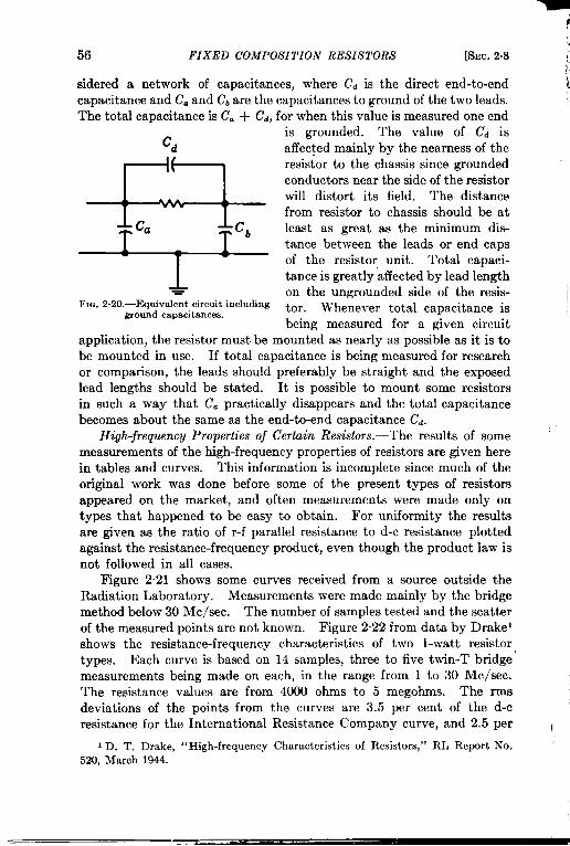
56 FIXED COMPOSITION RESISTORS
sidered a network of capacitances, where cd is the
!
[SEC. 2.8~
direct end-to-end icapacitance and C. and Cb”arethe capacitances to ground of the two leads.The total capacitance is C. + cd, for when this value is measured one end
is grounded. The value of Cd isd affected mainly by the nearness of the
~
resistor to the chassis since groundedconductors near the side of the resistorwill distort its field. The distancefrom resistor to chassis should be at
Cb least as great as the minimum dis-tance between the leads or end capsof the resistor unit. Total capaci-
1 tance is greatly affected by lead length- on the ungrounded side of the resis- 1
Fm. .2.20.-Equivalentcircuitincluding tor. Whenever total capacitance isgroundcapacitances.being measured for a given circuit
application, the resistor must be mounted as nearly as possible as it is tobe mounted in use. If total capacitance is being measured for researchor comparison, the leads should preferably be straight and the exposedlead lengths should be stated. It is possible to mount some resistorsin such a way that Cc practically disappears and the total capacitancebecomes about the same as the end-to-end capacitance Cd.
High-frequency Properties of Certain Resistors.-The results of some ‘measurements of the high-frequency properties of resistors are given herein tables and curves. This information is incomplete since much of theoriginal work was done before some of the present types of resistorsappeared on the market, and often measurements were made only ontypes that happened to be easy to obtain. For uniformity the resultsare given as the ratio of r-f parallel resistance to d-c resistance plottedagainst the resistance-frequency product, even though the product law isnot followed in all cases.
Figure 2.21 shows some curves received from a source outside theRadiation Laboratory. Measurements were made mainly by the bridgemethod below 30 Me/see. The number of samples tested and the scatterof the measured points are not known. Figure 2.22 from data by Drakelshows the resistance-frequency characteristics of two l-watt resistortypes. Each curve is based on 14 samples, three to five twin-T bridgemeasurements being made on each, in the range from 1 to 30 Me/see.The resistance values are from 4000 ohms to 5 megohms. The rmsdeviations of the points from the curves are 3.5 per cent of the d-cresistance for the International Resistance Company curve, and 2.5 per I
I D. T. Drake, “High-frequency Characteristicsof Resistors,” RL Report No.520, March 1944.

i%c. 2.8] HIGH-FREQUENCY PROPERTIES 57
cent for the Allen-Bradley curve. The original data showed the curvesof the individual resistors following closely the form of the average curve,
1.0
0.9:~ 0.8~
~ 0.7
.6s 0.6$ IRC’
: 0.5~m?? 0.4~
\
~ 0.3n
~ 0.2.:
T - \
~ 0.1 ‘AllenBradley EB Y2
o0.01 0.02 0.05 0.1 .0.2 0.5 1 2 5 io 20 50 100
Me/seex d+ megohms
FIG. 2.21.—Resistance-frequency characteristics (1),
,,
I
I
Lo
0.9~
j 0.8\.$?.
:0.7Gs 0.6alFm 0.5~ IRC \
; 0.4 ET.1z~ 0.3 — —
~ 0.2 i.g~ 0.1 \
Y
o\
0.01 0.02 0.05 0.1 0.2 0.5 1 2 5 10 20 50 100Me/seexd%megohms
FIG. 2.22.—Resistance-frequency characteristics (2).
indicating that the product law was valid for these resistors and fre-quencies, Figure 2.23 shows curves of 50,000-ohm resistors of severaltypes and wattages, based on bridge measurements made in the Radiation

58 FIXED COMPOSITION RESISTORS [Sscc. 2.8
Laboratory at 3, 10, and 30 Me/see.
1.0 ~0.9
m<
0.8al: 0.7~$ 0.6!!“5 0.5g
0,4
0.3
0.1 0.2 0.4 0,6 ].0 2 4 61310Mclsecx d-cmeaohms
\ h \ I ! I 1
\ .1 \\,v COntmental,C-1
\ \ Allen.BradleyG
Mclsecx d.cmegohms1.0 ~
m0.9 z
.4
0.8
z: 0.7~
# 0.6s.=s 0.5g
0.4
0.3
0.1 0.2 0.40.6 1.0 2 4 6B1OMclsecxd.cmegohms
FIG..2.23. —FLAstance-frequency characteris-istics (3).
k
Three samples were measured to \obtain each point.
Table 2.3, from measurementsby H. Beveridge at the Naval Re-search Laboratory, shows the di-rect end-to-end capacitance, thetotal capacitance, and the decreasein resistance from d-c to r-f for18 composition-resistor types.All measurements were made at60 Me/see on resistors of 2000-ohm and 10,000-ohm resistance.Each figure given is based on threesamples. Measurements of end- !to-end capacitance and of parallelresistance were made by the volt-age-divider method. The instru-ments were calibrated by assum-ing that the IRC Type-MPMresistors had the same resistanceat 00 Me/see as at d-c. Thereis some evidence that the 10,000 -ohm MPM units maybe a few per J
cent higher at this frequency thanat d-c. This would affect theresistance-decrease figures givenfor the other resistors of this value.During the total-capacitancemeasurements the units wereparallel to ground and ~ in. to }in. above it, depending on size. 1The exposed lead length, on theungrounded end, was in each case ,about half the length of the resis-tor body.
Figure 2.24 shows some resultsof measurements by Miller andSalzberg on IRC Type-F l-wattresistors. 1 As the figure shows, 1these units do not follow the pro-duct law, so a separate curve is 1
used for each resistance value. The measurements were made at fre- 1
1J. H. Millerand B. Salzberg,ibid. I

SEC.2.81 HIGH-FREQUENCY PROPERTIES
1.010k.
0.9 — — 4 / / t‘~ 20ks 0.8
50k..: f { \
lRC—100 k’
; 0.7 TyPSFw 200kz 0.6 \$J IRC
z 0.5 \ BTS~
$ 0.4g \g 0.3 sErie
n \ 524
= 0.2.: \ ,Allen
$ 0.1 BradleyES- ~Z
0.1 0.2 0.5 1 2 5 10 20 50 100I Me/see x d-c megohms
Fm. 2.24.—Resistance-frequencycharacteristics(4).
TABLE 2.3.—RESISTOR CHARACTERISTICS AT 60 MC/SEC
Maker
IRE,. . . . . . . . . . . . . .Global. . . . . . . . . . . . .IRE. . . . . . . . . . . . . . .IRE... . . . . . . . . . . . .Erie.. . . . . . . . . . . . . .Allen-Bradley.Stackpcde. . . . . . . . . . .Seer. . . . . . . . . . . . . .Stackpde. . . . . . . . . . .Erie.. . . . . . . . . . . . .Erie. . . . . . . . . . . . . . .Allen-Bradley,. . . .IRE. . . . . . . . . . . . . .Seer. . . . . . . . . . . . . .Stackpole,. . . . . . . . . .IRE.., . . . . . . . . . . . .Erie.. . . . . . . . . . . . . .IRC. . . . . . .
Type
MPM997-ABTRBTS524EB ~CM-+SI-*CM-4504B525GBBT-~SCI-+CM-1BTA518BBT-1
59
2000 ohms
A.
5.3
3.12.5
0.334,7
0.30
4.80.85
6.2
8.13.5
2.7
0.90
7.44.2
19.8
*A Percentage decrease in resistance at 60 Me/see.tBEnd-b”d capscitancek micromicrofarad8.: C Total capaci~nce in miorondcrofaradn.
Bt
0.010.25
0.280.24
0.110.300.160.250.120.40
0.380.230.210.100.420.340.7+
C$
0.25
0.37
0.42
0.40
0.35
0,500.35
0.450.45
0.75
0.75
0.550.58
0.55
0.85
0.901.40
10,000ohms
A“
27.018.818,512.427.09.6
29.39.3
25,222.433.417.310.88.8
27.016.458.3
Bt
0.020.270.200.200.140.260.140.290.090.230.330.340.190.100.080.260,210.46
—.c~
0.25
0,38
0.40
0.350.30
0,45
0.300.45
0.s00.60
0,65
0.730.50
0.50
0,52
0.68
0.901.10

60 FIXED COMPOSITION RESISTORS [SEC. 2.9
quencies from 30 to 250 Me/see by the transmission-line method pre-viously mentioned. Some Q-meter measurements, done mostly at IRC,and a few at Radiation Laboratory, indicate that IRC Types-F and-MPM resistors apparently have higher resistance in the neighborhoodof 10 Mc/scc than at d-c.’ The increase found was about 5 to 10 percent. The lower resistance values measured (around 10,000 ohms) stayedabove their d-c resistance up to 30 Me/see or higher, depending on watt-age and type.
Figure 2.21 also shows the results of measurements made with a high-frequency @meter on resistors of 100,000 to 300,000 ohms at frequenciesfrom 30 to 120 Me/see. In this frequency range the resistance-frequencyproduct law begins to fail, and the failure is relatively worse for resistorswhose values are fairly close to their d-c values (i.e., those with curves inthe upper part of the figure). The curves of this figure should thereforebe considered as very rough, and the information should not be used atother frequencies.
Figure 2.25 shows Drake’s total-capacitance measurements for theresistors of Fig. 2.22. Points are given instead of smoothed curves inorder to show the great variability of capacitance between resistors. Thedecrease in capacitance with increrising frequency can be accounted for byIIowe’s theory.
In certain high-frequency circuits the use of coils wound on resistorsand connected across them is common practice. If such a coil musthave a uniform or high inductance value or a high Q, a resistor with metalend caps should not be used. Since large currents are induced in theend caps, they decrease the inductance of the coil and increase its losses.
2.9. Stability. -In some measuring applications where great accuracyis not needed, composition resistors are used as parts of high-resistancevoltage dividers, etc. For such applications it is of interest to knowwhat changes in value may take place in a resistor that is kept indoorsand used only occasional y, and then at only a small fraction of its ratedwattage in a cool instrument.
Little investigation has been carried out on thk subject. Availabledata indicate that what changes take place are mainly caused by humidityvariations. Moisture can diffuse in and out of even the most completelyprotected general-purpose resistors, but it may take weeks for it to do so.In general, a resistor in equilibrium with a moderately humid atmosphereis likely to have a higher resistance value than the same unit in equi-librium with a dry atmosphere. The amount of change varies with themake and value of the unit, but its maximum change for the makes onwhich information is available is in the neighborhood of 3 per cent forconditions ordinarily found in laboratories in the northern United States.
I E. E. Johnson,‘<F-Type Resistors)”IRC Report 237,July 1945.
I

.
)
,,
SEC. 24)] STABILITY 61
1
2.0 -(a)
x*~
0 ~8 0
; 0 >
0.00; 0
0 > 0< , n 0L
c 0 ‘0 o ~ o
:.01 0.02 0.04 0.06 0.1 0.2 0.4 0.60.81.0 2 4 6810
tI 1 1 1 1
Me/seer d-c megohmsAllenBradleyGB1watt
1 0.02 0.04 0.06 0.1 0.2 0.4 0.60.81.0 2 4 6 810Me/seex d-c megohms
IRCBT1wattFIG.2.25.—Totalcapacitance-frequencycharacteristics,
,’

62 FIXED COMPOSITION RESISTORS [SEC. 2.9
A resistor that is used under load or in a hot chassis generally driesout fairly soon, and if it is used very often stays fairly dry. In suchcases changes in resistance are caused by high temperature rather thanby humidity.
The humidity test given in the AWS and JAN specifications is 25o hrat 95 per cent relative humidity at a temperature of 40”C. Before thistest is run, resistors should have been conditioned as for a temperaturetest. The permissible resistance change is 10 per cent. The change thattakes place in this test is generally an increase in resistance. As wasmentioned before, resistors in molded-bakelite cases ordinarily endurehumidity tests better than those with ceramic cases.
The changes that take place when a resistor is operated for a long timeat or near rated load can often be attributed to the decomposition, underthe influence of high temperatures, of the organic binder mixed with thecarbon. Since this results in the formation of carbon, a decrease inresistance would be expected. In the carbon-pellet resistor typesdecreases in resistance value are usually found, but in the filament typesthe change is more likely to be an increase.
The standard load-life tests have already been described in Sec. 2.5.The fact that these tests cover a fairly short time, (three weeks accordingto JAN-R-11 with proposed amendment 1, and six weeks according toAWS C75.7-1943) and the fact that the permissible changes are fairlylarge show that this test is not particularly severe. The wattage ratingsdetermined by these tests are not conservative and consequently tempera-ture deratings should be carefully observed wherever long-period reli-ability is important.
The standard overload test is the application of ~ times the ratedcontinuous-working voltage for a period of 5 sec up to certain limits. Topass this test, resistors must remain within 5 per cent of their orginalvalues.
Most composition resistors change somewhat in value when they aresoldered to connecting terminals. Joint Army-Navy Specification R-1 1specifies that this change must be less than 3 per cent under a certainsoldering test.
The mechanical strength of a composition resistor is adequate fornearly all applications. A 5-hr vibration testis specified, which resistorsmust withstand without showing mechanical damage or changing invalue more than 1 per cent. For all types except the small uninsulatedRC-15 the leads must be able to withstand a pull of 5 lb and a twistingtest.
Two types of cyclic temperature tests are specified. The first involvesfive cycles in air, starting at room temperature and alternating between– 55° ~~d -J-85”C. This cyclic treatment shall not cause a resistance
7F

SEC. 2.9] STABILITY 63
change of more than 5 per cent for any one resistor, and 90 per cent of asample group shall have changed less than 2 per cent.
The second cyclic test is the salt-water immersion test, which deter-mines the first of the two ‘( characteristic” letters in a resistor’s codedesignation. Each cycle lasts 3 hr: 1 hr in saturated salt water at 100”C,1 hr in salt water at O“C, and 1 hr of operation at maximum rated voltagein air at 40°C. After nine such cycles, a resistor must have changed notmore than 10 per cent to qualify for Characteristic B or D. This is avery severe test, and for most purposes resistors that will not pass it(Characteristics A or C) are perfectly satisfactory. Most bs,kelite-insulated resistors will pass the test; most ceramic-cased resistors will notpass; and very few uninsulated resistors of any type will pass.
BIBLIOGRAPHY ON COMPOSITION RESISTORS
General
American War Standard C75.7-1943, “ Fixed Composition Resistors,” AmericanStandardsAssociation,70 East 45th St,, New York City, 1943.
AmericanWar StandardC75.17-1944,‘<Method of Noise-testingFixed CompositionResistors,” AmericanStandardsAssociation,1944.
Cataloguesanddescriptiveliteraturefrommanufacturersof fixedcompositionresistors.JointArmy-Navy Specification,JAN-R-11, “Resistors, Fixed Composition,” Army-
Navy ElectronicsStandardsAgencyj 12 Broad St., Red Bank, N. J., 1944.“ProposedAmendment1 to JAN-R-11,” Army-h’avy ElectronicsStandardsAgency,
Aug. 15, 1945.StandardComponents List, 5th cd., Army-Navy ElectronicsStandardsAgency, 1945.Beveridge,H., Unpublished Table of Data, Combined Research Group, Naval
ResearchLaboratory, 1944.Boella,11., Alta Freqrwnza,3, No, 2 (April 1934).Bressi,Alta Frc.quenm, 7, 551 (August-September1938).Chipman,R. A., ‘1.4ResonanceCurve Method for Measurementof Inductance at
Frequenciesof the Orderof 300 Megacyclesper Second,” .Jorw.Applied Phys,;10, No. 1 (January1939).
Coursey,P. R., Letter, ibid,, 6, 37 (January1929).Drake,D. T., ‘‘ High-frequencyCharacteristicsof Resistors,” RI, Report No. E)20.
March 1944.Hartshorn, L., “The Behaviorof Resistorsat High Frequencies,” ibid., 16, 363 (July
1938).Howe,G. W. 0,, “The Behaviorof High Resistancesat High Frequencies,”Wi,eless
Eng., 12, 291 (June 1935).— “ The Behavior of Resistorsat High Frequencies)’)Wireless Ertg,, 17, 471
(~ovember 1940).— “ A FurtherNote on Resistancesat High Frequencies,”ibid., 12, 413 (August
19;5).—, “A New Method of Measuring High Resistances at Radio Frequencies,” Wire-
less Eng,, 17, 245 (June 1940).
High-frequency Properties
Jackson,W,, “The Effect of Frequencyon the Valueof High Resistancesof the GridI,eak Type)” Wireless Eng., 6, 677 (December, 1928).

64 FIXED COMPOSITION RESISTORS
7 ~
Johnson, E. E., “F-type Resistors,” InternationalResistance Co. Report No. 237, 1July 1945.
“Measurements of Effective Shunt Capacitanceof Resistors,” Report No. 1601W,HazeltineElectronicsCorp., Little hTeck,Long Island.
Miller, J, M., and B. Salzberg,“Measurementsof Admittancesat Ultra-HighFre-quencies,” RCA Rev., 3, 486 (April 1939). (Reissuedas “Publication ST-153,”RCA ManufacturingCo., Harrison,N. J,)
Pontecorvo,P., WireZes. Eng., 15, 500 (September1938).Puckle,O. S., “TheBehaviorof High Resistancesat High Frequencies,’’ibsd.,12,303
(June1935).“Radio-frequency Characteristicsof CompositionResistors,” Universityof Wiscon-
sin, Departmentof Miningand Metallurgy,CWA Project E 16-5.Sinclair,D. B., ~A NewNull Instrumentfor MeasuringHigh-frequencyImpedance,”
GemRadio Experimenter, 15, N0.7, 1 (January1941).—, “Parallel-resonanceMethods for Precision Measurementsof High Imped-
ances at Radio Frequencies,and a Comparisonwith OrdinarySeries-resonanceMethods,’’ Proc. IRE, 26, 1466 (December1938).
——, “A Radio-frequency Bridge for Impedance Nfeasurementsfrom 400 Kilo-cyclesto 60 Megacycles,” ibid., 28, 497 (November 1940).
—, “The Twin-T—A N’ewType of Null Instrumentfor MeasuringImpedanceat Frequenciesup to 30 Megacycles,” P,oc. ]RE,28,31O (July 1940).
—, “ The Type 663Resistor,”GemRadio Experimenter, 8, No. 8,6 (January1939).
Resistor Noise
Christensen,C. J., and G. L. Pearson, ‘(SpontaneousFluctuationsin Carbon Micro-phonesand OtherGranularResistances,”Betl System Tech. Jour., 15, 197 (April1936).
Johnson,J, B., ‘(Thermal Agitationof Electricityin Conductors,”Physical Reu., 32,97 (July 1928).
Terman, F. E., Radio Engineers’ Handbook, McGraw-Hill,New York, 1943,PP.476,477.
t’
I

!
I
FIXED WIRE-WOUND
CHAPTER 3
AND MISCELLANEOUS RESISTORS
BY Jh’f.D. FAGEN .4ND G. EHRENFRIED
This chapter consists of three main divisions, the first being devotedto standard wire-wound resistors capable of dissipating appreciableamounts of power, the second to low-power wire-wound resistors ofrelatively high accuracy and stability, and the third to a number ofmiscellaneous types of resistors that are of interest for various specialapplications.
POWER-TYPE WIRE-WOUND RESISTORS
3.1. Standard Types.—The units to be discussed in Sees. 3.1 through3.5 are those covered by the joint Army-Navy specifications JAN-R-26,“Resistors, Fixed Wire-wound, Power Type” and JAN-R-184, “ Resis-tors, Fixed, Wire-wound (Low Power). ” The latter are similar to themolded axial-lead insulated composition resistors previously discussed.They are made in $-, 1-, and 2-watt ratings, in both 5 and 10 per centtolerances. Their dimensions and resistance ranges are given in Table31 and Fig. 3.1.
FIIJ.3.1.—Low-power wire-wound resistor dimensions.
TABLE 31.-LOW-POWER FIXED WIRE-WOUND RESISTORS*
Dimensions Resistance, ohms
Type WattsA, max., B, max., C, min., in.in. in. min. max.
RU-3 + R ++ 0.032 (No. 20 A.W.G.) 0.24 470RU-4 1 l% & 0.036 (No. 19 A,W.G.) 0.51 2200RU-6 2 13 ++ 0.036 (No. 19 A.W.G.) 1.0 3300
* These resistors are specified by JAN-R-184. They arc identical in appearance with insulatedcompositionresistorsexcept that the first band of the color code is twice normal widLhto identify theunitsas wire-wound.
65

66 FIXED WIRE- WOUND AND MISCELLANEOUS RESISTORS [SEC.31
The JAN-standard power-type resistors are made in 35 styles, andmay be classified into six groups: ferrule-, stack-mounting-, tab-, screw-,axial-tab-, and axial-wire-lead-terminal resistors. Their dimensions andresistance ranges are given in Table 3.2 and Fig. 3.2. Figure 3.3 showsa group of typical power-type resistors.
(a)
-i
:“to :“
:’f=;qs
or -k
;to: (b)To ckar*8sc,ew
&
y160 ~;
(’”+~A,,
To clear C
(d
0.025th!ckness*0.005~~
(d
k)
0.032”dlam mm1 (“20 A.W.G.)/
FIG. 3.2.—Power-type resistor dimenaions.
The type designations used for power-type resistors are similar tothose for composition resistors, consisting of three letters and five num-bers as follows:
RW 10 F 100————
/’A/ 11Component Style Characteristic Resistance
Component: RW identifies the unit as a power-type wire-woundresistor.
Style: The first two figures identify the size and shape of the unit asexplained in Table 3.2.
Characteristic: The third letter identifies the class and grade of theunit according to Table 3.3.
Resistance: ‘l’he next two numbers give the first two significant
I
I
f
figures, and the last number gives the number of zero follcnving thesefigures, the combination expressing the resistance in ohms. For

i
SEC.3.1] STANDARD TYPES.
67
TABLE 3.2,—POWER-TYPE FIXED WIRE-WOUND RESISTORS >
Ferruleter-minalsFig. 3.%
f
1
Stack-mountingterminalsFig. 3.2b
Tab termi-
1 nals Fig.3.2c
L
Screwterminals Fig.3.2d
)
Axial-tabterminalsFig. 3.2e
Axial winleadsFig
I 3.2j
JANtype
RW-10RW-11RW-12RW-13RW-14RW-15RW-16
RW-20RW-21RW-22RW-23RW-24
RW-30RW-31RW-32RW-33RW-34RW-35RW-36RW-37RW-38RW-39
RW-40RW-41RW-42RW-43RW-44RW-45
RW-50RW-51RW-52RW-5?RW-54
RW-5:RW-5(
Dissipationrating,watts
ClsasI
1401209050402015
2231486070
78
162430386078
100155
30386078
100155
5102550
120
510
llmsIII
8067502722118
1317293435
348
12152033455786
152033455786
59
192560
59
H
403725151264
68
141719
23589
1218223043
91218223043
249
1842
24
Maxi-num*
anteilohm:
63635025166.34
25
101620
124
1616204050SO
100
1616255080
100
46.3
102550
46.3
Dimensions,in.
B c
1*1+1*H
2l%
1*23*4$6
1.14(I 14C).14(1.14() 47() 47().69().69().69().69(
) 47().47().69().69(). 69().6%
A3%A+sr%
. . . .
. . .
. . . .
~ max.H max.& max.H max.~ max.B max.
L* max.LA max.1+ max.1+ max.
~ max.~ max.
1+ max.1* max.1* max.1+ max.
● With2. Smil wire.
:,

;,
68 FIXED WIRE-WOUND AND MISCELLANEOUS RESISTORS [SEC.3.1
low resistances the letter R may be used for the decimal point; ~thus 2R5 would mean 2.5 ohms, and R25 would mean 0.25 ohms. k
The useful life of wire-wound resistors depends upon the maximumshort-time and the average continuous operating temperatures, the pres-ence of moisture or other agents that promote corrosion, and mechanicalconditions such as shock and vibration. It is evident from the tableabove that the Grade 1, Class I resistor, Characteristic F, will withstand
FIQ. 3.3.—Typical power-type resistors. (a) RW-39; (b) RW-37; (C) RW-35; (d) -RW-33; (e) RW- 32; (f) RW-31; (g) RW-53; (h) RW-51; (z) RW-16; (j) RW-15; (k)RW-14; (1) RW-13; (m) RW-12; (n) RW-56; (0) RW-55.
the most severe service usage without sacrificing wattage rating for agiven physical size. A resistor of this type can be made, at present,only by hermetically sealing the resistor element into a rugged Pyrex tube.Such a unit will withstand nine salt-water immersion cycles. Certainorganic coatings applied to conventional open-type resistors will also meetthe Grade 1 test but these invariably require derating to limit themaximum temperature to about 150”C, thus fitting them into Class III.Further information on derating factors is given in Sec. 3.4. Resistorsof characteristics E, F, and H will withstand at least nine salt-waterimmersion cycles, at the end of which they are not expected to have

4
SEC. 31] STANDARD TYPES 69
changed by more than 10 per cent from their initial value. Character-istic D resistors are expected to withstand two test cycles. The grade 3resistors, Characteristics C, G, and J, are required to withstand a500-hrcyclic temperature test at high humidity. At the end of the tests theresistance is not to have changed by more than 5 per cent. Resistors ofall classes and grades are expected to ~vithstand continuous vibration fora period of 5 hr, cycling through a frequency range of 10 to 55 cps with ahalf-amplitude of 0.03 in. A mechanical-strength test is specified callingfor a transverse load of 50 lb (25 lb for stack-mounting) applied at the
TABLE 3.3.—I’oiYER-TYPE JTIRE-IYOUNLIRESISTOR (CHARACTERISTICS
classI
11III
C,radc123
Lcttcr class Grade
c II 3D I 2E 11 1F I 1G I 3H 111 1J 111 3
TABLE3.3a31axinlumcontinuous
operatingtemperature,‘C275125200
‘hBLI? 3 3bResistancefollowingthermalshock
310st resistlnt to salt-~vatm immersionL(,ss rmistlnt to snlt-~vttcr immersionIksistant to humidity exposure
center of the resistor through a fulcrum having a radius of 0.25 in. or less.For this test the resistor is supported 0.125 in. from either end. Athermal shock test is required as a check on the coating material and onthe quality of the joint betJveen the end of the resistance wire and theterminal. This shock test consists of applying rated power to the resistorfor a time long enough to allow it to reach thermal stability, then plungingit into water at O“C (for Characteristic D, E, F, and H resistors) orimmediately subjecting it to an air temperatllre of —55°C (for Character-istic C, (1, and ,J resistors), After the thermal shock test, the resistor isnot to h:i~,e (,hwlged l]y more tliau 2 per cent, and the coating andterminals should show no observable mechanical damage. In the actual

70F
IXE
DW
IRE
-W
OU
ND
AN
DM
ISC
EL
LA
NE
OU
SR
ES
IST
OR
S[S
EC
.3.1
.-Z
4::::J:
+::::::
:
.mm
-$mm
.Ln
mm
t-rx
i02.sz

SEC. 3.2] CONSTRL’CTIO.V 71
testing procedure the thermal shock test precedes the salt-water-immer-sion or the moisture-resistance test, whichever applies.
3.2. Construction.-Standard power-type wire-wound resistors arewound of alloy resistance wire on ceramic forms, usually porcelain tubes,and the wound units are coated with a vitreous enamel or an organiccement. The resistance materials used are almost always either nickel-chromium or copper-nickel alloys. Some of the characteristics of themost-used alloys are given in Table 3.4. A collection of data on resist-ance wires will be found in Table 8,1 of Chapter 8.
The alloys used for wire-wound resistors may be divided into twogroups: the nickel-chromium alloys, of which the Nichromes are typical,and the copper-nickel alloys of the Advance type. There are otherresistance alloys that do not belong to either of these groups, but theyare not commonly used for fixed resistors of the types under discussion.In general the nickel-chromium alloys have a high resistivity (about 600ohms per circular mil ft) and a high temperature coefficient (about150 x 10–’/OC) which is substantially constant up to about 400”C. Thecopper-nickel alloys, particularly those with nickel contents of 40 percent or more, have lower resistivities (3OOohms per circular mil foot orless) and much lower temperature coefficients which may be eitherpositive or negative and which vary considerably over the temperaturerange 0° to 400”C.
The resistivities and especially the temperature coefficients of resis-tivity of all types of resistance alloy are greatly affected by slightvariations in alloy composition and by variations in the metallurgicaltreatment following the last annealing operation. Wire that is cooledslowly has a higher resistivity and a lower temperature coefficient thanthe same wire that is quenched from the last anneal. The problem ofmetallurgical stabilization is important if the temperature coefficient ofresistivity is to be held within close limits. For example, special process-ing is necessary to hold Nichrome V wire to a maximum of 100 X 10–6/OCand a minimum of 65 X 10–B/OC over the range 20° to 100”C. Uniformresistors can be made only if the wire is uniform as to metallurgicaltreatment, cross-sectional area, and circularity, and is free from scales,pits, slivers, seams, die marks, and corrosion.
Figure 3.4 shows the variation of resistance with temperature forfive of the more common resistance alloys. In Fig. 3.4a the “ mini-mum” curve is for wire that has been slowly cooled from 1000”C; the“ maximum” curve is for wire that has been quenched; and the “ aver-age “ is for the bright-annealed wire that is usually used for resistors.
The most widely used alloys for power-type resistors are those of theNichrome V group. In order to obtain the highest possible degree oflong-time resistance stability and uniformity of temperature coefficient

(
1,
72 FIXED WIRE- WOUND AND MISCELLANEOUS RESISTORS [SEC. 3.2
the wire must conform to a rigid set of specifications, such as the Bell Tele-phone Laboratories Specification KS-9140. This specification requires
81-Nichrome Y
0.8-
Tophet A~ Chromel A
(a)0.6-
(b)
Advance4 - 0.4-
:Y2g
0.2-
.5
go ogo 100 200 300 400 0 100 200 300 400.-:=8 rz~ (c)
56 -v
4 -
2 -
00 100 200 300 400 0 100 200 300 400
Temperature in degrees C Temperature in degrees C
FIG. 3.4.—Variations of resistance with temperature.
the following electrical and mechanical characteristics:
1.
2.
3.
The temperature coefficient of resistivity between 20° and 100”Cis to be between 100 X 10–s maximum and 65 X 10–s minimumper degree centigrade.The resistance tolerance is to be + 5 per cent for wire sizes AWG30 to 36, +8 per cent for sizes 37 to 44, and i 10 per cent forsize 45. (See Table 8.1, Chap. 8 for nominal values.)”The minimum tensile strength is to be 100,000 lb/in.a
4. The elongation in an 8-in. test piece is to be 20 per cent, minimum,for wire 0.010- to 0.040-in. diameter; 10 per cent for wire 0.0035-to 0.00175-in. diameter.
Windings.—Most power-type resistors are wound with bare wire on 1cylindrical porcelain forms with the turns widely spaced to reduce theprobability of short circuits. .TAN-R-26 specifies a maximum pitch of

SEC. 3.2] CONSTRUCTION 73
not, over 2.25 times the wire diameter for wiresup to lo-roil (0.0100 in.)diameter and not over 2.75 times the diameter for larger wires. Theminimum wire diameter according to the same specification is 2.5 milnominal (2.4 mil absolute minimum), but commercial resistors are woundof wire down to 1.5 mil and are satisfactory for most purposes. Theuse of ceramic insulation on the wire permits several other types ofwinding. One is analogous to the “coiled coil” used in incandescentlamp filaments; the insulated wire is formed into a close-wound helix ofa diameter of several times that of the wire, and this helix is then close-wound on the resistor form. Another type is the progressive universalwinding, which is also used on some low-frequency r-f coils and is therecalled “bank winding. ” In this winding the wire is fed through a guidethat oscillates parallel to the axis of the resistor form with an amplitudeof perhaps & in. as the form rotates and with a period of somewhat moreor less than the rotational period of the form. The guide advancesalong the form a fraction of a wire diameter per turn. The result ofthis rather complicated motion is that the wire builds up to a thicknessof perhaps 12 layers, the turns crossing and recrossing each other as ina regular universal winding. The winding is somewhat open and hasa low distributed capacitance and a fairly low voltage between adjacentturns. It permits resistances of up to 2* times the maximum obtain-able with a single-layer winding of the same wire on the same form, withonly a negligible increase in over-all diameter.
All these windings possess residual inductance and capacitance whichseriously affect their alternating-current properties at high frequencies(as will be discussed in Sec. 3.5), and many constructions have beendevised to reduce these quantities. By using a winding in which theadj scent turns carry current in opposite directions, the inductance isminimized; by spacing the turns as far apart as possible and keepingthe potential difference between turns to the lowest possible value, thecapacitive effects are reduced. Resistors made with such special patternsare termed “ noninductive, ” but this term is only relative since the timeconstant at 10 Me/see for a high-grade 1000-ohm resistor will be about0.1 psec.
The type of noninductive winding most commonly used is the Ayrton-Perry, which is made by winding a spaced helix between the terminals,after which a second helix is wound in the opposite direction between theturns of the first. The two windings are connected in parallel so thatthe resultant magnetic field is small and the capacitive effects are at aminimum because of the low voltage between adj scent turns. Such aconstruction, because of the parallel connection, reduces the resistancethat can be obtained in any given physical size by a factor of at least 2for single-layer windings and by a much larger factor for multilayer pro-

74 FIXED WIRE-WOUND AND MISCELLANEOUS RESISTORS [SEC. 3.2
gressive windhgs. Some comparative figures for the maximum resist-ance values obtainable with standard and Ayrton-Perry windings aregiven in Table 3.5. The type of resistor to which the table refers is an
TABLE 35.-MAXIMUM RESISTANCE OF FERRULE-TERMINAL RESISTORS
Resistorstyle
RW-16
RW-15
RJIT-l4
RW-13
RW-12
Ratingat 20”C, w
15
20
40
50
90
Type of winding
StandardSingle-layerProgressiveAyrton-PerryStandardProgressiveAyrton-PerryStandardProgressiveAyrton-PerryStandardProgressiveAyrton-PerryStandardProgressiveAyrton-Perry
Maximumresistance,ohms
1.5-roilwire
12,70030,000
600017,50050,000
Sooo53,00075,00025,0006S,000
100,OOO30,000
140,000200,00070,000
2.5-roilwire
3150
15004000
““i&12,50JI
600016,000...
WOO31,500
15,000
insulated-wire glass-enclosed ferrule-terminal sealed unit used widelvwhere severe humidity and atmospheric conditions are to be met. Th:90-, 40-, and 15-watt resistors are shown in Fig. 3.5.
Coatings. —Power-type wire-wound resistors must be protected afterwinding either by insertion in a glass or porcelain outer shell or by asuitable ceramic or organic-cement coating. The glass-shell construc-tion is exemplified by the JAN styles R W-10 through R W-16; theseunits employ the solder-seal technique to attach the ferrule terminalsto the shell and to obtain complete hermetic sealing of the windingagainst the entry of moisture or other corrosive agents. Most Sprague“ Koolohm” resistors employ a somewhat simpler construction in whichthe ceramic-insulated wire resistor with terminals attached is slippedinto a porcelain shell and sealed in place with a ceramic cement. Thegreat majority of power resistors, however, are wound with bare wireand therefore demand some sort of coating or impregnation, both forprotection of the wire against moisture and for holding the turns inplace on the winding form.
These coatings may be either inorganic or organic. The inorganircoatings are vitreous or semivitreou* enamels similar to those used onenameled kitchenware and bathroom fixtures, hut with special charaeter-

SEC. 3.2] CONSTRUCTION 75
istics required by the resistors. A good resistor coating should haveapproximately the same coefficient of thermal expansion as the resistancealloy (this also applies to the porcelain winding form); it should be reason-ably resistant to mechanical abuse; it should withstand severe thermalshocks without chipping or crazing; it should be impervious to moisture;and it should be easily applied and cured at a temperature low enough toprevent damage to the resistor. No coating has.been developed that is
.- .T-
.. .. . ..... .JFIQ. 3,5,—Ferrule-terminalresistors, F;;-l~p clown,respectively;RW.]2; RW-14;
completely satisfactory in all these respects and is at the same time ableto withstand continuous operation at high temperatures. Glassyinorganic enamels are satisfactory in many respects but are somewhatpervious to moisture and are often subject to damage by thermal shock.Other inorganic enamels have been developed which are highly resistantto thermal shock but which are somewhat porous and offer insufficientmoisture protection to fine-wire windings used in corrosive environments.Inorganic enamels, however, permit continuous operation at hot-spottemperatures as high as 275”C.
Organic coatings have been developed that are satisfactory in all ofthe above respects except that they limit the maximum operatingtemperature to their curing temperature, which is ordinarily from 130°to 160°C. These coatings usually employ a phenolic-resin varnish witha comparatively large proportion of inorganic filler; such as silica flour,mica flour, or iron oxide. They are highly resistant to moisture and tothermal shock, and can be made to pass the salt-water-immersion testspecified in JAN-R-26. The problem of lack of resistance to hightemperatures may be solved in the near future by the use of the heat-
* resistant silicone varnishes, some of which are good up to 500”C. Atpresent, however, the only resistors to receive a Class F rating (see Sec.3.1) are those sealed in glass tubes.

76 FIXED WIRE- WOUND AND MISCELLANEOUS RESISTORS [SEC. 32:
Too much emphasis should not be put on operation at extreme temper- t
atures. It would be possible to build a rugged resistor for continuousoperation at 1000”C, but it would hardly be practical to use it at thattemperature in the average chassis. Resistor operating-temperaturelimits are probably set more often by the neighboring components in thechassis than by the resistor itself.
Leads and Mountings. —Connection between the ends of the wind-ing and the terminals is made by soldering or welding the wire to ter-minal bands or lugs or by embedding them in alloy castings encircling
t
FIG. 3$-Resis,tor terminal construction. The upper unit IS an unfinished wire-wound resistor with die-cast terminals. The winding had been removed before the photo-graph was taken, leaving a short end of wire visible only in the original print. The ‘comcdgates would be clipped off in production, leaving only the radial wire leads protrudingthrough the insulating coating of the finished resistor. The lower unit is an RW-12 minusits protecting glass sleeve.
the ceramic winding form. Both methods are illustrated in Fig. 3.6.Besides the JAhT-standardized terminals of Fig. 3.2 many other types areavailable on commercial resistors, either standard or on special order.These include stranded wire leads, either bare or insulated with beads orsleeving; Edison medium screw bases to permit the use of the resistor ina standard electric light socket; single-hole mountings with mountingnut similar to that often used with filter condensers, the winding beingterminated on soldering lugs at the threaded end of the unit; ferrules ofvarious sizes and shapes, including conical ferrules to permit mounting in

SEC. 33] RESISTA.VCE VAL(JES .AND TOLERANCES 77
grid-leak clips ; live brackets, \vithth cwindin gterminate donthe mount-ing brackets; and various others. The mounting devices are even morevaried than the terminals. In some cases, as with the live-bracket andferrule-terminal types, the units are mounted by the terminals. Inothers, such as the stack-mounting resistors, the mounting is mechani-cally integral with the unit, but separate insulated terminals are provided.In still others, means for separate mounting are required, and the manu-facturers offer a wide choice of mounting hardware.
The JAN specifications require that terminals pass certain mechanicaltests which are fairly severe incases where the units are supposed to bemounted by their terminals. In general, mounting by the terminals isforbidden except for the smallest sizes of resistor. All wire-woundresistors, except the tiny RU styles and the types with integral mountingmeans, should always be mounted by suitable brackets, clips, or through-bolts. Where bare porcelain cores are exposed they should never bescrewed or clamped to metal panels or brackets without a cushioningwasher of asbestos, mica, or fiber. Because of their fragile flanges thisprecaution is particularly important for bobbin-wound precision resistors.
3.3. Resistance Values; Tolerances and Variations.-The maximumresistance obtainable in a given physical resistor size depends upon theminimum permissible wire size, the form of winding (single-layer, multi-layer, or noninductive), and the maximum permissible operating tem-perature of the completed resistor. The JAN values for maximumresistance given in Table 3.2 are based on the use of single-layer windingsof 2.5-roil wire. Not all applications require that the wire be so large orthat the winding be restricted to a single layer. For ordinary industrialor laboratory uses where corrosive conditions are much less severe thanin military applications 1.4- or 1.5-roil wire can be specified with reason-able assurance of long resistor life. If the hermetically sealed glass-en-closed form of resistor is used, the greater protection so afforded permitsthe use of the smaller wire even under unfavorable environmentalconditions. Table 3.5 presented a comparison of maximum resistancevalues obtainable in such a resistor for 2.5-roil and 1.5-roil wire, single-layer, multilayer, and noninductively wound. It is seen that in goingfrom 2.5 to 1.5 roil, single layer, the maximum obtainable resistance isincreased by a factor of approximately 4, and in going from a single-layer1.5-roil wire to a progressive winding of the same size wire, the factor isl+ to 3. It must be pointed out, however, that the use of progressiveor multilayer windings will reduce the wattage rating for a given physicalresistor size and full information on the reduction factor should beobtained from the manufacturer. Despite this reduction, such windingsafford considerable economy in space, particularly in applications wherethe actual dissipation is small compared to the dissipation capability

78 FIXED WIRE- WOU,VD A .VD MISCELI, A.VEOUS RESIS1’ORS [SEC. 33
that is inherent in the resistor because of the physical size required forthe necessary resistance.
Further information on the maximum obtainable resistances for threeother types of resistor is given in Table 3,6. Part a of Table 3.6 refersto the commonly used cylindrical resistor with radial soldering lugs,Part b to axial-lug ceramic-sheathed resistors with a coiled-coil windingof ceramic-insulated wire (Sprague “ Koolohm” construction), andPart c to flat stack-mounting or “ ribbon” resistors.
TABLE36.-IIAx1MuM ReSiStanCevs. WIRE SIZE AND TYPE OF WINDING
J.4N ‘~j’pc
—
I
Resistance,ohmsW’attage
2.5-roilkvire I 1.5-mil\vireI
h-Oninductive
a. Radial-lugtype resistorsI
RW-30 1711,00ci 2,500 I 3,000RW-32 16 ,j~ I 16,@30 3,000RW-33 24RW-34 30 16,000 I ;::: ;;ERW-35 38 20,000 72,500 5,000RW-36 60 40,000 120,000 5,000RW-37 78 50,000 180,000 5,000RW-38 100 80,000 340,000 5,000
b. hial-lug type resistors
RW-50 I5 I 4,OOO I 40,000 ‘i 5,000
R}V-51 10 6,300 70,000 ! 10,QOORIV-52 25 10,000 100,000 25,000RIV-53 50 25,000 100,OOO 50,000RFV-54 120 !50,000 250,000 100,OOO
c. Stack-mountingresistors
R1l’-2O 22 2,000 6,300RW-21 31 5,000 15,800RW-22 48 10,000 35,000RW-23 60 16,000 50,000RW-24 70 20,000 66,000
Standard Resistance Values.—The actual resistance values specified asstandard by JAN-R-26 follow a preferred number system rather like~hat used for composition resistors, but with fewer values per decade.The succession of values runs 10-12-16-2G25-31 -4O-5W3-8O– andrepeats in succeeding decades. Since the standard tolerance is ~ 5 percent for most values, it is obvious that there are numerous resistanceranges that cannot be covered with standard resistors, but for any appli-

r
f
i SEC. 3.3] RESISTANCE VALUES AND TOLERANCES 79
cation in which power-type resistors would be likely to be used the resist-ance tolerance should be large enough to render this objection immaterial.The standard minimum resistance is 0.10 ohms for all JAN types exceptRW-10, for which it is 2.0 ohms. The standard tolerance for RW typesis f 5 per cent except for values less than 1.0 ohm, when it is + 10 percent. For tapped resistors which are standard in performance and inconstruction except for the taps the tolerance is t 10 per cent for theindividual sections and t 5 per cent for the over-all resistance. The low-power RU resistors are made in two series, with f 5 and f 10 per centtolerances.
A perusal ‘of the catalogues of a number of resistor manufacturersindicates that few if any of them adhere to the conventions of the previousparagraph for either stock resistance values or standard tolerances. Atypical list shows very few stock sizes per decade in either very high orvery low values, whereas in the commonly used ranges there may be 15or more stock sizes per decade. This condition is due to two facts.First, a manufacturer will naturally list only those sizes for which he hasfound there is an appreciable demand. If, for example, there are twopopular audio-output tubes that require lo-watt cathode resistors andthe tube handbooks give 550 ohms as the correct value for one and 600ohms for the other, the manufacturer will probably list both of thesevalues, even though neither is standard and though either of the standardvalues of 500 and 630 ohms would probably be just as suitable in theaverage receiver. On the other hand, since an order for 0.63-ohm resis-tors of a particular type would probably be received only once in manymonths the manufacturer would probably prefer to consider this a specialvalue, to be made up when the order is received. Second, although thesusceptibility of the exposed wires of adjustable resistors to mechanicaldamage and corrosion has led to their being banned by the ArmedServices for use in combat equipment, they are quite satisfactory formany commercial applications and offer a solution to the problem ofobtaining intermediate resistance values that is itself a sufficient excuse foreliminating rarely wanted items from a stock list.
Somewhat more uniformity is found among the manufacturers in thematter of standard tolerances. Most of them specify t 5 per cent asstandard, increasing this to +10 per cent below 50 ohms. Others listonly t 10 per cent wire-wound resistors, and many manufacturers listother tolerances as obtainable on special order at an increased price.
Temperature Coeficient.-Practically the only variable that has anappreciable effect in changing the resistance of a wire-wound resistor istemperature, and the temperature coefficient of the resistor is approx-imately that of the resistance wire itself. Considerable latitude is givenin the JAN-R-26 specification which permits a coefficient, referred to

80 FIXED WIRE-WOUND AND MISCELLANEOUS RESISTORS
26°C, of 400 X 10-’/OC for resistors up to 50 ohms and 260 X
[SEC. 34
lo–6/0~
for resistors over 50 ohms. For the usual accuracy requirements ofpower-type resistors the change of resistance with temperature can beestimated satisfactorily from the curves of Fig. 3.4. A measurement ofthe rise of resistance at a single elevated temperature will usually showwhether the wire used is of the high- or the low-temperature-coefficienttype, if this information is not otherwise available. To determine theactual variation of resistance in service, however, it is necessary to takeinto account. the fact that the average temperature of the winding willnormally be less than the maximum hot-spot temperature and ]vill dependmarkedly on the cooling conditions. ordinarily the percentage of risein resistance is about two-thirds of that given by the product of hot-spotrise and temperature coefficient.
3.4. Ratings.-The dissipation ratings of power-type resistors arebased on the maximum permissible temperature rise when operating instill air and suspended in free space with an ambient temperature of25°C. Still air is defined as air with no circulation other than that createdby the heat of the resistor in operation. Free s~ace is defined as that inwhich no object is closer than 12 in. to the resistor coating except themounting clip, which must be at least 2 in. below the unit. The resistoris to be mounted horizontally. The temperature, is measured at thehottest spot on the surface, using a thermocouple hung over the resistorwith its leads weighted by a load of 2 oz to provide for pressure of thethermocouple junction against the uppermost portion of the resistorsurface. The couple is made of No. 30 AWG wire or smaller, lap-welded.
I
Per cent of rated watts
Resistors are classified on the basisof wattage dissipation under theconditions described above forwhich the maximum hot-spot tem-perature will not exceed a spec-ified value. This value dependson the type of construction andthe material used for protectivecoating. High-temperature re-fractory coatings allow a maximum
FIG 37.-Temperature rise vs. dissipa- hot spot of 275°C; moisture-resist-tion for Class I resistor at 25°C arnblenttemperature. ant organic cements are generally
limited to a maximum hot spotof about 160”C with a consequent reduction in rating to about 40per cent of the first type. Figure 3.7 shows the temperature rise of aClass I resistor of the radial-lug type, plotted against per cent of rateddissipation. It is evident from such a curve that the useful practicalwattage rating of a resistor must be something less than the free-air
I

SEC.3.4] RATINGS 81
rating since the latter condition is never achieved in actlml use. Some ofthe necessary considerations are summarized in the “ l’se Notes” whichare a part of specification JAN-R-26.
10090
z 80= 70$ 60
50; 40~ 30~ 20 .
10
30 40 50 60 70 80 90 100Ambient temperature in degtees centigrade
FIG.3.8. —Dcrating curves for h~gh ambient temperatures. Class I: 275°C maximum hotspot. Class II: 125°C max~mum hot spot. Class III: 200°C maximum hot spot.
1.
2.
3.
4.
For ambient temperatures higher than 25°C, a derating factorshould be used to normalize to the value for which the resistor israted at 25°C (see Fig. 3,8).When resistors are mounted in enclosures that limit ventilation,the wattage dissipation of any resistor should be reduced so thatthe maximum hot-spot temperature permissible for the resistor isnever exceeded under the most severe combination of temperatureconditions.When resistors are mounted in rows or banks they should be sospaced that, taking into consideration the restricted ventilationand heat dissipation by the near-by resistors, none of the resistorsin the bank or row exceeds its maximum permissible hot-spottemperature. It is difficult to give a definite factor but reductionin ratings of 50 per cent may frequently be necessary.The styles of resistors should be so chosen that, as mounted inequipment, they will at no time operate at temperatures in excessof their rating. More specifically, this applies to equipmentoperating as follows:a.
b.
c.
d.e.
In the maximum specified ambient temperature.Under conditions producing maximum temperature rise in eachresist or.For a sufficient length of time to produce maximum temperaturerise.With all enclosures in place.With any special conditions imposed which are possible duringthe life of the equipment, as at high altitude for airborneapparatus.

l’olkzge Ruting.—lkause of the comparatively large physical size d’wire-wound resistors and the fact that inherently the voltage gradientcan be uniformly distributed, the limiting operating voltage is establishedin most cases by the wattage rating and resistance value of the unit.One important exception is the limitation introduced by some types ofcoating when operated at the high temperatures corresponding to fullwattage ratings, since these coatings under such conditions are poorinsulators. In general it is necessary to limit the voltage, across theterminals of a vitreous-enamel-coated resistor operating at its maximumtemperature, to about 500 volts. This limitation may be introduced inother types of resistor for the largest units; for example, a 250,000-ohm,150-watt resistor. If the coating of such a resistor is not considered, thepower rating would permit 6100 volts but because of the coating theactual rating of the manufacturer might be 5000 volts.
Another-element to be examined is the voltage limitation of theresistor insulation between terminals and mounting hardware. The ,JAA”specification requires that all resistors, except the ferrule-terminal types,withstand 1000 volts rms at 60 cps between the resistor terminals con-nected together and the mounting hardware or metal plates in contact,with the ends or surface of the resistor. The insulation resistancebetween terminals and mounting hardware after this test is required tobe not less than 50 megohms. If there is to be a high potential betweenthe resistor and a grounded surface on which it is to be mounted, it willbe necessary to provide additional insulation in the form of ceramicbushings or other heat-resisting insulators.
3.5. Alternating-current Characteristics. -The behavior of wire-wound resistors at high frequencies is affected to a considerable extentby the inductance and capacitance that are inherent in their construction(see Sec. 3.2), Skin effect is not particularly troublesome because of thesmall-size wire generally used. Some indication of the magnitude of skineffect is given in Table 3.7, which shows the largest permissible wire sizefor a skin-effect ratio of 1.01, calculated for a cylindrical straight wireremote from other conductors.
TABLE 3 7.—SIUX ~FFECT IN RESISTANCEWIRES
Frequency,!
Wire size, roils—
kc/seeiYichrome Manganin
100 104,5 70.21,000 33.0 22 2
3,000 19.2 12 8
10,000 10 4 7.0
Constantan I Advance ~ Copper
74.5 71.6 14 023.5 22.4 4413 6 118, 2.67.5 , 72 1,4
(

SEC.3.5] ALTERNATING-CURRENT CHARACTERISTICS 83
Inductive andcapacitive effects arenotso easily disposed of. BecauseI of the difficulty of separating these parameters and in determining react-
ance of high-resistance components, little useful information is availableeither in the form of an applicable lumped-constant analysis or in that ofactual experimental data. The common procedure used by resistormanufacturers to find the inductance of a wire-wound resistor is either tocalculate it from standard inductance formulas or to make up a similarunit with copper wire and to measure its inductance. More recently, thispractice is being replaced by measurements made on actual resistors andsuitable techniques are being appliedso that some information can beobtained for resistors of moderatevalue. -
The most practical circuit repre-. .c
senting a wire-wound resistor at high FIG.3.9.—Equivalentcircuit of a wire-
frequencies is shown in Fig. 39.wound resistor.
Definite values can be assigned to the components of this circuit atany one frequency, and these, with certain limitations, will be reasonablyvalid over a wide range of frequencies. The errors in such a circuit, ifR is taken as the d-c resistance, are due to the following factors:
1. The capacitance and inductance are distributed, not lumped.2. There are dielectric losses present in the insulation and coating.3. There may be a skin effect with large wire and at very high fre-
quencies.
There is therefore a limiting frequency at which the simple circuit nolonger is applicable, depending on the type of resistor and the permissibleerror in calculations.
For measurements of conductance and effective parallel capaci-tance of typical wire-wound resistors at frequencies between 1 and 35Me/see, a twin-T impedance measuring circuit has been used. I Thismethod of measurement is more suitable in the megacycle range offrequencies where the usual series method giving effective values ofseries resistance and reactance affords no simple or direct capacitancemeasurement.
The parallel method applied to the equivalent circuit gives theadmittance.
R
[
L‘c = R, + (@L), 1+j@C–R2+(UL)2’
Since the inductance and capacitance are already fairly well separated,
I D. T. Drake, “High Frequency Characteristicsof Resistors,” RL Report No.520, Mar. 9, 1944.

84 FIXED WIRE-WOUND AND MISCELLANEOUS
no difficulty is involved in their calculation when
RESISTORS [SEC. 3.5
the conductance andsusceptance are known. If the resistance is assumed equal to the d-cvalue the inductance can be determined directly in terms of the parallelconductance and d-c resistance from the equation
100
90
80
70
:E.560E.E:s 50:uEv
40
30
2C
1(
\
Measured
//
(/
/
C=0.64pMf.\
\
Equivalent circuit\
\ e
‘\
>’ ‘~.
Y= ~ “‘) —‘3@ (C R2+(@2R *..
R2+(uL)2 R2+(loL)2
0 5 10 15 20 25 30 35Frequency in Mc Isec
FIG. 3.10.—High-frequency characteristics of IRC type AB resistor.
An accurate determination of the capacitance is more of a problembecause of the difficulty in obtaining accurate measurements of valueswhich are generally 1 pyf or less. One can ordinarily be satisfied with anapproximate solution, however, because the inherent capacitance of aresistor is usually small in comparison to circuit-wiring and vacuum-tubecapacitances.
A

SEC.35] ALTERNATING-CURRENT CHARACTERISTICS
Figure 3.10 shows the experimental and the calculated
85
values ofcapacitance and conductance-for a typical 10-watt 10,000-ohm IRCtype AB cylindrical single-layer power-type resistor. It isseen that theequivalent circuit in which L = 115 uh and C = 0.64 uuf is valid UDtoabout 17 Me/see.
+50
+40
+30
+20
+10
-lo
-20
-300 4 8 12 16 20 24 28 32
Fre~uency in Me/seeFIG, 3.11.—High-frcqucncy characteristics of wire-wound resistors.
Figure 3.11 is a set of curves showing the high-frequency character-istics of cylindrical single-layer power-type resistors ranging in valuefrom 500 to 50,000 ohms over the frequency range from O to36 Me/see.It is evident that the reactance may be either inductive or capacitive,

86 FIXED WIRE- WOIJA’D A A’D J[[ITCJ?I.I.A .Vfi:Ol”S RESISTORS [Sm. 35
depending on the frequency, and that the actual impedance may differfrom the d-c resistance by a factor of 10 or more. h-o general rules ofvariation can be given because the performance of a particular resistorwill depend on the number of turns, spacing, and physical dimensions andthese, in turn, on the wire size, wattage rating, and resistance value.Table 2.11 gives values of inductance for a range of resistance values of10-watt single-layer resistors. These are intended to give order ofmagnitude only, since the method by which they were measured has notyet been thoroughly examined and confirmed as completely reliable.
TABLE 38.-INDUCTANCE OF 1O-WATTSINGLE-LAYERRESISTORS(Length = 1%in.; Diameter = & in.)
Resistante, Inductance,ph Resistance,ohms Inductance,phohms
1000 56 6,000 2011250 47.5 7,000 1861500 73 7,500 2052250 72 10,OOO 1152.X)O 88 12,000 2823000 S4 12,500 753500 118 15,000 3154000 176 50,000 7354500 114
Special \vindings are obtainable in power-type resistors to reduce theinductance to much lower values than are obtained with simple solenoidalor progressive windings. The Ayrton-Perry \vinding is generally usedfor the so-called noninductive resistors. Table 3.9 gives comparativeinductance values for standard and noninductive windings on cylindricalcoated power-type resistors.
TABLE 3.9.—INDUCTANCESOF STANDARDAND AYRTOiY-PERRYJVINDINGS(Data from lRC Catalog38)
Inductance,uhIRC Wattage Resistance, Physicalsize,type rating ohms lengthand diameter,in. standard AyrtOn-Perry
AB 10 1000 l~x~ 66 0.6DG 20 1(XI 2x& 14 0.25
80 4+X: 76 0.3~A ] 1; 4000 6* X Ii 3360 0.3
As has been pointed out, the inductance of a resistor cannot, in itself,establish its high-frequency properties. Capacitive effects becomeincreasingly important with increasing frequency. For example, at 3

SEC.3.6] STANDARD TYPES 87
Me/see the reactance of a 15-watt RW16F resistor becomes capacitivefor a value of 300 ohms. For a 120-watt resistor of the same type, allvalues over 250 ohms are capacitive. It is evident that there is not muchto be gained by insisting on noninductive windings for resistance valuesabove a few hundred ohms, at this frequency. This point is demon-strated in Table 3.10, which gives the phase angles for three types of .wkdng of ferrule-mounting resistors, style RW16F and RW1 1F with15- and 120-watt ratings, at a frequency of 3 Me/see.
TABLE31O.-REACTANCEOFSFEAGUElVIRE-WOON~RESISTORSAT3 Mclsm
I Phase angle
1’
Style of winding RW16F RW1lF
~Kl&%%g, NXS%h:t&d)
Standard(type F) 60°57’ 57°20’Noninductive(type NIF) ~~~ ~ ~ ~~ ~ 6°22’ 22°“Super” noninductive(specialwinding) 2°15’ 14”20’
ACCURATEWIRE-WOUND RESISTORS
3.6. Standard Types. -There are many applications in electroniccircuits where accuracy and stability requirements are greater than canbe met with power-type resistors but where the power dissipation is solow that surface hot-spot temperatures can be kept to a maximum of105”C. For such applications a number of types of resistor have beendeveloped that may be called ‘‘ accurate wire-wound resistors. ” Theterm “ precision resistors” is also commonly used. These units are smallin size, wound of fine insulated resistance wire, usually in deep narrowslots in ceramic or plastic bobbins, and are widely used in d-c amplifiers,computing networks, linear sweep generators, multivibrators, and similarapplications where resistance tolerances of ~ 1 per cent or better arerequired.
Much of the material on power-type resistors in Sees. 3.1 through 3.5is also applicable to the accurate resistors. This section and the twofollowing will present additional information specifically relevant to theaccurate types.
Two Joint Army-hTavy Specifications cover accurate wire-woundresistors: JAN-R-93, “ Resistors, Accurate, Fixed, Wire-Wound, ” andJAN-R-29, “Resistors, External Meter (High Voltage, Ferrule TerminalType). ” Outline drawings of the five classes of resistor of JAN-R-93and the one of JAN-R-29 are given in Fig. 3.12; the dimensions andcharacteristics of the various styles are given in Tables 3.11 and 3.12.

88 FIXED WIRE-WOUND AND MISCELLANEOUS RESISTORS L%c. 36
TABLE 3 11.—ACCURATEWIRE-WOUNDRESISTORS—
IJAN-R-93
style
Radial-lug RB-10terminals RB-11(Fig,3.12a) RB-12
RB-13RB-14
Screw ter- RB-20minals RB-21(Fig.312b) RB-22
Sealed-in- RB-30glasstype RB-32(Fig.3.12c)
JSingle-ended RB-40
bobbin RB-41type (Fig. RB-423.12d)
Smallaxial- RB-51lead type(Fig.312.)
Vominal Resistancepowerrating, —watts min.,
ohms
—l—
$ 1.01 1.0
1.5 0.1
1 1.01 300,001
0.4 0,10.5 0.10.6 0.1
max.,Legohm:
0.1850.3000.3000.7504.0
0.4500.3001,250
0.3000.800
0.1500.3000.450
0,100
A IB I1 1max.
min. max. Ic
~
I 1*
I~., ,...
2& 2& 1*
Little need be said here concerning the meter resistors; their specifica-tions are almost identical with those of JAN-R-26 for ferrule-terminalpower resistors, except that no wattage rating is given for the meter resis-tors since they are intended for operation at a uniform current of 1 mafor all types, and their resistance tolerance is t 0.5 per cent. Thespecifications of JAN-R-93 are roughly similar to those of JAN-R-26but are somewhat less rigorous mechanically and more rigorous electri-cally. They will be discussed in more detail in Sees. 3.7 and 38.
Most of the accurate resistors made by the various manufacturersare similar to the JAN types, but there are a few other types of interest.Several manufacturers offer bobbin-wound resistors with one or moreintermediate taps. Several also make accurate resistors with higherpower ratings, both in the form of bobbin-wound units designed andtreated for operation at higher temperatures than the usual 105°C andin the form of small power-type resistors with close tolerances on resist-ance and temperature coefficient. Such resistors are available in ratings

SEC.3.6] STANDARD TYPES 89
Clearance for’6 screw
0.016’’min
~~
thickness
-— -_ ___ __~ _______ B-
,1
+“,
(a) (b)
0.032” dia (%?0A.W.G,) min
(c)
Clearance for 0.016” min
“a@
#6 screw
1 --—— _~.. --:_n - ~“f’ +3’
max
~ A+&:,, d
(d)I
F%iF=zii’otp~”@0.032” dia (~20 A,W.G.) min B
(e) (f)Fm. 3.12.—D,mensions of m-curate wire-wound resistors.
I
I TABLE 3.12.—EXTERNAL IYIETEERESISTORS(High-voltage, ferrule-terminal type, per JAN-R-29)
Type hlFA MFB MFC
Resistance,megohms 3.5, 4.0, 5.0, 6.0 1.0, 1.5, 2.0, 2.5, 3.0, 3.5 0.5, 0.8, 1.0Dimensions, in. A, max. 8fi 4& l=
B,9%** 5& 2~C,l*+L la g
64 — 6,
D,lfi*& 1=+~64 — 64 I*&E, Ntol& ~to 1* H to 1A
NOTE:No power dissipation ratings specified. All units operate at l-ma maximumcurrent. Reeiatance tolerimce ~0,5 pm cent. See Fig. 3.12j for outline drawing.
I

~ FIXRD WIRE- WOIJNI) A N]) MIS{lEI.l,A NI?OUS RE,’3JSTORS
up to 10 watts. Resistor units and resistive networks mayobtained in various enclosures including plug-in types.
[Ssf’, ::7
alS(J t)f?
The numerous forms of precision resistor that have been developedby the manufacturers of measuring and test equipment will not bediscussed here.
3.7. Construction.-Accurate wire-wound resistors are wound onsmall bobbins of molded plastic or ceramic material. Except in thesmallest sizes the windings are distributed among several slots, andusually the direction of winding is reversed in each successive slot in aneffort to reduce the inductance of the unit. Such a practice is effectiveonly at comparatively low frequencies because of the leakage flux betweenslots and the high distributed capacitance in the random-~vound sections.
Because of the low operating temperatures, insulated wire is alwaysused for the windings of accurate resistors. Enamel, Formex, andFormvar insulations are the most common, but textile wrappings suchas silk, Fiberglas, and resin-impregnated Fiberglas are also used. Theresistance alloys are the same as those used for power-type resistors,except that Manganin is also used for the lower resistance ranges.Manganin has a restricted operating temperature range (+10 to + 40”C)and is somewhat more difficult to handle than some of the other alloys;its principal advantage is its low thermal electromotive force againstcopper. Nichrome V is most commonly used for resistance values above100,000 ohms and also for lower values when a very low temperaturecoefficient is not required. When the coefficient must be low, Advanceor Manganin are usually chosen. A new alloy (Evanohm, produced bythe Wilbur B. Driver Co.) has recently appeared which combines thehigh resistivity of Nichrome V (675 ohm per circular mil foot) with thelow temperature coefficient of 25 X 10–’/OC, It is a nickel-chromiumalloy with a special metallurgical treatment and will soon be in general use.
JAN-R-93 specifies the minimum permissible wire diameter as 1.5roils for the copper-nickel and nickel-chromium alloys, and 2.0 roils forall others, “All others” in this case is intended to mean Manganin,which is brittle and comparatively weak. Commercial resistors may beobtained with wire as small as 0.8 roil.
After winding, resistors are impregnated with various materials toexclude moisture and to protect the windings mechanically. Before thewar, impregnation with any of the usual electrical varnishes was con-sidered sufficient, and some manufacturers used only a wax dip. Withthe imposition of military requirements for operation at high humidityand over a wide temperature range the prewar treatments were found tooffer wholly inadequate protection in most cases, and a number of newimpregnants and processes were developed. These processes are nowused on practically all units, and afford complete protection against all

SEC.3+3] ELECTRICAL CHARACTERISTICS 91
but the most severe conditions. For the maximum protection, units arehermetically sealed in glass or ceramic tubes, as in JAN types RB-30and RB-32 and the meter resistors, or in metal containers with solderedglass bushings. JAN-R-93 establishes two types of protection: Charac-teristic A resistant to 5 cycles of the salt-water-immersion test (between0° and 85”C), and Characteristic B to 10 cycles of the humidity test.
Accurate resistors may be furnished with any of a number of terminaltypes: screw or binding-post terminals, ferrules, soldering lugs, mountingears, or solid or stranded wire leads. They are usually mounted either bya screw through an axial hole or in fuse or grid-leak clips. Screw-mounting resistors should never be mounted in direct contact with ametal bracket or mounting plate; a bakelite or fiber cushioning washershould always be used between the bobbin and the mounting plate toprevent cracking of the brittle ceramic form. Figure 3.13 shows a groupof typical accurate wire-wound resistors.
One type of resistor that has been developed toorecently to find itiway into the JAN specifications but that meets all the JAN tests and hasNavy approval isthe Daven Seald-ohm, sho}vnin Fig. 3.l4. Up to fourresistor units, either bobbin- or card-type, are enclosed in a small drawn-metal case furnished with glass-insulated solder-seal bushings, the caseisthenfilled with ahlgh-melting-point ~vax,andthebottom is soldered on.
i 3“8. Electrical Characteristics. Resistance Vatues.—JAN-R-93 listsonly maximum and minimum values for the resistances of the various

92 FIXED WIRE- WOUND AND MISCELLANEOUS RESISTORS [SEC. 38
styles of accurate wire-wound resistor, and all but a very few of themanufacturers do the same for their commercial units. The reason forthis is that it would be impracticable, because of the narrow tolerancespermitted with this type of resistor, to stock resistors of enough differentresistance values to cover the whole range. Consequently these unitsmust be made up and sold on a special-order basis. Some manufacturersdo list standard values, the values themselves and the number of nominalvalues per decade being approximately the same as those listed for themore popular styles of power wire-wound resistors. The JAN resistanceranges are given in Table 3.11. Commercial resistors can be obtainedin resistances up to several times the JAN maxima, when smaller wirethan the JAN 1.5-roil minimum is used.
FIG.3.14.—DavenScald-ohmresistorunit and bracket, (The solderinglugs on thefront terminals were removed by the retoucher; the tips of the rear lugs can be seen abovethe case.)
The meter resistors of JAN-R-29 are made in eleven standard valuescorresponding to the ranges of JAN-standard l-ma voltmeters; somemanufacturers also furnish higher and lower values in the sameconstruction.
Resistance Tolerance.—The standard resistance tolerances of JAN-R-93 are +0.25 per cent (Tolerance C), t 0.5 per cent (Tolerance D),and +- 1.0 per cent (Tolerance F). The meter resistors are made to astandard tolerance of +-0.5 per cent. Commercial resistors are usuallymade to one or another of the above three tolerances, although severalstyles are made with a tolerance of ~ 2 per cent and special-order resis-tors can be obtained with tolerances of + 0.1 per cent, and even as lowas + 0.02 per cent in certain values and constructions. Such extremelyclose tolerances are justified only in special cases; even with the lowesttemperature coefficients available, the resistors and their associatedequipment should be temperature-controlled, and great precautionsshould be taken to avoid extraneous effects such as thermal electromotiveforces. In specifying close tolerances for low-value resistors it should alsobe borne in mind that unless special precautions are taken the resistanceof the leads and wiring to the resistor may easily be as much as several

SEC. 38] EI.ECTRICA II CIIA RACTERISTICS 93
per cent of the resistance of the resistor, thus rendering useless the closeI tolerance of the resistor itself.
Dissipation Rating .-The polver ratings given in Table 3.12 are basedupon a maximum hot-spot temperature of 105”C and specified from anambient temperature of 85” C’. 310st of the data published by manu-facturers gives \vattage ratings based on a 30° to 40”C rise over ambient,so that correspondence of ratings is not obtained in many cases. It isnecessary to reduce the rated dissipation for resistors supplied in toler-ances of better than 1 per cent. The permissible rating for a t 0.5 percent resistor is 75 per cent of the rating of a t 1 per cent resistor; for a~ 0.25 per cent resistor, it is 50 per cent.
Voltage Rating and Insulation.—Because of the high resistance valuesIpossible in the precision-type resistors it is obvious that a voltage limita-tion may be reached before the wattage dissipation limit is exceeded.Particularly with ~rire sizes smaller than 1.5 roils care must be taken tocheck the manufacturer’s voltage rating in the higher values. InJANT-R-93, a short-time overload test is specified in which a d-c voltagecalculated for twice the rated ~vattage (not to exceed twice the ratedmaximum voltage) is applied for 10 min. The allowable change inresistance after the test is not to be greater than 0.5 per cent; if the
( resistor tolerance is less than 0.5 per cent, the change should be no greaterthan the tolerance. Following this, a l-see flash test is given in which
>the applied voltage is calculated for three times the wattage, except thatit is not to exceed twice the rated maximum voltage. This test mustnot cause arcing, burning, or charring of the insulation. The insulationresistance and breakdown tests on precision resistors are made in amanner similar to that for the power-type resistors. A test potential of500 volts rms is applied for 1 min between the resistor terminals con-nected together and the mounting hardware on a V-block. The resistormust withstand this voltage without evidence of insulation breakdown,
\ fiashover, or change in resistance. The insulation resistance is measuredwith a d-c voltage of 100 volts applied as described for the breakdown
It test. The specification requires that the insulation resistance be not
less than 100 times the nominal resistance value in megohms divided bythe resistance tolerance in per cent, and in no case less than 50 megohms.
In using precision resistors it is necessary to recognize that they arenot able to withstand high voltage with respect to grounded surfaces onwhich they may be mounted. It is recommended that supplementaryinsulation be provided if the potential at one of the terminals is more than250 volts different from ground.
Z’crnpci-atureCo(ficicnt and Stabihly.-Although the wire alloys used
~ for resistors may be reasonably uniform in temperature coefficient, thetemperature coefficient of the finished resistors will vary from unit to

94 FIXED I!-IRB-lVOUKD AND MISCELLANEOUS IIWSIS1’ORS [SEC. 38
unit because of variations in the winding tension and the resultant irregu-larity of strains in the metal. Coatings applied to the surface of finishedresistors constrict some ~vireturns more than others and allow irregularphysical expansion, which also affects the temperature coefficient. ‘l’henet temperature coefficient and resistance stability are also dependent toa considerable extent on the physical properties of the bobbins or formson which the wire is wound. Thermal expansion of the form producesvery high pressures in a constrained winding which will upset carefuloriginal annealing of the wire.
The effects of strains introduced during the winding process can bealmost completely overcome by thermal and current aging of the wind-ings. This is most effectively done by actually passing current throughthe wire at an ambient temperature of about 100°(3. The current usedis about twice the normal maximum current for the particular resistancevalue. This technique removes the strains put in by the winding processand results in a high degree of stability in a very small fraction of thetime required by thermal aging alone. After such treatment, one canexpect a precision resistor of careful manufacture to retrace to 10 to 50parts per million over repeated temperature cycles between 0° and 80”C.Over a long period of time a properly aged precision resistor will be stableto t 0.1 per cent.
Actual measurements on four l-megohm 1 per cent precision resistorsfrom four manufacturers showed retrace characteristics on cyclingbetween – 20° and + 70”C of about 280 parts per million. The tempera-ture coefficients varied somewhat among the four resistors but this \-aria-tion was considerabl}r less than that of the resistance values themselves.
Altvnating-current Characteristics.-3Iuch of the information in Sec.3.5 on the a-c characteristics of polver-type resistors is also applicableto the bobbin-wound types. In general, the reversal of windings inalternate slots of the grooved form is not as effective in reducing theinductance as is the use of an .4yrt on-Perry winding. Furthermore,the depth of winding in the slots and the relatively large number of turnsresults in higher distributed capacitances than are found in the single-Iayer power-type resistors. Above about 50 kc/see, the capacitive effectis pronounced and, in fact, leads to the conclusion that reversal of thewindings in alternate slots has little effect on the over-all performance ofthe resistor at the higher frequencies. For frequencies up to severalmegacycles per second, the spool type of winding is replaced by .Ayrton-Perry windings on mica cards. Obviously, the maximum value ofresistance obtainable with this form is considerably less than for thespool type of the same physical size.
Table 3.13 gives the results of some measurements of the high-frequency properties of 1000- and 100,000-ohm bobbin-type resistors
I

SEC. 39] HIGH- J’01,T,4GE RESISTORS 95
from five different manufacturers. lt can be seen that such resistors areunsatisfactory :~t frequencies of 1 l~c~sec and higher.
T.ABLE313.-HXGJ{-FREWUEN’CY(’H.W.+CTERISTICSOF l’XUIBI\--TYFERESISTORS*
I 1000-ohIn resistors I 100,O(}O-hn,resisters
Freq., ~—l’lan~lfacturer ~lc ,~ecReff,
ohms t.l––—l —
A 1 1I
4,700.i 10 93
B
I1
I914
B 10 161,000
c~ I 990c I 1: 830
I
E 1 1,120E 10 44,000
*Datafmm M,. Leon Podolsk>-,Remar
l–--—l——~ “hm~ ) Shunt capaci-
X-.~[,ohms, t , .ancc, Pvf.
–278 85,000 14
– 390 .5,000 12
+2550 132,000 3res. ~ at 6.5 31c/sec 14,200 2.8
– 44 73,000 2–341.5 25,500 1.4
+2960 14,800 2res. ~ at 4 IMclsec 24,000 2.3
+ 1600 97,000 3.2res. ~ at 6 Illc/sec 14,200 3.2
I Engineer, Sprzgue Electric Co., North Adams, Mw+q.tR.~f.andXeff, aretheeKective aerlesreaistanceszndreactancea atthe frequency of measurement.:Res. = Resonates.
SPECIAL-PURPOSEAND MISCELLANEOUSRESISTORS
.k’’general-purpose” resistor, astheterm isusedin this chapter, isaresistor closely resembling a “standard” resistor, which conforms to oneor another of the JAN’ specifications. Such general-purpose resistorsdiffer from standard resistors only in minor respects, such as inability towithstand thesalt-water-imrnersion or other tests, orinhaving nonstand-ard resistance values, temperature coefficients, or dimensions. General-purpose or standard resistors will be found suitable for at least 99 percent of all applications in electronic equipment, but for the specialapplications a number of special resistors have been developed. The fol-lowing sections ~villbriefly describe some of these special-purpose resistors.
3.9. High-voltage Resistors.—A number of types of resistor havebeen developed for use as bleeders, voltmeter multipliers, and surgeresistors in high-voltage circuits such as X-ray power supplies. For somepurposes these resistors need not be particularly stable or constant inresistance value, but for voltage or other measurements the requirementsare more stringent.
The greatest stability is obtained by the use of wire-wound resistors,and several manufacturers list wire-wound high-resistance units for high-

96 FIXED WIRE-WOUND AND MISCELLANEOUS RESISTORS [S.c. 39
voltage uses. Sprague, for example, lists the 150-watt type 150F, whichis a glass-enclosed ferrule-terminal unit 1l+ in. long, rated up to 10 kvbetween terminals. The standard tolerance is 5 per cent; the resistancemay be as high as 100,000 ohms for the noninductive (.4yrton-Perry)type 150 IXIF, or 300,000 ohms for the 150F with a progressive ~vinding.Shallcross also lists a 150-watt unit, type 290, which is a 20&in. single-layer resistor with 1 per cent tolerance, available in resistances up to 3megohms. It has a heat-resistant lacquer finish and is rated for opera-tion at temperatures up to 175°C; the glass-enclosed Sprague resistorscan be used up to 250”C. For lower currents at high voltages Shallcrossoffers a somewhat less rugged type, consisting of a number of bobbin-type resistors mounted within a spun aluminum corona shield 10 in. indiameter. The shield m-events the formation of corona, with its deteri-orating effect on the resistors and the errors caused by the flow of coronacurrent through the resistors, and greatly reduces the electrostaticprecipitation of dirt and the resulting leakage. A number of these unitscan be stacked and connected in series for the measurement of highvoltages. Resistances are either 5 megohms + 0.1 per cent or 10 meg-ohms f 0.1 per cent; operating voltages are 5 or 10 kv per unit.
For applications in which the resistance required is higher than ispracticable to obtain with wire-wound units, composition resistors mustbe used, and there are several such on the market. The IRC h!IV andMP series are typical; they consist of ceramic tubes 3 to 18* in. long,fitted with lug, ferrule, or other terminals and coated with a thin filmof resistance material, with a heavy protective varnish coat over all.
*
The MP units have a continuous coating and therefore are good up tohigh frequencies; the NIV units are similar except that they have a smallinductance because the resistance material is applied in the form of aspiral band. Standard tolerances are f 15 per cent; resistances rangeup to 6 megohms for type hfPR and to 20,000 megohms for type MVR.Operating voltages may be as high as 50 kv per unit for the 35-wattI@-in. type iVIVO; dissipation ratings run from 4 to 100 watts for the I
five sizes. 1
A carbon resistor of construction radically different from that of othertypes is the Sprague hIeg-O-hIax unit. This is a large high-voltagepower resistor, sealed in glass with metal ferrule ends in the same manneras the Grade 1, Class I wire-wound resistor%. Figure 315 shows theoutside appearance and internal construction of this type. It is made ofa number of C-shaped carbon-composition pieces strung on a ceramictube and connected in series. Except at the point of connection eachpiece is separated from the next by a mica ring. Three sizes are made, $with over-all lengths of about 2~~, 5* ancl 9$ in., and a diameter of about
1A in. The resistance ranges available run from a fe}v thousand ohms

SEC. 3.10] STABLE COMI’OSITtON IULSI,STO1{S 97
to a few hundred megohms, depending on length. The wattage ratingsare from 5 to 22 watts, depending on len~th and resistance value. hlaxi-mum rms voltage ratings are in the neighborhood of 5, 10, and 17 lcv,respectively, for the three sizes, depending on resist:mcc value. Underlow-duty-cycle pulse conditions, peak voltages up to about threetimes the rms ratings are permissible. The Sprague Meg-0-Max resistoris not made to be a precision type, and a unit may clmnge in resistanceup to about 2 per cent in normal operation. In the Radiation I,aboratorythis type has been used mainly in twm applications: as a high-voltage
! bleeder in cathode-ray-tube power supplies, :UMIin higll-voltage regula-
-..-.r:.
FIG. 3.15.—Sprague Meg-O-Max resistor. (The lower unit was broken in removing theprotecting sleeve, and several of the C-shaped resistor elements are missing.)
tors using shunt regulator tubes. In the latter case the voltage dividerthat feeds the regulator tube grid uses a L’leg-O-Max resistor as its uppersection and a Western Electric glass-sealed resistor as its lower section.
v Since the temperature coefficients of these two types are approximatelyequal, changes of voltage caused by change of divider ratio with tempera-ture are minimized.I
3.10. High-stability Composition Resistors.—For many applications,as in electrometer-tube circuits, resistors are required which need notdissipate appreciable amounts of power, but which must have resistancevalues higher than can be obtained in a reasonable volume with wire-wound types. For most such uses the stability of the resistance is alsoimportant. For these applications several types of unit are available.One is the glass-sealed precision resistor of the Western Electric Company,shown in Fig. 3.16. This unit has been used by the Radiation Laboratory
bin critical parts of range-measuring circuits, chiefly in values between0.1 and 5 megohms. Its temperature coefficient is nearly constant at6different temperatures, with a value between – 0.032 and – 0.038 per

98 FIXED WIRE- WOUND AND MISCELLANEOUS RESISTORS [SEC. 3.10
cent per degree centigrade. For precision voltage-divider purposesthese resistors can be obtained in pairs with matched temperature k
coefficients, so that the ratio between the values of the two units willchange less than ten parts per million per degree centigrade. This typeis made by depositing resistance material on the outside of a ceramic tubeor rod and cutting a spiral groove through the coating so that the currentmust flow through a long high-resistance path. Glass-sealed resistanceunits are also made by the Victoreen Instrument Company in values upto 1012 ohms, for use in electrometer circuits. The Victoreen units areabout & in. in diameter and If in. long exclusive of the leads. f
S. S. White and International Resistance Corporation also make veryhigh resistance units in several different forms. The S. S. White type ,65X l-watt units are molded in bakelite with axial wire leads and may beobtained in resistance values up to 106 megohms. The IRC types FH-1,MG-3, MG-6, and MG-12 are similar in construction to the type F high-
FIG. 316.-Western Electric glass-sealedprecision resistor.
frequency units described below and consist of glass rods coated with ‘resistance material and enclosed in ceramic tubes, with the ends sealedby alloy castings which serve as terminals. All are & in. in diameter,with lengths from 1~~ to 12 in. and dissipation ratings from 1 to 8 watts.Maximum voltages are from 500 to 4000 volts, maximum resistances from1010to 10” ohms, and temperature coefficients from –0.01 to –0.06 percent/degree centigrade, with the higher values applying to the higherresistances. Standard tolerance is i 10 per cent.
Two types of resistor of better than ordinary stability are made by theContinental Carbon Company. The type X precision resistor is madein &, 1-, 2-, and 5-watt sizes. The range of available resistance values ‘runs from bet ween 1 and 5 ohms to between 1 and 15 megohms, dependingon wattage. These units are shown in Fig. 3.17. In many respectsContinental Carbon Company precision resistors resemble wire-woundresistors rather than carbon resistors, except that high resistances canbe obtained with small size. The temperature coefficient varies fromabout +0.01 per cent per degree centigrade in low values to —0.05 percent in high values. Resistors of this type are often used in voltagedividers for vacuum-tube voltmeters. L
The Continental type A is called a “ semiprecision” resistor. Theresistor unit is cemented into a glass tube by filling the ends of the tube

.
i,
i
SEC. 3.11] METAL-FILM
with a hard high-melting-point wax.
RESISTORS 99
The stability of this unit is not sogood as that of type X. Samples measured at Radiation Laboratoryhad temperature coefficients varying with resistance value from – 0.02to – 0.04 per cent per degree centigrade. These resistors are made in+ and l-watt styles.
,., .. . , -
m1
—--————___.._ i~
IL. —.. .— —. ..~
FIG. 3.17.—Continental Carbon Co. precision resistors.
3.11. Metal-fifm Resistors.—In an effort to produce resistors whosestability would be higher than that of a composition- or carbon-filmresistor, several manufacturers have tried sputtered or evaporated-metalfilms, and two of them have placed such units on the market. One ofthese is the P. J. Nilsen Company of Oak Park, Ill., whose resistorsemploy a sputtered film of platinum-iridium or silver-palladium alloy asa resistive element. The film is deposited on a threaded cylindricalporcelain form which is then ground to remove ,the conducting film from the top of the threads, ‘leaving a continuous metallic spiral. Theresistor is thus similar to the Western ElectricCompany precision unit described above.
e”The ends of the cylinder which serve as ter-minals, are plated with silver for about ~ in.;a porcelain outer shell with similarly plated ..-ends is slipped over the grooved form; and FIG. 3.lS,—Nilsen sputtered
the whole unit is sealed by dipping the platedprecisionresistor.
ends in solder. Figure 3.18 shows the unit without its protecting shell,and also a complete resistor. The resistance of the unit can be estab-lished to an accuracy of t 0.1 per cent by controlled or hand-finishingof the grinding process. By proper selection of the sputtering alloyand control of the film thickness the temperature coefficient can be
I

10~ J’IXELI WZRE-WOIJND ANI) MISCEI.LANEO(IS’ RESISTORS [%c. 3.12
varied and contrwllctl when accurate matching is required. Pairs ofresistors have been made which match to better than 50 X 10–s/OC. ~The absolute temperature coefficient depends somewhat on the resistancevalue and the physical size, varying from about 150 X 10–G/OC toslightly negative values. This negative value with a positive-coefficientmaterial has been explained as due to contact-potential effects presentin thin films. The voltage coefficient for a l-megohm resistor is about2 X 10-G per volt between 2 and 200 volts. The resistance range in the$- by 2-in. size of Fig. 3.20 is from 5000 ohms to about 3 megohms. It ispossible to obtain values as low as 500 ohms by using an ungrooved cylin- ,der, which also gives a practically noninductive resistor. This size isconservatively rated at 1 watt and may be operated at temperatures from– 400 to + 85°C \vithout derating.
Another type of metallic-film resistor has recently (January 1946)bcca placed on the market by the Corning Glass Works, the product of
l.1~. 3.19.—Pyrex resistors.
joint research by the Corning Glass Works and the Polytechnic Instituteof Brooklyn. According to the manufacturer these l’yrex resistors arevery stable in spite of the fact that the film thickness is only about 10–6cm. It is thin enough to pass an appreciable fraction of the visible lightincident on it; two such resistors showed transmissions of 13 and 50 percent, including the absorption of the glass and the protecting siliconevarnish film. After 1000 hr at maximum power the change in resistanceis less than 0.5 per cent. The films themselves are surprisingly resistantto abrasion, and are protected by the silicone coating. Standard toler-ances are ~ 10 per cent and closer tolerances are available on specialorder; resistance ranges and other characteristics are given in Table 3.14,and a photograph of three typical units is shown in Fig. 3.19.
3.12. Varistors and Thermistors. -In most applications it is desirablethat the resistance of a resistor remain constant under changing condi-tions, but there are many cmes ~~here a resistor could be used ~vhose ,resistance is a function of some condition such as temperature or appliedvoltage. Following Western Electric practice, such variable resistors

SEC. 3.12] VA RISTORS AND THERMISTORS
will be termed varistors. Three principal classes may
101
be distinguished:thermistors, which obey Ohm’s law but with a large variation of resistancewith temperature; symmetrical vanstors in which the current-voltagecharacteristic is nonlinear but is symmetrical about the origin; and unsym-metrical varistors such as the various types of dry-disk and point-contactrectifiers.
TABLE314.-PROPERTIESOF PYREXRESISTOEW1
,
Property
Resistancerange,ohms
Temperaturecoefficient*
Maximuminput, watts
Watts input for riseof,t“c
4080
130170230
Form
Flat strip & in. X # in.
5 in. long
00 to 400(
+0,02 to
–0.0212
248
12
4000 to
100,000+0.02 to
–0.08
8
24
8
1~ in. long
50 to 1000
+0 .02 to–0.02
3
+123
1000 to25,000
+0. 02 to–0.08
2
+
1
2
lhbe $ in.3D, 1+ in.
long
;,
1 to 500
0.08
4
+12
4
* Temperature coefficients in Der cent Der degree centigrade. Thev are km than 0.02 LW cent forreuistanceaUP to 5000 ohms in the 1l-in. strip .izea and less than 0.02 per cent for resistancesUPto20,000ohms in the 5-in. strip mzes.
t Rise above ambient of 25°C.Voltage coefficientsfor resistancesabove 1000 ohms arc less than +0.02 per cent volt for the 5-in.
and leasthan +0.06 for the 1i-in. strips; they are not defined for the tubular resistors.XData from Corning Bulletin EI-P-1O, Jan. 18, 1946.
Thermistors. —Devices in which the variation of resistance with tem-perature is utilized fall into two classes: those in which the resistor elementis metallic and those in which it is a semiconductor. The thermal coeffi-cients of most of the pure metals are positive and lie between +0.3 and+0.6 per cent/degree centigrade and are too small to be of much interestexcept for such specialized applications as resistance thermometry. Ironis a partial exception, since its resistivity changes rapidly over a smallrange of temperatures near red heat. This has led to its use in the iron-wire-in-hydrogen ballast lamp, which when connected in series with aconstant load will keep the current nearly constant over a range of inputvoltages as great as 3 to 1.
Certain of the semiconductors have coefficients negative in sign and, “U
much greater in magnitude than those of the metals. The coefficients of ;.i\ ~,
E.G. & G. LIBRARY
LAS VEGAS BRANCH

102 FIXED WIRE-WOUND AND MISCELLANEOUS RESISTORS [SEC. 312
uranium oxide (U308)> niclcel-rnawanese oxide (Nio + MnZOs), andsilver sulfide (AgzS), for example, are respectively – 3.0, – 4.2, and – 4.9per cent/degree centigrade. Such large coefficients result in a doublingof resistance for a temperature drop of as little as 20”C. The law relatingresistance and temperature is approximately of the form
R = ROeL?[1/T)–i UT.)],
where R. is the resistance at the reference temperature To and T is theactual (absolute) temperature. The “ constant” ~ is strictly a constantfor AgZS up to 179”C, where a phase change occurs. For the othermaterials @varies somewhat with temperature, resulting in slightly curvedplots of log R against l/T.
Resistors with these characteristics are manufactured by the KeystoneCarbon Company and the Speer Carbon Company (NTC resistors), bythe Globar Division of the Carborundum Company (Globar type Band type D resistors), and by the Western Electric Company (thermistors).Those of the first three companies are similar in appearance and construc-tion to ordinary uninsulated composition resistors. Western Electricthermistors are rods, beads, or plates of sintered oxides or sulfides. Con-nection is usually made to the beads by embedded platinum wiresand to the other forms by sprayed metallic coatings. Rod and diskthermistors may be used unmounted; beads are usually mounted inevacuated or gas-filled glass bulbs; and devices are also available inwhich one or more thermistors and other associated equipment are
mounted in unit assemblies, usually in metal cans.Thermistor applications may be divided into three main classes. In
the first class the current through the thermistor element is too small tocause appreciable heating, and the change of temperature is due to whollyexternal causes. This class includes the use of thermistors in resistancethermometry, in the bolometric measurement of radiant energy, and inthe measurement of microwave power. This last application was of greatimportance in the work of the Radiation Laboratory, and examples aregiven in other volumes of this series, particularly in Vol. 11.
As resistance thermometers, thermistors have at least ten times thesensitivity to temperature changes shown by platinum thermometers.Their absolute accuracy is not so high, at least in the present state of theart, but is said to be much greater than that of thermocouples. Therm-istors can easily be made to have much greater resistances than either ofthese devices, which is advantageous in cases where it is desired to coupleinto vacuum-tube amplifiers. Thermistors can also be made to havemuch smaller thermal capacities and shorter time constants than con-ventional resistance thermometers, though they do not as yet approachradiation thermocouples or bolometers in these respects.
b

SEC. 312] VA RISTORS AND THERMISTORS 103
Another obvious and useful application in this class is the use of athermistor to compensate for the positive temperature coefficient of a coilor other device. A thermistor of suitable characteristics may be closelyconnected thermally with the coil and electrically connected in serieswith it. As the temperature rises, the coil resistance will increase andthat of the thermistor will decrease correspondingly. If compensationover a wide temperature range is desired, it is usually necessary to shuntthe thermistor with a N’ichrome resistor in order to straighten out itscharacteristic.. This type of temperature compensation has been very
. useful, for example, in airborne instruments.In the second class of thermistor applications, the measuring current
is again too small to cause appreciable heating, but the change of tempera-ture is caused by heat generated in a resistance heater associated with thethermistor element. Such a heater-type thermistor may have the heaterphysically separate from the thermistor element or it may consist of aglass-covered thermistor bead with the heater imbedded in the glass.One obvious application of such a separately heated thermistor is as aremotely controlled circuit element. For example, the thermistor ele-ment could be used as the shunt element of an attenuator, and the heaterfed with a-c or d-c power from a remote point; the greater the heatercurrent the lower the shunt resistance and the greater the attenuation.
A variant of this scheme is a volume compressor or expander in whichthe output furnishes the heater current and the thermistor is an element ofan attenuator in the input C,rcuit. This is a special case of a feedbackamplifier in which the feedback is thermal rather than electrical. Thetime constant of the thermistor can be made sufilciently short to permitfollowing the syllabic variation of speech. Another use for the heater is tofurnish ambient temperature compensation for the thermistor element;the heater current is controlled by a disk-type thermistor mounted in thesame enclosure. Resistance control with a separate heater maybe accom-plished with fairly small heater powers; one type of thermistor with a100-ohm heater had a cold resistance of 1 megohm, which decreased to8 ohms for a heater input of 20 mw.
In the third class of thermistor applications, the heating is primarilydue to the thermistor current itself. This current may be held constant,and the change in resistance with changing external conditions used tomeasure such quantities as gas flow, thermal conductivity, pressure, oreven position. In this last application two thermistor beads in the samegas-filled bulb are connected in adj scent arms of a bridge. If the bridgeis balanced when the two beads are in the same horizontal line, a tilt of the
t bulb will cause an unbalance of the bridge because the upward-movingconvective gas streams in the bulb will cause the higher of the twothermistors to reach a higher temperature.

104 FIXED WIRE-WOUND AND MISCELLANEOUS RESISTORS [SEC. 312
Another group of applications of the third class depends upon the factthat if the power input is changed, the thermistor will come to equilib-rium at a new temperature and therefore at a different value of resistance.This property is used, for example, in protective devices for switchboardlamps, etc. If a self-heated thermistor of appreciable thermal inertia isconnected in series with a lamp, a momentary surge-even of considerablemagnitude—will not heat the cold thermistor enough to drop its resistanceto the point where the lamp will burn out while a much lower voltage oflong duration will heat the thermistor and permit the lamp to light.
The sam; scheme is used to prevent false operation of relays. It mayalso be used to secure time delays in the operation of relays or otherdevices. With proper design of both the thermistor and the relay,delays can be secured from a few milliseconds to many minutes. Inorder to secure reasonable constancy of delay, however, it is necessaryto compensate for ambient temperature variations, to assure constancy ofthe applied voltage, and to use a relay with a very constant operate cur-rent (see Chap. 13).
If the current through a self-heated thermistor is gradually increased,time being allowed for the attainment of thermal equilibrium after eachchange in current, it will be found that the voltage drop across the unit willreach a maximum and will thereafter decrease with increasing current, sothat the voltage-current curve has a negative slope. Still further increasein current will cause the curve to pass through a minimum and the slopeto become positive again. The result is very similar to the dynatroncharacteristic of a tetrode with a secondary-electron-emitting screengrid, and like it the thermistor can be used as an oscillator. The fre-quency range po&ible is limited by the finite thermal capacity of even thesmallest thermistor bead, but frequencies throughout most of the audiorange can be reached. There would appear to be no theoretical lower-frequency limit.
The negative resistance characteristic permits use of a thermistor as anamplifier or as a switching device, and the fairly sharp kinks in the char-acteristic suggest its use as a modulator or demodulator. These possi-bilities have been comparatively little explored, but the device does makea useful volume limiter and a very good output stabilizer for oscillators.When combined with constant series and/or shunt resistors, it also servesas a voltage regulator. Thermistors are still relatively new, and theiruses will undoubtedly multiply greatly in the future.
Symmetrical Varistors.—Symmetrical varistors are resistors whoseresistance is independent of the direction of the applied voltage butdepends upon its magnitude. They are manufactured by the GlobarDivision of the Carborundum Company (Globar Type BNR voltage-sensitive resistors), Metropolitan Vickers, Ltd. (Metrosil resistors),

SEC. 3.12] VARISTORS AND THERMISTORS 105
Western Electric Company (silicon carbide varistors), and GeneralElectric Company (Thyrite resistors). For convenience they will bereferred to by the General Electric trade name.
Thyrite resistors are made by pressing specially treated silicon carbidewith a ceramic binder into shapes and firing at about 1200”C. Theirproperties are very sensitive to variations in the process of manufacture,so that the finished resistors are somewhat variable in character-istics. (Two pairs of supposedly identical but not especially selectedunits showed characteristics that were the same within 5 per cent involtage. ) After firing and attaching terminals, the rather porous unitsare impregnated to prevent water absorption.
The conductivity of a mass of Thyrite is uniform in all directions butrises very rapidly with applied voltage. The material may be thought ofas an aggregate of resistive granules separated by minute gaps insulatedby films of silicon dioxide. The higher the potential gradient the largerthe number of these gaps that break down and conduct. The insulationreforms immediately after the discharge ceases. The current is thusindependent of the polarity and frequency of the applied voltage anddepends only upon its instantaneous magnitude.
To the first approximation, the current i through a Thyrite unit canbe expressed as a function of the applied voltage E by the equation
i = UIE” (amperes, volts), (1)
where ul is the conductivity of the unit in amperes at 1 volt applied and nis a constant depending upon the composition of the resistor material.The value of n usually exceeds 3.5 and may be as high as 7; its averagevalue is about 4. Its magnitude is only approximately independent ofthe applied voltage, so that the current-voltage curves plotted on a log-logscale droop for voltage gradients below approximately 100 volts per inch.With this limitation, however, Eq. (1) holds true over ranges of at least
, 200 db. Where heat dissipation is a factor, however, the usable rangemay be reduced to 100 db.
The conductivity of commercial Thyrite, measured as current forconstant applied voltage, rises about 0.4 per cent/degree centigrade risein temperature. This temperature sensitivity is probably accidentalrather than an inherent characteristic of the material. Its value varieswidely between samples; in a batch tested between —36° and +97”C.,the temperature coefficient varied between 0.12 and 1.2 per cent/de@eecentigrade. Even two strips fashioned from adj scent portions of the samedisk differed substantially in their temperature coefficients.
Since it has been fired at a high temperature in the process of manu-*facture, Thyrite itself is not harmed by reasonable overloads, but itswax impregnation will suffer, and so may the electrodes, which are usually

106 FIXED WIRE- WOUND AND MISCELLANEOUS RESISTORS [SEC. 3.12
sprayed-on metal deposits. A dissipation of 0.25 w-atts per square inch ofsurface is therefore given as the highest rating.
Thyrite units are made in the form of rods ~ in. in diameter and from1+ to 2+ in. long and as circular disks from ~ to 6 in. in diameter and fromO.O3to several inches thick. The rods and the smallest disks have pigtailleads; the larger units are intended to be mounted between clamps, eithersingly or in stacks.
By choosing the appropriate shape and composition, Thyrite unitscan be adapted to voltages from 0.1 to 10,000 volts and to currents from10–7 or less to hundreds of amperes. They are suitable for applicationswhere moderate nonlinearity is required over wide voltage ranges.
Thyrite has been comparatively little used except for surge and light-ning protection, for which it is almost ideally adapted. It offers interest-ing possibilities as a nonlinear element for multipliers, special waveformgenerators, etc., and will undoubted y find many more uses in the future.
Unsymmetrical VarL-tors.—Unsymmetrical varistors are resistors~ whose resistance is a function both of the magnitude and of the direction
of the applied voltage. Because the resistance is different for differentpolarities, they can be used as rectifiers. The two most importantclasses are the point-contact crystal rectifiers, to which Vol. 15 of theRadiation Laboratory Series is devoted, and the dry-disk rectifiers com-
; monly used for battery charging and similar purposes. Crystal rectifiers( depend for their action upon the rectifying properties of a fine metallic
point, usually of tungsten, in contact with either silicon or germanium.Dry-disk rectifiers depend upon the unilateral conductivity of the inter-faces between copper sulfide and magnesium, copper and cuprous oxide,or selenium and iron or aluminum.
As power rectifiers the copper sulfide, copper oxide, and seleniumunits have comparable properties, but their individual differencesare great enough to make one preferable to another in many applications.The copper sulfide rectifier is the oldest and probably the least popularand is made by comparatively few manufacturers. One of its desirableproperties is its ability to withstand high temperatures and high momen-tary overloads. It is also the cheapest of the three types.
Copper oxide rectifiers are desirable as meter rectifiers because theirrectification efficiency remains high at low voltages. They withstandoverloads better than selenium but cannot be operated at as high ambienttemperatures as copper sulfide. The modern copper oxide rectifier is aneconomical, dependable, and relatively trouble-free unit and is used inlarge numbers to furnish direct current for battery charging, electro-plating, magnet and relay operation, etc., as well as for low-currentapplications.
Selenium power rectifiers are newer than either of the other types and

SEC. 3.12] VA RISTORS AND THERMISTORS 107
seem to be displacing them for many purposes. They are characterizedby high efficiency, good voltage regulation, small change in propertieswith temperature (except that they cannot be used at as high temper~tures), and low weight and compactness in the higher voltage ratingsand especially by the high permissible back voltage per plate. This lastproperty is of especial interest in the use of selenium rectifiers in platesupplies. Special high-voltage selenium rectifiers are available withratings up to 4 kv at 5 ma. Four such units were used in the platesupply illustrated in Fig. 4,19. Larger high-voltage stacks are used in theplate supplies of several radio transmitters now on the market.
Unsymmetrical varistors are useful for a wide variety of applications.Crystal rectifiers are commonly used as mixers, detectors, d-c restorers,etc.; many examples of these uses will be found in the other volumes ofthis series. Crystals such as the 1N34 can be substituted for thermionicdiodes in perhaps 90 per cent of these applications, often with an improve-ment in performance. The principal weakness of the crystal diode is itsfinite back resistance, though this may be of the order of some megohms.Crystals and small copper oxide and selenium meter rectifiers are alsouseful as low-power modulators and demodulators, and matched pairs orsets of crystals are now obtainable for these purposes. Larger rectifierstacks are also useful at higher power levels. The frequencies at whichdisk-type rectifiers can be used are normally limited to the audio andcarrier ranges by their comparatively large interelectrode capacitance.
Beside their uses as rectifiers, both crystals and disk rectifiers arcuseful as symmetrical nonlinear circuit elements. The required sym-metry is easily obtained by paralleling two identical units with theirpolarities opposed. When so connected, a pair of copper oxide units willhave characteristics such that the current increases exponentially with theapplied voltage. The lower limit of t,his exponential characteristic lies atabout +70 mv, at a current density of about 50 pa/cm2. The upperlimit depends upon the application, but a range of 50 to 1 can be obtainedif the linear component of the rectifier resistance is canceled out by the useof a bridge circuit.
Certain germanium microwave mixer crystals show this characteristicto an even greater extent, since their forward resistances are very low.Their forward characteristic rises strictly exponentially from the lowestobserved point of 1 pa at +160 mv to 10 ma at +500 mv. If the bridgecircuit is used, this exponential range can be extended to as much as300 ma per contact.
Selenium rectifiers have a characteristic consisting of two approxi-mately linear portions connected by a sharp bend. They thus have ahighly nonlinear characteristic but only over a narrow voltage range.Such a characteristic is useful in a limiter; for example, a pair of

1
108 FIXED WIRE- WOUND AND MISCELLANEOUS RESISTORS [SEC. 3.12
selenium elements connected back to back makes an excellent limiterfor shunting a pair of headphones used with an a-f bridge.
When used in the back-t~back connection, the various rectifiers formauseful complement to Thyrite, having their field of application at voltagesbelow about 1 volt where Thyrite begins to fail.
A short bibliography on varistors and thermistors follows:
BIBLIOGRAPHY ON VARISTORS AND THERMISTORS
General
Becker,J. A., ‘‘ Varistors:Their Characteristicsand Uses,” BTL Record.MIT Electrical EngineeringStaff, ElectricCircuits,Wiley, New York, 1943,Chap.
XIII,
i Thermistorsj1
Batcher, R. R., “Thermistors in Electronic Circuits,” Elech-m. Ind., 4, 76–80 (Janu-ary 1945).
‘, Becker, J, A., C. B. Green, and G. L, Pearson, ‘(Properties and Uses of Thermistors
!I —Thermally Sensitive Resistors,” Bell System Tech, Jrrur., 26, 17@212 (January
~1947).
Johnson, J. C., “Thermistor Technics,’’Electron. Znd. 4, 7477 (August 1945)., Itlareno, T,, and O. C. Lundstrom, ‘‘ Microwave Power Measurements, ” Proc. IRE,
36, 514-518 (May 1947).Pearson, G. L., “ Thermistors: Their Characteristics and Uses,” B7’L Record, 19,
106-111 (December 1940).Tweeddale, J. E., “Thermistors,” Osti”lkzfor(December 1945).
‘tWeller, J. A., “A Volume Limiter for Leased-line Service,” BTL Record, 23,72-75
(March 1945).
i!SymmetricalVarisiOrs
$ Brownlee,T., “The Calculationof CircuitsContainingThyrite,” Gen.Elec. RerJ., 37,175-179 (April 1934)and 218-223 (May 1934).,’
Darrow, W. E,, “ ProtectingSwitchboardLamps with Varistors,” BTL Reccwd, 19,85-88 (November 1940).
GeneralElectricCo. Bull. GEA-4138-A, “ Thyrite.”Grisdale,R. O., “Silicon CarbideVaristors,”B?’L Record, 19,4&51 (October1940).
Capper Ozide Reclijiers
Beranek,I,. L., “ Applicationsof Copper Oxide Rectifiers,” Electronics, 12, 15 (July1939),
Brattain, W. H., “The Copper Oxide Varistor,” BTL Recod 19, 153-159 (January1941).
Caruthers,R. S., ‘‘ CopperOxide Modulatorsin CarrierTelephoneSystems,” Trans.A IEE, 68, 253 (June1939),
GeneralElectricCo. BuU, GEA-4244A,pp. 82-85 and 89. (This is an abridgementof the followingreference.)
GeneralElectric Co. Catalog, “ Equipmentfor ElectronicsLlanufacturers,” Copper-oxide StackSection, Aug. 15, 1944,pp. 1–19.
Grondahl,L. O., and P. H. Geiger,“ A New ElectronicRcctificr, ” Tmn.s. AIEE, 46,357 (1927).

SEC.3.13] WIRE- WOUND R-F RESISTORS 109
petermn,E., and L. W. Hussey,“ EquivalentModulatorCircuits,” l?el~S@em Tech.
Jour., 18, 32 (January1939).Sahagen,J., “The Use of Copper-oxideRectifiersfor InstrumentPurposes,” Proc.
IRE, 19, 233 (February1931).Terman, F. E., “ MultirangeRe:tifier InstrumentsHaving the Same Scale Gradua-
tionsfor All Ranges,” ibid., 23, 234 (March 1935).
SeleniumRectijizrs
Clarke,C. A., “Selenium RectifierCharacteristics,Applicationand DesignFactors,”Etec. Comrn., 20, No. 1, 47 (1941).
“ SeleniumRectifiersfor CloselyRegulatedVoltages,” ibid., 20, 124 (1941).GeneralElectricCo. Bull. GEA-4244A,pp. 82 and 8G89. (This is an abridgementof
the followingreference.)GeneralElectricCo. Catalog,“ Equipmentfor ElectronicsManufacturer,” selenium
StackSection,Jan. 24, 1944,pp. 1-13.Richards, E. A., “The Characteristicsand Applicationsof the SeleniumRectifier,”
Jour. IEE, 33 Part III, 238 (December1941),and 89 Part III, 73 (March 1942).Yarmack, J. E., “Selenium Rectifiersand Their Design,” Trans. AIEE, 61, 488
(July’ 1942).
3.13. Wire-wound R-f Resistors.—Although most wire-wound resis-tors have residual inc?uctances and capacitances too large to permit theiruse as accurate circuit elements at radio frequencies, there are certainforms that can be used up to fairly high frequencies. The a-c propertiesof Ayrton-Perry windings have been discussed in Sees. 3.5 and 3“8; otherwindings such as the Figure 8 and even more complicated configurationshave been devised which give even better characteristics, but most ofthem are too difficult to construct to be practical in any application exceptspecial measuring and test equipment. 1
There are certain commercially available resistors which have fairlygood high-frequency properties. Two such types are the Ohmite ModelsD-1OO and D-250, which have noninductive space-wound wire resistanceelements, supported on skeleton mica forms in sealed gas-filled bulbs withcomections brought out to four-prong vacuum-tube bases. The D-1OO1is available in 13 resistance values from 13 to 600 ohms with 100-wattdissipation ratings. Distributed capacitances are approximately 5 ~pffor all values; residual inductances range from 0.19 to 1.0 Yh. The fre-quencies at which the impedance increases 10 per cent vary from about5 Me/see for the 13-ohm unit to about 40 Me/see for 600 ohms. Thelarger Model D-250 has similar characteristics except for its dissipationrating of 250 watts. Resistance tolerance is + 5 per cent for both models.
Another high-frequency power resistor is the Ward Leonard placqueunit. This is a flat vitreous enameled unit, ~ in. thick, with a zigzagwinding covering a rectangular area in a depression in the form. Three
* sizes are available, with ratings of 20, 40, and 125 watts and resistances
] B. Hague, “ A-c Bridge Methods,” Pitman,London,“1943,pp. 80-127.

110 FIXED WIRE-WOUND
from 0.64 to 25,000 ohms.
AND MISCELLAA’EOUS RESISTORS [SEC. 3.14
The maker states that they show no standingwaves below 60 Me/see, that inductive effects are negligible up to 1 andcapacitive to 5 Me/see; changes in effective resistance are negligible to7, 3, and 0.2 Me/see for the small, medium, and large sizes, respectively.
A type of winding that is often used for heaters but which is nonre-active enough for use up to several megacycles per second is resistancecloth. It consists of a textile warp, of cotton or other organic fiber inlow-power types and of asbestos or Fiberglas cord in the higher powers,into which is woven a weft of resistance wire or ribbon. Such a windinghas very low inductance and capacitance and has been much used in theconstruction of dummy loads for broadcast and other radio transmitters.Because the whole area of the resistance wire is exposed to the air thedissipation of heat is excellent and if the material is oil-immersed orcooled by an air blast high powers can be dissipated. Under the nameof Ohm-Spun the material is sold for applications such as oven heaters;a lower-temperature type in the form of a l-in. continuous tape is usedfor a-c resistance standards of values higher than can conveniently beobtained in Ayrton-Perry cards. A coil of such material with a resistanceof about 25,0410ohms is only about an inch in diameter and has negligibleinductance up to the carrier-frequency range; distributed capacitance canbe minimized by interwinding the tape with a corrugated insulatingspacer.
Another material of similar properties is resistance cord, which maybe any of various types of continuous core over which is wound a con-tinuous coil of resistance wire. Such resistance cord is used in makingelectric heating pads, soil-heating cable, etc. For these uses it usuallytakes the form of bare h’ichrome space-wound on a heavy soft asbestoscord. Wound on enameled magnet wire with a heavy asbestos wrappingand the whole wound on a threaded ceramic form, it was used in the oldElectrad resistors; these units were greatly inferior to present-day powerresistors in some respects, but had the advantage of being easy to tapaccurately, so that accurate resistance values could be made up by theuser. One form of Electrad resistance cord, which was wound in a silkcore about =lTin. in diameter, had a resistance of as much as 15,000 ohmsper ft. Small lengths of resistance cord enclosed in insulating braidsleeving and terminated by tinned wire leads are often used for cathoderesistors for small tubes; one of their advantages is that they can easilybe coiled or bent to fit almost any space. Resistance cord has very lowinductance because of the small area of the core; the capacitance dependsupon the configuration into which it is bent or coiled.
3.14. High-frequency Resistors.—Resistors intended for use at high ,frequencies are usually designed to have one or more of the followingproperties:

111
~
,
sEC.3.14] HIGH-FREQUENCY RESISTORS
1. Low direct end-to-end capacitance., 2. LOW total capacitance.
3. Small change of resistance with frequency.4. Low inductance.
In the frequency range up to 100 ikfc/sec the first three propertiesare of interest in resistance values above about 500 ohms and the fourthin values below about 50 ohms. In the intermediate resistance rangesome suitable type of general-purpose resistor can usually be found.
The lRC filament-type resistors without the leads projecting insidethe unit have good high-frequency qualities in the high-resistancecategory. Type F shows much less resistance change at high frequency
I
I
1
L -JFIG. 3.20.—High-frequency resistors: (a) IRC type F; (b) IRC type F (longitudinal
wction); (c and d) two types of IRC disk resistors: (e) small Globar unit; (-f)MPM resistor;(u) dummy-crystal unit: (h) metal parts for dummy-crystal unit.
1 than ordinary resistors, and the new type MPM has unusually low directend-to-end capacitance. Its resistance is said to change even less thanthat of type F. Resistors of type F, because of their bulky end caps, arenot suitable where low total capacitance is desired (see Sec. 2.8). Bothtypes are shown in Fig. 3.20a, b, and f. Somewhat more specific informa-tion on their high-frequency properties is given in Sec. 28.
An example of a particular high-frequency resistor is also shown inFig. 3.20g and h. When radar receivers are being developed and tested,the intermediate-frequency test signal must be introduced through a“dummy mixer” to make the i-f input circuit act as it would if a real
t mixer were feeding it. The dummy mixer often is made by modifyinga real mixer, by substituting a resistor in the place of the rectifyingcrystal. The “dummy crystal” resistor is made to have the same

112 F1XEJ9 WIRE-WOUNLI A,VD MISCELLANY’OUS RESISTORS [SEC, 3.15
mechanical dimensions as a regular silicon rectifier unit by fitting suitableend caps onto it and soldering them to the leads, which are threadedthrough holes and cut off short. General-purpose RC-20 resistors ofabout 300 ohms are used in making .up these dummy crystals. Moreinformation on the use of these units is given in Vols. 18 and 23 of theRadiation Laboratory Series.
Some types of resistor are especially useful in high-frequency wide-band equipment because their small size allows them to fit into thecompact miniature type of layout which is often required in such equip-ment. The Globar 997-A is an example of a type used in such caseswhere insulated resistors were not required. Another very small Globartype, used in some experimental microwave devices, is shown in Fig. 3.20e.
3.16. Ultrahigh-frequency Resistors.—Resistors of very low reactancefind application particularly in the microwave region. An interestingexample of microwave resistors is the resistor disk, two samples of whichare shown in Fig. 3.20c and d. These are made by IRC from theirresistor sheet material, which is itself of interest. Resistor sheet materialconsists of a sheet of low-loss phenolic plastic coated with a layer ofresistive material. A square of this material will have the same resistancefrom the whole length of one edge to the whole length of the oppositeedge no matter what its size, so the specific resistance of this type ofmaterial is figured in terms of ohms per square. It is available in stripsup to 3 in. wide and in specific resistance values of 100, 200, 300, 400, 500,and 600 ohms per square. Reliable contact can be made to it only bypainting part of its surface with a metallic coating, but in some microwaveapplications pieces of resistor-sheet material are simply placed in anelectromagnetic field, outside connections being unnecessary. Theresistor disks of Fig. 3.20c and d are used as low-inductance shunt resis-tors in coaxial lines carrying microwave energy. For instance, diskshaving a resistance equal numerically to the characteristic impedance ofthe line are often built into devices which are connected to such a line.These disks form part of arrangements which terminate the line and thusminimize reflections. They are painted with an outer and an innermetal ring to make connection with the two conductors of the cable, andhave a hole punched in the center. Contacts are made by pressure onthe metal-painted surfaces, using mechanical parts that screw togethersqueezing the disk between them. If the inner diameter of the outermetallic ring is T-z,the outer diameter of the inner metallic ring, rl, andthe specific resistance S, then the resistance from center to rim of thedisk is given by
R = 0.367S Iog,o ;.

SEC.3.15] ULTRAHIGH-FREQUENCY RESISTORS 113
It iseasyto show that if the resistance of a coaxial disk is to matchthe impedance of acertain air-dielectric transmission line, andifrlandrzof the disk are to be the same as the corresponding radii of the coaxialline itself, then the specific resistance of the sheet material must be 376.6ohms per square, a value numerically equal to the impedance of freespace. Resistance sheet material is used in many ways in microwaveequipment using waveguides as well as coaxial lines. Some of its applicwtions are described in Vols. 11 and 16.
Another special low-inductance resistor, used at video frequencies, isthe coaxial pulse-current viewing resistor. When the shape of a largecurrent pulse, such as the current in a transmitting magnetron, is to beobserved, it is necessary to convert it into a voltage pulse for presentationon the cathode-ray tube of an oscilloscope or synchroscope. This is doneby putting a low-value resistor in series with the circuit at its groundedend, and observing the voltage pulse built up by the current through theresistor. The value of the resistor is low enough to be negligible com-pared to the rest of the virtual resistance of the circuit, and acts somewhatlike an ammeter shunt. An ordinary resistor has sufficient inductanceso that when the current pulse starts the series resistor has momentarilya much higher impedance than normally, and a high spike appears at thefront edge of the picture of the pulse. Two means are used for reducingthe spike in this special resistor:
‘.1. Lead inductance effect is minimized by making the resistor a three-
terminal device. The ungrounded lead runs through the centerof the resistor, and the voltage pulse is picked off at the oppositeend from the one at which the current pulse enters.
Tubula”r ~esistorsFIG, 32 1.—Coaxial pulse-current-viewing resistor showing paths of current flow.
2. Inductance of the resistor itself is minimized by arranging thecurrent paths so that the magnetic fields almost completely cancelout. The whole unit is built in cylindrical form, and its resistiveportion consists of a pair of tubular ceramic resistors furnished by

114 FIXED WIRE- WOUND AND MISCELLANEOUS RESISTORS [SEC.3.15
Bell Telephone Laboratories, (BTL ES-720916 and ES-720917 ).,The current paths in this device are shown in Fig. 3.21. Resistancevalues ordinarily used in this resistor range from 1 to 10 ohms.The inductance is low enough so that a reasonably accuratepicture is presented of a pulse of many amperes which rises inabout 0.01 psec. More detailed information on the use of thesedevices is given in Appendix A of Vol. 5 (Pulse Generators).
Constructions similar to that used in the pulse-viewing resistor havealso been used in other resistive devices for use at ultrahigh-frequency.Cylindrical film-type resistors have been employed in a number of ter-minating impedances for both coaxial lines and waveguides; the dissipa-tion ratings have ranged from a watt or so in low-level test equipmentup to several kilowatts in a water-cooled 10-cm termination for 1~-in.coaxial lines which has recently been developed by the InternationalResistance Corporation.

CHAPTER 4
IRON-CORE INDUCTORS
llY J. F. BLACKBURN AND S. N. GOLENLEIE
From the standpoint of the circuit designer, transformers and otheriron-core inductors occupy a place somewhat apart from such componentsas fixed resistors or capacitors. Units of the latter types are availablein an almost embarrassing profusion, and about all that a circuit orapparatus man needs to know about them is their electrical and mechani-cal characteristics and their construction. In the case of transformers,however, although there are on the market many stock sizes and typesthat will satisfy most ordinary requirements, it is frequently necessaryto order special units. In order to do so intelligently, and particularlyin order to know whether it is practicable to attain the desired perform-ance, it is important for the circuit designer to have at least a bowingacquaintance with the methods of transformer design and with itspossibilities and difficulties.
It would be impossible within the limits of a single chapter to coverthe field of transformer design, even in an attenuated form, but in thefollowing section there will be presented a group of useful design formulas,followed by three sections briefly outlining the design procedures for themore important classes of iron-core inductors. Following this designportion of the chapter there are five sections on construction and assemblytechniques, with special emphasis on those employed by the transformershop of the ‘Radiation Laboratory, and descriptions of several units thatwere designed and built there.
DESIGN OF IRON-CORE INDUCTORS
4.1. Design Formulas.-The design of iron-core inductors, like alltypes of design, is a process of continual balancing and compromise, andit is rendered more troublesome than many fields of design by a veryBabel of conflicting systems of units. In the United States, at least,it is the universal custom to use the English system of linear measure-ments for wire, insulating materials, and most other components enteringinto the construction of a transformer except the core. The manu-.facturers of magnetic materials, however, use both English and metricunits, presenting some data in one system and other data in the other.For this reason the formulas that follow will be given in two forms, one
115

116 lI{ON-COIW 1’V1)llCTO1{S
using the practical metric units and the other, abased on the inch.
The formulas in this section are not grouped
[SEC. 41
mixed system of units
in a particular logicalorder since each designer has his own preferred sequence of operations indesigning an inductor. The formulas arenotto reconsidered as highlyaccurate because many of them are empirical approximations andbecause almost all of them are subject to errors due to the inherentinaccuracies in some of the quantities involved. This does not implythat the design of apparatus involving magnetic circuits is necessarilyan inaccurate procedure, but rather that the formulas given here arefirst approximations that can be considerably refined by suitable correc-tions. As they stand they are sufficiently accurate for most ordinarypurposes.
Voltage.—The basic formula relating thevoltage across a coil to theflux density in its core is
E = 4 X 10⁻⁸jNF,AJ,Bm.x (1)
E = voltage across coil, volts,j = frequency, cps,
N = number of turns in coil,Ff = form factor of voltage wave = 1.11 for sine wave,.4. = over-all cross-sectional area of core = b X s, in. 2, (see Fig. 4.1)k, = stacking factor for core laminations (see Sec. 4.6),
B m.x = maximum flux density in core, lines/in .2.In this formula the units of linear measure are unimportant so long asthe same unit is chosen for A. and Bin..; for example, the core area couldbe given in cm’ and the maximum flux density in gauss (lines/cm’).
rlW—i—
1
~Bl
Coil I
Q“m8
(a) Shell type
J-+’-i-bW
T -lEzza-(b)Core type
FIG. 4.1,—Iron-ore inductor dimensions.
If the voltage and flux are sinusoidal so that F, = 1.11 and if AClc, isreplaced by its equivalent A,, the actual cross-sectional area of magnetic
material in the core, [;q. (1) becomes
E = 4.44 x 10-’jNA,B.s.. (la)
-

SEC, 41]
Coil
DESIGN FORM ULAS 117
Dimensions.—In the calculation of inductance, mutual induc-tance, and interwinding capacitance certain dimensions are involvedwhich are shown in Fig. 4.1 and in the several parts of Fig. 4.2 andtabulated below.
h h,.1?
m////ill/r//7(a)
Symbol Fig,s 41
b 41b, P,, etc. 4,1,4.2
r“ 4.1
a, a,, etc. 4.1,4.2
h,,, etc. 4.2
)f,,f,,),,,,,,,,,j,,r(b)
FIG. 4.2, —COil
.. --+-s+
–..~~
(c) (d)
dimensions.
RemarksStack height dependsnot only on the numberand thicknessof
laminationsin the core,but also on tightnessof clamping,etc.(SeeSec. 46)
Core widthOver-all axial length of winding(s) from outside of one end turn
to outside of other end turn. This quantity may not be thesamefor otherwindingson the samecore.
Radius of mean turn, measuredfrom cornerof stack. Equalsmeanof radii of innerand outer layers.
Radial thickness of winding(s), measuredfrom outside ofcopperof outerlayerto insideof copperof innerlayer,for eachwinding.
Total thicknessof insulationbetweenwindings. Measuredfromsurfaceof copper, not from surfaceof wire insulation. Axialmeasurements,m in Figs. 42b and 4.2d are usually of pooraccuracybecauseof difficultyof positioningcoil layerends.
A number of equations might be given to define the relationshipsbetween these and other dimensions for particular cases, but since theyare all obvious upon inspection of a sketch of the particular coil layoutin question they will be omitted.
Leakage Inductance.-For the coil constructions sketched in Figs. 4.2athrough 4.2d the leakage inductances (referred to the primary) are givenby the formulas
f#2
( )Ltp = 1.14 x 10-’+ hlz+~ , for Fig. 4.2a, (2a)
( )LIP = 1.26x 10⁻⁸~ h,,+~ ,for Fig. 4.2b, (2b)
1.N:LIP = 0.283 X 10-s~
(a1+~2+a3
)
hl, +h,s+- s , (2C)

IRON-CORE INDUCTORS118
for Fig. 42c, and
l~N2
(Ltp = 0.315 x lo–8T~ h12+ h23+
)191+ B2 +83
3’
for Fig. 4.2d.In these four formulasLIP = primary leakage inductance, henry,1~ = length of mean turn, cm,
NV = number of turns in primary.
[SEC. 4.1
(2d)
If the coils are not all of the same length, 1should be taken as the meanof the several lengths. The h’s, a’s, and B’s have been defined above.
If all linear dimensions are given in inches, the same four formulasapply providing the multiplying factors are all increased by the factor2.54, giving 2.9, 3.2, 0.72, and 0.8 in Eqs. (2a), (26), (2c), and (2d),respective y.
SeZj-inductance.-The calculation of the self-inductance of an iron-core inductor is a laborious procedure becauw of the nonlinear relation-ship between the magnetomotive force and the resulting flux and becauseof the almost invariable presence of an air gap in the core. The calcula-tion of a magnetic circuit of varying cross section and irregular shape istoo complicated and too rarely required in the design of transformers towarrant discussion in this chapter. Fortunately for the designer oftransformers and reactors, it is usually justifiable to make the followingassumptions:
1. The magnetic circuit is of uniform matenal throughout except forthe air gap and is of constant cross-sectional area.
2. The effects of leakage are negligible in that the total flux throughall cross sections of the core is the same, and the bypassing of partof the core by the leakage flux can be corrected for by a changein the air-gap effective length.
3. The effect of fringing at the edges of the air gap can be taken intoaccount by a change in the air-gap length.
4. The flux density is constant at all points in the core.
The actual calculation of inductance depends upon the definition ofthat quantity, which in turn depends upon the particular application ofthe inductor. For the most purposes the inductance may be assumedto be given by the formula
L, = 1.256 X 10–’ ‘~ (3)
i
!?Iif the linear dimensions are given in centimeters, or

.
SEC. 41] DESIGN FORMULAS
L, = 3.19 X 10⁻⁸~
I
119
(3a)
if they are in inches. In these formulas,L, = self-inductance, henrys,N = number of turns in coil,A~ = effective cross-sectional area of core = bs k,, where band s are
the core width and stack height respectively and k, is thestacking factor of the core,
L = effective length of the magnetic pathin the core,A = effective permeability.All of the above quantities are definite and easily determinable
except for the last two. The actual length of the magnetic path issomewhat ambiguous because of the unknown behavior of the flux atthe corners, but is usually assumed to be the center-line length of thecore as shown in Fig. 4.1. The value of p. is not so easily determined,however.
The permeability of a magnetic circuit is a quantity that is analogousto the electrical conductivity used to calculate the resistance of a pieceof wire of known length and cross section. As used here, however, theappropriate value depends upon the properties of the core material, theratio kl of the effective air-gap length la to the iron-path length L, andthe conditions of operation. In the case of a power-supply filter chokethe value of inductance, which is of interest in predicting the performanceof the filter, is what might be miscalled the “d-c” inductance. Thisinductance is a measure of the energy per cycle that the choke can storeup in its magnetic field and depends upon the average value of the coilcurrent. In the case of an interstage transformer, however, this quantityis of little interest, and what is needed is the incremental inductance,which is a measure of the reactance of the transformer primary to the a-ccomponent of the plate current. The case of a line-filter inductorworking at very low power levels is different again; here the importantquantity is the initial inductance, which determines the reactance of theinductor to small values of alternating current when the core has noinitial magnetization. All of these values of inductance will be given byEq. (3) by choosing the proper value for p..
The effective permeability may be calculated in a number of steps asfollows :
1. The effective air-gap length la and the length ratio k; = lJ& arecomputed.
2. If there is a d-c component present in the coil current and theincremental inductance is required, the operating point on theB-H curve must be determined,

120
3.
4.
5.
IRON-CORE INDUCTORS [SEC. 4.1
The appropriate value of the permeability of core material for thegiven operating conditions must be determined from the curvesfor the material.The value of the effective permeability of thewhole rnagneticcir-cuit must be obtained either graphically or by computation fromthe permeability found in Step 3.Using the value of the effective permeability from Step 4 and theknown dimensions of the core and coil, the inductance may becalculated from Eq. (3).
The calculation of the effective air-gap dimensions is a matter ofsome difficulty because they depend upon a number of poorly knownfactors. For long air gaps it is sufficiently accurate to assume that theeffective dimensions are the same as the actual dimensions, subject to thecorrections discussed below. For lap joints and for close butt joints,however, the effective length is greater than the actual length. Agood 100 per cent lap joint will have an effective length of not less than0.5 roil, and a very good butt joint will have an effective length of atleast 3 roils, even if the butting surfaces are ground. It is usuallypreferable in the case of short gaps to use the length factor discussedbelow.
Compensation can be made for the effect of fringing in gap lengthsless than ~ of either b or s (whichever is the smaller) by assuming thatthe effective air-gap area
.4. = (s + 1.)(Z) + la).
Leakage effects can be taken into account by using 21. instead of la inboth factors of this product. Within the limitation mentioned thisformula will give results accurate to within a few per cent. 1
In the interest of simplifying the inductance formula it is useful tocalculate a fictitious air-gap length—the length of a gap of area equal toA; which would have the same reluctance as the actual air gap—andthen to calculate the length ratio Ict of iron path to effective air path.This effective gap length will then be
1Excellentdiscussionsof the calculationof fringingand leakagefluxesare to befoundin the following: H. C. Roters, Electromagnetic Devices, Wiley, New York, 1941,Chap.V andin MIT ElectricalEngineeringStaff,JfagnekcCircuitsand Transformers,Wiley, New York, 1943,pp. 68-93.
A discussionof the designof iron-coreinductorsfor optimum Q will be found infour articlesfrom the GemRadio Experimenter; L. B. Arguimbau,“Losses in Audio-frequency Coils,” November, 1936; P, K. h’IcElroyand R. F. Field, “ How Good isan Iron-coredCoil?” hfarch 1942. P. K. hIcElroy, “Those Iron-cored Coils Again, ”December 1946 and January 1947. These four articles are available in reprint formfrom the General Radio Co., 275 hlassachusetts Ave., Cambridge 39, Mass.
I
\

SEC. 4.1]
‘r
I
~
Ir
,
I
(
#
DESIGN FORMULAS 121
1“” = 1“ (b + 2:%+ 21.)(3b)
and the length ratio kl = la./l~.
Since la is unknown or inaccurately known except for long gaps it isbetter for lap-joint and close-butt-j oint cores to assume a value for kl
according to the following rules.The factor kz = O only for continuous ring cores, which are seldom of
interest for transformers or reactors. For lap joints a value of 5 X 10–scan be attained with great difficulty in the largest core designs; in smallcores 10–4 can be attained with great difficulty, with 2 X 10⁻⁴ within thebest practical range, and 3 X 10-’ well within ordinary practice. Forclose butt joints a reasonable assumption would be 2 to 10 roils for theeffective length; if accurate inductance values are necessary the inductorsmust be adjusted by shimming the air gap.
If b is the width of the core laminations and s is the over-all heightof the lamination stack, the effective core area A i = bsk,. The stackingfactor k. depends on the thickness of the laminations and of the oxide orother nonmagnetic coating upon the lamination surfaces, on the tightnessof clamping of the stack, on the choice of a butt or a lap joint, and onvarious mechanical factors such as lamination flatness, freedom fromburrs, etc. The stacking factor varies from about 0.95 for medium-gauge laminations in a butt-jointed core to as low as 0.4 for very thinlaminations such as are sometimes used for r-f transformers. For 29-gauge (0.014in.) laminations the Allegheny -Ludlum Steel Companyuses a factor of 0.94 for butt-jointed and 0.88 for 100 per cent interleavedstacks. The stacking factor may be determined for a particular stackby weighing and dividing the apparent density of the stack by thedensity of the material. For the purposes of the Epstein Test it isstandard practice to assume a density of 7.7 g/cma (0.278 lb/in .3) forsilicon steel of a silicon content of less than 2 per cent and 7.5 g/ems(0.271 lb/in.3) for higher silicon contents. The actual density, however,vanes with both composition and metallurgical treatment, and foraccurate calculations the correct value should be obtained from themanufacturer.
Having established the ‘<effective” dimensions of the magnetic cir-cuit the coordinates of the operating point on the B-H curve must bedetermined. This determination may be omitted if there is no d-c com-ponent in the coil current, but unfortunately this is seldom the case forany inductor for which the self-inductance is of importance. The valuesof the flux density B. and the magnetizing field strength Ho at theoperating point are most easily determined by a graphical methodillustrated in Fig. 4.3. Two quantities, B1 and HI, are calculated fromthe equations

122 IRON-CORE INDUCTORS
H,= 1.256~J oersteds,*
and
H,‘1 = z’
gauss,
[SEC.41 ,
(3d)
whereN = number ofturns in coil,
Id+ = d-c component of coil current in amperes,~ = length of iron path in cm,
kl = air-gap length factor = lJl,.
(If inch dimensions are used the constant becomes 3.19 instead of 1.256and HI will be in gilberts per inch and Bl in maxwells per square inch.)
B,
KHO Hl
FIG. 4.3. —Graphical deter-mination of Operat-ing point.
On a plot of the B-H curve for the material (theplot must be made with linear scales for both B andH) a straight line isdrawn connecting the points (O,BJ on the B-axis and (H,,O) on the H-axis. Theintersection of this line with the B-H curve of the corematerial is the operating point, and the coordinates B.
and H. of this point are the values used in determiningthe effective permeability.
If the initial inductance or the d-c inductance arethe desired quantities the previous step may beomitted and the permeability of the core will be w,
the initial permeability, or p. = BO;H., the “ d~c” permeability. If theincremental inductance is desired the incremental permeability ~-.must be obtained from curves furnished by the core-material manu-facturer, such as those of Fig. 4.4. The value of Ho is obtained graphi-cally as just described; that of B~, is calculated from Eq. (1). Thelatter value need not be computed with great accuracy since pa- changesslowly with changes in B-,.
The effective permeability p. of the magnetic circuit as a whole isobtained from the appropriate value of core-material permeability andthe curves of Fig. 4.5; or it may be computed from the formula
(3e)
where p. is the quantity required for the calculation of inductance fromEq. (3), kl is the air-gap length ratio, and ALis the appropriate COBmaterial permeability. The computation of L. from Eq. (3) completesthe inductance calculation.
In actual practice inductance calculations are not as involved asmight be inferred from the description just given. The lamination
I
II
I.s7
I
-.

I
-,
:.
6EC. 4.1] DESIGN FORM ULAS 123
catalogues usually give data for each stock lamination which greatlyfacilitate the calculations, especially for cores with no air gap. If thereis no d-c component in the coil current, Step 2 above may be omitted,since in this case HO = O. The calculations of effective air-gap dimen-sions need not be made with great accuracy in most cases since theactual dimensions are not accurately known; for lap joints it is usually
FIG, 4.4.–
60004000
2000
: mooa Soo
600400
200
10010 40 100 400 1000 4000 10,OOO
B max-Incremental permeability curves for Allegheny Audio Transformer
steel.“A” sheet
) 11
I5 x 10+
T/ > I I1n-2
10 2 5 10* 2 5 103 2 5 104 2 5 105 2 5 106Incrementalp+rmealjlity JLa.c
l~IG, 4.5.—Effective permeability of core with air gap.
safe to assume a value for k~ from the rules given above. Finally itshould be remarked that an attempt to calculate the inductance of aniron-core coil with high accuracy is futile because the inductance itself isaffected by so many variable factors. The same remark applies toalmost all other coil calculations. All of the above equations assumethe use of the centimeter as the unit of length; if the inch is used instead

124 1IWIV-COI<l< 1 ,Vl) Ucn)lis [SEC. 4.1
the same equations apply if the factor 1.256 is replaced by 3.19 in Eqs.(3), (3b), and (3c).
Winding Capacitance. —Calculations of the interwinding and dis-tributed capacitances of layer-wound coils are inherently of low accuracybecause of inaccurate knowledge both of the dimensions involved and ofthe effective dielectric constant of the heterogeneous mixture of insulatingmaterials used in the construction of the coil. They are principally ofuse in making rough estimates of the performance of transformers athigh frequencies and in determining the effects of proposed modificationsin the construction of a particular coil.
The distributed capacitance of a multilayer coil is given approximatelyby the expression
cd = o.12dm13(n, – 1)dn~ ‘
(4a)
whereCd = distributed capacitance of coil, ~kf,1~ = length of mean turn of winding, cm,@ = axial length of winding, cm,~ = effective dielectric constant of insulation,
nl = number of layers of wire,d = distance between copper of one layer and copper of next
layer, cm.This formula neglects the effect of fringing at the ends of the layers andthe capacitance between turns in each layer, but both of these effectsare small in most windings and the formula is too inaccurate in practiceto make it worth while to include corrections. The interlayer distanced depends both on the actual thicknesses of the wire insulation andinterlayer paper and upon the adjustment of the winding machine; if thewire is springy or if it has a rough surface, as is the case with fibrousinsulations, and if it is not wound with sufficient tension, there will besome springing apart of the layers, and a resultant decrease in capaci-tance. The average dielectric constant varies in practice from about 2for unimpregnated coils to about 3 for the conventional paper-insulatedand wax-impregnated coils.
The capacitance between two adjacent windings of a coil is given bythe expression.
Am
c’ = 0“12’ z(4b)
whereC, = interwinding capacitance, ~pf,di = copper-to-copper distance between windings, cm,
Am= mean area of adjacent surfaces of windings, cmz.If the linear dimensions used in the above equations are given in
,

SEC. 4.1] DESIGN FORM ULAS 125
inches instead of centimeters the constants should be increased from 0.12
to 0.30.1Resistance.-The d-c resistance of a coil is given with fair accuracy
by the expression
R = K1.NP, (5)
wheref? = resistance, ohms,1* = length of mean turn, cm,p = resistivity of wire, ohms per unit length,
N = total number of turns in coi[,and the constant K depends upon the units used. In the United Statesit is customary to give p in ohms per thousand feet; if L is given ininches, K becomes 1/12,000. This formula is theoretically accurate; inpractice the accuracy is limited by variability of the wire (which isseldom more than a few per cent) and inaccuracy in the calculation of1~, which is given by
1~ = 2s + 2b + 2~rm, (5a)
where r~ is the radius from the corner of the core to the mean turn.This radius is greater than the sum of all the layers of wire and insulationthicknesses involved by an amount that depends upon the so-called“ build factor” kb. This factor is analogous to the stacking factor of thecore, and depends upon the springing of the wire in winding. R vanesfrom about 0.75 for a coil with many layers of very light or very heavywire, or with numerous secondaries, to about 0.95 for a compact singlewinding of medium-gauge wire. It also depends upon the type of wind-ing machine used, and ability of the machine operator, and the generalshop practice of the winding department, A build factor of 0.85 issafe for design purposes except in extreme cases. The value of r~ maybe taken as the sum of the thicknesses of all the layers of wire and insula-tion between the mean turn and the core, divided by the build factor.
An alternative method of calculating 1~is to assume that kb = 1 and touse the factor 3.22 instead of r in Eq. (5a.). This amounts to assumingthat kb = 0,977, but it has worked well in practice for one manufacturer.
Temperature Rise.—Because of the inherent complexity of thephenomena involved, thermal calculations for transformers are cap-
1If Eqs. (4a) and (4b) are derived from standard capacitanceformulassuch asEqs. (122) and (122a) in Terman’s Radio Engiwers’ Handbook, p. 112, the constantscome out 0.2244 and 0.08842 for the inch and centimeter cases. It is not obvious whythey should be different for coil capacitance, though it may he due to false a&umptionsas to coil dielectric constant, but capacitances given by Eq. (4a) or (4b) can be usedin practice to calculate resonant frequencies within a few per cent of measured valuesin most cases. Neither these formulas nor Terman’s Eq, (114) (ibid,, p. 101) areaccurate for windings with a very small number of layers.
e. i

126 IRON-CORE INDUCTORS [SEC. 42
able of giving only order-of-magnitude estimates of temperature rise.The two following equations are usually employed in the design ofsmall transformers.
The temperature rise of the core is given by the expression
~T= ~16w,&,% ‘ Aid
(6a)
whereATi = rise in temperature of the core, “C,
wi = core 10SS,watt/lb,Mi = weight of core, lb,Aid = exposed area of core available for dissipation, in.z
The temperature rise of the coil is given by the formula
AT, = 160A~,cd
whereAT. = rise in temperature of the coil, ‘C,W. = total copper loss, watt,
(6b)
Add = exposed area of coil available for dissipation, in. zThese formulas are based on several doubtful assumptions: that there isno heat flow between coil and core; that the dissipation factors of thetwo are 0.00863 watts/in2 per ‘C for iron and 0.00625 watts/in2per0Cfor the coil surface; and that the unit isuncased and all heat is removedby forced-air circulation or by conduction from the exposed surfaces.The formulas are useful principally as a check to ensure against unrea-sonably great temperature rises, and as aids in making the initial choiceof core.
4s2. Reactors. —Compared with other types of iron-core inductorsthe design of a reactor is usually fairly simple, and several short-cutmethods are available. The simplest case is that of a reactor with nodirect current in the windings, for which HO = O and the laboriousgraphical computation of the effective value of p= can be avoided. Ifin addition the air gap is of negligible length, p. = p-, and another stepis saved in the inductance calculation as outlined in Sec. 4.1, but this isseldom the case. For most magnetic core materials the permeabilityis high enough so that even the smallest attainable air gap appreciablyincreases the reluctance of the core, and in most cases the nonlinearityof the core material introduces objectionable distortion in the current orvoltage wave. This distortion can be greatly reduced by providing aseries air gap, in the same way that a high-resistance multiplier makesthe scale of a rectifier-type voltmeter accurately linear. For a particularcore and coil a curve of inductance vs. air-gap length can easily beplotted for a given impressed voltage by using the curves of Fig. 4.5.
!?

SEC. 4.2] REACTORS 127
This curve will be approximately correct for other values of voltage sinceexcept near saturationp~ changes slowly with Bin,, andtheair gap helpstodecrease the effect of such changes as do occur.
The calculation of d-c reactor inductance is more laborious since adifferent value of HOmustbe determined foreach new value ofhor~ d..,There is a short-cut method that is useful if anumberof reactors are tobe designed using the same core material. This method’ involves thepreparation of amaster curve of L&/Vi, vs. NId-#,. Themaster curveis the envelop-e of a family of individual curves each of which applies toa particular value of air-gap length.These individual curves may bepre- ~pared by the method of Fig. 4.3,but a much less laborious method ~involves the preparation of a set of ‘“sheared” curvesz of flux vs. mag-netomotive force, as shown in Fig.4.6. From each of these shearedcurvesa secondary curve is preparedusing the identity
LI?- = ~,A,NId..V,,,
(7) FFIG, 4.6.—Sheared-curve construe.
and plotting against NId.c/li. The tion. F = total magnetizing force. .$= total flux. V. = magnetic potential
envelope of the secondary curves drop in air gap. V, = magnetic potential
thus obtained is the desired master drop ‘n iron.curve. Such arnaster curve isshownin Fig. 4.7.
The design of areactorbythe use of this master curve then becomesa fairly simple matter; a core is chosen and a coil that will fit in the windowis designed using the size of wire required for the rated value of I&.This design fixes the value of N; NIdq/li is computed and the value ofLZ3+/Vi is determined from the curve. The value of L is known andthus the stack height needed to give the required core volume may becomputed. If this stack height is reasonable the design is complete.The value of the air gap may be obtained from a curve similar to thatof Fig. 4.8, which may be prepared from data obtained in the calculationsthat were used in preparing the previous curve. The curve of Fig. 4.8was actually obtained by measurements of the optimum gap length vs.magnetizing force on about one hundred chokes, and is accurate within
1C. R. Hanna, “ Design of Reactors and TransformersWhich Carry DirectCurrent,” Trans. A .I, E, E., 46, 155 (1927). Outlined in F. E. Terman, “ RadioEngineers’ Handbook,” pp. 103-4.
z M. I .T. Electrical Engineering Staff, “ Magnetic Circuits and Transformers,Wiley, New York, 1943, p. 73.

128 IRON-CORE INDUCTORS [SEC. 42
a few per cent. A final check on the design may be secured from thecurves of Fig. 4.9, which gives curves of filter-choke inductance vs.weight for various d-c current ratings.
1.00.8 - /
0.6 — —
0.4 { r
p
0.2/
2+ 0.1 [
0.08 A /
0.06- /
0.04 1/
0.02- d
0.01. I10 20 40 60 80 100 200 400 600 800 1000
NIll,
FIG. 4,7.—Master curve of LI’d.c/~i vs. NId../l, for Audio Transformer “A” sheet steel.
100 I= 90
I,: 80 I I A
E3ZEao 0.001 0.002 0.003 0.004 0.005
Air.gap ratio ‘/1
Fm. 4.8.—Filter-choke optimum air-gap ratio for Audio Transformer “A” sheet steel.(Air-gap ratio g/t is the same as k, in the text.)
The short-cut method just outlined gives results that are fairlyaccurate only for small values of a-c voltage across the coil, therefore itcan be used only for such applications as second or third chokes in
,
,,.
t

SEC. 42] REACTORS 129
choke-input filters, etc. In power-supply filters the actual value oft inductance used makes little difference in performance in most cases, so
long as the inductance is above a certain minimum. For this reasonchokes designed by the short-cut method may usually be used withoutregard to the a-c voltage, especially since the value of PW.increases withincreasing B-, until saturation is approached. Even operation beyondthe knee of the saturation curve has its merits; the decrease of inductancewith current peaks gives better voltage regulation to the power supply.
A more accurate but more laborious method must be used for thedesign of reactors such as modulation chokes and plate-circuit audioI
~.,o~2 3 6 8 10 12
Weight in pounds
FIG. 4.9.—Filter-choke inductance as a func-tion of weight.
II
‘lzllzldt
(a) Voltage
I
(b) Current
FIG.4,10.—Voltage and current wave-forms in resonant-charging choke.
1
reactors, for which the a-c component of coil current cannot be neglectedwith regard to the d-c component. For such reactors the completeinductance calculation outlined in Sec. 4.1 must be used; a core, coil,and air gap are chosen on the basis of previous experience and the induc-tance is calculated for the given operating conditions. The design ismodified by successive approximations until the calculated inductanceis within the specified range. No general method of procedure can begiven since the requirements vary too widely in various cases.
This general method is used in the design of the resonant-chargingchokes used in line-type radar modulators, but with a variation devel-oped at the Radiation Laboratory. The voltage and current curves insuch chokes are far from sinusoidal; typical waveforms are shown inFig. 4.10. The values of the peak and the average currents are known
● from circuit considerations; B~., is obtained from the B-H curve andthe value of the peak current and is used for the value of BI in drawingthe reversed air-gap line of Fig. 4.3; HI is calculated from the average

130 IRO.V-CORE INDUCTORS [SEC. 4.3
value of the current. From this point on the design method is thesame as outlined in Sec. 4.1.
4.3. Power Transformers.-The exact sequence of operations in thedesign of a power transformer depends both upon the purpose of thetransformer and upon the habits of the individual designer. The fol-lowing data are ordinarily furnished:
In
Supply voltage,Supply frequency,Number of outputs required,Voltage of each output,Current ofeach output.
addition any or all of the following maybe specified:
Waveform of supply voltage (it not approximately sinusoidal),Power factor of load(s),Presence of direct current in any of the windings, and its value,Permissible temperature rise,Permissible voltage regulation,Size and weight limitations,Other special requirements.
From thegiven data certain quantities may be calculated at once. Theoutput voltage and current for each winding are multiplied to give
the output volt-amperes for each; and unless one or more of the loads isspecified to have a power factor different from unity the sum of theoutput volt-amperes is assumed to be the total power output. Becausethe ordinary small power transformer has a full-load efficiency of about90 per cent the sum of the output volt-amperes is multiplied by 1.1(usually) and the product taken as the input power. This figure isagain multiplied by 1.1 since the input power factor is also about 90 percent in most cases, and the resulting input volt-amperes are divided bythe supply voltage to obtain the input current.
After the currents for all the windings are obtained, the wire sizes foreach can be chosen to give appropriate current densities. Table 4.4 ofSec. 4.6 gives values of circular roils per ampere that will result in approxi-mately a 40”C temperature rise in transformers of the ordinary con-struction when operated at 60 and at 400 cps. If some other temperaturerise is desired the current density may be changed accordingly, since therise will be approximately proportional to current density, or inverselyproportional to the number of circular roils per ampere.
After the wire sizes for each winding are obtained the interwindingand interlayer insulations can be chosen, but the coil layout cannot becompleted until the actual
g=. ..= - .. —-=-
number of turns in each coil and the core

SEC. 4.3] POWER TRANSFORMERS 131
window size are known. There are many different ways of choosing af
core for a trial design; one designer may work to a standard flux density,another to a particular figure of core loss, another to a given value ofwatts output per pound of core, etc., but all such rules lead to aboutthe same place in the end. Since temperature rise was the chief limita-tion for most of the transfomners designed at the Radiation Laboratory,Eq. (6a) was usually taken as the starting point. A core was chosenwhose weight and exposed area were such as to give the permissibletemperature rise with a reasonable value of core loss, and this value was
f used to obtain the working value of B-, from the core-loss curves forthe core material ueed.
After obtaining the value for Bm= the number of turns on the primarycan be computed from Eq. (1), using the input voltage for E, and fromthe number of primary turns the numbers of turns for each of the otherwindings can be calculated by the use of the appropriate voltage ratios.Choosing the core also establishes the window size, and a preliminarycoil layout is made The winding tables used at the Radiation Labora-tory are reproduced in Sec. 4.6, and contain sufficient information forthe design of any ordinary coil up to a capacity of 1 kw or more.
The preliminary coil layout can be checked against the window size.If it will not go into the space a larger core must be chosen; if it does notnearly fill the window a smaller one should be used, and in either case(the calculations must be repeated starting with the new value of B-,.
Some labor may be saved if the coil is not too far from the correct sizeby using the same lamination size and changing the stack height. Incommerical transformer design the stack height is usually changed insteps to correspond with the sizes of stock core tubes. If the tentativedesign is not far from the desired goal the resulting stack height willhave a reasonable value and the design will be complete; if the necessarystack height is unreasonably large or small a new lamination size must
tbe chosen and the calculations repeated.
Weight vs. Temperature Rise.—In most design, especially for airborne( equipment, the designer is always under pressure to decrease the size and
weight of his components to a minimum. The most important obstacleto the attainment of this goal is the rise in temperature of the unit, andthis is especially true of power transformers. It might appear that anincrease of the efficiency of a transformer from say 90 to 95 per centwould be of little benefit, but such an increase would decrease the lossesby one half and would therefore decrease the temperature rise in thesame ratio (assuming conductive or still-air cooling). A decrease in the
4 temperature rise would permit the over-all size to be decreased if the sameambient and maximum temperature limits held.
The relationships between power output, weight, and temperature
1

132 IRON-CORE INDUCTORS [SEC. 4.3
riaeare shown for certain typical small power transformers by the curvesof Figs. 4-11 and 4.12. It can be seen that much weight can be saved byallowing a greater temperature rise. Since the ambient temperature isusually fixed by conditions beyond the control of the transformer designerthe only way in which a greater temperature rise can be obtained is toraise the operating temperature limit. There are several ways of doingthis; the losses may be decreased by better materials and improveddesign, insulating materials may be used which have satisfactory life at
Weight in pounds
FXG.4.1I.—Power output vs. weight.
‘I—H—+&u
Temperature-rise i;-degree; centi~;ade
F1~. 4.12.—Weight va. temperature rise for100-watt 60-cps transformer.
a higher operating temperature, or conventional transformers may beoperated at excessive temperatures with resulting decreased life. Atypical curve of life vs. operating temperature is shown in Fig. 4.13.
Tests on one group of transformers showed that an average life of 200to 300 hr could be consistently obtained at operating temperatures of150° to 160°C.
A second method of raising the permissible operating temperatureinvolves the use of the new high-temperature insulations such as Formvarand Fiberglas wire insulations, silicone-varnished Fiberglas cloth inter-layer insulation and wrappers, and silicone impregnants. Tests indicatedthat transformers using these materials would have satisfactory operatinglives at temperatures of 190° to 200”C, but not enough work was doneat the Laboratory to establish accurate life curves. These temperatures,incidentally, are far above the rated maximum for Formvar.
High-frequency Operation.—Another effective method of reducing thesize and weight of a transformer is to operate at a higher frequency. At60 cps with conventional shell-type cores it is not usually possible towork the core to its full rating since the excitation limit will be passedbefore the maximum permissible core loss is reached. In other words, ifa core loss of 4 watts/lb were permitted by the allowable core temperature
I
b
I

4
SEC. 43] POWER TRANSFORMERS 133
rise, it would probably be found that the excitation current would becomeas large as the load current at flux densities corresponding to a core lossof 2 watts/lb or less. At 60 cps, therefore, the flux density is limitedprimarily by the copper losses; at 400 cps the limit is usually the ironlosses.
For a given transformer the maximum output power is determined bythe maximum allowable primary voltage and current. The voltage isultimately a function of the flux density in the core and the current afunction of the current density in the winding. If a given coil is assumedand its size and current density held constant bhen for constant power
1 \ 1
J Iif t ,.
al I I Y&-l-lI I I \ I I1 I 1 \ I
II I nRange of tests on small-
radar transformers10M
100 120 160 130
Degrees centigradeFIG. 4.13. —Transfmmer life VS. operating temperature,
output the input voltage must be held constant. Under such conditionsthe formula E = 4.44NfBA X 10-8 reduces to A = K/(jB,) where A is thecross-sectional area of the core, f is the frequency, and B is the fluxdensity. Since the core weight is directly proportional to A it followsthat it is inversely proportional to the product of j and B. The weightsaving on going from 60 to 400 cps is about 3.5 to 1 for the core, but sincelittle weight can be saved on the coil and housing the actual saving forthe complete transformer is only about 2.5 to 1. For core materials ofordinary quality the additional saving on going from 400 to 800 cps isabout 20 per cent for the core or 10 per cent for the complete unit. Withhigh-quality materials it would be possible to save 25 per cent by the useof 800 cps. Above 800 cps the weight remains fairly constant, and above2400 cps it increases slightly.

134 IRON-CORE INDUCTORS [SEC. 4*3
Three-phase Operation.—For high-power applicationsit is preferabletouse3-phase rather than single-phase supply. Thedifference in weightbetween asingle-phase anda3-phase transfomer is small, but the over-all weight of a d-c power supply is much less when operated with a3-phase transformer because a much lighter filter can be used. Anappreciable weight saving can also be made for the case and pottingcompound of a3-phase transformer. Figure 4.14 shows such a unit withthe cover of the case removed, and demonstrates the efficient utilizationof the space within the case by the 3-phase transformer.
r-- ..t,
1
L—–.. . .
FIG. 4 14. --Three-plIase transformer in case.
An idea of the weight savings permitted by 3-phase operation can beobtained from Table 4.1, which gives the weights of single-phase and3-phase power supplies for three typical cases. It is not ordinarilyadvisable to use 3-phase power below about 750 watts, and even up to1200 watts single-phase is usually preferable.
TAZLE 4.1.—WEIGHTS OF SINGLE- AND 3-PHASE POWER SUPPLIES
D-c output
1.25 ampat400v, 0.5 YOripple
0.2ampat SOOOv,0.01570 ripple . . . .
0.21 amp at 400 v, 0.0270 ripple, 0.5 ampat 850 v, 0.02L70 ripple, and 1.2 amp at
1600 v,0.04v0 ripple..
lVeight, lb Weight, lbsingle-phase 3-phase
27 21.5149 46 5
+
168.5 I 77.5

SEC. 4.3] POWER TRANSFORMERS 135
Weight Reduction by Improved Design.—Almost all small power trans-formers used in electronic equipment adhere to a single conventionaltype of construction using shell-type” cores, usually made up of E-Ilaminations stacked either 1 by 1 or in groups of 5 to 10, and with alIwindings in a single coil structure. Although such transformers aresatisfactory for most purposes and are comparatively inexpensive tomanufacture, they can be considerably improved by careful design.One example of such an improvement was given by Harrison. 1 He useda core-type construction with two symmetrical coil assemblies as shown
FIG. 4.15,—Core-t ype transformer with balanced coils.
in Fig. 4.15, and designed his transformer according to the followingrules that lead to the maximum efficiency:
1. The total core loss should equal the total copper loss at full load.2. The mean length of the magnetic circuit should equal the mean
length of the copper circuit.3. The over-all cross-sectional area of the core should equal the area
of the core window.
These rules are based on certain assumptions as to stacking and spacefactors, etc., which are fairly well justified in practice. The coils result-ing from the use of such a core as that shown in Fig. 4.15 are long sole-noids with their magnetic axes closely spaced, giving an almost perfectastatic construction if the several windings are split with half of each
I E. B. Harrison, “High-Quality Communication and Power Transformers,Jour. Sot. Motion Picture Ews., 43 No. 3 pp. 155-167 (Sept. 1944).

136 IRON-CORE INDUCTORS [SEC. 4.3
winding placed on each core leg. This astatic or “humbucking” con.struction results in a great reduction of the stray field of the transformer,which is important when it is to be placed near other transformersoperated in low-level circuits. The small radial thickness of the coilspermits heat developed in the winding to flow out to the surface of thecoil though the minimum thickness of low-heabconductivity material,and the large exposed surface of the coils aid in securing efficient cooling,whereas the shape of the whole assembly affords maximum utilization ofthe space within a rectangular can. The proximity of the large endsurfaces of the core to the walls of the case also aids in efficient cooling.
Several somewhat unusual precautions were taken in the assembly ofthese units, and resulted in improved performance and reduced losses.The interleaved cores of the power transformers did not require core
bolts. but in the case of filter_—— _ —___—__ reactors of the same construction,which had air gaps to prevent d-csaturation, the cores were clamped
. —_-—a—~.—=—_——_(0) 100percent interleaved
together by means of flanged clipsover the core ends and held to-gether by long bolts outside the
-- —-—------=--.—=—-——_____ core and coil structure. The re-—. —— ____——__—— _ ————— — moval of high-loss steel clamping
devices from the field of the unit(b) Stacked 2 x 2 ‘-- resulted in a considerable increaseFIGJ.4.16.—F1uxpaths at lamination lap
joints. in the Q of the reactor: audio reac-tors of thk construction have
shown a Q of 70 at 1000 cps. In interleaving the laminations of thetransformer cores it was found that as much as a 50 per cent increase inincremental permeability could be secured at high flux densities bystacking the laminations two by two instead of one by one. These twoconstructions are shown in Fig. 4.16, which indicates schematically theflux paths in the two cases. The two by two stacking results in a some-what longer effective air gap, but the increase in air-gap reluctance ismore than compensated for by the reduction of high-flux-density areasand a consequent increase in the permeability of the total core structure.
Table 4.2 gives data showing the improvement in characteristicswhich is obtained in going from a high-quality power transformer of theconventional type to one of the new construction. Both transformersused the same materials and techniques, and the improvement shown isdue entirely to the improved design. The cases were of the same height,so that the volumes of the units were also in the ratio of 47 to 23, ornearly 2 to 1. These transformers were designed for use in high-qualityaudio equipment, and no particular effort was made to reduce the weight.

SEC. 4.3] POWER TRANSFORMERS 137
In view of the small losses it is probable that they could be considerablyreduced in size without exceeding a safe operating temperature.
TABLE 4.2.—COMPARISON OF SHELb AND CORE-TYPETRANSFORMERS
Conventional Improvedshell-type core-type
Rating, va . . . . . . . . . . . . . . . . . . . . . . 360 350Eficiency, ~O. ., . . . . . . . . . . . . . . 92.7 96Total losses, watts . . . . . . . . . . . . . . . 27.7 15Weight, lb, . . . . . . . . . . . . . . . . . . . . . . 29~ 17+Chassis space required, in’. 47 23
Another example of weight and size reduction by judicious redesignand the use of new materials and techniques is afforded by a series of CRThigh-voltage power supplies designed and built at the Radiation Labora-, -—
FIQ. 4. 17.—High-voltage transformers.
tory. These units, which were intended for airborne operation at 400 to800 cps, used high-voltage selenium-rectifier stacks in a full-wave voltage-doubler circuit, thereby eliminating the filament-power requirements oftube rectifiers, halving the voltage needed from the high-voltage trans-former, and minimizing the required filter-condenser capacitance. Threeof the high-voltage transformers, designed for d-c output voltages from4 to 10 kv, are shown in Fig. 4.17. Although the rms secondary currentwas only 6 ma, the use of No. 40 wire for mechanical reasons provided acopper area of over 1600 circular roils per ampere, or about twice theminimum usually specified. The kraft paper interlayer insulation wasworked at a voltage gradient of not over 100 volts per roil. Single or
* double RI, No. 11 or 12 Hypersil cores were used at maximum fluxdensities of from 64 to 77 kilolines/in. 2, which gave core losses of from4 to 6 watts/lb.

138 IRON-CORE INDUCTORS [SE(. 43
The transformers were housed in hermetically sealed steel casesfitted with solder-seal glass or porcelain bushings and filled with sandand oil. No expansion bellows were used, but the flat sides of the caseswere sufficiently flexible so that no leakage or expansion troubles wereobserved up to temperatures of 105”C. The transformers shown in Fig.4.17 have outside case dimensions of 2 to ~ in. and weigh about 1 lb; atypical 4-kv transformer of conventional design measures about 3 by 4by 5 in. and weighs 4* lb. These transformers and power supplies weresatisfactory in service and had few failures.
Still another example of weight-saving in transformer design isafforded by a unit which was designed for CRT high-voltage supply and
+300 reg.
+
1
0.
FIG. 418.-A-f oscillator power supply.
operated at a frequency of about 3000 cps. The primary of the trans-former served as the tank coil of a 6V6 Hartley oscillator, the completecircuit being given in Fig. 4.18; the construction of the unit is shown byFig. 4.19. Since it was intended for airborne operation it was essentialto enclose as much of the high-voltage portion of the circuit as possiblein a hermetically sealed container, and therefore the transformer, thefour selenium-rectifier units, and the two output condensers were placedin a single oil-filled can. Only four bushings were required, three lolv-voltage ones for the input connections and a high-voltage one for the d-coutput. A metal bellows on the outside of the can took care of the expan-sion of the rather large volume of oil.
The operating frequency of such a unit is not critical, the upperlimit being fixed at approximately 10 kc/see by the increase of core loss
..

SEC. 4.3] POII’ER TRANSFORMERS 139
athigh frequencies and by the effects of distributed capacitance. Thelmver limit is fixed by the increasing size and weight of the unit necessaryfor low-frequency operation.
-43
--@
FIG, 4 19.—TransCormer-rectilierunit; (1) expansion bellows; (2) mountinK studs; (3)high-voltage d-. output busbing; (4) input bushings; (5) mica condensers; (6) high-voltageselenium rectifier stacks; (7) rectifier disks; (S) exposed end of primary coil form; (9)grooved secondary coil form: (1O)internal bakelit.ecan insulation.
The design of the transformer starts with a choice of the operatingfrequency and the full-load Q of the oscillator plate-tank circuit. Acompromise between efficiency and regulation must be made in choosingthe value of Q; the optimum value depends upon the driver tube, but for

1
140 IRON-CORE INDUCTORS [SEC. 4-3
a given tube an increase in Q improves the regulation but decreases theefficiency. Values from 3to10are satisfactory fora6V6dtiver operatedataplate voltage of300. Theprimary inductance necessary is given byL = R/%rfQ, where R is the equivalent total parallel tank-circuitante. A second compromise is necessary between allowable
m
——— ——— _=,
-——
——— ———— —
>1:+
(a)
5
/’
\
Y u(b)
Fm. 4.20.—Primary and secondary coil forms.
resist-trans-
former losses and size, since total losses decrease with an increase in size.Because efficiency and small size were both of importance in this applica-tion it was necessary to use low-loss core materials. The core finallychosen was a $-in. stack of 83 6-roil RL No. 50-EE laminations of ‘‘ Car-penter 49” nickel-iron alloy, weighing 0.333 lb. The primary windingwas 600 turns of No. 3.5wire tapped for the plate supply at 100 turns fromthe grid end. It was wound on a form of linen-base bakelite tub~ngshown in Fig. 4.20a.
There are two possible modes of oscillation in a circuit such as thatof Fig. 4.18, the second one involving a tank circuit consisting of the

SEC. 4.4] BROADBAND TRANSFORMERS 141
primary leakage inductance in parallel with a series combination of thetank condenser and the secondary distributed capacitance as seen bythe primary. This second mode of oscillation leads to unstable operationat high loads unless the leakage inductance and the secondary distributedcapacitance are minimized. With the construction necessary to provideadequate insulation and low interwinding capacitance it was difficult toreduce the leakage inductance, but the secondary capacitance was con-siderably reduced by winding the secondary in five sections. Eachsection consisted of 920 turns of No. 40 wire random-wound in a grooveof the bakelite coil form shown in Fig. 4.20b. With the voltage-doublingrectifier circuit used, the d-c output voltage of the unit was 48I3Ovolts ata current of 500 ~a.
4.4. Broadband Transforxners.-The term “broadband transformers”was chosen as a designation for the subject of this section rather than theterm ‘‘ audio transformers” since the latter seemed unnecessarily restrict-ive. The essential characteristic of a broadband transformer is that itwill give approximately the same performance over a comparativelybroad band of frequencies, usually several decades. The design methodsare essentially the same whether the unit is for a seismograph recordingamplifier working from fractional cycles per second to several hundredcycles per second or for a carrier telephone circuit using a band from1 to 100 kc/see.
Basically the design methods for broadband transformers are thesame as those for power transformers, but for any but the most uncriticalapplications the analysis of characteristics must be done in more detailand attention must be paid to the problems of minimizing distributedand interwinding capacitances, leakage reactancesj etc., and to maintain-ing accurate coil balance when push-pull windings are used. Anotherproblem that is encountered with broadband transformers is that theymust usually operate over a wide range of input signals without excessivenonlinear distortion, even though the windings may be carrying d-ccurrents several orders of magnitude larger than the desired signal.
The requirements for a broadband transformer are more difficult tosatisfy than those for a power transformer principally because the breadthof the frequency band over which it must operate brings into directconflict two opposing factors. At the low-frequency end of the pass bandthe output voltage is limited by the finite primary inductance of thetransformer, and this limitation is much more serious than with theusual power transformer because of the nature of the source of powerwhich feeds the primary. A power transformer operates from a sourcethat may ordinarily be considered to have zero impedance, and thereforeif the primary inductance is too low the only effect is an increase in theexciting current. This increase is of no moment as long as the heating

I
142 IRON-CORE INDUCTORS [SEC. 4.4
effects do not become too great. A broadband transformer, on theothe{hand, operates from a source of relatively high output impedance, sothat any drop in the primary impedance reduces the primary voltagedrop and therefore the output voltage. Transformers that work into thegrid of a tube, therefore, have a response curve which falls at the rateof 6db per octave below the cutoff frequency.
If the primary inductance is doubled by increasing the number ofturns, for example, thelol\'-frequency responw curve ~villbe shifted lo}verby a factor of 2 in frequency. In order to maintain the same outputvoltage, however, the secondary turns must be increased in the sameratio as the primary thereby doubling the secondary inductance and theleakage inductances (and perhaps seriously increasing the distributedcapacitance of the secondary). As a result, the high-frequency responsesuffers. The net result of the change will ordinarily be a shifting of thewhole frequency response curve (on a logarithmic scale) one octave tothe left, without affecting its shape.
The high-frequency response of a transformer begins to fall off at afrequency at which the effects of leakage inductance and shunt capaci-tance become appreciable. The actual value of this frequency dependsboth upon the magnitudes of these quantities and upon the circuit inwhich the transformer is being used, but the upper cutoff for a transformerthat works into a high impedance is determined principally by the proper-ties of the transformer itself. The shape of the upper cutoff differs fromthat of the lower because of resonance bet~;een the effective output seriesinductance (which is roughly the secondary leakage inductance) and thesecondary, distributed capacitance. This resonance effect changes theoutput curve from a gradual droop such as is found at the low end, intoa hump whose height depends upon the effective Q of the resonantcircuit, followed by a very rapid fall, the net effect being essentially thatof a low-pass filter. As with all networks where attenuation changesrapidly with frequency, the phase-shift of the transformer also changesrapidly in this region, and trouble with oscillation often results if thetransformer is used in a feedback amplifier or servo loop. The resonanthump can be suppressed by various methods, such as heavy loading orwinding the secondary with resistance wire, but usually at the expenseof a decrease in output voltage.
The two requirements for extended low- and high-frequency responseare mutually incompatible, but only to a limited extent. The low-fre-quency response is determined largely by the size and quality of the coreand the number of primary turns. Core design is also greatly affectedby the frequent necessity of permitting direct current of a magnitudeseveral times greater than that of the signal to flow through the winding,but this can often be taken care of by a careful choice of air-gap length
b-. —.. —

SEC. 4.4] BROADBAND TRANSFORMERS 143
and location. The high-frequency response, however, can be greatlychanged by changes in the coil layout without affecting the primaryinductance. Extending the bandwidth of a broadband transformer thenbecomes largely a matter of setting the low-frequency end by a choice ofprimary inductance and stretching the high-frequency end by jugglingthe coil layout in such a way as to decrease the capacitances and leakageinductances. A great increase in bandwidth can be obtained, butalways at the expense of increasing complication of the coil with resultingincrease in cost, and sometimes at a sacrifice of voltage stepup ratio.
The designer of broadband transformers seldom needs to worry aboutsome of the factors that are of importance in power transformers. Trans-former losses and heating are seldom significant except for large outputtransformers. Weight and size limitations are always important, butsince most broadband transformers are operated at low power levels andare small enough so that the case and potting compound may weigh morethan the transformer, the designer is relatively free to change core sizes,etc,. without affecting the net weight appreciably. The transformerweight is determined primarily by the power level and the low-frequencycutoff, and little can be done about it. Low operating temperatures and(usually) low voltages render the problems of insulation somewhat easierthan with power transformers, but impregnation of broadband trans-formers must be particularly thorough since the use of very fine wire, thepresence of d-c voltages, and the lack of the ability of the power trans-former to bake itself out invite trouble from electrolysis.
Every transformer designer has his own “bag of tricks,” dependinglargely upon hls past experience. Some of the tricks that have beenfound useful in broadband transformer design are given in the followingparagraphs.
One factor that reduces the effective primary inductance and increasesthe effective series resistance as the operating frequency is increased is theoccurrence of eddy currents in the core laminations and in the conductorsthemselves. This effect is not usually serious with usual lamination andwire thicknesses at frequencies below about 10 kc/see, but becomes largein the carrier-frequency range. Eddy-current losses in the core may bereduced at the expense of a reduction in the stacking factor by usingvery thin laminations. Losses in the windings are normally of lessimportance, but may be reduced if necessary by the use of very fine wire,wound with two or more strands in parallel in the same winding or inseparate windings connected in parallel. Litz wire may be used in thehighest frequency range.
The subdivision of windings is frequently employed for severalpurposes, one common purpose being to reduce the leakage inductancebetween two windings, as shuwn in Fig. 42. If the tlvo sections of the

1
144 IRON-CORE INDUCTORS [SEC. 44
split coil are connected in parallel it is essential that they should haveexactly the same number of turns, and this must be impressed upon thecoil winder. In commercial coil manufacture it is customary to assumethat a variation of a few turns in a winding of thousands of turns is ofno importance; this assumption is true in most cases, but decidedly nottrue in all. If the parallel halves of a winding do have the same numberof turns the effect of the circulating current that flows between them willbe to buck out the leakage flux and in effect to force more of the totalflux to flow through the core; if the numbers of turns are not equal theopposite effect will occur. This is particularly true if the two sections ofthe winding are widely separated, either in the same coil or on oppositecore legs. The effect is analogous to the third-harmonic cancellationproduced by the circulating current in a delta-connected 3-phase trans-former bank.
Another beneficial effect of subdividing windings is that a reduction ofdistributed capacitance may be obtained with a resulting displacement ofthe secondary resonant peak. Certain carrier transformers depend uponthis method to hold up the response out to several hundred kilocyclesper second. In effect the subdivision of the secondary subdivides theresonant peak, and by a suitable choice of the resonant frequencies ofthe individual portions of the winding the individual resonant peaks ofthe sections are spaced over the frequency range. The amplitude of thealternating peaks and valleys may be reduced by proper secondary load-ing and by the use of high-resistance secondary windings. The resultantcopper losses are usually unimportant except for high-level outputtransformers.
Interwinding capacitances can be effectively eliminated by the inter-position of a copper-foil shield, connected either to ground or to someother appropriate point in the circuit. Such shields, however, increasethe capacitance of the windings to ground. Another type of shield thatis sometimes useful is an eddy-current shield of heavy copper sheetplaced directly over the core tube. If a fairly wide insulated lap jointis used this shield will not affect the main flux that passes through thecore but any radial component of the flux will induce opposing eddycurrents in the shield, which will effectively force all the flux to passthrough the core. This type of shield is particularly useful on long thincores and on such units as that shown in Fig. 415. Its effectivenessdecreases rapidly at low frequencies.
If the best possible performance is desired from transformers havingbalanced inputs and outputs some care must be given to maintainingaccurate resistance and capacitance balance between the halves of thewindings. The easiest and most effective way of doing this is to maintaingeometrical symmetry between the halves, so that they are physically

SEC. 4.5] CORES 145
identical, but if this cannot be done, as when one half of a push-pullsecondary is wound on top of the other half, it may be necessary to windthe inner portion with smaller wire to maintain the resistance balance,and to juggle the numbers of layers and the turns per layer to keep thedistributed capacitance the same for the two halves.
Both distributed and interwinding capacitances can be somewhatreduced by the use of insulating materials and impregnants of lowdielectric constants. Certain waxes are available which have constantsappreciably lower than the usual varnishes, and styrene-base impregnantshave still lower constants. It is to be hoped that further progress inthe development of insulating materials will result in further reductions.
The maintenance of sufficiently high inductance as the over-all sizeof the unit is reduced depends upon the use of materials of very highpermeability and of core constructions with very-low-reluctance joints.The method of stacking described in connection with Fig. 4.1 lb is oftenhelpful in this connection. In addition, if the inductance is to be main-tained at very low power levels it is essential that the core material havehigh initial permeability; this requirement rules out the use of somesilicon steels and demands such materials as 78 Permalloy.
CONSTRUCTION OF IRON-CORE INDUCTORS
406. Cores.—The great improvement that has taken place in the lastthirty years or so in the characteristics of transformers and similardevices has been due in large part to the development of better magneticcore materials, and this development has been particularly rapid duringthe last decade. Many materials, moreover, that were developed priorto that period, have only recently become generally available, so thattoday there is a much widerchoice of improved m a gn e t i calloys, both hard and soft, thanwere on the market even in the1930’s.
The core materials that were%~f g
most extensively used for trans-formers and chokes by the FIG. 4.21.—RadLation Lahmatory standard
Radiation Laboratory were West-Hip.rsil rore..
inghouse “ Hipersil,” Allegheny “4750,” and Klagnetic lIetals CXompany“Carpenter 49” alloy. Hipersil is a grain-oriented silicon steel whichis furnished in the form of complete core assemblies, each core consisting oftwo C-shaped halves. A series of 20 such Hipcrsil cores was stimdardizedby the Laboratory for its own use and all of its designs for such a form ofcore were based on one or another of these sizes. The stamiard Hipersilcores are shown in Fig. 4.21 and their dimensions are given ill Table 4“3.

I
146 IRON-CORE INDUCTORS [SEC. 45
The Allegheny ’’4750’’ancf the “Carpenter49” arenickel-imna lloys,and were employed for the most part in the form of E-I laminationsstamped from 6-roil sheet. The E-Istampings used inmost commercialtransformers are of the so-called “strapless” type, which is designedfor the minimum loss of material in stamping rather than for magneticefficiency. J. P. Woods’ has shown that the most efficient laminationshape at any frequency at which the iron can be worked at its maximum
TASLE 43,-HIPERSIL CORE DIMENSIONS
Core No.
12345
6789
10
1112131415
1617181920
D
Dimensions of finished core, in
E F G
Laminationhickness, in.
0.0130 013
0013
0.013
0.013
0.013
0.013
0.0130.013
0.013
0.007
0.0070.007
0.007
0.007
0.0070.007
0.0070 0070.007
permissible loss value is that shown in Fig. 4.22. A series of laminationssimilar to this but with a slight compromise toward lessened scrap loss,was developed by the Radiation Laboratory. The dimensions of theselaminations are shown in Fig. 4.23. Both the laminations and the Hip-ersil cores were very useful and allowed efficient designs to be workedout. The use of these improved materials and designs permitted a reduc-tion in transformer weight of approximately 50 per cent, although the
1J. P. Woods, “ Principlesof the Design of Small Power Transformers,” RRLReport No. 411-78,Jan. 25, 1944.

SEC.45] CORES 147
better core materials cost from five to ten times as much per pound asthe older silicon steels in strapless lamination form.
Some idea of the way in which these improved magnetic materialscompare with older steels can be obtained from the characteristic curves
t--lI~II;. 422.-Most efficient lam)natioll shape.
T-+a-
L-a--
—
—
—
I:lG. 4.2:;. I{:,diat, o,, J.al,u, atu, y fita,ldard I)lckcl-irol, lal]llnations.
given in the next three figures. Fig. 4.24 shows the magnetization curvesfor tJvo thicknesses of lIipersil (labeled 13H 11’ and 5H11’, the figuresreferring to the thickness in roils), a nickel-iron alloy such as Allegheny“ 4750” (labelcxf Xi-lrc,), and tl~o of the older silicon steels, a low-losstype, A, and a. high-loss type, SD. It can be seen that the nickel-ironalloy saturates much more sharply and at a much lower magnetizingforce than (10 the other a]loys, but that its saturation flux density isabout the s~me as that of all the others except the 13H 11’. The 5HII>is much Iikc tllc .i arul S1), although its permeability is slightly higher,

I
148 lRON-CORE [ND UCTORS [SEC. 4.5 ,
but the 13HIP curve is still rising rapidly at an H-value of 18 ampere- ~turns per inch, at which it has reached a flux density about 50 per centhigher than the saturation value for the other materials. The difference
-h-1-
m
0~
qm! amnbsJad saqol!q @ap xnlj
in form between the 51-III’ and 13HI 1’ curves is striking, since the materialhas the same composition in the t\vo cases, and differs principally in themetallurgical treatment it has received.

SEC. 4.5] CORES 149
Figs 4.25 and 4.26 show core-loss curves at 60 and at 400 cps for threematerials in each case. At 60 cps and the standard Epstein Test densityof 10,OOOgauss (64.5 kilolines/in. 2,, for example, the total core loss for13HIP is only 0.35 watts/lb, compared to about 0.65 for A and 0.90 fo~the high-loss SD. The same type of improvement is shown at 400 cps
12013HIP
100 /A : $@
g &) [.! ‘i
.2 [ Jz [<& r~ ~.. 9
40[//
O
()20
~1
o 0.5 1.0 1.5 2.0Corelossinwattsperpound L..:
FIG. 4.25.--Core loss at 60 CPS. (Flux density is in kilolines/in.2)~ ; ~--y
()~02 4 6 8 10
Coreloss Inwattsper poundFIG. 4.26.—Core loss at 400 CPS. (Flux density is in kilolines/in.9
by the new materials; at 10,000 gauss the losses for A and for 5HIP areabout 8.5 and 4 watt respectively, whereas for Ni-Fe they are only about2.6. Since the most efficient transformer is one whose copper lossesequal its iron losses, so that decreased iron losses in a sense force a reduc-tion in copper losses, it can be seen that improved core materials permita transformer to run much cooler; or conversely, they permit a muchsmaller transformer to be built for the same temperature rise. The

150 IRON-CORE INDUCTORS [SEC. 46
steady improvement of magnetic materials has by no rneansstopped, andstill further improvements may confidently be expected.’
4.6. Coils. Magnet Wire. —Although the advances in core-materialmanufacture have somewhat overshadowed those in other fields of thetransformer art, they are bynomeans theonly improvements that havebeen made recently. One of the outstanding developments that hastaken place in the last few years has been the introduction of a numberof new insulating materials, and of these one of the most important ispolyvinyl acetal wire insulation, usually called Formvar, or its GEtrade name, Formex.
Before the introduction of Formvar, the manufacturer of electricalwindings had two principal types of wire insulation to choose from,fibrous wrappings of various types, or oil-base enamels. The fibrousinsulations suffer from a number of disadvantages, the chief of which isthe poor space factor of fibrous-insulated wire especially in the smallersizes. In addition this type of wire is more expensive, both on a perpound and a per foot basis, it is stiffer and harder to wind because itsprings back during the winding process and produces an open coil witha poor build factor, and fibrous insulations (except Fiberglas) are muchmore hydroscopic than other types. 0~1-base-enamel wire insulation isgreatly superior to fibrous insulation in these respects, but there aremany applications for which it is not suited because of its relativesensitivity to abrasion or its poor resistance to the attack of certain )
chemicals.The introduction of Formvar has furnished the coil manufacturer
with a wire insulation that is similar to enamel in its electrical propertiesbut is greatly superior mechanically and chemically, is more uniform, andstands high temperatures much better. Its chief advantage is itsabrasion resistance, which is from three to twenty times that of enamel,depending upon the method of measurement. The abrasion resistanceand other properties of Formvar are much less affected by high tempera- 1tures than are those of enamel. Another important property is its ~resistance to attack by chemicals, particularly some of the commonsolvents used in impregnating varnishes. The use of oil-type-enamelwire insulation ina coil severely Iimits the choice of the varnish, and thislimitation often results inthe use of fibrous-insulated wire in spite of itsdisadvantages. Formvar, however, is attacked only by phenols and ‘cresols and by certain mixed solvents containing both alcohol and aro-rnatic hydrocarbons, so that almost anyimpregnant maybe used with it.
The coating is applied to enameled wire by passing the wire through I
1This prediction, written early in 1946,has already come true. See O. L. Boothbyand R, M. Bozorth, “New Magnetic Material of High Permeability,” Jour. Applied !Ph~s., 18, 173-176(February1947),for a brief discussion of the new alloy Superalloy. I

I
I
SEC. 4.6] COILS 151
a bath of the enamel dissolved in a solvent, thence upward out of theliquid through a die which in effect draws the liquid film down to thecorrect thickness, and up through a high vertical oven in which the sol-vent is evaporated and the enamel hardens. Since the evaporation ofthe solvent and the initial hardening of the enamel require time andsince the wire cannot be allowed to touch anything until the coat hashardened sufficiently, the linear speed of the wire through the coating’machine is severely restricted. This restriction considerably increasesthe cost of production, and if the speed is injudiciously increased thecoating is scarred by contact with pulleys or guides before it has hardenedsufficiently. Other variables, such aschange ofviscosity or compositionof the bath, affect the thickness and regularity of the coating. One notuncommon fault of enamel coatings is the beaded wire illustrated inChap. 8, Fig. 8.3. Inapplications such astheprecision potentiometers ofthat chapter, in which uniformity of wire dimensions is essential, suchdefects may be serious.
Formvar may be applied by a similar process, but since it is thermo-plastic it may also be extruded on to the wire in the same way that largerwire and cable is jacketed. As a matter of fact, ‘‘ vinyl” cable jacketsand insulations for various types of wires are made of essentially thesame material as Formvar, and have the same desirable properties. (SeeChap. 1 for more data on the material.) The extrusion process resultsin a wire with a uniform, tough, highly adherent coating. This type ofinsulation is coming more and more into use as its merits become known.It is displacing fibrous insulations, in the smaller sizes at least, for allapplications except those involving the most severe abrasion, and it isreplacing enamel where its better mechanical and chemical propertiesare of importance. It will never wholly replace either, but it doesgreatly assist the coil manufacturer to turn out a better product.
Interlayer in.sulation.-Relatively less improvement has taken placein the field of interlayer and miscellaneous insulations, but here alsothere are a number of new and improved materials. Most transformercoils still rely largely upon various forms of paper for interlayer andinterwinding insulation, core tubes, and wrappers, and this situation isunlikely to change materially in the near future. There has beenimprovement in the properties of electrical papers, chiefly in the directionof greater purity and uniformity and the use of better impregnants, andsome new materials have appeared. Probably the most important classof new material is the Fiberglas prpducts, such as cloth, string, tape, andsleeving. Fiberglas textiles are very strong and chemically inert,and are immune to any rise of temperature likely to occur in an electricalwinding, but are harder to handle and are not as resistant to flexing andabrasion as organic textiles. They may be impregnated with the same

I52 IRON-CORE INDUCTORS [SEC. 4.6
varnishes as are used on organic textiles, or silicone varnishes may beused to permit operation at high temperatures. Fiberglas textiles areoften used unimpregnated if sealing or the prevention of fraying are notnecessary. Silk has almost vanished from the electrical field because ofwartime scarcity and the inroads of Formvar on the fine-wire field, butsynthetics such as rayon have replaced it. In particular an acetate-rayon tape introducedin 1944 proved to be greatly superior to varnishedcambric for the work of the Radiation Laboratory. It is more flexible,lies in place better, especially on an uneven surface, and has about 30per cent higher breakdown strength for the same thickness. Braidedsleeving is still largely used for the insulation of coil leads, but in somecases extruded tubing (usually of the ubiquitous vinyl plastics) may bepreferable. Synthetic sheets of various materials maybe useful, but sofar either inferior electrical properties or low softening temperatureshave prevented extensive application in the transformer field. This isparticularly true of cellophane, which is poor electrically, and nylon,which does not stand high temperatures. With the present intenseactivity in the field of synthetic plastics, however, this situation maychange.
The Winding Process.—The construction of the conventional paper-layer-insulated coil starts with the core tube. This is a rectangular tubeof spirally wound layers of paper or other suitable material, whose insidedimensions correspond to the core width and thickness. Core tubes maybe bought from dealers in electrical or paper specialties, or they may bemade by the user by winding ordinary gummed kraft paper tape, suchas is used for sealing cartons, around a suitable rectangular mandrel ofmetal or hard wood. The mandrel must be smooth and free from nicksand ridges or it will be impossible to remove the finished tube. A layerof tape is first applied in a helix with the gummed side out and the edgesjust butting, with no appreciable gaps or overlaps. Additional layersare then added in the same fashion, the gummed side being inwards andbeing moistened before winding, and the center of each layer comingdirectly above the joint of the previous layer. For most work the tubecan be used as wound; if additional insulation is required it may be addedwhen the core tube is being wound or before winding the coil. Thethickness of the wall depends upon the size of the coil; for small radiotransformers it should be from five to seven layers of 7-roil kraft.
The mention of gummed kraft paper brings up one precaution thatapplies not only to it but to everything that goes into the makeup of acoil. If materials are bought from a reputable electrical dealer it may besafely assumed that they are suitable for electrical uses. This is not thecase with apparently similar materials bought elsewhere; they may beperfectly suitable for their intended purpose but still capable of causing

i:)
I
SEC. 4.6]
serious trouble in a coil. Some
COILS 153
gum compositions and some papers, forexample, contain constituents that may cause serious trouble from cor-rosion of fine-wire windings. This is particularly true of scotch tape;electrical scotch tape is perfectly satisfactory for anchoring coil ends, ifused in moderation, and if not used in oil-immersed coils, but some gradesof cheap masking tape of identical appearance are highly corrosive tofine wire. It is poor economy to use substitute materials of unknowncharacteristics either in laboratory models or in production.
The actual technique of winding a coil depends largely upon the typeof winding machine used. It is possible to wind coils in a lathe, andthousands are so wound in the absence of a regular winding machine,but the patience of Job is required for the task if the coil includes high-voltage windings of fine wire. It will be assumed accordingly that asimple winding machine is to be used, which has accurate adjustmentsfor winding pitch, adequate wire-tension controls on the feed spools, andat least a rudimentary paper feed and cutoff knife. Such a machineshould be part of the equipment of any shop or laboratory that mustwind more than a very few transformers; quantity manufacturers useconsiderably more elaborate machines with multiple paper feeds, instant-change preset winding pitch control, and other desirable —and expen-sive —f~atures for speeding up production.
The first operation in winding a coil is to fasten the inside end. Theamateur coil winder will probably start by making and taping a solderedjoint between a stranded hookup wire lead and the enameled wire ofwhich the coil is to be wound. This method is satisfactory—except fortwo things. If this joint, or even the inner end of the hookup wireinsulation, comes inside the coil structure it will make a bump that willrender it difficult to do a smooth winding job, and the same thing appliesto all successive coil ends. Furthermore, unless the coils are beingwound one at a time, which is seldom the case in commercial work, thereis no place to put the wire lead while the coil is being wound.
The professional winder starts by winding a half-dozen turns in thecoil margin and then moves in to the actual start of the coil. He laysa bit of tape, adhesive or otherwise, under the start of the first turn,sets his turn counter to zero, and winds one turn. Just before completingthe turn he folds the outer end of the bit of tape over the starting endof the wire and catches it under the end of the first turn. He then startshis drive motor and proceeds to wind the coil. “Finish” ends aresimilarly secured except that since the anchor tape cannot be helddown by the next-to-last and preceding turns it must be fastened by anadhesive. Some winders use heavy shellac and cover the anchor tapeand the whole side of the coil with a strip of kraft paper shellacked inplace. A professional, moreover, will not bring out the coil leads on a

154 IRON-CORE INDIJCTORS [SEC. 4.6
side of the coil which is to be covered by a leg of the core; apparentlyevery amateur has to try this at least once, preferably on a coil of manythousands of turns. After anchoring the finish turn the winder will adda few turns in the margin before cutting the wire and starting the nextcoil. If the required number of turns in a winding is not such as to givean integral number of layers (which is invariably the case in practice)there are three possibilities. The number of turns per layer may besomewhat reduced to give an integral number of layers, and the windingpitch increased to maintain the correct margins; this is the professionalsolution, and the professional coil designer will include the number ofturns per layer in his winding specifications. The winding pitch may besufficiently increased to stretch the last layer over the allotted space;this can only be done if the deficiency in the last layer is not too great,and requires an extra time-consuming pitch adjustment. A filler can beused; this is sometimes done on filament windings that only occupy one-or two-and-a-fraction layers and which are usually wound one at a time.Often in the last case a better solution is to use a different wire size inorder to fill the space, if this can be done.
In winding the coil the professional winder using a nonautomaticmachine will keep track of the number of turns he has wound and willslow down smoothly near the end of each layer, stopping just as the limitswitches reverse the feed clutches. He will feed paper from the roll outto the coil mandrel, catch it under the wire as it feeds on to the coil,turn the mandrel a fraction of a turn by hand to anchor the paper, andthen operate the paper cutoff knife and continue with the next layer.The skilled winder will do this without actually stopping the machine,particularly if he is on piece work. The paper should be so caught andcut off that the lap comes outside the core window, and the lap shouldpreferably be alternated from one side of the coil to the other. If thisis not done with fair consistency the excessive number of laps will causethe window side of the coil to build out too fast and the coil will comeout too large to go in the window.
Succeeding windings are put on the coil in the same way as the firstwinding, the winding pitch adjustment, and if necessary the paper roll,being changed between windings. In production of small transformersas many coils are wound at a time as will go on a “stick,” whose lengthis determined by the width of the paper roll used. Since adjustmentsand machine changes are time-consuming a winder will ordinarily windall of the inner coils for a job with a single setup a stick at a time, thenreset the pitch adjustment and wind all of the second windings, etc.Heavy-wire windings, such as filament and low-impedance loud-speakerwindings, are usually put on the outside of the fine-wire windings andare wound by hand, one at a time. Heavy-wire leads are usually con-
1
I
[
v ___ ------- .~

f+t;C.46] COILS 155
tinuations of the winding itself, additional insulation being furnished bysleeving if necessary.
After completing the windings the stick of coils is cut apart. Thisprocess may be done on the winding machine by means of safety-razorblades held in a frame that can be swung down so as to bring the bladesin contact with the slowly rotating stick, in which case the mandrel mustbe grooved to permit the blades to cut clear through the coils and intothe core space, or the stick may be cut apart after removal from themandrel. Circular saws may be used for this purpose, in which casethey should be in the form of knives with scalloped edges, or straight-edge band knives may be used. The most effective device is a bandsawfitted with a sliding V-block to hold the stick and using a wavy-edgedknife made by the saw manufacturers for bread-slicing machines. Thisform of cutter gives a clean cut with much less tearing and friction thanthe circular knife, and cuts much truer than a straight-edge band.
Finzshing,-Af ter the coils are wound they must be finished; leadsmust be brought out and anchored, ~vrappers or lug strips applied, andall other operations prior to the core assembly completed. As has beenstated, the leads of heavy-wire windings are usually continuations of thewindings themselves, \vith insulating sleeving if necessary. The single-winder adds a few turns in the coil margins to form the leads, just as themachine-winder does, but the ends of heavy-wire leads are easy to findand to bring out for termination. Frequently the single-winder will alsoadd the insulating sleeving. The coil finisher, who must also be furnished\\ith the coil specification sheet, digs out the coil ends of the fine-wirewindings from bett}’een the paper layers, using a pointed or slightlyhooked too} for the purpose (a nutpick is a favored implement) and makessure that all of the extra turns are pulled out clear down to the end-turnanchorage, These ~~ireends are then led radially outward along the endof the coil, cut off to the proper length, bared, tinned, and soldered tothe flexible leads or to the solder lugs of the lug strip if one is used.
The coil leads must be securely anchored, the method of anchoringdepending sornelvhat on circumstances. Usually the leads are carriedacross the face of the coil, a turn or two of strong tape is wound over them,the leads are brought back over the tape, and another turn or two isadded. The exposed radial portions of the coil ends are insulated bystrips of paper, or for the higher voltages by varnished silk or cambricheld in place by a suitable adhesive. The final operations are the addi-tion of the outer heavy coil wrapper and the marking of an identificationnumber ‘on the \vrapper. The coil is now complete except for impregna-tion, which may be done either before or after inserting the core. Impreg-nation ~villbe discussed in Sec. 4,7.
Probably the best way to become acquainted with the techniques of

156 IRON-CORE INDUCTORS [Sm. 46
coil winding and finishing is to visit atransformer plant; if this isimprac-tical a great deal may be learned by the careful dissection of a few dis-carded transformers, preferably those of a maker with high qualitystandards.
Other Types of Windings. —Next to paper-insulated layer windingsthe most-used type is the so-called “random” winding, in which the wireis simply wound back and forth in the groove of a coil form until therequired number of turns has been wound. In commercial practice theterm “random” is somewhat inappropriate, since the wire is put on in aregular pattern that somewhat resembles that of a universal winding,although the winding is not an open one. The wire is wound as in a layerwinding but with a winding pitch several times the wire diameter, so thatthe turns of one pass fall at nearly the came average radius as those ofthe previous pass and not into definite layers. No insulation is usedwithin the coil except that of the wire itself. Random windings aredifficult to make on any except a round core, and are chiefly used forloud-speaker field coils, relay coils, etc. For such purposes they are verysatisfactory, and they are cheap to make. Random-wound coils differfrom most others in not being self-supporting, so that some sort of bobbinor form is required. This form may be molded from a suitable plastic,and such molded bobbins are often used on very small coils for whichlayer insulation is impractical. Bobbins may also be fabricated fromlaminated plastic tubing with laminated sheet plastic ends. Theprincipal difficulty with this form of construction is preventing the endsfrom coming off, especially if the coil is wound by hand and therefore istruly random. Commercial random-wound coils are often wound onflimsy bobbins made of heavy gummed kraft paper, the bobbin beingsupported during the winding process by a suitable form that can be takenapart later. If the wound coils are not roughly handled the paper bobbinwill support them long enough to permit the coil finisher to anchor theflanges in place with an outer wrapper of light gummed paper that islater reinforced by heavier end pieces and a final heavy wrapper. If thecoil is too large or of too fine wire to permit the use of the paper bobbinalone it may be held together by strips of tape inserted in a U-shapebefore the winding is started and having the ends fastened before remov-ing the supporting outer form. In either case the coil will be ruggedenough after impregnation to withstand considerable mechanical abuse.
One type of winding beloved of the amateur coil winder but rarelyused in production because of its high cost is the uninsulated layer wind-ing. It may be wound on an ordinary lathe, and may or may not use abobbin. If it does not it is somewhat easier to wind but wastes somespace at the ends. It may be wound by feeding the tire into place byhand, but the process is slow and some kind of glove or other protection
i
I
i

!?.Ec. 4.6] COILS 157
for the hand, although awkward, is absolutely necessary. Such windingsmay be made of enamel- or Formvar-coated wire, but fibrous-insulatedwire is preferable because it is less slippery and stays in place better.It is also far more abrasive.
In making an uninsulated layer winding on a lathe it is best to mounta guide pulley on an arm in the tool post, taking care not to have it tooclose to the surface of the coil, and to set the feed to approximately thewinding pitch required, or preferably slightly less. An adequate adjust-able smoothly operating brake on the wire spool, controlled by the wiretension, is almost a necessity, as is a smooth control of the spindle torque.This may be obtained from a series motor and foot rheostat, or foot switchand Variac, or by a foot-controlled tight-and-loose pulley arrangementwith the belt slack enough to permit some slipping.
The compound rest is set to move the guide pulley parallel to the waysof the lathe and is used to correct for the inequality between the windingpitch and the feed. The guide pulley should be allowed to lag slightlybehind so as to ensure that the wire will be truly close-wound withoutany spaces, especially on the first layer. If a bobbin is used the layersshould be wound full, but it is inadvisable to try to force an extra turninto place at the end of a layer because this will cause an excessive pressure
! on the bobbin flanges and is also likely to result in an irregularity thatwill propagate itself to all succeeding layers. If no bobbin is used the
1 ends of each layer may be held in place with bits of tape as describedpreviously, about four pieces being used per layer end. The tapes shouldbe staggered and the thinnest possible material used to prevent buildingout the coil ends.
The uninsulated layer winding has an excellent space factor if properlymade, but is maddeningly slow to wind and is impractical for fine wire.It should be used only when a better method is not available.
Another type of coil which is intermediate in character between arandom and a regular layer winding is the so-called “string-wound” coil.It has been used principally for the coils of power contractors, althoughthe old Giblin-Remler honeycomb coils and some Western Electrictransformers were also string-wound. The winding consists of uniformclose-wound layers of wire, as in a paper-insulated winding, but instead ofthe paper a very open universal winding of small yarn or string is used.The turns of yarn cross the wire turns at a large angle and the yarn guidepauses for an instant at each end of its stroke to allow the yarn to buildup a protective margin. The resulting coil is dense and solid, even beforeimpregnation, and has a good space factor. With the newer materials
tsuch as Fiberglas yarn, Formvar wire insulation, and silicone varnishimpregnation string winding should be an excellent method of coilconstruction.
)

158 IRON-CORE INDUCTORS [SEC. 46
Another type ot winding which has found its principal application intransformers for high voltage or high powers, is the pie winding, Thismay take either of two forms. In one, the conductor is usually a thinwide rectangular strip that is ~vound into flat spiral pies one turn thick inthe axial direction. The pies are stacked on the core and connected inseries. One disadvantage of this construction is the large number ofseries connections that must be made. Allis-Chalmers uses an ingeniousmethod of construction in which pairs of pies are wound from a singlelength of conductor, thus eliminating the inner connections. The othertype of pie winding consists of thin random-wound pies of fine wire,either wound in deeply grooved bobbins or individually taped, and againconnected in series. The voltage per pie is limited to that which the wireinsulation will stand, times the average number of layers per pie. Thisconstruction has been used chiefly for the high-voltage windings of X-raytransformers.
A rare construction that can occasionally be used for high-currentchokes and the like employs a spiral winding of copper foil or sheet, of a
TABLE 4.4.—COPPER ALLOWANCE FOR SMALLTRANSFORMERS
I
Rating, vaCopperallowance,
60 ~PS 400 Cps circularmilsfampere
CL 10 & 25 400I& 50 2.% 100 8005G 150 100– 300 \ 1000
15& 500 300- 750 1200500-1500 75@1500 1500
~vidth equal to the axial length of the coil less the necessary margins,insulated with paper or other suitable material, the whole coil beingsimilar in construction to a wound foil-and-paper condenser. This con-struction has the advantage of a good space factor and excellent heatconductivity, especially in the axial direction, but is difficult to wind andto impregnate. It might be useful for low-voltage windings.
There are many other possible types of windings, but they are toorare to be worth describing in detail. For small inductors such as thosewith which this chapter is concerned, constructions other than the paper-laver-insulated and the random-wound types seldom need be considered.
Coil Design Data.—The data to be given here apply primarily to thepaper-insulated layer winding because it is by far the most importanttype of transformer winding. Additional data may be obtained fromthe manufacturers of wire, winding machines, coils, and equipment in~vhich coils are used.

I
I
SEC. 46] COILS 159
The first operation in designing a coil is to select the wire size for eachwinding on the basis of the operating current for that winding. Table4.4 gives suitable values for the copper allowance for the windings ofsmall transformers of usual construction and mounting practice. Thetabulated values of circular roils per ampere will result in approximatelya 40°C rise in temperature under ordinary conditions; if a different riseis desired the area should be changed accordingly.
,, ,,
T+4- -+++
FIG.r. —r,
427.-Dimensions of layer-woundndw+ (n — 1)/,,
coil. r,”.—2= kb ‘
L, = 2(b + s + n-r”) = length of mean turn; f = build of winding; n = number of layers;d~ = OD of wire; h = thickness of interlayer insulation (this must be multiplied by a comstant to allow for lapping: for ~ turn lapping the constant is about j); kl, = build fartor= 0.S5 for average construction (see text).
It will often be found that the wire size required for heavy-current orlow-impedance windings is too stiff to wind easily on small coils. In suchcases stranded wire may sometimes be used at the expense of a seriousreduction in space factor, but a better expedient is to make the windingof two wires of half the area, wound side by side and connected in parallelat the ends. Even more than two strands may be used in special cases,although it is difficult to control more than two at a time if the wire isfed by hand.
A typical layer-insulated coil is shown schematically in cross sectionin Fig. 4.27, and certain quantities that are useful in designing a coil arelisted below the figure. A winding table, modified from the one used atthe Radiation Laboratoryj is given as Table 4.5. This table includes dataon single-coated and heavy-coated wire only, since other forms of insula-tion are less important for small transformers. The data apply to bothenamel and Formvar coatings since they are made to almost identicaldimensions. The bare-wire dimensions given apply to wire of the nominaldiameter; the standard diameter tolerance is t 1 per cent of the diameter.Similar data on wire with other insulations maybe found in the cataloguesof the wire manufacturers and in engineering handbooks. The valuesof turns per inch are obtained by multiplying the theoretical number of

I
160 IRON-CORE INIIUCTORIS [SEC.4.6
TABLE 4,5.—WINDING TABLE FOR PAPEI+INSULATE~ I,AYER IVINDINGS
AWGsize
number
1011121314
1516171819
20
2122
2324
2526
2’7
2829
30
313233
34
35
3637
38
39
40
4142
4344
NominalIiameter,
roils
101.990.780 8-’72.064 1
57.150,845.340.335,9
32 028.525.322.620.1
17,915 914.212,,611.3
10.08.98.07.16.3
5.65.04.54.03.5
3.1282.52.22.0
Bare wire
Area,circula
mils
0,3848226652951844109
32602580205216241289
1024812.:640.1510.[404,(
320.~252.1201.(158.f127,:
100.(79.!64.(50.’39. (
31.:25.I20.:16.(12 :
9.(7,:6.:4:4,(
tesistivit:at 20”C,lms/100C
ft
0,9991.2611.5882.0012.524
3.1814,0205.0546.3868.046
10.1312.7716.2020.3025.67
32.3741.0251.4465.3181.21
103.7130.9162,0205.7261.3
330.7414.8512.1648.2846.6
10791323165921432593
b/1000uomin
31.424.919.815,712.4
9.877 816.214.923.90
3.102.461.941.551.22
0.970.760.610.480.38
0.300.240.190 150.12
0.090.070.060.040.03
0.020.020.010.010.01
ISingle-coated wire
(E or 1’)
laximumIiameter,
roils
105,494.184.075 062.0
59.853.447.742.638.1
34.130.527.324.421.8
19.517.415.614.012.6
11.210.0918.17.2
6.45.85.24.74,1
3.73.33.02.72.4
rums/in.
910111214
1517192224
2730343842
4752596673
8291
101114128
142158174198220
246274304340
)
369
II
—

SEC. 46] COILS 161
TARLE 45,-WINDING TABLE FOR PAFER-INS~LATED LAYER ~lNDINGS.—(C0n~2nUed)
AWGsize
number
I
1011121314
1516171819
2021222324
2526272829
3031323334
3536373839
40414243
D 44
(HE or HF)
Maximumdiameter
roils
107.195.785.576.568.4
61.254.849.144 039.4
35.331.628.425.522.9
20.618 516.514.913.4
12.010.89.88.87,8
7.0
6.3
5.7
5.1
4.5
4.03.6
3.229
27
Turns/in,
910111214
1517182123
2629333640
4449566269
778494
105115
130146159182200
227251285317328
Layer;pace factor,
per cent
90
87
86
85
NI1nilnunl
interlayer
insulation
thickness,
roils
0.010
0.007
0 005
0.003
0.002
0.001
0.0007
Jlinimummargin,inches

162 IRON-CORE INDCCTORIS [SEC, 46
turns per inch (i.e. the reciprocal of the nominal outer diameter of thewire in inches) by the appropriate layer space factor. This factor isintended to take care of normal \-ariations in wire diameter and of kink-ing and springing of the wire during the winding process. The valuesgiven for the factor are conservative; if necessary a few per cent moreturns can usually be crowded into a given space than the figures of thetable wouldindicate, but it is not always safe to depend upon doing so.
For large transformers and for~vindings carry ingheav~~ currentsit issometimes desirable to use square or rectangular wirein order to improvethespace factor of the coil. Such wire isavailable inalarge number ofsizes and with various insulations, of which double cotton and heavyFormvar are standard. Square wire may be obtained from 64-roildiameter up~vards and rectangular wire from 100 roils wide and 12 roilsthick. Such wires are seldom needed for small coils but for large unitsand especially for pie-wound coils they are much easier to handle thanround ~~ire,
Wires smaller than No. 40 are usually avoided wherever possiblebecause of the difficulty of handling the very small sizes on the usualtypes of winding machines. They arerarely specified by Al$TG size, thediameter inmils being preferred. Theusual sizes are:
2.8 roils (No. 41)2.5 (No. 42)2.2 (No, 43)2.0 (No, 44)1.751.251.00
An idea of the fragility of the ultrafine sizes may be obtained from thefact that the insulation thickness of l-roil wire is 0.1 to 0.2 roils, its break-ing strength is 14 grams, and it runs 51 miles to the pound.
Besides the wire dimensions, Table 4.5 includes data on the thicknessof interlayer insulation and on coil margins. These data are based onthe mechanical requirements of a rugged coil; both margin width andinsulation thickness must be sufficiently great to withstand the operatingvoltage gradients; therefore the values given in the table may have to beincreased for electrical reasons. A safe value for the maximum per-missible voltage gradient along the surface of dry or varnish-impregnatedpaper is 10 volts per roil, which may be increased to 30 volts per mil foroil-immersed coils. These gradients refer to the test voltage, which maybe variously specified. One typical specification’ requires a test voltage
I Proposed Joint Army-Navy Specification ,J.iX-T-27, “ Transformers and Induc-tors (Audio and Power) for Use in Electronic and Communication Equipment. ”Aug. 15, 1945,
t
t

t
b
SEC.47] (7011, PROCESSING 163
of 700 volts (peak) for all windings \~ith (peak) working voltages up to175 volts, four times the \vorking voltage for windings up to 500 volts,andt\vice theworking voltage plus 1000 volts forhigher-voltage ~vindings.
The thickness of interlayer and other sheet insulation necessary forelectrical reasons may be calculated from the data in Table 4.6. Thevalues given in the table are safe working-voltage gradients in volts perroil; they may usually be tested at twice the tabulated values and willbreak, dmvn at four or five times the tabulated values.
T.+BLE 46,.-IVORK[SG-V(JITAGE (l RADt ENTS UF IN SI. L.+TING III ATERIALS
XIztcrimiITntreatcd, Varnished, In oil,volts,’mil Irolts,’mil voltsjmil
—,— ( I
Kraft paper 40Vulcanizedfiber. 40Varnishedcambric 100Glassine. 50Formvar 100Enamel. 20Scotchtape 40Pureoil.
60 10060 100
100 10075 100
100 10020 2040 20
125
4.7. Coil Processhg.-After acoilis \voundand finished itisneces~ryto treat it in order to drive out ~yhatever moisture it contains and to sealit against the entrance of moisture. A number of processes and materials,which vary considerably in their effectiveness, have been developed forthis purpose.
The simplest, cheapest, andleast effective of these processes, which isin common use for poor-quality competitive radio transformers, is thewax dip. The coils, with or without the coresin place, are dipped in acontainer of molten wax and allowed to remain there until all bubblinghas ceased, indicating that at least the major portion of the moisture hasbeendriven out, andarethen removed andallo\ved todrain. Theprocessis comparatively ineffective if the temperature of the molten wax isallowed to fall below about 110”C during the early part of the immersion,since the p~essure of the steam within the coils will be insufficient toforce the moisture out against the hydrostatic head of the molten wax;and the impregnation will be much more thorough if the bath is allowedto cool well below 100”C before removing the coils, since the decreasedvapor pressure will allow the wax to be forced into the voids in the coils.
A much more effective method of impregnation is the vacuum process.In this process the coils are placed in an evacuated container, heated todrive out the moisture, and then an impregnating medium, of wax,varnish. or some other material, is admitted to the vacuum chamber andthe vacuum released. The atmospheric pressure forces the impregnant.

164 IRON-CORE INDUCTORS [SEC. 47
into the voids in the coils; impregnation is us(mlly made more thoroughby the lMCof air pressure :~ftcrarhnission of tflc imprcglumt. This isafar better process then the simple \vaxcfip, but itseffectivcness dependsgreatly upon the processing schedule. It takes a surprising amount oftime to drive out all of the ]Yater in a coil, and any impregnation is oflittle uwtllat leaves more than tl~cslightest trace ofmoistt~re. Probablythe best check on the drying processisthe rate of evolution of moisture,which is most easily determined by the degree of vacuum for a givenpumping speed. Near the end of the process, when moisture is comingoff more slmvly, the rate can be checked by closing the Vacuum line andobserving the rate of rise of pressure in the chamber. Actual valuesdepcmf upon the particular inst:dlation and to some extent on the char-acter of the cbar:e in the chamber. The manufacturers of processingequipment \vill furnish schedules of processing, and information can alsobe secured from the makers of impregnating material.
A number of materials can be used for processing. Cheap trans-formers often depend upon beeswax, Ilsually mixed ~vith paraffin or rosin.Special “amorphous” ]~axes of high melting point are considerably better,but the impregnating varnishes especially developed for the p~wpose arebetter than any \vax,especially for high-temperature operation. Impreg-nating varnishes vary considerably in their properties, and the recom-mendations of the manufacturers should be follolred ]vith regard to thetype used and the processing schedule. Two varnishes, Irvington 100-clear and Harvel (i12C, ~~ere used by the Radiation I,aboratory, andproved excellent for most purposes, the IIarvel being some~vhat harderand more brittle. A properly impregnated coil should be so solid thatit can be cut in half with a band sa!v and show no voids or air spaces.
Varnish impregnation is satisfactory for units operating up to about10 kv, but for higher voltages it is preferable to operate the units immer-sed in oil. All moisture should be driven out under vacuum, but if theoil is clean it is not necessary to use a vacuum better than 29 in. ofmercury. One precaution necesszwy in ~~inding coils intended for oilimmersion is to avoid the use of components containing rubber, such asrubber-based odhesive tapes or rubber-insulated coil leads. The oilsoftens and dissolves the rubber, causing the coil to loosen up and some-times causing breakdown, and the dissolved rubber contaminates the oil.
High-voltage units can be built for operation without oil immersionby suitable insulation of the high-voltage winding. This is ordinarilydone by radially taping or “ half-lapping” the coil. Half-lapping consistsof taping the coil in a direction perpendicular to the windings, threadingeach turn through the coil and overlapping the preceding turn by half itswidth. One half-lap of 5-roil varnished cambric or rayon is good for
e
about 2 kv. The coil should be varnished before half-lapping and after ,

SEC. 4.71 COIL PROCESSING 165
each two layers. Varnished cambric was originally used by the Labora-tory for this purpose, but the more absorbent and flexible acetate-rayontape referred to above proved so much better that it entirely displacedthe cambric.
Transformers intended for operation in air at voltages above 35 kvshould depend upon increased spacing fo’r insulation. The high-voltagewinding should be supported by suitable insulators at a distance of from2 to 5 in. from the nearest grounded object such as core or primary. Thisconstruction also serves to reduce the capacitance of the high-voltage
? winding to ground, but the inherently high leakage reactance resultsin poor voltage regulation. Complete oil immersion, with or with-out increased spacing, is preferable to dry operation of high-voltagetransformers.
As a means of eliminating the increased weight of hermetic sealing,especially on airborne equipment, several improved materials for impreg-nating and coating, which are supposed to be highly resistant to moisturepenetration, have been developed. Chief among these are Westinghouse“ Fosterite,” GE “ Permafil,” BTL “ Flexseal, ” and Utah Radio Products“Styraseal.” These processes all use a thin fluid as an impregnant andthe same or a similar fluid loaded with an inert filler as a coating material.*The fluids are presumably monomeric plastics, such as meta-styrene,which polymerize to hard tough solids during the curing process. Thechief disadvantages of Fosterite, Styraseal, and Permafil is that theyseverely restrict the choice of materials that may be used in the con-struction of the transformer.
Although it is possible to build excellent transformers under thisrestricting condition, it does slow up the manufacturing process andincrease the expense. Styraseal may be used as a coating over ordinaryvarnish-impregnated coils, in which case the restrictions do not apply.Flexseal does not have the material limitations of the others but it is
? not as tough and it requires that the coil be half-lapped to present asmooth surface on the ends. In order to determine the relative effectiveness of impregnating and sealing materials a test program was inauguratedin July 1945 under the supervision of the Laboratory for InsulationResearch of the Massachusetts Institute of Technology. It was foundwithin a few weeks after the program had started that none of the com-mercial varnishes or other impregnants was good enough to meet Servicespecifications, and the program was expanded to develop a new impreg-nant that would be acceptable to the Services. At the termination ofoperation of the Radiation Laboratory the testing and development
e programs were still under way, and were not far enough advanced topermit the publication of definite conclusions. It is expected that thework will be continued under Service auspices.

166 IRON-CORE INDUCTORS [SEC, 48
4.8. Shieldkg.-Transf ormersand other coils must often be shielded,and this shielding may be either of two types, electrostatic or electro-magnetic.
The simpler of thetwois electrostatic shielding, which isusedtopre-vent capacitive coupling between two windings of a coil, or between awinding andan external field. Electrostatic shields ordinarily consist ofsheets of copper foil or some similar conducting material which areinserted between the two windings to be shielded from each other. Itis easy to secure 100 percent effective electrostatic shielding between twowindings by making the foil long enough to permit a lap joint at theends, the only precaution necessary being to insulate the joint so as toprevent the formation of a short-circuited turn. The shield is usuallyconnected to ground, but sometimes may be connected to other suitablepoints in the circuit. If a grounded winding is located between the twowindings which are to be shielded from each other the shield is notusually necessary. .4 common example of such an electrostatic shield isthe shield that is used between the primary and the high-voltage second-ary of most power transformers, which serves as a fairly effective meansof preventing any r-f noise that may be present on the supply line fromreaching the output via the capacitance between primary and secondary.On units intended for operation at 60 cps it is usually sufficient to groundthe shield to the core at one point; for operation at 400 cps it may benecessary to ground the shield at each end of the coil.
Electrostatic shielding against external fields is rarely necessary andis easily accomplished by the use of almost any sort of conducting endbell or can, but electromagnetic shielding is a much m ~re difficult problem.It is usually required to reduce the pickup of hum in the windings froman external magnetic field, but may sometimes be used to reduce theleakage field of a power transformer or choke.
The most effective method of electromagnetic shielding is to com-pletely enclose the transformer in a can of high-permeability alloy suchas Mumetal. A single Mumetal can of 10-mil thickness will ordinarilygive onlv about 10 db reduction in pickup, but if several concentric cansare used, alternating between h’lumetal and copper, with the copper canseither seamless or well soldered except for the lids, shielding of about 30db per pair of cans may be attained. It is necessary to provide the canlids with lips so that the joint at the top will be lapped and not a straightcrack; fields will sneak in through a crack to a most surprising extent.The Mumetal cans must be annealed in hydrogen after all forming opera-tions are completed, since the high permeability of the material is greatlyreduced by coldworking. If the astatic or ‘‘ humbucking” con ~tructionshown in Fig. 4.15 is used in conjllnction \vit,h threefol{l composite

SEC. 4.9] MOUNTINGS, ENCLOSURES, AND TERMINALS 167
Mumetal and copper shields the resulting pickup will be negligible foralmost any purpose.
There is a common belief that the use of a heavy cast-iron case willafford a useful degree of shielding for a transformer. This is definitelyuntrue; measurements on a number of commercial transformers in cast-iron cases showed less than 6 db of shielding, and if the top of the casewas left open the reduction was as little as 2 db. Drawn steel cases areslightly better if completely closed except for small holes for the leads,but again the shielding is not enough to be of much use. Hum pickupmay sometimes be reduced by careful reorientation of transformers on achassis, but this expedient is a makeshift at best. The only real remediesare astatic coil construction and the use of adequate high-permeabilityplus eddy-current shields.
4.9. Mountings, Enclosures, and Terminals.-A great variety ofmountings and enclosures has been used for transformers, depending uponthe requirements of the individual case. Most of these are intendedfor chassis mounting, usually flush with the surface by means of flanges,studs, or screws, but there are a number of types, such as the familiarhalf-shell mounting, which require that a hole be cut in the chassis sothat the unit may project through it. Such a mounting may permit areduction of over-all cabinet volume in some cases, and has the definiteadvantage that the mounting plane is close to the center of gravity ofthe unit, but the additional labor involved in cutting out the large holein the chassis is a serious disadvantage in laboratory construction. Somecommercial units are adapted for mounting in any of several positions,which offers a certain amount of freedom in chassis layout.
Enclosures are also of many types, the completely open types inwhich the coil and part of the core are exposed, the semienclosed formsusing end bells, the semisealed potted types, and the truly hermeticallysealed units, either potted in compound or oil-immersed. In general thedegree of protection of the windings increases with the total weight,although it is by no means true that a heavy transformer is necessarilyadequately protected. The principal advantage of the semienclosed unitis the mechanical protection afforded to the windings, usually at thecost of a minor increase in weight, although improved appearance is byno means a disadvantage. Total enclosure in a can filled with pottingcompound but not hermetically sealed does delay the absorption ofmoisture by the windings, and affords adequate protection for mostordinary climates. If the potting compound is exposed to air, however,complete protection cannot be guaranteed since all such materials arepervious to some extent, and oxidation, cracking at low temperatures, orflow when hot may expose the windings. The only method of ensuring

168 IRON-CORE INDUCTORS [SEC. 4.9
complete immunity to unfavorable climatic conditions is true hermeticsealing by solder or some other means that will not deteriorate with age.
Cans.—Transformer cans are usually made from light-gauge sheetsteel, although aluminum or some other nonmagnetic material may beused in certain cases where the location of a steel of poor magnetic qualityclose to the air gap of the core would affect the characteristics of the unit.In many cases the can is made, of fairly heavy material so that it canlransmit acceleration forces from the core clamps to the external support-ing brackets. This is poor practice, especially for oil-filled units, sincethe concentration of stress at the points of attachment between bracketsand can is sufficiently high to produce distortion and eventual failureunless the can is made extremely heavy. Weight will be saved and astronger unit produced if a light-gauge can is used and an adequatesupporting structure provided which is mechanically independent of thecan. This is the only satisfactory method of producing a unit to passthe Service shock and vibration tests.
Quantity-production cans may be deep-drawn from seamless sheet.This procedure makes anexcellent canthat \villconform fairly closely tothe shape of the core and coil assembly, but it is only practical in caseswhere the expense of drawing dies is justified. Most small-lot cans arerectangular to permit fabrication in an ordinary sheet-metal shop.Joints may besoft-soldered, brazed, orresistance-w'elded. Soft solderinggives an oil-tight joint if done with reasonable care, but the solder isinherently weak and subject to failure under vibrational stress; it shouldnever be used as a mechanical connection but only as a sealing medium.If vibrational or shock stresses are negligible, however, a good lapped andsoft-soldered joint is satisfactory. Torch brazing or welding gives astrong tight joint but is difficult to accomplish in light-gauge materialwithout excessive warping, and the subsequent cleaning of the joint is anuisance. Resistance welding gives excellent joints and is cheap, butusually cannot be depended upon for oil-tightness unless the joints arefilled with soft solder after spotwelding. The use of tin- or lead-coatedsteel greatly facilitates making good soft-soldered joints but may causedifficulty in spotwelding.
Potting.—For most low-voltage units the use of potting compound ispreferable to the complications of oil filling. There are many such com-pounds on the market, of varying quality, and the catalogues of themanufacturers should be consulted for details. One compound that wasmuch used by the Radiation Laboratory is Mitchell-Rand 868-EX, whichis effective and easy to handle in production. Potting is essentially a“messy” process, however, and if more than a very few transformers areto be potted it will pay to use a regular compound-melting unit withtemperature regulation and bottom-pouring spouts. The transformer

d
SEC. 4.9] MOUNTINGS, ENCLOSURES, AND TERMINALS 169 .
assemblies should be preheated to a temperature above the melting point }.of the compound, if possible, to prevent the formation of a “cold-shut”between the compound and the transformer, which would act as a channelfor the admission of moisture. Since the melted compound is extremelyviscous a distance of& in. should be left on all sides between the assemblyand the can, although A in. will suffice if necessary. Cooling should notbe too rapid since the compound shrinks considerably and its heat con-ductivity is poor, so that premature solidification of the outside portionmay result in the formation of voids next to the coil.
Oil Filling.-l’he two principal problems entailed by the use of oilfilling are the prevention of leaks and the provision for expansion of theoil. Leak prevention is largely a matter of workmanship, although thedesign of the can should be such as to prevent the transmission of appreci-able stresses across soldered joints and to facilitate the flow of solder intothe lapped joints. The high thermal expansion coefficient of transformeroil presents a considerable problem with units that must be exposed to awide range of temperatures. In some cases, such as the small high-voltage units of Fig. 4“17, the flat sides of the can may be allowed tospring sufficiently to take care of the change in volume, but in many casessome special expansion device must be used. This usually takes theform of a metal bellows or “ Sylphon,” many forms and sizes of which areon the market. Rubber bags have also been tried; such experiments havebeen conducted at the Radiation Laboratory and by the British at Tele-communications Research Establishment.
The total change in volume of the oil can be reduced by the use ofsand or small glass beads to make up part of the volume. This method issatisfactory electrically but the maximum theoretical displacement forspherical particles is only 66.7 per cent and in practice it runs closer to45 or 50 per cent. The use of sand necessitates a guard to keep it out ofthe convolutions of the bellows, the additional parts usually take up asmuch space as was originally saved, and the sand adds a great deal ofweight, so that in the long run it is usually better to use plain oil.
Bushings.—One of the principal problems in the development ofacceptable hermetically sealed units has been the provision of satisfactorybushings. The first to be used by the Radiation Laboratory were therubber-sealed types shown in Fig. 4“28. These were satisfactory bothmechanically and electrically when first installed but the progressivedeterioration of the rubber with age effectively destroyed the sealing after
I
a year or two. Another objection to these bushings was the large numberof parts, which increased both cost and assembly time.
A program begun with the T. C. Wheaton Company eventually ledto the production of the Wheaton T-1300 line of solder-seal bushingsshown in Fig. 4.29. These bushings have a metallic glaze fired directly

170 IRON-CORE INDUCTORS [SEC. 4.9
onto the glass so that they can be soldered to the can. The T-1302,T-1304, and T-1305 have been used extensively. The T-1301 has beenless satisfactory because the hollow rivet holding its lug goes through tothebottomof the glass, giving avery short creepage path inside the can.
t 01.
L~11~. 4.29.—T. C. Wheaton Co. bushings.
i
.
(L.\ttorighl: 1306; 1305; 1304; 1302; 1301.)
Instead of the T-1301 the GE C-12428-A has been much used. Thlsisalso a solder-seal bushing, but instead of soldering directly to the glassametal rim is molded to the bushing and the can is soldered to the rim.Although this bushing also has a stud going clear through, its construction

SEC. 49] MOUNTINGS, ENCLOSURES, AND TERMINALS 171
.
‘t

172
is such as to provide
~
8
IRON-CORE INDUCTORS [SEC. 44)
a satisfactory internal creepage path. Severalother types of small glass bushings which have also been used to someextent are shown in Fig. 4.30.
TABLE4.7.—BUSHINGOPERATINGVOLTAGESOperatingvoltage
Bushingtype at sealevel-dryLargeH A . . . . . . . . . . . . . . . . .,, 25,000”SmallH V., . . . . . . . . . . . . . . . . . . . . . . . . . ...15.000*Mediumextended. . . . . . . . . . . . . . . . . . . . . . . . . . . . . . ..lO. OoOtMedium. . . . . . . . . . . 6,000Small. . . . . . . . . . . . 3,000Little. . . . . . . . . . . . . . l,i’50Midget..,,..... . 7501306,. . . . . . . . . . . . . , ...,..20,0001305.. . . . . . . . . . . . . . . . . . . . . . 14,0001304,. . . . . . . . . . . . . . . . . . . . . . . . . . 10,OOO1302..,., . . . . . . . . . . . . . . . 5,0001301. . . . . . . . . . . . . . l,ocotC-1242S-A. . . . . . . . 3,000W-103. . . . . . . . . . . . . . . . . . . . . . . . . . . . . 6,000C-12290-A. . . . . . . . . . . . . . . . . . 12,500C-1296&A. . . . . . . . . . . . . . . . . . . . . . . . . . . . . . . 10,000C13330-A . . . . . . . . . . . . . . . . . . . . . . . . . . . . . . . . . . . . . . . . . . ...30.000
*Withoilinsideem.t Withoilorpotting compound inside can.
For high-voltage uses porcelain has been used in preference to glass ‘because of its greater mechanical strength. Three high-voltage porcelainbushings developed by Westinghouse are shown in Fig. 4.31. A summary
1.0
%
~~ 0,6~
2 0.4?.-5 0.26?
00 10 20 30 40 50 60
Altitudein thousands of feet
FIG. 4.32.—Derating curve for high-altitude operation.
of the recommended operating voltages for a number of types of bushingsis given in Table 4.7, and Fig. 4.32 gives a derating curve for high-altitude operation.
A number of other types of bushings have recently been placed on themarket. Besides a wide variety of solder-seal bushings of both glass and

I
1
sm. ’44] MOUNTINGS, ENCLOSURES, A .VD TERMINALS 173
porcelain, several manufacturers are producing bushings in which a centrallead or leads are imbedded in a glass bead or slug which is fused into aflanged rim. The metal parts are made of Kovar or Fernico, which hasthe same expansion coefficient as the special glass over a wide range oftemperature. Care should be used if such bushings must withstandextremely low temperatures, however, since some of these special alloyshave a low-temperature phase transformation that results in a consider-able change in volume with resulting cracking of the glass. Where lowtemperatures are involved the bushing manufacturer should be notifiedof the required minimum and a stabilized metal should be used. Thesebushings are available in a number of forms, including multiple-leadvarieties in which a number of leads, each with its own glass bead, are
FIG. 4.33. —Nfultiple-lead bushings. (1.eftto right: T. C. Wheaton; Westinghouse; Sylvania, )
sealed into a multiple-hole header. Three types of multiple bushing areshown in Fig. 4.33.
Another recent bushing construction involves the use of injection-molded lead borate-mica glass (Mycalex, Mykroy, etc. ) as the insulatingmaterial. It is stronger than either glass or porcelain and has excellentelectrical characteristics, but at the present time the price of such bushingsis very high. If their excellent qualities lead to sufficient use to bringthe price down they should become very popular. Similar bushings havebeen produced using plastics as the insulating material, but they have notbeen particularly successful. The molding process is inherently inexpen-sive and flexible and permits the use of a wide variety of inserts and flanges.
Assembly .—Several methods of soldering bushings to covers were usedat the Radiation Laboratory, including soldering iron, torch, inductionheating, and infrared heating. The first two tend to concentrate toomuch heat in one place, stripping the glaze from glass bushings and doingan uneven job. They are useful, however, on the large metal-flangedbushings. Induction heating heats only the metal parts of a bushingdirectly, tending to expand the flange away from the glass, and also tobuckle covers that have a large number of holes. By far the most success-ful method is infrared heating, which heats all parts evenly and quicklyand is uniform and easy to control. An infrared oven built by theLaboratory is shown in Fig. 4.34. It uses a total of twenty-four 350-watt ruby infrared lamps, arranged in six rows of four. A cover with its

174 IRO.V-CORE 1.VDliC7’OR,q [SEC. 4 !)
bushings in place, e:wh furnished l~ith a small prcforrnecl solder ring, isplaced on the track and pushed S1OW1Ythrough the oven. .k cover6 in.square with 15 to 30 bushings can be completed in 40 to 50 sec.
.
. . . .
FIG. 434.-Infrared soldering oven.
I

CHAPTER 5
PIEZOELECTRIC DEVICES’
1
By P. F. BROWN AND S. FRANKEL
QUARTZ-CRYSTAL FREQUENCYSTANDARDS
In the field of radar, quartz crystals areused as frequenc.v standardsbecause of their stability and high Q. They are frequently used not in
I hIuch information on the physics of crystals and upon the manufacturing proc-esses used in preparing crystal slabs is contained in the following articles by BellSystem authors:
E. J. Armstrong, “ X-ray Studies of Surf:lce Layers of Crystals, ” Bell System Tech.Jour., 26, 136-155 (January 1946).
t~. L. Bond, “ The Jfathematics of the Physical Properties of Crystals, ” ibid., 22, I-72(January 1943).
— “ A Lfineral Survey for Piezo-electric 31aterials, ” ibid., 22, 14.5–152 (July19;3).
— “ Methods for Specifying Quartz Crystal Orientation and Their l)etermina-tio’n by Optical Means,” ibid., 22, 224-262 (July 1943).
— and E. J. Armstrong, “ ITseof X-rays for Determining the Orientation of QuartzCrystals,” ibid., 22, 2!?3-337 (October 1943).
A. R. D’heedine, “ Effects of hfanufacturing Deviations on Crystal units for Filters,”ibid., 23, 26*281 (July 1944).
I. E. Fair, “ Piezoelectric Crystals in Oscillator Circuits, ” ibid,, 24, 161–216 (.4pril1945).
R. M. C. Greenidge, “ The 310unting and Fahricatiou of Plated Quartz Crystal [“nits, ”ibid., 23, 234–259 (July 1944).
C. W’. Harrison, 1’The lleasurement of the Perforn,:m.c Index of Quartz Plates,” ibid.,24, 217-252 (April 1945).
F. R. Lack, G, W. Jydlard, and I. E. Fair, “ Some Improvements in Quartz CrystalCircuit Elements, ” ibid., 13, 453–463 (July 1934),
Ilr, P. hIason, “ Quartz Crystal Applications, “ ibid,, 22, 178–223 (July 1943).—— and R. ..i, Sykes, “LOJVFrequency Quartz-crystal Cuts IIaving I,OIVTerl]pcra-
ture Coefficients,” Proc. IRE, 32, 208-215 (.lpril 1944).H. J. hfcSkimin, “ Theoretical .hmlysm of 310flcs of Vibration for Isotropic Rect:mgu-
Iar Plates Having All Surfaces Free, ” Bell 5’ysIem l’ech. Jo7/r., 23, 151-177 (.April1944).
R. A. Sykes, “ 310des of 310tior] in Quartz Crystals, the Effects of Coupliug and IIIeth-ods of Design, ” tbiff., 23, 52–96 (January 1!)44).
—, “ Principles of Ilounting Quartz I’latcs, “ ibid., 23, 178–18!) (.ipril 1944).G, W. Willard, “ Raw Quartz, Its Imperfections and Inspection (Chap. IV), ” ibui., 22,
338-361 (October 1943).—----, “ Use of the I;tch Trchniquc fur I)ctcmnining Orientation and T~vinIli]lg in
Quartz Cryst:Js, ” tbffl., 23, 11-51 (J:ul(l:iry 1944).
illost of the information ill these articles and much hmidcs is to be fotmcl inR. A. Heising, Quar~zCrystals jor E~eci,,c Circuits, Van Nostrand, l-ew York, 1{)46.
175

176 PZEZOELECTRIC DEVICES
the CRT display equipment itself but in associatedtors, or test equipment.
[SEC. 5.1
driver units, calibra-
Since the &y;tals used in radar equipment need not satisfy asngidQ and stability requirements and since they are requiredin quantitiessmall compared to those used in communication equipment, the procure-ment problem has not been serious for radar-equipment manufacturers.Moreover, because of the lower Q required and because they were usuallyused in the frequency range of 50 to 200 kc/see (20- to 5-ALW3Cmarkers),manufacturing facilities and techniques were already available (as wasnot the case in the vhf communication field).
The frequency stability necessary is derived from the over-all require-ments of the more precise CRT displays and special test equipment.Precise CRT displays do not usually require better than ~ 0.05 per centstability and crystals in special test equipment may vary by as much as~ 0.025 per cent. Thus a 10@kc/sec calibrator with a variation of+ 0.05 per cent would furnish lf)-psec markers on a time base with anaccuracy of +0.005 psec. In a radar set the 0.05 per cent specificationimplies a range accuracy of 2.0 yd at 4000 yd or of 15 yd, at 30,000yd, if there are no other errors in the system.
5.1. Use of Quartz Crystals in Radar.—The principal factors to beconsidered when using a crystal for radar purposes are temperaturecoefficient; initial accuracy; susceptibilityy to damage by shock, vibration,and humidity; and the electrical circuits.
Temperature Coeficient.-This is the most important of these factors.For equipment used by the Armed Forces the required ambient tempera-ture range is – 40” to +80”C. In laboratory test equipment the tem-perature range is more likely to be + 15° to + 70”C. The crystals usuallyused are of the bar type, which have a frequency-temperature curve flatnear 25° C and falling off for extreme negative or positive temperatures,thus making the coefficient positive at lower temperatures and negativeat higher temperatures. One such type (Valpey RL) has a coefficient of+2.o and – 3.o x 10-’/°C for temperatures above and below the normal.Another type (Bliley FM-6) has coefficients of + 1.6 and – 1.4 X 10-’/OCfrom +200C to – 40° and +60”C respectively. In the extreme case of a100-kc/sec crystal with a coefficient of 5.0 X 10–G/OC and zero error at25°C, the shift to + 70”C would give a frequency shift of 22.5 cps or of0.022 per cent. Since the more recent crystals have a coefficient of about1 X 10–G/OC, this factor is not critical for radar applications.
Initial Accuracy .—Initial accuracy is easily obtained. For example,the final calibration of a production run of 82-kc/see crystals will showthat they are all within 25 cps and that 80 per cent will be within 15 cps.The equivalent accuracies are 0.03 and 0.018 per cent respectively.

SMC. 52] SPECIAL QUARTZ CiJT,S I 77
Shock, Vibration, and Humidity .—The susceptibility of the crystal todamage by shock, vibration, and humidity has forced anew methcxl ofpackaging. Thecrystal types used fortlle cc~mparatively low frequenciesmentioned above are the bar, which vibrates lengthwise, and the wafer,which vibrates in shear. Since there isanode inthecenter in each case,the crystal elements may be tightly clamped at the center. For one type(Valpey RL), which is a bar 33 mm long, the clamp may be placed atleast i 2 mm from the lengthwise center and acljusted to any degree oftightness. Shock and vibration tests have shown that the center-clamp-ing method is satisfactory. In fact, with shocks of 110 g the pins in thesocket break before the quartz bar gives way. A fe\v broken crystalswere obtained and examination proved that the bar is more likely to breakin half at the clamping point than to slip out of the holder.
Humidity conditions may be severe for military equipment but presentno serious problem for the crystals of the types described, since they haveal\vays been tightly packaged to keep out dirt and to prevent atmosphericcorrosion of the silver plating. The package is usually metal, such as ametal tube shell, the only problem being to seal the insulated outputleads tightly. Manufacturers still have two problems, adequate tropical-ization and the selection of an insulating material that retains its lowdielectric loss after use and exposure.
Electrical Circuits.—The effect of the electrical circuit on the crystalis usually small. Tests in which a triode oscillator and a crystal holderwith two pins were used showed that reversing the holder in its socketchanged the frequency of an 82-kc/see crystal by 2 to 7 cps. This shiftmay be eliminated by grounding the metal case. Moving the 2-in. gridlead in the same oscillator caused a frequency shift of 6 cps. In anotherinstance, where a triode oscillator had a pulse transformer in its cathodecircuit, the frequency could be pulled by the feedback of signals throughthe transformer, but putting the transformer in the plate circuit correctedthis trouble. In those instruments in which the po\ver output of theoscillator is varied by changing the tuning of an r-f transformer in theplate circuit, it was found advisable to use a pentode as the oscillator tube.Changing the self-bias on the Radiation Laboratory type triode oscillatorwill change the frequency 2 to 3 cps. Changing the tuning of a pentodeoscillator with the tank circuit in the cathode may change the frequencyby as much as 25 cps. Crystal-oscillator circuits in general are discussedin Vol. 19, Sec. 8.5.
5.2. Special Quartz Cuts.—For some applications special quartz cutshave been selected or developed.
Pulsed crystal oscillators are used when it is necessary to keep theoscillations always in phase with random triggers or pulses. This is done

178 I’lEZOlll.17<:Tl?lC ~l?VfCl?,9 [SEC, 52
l)y shock-exciting the crystal, letting it run for the rc(~uired number ofcycles, and then completely stopping it until the next shock excitation.The standard Radiation I,almratory 82-kc/see crystal (18° X-cut andlength-t~width ratio of 0.35) vibrates in tivo modes and when shock-excited has an amplitude modulation caused by beats between the 82-and 95.6-kc/see modes. As a result of this, Valpey’s Type Ill, wasdeveloped to operate in a single mode. It is a 0° X-cut with a length-to-width ratio of 0.147. This ratio was selected in order to make the fre-quency of the coupled-flexure mode well removed from 82 kc/see.
r
‘@7
,,4
(b) (c)
@
5,, ,
(J} (e)
IJ) (h)
9;(J”) !
@
,,.
(i)
O in, 1 2 3 4 5 6t , , I 1 , 1
I1
l“r~. 5.1.—.k collection of crystal types showing the quartz bars and type of mounting.
Manufacturer and Type Frequenc~, ~Ian”fact”rcr and Tvue Freaucncv,
(a)(b)(c)(d)(e)
kc/see. .
k;lsec -Bliley, Type FMG 81.95 (j) ~-alpey, Type XLST S0.S6Valpey, Type XL 49.16 (g) BTL D171117 2Valpey, TJ-pe XL and XLS 81.94Valpey, Type RL
(h) GE Type 32C401SI.94
81,95
Valpey, Type XLS 40.93 (i) Valpey, Type XLR 93.11
During 1943 to 1944 the shortage of quartz caused a redesign of thelow-frequency cuts to save quartz. For example, Yalpey modified theirType XLS into the Type XLST, and the latter into Type XLR, as isshown by Fig. 5.1 (c, j, and i). A similar modification is also sho\vn byFig, 5.1 (b and e). In addition to saving quartz, the new cuts proved tobe more active.
The very-lo\v-frequency range for a quartz crystal (i.e., 2 to 4 kc/see)
—.

SEC. 5.2] SPECIAL QUARTZ CUTS 179
TABLE 5.1.—QUARTZ-CRYSTAL FREQUENCY STANDARDS USED BY THE RADIATIONLABORATORY
Mfg.
Valpey
Valyey
Valpey
ValpeyValpey
Valpe~
Bliley
Type
XL andXLS
XLST
XLv
(2BCXLR
XLT
FM6
32C401G43
D171117
lhown irFig. no.
,lb, c, e52 b, c
i.lj
i.2c
i.2e
i.la, 52
v.lh, 5.2(
).lg, 5.2,
cut
18° X-cut
18° X-cutthicknessreducedand newlength-towidth ra-tio
CT
AT5° x-cut
5° .x-cut
DT
Twistedx-cut
. . . .
Freq.,kc/see
40,4380.8681.9493.11
164.080.8681.94
163,93
819.480.8681.9493.11
80.86
‘Oto 11(
81.96
2.001
Temp.coeff.
per 1°C
–2t0 –!x 10-’
–2to –:
<1
1lt02
lt02
2
3
*
Temp.range, “C
-20to +8
. . . . . . . . .
. . . . . . . . .
.
. . . . . . .
-40to +6
Mount-
ing
On nodalline by2-pOintclamp
Same asXL
In centerhy 3points
Air gapLeads sol-
dered tocrystalfaces
Solderedleads,mountedin ~“ X1*” cy-linder
In centerby 3points
Solderedleads, inmetaltubehousing
Solderedleads, insealedglasstube
* Frequency wll ren,. m within +0.04 per cent of 2000 cm for all temperatures between —40° a“dI +70”C.

180 PZEZOELECTAVC DEVICES [SEC. 52
is covered by a development of the Bell Telephone Laboratories and theWestern Electric Company. Figure 5.1 (g) showsa 2-kc/see crystal ofthis type. It is a duplex unit with t\voelectrodes on one side and a com-mon one on the other. This split electrode is necessary to get the propermode of vibration.
(b)
(d) (f)
O [n. 1 2 3 4 5 6L——~~
WC. 5.2.—A collection of crystal types showing external appearances.Manufacturer ,u]d Type l:re<lumcy, hfanufacturcr and Type Frequency,
krjsw kc/see(a) Bliley, Type l’Mti 70 to 200 (d) GE, Type 32C SOto 165(b) Valpey, Type XL and XLS 40 to 50 (e) Valpey, Type XLT(c) Valpey, Type XLS and (mimature)
XLltso to 200
so to 200 (f) BTL, Type D171117 2
SUPERSONIC CRYSTAL TRANSDUCERS
The transducer described in this section was developed for underwater
use in a supersonic system designed to simulate radar echoes. In thissystem a piezoelectric crystal, submerged in a tank of water, is excited
with a high-power (approximately 1 kw) pulse of 15-L1c/sec energy.
The compressional ~vaves produced in the liquid are shaped by suitable
reflectors and spread out over the surface of a reflecting map located at
the bottom of the tank, lVaves reflected from the map impinge on the
quartz crystal aml the voltage produced by the piezoelectric action is
amplified, detected, and displayed on the usual radar indicator.
The requirements for t}lis transducer Jvere
1. That it should not introduce appreciable power losses other than
those representing po\ver radiating out into the water.
2, That there must be no spurious reflections within the crystal
cartridge (mount).

SEC. 53] THE PIEZOELECTRIC CRYSTAL 181
3.
4.
5.
6.
That the crystal should be easily replaceable and easily assembledinto its cartridge.That the cartridge must not leak during long periods of immersionin water.That the transducer must be designed to withstand the applicationof po\vers of 3 watts (average) at approximately 2000 volts.That the electrical characteristics of the mounted crystal must besuch that electrical circuits of maximum power efficiency can bedesigned.
The operating frequency of a supersonic echo-simulating system isdetermined by the range requirements. The absorption in water ofsupersonic energy in the 10- to 30-Lfc/sec band has been shown experi-mentally to increase as the square of the frequency (at 15 Me/see at 200Cthe absorption is 67 db/m). Thus in a supersonic system the range isdetermined largely by the logarithmic absorption, although the usuall/r4 attenuation is still present.
The crystal cartridge to be described has been used with 10-, 15-, 25-,and 30-h’Ic/sec quartz crystals, but there is no reason to believe that thisrange could not be extended to 40 or 50 Me/see.
The crystal cartridge was designed in an attempt to obtain maximumefficiency and therefore the crystal was backed with air rather than withsolids or liquids as the latter have an acoustic impedance of approximatelythat of quartz. The fact that the crystal is backed with air is advantage-ous as only a small amount of energy is radiated into the air to becomeavailable for undesired multiple reflections within the cartridge. Inaddition the high absorption of 15-Me/see supersonic energy in air mili-tates against the possibility of appreciable fractions of this power return-ing to reexcite the crystal.
The crystal cartridge was developed for a crash program and by nomeans represents the ultimate in design.
6.3. The Piezoelectric Crystal.-The specifications for the standard15-Mc/sec crystals require that the plated but unmounted crystal reson-ate to a frequency of 15.00 f 0.15 Me/see. The resonant frequency isdetermined in manufacture by measuring the frequency of an oscillatorthat employs the crystal as the frequency-determining element. Thegrid current of the oscillator is used as an indication of “activity.”Crystals that do not meet the standard oscillator-crystal grid-currentspecifications, however, are acceptable in supersonic applications wherethe crystal is heaviiy damped. The resonant frequency of the crystalmounted in the cartridge and damped by the action of the water dropsto 14.75 ~ 0.15 Me/see. The resonant frequency of the mounted crystalimmersed in a liquid is defined as the frequency at which the conductance

182 PIEZOELECTRIC DEVICES [SEC. 54
of the crystal is a maximum. The conductance may be readily meas-ured with the General Radio 821-A Twin-T Impedance-measuringCircuit.
The circular crystal is cut from quartz so that the crystallographicz-axis is perpendicular to the faces of the crystal to within 1° as deter-mined by X-ray measurement. No tests have been performed to deter-mine how great an angle may be tolerated. After the two plane surfacesof the crystal are ground to approximate thickness they are etched forat least 100 kc/see to the desired thickness. A gold plating is sputteredon and is baked for at least one hour at 500”C. Gold is used ratherthan a less noble metal in order to minimize the possibility of corro-sion of the plating by protracted immersion in the water of the echotank.
of6.4. The Crystal Cartridge. Mechanical Characteristics.—A drawing
the type 7B crystal cartridge is given in Fig. 5.3. The body of the
tat
FIG. 5+-Supersonic crystal cartridge.
cartridge is made of brass. Brass has been chosen because it is easilymachined, and can stand the deleterious effects of continued underwateruse. Stainless steel, aluminum, and plastic bodies have been used, butshow no advantages over brass. The crystal is kept in place with alarge threaded insulating bead that screws down into the cartridge bodyand forces the crystal against the ledge of the front face of the body. Athin rubber gasket is placed between the crystal and the ledge so that thepressure of the large insulating bead will provide a watertight seal.

SEC. 5,4] THE CRYSTAL CARTRIDGE
Leakage of water through the crystal-ledge interfacecrystal has three harmful effects:
183
to the back of the
1. The small spacing between the crystal plating and the cartridgebody and the conductivity of tap water combine to provide a low-resistance shunt across the crystal.
2. Water in place of air behind the crystal results in an increase incrystal resistance R,.
3. Half the power delivered to the crystal \vill be dissipated in thewater behind the crystal.
These factors not only add 10SSYelements to the crystal but alsochange its impedance and hence detune the matching networks thatdeliver power to it.
One end of a fine silver contact spring touches lightly on the goldplating of the crystal. The other end is soft-soldered to the connectorplug that leads the 15-Mc/sec voltage to the crystal. Another smallinsulating bead holds the connector plug in place. Holes are providedin both beads toallow insertion ofatool to facilitate assembly. To makethe crystal cartridge watertight at the connector-plug end, meltedparaffin is usually poured through these holes into the space between thebeads. To further reduce thepossibility ofleakage tothe upper bead, arubber gasket may be employed which fits over the connector plug. Thespace between the large insulating bead and the crystal is normallyfilled with air but may be filled with suitable liquids for the purpose ofacoustically damping the crystal.
Certain problemsin transducer design have arisen that are not metby the transducer described. When high intermediate-frequency volt-ages are applied to the crystal, the contact between the spring and goldplating often open-circuits. This is due to a “burning” of the goldplating at the point of contact. The cause of this burnout has not beendetermined but it may be due to arcing between the spring and platingwhen the crystal contracts. The frequency of burnouts has been greatlyreduced by shaping the front end of the spring as shown in Fig. 15.3 toobtain the maximum area of contact between spring and plating. Theoriginal type of spring made contact at only one point.
The use of the thin rubber gasket to render the crystal-ledge interfacewatertight requires careful assembly and, in general, this scheme has notbeen wholly satisfactory.
One of the most serious drawbacks of the transducer is the presenceof the phenomenon of “ringing.” When excited by a high-poweredpulse, the crystal appears to vibrate after the pulse for a period some-times as great as 150 psec. This ringing is not directly observable on a

184 PIEZOELECTRIC DEVICES [SEC, 5.4
synchroscopej but if a high-gain amplifier is connected across the crystal
FIG. 54.-Equiva-lent circuit of piezO-electric quartz crystal.Cp = capacitance be-tween both faces ofcrystal; C. = “equiva-lent electrical capaci-tance; L, = equivalentelectrical inductance;R, = “radiationresist-ance” of crystal.
(as must be done in asupersonic echo-simulatingsystem) it appears as a block of saturated signals.The ringing time increases as the power to thecrystal is increased. These spurious signals areobjectionable for they mask return signalsat shortranges. No adequate solution to this problem hasbeen found. It is believed that the ringing can-not be accounted for by the natural decrement ofthe crystal.
Electrical Chamxteristics.—The electrical charac-teristics of the crystal were obtained for the crystalmounted in the cartridge of Fig. 5.3. In generalthe Q of acrystal inair is high. However, the Qof a crystal is appreciably lower when one face ofthe crystal radiates directly into a liquid mediumsuch as water, whose acoustic impedance is of the
An equivalent electrical circuitof the crystal in the cartridge ofFig. 5.3 is given in Fig. 5.4. HereC, is the capacitance between theplated areas of the crystal plus thecapacitance between the “high”side of the crystal (plating, con-tact spring, and connector plug)and the cartridge itself; L, and C,are respectively the equivalentinductance and equivalent capaci-tance of the crystal and are relatedto its resonant frequency, uO, bytherelationu~,Cs =l. Forpiezo-electric crystals the ratio of thecapacitance between the plates ofthe crystal to the equivalentcapacitance, C., inconstant. Thisratio, represented by the constanta, is approximately 140 for quartz.The “radiation resistance’’ of thecrystal R. is a function of thesur-rounding medium. Forthecrys-tal in the mount of Fig. 53,radiating into water, R, = 4700
order of magnitude of that of the crystal.
200
180
160G=17~$;625A
(15. Mc/sec crystal)—
g 140
*~ 120.9E
/ ( 3/8~,x q~,“: 100
~m
~ 60 ~
/ ‘40
20
00 0.02 0.04 0.06 0.08 0.10 0
AreaA insauareinchesFIG, 5.5.—Conductance of auartz crvstal
vs. back-plating area. All f~ont pla~ingsl-in, diameter. AU back platings circularexcept as indicated,
ohms, Cp = 20 p~f, and C, = 0.14

SEC. 5.4] THE CRYSTAL CARTRIDGE
/b/if.1 For these values it is apparent that thedefined as l/aoC,R,, is approximately equal to 16.
185
Q of the crystal,The “front” face
of the crystal (the face radiating out into the water) is fully plated andtherefore grounds to the ledge of the cartridge. The “back” platingmust be of smaller diameter so that it is sufficiently removed from the
lti4y2
FIG, 5.6,—Validityof equivalent circuit of Fig. 54. Equivalent parallel resistance R’[fromEqs. (1) and (2)] is plotted as a function of Y*. Theoretical slope is R, Q., where R. =4.7kand Q, = 16.
side of the cartridge body to prevent arc-over. The radiation resistanceof the crystal is essentially a function of the smallest plated area, in thiscase the back plating. Figure 5.5 shows the relation between con-ductance and back-plating area for 10- and 15- Me/see crystalsin thecartridge of Fig. 5.3. These curves do not cross the origin but show afinite conductance when extrapolated to zero backplate area. This is
1R. and C, are functions of the back-plating area; the quoted values are for al& Mc/sec crystal witha ~-in, circular back plating.
I
‘1
,+I

186 PIEZOELECTRIC DEVICES
believed to be due to the edge effect resulting from
[SEC. 54
the use of a largeconstant-diameter front plate. As would be expected this effect issmaller for the thinner 15-Mc/sec crystal than for the 10-Mc/sec crystal.
The effective parallel resistance of the equivalent circuit of Fig. 5.4can be shown to be given by
R’ =R, (l +Q:~2), (1)
(2)
Thus the validity of this equivalent circuit maybe determined by plottingtheexperimentally determined values of R’ against yz. A representativeplot is given in Fig. 5.6. If the equivalent circuit is valid, the slope ofthis curve should be constant and equal to R,Q~. It appears that thevalue Q, = 16 is constant in a 2,5-Me/see band about the center fre-quency of 14.75 Me/see. At frequencies remote from the center fre-quency the effective Q, increases and the equivalent circuit becomes
FIG. 57.-Equivalent circuit of crystal andtuning network.
invalid.In applications in which the
bandwidth of the crystal andassociated networks is of impor-tance, asit isina supersonic echo-simulating system, the crystalcapacitance C= is usually tunedto resonance at the crystalfrequency. The parallel-tunedcircuit that results from this pro-cedure is usually damped with a
resistor. Figure 5.7 shows the equivalent circuit of crystal and tuningnetwork for a received signal, the resistor being represented by RP.
If EO represents a small voltage induced in the crystal by an incidentsupersonic wave, the bandwidth of the system is given by a plot of Eq.(3) as a function of y.
(-)E,
E, =
( –-$+(””=) ‘3)1 + Q:Qs
A plot of this expression fora = 140 forvarious values of QPis given inFig. 5.8.
It can be shown that the bandwidth of this system may be increasedby reducing the Q of the crystal. This may be done by substitutingvarious liquids for air in the space behind the crystal in the cartridge.For example the Q drops to 6.9 with castor-oil or mineral-oil backing and

\Sin-. 5.4] TIIE (:11’~’Sl’AIi C.41t Tlt11X;1$ 187
to 4.2 with methylene iodide backing. Although acoustically dampingthe crystal in this manner does produce svstems of \rider band\vidth, itresults in a sacrifice of some of the po\\-erthat IVould normally radiateinto the ~vater. It is possible, ho\\-ever,to increase the band\vidth with-out loss of po\ver by interposing bet\veen the cr.vstal and the medium aquarter-wavelength layer of material of acoustic impedance, p,Cz, suchthat
2. = p.c. = <(p(’),,,,.rtx “ (PC).,..,.,.. (4)
I1.0
0 0.5 1.0 1.5 2.0 25
l’ra. 5.8.—Frequency response of crystal in circuit of Fig. 5.7, where Q, = 15 and 140.
Successful ~vork along these lines has been carried out at the Telecom-munications Research Establishment in Great Britain.
It is also possible that the bandwidth of the crystal might be increased~ by proper design of the crystal itself. The properties of wedge-shaped
tryst als have not been investigated.Compensating circuits for the crystal may be designed in an effort to
increase the bandwidth but these usually result in a serious decrease ofgain. One type of compensating circuit is sho\vn in Fig. 5.9.
When the crystal is employed with an intermediate-frequencyamplifier it is possible to compensate for the narrow band of the crystalby proper design of the amplifier pass band. This method is somewhat
t similar to the method of Fig. 5.9 except that the final series-tuned circuitis placed after one or more stages of amplification.I In this \vay thecompensation is carried out well above noise level and no serious decrease

188 PIEZOELECTRIC DEVICES @EC. 5.4
of gain need be tolerated. Figure 5.10 shows the pasa band of such anamplifier operating at 10 hlc/sec. The frequency response of an assumedcrystal and input circuit having a Q of 11.3 was approximated in design
Fm. 5.9,—Crystal compensating circuit.
48
b46
44 /
42
40 \
e 38.Ecjj 36
34 (
32 t
30 /
// ‘28 / I
26 /5 6 7 8 9 10 11 12 13 14 15
Frequency m Me/see
FIG. 5.10. —Bandpae.s curves of compensating amplifier. Curve a, pass band of simu-lated crystal and tuning network. Curve b, pass band of uncompensated amplifier.Curve c, pass band of compensated amplifier. Curve d, pass band of over-all system.
by a simple series-resonant circuit. The pass band of this circuit isgiven in Curve a. Curve b shows the pass band of the uncompensatedamplifier alone; Curve c, that of the compensated amplifier; and Curve d,
I
I
I

SEC.5.5]
the over-all pass band of
THE REFLECTOR 189
the system. Comparison of Curves d and aindicates animprovement in3-db bandwidth from 1.3 to 2.1 Me/see andthere is no reason to believe that compensation
Position ofgreater than this cannot be achieved. cystaland reflector
6.5. The Reflector. -Experiments indicatethat the diffraction of sound waves emanating
x
e
from thecrystal cartridge follow thetheoretical h rpredictions for diffraction by a circular aper-ture.
A reflector designed to produce constant Stripof Constan;iflminationillumination along a line parallel to the face FIG. 5.11.-Geometry of re-
flectorderivation,of the crystal can be calculated. If it isassumed that the diffraction of a+in. aperture (approximately 65 wave-lengths at 10 Llc/see) is negligible, that the waves from the crystal areessentially plane, and that the aperture of the crystal is small compared
I
.$
Plane wave from crystal12
i +
11
10a—
9
8 /
7 / ‘(
6 - / Y/
5 i
4 ~
3
2
1
001234
/
—b #c
67FIG. 5.12.—Curves providing constant illumination. Curve a, trial-and-error curve.
Curve b, theoretical curve neglecting absorptlou in medium. Curveq theoretical ~urVeincluding absorption in water at 10 Me/see.
with the strip to be illuminated, then the required distribution for con-stant illumination [P(d) = constant] is given by
P(O) = Poh2csc20e–2a*~o. (5)
i

190 PIEZOELECI’RIC DEVICES [SEC. 5.5
The quantities involved in this equation are indicated in Fig. 5.11.This formula is basedon l/r4attenuation andonthe logarithmic absorp-tion of the supersonic waves given by
P = Poe–z”’, (6)
where a is the absorption coefficient.From the conservation of energy, the following equation is obtained:
P(z) dx = P(o) de. (7)
The energy incident on the reflector is constant if the radiations from thecrystal are plane waves.
If there is no absorption (a = O), Eq. (7) may be integrated andyields as the required surface
(8)
If however a # O, Eq. (7) must be graphically integrated for any onevalue of ah. Both types of calculated curves are plotted in Fig. 5.12.They are identical within the precision of the plot for those sections of thereflector that throw energy ~ut to large ranges. Both curves are calcu-lated for a 50-cm coverage when h = 3.5 cm. Curve b is the theoreticalcurve in which absorption is neglected. Curve c is calculated includingthe absorption at 10 Me/see in water, for which a = 3.45. Curve a isthat of a hand-tooled reflector that was made by trial-and-error methodsand was not entirely satisfactory.

i.1
CHAPTER 6
ELECTROMAGNETIC DELAY LINES
BY H. E. KALLMANN
Since pulsed radar is based upon measurement of time intervals, 1one of its most frequently recurring problems is that of delaying pulses orblocks of signals for accurately known times. Basically there are atleast two solutions to this problem: one involves recording a signal insome kind of storage device and reproducing it at a known time later;the other involves feeding the signal into one end of a” long” transmissionline and taking it out at the other end after an interval equal to the timeof transmission along the line. The stcwage technique, which involvesthe use of image-storing tubes whose operation is similar to that of theiconoscope of RCA, is outside the field of this volume but is discussed in
k Vol. 19, Chap. 21. The transmission-line technique led to the develop-ment of the two classes of devices which form the subjects of this chapter
. and Chap. 7. The choice of the method to be used in a particular casedepends principally upon the magnitude of the delay required: theelectromagnetic delay lines are most useful for delays up to a few micro-seconds, the acoustic delay lines up to milliseconds, and the storage-tubetechniques up to seconds. The applications of the delay lines and thedetails of their associated equipment and circuits will be found in Vol.19, and Vol. 20, Chap. 13; this chapter and Chap. 7 describe a numberof delay lines of both types and give a full discussion of methods ofdesign.
Steep-fronted signals are attenuated and distorted in delay lines, asin any other network, because of transmission losses and phase distortion
Iin the lines and mismatch at their ends. The degree of fidelity requireddiffers widely for different applications.
The main design parameters of an electromagnetic delay line are itsimpedance
d—
z= ; ohms, henrys, farads,
and its time delay
(1)
I 1(ThO~ knowst we work by wit, and not by witchcraft: and wit depends ondilatory time. ” Othello II, 3,
191

192 ELECTROMAGNETIC DELAY LINES [SEC. 61
T=fi~ seconds, henrys, farads. (2)
For a given impedance and time delay the inductance is determined by
L = TZ,
and the capacitance by
c=;.
(3)
(4)
Delay lines are designed to provide the required inductance and capaci-tance in a small space without undue signal distortion.
The most conservative delay line is a length 1 of coaxial cable. Itsdelay, regardless of its impedance, is
T=~.lO-’Ol~~ seconds, centimeters, (5)
where k is the dielectric constant of the space between the conductors.Thus a polyethylene cable with k equal to 2.25 delays signals by 1 psecper 200-m length.
Electromagnetic delay lines may be grouped into two classes: Thedistributed-parameter type, formerly called “condensed cable,”’ and thelumped-parameter type, derived from low-pass filter networks.
6.1. Distributed-parameter Delay Lines. Chamcteristics.—Delaylines of the distributed-parameter type are practicable for the impedancerange from 200 to over 3000 ohms. In their simplest form they arederived from a coaxial cable or a parallel line by changing one conductorinto a long thin coil; because of the resulting increase in inductance boththe delay and the impedance increase. Close spacing of the two conduc-tors increases the capacitance; this also increases the delay but reducesthe impedance.
The inductance of a long cylindrical coil is
LO = 10–’~2d2henrys per centimeter,
w(6)
where w is the pitch and d the average diameter, both measured in centi-meters. The inductance so computed applies exactly at low frequenciesonly. At higher frequencies, currents in different turns along a delay line,although still magnetically linked, are less and less in phase with eachother and add less and less to each other’s magnetic field. The separationof two turns having a given phase difference decreases in proportion tothe frequency; their mutual inductance thus drops and later reverses.This effect manifests itself as a steady drop in the effective inductance L
1H. E. Kallmann, “Transversal Filter,” Proc. I. R. E., 28, No. 7, 302–310,(July1940).

Y
SEC. 6.1] DISTRIBUTED-PARA METER DJYLA Y LINES 193
of the winding, as is shown in Fig. 6“1.1 The ordinate is LILo, that is,the effective inductance L compared with the low-frequency inductanceL,. The abscissa is proportional to frequency. The drop in effectiveinductance L at a given frequency j will increase as the phase chf-ference between any two points increases—that is in proportion to thedelay 2’ per unit length of line; and the drop will also increase as thecoupling between two given turns becomes stronger, that is, proportion-
8
Generalized frequency ~ f
FIG. 61 .—Effective inductance and time delay vs. frequency.
allv to the diameter d of the turn and inversely proportionally to these~aration 1. Thus the generalized frequency scale of Fig. 6.1 is presented
in units of ~j.
Because the distributed capacitance C of a delay line varies \\icielywith the geometry of the design and the dielectric properties of the spacer,it is not easily computed. The capacitance between conductors does notvary significantly with frequency.
Because inductance decreases as frequency increases the delay 2’ of asimple delay line is a function of frequency, decreasing steadily as plottedin Fig. 6.1. This decrease in time delay manifests itself as phase distor-
1J, P. Blewett, R. V. Langmuir, R. B. Nelson, J. H. Rubel, “Delay Lines, ”GE Report, hlay 31, 1943; also J. P. Blmvett and J. H. Rubrl, “Video 1h>layI~nes,”Pm-. Z.R. E., 35, 1580-1584 (December 1947.)
.:
194 ELECTROMAGNETIC DELAY LI.VES [SEC. 61
tion, the phases of the high-frequency components in a signal beingadvanced relative to the phase of the low-frequency components. Phasedistortion severely affects the shape of pulses, but it can be held withinacceptable limits either by conservative design, choice of a low coefficientTd/1, or by the equalizing means’ discussed in Sec. 62.
Signals are also distorted by the attenuation in the line. Equalattenuation of all signal frequencies is not considered distortion; it isharmful only in applications such as pulse-forming circuits where theabsolute rather than the relative steepness of the echo front is important.Because of increased attenuation of the higher-frequency components,pulses that were originally square are rounded as they are in a systemwith too narrow a pass band.
Attenuation in delay lines is due to resistance of the conductor andto dielectric losses between conductors. The attenuation A, due to theresistance R of the conductor is
A, = 4.35 ~ db> (7)
where R is the total series resistance of the line in ohms. The resistance
R rises with frequency because of skin effect; this rise starts, for example,near 2 Me/see in a coil of AWG No. 40 copper wire and soon reaches aslope of R = {j. However, the amplitude distortion due to skin effectplays only a minor role in delay lines used at present. With the materialsnow available for wire insulation, dielectric losses are more importantby far.
The dielectric losses arise: (1) in the space between the two conduc-tors: (2) between turns of a coiled conductor. The loss between theconductors can be held down somewhat by insertion of low-loss dielectricsas spacers between conductors; the losses between the turns of a coiledconductor can be reduced by spacing the turns, with a correspondingincrease in line length, or by reducing the wire thickness. Formexinsulation (a polyvinyl plastic now widely used), although better thanothers, is still unsatisfactory for frequencies above 2 Me/see. Therelative contributions of skin effect and dielectric loss in .4WG N’o. 40Formex HF wire (0.003 l-in. copper, OD 0.0036 in.) may be gauged fromFig. 62. The broken line shows the attenuation obtained with a 0.003-in. wire crudely hand-coated with a low-loss plastic.
Attenuation of high-frequency components is also caused by mismatchat the ends of a terminated line. The impedance of a line does not stayexactly constant over its whole useful frequency range, but because
t
*
I H, E. Kallmann, “ Equalized Delmy I,ines, ” PTOC.I, R, E,, 34, S(>. !), 646-6.57
(September 1946),

SEC. 61] DIS(TRIB UTED-PARA METER DELAY LINES 195
of the drop in effective inductance and the unavoidable load capacitance itusually changes slightly at the higher frequencies. At lower frequencies,for which the delay line is accurately matched, all power is delivered tothe load. At the higher frequencies, at which the line is mismatched, a
/— Measured with Formex insulation
!
/
/
//Measured with /
Iowloss insulation—w’/
, L -////--
--”~--
.-”. Computed from
/“, skm effect
/“/
-/”--
010 2 4 6 8 10 12 14 16 18 20
Frequency in Me/see
FIG. 6.2.—Relative contributions of skin effect and dielectric loss to attenuation.
fraction of the power is reflected at the termination, partly reflectedagain at the input terminal, and then appears at the output terminal asa short pip after each transition, delayed by twice the delay time of theline. (See Fig. 6.3.)
Another appreciable mismatch occurswithin the line just before the end. In thisregion, the inductance per unit length of theline changes because each turn is coupled to
LTime—
fewer and fewer other turns. Flaring of the FIG.6.3.—Effectof mismatchathighfrequencies.
ends or the insertion of conical pieces of iron-dust core may be used as a mean of compensation for manufactured lines.Another means of compensation is the simple expedient of cutting theline into small pieces. Thus the line may be wound in many equal sec-tions, each of which produces an end echo; the sections, however, are soshort that the echoes form a ripple of invisibly high frequency. If, forexample, each section has a delay of 0.025 psec, the echo ripple would

196 ELECTROMAGNETIC DELAY LINES [SEC. 61
correspond to an oscillation of 20 M c/see and its harmonics. None ofthese frequencies would pass through a line with a cutoff of, for example, ‘16-Mc/sec. Such lines are used in oscilloscopes for signal delay at highimpedance levels.
Faults such as short circuits or uneven distribution of capacitance in adelay line may show up as anomalous humps in the time-delay character-istic. They are certain to show conspicuously in the transient responseas echoes from the defective place. Touching a point of the coiledconductor will also give an echo pip because of the locally increasedground capacitance; and by moving one’s finger along the coil, this pip t
can be made to move along the transient response and to ride on thefault echo when the faulty place is touched.
FIG, 6.4.—Uniform delay line, General Electri,c Company.
Delay lines, wound either continuously or in sections, can be madewith much higher impedance than can be properly matched. Satis-factory models were made with impedances as high as 4000 ohms.
A lower limit to the impedance attainable is set by the operating ●
voltage, the dielectric constant of the insulator, and the space availablesince it is necessary to attach more and more distributed ground capaci-tance to less and less inductance. Unless special dielectrics, multiplewires, or tape are used, the lowest practicable impedance is approximately200 ohms.
Typical Delay Lines with Distributed Parameters.—A delay line manu-factured by the General Electric Company is widely used. Its innerconductor is a long thin coil, its outer one a metal braid surrounding theinner one so closely that it must be braided from insulated wires to avoidexcessive eddy-current losses. The manufacturing specification of an ~,early model] is:
1J. H. Rubel, H. E. Stevens,R. E. Troell, “Design of Delay Lines,” GE Report,Oct. 25, 1943;see also referencescited on p. 193.

SEC.6.1] DISTRIBUTED-PARAMETER DELAY LINES 197
Core: &-h.-diameter tubing of Saran, a moderately flexible plastic 1Winding: AWG No. 40 Copper (0.0031-in. diameter) Formex HF
insulation (OD 0.0036 in. ) clo~wound, 109 turns per centimeter;
(a) Input 1Paecpuke
inductance 20 ph/cmInsulator: #- by 0.00L%D. cellulose acet~
butyrate tape, single wrap, 50 per centoverlap
Outer conductor: braid of 24 by 8 strandsAWG No. 36 (0.005 in.) Formex-insulatedcopper wire; pitch, 1.9 in; capacitance,16.5 ppf/cm
Jacket: double cotton wrap (special lineshive polyvinyl jacket).
Ita electrical characteristics are: impedanceZ, 1100 ohms; delay To, 1 Ksec in 55 cm; vol-tage rating, 5000 volts d-c. The temperaturecoefficient of the delay in such lines is +0.12per cent per degree between – 60° and+ 100”C. The construction of this line is
4 shown in Fig. 6.4. The line is so flexible thatit can be bent around a 5-in. diameter. Allstrands of the braid are grounded at one end.The timedelay characteristic of such lines cor-responds closely to the computed curve of Fig.6.1, dropping 5 per cent in the range from Oto10 Me/see. The attenuation per microsecondwas found to rise from 1.5 to 2 db at very lowfrequencies to 2 to 3 db at 2 Me/see and to 4to 6 db at 4 Me/see. The distortion of al-psec pulse is illustrated in Fig. 6.5, where the.!shape of the pulse at the input terminal andafter 1-, 3-, and 5-~sec delays is shown.
-
J
(b) Delay lpaec
(c) Delay 3JI aec
(d) Delay SpaecFIG. 6.5.—Distotiion of
1--c pulse by line of Fig.6.4.
A somewhat similar s~ple line was manufactured by the FederalTelephone and Radio Corporation for a special application which requiredthat 0.25-~sec pukes of 25 kv be delayed with less distortion than couldbe noticed on the best available oscilloscopes. These requirements weremet by a line with conservative parameters designed to the followingspecifications:
Core: polyethylene 0.380 in. in diameterWinding: AWG No. 23 copper (0.0226 in.) Formex-insulated, close-
‘)wound to 15 turns per centimeter
Dielectric: solid polyethylene (k = 2.25) extruded to 0.680-in.::
Idiameter

t
198 ELECTROMAGNETIC DELAY LINES [SEC. 61
Outer conductor: single-braid plain AWG No. 35 copperwareJacket: polyvinyl to O.875-in. over-all diameter.
This line, shown in Fig. 66, closely resembles the RG-65/U high-impedance cable (Sec. 1.12) buthasa relatively much larger coil diameter(a/d < U;) whichservest oincreaset hedelay.
Polyethylene 00
-L_03W
-t-
\Formex T
wireFIQ. 6.6.—Uniform delay line, Federal Tele-
phone and Radio Corporation.
The delay line of Fig. 6.6 hasan impedance of 830 i 10 ohmsand a delay of 1 Wsec in 500 cm.When a 0.5 ~sec pulse whose frontrises from 0.1 to 0.9 of its totalrise in less than 0.03 pscc is trans-mitted through a length of thisline which gives a delay of 0.5 psec,the output pulse is attenuated 0.6db and shows a slight rounding
of its corners, but it still rises from 0.1 to 0.9 in less than 0.03 psec.Another line that avoids distortion by a conservative choice of
parameters is an experimental variable delay line, of which one conductoris again a long thin coil, and the other a grounded strip of metal foilplaced bet ween the winding and its core. Its design specification is asfollows:
Core: 0.30-in. -diameter tubing of SaranGrounded conductor: soft copper foil 0.090 in. by 0.001 in.Insulator: one layer of kraft paper 0.001 in. boiled in ceresin ~vaxCoil: AWG No. 30 copper Formex-insulated, close-wound \vith 36
turns per centimeter.
The line, which is 25 in. long, is bent into a circle of 9 in. diameter andfurnished with a contact arm, similar to that of a wire-wound potentio-meter. The line impedance is 1,000 ohms. Its total delay is 0,44 psec,calibrated in equal steps of 0.01 psec and reliable at all points to 0.002psec for frequencies up to at least 20 Me/see. For use as a variable delayline its far end is terminated in the characteristic impedance and thesignal taken off by a contact sliding on a bared path on the coil. Theload at this point should be of high impedance, but the calibration isremarkably insensitive to a load at the contact even if it is comparableto the line impedance.
The impedance of delay lines is increased if both conductors are sole-noidal in form. Such lines consist of two \vindings on a slim insulatingcore, continuously wound on top of each other \vith opposite windingsense, Such lines are called “balanced delay lines;” however, the signal
t

,
SEC. 6.2]
traveling
EQUALIZING THE TIME-DELAY CHARACTERISTIC 199
along them does not remain balanced with respect to groundt because the diameters of the two windings, and therefore their indu&nces
per unit length, are not exactly equal. This imperfect balance does notmatter in such applications as pul~forrning circuits where the far endof the line is either short-circuited or open.
Balanced lines, clew-wound in two layers of AWG No. 37 Formexwire on ++n.-dismeter core, were used experimentally in puke-forming *and pul~coincidence circuits; their impedance was 620 ohms.
Simple delay lines are adequate for the formation and delay of trigger1 pulses and, with moderate fidelity, for signal delay. Unless obscured by
‘“’~
‘/ -----.N-1
~
Calculated ---.
-.06
0 4 8 12 16Frequency in McAec
FIG.. 6.7.—Effect of subdivision of floating capacitance strip.
very bad attenuation, asymmetric distortion of pulses, as shown in Fig.6.5d, will be noticeable. For more stringent requirements, such as signaldelay in oscilloscopes, equalization of the phase distortion is necessary.This equalization has been achieved by the addition of phase-equalizingnetworks, 1 but, even for modest improvements, the size and the com-plexity of the networks may exceed that of the delay line itself.
6.2. Equalizing the Time-delay Characteristic. Methods.—A simplemems of equalizing the time-delay characteristic is the addition of a
1D. F. Weekes, “A Video Delay Line,” RL Report No, 61-20, Apr. 26, 1943.

200 ELECTROMAGNETIC DELAY LINES [SEC. 62
bridge capacitance that effectively increases with higher frequencies.This method of equalization may be understood from the observationsplotted in Fig. 6.7. A continuous coil of AWG. NTO.28 enameledwire was close-wound on an insulator of +in. diameter and 16-in.length overapaper-insulated strip of copper foilO.OO1by 0.160 by15 in.Its time delay, plotted asN = O (Fig. 6.7), dropped steadily from 0.78psec at low frequencies to 0.616 psec”at 16 Me/see. This rate issomewhat less rapid than that calculated from Fig. 6.1. Another stripof copper foil was then mounted along the outside of the coil and held inplace with tape. Connecting it to the inner copper strip and to groundjust doubled the ground capacitance; the initial time delay was thus in-creased by @ to 1.1 Psec, and the time delay dropped steadily to 0.764Psec at 16 Me/see. When one of the two strips was disconnected fromground, but left in place, a different type of curve was observed. Thenew curve started at TO = 0.78 psec. This effect was expected since atvery low frequencies there is no phase difference between any two turnsof a low-loss line, and therefore no alternating current flows by way ofthe floating strip from any turn to another turn in any bridge circuitformed by the capacitances. However, at very high frequencies, whenf>> I/T, the time-delay response will be the same as if the floating stripwere grounded because at those frequencies, the equal couplings to turnsat all phases cancel each other in their effect upon the potential of thestrip. Similar cancellations also take place at certain lower frequencies,whenever f = 1/2’, 2/T, etc. These may be observed near~ = 0.9 Me/seeand f = 1.8 Me/see in the curve for N = 1.
From the curve for N = 2 in Fig. 6.7, it is seen that the delay at verylow and very high frequencies is unaffected if the floating copper strip iscut into two equal pieces, each extending over one half of the line. Thecurve for N = 2 resembles the curve for N = 1 except that the peaks atlower frequencies occur at twice the former frequency, when f = 2/T, 4/Tetc. If the floating copper strip is divided into three or four equallengths, the peaks occur at proportionally higher frequencies. Continuedsubdivision of the floating copper strip, however, leads to a differenttype of curve. The delay at very low frequencies is still that of theunpatched line; it rises steadily with increasing frequency to a peakjust below the frequency . .
f, = &, (8)
where T is the total delay at that frequency and N the number of equalfloating patches along the line. The delay drops sharply at j=, thenrecovers to follow the curve of a line with all patches grounded. Thistype of response is observed on the model with 8 and with 16 equal floatingpatches. The delay response for these higher numbers of patches has

i
i3Ec. 6.2] EQUALIZING THE TIME-DELAY CHARACTERISTIC ml
its peak at a frequency for which each patch extends over about one-halfwavelength on the line. The phenomenon is different from that observedat N = 4, when the patches were one whole wavelength at the first peak.The change-over is rather sudden, as plotted in Fig. 6.8.
1
# 0.5
0 Fl!Elo 5 10 15 20
Number of patches N
Fm. 613.—Wavelength per patch at peak.
The smooth rise to the peak of the time-delay characteristic is utilizedfor the equalization of delay lines. The desired isochronism-or someother desired time-delay characteristic-is adjuskd by the choice of twoparameters, the length and width of each patch; periodical change of thesize of the patches may offer a third means of adjustment. The numberof patches is always so large that Eq. (8) applies. The characteristic isthen generally smooth over a frequency range to at least 0.8jP Thusthe lowest number of patches required for the equalization up to 0.8fP is
N = 2TfP. (8a)
There is no harm in choosing a larger number of patches, provided thatthey can be made proportionally wider. The width of the patches andthe thickness and dielectric constant of the insulation between them andthe coiled conductor serve to control the amount of bridge capacitance.At higher frequencies the delay is increased in proportion to these capaci-tances, and isochronism may therefore be adjusted by the width or thick-ness of insulation of the patches, as illustrated in Fig. 6“9 for a line withZ’Oequal to 0.90 g.ec. The response of this line before equalizationdropped steadily to 0.82 psec at 16 Me/see. An application of 24 patches,each 0.10 in. wide and 1 in. long, resulted in overcompensation of the drop,but over too narrow a. frequency range, the frequency of the peak, f,,being 10.8 Me/see. Another curve shows the result after each patch wascut in two, resulting in 48 patches, 0.10 in. by 0.50 in. The peak movedoutaide the observed range, presumably to 25 Me/see, and the equaliza-tion was nearly correct, rising to 0.93 ~sec at 16 Me/see. A slight reduc-tion of patch width then adjusted the delay characteristic to just-equaltdelays of 0.90 psec at zero and at 16 Me/see, with a drop of less than 1 percent in between. If necessary, this curvature can be further equalized by:,

202 ELECTROMAGNETIC L)h’LA Y LINES [SEC. 6.2
adding another row of about 14 slim patches which contribute a slightlift with a peak frequency near 8 Me/see.
1.15-
1.10 r )
1.05/ \
g
[ 1.00-24 patch es -0.10 x r
.-E
“: 0.95
548 patch es .0.10” x 0.5”
0.85
0.8002 4 6 8 10 12 14 16
Frequency in Mclsec
FIG. 6.9.—Effect of size and subdivision of patches.
In these models the delay characteristics, even before patching, didnot drop as much as was calculated. This fact can be attributed to thenatural coil capacitance CL, which may be found from the induct ante ofthe coil and from the frequency at which it resonates without externalcapacitance. It is best estimated from the following relation:
C’. = d, micromicrofarads, inches. (9)
Accordingly, the effects of natural bridge capacitance in a delay line arefound to increase with the diameter of the line. NIost of the bridgecapacitance is on the outside of the long slim coils. If, therefore, asubstantial part of the surface of the coil is covered by grounded con-ductors, such as the metal braid used on the GE lines, all but neighboringturns are effectively screened from each other and equalization due tonatural coil capacitance is suppressed (see Fig. 6“10).
For a given coil diameter, the less ground capacitance per turn isrequired, the higher the desired impedance of the line. The natural coil

-
~
SEC. 6.2] EfJ UA LIZING THE TIME-DELAY CHARACTERISTIC
capacitance, however, is not reduced. Thus, with increasintz
203
lineJ impedance, narrower and, finally, no equalizing patches are required.
Another means of influencing the delay characteristic of a line is todivide its winding into sections. This method results in 10SSof induc-
1.OC
0.%
TITO
Continuous lines with
coil capacitance
X3mputad andmeasured, on lineuithout coil capaciten ce
\
\
\\
FIG. 610.-ERect of natural coil capacitance and of subdividing coil.
tance which causes less delay per length, and consequently lees drop in( the delay characteristic. It also results in a conspicuous cutoff frequency
at which the delay rises to a peak as shown by the lower curve in Fig., 6.10, representing a coil wound in spaced sections with natural coil
capacitance suppressed by a cover of braid. Delay lines wound insections and with floating patches have certain special merits and severalexamples will be discussed.
Typical Equalized Delay Lines.—In the following examples the delayequalization is driven well beyond the beginning of excessive attenuation.These designs should be justified as soon as low-loss insulated wiresbecome commercially available.
$ The construction of a continuously wound delay line designed for amoderate frequency range is shown in Fig. 6.11. The delay is 1 psecfor about 10 in.; the impedance, 400 ohms. An insulating core of $in.
L

204 ELECTROMAGNETIC DELAY LINES [SEC. 62
diameter is covered with a conducting layer, by copper plating or bycementing on (with self-curing rubber) thin soft copper foil, which is cutinto four full-length strips separated by gaps about & in. wide. Threeof these strips are grounded and the fourth is divided into a row of float-ing patches, each ~ in. long, spaced & in. apart. 1 The complete core
1.05
+0 1.00jb.-E= 0.95.3&
(a)
~15/
&lay
0.900 1 2 3 4 5 6 7
Frequency in MCISeC
(b)I~IG.6,11 (a and b).—(’ontinuously wound delay line wit,h float,lng patches and grounded
strips.
is given a thin coating of low-loss dielectric and then wound with X-O.36Formex HF wire. The resulting time-delay characteristic is thusequalized to better than one per cent at frequencies up to jP = 4.5 JIc/sec(Fig. 6.1 lb). The transient response is symmetrical, its shape being dueentirely to attenuation. Losses rise to 10 db/Psec before any phase dis-tortion sets in (Fig. 6.1 lb). The upturn of the delay characteristic atthe lowest frequencies, if genuine, is harmless, corresponding to a phaseshift well below one degree. Delay lines of this construction are manu-factured by the Raytheon Manufacturing Company as type NI-1017S;they have an impedance of 390 ohms and a delay of 8 psec, and arefabrica~ed in 14 pieces sealed in a metal case of approximately 5 by 5by 10 in.
Another design of a continuously wound line, shown in Fig. 6.12, is a
I Such cores, made of Pyrex glass rod with grounded and floating strips of burnt-onsilver, are commercially available from Corning Glass Works.
!

1SEC. 6.2] EQUALIZING THE TIME-DELAY
modification of the Formex-braid-covered
CHARACTERISTIC
lines manufactured
205
by theGeneral Electric Company. The introduction of patches permits m-akingthe line thicker, and thus shorter and with somewhat less attenuationfor a given delay. This line is wound on a tube of insulating material
’40 Formex HF
it
,,
(a)
1.06
* 1.05
i ●3
,; 1.04c.-381.03 . *1
1.020 1 2 3 4 5 6 7
Frequency in Me/see
(b)
1500 15/’
/“ 1150 ohmsE
--- --—. .—-—
~ 1000 / 10 ~.E .s
.5
~ 500z
~ ‘ Computed fmm- 5:
skin-effect sAnent la~
_/. f-------- --—0 I
0-0
1 2 3 4 5 6 7
4 Frequency in Me/sac
M
Fm. 6.12 (a, b, and c) .—Continuousl y wound delay line with floating patches and Formexbraid.

F
206 ELECTRO.IIAGA’ETZC DELAY LINES [SEC, 62
having an outsicle cliameter of $ in. ‘l’he patches on the core are each
0.001 in. thick and 0.345 in. ~vide, and they are spaced i% in. from centerto center, with about 0.02-in. gap betlveen them; they are covered withone layer of 0.00 l-in. ceresin-wax-irnpregnated condenser paper. Theline is closely wound ~vith AWG No. 40 Formex HF and covered with atight-fitting braid of 195 strands of 0.005-in. Formex-insulated copperwire. The delay for a 10-in. length is 1 ~sec with an impedance of about1150 ohms. The delay characteristic of several models 10& in. long isplotted in Fig. 6. 12b. Since finished braid was drawn ver the windingsof these models and tightened by hand, ground capacitance, delay, andimpedanc~ varied slightly, which will explain the unevenness of curveNo. 3 of Fig. 6.12b. The transmission loss and impedance character-istics of such a line are plotted in Fig. 6.12c.
1.00 ~ .g: 0.98
H
q_ “W ‘Pe% ‘\,
Old type.~ 0,96 ++ :
. .
“: 0.94 +1 ‘.
2Q 0.92 I ‘-
O24681O 12 14Frequency in Mclsec
FIG. 6 13.—Effect of metal-paste dielectric.
The original design of the GE delay line shown in Fig. 6.4 has been
improvedl by the introduction of distributed bridge capacitance. The
coiled conductor is coated after winding with a paste of fine aluminum
powder in polystyrene coil dope. It is then covered with plastic tape
and Formex Ivire braid as before. The metal powder paste is a substance
of very high dielectric constant. Inserting it between the coiled and
the braided conductor will thus change the capacitance between them
only slightly, and this change is easily compensated by a slight adjust-
ment in the dimensions of the dielectric tape. However, the capacitive
coupling between distant turns, which before had been suppressed by the
close-fitting metal braid, is now very much increased and the resulting
benefits to the phase response are analogous to those derived from floating
patches. Fig. 6.13 shows the delay response of the improved GE line,
compared with that of an old line. The attenuation of the line is not
perceptibly affected by this modification.
To ensure signal delay without spurious echo pips, lines of the dis-
tributed-parameter type may be modified by w’indlng them in sections.
Figure 6.14 shows a signal delay line, wound in sections with l/d equal to1.6. Each section yields a delay of about 0.038 psec, at an impedance of
1See Blewettand Rubel papercited on p. 193.
*

;
SEC. 62] EQUALIZING THE TIME-DELAY CHARACTERISTIC
Each section 85 turns ’34 Formex HF
2 wwes#34 Formex HF rolled flat to 0.0025’; cutbetween sections after winding
(a)
,/ aI) Delay unpatched line
0.36 I I A/
\ 1 I ! .
I &’zK-l-~”+-7-4” Io
0 2 4 6 8 10 12
---- —).35 t I I Jo
Frequency in Mc Isec
(b)2250
2000 nR~ = 1000z =~
IIZi
‘“1750
:x 1500 P io
/\ / \j \1250 i
1000 J
750012--34567 891o
207
Frequency In Me/see
Input Impedance of 10 section delay line
(c)
FIG, 6.14 (a, b, and c), —Line with aectionaliaed winding, floating patches, and groundUtri?ls.

208 ELECTROMAGNETIC DELAY LINES
i
[SEC, 62 ;
3 wires ’36 Formex HFrolled flat to 0.003”
I
(a) -1 I- O.004°1,0” ~ 1 ‘0’004”
I
‘“”~1
9.c.-_2E
(c)
0.50/
‘9, Z=260 o
0.48
0.46
:~uneven capacitance distribution
o 2 4 6 8 10
Frequency in Me/see
Frequency in Me/see
FIG. 6.1.5 (a, b, and c) .—Line with sectionalized winding and three ground strips.

SEC. 63] LUMPED-PARA METER DELAY LINES 209
1000 ohms. The line is wound with AWG 34 Formex HF wire on bakelitetubing of }-in. OD with &-in. wall; each section of 85 turns is closelywound; sections are spaced 1 in. center to center. The capacitance toground of 39 ppf per section is provided in this model by four strips ofAWG No. 20 Formex HF wire rolled to O.010-in. thickness and placedbetween core and coil. Three strips of AWG No. 34 Formex HF wirerolled to 0.0025 in. are also inserted; after winding, the latter strips arecut between each two coils to form the floating bridge capacitances. Itis both reasonable and convenient to make the number of equalizing
! patches equal to that of the sections. The width and exact location ofthe cut between coils is immaterial. The delay response of 10 sectionsis plotted in Fig. 6. 14b with that of an unpatched line for comparison(Curves I and II). The transmission loss of such lines is also plotted inFig. 6.14b Curves III and IV, the latter computed from skin effect. Theinput impedance and the characteristic impedance of a very similar lineof 0.35-psec delay is plotted in Fig. 6.14c.
Another model of a signal delay line wound in sections is illustratedin Fig. 6.15. This line is designed for a delay of about 0.05 Psec persection at an impedance of 3000 ohms. It was wound on bakelite tubingof ~-in. OD and +-in. wall thickness, with 164 close-wound turns of No.
} 40 Formex HF per section, 10 sections spaced 1 in. center-to-center.The ground capacitance of 14.5 ~~f per section was provided by insertingthree grounded strips under the winding, each a No. 36 Formex HF wirerolled flat to 0.003 in. Since winding of fine wire by hand does not makefor closely predictable ground capacitance, those of different modelsvaried, resulting in impedances from 2600 to 3100 ohms, and delays from0.43 to 0.51 ~sec (Fig. 6“15b). Capacitances may also be uneven withina line as is shown in Curve No. 5, and cause a hump in the delay character-istic. There is no visible equalizing capacitance provided with theselines since the distributed coil capacitances are of just the right value
t for the 3000-ohm model. The delay of Curve No. 9 drops since thegreater delay time of 0.051 psec per section needs more equalization;
i similar models for higher impedances already have too much natural coilcapacitance, resulting in steadily rising delay characteristics. The trans-mission-loss characteristic of the line for 3000 ohms is plotted in Fig.6.15c; the input impedance resembles that of Fig. 6“14c.
Models of delay lines with iron-dust cores have been made but arestill in an experimental stage.
6.3. Lumped-parameter Delay Lines. Characteristics. —For very lowimpedances or for very high voltages, it is more convenient to lump theground capacitances than to distribute them along the winding. Also,
*

210 ELECTROMAG.VE TIC DELA S I,INES [SEC. 6.3
where suitable condensers are chosen, the attenuation, due largelyto dielectric losses, is appreciably lower in lumped-parameter than indistributed-parameter delay lines and the temperature coefficient usuallyis only approximately 0.01 per cent per degree centigrade.
The delay in a simple low-pass filter network comprising only seriesinductances and shunt capacitances rises appreciably with frequency maccording to the equation
T= 2 .
()
(lo)~_:?
Wo
It has therefore long been the practice to improve the delay character-istic of the ordinary low-pass filter by the use of sections with a value of
I I 1 1 I I I I I I I0 0.1 0.2 0.3 0,4 0.5 0.6 0.7 0.8 0.9 1.0
Frequency W/ WO
FIG. 6.16.—Delay in m-derived low-pass filter sections.
m = 1.27. The time delay of an m-derived filter is given in the followingequation,
T=2m
v’1 – (U/CJO)2[1 – (1 – m’) (a/uO)’]”(11)
Time delay is plotted for various values of m in Fig. 6.16. The choiceof m = 1.27 is arrived at by arbitrarily equating the delay at u = Owith that at u = 0,5w0; but it can also be seen from Fig. 6.16 that this

t.
SEC. 63] LUfifPED-PAIiA.4 fETEli DELAY LINES 211
choice offers the flattest possible delay characteristic up to about 0.55M.As shown in Fig. 6.16, each m-derived filter section is built with oneinductance Ll on each side of the condenser Cl, and the pair of inductancesis coupled with a mutual inductance Ml, whereby
Cl = 2mC = 2.54C,
L, = ~ L = 1.03L,
andMI ~2_l
L, =—— = 0.237.m2+l
(12)
Delay equalization depends critically on the coupling between the tlvocoils L]. Apparently the most convenient ~vayto control the equalizationis to wind both coils as a continuous close-wound or pitch-wound singlecoil with a tap at the center, and to choose the core diameter, wire gauge,and thickness of insulation so that the coupling between the two halves iscorrect. It can be shown that this method requires only that the ratioof the length to the diameter of the whole coil equal 1.55. In a propercoil the total inductance is
4m2
— L, = 2.46L,.2.54L = 2LI + 2M1 = mz + ~
The total inductance is thus 1.23 times larger than the sum of the halvesL1. This ratio depends only on the values of coefficients k which can befound from a plot of Nagaoka’s constant k for the inductance of a solenoidby searching for a pair of values k, and kz such that kz = 1.23 kl ~vhen1,/d = 21Jd. Such a pair occurs only once, for kl = 0.62 and k, = 0.77with 12/d = 1.55.
The design then requires the choice of an average coil diameter andpitch such that the desired total inductance 2.46L is obtained with a coil1.55 times longer than its average diameter d, to be found by satisfyingboth Eqs. (13) and (14).
2.46L1 =0.77 X 10⁻⁹r2n2d2= b x ~o_gnzd
1.55 ? henry, cm, (13)
and1 = nw. (14)
Satisfactory coils for delay networks wound according to the specificationsof Eqs. (13) and (14) are illustrated in Fig. 6.17. These coils were woundon cores & to 1 in. in diameter, for impedances from 70 ohms to over1000 ohms and for voltages up to 25,000 volts. Capacitances \vere notonly selected to tolerances of i 1 per cent, but also were placed in the order

212 ELECTIWJ1 AG.VIJTIC L)h’LA Y LINES
Low-pass filter, m = 1.27
—l—
[SEC. 6.3
(’4
2000 -20
g 1500 n 15 ;5 Input impedance *~ of 8 sections, terminated D
at far endu
\ ’000
\ 1 10.:
/ .:
z.- 5:= 500
/ 5~
Attenuation
o0 2 4 6 8 10 12 14°
Frequency In Me/sac
(c)
FIG, 6.17 (a, b, and c). —Lumped-parameter delay line.

SEC. 6.3] LUMPED-PA RA METER DELAY LINES 213
of their value so as to minimize impedance changes between adjacentsections. Results measured on a typical network of 24 sections withm = 1.27 are plotted (Fig. 6.17b); the impedance is 1000 ohms; thenominal cutoff frequency, 16 Me/see; the delay per section, 0.025 psec.In this as in all similar cases, the .2.54LO 0.7 LOdelay characteristic stays flat over asomewhat larger frequency range thanthat computed from Eq. 11 (see Fig.617b). The attenuation (Fig. 6. 17c)in such a filter with mica or ceramic =’condensers is much lower than in delay ‘~= 1.2~ + ~.0.7-Iines of the distributed parameter type FIG. 6.18.—Terminationof lumped-because of the much lower dielectric parameterline.
losses. The input impedance, shown for a line without input terminationin Fig. 6. 17c, is very flat, rising slowly after ().5co0. Conventional methodsof termination can be used for further improvements. The most satis-factory results were obtained with an m-derived half section, as shown inFig. 6.18.
0.60
0.55
#
n2 0.50\
& Attenuation
8
0.45 -2
Delay
0.400 1 2 3 4 5 6 7 8°
Frequency in Mc\sec
FIG. 6.19.—Characteristics of 8 sections of Raytheon delay line type CRP 14 ABD.
A delay network of this type suitable for long delay of trigger pulsesis manufactured by the Raytheon Manufacturing Company as typeCRP 14 ABD. The line has an impedance of 75 ohms. Each sectionof the line is connected to the next by a spade lug and terminal screw,and therefore any desired delay up to 2.4 psec can be set in steps of 0.05~wc. Six blocks of eight sections with m = 1.27 are housed in a commonmetal case about 15 by 3 by 8 in. Each center-tapped coil of 47 turns iswound to 3.46 ~h on a threaded ceramic core of 0.375-in. ~ 0.002-in.diameter. The capacitors are silver-mica condensers of 750 wf * 2 per
.
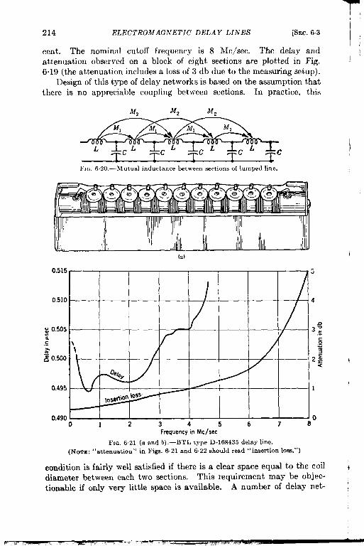
T214 ELECTROMAGNETIC’ DELAY LINES [SEC. 6.3
cent. The nominal cutoff frequency is 8 Me/see. The delay andattenuation observed on a block of eight sections are plotted in Fig.6.19 (the attenuation includes a loss of 3 db due to the measuring setup).
Design of this type of delay networks is based on the assumption thatthere is no appreciable coupling between sections. In practice, this
M2 Mz M2
L
FIC. 6.20.—Mutual inductance between sections of lumped line.
1’
(a) I
0.515
0.510
: 0.5052.E
i 0.500
0.495
0.490
/
- 3~/ .s
\ s\
=
/:
.Zg<
w 1
1-0
2 3 4 5 6 7 8Frequency in Me/see
FIG. 6.21 (a and b) .—BTL type D-16S435 delay line.(NOTE: ‘‘ attenuation” in Figs. 6.21 and 6,22 should read “insertion loss.”)
condition is fairly well satisfied if there is a clear space equal to the coil i
diameter between each two sections. This requirement may be objec-tionable if only very little space is available. A number of delay net- ~

(
I
SEC. 6.3]
works that
LUMPED-PARAMETER DELAY LINES 215
require very little space have been developed in the BellTelephone Laboratories.
These networks consist only of series coils and shunt condensers suchas would correspond to an ordinary low-pass filter with m = 1. But therelatively short coils of each section are wound with rather close spacingon a common core and the coupling to the adjacent section Ml and evento the next one, 342, becomes significant as shown in Fig. 6.20. In these
7(a) Formex HF,close.wound
0 1 2 3 4 5 6 7 8Frequency m Mck.ec
(b)FIG. 6.22 (a and b) ,—BTL type D-172597 delay line,
lines the relative amounts of inductance L and mutual inductances Ml
and M z are controlled by choice of three parameters:
1. the ratio of length to diameter of each coil,2. the spacing between sections, and3. in some models, the closeness of the short-circuited turn provided
by a rather narrow metal case.
I

216 ELECTROMAGNETIC DELAY LINES [SEC. 6.3
When properly proportioned, such lines have time-delay responses thatoscillate only slightly around the desired value up to 55 per cent of thenominal cutoff frequency. One or two phase-correcting T-sections maybe added to the whole delay line for further delay equali zation.
Typical Lumped-parameter Delay Lines.—The specifications of twotypical lines are as follows:
1. BTL tvDe D-168435. (This line is used in portable oscilloscopes.Ina.b.
::e.
f.
9.h.
Fig: 6.21a it is sketched lifted out of and-on top of its case:)Case: 6+ in. by 1 in. by & in.Impedance: z = 550 ohmsDelay: 2’ = 0.5 ~secNominal cutoff frequency: 9.5 Me/seePhase: equalized within t 3° up to 4 Me/seeAttenuation: 1/4 db at low frequencies rising to 1 db at 4Me/see (see Fig. 6.21b)Coil: 12 sections wound to 5 per cent toleranceCapacitors: button-type silver-mica condensers i 5 per cent
r ?
b %(a) lpsec test pulse
(b) l~sec testpulse through delay line of Fig 6.21
(c) 1Psactestpulse through delay line of Fig 6.22
FIG, 6.23,—Waveforms of BTL delay networks. Rise time is 0.2 Aec for (b) and 0.1 paecfor (c).
Z. BTL type D-172597. (This line is characterized by long delaywith very little distortion. It has negligible crosstalk.)a. Case: 9 by 3% by 22 in. with individual screen cans for each
length of line controlling mutual inductances (and helpingprevent crosstalk between them)
b. Impedance: 430 ohmsC. Delay: 4.6 ~sec in 144 sections and 2 equalizing Z’-sectiomsd. Nominal cutoff frequency: 12.5 Mc jsec
1(
1!“
1.
\
II

SEC. 6.3]
I e.
f.
9
I h.
LUMPICD-PARA MEI’ER DELAY LINES 217
Phase: equalized to 7 Me/see to within + 4°, (In Fig. 6.22b,the broken line applies to the line before 2 T-sections wereadded.)Attenuation: raised to 7 db at low and medium frequencies,then rising slowly beyond 4 Me/see, as in Fig. 6.22b
Coils: Dimensions of the windings and case are shown inFig. 6.22a
Capacitors: silver-mica button condensers ~ 5 per cent.
~ The distortion of l-psec pulses transmitted through these last “two
I lines is shown in Fig. 6.23.
I
.

14
1,
CHAPTER 7
SUPERSONIC DELAY LINES
BY H. B. HUNTINGTON
The supersonic delay of electrical signals is accomplished by changingelectrical impulses into sonic impulses through some appropriate trans-ducer and, at the end of a fixed path in a transmitting medium, convertingthe sonic impulses back into electrical signals by a second transducer.For frequencies in the megacycle range, which has been used for themost part in this work, quartz crystals are the most satisfactory trans-
ducers. Liquids, such as water and mercury, have been used as trans-mitting media, but transmission through solid material will probably be
developed in the future.
These delay devices may be divided into two general categoriesaccording to purpose: those that delay a video signal such as a triggeror range marker, which then reappears in differentiated form, and thosethat faithfully delay a pulsed carrier. For faithful delay a certain band-width is needed and the design requirements for this category are there-fore somewhat more complex than for the other type.
A discussion of experimental devices is not included in this chapter.Attention should, however, be directed to one particularly promisingpossibility now under development—namely, delay in fused quartzblocks, which is discussed in some detail in Vol. 20, Sec. 13a.7, RadiationLaboratory Series.
7.1. Summary of Supersonic Delay-line Formulas. Velocity of Prop-
agation.—The derivation of supersonic delay-line formulas has beentreated in more detail elsewhere. 1 In mercury the delay time’ is 17.52psec/in. at 200C. The temperature variation in this neighborhood is+0.0052 psec/in. per ‘C.
D = [17.52 + 0.0052(7’ – 20°C)]t, (1)
where D is the delay in microseconds and 1 the length of line in inches.
I A forthcoming article by the author (to be published in Jour. Franklin Inst.under the title “Ultrasonic Delay Lines,” I and II) providesa systematicdevelop-ment and a more complete discussionof these relations. The readeris referredtQthis articlefor the theoryin its most generalform.
i R. Jacobson, “ A Measurementof SupersonicVelocity in hfercuryat 15 Mega-cyclesper Secondas a Functionof Temperature,”RL Report No. 745,Sept.20, 1945.
218
,
i

T-
9
,
SEC. 7.1] SUMMARY OF SUPERSONIC DELA Y-LINE FORMULAS 219
The velocity of propagation in water has a temperature coefficient ofthe opposite sign from that of mercury (and of most other fluids investi-gated) in the region of room temperature. The curves for the two veloc-ities as a function of temperature actually cross at 1*C. See Fig. 7.1.The temperature coefficient of velocity in water, however, vanishes at72~°C, where the velocity is maximum. By mixing water with otherfluids in proper proportions, the temperature of the velocity maximumcan be lowered in a predictable manner.1 G. W. Willard of the Bell
I
FIG
1540/
1520
1500 //
148174+%(
~~e
1460 / / ,— Mercuy
1440 / //
1420 . /
1400
/
1360-5 0 +5 +10 +15 +20 +25 +30
Temperature in “C _
7.1.—S0nic velocity as a function of temperature.
Telephone Laboratories at Murray Hill has investigated supersonicvelocity in several such mixtures, particularly water solutions of ethanol,of methanol, and of ethylene glycol. z
Resonant Frequency .-–The resonant frequency of an X-cut quartzcrystal is given by
]vhere c1is the thickness of the quartz plate in millimeters.
(2)
1G. W. }Vlllard, ‘1( ‘compounding Liquids to (iive Zero Temperature Coefficient ofUltrasonic Velocity,” 11’J’1, Report 593, Sept. 9, 1941.
2 G. W. Will:ird, “ l-ltmsonic Absorption and Velocity Xfeasurements in Numerousl,iquids,” Jour. Acoustical ,Soc. ,4m,, 12, 438 (.January 1941). Scc also .k. Giacomini,Pontij, AcmL Sri. .4rfu, 6, 87 (1!)41 ); T. I)crcr)zitli and :i, Giacomini, Ricerca ,Sci., 1S,27, 242 ( 1942); (;. }V. W’illimi, Jour. Acoustical Sot. .4m., 19, 235 (January 1947); andA, Giacomini, tbul., 19,701 (.July 1!)47).

220 SUPERSONIC DELAY LINES [SEC. 7.1
Electrostatic Capacitance.-The electrostatic capacitance of a 10-Mc/aec X-cut quartz crystal (if edge effects are neglected) is given bythe formula
c = 91.5 x s lqlf, (3)
where S is the excited area of the crystal measured in square inches.This quantity is inversely proportional to crystal thickness or directlyproportional to its resonant frequency.
Bandwidth of a Piezoelectric Crystal.—The acoustic impedance of amaterial is the product of its density p times its velocity v for the prop-agation of the mode under consideration. Generally speaking, the fre-quency response becomes broader as the acoustic impedances of themedia with which it is in contact are increased. 1 As an illustrativeexample consider the case where the crystal is in contact with the samemedium on both sides. The Q of the crystal alone (exclusive of anyshunt circuit which tunes out the electrostatic capacitance) is given by
(4)
where p V refers to the piezoelectric crystal, PIVI to the adjoining media,and n is the order of the harmonic at which the crystal is being driven. 2
Beamspread Formula.—To estimate the order of magnitude for beam-spreading and also to establish mechanical tolerances for proper align-ment, it is useful to remember the formula for the half-angle o of thecone subtended by the first minimum in the free-space diffraction patternat large distances.
Asin 0 = 1.22 –7
d(5)
where d is the diameter of the transmitting crystal and A is the wave-length in the transmitting medium. Nearly all the emitted energy fallsinside this cone.
Insertion Loss. —There are two contributions to the insertion loss.
1. Voltage loss through impedance mismatch. For a line using aperfectly reflecting crystal (air-backed) the ratio of output voltageVo to input voltage 1’, is given by
V. 8E,E = kp,v,
if kplvl >> R,, (6)
I Huntington, op. cit., Part 1, Sec. Il.z In the journal article by Huntington, op. c&, the quantity Q is defied in a
particular way, It is the Q of the simple series-resonant circuit whose amplituderesponse exhibits the same curvature in the region of resonance as does the amplituderesponse of the transducer element,

SEC. 7.2] CRYSTAL DESIGN PROBLEMS 221
where R, is the value of the receiver input. For an X-cut, 10-Mc/sec quartz crystal in contact with mercury,
84,000kplvl = ~ ohms, (7)
where S is again the excited area measured in square inches. Thequantity k is primarily a function of the crystal and varies inverselyas the square of its resonant frequency.If the same medium is on both sides of the crystals, there is aresulting loss of 12 db, 6 db for each crystal.
2. Attenuation. (Empirical relations.) Free-space attenuation inmercury is given by
loss in db = (0.012 ~ 0.002)fll, (8)
where f is the frequency in Me/see and 1 is the length in feet.Tube attenuation is given by
loss in db = 0“05~j%’, (9)
where d is the inner diameter of the tube in inches. This value fortube attenuation applies only to smooth internal surfaces such asglass tubing. For rougher surfaces the attenuation is larger andincreases more rapid] y than 1/d with decreasing bore.
7.2. Crystal Design Problems. Crystal Thickness.—Equation (2)gave the relation between resonant frequency and thickness of crystalplate in the direction of the electric axis. When transmission of videosignals is involved, one customarily uses crystals whose fundamentalresonance is in the region of 1 to 10 Mc/eec, depending somewhat on the
I width of video pass band and the rise time desired. When a modulatedcarrier is used, one employs crystals whose resonant frequency lies nearthe frequency of propagation. Considerable latitude is possible, how-ever, in the choice of crystal thickness, particularly if mercury is employedfor the transmitting medium. The large acoustic impedance of mercurywill lower the Q of the crystal circuit according to Eq. (4).
Rather thick crystals may be used for these frequencies (5 to 30Me/see) if the crystals are driven at their odd harmonic frequencies.This involves, however, a loss in voltage by the same factor as the numberof the harmonic—that is, 1/nth the effective voltage at the crystal
o driven at the nth harmonic. However, for those delay lines where the
bandwidth must be maintained constant, there is a compensating effect.The live capacitance of the thicker crystal driven at the ntb harmonic

{
222 SUPERSONIC DELAY LINES [SEC. 7.2
will be smaller by a factor of l/n. If there were only the live capacitance,then the loading resistor which insures the proper bandwidth for theshunt resonant circuit could be increased by a factor, n. In turn theapplied or received voltage would be effectively increased by a factor nsince the generator and the line act as high-impedance sources. Undersuch circumstances there would be no disadvantage involved in usingharmonic operation. Actually, since the existence of additional straycapacitance at the driving and receiving crystals prevents completecompensation, harmonic generation is not generally preferred at thosefrequencies for which crystals operating on the fundamental can beconveniently handled.
Active A rea.—In determining crystal size the method of mounting andthe size of the inner diameter of the tube are important factors. Ingeneral one plans to make the active crystal area equal to the inner crosssection of the tube. Under these conditions a crystal perpendicular to thetube axis will propagate a nearly plane wave down the tube. Althoughsuch a plane wave is an oversimplification, experience has shown thatsatisfactory reproduction of pulse shape is generally achieved. Onegenerally chooses the size of the active area of the crystal so that thelive capacitance will be comparable with the ~tray capacitance when thelatter has been reduced to a minimum. It can be shown that the match-ing of live to stray capacitance gives a maximum ratio of output voltageto input current for a delay line which is passing a fixed bandwidth andfeeding into a low-impedance load. For best signal-to-noise ratio, theoptimum value of the live capacitance is somewhat greater than the straycapacitance, depending on the characteristics of the first stage of theamplifier at the receiver crystal.
Technique of Crystal Mounting.—A satisfactory crystal mounting mustfulfill the following fundamental requirements. The crystal must beadequately supported and protected so that it will not bend or break.It must be aligned with the tube axis to an accuracy of about 0.20 whereo corresponds with the angle of beam spread introduced in Eq. (5).Finally provision must be made for attaching electrodes to the crystalsurfaces in such a way as not to interfere with its sonic operation. Thisrequirement necessitates plating at least one face for transmission withnonconducting liquids. The usual procedure is to let the plated surfacemake contact against a retaining ring in the end assembly and so act asthe grounded side of the crystal.
In the crystal mounting for Line A 1 of Fig. 7.2, the crystal is backedby mercury, which obviates the necessity for any plating on that side.The large acoustic impedance of the mercury also loads the crystal and
1Table 71 gives the important characteristics of eight delay lines, including thosereferred to in the text by capital letters.
F
I

t
SEC. 72] CRYSTAL I) ESIG.V PROBLEMS 223
widens its pass band, thereby assuring rapid rise of the trigger with aminimum of “ringing.”
In the so-called ‘( Shockley line,” used for trigger delay in range units,the crystal is again loaded by being soldered to a brass backing.
~Textolite ~Brass
FIG. 7.2.—Crystal assembly for Line A. (1) A 10-Mc/sec crystal, plated on the frontside, is lacquered to Textolite piere. (2) This space holds tfie backing mercury. Tbemain part of the assembly slides inside a tube contaimng the water. (3) This screw ele-vates the piece into which it is threaded and so holds the assembly fixed in tbe tube. Wireleads connect tbe uhf fitting to the mercury well and to the (grounded) clamp ring (4).
) mm glass end plate
X-cutquirtz crystal(a) Detail of crystal mount
e
Fm. 73.-Liquid delay line for experimental system.
For those lines that were built to give faithful reproduction of pulseshape after delays of approximately 500 psec, an additional require-ment is the elimination of unwanted multiple echoes. This can be doneby absorbing nearly all the energy incident on the crystal in the mediumon the other side. Since the crystal at resonance acts as a half-wavesection, it is necessary only to match acoustic impedances on both sidesof the crystal. For the mercury lines this matching was first done by

224 SUPERSONIC DELAY LINES [SEC. 72
putting mercury also in back of the crystal. Figure 7.3 shows how thiswas done for one of the early lines used for an experimental system. Thebeam that was transmitted into the backing mercury cell was broken upand dissipated by the glass plate set at an angle to the direction of thebeam.
When the crystal mounting with absorbing backing was taken overinto actual system use, some provision had to be made to prevent pressure
Cap plug
rSurface of mercury 7
Threads into ~rosan insert
FIG. 7.4.—Mercury inlet with capil-lary loading.
transients caused by shock from break-ing the crystal. If the fluid on bothsides of the crystal completely filled itscontainer, leaving no air space intowhich it could be driven by suddenshock, equality of pressure would bemaintained under mechanical test butnot under thermal variation. In thecase of Line B the problem was solvedto a large extent by inserting a coiledsteel capillary which acted as a con-necting link between the completelyfilled chamber in the line and a partiallyfilled chamber in the loading plug. Theshort-time transients were damped bythe viscous forces in the capillary walls,but slow thermal variations altered themercury level in the cap chamber andproduced no net pressure change (seeFig. 7.4). The particular procedure forcrystal mounting in this case is shownin Fig. 7.5. As is indicated by the
captions, the crystal was lacquered into a carefully machined recess inthe bakelite end block. This was in turn lacquered to the end of the delayline and bolted in place. The oblique surface marked “deflecting plug”serves to break up the absorbed beam in the same way as was done inthe experimental line, Fig. 7.3.
Later some modifications in absorbing backings for crystals wereintroduced in a delay line for which a steel backing piece was used with adeeply cut sawtooth surface (see Fig. 7.6). The tops of the teethsupported the crystal’s back surface, and the space between the teethwas filled with mercury. The supporting steel area should be too smallto give appreciable reflection but should still support the crystal ade-quately under variation of static pressure as well as under sudden shock.It was found that this requirement was necessary in airborne operation.
There is another promising possibility for an absorbing backing that
\t.
I

SEC. 7.2] CRYSTAL DESIGN PROBLEMS 225
i-
t
C
.
.. . . ..— .-a
FIG. 75.-Assemblies for supporting cry.%als in Line B. A, trigger crystal mountingblock, containing cavity al for rectangular trigger crystal, wh,ch is backed by mercuryin the trigger shock well. This is filled through the loading duct a,, which is closed by acapillary bleeder plug and connector cap. B, receiver crystal mounting block, with cavityb~ for round receiver crystal, and shock-well loading duct 6Z similar to m. The rearsurface b, of the shock well is inclined to the axis of the beam (see text). C, end fitting, towhich A and B are bolted, The pinion shaft protrudes through tbe fitting c,, providingadjustment of tr]gger reflector position. Filling ducts C* give access to front faces ofcrystals, permittinge leaning while thelineis]oaded. (Courtesy of [email protected] Manuj.cturiwCompany.)
!aa%%t’ ~~silverplakd brass
m m“’”p””’Stainless steel
ERslPolystyrene
[
L Mercury in L Force fltthese spaces
10- Me/see crystal
l’I<;. 7.6,––End asse!llbly with sawt,ooth backing.

226
for cry:
SUPERSONIC DELAY LINES
(u) Variable end assembly
Knurled surface. turn to vary line length
packing gland nut
Space for packing material
cords dipped in ceresine wax
[SEC. 7.2
Wire springmakes contac
to rearelectrcde
ket
o
Tubes shrunk intoreflector block
~ Tubes must be parallel tot2 min
(c) Reflector blockFIG. 7.7.––End assemblies and reflector block for Line D
#
;.

SEC. 7.2] CRYSTAL DESIGN PROBI,l?MS 227
has not yet been incorporated into any system application—namely theuse of a solid backing that is a good match for the transmitting medium.For mercury a good match can be secured with the crystal soldered tohard lead (6 per cent Sb). Preliminary measurements have shown thatunder these conditions the reflected amplitude is about 18 db less than inthe case when the crystal is supported by a dry electrode. The hard leadhas two advantages: it is machinable, and it readily attenuates theabsorbed signals. For effective soldering, the crystals must first receive
i
a composite evaporated
Rmg clamp
film of chromium and silver according to the
34
~ FIXED END ASSEMBLY~A-. _,_ a
FIG. 7J3-End assemblies for Line D.
process developed by Professor John Strong of California Institute ofTechnology. Rose’s metal is suggested as a suitable solder to be usedwith a flux made of water, glycerine, and tartaric acid. Once the crystalhas been soldered onto the lead electrode the latter can be cemented intoa dielectric and incorporated into the end assembly. Precaution shouldbe taken to prevent the mercury from getting in contact with the solderor the lead. The final step is to machine the aligning surfaces so that
y the crystal will be perpendicular to the tube axis.With the work on longer lines it became less necessary to use absorbing
( backings. 1 It became practical to use dry steel electrodes, which reflectnearly all of the incident energy, and to take advantage of the resultingincreased transmission of longer lines (see discussion of insertion loss,Sec. 7.1). The problem of maintaining the crystal aligned, flat, anduniformly supported, was simply solved in many cases by employing aclamp with gaskets to hold the crystal in place on the electrode. The endassembly used in Line D is a good example of this construction ( Figs. 77and 7.8). There the 10-Lfc/sec crystals were set in recesses in the mount-
& ing and held in place with ring clamps. Polyethylene washers under theclamps made mercury-tight seals to prevent short-circuiting.
1For quantitativediscussion,seeVol. 20, Sec. 13a.2,RadiationLaboratorySeries.

FIG 7.9,—End assembly for Lhe C,
operation at tKls frequency, it was extremely difficult to mount them so
that they would not bend and deform the beams. Here again the crystals
were supported by ring clamps, as shown in Figs. 7.9 and 7.10. No recess
was used but the crystal covered the electrode exactly. The electrode
Surface for supporting crystal,
Screw sealingbleeder hole
FIG. 7.10.—End assembly for mounting30-Mc/sec crystals, Lhe C.
was ground flat to 0.0001 in.,otherwise the superimposed crystalwould show very evident distor-tion in optical reflections from itssurface. Often the electrode sur-face would be flat enough to permitone to observe Newton’s rings be-tween its surface and the bottom
surface of the crystal. A ring ofthin polyethylene outside the crys-
tal had its top surface flush with
the upper crystal surface. On topof both surfaces and sealing toboth was placed a ring of neopreneheld down by the ring clamp. Thebleeder screw shown in Fig. 7.9serves as a device for eliminating air
bubbles on the surface of the crystals. With the line in a horizo~talposition the screw is loosened until a fine jet of mercury passes thethreads. AL bubbles also escape simultaneously. The screw is thentightened and usually lacquered to make a tight seal. *
A similar construction was also employed in the crystal mountings forLine E. A type-N fitting, Fig. 7-11, was added at the back and the

i
.
t
,
SEC. 7.3] LINE-DESIGN PROBLEMS 229
thickness of the dielectric (formica) around the electrode was increasedto reduce the stray capacitance. Since this line operated at a lowerfrequency (15 Me/see), it was more important to keep the stray capaci-tance at a minimum. (At lower frequency the line capacitance is reducedand it becomes more difficult to match it to the stray capacitance. )
L&
I ‘@
“a
v
-:.k~
Collar for push
k
contact15- Mc/s6c
crystal
Bleede’r hole .!FIG: 71 1,—End assemhls,, Line E.
7.3. Line-design Problems. Electrical and Afechanical Stabilit y.—
Where great stability of delay is required, it is often advisable to maintainthe delay device at a constant temperature at which the thermal coeffi-cient of velocity is zero. This has been done successfully in the Shockleydelay tank for trigger delay with a mixture of water and ethylene glycolat 55°C, and in the water delay line built by H. Grayson in England forMT1 purposes, held at 72~°C. It is also possible to vary the line lengthto compensate for this effect as has been done with Line C.
Thermal variations introduce a problem in the expansion of the trans-mitting fluid. The solution to this problem for Line B was described inSec. 72, Reference to the end assembly (Fig. 7.8) for Line D shows anair space provided in back of the crystal mounting. Line C was providedwith a reservoir cup (Fig. 7.12) partly filled with mercury. In Line E
the reservoir was a pressure bellows completely filled with mercury(Fig. 713),
* In any system that contains an air chamber there is always a pos-sibility that air may become trapped against the surface of the crystaland thus change its live capacitance and the sonic transmission into the

. . . . . .. . . . . . ..-=-.. .> . . ---- .--,.Z&u SUY13KSVN1C ~.5LAr ldNISb [SEC. 75
medium. This effect is particularly serious with mercury since it doesnot wet the quartz and bubbles have a tendency to cling. With LinesC and E, bleeder holes were employ cd to allow bubbles trapped againstthe quartz to escape. It is necessary to “bleed” both end assemblies
after each filling of the line. With Line B, slanting holes were pro&ied(Fig. 7.5) at the surface of each crystal. Their purpose is to allowcleaning of the crystal surfaces without disassembling the line, but theyalso serve to eliminate any chance for air pockets.
~ Polyethylene
~& mm,a~....
s,chamber i.4
FIG, 713. -Prewure bellows for Lme E.
With liquid lines the need for securing tight seals is obvious but maystill cause difficulties. Long mercury lines when put on end will exertinternal pressures of several atmospheres. It requires good engineeringand careful workmanship to make them leakproof.
Folded Lines.—For longer delays it is often inconvenient to use astraight line for the complete length, The usual procedure is to employtwo or more lengths of pipe interconnected by corner reflectors. Acorner reflector consists generally of two reflections through 90°. Twoseparate examples suffice to show the type of construction involved. InLine L) two pipes are press- fitted into holes bored into the reflector blockas shown in Fig. 7.7c. Two stainless-steel plates, ground flat to 0.0001

*
SEC. 7.3] LINE-DESIG.V PROBLEMS 231
in., are attached to the block, it 45° to the beam, and serve as the cornerreflector. For Line E (Fig. 7.14) the parallel pipes are ~velded into flatend plates. The corner reflector (Fig. 7.15) is made of a single piece of
FIG. 7.14.—Line E.
stainless steel. The reflecting surfaces are plated with 0.015-in. chro-mium and ground flat. This piece is bolted to. the end plate and is
contained in a cover piece which is sealed to the end plate with a neoprene~vasher.
Since 45° is outside the critical “
angle for any transmission of en-
ergy from mercury into steel one
would expect very little loss on
reflection at this angle. Actually,
however, considerable attenuation FIG. 7.15.—Corner reflector for Line E.(1)Clearance holes for bolts which hold
may be present. H. J. McSkimin ,,fl~.t~, t. end~l~te. (z) Chrorniu~.pl.tedof the Bell Telephone Laborat ories reflector surfaces, flat to 0.0001 in. (3)
.41igning surface. Plane 2 must be accu-at Murray Hill has investigated r~tdYat 45° tith plane3.this effect systematically and
found practicably no loss for very smooth steel or polished glass reflectors.He also found negligible losses (less than 0.1 db per reflection) for roughsurfaces such as are obtained by lapping a steel surface with 160-mesh

232 SUPERSONIC DELAY LINES [SEC. 73
Carborundum. For surfaces of intermediate texture, however, a largeloss of perhaps several decibels usually occurred. The general explan-ation of this phenomenon, as propounded by McSkimin, is thatsince the mercury does not wet any surface with which it does notamalgamate small depressions in the reflecting surface give rise to airbubbles. If part of the beam is reflected from the steel and part from theair bubbles, there will be a phase difference between the two parts anddestructive interference will occur. The phase of the beam reflected fromthe steel for a 45° reflector differs by nearly ~ radians from the phase ofthe incident beam.’ The phase of the displacement associated with thepart of the beam undergoing reflection from the air—that is, low imped-ance—is reversed. From this it follows that the destructive interferencecould have a maximum effect of nearly 3 db per reflection.
Mechanical Tolerances. -As a general rule, such tolerances are requiredthat the maximum total deviation from parallelism of the crystal sur-faces will be about 0.2tI where o is the angle of beam spread. One must ofcourse take the same care with the aligning of reflectors as with crystalmountings. An accurately made corner reflector-that is, 900—need bealigned only in the angle perpendicular to the plane of the corner. In awater delay line this was accomplished by a manual adjustment. ForLine E close tolerances were demanded for the 90° angle betweenthe reflecting surfaces and also for the 90° angle between the plane of thereflection and the aligning surfaces which rest on the face plates. Theface plates were, in addition, machined to be flat and parallel. The useof the three corner reflectors in the signal line has one interesting con-sequence, that the parallelism requirement for the face plates was unnec-essary as far as performance of the signal channel was concerned.
In any mechanically variable line machining tolerances must be care-fully specified to insure that the moving part is subject only to translation,because any slight rotation will affect the alignment correspondingly.
Variable Lines. —Variable trigger delay lines have been used withwater or water solutions. In the Shockley line the transmitting crystalcould be translated by a carefully threaded screw. From the rotation ofthis screw, radar range could be read. The transmitting fluid wascompletely enclosed in the delay tank.
The movable feature for Line A was a much cruder affair. Thelong copper tube was open down the top in a wide slit and one crystalassembly could be slid up and down the tube by hand. A setscrewwas provided to maintain an adjustment.
In the water delay line of Fig. 7“16 a variable feature has beenintroduced by a “trombone” construction which can be adjusted from 4
1H. B. Huntington, op. cit. 1I

SEC. 7.3] LINE-DESIGN PROBLEMS 233
I
I
I
I,-.
LOin. 2
FIG. 716.-Water delay line, (a) Linebone” construction and reflector block; IRoyal Aircraft Establishment,)
assembled; @) line, cover removed; (c) “ tronl-:d) crystal mount disassembled. (Courte.w of

234 SUPERSONIC DELAY LINES [SEC. 73
outside the tank. Since the pipes themselves are surrounded by waterthere is no sealing problem involved.
At present there are two techniques for making variable mercury
Rotate to adjust.Iine Ieneth
IL. --- .--i
FIG. 717. -Variableend cell for Line D.
delay lines for field use. In one the position of a crystal or reflector iscontrolled by a mechanical drive. Part of the coupling shaft is actually
immersed in the liquid and a packing cell prevents leakage of the fluid.
FIG.718.-Drive for extending bellows in Line C. A drive shaft (1) with geared-downratio 36:1 causes collar (2) to rotate witbout translation. This action causes a translationof a second collar (3) at the rate of ~. in. per revolution. The rotation o{ collar (3) isprevented by a key (4) bolted to the ma,n tube and sliding in keyway (5). The plungerpiece (5) moves with collar (3), thereby extending or contracting the bellows (6) to whichit is bolted. Very precise machining of surfaces (7) is required tO maintain alignmentduring translation.
For mercury an effective packing gland is made of cord dipped in ceresinewax and tightly compressed around the shaft. Such a procedure \\asused in Line B to vary the position of a 45° reflector and in I,ine D to
I-–——’ ..- .—. . .

SEP. 7.4] CALCULATION OF I.VSERTIO,V LOSS 235
move a crystal mounting parallel to itself. The design used in theI latter case is depicted in Figs. 77, 7%, and 7.17. The second technique
involves a bellows construction which allows the driving mechanism tobe completely outside “the space occupied by the mercury. Stainless-steelbellows are used with Line C (Figs. 7.12 and 7“18).
Third Crystal.—In Line B, a third crystal inserted in the side of theline just in front of the receiver crystal (Fig. 7“5) is used to pick up the8-Me/see components of a strong video pulse sent down the line. Thissignal is then amplified and used as a trigger for repetition-rate control.
( A variable 45° reflector in the line serves to pick off a fraction of theincident intensity and deflect it to the third cry stal; A similar con-
f struction was used in another delay line but was later discarded. Theaction of that variable reflector is illustrated in Fig. 7.19.
= Neoprene Mercury in these spaces
H Textohte
@Zl Stainless steel
\
Third crystal
— 10 Me/see x-cut crystals/
FIG. 71 9.—Variable reflector and t},ird crystal
I 7.4. Calculation of Insertion Loss.—In this section Eqs. (6) to (9)are applied to calculate the insertion loss to be expected for a particularexample; Line E. The following specifications are pertinent:
1. 17~-Mc/sec crystals used with 15-Mc/sec carrier.2. Tubing of ~-in. ID.3. 6 reflections, 3 corner reflectors.4. R, = 500 ohms.5. Length of total mercury path, 4 ft, 9 in., or 1000 psec.
It follows then that
kp,u, =28,000 ohms = 250000
s-’ohms
since S = 0.111 in. z
(6a)
236 S 1:I>EILSO.VIC DELAY LINES [SEC, 75
V. 8R, 1K = kp,v, = m ‘r 36”0
db voltage loss. (7a)
For free-space attenuation 0.012 X (15)2 X 4: = 12.8 db. (8a)
For tubular attenuation ‘~ v’~ X 4: = 2.7 db. (9a)
This gives for the insertion voltage loss 52 db exclusive of loss at thereflecting surfaces, which might amount to 5 to 10 db.
If one wishes to find the insertion loss in available power-that is,the ratio of available power at the delay-line output terminal to theavailable po\ver at the output of the driving circuit—one must replaceEq. (6) by
P. 64R,RtP, = (kp,v,~’
~vhereIii is the impedance of the driving circuit.7.5. Assembly and Maintenance. Cleaning.—All metallic parts of a
mercury line that come in contact with the liquid must be carefullycleaned before assembly by immersion in some grease solvent such asxylene, toluene, or carbon tetrachloride. Any residual oil or grease willcause the formation of a scum on the surface of the mercury that willaffect transmission adversely, particularly if it comes in contact with thesurfaces of the crystals. Polyethylene and neoprene gaskets should becleaned in alcohol since they would be damaged by the toluene, etc. Careshould be exercised to handle cleaned parts as little as possible on assem-bly. Crystals in this frequency range are usually supplied waxed toglass plates. They can be slid off after gentle heating and should becarefully cleaned to remove all wax. One recommended technique forthis cleaning is to put the crystal on a flat surface, such as plate glass,and scrub with surgical gauze dipped in xylene. hlercury that containsonly mechanical impurities can be cleaned satisfactorily by passing itthrough a small hole in the apex of a cone of filter paper. If the mercuryis contaminated by metallic impurities, the filtering will not remove theamalgams. Generally a short time later more of the amalgam willbecome oxidized and scum will re-form on the surface of the mercury.
Filling. —Filling procedures differ according to line construction.When a long tube is filled from one end opposite a crystal mounting, itis advisable not to pour the mercury vertically before the surface of thecrystal has been covered, because crystals have been cracked by freelyfalling mercury.
Folded lines usually require a rather prolonged ritual of shaking,tilting, and filling piecemeal to eliminate unwanted air bubbles. Endassemblies equipped with “bleeder” holes usually require “bleeding”
.

,
SEC. 75] ASSh’M BL Y AND MAINTENANCE 237
after every refilling and possibly even after being transported from oneplace to another.
Transportation of mercury delay lines raises a problem because ofrisk of leakage or crystal breakage. In some instances it has been theprocedure to ship delay lines empty and to fill in the field. Steel bottlesare recommended for the transport of the mercury used in filling.
If the mercury used in filling has just been filtered, or violently shaken,or subjected to mechanical shock, or poured into the line in a thin stream,the supersonic transmission appears to suffer anomalous attenuation. Ifleft alone, the excess attenuation decreases, rapidly at first but moreslowly later, with the result that it may take several hours or even aday or so to reach its normal value. The effect is believed to be causedby small air bubbles in suspension in the mercury. In this connectionit should be remarked that a sharp blow on a delay-line tube containingrlercury will produce a similar increase in the attenuation. Experimentsby H. J. hIcSkimin of Bell Telephone Laboratories show that air bubblesare the cause of this effect. Because the mercury does not wet the wallsurface, a considerable quantity of air is occluded between the mercuryand the steel. Vibrations of the wall after being struck drive the air outinto the mercury in the form of small bubbles.
Measurement.—Measurement ofthe capacitance at the end assemblyis a very useful procedure in trouble-shooting because it shows up airbubbles, crystal fracture, or othercauses of instability in the crystalmounting. The measurement is easilydone at low frequency on a Q meter.
The insertion voltage loss of adelay line is a quantity that can bemeasured directly and gives impor-tant design information. It consistsin determining the ratio of input voltiage to output voltage (into a specific
I I
DelaylJ
Broad
line band~amplifier
TriggerOscilloscope
1 JFIG. 7.20.—Block diagram for voltage.
10ss measurement.
—impedance level) of the delay l& One procedure is given in the blockdiagram of Fig. 7.20.
The measurement consists in matching the delayed signal through thedelay line with an undelayed pulse through the attenuator and recordingthe attenuator reading. The following points in the procedure shoufdbe noted:
1. The outputs of delay line and attenuator are in general not inparallel but a switch is provided so that the amplifier input can be

238
,.
2.
3.
4.
5.
SUPERSONIC DELAY LINES [SEC. 7.5
shifted from one to the other. This arrangement simplifies theshielding problem, since pickup across the delay line does not affectthe delayed signals and the switch prevents it from reaching theattenuated pulse. The attenuator itself should be well shieldedand whatever pickup there is across the switch should be small.If the size of this pickup voltage can be measured, one can deducethat the limits of accuracy of measurements, at a power level20-db higher, are t 1 db.For reproducible measurements the frequency of the oscillatorshould be checked. This is particularly important for lines havingconsiderable free-space attenuation because this quantity variesas the square of the frequency.If a synchroscope or A-R scope is employed, the measuring equip-ment should be adjusted so that delayed and undelayed pulses canbe thrown on the same area of the scope alternately. Accuratematching is then possible and the inspector can compare the twopulses as to general character, shape, time of rise, etc. He shouldalso look for extra (unwanted) signals at high gain.The electrical inputs of the delay line and attenuator should be inparallel so that the input voltage will be the same across both.From the form of Eq. (6) it is apparent that a value for the insertionloss in voltage has meaning only when the impedance of the receiveris specified. If this impedance is about a few hundred ohms orgreater, it will be necessary to tune out fairly accurately (presum-ably with tunable coils) the capacitance at the receiving crystal.However, if the specified impedance is in the neighborhood of 70ohms, a single fixed-tuned coil in the right range will suffice for alllines of the same design. A measurement made at one impedancelevel in this range can be transformed to another impedance levelby considering the crystal output as a high-impedance source.
Transmission loss is affected by temperature mainly in the attenuationterms. As might be expected from the temperature coefficient of theviscosity, the free-space attenuation of water decreases markedly as thetemperature is raised. This effect has not been carefully measured formercury.
The signals in mercury lines are not so sensitive to changes in thermalenvironment as those in water lines. Thermal gradients in mercury thatarise from changes in thermal environment will cause changes in signalintensity. For unfolded lines that are not completely rigid the signalcan be restored by bending the line down in the middle. Such deforma-tion increases the relative path length for that part of the supersonicbeam in the lower portion of the tube where the mercury is cooler and
1

SEC. 76] COMPILATION OF DELA Y-LINE SPECIFICATIONS 239
the velocity is faster. The bending in this manner tends to counteractthe refraction. (It may be noted in passing that such bending of linesin every direction and at thermal equilibrium is a very simple test ofmechanical misalignment. )
There is some indication that changes in pressure affect transmissionloss, possibly by compressing air bubbles in the mercury or in contactwith the crystal. The effect has been observed with Line E on the benchand in the air. A similar effect was also reported for Line C when itwassubjected to a roll of about 15°On shipboard. Itispossible that suchpressure effects present a fundamental limitation of liquid delay lines forMT1 purposes in shipborne and airborne applications.
Mainknunce.-ilfaintenance routine, like filling procedure, differsfrom line to line. Instances of crystal fracture are rare, and, generallyspeaking, the main problem of delay-line maintenance appears to be inkeeping the mercury clean.
With Line B, slanting holesin thetube top give direct access to thecrystal surfaces so that they can be cleaned directly even while in contactwith the mercury. Line Ccanbe readily disassembled and the mercurycleaned by filtering. This is fortunate since mercury contaminationproved to be a serious problem in some of the delay lines that weresent out into the field. An attempt has been made to locate the originof this difficulty and some contamination has definitely been traced totl,e stainless-steel bellows.1 A thin coat of lacquer on the inside of thebellows appears to be a simple and effective preventive.
7.6. Compilation of Delay-line Spechications.-Table 7.1 of Delay-line Information includes most of the readily available information onseven delay lines as engineered for actual use, two for trigger delay andfive for the faithful delay of pulses. Photographs of the completelyassembled delay lines are included in this section. In general thespecific entries in the table have already been treated in detail, thus noadditional discussion is needed here.
Experimental delay lines and lines built for experimental systems havebeen omitted. Short fixed lines of about 5- to 10-psec delay, althoughnot of sufficient complexity to warrant inclusion in the table, were widelyemployed in system application and should be mentioned.
A drawing of a 6-psec glass delay line is shown in Fig. 7.24. It wasused to give a series of pulses appearing at odd multiples of the funda-mental delay, 6 psec. The crystals were fastened to the glass block bya thin layer of paraffin. This layer served to maintain acoustic contactbetween the quartz and glass. A brass electrode was pressed againstthe back of each crystal by a phosphor-bronze spring.
1H. B. Huntington, “ Notes on Cont:imi,,ation of Mercury by Stainless Steel, ”RL Report A’o. 935, March 1, 1!)46.

..
l’urpose . . . . . .
Manufacturer
.!pproximate quan-tity made.
L)wg. no. or type
Crystal no.
Fundamental fre-quency, Me/see.
Diameter, in
Diameter of activepart, in.
Capacitance at crys-tal, MJ.
Crystal backingLine delay, AIsec.Length over-allWeight (empty) lb\Veight (full), lb
TABLE 7.1.—TABLE OF DELAY-LINE INFORMATION ~o
Designation of delay line
Shockleyline
Line A
Trigger delay
WesternElectric
Part of D-150315 orD- 150463
2
1.4About ~square
About ~square
Sender, 55 t10; receiver75 + 10
Brass2 to 24021* in.
RadiationLaboratory
RI, 11021
2
101
;
-60
Mercury6 to 14007 ft
24
Line B1
Line C~
Line 1) I,ine E1
Line F IWater line(RAE)
Raytheon
-30
3
101*
0,86
N 60
Mercury555
3 ft5
I 13
RobertsonTool Co.
- 50RL 12499
2
26;
58
W93
Dry steel5863 ft
2032
Cancellation with MT1
RadiationI,aboratory
8RL T-D638(
2
10;
g
38 (58 forvariable)
Dry steel3000
8; ft140200
RobertsonTool Co.
1RL 14516
4
17++
z8
30
Dry steel1000
l+ft3039
WesternElectric
5BTLB-470670
2
6.51
0.885
45
Dry steel500070 in.
100200
2000
-... .-— . ..— ..”,,-——..—=.. . .. . . A

Purpose, . . . . . . . . .
Tube material.
Transmitting medium.
Tube ID, in,......Number of sectionsNumber of 45° reflec
tion . . . . .Variable feature.
General thermal regulation.
Driving frequency.Photograph of as
sembled line
1
g$5-1
TABI,E 7 1.—TABLE OF DELAY-LINE Information.—(Cntinued)&
Shockleyline
1Line A
Trigger delay
Steel and in-sulation
Water andEthyleneglycol
2&
1
0Calibratedscrew
135° t ~°F
Video
,.
Copper
Water
. . . . . . . . . .1
0Manualscrew adj.
None
Video
Designation of delay line Q
–~
Line B Line C Line D Line E Line FWater line
(RAE) >ss
. Stainlesssteel
Mercury MercuryI
0.86 i1 1
1 0Movable Steel bellowsreflector
N. one N’one
10 .Mc/sec 30 }lc/sec
Fig. 7.21 Fig. 7.22——
Cancellation with MTI
Stainlesssteel
Mercury
22
2Packinggland
Thermallagged
10 Mc/s(
Fig. 723
Hot-rolled 1%8 stain-steel less steel
Mercury Mercury
8None
Thermallylagged
15 Me/see
Fig. 714
0.8s54
6Adjustmentfor align-ment
N’one
5 Me/see
bWater g
b~F. . . . . . . . . .s. . . . . . . . . . kk
. . . . . . . . kIYombone
k~.
cOnstruc- %
.-. .*.. ..-—. .. . .

J’
242 SUPERSONIC
—. —
DELAY LINES ~EC. 7.6
——.- —. .
FIG. 721.-Line B, assembled.
1
—————FIC. 7.22.—Line C. assembled. ‘-”
1 Fixed end assembly~——- . ..— —. .
FIG. 7.23.—Line D, assembled.
Crystals
IPhosphor-bronze spring
Fm. 7.24.—C,lass 6-#see delay Iine.

CHAPTER 8
POTENTIOMETERS
BY F. E. DOLE
A potentiometer, as the term is used in this chapter, is an electro-mechanical device containing resistance element that is contacted by amovable slider. Such units may conveniently be divided into threeclasses. Laboratory precision potentiometers are large enclosed unitswhich are chiefly used for low-voltage highly accurate d-c potentialmeasurements in low-impedance circuits. Radio potentiometers (usuallycalled “pots”) are small inexpensive units of comparatively poor accuracywhich are commonly used for volume control and similar purposes inradio sets and other electronic equipment. The third and more recentlydeveloped class, ~vhich may be called “commercial precision” potentio-meters, is intermediate in character between the first two classes, andwill form the subject matter of this chapter.
Commercial precision potentiometers were orginally developed ascomponents of bridges and other test equipment that required variableresistors of good stability and of accuracies of the order of one part inseveral hundred. The war-born demand for large quantities of electronicmeasuring equipment—not only for test equipment, but for accuratemeasurements in radar and sonar—fathered a demand for great numbersof such potentiometers, and the Radiation I.aboratory began a develop-ment and small-scale manufacturing program that continued until theend of the laboratory’s activities. This chapter will be concernedprincipally ~vith the units developed by the I.aboratory or under itssponsorship. Such units ;vere used extensively for data transmission,for electromechanical computing elements, and for medium-precisionvoltage measurements in radar and other electronic devices.
8.1. The Resistance Element—The heart of a potentiometer is itsresistance element, which is always wire-wound in potentiometers of theprecision type. The element consists of resistance Ivire wound on aform or mandrel }vhose nature depends upon the design of the particularunit. The mandrel is usually a card or strip of sheet insulating material,or a roun(l rod of insulating material or of Formvar-insulated copper ~vire.T}LCaccurticy of the potentiometer depends directly upon the accuracy
IA,, :ll)ri~~lllCllt~[ tl,is ~bal~tcr})as txxm pui)]isbc[l: 1,. A. Xcttleton and F. EDole, “ I’otcutiomctcrs,” Reu. ,Sfi, Inslru,nenls, 17, 356-363 (october 1946).
243

244 POTENTIOMETERS [SEC. 8.1
of the mandrel, which must be made to accurate dimensions and accu-rately wound. Figure 8.1 shows a number of resistance elements ofseveral forms. Figure 8.la shows atoroidal mandrel; this type is moredifficult towind than the other types, but hasthe advantage that whenit is once properly wound it need not be bent or otherwise distorted inorder to mount it in a potentiometer. It is also the only type that ispractical when a useful angle of 360° is required. The long narrowcard of Fig. 8.lb is used in most linear potentiometers and the squarecard of Fig. 8.lc is used in most sine-cosine units. The “violin string”winding of Fig. 8.ld is used in linear potentiometers, both in the single-turn type such as the RL-270 series and in the multiturn units such asthe Beckman Helipot and the Gibbs Micropot. Nonlinear potentio-meters, except sine-cosine units, are usually based upon a tapered formof the card of Fig. 8.lb; an example is the logarithmic 433AC potentio-meter used in the General Radio 650A bridge.
Violin-string or Kohlrausch windings are usually wound ona core ofFormvar-insulated copper wire. Such a mandrel has the advantage thatit is uniform in dimensions, smooth and free from surface defects, easilyformed into the shape required for mounting in the potentiometer, andof excellent heat conductivity so that the winding can dissipate morepower than with most other constructions. Its principal disadvantage isthe excessive capacitance between the turns of the winding and thecopper core, which limits the frequency range at which such an elementcan be used. Extruded rods of a suitable plastic may be used instead ofthe copper core, but it is difficult to obtain rods of sufficient dimensionalstability and uniformity.
Laminated sheet phenolic plastics have been used almost universallyfor card-type mandrels. They have been satisfactory in most cases, andmuch of the trouble that has occurred has proved to be due to improperdesign or fabrication of the mandrel rather than to the material itself.The susceptibility of sheet phenolics to water absorption has not been aserious defect since the impedance level at which a wire-wound poten-tiometer is operated is seldom excessively high, and since the wholeelement must be properly varnished after winding in order to keep theturns in place while buffing the contact area and during operation. Ifoperation in tropical climates is to be expected a suitable fungicideshould be mixed with the varnish.
Fiberglas cloth laminated with nonwater-absorbent resins is superiorto phenolics from the standpoint of stability of dimensions, water absorp-tion, and resistance to fungus attack, but has not been much used formandrels because it is difficult to machine. The abrasive character ofthe glass particles necessitates the use of Carboloy tools for all cuttingoperations and even then tool life is poor. Glass-cloth laminates aregood for insulating and protecting sheets.
I
I
:

(
I
SEC. 8.1] THE WXISTANG’E
(a)
1
(I
ELEMENT
.—. —..
,,,.
245
\-,FIG. 8. 1.—Potentiometer resistance elements, (a) Toroidal element; (b) rectangular
card; (c) square card; (d) ‘‘ violin string,” Kohlrausch, or circular mandrel. The smallcircles are rnicrophotographs of portions of the windings.

246 POTENTIOMETERS [SEC. 8.1
It is essential that the surface of the mandrel be free from nicks,dents, and abrasions, especially beneath the path of the contact. Wiremandrels may be drawn through a diamond die after coating; thisstraightens, sizes, and smooths the mandrel in a single operation. Card-type mandrels should have the edges rounded to a semicircular shape bymeans of a epecial milling cutter. This cutter must be kept very sharpand the cards should be inspected after the milling operation k makesure that the milled surface is smooth and free from waves or tool marks.It is usually desirable to buff the milled surface, using a soft or mediumfelt bufl with aluminum oxide or Tripoli 2D as an abrasive. Mandreldimensions should be held to well within the required tolerance, especially
(a) G) (c)
(d) (e) mFIG. S.2,—Mandrel and winding defects: (a) Card-type mandrel properly milled;
(b) rough mandrel; (c) and (d) irregular windings due to rough mandrels; (e) w,dely spacedwinding; (f) good winding on properly treated mandrel.
if the total resistance tolerance is small. A rough surface on the mandrelwill cause displacement of the wire during the winding process. Such adisplacement will result in low and high wires or nonuniform spacing andwill seriously affect accuracy. Figure 8.2 shows microphotograph ofsatisfactory and unsatisfactory mandrels and windings.
The Resistance Wire.—The resistance wires used for potentiometersare usually drawn from alloys of the ‘‘ Nichrome” family or from copper-nickel alloys similar to Midohm or Lobm. A discussion of the propertiesof such alloys has been given in Chap. 3 of this volume; Table 8.1 givesthe resistance in ohms per foot of a number of the more common resistancealloys, in sizes from No. 10 AWG to 0.60 mil in diameter.
The accuracy and uniformity requirements for resistance wire that isto be used in potentiometer elements are much more stringent than thos~

I
I
I
I
I
SEC.8.1] THE RESISTANCE ELEMENT 247
TABLE 8.1.—COMMERCIAL RESISTANCE WIRE CHARACTERISTICS
Nominal composition, peroent
Ohms/circular rnil footTemp. ,AWGNo.101112131415161718192021222324
~ 2526
i
I
‘ 1
I
..-
2728293031323334353637383940
.,
,.
ficierlam,,
029181726457514540363228.52.5322620 117‘315914212611310089807.1635650454035312725222C171.514121:111(() !0[0;Oc—
circularrnils),4001230;530i18011101260
?580?05016201290L020
810642.509404320
25420216012.7101
79 763 250 139 831 5
25 019 815 712 59 !)
7662.51403,1
22201714‘2
10080 604() 3
Trade“arnes;hmmelC ChmmelA COpel Mid.hm 90A11oYiichrome NichmmeV Advance180AlloybphetC TophetA C.pronilloyc AlloyA AI1OY45;0Ni 80Ni 45Ni 22Ni 12Ni6 C, 20Cr 55(z. 78Cu 88Cu!4Fe;75 650 294 180 90I00022 0 00014 0 00002 0 00016 0 0W38
O06490 08150.1030 1300.1650.2080.2600 3330 4220 5210 6590.8311.061 321 672 112.673 354.255 296.758 52
10613.417.021,527033342.255.170,2887
108133169~~~
300344399469,55867.;833
105413781874
Ohms p’?, foot at 20°C
0.06250 07.950.09910 1260,1590 2000 2500.3210.4060.5020 6350,8001 021 271 612 032.573 234 095 096.508.21
10212,916420.726.032.140653.167.685 5
1041’2816221228933138.54515376.50802
1016132718(IG
0.0280 0350 044:0 0560 0710.0900.1130.1450.1840,2270 2870.3620.4560.5760 7280.9181 161 461 852 302 943 724 595.837 419 38
IL814518.424030 G38746757673 595 0
131150174204243~,,~~3ti3459600817
0 01730.02170.02740.03470,04390.05540 06920.08880.1120 1390,1760.2220 2810 3520 4460 5620.7120 8931 131 411,802 272 813.574 545 747 208.89
11214,718.723828835 543 058.780091.8
106125149180~~y281367300
0.008
0.0100.0130 0170.0210.027
0.0340,0440 0560.0690.087
0 1110 1410 1760 2230 281
0 3560 4460.5670 7050.900
1.141 411 782,272.87
3 604 445 627 419 36
11 914 417 822 529,4
40 045 95“ 262 574 3
90 0111141184250
Commercdcopperwire
99.9Cu
1050 00400
0.001000 001260,001590 00200(1002320 003180 004020 005060 006380 008030.01020.01280 01610 02040 02570 03240.04080.05150 06490.08180.1030.1300,1640 2070 2610.3290 4150 5230.6600.8321 051 391.682,072 623 434.665,356 217.298 68
10513016421‘129 2—.

I t.
248 POTENTIOMETERS [SEC.8.1
formagnet wire, for instance. Forreproducibility andaccuracy not onlymust the composition and heat treatment of the wire be accuratelycontrolled, but the wire diameter and the thickness of the insulationmust be held within close limits. Wire that has been coated with Form-var or Formex by the extrusion process has been found to be greatlysuperior to ordinary enameled wire, not”only because of its more uniformover-all diameter but also because it is free from “beady” spots andsimilar defects. Figures 8.3and8.4show microphotographsof defectivewire and of windings made from it.
Fro. 83.-Defective wire.
FIG. 84, -Defective windings due to had wire.
The ]~zndang 1%-ocess.-Windings of sufficient accuracy for use inprecision potentiometers can only be made on properly designed windingmachines, and several such machines were designed and built at theRadiation Laboratory. Figure 8.5 is a photograph of a machine thatproved very satisfactory for winding flat card-type resistance elements,and Fig. 8.6 is a close-up of the carriage showing the wire-straighteningpulleys and the dust brushes. The machine was designed to minimizebacklash and periodic errors due to the feed gearing, to ensure smoothand uniform motion of the carriage, and to furnish accurate control ofthe wire tension. The headstock and tailstock chucks were driven
1,

SEC. 8.1]
together to prevent
THE RESISTANCE ELEMENT 249
twisting of the card, and the tailstock was spnng-loaded to ensure a constant tension on the card. Special jaws for eachsize of card were provided for the chucks, and a smooth and accuratespeed control was incorporated in the drive. Cards up to 7* by 20 in.could be handled.
With the development of the RL270 series of potentiometers, whichuse a round mandrel of heavy Formvar wire, a new winding machine wasbuilt by modifying an inexpensive screw-cutting lathe. This machine isshown in Figs. 8”7 and 8.8. The modifications included the substitutionof precision cut gears for the original die-cast change gears, a simple wire-tensioning and feed device on the carriage, and a ball-bearing tailstock
FIG. 8.5. —Flat.card winding machine.
chuck. Round mandrels can be wound at a much higher winding speedthan is possible with flat cards since the wire velocity is uniform. Thismachine proved very satisfactory in winding resistance elements withIinearities of t 0.03 per cent in the 100,000-ohm value to ~ 0.15 per centin the 200-ohm value.
A machine for winding toroidal elements such as that shown in Fig.8“1u was designed, but construction had not yet started at the time theactivities of the Laboratory were terminated. The design incorporated anumber of novel features, including a preset turn counter and a precisionspeed control which would greatly facilitate the production of windingsof identical characteristics.
Varnishing, Curing, and Bufing.-After winding, the resistance ele-ment must be coated with a suitable varnish in order to hold the wiresin place and to protect them against moisture and mechanical abuee.One difficulty that arises with most electrical impregnating varnishes isa creeping or displacement of the wires during the curing process. Aftera number of trials a satisfactory process was evolved. A single coat of

250 POTENTIOMETERS [SEC. 8.1
TUF-ON No. 74-F or h-o. 76-F varnish (made by the Brooklyn Varnis}lCompany) diluted with about 40 per cent of the appropriate solvent wasapplied by spraying, brushing, or dipping. Both varnishes are of the
.-a
FIG. 8.6.—Carriage of flat-card winding machine.
phenolic resin type, both contain a fungicide, and will air-dry within48 hr. Drying may be speeded Up by heating to approximately 50°C ina convection oven. If the specific gravity of the varnish is maintained

SEC.8.1] THE RESISTANCE ELEMENT 251
at the proper value the coating will be ready for buffing after 24 hr in
~he oven.Two methods of buffing were standardized at the Radiation Labora-
tory. For both, wheels of white ‘‘ Extra-Spanish” felt in the medium or
FIG. S.7.—Round-mandrel winding lathe, front view.
FIG. S.8.—Round-mandrel winding lathe, side view.
soft grades were used. For buffing mandrels and for windings of con-
ventional enameled wire the wheels were run at about 2500 ft/min and
aluminum oxide or “ Tripoli 2D” were used as abrasives. For buffing
windings of Formex-insul~ted wire and for all “violin string” windings
..— —

252 POTENTIOMETERS ~EC. 82
the wheels were run at 1500 ft/min and were used without abrasive.Buffing of windings must be done with great care in order not to removemetal from the wire or to heat the winding excessively. This is particu-larly important with round mandrels.
To sum up, the production of resistance elements of high accuracyand stability demands attention to the following points:
1. Proper preparation of the mandrel.2. The use of wire of the highest quality.3. Winding on a properly designed and accurate winding machine,
run by a careful and competent operator.4. Care in removing the winding from the machine, and in handling
through all stages of production.5. Impregnation with a suitable varnish, maintained at the correct
specific gravity.6. Adequate curing at the correct temperature.7. Careful buffing, using the correct technique.8. Proper assembly technique.9. Adequate inspection.
10. Cleanliness throughout the entire operation.
Resistance elements manufactured with these precautions will remainstable and accurate throughout the life of the potentiometer.
8.2. Mountings and Enclosures.—The mountings and enclosures ofpotentiometers may take various forms; the illustrations of this chaptersholv a number of typical examples. Most commercial precision poten-tiometers are cylindrical in shape, ranging in axial length from ~ to 3 in.and in diameter from l+ to 5 in. Enclosed types are usually providedtvith a locating boss or ring and with a mounting flange with slots forphasing.
‘l’he design of the body of the potentiometer depends upon the wayin \vhich the resistance element is to be mounted, and there is a choice ofthree methods for accomplishing this. In one, the element, which hasbeen wound while it is straight, is \vrapped around a cylindrical formthat is provided with an axial shaft. The form may be stationa~ andprovided with a mounting surface, and with central bearings for the shaft,or it may be fastened to, and rotate with, the shaft. The resistanceelement may be drawn around the form by an assembly jig or fixture, orit may be held in place by a permanent protective strap. In either caseit is fastened by screws or rivets through the wall of the form.
A sgcond method employs a toroidal. form such as that of Fig. S.la,which is pressed onto a central cylindrical body similar to that used inthe previous method. An enclosure usually surrounds the element andcentral body in this type of construction.

SEC.8.2] MOUNTINGS AND ENCLOSURES 253
In the third method the resistance element is mounted on the inside( of a hollow cylindrical form. In units having a violin-string winding,
such as the RL-270 series, the element may be held in grooves in twoinsulating pieces that expose a portion of the inner surface of the winding.In card-type units the card may be bent around a temporary arbor,pressed into the cylindrical body, and the ends fastened with rivets,screws, or pins. The element may also be held in a temporary fixturewhile the body is molded around it; this type of construction is oftenused in multiturn units such as the Micropot.
> The potentiometer body itself may be made either of metal or ofinsulating material. If made of the latter it may be molded and used asit comes from the mold, or it may be finish-machined after molding.With most plastics finish-machining removes the comparatively imper-vious skin of the molding and may increase any tendency to waterabsorption. This can be counteracted to some extent by suitable sealingtreatments, but it is preferable to disturb the surface as little as possible.If finish-machining is not to be used it is necessary to choose a plasticwith the greatest possible dimensional stability and to take great careboth with the mold design and with the curing process to maintain
t sufficiently accurate dimensions in the molded piece.For units of high precision, metal is much superior to plastics from
the standpoint of dimensional stability. Aluminum alloys are fre-,quently used; one casting alloy that has good stability is Alcoa 395 witha T-6 heat treatment, The principal disadvantage of using metal is thenecessity of providing additional insulation for the winding. Bodies mayalso be machined from rod or plate stock, either of metal or of insulatingmaterial. For the RL-270 series the bodies were machined from a glass-mat-filled plastic kno~vn as Formica MF-66. This material proved to bevery stable dimensionally and to be unaffected by tropical climates.Certain molded plastics with mineral fillers were also satisfactory.
+ In the cheapest types of commercial precision potentiometers theshaft rotates in a cored or reamed hole in the molded body. This is
, satisfactory for a low-precision unit that is to be adjusted manually,but the variation in hole diameter and position renders the methodunsuitable for high precision or for gear-driven units. Brass, bronze, orOilite inserts maybe molded into the body, and will improve the centeringof the shaft and decrease the bearing friction. Where highest precisionand minimum friction are required it is necessary to use ball bearings.
Shafts may be of either metal or plastic material. The latter is oftenused in the cheaper potentiometers, but is unsatisfactory in many
? applications because of its tendency to warp and its great flexibilitycompared to metals. If an insulating shaft is required one usefulexpedient is to press a thin-walled plastic tube over a steel shaft, the

254 POTENTIOMETERS [SEC. 83
latter being knurled if necessary to prevent slipping. It is preferable,however, to put the insulation in the hub of the contact arm where itbelongs andtouse agrounded metal shaft. Metal shafts are usually ofsteel; drill rod is convenient but stainless steel is to be preferred if thereis any possibility of corrosion in service. Hubs, collars, etc., may besecured to the shaft by setscrews, preferably in pairsat 90°, but pinningor clamping is better. Split hubs with clamp screws are particularlyhandy from the standpoint of ease of adjustment.
Potentiometers intended for laboratory use or for mounting withinadequately sealed cabinets are not usually enclosed. Units intended foroperation in exposed positions or in the tropics must be provided withadequate enclosures. These units cannot be hermetically sealed withoutusing an expensive and clumsy hermetic shaft seal, but the use of water-proof AN connectors for the terminals, suitable gasketing, and a com-pression shaft seal such as a Garlock Klozure will afford adequateprotection for all but the most extreme conditions. Under most condi-tions ordinary dusttight construction will suffice. Typical potentiometerenclosures are shown in the potentiometer drawings of this chapter.
8.3. Leads and Attachments.-One rather troublesome problem inthe construction of a potentiometer is the provision of sturdy and per-manent attachments to the resistance winding. The use of very smallwire sizes and of nickel-chromium alloy wire that cannot be satisfactorilysoft-soldered makes such connections difficult.
Connections to the resistance element may depend upon mechanicalpressure alone, or they may be soldered. Pressure connections may bemade in several ways. A screw or a stud may be used to draw a pieceof metal tightly against a cleaned portion of the winding, or the wiremay be pressed between two pieces of metal. The screw may then beused as a binding post. A rivet may be used instead of the screw; asoldering lug may also be used under the head of the rivet. A rod tippedwith a soft noble metal such as gold may be pressed against a baredspot on the winding, as in the RL-270 series units. A connection maybemade to N“ichrome wire by placing the cleaned wire across a strip ofcopper foil and persuading molten solder on the copper strip to coverthe wire as well. Although this is not a true soldered joint the con-traction of the solder on cooling helps to lock the wire tightly in place.The finished joint should be inspected carefully and tested for electricalcontinuity. This method is sometimes useful for making taps on flat cards.
Successful soft-soldered joints may be made to nearly all resistancealloys except those of the N’ichrome family. Rosin or rosin in alcohol isthe only permissible flux, in spite of advertising claims to the contrary.The flux should be used sparingly to avoid later trouble with excessiveresidue, and the joint should be cleaned with alcohol if possible,

SEC. 8.4] CONTACTS 255
Breakage of the smaller wires during the soldering process can oftenbe avoided by the use of a small strip of copper or brass foil as an inter-mediate connection. The foil and the wire are tinned and solderedtogether and the other end of the foil is then soldered to the terminal.Alternatively, a pressure connection can be made from the foil to theterminal. The end of the foil may be captured beneath a washer heldby the terminal stud or rivet, or may be inserted into the end of a metaltube or hollow rivet moulded into the frame, and the end of the tubecrushed onto the foil.
! One method that is occasionally used involves baring and tinning aspot on the winding, opposite and close to a rivet or insert in the housing.A drop of solder on the tip of the rivet will form a conducting bridgewhen the latte~ is heated. Since the lug for the connection to theexternal lead is usually located at the outer end of the rivet there isalways the possibilityy that the heat of soldering the external lead maydestroy the solder bridge.
Nickel-chromium alloys cannot be successfully soft-soldered but mustbe hard-soldered or welded. No successful welding techniques weretried at the Radiation Laboratory, but one convenient method of hard.
B soldering fine wires was developed. A loop of bare No. 12 or No. 14copper wire 5 or 6 in. long was looped between the terminals of a 50-amp1.25-volt transformer connected to a 5-amp l’ariac and a foot switch..*Copper is the only material suitable for the loop since with materials oflower conductivity the drop of solder will freeze as soon as it bridges anappreciable length of the loop. The center of the loop was painted withborax flux and sufficient current was passed through it to melt hardsolder. It is easy to pass the joint that is to be soldered through thedrop of molten solder in the loop. The solder rapidly dissolves thecopper wire and both loop and solder drop must be replaced after ashort time. The fine wires should be passed through the drop rapidly
“ and at right angles to the direction of the current flow in order to mini-mize the chances of dissolving or burning them out.
* 8.4. Contacts.—The accuracy and life of a potentiometer dependprimarily upon the design and material of the movable contact. Muchof the work of the potentiometer group at the Radiation Laboratory wasdevoted to the investigation of this problem and a very extensive seriesof life tests was carried out.’ These tests showed that for windings ofnickel-chromium-alloy wire there is one outstanding alloy, Paliney No. 7,made by the J. M. Ney Company of Hartford, Corm. It is a palladium-silver alloy with additions of platinum, gold, copper, and zinc. Tests on
I 1F. E. Dole and R. J. Sullivan,“Life Test of Contact Materialon Standard LinearWire-wound Potentiometers, ” RL Report No. 617, Mar. 12, 1946; R. J. Sullivan, “The
, RL270 Series of Precision Potentiometers, ” RL Report No. 864, h4ar.25, 1946.

256 PoTENTloM&TEitb’ [SEC.84
windings of copper-nickel alloys were not completed but indicated thatforthese materials the best contact material wash-o. 19 A11oY, an alloyof platinum and silver made by the H. A. Wilson Company of Newark,N. J. Stellite and various grades of carbon were also used in some of theearlier potentiometers designed by the Laboratory, but were definitelyinferior to the Paliney and No. 19 Afloy. Over thirty alloys were testedaltogether, and the spring-temper phosphor bronze commonly used forpotentiometer contact arms was found to be one of the poorest for thepurpose. Typical linearity test osciliograms and microphotograph ofcontacts and windings after the tests are shown in Figs. 8.9 through 8.14.
(a) (b)
(c) (d)FIG. S.9.—Effect of contact shape on linearity. (a) Type B 50,000-ohm potentiometer
with standard blade contact, linearity 0.1 S per cent; (b) same potentiometer after modliyingwith 0.020-in. rod contact, linear]ty 0.05 per cent; (c) type D 50,000-ohm potentiometerwith finger-type arm, linearity 0.32 per cent; (d) same potentiometer after modifying withrod contact soldered to fingers and cut between each pair of fingers, linearity 0.12 per cent.
A number of different shapes and sizes of contacts may be used onstandard wir~wound mandrels where the surface of the wire will not besmoothed down to a flat surface. A cylindrical rod with its axis parallelto that of the wire has proven very satisfactory, one reason being thatwith such a shape no more than two wires can be contacted at the same
, I
,
4
I
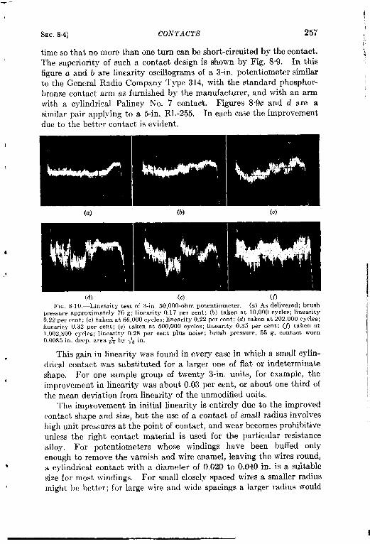
4
SEC.8.4] CONTACTS 257
timesothatnom ore than cmeturn can beshort-circuitid by the contact.The superiority of such a contact design is shown by Fig. 8“9. In thisfigure a and b are linearity oscillograms of a 3-in. potentiometer similarto the General Radio Company Type 314, with the standard phosphor-bronze contact arm as furnished by the manufacturer, and with an armwith a cylindrical Paliney No. 7 contact. Figures 8.9c and d are asimilar pair applying to a 5-in. RL-255. In each case the improl’ementdue to the better contact is evident.
(a) (b) (c)
(d) (e) (f)FIG. 8 10.—Linearit y test of :3-in. 50,000-ohm potentiometer. (a) As delivered; brush
pressure approximate y 70 g: linearity 0.17 per cent; (b) taken at 10,000 cycles; linearity0,22 per cent; (c) taken at 66, oOOcycles; linearity 0.22 per cent; (d) taken at 202,000 cycles;linearity 0.32 per cent; (e) taken at 500,000 cycles; linearity 0.35 Wr cent; (f) takel~ at1,002,800 cycles; linearity O.2S per cent Plus noise; brush pressure, 55 g, contact worn0.00s5 in. deep, area ~qzby T16in.
This gain in linearity was found in every case in which a small cylin-drical contact was substituted for a larger one of flat or indeterminateshape. For one sample group of twenty 3-in. units, for example, theimprovement in linearity was about 0.03 per cent, or about one third ofthe mean deviation from linearity of the unmodified units.
The improvement in initial linearity is entirely due to the improvedcontact shape and size, but the use of a contact of small radius involveshigh unit pressures at the point of contact, and wear becomes prohibitiveunless the right contact material is used for the particular resistancealloy. For potentiometers whose windings have been buffed onlyenough to remove the varnish and wire enamel, leaving the wires round,a cylindrical contact with a diameter of 0.020 to O.O4Oin. is a suitablesize for most windings. For small closely spaced wires a smaller radiusmight lW }mt,ter; for large wire and wide spacings a larger radius would

258 POTENTIOMEThZiS
(a)
[SEC, 8.4
I
(b) (c)
(d) (e)
(f) (o)FIG. 811.-Linearity test of 3-in. 50, f)O0-ohm potentiometer with Paliney No. 7 con.
tact. (a) .4s received from nmnufartur?r; brush pressure 110 g, no elld play; linqarity0.18 per cent; (b) potentiometer using PalineJ INo. 7 contact, 0.040 in, in diameter onregular arIW t,rush pressulc 50 to 65 g; line:wity 0.08 per cent: (c) taken at 10,000 cycles;linearity 010 per rent; (d) taken at 66,000 cycles; Iineanty 0.12 per cent; (e) taken at202,000 CYCI~S; l~nea,rity 0.12 per cent; (j) takenat 500,000 cycles ; linearity 0.13 pel cellt;(u) takeI1 at 1,002,800cycles;limarlt~0.10 per cent; brushPre&,ure45 g; col,tactwear0.0015in.

Sm. 8.4] CO.YTA CTS’ ?59
be rcquire(l. one possibility of {Iecrcasing ~rcm on the winding would beto ([se a rolling rather than a sli(ting contact, lxlt one such unit tha~ wastested proved unsucccssl’ul. Its contact ~ras in the form of a bluntdouble cone that Jvedged between the edge of the winding and a centralcontact disk. The initial linearity of 0.24 per cent increased to 0.36 perrent and very bad noise developed after only 6125 cycles. This per-formance may be compared with that of a standard 3-in. potentiometer,which is shown in Fig. 8.10, and that of a similar unit modified by thesubstitution of a Paliney contact, shown in Fig, 8.11. It can be seenfrom these pictures that the dcteriortition in performance is much moresevere }vith the phosphor-bronze arm. ‘his is presumably due to thefact that the phosphor bronze is ~vorn alvay much more rapidly thanthe Paliney, and this fact was demonstrated by other tests in which the
(a) (b) (c)F1~. 8.12.—Wear of Paliney No. 7 contart and Nicbronle wire. (a) Contact surface
after 106 cycles; (b) contact profile, worn 0.0015 in. deep; (c) windillg, very little wear;piece of material in lower center is not a broken wire but a piece of lint. Colltact materialexcellent for Nichrome wire.
replacement of a worn Paliney contact by a new one after ljOOO,OOOcycles restored the linearity of the potentiometer to its initial value.
In the tests just described the deterioration of the performance wasdue primarily to wear of the moving contact. If a harder material suchas Stellite is used, however, the deterioration is even more rapid becauseof wear of the wires. It is certainly preferable to have the w7eartakeplace on th~ moving contact because it can be much more easily replacedthan the winding. Although several other materials proved fairlysatisfactory the performance of Paliney No. 7 was outstanding on wind-ings of nickel-chromium wire. With the softer cupro-nickel alloys,Paliney seems ‘to be too hard and softer contact alloys such as WilsonNo. 19 Alloy give longer winding life. The tests on the cupro-nickelswere not so complete as those on Nichrome, but it appears that thelife of the softer alloy windings should not be greatly inferior if theproper contact material is used. Three sets of microphotograph show-

t
260 PO TEN TIOMETA’ILY [S~c, 8.4
ing windings and contacts after \vear tests, are shown in Figs. 8.12through 8.14. The advantages of matching the contact material to thewire alloy are obvious.
(a) (b) (c)FIG. 8.13.—Wear of No. 19 Alloy contact and Lohm wire. (a) Contact surface after
875,000 cycles; (b) contact prolile worn 0.006 in. deep; (c) winding, very little wear, Con-tact material excellent for Lohm wire.
The contact paths of certain potentiometers such as the RL-B,RL-225, and RL-ZOOB are honed down so that the contact surfaces are ,flat rather than convex. Special forms of contacts have been used in
(a) (b) (c)FIG, S.14.—Wear of Paliney M contact and Lohm wire. (a) Contact surface after
11,85Q cycles; (b) contact profile, worn less than 0.001 in. deep; (c) winding, wires verybadly scored and peened, resulting in drop to less than one-third of original resistance.
such cases; some of theee special contacts are shown in the drawings ofthe potentiometers.
It is important to maintain the correct contact pressure throughoutthe life of the unit, and the contact arm must be designed to accomplishthis. Excessive pressure causes unnecessary wear and shortens the life ● Iof the unit; insufficient pressure results in noisy operation, particularlyunder bad vibration conditions or with rapid motion of the contact arm.

Ssc. 8.51 NONLINEAR POTENTIOMETERS 261
For contacts of the types described above the optimum pressure is 40 to50 g; a potentiometer with this pressure and a properly shaped Palineycontact on Nichrome wire should have a useful life of at least 1,000,000cycles. Much greater life can be obtained in some cases; one RL-255unit lasted over 12,000,000 cycles without excessive deterioration. Theresults of a large number of life tests are given in Radiation LaboratoryReports N’o. 617 and No. 864.
8.5. Nonlinear Potentiometers.-So far, nothing has been saidexplicitly concerning the relationship between the shaft angle and thevariation of resistance between the contact point and the end of thewinding. For many purposes it is desired that this relation be linear,
$ but for certain applications, especially in electromechanical computersand similar devices, it is necessary that some nonlinear function be gen-erated, often to a high degree of accuracy. There are a number ofmethods of generating such nonlinear functions by means of potentiom-eters, and this section will list them briefly without attempting to gointo great detail.
The choice of a method depends upon two factors; the form of thedesired function and the accuracy with which it must be approximated.Strictly speaking, the only type of potentiometer which generates acontinuous function is one in which the contact moves along the wholelength of the wire. In the usual case, in which the contact touches thebared portion of one turn after another on a wound mandrel, it generatesa curve consisting of a series of small steps, the size of the steps dependingupon the number of turns in the winding and the applied voltage. Formost purposes, however, the steps are small enough and numerousenough so that the resulting curve can be considered smooth. There aremany applications in which a small number of steps—say 30 to 10&aresufficient, and in such cases a step potentiometer can be used. This issimply a multipoint switch with resistors connected between each suc-cessive pair of points. A familiar example of such a step potentiometeris the volume control commonly employed in broadcast stations. Thistype of potentiometer is the most flexible in conforming to an arbitraryfunction, but if the conformation must be close-that is, if high resolvingpower is required-a prohibitively large number of points and resistorsmust be used.
A set of straighhline segments is a considerably better approximationto a smooth curve than a set of steps, and there are several potentiom-eter constructions that result in such a function. One such is the useof a stepped mandrel; since the slope of the curve is proportional to thewidth of the mandrel a series of steps on the mandrel will result in acurve consisting of a series of linear segments of different slopes. Alter-natively, the wire size can be varied; the greater the resistance per turn
4

t
262 POTENTIOMETERS [SEC. 83
thesteeper theslope of the corresponding segment of the curve. Similarresults may be obtained by tapping the winding at appropriate pointsand connecting resistors either to ground or in shunt across portions ofthe winding. Another method involves theusc of different spacings fordifferent sections of the winding. Most of these methods are somewhattroublesome in production, but stepped caTds have been used in certaincases, such as the RL-B potentiometer, and the tapped winding withshunts is a useful laboratory technique for modifying an existing linearpotentiometer to approximate an arbitrary function.
If the approximation to the given function must be so good as torequire an unreasonably large number of straight-line segments, someother method must be used. The most direct method is to use a cardof continuously variable width, which isin effect an electrical cam. Thismethod has been used successfully in many cases, its principal disadvan-tages being that it requires the accurate machining of an irregularlyshaped edge on the card, and that it places certain limitations on theratio of maximum to minimum slope and on the maximum rate of curva-ture of the function. A high ratio of slopes implies a high ratio ofmaximum to minimum width of the card, and if this ratio exceeds5 to 1or perhaps 10 to 1 the card becomes rather fragile at the small end andis difficult to mount. A high rate of curvature of the function impliesarapid change of width of the card, and it is impossible to make the wirestay in place on a rapidly tapering card. A successful example of ashaped-card potentiometer is the RL-256 twc-cycle logarithmic unitmade by the General Radio Company. The RL-281, made by the Radia-tion Laboratory, was less successful because of a total angle of 34°, awinding angle of 10° on the contact edge and up to 24° on the curvededge. The maximum safe angle is about 10° to 15°.
The equivalent of a shaped mandrel is a mandrel of constant widthwith continuously varying wire spacing. This method is not often usedsince it requires a special cam for the winding-machine feed and sincethe maximum permissible variation in slope is even less than in the caseof the shaped mandrel. Variation of spacing is principally useful as amethod of correcting a winding during manufacture. The winding canbe continuously compared with a master potentiometer and the error inresistance can be used to control a servomechanism that corrects thefeed mechanism through a differential gear. This method is easilyapplicable to round mandrels wound with bare wire. It is somewhatmore difficult with card mandrels and is really complicated with insulatedwire; the wire must be bared at the correct point on each turn and theresistance measured as the bared spot is fed onto the mandrel. Suchwinding machines have been successfully built, however.
Another possibility is t~ use a tz.pered wire, which might be obtained
*

/!
SEC.85] NONLINEAR POTENTIOMETERS 263
bycontrolled chemical orelectrolyti catching. Avariant of thismethodmight be useful in some cases; the ~rinding, which must be made of barewire, could be partially immersed in a plating solution and varyingfractions of each turn could be plated with copper or silver. Such amethod was actually used some years ago to produce nonlinear volume-control potentiometers. The plating of high-conductivity materialeffectively short-circuited a varying length of each turn and had thesame effect as the use of a tapered mandrel.
A nonlinear function can be generated by the expedient of slippingwedges or shims between the card and the circular form around which itis stretched. This in effect expands or shrinks certain portions of thecard and amounts to the same thing as varying the spacing. This
method is chiefly useful for adding small corrections. It was used bythe Bell Telephone Laboratories in some of the large precision potentiom-eters for the M-9 and similar computers. In these potentiometersseveral concentric cards were mounted on the same unit and thereforea correcting cam acting on the contact arm could not be used. Theprincipal difficulty with this method is that of ensuring that the contactis of sufficient length and has uniform pressure at all radii.
The mechanical equivalent of this method is the use of a correctingcam to advance or retard the contact arm with respect to the shaft.This method is also chiefly useful for corrections, and has been verysuccessful in various models of the General Radio Type 433AC potentiom-eter. This unit is shown in Fig. 8.15. The arm is held to the shaft by
I

t’
264 POTENTIOMETERS [SEC.8.5
two set screws and rotates with it. The contact spring and its hub canrotate with respect to the shaft, and the spring is pulled toward theobserver (in the view shown) by a small helical spring. Its position withrespect to the arm is determined by the position of a small bent lever,one end of which bears on a sheet-metal plate. This plate can be warpedto form a face cam, whose shape is determined by eight screws. Thecharacteristic can be set exactly to the specified curve at eight points,and the correction varies smoothly and more or less linearly betweenthese points.
One method of generating arbitrary functions begs the questionentirely as far as the potentiometer is concerned and places the respon-sibility on its mechanical drive. Linear potentiometers, in which thecontact either rotates on a shaft or slides along a track, can be driven bya cam or linkage mechanism which generates the correct function. Thisis a common expedient in computers and is particularly well adaptedto the linkage mechanisms described in Vol. 27 of this series.
A simple electrical method of generating certain types of curves con-sists of loading the potentiometer by means of a resistor. Since theoutput impedance of the potentiometer is a function of the position of thearm (being highest at the position at which the resistance around the cir-cuit to ground is equal in each direction from the contact), the effect ofa loading resistor connected to ground will be to “drag down” the outputvoltage and to give a positive curvature to a previously linear character-istic. If the resistor is connected to the upper end of the potentiometerthe curvature will be negative. The method is limited in its applicationbut its simplicity recommends it when it can be used. 1
One other method of generating certain functions is of great impor-tance. It consists of causing the contact to move in an arbitrary fashiono~er the surface of a uniformly wound resistance card. This method ismost useful for the generation of sine and cosine functions, for which thenecessary motion is circular. In some forms of such units the card isstationary and the brush or set of brushes rotates; in others the card ismounted on the shaft and rotates against a stationary set of brushes.One typical example of the rotating-card type is the RL-11 ahown inFig. 8.16. Sine-cosine potentiometers have many uses and have beenproduced in a number of forms, several of which are shown in the illus-trations of this chapter. Other trigonometric functions maybe generatedby the same method, an example being a tangent function that wasused in the gun-order converter of a Navy computer that was designedat the Radiation Laboratory. An arm with a lcxig radial contact moved
] R. Hofstadtm, “Simple Potentiometer Circuit for Production of the TangentFunction,” Rev. Se-i.Znstrumerds,17, 298–300 (August 1946); L. A, Nettleton and F. E.Dole, “Reducing Potentiometer Loading Errors, “ ibid., 18, 332–341 (May 1947).
1

SEC. 8.5] NONLINEAR P07’ENTIOMETERS 265
DETAIL OF BRUSH AND BRUSH-ARMWHICH CONTACTS THE CARO
Copper eyelet soldered Carbon brushto brush-arm
\Y
soldered intocopper mounting
eyeletTwo layers of phosphor. bronze,
spring temper, soldered to- Single layer ofgether to form “rigid” phosphor. bronze,
brush-arm spring temper,sawes asa “hinge”so that almost all
Slipring (a second slipring the flexing of theon the right is not seen in brush.arm takes
this drawing) place at this “hinge’
\
Holes for fastening brush-Bakelite rotor, fastened arm to bakelite housing
to shaft of potentiometer.
stance wire, woundlyon bowed bakehte
card
able connector
Slipring brushesand brush-arms
/-\
I Four brushes (and brush-arms)which Contact thewire.wound
“Brush circle” L E.’~th. . .traversed on the wire-wound
card byits four contactbrushes
resistance card .seedetailabove
FIG. 8.16. –-Construrtionof potentiometer, type RL-11

266 POTENTIOMETERS [SEC. 8.6
throllgh an angle equal to the computed lead angle and made contactwith the edge of a flat card. The resulting electrical output was pro-portional to the tangent of the lead angle. The method is limited toangles whose tangents are not too large, since there are practical limitsto the length of the radial contact, but in this particular case the maxi-mum lead angle was less than 30° and the required length of contactwas not excessive.
The methods outlined above are the principal ones that have beenused to make nonlinear potentiometers. Others are undoubtedlypossible, and a particular potentiometer may use several of the methodsin conjunction.
POTENTIOMETER CHARACTERISTICS
8.6. Linearity and Noise.—Probably the most important character-istic of a commercial precision potentiometer is its linearity. This termmight be extended to include not only the straightness of the resistance-vs.-shaft-angle curve of a linear potentiometer, but the accuracy offollowing the prescribed curve for a nonlinear unit. In the discussionwhich follows, a linear potentiometer will be assumed, but the statementsmade can be applied to the nonlinear case with obvious modifications.A discussion of test methods will be found in Sec. 88.
A discussion of linearity should start out with certain definitions:
1.
2.
3.
4.
5.6.
7.
8.
Q. .
Linearity is the deviation of the curve of the resistance of apotentiometer vs. the shaft angle from a straight line.Independent linearity is the deviation when the slope and positionof the straight line may be chosen to make the deviation a mini-mum.Terminal linearity is the deviation when the position and slope ofthe line are defined by the “terminals” of the potentiometer.Terminals are the points of O and 100 per cent resistance. Theymay not be accessible to the moving contact.Total rem”stance is the resistance measured between terminals.Total electrical angle is the total shaft angle between terminals,assuming that the terminals are accessible to the moving contact.Brush angle is the angle between the terminal and the movingcontact measured in a clockwise direction as viewed from theshaft end of the unit.Slope is the change of resistance caused by movement of thecontact through unit angle.A stTaight-line resistance function is any function that satisfies theequation R = kO, where R is the resistance bet!~een the terminaland the contact at a brush angle of (l, and the slope k is a constant.

f
SEC. 8.6]
K.). D.miation
LINEARITY AND NOISE
is the plus or minus difference
267
between the actualresistance and the straight-line resistance function at any point,expressed in per cent of the total resistance.
11. Angulur resolution is the minimum change in brush angle whichis necessary to produce a change in resistance. It is a measureof the width of the steps of the tine structure of the resistanceCuwe.
12. Voltage resolution is the change in voltage from one step to thenext for unit voltage applied between terminals. An equivalentquantity is resistance resolution, which is the minimum change inresistance per step as a fraction of the total resistance.
One school of thought has maintained that a mandrel with, say, 1000turns of wire is capable of giving a resolution of much better than onepart in 1000. This idea is based on a theory of “partial contact” whichassumes that the contact resistance between the moving contact and thewire varies smoothly and continuously with contact pressure. As thecontact starts to leave one wire and climb up one side of the next, the resistance is supposed to increase slowly between the first wire and the contactand to decrease between the second wire and the contact, so that the
o process of transferring from one wire to the next takes place as thoughthe gap between the wires were bridged by a continuous smooth resistivefilm. Tests on an oscilloscope linearity tester have refuted this theory,at least as to clean windings and contacts. With metallic surfaces thecircuit is either closed or open and no evidence has been found thatpartial contact can occur. When the contact makes connection simul-taneously with two wires it does short-circuit one turn and assumes apotential intermediate between those of the two wires when the shortcircuit is removed. This in effect doubles the number of steps andincreases the resolution of the winding, but it is not what is meant by
1 “partial contact. ” The effect of short-circuited turns is easily calcul-able from circuit considerations.
J The theory of partial contact may have some validity in the presenceof carbon or other materials which do change in resistance with varyingpressure. Tests on nonmetallic materials at the Radiation Laboratorywere confined to various grades of carbon and graphite brushes, and someevidence for partial cent act was found. The contact resistance was soerratic, however, and varied so much with current and with speed ofbrush movement that the results were not conclusive. Carbon brushesare noisy and should only be used when extremely long life is requiredand noise can be filtered. Commutation effects dependent upon such anerratic phenomenon would be just as erratic and unpredictable, and theeffect must be considered unreliable as a means of increasing the resolution
I
I

268 POTEN7VIOME7’ERS ISEC.8.7
of a p >tentiometer for low-current conditions. In cases where the currentdensity at the contact surface is very high, however, this conclusionmay rot hold.
N6ise.—The noise generated by a wire-wound potentiometer is oftwo types, vibrational noise and noise due to imperfect contact. Vib-rational noise is due to the jumping of the contact away from the winding,thereby opening the contact circuit. If reasonable care is taken in design-ing the contact arm, this type of noise should never be produced byexternal vibration, but in rotating the contact arm, the contact and itssupporting spring must constantly climb out of the notch between onepair of wires and slide down into the next. If the arm is rotated toorapidly the contact does not have time to follow the downward slopesand contact is momentarily broken at each wire. The resulting noiseappears as “grass” ontheoscilloscope linearity tester, and the individualopen circuits are often of such short duration that the time constant ofthe deflection plate and a +megohrn resistor is too long to permit thespot to reach the edge of the pattern. When the brush speed is suffi-ciently reduced this type of noise vanishes. The short lightweight con-tact arm of the RL-270series potentiometers has never given this sort oftrouble at reasonable speeds because of its short vibrational period.
Noise due to imperfect electrical contact is caused by some insulatingsubstance getting between the contact and the surface of the winding.This material may be produced by the wear of the potentiometer itselfor it may be a foreign substance. Foreign matter is best excluded byproviding adust-tight enclosure forthep{~tentiometer. The exclusion ofdust and the protection of the winding from mechanical damage haveresulted in a decided preference forthetotally enclosed type of potentiom-eter. The accumulation on the contact path of products of wear isminimized by the proper choice of contact form, pressure, and material,byproper slip-ring and brush design, bythe use of proper bearings, andespecially by avoiding the use of lubricant on the windings. No matterwhat lubricant is chosen, its principal effect is to act as an adhesive thatretains noise-producing dirt particles on the contact path instead of per-mitting them to fall to some portion of the potentiometer where theywill do no harm. The use of lubricant may decrease the wearof wind-ings if inferior contacts are used, but the life becomes limited by thedevelopment of excessive noise.
8.7. Other Characteristics. —Besides the linearity and noisiness of apotentiometer certain other mechanical and electrical characteristics areof importance. The conditions necessary forthe production of a stableandaccurate winding were enumerated in Sec. 8.l. Careful assembly andextreme cleanliness were mentioned there but should be emphasizedagain. Figure 8.17 shows linearity oscillograms of a unit in which various

~
i
8BC.8Vl OTHER CHARACTERISTICS
errors of technique were intentionally made. F@reoscillogram of the unit as received; the linearity was
269
8“17a shows the~ 0.10 per cent.
One OFthe card clamping screws was loosened, ‘permitting the card toslip slightly on the form, and the screw was retightened. As shown byFig. 8.17b the form of the deviation curve was changed, although the
FIG. 8.17.—Effects of incorrect assemblj- techniques,
over-all linearity remained the same. The card was then loosened anddisplaced radially by & in. at the 80 per cent point. This simulated
6 the effect of a nonconcentric form, and resulted in an error of ~ 0.42per cent, as in Fig. 8. 17c. Finally the card was removed and replaced,the technician taking care to have his hands smeared with grease, dirt,and brass filings, as would be the case in the average machine shop orlaboratory where no care is taken as to cleanliness. Brass filings werevisible on the surface of the winding before reassembly. After reassem-
bly, as shown by Fig. 817d, the deviation was + 0.19 per cent and sevenor eight short circuits were evident on the oscillogram.
!fokd Resistance.—The total resistance of a potentiometer windingdepends upon the surface area of the winding form, the winding pitch,and the resistivity of the wire. If small-diameter wire is used care must?be taken to maintain uniform tension on the wire throughout the windingprocess. In the case of units intended for military use the minimum wire

270 POTENTIOMETERS [SEC.8.7
size is often limited by Service specifications. High-resistance alloysother than those of the Nichrome family usually have comparatively poorwear resistance and short life when used in potentiometers, although itis possible that other suitable materials will become available in thefuture. At the present time resistantes up to 0.5 megohm can beobtained in the large 5-in. potentiometers such as the RL-255 and GeneralRadio 433 types. The maximum resistance values for various types aregiven in the tables at the end of this chapter.
Minimum total resistance is limited primarily by the requirements ofresolving power, which depends upon the winding pitch. Obtaining alow resistance is seldom a serious problem since the potentiometer canalways be shunted with a fixed resistor unless it is necessary to workinto a low impedance, and in such cases it is often possible to redesignthe circuit to permit using a higher value of resistance.
Ambient temperature mdegrees centigrade
FIG. 8.18.—Power dissipation oftype RL-270 potentiometer.
Dissipation Rating.—The maximumpower dissipation of a potentiometer windingis usually limited by the maximum permis-sible operating temperature, which is 105”Cfor most materials used in potentiometerconstruction. Power ratings are given formost of the units listed in the tables below.A curve of permissible power input vs.ambient temperature is given for the RL-270potentiometer in Fig. 818. Temperatureswere obtained from a thermocouple in a holedrilled in one end of the copper-wire man-drel. The determination of the hot-spot
temperature of windings on nonmetallic mandrels is a matter of consider-able difficult y, although the average temperature may be determinedfrom resistance measurements if the ~virehas a sufficiently large tempera-ture coefficient of resistance. Such a determination would ordinarilyentail very precise resistance measurements.
The po~ver-handling ability of a potentiometer may also be limitedby the permissible change in resistance if the circuit conditions call foran accurate value of total resistance and if the temperature coefficient ofthe winding is high.
The power-dissipation rating of a potentiometer is not usually aserious limit ation to its use. Excessive ambient temperatures may forcethe unit to be derated, and ambient temperatures over 100”C would beimpractical for units of ordinary construction. At the other end of thescale, low temperatures may cause trouble either through excessivechange of total resistance or through increased torque requirements dueto congealed bearing lubricant.
i

1
SEC.8.8] TEST METHODS AND EQUIPMENT 271
Torque Requirements.—The torque requirements of commercialpotentiometers vary over a considerable range but are of the order of afew inch-ounces for most units. Torques of a few thousandths in.-oz.will operate the tiny units produced by the G. M. Giannini Companyand listed in the tables; large units with long contact arms, heavy con-tact pressures, and poor bearings will require more torque than theaverage. It may be stated that the torque requirements of the averageinexpensive wire-wound potentiometer are excessive, due principally topoor bearings and poorly designed contacts and contact arms. The useof either ball or powdered-metal antifriction bearings and the substitutionof better contacts will greatly decrease the torque and improve thecharacteristics of the average potentiometer.
8.8. Test Methods and Equipment.—The potentiometer development work of the Radiation Laboratory involved such a volume of time-consuming measurements and tests that it was necessary to construct anumber of automatic and semiautomatic testing devices. The moreimportant test techniques and pieces of test equipment will be brieflydescribed in this section.
Linearity Tests.—All methods of testing linearity are based eventuallyon a series of point measurements. These point measurements may bemade either as resistance measurements or as volt-age-ratio measurements. The latter are preferablesince they eliminate the effects of thermal changesin resistance and of contact potentials, and involveless calculation than the resistance-measurementmethod. Voltage-rat io measurements were madeby a null method shown schematically in Fig. 8.19.The standard used was a potential divider of theKelvin-Varley slide type, with three decades ofeleven resistors each and a slidewire. The nullindicator was a vacuum-tube voltmeter of specialdesign, based on a circuit by Roberts.’ An accu-rate protractor coupled to the shaft of the unitunder test is used for angular measurements. Apush-button decade attenuator was used for con-venience in approaching the null point. A sufficientd-c voltage was applied to the circuit to give an
i
--1111 ------4 ]l\--
Voltagedivider
ENullindicator
Potentiometerunder test
l~IG. 8.19.—Basiccircuit for ratio meas-urements.
easily detect able voltage for the smallest per cent error to be measured.A photograph of the whole assembly is shown in Fig. 8.20.
Voltage-ratio measurements of low-resistance units were made at 60cps, using an oscilloscope as a null indicator. The use of low frequency
~1Shepard Roberts, “ A Feedback Micro-microammcter,’] Rcu. Sri. In.$trwrnents,
1
10, 181-183, June 1939.

272 POTENTIOMETERS L%c. 8.8
minimized errors due to stray capacitance and permitted measurementsof almost four-place accuracy. It had the disadvantage that the nullwas somewhat obscured by the slight residual phase shift. A low-resist-ance voltage divider would probably result in considerable improvement.
The linearity figure derived from point measurements is a compromisebetween independent and terminal linearity. The straight-line functionfrom which the deviations are determined is based upon two measuredpoints near the ends of the \vinding. The actual end points are avoidedbecause the contact may have touched the riser, or the contact arm mayhave been sprung slightly upon touching the stop. The sum of the
l:r~ S.ZO.- Point-measurement linearity test assembly.
maximum plus and the maximum minus deviations divided by t~~()gives the linearity figure for the potentiometer. The acceptance of thet~vomeasured points near the ends of the winding as defining the straight-line function avoids the more complicated calculations necessary toconvert the figures to a true independent linearity calculation in whichthe maximum plus and maximum minus deviations are equal in magni-tude and there are at least two separated points at which the deviationis either the maximum plus or the maximum minus.
Continuous-comparison Linearity lkfeasuremenLs.-The time-consum-ing nature of point measurements and the fact that they yield no informa-tion as to deviations between the measured points made necessary thedevelopment of a continuous-comparison method. In its earliest formthis method employed a master potentiometer of the continuously woundmandrel type coupled directly to the unit under test. A known voltagewas applied to the unit under test and to the portion of the masterpotentiometer that was used. The two potentiometers were rotated‘together and the vacuum-tube-voltmeter needle was observed to deter-

r
I
!
tiEC.8.8]
mine the errors.
TEST METHODS ANI) EQUIPMENT 273
The time constant of the meter was too great to permita good picture of the nature of the error curve. This method was quickerthan the point method, however, and did give a continuous and more orless repeatable check. A redesign of the method employing a new andmuch more accurate master potentiometer and cathode-ray-tube pre-sentation of the error signal resulted in a practically perfect method forthe purpose. The error-voltage vs. brush-angle trace presented on thelong-persistence P7 screen of the oscilloscope makes accurate readings ofthe linearity easy. The entire picture of the behavior of the potentiom-eter is presented to the operator, and nothing is left to chance or memory.The CRT picture also gives much information about the potentiometerbeside its linearity. A permanent record maybe made by photographingthe CRT trace with a standard 35-mm oscilloscope camera. A photo-graph of the entire assembly of equipment for continuous linearity testingis shown in Fig. 8.21.
FIG, 8.21.—Continuous linearity testing assembly,
A comparison of the results obtained by the point method and the
continuous-comparison method is of interest. Table t3.2 gives the results
of measurements on a particular potentiometer and the computed
“terminal” linearity, independent linearity, and compromise linearity.Figure 8.22 shows the curve obtained on the same unit with the compari-son linearity tester.
The figures for terminal linearity in Table 8.2 illustrate the difficultyof determining the position of the “real” terminal. The same decaderatio was obtained for all brush angles between 239°9’ and 238045’.This was the lowest ratio obtainable but was not zero because of the

274 POTENTIOMETERS [SEC. ,%.8
TABLE82.-’Y1]I(,A,A 1, ]’olNrF-MI’;ASIJ1~F:MENrr l,lNEAR1T%‘]’F;$,T
I,aboratorydata
Protrac-tor angle
239°9’238°45’238°57’230°220°210”200°190”180°170”160°150°140°130”120”110°100°
90°80°70°60°50°40°30°20°10°0°
350°340°330”320°310°300°299°27299°39299°12
Decaderatio
0.0010000100.00100.03120.06440.09760.13100.16440.19840.23120,26520.29860,33270.36610.40040.43360.46660.50030.53380.56680 59990.63340.66700 70040.73330.76670.79910.83220.86540.89850.93100.96490.99810.99960.99960.9996
1’Terminal”linearity
calcu-ked ratio
060100.0308006420.09750.13090.16420.19760.2309026420.29760.33090.36430 39760.43090.46430.49760.53100.56430.59770.63100.66430.69770.73100.76440.79770.83110.86440.89770.93110.96440 9978
0 9996
Per cent,eviation
...
0“040.020.010.010.020.080.030 100 100 180.180.280.270 230.270.280 250.220 240.270.270.230.230.140.110.100.080.010.0.50 030.00
Independentlinearity
Calcu-ted rati{
0:4240.03220 0656009890.13230.16560.19900 23230.26560.29900.33230.36570.39900 43230 46570.49900 53240.56570.59910 63240.66570 69910.73240 76580.7991(). 93250.86580,89910 93250.96580.99921.0010
Per cent.eviation
0.140.100.120.130.130.120 060.110 040.040 040 040.140 130.090.130.140.110 080.100.130.130.090,090.000.030.040.060.150.090.110.14
(~ompromieelinearity
Calcu-ted rati{
0’03120.06450.09790.13120.16460.19790 23120.26460.29790.33130.36460.39800.43130.46460.49800.53130.56470.59800.63130.66470.69800.73140.76470.79810.83140.86470.89810.93140,96480,9981
...
‘er centWiatinn
o 010.030 020.020.050.000.060.070.140.150.240230.200,230.250.210.190.210.230 240.190.?00.100 080.070 040.040 010.00
resistance from the first wire of the winding out to the terminal connec-tion. The construction of the contact and winding were such that asetting half way between these two angles would not place the contactdirectly above the first wire, asshown in Fig. 8.23. In the calculationsof Table 8.2 the half-way point was assumed to correspond to the mini-

SEC. 88] TEST METHODS AND EQUIPMENT
I mum voltage ratio 0.0010 in spite of the resulting error,procedure was used at the other end of the winding.
275
and a similarThese points
corresponded to apparent errors of about —0.15 per cent at each end of
I
FIG.8.22,—Linearity testoscillogramof unit of Table 82.
the oscillogram of Fig. 8.22. The accuracy of the decade voltage dividerused for the point method was about + 0.001 per cent. The masterpotentiometer used in the comparison tests was accurate to about ~ 0.03per cent when checked at 48 points againstthe voltage divider. The oscillogram dk- : ~f;
closes a cyclic error of about 0.06 per centspread due to a mechanical error in the
u
\
winding machine used in making the test / A$,l
/\\
potentiometer.Further Developments.—Linearity and \ ,’
accuracy testers employing CRT presenta- \tion of error data give very satisfactory \ J 0000results. To gain the full benefit of the FIG. 8.23.—Method of defining
terminal position.method the master potentiometer musthave sufficient accuracy and resolution, and it requires much time andeffort to construct a suitable master. Improvements are also desirable inthe electronic portions of the equipment. One uncompleted effort in this

276 POTENTIOMETERS [SEC. &~
direction was a linearity tester forpotentiometers with resistances to 10ohms, which was under development at the time of the termination ofthe Radiation Laboratory. This tester wastoapply400to 500 cps a-cto the unit under test and to operate the vertical error amplifier entirelyon alternating current with a negative pip applied to the CRT cathode tobrighten the tube momentarily at the appropriate time in each cycle.Sufficient experimental work was done before termination to demon-strate that the plan tvas feasible and that a few more weeks’ work wouldpermit turning a design over to the shop for construction.
8.9. Commercial Potentiometers. -This section will describe anumber of the commercial precision potentiometers that are available onthe market. At the time of writing it is not known whether all of thetypes enumerated here will continue to be manufactured, and it is knownthat at least one of the companies that has been producing potentiometersduring the war does not intend to continue this production. It is to beexpected, however, that any such losses will be made up by other com-panies, and that the list of available types will increase rather thandiminish. The lists of types in this section are by no means complete,but include most of the types with which the Radiation Laboratory wasconcerned. Various companies other than those listed here manufac-tured potentiometers for use in equipment of their own manufacture, andmay make certain of their units generally available in the future. It isbelieved, ho~vcver, that the lists given here do include a fair sample ofcurrently available types
Standard Linear Potentio?rLclcrs.—The potentiometers listed in Table8.3 are all of the type in which a single brush makes contact with aterminated winding that has a constant resistance per unit angle. Mostof the potentiometers of table 8.3 employ card-type resistance elementsand have operating angles of 270 to 300°. The Micropots and Helipots
\ are multitu~n unit; em&ying Kohlrausch resistance elements: Fig. 8“24~;;

iI
I
SEC.L++ COMMERCIAL POTENTIOMETERS 277
shows the construction of a standard Helipot. The RL-270 series alsouse Kohlrausch windings but have only a single turn. The shaft rotationis limited by stops in nearly all potentiometers, but a few, such as theRL-270’s, use an insulating bridge that permits continuous rotation; the
Upper bearing plate
h
e
FIG. 8. 25.—RL-27O potentiometer construction,
. . .. —.. —— - . -+
1
I i
~
~\
I
I
.L. . . . ..J~G. 8.26. —DeJur No, 12 potentiometer with Paliney contact.
contact rides off the end of the winding onto the bridge and then off
the bridge onto the other end of the winding. This bridge is shown inthe drawing of the RL-270 in Fig. 8.25.
Most standard linear potentiometers, such as the various models madeby DeJur, General Radio, and most of the Muter models, use wound-card

TABLE83.-STANDARDLINEAR POTENTIOMETERS
Maker
The Muter Co,General Radio Co. and
the hfuter Co.
The Muter Co.
DeJur-Amsco Corporation
The Muter Co., Fair-child Camera andInstrument Corp.
Fairchild Camera andInstrument Corp.
Helipot Corp.
Thomas B. Gibbs andco.
G. M. Giannini andCo. Inc—
Nfodel no.
301A, 401A214.4314A371A471A433A214A Special314.4 SpecialRL-255291, 292296281260, 261260T275, 276RI-270RI,-271
RL-272
680, JIX1690
Micropot
B, c
Resistance,ohms
Dimensions, in
\fin, Max. Diam.
5 20,000 - 2A10 20,000 3&
1,000 100,OOO 3A1,000 100,000 3*O,ooo200,000 3AO,ooo 500,000 5;1,000 50,000 3&1,000 100,OOO 3A0,000 400,000 5i
1 20,000 1%5 25,000 lH
50 50,000 3100100,000 3100 20,000 3100200,000 330 50,000 320 30,000 2&
50 100,000 5
100 30,000 1;30 9,000 1;
2,000 30,000 1+
100 2,500 ;
Deptt—
Veightoz.
36688
1666
223.5353.555774
15
4+2+
5
~
——
>iam.,in.
Shaft
Material
steelsteelbakelitesteelbakelitebakelitebakelitebakelitebakelitesteelsteelbakelitebakelitebakelitebakelitestainless steelstainless steel
stainless steel
stainless steeljtainless steel
~teel
steel
Usefulangles
254°303°294°303°294°322°303°294”322°258°
248°300°300°300°355+” * *’354° + ~“
358° t *D
3600°1080°
3600°
270°
——Dissi-pationwatts
4108
151225108
2568466
11645
11.8
21
2
2.5
N
2
Notes *
(l), (2)(2)(3)(2), (4)(3)(3) , (5)(6)(6)(6), (7), (8)(2)(2)
(6), (7), (9)(6), (7), (9)
(6), (7), (9)
(lo), (11)(lo), (11)
(11), (12)
(11), (13)
— —.—. — “–l

., ---- , —–—-- —.-— . ..— -—
● Unless otherwise noted all units in the table are flushmounting with brassbearings,have torques of 3 to 15m.-.., at normal ternperstures, and have Ii”esrities ,0g
of + + to 1 per cent with standard contact arms. S“hstit”ticm of correctly designed Paliney No. 7 mmtactarms WIIIreduce the torque a“d improve the Ii”emity to ~+ 0.3 per cent or better. Standard tolerance on total resistaxe is + 10 per cent.
(1) 301A is Euahmounting; 418A has i-in. threaded shank fm single-hole panel mo”nti”g,*
(2) Shaft is not insulated from contact mm.(3) Supplied with linen bakelite protecting strip.(4) 12-watt dusipation with protecting strip. Muter 371A has i-m. hakelite shaft.(5) Type 433AC is same as Type 433A but ba.scorrecting cam.(6) F“mished with Pali”ey No. 7 ccmtact; li”earity + (),3 per cmt rnaxim”m.(7) Furntihed with slip ring and Palimy No. 7 brunhes.(8) Same as 433A except has special contact arm, flange mounting on bousmg, and ball thrust hearings; torque 2 to 4 i“-oz., Ii”earity + 0.1 per cent.(9) Flush mounting with centeringboss, Oilite bearings, torque 1 im-oz. I.ineanty + 0.1 per cent, resktance tolersnce * 5 per cent.
(10) I,mearity + 0.5 per cmt; resistancetolerance + 5 per cent, Also available with special tolera”cea.(11) fIu threaded shank for sin~le-holepanel mo””ting.(12) Re~ists”ce tolerance per specification; linearity +0,1 per cent.(13) Linearity + 0.5 per cent.
‘sw

I f.
2s0 POTENTIOMETERS [SEC.8.9
~esistance elements secured to the outside of a cylindrical molded plasticform. Table 83 gives the principal characteristics of a number of theseunits, and Figs. 8.25 through 8.28 show four typical units.
L_--.—---- ...---- ~~ -.. JF1~, 8.28.—General Radio Type 371A potentiometer.
Ring Potentiometers. —There are many applications, such as datatransmission, for which it is desirable to use a potentiometer that is ca~
t1
I
J\
?
.
r
,
L

SEC.8.9] COMMERCIAL POTENTIOMETERS 281
able of continuous rotation but that does not have the discontinuous out-put characteristic of a standard Potentiometer with a bridge, such as theRL-270. For these applications a r@ Potentiometer is commonly used.This is a potentiometer with a continuous winding on a toroidal mandrel,
FIG.S.30.—GimniniMicrotorquepotentiometer,Type A.
.
tapped at appropriate points. For angular data transmission to a d-cSelsyn or to a matching potentiometer and servo system it is customaryto tap the winding at three points 120° apart and to use two brushes180° apart, as in the d-c Selsyn system shown in Fig. 10”43. Potentiom-eters of this type are shown in Figs. 8“30 and 8.31.

282 POTENTIOMETERS @Ec. 89
For other applications it maybe desirable to use other arrangements oftaps and brushes. Certiain types ofradar indicators, forexample, uset~\,otaps 180° apart and two brushes also 180° apart. If the potentiometeroutput works into a high impedance such as the plates of an electrostatic
—.
I
t
!,jI
.!
_—–--–--..._JFIQ, S.32.—RL-B potentiometer.
CRT the winding should be linear in order to obtain a linear relationship
between output voltage and shaft angle. If the potentiometer feeds
current to the deflection coil of an electromagnetic CRT a different
characteristic is required. The RL-Bpotentiometer w-as given a’’hump-hacked” characteristic by using a stepped mandrel in order to compensate

Maker
CTS
CTS, GCTS, GCTS, GGCTSCTSCTS, GG
CTS
G
Type
RL-B
RL-200RL-200BRL-21ORL-225RL-225ARL-225f3RL-226RL-226BRL 237A,RL 237B,RL 237CRL 273
Resistance,ohms
100
6,0001,5001,s00
10,OOO10,OOO10,OOO5,000
20,0041
20,000
,ooot050,00
TARLE 8.4,—RLB AND SIMILAR POTENTIOMETERS
Toler-mce, +)er cent
10
101015
5
5
5. . . . . .
. . . . . .
+5, –8
5
Linearity,+ per cent
2 (or 1.8°)
. . . . . . .0.5 (Terminal)0.7
0.5
0.5
0.751.0
1.0
1.0 each section
Rota-tion,egrees
cont.
cent.
cont.
cont.
cent.
cent.
cent.
cent.
cont.
170°
cont.
Numberof
brushes
2 at 180’
11
2 at 180C111
2 at 180°2 at 180°
2 at 180°
1
>-umberof taps
2 at 180”
nonenone2 at 180”nonenonenone2 at 180°2 at 180°
none
Electri-al angledegrees
360
359.4357360°185°185”350°360”360”
170°
350”
Remarks
nonlinear ring: gives linear ~~
output with CRT deflec-tion coil load ;
linear. 0,6° gap blinear. 3“ gap gring S-linear h
linear ‘u0
linear y
ring 2ring ~
s5z independent linear sec-tions on same mandrel
;w
linear M2
As of 1947, it is understoodthat the Chicago Telephone Supply Co. is no longer making potentiometers of the above types, but that tb. Garnewll Co. is mahlng
all the former CTS pr.cimon types.
ATOTES: CTS means Chicago Telephone Supply Co.; G means Gamewell Co. All units similar mechanically: have Oilitc bearmgaand }-in. stainless steel shafts. Weights run from 14 to 14.5 oz.
G. M. Giar-miniand Co. also make a ring potentiometer, type A, similar to the types B and C of Table 83, but with continuous rota-tion, 2 brushes at 180°, and 3 taps at 120°.
‘%w

284 POTENTIOMETERS [SEC. 8.9
for the droop caused by the output current. The original RL-B sired alarge family of variant forms, some of which are listed in Table 8.4;An RL-B potentiometer is shown in Fig. 832.
Sine-cosine Potentiometers. -For many applications, particularly forradar PPI displays and for various types of computers, potentiometersare required which give outputs proportional to the sine or cosine of the
Brass shank to which
&
alloy is fusedf ,.
Brass contact I.arm --i+mo”
5kFr:$5Metal cover
shown remowdMounting lug\ f-aik=?“@d-”l
+4which is tangentto brush circle
to hmit angle of rotationof main contact arm
\. Iilllll %%’
~ Illlluu1,~ .aincon.ctzm-rr
(movmg arm), essentially
‘h”n/ <~~af~~
patentiimeter. “Hinge” is essentially
/’ ~,eon,ackofCar/ “Mechanical stop which prevents mainFlexible “p@aiY’ contact arm from vibrating with too great
connactlon to main is kept taut bycontact arm
an ampltiude if the potentiometer isbowed bakelite card subjected to severe vibration
FIG, S.33.—RL-2@t potentiometer construction.
brush angle: The RL-11 potentiometer, which gives both sine andcosine outputs, was shown in Fig. 8.16; a more specialized type, theRL-204, which was never produced in large numbers, is shown in Fig.8.33. The sine potentiometers which were most extensively used by theRadiation Laboratory were those made by the F. W. Sickles Company,the RL-llC and the RL-14, shown in Figs. 8“34 and 8“35, Both are
l’-#’
I

~
SEC. 89]
flush-mounting\ bearings. The
*
:C
&in. shaft, and....-—-
COh4h4ERCIAL POTENTIOMETERS 285
flanged rotating-card types with four brushes and ballRL-1 lC is 2* in. in diameter by l% in. deep, with a
t
weighs 4: oz. Its torque is ~ in-oz, its total resistance.— . .. -y
I
FIG.s.34.—RL-11Cpotentiometer..- ..—=.
-
A“
AA
—---- . ._.i... -J
F1~, S.35.—RL-14 potentiometer.
16,000 ohms ~ 10 per cent, its angular accuracy + 0.35°, and the radialaccuracy of the brush positions +0.4 per cent. The RL- 14 is a largerunit with carbon brushes for long life (although at a sacrifice of accuracy

28b POTENTIOMETERS [SEC. 8.9
and noise characteristics), a diameter of 4: in., a depth of 4=5Fin., aweight of 29 OZ, and a +-in. shaft. Its total resistance is 34,000 ohms~ 10 per cent, angular accuracy 0.5°, and radial accuracy 0.65 per cent.The RL-14MS is similar except that it uses Paliney brushes and has a35,000-ohm total resistance. Itsangular accuracy is0.35° and its radialaccuracy is 0.4 per cent. The dissipation rating of the RL-llC is 1$watts and of the RL-14, 3+ watts.
Nonlinear Potentiometers.—Nonlinear potentiometers are ordinarilydesigned for each particular application, and therefore are not listed bymodel number in ordinary catalogues. Several manufacturers will makeupsuchunits to order, andshould reconsulted astothe practicability offitting the particular curve desired. The General Radio Company hasmade various types, using the 371 and 433 frames, and the FairchildCamera and Instrument Corporation has recently announced a line ofnonlinear potentiometers with a diameter of l; in. and a maximumresistance (for a linear unit) of 100,000 ohms. The Fairchild units can
be ganged on a common shaft. The electrical rotation can be as large
as 310°, and the mechanical rotation can be either continuous or limited
by stops. Fairchild guarantees to fit a given curve (within necessary
hrnitationsof slope and curvature) within 1 percent.
Manufacturers of Potentiometers and Components.—The following listof manufacturers of potentiometers and potentiometer componentsincludes only those firms with whichtheRadiationL aboratory-p otentiom-eter group had extensive experience. Other sources of supply of theitems mentioned will undoubtedly be found equally suitable.
PRECISION COMMERCIAL POTENTIOMETER MANUFACTURERS
Chicago Telephone Supply Co. * Cinema Engineering Co,1142 W. Beardsley .kve. 1508 West Verdugo AvenueElkhart, Ind. Burbank, Calif,
DeJur-Amsco Corporation Fairchild Camera and Instrument Cor-Northern Blvd. at45th St. porationI,ong Island City 1, N. Y. 475 Tenth Avenue
New York 18, N. Y.
Gamewell Co., The General Electric CompanyChestnut Street West Lynn, Mass.Newton Upper Falls, Mass.
General Electric Company General Radio CompanySchenectady 5,N. Y. 275 Massachusetts Avenue
Cambridge 39, Mass.
G. M. Giannini& Co., Inc. Thomas B. Gibbs Co.285W. Colorado St. Div. of George W. Borg Corp.Pasadena 1, Calif. 814 }fichigan St.
Delavan, Wis.
● Note: .4scd 1947,it is under~tocdtbe.tboth CTS and Sickles have dimonti. ued the manufactureof potentiometers.
r
.

287SEC. 8,9] COMMERCIAL POTENTIOMETERS
Helipot Corporation Leeds and Northrup Co.1011 Mission St. 4970 Stenton Ave.So. Pasadena, Calif. Philadelphia 44, Pa.
Minneapolis-Honeywell Regulator Co. The Muter Company2753 Fourth Ave. S., 1255 South Michigan AvenueMinneapolis, Minn. Chicago, Ill.
F. W. Sickles Co. *165 Front St.Chicopee, Mass.
CONTACT MATERIAL MANUFACTURERS
Baker and Company, Inc. Instrument Specialties Company, Inc.
113 Astor Street Little Falls, N. J.
Newark 5, N. J.
The International Nickel Company, Inc. P. R. Mallory and Co., Inc.67 Wall Street 3029 E, Washington St.New York, N. Y. Indianapolis 6, Ind.
The J. M. Ney Company The H, A. Wilson Company71 Elm Street 105 Chestnut StreetHartford, Corm. Newark 5, N. J.
RESISTANCE WIRE MANUFACTURERS
Driver-Harrk Company Wilbur B. Driver Company
201 Middlesex St. 150 Riverside Avenue
Harrison, N. J. Newark 4, N. J.
Hoskins Manufacturing Company The C. O. Jelliff Mfg. Corporation
4445 Lawton Avenue 200 Pequot Ave.
Detroit, Mich. Southport, Corm.
North American Philips Company, Inc.100 East 42nd StreetNew York 17, N. Y.
SFWXAL RESISTANCE WIRE COATINGS
General Electric Company Phelps Dodge Copper Products Corpora-
Schenectady, N. Y. tionFt. Wayne, Ind.or, 40 Wall St., N-ew York, N. Y.
POTENTIOMETER VARNISH MANUFACTURER
Brooklyn Varnish CompanyDivision Wipe-On Corporation105 Hudson StreetNew York, N. Y.
BUFFING WHEEL AND BUFFING COMPOUND MANUFACTURERS
Bacon Felt Company Hanson, Van Winkle, Munning Co.
Winchester, Mass. Matawan, N. J.
* %. foolmote on opposite page.
i.
i.

c
CHAPTER 9
SPECIAL VARIABLE CONDENSERS
BY E. A. HOLMES, III
9.1. Phase-shifting Condensers.—The phase-shifting condensersdescribed in this section were primarily intended for the accuratemeasurement of time intervals in radar systems. The technique usedconsists of allowing the transmitted pulse to initiate a train of oscillationsof known frequency, or of allowing a continuous train of sinusoidaloscillations to initiate the transmitted pulse at the desired instants. Thezero-voltage points of either set of these oscillations then constitute aseries of accurate time marks. The time measurements can be made con-tinuous by shifting the phase of the oscillations and causing a marker pipto follow a particular zero-voltage point. If the oscillation is shifted inphase by 360°, the resulting wave is indistinguishable from the unshiftedwave, but the marker will have moved in time an amount correspondingto 1 cycle of the oscillation. A further shift causes the marker to move,a proportional amount farther. The phase shift necessary to make themarker coincide with an echo of the transmitted pulse is then a measure
~------—l
I c,E
%
i1; =. I
E’C2 =-1:211~ -4 10
E’3 II31
EO
Ic ~.; ;
E“41 ’12
‘-J
L ___-_.l =
FIG. 9.1.—Schematic diagram ofphase-shifting condenser.
of the time delay of the echo and thus of thedistance to the echo-producing object. De-tails of the circuits and techniques useful forthis form of time measurement will be foundin Vol. 20, Chaps. 8 and 9 of the RadiationLaboratory Series.
The design and construction of the con-densers used in shifting the phase of suchpulsed or continuous oscillations will formthe subject matter of this section. Thesecondensers are by no means useful for thisspecific purpose alone, but since they were
so designed and used, the information given is taken from calculationsand experiments for this use. Most of the data, design information, andresults are from the work of G. R. Gamertsfelder. 1
The method of shifting the phase of the oscillations consists of splittingthe original oscillation into four separate phases 90° apart by means of
1GkR. Gamertsfelder, “Errors in the Continuous-type Condenser Phase Shifter,”RL Report No. 633, Dec. 6, 1944.
2%?
r

SEC.9.1] PHASE-SHIFTING CONDENSERS 289
resistance-capacitance bridges or other phase-shifting devices and recom-bining these phasesin the proper proportions in a capacitance mixer togive a resultant of any desired phase. Specifically, consider Fig. 91 inwhich
E, = Esinut,
E, = –E COS d,
E3 = –E sin d,(1)
E, = E COS d
The voltages El, EZ, E,, and E, are of equal magnitude and are 90°apart in phase.
Let
C,= D+ Gcos@,C,= D+ Gsin@,C,= D–Gcos~, (2)C,= D–Gsin~,
where D and G are constants (D ~ G) and 1#1is the angular position ofthe shaft. Equating to zero the sum of the currents flowing to point Ogives the equation
(EI – Eo)juC, + (E, – Eo)jcoC, + (E, – Eo)joC,
+ (E, – Eo)@, – ~ = O, (3)
which yields Eq. (4) upon substituting the values of the E’s and C’sfrom Eqs. (1) and (2):
or
E,=-2EG
sin (d — ~).4D+~
](JZ
(4)
Thus the input voltages are attenuated by the factor2G
and4D+~
Jwz
the phase shift is proportional to .$.There are two condensers (the Cardwell KS-8534 and the Western
Electric D-150734) available for 4-phase phase-shifting of this type anda third (the P. J. Nilsen Model 301) for a 3-phase input. Figures 9.2through 9.5 show the external appearance and the construction of these

290 SPECIAL VARIABLE CONDENSERS LSEC.9.1
condensers. The Western Eiectric and Niknunits have the advantagesof compactness, complete shielding, higher impedance, and absence ofrotary contacts and have therefore been more generally used. The con-struction of the Western Electric condenser is shown schematically in
FIG. 9.2. —Cardwell KS-8534 condenser.
--- . .
Oin. 1 2 3 5 6J__l---
. . . . -i
FIG. 9.3. —Cardwell condenser disasse],,bled.
Fig. 9“6; the Nilscncondensw is of thesame general construction exceptthat itstopplate isdivided into three instead of four equal wctors. Thevariation of capacitance is produced in both units by the rotation of aneccentric Mycalex plate between the scctoral and the circular electrodes,the shapes of the eccentrics being different in the two cases. It happens

SEC.9.1] PHASE-SHIFTING CONDENSERS 291
(a) (b)FIG. 9.4a. —Western Electric condenser.
FIG. 9.4 b.—Nilsen condenser.
2 3
. . . . . . . _. _.=
4 5 6k 1 1 I
L-.._. .1 I
FIG. 9.5.—Western Electric and Nilsen condensers disassembled..J
.—– —

292 SPECIAL VARIABLE CONDENSERS [sm. 9.1
that the theoretically correct shape for a four-electrode condenser isalmost a perfect circle, and in the interests of simplifying manufacture,the Western Electric rotor was made circular.
Pmformance of a Circular Rotor.—The polar equation for a circle of
n
F1~. 9.6.—Mechanical schematic dia-gram of 4-phase condenser, R, eccentricdielectric rotor; .S,, Sz, S,, S,, input sectors;SO, output stator ring.
POQ whose bisectorgiven by
When the value for p
f4+;
OR makes an
radius a whose center is at a dis-tance b from the origin is
P= bcose
+ ~a’ – b’ sin’0. (5)
From Fig. 9.7 the area commonto this circle and to a quadrant
●
F1~.9.7.—Geometry of circular rotor
angle ~ with the direction @ is
/
4+: ~A= $ de.
+–;
is substituted from Eq. (5),
(6)
)A=+ (b’ COS’0 + a’ – b’ sin’ t?+ 2b cos 0 v’s’ – b’ sin’ O)dt?. (7)4-:
The first three terms of this equation can be integrated directly. Thefourth may be transformed into a series that converges sufficiently rapidlyto permit the omission of terms in sin o of powers higher than the thirdwithout appreciable error. After thus integrating and rearrangingterms, Eq. (7) becomes
*

II
SEC. 91] PHASE-SHIFTING CONDENSERS 293
I ‘=:[i+(4’-%%’+k2c0s2@+k3f$’&’l’‘8)wherek = b/a. This equation is of the form
C,= D+ Gcos@+F cos2@+Ncos31#J +. . . . (8a)
For the Western Electric condenser, k = 0.53; hence the equationbecomes
, C,=;’ (1.57+ 1.55 coso+0.28c os20+0.018cos30). (9)
The effect that a circular rotor has on the accuracy of phase shiftmay be found by substituting the values of the E’s from Eqs. (1) and ofthe C’s from Eqs. (2) in Eq. (3), which yields after rearrangement,
2E[sinut(G cos@+Ncos 3@) – cosd(Gsind –Nsin 3@)]
‘Ef’(4D~&) ’10)
It should be noted that this expression contains no terms in 2$.+ Let
Gcosl$+ Ncos3&=scosy (ha)and
Gsin~– Nsin3&=Ssin Y (llb)
where ~ represents the angle of phase shift of EO in the expression
E. = 2ZIS sin (d – -f)(12)
4D+~J(JZ
From Eq. (11) it can be shown thati
N Nsin (* — ~) = ~ cos 34 sin ~ + ~sin 3@ cos ~. (13)
Since $ – -ywill be small,
N.@–-f= Gsm4@ (14)
Thus the error 1#1– y is of period m/2 and has an amplitude of N/Gradians. From Eq. (9) it can be seen that N/G = 0.018/1.55 = 0.0116,and the maximum error is therefore about 0.7°.
6A rotor constructed according to the polar equation,
p = 41. + M CGS 0, (15)

/
294 SPECIAL VARIABLE CONDENSERS [SEC.9.1
can be shown to give a capacitance variation of the form of Eqs. (2) ‘and would eliminate this error.
The amplitude of the output voltage from the Western Electric con-denser will vary with shaft rotation because S in Eq. (12) is not a con-stant. From Eq. (11) it can be seen that
consequently there will be four maxima per revolution in the amplitude.The variation in the square of the amplitude will be 2NG/(G2 + N2), orapproximately 2N/G, since N << G. The variation in the amplitudewill be approximately N/G, or about 1 per cent for the Western Electriccondenser.
Design of a 3-phase Condenser.-In the case of the 3-phase condenserthe voltages given by Eqs. (1) must be modified to
El = E sin d,
E, =()
Esin d+:,
()Ea=E sin d+~~
(17)
and the capacitances of Eqs. (2) to
C,= D+ GCOS4,
()C2=Di-GcoS 4+~J (18)
()C,= D+ GCOS d+~”
Equating to zero the sum of the currents flowing into point O, as before,gives
(E, – Eo)CI + (E2 – Eo)C’2 + (E, – Eo)c, – ~~z = 0. (19)
If the E’s and C’s from the two previous sets of equations are substituted,
E. =3EG
sin (at — d), (20)6D + ~+z
If Eq. (15) is then combined with Eq. (6),

I
of voltage that occur with the WesternElectric condenser.
Design of Car-dwell Condenser.-TheCardwell phase-shifting condenser shownin Figs. 9.2 and 9.3 is constructed in a moreconvent ional fashion than are the Nilsenand Western Electric condensers. It hasfour sets of conventional rectangular statorplates which are electrically independentand two sets of specially shaped rotorplates mounted at 90° with respect to eachother on a common shaft. The change in
295I SEC. 9.11 PHASE-SHIFTING CONDENSERS
where n = M/L. This equation may be written)
A= P+ Qcos8, (22)
which is of the form required to satisfy Eqs. (18).In the Nilsen condenser the rotor is so shaped that the conditions of
Eqs. (15), (17), and (18) are satisfied; the resulting rotor shape is shownin Fig. 9.8. This design eliminates both the phase error and the variation
I;IG. 9.8.—Shape of Nilsen con-denser rotor.
# capacitance is produced, as with conventional condensers, by varying thearea of meshing of the rotor and stator plates, and not by inserting avariable area of dielectric as in the Western Electric and Nilson condens-ers just described. Although the rotor of the Cardwell condenser wasdesigned according to Eq. (15), which produces the correct capacitancevariation, the condenser has been little used in equipment designed bythe Radiation Laboratory because of its larger size, lack of sealingagainst dust, and use of a rotating contact to the rotor. It has theadvantage, however, of having considerably more capacitance per sec-tion than the Western Electric and h-ilsen units.
Low-frequency Limit oj Operation of a Phase-shifting C’ondenser.-It is$of interest to calculate the attenuation in a phase-shifting condenser as afunction of frequency. From Ills. (4) and (20) it can be seen that theratios of output to input voltages for the 1- and the 3-phase condensersare respectively,
and
2=04=G%(4-phase) (23)
“=”3=(4) “-phase)’(24)
.

296 SPECIAL VARIABLE CONDENSERS [SEC. 9.1
The load impedance of the condenser, including the capacitance of itsoutput plate to ground, is Z. It can be written
z=1
(25); + ju(c + c’)’
where C’ is the output capacitance of the phase shifter, and R and C arethe parallel input resistance and capacitance of the amplifier that followsthe phase shifter. Thus
fi, = 2G 2G—— (26)4D+C+C’+A
JUR d(4D + c + c’)’ +*,
and
p3 =3(7 3G—
(
—
) J
(27)
6D+2 C+ C’+~ (6D + 2C + 2C’)2 + ~,yoR
for the two cases. For the Western Electric condenser G = 0.75 ~pf,D = 1.5 ppfj and C’ = 12.7 ~~f. The corresponding quantities for theNilsen condenser have not been measured, but it is known that theirrespective values are only slightly greater than those for the WesternElectric condenser.
In Fig. 9.9 the reciprocal of the attenuation factor for the WesternElectric condenser has been plotted as a function of frequency for twosets of values of R’ and C. The attenuation is less when the 3-phasecondenser is used. By using a cathode follower after the phase shifterit should be possible to work at frequencies as low as 100 cps.
Accuracy of Phase Shijt.-ufficient data are not available to specifyaccuracy in terms of phase shift vs. shaft angle for any of the condensersdescribed here. It is known that the Western Electric condenser can berelied upon to shift the phase of the output voltage to within 2°, andthe Nilsen condenser to within 1° of the position of the rotor. Althoughthe variation of capacitance of any one element of the Western Electriccondenser is only approximately a sine function, when the condenser isused as described above the errors of opposite pairs of elements verynearly cancel, and the net effect is therefore close to that of a true sinecondenser.
Mechanical Design of Western Electric and Nilsen Condensers.-Thedesign and construction of the Western Electric condenser are similar tothose of the Nilsen unit, the principal difference being that in the formerthe stator plates are made separately and screwed in place, whereas in
,
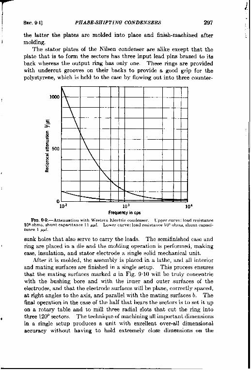
SEC. 9.1] PHASE-SHIFTING CONDENSERS 297
the latter the plates are molded into place and finish-machined aftermolding.
The stator plates of the Nilsen condenser are alike except that theplate that is to form the sectors has three input lead pins brazed to itsback whereas the output ring has only one. These rings are providedwith undercut grooves on their backs to provide a good grip for thepolystyrene, which is held to the case by flowing out into three counter-
1000 -
\~b5 \S&a
g 500z8.-; \ ,
\
0102 103 104
Frequency in cps
Frm9.9.—Attenuation tith Western Electric condenser. Upper curve: load resistance100ohms, shunt capacitance 11 ppf. Lower curve: load resistance 1070hms, shunt carwwi-tance 1 PP1.
sunk holes that also serve tocarry the leads. The semifinished case andring are placed in a die and the molding operation is performed, makingcase, insulation, and stator electrode a single solid mechanical unit.
After it is molded, the assembly is placed in a lathe, and all interiorand mating surfaces are finished in a single setup. This process ensuresthat the mating surfaces marked a in Fig. 9.10 will be truly concentricwith the bushing bore and with the inner and outer surfaces of theelectrodes, and that theelectrode surfaces will be plane, correctly spaced,at right angles to the axis, and parallel with themating surfacesb. Thefinal operation in the caw of the half that bears the sectors is to set it upon a rotary table and to mill three radial slots that cut the ring intothree 120°sectors. Thetechnique ofmachining allimportant dimensionsin a single setup produces a unit with excellent over-all dimensionalaccuracy without having to hold extremely close dimensions on the
1.I

298 SPECIAL VARIABLE CONDENSERS [8Ec. 92
individual pieces, and without necessitating difficult or critical aseemblyoperations.
The Mycalex sheet from which therotor is formed is surface-groundon both sides to ensure flatness, parallelism, and smoothness of faces. Itisthenblanked out, bored, assembled between twocollars on the stainless-steel shaft, and the edge is finish-machined to the shape shown in Fig. 9.8.
b
a
—FIQ, 9. 10.—Nilsen condenser construction.
Both the Western Electric and the Nilsen condenser are compact,dustitight, reasonably immune to corrosion, and uniform in character-istics, and both have proved satisfactory in the field. In operation therotors do not turn at speeds over a few revolutions per second, nor forintervals of more than a few seconds, but their low torque and the use ofoilite bushings would permit their operation at higher speeds if necessary.
9.2. “Sweep-scanning M Condensers.—The development of the so-
called “sweep-scanning” condensers was made necessary by the develop-ment of radar antennas that permitted rapid continuous scanning with asharp beam. To take full advantage of the information furnished bysuch an antenna it became necessary to devise a position-data-trans-mitting device that would follow the antenna, and to choose repetitionrates that would be compatible with the geometry of the display. Theproblem was complicated by the fact that the relation between theposition of the radar beam and that of the shaft controlling its motionis not necessarily linear; therefore, a linear sawtooth slveep-volt age gen-erator with only a synchronizing signal from the scanning shaft cannot

SEC. 9.2] “S WEEP-SCANNING “ CONDENSERS 299
ordinarily be used. Other “devices such as potentiometers, rotaryinductors, etc. also have serious limitations, particularly when operatedat the high speeds necessary. A major disadvantage of devices usingnonlinear circuit elements is the impossibility of making static measure-ments on the system in order to calibrate the position of the cathode-raybeam in terms of the radar beam. The most satisfactory solution insuch cases has proved to be the use of capacitive voltage dividers withthe special condensers described in this Section.
Figure 9.11 is a simplified block diagram showing the method of gen-
M Cwaitt @@J@ Detector ~ f.at,d mOscillator and
divider filter~ amplifier
I l—
I‘1+Gating
Ipulses
I — Gating——-—-----—4—–
Mechanical input circuit
FIG. 9.11 .—Generation of sweep-voltage wave.
crating sweep-voltage waves of arbitrary shapes by means of capacitivevoltage dividers. An oscillator generates a constant-amplitude voltage,usually at a frequency of approximately 1 Me/see, which is amplitud-modulated by the voltage divider. The modulated voltage is detectedand all frequencies except those necessary for satisfactory reproductionof the modulation envelope are filtered out. Theenvelope voltage is then passed through a gatedamplifier that removes all of the envelope waveexcept the portions that are to be applied to thecathode-ray tube as sweep voltages. Synchroniza-tion of the motion of the cathode-ray beam andthe radar beam is assured by driving both the sweepcondeneer of the voltage divider and the pulse-producing device in the gating circuit from thesame shaft that drives the antenna rapid-scanmechanism, either directly or by means of a suibable servomechanism.
P c,
!_&El
C2Ez
FIG. 9.12.—Simple ca-pacitive voltage divider.
Voltage-divider Circuits.—If a constant a-c voltage El is impressedacross the circuit of Fig. 9.12, the output voltage Ez across the condenserC, will be
c,EZ=E, C,+C2— = pE,. (28)
L
.
If C, (or C,) is a variable condenser with plates suitably shaped and ifthe motion of its shaft duplicates that of a radar beam, the output voltage

300 SPECIAL VARIABLE CONDENSERS [sm. 9.7,
El may be used to generate sweep voltages for the radar indicator.A simple analoguc of this method would be the use of a constant d-cvoltage impressed on a potentiometer, the motion of whose arm duplicatesthat of the beam.
Either C* or C, or both can be made variable but it is preferable inmost cases to make Cz variable. Then Cl can be a small fixed condenserwhose stray capacitance to ground will be negligible, In this case, thegeneral equation for the capacitance of CZ in terms of the voltage ratiop(13) will be
c,(e) = c, ‘ -#). (29)
Here p(tl) is a function of the angle o of the radar beam, which may ormay not be a linear function of the angle of the condenser shaft. If itis not linear, the expression (29) must be modified by including theappropriate function in the p(t?).
Display systems using this method of precision data transmissionusually require one of two functions of p in terms of 0. For accuratemapping it is desirable to make
P(L?) = a + be. (30)
In cases where the radar antenna as a whole is to be pointed at the targetit is desirable to have the central portion of the display greatly expandedto permit accurate angular settings to be made, but the peripheral por-tions compressed to include a sufficiently large angular range to facilitategetting on target. In such cases (and also in others) a very usefulfunction is
p(e) = a + b sin O. (31)
In these two expressions b may be either positive or negative, but it isalways smaller than a. In Eq. (31) the sine may be replaced by a cosineby a suitable shift of the zero value of t?. The r-f voltages modulatedaccording to either Eq. (30) or Eq. (31), after rectification and filteringand with their d-c bases shifted, give control voltages proportional to oand sin o respectively.
The substitution of Eqs. (30) and (31) in Eq. (29) gives, respectively,
l–a–bec, = c, --+~)
and
c, = c1l–a–bsind
a+ bsind ‘
(32)
(33)

I SEC. 9.2] “SWEEP-SCANNING “ CONDENSh’RS 301
I from which the plate shapes of C2 may be designed. If the mean value; of p is made ~ so that the mean value of Ct is equal to Cl, these expressions
become, respectively,1 – 2b8
C2 = C’ ~e’
and
c, = c,l–2bsin01 + 2b sin 0“
(34)
(35)
The actual calculation of the plate shapes, once the law of variation ofI capacitance with angle is established, depends upon a number of factors
and will not be discussed here, but several examples of actual condensersI will be given later in this section.
For rotor plates in the form of comparatively narrow blades, a suit-able procedure is to design the stator plates on the assumption of infinitelynarrow rotor plates, then to correct the resulting curve for the finiterotor-plate width, and finally to make the corrections for fringing (edgeeffect). This method was used in the designs of Bendix OAL-74747-1and OAR-97 130-1, as well as the Rauland CV-11. Analytical designmethods are excessively laborious except in special cases, and correctionsfor fringing must usually be calculated graphically in any event. Onefactor that considerably lessens the labor involved is that the absolutevalue of the capacitance is relatively unimportant, because a constantfactor can always be compensated for by changing Cl, and a capacitance-variation curve, corrected at comparatively few points and faired “byeye, ” will be sufficiently accurate for most purposes.
The input impedance of the simple voltage-d~vider circuit of Fig. 9.12is a function both of the load impedance into which it works and of thecapacitance of C2. For most operating conditions the load impedancecan be safely assumed to be infinite, but the variation of input capacitancemay result in both amplitude and frequency modulation of the oscillator.For a modified Hartley oscillator such as is usually used as a driver, theamplitude modulation can be reduced to a negligible amount by using aplate tank circuit with a Q of 100 or more. Frequency modulation canbe reduced to 10 per cent or less by using a high-C tank; however, iftuned r-f transformers are used in the sweep-generating circuit, even asmall frequency shift may cause excessive amplitude modulation withconsequent distortion of the sweep waveform.
One method of avoiding difficulties due to changing input impedanceis the use of a push-pull voltage divider shown in Fig. 9.13. Here theadmittance of the left-hand branch is given by
*y = ju C1C2
c, + c,’(36 )

302 SPECIAL VARIABLE CONDENSERS [SEC. 9.2
and a corresponding expression with the quantities primed applies to theright-hand branch, If the input admittance is to remain constant,
(37)
Substituting the values for the y’s in this equation and rearranging gives
(38)
as the required expression. The condition for a balanced push-pull out-put voltage is
dE, dE:de=–~’
from which can be obtained
dC,c1 _=_ cl dC~(C, + C,)z do (c{ + c;)’ m“
(39)
(40)
The conditions of Eqs, (39) and (4o) are identical if Cl = Cf.The principal objection to the use of push-pull dividers is the dlficulty
of mechanically aligning the two variable condensers and of maintaining
FIG. 9.13.—Push-pull capacitive voltagedivider.
this alignment in the field. Theproblem is much less difficult,however, if it is possible to usestraight-line-capacitance condens-ers, which can be aligned bysmall trimmer condensers in shuntwith the variable condensers.Push-pull dividers have not beenmuch used.
It is sometimes possible tocompensate for nonlinear radar-beam angle vs. scanning-shaft
angle characteristics by a suitable choice of network parameters. Anexample of this method is furnished by the voltage-divider circuits fora radar set that employed two sharp oscillating fan beams. The azimuthantenna scanned through an angle of 20° and the elevation antennathrough 9°, but only 18° and 7°, respective y, were presented on theindicator tubes. The relations between beam-position and condenser-shaft angle (with the linkage actually used to drive the condenser) areshown in Fig. 9.14.
It was found that the use of a straight-line-mpacit ante condenser inthe circuit of Fig. 9.15 would give an amplitude modulation of the
)
I
I

SEC. 92] “SIVEEP-SCA N.VI .VG “ CONDIIJVSERS 303
Shaft angle-
Elevation in degrees
“o 6 12 18Shaft angle
Azimuth in degrees
FIG. 914.-Beam position vs. shaft angle
8ias adjusted so thisr point equals O volts dc
gs!%:-m
out
Elevat[on E c, Anmuthout
c=otOllo#Pf —. —E,n C+ C,+C2
c = o to 220 WIC1=122 Wf C,=54 WfC2=194 ##f C2=198/IJd
I:IG. 9 15.—\-oltage dividers for Fig, 9.14.
!
required form if the network parameters ~vere chosen as given there.The modulated output voltages are also showm symbolically in Fig. 9“15,and the curves of output (d-c) voltage vs. condenser-shaft angle in Fig.916. Comparison of these curves with those of Fig. 9.14 shows that the

1’
,.
304 SPECIAL VARIABLE CO.VDZl.VSh’ILS [SEC. 9.2
50
40
10
no 3 6
\
I
I
019“ o
I
6 12Shaft angle In degrees Shaft angle m degrees
Io 36.75 73.5 110,25 0 73.5 147.0
Capacdance in u~f Capacitance in ~pfFlu. 9.16.—Performance of voltage dividers of Fig. 9.15.
Insulating~stator support
Fm. 9.17.—Bendix OAL-74747-1 sweep condenser
18”
220,5
I
I
I

SEC. 92]
approximations
“SH ‘EEP-SCANNING” CONDENSERS 305
used are accurate, and the performance of this systemin the field has been very good.
Since the ranges of variation of the variable condensers used in thetwo cases just discussed were chosen to be in the ratio of 2 to 1, andsince the condenser shaft was required to oscillate rapidly over a limitedangle because of the nature of the drive, it was found convenient to usea condenser with a balanced rotor and two identical insulated stators,
and to ground the rotor through a spring “pigtail” instead of dependingupon friction contacts. For the azimuth system, which required thelarger capacitance variation, both stators were used, whereas only onewas connected in the elevation system. Identical condensers couldtherefore be used in both systems. Figure 9.17 shows the constructionof this condenser.
Commercial Linear-sweep Condensers.-Besides the Bendix OAL-74747-1 condenser, there are in production t~vo other sweep condensersthat are intended to generate linear-sweep waves [according to Eq. (30)]when used in the circuit of Fig. 9.12, These are the Rauland CV-11and the Bendix OAR-97130-1. The CV-11 is shown in Figs. 9.18 and9.19, and the shapes of the rotor and stator plates of both are shown inFig. 9.20. The Bendix condenser is packaged similarly to the Raulandunit and is like it in general construction but is somewhat shorter andgreater in diameter.
The actual construction of the Rauland condenser deserves some
I

306 SPECIAL VARIABLE CONDENSERS [SEC. 92
FIG. 9.19.—Construction of Rauland CV-11 condenser. (1) Housing; (2) end plates;(3) stator-plate assembly ;(4) stub steel driving shaft;(5) ceram,c main shaft; (6) counter-weights; (7) rotor-plate assembly; (8) index marks for zero, ng rotor; (9) shp ring; (10)solder connection from slip ring to stator plates; (11) brush; (12) bear,ng retainer plates;(13) sh]ms for longitudinal rotor position adjustment; (14) loading spring; (15) ball bearings.
Rauland CV-11 Bendix 0.4 R-97130-1FIG. 9.20.—Plate shapes of CV-11 and OAR-97130-1 condensers,
comment because it represents good practice in the design of precisionequipment. In general the CV-11 conforms to the standard Navyspecifications as to material, workmanship, andresistance to temperatureand humidity tests, salt-spray corrosion tests, vibration, shock, etc.

TSEC. 92] 8’SI1’EA’P-SC.1 .V.V1.VG “ CONDENSERS 307
The case of the unit consists of a heavy cast Jlonel-metal body to whichare screi~etl tJro cast end plates, also of hIonel metal. The 17 statorplates, of o.040-in. planishecf Xlorml sheet, are mounted in grooves in sixmounting posts to \vhicll they are soldered after assembly. The statorplate assembly is held concentric Jvith the cylindrical body by an internalridge in the body, and is aligned longitudinally by being scre}ved to amachined s~wface on the front end plate. The rotor-plate assembly is .similarly constructed, and is mounted on a ceramic shaft that also carriesa stub, steel dri~ing shaft, two counterweights, a bearing collar, and asilver slip ring to which contact is made by a pair of silver-graphitebrushes mounted outside the front end plate. This method of mountingthe rotor plates on an insulating shaft is expensive but greatly improvesthe performance of the unit by keeping the bearings, counterweights,and stub shaft at ground potential and by making the rotor connectionthrough the brushes andslip ring instead of through the bearings. Themetal rotating parts are soldered to metallized surfaces on the ceramicshaft, and connection is made from the rotor-plate assembly to the slipring by solder fillings in radial and axial holes in the shaft, as shownin Fig. 9.18. The light sheet-metal cover for the brush assemblywas a temporary arrangement; in a service model it would be replacedby a heavier Jvaterproof co~-er and all joints would be gasketed andsealed. Both rotor- and stator-plate assemblies are aligned longi-tudinally from the front end plate, and the rotor position is adjustedby shimming the front bearing retainer plate. End plav is removedand differential expansion is allowed for by a loading spring under therear bearing.
S’peci$cations for Linear-sweep Condensers.—The dimensional andperformance specifications may be briefly summarized in the followingway. The condenser is to operate continuously in one direction to fur-nish a capacitance variation that agrees with the specified curve (givenin Fig. 921 for both the CV-11 and the Bendix 0.4R-97130-1 units)within + ~ per cent for not less than 320° of a complete rotation andthat returns to its orginal value in not over 40° of a complete rotation.The capacitance tolerance holds for all tests except the temperature test.For the temperature test, the temperature coefficient is to be not morethan 100 X 10–c/OC. The condenser must operate satisfactorily over atemperature range of – 40° to +70°C, and in air of 95 per cent relativehumidity at 45°C. It must withstand the standard Navy salt-spray,vibration, and shock tests. It must also withstand the continuousapplication of 400 volts a-c at 60 cps at any of the above temperaturesand humidities, and the application of 1000 volts for 1 min immediatelyafter the humidity test. Within 30 min of the humidity test, its leakageresistance must be not less than 10 megohms. The condenser must becapable of continuous rotation for 10,000 hr at speeds up to 2000 rpm,

308 SPECIAL VARIABLE CONDENSERS [SEC. 9.2
la
MO
; 120a
~ 109
!/Jso
m
40
0 40 w 120 lW 200 240 2m 320 3WRotor angle in dagraaa
FIG. 9.2 1.—Capacitance vs. rotor an~e.
FrIJ.9.22.—P1ate shapes for Binuaoidalsweep condenser.
and must withstand an accelerated life test of 1000 hr at 3000 rpm at 20°to 30”C and 50 to 70 per cent relative humidity. The maximum allow-able torque is 4 oz-in. at normal temperatures and 8 oz-in. after 8 hr at–40”C.
The center-to-center spacing of the 17 rotor and 17 stator plates is to

r
SEC, 9.2]
be 0.160 + 0.001
‘ ‘SWEEP-SCA ,ViVING “ CONDENSIIIM 309
in., and the plates of each set are to be parallel withinO.001-in. total indicator rea.d~ng. The tolerances on th~ concentricitybetween rotor-blade tips and stator-plate peripheries and on the parallel-ism between rotor and stator plates are 0.002 in. max. Longitudinalcentering is to be done by setting the rotor in its maximum-capacitanceposition and adjusting the rotor longitudinally for minimum capacitance.
No condensers have been put into production for the sinusoidalcharacteristic of Eq. (31), but Fig. 9.22 gives the plate shapes for such acondenser. Onereason that such condensers havenot been made is thatthe Cardwell KS-8534 condenser of Sec. 9.1 is suitable for many suchapplications; another is that synchros can often be used to generatesinusoidal sweeps. Detailed information regarding the generation ofsweep waveforms of arbitrary shapes and their application to cathode-ray tubes will be found in Vols. 19 and 22 of the Radiation LaboratorySeries.

CHAPTER IO
ROTARY INDUCTORS
BY W. F. GOODELL, JR.
10.1. Introduction.-A rotary inductor, as the term is used in thischapter, is a device in which the coupling between one or more statorcoils and one or more “rotor” coils can be varied by the rotation of ashaft. In certain forms of rotary inductors the so-called “rotor” coilsdo not rotate although the variation of coupling still takes place whenthe shaft is rotated. These devices may be used to transmit angularinformation or torque to remote points, to modulate an electrical signalwith mechanical information, or to demodulate an electrical signal, pre-senting the modulating information in electrical or mechanical form.Power-handling capacities of the different types and sizes of units rangefrom milliwatts to kilowatts, and the torque-transmitting capacitiesfrom milligram-millimeters to hundreds of pound-feet. Because fewapplications require large power-handling capacity, most of the unitsdiscussed here are those whose capacity is a few hundred watts or lessand whose output torque is of the order of a few inch-ounces.
In the following discussion, units have been primarily classifiedaccording to their construction and basic principles of operation, assynchros, hIagnesyns, and Telegons. Synchros have been further classi-fied according to the most common use of the particular unit, for example,the transmission of torque or position or the electrical modulation of atiming wave.
SYNCHROS
10.2. Nomenclature. -’’Synchro “ isageneric term used by the Navyto describe a rotary inductor similar to an induction regulator, in whichvariable coupling is obtained by changing the relative orientation of theprimary and secondary windings. The primary windings, from one tothree in number, are normally wound upon a rotor of laminated magneticmaterial. The secondary windings, from one to three in number, arenormally wound on a slotted stator of magnetic material. The rotor mayhave only limited rotation, in which case the connections to the primarywindings are brought out on flexible leads, but usually it is free to rotatecontinuolmly and the connections are brought out by slip rings andbrushes. Although all Navy standardized units are known as “syn-
310
I

SEC. 102] AYOME.VCLATURE 311
chros, ” manufacturers have designated their particular units by tradenames such as ‘‘ Selsyn” for the General Electric Company, “ Aut,osyn”for the Bendix .iviation Corporation, ‘‘ l’eletorque” for the KollsmanInstrument Company, and “ Diehlsyn” for the Diehl h’manufacturingCompany. A representative group of synchros is shown in Fig. 10.1.
(c/)
i..
I(d ‘J”’..-J
FIG. 101.-TypIcal synchros. (a) S,ze 7 synchro; (b) Size 5 synchro; (c) PioneerAY-series Autosyn; (d) Size 6 synchro; (e) D1ehl Frame B1731s5 synchro; (j) Size Isynchro.
Probably the most common use of synchros is the transmission ofangular data or torque by the use of two such units back-to-back or inconjunction with a servo system. Other uses include modulation ofelectrical waveforms, resolution of vectors into components, and com-bhation of vectors in various computing devices.
The nomenclature of synchros is further complicated by the differentdesignations given the same functional types of units by the Army andNavy. For purposes of simplification the Navy nomenclature will beused here. The .4rmy equivalent nomenclature is given in Table 10.1.
TABLE 1O.1.—SYNCHFCO FUXCTION-AL CLAC+SIF1C.~TIO~
I I
Navy term
Synchro generatorSynchro motorSynchro control transformerSynchro differential generatorSynchro differential motor
INavy symbol I Army term I.hrmysymbol
Gnone (see text)
~lrr
DCD
ITransmitterRepeaterTransformerDifferential transmitterDiffcrenti3,1 repeater
TRRPCTDTDR

312 ROTARY INDUCTORS [SEC.10.2
Astandard Navy synchro would be designated by a symbol such as5HCT Mark 2 Mod 3B, where the various digits have the followingsignificance:
1. The inititd number indicates the size group to which the unitbelongs. Standard Navy synchros fall naturally into six distinctgroups, according to Table 10.2. Because of the convenience of
TABLE 1O.2.-SYNCHRO SIZES AND WEIGHTS
Sise Approx. weight, lb. Approx. length, in. Approx. diameter, in.
1 2 3.9 2.953* 3 5.2 3.105 5 6t06.8 3.4-3.66 8 6.47.5 4.57 18 8.9-9.2 5.758“ 60 13.13 8.63
● Sises3 and 8 me seldom used.
2.
3.
4.
5.
this method of designating size, other synchros such as Army unitsand GE Selsyns are often referred to as “Size 1‘’ or “Size 5” ifthey approximate the corresponding Navy type.One or more modifying letters may follow the numeral. In theexample above, the H indicates that the unit is fitted with specialbearings and brushes to permit high-speed operation. Othermodifying letters are the mounting designations F, N, and B,which designate flange-, nozzle-, or bearing-mounted (see below),and S, which indicates that the unit is special in some way andmay not be interchangeable with other units with the samedesignation but with a different “Mod” number.After the modifying letters, if any, come the letters designatingthe function of the unit; according to Table 10.1. In the case ofa motor, for which no symbol exists, the mounting designationletter is used: thus a lF, a 5N, and a 6B would all be standardmotors without any special features. Since units with N or Bmountings are relatively uncommon, F has come to be practically asynonym for motor. For the same reason the F is usually omittedin the designations of units other than motors.The “Mark” number is actually a type designation: all stand-ard synchros of the same symbol and Mark number are inter-changeable.The “Mod” (model, or modification) number designates themanufacturer, according to Table 10.3.
I
I
I

SEC. 10.3] DEFINITIONS
All replaceable parts of a given synchro
313
will interchange with thoseof any other synchro of the same type, Mark, and model. When amanufacturer makes minor improvements on a synchro the improvedunits bear a letter after the Mod number: thus a Mod 3B unitwouldinterchange with a corresponding Mod 3 unit, but the parts of the twowould not necessarily interchange since the two do not have the sameMod number.
TABLE 1O.3.—MANUFACTURERS OF STANDARD hTAvrSYNCHROS
Model Manufacturer1 Arma Corporation, Brooklyn, N, Y.2 General Electric Company, Schenectady, N,Y.3 Ford Instrument Company, Long Island City, N. Y.4 Bendix Aviation Corp., hIarine Division, Brooklyn, N. Y.5 Control Instrument Company, Brooklyn, N. Y.6 Diehl Manufacturing Company, Finderne, N. J.7 Bennel MachineCompany
The Navy nomenclature is somewhat involved but it is practical.The Army designates its units by Roman numerals assigned in order ofadoption of the units by the Ordnance Department. If minor modifica-tions in shaft-end or mounting details are made, an Arabic numeral isadded to the designation. Thus the Army designation is entirelyarbitrary and is useless in determining the function, size, or manufacturerof a unit.
The nomenclature used by the General Electric Company for itsSelsyn units is as follows. All designations start with “ 2J” whichindicates that the unit is listed under the GE catalog subdivision 2J,which covers Selsyn units. After the 2J, a D may appear; if present, itindicates that the unit is provided with a damping disc to permit opera-tion as a motor. Units without the D must be geared to a drivingmechanism. Following the D is a,number denoting size, using the Navysystem of Table 10.2. A letter following the size number indicates theshaft and frame type, and a final number designates the serial numberof the electrical design of the unit using that particular set of mechanicalparts. Thus a 2JD5H1 would be a Size 5 synchro motor with an H-typemechanical design and the first electrical design in the 5H frame.
Most other manufacturers designate their units numerically. Pio-neer-Bendix prefixes the letters “ AY” to the type number to indicatethat the unit is a synchro or “ Autosyn,” and Diehl uses” FJ” or” FJE,”except in the case of the FPE-43- 1, a Diehl synchro which was incorrectlydesignated.
10.3. Definitions. Sunchro Generator.-A unit the rotor of which ismechanically driven, for generating or transmitting electrical signalscorresponding to the angular position of the rotor.

314 ROTARY INDUCTORS [SEC. 104
Synchro Mo1oT.—A unit the rotor of which is free to turn in accordancewith the electrical signals received.
Synchro Differential Generator.-A unit therotor ofwhichismeehan-ically driven, for modifying a received signal and transmitting an elec-trical signal corresponding to the sum or difference of the impressed andmodifying signals.
Synchro Differential Motor.—A unit the rotor of which is free to turnin accordance with the sum or difference of electrical signals receivedfrom two sources.
Synchro Control Transformer.—A unit which is normally used toproduce a single-phase voltage whose magnitude is proportional to thesine of the angle of rotation of its rotor with respect to the magneticfield of its stator.
Synchro Capacitor.-A unit whose function is to counteract thelagging component of the exciting current drawn by a differential unitor a control transformer, thereby reducing the heating of the rotors ofthe synchro generator and also improving the stiffness of the system.
In the interests of brevity, when it is not required to prevent ambi-guity, the word “ synchro” will frequently be omitted from these designa-tions throughout the remainder of this chapter.
1004. Theory and Construction of Units.—The structure of mostsynchros is similar to that of a conventional 3-phase alternator in afractional-horsepower size.
Statoi-s.-Generally speaking, the stator of a synchro is a cylindricalslotted laminated magnetic structure usually bearing a 3-phase Y-connected winding which is (with the exception of differentials andcontrol transformers) the secondary of the synchro. In most cases thestator laminations are skewed one slot pitch to eliminate slot-lock andthe resulting angular errors. In units in which the stator laminationsare not skewed, the rotor laminations are skewed instead.
The stator winding is not 3-phase in the usual meaning of the termsince all induced voltages are in time phase. The three legs of thestator winding are spatially displaced 120° from each other.
Rotors.—The standard types of synchros are of two-pole rotor con-struction. Three types of rotors are employed, and are illustrated inFig. 10.2.
The salient-pole rotor, shown in Fig. 10.2a, is the most commontype of synchro rotor. This is also known as the “dumbbell” or “H”type and is used in synchro generators and motors. It bears a machine-wound single-phase spool winding which serves as the primary or excita-tion winding of the synchro. Only two slip rings are required for thisunit, and it should be noted that they have the full excitation voltageimpressed upon them at all times.
I
!
I
I

I
SEC. 10.4] THEORY AND CONSTRUCTION OF UNITS 315
The umbrella rotor, shown in Fig. 10.2b, has been used in some con-trol transformers. This is an”intermediate design and maybe considereda modification of the salient-pole design.
The third type of rotor is the cylindrical or drum type, and is shown
(a)
(b)
k)l’]~. 102. -Synchro rotors. (a) Dumbbell; (b) umbrella; (c) drum or wound.
in Fig. 10.2c. These are commonly called wound rotors and are slottedand laminated structures carrying either a single-phase winding withItwo collector rings for control transformers or a Y-connected 3-phasewinding with three collector rings for differential units.

316 ROTARY INDUCTORS [SEC. 104
S~nchro Generators.-In the conventional synchro generator, single-phase a-c excitation is applied to the winding of a dumbbell rotor. Theexciting current flowing in this primary winding produces a flux whichlinks each of the three stator (secondary) windings to a greater or lesserdegree depending upon the angular position of the rotor with respect tothe several stator windings. Figure 10.3 shows the induced secondary
,@:@j@=
(a)Rotoron electrical zero (b) Rotor at 45° (c) Rotor at 90”
FIG, 10.3.—Induced voltages in synchro-generatm atator. (NOTE: rotation is reversedfrom Navy standard, which specifies counterclockwise rotation for increasing quantities.)
line voltages for three different positions of the rotor. These inducedvoltages may be represented as V sin a, V sin (a — 1200), and V sin
(a – 2400), where V is the rated secondary voltage and a is the angular
displacement of the rotor from its electrical zero position. A plot of
these voltages as functions of a is shown in Fig. 10.4.
For a given distribution and. +90%= polarity of stator voltages, there~ is but one corresponding position:.= of the rotor, and conversely, for‘d= any position of the rotor there is
270 360Rotor positkm in degrees
but one secondary-voltage condi-
~lG.10.4.—Navy synchro stator voltages. tion. Thus the stator voltagesconstitute an electrical indication
of the rotor position. A typical synchro generator is shown in Fig. 10.5.$ynchro Motors. —Electrically, a synchro motor is identical with a
synchro generator, and the preceding discussion applies. The distin-guishing feature of a synchro motor is that near one end of the rotor shaftthere is an oscillation damper, a flywheel with about the same momentof inertia as that of the rotor itself, which is free to rotate on the shaft.A friction coupling between the rotor and the shaft provides a means fortransferring energy from the rotor to the disk, and stops limit to about45° the free rotation of the flywheel relative to the shaft. This frictioncoupling dissipates energy when the rotor oscillates, as it does when
It I
t
i

b
SEC. 10.4] THEORY ANJ9 CONSTRUCTION OF UNITS 317
Stator coilsK wound in slots
Laminatedfield
Cross section of stator (reduced)
@&
Fm. 10.5.—Synchro generator.
.s-3
s-2
%1

318 ROTARY INDUCTORS [SEC, 104
coming into the synchronous position.’ The added inertia furnished bythe oscillation damper prevents the motor from “running away,” aninherent danger in either synchro motors or differentials. The damper
T Flywheel canturn 45° or so
FIG.10.6. —Synchro-motor damping flywheel.
is illustrated in Fig. 10”6.“Running away” of a synchro
motor is not the same phenomenonas that associated with the highspeed attained by a series motoron removal of the load, but arisesfrom the similarity of a synchrounit to a single-phase inductionmotor. The currents in the statorare approximately in the sametime phase and so produce a mag-netic field constant in direction.There is, of course, a primarymagnetic field due to the rotor
current. This is the same situation that exists in the single-phase induc-tion motor, and, like this induction motor, the synchro unit has no start-ing torque. When the synchro generator drives a synchro motor or adifferential at low angular velocities, the motor torque developed is notgreat enough to overcome the synchronizing torque, and the units remainin step. If the angular velocity becomes large, however, the motor torquebecomes sufficiently great to overcome the synchronizing torque, and thesynchro generator no longer has control. The effect of the inertia anddissipation added by the damping flywheel is to prevent momentaryoscillatory velocities greater than the critical value.
Obviously, a synchro motor can be used as a synchro generator butthe converse is not true for 60-CPS units. Generally speaking, synchromotors designed for 400-cPs application have little tendency to runaway and so are not provided with dampers.
Differential Units.—Differential machines are wound with 3-phase Y-connected windings on both rotor and stator; the rotor is a slottedcylindrical structure.
A 60-cps differential machine is usually connected between twosalient-pole synchros. The stator winding is the primary and derivesits magnetizing current from the stator of a connected synchro generator.The three line voltages of the synchro generator give rise to proportionalcurrents in the 3-phase stator windings of the differential machhe. The
1Althotighcommonlyused,“synchronism“ is perhapsnot correctin itsapplicationto synchros,since no notion of time is involved. Two synchros are in synchronismwhen their unbalance voltages are minimized by placing their rotors in correspondingpositions.
t
t
b

SEC. 104] THEORY AND CONSTRUCTION OF UNITS 319
resultant magnetic flux produced by these currents in the differential? stator is in the same position with respect to the stator winding as the
exciting flux in the generator is with respect toits stator winding. Thus,there is produced in the differential machine a flux whose positioncorresponds to the position of the synchro-generator rotor.
As was the case with the synchro generator, this flux inducesin the—secondary windings of the differential, voltages whose magnitudes aredependent upon the relative positions of the windings and the flux. Itfollows that the distribution and polarity of the voltages induced in the
4 secondary of the differential machine represent the algebraic sum of therotations of the rotors of the synchro generator and the differential withrespect to their stators.
The differential generator obtains its excitation from the other unitsof the system to which it is connected, and since it has losses it is evident ,1that to have W-volt primary (stator) windings supply 90 volts on thesecondary (rotor) windings, the units cannot be wound on a 1/1 turnratio, but on a I/l-plus basis. For this reason the stator is always con-sidered the primary and should be connected to the stator windings of itsassociated synchro generator.
This machine can be used either as a differential generator for super-b imposing a correction on the signal from a synchro generator, or as a
differential motor for indicating the sum or difference of rotation of two) separate synchro generators. In the latter case, it is equipped with a
mechanical damper, as explained in the above discussion of synchromotors. A typical synchro differential is illustrated in Fig. 10.7.
Synchro Control Transformers.—The control transformer is equippedwith a single-phase winding on a cylindrical rotor. In this machine, asin the differential machine, the stator constitutes the primary winding,receiving excitation from a synchro generator. Also, as in the differentialmachine, the exciting currents produce a resultant flux in the machine,
! the position of which, with respect to the stator, corresponds to the anglerepresented by the applied stator voltages. This flux induces in the
. rotor winding a voltage whose magnitude is dependent upon the positionof the rotor with respect to the flux. If the rotor is in such a positionas to link a maximum of the flux, the induced voltage is a maximum; a90° displacement will place the rotor cofi across the flux and the inducedvoltage will be zero. The latter position (often called the “null” posi-tion) is the normal condition of operation of a control transformer.
It is apparent that there are two positions of the rotor at which zerovoltage will be induced; but a slight rotation of the rotor in the clockwisedirection, for example, will produce a small voltage whose polarity*depends upon which of the two null positions is chosen. Thus, if meansare provided for recognizing polarity, there is but one “correspondence”

320 ROTARY INDUCTORS [SEC. 10.4
position of a control transformer for a given distribution of excitingvoltages. Forafurther discussion ofthismatter seethe instructions for“zeroing” acontrol transformer in Sec. 10”10.
Conceivably, a machine with a dumbbell rotor could be used togive control-transformer action. Because of the fringing at the pole tips,
I* I
FIG. 10.7. —Synchro differential.
however, the zero position would not be accurately defined, and, becausethe rotor axis is displaced 90° from the axis of the exciting flux, thisflux would meet a very large air gap and the magnetizing current wouldbe prohibitively high. The input impedance to the control transformerwould therefore vary with rotor position. This variation would intro-duce additional errors into the data-transmission system.
+
t
.

SEC. 10.4] THEORY AND (INSTRUCTION OF UNITS 321
The impedances of the stator and rotor windings of a control trans-former are considerably higher than those of an equivalent-sized sy nchrogenerator or motor and a control transformer should never be used tofeed a low-impedance load. High impedance of the stator windingreduces the excitation current drawn from the system by the addition of
t
t
.
q,;’ ;ff iL.,
1a
(“’ :(. ‘)(:.’; y~ &.A
FIG. 10.S.—Synchro control transformer.
the control transformer, and high impedance of the rotor winding gives ahigher and more useful output-voltage gradient. A typical control trans-former is shown in Fig. 10.8.
Syndwo Control Motors. —There are a great many possible variationsin the mechanical and electrical details of synchros. One of the mostusefuf modifications of a synchro is the” B” or bearing-mounted machine.Here the rotor and the stator maybe rotated independently. The usual

4’.
322 IWTA It Y 1.V1)(JC,’I’0IL% [s!,1. 104
type is the synchro control motor , which is identical to a standardsynchro motor except that the whole machine is rotatable. Controltransformers are also frequently mounted in this same fashion. The
k’IG. 10.9. —Synchro control motor
stator of the unit is mounted on two sets of ball bearings as shown inFig. 10.9 so that it, as well as the rotor, is free to rotate. Ball racesare fitted over shoulders provided on each end of the stator and thewhole motor is supported on hangers. To allow connections to the three
n
4

SEC, 104] TI{IIORI’ ANT) COiV,~TRUCTION OF 1:.VI TS 323
stator leads, three additional slip rings are provi(lwl. They are m ountr{i
on the end of the sta,tor opposite the sbuft extension. }Vith t}~isarrange-ment the position of the rotor with respect to the stator is determinedby the voltages applied to the five leads, as is the case ~vithany synchromotor. The position of the stator with respect to its mounting isusually set by means of a worm or pinion ~vhich drives a gear on thestator. This givm an action equivalent to that of the differential gen-erator without the loss of accuracy which the insertion of such a unitordinarily involves.
It%oeTsedSynchros,—Higher torques can be obtained from synchrosif the magnetizing power is increased. In conventional synchro genera-tors and motors the magnetizingpower is applied to the rotor wind-ings and the heat produced by therotor copper and iron losses mustI,e dissipated through the air gapto the stator and thence to the sur-rounding air. For a given temper-ature rise the allo!~able input poJvermay be increased if excitation is
:lPPlied to the stator instead of therotor. The change in torques ob-tainable is dependent upon the
resistance-reactance ratio of thelvindings, Such modified machines
arc knowm as reversed synchros,and are exemplified by the types
“A” and “xl “ Autosyns built by
the illarine Division of Bendix
Aviation Corporation, the type
15-021 synchro generator and the
type 15-022 synchro motor built by
Henschel, the type FJ 1’;-65-4 built
General I’lectric Selslns.
7“=”r“
\~ Sacondary
Brush path
I:lG. 10,1O.—A-C commutator transmitter.
IJ.YIliehl, and several commercial
The chief disatl~antage of this type of synchro is that the secondaryunbalance currents, which are very small for rotor positions near thenull, must pass through slip rings and brushes. These components maybecome dlmtv or dirty and offer a high resistance to the currents. Sincethe unbalance voltoges are so low, they may not be able to burn throughthis grime, in lvhich case the accuracy and smoothness of operation of theassociated synchro system lvill suffer.
!Z’heA-c Commutator Transmitter. -Another device which may be dis-cussed here, (although strictly speaking it is not a synchro), is the a-c
.,,

324 ltOTAlt Y lNDUCTORS [SEC. 10.5
commutator transmitter shown in Fig. 10”10. This device is simply atransformer with a single-layer secondary, on the flat side of which there isa bare circular path on which three brushes spaced 120° apart around acommon shaft make contact with the secondary winding. The action isanalogous to that of a General Radio Variac, or to one of the sine-cosinepotentiometers described in Chap. 8. The commutator transmitter has notbeen extensively used, but possesses certain advantages over a synchro gen-erator, especially in the larger sizes. If the pitch of the secondary wind-ing is uniform and sufficiently fine to avoid trouble from “ graininess,”the accuracy should be better than that of a synchro generator since there
A-c SUp@y
S2
R1
R2
S3
Generator
Motor
l~l[;. 10.11.—Synrhro generator-motor system.
.!
●
is no possibility of mechanical reaction from the load back to the trans-mitter shaft. Also, since there is no air gap, the coupling coefficientbetween primary and secondary can be made appreciably higher than ispossible with a synchro. It would seem that a properly designed com-mutator transformer might be useful as a driver for cathode-ray-tubedeflection yokes (see Sec. 10. 14).
10.6. Common Synchro Systems. Synchro Generator and Motor .—It has been shown that for a given position of a synchro-generator rotorthere is a given distribution of single-phase voltages between the threestator leads; the same holds true for a synchro motor. If the two statorsare interconnected, as in Fig. 10.11, and if the rotors are in identicalpositions, the stator voltages will balance and no current will flow in thestator windings. If, however, therotors are displaced with respect toeach other, then the stator voltages will not be matched and the net
I
I
4
I

4
SEC. 10.5] COMMON SYNCHRO SYSTEMS 325
unbalanced voltages will cause current to flow in the stator windings.These currents will create torques in both machines, and the motor rotor,IAng unrestrained, will move to a position of synchronism with thegenerator. Note that thesynchro motor is not a“motor” in the usualsense of the word: the mechanical work done by the synchro motor isderived from the work done on the synchro generator; electricity servesonly as the means for transmitting this work from the synchro generatorto the synchro motor.
The uses of the synchro generator-motor combination are obvious.If the rotor of the generator is turned manually or automatically to
S2
R1
A+ 5Upply
R2
S3
Note: Synchro capacitor may be omittedm some applications
voltage
FIG. 10. 12.—Synchro generator-control transformer-servo system.
represent the position of a gyrocompass, a water-level float, a valve, etc.,then the attached synchro motor, wherever it may be located, will indi-cate the position of the controlled member. Furthermore, one synchrogenerator can control several synchro motors so that the desired positioncan be indicated at a number of different locations.
Synchro Generator and Control Transformer.-A control transformeris used when it is desired to position a load of any sort by a synchro-servosystem. Volumes 21 and 25 of the Radiation Laboratory Series coversynchro-servomechanisms in detail. However, a few notes regardingthe function and application of thk combination of synchros follow.
When connected to a transmitting synchro system as in Fig. 10.12the rotor of a control transformer furnishes an a-c voltage, the magnitudeof which is an indication of the size of the angular error between thecontrol-transformer rotor and transmitting-element rotor, while its 1
polarity or phase is an indication of the direction of the error. This
i

[,
326 ROTARY INDUCTORS [SEC.105
voltage may be fed to a visual-reading meter and the position of thecontrol-transformer rotor adjusted manually until the meter reads zero,or it may be fed into an amplifier of some sort and used to control a motorthat automatically positions the rotor. All automatic controls haveantihunt features incorporated in their systems to prevent overtravel andoscillation at coincidence and to improve accuracy and speed of response.The complexity of the actual system depends upon the power and thedegree of precision required as well as upon other special control features.
Diflerentzid Synchro Systems.—A simple application of a differentialsynchro is its use as an indicator to show the sum or difference of theangular positions of two synchro generators. In this case, the stator ofa differential motor is connected to the stator of one synchro generator
A.c SUOPIY
I 1Generator
#l
)-
I Ii 11 I I I J
nw!-v=i
Fr~. 10.13.—Differentlal synchro system.
and its rotor to the stator of another synchro generator as is shown inFig. 10.13. From the description already given of its operation, it willbe apparent that the differential motor will indicate the differencebetween the positions corresponding to the two electrical signals comingto it. If, however, one pair of its leads—for example, S-1 and S-3—isreversed, then the direction of rotation indicated by the stator windingwill be reversed, and the machine will indicate the sum of the positionsof the two connected synchro generators. The same holds true for areversal of one pair of its rotor leads.
When used as a differential generator no damper is required, and themachine serves simply to superimpose upon the synchro-generator outputvoltages an electrical signal representing the position of the rotor of thedifferential generator. The resultant signal is then carried on to asynchro motor ur to a control transformer, whose indication will obviouslybe the sum or difference of the positions of the two driven members.
4
I

SEC. 10.6] SYNCHRO CAPACITORS 327
Thus the differential generator is a convenient device for adding correc-tions either to a synchro indicating system or to a synchro-controlledfollow-up mechanism.
Because the differential machine derives its excitation from anothersynchro, it is usually necessary to use synchro capacitors to assist infurnishing excitation. This machine isdesigned with thestator windingas the primary, and the capacitors should therefore be connected in shuntacross the stator leads.
Two-speed Synchro-transmission Systems.—It frequently happens thatthe accuracy required from a synchro-trrmsmission system is greater thancan be obtained dh-ectly from any synchro. In such cases it is possibleto gear up the synchro generator so that it turns faster than the drivingdevice, and to gear down in the same ratio from the motor or controltransformer. If a gear ratio of 2/1 is chosen, for example, the over-allaccuracy of the system is doubled. This method introduces a complica-tion, however, in that the system is no longer completely self-synchronoussince it is possible for the motor to “slip a pole” and to find a synchronousposition other than the correct one. The danger of such an occurrenceincreases directly with the ratio chosen; thus, for a 36/1 ratio, there are35 possible wrong positions for one correct one. To avoid such falseindications it is customary to add a duplicate pair of synchros operatingat a low ratio, usually 1/1. If the receivers are motors, two dials areused, one for coarse and one for fine readings, similar to the hour andminute hands of a clock. Such a double system is called a “two-speed”system. This use of “speed” in connection with the system as a wholeshould not be confused with its use to denote the gear ratio; thus a 36-speed synchro is one that turns 36 times for one turn of the actuatingdevice. Common speeds are 1, 2, 10, 18, and 36. If the receivers arecontrol transformers, both are geared with their appropriate ratios to thesame servo motor. The error signal is ordinarily taken from the “fine”or high-speed CT, but if the error voltage from the ‘‘ coarse” CT corres-ponds to an error of more than about + 3° in a 36-speed system, the“coarse” CT takes charge to return the system to approximately thecorrect setting. The details of such systems are discussed at length inVols. 21 and 25 of the Series.
In any two-speed system all of the elements of the system must nor-mally be duplicated; thus, in the differential-sy nchro system of Fig.10.13, two pairs of synchro generators would be required, and also twodifferential motors. Normally, with a two-speed system, the only ele-ments that are common to both speeds are the exciter buses, and theservomotor and amplifier if one is used.
10s6. Synchro Capacitors.—Differential generators, differential mo-tors, and control transformers draw magnetizing current from the syn-

328 ROTARY IND(JCTORS [SEC, 107
Ichro generators supplying their stators. This current lags behind thevoltage by a large angle. Three static capacitors, connected in delta,are usually added to the circuit as shownin Figs. 10.12 and 10.13. Thecurrent drawn by the capacitors, being a leading current at almost zeropower factor, neutralizes the lagging reactive component of the mag-netizing current and thus reduces the total current drawn from thesynchro generator by a factor of approximately 4. Three such capaci-
..q tors, connected in delta and suit-ably mounted in a hermeticallysealed metal container, comprisea synchro capacitor.
The capacitance of the threelegs of the capacitor must be bal-anced to within 1 percent in orderto ensure proper operation, butthe absolute value of the legs mayvary over +-10 per cent.
To obtain maximum benefitfrom the insertion of the capaci-
FIG.10.14a. —Synchro cauaritnt*.tors, it is necessary that the leadsfrom the capacitor to its associated
unit be as short as possible. This requirement may involve mountingthe capacitor in an exposed position. For protection it is often mountedin a waterproof capacitor box of standard hTavy design. A group ofstandard Navy capacitors and boxes is shown in Fig. 10.14.
10.7. Torque.—Figure 10”15 shows the torque-displacement curveof a Navy 5F synchro motor. This curve is typical of the synchros,regardless of unit size, used by the armed services. It may be seen
RG 10.14h.- Synchro capacitor hoxcs
that the rotor excitation current is at its minimum value (0.6 amp) witha 0° displacement and at its maximum (1.8 amp) at 180°. All threestator currents (not shown) are practically zero (2o to 50 ma per statorlead) for a 0° displacement and are maximum for 60°, 120°, and 180° ~displacements, respectively. Any continuous displacement of over 8°to 10° is likely to cause serious overheating of the rotors.

SEC. 10.7]
Torque Gradient .—The
TORQUE 329
torque gradient of a synchro is defined as the$
slope of the curve shown in Fig. 10”15 expressed in inch-ounces per degreeof rotor displacement at the point of zero displacement. Within thenormal operating range of the synchro, this curve approximates a straightline with a slope equal to the torque gradient.
Unit-torque Grad i e n L-The Toraueuni~torque gradient of a synchro
2s0~ 25.0Pis its torque gradient when meas- /ured against a standard single 2.25- 22.5-1
2.lm-synchro unit of identical charac-teristics (i.e., a IF against a IF;a 5F against a 5F; etc.).
System-torque Gradient.-The ~system-torque gradient is definedas the torque gradient of a synchro 0.75- ~ 7.5-
unit when measured in a systemof standard synchro units (i. e.,5G against two 5F’s; 5G against 0. 0
02040 m.solm1401alfour lF’s, etc.). Degrees displacement
Maximum Torque.—Maximum FIG. 10.15.—T ypical synchro torque-dis-t
torque is defined as that point onplacement curve.
the displacement-torque curve at which a tangent of zero slope can be~drawn.
If a synchro motor is driven by a synchro generator whose unit-torquegradient is R times that of the motor, then the actual motor-torquegradient will be 2R/ ( 1 + R) times the unit motor-torque gradient—thatis, the torque gradient that the motor would have if operated against anidentical unit as a generator. If N such motors are operated by the gen-erator of the previous example and the motors are equally loaded, each willdevelop a torque gradient of 2R/(N + R) times its unit-torque gradient.
t For example, if a synchro motor whose unit-torque gradient is0.06 in-oz/degree and a synchro generator with a unit-torque gradi-
i ent of 0.3 in-oz/degree are used, R is equal to 0.3,/0.06 or 5. Then withN = 1 the torque gradient of the motor would be ~ times its unit-torque gradient or 0.10 in-oz. With N = 2, its torque gradient wouldbe 0.086 in-oz/degree.
Torque-accuracy Relationships.—The basic error figure of a synchrois based upon measurements of errors when a synchro generator of agiven size drives a synchro motor of identical size. Because this erroris nearly inversely proportional to the torque gradient of the units, it is
4 possible to estimate the errors to be expected from a unit of knowntorque gradient. An increase in torque gradient gives an approximately
\ proportional decrease in static error.

330 ROTARY
10.8. Synchro-generator Load
INDuc~oR~ [SEC. 108
Capacities.—The accuracy and avail-able torque of a synchro system are reduced when synchro motors areadded. The allowable load clepends upon the rated permissible temp-erature rise of the synchro-generator rotor. This temperature risedepends upon the size of the generator, upon the size and number ofmotors, andupon their mechanical loads. It also varies with the numberof control transformers and differentials connected into the systemeven though the proper capacitors are used with these units.
No information on load capabilities is available at present for synchrosystems using differentials and control transformers as well as motors.To give some idea of synchro-generator capabilities, however, the follow-ing table is included. These figures assume no load on the motors otherthan that of a simple dial. Where greater loading is used, the numberof motors should be reduced. Where adifferential is listed, it is assumedto be connected to a generator of at least equivalent size.
Generatortype
1c.5G5DG6G6DG7G7DG
TABLE 1O.4.—SYNCHRO-GETVERATOIILOAD CAPACITIIXS
No. 5Funits
none
42
96
1812
No. IFunits
195
18123624
so. 5c’runits
none76
12102420
A-o. 5CT unitswith capacitors
1141230246048
No. lCTunits
none54
119
2218
N’o. lCT unitswith capacitors
1141230246048
10.9. Errors.—All svnchro generators, differential generators, andcontrol transformers, even though they are driven units, are subject toelectrical errors due to manufacturing irregularities in the windings andinthe magnetic structure. Synchro motors have allthe errors of synchrogenerators, and, in addition, have friction errors due to their bearingsand brushes.
The electrical errors can (if the windings and magnetic structuresare not properly designed) be such as to cause the dial of the synchromotor to lead the reading of the synchro generator at certain sectorsabout the periphery of the dial. Mechanical errors, on the other hand,being caused by friction in the bearings, always are lagging componentsof the total error.
Error Plotting. —Figure 10.16 shows a polar plot of the error? of aNavy size-lG synchro generator driving a Navy size-lF synchro motor.The space between the two curves, one showing clockwise readings andthe other showing counterclockwise readings, represents the error band
..1
r’“

SEC. 1010] ZEROING 331
and is mainly due to mccha.nical errors. Synchro errors may also beplotted in rectangular coordinates. ‘l’he latter method has the advan-tageof perrnittin geasiervisualization of maximum, minimum, and aver-age errors and error spread, but the symmetry of the errors may bemore readily seen from a polar plot.
10.10. Zeroing.-In order fortheangular indicationsat both ends ofa synchro system to correspond, it is necessary to orient the machines~vith respect to each other. There is only one angular position of asvncliro rotor for a given set of stator voltages, and, in view of this, adefinite relative position has been arbitrarily designated as “electricalzero” for all standard synchro units.
270
90
FIG,10.16.—Staticaccuracytest. Oneradialdivision=0.2” error,
This zero convention makes it possible to ‘‘ zero” the dial of a synchromotor on one unit of a system and then to reconnect the unit to a systemthat has been operating on a “ zeroed” basis and have the unit givereadings that correspond to its synchro generator without further adjust-ments. It is to”facilitate the zeroing of synchros that they are providedwith standardized flanges that are accurately concentric with the shafts.These flanges may be located either on the head end of the frame, as insome aircraft designs, or near the center of the cylindrical frame. Theyare machined to very close tolerances so that the synchro may be installedaccurately in a mounting assembly and held in place by a ring retainer
i
.
I

i:..
.,
332 ROTARY INDUCTORS 1(“i
[SEC.10.10 !
‘d
(c)
(e) v)FIG.10.17.—Typicalsynchromountinm. (a) Navysize5synchros,alsocertainArmY
styles; (b) B.mdix-Pioneer AY-100smies: (c) Diehf Frame B173185; (d) GEtize 1 airoraftaynchro: (e) Army Type VIII, IX, etc.; (j) Bendix-Pioneer AY-1 series. (Mounting andIoc.ating surfaces outlined in heavy lines.)
d
.’
*

SEC.10.10] ZEROING 333
or by dogs held against the flange. Thus, by loosening the ring or dogs,the stator may be rotated while energized for zeroing. Figure 10.17shows six common types of synchro housings, with the mounting andlocating surfaces emphasized. The larger synchro generators and motors,when properly connected and energized for the electrical-zero position,possess sufficient torque to position their rotors accurately, but, sincecontrol transformers and small differentials require a sensitive low-reading voltmeter or its equivalent for accurate zeroing, it is usuallydesirable to use a meter for zeroing all units.
The general method used to zero synchros is shown diagrammaticallyin Fig. 10.18. A synchro may be considered as a rotatable transformer,usually with a ratio of transforma-tion different from unity. For agiven distribution of stator volt-ages, there are two possible posi-tions of the rotor (these positionsbeing 180° apart) depending uponthe phase or polarity of the rotorwinding with respect to the statorwinding. In a synchro generatoror motor, when the rotor is nearthe 0° position, the effective volt-ages of the stator and rotor wind-ings are in the same direction, andif connections are made as in Fig.
I A<SUpply I
I I
QR1 R2
S1- —S3
S2
(dFm. 10.lS. —Fundamentals of zeroing.
(a) Voltagw aiding, lamps bright, windingsOppOsitely poled: (b) voltages opposing,lamps dim, windings aimdarly poled.
10.18b, the lamps will be dim, as thedifference voltage will be at a minimum. When the rotor is somewherenear the 180° position, the rotor and stator voltages are opposed as shownin Fig. 10.18a and there is a maximum voltage across the lamps.
In differential units and control transformers, the near-zero positionis indicated by maximum voltage across the lamps as represented in Fig.10.18a, and the 180° position by minimum voltage across the lamps asindicated in Fig. 10. 18b.
For the final accurate positioning of most synchros, a sensitive low-reading a-c–voltage-indicating device is required. This can be a cathode-ray oscilloscope or a vacuum-tube voltmeter in laboratories, and asensitive low-reading voltmeter or a 2000-ohm headset (telephonereceiver) for field applications.
Army-Navy Correlation.—The following set of instructions is basedprimarily on voltages and designations associated with Navy-typesynchros. However, by substituting proper voltages and designations,all information contained herein is equally applicable to all other typesof synchros. For zeroing Army synchros, the following voltage andnomenclature changes must be made:

334 ROTA R1’ INI) l: CTORS [5 EC, 10IO
1. Army s-ynchros are designed with a maximum stator-to-statorvoltage rating of 105 volts instead of the 90-volt rating of the Navysynchros. This means that wherever 78 volts is indicated in theseinstruetions, it should be raised to 91 volts for Army synchros.Because of the difference in terminology between the Services, thedesignations R1 and R2 should be interchanged on all single-phasewindings and S1 and S3 (or RI and R3) interchanged on all3-phase windings.
2. The voltages and designations to be applied to other nonstandardsynchros must be derived from their electrical and mechanicalconstructions.
S’ynchro Generators and iWotors.-To zero a synchro generator ormotor ]vhose rotor is free to turn, connect the unit as shown in Fig. 10.19.
The rotor will definitely turn toits zero position. Make the neces-sary mechanical adjustments whilethe unit is thus energized. Inan emergency, 115 volts may be
115Vapplied directly between S2 and
a-co
S1-S3, but the unit will overheatand become damaged if left ener-
R2 gized more than a very short(
\‘ T S3 S1period of time. (A maximum of 5min is specified for Navy synchos,
FIG. 10.19.—Zeroing a Navy synchrogenerator or motor with rotor free to turn. 15 min for Army units.)When connected as shown, rotor autonlatic- To zero a generator whoseally assumes electrical zero position, rotor is not free to turn, connectthe unit and test lamps as indicated in Fig. 10.20a and adjust for minimumvoltages as indicated by the lamps. This will give the approximate zeroposition. To refine the zero setting, connect as shown in Fig. 1020b andadjust until the voltage across S1 and S3 is zero as indicated by minimumnoise in the 2000-ohm headset or minimum voltage on the sensitive volt-meter. (This voltmeter should be sensitive enough so that a voltage of0.1 volt may be noticed.)
Differential Generators and Motors.—To zero a differential generator—or motor whose rotor is free to turn, connect the unit as shown in Fig.10.21. The rotor will definitely turn to its zero position, and the mechan-ical adjustments can be made while the unit is thus energized. Asnoted before, in an emergency, 115 volts may be applied directly betweenS2 and S3-S1, and R2 and R3-R1, but the unit will overheat and becomedamaged if left energized more than a very short time.
The differential units in the small sizes may not develop enough tor-

SEC. 1010] ZEROING 335
que to allow zeroing in this manner. In that case, they should be zeloedaccording to the plan for a unit whose rotor is not free to turn.
To zero a differential generator whose rotor is not free to turn,
l15va-c~-
115v lamp
(a)
l15va$
I(b)
FIG. 10.20.—Zeroing a Navy synchro generator or motor with rotor not free to turn.(a) Arfjust rotor or stator for minimum brightness. (b) Adjust for zero voltage.
connect the test lamps and unit as shown in Fig. 1022a and adjust thestator or rotor for minimum voltage as indicated by the brilliance ofthe lamps. This indicates theapproximate zero position.
To refine the zero setting, con-nect as shown in Fig. 10.22b andadjust the unit until the voltageacross RI and R3 is zero as in-dicated by minimum noise in the2000-ohm headset or minimumvoltage on the sensitive voltmeter.It is possible to use 115 volts inplace of the designated 78 volts,but for a very short period of time.
iYynchro Control Transformers.
To set a synchro control trans-former on electrical zero, connecttest lamps into the !circuit as
Auto.transformer
FIG. 10.21.—Zeroing a Navy synchrodifferential with rotor free to turn. Whenunit is connected as shown, rotor automatic-ally assumes electrical zero position.
illustrated in Fig. 10.23a and turn the rotor or stator until the testlamps indicate minimum voltage. This is the approximate zero position.Reconnect as shown in Fig. 1023b and refine the adjllstment until the

336 ROI’AR Y INDUCTORS [SEC. 1011
voltage across RI and R2 is zero as indicated by the headset or the
voltmeter.
10.11. Miscellaneous Specifications.-1n order to enable an engineer
to know the requirements that s~nchros as-e designed to meet, the follo~v-
78 v a-c 78 v a-c I
S2( )
(al (b)
FIG. 10.22.—Zeroing a Navy synchro differential with rotor not free to turn. (a)Adjust rotor or stat or for minimum brightness. (b) Adjust for zero voltage. The symbol%’represents a low-range a-c voltmeter or 2000 -ohm headset.
115v a.c 115v a.c
! S2 1( S2
S1
(b)Uuuu(a) 115 v lamps w
)
FIG.10.23.-—Zeroinga Navycmtrol tmnsformer. (a) Adjustforminintwnbrightnew(h)Adjustfor zerovoltaKe. The symbolV representsa law-rangea-c voltmeteror 2000-ohm headset.
ing paragraphs list some of the pertinent requirements for Navy 60-cyclesynchros as described in BuOrd Specifications A;o. OS-671 Revision l~;,These are the reqllirements which a manllfart,urer’s sample m~lst satisfy
,
I

r
r
I
I
SEC.101 1] MISCELLANEOUS SPECIFICA l’IONS 337
to become type-approved. It should be emphasized that these specifica-tions pertain only to standard Navy synchros, and that many non-standard syrwhros do not meet them.
Frequency and Voltage.—Theunits shall meet their specified accuracyand performance requirements at their rated voltage ~ 10 per cent andat a frequency of 60 cps t 10 per cent. The torque gradient increaseswith increase in voltage and in proportion to the square of the frequency.
Humidity .—The units are expected to stand 95 per cent humidityindefinitely. If they are expected to be exposed to 100 per cent humidity,at which they would be dripping wet, they are provided with weatherprotection. Ml studs, springs, washers, nuts, bolts, terminals, andexposed parts shall, where practicable, & protected against corrosion.
Tropicalization. —Synchros are not required to be “ tropicalized,”but some manufacturers use fungicides such as mercury compounds orpentachlorophenol.
Brushes.—Some companies (Ford Instrument Company and ArmsCorporation) use silver brush contacts soldered on to copper brush armsthat are backed by thick steel pressure blades; others (General Electric)use phosphor-bronze brushes. The brush pressures for driven unitsare to be between 10 and 20 g for the lF synchro-motor, and between 5and 9 g for the 5F synchro motor. These pressures are to be checkedon every unit during inspection.
It has been standard practice to provide silver slip rings on therotors and silver button contacts on the brushes of these slower-speedNavy synchros. Driving the rotors at higher speed accentuates anytendency to sparking, which, if once started, rapidly burns off thebrush contacts.
In order to permit satisfactory operation at the higher speed, brushesare now provided with graphalloy contact material which is composed of90 per cent silver and 10 per cent graphite. Some manufacturers supplybuttons made of this material; others use a rectangular block with a Vnotch. Synchros treated in this manner are supposed to function sat-isfactoril y at 1200 rpm for 1500 hr continuous rotation.
Shock.—For type approval by the Navy Department the presentrequirements for shock tests are as follows:
1. Bureau of Ordnance synchros: six blows of 2000 ft-lb-three blowseach in two directions; synchro to be energized during this test.
2. Bureau of Ships synchros: one blow of 400 ft-lb, one blow of 1200ft-lb and one blow of 2000 ft-lb in each of three directions.Total, nine blows.
Vibration.—The vibration requirements for type approval are at pre-sent as follows:

338 ROTAR1’ I.V[)[!CTOIM [SEC. 1o11
1. Frequency—any value between 50 and 1.500 cycles per minute.2. Amplitude-not greater than 0.03 in. (0.06-in. total excursion. )3. Duration—not over 24hrfor all tests.4. Direction—three directions, one parallel to rotor axis.
Thermal Range.—The units shall be excited with rated voltage andfrequency, and the temperature rise of the windings shall not exceed50”C as measured by the change of resistance method.
The units shall be capable of operating without damage at ambienttemperatures from – 25° to 55°C.
Lubrication. —Navy synchros were not designed for continuous rota-tion at speeds higher than 300 rpm. The standard units were, untilrecently, provided with selected magneto-type ball bearings that wereoiled initially at the factory with only a sufficient film of light oil to pre-vent rusting. In order to permit satisfactory performance at higherspeeds, the bearings of all driven units are now being greased with aspecified light grease. Any motors driven at high speeds should havegreased bearings. However, the application of this grease by the manu-facturer would probably prevent the unit from meeting the static-accuracy test requirements of Bureau of Ordnance Specification 0S-671.
Endurance. -Driven units shall be given a continuous endurance runof 500 hours at 300 rpm for the standard slow-speed units. High-speedunits shall pass a similar test of 1500 hours at 1200 rpm. These testsshall run at normal room temperatures and excitation.
Synchro motors and differential motors shall be driven by a synchn)generator following a simple harmonic motion for 500 hr. This motionshall consist of ~ 5 complete revolutions (i.e., 10 complete revolutionsbet ween reversals) during a period of 7.5 sec for the complete cycle.
lVoise.-The unmounted synchro when properly excited shal 1 be freefrom disturbing noises due to mechanical causes such as knocking in thebearings, loose laminations, etc. The noise or hum emanating from themagnetic structure shall not be considered objectionable.
Shaft End Play.—With the unit horizontally mounted and a force of3 lb applied to the shaft extension in a horizontal direction, pushing orpulling, the shaft end play shall not exceed 0.008 in.
Phase Rotation.-Phase rotation is the measure of the accuracy withwhich the rotor of the synchro unit positions itself when the unit iselectrically connected for angular positions of 0°, 60°, 120°, 180°, 240°,and 300°. With 115 volts applied to the primary and, in the case ofNavy units, 78 volts applied to the secondary, there m-e six uni(lucpositions that the rotor will assume, depending upon the phase relations-hips of the stator and rotor voltages and the manner in wbirh thevoltages are applied to the stator. These positions me illustrate~i ill
——

SEC.1011] h{lSCh’LLANEOfJS SPIK’lFICA 2’IONS 339
Fig. 10.24 which shows the connections necessary for the phase-rot ationtest.
Time-phase Shift .—The time-phase shift in a synchro system isimportant since it affects the performance of any attached amplifier
.-S2
1200
=r
ER2
R1
S3 S1
aS2
R1
R2
S3 S1I J
180° 240° 300”1:1{;. 10.24.-Phase rotation of Navy synrhro generator or motor, Rotor must he free to
turn.
and the stability of the whole servo system. Several standard syn-chro systems have been measured for time-phase shift between varioussections. hleasurements were made on a cathode-ray oscilloscope and,
I therefore, are not more accurate than about f 1°.
TARLE 105. -SYNCHRO TIME-PHASE SHIFTS
SystcrnNo.
12345
I
Fre-Iuency,
r,ps1(ienera-
tor
60606060
400
5(35(;5(:5rr
2.J1l?1
(’:ipaci- Differen-tor, pf[ tial gen-eg, delta erator
none I 51X210 5DGnone 51)(;
10 5r)G11011(! 2,J1H 1
Controltrans-former
1(Xl~T5cT5(x
2.11(;1
Phase shift
(;en,
—
14.5°7.5°
14.5°8°29.
Diff.gen.
18°12”18.5”12°7“
C.T.
30”26°20 5°17°11”
—-
I.

340
Synchro Matching
ROTARY I.VD{;CTORS [SEC. 1012
?’ra?tsformers, -Because Navy synchros are
designed for a maximum voltage between stator leads of 90 volts whereasArmy synchros have a 105-volt rating, the two types of svnchros maynot be interconnected without some sort of matching transformer. Threesizes of these special transformers are shown in Fig. 1025, but theiradditional weight and bulk has, in most cases, made them unusable.Consequentlyj the Army has consented in many cases to use Navy-typesynchros in .4rmy.,.
(
!-
0 IN. I 2 34-—. — —.—
PIG 10’25.-S.vnrhru xnatrh,ng tran.iormcrs
RESOLVERS
10.12. Definition. -An alternative method i of anal yzing the opera-tion of a synchro system such as that illustrated in Fig. 1011 is to con-sider the synchro generator as a vector resolver and the synchro motoras a component combiner or vector adder. In the case of the synchrogenerator, the vector is defined by the amplitude of the rotor excitationvoltage and the relative angle bet!reen the stator and rotor. This vectoris resolved into components along the axes of the three stator windings.These components are then transmitted electrically to the stator of thesynchro motor, where they are recombined to form a vector composed ofa magnetic field of a given strength in a given direction. The magneticfield due to the rotor excitation of the motor then aligns itself with thisve[:t,or field by rotation of the rotor,
1SW S(C 10.4 f~,rdescription of first method.


I
342 ROTARY INDUCTORS
Vector Adders. —When used as a vector adder,either electrical or mechanical outputs or both.
[SEC. 1013
a resolver may provide
These functions areshown in Fig. 10.27. Figures 10.11 and 10.12 show an ordinary synchromotor and a synchro control transformer. In synchro and servo data-transmission systems both act as combiners. In the motor and thetransformer, the vector output isin the form of a magnetic field due tothe combined magnetomotive forces of the stator windings. In themotor, the rotor turns until the mametic field due to its excitation isantiparallel to that due to the stator windings. The mechanical outputis then the angular position of the rotor with respect to the stator. Inthe control transformer, the vector output is again the stator magneticfield, but here the rotor }vinding is maintained at right angles to the
output
-
.,=p&*F’=+,_--_—________“=~ EZ and EY must be m phase
FIG. 10.27 .—Sirkgle-frequency component-combining circuit using differential resolver
direction of the magnetic field by the servo amplifier and drive motor.Again the data output is a scalar, the angle between the rotor and stator.
Figure 10.27 shows a resolver as it is often used in computers. Oneof the rotor windings is attached to a servo amplifier and drive motorand acts as the rotor of a control transformer. This winding is thereforekept at right angles to the vector magnetic field at all times. The secondrotor winding is at right angles to the first, and is thus always alignedwith the stator field. The induced voltage in this winding is proportionalto the amplitude of the magnetic field. Thus a vector output is obtained,the magnitude of which is the magnitude of the signal on the secondrotor winding, and the phase of which is given by the angle between therotor and stator. If the stator windings are two in number and are atright angles to each other, the resolver may be considered as a coordinatetransformer, transforming rectangular coordinates into polar coordinates.
Differentials. -Differential generators may be treated as combinedresolvers and vector combiners. The action of the 2-phas~to–2-phasedifferential shown in Fig. 10.27 may be analyzed as follows. Consideringonly one of the primary stator windings, the signal applied to it is resolvedalong the two axes of the secondary rotor windings. The signal applied
..

SEC. 10.14] SYNCHROS WITH NONSINUSOIDAL VOLTAGES 343
to the other stator winding is similarly resolved. The outputs of eachof these resolutions are induced voltages along the secondary windings.These voltages are additive and produce the total output signals. Forcomputing applications, theprocess issimilar to a rotation of coordinates.
Electrical Characteristics. —Since the units are operated at a singlefrequency in the foregoing application, ”the frequency response of theunit is not too important. Most units are designed for either 60-or400-cps operation. The single frequency also permits fairly accuratetemperature and load compensation. In order to maintain the desiredaccuracy of operation, thesynchros must be as lightly loaded as possible.In some cases booster amplifiers may be used to drive low impedancesfrom the resolver outputs. Phase shifts due to the inductive componentsof the resolver-winding impedances may also be compensated by thesimple addition of resistors. Stray capacitances should be kept to aminimum to avoid errors.
10.14. Use of Synchros with Nonsinusoidal Voltages. -Althoughsynchros are normally used with approximately sinusoidal voltages offrequencies varying only slightly from their design frequencies, they canbe operated with somewhat decreased accuracy at widely different fre-quencies if the exciting voltages are properly chosen. Since a synchrogenerator or resolver is essential] y a transformer, its equivalent circuit isthe same as that of a transformer, and the same theory applies. Becausestandard synchros will pass frequencies up to several tens of kilocyclesper second without prohibitive distortion, they have been used in variousradar-indicator circuits, principally as devices for rotating the sweeps ofPPI tubes. An extended treatment of this subject is given in Vol. 22 ofthe Series, but a brief discussion of the properties desired in a synchrofor this application will be given here. Figure 10.28a shows the type ofsawtooth sweep-voltage waveform that is desired on the tube, and alsothe type of curve that is actually obtained from the synchro output.The actual curve differs from the ideal curve in three principal respects:
1. The output voltage lags the input voltage by a few microseconds,the lag being practically independent of the length of the sweep.Its effect is a distortion of the PPI map, which is serious for astandard lG or 5G synchro within about 5 miles of the center andwhich practically eliminates all signals within 2 miles.
2. The droop at the upper end of the sawtooth waveform compressesthe peripheral portions of the map. It is serious only for thelonger sweeps.
3. The oscillations after the end of the sawtooth waveform aretroublesome only when the duration of the sweep becomes a largefraction of the pulse-repetition period, when they may persist into

344 ROTARY lND[iCTORS [SEC. 1014
the beginning of the succeeding sweep, ‘l’he cathode-ray tube isordinarily blanked out between the end of one sweep and thebeginning of the next.
Of these three types of distortion the first is usually the most trouble-some and the hardest to cure. It iscaused prirnaril vbythedistributedcapacitance and leakage inductance of the windings, neither of ~vhich is
17:Lag due to distributed capacitanceand Ieakage reactance
(a) Typical waveform
Resolver CRT
-71)I
(b) High. impedance Ioadmg de flechon yoke
+. Amphfler
ResolverL_______J
(.) Low-rmpedance loading Deflection yoke
easy to reduce in a synchro. Some improvement can be gained bv usingthinner laminations of higher permeability and by reducing the air gap,both of which expedients permit reducing the number of turns for agiven inductance, and therefore the distributed capacitance, Thedecreased air gap also aids in increasing the coupling coefficient, whichreduces the leakage inductance. The droop, of course, can be improvedby an increase of total inductance, which increases the lag, or by ~vorkingat a lower impedance level, which is often prohibited by circuit con-siderations. When necessary, the oscillations can be minimized by suit-able circuit design.
Sweep s,ynchros may be used in either of two main t}’pes of circuit,and the electrical characteristics required depend upon which of these
SEC. 10.15] MAGNILSYNS 345
types is chosen. In one type, the load on the output windings is ofcomparatively high impedance, such as the amplifier inputs of Fig. 10.28b.In this case the secondary inductance is made as large as possible with-out sacrificing the high-frequency response, and the primary inductanceis kept down for the same reason and to obtain the maximum voltagestepup. The low-frequency response suffers if the primary inductance isreduced too much; therefore an optimum value must be chosen. Theflux density in the unit is usually run as high as possible in order toincrease the output voltage.
In the second type of circuit, shown in Fig. 1028c, a low-impedancesynchro drives a CRT deflection yoke directly. This circuit is used inradar indicators where the accuracy requirements are not great enoughto warrant the additional expense of the amplifiers of Fig. 10.28b. Theyoke is similar in design and construction to the stator of a synchro motoror control transformer, and standard stators can be used to give fair-quality presentations. The cathode-ray beam is deflected by themagnetic field set up by the yoke windings, and the direction of deflec-tion follows the motion of the generator rotor.
For efficient operation into a low-impedance load, the impedances ofthe yoke and of the synchro output must be matched. In this applicationthe synchro is usually run at a moderate flux density because the requiredoutput voltage is low. The response must be maintained to compara-tively low frequencies in order to transmit long sawtooth waves.
Because of the requirements for good response at both low and highfrequencies, and because the construction of a synchro demands aparticular coil construction, most of the improvements in synchros forsweep applications have been in the direction of using improved lamina-tions and in choosing the optimum numbers of turns for primary andsecondary. The majority of synchro-driven PPI’s that reached theproduction stage used standard synchros since they were the only onesavailable, and obtained fairly satisfactory results except for very shortor very long sweeps or where close-in resolution was required. hfost ofthe improved synchros tried by the Radiation Laboratory were individualexperimental models, and at present very few types are available.
MISCELLANEOUSROTARY INDUCTORS
10.15. Magnesyns.—3lagnesyns are rotary inductors for remoteposition indication, consisting of a toroidally wound coil and a permanentmagnet. They are not power-transmitting units, and therefore, whenconnected back-t o-back, should be used only to drive pointers or similardevices. A single unit may be connected to a synchro through propermatching devices and the combination used as the data-input system fora servomechanism. The NIagnesvn is also constructed in a linear form,

346 R07’ARY IN D(JCTORS [SF,(’, 10.15
but this type has a high inherent friction and should be used only as agenerator.
Construction .—The rotary type of Lfagnesyn consists of a stator anda permanent-magnet rotor. The stator windings are ~round on a tw-oidalform around laminations of a soft, easily saturable material such as per-
——. . . —.—— _.— ... ..—— ,
!
I Oin. 1I . .
aL
L.–—---L . -.--l_. -_L_ .~-!,. ., > 4—.....__. ________ . .FIG.10.29.—Mechanical construction of a .Magnesyn.
malloy. Surrounding the toroid itself is a cylindrical stack of core
laminations which acts to complete the magnetic path when the permalloy
has been saturated by a-c excitation. In the center of the toroid is a
strong cylindrical permanent magnet, mounted on bearings. The
cylindrical shape produces a uniform field around the peripheral toroid.
TIVO taps are taken off at 120° and 240° from the ends of the stator coil,
dividing it into three equal segments. The structure is illustrated in
Fig. 10.29.
Electrical Characteristics.—Magnesyns are designed for use with 400-cycle 28-volt power, and draw approximately 50 ma for the smallerunits and 80 to 100 ma for the larger units.
The units are built to give accuracies of ~ per unit, thus being ca-pable of ~ accuracy when used in a back-to-back system. When a linearMagnesyn is used to drive a rotary unit, errors up to 2° may be cxprrtrd
I

SEC.10,15] MAGN.YSYNS 347
Theory of Operation.—In the case of the circuits to be found in atransmitter unit, it can be seen from Fig. 10”30 that the permanent mag-net will cause a magnetomotive force to be set up in each half of theannular core, and that the core will be bisected by the axis of the polesof the magnet. This magnetomo-tive force will be called H~.c. Fur- Lamination wth
thermore, since the core is made oftoroidal winding
homogeneous material, symmetrical Hac /
in shape and concentric with the
m
[( S’\)magnet, the reluctance of the two H~.~i _magnetic paths will be the same, Ha.c
and H+. will be equal in the two
)
--Hd.c
halves of the ring.+-
N
The a-c excitation will cause an ~ ~alternating magnetomotive force to
1 ~ ~h _=H2
be set up in the core, which will beFIG. 10.30, —Magnetomotive forces in
considered to cause a “clockwise flux Magnesyn core,
in the core at a specific time. Thismagnetomotive force will be indicated by Ha...
I Then the total magnetomotive force in one half of the coil will be
J H, = H=.. ~ H,.., (1)
and in the other half,
H, = Hwc – H,... (2)
The magnetomotive force gives rise to a flux density B,, which is madeup of two components—name] y B..., which is common to both halves ofthe ring and varies at the same frequency as Ha.., and an additional fluxdensity B,, which exists because of the presence of H... combined withH..., or
B, = Bin.. + B=. (3)
Likewise,
B, = B... – B=. (4)
From Eqs. (3) and (4),
(5)
(6)
If the permanent magnet furnishes a magnetizing field corresponding

348 ROTARY INDUCTORS [SEC.10.15
to the point HI on the low-hysteresis permalloy magnetization curve ofFig. 10.31, the flux and magnetomotive force relationships will be as ‘
shown in Fig. 10,32. Curve b is the mag-B netomotive force due to the a-c excitation.
Curves a and c,are the total magnetomo-tive forces in the two halves of the core,as given by Eqs. (1) and (2). Curves dand e show the time variations of the fluxes
H BI and Bj due to the magnetomotive force1 H, shown above. Curves g and j show theItime variation of the fluxes B,.. and B=,
Iwhere these two fluxes are defined as in 13qs.(5) and (6). It will be observed that B=
FIG. 10.31.—Magnetization curvevaries at twice the frequency of the funda-
of Mwnesynstator. mental flux B,.., and is therefore a second-harmonic flux.
In the case of the toroidal winding as shown in Fig. 10.33, the excitingvoltage E impressed across the coil ~vill be
~s +Hd.c Hl=Ha.c+ Hd.cY.=
eo Ha<0z~ -Hd.c H2= Ha.,- I&c
2
Time—+FIU. 1032. ,klaglletonlotive fol ce and flux ill Magtlcsyn
E = e, + e, = e.... (7)‘t’hen
where, . _k~z,.
dt “
I

,,
I
SEC. 1015]
The voltage e= constitutes a
MAGNES YNS 349
voltage of a frequency double that of theimpressed voltage, or a second-harmonic voltage. This voltage is amaximum at the points of the coil adjacent to the poles of the magnet.
If two taps are placed 120° apart as shown and the rms second-har-monic voltages are plotted against angular rotation of the permanent-
-1A•L•¬•Ø‹X
magnet rotor, the curves shown in/ ‘~1 B2 Fig. 10.34 will be obtained. Upon
comparison with Fig. 10.4 it will~ be seen that this is identical with
+120% I I 1m
.: g +40~:
. I
-40 + — — “w# —
-80 \ /l\T /l\ /l\/ ‘ 1 - /
-120 I I Io 60 120 180 240 300 360
i Rotor angle O in degrees
FIG. 1033. -A-c flux and voltage distribu- FIG. 10.34 .—Second-harmonic phase-voltagetionin Magnesyn. distribution in Magnesyn.
the distribution of secondary voltages in a synchro as the rotor isturned.
There are also fundamental-frequency voltages present, but theiramplitudes are independent of t}~eposition of the rotor. Therefore, whentwo units are connected back-to-back as shoirn in Fig. 10.35, the same
Ilt:. 10.35 .--Rot:my Magnesyns in bark-to-bark riuv,it.
fundamental-frequency voltages appear at corresponding taps of the twounits and are balanced regardless of the position of the rotor; but thesecond-harmonic voltages change with the rotor position, and any tlffer-ence in position of the rotors of t,he tlvo units Jvill produ(,e an llnbalancein these voltages for the two ~mits, This ~roltage unb:llance ra~lses rur-
1

350 ROTARY INDUCTORS [SEC. 1016
rents to flow which in turn produce restoring torques to bring the rotorsinto alignment.
Linear Magnesyn.-The operation of the linear Magnesyn is exactlylike that of the rotary unit; its construction and its use with a rotaryMagnesyn are shown in Fig. 10.36. It consists of a shell-type permalloymagnetic structure with a hollow central leg within which a permanentmagnet can be moved longitudinally. The design of the coils and mag-netic circuits is such that the fundamental and second-harmonic voltagesvary with linear motion of the permanent magnet in exactly the samefashion as in the rotary unit.
I II II t-c (I! I L I /’2ciz-’
A II I I r
Magnet
Linear Magnesyn transmitter“ s
26v -400 CpS
Rotary Magnesyn receiver
FIG,10.36.—Linear and rotary Magnesyns back-to-back.
Magnesyn and Autosyn (~ynchro) .—If it is desired to couple a Mag-nesyn to an Autosyn a coupling transformer is required to cancel out thefundamental voltages because these voltages must not appear on theAutosyn secondaries. Although the Autosyn was designed for use at400 CPS, it will operate satisfactorily at the second-harmonic frequency of
800 cps. Such a coupling transformer is shown in Fig. 10”37. If the
voltage between any two points on the Autosyn stator is determined,
only second-harmonic voltages }vill be found to exist.
For example, the voltage between b and c may be derived as follows:
E,c=–+F+*F+s–@’=s,
where F = fundamental rms voltage, and S = second-harmonic rmsvoltage.
10.16. Telegons.—Telegons, like synchros, are used in follow-upsystems—that is, a mechanical motion at the transmitter rotor shaft iselectrically transmitted to the receiver. This electrical energy is mag-

SEC.1016]
netically resolved
TELEGOVS 351
into a torque which displaces the receiver rotor shaftby an equal amount.
rII
:IIIL.
b“1’ I
Rotor \ L_––. J\
\ Couphng transformer\
\Servo ,
mpllher Motor
$ FIG. 10.37 .—Magnesyn-AutosYn servo system,
Construction and Theory .—The unit is a single-phase-to-2-phase# instrument. All coils are stationary and are wound on a nonmagnetic
core. The rotor, which is simplya low-inertia extremely light mag-netic vane as shown in Fig. 10.38,is mounted axiall y on jeweled bear-ings so that it passes through thesingle-phase ‘‘ rotor “ excitingwinding. Magnetic coupling withthe 2-phase “ stator” windingsexists through the vane. With-
4 out the vane, the coupling coeffici-ent from the single-phase to the2-phase windings is extremely low.
Even with the vane, however,the coupling is still relativelysmall. The magnetic vane with
FIG, 10.3 S.—Telegon construction.
I
the two leaves on its ends acts to guide the alternating flux from the‘ (rotor” stationary winding so that it links the two right-angle “stat or”windings in a manner which is a function of the angular position of theIvane. Voltages are induced in the two right-angle windings accordingto the relations

[SEC. 10.16352 ROTARY INDUCTORS
El = E,.ti,rm, sin e
andEZ = Eroto,,= COS 9,
where 0 is the angular position of the vane with respect to a fixed zero.These two 90° 400-cps voltages are transmitted to the receiver
unit. In the receiver the 90° voltages are combined into am alternatingmagnetic field that matches the field set up by the rotor excitation ofthe receiver unit. Schematically, the units can be illustrated as in Fig.10.39. When the units are matched in rotor angle, no currents flow
Rotor, coil (fixed)
T I
d-c 40026v Cps
200 ohms d.c
FIG. 10 39,—Telegou system schematic diagram.
between them and hence no torque exists on the receiver vane. Ifrestoring torque is plotted against the angle of the receiver off null, theresponse curve will be as shown in Fig. 10.AO.
The accuracy of the units is f 2° per unit. A back-to-back system,therefore, has an over-all accuracy of ~ 1°.
Use.-The units were primarily designed to transmit rotary motion
.? u~~&s %7_-Sinecurve
I’iwa o 90 180 270 360
Angle of receiverind~gr~~~FIG, 10.40, —Telegon performance curl-es.
to a remote source. However,special consideration has beengiven to attaching the transmitterrotor to aircraft instruments (alti-meter, airspeed meter, etc. ) wheretorque is at a premium. For suchapplications, it takes only 20mm-mg to rotate the transmitterrotor. Likewise, it is easily seenthat only pointer-indication loads,or the like, can be actuated by thereceiver. Although two unitsback-to-back do not lend them-
selves to servo control, it is possible to get torque amplification at thereceiver by coupling the telegon to a 2-phaseto–single-phase synchrocontrol transformer, and using the a-c error signal from the controltransformer to control a servo motor.
Practical application of the Telegon is limited because of its poorarfuracv.

SEC. 1017]
Excitation and
THE 1)-C SELSYN 353
Electrical Characteristics. —’l’he Telegon requires 90ma at 26 volts, 400 cps, .in indication of the small magnetic couplingcan be gained from the fact that a maximum rms voltage of only 6.2volts is obtained across one of the output phases for a 26-volt input.Figure 1O-I1 shows an exploded view of a Telegon.
(a) (b) (c) (d)l.lG. 10.41. liollh,,,x),TelegoIlancldisassembledparts. (a) U1l,trcn,ovedfro,x,.ase;
(b) statorwindings removecl, sllowing’’rotor” winding and vane; (c) vane; (d) assembledTelegcm
10017. The D-c Selsyn.—All thertJtary inductors discussed so far arcintended for operation on alternating current. There are some applica-tions \vhcrc a remote-indicating system is needed that will operate on
4 low-voltage direct current, and several s~”stems have been devised to fillthis need. The General Electric ~ompanv manufactures such a system
b in several modifications under the name of d-c Selsyn svstems, and inex-pensive versions of the same de-vice have been used as fuel-tank ~ *X
al=kEsina-gauges in automobiles. I
+1,
The principle of operation canbe most easily understood fromFig. 10.A2. Here a battery E
supplies current to two coils LI2
and L~ through a sine-cosine .,potentiometer which operates in ‘tL~such a way that the currents il 1:1c4,10.42 .-Principleof d-c, S~lb)-rloperatiO]l.
and iz through the two coils arerespectively equal to kE sin a and kE cos a. If the tlvo coils are iden-tical and have their axes at right angles, the resulting steady magneticfield at their common center will be constant in magnitude and its direc-tion will make an angle a with the reference direction. This angle a isthe angular position of the potentiometer shaft. Therefore, if a compassneedle is placed at the center of the coils it will turn as the shaft is turned,thus serving as an accurate remote indicator of the shaft position. Thk
1 indication will be independent of the voltage of the battery since a volt-age change will affect both coil currents in the same ratio and the directionof the resultant field will be unchanged.
)

354 ROTARY INDUCTORS [SW, 10.17
There are a number of variations of this basic system, using eithertwo or three sets of coils and with various added features for particularapplications, but the three-coil three-wire system shown in Fig. 10.43 istypical. In this system the transmitter is a potentiometer with a con-tinuous360° ring winding tapped every 120° and fed with direct currentfrom a battery by two brushes, 180° apart.1 It can be seen from theconstruction that if the voltages across thethree portions of the winding,A-B, B-C, and C-A, are plotted against shaft angle, a set of curves willresult that are roughly like those plotted in Fig. 10.4 for the voltagesinduced in a synchro-generator stator. If the three leads of a synchro-motor statorare connected tothethree points A, B, and Cof thepotentio-
FIG. 10.43.—Three-wire three-cod d-c Selsyn system
meter winding, a steady magnetic field will result in the stator, and willrotate as the potentiometer shaft turns. The actual indicator used in ad-c Selsynsystem mayusea Gramme ring, asshown in Fig. 10.43, or it,may employ salient poles, with the coils either on the pole necks or onthe ring between them, but the end result is the same. The rotor is acylindrical permanent magnet similar to that of a iVfagnesyn and similarlymounted, but since alternating current is not present in a d-c Selsyn astationary copper damping ring or cup is usually mounted in the air gapbetween the rotor and the pole pieces.
Magnetic-circuit efficiency in a d-c Selsyn indicator can be made fairlyhigh, and the cylindrical permanent-magnet rotor gives an excellenttorquo-to-weight ratio, permitting the use of plain steel-to-bronze bear-ings instead of the fragile and expensive jewelled bearings required forsome remote-indicating devices. .4 single system consisting of a potentio-meter and one indicator requires about 2 watts at either 12 or 24 ~-olts
..
r
r.
1One S(ICIIpotentiometer is the Ohrnlte model PR-12 ,5, sholvn in Fig. 831 ofchap, 8.

SEC, 10.1i’1 THE D-C SELS YJV 355
direct current. ‘l’Jvo indicators can be connected to a single transmitter1 if the dial calibrations are suitably altered. Direct-current Selsyns are
light and compact; a complete transmitter unit weighs 0.3 lb and aquadruple indicator, giving four independent indications on a 2~-in. dial,weighs 0.95 lb, Further details on d-c Selsyn systems can be found inthe GE catalog, Sec. 6015, pp. 21–34.

CHAPTER 11
INSTRUMENT MOTORS AND TACHOMETERS
BY T. B. MORSE
THE CHOICE OF A MOTOR
The fractional-horsepower motor field, prior to the expansion of theaircraft and radar industries, was rather limited as to the number oftypes and sizes available. In general, the choice n-as limited to smalluniversal (a-c–d-c series) motors, induction motors lvhich were seldomavailable in sizes smaller than ~ hp, and small cheap shaded-pole motorsfor fans, phonographs, and clocks. They were greatlv inferior to thosenow available after the rapid strides of the last feJv years.
There have been very few changes in the basic designs of motors, butmuch work has been done on the utilization of recently available materialsin order to obtain the greatest power per pound and per cubic inch, andalso on the design of special motors for particular applications. It isbecause of the large number of special designs that the Radiation Labora-tory found it necessary to carry over 300 different types of motors instock, and these covered only a portion of the small-motor field.
In drawing up a set of specifications for a new motor it is often desir-able to include a fairly complete set of data on an existing motor that isas near as possible to the required design. This is particularly importantif the new motor is to be ordered from a manufacturer who has had limitedexperience in making the class of motor desired, since it will give hisdesign department a basis from which to start. For example, manu-facturers of industrial motors have often produced aircraft motors threeor four times as large and heavy as similar units produced by moreexperienced companies. On the other hand, if the manufacturer isthoroughly familiar with the design of the particular class of motorinvolved he ~vill not need such information. In any case, ho~vever, it isnecessary for best results that the designer be furnished with as completeand accurate a set of performance curves and other specifications as canbe obtained, with information as to the relative importance of the variousitems.
There are several sets of standard motor specifications which havebeen prepared by various agencies, but they are perhaps less useful than
356

I’HE CH(JICh’ OF .1 .I1O?’OR 357
they might be for ~:wious reasons. Some of them are intended for,, machine-tool manufacturers and other motor users ~vhose requirements
are mow or less similar, and are not applicable to aircraft or instrumentmotors. otl~cr slx,citicati~)ns ha~e been drawn up by certain classes ofusers, s~lch LLStlu’ :~rmrd forces, and represent ~vhat they would like toh:~~rer>~tll~’ltll:~n!t-l~:~tc:~ntlct~l:~llyl)enl:~n~lf:~ctured. Military specifica-tions are apt to lx, general in nature but are so rigid in some respectsthat veryfely motors will actuid]ymect them. If the military specifica-tions ar~ quote({ to :L motor manufacturer it ~vill usually be found that
$ numerous compromises must be made in the design, and these com-promises mfiy result in a poorer motor for the application in question thanif a ne~vset of specifications had been drawn up on a more realistic basisfor the specific purpose in mind.
It isalways profitable to draw up a checklist of characteristics anddesired features }vhen purchasing a piece of equipment, and the followinglist may smw.easabasisfrom which to construct a more detailed set ofspecifications of a motor for a particular application. It is necessarilygeneral and lacking in detail but it covers some of the more importantpoints.
n
dPower source
Voltage and voltage regulation(
Range of voltage variationRipple (if direct current); harmonic content (if alternating current)Frequency and frequcncyvmiation (if alternatin gmu-rent)Effect of heavy starting currents onpmver source
Horsepower ratingActual output required (average and peak)Duty cycleMomentary overloadsStarting torque ;Pull-intorque (if synchronous)Frequency of reversal or starting
Temperature riseAmbient temperature rangeType of enclosureMethod of cooling
SpeedSpeed regulationChanges of speed with voltage, frequency, etc.
Control featuresControl by: inherent motor characteristics
integral controlling devicesexternal control systems

358 l.V,YTI{l ’.IIIJN1’ MO1’OIM .IVD I’.4CIIO,UKT.YRS [SEC. 111
Control of: speedtorquestarting currentsynchronization, etc.
Noise and vibrationR-f and other electrical noiseMechanical noise
, Vibration and balancingFrames and enclosures
Frame sizeJlountingsDimensional tolerances
hlaterials and protective treatments; finishesLeads and terminalsBrushes and brush mountingsBearings and lubrication3faintenance requirements and ease of maintenanceSpecial features and attachmentsCorrelation of motor design ]vith design of remainder of equipment
with \rhich motor is to be ~~sed.
The last point is sometimes the most important of all.The preceding list does not incllldc a reference to the type of motor,
The decision m to the type required is usually based upon the requiredcharacteristic, and for most critical applications there is little choice,The two follo!ving sections Ivill discuss the more important of the fore-going points, and the remaining sections will describe very briefly themore important types of small motors and also certain kinds of motorattachments and accessories.
1101. Motor Characteristics. Power Source.—The first considera-tion in choosing a motor is the type of electrical power that will be usedto drive it, The voltage, frequency, and normal voltage variation of thesource Jvill ordinarily be given, but it is often necessary to specify theseand other points Jvith considerable care. If a motor is to be connectedto a’ well-regulated commercial d-c 120- or 240-volt line all that is neces-sary is to give the line voltage. If the line voltage is subject to Ividevariation the maximum and minimum voltfiges must be specified, Ifthis variation “is excessive it may be necessary to provide some type ofvoltage control and to design the motor for the minimum expected volt-age. If the speed of the motor must be kept reasonably constant,excessive line-voltage vfiriat,ion may force the use of a centrifugal orother type of speed gt)~,crn{)r that would not otherivise be required.
In airborne cquiprn(!nt the existence of large percentage Iine-voltage
.
,
,
4

SEC. 111]
variations may
MOTOR CHARACTERISTICS 359
be made seriom by the comparatively large ~-oltagc drop inthe motor leads. These leads must be kept small to reduce weight, butthe large currents drawn by most aircraft motors (which are usuallyintended for intermittent high outputs) may result in drops of severalvolts. For this reason it is often necessary to specify the voltage at themotor terminals, rather than the nominal supply voltage. hlany nominal27-volt motors are actually designed to operate at 26, 25, or even 24 volts.If such motors are operated continuously at full output and 27 volts theymay overheat seriously.
A related consideration that will be discussed later is the questionof starting current. Excessive starting currents are not usually of suf-ficient duration to damage the windings of a small motor, but may causebrush or commutator trouble. If the line does not have very good regula-tion, however, it may be necessary to limit the starting current to protectother equipment on the line. This limitation may be done by auxiliaryequipment such as starting rheostats or resistor-relay combinations, but,if possible, it is preferable to accomplish it by suitable design of the motor.
Another rather rarely encountered consideration is the nature of the“direct current” supplied to a d-c motor. The a-c component of most d-cpower sources is negligible for motor operation, but if a d-c motor is tobe powered from an unfiltered half- or full-~vave rectifier the heating dueto excessive core losses may be excessive. Such situations arise occa-sionally in the use of small d-c motors in a-c–powered equipment, andfrequently in electronic d-c servo applications.
If the power supply is a-c further complications arise. The onlytype of motor whose performance is reasonably independent of frequencybelo!v 100 cps is the universal series type, and its poor speed regulation andother unfavorable characteristics rule it out for many applications. Air-craft a-c power supplies are notorious for varying in frequency, butfrequency variation is a problem in many other fields also. A variation of20 to 30 per cent in frequency will be tolerated in noncritical applications,so that most 60-cps motors can be operated successfully at 50 CPS,but anattempt to operate at 25 cps and rated voltage would probably be disas-trous. operation at a frequency higher than the design frequency willcause less trouble, but ratings must be reduced to make up for theincreased iron losses and the operating voltage may have to be increased.Accurate speed regulation of most types of a-c motors on a power supplyof widely varying frequency is impossible with normal commercialdesigns, but there are certain types of motors that will operate at speedsalmost independent of frequency over a wide range. One such motor isshown in Fig. 11.17.
Another point that is only of occasional importance is the waveformof an a-c supply. The harmonic content of the usual commercial power

360 IJ-,VT1{ 1“.blIi’zVT .lfOTORS A,VI) TAC’HO,ll ETIil{,~ [SEC. 11.1
line is small except in rare cases where a line of poor regulation suppliescertain types of nonlinear loads such as electroplating rectifiers that, ineffect, feed harmonic voltages back into the line. Some voltage regula-tors, especially the types using saturable reactors as control elements,cause pronounced distortion of their output voltage waveforms. TheJvaveform of many small alternators, particularly the 400-cps aircrafttypes, is poor. If motors are to be driven from any of these sources ofpower, attention must be paid to possible trouble from excessive har-monic content. This will not usually affect the characteristics of themotor to any great extent, but in some cases may lead to increased heatingand thereby necessitate a reduction in ratin~.
Mode oj Control,—For many applications the inherent character-istics of a standard motor are such that no additional means need brprovided for controlling speed, etc. In others the requirements are sostringent that elaborate control systems are required; such systems arediscussed in Vols. 21 and 25 of this series and }vill not be elaborated here.For the intermediate class of applications, however, there are severalsimple control methods, and for best results it is necessary to considerthe control and the motor as a unit rather than to pick a motor andhang a control on it. Many motor manufacturers are now supplyingvarious types of motors with centrifugal speed governors attached andwith the characteristics of motor and governor matched to secure themost desirable characteristics. When such controls are required themanufacturer should be informed as fully as possible of all the conditionsof operation and of the required characteristics so that the control willbe given a chance to work properl~f. This applies not only to centrifugalspeed governors but to all types of control, and is the more importantthe more critical the application.
Speed control is only one of the types of control which it may benecessary to consider. Another important type is the limitation ofstarting current. This must be considered for large or heavily loadedmotors, or in cases where momentary voltage dips cannot be permittedon the line that feeds the motor, and particularly for motors in reversingservice such as some antenna-scanning drives. In such cases it is some-times possible to use a motor that has an inherently limited startingcurrent, and if it is possible, this should be done. If it is not possiblesome other means must be used, such as series resistors that are auto-matically cut out by relays after the motor has come up to speed. Othertypes of control such as torque limitation or synchronization of the posi-tion of two or more motors may be needed in certain cases and mayrequire modification of the motor design.
Noise and Vibration .—Consideration must often be given to vibrationm to mechanical or electrical noise generated by a motor. Vibration
..
.
.’
..

SEC. 11.1] MOTOR CHARACTERISTICS 361
may effect components that are mounted on the same chassis or structure5 as a motor. The motor may be isolated to some extent by shock-mount-
ing the motor frame and providing a flexible vibration-absorbing couplingin the output shaft, but it is usually easier and far better to use a motorwith a properly dynamically balanced rotor. Bearing and brush noises,slot whine, and winding hum are occasionally annoy ing if the motor is tobe used in a quiet environment. Certain types of starting switches makean annoying pop in operation and have proved to have a strong negativesales appeal in domestic appliances. The quieting of airborne noise is
+ not particularly difficult for most types of motors unless the permissiblenoise level is very 10JV;for such applications as sound-motion-picturecamera drives the best solution is usually to enclose the whole equipmentin a sound-insulated booth or “blimp. ”
The elimination of electrical noise is a far more common problem, andmay be extremely difficult. Except for pops due to starting switchesand chatter due to vibrating-contact governors, nearly all mot or noiseis due to sparking commutators. Slip-ring brushes are usually quiet ifthe ring and brushes are in good condition. If a motor with a sparkingcommutator is used on the same electrical system with low-level electronic
* equipment some kind of filtering or isolation will almost always be neces-sary, This filtering may be done in the power leads of the low-levelequipment, but is much easier and more effective if done at the noise
●
generating equipment itself. One of the simplest and best methods is theconnection of small paper condensers from each brush-holder to thegrounded motor frame. It also helps if the motor is connected with onebrush grounded, leaving the series fields on the “hot” side of the line toact as a choke. In many cases there will be sufficient space to permitmounting the condensers inside the end bell; if this is impossible theyshould be mounted as closely as possible to the brush leads and coveredwith a grounded metal shield. Additional precautions include the provi-
* sion of a motor-frame ground connection of the lowest possible impedanceand sometimes include the covering of all openings in the motor frame over
3 + in. diameter ~vith grounded metallic screening. If the brush holdershave the usual insulating caps they may have to be covered in turn withgrounded metallic covers.
Hoi”sepower Rating and Temperature Rise.—The term “motor rating”is ambiguous unless all of the operating conditions are specified. Forexample, the term “continuous duty” may be chosen. For commercialmotors it is usually specified that the ambient temperature may notexceed 40”C. In many radio and radar applications it is found that the
T ambient temperature may be as high as 90”C, and for a continuous-dutyrated motor the rating must be greatly reduced or an entirely new
Idesign may be required. “ Intermittent duty ‘‘ is also a rather tricky
I

362 I.VSTRC:ME.VT .ifOTORS A)VD T.4CH0.VETERS [SEC, 111
rating, For example, a motor may be rated for a 2-rein, a 5-rein, a 10-
min, or a Zo-min duty under specified conditions of ambient temperature
and intervening cooling periods. These periods may be from 2 to 10
times the operating period. Forexamplej the same size rnotorwiththe
same Windings may be rated either for TIU hp intermittent duty on a
5-rein cycle or for ;T hp continuous duty, at 50° ambient temperature.
If this temperature is raised to 60° or 70”C, the rating may be reduced
to #T hp continuous, or the motor may not be suitable for the application
in question. Agoodexample is the General 131ectric Company aircraft
motor in the Size 25 frame. It may be rated for as much as ~ hp for
1 min at 7500 rpm, while the maximum continuous rating for the same
frame and speed is not over fir hp.
Another factor that enters into the rating of a motor is the frequency
of starting and stopping, or the frequency of reversal. Unless specialprecautions are taken to limit the starting or reversing currents in thelarger motors, serious overheating may result. Small motors of 3&sec,l-rein, or e~’en longer intermittent-duty ratings ordinarily do not haveinternal fans, since the operating time is so short that heat conduction tothe exterior of the windings ~vherethe fans ~vould do some good is inade-quate. On a continuous-duty motor, however, proper air ducts must beprovided to give the cooling air access to the hot spots.
The cooling problem has been met in different ways by differentmanufacturers. For the small permanent-magnet motors such as theDiehl or Delco units a flat mounting surface is provided, it being intendedthat the motor be mounted on a heavy body of metal so that heat can beconducted away. On larger motors, integral fans are provided and insome cases special ducts are cast into the motor shell and the cooling airis blown through these. In others a shroud is provided over the motor,the fan is mounted externally, and the air is directed along the outersurface of the motor shell. On some Diehl units a fan is provided in thesame housing which is operated by a separate motor that runs all thetime, independently of the main motor. This method is especially },allla-ble for servo motors and others that run at reduced speed for much of thetime.
The exterior finish may make a considerable difference in the operat-ing temperature of a motor. If there is no provision for cooling otherthan radiation cooling, a motor with a brightly polished or nickel-platedshell may run as much as 10° hotter than one with a dull black finish.
In certain hazardous locations, as on gasoline pumps, totally enclosedexplosion-proof motors are necessary. Such an.enclosure usually reducesthe rating of a motor by about 50 per cent, but the intermittent natureof most such applications frequently permits a reasonably sm:dl motorto be lkwd,

SEC.112]
‘fle method
.VISCEI,I,A ,Vl?O(~S FEATURES 363
of cooling a motor should usuall}” be left to the manu-facturer’s design departm&t. It is best to specify the operating condi-tions as completely as possible, let the manufacturer supply the type ofmotor he feels most suitable, and then make tests to determine ho~v wellthe specifications have been met.
The ambient temperature range should be specified on a realisticbasis. The usual military specification of – 55° to +70”C is difficult tomeet, particularly with respect to lubrication, and it is usually necessaryfor the designer to favor either the upper or the lower portion of the range.If it is not actually necessary for the motor to work over such an extremerange the limits should be moved inward to correspond with the facts.
Motor Speeds.—hlotor speeds have not been standardized for smallunits other than the 60-CPSinduction motors, each manufacturer design-ing motors for particular applications. The General Electric Companycommonly supplies aircraft motors with speeds of 1750, 2800, 3800, 5800,and 75OO rpm. h’lany of the smaller manufacturers try to adhere tothese ratings, although 3600 and 6000 rpm are also fairly common. Theratings of 60-cps a-c motors are usually either 1725 or 3450 rpm, althougha few 1100-rpm motors are available. The ratings of 400-cps motors(in which the 2-pole synchronous speed is 24,000 rpm) are usually12,000-, 8000-, or 6000-rpm, the 8000-rpm being the most common.In the smaller sizes considerable difficulty is encountered in findingsufficient space to wind the required number of poles for the lower speeds.
The speed characteristic required for a particular application ~villoften determine the choice of motor tvpe, especially for d-c motors.In general the speed regulation is poorest for series motors, much betterfor shunt-wound motors, and still better for compound-wound motors.Very good speed regulation is obtainable from the use of integrallymounted centrifugal speed regulators. In cases requiring two-speedoperation a double-commutator d-c machine may be used, such as theJohn Oster unit shown in Fig. 11.2. Multispee(l operation can also beobtained in certain types of pole-changing a-c motors, although here thechoice of types and sizes is limited.
11.2. Miscellaneous Features.—Beside the strictly electrical andmechanical features of a motor there are a number of others that shouldnot be overlooked in choosing an existing motor or in drawing up a speci-fication for a new one.
Frames and Enclosures, —N’lost motors of the fractional-horsepowerclass or larger can be obtained in several types of frames or housings.Of these the most common are the conventional open frame and the drip-proof, the splash-proof, the totally enclosed fan-cooled, and the explosion-proof housings, in increasing order of degree of enclosure, complexity,iveight, and expense. Motors may also be purchased less frames, or less

t
364 INSTltlrME.VT .JIOTORS A.V1) TACIiOMEYERS [SEC. 11.2
certain parts of the frame, for incorporation into machine tools or otherequipment in which suitable provisions are made for mounting the rotor, #stator, andaccessories. Thevariety ofhousings islessfor motors smallerthan about ~ hp, and the most instrument motors are furnished with onlyone type of housing. Many types of instrument motors, however, aretotally enclosed, which renders them less liable to trouble from dirt andcorrosion than the conventional open-frame type.
The mounting dimensions and styles of fractional-horsepower andlarger motors have been more or less standardized in the interests ofinterchangeabilityy. Standardization has also been carried out for certain ,special classes of motors, particularly for aircraft motors, and standard-ized mountings should be used wherever possible. There are manycases, however, where special mountings are necessary, and if a particular
,
motor is of such a special nature that it cannot be replaced by some typeof standard motor a standard mounting should not be allowed to force anunfavorable compromise in some more important design feature.
Most motors in the past have been mounted by mounting feet orflanges in a plane roughly tangent to the cylindrical motor shell. In theinterests of compactness, easy alignment, and less weight, however,aircraft motors are usually end-mounted, and many instrument motorsare mounted in the same way.
Concentricity and dimensional tolerances on mounting and locatingsurfaces should be given to the required accuracy, but no more. A motor 4that drives a fan or pulley mounted on its shaft need not be accuratelylocated, but if it is geared to its load the required accuracy is determinedbv the design of the gear box. If tolerances tighter than normal produc-tion tolerances are specified the manufacturer must use selective assemblyor must make certain parts with greater than normal accuracy, usuallyin his tool room or model shop, and in either case delivery will be retardedand production cost will be considerably increased.
Shaft end play may be of importance in some applications. The ,design of the equipment associated with the motor should be such as topermit a reasonable amount of end play, say 0.010 in., if possible; if not, /the shaft should be located longitudinally by one bearing and the otherbearing should usually be backed with a loading spring. If the locatingbearing is the one closer to the output end of the shaft the effects of dif-ferential expansion of shaft and housing will be minimized.
Materials and Protective Treatments.—It is usually best to allow themanufacturer to decide what materials are to be used in the constructionof the motor, and what the internal construction is to be. The less theinterference with his standard production techniques and the fewer thespecial parts required the less expensive and often the more satisfactory f
the final product will be. In many cases, however, it is necessary to9’

SEC. 11.2] MISCELLANEOUS FEAT URES 365
t
rI
L
specify certain materials or details. For example, Navy specificationsforbid the use of cast iron for motor frames because its brittleness rendersit vulnerable to damage from shock. If the piece of equipment of whichthe motor is a part is itself shock-mounted, however, this objection losesmuch of its force and it would be in order to apply for a waiver of thisrestriction. Standard motors are usually adequately protected againstthe degree of atmospheric humidity prevalent in the temperate zone, buta motor intended for tropical service should be tropicalized. This treat-ment should include not only impregnation with a fungicidal lacquer,but also the provision of special materials for motor and coil-lead insula-tion, slot insulation, slot wedges, etc. Standard maple slot wedges,for example, are excellent culture media for fungi, often even when coatedwith a fungicidal lacquer, and should be replaced with more suitablematerials. Mild-steel shafts should be replaced by stainless-steel shafts,and all parts that are subject to corrosion in humid conditions should beadequately protected. Motors furnished as spare parts for other equip-ment should be packed in sealed cans with a drying agent.
Leads and Z’erminals.-The number, type, and location of motor leadsand terminals should be specified. For many purposes the standard ANconnectors are suitable, as they can be obtained in a wide variety oftypes and sizes to fit all ordinary requirements. In some cases the motorwill be installed in an inaccessible position or will be so closely surroundedby other equipment that it will be impossible to use a connector. Insuch cases it will be necessary to use wire leads, and the position of emer-gence from the housing, the length, size, and color or other coding ofthese leads, should be carefully specified.
Brushes and Brush JIountings.-hIuch developmental work has beendone on motor brushes. In the early days of military aviation it wasfound that ordinary carbon brushes which might have lives of severalthousand hours at sea level were ground to destruction in 10 to 15 minwhen operated at high altitudes. This was later found to be due to thedissociation, under conditions of low oxygen pressure, of a film of copperoxide that forms on the surface of the commutator at normal pressuresand that acts as an effective lubricant. Satisfactory brushes wereeventually produced by impregnation with certain organic materials orwith halogen compounds such as lead iodide. Many manufacturersare now producing such brushes, each with his own particular process ofimpregnation. Sometimes this is done before pressing and baking thebrush, sometimes by dipping the completed brush.
Of the many types produced, ‘‘ altitude-t rested” brushes are avail-able that are suitable for operation at both low and high altitudes. Itis preferable not to specify such brushes if high-altitude work is notnecessary, since in many cases the treating compound has a tendency to

366 INSTRUMENT MOTORS A.\rI) TACHOMETERS
bleed out and gum up the commutator. This is especiall~’
[SEC. 11.2
true of thevery small motors and generators used as instrument and computerdrives, tachometers, etc. The manufacturers, therefore, indicate thetype of brush to be used in a particular unit. Details of the impregnatingcompounds and treatments used are beyond the scope of this volume.
Another method of varying the properties of a brush material is thecombination of such metals as silver or copper with the carbon, either inthe mix or by treatment after pressing. High-metal-content brushes aresatisfactory for slip-ring use and for generators and tachometers wherevoltage drop across the brush must be held to a minimum and currentsare not large. All-metal brush materials such as copper gauze are usedfor low voltage drop and very heavy currents, as on starter motors andplating generators, but are not recommended for general use. Copper-carbon brushes with a high metal content (up to 80 per cent) are usedfor the same purpose. One trouble with both these types is that the low-resistance particles collect in the cracks between commutator segmentsand tend to short-circuit them. For this reason the mica spacers on suchcommutators are not usually undercut, even though this tends to increasethe liability of sparking. Another difficulty in the use of all-metalbrushes lies in the fact that when similar metals are rubbed together, ascopper on copper, they have a tendency to seize and gall. This causesserious difficulties, especially in the case of silver brushes on silver sliprings. If dissimilar metals are used, as silver on stainless steel, the tribo-electric effect produces appreciable electromotive forces between themetals, which may lead to difficulties except when the armature voltageis comparatively high.
One difficulty often encountered with motor-generator sets and dyna-motors is that heavy starting currents cause intense local heating andexpansion of the contact surface, with consequent cracking and dis-integration of the brushes. In general, metal-graphite brushes aresuitable for 6- to 28-volt applications, but not for high-voltage armaturesor for those applications in which there is a high voltage between com-mutator bars.
Another consideration that is important with any brush that mayhave to carry appreciable currents is the provision of a ‘‘ pigtail” con-nection from the brush to the lead or holder so that the current will nothave to flow through the brush springs. Spring materials have compara-tively high resistivities, and a brush spring will be annealed and ruinedin a moment by excessive current such as might be caused by an acci-dental short circuit. Most motor brushes are now provided with a pig-tail of extra-flexible stranded copper wire that is imbedded in the brushmaterial at one end and carries an eye or contact lug at the other.Certain types of brush holders in which the brush pressure is produced
If

i.
I
SEC. 112] MISCELLANEOUS FEATURES
by a spring that is not electrically connected to the
367
brush do not reauirethe pigtail-f or the protection of the spring, but it is still useful to reducebrush-circuit resistance. Brushes that slide radially in a round or rec-tangular tube, as inmost small d-c motors, donotmake good connectionto the tube, especially after they become soaked with oil or grease fromthe bearings. In very small motors where the provision of a pigtailwould be difficult or impossible and where current must be carried by thebrush spring beryllium copper may be used, since it retains its springyqualities up to fairly high temperatures.
The actual design of the brush holder is frequently a matter of impor-tance, The common tubular holder is satisfactory for most purposes ifa pigtailed brush is used, but it should be constructed either with bothholder and brush cap flush with the motor shell or with an integralshoulder to prevent the holder from being driven inward against thecommutator by an accidental blow. Such. an accident will necessitate amajor overhaul of the motor, including turning down the damaged com-mutat or. Another precaution in this type of brush holder is the provisionof insulating brush caps so designed that no metal that is electricallyconnected to any part of the motor circuit is accessible from outside themotor. There is no excuse for the ‘‘ hot” exposed metal brush caps fre-quently found on cheap motors, and their presence on motors used inhome appliances is criminal.
In certain applications, particularly in Amplidyne generators andprecision d-c tachometers, it is essential to use a brush mounting thatwill not permit the brush to move tangentially with respect to themotor frame. In the case of some aircraft Amplidynes the brushes arein the form of a segment of a cylinder and are mounted on an arm thatswings about an axis in the center of curvature of the brush and parallelto the generator shaft. A somewhat simpler construction which does notrequire curved brushes is illustrated in Figs. 11.3d and 11.7. In theexamples shown, the brushes are rigidly attached to triangular brush armsthat pivot about axes that are at right angles to the shaft axis and arelocated near the outside surface of the generator housing. The finger-brush construction of the Elinco generator of Fig. 11.4 is also effectivein eliminating sudden brush shifts, but a gradual change of effectivebrush position may take place because of wear.
Bearings and Lubrication.—One of the most prolific causes of failureof small motors has always been the bearings. The choice is limited toball bearings and sleeve bearings, the Army and Navy generally favoringthe former exclusively. Powdered-metal sleeve bearings, however,have many desirable features. They are especially suited to applicationsat normal or high ambient temperatures, but have a tendency to seize atvery low temperatures. In fan and blower duty, however, this is not a

368 I.VSTRUMENT MOTORS AND TACHOMETERS [SEC. 112
serious defect because cooling is not necessary at the lower temperatures.By the time the temperature has risen sufficiently to require that thecooling system start working the bearings will have warmed up suf-ficiently to operate, Sleeve bearings are almost essential for very-high-speed operation (above 10,000 rpm), since at such speeds rather elaborateprecautions are necessary to ensure proper lubrication of ball bearings..%t high speeds these require very little oil, but must have an unfailingsupply. Grease is impractical for high-speed operation since the particlesof grease do not have time to get out of the way of the balls as they roll onthe races. The result is that the balls slide rather than roll with con-sequent overheating, galling, and destruction of the bearing in a veryfew seconds.
Sleeve bearings require much care in their application. The bearingsurfaces should be broached or bored but not reamed, since the burnishingaction of a reamer has a tendency to close the pores in the surface of themetal. .\fter sizing it is necessary to cut the lip off the oil grooves toeliminate its tendency to sha~’e the film of oil from the journal, causingrapid ~vear. If sleeve bearings are fitted loosely enough for low-tempera-ture starting they are frequently too loose for normal-or high-temperatureoperation. Under very low-temperature conditions ball bearings maybe preferable, though they still have drawbacks.
Sleeve bearings are satisfactory for long life and quiet operation if asuitable felt- or wool-packed oil reservoir is provided. They are particu-larly applicable in dirty or dusty locations, since they are much less liableto damage from grit than ball bearings. It is desirable, however, toprovide some means for periodic lubrication of sleeve bearings, even ifthis requires running a length of tubing from the oil reservoir to someaccessible outside point. Sleeve bearings are also preferable to ballbearings when the equipment is infrequently used or is subject to longperiods of storage, since they provide a constant and large-area film oflubrication. Under these conditions ball bearings are subject to corrosionand to deterioration of the lubricant. The grease may turn rancid orits oil and soap components may separate, destroying its lubricatingproperties and gumming the bearing with hard sticky soap. Ball bear-ings that have been in storage over six to nine months should be returnedto the manufacturer for cleaning and relubrication. This is not a fieldjob.
Properly fitted sleeve bearings can have a coefficient of frictioncomparable to that of the average ball bearing, but when extremely lowfriction is necessary ball bearings must be used. The original open typeof bearing was susceptible to the picking-up of dirt, dust, and fuzz, andto the loss of lubrication due to seepage and leakage, especially at the
f higher temperatures. For example, ball bearings operated with the
I

I
(
SEC, 11.2] MI,SCELLA NEOII,S FliA T (IRE}, 369
shaft vertical are found to have only about two-thirds of the normal lifebecause of the loss of lubrication. Shielded ball bearings offer a partialsolution to the problem but their biggest drawback is insufficient grease-storage capacity, especially in the types that are made to the same over-all dimensions as unshielded bearings.
It has been found impracticable to clean and relubricate ball bearingsunless special equipment is provided in a suitable dust-free room andunless the work is done by properly trained personnel. In an emergencyball bearings can be cleaned with kerosene or some other suitable solvent,but in general this is unsatisfactory under field conditions. After thebearings have been soaked for several hours they may be spun by handuntil all of the grease and dirt has been worked out of them. If they arespun by an air hose or other mechanical means the races are liable todamage by small particles being ground into the bearing surfaces.
In general, single-shielded ball bearings are preferable to the double-shielded type, particularly if the bearing mount is designed so that thereis adequate shielding on the open side and if sufficient space is allowed onthe other side for an adequate grease reservoir.
Proper lubrication of any bearing is essential. For low-temperatureoperation of ball bearings, any grease meeting Army-ATavy AeronauticalSpecification AN-G-3a has been found suitable; most lubricant manu-facturers can furnish approved greases. For temperatures above 700and even up to 100”C Andox G has been found satisfactory, although 100”Coperation is not desirable. At low temperatures Andox C has a tendencyto solidify. At very low temperatures (below -55°C) Univis 48 or anequivalent oil should be used, although it has a tendency to creep out ofthe bearings at higher temperatures. At present (1s)45) there is nolubricant that is satisfactory over the entire temperature range and it isnecessary to decide which end of the range to favor and to choose thelubricant accordingly.
In practice it has been found necessary to service or replace motorball bearings operating at room temperature at least every 1000 hr ofoperation for best results, and at least every 300 to 500 hr when operatedat an ambient temperature of 70° to 80°C.
Oil-slinging disks or rings have been found desirable on all types ofmot ors. These are knife-edge washers that rotate with the shaft andcause any oil or grease leaking from the bearing to be thrown out intothe end bell by centrifugal force rather than to creep along the shaftand onto the commutator or winding.
The recent advent of high-temperature insulations such as Fiberglasand the silicone varnishes has permitted the construction of motors thatcan operate at greatly increased temperatures, but full benefit of the newmaterials cannot be obtained until good high-temperature lubricants are

I;
370 INSTRUME>VT MO TORLY AND TA CIIOMET17RS [SEC, 112
developed. One of the most promising classes of lubricants is the siliconroils and greases, but to date (late 1945) they have not been satisfactoryfor use in standard ball bearings. Silicone-lubricated steel bearingsscore very readily and have short life. Better results have been obtainedwith special bearings having bronze races and steel balls, but these arenot generally available at the present time. Active development workis continuing, especially on special additive compounds to improve thelubricating qualities of the silicones, and satisfactory high-temperaturelubricants will probably be available in the future. It is likely that theselubricants will also be suitable for operation at very low temperatures.since the properties of the silicones change very little over a wide tempera-ture range.
Special Features and Attachments.—In many cases the only thing thatis “special” about a special motor is the provision of some integrall,vmounted feature that might otherwise be considered part of the associatedequipment rather than of the motor. There is a great variety of suchattachments; probably the most common are integral gear boxes amlcentrifugal governors, but the list also includes magnetically or centri-fugally operated clutches and brakes, thermal relays to protect the wind-ings or bearings against excessive temperatures, extra-long or doublyextended shafts, special mountings, and many other features that may beseen in various motor catalogues. NO general rules can be made forspecifying such special features, but a few of them are discussed inSec. 116.
TYPES OF MOTORS
In the 1930’s most small motors were of the universal a-c–d-c type orwere split-phase, shaded-pole, capacitor-start, or capacitor-run a-cmotors. l-cry few motors of other types were made in sizes smaller than+ hp, and small d-c and polyphase motors were almost unobtainable.The great demands of the war years for motors of all kinds forced aphenomenal development of specialized types, and today it may almostbe said that there is no such thing as a standard fractional-horsepowermotor, each model being designed to fit one particular application. Withthe change to peacetime production this situation is bound to change;many highly specialized types for which there is little demand ~vill noionger be produced, and effort will be concentrated largely upon fe]vertypes of more general applicabilityy. In spite of this trend, however,there will be many types for which a steady demand will persist in suf-ficient volume to warrant continued production, and in the future manymore types of motors will be available to the designer than there havebeen in the past.
The remaining portion of this chapter will be devoted to brief descrip-

—
SIX. 113]
tions of a number of
OIRECT-C(JRRENI’ MO1’OIM
the more important or more
371
interesting types ofmotors, and of certain types of special attachments that are available asintegral parts of small motors.
11.3. Direct-current Motors. —Direct-current motors in fractional-horsepowcr sizes or larger are usually designed to operate at 110 or 220volts, or higher in the cases of large units or railway motors. hfotorsfor shipboard operation may also be rated for 24- or 32-volt operation.Early aircraft motors operated at 6, 12, 24, or 27 volts, but later all butthe 27-volt rating were practically abandoned. Aircraft motors range insize from midget l-watt units (weighing 4 oz and occupying about 2 in3)to integral-horsepower types that are considerably smaller and lighterthan older units of the same ratings.
Standard Types.—Standard d-c motors are usually classified intoseries-, shunt-, and compound-wound types. Recently the permanent-magnet-field type has become important, and there are various specialmotors that do not fit easilv into any of these classes.
Series motors are used Ivhere high starting torque is required andwhere poor speed regulation and high voltage sensitivity (speed varyingas the square of the applied voltage) can be tolerated. ‘l’he universalmotor is a slightly specialized type of series motor, its principal dis-tinguishing feature being the lamination of the field structure to reduceeddy-current losses when operated with alternating current. A seriesmotor is the only type that is practical for a-c–d-c operation because ofthe requirement that the field be of low enough inductance to permit(irawing the same magnetizing current in both a-c and d-c operation. Asit is, the average universal motor ]vill deliver about 10 per cent less powerwith alternating current than with direct current.
Series motors are ideal for fans and blowers, step-positioning devices,and other applications where speed is comparatively unimportant andthe load is constant. They have poor speed regulation, short startingtimes, and draw very heavy starting currents when started directly acrossthe line, so that starting-current–limiting devices must often be used.In the larger sizes, series motors must never be fed full voltage when notconnected to a load because the excessive no-load speed is likely to causedestruction of the motor through the high centrifugal forces on the rotorwindings. Certain types, however, are designed to withstand thesestresses, and are useful when high rotational speeds are required. Seriesmotors are particularly ~~elladapted to speed control by series resistorsor rheostats and by centrifugal contact-making governors.
Shunt motors have from low to medium starting torques and fairlygood speed regulation, that of a good motor being in the neighborhoodof 10 to 20 per cent. The speed is roughly proportional to the impressed~oltage and is easily regulated over a considerable range by a rheostat
ii
1

372 1NSTRUA4E.’V’T MOTORS AND TACHOMETERS [sm. 11.3
in series with the field; the speed regulation becomes poorer with decreas-ing field current, and care must be taken never to permit the field circuitto be opened while the armature is excited since the motor will eitherrun away or will stall and burn out. Shunt motors are suitable forantenna drives and other applications requiring better speed regulationthan can be obtained with series motors.
Compound motors have both shunt and series fields, which allow con-siderable latitude in design. They can be designed to have a “ drooping, ”a flat, or a rising speed characteristic (full-load speed less than, equal to,or more than no-load speed). Motor-generator sets often use compoundmotors that are designed to approximate series-motor characteristics inorder to get high starting torque and then short-circuit the series field by‘J centrifugal s\vitch or a relay in order to get the better speed regulationof a shunt motor after the unit is up to speed. Compound motors withflat or rising speed characteristics must usually be started with the seriesfields short-circuited in order to prevent the high starting current throughthe series field from overcoming the shunt field, causing the motor tostart in the \vrong direction with a resulting excessive input current.The series Ivindings in some compound motors may have as few as oneturn; in other types they may have sufficient turns so that the motormay br rlm as a shunt motor, ~vith the “series” field in parallel with theshunt fiekl. A typical small unit, that may be used either as a motor or agenerutor, is shoJrn in Fig. 11.1.
Permanent-maqnet Afotors.—lVith the advent of the various Alnicomagnetic materials, permanent-magnet-field (PM) motors and generatorshave again come into common use PJI motors have characteristicssimilar to those of shunt motors. A number of types have been placedon the market, the motors being rated from one to several hundred wattsand the generators up to 5 kw. Several of the smaller types are shownin Fi~s. 11.2, 113, and 11.4.
The smaller l’hl motors m-e produced as plain motors for directtwnnection to fans, bloJvers, etc., and also Ivith integral gear boxes withvery high reduction ratios (1000/1 to 10,000/1). Some models also havef,rnt,rifugai governors for accurate speed regulation. Spur gearing isgc~llerallvIlse(i be(,a~lse of its high efficiency. Geared midget Ph’I motors
arc commonly used in positioning devices for remote tuning, trimming,:mtenna tilting, etc. ‘rfvo of the chief advantages of a PM motor areits ease of speed control by controlling armature current and its easyreversibility by reversing the polarity of the feed voltage. Its chief dis-advantage is that overload or plugging may cause loss of field or shiftingof field poles.
The principal use of PM units in the Radiation Laboratory has been:1+generat,orsj both a-c and d-c., The d-c generators have been designed

SMC. 11.3] DIR EC T- CUI{IW.VT ,}IOTOR.S 373
~’
FIG, 111. -Bodine rompnund-wnund d-c motor cm generator: 11,5 \,olts d-c, & hp, 1725rpm, sleeve bearings.

374 INSTRUME.VT J10TOhL9 AIVD
for special characteristics such as linearity
TACIIOJIETERS
and constancy of’
[SEC. 113
the speetl-voltage characteristic, low ripple, etc. They are often used as tachom-eters and in various forms of computers. Alternating-current units areavailable Ivith 1-, 2-, and 3-phase outputs, the single-phase being themost common.
The design of an accurate 1’31 d-c tachometer generator involvesattention to a number of details if the best results are to be obtained.One of the most important means of eliminating erratic shifts in output
m ““--2
FIG. 11.2.—DcIco midget PM motors. (a) Standard type; (h) standard type, dis-assembled; (c) standard type with Lee governor; (d) with hin~e-txpe brushes for tachometeruse; (e) with integral gear-reduction unit and brush cover.
voltage is the pro\’ision of hinge-type brush holders, as mentioned in
Sec. 11.2 and shown in Fig. 11.5. other important features are the useof heavy shafts and high-grade ball bearings, silver commutators withmany more bars than normal for the size, and armature laminationsskewed to reduce slot-lock and ripple to a minimum. Figure 11.6 showsan experimental tachometer generator involving these features.
Special D-c Motors.-There are many more or less specialized typesof d-c motors. illost of these are of too restricted application to warrantmention here, but there is one common type that is of general application.
I
I

SEC. 113] DIRECT-CURREN 7’ lJOTORS 375
FIG. 113. -Elinco PM d-c generator assembled and disassembled: generally usedfor tachometer and computer applications, output about 37 volts at 1800 rpm; fingerbrushes, as shown. intended for speeds uuder 2000 rpm; for higher speeds conventionalsquare brushes are recommended to reduce brush bocncing.
, !
I
FIG. 11.4.—Hansen PM d-c motor with wafel commutator andintcgral gear-reductionIttlit: made fol 6-, 12-, or 27-volt ser~,i~~ with OlltpIlt speeds Of 1. :~, CN10 rpm: used fOrretl]ote-posi tiolling appli catlolls, etr; ok fulti]dlrd without gciu box for fclll servl cc, orw)th centrifugal frirtion speed governor.

376 INSTRUMENT MOTORS AND TACHOMETERS [SEC. 113
..
FIG, 11.5.—Dc]co midget PM motors with special brushes for tachometer service:hinge-type brush mounting prevents voltage variations due to changes in position of brushaxis.
FIG. 11& Ex~crimental tachometer aud suare armature: hinee-tvne brushes. heavv
T
. .shaft and bearings, many -se.rtlnn tiilver commutator, and armature laminations skewed torrdure slot Iorli :md rippl r..

SEC, 11.4] ALTERNATING-CIJRRENT MOTORS 377
This is the so-called ‘(split-field” motor intended for reversing service.In its commonest form it is a series motor ~vith two oppositely poledfield windings. One end of each field winding isconnected toonearrna-turebrush andleads are brought out from the other brush and from thetwo free ends of the field windings. Connection of the line betweenthe brush lead and one field lead will cause the motor to run in onedirection with full power; connection to the other field lead will reversethe rotation, so that the motor can be controlled remotely by a single-poleswitch and only three leads need to be run to it. The split-field principlecan be applied to other types of motors, but the complications involvedare such that very little is gained over the use of conventional windings.
11.4. Alternating-current Motors. Standard Types.—Wartime devel-opments in the a-c motor field have been relatively fewer than in the d-cfield, both because a-c motors are less important in military equipmentand because the prewar types of a-c motors required less work to adaptthem to wartime requirements. In the small a-c motor field the mostimportant types are the universal motor (previously discussed), the split-phase, the shaded-pole, and the capacitor motors. Polyphase, repulsionand repulsion-induction, and other types are seldom made in small sizes,with certain exceptions to be discussed later.
With the exception of the universal motor and certain types of a-ccommutator motors, all of which have essentially series-motor character-istics, the speeds of a-c motors depend primarily upon the frequency andthe number of poles, and can be controlled with difficulty if at all. Wherespeed control is necessary and commutator motors cannot be used it isnecessary to use some type of variable-speed mechanical transmission.One exception to this rule is the ~vound-rotor polyphase induction motor,but this type is seldom or never made in fractional-horsepower or smallersizes.
Split-phase motors are probably made in greater numbers than anyother type of a-c motor. They have high starting torque and good speedregulation and are comparatively inexpensive, but their starting currentis high, they do not handle high-inertia loacls well, and they cannot bereversed while running but must be brought to a stop first. In addition,the centrifugal starting switch is the source of abundant trouble, espe-cially in corrosive or dusty atmospheres, and the starting winding isusually made of such small wire that frequent starting and stoppingquickly burns it up.
Capacitor motors are somewhat better than split-phase motors in manyrespects, but are more expensive. They have lower starting currents ahdusually operate more smoothly and quietly than split-phase motors.The capacitor-start motor uses a centrifugal starting switch; the capaci-tor-run motor does not but has very low starting torque and is most

378 INSTRUMENT 3tOTORS A .VD T.i CHO.VETERS [SEC. 11-I
suitable for light loads such as fans and blowers. A typical low-po~rcrsynchronous capacitor-run geared motor is shown in Fig. 11.7. Smallcapacitor-run motors with tlvo identical windings in space quadratureand with low-inertia squirrel-cage rotors of high resistance are suitablefor contact-type servo applications, but are gradually being replaced bysimilar tJ+pesintended for electronic servo use. Capacitor-start-and-runmotors use a large capacitor to get hl~h starting torque and then cut it outby means of a centrifugal switch; they run with a smaller capacitor. The
L
]’lG. 117.-Bodine Series KYC-Z2 s>-nrhronous capacitor-run a-c motor with integralgear-reduction unit: output from ~ to 1 watt, various output speeds from 1 to 1$00 rpn,;115 volts, 60 rps; also made in nons)nchronous type with about twice the output power.
large condenser is rather expensive aml the starting switch is likely togive trouble.
Shaded-pole mot ors are in some respects the simplest and cheapesttype of induction motor, but are only made in small sizes since theirefficiency is seldom over 20 per cent and they have very poor speedregulation. They aremade both in the slug type which will run in onlyone direction and in the two-coil type in which one or the other shadingcoil is short-circuited in order to get the shaded-pole effect and to reversethe rotation, Thet\vo-coil typeisusually made only insizes belolt'~u hp.Atypical modern shaded-pole motor isshown in Fig. 11.8.
Small timing and clock motors such as those made by Haydon andHansen are of the shaded-pole type with multipole salient-pole rotors;they run at synchronous speeds of 600 to 900 rpm, Telechron motors

SEC. 11.4] ALTERNATING-CURRENT MOTORS 379
are also of theshaded-pole type but have ring rotors of hard steel and runat3600rpm. Most clock motors are equipped with integral gearboxesgiving output speeds of from 60 rpm down to as low as 1 revolution per24 hr. They areall in the “flea-power” class, with inputs of from2to12 watts.
Repulsion-start induction-run motors have high starting torques andlow starting currents but are expensive and are not made in small sizes.Brush-shifting commutator-type a-c motors of the repulsion-inductiontype are made down to about ~ hp, but are expensive and have ratherpoor speed regulation. Their speed can be controlled by shifting thebrush position, and they are often used for blowers, fans, coil winders,and other devices for which a variable speed is necessary.
_. -’, ----
.-
FIG. 11 ,S.— Redmond shaded-pole a-c motor: 115 volts, 60 CPS, z’, hp, 1200 rpm: resihentmounting, external fan, coolin~ fins, and shroud; principally used for fan service.
Hig}l-jrequcncy Motors.-The rapid increase in the total connectedload of airplane electrical systems and the introduction of variouselectronic devices that demanded a supply of a-c power forced the adop-tion of the (nominal) 400-cPs 120-volt aircraft power system. This inturn created a demand for a-c motors that would operate at the newhigh frequencies, and led to the development of a number of differenttypes. Those developed by the Eastern Air Devices Corporation weretypical; two models are showm in Figs. 119 and 11.10. The type J31Cmotor shown in Fig. 11”9 is particularly interesting since it Ivas so designedthat with a No. 2 L-R blower as a load it runs at an approximately con-stant speed of 6000 rpm for all input frequencies from 400 to 1800 cps.
# With other than the design load, of course, the speed varies someJvhat,ivith frequency. Operation in the higher position of the frequency rangrmay be improved by using somewhat smaller capacitors than those

-.’.
380 INSTRUMENT MOTORS AND TACHOMETERS [SEC. 11.4 ~
.— . AFIG. 11.9.—Eastern Air Devices variable-frequency capacitor-run a-c motor: with fan
load, motor runs at nearly constant speed of 8000 rpm and output of ~~~hp at all fre-quencies from 400 to 1800 cpa; also made for single-frequency operation.
o
I
FIG.1l.10.—Eastern Air Devices 3-phase 400-cPs synchronous motor: -~, hp, 115 voltmsalient pole.
1

SEC. 11.4] ALTERNATING-CURRENT MOTORS 381
required for operation at 400 cps. The motor of Fig. 11.10 is a straight3-phase induction motor with a milled squirrel-cage rotor for synchronousoperation. Larger high-frequency motors are generally squirrel-cage3-phase motors; a number of very compact high-speed high-output typeshave been developed for driving the propellers of wind-tunnel modelairplanes and for gearless drives in high-speed machine tools. Some ofthe largest units have outputs of 30 hp or more in sizes of about 6 in.diameter by 18 in. long; water-cooled windings must be employed to keepthe unit from burning up. High-frequency motors of ~hp or less areusually of the capacitor-run type.
m-~——.—.FIG. 11.11 .—Diehl 2-phase low-inertia a-c motor: type FPES-1, 20v01ts, 60 CPS,2-pole;
useful for very low-power servo applications.
Low-;nertia fl~otors.-One class of a-c motor that has become impor-
tant within the last few years is the low-inertia servo motor. These
motors, of which those shown in Figs. 11.11 through 11.13 are typical,
areusually small ormedium-sized a-cmotors with two (usually identical)
windings in space quadrature on the stator and squirrel-cage rotors that
are made long and of small diameter to reduce the moment of inertia.
t The rotor resistance is usually high in order to improve the starting
torque; this is permissible since these motors normally run well below
synchronous speed. A somewhat different a-c servo motor is shown in

4,.
382 INSTRUMENT MOTORS AND TACHOMETERS [SEC. 11.4
,, . ..~.. ----
.-
FIc. 1112.-Diehl 2-phase low-inertia a-c motor: type FP25-2, 22 volts, 60 cps, 2-pole;useful for instrument servo drives.
—
I
1= ..
1
> .... . —_.——-—..— —..— _..__ ..— . . .FIG, 11 .13. —Diehl 2-phase low-inertia a-c motors: (a) type FPE49-4, 115 volts, 60 CPS,
2-pole, mechanical output 11 watts; (b) identical unit except furnished with cooling fandriven by separate motor, output 22 watts.

SEC. 114] .4LTER.VA TI.VG-CU1<RE.VT .WOTOILS 383
I
A
:,~~1.,,
Fig. 11,14. In this motor the length-t ()-diameter ratio is not so great, asin the previous examples, bLlt the rotor is furnished Jvith a small drag-cupthat rotates in the field of a permanent magnet in the end bell. Thisfield causes a drag on the rotor that is proportional to velocity and dampsout high-acceleration “ jitter” of the rotor.
These 2-phase motors may be used in a }~ide variety of circuits; in oneof the simplest and most satisfactory, one phase is continuously excitedfrom the a-c line and the other is fed from a servo amplifier. If the errorsignal is alternating currrmt of line frequency, as l~hen it comes from a
r
It {
I
I‘b 7*,.* ‘9- ., ,,:..
i’~FIG. 11.14.—Pioneer-Bendix type C K-5 servo motor: squirrel-cagerotor and drag
cup used for damping; small Alnico damping magnet is mounted in end bell; integral gear-reduction unit.
synchro control transformer, the amplifier merely serves to raise its powerlevel to the point required by the motor. If the error signal is direct cur-rent a suitable modulator unit such as a Brown vibrator (see Chap. 13)may be used. The necessary 90° time-phase shift may be introduced inthe error signal circuit, in the amplifier, or in the fixed-phase circuit.Servomechanisms of this type have been extensively used in equipmentdesigned by the Radiation Laboratory, especially in fire-control com-puters and in similar applications. They are discussed at length inVols. 21 and 25 of this series.
Since one criterion of the suitability of a motor for servo applicationsis its torque-to-inertia ratio, several manufacturers have attempted toreach the highest possible values of this ratio by using the principle ofthe induction-disk watt-hour meter in the form of the drag-cup motor.Typical drag-cup motors are sho~vn in Figs. 11.15, 11.16, and 11.17.These motors are used in much the same fashion as those just described.
I
I
I
I
1I

384 INSTRIJMENT MOTORS AND TACHOMETEI{,S [SEC. 11!5
The very light aluminum rotors have small moments of inertia, but thedrag-cup motor as a class has a rather lo~voutput for a given total weight.The drag-cup construction, however, does make an excellent a-c tachom-eter; if one winding is excited by single-phase alternating current, asingle-phase voltage that is accurately proportional to the velocity of therotor will appear on the other winding. This permits multiplying twoquantities, one of which is in the form of an a-c voltage and the other inthe form of a shaft speed. The product is in the form of an a-c voltage.Such a device has many applications.
-hFIG. 11 .15.—Elinco midget drag-cup generator, type B-68: 110-volt 60-CPS input, 60-CPS
output proportional to speed; used as ,a-c tachometer..——
*
.-. i~.
p
k
$.“.~lG. 11 .16. —Kollsman a-c drag-cup tachometer or motor: used as tachometer or very
low-power servo motor,
1105. Special Types of Motors. —Tlost “ special” motors differ fromstandard types in having nonstandard ,dimensions or mountings, in havingwindings modified for operation at a nonstandard voltage, or else in theprovision of some special attachment or device not ordinarily furnishedwith a motor. There are certain types of motors whose internal structureor mode of operation differs from standard types; most of these are toospecialized to warrant discussion here but one or two types may serveas examples of special motors.
Many specialized motor types include elements of two or more motorsor generators within one frame. They may often be distinguished from
I
I

SEC. 11.5] SPECIAL TYPES OF MOTORS 385
motor-generators only in that the output of interest is mechanical andthat the electrical output is incidental to speed control or some similarpurpose. .\n elementar~f example Ivould be a large motor (of any type)with abuilt-in tachornete rgenerator. Such a machine ]vould be a specialmotor, but it would also be highly uneconomical since it would be muchsimpler znd cheaper to attach a standard tachometer generator to astandard motor by a suitable mounting device.
FIG. 11.17,—BellTelephoneLaboratoriesdrag-cupmotor: has integralRear box andspring-loaded antihacldash output pinion; used in a-c servo applications.
For particular applications, however, especially in airborne equipmentwhere weight and size are more important than cost and standardization,It is necessary to design multifunction machines. One example is a d-cmotor with accurate speed control, made by the Bell Telephone Labora-tories. It is a descendant of the old Stoner system motor origin:dly usedfor projector and turntable drives in the early days of talking motion pic-tures. It consists cssentiallyof anormal d-c motor with asrnallcoilatone end embedded in tbe face of orm pole piece. A portion of the rotor
opposite this coil is milled to give salient poles and the small coil h~s avoltage induced in it jlwt, as in the windings of an indl~ctor alternator.

386 I.VSTRC:ME.~-T MO1’ORS A,VD TACHOMETERS [Szc. 115
This voltage is passed through a frequency discriminator ancl rectifier
circuit, giving a d-c output that varies linearly w-ith frequency o~-er a
small range; this d-c ~-oltage is amplified and fed back to the control
field of the motor. Inonesample the motor speed Washeldto 7200 +
3 rpm over the entire rated range of loads and input voltages. Still
closer regulation could be accomplished by using a discriminator of greater
slope, such as a quartz-crystal filter.
Another type of special motor is used in the Electro-Tie system,
manufactured by the Electrolux Corporation. A tvpical l?lectro-Tie
motor is shown in Fig. 11.18. This motor is essentially a conventions
[---
—
I
I_..._-.. - -. .—. . .. ..FIG, 1118. -Electro1ux “Electro-Tie” or “d-asynchronous” motor: 27-volt d-c input,
2 slip rings bringing out taps on armature winding; interconnection of corresponding sliprings on all motors of a system serves to keep motors ill step.
aircraft motor to which two slip rings have been added. The slip ringsare connected to two opposite points on the armature winding, so tlu~tas far as the slip rings are con:~rned the motor looks like a conven-tional rotary converter. If corresponding terminals of two or mowa-c–d-c motors are connected together the a-c terminal voltages ]~ill I)erespectively equal if and only if the motors run in exact synchronisnl.Any lead or lag of the position of one armature wil~ change the generate{{a-c voltages and currents will flo}~ in the a-c leads in such a direction as ttfrestore synchronism betJveen the several armatures. The synchronizingaction is exactly the same as that of a conventional synchro, except that,it occurs only ~vhenthe fields are excited and the armatures are rotating.The synchronizing action would he \veak at very 101vspeeds because ofthe small induced voltages, although there is also a slight sync~hronizingaction due to the d-c !’oltagt~drops in the armature windings. 1n normaloperation initial synchronization is accomplished by a set of relays which
r
I
.

SEc. 116] MOTOI{ .4 T7’.4C!IJ[E.V1’S A .Vl) A ( ‘X It,IA RIES 387
applies d-c voltage to the fields, then momentarily to the a-c (ermimds,thereby pulling all the armatures into corresponding positions withrespect to the fields, The direct current is then removed from the a-cterminals and applied to the commutator brushes and the motors startand run in synchronism. In stopping, the reverse operation takes place;the dir~ct current is removed from the commutator brushes and appliedto the a-c leads, which gives almost instantaneous stopping and leavesthe motors in step. The direct current is then removed from the wholesystem.
The 121ectro-Tie system ~vas originally applied to the control of thefIO,PSon an airplane, and then ~vasadapted to the carburetor controls ona four-motored plane. The system is capable of numerous variations;one motor can be run at a faster or slower speed than the others, limitswitches can be used, and all ordinary d-c motor controls can be appliedto the system for reversing, speed control, etc. The load on any onemotor can be varied from zero to overload without loss of synchronism.Any number of motors may be operated together.
In certain applications it is desirable to use a motor that is capableof operating at two or more fixed speeds with electrical selection of thespeeds and fairly good speed regulation at each speed setting. With a-cmotors this is most simply accomplished by pole changing. With d cmotors there are several possible methods. One is to provide a seriesmotor ~vith an auxiliary shunt field. One type tested gave a speed ratioof 2 or 3 to 1; as a shunt motor the operation was fair but as a series motorthe speed regulation ~vaspoor, as might be expected. For certain applica-tions this might not be a serious disadvantage. Another method is toprovide a shunt motor ~rith tivo commutators and two independentm-mature windings; the commutators are connected in series for low-speedoperation and in parallel for high speed. A speed ratio of 2 to 1 isobtained, with good regulation at both speeds. Such a motor, made bythe ,John Oster IIanufacturing (~ompany, is sho~~n in Fig. 11.19. Asimilar unit is made by Speedway.
There are many variations of field ~vindings that place a d-c motorin the “ special” category. The provision of duplicate series fields,referred to above, to allo!v instantaneous two-fvire reversing is so commonas hardly to merit the term “ special. ” JIany motors have additional
control-field windings, piutic~ilarly Ivhen they are to be used for servo
applications; control fields on dynarnotors and motor-generators are alsovery common and several examples are to be found in Chap., 12.
11.6. Motor Attachments and Auxiliaries. —3Iany special motors are
special only because of some I)uilt-in or integrally attached device that isnot actually a part of the motor but is most conveniently incorporatedin its structure. .4 ~vide variety of motor attachments and auxiliaries is I

388 INSTRUMENT MOTORS AND TACHOMETERS [SEC. 11.6
available, as a perusal of any motor catalogue will show. Many of theseneed not even be mentioned here, but there are certain attachments thatare of sufficient importance to warrant discussion.
Many special motor features are in the nature of mechanical modifica-tions rather than attachments. Special mounting devices, such as the
.:
FIG. 11.19. —Oster double-commutator two-speed d-c shunt-wound motor: 27 volts, ~. hp;speed change obtained by series or parallel connection of the two armature windings.
resilient mounting shown in Fig. 11.8, and various tripod or flange mountsare available for almost any motor. Extra-length or double-extendedshafts are also needed occasionally. Another special shaft that is some-times useful is the hollow shaft, often used in wood-lathe spindle motorsand other machine tools. A standard hollow-shaft motor was adaptedto the requirements of a conical-scanning radar antenna by the RadiationLaboratory, and was later produced in considerable numbers by the Gen-eral Electric Company. It consisted of a conventional a-c motor plus atwo-phase permanent-magnet-rotor alternator used for generating areference voltage for the antenna servo circuits, both mounted on a largehollmv shaft. Either a concentric line or a round waveguide could be
-r,

SMC. 11.6] MO1’OR ATTACHMENTS AND AUXILIARIES 389
run through the shaft from a rotating joint in the rear to the spinningantenna in front of the reflector. The motor was mounted at the rearof the reflector.
Other features are attached to the motor structure without majormodifications of the latter. These features include special connectors orterminal boards, boxes and conduit fittings, switches, limit switches(usually only on gear motors with low output-shaft speeds) and ther-mostatic switches to protect the windings or bearings from excessivetemperatures.
The most important motor attachments, however, are probablyintegral gear boxes, clutches and brakes, and speed governors. Thesefeatures warrant discussion at some length.
Gearing.—h”early all important types and sizes of motors may nowbe obtained with integrally mounted gear boxes of various reductionratios. Cheap motors usually obtain high ratios by using one or two]vorms and worm gears. The worms are usually unhardened steel andthe worm gears, laminated plastic. Such gear trains are inexpensive andoperate quietly, but the efficiency of a worm-gear train is low and theplastic gears are so weak that high torques cannot be obtained from theoutput shafts. Worm-gear efficiencies vary with size, type, and precisionof manufacture, but usually lie between 20 and 50 per cent for smallgears, while 60 to 80 per cent is considered only fair for spur-gear trainsand 90 per cent can be obtained in many cases with little trouble. Thehigher-quality motors and many of the very small ones consequently usespur gearing. It is usually found that only one additional pair of gears isrequired in a spur-gear train to get the same reduction as for a worm-geartrain, except for very high ratios.
It should be pointed out in this connection that when a gear train isused with a high-inertia load or under conditions of frequent reversal orother high accelerations an irreversible device such as the usual wormdrive must not be used because the resulting high tooth pressures willcause immediate damage or destruction of the train. Spur-gear trainsare reversible and can easily be designed to take the stresses encounteredin such service. It is often possible to use some sort of cushioning devicesuch as a slip-clutch or spring coupling between gear box and load.
Afany of the motors with worm reduction gears are intended to runin only one direction and the gear boxes provide for taking up the thrustof the ~vorm in forward rotation only, so that serious wear and frictionwill result if they are run backward. In addition, practically all seriesmotors with integral worm-gear reducers have their brushes set for bestoperation in the forward direction, and have poor speed regulation andrelatively low power when run backwards.
Unless spring-loaded split worm gears or similar devices are used the

390 INSTRUMENT MOTORS AND TACHOMETERS [SEC. 11.6
backlash of a worm-gear reducer is usually much greater than that of awell designed spur-gear unit. The use of spring loading will reduce theefficiency of a worm gear still further below that of a spur-gear train ofequivalent ratio and load capacity.
A variant of the gear motor is the motor with an integral variable-ratio mechanical transmission, with or without additional gear reduction.
..,.
*
I
FIG. 1120.-Genera1 Electric and Delco d-c aircraft motors with integral gear boxes:27-volt input, split-field reversing.
Several small units of this type have appeared on the market, most ofthem intended for laboratory use in driving stirrers, etc., but mostvariable-speed motor drives are in the integral-horsepower class. Theyare useful for driving machine tools, plastic-extruding machines, andmany other applications requiring precise control of motor speed. A lineof inexpensive units with motors of ratings from, say, & to 1 hp and reallyhigh-quality rugged mechanical variable-ratio speed reducers that couldbe accurately and reproducibly adjusted would be useful in manyapplications.
Various gear-reduction units are shown both whole and disassembledin several of the pictures of this chapter. Typical small aircraft gear-motors are shown in Fig. 11.20.
Clutches and Brakes.—llany positioning devices require motors thatstart and stop almost instantly, and to satisfy this demand a number oftypes of motors have been produced that have integral magnetic clutchesand brakes. Magnetic brakes have long been used on crane and elevator

-4
SEC. 116] MOTOR A TTACIIME,VT,S AND A lJXILIA RIES
motors; the brake is normally ‘‘ on, ” being held against the
391
(irum b-y :1strong spring. The brake solenoid winding is connected across the motorterminals so that when the motor is energized the brake is released andallows the motor to run free; when the current is cut off the brake isapplied and brings the motor to a quick stop and holds it in position.In some applications in which the inertia of the motor armature ~voulddelay this action too much a clutch is also provided. In the aircraft
i. &,
FIG. 11 .21. —Loar Avis aircraft positioning motors: 27-volt d-c input, integral magneticclutrhes and brakes for instant start and stop, split-field reversing, high output, inter-mittent duty; used for operatiug bomb-bay doors, positioning cowl flaps, and simdar appll.cations on airplanes.
positioning motors of Fig. 11.21 the output shaft is connected to a diskthat is normally held outward against a stationary braking disk by acoil spring. When the motor is energized the disk is drawn inJvard by asolenoid against a driving disk on the end of the armature shaft. Themoment of inertia of the driven disk is small and the output shaft stopsalmost instantly on deenergizing the motor and solenoid. These motorshave been used for operating machine-gun ammunition boosters, etc.,for which an overshoot is undesirable. There are many modifications ofthis construction, some omitting the clutch or the brake and some addingreduction gearing, limit switches, or other auxiliaries.
When high-inertia or “sticky” loads are encountered a modificationof the clutch motor is often useful. In one form this includes a centrifugalswitch that delays thro~ving in the clutch until the armature is up tospeed; the full rotational energy of the armature is then available to kickthe heavy load free. In a much older and somewhat simpler modification
I
I

392 INSTRUMENT MOTORS AND TACHOMETERS [SEC, 11.6
the same result is obtained by the use of a centrifugally operated mechanical clutch; this device was formerly incorporated into fractional-horsepower shaded-pole motors to compensate for their very poor startingtorque.
Speed Governors.—One of the most important motor attachments hascome to be the centrifugal speed governor. The development of satis-factory governors has done much to revive the use of the series motor,which has several excellent characteristics but is handicapped by poorspeed regulation. These governors are also applicable to certain othertypes of motors, although usually with less advantage than in the caseof the series motor.
One of the simplest governors is purely mechanical, being essentiallya centrifugal brake. Mechanical governors are used on many types ofphonographs, dictating machines, etc., and if properly designed andadjusted will give excellent service. They are subject to mechanicaltroubles, however, and if dirty, dry, or out of adjustment may introduce‘‘ wows” or other variations in the speed of the motor. A very compacttype of mechanical governor is furnished with some models of the midgetHansen motor of Fig. 11.5. In this type, fiber slugs mounted on thearmature shaft are thrown outward against spring pressure by centrifugalforce and drag on the inner surface of a stationary brass cup. In general,however, mechanical governors are unsatisfactory for critical applications,and since they act solely as “ lossers” they are not applicable to motorsabove the “flea-power” class.
Another possible method of controlling motor speed is analogous tothe centrifugal governor of a steam engine, which closes the throttle andreduces the power input to the engine when the speed exceeds the desiredvalue. This throttling action may be either gradual, as by a partialclosing of the valve, or it may be an on-off type of control. The gradualclosing method is exemplified by various electronic speed controls, suchas the Bell Telephone Laboratories system referred to in Sec. 11.5, andby the Holtzer-Cabot carbon-pile speed governor described in Chap. 12.The on-off method is exemplified by the Lee governor and various othercontact-making devices.
Most governor-controlled motors on the American market use the Leegovernor, manufactured by the Lee Engineering Company of hfilwaukee.This is a centrifugal vibrating-contact type of governor that is usually(but not necessarily) mounted on the end of the motor shaft. It hastwo contacts mounted on leaf springs, the inner one being adjustableeither by a screw bearing on its spring or by an axial stationary screwoperating through a linkage mechanism. In the latter case the motor “,speed may be adjusted while the motor is running; in the former it isnecessary to stop the motor and to use tools to change the speed setting.
.
,
,. I

SEC. 11.6] MOTOR AT TACIIMENTS AND A UXII,IAItI&s 393
Lee governors are furnished in sizes from ~ to 4% in. in diameter andmay be applied to motors in sizes from 1 watt to 50 hp. Typical smallgovernor-controlled series motors are shown in Figs. 11.22 and 11.23,In most cases Lee governors will hold the speed regulation of a motor towithin ~ per cent for all loads from zero to full load and for line-voltage
..
FIG 11 ,22.—Delco constant-speed d-c series motor: 27-volt input, ~~b hp, 6000 rpm, withLee cent rifugal governor; also made uith adj ustahle-speed governor.
variations of f 10 to 15 per cent. With special precautions the regulationcan be reduced to 0.1 per cent. These figures apply to the fixed-speedtypes; for the adjustable types the consistency of speed settings for anyone governor is very good, but there is a 5 to 10 per cent variation inthe speeds for corresponding dial settings of different governors. Themakers believe that this variation can 1x>greatly reduced in volume

394 INSTRUMENT MOTORS AND TACHOMETERS [SEC. 116
production if the need arises. Adjustable speed governors would beparticularly useful on aided-tracking devices, etc.
Lee governors are adaptable to series, shunt, compound, or PM.-.
i,
,
FICI. 11.23.—Diehl constant-speed d-c series motor: 27-volt input, +0 hp, 6000 rpm, withLee centrifugal xox,elnor.
mot ors. Alter~latil~g-c~Lrrellt governor motors are available with alo-to- I speed range. In cases requiring multiple-speed operation up tothree sets of contacts can be mounted on the same governor disk, with
,
,
r

(J]Wslip ring tiddecf for ctirll coal at’t pair, and [1~()- (Jrthree-speed opvr:i-;; tif]n can be obtained by switrt]ing to the proper set, of contacts.
‘1’he (Iirwtion of rotati(m titiects tlm setting of certain t~’pes of goler-nors whrn operat(!d at speeds bclolr 3000 rpm. ‘rtlc c}langc Of setting
~vith re~’ersal of the motor is usually less than ~ per cent.
The thrust button of the adjustable governor is made of linen-base
I}almlitc. It is lightly lubricatml at the factory Ivith graphite, ami
rmluircs no further attcnti(m dl~ring the life of the unit. In general the
Iifc of a lxx governor is much greater than th~t of the motor on whichd it is uswl.
Xot all motors are suite(l to governor control. It has heen found
+ that for best results the controlled motor should have the folh)lvingchar: wteristws:
1. It slmuhlbc reastmal)ly efficient.2. ‘rhc rotor shtm}d have an even numl~er of slots; when an odd
nurnlwr of slots is USC(1the governoi- action is sornejrhat erraticand noise and vibmtion become noticzblc.
3. ‘Me comrnutatorshould have notlcsstlum 24 bars.4. ‘Ile pole faces should be tapcwedsli~htly.
@
.l contact-making go~rernor usually must br shlmte(l by a condenser
i andrcsist[)rlVlli('ll: lrcin(livi(lll: ~llyaclj~lstrdf (~rtllr !~:~l.til’lllarappli(’ation.‘]’lwy must usually be mounted extcmally except in the case of thesmallest sizes, for li-hich they may Im mollnted on tile go~’ernor disk.‘1’he optimum size for the condenser is Usualllr found by trial and error,starting !!-ith about 0.5 pf for a small 115-volt motor and increasing theI’:lllle 1)~’ 0.25-~f steps until minimum sparking is observed. In some:q~plirations it is necessary to ad(l a sma~l resistor in series tvith ther(mdenscr to cut dolvn sparking on making cont~ct. The shunt resistor
: value for a series motor is found by operating the motor at the highestexpected line voltage and lightest load and reducing the resistance acrossthe:contacts until the governor loses control.> This lal~lc is then increasedabout 10 to 15 per cent to provide a margin of safety
.i shunt motor intended for go~ernor control should be wound to giveabout 10percent less tbanthedcsirc+ speed, :mdthensufficient resistanceis added in series ~~ith the field to ~ive about 10 pcr cent excess speed.The governor contacts are shuntmi across this resistor.
IJee govcrnurs can bc furnished \J-ithtropical treatment. Specialgovernors are also available Jvith Z-nickel springs for operation at very
I 101Ytemperatures.‘i

CHAPTER 12
POWER SUPPLIES
I)Y J1. hl. HC-BB.+RD
12.1. Choice of a Power Supply .—hIost electronic equipment ulti-mately cferivcs the polver required for its operation from the commercialpower lines, but there are many cases in which commercial power is notavailable or supplementary or standby power supplies are necessary.‘l’his chapter Jvill be devoted largely to a discussion of prime powersupplies and the devices necessary to convert their outputs into the formsrequired by electronic devices, but the last three sections will includediscussions of certain types of apparatus ~vhich are equally useful nomatter what the orginal source of the poI~er.
When commercial poIver is available it should almost always be usedin preference to any other source. There are rare exceptions to this rule,but they are comparatively unimportant. In many cases, however,it is necessary to supplement the commercial po~ver lines with emergencyor standby poi~er sources, particularly if continuity of operation is imper-ative. An example of such a case is a navigational radio beacon in anisolated location Jrhere the commercial po!ver lines are subject to failuresin times of lightning or sleet storms, Here it would be necessary toprovide a standby polrer plant; if the same beacon were located in ametropolitan area }vhere polver failure averaged only a few minutes a.vear, and particularly if a secondary po!ver line ~vere available, theexpense of the additional plant Irould probably be unjustified.
Even in cases Jvhere continuity of operation is of less importance itis often impossible to depend upon commercial power without auxiliaryequipment. Common examples of such a situation are the use of appara-tus that requires a constant input voltage or frequency on lines withpoor voltage regulation and widely varying load conditions, In the firstexample if the voltage at the load varies sloJvly enough, a manuallyadjusted autotransformer may be all that is necessary to maintain con-stant voltage at the input; in more critical cases more elaborate pre-cautions must be taken. In Sec. 12.13 several types of line-voltageregulators are discussed. Frequency variation is much less often a prob-lem, both because the frequency of most commercial power lines is heldIvithin close limits and because most equipment is fairly tolerant toreasonable variations in frequency if the voltage regulation is good. In
396
I

SEC.121] CHOICE OF A PO 11’Eh’,s(”I’I’1> )“ 397
extreme cases, hol~ever, it might be necessary to install independentpower sources even if commercial power were available.
The principal fields of applicability of prime power supplies are,however, portable and mobile equipment, and isolated locations wherecommercial power is not available. Two cases may be distinguished.
1.
2.
In mobile operation there is almost always a source of mechanicalpower available, and it is usually preferable to connect a suitablegenerator to the propelling engine and to convert the po]ver fur-nished by this generator into the desired form. Sections 12.5 and12.6 discuss generators, with the emphasis largel~~ on aircraftgenerators, and Sees. 12.7 through 12.11 discuss various forms ofconverters. Section 12.12 is devoted to the problem of generator-voltage regulation.In mobile equipment that is to be operated when the propellingengine is not running, and in cases such as isolated fixed stationswhere no such engine exists, it is necessary to supply some otherprime power source. This source may be an engine intended onlyfor supplying the electrical power required. Various problemsassociated with such engines are discussed in Sec. 12.3. Finally,the power may be derived from batteries, which are briefly dis-cussed in Sec. 12.2.
The subject matter of this chapter largely duplicates that of Chap. 14of Vol. 1 of this series, ~vherepower supplies are discussed from the basisof system engineering, with the emphasis upon the selection of the properpower supply for a particular case. Before entering upon a detailed dis-cussion of individual power-supply components it may be in order toi]resent here a brief outline of the fields of application of the differenttvpes, following the treatment of Vol. 1,
The problems of fixed locations with commercial power availablerequire no discussion here. The solution, if commercial power is notavailable, depends primarily upon the magnitude of the load. For loadsup to a few watts, especially if the service is intermittent, and if themaximum voltage required does not exceed a few hundred, primarybatteries are frequently the most convenient solution. For somewhatgreater loads it is usually best to depend upon storage batteries if recharg-ing facilities are available. Recharging (which can usuallv be donewithout interruption to service) is usually accomplished by a gasoline-engine–driven generator, although the use of windmill-driven generatorsand even of water power or small steam engines is often practical.
The power level at which the use of storage batteries becomes undesir-able depends largely upon the voltage. A 6-volt battery should notordinarily be called upon to furnish more than 100 to 200 watts contin-

398 POJ!’IIR S(rPPLIllS [SEC. 121
uously; 24-, 32-, and 110-volt installations are good for powers up toseveral kilowatts. The limitation often depends more upon the currentlimitations of the converter than upon those of the battery. It should benoted also that because of its low internal resistance a lead-acid storagebattery is about the best generator-voltage regulator and filter that canbe obtained, so that even in cases where the power is actually suppliedby an engine-driven d-c generator, a battery floated across its output willfrequently impro~-e the operation of the system.
Powers greater than those }vhich can be furnished by storage batteriesmust be derived from engine-driven generators, at which power levelsthe po!ver is usually generated as a-c and the system design becomes thesame as for commercial po~ver, with the added problems of generator~’oltage and frequency stabilization.
l’he problems of mobile equipment are essentially the same as thoseof the locations just discussed, plus the usual restrictions on weight, size,operation at high altitudes, etc., peculiar to the particular service.Electronic equipment in aircraft is usually supplied with power from the12- or 24-volt d-c system of the airplane, using vibrator power suppliesup to about 150 watts, with dynamotors as second choice. For powersin the 150- to 250-watt range, motor-alternators are most useful, withdynamotors again in second place. lfotor-alternators are obtainable inratings up to 2500 ~vatts, but for powers above about 250 watts, direct-engine-driven alternators furnishing 115 volts at 400 cps are usually thebest solution. For loads up to 750 watts the generation may be single-phase; above this value, and up to a limit of perhaps 10 kw, 3-phasegeneration is preferable because of the saving in weight of filters andother components, For the exceptional case demanding more than 10kJv, alternators driven by separate engines are still the only solution.
In land vehicles the situation is much the same as in aircraft, exceptthat the ~veight restrictions are not so stringent and the space restrictions,if anything, are more stringent. hlost automobiles have 6-volt d-csystems; heavy trucks may use 12 volts or even more, and railroad trainsordinarily use 32 volts. Because of the lower voltage, the power thatcan be drawn from an automobile electrical system is much lower thanin the case of an airplane, and engine-generator sets must be used forall powers above a few hundred watts.
In watercraft the situation is again somewhat the same, small boatsbeing comparable with automobile~, PT’s and large pleasure craft with
I aircraft, and ships ~vith land stations. Most older merchant and navalvessels have 120/2-10-volt d-c systems of adequate capacity for anyreasonable load, although the volt age regulation is frequently poor. Thenewer large craft have 3-phase 60-cps systems, usually with both 115 and440 volts available. The frequency regulation is usually adequate for:
II
f

.
SEC. 122] BATTERIES
all but the most critical applications, but
399
ship systems are notoriouslysubject to transient voltage disturbances caused by the operation ofheavy gun turrets, plane elevators, etc. In the operation of shipborneradar sets, which are particularly vulnerable to such disturbances, thebest solution has been to feed the radar set from an alternator driven byan induction motor, whose speed is relatively independent of voltage.
There are two special cases that do not come under any of the aboveclassifications. One is the ultraportable or man-pack class of equipment,such as paratroop beacons and communication sets, which are usuallypowered by primary batteries. In cases where the power is too great forbatteries the ultraportable gasoline engine sets described in Sec. 12.3 mustbe used. The other case is that of test equipment, wherever it may beused. Primary batteries are commonly used for test equipment, becausethe service is intermittent, the power demands small, and the use ofbatteries in the same case as the rest of the apparatus results in economyof equipment and improved operation. Test equipment also, b?’ itsvery nature, is more likely to receive adequate attention to batteryrenewals than are other electronic devices.
PRIME POWER SUPPLIES
12.2. Batieries.-Of theseveralpossible sources ofpoJ~erf oroperatingportable equipment, the Radiation Laboratory has had the least expe-rience with primary batteries since, almost without exception, the powerrequirements of its systems were much greater than could be suppliedfrom such a source. This section, therefore, will be brief andof a generalnature. Both dry batteries and storage batteries have undergone con-siderable development during the war and much of the information pre-sented here may soon be out of date.
Primary Batteries.—Primary batteries—or, more accurately, “ dry”batteries, of the type commonly used for filament and plate powersources in electronic equipment—are particularl~r suitable for applicationsrequiring powers up to 20 or 30 lvatts at voltages up to 300 or more. Forsuch applications the principal advantages of primary batteries areportability, silence in operation, instant availability ~vithout ~varmupperiods, lack of necessity for filtering, relati~-e cleanliness, and lack ofacid spray or fumes. Their principal disadvantage is the small amountof energy that can be obtained before replacement is necessary. Figure12.1 shows the life of seven typical prewar 45-volt batteries of varioussizes, plotted against current drain. In each case, current It-as draJmfor 4 hr per day, and battery life ~vasconsidered the number of operatinghours before output voltage fell to 34 volts per unit. Figure 12.2 sho~!sthe same data replotted to show the total energ]f output in watt-hours,assuming an average voltage of 40 volts for the \vhole life of the I)at ter}.

400 POWER SUPPLIES [SEC. 12.2
Division of theordlnatesof Fig. 12.2 bytheappropriate battery weightscauses the curves of the figure to fall more or less on top of each other,giving afigurethat is not suited for reproduction, but showing that thetotal energy output is roughly the same for the various batteries, rangingfrom about 15 to about 30 w-hr/lb at low outputs, the lower valuesapplying to the smaller units. The currentsat which the total outputdrops to half of its maximum value range from about 20 ma for the small-est unit to about 100 ma for the largest.
2000
1000
400
40
20
10
5
600
400
200
1008060
40
20
1086
45 10 20 40 100 150
T/
[#“
Current in ma Current in maI:IG, 12.1. —Battery life vs. current. FIG. 12.2. —Totalenergy output vs. current. {
Similar curves can be plotted for batteries of other voltages, and wouldlead to the same general conclusions. In general, dry batteries will ;furnish the greatest total energy output at a current that depends uponthc size of the cell, but varies from a few milliamperes up to a few hundred..lsthecurrent drain isincreased thetotal output falls off, slowly at firstandthen more rapidly. Thetotal output is also greatly affected by theway in which the current is drawn, intermittent operation allowing muchgreater output than continuous operation at any but very small currents.It is impossible to give exact figures since the characteristics of a drybattery are greatly affected not only by its design and construction but ialso by small amounts of certain impurities in the chemicals of which it ismade, and by its age, conditions of storage, etc. t

1
SEX.12.3] ENGI.Vl?,$’ 401
Standard Army and Na~y dry batteries (and also a few British units)are covered by ,Joint Army-Nxvy Specification JAN-B-18, w~~ch givesoutline drawings and test specifications for S1 different types, includinggeneral-purpose and flashlight batteries and a number of special unitsdesigned to furnish A, B, and C voltages for particular pieces of equip-ment. The information included in JAN-B-18 is too voluminous andvaried for inclusion here, and reference must be made to it and to thecatalogues of various battery manufacturers for specific information.
There is one aspect of the use of dry batteries which should be men-tioned here, and that is the possibility of recharging. It is commonlybelieved that a dry battery cannot be recharged, but thk is not necessarilytrue. Batteries that have not been too much discharged can often berecharged a number of times if the zinc container has not been perforated.Details of the method of recharging have been given by 13ubank.’
Skwage Bafteries.—I’or powers up to several hundred watts, storagebatteries are often used where recharging facilities are available. Stor-age-batter y power is used almost universally for electronic equipmentintended for use in automobiles, aircraft, and small boats. Edisonbatteries are used occasionally, but their high initial cost, high internalresistance, and large volume per watt-hour as compared with lead-acidbatteries have rendered them practically obsolete except for specialapplications,
Common storage-battery voltages are 2 volts for small portable orultraportable equipment, 6 volts for practically all automobiles and mosttrucks, 12 volts for heavy trucks and many civilian aircraft, 24 to 28 voltsfor military airplanes, tanks, etc., and either 32 or 110 voIts for farm-lighting equipment and small boats. Most Radiation I,aboratory equip-ment intended for storage-battery operation was designed for a 28-voltSupply.
12.3. Engines.—For power requirements in excess of those which canbe supplied by batteries, or in other cases in which the use of batterypower is inadmissible, it becomes necessary to use engine-driven genera-tors. Engine-driven generators may be divided into three categories:
1. I,arge ground systems.2. Portable ground systems.3. Ultraportable systems.
Large Ground Systems.—Large ground systems of the 10-kw classand larger have in general been satisfactory and have not received thecriticism which has been prevalent wit h the smaller units. This isprincipally because the larger systems were intended for permanent orsemipermanent installation and were therefore designed with little or no
1R. N. Eubank, “Restoring Dry Cells, ” QS7’28 No. 6, 11–15, (June 1944).

402 1’OIT’ER Sl~PF’LIi3S [SEC. 123
attempt at weight reduction. Conservative design has produced unitswhich, although cumbersome, have been dependable and conservativelyrated, and which usually have given more satisfactory service with lessmaintenance than the smaller units. In the higher-power class, also,there is usually the choice between Diesel and gasoline engines. TheDiesel is heavier and less subject to numerous minor ailments than thegasoline engine, but ~vhen trouble does occur with a Diesel it is usuallyof a more serious nature. Diesel fuel is less easy to obtain than gasoline,although it is becoming more readily available with the increasing use ofsmall Diesel units.
Portabk [email protected] the most widely used class ofpower supply has been the portable type in the 1- to 5-kw range. Sincethis class is at the limit of the man-pack–size range, a great deal ofemphasis has been placed on weight reduction, sometimes at the expenseof other necessary qualities. In the past most of these units ha~’e beenair-cooled, but the trend at present is towards water cooling since itpermits more uniform operation. Much work has been done on packag-ing for transporting the larger portable systems that weigh about 500 lbs.In order to reduce the weight per package some effort has been made tosplit, the system into two components. This has been done in either oftxvo ways: by using a direct-connected unit with a quick-disconnectcoupling, or b~f using a belt-connected unit. The former method hasbeen unsuccessful because of the difficulty of realignment in the field andthe requirement of a hea~’y rigid base to maintain tbk alignment. (Par-enthetically, it might be remarked that it does not seem out of the ques-tion to avoid both difficulties by the use of properly designed matingflanges on the engine and generator units. ) The use of a belt connectionoffers two principal advantages: it obviates the necessity of accuratealignment, and it permits operation of the engine at a different shaftspeed from that of the generator. This allows the use of a high-speedgenerator of small size and h@ performance with an engine operating atits most economical speed. The principal disadvantage is the increase inweight entailed in making the engine and generator structurally separateunits. This disadvantage, plus the possibility of receiving two enginesor two generators instead of one of each when the units are packagedseparately, has led the Services to favor the single-unit systems.
Portable power supplies in the 5-kw class have employed many makesand types of engines but perhaps the most widely used have been theHercules 11’fodels ZXA and ZXB. These engines have an excellentreputation for performance and reliability and at the same time are easyto maintain.
IUltraportableS’@erns.—The field of ultraportable power supplies waslargely unexplored before the war, but the design of very light equipment

SEC. 124] SELIiCTIO.f- OF ENGINILDRI VEA- GEiVEltA TOR 403
for paratroop operations, etc., produced the need for a very light ,veightunit with an output of about 150 watts. The maximum ~veight of such aunit was placed at about 15 lb. Several companies have attempted tosupply such units, and so far the most successful have been the ,JacobsenManufacturing Company of Racine, Wis., and the Judson LIanu-f’acturing Company of Philadelphia.
The Jacobsen Manufacturing Company has produced a unit with :1total weight of 12% lb including fuel tank and carrying frame. It has ;Ltwo-cycle single-cylinder engine driving a direct-connected generatorwith an output of 125 watts at 400 cps. Ignition is obtained from amagneto, the housing of which serves as a blower wheel for the air blast.Engine speed is controlled by an air-vane governor. This unit has beensatisfactory but must be shut down for about 10 min every 20 or 30 hrof operation to permit cleaning of the exhaust ports.
The Judson Manufacturing Company has produced several units inthis power range. One of these is a single-cylinder l~T by +% in. two-cycle air-cooled engine belt-connected to a 150-watt generator. Thisunit is also controlled by an air-vane governor and operates at a speedof 5600 to 6000 rpm. It uses a fuel consisting of 60 parts of gasoline toone part of oil and does not foul as rapidly as the Jacobsen engine;cleaning of the exhaust ports can be done while the engine is in operationsince the ports are removable. Including carrying frame and fuel tankthis unit weighs approximately 15 lbs.
Another model developed by the same company utilizes the generatoras the source of the ignition, and weighs only 8%lb for a 1.50-watt output.The company has also developed a magneto which weighs well under 1lb, as compared to 4 lb for a standard magneto.
Some work has also been done on the design and development of othertypes of prime movers, such as steam engines and turbines, air motors,
gas turbines, etc. Although both air motors (\vindmills) and ~vater\vheels
may be used occasionally for charging batteries, to date there appearsto be nothing that competes seriously with the gasoline engine in thesmall-power field.
12.4. Selection of an Engine-driven Generator Set.—In selectingengine-generator sets it is advisable to give serious consideration to bothengine and generator specifications. The practice of ordering S(IC1lequipment on rating alone is certain to result in disappointment andinadequate performance if the unit is to supply power to equipment ~vhoseoperation is affected by variations in supply voltage, frequency, or ~i-ave-form. It must be remembered that most commercial engine-generatorsets are intended for use with lights, electrical appliances, motor-driventools, etc., whose performance requirements are not critical. The use ofsuch sets to supply power to radar s,vstems has led to disappointment in

!<
404 PO IJ’ER S(JPPLIES [SEC, 12.4
the past. It should be understood at” the start that an ideal machinecan never be obtained, and that compromises are always necessary. Ifthe dangers are known and understood, however, they can be minimizedby suitable precautions in the design of both the generator set and thesystem.
As a general guide to available equipment and manufacturers theSignal Corps booklet TIM-1 1-223 on power supplies lists a large numberof sets. A word of caution is necessary in the use of this guide, since itappears that sufficient attention has not been given to the electricalcharacteristics of these sets in all cases and as a result it is necessary toconsider most of the points outlined in this section even in choosing fromaccepted Signal Corps machines. Reference may also be made to theAmericar, Standards Association publication C50-1943, Rotating Electri-cal Machinery. While the selection of a suitable engine and that of thegenerator which it is to drive cannot be made independently of eachother, the present section will be devoted primarily to problems associatedwith the engine, deferring questions regarding the generator until thenext section.
In selecting the engine for an engin~generator set it is necessary firstto determine the conditions under which the set will have to operate.Once these conditions are determined, consideration should be given tothe following factors.
1.2.3.4.5.6.7.8.9.
Type of dutyPower requiredType of fuelTwo- or four-cycle engineType of coolingType of ignitionSpeed of operationControlsMaintenance
Type of Duty. —Nearly all the power requirements for service equip-ment require an engine-generator capable of continuous operation witha relatively small percentage of shutdown time. Prior to the outbreakof the war this requirement could only be filled by the use of a very slowspeed and hence a very heavy unit. Since these heavy units would besatisfactory only in permanent installations, considerable work was doneto decrease the weight and increase the speed and hence provide a moreportable unit. It was desirable to do this without a sacrifice in reliability.Since this was found to be nearly impossible the Signal Corps finallyestablished a program whereby two sizes of engine would be built forevery generator rating. This permitted one lightweight unit and one

SEC. 124
heavy-duty
SELE(’TIO.V OF BNGINE-DRI VEN GENERA TOR 405
unit for each rating. In order to minimize the number ofdiffe~ent engines, one engine is- designed for two speed ranges; thus alightweight engine becomes a heavy-duty engine of the next smallerpower range. Except in cases where weight is the primary consideration,a heavy-duty unit is desirable, because of its greater reliability andincreased life. The advantage of increased reliability should outweighthe weight reduction considerations for all ratings except those whichare of the back-pack class.
Power R~y~iircd.-X~]rmally the selection of an engine for a certain~eneratc)r is done by the manllfacturer of the unit and need not be con.
sidered, Should this notbethecasej aminimum horsepowerof 1.7 timesthe output of the generator in kilowatts inadvisable. This factor of 1.7isoftcn increased toasmucll as3fora more conservative designj depend-ing on the type of operation to which the unit will be subjected. Afigure somewhat nearer 3 would be recommended for a unit that is to beused for continuous service. When endeavoring to select an engine fora generator that must! be suitable for fully automatic service—that is,capable of starting under full load—this factor must be still furtherincreased to approximately 6. An example of a unit of this type is thatused on all engine-dri~’en welding equipment, Here striking of the arcactuates the throttle by means of a solenoid and immediately throwsapproximately full load on the engine. When the arc is broken the unitidles in order to save fuel,
l’ype of Furl.-.ltthe outset of the war it was felt by the ArmedServices that they could use existing industrial units, possibly altered to
provide more convenient handling, and place them directly into fieldapplications. These units, employed principally as rural lighting plants,were using butane, natural gas, and “ white” gas as a fuel and fe~v dif-ficulties were encountered. With the use of the so-called “ all-purposefuel, ” an 80-octane gasoline containing tetraethyl lead, numerous failureswere encountered ranging from burned valves to fouled plugs. Thistrouble was finally isolated and attributed to the tetraethyl lead. Thesubstitution of stellite valves, aircraft-type spark plugs, etc., has reducedthese failures to a minimum. Considerable work is still being done onthis problem, especially with the use of 100-octane aviation gas. Whenit is proposed that a unit must run on higher octane fuels (80-octane orover) the use of stellite valves, aircraft spark plugs, etc., should be con-sidered a “ must, ” but for operation on fuels such as butane, natural gas,etc., the standard type of industrial equipment is adequate. The useof the higher octane fuels should be avoided whenever possible in orderto decrease the maintenance necessary.
Two- or Four-cycle Engine .—There is considerable controversy as towhether a two- or a four-cycle engine is preferable, To date, the four-

,’.
406 POWER SUPPLIES [SEC. 124
cycle engine has been considered preferable partially because moreresearch and development have been done on it, and partially because ofa general prejudice against t~vo-cycle units, resulting from their poorshowing. During the past few years considerable work has been doneon the design, balancing, silencing, etc., of two-cycle engines and theyshould become increasingly popular. The problem of maintenancebecomes simplified because there are fewer things that can go wrong;that is, there is no oil to change, no external parts to lubricate, no periodictappet adjustments, etc. The principal disadvantage of a two-cycleengine is that it requires the mixing of oil and gasoline for fuel. This isprobably the cause of more failures than any other single factor. If thismixing is forgotten or performed incorrectly, a failure is inevitable,since this is the only means of lubrication. Should there be some way ofdecreasing this danger, such as by the use of “ ready-mixed” fuel, thetwo-cycle engine would be preferable to the four-cycle engine because ofits simplicity of construction and maintenance, its lighter weight, etc.
Type of Cooling. —There are three principal methods used for the cool-ing of internal-combustion engines. Perhaps the simplest cooling systemis the air type in which a blast of air from a fan or blower mounted onthe engine is directed across the cylinder. The cylinder is provided withnumerous fins, either machined or cast integrally, to increase the heat-transfer coefficients. Advances in casting techniques have greatlyimproved the results obtainable from cast fins by makhg possible agreater number of fins per unit of length of cylinder and by improvingthe surface condition of the fins themselves. This method of cooling,although probably the simplest, is also the most subject to other factorssuch as direction and velocity of wind, ambient temperature, ”etc. Thesefactors all affect the engine temperature and hence the operation.
Perhaps the most common type of cooling to date is the so-called“ radiator” type in which water from the engine jacket is cooled in a heatexchanger (radiator) by mcans of an axial-flow fan. This type of coolingutilizes two different methods of fluid transfer: the use of a water-cir-culating pump and the thermosiphon system. Radiator cooling, whilestill the most popular, does not prevent changes in engine temperatureand hence in performance. In other words, it is still affected by theambient conditions.
The system that shows the greatest promise both from the standpointof weight and performance is the constant-temperature or vapor-phasesystem. This system, developed largely by the Fort NIonrnouth GroundSignal Agency, utilizes the heat of vaporization of water and cools with acentrifugal fan through a radiator condenser. Since the system is of thethermosiphon type, the use of a circulating pump is eliminated, andhence increased horsepower output becomes available. The usual dif -

f?mc. 1241 SELECTION OF ENGINE-DRIVEN GENERATOR 407
ficulties of fouling at light loads are eliminated since this type of systemautomatically controls the engine temperature at all conditions of loadand ambient temperature. Since less liquid is used in this type of systemthan in the radiator type, considerable weight is saved. The system asnow developed operates at atmospheric pressure and requires no pressurevalve,
Type of Ignition .—l’he two types of ignition systems in use todayare the battery type and the magneto. The former utilizes a battery, ahigh-voltage coil, a distributor, and a breaker and is operative only whenthe battery is charged. This system is used primarily on self-startingunits that require a battery for starting. The principal disadvantage ofthis system is that if the battery fails there is no way of starting untilsufficient charge ran be stored in the battery.
The magneto consists of a generator, a coil, a breaker, and a dis-tributor mounted as a unit. This system requires no outside excitationand herrcc is greatly preferred. In addition most magnetos can beobtained ~rith a so-called “impulse coupling. ” This coupling is espe-ciall~f useful when endeavoring to start a unit b.y hand. When this isdone, the coupling gives a slight impulse to the magneto armature at theproper time and hence gives a better spark.
In order to decrease weight still further, development has been underway for some time on the problem of taking the ignition directly fromthe generator. This type of ignition system shows great promise but canbe used only with permanent-magnet generators. It is especially bene-ficial wit h ultraportable units where the weight of the magneto is oftenas great as that of the generator itself,
The problem of shielding the ignition system is one that comes upfrequently, especially in connection with radio equipment. The onlyeffective type of shielding is that consisting of a flexible metal hose withthe necessary end fittings to connect to the magneto (or generator) andshielded spark plugs. The subject of proper shielding is complex andcannot be treated here.
Speed of Operdion.-The speed of operation of an engine has beenmentioned previously in this section in relation to lightweight and heavy-duty machines. Control of the speed of the engine is accomplished bymeans of a governor of the mechanical or electrical type. The mechan-ical-type governor is usually a pair of flyballs driven at high speed from apower take-off on the engine. This type of governor consists of manymoving parts and hence is subject to the usual maintenance problems.
A recently dcveloperf governing mechanism of the electrical typell~ilizes a solenoi(l controlled by the output voltage of the generator.‘1’he soleuoi(l (Iesign has bven pwtected to provide stability under allconditions of operation and can be used to provide a rising speed charac-

408 POWER SUPPLIES
teristic. This characteristic is important in
[SEC. 12.5
order to obtain combinedvoltage and frequency regulation within the normal limits for permanent-magnet alternators whose inherent voltage regulation is poor. In thisway the necessity of a voltage regulator is eliminated.
Controls.—The use of automatic controls such as automatic chokes,remote controls, automatic shutoffs for high water temperature, low oilpressure, etc., should be avoided whenever possible. These controlsserve only as possible sources of trouble and accomplish nothing that aslight amount of care and thought will not accomplish as well. Theindicating instruments should likewise be limited to those actually neces-sary, such as a voltmeter, frequency meter, hour meter, engine-waterthermometer, oil-pressure gauge, etc.
Maintenance.—The problem of proper maintenance of power suppliesis one that cannot be overemphasized. The same maintenance tech-nique and schedule is often applied to an engine-generator that is com-monly used on automobiles even though an automobile is usually operatedas an intermittent-duty machine and hence does not require the samemaintenance. It is desirable that a definite daily maintenance procedurebe established in order to make a frequent check of the operation. Inthis way failures are more likely to be foreseen before they occur, in timeto apply corrective maintenance. The use of trained personnel in themaintenance of power units is essential if the best performance is expected.Much emphasis has been placed on the training of personnel to operatethe power-using equipment but very little training has been given topersonnel on operating and maintaining the power equipment. A betterbalance of this training should be achieved.
It should also be recognized that since power is essential to the opera-tion of the power-using equipment, a sufficient number of units must beprovided to permit continuous operation while individual units are shutdown for preventive maintenance.
GENERATORS
12.5. Generator Specifications. -In ordering generators for specificapplications the following characteristics should be specified on the orderor request for quotation.
1.2.3.4.5.6.7.
RatingType of winding (for d-c generators only)Type of excitationType of voltage controlEnclosureBearings and lul)ricatio”nSpecial ctmsidwvtti{ms

SEC. 125] GENERA T(lli ,qPECIFIC!A TIO.V,~ 409
D-c Generator Ratings.—The rating of a d-c generator includes thefollowing: kilowatts, voltage, current, speed, duty, and temperature rise.Of these, the last two require some explanation.
Duty is usually classified as continuous, short-time, or intermittent.Most applications call for continuous dutv, and other duty classificationscan be applied only if the maximum continuous-operating period of thegenerator is 1 hr, after which it will remain at rest until cool.
Temperature rise pertains to the rise in temperature of the windingso~~erthe ambient temperature after the machine has reached operatingtemperature at full load. Allowable temperature rise is determined bythe type of insulation used and the maximum ambient temperature to beencountered. Standard values and further explanation of these pointsare given in the American Standards Association publication C50-1943.
A-c Generator Ratings.—The rating of an a-c generator includes thefollowing: kilovo~t-amperes, kilmvatts, voltage, current, power factor,phase, speed, duty, and temperature rise.
Type of Winding (D-c Generators) .—D-c generators may be series-wound (having all field windings in series with the output), shunt-wound(having all field windings connected across the output terminals), orcompound-wound (having both series- and shunt-connected fields).They may be wound either with or without interpoles.
Series-wound generators are seldom used, except as exciters, sincethey produce only residual voltage at no load and hence are generallyunsuitable for constant-voltage applications. Furthermore, the controlof field current involves handling of much greater currents than in thecase of shunt-wound machines.
Shunt-wound generators are commonly used where automatic controlof the output voltage is provided, or ~vhere manual control over a widerange of voltages is desired. Shunt-wound generators have inherentlypoor voltage-regulation characteristics, and hence are not suitable forconstant-voltage use without some form of automatic field control.
Compound-wound generators are useful ~~here a roughly constantvoltage is desired over the entire load range, and ]vhere it is desirable toeliminate voltage regulators. Factors to be considered in the use ofcompound-wound generators are—
1. Speed of driver. Compound generators without, voltage regulatorsproduce voltage variations in proportion to the speed variations ofthe driver. In the case of an engine, unless the governor is ~-erystable and consistent, undesirable voltage variations ]rill occur.Often the governor performance on small engimw (Deterioratesappreciably after usage.
2. Ambient and winding temperatures. Con]po{ln(i generators

410
without regulators
POlirER SUPPLIES [SEC. 12.5
Jrill produce output-voltage variations withchanging ambient and winding temperatures, thereby requiringcontinuous readjustment of the voltage during the warmup period.It is possible to counteract this effect by the use of negative-temperature-coefficient materials, and if this is desired, it shouldbe specified in the design, rather than added later.
3. Use over a wide range of voltages. A compound generator, ingeneral, will have a flat voltage-load curve only for one voltage.If it is operated above that point the voltage will droop under load.If it is operated below that point, the voltage will rise underload. This is true only under saturated conditions, but for the sakeof stability it is necessary to operate there. Consequently, the useof a flat-compounded machine over a Ivide range of voltages ~villproduce unsatisfactory regulation, and control will be difficult.
In general, for constant voltage applications, the most reliable opera-tion can be obtained by the use of a shunt-wound d-c generator plus asuitable voltage regulator, especially where a gasoline engine is the primemover.
The use of interpoles falls in the realm of design rather than of applica- ,tion, and is normally left to the discretion of the manufacturer.
Type of Excitation (D-c Generators) .—The type of excitation used ona generator has considerable bearing on its control problems and char-acteristics, and should therefore be considered in selecting equipment.
Most d-c generators smaller than about 15 kw-and many largerones—are self-excited, using the types of field windings described shove.Self-excitation eliminates the need of an extra exciter generator or otherpower supply for field excitation. It is a convenient and economicalform of excitation when the field current is small enough to fit the desiredtype of control, and when the generator will not be operated below satura-tion, which would lead to instability.
When the magnitude of the main generator field current becomes tot)large for the type of control desired, or when the desired operating ‘range of the generator extends below saturation, the use of an excitergenerator is advisable. By this method the control may be transferre~ifrom the main generator field to the exciter field, reducing the controlcurrent by a factor of 10 or more. Exciter generators arc usuallyattached to the main generator. It should be noted that exciters thenl-selves are open to the criticism voiced above regarding instability beloJvthe saturation point. Since exciters are usually operated over a verywide range, this is an important consideration. Considerable ingenuity !is required in the design of a stable exciter, and many regulating dif-
ficulties can originate in poorly designed exciters. I{o\vever, it is possil~lc

,.
SW,,.12.5] GE.Vl%liA TOlt SF’,9C1F1CA TI().VS 411
to design stable exciters by the use of methods not advisable in the maingenerator for reasons of economy, efficiency, and operating characteristics,It should also be noted that the use of an exciter adds another time lagto the response characteristic of the generator,
Type oj Excitation (.4-c Generators) .—A-c generators are said to beself-excited ~vhen a d-c exciter winding is wound on the same rotor coreas the main a-c winding, and both have a common field. Thus, theexciter generates its own field, which also serves as field for the maingenerator. This arrangement is usually used on small a-c generators,and is a compact and inexpensive type of construction, It lends itselfto the same type of control as do separate exciters but with more inher-ent speed of response.
In the case of larger a-c generators, independent exciter generatorsare usually attached to the main generator, In general, the above dis-cussion of d-c generators with attached exciters applies also to a-c gener-ators with attached exciters.
Type oj Voltage Control.—In regard to the general problem of selectinga voltage regulator for a specific application, a few comments are relevant(see also Sec. 12.7). The volt age regulator must be matched to the
I performance characteristics of the exciter and main generator which itcent rols. .k regulator designed to control a specific generator and excitermay be useless ~~henapplied to another generator and exciter of identicalpoIver rating but different characteristics, If it is necessary to order the~’oltage regulator from a different manufacturer than that of the gener-ator, the follo}ving data should be supplied to the manufacturer of theregulator:
1. The complete name-plate rating of generator and exciter.
2. The exciter saturation curve, showing both increasing and decreas-
ing held c~mrent portions, with the alternator field as load on the
exciter output and a record of the speed at which data were
taken.
3. The load curves (field current vs. kilowatt load at rated voltage)
of the main generator Jvith a resistive load and (on a-c generators)
at rated pol~er factor (usually 80 per cent lagging).4. The cold resistances of the exciter field and the main generator
field as well as the temperature at which the resistances weremeasured.
5, The actual temperat~lre rises (hy the resistance method) of theexciter field and main generator field under maximum-rated-loadconditions.
6. ‘1’he timhient temperature range over ~rhich the generator isrequired to operate,
.1
,

412 Poli ’lllt S[ll’ PLIES [SIW. 12.5
7. The speed-vs.-load curve of the engine-generator unit.8. Any unusual operating conditions or requirements that may
affect regulator design.
It must also be remembered that in many cases the choice of a regula-tor may be a primary consideration (as in the case where electroniccontrol is required), and may, therefore, dictate certain requirements tothe generator and exciter manufacturer. For instance, it may be desira-ble to keep the exciter field current below 400 ma in order to use a certaintype of electronic control. Such a requirement will definitely influencethe choice of generator and exciter, and should therefore be considered inthe early stagys of the design.
Enclosures.—The type of enclosure required on the generator dependson the intended operating conditions, and should be specified at the timeof ordering. The most common type of enclosure in current usage isthe semienclosed, or drip-proof type. Other enclosures are: the open,the totally enclosed, the totally enclosed fan-cooled, the explosion-proof, the splash-proof, and others. The Bureau of Ships has formulated a~omplete set of definitions for enclosures and the conditions under whicheach should be used, which is helpful as a guide in selecting the appropri-ate type.
Bearings and l.ubrication.-Generator bearings may be of either the
sleeve or the ball type. The use of sleeve bearings on Service eq~lipmentis not recommended because oil leakage is unavoidable Ivhen the equip-ment must be moved frequently. Furthermore, the danger of a }Jearingburnout is greater for sleeve than for ball bearings if periodic lubricationis neglected, The use of double-shielded ball bearings is not recom-mended because of maintenance difficulties encountered. The experienceof the Radiation I,aboratory has led to the conclusion that a 1000-hr lifeis all that can be expected from double-shielded ball bearings undernormal conditions of operation. After this time the lubricant becomesburned to such a degree that its effectiveness is impaired. Further useresults in overheating and finally in binding. Double-shielded l)earingsmust be replaced e~rery1000 hr, ~vhich requires dismantling the generator,removing old lwarings, inserting new ones, reassembling the generator,and sometimes realigning it t~ith the engine. Consiflerable damage maybe done in this process, and the realignment is critical. l~urthermore,the loss of time during this servicing operation may I)e serious. For thesereasons it appears that t})e most satisfactory type of hearing and lut)ricat-ing system consists of the use of open ball hearings in adequate greasereservoirs, fitted Ivith a means of introducing ncw grease and exhaustingthe old, and supplied irith grease retainers to prevent the flo~v of greaseinto the generator frame.

SEC. 126] AIRCRAFT-ENGINE GEATERATORL9 413
.Specicd Considerations. —There are a number of special considerationswhich influence the design of the generator. They are listed below asareference check list for consideration in ordering equipment.
1.2.3.4.5.6.7.8.9.
Size limitationsWeight limitationsAllowable limits of voltage regulationAllowable limits of frequency variationWaveform requirements of a-c generatorsRequirements for operation in parallel with other generatorsh“oise-level restrictions (both mechanical and electrical)Vibration and shock conditionsAmbient conditions likely to be encountereda. Ambient temperature rangeb. Ambient humidity rangec, Altitude ranged, Exposure to explosive or combustible atmospheres, dust, sand,
lint, salt air, corrosive chemicals, fungus
12.6. Aircraft-engiqe Generators.—The large numbers of generatorsrequired for combat aircraft and the comparatively few sizes and typesneeded have permitted such units to be standardized to an extent thathas been impossible with generators for other applications. If is worthwhile to describe aircraft-engine–driven generators at some length bothbecause of their o}vn importance and because they represent presentgenerator design practice.
The present standard electrical system used in U. S. military airplanesis nominally 27.5 volts d-c. This is supplied by generators mounted oneach engine of the airplane and connected in parallel. Each generatoris geared to the crankshaft of its engine, its speed varying ]vith the enginespeed. A voltage regulator is connected to each generator to maintainthe voltage at 27.5 i 2.5 volts.
The generator jack shaft is geared up from the crankshaft by a ratioof 1.75 in Curtiss-Wright engines and 3.15 in Pratt and Whitney engines.Over the normal range of engine revolutions per minute from minimumcruising speed to take-off speed, this gives a jack-shaft speed lange of2000 to 4000 rpm and 4000 to 8000 rpm for the two engines. It isnecessary, therefore, to build tIro series of generators to operate in thetwo speed ranges. For each series, gencrtitors are built in a number ofcurrent ratings, of which the most commonly used are the 100-, 200-, and300-amp sizes, designated by the letters 0, 1’, and R respectively. Thesix most common ~lrmy generators are shown in Table 12.1.
Generators have also I)een b~lilt Jvith 25- and 50-amp outputs, butthese sizes are no longer in general use, Generators rated at 500 amp

;
414 1’O1l”E1( SUPPLIES [SEC. 126
have been built experimentally but it is doubtful if they Ivill be used,since the trend is toward higher voltages when such large polver ratingsare required.
Occasionally it becomes necessary to dri~e a high-speed generator froma lo!v-speed jack shaft. Planetary “ sandwich” gear boxes have beendeveloped which can be inserted betiveen the generator and the mounting
TAB1.E 12.1.—SIX .$RllY GEX~KATORs
Designation I Speed, rprn I Current, amp—-i_— _ ._ __
o-l 200&MO0 1001’-1 200@4000 2oilii-2 ~ 200@4000 3000-2 400&8000 1001’-2 401X L8000 200It- 1 4000-8000 300
Xotc that the speed dc signfltlons of the 300-amp generators are reversed; this
causes much confusion.
pad on the engine and which give a 2 to 1 increase in generator speed.Experimental governor-controlled variable-speed transmissions have alsoI)een built for installation in the same position, but to date have notI)een particlllarly successful.
The space available for the generator on a standard engine is limitedto a maximum over-all length of about 14 in. and a maximum diameterof (ij in, ‘he maximum permissible ~veight is approximateely 55 lb. In(Ir(ler to get a generator with a po}~-er rating of as much as 9 k~v intothis space, it must be blast-cooled to dissipate its losses.
Brush ~vearbecame a problem as the airplane ceiling was raisetl almve20,000” ft. At that altitude, excessi~e dusting and wear take placeI,ecatlse there is insufficient oxygen and ~vater vapor to provide a lub-ricating film of copper oxide on the commutator as l~ell as ins~lfficient airfor adequate cooling. Extensive investigation and experimentation onspecial brush materials and treatments ]vere begun, and today this is nolonger a serious problem although brush life at high altitude is still con-siderably less than at sea level. During the period ~vhen brushes ~veregiving so much trouble, other means of power generation ~J-eretried.one of these ~vas a 3-phase a-c generator, rated approximately 30 volts,]t-flich used a blast-cooled selenium rectifier. For this generator, sliprings Ivere used instead of commutators, and the current density throughthe }Jrushes ~vas much less than in the case of a d-c generator. Whensatisfactory high-altitude brushes }vere de~-eloped, however, this schemewas dropped because it had the disad~,antage of greater v-eight and com-
,

plexity, lt has since been revived with generation at 120 volts insteadof 30 volts to supply a high-voltage d-c airplane distribution system.
In order to obtain the high-voltage direct current required for radarsets, the airplane low-voltage direct current is converted to 115 volts a-cat 400 or 800 cps by means of a motor-generator or in~’erter; this voltageis stepped up and rectified. This will be discussed later, I]llt it is men-tioned at this point in order to introduce the discussion of dllal-vt)ltage
generators. In the case of small single-engined airplanes that carry aconsiderable amount of electronic equipment, it is often possible to reducepolrer losses and ~veight by having the a-c generator mounted directly onthe engine. Since the d-c load of these airplanes is not large, it is possible
I to place both windings in the same generator frame. The two largestgenerators of this type are the A-EA-6, rated 28,5 volts, 75 amps d-c,and 115 volts, 3.4 kva single phase, 800 to 1(;00 cps a-c; and the IW3A-7,

416 PowEtf SIIPI’[.IE$S [sm. IZ.fi
rated 30 volts, 125 amps cl-c and 120 volts, 2.5 kva single phase, 800 to1600 cps (see Fig. 123). Becaust’ of tlw variable frequency, all motorsmust be d-c. If a small amount of constant-frequency power is requiredan inverter can be installed.
In one special system in a single-engined carrier-based airplane bothd-c and a-c requirements ~verelarge, and separate d-c and a-c generators,w-ere driven from the engine through a gear box (see Fig. 124). Theratings of the generators ]vere: 30 volts, 300 amps d-c and 120/208 volts,10 k~’a, 3-phase, 600 to 800 cps a-c. The constant-frequent}’ require-ment }vas approximately 140 watts, which ]vas furnished by a 250-va600-cps in~erter.
This system is now being installed in a four-motored airplane andinitially the 10-kva 3-phase alternator ~rill be driven by a suitable d-c
Gear, box
Spice: drive 1. ~. . .. . ..
FIG. 124. Gemral Electric Company dual-out~llt !zear t~Oxwld !xenlel~t<llx fOr :~-Ptlasea-c radar power and aircraft d-c supply.
motor. For future installations a gear box similar to that used in thesmall airplane has been designed, and it is expected that it ~villbe placedin each of the two outboard-engine nacelles giving a total power installa-tion of four 300-amp d-c generators and two 10 kva alternators, whichTvill give maximum reliability, flexibility, and reserve capacity withminimum polver losses.
}Vith the increase in the electrical load in airplanes, particularlymilitary airplanes, serious consideration has been given to the possibilityof higher-voltage generation, either d-c or a-c. Because of its greaterflexibility the present trend is toward alternating current with 3-phasefour-wire, 120/208-volt. In this case no d-c generation is contemplatedand the alternating current must, therefore, be of constant frequency in
I
SM. 127] M07’(llWb:N I<l<A 7’01<S AND 1) Y,+’A M 07Y)1L,S
order to permit parallel operation and to carry motor Ifxds.been accomplished on an experimental basis by means of a
.417
‘l’his has Ihydrau]i c
drive that consists of a hydraulic pump with variable stroke (Iriving a
hydraulic motor. The stroke of the pump is controlled hy a governorthat operates to maintain a constant output-shaft speed regardless ofengine speed. The alternator is driven hy the output shaft. A drot)pin~characteristic is introduced in the speed-load curve })y means of currenttransformers placed in the main leads of each alternator. This arrange-ment insures proper division of load when two or more alternators areoperated in parallel. Individual voltage regulators connected to each
alternator are adjusted to maintain constant voltage and tu divide thereactive kilovolt-amperes among alternators operating in parallel. ,It,the present time the generators ~vhich have been built for this experi-mental setup are rated 40-kvaj 3-phase, 120/208-volt, 400-cps, 600()-rpm,The alternators are somewhat larger than the maximum dimensionsgiven earlier, and the nacelle and mountings must be designed to supportthe alternator as well as the hydraulic drive. The }veight of the genera-tor is approximately 80 lb, and of the hydraulic drive, 90 lb.
CONVERTERS
12.7. Motor-generators and Dynamotors.—There are many cases inwhich the electrical power available is adequate in magnitude but of thewrong voltage. When the supply is a-c, which is the usual case in allexcept mobile or military installations, the customary transformer-rectifier-filter arrangement will serve to supply almost any electronicdevice, but when only d-c supply is available, some type of convertermust be used. Depending upon circumstances, this converter may beamotor-generator with either d-c or a-c output, a dynamotor with d-coutput, or an inverter or vibrator ~rith a-c output.
Little need be said on the subject of motor-generator setsin additionto the discussion in Sec. 12.6. The basic factors are the same whetherthe generator obtains mechanical power from a gasoline engine or from ad-c motor. The special factors pertaining to the motor are discussed inChap. 11 and (where speed regulation is concerned) in Sec. 12.8. It
should be noted that d-c to d-c motor-generator sets are seldom usedfor military or mobile equipment because of their great weight and sizecompared todynamotors. Their principal advantage isthepossibilityotindividual regulation of each outpllt.
Dynamotors find their principal application to loads requiringnloderate amounts of poIver at voltages up to 1000 or 1200 volts. Inthis range their ~veights are often less and their efficiencies greater thanthose of au inverter plus a transformer and rectifier. A dynamotor isrweutiall,y a rotating d-c transformer; it has convention:il d-c shunt- and

,f
418 PO1l’ER SUPPLIES [SEC.127
series-field windings on the stator, and one or more armature windingson the rotor. The primary winding is excited from the input voltagethrough brushes and a commutator. In the case of a single winding, thiswinding is tapped to give the required secondary voltage. Separatesecondary fvindings have a fixed turns ratio to the primary winding andthey deterrnin etheoutpu tvoltag eorvoltages. The secondary windingsare brought out through commutators to give the required d-c voltages.Dynamotors have been built )vith voltages as high as 2000 but this isinadvisable because of difficldties with commutation and insulation,Dual- and triple-output dynamotors are common, and several machines
t ..-——,
having four outputs (Fig. 125) have been built, but it is impracticalto go beyond this because of the large number of windings and com-mutators involved.
Dynamotors for military aircraft are built for an input voltage of 27,5.For automobiles, commercial airplanes, and miscellaneous uses, dyna-motors are built for input voltages of 6, 12, 32, and 110. The outputsmay vary from 14 volts or less to over 1200 volts, from 5 amp to 30 ma,and in any combination of two, three, or four at a time. Weights varyfrom 5 lb for a total output of 20 watts, to 26 lb for an output of 400 watts,Efficiencies range from 40 to 60 per cent.
one disadvantage of the dynamotor is its inherently poor regulation.In addition to the regulation of the dynamotor itself there is the variationin input voltagej Irhich may be as much as 10 per cent. To overcomethe secoml difficulty] the dynamotor can be designed for an input voltage
I
4
,
.

SEC. 1271 MOTOR-GENERA TORS AND D YNA MOTORS 419
of 19 or 20, assuming a nominal input voltage of 27.5 and a variablei resistor in series with the line. This resistor usually takes the form of a
carbon-pile voltage regulator having the carbon pile in series with theline and the operating coil across the line just ahead of the dynamotor.With an input variation of 25 to 29 volts and at constant load, the regul~tion of the output voltage can be held within a range of 5 to 10 per cent;but, of course, with changing load this will be materially increased.
A recent development to improve dynamotor regulation has been theconstruction in the dynamotor itself of a booster armature winding and
3 regulating field. A three-voltage dynamotor is shown in the photographof Fig. 12.6, and the circuit of a dual-voltage machine is shown schematic-ally in Fig. 12.7. In any multioutput dynamotor only one voltage can beregulated, but, except in the case of very unevenly loaded circuits, the
unregulated voltages will closely follow the regulated voltage. There areseveral ways in which the regulating feature may be handled.
1. All output circuits may have windings on the booster armature,with only one of them controlled (Fig. 12.7).
2. The voltage to be regulated may alone have a booster winding.3. The voltage to be regulated may be generated entirely in the wind-
ings of the booster armature.
The third method is practical only for low voltages because of thelarge number of turns and the relatively high field current that would berequired to generate a high voltage. In any case it is less practical toregulate the highest voltage output because it is necessary to use resistorsin the regulator coil circuit to limit the current, and at high voltages the
t loss would be excessive. Furthermore, it is less important to regulatethe higher voltages because this can readily be done by regulating circuitsin the radar set itself. The demagnetizing field is used to allow the

42cf POWER SUPPLIES [SEC, 12.8
carbon-pile regulator to operate in the region of optimum performance.Choice of one of the foregoing methods depends on the requirements ofthe device with which the dynamotor is to be used.
Over ranges of input voltage of from 25 to 29 volts and from no loadto full load on the dynamotor, the regulation will be approximately 3 percent. The addition of the booster armature and regulating field will, ofcourse, increase the size and weight of the dynamotor, but the regulatoritself can be considerably smaller than a series regulator because it carriesonly the field current rather than the line current.
C~o&~ile Voltageadjusting
regulator rheostat
outputRegulating ,,.
I
[:lG
+tilgn-voltageoutput
i
I , “:l,,,,u.a,v,.
presentstion fromre wind.commu-
a rs
n
output
12.7. —Schernatic diagram of dual-output dynmnotor with booster windings andregulating field.
At high altitudes, brushes of the larger dynamotors present the sameproblem as inverter brushes and should be treated as discussed in Sec.12.8. The smaller dynamotors do not generally give brush trouble as thecurrent densities are much less.
12.8. Inverters.-When the available power supply is direct currentand the voltage or power requirements of the power-using equipment aregreater than can be supplied by dynamotors, it becomes necessary to useinverters or motor-alternator sets to furnish a-c power. This sectioncovers only those aircraft inverters with which the Radiation Laboratoryhas had experience, but it is believed that this experience is typical andthat the information presented here is applicable to other problems of thesame type.

.
SEC. 128] I.VVERTERS 421
Aircraft inverters are built with outputs of 100 to 2500 va, usually atI approximately 400 cpsto 800cpsakhough other frequencies are occasion-
ally used. The Army has adopted a nominal frequency of 400 cps as astandard for its airborne equipment, while the Navy uses 800 CPS. Theweight-saving in magnetic components and filter condensers is approxi-mately 50 per cent in going from 60 to 400 cps, but the further saving ingoing to 800 CPSis negligible and the choice of these two frequencies by thetwo Services was more or less arbitrary. The British use frequencies of1400 to 2800 cps, at which any saving of weight is questionable, and
“r alternator design is made more difficult because of the large numbers ofpoles and the high speeds involved.
An aircraft inverter consists of a 27.5-volt d-c motor, either shunt-er compound-wound, direct-connected to an a-c generator and mountedin a common frame. Strictly speaking, in an inverter the field windingsare common to both units and the armature windings may or may notbe common, whereas in a motor-alternator the two units are electricallyand magnetically separate except for the fact that the alternator field isusually fed from the same d-c supply that powers the motor. Both typesare commonly referred to as ‘‘ inserters, ” however, and that usage will be
+ followed here.In most inverters the alternator field is on the rotor, although this is
4 by no means always the case. Most inverters use conventional salient-pole wound fields, but the 800-cps inverter of Table 12.2 uses an inductor-type field. The most popular aircraft inverters in current use are listedin Table 12.2. For all the units of Table 12.2 the input voltage is nomi-nauy 27.5 and the output is 115 volts. Efficiencies are approximately 50per cent. Some of these units are shown in Figs. 12.12, 12.13, and 12.17.
Some of the principal problems encountered in inverter operation are
Type de-signation
12123-1-A.12121-1-A.10596 ..,,..PU-16 . . . . .800-1-C.PE-21&CPE-213-DPU-7. . . .
t
TABLE 12.2.—AIRCRAFT INVERTERS
Maker
—
EclipseEclipseLelandWinchargerEclipseLelandGE }Airways
(~apacit y, Frequency,Phase
Weight,Va Cps lb
va/lb
100250500750840 “
1500
400 3400 10r3 13400 23
~ , ~0r3 :
I
4oolli55
19 221.819.8
26.2
27.2
2500 I 400 ~ 1I 75 I 33.4
I
* This is the name-plate rating. Tests have indicated that this unit will carry 1000 va with blastcooling and at altitudes of less than 10,000 ft. The weight figure includes m extemsl r-f filter and aJZ-pf compenmti”~ condemer. Toe 1000-vs rating increaaes the output to 31,3 va/lh,

422 POWER SUPPLIES [SEC. 12.8
those of waveform, voltage regulation, excessive starting current, brushwear, and speed regulation.
~aoejorm.—Because most a-c power used in electronic equipment iseither converted to direct current or used for heating, there is usually noinherent requirement for sinusoidal wave shape. (One exception to thisstatement is furnished by a-c resonant-charging radar modulators, whichmust be furnished with power of low harmonic content. ) With mostinverters, however, the output waveform may vary radically with changesin load. Since a stable d-c voltage is the final requirement in mostelectronic power supplies, it isnecessary to maintain a fixed ratio betweenthe a-c maximum voltage and the rms voltage, which ratio is called the“crest” or “amplitude factor. ” The output voltage of rectifier circuitsemploying condenser-input filters depends upon the crest voltage. Forrectifiers employing choke-input filters, the ratio of rms voltage to averagevoltage is important; this ratio is called the “form factor. ” These tworatios should be as constant as possible under all load conditions. Thisrequirement is most easily met by alternators with low subtransient reac-tance. Practically, it is preferable to employ conventional salient-polerotating-field alternators operating at 400 cps rather than high-impedanceinductor alternators operating at higher frequencies. Although thereactance of such an inductor alternator can be neutralized by a seriescapacitance (as is done in the Model 800-1-C Bendix 800-cps motor-alternator) such balance is completely effective only at one value of loadimpedance. Changes in load cause changes in ]rave shape; hence, evenif the voltage regulator operates perfectly and maintains a constantaverage or a constant rms voltage, the d-c output of po~ver supplies fedfrom the alternator may vary excessively. Fig. 128 shows how the waveshape of a typical aircraft alternator may vary with varying load.
Besides the variation in ~vaveform with changing load, individualmachines of the inductor-alternator type show wide variations in charac-teristics. Crest factors measured for different machines of the same typehave varied from 1.15 to 1.75. When such machines are used, powertransformers should be provided with primary taps, and separate filamenttransformers should be used.
Voltage Regulation.—The problem of voltage regulation of an alter-nator is discussed in Sec. 129 and will not be elaborated here. It shouldbe pointed out, however, that simultaneous regulation of voltage andfrequency in a true inverter, in ~vhich the motor and alternator fields aremagnetically common, c:~.nonly be accomplished by varying the field tocontrol the output voltage and by controlling the rotor speed by varyingthe motor armature current. Such a method is hardly practical.
S~arting Currmh-When an aircraft inverter is connected directlyacross the d-c bus of the airplane, it will draw a momentary starting
F

.
No load800 CPS
CF 171 FF 116. . . ----
❑No load
1200 CpsCF 1.70 FF 1.16
NO load1600 CPS
CF 1.70 FF 1.14
Choke input ?S 1/4 load0.9 PF 800 CPSCF OVel 2 FF 1.24
Choke input PS 1/4 load09 PF 1200 CPSCF over 2 FF 1.19
Choke input PS 1/4 load0.9 PF 1600 CPSCF 1.86 FF 1.15
❑Full load900CPS
CF1.40 FF 1.09
❑Full load 1.0 PF
1200 CpsCF 1.47 FF 1.11-.
❑Full load 1.0 PF
1600 CPSCF 1.45 FF 1.09
FIG. 12,8.—Voltage waveshape of Eclipse NEA-6 generators.
m<?Gg
Full load w th choke InputPS O 9 PF 800 CPS
CF 147 FFl12
m
b/
h
z’3%+
Full load with choke !nput a
?S O 9 PF 1200 CPSCF162FF 114
mFull load with choke Input
PS O 9 PF 1600 CPSCF159FF 112
... -

424 POit’b:h’ SUPPLIES [SEC. 128
current of three to fOIIr times the rated full-load current, These highstarting mlrrents muse excessive brush nxwr and also a momentary dipin the bus voltage l~hich may affect other equipment operating on thesame bus. This is not usually a serious matter ~vith inverters below750-va capacity but, Jvith larger sizes, special starting relay circuits mustbe employed to limit the starting current. (he of the most commonmethods is to start the motor as a compound motor and then to short-circuit the series field, as sholvn in Fig. 12.9. In this ~vay the initial
FIG.
Shunt field
Pr)marycontactor
+27v Series field
Seconda~contactor
Start-T— t
stop Starting relay
r+
Om
*
129. -. Motor circuit of 1500- unci 2500-va inverters showing starting relayrontartors.
Shunt field
Primary
series field
StartA-?
0
Startingrelay
FIG, 12.10.—Addition of auxiliary starting relay to circmt of Fig. 129.
starting current is materially reduced, but the current again rises sharply~vhen the secondary contactor closes and before it reaches its steady-state value. Closing of the secondary contactor can be further delayedby using an auxiliary starting relay connected as in Fig. 12.10. Thecurves of Fig, 12.11 sho}v the reduction of starting current which can beobtained by the use of this circuit,
Brush lVear.—The problem of brush wear has been mentioned inSec. 124 and has heen discussed at some length in Chap, 11. The usualremedy for high-altitude brush wear consists of treating the brushes witha compound that liberates oxygen at the operating temperature of thebrushes, thus helping to maintain the lubricating oxide film on thecommutator, Another treatment is the incorporation of a metallic
t

.
SEC. 128] INVERTERS 425
halide in the carbon mixture of which the brush is made. Lead iodide,which also produces a lubricating film, is the metallic halide ordinarilyused. Even with the high-altitude treatment, however, brushes seldomlast longer than 300 to 400 hr at 20,000 ft, as compared ~vith at least1000 hr at sea level, The value of the treatment is shown by the factthat an untreated brush ~rill last only about 4 hr at 20,000 ft.
Speed Regulation.—The output frequency of an inverter is directlyproportional to its speed, ~vhich may vary over a ~vide range with varia-tions of input voltage, load, altitude, and temperature. At high alti-
r
/-,l\
——— Currentto unmodlf!edmachme
1! ‘\— Represents machmes
wdh auxhary starting
: \, relay
\\\\
-0 0.2 04 0.6 0.s 1.0 1.2Timeanseconds
~lG. 12.1 I.—Starting current of 15W-\.a inve,te,, Signal Corps Type PE-218-D. No loadon inverter.
tudes, low temperatures and air densities are encountered. The 10IV
temperature tends to lower the speed by reducing the resistance of themotor speed, while the reduced air density tends to allow it to increasebecause of the lo~ver windage losses. Table 12.3 summarizes the resultsof tests on the 1500-va PE-2 18-C and PE-2 18-D inverters. From thetable it can be seen that the variation in frequency on changing theinput voltage from 29t026~vas 76 cps, or 17 percent for the PE-218-C,and 49 cps or 11.5 per cent for the PE-218-D. The latter machine has acompensating resistor in series with the field, ~vhich accounts for itssomewhat better regulation. It also has an adjustable resistor that
t allows the frequency to be varied over a range of about 40 cps. Thetwo machines are shown in Figs. 1212 and 1213.
Inmanyelectronic applicationsa i10 percent variation infrequence
I
I

4X PoJ}’ER SUPPLIES [SEC. 128
is not objectionable, but certain indicator and computer circuits requiremuch closer regulation ( +2.5 per cent or better). Good speed regulation
T.*BLE12.3.—1XVERTERSPm~ V.UW\TIONX
Input~oltage
28 528.5262626292929
Load
$
FullFR1lFRI1FRIIFullFullFII1l
Telllperfl-ture, ‘(’.
–15– 35– 45
2555
–4.52555
35,00000()o00()
I,elalldPI:-218-(’, ~
cps
.4854013733~(j.40(j411443449
( ; P;PE-218-D,
Cps
45839237$)39(j398404423428
also greatly decreases the difficulty of obtaining good ~-oltage regldation,particularly with most types of saturating-transformer or resonant-circuit a-c regulators. In accordance ~vith the need for better speed
,
.
.
regulation of iuvwters the ]FL~M~:I])p]ica])k specifications (AN-1-1O)permit a maximum frcquenc.v range of 390 to 410 cps for an inpllt laria-

,
SEC,128] I.YI’I!lt TI<li’S 127
tion of 26 to 2Y volts and a temperature range of – 10” to +lLY’L’ and ollt~third full load. For the Ivider ambient temperature rmgc of – 55° tu+ 70°C the range may lw 380 to 420 cps, Tab]e 12.4 gives the fre-
~.. .
jFIG. 12.13. — General Electrir CONBPan>- alrrraft motor altcrnatnv ulth regulator.
quency range of the inverters no~v in general use, with an indication inthe “remarks” column of the type of motor or speed control used. Mldata in the table ~vere taken at 25°C and at sea level,
T.4BLE 12,4. —.\1rR’\FTFT IXVERTER SPEED REG~-L+TION
31akr andtype‘.
Eclipse 12123-1-.iEclipse 12121-1-.$.Lelancl 10596.
Fr(’qurllc)
Rating, — ——Ya .it full load
(26 v), Cps
1002.50500
Wincharger PC--16. .; 750Holtzer-Cabot}1(1-153. ~ 1000LelandPF;-21SC. 1500GE PE-21f&D. . . ; 1500AirwaysPLT-7. 2500
I Eclipse800-1-C* 840
410400395
390340395395410730
At ~10UI(29 Y), Cps
—410410475
403395450440410900
llem:wks
I,ee governorLce governorC’ompound-
woundCarbon pileResonantShunt-woundShunt -woundRegulating fieldCompound-
* Nominal rated frequency 800 cpB

428
The Lee speedcentrifugal device
7
:
P014’EI~ 8(:111’LIb;,9 [,%(.. 12.s
regulator, which has been discussed in Chap. 11, is awhich alternately opens and C1OSCSa short circuit “.
across a-fixed resistor lJ-hich isin series with the motor field. ‘~h~ short-circuiting contacts are on the centrifugal device and can be set to openand close at any predetermined speeds within 5 per cent of each other.The speed regulation is therefore good, as it can be maintained at 5 percent over all. The principal disadvantages of this type of governor arethat it creates a good deal of radio interference, which is diffic~llt to
-:%’’Os’”
FIG. 1214. -
voltage 1regulator ,
Alternator =
-Schematir rircult of Airways PLT-7 airr]aft ]I]oto! :dtematnr,volts, 400 Cps.
2!500 la, 11,5
suppress, and that it causes a pronounced modulation of the outputvoltage.
Speed regulation can also be accomplished by means of a regulatingfield controlled bythegenerator voltage regulator. This method is usedin the AirTvays 2500-va Type PU-7 inverter shown schematically inFig. 12.14. As the input voltage or the inverter load changes, theresistance of the carbon pile in the voltage regulator varies to maintainconstant output voltage. This also serves to vary the current throughthe motor regulating field in such a way as to maintain constant speed.The motor is designed to have the proper division of flux between themain field and the regulating field, The resistances of the regulatingfield and of the alternator field must have the proper relation to the
J

SB(. 128] I.\-I’L’1{7’LIL!S 429
normal range of resistance of the carbon pile in order to obtain good. speed regulation.
If the regulator is removed from the circuit the alternator ~vill stillgenerate a ~oltage becallse its field current ]vill be supplied through thereglllating field, In the case of iuvcrters ~~ithout the regulating field,removal (i the regulator from the circuit kills the output voltage.
In or(ler to get good results from the ~lse of a regulating field themotor-fiel(l stnlctlwe mllst be operated lwloti satllration, J~hich req~lires
,,
1 rI =--- I I
‘ Alternator 1r
~ 115V3’$ I field #1
o I
I
I
B 26v 1’$
=~o115v341 =
I Alternator I+28v d.CDo ,Input power
L field #2 -IG- Alternator
I
I Shunt I
L~
,:,.
the Leland 150()-va 1’E-2 18-.\ inverter, b~lt \vas not successful becausethe emphasis at that time Jvas on weight reduction at the expense ofperformance. .It the present time the only inverter using the method is
4 the Airways PC-7.An interesting method of speed control (sholvn schematically in Fig.
12 15) has been used by the Holtzer-Cabot Electric Company in theirMG-153 inverter. The reactor and condenser, connected in series withthe rectifier that energizes the regulating field, are designed to resonateat a frequency well above the rated frequency of the alternator (in thiscase 400 cps). The circuit therefore operates on the low-frequency sideof the resonance curve; any change in speed will alter the reactance ofthis circuit and thus vary the field current in the correct direction toprovide speed’ regulation. Should the motor attain a speed that would
1 generate a frequency above resonance, the reverse action would takeplace, and the speed would continue to increase until limited by frictiontind windage losses.

#
430 1’011”1<11’s UI’I’I>l ES [SW. 12.s
The same basic idea was IIsed in a more elaborate form in the 1920’sin the Stoner drive for the early IVestern Electric sound-motion-picture ,projectors; extremely close speed regulation ]vas attained, but thesystem was cumbersome, complicatecl, and relatively inefficient.
The most recent method of aircraft-inverter speed regulation is theuse of a centrifugal carbon-pile governor introduced by the Holtzer-Cabot Electric Company. A cross section of this device is sho}vn inFig. 12.16 and it is shon”n in Fig. 12.17 mounted on a PU-16 inverter.The electrical circuit llsed Ivith the governor is sholvn in lrig. 1218. .icmtrifufgal device mounted on the en{l (If the inverter shaft acts against
FIG.
n rBushing
K
12.16.—Holtzer-Cahot Electric Company carbon-pilr speed Eovwnor.
the carbon pile in such a manner that increased speed will reduce thepressure on the pile and reduced speed will increase it. As may be seenfrom Fig. 1216, when the machine is at rest the pile is held in compressionby the large coil spring in the rotating element. The resistance is then
j
a minimum, giving maximum field for good starting characteristics. ASthe machine speed increases, the centrifugal weights compress the spring ~and reduce the pressure on the pile, increasing its resistance. Shouldthe machine increase its speed sufficiently to decrease the pressure onthe ball to zero, the pile will still have some residual pressure from thespring under the pile adjusting screw. This helps to keep the motorfrom running away and protects the pile from the burning which usuallyresults from too great a decrease of pressure when voltage is still appliedto it. At rated speed the pile is balanced between the two springs, anda slight change in speed will cause a relatively large change in resistance. 1
The two laminar springs A and B serve to position the tube holdingthe pile.

?
t
SEC. 12,9] J-I BRA TOR F’O}VER S(!ppLIES 431
12.9. Vibrator Power Supplies. —l”ibrator power supplies are par-‘, titularly suited to applications requiring po~ver up to approximately 150
.J
.
FIG. 12.17 .-– Wiucl~arger Co,-pol ~tio]) aircl aft motor alternator with Holtzer-Cabot speed
control.
n- Alternator field
1
u.falter Contador
5:
L.~J&
F[G. 12.18.—Scht=matic diagram of Wincharger PU-16 alrrraft inverter, 75o va, 115 volts,400 Cps.
watts, especially in cases trhere this power is needed at several differentvoltages. Conventional vibrators, of the type used in auto radios, cansuppl.v sqlmre-Jvave a-c olltpllts l]p to aboll t M Jvat,ts. So-called “ power
.-— — -. -

432 PoWER SUPPLIES [SEC. 12.9
~-ibrators” manhandle po~rersupto4 or5 times as great, and heavy-duty~mits, usually involving several vibrators operated either separately or ins~-nchronism, can handle up to a kilo~vatt or more, although such largewltputs have heen comparati~rely rare.
The chief advantage of avibrator powers upply over adynamotor isthefaet that b~rits useit iscomparatively easy tosupply several ditierentoutputs from a single unit; thus a single Vibrator and transformer withthe appropriate rectifiers and filters might supply at the same time 5 maof direct current at 2500 volts for a cathode-ray tube, 5 ma at 150 voltsfor bias, and 100 ma at 250volts forplate supply, the Tvholeunit ~veigh-ing 6 to 8 lb and operating from a 6- to 24-volt battery supply with anefficiency of 50 to 60 per cent. Another advantage is that since avibrator supDly is composed of a number of small, mechanically indepen-dent units it can be built into the same assembly to which it suppliespott-er. l“ibrators ha~e suffered in the past from a largely unjustifiedreputation for poor dependability, but their popularity has been growingrapidly during the last few years and the future will see them muchmore generally employed than has been the case so far.
The principal disadvantage of a vibrator power supply is that it isdifficult to regulate its output voltage except by the use of comparativelyinefficient series-tube regulators in the output leads, In calculatingefficiency it is also necessary to take into account the power necessary toheat the rectifier and regulator-tube cathodes, since this po}ver mustusually be supplied by the vibrator transformer; where a number of d-coutput voltages are required the cathodes may use up a large part of theavadable polver.
Vibrators may be divided into three classes on the basis of poweroutput. Small vibrators of the automobile radio class usually have asingle pair of input-power-handling contacts and can handle po~vers upto about 50 watts. Powers upto several hundred wattscanbeh andledby the so-called power vibrators, which usually have several pairs ofcontacts. The input current must be divided equally bet~reen the severalpairs of cent acts, either by accurate contact setting, by equalizingresistors or chokes, or by multiple transformer primaries ~vith a singlepair of contacts feeding each primary. The method using no equalizingresistors gives the best rectification or a-c output. Cold-cathode gas-tuberectifiers are particularly well adapted to use with vibrators, and requireno heater power. Contact rectifiers have not been much used in thisfield because of their high cost.
The voltage regulation of a vibrator power supply is approximately20 to 25 per cent for d-c output and 15 to 20 per cent for a-c output.Freqllency variations are usually small. The frequency of most vibratorsis set bet !veer 100 and 125 cps, but there is a trend toward higher fre-

SEC. 12.10] J-IBRATOR CO.VS!!’R[JC7’10.Y 433
quencies. Several types of vibrators are now made with a frequency of180 cps, which permits a weight-saving in the transformer and filter ofabout 25 per cent, but they have not been particularly successful becauseof their short life. Vibrators have also been made for operation at 400cps, but at this frequency the problems of contact life and of clean makeand break without excessive bounce are extremely difficult and have notyet been solved satisfactorily.
The output waveform of a vibrator transformer is a poor approxima-tion to a square wave. At the cost of efficiency, vibrator po~ver suppliescan be built which have good voltage regulation and a sine-ivave output.The waveform, however, usually changes wit h changes in load.
Vibrators are relatively immune to changes in temperature, and ifenclosed in a hermetically sealed case are also immune to changes inatmospheric pressure,
The weight of a vibrator power supply varies between wide limits,depending upon output, number of separate outputs, degree and type offiltering, method of packaging, etc. Outputs of from 4 to 6 ~vatts/lb canbe expected from usual types of units.
Vibrator power supplies are considerably cheaper than their principalcompetitor, the dynamotor, especially in the lower power ratings.Dynamotors have better voltage regulation, as a rule, and are preferablefor low-voltage high-current outputs, For output voltages over 1000 to1200, dynamotors are usually out of the question because of commutationand insulation difficulties. Dynamotors are heavier than vibrators andalthough they do not require as much low-frequency filtering they createa particularly vicious form of radio interference that is usually muchharder to eliminate than the “hash” of the ordinary vibrator. Dyna-motors are relatively vulnerable to unfavorable climatic conditions andrequire considerable maintenance. The argument as to the short life ofvibrators is not particularly cogent, since a plug-in vibrator is as easy toreplace as a vacuum tube. Vibrators are finding a rapidly increasingfield of application, not only in mobile electronic equipment but also influorescent lighting of aircraft and trains, for portable low-polveredelectrical equipment, for control devices, and for furnishing small amountsof a-c pow-er in districts where only direct current is available.
12.10. Vibrator Construction. —Basically, a vibrator is a vibratingsingle-pole double-throw switch. A typical lo~v-power vibrator is shownin Fig. 12.19 and a larger unit in Fig. 12.20. A vibrator consists of a steelreed carrying one or more pairs of contacts mounted bet~veen one or morepairs of stationary contacts. A small soft-iron armature is mounted onthe tip of the reed and a driving coil is mounted ~vithits longitudinal axisparallel to the axis of the reed but offset by a small amount. When thecoil is energized the armature is attracted and deflects the reed. This

.
434 POti”ER SUI’PLILX [SEC. 1210
either makes or breaks the driving contacts, depending on the type ofdrive, and the reec-Lismaintained in oscillation in a manner similar to theoperation of the ordinary doorbell.
The contacts are mounted on flat steel springs that allow them to“give” and help to eliminate bouncing. Contact bouncing is highlyundesirable because it results in inefficient operation and greatly shortens
Mng411wCoil
— Frame
Reedarmature
Coilcontact
‘adjustingscrew
)
FIQ. 12.19.—Typical low-power plug-in vibrator.
the life of the contacts. The slight sliding of one contact over the other
which results from the “give” helps to keep the contact surfaces clean
but if this movement is too great it will result in excessive wear and short
contact life.
The steel reed must be so shaped and mounted as to ensure an even
distribution of stresses. This helps to ensure a clean make and break of
the contacts and to prevent fatigue Cracking of the reed.
The most critical adjustment in a vibrator is the contact spacing.

SEC. 12.10] VIBI{A I’OR L’0N,Y7’1L(JL’7’10N” 435
This determines the length of time the contacts are closed, the symmetryof the voltage wave, and the efficiency of the vibrator. Contact spacingis particularly critical in the case of power vibrators that have severalcontacts connected in parallel. If the contact spacings are not exactlythe same the load will not be equally shared andruined in a short time.
Rubbershock mount /
Frame —
Rubbershock mount
Coil contactadjust!ng —screw
Base
—
the contacts will be
Drwing
coil
Rubber
shock mount
Coil
— contacts
Primary
contacts
— Reed
FIG. 1220.-Typica1 heavy-duty vibrator.
The life of a vibrator is usually the life of its contacts. Contacts mayfail either by burning or by mechanical wear. In an emergency a vibratorthat has failed because the contact spacing has been excessively changedby burning or wear may be repaired by respacing the contacts, dressingthe surfaces smooth if necessary. The best way to adjust the contactsis to use an oscilloscope on the output of the vibrator transformer, settingthe contacts to give the correct output waveform. The process is notparticularly difficult after a little experience, but is not ordinarily worthwhile because the added life will be short at best and a vibrator is a fairlyinexpensive piece of equipment.
Driving Circuits. —Most vibrators use either the shunt-drive or theseries-drive circuit. In the shunt-drive circuit of Fig. 12.21 the driving
L
I

1
436 POWER SUPPLIES [SEC. 12.10
coil is connected across the reed and one contact, and the contacts arenormally open. When voltage is applied to the circuit, current flows fromthe battery through one half of the transformer primary, the driving coil,and back to the battery. The field of the driving coil pulls the reed tothe left until the contacts close, which shorticircuits the driving coil andpermits a much larger current to flow through the left half of the trans-former primary. The momentum acquired by the reed causes it toswing past the position of contact closure, carrying the stationary contactwith it on its spring. Since the driving coil is now short-circuited thereis no force tending to hold the reed to the left and it springs back, openingthe contacts on the way and then closing the other pair of contacts. Thisclosure permits a heavy current to flow through the right half of theprimary which more than balances the weak current in the left half, andthe second half of the output wave is started. The reed continues toswing to the right past the point of closure of the right contact pair, then
&Driving
Coil\
I
Reedarmature
J
Primarycontacts
D.c
supply
Transformer primary
R
Driving ~coil I
Coi Icontacts
v
arK& j;;~::
DC 5Upp!y’
Fm, 12.21 .—Shunt-drive vibrator circuit. FIG. 12.22.—Series-drive vibrator circuit.
reverses and starts a new cycle. The frequency of vibration is deter-
mined principally by the material and construction of the reed.
The shunt drive has the disadvantage of allowing the driving-coil
current to flow through one half of the transformer primary while the
load current flows through the other half, which results in an asymmetri-
cal voltage wave. This type of vibrator is used extensively in automobile
radio power supplies because of its low cost.
In the series-drive circuit the driving coil is connected directly acrossthe d-c supply in series with an extra pair of normally closed contacts.The action is exactly that of the conventional doorbell; energizing thecoil pulls”the series contacts apart and breaks the coil current, whereuponthe reed springs back, the contacts reclose, and the cycle repeats. Theseries-drive circuit is shown in Fig. 12.22. Its principal disadvantage isthe slightly greater cost of the additional pair of contacts, but the separa-

SEC.12.101 VIBRATOR CONSTRUCTION 437
tionof the driving and load currents and the greater ease of adjustmentmake it decidedly preferable to the shunt-drive type of vibrator.
Mountings.-Almost all small vibrators are mounted in cylindricalmetal cans with contact pins at one end to permit plug-in mountings.Some types may be plugged into standard tube sockets but many requirespecial sockets, which are usually fitted with spring clips that snap intoembossed grooves in the can when the vibrator unit is plugged in. Ifstandard tube sockets are used, some adequate means of holding the unitinto the socket is required to prevent it from working loose because of itsown vibration or because of external shocks. The can is lined with aresilient sheath of sponge rubber and the connections from the vibratorto the base pins are made with flexible wire so that the vibrator is mechan-ically fairly well isolated from the can and chassis. The can must be sodesigned that its natural vibration frequency is remote from that of thevibrator. Most cheap vibrator cans merely provide mechanical and dustprotection for the vibrator, but hermetically sealed types are availablefor use at high altitudes and in unfavorable climates. Vibrator unitsmay be mounted in any position.
Large vibrators are usually mounted in rectangular metal cans whichare often provided with two tube bases on the bottom of the can. Theuse of two bases separated by a few inches provides a much more rigidsupport than could be obtained from a single one. The vibrator isusually isolated from the can by rubber shock mounts. The cans mayor may not be hermetically sealed, and may be mounted in any position.
Synchronous and Nonsynchronous Rectijcation.-From the standpointof the method used for the rectification of the transformer output voltage,vibrators may be divided into two classes, synchronous aud nonsyn-chronous. Nonsynchronous vibrators, also known as “ polarity chang-ers,” “ converters, ” or “ interruptors,” have one or more pairs of contactsthat act to make and break the primary current only, rectificationusually being accomplished by a tube rectifier. They are used for theconversion of direct current to alternating current and for applicationsfor which the synchronous type is unsuitable.
Synchronous vibrators are provided with extra sets of contacts thatmake and break the transformer secondary current synchronously withthe primary make and break, thus acting as synchronous rectifiers. Thespacing of the secondary contacts is greater than that of the primarycontacts, thus permitting the former to make after and to break beforethe latter. This action relieves the primary contacts of having tohandle the input load current and greatly increases their life.
In most types of synchronous vibrators the input and output circuitshave a common point since the reed contacts of both sets are electricallyconnected through the reed. These types of vibrator are used for low-

438
voltage power supplies,
POW’ER S(JPPL[ES
the maximum voltageinsulation. Maximum ratings are usually aboutbut special units can be made for much higher
[SEC, 1211
being limited by the300 volts and 100 ma,volt ages.
A-form of the synchronous vibrator known as the “split-reed vibra-tor” has a twin reed the two halves of which are mechanically connectedby insulating material. One half carries the primary and the other thesecondary contacts. In this type the input and output circuits have nocommon connection, which permits a wider variety of applications.
12.11. Vibrator Circuits.—If a vibrator is connected across a resistoras shown in Fig. 12.23a the resulting voltage wave across the lvhole
—E—
i-c supply
tz
(a) (b)FIG. 1223.-Vibrator with resistive load.
resistor will appear as shown in Fig. 12.23b, In the latter figure, L1isthe time that the current flows through the resistance in one direction;t! is the time during which the circuit is open and the moving contact istraveling from one fixed contact to the other; ts is the time that thecurrent flows through the resistance in the other direction; and h is arepetition of tzbut in the opposite direction. The ratio of the time thatthe contacts are closed to the total time for one complete cycle,
is known as the “time closure factor” or “time efficiency. ” It is usuallyexpressed as a decimal or percentage. Present-day vibrators have a timeclosure factor of 0.80 to 0.95. This value varies with different manu- ,facturers, with different vibrator frequencies, and with aging of thevibrator. For highest efficiency and best results it should be kept as ,large as possible.
From the time-closure factor the following waveform relationshipsmay be obtained. If E is the applied d-c voltage and T. is the time-closure factor,

439SEC. 12.11] VIBRATOR CIRCUITS
E ,.= = ET. average value of voltage,E,, = E peak value of voltage,
E mm = E& rms value of voltage,1F,= E~=7T form factor,
F=%= 1.
E r.. ~–amplitude factor.
c
When a vibrator works into an inductive load such as the primary ofa transformer, hmvever, the voltage wave is very different from that inthe resistive case. The transformer requires a 90° lagging magnetizing
D-c input
(a)
E+,
I
n--kI
o’ Time
E-:
II
(b)FIG. 12.24.—Shunt vibrator circuit with buffer condenser.
current that can be supplied by the battery while the contacts are closed.When the contacts open the magnetizing current is suddenly interruptedand the magnetic field of the transformer collapses. The energy storedin the field must be dissipated at the contacts, which causes severe arc-ing and the destruction of the contacts. In order to avoid this conditionsome means must be provided to supply magnetizing current during thetime that the contacts are open. This is done by connecting a buffercondenser of the proper value across the transformer.
If the vibrator is connected to a transformer load with a buffer asshown in Fig. 12.24a, theoretically the output voltage wave will appearas shown in Fig. 12.24b. When contact is made on one side of thevibrator, current flows through the transformer primary and at the sametime the condenser is charged. When contact is broken and the reed istraveling across to the other contact the energy stored in the condenser
i
I
....- -.,

#
I
440 POWER SUPPLIES [SEC. 12.11
is discharged through the transformer, supplying the needed magnetizingcurrent. Contact is then made on the other side and the other half of thecycle is completed.
Fundamentally, there are two types of vibrator circuits: the shuntcircuit of Figs. 12.24a and b and the series circuit of Figs. 12.25a and b.Due to manufacturing tolerances in transformers, condensers, and vibra-tors, and to changes due to aging of the vibrator, the actual outputwaveforms will12.25b.
differ somewhat from those shown in Figs. 12.24b and
B$FBI
E+
Ac
output
o
%e
E-D-c input
(a) (b)
F’IG. 12.25.—Series vibrator circuit
The waveform of a vibrator supply varies greatly with the amountand type of load. It is possible by the use of suitable capacitance,inductance, resistance, and transformer design to obtain almost anytype of waveform, but at a sacrifice of efficiency.
Design Considerations. —The design of any one component of avibrator power supply is complicated by the fact that its design isdependent upon the other components associated with it. The mostcomplicated and important—and the least understood—is the vibratortransformer. The voltage induced in any winding is given by Eq. (1)of Chap. 4;
E = 4 X 10-~NFJACK,Bma=,where
= induced voltage, volts,
; = frequency, cps,N = number of turns in coil,F, = form factor of voltage wave,

SEC. 12.11] VIBRATOR CIRCUITS 441
A. = overall core area, cm 2,K, = stacking factor,B m. = maximum flux density, gauss.
Since the form factor of a vibrator wave shape is F, = l/~C, theinduced voltage formula becomes
In normal power-transformer design at low frequencies the operatingflux density is approximately 80,000 lines per square inch.
In a vibrator transformer design, the flux density is kept to a maxi-mum of 50,000 lines per square inch for a relatively long vibrator life.The actual value used depends upon the shape of the saturation curveof the core material used. This low value of flux density must be usedbecause when the vibrator first starts the total flux in the transformeris double the steady-state flux.
It is well known that conventional power transformers operating onsinusoidal alternating current are subject to an inrush current that mayreach ten times the normal full-loadcurrent. The magnitude of the in-
J+,
rush current depends on the instan-taneous value of the voltage whenthe circuit is. closed and upon the /’ /steady-state maximum flux densityand the saturation characteristics of ‘o ;the magnetic core material. 1 Assum- / \!Iing the worst condition, that thecircuit is closed at the instantaneous t3 Lvalue of voltage which results in the Fm. 1Z.26.—Voltage and flux in vibrator
maximum transient inrush current, transformer.
the flux will rise to a maximum of approximately twice the steady state.A vibrator transformer may be analyzed in a similar manner, taking
into consideration the fact that the impressed voltage is mechanicallyswitched direct current that approximates a square wave. In this case,the maximum transient value of the flux always reaches approximatelytwice the steady-state maximum flux, and the maximum value of theinrush current will be twice the steady-state maximum current, or more,depending on the flux density and the saturation curve of the magneticmaterial.
An idealized drawing of voltage e, transient flux +,, and steady-stateflux + is shown in Fig. 1226. To simplify the analysis, the effect of
1R. R. Lawrence, Principles of Alternating Current Machinery, 3rd ed., McGraw-Hill, New York, 1940, pp. 18f3190,

442 POWER ,~lJ1’PLIlL9 [%-, 1211
residual magnetism has been omitted. When the vibrator is energized,contact is made at t,, and the current and flux start to build up according
to the exponential function z = ~ (1 – c–~). The flux I& is shown
in Fig. 12.24 as a straight line because the closure time tl — tz is veryshort compared }vith the time required for the current to build up whenapproaching the limiting value e/r. The contacts break at tz and thecircuit is open until the other contacts make at t~. No decay of flux isshown during the interval t~ — f~ because the current is maintained bythe buffer condenser. (In practice there is some decay of flux duringthe open-contact period bllt it is not usually more than 5 to 10 percent. ) The other contacts are energized from L3to ti and the flux is builtup in the reverse direction in the same manner.
After a few cycles the flux becomes symmetrical about the time axisbecause of the losses in the iron and copper circuit in the same manneras in conventional polrer transformers operated on sinusoidal alternatingcurrent, l-he steady-state flux is shown by o in Fig. 122(;, Thisanalysis is made on the assumption that the forward-contact closuretime is equal to the back-contact closure time and that the closure timesare the same during the first cycle as during the steady state, This, ofcourse, is not true in the practical case, but although it is probable thatthe closure times during the first several cycles are some~vhat shorterthan during the steady state, there is also some contact bounce or chatter.This increases the tendency to contact burning and offsets ~vhatever gainthere is from the shorter closure time, which results in less than theoreticalmaximum flux density and maximum inrush current. Thus at thestart the contacts must carry high currents at a time when they areleast able to do so. Unless the inrush current is kept down to a satis-factory value, the contacts will be immediately destroyed.
Slightly higher values of flux density can be obtained by winding thetransformer primary with a high resistance or by inserting a series limitingresistor, but this means lower efficiency and poor regulation.
An effort should be made to keep the leakage reactance in the vibratortransformer as small as possible. The input leakage reactance of a smallpower transformer operated with 115-cps sinusoidal input would be a fewpercent of the primary reactance. Since the square wave normally foundin a vibrator transformer contains a high percentage of harmonics, how-ever, the leakage reactance is three or four times greater than it wouldbe with a sine wave of the same fundamental frequency. Leakagereactance can be minimized by completely filling the core window withwinding, by subdividing the windings, by properly locating the windingswith respect to each other, and by employing as high a space factor aspossible.

SEC. 12.1 1] VIBRATOR CIRCUITS 443
The transformer must be so designed that the flux density will notexceed the permissible value with a maximum value of applied voltage.This should receive the highest consideration when the vibrator supplyis powered from a battery-generator combination. The voltage actuallyapplied to the transformer primary is the input d-c voltage minus thedrop through theswitch, fuse, and vibrator contacts. If the supply hasa delayed load such as a heater-type rectifier, the voltage impressed onthe transformer primary at the start will be higher than when runningunder load. Any a-c measurements on the vibrator supply should bemade with thermocouple meters. Because of the presence of harmonicsmost other types of meters will not give correct readings.
Thin laminations should be used to keep the magnetizing currents toa minimum. The thickness should not exceed 0.014 in. and preferably0.007-in. laminations should be used. Thestacking factor should be highand the air gap kept to a minimum.
The output-voltage waveform of a vibrator is far from sinusoidal.If a vibrator is to be used as a standby source of power equipment whichnormally operates from the regular 60-cps lines, the differences in wave-form and frequency should be taken into account in the design of theequipment.
Although the value of the buffer capacitance can be calculated, it isso easy to obtain its value by trial and error that this method is uni-versally used. In the shunt-type circuit this condenser maybe connectedeither across the transformer primary or across the secondary, Bestresults will usually be obtained by connecting the capacitance across theprimary. When connected across the secondary the reflected capacitancewill be adversely affected by the leakage reactance. A primary buffercondenser cannot always be used for reasons of size, weight, and cost,especially with low input voltages. In such cases the capacitance willhave to be connected across the secondary. Another solution is to placecapacitance on both transformer windings.
In the series-type circuit, some secondary capacitance should be usedbut the main capacitance must be in the primary circuit. Since thevalue of capacitance required is inversely proportional to the square ofthe voltage, large capacitance is needed at low input voltages. Forreasonable size and weight, electrolytic condensers must be used, butsince this type of capacitor has adverse temperature characteristics itsuse involves voltage and temperature limitations.
This value of capacitance depends upon the core-material character-istics, the vibrator frequency, and the contact-closure factor. Trans-former iron with a high magnetizing current requires a large capacitance,and vice versa. The higher the vibrator frequency and the greater thecontact-closure factor, the less capacitance is necessary.

444 1’(1H‘Elt s UI’PI’I Im [sEC, 12.11
Since the vibrator frequency decreases with age and the contact-closure factor decreases because of contact wear, the value of capacitanceused should be somewhat greater than needed for a new vibrator.
As the vibrator contacts ~rear, ‘‘ spikes” will appear on the voltageJvave. To prevent breakdown under this condition and with high nc-load output voltage the rating of the buffer condenser should have asufficiently high safety factor.
A resistor should always be connected in series with the buffer con-denser to limit the current and tominimize the steep ~vavefront.
Rectification of the a-c output of avibrator is usually accomplishedby tubes, synchronous contacts in the vibrator, or dry-disk rectifiers.
Synchronous contact rectification is ordinarily limited to approxi-mately300 voltsat 100ma. This type ofrectification isused extensivelyin lightweight low-power supplies. It has a high efficiency, but intro-duces r-f interference that is difficult to eliminate.
Cold-cathode rectifiers are used for low-powered supplies. Thevoltage characteristics of a vibrator supply are well suited for the opera-tion of this type of tube. It hasthe disadvantage that a minimum cur-rent is required to keep the gas ionized. For this reason it cannot beused for loads that will draw less than approximately 35 ma. A bleedercan be used to satisfy this condition, but at a loss of efficiency, Contactrectifiers have been used only to a slight extent because of their highcost.
Heater- and filament-type rectifier tubes are used extensively be-cause of their versatility, their 10JVcost, and their ease of maintenance.Iieater-type tubes in Jrhich the filament is not directly tied to the cathodehave been developed especially for vibrator potver supplies. The r-finterference problem is minimized ~vhen using these tubes. Anotheradvantage is that, ~vhen a po]ver supply using this type of rectifier isfirst turned on, the vibrator contacts will carry only the magnetizingcurrent. There will be no load current until the cathode is heated up.Thus, during the first fe\vcycles at starting when the contacts are alreadyoverloaded, they will not be further overloaded by the load current.
All rectifiers should be of the full-~vave type. Half-~vave rectifiers
should never be employed lmless the amount of half-Ivave po\ver is a verysmall percentage of the total polver used. This limits half-wave rectifi-cation to bias usages. It is impossible to obtain the prop6r value ofbuffer condenser ~rhen using this type of rectifier because, if the valueis correct for the half cycle !vhen power is drawm from the transformers,it will be too great for the other half cycle. This means that the vibratorlife will be shortened.
For many applications adequate filtering can be obtained by using artmcfenser filter. The output ~vave of the rectifier will be approximately

SEC. 1212] GENERATOR-VOLTAGE REGULATORS 445
a square wave, and less filtering will be needed than if the wave weresinusoidal.
The suppression of r-f interference in a vibrator power supply is acomplex problem. Methods that work in one case may fail entirely inanother. There are some things that can be done that will alwaysminimize the r-f disturbance, but to completely eliminate it cut-and-trymethods must be used.
All components should be fully shielded magnetically and electrostahically. Special consideration should be given to the proper location ofcomponents and leads. Leads should be as short as physically possibleand twisted or shielded. Primary and secondary circuits should beisolated from each other. A good electrical ground should be providedand one side of the input and output circuits should be grounded. Th~
..-:;. rI
FIG. 12.27.—R-f interference suppression in vibrator power supply. (Dottedr-f suppressors.)
lines show
use of a larger input choke than necessary should be avoided as it mayresult in more r-f interference than would be present without it.
Figure 12.27 shows a vibrator circuit with the typical r-f interferencesuppressors. Other suppressors may be needed depending on the amountof r-f interference that is present and the amount that can be tolerated.
REGULATORS
12s12. Generator-voltage Regulators.—Regulation of the outputvoltage of a generator is usually accomplished by changing the fieldcurrent with a suitable variable resistor to compensate for changing load,temperature, or speed. This change may be made manually in applica-tions where the load is constant and the speed of the generator variesslowly or not at all, but in many cases manual regulation is impracticableand some form of automatic regulator must be employed.
Mechanical Regulators.—The simplest form of automatic generator-voltage regulator is the vibrating-contact regulator. It is essentially asensitive, rapid-acting contactor with its coil energized by the outputvoltage of the generator and with a pair of normally closed contacts in
I\

446 POWER SUPPLIES [SEC. 12.12
series with the field coil and exciting current supply. In the interests ofbetter operation the contacts are usually shunted by a resistor so thatthey may vary the field current by only a fraction of its total value.The lower the value of the resistance the less the range of control but thelonger the life of the contacts. In operation the regulator armaturevibrates continuously, opening and closing the contacts. The ratio oftime open to time closed governs the average current through the contactsand thereby controls the average generator voltage.
Vibrating-contact regulators are compact and inexpensive but havenot proved satisfactory for service in the field. They have two principaldisadvantages: the life of the contacts is very short, and changes in thecontact surfaces result in sudden and erratic zero shifts of several per centof the output voltage. These regulators may be satisfactory for non-critical applications where adequate maintenance is assured, but theyhave been largely superseded by other types.
A second type of regulator is the so-called “finger-type” regulatorsuch as the Westinghouse Silverstat. This is essentially a multistepfield rheostat with a special type of switch controlled by a solenoid whichis excited by the output voltage. The switch consists of a number ofparallel flexible spring fingers with contacts on the outer ends. An armactuated by the solenoid presses the fingers together and brings thecontacts successively together as it moves. Resistors are connected fromeach finger to the next and their ~-alues are so chosen that each oneproduces approximately the same change in the output voltage. Themotion of the arm is opposed by an adjustable spring, and in operationthe plunger of the solenoid floats in a position that is determined by thespring setting. A decrease in output voltage weakens the pull of the sole-noid, which permits the plunger to be pulled farther out of the coilby the spring; the Iesulting motion of the arm presses on the stack offingers and short-circuits one or more additional sections of the resistor.This action increases the field current and restores the generator voltageto normal. A dashpot or other damping device is connected to the armto prevent hunting.
When properly installed and maintained finger-type regulators pro-vide satisf act ory regulation, but they are not suitable for most applica-tions in the field because of contact troubles. Even in the absence ofcorrosion the contacts tend to stick and burn, and this tendency isgreatly increased by corrosive conditions. The maintenance of finger-type regulators has proved to be impracticably difficult in the field, andthey have not been much used in military equipment.
The most widely used type of voltage regulator, at least in militaryequipment, is the carbon-pile type. The carbon-pile regulator (Fig.12.28) was first developed in England, where it is known as the Newton

SEC!. 12.12] GENERA TO fLJ’OLT.4GE Rlt’({( ‘L.! I’ORS 447
regulator after the inventor. ‘I’he variable resistance element consistsof a stack of carbon disks or annular rings placed in a ceramic or temperedglass cylinder. The cylinder is mounted in a metal housing whichserves to dissipate the heat from the pile and gives structural support.One end of the pile rests against a button held in place by radial leafsprings; the other end is retained by a screlv usually referred to as the“ pile scrm~” or ‘( pile-adjusting scre~v,”
I
and adjusting ‘Solenoid coilscrew
screw
l~IG. 12.28.—Carbon-pile voltage regulator (rrom sertion,.
The control element of the regulator is a solenoid coil and armature.The current through the solenoid coil is proportional to the voltage to beregulated, and the pull of its core on the armature is proportional to theair gap between the two and to the coil current. The air gap is adjust-able by movement of the core; this constitutes one of the adjustmentsto be made on the regulator.
With the core in fixed position and the pile-adjusting screw tight, theoutput voltage of the generator ]vill be high. As the pile screw is loosenedthe voltage will drop, reach a minimum point, rise, and then drop againas shown in Fig. 12.29. The generator ~!-ill regulate properly to theleft of the hump or to the right of the dip, Between these two points,that is, on the downward slope of the curve, regulation iJill be unstable.

448 POWEft SUF’PLIES [SEC. 1212
The slope of the curve to the left of the peak is less than that to theright of the valley, giving better regulation. However, in this region .the carbon pile is under less pressure and is thus more susceptible tomechanical vibration and shock. Most recent practice, therefore, is toadjust the regulator to operate on the right-hand side of the dip.
120
%~:gl15~
$
110- out Ine
Pile.screwturnsFIG. 12.29.—Carbon-pile regulator ad-
justment: point A—bottom of dip, 115volts; point B—optimum operating point,117 volts.
When carbon-pile regulatorswere first used on inverters theywere mounted directly on the rotat-ing machine. This gave rise toserious troubles because of the 1susceptibility of the regulator tovibration. Vibration of the car-bon pile causes amplitude modula-tion or “jitter” of the a-c voltage,which in a radar set shows up as“spoking” and blurring of the indi-cator scope. The frequency of themodulation is normally 30 or 40 cps.The maximum jitter which can betolerated is about 1 to l+ volts.
The regulator should be shock-mounted as a separate unit (Fig. 1230). I
This procedure, together with adjustment of the regulator on the tightside of the dip, helps not only in clearing up the troubles mentioned I
above, but also in increasing the interval between regulator adjustmentsand in reducing the wear of the carbon disks.
The carbon-pile regulator is affected by moisture. ~Moisture in thecarbon pile materially reduces the resistance, and frequently when amotor-alternator is started after having stood for some time the outputvoltage is high—approximately 135 to 145 volts. After the machine hasrun for an hour or longer, the moisture is usually driven off and thevoltage returns to normal. During this drying-out period the carbondisks are often burned because, as the film of moisture is graduallyreduced, it may break down at one particular point on the face of thedisk and the high current density at that point may be sufficient toburn the disk. In this event, the regulator pile must be removed andthe damaged disk replaced.
One fundamental defect of the carbon-pile regulator is the lack ofany means for insuring uniform voltage distribution across the stack.Some carbon junctions may be tightly mated, with low voltage drop;others may be loose, with high voltage drop. If the drop per junctionexceeds 1 to 2 volts, sparking may occur which will ruin the pile.
Under changing load conditions, the regulator acts to increase orreduce the field current; as in any action of this kind, hunting may result.

SEC. 12.12] GENERATOR-VOLTAGE REGULATORS 449
I
FIG. 12.30.—Typical vibration mount forvoltage regtdator.
In order to reduce hunting, a stabilizing transformer (Fig. 12.31) is nowused with most of the larger alternators. Such a transformer providesa correction depending on therate of change of excitation.
The resistance of the carbonpile ranges from 2 to 60 ohms.1Its electrical rating is based on therate of allowable heat dissipation,and is given in watts. The unitoften used on aircraft inverters israted at35watts. Smallerinvert-ers, notably the Eclipse 100- and
+d.c ,
(j!l!fzCarbompde
voltageregulator
Rect. 115VAlternator 4oocps
fiaid P s
Fm. 12.31 .—Schematic diagram ofstabil-izing transformer in voltage-regulator cir-cuit of 400-cps aircraft invert.er.
250-va units, use a smaller regulator rated at 20 watts, while 2500-vainserters use a 75-watt regulator, of the same physical size asthe 35-watt
IAlthoughthe 35-wattcarbon-pileregulatorcan be madeto operateovera rangeof resistancefrom2to 600hms, ithasbeen found desirabletouseonly therangefrom2 to 30 ohms,as the high-resistanceend of the range has a tendency to be unstable.
\,

450 POH’ER SUPPLIES [SE(!. 1212
unit, but with fins to increase the rate of heat dissipation. For the pur-pose of using a smaller regulator than would otherwise be possible, the f
carbon pile can be shunted Ivith a fixed resistor. Such an arrangementincreases the range of resistance over which the carbon pile must operate,and care must be taken that the maximum stable range of the pile is notexceeded. 1
The coil of thecarbon-pile regulator usually use dinaircraft invertershas a resistance of 185 ohms and a current rating of l15to 125 mad-c,which gives a voltage drop of 21 to 23 volts. AS the voltage to beregulated is 115 volts a-c, rectification and voltage-dropping are neces- ?sary. Rectification is provided by a selenium dry-disk rectifier, inseries with a “globar” resistor which provides some temperature com-pensation. Thevoltage isreduced either bya small autotransformer orby a dropping resistor. ? In any case, a variable resistor is used, eitheron the a-c or d-c side of the rectifier, to provide a voltage adjustmentwhose range is approximately 10 volts.
Figure 12.32 shows a carbon-pile regulator for use with a 10-kva,3-phase, 208-volt engine generator; Fig. 1233 is a schematic diagram ofthe circuit. Note the two potential transformers, connected in opendelta, which energize the regulating coil so that the regulated voltageis an average of the three line-t~line voltages. Note also the antihunt
c
circuit and coils on the solenoid,It is probable that further development of the carbon-pile regulator ‘
can greatly extend the usefulness of the device. At the close of kVorldJ$’ar II, Leland Electric Company of Dayton, ohio, had developedexperimental models of improved carbon-pile regulators that appeared tohave a greatly extended operating range of resistance and impro~redresistance to humidity as compared to service models.
Static Voltage Regzdators.-Since the initial emphasis in the designof airborne generating equipment has been on lightness and compactness,and since most of the recent development }vork on generating eq~liprnenthas been done in that field, the carbon-pile regulator has received mostof the attention and other types have been relatively little de~eloped. <The inherent sensitivity of mechanical reg~dators to shock and vibrationand the other shortcomings of this class, together with the increasingimportance of electronic equipment with its vulneral)ilit y to “jitter” inthe power supply, have made the use of static (nonmechanical) voltageregulators more attractive in spite of their greater complexity and ~reight.
A number of static voltage regulators have been proposed and a few
1W. G. Nield, 1’Carbon-pile Regulatorsfor Aircraft,]’ ‘f’ramsa(tio~~s .4 lh’E, 63,839–842 (N’ov., 1944).
h
z A third method, employed m f,he 1,50()-\m sci-ies 1>],;-2] S i,,v~.rl el+ ;1S \!’()]! ah a
number of others, is the use of a low-voltage tap or] the arn]at~lrc winding.

SEC. 1212] GENERATOR-VOLTAGE REGULATORS 451
have been built, using various nonlinear circuit elements as sampling orcomparison elements for voltage regulation. One type that was tested
FIG, 12.32.—General Electric Company voltage regulator for 10-kva alternator.
Regulating An~.hunt Cartmr
FIQ. 12.33.—Schematic diagram of a General Electric Company voltage regulator typeGEA-2-B2 and 3-phase 230-volt alternator with exciter.
I
1
I
at the Radiation Laboratory used a saturable reactor as the nonlinearelement and controlled the output voltage of an alternator to within 1per cent when the alternator was driven at constant speed. Such a

452 P(7 II ‘El{ ,s1:l’I’[, [1<,< [SSX. 1212
regulator might not be applicable to cases in which the alternator speedcontrol is not reliable since the characteristics of the saturable reactorvary ~vith i’recluency. With adequate frequency control such a regulatorseems to have possibilities. Saturable-transformer line-voltage regula-tors ]vill be disc~lssecl in Sec. 1213.
The most promising static voltage reg~llatow at the present time arethe electronic types, of which several different models hare hem prodllced.They have suffered in the past from thc common misapprehension as tothe .fragilit y of electronic equipment, which has been abundantly dis-proved by the performance of sllch equipment in military service, andtheir use will undoubtedly expand greatly in the future.
h’kcfronic VolLage Rrgulaiurs.—.ln electronic voltage regulator con-sists of a voltage-sensitive element, an amplifier, and an output stage~vhich supplies d-c excitation for the generator or alternator field,
Three types of voltage-sensitive elements have been used in experi-mental regulators. One consisted of a \“R-tube bridge excited from atransformer and rectifier connected to the output of the alternator tobe controlled. A suitable filter could be added to the rectifier so thatregulation was performed Ivith respect to the peak value of the outputtvaveform. Similarly, other types of filters could be used to regulatewith respect to the average value of output voltage, or to some chosenvalue betl}-een peak and ayerage. The filter introduces a time constanttvhich, in some cases, is too long to achieve the desired rate of response.
The second voltage-sensitive element, developed by Bell TelephoneLaboratories, was a bridge nettJork made of Thermistors and excitedfrom alternating current. This gives an a-c owtput error voltage thatcan be readily amplified, but has the disadvantage of a relatively longtime constant. The Thermistor bridge, though rather difficult to com-pensate for ]vide variations in temperature, regulates to the rms value ofoutput \\ave, which is a considerable advantage for some aDDlications.
‘The third form of voltage-sensitive eleme~t was a tungs~en-filament -diode operated in the region of saturated emission. The filament washeated by the a-c output through a transformer, and the anode excited ,from the d-c power supply. The plate current varies in proportion tonearly the fourth power of the rms value of the alternator output voltage.This provides a very sensitive signal voltage with a very short time con-stant—that is, if the filament is of small diameter. Such a diode mustbe ruggedly constructed in order to maintain the mechanical spacing ofthe tube elements, and thus the tube characteristics, even under severemechanical vibration.
A conventional d-c amplifier which must have sufficient gain to pro- bvide the required over-all sensitivity is used. Stable operation of thecombination of voltage-sensitive element, amplifier, output stage, and

i.
SEC. 1212] (; B.VLR.47’01{- l’O1, Y’..IGE ltliGL’1,.47’U&S’ 453
alternator demands that the usual conditions for stability of a servosystem be fulfilled.
D-c excitation for the alternator field is provided by a controlledrectifier fed from the alternator output. This may have a combinationof transformer and rectifier controlled by a saturable reactor, or may usegrid-controlled thyratrons for rectification.
I
L. .--4
Fm. 12.34 .—KS-15O55 electronic voltage regulator designed by Bell Telephone Labora-tories,
Bell Telephone Laboratories developed a regulated exciter, Type
KS-15055, which weighed about 12 lb complete and was meant for use
with the PE-218inverter (see Fig. 12.34). It regulated 115-volts output
to about t 0.5 volt rms, but had a rather slow response and only f air tem-
perature compensation. The temperature compensation was improved
in a later model.
General Electric Company developed a similar regulator, Type
3G~A10BYl, for use with PE-218-D inverters; it used a saturated-diode
voltage-sensitive element (see Fig. 1235). This regulated the 115-volts
II
,1
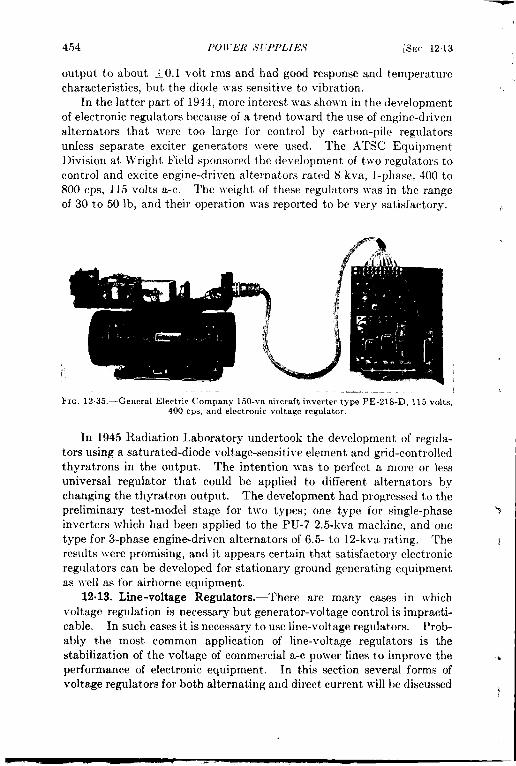
454 I’Olt’ER ,Y( ‘PI’LIE.S [s!;(, 121:3
output to about +0. I volt rms and had good response and temperaturecharacteristics, but the diode was sensitive to vibration.
In the latter part of 1944, more interest was sho~vn in the de~relopmentof electronic regulators because of a trend toward the use of engine-drivenalternators that were too large for control by carbon-pile regulatorsunless separate exciter generators were used. The ATSC EquipmentDivision at YVright Field sponsored the development of two regulators tocontrol and excite engine-driven alternators rated 8 kva, l-phase, 400 to800 cps, 115 volts a-c. The ~veight of these regulators }vas in the rangeof 30 to 50 lb, and their operation was reported to be very satisfactory.
FIG. 12.35.—General Electric Company 150-va aircraft inverter type PE-218-D, 115 volts,400 cps, and electronic voltage regulator.
In 1945 Radiation Laboratory undertook the development of regula-tors using a saturated-diode voltage-sensitive element and grid-controlledthyratrons in the output. The intention was to perfect a more or lessuniversal regulator that could be applied to different alternators bychanging the thyratron output. The development had progressed to thepreliminary test-model stage for two types; one type for single-phaseinverters which had been applied to the PU-7 2.5-kva machine, and onetype for 3-phase engine-driven alternators of 6.5- to 12-kva rating. Theresults were promising, and it appears certain that satisfactory electronicregulators can be developed for stationary ground generating equipmentas well as for airborne equipment.
12.13. Line-voltage Regulators. —There are many cases in whichvoltage regulation is necessary but generator-voltage control is impracti-cable. In such cases it is necessary to use line-voltage regulators. Prob-ably the most common application of line-voltage regulators is thestabilization of the voltage of commercial a-c power lines to improve theperformance of electronic equipment. In this section several forms ofvoltage regulators for both alternating and direct current will be discussed
b

SEC. 1213] LINE-VOLTAGE REGULATORS 455
briefly; a much fuller discussion of voltage and current regulation will be:. found in Vol. 210f the Radiation Laboratory Series.
Electromechanical Regulators.—The oldest example of voltage orcurrent regulation is the use of a manually operated rheostat in series withthe load; a more modern analogue of the same device is the Variac of theGeneral Radio Company, which hascome to be a practically indispen-sable device in all electrical and electronic laboratory work. Manualcontrol is satisfactory in many cases, particularly where the controlrequirements are not particularly stringent and the line-voltage variationsare comparatively slow. For more critical cases some type of automaticcontrol is necessary. This may take an electromechanical form; avoltage relay across the output line could control a reversing motor thatwould turn the shaft of the rheostat or Variac in such a direction as tocorrect the change in output voltage. Such relay-motor-inductionregulator devices are often used for voltage control on commercial powerlines. Instead of a relay an electronic servo circuit may be used to con-trol the motor; an example of such an electromechanical regulator is theSeco Automatic voltage regulator. This device is made by the SuperiorElectric Company of Bristol, Corm., in capacities of from 1 to 100 kva.It uses a thyratron control circuit to control a reversible 2-phase motorithat drives the shaft of one or more Powerstat variable autotransformers.Its principal advantages are good output waveform, low maintenance,
t high efficiency, and independence of the output voltage of fluctuations inthe load, load power factor, or input voltage. Its principal disadvantageis its slow response, the standard speed being 6 sec from full buck to fullboost. This speed is much slower than static regulators but is about tentimes as fast as the usual commercial induction regulator and can besomewhat increased if necessary.
Saturabk-transformer Regulators.—The most common form of auto-matic a-c line-voltage regulator is the saturable-transformer type, which
-,, is made by Raytheon Manufacturing Company, General Electric Com-pany, and Sola Electric Company. The actual transformer design and
t circuit details vary with the maker, but the basic theory is the same forall three.
The saturable-transformer voltage regulator may be considered to be acombination of a quarter-wave impedance transformer and a saturatingcircuit element. The impedance transformer makes the line look like aconstant-current source and the saturable element absorbs changes incurrent due either to line-voltage changes or to load changes. In the sim-plified circuit shown in Fig. 12.36, if the impedance of the elements to the
$ right of the dotted line is denoted by Z, the voltage across the load ezwill be
2X.ez=Ziz=e
2X, + XL(Z+ xc)”

456 POWER S(;PPLIES
:
[SEC. 1213
At resonance X. + XC = O and the equation reduces to
“ z $.’which is independent of the value of Z. The LC-network thus acts as atransformer which forces a constant current through Z when a constantvoltage is impressed on the input terminals.
Considering the elements to the right of the dotted line, if the element
FIG. 12.36 .—S1mphfied equivalent ck- FIG. 12.37.—Voltage-currentCuit of saturable-transformer volt age characteristic of saturable reac-regulator. tor.
B has a saturating characteristic such that over a range of current valuesthe voltage across it varies slowly, as shown in Fig. 12.37, the combinationof L, C, and B will act as a constant-voltage source for the load. If theinput voltage decreases, the current is will decrease in the same propor-
?Eout
InTaps for 115
120.125v
Saturablereactor
(a)
%
out
In
Saturablereactor
(b)
E3In
F
out~ =
/Magnetic
shunt
(c)
GE circuit Raytheon circuit Sola circuit
FIG. 12.38 .—Conlmercial ronstant-voltage transformer circuits,
tion, but if the operating point on the characteristic curve of the saturableelement is properly chosen its current ib ~vill decrease by nearly the sameamount as the decrease in i,, with the result that the load voltage andcurrent will remain nearly constant. Similarly, if the load impedancedecreases the load will draw more current, but i, will decrease by aboutthe same amount and the load voltage will remain nearly constant. t
There are several possible types of saturable devices that might beused for the element B, but the most practical one is a saturable reactor.

SEC. 1213] LINE-VOLTAGE REGULATORS 457
Such a reactor can be designed to have a fairly flat voltage-vs.-current:, characteristic over a considerable range of currents, and will give excellent
regulation. In the commercial devices the saturable reactor and theinductor L may be combined into a single unit. The actual forms ofcore and windings differ with thevarious makers; they are shownschematically in Fig. 12.38.
It is not practicable to designa saturable reactor with a zero
., slope of the operating range of itscharacteristic, and commercial
., constant voltage transformers in-clude a low-voltage secondarywinding whose voltage is propor-tional to the input voltage. Thiswinding is so connected as tooppose the output voltage of thesaturable part of the circuit, andthe magnitudes of the two outputvoltages are such that the larger
tvariation of the smaller voltage is
’17 o% 50% 110%— —_ _115 ~ — ,L_
/- -- -— Eo%
113 /,
. 150%~ 111
=z 109 /0
107
105
10395 100 105 110 115 120 125 130
Input volts
FIG. 12.39.—Regulation curves withresistive load: figures on curves give percent of full load.
equal to the smaller variation of the larger voltage, thus achieving almost.< complete compensation for input voltage variations. The compensation
cannot be complete since the saturation characteristic is always some-what curved and since changes in load affect the outputs of the twowindings differently. Typical regulation curves for a standard 500-va
i’Pl$$$d2109 \ , ) I
lx 100% loadI
107 11.00 0.90 0.80 0.70 0.60 0.50 0.40
Load power factorFIG. 12.40.—Effect of load power factor.
unit are shown in Fig. 12.39 for resistive loads. If the load power factorcliffers from unity the regulation suffers; Fig. 12.40 shows output voltageas a function of load power factor for three different load percentages
1 at standard input voltage.The outstanding advantages of a saturating-transformer voltage
regulator are its rapid response, its simplicity and lack of adjustments,
i

458 POWER SUPPLIES [SEC. 12.13
and its self-protection against overloads. Such a regulator will normallyrestore the output voltage to its normal value within two cycles after asudden change of either input voltage or load, which is faster than anyother common a-c regulator. The device is inherently simple; it containsno moving parts and no adjustments (except tap-changing switches orjumpers in certain models), and it requires ho more maintenance than anyother transformer and has as long a life. A most important advantageis its ability to protect both itself and the equipment that it feeds againstoverloads; even with the output short-circuited the output current willnot rise above about 150 to 200 per cent of normal full-load current, andthe output voltage will return to normal as soon as the short circuit isremoved. Since the rise of input current above nor,mal will be even less,the line fuses will also be protected against blowing in case of a shortcircuit.
The principal disadvantages of the saturating regulator are its fre-quency dependence, its poor output waveform, and its stray magneticfield. The usual types of such regulators give constant output voltageat only one frequency, and show an increase of 1.5 to 1.8 per cent of outputvoltage for 1.0 per cent change of input frequency. This effect is inherentin the operation of the regulating transformer itself, but can be eliminatedby adding a suitable series-resonant circuit in series with the output.Such frequency-compensated regulators are available as special-ordermodifications of the standard models.
The use of a saturated magnetic core involves several effects, of whichthe most troublesome is the poor output waveform of a typical saturatingregulator. The harmonic content of the output voltage varies with bothinput voltage and load, and varies to a greater degree with small loadsand high input voltages. Under the worst conditions it may be 20 percent or more of the fundamental. The strongest harmonic is the third,which is in such a phase as to give a flat-topped or sway-backed wave-form. The crest factor of the output wave is of the order of 1.22, incomparison with the 1.414 of a sine wave. This requires special consider-ation in the design of rectifiers that are to be fed from such a voltageregulator, and the variation of waveform with varying input voltage andload may lead to variations in the rectifier output voltage even thoughthe rms input voltage to the rectifier may be kept constant by the regula-tor. The poor output waveform also leads to errors in the indicationsof certain types of meters; dynamometer- and thermocouple-type meterswill read the correct rms values of output voltage or current, but moving-iron types may show waveform errors and rectifier-type instruments willusually read from 8 to 10 per cent high. Care must also be taken inaccepting the reading~ of ordinary ammeters in measuring the load cur-rents of nonlinear loads, particularly if the positive and negative hali’-

SW. 1213] I, IA’E- J’01,7’.4(7E REGU1,A TORS 459
c.vcles of the load current are different. The regulator must be designed~. for the maximum instantaneous value of the current in all cases.
The use of a series-resonant output circuit for frequency compensationconsiderably improves the output waveform, reducing the total harmoniccontent in a typical case to about 6 per cent at maximum input voltageand 60 per cent load. If still lower harmonic contents are required,regulators may be obtained ~vith special low-pass filters in the outputcircuit.
The presence of a highly saturated magnetic core in a regulator of this, type produces a considerable stray magnetic field Ivith a high harmonic
content. Care must be taken, therefore, in mounting a regulator in
.< proximity to equipment operating at IOJVpower levels unless this equip-ment is ~vell shielded. Adequate shielding of the regulator is usuallyimpracticable,
The full-load efficiency of a standard saturable-transformer voltageregulator ranges from about 70 per cent for a 50-va unit to about 95 percent for a 5-kva unit. For a particular unit the efficiency varies littlewith input voltage but decreases rapidly with decreasing load. Thelosses are somewhat higher than those of a standard polver transformerof the same rating because of the high core loss in the saturated portion
< of the magnetic circuit. The total loss and therefore the heating arepractically independent of load.
.4The input polver factor of a standard unit at 100 per cent resistive
load is fairly high, ranging from 98 per cent leading at minimum inputvoltage down to 90 per cent leading at maximum input voltage for a500-va rating.
ltegulators such as the Sola, which have electrically isolated outputIvindings, may be operated in multiple. The outputs may be connectedin series for higher-voltage operation or in parallel to increase the availableoutput current, but the inputs must not be connected in series. Trans-
,,. formers \\ith electrically connected input and output windings may beoperated in parallel, but cannot be operated in series. Two or more
$ regulators may be operated in cascade—that is, with the output of thefirst feeding the input of the second—and ]vill then give almost perfectcompensation of input-voltage variations at some sacrifice of regulationfor changing load and of output }vaveform.
Stock regulators are available in ratings from a few volt-amperes upto 10,000 ~a, and larger units can be built to order. Some types havetapped ivindings to permit a choice of nominal 115- or 230-volt input, orto adjust the output voltage. Certain types also have taps that permit
) operation at either 50 or 60 cps. 11 ost standard units are intended for
60-cps operation but stock designs are on hand for 25-, 50-, and 400-cPs
units. Available on special order are very small units that are adapted
I

400 POWER SUPPLIES [SEC. 12.13
for incorporation in a-c bridges and other devices requiring 4 to 5 wattsof regulated alternating current. I
Numerous modifications of standard regulators may be obtained on>
special order. If the range of input-voltage variation can be decreasedthe design can be modified so that the output-voltage regulation becomesmuch better than the standard f 1 per cent. Conversely, if a greatervariation in output voltage can be tolerated the unit can be designed toregulate over a wide range of input voltage; from 40 to 150 volts, forexample. Matched and interconnected sets of single-phase regulatorscan be obtained for polyphase operation. In some types, any reasonable ,transformation ratio can be furnished besides the usual 1 to 1 and 2 to 1ratios. This permits drawing regulated 115-volt power from 220 or440-volt lines, or other similar types of operation. Units are also avail-
,.
able in special mountings or housings, such as drip-proof regulators that
Regulatingtransformer
-a
A-c ginput g
.
%2
$
t J 1 iFx~. 12.41 .—Basic circuit of electronic line-
voltage regulator.
!vill withstand the Navy shocktests. Information on these andother special regulators may beobtained from the manufacturers.
Electronic A-c Line-voltage Re-gulators.—In an effort to producea-c line-voltage regulators that rwould be free from some of thedisadvantages of the saturating- :transformer type, particularly itsfrequency sensitivity, considerabledevelopmental work has beendone on re&.daters using electroniccircuits. ‘These may be of manydifferent tv~es, but one developed
by the Radiation Laboratory is typical, Its b~~c circuit, is show; in
Fig. 12-41. The output voltage is equal to the vector sum of the line ~
voltage and the secondary voltage of a regulating autotransformer. The
primary of the autotransformer is connected across the line in series with .
a saturable reactor whose d-c winding is fed from an electronic circuit<
that is controlled by the output voltage. A vector diagram of the actionof this regulator for four different input voltages is shown in Fig. 1242.In this figure, the input voltages lie along the horizontal axis, V. and V.are the primary and secondary VOItages of the regulating aut otrans-former, and V,, is the voltage drop across the saturable reactor. Theterminations of the output-voltage vector fall on a circular arc of constantradius with its center at the origin. From the circuit it can be seen thatt’P and V, have a constant ratio and are 180° out of phase and that ‘
$
V. + V,r = V,...,, as shown on the vector diagram.0
I

(
I/
FIG. 1242. -Fundan]enta1 vector diagram of electronic line-voltage regulator.
is to rectify and filter the regulator output voltage and to compare it with
SEC. 1213] LINE- VOLTAGE REGULATORS 461
Several different types of sampling and comparison circuits were triedas sources of control voltage for the saturable reactor. One possibility
the d-c drop across a VR tube.‘l’his method works very well buthas the disadvantage that it regu-lates the peak value of the output
; voltage rather than the rms value.This is unsatisfactory because of the
: variation of output waveform dueto the varying degrees of saturationof the reactor. Thermistor bridgeswere tried, and gave good rmsregulation but were much too slug-gish for many applications. Themost successful circuit used a volt-age-saturated diode, as shown in
Y Fig. 1243.
II T
transformer
(3?pCTo a.coutput
of
Tungsten. regulator
filamentdiode
L L L- D.c
FIG.12.43.—Emission-tube control circuit.
‘The diode used in the control circuit may be any tube with a puretungsten filament. Since the emission of such a filament varies with the*

462 1’OWER SUPPLIES [SEC. 1213
fourth power of its absolute temperature, it furnishes a very sensitiveindicator of variations in the output voltage. The heating depends onthe rms value of the output voltage, which is the quantity that should bestabilized. In order to obtain a sufficiently fast response it is necessaryto use a tube with a comparatively thin filament, ~vhich leads to difficultyin applications involving excessive shock or vibration conditions, and thedesign of a quick-heating diode with a sufficiently rugged filament is theprincipal problem remaining to be solved in connection with this type ofregulator. For all applications except those involving excessive vibra-tion, however, it has given excellent service.
The method of design of this type of regulator may be outlinedbriefly as follows. It is based on two assumptions:
1. The autotransformer has no losses and its primary-to-secondarycoupling coefficient is unity. Its primary inductance will bedenoted by L, and its stepup ratio by k.
2. The saturable reactor acts as a pure inductance with a minimuminductance value L. = O and a maximum L. = S.
An approximate theory of the operation of any regulator using acontrol inductance in the ground connection of a booster autotransformer
(l-k)Ll (k2-k)Ll
~-n=o
F]c. 12.44.—Equivalent circuit of electronic regulator.
can be derived from the equivalent circuit of Fig. 12.44. As seen fromthe load, the regulator looks like a generator ~vithan internal impedance of
z. = ju(k – 1)’kL. + L.
and an open-circuit voltage of
(1)
(2)
If the load impedance is a pure resistance R and the scalar voltage ratioV~/V.u, = lel/lell = q, where e is the line voltage (taken as the referencevector) and el is the regulator output voltage which is to be held constant,
R’(L, + L.)z + ~’(k – 1)4L;L:.q’= R’(L,k + Lc)2
(3)
The regulator may be considered as having two modes of operation,depending upon the input voltage. For inputs near the minimum voltage
.-
.
.

.
SEC. 1213]
it acts as a simple
LINE-VOLTAGE REGL’1,,47’ORS 463
booster transformer ~vith a voltage regulation that{
-+ depends upon L,. For inputs near the maximum th~sec&dary of theautotransformer acts as a series voltage-dropping choke that is loaded bythe control inductor. For intermediate inputs the operation may be con-sidered as including both modes.
When the impedance of the re-actor is large compared ~viththat ofthe transformer secondary the cur-rent laps the voltage across the sec-
~ ondary by 90° since its impedanceis a pure inductive reactance. If
J the load is a pure resistance, forwhich the cllrrent and voltage arein phase, the voltages across the leadand the secondary must be 90° spa) tin phase. Since the magnitudes 01both the input and the output volt-ages are kno~vn, a vector voltagetriangle may be constructed, as inFig. 1245. The secondary voltage
* is tangent to the output voltagelocus.
q.<
1:16. 12.45.-– Vector chagram fol- maxin,uminput voltage,
-; Since the primary and secondary voltages are 180° out of phaseand have the ratio VP/V. = l/(k — 1), the primary vector can bedrawn, which establishes the voltage V,, across the saturable reactor,and the diagram is complete,
For the minimum input voltage all voltage vectors are coincidentalong the reference line and e..~ = eP + e, and e,n= eu. For intermediateconditions the calculation is more complicated and depends on the valuesof R, Ll, and Lc according to Eq. (3). If the load has a reactive com -
tr ponent the calculations are still more complicated. Details of thecalculations will not be given here, but a vector diagram derived from
i measurements on a typical electronic regulator of this type is given inFig. 1242.
The design of the regulator may proceed by either of tJvo paths,depending upon whether the saturable reactor or the autotransformer isdesigned first. The maximum values of the ~roltage drops across theseveral ~vindings are obtained from the vector diagram of Fig. 1245;for the condition of maximum input voltage
1.
I

464 POWER SUPPLIES [SEC. 12.13
where VI is the voltage across the whole autotransformer. The maxi-mum current through the secondary will be the load current Z1; themaximum current through the primary and saturable reactor willoccur at minimum input voltage and minimum reactor impedance,when Z,r = 11(,%– 1).
The minimum primary inductance that the autotransformer mayhave can be calculated from Eq. (3), using the maximum values of q, R,
and L,, if the reactor is to be designed first. If it is not, a rough cal-culation of LI should be made assuming that L, is infinite, for whichcondition ,
~; _ (92– w:,d(,k — 1) d
where q and R have their maximum values. If w is variable its minimumvalue should be taken. For a typical case in which k = ++ = 1,28 andqm,, = ~~ = 1.175, uL, = 7.4R. This value should be increased toprovide a margin of safety; a factor of 2 should be sufficient, but ahigher factor does no harm as long as it does not result in excessive sizeor copper loss in the transformer and reactor. Using this higher factor,for example oL, = 15R in the case just mentioned, the value of L. is
calculated from Eq. (3), again using the maximum values of q and R.j
The design of the saturable reactor depends not only upon the maxi-I mum values of current, voltage, and inductance calculated above, but ;
~ also upon the d-c power that will be available for saturating the core,and this in turn upon the choice of the tube or tubes for the final stageP
b of the d-c control amplifier. A 6L6 or similar tube will furnish adequateif power for regulator capacities up to 1 kw or more if the saturable reactor[ is properly designed, but a filament-type tube is preferable if a minimumI warmup time is required. The d-c ampere-turns available should at
least equal the maximum a-c ampere-turns and should preferably be
isomewhat greater. ,
Having established the design of the saturable reactor the required
1minimum value of LI may be recalculated using the value of L, from 4
1the reactor design. This step, however, is hardly justified in view ofthe approximate nature of saturable-reactor design and of the designassumptions made in the beginning and also in view of the fact that theaction of the control amplifier is such as to compensate for variations inthe characteristics of all elements in the circuit. The only effect of aconsiderable variation in any of the parameters will be an increase or
Idecrease of the operating range or a slight change in the slope of theregulation curve. Further approximations are necessary only when one
f
Im more of the circuit elements comes out absurdly large or when weight
v
Iand size must be decreased as much as possible.
i

SEC. 12.13] LINE-VOLTAGE REGULATORS 465
Like the saturable-transformer voltage regulator previously discussed,the electronic voltage regulator furnishes a distorted output wavebecause of the presence of the saturated-core element. In the lattercase, however, the distortion is of such a nature as to produce a peakedinstead of a flattened waveform. Appreciable improvement in waveform~an be obtained by connecting a resistor across the saturable reactor.Figure 1246 shows typical uncorrected and corrected waveforms, with asine wave for comparison. Theaddition of the correcting resistorlowers the efficiency and increases(the minimum permissible value ofL,. It should be made adjustable
+so that the optimum waveform canbe secured at the normal value ofload. Waveform correction ismost desirable for 60-cps opera-tion. The waveform of the usualsmall generator operating at 400cps or above is likely to be so bad
Uncorrected True sme
*
Reactance in series Reactance shunted bywith primary resistance in series
with primary
FIG, 12.46.—Waveform corrections in volt-age stabilizer.
that any regulator will normally improve it./ The frequency range of an electronic voltage regulator of this type
depends principally on the design of the saturable reactor. If the power; for the control amplifier is taken from the output circuit, as is usually
the case, a saturable-reactor impedance that is too high or too low willresult in an excessively low or high voltage to the amplifier power supplyduring the warmup period, especially if the line voltage error is in such adirection as to exaggerate the condition. If necessary a single-poledouble-throw time-delay relay can be added to permit the amplifier to bewarmed up from the input voltage and then switched to the output fornormal operation. If no special precautions are taken in the design of
} the magnetic circuits a +20 per cent change in operating frequency canbe tolerated, the only effect being a small change in the regulating range.
#The size and weight of an electronic regulator of the type described
depend on the allowable operating temperature of the. coils, the poweroutput, and the type of mounting and weatherproofing used. A labora-tory model of a 350-watt 400-cPs regulator that proved successful infield service weighed 12$ lb and had a volume of 330 in. 3 The 1700-watt60-cps version of this model weighed about 100 lb. The weights of thecommercial versions run from 28 lb for the 250-watt model to i60 lb forthe 5-kw model.
The performance of a typical commercial version of the regulator# just described is very good. The output voltage is adjustable from 110
to 120 volts and will maintain that value within 0.2 per cent for inputt

466 POWElt SUPPLIES [SEC. 1213
voltages from 95 to 130 volts and frequency variations of +-15 per cent.It is alleged to be independent of load power factor, though this may bedoubted for loads of very low leading power factors for which resonancemight occur. It has a quick response time, 6 cycles maximum. Fourstandard models are available from Sorensen and Company, with out-puts of 250, 1000, 1750, and 5000 va, plus a light (16&lb) model for400-cps airborne use. A somewhat similar regulator using a carbon pileinstead of the electronic amplifier for controlling the saturable reactor ismade by the Ah-craft Equipment Manufacturing Company of Da yt on,Ohio.
D-c Line Voltage Regulation.—The problem of regulating the voltageof a d-c line occurs relatively infrequently since most direct current usedin electronic equipment is either regulated at the generator, as describedin Sec. 12.12, or is derived from a-c lines via transf ormer-rect ifier-filterpower supplies that may or may not be regulated. If regulation is usedthe regulator is normally considered to be a part of the power supply,but there is no logical reason for this and it is occasionally desirable toregulate the voltage of a d-c line remotely from the source of power.
Basically there are three methods of regulating the voltage of a d-cline.
1. A variable series element, normally a vacuum tube, may be usedas a dropping resistor.
2. A variable shunt resistor, also usually a tube, may be used to pulldown the voltage of a line with poor regulation. If the regulationof the line is too good a series resistor can be added.
3. An additional source of d-c power can be added in series with theline, either aiding or opposing the line voltage. This method isseldom used.
Methods 1 and 2 can only act to reduce the line voltage and not toincrease it. The choice between Methods 1 and 2 depends upon tbeapplication; the first method is more common and is indicated in casesof low voltage and relatively high line current. The second method isused principally for the regulation of high-voltage low-current sourcessuch as are used for such applications as CRT high-voltage supplies, etc.Details of d-c regulators will not be given here; they are thoroughlydiscussed in Vol. 21 of this series. Commercial regulated power suppliesare available from a number of manufacturers, and many papers on thesubject have appeared in scientific and eugineering journals over thelast ten years.

i
I
CHAPTER 13
RELAYS AND RELATED DEVICES’
BY J. F. BL.kC~BURN
A relay is an electrically operated switch, and the two basic criteriain selecting a relay for a particular purpose are first, the switching opera-tion that is to be performed, and second, the po~versource that is availableto actuate the relay. The one determines the number, type, and arrange-ment of the contacts required; the other, the design of the coil and themagnetic circuit. There are, of course, many auxiliary specifications tobe satisfied, such as size and weight, expected operating life, liabilityto failure and the severity of its consequences, insulation, resistance toshock and vibration, etc. These will be taken up in the latter part of thischapter, after discussing the contacts and the coil and magnetic circuit.
In the interest of brevity, thediscussion will be confined to lo\r-poJver relays of the type usually usedin electronic equipment, omitting thelarger types used primarily in indus-trial equipment and mentioning onlybriefly a few relays of special con-struction or function.
13.1. Contacts.~ Contact A r-ra ngmrwnts.-The general arrange-ment of the contacts of a relay is(Determined by the number and se-tlllence of the s~vitching operations toI,e performed. Relays are availablein many forms, with contact arrange-
‘c’=(dJ
Normally
open (NO)
Normallyclosed (NC)
Oouble throw(DT)
Make before
break (MBB)
FIG. 13.1 .—Basic relay -contart groups.
ments ranging from a single pair, to make or break a single circuit, tostacks of dozens of contacts handling a number of independent circuits.For most purposes, however, there are four basic contact groups, asshown in Fig. 13.1. Practically all relay contact arrangements can be
1There is an extensive literature on relays, but books devoted specifically to relaysof the class discussed here are rather rare. One of the most recent is Relay Engineering,by Charles .%.Packard, Struthers-Dunn, Inc., Philadelphia, 1945.
2See Pucknrd, op. cit., pp. 75-101; also C,. W’indred, li’lectrzca~ Corafac.!s, Macmillan,
London, 1940.467

468 IiELA YS AND RELA TED DEVICES [SEC. 131
considered as made up of one or more groups of these four types. Figures13. la and b are self-explanatory; c and d differ only in that with c thecircuit from one to two is broken before that from one to three is estab-lished, while the opposite is true Ivith d. Double-break, DB, contactsimply the use of tlvo contact groups, usually a or b, in series.
In an assembly of severol contact groups some control of the sequence
of contact-making can be obtained by adjusting the individual contacts;
for example, in A dolll)lc-pole single-throlr, DPST, relay, if one fixedcontact is set someJvhat ahead of the other it lvill make first, and willbreak last ~rhen the relay is clecncrgized. In general, holvever, if thesequence and timing of s}vitching operations are important it is best touse a relay in Jvhich the several conttict groups are operated by individualcams, as in relay No. 91 Table 13.5 (Fig. 13.2) or to use several relays incascade, each relay after the first being energized through contacts on anearlier one in the series.
Contact Ra(ings.-Having established the contact arrangement, thecontact size and materials must be chosen in accordance with the electri-cal characteristics of the circuits to be made or broken. Here there arethree operations to be performed; the circuit must be established whenthe contacts close, it must be maintained as long as they are held together,and it must be broken ~vhen they separate.
Successful establishment of the circuit demands that the contactsclose cleanly with minimum bounce or chatter, and that they are sufT-

SEC. 1311 CONTACTS 469
ciently large, of the correct material, and actuated with sufficient forcetoprevent lvelding orarcing ~viththe initial value of the current. Certaintypes of loads, especially motors, tungsten-filament lamps, some heaters,and circuits in which there is a considerable amount of energy stored incondensers, have a high inrush current that later drops to a much loivervalue, Inthecase ofmotor andlamp loads jthisinrush current maybe5to 12times the steady value. In such cases the inrush rather than thesteady current determines the choice of contacts.
Successful maintenance of the circuit once it is established demandsthat the contacts be large enough, properly shaped, clean and smoothenough, and adequately held together so that the contact resistance issufficiently low to carry the steady current without excessive heating orvoltage drop. In very low-voltage circuits the contact resistance maybe an important factor, and special precautions may have to be takento keep the contacts clean and smooth, and to prevent even slightmomentary opening due to shock or vibration.
Successful interruption of the circuit demands that the contacts opencleanly and rapidly to a sufficient distance to extinguish the arc that alwaysforms on breaking a circuit. High speed of separation without momentaryreestablishment of the circuit, wide separation of the opened contacts,and the use of several gaps in series permit the interruption of largercurrents. High voltage, low atmospheric pressure (as in high-altitudeairborne operation), excessive arc-forming tendency of the metal of thecontacts, and particularly highly inductive loads greatly decrease theinterrupting capacity. In many cases it is necessary to use auxiliaryarc-suppressing devices, such as blowout coils in series or RC-circuits inshunt with the gap. Blowout coils find considerable use in the field ofpower relays, but are seldom applied to small units because of insufficientspace and the tendency of the drawn-out arc to strike other closely adja-cent contact groups. Arc-suppressing circuits are discussed in Sec. 13.3.
Careful perusal of a number of relay catalogs indicates that there is nogeneral agreement on the amount of current that can be safely handledby a given pair of cent acts, but by plotting contact diameter, etc.,against ratings and by referring to the few definite statements made bythe manufacturers, some rough rules can be laid down. Silver contactsused in the low-power relays discussed here are good for currents up toabout 3 or 4 amp in the +in. size, 5 or 6 amp in the &-in. size, 8 or 10amp in the +in. size, and 15 or 20 amp in the ~-in. size. These valuesapply to at least 90 per cent of the several hundred relays checked.They may be too conservative, since several reputable relay manufac-turers use higher ratings. Double-break contacts will handle about 50per cent more current than single-break. These ratings are for 115-volt60-cps a-c, or for d-c voltages up to 32 volts, and for noninductive loads

470 RELAYS AND RELA TED DE VICES [SEC. 131
without excessive inrush currents. They are about half the value ofcurrent which can be handled without appreciable heating by a pair ofcontacts with the usual contact pressure of 1 to 2 oz. For 110 volts d-cthe current ratings should be halved. Increased contact pressures some-what increase the ratings, especially for large contacts. For very lowvoltages, contact heating is the only limitation and ratings may bedoubled. Quick-break operation and wide contact separation permitsome increase in current rating, especially at higher voltages and withinductive loads.
For contact materials other than silver, palladium will carry two orthree times the current at the same voltages. Platinum-iridium hasabout the same current-carrying capacity as palladium, but its greathardness gives a much longer contact life under severe mechanicaloperating conditions. Tungsten contacts will handle only about 75 to
100 per cent of the current of silver contacts of the same diameter, butwill do so at two or three times the voltage.
The ideal contact material should have high electrical and thermalconductivity, high melting and vaporization temperatures, and highresistance to mechanical wear. In addition, the ideal contact materialshould have either no tendency to form an oxide or tarnish film, or at leastsuch a film should be of low resistance. High thermal conductivity aidsin carrying heat away from the point of contact. A high melting pointimproves the ability of the contact to withstand high arc temperatureswithout melting or welding the contacts. High vaporization temperatureresults in less tendency for the formation of metallic vapors that help tomaintain an arc. High electrical conductivity usually means lowercontact resistance and less contact heating, which is especially importantwhere high current densities are employed on the contacts.
High contact pressure is an aid in breaking down any film of dust oroxide that may prevent the contacts from coming together and alsoimproves the ability of the relay to maintain contact during shock andvibration. Some relays have adjustable armature springs that permitsome adjustment of contact pressures.
Cent-act follow-through ii the motion that occurs after the physicalcontact has been made. Contacts mounted on leaf-type springs musthave follow-through to deflect the springs and build up the contactpressure. During the follow-through the contacts slide over one anotherwith a wiping action that aids in keeping the surfaces clean.
Low-voltage contacts are particularly susceptible to failures becausethe voltage may not be sufficient to break down any nonconducting filmor dust between contacts. Where hermetic sealing is not possible it isdesirable to mount relays with the contacts in a vertical dane to minimizethe tendency for dust ~o accumulate. I

SEC. 131] CONTACTS 471
The contact gap must besufficiently wide to extinguish the arc thatforms on opening the contacts and to ~vithstand the maximum voltagethat is to be impressed across the gap. AS h the case of contact diameter,a study of the relation bet]reen gap and ratings shoJrs very little correla-
tion bet!veen the tli-o; apparentlya gap of 0.010 in. or less is good only
up to about 1 amp; O.010 in. to 0.025 in. up to 15 amp. Currents of 20
amp or more usually require tlvo gaps in series.
It is incorrect to assume that t~vice the current can be carried by
connecting t~~o sets of contacts in parallel; it is impossible to ensure
simultaneous opening and closing of the two sets, and the make and break
will be handled by only one set.
Double-break contacts are more effective in arc interruption than
single breaks of the same total contact separation.
High speed of contact operation is desirable because it reduces theduration of the arc and thereby decreases the heating of the contacts.
Most relay contacts rebound and reopen their contacts once or severaltimes during the process of closing, and many do so also on opening.This is an objectionable feature but is difficult to overcome, particularlywhere the contacts are of the butt type. Contact bounce is particularlydestructi~re when there is a high inrush current, since the contacts arereopening at a time when the current may be several times its full-loadvalue. Contact bounce reduces contact life and may cause fusing ofcontacts.
From the standpoint of high current-carrying capacity the idealcontact shapes are two flat-faced surfaces, which provide the largestpossible contact area for a given contact size. The objection to thisconstruction is that it is almost impossible to maintain perfect alignmentof the contacts and it also provides less unit pressure between contacts,which reduces the effectiveness of pressure breakdown of any noncon-ducting film. For this reason most relay contacts have at least oneradius-faced surface per pair.
Actual measurements on a large number of small relays as deliveredshowed practically no correlation betl~-een contact pressures and currentratings. Actual pressures ranged from zero (where the contacts did noteven touch) to about 1 lb. The average pressure for most types of relayswas from 1 to 2 oz. One manufacturer of telephone-type relays uses astandard pressure of 30 to 40 g, increasing this to 70 g in relays intendedfor use under conditions of vibration, and reducing it to not less than 15 gfor certain special applications. High-current relays such as aircraftmotor contractors use from 1 to 2 lb.
The variability in contact pressures and gaps perhaps illustrates aswell as anything the considerable variability in the properties of com-mercial relays. Both quantities can be adjusted on almost any relay by

472 RELAYS AND RELA TED DEVICES [SEC. 132
a careful and skilled technician, but manufacturing tolerances and theunskilled and sometimes careless assembly practices necessitated bymanufacturing to meet low-priced competition result in great variations!n contact settings. For critical applications all relays should be checkedand adjust ed individually before installation; but such adjustmentshould not be attempted unless the adjuster thoroughly understands whathe is trying to do. If it must be done, it is most desirable to ascertainfrom the manufacturer the correct settings for the performance desired.
Certain special forms of contacts are sometimes used for especiallysevere operating conditions. For cases in which the coil voltage fluctu-ates through the range within which the contact pressures are insufficientto maintain proper contact, whether from vibration or other causes,snap-action switches such as microswitches are often used. For high-volt age operation, especially at radio frequencies and at high altitudes,vacuum contacts are frequently the only solution. Both vacuum andmercury contacts are useful for operation in explosive atmospheres.Relays using such forms of contacts, however, are usually bulkier andmore sluggish in operation than the ordinary types, and are not oftenmanufactured in contact arrangements more complicated than DPDT.Mercury contacts are especially vulnerable to disturbances from vibra-tion and shock and must be mounted in a fixed position, which usuallyrules them out for mobile applications, especially in aircraft.
13.2. Coils and Magnetic Structures. ‘—Having established thecontact design, which in effect determines the amount of work to bedone by the relay armature, it remains to choose a suitable magneticstructure and coil to do that work when energized from the powersource to be used. The magnetic structures used in most small relayscan be classified into four principal types, shown in Fig. 13,3. h’umerousvariations exist in the mechanical assembly, arrangement, and com-position of various parts of the many relays that are available.
Magnetic Circuit. —Figure 13.3a shows the magnetic circuit of a com-mon type of single-coil clapper-armature relay. (Contacts, mountingdetails, armature restoring spring, etc., are omitted from all the viewsin Fig. 13.3. ) The useful magnetic flux that actuates the armatureis the flux in the air gap between the armature and the pole face. Theflux must also traverse another gap at the hinge end of the armature,but the flux passing through this gap does not contribute to the pull onthe armature. The magnetic reluctance of the air gap at the hinge issometimes reduced by providing fins of magnetic material on thearmature.
I See Packard, op. cit., pp. 373-416, for a discussion of relay coils and magneticcircuits. A very thorough discussion of design methods is given in H, C. Roters,EJecb-omagneticDevices.Wile,v,New York, 1!241.
.

SEC. 132] COILS AND .bIAG,VETIC STR U(X’’UIWS 473
Figure 13.3b shows the magnetic circuit of a double-coil relay. Withthis construction the flux again traverses two air gaps, but the flux ineach gap now contributes to the pull on the armature. Relays usingtwo-coil construction can therefore be designed to operate on fewerampere-turns than the previous type.
PolePole fa ge
Flux path
x path
(al
~otatyre
Flux )
(c)
FIG, 13.3.—Basic relay magnetic structures. (a) S,ngle-coil clapper type; (b) two-coilclapper type; (c) plunger type; (d) rotar~, type.
aface
Coil
Figure 13.3c shows a solenoid or plunger-type structure providing acomparatively large armature pull in a compact size. This constructionis widely used for aircraft contractors with contacts carrying as high as200 amp at 30 volts direct current.
Figure 13.3d shows a rotary-type armature construction. Althoughnot many relays of this type are available, its symmetry should make itmore vibration- and shock-resistant than most other types.
In good magnetic-circuit design the leakage flux, that does not traversethe armature-t o-pole-face air gap, is reduced to a minimum. Designswith short chunky coils and low-reluctance paths except for the usefulair gap usually have low leakage; long-coil telephone-type relays in whichthe return path hugs the outside of the coil are prone to have high leakage,especially when the use of an armature-end slug crowds the coil to theheel end of the core. Such a construction may require up to 25 per centmore ampere-turns than would otherwise be needed.

474 RELAYS AA’D RELATED DEVICES [SEC. 13.2
i
I
Alternating-current relays require a shading coil in the pole face tominimize armature chatter and hum. Most small a-c relays do notrequire laminated cores to limit eddy-current heating because the crosssection of the core is small, but the best designs do use laminations.
Since the cheaper magnetic materials have considerable residualmagnetism most d-c relays, especially the power-sensitive types, requirean appreciable minimum air gap to prevent the armature from stickingtothepole face when the coil current isreduced to zero. In many relaysthis is obtained by spot-welding a nonmagnetic shim to the pole face orto the armature, but some types use a nonmagnetic screw in the armatureopposite the pole face to permit adjustment of the residual gap. Theeffect of residual magnetism may often be countered by using a strongerarmature return spring, but this requires an increase of power of the coil.For high-sensitivity relays where the air gap must be kept to a minimumit is necessary to use materials such as permalloy which have very lowresidual magnetism. Such materials also have high permeabilities thathelp to increase the efficiency of the relay.
Cod Construction.—Methods of winding, insulating, and impregnatingrelay coils will not be discussed here since the discussion would largelyduplicate that given in Chap. 4 of this volume. The method of construc-tion is important, however, since it largely determines the maximumsafe operating temperature of the winding, and this in turn governs thecoil wattage and the maximum force available at the armature. If thereis no limitation on the size and weight of a relay there is theoretically nolimit to the power sensitivity that can be attained. By increasing thearea of the flux path while maintaining the ampere-turns and coil wattageconstant the total air-gap flux and therefore the armature pull can beincreased indefinitely, and the increased coil area will permit cooleroperation of the coil. In practice, however, in addition to the increasedspace, weight, and cost, the armature would become so massive and thecoil inductance so high that the relay action would become very sluggishdue to the combined mechanical and electrical inertia. It is more practi-cal to build a relay of reasonable size and, if necessary, to amplify thecontrolling power either with vacuum tubes or by the use of a smallhigh-sensitivity pilot relay.
Maximum Operating Temperature.—The maximum continuous powerinput to a given relay coil is limited only by the maximum temperaturethat the coil insulation can withstand without breakdown during therequired life of the relay. This temperature is dependent on the coilconstruction, the nature of the insulating material, and the conditions ofoperation. If the coil is operated in intermittent duty, where it is neverexcited for a long enough period to attain the high temperature that itwould reach with continuous excitation, the most important criterion is
T
.’.

SEC. 13.2] COILS AND MAGNETIC STRUCTURES 475
the thermal capacity of the winding and any adjacent parts that are ingood thermal contact with it.
In deciding upon the maximum operating temperature a number offactors must be considered. Since insulation breakdown is a progressiveprocess a relay in an expendable device such as a bomb could be allowedto run at a temperature that would cause charring and breakdown in afew minutes; on the other hand, a relay for an industrial control applica-tion or one used in an unattended device such as an automatic lighthouseor weather transmitter ~vould have to run at a low power input to avoideventual failure. Under humid conditions a high but not excessivetemperature might be a virtue since it would help to dry out the coil,though in such a case there would always be the danger of electrolyticcorrosion of the ~~inding. In general, except with the newer high-temperature insulations, the maximum temperature is in the neigh-borhood of 220”F; one manufacturer specifies this for enameled-wirewindings and 250”F for silk-covered wire.
The maximum temperature depends upon the power input, theambient temperature, and the method of cooling. For usual ambienttemperatures the same manufacturer allows 2 watts/in.2 of coil radiatingsurface (excluding the coil ends) for enameled wire and 3* watts/in. 2 forsilk; if the relay is enclosed these values are reduced to 1 and l+ watts.In combat and other equipment where considerable power is beingdissipated in a small volume the ambient temperatures will be very muchhigher than is usual in laboratory or in most colamercial practice, and insuch cases a considerable reduction in coil power may be necessary. Inthe relay tests reported later in this chapter an ambient temperature of65°C was chosen; this represents a high but not extreme temperaturefor combat equipment. Of the hundred or so relays tested only aboutone third did not exceed 100”C under the conditions of the test, and manyof these were power-sensitive types for which heating is seldom a consider-ation. Besides starting from a high ambient temperature, the coils wereovervolted 25 per cent in most cases, making the test doubly severe; sothese results should not be taken to mean that the average relay is likelyto burn up under average conditions. Alternating-current relays usuallyrun somewhat hotter than d-c relays of the same types, not only becausethey are less po~ver-sensitive but also because when alternating currentis used, eddy-current and hysteretic heating help to raise the temperature.
One effect of coil heating that is often overlooked in relay applicationsis the increase of coil resistance associated with increasing coil tempera-ture. At 25°C copper wire increases in resistance about 0.4 per cent perdegree centigrade. In many cases the high temperatures attained inservice may cause a 30 to 40 per cent increase in coil resistance, and thedecreased power drawn from a constant-voltage source may cause poor

-
476 RELAYS AND RELA TED DEVICES [SEC, 13.2
operation of the relay. When the coil is powered from a constant-currentsource such as the plate of a vacuum tube this effect is usually negligible.In vacuum-tube applications, however, if the plate current containsconsiderable ripple, as is the case ~vith rectified but unfiltered current,the a-c component may cause appreciable heating without contributingto the armature pull, so that the dissipation should not be considered tobe merely that of the I’R loss due to the d-c component alone.
Power Requirements.—The actual po]ver required to operate small
relays of the types described here varies from a few milliwatts to a few
Witts. In classifying the relays whose tests are outlined in Sec. 13.7,
those with an actual minimum operating polver of less than 100 mw wereclassified as “sensitive” and listed in Table 13.2; they required from
6.4 to 90 mw. Two of the “special” relays in Table 13.5 were also
sensitive; the Allied Control Company Type GS balanced relay (No 93)
operated on 59 mw and the Barber-Colman polarized relay (N’o. 94) ononly 0,6 mw. Of the d-c relays listed in Table 13.1, about two-thirds
required from 0.1 to 1 ~vatt, one-fourth from 1 to 2 watts, and the restfrom 2 to 3 watts. These are minimum values, the actual wattages at
rated voltage being considerably higher; one third of the d-c relays listed
required from 0.1 to 1 watt, one third from 1 to 2 watts, one fourth from
2 to 3 watts, and the others from 3 to 6 watts. These percentages are
not particularly significant, but do indicate l~hat may be expected.
Power requirements ~vere not measured for the a-c types, but from
data given in several catalogs, a-c relays require from one and one half
to four times the wattage of d-c relays of the same construction. This
discrepancy is greater the lower the power; d-c relays operating on less
than 10 mw are not difficult to make, but 35-row sensitivity is high for
alternating current, and in some cases the sensitivity ratio is as high as
15 to 1.
The power factor and impedance of relays are very sensitive to ah--gap
adjustment, but for most 60-CPS relays the ratio of volt-amperes to wattsfalls between l+ and 4. Because of the increase of inductance ~vith the
shortening of the air-gap the a-c coil current with the armature closedis usually about 60 per cent of that with it open. The inductance of the
usual small 110-volt relay with the armature closed is of the order of afew henrys.
Voltage and Current Variations.—In designing a relay, considerationmust be given to the voltage or current variations likely to occur inservice. For military use, the expected ranges are from 25 to 30 voltsfor a “24-volt” d-c source, and from 92 to 138 volts for a nominal 110-volt 60-cps source. Such variations are large but by no means unknownin commercial service. To pass the test a relay must operate satisfac-torily on the minimum expected voltage immediately after having

SEC. 13.2] COILS AND MAGNETIC STRUCTURES 477
attained the maximum temperatures produced by continuous excitationwith the maximum expected voltage. Such a test is admittedly severe,but if the ambient temperature and voltage ranges are fairly chosen forthe intended use, a relay that will not pass this test will not be satisfac-tory. A wide range of supply voltage or current variation requires morecoil power at the nominal operating value, and frequently a larger andheavier relay than if the variation were small.
Various other factors affect the coil power requirements to someextent. In the case of sensitive relays an increase in the number ofcontacts increases the power required; in the case of one particular typethe single-pole model operated on 15 mw, but the double-pole requiredfrom 60 to 70 mw. This effect is much less apparent for the higher-power relays since they are usually over-powered to ensure fast operationof the relatively heavy armature. Relays for special operating condi-tions, such as high-inrush-current, close-differential, latching, or indexingrelays, usually require twice to four times as much coil power.
In some relays where it is not desirable to provide mechanical lockingdevices, and where the coil must handle enough power to cause seriousoverheating if the current remains at its initial value, two windings aresometimes provided. Such relays have a pair of auxiliary normallyclosed contacts to break the current in the low-resistance windingwhen the armature closes, while the high-resistance winding furnishesenough flux to hold the armature closed but not to close it. Anothermethod is to use an auxiliary relay that has a pair of normally closedcontacts connected across a resistor in series with the coil of the mainrelay. The auxiliary relay coil may be connected to the same powersource as the main relay, in which case it should be a slow-operatingtype, or it may be powered through a pair of normally open auxiliarycontacts on the main relay. The method requires an extra relay andresistor, but avoids the necessity of a special double-winding relay.
Voltage and Current Requirements.—In control applications it is oftenimportant to consider the range of input voltages or currents required tooperate and to release the relay. Most relays are poorly adapted toapplications that require great constancy of pull-in and drop-out currents,particularly if these are to be nearly the same. This is due primarily totwo causes; hysteresis in the magnetic circuit, that can be minimized bythe use of suitable materials, and the change of reluctance with air gap.As the gap is reduced the total reluctance in the magnetic circuit is alsoreduced and consequently the magnetic flux and pull on the armatureincrease rapidly as the armature approaches the pole face. The armaturepull in the closed position may be several times the pull in the openposition with the same coil current. Since the reluctance has beendecreased with the closing of the gap, the coil current can now be reduced

478 RELAYS AND RELA1’ED DEVICES [SEC. 13.2
below the operating value before the flux will again drop to a value wherethe restoring spring overcomes the armature pull and opens the gap.This latter value of current is called the “releasecurrent” of the relay;the value necessary to pull the armature in from the open position iscalled the operate current.
The operate current of a given relay isdetermined by the length ofthe open air gap, the rising magnetization current of the iron ~~ith theopen gap, and the spring-restoring force on the armature. The releasecurrent is determined by the length of the closed gap, the falling mag-netization curve of the iron with the closed gap, and the spring force.To make the release current approach the operate current the ratio ofopen-gap to closed-gap lengths must approach unity and the residualmagnetism in the iron must be reduced to a minimum. Close-differentialrelays are therefore much less power-sensitive than the normal type,since the open gap must be made long to maintain near unity ratiobetween closed- andopen-gap lengths. Extremely close differentials, asfor generator voltage control, are best obtained by a moving-coil con-struction, where the air gap and reluctance remain constant.
Inideal relay operation, thepressure onthe normally closed contactsremains constant until the coil current reaches a definite value and atthis value (the operate current) the movable contacts transfer from the )
normally closed to the normally open contacts with full pressure immedi-ately applied to them. On release the same operation takes place in {
reverse order. In actual practice such conditions are not attainable.Usually there is a range of coil currents near the operate and releasepoints where the contact pressure becomes very small and contact con-tinuity becomes erratic, especially under vibration and shock. Withgood relay design the coil-current range of erratic operation is small.
There are certain methods of avoiding the condition just described,usually at the expense of widening the range between operate and releasecurrents. One is the use of snap-action contacts such as microswitches,and the other is the use of small permanent holding magnets with a highforce-to-armature-displacement gradient. Several manufacturers are ,making relays with micros~vitch or similar contacts; holding magnets areused principally on high-power relays and contractors, although theyhave been applied to certain moving-coil voltage relays. Somewhat thesame effects can be produced by certain special relay constructions suchas are used in high-speed telegraphic keying relays. These usuallyinvolve several differentially connected windings and magnetic circuitsmuch more complicated than those of the usual power relay. Inci-dentally, it was noted during the relay tests described in Sec. 137 thatrelays employing only leaf-type springs usually have more clearly definedoperate and release currents than those that employ an additional arma-ture restoring spring.

SEC. 133] OPERATE AND RELEASE TIME 479
From the above it can be seen that a careful choice of relays must bemade when the coil current varies gradually through the operate andrelease values. If possible, the circuit should be redesigned to producea rapid variation. This is particularly true in the a-c case because ofthe wide range of coil current values at which chattering occurs; agradually varying low-frequency alternating current is about the worstpossible source of relay coil power.
13.3. Operate and Release Time. —Relays vary widely in the timetaken to perform their switching operations, and there are a number ofmethods by whichtheset irnes canbe controlled. In general, high 1:speed operation is attained with ~low coil inductance, light moving
g 40parts, high power input, short ~stroke, and magnetic material Elaminated to reduce eddy cur- “~
,g 20rents. The effect of inductance ~
is often large; in a certain tele- :
phone relay with an operating time ~ 10
of 12 msec, it requires 10 msec 8
for the current to reach the oper- 6ate point and only 2 msec for the
. armature to respond. One pos-4
16 20 24 28 32
sible way of speeding up theCoil voltage
FIG. 13.4.—Typical operate-time curves.response of a d-c relay would be (a) potter and Brumfield KLD-1, ~elea~e
to operate it from a voltage source time 13 msec; (b) Allied BJC6D36, releasetime 9 and 3 msec for two samples; (c) G-M
several times larger than Its rat ed Laboratories 13117, ~elea~e time 7 ~~ec for
voltage, with a condenser to store each of two samples. (Release times wereindependent of voltage. )
enough energy to kick the relay
closed and a resistor in series with the power supply to limit the coilcurrent. The principal objection to such a scheme in most cases isthe large size of the condenser required. Some special types of fairlysensitive relays have been designed for high-speed operation, but mostsensitive relays are somewhat sluggish. Increasing the number of con-tact springs on a given relay increases the operate time and decreasesthe release time. The latter is also affected by the manner in which thecoil current is interrupted; if an arc persists during the interruption therelease time will be longer. Typical operate- and release-time curvesare shown in Fig. 13.4.
One way of reducing release time and at the same time eliminatingresidual magnetic effects is the addition of a small constant magnet~motive force opposing that of the operating winding. This can befurnished either by a small permanent magnet or by an auxiliary winding,
.1
I

480 RELAYS A.VI) REJ>A TED DEVICES [SEC. 133
When the circuit to the main winding is interrupted the opposing magnetomotive force makes the effective flux decay more rapidly and also cancelsthe magnetomotive force of residual magnetism.
Exclusive of relays especially designed for high speed, operate timesof 5 to 10 msec may be considered fast, Of the relays in Table 13.1,80 per cent had operating times between 6 and 30 msec. Release timeswere shorter and more constant, with 80 per cent between 3 and 11 msec.Alternating-current relays operated much faster than d-c (80 per centbetween 4 and 11 msec) and released somewhat more slowly (80 percent between 4 and 18 msec).
There are a number of methods of slowing down the action of a relay.One group involves the use of some mechanical device connected to thearmature. This may be an escapement, a pendulum or inertia devicewith or without a ratchet, or an oil or air dashpot. Operate or releasetimes or both up to a minute or so can be obtained by such devices, buttheir weakness lies in the fact that most of them require so much mechan-ical work to complete a long operating cycle that the relay requires anexcessive power input. If the delay mechanisms are made sufficientlylight and frictionless to operate with small power inputs, they becometoo delicate and expensive for most applications. For most purposeswhere their somewhat large pow-er requirements can be tolerated, motor- ,
operated time switches have superseded these relay devices.Probably the commonest and certainly the simplest way of slowing &
down a relay, but one that can be used only on d-c coils, is the use of alag coil or slug. This is usually a large copper slug at one end of thewinding, or a tubular sleeve between winding and core. The lag coilacts as a short-circuited secondary for the relay coil, and the countermagnetomotive force due to the current induced in it by the changingcoil current delays the flux buildup or decay in the air gap and hencethe closing or opening of the armature. A short slug near the armatureend of the core has relatively more effect on the operate time and one atthe heel end has more on the release time. A core sleeve affects both,and is more effective than a slug. operate times up to 100 msec and ,release times up to 500 msec can be obtained in practice. Thesedelays are rather sensitive to variations in the applied voltage; curves ofoperate and release time vs. voltage are given in Fig. 13.5.
Another type of relay that has not been greatly developed but whichseems to have excellent possibilities is the thermal type. This is not anelectromagnetic device but operates like a thermostat. It usually con-sists of a heater to which the control voltage is applied and some sort ofthermally responsive mechanism that operates the contacts. It usuallyhas snap-action contacts since the movement of the mechanism (normallya bimetal strip) is fairly slow, and it is often hermetically sealed. Delay

SEC. 13.3] OPA’RA YE AND RELEASE 1’IME 481
times of several minutes are possible. It is sensitive to variations incontrol voltage, but ambient temperature compensation is not particu-larly difficult. It is not very power-sensitive, but will operate on anytype of cur-rent, even radio-frequency.
relay is shown in Fig. 13.6.
400,
200
10080
60
40
20
108 10 20 40 60 80
An Edison thermal time-delay
Volts across coil Volts across coil
FIQ. 13.5.—Operate and release times of lag relay. (a) Allied BOLX-4; short type,slug on heel of core, two curves for each of three samples. (b) Clare B-1 S466; long t>-pe,slug on heel of core, release curve b, is for minimum residual gap setting; opernte time isunaffected by residual setting; release time is greatly affected. (c) Clare .4-1797S; longtype, armature-end slug; release times would not repeat consistently for cod voltages aboveSO volts. (d) Clare A-1 S466; long type, slug OILheel of core; curve d, is for minimumresidual gap setting. (e) Clare A-13960; short type, armature-end slug; cu:ve e, is forminimum residual gap setting. (-f) Guardian G-34464 type B-9; four heavy copper washerson armature end of core. (AU operate-time curves solici; all l-elea>e-time curves dashed. )
This same mechanism is frequently used to operate the coil of a poJverrelay, ~vith the thermal and electromagnetic units mounted on a singlebase. These relays usually have an auxiliary set of S1’DT contacts toprovide electrical lock-in of the povwr rel:~y and to disconnect the heateras soon as it has functioned. This device considerably prolongs relaylife and permits immediate recycling provided the poJvm relay remainsclosed long enough for the heater to cool down.
A very simple thermal method of delaying the operation of a relay is toconnect a self-heating thermistor (see Sec 3.12) in series Jviththe J~inding.J>ela,Vsup to many nlinlltes i\I’(> ol)ti,inal)le, hilt tb(’ actual &la~ is \’t’r~
1.
I
I

,,
482 RELAYS AND RELA TED DEVICES [SEC. 13.3
sensitive to variations in ambient temperature, applied voltage, and relay
operate current.
There are a number of methods of slowing down d-c relays by means
of external delay circuits. If a large condenser or inductor is shunted
across the relay coil, it will continue to supply energy from its own elec-
trostatic or magnetic field to the relay winding for a time after the inter-
,.. . . . .
\
*
.
k.
r
ruption of the control current.<.
If the current source has a low internalimpedance the operate time will not be much affected; if it does not have
a low internal impedance the operate time will be prolonged. Thismethod works best with high-impedance relay coils, since long delayswith low-impedance coils require prohibitively large values of inductance
or capacitance. The scheme is considerably more effective if the relay
is connected in the plate circuit of a gas or vacuum tube and the delay
circuit is connected to the grid; the very high impedance of the grid
circuit plus the power amplification of the tube permit delay times ofh
the order of minutes without requiring prohibitive values of reactance.
Care must be taken in all LC-circuits to have enough resistance present ‘

.to prevent oscillations, though it is possible to take advaut,agt, (d’ the shal N>of the transient curve to improve the operation to some extent.
The added complexity, size, and weight involved in the use of ttlt,
above systems renders them undesirable for many applications, partic-ularly in combat equipment. Probably the best fixed-time-delay relay
available for such purposes is the hermetically sealed thermal device,such as those made by Thomas A. Edison, Inc. and by the Amperite
(’ompany.
13.4 Other Aspects of Relay Design. Shock and Vibration Itcsistance.
In some industrial and in all mobile applications, equipment is operated
llnder conditions of vibration and shock that are particularly severe in
aircraft and in military service. Airborne devices should function
properly ~vhen vibrated sinusoidally in any direction at a maximum total
excursion of T$ in. at any frequency between 5 and 55 cps. For shipborne
service the frequency range is lower and the amplitude somewhat higher.
In addition, combat equipment must ~vithstand shocks ~vhose severity
depends upon the type of service. Components installed in chasses that
are properly vibration- and shock-isolated are not subjected to such
se~rere conditions. Adequate vibration and shock resistance generally
requires considerably more coil power than is necessary in normal service.
The results of an extensive series of vibration and shock tests on
commercial relays are summarized in Sec. 13,7. In general it may besaid, in spite of advertising claims to the contrary, that the majority of
the types tested are unsatisfactory for many military applications, for!rhich they Ivere not designed. Their sensitivity to shock and vibrationis primarily due to the lack of dynamic balance and the flexibility of the
armature and moving contacts, to resonance in the contact arms, partic-
ularly ~vhen these are in the form of leaf springs, and to the general use of
butt-type rather than wiping or knife-blade contacts. Adaptations ofcommercial designs, as by the addition of armature balance weights or thelike, generally produce little improvement. Attempts to increase shockresistance by increasing coil power usually lead to operating temperaturestoo high for conventional coil constructions; this might be a partial solu-tion if ne~vinsulating materials were used, such as Fiberglas and siliconeinsulating varnish. It would seem that a rotary type of relay Ivith gooddynamic balance, adequately strong mechanical construction, and knife-blade contacts might solve the problem, but at the expense of considerableincrease in coil po~ver and manufacturing cost.
Rotary Construction.—The possibilities of the rotary constructionhave impelled at least two manufacturers to produce such relays. Thefirst in the field ~vas Price Brothers Company, of Frederick, Md. Theyhave brought out a number of types all based on the same magneticstructure and coil construction: several of these are shown in Figs. 13,7
.
I

484 RELAYS AND RELA TED DEVICES
----
,,
[SEC. 134
!
FIG. 13.7.—Price Brothers Company, Type 311 relay (No, 99, Table 13.5)
FIG. 138.--Price Brothers Company, Type 76-4 relay (No. 97, Ta~le 135)
through 13.10. The contact mechanism of the Type 311 and the similarType 310 (No. 98, Table 13.5) are more or less conventional, consistingof silver button contacts mounted on leaf springs that are actuated bybakelite cams mounted on the operating shafts. Type 76-4 and Type
-1!

,,
SEC. 134] OTHER ASPECTS OF RELAY DESIGN 485
F1c+. l:3S1-Price Brothers Company, antenna-transfer relay.
FIG. 13.10,—Price Brothers Company, Type 82-2 stepping switch and actuating mechanism.
82-2 utilize standard wafer-switch assemblies, which provide a simple andinexpensive means of building up s~vitching assemblies of almost anydegree of complexity from standard parts, since a ~vide variety of switchwafers is available on the market. Wafer switches provide an assembly
I
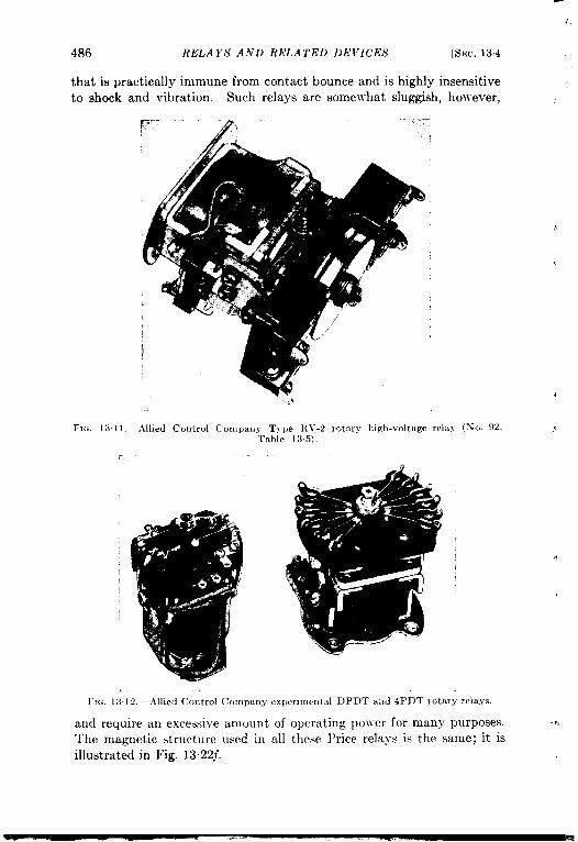
.,
486
thatto S1
is prlock
RELAYS AND RELATED DE171CES
actically immune from contact bounce and is highlyand vibration. Such relays are somewhat sluggish
,3$?’.:.—
[SEC. 134
mensitivehowever,
....—
FIG. 1:11 1.—Allied Control Company Trpe l{ V-2 rotary Iugh-vo]tage rel:i>- (No. ~~,Table 135)
l’1~. I:) I ‘2–-Allied Control Company experimental DPDT and 4PDT rotary rclaYs.
and require an excessive amount of operating po]ver for many purposes. ?,
‘rhe magnetic structure used in all these Price relays is the same; it isillustrated in Fig. 13.22~.

SEC. 13.4] OTHER ASPECTS OF R.L’LA Y I) ESIG.V 487
The Radiation Laboratory sponsored the development by the AlliedControl Company of a series of rotary relays, some of ~vhich are shownin Figs. 1311 and 13.12. The RV-2 was developed to switch circuitsoperating at several thousand volts in airborne equipment, and wasfairly successful in that service. This success led to the development oflo~v-voltage multipole relays for a Navy project where the relays had topass the standard A-avy shock, vibration, and salt-water immersion tests.
FIG. 13.13.—Magnetic structures of Allied Control Company rotary relays.
.,
These relays were given the type numbers R.AIH-l, RMH-2, and RLH-3.The RMH is a 1000-ohm d-c relay with one NO l)B wad one 1 NC DBcontact; it operates on 20 ma. T-he RMH-2 is identical except that ithas a 5000-ohm coil intended for operation at 115 volts cl-c and has DPDTcontacts. The RLH-3 is a somewhat larger unit with 4PDT contactsand has a 3800-ohm 115-volt d-c coil. All three are mounted in hermeti-cally sealed metal cans as shown in Figs. 13. lla and b. The magnetic
q structures are shown in Fig. 13.13.All three of these units will pass the >-avy salt-~rater immersion test;
in fact the Rhf H-1 and RMH-2 ~rere not injured ~rhen their cans were‘,crushed by accidentally allo~ving the salt-~vater bath to freeze. The canof the RLH-3 opened a seam and filled ~vith~vater, but in spite of this therelay operated after it was dried off. (The freezing test is not requiredin the specifications, )
The shock resistance of all three units was high, varying from 20- to120-g acceleration required to cause momentary contact opening, depend-ing upon the direction of the shock and the amount of excitation. Anearly experimental model of the RM H-2 ~vas damaged by transverse
-7,shock, the can pulling loose from the base plate at the soldered ,iob~.A redesigned and heavier base plate remedied that weakness.

:.
488 RELAYS AND RELATED DEVICES [SEC. 134
All units satisfactorily withstood the Navy vibration test, exceptthat after prolonged vibration at a critical frequency some of the framescrewsl oosenedinspite of their lockwashers, and two of the cams rotatedon the shafts. Both of these defects caneasily beremedied introduction.
The Allied relays, with the exception of the RV-2, were received toolate to reincluded inthetests reported in Sec. 13.7 andwereonly testedfor resistance to salt-water immersion, shock, and vibration. Their’shock and vibration resistance incomparable to that of the Price BrothersInc. rotary types and they require far less operating power. At thepresent time, they are certainly among the most satisfactory typesavailable for the application for which they were designed.
Insulation. —Coil insulation will not be discussed here except to pointout that in some applications severe surge voltages may appear across therelay coils. Extra insulation and wider spacing of the end turns may berequired, or in some cases a protective glow tube, spark gap, or Thyriteresistor may be shunted across the coil. In some plate-current relaysthe coil ~vill be at high voltage with respect to ground. This calls forextra insulation between coil and core, and in some cases for a modifiedconstruction of the relay.
The contact insulation in most relays is either laminated or moldedphenolic plastic, though many manufacturers also supply ceramic-insu-lated types. Punched laminated sheet phenolics are particularlysusceptible to water absorption and deterioration of the insulation.Molded plastics are somewhat better in this respect, and properly treateddense ceramics are much better. Ceramicsj Mycalex, or 10IV-1OSSplasticsmust be us:d ~l”hen r-f currents are to be handled. Radio frequencyusually calls for special contact construction to minimize the electrostaticcapacitance between open contact pairs.
Tropicalization, —The entire structure of a relay—coil, contactassembly, and mechanical parts—must be specially treated in cases whereit is to be used in the humid tropics or in other unfavorable climates,Insulating materials must be protected with fungicides by impregnationor lacquering, and metal parts must be proofed against corrosion. 31uchwork has been done on this during the war, and numerous specificationsfor the various treatments have been issued, but the problem has not yetbeen completely solved.
Probably the best method, where it can be used, is the completehermetic sealing of the whole relay in a suitable enclosure, as in therelays of Fig. 13.14a, b, c, and d. If the sealing is completely airtight,it also has the advantage of providing immunity to the effects of 10IVatmospheric pressure at high altitudes, Incomplete protection is worsethan none at all, however, since it discourages maintenance and mayencourage condensation, fungus, and insects. If the sealed relay is
?,

1
SEC, 134] OTHER ASPECTS OF RELAY DESIGN 489
provided with a plug-in base, it greatly facilitates maintenance and test-. ing of the equipment. The principal disadvantages of hermetic sealing
are that it slightly increases size, weight, and cost and considerablyincreases the difficulty of adequately cooling the coil.
Servicing and Replaccm<nt,-Rel:iy contacts are usually the greatestsource of relay failures. For this reason, relays should always be installedif possible so that the contacts are accessible for inspection and servicing.
(E9 (b)W
@
1
u
,.$
W (e) .. .. . .,.. ‘ w.-
FIG, 13.14.—Relay enclosures. (a) Allied RLH-3; (b) Allied RMH-1 ; (.) Sigma 4RHP-50;(d) Clare SK-5001; (e) Sigma MX with removable dust cover; (f) GE CR 2791C103C25...
If this is not possible, as ~vith sealed relays, great care should be taken
to keep arcing at the contacts to a minimum.
This can often be accomplished by the use of arc-suppressing circuits
across the contacts. These usually take the form of a resistor and a
condenser in series. No adequate method is available to calculate the
optimum values; it is usually best to start with about ~ pfd in serieswith 10 ohms for 24 volts d-c or less on the contacts; for 24 to 110 volts
about 1 pfd and 200 ohms will usually serve. Selection of the propervalues is largely a matter of cut-and-try, the effectiveness of arc sup-
pression being estimated by visual observation of the arc.7,Replaceable contacts are usually provided on large relays and con-
tractors, but this is not practicable on small units. The spring leaves on
most small relays, especially the telephone types, are fragile and easily

I
490 RELAYS AND RELA TED DEVICES [SEC. 13.5
bent. In many cases, especially in combat equipment, it is better toreplace the whole relay than to try to service it in the field. Replace-ment is most easily done with the sealed plug-in units, and the easyreplacement and the added protection of such units usually more thanpay for the additional size and }veight.
Relay Lije.—If the coil does not run unduly hot, the life of a relay isusually the life of the contacts. The number of operations that a relaycan satisfactorily perform depends principally upon the contact currentand the rate of operation. Heavy contact currents cause contact heatingand call for high contact pressures, which cause more rapid wear of botharmature bearings and contacts. Contact temperatures may alsobecome very high if the frequency of operation is too great to permitadequate cooling between operations.
Size and Weight.—The permissible size and weight of a relay dependupon the application. Fm most applications the average relay is notexcessively large or heavy, but for airborne and portable equipment thesefactors become important. This often leads to ~rorking the materials ofthe relay near their endurance limits, with consequent shortening of therelay life. The weights of the relays tested at the Radiation Laboratoryare given in Sec. 137.
13.5. Special Types of Relay s.—Although ne~her space nor theavailable data permit anything like a complete listing of the low-poweredrelays available on the American market, it may be worth while todiscuss briefly a few of the more specialized types that are regularlymanufactured.
Relays with special forms of contacts have been referred to in Sec.13.1. Most of the relay manufacturers supply relays with snap-actioncontacts; examples are the Automatic D55523G11 (No. 13, Fig. 13. 15),the Sigma MX (Fig. 13.14e) and the Clare AMS and CMS series. Manymakes of mercury contact relays are available; some operate by tiltingthe mercury container, such as the Automatic ANIC, Clare M, andDunco 22 and 91 series, while others use a stationary container and aninternal magnetic plunger and a surrounding coil. The Dunco Type 22is rather novel; its mercury contractors are mounted on a swingingtopheavy arm that comes to rest against stops on either side of center,and a momentary current to the centered stationary coil swings thearm over the top to come to rest on the other side. Another interestingtype is the hfercoid Type B transformer relay; this has a fixed primaryand core and a short-circuited secondary that is free to move on an armthat is repelled from the primary in a way analogous to the old movable-secondary constant-current transformers used in series arc-lightingcircuits.
Nonwelding contacts (tungsten, elkonite, carbon or metal-carbon
?,

?.
SW, 135] SPECIAL TYPES OF RELAYS 491
mixtllres, etc. ) are often used in relays forhandling heavy inrush currents
such as occur with tungsten-filament lamps and some types of motors.
Sllch r(:lays usually employ large-area flat contacts and very heavy
contact pressures; examples are the Cutler-Hammer 6041H54A (No. 71,Table 13.3, Fig, 1327d) and the Dunco 61 and 62 series. The Dunces,
using special contact materials, handle inrush currents of as much as
1000 amp at 2A~oltsd-c Ivith only 10 Jvattsin the coil.
I-lo. 1315.-Automatic Elertric Colnpany D55523G11 relay.
Some manufacturers offer potential or current relays that operateeither across or in series with the load, These are normally used asprotective devices to shut down equipment in case of power supplyfailure; for example, a potential relay might be connected across a biassupply to disconnect plate power from a po~ver amplifier in case of biasvoltage failure, or a current relay might be connected in the cathodereturn of a modulated stage to remove plate voltage from a class-Bmodulator and protect the modulation transformer in case of loss ofexcitation to the modulated stage. Such relays are closely allied infunction to underload and overload relays, that usually differ from theabove only in having rather more definite operate and release points.An underload relay is often used with motor-generator battery chargingsets to disconnect the battery and prevent discharging it back throughthe generator if the motor power fails. The ordinary cutout on anautomobile generator is a similiar device ~~ith the addition of a potentialJrinding that leaves the battery disconnected until the generator reachescharging voltage. Overload relays are used to disconnect power sourcesif load current (or sometimes voltage) becomes excessive. Some modelssuch as the Advance 700, the Leach 1042-P (Fig. 13.16), and the Guardian.X-1OOmust be reset manually; others such as the Advance 650 and theI.each 2417BF (Nos. 95 and 96, Table 13.5, Fig, 13.17) have auxiliary

T
,,
492 REI.A YS A ‘VI) ltELA TED DE VICES [SEC. 135
coils to permit electrical resetting from a remote point. Dunco Types55 and 56 are furnished in both forms. Overload and underload relays .,may have their operating points set at the factory, or they may beadjustable either by varying the air gap or the armature return spring,
or by a rheostat in shunt with the+?. coil.
In some applications a relay
ii is re(lllired }vhich is sensitive tothe direction of current flow.The a{ltornobile cutollt is an ex-
1
i
ample of this function; if themotor stops the potential ~vinding]~ill try to hold the contacts closed,but the current flo}ving from the
H battery to the generator in theFlu. 1316. - Leach Relay Company Type discharge direction through the1042-P !Elarlual-m.ct overload relay.
relay current ~vinding Will Droducew.
a counter magnctomotive force ~vhich will cancel that of the potential\vinding and ]rill allow the armature to open. So-called polarized relays,holrever, almost alJvays ~mepermanent magnets to furnish the sense ofdirection, as in the Automatic 1’1.D, the Ihmco 19 and 59 series, and theBarber-Colman AYI,Z-2022-1 (Xo. 94, Tal)le 135). l’olarized relays
I
I~ are often highly sensitive and may be made for very fast and precise! operation, especially for high-speed and mllltiplex telegraph operation.i hIultiplex telegraphy also employs many high-precision nonpolarized
relays such as the .I(ltornat,ic TQA. These arc usually characterizedby fairly high sensitivity, high speed, and accurately adjustable air-gap
?,
i and contact spacings. They often employ either multiple windings onr P
rLt!F

sE~. 135] SPECIAL TYPES OF RELA YS 493
the same core or mechanically-opposed magnetic circuits as in the Allied
J CS (No. 93 of Table 135, Fig. 13”18); many polarized relays such as theBarber-Colman unit above also use opposed coils for differential opera-tion, This use of the word should not be confused with that of ‘‘ close-differential” applied to such relays as the Lhmco 49 or to moving-coilrelays such as the Weston Model 705 and others (which are really meterswith contacts added where the pointer would be ordinarily), and inwhich “differential” refers to the current range between the operate andrelease points. Thus “close differential” implies a release factor near100 per cent.
Another type of relay used in communication circuits is the keyingrelay. Such relays are characterized by high operating speed and often
by relatively great complexity of contact arrangement and function.A simpler type is the Allied AK. hlany keying relays are normal typeswith increased contact insulation and spacing and decreased contactelectrostatic capacitance, at least for the contacts used in the antennacircuit.
Ordinary relays are seldom built with more than six or eight poles,‘.but there are special types that handle large numbers of circuits, suchas the Automatic WGA and “ Sunflower” types and the AEMCO SeriesHJ. These open or close a number of circuits simultaneously; there arealso relays, usually called “ line switches” or “ stepping switches” thatare electrically operated multiposition switches. These make contactsuccessively between one contact arm and a number of individual con-tacts. There may be a number of such electrically independent decks.Examples of such stepping switches are the Automatic 204E and the1,Western Electric D87856F1O (Fig, 13. 19) the Price 82-2 (Fig. 13 10),the Automatic “ Minor” switch, the Guardian R, and a multitude of
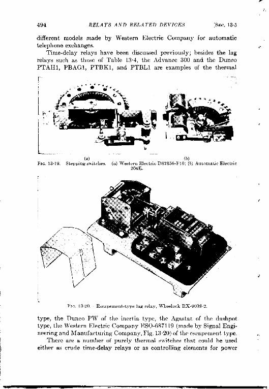
I
494 RELAYS AND liELA TED DEVICES
different models made by Western Electric Companytelephone exchanges.
T
.,
[SEC. 13.5
for automatic
<Time-delay relays have been discussed previously; besides the lag
relays such as those of Table 13.4, the Advance 300 and the DuncoPTAH1, F’BAG1, PTBK1, and PTBL1 are examples of the thermal
[..-
. . .*. . ,.’ ‘o u“ “ c-
-/0 -
i?
G-%.~x.
B * : ●;’ u.?%-,--
‘.!
,, ... .vJ, 2>-
-!f
L ?.+ ‘&k’
@—-.
(a) (b)FIG. 13.19.—Stepping switches. (a) Western Electric D87856-F1O; (b) Automatic Electric
204E.
(
.’
1
.,
FIG. 13.20.— Escapement-type lag relay, Wheelock RX-9038-2.
type, the Dunco PW7 of the inertia type, the Agastat of the dashpot
type, the Western Electric Company ESO-687119 (made by Signal Engi-
neering and Nfanufacturing Company, Fig. 13.20) of the escapement type. ,!There are a number of purely thermal switches that could be used
either as crude time-delay relays or as controlling elements for power

SEC. 136] DEVICES RELATED 1’0 RELAYS 495
relays. Themost common type isthecombined toggle s\t'itch and circuit~, breaker so much used in domestic light and power distribution switch-
boards; it is actually a manually reset overload relay. Others such asthe Edison and Amperite units referred to in Sec. 13.3 and the cheaperKlixon and similar units are actual time-delay units, and can be used asdelay elements for power relays. Alternatively, thermostats such as theFenwal could be thermally connected to a suitable heater element andused for the same purpose.
There are several classes of devices involving two or more relayelements plus electrical and mechanical interconnections. Several suchmultiple-unit devices have already been discussed, such as the electricallyreset-o~’erload relays and their close relatives, the
tlatching relays. The Leach 2417-BFoflig.13.17
and the Dunco 5 and 51 types are examples of thelatter class. Another class includes various me-
chanically interlocked relays such as the Dunco 38
where the armatures are so arranged that both
cannot close at the same time, and the Allied BJU
(Fig. 1321) where the interlock bar actuates an
over-center spring which ensures that either Relay... A is closed and B open, or vice versa. Inciden-
tally, most such relays that are intended fori momentary contact operation will overheat if
the coils are left excited for very lorwz Where
FIG. 13.21.—AlliedControl Company TypeBJU twin interlockedrelay.
this cannot be avoided, continuous-rati~g coils should be specified. Thisis true also of single-unit relays for impulse operation, such as the Duncoswinging-armature mercury relays and the cam-operated impulse relayssuch as the Advance 904A (Fig. 13.2) and the Dunco 11 and 85.
The preceding paragraphs by no means cover the field of specialtypes of relays, but do give a suggestion of the stock types of specialrelays that are available. Nlost of the relay manufacturers are in aposition to build variations and elaborations of stock types to order,
; especially if standard parts and subassemblies can be used. It is alsopossible in many cases to use several stock relays to perform specialand often highly complicated switching operations by suitable electricalconnections with or without mechanical modification or interconnection.’
13.6. Devices Related to Relays.—This section will be devoted to abrief description of several classes of components that are related torelays either in form or in function and that did not fall logically underany of the other chapter headings of thk volume.
Solenoids and Actuators.—One useful class of devices that may be1,f considered as relays minus their contact assemblies includes solenoids
j Packard, op. cit., particularly Chap. IV.

.’
/
496 RJ9LA YS A.V.D RELA TED DEVICES [SEC. 136
and electromagnetic actuators, either rotary or linear. Several suchunits are shown in Fig. 13.22.
Solenoids are manufactured by a number of firms for both a-c and d-coperation and in a wide variety of sizes. An extensive line of industrialsolenoids such as that of the General Electric Company includes severalhundred different models for 25, 50, and 60 cps and for d-c operation atvarious voltages. These models are made up on ten different core andframe sizes, with useful pulls (or pushes, in most types) of from less
FXG. 13.22.—Solenoids and rotary actuator. (a) Automatic Electric D2S2479-130;(b) Allen-Bradley Bulletin S60 Series 2PPW; (c) D. W. Davis 11 10A CD23; (d) D. Yf-.Davis 21 10A D-2 with armature removed showing shading coil; (e) National Acme 16KKK-100A; (f) Price Type 76 rotary actuator with housing and auxiliary contacts removed,.howing shape of armature and pole pIevc.
than 1 lb to about 100 lb and with strokes of from ~ to 3 in. Variousaccessories can be furnished, such as fittings to permit the unit to pushas well as to pull (a push fitting is shown on the Allen-Bradley solenoidof Fig. 13.22b) and holding contacts to permit the use of a series resistoror holding winding in order to reduce the polver consumption and heatingof the main winding after the solenoid has closed. Alternating-currentsolenoids, except in the smallest and cheapest types used in single-strokebells and the like, always use laminated magnetic structures with shadingrings such as that shown in the end-on view of the armature of Fig. 13.22d.,Many d-c solenoids use the same structures, but others, such as the.4utomatic Electric unit of Fig. 13.22a, use solid magnetic structures and
,
(,

4
SEC. 136] DEVICES R,!lf,,l 7’ED 7’0 1{1<1,.11“,S 497
solid armatures. The metal coil heads, however, are usuallv slotted toreduce eddy currents and thereby to speed up the action of the unit.
Another device that is used to obtain translational motion and forcebeyond the practical range of a solenoid is the General Electric Thrustor.This is a self-contained combination of hydraulic cylinder, spring, andmotor-operated pump, which looks somewhat like a rather ungainlyhydraulic aircraft shock-absorber. It is useful for forces UKIto severalhundred pounds and strokes up to a foot or more.
.
Most of the relay manufacturers will sell any of their models ~viththe contact assemblies omitted, and on s~ecial order some of them willsupply certain types of fittings to adapt the units to furnish forces of afew ounces at strokes of a fraction of an inch. Standard relay mech-anisms are useful for operating latches or triggers, shutters, etc., ineither experimental or production equipment. In some cases they maybe used to furnish torques if the angular range of motion is small.
For applications in which the required torque or angular motion isbeyond the range of a conventional relay mechanism a rotary actuatoris useful. One such rotary actuator is the Price Brothers CompanyType 76, shown in Fig, 13.22j. This particular model is intended foroperation on 24 volts d-c. It has a throw of 60° and a torque of about10 in.-oz. It is furnished with a holding coil and auxiliary contacts(shown disassembled in the photograph) to disconnect the main actuatingcoil at the end of the stroke, thereby permitting continuous excitationwithout overheating. A similar but more compact unit is the Ledexrotary actuator, manufactured by the Henry 31. Leland Company ofCleveland. It has a stroke of 45° and a torque of 4 in-lb.
Instrument Vibrakn-s.—.A device which is closely related in structureto the power-supply vibrators of Chap, 12 but which is related to therelays since it is used as an electrically actuated s~vitch is the instrumentvibrator or Brown Converter, manufactured by the Brown InstrumentCompany of Philadelphia. This vibrator (shown in Fig. 13.23) is madein two forms. The larger, Fig. 1323a and b, is intended for operationat 50 to 60 cps but can be used at somewhat lower or higher frequencies;the resonant frequency of the reed is 90 cps. The smaller model hasbeen produced only in small quantities. It is intended for operationat 400 cps but has been used experimentally at considerably higherfrequencies.
‘The Brown vibrator is not contact-driven, as is the case with a power-supply vibrator, but must be driven by a source of alternating currentof the desired frequency. The standard coil is intended for 6.3-voltoperation, but will work well at 9 volts without overheating. Thestationary contacts are set at the factory so that all three contacts are
L
connected for about 7; per cent of the operating cycle at standard

498 RELAYS A.VL) ItELA1’ED L)E1”ICES [sm. 136
amplitude. The contact noise generated is of the order of 1 pv or less,being toolowtomeasure, The usable power level is limited at the lowend by electrostatic pickup from the coil and coil leads; the capacitancefrom coil and leads to the reed is about 5 wf, which gives a pickupvoltage on the reed of 1 PV at 60 cpsif thereedworks intoa 100,000-ohmload. This pickup can be greatly reduced by opening the can andbringing the coil leads out of the top, alvay from the reed and contacts.The limitation at the high end of the po}ver range is the burning of the~ontacts, A series of life tests }vas made on 16 vibrators at the Radiation
(c)., .,k-lG. 13.23-Brown Instrument Company vibrators. (u) W-cps unit w~tl, cover removed;
(b) standard 60-cps unit; (c) experimental 400-cPs unit.
Laboratory and indicated that the contact life is indefinitely long at acurrent of 0.6 ma; at higher currents it decreases, being over 1000 hrs at1.7 ma and less than 20 hrs at 4.5 ma. The contact current was suppliedfrom a d-c source through a 10,000-ohm resistor. The end of the life ofthe unit ~vas taken to be the point at which an appreciable change inperformance was observed.
The standard Brown vibrator is mounted in a hermetically sealedmetal can and plugs into a standard six-pin tube socket. These con-verters have been used in large numbers in apparatus designed by theRadiation Laboratory, particularly in servo circuits, precision voltageregulators, and computers, and have given excellent service. Their useshould be even more extensive in the future. A discussion of theirapplication to various problems will be found in Vol. 21 of this series.
Mercury Rday.-.lnother device that is intermediate in characterbetuee~ ~ conventional relay and an instrument relay is the Bell Tele-

SEC, 136] DEVICES RELA TEL) TO RllLA YS 499
phone Laboratories D-168479 mercury relay, a cross section of which isshown in Fig. 13.24. This is a glass-enclosed SPDT contact assembly inan inert gas under pressure. The contact surfaces are mercury on thesurfaces of amalgamated Kovar or some similar alloy. The mercurymppl.y on the contacts is maintained by capillary action from a quantityof mercury in the lo!ver part of the glass bulb. The fixed contact spacing
,Wax flllmg
is such that in normal operation with the tube mounted vertically amomentary bridge of mercuryconnecting all three contacts isformed during the motion of themovable contact, The durationof this short-circuited conditionincreases as the tube is tilted,becoming continuous b e y o n dabout 45° from the vertical. Thesmallness of the parts and the useof the mercury permits high-speedoperation with negligible chatterand comparatively large voltage-and current-handling capacity.The maximum current is limitedto 5 amp averaged over 100 see,10 amp over 10 see, or 50 ampover 10 ~sec. Instantaneous volt-ages across opening or closing con-tacts should not exceed 500 volts,For these conditions the life at 60cps should exceed 1000 hr.
The relay tube is enclosed ina steel shell and mounted on astandard octal tube base. Thepin connections are as follows:
Pins 1, and 2, 700-ohm coil(5925 turns No. 40 enamel wire)
yin 3, no connectionPin 4, back contactPin 5, movable contactPin 6, front contactPins 7 and 8, 3300-ohm coil (16,950 turns No. 40 enamel wire)
Upperpole
piece \
Frontcontact -
Armature-
Lowerpole _
piece
Mercuryl
Feltwasher
/Glass
Back contact/ support
Back contact
Armature- contact
% Armaturecapillary
.Sprlng
Gas under
nlll “Mediumoctal base
Fm. 13.24.—Bell Telephone Laboratoriesmercury relay. (CourtesV of the Bell Tde-phone Laboratories.)
Pins 1 and 8 may be strapped for a series-aiding connection of thecoils.
The operating current with the coils series aiding is 6,6 ~ 0.7 ma,

.500 RELAYS AND RELA1’ED DEVICES [SEC. 137
the release current 5.2 f 0.7 ma. The continuity time for normaloperation is 8 per cent maximum.
The mercury relay has been used principally in two types of service;as a “chopper,” similarly to the applications of the Brown vibrator, andas a switching device to give 60-cps pulses ~vith a duration that dependsupon the magnitude of a control current. For the latter service theprovision of t~vo coils is con~enient; an a-c current through one coil isprovided to maintain the motion of the armature, and a variable d-ccurrent through the other coil provides a variable d-c bias and varies theduration of the contact and thus of the output pulses. The mercuryrelay is a novel device and has interesting possibilities.
13.7. Relay Tests at the Radiation Laboratory. Relay Data. —Sincerelay failures and malfunctions had proved to be important sources oftrouble in military electronic devices, and especially in airborne equip-ment, an extensive series of tests was carried out at the RadiationLaboratory on typical commercial relays such as ~rere used in its equip-ment. Samples of over a hundred different models from a number ofdifferent manufacturers m-eretested, with particular emphasis on resist-ance to shock and vibration. This section is an abridged summary of theresults of the tests; the original report 1should be consulted for additionaldetails.
Tables 131 through 13.6 and Fig, 13.31 present the data on 95 relaysfrom 15 different manufacturers. The choice of types and manufacturerswas largely arbitrary, being governed as much by the types that happenedto be in stock as by any other consideration. An effort was made tochoose a representative group of the types of relays that were of interestfor military equipment, with some emphasis on the 24-volt aircraft classbecause of its importance and the severity of the conditions encounteredin airborne ser~ice. In a number of cases pairs of relays were selectedlvith the maximum and the minimum numbers of contacts in order toobtain both the least and the most favorable conditions for a given relaystructure.
Because of the great amount of labor involved in the tests it wasusually impossible to test more than two samples of each type. Thisgave a check on the consistency of the test results but the variationsfound between supposedly identical relays demonstrated conclusivelythat the tabulated values must be considered neither as accurate stand-ards nor as statistical averages for the purpose of comparing types ormakes. Relays are particularly subject to variation of characteristicsdue to minor changes in adjustment, and it is doubtful even that averagesbased upon large samples would have any great significance.
1 H. Baur, 1’Relay Data Including Shock and Vibration Measurements,” RLReport No. 747, Al]g. 1, 1945,

SEC. 1371 RELAY TESTS A T THE RAI)IA 7710N LABORA TORY 501
Detailed comments follow on those columns of the tables for whichthe column headings are not self-explanatory.
In Column 2 the name of the manufacturer is given in abbreviatedform. The full names and addresses of the manufacturers whose relaysare included in the tables are as follows:
Advance Electric and Relay Co., 1260 W. 2nd St., Los Angeles, Calif.Allied Control Co, j Inc., 2 East End Ave., New York 21, N. Y.Automatic Electric Co., 1033 W. Van Buren St., Chicago 7, 111.Barber-Colman Co., Rockford, 111.C. P. Clare and Co,, 4719 Sunnyside Ave., Chicago 30, Ill.Cutler-Hammer, Inc., 315 N. 12th St., Milwaukee 1, Wis.General Electric Co., Schenectady 5, N. Y.G-h’l Laboratories, Inc., 4313 N. Knox Ave., Chicago, Ill.Guardian Electric Mfg. Co., 1400 Washington Blvd., Chicago 7, Ill.Leach Relay Co., 5915 Avalon Blvd., Los Angeles, California.Potter and Brumfield Mfg. Co., Inc., 617 N. Gibson St., Princeton,
Ind.Price Bros. Co., Frederick, Md.R. B. M. Mfg. Co., Div. of Essex Wire Corp., Logansport, Ind.Sigma Instruments, Inc., 70 Ceylon St., Boston 21, Mass.Signal Eng. and Mfg. Co,, 154 W. 14th St., New York, N. Y.
Column 4 gives the nominal coil voltages in volts, This is a rathermeaningless quantity, as consideration of the other data will demonstrate,particularly in the case of relays intended for plate-circuit operation.It is principally of use as a basis from which to design coils for otherrelays of identical construction for operation on other voltages. It mustbe used with caution in attempting to compare the performance ofrelays of different types.
Column 5 gives the contact classification, noting in order, poles,throws, normal position, breaks. Thus SPST NO DB signifies as asingle-pole single-throw normally open double-break relay. Normallyclosed is signified by NC. All contacts are single-break except whennoted as DB. When relays have several sets of different y functioningcontacts the several groups are separately listed; thus DPDT + 1 NO DBwould mean a double-pole double-throw relay with an additional set ofnormally open double-break contacts. Naturally NO and NC are usedonly for single-throw contacts.
Column 6 gives the contact rating in amperes. This rating is notnecessarily the same for all contact groups of the same relay, and dependsgreatly upon operating conditions as explained in Sec. 13.1. The valuesgiven in the table must not be used as a guide to the application of a

particular relay; they are included only to indicate Jvhat, the relay issupposed to be capable of doing under normal conditions. t
Column 8 gives the d-c coil resistances in ohms at 25”C, rounded offto the nearest 5 or 10 ohms except in the case of low-resistance coils.The resistances of supposedly identical coils were usually the same within1 or 2 per cent.
1“ Coiumn 9 gives the temperature rise in degrees centigrade above a65°C ambient temperature. LIost of the relays were tested at 125 percent of nominal coil voltage; the actual per cent voltage used (or theapplied voltage, in the case of relays for ~vhich no nominal voltage ~vasspecified) is given in parentheses for the other relays. This choice ofambient temperature and overvoltage is admittedly a severe test, but isnot unreasonable for military equipment in view of the high ambienttemperatures encountered in crowded chassis and the poor voltageregulation of field power sources. Coil temperatures were determined byresistance measurements, and the tabular values are rounded off to thenearest five degrees.
Columns 10, 11, and 12 give respectively the coil input in wattsat nominal voltage and 25”C, the minimum input at 25°C necessaryto operate the relay, and the ratio of the minimum to nominal inputexpressed in per cent. Coil powers were not measured for the a-c relays.
The release factor in Column 13 is 100 times the maximum releasecurrent (or voltage) divided by the minimum operate current (or volt-age). It is a measure of the “ differential” of a relay, a zero differentialcorresponding to a release factor of 100 per cent. Minimum operatecurrent (for d-c relays) is the minimum coil current that will operate thearmature, opening all h“C contacts and closing all NO contacts. In the
case of a-c relays, minimum operate voltage is the minimum voltage
that, when applied to the coil at 25”C, will perform the same function,
the contacts being closed tightly enough to prevent momentary opening
due to contact chatter. The point of minimum a-c operating voltage isnot as sharply defined as that for d-c current.
Maximum release current is that value of (d-c) current that will justpermit the previously energized armature to drop out, opening all NOand closing all NC contacts. Release (a-c) voltage is that voltage atwhich the closed NO contacts just begin to chatter open, as shown by asudden large increase in the contact resistance.
The table gives the maximum and the minimum values of releasefactor obtained for any sample of each type. When only one value isgiven it may mean either that only one sample was tested, or that allsamples gave the same value.
The last five columns of the tables give the operate and release timesin milliseconds. Operate time is the total elapsed time from the applica-
—

SEC, 13.7] RELAY TEs~s AT THE RAI)IA y’fo.~ LABORA Tf_)fi~ 503
tion of voltage to the relay coil until all A“O contacts close and all contactbouncing ceases. Release time is the total ehipsed time from the break-ing of the coil circuit until all NC contacts close and bouncing ceases.In the case of multiple-pole relays all A-O contact pairs Ivere wired inseries, and like~vise all XC pairs.
Columns 11, 15, and 16 give respectively the maxlmurn operate timeobserved for any sample at minimum coil voltage, the average time atnominal voltage, and the minimum time at maximum voltage, For the
FIG. 13.25.—Typical telephone-type relays. (a) Western Electric B-101s with roverand lid removed; (b) Western Electric R-323; (c) l~estern Electric 20S-B; (d) Clare A-1 }906;(e) Western Electric 41 /LJ692; (/) Clare A-1 1137; (o) Clam A-2202:3; (h) AutomaticElectric H-77734-7; (i) Allied TSL-C low-capacitance type; (j) Allied TSL-C standard t~pe.
release times, which are much more consistent and nearly independent ofapplied voltage, the maximum and minimum obser~red ~.alues are givenin Columns 17 and 18. Because operate time in particular is greatlyaffected by relay adjustment the tabulated figures are not significant inthemselves, but do give a rough idea of ~vhat performance may beexpected. In the case of the a-c relays only maximum and minimumvalues are given for the operate times, In the case of the slug-type lagrelays the operate- and release-time curves havi already been given inFig. 135.
Figures 1325 through 1329 S}1O}Va number of typical small relays of

.,
504 RELAYS AND RELA TEL) DEVICES [SEC. 13.7
various types. Relays identical with those listed in Tables 13.1 through136 were chosen as far as possible.
vibration and Shock Tests.—Contact opening in the vibration andshock tests was detected b~’ an electronic indicator whose response time
FIG. 13.26 .—Typicd sensitlle relays. (a) Sigma 4RHP1,; (b) .Illied 13D-330; (c) General
Elertric CR2791CI 04C23 ~Vjtll ~O~e~ ~elllOVed; (d) ~llie[l G
(a) @) (c) (d)
FIG. 13.27 .—S1]MU d-c motor contractors. (a) Square-D rlass 9350 Type B5A; (b) LeachB6; (c) Cutler-Han, mer 604H14.i; (d) Cutler-Haml,ler 6041 H54.k.
was a few microseconds. The vibration tests ~rere made on a TypeVUDM Vibration Test Table made by the I..\B Corporation of Summit,N. J., the amplitude being held constant at 0.03 in. (total excursion0.06 in.) and the frequency gradually increased from O to 55 or 60 cps,or until the contacts opened. The peak acceleration in g’s is given byA. = 0.051 lDf2, ~vhere D k the total displacement in inches and f isthe frequency in cps. The shock tests }vere made on an American War

SEC. 137] liELA Y TESTS .4 T TIIE HA 1)1.1 TIO.Y 1,.4 BORA TOR17 50.5
Standard C29.3-1943 Shock Testing Llachine, made by Radio FrequencyLaboratories, Inc., Boonton, N. ,J. The relays were rigidly mounted onthe shock table and successively greater drops were made until thecontacts opened. For the particular spring used, the acceleration wasgiven by A, = 203 ~S/lV, where S is the drop in inches and W is thetotal weight dropped, in pounds. In these tests 1}’ can be taken asconstant at 10 lbs lvithin the accuracy of the tests, ~~hich is estimatedat + 10 per cent. It was found that variations of 15 to 20 per cent in
(b)
FIG. 13.28.—Slug-type lag relays. (a) Western Electric 178-BD with cover removed;(b) cover for 17S-BD; (c) Clare A-18360; (d) Clare B-18466; (c) Clare A-13960; (~) ClareA-18466; (g) Allied BOLX-4.
drop height were obtained from successive tests of the same relay; thismay have been due to variations in the seating of the armature afterthe previous shocks, or to high-frequency accelerations associated l~iththe impact.’ The lowest value of drop at which the relay openedwas the one recorded.
The coil currents used in the shock and vibration tests were thosecorresponding to minimum expected operating voltage at maximum hotcoil resistance. In the case of the 24-volt d-c relays these currentsusually corresponded to coil voltages between 17.5 and 19 volts at 25°C;accordingly all these relays were tested at 18.5 volts. Many of the a-crelays chattered at the calculated coil currents; the current was therefore
I Dr. Irwin Vigness, N.R.L. Report No. 0-1414, 5 Dec. 1944.

TABLE 13, 1.—GENERAL-PURPOSE D-c RELAYS
Operat,ng LXWW,watts lelease t[meI’emp.meabove 05”ambient,degreesC.6055605535 (I 75)
40 (185)60
J50
3045
3;10(260)
7045 (260)6055 (115)45
H ( 107)
!: (215)15(230)
M55 (320)30( 185)25 (21XI)
20
2:45 (115)70
20(1 18)
U7540
contactcunentratmm,amp
5
1!1510
1010511
1111
10
33333
2:
;15
41515154
411
12125
4
:
2:
Make
,Oled
,Utnmat,c
Nominal0311
voltage,v
Relemefactor,m cent
36345+69364874-78
22
374337-58
44%248-56
44-6544
53T;826-29
51-6359-73
445~855
S-7548
27:2
82
2321-27
;:38-46
31-40%5466-7132-354C-48
33+221-23
J;B44-55
bmk time, mwCmtact
arrangement?v’L?lgbt,
g
lR127158141
1402971085034
33
:;52
339
3!;353842
70107175157161
170144160160165
;$340197137
157156215230167
Ma,.0, Makm’a no. r—
,ormal
2302 102 50245091
074330022I 921.95
0961 510 191 13023
3 201001 922 251 92
1 922 725340490 72
433204039086070
0470242403983.84
1 223503423602 26
mm.
1 101051 471 37040
0292 760 153241 40
0 280 770090 460 16
I 390690400 35085
0560 52226034050
1 330630 230600 60
0430060511 70206
1 031 021 6207224-O
G.Kc12:14272224
2542331019
9
;;15
180
:;6
::
1;246048
2227
;:,..
60493433
4?
;;1619
a . ..(
505060w40
::
702W30
70
3050
E70
4070202040
3020407070
303060
E
9030204050
80303020
10-20
max.
E343536
3854)55
::
20307532
20
101515
;;3290
353540
120704540
;:40
;;
Ilsx, nin
BJ6D36BJC6D36B06D35BO12D35BOY6D3J
BOY6D42BN18D33PC-14rwccrsLcc-cc
TSLCTSLCC211590283384D55523GI [
2424242424
DPDTDPDTDPDT4PDTDPDT
8585
171512
152825
1!
67
13
3:
830
45457
611171812
1719121812
2846372824
20
E1316
3395
1013
156
55
45
:5
6
:44
518255
576!36
1;
7
1:
2510!2
;
F-35,05
86::
;24
2424242450
DPDT6PDTDPDTDPDTDPDT
10250175
2565303295
;:3000510
lIOCQ
180250i2300
;:
3C0
1::locm
17
1332&3
57;354M
105W24CQ240170130
9950165168
;:
44
24335
3
:44
38!35
SPDTDPDTSPDT4PDTDPDT
be
iE
:.M. Lab
A11191kl1906A19657A21136019657
;;;;SPDTSPDTSee Note
3K5cK11CR279IB1OOC2CR279ID IOOF31284212848
DPDTSPDT DBDPDT DBDPDTSPST NO DB
24
;;703.5
2424
257030
SPDTj$PD’;DB
DPDT4PDT
576‘i6
,07
:0
!0
,1253
3PDTSPDT8PDT3PDTDPDT
313223
:
3637383940
mmg’
1423RW1457MX1601MX
11024342424
4PDTDPDT~P&DB
SPST NO DBcd4
.—-. .

..
9612852
121138
71556641
111
156
I 921 95I 122 450 82
1 87I 302 70233074
0 13
73-784>57
:;37
336129
4+5439-42
86
T%=m47
759:051-56
6S7016
iB
1318
2320
18 1019’7
19I
1:7
1014
159756
25
T1052
18
2:—
SPDT4PDTSPDTSPDTDPSTNODB
3
;55
0 250 25111
1
1 11081031064035
I 020 65047046064
0 11
::840
6030202090
80
740
1006070
10060
41 P&B4243
KLD- 1#RImjo
W:.1
501
~$233W230054AH
4RHP-30
10’165
5
55
10
05—
48
;22
570—
8115
4
54
10
05
:718
510.
4445
464748
:
51
P,,..
R B.M.Slgm
DPDT3PST NO4PDTSPDTSPDT DB
n 4077 40(130)
230 55 (115)2!70 60(115)
11030 30
SPDT 47 I 40 (36o)
NOTEB:Relay No. 15: Uses 2 BRL-2 Microsw’itches. See Fig. 1315.Relay No. 20: Contacr6 SPDT + 1 NO make before 1 NC break.Relay No. 21: Hermetmdly sesled on octal base. See F[g 1314d.Relay No. 50: Sealed dust cover on S-pm !>lu~-in base.Relay No. 51: Hermetically sealed. See Fig. 1314..
TABLE 13 2.—SENSITIVE D-c RELAYS
61 I GE I CR279IC103C25 1062 Pm, MD4C4 6a Slgm p;cl 256465 I 46! ;:
66 4RHPLIOO0 867 Slgd RR-4 6
p’J--SPDTSPDTSPDT
30 (5CO) 0044 002720 (333) O 078 003545(1200) o 013 001340( 1330) o 011 0 00635( 1730) o (8)7 O W6
I 109 2300025’ 25 ~ 4651 130 4881 66 2001 103 76ao
38
120—SPDTSPDT
0064 00640008 0 L-w
30 (440)_
NOTE8Relay No. 61, 63, 64: Dust cover and 5-inn, d~,g-in base.Relay No. 66: Hern)etmdly sealed. See F)&. 1314c.Relay No. 67: Welsht without cover.
TABLE 133.-SMALL D-c NIOTORCONTRACTORS
NOTESRelay No. 72: Ha. double %mding; low-resistance winding cut out by s~rics NC contacts on operation. Normal mp”t 69 watts to low-resistance coil; holds on
Iew than I watt.
~_*_.:....—....- -----.

TABLE 13.4.—SLUG-TYPE LAG RELAYS
Ti=kj=; s83 .\17978 2484 .AIS46635 BlS466
.36 Guardw.n G.-44464 24
f’ont.wt:Irr.w,g?”,mt
DPDTSPDTSPST NOWDTSPDT
DPDT
ro,,t:l,tCurr?llt \\,,ghtratlug, g
amp
10 223211
; 3474 2114 328
15 1 19s
rod Temp. rMt-r(’,wtmcc above S-5°;,t 25”C, ambmnt,
ohms degreesC.
230 60u 75 (20 v.)
2000 30 (365)80 55 (20 v )
250 40 (30 v.)
190 I 50
operatingpaw?,, watts
mrmd
230
029
296
,,,,,1, W, .,.t
037 200 250 19 200200 17
017 I 20
9192939495
969798
*
Operate. znd release-ti,,,e curves gi, en ,. k’,g. 135
‘rABLE 13.5. —h1ISCl:L1,ANE0US SPECIAL RELAYS
miR-.40md
B-CLeach
P,,,,
904A34V.2Cs.AYLL-?022-12417-BF
2417-BF764310311
ll0Y,60-24v. dc24vdc24vdc24vdc
115v,60-24vdc12vdc40v. dc
DPDT
I4I
225 I 53;1 2793PDT 40 398DPDT 5 325 1878
0040
2:45
4025
k
3 27”00720622,3o
77””’16~
149”0 0590 CW6O 81
14 60540 55
50so0,1
40
60
RQlms,facto,
pm cult
47-5458-6719-9525-382%46
41
14-199097
_&
~OT,S,Relay ~“. !)1 : Ratchet -a!, cl-ca!r operated sequence relay; “ on’’—” off “-” on “ate. C.mki rated for momentary duty only. See Fig. 13.2.1{,1.}- No, 92: Rotary relay for h]gb-voltage ok)erntlon; 8-kv msulnt loat. Sec Fig. 1311.Relay No. 93. 3-uo.ItmrI srns,ti, e cfifTercr]t ial relay; 2 mdependcnt cods nnd mngnetic circuits mechanically opposed. Center “ OH” position. See Fig.
1318.R+y So, !M: 3-f>O~,l,~~. bmh-sensiti~ity di~ere!,tial l~ol=,zed rela,r. 2 ~i,,din~s. center a’ofl” ?Ositlon.Relav NO !45, 96: Latrbmg relay u,tb eh-ctnc.l release.Relay No 97:
Coils normally ouerated only rnomentardy but rated for continuous excitation. See Fig. 13.17.RotaryWI:(Vwith wder-switch coutacts and double wmcfing.watts. IY,ll bold w!th 0.’2 watts. See Fig. 138.
Normal input to low-resistance nindmg 79 watts; to holding winding 2.2
Relay No. 98: Rotary relay w,tb double wmdms. Normal inout 16 watta to low-resistance cod, 1.1 watt to holding cod. W]ll hold with 0.15 watt.Relay No. 99: Rotary relay. See F,E. 137.
.- ..- .s -. . (
-.

Relayno.
1o1-102103104105
106107108109110
111112113114115
116117118119120
hn
Mnke
Allied
Clare
Guardian
I/each
P&B
Maker’s no.
BJ6A115BJCGA115B06A115B09A115B012A115
BN18A33B20392B21276400A34990
1127BFRW1157RWBFI157C’RWBF1326Dl?W1557Mx
1701MXKL.!-1KL.4-10KR.4-4SPA-1
TABLE1344ENERAL-PURPOSEA-c RELAYS
Nocrjpd
ICent act
wltlxge, v .wra. gement
110 DPDT110 DPI)T110 DPDT110 3PDT110 4PDT
L110 6PDT115 4PDT115 DPDT120 DPDT110 3PDT
110 DPDT110 DPDT110 3PDT110 1NO DB + lNC110 DPDT
110 SP NO DB115 SPDT110 4PDT115 DPDT110 SPDT DB
contactc.r~e”tmtmg,amps55
15
;:
10343
12.5
;6
256
253335
Weight,g
92101140161169
;!3;
167
1;:
13714!2150191226
22610011250
118
Coile$t5mCce
“,ohms
645640450300300
175150215215385
540520510360525
520540540
31301235
remp.,k.;bove;~
Iegrees C.706530
%
35
[80 120)40 115);: (120)
50
:;6555
5040352535
,Es:w No. 109: F., 400.CPSoperatmn. All other a-c relay, m tables intended for 60-CLW operation
ye~percent
87Y!3489-95
9~–;8
95
E8590
94
88–9393-95y:
92–94
87-9486–928S948690
~
verate time, msec
min.
;654
575
1:
;
1815
65777
1:12
li
13117
2:
1219
;;27
ii17209
.... ... .. -“- .,.,. -.
. .

510 RELAYS AiVD RELATED DEVICES [SEC,13.7
increased to the minimum value at which the contacts would remainclosed.
The resistance of a relay to shock and vibration depends upon thedirection of the resulting acceleration, and therefore the relays weretested in three directions. The notation used for these directions isexplained in Fig. 13.30. Relays }veredivided into six classes depending
I
1
8
,
J
FIG. 1329.-Typical small general-purpose relays: (a) Allied BJ61X16; (b) AlliedB06A36; (c) Allied BO12A1 15; (d) .Mlied BN18.il 15; (e) G-M Laboratories 12968-8;
(j) Clare A231W 400-cPs relay; (u) same with armature and contacts removed, showinglaminated magnetic structure and shading coil; (h) Potter and Brumfield PRA-4; (i) Leach1157 RW-BF; (j) Leach 1020 (note M BB contacts) ; (k) Leach 1423-RW, M ycalex base,high-voltage insulation; (1) Learh 1507-MX, Mycalex base, for radio frequency.
upon the mechanical structure of the armature and moving contactassembly. For most of these classes the X-axis was taken parallel to thecoil axis and the Z-axis parallel to the armature pivot axis. The actualchoice between positive and negative direction along the three axes isnot distinguished in the figure, but in the tests the least favorable direc-tion was usually chown.
Figure 13.31 presents the results of the tests in semiquantitativeform, In the case of the vibration and shock tests, quantitative resultswere available and six grades were set up, with the following limits:1.,.
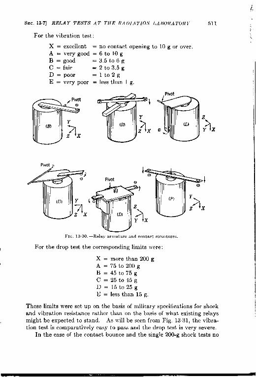
i’,,
SEC.137] Ri3LA Y TESTS AT THE RA DIA TIOA’ I. ABORA TOR Y 511
For the vibration test:
X = excellent = no contact opening to 10 g or over.A = very good = 6 to 10 gB = good =3.5 t06gC = fair =2t03.5gD = poor =lto2gE = very poor = less than 1 g,
z
3Yx
Pivot,
I
FI~. 13.30,—Relay armature and contact structures.
For the drop test the corresponding limits were:I
X = more than 200 gA=75t0200gB=45t075gc=25t045gD=15t025gE = less than 15 g.
These limits were set up on the basis of military specifications for shockand vibration resistance rather than on the basis of what existing relaysmight be expected to stand. As will be seen from Fig, 1331, the vibra-1tion test is comparatively easy to pass and the drop test is very severe.
In the case of the contact bounce and the single 200-g shock tests no
1I

—
“.
512
RelayNo.
12345678
1:11121314151617181920
:;2324252627282930313233343536373839404142434445
4647484950
51
RIYLA 1’,S .-t.1’1) 1<1<1,.4Ttii) I)N I’lCILS ISW. 137
Contact Single Vibration Shockbounce 2oo-g
Structure shock Excited Unexctted Excded Unexcited
class OP. Rel Exe. Unex X 1’ Z XYZ XYZXYZ
BBLLLLLuLLLLLLLLLLLLLDDLLLLLLLLLLLLuuuuuu
:BuL
iLBB
0----m----
--m---mm--
--Um0-0--n
--m---n---
u-----mm-
--m---
-murn
-u-9-9----
--D=2--9mm-0
--mm-m----
-nno-m0-
-
--
FIG. 13.31 .—l<elay shock, vibration,
quantitative data were available, so that the oscillograms of contactcurrent were classified by visual inspection into six classes. The samesix letters were used as before, X signifying either no effect or only atrace of “ grass” on the oscillogram, while E signified severe, repeated,
Y
*
.
1

Ssr. 137] RL’LA Y I’K,ST,S .47’ 7’11# I(A1)[A 7’1ON I>AIJORA TORY
RelayNo.
6162
::656667
7172
:;838485
86
91
929394
$ 95
96979899
101102103104105
106107108109110
111112113114115
116117118119
120
Contact Singlebounce ZoQ.g
Structure shockclass Op. Rel. Exe. Unex,
BuBBBBu
PP
LL
iL
1.
cR——uuRRR
BB
iLLLLLL
;uuuuu
;B
-- 0-- n-
-- ---n --00 m-
-n ---- ---- --
and rontxct bounce characteristics,
513
Vibration Shock
Excited Unexcited Excited UnexchedXYZ XYZ XYZ XYZ
mD ----
3. Small d.c motor contractors00-00 n -- n---000 000 -nn
and long-continued contact chatter. Such a method of grading is\ admittedly arbitrary, but it is believed to be fair as a comparative method.
In Fig, 13.31 each small lectangle represents the result of t)]le test onone relay, the amount of blackening representing the res~llt of the test

514 RELAYS AND RELA TED DEVICES [SEC. 137
Thus a white rectangle signifies a grade of X, a rectangle which is cme-fifth black a grade of /1, and so on to an all-black rectangle for E. JIiss-ing rectangles signify that the test data were lacking. The numbers ofthe rows are the relay numbers from Tables 131 through 13.6; thestructure class letters refer to the sketches of Fig. 13,30.
Conclusions.—The first conclusion to be drawn from the mass of datapresented in the tables and in Fig. 13.31 is that no evidence of out-standing superiority or inferiority can be found for any one make, con-struction, or class of relay. There are statistical differences, to he sure,but in view of the variability of relay characteristics with adjustment ,and other conditions the differences in the averages for the \-ariousclasses are not particularly significant in most cases. s
The data from the tables may be discussed first. The averagetemperature rise in Column 9 Ivas -12,5°C for the 51 d-c relays of Table13.1 and 48.5°C for the 20 a-c relays of Table 136. If all relays nottested at 125 per cent of rated voltage are omitted the fig~lres become46° and 48° respectively; in neither case is the difference ~’ery significant.Sensitive relays naturally run with very little temperature rise; theaverage 27° rise in Table 13.2 ~vas caused by relatively enormous o~,er-excitation. Slug-type lag relays tend to run hot because of’ their neces- 4sarily less efficient magnetic design and because long delay times requireconsiderably greater than normal excitation.
The release factors of the d-c relays varied considerably; most of6
them lay between 20 and 60 per cent. The a-c relays naturally showed amuch smaller spread; all were above 80 and two-thirds above 90 per cent.
Operate times of d-c relays at normal excitation varied from 6 to 80msec, 80 per cent being below 30 msec. Release times were much moreconstant; 0,5 to 25 msec, with 80 per cent between 3 and 11 msec. Sen-sitive relays should theoretically be more sluggish than the normal type,but actually averaged about the same. A-c relays operated much fasterthan d-c relays (80 per cent between 4 and 11 msec) but released some-
t
what more slowly (80 per cent between 4 and 18 msec).From the data of Fig. 13.31 certain conclusions are obvious and ‘
certain others can be tentatively drawn from a comparison of averagescores. The scoring technique used was to express the score as the percent of white space in all the rectangles of a given group, X scoring 100per cent and E, O per cent. In comparing individual columns, contactbounce on release (38.6 par &nt) is much worse than on operate (68.7per cent). In all shock and vibration tests performance is worse withthe coil unexcited than with it excited, the scores being for the single200-g shock, 35.2 vs. 65.3 per cent; for the vibration test 78.9 vs. 88.0 t
per cent; and for the drop test 41.3 vs. 53.5 per cent. In the latter twotests the figures are average scores for the three directions in each case. ‘

SEC. 13.71 RELAY TESTS AT THE RADIA TIO.V LABORATORY 515
The differences in sensitivity to vibration and shock in the three directions7 are not striking except in the case of the drop test with the coil unexcited:
here the scores are X, 27.7; Y, 37.2; and Z, 59.0 per cent. The Z-direction is also somewhat better in the other tests.
The vibration test is comparatively easy, scoring 83.4 per cent, whilethe other three tests averaged near 50 per cent. It might be notedthat tbe vibration test used was that of the Navy, which is less severethan that of the Air Forces since it only employs frequencies up to55 or60 cps. If higher frequencies had been ‘used it is probable that contact-spring resonance and similar effects would have caused a larger per-centage of failures. The individual tests were of short duration also,
$ and if time had permitted vibration life tests many more failures wouldhave been caused by the loosening of screws, etc. This was demon-
strated in the later tests on the Allied RMH and RLH relays, reportedin Sec. 13.5.
Since most of the relays belonged to structure Class L, too few ofany of the other classes were available to permit drawing conclus~ons as“to the relative merit of the several classes. The shock resistance of therotary relays was good, as was to be expected from their symmetrical
4 form, and the plunger relays were good because of the large magneticforces available in comparison with the inertial forces on the armature.Some of the relays that had been “ shock-proofed” by adding counter-6weights to the armature were conspicuously bad,
hTo significant differences were seen between various classes of relaysexcept that the a-c relays were much poorer than the others, This is tobe expected in the excited condition, since the constantly repeatedmomentary weakening of the armature” pull to a small value is notcalculated to help the contacts to stay closed. It might be said that ana-c relay has its own vibration test built in. The inferiority of a-crelays with the coils unexcited is somewhat surprising, but may be due
7to the use of ~veaker armature springs, as indicated by the longer releasetimes found for a-c relays. The a-c relays w-ere tested just abo~e the
*chatter point and the d-c just above drop-out, so the former were perhapsunduly penalized.
There were great differences in the performances of similar and evenof supposedly identical relays, as well as a lack of ‘sharp reproducibilityof test results on any one relay. h-umerical comparisons betweenindividual models is therefore useless, and the diversity of constructionsmakes any kind of comparison difficult. Telephone-type relays seemedto be somewhat better than average in most respects, although this
I impression is not borne out by any significant difference in the scores.It was noted that relays with leaf-spring-mounted contacts did give
:, more consistent and reproducible results in the tests. The superiority of

516 RELAYS AND RELATED DEVICES [SEC. 137
telephone-type relays, if it exists, may be due to their usually beingmade to more rigid specifications than other types. .
In certain cases the shock tests resulted in permanent mechanicaldamage to the relays, often without opening the contacts. In the casesof Relays 24, 25, 27, 28 and 29 the armature was driven out of its pivotsby shocks in the direction of the pivot axis, sometimes even by compara-tively mild shocks. This is an inherent weakness of relays in which thearmature is mounted between opposed cone-pointed screws rather thanon an adequately captured through-pin.
The latching relays No’s. 95 and 96 did not latch or unlatch underany of the shock or vibration tests; the open-circuiting was caused byvibration of the contact springs. The wafer-switch rotary relay, ATO.97,successfully withstood all shock and vibration tests, either excited orunexcited.
The best score of any relay for which all tests were made was 96.7per cen$; the poorest was 16.2 per cent.
.!
a
,

L
CHAPTER l-l
RECEIVING TUBES
BY F. h’. B.4RRY
14.1. Receiving Tubes. —This chapter ~vill be devoted to a class ofelectronic tubes usually called “small tubes” or “recei~,ing tubes. ”Neither term is particularly accurate as a class designation, but the latterwill be used in the absence of anything better.
The decision as to ~vhether a particular tube belongs tothe class ofreceiving tubes or to some other class is often arbitrary, and in a numberof the tables of thechapter tubes such as the 807 are included that wouldusually be considered transmitting tubes. Since they are often used in“receiving” equipment, however, it is felt that their inclusion is just,itied.
Considerations of space and time have made it necessary to eliminatea number of classes of tubes that could have been included in this chapter.The criterion for inclusion has been principally the importance of the classin the work of the Radiation Laboratory, and its application has led to theexclusion of filamentary-cathode tubes (except rectifiers and a fe~v po~vertubes), acorn tubes, velocity-variation tubes (to which Vol. 7 of thisseries is devoted), and certoin other classes. It has also led to the exclu-sion of various obsolete or obsolescent tubes, though this particularpractice could have been carried considerably further.
The tables of this chapter are not intended to duplicate the tables oftypical operating characteristics and other data which are to be found innumerous engineering handbooks and in the publications of the tubemanufacturers. They are based primarily upon the information con-tained in ,Joint Army-A-avy Specification JAh”-1.\ for Radio ElectronTubes, and contain limding and test values of various tube parametersrather than typical operating values. Ifuch data, however, has alsobeen obtained from the publications of the manufacturers, and somefrom tests macfe at the Radiation Laboratory,
The ttibulated limits of essential characteristics are taken fromJAN-1A and represent the values ~vithin which production tubes must,remain in order to be acceptable to the Armed Forces. Tubes placed onthe civilian market after the ~varmay or may not be found to be withinthese limits, which are somewhat stringent in many cases, but the dataas presented give an idea of the range of variation likely to be encoun-tered. This matter will be discussed in greater detail in Sees, 143and 144.
517

518 ~li~’l?l VI.VG TUBES
The maximum ratings given in both the
—
,’.
[SEC’. 1-11
tables and the text are“absolute maximum” unless other~vise specified. These values differ ,,
from the “ design maximum” usually given by tube manufacturers, thelatter normally being about 10 per cent lower than the “ absolute maxi-mum” values,
In all tables of characteristics the types which are underlined were onthe .\rmy-Xavy preferred list of tubes dated A-ov. 1, 1945. This listwas set up because of the great number of tube types which differ inmany cases only in some relatively unimportant detail such as mechanicalstructure or basing. In specifying a relatively limited number of types +to be included in new equipment the problems of stock and supply aregreatly simplified. The use of types included in this list often results in ,other advantages. The preferred types usually have characteristicswhich are superior, or at least not inferior, to those of similar nonpreferredtypes. Concentration by various manufacturers on large-scale pro-duction of a comparatively few types usually results in lower prices andmore uniform characteristics, At least one manufacturer has beenadvocating a similar list for several years, with the same objective inmind.1
There will be cases, however, where a particular nonpreferred typehas a special characteristic that makes it more suitable than any preferred
(
type for a particular application, and in such cases, especially ~vithoutthe Ivartime necessity for standardization, the designer need not hesitate .~
{ to specify the nonpreferred type,In choosing a tube type for a new piece of equipment there are
several general rules that may be observed with benefit:
iI
1.
2.
3.
With types that are made in both “ G and “ GT” styles the ‘( G‘’style may be considered obsolescent. For example, use a 6H6GTor a metal 6H6 rather than a 6H6G. Many manufacturers havediscontinued most of the “G” types and furnish tubes which aredouble-branded “ GT/G”;
vthe double-branding signifies that the
tube will replace either the “G” or the “ GT” type without cir-cuit changes, Interelectrode capacitances may be somewhat dif- ‘ferent, however, often requiring retuning of i-f transformers, etc.Tubes ~vith a top-cap connection, except transmitting or high-voltage types or certain photocells, electrometer tubes, etc., maybe considered obsolescent and similar single-ended types are tobe preferred. For example use a 6S,J7 instead of a 6J7.Types }vith the older bases (i. e., types that do not have octal,lortal, or miniature bases) are of older design and are usually inferior
1on Apr. 15, 1947, RCA issued a list, including some 82 receiving types, of tubes,!
t}Iat are obsolete or nearly so and that designers are urged not to specify in the future.t.,. This is an excellent move and could well be made industry-wide. +

r1
SEC. 141]
to some later type.
R,VCRIVING T(JBES ~(:)
Often an exactly similar tube may be fo{mdwith a newer base: the 5Y3GT/G, a preferred and very widely usedtype, is electrically identical with the older type 80, but has anoctal base and is made in a smaller bulb. This rule does not applyto most special-purpose and transmitting tubes; the 807 has a5-pin base and the 2X2 a 4-pin base and top cap, but each is ahighly desirable type in its class.
4. The choice between “ loctal,” “GT,” or metal construction islargely a matter of individual preference and of which manufactureris writing the advertising. Metal tubes have a psychologicalappeal to industrial users and others who stress the importance ofmechanical ruggedness; they are better shielded than the glasstypes and have lower interelectrode capacitances but highercapacitance from some electrodes to ground and often poorer insula-tion. Loctal tubes have lower lead inductance and somewhat
R
$
L
t
;1
lower capacitances than tubes using a conventional stem construc-tion, permitting them to be used at somewhat higher frequenciesin many cases, but are much more prone than other types to contacttrouble, since it is difficult to design a satisfactory socket contactfor the hard small-diameter pins used in loctal and miniature tubes,
5. In recent years a number of miniature tubes have been announced.Ilost of these have 7-pin button bases and T-% bulbs, but latelya number of sub-miniature types in very small bulbs and withtinned leads, intended to be soldered into the circuits. have beendeveloped. These small tubes save much valuable space and inmany cases have additional advantages such as the ability tooperate at high frequencies. A number of miniature and sub-miniature tubes are now in the developmental stage, and an increas-ing variety will be available in the future.
Physical Characteristics. -Receiving tubes range in size from the midg-et subminiatures, about ~ in. in diameter and I+ in. long, or even smaller,to about 2 by ~ in. Figure 14.1 shows a number of small tubes in sizesfrom the subminiature SD834 to the large 6L6 in the MT-10 metal bulband the 8016 in a T-9 bulb. Figure 14.2 shows tubes using the commonersizes of ST-bulbs, from the ST-12 to the ST-16. Representative mini a-tures and subminiatures are shown in Figs. 14.3 and 14.4 and the con-struction of several individual types of tubes is shown in the cutawaydrawings of later sections.
The requirements of electronic equipment for combat service havegreatly accelerated two trends in the evolution of receiving tubes thatwere apparent before the war; the decrease in over-all dimensions and theincrease in ruggedness. Both of these have various desirable by-pro-ducts, and both merit a brief discussion.
.

::
520 RECEIVING TUBES [SEC. 14.1
(a) (b) (c) (d) (e) (fr (17) (h)
1
(i) (j) (!+) (1) (m) (n) (0) (P) (
FIG. 14.1.—Typical receiving tubes. (a) 6L6, RCA, Metal MT-10; (b) 6AG7, Ken-Rad, Metal MT-8; (c) 6AC7, Ken-Rad, Metal MT-8; (d) 6H6, RCA, Metal MT-8; (e)HD52, Hytrcm, long miniature T-51; (f) 6C4, RCA, medium miniature T-5i; (g) 6AK5,WE, short miniature T-5}; (h) SD834, Sylvania, subminiature T-3; (t) 7F8, Sylvania,
.
Loctal T-9; (j) 7H7, Sylvania, Loctal T-9; (k) 7N7, Sylvania, Loctal T-9; (1) 6H6GT/G,RCA, Octal T-9; (m) 6SN7GT, Tung-Sol, Octal T-9; (n) 6SJ7GT, Tung-Sol, Octal T-9;(.) 5Y3GT/G, Sylvania, Octal T-9; (p) 8016, RCA, Octal T-9with top cap.
I
is ;:
6’A
~’a *..,~~
\
~;i c, c
!$#k
1’}
“. 1. ‘-[~li “-ti-n=
L ...!!!. 1“ ‘“ ““
1,1 ,.$’I
FIG. 14.2,—Typical large receiving tubes. (a) 0C3/VR105, Hytron, ST-12; (b) 2X2,Ken-Rad, ST-12 with top cap; (c) 72, Raytheon, T-12 with top cap; (d) 6L6GA, Sylvania,ST-14; (e) 6B4G, National Union, ST-16; (f) 807, RCA, ST-16 with top cap.
a
r

I
(
SEC. 141]
Several
ILVCEI VI.VG TUBES
considerations have led to decreasing
52 I
the over-all size of-, tubes, but the trend became apparent with the development of the acorn
types in the ‘30’s in an effort to secure higher-frequency operation bydecreasing the lead inductance and interelectrode capacitance and increas-ing transconductance by the use of closely spaced elements. Acorn tubeswere and are successful in attaining the results aimed at, but they areexpensive to make and troublesome to mount, and the type of socketnecessary occupies an excessive space. The next development was theloctal tube, which considerably reduced lead length and capacitance but
, which was not intended to save a great deal of space. The loctal tube,however, was successfully scaled down into the standard 7-pin miniaturetype, I and with this tube a real reduction in over-all size was realized.The miniatures were just beginning to make their mark before the warin small portable broadcast receivers, etc., and had in turn begotten astill smaller series of subminiatures which were principally used forhearing-aid amplifiers. The demands of the war greatly stimulated theproduction of miniature and subminiature types with low-drain filaments,both for walkie-talkies and other ultraportable equipment and for theproximity fuzes. The fuze tubes, which are still on the classified list,
v were produced in enormous quantities and are at present the ne plus
u!tra of compactness and ruggedness.The demands for compact tubes capable of giving useful amplification$
at frequencies upwards of a hundred megacycles per second were met bya series of tubes of which the 6AK5 is typical, These were heater-typeminiatures with- very high transconductances and with short leads andfairly low capacitances. The miniature r-f amplifiers were accompaniedby various other miniature heater-type tubes, notably several that weredesigned for operation at the low plate voltage of 28 volts, which can beobtained directly from the electrical systems of combat aircraft.
The trend to increased ruggedness in tube construction first became;. accelerated with the appearance of the metal tube. One of the hardest
things to overcome in selling industrial electronic equipment is the4 assumption of the average buyer that a vacuum tube is delicate because
it has a glass envelope, and one of the purposes of the metal tube was toassist in overcoming this prejudice. The advent of the metal tubestimulated the redesign of glass-envelope tubes for improved mechanicalstrength, and the military demands for tubes capable of withstandingvery severe vibration and the shocks of gunfire have been answered bythe production of “ ruggedized” versions of several of the most-used (ormost susceptible) tubes. These shock-resistant tubes usually have a
a suffix “W” in the type number: thus a 6L6WGA is a 6L6GA which is
1N, H. Green,‘(MiniatureTubes in war and Peace,” RCA Rev., 8, 331–341 (.Junet 1947).

FIG. 14.4.—Typical miniature tubes, (a) 6AK5, Tung-Sol; (b) 6AS6, WE; (.) 6AL5,Hytron; (d) 9001, Ken-Rad; (e) 9002; (f) 9003, Ken-R ad; (o) 6J6, Raytheon; (h) 6D4,Sylvania; (i) 6AG5, RCA; (j) 6C4, RC.L

SEC. 141] RECEI VI.%-G TUBES 523
accelerations of tens of thousands of g while being fired from a gun, am{also high centrifugal accelerations due to the rotation of the shell in flight.
Table 1 lists a number of acorn, miniature, and subminiature tubes,including various developmental types. An asterisk in the table signifies
~. . . .- ———1
FIG, 14.5. —Typica1 subminiature tubes. (c) 6AK5, for comparison of size; (b) VW41,Victorecn; (c) V\V32, Victoreen; (d) SD917, Sylvania; (e) SD834, Sylvania; (f) SD828A,Sylvania; (g) SD S28E, Sylvania; (h) VR92 (British), Raytheon; (i) CK604A, Raytheon;
(j) CK604A with conducting coating removed.
that the tube was a developmental type in 1946, when this chapter waslvritten. Figures 14.4 and 11..5show typical miniature and subminiaturetubes. The only fairly common types of small tubes that are not repre-sented in the figures are the acorn series.
Index of Types. —Tube types are arranged in the tables of characteris-tics according to function, structure, and characteristics and not accordingto type number. A cross index by type number is therefore given hereas Table 2. Type numbers on the preferred list are underlined, and thereferences to the tables consist of the table and group numbers separatedby a dash; thus the 6B4G has a reference of 10-3, which means it is tobe found in Group 3 of Table 10. A particular tube may appear in morethan one table; if so, references to each will be given, since cross referencesare not usually given in the tables of characteristics. A single asteriskfollowing the type number signifies that the type is still in the develop-mental status at the time of compiling the tables. For conveniencethese developmental types have been listed separately in Table 3, togetherwith the name of the manufacturer. Listing of a type, however, does notimply that it will necessarily become available on the market in the future.
i.

t
524 RECEIVING TUBES [SEC. 141
TARLE1.—AcoRN, MINIATURE,AND SUBMINIATURE TUBES
Acorn Tubes GroupDiodes
9004. . . . . . . . . . . . . . . . . ...5-49005 . . . . . . . . ...5-3
Triodes6F4. _ .. 12-SREL36 . . . . . . . . . . . . . . . . . . . . 12-13955 . . . . . . . . . . . . . . . . . . . . ...12-13
Pentodes954 . . . . . . . . 19-19956 . . . . . . . . . . . . . . . . . . . . ...20-10A4466B*.. . , . . . . . . . . . . ...2021A4481A* . . . . . . . . . . . . . . . . . . 19-27
Miniature TubesDiodes
1A3 . . . . . . . . . . ...2.........5-2122 . . . . . . . . . . . . . . . . . . . . ...9-52B25, ,., ,, . . . . . . . . . . . . . . ..9-l46AL5 . . . . . . . . . . . . . . . . . . ...6-26AN6, . . . . . . . . ...5........6-5
6X4*. ,, . . . . . . . . . . . . . . . . ..8-2O35W4 . . . . . . . . . . . . . . . . . . ...7-54523 . . . . . . . . . . . . . . . . . . . ...7-311723, ..,..........,..,,..7-4VC1017* . ., ., . . . . . . . . . . ...9-18
R1045-1* . . . . . . . . . . . . . . . . 9-16R1045-4* . . . . . . . . . . . . . . . 9-171654” . . . . . . . . . . . . . . . . . . ...9-159006 . . . . . . . . . . . . . . . . . . ...5-6
Triodes6AQ6 . . . . . . . . . . . . . . . . . . . 15-76AT6 . . . . . . . . . . . . . . . . ...15-86C4. . . . . . . . . . . . . . . . . . . . . . . 12-76J4. . . . . . . . . . . . . . . . . . . ...15-46J6. . . . . . . . . . ...163
6N4* . . . . . . . . . . . . . . . . . . . . . 15-1912AT6 . . . . . . . . . . . . . . . . . . . . 15-826 C6”. . . . . . . . . . . . . . . . .,, 15-17A4442*. . . . . . . . . . . . . . . . . . . . 12-15A4452*, . . . . . . . . . . . . . . . . . . . 12-16
9002. . . . . 12-13Rf Pentodes
6AG5. . . . . . . . . . . . . . . . . . . . 19-176AJ5. . . . . . . . . . . . . . . . . . . . . . 19-146AK5. . . . . . . . . . . . . . . . . . . . . 19-66AS6. . . . . . . . . . . . . . . . . . . . . . 19-116AU6. . . . . . . . . . . . 19-5
Miniature Tubes Group
6BA6 . . . . . . . . . . . . . . . . . ...20-312BA6. ., . . . . . . ..20 . . . . . ..2O-3
26A6” . . . . . . . . . . . . . . . . . . ..2O-22A4444C”. .,, . . . . . . . . . . . . ..2O-2O
A4464*,. . . . . . . . . . . . . . . . . . . 19-29
A4485’ . . . . . . . . 19-27
9001 . . . . . . . .. 19-19
9003 . . . . . . .2B1O
Output and Transmitting Tubes2E30, . . . . . . . . . . . . . . . . . . . ..2Y1
6AK6 . . . . . . . . . . . . . . . . . . ...21-2326A5* . . . . . . . . . . . . . . . . . . . . . 21-24HD34*.., .,, . . . . . . . . . . . . . . 21-27
50B5 . . . . . . . . . . . . . . . . . . . ...21-7
HD59*, . . . ..2 Y1. . . . . . . . . ..2Y1A4450B*.. ., ., .,, . .,, . . ...21-25A4455” . . . . . . . . . . . . . . . . . . . . 21-26
A4470* . . . . . . . . . . . . . . . ,. .,21-26
Converters
6BE6 . . . . . . . . . . . . . . . . . ...27-312BE6,. .,...,.,......,.,.27-3
26D6”, ,, .,.,.,,. ... .27-5Voltage Regulators
0A2 . . . . . . . . . . . . . . . . . . . ...31-70B2* . . . . . . . . . . ...31......31-2
C)C2* . . . . . . . . . . . . . . . . . ...31-5HD52. ..,.,.31...........31-2
Thyratrons
2C4.,, .,..........,....,,,32-5
2D21. .,,.,,..............33-l
6D4 . . . . . . . . . ...4.........32-4GL546 . . . . . . . . . . . . . . . . ...33-2
Subminiature Tubes GroupDiodes
VR78. .,, . . . . . . . . . . . . . . . ..$8
VR92 . . . . . . . . . . . . . . . . . . ...5-8
SC650*, . . . . . . . . . . . . . . . . . . . $11
R6271* . . . . . . . . . . 5-12Triodes
2C35*..,.,., ..,,......,,.. 15-21
6K4* . . . . . . . . . . . . . . . . . . . . . 12-18CK603*. ,., . . . . . . . . . . . . . . . 15-22
SD834*, . . . . . . . . . . . . . . . . . . 12-18
SD917”. ,, ..,,,,,,,....,,. 15-20
R-f PentodesCK602*,.., . . . . . . . . . . . . . . . 19-26
CK604A” . . . . . . . . . . . . . . . . . . 19-26
SD828A” . . . . . . . . . . . . . . . . . . 19-23SD82SE0.,., .,, ., ..,.,,... 19-24
,.

i,
SIX’. 14.1] I/h’c’El JrJ.\c 7’r TBE*s 525
TABLE2.—INDEXBy TYPEN-UMBEWType Group
0.42. . , . . . . . ...31-7
0.A3VR75 . 31-2
0132 31-5
0B3VI{90. 31-3
0(’2 .. 31-1
0C3, VI{ 105 31-6
0D3/VR150 31-8
1.43 5-2
IB46 31-101B47 31-11
lR4/1294 5-1l-v 7-11Z2. ., . . ...9-5
2A3. .. 10-3
2A4G. . ,,, 32-2
2A5 11-8, 21-52.46 15-122.47 ,., :,:.: ‘2&12B7. : .20-18
2B25*. . .. 9-14
2C4. . .32-5
2C21 13-12C22 12-12
2C26:\. 12-5
2C34 ,, ,,13-2
2C35*. .. 15-21
2(’40 . . . . . . . . . . ...15-1
2C43. 1$3
2C48. ... . . . . . . . . ..1 O-72D21 . . . . . . . ...33-1
2E22. ,, .24-12
2E25. ., .,, ,, ,24-5
2E30. . .24-12X2 .,,. 9-22X2A .’ 9-2
3B23. . ,8-103B24. 9-8313241 T.. 9-8
3B26 .- 9-4
3D21A 24-7
Type (>roup3E29. . ... .25-3
5R4GY. . ..8-8
5T4. . 8-65U4(; . . 8-75V4C;’. .. 8-5
5JV4. .,8-15JV4G’I(; 8-15X4G. ,“ ““”’:%75Y3C; . . 8-25Y-3GT/G ., 8-2
5Y4( ; 8-25Z3 “: ., &75Z4 ., ,8-36A3 10-36A4/1>.A ‘. ., 21-21
6A5(; 10-36.i6 1616A7 26-16.i8 2&16.$8(: 26-1
6.’I8(:T. ., 26-16.4B7. 20-16A(’7. 17-3, 19-16.4C7M. 19-1
6AD7G 11-8, 21-5
6AG5. 17-4, 19-76AG7 11-14, 14-3, 21-13
6AH7GT 13-36AJ5. . . 19-14
6AJ7/6AC7 19-1
6AK5 17-2, 19-6
6AK6. 11-13, 21-23
6AK7 6.1(:7 11-14, 21-136AL5 6-2
6AS6. 6-5
6AQ6 15-7
6AR6. 21-2
6AS6 19-116AS7G. 10-8
6AT6. 15-8

526 RECEI VI.VG TUBES [SEC. 14.1
TABLE 2,—INDEX BY TYPE NUMBERS (Continued)
Type Group6AU6. 19-56B4G. 10-36B6G . . . . . 15-126B7. ,, .,. 20-186B8 . . . . ..:21M6
6B8G. . 20-186BA6. . ,: 20-36BE6. . . . . . . . ...27-3
6C4 . . . . . . . . . . . . . ...12-7
6C5 . . . . . . . . . . . . . .12-19
6C5G. . . . . . . . . . . . . . . 12-96C5GT/G 12-96C6. . . . 14-2, 19-226C8G. . . . . . . . . 1626D4. . . . . . . . . ...32-4
6D6. . . . . . . . . . . . . . .20-146D8G. . . . . . . . . ,, .26-26F4. 12-86F5 . . . . . . . . . . . . ...15-146F5GT. . . ...15-14
6F6. . . . . . . . . . . . . . . . 11-8,21-56F6G. 11-8,21-56F6GT. 11-8, 21-56F8G. . . . . . . . . . . . . . . 13-56G6G. 11-13,21-23
6H6. , . . . . . . . . . . . ...6-16H6G 6-16H6GT/G . . . . . . . ..&l6J4 . . . . . . . . . . . . . . . . . 15-4
6J5 . . . . . . . . . . 12-11
6J5GT/G . . . . . . . . . . . 12-116J6 . . . . . . . . . . . . . . . . . 163
6J7 . . . . . . . . . . . . . . . . . 14-2,19-226J7G . . . . . . . . . . . . . . . 14-2,19-226J7GT . . . . . . . . . . . . . . 14-2,19-22
6J8G . . . . . . . . . . . . . . . 29-16K4*,... . . . . . . . . . . . 12-186K5G. . . . . . . . . . . . . 15-96K5GT,.. . . . . . . 15-96K6GT/G . . . . . . . . 11-6, 21-9
Type Group6K7 . . . . . . . . . . . . . . ..2O-156K7G. . .. 20-156K7GT . . . . . . . . . . . . . 20-156K8 . . . . . ..28-16K8G. 28-1
6K8GT. . ,, 28-16L5G . . . . . . . 12-6
6L6. 11-10, 21-16L6G . . . . . . . . . . . . . . 11-10, 21-16L6GA. 11-10, 21-1
6L7 . . . . . . . . . . . . . .. ,30-16L7G . . . . . . . . . . . . ..3O-16N4*. . 15-196N7 . . . . . . . . . . ., 16-16N7G. .,.,.,.. 16-1
6N7GT/G 16-16P5GT/G . . . . . 12-26Q7. .. ,15-66Q7G. . 15-66Q7GT/G. 15-6
6R7 . . . . ..12-46R7CT... 12-46R7GT/G . . . . ,“. : 12-46S7 . . . . . . . . . . ..20-116S7G . . . . . . . . . . . . . ..2O-11
6SA7 . . . . . . . .27-4
6SA7GT/G. 27-46S137Y. . . 27-16SC7 . . . . . . . . .: 1666SC7GT. . . ..166
6SC7GTY. 1666SD7GT 20-46SF5 . . . . . . . . . : .15-146SF5GT. 15-146SF7 . . . . . . . . . . . . . ..2O-7
6SG7 . . . . . . . . . . . . .. 20-2
6SG7GT. . . . ..20-26SH7 . . . . ., 17-1, 19-8
6SH7GT. . . . . . . . . . . . 17-1, 19-86SH’7L . . . . . . . . . . . 17-1, 19-8
-r
:.
r’
;
;
I
,
,.
‘

SEC. 141] RECh’I VING TUBES 527
T.+BLE 2,—INDEX BY TYPE NUMBERS (Continued)
Type Group6SJ7. . 14-1,19-17
6SJ7GT. ., ., 14-1, 19-176SJ7Y 14-1, 19-176SK7 . . . . 20-86SK7GT/G 20-8
6SL7GT. 16-76SL7W . ..” “: 16-76SN7GT ., 13-5
6SN7VV 13-5
6SQ7 ., ..15-12
6SQ7(;T/(; . 1$126SR7 . . . . . 12-46SR7G’~. 12-46SS7 ..,. . . . . . . . ...20-96ST7. . ,,, .,. 12-4
6SU7GTY 16-76T7G 15-56C6GT. . . ., .. 21-66U7G. 20-146V6 . . . . 11-12, 21-4
6V6G. . . 11-12, 21-46V6GT/G 11-12, 21-4
6W5G. .,... 8-146W7G. . 19-226X4. . . 8-20
6X5 . . . . 8-136X5G. . s136X5GT/G. . 8-136X5WGT 8-136Y6G. . 11-3, 21-8
6Y7C 16-86Z7G ,, ..16-96ZY5G :’. 8-117A4. ,,12-117.15. . , . . . . . . . ...21-17
7A6 . . . . . . . . . . . . . ...6-37A7 . . . . . . . . . . . . . . ..2O-87.%8. . . . . . . . . . . . . . .26-37AF7 I3-47B4. . .’. : 15-14
Type Group7B5. . . ..11-6.21-9
7B6. ,15-12
7B7. . . . . . . . . ..2@12
7B8. . 26-17C4/1203.< ., 5-7
7C5 11-12, 21-47C6. . :... .15-11
7C7 1%207E5/1201 : 15-27E6 . . . . 12-4
7E7. . 20-177F7. :167
7F8. .. 16-4
7G7/1232. 19-9
7G8/1200 22-4
7H7. . ,20-57J7. . . ,.” .29-27K7. 15-10
7L7 19-137N7. ., .,”1~5
7Q7. . 27-27R7 . . . . . . .14-6
7s7. . 29-37V7 . . . . . 19-37W7. ,. .: 19-3
7X7 . . . . . ...15-13
7Y4 8-12724. 8-1512A5. 21-1212.46. 11-11, 21-16
12A6GT 11-11, 21-1612A8GT 26-112.iH7(;T 13-312AT6. 15-812BA6 20-3
12BE6. 27-3
12C8. ..: . . . . . . . . . ..2O-1612F5GT 1.5-1412H6. ,, ,. 6-1
l~J~(iT ,, 12-11

528
Type12J7GT.. . . . . .12K7GT. . .12K8. . . . . . . . .12KEY. . . . . . . .12L8GT,...,,.
12Q7GT.. .,..12SAC. . . . . . . .12SA7GT/G12SC7.. . . . . . .12SF5. . . . . . . .
12SF5GT.12SF7. . . . . . . .12SG7. . . . . . . .12SH7. . . . . . . .12SH7GT,.,..
12SJ7. . . . . . . . .12SJ7GT.12SKI . . . . . . .12SK7GT/G12SL7GT
12SN7GT,...12SQ7. ..:....12SQ7GT/G12SR7. . . . . . . .12SR7GT/G
12SW7. .12SX7GT ,..12SY7. . . . . . . .12SY7GT.12Z3. . . . . . . . . .
14A4. . . . . . . . .14’%5. . . . . . . .14A7/12B7, ,,14.4F7. ..,,,,.14Be. . . . . . . . .
14Be. . . . . . . . .
RECEIVING TUBES [SEC. 14.1 ~
TABLE 2.—INDEX BY TYPE NUMBERS (Contimd) !.Group
14-2, 19-2220-1528-128-1
. ...22-1
15-627-4
27-416-615-14
15-1420-7
,., .20-2
17-1, 19-8
17-1, 19-8
14-1, 19-17
14-1, 19-1720-8
20-818-7
13-5
15-12
,., 15-1212-4
12-4
12-413-527-427-47-2
12-1121-1620-813-4
.,. 15-12
. . ...26-114C5 . . . . . . . . . . . . . . . 11-12, 21-414C7. . . . . . . . . . . . . . . 19-1814Em. . . . . . . . . . . . . . . 12-414E7 . . . . . . . . . . . . . ..?O-17
Type Group f14F7. . . . . . . . . . . . ...16714H7.,.. ., . . . . . . . ..2O-514J7. . . . . . . . . . . . . . . . 29-214No . . . . . . . . . . . . . . . 13-514Q7., ,, . . . . . . . . ...27-2
14R7. . . . . . . . . . . . . . . 19-614S7,. . ... . . . . . . . . . . . 29-314We. . . . . . . . . . . . . . . 19-314Y4. . . . . . . . . . . . ...8-1315R, . . . . . . . . . . . . ...9-7
RK25. . . . . . . . . . . . . . . 23-825A6. . . . . . . . . . . . ...21-1925A6GT. . . . . . . . . . . . 21-1925COG.. , . . . . . . . . . . . 11-3,21-325L6,. . . . . . . . . . . . . . . 11-7,21-7
25L6G.. . . . . . . . . . . . . 11-7,21-725L6GT/G. 11-7,21-725Z5. 3-1825Z6. . ,,. .,8-1825Z6GT/G . . . . . . ...3-18
26A5*. , . . . . . . . . . ...21-2426A6, ,,, , . . . . . . . . ..2O-2226A7GT. . . . . . . . . . . . 11-1, 22-326C6* . . . . . . . . . . . . . . 12-17
26D6 . . . . . . . . . . . . ...27-5
28D7.,. , .,.,.......22-2
28Z5 . . . . . . . . . . . . %15HD34. ,, . ., . . . . . ...21-2735A5 . . . . . . . . . . . 11-9,21-1135L6GT/G . . . . . 11-9, 21-11
35We . . . . . . . . . . . . . . . 7-535Y4 . . . . . . . . . . . ...7-535Z3 . . . . . . . . . . . . . . . . 7-535Z4GT . . . . . . . . . . . . . 7-535z5GT/G... 7-5
REL36 . . . . . . . . . . . . . . 12-1338, . . . . . . . . . . . . . . . . . 21-1839/44 .,..., . . . . . . . . . 20-1941, ...,.,.,,,,,.....21-942 . . . . . . . . . . . . . . . . . . 11-8, 21-5 I

I
I
1/\
II
I
L
SEc. 141] RECEI V1.VG TUBES 52!)
TABLE 2.—INDEX BY TYPE ~CMBERS (cOfL/i71UWi)
Type Group43 . . . . . .21-19
45 . . . . . . . . . . . 10-245Z3. ,, . . . . . . . . .7-3
45Z5GT . . . . . . . 7-546 . . . . . . . . . . . . . . ., 11-4
47, , . . . . . . . . . . . 21-15
EF50 . . . . . . . 19-2
50A5 . . . . . ..21-750B5. . 21-7
50L6GT . . . . 11-7, 21-7
50Y6GT/G 8-I{)
53 . . . . . 16-1
56 . . . . . . . . ...12-2
57 . . . . . . . . . . . . . . . . . . 14-2,19-2258 . . . . . . . 20-14
59. . . . . . . . . . . . . . 11-5, 21-8
65 . . . . . . . . . . . . . . . . 23-5
72 . . . . . . .. 9-673 . . . . . . ..9-375, . . . . . . . . . . . . . . 15-12
76 . . . . . 12-277 . . . . . . . . 19-21
78 . . . . . . . . . . . . . . ..20-15
VR78 . . . . . 5-8
79 . . . . . . . 168
80 . . . . . . . . . . . . . . ...8-2
83V . . . . . .8-584/6Z4 . . . . . . . . 8-12
89 . . . . 11-2,21-1489Y . . . . . . . . . . . . . . . 11-2. 21-14
VR91. . . 19-2
VR91A . . . . . . . . . . .19-2
VR92 . . . . . . . . . . . .5-8QK95*.. %19
100R. . . . . . . . . . . .9-13
VR116 . . . . . . . . . . . . . . 18-1211723 . . . . . . .7-4117Z4GT . . . . . . . . 7-4
l17Z6GT/G. 8-17
VT153. . . . . ...20-16
Type Group262B,.....,, ,. 12-3271A, . . ,. 10-6274A, . . . . . . . . . . ,, %4274B . . . . . . . . . . . . ,. 8-4275A, ,. 10-1
293A,.,.,,,,, .,, .21-22307A.....,. ,,24-631OA.. 19-16311A. ,., , ., . ., ...21-20328A,. .. 19-16
329A,, . . . . . . . . . . . . 21-20337A . . . . . . ..13 . . . ..2O-13338A . . . . . . . . . . . . . . 32-1345A . . . . . . . . . . . . . ,8-16349A . . . . . . . . . . . . ...21-10
350A . . . . . . . . . . . . . . 24-11352.4 .,.,....,..,.. 12-1380A . . . . . . . . . . . . ...5-5381A . . . . . . . . . . . . ...5-5383A . . . . . . . . . . . ...12-14
384A. . . . . . . . . . ., .19-15385A..,.... .19-15S491R*. . . . . . . . . . . 15-16GL502A. ,., , ...,..33-1GL546 . . . . . . . . ., ,, 33-2
559.................5-lo
CK602*, 19-25CK603* . . . . . . . . . . . . 15-22CK604A* . . . . . . . . . . . 19-26HY-615, . . . . . . . . . . 12-10
SC650* . . . . . . . . . . . 5-11SD673D*. . 19-30Z694*. ... ... ,. 15-17Z696* . . . . . . . . . . . . . . . 15-18SD698C*., ,., . . . . . . . 1610
704A,. , ..,.........5-9SD705* . . . . . . . . . 13-6705A . . . . . . . . . . . . ...9-10
713A . . . . . . . . . . . . ...19-10717A..... . . . . . . . .. 1%10
i.

7
.’.
530 RECEIVING TUBES [SEC. 14.1
TABLE 2.-INDEXBY TYPE NUMBERS (L’ontinuai)
Type Group802. . . . . . . . . . . . . . ...24-2807.................24-10~5 . . . . . . . . . . . . . . ...25-2=828A* . . . . . . . . . . . . 19-23SD828E*. . . . . . . . 19-24
829B. . . . . . . . . . . . . ..2S3832A. . . . . . . . . . . . ...25-1SD834*. . . . . . . . . . . . . 12-18837.,.., ...,...,....24-3SD838*, . . . . . . . . . . . . 10-9
843.,.., . . . . . . . . . . . . 10-5VC861*... . . . . . . . . . . 9-20874 . . . . . . . . . . . . . . . . . 31-4884..., . . . . . . . . . . . . . 32-3
885.. , . . . . . . . . . . . ...32-3
SR886. . . . . . . . . . . ...8-21SD917*. . . . . . . . . . . . . 15-20953B. . . . . . . . . . . . ...9-9954. . . . . . . . . . . . . . . . . 19-19955. . . . . . . . . . . . . . . . . 12-13
956,..., . . . . . . . . . . . . 20-10991 . . . . . . . . . . . . . . ...31-9
VC1017*.. . . . . . . . . . . 9-18R-1045-1 *,., ,, . . . . . . 9-16R-1045-4 . . . . . . . . . . . . 9-17
M-1060*. . . . . . . . . . . . 15-15E1148. . . . . . . . . . . . . . 12-101205’ . . . . . . . . . . . . . . . 19-301207*.,, . . . . . . . . . . . . 16101231. . . . . . . . . . . . . . . . 19-4
1603 . . . . . . . . . . . . . . . . 14-2,19-22
1612 . . . . . . . . . . . . . . . . 30-1
1613 . . . . . . . . . . . . . ...21-5
1614 . . . . . . . . . . . . . . . . 21-1
1619 . . . . . . . . . . . . . ...24-4
1620. . . . . . . . . . . . . . . . 14-2,19-221621 . . . . . . . . . . . . . . . . 11-8, 21-51622 . . . . . . . . . . . . . . . . 11-10, 21-1
Type Group1624.., . . . . . . . . . . . . . 24-91625 . . . . . . . . . . . . . . . . 24-10
1626...,., ,,, . . . . . . . 10-4
1631., ,., . . . . . . . . . . . 11-10, 21-1
1632., . . . . . . . . . . . . . . 11-7, 21-7
1633 . . . . . . . . . . . . . . . . 13-51634 . . . . . . . . . . . . . . . . 16-6
1635..., ... ,. . . . . . . . 16-51641 . . . . . . . . . . . . . . . . 8-91644 . . . . . . . . . . . . . . . . 22-11654 . . . . . . . . . . . . . ..9-151851.,., . . . . . . . . . . . . 19-1
2050 . . . . . . . . . . . . . . . . 33-1
A4442*, . . . . . . . . . . . . 12-15A4444C* . . . . . . . . . . . . 20-20A4450B”, . 21-26A4452*, . . . . . . . . . . . . 12-16
A4455*, . . . . . . 21. ...21-25A4464*, . . . . . . . . . . . . 19-29A4466B*,, ,., ...,,,. 20-21A4470*. . . 21. . . . . ...21-26A4475(6AS7G) ..,,,,. 10-8
A4481A* . . . . . . . . . . . . 19-27A4485*. . . . . . . . . . . . . 19-28R6271* . . . . . . . . . . ...5-12R6277*(6X4) .,....,, 8-207193. ... . . . . . . . . . . . . 12-12
8013A . . . . . . . . . . . ...9-118Q16. . . . . . . . . . . . . ...9-18Q20, . . . . . . . . . . . . . . . 9-12
9001. . . . . . . ...19-19
9002 . . . . . . . . . . . . . . . 1213
9M)3. . . . . . . . . . . . . . ..2O-10
9004. . . . . . . . . . . . . . . . 6-49005 . . . . . . . . . . . . ...5-39006 . . . . . . . . . . . . ...5-6

SMC. 141] Rh’CEIVING TUBES 531
T.OLE 3.—TUBES LISTED AS DEVELOPMENTAL IN THESE TABLES
The manufacturers of these tubes are under no obligation as to future production,if any, of these tubes.Type Manufacturer Type Manufacturer0B2 . . . . . . . . . . . . . . . . Hytron SD828E . . . . . . . . . . . . . . . SylvaniaOCR. . . . . . . . . . . . . . . . Sylvania SD834, ... , . . . . . . . . . .. Sylvania2B25 . . . . . . . . . . . . . .. Raytheon S859(OC2) . . . . . . . . . . . . Sylvania2C35 . . . . . . . . . . . . . .. Raytheon VC861 . . . . . . . . . . . . . . . . Sylvania6K4 . . . . . . . . . . . . .. Sylvania SR886. ,.. .,, ,,, Sylvan ialvania
6N4 . . . . . . . . . . . . . . .. Raytbeon SD917. ., . . . . . . . . . . . . . Sylvania6X4 . . . . . . . . . . . . . . . . RCA (and others) VC1017 . . . . . . . . . . . . . . Xational L’nion26.45 . . . . . . . . . . . . . .. RC.4 R-1045 -.. . . . National Union26A6 . . . . . . . . . . . . .. RCA R-104 $4... ., h-ational LTnion26C6 . . . . . . . . . . .. RCA M1060. . . Ifational LTnion
26D6 . . . . . . . . .. RCA 1205. ., . . . . . . . . . . . . . .. SylvaniaHD34 . . . . . . . . .. Hytron 1207, ., . . . . . . . . . . SylvaniaHD52(OB2) Hytron 1654 . . . . . . . . . ., RCAQK95. . ., Raytheon A4442.. .,. ... . . . . . . .. RCAS491R. Sylvania A4444C . . . . . . . . . . . . . . . RCA
CK602 Raytheon A4450B. . . .,, .. RCACK603, . . . . Raytheon A4452 ., RCACK604.A Raytheon A4455 . . . . . . . ..”. .” RCASC650 . . . . . . . . . . .. Sylvania A4464. ,, .RCASD673D (1205).. Sylvania A4466B. , . . . . . . . .. RCA
Z(KJ4 ., KenRad A4470 . . . . . . . . .. RCAZ696. :. Ken Rad A4481.4.., , RCASD698(~ (1207) Sylvania A4485, ,. .,. ,. RCASl1705 . Sylvania R6271, ,. .,,,. .. RCASD828,k. . Sylvmia R6277 (6X4). . ,., RCA
Notation.—The notation used in this chapter differs rather widelyfrom that used in the remainder of the volume and of the series. It ishasedupon the notation of JAN-1A, which uses capitals for steady-state(d-c andrms) values and units and lower-case letters for instantaneousvalues of the same quantities, and which writes prefix and suffix letterson the same line with the main symbol instead of using subscripts. Abrief list of symbols is given in Table4, which does not contain all thesymbols used in the tables but which does contain enough of them sothat the others can be easily understood by analogy. A further variationfrom the standard practice of the rest of the book is the omission of theprefixed chapter number from the number of a table; thus the followingtable is numbered simply 4, and not 144. This is done in the interestsof readability, since most of the remainder of this chapter is a continuousseries of references to tables and it is not felt that prefixing each referencewith an unnecessary 14 would serve any useful purpose.
t.

532
.4a
.ivgc
Cin
Cout
D
e
eb
Eb
eclEcEc2 +4
Em
EfEhkEppepxepyEtdetdg, gl, etc.
gm
gin/section
H
hk or b-ki
IbIhkik
RECEIVING TUBES [SEC. 141
TABLE 4. —SYM!HOLS AND ABBREVIATIONS
Amperes, d-corrms a-c.Amperes, instantaneous or peak value. This usage is followed for \
other quantities such as voltage and power.Average value.Capacitance in micromicrofarads. Symbols are suffixed to the C to
indicate between which electrodes the capacitance is measured, asCgp, grid-to-plate capacitance. When the sufilx becomes long orcomplicated a dash is inserted between the suffixed symbols, asC2g-lp, capacitance between the grid of Unit No, 2andthe plate ofUnit No. 1 (of atwintriode, etc.)
Input, capacitance, normally the capacitance from input grid to all 1other elements connected together.
Output capacitance, normally the capacitance from plate to all otherelements connected together.
Diode element, or d~ode plate. If there is more than one a number isprefixed, as ID, 2D. Prefixed numbers are also used with twintriodes, etc., to distinguish between sections.
Peak or instantaneous voltage.Peak d-c plate voltage,D-cplate voltage (same as Ebb, theplate supply voltage, inthe absence
of external plate-circuit resistance. )Peak grid No. lvoltageD-c grid voltage,D-c voltage of Grids 2 and 4 connected together, as iu the screen of a f
pentagrid converter. Voltages of other elements m- combinations ofelements are indicated in the same way.
D-c grid supply voltage (differs from Ec if grid current flows throughan external resistor.)
Filament or heater voltage.Voltage between heater and cathode.A-c plate supply voltage.Inverse peak plate voltageForward peak plate voltage.Average voltage drop between anode and cathode.Peak voltage drop between anode and cathode.Grids, numbering outward from grid closest to cathode as gl. Number ,
of grid is omitted in case of triodes.Grid (or control grid, if other than triode) to plate transconductance in
micr omh os.Transconductance of one section of a twin tube. Other quantities for a
twin tube are designated in the same way where necessary.Heater-type cathode, Also may be used as a sutilx, as -H, to designate
hexode or heptode section of a converter.Heater to cathode. I
Instantaneous or peak value of current, Used with modifying suffixes,as ib/p, peak current per plate of twin tube.
Steady-state (d-c or rms a-c) current in amperes, Used with modifyingsuffixes.
D-c component of plate current. 4
Heater-to-cathode leakage current.Peak cathode current.

SEC. 142]
10
Isi surgekV
maxminMunnoPPPiRb, Rg, etc.rpRLllp/Ib
ScTCTThTutkvv
wxx
533DIODES
TABLE 4.—SYMBOLS AND ABBREVIATIONS (Continued)D-c output current of a rectifierCathode emission current.Instantaneous surge current.Kilovolts (d-c). Other prefixes such as m and P are used in same way,
as mAdc, milliamperes d-c.MaximumMinimumAmplification factm.Refer to note for that tube type.Oxide-coated filament.PlatePower dissipation rating; as Pg2, dissipation rating of Grid No. 2.Total power input (to plate).External circuit resistances.Plate resistance (dynamic).Plate or output load resistance.Adjust Rp until Ib has specified value. Ec/Ib, etc., may be used in
same way.Conversion transconductance of a converter or mixer tube.Top cap.As suffix, triode section of triode-hexode etc.Thoriated filament.Pure tungsten filament.Cathode heating time, seconds, before plate voltage may be applied.Volts d-c or rms a-c.Instantaneous or peak volts.Watts.Not applicable, as Ehk to a filamentary-cathode tube.
Additional symbols are used to denote the tyw of base, as 4, 5, 6, 7S and 7L for the old-style 4- tolarge 7-pin bases; Ott for standard octal; Loc for Ioctal or lock-in; Min for the miniature 7-pin buttonb-; nnd SWC for special bases. S“bmini.ature tubes ordinarily have no bcaea, and are dmoted by SM.
Lighthouse tubes, denoted by LH, usually have octal bases for the heater and d-c cathode connections.Bulb sizes me denoted by tbe RMA aymhola except tbe.t the sizes of metal bulbs are not given. Acmean. acorn tube. ToP cap or caps are indicated after the b~ing symbol.
1402. Diodes.—Diodes are most conveniently classified according totheir intended applications. This section is concerned with three mainclasses of diodes: small single or multiple diodes such as are used fordetection, clamping, etc.; medium-voltage medium-current rectifiers suchas are commonly used in receiver plate supplies; and small low-currenthigh-voltage rectifiers such as are most often used for CRT high-voltagesupplies. The several other classes of diodes used for transmitter, X-raytube, and battery-charging rectifiers, etc., will not be discussed.
Defectors.-The small diodes of Tables 5 and 6 are used primarilyfor the rectification of r-f currents in applications where the impressedvoltages are moderate and the output current no greater than a few milli-amperes, and where such characteristics as interelectrode capacitancesand heater-to-cathode leakage are of primary importance. Single-section(half-wave) diodes are listed in Table 5; multiple diodes in Table 6.

534
Most of the types in
ILECEI VING TUBES [SEC. 14.2
Table 5 were designed for application at fre-. .quencies up to several hundred Me/see, and the requirements for opera-tion at high frequencies (low capacitance, short lead length, and smallelectrode structure) has resulted in many cases in somewhat unusual con-structions. Probably the extreme in this direction at present is thedevelopmental type R6271, which uses the disk-seal “lighthouse” con-struction in a size small enough to fit the standard crystal-detectorholder.
The individual columns of Tables 5 and 6 will now be discussed inorder, the discussion of most of them being applicable also to the othertables of characteristics of this chapter.
The column headed “group” sets off into individual groups thosetypes which have essentially the same electrical characteristics anddiffer only in heater voltage, basing, or some other relatively minorcharacteristic.
“Type” shows the type number of the tubes in the group. The listof type numbers is by no means complete, even within the limits set forthis chapter, since in many cases a particular type may have been knownby half a dozen different numbers at various times and places. Thenumber given is usually either the RMA number or the manufacturer’snumber, which are commonly the same, In some cases a double number,such as 6A4/LA, is used for a tube which was simultaneously brought outby one manufacturer under one name and by another under anothername. In a few cases also an equivalent number is added either inparentheses or in a footnote. Underlined types are those on the JANpreferred list.
The next two columns give the filament or heater voltage and currentin volts and amperes. Nearly all of the tubes of this chapter haveequipotential cathodes with the cathode sleeves insulated from the heat-ers; the exceptions are noted in the tables.
The next group of columns, entitled ‘‘ maximum ratings,” gives thecharacteristics of the tube which must never be exceeded if satisfactoryoperation and reasonably long life are to be obtained. As stated before,these are in most cases the “absolute maximum” values, and the “designmaximum” values, which should be used in design work, are those usuallygiven by the tube manufacturers and are somewhat lower. For Tables5 and 6 the ratings given are the following:
epx Maximum inverse plate voltage, or the maximum instantaneousvoltage across the diode when it is nonconducting,
ib Maximum instantaneous plate current, determined principallyby the available cathode emission.
10 Maximum average cathode output current.Ehk Maximum permissible potential between heater and cathode.

SEC. 14.2] DIODES 535
i surge Maximum momentary peak current at infrequent intervals suchas warm-up periods. This is given in Table 6 only. Thevalues of ib, Io, and i surge are per section for the tubes ofTable 6, and are so denoted by the symbol /p.
The next group of columns shows the emission test data, which shouldnot be confused with the Eb-Ib characteristic. Emission tests for alltypes of tubes are similarly made; all elements except the cathode areconnected together and made positive by a voltage which is given in theEb column; the limits of the resulting total emission current Is are givenin the following columns. In the case of tubes with more than one ~et ofelectrodes, each set may be tested separately, as indicated by /p or/section.
The sixth and ninth groups of columns give the nominal interelectrodecapacitances and the JAhT acceptance limits of capacitance. Throughoutthis chapter all capacitances are given in micromicrofarads.
The next column gives the average emission current at Eb = 10 Vdc.This value is principally useful as a means of comparison; more completeinformation is available in the curves of Figs. 14.6 and 14.7.
The heater-cathode leakage test is made with the heater at 100 Vdcpositive with respect to the cathode except as otherwise noted. It is aparticularly important characteristic for the tubes of Tables 5 and 6.
The low-voltage test gives the limits of the plate current with zeroexternal voltage applied. It is given for only a few types.
The next column gives the nominal resonant frequency in Me/see ofeach type with the shortest possible external leads.
The column headed “base” is really an indication of the kind ofsocket required since no indication is given of the type of base other thanthe pin arrangement. “ Bulb” gives the R,MA designation of the bulbsize, except that the various sizes of metal bulbs are not distinguished.
The last column in each case gives numbers referring to footnotesconcerning individual tubes or groups.
The principal considerations governing the choice of a diode for aparticular application can be summarized fairly briefly. The singlediodes of Table 5 are principally of interest at frequencies above thoseat which other types cease to be useful. The two lighthouse types 559(5-10) and R6271 (5-12) are greatly superior to the others in frequencyrange, and the very small size of the latter and the relatively great power-handling capabilities of the former are also desirable in some cases. It.is often possible to use modern point-contact crystal detectors such asthe 1N21 and its various descendants, particularly the 1N34, in applica-tions which would formerly have demanded a diode, and at frequenciesabove the range of the h-f diodes the crystals must be used.
The British VR 92 (5-8) has many desirable characteristics. It was

.. — .. . . .—
( ;roup T~
—!
1R4;1294
.+-.
4 ~ 9004
~ 380.45 ‘—
391A——
6 9006
7 7C4/1203.
VR78Y —
VR92
9 704A
10 ~9
TABLE 5.-SMALL HALF-WAVE DIODES—FOR DETECTION, ETC.
IMuimummti.ga I Emi=io.tat INomindcaPacitancml ~ ~ Litmti of capacitances 1111
El, If, 1’v A
1s, mAdcepx, ib, Io. Epp, Ebk, Eb Cj, Cab,
v ma m.kdc Vac v VdcMm. Max.
—-—, -.— . . . , _
II_—— — ,— l—I——l —(—.l—l —I—l —631015136513015011301 160 1012001 .113103
1 ———..————11
63 0 15 500 28550 200 1o11 10 55 95——14— ——— —l.——— — — — —
63 0 15 825 16 5 55 100 20 13 0 14 02_ ———— — — . —
:+ >:; ,M ,3° fli.-~xo — - — ? -
——– 500 500 ;6310151 ‘1 ‘01340 135 045
l—l—
Ieak- ____— F,,
#dc ;& Cpk, ~~f : Cph, .uPf Cbk, Wd ?4,/ ~Me B~b ~~=f.J., Avg ~Adc Id max.
Mi”l ‘ax 14‘ax‘mI “x I ‘&
_l—\—l —;—:——
241 20 120 I ~ 101 I 40, ~SM ; T-4 (5)
I — ~—I,_ ——
,055085 1,~ NO., Spec (6)
65 ,21132~, I LH LH-. —
Developmental types,,, ,, ,,,’1 1,
11 SCFJ50 1631015 i : ~ ___ : 90 ~ ,’SM IT+
1? R6271 ) 63 030 200 I ;1250 ~ 1 I 25.4v, ,3.5 I ~ ~‘-” ‘---— -~-—-i-~P+(’)
YOTE : The emis+ioncurrent 1Sat 10 Vdc may exceed the mammum rating cd tbe tube b“t N shown M a basis of rompamon betwwn t~.Tbe leakage test m made wttb Ebk lWI Vdc except m noted.(1) Cp-hk = 2.5 wpf max. Ehk = 50 Vdc for leakage test. ~p—all others= 1.6ppf nominal(2) Ef = 1.1 V for emmioo test.(3) Cp.hk = 045 ppf mm., 085 max.(4) b–all others =, 2.2 WJ ngmmnl.(5) S“bmmmture w]th ,hort r!g]d tinned leads, plate lead out of top. Have tmt for very low val.ea .( l?b: Eb = – 10 Vdc, Ib = 5 ~.4dc max.; Eb = –0.2 Vdc, lb = 5 x,idc min.(6J Cathode tied inter@ly to one beater lead(7) very small s“bmmature Iihthouse, wune dimensionsx standard crystal rwtifmr.
i;.

TABLE 6.-SMALL MULTIPLE DIODES—FOR DETECTION, ETC.
:mmsion kat Nominalcapacitanws I Capacitance limits
—
E3,v
6.:
—
12 t—
63—
62—
—
If,A
o 3(
—
0,1:—
o 3(—
0,11
B~e
Get
Ott—
Ckt
at
Min
La
Min
—
!lOt.s
1)
0, (2)
l),(5)
3)
Maximum ratingsLOw.voltagetest
Ebb = OVdc
I
b/p,mA
52
60—
50
It/P, i mrgelp,mAdc mAdc
88 176
.&.nge, Clp–all[bk, exceptpAdc 2P, 2k, ~fnax.
Ebkv
360
—
360—
3343—
—
Eb,{dc
—
20
—
10—
20
—1 I
,px,v
465
—
460—
466
Is/P, :K K ‘:; $$mAdc cept Ceptmin 2P, 2k, lp, IL -’,
Wf d J+f
Czpdi
except
1P, Ik, /+f
Min.
— —
Max,
35 4.5
lb, pAdcRLohm
Min Max.
— — .
Bulb
Ifeti
;T-12
fkm
1
2
3
4
5
—
TYW
6H6—
6H6G
Min. Max.
2.2 38
14,W0 4 25
. — .
O,lxm 5 30— —
1 T——i .,
. ———
l—l—3.2 40 0 10
M — — — 123.0 4.0 0,10
52.0 4.5 3,0 5.0
— —
2,5 45
23 37
r-9
Jetd
‘-34
6HwT/G
12H6
6AL5
3.0— l—
35 0 10
40 ~ 3.0 3.0 0.026 65—l— — — —
151, ., 0.10 14
100 330
88, 176 ‘-97A6 . . . . .
Typical diode in “duo.diode tricde;’ etc.
6AN6 6303C~ !.
,,— — ,—_,—20’, ‘-5* ‘(4)
NOTE= Ehk = 10+3Vdc for I&e test. Test at Ebb = Ois ~r mcti.n for 6AL5; for botb .ectiona for group 1. Leakagetit is per section.(1) Two independent dlcde sections in same envelope.(2) Clk-dl except 2k, 2p = 2.8 ppf mim 4.0 me.x.
C2k-aO except lb 1P = 2.8 #f mim 4.0 m=.Nominaf remmnt frequency is 700 Mc/&.
(3) Cathode common Withtricde m Pmtie mction b mme envelope; IM fwtier data S= Tables 12, 15, and 20(4) Four plateaud common catbcde.(6) Clmlk = 2.0 Md average; C3p2k = 2.6wd svew.
cl!w-1

:.
538 I<l<clil VI .\’(; 7’1 ‘HESS [s~c. 14.2
manufactured in quantity in this country during the war, but it may notbe easily obtained in the future. Since it has no base it is ordinarilysoldered into the circuit like most other subminiature, although it isexceptional in having short rigid tinned leads that might be successfullyheld in clips,
Of the more conventional multiple diodes, those of groups 6-1 and 6-2
are the most Ividely used because of their high I?hk ratings, low-voltage
specifications, moderately lUJVcapacitances, and low cost resulting from
volume production. The 7A6 (6-3) is approximately equivalent to 6-1
and 6-2 but does not have as complete specifications, The 6AL5 (6-2)
has a particularly IOJV forward resistance, which is desirable for someclamping-circuit applications, The 1’R-92 also has a low forward resist-
ance, The 6AN-6 (6-5) is a miniature quadruple diode, but for many
tipphcations its use of a common cathode for all sections is a disadvantage,This disadvantage is shared by practically all the tubes grouped under
6-4, Ivhich applies to a typical diode section of J duo-diode triode or duo-diode pentode such as is used for the secontl detector and first audio stage
of most I)roa(lrast receivers. The (Iiode sections of practically all of
these tlllws are similar, b~lt are good for little else than their intended~lse because of their common cathodes and their excessive forwardresist ante,
Figure 146 sholvs the Eb-Ib Characteristics of a number of detectordiodes, These characteristics are slightly idealized by assuming thatthey all follolv a three-hfilves-poirer la\v of Ib vs. Eb. This assumptionis reasonably accurate in most cases if the origin of the voltage scale istaken not at zero impressed voltage but at some point usually about one-half volt negative, \vhich is approximately the point of zero virtual cur-rent. Unless this point is taken as the origin, the characteristics willnot give straight lines on log-log paper,
Figure 146 also gives the characteristics of several diode-connectedtriodes and pentodes. These tubes are often used as diodes either toreduce the number of tube types in a given piece of equipment or becausea few such tubes have lolver forlvard resistances than any of the regulardetector diodes. An excellent example is the 6AC7. A power rectifierdiode may be used occasionally because of its higher current rating, butthe 6AL5 has a lower resistance at low currents than any of the powerdiodes.
To summarize for all except very high frequencies, the 6H6 is a popu-lar but rather poor diode with separate cathodes, much used for amplitudeselection and detection of c-w and video signals. The 6AL5 is a far betterminiature version of the 6H6 with very loiv rp and Cpk; it is the best low-power diode for general use in i-f and pulse circuits. The VR-92 isessentially half of a 6AI,5, and is useful up to fairly high frequencies

SEC. 142] Illol>h’,s 539
I’late-supply Rectifiers.—l’he tubes of Tables 7 and 8 are used pri-marily for power rectification for outputs up to several hundred volts.The various columns of the tables indicate nearly the same characteristicsas those of Tablm 5 and 6. For po\rer-supply purposes such character-istics as capacit :mces, heater-to-cathode leakage, etc., are unimportantan(l arc nf~t (lslIally given, so that these columns have been omitted from
/ v,/J—/ /I I I / /l A 1/ !
5 1 23 5 10 20Diode voltage d-c
1,’1(,. 14 (i.– ( ‘h:,r;wtcri~t!rs of bn,all diodes. Diode voltage = externally appliedI>oaitivc voltage pllis ]mwltivc v<,ltatze at wluch diode first roudurts, sometimes called“1’[)llt:lrt potent ial. ” I)aslied li]ws are for diode-connected triodes or pentodes.
Tables 7 and 8. An a(iditional column in Table 8 indicates the type ofrathode, since many of the more important power rectifiers have fila-mentary cathodes.
Table 7 lists half -~vavehigh-vacuum po~ver rectifiers, arranged inorder of increasing maximum output currents. These tubes are widelyused in transformerless (a-c–d-c) home radio receivers but find littleapplic:~tion elsewhere. None is on the ,JAN preferred list; this indicatesnot that they are unsuited for military applications but that the Servicesfrowned upon transformerless power supplies.

.. . . ...
TABLE 7.-SMALL HALF-WAVE PLATE-SUPPLY DIODES
Not=
.—
:1)
1), (2)
If,A
0.30
0.30
0, 07!
0.04
0.15
0.15
Emission testMaximum ratingsIs
mAdcAvg
65
140—.
110
—
250
275
ib,ma
Ef,v
6.:
12,(
45
117
35
Cpx,v
1000
750
Is, mAdc Base Bulb
ST-12
Group Type 10,
mAdsurge,
a
1.0
Ehk,v
500
Eb,Vdo Min. I Max.
-1l-v
12Z3
45Z3———
117Z3
117Z4GT
35Z3
35z4GT/G
35Y4
35W4
35z5G’r/G
45Z5GT
300 50 20 60 I 41
1.2 365
200
175
30
30
200—— ——.
100 270
4 ST-12——T-5;
T-5+
2 360 60
72 Min3 385
365
——
365
430
I hlin250 t600 100 2.0 304
5
Ott T-9
1.1 200
250
I,oc T-9
T-9
T-9
T-5$
Ott
I,OC
2.2
660 110 350 30 “’”l““’—— Min
oct“1
250 T-92.245
NOTES: (1) TVDE!S in this group, except the 35W4, may be operated with epx = 700 v provided the circuit contains a minimum plate-.,. . .,.supply impedance of 100 ohms.
(2) Has heater tap for dial lamp.Eb = 20 Vdc for average Is values given.
I-.
,,, . .,
-- .-,. ...,. . .,.,
--,,

SEC. 142] DIODES 541
Table 8, listing full-wave power rectifiers, is divided into three sec-tions. Tubes of Groups 8-1 to 8-10 are primarily intended for a-c powersupplies with conventional center-tapped transformer secondaries, asdistinguished from vibrator and voltage-doubler circuits. Tubes suit-able also for vibrator circuits are included in Groups 8-11 to 8-16, andvoltage-doubler tubes in Groups 8-17 to 8-19. Within each sectiontubes are arranged in order of increasing output current.
The tubes of Table 7 require little comment and will not be discussedhere. Those of the first section of Table 8 all have either filamentarycathodes or equipotential cathodes which are internally connected to theheater. In general they may be divided into two classes, those whichhave a close-spaced cathode-plate structure with a resultant low voltagedrop, and those which have a wider spacing and a higher drop. All ofthe close-spaced tubes (Groups 8-3 and 8-5 and the 5V4G, 83V, and 5Z4)have heater-type cathodes. The 5T4, which has a filamentary cathode,is intermediate in characteristics between the two classes. The close-spaced tubes offer the advantages of lower tube drop, higher efficiency,and better volt age regulation, approaching the characteristics of mercury-vapor rectifiers. Their disadvantages are that they offer little protectioneither to themselves or to the transformer in case of a short-circuit acrossthe output, and both may be destroyed unless properly fused. It is
commonly believed also that they are less rugged and more prone to
develop internal short-circuits than the wide-spaced tubes. None is on
the JAN preferred list.
Of the wide-spaced tubes the 5Y3GT/G and the 5U4G are both widely
used, the latter having a high output-current rating and the former a
smaller physical size and lower filament power, which is advantageouswhen output current requirements are within its ratings. The 5R4GYhas a considerably higher voltage rating than either of the two previoustypes, and a fairly high current rating.
The 1641 and the 3B23 are really small transmitting rectifiers butwere included in the table since they are the only common types of full-wave high-vacuum transmitting rectifiers and since they differ only indegree from the other tubes in the table.
The Eb-Ib characteristics for many of the tubes in Table 8 are givenin Fig. 14.7, which is similar to Fig. 14.6 for the detector-type diodes.
The tubes of Groups 8-11 to 8-16 were intended to be used in vibrator-type power supplies as well as for a-c supplies. All of them have separateheaters with high heater-to-cathode voltage ratings. None has separatecathodes for the two sections, however. The largest of them has a lowermaximum output current rating than even the smallest of the previoussection. All except the 7Z4 and 28Z5 of group 8-15 are of close-spacedconstruction. The 6X5GT is probably the most widely used, although
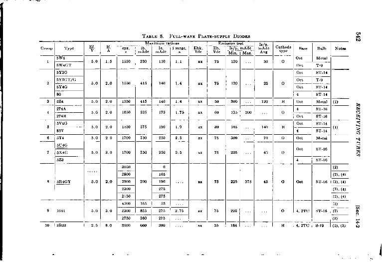
TAZLE 8.—FULL-WAVE PLATE-SUPPLY DKODES
Mammum ratings
‘Y’ ] m’idc ] M!!dc I i ‘“:’”
mIs/p,Min.
120
t Is/P,LAdc mAdcMax. Avg
CathodtypeGroup
TEb,Vdc
Ef,v
5.0
5.0
If,A
Ehk,Vdc
Base
OttGCtOttOttOtt4
Ott
4
Ott
Ott
4
Ott
Ott
Bulb I Now
5W41550 330 110 1.1
Iiair —T-9
G —
T-9
ST-14
ST-14
1 1,5 75 I 30 05W4GT
xx
—— — —
415 140 1,4
5Y3G
5Y3GT/G
5Y4G,.. 252 2.0 1550 76 120
306
0xx
86—l—
3 5Z4
ii4A
274B
5.0
5,0
5.0
5,0
5.0
5.0
5.0
2.0 1550
1650
415 140 1.4
525 175 1.75
xx 56 I 120 Ii Metal I (1)
ST-16
ST-16
ST-14— (1)ST-14
Metal
2.0 60 135 200 I o4 xx
1
575 190 1.9
—5v4G
5
6
2.0
2,0
1550
1706
xx 30
75
185
36+3
I 140 Ff
o83V
5T4 750 250 2.5 xx —l— 70
5u4G
5x4G
5Z3
ST-16 I750 250 2,5
. — —0
165
700 190
275
7
8
3.0
2.0
3.0
1766 xx 75 226
225
45
375 45
0
0
—14
Ott
4, 2TC
4, 2TC
ST-16
(2)
(2), (4)
3050
2S6Q
2900
2300
5R4GY 75xx ST-16 I (3), (4)
(3), (4)
(2), (4:l—l2752150
4500
2300
2750
165 I 55 I I (2)
825 I 275 I 2.75
— —...
9 1641 75 225 0xx ST-16 (2)
(3)
S-19 (l), (5)
—1360 TIT10 3B23 2,5 8,0 3506 600 I 200 I 25 184 Hxx
.. I. .
-. --

11 I 6ZY5G
7Y412
8416Z4
16X5
6X5G
13 6X5GT/G
6X5WGT
14Y4
14 6W5G——7Z4
1528Z5
—116 34.5A
17 I 117Z6GT
—125Z5
18 2538
25 Z6GTIG
19 50Y6GT/G
—1
20 6X4 (R6277)
21 SR886
6.3 I 0.3 I 1375
6.3 0.5 1375
———
12.6 I O 3
63 0,9 1375—l———
631 09—l— 1375
2s,0 0 24
2.5.0 0 3 I 730
—’—l—50 I 0.15 365
130
200
230
300
330
330
400
500
500
44
65
75
.-
0,45
0.65
0.75
100 10
110 1.1
110111_l—
66 i 1,35
85 1.65
T — 1.65
450
450
450
——450
450
450
383
385
330
30 , 451.148
30 7565
25 60— —
50 140 .,.65
ni- —80. — — —
50 150 70
50 I 801 I 37
.
— ..m%.
Developmental types
15 55 95
30 1.50 175
30 170 . 140
,—
H I Ott
OttOtt
H Ott
Ott
LOC
EfI
Loc
=%-H Ott
6
Ef Ott
Ott
If Ott
6,3 0,60 Ratings and characteristicsairnilarto 6x5 H ~ M,,,
117 Ratinga and characteristics similar to 117Z6GTI
HI
Lo.
ST-12
T-9
ST-12
Metal
ST-12
T-9
T-9
T-9
ST-12
T-9
ST-12
T-9
ST-12
Metal
T-9
T-9
T-5$
T-9
(6)
[6), (7)
(6)
(6)
(9)
(6)b
3(8), (10) C
$
(8), (10)
(s), (lo)
(6)
(8)
NOTE8: (1) Cathode internally connected to one side of heater. (6) Cathode common to both mctiom.(2) With choke-rep. t filter. (7) Ruggedi.ed.(3) With condemer-input filter. (8) Separate catbodea. May be usad in voltage-doubler circuits.(4) Filament mum he preheated for 10 aec before application of plate (!3) Heater is center-tapped; may be operated at 0,4s amp a“d 14.o volta
voltage for these mti”gs. This M “ot necesnary for nomewhat (10) Val”ea for ib and Io are per plate.lower applied voltages. Average Is/p is determined at Eb = 20 Vdc.
(5) Filsmen t preheating time 30 sec.

;.
544 I<l<cEI VIArG TUBES [SEC. 142
Groups 8-15 and 8-16 are useful if higher output currents are required.The developmental 6X4 is a miniature equivalent of the 6X5GT and isthe only miniature of this type in the table.
The tubes of Groups 8-17 to 8-19 are intended primarily for trans-formerless power supplies and are suitable for llse in ~oltage-dnubling
FIG.
1000800
600
400
200
100I+ 80-ua 60E.~ 40Eg
~ 2055
1086
4
2
1I 2 4 6 810 20 40 60 80100
Diode voltage d.c14.7.—Characteristics of small plate-supply diodes. Diode voltage =applied positive voltage Plus negative voltage at which diode first condur
externally-ts.
circuits. All are of close-spaced construction and have separate cathodesand fairly high heater-t o-cathode voltage rat ings.
Not shown in the tables are the full-wave mercury-vapor rectifiers.There are only two of these; the 82, which is obsolescent, and the 83,which is essentially a mercury-vapor 5Z3. The latter is on the ,JAN pre-ferred list.
To summarize the power-supply rectifiers, the 5Y3GT/G is a usefulgeneral-purpose rectifier for power supplies furnishing up to about 125 maat 400 volts, the 5U4G up to 600 volts and 250 ma, and the 5R4GY forstill higher voltages. The 6X5 is useful in small power supplies in which

SEC. 142] DIODES 5 +5
the heater must be grounded, and is commonly employed in negativebias supplies. It is also useful as a diode switch since it has a lowimpedance and is very reproducible in manufacture. It can be used inprecision modulation and demodulation.
High-voltage I%ctijiers.-l’he third general class of diodes discussed inthis chapter consists of the types intended to supply currents of a few
—FIG. 14. S.—Typical high-voltage rectifier tubes. (a) 1Z2, National Union; (b) S016, RCA;
(c) 2X2, RCA; (d) 72, Raytheon.
milliamperes at several kilovolts, and are most commonly used in cathode-
ray-tube high-voltage supplies. Since there is no sharp division between
these types and the somewhat larger types, however, a few of the latter
are included. All except one developmental type have the plate con-
nected to a top cap in order to increase the voltage rating. .U have
rather high internal voltage drops, but this is of minor importance sincethe current is small and the drop is a very small fraction of the outputvoltage. They are listed in Table 9.
The 2X2 and 2X2A are the most widely used tubes of this class.The 1Z2, which has only recently reached the market, also has consider-able value in low-current high-voltage applications.
Four typical high-voltage diodes are showm in Fig. 14.8. In con-nection both with high-voltage rectifiers and po!ver-supply rectifiers, itshould be pointed out that high-voltage selenium rectifier stacks arebeginning to make appreciable inroads on the market for rectifier tubes.Selenium rectifiers are still much more expensive than most tubes, butthey have numerous advantages, particularly in the absence of a require-ment for filament or heater power, aud in their long life, which makespracticable the construction of self-contained transformer-rectitivr-f iltrrunits such as those desrrihed in Chapter 4 of this vol{lme.

.- . ..
l’ABLE 9.—HALF-WAVE HIGH-VOLTAGE RECTIFIPRS
I Maximum ratings Emise.ion testI ~,
1s, rn.ldc~Adc Cathode
Eb, BasetYPe I
Vdc Min. I Max. ‘“s
Bulb Noten
T-9
TYrmEf,v
If,A epx, ib,
k. rnAdc
0.20 10,0 f 7.5
— —
1.75 12.5 45.0
— —
4.25 13.0 3000
GroupIo, i surge, Pp.
mAdc ma~
2.0
— — —
7.5 10U
. — ——
30
20
2
=1 ~~~~
—-. .100 2.5 8.0 4 0 oet—
——l———-
1
2
3
8016 1.25—— —
2X22,50
2X2A
— —
73 2.50
I200 30 65 17 H
I4 I SI.12
I (4)
—I—lp — —’——
130 I 100 ,, 0 Ott : ,r.9 (1)
130 100 H I Ott I T.9 (1)
—. — —, — — —l—
14 Tb Mi” ‘r-5*.i
200 70 140 Tb 4 I T-12 I——
200 120 1s0 Tb Spec \ s,].. I—— —
I — I ~(2), (3)
3B26 2.50—. —
1Z2 1.50—
475 I 15.0 I Sooo
0.30 20.0 10
_ — .
3.00 20,0 1006 72 I 2.50
7
8
9
15R 5.00
3B24—,2 .5/5.0
—13B24W
30 1200— — ——
30/60
40
100
601.50
3.90 20.0 150— —
3.00 20.0 150/300
— — l—250 lcm
1
TII
1
4
1
‘r-u !——
I (~), (3). (4)
—l— l—l—l—’—— —l—
953B I 7.50 6.OO 30.0 30— —
30.0 4005,00 — —
15,0 600
200 80 ~ ~~ Tul ~ ~~~——300 290 I 440 Tb Sw.
ISpec705A
i
5,0010
I3041 133159110~Th~4 l—lT-168013A 2.50
—
8020 5 00
— — ,—
11 5.00 I 40,0 I 154 20 I 200 ~
12
13
600I 400I 750 llnl I 75
100 2000 75
200 75 ‘rbI
4 T-19
———
200 75 \Tb14 T-19100R [ 5001 6.201 4001 750 I
. .

.. _
TABI.E 9.—HALF-WAVE HIGH-VOLTAGE Rectifiers.—(ConLinu.d)
Group 1‘Ewe
I1
13f,v
Maximum ratings I Emission teat I ~,
If,—
l..L+,mAdc
AmAdc
efn, ,b, 10,kv mAdc mAdc
‘i” I ‘ax: “g
14 I 2B25
,.5 j ,654
16 R104%1— —
17 R1043-<
18 j VC1017
20I
VC861
——.
i .:;:< ~ $ ;:;
Developmental types—- —.
Cathode
type
_——
Notes
1 40 0.11 2.81...
2 i..i..~60~ 4 Av~ M,,, T-.5+. — —.
1.40 0.05 100 pAdc at 5 kVdc 0 iw,n T-5i— — — . —
6.3 0,30 2 ,,, Adc at 10 kVdc Min T-54— . —
63 0 15 20 mAdc at 2 k~’dc I 2: .T”5’63 0.15 Mimature equivalent of 2X2 I :: Min T-5k
— —
Improved 3B2(i I
II ep. = 15 kv, 11) = 50 to 60 rnAdc. 111”1NOTE8: All the tubes listed have top-cap plate connection exceot the 2B25.Not listed are the 2V3G snd 878 (obsolescent types) and tbe VU-111 (British)..kvemge VdU&9 of k are fol Eb = 100 Vdc.
(1) 73 aud 3B26 me clipper diodes.(2) Fdament has two halves; either or both MaY t~e used. Lower .,,rr~,,t ratws ZPPIS to upcrstion with half of the 61a111entlighted(3) Emission test k made with both ba)ves of filament )ighted.(4) Ruggedized type.
,.”. -.. .- , -.

‘~ABM: 1O.—LOW-MU ‘rR1ODES
Max. rating
Eb,Vdc
2cm
250
250
250
—
425
4CQ
30a
135
Text co.dt]om I Lim,ts of essentialcharacteristics L+ak- Emm.ion teat
Ic, age, ) Cath
‘~. I uAdc I ‘
E{, H,v A Eb, Pp,
Vdc w
—
mVdc
xx
.—
xx
—
Km
100
lCCI
330
—
2,1, Ib,Vdc mAdc
-45 47
--lBMe Bulb Nc,&GrouP , TYIE
mwnbc
2300
216a
5250
210il
1600
3200
35fm
7500
I lb, mAdc vu who Mu ldc I D&. I ~b = EC 1s, tie
I ‘ax I ‘d’ ‘l::l’ypMu —Min.
—
28 30
35 21
42 42
“f,L
65—
40
82
IMu., Max. Min.–~_l_
!4...
–l– — .4 ST-16SW
—
—
130il
—
—
-50 xx 0
—~~ y-20 II 30
—,— ,—
——5.01 m 330 ,17 2100 35OO I 2.4
_ —l—
1750 24543I 3.2
32
3.8
1 275A
2 43 LIE!! _CM ST-16
-50 32— —
-45 w
251,50 275————
~
_ —!—
30 l1400
- 5.0 xx —I_
i ‘+ ~kTI_–20! 30 30 70’H
—’— ,——, —1-
6.3 llm
— — 360 15
2.5 ,2 MI
bR&- y: +~Ott I ST-12 (2)
9
5 ST-16 ckg
5 S-19 (3)
Lo, T-9 (4)——_
Ott I 5T-16 ] (5)
6A33 —
2.A3
6A50
4 1626
5 S43
6 271A— _
7 2C48
8 6AS7L
4060 6750 3.8
,!
4.5
63 1 25 ~ i I_l—
–32 25
–35 25
–28 45
–24 25— —
125
53 16 I 34 1600‘2600 48~58! ——
80 18 32 1350 1900
85 35 ‘=1= 3’00; ‘4=1=’z EE95 15
2,1 100 150 I 631X~8700 15 27
Developmental tyw
1260,25 2.33 5
25 250 425 12
50 203 5fKl
k7w~ 5750 ,–50 100 70 160 H—
I.,. –10 o 100 l,”—l— — —
,!, –30 20 30 ti5~H—,—— —
63 060 550 7
63 2 50 275 14I I
‘1 SD++++ I ,12w1-3z12212~o15511 I II I I i Ii “1 I IHIL=IT-+Norm: Leakagekst made at Ebk = I@ Vdc. (5) Twin trmie with separate catbcdes, developmental number A4475. Hated mammum fk = ~
(1) k beater-typ+ catbmle, but cathode sleeve is connected internally to beater center tap. 125 rn.4dc per wction. Tabular values of Pp, lb, gm, and Is me per section. Maximum Ic m
(2) Deaigmi m r-f vacillator and not particularly a.,ted to other appbcatlorw test is for bath sectmns wltb l-megobm grid resistor. For cutotl test Eb = 250 Vdc, Ecl = .=
(3) Sated mnximum Ik = 65 mAdc. –2OO Vdc, Ib = 10,uAdc max]mum. For test conditions no separate bias isused, but catbc+
(4) For mtofl tat, Eb = 530 Vdc, Ecl = -em Vdc, lb = 1.20 mAdc ~,z
resistorof 254 ohms ISuwd in each catbcde lead N
- .’ . .

SEC. 14.3] TRIODES 549
14.3. Triodes.—The triodes of this section are divided into classesaccording to amplification factor, the divisions between classes being atamplification factors of 10 and 25. This division is not entirely arbitrarysince, as will be explained, tubes of low, of medium, and of high amplifica-tion factors also differ in their other characteristics and in their applica-tions. The tables of the section include not only ordinary triodes but alsodiode triodes, twin triodes, and triode-connected tetrodes and pentodes.
Low-Mu Triodes. —Low-Mu triodes may be defined as triodes whoseamplifitiation factors are less than about 10. Tubes of this classificationwere formerly widely used as audio power output tubes, and thereforehave the general characteristics of comparatively high rated plate dissipa-tion and plate current, and low plate resistance. Triodes have largely
TAELE 10a
Interelectrode capacitances
ICgk, ,upf (’pk, pvf ~gP, Pwf
Tube Type ‘–-–——-— -.
Min. .4vg. NIax. Jfin. I .kvg. Max. Min. Avg. hIax.— ——
45 ..i 4.0 3.0 . 7.0 .,’””
-, — I__ _ _ _
6134G, 6A3, 6A5G 7.0: . 5.o~ . ..’ 16.0,
I — l——
2.%3 ’75, . . . . ,5.5, ... 16.5,
343 ~ 3.3 ~ 4,7 Iud<xidx2.0
271A ‘5.2. . 7,8 ‘3.0 ..~46’ 3.7 6.9
been superseded as output tubes by pentodes and beam tetrodes becauseof their greater efficiency and sensitivity; the higher distortion incurred intheir use may be overcome by the use of negative feedback. Low-Mu
4triodes are now used mainly for special applications for which a high-current triode is desired, as for the series tube in a voltage-regulatorcircuit.
The characteristics of the low-Mu triodes are shown in Table 10.These are all single triodes except the 6AS7G, which is a twin. Charac-teristics of low-Mu triode-connected pentodes and beam tetrodes areshown in Table 11.
One of the most desirable characteristics of a tube for use as a seriesvoltage regulator is a low plate-to-cathode voltage drop at zero gridvoltage, since this value determines the average tube drop necessary for
;! a particular range of regulation. Tubes whose characteristics best meet

~,’
550 RECEIVING TUBES [SEC. 14.3
TABLE 11. —TRIODE-COFiNECTED TETRODES AND PENTODES (Low-Mu)
Max. ratinm
Group Typel?f, If,
v .4 ~bh, Eb
Vd; w Vd(
1 26.47GT 26 5 0 60 55 2.2 26.
-L :Y63040 275 250
.V. c. l— — — –6,31,25
— —— 150 14. . nc, .r, 150
Test ccmditions
Base Bulb Notw
Mu
— — —_
3.2 Ott T-9 (1)
4.7 6, TC ST-12 (2)— — — _
Eel,Vdc
lb,mAdc
17.5
32
6C
22
26
26
41
31
40
40
23
37
11
28
gm,, rnhos
-5 5500
1800-31
-17
-31
-28
-23
“.”=
3 -25CSG ‘0””0”
4 46 —1 —27525175_ 1250
5 59 2 5~2,00 275 ~ 25Q~l.--- .- —l—–—
6 —7E,I I25L6
25L6G ~. n n ~n i-– –1 -
7 25L6G T/G
6300
2350
2600
2200
5.410ct I ST-14]
56 5– — = — (2)
60 7L— — = _64 Ott T-9
LOC T-9
Ott Metal
*’– *6 4, Ott
-163040 I 315 I 941250
-10 6600
Ott T-9
Ott _ _MetalOtt Metal
50L6GT JLlx1632 12 610 60 60
6F6
6F6G
—
“Ott— ‘?Ott ‘T-9— —
6,8 6 ST-14
6 ST-14
Ott Metal
— =. -g &To Ott
Loc T-9
Ott nktal
— EOtt8.0 Ott ST-14 (4)
Ott _ Metal
Ott Metal
Ott m —8.9 — —
Ott T-9
Ott Metal
0.6— m93 Ott T-9
6F6GT63 0 70
42
2A5 2.5 1 7.5
1621 6.3 0 70
6AD7G 63 0 85
35L6GT/G
35.4535 0 0 15
6L6
12.0
250
9.-F
95 _
9.3 120
8 315 -20 2600
9 125 -10 6000
4700
27OO
61
-20
1622 275 15 01631 12.6 0 45 300 ~17 5
12A611 — 12 6 0 15
_ 12A6GT275 8 25 250
~V6
-17
6V6Gt 6.31045 3,0 ,3,2
6v6GT/G12
7C5
14C5 12 6 0 225
6G6G13
330
6AK66.3 0,15 ~ 3.0
CAP.,
250
180
#
.[
.16 4100
Lo. T-9
LOG _T-9
Ott_ ST-12 ‘—
“1 Min ~ _-12
-s
2000
14 1~/6AG716 31065 I 33o I 80,2509500 !1,0 Ott IMetal I (5)
I II 1
NoT=E=: Forother characteris~ics of these types.we Tables 21 and 22.(1) Twin tube, cbsrsctermtics are for each half.(2) JAN specdicatio,t covers triode operation of this type.(3) Also has small medium-m” triode section.
$ (4) RCA gives triode-connected Pp rating of 10 W msximumon tbeae types, There apWars to beno justification for at,cb a low rating since neither the individual PrJ or Pg2 rati”ga will ),
be exceeded when Pp (total) = 21 W.
I (5) Thiatype isincluded here in spite of the value of Musitwe,tx. tlwl ,l,sracterbticss resir,,itart.j tho~e of the other types in this table,
f[1

tSEC. 143] TRIODES
this requirement have low Mu and high trallscorld~lctallce.
551
The tubrbest suited to this application, and which was specifically designed for it,is the 6AS7G (10-8), shown in Fig. 14.9. The two sections in parallelhave a plate-current rating of 250 ma. This tube also has a 3i0-voltheater-to-cathode voltage rating whichpermits the heater to be operated atground potential in many cases, thuseliminating the necessity for an addi-tional filament winding on the poJvertransformer. Two other groups oftubes suitable for this application are10-3 and 11-3. The 6B4G and theothers of Group 10-3 have the advan-tages of higher plate dissipation andmaximum plate voltage, and the dis-advantages of slightly higher voltagedrop and filamentary cathodes. The6Y6G and others of group 11-3 haveslightly lower minimum drop, smallerbulb size, and a 300-volt heater-to-cath-
., ode voltage rating. ‘l’he 6V6GT an(lothers in Group 11-12 are also useful for
, somewhat lower currents; they havesmall bulbs and require fairly lowheater power.
The 1626, 843, 271A, 2C38, andSD838 are most commonly used as r-fpower amplifiers or oscillators. The6AG7 is listed in Table 11 in spite ofits high .Mu because its other charac-teristics when triode-connected aresimilar to those of the other tubes of Tables 10 and 11.
, Medium-Mu Triodes.—For the purposes of classification medium-Mutriodes are considered to be those with amplification factors between 10and 25. This is, with some exceptions, a satisfactory functional classi-fication also, since lower-Mu tubes are primarily intended as power out-put tubes and those with higher Mu’s are usually employed strictly as
voltage amplifiers in lower-frequency circuits. Medium-llu triodeshave the most diversified applications of any class of tubes in these tables.
They are used in radar equipment as voltage amplifiers, switch tubes,
clamping tubes, sawtooth generators, cathode followers, etc. For many
of these applications twin triodes are used since in equipment using anumber of such tubes the number of envelopes is approximately halved.
; 1,
F[~. 1.1.9.-Twin 1ow-.Mu triodefi.W7G.
,

‘~ABLE 12.—MEDIuM-Mu ‘~RIODES
TLea]
~~dc %;max. ~#.d
mm
–lo 2
–1 o 21
Test c.mditmw.Ma.. ratmp Limtx of essentialchwactemtm
Eel,Vdc
,.
—
– 1:
—
—
–35
lb,.Ad,ma
—
f
100
— —m IIIIIh~ M. rp, kilobr
—
sm.test,
Is B%. Bulb Notes
nAdcmm
E. 1, lb,Vdc mAd
[b, mAdc
m-mInk).
-67:—
143(
93(
3‘?
G
-i
2
3
4
5
6——
7
8
._
{m.Mm
16-3
hf,n M.,. M,.. Max. Mm Ma
i- —‘---‘-540 810 12 0 143 16 24
1
I1250 1650~ I ,. 8 11
I7501 1150 i;ol G m, G
1500 23WI 14
1700127W; 15 \
~-352A ti10 32
I-2170’-I “,00
I I6,TC ST-12 (1)
IOtt IT-9 ~6P5GT/G63’030
76I275 1 60 100 37 6150
135
4515 ST-12
:5— (2)ST-1236 25i100
262B 100’0 32 20L, ; 30———
,275
~=
’275
i250
z75~ lcm
1
4(
12 7
—22
G—.
—l—
4,TC ST-12—’_—
OCt ~hkt.l~~-
–o 51l—l— .
—~
I
–1 o
I
—
2(
—
—16SR7GT I
I
fiR7 !— —1630306n7G {
Ott T-9 (1)
30 Ott, TC Metal (1)
1
I180
17 5( i
,,190 ,i
18 5
220
1—; O.t, T~ ST-12 (1)
~Oct. TC ~T-9 1(1)I
6R7GT/G I I
“ I7E6 !50
00
91
15 (
19011 6 55 Lo, IT-9 1(1).— 16ST7 !63 o 15
12SR7
—1 —l—
’275
_,_ ,—L31qloo / Iwl_ ————
~
I
[6 0’ 2200
8 O“ 1900
105 2203
30 5s00
,,
I12SR7GT ~—126 o 1512SW7
14E6
2C26A 63 1 10
30 Ioct IT-9 I(l)l—l— l—IOtt IMetal,
–l—’——125 Ott, 2TC , T-9 1(Z)–10 lM1 1,
150d 23WI 156L.X 163~015 275 : 10I WI-9( -20’ 30 5 –101 2(
–1 5: 2(
–201 2(
3015 I ST-IZ I—l—l— —1—l —l—
330 3 80 ICm_—— —1651203 WI
‘!50 –8!
so ““
-30~ 30——-Is 300
6—8
II14 5 1750 2650 15——— ,——[8 o 4003 8mi 12
701M]” IT-5* I
.,.
>, ,,,,-.,,, ,,,

.. . ,, ,..
——O@
–1,0 20 I 40 Ott
——
-,--
_—— —— ‘—’— ,–
‘1—80 80 2000 20.0 –!30 30
— . J— — ,— —, —22 50
–6o 11 0 220+320 ol— ‘—– 25 100
— i—i—~–~— —
I– 80 9.0 2600 20.0 – 24 20
~i1 I_ ,’ _
–lo 5 11 0 3030 20 0; –261 30
— — ~:i
l—
-7 ‘i ‘ 3i 220012501‘m! 50
I i’
[80 220 ,.
I ,1—— ,—.
‘118 0 22 0)
———,— ~—:_
( JI
Metal——ST-12
T-9
MM250
llG-1—— ,_ ——
20–I ol~
———
264
—
312,
75 oCt 2Tc
m
CM——Lw
Ott
Lw
Ott 2TC——Od 2TC
Mm
AC –
4<
)Ct
T-9 I230
— —hietaf
T-9
T-9
16J5GT/G j 6 3j0 30 ~ ~(
11 7.44 330 2 75 100,—.——’— — I
–1 51 20 40
100
—
20
230
300
250
—120
T-9
T-9
T-9
112J5GT ; ill‘,. — 126015{114,44
____ .—— ———————2(V2 330’ I
]~ I —–—–’ 63 () 30 ;+ 3 ’01 100(7193 I
–1 5~ 20[
Ir’.9 (3)
r.5* 1(5)‘-;= ‘-–l—i—~—13 !155 6310 15 ~ 275; 1 so~ 90
‘—I RELS~ 1
..— — —— 1
14 I 383.! 63015 200 1.60, 100
\
–lo20 ‘lC I(5)
—1
–1 St i, (5),(6)
;pec
.—
I (_,— ,—-— —— I_-3o’ 52,2600250 I
1’ 1,”
—1— ——————— . ..— —25; 90 2102!10,, 60130
Developmental types
15 : A4442 ‘<3~030 ~ 2jlJ i \ 2,50- g ~ 9511900 1601 ~ ,11 1, 11
———lb ~A4452 ‘— qII--,I =::!z’::-,::=i::_l_!=l~ % :%;::~:: l---! -–’-–-’-,-- . ,_——,— —— ——,———_., .—, ——__17 ! 26(% l,, /.,
, .,, l---~l;- ‘-—
3301z 25 300 z( h-801802600;~~j-x- —-”
_;_ .-...– ,–_ . .../_/_. :M ,m T-5+ “1 ,
18 I 6K4 63 0 15~~l; –
50’ 11 0 2075 31?5 18 0 23 0, -60/ 2
1 i I I ! !-]O1 Z“i 40’sM IT-3 ‘9’
NOTES: 0k601ewent typm 27, 37, 55, 85, 6v7G, and 272.4 are om,tted from this Labte. (7) Characterktics similar t.. A4442, Group 13(1) ffm two dmde plate% cathode common wkh trmfe sect,... (8) Designedfor oper,tion at Eb = 28 Vdc.(z) Eb = 110 Vdc for ,utoff trot. (9) Develo mental number sD-834. Same characteristics M 6J5 group .? one half of 6SN7,(3) For 20 per cent duty ratio Eb = 300 Vdc. ?3See Ta le % for interelectrcde mpmitames(4) 12SW7is 12SR7selectedfm operation at Eb = 28 Vdc. (10) Under “Trot condjtmm,” for Eel, bias ISobtaid from cathode rmistw. ( 150ohm(5) For cutoff test Eb = 150Vd. andEd = – 30Vdch) rwmd:%n type: h~ thrm grid lead
—,— _.

r
;,
,’
554 RECEIVING TUBES [SEC. 14.3
Other triodes inthemedium-Mu class aredesigned especially for opera- ,:tion at very high frequencies, such as the acorn triodes. Duo-diodetriodes are also included since the triode sections of these tubes haveessentially the same characteristics as other tubes of the class which lackthe diode sections.
Medium-Mu triodes and diode-triodes are listed in order of increasingMu in Table 12, twin medium-Mu triodes in Table 13, and triode-con-nected pentodes”in Table 14.
TABLE12aInterelectrodecapacitances(medium-mutriodes)
Allcapacitances are given in ~~f
I
1Cgk
ICpk CEP
ICgk Cpk
Type
Min. Max. Min. Max. Min.
352A 1.0 2,0 2.7 4.5 1.076, 56 26 38 14 29 2.6262B 1,6 30 3.0 60 1.36SR7 2,4 3.6 2.4 3,4 1.6
6~7GT 28 42 2,8 4.8 1.66R7 3.5 60 3.5 50 1.66R7G 15 3,5 3.0 65 1.16R7GT/G 21 31 3.6 6,8 1.6
6ST7 2,8 Avg 30 Avg 1.5
12SR7 2,4 3.6 2.4 3,4 1.612SR7GT 2.8 4,2 2,8 4.8 1.612SW7 2.4 3.6 2,4 3.4 1.6
— — —6L5G 3 OAvg 5 OAvg 276C4 1.8Avg 1 3 Avg ‘1.6—
6P5GT7E614E62C26A
6 F4—
’11 ‘YW
20 6C53,8 6C5G2.5 6C5GT
3.0 HY-615,
30 E1148
2.42.92.91,1
3,04,0 6J5 34.:
2s Z5GTIG 42— 7A4 34ivg 12J5GT 42
Cin
Max. Min. .M*X
3.6 7,7 14,34.7 8.4 15 64.7 84 15.61,7 0,9 1.5
,,g 3 6Avg
503.05.0
LMin. Max.
3.0 4.22.4 3.6
2.4 3.622 3.0
1.4 2.6 7Cout c~p
Min. Max. Min. Max.
4,4 6.6 2.2 3.01.8 4.0 1,0 2.01,8 4.0 1.0 2.0
0.6 1.6 23 3.2
0,3 0,9 1.5 2.3
—I
Mim Ma.
17 231.4 2614 261.45 1.95
–1– ‘3 4 Avg
3.8 .4.038
32 40
1.1 1.6
1,0 1810 16
The types in Groups 2, 6, 7, 9, 11, and 18 of Table 12 and in Groups !3, 4, and 5 of Table 13 are so-called “ general-purpose” triodes, and there- ‘fore find a wide variety of applications, Of these the types in Group ~

-..—- .~m
TABLE 13.—MEDIUM-MU TWIN TRIODES
,.- .
—-Max, r.tw Teat cond]twns Cuton
char Lmut.sd w..ntm.l characterutw?a EmuI.eak- .won
Ic, we tat ,
11P, g~/8ff- ~c , Ib/p. lh/p, rnAd, ‘m/’’cOnVnV ~~htg!, pAdc lhk/k , 18/8~
Ad. tlon, Mu “~; .A.dc ~mhcm Inaa ~Adc t,o”
~“,hce “,.X. mm. rnAd,
MKr3 1375 104 I “67
:,fi>~; TO _,r +
~ — ‘-–2 o 30 125
Bme Bulb I NotreI
Group TYWEf, 1[,v .\ E& P$p,
1 2C21 63 0 Ml 275’ 23-
Zhk, Eb, Eel,v Vdc Vdc
Mu
7s, TC ST-12 (1)
7s, 2TC ST-14 (2), (3)
Ott T-9 (l), (4)
k T-9 (2)
k
11 9—1 11’———— —1——
15 61 17W~260
I I
—142 I 2C34 ~ 63~030, 3301 .50 125 2150 1130 I 94
— —,——— —I
7,5 19111 ,160–16 30 50II
—,,, ,
–lo 20 406.AH7GT 6 3:0 30 I
3 — —’––’ 2W 1 512.AH7GT ~12 60 15 I
~— —___7AFi !63030 I
4 —:——’—’, 330 2 7:14AFi ,1260 15
100 180–6!
10(1254-10
‘0Oi‘WI23”14 18
;ixizj-l–1 “,30 55I
12 5 170Q 250
I
.~-+i 50
~
‘–201,40
14
18
18
23
—
“-——-+-,!
—1100
250
Ott IT-9 1(2))(5)6SN7GT i j,
6SN7W 33063 0 rfl
_i 1--7X7
‘–24, 5155
II ,’
12 51
12 6—
20;5 ;2125
IOtt T-9 (2), (5),
(7), (8)II
–1 5
— 20
–2 o
–1 5
–2 01
65ti2 La IT-9 (1)
Oct. TC ST-12 (1)
Ott T-9 (2), (7)
Ott T-9 (~~)(6),
, P I ~ ~z” 2,512SN7GT
10312SX7GT 12 61030
II
330
—-14N7
) u, I– 24 20
,,
~
11’
s 9 0 216)0
1’ 55
62
12 5’ I
i
40
65
40—_
1
I
I,1
12 6; I~1La T-9 (~})(6).
Ott I T-9 1(2), (7)
II–251 25 I 55 1251 ld 32.5 — —
U,v,lopmm,lal typl-
6 SD705~ I , ]+ i+’ I’00123W,’2012 60 30!
Noms ba~e test.sare made with Ehk = IM Vdc and cmissi.. tc%tsW,tb~b = EC = 30 Vdc (5) For cuhofl test lb my Lx 5 to 20 pAdc if g., <0.5 wmho.(6) Also hx specifications for operation st Eb = 28 Vdc.(7) Maximum Ik/k = 20 mAdc.(8) For Icnkaqetat Ehk = 260 Vdc.For intcrel.xtmde capacitates me Table 130.
except w natal ‘-(1) Maximum Ic isfm eachsect,.., testedseparately(2) Maximum 1. is for both wctiom connectedin parallel.(3) Hx commoncathode for both xctions Eb = Ec = 60 Vdc for em~,on test.(4) La&e le# is frx both sections ccmncctcd in parallel. For cutofl test RP = I mtim.
..... - .-.

12-11, as typified by the 6J5, and the miniature tiC4 (12-7) and the sub-miniature 61{4 (12-18) are of the latest design of the class, while many ,’
of the others are somewhat older. The twin tubes of Groups 13-3, 13-4,and 13-5 are all of recent design.
The tubes of Groups 8, 10, 13, and 14 of Table
FIG. 14.10 .—Submin-iature triodc 6K4.
12 are designed primarily for vhf operation, andalthough they are by no means restricted to such
operation it is usually less expensive andmore satis-
factory to use other types atthe lower frequencies.The 6C4 and the tiny 61i4, although well suited togeneral-purpose applications, will also operate wellat high frequencies. The 6K-1 is a remarkable littletube. It is essentially a 6J5 or half of a 6SX7 ina subminiature bulb. Its ratings and characteristicsare almost the same as those of the larger tubes; ithas the added advantage of a 300-volt heater-to-cathode voltage rating; and it will oscillate in suit-able circuits up to frequencies as high as 1500Me/see. Only its grid cutoff specifications appearto be inferior. It is sho~vn in Fig. 1410.
For applications requiring sharp and uniformgrid cutoff characteristics, a requirement often en-countered in radar equipment, the 6SX7GT or itsruggedized counterpart, the 6SA’7W, is unques-tionably the best tube in the medium-31u class.This type has been very extensively used in radarequipment. Except that the 6SX7W has a heater-to-cathode voltage rating of 250 volts, the rug-gedized tube should have few advantages over theconventional 6SA’7GT in applications not requiringresistance to excessive vibration or shock.
The twin-triode tubes in Groups 13-3 and 13-4 have only half the
heater power requirements of the types in Group 13-5, but have some-
what lower Mu’s and transconductances.
When considering the comparative merits of twin triodes for a specific
application, consideration should idso be given to the 6J6 and 71?8, listed
under high-A1u triodes in Table 16. .Ilthough these types have high
Mu’s, they also have such high transcomluctances that their plate resis-tances are comparable with those of the types in Table 13,
Tubes ~vithmore specialized applications in Table 12 are the duo-diodetriodes of Groups 1, -1, 15, 16, and 17, These are commonly used asdetectors plus audio amplifiers in radio receivers. The 26C6 (12-17) isintended for operation at a plate voltage of 28 volts. The 262B (12-3)

SEC. 14.3] TRIODES
TABLE 13a
Interelectrode capacitances (twin medium-mu triodes)
1-111Clg lk, ppf Clplk, WJf Cl~-lP. .wf C2g-2k. ppf C2w2k, wf c%h! lwf
Types —
Min.
2C21 2.02C34 2.56AH7GT,
12AH7GT 2.27AF7, 14AF7 1.2
ZIMinl Max. !Ivfin.1 Max lNfinl Mu. Iii3.2 0.8 20 2.0 2,8 10 2.2 1.44.0 0.3 0.7 1.8 3.0 2.5 4.0 03
42 1.4 3.4 2.0 4.0 1.8 3.8 1.62.0 1.0 2.0 16 2.6 12 20 1.0
—
—.
Max, Min. Max.
_l_l—2.6 1.4 2.20.7 1.8 3.0
3.7 2.0 4.020 16 2,6
6SN7GT 2.8Avg 0,8Avg 3.8Avg 3. OAvg 1.2Avg 4 0 Avg, 7N7, 14N7 3.4 2,0 3.0 29 2.4 30
6F8G 3,2 1.0 3.8 1.9 1.9 3.212SN7GT 2.8 0.8 3.8 3.0 1.2 4.01633 3.0 0.8 3.6 2.8 2.2 3.s
557
~otes
(1)
(2)
(3)
—
NOTE.: (1) Clg-2g == O 1 ppf max. CIP-2P = 0.8 ~pf max.(2) Clg-2g = O, 20 upf max. CIP-2P = 0.60 ##f max. Clg-2p = 0.06 wf max. C2g-lp
= O. 10 **f max.(3) clg-2g = 0.40 wI. CIP-2P = 0.34 wf. Clg-2p = 0.08 ppf. C2g-lp = 0.06 ~pf.
was designed to have minimum hum and noise in low-level audio applica-,
tions and is still one of the best tubes for the purpose in spite of its lowtransconductance. Another tube for similar applications is the 1603
, pentode, which may be used triode-connected and whose characteristicswhen so connected are listed in Group 14.2. The 2C26A (12-5) wasdesigned as a pulsed oscillator for operation at about 200 Me/see. Itshigh plate-voltage rating might be of use in other applications. The2C34 (13-2) is a small twin transmitting triode for vhf applications. Itis the only tube in Table 13 that has a common cathode for both sections.This feature is a disadvantage for many applications though not for itsoriginal purpose.
Zligh-lfu Trzodes.—The characteristics of single high-Mu triodes aregiven in Table 15, those of twin high-Mu triodes in Table 16, and thoseof high-Mu triode-connected pentodes in Table 17. In each of thesetables the tubes are listed in order of increasing Mu.
In Tables 15 and 16 the tubes may also be considered as divisibleinto three classes according to their original design purpose. Some typeswere designed as vhf oscillators and amplifiers; for example, the light-house types 2C40 (15-1) and 2C43 (15-3). These tubes will operate upto frequencies as high as 3300 Me/see, and although their characteristicsare such that they might find application for other purposes their costand mechanical structure make their use in other than high-frequencyapplications rather impractical. Other high-frequency tubes are the7E5/1201 (15-2), which will operate up to 500 Me/see, the 6J4 (15-4),

558 RECEIVING TUBES [SEC. 14.3
TABLE 14. —TIUODE-CONNECTED PENTODES (MEDIUM Mu)—
IGroup
Ef IfType “, *$
— — . —
6SJ7
6SJ7GT 6.3 0.3(
1 6SJ7Y— —
12SJ7
— 12.6 0.1:12SJ7GT
. — — —
eJ7
6J7G
6J7GT— 6.3 0.3(
6C6
16032 —.
1620— —
12J7GT 12.6 0.1!— —
57 2.5 1.0(— . — —
3 6AG7 6.3 0.6
Maxim..ratingn
Eb,Vdc
275
—
275
330
—
‘P!
w
—
,8
—
.7
—
.0
—
II
Eb,Vdc
250
—
250
250
—
Teat conditions
Eel, Ib,Vdc rnAd(
— —
-8.5 9.2
— —
-8,0 6.5
— —
-8 5 28,0
w,mhoe
2500
1900
9500
— Baae Bulb
‘2U
Ott h~.std
. —
oat T-9
19 Ott Metal— —
Ott Metal
Ott T-9—
Ott, TC Meta2— —
Oct. TC ST-12
Oct. TC T-9
6, TC ST-2220 — —
6, TC ST-12— —
Ott, TC Metal
Oct. TC T-9. —
6, TC ST-12—
21 oat Metal
Notes
(1)
(2)
(2)——
(2)
(2)
(2), (3) I
——
(2), (3)——
(2)
(2)
NOTES: (1) Maximum ratings for triode connection are from JAN-1A specifications,(2) Maximum ratings from RCAapeci6caticma.(3) Special low-nohe nonmicropho”ic type.
For othar characteristic me Tables 19 and 21.
which was designed for operation as a grounded-grid amplifier up to500 Mc/secand has extremely high transconductance, and the develop-mental S491R (15-16), 61NT4(15-19), 2C35 (15-21), and CK603 (15-22). .The last two types are subminiature. of the twin triodes the 7F8 (16-4)and the 6J6 (16-3) are also suitable for high-frequency operation, and areexcellent for more general applications as well, and are commonly soused. In addition to the 6J4, another type which is useful as a grounded-grid amplifier at high frequencies is the 6AK5 when connected as atriode (17-2).
The second class of high-Mu triodes includes those tubes which wereoriginally designed as Class B audio power output tubes and which are I
listed in Groups 1, 5, 8, and 9 of Table 16. They have been used as Class ‘A amplifiers and in some cases in r-f applications. All have a common
,

SEC. 14.3] TRIODES 559
cathode for both sections, however, which is a disadvantage in someI circuits, and have been largely superseded by more suitable tubes both
for Class A and for r-f applications.The third class consists of tubes which were originally intended for
Class A voltage amplification or for other similar applications having lowplate-current requirements. This class” includes both twin and singletubes, many of the latter also having two small diode sections. Thesingle types without diodes are those in Groups 15-9, 15-14, and 15-20.Thesingle types with diodes arelisted in Table 15, Groups 5,6,7,8, 10,11, 12, 13, 17, and 18. The twin types are in Groups 16-2, 16-6, and 16-7.All of these types are similar in that the amplification factor ranges from
1 65 to 100 (except for the 6C8G) and the transconductance under testconditions from 1050 to 1600. Many, however, have some distinctivefeature or features that may make one type uniquely fitted for a particularapplication. Of the single tubes without diodes those in Group 15-14are to be preferred to those in Group 15-9 since the former have higheramplification factors and transconductances and most are of single-endedconstruction, while the latter all have top caps. None of these typeshas found wide application, however, since a diode-triode is usually pre-ferred for receiver use and twin triodes are more popular for other applica-tions. The subminiature SD917 (15-20) has some desirable featuresincluding good grid cutoff characteristics and a 300-volt heater-to-cathode
-i voltage rating.The duo-diode high-Mu triode types have been little used except in
radio receivers. The types in Groups 15-5 and 15-6 are of older designsince all have top-cap connections. The miniature 6AQ6 (15-7) and6AT6 (15-8) have desirable characteristics in miniature tubes, whilethose in Groups 15-11 and 15-12 should be considered if larger tubes aredesired. The 6B8G, 75, and 2A5 of the last group are of older design,however, and have top caps and larger bulbs. The 7K7 (15-1o) 7X7
8 (15-13) Z694 (15-17), and Z696 (15-18) are somewhat different from otherduo-diode triodes in that one or both of the diode sections have separatecathodes. They are intended for use in discriminator circuits in FMreceivers, and should find considerable application for their intended use.
The twin tubes of Table 16 have probably been as extensively usedin radar equipment as any class of tubes. Of these the types in Group16-6 are less often used because they have a common cathode for bothsections. The types in Groups 16-3, 16-4, and 16-7 are commonlyused. The 6J6 (16-3) has a common cathode, but since it is the onlyminiature twin triode available it has been very popular. The 7F8 (16-4)has several highly desirable characteristics for use in radar equipment
T and other devices of a similar nature. It has a 250-volt heater-to-cathode~oltage rating, good grid cutoff characteristics, relatively high plate
‘r

..
TABLE 15.—HIGFI-MU TRIODES— I
Maimuro mtinm Lim]tn of mential chamctertiica ILesk
Bulb Note?GrouP Type Ik
Ib, mAdc gm, @nbca M“ pAdcUOU.Eb, Ik,
?dc mAdc
51m 25
mh ‘ugm,
—
k—,5
z
3—!5—
—
—
—
—
—II—
—
pfFAdcmax.
;[,
63
If,A
075
0 15
lbk,Vdc
Eb,I’d,
—
250
[b,Adc
65
55—:0 0
45
12
1.0
10
10
11
23
13
—1.
Mm. Max. Min.
—— —
Max. Mm. Max.
—— ——
Ulin,
M—l—— 1
—l—4,8CHI 36
3,0W1 36
LH I(1)100
3.0 85 2250
I
1,900 31 41 –1 ( 20I
T-9 (2)
LH I (3)
—30 ILoc2 7E5/1201
— .—3 2C43
— —4 6J4
5 6T7G— .
6Q7
63
63
63
275 16
500 40
165 20
180
250100
1
- =1= ~ z 1 1Ott
5,0im 40 70 –2 o 20 40 Mm
1,300 50 80 –o 5 20 30 Oct, TC
Ott, TC
Oct. TC1,6C4 55 85 –0.5 20 30 —
Oct. TC
Ott, T.
1,6WI 57 33 –0.6 20 25 Mm
Min
— . .Ott, TC
1,870 55 8.5 –o 5 20 75 —OCt,TC
Lcm
1,250 85 115 –0,5 20 30 LOC
6, TC1,425
Oct. TC
6. TC
30 Ott
8,(KO 48090
040
0 15
9.0 200 90Q0
06 20 800. — —
0,4 20 950
l–TL5+ (4)100 150 m
3
3
3
12,00U 55—1,050 65 ST-12 I (5)63 250 I 250
—l—Meta]— —
330
— .330
—
1,200 70ST-12— (5)T-9
6Q7G6 —
6Q7GT
6,3
12 6
0.30
0 15
lCNI
—110—
100
250
—250
—1T-9_ _l_0.5 18 900
— — .
12Q7GT-— —
7 6AQ6— —
6AT6
T-5+ (5)
I
1,200 70
1,2Gll 70
I,4LW 70
1,600 70
1,00Q 100— —
63
63
0 15
030
0 15T-5* (5)330 250 3
8 l—12AT6 12 6
ST-12
T-9
6K5G9 —
6K5GT— —
10 7K7
——330 Km 250 3 0,4 I 2.0 I 110063
63
030
0 3[–,_,_——
330—
T-9 I (5), (6)m
100
250—250
2— l.— ——T-9 (5)
ST-12
ST-12
11 17C6 63 0 15 300 I 1——l—
12A6 25
63
0 8[
6B6G
75
275
—ST-12
Metal0.3C
47, -., .-. .-.-.

—, -> , .
—
—
–..—.. —
412 oSQ7GT/G
— —12SQ7= 12,612SQ7GT/G
7B6 63
Ott T-9 (6)
Ott Metaf
Ott T-9
1,103 ICCl
— —1,501 100
— —
1,501 10I
0.6 1.s
— .
10U 250 –2
250 –1— —
250 –2
0,9 825 1,42s S5 115
—
115
—
-0.5 20
–0.6 20
330
—
301
3cm
330
I0.15
030
0 15
030
030
0.15
ILoc T-9
55 — —Lo, T-9
1,4700,5 14
— .
— .
0.4 1.7
350I l—114B6 1126
(13 7x7 63
17B4 1
19—
0,9
LW T-9
Ott, TC Metal
Ott, TC T-9
2,m
2,UJI 85
l—l6F5
16F5GT I 6.3
6SF514 —
6SF3GTI l—I12F3GT I 100 2,ctUl
2,100
1— I12SF5 I12,6
12SF3GT I 100
Developmmtaf Types
15 641060 63 030 n. 20 10 0 rm .“ 10 50Q 500 Desigmd as high-voltage shunt regufator tube. Oct. TC T-9 (8)
16 S491R 63 0 175 70 180 –1 14 0 6,303 58 Dmgmd u cwilfatm to 400Mc/sw. Loc T-9
17 2694 63 Stmila.rto 7K7 except for base. Ott T-9
18 2696 63 Simdar to 7X7 except for base. Ott IT-9
19 — T 0206N4 Characteristicsmular t. 2C35,&od min. bulb.,. M,, I T.54
20 SD917 6.3 0 15 330 T x x 7 23 l,60il 70 14 1321120L12,0CO1551 851–021–201
21 2C35 63 020 180 225 180 –3 5 12.0 6,W0 32 Dsigmd for appbcatims up to 1200 Me/see._l!+- L
22 CK603 63 0 20 Dmbl.+.d,d tried, for uhf ~D@r,t>m,. I S!ll I T-3
~WE : (1) Dewgd for applications up to 3370 McIsec. Under “ test condkiom” use (5) Hzs @ dimie plates wltb following characteristics: Ilb = 12b = 1.0 mAdc mm. T*200-ahmbi~ resistor for Ecl.
(2) Demgnd for appbcatiormUP to 500 Me/me Em&on test made with Eb =condltlons: Elb = E2b = 10 Vdc: Ilb = 12b = 0,8 mAdc min.
(6) The two d,wk have a common cathrxk which is wparate from the tricde catbcde.Ecl = 10 Vdc. (7) One of the diodes baa a separate cathode.
(3) Dm,gnaf for appbcatmm up to 337o Mcia%. Under ‘atest conditjom” use (8) For test conditions adjust E.] so that fb = 1.0 mAdc, Maximum rated m.fue d Eb iaKW,bm bias rm,stor for Ecl ALSObaq rati”ga for pulsed operatmn, eb = 10 kVdc: tat value k 5 kVdc.3.5 kv max. (9) Cutoff characteristrs: Ib = 25 pAdc max when Ec] = –55 Vdc; Ib = 2 pAdc max when
(4) Designed as grounde+grid ampbfier up to 500 Me/see. Under “test condi- Ecl = –10 Vdc.tioiw” use 100ohm bms resistor for Eel. Cutofl cbnr.scteristlc: Ib = 75 @dc fakage tfsts made with Ehk = lcO Vdc; Em~*ion tesh made with Eb = Ec = 30 Vdc cxrer,tIIIBI at Ecl = –15 Vdc. as notd.
,...-,,. .-.=

7
;.
562 RECEIVING TUBES [SEC, 14.3
TABLE 15a
Interelectrode capacitances (high-mu triodes)
Type
2C40
7E5/1201
2C436T7G6Q76Q7G6Q7GT, 12Q7GT
6K5G6K5GT
7K77C62A6, 6B6G
75
6SQ76SQ7GT/G12SQ712SQ7GT/G7B6, 14B67B46F56F5GT6SF512F5GT12SF52C35
Min. I Max.
2,1Avg
2.8 I 4.4
2.8Avg2.85.03.22.2
2.0 I 3.62.0 3.8
2.6 Avg2,41.7
1.2 I 2,2
3.2 Avg4,23.24.23.03.25,02.24.02.24,02.5
Min. I Max.
0.02 Avg
2.2 I 3.4
0.02 Avg3.03.85.05.0
4.0 7.53.2 6.2
3.OAvg2.43,8
2.8 I 4.8
3.OAvg3.43,03.42.43.24.03,23.63.23,60.5
@P, ##f
Min. I Max,
l,3Avg
1,1 I 1.9
1.7Avg1,5
1,4
1.51.6
1.2
I
2.81.6 4.0
1.8Avg1.61,7
1.2 I 2.2
l,6Avg1.81.61.81.61,62.32,82.42.82.41.5
NOTES: Capacitance of 2C40 and 2C43 cathode to shell is 100 Wf Av.For6J4:
Cg-(kh) =4.0 t06.6~~.Cp-(kh) = 0.24ppf max.Cgp = 3,3t04.5#pf.Chk =2.5 t03.9~ti.
For 6AQ6:Cg-(kh) = 1.7 ~,ufAv.Cp-(kh) = 1,5 g~f Av.Cgp = 1,8 Ppf Av.
For 6AT6 and 12AT6:Cg-(kh) = 2.3 /tpf Av.Cp-(kh) = 1.1 ppf Av.Cgp = 2.1 ~~f Av.
For 7X7 capacitances are:CD1-all = 2.6 ggf Av.CD2-all = 2.6 ppf Av.CD1-g = 0.1 p~f max.CD2-g = 0.1 gpf max.CD1-D2 = 0.5 ~~f max.
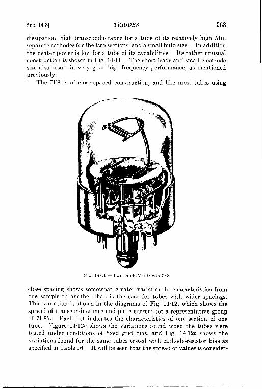
SEC. 143] T1tIODES 563
dissipation, high transconductance for a tube of its relatively high Mu,separate cathodes for the two sections, and a small bulb size. In additionthe heater power is low for a tube of its capabilities. Its rather unusualconstruction is sholvn in Fig. 14.11. The short leads and small electrodesize also result in very good high-frequency performance, as mentionedpreviously.
The 7F8 is of close-spaced construction, and like most tubes using
FIG, 1411. -Twir1 I,igh.\lu triode 7FS.
close spacing shows somewhat greater variation in characteristics from
one sample to another than is the case for tubes with wider spacings.
This variation is sho~vn in the diagrams of Fig. 14.12, which shows the
spread of transconductance and plate current for a representative group
of 7F8’s. Each dot indicates the characteristics of one section of one
tube. Figure Il. 12a shows the variations found when the tubes were
tested under conditions of fixed grid bias, and Fig. 14. 12tJ shows the
variations found for the same tubes tested with cathode-resistor bias as
specified in Table 16. It will be seen that the spread of values is consider-

TABLE 16.—TwIN HIGH-MU TRIODES
Mxmmrnratings
—
Bulb Notes
Test condtmns Icutoff char.I
Limits o{ essentialcbaractemtm1
-1o11 test
Ii 1Vd
-G
grw swJ/P!Ad, “0”,
whm
I
1,,Ad,nlax
–2
[IlkAdc“ax.
30
20
20
10
20
Ef,v
G
If,A
1 8(
nl,’bcctm”,Mu
wnhm
Tme
6N7
6N7G
6N7GT/G
6A6
53
6C842
6J6
7F8—
1635
6SC7
6SC7GT
6SC7GTY
12SC7
1634
I,b,p, ~lb/p, m.4d
E(’1,~~c @ \d,
“ax , >1,,, M*,
25 45
B.zseshec-tm,nAdcml..
125
Eb,Vdc
Eb,Vdc .M,
HJ- Ec,Vdc
m“,
136C
.
120C
milo
$500
nf=x, hlin .l-–—W Metal
ST-14
r-9 (1), (2),— (3), (4)ST-14
35 1600 35 1850 30
I
1 330 60 300 40
—
40
50 M
7L
7L ST-14
ST-12 (5), (6)
r-5+ (3), (7)
252oo
ti 310 30
I———I
32 1600 —~— “ —36 ‘–lo 25 20 44.
; j-. :38 30 75 55 12 5_ — —
‘50~–9 itlo 80 ~14,0–25 1
I—_ ,___ _
1.6, 700 65 : 2,25, 431’
2—
3
275110 250 -4
m
2000 32 –1
–2
–1.
–2,
—
30 30
40
40
M, TC
Min
LW
6 3~0.45, 330 ~ 1 6 I00 73001 28 10
63 1030’ 330 ~ 385
63 0,60 330 33
IG,3030
275
4 250 6800140 65
—
.. T-9 (5), (6),(8)
r-9 (3), (4),
(9)
—5 300 –2 50 lCQ
30
I
,’
1,
1’
2,0’ 1325 ~ 70 ,,
1
,1
‘
M Mebl (l),(3)
)Ct r-9 (1), (3)
1650 55 85!–10 20
~
6 250 2 1001 30 r.9 (1),(3),(15)
)Ct
1’
2,60.15~I
)Ct \letal~(1), (3)
web] (l),(3)
. . ... -
1
k, ...e= .._..,_. .. -,

—-
I 06L,GT_~
6SL7W I 6.3 0.30
I
7 = I_ _ ‘12SL7GT 12,6 0 15
7377 6,3 030— —
14F7 12 6 0.15— —
6Y7G
8 — 63 0607Q
— —
9 6Z7G 63 030
11
575
40
Zsl –2
25o –2
180 0
23 1604
—
1.1 700
4.61
[’–55 25 14
1570 — — —
–55 25 14
i ‘—
85 .,’; , ., 37
Ii
[ 132
I,1
3,
—
3.4
32
72
—
6.0
1,
lm 2QOI
— —
1275 1925— — 35
120Q 3QO0
I
..1I
—— —.1ill
S5
. .
–1.0 m 30 40~1 T-9
— —(1), (5)
Ott T-9 (1), (5).(11)
10 30 50 Ott T-9 (5), (12)— — .
I–1
40 Ott
i 2 ~—y : =–1 o 2030 — .
Im Lm(5), (6)
II T-9
–-—l—–1,0 20 ~ 30
1,
I
1— _ —Ott ST-12 (3), (4),
(6), (13)
30 — — —6,T~ ST-12 (1), (3),
(4), (13)
–1.0 20 [ 30 , lsT-12 (1).(3)40 IOttI (4)
I
Deve10pmentB4type
10 1207 63 0.30 180 –3.0 5.5 3000 36 ,, ., ~.1.~.li p, IT., p
(SD698C)I
NOR.LTMaximum rated Ehk = 10+V except for 7F8, wh,ch k ratd 250 V. Leakage test isde at maximum rated Ebk m ead =.
—
(1) Both uniti tied in parallelfor max Ic test.(2) Fm Ic &t Ed = –2Vdc. Maximum rated Ik/k = 70 mAdc.(3) Common ratbcde connection f.r Mb mctior.n.(4) D@md priidy forClamB audioamplfier.(6I Sqemts connection brought out for the two catbodea.(6) Far IC taat tach unit is tentedseparately.
(z) For the 10 kt Eb = 230 Vdc, ~ = ~ ohm ~tb ~i~ are ~~ ~ ~lel Thecbamctmisticmunder” tet conditions” are for mob umt testd seprately, but with both
uniia ope.mtiug. lb &J6ww designed as an r-f amphder and mcioator to 230 Mclmc
andu a c.mverterto ~ 14CIW,butisextensivelyused for other p~. Under“’testcmditions,”Ecl b obtakd fromacstboderesistorof60ohm.
(8) The 7F8 k usefufat frequencl.esup ta 400 M./sec. Under’<teat conditmn,,” Ecl inobtainedfrom &cathode resistor of 200 ohms.
(9) For tbe Ic mar test Ecl = –2Vdc; each unit is &ted separately.(10) The 1634 is a 12SC7 selected for mr.t.cbbetween sections.(11) The 6SL7W is a n.wgedid 6SL7.(12) The 6SU7GTY has sp+cial teak for Ic and match between sections. It h= n low-ices ha?.
.nd is suitable for une as a d+ amplider.(13) The Iimh of Ib are fcmEd = OVdm(14) The 1207bns common p4atesmd commoncathodes. It is i.tmded far converter we up ta
600 McIaec.(15) Hrwa Iow.lma ba9e.
_——. ..~.

(
566 RECEIVI.VG TUBES [SEC. 14.3
TABLE 16r7
Interclectrode capacitances (twin high-mu triodes) (
Clg-lk, wf
Type
Min. Max,
6C8G 2.6Avg
6J6 14 26
7F8 21 35
6~C7 1.2 2.8
12SC7 12128
6SL7GT,12SL7GT 3.0 .l\-g
7F7, 14F7 24
Clp-lk, ~pf Clg-lp, ##f
Min. Max. Min. Max.
2 0 Avg 2,6 A\.g
O 25 0.65 1.2 1,8
1.0 1.8 09 15
20 4,0 242.0 40 1.6 24
3.8Aw 2. s .ivg
20 16
I I I
IllC2g-2k, ppf C2p-2k, pfif C2K-2LI, wf
Note.
Min. Max. Min. Max. Min. Max.
1.3AvK I 2.2Avg I 1.8Avg l(l)
I3.4Av)z ; 3.2.~vg 2.SAvg (5)2.4 2.0 16 (3) , (6)
NOTE6: (1) CIK-2E = 0.1 w{ Av., Clw2P = 2.o jwf AVK.(2) Chk = 3 3 g~f rein, 7.5 p~f max.(3) Capacitances under “Cg-k” and “ Cp-k” me actually Cin and Co”t,(4) Clg-2g = O 02 wf rein, 0.06 wpf max.
Clp-211 = O 20 p~f rein, O 50 g~f max.Chl. = 2 7 ~pf rein, 4 5 ~yf max.
(5) Clg-2g =-0 65 gpf Aw, CIP-2P = O 4 wf Avg, C2g-lp = O. 13 ##f A~,g.(6) C1g-2g = O 2 ppf Avg. CIP-2p = 1,0 jtpf Avg.
ably reduced by the use of resistor bias, and for this reason this type ofbias should be used whenever possible. This is generally true of all
I
b . .
7000-
6000
;E* 5000 ..s$ ● ..
b. : ““4000 -. ..” ● ... . .*. .. “
30006 8 10 12 14
}__-––. ------- 1---—-1!
II I
I i
~ Bogie II value _ . I
-+ :.1!I ../”.0
w $ “. 1
I . .L------ .:-7-.L - -. ----- 1
6 8 10 12 14(a) 1P in ma d.c (b) 1P in ma dc
FIG. 14.12,—Variation of plate current and transconductance of 7FS tubes. (o) With fixedbias; (b) with resistor bias.
closed-spaced tubes, such as the 6J6 and the pentode types 6AC7, 6AK5,and 6AG5 of Table 18, to mention only a few.
The 6SU7GTY (16-7) is identical in most respects with the morecommonly used 6SL7GT but has specifications to ensure a high degree of

TABLE 17. —TRIODE-CONNECTED PENTODES (HIGH-MU)
Group
1
2
Notes
(1)
Cutoff char
Eel, lb’Vdc
~Adcmax
–6.5 50
— —
_—
Bulb
Nfetal——
r-9
Test conditionsMaximum ratings
Eel,
Vdc
–5
Ib,nAdc
8.5
8.0
8,0—
5.5
Eb,Vdc
330
Jk,nAdc
~
Pp,w
2.50
Mu
31
Ef,v
6.3
12.6
6.3
If,A
0.30
—.
0,15
0.17<
0.45
0.30
Type
6SH.7
6SH7GT
Base
Ott
Ott
Eb,Vdc
250
gm,wmhos
6SH7L
12SH7
4800
5700
6600
3800
Ott
Ott
r-9
Metal
r-912SH7GT
6AK5
Ott
200 20
330
330
1.85 180 –4 31
35
Min r-5 i
$letal
(2)
3 6AC7 6.3
6.3
2.25
2.50
250 _5, !
–4. !
Ott
Min4 6AG5 250 42 r-5+
NOTES: (1) For cutoff test Eb = 150 Vdc.
(2) RCA ratings for triode operation are identical with those in table.
u!m-4

56S RECEIVING TUBES [SEC. 1~-~
uniformity between sections and is thus desirable when accurate balanceis important. It also has a low-loss base.
The M 1060 (15-15) has some unique and interesting features, althotighat present it is in the developmental stage. It is intended to be used as ashunt regulator tube in high-voltage power supplies for cathode-raytubes, and accordingly has a much higher voltage rating than any othersmall receiving tube. It also has the unusually high amplificationfactor of approximately 500. A typical 8-kv supply using this tube asthe regulating element and a 300-volt regulated voltage as the comparisonstandard showed output variations of approximately 0.6 per cent forchanges of output current from O to 0.5 ma, and approximately f 0.3per cent for input-voltage variations of f 10 per cent.
The early experimental M106O’S that were tested at the RadiationLaboratory were very satisfactory electrically and mechanically but hadrather short lives. Most samples showed cathode emission failures afterabout 100 hr at 8 kv and 1 ma. A few tubes were unstable due to gridcurrent flow through the necessarily high grid resistor. A somewhathigher transconductance would be desirable and a reduction of amplifica-tion factor by a factor of 2 could be tolerated in voltage-regulatingapplications. These changes would result in more stable operation andbetter regulation.
Another tube that can be used in shunt voltage-regulating circuits isthe 15E (not listed in these tables). This is a small transrnittimz triodethat was’ originally designed as a pulsed oscillator in vhf circ~its butwhich will operate in the same type of circuit that is used for the M 1060.It is far less effective, however, since it has a Mu of only 20, and it requires20 watts of filament heating power.
Table 17 lists the characteristics of a number of high-Mu triode-connected pentodes. It will be noted that all of them have high trans-conductance when so connected, higher in fact than any of the regulartriodes except the 7F8 and 6J6 and some of the specialized high-frequencytubes. Figure 14.13 shows the variation of Mu, transconductance, andplate resistance, with variations of plate current for a triode-connected6AG5 at two different plate voltages. The high tran~conductance is ofvalue in applications as a cathode follower, for which a tube with both ahigh transconductance and a high Mu is required.
As far as the principal uses of the Radiation Laboratory were con-cerned, the most valuable triodes were the following:
6SL7—Dual unit with separate cathodes, used in high-gain d-c andlow-frequency a-c amplifiers in which a plate current of less than10 ma was sufficient. Sharp cutoff characteristics. Sections wellmatched, useful as amplitude comparators and selectors, and asdifferential amplifiers. Very low grid current.

SEC.14.3] TRIODES 569
6SU7—Same as 6SL7 except low-loss base and selected for matchbetween sections. 6SU7 matching specifications are passed byabout 50 per cent of production 6SL7’S.
min ohms
30000
gm inM mhos
WOO
20000
15000
1000O
5000
0
4000
2000
1000
0
1P in ma
FIG. 14.13.—Plate resistance, transconductance, and LMU of triode-connected 6AG5 as 8
function of plate current. Solid curves: Eb = 250 Vdc. Dashed curves: Eb = 150 Vdc.
6SN7—Dual medium-Mu unit with separate cathodes. Generallyuseful in pulse circuits and as oscillator and amplifier for moderatepowers. Will stand great abuse. Best small blocking oscillator aspower gain is high even with grid at high positive voltage. Oftenused as double diode before advent of 6AL5 (far better than 6H6).When used as switch tube in sweep circuits gives most uniformclamping. In pulse circuits it is useful as an amplifier up to 2 or 3Me/see, above which the effects of Cgp are excessive. Grid cutoffnot very sharp. Most used as blocking oscillator, multivibrator,etc. Very large grid resistor may be used without serious effectseven at maximum plate dissipation.
6J6—Miniature dual unit with common cathode. Designed as uhfoscillator. Large transconductance, low capacitance, medium Mu,matching between sections poor. Cutoff not very sharp. Tend-ency for grid to limit and block if large grid resistor is used. Nota very good sweep clamp. An excellent diode. Better video

570 12EcZ?ZVING TUBES [sac. 144
amplifier than 6~X7 because of higher Mll and lower capacitance.(Plate resistance is about the same.)
6C4—Miniature single unit approximately equivalent to half of a6SN7. Somewhat lower capacitances.
6K4—Subminiature single unit. Same specifications as 6SN7, lowheater power, lower capacitances, very ruggedly constructed.
6B4—(AIso 2A3, 6A3, etc. ) High current, low Mu, low plate resist-ance, filamentary triode, most used as regulator tube in series-typevoltage regulators. Low-distortion audio amplifier.
6AS7—Dual high-current heater-type triode for voltage regulators;one tube will regulate two separate 100-ma supplies.
3A5-(Not listed in tables. ) Best filamentary triode for pulse use,Blocking oscillator, multivibrator, etc.
14.4. Tetrodes and Pentodes.—Tetrodes and pentodes are most con-veniently classified according to function rather than to structure, andthe tubes of this section will be classified primarily as r-f amplifiers or aspower output tubes. There are many tubes which might be consideredas belonging in either or both of these categories, but the great majorityfall clearly into one or the other class.
R-f Amplifiers,-R-f and i-f amplification in radio receivers is nowalmost invariably obtained from small pentodes, which may be classifiedon the basis of their cutoff characteristics into sharp-cutoff and remote-cutoff types. The latter type is occasionally and rather meaninglesslydesignated the “super control” type, and in some tube lists the formertype is vaguely called a ‘‘ triple grid amplifier. ” Some tubes are inter-mediate in character between the two classes, and are called ‘‘ semi-remote-cutoff” pentodes; they may most conveniently be classed withthe remote-cutoff tubes.
Sharp-cutoff pentodes have Eg-Ip characteristics such that platecurrent and transconductance decrease to practically zero when the con-trol grid is made a few volts negative. In a remote-cutoff pentode theywill decrease rapidly at first with increasing negative grid bias, but therate of decrease becomes less and the quantities become essentially zeroonly when the negative bias becomes comparatively large. This remote-cutoff or variable-Mu characteristic is desirable when a variable bias volt-age is used to control the gain of the tube as in the ordinary receiverAVC circuit.
Representative curves of transconductance vs. grid bias voltage areshown in Fig. 14.14. The 6SK7 (curve a) and the 6SJ7 (curve c) arealmost identical tubes except that the former is remote-cutoff and thelatter is sharp-cutoff. Likewise the 6SG7 (curve b) and the 6SI17(curve d) are almost identical except that the cutoff of the former issemiremote and that of the 1atter is sharp. Of the two sharp-cutoff

sm. 11+] YE TROl)h’S A.V.!) PEN TO DES 571
tubes the6SH~ c~ltsotY ataconsiderably less negative grid voltage thandoes the 6SJ7: in fact it has probably the sharpest cutoff of any pentodelisted.
Sharp-cutoff pentodes are listed in Table 19 and remote- and semi-remote-cutoff pentmlcs in Table ’20, in order of decreasing transconduc-
10,000
/
: 1,000 /~ / /1
/j
ra
/100 d
/ /
/A ‘
,●
-30 -25 -20 -15 -lo -5 0
14.14,—Cutoff rharavtmiatlm of typical r-f pentodes. (a) 6SK7, remote cutoff;(6) 6SG7, semiremote cutoff; (c) 6SJ7, sharp cutoff; (d) 6SH7, sharp cutoff.
tance in each case. For many applications it is desirable to have as
high a transconductance as possible, but in probably the majority of
applications a more important quantity is the figure of merit of the tube,
or the ratio of transconductance to interelectrode capacitance. In such
applications as video amplifiers or wideband i-f amplifiers the gain for a
given bandwidth will be exactly proportional to the figure of merit in
such circuits as a shunt-peaked video amplifier, and approximately pro-
portional in other circuits. Table 18 lists the figures of merit of many
of the tubes of Table 19 and some from Table 20.
Types marked * in Table 18 are acorn, miniature, or subminiature
construction. Those marked ** are of some special construction, such as
the 713A and 717A precursors of the 6AK5, which had similar electrode
structures and very small bulbs but standard bases. It will be notedthat most ~f the types with figures of merit over 400 are of miniature,subminiature, acorn, or special construction. The only “standard-ized” tubes with high figures of merit are the 6AC7 and 6AC7W and theBritish types VR91, VR91A, and EF50. It may also be noted that mostof the tubes in the table with figures of merit over 300 are of the sharp-cutoff type, a few are semiremote-cutoff, and none is remote-cutoff. The

572 fiEC.EIVI.VG TUBES
TABLE 18.—FIGURES OF MERIT OF R-F
,’
[SEC.14.4
i, MPLIFIERs
Type
A4444C* . . . . . .6AK5*. .,...6.4G5* . . . .CK604A*.713A* . . . . . . . . . . . . . . . . . . . . . . . . . . . .
6AC7,6AC7W. .6.4S6” . . . . . . . . . . . . . . . . . . . . . . . . . .384.4 . . . . . . . . . . .6AU6*, A4464” . . . . . . . . . . . . . . . . . . . .717A* . . . . . . . . . . . . . . . . . . . . . . . . . . . . . . . .
VR91, VR91A, EF50 . . . . . . . . . . . . . . . . . . . . .385A* *....... . . . . . . . . . . . . . .6BA6*,12BA6*. . .:. . . . . . . . . . .6AJ5*. ,., . . .7V7 . . . . . . . . . . .. . :::::::::::::::::::::::
6AB7 . . . . . . . . . . . . . . . . . . . . . . . . . . . . .7W7,14W7. : . . . . . . . . . . . . . . . . . . .6SH7,6SH7GT, 12SH7, 12SH7GT . . . . . . . . .1205. . . . .7R7,141t7 . . . . . . . . . . . . . . . . . . . . . . . . ::::::
6SG7,6SG7GT, 12SG7CrT. . . . . .956” . . . . . . . . . . . . . . . . . . . . . . . . . . .9003” . . . . . . . . . . . . . . . . . . . . . . . . . .954*, . . . . . . . . . . . . . . . . . . . . . . . .9001* . . . . . . . . . . . .
6SK7,12SK7, 7A7,14A7 . . . . . . . . . . . .6SJ7,6SJ7Y, 12SJ7 . . . . . . . .
—rigure of merit
920745600580575
560500500495495
465445440435390
385350315315310
305280280220210
155125
:Utoff
SRssss
sssss
ssSRss
SRsssSR
SRRRss
Rs
last two groupsin the table, as represented by the6SK7 and6SJ7, are
typical of modern “general purpose” remote-cutoff and sharp-cutoff pen-,
todes in which a high figure of merit was not one of the design objectives.
A high figure of merit should not be taken as an indication of thevalue of a given type for all applications, however, since other desirablecharacteristics may be sacrificed to obtain this figure. The types with ahigh figure of merit are usually of close-spaced construction and thereforefrequently show greater variation in characteristics than more conven-tional types. It may be noted from Table 19 that many of the typeswith high transconductances are tested with resistor bias. Under these ‘conditions the deviations from the normal or “ bogie” values of essentialcharacteristics for a representative group of tubes will be only about

SEC. 144] TETRODES AND F’ENTODES 573
half as great as if the test were made with fixed bias. This effect wasillustrated forthe7F8triodein Fig. 14”12. For audio-frequency applica-tions, especially at low power levels, tubes with high transconductancesmay not be desirable. One manufacturer states that the 6AC7 and 6SH7are generally unsuitable for such uses because trouble may be encounteredfrom heater hum unless a d-c heater supply is used.
The tubes listed in Group 19-1 have the highest transconductance ofany pentodes of similar size. For this reason they have been extensivelyused in radar equipment as video and i-f amplifiers, as multivibratorswhen a fast rise and fall are desired, and for various other applications.Their figure of merit, while higher than those of any other standard-sizedtubes, is less than those of some of the newer miniature and subminiaturetubes. The 1851 is the parent of the other tubes of the group and maybe considered obsolescent.
Group 19-2 includes three similar British tubes, which are includedbecause they have some interesting features and because they were usedin some equipment intended for joint British-American use during thewar. At least two of them, the EF50 and the VR91A, were manufacturedin this country. They have values of transconductance exceeded only bythe tubes of the previous group and by the developmental types A4481A*(19-27) and A4485 (19-28) and by two of the developmental types ofTable 20. They have fairly good g3 control characteristics, a feature
Ithat will be discussed later in connection with the 6AS6.
The three types in Group 19-3 are roughly the loctal equivalents ofthe types in Group 19-8. They are also the nearest loctal equivalents tothe tubes of Group 19-1, but cliffer considerably from both groups in con-struction and characteristics. The 7V7, 7W7, and 14W7 are actuallyhexodes, but since g2 and g3 are internally connected and function as asingle screen grid they are usually considered as pentodes. The 7W7 and14W7 have two separate cathode pins to permit the isolation of inputand output circuits in high-frequency amplifiers. These types also havespecifications on the g4 (suppressor grid) cutoff characteristics, as dis-cussed later. The 1231 (19-4) and the 7G7/1232 (19-9) are predecessorsof the types in Group 19-3 and may be considered obsolescent.
Groups 5, 6, and 7 of Table 19 list three similar high-transconductanceminiature pentodes, the 6AU6, 6AK5, and 6AG5. All have approx-imately the same transconductance, but the 6AK5 has the highest figureof merit of any high-production type. 1 It is more uniform than mosthigh-transconductance tubes; note that the test conditions specify fixedbias. The input and output capacitance limits are also much tighterthan for any comparable type. The maximum grid current is very low,,
1G. T. Ford, “ Characteristics of Vacuum Tubes for Radar Intermediate FrequencyArnplifiers,” Belt System Tech. Jour., 26, 385-407 (July 1946).,’

..
TABLE 19.—SHARP-CUTOFF PENTODES—,mk-
t%,IhkAd.nax.
20
20
30
R-.
%
20
—
20
—20
30
EFit
:b,‘dc
10
—
10
—
10
G—
—
—10
—
20
G—
ITEf If
TYPev’~
?G—
8AC7
8AC7W1 - 6.3045
6AJ7/6AC7
1.951—
EF50
2 VR91 630.30
VR91A
Maximum mtinm Test conditiow Lmmu of emential cbaracterrnticn I
lb, Ec2, Pp, P 2,/d. Vdc w k
330 165 3.3 0.45
— — . —1,0
3W 300 30 ;
_ — — .
330 105 4.0 0.8
— — . .330 175 33
330 163 3.3 07
203 155 185 0.55
— — — —330 165 25 0.55
— — — —
330 165 33 07
275 1101.7 0.3_ — — _
i3m 130
IC2,r,Adc
[clgm, IAmbm ~Adc
Ulna.
Min. I Max,
Eb, Ec2, Eel,Vdc Vdc Vdc
— — —
300 150 n.
Ib, mAdc Ic2, mAdc Bulb
lleta)
Mets
Mets
Met.
m
Not-alhk,Vdc
Min.
80
80
75—8.0
8.0
G
30
52
8.2
42
30
.
flu. M in
12 5 16
— .12,5
Max
34
40
II— —
Ott
Ott40 —
Ott
7m111”m9LWI –6o 91Xl
— —
OYm
(1)
(2)
100 10
—
10
2.5
—
3,0
——
Oct. TC
m
230 250 –2
nn— — —
52WI 7,30i —–0 5
63un140 12 5 23
125— .
10
12507
— —11,5 05— —
— —12.0 08
— —88 13
— —
13.4 20
–l–l–——
607V7— 6.3 045
3 7W7— — —14W7 12 6 0 22:
58LM –80 10AV
55MI –90 10
52fM – 6.2 10Av— .5cim –10.0 ml
4650 6,950 –1.0 70 Imc T-9
G
T-5+
T-V
T-54
Met,
T-9
T-9
Mets
T-9
T-9
Swc
(3), (4)llxl 3@3 154 ml 10 3,962
—50
— — —3LUI130 nn
250 130 –1
130 120 –2
(5)411221 I 6.310.45 2,5—43
z
_l—l —I I516AU6 I 631030 1C4
G
—lcm
——3WI 6,5@l –O 1T 6AK5
,6.2 0,17: (3), (6),
(7), (8)4,0
27Scca –90 <
. — —
4WI – 6.5 30
————4WNI 6,600 -1.0
——2.-5 Milt (3), (6),
(6), (7)
(3), (6),(7), (9)
2WI‘W1‘n 20
—
4.0
———..— — —
2S3 154 –1
250 10Q–2
3920 5,830 –1.0
O&(M
95 Ott
Ott
Ott—[10 k
6SH7
OSH7GT 63 030
8 6BE7L— — —12.sH7
- 126 0 1512SH7GT
— — — —9 7G7/12-22 63 045
60100
—100
10.
— —4.WI – 7.0 lml
I 1
— — —3700 5,6CQ –1 5
2701 5,200 –o 1
6’ 20 841 0.4 32—1 l—l— _—— — —
713A10 — 630.171
717A(3), (6)3W1-]001‘m 12.0 08 40 ,, CM100
lml 1201-27,5 2,4
.- -.

11 6AS6 6.3 0 175 2W Iw’1 85 Ou 100
;2 YRI16 (B,,) x ,;; TN Tm l—– — -
G 7L7 6,3 0.30 330 1401 65033 m
i 6AJ5 63 0 175 21m 155185 035 102
. — —— . — — — —384.4 135
15— 6.3 0 15 275 130— 055 100385.>
31OA 10,0 0,31516— — ,— 275 180t2 5 04 130
328.A 7,5 0422
6SJ7
6SJ7GT ~ 63 030
17 &%J7Y 330 14028 07 m
12SJ7 I~;12 6 0 1512SJ7GT i I
_ —— —’— — —— —18 14C7 ,12 6 0 15 330, 11010101 106
934 I19 — 6,3 0 15 ~ 275 110 1.0 055 90
9031
–20 -!=7C7 =~m G =Itiim
ISJI’
22 1620 ~~
1602— i_.12J7GT ,12.6,0.15
l_l —l—
1~~’
330 1400R 10 11’ l@l
~
i _110
375 —200
_ — — — ——220 140~ ~olo 8 0 II
Ilm— —— —*3O I1OO 53 0 11
120 1%1–2 5.7 30
m 200 –4 67
250 Iml –1 5 4.5 1.5
28 26 n. 29 1,0
120 120–2 50 1,7
135 135–3 56 15
230 10I –3 30 0.8
_ — — . —230 loa –3 22 0
250 106–3 20 07
250 100–3 20 05
250 lcm –3 23 05— — — —— —
,,
230 100–3 20 0.5
130111–1001 10I
13301 . ...1...
11111– 501 WI
27COI– 5.01 30
–l–l–250”1-10‘1‘w1875 –12 o 50
1630 –10.0 30
1575 –65 30
140Q –10,0 25
——13cd 3-85 I 30
1250 –8 O 30
,-80, 30
II
–80 25
1225
–80 30
–75 30
I— 801 30
2,5
2,9
18
—
2,0
3.
2.0
15
1.0
14
15—
13
—
g01— l—
— —63 03
. .4,0 0,1
— —
8.0
75 05
— —
4.0 0.4
30 0
0,330 —
03_ ——
26 01
3,1 0— ——
29 02
— —
29 02
60 2500 4,300 –0 2— —
— —24 2530 3,830 –1 o
— —2.0 m 3,500 –0.25
—l—l—l—
I ——
25 1503 2,250-05
— — . —
12 1325 1,975 –0.5
— —11 1300 1,950 –o 5
— — . —125
—- lMXI I,91m –1 o11— ——0.8 1050 1,606 –o 5
— — — .08 1025 1,475 –o 5
—— — — —
10 161M 1,430
--’--l— -0.5— —lo~lm 1,436
I
20
20
20
—
20
—
20
—
20
20—
20
20
20—
20
20—
—
30
30
15
30
lMm lT-5>il (8),(10)
nn ml l(u)
T LOc T-9—
Mm T-5}+ (~~)(6),
— — — —Nme SW
Ott, TC Spec
16,Tc 1ST-121
— l— — —Ott Metal
Ott T-9
60 oct Meti
]O,t lM,tall
Ott T-9— — —
40 Lm T-9—
Ac AC (7)20 — — —
Min T-3$5 (3), (7)
z La T-9— —
45 6, TC ST-12
Ott, TC Metall—l —110ct,TC IST-12 I
Oct.TC T-9. —6,TC ST-12
45 lh?!mk!4’’’’’21)16, Tc 1sT-121
Oct.TC T-9
6, TC ] ST-12
10CLTCIST-121
..—

TABLE 19.-SHARP-CUTOFF PENTIJDES.— (Con&ued)
I Maximumratings Ted conditiom Cutiu char. Limb d eawlltd Gbaracteritm ELeak- %?
Tm Ef, If,
Iv
ICI we
A Eb, Ecz, p, p 2, Ehk, Eb, ECZ, ECI, Ib, 14 Ib, mAd’ 1’2, m’4d’ gm, “’”b~ ::$ R’ EbV(IC “d, # b “d, “d, “d, “d, tnAdc mAdc #%& % ;; — —
Bme Bulba,:1
I I 1“
.Adc Vd: ~::
51 Min. Max, Min. Max Min. Max. ~.
NoteE
23 SD828A 6310‘5I““l‘“12”251”7I3“”I‘ml‘“-1I 6712”’12’Z%3751 ‘“1’2128122’73’7’T”21201‘“l ‘M ‘4 “3)24SD828E Simikarto SD828A but b= higher gm and mid lead out the toP. ‘M T-Y
25 CKO02 6.310 YA I S,mdar to 6AK5 and CK604A but bzs doubl~nded constwction and integral g2 to k byp= condenser. ‘M ~
76 CK604A 63 020 2001 15511.851055] 10I3I 1201 1201–2 I 7,5125 I ‘~ 1-1, o~loAvl I I I I _~_l ] ] 1 ~ T4}4~ (14)— — — —27 A448M 63 030 S,milar to mmiat.re tyrm A4485; gm = 854M@nbcw.
— ~1–=A.— — — — —2a A4485 63 030 Slmkw to acorn type A4481A; gm = 8500~mhw.
—Mm T-535
— —G A4464 126 0 15 Identical w]th 6AU6 (Group 5 above) exceptfor beater ratings Mm T-5)4
— .10 1205 6 3{0 30
(SD673DI ,1 ill 130011501nn16512013’”’lI 1“I l“”I I I ‘1 1“1 I r F =Nm’EK For leakage t=t Ehk = 1~ Vdc except for SD828A, for which it is 303 Vdc. For ~mE1on tmt Eb = E.1 = Ec2 = suppre=or wd voltage for all tws Wb!ch have separatesuppressor-gridlead:
for other types the suppressor voltage ISnaturally zero wtb respect to tbe cathyie. All tubes m this tible are pea~r-t W. Suppressor d.$ are brought out to a sewuate Pm except m denoted by Note (6).(1) Under “ te.it cond,tlons” E.1 m obtained from 100-ohm cathode reastor. The 6AC7W ISa rumedmd 6A{7; the 6A.f7/6AC7 ha a uw contact for duect gr..ndmg of the abell and h= speci6ca-
tions for g3 cutoff; Ecl = –3 Vdc, Ec3 = – 150 Vdc, Ib = 150 Adc max.J(z) The EF.YI,VR91, and VR91A are Britmh tubes but tbe EF50 an VR91A have beenm.mti=t.red m tbk country. AO thre+ have ad- bulb coverd by a metal shell and s British 9- in locking
base Under a,t~t conditiorm” Ed k obtame.1from a 15@ebm cathcde resistor m tbe casesof tbe EF-50 and the VR91A. All three have spec,ficatmnsfor g3 cutoff; Ec3 = –60 Vdc, 1 = Orein,2.o pAdc max.
g
(3) h two cathode connections for h, b-frequency application..J(4) Three types have 4 gmls, huts2 an g3 are internally connected and function as a screen grid; g4 is tbe suppr=~r grid. The 7V7 dces not +ve tbe second cathode ccmnect]on. All have specifica-
tions for g4 cutot7;Ec4 = – 70 Vdc. lb = 2tOpAdc rnaxand (except,fm tbe 7V7) gm = 50Mnfmsmax. Under teat condlt]ons,” Ecl mobtamd from 160.ohm catbcde remtor.(6) Under ‘<test cond,tmrm,” Ecl !s obtained from 20Q.obm cathcde remstor.(6) Suppressor gmd u internally connected to catbtie.(7] Useful man ampbfier UPto a proximately 40Q Me/me.
i(8) Mammum ratd Ik = 20 mA c.(9) The 6SH7L diilem from the 6SH7GT only in ib CgP and in being 0.32 in. shorter. For the cutoff teat, Eb = Ec2 = 150 Vdc, Ecl = – 6.5 Vdc,
Ecl = –1 5 “de.“ Ih” in table = total Ik. For tbe Icl mm test
(10) EbMspecificat,om for g3 cutoff; Ec3 = – 15Vdc, Ib = 20pAdc max. Afs. has specifications for g3-p transomductance of 4,C4t. 140@nhcm for Ec3 = –3 Vdc.(II) H= a .dmrpg3 cutoff cbaracter~t,c; Ecl = –3 Vdc, Ec3 = – 7.5 Vdc, Ib = 200 pAdc Av. Br,td Mazda octal base. ‘lb ISa Br,tsh tube ~.d E mcludd in this table because it and tbe 6AS6 are
tbe only tywa available with a sharp g3 cutofl.(12) The 1620is a nonmicrophomc 6J7; the 1603is ement]allya 6C6 with very low noise and micropbo.ic output; both typm are intended pr,marlly for low-level a.dm.frequency appbce.tions(13) For leakage td Ehk = 3fu3Vdc. H= specifications for g3 cutoff; Ec3 = –50 Vdc, Ib F 20 #Adc max. For 1.1 ma. test Ecl = – 2 Vdc.(14) Tbii typ ~ an external m:tallk shielding coating, connected to .smparate lead. Max,m.m rated Ik = 12 mAdc.(15) Fornpphcatlomatfrequenawup tn 2MlMc/sm.
.- I:.

. .
TABLE 19a
Int.relectmde capacitances (,harp-cutoff pentodes)
Cin, wf Cin, psf II Co”t, ##f1 Cwl,
hut, Wfc’w,##f
max.#*f TY Pe
ma,
Max. Min. Max.
TypeI
M.x.
13 2
12 6
95
11 5
11.5
10 5
,“.
1Upf
,,1s,.
Max. Min. Max.Max,
63
67
65
05
90
82
Lv.
3 25
23-.
91
91
97
85
Min. \! L”.Mm.
35
37
48
45
50
48
,5 (
2 45
13
49
49
Min.
l—l—l——
48 2,1 29 0 020
53 27 35 0,025
45 26 34 0,020
46 16 24 0 020— — . —
34 17 25 0 030
37 20 28 0 030
4 0 20 40 0 009
43 21 39 0 010
53 !) 7 12 3 0.007
66 84_ _ ,156 ~
6AC76AC7W i 88
310’4328A
6SJ7
6SJ7Y12SJ7
68J7GT12SJ7GT
14C7
7C7
6J7
6J7GT
47
49
57
47
45
56
3,6
71 11.0 19 0 0,013 713A
— 717A
6AS67.1 5,2
88 0 0(’5 6AJ5
—.83 — K ~56 94
38
43
35
36
24
27
20
29
41
40
0 015
0,015
6AJ7/6AC7 l—1851 84
EF50vR91 70VR9 1.%
7V7 75
7W7 75
0 007
0.004
0,002:
0 015
0 003!
o 020
IZ7.-—l_1231 65
6.4U6 I 5 12J7GT
6!-6
162:)~1—1—~~60 4.6 84 0007
4“. 12.0 A.-.64K5 —l— 34 47
—. ,_6AG.5 52 [78
6SH7 ~
6SH7L 68’ 10212SH7
6SH7GT i68 :102
4.0
7,((J 025
(J 003
0 004
161,3
57
4 6 Av. 6 5 .kV. o 00,43 .5 7 5617,4— ‘) !!!’35167 6,0 [ 11 0 –u 017
5 0 Av. 3 6 A“. -o030.54 Av. 4.4.4V. o 003
I I
6W7G
C K61J4A
1205 (SD673D),t12SH7GT !. —..__ l.—7G6/1232 I 68 1121.53—— ,—
(J 007
i 010’7L7 ~ 64 9645——. —1 m
-14

578 ltECE1 VING TUBES [SEC. 144
probably due in part to the use of a gold-plated grid. It is the mostdifficult to manufacture and the highest-priced of the three, and requiresthe least heater power. The 6AG5, while having a figure of merit about20 per cent lower than that of the 6AK5, has the advantages of a higherplate-voltage rating, a higher plate dissipation, and a sharper cutoff.
L..
FIG. 1415,-Miniature r-f pentode6AS6.
Both have two cathode connections for theisolation of input and output circuits.The 6AU6 was not produced in quantityuntil after the war, and was intendedprimarily for F~l and television receiversand for general-purpose applications.Although its transconductance is aboutthe same as that of the other two, it isobtained at the expense of considerablyhigher plate and screen currents. Unlikethe other two, the 6AU6 does not havetwo cathode connections. The 6AK5 isperhaps the most widely used miniaturetube in radar equipment, finding applica-tions in high-frequency, wideband i-f, andvideo amplifiers, as a multivibrator orswitch tube, and in other uses. It is alsoused as a triode, and occasionally even asa diode, The 6AG5 is used to a somewhatlesser extent for similar applications.
The types of Group 19-8 (the 6SH7,etc. ) are intended for high-frequency am-plifiers. Although their transconductanceand figure of merit are not so high as forthe 6AC7 their other features make thempreferable for such applications. Thesefeatures include the use of two cathode
leads, considerably less variation when operated under the same condi-tions, and very sharp grid cutoff characteristics. This last feature isoften of advantage in multivibrator and switching applications.
The 713A and 717A of Group 19-10 are essentially earlier versions ofthe 6AK5 and appear to have no advantages over the latter.
The miniature 6AS6 (19-11) shown in Fig. 14.15, is essentially a 6AK5with the suppressor grid brought out to a separate pin and with thestructure so modified as to obtain a sharp g3 cutoff and comparativelyhigh g3-to-plate transconductance, .4s a result the gl-to-plate trans-conductance is somewhat lower than that of the 6AK5, but the 6.1S6 is theonly American pentode with really sharp g3 cutofl characteristics. The
,.
8
L

sEC.14.4] TETROi)ES AND PENTODES 579
VRI16 (19-12) has similar characteristics, and although not easilyobtained in this country, is included because it is the only other typewith this feature. The sharp g3 cutoff is of value in several radar applica-tions, particularly in range unit and synchronizer circuits. Some of thepentagrid mixer and amplifier tubes can be used when good control onmore than one grid is desired, and several pentodes other than the 6AS6have g3 cutoff characteristics that maybe satisfactory for certain applica-tions. The values of grid bias for nominal plate-current cutoff for severalpentodes are as follows:
Type Group Bias, Vdc on g3
6AS6.. . . 19-11 – 15SD828A . . . . . . . . . . . . . . 19-23 – 50EF50, VR91, VR91A . . . . . . . . 19-2 – 607V7J7W7,14W7. . . . 19-3 –70
By comparison the 6AC7 requires a g3 voltage of – 150 for nominal cut-
off. More complete specifications are given in Table 19. The SD828A
is a subminiature developmental type.
Of the pentagrid mixer and amplifier tubes several may be used to
obtain good control from two grids. The transconductance of these
types is usually less than would be desired, however. The 6L7 or 6L7G
of Table 30 have gl-to-plate and g3-tc+plate transconductances of about
1100 micromhos each, but gl has remote-cutoff characteristics. The
same thing is true of pentagrid converters such as the 6SA7 and 6A8
and other types of Tables 26 and 27, for which one of the two “ control”
grids has a remote cutoff.
The 6AJ5 (19-14) is a miniature sharp-cutoff pentode designed for
operation at a plate and screen supply voltage of 28 Vdc, which can be
obtained directly from the electrical system of a military airplane. Its
characteristics at this low voltage are essentially the same as those of
the 6AK5 at a much higher voltage. ,The transconductance of the 6AJ5
at 28 Vdc is about half that of the 6AK5 at 150 Vdc, but is remarkably
high for operation at such a low voltage. A number of other tubes of
various types have been or are being developed for 28-volt operation.The tubes of Group 9-17 are general-purpose sharp-cutoff pentodes
of modern design. They have excellent characteristics for all applicationswhere high transconductance values are not required. The same is trueof the loctal types 7C7 (19-20) and 14C7 (19-18). The types in Groups19-21 and 19-22 have the same general characteristics but are of olderdesign and may be considered obsolescent. The 1603 (19-22), however,is particularly suited to low-level audio stages because of its low noiseand hum level.

580 RECEIVING TUBES [SEC. 14.4
The miniature 9001 and the acorn 954 of Group 19-19 were designedas r-f amplifiers at frequencies up to 400 M c/see. Although neither isof recent design, either one is probably as satisfactory as any other tubefor narrow-band operation. For broadband operation such types as the6AK5 or the 6AG5 are preferable.
Of the developmental types, the SD828A (19-23’) is a subminiature. . . .pentode with characteristics suitable for general-purpose applications.Its ratings and characteristics are comparable to those of a full-sizedtube, and it has a 300-volt heater-to-cathode voltage rating. It wouldbe more generally useful if the suppressor grid were brought out. TheSD828E is similar but has a higher transconductance and figure of merit.The exact values of its characteristics are not known. The CK604A isalmost exactly the same as the 6AK5 but is made in a baseless T-4* bulb.The A4481A and A4485 have higher transconductance than any otherminiature or acorn tubes, and presumably also have very high figures ofmerit.
The characteristics of remote-cutoff and semiremote-cutoff pentodesare given in Table 20. The distinctions between these and the sharp-cutoff types have beerx discussed previously. In general they find theirprincipal applications in broadcast and communications receivers whereautomatic gain control is used and the receivers are intended for thereception of amplitude-modulated signals. In such cases their usereduces the cross modulation encountered with signals of high intensityand in addition permits more satisfactory gain control circuits. Theyare little used in radar systems or in f-m receivers.
In many cases a remote- or serniremote-cutoff tube is the counterpartof one among the sharp-cutoff types, although usually the transcon-ductance of the former will be lower at similar values of plate and screencurrents. For example, the 6AB7 (X)-l) is similar in construction andin many characteristics to the sharp-cutoff 6AC7. The 6SG7 (20-2) issimilar to the 6SH7 (19-8), the 6BA6 (20-3) is much like the 6AU6 (19-5),and the 6SK7 (20-8) has its sharp-cutoff counterpart in the 6SJ7 (19-17).
The types in the first five groups of Table 20 are all of the semiremote-cutoff class with fairly high transconductance. Those in Group 20-2,such as the 6SG7, have two cathode leads for the isolation of input andoutput circuits in high-frequency operation. The 6BA6 and 12BA6(20-3) are the only semiremote-cutoff miniature types in production.
The 7R7 and 14R7 (20-6) are loctal duo-diode pentodes with fairlyhigh transconductance and figure of merit of the semiremote-cutoffsection and are thus unique. Other duo-diode pentodes are listed ingroups 20-16, 20-17, and 20-18, and the 6SF7 and 12SF7 of group 20-7have a single diode in addition to the pentode section.
Group 15 lists remote-cutoff pentodes which have transconductancesof about 2000, and which find wide application at moderate frequencies,
-?
-,

SEC. 14.4] TETRODES AND PEN TODES 581
The 6SS7 (20-9) and the 7B7 (20-12) are similar but require only halfthe heater power.
The tubes in a number of the other groups of Table 20 are also muchlike those of Group 20-8 but are of older construction and may be con-sidered obsolescent. They are listed in Groups 11, 14, 15, 16, 18, and 19.
The acorn 956 and the miniature 9003 (20-10) are very similar respec-tive y, to the 954 and 9001 of Table 19. The 9003 is the only miniatureremote-cutoff pentode made.
Of the developmental types the A4444C and the A4466B have the-r highest values of transconductance of any semiremote-cutoff pentodes
listed. The 26A6 is intended for 28-volt operation like the 6AJ5, andis one of a new line of 28-volt tubes which also includes an output tube,the 26B5, a duo-diode medium-Mu triode, the 26C6,’ and a converter,the 26D6.
Audio Output and Small Transmitting Pentodes and Tetrodes.—The
tube classified as output and small transmitting tubes are tetrodes andpentodes for which the most important design requirement is the abilityto deliver an appreciable amount of power to the load circuit. Thisfeature distinguishes them from the pentodes previously discussed, forwhich the most usual requirement is a large voltage gain at low power
●
levels. In general, the output or “power” tubes have higher plate dis-sipation ratings and somewhat higher plate voltage ratings than the r-f
,.amplifier pentodes. In most cases no attempt has been made to obtainvery low values of plate to control grid capacitance since this is notrequired for the usual applications of power tubes. The value of thiscapacitance ranges from ~ to about 1 ppf, or much larger than the samevalue for the r-f tubes.
The distinction between audio output and small transmitting tubes islargely arbitrary, and is made chiefly on the basis of the commonestuses for each type in the past. Most audio output tubes make fairlygood low-powered transmitting oscillators or r-f amplifiers, and the con-verse is also true in many cases.
Undoubtedly the most common application of the tubes of Table 21is in the output stage of a radio receiver or other audio amplifier, drivinga loud-speaker or other electroacoustic device, but they may also beused for many other purposes. Many of them are used as crystal oscilla-tors or frequency multipliers in the lower-powered stages of transmitters.In radar they are used for many applications where tubes of fairly highpower capabilities are required, as in deflection-yoke drives for electro-magnetic CRT circuits, in voltage regulators, and sometimes as videoamplifiers.
Output pentodes and beam tetrodes are listed in order of decreasingplate dissipation in Table 21. Twin output tubes, of which” there are

...—
I I I I bfaximumrstinm
—m Ef, If,
!
v ‘ ;b.c :Cl ~ P#, y
— _ _ — — . — —
1 6AB7 6.3 0.45 230 220 40 0.75 1C41— _ _ — — — — .
WI6.3 020
9, &?G7GT 230 220 3.3 0.70 100— —
12S(37 126 0 15— — — — — — — — —
6BA63
6.3 0.30— — 220 140 3.3 0.65 100
12BA6 12,6 0.15
< 6BD7GT 63 0,30 230 14044 0.44 100— — — — — — .—~H7
563 0.30
— — 32a 1663.75033 ml14H7 12.60.15
— _ — — — — — —7B7 6.3 0.30
6 — — 300 1102.2 0.30 10I14R7 12 60 15
— —. . — — — — —WV 6.3 0.30
7 — — 330 11035 0.30 K@12SF7 126 0.15
— _ _ — — — — —6SK7—60K7GT/G 6,3 0.30
7’78 — — — 320 140 4.4 mu 100
12SK7
12SK7GTfG 12,6 0.15
14A7112B1
TABLE 20.—REMoTE- AND SEMIREMOTE-CUTOFF PENTODES
Teat mcditions
“dcVdcVdc~dc*11%Eb, Ec2, Ecl , Ib,
— — — — .
3@l m –3 12.5 3.2— — — — —
230 125 –1 11.8 4.4
— — — — —
260 lW nn 11.0 4.2
— — — — —260 125 –3 95 32— — — — —
2W 130 ml 10.0 3.2
— — — — —
230 100 –1 6.2 1.6
_ — — — —
230 125 -3 13.5 3.6
— — . — —
%0 lal –3 9.2 2.6
I Cutomcbar.
— .
Ed,:%3 Vdc
—l—6000 – 15— —
47W – 14
— —
4W0 -Xl
I4250 – 16— .
42CK7– 19
——246U –%3
——
2030 –45
— —
2000 -3s
hi. Max
6 140— —
10 IKl
— .
M Av.
1—
6
1
1
—-
1
ii-
70
—
30
20
—
20
L* d mwntid cbaracterkthI IE’I
h m’do Ic2, m’do
— —dim. Mu. Min.
— — .
9.5 15.6 2.3— — —
9.0 14.6 2.9
— — .
— — —7.1 11.2 2.0
8.0 12.5 2.0
. — —
4.3 7.4 0.4
— . —
10.2 16.8 24
—- — ——
1,6
z8,6 12.0 —
1.6
x
—wax
4.1
6.9
4.5
—
3.4
4.8
—
3.4
G—
3.4
4.0—
1,1 —gm, #mbm JIAdc
nmx. ~,Vd[
Him Max.
_ — — —
4oo0 L?4nm–2.0 20— —— — .
.38@) w –1,0 20
— — — —
,.. . . .
— — — —34CQ 6100 –1.0 20. — — —
36LM 4noo –1.0 20
— — — —–1,0
2660 3930 75 m
— — — —
1660 2450 –1.0 30
-l–l–-l--
1600 2400 -1.0 30
mimIt—
Base
~domm.
—
a CM—
oct
95 w
Ott— —
Min
95 I CM
60 Lx
— —
70 Lx
— —
40 CM
Ott
WLx
65 —OttCM
L3c
TBulb Nc4ea
——
U etal——M d
T-9 (2), (3)
Metal——
T-3} (4i
_—T-9 I_—
—l—
T-9 (1), (2), (6)
_ —
Metal (2), (7)
Metal I
=1Id—1
.. .. .- ..

...* . . . . .,
9 6SS7 63 0 15 220 140 223 035 10I— . — . .— — .
;0 C1560.3 0 15 275 110 18 0.22 96
w— — — — — — — — —
6s711 63 0 15 220 110 24 0.27 166
6S7G. — — — — — .
72 7B7 63 0 15 220 110 25 027 lCQ— —— — — — — — — —
13 227A 10,0 0,32 275 MO 25 040 130— — — — — — — —
6U7G63 0.30
14 ecm 220 110 2.5 070 103— —
59 26 1.00— _ — — — — — —
6K7
6K7G63 030
15 6K7GT 220 140 30 040 10I
78— —
12K7GT 126 0 15— _ — — — — — .
6B8 63 026
— —16 12C8 275 140 25 022 I@l
126 0.16
VT162—
7E7 6,3 03017 ~. =5 31M 110 22 040 103
14E7—
6BSG63 030
18 6B7 275 140 25 022 KM
287 25 0s6_ — — — — — —
x 70144 83 030 230 w 103
50 100 –3 90 20— — — . —
256 166 –3 67 2.7
— — — . —
256 100 –3 8,5 2.0
— — — — —WI 100 –3 85 17— — — . .135 135 –3 6.0 1.8— — — — —
230 160 –3 8.2 20
— — — — —
2.!4 ICQ –3 70 1.7
336 125 –3 100 23
230 100 –3 75 16
_ — — — —
266 125 –3 90 23
_ — — . —230 w –3 68 14
—133C
—
180C
173C
1730
172s
16@
1456
1326
1125
low
,.
-35
–35
–23
-40
x
–40
-23
-21
-35
-21
-30
1 30 92 16,8 1,6 34 1.WI 2WI -1.0 30— — — — — — — — — .
2 30 44 89 1,4 40 1300 2400 –1 o 15
1 30 60 11,0 11 29 1430 2630–1.0 30
— — — — — . — — — .1 30 65 110 0.35 27 1430 2130 –1 o 30
— — — — — — — — — —m m 4.0 80 0.6 3.0 1330 2101 –O b— — — — — . — — — —
–1,01 20 6.0 10.9 1.0 3.5 1325 lWI 20
–0,5— — — . — — . — — —
0.9 2.4
1 26 49 9.1 120) 17CQ–1.0 20— —
13 27— —
09 2,4— — — — — — ——— — —
nn m 7.3 12.7 1.7 3.2 1030 leca –1.0 30
— — — — — — — — — —
1 30 56 9.7 03 2.6 1075 1600 –1 5 30
_ _ _ _ — — — — — —m nn— —
6.6 11.4 17 29 m 133cl–1.0 30
— — — — — — — — —— —5 40 45 70 07 2.0 Km 13cm–1.0 30
45 CM— —
Ac20 —
Mill
CM, TC40 —
Ckt, TC. —60 Lm
— ——6, TC
— —ck4,Tc
466, TC
—Oct. TC
Oct.TC
45 Oct. T~
6. TC
&t, TC—
23 Oct. TC
—40 Lx
—Oct. TC
257S, TC
z 5, TC
-
MAI (9)———AC (2), (10)——T+. —
(10)
Mdd
6r-12. —T-9
f
=2 iiij--
ST.12
ST-42
Me4al
G
T-9
ST-12
T41
(l), (2),(lo), (13)
_ —
T-CI IO),(2)
ST-12
(l), (2)ST-12
IM’- 12 (2)

—
SJ
—
TABLE 20.—REMoTE- AND SEMIREMOTE-CUTOFF pENToDEs.-(Continued)
I Muimunlratim
U,~ Eb, Ec2, pp. PS2, E$k,
Vdc Vdc w w
,,, ,,,
tat$, ICI
gm, .umtm lb, mAdc Ic2, mAdc gm, ,umbw ~Adc B=Eb, Ec2, Eel, Ib, Ic2 Ed,Vdc Vdc Vdc m,ldc mA$ &m& Vdc -“ “yc ~dc
Mm. Max Mm, Max brim Max. Mm. Mu. nun.
Developmental t~
,,, ,,
Bulb Notre
I
.,..._ —. ... .,, ~,, ...-.-.= , -.--P ---- .- ., . .
--- -==---fw-fw- --–..—..-,< ..-+ . .-,.- .. ... .- —., =,.. ,m,-. ---- --- . . . . . ., ..x..—
20 .44444C 63 030 230~lM~2010301, I2WI1OOI-1 70~ 2017001-151 20Av. 1,,1..1 ,,i, .1, ..l.,.,l.. .l 1 Min IT-5} (2), (lo)
21 A4400B 63 030 Cbata,k,istn sin,,lact. Lhm, of .44444C, ‘~ A. ; AC—22 26A6 26 5 007 Skdw to 6BA6 md 12B.46but for operatim at Eb = 28 Vdc.— iF7- —
NcmGx AU tw in tbii table have heater-type cdhcdes. Heateratbcde leakage specidcati.ns are Ihk = 20 Ad. mm f.n Ehk = 100 Vdc fm all except the 6BA6 a“d 12BA6 and the develcp
‘uti’J-m’fw ‘h’ch ‘r~fimt,orume not gwen. Ehk = lcQ Vdc max except for tbe 956 and 9033 (Ebk = 92 V~c mm) and the developmental types. The .quppresgmgrid (g3) is bmugbt out hs
:r.mstc PJJcxcpt as m jmted by Note (2). —
(1) U“A two di~~ w,~ ~~~e cOmrnO. with ,wnltie section. Dlc.ie mtmm for all tyws are: I lb = 12b = 1 mAdc max.~, = 0,8 ddc,mm, For further i“fornmlm” on dmdeasee SW. 14.2h“.?.
Test ccmditioname: Elb = E2b = 10 Vdc; 11s = 0.8 mAdc ~
I
~ f~--$~~$@~t~~%~$~~)%c.tiom. [email protected],tionfor Icmx.Ecl = -16Vdc.4) _“%@ndltlom, E,, is obtamdfmm ,Gbm catbcde mmstor.5 JJ+ :>.? mtmga for 28-volt opemtion: Eb = Ec2 = 28 Vdc, Rk = O,Rgl = 2.0 megohms, gm = 1.50tl~mbm min. 2700 max. Under” test conditions’’Ecl inobtained from C3fkbrn catbcde
M(8)(’a)
I
10)11)12)
, !3)
,-.0-.
Afso b~ ratings for Z&volt o mtlon: Eb,= Ec2 = 28 Vdc, Ecl = –0.75 Vdc, gm,= 1100pmbm mm, 21cp,nuu,0$Has m“gle dmde plate, catb e common w,tb pentode, ratmm and characterwtlcs as m Note (1). Test condit]onnfor tbii group are not twical operating cordkions; note tbst tent Ec2 eIcee&
maximum rating,Also bw ratings for 2S-volt .peratiorc Eb = Ec2 = 28 Vdc, Rk = O. Rgl = 2 megohms, Ib = 13 mAdc rein, 2.6 max. Ic2 = 0,36 mAdc min. 1.0 max. gm = %56xmbas rein, 1450 max.L!mits of -ential cbamcteristim are for Ecl = – 1 Vdc; tmt cond,tmn for IcI ma. M Ec 1 = – 1.5 Vdc.Useful 8s an amplifierup to 400 h!clsw.Cutd cbaracterstic: at Ecl = – 135 Vdc, Ib = 60 pAdc mim 40QmmThe VT132 diflem fmm tbe 1208.nl in having a low-im~dance lead welded between Pin 1 a“d tbe sbefl.
zGJtmflcbaractemstic: at Ecl = –21 dc, Ib = 70Adc mu.

.s. . .. . . .
Interelectrode capacitances (remote- and nemiremotecutofl pentode.)
TCgp,~Pf Noka ‘rype
max.
cm,W( Note
max.
Cpk, ##fCgp,##f Note.,—
“,ax.h%in.Max.
Cin, ppf
Twe TYLR
Min. t&X,Mim Max. Min. 3fax.“n” I‘ax” Min. Max.
) 015 6S7G
7B7I 0035
337A
I 0076U7G
_ _ ~
58‘ ‘4 (1) ~
1 003 12C8
— — 7E714E7
I 005_ A4444C
—1 1- 1———’—l—l
64 10 0
40 80
11 0 19 0
67 11 3
52 7.8
44 82
7,2 10 8
9 0 Avg
32 I 602 3 Avg
I49
191 000370 I ‘0
5.5 Avg
35
35
47
4,1
37
37
4.8
6(
3.5
53
53
70
71
59
57
5.7
72
0 008
0.007
0 013
0 007 —
0.007
6SG7
12SG7
6SG7GT
6SD7GT
6SF712SF7
956
9003
6K7
6K7G
6K7GT12K7GT
78
6BSG
6B7
2B7
39/44
6AB7-—
6BA612BA6
7H714kf7
7R7
40160
5 0 Avg
6,8 10 2
68 10 2
7.2 I 10 8
4,9191 0 004
60190100046.5 95
4,2 7.0
5.5
4.0
5,2
56
50
49
79
85
66
88
9.4
90
44 66— —
20 40
2.7 41
1-1-1-42 7 8 0,004
(3)
20 40 0 oi19
o 0Q7
o 005
0 005
14R7
6SK7
12SK748 I 7.2 ml=d-ol”---W
5.7
I58 82
40 1 6.6
I I I90 15 0 0 005
901150100071
.—6SK7GT/G12SK7GT
7A7
-l— 0“w5 (2)
0 00552178
w3.6 6.2
39 51— —
29 43
2,8 4,2
25 45
30 40
— t— . _–9.0 15.0 0.005
97 12 3 0.0Q7
70 12 0 0.010
70 12 0 0.007
70 12,0 0 007
80 12.0 0.007
—l—4.01 80
l-l1.005
I 004
I 005
14A7/12B7
6SS7
b~
44 66
53 77
91
13 1
II I I
Norm: (1) Cgl-Dl = 0.005 spf max. Cgl-D2 = 0.002 wd max.I (2) Cgl-Dl = 0.013 ppf max. Cgl-D2 = 0.003 ppf max.
(3) CE1-D - 0.C02 wf msx. CP-D = 0.5 PA min. 1.1 max.

TABLE 21.-0 UTPUT PENTODES AND BEAM TETRODES
Emiwmtmt
;~c mimm
Maximum r.tiu.g TeatCOditiOM Limib d csnmtialcharacterktim
ldcmax.
–3
–3
–3
–2
–4
—
–4
Y..,
T
. ...
Ef,v
If,A
.l_l_Ib, mAdc 1.2, m,ldc gm. /mbmEb,
Vdc
w
—
2M
—
202
—
230
230
IJ
—h2r’d—
2.5
—
231
—
13:
—
W
—
!3(
—
B=e Bulb N&aEbl
vWI, Ib,Vdc tid
Ic2,nAd Mi k. Min. IMax. Mi.. Max
o 886 ; Sm, 6.900
ICM Mehl
Ott ST-16
Ott ST-14In6L6G 4w 275
30321
— —375 3,50 llC
330 275 15 1.30— — — — —400 31x317.5 2.75— — — — —400 315 21 330 125— — — — —630 215 21 3.50 60— — . — —
220 1S3 14 2.W
330 310 13 2 220
58
.14 726La.2A
1-1614
90
—45
5 6, fH
-—
5,40
7,10
30 275—— I01
0
05
0
0
—
o
—
1
—
4
T—
r
tit IMetal(1)
CM .Mwal (2)____Ott ,Metal/————
I 162262 .92
I1631 m ———225 77 Ott T-1 1 (3)2 6AR6
6YOG3 -
23clY3
m
25
5
—
22
—
45
—
65
—
33
—43
m
79
8 430S &51m
— — .44 5.9ml 8401
— — .
— —14 61
— —
12,5 45
30 180Ott ST-14
30—6V6
6VW 75 3000 5200
CM IMetal I
33
32
—
25
576:
4 6v6GT/G
7C5
14C5—
6F6
4, 10(
2, 54X
30 Ifm
85 32fQ 33ml
— — —
60
—
46
Lx T-9— —
Ott Metal
M ST-1485 2075 2025
6F6G
6FGT
42b —
1621
410 315 120 4.00
360 3fM 7,9 1 90— — — — —330 275 100 2,34 bO
410 315 90 3cm .
410 31b 12,0 400
10I 30 55Ott .T-9
6 IST-14165 34
8,0 2075 2925
M Metal (2)
Ott Metal (1)—1751613
6AD7G
25 43II———
3ct IST-M (4)
G. z—
.,F—
....11...
I—l— l—
I2Ab ‘(
—.—4-——-
30— 63— 6 I ST-141
-—-. - ., —--- -,. ,.

.-! -... -,, -. - .. .. .
_ — . —135 135 –13 s .55
— . . —
2$6 110 – 8.0 30
. —6.2W 41. —
— —— —.170 Ott T-9— — . .
CM M,bl,_ .w sr-12
1s0 — —Ott T-9
T
04
—
. — .75 46W 7scm ;
— — — .—
54 7100 12,m –3
75
.
75
6—
I 6uWT I 6.310.75 I 220 130 11 1 2.20— — — — —
22a 125 11,01.40
mo 69
67
.—— —26L6
23La 2300.309,3@l 35
25MGTIG— — —501.WT30A5 M 0.16
100
Ikk7
— —110 110 – 7.5 49
. —
. ——9 2075 2925 T
— — . —KWl 2SOI
8 2W0 3oim –2
18CQ 2801
———8,2WI ——
Min T-5i—.CM Metal
100 7,300
9,0@l
2,300 25— —
25
4,0
—90
——— ——. —1032 1260.60 125 125 6S
.——. ——— ——8E4 252.00 275 275 ,..
— — ——.230 254 –18 o 35
— —
234 250 –1s.0 32
— —250 230 -140 32
— — — —
m 110 – 8.0 41
— —1s0 180 –25. o 45
125 I 7L 1ST-161————
44 5 30— — — — — . — — —6KffiT/G
33(J 3159 7B5 63 0.40 94 3.10
— —41 275 275
.—— —20 I&t IT-9 I——
4oLm3 T-9——6 sT-12
5.5 ,320 I 23 45 3 30m 30
20
50
I
-dzii-%xliz+ilxi,.413 101——— ——
4,230 22— — —
M ST-12 (5)
T Ott T-n
K Imc T-9
60—
10I
—Iw
65 43 3.5 95 35W 6cau –2— —
4,2 44cm 7400 :— — .
42 4430 73s0. — . —
_ — — — — — — . —23M.2T
11 - 35 015 220 125 93 1.1025A5
. — — — . — — — —12 12A5 1266f 0:16 200 m 9,1 2.76
. — — — — — — — —6AG7
13 - 6,3 0.65 330 320 90 1.606AK716AG7
. — — — — — — — —89
14 — 63 0.40 275 275MY
5,9M z28
— —2,46U 32
52
63
04
052.0 75
————80 00 ““01‘ml3’m‘5
75 54 1.54 7s ST-12
— — — —CM Metal (6)
180 — — —CM Metal (6), (7)
— —1— —
: 9m 14,2(uI –290
— — . —
— —8.0 1225 2275 5
— — . —7.5 2200 3000 –2
3CQ 13(-30 30 70 I,ocm 20 40 40 20lLM
—
WI
—— —l—l—l————
230 250 –25 o 32
— —230 230 –16.5 31
— —
2YI 230 –12 5 30
l,WI -24
— —2,31M 25
+ 6, TC ST-12
. —x 5 ST-16 (co— . —
30
G
55
60
30
G—
1.0
—
G
25—l— l—l—l—l—)—-l—)—
16 47 2,5 1.75 275 275_ — — — — — — — —
12A6- 275 275
16 12A6GT 12.6 0 15 823 165
xx—
Km
ii
xl
–l—l—l— (M Metal65 — —
Ott T-9— — —
Loo T-9— — — .140 lxx T-9
223,0W
38 601 220(1 3slm I -2 100 3035 — — — —
... ,.,7014 MM172C01-4
l— II l—l—l I II MA6 I I 13fd300 I I _ — —. —
125 125 – 9.0 44— — — .230 230 –25 o 22
I—————.———~ 7A6 6.30.75 136 135 6.0 1.30
–l—l–i–l-l–!–l–i–18 ’38 63030 275 276 . . . . .
35 6,000130 00 30
100— 38— 1,200 16 ! 28— 4,81 9751 1430 I –2 I 20— 45 15, TCIST.121
-. -,
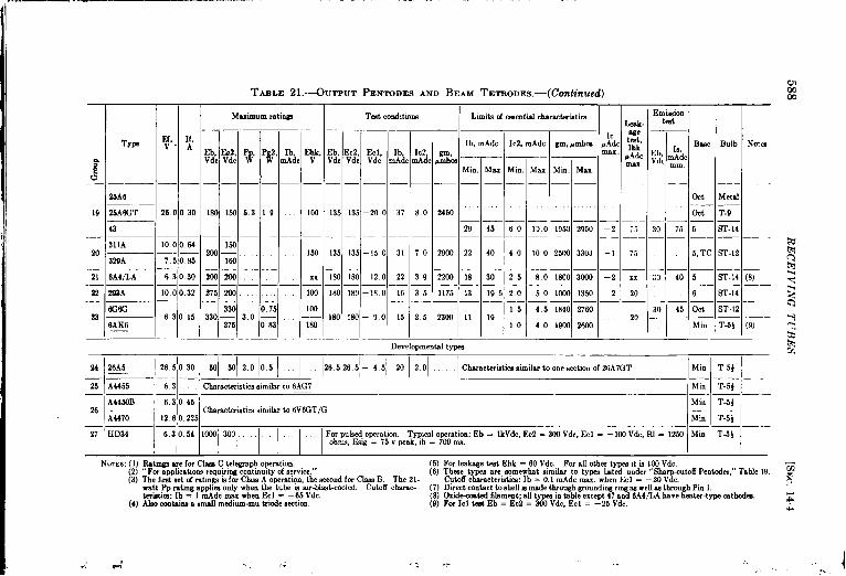
..1—W u(ml —. - - . . .. . ....=- .-.-=.-. --- .... .. . . . . —.. . -. . . .
—
:G
19
36
21
23
23
35Ae
25A6GT 23 I
43
339A /7!
6A4LA 6:
303A 10 (
mo
I6:
6AK6
TABLE 21.-OUTMIT PENTODES AND BEAM TETRoDEs.-(Continued)—
M=imum r.stiw I Tmt cond,tmna
11,A
30
64—
15
;b.c y; q,, P#,
— — . —
180 130 53 19
Zml;
. — — —206 200
215 206— — —. —
330 015330— 3,0 —
275 0,83
,,,
Ib, Ebk, Eb, Ec2, Eel,tide v Vdc Vdc Vdc
100 135 135 –20 o
150 135 135 –150
xx 180 180 –120
Ioa 180 180 –18 O
100—— 180 180 –90
180,,__
,,,
lb, 1C2,nAdc mAdc
1-
37180
I
31 70
1
22 39
16135
15 25
Develqmw,,
Limits of essentialduaracterktimLeak
lc welb, rnAdc Ic2, mAdc Zm, lmlbm PA: :~~
w,.Mbm
~Ad,
Mm Max Min. Max Min. Maxlnax
— —
2456
29 45 60 130 1959 2950 –2 ;;
2900 22 40 40 100 2WI 3303 –1 75
— — — — — —2266 18 30 25 80 1800 3606 –2 x.
1175 13 195 20 50 IOCQ 1330 –2 20— —
15 45 1840 27602WI 11 19 ~ —— — — 20
40 191M 26ao,,
.91WDa
Em&ion
Bw, Bulb No%Eb 1’,“d; mAdc
mm
oct Metal
Ott T-9
30 75 0 ST-14
5, TC ST-12
30 40 5 ST-14 (8)
6 ST-14
30 45 Ott ST-12 -
M in T.5: (9)
34 26A5 126~0301 ml W12.olo51 .1. 1265~26~-45~ 201201 I Cbe.racteristicasimilar to onesectionof 26A7GT Min T-54—— ——
25 A4455 63 Cbarackmstics simdar to 6AG7 ~Mm ~ T-5} I— 1,——A44E4)B 63’045
26 ——l— Cbaractetiticn similar to 6V6CT/GA4470 12 6,0.235
I I IMi. T-5:
Mi. I T-5} I—— , I I27 I ~D34
II 6310w11mi30’1I 1 I I For pulsed opem.lion, Typed opemtm.: Eb = lkVdc, Ec2 = 31XIVdc, Ecl = – 10I Vdc, RI = 12.!43 Min T-3}
.bms, I@ = 15 V peak, ,b = 7011ma.

-. .; .
TYP?
6L66L6G
1614
1622
6AR6
6V6
6V6G
6v6GT/G
7C514C5
6F6
6F6G
1621
25L6
2~6G’T/G
50B5
6K6GT/G
7B5
35L6GT
Cin, *#f
1
Min. Max,
10 0 Avg11,5Av.
7,0 13,0
85 13 5
7.0 13 0
79 11.1
9.5Avg
65
80
7.5
16 0
15,0
13 0
5.5
7.4
13 (J
Co”t, W.f
Min. Max.
12.0 Avg9,5 Av.
7.2 16 8
50 9.2
5.4 12,6
56 13 5—
9,0Avg
13,0
6,5
11,5
13 5
10.0
65
60
8,o
95
TABLE 21a.
Interelectrode capacitances (output pentodes and beam titrodea)
Mim Max,
0,4Avg0.9 Av.
0,6
04 0.9
09
09
0.7
0.2 Avg
0,5
0,2
0.3
08
05
05
08
08
_—
Type
Min. Max. Min. Max. Min. Max
1
6AG7 11.5 14.5 6,5 8.5 . 0,066A K7/6AG7
67 . . 13.0 Avg 1.2Aw
12A6 7.0 11.0 6,5 11.5 0,60— —— ——
12A6GT 5.0 11,0 5.6 11.5 0.60
14A5 6 8 Avg 7. OAvg O 4 Avg
7A5 13 0 7.2 0,8
18 35 75 0 30
25A6 8,5 12,5 0 20
FG6G 55 70 05
;.41{6 36 4,2 0 12
Type I I
Min. Max. Min. Max. Min. Max.
1613 4,5 8,5 9.5 17.5 0.09 0.6
89Y 1.2 18 3,5 55 2.0 3.0
I \ \ ) I I
NOTE: The capacitances for the 89Y are forthe triode connection, with g2 and g3 connectedto p.

4’,
590 RECEIVING TUBES [SEC. 14.4
only a few types, are similarly listed in Table 22. The small transmittingtubes of Table 24 and the twins of Table 25 may be of use for the same ,general purposes as those of Tables 21 and 22 when higher voltage ordissipation ratings are required.
In all four of these tables the aligned-grid or “beam” tetrodes arenot distinguished from the true pentodes, whether the latter are of beamconstruction or not. There are now very few nonbeam tetrodes. Thebeam tetrodes are very similar to the pentodes in characteristics andapplications. The beam types, whether tetrodes or pentodes, tend to
6400 —r. -- Limits of JAN specs.
------ ------ ------ ______
1
Bogie
\- / “ ~
./ i
/ ,/ ~6200
value
I . /.$ I$ . ~A“ : I
~ Gw :! .> ,I
.I
.E ElS ml . I
a I .I
5600 — ---- ----- _____ J./& Line of slope d%= s
/.
1 I I 1 I 1 155 60 65 70 75 80 85 90
1= in .ma d<
FIG. 14 16.—Variations in characteristics of 6L6GA tubes.
have higher values of transconductance, greater power sensitivity, andlower screen currents than nonbeam tubes of comparable size. In mostcases, but with some important exceptions, the beam types are superiorand of later design. In Table 21 the beam tubes are those in Groups 1,2, 3, 4, 6, 7, 11, 16, 17, 24, 26, and 27. The nonbeam pentodes are in .Groups 5, 8, 9, 10, 12, 13, 14, 15, 18, 19, 20, 21, 22, 23, and 25. Mostof the latter will not be further discussed.
The tubes of Group 21-1, such as the 6L6, are the largest” receiving”beam tubes made, and are commonly used where tubes of their capacitiesare required. Most of the types in this group have the desirablecharacteristics of 200-volt heater-to-cathode voltage rating and closertolerances on plate current and transconductance than any other typesin the table. The actual variations found in a representative group of6L6GA tubes tested under the conditions specified in the table are shownin Fig. 14.16. The 6L6, 6L6GA, and 6L6G are all identical in ratings and ,essential characteristics and differ only in mechanical construction and
f
interelectrode capacitances. The 1614, 1622, and 1631 are somewhat<

..---- ,
TABLE 22.—TwIN OUTPUTPENTODESAND BEAM TETRODES
Lunita C4ementiafcbnractiitim I
—
E(.v
—
12.(
—
If,A
—
1,1
—1.4—16—,.3—
Maxmum r.tirgn
;bk, Eb, Ec2,Vdc Vdc Vdc
100 180 180
— — —103 28 28— — ——100 265 265— — —10) 2543 100
Test condttims EmissiontQdt
.Ek2 ~d
.VE; 1 mm
— —
30 40
20 lca— —
10 70— —
10 15
Le8k-
lb/nec~con, 1c2~~:c0n, gm/.wcti0n Icl, we
wmbca pAdc :;
— ‘. ~Adc1 umx
TW
12L8GT
1.2/ gml,ectIon mctlormAdc ,umbm
28 2150
10 34fm
2,0 5.WO
0.8 21C41
Min. Max. Min
9,5 17,5 1.5
Max.\Min.lbfaxl I
T-9— ——T-9 (1)
T-9 (2)
T-9
200 200 2 ?5 1 10 –9 o 13 0 38 1850 2560 –2.0 401644
.——8,0 17.5 0.2
— — —lW 675 30 0,56
35 55 2.2 0,35
28D7—
26A7GT
18,(—!6. !
–3 5 12,5
–4 5 200
2,2 2WI 481m–2,0 150— — — — —4.0 33Lm 65Lm–2 o 100— — — — —1.3 1576 2625–1,0 20 J-
——.T-9 (2),(3)lG8/136f 6.: -2,5 45 251651“
he 1644i .Iwtdfm bla”cektww. swtiom.[aximum 1 ispersectim.be 7G8/’ )6 kn.tan.utput tu&, W,W,dm~ndf mr.fsmplificationu pti4WMc/m. Itkstwin ktrdeht rnnotshm ti&; itmmtib dtiapphmtiomhw&chc2crm exceed Eb. Its cutoff cbmacterktm in: Ecl = —11.0 Vdc, Ib/mction = 304dcm~.
Interelectrode Capacitance
Cin, WI
Type
min. max.
12L8GT 3.8 6,21644
26A7GT 16,0 Av,
— =1-7G8/1206
rni”. I max. I min. I max.
42 7.8 0.4 10
13.0 Av. 1.2Av.
Nom The capacitances above are per wction

592 RECEIVING TUBES [SEC, 14.4
more specialized, the first having ratings as a transmitting tube, thesecond being selected for uniform characteristics and long life, and thelast having a 12.6-volt heater. There have been manufactured fromtime to time various other variations of the same basic type, such as the6L6GX, T21, and RK49, which are essentially 6L6G’s with ceramicbases. There is a ruggedized version, the 6L6WGA, in development.
Some of the small transmitting beam tetrodes of Table 24 are alsovery similar to the 6L6. In particular the 807 (24-10) is almost identicalwith the 6L6 when tested under the same conditions. It differs, however,in that it has the plate connected to a top cap and has better internalinsulation, both of which permit a higher plate-voltage rating, and hasa lower grid-to-plate capacitance, a 5-pin low-loss base, a higher dissipa-tion rating, and is rated for r-f power applications. The 1625 (24-1O) isidentical with the 807 except for its 12.6-volt heater. Other small trans-mitting tetrodes that are similar to the 6L6, though less so than the 807,are the 1624 (24-9) which is essentially an 807 with a filamentary cathode,and the 1619 (24-4) which is a metal 6L6, also with a filamentary cathode.These last two tubes have lower transconductances than their unipoten-tial-cathode counterparts. The 35oA (24-1 1) is also not unlike the 807,though its actual ratings and characteristics are considerably different.
The 6AR6 (21-2) is of interest because of its small bulb size in pro-portion to its plate dissipation and other ratings. Its maximum ratingsapply only if the bulb is cooled with an air blast, however. This tubeshould find its application where space is at a premium.
The tubes in group 21-3 are designed to give high outputs at com-paratively low values of ~late voltage, operation at 135 Vdc beingtypical. One common use of the 6Y6G in radar equipment is as a volt-age-regulator triode. Another somewhat similar tube is the 6U6GT(21-6), which has a lower maximum dissipation rating but a smaller bulbsize. The 6Y6G has a 300-volt heater-t~cathode voltage rating, whichis unique for tubes of its class.
The 6V6GT/G and the other tubes of Groups 21-4 are widely usedsmall beam output tubes. While having lower maximum ratings, lowertransconductance, and greater variation in essential characteristics thanthe tubes of the 6L6 group their small bulb size and low heater powermake them very attractive for applications within their ratings. Theminiature developmental tubes A4450B and A4470 (21-26) are verysimilar in characteristics to the 6V6 Group.
The types in Groups 21-7 and 21-11 were designed for use in trans-formerless radio receivers and are normally operated with supply voltagesaround 110 Vdc. They therefore have fairly large outputs for the lowvoltages at wnich they operate. They also have large values of trans-conductance. They have been little used in radar equipment since it is
,(
,
,
‘#

SEC. 14.4] TETRODES AND PENTODES 593
seldom designed fortransformerless operation, but arecommon in broad-cast receivers. Group 21-7 includes a miniature type, the50B5. Thetubes of Group 21-11 have lower output but require less heater power.
The 6AG7 and the 6AK7/6AG7(21-13) are pentodes rather than beamtubes and are unique in that they are theonly output tubes designed primarily asvideo amplifiers. In many respects theyare more like the sharp-cutoff pentodes ofTable 19 than the output tubes. Theconstruction of the 6AG7 is shown in Fig.14.17. It may be considered a scaled-up6AC7. These two tubes have very highvalues of transconductance, higher in factthan for any other tubes of this chapter,and a high figure of merit, Because ofthese characteristics they have foundapplications as multivibrators and in othercircuits where a high transconductanceand low capacitances are desired in a tubeof moderately high power capabilities.They have also been used to a limited ex-tent in r-f applications, particularly asfrequency multipliers.
The figures of merit of a number ofoutput and small transmitting tubes aregiven in Table 23.
The types in Group 21-16 are chieflyinteresting for their low heater powerrequirements. They have been used prin-cipally in mobile equipment.
FIG. 14.17.—Video amplifierpentode 6AG7. (Redrawn frompicture furnished by Radio Corpo-ration of America. )
The 7A5 (21-17j & intended for operation at fairly low plate andscreen voltages, and is in this respect similar to the 6Y6G (21-3).
The 6G6G and the 6AK6 (21-23) have the lowest heater power ofany output tubes listed and therefore find application where this is animportant consideration. Both are nonbeam pentodes.
The 26A5 (21-24) and the 28D7 (22-2) and 26A7GT (22-3) twins areintended for 28-volt operation. The first is still in the developmentalstatus. All three have remarkable high outputs for such low platevoltages.
The developmental type HD34 (21-27) is a miniature beam tetrodeintended for pulsed operation. The only other small beam tubes in thesetables intended for such operation are the 3D21.4 (24-7) and the 3E29

-
594 RECEIVING TUBES [SEC. 14.4
(25-3). The last is essentially an 829B with ratings for high-voltage
pulsed operation.
The 12L8GT and 1644 (22-1) are the only twin output tubes designed
for operation at normally high voltages. hTeither is widely used,
TABLE 23.—FI~uBEs OF MERIT OF OUTPUT AND SMALL TRANSMITTING TURES
Type Group
21-1325-321-724-1021-2
21-2321-1721-121-121-11
24-1221-424-422-122-3
21-23
Figure of merit
535420380335300
295285285275260
260240205195190
185
* The6e types are twin tubes; the figuresof merit will be tbe mrnefor both mctiona in parallel M fmone mctim since both transconductance and capacitances will be doubled.
T The tig”re of merit Biven for the 807 and 1625 is for these t“be~ operated under the test co”ditio”aspecified for the 6L6 in group 21-1.
The tubes listed in Tables 24 and 25 are all primarily intendedfor application as r-f power amplifiers and oscillators, although theymay be suitable for other quite different purposes. One exceptionis the 3D21 A (24-7), which is a pulsed modulator. Both beam typesand nonbeam types are listed, the latter in Groups 2, 3, 6, 8, and 12 ofTable 24. Because of the large number of characteristics given it hasbeen necessary to split Table 24 into two parts, which has also been donein a somewhat different fashion with Tables 26 through 30 of the nextsection.
All of the nonbeam pentodes listed in Table 24 have Grid No. 3characteristics such that they are suitable for suppressor-grid–modulatedphone applications. The characteristics of many of these types, and ofthe beam transmitting tubes, have already been discussed. One interest-ing type not previously mentioned is the 2E30 (24-1), which has higherpower-handling capabilities than any other miniature tube.

4 SEC. 1441 TETRODES A,VD PENTODES 585
The twin beam transmitting tubes of Table 25 are intended as r-fpower amplifiers at frequencies as high as 200 to 300 Me/see. ThK829B
! in particular, however, is often used in wideband video amplifiers sinceit has a higher figure of merit than other types of a similar size. It isshown in Fig. 14.18, together with the 3D21.
Only those transmitting tubes with plate dissipations of 30 watts orless have been listed in the tables, since the larger types are almostnever used for other than transmitting purposes and therefore cannot beconsidered “ receiving” tubes.
FIG. 14.1S.–
.-(a)
–small transmitting beam tetrodes.
.,
5.AM
(b)(a) S29B, Ken-Rad; (b) 3D21. Hytron.
From the standpoint of the uses of the Radiation Laboratory thefollowing is a brief outline of the principal characteristics of interest forthe most-used tetrodes and pentodes:
Tetrodes.—6V6-General-purpose beam power amplifier. Useful in pulse cir-
cuits as amplifier, cat bode follower, etc. Excellent r-f oscillatorand a-f amplifier. Not as high gm or as good shielding betweengrid and plate as 6AG7. Large screen and plate dissipation forits size. Very rugged tube, uniform in manufacture.
6L6-Similar to 6V6 but higher voltage and current ratings. Usefulas pulse amplifier and cathode follower. Large dissipation, highpower gain. Useful as audio and servo power amplifier. Goodseries regulator tube when triode-connected.
807—Similar to 6L6 but with higher ratings and lower capacitances.Very rugged tube.
—

TABLE 24 PART 1.-SMALL TRANSMITITNG PENTODES AND BEAMTETRODESI I I
Group
1
2
—.
Type
2E30(HD59)
S02
SW-
1619
6+5
2525—
307A
2D21A
REM
1624
So7-
1623=
WA
3E22
—
Bulb
T+
ST-16
ST-1(
Metal
Mwmum mtinm
If,A
Vdc Vdc’ Vdc Vdc w w w ~hdc id;. :;O :Eb, Ec2 Ec2, Eel, Pp, Pg3, Pg2,
— — — . — — — — . —
0.7 2WJ xl 2.50 .,,.. 10 xx 00 . . . ..,.
. — — — — . — . — — — .
0.9 m ~ ml -24m 10 2 6 so ,, 7.5 25— — — — — — — — — — — —
07 WI m 200 –m 12 5 8 so 8 32— .— — —. — — — — . . —
2.0 ~oo , ~ – ]23 ]5 3.5 75 5 30. — — — _ _ — — — —— — —
0.8 450 ,., 250 -3CQ 15 4 75 4.6 ,..,
— — — — — — — . — — .
1.0 500 0 250 15 ,. 6 60 25
Teatcmditionu
—Sue
Elk, Eb, E&, Ec2, Eel, Ib, Ic2, Bll,Vdc Vdc Vdc Vdc Vdc m.4dc mAdc Wnhm
— — — — — — — — —
xx 250 xx 250 -2a 40 2.5 Mm
— — — — — — — — .
100 50U o 225 – 17 26 7.0 23CQ 7L, TC
m,v
6.0
Cdade
WP
o
H
H
6.3— — . — . — . . —10I m o m – 16 24 240Q 7L, TC_ — — — — — — — —
Ix 303 0 300 –13.5 34 6.0 45ca Ott— — — — — — — — —
xx 450 0 ?.50 -2a 30 1.6 W, TC
— — — — — — — — —
. 350 0 250 –m 50 4.0 4200 5, TC— — — — — — . — —
150 6o11 xx 200 –30 32 2.0 w M, TC— — — — — — — . .
100 330 0 250 – 18 .,., 7L, TC_ — — _ . _ — _ .
xx Ooo xx 300 –16.5 40 4.0 3s00 5, TC_ — — _ _ — . _ .
5, TC136 sol xx 300 -2’4 36 2.0 4201 —
7L, TC— — — — — — — — .
150 250 xx 260 – 1.9 62 4.0 saoo 5, TC
3
4
126
2.5
6.o
5.5
0
T-1(M
ST-16
3 TII
o6
7
8
_l— — _ — — — — — — — —).85/1.7 33W xx 850 15 xx 3 ,,
— — — — — — — — — — .
0.9 5.54 230 16,5 65 64 45. — — — — — — . — — —
2.0 600 xx 31m –200 25 xx 3.5 90 6 54— — — — — — — — — — . —
0.9
— 600 xx 300 –200 2s xx 3.5 lCO ., 5 000.45
— — — — — — — — — — —
1.6 600 xx 3Kl –2cm 30 xx 4 105 b 62.— — — — — — — — — — _ _
15 750 0 250 - 2W 30 100 20 ,,.
ST-14
ST-16
ST-16
H
H
2.6/6
6.3
259
10
0
ST-16—
ST-16
H
H
6.3
12.6
6,311
lz
ST-16 H—————————
44+1 -’’14’013.NIO 5, TC ST-16 o63
,1, ,8 ,,1
.4, .J, ——. .—
,,
,,. . . . .- —...—— .—.. /

.. ..-. . >.. .-
TABLE 24 PART 2.-SMALL TRANSMITTING PENTODES AND BEAM TETRODES
~ I Limitn of enaentid charactaristicn lntere’ec’rdec8pacit’’nc= I I ‘Sk-et-’I Emkmion tit
Group Type Ib, mAdc Ic2, mAdc gm, WDIIm Cin, d
Min. Max. Min. Max. Min. Max. Min. Ma..
— — — 1 I
1 zE30 10 Avg(HD59) ““ ““ ““” ““” ““”” ‘“””
— — . . — —— ~2 12
3 837 15 33 13 I 19— — — . — — — —
4 1619 36 64 0 8 4000 5000 9.6 AVK— — — — — — —
65 20 40 0 3 7.9 I 103
5 /~————i.l. ~...111.lll 8.5Avg_ 1- I_——_—— —
6 307A 13— —— —
7 3D21A
— =+ % & G % % &8
9 ‘1~1 52 01624 7.5 3000 5000 8
80710 - 24 48 0 4 — — 10
1625 5100 6900— . — . . — —
11 35oA 45 80 0 7 5500 8200 13 5— — . — —
2E2212 _ 42 78 0.5 65 4200 6800 11.5I 1110
(3)(4)
(5)
19
21
16
14
14
19
15,5
Maximum rating? for CbMS A operation: Pp = 15 W, Pg2 = 3 W.For max. Ic 1 teat adjust Ecl so that Ib = 36 mAdc. For g3cut.fi teat Ec3 _ — 145 Vdc, Ib = 2 mAdc rein, 12 max.
The 65 has been numemeded by the 2E25.For the emimion tea; Ef = 5.o”V. For g3 c.toil teat Ec3 - – 90Vdc, Ib - 0 min. }5 mAdc max.The me.xnm”m ratmga in the table are for Krid-puhed operation.Additional maximum ratingn are Ecl = 220 v, Pgl = 0.5 W,
~bb -4000 Vdc. Ec2 -800 Vdc, Ecl --130 Vdc. RP -“be length - 10 psec, typical ib - 8 SmP. For gl cutoff tit
2 megohms, Ib -“300 pAdc max.
Cout, /llIf
Min. Mnx.
5 Avg
8.5
7 5 ] 12.5
12.5 Avg
6.2 I 8.2
6. OAvg
9 15
10 15—1—10 18
5,5 9.5
_i_:
53
61 99
5.8 9.3
ceeP! J:: NotAsMax. Ihk ~b
- Ec3 -1s,
Ehk mAdc,~Adc Ec2 = Ecl , Vdc tin
Max.max.
—1—l —1—l l—l—
0501~~1 + ‘xl— — — .0.15 —r
0.20 I –5 100 I 100 30 —r130
0,29
0 18
0.15
1,00
1.00
0.20
0.25
0.20
0.30
0 20
_ —Y ni- Xx 50 200
–2 .50 — 140 rxx xx
–5 xx xx 50 125 (4)
–5 100 175 7 r
–4 xx xx 50 — r—200— — _ —
(7) , (8)–4 100 100 50 300 —
(7) , (9)— .
–7 100 125 (lo)— —
–5 xx xx 50 250 (11)
(6) Limits of gm arefor Ecl adjusted so that lb = 48 mAdc at Eb = 300 Vdo.(7) Maximum lb for ckum-B audio application is 120 mAdc. The characteris-
tics of the 807 and the 1625 are nearly identical with those of the 6L6 whenoperated u~er tbe name conditions.
(8) For gl cutoff teat Ecl = – 100 Vdc, Ib = 0.5 mAdc max.(9) Limitx of gm are for Eb = 250 Vdc, Ec2 = 250 Vd., Ecl = – 14 Vdc.
(10) For audio applications lb = 125 mAdc max.(11) For g3 cutoff teat, Ec3 - – 170 Vdo, Ib = O rein, 10 mAd. max.
,,, ,.“,,.

TABLE 25.-SMALL TWIN TRANSMITITNG PI IIWDES AND BEAM TETRODES
Linib of wentidcbaractii9tic4
Lmk-Icl/ age
lb/p, mAdc 1c2~ec:im, ‘g;: ~
lull. UAdc.
Emk-simtat,Id BMC Bulb Nok
sect ion,mAd%min.
Type *
— —
m2’4 o.;{—— —815 0.0/— 1— —820B 1.12— 2.23E29.
(vduca:R%Ll!%’wtic.ns)
fill lb/p, Icz/
Vdc mAdc fl~~
—
g: ~: ~ P# JJic I&&
— . — . — .2s0 – 100 15 5 Pil 6
— — — — — —2!4s –175 m 4.s 150 7
. — — —223 – 175 40 7 240 15
$29E identical with tbe 82QBbut also—
Groq
ECZVdc
—
135
‘max.Min. Mm. MiKI. Max
le. 43 01 5.5 –2 100
IPn Spec. 7, 2TC T-16 (1),(2)
I I
-10 30 31
I I I130 w, 2TC T-16 (2), (3)
— .——7470 6.0 –1 7135 -’0135I 32
.175 250 (2), (4)
— SW. 7, 2TC T-16 —3
725 Vd
((
an ratircm-rut Ml far typ bsve center-tapped 12.6/6.&vdt heat?m., Ehk rstings d 100 Vdc mxx, and the leakage teat in made at 100 Vdc. The emimion &t m made with Eb = Ec2 = Ecl =
Fm [cl tat Eb - 4WVdc, ~2 = 250 Vdc, ~l rnadjustedmtbat lb = 19mAdc.Maximum frequency far swticd input mtir.m rn~ hfclaec for the K32Aand ~ 123 Mc/k?c fc? the ~. NI are usable at nomewbst higher frequencies at reduced inputs.
(3) Average /swtim and limib d g+wcticm ire fcr Eb = 400 Vdc, EcZ = WI Vdc, Ec1 adjusted to make Ib = 26 mAdc. For Icl tat the name conditions are specidcd, Average gm =t%”4CU)Srn ,hnu&~32420@bm rnm,4800mu
(4) Aprmwmte smbtwn - 90CQ& fcx Eb = 300 Vdc, Ec2 = n Vdc. Ecl admstcd so that Ib = 60 mAdc.Interelectrode capacitances in wf
Ci”/8ecti0n
Min. Max.
6.2 9.411 0 15 612 8 16,2
Cout/8ection
Min. Max.
2.8 486,4 10,65.2 8.7
cgQ/mect]on
max.Cg2-k
avgType
822A81583B
0.060 22
0 10
65
65
r“.. ._ . -.

SEC. 14.5] CON VERTERS AND MIXh’RS 599
3D21—Similar to 807 but physically smaller. Designed as a pulsetube, used mainly as a modulator and driver in radar sets. Willstand 4 kVdc on plate and very large currents.
6Y6G—Similar to 6L6 but will take very large currents at low platevoltages. Good blocking oscillator, excellent series regulator tube.
829--Essentially two 807’s in one envelope. Primarily designed asuhf oscillator and amplifier but sometimes used as output stage invideo amplifier.
Pentodes.—6SJ7—General-purpose receiving pentode. High gain at low cur-
rents. Useful as audio voltage amplifier. Sharp cutoff. Uniformcharacteristics. Can be used in suppressor-control circuits. Veryhigh gm (2500) and rp (over 1 megohm). Low grid current.
6SH7—Like 6SJ7 but higher gm and very sharp cutoff.6SK7—Like 6SJ7 but with remote-cutoff control grid. Useful in
AVC circuits and in devices where a parabolic control characteristicis required.
6AC7—High-performance i-f and video pentode. Very high gm(10,000), moderate input, g3 cutoff about – 100 Vdc. Useful invideo amplifiers, pulse generators, cathode followers, amplitudeselectors, limiters, etc.
6AK5-Miniature i-f and video pentode, slightly better performancein i-f and video circuits than 6AC7 because of higher figure of merit.Low heater power, sharp cutoff. Generally useful in pulse circuits.
6AG5-Practically same as 6AK5 but higher capacitances and higherdissipation ratings.
6AG7—High-performance video pentode. Very high gm (10,000),moderate capacitances. Essentially a large 6AC7. Useful asvideo deflection amplifier, blocking oscillator for extremely rapidrates of rise, and as cathode follower to drive coaxial cable.
VR91—British equivalent of 6AC7 in nearly all respects.VR65-(Not listed in tables.) British equivalent of 6SH7.CV9—British, not listed in tables. Like 6AG7 but higher dissipation
and gm.6AS6—Similar to 6AK5 but with sharp g3 cutoff (– 10 Vdc). Used
as a time selector and in regenerative circuits of the “negativetransconductance” variety in transitron, phantastron, etc. OnlyAmerican equivalent of VR1 16.
VR1 16—British tube most used in time-selector and negative trans-conductance devices. Prototype for phantastron, sanatron, etc.High gm, low capacitances, large plate and screen dissipations.
14.6 Converters and Mixers.—The converter and mixer tubes of thissection are vacuum tubes of relatively complicated structures, used pri-

.— .?. . ... .. . —.-T-
TABLE 26.—PENTAGRID CONVERTERS (CLASS 1)Jhbes of this clam have the following structure: gl, oscillator grid; g2, oscillator plate; g3 and g5 (internally connected), screen; g4,
signal input grid.All types in this table have the following characteristics in common:Maximum ratings: Eb = 330 Vdc; Ec2 = 220 Vdc; Ec3 + 5 = 110 Vdc; Pp = 1.0 W; Pg2 = 0.75 W; Pg3 + 5 = 0.3 W; Ik = 15
mAdc; Ehk = 100 Vdc, at which Ihk = 20 pAdc max.Test conditions: Eb = 250 Vdc; Ec2 = 250 Vdc; Ec3 + 5 = 100 Vdc; Ec4 = –3 Vdc; Ecl = O with input signal adjusted to
18 Vat; Rgl = 50,000 ohms; Rg2 = 20,000 ohms, SC = 550 ~mhos.Emission test ie made with all elements except the cathode at 30 Vdc.
Ef IfGroup Type v, ~,[b,
mAdc
6A8——6ASG
6ASGT 63 030
6A71 — 35
7B8
12AWT— 12,6 0 1514B8
2A1 2,6 0.s0
2 6Dffi 63 0 15 35— —— . . —
3 7A8 6.3 0 15 30
Teat conditi.ne I Cutaucbar.1 L]mib d eamtidcimracteristirs—
1C2,nAd
40
4.3
42
—
—
ICI,tid(
—
04
04
04
(... Min.
Ib, mAdc Ic2, mAdcIk, Ec4, ~~m _ —
n4dc Vdc ~v,Min. Max. Min.
— — . — — —
106 –35 6 33 4,9 26
— — —10.8 –35 6 26 56
108 –30, 2 20 43 38
5.6
60
.-
12
.. ,,, ,. ,, .,,. ,. ,”” ,. ”.., ,., ,., “,, ,.,
I Ik, rn.kdc IcI, rnAdc
k. Min. Max. Min.— — . —
78 135
1’fi3— —- 03
78 12 8— —78 13,5
l—l—l
7.8 13.5————1.2 7.5 13 5 03
I I I5.0 80 130 03
%x.
06
0.6
06
1,4, sfik, Pmb.a Adc, ~ he Bulb Notes
‘x mA,dc,
Min. Max. -“
I I IL-I-I-
I —l_&t,TC MeM
CM, TC ~BT-12
325 7W 1-2”0140 ,lximrII l—l —.1
l’: I 7S, TC i ST-12 I
————— 1— l——l—31N 130 –1 5 63 I.cu 1 T-9 (1)
325 I 703 –2 o 40 7S, TC ST-13
32s 730 –2 o 40 Oct, TC I ST-12 i— —— — —l———360 760 –15 50 Lx ~T-9 (I), (2)
-. -. . .,,, ,,, ,,,, ,,,, ,,., ,., . ,. ., .“, ... ., ,- .,, -.

The cmcillatorsections hsve the foUowU eharscterhtica (not mcdlstuw): Nom.% (1) The maximum rat.d valued ICI is 0.5 +dc.(2) The 7A8 w an oclnde: the supprwm md @ M interndy co.-
1nettedla theCdh3de.
g l-g2 trmsconductance,I
pmhm
min. max._ —
1150AV.850 1530
1500Av.
1C2,mAdc,avg
MuEc2,Vdc
10IlW180
Eel,VdcGrow
3335
103
—l—230 –2
–o 5;g o
–1o0 10 65
Interelectrode capacitances in ~~f
Cg4—all
others (Cin)
Cp-allithers (Cout~
Cgl—all?xcept g2,
avg
6.5
6.0
5.0
5.5
3.8
Cg2—allothers,
avg
Cgl—allothers,
avg
I Cg2—allI except gl,egl-g2,
avg
—
0.8
1.1
1,0
0.9
1.1
0.6
cg4-p,max.
cg4-g2,
avg
0.10
0.19
0.15
0.2 max.
0.20
0.15 max.
cg4gl,
avg
0.09
0.16
0,15
.
0.2 max.
0.16
0.15 max.
Type
6A8
6A8G6A8GT12A8GT
2A76A7
7B814B8
6D8G
7A8
Min.
10.0
7,8
6.4
7.5
6.2
6.0
Max.
14.0
11,2
10.6
12.5
9.4
9.0
Min.
9.0
9.0
6.8
6,7
7.5
6.7
Max.
15,0
15.0
11.2
11.3
14,5
11.2
avg
0.09
0.35
0,30
0.25
0.28
0.20
5.0
4.6
3.4
4.6
3,4
5.5 7.0
. . .
,., ,, ,,. .,, ,,, ,,, ,, ,,, ,., ,, ,,

:.
RE
CE
IVIN
GT
UB
ES
[SEC
,14.5
‘1e
1:>
’4.m
,,n.
0–
.
$I

The fotlowlng cbrscterkt,cs apply totheoscillator aectio,> inthenono~cillat- No’rEs: (1) Fm8r0. p 1 under teatcond,tione,, nignal voltage Ecl = 10 VSC. ‘“ing ,conditions: Eb - Ec2 + 4 = 100 Vdc; Ecl = Ec3 = Ec5 - 0. Signalapphed ta E1 only.
There is also a test for Icl; Rgl - 50,0000hms, Ec3 = O, Icl= ~0.17 mAdc min. 0.3 max.
(2) The12SY7 and 12 SY7GThave ratmgnfor 28-volt operation:Eb = &Gm, I J& Ec2 + 4 = 28 Vdc, Ecl = O, Ec3 = –lVdc, adjustsigna lvoltage
Grouppmlms Egl ~othe.t kl = 120 FAdc; S. = 200 Fmhon m,., 400 max.
Under “em&ion teat, ”min.
Eb i, the voltage apphed to all elements exceptavg max. SVE ‘ hand k.
7760 35; 4400““”” 5500 304 3500 4500 5900
I I I I
I Cin, I Cout, I cg3-p,T ~pe
? Q714Q7
6BE612BE6
6SA7
12SA7
6SA7GT/G12 SA7GT/G
Cgl-gma.
0,20
0,15
0 15
0,40
Cgl-p,max.
o 15
0.05
0.06
0 20
Cgl—dlothers,
a Vg
7.0
5,5
7.0
80
Cgl—all ~ ~gl-k,except k,
I avg. VgType I —- -—
hli”, Max, Min. Max. Max.
.—
7 Q714(J7 _\67 11 3 64 10 6 0 30
6BE612BE6 7.2 Av. 8,6 A“. o 30
——,—~— — — —
—
6SA7
l~A7 ] 7,6 11.4 8,4 15.6 0 13
12SY7
6SA7GT/G12SA7GT/G 88 13,2 77 14 3 0,50 6SA7GT, 12SA7GT, 6BE6, and 12 BE6 have 85 internaOy connected to k.12SY7GT
Cin above is Cg3—sll others; Cout is Cp—aO others.
50
2,7
4.4
5,0
2,2
2,8
2.6
30
Ck—rdlxcept gl,
a VE
60
15 0
50
14 0

604 Rh’CEIVING TUBES [SEC. 14+
marily for frequency conversion in superheterodyne receivers. Fiveclasses of these tubes may be distinguished: two different classes ofpentagrid converters, listed in Tables 26 and 27; triode-hexode andtriode-heptode converters, listed in Tables 28 and 29; pentagrid mixers,listed in Table 30. Because of the large number of characteristics ofeach type and the small number of types per class, the tabular form ofthe other tables of this chapter could not be used, and the five tablesof this section have accordingly been considerably modified. Essentiallythe same kinds of data are presented here as for the other classes oftubes, however. v
Pentagr-id Converters.-Pentagrid converters are tubes with five con-centric grids successively surrounding the cathode and a plate aroundthe outermost grid. They are of twornainclasses. The first and earlierclass, listed in Table 26, uses the cathode and the first two grids as anoscillator, Grid No. 2actingasthep1ate. It is actually two rods withoutthe usual spiral grid wires. Grids No’s. 3 and 5 are internally connectedand serve to screen the signal-input grid (No. 4) from the oscillatorsection and the plate. All tubes of this type are restricted as to operatingpotentials by the usual requirement of a nonbeam tetrode that theplate must never become negative with respect to the screen, except for jthe 7A8 (26-3) which is actually an octode, having a sixth grid internallyconnected to the cathode.
The second class of pentagrid converters, listed in Table 27, have a -.
structure in which the first grid is the oscillator grid, as before, and thesecond functions both as the oscillator plate and as a screen between theoscillator section and the signal Grid No. 3. This structure requires thatg2 be grounded for radio frequency, and the circuit thus becomes agrounded-plate oscillator. The fourth grid is connected internally to g2and screens the signal grid from the remainder of the mixer section. Thefifth grid is the suppressor.
Tubes in this second class of pentagrid converters are superior tothose of the first class in two respects. Their much higher oscillator-section transconductance gives far better performance at high frequencies,and the use of a suppressor grid results in a considerably higher plateresistance with less resultant loading of the output transformer, Eitherclass may be used with a separate oscillator tube, and they are often soused at the higher frequencies. All of these pentagrid converters maybeused for other applications lvhere a tube with two separate grids of goodcontrol characteristics is required. This type of operation has been dis-cussed previously in connection with the 6AS6.
The types listed in groups 27-2, 27-3, and 27-4 are basically similar Iand are probably more frequently used than any other class of converter.The 6BE6 and 12B176 (27-3) are the only miniature converters in quantity
= ..

SEC. 14.5] cOATVERTERS ,4IVD MIXERS 605
TABLE 28. —TRIODE-HEXODE CONVERTERS
Type Ef, V If, A Bne.e Bulb
6K8 Ott, TC Metal
6K8G 6.3 0.30 Oct. TC ST-12
6K8GT Ott, TC T-9
12K8 I 0.,, TC nlet.k
12.6 0.15
12K8Y ● Oct. TC Metal
Y ● The 12K8% bm s 10W-1OSSham.The interelectr.nie capacitance, are an follows:
Ci”, ppf Cout, ##f
Type CEP7 JvJf\
Min. Max. Min. hlax.Max,
I_ ._. -- l.—.–
6K8
12K8 5.4 7.8 2.6
12K8Y
44 0,03
6K8G 3,7 5.5 3,5 .5.5 0 08
6K8GT 4.0 6,0 33 53 0.08
8 NOTE: Cin is the capacitance between hex ode g3 and all other electrodes; Cout is from hexode plateto e.11other elemente.: Cgp k the capacitance between bexode g3 (the sigmd grid) .nd hexode plate.
Other cspacitmme.s are as follows:.’
Type
Capacitance, wf 6K8 6K8G12K8 6K8GT
— .l— —Hexodeg3to triodeplate, max ,, . . . O.OZ 0,05Hexodeg3to hexodea”dtriode gl, max, . ,., ., 0,2 0.2
Hexodeand triodegltotricde plate, avg...... ,.. .,, ,,. 1.1 1.8Hexodea”d triodeglto hexode plste, max.,... 0 10 0 15Triodeplate to all except triode and hexodegl, avg. . ., 3.2 3.4Triode and hexcde gl to all except triode plate, avg. . 60 6.5
All five types belong to one group and have the following characteristics:Mtimum ratings:
Forthetriode ~ectio”, Eb = 140 Vdc, Pp = 0.75 W,Forthehexode sectio”, Eb = 330 Vdc, Ec2+4 = 165 Vdc, Pp = 0.75 W, Pg2+4 = 0.70W.
Ik - 16 mAdc, Ehk - 100 Vdc.Teat conditions:
For the triode mcti,m, Eh = 100 Vdc, Ib = 3.8 rnAdc.For the hexode section, Eh = 250 Vdc, Ec2+4 = 100 Vdc, Ec3 = –3 Vdc, Ib = 2.5 mAdc,Ic2+4 - 6.o mAdc.
For both, Ecl - 0, Rgl = 50,000 ohms, the input signal to the gl’e is adjmted to that 1.1 =
150 pAdc, and tbe ccmvemion tramcond. ctame S. = 35o p mhm.Cutofl characteristic: for hexode Ec3 = -30 Vdc SC = 2 pmhoa av.Lirnit.g of essential chsre,cterintim:
Hexode Ib - 1.6 mAdc mi”, 3,6 ma.; Ic2+4 = 3.6 rnAdc mi”, 9.o ins..
Ik - 9.5 mAdc rein, 15,5 max; Sc = 230 ~mhc.s rein, 49o max.Hexode 1c3 - -2 pAdc max.For the h-k leakage teat, Ibk = 20 ~Adc ma, when Ebk = 1O(I Vdc.
( For the emission test, with all elements except heater s“d ce.thcde at 30 Vdc, Is = 70 rnAdc min.
The oscillator section trwmconducte.nce (not oscillating) is 22OO ~mbm min, 4000 rnax, with triodoEh = 100 Vdc, Ecl = O, and hexode Ec2 +4 = 55 Vdc and Ec3 = – 0.5 Vdc.
With the oscillator section oscillating the triode and hexode Ic 1 = 110 pAdc min. 22o max.

606 R,K’EIVI.VG TUBES [sm. 145
production at present. ‘~he clevelupmental 261X (27-.5) is designed for28-volt operation.
Triode-kcode Converters.—The third basic class of converters is thetriode-hexodes of Table 28.
These tubes may be considered as essentially pentagrid mixers of thefirst type with a separate triode oscillator section since the hexodesection is similar to a pentagrid converter of the 6A8 type with the rodsforming the oscillator plate omitted. This comparison is not strictlyaccurate since the triode-hexodes employ beam-forming shields whichgive a high plate resistance without the use of a suppressor grid. Thetriode control grid and the hexode A-o. 1 grid are actually one electrodein which the portion on one side of the cathode serves as the triode gridwhile the opposite portion furnishes the oscillator input to the hexode.These tubes are intended to give good performance at the higher fre-quencies. Unfortunately none is of the single-ended construction, allhaving top-cap connections to the signal grid.
Triode-heptode Converters and Penlagrid Mixers. —These last twoclasses will be described together, since the former is essentially the sameas the latter plus a separate but internally connected triode oscillatorsection. They are listed in Tables 29 and 30,
Pentagrid mixers and triode-heptode converters are basically differentfrom the other three classes of converters in that the signal input isimpressed on the first grid rather than on the third and fourth as in theother types. This feature is intended to give better isolation between theoscillator and signal-frequency circuits. The other grids function asfollows: g2 and g4 are internally connected and act as the screen; g3 isthe oscillator input grid; g5 is the suppressor grid. In the triode-heptodesthe oscillator grid is internally connected to the heptode g3, and for thepentagrid mixers an external oscillator is simiku-ly connected eitherdirectly or through a condenser. The oscillator-section transconducta:lceof the triode-heptodes is considerably lower than that obtainable withseparate triodes or than the oscillator-section transconductance of thetriode-hexodes or the second class of pentagrid converters.
The conversion transconductance of the 7S7 and 14S7 (29-3) isappreciably higher than for any other tubes of this section.
The pentagrid mixers of Table 30 are all essentially the same, the1612 being a 6L7 selected for quiet operation in audio circuits. Severalof the tube manufacturers who do not list the 1612 will furnish similarlyselected 6L7’s without changing the tube numbers. Pentagrid mixers areoften used for other than r-f applications, such as d-c–controlled audiomixers and volume-expanding or -compressing amplifiers, where a tubewith good control characteristics on two grids is required. The first gridhas a remote cutoff characteristic, which may be a disadvantage in some

.. . ,-
TABLE 29.—TRIODE-HEPTODE
The following characteristics are common to all types in this table:
CONVERTERS
Heptode Eb’= 330 Vdc max, Ec2 + 4 = 110 Vdc max. Ehk = 100 Vdc max, at which voltage Ihk = 20 pAdc max HeptodeICI = – 1.5 ~Adc max. For the triode section, the test conditions are Ebb = 250 Vdc, Ecl = O with the signal voltage adjusted to18 Vat, Rg = 50)000 ohms, Rb = 20,000 ohms.
Other characteristics are as follows:I Maxnnum ratings Test omd~ticms,H@od. Cutoll char. Limutaof amentialcbaractirktics, H@ade :~
Ib, mAdc 1c2 + 4, mAdc Ik, mAdc , ,
! ‘::- : : E ~ 3 ‘z * ‘:: :$ 2 H 5 %- % ‘; %> : :- $ z B :—
7J7 63 024 — I2 — — — 165 1 25
I 14J7 126 01514 5 –3 14 28 290 – 20 2 09 20 11
I 45 74 I “ I 2Q6 4oi7 * ~ ~ :::ofi ,3)
,,I I 1 I I 17s7 63 030
_,_–..– ‘—l——’—
3 —1— — 175 10;06 04 ‘1I 14S7 1126 015
14 5! –21 1 8 30 525 –21 2 11 26 12 48 74 12 6 340 710 96 Ik !T.9 ,(1),,
For all typca tbe oscillatingtricde IcI = 300 uAdc rein; 436 av.; tbe maximum k 530 pAdc for m..m I and 3 and 600 for group 2 For tbe noncecdiati.g condition Heptcde Eb = Ec2 + 4 =Ecl = O; tbe trmie cbaracter,stlm are:
‘rl T- ‘-K=:Types Eb, Vdc Ec, Vdc —
Min.
SJS2 136 13M77J7, 14J7 130 :! 11507s7, 14s7 Ifm o 1336
Avg
1f4m14ml1630
[b, mAdc,
.Min,
004342
Avg
6665
Max.
12 09391
Mu
iiIs
1 1 ,
Norm (1) Maximum ICI = 53o p.%dc.(2) Wdl operate .sak.sfactardyup t. 100 McImc(3) Also b.w mtmg$ for Z&volt owmtion: Triode Eb = 28 Vdc Heptcde Eb = Ec2 + 4 =
28Vdc. Trmde Ecl = O, fig] = .5W111elms, gl sig”d voltage 3.4 Vac Heptcde Ecl =-0.75 Vdc. % = IE41prnhm min. 310 mm.
Inkrdectmde capacita.cea in WI
Capacitance
Heptcde gl t. all .thwnHeptcde p to all othersHeptode gl to pHeptode gl to kiode pHeptode gl to trmde gl
“1YPP6JSG 7J7 7s7
14J7 14s7Mm. Mm. Min. Max Min. Max.— —
36 60 37 55 37 637.3 125 55 95 60 100
002 002 0,620015 0 10 0 100 13 (1 30 .“ 035. — .1- 1’ I
Tricde g 1 top 2 2 Avg O 9 Avg l, OAvg
Triode Dt. all .thwa I 55 I .1. 1 .1
Triode p to all except trmde gl ] I ‘-1 32Avg ] 35’.4v,1’ 1
Tricde gl ta all others 111711,1.I
Triode gl to all except trmde p~ I I 75 Avg I 7.o AVE
.

t
608 RECEIVING TUBh’S [SEC. 145
applications. The first grids of all the triode-heptode types of Table 29have sharper cutoff characteristics and it should be possible to use theheptode sections of these types in similar applications by not using thetriode sections. No information is available on such operation of thesetubes.
The Radiation Laboratory made comparatively little use of convertertubes. The 6SA7 (27-4) was used as an electron-coupled oscillator-
—1I
,’.
TABLE 30. —PENTAGRID MIXERS
This class includes only three types, all belonging to one group. The 6L7 and1612 are metal tubes with an octal base and top cap; the 6L7G has an ST-12 bulb with J
an octal base and top cap. All have 6.3-volt 0.3-ampere heaters. The 1612 is a 6L7
selected for nonmicrophonic characteristics for use in audio applications; no charac-
teristics are given except maximum ratings as an amplifier, Which are the same as
for the other types except that Eb = 275 Vdc max. Presumably the other charac-teristics are identical with those of the other types. For the 1612 Cg3-p = 0.1 ppfmax. Other capacitances are:
Cgl—all others, Cg3-all others, Cp—all others,Cgl-p, cgl-g3,
Typep).lf ppf ppf
/l*f /I/If
Min. Max. Min. Max, Min. Max.max. max.
— — 86L7 6.2 8,8 8.3 11.7 8.2 13,8 0.001 0,2
6L7G 4.9 7.1 12 Av. 7.2 12.8 0.005 0.2
1612 7,5Av. 10 Av. 11 Av. 0.001 .
The other characteristics are:Maximum ratings:
As an amplifier, Eb = 330 Vdc, Ec2 + 4 = llOVdc, Pp = 1.5W, Pg2 = 1.0 W,Ehk = 100 Vdc.
As a mixer, Eb = 300 Vdc, Ec2 + 4 = 165 Vdc, pp = 1.0 W, Pg2 = 1.5 W,Ehk = 100 Vdc.
Test conditions:As an amplifier Eb = 250 Vdc, Ec2 + 4 = 100 Vdc, Ecl = Ec3 = –3Vdc,
Ib = 5.3 mAdc, Ic2 + 4 = 6.5 mAdc, gm = 1100 ~ mhos. >As a mixer, Eb = 250 Vdc, Ec2 + 4 = 100 Vdc, Ecl = –3 Vdc, Ib =
2.4 mAdc, Ic2 + 4 = 7.1 mAdc, Ec3 = -10 Vdc, peak signalvoltage = 12 v rein, Sc = 375 gmhos,
Cutoff characteristics as an amplifier:For gl, Ecl = –30 Vdc, gm = 1 ~mho rein, 20 max.for g3, I?c3 = –15 Vdc, gm = 1 ~mho min 05 max.
Limits of essential characteristics as an amplifier:Ib = 3.6 mAdc rein, 7.0 max. Ic2 + 4 = 4.7 mAdc rein, 8.5 max. gm =900 pmhos rein, 1300 max.
Maximum Ic3 = –2,0 ~Adc.For h-k leakage test, Ihk = 20 pAdc max for Ehk = 100 Vdc.For emission test, with all grids and the plate at 30 Vdc, Is = 45 nL.4dc ltli!~.

.-
TABLE 31.—COLD-CATHODE GAS DIODES (VOLTAGE REGULATORS)
L
Teat conditions and chmmteristica
Base BulbIb = (2)Eb
Vdcmax.
LeakageEb =
50 Vdc,lb
Adcmax.
Nmni- ‘ini-Gm.p TYPS II*1 op- ~;;r:_
cratingi“g
v 01t-vdt-
Sge ,Vdc
age,Vdc
Regu- ReauIation IatlonIb(l) Ib(2)
Operatingcurrent,
rnAdc
Mim Max.
— .
5 30
NotesIb = (1)Eb
Vdcmax.
[b - (3)EbVdc
mm.
(1)Rp/lbmAdc
.,
40
(2)
Rp/IbmAdc
(3)Rp/Ib
EbbVdc
1:3) 1;3)Vdc Vdc
=1=.,. .
.5
Min T-5}1 0C2(S859) 75— _
2 I oA3/vR75 75 105
3 oB3/vR90 90 130
4 874 90 130
(1)
(2)
— —6.5 4.5
— —
6.0— —
. 10.0— .
l.oAv— —
4.0 2.0
—150 305140 81 79 / 70 10 Ott I ST-12
5 30
10 50
5 30
5 40
5 30
Ott IST-12150
300—.
30
50
5
10
10I’8O
10Q 80
10
10 4 I ST-16 (2)
Min T-54— .
Ott ST-12
(1)30
30
5
5
I
112 111 105— ,—. —
106 0C3/VR105 105 127— —
7 0A2 150 185— —— — —
8 oD3/vR150 150 180
9 991 60 87
10 1B46 80 225
11 1B47 80 225
300 40 (2)
2. OAV— —
5.5 4.0
30 b
5
Min I T-5*——
Ott ST-12
(2)
(2)103 40
04 2
31XI I 40_l—
I
30
2
162 160 \ 145
67 480.4 . . I 8.0 (3)
(4)
(4)11 2
1 2
85 79 I 30 Bay i T-4i—,—
250— —
250
2
2
1
1I
““”I 3“0NOTES: (1) TYpm 0C2 (S859) a“d 0B2 (HD52) are devel.pme”tal types.
(2) Maximum range of .pemting ternpemt”res is – 55” to +90”C.
(3) TYD.S 991 h= a nmmcdarized b=e (same as Ordinary 2-cOntact autOmObde buJb). specificmtiOna apply to tub connected in e]ther dmection.
(4) PoIar~baae,
-.%.

:.
610 ILWfiI VIA’C T(JRE,S [SE( 141;
converter and as a time selectur. IL is not, as good as the 6AS6 for th(,latter application since its g3 cutoff is not as sharp. It was successfllllyused in the phantastron circuit, as was also the 7A8 octode (26-3).
14.6. Gas-filled Tubes. —This section presents data on only a smallnumber of the many gas-filled tubes that are available on the market,and on only three classes—cold-cathode diode voltage regulators andhot-cathode triodes and tetrodes of small size and comparatively lowpower-handling capacity.
Volkzge-r-egulator Diodes .—The characteristics of the cold-cathodegas diodes intended for voltage regulation are given in Table 31.
Three of the types in the table, the 1B46, 1B47, and 991, have lowmaximum current ratings in comparison with the other types. The 874is of older design and has a large physical size. These types will not befurther discussed.
The remaining types are made ‘.rith four nominal values of voltagedrop, as follows:
0A3/VR75 and (miniature) 0C2 75 voltsoB3/vR90 90 volts0C3/VR105 and (miniature) 0112 ‘. 105 volts0D3/VR150 and (miniature) 0.42. 150 volts
The miniature types appear to be identical in all respects with theirlarger counterparts, except for a slightly lower maximum current rating.The regulation characteristics of the several types vary considerably, bothwith regard to the absolute value of voltage change and to the nominalvoltage drop. The 105-volt tubes have the best regulation, followed inorder by the 150- and the 75-volt types, with the VR90 a poor fourth.The clifferences are apparently due to the different gas mixtures used,and also perhaps to other causes.
The Radiation Laboratory made extensive use of regulator diodesboth directly as voltage regulators and also as standard voltage sourcesfor regulated power supplies.
Gas Triodes and Tetrodes.—Tables 32 and 33, respectively, list small ;grid-controlled gas triodes and tetrodes (Thyratrons). In addition tothose listed in these tables there are many larger types with power-handling capabilities running up to hundreds of kilowatts.
Of the triodes the 884 and 885 (32-3) are the most widely used, thelatter type having a somewhat obsolescent heater voltage and base.Two miniature triodes are available, the 6D4 (32-4) and the 2C4 (32-5).These two types have considerably lower current ratings than the largertubes. *
For many applications the tetrodes of Table 33 are preferable to thetriodes, since they will operate on smaller input signals and have higher ,

,--- —,—_
.- .? 1.
TABLE 32.+MALL HOFCATHODE GAS TRIODES (THYRATRONS)
‘
c—
I—
—
—
4
;
Baa. Bulb
5 ST- 12
Starting Voltage k?.sk Tubedrop teat
! bewee.W.Ytwoelw-Odes
v
325
2N
350
—
Ec,
Ebb Rp ~Vdc
Vdc .bms meg-ohms
Mm. Max.
— — — ——
250 5020 0001, –4 – 10
75 n“ ~–4~–6
Ihk~Adcma,
300
xx
20
15
15
epy,v
300
200
.
3011
350
330
—
:bbtdc
—
—
—
154
G—
—
tkse<
—
60—
2
—
30
—
30
z
—
Ef, If,v A
00 0,5
2,5 25
—63 0,6
Lv?JIdcib, 1b,
ma mAd,
remp range“crYPe
338A
N04E8
—-
.1), (4
(3)
X44Id,
ig, E hkna Vdc
— —
10 *5O
x.
, ~ ;~
+ 25,–11(
+ Ifn
EbbVdc
250
tb/lbmAdc
100
It&Id.
llx
.N4in
– 60
– 55
6@l ml— .
+35
+90
203fm
Zfm
—
3ml
354
1230 100
1Ott ST-1:
Ott ST-12——5 ST-12
Ott ST-U——5 ST-12
Mi” T-5}
——.Mm T-5*
!A4G
—.?84—
135
034—
!85
;D4—
—!C4
—mm
20+3
50
20
20
15 x,
Ill
I l—l—-———150 n“
[10 17CQ
1–65–8—,———
01 –10 –1425 1.5
63 06
25 15— .
63 0 2!
300 75 16 :1),(4)
:5)
:6)
-l—l—
01 I-2, o@250 56(M
125 630— ——
50 650
125 20Q0
06 1–11 1–14110 25 16
165 17
0,5 –50 –71
05 –11 5 –13, ! 12522 52506 354-—1) FormWatoraerviceIb = 2mAdc max.2) Eti= 8Vdc mm.3) tild~mtd filament; allotber tywin@ble baveh~ter-tyN cathtia.
Fw@rttw-voltage &bdjwtplati rw~tiaotbat Ib= 100mAdc.~] #:mumvalue,fMk0.5 rne,obm. Averwe,nhrel~trde mwc]tancame: Cin, 2.O#f;Cout,O.6wf:
puldoperatjonm ax.ratmqa rtiEbb= 350Vdc,, b=2~ma,Ib= 15mAdc, Ebk= –ZOOvpakFM starting-voltage ted W = 40311ohms.For imtmtaneous tube-droD test, adjust RP + Rk so that ib = 2011 ma; etd = 90 v max.
Max
Ec= -150 Vdc max.(6) Fmstiiw-vol@e tWM=~,~obm.
., .-

TABLE 33.—SMALL HOT-CATHODE GAS TETRODES (THYRATBONS)
2D21
1 2050—
2D21
GL50i. —
2 GL54t
—
If,.4
Mammum rztmgs,I
Startmg-vokage ttsb,
1-
1’ 31KK’1+25 ~ ~ -- -- – ----~ 3WJ
10 ,-1OI 10 ~ –6o +75 980 1,’ — — 460
~ -50 +65o 10 — ,o–7~
3000 1:
I -6o +,5 ., ,., .,.— ,— —— . — . — . — . —
110 10 –40 +80
Ill
Tubedrop &at,
Sgl, RD, IEc1
‘eg” oh”,s Vd]hMS;,
— —
01 10JOO o
— — .
,..— — —
Etd
I
epx,epy,EC2, Ec1, ,k, 10 M1~E~~,~ tk,l ‘&c ~p,, ~c,, R,,, ~p, ?. Ebb
“ V& V,J. m, ~A& ‘~- Vd. sec. — -–– v,, Vdc ‘eg- obmv Vdcohms I ohITIS
: hfm Max,Mm. Max.
i,
I—
–’–l: G– – – : – i-- ‘–,—— 460 0,’ 0.1 — –2 91–4 5
– lIYJ
061300 650 100 w’ ml
– Zfm— . — — —— .
).15 sol XQ 100 20l“”, ,
Manufacturer’srating gws ]k = 1000mamax. Value in table u from JAN-1A. Average interelectrc.ie capacitances are: Cin, 4.2P.uf;Cot, 3.6##f; Cgp. 0.26 d
lb,nAd<
2cm
Vdcmax
11
—
—
—
—
ivg;ti,?dc
8
..Amge td, 1!I
Bane Bulb Not-
Ehk, I ‘hk,Vdc 1wAdc,
ma. .,,
Ott ST-12 (1)
Min T-5* (2)- ml m — — —
Ott ST-12 (1)
Mi” T-5~ (2)— .—— .
11 / Ott Metal (3)
I ~Min ~T-5* (4)‘51”””1 ,
fiea .perati”g temperature rangeof –55 t. +90”C.(2) Average mterelectmdecapacitancesare: Cm, 2.4 wd; Cout, 1.6 JWf; Cgp, 020 ##f. Manufacturer specifiesoperating tempwature rmge of – 55 to +90”C
(3) Manufacturer specifie9operatingtemperature range of –55 ta +90”C. Cgp M 0.20 fipf average.(4) Temperature range .S g,..” by marmfacturer. Cgp is 0.10 ~~f average.
. . * >!. . ..

SEC. 1461 6’AS-FILLh’D y7L’BES 613
ratings for comparable size and heater power. At one time they wereconsiderably more expensive than the triodes, but this is no longer true.
In Table 33 there are only two basic types, since the 2050 (and itsnearly identical twin, the now-obsolete 2051 ), the miniature 2D21, andthe metal GL502A are practically identical except for physical construc-tion. Theminiature GL456has one-f o(lrththe heater po~verof theothersand lower ratings.
All of the types, both triodes and tetrodes, have negative values ofcritical control-grid voltage, although the tetrodes of group 33-1 can begiven a positive grid characteristic by biasing the screen slightlynegative.
Thyratrons were used by the Radiation Laboratory for a numberof purposes, ranging from oscilloscope sweep generation to the control offairly large servo motors. The useful characteristics of the tubes ofTables 32 and 33 can be summarized as follows:
884—Argon-filled triode. Safe peak current 1 amp. Useful asswitch tube in delay-line pulse generators, as oscilloscope time-basegenerator, and as frequency divider.
6D4—Miniature version of 884. Also useful with magnet as r-fwideband (10 Me/see) noise source.
2050-Xenon-filled tetrode. Very low control electrode capacitance.Firing characteristic nearly independent of plate voltage, Usefulto control small d-c motors, as an instantaneous amplitude com-parator, and as a switch.
2D21—Miniature version of 2050.3C45—(Not listed in tables.) Best low- and medium-polver switch
tube. Deionization time 10 to 20 microseconds. Not a goodamplitude comparator as it requires large positive grid dri~’e beforeconduction takes place.

—
;.
L
.
I
*

Index
A
Abrasion resistance of hook-up wire, I&
11A-c characteristics, of accurate wire-
wound resistors, 94–95of power-type ~vire-wound resistors,
82-87A-c commutator transmitter, 323-324A-c motors, 377-384
brush-shifting commutator-type, 379capacitor, 377–378drag-cup, 383–385high-frequency, 37%381low-inertia, 381–385repulsion-start, 379shaded-pole, 37%379split-phase, 377variable-frequency capacitor-run, 380
A-c tachometers, 384Actuators, rotary, 495–497A-f oscillator power supply, 138-141Aircraft a-c generator, voltage waveshape
of, 422423Aircraft-engine generators, 413-417Alloys, resistance, properties of, 7CL72American Standards Association, 34, 63Arc-supprmsing circuits for relays, 489Arguimbau, L. B., 120Armor for r-f cable, 23Armstrong, E. J,, 175Army -h”rtvy Electronics Standards
Agency, 1, 2, 16, 34, 63Army-Navy R.F. Cable Coordinating
Committee, 16Ayrton-Perry windings, inductance of, 86
B
Batcher, R. R., 108Batterim, 399-401Battery life, (fry, vs. current, 400Brtur, H,, 500
Beam-spread formula for delay-line crys-tals, 220
Bearings, 367-370, 412Becker, J. A., 108Bell Telephone Laboratories, 180, 215,
216, 219, 231, 237, 263, 452, 453, 499Bell Telephone Laboratories delay lines,
215Bell Telephone Laboratories mercury
relay, 49%500Beranek, L. L., 108Beveridge, H,, 58, 64Blewctt, J. P., 193Boella, M., 55, 63Bond, W. L,, 175Boothby, O. L., 150Bozorth, R. M., 150Brakes, magnetic, on motors, 39&391Brattain, W. H., 108Bressi, 63Brownlee, T., 108Brushes, 365-367, 414, 424-425Bushings (see Transformer bushings)
c
Cables, r-f, 15-32air-spaced dielectric in, 22armor for, 23attenuation of, 17-19, 25–27capacitance of, 17–20, 24center conductor for, 1621high-attenuation, 21, 26high-impedance, 27-32
delay in, 27-32design methods for, 27-31RG-65/U, characteristics of, 31-32
impedance of, 17–19, 24-25, 2LW31jacket for, 23metal-braid armor for, 22primary insulation for, 21-22resistance to extreme temperatures,
23-24615
1

616 COMPONEN 1’S HANDBOOK
I
I
Cables, r-f, resistance to moisture and sol-vents, 24
standard, characteristics of, 17–19,24-27
voltage rating of, 17–19, 27Caller, J. M., 1, 12Capacitance, of delay-line crystals, meas-
urement of, 237distributed, of transformer winding,
124, 141-145interwinding, in transformers, 124–125,
144of X-cut crystal, 220
Capacitance strip, effect of, in electro-magnetic delay lines, 198-203
Capacitors, synchro, 314, 325-328Carbon-pile centrifugal governor, 430Carbon-pile voltage regulators, 446-451Carbon resistors (see Resistors, composi-
tion)Caruthers, R. S., 108Characteristic, JAhT, of composition
resistors, 35, 37, 44of power-type wire-wound resistors,
6t+69Chipman, R. A., 63Chokes (see Reactors)Christensen, C. J., 50, 64Circuits of constant-voltage transformers,
456Clarke, C. A., 109Clutches, motor, 3W392Coatings for power-type wire-wound
resistors, 74–76Coils, iron-core inductor (we Transformer
coils)relay, 47*479
Color code for composition resistors, 37–38
Composition resistors (see Resistors,composition)
Condensers, linear-sweep, commercial,305-309
construction of, 305–307specifications for, 307–309
phase-shifting, 283-298accuracy of phase shift of, 296mechanical design of, 296-298
sinusoidal sweep, 308-309sweep-scanning, 29%309variable, 288-309
:
Conductor, center, for r-f cable, 16-21stranded, for hook-up wire, 3–4
Contact bounce, 471, 512, 514Contact pressure, potentiometer, 261Contractors, motor, d-c, 50L-507Contacts, potentiometer, 255-261
relay, 467–472materials for, 470pressures of, 471ratings of, 46%470shapes of, 471special forms of, 472, 490--I91
Control circuit, emission-tube, 461Control motors, synchro, 321-323Control transformer, synchro, 314, 319-
321, 325-326Controls, automatic, for engine-driven
generator sets, 408Converter tubes, 599–610
pentagrid, 60W604, 606rotating, 417–431triode-heptode, 606–607triode-hexode, 605–606 ivibrator (see Vibrator power supplies)
Cooling system, constant-temperature,40&407
Core 10ss, 149Cores (see Transformer cores)Coursey, P. R., 63Covering, outer, of hook-up wire, 7–9Crystal frequency standards, 175-180
accuracy requirements for radar, 176effect of oscillator circuit on frequency,
177mountings for, 178-180resistance to humidity, 177 4
resistance to shock and vibration, 177special quartz cuts for, 177–178 1table of, 179temperature coefficient of, 176use of, in radar, 176–177
Crystals, delay-line, 221-229absorbing backing for, 224–225, 227active area of, 222bandwidth of, 220beam-spread formula for, 220capacitance of, measurement of, 237mounting technique for, 222–229 Ythickness of, 221–222
quartz, for supersonic crystal trans-ducer, 181-182 \
. ~--–--”’- “— “=*--

INDEX 617
*
,
1
i
Crystals, third, in supersonic delay lines,225, 235
X-cut, capacitance of, 220resonant frequency of, 219
Current-carrying capacity of hook-upwire, 12-13
Cutoff characteristics, of pentodes, 570-571
suppressor-grid, 57%579
D
Darrow, W. E., 108D-c motors, 371-377
compound, 372–373permanent-magnet, 372, 374–376series, 371shunt, 371–372
2-speed, 387-388split-field, 377
D-c 8elsyn system, 354D-e 8elsyns, 353-355
theory of operation of, 353D-c tachometers, 374-376Delay-1ine crystals (see Crystals, delay-
line)Delay lines, electromagnetic, 191-217
balanced, 198-199continuous, Federal Telephone and
Radio Corporation, 197–198with floating capacitance strip,
19s199General Electric Company, 196-
197with grounded capacitance strip,
198with subdivided capacitance strip,
200-202distributed-parameter, 192-209
equalized, 19S+209effect of natural coil capacitance in,
202effective inductance of, 192–193equalized, typical, 203–209high-dielectric-constant, 206lumped-parameter, 20%217
Bell Telephone Laboratories, 214-217
Delay lines, electromagnetic, mismatchin, effects of, 194–196
simple, attenuation in, 194delay of, 193
with subdivided winding, 203, 20&209
supersonic, 21S242assembly of, 23&239crystals for (see Crystals, delay-line)folded, 226, 231-233, 242formulas for, 21=221insertion loss of, 22(F221, 235–236line-design problems, 229-235maintenance of, 239mechanical tolerances for, 232multiple echoes in, 223reflectors for, 226, 23C232, 235specifications, 23%24 1stability of, 22%230table of, 240-241variable, 226, 227, 230, 232-235,
242Derenzini, T., 219D’heedine, A. R., 175Diameter, over-all, of hook-up wire, 8-9Dielectric, air-spaced, in r-f cables, 22Differential synchros, 314, 31%320Diode detectors, 533–539
choice of, 535, 538Diode rectifiers, high-voltage, 545-547Diodes, 533-548
cold-cathode gas, voltage regulators,60%610
half-wave, for detection, 536multiple, for detection, 537, 538plate-supply, 53%547
full-wave, 542-545small half-wave, 539–541, 544
Dksipation rating, of fixed compositionresistors, 43–45
of power-type wire-wound resistors, 67,*81
Dole, F. E., 243, 255, 264Dow Chemical Cknnpany, 11Drag-cup a-c motors, 383-385Drake, D. T., 56, 60, 64, 83
derivation from m-derived flter, Du Pent De INemours Company, l?. I.,
21G211 11
Raytheon Manufacturing Com- Dynamotors, 417-420
pany, 213 voltage regulation of, 418–420
.-

618 COMPONENTS HANDBOOK
E
Echoes, multiple, in supersonic delaylines, 223
Electro-Tle system, 386-387Enclosures, generator, 412
motor, 36~–364
relay, 489
transformer, 167–169
Engine-cooling system,
perature, 406-407
Engine-driven generator
controls for, 408
heavy-duty, 401-402
maintenance of, 408
portable, 402
cOnstant-tem-
sets, automatic
power required for, 405
selection of, 403408
speed of operation, 407408
type of duty, 404405
ultraportable, 402–403
Engines, 401-403
cooling for, type of, 406–407
fuel for, type of, 405
ignition for, type of, 407
two-cycle vs. four-cycle, 405406
Errors, synchro, 33&331
F
Fair, I. E., 175
Federal Telephone and Radio Corpora-
tion, 197
Field, R. F., 120
Figures of merit, of output tubes, 594
of r-f amplifier pentodes, 571–572
Flammability of hook-up wire, 11
Flywheel, synchro motor damping, 316,
318
Ford, G. T., 573
Formvar, 15&151
Frames, motor, 363-364
Frequency standards, crystal (see Crystal
frequency standards)
G
Gamertsfelder, G. R., 288
[% tubes, 61&613
( }ear motors, 389-390
Gei~er, P. H., 108
General Electric Company, 108, 109, 196,205, 453-454
Generator bearings and lubrication, 412Generator ratings, 409Generator specifications, 408-413Generator voltage regulators, carbon-
pile, 44G451Generators, 408-417
a-c, type of excitation, 411aircraft-engine, 413-417compound-wound, 409–4 10d-c, type of excitation, 41M11dual-voltage, 415-416permanent-magnet, 372, 374–376series-wound, 409shunt-wound, 409synchro, 313, 316–317synchro differential, 314voltage control of, 411–412, 418-420,
445454Giacomini, A., 219Governor, centrifugal carbon-pile, 430
Lee centrifugal, 392-395motor-speed, 392–395
Green, C. B., 108Green, N. H,, 521Greenidge, R. M. C., 175Grisdale, R. O., 108Grondahl, L. O., 108
H
Hague, B,, 109Hanna, C. R., 127Harrison, C. W., 175Harrison, E. B., 135Hartshorn, L., 63Hazeltine Electronics Corporation, 64Heising, R. A., 175High-frequency a-c motors, 379–381High-frequency properties, of composi-
tion resistors, 51+0measurements of, methods of, 54–56
Hipersil, 14>149Hofstadter, R., 264Hook-up wire, 1–13
conductor for, 2–4current-carrying capacity of, 12–13flammability of, 11insulation resistance, 14-15J.4N type designation, 2

;
INDEX 619
Hook-up wire, outer covering of, 7--9over-all diameter of, %9primary insulation, 5–7resistance to abrasion, lW 11resistance to fungus, 11resistance to high temperatures, %10resistance to low temperatures, 10resistance to moisture, 11–12resistance to solvents, 11stranded conductor for, 3–4temperature rise in, 12
b voltage drop in, 13voltage rating of, 13–14
Horsepower rating, motor, 361-362.,Howe, G. W. O., 52, 53, 63, 64Huntington, H. B., 218, 220, 232, 239Hussey, L. W., 109
I
Inductance, effective, of electromagneticdelay lines, 192-193
leakage, in transformers, 117-118* self-, of iron-core coil, 11*124
of single-layer resistors, 86vs. weight of filter chokes, 129
Inductors, iron-core (see Transformers)rotary (see D-c Selsyn; Magnesyn;
Resolver; Synchro; Telegon)Insertion loss, calculation of, for super-
sonic delay lines, 22G221, 235–236Instrument motors, 356-395Instrument vibrators, 497-498Insulation, hook-up wire, 5-7
primary, for r-f cables, 21–22relay, 488
Insulation resistance of hook-up wire, 14-15
Inverters, 420-4311output waveform of, 422-423speed regulation of, 425–431speed variations of, 426starting current of, 422, 424
J
Jacket for r-f cables, 23Jackson, W., 63
f .Jacobson, R., 218JAN type designations, for fixed com-
position resistors, 35, 37
JAN type designations,for hook-upwir~,2
forpower-typewire-woundresistors,66Johnson,E. E., 60, 64Johnson,J. J1.,64, 108
K
Kallmann,H. E., 27, 192, 194
L
Labelingof compositionresistors,37-38Laboratory for Insulation Research,
Massachusetts Institute of Technol-ogy, 1, 5
Lack, F. R., 175Langmuir, R. V,, 193Lawrence, R. R., 441Leads, potentiometer, 254-255Lee centrifugal governor, 392–395Linearity, potentiometer, 25&258, 266-
268, 271-276Liquids, velocity of propagation of sound
in, 218–219Low-inertia motors, 381–334Lubrication, 367-370, 412Lundstrom, O. C., 108
M
rrzderived filter, derivation of delay linefrom, 21W211
McElroy, P, K., 120McSkimin, H, J., 175, 231, 232, 237Magnesyn-Autosyn servo system, 35&
351Magnesyns, 34$351
construction of, 346electrical characteristics of, 346linear, 350theory of operation of, 347-349
Magnet wire, 15W151Magnetic structures, relay, 472-474Mareno, T,, 108Mason, W. P., 175Massachusetts Institute of Technology,
Electrical Engineering Staff, 108,120, 127
Laboratory for Insulation Research, 1,5
“1

620
Materials, contact, for
255, 259-260
.Nliller, J. M., 55, 58, 64
Mismatch, effects of, in
COIVIP().V17.V’SLS
potentiometers,
electromagneticdelay lines, 194-196
Mixers, 599–6 10pentagrid, 606, 608
Monsanto Chemical Company, 11Motor attachments and auxiliaries, 370,
387-395Motor bearings and lubrication, 367-370Motor brushes, 365-367Motor characteristics, 35%363
check list of, 357–358Motor clutches and brakes, 39@392Motor contractors, d-c, 504, 507Motor control, mode of, 360Motor frames and enclosures, 363-364Motor horsepower rating, 361-362Motor materials, 364-365Motor noise, electrical, 361
and vibration, 36G361Motor power source, 35%360Motor speeds, 363Motor temperature rise, 361–363Motors, a-c (see A-c motors)
brush-shifting, 379capacitor, 377–378choice of, 356–370compound, 372control, synchro, 321–323direct-cur;ent (see D-c motors)drag-cup, 383-385gear, 38%390high-frequency, 379-381instrument, 356-395with integral variable-speed transmis-
sions, 3Wlow-inertia, 381-384magnetic brakes on, 390–391permanent-magnet, 372, 374-376power source for, 35*360repulsion-start induction-run, 379shaded-pole, 378-379shunt, 371–372split-field, 377split-phase, 377synchro, 314, 316, 318synchro differential, 314two-speed, 387–388types of, 37W395
II A.VI)BOOK
Mounting technique for delay-line rrys.
tals, 222-229Lfountings, for crystal frequency stand-
ards, 178–180potentiometer, 252-254for power-type wire-wound rrsistom,
66, 76-77synchro, 331–333transformer, 167–16Svibrator, 437
Nelson, R. B., 193
Nettleton, L. A., 243, 264iYey Company, J. M., 255Noise, in composition resistors, 49-51
motor, 36~361in potentiometers, 268
0
Operate current, relay, 478Operate time, relay, 479-483,
P
Packard, C. A., 467, 495Pearson, G, L., 50, 64, 108
514
Pentagrid converters, 60G604, 606Pentagrid mixers, 606, 608Pentode r-f amplifiers, 57G585
cutoff characteristics of, 570–57 1figures of merit of, 571-572
Pentodes, 57G599choice of, 595, 599cutoff characteristics of, 570-571output, 581, 586–594remote-cutoff, 580, 582–585SemiremOte-cutoff, 580, 582-585sharp-cutoff, 574–577transmitting, small, 594–599twin output, 591twin transmitting, small, 594–599
Permanent-magnet motors and genera-tors, 372, 374-376
Permeability, effective, 123incremental, 123
Peterson, E., 109Phase rotation, synchro, 338-339