Minimizing Range Rules for Packet Filtering Using Double ...
12
HAL Id: hal-02102225 https://hal.inria.fr/hal-02102225v2 Preprint submitted on 23 Apr 2019 (v2), last revised 24 Apr 2019 (v4) HAL is a multi-disciplinary open access archive for the deposit and dissemination of sci- entific research documents, whether they are pub- lished or not. The documents may come from teaching and research institutions in France or abroad, or from public or private research centers. L’archive ouverte pluridisciplinaire HAL, est destinée au dépôt et à la diffusion de documents scientifiques de niveau recherche, publiés ou non, émanant des établissements d’enseignement et de recherche français ou étrangers, des laboratoires publics ou privés. Minimizing Range Rules for Packet Filtering Using Double Mask Representation Ahmad Abboud, Abdelkader Lahmadi, Michaël Rusinowitch, Miguel Couceiro, Adel Bouhoula, Saif El Hakk Awainia, Mondher Ayadi To cite this version: Ahmad Abboud, Abdelkader Lahmadi, Michaël Rusinowitch, Miguel Couceiro, Adel Bouhoula, et al.. Minimizing Range Rules for Packet Filtering Using Double Mask Representation. 2019. hal- 02102225v2
-
Upload
khangminh22 -
Category
Documents
-
view
4 -
download
0
Transcript of Minimizing Range Rules for Packet Filtering Using Double ...

HAL Id: hal-02102225https://hal.inria.fr/hal-02102225v2
Preprint submitted on 23 Apr 2019 (v2), last revised 24 Apr 2019 (v4)
HAL is a multi-disciplinary open accessarchive for the deposit and dissemination of sci-entific research documents, whether they are pub-lished or not. The documents may come fromteaching and research institutions in France orabroad, or from public or private research centers.
L’archive ouverte pluridisciplinaire HAL, estdestinée au dépôt et à la diffusion de documentsscientifiques de niveau recherche, publiés ou non,émanant des établissements d’enseignement et derecherche français ou étrangers, des laboratoirespublics ou privés.
Minimizing Range Rules for Packet Filtering UsingDouble Mask Representation
Ahmad Abboud, Abdelkader Lahmadi, Michaël Rusinowitch, MiguelCouceiro, Adel Bouhoula, Saif El Hakk Awainia, Mondher Ayadi
To cite this version:Ahmad Abboud, Abdelkader Lahmadi, Michaël Rusinowitch, Miguel Couceiro, Adel Bouhoula, etal.. Minimizing Range Rules for Packet Filtering Using Double Mask Representation. 2019. �hal-02102225v2�

Minimizing Range Rules for Packet Filtering UsingDouble Mask Representation
Ahmad Abboud†∗, Abdelkader Lahmadi∗, Michael Rusinowitch∗, Miguel Couceiro∗Adel Bouhoula‡†, Saif El Hakk Awainia†, Mondher Ayadi†
∗ Université de Lorraine, CNRS, Inria, Loria, F-54000 Nancy, France, {firstname.lastname}@inria.fr† NUMERYX, France, [email protected], [email protected], [email protected], [email protected]
‡ Digital Security Research Lab, Sup’Com, University of Carthage, Tunisia, [email protected]
Abstract—Packet filtering is widely used in multiple net-working appliances and applications, in particular, to blockmalicious traffic (protect network infrastructures through fire-walls and intrusion detection systems) and to be deployed onrouters, switches and load balancers for packet classification.This mechanism relies on the packet’s header fields to filter suchtraffic by using range rules of IP addresses or ports. However,the set of packet filters has to handle a growing number ofconnected nodes and many of them are compromised and usedas sources of attacks. For instance, IP filter sets available inblacklists may reach several millions of entries, and may requirelarge memory space for their storage in filtering appliances. Inthis paper, we propose a new method based on a double maskIP prefix representation together with a linear transformationalgorithm to build a minimized set of range rules. We defineformally the double mask representation over range rules andwe prove that the number of required masks for any rangeis at most 2w − 4, where w is the length of a field. Thisrepresentation makes the network more secure, reliable andeasy to maintain and configure. We define formally the doublemask representation over range rules. We show empirically thatthe proposed method achieves an average compression ratio of11% on real-life blacklists and up to 74% on synthetic rangerule sets. Finally, we add support of double mask into a realSDN network.
I. IntroductionMultiple network appliances and applications including
firewalls, intrusion detection systems, routers, and loadbalancers rely on a filtering process using sets of rulesto decide whether to accept or deny an incoming packet.Effective filtering is essential to handle the rapidly increas-ing and the dynamic nature of network traffic where moreand more nodes are connected, due to the emergence of 5Gnetworks and the increasing number of sources of attack.
With the large number of hosts, it remains crucial tominimize the number of entries in routing tables and toaccelerate the lookup process. According to [1], currentrouting tables contain more than 600k entries, this numberwill surpass 1 Million in 2020.
Furthermore, when simulating large-scale networks us-ing commodity hardware, the size of routing table is ahard constraint due to the limited resources of the usedcomputers [2]. The problem of minimizing the size of therouting table is also present in Software-Defined Networks.
On the other hand, according to [3], a routing tablethat uses Border Gateway Protocol (BGP), may have more
than 500k entries and needs to be installed into OpenFlowswitches that use ternary content addressable memories(TCAM) to store them for fast packet classification.However, TCAM has a limited capacity, a high powerconsumption and a high cost [4].
On the other hand, attacks on Internet have reacheda high level according to [5]. The rate of spam mail hasreached 53% in 2016 and more than 229000 web attackshave been detected each day. The number keeps increasingwhich in turn increases the size of blacklists and thenumber of rules in firewalls. The limited storage capacity[6] requires efficient management of that space.
To face the large number of hosts and routing tables,[7] developed Classless Inter-Domain Routing (CIDR) toreplace the classful network architecture. The CIDR allowsprefixes of arbitrary lengths. This notation relies on aprefix and a mask as follows: a.b.c.d/m. The prefix a.b.c.didentifies the network, and the mask m identifies hostsin the network. However, using this notation to representrouting table rules that contain ranges can lead to multipleentries and thus there is a need for a better notationalong with an efficient algorithm to reduce the number ofentries and therefore the classification and lookup time,and memory usage [8].
Reducing range rule sets for classification or filtering,has been extensively studied in the literature. The maingoal in these studies is to reduce the number of entriesby mainly using optimization techniques while keepingtheir intended semantics. However, all these minimizationproposals still rely on the notions of single prefix ormask, in particular representation of filtering rules. Someprevious works have provided solutions to the packetclassification problem by introducing algorithms for fastpacket filtering [9]. Other works have focused on reducingthe size of routing table by removing the redundant rules[6], [10], [11].
In this work, our main goal is to find a simple repre-sentation of filtering rules that allows one to get morecompact rule tables, easy to manage, whilst keeping theirsemantics unchanged. The construction of rules should beobtained with reasonably efficient algorithms too.To achieve this goal, we introduce a novel representationof packet filter fields, so called double masks [12], where

the first mask is used as an inclusion prefix and thesecond as an exclusion one. This new representation canadd flexibility and efficiency in the deployment of securitypolicies, since the generated rules are easier to manage.The double mask representation makes configurationssimpler since we can accept and exclude IPs within thesame rule. A double mask rule can be viewed as anextension of a standard prefix rule with exceptions. Itis often more intuitive than alternative representationsand therefore can prevent errors in network managementoperations.
In this paper, we demonstrate the practicality of thisrepresentation over range rules and we prove that thenumber of required masks for any range is at most 2w−4,where w is the length of a field. We provide an efficientalgorithm (linear time) that is able to build the doublemask representation of a set of range rules.
To summarize, our contributions are threefold:1) We formally define the double mask representation
over range rules.2) We design a linear algorithm to transform range rules
into a double mask representation.3) We empirically show that the proposed algorithm
achieves an average compression ratio of 11% on real-life blacklists and up to 74% on synthetic range rulesets.
The remainder of this paper is organized as follows.In Section II, we formally introduce the double maskrepresentation. In Section III we propose an algorithmto compute the masks for a given range using double andsimple mask representations. In Section IV we show that2w − 4 masks are sufficient for representing any range,and that for some ranges we cannot do better. SectionV presents a more efficient linear algorithm for buildingdouble mask representations over range fields. In SectionVI, we describe our experiments and the performanceevaluation results of the proposed algorithm using real-life and synthetic datasets. Related works are discussedin Section VII. In Section VIII, we present the hardwareimplementation for adding support of the double maskrepresentation in SDN networks and the matching processbetween a packet and a double mask rule. In Section IXwe present the conclusion and discuss topics of futureresearch.
II. Double Mask RepresentationA. Notation and definitions
Before introducing the double mask representation, wedefine the notation used throughout the paper, that issummarized in Table I.
1) Prefix, Simple mask: A prefix P is a word of lengthw on alphabet {0, 1, ∗} where all ∗’s occur at the endof the word: P = pk−1...p0∗i where k + i = w. To avoidconfusion with the usual notion of word prefix, we will alsosometimes call P a simple mask. An address ip ∈ {0, 1}w is
TABLE I: Notation employed throughout the paper.ip IP addressw number of bits representing an IP adressP prefix covering an ip
binv(a) binary representation of integer a using v bitsvalv(a) integer value of bitstring a with length v
range [a, b] set of IP addresses with value between a and btw perfect binary tree of height wε empty bitstringp bitstring (or path in tw)|p| length of pt(p) perfect binary subtree of tw with root pl(p) set of leaves of t(p)p|k prefix of length k of pSMp set of simple masks covering l(p)DMp set of double masks covering l(p)
covered by simple mask P if ipi = pi for i ∈ [k, k− i+1].The subword p = pk−1...p0 is called the path of P forreasons to be explained below.
2) Range: A range is denoted by an integer interval[a, b] (where 0 ≤ a ≤ b ≤ 2w − 1). A range represents theset of IP addresses ip, with integer value valw(ip) betweena and b.
3) Perfect Range: [a, b] is a perfect range if there is r ∈{0, 1}w−k such that binw(a) = r.0k and binw(b) = r.1k.
4) Perfect Binary Tree: Note that the IP addresses oflength w are in bijection with the leaves of a perfect binarytree tw of height w. More generally, we can define thefollowing bijection t() on the set of bitstrings of length≤ w with the perfect binary subtrees of tw : t(ε) = twwhere ε is the empty bitstring, and given bitstring v wedefine t(v0) (resp. t(v1)) to be the left (resp. right) subtreeof t(v). In particular, if prefix P has a path p of lengthk the IP addresses covered by P are exactly the leaves ofthe perfect subtree t(p). This set of addresses is a perfectrange. In fact, every perfect range is also the set of leavesof a perfect subtree.
a b
t(p) t(p′)
k + 1 k + 1
c d e
height w
Fig. 1: Illustration of a perfect Binary Tree.
In Fig. 1, [a, b] is a perfect range as it is the set of leavesof the perfect binary tree t(p) of height k. However, [c, d]is not a perfect range as it is not the set of leaves of aperfect binary tree.

B. Definition of the double mask representationThe double mask representation has been introduced
informally in [12] in order to reduce the number offiltering rules. We now define this representation for rangefields, in particular for IP address fields. Note that therepresentation can be applied to other range fields suchas ports.
We assume in the following that IP addresses are binarywords of length w, i.e., IP addresses are elements of {0, 1}windexed from 1 to w. A double mask representation hasthree components and is denoted netpref/mask1/mask2.The first component netpref ∈ {0, 1}w is a networkprefix. The second and third components are integersmask1,mask2 ∈ [0, w]. Component mask1 defines allaccepted IPs, and component mask2 defines all excludedIPs from the list of accepted ones.
Definition 1. An IP address ip is in the set definedby netpref/mask1/mask2 if ipi = netprefi for i ∈[1, . . . ,mask1] and there exists j ∈ [mask1 + 1,mask2]such that ipj 6= netprefj . In that case we say that ip iscovered by netpref/mask1/mask2.
Let us consider the following example of a double maskrepresentation:
192.168.100.96/26/2
This representation means that any selected (or fil-tered) adress must have its 26 first bits equal tothe 26 first bits of 192.168.100.96 (that is equal to11000000.10101000.01100100.01), and at least one of the 2following bits 27,28 should not be equal to the correspond-ing bit of 192.168.100.96. In other words either bit 27 is not1 or bit 28 is not 0. As we will see, this new representationcan reduce the number of filtering rules dramatically. Itis also possible to represent more explicitly the doublemask as a word where the forbidden combination of bitsis overlined, the leftmost part specifies the fixed bits andthe rightmost part the free bits (that are allowed to takeany value). The two possible notations of a double maskare given below:
N1 : ak−1...a0aj−1...a00i−1...00/k/j
N2 : ak−1...a0aj−1...a00i−1...00
where (i + j + k = w), and if j = 0 the doublemask is equivalent to a simple mask (or a TCAM entry)ak−1...a0∗w−k.
When designing filtering rules, it is useful and moreefficient to represent the excluded addresses rather thanthe accepted ones, especially, when there are much moreexcluded addresses than accepted ones.
In this case using a double mask representation has abetter effect, since by reducing the number of filteringrules, we reduce computation time, memory and powerusage.
The examples below illustrate the benefits of using doublemasks over simple masks.
Example 1. Range [1,14] needs a set of 6 standard prefixesto be represented. However this range can be representedusing only two double masks prefixes as shown below :
range simple masks double masks
[1, 14
]=
0001001∗01 ∗ ∗10 ∗ ∗110∗1110
{00001111
Example 2. Range [1, 15] is of form [1, 24 − 1] and needs4 simple masks {0001, 001∗, 01 ∗ ∗, 1 ∗ ∗∗} but only onedouble mask: 0000.More generally, a range [1, 2w − 1] can be representedby a unique double mask 0
w but cannot be representedby less than w simple masks. Let us demonstrate thisby contradiction. Let us assume that [1, 2w − 1] can berepresented by strictly less than w simple masks. Thenat least two different addresses 2i − 1, 2j − 1(j > i) arecovered by the same mask. The mask has to be a commonprefix of their binary representations: therefore it has tobe a prefix of 0w−j . However, in that case, the mask wouldalso cover 0w, which is a contradiction.
III. Double Mask Computation
We now present an algorithm to generate a set of doublemasks that covers a range [a, b], i.e., selects exactly theaddresses in this range.
The algorithm proceeds recursively on the binary treetw = t(ε) that stores all IP addresses of size w. Notethat each node of t(ε) can be located uniquely by a path(bitstring) p from the root to this node: the root is locatedby ε; the left and right child of the node located by p arelocated by p0 and p1 respectively. We will identify a nodewith the path that locates it. A path can also be viewed asa prefix where the ∗’s are omitted. The leaves of t(ε) arethe IP addresses. We denote the set of leaves of subtreet(p) by l(p). Algorithm computes in a bottom-up way a setof double masks covering l(p). Moreover we denote thesepartial results by by DMp. We denote by i the complementof boolean i, i.e., 0 = 1, 1 = 0.
To process a node p in t(ε) we have to consider severalcases according to the left and right children of p, asdescribed below and as illustrated in Fig. 2.Case 0: if p is a leaf and l(p) ⊆ [a, b], then
DMp = {p/|p|/0}, else ∅Case 1: if l(p0) and l(p1) are both subsets of [a, b] then
DMp = {p0w−|p|/|p|/0}Case 2: if there is a unique i ∈ {0, 1} such that l(pi) is a
subset of [a, b] then
Case 2.1: if DMpi = {pidq/|p| + 2/0} (d ∈ {0, 1})thenDMp = {pidq/|p|/2}
Case 2.2: if DMpi = {piq/|p|+ 1/m} (where m > 0)thenDMp = {piq/|p|/m+ 1}
Case 3: Otherwise DMp = DMp0 ∪DMp1
pCase 2.2 :
a b
p
a
Case1 :
b
pCase 2.1 :
a b
Fig. 2: Typical examples for Cases 1, 2.1 and 2.2
Algorithm 1 NaiveMasks(a,b)1: Input: a,b2: Output: set of double masks representing [a,b]3: return DMε where:4: if p is a leaf then5: if p 6∈ [a, b] then6: return DMp = ∅7: else8:9: return DMp = {p/|p|/0} .Case 0
10: end if11: end if12: if l(p0), l(p1) ⊆ [a, b] then13:14: return DMp = {p0w−|p|/|p|/0} .Case 115: else16: if l(pi) ⊆ [a, b] then17: if DMpi = {pidq/|p|+ 2/0} (d ∈ {0, 1}) then18:19: return DMp = {pidq/|p|/2} .Case 2.120: else21: if DMpi = {piq/|p|+ 1/m} (m > 0) then22:23: return DMp = {piq/|p|/m+ 1} .Case 2.224: end if25: end if26: end if27: end if28:29: return DMp = DMp0 ∪DMp1 .Case 3
Given a range [a, b], the set of double masks DMε
returned by Algorithm 1 covers [a, b]. The proof of correct-ness is to demonstrate by induction on w− |p| that DMp
spans l(p)∩ [a, b]. For the base case |p| = w and l(p) is anIP address: then DMp = {p/0/0}. For the induction stepwe have to prove by cases that if DPpi spans l(pi)∩ [a, b]and DPpi spans l(pi)∩ [a, b] then DMp spans l(p)∩ [a, b].We then conclude that DMε spans l(ε) ∩ [a, b] = [a, b].
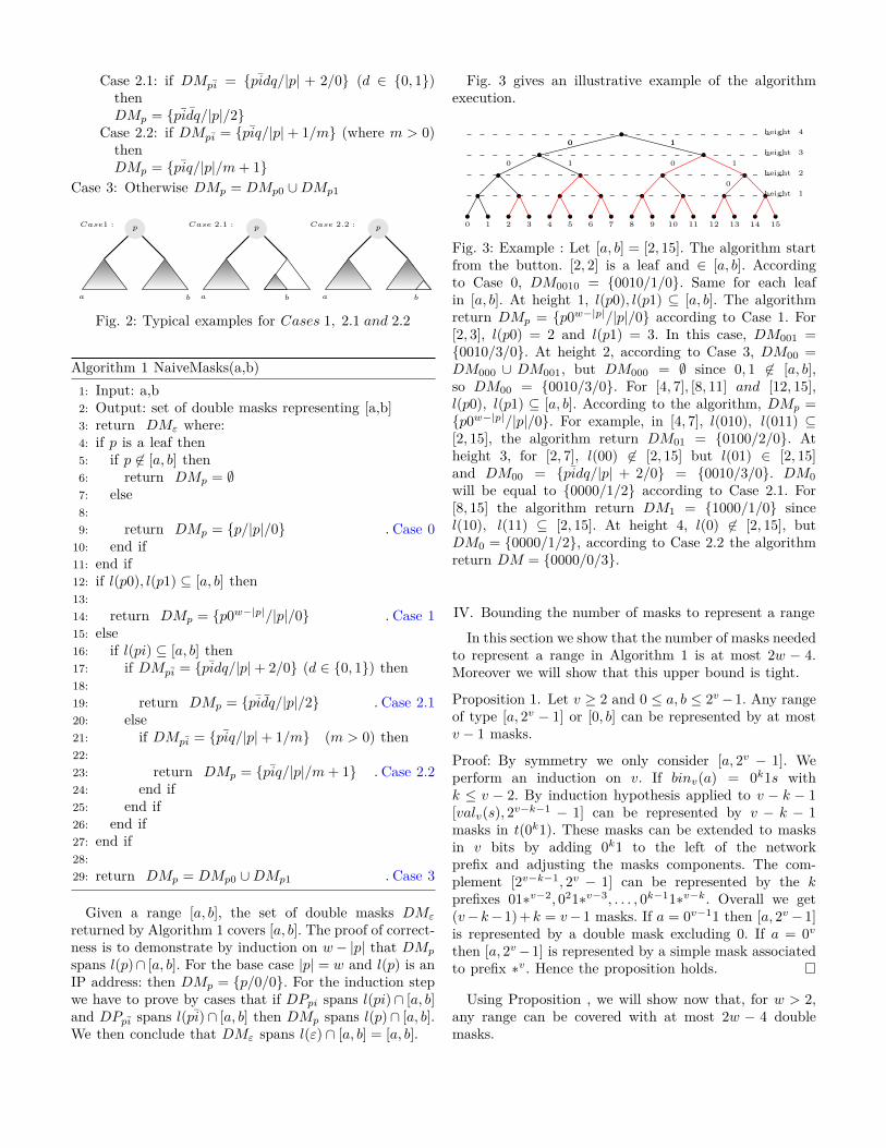
Fig. 3 gives an illustrative example of the algorithmexecution.
0 1 2 3 4 5 6 7
0 1
8 9 10 11 12 13 14 15
0 1
10 10
0
height 4
height 3
height 2
height 1
Fig. 3: Example : Let [a, b] = [2, 15]. The algorithm startfrom the button. [2, 2] is a leaf and ∈ [a, b]. Accordingto Case 0, DM0010 = {0010/1/0}. Same for each leafin [a, b]. At height 1, l(p0), l(p1) ⊆ [a, b]. The algorithmreturn DMp = {p0w−|p|/|p|/0} according to Case 1. For[2, 3], l(p0) = 2 and l(p1) = 3. In this case, DM001 ={0010/3/0}. At height 2, according to Case 3, DM00 =DM000 ∪ DM001, but DM000 = ∅ since 0, 1 6∈ [a, b],so DM00 = {0010/3/0}. For [4, 7], [8, 11] and [12, 15],l(p0), l(p1) ⊆ [a, b]. According to the algorithm, DMp ={p0w−|p|/|p|/0}. For example, in [4, 7], l(010), l(011) ⊆[2, 15], the algorithm return DM01 = {0100/2/0}. Atheight 3, for [2, 7], l(00) 6∈ [2, 15] but l(01) ∈ [2, 15]and DM00 = {pidq/|p| + 2/0} = {0010/3/0}. DM0
will be equal to {0000/1/2} according to Case 2.1. For[8, 15] the algorithm return DM1 = {1000/1/0} sincel(10), l(11) ⊆ [2, 15]. At height 4, l(0) 6∈ [2, 15], butDM0 = {0000/1/2}, according to Case 2.2 the algorithmreturn DM = {0000/0/3}.
IV. Bounding the number of masks to represent a range
In this section we show that the number of masks neededto represent a range in Algorithm 1 is at most 2w − 4.Moreover we will show that this upper bound is tight.
Proposition 1. Let v ≥ 2 and 0 ≤ a, b ≤ 2v−1. Any rangeof type [a, 2v − 1] or [0, b] can be represented by at mostv − 1 masks.
Proof: By symmetry we only consider [a, 2v − 1]. Weperform an induction on v. If binv(a) = 0k1s withk ≤ v − 2. By induction hypothesis applied to v − k − 1[valv(s), 2
v−k−1 − 1] can be represented by v − k − 1masks in t(0k1). These masks can be extended to masksin v bits by adding 0k1 to the left of the networkprefix and adjusting the masks components. The com-plement [2v−k−1, 2v − 1] can be represented by the kprefixes 01∗v−2, 021∗v−3, . . . , 0k−11∗v−k. Overall we get(v−k− 1)+k = v− 1 masks. If a = 0v−11 then [a, 2v− 1]is represented by a double mask excluding 0. If a = 0v
then [a, 2v−1] is represented by a simple mask associatedto prefix ∗v. Hence the proposition holds.
Using Proposition , we will show now that, for w > 2,any range can be covered with at most 2w − 4 doublemasks.

Proposition 2. Let w > 2. Every range [a, b] ⊆ [0, 2w − 1]can be represented by at most 2w − 4 masks.
Proof: Let [a, b] be a range of addresses of length w. Itis well known, according to [13], that n ≤ 2w − 2 simplemasks are sufficient to represent a range [a, b] ⊆ [0, 2w−1].
Now let us prove by induction that a range [a, b] of wbits can be represented with ≤ 2w − 4 masks.For w = 3, two masks are sufficient. For w = 4, four masksare sufficient to represent any range [a, b].Assume the proposition holds for w− 1 bits. We performa case analysis and assume that one case is applied onlyif the previous ones are not applicable:
• [a, b] ⊆ l(0) or [a, b] ⊆ l(1) then by inductionhypothesis the proposition holds.
• [a, b] ⊆ l(01) ∪ l(10) then applying Proposition IVto [a, b] ∩ l(0) with v = w − 2 we obtain that [a, b] ∩l(0) is covered by v − 3 masks. These masks can beextended to masks in w bits. In the same way [a, b]∩l(0) is covered by w − 3 masks. Therefore [a, b] canbe represented with 2w − 6 masks.
• [a, b] ⊆ l(01) ∪ l(10) ∪ l(11) we apply the previousitem reasoning to show that [a, b] ∩ (l(01) ∪ l(11))is represented by 2w − 6 masks. Since one mask issufficient for perfect range [a, b] ∩ l(10), we obtainoverall 2w − 5 masks.
• [a, b] ⊆ l(00) ∪ l(01) ∪ l(10): we reason as in theprevious case.
• [a, b] ⊆ l(00) ∪ l(01) ∪ l(10) ∪ l(11): we need 2w − 6masks for [a, b]∩ (l(00)∪ l(11)), one mask for each of[a, b] ∩ l(01) and [a, b] ∩ l(10) since they are perfectranges. Hence overall 2w− 6 + 2 = 2w− 4 masks aresufficient.
Therefore the total number of masks needed to represent[a, b] is 2w − 4.
The following proposition shows that the 2w− 4 boundis tight, i.e., some ranges cannot be represented by lessthan 2w − 4 double masks.
Proposition 3. Let w > 3. The range [3, 2w−4] cannot berepresented by less than 2w − 4 double masks.
Proof: First note that no mask can cover a set of addresseswith non empty intersection with both l(0) and l(1).Therefore we have to add the minimal number of masksfor covering [3, 2w−1 − 1] and the minimal number ofmasks for covering [2w−1, 2w − 4]. Address 3 cannot becovered by a mask s/p/k with p < w − 1: otherwise, ifk > 0 only a unique perfect subrange l(s|p+ k) would beexcluded, but [0, 2] is composed of two perfect subranges,contradiction ; if k = 0 then l(s|p) would contains address2, contradiction. Hence address 3 can be covered onlyby 0w−211/w/0 or 0w−110/w − 1/1. In the same way,no address between 3 and 2w−1 − 1 can be covered bya double mask. By reasoning as in Example 2 we can
also show that two addresses of type 2w′−1 − 1 with
3 < 2w′−1 − 1 ≤ 2w−1 − 1 cannot be covered by the same
simple mask. As a consequent the minimal number ofmasks needed to cover [3, 2w−1−1] is w−2. By symmetrythis is also true for [2w−1, 2w − 4]. The total number ofmasks is therefore 2w − 4.
V. Linear time algorithm
In this section we introduce a more efficient algorithm,named DoubleMasks, to compute a set of masks coveringany range [a, b]. As it will become clear, this algorithmis linear in k where k is the number of bits to representan IP address. Given two binary strings u, v we writeu ≺ v (resp. u � v) when u is a strict prefix (resp. prefix)of v. We denote by prec(p) the longest proper suffix ofp. Recall that u < v indicates that the natural numberdenoted by u is smaller than the one denoted by v. Weassume that binw(a) = ca′, binw(b) = cb′ where c is thelongest common prefix of binw(a) and binw(b).NaiveMasks (Algorithm 1) processes all nodes on
paths from the root to leaves with value in [a, b].Hencethe number of processed nodes can be exponential inw. Unlike NaiveMasks, the second proposed algorithmDoubleMasks (Algo. 3) only processes nodes p in pathsleading to leaves with value a or b, i.e., DoubleMasksexamines only two branches in the tree t(ε). Fig. 4 showsus the idea behind the algorithm. DoubleMasks works intwo phases. The algorithm computes first for each nodep a set of masks for l(p) ∩ [a, b], in a bottom up wayand starting from the two nodes binw(a) and binw(b).Then, when reaching node c, the set of masks computedat the siblings of c (i.e., c0 and c1) are combined and thealgorithm stops. This strategy is justified by the followingFact 1:
Fact 1. Let c be the longest common prefix of binw(a)and binw(b). Interval [a, b] is the disjoint union of[a, valw(c01
w−|c|−1)] and [valw(c10w−|c|−1), b].
Now we introduce ComputeMasks, a procedure thatcomputes the double-mask DM representation of eachsubinterval in Fact 1. ComputeMasks has a parameterx that will be successively substituted by a and bin the main algorithm DoubleMasks. The Booleanparameter β is chosen such that cβ is a prefix of x.If x < valw(cββ
w−|c|−1) (resp. x > valw(cββw−|c|−1)),
the algorithm computes a DM representation of range[x, valw(cββ
w−|c|−1)] (resp. [valw(cββw−|c|−1), x]).
ComputeMasks relies on the following case analysis:
Case 1: c ≺ pβ � x:Case 1.1: if DMpβ = {pββs/|p|+2/0}, then DMp ={pββs/|p|/2} (DM generated)
Case 1.2: if DMpβ = {pβs/|p| + 1/k}, then DMp ={pβs/|p|/k+1}, since l(pβ) ⊆ [a, b] (DM extended)

Case 1.3: if DMpβ = {pβs/|p| + 1/0}, then DMp ={pβs/|p|/0}, since l(pβ) ⊆ [a, b] and DMpβ is asimple mask (SM Extended)
Case 1.4: otherwise DMp = DMpβ ∪{pβs/|p|+1/0},since l(pβ) ⊆ [a, b] (SM added)
Case 2: if c ≺ pβ � x, then DMp = DMpβ (masksmaintained)
a b
p q
c
Fig. 4: Illustration of DoubleMasks strategy.
Now we detail the auxiliary procedure ComputeMasksand the main procedure DoubleMasks.
1) ComputeMasks (Algo. 2): This algorithm takesa binary number x such that cβ ≺ x and returns aset of masks representing the interval between x andvalv(cβ
w−|c|).First we add the simple mask corresponding to x (line
3). Then, we proceed on all prefixes of x from the longestone (lines 4-20). For each prefix, the algorithm checksthe type of the previously computed mask. If this maskcontains a mask1 of length |p| + 2 (corresponding toa perfect tree of height |p| + 2) a new double mask isgenerated (lines 7-8). If a double mask is present, thisdouble mask will be extended (lines 9-10). If the maskcomputed before has a mask1 of length |p|+ 1 the samemask will be extended (lines 11-12). If neither of theprevious cases holds, the algorithm adds a new mask tothe set of masks computed before (lines 13-14).
The proof of correctness of ComputeMasks is byinduction on w − |p| and checks whether DMp coversl(p) ∩ [a, b], as for NaiveMasks. Therefore the result ofComputeMasks(a, c, 0) (resp. ComputeMasks(b, c, 0)) isa DM representation of l(c0) ∩ [a, b] (resp. l(c1) ∩ [a, b]).
2) DoubleMasks (Algo. 3): This algorithm takes asinput an interval [a, b] and computes a set of masksrepresenting it. First, the algorithm computes the commonprefix c of a and b (line 3). Then, according to Fact 1,interval [a, b] can be divided into [a, valw(c01
w−|c|−1)] and[valw(c10
w−|c|−1), b]. ComputeMasks is called for eachsubinterval (lines 5-6). The final result depends on thesets of masks DMp and DMq generated by Algo. 2. Ifl(c0), l(c1) ⊆ [a, b] a new simple mask is generated (lines7-9). If a double mask is generated for t(c1) (resp. t(c0)), the double mask will be extended (lines 10-11) (resp.
Algorithm 2 ComputeMasks(x,c,β)1: Input: x, c, β such that cβ ≺ x2: Output: set of masks DMcβ
3: p← prec(x);DMx ← {x/w/0} .processing path x4: while c ≺ p do5: if case 1 then6: switch (DMpβ)7: case 1.1 = {pββs/|p|+ 2/0}:8: DMp ← {pββs/|p|/2} .new DM generated9: case 1.2 = {pβs/|p|+ 1/k}:
10: DMp ← {pβs/|p|/k + 1} .DM extended11: case 1.3 = {pβs/|p|+ 1/0}:12: DMp ← {pβs/|p|/0} .SM extended13: default:14: DMp ← DMpβ ∪ {pββ|w|−|p|−1/|p|+ 1/0}.SM
added - Case 1.415: end switch16: else17: case 218: end if19: p← prec(p) .process parent node on the path20: end while21: return DMp
18-19). If l(c0) (resp. l(c1)) is covered by a simple maskof length |p| (resp. |q|) and l(c1) (resp. l(c0)) is covered bya mask of length |q|+1 (resp. |p|+1), then a new doublemask will be generated (lines 12-13) (resp. lines 20-21). Ifnot, the algorithm returns the union of the two parts.DoubleMasks computes a DM representation of l(c)∩
[a, b] from DM representations of l(c0)∩ [a, b] and l(c1)∩[a, b] obtained by calling ComputeMasks. We can stopwhen reaching c in the main “while” loop of DoubleMasksand return the result DMc since we can see easily thatl(c) ∩ [a, b] = l(ε) ∩ [a, b] = [a, b].
VI. Experimental ResultsIn this section we evaluate the performance of the
Algorithm DoubleMasks and we compare it with thealgorithm that only generates simple masks and thatis obtained by a simple modification of DoubleMasks.We conducted experiments using two types of data sets.The first dataset is a real blacklist downloaded from therepository http://iplists.firehol.org/. The second datasetis a list of synthetically generated IP addresses.
1) Simulation setup: The real blacklist dataset containsmore than 1.5 million IP addresses that are collectedfrom different sources and combined together. We firsttransform this set of IPs into ranges. Then we comparethe effects of a double mask representation w.r.t. a simplemask representation in reducing the size of our dataset.To generate double masks we rely on DoubleMasks algo-rithm and to generate simple masks we rely on a simplemodification of DoubleMasks called SimpleMasks.The two programs were coded in Java language. The
Algorithm 3 DoubleMasks(a,b)1: Input: a, b2: Output: set of masks representing [a, b]3: c← longest common prefix of a and b4: p← c0, q ← c1 .final result will be computed from
siblings of c5: DMp ← ComputeMasks(a, c, 0) .refer to Algo. 26: DMq ← ComputeMasks(b, c, 1) .refer to Algo. 27: if DMp = {pr/|p|/0} then8: if DMq = {qs/|q|/0} then9: return {cr/|c|/0} .new SM generated
10: else if DMq = {c{1}w−|c|/|q|/|s|} then11: return {c1s/|q| − 1/|s|+ 1} .DM extended12: else if DMq = {qs/|q|+ 1/0} then13: return {c11t/|c|/2} .new DM generated14: else15: return DMp ∪DMq
16: end if17: else if DMq = {qs/|q|/0} then18: if DMp = {c{0}w−|c|/|p|/|s|} then19: return {c0s/|p| − 1/|s|+ 1} .DM extended20: else if DMp = {ps/|p|+ 1/0} then21: return {c00t/|c|/2} .new DM generated22: else23: return DMp ∪DMq
24: end if25: else26: return DMp ∪DMq
27: end if
experiments are carried on a desktop computer with Intelcore i7-7700 3.6-GHz CPU, 32 GB of RAM and runningWindows 10 operating system.
We define the following metrics for analysing the per-formance of the two algorithms:
Average Compression Ratio = 1− Mn∗S
whereM is the number of masks generated in all iterations,S is the number of IPs in the dataset,n denotes the number of iterations.
To compute the average compression ratio, the numberof iterations is set to 20. We use this metric to show thatour algorithm can generate a more compact list of rulesin comparison with SimpleMasks algorithm.
2) Results of real life IP blacklist: The blacklist IPsare aggregated into approximately 6000 ranges. In orderto have a much larger ranges, the two algorithms willtake as input all the ranges located between the set ofranges computed previously. The two programs take asinput each range and compute a set of masks covering thisrange. Fig. 5 shows the distribution of range lengths usedin this experiment. We observe, that several ranges havevery large lengths, but our algorithm is not sensitive to
range length since it only processes the two IP boundariesof a range.
0-50
050
0-1K
1K-2
K2K
-5K
5K-1
0K10
K-2
0K20
K-5
0K50
K-1
00K
100K
-200
K20
0K-5
00K
500K
-1M
1M-5
M>
5M
0
2
4
6
8
10
12
14
Perc
enta
ge(%
)
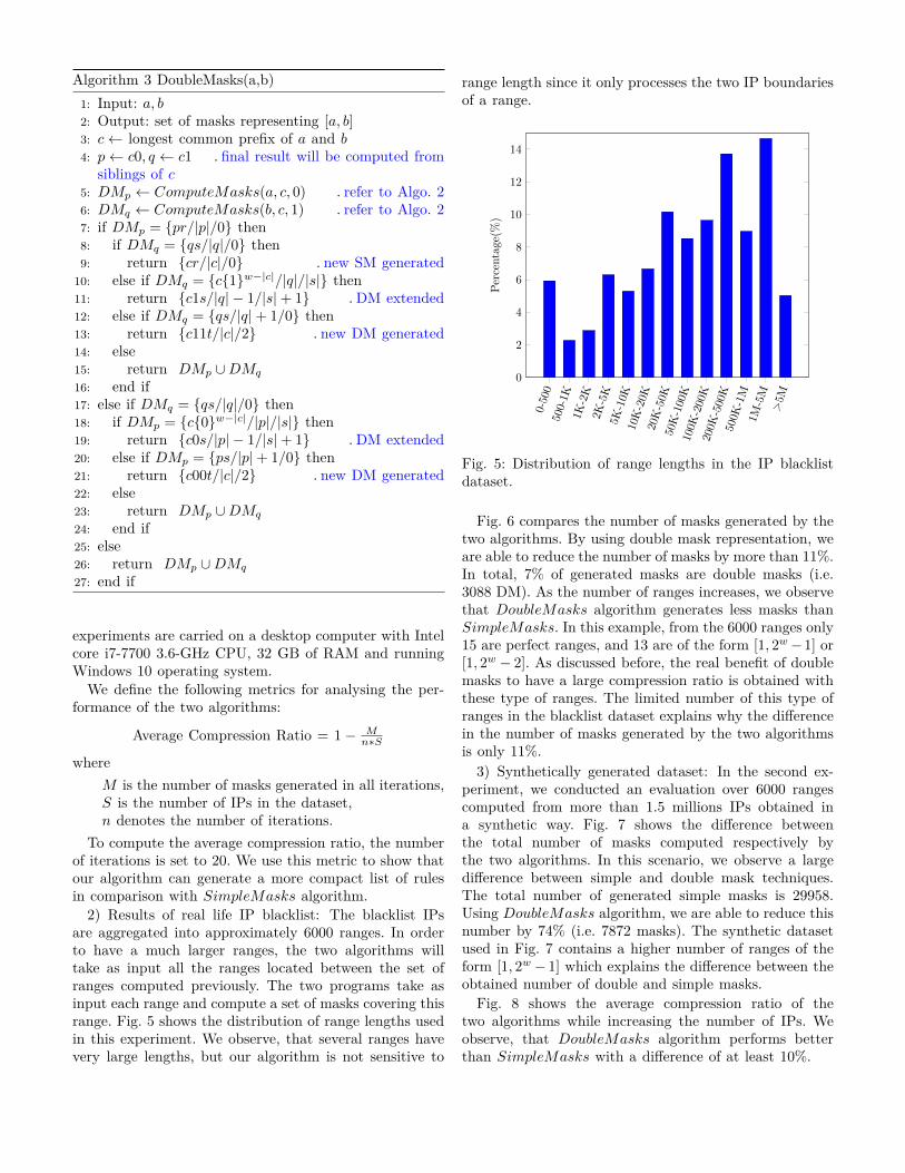
Fig. 5: Distribution of range lengths in the IP blacklistdataset.
Fig. 6 compares the number of masks generated by thetwo algorithms. By using double mask representation, weare able to reduce the number of masks by more than 11%.In total, 7% of generated masks are double masks (i.e.3088 DM). As the number of ranges increases, we observethat DoubleMasks algorithm generates less masks thanSimpleMasks. In this example, from the 6000 ranges only15 are perfect ranges, and 13 are of the form [1, 2w−1] or[1, 2w − 2]. As discussed before, the real benefit of doublemasks to have a large compression ratio is obtained withthese type of ranges. The limited number of this type ofranges in the blacklist dataset explains why the differencein the number of masks generated by the two algorithmsis only 11%.
3) Synthetically generated dataset: In the second ex-periment, we conducted an evaluation over 6000 rangescomputed from more than 1.5 millions IPs obtained ina synthetic way. Fig. 7 shows the difference betweenthe total number of masks computed respectively bythe two algorithms. In this scenario, we observe a largedifference between simple and double mask techniques.The total number of generated simple masks is 29958.Using DoubleMasks algorithm, we are able to reduce thisnumber by 74% (i.e. 7872 masks). The synthetic datasetused in Fig. 7 contains a higher number of ranges of theform [1, 2w − 1] which explains the difference between theobtained number of double and simple masks.
Fig. 8 shows the average compression ratio of thetwo algorithms while increasing the number of IPs. Weobserve, that DoubleMasks algorithm performs betterthan SimpleMasks with a difference of at least 10%.

0 1,000 2,000 3,000 4,000 5,000 6,000
0
2
4
·104
Number of ranges
Num
ber
ofm
asks
DoubleMasksSimpleMasks
Fig. 6: Number of masks computed respectively byDoubleMasks and SimpleMasks algorithms using the IPblacklist dataset.
0 1,000 2,000 3,000 4,000 5,000 6,0000
0.5
1
1.5
2
2.5
·104
Number of ranges
Num
ber
ofm
asks
DoubleMasksSimpleMasks
Fig. 7: Number of masks generated respectively byDoubleMasks and SimpleMasks algorithms using thesynthetic dataset.
Fig. 9 shows the difference in compression ratio betweenDoubleMasks and SimpleMasks while modifying thelength of IPs. We observe that DoubleMasks alwaysperforms better than SimpleMasks for each length value.
The compression ratio depends on each dataset and onthe nature of IPs ranges. We use two types of datasetsin order to demonstrate that this technique can reducethe number of rules by 79% and more in some casesand by 11% or less in others depending on the natureof IPs ranges. Since DoubleMasks algorithm generatesa simple mask when no double mask can be generated,
0 1 2 3 4 5
·104
0
20
40
60
Number of IPs
Avar
age
com
pres
sion
ratio
(%) DoubleMasks
SimpleMasks
Fig. 8: Compression ratio of DoubleMasks andSimpleMasks using a synthetic dataset of range fieldsof length 16bits.
8 bits 12 bits 16 bits 20 bits 24 bits 32 bits0
20
40
60
80
Aver
age
com
pres
sion
ratio
(%) DoubleMasksSimpleMasks
Fig. 9: Comparison of compressions ratio betweenDoubleMasks and SimpleMasks while varying the lengthof a field.
the total number of masks will be at most equal to thenumber of simple masks computed by SimpleMasks.This is why, according to our empirical simulations,SimpleMasks cannot generate a smaller set of masks thanDoubleMasks.
VII. Related WorksReducing the number of rules in a firewall is a very
common problem that has been studied in multipleworks. For instance, [14] proposes an approach to detectanomalies in firewall rules like generalization, shadowingand correlation and recommends actions for correctingthose anomalies in order to reduce the number of rulesand increase the performance of firewalls. In [6], anew compression scheme was presented to minimize the

number of policies in a firewall by removing redundantand shadowed rules. In [10], the authors present a newaggressive reduction algorithm by merging rules togetherusing two-dimensional representation.
Since TCAM is the standard for rules storage andmatching in packet classification for Openflow switches,multiple attempts to solve their problems was consideredin [15]–[19]. To reduce the number of entries in TCAM, [9]proposes a new algorithm to remove redundant rules usinga tree representation. On the other hand, [11] proposes anew compiler that aims to reduce the number of entries inswitches and to speed up the packet classification process.In [20] a new systematic approach was introduced tominimize the prefix rules in TCAM. A mechanism called“Flow Table Reduction Scheme” has been introduced in[21] to minimize the number of flow entries in SDN. Thispaper focuses on reducing the number of entries by usinga new representation for IP ranges, since reducing thenumber of entries can improve the power consumption ofTCAM, while respecting the capacity constraint.
The number of prefixes needed to cover a range hasalso been studied extensively in the literature. In [22], theauthors show that by using Gray encoding, the number orintervals needed is also 2w − 4. Despite having the sameupper bound with double mask approach, our techniquecan be more efficient in some cases. For example, therange [6,14] mentioned in [22], need three entries to berepresented using gray code but two using a double mask.The DNF (disjunctive normal form) has also been appliedto compute the minimal Boolean expression for a rangein linear time [23] and to prove the 2w − 4 upper bound.The works above admit only “accept” actions. Severalworks have also addressed the minimization of the numberof entries with both “accept” and “deny” actions. In thiscase the upper bound can reach w entries [24], [25].However the order of rules is very important in theseapproaches and rules management gets more complex. Ourwork is software-based, and relies only on accept rules,unlike [8], [24], [25]. We rely on a notation proposed in[12] that can reduce dramatically the number of entries inrouting tables. In comparison, representing a w-bit rangemay need 2w− 2 prefixes [26]. For example [1, 14] needs 6entries but with the double-mask notation two entries aresufficient. This new notation has the same upper boundof 2w− 4 presented in other papers [22], [23], [27], but insome cases, the number can be reduced as shown beforein our experimental results.
VIII. Hardware ImplementationA. Architecture
In this work, we implement and set-up the architectureshown in Figure 10, which consists of a controller, a switchand multiple hosts.
In our set-up, we use the OpenFlow-enabled zodiac FXswitch that provides an inexpensive alternative to exper-iment SDN networks in hardware. The switch provides
Fig. 10: Architecture and set-up of our SDN network.
four ports, one for the controller and the three others areto be used for hosts as shown in Figure 11.
Fig. 11: The Zodiac Fx switch set-up.
The switch communicates using the Openflow protocolwith an SDN controller. We used the Ryu SDN controller[28] that runs on a machine connected via Ethernet cableto the zodiac Fx switch. Ryu controller supports severalprotocols such as OpenFlow and it is developed in Python.The rules containing the double mask representation ofIP matching fields are provided to the controller to installthem in the switch. When the switch receives a packet itwill perform a matching between the IP source and all therules in the routing table, if the switch finds a match, theaction of the rule that matches the IP will be performed.
B. Extending the control and data plane with the double-mask representation
We modified the control plane of our SDN system whichthe Ryu controller in order to integrate the double maskrepresentation in the OpenFlow protocol match fields. Inour modified implementation of Ryu, when the controlleris provided with a rule containing a double mask itcomputes in the matching field the first and second masksand installs the rule in the flow table of the switch.
For the data plan component, we modified the Open-Flow implementation of the Zodiac Fx switch [29] tointegrate the processing of rules containing the doublemask representation. The code of this switch is open source

and developed in C language. This code has also beenmodified in order to store a double mask in the forwardingtable and to apply a matching between the IP source ofa packet and all the rules in the switch. The Algorithm 4has been integrated in the code of the switch to supportthe matching of a double-mask based OpenFlow rule andeither the IP source or destination fields of a packet. Ifthe value of S0 is zero, that means that the IP matchesthe network prefix (netref). If the value in S1 is differentfrom zero that means that the IP is not included in the setof rejected IPs by mask2, in this case, the IP will matchthe rule in the switch.
Algorithm 4 Matching(netref,mask1,mask2, ip)
1: Input: netref,mask1,mask2, ip2: Output: accept or deny3: AND1 ← mask1∧ netref4: XOR1 ← AND1 ⊕ ip5: S0 ← XOR1 ∧ mask16: if S0 = 0 then7: .ip match the prefix of the network8: OR ← mask1∨mask29: AND2 ← OR ∧ip_source
10: AND3 ← OR ∧ netref11: S1 ← AND2 ⊕ AND312: if S1 # 0 then13: .ip not included in IPs rejected by mask214: return accept15: else16: return deny17: end if18: else19: return deny20: end if
The Algorithm 4 has been integrated in the code of theswitch to support the matching of a double-mask basedOpenFlow rule and either the IP source or destinationfields of a packet. If the value of S0 is zero, that meansthat the IP matches the network prefix (netref). If thevalue in S1 is different from zero that means that the IPis not included in the set of rejected IPs by mask2, in thiscase, the IP will match the rule in the switch. When thecontroller matches a packet, the rule is sent to both theswitch and the Web Application. The switch then addsthe rule to the flow table order to perform the matchingdirectly without the need of the controller. The rule is alsoadded to the database in order to perform some statisticslike specifying the importance of some rules based on thenumber of times a packet is being matched to a specificrule.
IX. Conclusion and future workThe double mask representation has been informally
introduced in [12] to reduce the number of rules infirewalls, IDS’s or routing tables in order to make theconfiguration, the management and deployment easier.
In this paper, we formally propose the first linearalgorithm to compute a set of double masks covering arange of IPs. Note that our algorithm can be appliedafter or in combination with known redundancy removal
techniques [6] in order to further reduce the number ofentries in filtering rule tables. Then we conducted a seriesof experiments on real and synthetic dataset. Accordingto our experiments, using the double mask representationallows one to reduce the number of rules needed to cover aset of ranges by more than 11% on a real blacklist (afterremoving the redundant rules) and more than 74% onsynthetic data. The algorithm is not limited to IP rangesand it can be applied to port ranges too and to reducethe range expansions in TCAM. Finally, we demonstrateby adding support of double masks in SDN networks,that this new representation can be used instead of simplemask.Our future work consists of computing double masks forunion of ranges in order to achieve a higher level ofoptimization in routing tables. We also plan to designfast update strategies of generated double masks to handlerapid changes in filtering policies.
AcknowledgementThis work is supported by a CIFRE convention between
the ANRT (National Association of Research and Tech-nology) and the company NUMERYX Technologies.
References[1] bgphelp, 2017 BGP Table Size Prediction and Potential Impact
on Stability of Global Internet Infrastructure, 2017. [Online].Available: http://bgphelp.com/2017/01/01/bgpsize/
[2] A. Hiromori, H. Yamaguchi, K. Yasumoto, T. Higashino, andK. Taniguchi, “Reducing the size of routing tables for large-scalenetwork simulation,” in Seventeenth Workshop on Parallel andDistributed Simulation, 2003. (PADS 2003). Proceedings., June2003, pp. 115–122.
[3] W. Braun and M. Menth, “Wildcard compression of inter-domain routing tables for openflow-based software-defined net-working,” in 2014 Third European Workshop on SoftwareDefined Networks, Sept 2014, pp. 25–30.
[4] C. R. Meiners, A. X. Liu, and E. Torng, “Bit weaving: A non-prefix approach to compressing packet classifiers in TCAMs,”IEEE/ACM Transactions on Networking, vol. 20, no. 2, pp.488–500, April 2012.
[5] Symantec, Internet Security Threat Report, April 2017.[Online]. Available: https://www.symantec.com/content/dam/symantec/docs/reports/istr-22-2017-en.pdf
[6] A. X. Liu, E. Torng, and C. R. Meiners, “Firewall compressor:An algorithm for minimizing firewall policies,” in IEEE INFO-COM 2008 - The 27th Conference on Computer Communica-tions, April 2008, pp. 176–180.
[7] V. Fuller, T. Li, J. Yu, and K. Varadhan, “Classless inter-domainrouting (CIDR): An address assignment and aggregation strat-egy,” United States, 1993.
[8] N. B. Neji and A. Bouhoula, “Naf conversion: An efficientsolution for the range matching problem in packet filters,” in2011 IEEE 12th International Conference on High PerformanceSwitching and Routing, July 2011, pp. 24–29.
[9] Y. Sun and M. S. Kim, “Tree-based minimization of TCAMentries for packet classification,” in 2010 7th IEEE ConsumerCommunications and Networking Conference, Jan 2010, pp.1–5.
[10] M. Yoon, S. Chen, and Z. Zhang, “Reducing the size of ruleset in a firewall,” in 2007 IEEE International Conference onCommunications, June 2007, pp. 1274–1279.
[11] S. Hommes, P. Valtchev, K. Blaiech, S. Hamadi, O. Cherkaoui,and R. State, “Optimising packet forwarding in multi-tenantnetworks using rule compilation,” in 2017 IEEE 16th Inter-national Symposium on Network Computing and Applications(NCA), Oct 2017, pp. 1–9.
[12] A. Bouhoula and N. B. Neji, “Double-masked IP filter,”Patent, 04 10, 2015. [Online]. Available: https://bases-brevets.inpi.fr/fr/document/FR3011705.html
[13] D. E. Taylor, “Survey and taxonomy of packet classificationtechniques,” ACM Comput. Surv., vol. 37, no. 3, pp. 238–275,Sep. 2005. [Online]. Available: http://doi.acm.org/10.1145/1108956.1108958
[14] A. Bouhoula, Z. Trabelsi, E. Barka, and M. Anis Benelbahri,“Firewall filtering rules analysis for anomalies detection,” IJSN,vol. 3, pp. 161–172, 01 2008.
[15] M. Degermark, A. Brodnik, S. Carlsson, and S. Pink,“Small forwarding tables for fast routing lookups,” SIGCOMMComput. Commun. Rev., vol. 27, no. 4, pp. 3–14, Oct. 1997.[Online]. Available: http://doi.acm.org/10.1145/263109.263133
[16] H. Liu, “Efficient mapping of range classifier into ternary-cam,” in Proceedings 10th Symposium on High PerformanceInterconnects, Aug 2002, pp. 95–100.
[17] Q. Dong, S. Banerjee, J. Wang, D. Agrawal, andA. Shukla, “Packet classifiers in ternary cams can besmaller,” SIGMETRICS Perform. Eval. Rev., vol. 34,no. 1, pp. 311–322, Jun. 2006. [Online]. Available:http://doi.acm.org/10.1145/1140103.1140313
[18] E. Spitznagel, D. Taylor, and J. Turner, “Packet classificationusing extended TCAMs,” in 11th IEEE International Confer-ence on Network Protocols, 2003. Proceedings., Nov 2003, pp.120–131.
[19] O. Rottenstreich, I. Keslassy, A. Hassidim, H. Kaplan, andE. Porat, “On finding an optimal TCAM encoding scheme forpacket classification,” in 2013 Proceedings IEEE INFOCOM,April 2013, pp. 2049–2057.
[20] C. R. Meiners, A. X. Liu, and E. Torng, “TCAM razor: Asystematic approach towards minimizing packet classifiers inTCAMs,” in 2007 IEEE International Conference on NetworkProtocols, Oct 2007, pp. 266–275.
[21] B. Leng, L. Huang, C. Qiao, H. Xu, and X. Wang, “Ftrs:A mechanism for reducing flow table entries in softwaredefined networks,” Computer Networks, vol. 122, pp. 1 –15, 2017. [Online]. Available: http://www.sciencedirect.com/science/article/pii/S1389128617301470
[22] A. Bremler-Barr and D. Hendler, “Space-Efficient TCAM-Based Classification Using Gray Coding,” IEEE Transactionson Computers, vol. 61, no. 1, pp. 18–30, Jan 2012.
[23] B. Schieber, D. Geist, and A. Zaks, “Computing the minimumDNF representation of boolean functions defined by intervals,”Discrete Applied Mathematics, vol. 149, no. 1, pp. 154 – 173,2005.
[24] R. Cohen and D. Raz, “Simple efficient TCAM based rangeclassification,” in 2010 Proceedings IEEE INFOCOM, March2010, pp. 1–5.
[25] O. Rottenstreich, R. Cohen, D. Raz, and I. Keslassy, “Exactworst case TCAM rule expansion,” IEEE Transactions onComputers, vol. 62, no. 6, pp. 1127–1140, June 2013.
[26] V. Srinivasan, G. Varghese, S. Suri, and M. Waldvogel,“Fast and scalable layer four switching,” SIGCOMM Comput.Commun. Rev., vol. 28, no. 4, pp. 191–202, Oct. 1998. [Online].Available: http://doi.acm.org/10.1145/285243.285282
[27] T. Sasao, “On the complexity of classification functions,” in38th International Symposium on Multiple Valued Logic (ismvl2008), May 2008, pp. 57–63.
[28] Ryu OpenFlow controller. [Online]. Available: https://osrg.github.io/ryu/
[29] NorthboundNetworks, Zodiac Fx switch. [Online]. Available:https://github.com/NorthboundNetworks/ZodiacFX