Informational Expert System for Minimizing the Time in ...
11
170 Informational Expert System for Minimizing the Time in Searching of Ship Electrical Equipment Failures Sergiy Rozhkov a , Kostyantyn Kondrashov a , Oksana Tereshchenkova a , Maryna Falenkova b a Kherson State Maritime Academy, 20, Ushakova str., Kherson, 7300, Ukraine b Petro Mohyla Black Sea National University, 68-Desantnykiv St 10, Mykolaiv, 54003, Ukraine Abstract Analysis of the failure diagnostic tools used by the operator in real navigation conditions to find and eliminate the causes of malfunction of shipboard automated systems and mechanisms is an actual problem. Quick search and elimination of a defect affect the level of ship’s safety. This article is devoted to obtaining and comprehensively studying methods and models for fault trees and decision trees construction for identifying a defect in specific diagnostic objects and their structural units, as well as methods used to defects finding. The basic subjective and objective conditions that affect the time spent by maintenance personnel on the readapting to work of the failed ship system are systematized and arranged. The article substantiates the need of the transition from existing paper documentation to electronic maintenance documentation using the expert system. Keywords 1 object of diagnostics, electric automation devices, complex technical system, decision maker, ship automated systems, expert system, alarm monitoring system, decision support system. 1. Introduction Modern electronic technologies have found the widest application in the field of navigation. Meanwhile, the complication of electrical equipment configuration and increasing of its number and the widespread introduction of integrated automation on ships, inevitably leads to an enlargement of the failure rate of ship systems. As a result, ship downtime caused by the need to repair electrical equipment is not uncommon. And, accordingly, the losses related with spent time and resources are significantly increasing. The operation experience of complex technical systems shows that the main part of the time of readapting to work of electrical automation devices (EAD) is the time spent on searching of defects. This proportion often accounts of 70–90% of the total recovery time and depends completely on the competence of the maintenance personnel [1, 2]. So, the more obvious is the fact that the more complex the functions of various automatic and automated ship systems are, the need in the coordination of maintenance personnel in case of unusual situations or electrical failures is acute. The article’s actuality is the necessity to find solutions to reduce the negative impact of the so - called “human factor” in the operation and maintenance of ship equipment , it is written in IMO resolution A.884 (21). Including, the necessity of crew safety improvement, as well as the increasing of the operational period of the ship’s electrical equipment are actual. The analysis of scientific works [3–5] showed that many researchers studied the problem of forecasting and anticipating failure of ship systems. As a result, the developed and implemented methods helped to reduce the failures of electrical equipment. However, the drawback of this approach is the lack of coordination of the decision-maker in action with, the occurred failure facts. It may lead to catastrophic consequences. IT&I-2020: Information Technology and Interactions, 2-3 December, 2020, Kyiv, Ukraine EMAIL: [email protected] (A. 1); [email protected] (A. 2); [email protected](A. 3);[email protected] (A. 4) ORCID: 0000-0002-1662-004X (A. 1); 0000-0003-1352-6098 (A. 2); 0000-0002-0023-5550 (A. 3); 0000-0001-7797-0142 (A. 4) 2020 Copyright for this paper by its authors. Use permitted under Creative Commons License Attribution 4.0 International (CC BY 4.0). CEUR Workshop Proceedings (CEUR-WS.org)
-
Upload
khangminh22 -
Category
Documents
-
view
0 -
download
0
Transcript of Informational Expert System for Minimizing the Time in ...
170
Informational Expert System for Minimizing the Time in Searching of Ship Electrical Equipment Failures
Sergiy Rozhkova , Kostyantyn Kondrashova, Oksana Tereshchenkovaa, Maryna Falenkovab
a Kherson State Maritime Academy, 20, Ushakova str., Kherson, 7300, Ukraine b Petro Mohyla Black Sea National University, 68-Desantnykiv St 10, Mykolaiv, 54003, Ukraine
Abstract Analysis of the failure diagnostic tools used by the operator in real navigation conditions to
find and eliminate the causes of malfunction of shipboard automated systems and
mechanisms is an actual problem. Quick search and elimination of a defect affect the level of
ship’s safety. This article is devoted to obtaining and comprehensively studying methods and
models for fault trees and decision trees construction for identifying a defect in specific
diagnostic objects and their structural units, as well as methods used to defects finding. The
basic subjective and objective conditions that affect the time spent by maintenance personnel
on the readapting to work of the failed ship system are systematized and arranged. The article
substantiates the need of the transition from existing paper documentation to electronic
maintenance documentation using the expert system.
Keywords 1 object of diagnostics, electric automation devices, complex technical system, decision maker,
ship automated systems, expert system, alarm monitoring system, decision support system.
1. Introduction
Modern electronic technologies have found the widest application in the field of navigation.
Meanwhile, the complication of electrical equipment configuration and increasing of its number and the widespread introduction of integrated automation on ships, inevitably leads to an enlargement of
the failure rate of ship systems. As a result, ship downtime caused by the need to repair electrical
equipment is not uncommon. And, accordingly, the losses related with spent time and resources are significantly increasing.
The operation experience of complex technical systems shows that the main part of the time of
readapting to work of electrical automation devices (EAD) is the time spent on searching of defects. This proportion often accounts of 70–90% of the total recovery time and depends completely on the
competence of the maintenance personnel [1, 2]. So, the more obvious is the fact that the more
complex the functions of various automatic and automated ship systems are, the need in the
coordination of maintenance personnel in case of unusual situations or electrical failures is acute. The article’s actuality is the necessity to find solutions to reduce the negative impact of the so-
called “human factor” in the operation and maintenance of ship equipment, it is written in IMO
resolution A.884 (21). Including, the necessity of crew safety improvement, as well as the increasing of the operational period of the ship’s electrical equipment are actual.
The analysis of scientific works [3–5] showed that many researchers studied the problem of
forecasting and anticipating failure of ship systems. As a result, the developed and implemented methods helped to reduce the failures of electrical equipment. However, the drawback of this
approach is the lack of coordination of the decision-maker in action with, the occurred failure facts. It
may lead to catastrophic consequences.
IT&I-2020: Information Technology and Interactions, 2-3 December, 2020, Kyiv, Ukraine
EMAIL: [email protected] (A. 1); [email protected] (A. 2); [email protected](A. 3);[email protected] (A. 4)
ORCID: 0000-0002-1662-004X (A. 1); 0000-0003-1352-6098 (A. 2); 0000-0002-0023-5550 (A. 3); 0000-0001-7797-0142 (A. 4)
© 2020 Copyright for this paper by its authors.
Use permitted under Creative Commons License Attribution 4.0 International (CC BY 4.0).
CEUR Workshop Proceedings (CEUR-WS.org)
171
The principles of expert systems developing were described in scientific works of A. Brucking [6], K. Neilor [7] and others. The use of modern technologies in intelligent systems development was
investigated by R. Bazhenov and D. Lopatin [8]. T. Kozlova and others examined the implementation
of the expert system of solution decision to identify failures of the technological system [9]. There are
also a number of works that consider approaches to the formation of expert groups. In [10, 11] proposed approach allows to distinguish groups of experts, with a “close” opinion, to analyze them in
order to develop a final (group) assessment that takes into account the opinions (arguments) of each
expert. B. Palyukh and others considered an intelligent decision support system for complex objects managing using dynamic fuzzy cognitive maps [12]. In the researches of the US Electric Power
Institute in the field of developing and using expert systems, special attention is paid to three main
areas: management, equipment diagnostics, and information support [9]. The developing experience of foreign scientists is described in [13, 14].
Currently, many information systems, methods and tools for monitoring and diagnosing of the
technical condition of electrical equipment are used and developed [15, 16]. At the same time, it is
necessary to improve existing and develop new technologies, practical methods that would ensure effective maintenance and repair of electrical equipment according to their technical condition. The
analysis of their effectiveness shows that, along with many specific advantages, they have several
disadvantages [17–19]. As a rule, there are methods of extracting information from a sufficiently large number of control points. In this case, the diagnostic process involves the implementation of
branching algorithms, their complexity increases with dimension growing of the diagnosed electrical
circuit.
2. Problem statement
The troubleshooting process is the most difficult at electrical equipment repairing, as modern
automated systems are a complex interconnected network of electrical and electronic circuits. The
task of faulty element findingis finding of the sequence of checks when a minimum of time is spent on defect searching. To be able to show the possible amount of time spent searching and repairing, an
experiment was conducted on one of the container ships of the shipping company Mediterranean
Shipping Company (MSC) m/v MSC “Brunella”. We used the archive logbook of the Kongsberg K-Chief 600 alarm monitoring system, the container ship MSC “Brunella”, it was built in 2015. The
total number of parameters controlled by the AMS is 3410 units [20, 21]. Data of ship failures
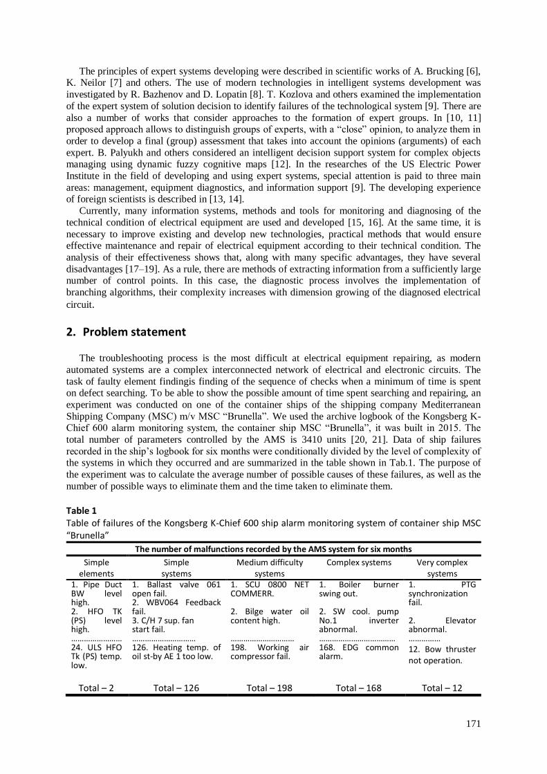
recorded in the ship’s logbook for six months were conditionally divided by the level of complexity of the systems in which they occurred and are summarized in the table shown in Tab.1. The purpose of
the experiment was to calculate the average number of possible causes of these failures, as well as the
number of possible ways to eliminate them and the time taken to eliminate them.
Table 1 Table of failures of the Kongsberg K-Chief 600 ship alarm monitoring system of container ship MSC “Brunella”
The number of malfunctions recorded by the AMS system for six months
Simple elements
Simple systems
Medium difficulty systems
Complex systems Very complex systems
1. Pipe Duct BW level high. 2. HFO TK (PS) level high. …………………… 24. ULS HFO Tk (PS) temp. low.
1. Ballast valve 061 open fail. 2. WBV064 Feedback fail. 3. C/H 7 sup. fan start fail. ………………………… 126. Heating temp. of oil st-by AE 1 too low.
1. SCU 0800 NET COMMERR. 2. Bilge water oil content high. ………………………… 198. Working air compressor fail.
1. Boiler burner swing out. 2. SW cool. pump No.1 inverter abnormal. ……………………………… 168. EDG common alarm.
1. PTG synchronization fail. 2. Elevator abnormal. …………… 12. Bow thruster not operation.
Total – 2 Total – 126 Total – 198 Total – 168 Total – 12
172
The initial data of the logbook are summarized in the table 2.
Table 2 Source data table
№ Variable Value Characteristics
1 M 180 The number of days during which malfunctions were recorded;
2 n 522 the average number of failures for six months
3 m 5 number of fault categories by difficulty level 4 Х1 4 average number of possible causes of failure for simple
elements
5 Х2 9 average number of possible causes of failure for simple systems
6 Х3 15 average number of possible causes of failure for systems of medium complexity
7 Х4 21 average number of possible causes of failure for complex systems
8 Х5 27 average number of possible causes of failure for very complex systems
9 N1 24 half-year average failure rate for simple elements
10 N2 126 half year average failure rate for simple systems
11 N3 198 the average frequency of malfunctions for six months related to systems of medium complexity
12 N4 162 six-month average failure rate for complex systems
13 N5 12 six-month average failure rate for very complex systems
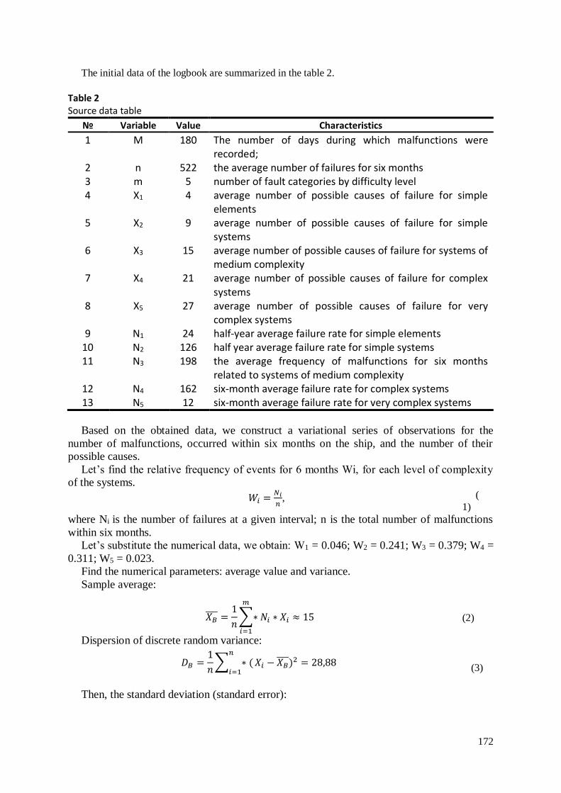
Based on the obtained data, we construct a variational series of observations for the
number of malfunctions, occurred within six months on the ship, and the number of their
possible causes.
Let’s find the relative frequency of events for 6 months Wi, for each level of complexity
of the systems.
𝑊𝑖 =𝑁𝑖
𝑛, (
1) where Ni is the number of failures at a given interval; n is the total number of malfunctions
within six months.
Let’s substitute the numerical data, we obtain: W1 = 0.046; W2 = 0.241; W3 = 0.379; W4 =
0.311; W5 = 0.023.
Find the numerical parameters: average value and variance.
Sample average:
Dispersion of discrete random variance:
Then, the standard deviation (standard error):
𝑋𝐵 =
1
𝑛∑∗ 𝑁𝑖 ∗ 𝑋𝑖
𝑚
𝑖=1
≈ 15
(2)
𝐷𝐵 =1
𝑛∑ ∗ (
𝑛
𝑖=1𝑋𝑖 − 𝑋𝐵
)2 = 28,88
(3)
173
Thus, the average number of possible causes of an accidental failure recorded by the AMS
system Хв= 15 with the standard deviation of σв= 5.
One-sigma interval (confidence probability is 67%) for the given random variable is from
10 to 20 possible reasons.
This means that very often even experienced electricians will spend quite a lot of time
guessing about the causes of the breakdowns and how to fix it.
Research methods
The diagnostic technique of SAS (SHIP AUTOMATED SYSTEMS) includes a hierarchical
principle of defect search. At each stage of diagnosis, a gradual clarification of the location of
the defect occurs. An inoperative block is determined (structurally designed OOD (object of
diagnostic) element that sent an error message). The detected block is diagnosed with the
depth search to the node/element of the functional diagram, etc. The result is in diagnosing at
the level of the functional diagram element with the depth search to the element of principal
diagram.
Confirming the fact of a system failure, the period of defect search begins. Because, the
main part of the time from the moment of failure to restoration of working capacity of the
system is spent on the search for a defect. We will consider this period in detail.
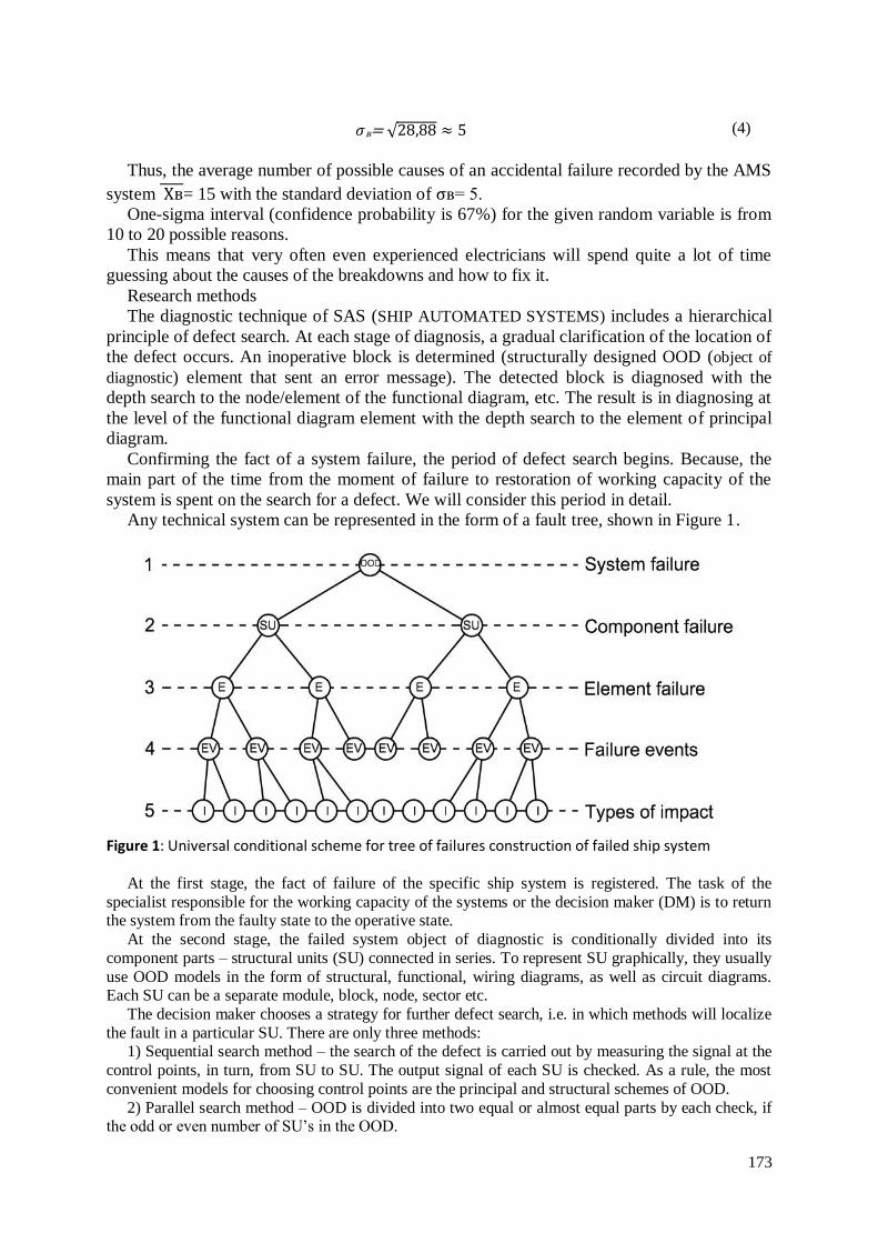
Any technical system can be represented in the form of a fault tree, shown in Figure 1.
Figure 1: Universal conditional scheme for tree of failures construction of failed ship system
At the first stage, the fact of failure of the specific ship system is registered. The task of the
specialist responsible for the working capacity of the systems or the decision maker (DM) is to return the system from the faulty state to the operative state.
At the second stage, the failed system object of diagnostic is conditionally divided into its
component parts – structural units (SU) connected in series. To represent SU graphically, they usually
use OOD models in the form of structural, functional, wiring diagrams, as well as circuit diagrams. Each SU can be a separate module, block, node, sector etc.
The decision maker chooses a strategy for further defect search, i.e. in which methods will localize
the fault in a particular SU. There are only three methods: 1) Sequential search method – the search of the defect is carried out by measuring the signal at the
control points, in turn, from SU to SU. The output signal of each SU is checked. As a rule, the most
convenient models for choosing control points are the principal and structural schemes of OOD.
2) Parallel search method – OOD is divided into two equal or almost equal parts by each check, if the odd or even number of SU’s in the OOD.
𝜎в= √28,88 ≈ 5 (4)
174
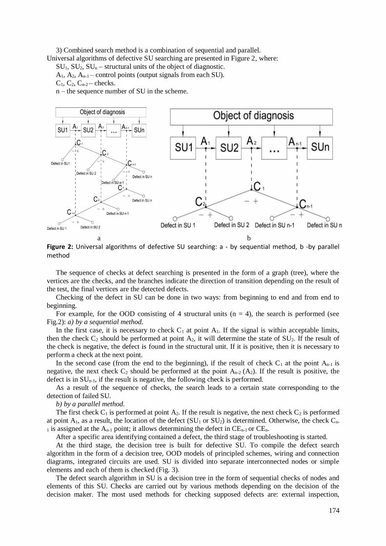
3) Combined search method is a combination of sequential and parallel. Universal algorithms of defective SU searching are presented in Figure 2, where:
SU1, SU2, SUn – structural units of the object of diagnostic.
A1, A2, An-1 – control points (output signals from each SU).
C1, C2, Cn-2 – checks. n – the sequence number of SU in the scheme.
a b
Figure 2: Universal algorithms of defective SU searching: a - by sequential method, b -by parallel method
The sequence of checks at defect searching is presented in the form of a graph (tree), where the
vertices are the checks, and the branches indicate the direction of transition depending on the result of the test, the final vertices are the detected defects.
Checking of the defect in SU can be done in two ways: from beginning to end and from end to
beginning.
For example, for the OOD consisting of 4 structural units (n = 4), the search is performed (see Fig.2): a) by a sequential method.
In the first case, it is necessary to check C1 at point A1. If the signal is within acceptable limits,
then the check C2 should be performed at point A2, it will determine the state of SU2. If the result of the check is negative, the defect is found in the structural unit. If it is positive, then it is necessary to
perform a check at the next point.
In the second case (from the end to the beginning), if the result of check C1 at the point Аn-1 is negative, the next check C2 should be performed at the point Аn-2 (A2). If the result is positive, the
defect is in SUn-1, if the result is negative, the following check is performed.
As a result of the sequence of checks, the search leads to a certain state corresponding to the
detection of failed SU. b) by a parallel method.
The first check C1 is performed at point A2. If the result is negative, the next check C2 is performed
at point A1, as a result, the location of the defect (SU1 or SU2) is determined. Otherwise, the check Cn-
1 is assigned at the An-1 point; it allows determining the defect in CEn-1 or CEn.
After a specific area identifying contained a defect, the third stage of troubleshooting is started.
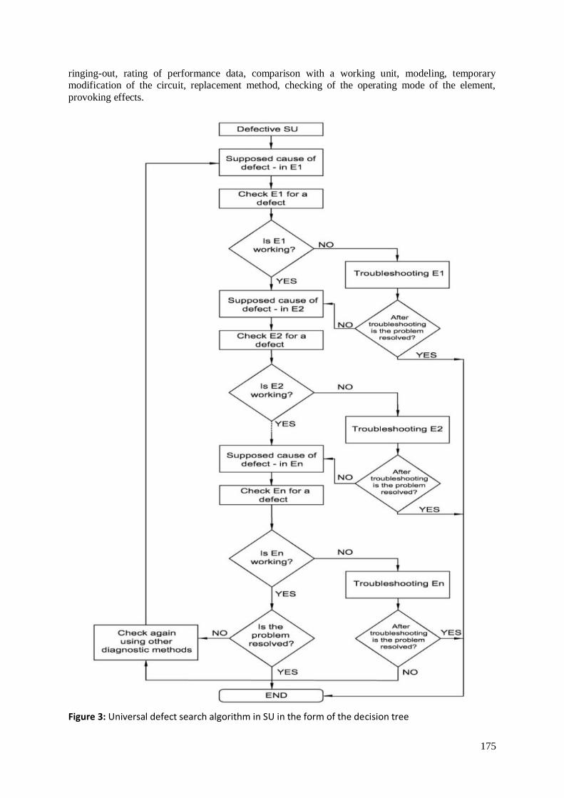
At the third stage, the decision tree is built for defective SU. To compile the defect search
algorithm in the form of a decision tree, OOD models of principled schemes, wiring and connection diagrams, integrated circuits are used. SU is divided into separate interconnected nodes or simple
elements and each of them is checked (Fig. 3).
The defect search algorithm in SU is a decision tree in the form of sequential checks of nodes and elements of this SU. Checks are carried out by various methods depending on the decision of the
decision maker. The most used methods for checking supposed defects are: external inspection,
175
ringing-out, rating of performance data, comparison with a working unit, modeling, temporary modification of the circuit, replacement method, checking of the operating mode of the element,
provoking effects.
Figure 3: Universal defect search algorithm in SU in the form of the decision tree
176
For typical failures, OOD defects tables are used. After finding the defect in SU, the fourth stage is started.
At the fourth stage, the analysis of causes is conducted. The event that led to the defect of this
element is determined. There are poor contact, corrosion, oxidation, insulation breakdown, voltage
jumps, current overloading, material defect, etc.
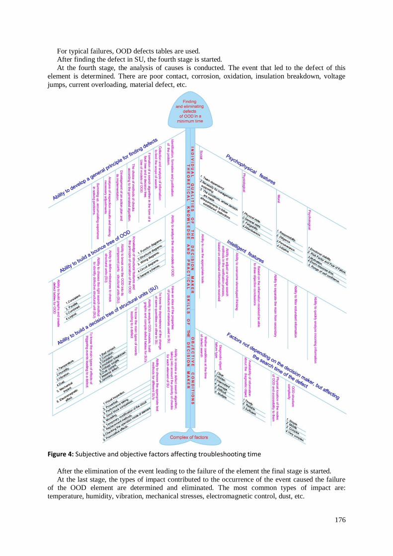
Figure 4: Subjective and objective factors affecting troubleshooting time
After the elimination of the event leading to the failure of the element the final stage is started.
At the last stage, the types of impact contributed to the occurrence of the event caused the failure of the OOD element are determined and eliminated. The most common types of impact are:
temperature, humidity, vibration, mechanical stresses, electromagnetic control, dust, etc.
177
A lot of time spent by maintenance personnel on restoring the failed system is spent on the search of defects; all the subjective and objective factors affected this time are systematized and shown in the
form of Ishikawa diagrams.
3. Implementation
The proposed system will be built on the basis of knowledge, which includes the experience of
experts in repair and troubleshooting. The knowledge base is formed on the basis of expert evaluation
(experts are electricians with experience of at least 5 years, as well as superintendents of crewing
firms with the same experience).
The system uses the approach that implements the task of separating of information stored in a
common database and directly in the knowledge base (a set of decision tables).
To implement this approach, linking variables (link tables) are used.
By the use of these communication tables, a variable from the knowledge base is connected with
the data stored in a common database of equipment and ready-made troubleshooting algorithms.
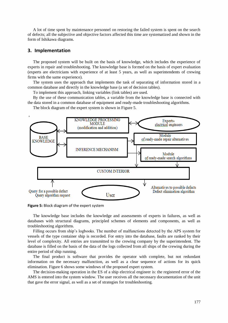
The block diagram of the expert system is shown in Figure 5.
Figure 5: Block diagram of the expert system
The knowledge base includes the knowledge and assessments of experts in failures, as well as
databases with structural diagrams, principled schemes of elements and components, as well as
troubleshooting algorithms.
Filling occurs from ship’s logbooks. The number of malfunctions detected by the APS system for
vessels of the type container ship is recorded. For entry into the database, faults are ranked by their
level of complexity. All entries are transmitted to the crewing company by the superintendent. The
database is filled on the basis of the data of the logs collected from all ships of the crewing during the
entire period of ship running.
The final product is software that provides the operator with complete, but not redundant
information on the necessary malfunction, as well as a clear sequence of actions for its quick
elimination. Figure 6 shows some windows of the proposed expert system.
The decision-making operation in the ES of a ship electrical engineer is: the registered error of the
AMS is entered into the system window. The user receives all the necessary documentation of the unit
that gave the error signal, as well as a set of strategies for troubleshooting.
178
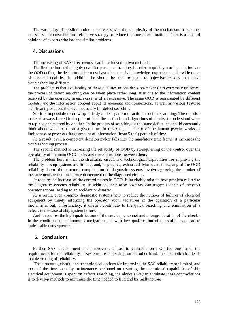
The variability of possible problems increases with the complexity of the mechanism. It becomes
necessary to choose the most effective strategy to reduce the time of elimination. There is a table of
opinions of experts who had the similar problems.
4. Discussions
The increasing of SAS effectiveness can be achieved in two methods.
The first method is the highly qualified personnel training. In order to quickly search and eliminate
the OOD defect, the decision-maker must have the extensive knowledge, experience and a wide range
of personal qualities. In addition, he should be able to adapt to objective reasons that make
troubleshooting difficult.
The problem is that availability of these qualities in one decision-maker (it is extremely unlikely),
the process of defect searching can be taken place rather long. It is due to the information content
received by the operator, in each case, is often excessive. The same OOD is represented by different
models, and the information content about its elements and connections, as well as various features
significantly exceeds the level necessary for defect searching.
So, it is impossible to draw up quickly a clear pattern of action at defect searching. The decision
maker is always forced to keep in mind all the methods and algorithms of checks, to understand when
to replace one method by another. In the process of searching of the same defect, he should constantly
think about what to use at a given time. In this case, the factor of the human psyche works as
limitedness to process a large amount of information (from 5 to 9) per unit of time.
As a result, even a competent decision maker falls into the mandatory time frame; it increases the
troubleshooting process.
The second method is increasing the reliability of OOD by strengthening of the control over the
operability of the main OOD nodes and the connections between them.
The problem here is that the structural, circuit and technological capabilities for improving the
reliability of ship systems are limited, and, in practice, exhausted. Moreover, increasing of the OOD
reliability due to the structural complication of diagnostic systems involves growing the number of
measurements with dimension enhancement of the diagnosed circuit.
It requires an increase of the control points in OOD; it inevitably raises a new problem related to
the diagnostic systems reliability. In addition, their false positives can trigger a chain of incorrect
operator actions leading to an accident or disaster.
As a result, even complex diagnostic systems help to reduce the number of failures of electrical
equipment by timely informing the operator about violations in the operation of a particular
mechanism, but, unfortunately, it doesn’t contribute to the quick searching and elimination of a
defect, in the case of ship system failure.
And it requires the high qualification of the service personnel and a longer duration of the checks.
In the conditions of autonomous navigation and with low qualification of the staff it can lead to
undesirable consequences.
5. Conclusions
Further SAS development and improvement lead to contradictions. On the one hand, the
requirements for the reliability of systems are increasing, on the other hand, their complication leads
to a decreasing of reliability.
The structural, circuit, and technological options for improving the SAS reliability are limited, and
most of the time spent by maintenance personnel on restoring the operational capabilities of ship
electrical equipment is spent on defects searching, the obvious way to eliminate these contradictions
is to develop methods to minimize the time needed to find and fix malfunctions.
179
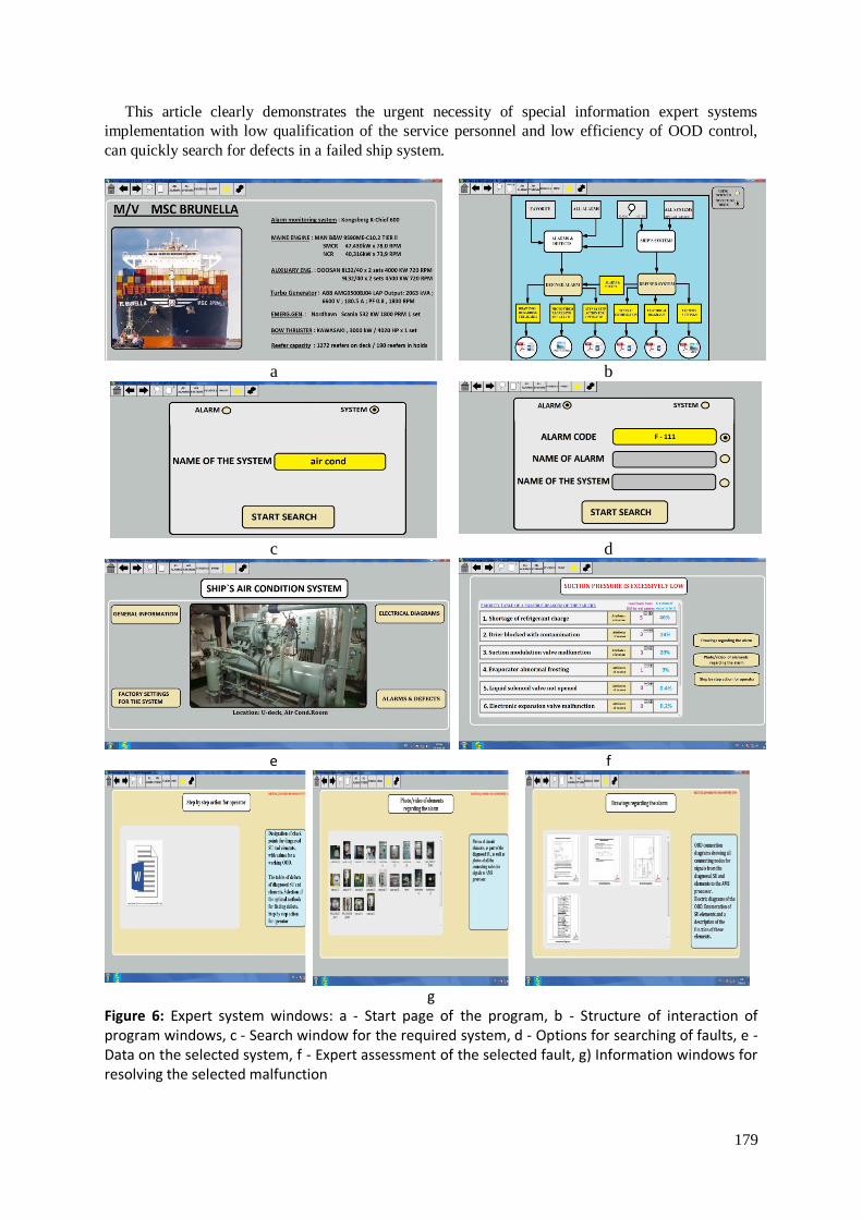
This article clearly demonstrates the urgent necessity of special information expert systems
implementation with low qualification of the service personnel and low efficiency of OOD control,
can quickly search for defects in a failed ship system.
a b
c d
e f
g
Figure 6: Expert system windows: a - Start page of the program, b - Structure of interaction of program windows, c - Search window for the required system, d - Options for searching of faults, e -Data on the selected system, f - Expert assessment of the selected fault, g) Information windows for resolving the selected malfunction
180
6. References
[1] G. Bigus, Yu. Daniev, D. Galkin, Diagnostics of technical devices. MSTU named after N.E.
Bauman, 2014.
[2] N. Yahyaev, A. Korablin, Fundamentals of the theory of reliability and diagnostics. Textbook for high schools, Academy, 2009.
[3] N. Shibaeva: Methods for assessing and predicting the technical condition of shipboard complex
systems, dis. Cand. tech. Sciences: special. 05.22.20, Odessa National Maritime University, Odessa, 2016.
[4] A. Steklov, Models and algorithms for diagnosing and predicting the technical conditions of ship
electrical power systems in operating conditions, Nizhny Novgorod State Technical University,
2017. [5] A. Ravin: Diagnostic support of ship power equipment: problems and solutions, St. Petersburg
State Marine Technical University, 2015.
[6] A. Brooking, Expert systems. Principles of work and examples, Radio and communications, 1980. [7] K. Naylor: How to build your own expert system. Energoatomizdat, 1991.
[8] R. Bazhenov, D. Lopatin, On the application of modern technologies in the development of
intelligent systems, Journal of scientific publications of graduate students and doctoral students,
2014. [9] T. Kozlova, A. Ignatiev, E. Samoilova, Implementation of an expert decision support system for
determining failures of a technological system, Bulletin of the Saratov State Technical
University, 2011. [10] I. Kovalenko, Y. Davydenko and A. Shved, Formation of Consistent Groups of Expert Evidences
Based on Dissimilarity Measures in Evidence Theory, in: Proceedings of the 14th International
Conference on Computer Sciences and Information Technologies (CSIT), Lviv, Ukraine, 2019, pp. 113–116. doi: 10.1109/STC-CSIT.2019.8929858
[11] A. Shved, I. Kovalenko, Y. Davydenko, Method of Detection the Consistent Subgroups of
Expert Assessments in a Group Based on Measures of Dissimilarity in Evidence Theory. In:
Shakhovska N., Medykovskyy M. (eds) Advances in Intelligent Systems and Computing IV. CCSIT 2019. Advances in Intelligent Systems and Computing, vol 1080. Springer, Cham, 2020,
pp. 36–53. doi: 10.1007/978-3-030-33695-0_4
[12] B. Palyukh, T. Kakatunova, O. Baguzova, Intelligent decision support system for managing complex objects using dynamic fuzzy cognitive maps, Software Products and Systems, 2013.
[13] C. Moreno, E. Espejo, A performance evaluation of three inference engines as expert systems for
failure mode identification in shafts, Engineering Failure Analysis, 2015. [14] E. Liberado, Novel expert system for defining power quality compensators, Expert Systems with
Applications, 2015.
[15] Y. Krainyk, Y. Davydenko and V. Tomas, Configurable Control Node for Wireless Sensor
Network, in: Proceedings of the 3rd International Conference on Advanced Information and Communications Technologies (AICT), Lviv, Ukraine, 2019, pp. 258–262. doi:
10.1109/AIACT.2019.8847732
[16] Y. Krainyk, Y. Davydenko and V. Starchenko, Message-level Decoding of Error Patterns for Turbo-Product Codes, in: Proceedings of the 39th International Conference on Electronics and
Nanotechnology (ELNANO), Kyiv, Ukraine, 2019, pp. 660–663. doi:
10.1109/ELNANO.2019.8783849
[17] A. Boran-Keshishyan, Ensuring the reliability of shipboard navigation and control systems in modern conditions, Novorossiysk, 2008.
[18] E. Afromeev, Criteria for technical excellence of ships, 2005.
[19] V. Kalyavin, L. Rybakov, Reliability and diagnostics of electrical components in St. Petersburg: Elmore, 2000.
[20] KONSBERG. Standard K-Chief 600 Alarm and Monitoring System / 354760 / Rev.D March
2013 © Kongsberg Maritime AS [21] KONSBERG. Kongsberg K-Chief 500/600 Marine Automation System Installation Manual /
311956 / F March 2013 © Kongsberg Maritime AS.