Local and over-all heat transfer coefficients in baffled heat ...
Upload
khangminh22Category
view
0download
0
MEASUREMENT • OF HEAT... TRANSFER COEFFICIENT IN
CONCENTRIC AND ECCENTRIC ANNULI
by
WASIUDDIN CHOUDHURY
B.Sc.Eng. , University of Dacca, 1958
A THESIS SUBMITTED IN.PARTIAL FULFILMENT OF
THE REQUIREMENTS FOR THE DEGREE OF
MASTER OF APPLIED SCIENCE
i n the Department
of
Mechanical Engineering
We accept this thesis as conforming to the
required standard
THE UNIVERSITY OF BRITISH COLUMBIA
APRIL, 1963
i i
In presenting this thesis i n p a r t i a l fulfilment of the
requirements for an advanced degree at the University of Br i t i sh
Columbia, I agree that the Library shal l make i t freely available
for reference and study. .1 further agree that permission for ex
tensive copying of this thesis for scholarly purposes may be granted
by the Head of my Department or by his representatives. It is
understood that copying or publications of this thesis for f inancial
gain shal l not be allowed without my written permission.
Department of Mechanical Engineering,
The University of Br i t i sh Columbia,
Vancouver 8, Canada.
A p r i l , 1963.
i i i
ABSTRACT
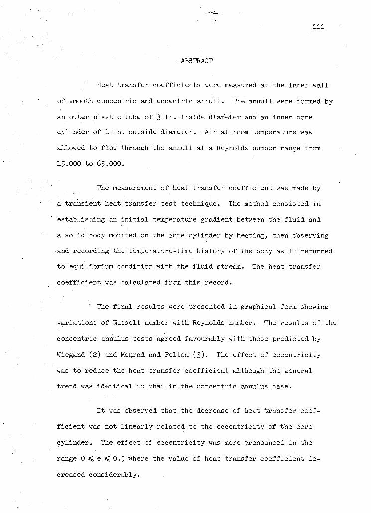
Heat transfer coefficients were measured at the inner wall
of smooth concentric and eccentric annuli. The annuli were formed by
an,outer plast ic tube of 3 i n . inside diameter and an inner core
cylinder of 1 i n . outside diameter. A i r at room temperature was;
allowed to flow through the annuli at a Reynolds number range from
15,000 to 65,000.
The measurement of heat transfer coefficient was made by
a transient heat transfer test technique. The method consisted i n
establishing an i n i t i a l temperature gradient between the f l u i d and
a so l id body mounted on the core cylinder by heating, then observing
and recording the temperature-time history of the body as i t returned
to equilibrium condition with the f l u i d stream. The heat transfer
coefficient was calculated from this record.
The f i n a l results were presented i n graphical form.showing
variations of Nusselt number with Reynolds number. The results of the
concentric annulus tests agreed favourably with those predicted by
Wiegand (2) and Monrad and Pelton (3)' The effect of eccentricity
was to reduce the heat transfer coefficient although the general
trend was identical to that in the concentric annulus case.
It was observed that the decrease of heat transfer coef
f ic ient was not l inear ly related to the eccentricity of the core
cylinder. The effect of eccentricity was more pronounced in the
range 0 < e < 0.5 where the value of heat transfer coefficient de
creased considerably.
X
•ACKNOWLEDGEMENT
The author would l ike to thank the many persons whose
direct or indirect assistance has made this report possible. He
should l ike to mention some of them by name:
Professor W. 0. Richmond deserves many thanks for his
continued encouragement and assistance during a l l phases of the
work.
Professors V. J . Modi, N. Epstein) C . - A . Brockely and
Mr. J . D. Denton for many valuable discussions during different
phases of the project.
Professor W . A . Wolfe who suggested the present.topic and
through whose i n i t i a l efforts the project was started.
F ina l ly the author would l ike to express his thanks
for the permission to use the Computing Centre at the University
of Br i t i sh Columbia and the National Research Council of Canada
for providing funds to make this research possible.
i v
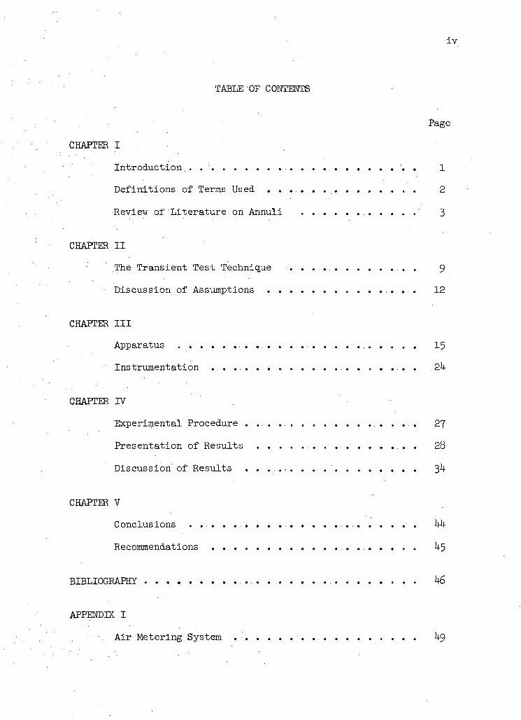
TABLE OF CONTENTS
Page
CHAPTER I
Introduction.. . . . . . . . . . . . . . . . 1
Definitions of Terms Used 2
Review of 'Literature on-Annuli ' 3
CHAPTER II
The Transient Test Technique 9
Discussion of Assumptions . . . . . . 12
CHAPTER III
Apparatus 15
instrumentation . . . . . . . . . . . . 2h
CHAPTER IV
Experimental Procedure 27
Presentation of Results . . . . . . . . . . . . . . . . . . . . 28
Discussion of Results 3-
CHAPTER V
Conclusions . . . . . . . . . . . . . . . Mi-
Recommendations k-5
BIBLIOGRAPHY k6
APPENDIX I
A i r Metering System . . . . . . . . ^9
V
Page
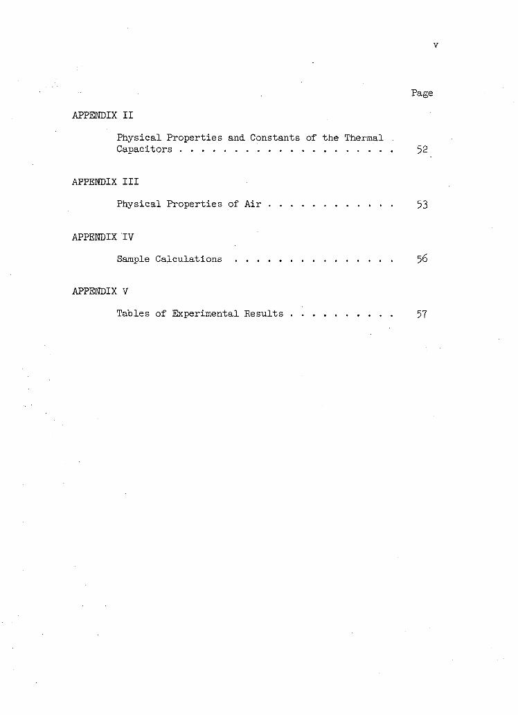
APPENDIX II
Physical Properties and Constants of the Thermal . Capacitors 52
APPENDIX III .
Physical Properties of Air 53
APPENDIX TV
Sample Calculations 56
APPENDIX V
Tables of Experimental Results 57
v i
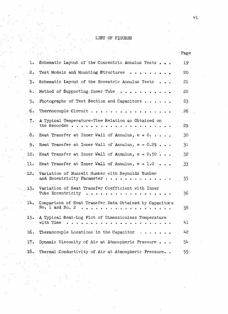
LIST OF FIGURES
Page
1. . Schematic Layout.of the Concentric Annulus Tests . . . 19
2. Test Models and Mounting Structures . . . . . . . . . 20
3. Schematic Layout of the Eccentric Annulus Tests . . . 21
k. Method of Supporting Inner Tube . . . . . . . . . . . . . . . 22
5. Photographs of Test Section and Capacitors . 23
6. Thermocouple Circu i t . . . . . . . . . . . . . . . . . . . . 26
7« A Typical Temperature-Time Relation as Obtained on
the Recorder . . . . . . . . . . . . . . . . . . . . . . . . . . 29
.8. Heat Transfer at Inner Wall of Annulus, e = 0. . . . . : 30
9« Heat Transfer at Inner Wall of Annulus,.e.= Q'.25 .... .31
10. Heat Transfer at Inner Wall of Annulus, e = 0.50 , . . 32
11. Heat Transfer at Inner Wall of Annulus, e = 1.0 . . . .33
12. Variation of Nusselt Number with Reynolds Number and Eccentricity Parameter . 35
13. Variat ion of Heat Transfer Coefficient with Inner Tube Eccentricity . . . . . 36
l U . Comparison of Heat Transfer Data Obtained by Capacitors No. 1 and No. 2 . . ..................... 38
15« A Typical Semi-Log Plot of Dimensionless Temperature
with Time kl
16. Thermocouple Locations in the Capacitor k2
17. Dynamic Viscosity of A i r at Atmospheric Pressure . . . 5
18. Thermal Conductivity of Air at Atmospheric Pressure. . 55
v i i
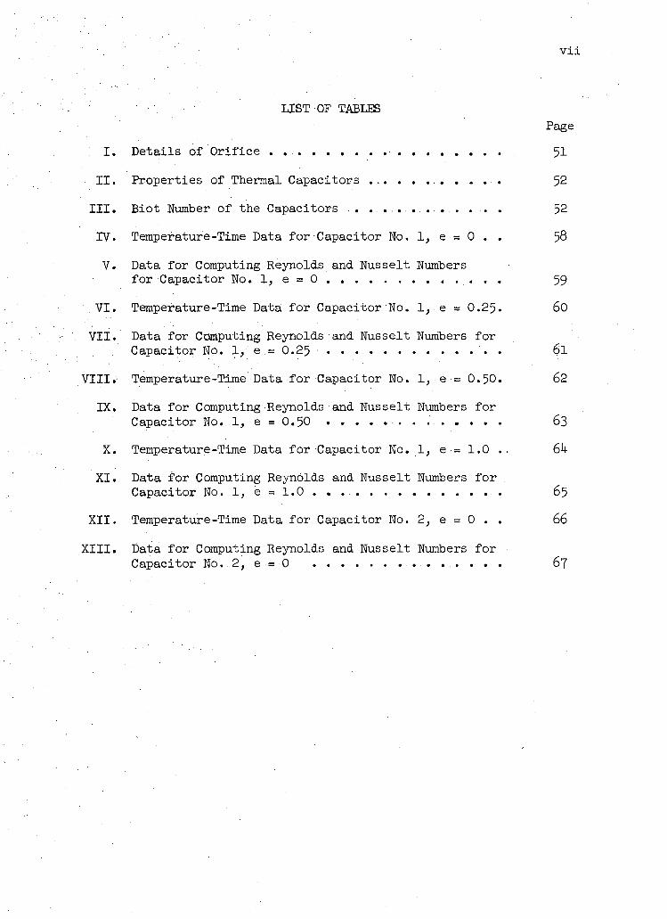
LIST OF TABLES Page
; I i Details of Orifice 51
II. Properties of Thermal Capacitors 52
III. Biot Number of the Capacitors . . . . . . . . . . . . . . . . . 52
TV. Temperature-Time Data for Capacitor No. 1, e = 0 . . 58
V. Data for Computing Reynolds and Nusselt Numbers
for Capacitor No. 1, e = 0 ... 59
VI. Temperature-Time Data for Capacitor No. 1,. e = O.25. 60
VII. Data for Computing Reynolds and Nusselt Numbers for
Capacitor No. 1/ e .= 0.25 . . . . . . . . . . . . . 6 l VIII. Temperature-Time Data for Capacitor No..1, e = 0.50. 62
IX. Data for Computing Reynolds and Nusselt Numbers for
Capacitor No. 1, e = 0.50 63
X. Temperature-Time Data for Capacitor No. 1, e = 1.0 .. 6k
XI. Data for Computing Reynolds and Nusselt Numbers for Capacitor No. 1, e = 1.0 65
XII. Temperature-Time Data for Capacitor No. 2, e = 0 . . 66 XIII. Data for Computing Reynolds and Nusselt Numbers for
Capacitor No..2,. e •= 0 . . . . . . . . . . . . . . . . . 67
v i i i
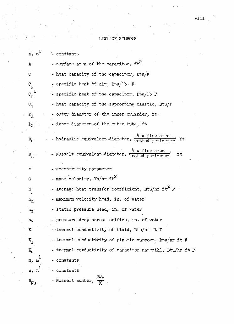
LIST OF SYMBOLS
a, a"*" - constants
p
A - surface area of the capacitor, f t
C - heat capacity of the capacitor, Btu/F
0^ - specific heat of a i r , Btu/ lb . F
C "*" '- specific heat of the capacitor, Btu/lb F
- heat capacity of the supporting p las t ic , Btu/F
D- - outer diameter of the inner cylinder, ft.,
LV> - inner diameter of the outer tube, f t k x flow area ,
D e - hydraulic equivalent .diameter, w e t t e d perimeter f t
k x flow area , D n -Nusse l t equivalent diameter, h e a t e d perimeter f t
e - eccentricity parameter
G - mass velocity, lb /hr f t
2 h - average heat transfer coefficient, Btu/hr ft' F
1^ - maximum velocity head, i n . of water
h s - stat ic pressure head, i n . of water
h w - pressure drop across or i f i ce , i n . of water
K - thermal conductivity of f l u i d , Btu/hr ft F
- thermal conductivity of plast ic support, Btu/hr f t F
Kg - thermal conductivity of capacitor material, Btu/hr f t -F
1 m, m - constants
constants hDe
~K - Nusselt number,
I X
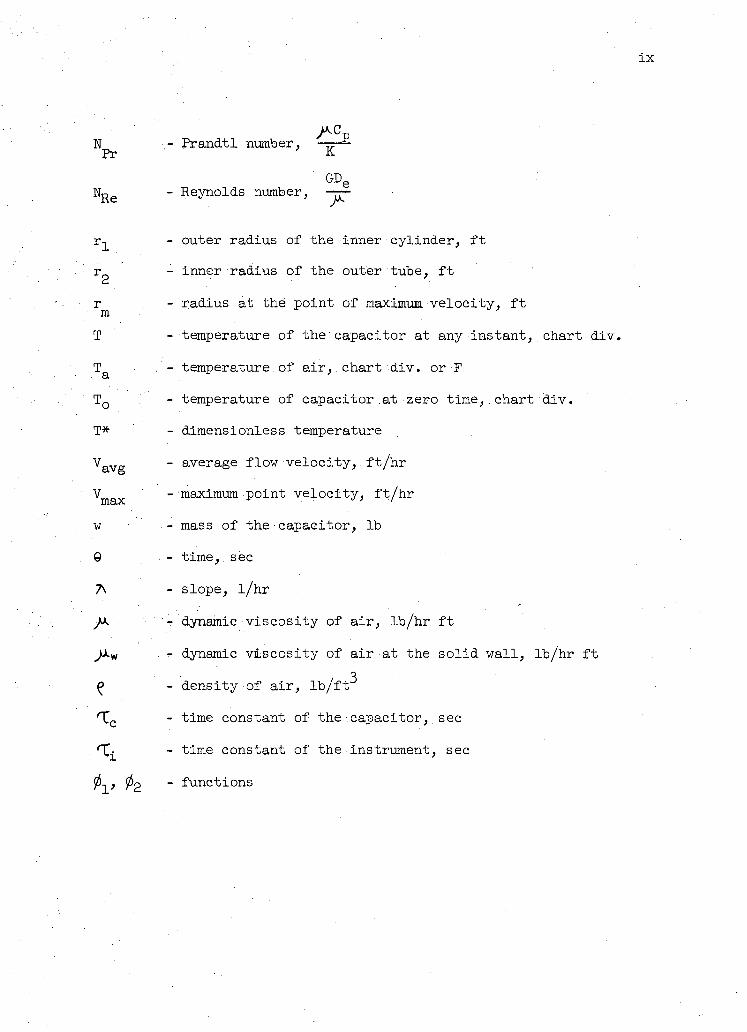
N - Prandtl number, • • 1
Pr
GDe
W^e - Reynolds number,
r-j_ - outer radius of the inner cylinder, f t
r^ - inner radius of the outer tube, f t
r - radius at the point of maximum velocity, f t m
T - temperature of the capacitor at any instant, chart div.
T . - temperature of a i r , chart div. or F a
T Q - temperature of capacitor at zero time,.chart div .
T* - dimensionless temperature
V a V g - average flow velocity, . f t / h r
V m a x - maximum point velocity, f t /hr
w - mass of the capacitor, lb
9 • - time,. sec
A - slope, l / h r
- dynamic viscosity of a i r , lb /hr f t
^M.w - dynamic viscosity of a ir at the so l id wall , lb /hr f t
^ - density of a i r , l b / f t
'XQ - time constant of the capacitor,.sec
. - time constant of the instrument, sec
- functions
1
CHAPTER I
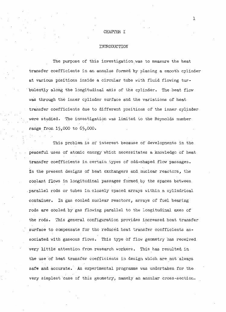
INTRODUCTION
The purpose of this investigation was to measure the heat
transfer coefficients in.an annulus formed by placing a smooth cylinder
at various positions inside a c ircular tube with f l u i d flowing tur-
bulently along the longitudinal axis of the cylinder. The heat flow
was through the inner cylinder surface and the variations of heat
transfer coefficients due to different positions of the inner cylinder
were studied. The investigation was l imited to the Reynolds number
range from 15,000 to 65,000.
This problem is of interest because of developments in the
peaceful uses of atomic energy which necessitates a knowledge of heat
transfer coefficients i n certain types of odd-shaped flow passages.
In the present designs of heat exchangers and nuclear reactors, the
coolant flows in longitudinal passages formed by the spaces between
para l l e l rods or tubes in* closely spaced arrays within a cy l indr ica l
container. In gas cooled nuclear reactors, arrays of fuel bearing
rods are cooled by gas flowing para l l e l to the longitudinal axes of
the rods. This general configuration provides increased heat transfer
surface to compensate for the reduced heat transfer coefficients as
sociated with gaseous flows. This type of flow geometry has received
very l i t t l e attention from research workers. This has resulted i n
the use of heat transfer coefficients in design which are not always
safe and accurate. An experimental programme was undertaken for the
very simplest case of this geometry, namely an annular cross-section.
2
The usual method of determining the heat transfer coefficients
requires the measurement of the temperature of the heat transfer me
dium, and of the heat, transfer surface under steady-state conditions.
It is. d i f f i c u l t to measure the,surface temperature accurately so that
steady-state methods require elaborate apparatus and instrumentation.
To obviate these d i f f i cu l t i e s a non-stationary method has been used i n
this investigation. This method, the transient heat transfer test
technique ( l )* is based on the cooling.of a body having fixed thermo-
physical properties under a step-change of temperature. The under
lying theory of this technique w i l l be discussed i n . d e t a i l in the next
chapter.
Using this technique results were.obtained .for heat transfer
in the concentric annulus. These results were compared with correla
tions given by Wiegand (2) and Monrad and Pelton (3). Results for the
eccentric annulus were also obtained in a similar manner. These lat ter
results are of interest because of the paucity.of data for the eccen
t r i c annulus.
DEFINITIONS OF TERMS USED
Annulus An annulus is defined as the flow passage formed by
placing a cy l indr ica l core inside a c ircular tube with f l u i d flowing
along the longitudinal axis of the core. When the cy l indr ica l core is
at the centre of the outer tube the resulting flow cross-section is
termed a concentric annulus. • An eccentric annulus is formed by placing
the core cylinder at positions other than the centre of the outer, tube.
* Numbers in parentheses refer to bibliography at the end of the Thesis.
3
Thermal Capacitor The heated so l id body used in.the exper
iment is cal led the thermal capacitor cylinder. For the sake.of bre
v i ty in the subsequent chapters this w i l l be cal led the capacitor.
REVIEW OF LITERATURE ON ANNULI
Concentric Annulus A large number of experiments has been
carried out on heat transfer in turbulent flow in a concentric annulus.
Most investigators attacked the problem by dimensional analysis and
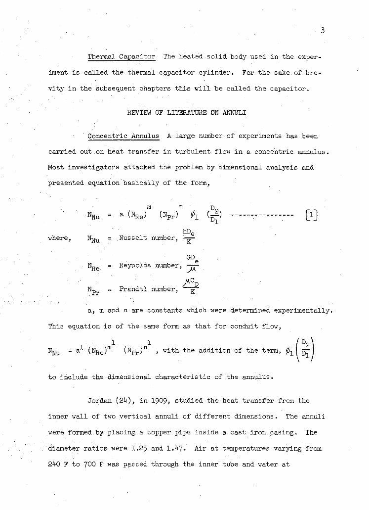
presented equation basical ly of the form,
m n D %u - a (%e) ttpr) 01 C^) — - [ l ]
hD e
where, N|gu = Nusselt number, • -—
GD e . 1 L 0 = Reynolds number, —— ite ^/\A
Np , = Prandtl number, ^~
a, m.and n are constants which were determined experimentally.
This equation is of the same form as that for conduit flow,
1 1 / D 2
%u = a (%e)m ( N P r ) n > w i t h t h e addition of the term, 011 ^
to include the dimensional characteristic of the annulus.
Jordan (2U), i n 1909> studied the heat transfer from the
inner wall of two ver t i ca l annuli of different dimensions. The annuli
were formed by placing a copper pipe inside a cast iron casing. The
diameter ratios were 1.25 and 1.^7• A ir at temperatures varying from
2^0 F to 700 F was passed through the inner tube and water at
temperatures up ."to 200 F was circulated through the annular space. The
test section was hO f t . long and i t was placed direct ly after an elbow.
The experimental results covered a Reynolds number range from-7,000 to
95 ,000 .
Thompson, and Foust ( 25 ) , in 19^+0, investigated the heat
transfer characteristics in two double-pipe heat exchangers. One of
them was made of one inch pyrex tubing jacketed with two inch iron pipe;
the other was two inch pyrex tubing i n a three inch pipe. Cold water
at 50 F to 95 F flowed through the annular space and :sfceam.!. was con
densed at the inner pyrex tube. The test section was 10 f t . long and
was placed direct ly after an elbow. The heat transfer, coefficient was
determined from the overall resistance by assuming that the coefficient
was a function of water velocity in the annulus only. The experimental
data was taken at Reynolds number greater than 100,000.
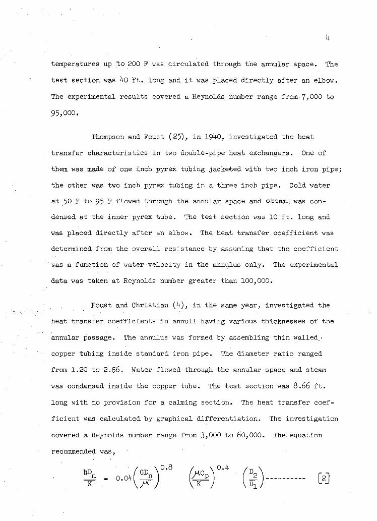
Foust and Christ ian ( 4 ) , i n the same year, investigated the
heat transfer coefficients i n annuli having various thicknesses of the
annular passage. The annulus was formed by assembling thin walled;,
copper tubing inside standard iron pipe. The diameter rat io ranged
from 1.20 to 2 . 5 6 . Water flowed through the annular space and steam
was condensed inside the copper tube. The test section was 8 .66 f t .
long with no provision for a calming section. The heat transfer coef
f ic ient was calculated by graphical dif ferentiat ion. The investigation
covered a Reynolds number range from 3>000 to 60 ,000 . Thet equation
recommended was,
? . . . o < ? ) " fc)" (1) H
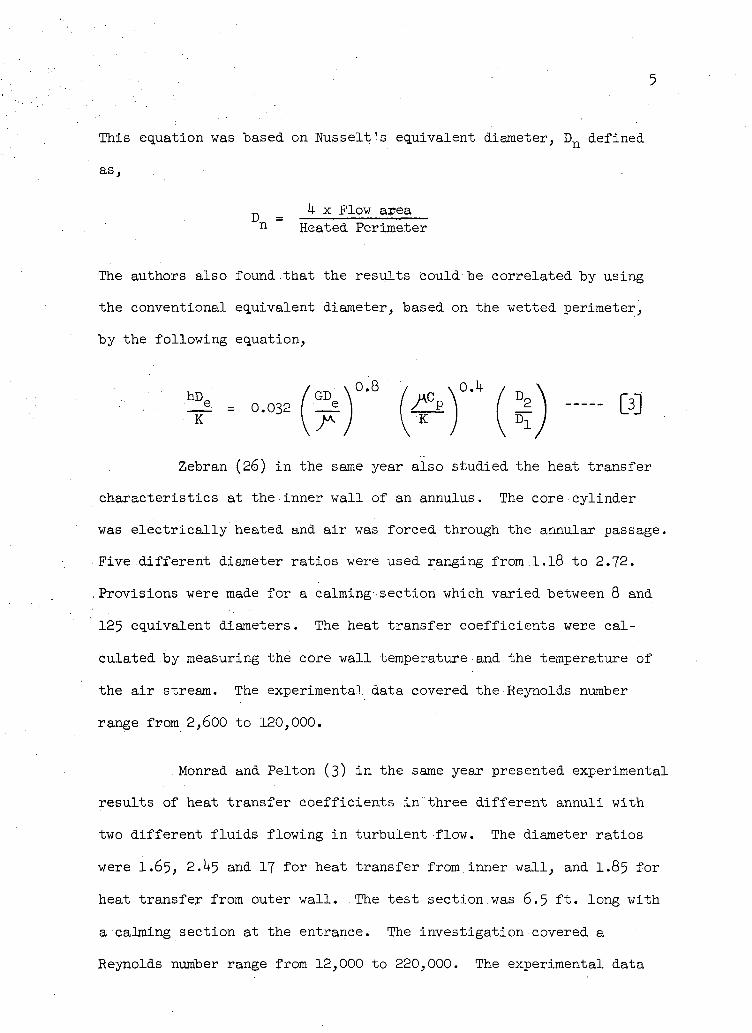
5
This equation was based on,Nusselt's equivalent diameter, D n defined
as,
D _ h x Flow area n Heated Perimeter
The authors also found.that the results could be correlated by using
the conventional equivalent diameter, based on the wetted perimeter,
by the following equation,
* - « ( J ) " ( j) H
Zebran (26) i n the same year also studied the heat transfer
characteristics at the inner wall of an annulus. The•core cylinder
was e l ec tr i ca l ly heated and a ir was forced through the annular passage.
Five different diameter ratios were used ranging from-.1.18 to 2.72.
Provisions were made for a calming-section which varied between 8 and
125 equivalent diameters. The heat transfer coefficients were ca l
culated by measuring the core wall temperature and the temperature of
the a ir stream. The experimental data covered the Reynolds number
range from 2,600 to 120,000.
. Monrad and.Pelton (3) i n the same year presented experimental
results of heat transfer coefficients i n three different annuli with
two different f luids flowing i n turbulent flow. The diameter ratios
were I.65, 2.^5 and 17 for heat transfer from.inner wall , and I.85 for
heat transfer from outer wal l . The test section.was 6.5 f t . long with
a calming section at the entrance. The investigation covered a
Reynolds number range from 12,000 to 220,000. The experimental data
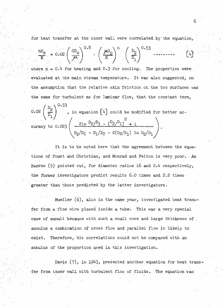
6
for heat transfer at the inner wall were correlated.by the equation,
• / \ ° - 8 / \ n / \ 0.53
where n = O.h for heating and.0.3' for cooling. The properties were
evaluated at the main stream temperature. It was also suggested, on
the assumption that the relative skin f r i c t i o n on the two s'urfaces was
the same for turbulent as for laminar flow, that the constant term,
AM 0 - 5 3
0.02 I — I , i n equation |_UJ could be modified for better ac-
+ n o « l 21n D 2 / D l - ( D2 / D l ) 2 + 1 curacy to 0.023 [ ' *—' : D2/Dx - D X/D 2 - 2(D 2 /D X) I n D 2 / Y ) ±
It is to be noted here that the agreement between the equa
tions of Foust and Christ ian, and Monrad and Pelton is very poor. As
Barrow (5) pointed out, for diameter ratios 16 and 2.k respectively,
the former investigators predict results 6.0 times and 2.2 times
greater than those predicted by the lat ter investigators.
Mueller (6), also in the same year, investigated heat trans
fer from a fine wire placed inside a tube. This was a very special
case of annuli because with such a small core and large thickness of .
annulus a combination of cross flow and para l l e l flow is l i k e l y to
exist . Therefore, his correlations could not be compared with an
annulus of the proportion used in this investigation.
Davis (7), i n 19 3, presented another equation for heat trans
fer from inner.wall with turbulent flow of f lu ids . The equation was
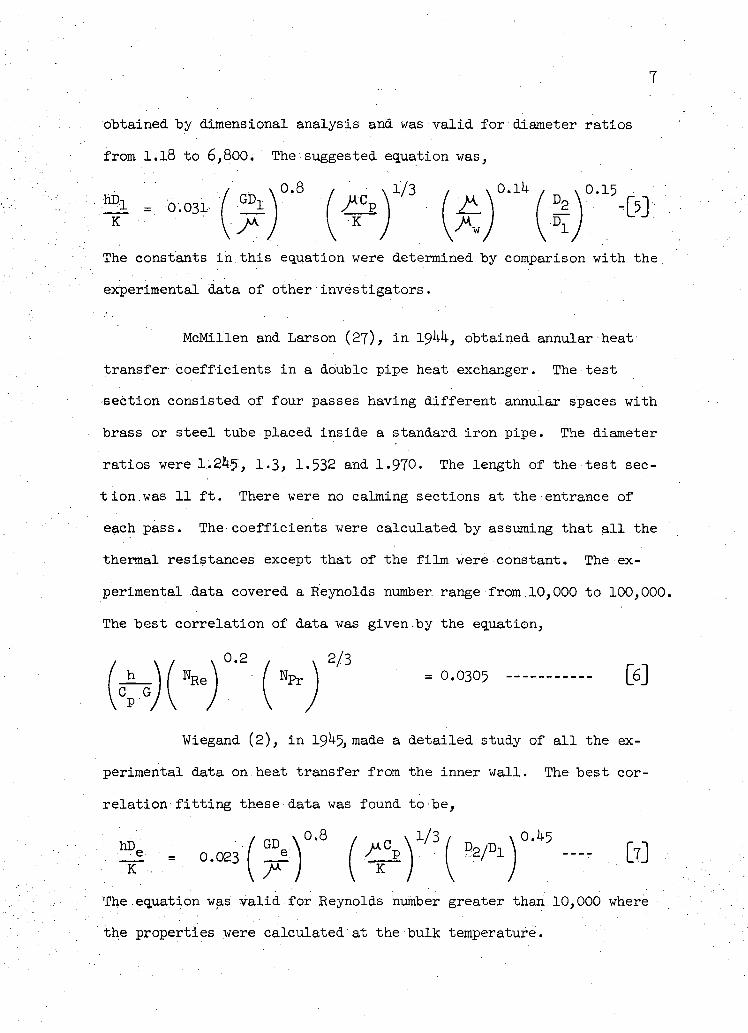
obtained by dimensional analysis and was valid for diameter ratios
from 1.18 to 6,800. The suggested equation was,
. / \ 0.8 / x 1/3 , v 0.1k' , x 0.15
The constants i n this equation were determined by comparison with the
experimental data of other investigators.
McMillen and Larson (27), i n 19kk, obtained annular heat
transfer coefficients i n a double pipe heat exchanger. The test
section consisted of four passes having different annular spaces with
brass or steel tube placed inside a standard iron pipe. The diameter
ratios were 1.245', 1-3, 1.532 and 1-970. The length of the test.sec
tion.was 11 f t . There were no calming sections at the entrance of
each pass. The coefficients were calculated by assuming that a l l the
thermal resistances except that of the film were constant. The ex
perimental data covered a Reynolds number, range from 10,000 to 100,000. The best correlation of data was given by the equation,
= 0.0305 —- [6]
Wiegand (2), i n 19 -5, made a detailed study of a l l the ex
perimental data on heat transfer from the inner wall. The best cor
relation f i t t i n g these data was found to be,
The equation was va l i d for Reynolds number greater than 10,000 where
the properties were calculated at the bulk temperature.
8
Apart from dimensional analysis, this problem has also been
attempted by establishing an analogy between f l u i d f r i c t i o n and heat
transfer. In 1951> Mizushina (10) investigated this approach but the
analysis was quite d i f f i c u l t due to lack of similarity between the
velocity and temperature profiles when heat was flowing from .the inner
wall only. Using' many assumptions Mizushina derived an equation for
the heat transfer coefficient which was very complicated for general
use. Barrow ( l l ) , i n 1961, presented a semi-theoretical solution by
considering the transfer of heat and transfer of momentum. The sol
ution was applicable for fluids having a Prandtl number equal to
unity.
Eccentric Annulus Heat transfer i n eccentric annuli has
received very l i t t l e attention. Deissler and Taylor ( l 2 i ) , i n 1955>
made a theoretical analysis of f u l l y developed turbulent heat transfer
i n an eccentric annulus. It was found that the average Wusselt number
decreased as the eccentricity of the inner tube was increased. It was
also shown that the Wusselt numbers for a concentric annulus were
sli g h t l y higher than those for a tube with an equivalent diameter.
In 1962, Leung, Kays and Reynolds (13) presented heat
transfer data i n concentric and eccentric annuli based on a theoret
i c a l study as well as an experimental investigation. For the eccentric
annulus the diameter ratios ranged from 2 .0 to 3»92 and for the con
centric annulus from 2 .0 to 5»2. Air was flowing through the annulus
under f u l l y developed turbulent flow conditions. The experimental
results covered a Reynolds number range from 10,000 to 150 ,000.
9
CHAPTER II
THE TRANSIENT TEST TECHNIQUE
The transient heat transfer test technique as used in this
investigation has also .been used by other investigators in different
types of flow situations. London, Boelter and Nottage ( l ) proposed
this method i n 19^1, Eber (l^) used this method to obtain.data on heat
transfer characteristics i n superonsic flow over cones, and Fischer
and Norris (15) determined the convective heat transfer coefficient
by an analysis of skin temperature measurements on the nose of a V-2
rocket i n f l i g h t . In the past decade Garbett (16) used the transient
technique to determine the heat transfer coefficient from bodies i n
high velocity flow. Kays, London and Lo (l?) demonstrated success
f u l l y i t s usefullness in determining the heat transfer coefficient
for gas flows normal to tube banks.
•Basical ly the transient technique for determining heat
transfer coefficient consists i n establishing an i n i t i a l temperature
potential between the f l u i d and the body by heating.or cooling, then
observing and recording the temperature-time history of the body as i t
returns towards equilibrium with the f l u i d stream. The heat transfer
coefficient is calculated from this record.
The simplest case of transient heating or cooling of a body
i s one i n which the internal resistance of the body is negligibly
small i n comparison with the thermal resistance of the sol id-f luid ,
interface. This is because such a system permits the lumping of a l l
the resistances to heat transfer at the boundary of the so l id body.
10
This ideal i sat ion. i s based on the assumption that the material of the
capacitor has i n f i n i t e l y large thermal conductivity. .Many transient
heat flow problems can be solved with' reasonable accuracy by assuming
that the internal conductive resistance is so small that the temper
ature throughout the body is uniform at any instant of time.
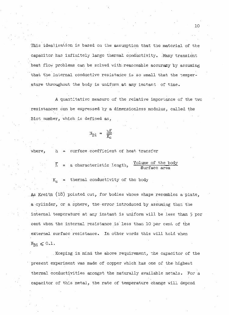
A quantitative measure of the relat ive importance of the two
resistances can be expressed by a dimensionless modulus, cal led the
Biot number> which is defined as,
= B L KS
where, h = surface coefficient of heat transfer
=- , , . . . , j . . Volume of the body L = a characteristic length, — — Surface area
K s = thermal conductivity of the body
As Kreii^h (l8) pointed out, for bodies whose shape resembles a plate,
a cylinder, or a sphere, the error introduced by assuming that the
internal temperature at any instant is uniform w i l l be less than 5 per
cent when the internal resistance is less than 10 per cent of the
external surface resistance. In other words this w i l l hold when
N B i < 0 . 1 .
Keeping in mind the above requirement, the capacitor of the
present experiment was made of copper which has one of the highest
thermal conductivities amongst the naturally available metals. For a
capacitor of this metal, the rate of temperature change w i l l depend
11
only on the average surface heat transfer-coefficient which varies
mainly with the f lu id properties, the flow conditions, and the flow
geometry.
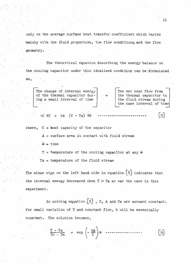
The theoretical equation describing the energy balance on
the cooling capacitor under this idealised condition can be formulated
as,
The change of internal energy of the thermal capacitor during a small interval of time
-C dT = hA (T - Ta) d'9
The net heat flow from the thermal capacitor to the f l u i d stream during the same interval of time
where, C = heat capacity of the capacitor
A = surface area in contact with f l u i d stream
9 = time
T = temperature of the cooling capacitor at any 9
Ta = temperature of the f l u i d stream
The minus sign on the l e f t hand side in equation [_Q~]' indicates that
the internal energy decreased when T > Ta as was the case in this
experiment.
In solving equation [jf) , C, A and Ta are assumed constant.
For small variation of. T and constant flow, h w i l l be essentially
constant. The solution becomes,
T - Ta To - Ta exp
hA 9 03
12
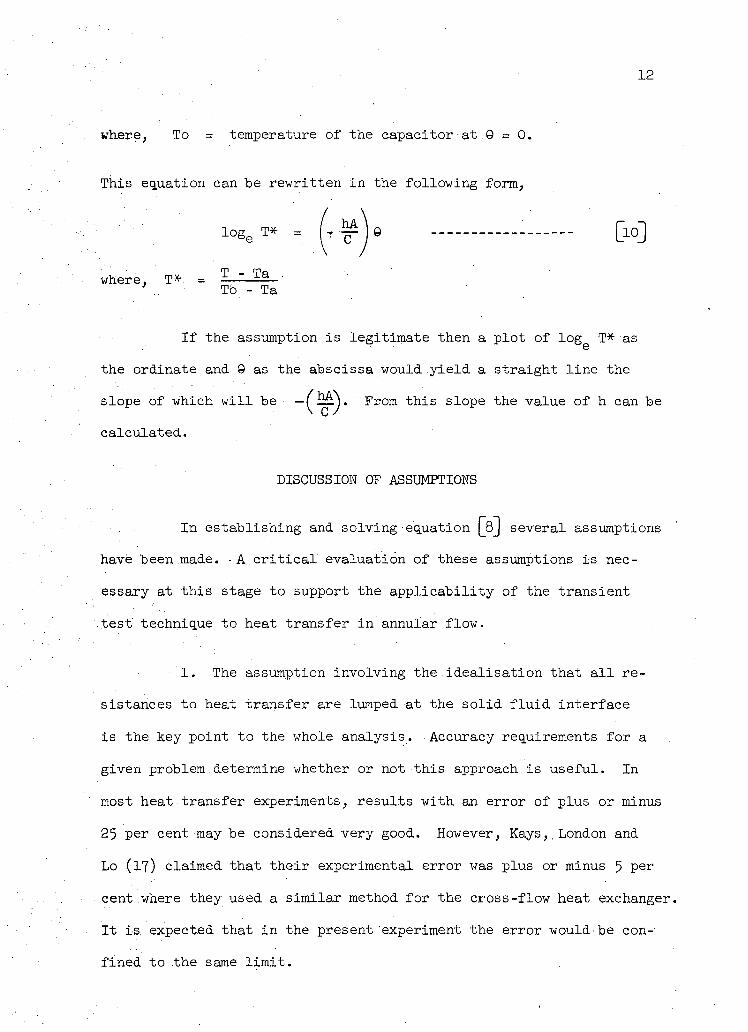
where, To = temperature of the capacitor•at.9 = 0.
This equation can be rewritten in the following form,
log„ T* = I -r ~ ] 6 [10]
where, T* =
3e . \ • C
T - Ta To - Ta
If the assumption i s legitimate then a plot of l o g g T* as
the ordinate and. 9 as the abscissa would y ie ld a straight l ine the
slope of which w i l l be — From this slope the value of h can be
calculated.
DISCUSSION OF ASSUMPTIONS
In establishing and solving equation QjJ several assumptions
have been made. - A . c r i t i c a l evaluation of these assumptions is nec
essary at this stage to support the appl icabi l i ty of the transient
test technique to heat transfer in annular flow.
1. The assumption involving the ideal isat ion that a l l re
sistances to heat transfer are lumped at the so l id f l u i d interface
is the key point to the whole analysis. Accuracy requirements for a
given problem.determine whether or not this approach.is useful. In
most heat transfer experiments, results with an error of plus or minus
25 per cent may be considered very good. However, Kays,, London and
Lo (17) claimed that their experimental error was plus or minus 5 P e r
cent where they used a similar method for the cross-flow heat exchanger.
It is. expected that in the present experiment the error would be con
fined to the same l i m i t .
13
2. Heat transfer is assumed to be by forced .convection only.
In a f u l l y developed turbulent flow free convection effects are almost
negligible. However, in viscous flow with a large'annular gap the
poss ib i l i ty of free convection effects cannot be to ta l ly ignored. . In
this experiment the flow conditions were always turbulent and therefore
free convection effects can be neglected.
It is also assumed that radiation effects are negligible.
For small temperature difference at low temperature leve l with pol
ished model surfaces this effect would be very small. But for high
temperatures, radiation loss can be significant which means that the
heat transfer coefficient as determined by this method would contain
a contribution f rom the radiation coeff icient. Temperatures of about
60 to 70 F above ambient can be considered low enough so as not to
cause any serious error due to radiation. The present experiment was
conducted in this range of temperature.
3• The temperature difference i n the radia l direction inside
the capacitor and i n the axial direction along i t s length is negl i
gible . This can be achieved by having a thermal capacitor of very high
thermal conductivity and re lat ive ly thin wall thickness.
k. Heat loss to the supporting structure of the model is
assumed very small. -As Garbett (16) noted in his investigation, the
mounting structure sometimes provide additional sources of heat loss.
For example, during a cooling process the capacitor cools much faster
than the supporting medium so that towards the end of the transient
cooling heat may flow from the supports to the capacitor. This effect
Ik
can be best-reduced .by keeping the area of contact between capacitor
and.support small and using supporting material having a small (K^C^)
product,
where, . = thermal conductivity of the supporting material
= heat capacity of the supporting material
5• The average value of the specific heat of the material
of the capacitor is constant. The specific heat of•copper is essen
t i a l l y constant between temperatures-'70 to 150F. The mass of the
capacitor is also constant;, and therefore the heat capacity is
constant.
6. The bulk temperature of the f l u i d stream is constant
during the test. To verify this a i r temperature was measured con
tinuously at the outlet of the test .section for the duration of one
..complete run. It was found that the variation was not more than 1 F
which was less than 1.5 per cent of the ambient temperature.
15
CHAPTER III
APPARATUS
The apparatus was designed to measure the following:
(a) the a ir flow rate
(b) the temperature and pressure of a ir
(c) the temperature-time history of the capacitor
Two different arrangements of apparatus were used. One for
the study of the concentric annulus and another for the eccentric
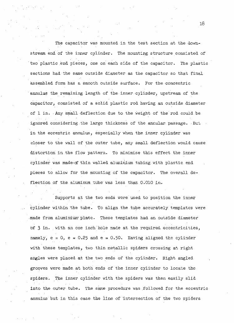
annulus. In Figure 1, a schematic layout of the apparatus used for
the concentric annulus is. shown. The arrangement consisted of a test
section, a mixing box and a centrifugal blower. The test section,
shown in Figure 2, was made of transparent plast ic outer tube having
an inside diameter, Uq = 3 i n . , and a wall thickness of l/k i n . The
inner cylinder on which the capacitor wasi mounted had an outside dia
meter, = 1 i n .
Air at room temperature was blown through the test section
by a l/3 hp centrifugal type blower with a speed rating of 3^50 rpm.
The a i r flow rate was determined by measuring the maximum velocity in
the annulus by a pitot static tube placed at the downstream end of the
test section and connected to a micro-manometer.
A mixing box between the blower and the test section acted
as a surge tank and tended to smooth pulsations in the a ir stream.
16
The temperature variation of the cooling capacitor was
measured by a copper-constantan thermocouple connected to an .automatic
recorder to obtain a temperature-time history.
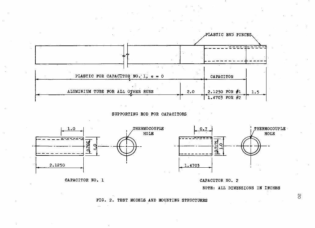
The apparatus'" used for the eccentric annulus test is shown
schematically in Figure 3« The same test section and mixing box were
used i n this arrangement but a higher capacity blower was used to
allow an or i f i ce meter to be used for measuring a ir flow. In the ec
centric annulus the a ir flow rate could not be determined by pitot tube
as in the case of concentric annulus because of the non-symetrical.
fom of velocity prof i le in an eccentric annulus. The flow rate was
therefore measured by a f la t plate, square edged or i f ice placed up
stream of the test section. The large pressure drop across the or i f ice
required the higher capacity blower to cover the same range of Reynolds
number as was obtained in the concentric annulus flow. A detailed
description of the two a ir metering systems i s given i n Appendix I .
The blower used in the second arrangement was a 3/h hp
centrifugal type blower with a speed rating of 3^50 rpm. A i r temp
erature was measured by a mercury in.glass thermometer graduated to
1 F and also by a copper-constantan thermocouple placed in the mixing
box. The change i n the flow Reynolds number was accomplished by
thrott l ing the a ir flow at the in le t side of the fan.
The length of the test section was selected to give a f u l l y
developed hydrodynamic flow. There is s t i l l a considerable doubt as
to the exact length after which the flow is f u l l y established in an
annulus. One group of investigators, M i l l e r , Byrnes and Benforado (19)
17
claimed that i n a concentric annulus the velocity prof i le is establish
ed i n twenty equivalent diameters. In the present investigation, this
figure was taken as the design cr i ter ion to select the length of the
test section. It was also found that there was no re l iable information
available as to the entry length required for the establishment of a
f u l l y developed flow in an eccentric annulus. However, i t was assumed
that the entry length.in both concentric and eccentric annuli was of
the same order of magnitude.
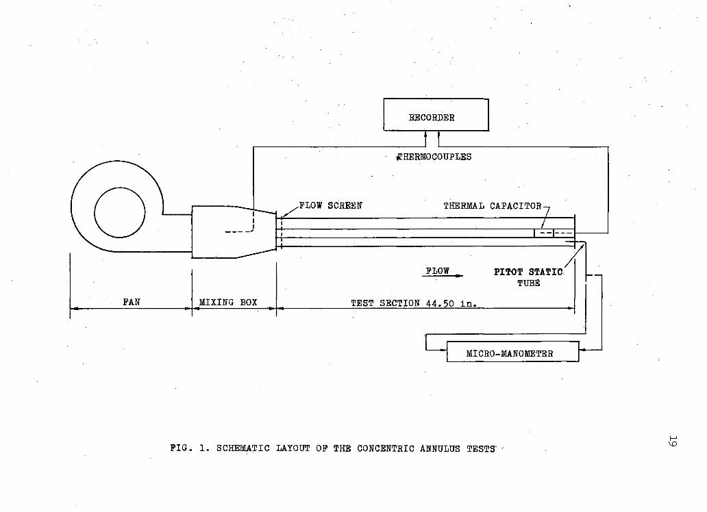
The heat transfer characteristics of the capacitor was
studied by recording i t s temperature-time history during a transient
cooling period. Two capacitors were used. The f i r s t one, shown in
Figure 2, was 2.125 i n . long with an outside diameter of 1 i n . and an
inside diameter of.0.776 i n . The capacitor was made from so l id copper
rod d r i l l e d to the required inside diameter and faced to the desired
length. A small hole was d r i l l e d in the wall of the capacitor to
provide space for the thermocouple junction. In selecting the size
of the capacitor, care was taken to comply with t h e B i o t number re
quirements and other assumptions made i n Chapter I I .
A second capacitor was made of the same material as the f i r s t
but was smaller i n length and mass. It was 1.1+703 i n . long with an
outside diameter of 1 i n . and an inside diameter of 0-7175 i n . Figure 2
shows the dimensions of this capacitor. A few tests were made with this
capacitor to show that the length of the capacitors had l i t t l e effect
on the results obtained. Further details of the comparison are given
in Chapter IV.
18
The capacitor was mounted in the test section at the down
stream end of the inner cylinder. The mounting structure consisted of
two plast ic end pieces, one on each side of the capacitor. The plast ic
sections had the same outside diameter as the capacitor so that f i n a l
assembled form has a smooth outside surface. For the concentric
annulus the remaining length of the, inner cylinder, upstream of the
capacitor, consisted of a so l id plast ic rod having an outside diameter
of 1 i n . Any small deflection due to the weight of the rod could be
ignored considering the large thickness of the annular passage. But
in the eccentric annulus, especially when the inner cylinder was
closer to the wall of the outer tube, any small deflection would cause
distortion i n the flow pattern. To minimise this effect the inner
cylinder was madeiof thin walled aluminium tubing: .with plast ic end
pieces to allow for the mounting of the capacitor. The overal l de
f lect ion of the-aluminum tube was less than 0.010 i n .
Supports at the two ends were used to position the inner
cylinder within the tube. To al ign the tube accurately, templates were
• made from aluminium' plate. These templates had an outside diameter
of 3 i n . • with an one inch hole made at the required eccentric i t ies ,
namely, e = 0, e = 0.25 and e = 0.50. Having aligned the cylinder
with these templates, two thin metallic spiders crossing at right
angles were placed at the two ends of the cylinder. Right angled
grooves were made, at both ends of the inner cylinder to locate the
spiders; The inner cylinder with the spiders was then easi ly s l i d
into the outer tube. The same procedure was followed for the eccentric
annulus but in this case the l ine of intersection of the two spiders
RECORDER
MICRO-MANOMETER
PIG. 1. SCHEMATIC LAYOUT OP THE CONCENTRIC ANNULUS TESTS' H
^PLASTIC END PIECESN
4 r
?0
r
PLASTIC FOR CAPACT1
4 r
?0 rso.-ij e a 0 CAPACITOR
1.5
- — V
ALUMINIUM TUBE FOR ALL OJT-HER RUNS 2.0 2.1250 FOR #1 1.5 * it v
'l.4703 FOR #2 '
SUPPORTING ROD FOR CAPACITORS
1.0
2.1250
d.
CAPACITOR NO. 1
HERMOCOUPLE HOLE
0.7
1.4703
! THERMOCOUPLE HOLE
CAPACITOR NO. 2 NOTE! ALL DIMENSIONS IN INCHES
FIG. 2. TEST MODELS AND MOUNTING STRUCTURES ro o
RECORDER
ORIFICE7 THERMOMETER THERMOCOUPLES
/FLOW SCREEN THERMAL CAPACITOR-
FLOW
TEST SECTION 44.50 i n .
MANOMETERS
FIG. 3. SCHEMATIC LAYOUT OF THE ECCENTRIC ANNULUS TESTS
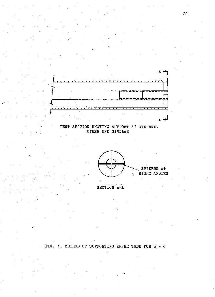
TEST SECTION SHOWING SUPPORT AT ONE END. OTHER END SIMILAR
SECTION A-A
4. METHOD OP SUPPORTING INNER TUBE FOR e = 0
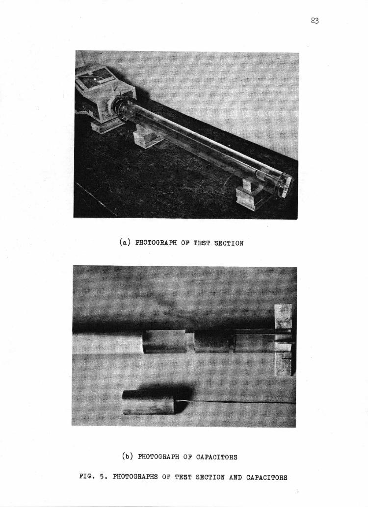
(a) PHOTOGRAPH OP TEST SECTION
(b) PHOTOGRAPH OP CAPACITORS
PHOTOGRAPHS OP TEST SECTION AND CAPACITORS
2k
was shifted to give the desired eccentricity of the inner cylinder.
The supporting device for the concentric annulus is shown i n Figure k.
Photographs of the test section and the capacitors are shown i n
Figure 5•
INSTRUMENTATION '
As mentioned i n the earlier chapter, the heat transfer co
efficient was determined from a record of the temperature-time history
of the cooling capacitor. Since the temperature of the capacitor was
decreasing with time, a measuring probe capable of fast response to
a changing temperature was desired. An ideal temperature measuring
probe would f a i t h f u l l y respond to any change regardless of the time
rate of temperature change of the capacitor. The thermocouple was
the obvious choice for this type of measurement because of the f o l
lowing reasons:
.' The time constant of the thermocouple wire i s a function of
the ratio of heat.capacity to i t s surface area. The thermocouple
junctions have small mass and hence small thermal capacity. The area
of contact is comparatively large due to soldering of the probe to the
capacitor. Therefore, the thermocouple wire has a small time constant
and follows closely any temperature variation i n the capacitor.
In the range of the experiment, which was from 70 to 1^0 F,
the electro-motive force of the thermocouple is practically a linear
function of the temperature. Thus i t was possible to plot the dimen
sionless temperature T* in equation N-Ol i n terms of the emf difference
25
instead of the temperature difference. This simplified not only the
computation but also the cal ibration of the recording instrument.
The copper-constantan thermocouple used for measuring the
capacitor temperature and the a ir temperature in the mixing box was
26 gauge B & S, so l id wire with polyvinyl insulation.
The temperature-time variation of the capacitor was recorded
on, the chart of a B r i s t o l recorder. The range of the recorder was
adjusted to 0 to 2.5 mi l l ivo l t s and the chart speed was kept constant
at 3/8 in . .per min. It was believed that the Br i s to l recorder had a
faster response than that of the capacitor so any error due to instru
ment lag was negi l ig ib le . A quantitative estimate of the relat ive
error w i l l "be presented in the discussion of results , Chapter XV.
This error, according to Garbett (l6), i s the rat io of the instrument
time constant to the capacitor time constant.
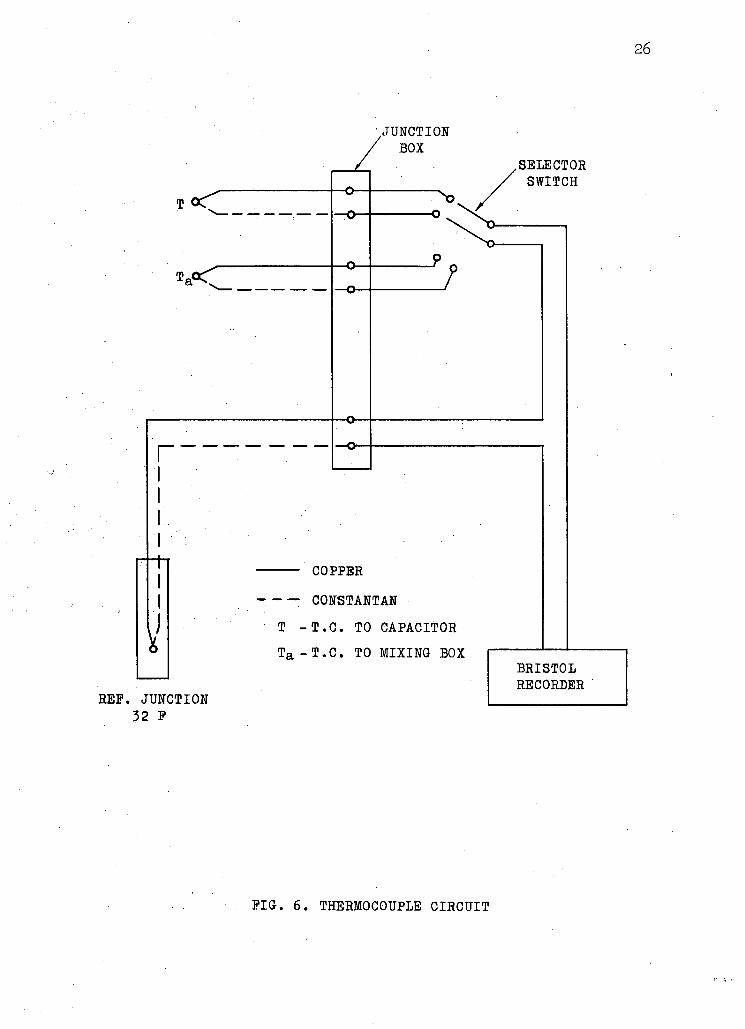
Two thermocouples were used i n the experimental arrangement
with a selector switch to connect one thermocouple to the recorder
at any one time. A schematic diagram of the thermocouple c i rcu i t with
related instrumentation is shown in Figure 6.
26
r
V
REP. JUNCTION 32 P
.JUNCTION BOX
COPPER
: CONSTANTAN T -T.C. TO CAPACITOR T a -T.C. TO MIXING BOX
.SELECTOR SWITCH
BRISTOL RECORDER
PIG. 6. THERMOCOUPLE CIRCUIT
27
CHAPTER IV
EXPERIMENTAL PROCEDURE
For each set of experiments the inner tube was f i r s t aligned
to the particular eccentricity for which the test was to be made. The
capacitor was then heated to 60 to 70 F above the ambient temperature
by an external heat source consisting of an e lectr ic soldering iron
with an aluminium extension piece to reach the capacitor inside the
tube. The heat source was then withdrawn, the recorder and the a ir
fan motor switch were turned on. As the capacitor was cooling towards
equilibrium in the f l u i d stream, a continuous record of temperature
against time was made in the recorder. This record was taken for .
approximately 130 seconds. The selector switch was then turned on to
the a ir temperature thermocouple and a record of this temperature was
also made on the same chart. About the middle of each run; or i f i ce
pressure drop, static pressure and temperature of a ir at the in le t
side of the or i f ice and the a ir velocity were recorded. When one
test was complete, the flow.rate was changed by thrott l ing the a ir at
the in let to the fan. The same procedure was then repeated t i l l a
Reynolds number range from 15,000 to 65,000 was covered. A tota l of
about 13 to 16 runs were taken for each position of the annulus.
Four positions of the annulus were investigated. Each posi
t ion was designated by the eccentricity parameter, e, defined by the
following•relation:
e _ Distance between the centres of the two cylinders r2 " r l
28
The four positions were thus, e = 0, e = 0.25, e = 0.50, and e = 1.0.
PRESENTATION•OF RESULTS
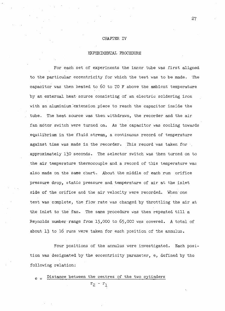
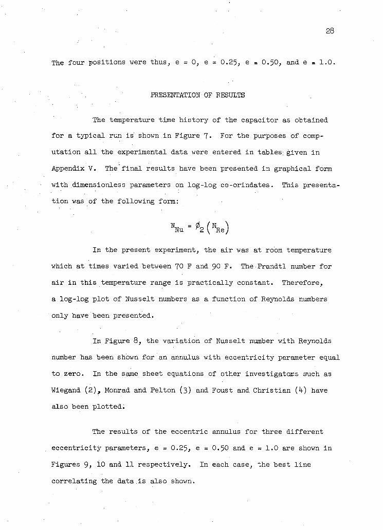
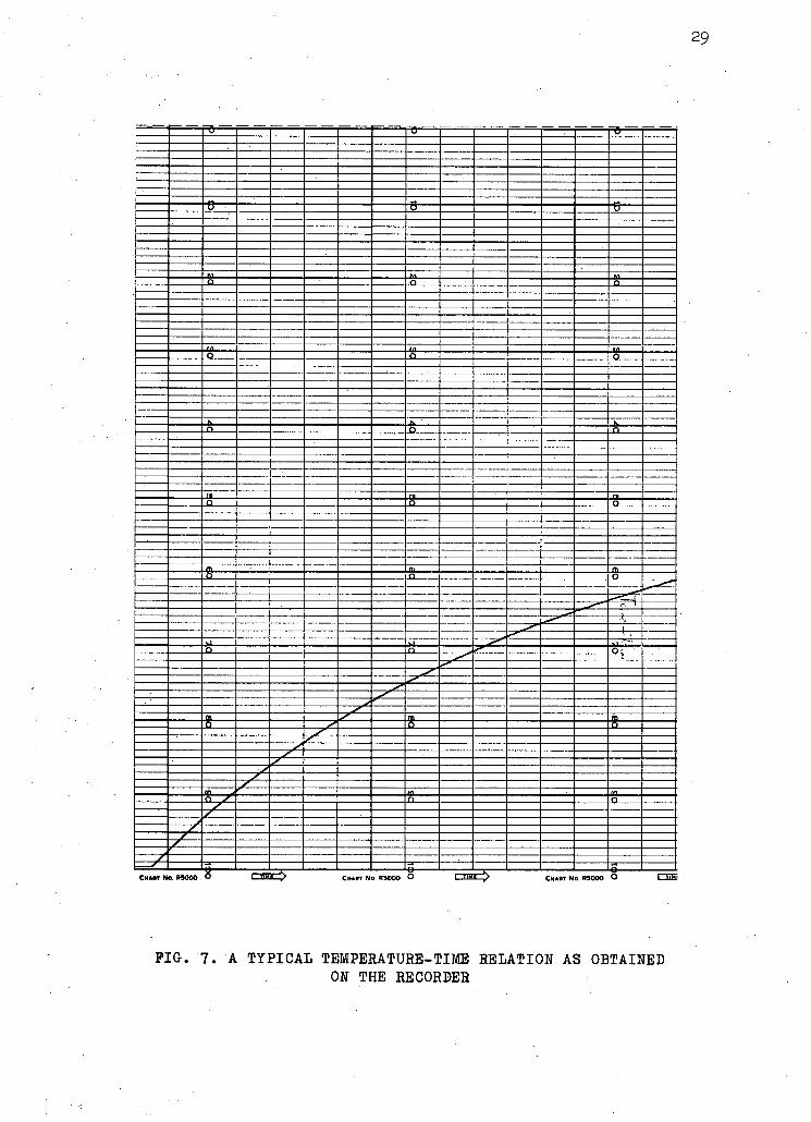
The temperature time history of the capacitor as obtained
for a typical run is shown.in Figure 7. For the purposes of comp
utation a l l the.experimental data were entered in tables; given in
Appendix V. The f i n a l results have been presented in graphical form
with dimensionless parameters on log-log co-orindates. This presenta
tion was of the following form:
NNu = i 2 S
2 ( W Re)
In the present experiment, the a ir was at room temperature
which at times varied between 70 F and 90 F . The Prandtl number for
a ir i n this temperature range is pract ica l ly constant. Therefore,
a log-log plot of Nusselt numbers as a function of Reynolds numbers
only have' been presented.
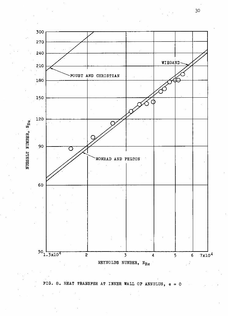
In Figure 8, the variation of Nusselt number with Reynolds
number has been shown for an annulus with eccentricity parameter equal
to zero. In the same sheet equations of other investigators such as
Wiegand (2), Monrad and Pelton (3) and Foust and Christ ian (k) have
also been plotted.
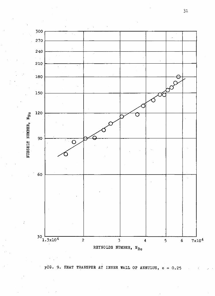
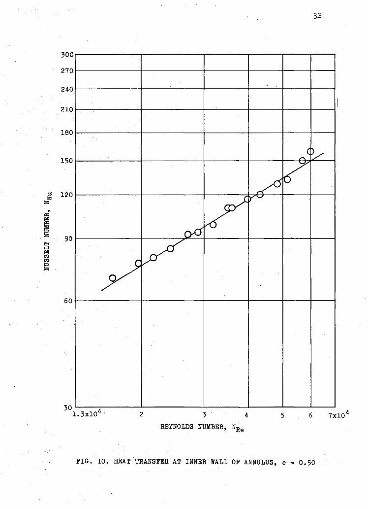
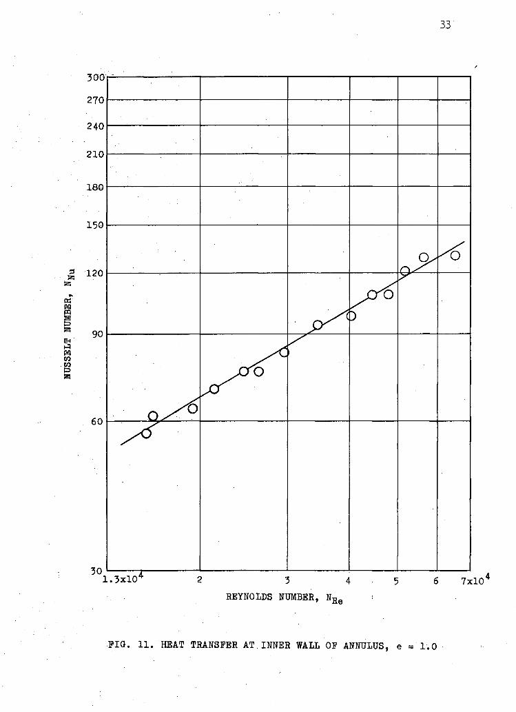
The results of the eccentric annulus for three different
eccentricity parameters, e = 0.25, e = 0.50 and e = 1.0 are shown i n
Figures 9> 10 and 11 respectively. In each case, the best l ine
correlating the data.is also shown.
29
-o =e— p 1
,—1
_ "
0 0 0
hi n n n
r.t o O o
ri n n
f* a o o
rti o o O
;
( , r> o -
T m
o S 5
n n
7?
C a w No. R5000 5 QlMI_J> CHUT No. RSOOO 8 l_lu3Z CHUT No. RSOOO O [ZSB
PIG. 7. A TYPICAL TEMPERATURE-TIME RELATION AS OBTAINED ON THE RECORDER
30
&5
tt w pp
E-i H i W CO ra &5
300
270
240
210
180
150
120
90
60
30,
WIEGA
iND CHRISTIAN
)
/ ^ ^ ^ ^
^MONRAD AND I 'ELTON
REYNOLDS NUMBER, N R E
FIG.. 8. HEAT TRANSFER AT INNER WALL OF ANNULUS, e = 0
31
300
270
240
210
60
1.3xl0 4 2 3 4 5 6 7xl0 4
REYNOLDS NUMBER, N R e
pIG. 9. HEAT TRANSFER AT INNER WALL OF ANNULUS, e = 0.25
32
300
270
240
210
180
60
1.3xl0 4 y 2 3 4 5 6 7xl0 4
REYNOLDS NUMBER, N R
PIG. 10. HEAT TRANSFER AT INNER WALL OP ANNULUS, e = 0.50
33
300 •
270 •
240 •
210 •
180 -
150
1.3x10* 2 3 4 5 6 7x10 REYNOLDS NUMBER, N R e
PIG. 11. HEAT TRANSFER AT INNER WALL OP ANNULUS, e =1.0
3^
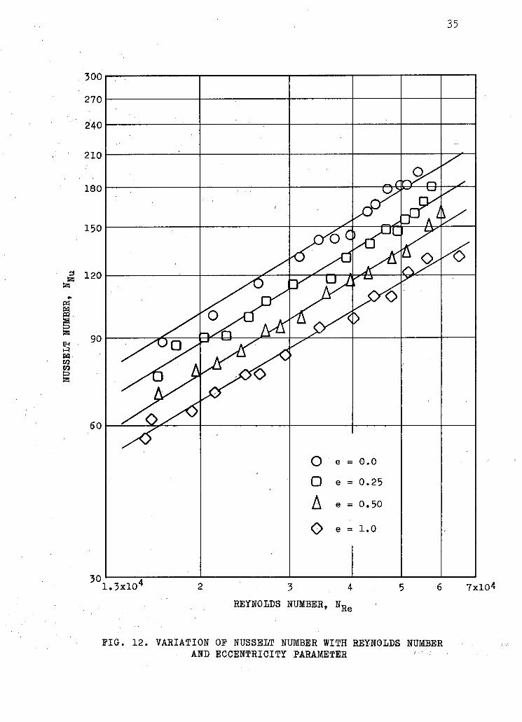
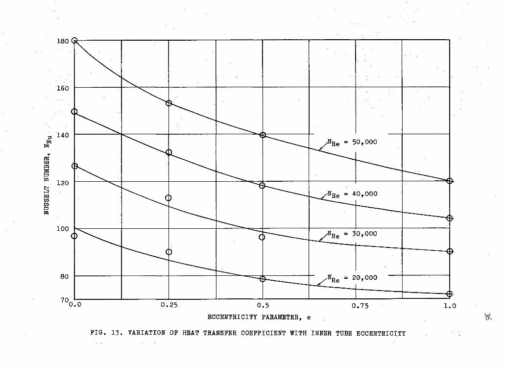
In Figure 12, the variat ion of Nusselt number with Reynolds
number and eccentricity parameter is shown. It is interesting to note
that the average Nusselt number decreased with increasing annulus
eccentricity. In•Figure 13, this decreasing trend of Nusselt number
with eccentricity parameter has been plotted for a fixed Reynolds
number.
DISCUSSION OF RESULTS
This section includes a discussion of a l l the experimental
results and an evaluation of the probable errors involved in different
parts of the investigation.
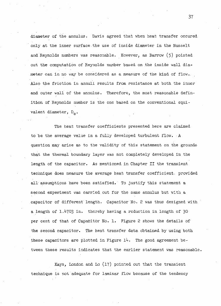
Experimental data for the average heat transfer coefficient
in a concentric annulus are shown in Figure 8. Since a l l these data
were obtained in almost isothermal condition, the Prandtl number of
the a ir was always constant. The equations of Wiegand, Qi-J of
Monrad and Pelton and of Foust and Christ ian are plotted in the
same sheet to compare the experimental results . It is noted that the
agreement is very good indeed with equations (V) and QJ-J . The
equation of Foust and Christ ian predicts much higher values of heat
transfer coefficients although the trend shown is the same. .Foust and
Christ ian obtained their water side coefficients by means of a semi-
graphical method which resulted in steam coefficients which were very
high so that their results have been questioned by latter investigators
(5, 21).
The equation Qjf} of Davis (7) was not considered a proper
comparison with the present data because i t is based on the inside
35
270
240
o e = 0.0
• e = 0.25
A e = 0.50
O e = 1.0
1.3x10* 2 3 4 5 6 7x10⁴ REYNOLDS NUMBER, N R -
PIG. 12. VARIATION OP NUSSELT NUMBER WITH REYNOLDS NUMBER AND ECCENTRICITY PARAMETER
0.0 0.25 0.5 0.75 1.0 ECCENTRICITY PARAMETER, e
PIG. 13. VARIATION OP HEAT TRANSFER COEFFICIENT WITH INNER TUBE ECCENTRICITY
37
diameter of the annulus. Davis agreed that when heat transfer occured
only at the inner surface the use of inside diameter in the Nusselt
and Reynolds numbers was reasonable. However, as Barrow (5) pointed
out the computation of Reynolds number based on the inside wall d ia
meter can in no way be considered as a measure of the kind of flow..
Also the f r i c t i o n in annuli results from resistance at both the inner
and outer wall of the annulus. Therefore, the most reasonable defin
i t i o n of Reynolds number is the one based on the conventional equi
valent diameter, D e .
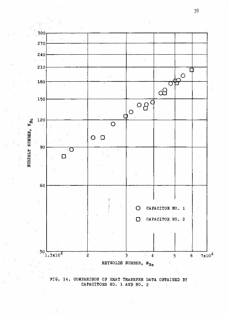
The heat transfer coefficients presented here are claimed
to be the average value in a f u l l y developed turbulent flow. A
question may arise as to the v a l i d i t y of this statement on the grounds
that the thermal boundary layer was not completely developed in the
length of the capacitor. As mentioned in Chapter II the transient
technique does measure the average heat transfer coefficient, provided
a l l assumptions have been sat is f ied. To just i fy this statement a
second experiment was carried out for the same annulus but with a
capacitor of different length. Capacitor No. 2 was thus designed with
a length of I.U703 i n . thereby having a reduction in length of 30
per cent of that of Capacitor No. 1. Figure 2 shows the details of
the second capacitor. The heat transfer data obtained by using both
these capacitors are plotted in Figure lh. The good agreement be
tween these results indicates that the earl ier statement was reasonable.
Kays, London and Lo (17) pointed out that the transient
technique is not adequate for laminar flow because of the tendency
38
fe
fe
EH
CO
•B
300
270
240
210
180
150
120
90
60
30
C o r> )
di ii
c
>
o
o •
0 •
!
/
i O CAP
• CAP
ACITOR N
ACITOR N
0. 1
0. 2
7x10 REYNOLDS NUMBER, N R e
PIG. 14. COMPARISON OP HEAT TRANSFER DATA OBTAINED BY CAPACITORS NO. 1 AND NO. 2
39
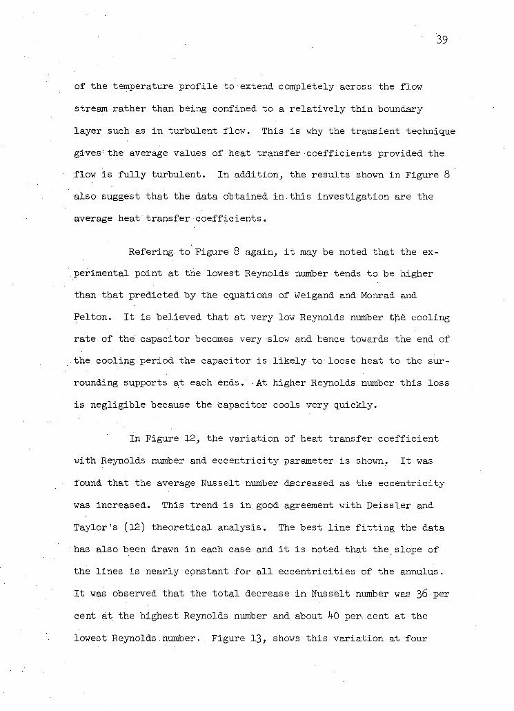
of the temperature prof i le to extend completely across the flow
stream rather than being confined to a re la t ive ly thin boundary
layer such as in turbulent flow. This is why the transient technique
gives' the average values of heat transfer coefficients provided the
flow is f u l l y turbulent. In addition, the results shown in Figure 8
also suggest that the data obtained in . th i s investigation are the
average heat'transfer coefficients.
Refering to Figure 8 again, i t may be noted that the ex
perimental, point at the lowest Reynolds number tends to be higher
than that predicted by the equations of Weigand and Monrad and
Pelton. It i s believed that at very low Reynolds number the cooling
rate of the' capacitor becomes very slow and hence towards the end of
the cooling period the capacitor is l i k e l y to loose heat to the sur
rounding supports at each ends. At higher Reynolds number this loss
is negligible because the capacitor cools very quickly.
In Figure 12, the variation of heat transfer coefficient
with Reynolds number and eccentricity parameter is shown. It was
found that the average Nusselt number decreased as the eccentricity
was increased. This trend is in. good agreement with Deissler and
Taylor's (12) theoretical analysis. The best l ine f i t t i n g the data
has also been drawn in each case and i t is noted that the slope of
the lines is nearly constant for a l l eccentricit ies of the annulus.
It was observed that the tota l decrease in Nusselt number was 36 per
cent at the highest Reynolds number and about 1+0 peri.cent at the
lowest Reynolds.number. . Figure 13, shows this variation at four
^0
different Reynolds number. The rate of decrease of heat transfer co
eff icient was found to be greater within the f i r s t 50 P e r cent of
the eccentricity. Between 50 and 100 per cent eccentricity the var
iat ion of heat transfer coefficient was much.less.
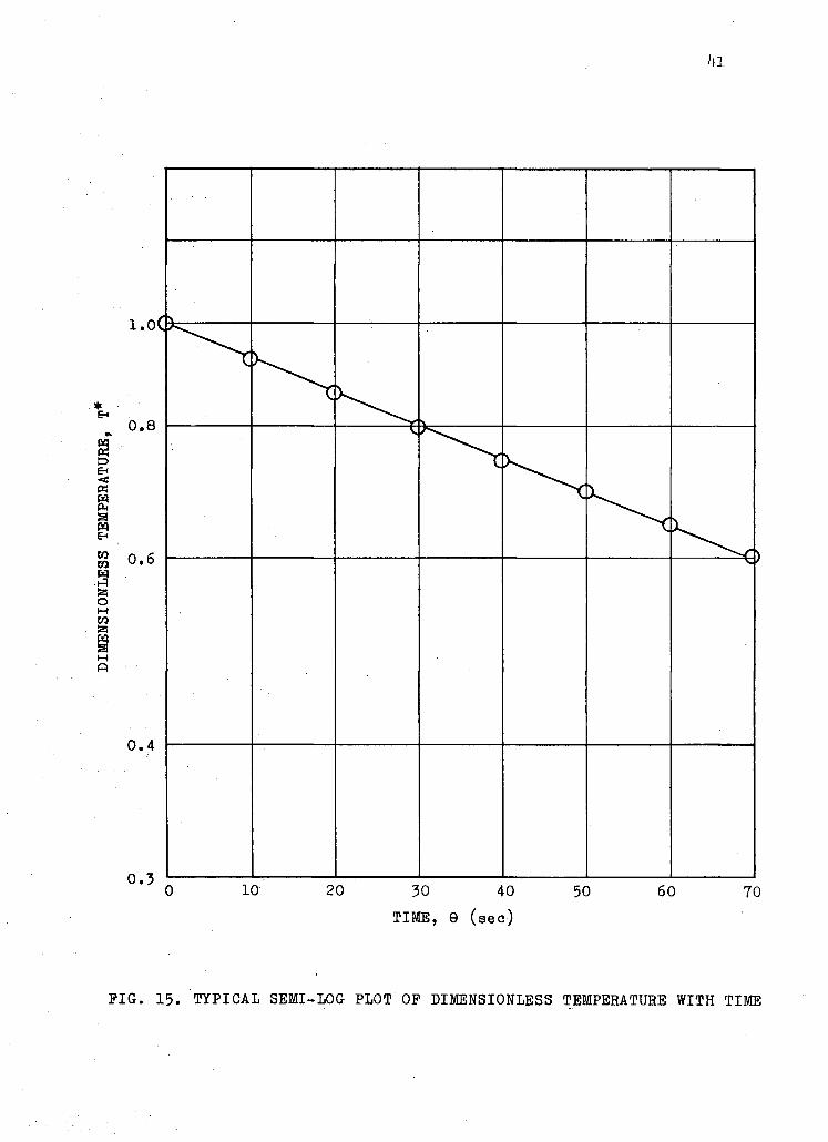
It was pointed out i n Chapter II that in the solution of
equation (V) the heat transfer coefficient and the heat capapcity of
the test model were assumed constant. Considering the fact that the
semi-log plot of equation [loj from the experimental data followed
the expected straight- l ine relationship, these assumptions seem to
be jus t i f i ed . A typical semi-log plot of •equation (jLOj is shown in
Figure 15• However, any definite departure from the l inear relation
would necessarily make the above assumptions questionable. The con
stancy of the heat capacity of the model w i l l depend on the variation
of the specific heat of copper with temperature. The temperature range
in the present investigation was between 70 F and ikO F . It is believed
that the variation of specific heat i n this temperature range was neg
l i g i b l e .
The instrument lag effect may cause an error in the measure
ment of heat transfer coefficient especially when the data recorded
were those of a transient state. As mentioned in Chapter III , the
relat ive error in the calculated value of the heat transfer coeff i
cient is given by the following relat ion:
Relative error = -— x 100 per cent -c
i l l
0.4
0 10 20 30 40 50 60 70 TIME, 9 (sec)
PIG. 15. TYPICAL SEMI-LOG PLOT OF DIMENSIONLESS TEMPERATURE WITH TIME
k2
w h e r e , = time constant of the recording instrument.
T c = time constant of the capacitor model.
The time constant of the recording instrument was obtained by apply
ing a step change in the input. This was found to be 2.5 sec. The
time constant of the capacitor was given by the inverse of the slope
of the semi-log plot shown in Figure 15. The lowest time constant of
the capacitor during the entire experiment was that of Capacitor No. 1
during Run 13• This was found to be 9^-5 sec. Therefore, the maximum
relative error was 2.67 per cent.
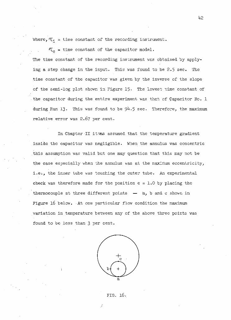
In Chapter II itwas assumed that the temperature gradient
,inside the capacitor was negligible. When the annulus was concentric
this assumption was va l i d but one may question that this may not be
the case especially when the annulus was at the maximum eccentricity,
i . e . , the inner tube was touching the outer tube. An experimental
check was therefore made for the position e = 1.0 by placing the
thermocouple at three different points — a, b and c shown in
Figure l6 below. At one particular flow condition the maximum
variation in temperature between any of the above three points was
found to be less than 3 psr cent.
a
FIG. 16.
h3
The deflection or sag of the inner cylinder could cause an
error in the transient cooling of the model. When the annulus was
concentric any small sag in.the inner cylinder could not appreciably
influence the flow pattern because of the re lat ive ly large annular
thickness. Also the capacitor was mounted near the downstream support
'so.that any small sag was around the middle of the test section which
has much less influence on the capacitor. For the eccentric annulus,
however, the effect, of the sag', of the inner cylinder could be apprec
iable especially at higher eccentricity. To avoid this a hollow alum-
i inium tube was used to support the capacitor i n the eccentric annulus.
This is shown i n Figure 2. The tota l deflection in the centre of
the tube was, in this case, l imited.to 0.010 i n . which is 10 per cent
of the maximum annulus thickness. It was assumed that this tolerance
was within the required accuracy of the experiment.
The errors due to cal ibration of the recording instrument
and also of the thermocouples were not considered to be of any con
sequence. The experiment was conducted i n a small temperature range
and i t was.found that within this range the•temperature-emf response
of a copper-constantan thermocouple was very close to l inear . There
fore, in the dimensionless temperature-time plot , Figure 15, i t was
sufficient to plot the logarithm of the emf ratios d irect ly from.the
recorder chart. Also because of the dimensionless temperature, the
cal ibration of the recording instrument was not required as long as
i t demonstrated a l inear scale.
1+1+
CHAPTER V
CONCLUSIONS
1. The use of the transient test technique was found to
be a simple and quick method for determining the heat transfer chara-
ter i s t i c s in an annulus. Heat transfer coefficients in an eccentric
annulus were found to decrease with increase i n eccentricity. The
decrease of heat transfer coefficient did not seem to be l inear ly
•related to the increase of eccentricity. However, the effect of
eccentricity was more pronounced in the range 0 e <0.5 where the
value of heat transfer coefficient decreased considerably. For
example, at Reynolds number of 50,000 approximately 67 per cent of
the to ta l decrease occured i n the range 0 ^ e <0.5 while the other
33 P e r cent occured in the range 0.5 ^ e ^1.0.
Equations of Wiegand (2) and Monrad and Pelton (3) were
found to correlate the annulus data of the present investigation very
well .
2. Almost isothermal data was obtained by the transient
method. In the annulus, the air temperature was pract ica l ly constant
for one complete: run. and therefore the evaluation of the properties
could be easi ly made at this temperature. This eliminates the trouble
of determining the f l u i d f i lm temperature required in other methods
of determining the heat transfer data.
3• The temperature of the cooling capacitor was measured
in an arbitrary scale during the experiment. Therefore, careful
1+5
cal ibration of the thermocouple and the recording instrument was not
required.
RECOMMENDATION FOR FUTURE WORK
The present investigation may be considered as an explor
atory work for more extensive studies in the same f i e l d . One of the
important studies which is yet to be done is the behaviour of the heat
transfer coefficients in the region where neither the thermal nor
the hydrodynamic boundary layer has developed completely. This s i tua
tion may be encountered in practice i n a reactor where the heat trans
fer from the fuel rod is expected to take place from the very start
of the tube. This investigation can probably be made by using the
same technique provided a method is found to isolate the capacitors
thermally along the longitudinal direct ion.
BIBLIOGRAPHY
London, A. L . , Nottage, H. B . , Boelter, L. . .M. K. "Determination of Unit Conductances for Heat and Mass Transfer by the Transient Method" Ind. and Eng. Chem. V o l . 33, 19^1, P- 67
Wiegand, J . H. "Discussion on.Annular Heat Transfer Coefficients for Turbulent Flow by McMillen and Larson" Am. Inst. Chem. Engrs. Trans. V o l . i n , 191*5, p. U7
Monrad, C. C , Pelton, J . F . "Heat Transfer, by Convection in.Annular Spaces" Am. Inst. Chem. Engrs. Trans. V o l . 38, 19U2, p. 593
Foust, A . S . , Christ ian, G.A. "Non-boiling Heat Transfer in. Annuli" Am. Inst. Chem. Engrs. Trans. V o l . 30, 191+0, p. 5^1
Barrow, H. "Fluid Flow and Heat Transfer in an.Annulus with a Heated Core Tube" Proc. Inst. Mech. Engrs. V o l . 169, 1955, p. 1113
a
Mueller, A. C. . '!Heat Transfer from Wires to Air i n Paral le l
Flow " Am. Inst. Chem..' :Engrs. Trans. V o l . 38, 19^2, p. 613
Davis, E . S. "Heat Transfer and Pressure Drop in Annuli" Trans.•ASME V o l . 65, 19^3, P . 755
Knudsen, J . G . , Katz, D . . L . "Fluid Dynamics and Heat Transfer" McGraw-Hill Book Co. .Inc . 1958
Stein, R. P . , Begel, W. "Heat Transfer to Water in Turbulent Flow in Internally Heated Annuli" Am. Inst. Chem. Engrs. Jour:... V o l . k, 1958, p. 127
hi
(10) Mizushina, T. "Analogy between F lu id Fr i c t i on and Heat Transfer in Annuli" General Discussion on Heat Transfer - ASME/IME 1951, P. 191
(11.) Barrow, H. . "A Semi-theoretical Solution of Asymmetric
Heat Transfer in. Annular Flow Jour. Mech. Eng. Sc. V o l . 2 , i 9 6 0 , P . .331
(12) Deissler, R. G . , Taylor, M. F . "Analysis of Fu l ly Developed Turbulent Heat Transfer and Flow in.Annulus with Various Eccentric i t ies" NACA - TN 3U51, March, 1955
(13) Leung, E . Y . , Kays, W. M . , Reynolds, W. C. "Heat Transfer with Turbulent Flow in Concentric and Eccentric Annuli with Constant and Variable Heat Flux" NASA - N62 - 131V3, August, 1962
(lh) Eber, G. R. "Experimental Investigation of the Brake Temperature and Heat Transfer of Simple Bodies at Supersonic Speeds" Archiv. 6 6 / 5 7 , Peenemude, Nov., 19U1
(15) Fischer, W. W., Norris , R. H. "Supersonic Convective Heat Transfer Correlation from.Skin Temperature Measurements on a V -2 Rocket in Fl ight" Trans. ASME V o l . 71 , I9U9, p. ^57
(16) Garbett, C. R. 'The Transient .Method for Determining Heat Transfer Conductance from Bodies i n High Velocity
. F lu id Flow" Heat Transfer and F lu id Mechanics Institute Preprints of Paper, 1951 Stanford Univ. Press
(17) Kays, W. M . , London, A. L . , Lo, R.. K. "Heat Transfer and Fr i c t i on Characteristics for Gas Flow Normal to Tube Banks - Use of a Transient Test Technique" Trans. ASME V o l . 76, 195^, P- 387
(18) Kreith, F , "Principles of Heat Transfer" International Text Book Co. 1958
(19) M i l l e r , P . , Byrnes, J . J . , Benforado, D . M . "Heat Transfer to Water in an Annulus " Am. Inst. Chem.. Engrs. Jour. V o l . 1, 1955, P- 501
(20) ASME Power.Test Codes, Chap, 4, Part. 5
(21) Rothfus, R. R. "Velocity Distribution and F lu id Fr ic t ion in Concentric Annuli " D. Sc. Thesis, Carnegie Inst. Tech. 1948
(22) Stein, R. P . , Begell , Wm. "Heat Transfer to Water in Turbulent Flow in Internally Heated Annuli" Am. Inst. Chem. Engrs. Jour. V o l . 4, 1958, p. 127
(23) Giedt, W. H. "Principles of Engineering Heat Transfer" D. Van Wostrand Co. Inc. , 1958
(24) Jordan, H.P. "On the "Rate of Heat Transmission between F lu id and Metal Surfaces" Proc. Inst. Mech. Engrs. Parts 3 - 4 , 1909, p. 1317
(25) Foust, A. S. , Thompson, T. J . "Heat Transfer Coefficients in Glass Exchangers' Am. Inst. Chem. Engrs. Trans. V o l . 36, 1940, p. 555
(26) Zebran, A. H. 'Clar i f icat ion of Heat Transfer Characteristics of Fluids in Annular Passages" Ph. D. Thesis, Univ. of Michigan 1940
(27) McMillen, E . L . , . L a r s o n , R. E . "Annular Heat Transfer Coefficients for Turbulent Flow" Am. Inst. Chem. Engrs. Trans. V o l . 40, 1944, p. 177
h9
APPENDIX I
AIR METERING SYSTEMS
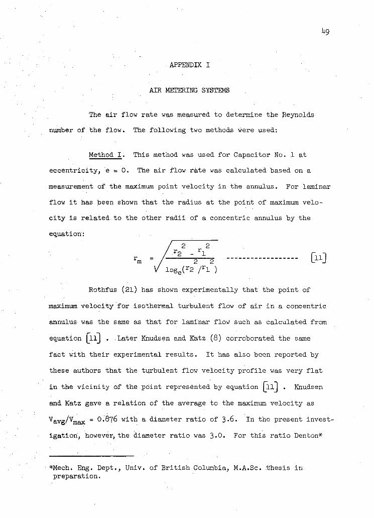
The a ir flow rate was measured to determine the Reynolds
number of the flow. The following two methods were used:
Method I . This method was used for Capacitor No. 1 at
eccentricity, e = 0. The a ir flow rate was calculated based on a
measurement of the maximum point velocity in the annulus. For laminar
flow i t has been shown that the radius at the point of maximum velo
c i ty is related to the other r a d i i of a concentric annulus by the
equation:
r. m / 2 2 l o g e ( r 2 / r x ) =ex
Rothfus (21) has shown experimentally that the point of
maximum velocity for isothermal turbulent flow of a ir in a concentric
annulus was the same as that for laminar flow such as calculated from
equation [ l l ] . Later Knudsen and Katz (8) corroborated the same
fact with their experimental results . It has also been reported by
these authors that the turbulent flow velocity prof i le was very f la t
in the v i c i n i t y of the point represented by equation [ l l j . Knudsen
and Katz gave a relat ion of the average to the maximum velocity as
^avg/^max = ^ ^ T S with a diameter rat io of 3-6. In the present invest
igation, however, the diameter rat io was 3>0. For this rat io Denton*
*Mech. Eng. Dept., Univ. of Br i t i sh Columbia, M.A.Sc. thesis in. preparation.
50
studied the velocity profi les in turbulent flow and concluded that
O.876 was correct for the present annulus. The average flow velocity
thus calculated had a maxiipum variation of 1.8 per cent.
The maximum point velocity was measured by a pitot static tube
placed at the radius, r m . It was mounted at the exit of the test sec
t ion and was connected to an accurate micro^manometer capable of read
ing low pressures from zero i n . of water head to 6.0 i n . of water head.
The temperature of the a ir stream was measured by an ordinary
mercury i n glass thermometer. The thermometer was graduated to 1 F .
It was found that the a ir temperature did not change appreciably dur
ing this part-, of the experiment.
The Reynolds number was f i n a l l y calculated from the above data.
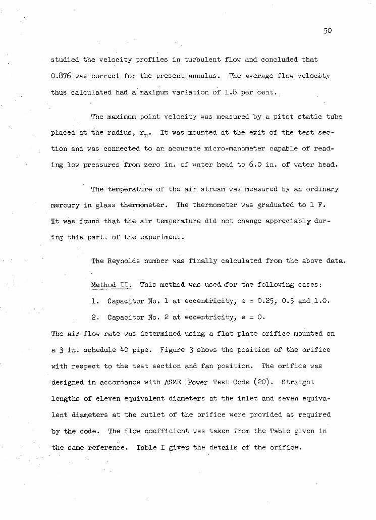
Method I I . This method was used i f o r the following cases:
1. Capacitor No. 1 at eccentricity, e = 0.25, 0.5 and,1.0.
2. Capacitor No. 2 at eccentricity, e = 0.
The a ir flow rate was determined using a f la t plate or i f ice mounted on
a 3 i n . schedule hO pipe. Figure 3 shows the position of the or i f ice
with respect to the test section and fan posit ion. The or i f i ce was
designed in accordance with ASME -.Power Test Code (20). Straight
lengths of eleven equivalent diameters at the in let and seven equiva
lent diameters at the outlet of the or i f ice were provided as required
by the code. The flow coefficient was taken from the Table given in
the same reference. Table I gives the details of the o r i f i c e .
51
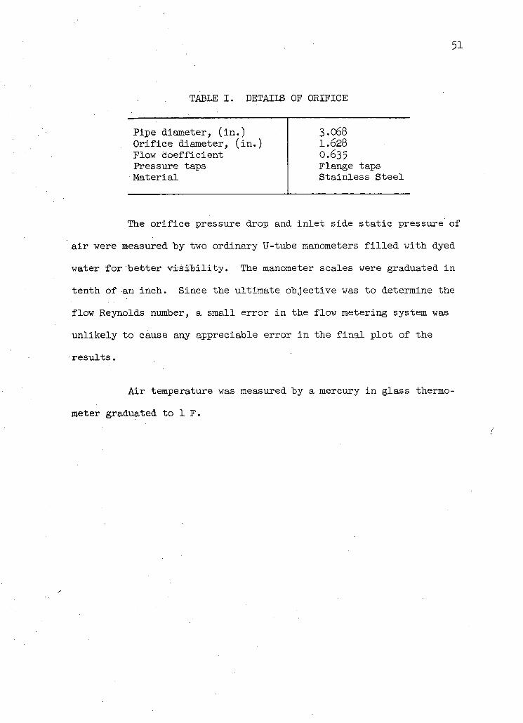
TABLE I. DETAILS OF ORIFICE
Pipe diameter, (in.) 3.068 O r i f i c e diameter, (in.) 1.628 Flow c o e f f i c i e n t 0.635 Pressure taps Flange taps M a t e r i a l S t a i n l e s s S t e e l
The o r i f i c e pressure drop and i n l e t side s t a t i c pressure of
a i r were measured by two ordinary U-tube manometers f i l l e d with dyed
water f o r be t t e r v i s i b i l i t y . The manometer scales were graduated i n
tenth of an inch. Since the ultimate objective was to determine the
flow Reynolds number, a small error i n the flow metering system was
u n l i k e l y to cause any appreciable error i n the f i n a l p l o t of the
r e s u l t s .
A i r temperature was measured by a mercury i n glass thermo
meter graduated to 1 F.
52
APPENDIX II
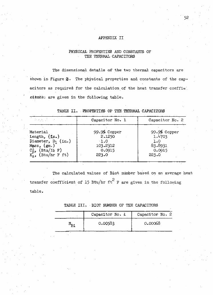
PHYSICAL PROPERTIES AND CONSTANTS OF THE THERMAL CAPACITORS
The dimensional details of the two thermal capacitors are
shown i n Figure 3» The physical properties and constants of the cap
acitors as required for the calculation of the heat transfer coeffits:"
cdentBc are given i n the following table.
TABLE II. PROPERTIES OF THE THERMAL CAPACITORS
Capacitor No. 1 Capacitor No. 2
Material Length, (in.) piameter, Dj (in.) Mass, (gm.) Cl (Btu/lb F) Kg, (Btu/hr F ft)
99-9$ Copper 2.1250 1.0
103.2312 0.0915
223.0
99.9$ Copper 1.4703 1.0
83.8931 O.O915
223.0
The calculated values of Blot number based on an average heat 2
transfer coefficient of 15 Btu/hr f t F are given i n the following
table. TABLE III. BIOT NUMBER OF THE CAPACITORS
Capacitor No. 1 Capacitor No. 2
N B i 0.00583 0.00068
53
APPENDIX III
PHYSICAL PROPERTIES OF AIR
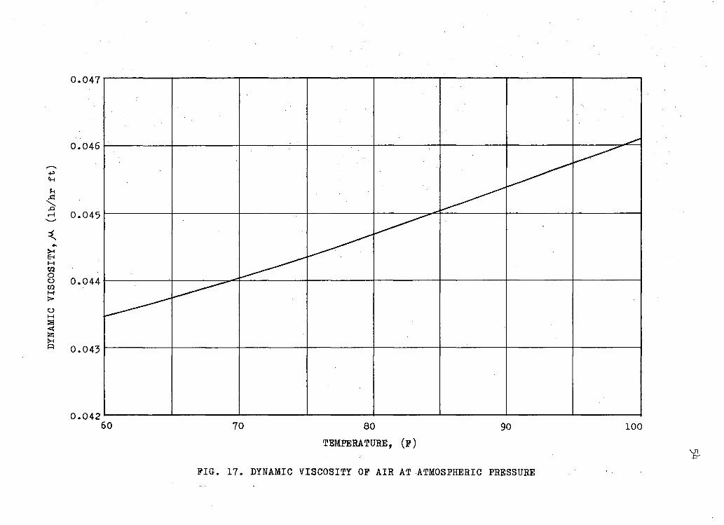
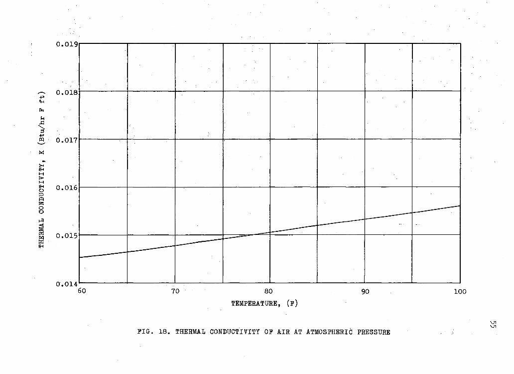
The properties of a ir required for the calculation of
Reynolds and Nusselt numbers were the following:
1. Density, ^
2. Dynamic v i s c o s i t y , ^
3. Thermal conductivity, K
The density of a ir was determined from the equation of
state. The viscosi ty and the thermal conductivity of a ir were taken
from the tables given by Giedt (23). In Figures L7 and 18, these
properties are shown as a function of temperature only at ih.'J lb/in^abs.
pressure.
0.047
0 . 0 4 2 • " 1 1 1 ' 1 1 » 60 70 80 90 100
TEMPERATURE, (p)
PIG. 17. DYNAMIC VISCOSITY OP AIR AT ATMOSPHERIC PRESSURE
0.019
0.018
0.017
0.016
0.015
0.014 60 70 80 90 100
TEMPERATURE, (?)
PIG. 18. THERMAL CONDUCTIVITY OP AIR AT ATMOSPHERIC PRESSURE \J1
APPENDIX IV
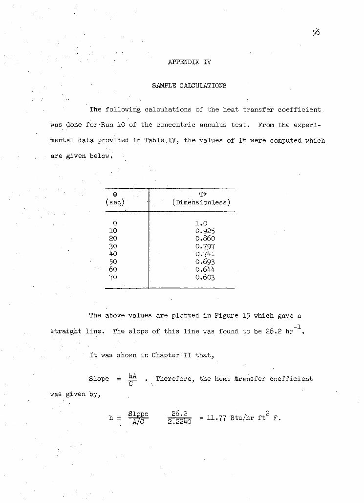
SAMPLE CALCULATIONS
The following calculations of the heat transfer coefficient.
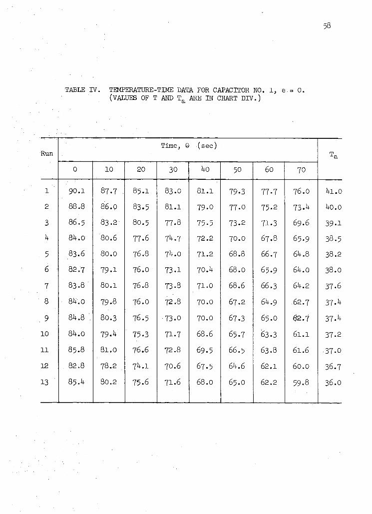
was done for Run 10 of the concentric annulus test. From the experi
mental data provided in Table.IV, the values of T* were computed which
are given below.
e . (sec) (Dimensionless)
0 1.0 10 0.925 20 0.860 30 0.797 ^0 O.7J+I 50 0.693 6o 0.6UU 70 0.603
The above values are plotted in Figure 15 which gave a
straight l ine . The slope of this l ine was found to be 26 .2 hr 1 .
It was
Slope
was given by,
shown in Chapter II that,
= — . Therefore, the heat transfer coefficient C '
"-W ££0 - *-Tl BtuAr f t 2 P.
APPENDIX V
TABLES OF EXPERIMENTAL RESULTS
58
TABLE IV. TEMPERATURE-TIME DATA FOR CAPACITOR NO. 1, e.= 0. (VALUES OF T AND T a ARE IN CHART DIV.)
Run Time, 9 (sec)
0 10 20 30 40 50 60 70
.1 90.1 87.7 85.I 83.0 81.1 79-3 77-7 76.0 4i.0 2 88.8 86.0 83.5 81.1 79-0 77-0 75.2 73-4 40.0 3 86.5 83.2 80.5 77-8 75.5 73.2 71.3 69.6 39-1
4 84.0 80.6 77-6 74.7 72.2 70.0 67.8 65.9 38.5
5 83.6 80.0 76.8 74.0 71.2 68.8 66.7 64.8 38.2
6 82.7 79-1 76.0 73-1 70.4 68.0 65.9 64.0 38.0 7 83.8 80.1 76.8 73-8 71.0 68.6 66.3 64.2 37-6
.8 84.0. 79.8 76.O 72.8 70.0 67.2 64.9 62.7 37.4 9 84.8 . 80.3 76.5 73.0 70.0 67.3 65.0 62.7 37-4 10 84.0 79.4 75.3 71.7 68.6 65.7 63.3 6 l . l 37-2
11 85.8 81.0 76.6 72.8 69.5 66.5 63.8 61.6 37-0 12 82.8 78.2 74.1 70.6 67.5 64.6 62.1 60.0 36.7
13 85.4 80.2 7-5.6 71.6 68.0 65.O 62.2 59-8 36.0
59
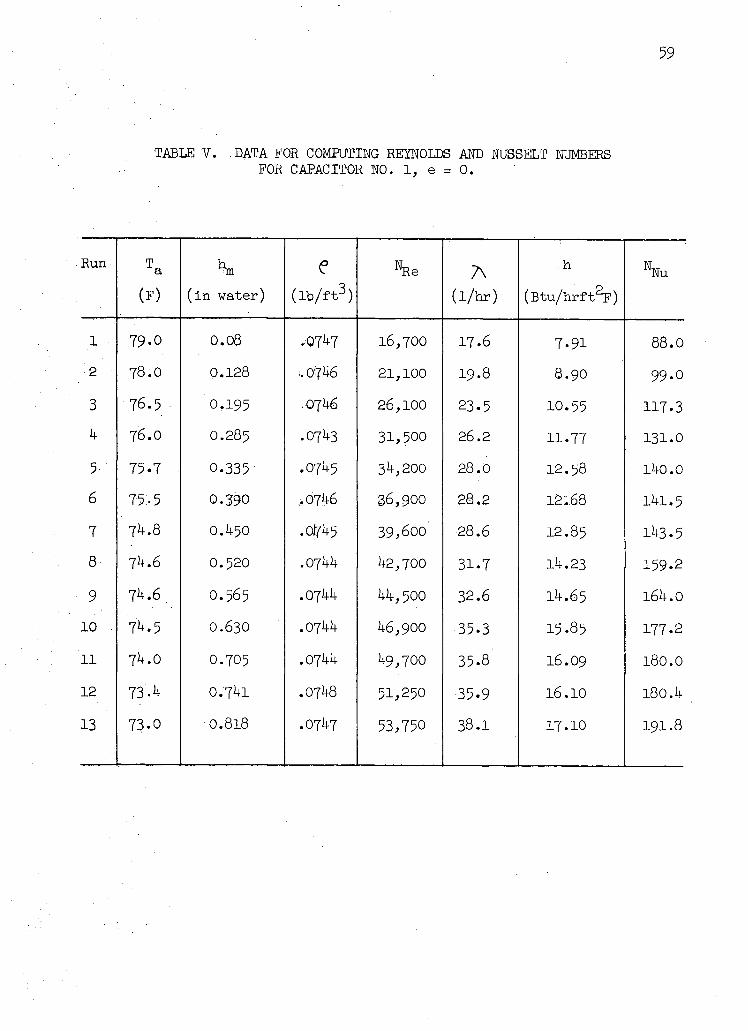
TABLE V. DATA FOR COMPUTING REYNOLDS AND NUSSELT NUMBERS FOR CAPACITOR NO. 1, e = 0 .
Run T a e %e A h Nu
(F) ( in water) ( i b / f t 3 ) ( l /hr) (Btu/hrft 2 F)
1 79-0 0 . 0 8 .0747 16,700 17.6 7.91 88 .0
•2 78 .0 0.128 1.0746 21,100 19.8 8 .90 99-0
3 76.5 0.195 .071+6 26,100 23 .5 10.55 117.3
4 76 .0 O.285 .07U3 31,500 26.2 11-77 131.0
5 75-7 0.335 .071+5 34,200 28 .0 12.58 l 4 0 . 0
6 75:-5 0 . 3 9 0 ..0746 36,900 28 .2 12:..68 11+1.5
7 74.8 0.1+50 . 0 ^ 5 39,600 28.6 12.85 1^3.5
8 74.6 0.520 .Ojhh 1+2,700 31.7 14.23 159.2
9 7^.6 O.565 .07I+I+ 44,500 32.6 11+.65 164.0
1 0 74.5 0.630 1+6,900 35.3 15.85 177-2
l l 74 .0 0.705 .071+1+ 1+9,700 35-8 16.09 180.0
12 73-4 0 . ' 7 l a .071+8 51,250 •35-9 16.10 180.4
13 73 .0 • 0 . 818 .0747 53,750 38.1 17.10 191.8
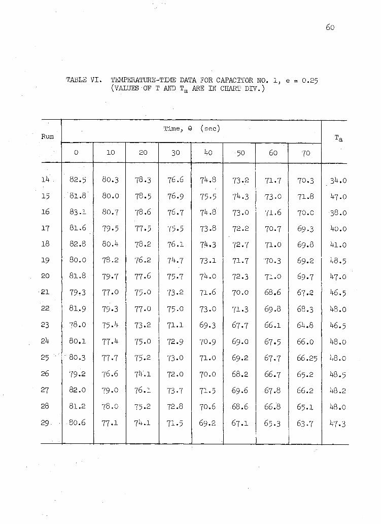
TABLE VI. TEMPEMTURE-TIME DATA. FOR CAPACITOR WO. 1, e = 0.25 (VALUES OF T AND T a ARE IN CHART DIV.)
Run Time, G (sec)
0 10 •20 30 40 50 60 70
14 . 82.5 80.3 78.3 76.6 74.8 73-2 71.7 70.3 34.0
15 81.8 . 8 0 . 0 78.5 76.9 75-5 74.3 73.0 71.8 47.0
16 83.1 8 0 . 7 78.6 76.7 74.8 73.0 71.6 7 0 . 0 •38.0
17 81.6 79-5 77-5 75.5 73.8 72.2 70.7 69.3 4o.o 18 82.8 80.4 78.2 76 .1 74.3 72.7 71.0 6 9 . 8 4i.o
19 8 0 . 0 78 .2 76.2 74.7 73-1 71.7 70.3 6 9 . 2 48.5 20 8 1 . 8 79-7 77.6 75-7 74.0 72.3 71.0 6 9 . 7 4 7 . 0
21 79.3 77-0 75-0 73.2 71.6 7 0 . 0 68.6 67.2 46.5 22 8 1 . 9 79.3 77-0 75-0 73.0 71.3 6 9 . 8 6 8 . 3 48.0
23 7 8 . 0 75-4 73.2 71.1 69.3 67.7 6 6 . 1 64.8 46.5 2h 80.1 77.4 75.0 72.9 70.9 69.O 67.5 66.0 48.0
25 : 80.3 77.7 75.2 73-0 71.0 6 9 . 2 67 .7 66.25 48.0
26 79.2 76.6 74". l 72.0 7 0 . 0 68.2 66.7 6 5 . 2 48.5
27 82.0 79.0 76.1 73-7 71-5 69.6 67.8 66.2 48.2
28 81.2 7 8 . 0 75-2 72.8 70.6 68.6 66.8 6 5 . 1 48.0 29.. • 80.6 77.1 74.1 71.5 6 9 . 2 6 7 . 1 65.3 63.7 47.3
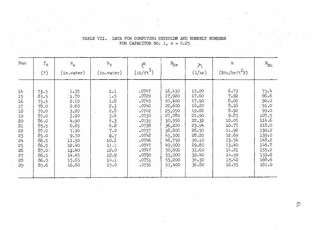
TABLE VII. DATA FOR COMPUTING REYNOLDS AND NUSSELT NUMBERS FOR CAPACITOR NO. 1, e = 0.25
Run T a h w
h s e %e A h Nu
• (F) (in.water) (in.water) (ib/fto (l/hr) (Btu/hrft 2 F)
l 4 73 .5 1.35 1.1 .0747 16,430 15.00 6.73 75.4 15 85-5 ."'.1.70 1.5 .0729 17,920 17.60 7.92 86 .6 16 75-5 2 .10 1.8 .0743 20,400 17.90 8.06 90.0 17 78 .0 2 .60 2 .3 .0740 22,600 18.20 8.18 ' 9 1 . 0 18 79-0 3-20 2 .8 .0742 25,050 19.82 8.92 99 .0 19 87 .O 3.90 3.4 .0730 27,080 21.90 9.85 107.5 20 8 6 . 0 4 .90 4 .3 .0735 30,550 22.32 10.05 114.6 21 85 .5 6.85 6 .2 .0738 36,200 23.94 10.77 118.0 22 87 .O 7.90 ' .7 .0 .0737 38,800 26.50 11.92 130.2 23 85 .O 9.70 8 ,7 .0742 43,300 28.20 12.69 139.0 2k 86 .5 11.30 10 .1 .0746 46,750 30.10 13.54 148.2 25 86 .5 12.40 11 .1 .0747 49,060 29.80 13.40 146.7 26 87 .O 13.40 12 .0 .0747 50,800 31.60 14.21 155.2 27 86 .5 14.45 12.9 .07-50 53,ooo 32.40 14.59 159.8 28. 86 .0 15.65 14.1 .0751 55,200 34.30 15.42 168.6 29 85.6 16.80 15 .0 .0756 57,4oo 36.80 16.55 181.0
62
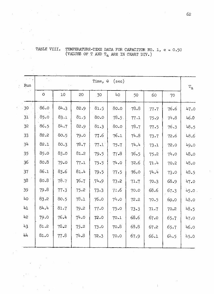
TABLE VIII. TEMPERATURE-TIME DATA FOR CAPACITOR NO. 1, e = O.50 (VALUES OF T AND T a ARE IN CHART DIV.)
Run Time, Q (sec)
T a 0 10 20 30 40 . 50 60 70
3.0 86.0 84.3 82.9 81.5 80.0 78.8 77.7 76.6 47.0 31 85.0 83.1 81.5 80.0 78.5 77.1 75-9 74.8 46.0 32 86.5 84.7 82.9 81.3 80.0 78.7 77.5 76.3 48.5 33 82.2 80.5 79-0 77-6 76.I 74.8 73.7 72.6 48.6 34 82.1 80.3 78.7 77.1' 75.7 74.4 73.1 72.0 49.0
35 85.0 83.O 81.2 79-5 77.8 76.5 75-2 74.0 48.0 36 80.8 79-0 77.1 75-5 74.0 72.6 71.4 70.2 48.0 37 86.1 83.6 81.4 79.5 77.5 76.O 74.4 73.0 48.5 38 80.8 78.7 76.7 74.9 73.2 71.7 70.3 68.9 47.0
39 79-8 77-3 75-2 73.3 71.6 70.0 68.6 67.3 45.0 1+0 83.2 80.5 78.1 76.O 74.0 72.2 70.5 69.0 48.0 4i 84.4 ' 81.7 79-2 77-0 75.0 73.3 71-7 70.2 48.5 42 79-0 76.4 74.0 72.0 70.1 68.6 67.0 65.7 47.0
43 81.2 78.2 75.2 73-0 70.8 68.8 67.2 65.7 46.0 hh 81.0 77.8 74.8 72.3 70.0 67.9 66.1 64.5 45.0
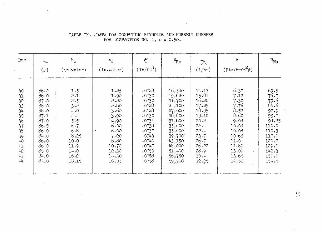
TABLE IX. DATA FOR COMPUTING REYNOLDS AND NUSSELT NUMBERS FOR JCXPACITOR NO. 1, e = 0 . 5 0 .
Run e WRe A h %u
(F) (in.water) (in.water) ( l b / f t 3 ) ( l /hr) (Btu/hrft 2 F)
30 86 .2 1-5 1.25 .0728 16,580 14.17 6.37 69 .5 31 8 6 . 0 2 .1 1.90 .0730 19,620 15.81 7.12 76 .7 32 87 .0 2 .5 2 .20 .0730 21,700 16.20 7.30 79-6 33 88 .0 3.2 .2 .80 .0728 24,100 17.25 7.76 84 .6 34 88 .0 4 .0 3 .60 .0728 27,000 18.95 8.52 92 .9 35 8 7 . I 4.4 3 .90 .0730 28,800 19.10 8.60 93-7 36 87 .O 5-5 - 4 . 9 0 .0734 31,800 20.2 9.08 98.25 37 8 6 . 5 6 .7 6 .00 .0738 • 35,800 22.4 10.08 110.0 38 86 .0 6 .8 6 .00 .0737 35,600 22 .4 10.08 110.3 39 84 .0 8 .25 7 .20 .0743 39,700 23.7 IO.65 117.0 ko 8 6 . 0 10 .0 8 .80 .0740 43,150 26 .7 11.0 120.2 kl 86 .0 11.9 10.70 .0747 48,000 26.22 11.80 129.0 kl 85 .O 14.0 12.30 .0750 5 l , 4oo 28.9 13.00 142.3 43 84.0: 16.2 14.30 .0758 56,750 30.4 13.65 150.0 kk 8 3 . 0 18.15 16.05 .0758 59,900 32.25 14.50 159.5
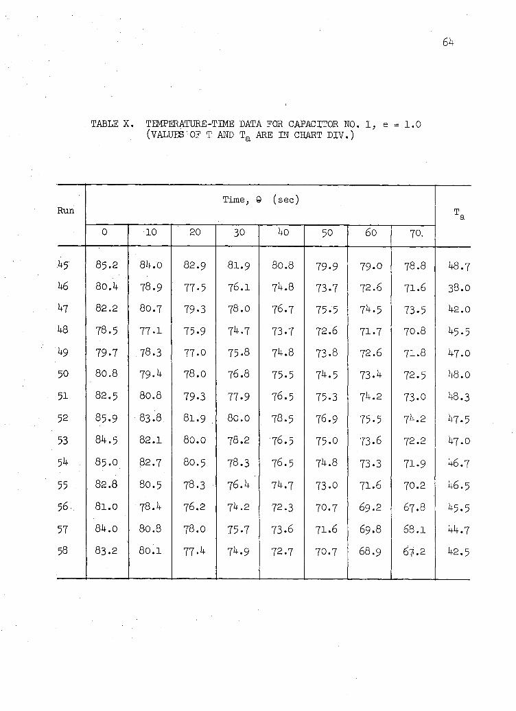
TABLE X. TEMPERATURE-TIME DATA FOR CAPACITOR N 0 . . 1 , e = 1 . 0 (VALUES OF T. AND T a ARE IN CHART DIV.)
Run Time, 0 (sec)
T a 0 10 20 30 40 50 60 70.
45 85.2 84.0 82.9 81.9 80.8 79-9 79-0 78.8 48.7 46 80.4 78.9 77-5 76.1 74.8 73.7 72.6 71.6 38.0 47 82.2 80.7 79.3 78.0 76.7 75-5 74.5 73-5 42.0 48 78.5 77-1 75-9 74.7 73-7 72.6 71.7 70.8 45.5 49 79.7 78.3 77.0 75.8 74.8 73.8 72.6 71.8 47.O 50 80.8 79.4 78.0 76.8 75.5 74.5 73.4 72.5 48.0 51 82.5 80.8 79.3 77-9 76.5 75-3 74.2 73-0 48.3 52 85.9 83.8. 8I.9 80.0 78.5 76.9 75-5 74.2 47.5 53 84.5 82.1 80.0 78.2 76.5 75.0 73-6 72.2 47.0 54 . 85.O 82.7 8O.5 78.3 76.5 74.8 73.3 71.9 46.7 55 82.8 8O.5 78.3 76.4 74.7 73-0 71.6 70.2 46.5 56. 81.0 78.4 76.2 74.2 72.3 70.7 69.2 67.8 45.5 57 84.0 80.8 78.0 75-7 73.6 71.6 69.8 68.1 44.7 58 83.2 80.1 77.4 74.9 72.7 70.7 68.9 67-2 42.5
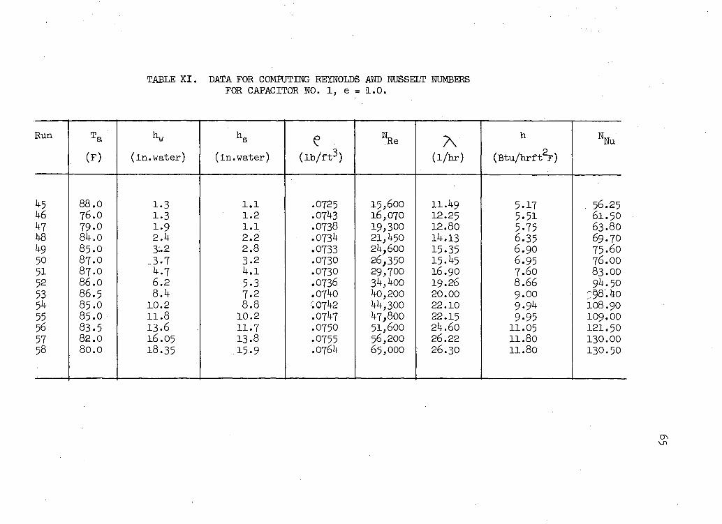
TABLE XI. DATA FOR COMPUTING REYNOLDS AND NUSSELT NUMBERS FOR CAPACITOR NO. 1, e = 1.0.
Run T a e NRe A h WNu (F) (in.water) (in.water) ( i b / f t 3 ) (1/hr) (Btu/hrft^)
45 88.0 1.3 1.1 .0725 15,600 11.49 5.17 56.25 46 76.0 1.3 1.2 .0743 16,070 12.25 5.51 61.50 47 79.0 1-9 1.1 .0738 19,300
21,450 12.80 5.75 63.80
48 84.0 2.4 2.2 .0734 19,300 21,450 14.13 6.35 69.70
49 85.0 3*2 2.8 .0733 24,600 15.35 6.90 75.60 50 87.0 -3-7 3-2 .0730 26,350 15.45 6.95 76.OO 51 87.0 4.7 4.1 .0730 29,700 16.90 7.60 83.00 52 86.0 6.2 5.3 .0736 34,400 19.26 8.66 94.50 53 86.5 8.4 7.2 .0740 40,200 20.00 9.00 :98'.4o 54 85.0 10.2 8.8 '.0742 44,300
47,800 22.10 9.94 108.90
55 85.0 11.8 10.2 .0747 44,300 47,800 22.15 9.95 109.00
56 83.5 13.6 11.7 .0750 51,600 24.60 11.05 121.50 57 82.0 16.05 13.8 .0755 56,200 26.22 11.80 130.00 58 80.0 18.35 15.9 .0764 65,000 26.30 11.80 130.50
66
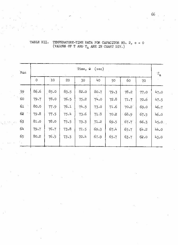
TABLE XII. TEMPERATURE-TIME DATA FOR CAPACITOR NO. 2, e = 0 (VALUES OF T AND T a ARE IN CHART DIV.)
Run Time, 9 (sec)
T a 0 10 20 30 ko 50 60 70
59 86.6 85.O 83.5 82.0 80.7 79-3 78.2 77-0 1+7.0 60 79-7 78.0 76.5 75-2 7U.0 72.8 71.7 70.6 ^7.5 6 i 80.0 77-9 76.1 74.5 73.0 71.6 70.2 69.0 1+6.7 62 79-8 77.5 75-4 73-6 71.8 70.2 68.9 67.5 U6.0
8l.O 78.0 75.5 73-3 71.2 69.5 67.7 66.3 1+5.0 6k 79-7 76.7 73-8 71-5 69.3 6l.k 65.7 6k.2 kk. 0
65 80.2 76.5 73-3 70.4 67.9 65.7 63.7 62.0 1+3.0
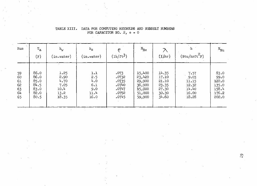
TABLE XIII. DATA FOR COMPUTING REYNOLDS AND NUSSELT NUMBERS FOR CAPACITOR NO..2, e = 0
Run T a K h s e % e A . h % u
(F) (in.water) (in.water) ( l b / f t 3 ) (T/ihr) (Btu/hrft 2F)
59 86.0 1.25 1.1 .073 15 , 4 0 0 14.35 7.57 83.0 6o 86.0 2.90 2-5 .0732 23,420 17.10 9.03 99.0 61 85.O U.70 4.0 .0735 29,900 21.10 11.15 122.0 62 8U.5 7.05 6.1 .0740 36,900 23.35 12.32 135.0 63 83.O 10.il 9.0 .07U7 ^5,000 27.30 ih.ko 158.4 6h 82.0 13.2 11.k .0752 51,000 30.30 16.00 176.2 65 80.5 18.35 16.0 .0745 59,900 34.60 18.28 202.0
Copyright © 2022 FDOKUMEN