Chapter 12 Radiation Heat Transfer Chapter 12 RADIATION HEAT TRANSFER View Factors
84
Chapter 12 Radiation Heat Transfer 12-1 Chapter 12 RADIATION HEAT TRANSFER View Factors 12-1C The view factor F i j → represents the fraction of the radiation leaving surface i that strikes surface j directly. The view factor from a surface to itself is non-zero for concave surfaces. 12-2C The pair of view factors F i j → and F j i → are related to each other by the reciprocity rule AF AF i ij j ji = where A i is the area of the surface i and A j is the area of the surface j. Therefore, AF AF F A A F 1 12 2 21 12 2 1 21 = ⎯→ ⎯ = 12-3C The summation rule for an enclosure and is expressed as F i j j N → = = ∑ 1 1 where N is the number of surfaces of the enclosure. It states that the sum of the view factors from surface i of an enclosure to all surfaces of the enclosure, including to itself must be equal to unity. The superposition rule is stated as the view factor from a surface i to a surface j is equal to the sum of the view factors from surface i to the parts of surface j, F F F 1 23 1 2 1 3 → → → = + (,) . 12-4C The cross-string method is applicable to geometries which are very long in one direction relative to the other directions. By attaching strings between corners the Crossed-Strings Method is expressed as F i i j → = − × ∑ ∑ Crossed strings Uncrossed strings string on surface 2
-
Upload
itchihuahua -
Category
Documents
-
view
0 -
download
0
Transcript of Chapter 12 Radiation Heat Transfer Chapter 12 RADIATION HEAT TRANSFER View Factors

Chapter 12 Radiation Heat Transfer
12-1
Chapter 12 RADIATION HEAT TRANSFER
View Factors 12-1C The view factor Fi j→ represents the fraction of the radiation leaving surface i that strikes surface j directly. The view factor from a surface to itself is non-zero for concave surfaces. 12-2C The pair of view factors Fi j→ and Fj i→ are related to each other by the reciprocity rule
A F A Fi ij j ji= where Ai is the area of the surface i and Aj is the area of the surface j. Therefore,
A F A F FAA
F1 12 2 21 122
121= ⎯ →⎯ =
12-3C The summation rule for an enclosure and is expressed as Fi jj
N
→=
=∑ 11
where N is the number of
surfaces of the enclosure. It states that the sum of the view factors from surface i of an enclosure to all surfaces of the enclosure, including to itself must be equal to unity. The superposition rule is stated as the view factor from a surface i to a surface j is equal to the sum of the view factors from surface i to the parts of surface j, F F F1 2 3 1 2 1 3→ → →= +( , ) .
12-4C The cross-string method is applicable to geometries which are very long in one direction relative to the other directions. By attaching strings between corners the Crossed-Strings Method is expressed as
Fii j→ =
−
×∑∑Crossed strings Uncrossed strings
string on surface 2

Chapter 12 Radiation Heat Transfer
12-2
12-5 An enclosure consisting of six surfaces is considered. The number of view factors this geometry involves and the number of these view factors that can be determined by the application of the reciprocity and summation rules are to be determined.
Analysis A seven surface enclosure (N=6) involves N 2 26= = 36 view
factors and we need to determine 152
)16(62
)1(=
−=
−NN view factors
directly. The remaining 36-15 = 21 of the view factors can be determined by the application of the reciprocity and summation rules. 12-6 An enclosure consisting of five surfaces is considered. The number of view factors this geometry involves and the number of these view factors that can be determined by the application of the reciprocity and summation rules are to be determined.
Analysis A five surface enclosure (N=5) involves N 2 25= = 25
view factors and we need to determine N N( ) (5 )−
=−
=1
25 1
210
view factors directly. The remaining 25-10 = 15 of the view factors can be determined by the application of the reciprocity and summation rules. 12-7 An enclosure consisting of twelve surfaces is considered. The number of view factors this geometry involves and the number of these view factors that can be determined by the application of the reciprocity and summation rules are to be determined. Analysis A twelve surface enclosure (N=12) involves 144== 22 12N view factors and we
need to determine N N( ) ( )−
=−
=1
212 12 1
266
view factors directly. The remaining 144-66 = 78 of the view factors can be determined by the application of the reciprocity and summation rules.
2
1
4
5
3
6
5
4
32
1
21
3
9 11
12
10
4 5
8
6
7

Chapter 12 Radiation Heat Transfer
12-3
12-8 The view factors between the rectangular surfaces shown in the figure are to be determined. Assumptions The surfaces are diffuse emitters and reflectors. Analysis From Fig. 12-6,
24.05.0
211
5.021
31
3
=
⎪⎪⎭
⎪⎪⎬
⎫
==
==F
WLWL
and
29.01
22
5.021
)21(321
3
=
⎪⎪⎭
⎪⎪⎬
⎫
==+
==
+→F
WLL
WL
We note that A1 = A3. Then the reciprocity and superposition rules gives
0.24==⎯→⎯= 3113313131A FFFAF
05.024.029.0 32323231)21(3 =⎯→⎯+=⎯→⎯+=+→ FFFFF
Finally, 0.05==⎯→⎯= 322332 FFAA
W = 2 m
(2) L2 = 1 m L1 = 1 m
L3 = 1 m A3 (3)
A2 A1 (1)

Chapter 12 Radiation Heat Transfer
12-4
12-9 A cylindrical enclosure is considered. The view factor from the side surface of this cylindrical enclosure to its base surface is to be determined. Assumptions The surfaces are diffuse emitters and reflectors. Analysis We designate the surfaces as follows: Base surface by (1), top surface by (2), and side surface by (3). Then from Fig. 12-7 (or Table 12-1 for better accuracy)
38.01
1
2112
2
22
1
1
1 ==
⎪⎪⎭
⎪⎪⎬
⎫
==
==
FF
rr
Lr
rr
rL
1 :rulesummation 131211 =++ FFF
62.0138.00 1313 =⎯→⎯=++ FF
( ) 0.31==ππ
=ππ
==⎯→⎯= )62.0(21
22 :ruley reciprocit 13
11
21
131
21
133
131313131 F
rrr
FLr
rF
AA
FFAFA
Discussion This problem can be solved more accurately by using the view factor relation from Table 12-1 to be
1
1
2
222
1
111
===
===
rr
Lr
R
rr
Lr
R
382.0114334
31
1111
1
5.022
21
5.02
1
2221
12
2
2
21
22
=⎪⎭
⎪⎬⎫
⎪⎩
⎪⎨⎧
⎥⎥⎦
⎤
⎢⎢⎣
⎡⎟⎠⎞
⎜⎝⎛−−=
⎪⎭
⎪⎬
⎫
⎪⎩
⎪⎨
⎧
⎥⎥
⎦
⎤
⎢⎢
⎣
⎡⎟⎟⎠
⎞⎜⎜⎝
⎛−−=
=+
+=+
+=
RR
SSF
RR
S
618.0382.011 1213 =−=−= FF
( ) 0.309==ππ
=ππ
==⎯→⎯= )618.0(21
22 :ruley reciprocit 13
11
21
131
21
133
131313131 F
rrr
FLr
rF
AA
FFAFA
(2)
(3)
(1)
L
D

Chapter 12 Radiation Heat Transfer
12-5
12-10 A semispherical furnace is considered. The view factor from the dome of this furnace to its flat base is to be determined. Assumptions The surfaces are diffuse emitters and reflectors. Analysis We number the surfaces as follows:
(1): circular base surface (2): dome surface Surface (1) is flat, and thus F11 0= .
11 :ruleSummation 121211 =→=+ FFF
0.5=====⎯→⎯=21
2
4)1(A :ruley reciprocit2
2
2
112
2
121212121
D
D
AA
FAA
FFAFπ
π
12-11 Two view factors associated with three very long ducts with different geometries are to be determined. Assumptions 1 The surfaces are diffuse emitters and reflectors. 2 End effects are neglected. Analysis (a) Surface (1) is flat, and thus F11 0= .
1=→=+ 121211 1 :rulesummation FFF
0.64==⎟⎠⎞
⎜⎝⎛
==⎯→⎯=ππ2)1(
2
A :ruley reciprocit 122
121212121
sDDsF
AA
FFAF
(b) Noting that surfaces 2 and 3 are symmetrical and thus F F12 13= , the summation rule gives
0.5=⎯→⎯=++⎯→⎯=++ 121312131211 101 FFFFFF
Also by using the equation obtained in Example 12-4,
FL L L
La b b
aaa12
1 2 3
12 2 212
=+ −
=+ −
= = = 0.5
2ba
=⎟⎠⎞
⎜⎝⎛==⎯→⎯=
21A :ruley reciprocit 12
2
121212121 b
aFAA
FFAF
(c) Applying the crossed-string method gives
F FL L L L
L
a b ba
12 215 6 3 4
1
2 2
2
2 22
= =+ − +
=+ −
=+ −
( ) ( )
a b ba
2 2
(1)
(2)
D
(1)
(2)
D
(1)
(3) (2)
a
L3 = b L4 = b L5 L6
L2 = a
L1 = a

Chapter 12 Radiation Heat Transfer
12-6
12-12 View factors from the very long grooves shown in the figure to the surroundings are to be determined. Assumptions 1 The surfaces are diffuse emitters and reflectors. 2 End effects are neglected. Analysis (a) We designate the circular dome surface by (1) and the imaginary flat top surface by (2). Noting that (2) is flat, 022 =F
11 :rulesummation 212221 =⎯→⎯=+ FFF
0.64====⎯→⎯=ππ2)1(
2
A :ruley reciprocit 211
212212121 D
DFAA
FFAF
(b) We designate the two identical surfaces of length b by (1) and (3), and the imaginary flat top surface by (2). Noting that (2) is flat, 022 =F
5.01 :rulesummation 2321232221 ==⎯→⎯=++ FFFFF (symmetry)
11 :rule summation )31(2)31(222 =⎯→⎯=+ +→+→ FFF
2ba
===⎯→⎯
=
+→+→+
→+++→
)1(
A :ruley reciprocit
)31(
2)31(2)31(
2)31()31()31(22
AA
FF
FAF
surr
(c) We designate the bottom surface by (1), the side surfaces by (2) and (3), and the imaginary top surface by (4). Surface 4 is flat and is completely surrounded by other surfaces. Therefore, F44 0= and F4 1 2 3 1→ + + =( ) .
2b+aa
===⎯→⎯
=
++→++→++
→++++++→
)1(
A :ruley reciprocit
)321(
4)321(4)321(
4)321()321()321(44
AA
FF
FAF
surr
12-13 The view factors from the base of a cube to each of the other five surfaces are to be determined. Assumptions The surfaces are diffuse emitters and reflectors. Analysis Noting that L w L w1 2 1/ /= = , from Fig. 12-6 we read
F12 0 2= .
Because of symmetry, we have F F F F F12 13 14 15 16= = = = = 0.2
12-14 The view factor from the conical side surface to a hole located at the center of the base of a conical enclosure is to be determined. Assumptions The conical side surface is diffuse emitter and reflector. Analysis We number different surfaces as the hole located at the center of the base (1) the base of conical enclosure (2) conical side surface (3)
(1)
(3), (4), (5), (6) side surfaces
(2)
d
D
h
(2) (1)
(3)
(3) (1)
a
b b
(2)
b b (2) (3)
(1) a
(4)
(1)
(2)
D

Chapter 12 Radiation Heat Transfer
12-7
Surfaces 1 and 2 are flat , and they have no direct view of each other. Therefore, F F F F11 22 12 21 0= = = =
11 :rulesummation 13131211 =⎯→⎯=++ FFFF
2Dhd2
=⎯→⎯=⎯→⎯= 3131
2
313131 2)1(
4A :ruley reciprocit FFDhdFAF ππ
12-15 The four view factors associated with an enclosure formed by two very long concentric cylinders are to be determined. Assumptions 1 The surfaces are diffuse emitters and reflectors. 2 End effects are neglected. Analysis We number different surfaces as the outer surface of the inner cylinder (1) the inner surface of the outer cylinder (2) No radiation leaving surface 1 strikes itself and thus F11 = 0
All radiation leaving surface 1 strikes surface 2 and thus F12 = 1
2
1
DD
===⎯→⎯= )1(A :ruley reciprocit2
112
2
121212121 hD
hDF
AA
FFAFππ
2
1
DD1 −=−=⎯→⎯=+ 21222221 11 :rulesummation FFFF
(2)
D2 D1
(1)
Chapter 12 Radiation Heat Transfer
12-8
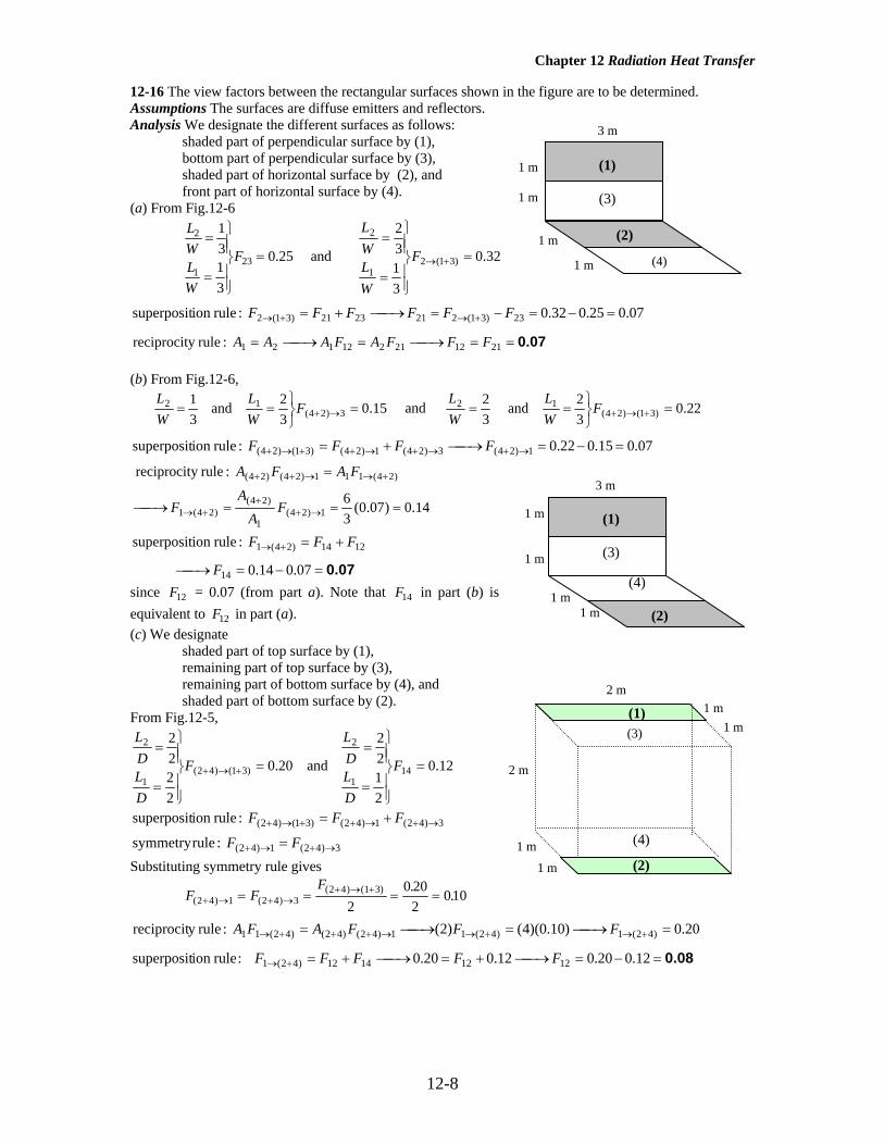
12-16 The view factors between the rectangular surfaces shown in the figure are to be determined. Assumptions The surfaces are diffuse emitters and reflectors. Analysis We designate the different surfaces as follows: shaded part of perpendicular surface by (1), bottom part of perpendicular surface by (3), shaded part of horizontal surface by (2), and front part of horizontal surface by (4). (a) From Fig.12-6
25.0
3131
231
2
=
⎪⎪⎭
⎪⎪⎬
⎫
=
=F
WLWL
and 32.0
3132
)31(21
2
=
⎪⎪⎭
⎪⎪⎬
⎫
=
=
+→F
WLWL
07.025.032.0 :ruleion superposit 23)31(2212321)31(2 =−=−=⎯→⎯+= +→+→ FFFFFF
0.07==⎯→⎯=⎯→⎯= 211221212121 :ruley reciprocit FFFAFAAA (b) From Fig.12-6,
15.032 and
31
3)24(12 =
⎭⎬⎫
== →+FWL
WL
and 22.032 and
32
)31()24(12 =
⎭⎬⎫
== +→+FWL
WL
07.015.022.0 :ruleion superposit 1)24(3)24(1)24()31()24( =−=⎯→⎯+= →+→+→++→+ FFFF
14.0)07.0(36
:ruley reciprocit
1)24(1
)24()24(1
)24(111)24()24(
===⎯→⎯
=
→++
+→
+→→++
FA
AF
FAFA
0.07=−=⎯→⎯
+=+→
07.014.0
:ruleion superposit
14
1214)24(1
F
FFF
since F12 = 0.07 (from part a). Note that F14 in part (b) is equivalent to F12 in part (a). (c) We designate shaded part of top surface by (1), remaining part of top surface by (3), remaining part of bottom surface by (4), and shaded part of bottom surface by (2). From Fig.12-5,
20.0
2222
)31()42(1
2
=
⎪⎪⎭
⎪⎪⎬
⎫
=
=
+→+F
DLDL
and 12.0
2122
141
2
=
⎪⎪⎭
⎪⎪⎬
⎫
=
=F
DLDL
3)42(1)42()31()42( :ruleion superposit →+→++→+ += FFF
3)42(1)42( :rulesymmetry →+→+ = FF Substituting symmetry rule gives
F FF
( ) ( )( ) ( ) . .2 4 1 2 4 32 4 1 3
20 20
2010+ → + →
+ → += = = =
20.0)10.0)(4()2( :ruley reciprocit )42(1)42(11)42()42()42(11 =⎯→⎯=⎯→⎯= +→+→→+++→ FFFAFA
0.08=−=⎯→⎯+=⎯→⎯+=+→ 12.020.012.020.0 : ruleion superposit 12121412)42(1 FFFFF
3 m
(1) (3)
1 m 1 m
1 m 1 m
(4)
(2)
3 m
(1) (3)
1 m 1 m
1 m (2)
1 m (4)
2 m
2 m
1 m
(1)
(4)
(2) 1 m
1 m1 m(3)
Chapter 12 Radiation Heat Transfer
12-9
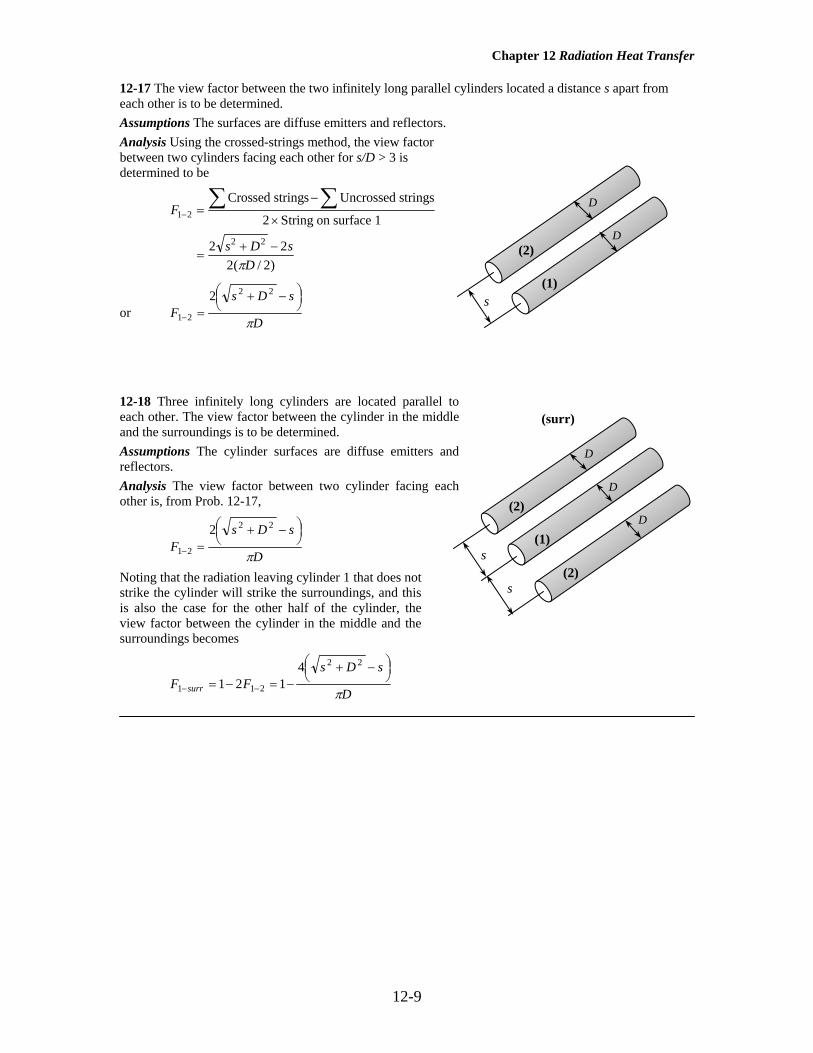
12-17 The view factor between the two infinitely long parallel cylinders located a distance s apart from each other is to be determined. Assumptions The surfaces are diffuse emitters and reflectors. Analysis Using the crossed-strings method, the view factor between two cylinders facing each other for s/D > 3 is determined to be
F
s D sD
1 2
2 2
2
2 22 2
− =−
×
=+ −
∑ ∑Crossed strings Uncrossed strings
String on surface 1
( / )π
or D
sDsF
π
⎟⎠⎞⎜
⎝⎛ −+
=−
22
21
2
12-18 Three infinitely long cylinders are located parallel to each other. The view factor between the cylinder in the middle and the surroundings is to be determined. Assumptions The cylinder surfaces are diffuse emitters and reflectors. Analysis The view factor between two cylinder facing each other is, from Prob. 12-17,
D
sDsF
π
⎟⎠⎞⎜
⎝⎛ −+
=−
22
21
2
Noting that the radiation leaving cylinder 1 that does not strike the cylinder will strike the surroundings, and this is also the case for the other half of the cylinder, the view factor between the cylinder in the middle and the surroundings becomes
D
sDsFF surr π
⎟⎠⎞⎜
⎝⎛ −+
−=−= −−
22
211
4121
D
D
(2)
(1) s
D
D
(1) s
D
(surr)
s
(2)
(2)

Chapter 12 Radiation Heat Transfer
12-10
Radiation Heat Transfer Between Surfaces 12-19C The analysis of radiation exchange between black surfaces is relatively easy because of the absence of reflection. The rate of radiation heat transfer between two surfaces in this case is expressed as
)( 42
41121 TTFAQ −σ=& where A1 is the surface area, F12 is the view factor, and T1 and T2 are the
temperatures of two surfaces. 12-20C Radiosity is the total radiation energy leaving a surface per unit time and per unit area. Radiosity includes the emitted radiation energy as well as reflected energy. Radiosity and emitted energy are equal for blackbodies since a blackbody does not reflect any radiation.
12-21C Radiation surface resistance is given as RAi
i
i i=
−1 εε
and it represents the resistance of a surface to
the emission of radiation. It is zero for black surfaces. The space resistance is the radiation resistance
between two surfaces and is expressed as RAi
i
i i=
−1 εε
12-22C The two methods used in radiation analysis are the matrix and network methods. In matrix method, equations 12-34 and 12-35 give N linear algebraic equations for the determination of the N unknown radiosities for an N -surface enclosure. Once the radiosities are available, the unknown surface temperatures and heat transfer rates can be determined from these equations respectively. This method involves the use of matrices especially when there are a large number of surfaces. Therefore this method requires some knowledge of linear algebra. The network method involves drawing a surface resistance associated with each surface of an enclosure and connecting them with space resistances. Then the radiation problem is solved by treating it as an electrical network problem where the radiation heat transfer replaces the current and the radiosity replaces the potential. The network method is not practical for enclosures with more than three or four surfaces due to the increased complexity of the network. 12-23C Some surfaces encountered in numerous practical heat transfer applications are modeled as being adiabatic as the back sides of these surfaces are well insulated and net heat transfer through these surfaces is zero. When the convection effects on the front (heat transfer) side of such a surface is negligible and steady-state conditions are reached, the surface must lose as much radiation energy as it receives. Such a surface is called reradiating surface. In radiation analysis, the surface resistance of a reradiating surface is taken to be zero since there is no heat transfer through it.
Chapter 12 Radiation Heat Transfer
12-11
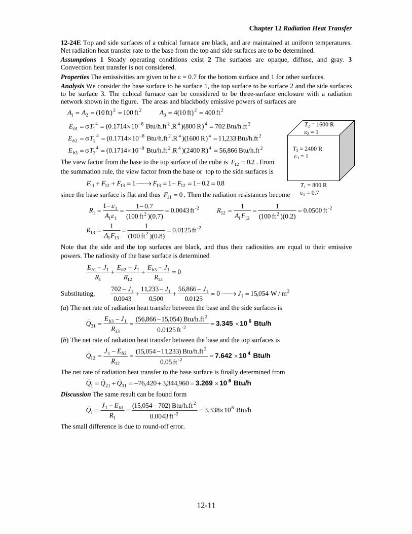
12-24E Top and side surfaces of a cubical furnace are black, and are maintained at uniform temperatures. Net radiation heat transfer rate to the base from the top and side surfaces are to be determined. Assumptions 1 Steady operating conditions exist 2 The surfaces are opaque, diffuse, and gray. 3 Convection heat transfer is not considered. Properties The emissivities are given to be ε = 0.7 for the bottom surface and 1 for other surfaces. Analysis We consider the base surface to be surface 1, the top surface to be surface 2 and the side surfaces to be surface 3. The cubical furnace can be considered to be three-surface enclosure with a radiation network shown in the figure. The areas and blackbody emissive powers of surfaces are
223
2221 ft 400)ft 10(4 ft 100)ft 10( ===== AAA
244284
33
24428422
24428411
Btu/h.ft 866,56)R 2400)(R.Btu/h.ft 101714.0(
Btu/h.ft 233,11)R 1600)(R.Btu/h.ft 101714.0(
Btu/h.ft 702)R 800)(R.Btu/h.ft 101714.0(
=×=σ=
=×=σ=
=×=σ=
−
−
−
TE
TE
TE
b
b
b
The view factor from the base to the top surface of the cube is F12 0 2= . . From the summation rule, the view factor from the base or top to the side surfaces is
F F F F F11 12 13 13 121 1 1 0 2 0 8+ + = ⎯ →⎯ = − = − =. .
since the base surface is flat and thus F11 0= . Then the radiation resistances become
2-
2131
13
2-2
12112
2-2
11
11
ft 0125.0)8.0)(ft 100(
11
ft 0500.0)2.0)(ft 100(
11 ft 0043.0)7.0)(ft 100(
7.011
===
====−
=−
=
FAR
FAR
AR
εε
Note that the side and the top surfaces are black, and thus their radiosities are equal to their emissive powers. The radiosity of the base surface is determined
E J
RE J
RE J
Rb b b1 1
1
2 1
12
3 1
130
−+
−+
−=
Substituting, 7020 0043
11 2330 500
56 8660 0125
0 15 0541 1 11
−+
−+
−= ⎯ →⎯ =
J J JJ
.,
.,.
, W / m2
(a) The net rate of radiation heat transfer between the base and the side surfaces is
Btu/h 103.345 6×=−
=−
=2-
2
13
1331
ft 0125.0Btu/h.ft )054,15866,56(
RJE
Q b&
(b) The net rate of radiation heat transfer between the base and the top surfaces is
Btu/h 107.642 4×=−
=−
=2-
2
12
2112
ft 05.0Btu/h.ft )233,11054,15(
REJ
Q b&
The net rate of radiation heat transfer to the base surface is finally determined from
Btu/h 103.269 6×=+−=+= 960,344,3420,7631211 QQQ &&& Discussion The same result can be found form
Btu/h 10338.3ft 0043.0Btu/h.ft )702054,15( 6
2-
2
1
111 ×=
−=
−=
REJ
Q b&
The small difference is due to round-off error.
T1 = 800 R ε1 = 0.7
T2 = 1600 R ε2 = 1
T3 = 2400 R ε3 = 1

Chapter 12 Radiation Heat Transfer
12-12
12-25E "!PROBLEM 12-25E" "GIVEN" a=10 "[ft]" "epsilon_1=0.7 parameter to be varied" T_1=800 "[R]" T_2=1600 "[R]" T_3=2400 "[R]" sigma=0.1714E-8 "[Btu/h-ft^2-R^4], Stefan-Boltzmann constant" "ANALYSIS" "Consider the base surface 1, the top surface 2, and the side surface 3" E_b1=sigma*T_1^4 E_b2=sigma*T_2^4 E_b3=sigma*T_3^4 A_1=a^2 A_2=A_1 A_3=4*a^2 F_12=0.2 "view factor from the base to the top of a cube" F_11+F_12+F_13=1 "summation rule" F_11=0 "since the base surface is flat" R_1=(1-epsilon_1)/(A_1*epsilon_1) "surface resistance" R_12=1/(A_1*F_12) "space resistance" R_13=1/(A_1*F_13) "space resistance" (E_b1-J_1)/R_1+(E_b2-J_1)/R_12+(E_b3-J_1)/R_13=0 "J_1 : radiosity of base surface" "(a)" Q_dot_31=(E_b3-J_1)/R_13 "(b)" Q_dot_12=(J_1-E_b2)/R_12 Q_dot_21=-Q_dot_12 Q_dot_1=Q_dot_21+Q_dot_31
ε1 Q31 [Btu/h] Q12 [Btu/h] Q1 [Btu/h] 0.1 1.106E+06 636061 470376
0.15 1.295E+06 589024 705565 0.2 1.483E+06 541986 940753
0.25 1.671E+06 494948 1.176E+06 0.3 1.859E+06 447911 1.411E+06
0.35 2.047E+06 400873 1.646E+06 0.4 2.235E+06 353835 1.882E+06
0.45 2.423E+06 306798 2.117E+06 0.5 2.612E+06 259760 2.352E+06
0.55 2.800E+06 212722 2.587E+06 0.6 2.988E+06 165685 2.822E+06
0.65 3.176E+06 118647 3.057E+06 0.7 3.364E+06 71610 3.293E+06
0.75 3.552E+06 24572 3.528E+06 0.8 3.741E+06 -22466 3.763E+06
0.85 3.929E+06 -69503 3.998E+06 0.9 4.117E+06 -116541 4.233E+06

Chapter 12 Radiation Heat Transfer
12-13
0.1 0.2 0.3 0.4 0.5 0.6 0.7 0.8 0.91.0x106
1.5x10⁶
2.0x10⁶
2.5x10⁶
3.0x10⁶
3.5x10⁶
4.0x10⁶
4.5x10⁶
ε1
Q31
[B
tu/h
]
0.1 0.2 0.3 0.4 0.5 0.6 0.7 0.8 0.9-200000
-100000
0
100000
200000
300000
400000
500000
600000
700000
ε1ε1
Q12
[B
tu/h
]

Chapter 12 Radiation Heat Transfer
12-14
0.1 0.2 0.3 0.4 0.5 0.6 0.7 0.8 0.90.0x100
5.0x10⁵
1.0x10⁶
1.5x10⁶
2.0x10⁶
2.5x10⁶
3.0x10⁶
3.5x10⁶
4.0x10⁶
4.5x10⁶
ε1ε1
Q1
[Btu
/h]

Chapter 12 Radiation Heat Transfer
12-15
12-26 Two very large parallel plates are maintained at uniform temperatures. The net rate of radiation heat transfer between the two plates is to be determined. Assumptions 1 Steady operating conditions exist 2 The surfaces are opaque, diffuse, and gray. 3 Convection heat transfer is not considered. Properties The emissivities ε of the plates are given to be 0.5 and 0.9. Analysis The net rate of radiation heat transfer between the two surfaces per unit area of the plates is determined directly from
2 W/m2795=−+
−⋅×=
−+
−=
−
19.0
15.0
1])K 400()K 600)[(KW/m 1067.5(
111)( 44428
21
42
4112
εε
σ TTA
Q
s
&
T2 = 400 K ε2 = 0.9
T1 = 600 K ε1 = 0.5

Chapter 12 Radiation Heat Transfer
12-16
12-27 "!PROBLEM 12-27" "GIVEN" T_1=600 "[K], parameter to be varied" T_2=400 "[K]" epsilon_1=0.5 "parameter to be varied" epsilon_2=0.9 sigma=5.67E-8 "[W/m^2-K^4], Stefan-Boltzmann constant" "ANALYSIS" q_dot_12=(sigma*(T_1^4-T_2^4))/(1/epsilon_1+1/epsilon_2-1)
T1 [K] q12 [W/m2] 500 991.1 525 1353 550 1770 575 2248 600 2793 625 3411 650 4107 675 4888 700 5761 725 6733 750 7810 775 9001 800 10313 825 11754 850 13332 875 15056 900 16934 925 18975 950 21188 975 23584
1000 26170
ε1 q12 [W/m2] 0.1 583.2
0.15 870 0.2 1154
0.25 1434 0.3 1712
0.35 1987 0.4 2258
0.45 2527 0.5 2793
0.55 3056 0.6 3317
0.65 3575 0.7 3830
0.75 4082 0.8 4332
0.85 4580 0.9 4825

Chapter 12 Radiation Heat Transfer
12-17
500 600 700 800 900 10000
5000
10000
15000
20000
25000
30000
T1 [K]
q 12
[W/m
2 ]
0.1 0.2 0.3 0.4 0.5 0.6 0.7 0.8 0.9500
1000
1500
2000
2500
3000
3500
4000
4500
5000
ε1
q 12
[W/m
2 ]

Chapter 12 Radiation Heat Transfer
12-18
12-28 The base, top, and side surfaces of a furnace of cylindrical shape are black, and are maintained at uniform temperatures. The net rate of radiation heat transfer to or from the top surface is to be determined. Assumptions 1 Steady operating conditions exist 2 The surfaces are black. 3 Convection heat transfer is not considered. Properties The emissivity of all surfaces are ε = 1 since they are black. Analysis We consider the top surface to be surface 1, the base surface to be surface 2 and the side surfaces to be surface 3. The cylindrical furnace can be considered to be three-surface enclosure. We assume that steady-state conditions exist. Since all surfaces are black, the radiosities are equal to the emissive power of surfaces, and the net rate of radiation heat transfer from the top surface can be determined from )()( 4
34
11314
24
1121 TTFATTFAQ −+−= σσ&
and A r12 22 12 57= = =π π ( ) . m m2
The view factor from the base to the top surface of the cylinder is F12 0 38= . (From Figure 12-44). The view factor from the base to the side surfaces is determined by applying the summation rule to be F F F F F11 12 13 13 121 1 1 0 38 0 62+ + = ⎯ →⎯ = − = − =. .
Substituting,
kW -762=×−=
×+
×=
−σ+−σ=
W1062.7
)K 1200-K )(700.K W/m1067.5)(62.0)(m 57.12(
)K 500-K )(700.K W/m1067)(0.38)(5.m (12.57
)()(
5
44428-2
44428-2
43
41131
42
41121 TTFATTFAQ&
Discussion The negative sign indicates that net heat transfer is to the top surface.
T1 = 700 K ε1 = 1 r1 = 2 m
T2 = 1200 K ε2 = 1 r2 = 2 m
T3 = 500 K ε3 = 1
h =2 m

Chapter 12 Radiation Heat Transfer
12-19
12-29 The base and the dome of a hemispherical furnace are maintained at uniform temperatures. The net rate of radiation heat transfer from the dome to the base surface is to be determined. Assumptions 1 Steady operating conditions exist 2 The surfaces are opaque, diffuse, and gray. 3 Convection heat transfer is not considered. Analysis The view factor is first determined from
F
F F F11
11 12 12
01 1
=+ = → =
(flat surface) (summation rule)
Noting that the dome is black, net rate of radiation heat transfer from dome to the base surface can be determined from
kW 759.4=×=
−⋅×−=
−−=−=−
W10594.7
])K 1000()K 400)[(K W/m1067.5)(1]( /4)m 5()[7.0(
)(
5
444282
42
411211221
π
σε TTFAQQ &&
The positive sign indicates that the net heat transfer is from the dome to the base surface, as expected. 12-30 Two very long concentric cylinders are maintained at uniform temperatures. The net rate of radiation heat transfer between the two cylinders is to be determined. Assumptions 1 Steady operating conditions exist 2 The surfaces are opaque, diffuse, and gray. 3 Convection heat transfer is not considered. Properties The emissivities of surfaces are given to be ε1 = 1 and ε2 = 0.7. Analysis The net rate of radiation heat transfer between the two cylinders per unit length of the cylinders is determined from
kW 22.87==
⎟⎠⎞
⎜⎝⎛−
+
−⋅×π=
⎟⎟⎠
⎞⎜⎜⎝
⎛εε−
+ε
−σ=
−
W870,22
52
7.07.01
11
])K 500(K) 950)[(K W/m1067.5](m) m)(1 2.0([11
)( 44428
2
1
2
2
1
42
411
12
rr
TTAQ&
D2 = 0.5 m T2 = 500 K ε2 = 0.7
D1 = 0.2 m T1 = 950 K ε1 = 1
Vacuum
T1 = 400 K ε1 = 0.7
T2 = 1000 K ε2 = 1
D = 5 m

Chapter 12 Radiation Heat Transfer
12-20
12-31 A long cylindrical rod coated with a new material is placed in an evacuated long cylindrical enclosure which is maintained at a uniform temperature. The emissivity of the coating on the rod is to be determined. Assumptions 1 Steady operating conditions exist 2 The surfaces are opaque, diffuse, and gray. Properties The emissivity of the enclosure is given to be ε2 = 0.95. Analysis The emissivity of the coating on the rod is determined from
( ) ( )
⎟⎠⎞
⎜⎝⎛−
+
−⋅×=
⎟⎟⎠
⎞⎜⎜⎝
⎛−+
−=
−
101
95.095.011
]K 200K 500)[K W/m1067.5](m) m)(1 01.0([ W8
11)(
1
44428
2
1
2
2
1
42
411
12
ε
π
εε
ε
σ
rr
TTAQ&
which gives ε1 = 0.074
12-32E The base and the dome of a long semicylindrical duct are maintained at uniform temperatures. The net rate of radiation heat transfer from the dome to the base surface is to be determined. Assumptions 1 Steady operating conditions exist 2 The surfaces are opaque, diffuse, and gray. 3 Convection heat transfer is not considered. Properties The emissivities of surfaces are given to be ε1 = 0.5 and ε2 = 0.9. Analysis The view factor from the base to the dome is first determined from
F
F F F11
11 12 12
01 1
=+ = → =
(flat surface) (summation rule)
The net rate of radiation heat transfer from dome to the base surface can be determined from
Btu/h 101.311 6×=
⎥⎦
⎤⎢⎣
⎡π−
++−
−⋅×−=
εε−
++εε−
−σ−=−=
−
)9.0(2
ft) 1)(ft 15(9.01
)1)(ft 15(1
)5.0)(ft 15(5.01
]R) 1800()R 550)[(RBtu/h.ft 101714.0(111)(
22
44428
22
2
12111
1
42
41
1221
AFAA
TTQQ &&
The positive sign indicates that the net heat transfer is from the dome to the base surface, as expected. 12-33 Two parallel disks whose back sides are insulated are black, and are maintained at a uniform temperature. The net rate of radiation heat transfer from the disks to the environment is to be determined. Assumptions 1 Steady operating conditions exist 2 The surfaces are opaque, diffuse, and gray. 3 Convection heat transfer is not considered. Properties The emissivities of all surfaces are ε = 1 since they are black. Analysis Both disks possess same properties and they are black. Noting that environment can also be considered to be blackbody, we can treat this geometry as a three surface enclosure. We consider the two disks to be surfaces 1 and 2
Disk 1, T1 = 700 K, ε1 = 1
0.40 m
Environment T3 =300 K ε1 = 1
D = 0.6 m
D2 = 0.1 m T2 = 200 K ε2 = 0.95
D1 = 0.01 m T1 = 500 K ε1 = ?
Vacuum
T1 = 550 R ε1 = 0.5
T2 = 1800 R ε2 = 0.9
D = 15 ft

Chapter 12 Radiation Heat Transfer
12-21
and the environment to be surface 3. Then from Figure 12-7, we read
F FF
12 21
13
0 261 0 26 0 74
= == − =
.. . ( )
summation rule
The net rate of radiation heat transfer from the disks into the environment then becomes
( ) ( ) W5505=
−⋅×=
−=
=+=
− ]K 300K 700)[K W/m1067.5]()m 3.0()[74.0(2
)(2
2
444282
43
411133
1323133
π
σ TTAFQ
QQQQ&
&&&&
12-34 A furnace shaped like a long equilateral-triangular duct is considered. The temperature of the base surface is to be determined. Assumptions 1 Steady operating conditions exist 2 The surfaces are opaque, diffuse, and gray. 3 Convection heat transfer is not considered. 4 End effects are neglected. Properties The emissivities of surfaces are given to be ε1 = 0.8 and ε2 = 0.5. Analysis This geometry can be treated as a two surface enclosure since two surfaces have identical properties. We consider base surface to be surface 1 and other two surface to be surface 2. Then the view factor between the two becomes F12 1= . The temperature of the base surface is determined from
( ) ( ) K 543T1 =⎯→⎯
−++
−−⋅×
=
−++
−−
=
−
)5.0()m 2(5.01
)1)(m 1(1
)8.0)(m 1(8.01
]K 500)[K W/m1067.5( W800
111)(
222
441
42822
2
12111
1
42
41
12
T
AFAA
TTQ
εε
εεσ&
Note that .m 2 and m 1 22
21 == AA
q1 = 800 W/m2
ε1 = 0.8
T2 = 500 K ε2 = 0.5
b = 2 ft

Chapter 12 Radiation Heat Transfer
12-22
12-35 "!PROBLEM 12-35" "GIVEN" a=2 "[m]" epsilon_1=0.8 epsilon_2=0.5 Q_dot_12=800 "[W], parameter to be varied" T_2=500 "[K], parameter to be varied" sigma=5.67E-8 "[W/m^2-K^4], Stefan-Boltzmann constant" "ANALYSIS" "Consider the base surface to be surface 1, the side surfaces to be surface 2" Q_dot_12=(sigma*(T_1^4-T_2^4))/((1-epsilon_1)/(A_1*epsilon_1)+1/(A_1*F_12)+(1-epsilon_2)/(A_2*epsilon_2)) F_12=1 A_1=1 "[m^2], since rate of heat supply is given per meter square area" A_2=2*A_1
Q12 [W] T1 [K] 500 528.4 525 529.7 550 531 575 532.2 600 533.5 625 534.8 650 536 675 537.3 700 538.5 725 539.8 750 541 775 542.2 800 543.4 825 544.6 850 545.8 875 547 900 548.1 925 549.3 950 550.5 975 551.6
1000 552.8
T2 [K] T1 [K] 300 425.5 325 435.1 350 446.4 375 459.2 400 473.6 425 489.3 450 506.3 475 524.4 500 543.4 525 563.3 550 583.8 575 605 600 626.7 625 648.9 650 671.4

Chapter 12 Radiation Heat Transfer
12-23
675 694.2 700 717.3
500 600 700 800 900 1000525
530
535
540
545
550
555
Q12 [W]
T 1 [
K]
300 350 400 450 500 550 600 650 700400
450
500
550
600
650
700
750
T2 [K]
T 1 [
K]

Chapter 12 Radiation Heat Transfer
12-24
12-36 The floor and the ceiling of a cubical furnace are maintained at uniform temperatures. The net rate of radiation heat transfer between the floor and the ceiling is to be determined. Assumptions 1 Steady operating conditions exist 2 The surfaces are opaque, diffuse, and gray. 3 Convection heat transfer is not considered. Properties The emissivities of all surfaces are ε = 1 since they are black or reradiating. Analysis We consider the ceiling to be surface 1, the floor to be surface 2 and the side surfaces to be surface 3. The furnace can be considered to be three-surface enclosure with a radiation network shown in the figure. We assume that steady-state conditions exist. Since the side surfaces are reradiating, there is no heat transfer through them, and the entire heat lost by the ceiling must be gained by the floor. The view factor from the ceiling to the floor of the furnace is F12 0 2= . . Then the rate of heat loss from the ceiling can be determined from
1
231312
211
11−
⎟⎟⎠
⎞⎜⎜⎝
⎛+
+
−=
RRR
EEQ bb&
where
244284
22
24428411
W/m 5188)K 550)(K.W/m 1067.5(
W/m 015,83)K 1100)(K.W/m 1067.5(
=×==
=×==−
−
TE
TE
b
b
σ
σ
and A A1 2
24 16= = =( ) m m2
R
A F
R RA F
121 12
13 231 13
1 116 0 2
0 3125
1 116 08
0 078125
= = =
= = = =
( )( . ).
( )( . ).
m m
m m
2-2
2-2
Substituting,
kW 747=×=
⎟⎟⎠
⎞⎜⎜⎝
⎛+
−=
− W1047.7
)m 078125.0(21
m 3125.01
W/m)5188015,83( 51
2-2-
2
12Q&
T2 = 550 K ε2 = 1
T1 = 1100 K ε1 = 1
Reradiating side surfacess
a = 4 m

Chapter 12 Radiation Heat Transfer
12-25
12-37 Two concentric spheres are maintained at uniform temperatures. The net rate of radiation heat transfer between the two spheres and the convection heat transfer coefficient at the outer surface are to be determined. Assumptions 1 Steady operating conditions exist 2 The surfaces are opaque, diffuse, and gray. Properties The emissivities of surfaces are given to be ε1 = 0.1 and ε2 = 0.8. Analysis The net rate of radiation heat transfer between the two spheres is
( ) ( )
W1669=
⎟⎠⎞
⎜⎝⎛−
+
−⋅×=
⎟⎟⎠
⎞⎜⎜⎝
⎛−+
−=
−
2
444282
22
21
2
2
1
42
411
12
m 4.0m 15.0
7.07.01
5.01
]K 400K 700)[K W/m1067.5](m) 3.0([
11
)(
π
εε
ε
σ
r
r
TTAQ&
Radiation heat transfer rate from the outer sphere to the surrounding surfaces are
W685])K 27330()K 400)[(K W/m1067.5](m) 8.0()[1)(35.0(
)(444282
4422
=+−⋅×π=
−σε=−
surrrad TTFAQ&
The convection heat transfer rate at the outer surface of the cylinder is determined from requirement that heat transferred from the inner sphere to the outer sphere must be equal to the heat transfer from the outer surface of the outer sphere to the environment by convection and radiation. That is,
W9845685166912 =−=−= radconv QQQ &&&
Then the convection heat transfer coefficient becomes
( )
[ ] C W/m5.04 2 °⋅=⎯→⎯π=
−= ∞
hh
TThAQconv
K) 303-K (400m) 8.0( W984 222.
&
D2 = 0.8 m T2 = 400 K ε2 = 0.7
D1 = 0.3 m T1 = 700 K ε1 = 0.5
Tsurr = 30°C T∞ = 30°C
ε = 0.35

Chapter 12 Radiation Heat Transfer
12-26
12-38 A spherical tank filled with liquid nitrogen is kept in an evacuated cubic enclosure. The net rate of radiation heat transfer to the liquid nitrogen is to be determined. Assumptions 1 Steady operating conditions exist 2 The surfaces are opaque, diffuse, and gray. 3 Convection heat transfer is not considered. 4 The thermal resistance of the tank is negligible. Properties The emissivities of surfaces are given to be ε1 = 0.1 and ε2 = 0.8. Analysis We take the sphere to be surface 1 and the surrounding cubic enclosure to be surface 2. Noting that F12 1= , for this two-surface enclosure, the net rate of radiation heat transfer to liquid nitrogen can be determined from
( )
[ ]( )( ) ( )[ ]
W 228=⎥⎥⎦
⎤
⎢⎢⎣
⎡−+
−⋅×−=
⎟⎟⎠
⎞⎜⎜⎝
⎛−+
−−=−=
−
2
2
444282
2
1
2
2
1
42
411
1221
m) 6(3m) 2(
8.08.01
1.01
K 240K 100K W/m1067.5m) 2(
11
π
π
εε
ε
σ
AA
TTAQQ &&
12-39 A spherical tank filled with liquid nitrogen is kept in an evacuated spherical enclosure. The net rate of radiation heat transfer to the liquid nitrogen is to be determined. Assumptions 1 Steady operating conditions exist 2 The surfaces are opaque, diffuse, and gray. 3 Convection heat transfer is not considered. 4 The thermal resistance of the tank is negligible. Properties The emissivities of surfaces are given to be ε1 = 0.1 and ε2 = 0.8. Analysis The net rate of radiation heat transfer to liquid nitrogen can be determined from
( ) ( )
W227=
⎟⎟⎠
⎞⎜⎜⎝
⎛−+
−⋅×=
⎟⎟⎠
⎞⎜⎜⎝
⎛−+
−=
−
2
2
444282
22
21
2
2
1
42
411
12
m) (1.5m) 1(
8.08.01
1.01
]K 100K 240)[K W/m1067.5](m) 2([
11
)(
π
εε
ε
σ
r
r
TTAQ&
D2 = 3 m T2 = 240 K ε2 = 0.8
D1 = 2 m T1 = 100 K ε1 = 0.1
Vacuum
Liquid N2
Cube, a =3 m T2 = 240 K ε2 = 0.8
D1 = 2 m T1 = 100 K ε1 = 0.1
Vacuum
Liquid N2

Chapter 12 Radiation Heat Transfer
12-27
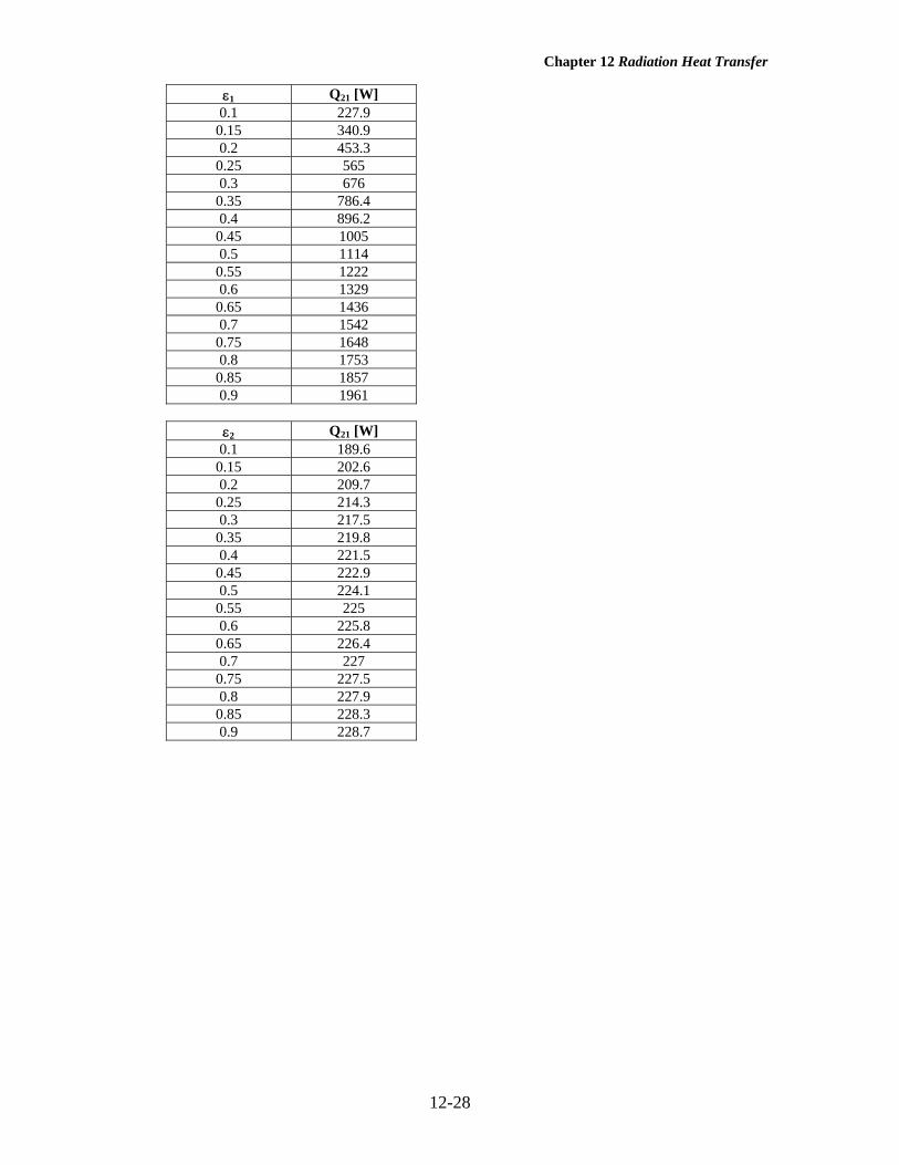
12-40 "!PROBLEM 12-40"
"GIVEN" D=2 "[m]" a=3 "[m], parameter to be varied" T_1=100 "[K]" T_2=240 "[K]" epsilon_1=0.1 "parameter to be varied" epsilon_2=0.8 "parameter to be varied" sigma=5.67E-8 "[W/m^2-K^4], Stefan-Boltzmann constant" "ANALYSIS" "Consider the sphere to be surface 1, the surrounding cubic enclosure to be surface 2" Q_dot_12=(A_1*sigma*(T_1^4-T_2^4))/(1/epsilon_1+(1-epsilon_2)/epsilon_2*(A_1/A_2)) Q_dot_21=-Q_dot_12 A_1=pi*D^2 A_2=6*a^2
a [m] Q21 [W] 2.5 227.4
2.625 227.5 2.75 227.7
2.875 227.8 3 227.9
3.125 228 3.25 228.1
3.375 228.2 3.5 228.3
3.625 228.4 3.75 228.4
3.875 228.5 4 228.5
4.125 228.6 4.25 228.6
4.375 228.6 4.5 228.7
4.625 228.7 4.75 228.7
4.875 228.8 5 228.8
Chapter 12 Radiation Heat Transfer
12-28
ε1 Q21 [W] 0.1 227.9
0.15 340.9 0.2 453.3
0.25 565 0.3 676
0.35 786.4 0.4 896.2
0.45 1005 0.5 1114
0.55 1222 0.6 1329
0.65 1436 0.7 1542
0.75 1648 0.8 1753
0.85 1857 0.9 1961
ε2 Q21 [W] 0.1 189.6
0.15 202.6 0.2 209.7
0.25 214.3 0.3 217.5
0.35 219.8 0.4 221.5
0.45 222.9 0.5 224.1
0.55 225 0.6 225.8
0.65 226.4 0.7 227
0.75 227.5 0.8 227.9
0.85 228.3 0.9 228.7

Chapter 12 Radiation Heat Transfer
12-29
2.5 3 3.5 4 4.5 5227.2
227.4
227.6
227.8
228
228.2
228.4
228.6
228.8
a [m]
Q21
[W
]
0.1 0.2 0.3 0.4 0.5 0.6 0.7 0.8 0.9200
400
600
800
1000
1200
1400
1600
1800
2000
ε1
Q21
[W
]

Chapter 12 Radiation Heat Transfer
12-30
0.1 0.2 0.3 0.4 0.5 0.6 0.7 0.8 0.9185
190
195
200
205
210
215
220
225
230
ε2
Q21
[W
]

Chapter 12 Radiation Heat Transfer
12-31
12-41 A circular grill is considered. The bottom of the grill is covered with hot coal bricks, while the wire mesh on top of the grill is covered with steaks. The initial rate of radiation heat transfer from coal bricks to the steaks is to be determined for two cases. Assumptions 1 Steady operating conditions exist 2 The surfaces are opaque, diffuse, and gray. 3 Convection heat transfer is not considered. Properties The emissivities are ε = 1 for all surfaces since they are black or reradiating. Analysis We consider the coal bricks to be surface 1, the steaks to be surface 2 and the side surfaces to be surface 3. First we determine the view factor between the bricks and the steaks (Table 12-1),
75.0m 0.20m 15.0
====Lr
RR iji
7778.30.75
75.0111
2
2
2
2
=+
=+
+=i
j
R
RS
2864.075.075.047778.37778.3
214
21
2/122
2/122
12 =⎪⎭
⎪⎬⎫
⎪⎩
⎪⎨⎧
⎥⎥⎦
⎤
⎢⎢⎣
⎡⎟⎠⎞
⎜⎝⎛−−=
⎪⎭
⎪⎬
⎫
⎪⎩
⎪⎨
⎧
⎥⎥
⎦
⎤
⎢⎢
⎣
⎡
⎟⎟⎠
⎞⎜⎜⎝
⎛−−==
i
jij R
RSSFF
(It can also be determined from Fig. 12-7). Then the initial rate of radiation heat transfer from the coal bricks to the stakes becomes
W1674=
−⋅×=
−=− ])K 278()K 1100)[(K W/m1067.5](4/m) 3.0()[2864.0(
)(444282
42
4111212
π
σ TTAFQ&
When the side opening is closed with aluminum foil, the entire heat lost by the coal bricks must be gained by the stakes since there will be no heat transfer through a reradiating surface. The grill can be considered to be three-surface enclosure. Then the rate of heat loss from the room can be determined from
1
231312
211
11−
⎟⎟⎠
⎞⎜⎜⎝
⎛+
+
−=
RRR
EEQ bb&
where W / m K K W / m
W / m K K W / m
4 2 2
4 2 2
E T
E Tb
b
1 18 4 4
2 28 4 4
67 10 1100 83 015
67 10 18 273 407
= = × =
= = × + =
−
−
σ
σ
(5. . )( ) ,
(5. . )( )
and A A1 2
20 3 0 07069= = =π( . ) . m
4 m2
2-
2131
2313
2-2
12112
m 82.19)2864.01)(m 07069.0(
11
m 39.49)2864.0)(m 07069.0(
11
=−
===
===
FARR
FAR
Substituting, W 3757=
⎟⎟⎠
⎞⎜⎜⎝
⎛+
−= −1
2-2-
2
12
)m 82.19(21
m 39.491
W/m)407015,83(Q&
Steaks, T2 = 278 K, ε2 = 1
Coal bricks, T1 = 1100 K, ε1 = 1
0.20 m

Chapter 12 Radiation Heat Transfer
12-32
12-42E A room is heated by lectric resistance heaters placed on the ceiling which is maintained at a uniform temperature. The rate of heat loss from the room through the floor is to be determined. Assumptions 1 Steady operating conditions exist 2 The surfaces are opaque, diffuse, and gray. 3 Convection heat transfer is not considered. 4 There is no heat loss through the side surfaces. Properties The emissivities are ε = 1 for the ceiling and ε = 0.8 for the floor. The emissivity of insulated (or reradiating) surfaces is also 1. Analysis The room can be considered to be three-surface enclosure with the ceiling surface 1, the floor surface 2 and the side surfaces surface 3. We assume steady-state conditions exist. Since the side surfaces are reradiating, there is no heat transfer through them, and the entire heat lost by the ceiling must be gained by the floor. Then the rate of heat loss from the room through its floor can be determined from
2
1
231312
211
11 RRRR
EEQ bb
+⎟⎟⎠
⎞⎜⎜⎝
⎛+
+
−=
−&
where
24428422
24428411
Btu/h.ft 130)R 46065)(R.Btu/h.ft 101714.0(
Btu/h.ft 157)R 46090)(R.Btu/h.ft 101714.0(
=+×=σ=
=+×=σ=−
−
TE
TE
b
b
and
A A1 2212 144= = =( ) ft ft2
The view factor from the floor to the ceiling of the room is F12 0 27= . (From Figure 12-42). The view factor from the ceiling or the floor to the side surfaces is determined by applying the summation rule to be
F F F F F11 12 13 13 121 1 1 0 27 0 73+ + = ⎯ →⎯ = − = − =. .
since the ceiling is flat and thus F11 0= . Then the radiation resistances which appear in the equation above become
2-2
1312313
2-2
12112
2-2
22
22
ft 009513.0)73.0)(ft 144(
11
ft 02572.0)27.0)(ft 144(
11
ft 00174.0)8.0)(ft 144(
8.011
====
===
=−
=−
=
FARR
FAR
AR
εε
Substituting,
Btu/h 2130=
+⎟⎟⎠
⎞⎜⎜⎝
⎛+
−=
−2-
1
2-2-
2
12
ft 00174.0)ft 009513.0(2
1ft 02572.0
1
Btu/h.ft )130157(Q&
T2 = 90°F ε2 = 0.8
Ceiling: 12 ft × 12 ft
T1 = 90°F ε1 = 1
Insulated side surfacess 9 ft

Chapter 12 Radiation Heat Transfer
12-33
12-43 Two perpendicular rectangular surfaces with a common edge are maintained at specified temperatures. The net rate of radiation heat transfers between the two surfaces and between the horizontal surface and the surroundings are to be determined. Assumptions 1 Steady operating conditions exist 2 The surfaces are opaque, diffuse, and gray. 3 Convection heat transfer is not considered. Properties The emissivities of the horizontal rectangle and the surroundings are ε = 0.75 and ε = 0.85, respectively. Analysis We consider the horizontal rectangle to be surface 1, the vertical rectangle to be surface 2 and the surroundings to be surface 3. This system can be considered to be a three-surface enclosure. The view factor from surface 1 to surface 2 is determined from
27.075.0
6.12.1
5.06.18.0
122
1
=
⎪⎪⎭
⎪⎪⎬
⎫
==
==F
WLWL
(Fig. 12-6)
The surface areas are
22
21
m 92.1)m 6.1)(m 2.1(
m 28.1)m 6.1)(m 8.0(
==
==
A
A
2223 m 268.36.12.18.0
28.02.12 =×++
××=A
Note that the surface area of the surroundings is determined assuming that surroundings forms flat surfaces at all openings to form an enclosure. Then other view factors are determined to be
18.0)92.1()27.0)(28.1( 2121212121 =⎯→⎯=⎯→⎯= FFFAFA (reciprocity rule)
73.0127.001 1313131211 =⎯→⎯=++⎯→⎯=++ FFFFF (summation rule)
82.01018.01 2323232221 =⎯→⎯=++⎯→⎯=++ FFFFF (summation rule)
29.0)268.3()73.0)(28.1( 3131313131 =⎯→⎯=⎯→⎯= FFFAFA (reciprocity rule)
48.0)268.3()82.0)(92.1( 3232323232 =⎯→⎯=⎯→⎯= FFFAFA (reciprocity rule) We now apply Eq. 9-52b to each surface to determine the radiosities.
Surface 1: [ ]
[ ])(73.0)(27.075.0
75.01)K 400)(K.W/m 1067.5(
)()(1
312114428
311321121
11
41
JJJJJ
JJFJJFJT
−+−−
+=×
−+−−
+=
−
εε
σ
Surface 2: 24428
24
2 )K 550)(K.W/m 1067.5( JJT =×⎯→⎯= −σ
Surface 3: [ ]
[ ])(48.0)(29.085.0
85.01)K 290)(K.W/m 1067.5(
)()(1
312134428
233213313
33
43
JJJJJ
JJFJJFJT
−+−−
+=×
−+−−
+=
−
εε
σ
Solving the above equations, we find 2
32
22
1 W/m 5.811 ,W/m 5188 ,W/m 1587 === JJJ Then the net rate of radiation heat transfers between the two surfaces and between the horizontal surface and the surroundings are determined to be W1245=−−=−−=−= 22
211211221 W/m)51881587)(27.0)(m 28.1()( JJFAQQ &&
W725=−=−= 223113113 W/m)5.8111587)(73.0)(m 28.1()( JJFAQ&
W = 1.6 m
(2) L2 = 1.2 m
L1 = 0.8 m A1 (1)
A2T3 = 290 K ε3 = 0.85
T2 = 550 K ε2 = 1
T1 =400 K ε1 =0.75
(3)

Chapter 12 Radiation Heat Transfer
12-34
12-44 Two long parallel cylinders are maintained at specified temperatures. The rates of radiation heat transfer between the cylinders and between the hot cylinder and the surroundings are to be determined. Assumptions 1 Steady operating conditions exist 2 The surfaces are black. 3 Convection heat transfer is not considered. Analysis We consider the hot cylinder to be surface 1, cold cylinder to be surface 2, and the surroundings to be surface 3. Using the crossed-strings method, the view factor between two cylinders facing each other is determined to be
F s D sD1 2
2 2
22 2
2 2− =−
×=
+ −∑ ∑Crossed strings Uncrossed strings
String on surface 1 ( / )π
or 099.0)16.0(
5.016.05.022 2222
21 =π
⎟⎠⎞⎜
⎝⎛ −+
=π
⎟⎠⎞⎜
⎝⎛ −+
=− D
sDsF
The view factor between the hot cylinder and the surroundings is
901.0099.011 1213 =−=−= FF (summation rule)
The rate of radiation heat transfer between the cylinders per meter length is
2m 2513.02/m) 1)(m 16.0(2/ === ππDLA
W38.0=−°×=−σ= − 44428242
411212 K)275425)(C. W/m1067.5)(099.0)(m 2513.0()( TTAFQ&
Note that half of the surface area of the cylinder is used, which is the only area that faces the other cylinder. The rate of radiation heat transfer between the hot cylinder and the surroundings per meter length of the cylinder is
21 m 5027.0m) 1)(m 16.0( === ππDLA
W629.8=−°×=−σ= − 44428243
4113113 K)300425)(C. W/m1067.5)(901.0)(m 5027.0()( TTFAQ&
D
D (2)
(1) s
T3 = 300 K ε3 = 1
T2 = 275 K ε2 = 1
T1 = 425 K ε1 = 1
(3)
Chapter 12 Radiation Heat Transfer
12-35
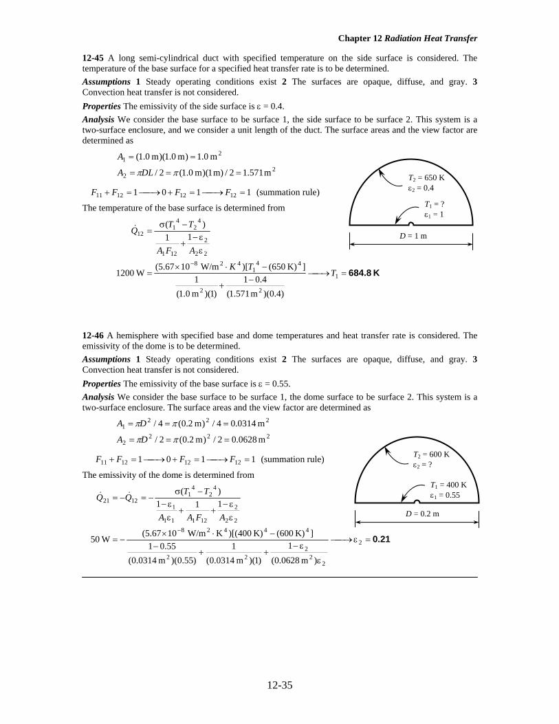
12-45 A long semi-cylindrical duct with specified temperature on the side surface is considered. The temperature of the base surface for a specified heat transfer rate is to be determined. Assumptions 1 Steady operating conditions exist 2 The surfaces are opaque, diffuse, and gray. 3 Convection heat transfer is not considered. Properties The emissivity of the side surface is ε = 0.4. Analysis We consider the base surface to be surface 1, the side surface to be surface 2. This system is a two-surface enclosure, and we consider a unit length of the duct. The surface areas and the view factor are determined as
22
21
m 571.12/m) 1)(m 0.1(2/
m 0.1)m 0.1)(m 0.1(
===
==
ππDLA
A
1101 12121211 =⎯→⎯=+⎯→⎯=+ FFFF (summation rule)
The temperature of the base surface is determined from
K 684.8=⎯→⎯−
+
−⋅×=
εε−
+
−σ=
−
1
22
441
42822
2
121
42
41
12
)4.0)(m 571.1(4.01
)1)(m 0.1(1
]K) 650()[ W/m1067.5( W1200
11)(
TTK
AFA
TTQ&
12-46 A hemisphere with specified base and dome temperatures and heat transfer rate is considered. The emissivity of the dome is to be determined. Assumptions 1 Steady operating conditions exist 2 The surfaces are opaque, diffuse, and gray. 3 Convection heat transfer is not considered. Properties The emissivity of the base surface is ε = 0.55. Analysis We consider the base surface to be surface 1, the dome surface to be surface 2. This system is a two-surface enclosure. The surface areas and the view factor are determined as
2222
2221
m 0628.02/)m 2.0(2/
m 0314.04/)m 2.0(4/
===
===
ππ
ππ
DA
DA
1101 12121211 =⎯→⎯=+⎯→⎯=+ FFFF (summation rule)
The emissivity of the dome is determined from
0.21=ε⎯→⎯
ε
ε−++
−−⋅×
−=
εε−
++εε−
−σ−=−=
−
2
22
222
4442822
2
12111
1
42
41
1221
)m 0628.0(1
)1)(m 0314.0(1
)55.0)(m 0314.0(55.01
]K) 600(K) 400)[(K W/m1067.5( W50
111)(
AFAA
TTQQ &&
T1 = ? ε1 = 1
T2 = 650 K ε2 = 0.4
D = 1 m
T1 = 400 K ε1 = 0.55
T2 = 600 K ε2 = ?
D = 0.2 m
Chapter 12 Radiation Heat Transfer
12-36
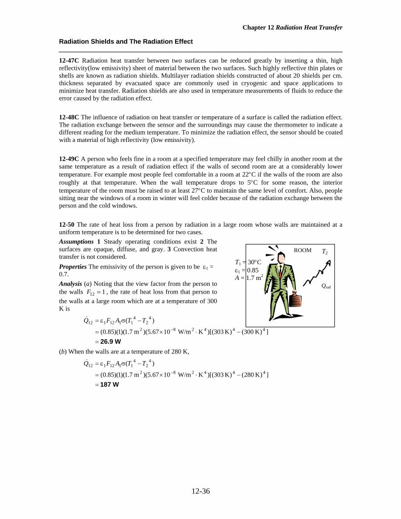
Radiation Shields and The Radiation Effect 12-47C Radiation heat transfer between two surfaces can be reduced greatly by inserting a thin, high reflectivity(low emissivity) sheet of material between the two surfaces. Such highly reflective thin plates or shells are known as radiation shields. Multilayer radiation shields constructed of about 20 shields per cm. thickness separated by evacuated space are commonly used in cryogenic and space applications to minimize heat transfer. Radiation shields are also used in temperature measurements of fluids to reduce the error caused by the radiation effect. 12-48C The influence of radiation on heat transfer or temperature of a surface is called the radiation effect. The radiation exchange between the sensor and the surroundings may cause the thermometer to indicate a different reading for the medium temperature. To minimize the radiation effect, the sensor should be coated with a material of high reflectivity (low emissivity). 12-49C A person who feels fine in a room at a specified temperature may feel chilly in another room at the same temperature as a result of radiation effect if the walls of second room are at a considerably lower temperature. For example most people feel comfortable in a room at 22°C if the walls of the room are also roughly at that temperature. When the wall temperature drops to 5°C for some reason, the interior temperature of the room must be raised to at least 27°C to maintain the same level of comfort. Also, people sitting near the windows of a room in winter will feel colder because of the radiation exchange between the person and the cold windows. 12-50 The rate of heat loss from a person by radiation in a large room whose walls are maintained at a uniform temperature is to be determined for two cases. Assumptions 1 Steady operating conditions exist 2 The surfaces are opaque, diffuse, and gray. 3 Convection heat transfer is not considered. Properties The emissivity of the person is given to be ε1 = 0.7. Analysis (a) Noting that the view factor from the person to the walls F12 1= , the rate of heat loss from that person to the walls at a large room which are at a temperature of 300 K is
W26.9=−⋅×=
−σε=− ])K 300()K 303)[(K W/m1067.5)(m 7.1)(1)(85.0(
)(444282
42
41112112 TTAFQ&
(b) When the walls are at a temperature of 280 K,
W187=−⋅×=
−σε=− ])K 280()K 303)[(K W/m1067.5)(m 7.1)(1)(85.0(
)(444282
42
41112112 TTAFQ&
T2
Qrad
T1 = 30°C ε1 = 0.85 A = 1.7 m2
ROOM

Chapter 12 Radiation Heat Transfer
12-37
12-51 A thin aluminum sheet is placed between two very large parallel plates that are maintained at uniform temperatures. The net rate of radiation heat transfer between the two plates is to be determined for the cases of with and without the shield. Assumptions 1 Steady operating conditions exist 2 The surfaces are opaque, diffuse, and gray. 3 Convection heat transfer is not considered. Properties The emissivities of surfaces are given to be ε1 = 0.5, ε2 = 0.8, and ε3 = 0.15. Analysis The net rate of radiation heat transfer with a thin aluminum shield per unit area of the plates is
2 W/m1857=
⎟⎠⎞
⎜⎝⎛ −++⎟
⎠⎞
⎜⎝⎛ −+
−⋅×=
⎟⎟⎠
⎞⎜⎜⎝
⎛−++⎟⎟
⎠
⎞⎜⎜⎝
⎛−+
−=
−
115.01
15.011
8.01
5.01
])K 650()K 900)[(K W/m1067.5(
111111
)(
44428
2,31,321
42
41
shield one,12
εεεε
σ TTQ&
The net rate of radiation heat transfer between the plates in the case of no shield is
244428
21
42
41
shield ,12 W/m035,121
8.01
5.01
])K 650()K 900)[(K W/m1067.5(
111)(
=⎟⎠⎞
⎜⎝⎛ −+
−⋅×=
⎟⎟⎠
⎞⎜⎜⎝
⎛−+
−=
−
εε
σ TTQ no&
Then the ratio of radiation heat transfer for the two cases becomes
&
& ,,
,
12
12
185712 035
one shield
no shield
W W
= ≅16
T2 = 650 K ε2 = 0.8
T1 = 900 K ε1 = 0.5
Radiation shieldε3 = 0.15

Chapter 12 Radiation Heat Transfer
12-38
12-52 "!PROBLEM 12-52" "GIVEN" "epsilon_3=0.15 parameter to be varied" T_1=900 "[K]" T_2=650 "[K]" epsilon_1=0.5 epsilon_2=0.8 sigma=5.67E-8 "[W/m^2-K^4], Stefan-Boltzmann constant" "ANALYSIS" Q_dot_12_1shield=(sigma*(T_1^4-T_2^4))/((1/epsilon_1+1/epsilon_2-1)+(1/epsilon_3+1/epsilon_3-1))
ε3 Q12,1 shield [W/m2] 0.05 656.5 0.06 783 0.07 908.1 0.08 1032 0.09 1154 0.1 1274
0.11 1394 0.12 1511 0.13 1628 0.14 1743 0.15 1857 0.16 1969 0.17 2081 0.18 2191 0.19 2299 0.2 2407
0.21 2513 0.22 2619 0.23 2723 0.24 2826 0.25 2928

Chapter 12 Radiation Heat Transfer
12-39
0.05 0.1 0.15 0.2 0.25500
1000
1500
2000
2500
3000
ε3
Q12
,1sh
ield
[W
/m2 ]

Chapter 12 Radiation Heat Transfer
12-40
12-53 Two very large plates are maintained at uniform temperatures. The number of thin aluminum sheets that will reduce the net rate of radiation heat transfer between the two plates to one-fifth is to be determined. Assumptions 1 Steady operating conditions exist 2 The surfaces are opaque, diffuse, and gray. 3 Convection heat transfer is not considered. Properties The emissivities of surfaces are given to be ε1 = 0.2, ε2 = 0.2, and ε3 = 0.15. Analysis The net rate of radiation heat transfer between the plates in the case of no shield is
2
4442821
42
41
shield ,12
W/m3720
12.0
12.0
1])K 800()K 1000)[(K W/m1067.5(
111)(
=
⎟⎠⎞
⎜⎝⎛ −+
−⋅×=
⎟⎟⎠
⎞⎜⎜⎝
⎛−
ε+
ε
−σ=
−
TTQ no&
The number of sheets that need to be inserted in order to reduce the net rate of heat transfer between the two plates to onefifth can be determined from
3≅=⎯→⎯⎟⎠⎞
⎜⎝⎛ −++⎟
⎠⎞
⎜⎝⎛ −+
−⋅×=
⎟⎟⎠
⎞⎜⎜⎝
⎛−
ε+
ε+⎟⎟
⎠
⎞⎜⎜⎝
⎛−
ε+
ε
−σ=
−
92.21
15.01
15.011
2.01
2.01
])K 800()K 1000)[(K W/m1067.5( ) W/m(372051
111111
)(
shield
shield
444282
2,31,3shield
21
42
41
shields,12
NN
N
TTQ&
12-54 Five identical thin aluminum sheets are placed between two very large parallel plates which are maintained at uniform temperatures. The net rate of radiation heat transfer between the two plates is to be determined and compared with that without the shield. Assumptions 1 Steady operating conditions exist 2 The surfaces are opaque, diffuse, and gray. 3 Convection heat transfer is not considered. Properties The emissivities of surfaces are given to be ε1 = ε2 = 0.1 and ε3 = 0.1. Analysis Since the plates and the sheets have the same emissivity value, the net rate of radiation heat transfer with 5 thin aluminum shield can be determined from
2 W/m183=
⎟⎠⎞
⎜⎝⎛ −+
−⋅×+
=
⎟⎟⎠
⎞⎜⎜⎝
⎛−+
−+
=+
=
−
11.0
11.0
1])K 450()K 800)[(K W/m1067.5(
151
111)(
11
11
4442821
42
41
shield no ,12shield 5,12
εε
σ TTN
QN
Q &&
The net rate of radiation heat transfer without the shield is
W1098=×=+=⎯→⎯+
= W1836)1(1
1shield 5,12shield no ,12shield no ,12shield 5,12 QNQQ
NQ &&&&
T2 = 800 K ε2 = 0.2
T1 = 1000 K ε1 = 0.2
Radiation shields ε3 = 0.15
T2 = 450 K ε2 = 0.1
T1 = 800 K ε1 = 0.1
Radiation shields ε3 = 0.1

Chapter 12 Radiation Heat Transfer
12-41
12-55 "!PROBLEM 12-55" "GIVEN" N=5 "parameter to be varied" epsilon_3=0.1 "epsilon_1=0.1 parameter to be varied" epsilon_2=epsilon_1 T_1=800 "[K]" T_2=450 "[K]" sigma=5.67E-8 "[W/m^2-K^4], Stefan-Boltzmann constant" "ANALYSIS" Q_dot_12_shields=1/(N+1)*Q_dot_12_NoShield Q_dot_12_NoShield=(sigma*(T_1^4-T_2^4))/(1/epsilon_1+1/epsilon_2-1)
N Q12,shields [W/m2] 1 550 2 366.7 3 275 4 220 5 183.3 6 157.1 7 137.5 8 122.2 9 110
10 100
ε1 Q12,shields [W/m2] 0.1 183.3
0.15 282.4 0.2 387
0.25 497.6 0.3 614.7
0.35 738.9 0.4 870.8
0.45 1011 0.5 1161
0.55 1321 0.6 1493
0.65 1677 0.7 1876
0.75 2090 0.8 2322
0.85 2575 0.9 2850

Chapter 12 Radiation Heat Transfer
12-42
1 2 3 4 5 6 7 8 9 100
100
200
300
400
500
600
N
Q12
,shi
elds
[W
/m2 ]
0.1 0.2 0.3 0.4 0.5 0.6 0.7 0.8 0.90
500
1000
1500
2000
2500
3000
ε1
Q12
,shi
elds
[W
/m2 ]

Chapter 12 Radiation Heat Transfer
12-43
12-56E A radiation shield is placed between two parallel disks which are maintained at uniform temperatures. The net rate of radiation heat transfer through the shields is to be determined. Assumptions 1 Steady operating conditions exist 2 The surfaces are black. 3 Convection heat transfer is not considered. Properties The emissivities of surfaces are given to be ε1 = ε2 = 1 and ε3 = 0.15. Analysis From Fig. 12-44 we have 52.01332 == FF . Then 48.052.0134 =−=F . The disk in the middle is surrounded by black surfaces on both sides. Therefore, heat transfer between the top surface of the middle disk and its black surroundings can expressed as
]})K 540([48.0])R 1200([(52.0){RBtu/h.ft 101714.0()ft 069.7(15.0
)]([)]([44
344
34282
42
43323
41
433133
−+−⋅×=
−σε+−σε=− TT
TTFATTFAQ&
Similarly, for the bottom surface of the middle disk, we have
]})K 540([52.0])R 700([(48.0){RBtu/h.ft 101714.0()ft 069.7(15.0
)]([)]([44
344
34282
45
43353
44
433433
−+−⋅×=
−σε+−σε=−− TT
TTFATTFAQ&
Combining the equations above, the rate of heat transfer between the disks through the radiation shield (the middle disk) is determined to be
Btu/h 866=Q& and T3 = 895 K
T1 = 1200 R, ε1 = 1
ε3 = 0.15
T2 = 700 R, ε2 = 1
1 ft
1 ft
T∞ = 540 K ε3 = 1

Chapter 12 Radiation Heat Transfer
12-44
12-57 A radiation shield is placed between two large parallel plates which are maintained at uniform temperatures. The emissivity of the radiation shield is to be determined if the radiation heat transfer between the plates is reduced to 15% of that without the radiation shield. Assumptions 1 Steady operating conditions exist 2 The surfaces are opaque, diffuse, and gray. 3 Convection heat transfer is not considered. Properties The emissivities of surfaces are given to be ε1 = 0.6 and ε2 = 0.9. Analysis First, the net rate of radiation heat transfer between the two large parallel plates per unit area without a shield is
244428
21
42
41
shield no,12 W/m48771
9.01
6.01
])K 400()K 650)[(K W/m1067.5(
111)(
=−+
−⋅×=
−+
−=
−
εε
σ TTQ&
The radiation heat transfer in the case of one shield is
22
shield no,12shield one,12
W/m 6.731W/m 487715.0
15.0
=×=
×= QQ &&
Then the emissivity of the radiation shield becomes
⎟⎟⎠
⎞⎜⎜⎝
⎛−+⎟
⎠⎞
⎜⎝⎛ −+
−⋅×=
⎟⎟⎠
⎞⎜⎜⎝
⎛−++⎟⎟
⎠
⎞⎜⎜⎝
⎛−+
−=
−
1219.0
16.0
1])K 400()K 650)[(K W/m1067.5(
W/m731.6
111111
)(
3
444282
2,31,321
42
41
shield one,12
ε
εεεε
σ TTQ&
which gives 0.18=3ε
T2 = 400 K ε2 = 0.9
T1 = 650 K ε1 = 0.6
Radiation shieldε3

Chapter 12 Radiation Heat Transfer
12-45
12-58 "!PROBLEM 12-58" "GIVEN" T_1=650 "[K]" T_2=400 "[K]" epsilon_1=0.6 epsilon_2=0.9 "PercentReduction=85 [%], parameter to be varied" sigma=5.67E-8 "[W/m^2-K^4], Stefan-Boltzmann constant" "ANALYSIS" Q_dot_12_NoShield=(sigma*(T_1^4-T_2^4))/(1/epsilon_1+1/epsilon_2-1) Q_dot_12_1shield=(sigma*(T_1^4-T_2^4))/((1/epsilon_1+1/epsilon_2-1)+(1/epsilon_3+1/epsilon_3-1)) Q_dot_12_1shield=(1-PercentReduction/100)*Q_dot_12_NoShield
Percent Reduction [%]
ε3
40 0.9153 45 0.8148 50 0.72 55 0.6304 60 0.5455 65 0.4649 70 0.3885 75 0.3158 80 0.2466 85 0.1806 90 0.1176 95 0.05751
40 50 60 70 80 90 1000
0.2
0.4
0.6
0.8
1
PercentReduction [%]
ε 3

Chapter 12 Radiation Heat Transfer
12-46
12-59 A coaxial radiation shield is placed between two coaxial cylinders which are maintained at uniform temperatures. The net rate of radiation heat transfer between the two cylinders is to be determined and compared with that without the shield. Assumptions 1 Steady operating conditions exist 2 The surfaces are opaque, diffuse, and gray. 3 Convection heat transfer is not considered. Properties The emissivities of surfaces are given to be ε1 = 0.7, ε2 = 0.4. and ε3 = 0.2. Analysis The surface areas of the cylinders and the shield per unit length are
2
33shield
222outerpipe,
211innerpipe,
m 942.0)m 1)(m 3.0(
m 314.0)m 1)(m 1.0(
m 628.0)m 1)(m 2.0(
====
====
====
ππ
ππ
ππ
LDAA
LDAA
LDAA
The net rate of radiation heat transfer between the two cylinders with a shield per unit length is
W703=
−++
−++
−−⋅×
=
−++
−+
−++
−−
=
−
)4.0)(942.0(4.01
)1)(628.0(1
)2.0)(628.0(2.012
)1)(314.0(1
)7.0)(314.0(7.01
])K 500()K 750)[(K W/m1067.5(
111111)(
44428
22
2
2,332,33
2,3
1,33
1,3
13111
1
42
41
shield one,12
εε
εε
εε
εε
σ
AFAAAFAA
TTQ&
If there was no shield,
W7465=
⎟⎠⎞
⎜⎝⎛−
+
−⋅×=
⎟⎟⎠
⎞⎜⎜⎝
⎛−+
−=
−
3.01.0
4.04.01
7.01
])K 500()K 750)[(K W/m1067.5(
11)(
444282
1
2
2
1
42
41
shield no,12
DD
TTQ
εε
ε
σ&
Then their ratio becomes
&
&,
,
12
12
7037465
one shield
no shield
W W
= = 0.094
D2 = 0.3 m T2 = 500 K ε2 = 0.4
D1 = 0.1 m T1 = 750 K ε1 = 0.7
Radiation shield D3 = 0.2 m ε3 = 0.2
Chapter 12 Radiation Heat Transfer
12-47
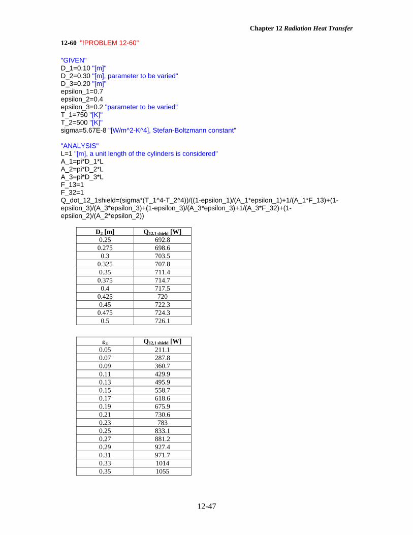
12-60 "!PROBLEM 12-60" "GIVEN" D_1=0.10 "[m]" D_2=0.30 "[m], parameter to be varied" D_3=0.20 "[m]" epsilon_1=0.7 epsilon_2=0.4 epsilon_3=0.2 "parameter to be varied" T_1=750 "[K]" T_2=500 "[K]" sigma=5.67E-8 "[W/m^2-K^4], Stefan-Boltzmann constant" "ANALYSIS" L=1 "[m], a unit length of the cylinders is considered" A_1=pi*D_1*L A_2=pi*D_2*L A_3=pi*D_3*L F_13=1 F_32=1 Q_dot_12_1shield=(sigma*(T_1^4-T_2^4))/((1-epsilon_1)/(A_1*epsilon_1)+1/(A_1*F_13)+(1-epsilon_3)/(A_3*epsilon_3)+(1-epsilon_3)/(A_3*epsilon_3)+1/(A_3*F_32)+(1-epsilon_2)/(A_2*epsilon_2))
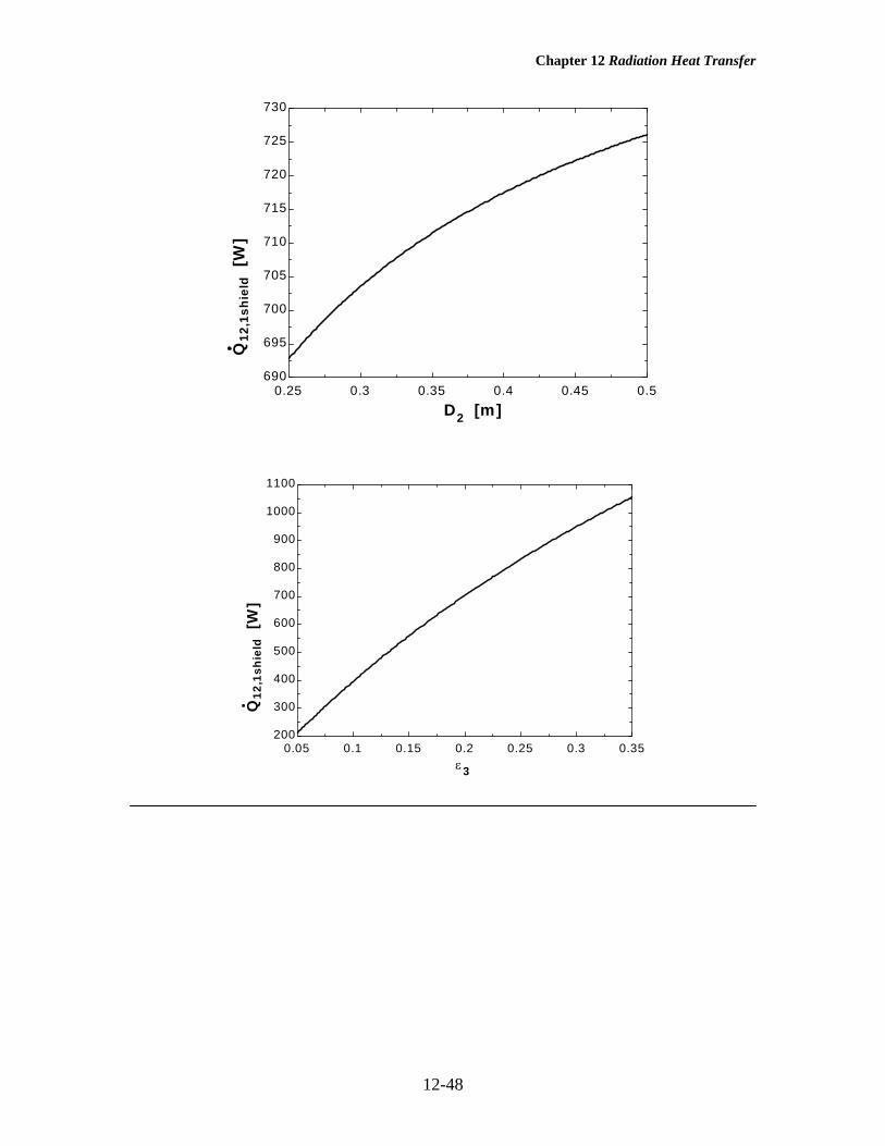
D2 [m] Q12,1 shield [W] 0.25 692.8
0.275 698.6 0.3 703.5
0.325 707.8 0.35 711.4
0.375 714.7 0.4 717.5
0.425 720 0.45 722.3
0.475 724.3 0.5 726.1
ε3 Q12,1 shield [W]
0.05 211.1 0.07 287.8 0.09 360.7 0.11 429.9 0.13 495.9 0.15 558.7 0.17 618.6 0.19 675.9 0.21 730.6 0.23 783 0.25 833.1 0.27 881.2 0.29 927.4 0.31 971.7 0.33 1014 0.35 1055
Chapter 12 Radiation Heat Transfer
12-48
0.25 0.3 0.35 0.4 0.45 0.5690
695
700
705
710
715
720
725
730
D2 [m]
Q12
,1sh
ield
[W
]
0.05 0.1 0.15 0.2 0.25 0.3 0.35200
300
400
500
600
700
800
900
1000
1100
ε3
Q12
,1sh
ield
[W
]

Chapter 12 Radiation Heat Transfer
12-49
Radiation Exchange with Absorbing and Emitting Gases 12-61C A nonparticipating medium is completely transparent to thermal radiation, and thus it does not emit, absorb, or scatter radiation. A participating medium, on the other hand, emits and absorbs radiation throughout its entire volume. 12-62C Spectral transmissivity of a medium of thickness L is the ratio of the intensity of radiation leaving
the medium to that entering the medium, and is expressed as LL eII
λκ
λ
λλτ
−==0,
, and τλ =1 - αλ .
12-63C Using Kirchhoff’s law, the spectral emissivity of a medium of thickness L in terms of the spectral absorption coefficient is expressed as Le λκ
λλ αε −−== 1 .
12-64C Gases emit and absorb radiation at a number of narrow wavelength bands. The emissivity-wavelength charts of gases typically involve various peaks and dips together with discontinuities, and show clearly the band nature of absorption and the strong nongray characteristics. This is in contrast to solids, which emit and absorb radiation over the entire spectrum. 12-65 An equimolar mixture of CO2 and O2 gases at 500 K and a total pressure of 0.5 atm is considered. The emissivity of the gas is to be determined. Assumptions All the gases in the mixture are ideal gases. Analysis Volumetric fractions are equal to pressure fractions. Therefore, the partial pressure of CO2 is
atm 25.0atm) 5.0(5.02CO === PyPc
Then, atmft 0.98atmm 30.0m) atm)(1.2 25.0( ⋅=⋅==LPc
The emissivity of CO2 corresponding to this value at the gas temperature of Tg = 500 K and 1 atm is, from Fig. 12-36,
14.0atm 1 , =ε c
This is the base emissivity value at 1 atm, and it needs to be corrected for the 0.5 atm total pressure. The pressure correction factor is, from Fig. 12-37,
Cc = 0.90 Then the effective emissivity of the gas becomes
0.126=×=ε=ε 14.090.0atm 1 ,ccg C
12-66 The temperature, pressure, and composition of a gas mixture is given. The emissivity of the mixture is to be determined. Assumptions 1 All the gases in the mixture are ideal gases. 2 The emissivity determined is the mean emissivity for radiation emitted to all surfaces of the cubical enclosure. Analysis The volumetric analysis of a gas mixture gives the mole fractions yi of the components, which are equivalent to pressure fractions for an ideal gas mixture. Therefore, the partial pressures of CO2 and H2O are
atm 09.0atm) 1(09.0
atm 10.0atm) 1(10.0
2
2
H
CO
===
===
PyP
PyP
Ow
c
The mean beam length for a cube of side length 6 m for radiation emitted to all surfaces is, from Table 12-4, L = 0.66(6 m) = 3.96 m
6 m
Combustion gases
1000 K

Chapter 12 Radiation Heat Transfer
12-50
Then,
atmft 1.57atmm 48.0m) atm)(3.96 09.0(atmft .301atmm 396.0m) atm)(3.96 10.0(
⋅=⋅==⋅=⋅==
LPLP
w
c
The emissivities of CO2 and H2O corresponding to these values at the gas temperature of Tg = 1000 K and 1atm are, from Fig. 12-36,
17.0atm 1 , =ε c and 26.0atm 1 , =εw
Both CO2 and H2O are present in the same mixture, and we need to correct for the overlap of emission bands. The emissivity correction factor at T = Tg = 1000 K is, from Fig. 12-38,
039.0 474.010.009.0
09.0 87.257.130.1
=εΔ⎪⎭
⎪⎬⎫
=+
=+
=+=+
cw
w
wc
PPP
LPLP
Note that we obtained the average of the emissivity correction factors from the two figures for 800 K and 1200 K. Then the effective emissivity of the combustion gases becomes 0.391=−×+×=εΔ−ε+ε=ε 039.026.0117.01atm 1 ,atm 1 , wwccg CC
Note that the pressure correction factor is 1 for both gases since the total pressure is 1 atm.

Chapter 12 Radiation Heat Transfer
12-51
12-67 A mixture of CO2 and N2 gases at 600 K and a total pressure of 1 atm are contained in a cylindrical container. The rate of radiation heat transfer between the gas and the container walls is to be determined. Assumptions All the gases in the mixture are ideal gases. Analysis The mean beam length is, from Table 12-4 L = 0.60D = 0.60(8 m) = 4.8 m Then,
atmft .362atmm 72.0m) atm)(4.8 15.0( ⋅=⋅==LPc
The emissivity of CO2 corresponding to this value at the gas temperature of Tg = 600 K and 1 atm is, from Fig. 12-36,
24.0atm 1 , =ε c
For a source temperature of Ts = 450 K, the absorptivity of the gas is again determined using the emissivity charts as follows:
atmft 1.77atmm 54.0K 600K 450m) atm)(4.8 15.0( ⋅=⋅==
g
sc T
TLP
The emissivity of CO2 corresponding to this value at a temperature of Ts = 450 K and 1atm are, from Fig. 12-36,
14.0atm 1 , =ε c
The absorptivity of CO2 is determined from
17.0)14.0(K 450K 600)1(
65.0
atm 1 ,
65.0
=⎟⎠⎞
⎜⎝⎛=ε⎟
⎟⎠
⎞⎜⎜⎝
⎛=α c
s
gcc T
TC
The surface area of the cylindrical surface is
222
m 6.3014m) 8(
2m) 8(m) 8(4
2 =π
+π=π
+π=DDHAs
Then the net rate of radiation heat transfer from the gas mixture to the walls of the furnace becomes
W101.91 5×=
−⋅×=
α−εσ=− ])K 450(17.0)K 600(14.0)[K W/m1067.5)(m 6.301(
)(444282
44net sgggs TTAQ&
8 m
8 m Tg = 600 K Ts = 450 K
Chapter 12 Radiation Heat Transfer
12-52
12-68 A mixture of H2O and N2 gases at 600 K and a total pressure of 1 atm are contained in a cylindrical container. The rate of radiation heat transfer between the gas and the container walls is to be determined. Assumptions All the gases in the mixture are ideal gases. Analysis The mean beam length is, from Table 12-4 L = 0.60D = 0.60(8 m) = 4.8 m Then,
atmft .362atmm 72.0m) atm)(4.8 15.0( ⋅=⋅==LPw
The emissivity of H2O corresponding to this value at the gas temperature of Tg = 600 K and 1 atm is, from Fig. 12-36,
36.0atm 1 =εw
For a source temperature of Ts = 450 K, the absorptivity of the gas is again determined using the emissivity charts as follows:
atmft 1.77atmm 54.0K 600K 450m) atm)(4.8 15.0( ⋅=⋅==
g
sw T
TLP
The emissivity of H2O corresponding to this value at a temperature of Ts = 450 K and 1atm are, from Fig. 12-36,
34.0atm 1 , =εw
The absorptivity of H2O is determined from
39.0)34.0(K 450K 600)1(
45.0
atm 1 ,
65.0
=⎟⎠⎞
⎜⎝⎛=ε⎟
⎟⎠
⎞⎜⎜⎝
⎛=α w
s
gww T
TC
The surface area of the cylindrical surface is
222
m 6.3014m) 8(
2m) 8(m) 8(4
2 =π
+π=π
+π=DDHAs
Then the net rate of radiation heat transfer from the gas mixture to the walls of the furnace becomes
W105.244 5×=
−⋅×=
α−εσ=− ])K 450(39.0)K 600(36.0)[K W/m1067.5)(m 6.301(
)(444282
44net sgggs TTAQ&
8 m
8 m Tg = 600 K Ts = 450 K

Chapter 12 Radiation Heat Transfer
12-53
12-69 A mixture of CO2 and N2 gases at 1200 K and a total pressure of 1 atm are contained in a spherical furnace. The net rate of radiation heat transfer between the gas mixture and furnace walls is to be determined. Assumptions All the gases in the mixture are ideal gases. Analysis The mean beam length is, from Table 12-4 L = 0.65D = 0.65(2 m) = 1.3 m The mole fraction is equal to pressure fraction. Then,
atmft .640atmm 195.0m) atm)(1.3 15.0( ⋅=⋅==LPc
The emissivity of CO2 corresponding to this value at the gas temperature of Tg = 1200 K and 1 atm is, from Fig. 12-36,
14.0atm 1 , =ε c
For a source temperature of Ts = 600 K, the absorptivity of the gas is again determined using the emissivity charts as follows:
atmft .320atmm 0975.0K 1200K 600m) atm)(1.3 15.0( ⋅=⋅==
g
sc T
TLP
The emissivity of CO2 corresponding to this value at a temperature of Ts = 600 K and 1atm are, from Fig. 12-36,
092.0atm 1 , =ε c
The absorptivity of CO2 is determined from
144.0)092.0(K 600K 1200)1(
65.0
atm 1 ,
65.0
=⎟⎠⎞
⎜⎝⎛=ε⎟
⎟⎠
⎞⎜⎜⎝
⎛=α c
s
gcc T
TC
The surface area of the sphere is 222 m 57.12m) 2( =π=π= DAs
Then the net rate of radiation heat transfer from the gas mixture to the walls of the furnace becomes
W101.936 5×=
−⋅×=
α−εσ=− ])K 600(144.0)K 1200(14.0)[K W/m1067.5)(m 57.12(
)(444282
44net sgggs TTAQ&
Tg = 1200 K Ts = 600 K
2 m

Chapter 12 Radiation Heat Transfer
12-54
12-70 The temperature, pressure, and composition of combustion gases flowing inside long tubes are given. The rate of heat transfer from combustion gases to tube wall is to be determined. Assumptions All the gases in the mixture are ideal gases. Analysis The volumetric analysis of a gas mixture gives the mole fractions yi of the components, which are equivalent to pressure fractions for an ideal gas mixture. Therefore, the partial pressures of CO2 and H2O are
atm 09.0atm) 1(09.0
atm 06.0atm) 1(06.0
2
2
H
CO
===
===
PyP
PyP
Ow
c
The mean beam length for an infinite cicrcular cylinder is, from Table 12-4, L = 0.95(0.15 m) = 0.1425 m Then,
atmft 0.042atmm 0128.0m) 5atm)(0.142 09.0(atmft .0280atmm 00855.0m) 5atm)(0.142 06.0(
⋅=⋅==⋅=⋅==
LPLP
w
c
The emissivities of CO2 and H2O corresponding to these values at the gas temperature of Tg = 1500 K and 1atm are, from Fig. 12-36,
034.0atm 1 , =ε c and 016.0atm 1 , =εw
Both CO2 and H2O are present in the same mixture, and we need to correct for the overlap of emission bands. The emissivity correction factor at T = Tg = 1500 K is, from Fig. 12-38,
0.0 6.006.009.0
09.0 07.0042.0028.0
=εΔ⎪⎭
⎪⎬⎫
=+
=+
=+=+
cw
w
wc
PPP
LPLP
Then the effective emissivity of the combustion gases becomes 0.050.0016.01034.01atm 1 ,atm 1 , =−×+×=εΔ−ε+ε=ε wwccg CC
Note that the pressure correction factor is 1 for both gases since the total pressure is 1 atm. For a source temperature of Ts = 600 K, the absorptivity of the gas is again determined using the emissivity charts as follows:
atmft 0.017atmm 00513.0K 1500K 600m) 5atm)(0.142 09.0(
atmft 0.011atmm 00342.0K 1500K 600m) 5atm)(0.142 06.0(
⋅=⋅==
⋅=⋅==
g
sw
g
sc
TT
LP
TT
LP
The emissivities of CO2 and H2O corresponding to these values at a temperature of Ts = 600 K and 1atm are, from Fig. 12-36,
031.0atm 1 , =ε c and 027.0atm 1 , =εw
Then the absorptivities of CO2 and H2O become
041.0)027.0(K 600K 1500)1(
056.0)031.0(K 600K 1500)1(
45.0
atm 1 ,
45.0
65.0
atm 1 ,
65.0
=⎟⎠⎞
⎜⎝⎛=ε⎟
⎟⎠
⎞⎜⎜⎝
⎛=α
=⎟⎠⎞
⎜⎝⎛=ε⎟
⎟⎠
⎞⎜⎜⎝
⎛=α
ws
gww
cs
gcc
TT
C
TT
C
Also Δα = Δε, but the emissivity correction factor is to be evaluated from Fig. 12-38 at T = Ts = 600 K instead of Tg = 1500 K. There is no chart for 600 K in the figure, but we can read Δε values at 400 K and 800 K, and take their average. At Pw/(Pw+ Pc) = 0.6 and PcL +PwL = 0.07 we read Δε = 0.0. Then the absorptivity of the combustion gases becomes
0.0970.0041.0056.0 =−+=αΔ−α+α=α wcg
The surface area of the pipe per m length of tube is
Ts = 600 K
D = 15 cm
Combustion gases, 1 atm Tg = 1500 K

Chapter 12 Radiation Heat Transfer
12-55
2m 4712.0m) 1(m) 15.0( =π=π= DLAs
Then the net rate of radiation heat transfer from the combustion gases to the walls of the furnace becomes
W6427=−⋅×=
α−εσ=− ])K 600(097.0)K 1500(05.0)[K W/m1067.5)(m 4712.0(
)(444282
44net sgggs TTAQ&

Chapter 12 Radiation Heat Transfer
12-56
12-71 The temperature, pressure, and composition of combustion gases flowing inside long tubes are given. The rate of heat transfer from combustion gases to tube wall is to be determined. Assumptions All the gases in the mixture are ideal gases. Analysis The volumetric analysis of a gas mixture gives the mole fractions yi of the components, which are equivalent to pressure fractions for an ideal gas mixture. Therefore, the partial pressures of CO2 and H2O are
atm 09.0atm) 1(09.0
atm 06.0atm) 1(06.0
2
2
H
CO
===
===
PyP
PyP
Ow
c
The mean beam length for an infinite cicrcular cylinder is, from Table 12-4, L = 0.95(0.15 m) = 0.1425 m Then,
atmft 0.042atmm 0128.0m) 5atm)(0.142 09.0(atmft .0280atmm 00855.0m) 5atm)(0.142 06.0(
⋅=⋅==⋅=⋅==
LPLP
w
c
The emissivities of CO2 and H2O corresponding to these values at the gas temperature of Tg = 1500 K and 1atm are, from Fig. 12-36,
034.0atm 1 , =ε c and 016.0atm 1 , =εw
These are base emissivity values at 1 atm, and they need to be corrected for the 3 atm total pressure. Noting that (Pw+P)/2 = (0.09+3)/2 = 1.545 atm, the pressure correction factors are, from Fig. 12-37, Cc = 1.5 and Cw = 1.8 Both CO2 and H2O are present in the same mixture, and we need to correct for the overlap of emission bands. The emissivity correction factor at T = Tg = 1500 K is, from Fig. 12-38,
0.0 6.006.009.0
09.0 07.0042.0028.0
=εΔ⎪⎭
⎪⎬⎫
=+
=+
=+=+
cw
w
wc
PPP
LPLP
Then the effective emissivity of the combustion gases becomes 0.0800.0016.08.1034.05.1atm 1 ,atm 1 , =−×+×=εΔ−ε+ε=ε wwccg CC
For a source temperature of Ts = 600 K, the absorptivity of the gas is again determined using the emissivity charts as follows:
atmft 0.017atmm 00513.0K 1500K 600m) 5atm)(0.142 09.0(
atmft 0.011atmm 00342.0K 1500K 600m) 5atm)(0.142 06.0(
⋅=⋅==
⋅=⋅==
g
sw
g
sc
TT
LP
TT
LP
The emissivities of CO2 and H2O corresponding to these values at a temperature of Ts = 600 K and 1atm are, from Fig. 12-36,
031.0atm 1 , =ε c and 027.0atm 1 , =εw
Then the absorptivities of CO2 and H2O become
073.0)027.0(K 600K 1500)8.1(
084.0)031.0(K 600K 1500)5.1(
45.0
atm 1 ,
45.0
65.0
atm 1 ,
65.0
=⎟⎠⎞
⎜⎝⎛=ε⎟
⎟⎠
⎞⎜⎜⎝
⎛=α
=⎟⎠⎞
⎜⎝⎛=ε⎟
⎟⎠
⎞⎜⎜⎝
⎛=α
ws
gww
cs
gcc
TT
C
TT
C
Also Δα = Δε, but the emissivity correction factor is to be evaluated from Fig. 12-38 at T = Ts = 600 K instead of Tg = 1500 K. There is no chart for 600 K in the figure, but we can read Δε values at 400 K and 800 K, and take their average. At Pw/(Pw+ Pc) = 0.6 and PcL +PwL = 0.07 we read Δε = 0.0. Then the absorptivity of the combustion gases becomes
Ts = 600 K
D = 15 cm
Combustion gases, 3 atm Tg = 1500 K
Chapter 12 Radiation Heat Transfer
12-57
0.1570.0073.0084.0 =−+=αΔ−α+α=α wcg
The surface area of the pipe per m length of tube is 2m 4712.0m) 1(m) 15.0( =π=π= DLAs
Then the net rate of radiation heat transfer from the combustion gases to the walls of the furnace becomes
W10,276=−⋅×=
α−εσ=− ])K 600(157.0)K 1500(08.0)[K W/m1067.5)(m 4712.0(
)(444282
44net sgggs TTAQ&

Chapter 12 Radiation Heat Transfer
12-58
12-72 The temperature, pressure, and composition of combustion gases flowing inside long tubes are given. The rate of heat transfer from combustion gases to tube wall is to be determined. Assumptions All the gases in the mixture are ideal gases. Analysis The mean beam length for an infinite cicrcular cylinder is, from Table 12-4, L = 0.95(0.10 m) = 0.095 m Then,
atmft 0.056atmm 0171.0m) atm)(0.095 18.0(atmft .0370atmm 0114.0m) atm)(0.095 12.0(⋅=⋅==⋅=⋅==
LPLP
w
c
The emissivities of CO2 and H2O corresponding to these values at the gas temperature of Tg = 800 K and 1atm are, from Fig. 12-36,
055.0atm 1 , =ε c and 050.0atm 1 , =εw Both CO2 and H2O are present in the same mixture, and we need to correct for the overlap of emission bands. The emissivity correction factor at T = Tg = 800 K is, from Fig. 12-38,
0.0 6.012.018.0
18.0 093.0056.0037.0
=εΔ⎪⎭
⎪⎬⎫
=+
=+
=+=+
cw
w
wc
PPP
LPLP
Then the effective emissivity of the combustion gases becomes 0.1050.0050.01055.01atm 1 ,atm 1 , =−×+×=εΔ−ε+ε=ε wwccg CC Note that the pressure correction factor is 1 for both gases since the total pressure is 1 atm. For a source temperature of Ts = 500 K, the absorptivity of the gas is again determined using the emissivity charts as follows:
atmft 0.035atmm 01069.0K 800K 500m) atm)(0.095 18.0(
atmft 0.023atmm 007125.0K 800K 500m) atm)(0.095 12.0(
⋅=⋅==
⋅=⋅==
g
sw
g
sc
TT
LP
TT
LP
The emissivities of CO2 and H2O corresponding to these values at a temperature of Ts = 500 K and 1atm are, from Fig. 12-36,
042.0atm 1 , =ε c and 050.0atm 1 , =εw Then the absorptivities of CO2 and H2O become
062.0)050.0(K 500K 800)1(
057.0)042.0(K 500K 800)1(
45.0
atm 1 ,
45.0
65.0
atm 1 ,
65.0
=⎟⎠⎞
⎜⎝⎛=ε⎟
⎟⎠
⎞⎜⎜⎝
⎛=α
=⎟⎠⎞
⎜⎝⎛=ε⎟
⎟⎠
⎞⎜⎜⎝
⎛=α
ws
gww
cs
gcc
TT
C
TT
C
Also Δα = Δε, but the emissivity correction factor is to be evaluated from Fig. 12-38 at T = Ts = 500 K instead of Tg = 800 K. There is no chart for 500 K in the figure, but we can read Δε values at 400 K and 800 K, and interpolate. At Pw/(Pw+ Pc) = 0.6 and PcL +PwL = 0.093 we read Δε = 0.0. Then the absorptivity of the combustion gases becomes
0.1190.0062.0057.0 =−+=αΔ−α+α=α wcg The surface area of the pipe is
2m 885.1m) 6(m) 10.0( =π=π= DLAs Then the net rate of radiation heat transfer from the combustion gases to the walls of the tube becomes
W3802=−⋅×=
α−εσ=− ])K 500(119.0)K 800(105.0)[K W/m1067.5)(m 885.1(
)(444282
44net sgggs TTAQ&
Ts = 500 K
D = 10 cm
Combustion gases, 1 atm Tg = 800 K
Chapter 12 Radiation Heat Transfer
12-59
12-73 The temperature, pressure, and composition of combustion gases flowing inside long tubes are given. The rate of heat transfer from combustion gases to tube wall is to be determined. Assumptions All the gases in the mixture are ideal gases. Analysis The volumetric analysis of a gas mixture gives the mole fractions yi of the components, which are equivalent to pressure fractions for an ideal gas mixture. Therefore, the partial pressures of CO2 and H2O are
atm 10.0atm) 1(10.0
atm 10.0atm) 1(10.0
2
2
H
CO
===
===
PyP
PyP
Ow
c
The mean beam length for this geometry is, from Table 12-4, L = 3.6V/As = 1.8D = 1.8(0.20 m) = 0.36 m where D is the distance between the plates. Then, atmft .1180atmm 036.0m) atm)(0.36 10.0( ⋅=⋅=== LPLP wc The emissivities of CO2 and H2O corresponding to these values at the gas temperature of Tg = 1200 K and 1atm are, from Fig. 12-36,
080.0atm 1 , =ε c and 055.0atm 1 , =εw Both CO2 and H2O are present in the same mixture, and we need to correct for the overlap of emission bands. The emissivity correction factor at T = Tg = 1200 K is, from Fig. 12-38,
0025.0 5.010.010.0
10.0 236.0118.0118.0
=εΔ⎪⎭
⎪⎬⎫
=+
=+
=+=+
cw
w
wc
PPP
LPLP
Then the effective emissivity of the combustion gases becomes 0.13250025.0055.01080.01atm 1 ,atm 1 , =−×+×=εΔ−ε+ε=ε wwccg CC Note that the pressure correction factor is 1 for both gases since the total pressure is 1 atm. For a source temperature of Ts = 600 K, the absorptivity of the gas is again determined using the emissivity charts as follows:
atmft 0.059atmm 018.0K 1200K 600m) atm)(0.36 10.0( ⋅=⋅===
g
sw
g
sc T
TLP
TT
LP
The emissivities of CO2 and H2O corresponding to these values at a temperature of Ts = 600 K and 1atm are, from Fig. 12-36,
065.0atm 1 , =ε c and 067.0atm 1 , =εw Then the absorptivities of CO2 and H2O become
092.0)067.0(K 600K 1200)1(
102.0)065.0(K 600K 1200)1(
45.0
atm 1 ,
45.0
65.0
atm 1 ,
65.0
=⎟⎠⎞
⎜⎝⎛=ε⎟
⎟⎠
⎞⎜⎜⎝
⎛=α
=⎟⎠⎞
⎜⎝⎛=ε⎟
⎟⎠
⎞⎜⎜⎝
⎛=α
ws
gww
cs
gcc
TT
C
TT
C
Also Δα = Δε, but the emissivity correction factor is to be evaluated from Fig. 12-38 at T = Ts = 600 K instead of Tg = 1200 K. There is no chart for 600 K in the figure, but we can read Δε values at 400 K and 800 K, and take their average. At Pw/(Pw+ Pc) = 0.5 and PcL +PwL = 0.236 we read Δε = 0.00125. Then the absorptivity of the combustion gases becomes
0.192800125.0092.0102.0 =−+=αΔ−α+α=α wcg Then the net rate of radiation heat transfer from the gas to each plate per unit surface area becomes
W101.42 4×=
−⋅×=
−=− ])K 600(1928.0)K 1200(1325.0)[KW/m 1067.5)(m 1(
)(444282
44net sgggs TTAQ αεσ&
Ts = 600 K
20 cmCombustion gases, 1 atm Tg = 1200 K

Chapter 12 Radiation Heat Transfer
12-60
Special Topic: Heat Transfer from the Human Body 12-74C Yes, roughly one-third of the metabolic heat generated by a person who is resting or doing light work is dissipated to the environment by convection, one-third by evaporation, and the remaining one-third by radiation. 12-75C Sensible heat is the energy associated with a temperature change. The sensible heat loss from a human body increases as (a) the skin temperature increases, (b) the environment temperature decreases, and (c) the air motion (and thus the convection heat transfer coefficient) increases. 12-76C Latent heat is the energy released as water vapor condenses on cold surfaces, or the energy absorbed from a warm surface as liquid water evaporates. The latent heat loss from a human body increases as (a) the skin wettedness increases and (b) the relative humidity of the environment decreases. The rate of evaporation from the body is related to the rate of latent heat loss by & &Q m hfglatent vapor= where hfg is the latent heat of vaporization of water at the skin temperature. 12-77C The insulating effect of clothing is expressed in the unit clo with 1 clo = 0.155 m2.°C/W = 0.880 ft2.°F.h/Btu. Clothing serves as insulation, and thus reduces heat loss from the body by convection, radiation, and evaporation by serving as a resistance against heat flow and vapor flow. Clothing decreases heat gain from the sun by serving as a radiation shield. 12-78C (a) Heat is lost through the skin by convection, radiation, and evaporation. (b) The body loses both sensible heat by convection and latent heat by evaporation from the lungs, but there is no heat transfer in the lungs by radiation. 12-79C The operative temperature Toperative is the average of the mean radiant and ambient temperatures weighed by their respective convection and radiation heat transfer coefficients, and is expressed as
Th T h T
h hT T
operativeconv ambient rad surr
conv rad
ambient surr=+
+≅
+2
When the convection and radiation heat transfer coefficients are equal to each other, the operative temperature becomes the arithmetic average of the ambient and surrounding surface temperatures.

Chapter 12 Radiation Heat Transfer
12-61
0.4 0.6 0.8 1.0 1.2 1.4 1.6 1.8 2.05.0
6.0
7.0
8.0
9.0
10.0
11.0
12.0
13.0
V
h
12-80 The convection heat transfer coefficient for a clothed person while walking in still air at a velocity of 0.5 to 2 m/s is given by h = 8.6V0.53 where V is in m/s and h is in W/m2.°C. The convection coefficients in that range vary from 5.96 W/m2.°C at 0.5 m/s to 12.4 W/m2.°C at 2 m/s. Therefore, at low velocities, the radiation and convection heat transfer coefficients are comparable in magnitude. But at high velocities, the convection coefficient is much larger than the radiation heat transfer coefficient.
Velocity, m/s
h = 8.6V0.53 W/m2.°C
0.50 0.75 1.00 1.25 1.50 1.75 2.00
5.96 7.38 8.60 9.68
10.66 11.57 12.40

Chapter 12 Radiation Heat Transfer
12-62
12-81 A man wearing summer clothes feels comfortable in a room at 22°C. The room temperature at which this man would feel thermally comfortable when unclothed is to be determined. Assumptions 1 Steady conditions exist. 2 The latent heat loss from the person remains the same. 3 The heat transfer coefficients remain the same. 4 The air in the room is still (there are no winds or running fans). 5 The surface areas of the clothed and unclothed person are the same. Analysis At low air velocities, the convection heat transfer coefficient for a standing man is given in Table 12-3 to be 4.0 W/m2.°C. The radiation heat transfer coefficient at typical indoor conditions is 4.7 W/m2.°C. Therefore, the heat transfer coefficient for a standing person for combined convection and radiation is
h h hcombined conv rad2 W / m . C= + = + = °4 0 4 7 8 7. . .
The thermal resistance of the clothing is given to be
Rcloth2 2 clo m . C / W = 0.109 m . C / W= = × ° °0 7 0 7 0155. . .
Noting that the surface area of an average man is 1.8 m2, the sensible heat loss from this person when clothed is determined to be
W 104
C.W/m 8.71+C/W.m 0.109
C)2033)(m 8.1(1
)(
22
2
combinedcloth
ambientskinclothedsensible, =
°°
°−=
+
−=
hR
TTAQ s&
From heat transfer point of view, taking the clothes off is equivalent to removing the clothing insulation or setting Rcloth = 0. The heat transfer in this case can be expressed as
C.W/m 8.71
C)33)(m 8.1(1
)(
2
ambient2
combined
ambientskinunclothedsensible,
°
°−=
−=
T
h
TTAQ s&
To maintain thermal comfort after taking the clothes off, the skin temperature of the
person and the rate of heat transfer from him must remain the same. Then setting the
equation above equal to 104 W gives
Tambient = °26.4 C
Therefore, the air temperature needs to be raised from 22 to 26.4°C to ensure that the person will feel comfortable in the room after he takes his clothes off. Note that the effect of clothing on latent heat is assumed to be negligible in the solution above. We also assumed the surface area of the clothed and unclothed person to be the same for simplicity, and these two effects should counteract each other.
Troom= 20°C
Clothed person
Tskin= 33°C
Troom
Tskin= 33°C
Unc

Chapter 12 Radiation Heat Transfer
12-63
12-82E An average person produces 0.50 lbm of moisture while taking a shower. The contribution of showers of a family of four to the latent heat load of the air-conditioner per day is to be determined. Assumptions All the water vapor from the shower is condensed by the air-conditioning system. Properties The latent heat of vaporization of water is given to be 1050 Btu/lbm. Analysis The amount of moisture produced per day is mvapor = (Moisture produced per person)(No. of persons)
= (0.5 lbm/person)(4 persons/day) = 2 lbm/day Then the latent heat load due to showers becomes Qlatent = mvaporhfg = (2 lbm/day)(1050 Btu/lbm) = 2100 Btu/day 12-83 There are 100 chickens in a breeding room. The rate of total heat generation and the rate of moisture production in the room are to be determined. Assumptions All the moisture from the chickens is condensed by the air-conditioning system. Properties The latent heat of vaporization of water is given to be 2430 kJ/kg. The average metabolic rate of chicken during normal activity is 10.2 W (3.78 W sensible and 6.42 W latent). Analysis The total rate of heat generation of the chickens in the breeding room is
W1020=chickens) (100W/chicken) 2.10(
chickens) of (No. totalgen, totalgen,
=
= qQ &&
The latent heat generated by the chicken and the rate of moisture production are
kW 0.642=
W642=chickens) )(100 W/chicken42.6(
chickens) of (No.latent gen,latent gen,
=
= qQ &&
g/s 0.264 kg/s 000264.0kJ/kg 2430kJ/s 642.0
fg
latent gen,moisture ====
hQ
m&
&
Moisture 0.5 lbm
100 Chickens 10.2 W

Chapter 12 Radiation Heat Transfer
12-64
12-84 Chilled air is to cool a room by removing the heat generated in a large insulated classroom by lights and students. The required flow rate of air that needs to be supplied to the room is to be determined. Assumptions 1 The moisture produced by the bodies leave the room as vapor without any condensing, and thus the classroom has no latent heat load. 2 Heat gain through the walls and the roof is negligible. Properties The specific heat of air at room temperature is 1.00 kJ/kg⋅°C (Table A-15). The average rate of metabolic heat generation by a person sitting or doing light work is 115 W (70 W sensible, and 45 W latent). Analysis The rate of sensible heat generation by the people in the room and the total rate of sensible internal heat generation are
W 500,144000500,10
W 10,500= persons)150W/person)( 70( people)of (No.
lightingsensible gen,sensible total,
sensible gen,sensible gen,
=+=
+=
=
=
QQQ
&&&
&&
Then the required mass flow rate of chilled air becomes
kg/s 1.45=°−°⋅
=
Δ=
C15)C)(25 kJ/kg(1.0 kJ/s5.14
sensible total,air TC
Qm
p
&&
Discussion The latent heat will be removed by the air-conditioning system as the moisture condenses outside the cooling coils.
Chilled air
Return air
15°C25°C
150 Students
Lights 4 kW

Chapter 12 Radiation Heat Transfer
12-65
12-85 The average mean radiation temperature during a cold day drops to 18°C. The required rise in the indoor air temperature to maintain the same level of comfort in the same clothing is to be determined. Assumptions 1 Air motion in the room is negligible. 2 The average clothing and exposed skin temperature remains the same. 3 The latent heat loss from the body remains constant. 4 Heat transfer through the lungs remain constant. Properties The emissivity of the person is 0.95 (from Appendix tables). The convection heat transfer coefficient from the body in still air or air moving with a velocity under 0.2 m/s is hconv = 3.1 W/m2⋅°C (Table 12-3). Analysis The total rate of heat transfer from the body is the sum of the rates of heat loss by convection, radiation, and evaporation, & & & & ( & ) & &Q Q Q Q Q Q Q Qbody, total sensible latent lungs conv rad latent lungs= + + = + + +
Noting that heat transfer from the skin by evaporation and from the lungs remains constant, the sum of the convection and radiation heat transfer from the person must remain constant.
])27318()273[(95.0)(
)()(
])27322()273[(95.0)22(
)()(
44 newair,
4newsurr,
4 newair,newsensible,
44
4oldsurr,
4old air,oldsensible,
+−++−=
−+−=
+−++−=
−+−=
ssss
ssss
ssss
ssss
TATThA
TTATThAQ
TAThA
TTATThAQ
σ
σε
σ
σε
&
&
Setting the two relations above equal to each other, canceling the surface area As, and simplifying gives
− − + = − − +
− + × × − =−
22 0 95 22 273 0 95 18 273
31 22 0 95 5 67 10 291 295 0
4 4
8 4 4
h hT
T
. ( ) . ( )
. ( ) . . ( )
σ σair, new
air, new
Solving for the new air temperature gives Tair, new = 29.0°C Therefore, the air temperature must be raised to 29°C to counteract the increase in heat transfer by radiation.
22°C
22°C

Chapter 12 Radiation Heat Transfer
12-66
12-86 The average mean radiation temperature during a cold day drops to 12°C. The required rise in the indoor air temperature to maintain the same level of comfort in the same clothing is to be determined. Assumptions 1 Air motion in the room is negligible. 2 The average clothing and exposed skin temperature remains the same. 3 The latent heat loss from the body remains constant. 4 Heat transfer through the lungs remain constant. Properties The emissivity of the person is 0.95 (from Appendix tables). The convection heat transfer coefficient from the body in still air or air moving with a velocity under 0.2 m/s is hconv = 3.1 W/m2⋅°C (Table 12-3). Analysis The total rate of heat transfer from the body is the sum of the rates of heat loss by convection, radiation, and evaporation, & & & & ( & ) & &Q Q Q Q Q Q Q Qbody, total sensible latent lungs conv rad latent lungs= + + = + + +
Noting that heat transfer from the skin by evaporation and from the lungs remains constant, the sum of the convection and radiation heat transfer from the person must remain constant.
])27312()273[(95.0)(
)()(
])27322()273[(95.0)22(
)()(
44 newair,
4newsurr,
4 newair,newsensible,
44
4oldsurr,
4old air,oldsensible,
+−++−=
−+−=
+−++−=
−+−=
ssss
ssss
ssss
ssss
TATThA
TTATThAQ
TAThA
TTATThAQ
σ
σε
σ
σε
&
&
Setting the two relations above equal to each other, canceling the surface area As, and simplifying gives
0)295285(1067.595.0)22(1.3
)27312(95.0)27322(95.022448
newair,
4 newair,
4
=−××+−
+−−=+−−−T
hTh σσ
Solving for the new air temperature gives Tair, new = 39.0°C Therefore, the air temperature must be raised to 39°C to counteract the increase in heat transfer by radiation.
22°C
22°C

Chapter 12 Radiation Heat Transfer
12-67
12-87 A car mechanic is working in a shop heated by radiant heaters in winter. The lowest ambient temperature the worker can work in comfortably is to be determined. Assumptions 1 The air motion in the room is negligible, and the mechanic is standing. 2 The average clothing and exposed skin temperature of the mechanic is 33°C. Properties The emissivity and absorptivity of the person is given to be 0.95. The convection heat transfer coefficient from a standing body in still air or air moving with a velocity under 0.2 m/s is hconv = 4.0 W/m2⋅°C (Table 12-3). Analysis The equivalent thermal resistance of clothing is
Rcloth2 2 clo m . C / W = 0.1085 m . C / W= = × ° °0 7 0 7 0155. . .
Radiation from the heaters incident on the person and the rate of sensible heat generation by the person are
& . & . ( .& . & . (
Q Q
Q Qrad, incident rad, total
gen, sensible gen, total
kW) kW = 500 W
W) W
= × = =
= × = =
0 05 0 05 10 05
05 05 350 175
Under steady conditions, and energy balance on the body can be expressed as
& & &
& & &
E E E
Q Q Qin out gen
rad from heater conv+rad from body gen, sensible
− + =
− + =
0
0
or
0W 175)K) 306)[(KW/m 10)(5.67m 8.1(95.0
)306)(m K)(1.8W/m 0.4(W) 500(95.0
0)()(
4surr
442-82surr
22sensible gen,
4surr
4surrconvincident rad,
=+−⋅×−
−⋅−
=+−−−−
T
T
QTTATTAhQ ssss&& σεα
Solving the equation above gives Tsurr 266.2 K == °-7.0 C
Therefore, the mechanic can work comfortably at temperatures as low as -7°C.
Ra
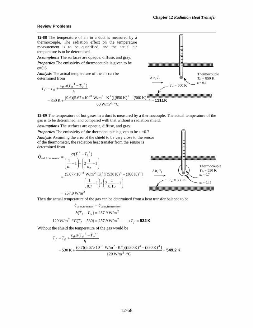
Chapter 12 Radiation Heat Transfer
12-68
Review Problems 12-88 The temperature of air in a duct is measured by a thermocouple. The radiation effect on the temperature measurement is to be quantified, and the actual air temperature is to be determined. Assumptions The surfaces are opaque, diffuse, and gray. Properties The emissivity of thermocouple is given to be ε=0.6. Analysis The actual temperature of the air can be determined from
K 1111=
°⋅
−⋅×+=
−σε+=
−
C W/m60])K 500()K 850)[(K W/m1067.5)(6.0(K 850
)(
2
44428
44
hTT
TT wthththf
12-89 The temperature of hot gases in a duct is measured by a thermocouple. The actual temperature of the gas is to be determined, and compared with that without a radiation shield. Assumptions The surfaces are opaque, diffuse, and gray. Properties The emissivity of the thermocouple is given to be ε =0.7. Analysis Assuming the area of the shield to be very close to the sensor of the thermometer, the radiation heat transfer from the sensor is determined from
2
4442821
42
41
sensor from rad,
W/m9.257
115.0121
7.01
])K 380()K 530)[(K W/m1067.5(
11211)(
=
⎟⎠⎞
⎜⎝⎛ −+⎟
⎠⎞
⎜⎝⎛ −
−⋅×=
⎟⎟⎠
⎞⎜⎜⎝
⎛−
ε+⎟⎟
⎠
⎞⎜⎜⎝
⎛−
ε
−σ=
−
TTQ&
Then the actual temperature of the gas can be determined from a heat transfer balance to be
K 532=⎯→⎯=−°⋅
=−
=
ff
thf
TT
TTh
22
2
sensor fromconv,sensor toconv,
W/m9.257)530C( W/m120
W/m9.257)(
&&
Without the shield the temperature of the gas would be
K 549.2=°⋅
−⋅×+=
−σε+=
−
C W/m120])K 380()K 530)[(K W/m1067.5)(7.0(K 530
)(
2
44428
44
hTT
TT wthththf
Air, Tf
Tw = 500 K
Thermocouple Tth = 850 K ε = 0.6
Air, Tf
Tw = 380 K
Thermocouple Tth = 530 K ε1 = 0.7 ε2 = 0.15

Chapter 12 Radiation Heat Transfer
12-69
12-90E A sealed electronic box is placed in a vacuum chamber. The highest temperature at which the surrounding surfaces must be kept if this box is cooled by radiation alone is to be determined. Assumptions 1 Steady operating conditions exist 2 The surfaces are opaque, diffuse, and gray. 3 Convection heat transfer is not considered. 4 Heat transfer from the bottom surface of the box is negligible. Properties The emissivity of the outer surface of the box is ε = 0.95. Analysis The total surface area is
2ft 67.3)11()12/18(4 =×+××=sA
Then the temperature of the surrounding surfaces is determined to be
F43°==⎯→⎯
−⋅×=×
−=−
R 503
])R 590)[(RBtu/h.ft 101714.0)(m 67.3)(95.0(Btu/h )41214.3100(
)(444282
44
surr
surr
surrssrad
T
T
TTAQ σε&
12-91 A double-walled spherical tank is used to store iced water. The air space between the two walls is evacuated. The rate of heat transfer to the iced water and the amount of ice that melts a 24-h period are to be determined. Assumptions 1 Steady operating conditions exist 2 The surfaces are opaque, diffuse, and gray. Properties The emissivities of both surfaces are given to be ε1 = ε2 = 0.15. Analysis (a) Assuming the conduction resistance s of the walls to be negligible, the rate of heat transfer to the iced water in the tank is determined to be
m m2A D1 12 22 01 12 69= = =π π( . ) .
W107.4=
⎟⎠⎞
⎜⎝⎛−
+
+−+⋅×=
⎟⎟⎠
⎞⎜⎜⎝
⎛εε−
+ε
−σ=
−
2
444282
2
2
1
2
2
1
41
421
12
04.201.2
15.015.01
15.01
])K 2730()K 27320)[(K W/m1067.5)(m 69.12(
11
)(
DD
TTAQ&
(b) The amount of heat transfer during a 24-hour period is
kJ 9275)s 360024)(kJ/s 1074.0( =×=Δ= tQQ &
The amount of ice that melts during this period then becomes
kg 27.8===⎯→⎯=kJ/kg 7.333
kJ 9275
ifif h
QmmhQ
D2 = 2.04 m T2 = 20°C ε2 = 0.15
D1 = 2.01 m T1 = 0°C ε1 = 0.15
Vacuum
Iced water 0°C
Tsurr
8 in 100 W ε = 0.95
Ts = 130°F
12 in 12 in
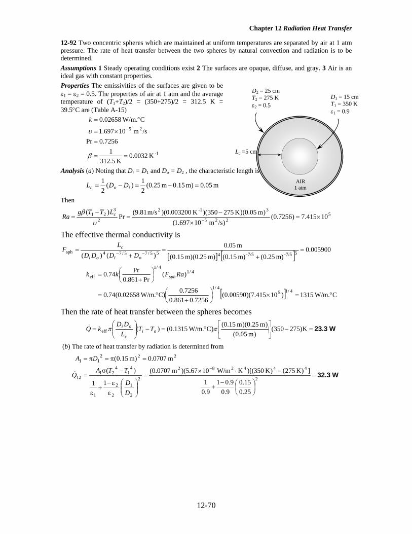
Chapter 12 Radiation Heat Transfer
12-70
12-92 Two concentric spheres which are maintained at uniform temperatures are separated by air at 1 atm pressure. The rate of heat transfer between the two spheres by natural convection and radiation is to be determined. Assumptions 1 Steady operating conditions exist 2 The surfaces are opaque, diffuse, and gray. 3 Air is an ideal gas with constant properties. Properties The emissivities of the surfaces are given to be ε1 = ε2 = 0.5. The properties of air at 1 atm and the average temperature of (T1+T2)/2 = (350+275)/2 = 312.5 K = 39.5°C are (Table A-15)
1-
25
K 0032.0K 5.312
17256.0Pr
/sm 10697.1
CW/m. 02658.0
==
=×=
°=−
β
υ
k
Analysis (a) Noting that Di = D1 and Do = D2 , the characteristic length is
m 0.05m) 0.15m 25.0(21)(
21
=−=−= ioc DDL
Then
5225
3-12
2
321 10415.7)7256.0(
)/sm 10697.1()m 05.0)(K 275350)(K 003200.0)(m/s 81.9(
Pr)(
×=×
−=
−= −υ
β cLTTgRa
The effective thermal conductivity is
[ ] [ ] 005900.0m) 25.0(m) 15.0(m) 25.0(m) 15.0(
m 05.0)()( 57/5-7/5-455/75/74sph =
+=
+=
−−oioi
c
DDDDL
F
[ ] CW/m. 1315)10415.7)(00590.0(7256.0861.0
7256.0C)W/m. 02658.0(74.0
)(Pr861.0
Pr74.0
4/154/1
4/14/1
eff
°=×⎟⎠⎞
⎜⎝⎛
+°=
⎟⎠⎞
⎜⎝⎛
+= RaFkk sph
Then the rate of heat transfer between the spheres becomes
W23.3=−⎥⎦
⎤⎢⎣
⎡°=−⎟⎟
⎠
⎞⎜⎜⎝
⎛= K)275350(
)m 05.0()m 25.0)(m 15.0(
)CW/m. 1315.0()(eff ππ oic
oi TTLDD
kQ&
(b) The rate of heat transfer by radiation is determined from
W32.3=
⎟⎠⎞
⎜⎝⎛−
+
−⋅×=
⎟⎟⎠
⎞⎜⎜⎝
⎛εε−
+ε
−σ=
=π=π=−
2
444282
2
2
1
2
2
1
41
421
12
22211
25.015.0
9.09.01
9.01
])K 275()K 350)[(K W/m1067.5)(m 0707.0(
11
)(
m 0707.0)m 15.0(
DD
TTAQ
DA
&
D2 = 25 cm T2 = 275 K ε2 = 0.5
D1 = 15 cm T1 = 350 K ε1 = 0.9
Lc =5 cm
AIR 1 atm

Chapter 12 Radiation Heat Transfer
12-71
12-93 A solar collector is considered. The absorber plate and the glass cover are maintained at uniform temperatures, and are separated by air. The rate of heat loss from the absorber plate by natural convection and radiation is to be determined. Assumptions 1 Steady operating conditions exist 2 The surfaces are opaque, diffuse, and gray. 3 Air is an ideal gas with constant properties. Properties The emissivities of surfaces are given to be ε1 = 0.9 for glass and ε2 = 0.8 for the absorber plate. The properties of air at 1 atm and the average temperature of (T1+T2)/2 = (80+32)/2 = 56°C are (Table A-15)
1-
25
K 003040.0K)27356(
117212.0Pr
/sm 10857.1
CW/m. 02779.0
=+
==
=×=
°=−
fT
k
β
υ
Analysis For θ = °0 , we have horizontal rectangular enclosure. The characteristic length in this case is the distance between the two glasses Lc = L = 0.03 m Then,
4225
3-12
2
321 10083.8)7212.0(
)/sm 10857.1()m 03.0)(K 3280)(K 00304.0)(m/s 81.9(
Pr)(
×=×
−=
−= −υ
β LTTgRa
2m 5.4m) 3(m) 5.1( ==×= WHAs
[ ] [ ]
747.3
118
)20cos()10083.8()20cos()10083.8(
)208.1sin(17081)20cos()10083.8(
1708144.11
118
)cosRa(cosRa
)8.1(sin17081cosRa
1708144.11Nu
3/14
4
6.1
4
3/16.1
=
⎥⎥⎦
⎤
⎢⎢⎣
⎡−
×+⎥
⎦
⎤⎢⎣
⎡
××
−⎥⎦
⎤⎢⎣
⎡
×−+=
⎥⎦
⎤⎢⎣
⎡−+⎥
⎦
⎤⎢⎣
⎡−⎥⎦
⎤⎢⎣⎡ −+=
++
++ θθθ
θ
W750=°−
°=−
=m 03.0
C)3280()m 5.4)(747.3)(CW/m. 02779.0( 221
LTT
kNuAQ s&
Neglecting the end effects, the rate of heat transfer by radiation is determined from
W1289=−+
+−+⋅×=
−+
−=
−
19.0
18.0
1])K 27332()K 27380)[(KW/m 1067.5)(m 5.4(
111)( 444282
21
42
41
rad
εε
σ TTAQ s&
Discussion The rates of heat loss by natural convection for the horizontal and vertical cases would be as follows (Note that the Ra number remains the same): Horizontal:
812.3118
)10083.8(10083.8
1708144.11118
RaRa
1708144.11Nu3/14
4
3/1=⎥
⎦
⎤⎢⎣
⎡−
×+⎥⎦
⎤⎢⎣⎡
×−+=⎥
⎦
⎤⎢⎣
⎡−+⎥⎦
⎤⎢⎣⎡ −+=
++++
W1017=°−
°=−
=m 03.0
C)3280()m 6)(812.3)(CW/m. 02779.0( 221
LTT
kNuAQ s&
Vertical:
001.2m 03.0
m 2)7212.0()10083.8(42.0Pr42.03.0
012.04/143.0
012.04/1 =⎟⎠⎞
⎜⎝⎛×=⎟
⎠⎞
⎜⎝⎛=
−−
LHRaNu
W534=°−
°=−
=m 03.0
C)3280()m 6)(001.2)(CW/m. 02779.0( 221
LTT
kNuAQ s&
Solar radiation
θ = 20° Insulation
Absorber plate T1 = 80°C ε1 = 0.8
Glass cover, T2 = 32°C ε2 = 0.9
1.5 m
L = 3 cm

Chapter 12 Radiation Heat Transfer
12-72
12-94E The circulating pump of a solar collector that consists of a horizontal tube and its glass cover fails. The equilibrium temperature of the tube is to be determined. Assumptions 1 Steady operating conditions exist. 2 The tube and its cover are isothermal. 3 Air is an ideal gas. 4 The surfaces are opaque, diffuse, and gray for infrared radiation. 5 The glass cover is transparent to solar radiation. Properties The properties of air should be evaluated at the average temperature. But we do not know the exit temperature of the air in the duct, and thus we cannot determine the bulk fluid and glass cover temperatures at this point, and thus we cannot evaluate the average temperatures. Therefore, we will assume the glass temperature to be 85°F, and use properties at an anticipated average temperature of (75+85)/2 =80°F (Table A-15E),
s
k
/ft 101.697/hft 6110.0
FftBtu/h 01481.024-2 ×==
°⋅⋅=
υ
R 54011
7290.0Pr
ave==
=
Tβ
Analysis We have a horizontal cylindrical enclosure filled with air at 0.5 atm pressure. The problem involves heat transfer from the aluminum tube to the glass cover and from the outer surface of the glass cover to the surrounding ambient air. When steady operation is reached, these two heat transfer rates must equal the rate of heat gain. That is,
Btu/h 30gainsolar ambient-glassglass-tube === QQQ &&& (per foot of tube) The heat transfer surface area of the glass cover is 2ft 309.1ft) 1)(ft 12/5()( ==== ππ WDAA oglasso (per foot of tube) To determine the Rayleigh number, we need to know the surface temperature of the glass, which is not available. Therefore, solution will require a trial-and-error approach. Assuming the glass cover temperature to be 85°F, the Rayleigh number, the Nusselt number, the convection heat transfer coefficient, and the rate of natural convection heat transfer from the glass cover to the ambient air are determined to be
6
224
32
2
3
10092.1)7290.0()/sft 10675.1(
)ft 12/5)(R 7585](R) 540/(1)[ft/s 2.32(
Pr)(
Ra
×=×
−=
−=
−
∞
νβ oo
DoDTTg
( )[ ] ( )[ ]95.14
7290.0/559.01
)10092.1(387.06.0
Pr/559.01
Ra 387.06.0Nu
2
27/816/9
6/162
27/816/9
1/6D
=
⎪⎭
⎪⎬⎫
⎪⎩
⎪⎨⎧
+
×+=
⎪⎭
⎪⎬⎫
⎪⎩
⎪⎨⎧
++=
FftBtu/h 5315.0)95.14(ft 12/5
FftBtu/h 01481.0Nu 2
0°⋅⋅=
°⋅⋅==
Dkho
Btu/h 96.6 F)7585)(ft 309.1)(FftBtu/h 5315.0()( 22conv, =°−°⋅⋅=−= ∞TTAhQ oooo
& Also,
[ ]Btu/h 5.30
R) 535(R) 545()ft 309.1)(RftBtu/h 101714.0)(9.0(
)(442428
4sky
4rad,
=−⋅⋅×=
−=−
TTAQ oooo σε&
Then the total rate of heat loss from the glass cover becomes
Btu/h 5.375.300.7rad,conv,total, =+=+= ooo QQQ &&&
D2 =5 in
Aluminum tube D1 =2.5 in, T1 ε1 = 0.9
Air space 0.5 atm
Plastic cover, ε2 = 0.9, T2
Water
T∞ = 75°F Tsky = 60°F
30 Btu/h.ft

Chapter 12 Radiation Heat Transfer
12-73
which is more than 30 Btu/h. Therefore, the assumed temperature of 85°F for the glass cover is high. Repeating the calculations with lower temperatures (including the evaluation of properties), the glass cover temperature corresponding to 30 Btu/h is determined to be 81.5°F.
The temperature of the aluminum tube is determined in a similar manner using the natural convection and radiation relations for two horizontal concentric cylinders. The characteristic length in this case is the distance between the two cylinders, which is
ft 1.25/12in 25.12/)5.25(2/)( ==−=−= ioc DDL Also, 2ft 6545.0ft) 1)(ft 12/5.2()( ==== ππ WDAA itubei (per foot of tube) We start the calculations by assuming the tube temperature to be 118.5°F, and thus an average temperature of (81.5+118.5)/2 = 100°F=640 R. Using properties at 100°F,
4224
32
2
3
10334.1)726.0()/sft 10809.1(
)ft 12/25.1)(R 5.815.118](R) 640/(1)[ft/s 2.32(Pr)(
Ra ×=×
−=
−= −ν
β LTTg oiL
The effective thermal conductivity is
1466.0]ft) 12/5(ft) 12/5.2[(ft) (1.25/12
)]5.2/5[ln()(
)]/[ln(53/5-3/5-3
4
55/35/33
4
cyc =+
=+
= −−oic
io
DDLDD
F
FftBtu/h 03227.0
)10334.11466.0(0.7260.861
0.726F)ftBtu/h 01529.0(386.0
)Ra(Pr861.0
Pr386.0
4/14
4/1cyc
4/1
eff
°⋅⋅=
××⎟⎠⎞
⎜⎝⎛
+°⋅⋅=
⎟⎠⎞
⎜⎝⎛
+= LFkk
Then the rate of heat transfer between the cylinders by convection becomes
Btu/h 8.10F)5.815.118(ln(5/2.5)
F)ftBtu/h 03227.0(2)()/ln(
2 effconv , =°−
°⋅⋅=−=
ππoi
ioi TT
DDk
Q&
Also, [ ]
Btu/h 0.25
in 5in 5.2
9.09.01
9.01
R) 5.541(R) 5.578()ft 6545.0)(RftBtu/h 101714.0(11
)( 442428
i
4o
4
rad, =⎟⎠⎞
⎜⎝⎛−
+
−⋅⋅×=
⎟⎟⎠
⎞⎜⎜⎝
⎛−+
−=
−
o
i
o
o
iii
DD
TTAQ
εε
ε
σ&
Then the total rate of heat loss from the glass cover becomes
Btu/h 8.350.258.10rad,conv,total, =+=+= iii QQQ &&&
which is more than 30 Btu/h. Therefore, the assumed temperature of 118.5°F for the tube is high. By trying other values, the tube temperature corresponding to 30 Btu/h is determined to be 113.2°F. Therefore, the tube will reach an equilibrium temperature of 113.2°F when the pump fails.

Chapter 12 Radiation Heat Transfer
12-74
12-95 A double-pane window consists of two sheets of glass separated by an air space. The rates of heat transfer through the window by natural convection and radiation are to be determined. Assumptions 1 Steady operating conditions exist 2 The surfaces are opaque, diffuse, and gray. 3 Air is an ideal gas with constant specific heats. 4 Heat transfer through the window is one-dimensional and the edge effects are negligible. Properties The emissivities of glass surfaces are given to be ε1 = ε2 = 0.9. The properties of air at 0.3 atm and the average temperature of (T1+T2)/2 = (15+5)/2 = 10°C are (Table A-15)
1-
2551
K 003534.0K )27310(
17336.0Pr
/sm 10753.4/0.310426.13.0/
CW/m. 02439.0
=+
=
=×=×==
°=−−
β
υυ atm
k
Analysis The characteristic length in this case is the distance between the glasses, m 05.0== LLc
4225
3-12
2
321 10918.1)7336.0(
)/sm 10753.4()m 05.0(K)515)(K 003534.0)(m/s 81.9(
Pr)(
×=×
−=
−= −υ
β LTTgRa
539.105.02)10918.1(197.0197.0
9/14/14
9/14/1 =⎟
⎠⎞
⎜⎝⎛×=⎟
⎠⎞
⎜⎝⎛=
−−
LHRaNu
2m 6)m 3)(m 2( ==sA
Then the rate of heat transfer by natural convection becomes
W45.0=°−
°=−
=m 05.0
C)515()m 6)(539.1)(CW/m. 02439.0( 221
LTT
kNuAQ sconv&
The rate of heat transfer by radiation is determined from
( ) ( )
W252=
−+
+−+⋅×=
−+
−=
−
19.0
19.0
1]K 2735K 27315)[KW/m 1067.5)(m 6(
111)(
44428221
42
41
rad
εε
σ TTAQ s&
Then the rate of total heat transfer becomes
W297=+=+= 25245radconvtotal QQQ &&&
Discussion Note that heat transfer through the window is mostly by radiation.
5°C 15°C L = 5 cm
H = 2 m
Q& Air

Chapter 12 Radiation Heat Transfer
12-75
12-96 A simple solar collector is built by placing a clear plastic tube around a garden hose. The rate of heat loss from the water in the hose by natural convection and radiation is to be determined. Assumptions 1 Steady operating conditions exist 2 The surfaces are opaque, diffuse, and gray. 3 Air is an ideal gas with constant specific heats. Properties The emissivities of surfaces are given to be ε1 = ε2 = 0.9. The properties of air are at 1 atm and the film temperature of (Ts+T∞)/2 = (40+25)/2 = 32.5°C are (Table A-15)
1-
25
K 003273.0K )2735.32(
17275.0Pr
/sm 10632.1
CW/m. 02607.0
=+
=
=×=
°=−
β
υ
k
Analysis Under steady conditions, the heat transfer rate from the water in the hose equals to the rate of heat loss from the clear plastic tube to the surroundings by natural convection and radiation. The characteristic length in this case is the diameter of the plastic tube,
m 06.02 === DDL plasticc .
5225
3-12
2
32 10842.2)7275.0(
)/sm 10632.1()m 06.0(K)2540)(K 003273.0)(m/s 81.9(
Pr)(
×=×
−=
−= −
∞
υβ DTTg
Ra s
( )[ ] ( )[ ] 30.10
7241.0/559.01
)10842.2(387.06.0Pr/559.01
Ra 387.06.0Nu
2
27/816/9
6/152
27/816/9
1/6D =
⎪⎭
⎪⎬⎫
⎪⎩
⎪⎨⎧
+
×+=
⎪⎭
⎪⎬⎫
⎪⎩
⎪⎨⎧
++=
2
22
2
2
m 1885.0m) m)(1 06.0(
C.W/m 475.4)30.10(m 06.0
CW/m. 02607.0
====
°=°
==
ππ LDAA
NuDkh
plastic
Then the rate of heat transfer from the outer surface by natural convection becomes
W12.7=°−°=−= ∞ C)2540)(m 1885.0)(C.W/m 475.4()( 222 TThAQ sconv
&
The rate of heat transfer by radiation from the outer surface is determined from
W26.2=
+−+⋅×=
−=− ]K) 27315()K 27340)[(KW/m 1067.5)(m 1885.0)(90.0(
)(444282
442rad skys TTAQ σε&
Finally,
W 9.382.267.12, =+=losstotalQ&
Discussion Note that heat transfer is mostly by radiation.
D2 =6 cm
Garden hose D1 =2 cm, T1 ε1 = 0.9
Air space
Plastic cover, ε2 = 0.9, T2 =40°C
Water
T∞ = 25°C Tsky = 15°C

Chapter 12 Radiation Heat Transfer
12-76
12-97 A solar collector consists of a horizontal copper tube enclosed in a concentric thin glass tube. The annular space between the copper and the glass tubes is filled with air at 1 atm. The rate of heat loss from the collector by natural convection and radiation is to be determined. Assumptions 1 Steady operating conditions exist 2 The surfaces are opaque, diffuse, and gray. 3 Air is an ideal gas with constant specific heats. Properties The emissivities of surfaces are given to be ε1 = 0.85 for the tube surface and ε2 = 0.9 for glass cover. The properties of air at 1 atm and the average temperature of (T1+T2)/2 = (60+40)/2 = 50°C are (Table A-15)
1-
25
K 003096.0K )27350(
17228.0Pr
/sm 10798.1
CW/m. 02735.0
=+
=
=×=
°=−
β
υ
k
Analysis The characteristic length in this case is
m 0.02=m) 0.05-m 09.0(21)(
21
12 =−= DDLc
850,10)7228.0()/sm 10798.1(
)m 02.0(K)4060)(K 003096.0)(m/s 81.9(Pr
)(225
3-12
2
321 =
×−
=−
= −υβ cLTTg
Ra
The effective thermal conductivity is
[ ] [ ]
[ ] 1303.0m) 05.0(m) 09.0(m) 02.0(
)05.0/09.0ln()(
)/ln(53/5-3/5-3
4
55/35/33
4
cyl =+
=+
=−−
oic
io
DDLDD
F
[ ] CW/m. 05321.0)850,10)(1303.0(7228.0861.0
7228.0)CW/m. 02735.0(386.0
)Ra(Pr861.0
Pr386.0
4/14/1
4/1cyl
4/1
eff
°=⎟⎠⎞
⎜⎝⎛
+°=
⎟⎠⎞
⎜⎝⎛
+= Fkk
Then the rate of heat transfer between the cylinders becomes
W11.4=°−°
=−= C)4060()05.0/09.0ln(
)CW/m. 05321.0(2)()/ln(
2 effconv
ππoi
ioTT
DDk
Q& (Eq. 1)
The rate of heat transfer by radiation is determined from
W13.4=
⎟⎠⎞
⎜⎝⎛−
+
+−+⋅×=
⎟⎟⎠
⎞⎜⎜⎝
⎛−+
−=
−
95
9.09.01
85.01
])K 27340()K 27360)[(KW/m 1067.5)(m 1571.0(
11)(
4442822
1
2
2
1
42
411
rad
DD
TTAQ
εε
ε
σ&
Finally,
W 8.244.134.11, =+=losstotalQ& (per m length)
D2 =9 cm
Copper tube D1 =5 cm, T1 = 60°Cε1 = 0.85
Air space
Plastic cover, T2 = 40°C ε2 = 0.9
Water

Chapter 12 Radiation Heat Transfer
12-77
12-98 A cylindrical furnace with specified top and bottom surface temperatures and specified heat transfer rate at the bottom surface is considered. The temperature of the side surface and the net rates of heat transfer between the top and the bottom surfaces, and between the bottom and the side surfaces are to be determined. Assumptions 1 Steady operating conditions exist 2 The surfaces are opaque, diffuse, and gray. 3 Convection heat transfer is not considered. Properties The emissivities of the top, bottom, and side surfaces are 0.70, 0.50, and 0.40, respectively. Analysis We consider the top surface to be surface 1, the bottom surface to be surface 2, and the side surface to be surface 3. This system is a three-surface enclosure. The view factor from surface 1 to surface 2 is determined from
17.05.0
2.16.0
26.02.1
12 =
⎪⎪⎭
⎪⎪⎬
⎫
==
==F
LrrL
(Fig. 12-7)
The surface areas are
2
3
22221
m 524.4)m 2.1)(m 2.1(
m 131.14/)m 2.1(4/
===
====
ππ
ππ
DLA
DAA
Then other view factors are determined to be 17.02112 == FF
83.0117.001 1313131211 =⎯→⎯=++⎯→⎯=++ FFFFF (summation rule), 83.01323 == FF
21.0)524.4()83.0)(131.1( 3131313131 =⎯→⎯=⎯→⎯= FFFAFA (reciprocity rule), 21.03132 == FF We now apply Eq. 12-35 to each surface
Surface 1: [ ]
[ ])(83.0)(17.070.0
70.01)K 500)(K.W/m 1067.5(
)()(1
312114428
311321121
11
41
JJJJJ
JJFJJFJT
−+−−
+=×
−+−−
+=
−
εε
σ
Surface 2: [ ]
[ ])(83.0)(17.050.0
50.01)K 500)(K.W/m 1067.5(
)()(1
321224428
322312212
22
42
JJJJJ
JJFJJFJT
−+−−
+=×
−+−−
+=
−
εε
σ
Surface 3: [ ]
[ ])(21.0)(21.040.0
40.01)K.W/m 1067.5(
)()(1
312134
3428
233213313
33
43
JJJJJT
JJFJJFJT
−+−−
+=×
−+−−
+=
−
εε
σ
We now apply Eq. 12-34 to surface 2 [ ] [ ])(83.0)(17.0)m 131.1()()( 3212
23223122122 JJJJJJFJJFAQ −+−=−+−=&
Solving the above four equations, we find 2
32
22
13 W/m 8193 ,W/m 8883 ,W/m 4974 , ==== JJJT K 631 The rate of heat transfer between the bottom and the top surface is W751.6=−=−= 22
1221221 W/m)49748883)(17.0)(m 131.1()( JJFAQ& The rate of heat transfer between the bottom and the side surface is W644.0=−=−= 22
3223223 W/m)81978883)(83.0)(m 131.1()( JJFAQ& Discussion The sum of these two heat transfer rates are 751.6 + 644 = 1395.6 W, which is practically equal to 1400 W heat supply rate from surface 2. This must be satisfied to maintain the surfaces at the specified temperatures under steady operation. Note that the difference is due to round-off error.
T1 = 500 K ε1 = 0.70 r1 = 0.6 m
T3 = ? ε3 = 0.40
h = 1.2 m
T2 = 650 K ε2 = 0.50 r2 = 0.6 m

Chapter 12 Radiation Heat Transfer
12-78
12-99 A cylindrical furnace with specified top and bottom surface temperatures and specified heat transfer rate at the bottom surface is considered. The emissivity of the top surface and the net rates of heat transfer between the top and the bottom surfaces, and between the bottom and the side surfaces are to be determined. Assumptions 1 Steady operating conditions exist 2 The surfaces are opaque, diffuse, and gray. 3 Convection heat transfer is not considered. Properties The emissivity of the bottom surface is 0.90. Analysis We consider the top surface to be surface 1, the base surface to be surface 2, and the side surface to be surface 3. This system is a three-surface enclosure. The view factor from the base to the top surface of the cube is F12 0 2= . . The view factor from the base or the top to the side surfaces is determined by applying the summation rule to be
F F F F F11 12 13 13 121 1 1 0 2 0 8+ + = ⎯ →⎯ = − = − =. .
since the base surface is flat and thus F11 0= . Other view factors are 20.0 ,80.0 ,20.0 323113231221 ====== FFFFFF We now apply Eq. 9-35 to each surface
Surface 1: [ ]
[ ])(80.0)(20.01
)K 700)(K.W/m 1067.5(
)()(1
31211
11
4428
311321121
11
41
JJJJJ
JJFJJFJT
−+−−
+=×
−+−−
+=
−
εε
εε
σ
Surface 2: [ ]
[ ])(80.0)(20.090.0
90.01)K 950)(K.W/m 1067.5(
)()(1
321224428
322312212
22
42
JJJJJ
JJFJJFJT
−+−−
+=×
−+−−
+=
−
εε
σ
Surface 3: 3
44283
43
)K 450)(K.W/m 1067.5(
J
JT
=×
=−
σ
We now apply Eq. 9-34 to surface 2
[ ] [ ])(80.0)(20.0)m 9()()( 32122
3223122122 JJJJJJFJJFAQ −+−=−+−=& Solving the above four equations, we find
23
22
211 W/m 2325 ,W/m 985,41 ,W/m 736,11 , ==== JJJ0.44ε
The rate of heat transfer between the bottom and the top surface is
2221 m 9)m 3( === AA
kW 54.4=−=−= 221221221 W/m)736,11985,41)(20.0)(m 9()( JJFAQ&
The rate of heat transfer between the bottom and the side surface is
2213 m 36)m 9(44 === AA
kW 285.6=−=−= 223223223 W/m)2325985,41)(8.0)(m 9()( JJFAQ&
Discussion The sum of these two heat transfer rates are 54.4 + 285.6 = 340 kW, which is equal to 340 kW heat supply rate from surface 2.
T1 = 700 K ε1 = ?
T2 = 950 K ε2 = 0.90
T3 = 450 K ε3 = 1
3 m

Chapter 12 Radiation Heat Transfer
12-79
12-100 A thin aluminum sheet is placed between two very large parallel plates that are maintained at uniform temperatures. The net rate of radiation heat transfer between the plates and the temperature of the radiation shield are to be determined. Assumptions 1 Steady operating conditions exist 2 The surfaces are opaque, diffuse, and gray. 3 Convection heat transfer is not considered. Properties The emissivities of surfaces are given to be ε1 = 0.8, ε2 = 0.9, and ε3 = 0.12. Analysis The net rate of radiation heat transfer with a thin aluminum shield per unit area of the plates is
2 W/m748.9=
⎟⎠⎞
⎜⎝⎛ −++⎟
⎠⎞
⎜⎝⎛ −+
−⋅×=
⎟⎟⎠
⎞⎜⎜⎝
⎛−
ε+
ε+⎟⎟
⎠
⎞⎜⎜⎝
⎛−
ε+
ε
−σ=
−
112.01
12.011
9.01
8.01
])K 550()K 750)[(K W/m1067.5(
111111
)(
44428
2,31,321
42
41
shield one,12TT
Q&
The equilibrium temperature of the radiation shield is determined from
K 671.3=⎯→⎯⎟⎠⎞
⎜⎝⎛ −+
−⋅×=
⎟⎟⎠
⎞⎜⎜⎝
⎛−
ε+
ε
−σ=
−
3
43
44282
31
43
41
13
112.01
8.01
])K 750)[(K W/m1067.5( W/m9.748
111
)(
TT
TTQ&
T2 = 550 K ε2 = 0.9
T1 = 750 K ε1 = 0.8
Radiation shieldε3 = 0.12

Chapter 12 Radiation Heat Transfer
12-80
12-101 Two thin radiation shields are placed between two large parallel plates that are maintained at uniform temperatures. The net rate of radiation heat transfer between the plates with and without the shields, and the temperatures of radiation shields are to be determined. Assumptions 1 Steady operating conditions exist 2 The surfaces are opaque, diffuse, and gray. 3 Convection heat transfer is not considered. Properties The emissivities of surfaces are given to be ε1 = 0.6, ε2 = 0.7, ε3 = 0.10, and ε4 = 0.15. Analysis The net rate of radiation heat transfer without the shields per unit area of the plates is
2 W/m3288=
−+
−⋅×=
−ε
+ε
−σ=
−
17.0
16.0
1])K 300()K 600)[(K W/m1067.5(
111)(
4442821
42
41
shield no12,TT
Q&
The net rate of radiation heat transfer with two thin radiation shields per unit area of the plates is
2 W/m206=
⎟⎠⎞
⎜⎝⎛ −++⎟
⎠⎞
⎜⎝⎛ −++⎟
⎠⎞
⎜⎝⎛ −+
−⋅×=
⎟⎟⎠
⎞⎜⎜⎝
⎛−
ε+
ε+⎟⎟
⎠
⎞⎜⎜⎝
⎛−
ε+
ε+⎟⎟
⎠
⎞⎜⎜⎝
⎛−
ε+
ε
−σ=
−
−
115.01
15.011
10.01
10.011
7.01
6.01
])K 300()K 600)[(K W/m1067.5(
111111111)(
44428443321
42
41
shieldstwo12,TT
Q&
The equilibrium temperatures of the radiation shields are determined from
K 549=⎯→⎯⎟⎠⎞
⎜⎝⎛ −+
−⋅×=
⎟⎟⎠
⎞⎜⎜⎝
⎛−
ε+
ε
−σ=
−
3
43
44282
31
43
41
13
110.01
6.01
])K 600)[(K W/m1067.5( W/m206
111
)(
TT
TTQ&
K 429=⎯→⎯⎟⎠⎞
⎜⎝⎛ −+
−⋅×=
⎟⎟⎠
⎞⎜⎜⎝
⎛−
ε+
ε
−σ=
−
4
444
4282
24
42
44
42
17.0
115.01
])K 300()[K W/m1067.5( W/m206
111)(
TT
TTQ&
T2 = 300 K ε2 = 0.7
T1 = 600 K ε1 = 0.6
ε3 = 0.10
ε4 = 0.15

Chapter 12 Radiation Heat Transfer
12-81
12-102 Combustion gases flow inside a tube in a boiler. The rates of heat transfer by convection and radiation and the rate of evaporation of water are to be determined. Assumptions 1 Steady operating conditions exist. 2 The inner surfaces of the duct are smooth. 3 Combustion gases are assumed to have the properties of air, which is an ideal gas with constant properties. Properties The properties of air at 1200 K = 927°C and 1 atm are (Table A-15)
/sm 10586.1
C W/m.07574.0kg/m 2944.0
25-
3
×=υ
°==ρ
k 7221.0Pr
CJ/kg. 1173
=
°=pC
Analysis (a) The Reynolds number is
373,28/sm 10586.1
m) m/s)(0.15 (3Re25
=×
=υ
=−
DmV
which is greater than 10,000. Therefore, the flow is turbulent and the entry lengths in this case are roughly
m 5.1m) 15.0(1010 ==≈≈ DLL th
which is much shorter than the total length of the duct. Therefore, we can assume fully developed turbulent flow in the entire duct, and determine the Nusselt number from
14.76)7221.0()373,28(023.0PrRe023.0 3.08.03.08.0 ====k
hDNu h
Heat transfer coefficient is
C. W/m45.38)14.76(m 15.0
C W/m.07574.0 2 °=°
== NuDkh
Next we determine the exit temperature of air
kg/s0.01561=)m 67m/s)(0.017 )(3 kg/m2944.0(
m 0.01767=/4m) 15.0(4/
m 2.827=m) m)(6 15.0(
23
222
2
==
==
==
c
c
VAm
DA
DLA
ρ
ππ
ππ
&
C107.2)927105(105)( )1173)(01561.0()827.2)(45.38(
)/( °=−−=−−=−
− eeTTTT pCmhAisse
&
Then the rate of heat transfer by convection becomes
W15,010=°−°=−= C)2.107927)(CJ/kg. 3 kg/s)(11701561.0()(conv eip TTCmQ &&
Next, we determine the emissivity of combustion gases. First, the mean beam length for an infinite circular cylinder is, from Table 12-4, L = 0.95(0.15 m) = 0.1425 m Then,
atmft 0.075atmm 0228.0m) 5atm)(0.142 16.0(atmft .0370atmm 0114.0m) 5atm)(0.142 08.0(⋅=⋅==⋅=⋅==
LPLP
w
c
The emissivities of CO2 and H2O corresponding to these values at the average gas temperature of Tg=(Tg+Tg)/2 = (927+107.2)/2 = 517.1°C = 790 K and 1atm are, from Fig. 12-36,
055.0atm 1 , =ε c and 062.0atm 1 , =εw
Both CO2 and H2O are present in the same mixture, and we need to correct for the overlap of emission bands. The emissivity correction factor at T = Tg = 800 K is, from Fig. 12-38,
0.0 67.008.016.0
16.0 112.0075.0037.0
=εΔ⎪⎭
⎪⎬⎫
=+
=+
=+=+
cw
w
wc
PPP
LPLP
Ts = 105°C
D = 15 cm
Combustion gases, 1 atm Ti = 1200 K
3 m/s

Chapter 12 Radiation Heat Transfer
12-82
Then the effective emissivity of the combustion gases becomes 0.1170.0062.01055.01atm 1 ,atm 1 , =−×+×=εΔ−ε+ε=ε wwccg CC
Note that the pressure correction factor is 1 for both gases since the total pressure is 1 atm. For a source temperature of Ts = 105°C = 378 K, the absorptivity of the gas is again determined using the emissivity charts as follows:
atmft 0.036atmm 0109.0K 790K 378m) 5atm)(0.142 16.0(
atmft 0.018atmm 00545.0K 790K 378m) 5atm)(0.142 08.0(
⋅=⋅==
⋅=⋅==
g
sw
g
sc
TT
LP
TT
LP
The emissivities of CO2 and H2O corresponding to these values at a temperature of Ts = 378 K and 1atm are, from Fig. 12-36,
037.0atm 1 , =ε c and 062.0atm 1 , =εw
Then the absorptivities of CO2 and H2O become
0864.0)062.0(K 378K 790)1(
0597.0)037.0(K 378K 790)1(
45.0
atm 1 ,
45.0
65.0
atm 1 ,
65.0
=⎟⎠⎞
⎜⎝⎛=ε⎟
⎟⎠
⎞⎜⎜⎝
⎛=α
=⎟⎠⎞
⎜⎝⎛=ε⎟
⎟⎠
⎞⎜⎜⎝
⎛=α
ws
gww
cs
gcc
TT
C
TT
C
Also Δα = Δε, but the emissivity correction factor is to be evaluated from Fig. 12-38 at T = Ts = 378 K instead of Tg = 790 K. We use the chart for 400 K. At Pw/(Pw+ Pc) = 0.67 and PcL +PwL = 0.112 we read Δε = 0.0. Then the absorptivity of the combustion gases becomes
0.1460.00864.00597.0 =−+=αΔ−α+α=α wcg
The emissivity of the inner surface s of the tubes is 0.9. Then the net rate of radiation heat transfer from the combustion gases to the walls of the tube becomes
W6486=
−⋅×+
=
α−εσ+ε
=
− ])K 378(146.0)K 790(117.0)[K W/m1067.5)(m 827.2(2
19.0
)(2
1
444282
44rad sgggs
s TTAQ&
(b) The heat of vaporization of water at 1 atm is 2257 kJ/kg (Table A-9). Then rate of evaporation of water becomes
kg/s 0.0644=×
+=
+=⎯→⎯=+
J/kg 107.333 W)6486010,15(
3radconv
evapevapradconvfg
fg hQQ
mhmQQ&&
&&&&

Chapter 12 Radiation Heat Transfer
12-83
12-103 Combustion gases flow inside a tube in a boiler. The rates of heat transfer by convection and radiation and the rate of evaporation of water are to be determined. Assumptions 1 Steady operating conditions exist. 2 The inner surfaces of the duct are smooth. 3 Combustion gases are assumed to have the properties of air, which is an ideal gas with constant properties. Properties The properties of air at 1200 K = 927°C and 3 atm are (Table A-15)
/sm 105287.0
/s)/3m 10586.1(
C W/m.07574.0kg/m 2944.0
25-
25-
3
×=
×=υ
°==ρ
k
7221.0Pr
CJ/kg. 1173
=
°=pC
Analysis (a) The Reynolds number is
114,85/sm 105287.0
m) m/s)(0.15 (3Re25
=×
=υ
=−
DmV
which is greater than 10,000. Therefore, the flow is turbulent and the entry lengths in this case are roughly
m 5.1m) 15.0(1010 ==≈≈ DLL th which is much shorter than the total length of the duct. Therefore, we can assume fully developed turbulent flow in the entire duct, and determine the Nusselt number from
4.183)7221.0()114,85(023.0PrRe023.0 3.08.03.08.0 ====k
hDNu h
Heat transfer coefficient is
C. W/m59.92)4.183(m 15.0
C W/m.07574.0 2 °=°
== NuDkh
Next we determine the exit temperature of air
kg/s0.01561=)m 67m/s)(0.017 )(3 kg/m2944.0(
m 0.01767=/4m) 15.0(4/
m 2.827=m) m)(6 15.0(
23
222
2
==
==
==
c
c
VAm
DA
DLA
ρ
ππ
ππ
&
C105.0)927105(105)( )1173)(01561.0()827.2)(59.92(
)/( °=−−=−−=−
− eeTTTT pCmhAisse
& Then the rate of heat transfer by convection becomes W15,050=°−°=−= C)0.105927)(CJ/kg. kg/s)(1173 01561.0()(conv eip TTCmQ &&
Next, we determine the emissivity of combustion gases. First, the mean beam length for an infinite circular cylinder is, from Table 12-4, L = 0.95(0.15 m) = 0.1425 m
Then, atmft 0.075atmm 0228.0m) 5atm)(0.142 16.0(atmft .0370atmm 0114.0m) 5atm)(0.142 08.0(⋅=⋅==⋅=⋅==
LPLP
w
c
The emissivities of CO2 and H2O corresponding to these values at the average gas temperature of Tg=(Tg+Tg)/2 = (927+105)/2 = 516°C = 790 K and 1atm are, from Fig. 12-36,
055.0atm 1 , =ε c and 062.0atm 1 , =εw These are the base emissivity values at 1 atm, and they need to be corrected for the 3 atm total pressure. Noting that (Pw+P)/2 = (0.16+3)/2 = 1.58 atm, the pressure correction factors are, from Fig. 12-37, Cc = 1.5 and Cw = 1.8 Both CO2 and H2O are present in the same mixture, and we need to correct for the overlap of emission bands. The emissivity correction factor at T = Tg = 800 K is, from Fig. 12-38,
0.0 67.008.016.0
16.0 112.0075.0037.0
=εΔ⎪⎭
⎪⎬⎫
=+
=+
=+=+
cw
w
wc
PPP
LPLP
Then the effective emissivity of the combustion gases becomes
Ts = 105°C
D = 15 cm
Combustion gases, 3 atm Ti = 1200 K
3 m/s

Chapter 12 Radiation Heat Transfer
12-84
0.1940.0062.08.1055.05.1atm 1 ,atm 1 , =−×+×=εΔ−ε+ε=ε wwccg CC
For a source temperature of Ts = 105°C = 378 K, the absorptivity of the gas is again determined using the emissivity charts as follows:
atmft 0.036atmm 0109.0K 790K 378m) 5atm)(0.142 16.0(
atmft 0.018atmm 00545.0K 790K 378m) 5atm)(0.142 08.0(
⋅=⋅==
⋅=⋅==
g
sw
g
sc
TT
LP
TT
LP
The emissivities of CO2 and H2O corresponding to these values at a temperature of Ts = 378 K and 1atm are, from Fig. 12-36,
037.0atm 1 , =ε c and 062.0atm 1 , =εw Then the absorptivities of CO2 and H2O become
1555.0)062.0(K 378K 790)8.1(
0896.0)037.0(K 378K 790)5.1(
45.0
atm 1 ,
45.0
65.0
atm 1 ,
65.0
=⎟⎠⎞
⎜⎝⎛=ε⎟
⎟⎠
⎞⎜⎜⎝
⎛=α
=⎟⎠⎞
⎜⎝⎛=ε⎟
⎟⎠
⎞⎜⎜⎝
⎛=α
ws
gww
cs
gcc
TT
C
TT
C
Also Δα = Δε, but the emissivity correction factor is to be evaluated from Fig. 12-38 at T = Ts = 378 K instead of Tg = 790 K. We use the chart for 400 K. At Pw/(Pw+ Pc) = 0.67 and PcL +PwL = 0.112 we read Δε = 0.0. Then the absorptivity of the combustion gases becomes
0.2450.01555.00896.0 =−+=αΔ−α+α=α wcg
The emissivity of the inner surfaces of the tubes is 0.9. Then the net rate of radiation heat transfer from the combustion gases to the walls of the tube becomes
W10,745=
−⋅×+
=
α−εσ+ε
=
− ])K 378(245.0)K 790(194.0)[K W/m1067.5)(m 827.2(2
19.0
)(2
1
444282
44rad sgggs
s TTAQ&
(b) The heat of vaporization of water at 1 atm is 2257 kJ/kg (Table A-9). Then rate of evaporation of water becomes
kg/s 0.0773=×
+=
+=⎯→⎯=+
J/kg 107.333 W)745,10050,15(
3radconv
evapevapradconvfg
fg hQQ
mhmQQ&&
&&&&
12-104 ….. 12-106 Design and Essay Problems