
1 Heat Transfer Operations
55
Heat Exchangers
-
Upload
independent -
Category
Documents
-
view
0 -
download
0
Transcript of 1 Heat Transfer Operations
Heat Exchangers
Outline
Heat Transfer OperationsClassification of Heat Exchanging EquipmentsBasic Design Methods of Heat ExchangersFouling of Heat ExchangersHeat Exchangers Design Calculations and Methodology
Rating of Heat ExchangersHeat Transfer in Selected Chemical ApparatusIntensification of Heat Transfer
The Effectiveness- NTU Method for HE Analysis
3
The LMTD method is used for heat exchanger analysis when the fluid inlet temperatures are known and the outlet temperatures are specified or readily determined from the energy balance expressions.
The value ΔTlm for the HE may then be determined.
However, if only the inlet temperatures are known, use of the LMTD method requires an iterative procedure.
In such case it is preferable to use an alternative approach, termed as the effectiveness NTU method.
The Effectiveness- NTU Method for HE Analysis
4
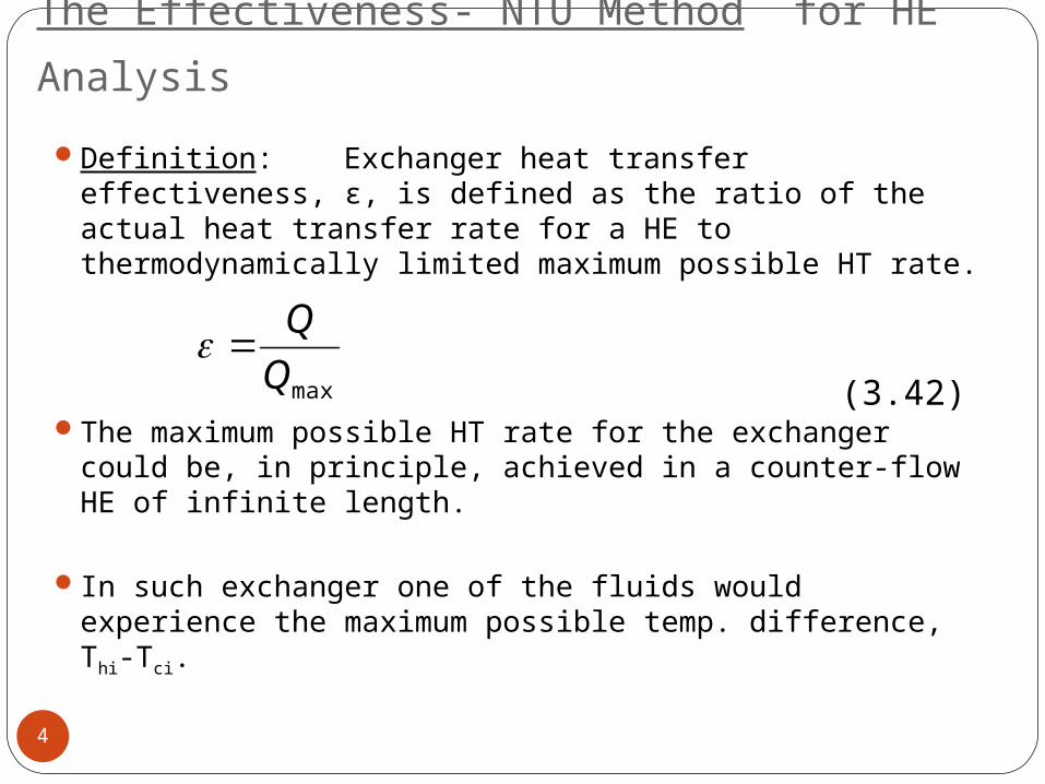
Definition: Exchanger heat transfer effectiveness, ε, is defined as the ratio of the actual heat transfer rate for a HE to thermodynamically limited maximum possible HT rate.
The maximum possible HT rate for the exchanger could be, in principle, achieved in a counter-flow HE of infinite length.
In such exchanger one of the fluids would experience the maximum possible temp. difference, Thi-Tci.
maxQQ
(3.42)
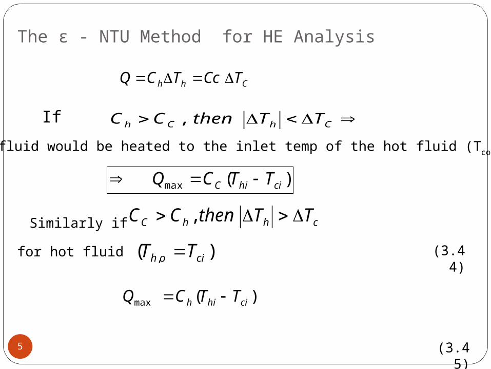
The ε - NTU Method for HE Analysis
5
Chh TCcTCQ
ChCh TTthenCC ,
)(max cihiC TTCQ
chhC TTthenCC ,)( , cioh TT
)(max cihih TTCQ
(3.43)
the cold fluid would be heated to the inlet temp of the hot fluid (Tco = Thi).
(3.44)
Similarly if
(3.45)
If
for hot fluid
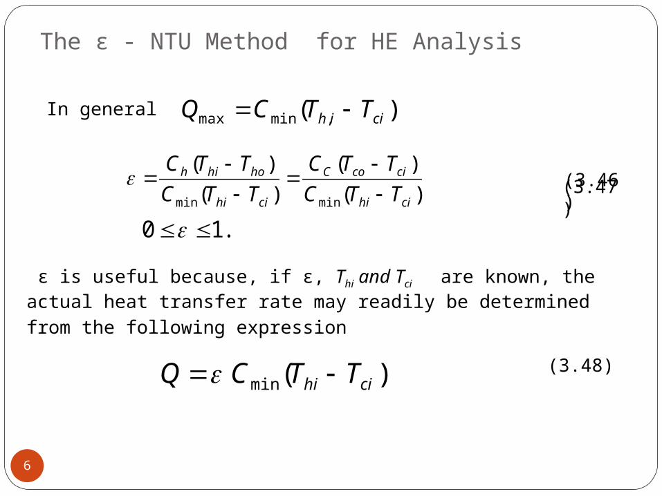
The ε - NTU Method for HE Analysis
6
)(min cihi TTCQ
)( ,minmax ciih TTCQ
)()(
)()(
minmin cihi
cicoC
cihi
hohih
TTCTTC
TTCTTC
.10
In general
(3.46)
(3.47)
ε is useful because, if ε, Thi and Tci are known, the actual heat transfer rate may readily be determined from the following expression
(3.48)
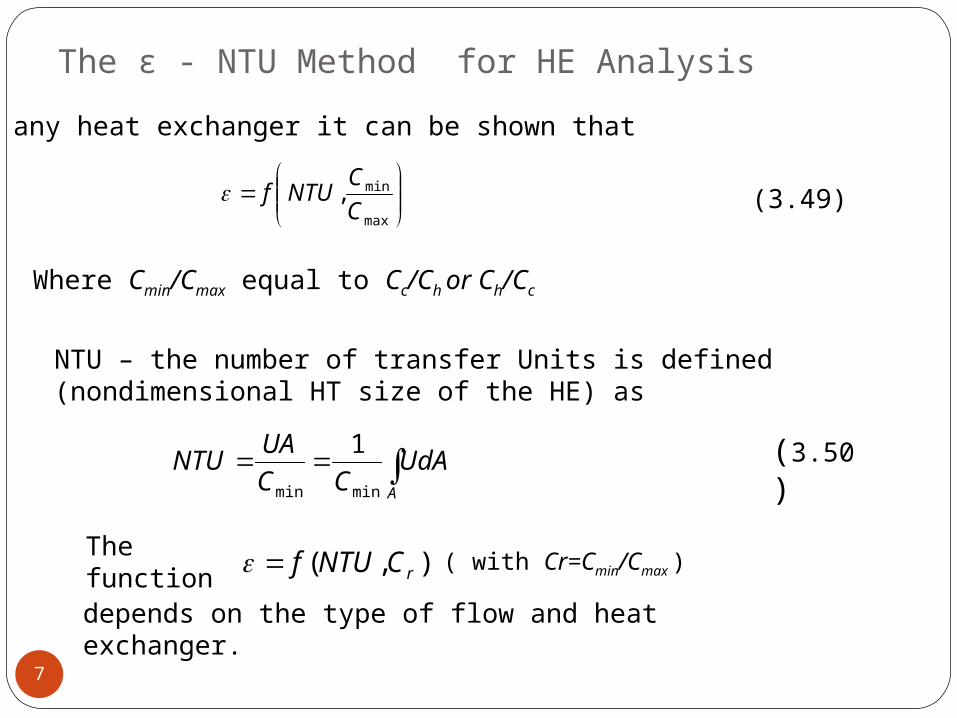
The ε - NTU Method for HE Analysis
7
max
min,CCNTUf
A
UdACC
UANTUminmin
1
),( rCNTUf
NTU – the number of transfer Units is defined (nondimensional HT size of the HE) as
The function depends on the type of flow and heat exchanger.
(3.50)
For any heat exchanger it can be shown that
Where Cmin/Cmax equal to Cc/Ch or Ch/Cc
(3.49)
( with Cr=Cmin/Cmax )
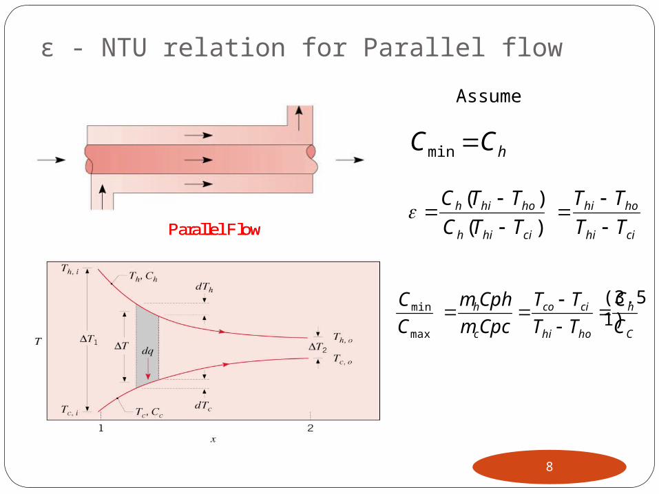
ε - NTU relation for Parallel flow
8
Parallel Flow CounterflowParallel Flow Counterflow
Assume
hCC min
cihi
hohi
cihih
hohih
TTTT
TTCTTC
)()(
C
h
hohi
cico
c
h
CC
TTTT
CpcmCphm
CC
max
min
(3.51)
(3.52)
ε - NTU relation for Parallel flow
9 cihi
coho
TTTT
(3.54)
Chcihi
coho
CCUA
TTTTn 11
)1(1max
min
minrCNTU
CC
CUA
)1(exp rcihi
coho CNTUTTTT
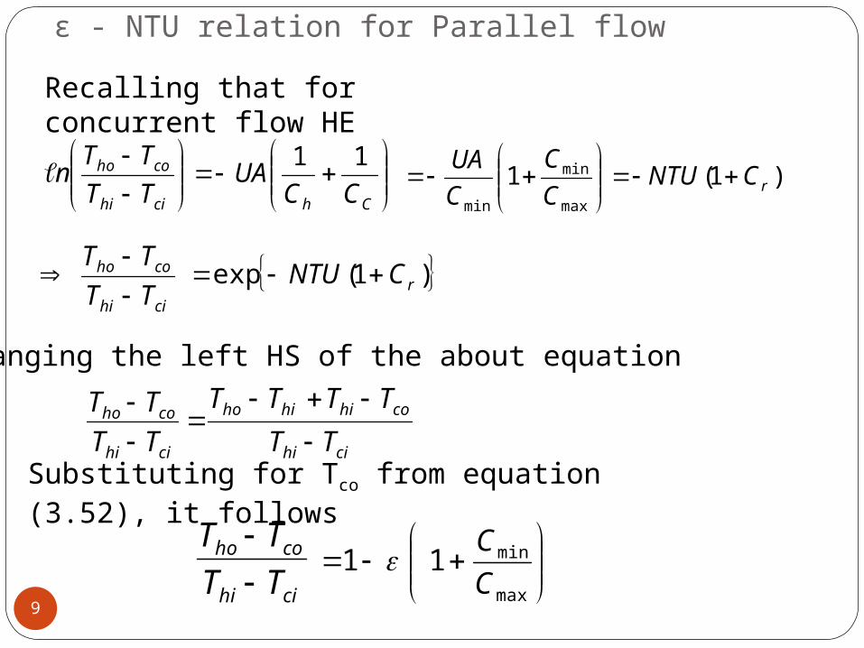
Recalling that for concurrent flow HE (3.53)
Rearranging the left HS of the about equation
cihi
cohihiho
cihi
coho
TTTTTT
TTTT
(3.55)Substituting for Tco from equation (3.52), it follows
max
min11CC
(3.56)
ε - NTU relation for Parallel flow
10
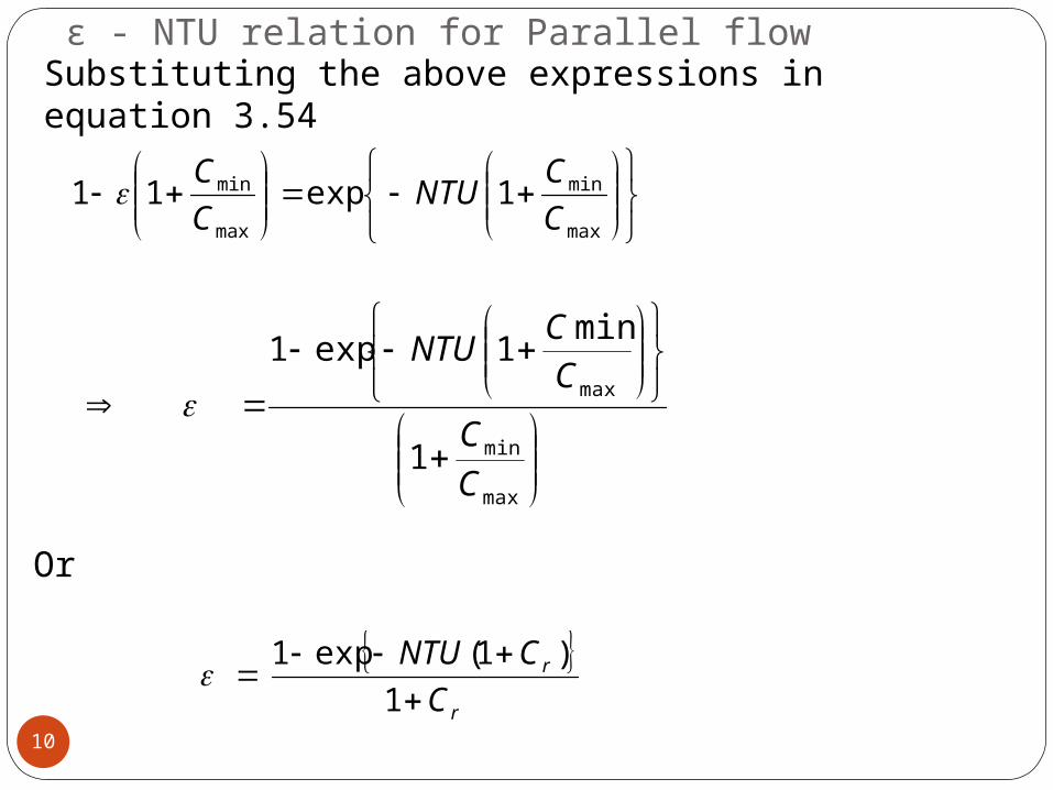
Substituting the above expressions in equation 3.54
(3.56)
Or
(3.57)
max
min
max
min 1exp11CCNTU
CC
max
min
max
1
min1exp1
CC
CCNTU
r
r
CCNTU
1)1(exp1
ε - NTU relation
11
NTU exp1
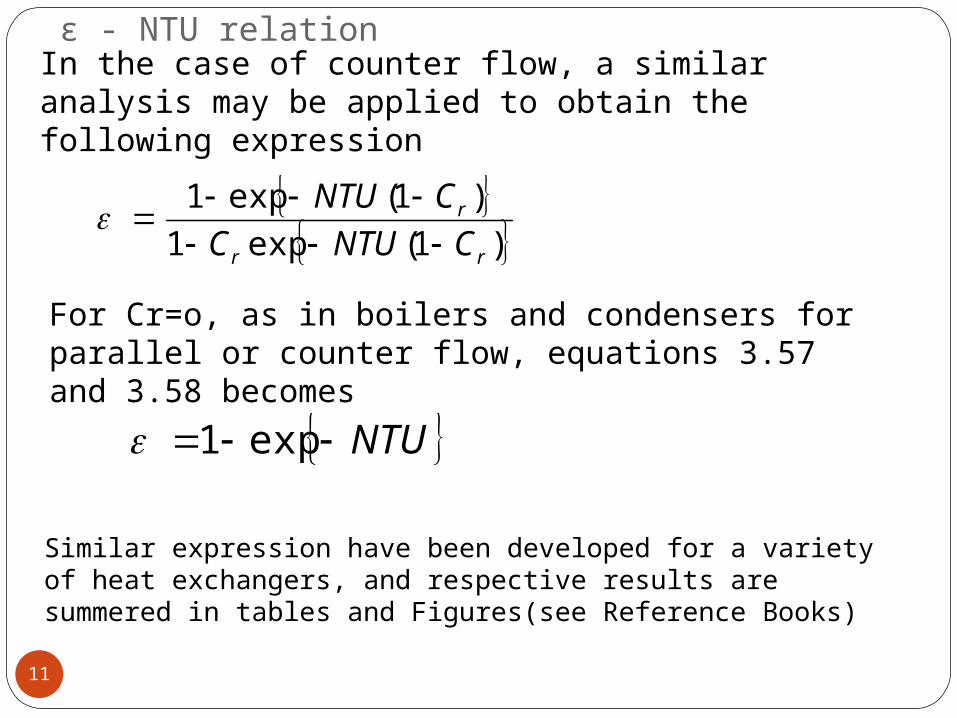
In the case of counter flow, a similar analysis may be applied to obtain the following expression
(3.58)
(3.59)
)1(exp1
)1(exp1rr
r
CNTUCCNTU
For Cr=o, as in boilers and condensers for parallel or counter flow, equations 3.57 and 3.58 becomes
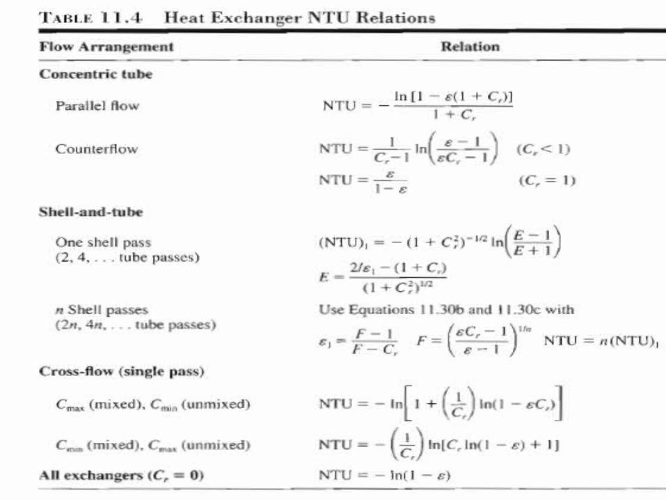
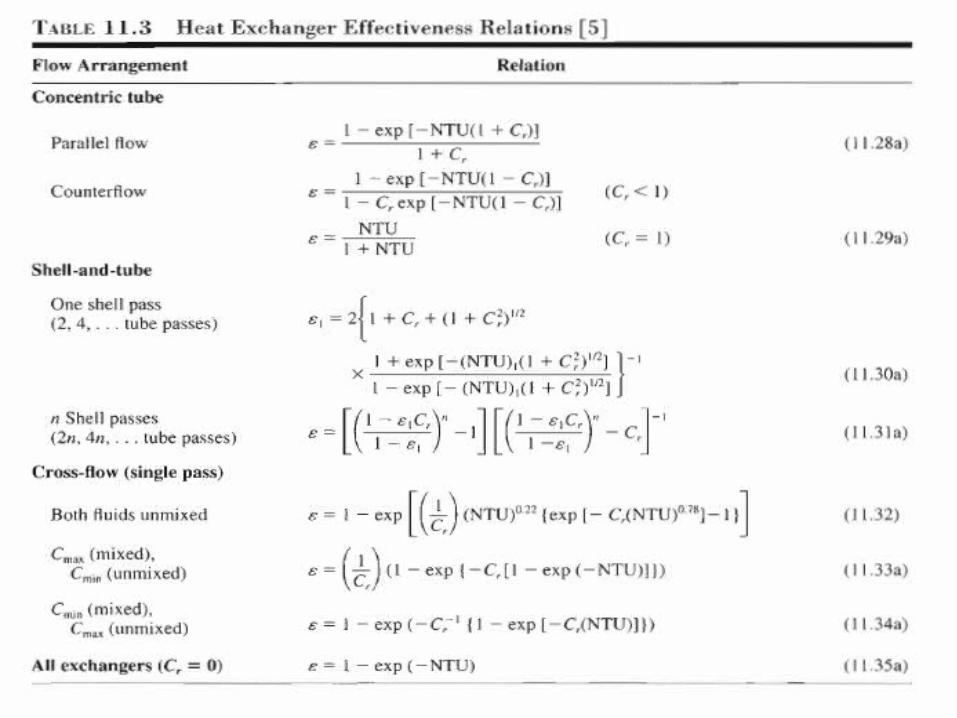
Similar expression have been developed for a variety of heat exchangers, and respective results are summered in tables and Figures(see Reference Books)
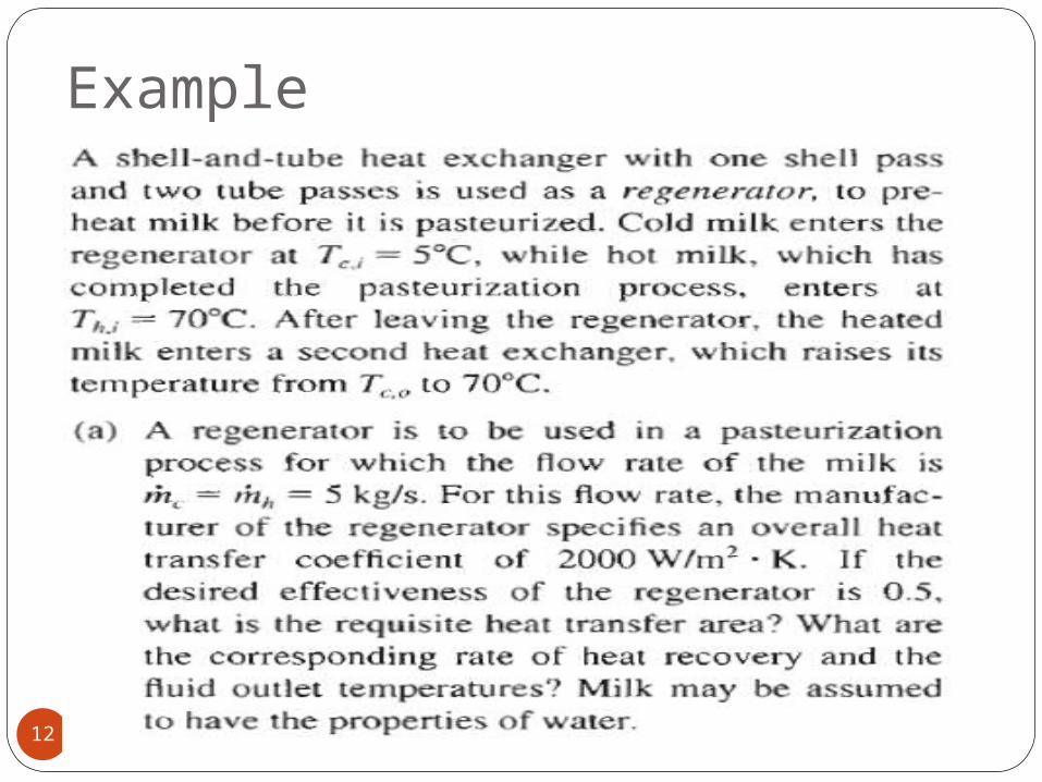
Example
12
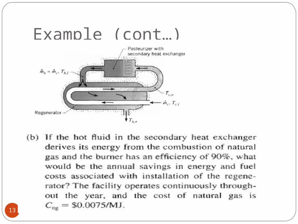
Example (cont…)
13
ε - NTU relation
14
ε - NTU relation
15
ε - NTU relation
16
ε - NTU relation
17
ε - NTU relation
18
),,( ementflowarrangCNTUf r
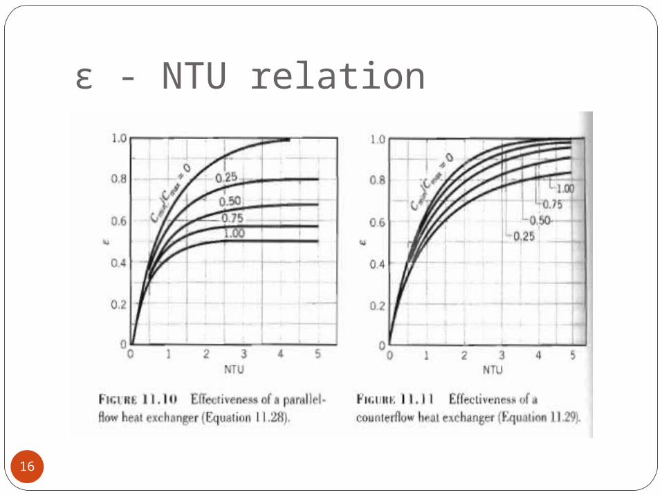
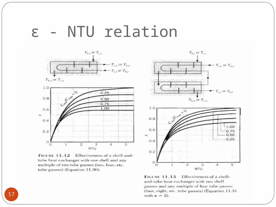
• The following observations may be made by reviewing these figures:1. The HE thermal effectiveness
increases with increasing values of NTU for specified Cr
2. The HE thermal effectiveness increases with decreasing values of Cr for specified NTU
3. For ε <40%, the capacity rate ratio Cr does not have a significant influence on the exchanger effectiveness
• The counter flow HE has the highest ε for specified NTU and Cr compared with those for all other HE flow arrangements
It is noted from the above expressions that
LMTD ε - NTU relation
19
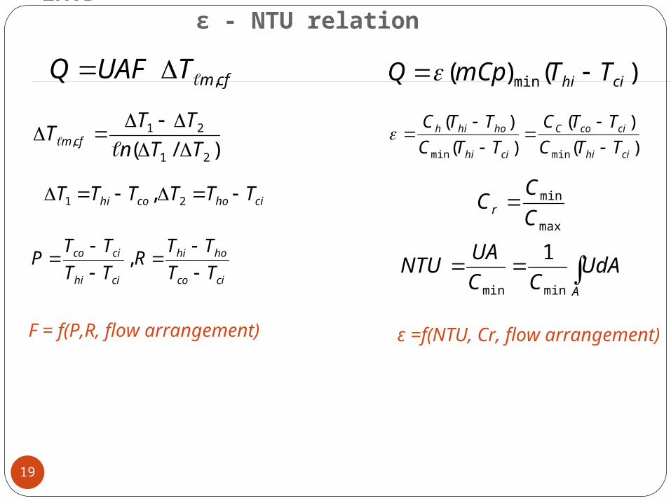
cfmTUAFQ , )()( min cihi TTmCpQ
)/( 21
21, TTn
TTT cfm
)(
)()()(
minmin cihi
cicoC
cihi
hohih
TTCTTC
TTCTTC
cihocohi TTTTTT 21 ,max
min
CCC r
cico
hohi
cihi
cico
TTTTR
TTTTP
, A
UdACC
UANTUminmin
1
F = f(P,R, flow arrangement) ε =f(NTU, Cr, flow arrangement)
Fouling of Heat Exchangers
20
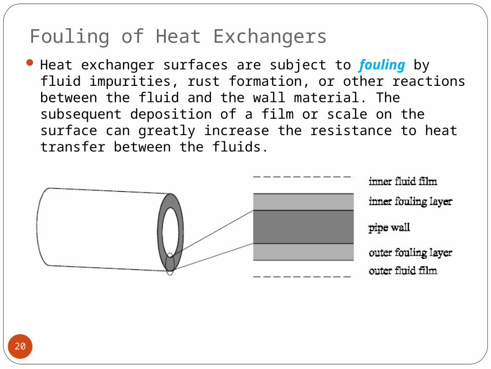
Heat exchanger surfaces are subject to fouling by fluid impurities, rust formation, or other reactions between the fluid and the wall material. The subsequent deposition of a film or scale on the surface can greatly increase the resistance to heat transfer between the fluids.
Fouling of Heat Exchangers
21
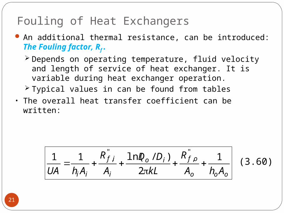
An additional thermal resistance, can be introduced: The Fouling factor, Rf. Depends on operating temperature, fluid velocity and length of service of heat exchanger. It is variable during heat exchanger operation.
Typical values in can be found from tables • The overall heat transfer coefficient can be written:
ooo
ofio
i
if
ii AhAR
kLDD
AR
AhUA1
2)/ln(11 "
,",
(3.60)
Types of fouling
22
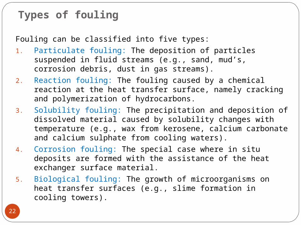
Fouling can be classified into five types:1. Particulate fouling: The deposition of particles
suspended in fluid streams (e.g., sand, mud’s, corrosion debris, dust in gas streams).
2. Reaction fouling: The fouling caused by a chemical reaction at the heat transfer surface, namely cracking and polymerization of hydrocarbons.
3. Solubility fouling: The precipitation and deposition of dissolved material caused by solubility changes with temperature (e.g., wax from kerosene, calcium carbonate and calcium sulphate from cooling waters).
4. Corrosion fouling: The special case where in situ deposits are formed with the assistance of the heat exchanger surface material.
5. Biological fouling: The growth of microorganisms on heat transfer surfaces (e.g., slime formation in cooling towers).
Minimizing of fouling
23
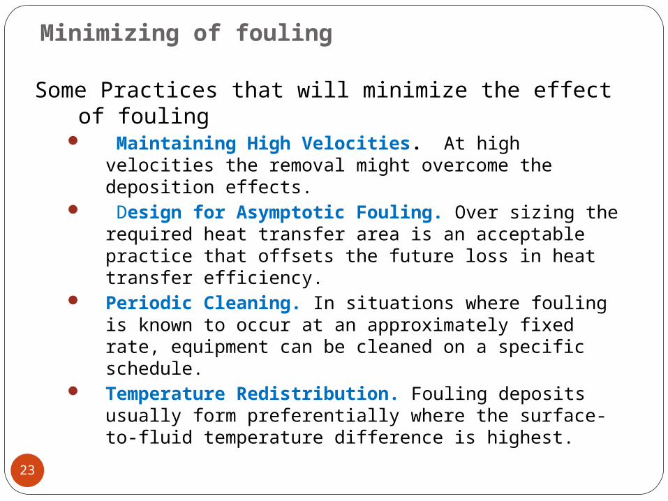
Some Practices that will minimize the effect of fouling
Maintaining High Velocities. At high velocities the removal might overcome the deposition effects.
Design for Asymptotic Fouling. Over sizing the required heat transfer area is an acceptable practice that offsets the future loss in heat transfer efficiency.
Periodic Cleaning. In situations where fouling is known to occur at an approximately fixed rate, equipment can be cleaned on a specific schedule.
Temperature Redistribution. Fouling deposits usually form preferentially where the surface-to-fluid temperature difference is highest.
Heat Exchanger Design and Calculation Methodology
24
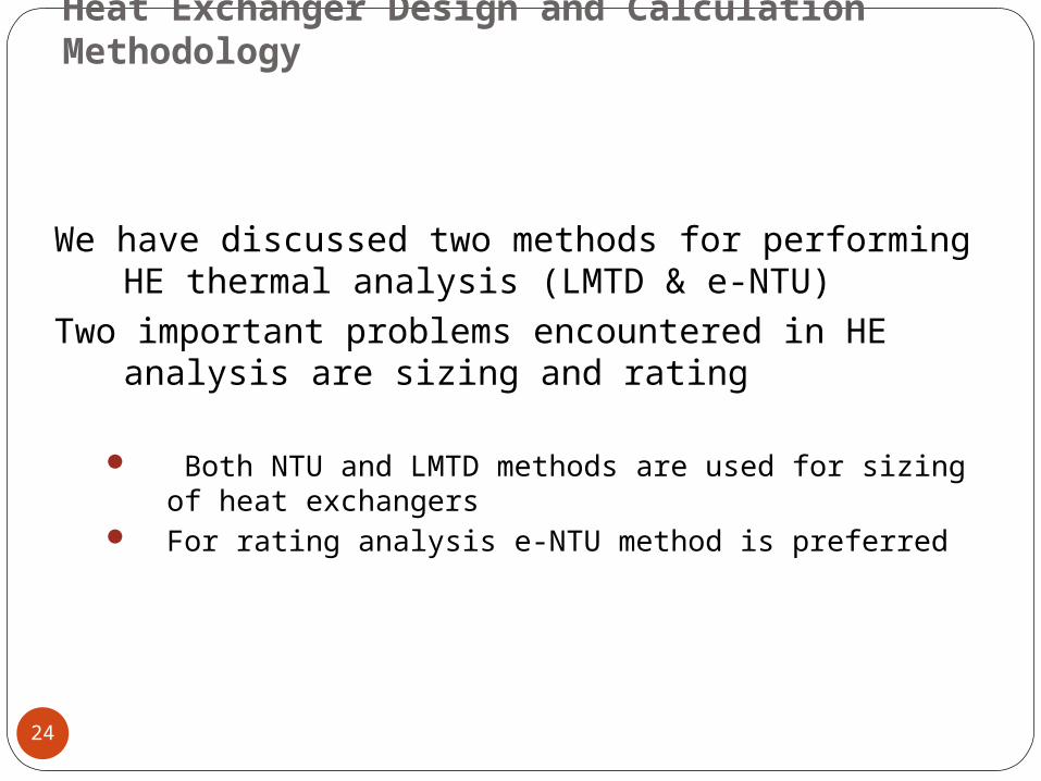
We have discussed two methods for performing HE thermal analysis (LMTD & e-NTU)
Two important problems encountered in HE analysis are sizing and rating
Both NTU and LMTD methods are used for sizing of heat exchangers
For rating analysis e-NTU method is preferred
Steps in HE analysis using LMTD
25
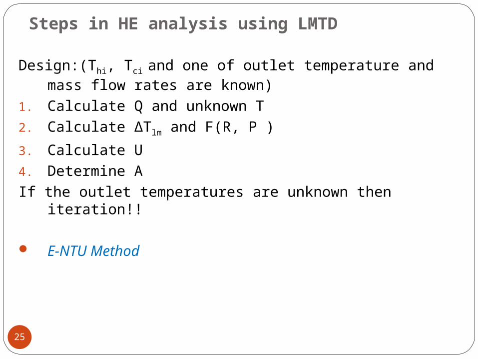
Design:(Thi, Tci and one of outlet temperature and mass flow rates are known)
1. Calculate Q and unknown T2. Calculate ΔTlm and F(R, P ) 3. Calculate U4. Determine AIf the outlet temperatures are unknown then
iteration!!
E-NTU Method

Steps in HE analysis using e-NTU
26
Design:(Thi, Tci and one of outlet temperature and mass flow rates are known)
1. Calculate Q and unknown T and ε 2. Calculate Cr3. Calculate U4. When ε , Cr, and flow arrangements are
known, determine NTU from the chart or ε-NTU relation
5. When NTU is known, calculate A
Note: ε -NTU Method is generally used for compact HE and LMTD for process, Power & petrochemical
Steps in HE analysis using e-NTU
27
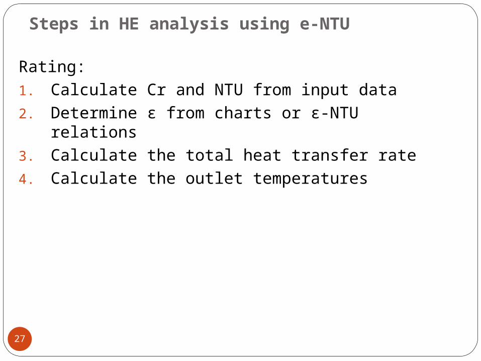
Rating: 1. Calculate Cr and NTU from input data 2. Determine ε from charts or ε-NTU
relations 3. Calculate the total heat transfer rate4. Calculate the outlet temperatures
Approaches in HE Design
28
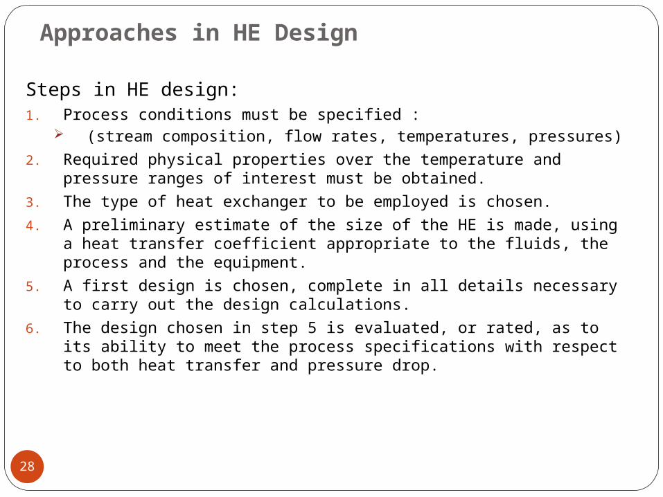
Steps in HE design:1. Process conditions must be specified :
(stream composition, flow rates, temperatures, pressures)2. Required physical properties over the temperature and
pressure ranges of interest must be obtained.3. The type of heat exchanger to be employed is chosen.4. A preliminary estimate of the size of the HE is made, using
a heat transfer coefficient appropriate to the fluids, the process and the equipment.
5. A first design is chosen, complete in all details necessary to carry out the design calculations.
6. The design chosen in step 5 is evaluated, or rated, as to its ability to meet the process specifications with respect to both heat transfer and pressure drop.
Approaches in HE Design
29
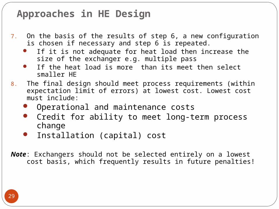
7. On the basis of the results of step 6, a new configuration is chosen if necessary and step 6 is repeated.
If it is not adequate for heat load then increase the size of the exchanger e.g. multiple pass
If the heat load is more than its meet then select smaller HE
8. The final design should meet process requirements (within expectation limit of errors) at lowest cost. Lowest cost must include:
Operational and maintenance costs Credit for ability to meet long-term process
change Installation (capital) cost
Note: Exchangers should not be selected entirely on a lowest cost basis, which frequently results in future penalties!
Design of Shell- and- Tube Heat Exchangers
30
Shell- and- Tube HE are the most versatile type of HEs. They are used in
process industries, conventional and nuclear power stations as
condensers, steam generators, pressurized water reactor power plants, feed water heaters, and some air conditioning and refrigeration systems.
They are also proposed for many alternative energy applications including ocean, thermal, and geothermal.
STHE offer great flexibility to meet almost any service requirement. They can be designed for high pressure relative to the environment and high pressure difference between the fluid streams.
Shell-and-Tube Heat Exchangers
31
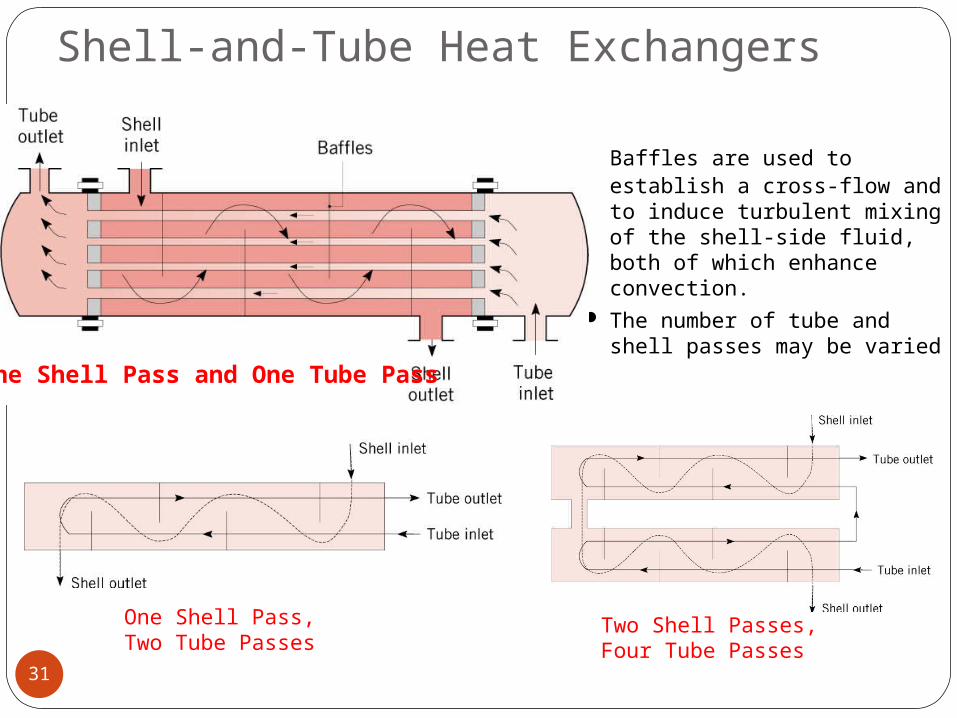
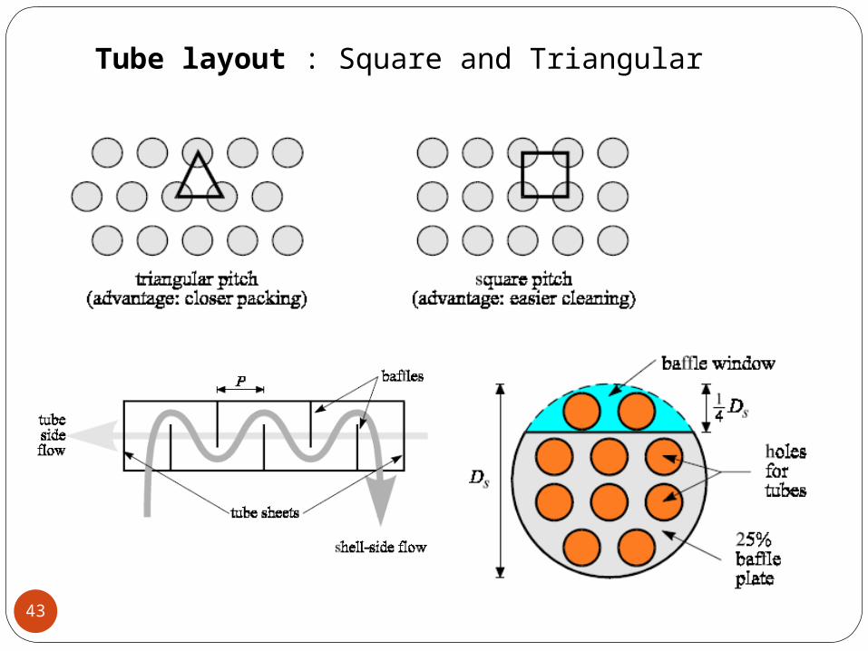
Baffles are used to establish a cross-flow and to induce turbulent mixing of the shell-side fluid, both of which enhance convection.
The number of tube and shell passes may be varied
One Shell Pass and One Tube Pass
One Shell Pass,Two Tube Passes
Two Shell Passes,Four Tube Passes
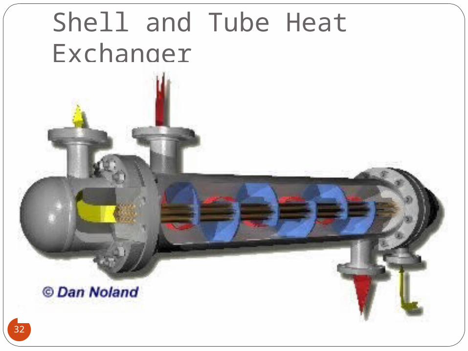
Shell and Tube Heat Exchanger
32
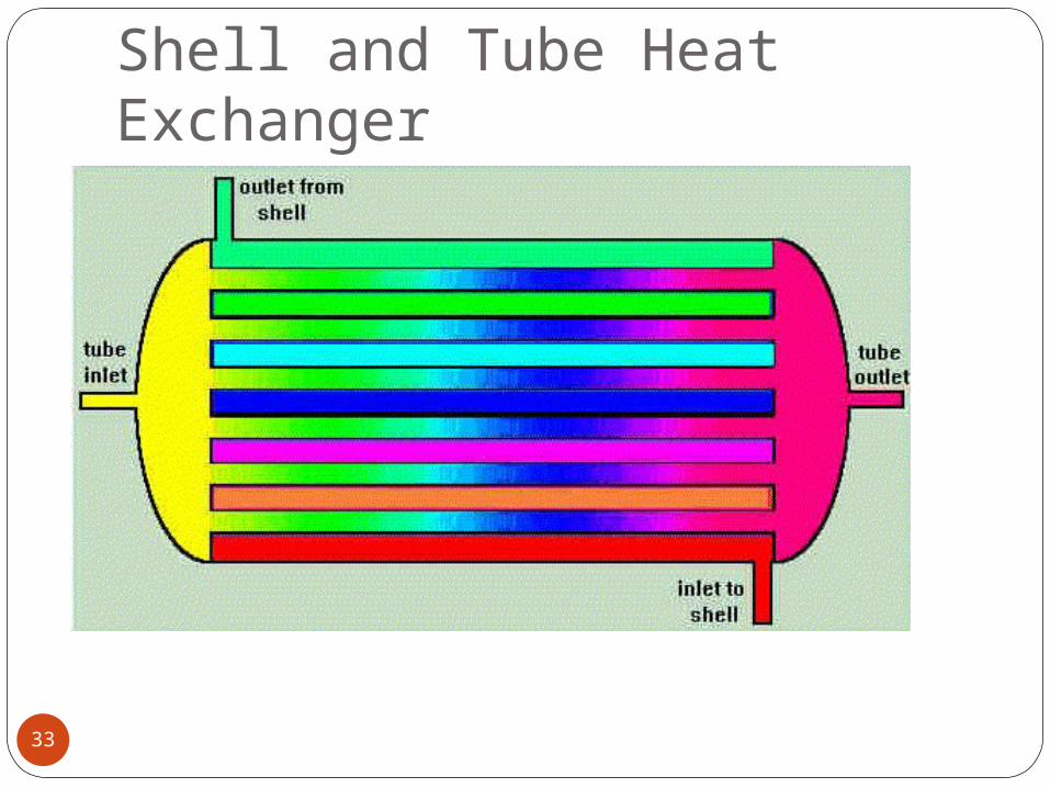
Shell and Tube Heat Exchanger
33
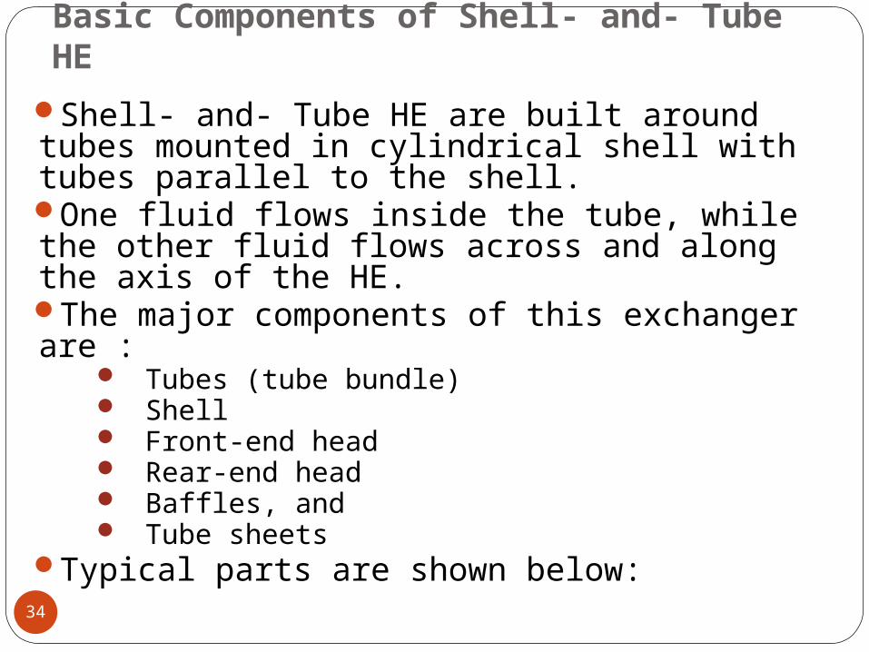
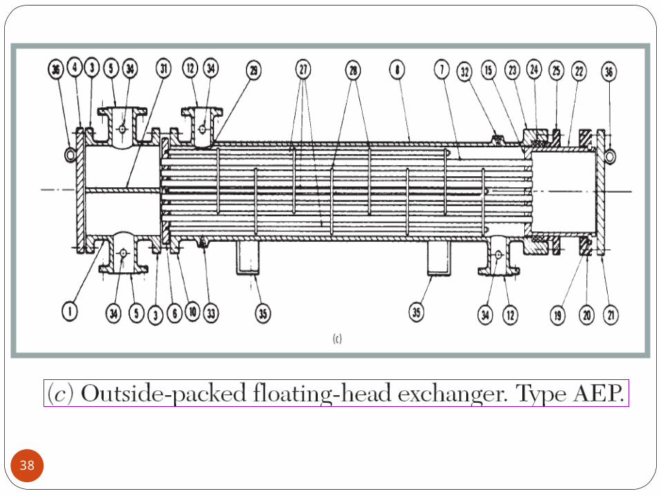
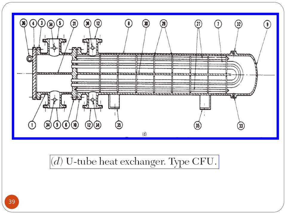
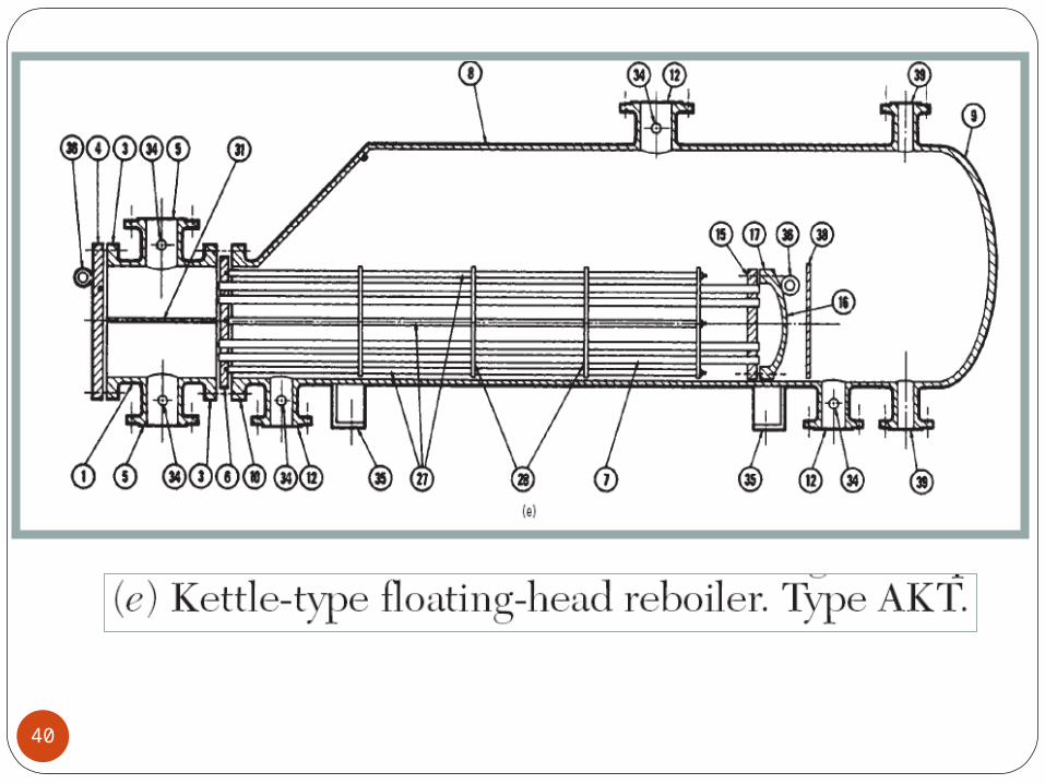
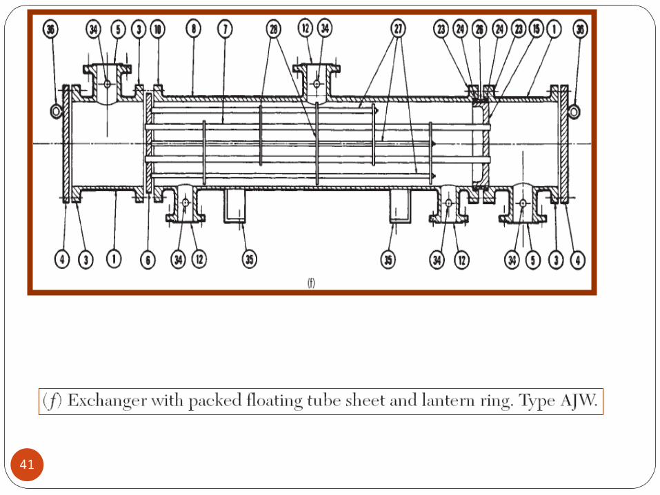
Basic Components of Shell- and- Tube HE
34
Shell- and- Tube HE are built around tubes mounted in cylindrical shell with tubes parallel to the shell.One fluid flows inside the tube, while the other fluid flows across and along the axis of the HE. The major components of this exchanger are :
Tubes (tube bundle) Shell Front-end head Rear-end head Baffles, and Tube sheets
Typical parts are shown below:
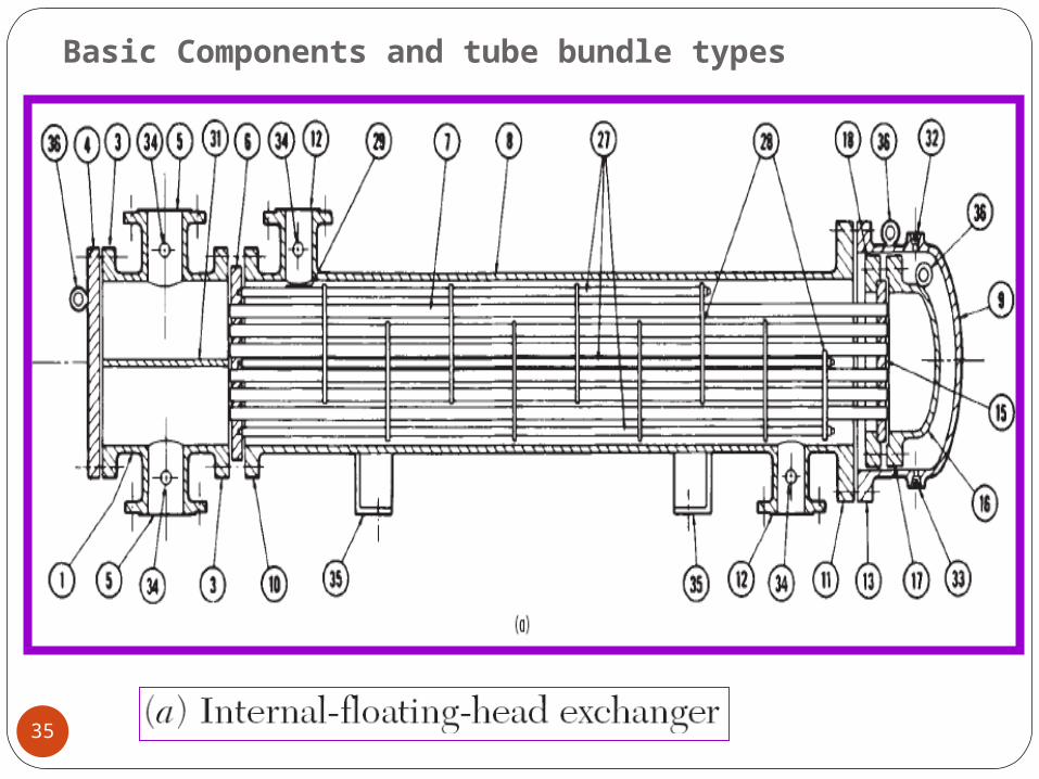
Basic Components and tube bundle types
35
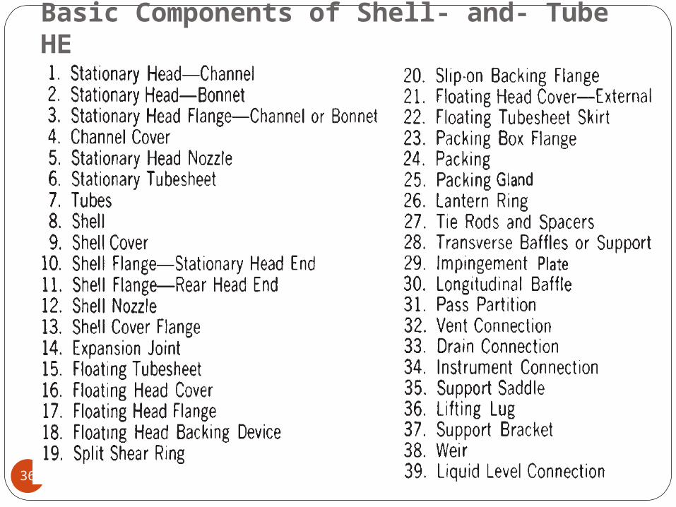
Basic Components of Shell- and- Tube HE
36
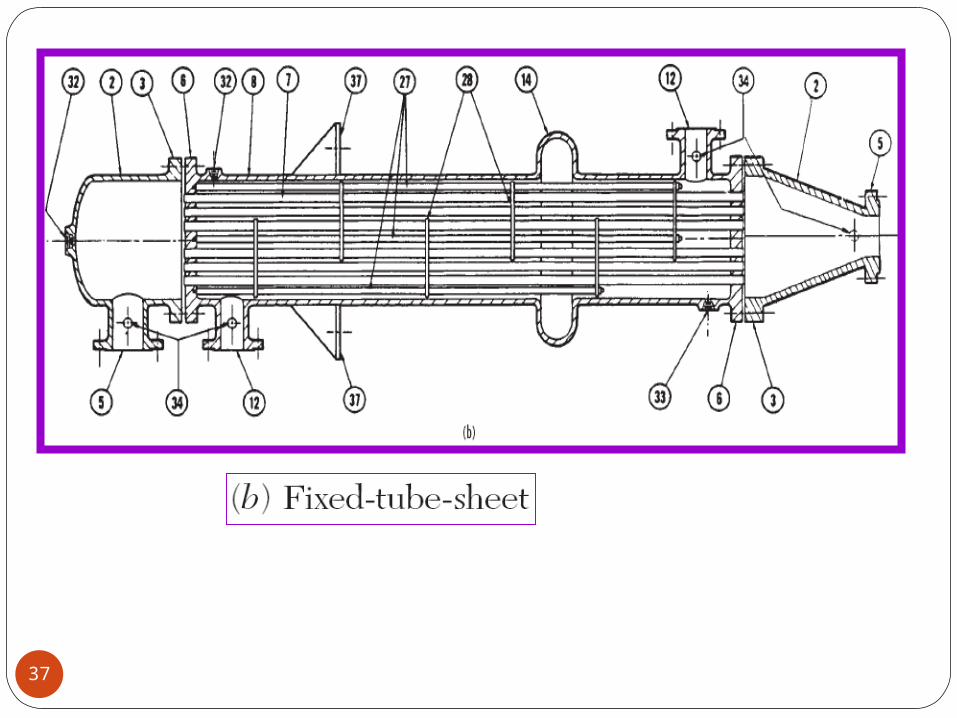
37
38
39
40
41
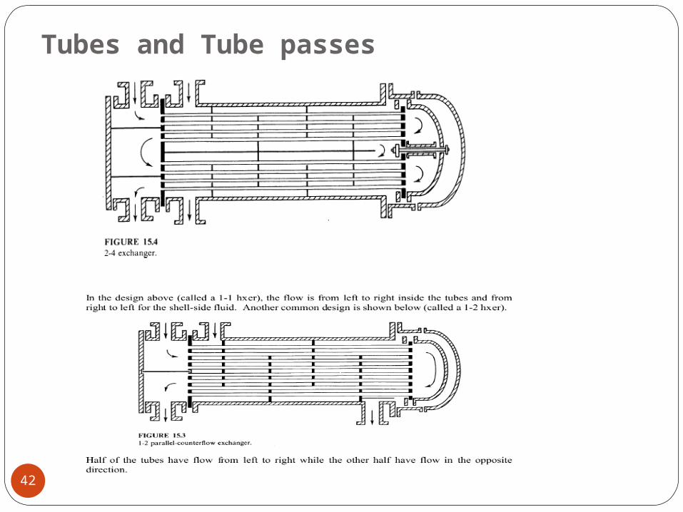
Tubes and Tube passes
42
43
Tube layout : Square and Triangular
44
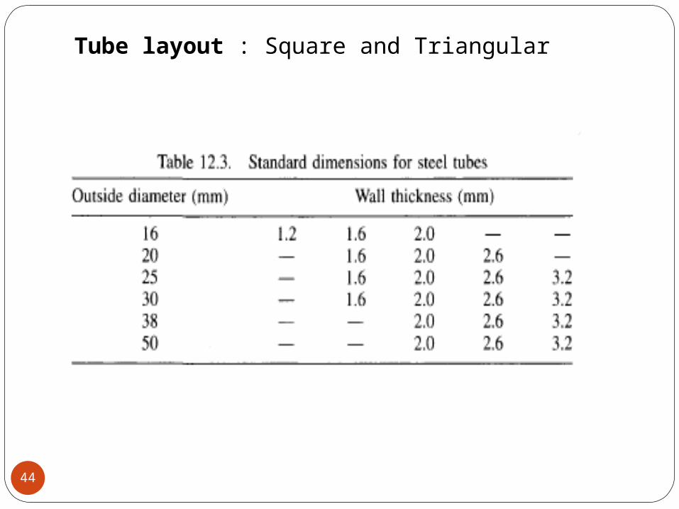
Tube layout : Square and Triangular
45
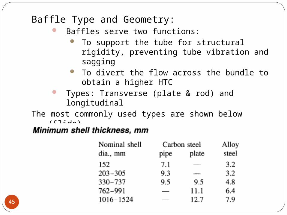
Baffle Type and Geometry: Baffles serve two functions:
To support the tube for structural rigidity, preventing tube vibration and sagging
To divert the flow across the bundle to obtain a higher HTC
Types: Transverse (plate & rod) and longitudinal
The most commonly used types are shown below (Slide)
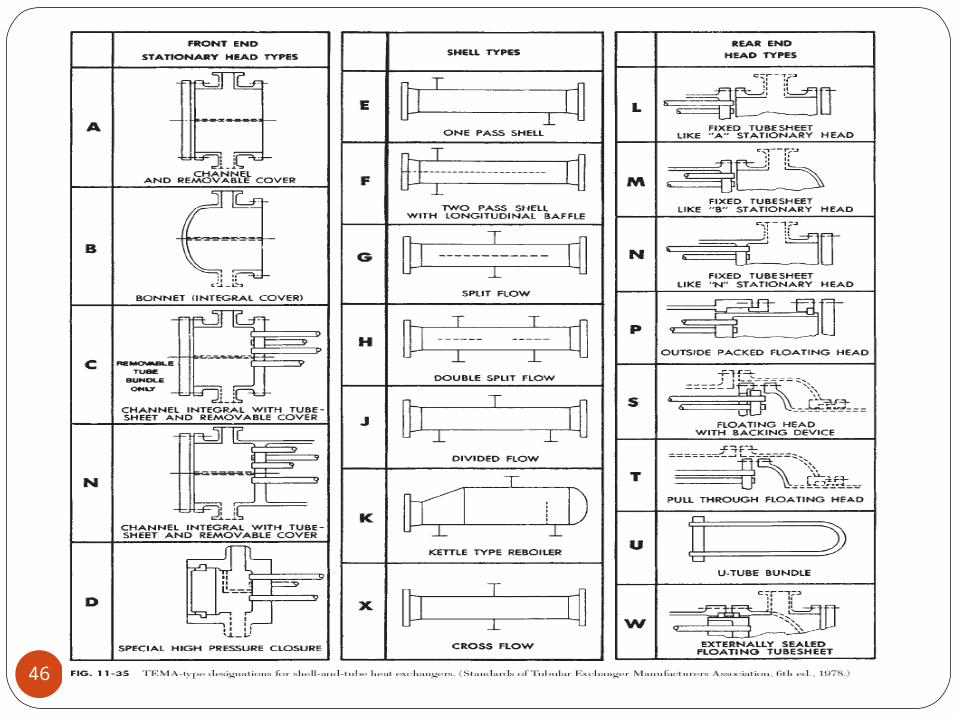
46
47
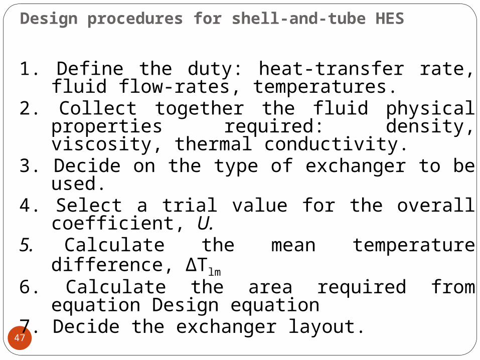
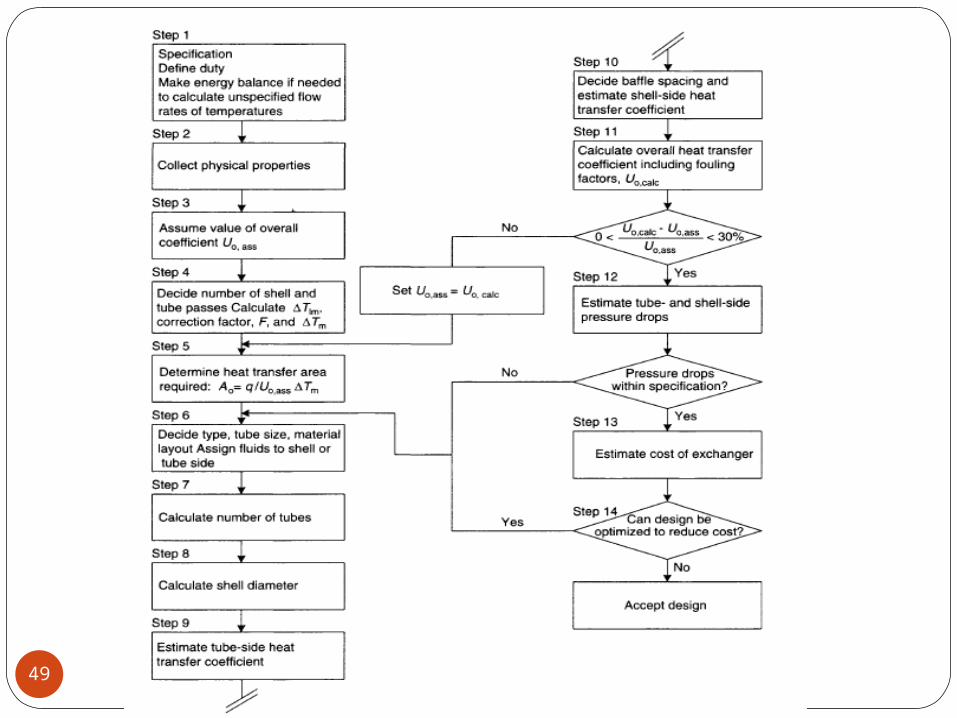
1. Define the duty: heat-transfer rate, fluid flow-rates, temperatures.
2. Collect together the fluid physical properties required: density, viscosity, thermal conductivity.
3. Decide on the type of exchanger to be used.
4. Select a trial value for the overall coefficient, U.
5. Calculate the mean temperature difference, ΔTlm
6. Calculate the area required from equation Design equation
7. Decide the exchanger layout.
Design procedures for shell-and-tube HES
48
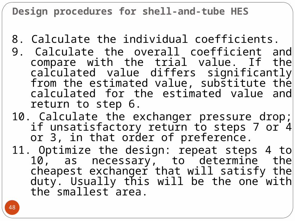
8. Calculate the individual coefficients.9. Calculate the overall coefficient and
compare with the trial value. If the calculated value differs significantly from the estimated value, substitute the calculated for the estimated value and return to step 6.
10. Calculate the exchanger pressure drop; if unsatisfactory return to steps 7 or 4 or 3, in that order of preference.
11. Optimize the design: repeat steps 4 to 10, as necessary, to determine the cheapest exchanger that will satisfy the duty. Usually this will be the one with the smallest area.
Design procedures for shell-and-tube HES
49
50
Fluid allocation: shell or tubesWhere no phase change occurs, the following
factors will determine the allocation of the fluid streams to the shell or tubes.
Corrosion. The more corrosive fluid should be allocated to the tube-side. This will reduce the cost of expensive alloy or clad components.
Fouling. The fluid that has the greatest tendency to foul the heat-transfer surfaces should be placed in the tubes. This will give better control over the design fluid velocity, and the higher allowable velocity in the tubes will reduce fouling. Also, the tubes will be easier to clean.
SHELL AND TUBE EXCHANGERS:GENERAL DESIGN CONSIDERATIONS
51
Fluid temperatures. If the temperatures are high enough to require the use of special alloys placing the higher temperature fluid in the tubes will reduce the overall cost.
Operating pressures. The higher pressure stream should be allocated to the tube-side. High-pressure tubes will be cheaper than a high-pressure shell.
Pressure drop. For the same pressure drop, higher heat-transfer coefficients will be obtained on the tube-side than the shell-side, and fluid with the lowest allowable pressure drop should be allocated to the tube-side.
Viscosity. Generally, a higher heat-transfer coefficient will be obtained by allocating the more viscous material to the shell-side, providing the flow is turbulent.
Stream flow-rates. Allocating the fluids with the lowest flow-rate to the shell-side will normally give the most economical design.
52
Shell and tube fluid velocities High velocities will give high heat-transfer coefficients
but also a high-pressure drop. The velocity must be high enough to prevent any suspended
solids settling, but not so high as to cause erosion. High velocities will reduce fouling. Typical design velocities are given below:Liquids:
Tube-side, process fluids: 1 to 2 m/s, maximum 4 m/s if required to reduce fouling; water: 1.5 to 2.5 m/s.
Shell-side: 0.3 to 1 m/s.Vapours: For vapours, the velocity used will depend on the
operating pressure and fluid density; the lower values in the ranges given below will apply to high molecular weight materials.
Vacuum : 50 to 70 m/s, Atmospheric pressure: 10 to 30 m/s High pressure: 5 to 10 m/s
53
Stream temperatures The closer the temperature approach used the
larger will be the heat-transfer area required for a given duty.
The optimum value will depend on the application, and can only be determined by making an economic analysis of alternative designs.
As a general guide: the greater temperature difference should be at least
20°C, and the least temperature difference 5 to 7°C for coolers using cooling water, and 3 to 5°C using refrigerated brines.
The maximum temperature rise in recirculated cooling water is limited to around 30° C.
Care should be taken to ensure that cooling media temperatures are kept well above the freezing point of the process materials
54
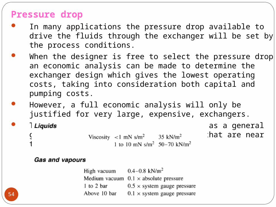
Pressure drop In many applications the pressure drop available to
drive the fluids through the exchanger will be set by the process conditions.
When the designer is free to select the pressure drop an economic analysis can be made to determine the exchanger design which gives the lowest operating costs, taking into consideration both capital and pumping costs.
However, a full economic analysis will only be justified for very large, expensive, exchangers.
The values suggested below can be used as a general guide, and will normally give designs that are near the optimum.
55
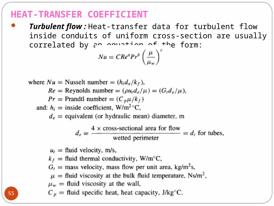
HEAT-TRANSFER COEFFICIENT Turbulent flow : Heat-transfer data for turbulent flow
inside conduits of uniform cross-section are usually correlated by an equation of the form: