
heat transfer - IARE
185
INSTITUTE OF AERONAUTICAL ENGINEERING (AUTONOMOUS) Dundigal, Hyderabad - 500 043 HEAT TRANSFER III B. TECH II SEMESTER PREPARED BY, S. SRIKRISHNAN, Assistant Professor, Department of Mechanical Engineering N. SANTHISREE, Assistant Professor, Department of Mechanical Engineering
-
Upload
khangminh22 -
Category
Documents
-
view
2 -
download
0
Transcript of heat transfer - IARE

INSTITUTE OF AERONAUTICAL ENGINEERING (AUTONOMOUS)
Dundigal, Hyderabad - 500 043
HEAT TRANSFER
III B. TECH II SEMESTER
PREPARED BY,
S. SRIKRISHNAN, Assistant Professor, Department of Mechanical Engineering
N. SANTHISREE, Assistant Professor, Department of Mechanical Engineering
UNIT I – INTRODUTION TO HEAT TRANSFER
2

Thermodynamics & Heat Transfer
Study of
Heat and Work transfer
(quantitatively) Thermodynamics
Heat Transfer Study of
“How heat flows” every activity involves
heat transfer
3

Conduction
Solids > Lattice vibrations
Fluids > Molecular collisions
dTq
dx
The transfer of energy in a solid or fluid via molecular contact
without bulk motion
MODE
T
T T0 x
PHYSICAL
PHENOMENON
MATHEMATICAL
EQUATION

Conduction (contd.) Fourier Law of Heat Conduction
• The heat flux, q is directly proportional to temperature gradient
• The proportionality constant, k, is defined as the thermal conductivity, a thermo physical property.
dTq
dx
x
Tq k
x
5

Conduction (contd.)
k/ksilver
Silver 1
Gold 0.7
Copper 0.93
Aluminum 0.86
Brass (70% Cu:30% Ni) 0.33
Platinum, Lead 0.25
Mild steel (0.1% Cu), Cast iron 0.12
Bismuth 0.07
Mercury 0.04
Thermal Conductivity, k
Silver = 410 Wm-1K-1
METALS
k/ksilver
Air 0.19
Water 0.0014
Granite, Sandstone 0.011
Average rock 0.012
Limestone 0.007
Ice 0.015
Glass (crown) 0.0058
Concrete (1:2:4) 0.0042
Brick 0.0038
Snow (fresh or average) 0.005
Soil (sandy, dry) 0.002
Soil (8% moist) 0.0033
Wood 0.0045
NON-METALS
6

Convection
( )w aQ hA T T
Convection occurs in liquids and gases.
Energy is carried with fluid motion when convection occurs.
PHYSICAL
PHENOMENON MATHEMATICAL
EQUATION
7

Convection (contd.)
• The quantity h is called the convective heat transfer coefficient (W/m2-K).
• It is dependent on the type of fluid flowing past the wall and the velocity distribution.
• Thus, h is not a thermo physical property.
Newton’s Law of Cooling
( )w aQ hA T T
Convection Process h(W/m2-K)
Free convection
Gases 2–25
Liquids
50–1000
Forced convection
Gases 25–250
Liquids
50–20,000
Convection phase change 2,500–200,000 8
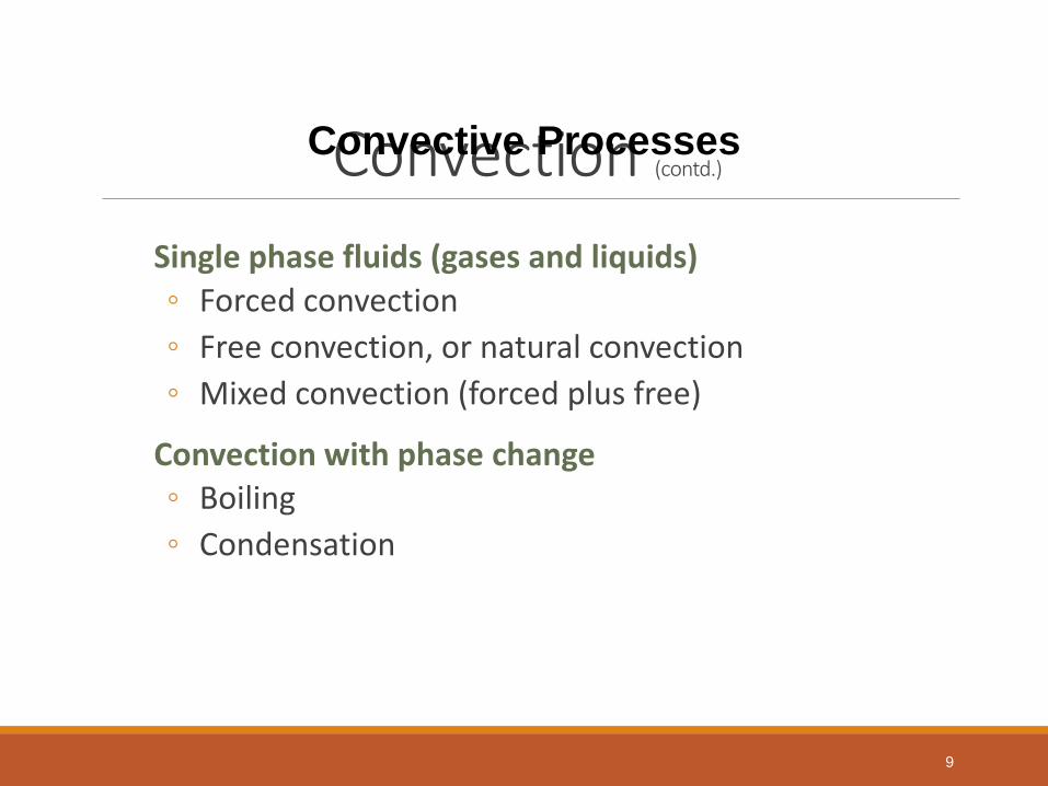
Convection (contd.)
Single phase fluids (gases and liquids) ◦ Forced convection
◦ Free convection, or natural convection
◦ Mixed convection (forced plus free)
Convection with phase change ◦ Boiling
◦ Condensation
Convective Processes
9

Radiation Energy transfer in the form of electromagnetic waves
PHYSICAL
PHENOMENON MATHEMATICAL
EQUATION
4
sE T
sA,T
10

Radiation (contd.)
Stefan-Boltzman Law
4
b sE T
The emissive power of a black body over all wave
lengths is proportional to fourth power of temperature
11

One Dimensional Heat Conduction
Net rate of heat gain by conduction
Rate of energy
generation Rate of increase
of internal energy = +
[Aq]x – [Aq]x+ Δx A Δx g t
txTcxA p
),(
t
txTcg
x
AqAq
Ap
xxx
),(][][1
+ =
Heat flow in
[Aq]x
Heat flow out
[Aq]x+Δx
g
k
Δx
12
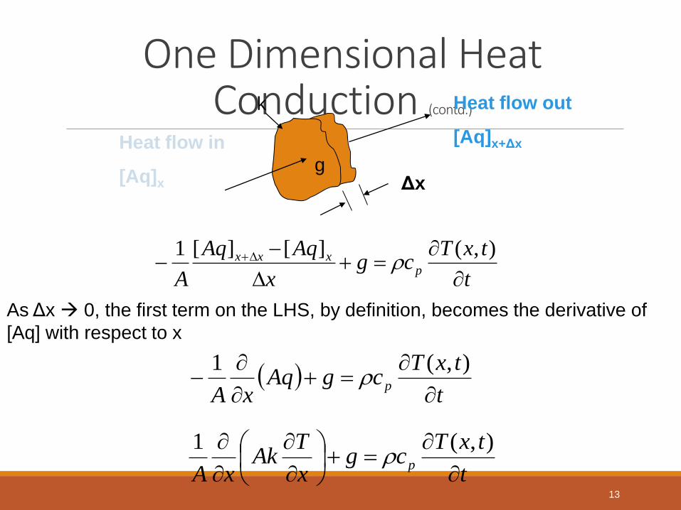
One Dimensional Heat Conduction (contd.)
t
txTcgAq
xAp
),(1
As Δx 0, the first term on the LHS, by definition, becomes the derivative of
[Aq] with respect to x
t
txTcg
x
AqAq
Ap
xxx
),(][][1
t
txTcg
x
TAk
xAp
),(1
Heat flow in
[Aq]x
Heat flow out
[Aq]x+Δx
g
k
Δx
13

One Dimensional Heat Conduction (contd.)
Rectangular Coordinates
Cylindrical Coordinates
Spherical Coordinates
A Compact Equation
t
txTcg
x
Tk
xp
),(
t
trTcg
r
Trk
rrp
),(1
t
trTcg
r
Tkr
rrp
),(1 2
2
t
trTcg
r
Tkr
rrp
n
n
),(1
n = 0
n = 1
n = 2
14

Boundary Conditions Prescribed Temperature BC (First kind)
Prescribed Heat Flux BC (Second kind)
Convection BC (Third kind)
15

Boundary Conditions Prescribed Temperature BC (First kind)
Prescribed Heat Flux BC (Second kind)
Convection BC (Third kind)
0 L x
T1 T2 T (x,t) | x=0 = T (0,t) = T1
T (x,t) | x=L = T (L,t) = T2
16

Boundary Conditions Prescribed Temperature BC (First kind)
Prescribed Heat Flux BC (Second kind)
Convection BC (Third kind)
0 L x
Heat
Supply Conduction
flux
Heat
Supply
Conduction
flux
0
0
xx
Tkq
L
Lx
qx
Tk
W/m2
W/m2 L
Lx
qx
Tk
0
0
qx
Tk
x
Plate
17

Boundary Conditions Prescribed Temperature BC (First kind)
Prescribed Heat Flux BC (Second kind)
Convection BC (Third kind)
b
br
qr
Tk
a
ar
qr
Tk
Hollow Cylinder or
hollow sphere
b r Heat
Supply
ar
ar
Tkq
b
br
qr
Tk
W/m2
a
18

Boundary Conditions Prescribed Temperature BC (First kind)
Prescribed Heat Flux BC (Second kind)
Convection BC (Third kind)
Plate
Conduction
Convection
T1, h1
)( 22 LxLx
TThx
Tk
Convection
Fluid
Flow
Conduction
T2, h2
Fluid
Flow 0011 )(
xx x
TkTTh
Convection heat flux
from the fluid at T1 to
the surface at x = 0
Conduction heat flux
from the surface at
x= 0 into the plate
0011 )(
xx x
TkTTh
19

Boundary Conditions Prescribed Temperature BC (First kind)
Prescribed Heat Flux BC (Second kind)
Convection BC (Third kind)
Plate
Conduction
Convection
)( 22 LxLx
TThx
Tk
Convection
T1, h1
Fluid
Flow
Conduction
T2, h2
Fluid
Flow 0011 )(
xx x
TkTTh
Convection heat flux
from the fluid at T2 to
the surface at x = L
Conduction heat flux
from the surface at
x = L into the plate
LxLx x
TkTTh
)( 22
20

Boundary Conditions Prescribed Temperature BC (First kind)
Prescribed Heat Flux BC (Second kind)
Convection BC (Third kind)
Hollow Cylinder or
hollow sphere
b
r Heat
Supply
a
)( 22 brbr
TThr
Tk
Fluid
Flow
T1, h1
Fluid
Flow
T2, h2
arar r
TkTTh
)( 11
Convection heat flux
from the fluid at T1 to
the surface at r = a
Conduction heat flux
from the surface at
r= a into the plate
arar r
TkTTh
)( 11
21

Boundary Conditions Prescribed Temperature BC (First kind)
Prescribed Heat Flux BC (Second kind)
Convection BC (Third kind)
Hollow Cylinder or
hollow sphere
b
r Heat
Supply
a
)( 22 brbr
TThr
Tk
Fluid
Flow
T1, h1
Fluid
Flow
T2, h2
arar r
TkTTh
)( 11
Convection heat flux
from the fluid at T2 to
the surface at r = b
Conduction heat flux
from the surface at
r= b into the plate
brbr r
TkTTh
)( 22
22

UNIT II - CONDUCTION
23

Steady State One Dimensional Heat Conduction
Rectangular Coordinates
T = T1
0 L
T = T2 x
02
2
x
TGoverning Equation
21)( cxcxT
112)( Tx
L
TTxT
L
TTAKQx
).(. 21
AK
LR
.
24

Steady State One Dimensional Heat Conduction Cylindrical Coordinates (Solid Cylinder)
T = T1
0 r
T = T2
b
0)(1 0
k
g
dr
rdTr
dr
d
rGoverning Equation
0
0)(
ratdr
rdT
brat
TrT
2)(
210 ln
2)( crcr
k
grT
2
2
0 14
)( Tb
r
k
grT
Solving,
2
)()( 0rg
dr
rdTkrq
25

Steady State One Dimensional Heat Conduction Cylindrical Coordinates (Solid Cylinder)
Solved Example
T = T1
0 r
T = T2
b
Solution
T(0) = 350 °C
q(r) = 106 W/m2
2
2
0 14
)( Tb
r
k
grT
2)( 0rg
rq
For r=1cm
g0 = 2 x 10⁸ W/m3
k = 20 W/(m.°C)
T2 = 100 °C
What will be the
1. Centre temperature T(0)
2. Heat flux at the boundary surface (r=1cm)
Equations to use (derive)
26

Steady State One Dimensional Heat Conduction
Cylindrical Coordinates (Hollow Cylinder)
Determination of Temperature Distribution
0)(
dr
rdTr
dr
d
21 ln)( crcrT
Solving, a
b
r 0
T1
T2
k
Mathematical formulation of this problem is
in a < r < b
)/ln(
121
ab
TTc
)/ln(
)ln()( 1212
ab
aTTTc
)/ln(
)/ln()(
12
1
ab
ar
TT
TrT
27

Steady State One Dimensional Heat Conduction
Cylindrical Coordinates (Hollow Cylinder)
Expression for radial heat flow Q over a length H
rHdr
rdTkarearqQ 2
)().(
12 Hck
Since,
a
b
r 0
T1
T2
k
The heat flow is determined from,
1)/1(/)( crdrrdT
)()/ln(
221 TT
ab
kHQ
Rearranging,
R
TTQ 21
kH
abR
2
)/ln(where,
28

Steady State One Dimensional Heat Conduction
Cylindrical Coordinates (Hollow Cylinder)
Expression for thermal resistance for length H
here, A0 = 2πaH =area of inner surface of cylinder
A1 = 2πbH =area of outer surface of cylinder
Am = logarithmic mean area
t = b – a = thickness of cylinder
a
b
r 0
T1
T2
k
Above equation can be rearranged as,
kH
abR
2
)/ln(
where,
Hkab
aHbHab
kH
abR
2)(
)]2/(2ln[)(
2
)/ln(
mkA
tR
)ln( 01
01
AA
AAAm
29

Steady State One Dimensional Heat Conduction Spherical Coordinates (Hollow Sphere)
Expression for temperature distribution
in a < r < b
The mathematical formulation is given by,
where,
r a
0
b
0)(2
dr
rdTr
dr
d
21)( cr
crT
)( 211 TTab
abc
ab
aTbTc
12
2
21 ....)( Tab
ar
r
bT
ab
rb
r
arT
30
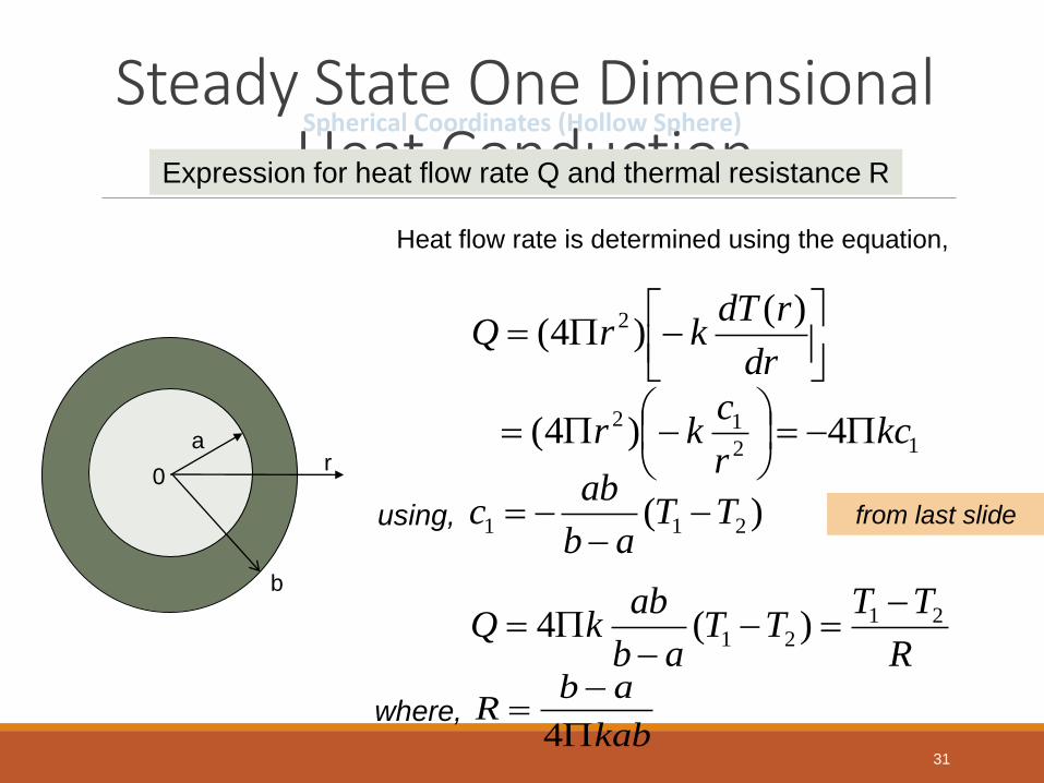
Steady State One Dimensional Heat Conduction Spherical Coordinates (Hollow Sphere)
Expression for heat flow rate Q and thermal resistance R
Heat flow rate is determined using the equation,
r a
0
b
dr
rdTkrQ
)()4( 2
12
12 4)4( kcr
ckr
using, )( 211 TTab
abc
from last slide
R
TTTT
ab
abkQ 21
21 )(4
where, kab
abR
431

Composite Medium Example (Furnace Wall)
FURNACE
RE
FR
AC
TO
RY
LIN
ING
2
RE
FR
AC
TO
RY
LIN
ING
1
FURNACE WALL
BR
ICK
WA
LL
Ambient
32

Composite Medium Example (Condenser Water Tube)
Condensing Medium (Steam)
Cooling Water
Scale
Tube Wall
33

Composite Medium Composite Slab (resistance in series)
L1 L2 L3
Ta
T0
T1
T2 T3
Tb
Ta T0 T1 T2 T3 Tb
Ra R1 R2 R3
Rb
Q
Q
Ta, ha
Fluid
Flow
Tb, hb
Fluid
Flow
Q Q
b
b
a
a
R
TT
R
TT
R
TT
R
TT
R
TTQ
3
3
32
2
21
1
100
b
b
a
aAh
RAk
LR
Ak
LR
Ak
LR
AhR
1;;;;
1
3
33
2
22
1
11
WR
TTQ ba
ba RRRRRR 321
34

Composite Medium Composite Slab (resistance in parallel)
A E
B
C
D
Insulated
Insulated
T1 T2
RA
RD
Rc
RB RE T1 T2
WR
TTQ 21
DCBpeq
EpeqA
RRRR
RRRR
1111
.
.
35

Composite Medium Composite Cylinder
ha k1
k2 k3
hb
Ta T0 T1 T2 T3 Tb
Ra R1 R2 R3
Rb
Q Q
b
b
a
a
R
TT
R
TT
R
TT
R
TT
R
TTQ
3
3
32
2
21
1
100
b
b
a
a
HhrR
r
r
HkR
r
r
HkR
r
r
HkR
HhrR
32
3
3
3
1
2
2
2
0
1
1
1
0
2
1;ln
2
1
ln2
1;ln
2
1;
2
1
WR
TTQ ba
ba RRRRRR 321 36

Composite Medium Composite Spheres
Ta T0 T1 T2 T3 Tb
Ra R1 R2 R3
Rb
Q Q
b
b
a
a
R
TT
R
TT
R
TT
R
TT
R
TTQ
3
3
32
2
21
1
100
b
b
a
a
hrR
rr
rr
kR
rr
rr
kR
rr
rr
kR
hrR
2
323
23
3
3
12
12
2
2
01
01
1
12
0
4
1;
4
1
4
1;
4
1;
4
1
WR
TTQ ba
ba RRRRRR 321
hb
ha
k1
k2 k3
37

Composite Medium Critical Thickness of Insulation
T1
r1
ro
H Convection
into an
ambient at
T∞,h0
Insulation Radius, r
rc
Heat Loss, q
38
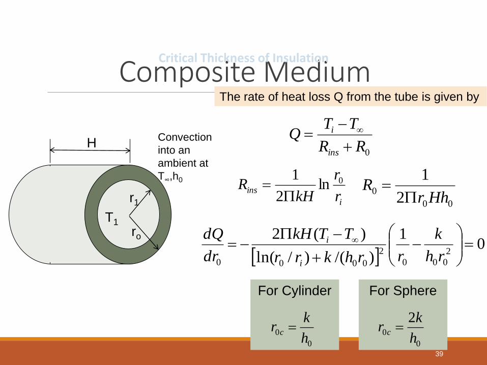
Composite Medium Critical Thickness of Insulation
T1
r1
ro
H Convection
into an
ambient at
T∞,h0
The rate of heat loss Q from the tube is given by
0RR
TTQ
ins
i
i
insr
r
kHR 0ln
2
1
00
02
1
HhrR
0
1
)/()/ln(
)(22
000
2
0000
rh
k
rrhkrr
TTkH
dr
dQ
i
i
For Cylinder
0
0h
kr c
For Sphere
0
0
2
h
kr c
39

Composite Medium Solved Example (Composite Cylinder)
Calculate,
1. Heat loss from tube for length H=10m
2. Temperature drops resulting in thermal
resistances
7.6 cm
K = 15 W/(m °C)
Insulation
t =2 cm
K=0.2 W(m.°C)
Ta=330°C
ha=400 W/(m2.°C)
Ambient air
Tb=30°C
hb= 60 W/(m2.°C)
Determination of heat loss
WRRRR
TTQ
ba
ba
21
40010025.02
1
2
1
0
a
aHhr
R
WCRa /1059.1 3
5.2
8.3ln
15102
1ln
2
1
0
1
1
1
r
r
HkR
WCR /1044.0 3
1
40

Composite Medium Solved Example (Composite Cylinder)
Calculate,
1. Heat loss from tube for length H=10m
2. Temperature drops resulting in thermal
resistances
7.6 cm
K = 15 W/(m °C)
Insulation
t =2 cm
K=0.2 W(m.°C)
Ta=330°C
ha=400 W/(m2.°C)
Ambient air
Tb=30°C
hb= 60 W/(m2.°C)
Determination of heat loss
WCR /1065.33 3
2
WCRb /1021.4 3
WCRRRRRR ba /1089.39 3
321
WQ 75211089.39
303303
41

Composite Medium Solved Example (Composite Cylinder)
Calculate,
1. Heat loss from tube for length H=10m
2. Temperature drops resulting in thermal
resistances
7.6 cm
K = 15 W/(m °C)
Insulation
t =2 cm
K=0.2 W(m.°C)
Ta=330°C
ha=400 W/(m2.°C)
Ambient air
Tb=30°C
hb= 60 W/(m2.°C)
Determination of temperature drops
b
b
a
a
R
TT
R
TT
R
TT
R
TTQ
2
2
21
1
100
CQRT
CQRT
CQRT
CQRT
boutside
insulation
tube
ahotgas
7.31
0.253
3.3
0.12
2
1
42
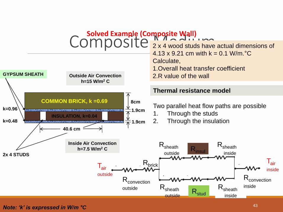
Composite Medium Solved Example (Composite Wall)
2 x 4 wood studs have actual dimensions of
4.13 x 9.21 cm with k = 0.1 W/m.°C
Calculate,
1.Overall heat transfer coefficient
2.R value of the wall
Thermal resistance model
Note: ‘k’ is expressed in W/m °C
Tair
inside
Rsheath
outside
Rsheath
inside Rinsul
Rsheath
outside
Rsheath
inside Rstud
Rconvection
inside
Rconvection
outside
Rbrick Tair
outside
Two parallel heat flow paths are possible
1. Through the studs
2. Through the insulation
COMMON BRICK, k =0.69
INSULATION, k=0.04
GYPSUM SHEATH
k=0.96
k=0.48
2x 4 STUDS
40.6 cm
8cm
1.9cm
1.9cm
Outside Air Convection
h=15 W/m2 C
Inside Air Convection
h=7.5 W/m2 C
43

Composite Medium Solved Example (Composite Wall)
Calculate,
1. Overall heat transfer coefficient
2. R value of the wall
Heat flow through the studs
Note: ‘k’ is expressed in W/m °C
Area = 0.0413m2/unit depth
Heat flow occurs through 6 thermal resistances
1. Convection Resistance outside of brick
2. Conduction resistance in brick
3. Conduction resistance through outer sheet
4. Conduction resistance through wood stud
5. Conduction resistance through inner sheet
6. Convection resistance on inside
Recall,
hARconvection /1 kAxRconduction /
WCRtotal /39.3123.396.03.2248.0807.2614.1
COMMON BRICK, k =0.69
INSULATION, k=0.04
GYPSUM SHEATH
k=0.96
k=0.48
2x 4 STUDS
40.6 cm
8cm
1.9cm
1.9cm
Outside Air Convection
h=15 W/m2 C
Inside Air Convection
h=7.5 W/m2 C
44

Composite Medium Solved Example (Composite Wall)
Calculate,
1. Overall heat transfer coefficient
2. R value of the wall
Heat flow through the insulation
Note: ‘k’ is expressed in W/m °C
The five of the materials are same, but the
resistances involve different area terms, i.e.,
40.6 - 4.13 cm instead of 4.13 cm.
Thus the total resistance of the insulation
section is given below
WCRtotal /337.7
COMMON BRICK, k =0.69
INSULATION, k=0.04
GYPSUM SHEATH
k=0.96
k=0.48
2x 4 STUDS
40.6 cm
8cm
1.9cm
1.9cm
Outside Air Convection
h=15 W/m2 C
Inside Air Convection
h=7.5 W/m2 C
45

Composite Medium Solved Example (Composite Wall)
Calculate,
1. Overall heat transfer coefficient
2. R value of the wall
1. Overall heat transfer coefficient
Note: ‘k’ is expressed in W/m °C
Overall resistance is obtained by combining
the parallel resistances as calculated earlier.
Overall heat transfer coefficient is found by,
(here, A = 0.406m2)
WC
Roverall
/947.5
)337.7/1()39.31/1(
1
overallR
TTUAq
CmWRA
U 2/414.0)406.0)(947.5(
11
COMMON BRICK, k =0.69
INSULATION, k=0.04
GYPSUM SHEATH
k=0.96
k=0.48
2x 4 STUDS
40.6 cm
8cm
1.9cm
1.9cm
Outside Air Convection
h=15 W/m2 C
Inside Air Convection
h=7.5 W/m2 C
46

Composite Medium Solved Example (Composite Wall)
Calculate,
1. Overall heat transfer coefficient
2. R value of the wall
2. R Value of the wall
Note: ‘k’ is expressed in W/m °C
The resistance of the wall is calculated using
the overall heat transfer coefficient, as given
below:
WmCU
Rvalue /.414.2414.0
11 2
COMMON BRICK, k =0.69
INSULATION, k=0.04
GYPSUM SHEATH
k=0.96
k=0.48
2x 4 STUDS
40.6 cm
8cm
1.9cm
1.9cm
Outside Air Convection
h=15 W/m2 C
Inside Air Convection
h=7.5 W/m2 C
47

Composite Medium Solved Example (Critical Thickness of Insulation)
Calculate, the critical thickness of rubber and the
maximum heat transfer rate per metre length of
conductor.
The temperature of rubber is not to exceed 65 °C (due
to heat generated within).
Critical thickness
r = 5mm
Rubber
k = 0.155 W/mK
Ambient at
30°C, 8.5 W/m2K
mWRR
TTQ
ins
i /89.1402.132.1
3065
0
mWC
r
r
kHR
i
ins
/
32.1005.0
0182.0ln
155.02
1ln
2
1 0
mWCHhr
R
/02.15.80182.02
1
2
1
00
0
mhkr oc 0182.05.8/155.0/0
Maximum heat transfer rate
48

Heat Source Systems Plane wall with heat generation
Expression for mid plane temperature is given
by,
The temperature distribution can also be written
in alternative form as:
wTLk
gT 2
02
2
0
1
L
x
TT
TT
w
w
q = heat generated
per unit volume
Tw
Tw
x
L
L
x=
0
49

Conduction-Convection Systems Fins / Extended Surfaces
• Necessity for fins
• Biot Number
=
LONGITUDINAL
RECTANGULAR FIN
h
kx
k
hx
/1
)/(
Internal Conductive resistance
Surface Convective resistance
FIN TYPES
RADIAL FIN 50
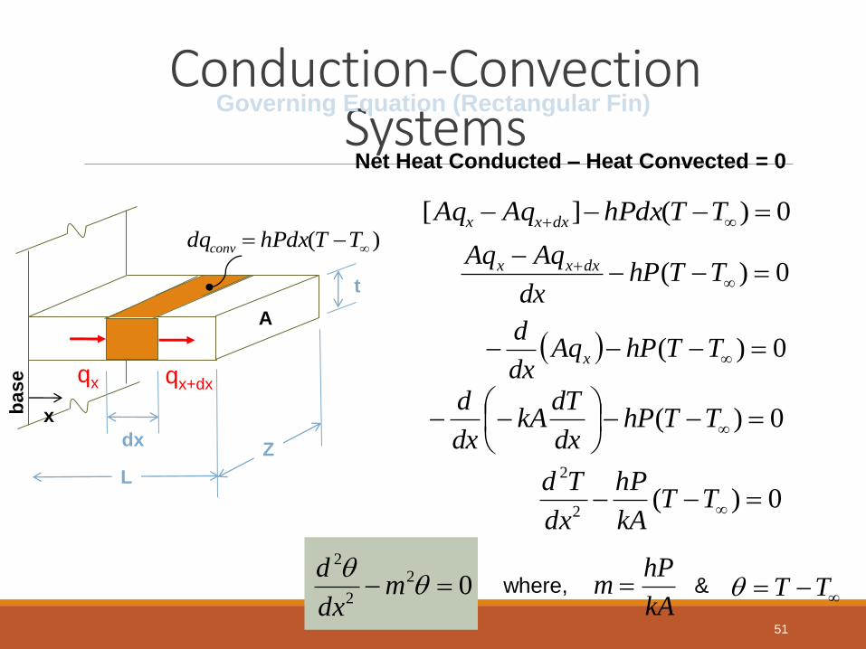
Conduction-Convection Systems
Governing Equation (Rectangular Fin)
Net Heat Conducted – Heat Convected = 0
0)(][ TThPdxAqAq dxxx
)( TThPdxdqconv
qx qx+dx
dx
L
Z
x base
A
t 0)(
TThPdx
AqAq dxxx
0)( TThPAqdx
dx
0)(
TThP
dx
dTkA
dx
d
0)(2
2
TTkA
hP
dx
Td
02
2
2
mdx
dwhere, &
kA
hPm
TT
51

Conduction-Convection Systems Boundary Conditions
LONG FIN
xas 0)(
0at x )( 00
x
TTx
0in x 0)()( 2
2
2
xmdx
xd
Lat x 0dx
(x)d
0at x T(x)
Lx0in 0)()(
00
2
2
2
T
xmdx
xd
SHORT FIN
(end insulated)
Lat x 0)(dx
(x)d
0at x T(x)
Lx0in 0)()(
00
2
2
2
xhk
T
xmdx
xd
e
SHORT FIN
( end not insulated)
52

Conduction-Convection Systems
Types of Fin Boundaries
Type of FIN boundary
Temperature Distribution
Heat transferred by fin
Q
Long Fin (TL= T∞)
e-mx (Tb-T∞)(hPkA)0.5
Short Fin (end insulated)
(hPkA)0.5 (Tb-T∞) tanh (mL) *
Short Fin (end not insulated)
Specified End Temperature At x=L; T=TL
b
T T
T T
m(L-X)
(mL)
Cosh
Cosh
)()/()(
)]([)/()]([
mLSinhmkhmLCosh
XLmSinhmkhXLmCosh
L
L
5.0)()tanh()/(1
)/()tanh()( hPkA
mLmkh
mkhmLTT
L
Lb
)(
)]([)(
mLSinh
xLmSinhmxSinhTT
TT
b
L
5.0)(
)(
1)()]()[( hPkA
mLSinh
mLCoshTTTT Lb
* For higher values of mL (i.e., m=4), tanh mL = 0.999 ≈ 1.
Thus Qshort fin Qlong fin for higher values of mL
53
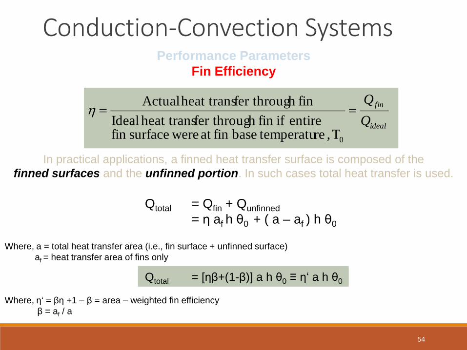
Conduction-Convection Systems Performance Parameters
Fin Efficiency
ideal
fin
Q
Q
0T, re temperatubasefin at weresurfacefin entire iffin h fer througheat trans Ideal
finh fer througheat trans Actual
In practical applications, a finned heat transfer surface is composed of the
finned surfaces and the unfinned portion. In such cases total heat transfer is used.
Qtotal = Qfin + Qunfinned
= η af h θ0 + ( a – af ) h θ0
Where, a = total heat transfer area (i.e., fin surface + unfinned surface)
af = heat transfer area of fins only
Qtotal = [ηβ+(1-β)] a h θ0 ≡ η‘ a h θ0
Where, η‘ = βη +1 – β = area – weighted fin efficiency
β = af / a
54

Conduction-Convection Systems Performance Parameters
Fin Efficiency
Fin
Effic
ien
cy,
η
L (2h/kt)0.5
Fin efficiency curves are available for fins of
various configuration (eg. Axial, circular disk
fins of various length, thickness etc)
Each curve is specific for
specific fin configuration
55

Conduction-Convection Systems Performance Parameters
Fin Effectiveness
Although the addition of fins on a surface increases surface area, it also increases
thermal resistance over the portion of the surface where fins are attached. Therefore
there may be situations in which the addition of fins does not improve heat transfer.
Pk / (Ah) > 1 (to justify usage of fins)
finwithout
finwith
Q
Q essEffectiven
56

Conduction-Convection Systems Solved Example
A steel rod is exposed to ambient air. If one end of the
rod is maintained at a temperature of 120 °C, calculate
the heat loss from the rod
Diameter = 2cm
Length = 25 cm
k = 50 W / m. °C
Tamb = 20°C
h = 64 W / m2. °C
Tbase=120°C
The condition for other end of the rod is not specified
explicitly. By considering L/D ratio, it appears that a
long fin assumption is applicable. Using the simplest
analysis to solve, computing mL:
Therefore, expression for Qlong fin can be used.
4 0.25 16 mL and 16
02.050
6444
)4/( 2
2
m
kD
h
kD
Dh
kA
hPm
W1.256450)02.0(2
20120
4)(
3
2
khDDTThPkATTQ bb
57

Conduction-Convection Systems Solved Example (Fin Efficiency)
CIRCULAR DISK FIN
Circular disk fins of constant thickness are attached on a 2.5 cm OD
tube with a spacing of 100 fins per 1m length of tube.
Fin Properties: Aluminium k = 160 W / m.°C, t = 1mm L = 1 cm
Tube wall temperature = 170 °C; Ambient temperature = 30 °C
Heat transfer coeff. of ambient , h = 200 W/m2. °C.
Calculate,
1. Fin Efficiency and area weighted fin efficiency
2. Heat lost to the ambient air per 1m length of tube
3. Heat loss with that if there were no fins on tube
t
L
Fin
Eff
icie
nc
y, η
L (2h/kt)0.5
ro/ri
Fin Efficiency
Fin efficiency is determined using the graph shown aside.
The following parameters are calculated, firstly:
9.0
graph from determined is efficiencyfin The
8.125.1
125.1
5.010160
2002101
23
2
i
o
r
r
kt
hL
58

Conduction-Convection Systems Solved Example (Fin Efficiency)
CIRCULAR DISK FIN
Calculate,
1. Fin Efficiency and area weighted fin efficiency
2. Heat lost to the ambient air per 1m length of tube
3. Heat loss with that if there were no fins on tube
t
L
Area Weighted Fin Efficiency
Ratio of heat transfer area for fin to the total heat transfer area, β
Fin Surface per cm of tube length = 2π(r02-ri
2) = 2π[2.252-1.252]
= 21.99 cm2
Total heat transfer surface per cm of tube length
= 2π (r02-ri
2) + 2πri (1 – t)
= 2π[2.252-1.252] + 2π(1.25)(1 – 0.1)
= 29.06 cm2
β = af / a = 21.99 / 29.06 = 0.757
Area Weighted Fin Efficiency, η’ = βη +1 – β = 0.757(0.9) + 0.243
= 0.924
Tube OD = 2.5 cm
100 fins per 1m tube length
kfin = 160 W/m°C
t = 1mm; L = 1cm
Ttube = 170°C; Tamb = 30°C
hamb = 200 W/m2. °C
59

Conduction-Convection Systems Solved Example (Fin Efficiency)
CIRCULAR DISK FIN
Calculate,
1. Fin Efficiency and area weighted fin efficiency
2. Heat lost to the ambient air per 1m length of tube
3. Heat loss with that if there were no fins on tube
t
L
Heat lost to ambient per 1m length of tube
Total heat transfer surface a per 1m of tube length
a = 29.06 x 100 cm2 = 0.29 m2
Q = η’ahθ0 = 0.924 x 0.29 x 200 (170 – 30) = 7503 W Tube OD = 2.5 cm
100 fins per 1m tube length
kfin = 160 W/m°C
t = 1mm; L = 1cm
Ttube = 170°C; Tamb = 30°C
hamb = 200 W/m2. °C
Heat lost per 1m length of tube with no fins
Qno fin = 2πrihθ0 = 2π x 0.0125 x 200 x (170 – 30) = 2199 W
Clearly, the addition of fins increases the heat dissipation by a
factor of about 3.4
60

Transient Conduction
• If the surface temperature of a solid body is suddenly altered, the
temperature within the body begins to change over time.
• Variation of temperature both with position and time makes determination of
temperature distribution under transient condition more complicated.
• In some situations, variation of temperature with position is negligible under
transient state, hence the temperature is considered to vary only with time.
• The analysis under the above assumption is called lumped system
analysis.
• Biot Number, Bi = (hx) / k
• Lumped System Analysis is applicable only when Bi < 0.1
61

Systems with Negligible Internal Resistance
• The convective heat loss from the body (shown aside) has its
magnitude equal to decrease in internal energy of solid.
On Integration,
Solving and rearranging,
Lumped Heat Analysis
dt
dTpcVTThAQ )(
dtpcV
hA
TT
dT
1)ln( CtpcV
hATT
Volume V
Area A
Q
T∞
T
T=T0 at t=0
tpcVhATT
TT)./(exp
0
1/hA Cth=ρcV
S T0
T∞
62

Systems with Negligible Internal Resistance
• It is a non-dimensional parameter used to test the validity of the lumped heat
capacity approach.
• The characteristic length (Lc) for some common shapes is given below:
Plane Wall (thickness 2L) Long cylinder (radius R)
Sphere (radius R) Cube (side L)
• The lumped heat capacity approach for simple shapes such as plates, cylinders,
spheres and cubes can be used if Bi < 0.1
Biot Number
k
hL
resistance convective
resistance internalBi c
LA.2
L2.ALc
2
R
L.R2
L.RL
2
c
3
R
R4
R)3/4(L
2
3
c
6
L
L6
LL
2
3
c
63

Systems with Negligible Internal Resistance
• For a rapid response of temperature measuring device, the index, (hAt/ρcV) should
be large to make the exponential term reach zero faster.
• This can be achieved by decreasing wire diameter, density and specific heat or by
increasing value of ‘h’.
• The quantity (ρcV/hA) has the units of time and is called ‘time constant’ of system.
Hence at time t=t* (one time constant),
• At the end of time period t* the temperature difference between the body and
ambient would be 0.368 of the initial temperature difference.
• In other words, the temperature difference would be reduced by 63.2 percent.
• This reduction in 63.2 percent of initial temperature difference is called ‘sensitivity’
• Lower the value of time constant, better the response of instrument.
Response time of a Temperature measuring Instrument
tpcVhATT
TT)./(exp
0
368.01
0
eTT
TT
64

Systems with Negligible Surface Resistance
• When convective heat transfer coefficient at the surface is
assumed to be infinite, the surface temperature remains
constant at all the time (t>0) and its value is equal to that of
ambient temperature.
• The systems exhibiting above said conditions are considered
to have ‘negligible surface resistance’
• An important application of this process is in heat treatment of
metals by quenching, viz., the dropping of a metallic sphere
initially at 300 °C into a 20 °C oil bath.
• Mathematical formulation of this case is :
Ts = T∞ (t>0) Ts
T0(x) for
t = 0
x
L
Large Flat Plate with
Negligible Surface Resistance
t
T
x
T
12
2
Lx 0
condition) (initial Lx0for 0at t )x(TT 0
0for t 0at x TT s Boundary
Conditions 0for t Lat x TT s
65

Heat flow in an Infinitely Thick Plate
• A semi-infinite body is one in which at any instant of time there
is always a point where the effect of heating / cooling at one of
its boundaries is not felt at all.
• At this point the temperature remains unchanged.
• Mathematical formulation is :
with initial and boundary conditions,
Semi-Infinite Plate
Semi-infinite body
Qo
Ts
x
To
at t=0
t
T1
x
T2
2
xallfor 0at t TT 0
0 tallfor 0at x TT s
0 tallfor xas TT 0
66

Systems with Finite Surface and Internal Resistance
Mathematical formulation :
Infinitely Large Flat Plate
of Finite Thickness (2L)
T∞
h
x=0
h
x=L
x=-L
at t=0
x
-x
T∞
1
2
2
t
T
x
T
L)x L-(for 0at t 0 TT
line) (centre 0at x 0x
T
Lat x )TT(k
h
x
T
67

Chart Solutions of Transient Heat Conduction Problems
Time History
Mid Plane
Heisler Charts (by Heisler, 1947)
Infinite Plate
1
0.9
0.8
0.6
0.4
0.2
0.1
0.5
T(x,t) - T∞
Ti- T∞
Fourier number, ατ/L2
hL/k
68

Chart Solutions of Transient Heat Conduction Problems
Time History
Any Position, x
Heisler Charts (by Heisler, 1947)
Infinite Plate
Biot Number, hL/k
x/L
1
0.9
0.8
0.6
0.4
0.2
0.1 100
T(x,t) - T∞
Ti- T∞
0
1
69

Chart Solutions of Transient Heat Conduction Problems
Heat Flow
Heisler Charts (by Heisler, 1947)
Infinite Plate
Q/Qo
hL/k
10 1 0.5 0.1 0.05 0.01 0.001 50 20 40
FoBik
h 2
2
2
)( Where, TTcVQ oo 70
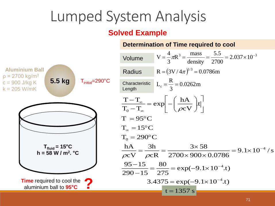
Lumped System Analysis Solved Example
Determination of Time required to cool
Aluminium Ball
ρ = 2700 kg/m3
c = 900 J/kg K
k = 205 W/mK
m0262.03
RL
m0786.04/V3R
10037.22700
5.5
density
massR
3
4V
c
3/1
33
5.5 kg
Tfluid = 15°C
h = 58 W / m2. °C
Time required to cool the
aluminium ball to 95°C ?
Tinitial=290°C
Volume
Radius
Characteristic
Length
s 1357 t
)t.101.9exp(3.4375
)t.101.9exp(275
80
15290
1595
s/101.90786.09002700
583
cR
h3
cV
hA
C290T
C15T
C95 T
t.cV
hAexp
TT
TT
4
4
4
0
0
71

Lumped System Analysis
Solved Example
The temperature of a gas stream is to be measured by
a thermocouple whose junction can be approximated
as a 1mm diameter sphere (shown aside)
Determine how long it will take for the thermocouple to
read 99% of initial temperature difference
Gas T∞
h=210 W/m2 °C
How long will it take for the
thermocouple to read 99 %
of Initial Temperature
difference
?
Lc = V/As = (1/6)D = (1/6)x0.001 = 1.67x10⁻⁴ m
Bi = hL/k = (210x 1.67x10-4) x 35 = 0.001 < 0.1
Therefore, lumped system analysis is applicable.
In order to read 99% of initial temperature difference
Ti – T∞ between the junction and the gas, we must
have
Temperature Measurement by Thermocouples
Junction (Sphere)
D= 1mm
ρ = 8500 kg/m3
k = 35 W/mK
c = 320 J/kg K
Thermocouple Wire
01.0TT
TT
0
72

Lumped System Analysis
Solved Example
The temperature of a gas stream is to be measured by
a thermocouple whose junction can be approximated
as a 1mm diameter sphere (shown aside)
Determine how long it will take for the thermocouple to
read 99% of initial temperature difference
Gas T∞
h=210 W/m2 °C
How long will it take for the
thermocouple to read 99 %
of Initial Temperature
difference
? t = 10s
Temperature Measurement by Thermocouples
Junction (Sphere)
D= 1mm
ρ = 8500 kg/m3
k = 35 W/mK
c = 320 J/kg K
Thermocouple Wire
Time
t).pcV/hA(exp01.0TT
TT
0
1
4
c
s s 462.01067.13208500
210
cL
h
cV
hA
01.0t).462.0(exp
73

Transient Conduction in Semi-infinite Solids Solved Example
A water pipe is to be buried in soil at
sufficient depth from the surface to prevent
freezing in winter.
What minimum depth is required to
prevent the freezing of pipe when soil is at
uniform temperature of Ti = 10 °C, the
surface is subjected to a uniform temperature
of T0 = -15 °C continuously for 50 days.
Also the pipe surface temperature should
not fall below 0 °C 74

Transient Conduction in Semi-infinite Solids Solved Example
What burial depth is needed to
prevent freezing of the pipe ?
SOIL
Water Pipe
(to be buried)
?
Tsurface = -15 °C
Condition : Tpipe wall should not fall below 0 °C
Tsoil = 10 °C
75
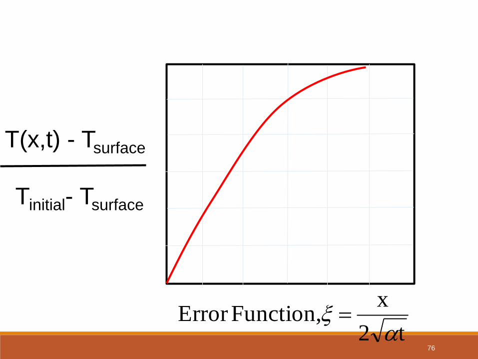
T(x,t) - Tsurface
Tinitial- Tsurface
t2
x Function,Error
Temperature Distribution in Semi-infinite Solid
76

Determination of Burial depth
graph) (from 0.6 ,6.0),(For
6.01510
150),(),(
0
0
tx
TT
TtxTtx
i
by,given is function error the
3600s2450 tand /100.2For 2-6
sm
x538.036002450100.22
x
t2
x
6-
77

Determination of Burial depth
m
x
12.10.538
0.6 x
6.0538.0
The pipe should be buried at least to a depth of
1.12 m to prevent freezing.
78

Application of Heisler Charts
Aluminium Slab
Thickness=10cm
α = 8.4x10⁻⁵ m2/s
ρ = 2700 kg/m3
c = 900 J/kg K
k = 215 W/mK
Tfluid = 100°C
h = 1200 W / m2. °C
Mid-plane Temperature and Surface
Temperature after 1 min?
Tinitial=500°C
79

Determination of Mid plane Temperature
2L=10 cm ; L = 5 cm ; t = 1min = 60 s
αt/L2 = (8.4x10-5 x 60) / 0.052 = 2.016
Bi = hL/k = (1200x0.05) x 215 = 0.28
Using above two parameters in Heisler Chart,
C372)100500(68.0100T
68.0TT
TT
0
80

Determination of Surface Temperature
For x/L = 1 and Bi = 0.28,
C36.339)100372(88.0100T
88.0TT
TT
0
81

Energy Loss
h2αt/k2 = (12002x8.4x10-5 x 60) / 2152 = 0.157
Bi = hL/k = (1200x0.05) x 215 = 0.28
Using above 2 parameters in Heisler Chart for
Heat flow, Q/Q0 = 0.32
26
000
m/J1097.2
4001.09002700
)TT)(L2(cA
TTcV
A
Q
82

Heat removed per unit surface area
26
6
m/J101.31
102.9732.0A
Q
83

UNIT III – CONVECTIVE
HEAT TRANSFER
84

85
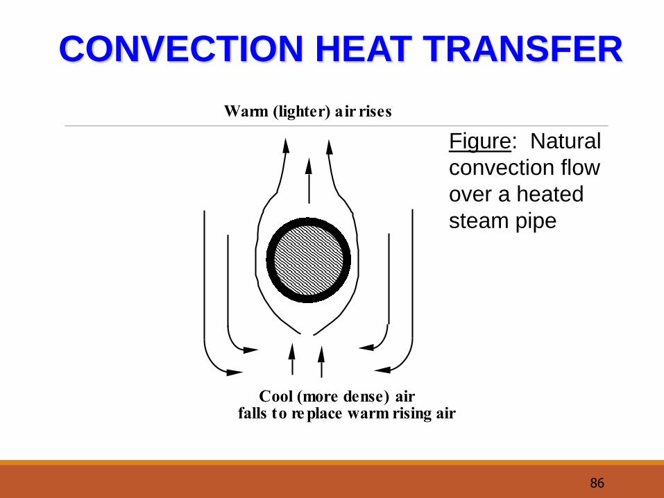
CONVECTION HEAT TRANSFER
Modes
forced
flow induced by external agency e.g. pump
eg. forced-draught air cooler, evaporators
natural
fluid motion caused by temperature-induced
density gradients within fluid
Examples
air flow over hot steam pipe, fireplace
circulation, cooling electronic devices
86
CONVECTION HEAT TRANSFER
Warm (lighter) air rises
Cool (more dense) air falls to re place warm rising air
Figure: Natural
convection flow
over a heated
steam pipe

87
Forced convection generally most-effective transport of
energy from solid to fluid.
Modelling Convection
SolidT
s Flowing
fluid
Tb
Q. Engineer's prime
concern
rate of convection
enables sizing of
equipment

88
Modelling Convection
h - convective heat transfer
coefficient.
Main problem
predict h value for:
• variety fluids & flow rates
• range of shapes
Experimentally found that:
s b
s b
Q A T T
Q A T Th

89
Rate equation Written in same form as Ohm’s Law:
Resistance Concept
Potential Difference V Current flow I =
Resistance R
s b s b
s b
T T T T Q A T T
1/ A Rh
h
(Ts-Tb)= driving force
(1/hA) – thermal resistance (R) for convection heat transfer.
Ts
hA
1
surface fluid
Q•
bT
Ts
bTQ•

90
TYPICAL UNITS FOR h
S.I.: W m-2
K-1
or J s-1
m-2
K-1
British: Btu hr-1
ft-2
(F deg)-1
Conversion: 1 W m-2
K-1
= 0.176 Btu hr-1
ft-2
(F deg)-1
Typical Values
free convection (air) 5 - 60
forced convection (air) 25 - 300
forced convection (water) 200 - 10,000
boiling water 2,000 - 25,000
condensing steam 4,000 - 110,000

91
Illustration 27.1
Air at 20°C is blown over an electrical resistor to keep it cool.
The resistor is rated at 40,000 ohm and has a potential
difference of 200 volts applied across it.
The expected mean heat transfer coefficient between the
resistor surface and the air is 50 W m-2K-1.
What will be the surface temperature of the resistor, which
has a surface area of 2 cm2?
R = 40,000
Air 20°C
h = 50 W m K
Potential = 200 V

92
SOLUTION
Energy Balance
Generation = heat loss by convection
Rate of heat generation
Convective loss
2
2 2
4
P Q
VP VI V
R
V 200Q 1 watt
R 4x10
V
R
s b4
so
s
Q A(T T )
1 (50)(2x10 )(T 20)
T 120 C
h

93
Determining the size (H/T area) of the
exchanger
2 31 1 2 2 3 4
T T Q h A T T kA h A T T
x
Figure 1. Heat transfer between two flowing fluids
separated by a rectangular
1 4
1 2
T T overall driving forceQ
1 x 1 resis tances
h A kA h A
(10.25)
(10.26)

94
Determining the size (H/T area) of the
exchanger
i o
o
i
i i o o
i o
1 2 3
T T Q
rln
r1 1
h A 2 kL h A
T TQ
R R R
Figure 2: Heat transfer between
two flowing fluids separated by a
cylindrical wall (10.27)

95
Overall heat-transfer coefficient
2overall heat-transfer coefficient /o
where
U W m K
duty o
duty
o
Q U A T
T TQ
1 R
U A
As a short-hand method of describing heat-
exchanger performance, we use the overall heat-
transfer coefficient,
(10.28)
s bQ A T Th

96
Determining the size (H/T area) of the
exchanger

97
Illustration 27.2
Consider the kettle below. For the conditions given, find the flame
temperature for the following values of the heat transfer coefficients:
hi (boiling) = 4000 W m-2K-1 ho (gas flame) = 40 W m-2K-1
T
1
2
3
h
i
o
Water
Flame
Q.
h
T
T
T
o
h
1
Q•
= 1.88 kW
hio
x
k
T0 1 2 3T = 100°CT T
1?
FLAME
BOILING WATER

98
Solution
Plane slab- area constant, eliminate A:
o o 1
1 1 x 1
U A h A kA h A
3
o
-2 -1o
1 1 1.2x10 1
U 40 204 4000
U 39.6 W m K

99
Solution
Q 1883 W (as before)
duty o o 3
dutyo 3
o
oo 3 2
oo
Q U A T T
QT T
AU1883
T T 1514K 1514 C3.14x10 39.6
T 1514 100 1614 C
-2 2A = 3.14x10 m (as before)
T
1
2
3
h
i
o
Water
Flame
Q.
h
T
T
T
o

100
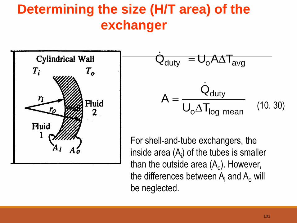
Determining the size (H/T area) of the
exchanger
• The term Tavg in equation 10.28 represents the temperature
difference between the hot and cold streams averaged.
• For single-pass exchangers, the appropriate form of Tavg is
the log-mean temperature difference, Tlog mean (often
abbreviated LMTD), defined as
(10.29)
duty o avg Q U A T (10.28)
log mean
1 2log mean
1
2
Log mean temperature difference T
T TT
Tln
T
101
Determining the size (H/T area) of the
exchanger
duty o avg Q U A T
(10. 30)
duty
o log mean
QA
U T
For shell-and-tube exchangers, the
inside area (Ai) of the tubes is smaller
than the outside area (Ao). However,
the differences between Ai and Ao will
be neglected.

102
Example
Hot
Cold
Saturated Steam,
280oF, mstream
Saturated water,
280oF, mstream
Oil, 110oF, 960 lbm/min Oil, 35oF, 960 lbm/min
Balance on cold stream:
p out in dutycold
omdutyo
m cold
duty
mC T T Q 10.24b
lb Btu960 0.74 110 35 F Q
min lb F
BtuQ 53,280
min

103
Example
How much area is required for the counter-current heat
exchanger in Example 10.5?
Hot
Cold
Saturated Steam,
280oF, mstream
Saturated water,
280oF, mstream
Oil, 110oF, 960 lbm/min Oil, 35oF, 960 lbm/min
o1
o2
olog mean
T 280 35 245 F
T 280 110 170 F
245 170T 205 F
245ln170
1
2
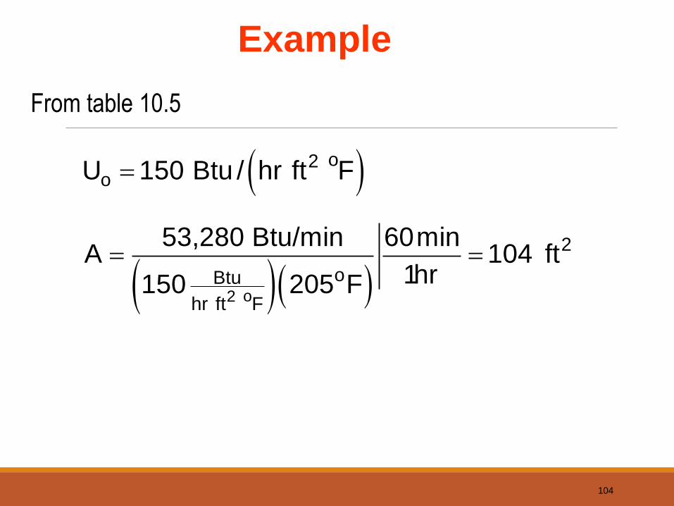
104
Example
o2
o2o
2
oBtu
hr ft F
U 150 Btu / hr ft F
53,280 Btu/min 60minA 104 ft
1hr150 205 F
From table 10.5

105
Example
How much area is required for the co-current heat exchanger
in Example 10.5?
Hot
Cold
Saturated Steam,
280oF, mstream
Saturated water,
280oF, mstream
Oil, 110oF, 960 lbm/min Oil, 35oF, 960 lbm/min
o1
o2
olog mean
T 280 110 170 F
T 280 35 245 F
170 245T 205 F
170ln245
1
2

106
Example
o2
o2o
2
oBtu
hr ft F
U 150 Btu / hr ft F
53,280 Btu/min 60minA 104 ft
1hr150 205 F
From table 10.5

UNIT IV – RADIATION
107

General Considerations
General Considerations • Attention is focused on thermal radiation, whose origins are associated with emission from matter at an absolute temperature T >0
• Emission is due to oscillations and transitions of the many electrons that comprise matter, which are, in turn, sustained by the thermal energy of the matter. • Emission corresponds to heat transfer from the matter and hence to a reduction in thermal energy stored by the matter.
• Radiation may also be intercepted and absorbed by matter.
• Absorption results in heat transfer to the matter and hence an increase in thermal energy stored by the matter. • Consider a solid of temperature in an evacuated enclosure whose walls are at a fixed temperature
What changes occur if Why ?
What changes occur if Why ?
108
sT
: surT
?surs TT
?surs TT

General Considerations (cont)
• Emission from a gas or a semitransparent solid or liquid is a volumetric phenomenon. Emission from an opaque solid or liquid is a surface phenomenon.
For an opaque solid or liquid, emission originates from atoms and molecules within 1 of the surface. m
• The dual nature of radiation:
– In some cases, the physical manifestations of radiation may be explained by viewing it as particles (aka photons or quanta). – In other cases, radiation behaves as an electromagnetic wave.
109

General Considerations (cont)
– In all cases, radiation is characterized by a wavelength and frequency
which are related through the speed at which radiation propagates in the
medium of interest:
For propagation in a vacuum,
110
c
m/s 10998.2 8 occ

The EM Spectrum
The Electromagnetic Spectrum
• Thermal radiation is confined to the infrared, visible, and ultraviolet regions of the spectrum . • The amount of radiation emitted by an opaque surface varies with wavelength, and we may speak of the spectral distribution over all wavelengths or of monochromatic/spectral components associated with particular wavelengths.
111
m)1001.0(

Directional Considerations
Directional Considerations and the Concept of Radiation Intensity
• Radiation emitted by a surface will be in all directions associated with a hypothetical hemisphere about the surface and is characterized by a directional distribution.
• Direction may be represented in a spherical
coordinate system characterized by the zenith
or polar angle and the azimuthal angle .
unit element of surface on a hypothetical sphere and normal to the , direction.
• The amount of radiation emitted from a surface, and propagating in a particular direction, , , is quantified in terms of a differential solid angle associated with the direction.
112
1dA
2r
dAd n
ndA

Directional Considerations (cont)
– The solid angle has units of steradians (sr).
– The solid angle associated with a complete hemisphere is
• Spectral Intensity: A quantity used to specify the radiant heat flux (W/m2) within a unit solid angle about a prescribed direction (W/m2
sr) and within a unit wavelength interval about a prescribed wavelength (W/m2
sr m)
113
ddr
dAd
ddrdA
n
n
sin
sin
2
2
sr 2sin2
0
2/
0hemi
dd
• The spectral intensity I,e associated with emission from a surface element dA1
in the solid angle d about , and the wavelength interval d about is defined as:
dddA
dqI e
cos,,
1
,

Directional Considerations (cont)
• The rationale for defining the radiation flux in terms of the projected surface area (dA1 cos ) stems from the existence of surfaces for which, to a good approximation, I
,e is independent of direction. Such surfaces are termed diffuse, and the radiation is said to be isotropic.
The projected area is how dA1 would
appear if observed along , .
– What is the projected area for = 0 ?
– What is the projected area for = /2 ?
• The spectral heat rate and heat flux associated with emission from dA1
are, respectively,
114
ddAId
dqdq e cos,, 1,
ddIdIdq ee sincos,,cos,, ,,
"

Radiation Fluxes
Relation of Intensity to Emissive Power, Irradiation, and Radiosity
• The spectral emissive power (W/m2 m) corresponds to spectral emission over all possible directions (hemispherical).
• The total emissive power (W/m2 ) corresponds to emission over all directions and wavelengths (hemispherical).
• For a diffuse surface, emission is isotropic and
where Ie is called total intensity.
115
2
0 0,
2
sincos),,()( ddIE e
dEE )(0
)(sincos)()( ,
2
0 0,
2
ee IddIE
ee IdIdEE
)()(0
,0

Radiation Fluxes (cont)
• The spectral irradiation (W/m2 m) is then
and the total irradiation (W/m2 ) is
How may G and G be expressed if the incident radiation is diffuse?
116
• The spectral intensity of radiation incident on
a surface, I,i , is defined in terms of the unit
solid angle about the direction of incidence,
the wavelength interval d about ,
and the projected area of the receiving
surface, dA1cos .
Irradiation
2
0 0,
2
sincos),,()( ddIG i
dGG )(0
)(sincos)()( ,
2
0 0,
2
ii IddIG
ii IdIdGG
)()(0
,0

Radiation Fluxes (cont)
• With I,e+r designating the spectral intensity associated with radiation
emitted by the surface and the reflection of incident radiation, the spectral radiosity (W/m2 m) is
and the total radiosity (W/m2 ) is
How may J and J be expressed if the surface emits and reflects
diffusely?
117
• The radiosity of an opaque surface accounts for all of the radiation leaving the surface in all directions and may include contributions to both reflection and emission.
Radiosity
2
0 0,
2
sincos),,()( ddIJ re
dJJ )(0
)(sincos)()( ,
2
0 0,
2
rere IddIJ
rere IdIdJJ
)()(0
,0

The Blackbody
Blackbody Radiation
• The Blackbody An idealization providing limits on radiation emission and absorption by matter.
– For a prescribed temperature and wavelength, no surface can emit more radiation than a blackbody: the ideal emitter.
– A blackbody is a diffuse emitter.
– A blackbody absorbs all incident radiation: the ideal absorber. • The Isothermal Cavity
(a) After multiple reflections, virtually all radiation entering the cavity is absorbed.
(b) Emission from the aperture is the maximum possible emission achievable for the temperature associated with the cavity and is diffuse.
118
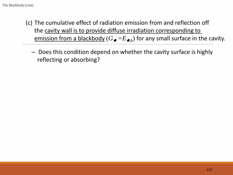
The Blackbody (cont)
(c) The cumulative effect of radiation emission from and reflection off the cavity wall is to provide diffuse irradiation corresponding to emission from a blackbody (G
=E
,b) for any small surface in the cavity.
– Does this condition depend on whether the cavity surface is highly reflecting or absorbing?
119

Planck Distribution
The Spectral (Planck) Distribution of Blackbody Radiation
• The spectral distribution of the blackbody emissive power (determined theoretically and confirmed experimentally) is
120
1exp
),(),(25
1,,
TC
CTITE bb
Km10439.1,m/mW10742.3 4
2
248
1 CC
E,b varies continuously with and increases
with T.
The distribution is characterized by a
maximum for which max is given by
Wien’s
displacement law:
The fractional amount of total blackbody emission appearing at lower wavelengths increases with increasing T.
Km 28983max CT
Stefan-Boltzmann Law
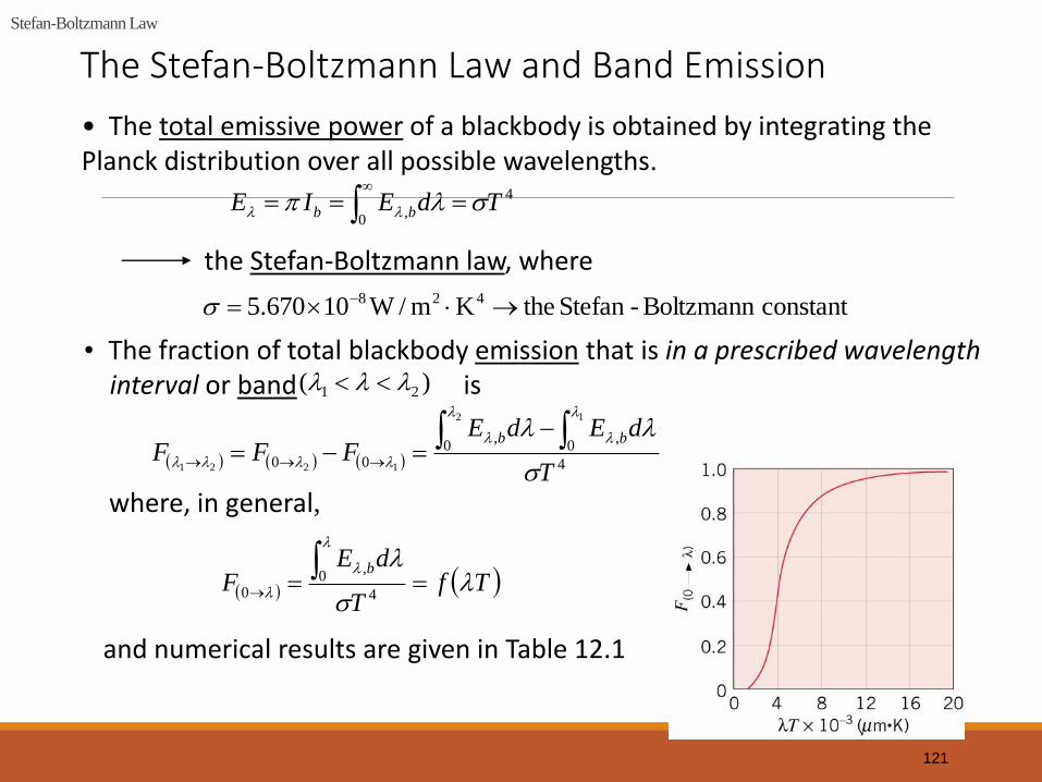
The Stefan-Boltzmann Law and Band Emission
• The total emissive power of a blackbody is obtained by integrating the Planck distribution over all possible wavelengths.
the Stefan-Boltzmann law, where
• The fraction of total blackbody emission that is in a prescribed wavelength interval or band is
where, in general,
and numerical results are given in Table 12.1
121
4
0, TdEIE bb
constantBoltzmann -Stefan theKm/W10670.5 428
)( 21
4
0,
0,
00
12
1221 T
dEdEFFF
bb
TfT
dEF
b
4
0,
0

Band Emission
• Table 12.1
. . . .
. . . .
. . . .
122

Band Emission (cont)
Note ability to readily determine I,b and its relation to the maximum
intensity from the 3rd and 4th columns, respectively.
If emission from the sun may be approximated as that from a blackbody at 5800K, at what wavelength does peak emission occur? Would you expect radiation emitted by a blackbody at 800K to be discernible by the naked eye?
As the temperature of a blackbody is increased, what color would be the first to be discerned by the naked eye?
123

Emissivity
Surface Emissivity • Radiation emitted by a surface may be determined by introducing a property (the emissivity) that contrasts its emission with the ideal behavior of a blackbody at the same temperature.
• The definition of the emissivity depends upon one’s interest in resolving directional and/or spectral features of the emitted radiation, in contrast to averages over all directions (hemispherical and/or wavelengths (total).
• The spectral, directional emissivity:
• The spectral, hemispherical emissivity (a directional average):
124
2
0 0,
2
0 0,
,2
2
sincos),(
sincos),,,(
),(
),(),(
ddTI
ddTI
TE
TET
b
e
b
),(
),,,(),,,(
,
,
,TI
TIT
b
e

Emissivity (cont)
• The total, hemispherical emissivity (a directional and spectral average):
• To a reasonable approximation, the hemispherical emissivity is equal to the normal emissivity.
• Representative values of the total, normal emissivity:
Note: Low emissivity of polished metals and increasing emissivity for unpolished and oxidized surfaces. Comparatively large emissivities of nonconductors.
125
)(
),(),(
)(
)()( 0
,
TE
dTET
TE
TET
b
b
b
n

Emissivity (cont)
• Representative spectral variations:
Note decreasing ,n with increasing for metals and different
behavior for nonmetals. • Representative temperature variations:
Why does n increase with increasing T for tungsten and not for aluminum oxide?
126

Abs, Ref & Trans
Response to Surface Irradiation: Absorption, Reflection and Transmission
• There may be three responses of a semitransparent medium to irradiation:
Reflection from the medium refG , .
Absorption within the medium absG , .
Transmission through the medium trG , .
Radiation balance
ref abs trG G G G , , ,
• In contrast to the foregoing volumetric effects, the response of an opaque material
to irradiation is governed by surface phenomena and 0trG , .
ref trG G G , ,
• The wavelength of the incident radiation, as well as the nature of the material, determine whether the material is semitransparent or opaque.
Are glass and water semitransparent or opaque?
127

Abs, Ref & Trans (cont)
• Unless an opaque material is at a sufficiently high temperature to emit visible radiation, its color is determined by the spectral dependence of reflection in response to visible irradiation.
What may be said about reflection for a white surface? A black surface?
Why are leaves green?
128
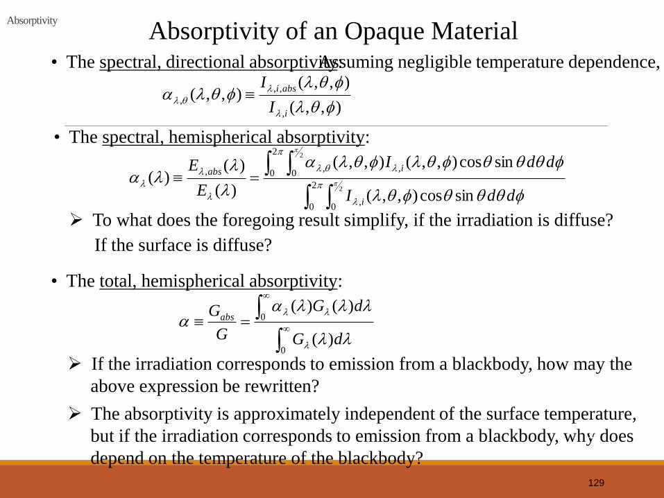
Absorptivity
Absorptivity of an Opaque Material • The spectral, directional absorptivity:
• The spectral, hemispherical absorptivity:
To what does the foregoing result simplify, if the irradiation is diffuse?
If the surface is diffuse?
• The total, hemispherical absorptivity:
If the irradiation corresponds to emission from a blackbody, how may the
above expression be rewritten?
Assuming negligible temperature dependence,
The absorptivity is approximately independent of the surface temperature,
but if the irradiation corresponds to emission from a blackbody, why does
depend on the temperature of the blackbody?
129
),,(
),,(),,(
,
,,
,
i
absi
I
I
2
0 0,
2
0 0,,,
2
2
sincos),,(
sincos),,(),,(
)(
)()(
ddI
ddI
E
E
i
iabs
0
0
)(
)()(
dG
dG
G
Gabs

Reflectivity
Reflectivity of an Opaque Material
• The spectral, directional reflectivity: Assuming negligible temperature dependence:
• The spectral, hemispherical reflectivity:
To what does the foregoing result simplify if the irradiation is diffuse?
If the surface is diffuse?
• The total, hemispherical reflectivity:
• Limiting conditions of diffuse and
spectral reflection. Polished and
rough
surfaces.
130
),,(
),,(),,(
,
,,
,
i
refi
I
I
2
0 0,
2
0 0,,,
2
2
sincos),,(
sincos),,(),,(
)(
)()(
ddI
ddI
E
G
i
iref
0
0
)(
)()(
dG
dG
G
Gref

Reflectivity (cont)
Note strong dependence of and 1 on .
Is snow a highly reflective substance? White paint?
131

Transmissivity Transmissivity The spectral, hemispherical transmissivity: Assuming negligible temperature
dependence,
trG
G
,
Note shift from semitransparent to opaque conditions at large and small wavelengths.
• The total, hemispherical transmissivity:
0
0
trtrG dG
G G d
,
132

Transmissivity
• For a semitransparent medium,
133
• For a gray medium,
1
1
1
1
• The demo experiment shows that the black material absorbs more irradiation than the aluminum does.

Kirchhoff’s Law
• Kirchhoff’s law equates the total, hemispherical emissivity of a surface to its total, hemispherical absorptivity:
Kirchhoff’s Law
However, conditions associated with its derivation are highly restrictive:
Irradiation of the surface corresponds to emission from a blackbody at the same temperature as the surface.
• However, Kirchhoff’s law may be applied to the spectral, directional properties without restriction:
Why are there no restrictions on use of the foregoing equation?
134
,,

Diffuse/Gray Surfaces Diffuse/Gray Surfaces
• With
Under what conditions may we equate to ?
• With
and
Under what conditions may we equate ?
• Conditions associated with
assuming a gray surface:
135
Note: informally, a poor reflector (a good absorber) is a good emitter, and a good reflector (a poor absorber) is a poor emitter.
2
0 0
2
0 0,
2
2
sincos
sincos
dd
dd
2
0 0,
2
0 0,,
2
2
sincos
sincos and
ddI
ddI
i
i
)(
)(0
,
TE
dE
b
b
G
dG
0)(
to

Radiation Exchange Between Surfaces: Enclosures with Nonparticipating Media
CHAPTER 13
SECTIONS 13.1 THROUGH 13.4

Basic Concepts
Basic Concepts
• Enclosures consist of two or more surfaces that envelop a region of space (typically gas-filled) and between which there is radiation transfer. Virtual, as well as real, surfaces may be introduced to form an enclosure.
• A nonparticipating medium within the enclosure neither emits, absorbs, nor scatters radiation and hence has no effect on radiation exchange between the surfaces.
• Each surface of the enclosure is assumed to be isothermal, opaque, diffuse and gray, and to be characterized by uniform radiosity and irradiation.
137

View Factor Integral
The View Factor (also Configuration or Shape Factor)
• The view factor, is a geometrical quantity corresponding
to the fraction of the radiation leaving surface i that is intercepted by
surface j.
,ijF
i j
ij
i i
qF
A J
The view factor integral provides a general expression for Consider exchange
between differential areas
.ijF
i :jdA and dA
2
1 cos cos
i j
i j
ij i jA Ai
F dA dAA R
2
cos coscos
i j
i j i i i j i i i jdq I dAd J dAdAR
138
Surfaces are diffuse emittters and reflectors and have uniform radiosity.

View Factor Relations
View Factor Relations
• Reciprocity Relation. With
2
1 cos cos
ji
i j
ji i jAAj
F dAdAA R
• Summation Rule for Enclosures.
1
1N
ijj
F
• Two-Dimensional Geometries (Table 13.1) for example,
An Infinite Plane and a
Row of Cylinders
1 2 1 22 2 2
1
21 1
/ /
tanijD D s DFs s D
i ij j jiA F A F
139

View Factor Relations (cont)
• Three-Dimensional Geometries (Table 13.2).
For example, Coaxial Parallel
Disks
1 222
2
2
1 42
11
/
/
/ /
ij j i
j
i
i i j j
F S S r r
RS
R
R r L R r L
140

UNIT V – HEAT EXCHANGERS
141

Classification of heat exchangers Heat exchangers are devices that provide the flow of thermal
energy between 2 or more fluids at different temperatures.
They are used in a wide variety of applications. These include
power production, process, chemical, food and manufacturing
industries, electronics, environmental engg. , waste heat
recovery, air conditioning, reefer and space applications.
Heat Exchangers may be classified according to the following criteria.
•Recuperators/ regenerators
•Transfer process: direct and indirect contact
•Geometry of construction; tubes, plates, and extended
surfaces.
•Heat transfer mechanism: single phase and two phase
•Flow arrangement: Parallel, counter, cross flow. 142

Recuperation/regeneration HE
Conventional heat exchangers with heat transfer between
2 fluids. The heat transfer occurs thro a separating wall or
an interface.
In regenerators or storage type heat exchangers, the same
flow passage alternately occupied by one of the two fluids.
Here thermal energy is not transferred thro’ a wall as in
direct transfer type but thro’ the cyclic passage of 2 fluid
thro the same matrix.
Example is the ones used for pre heating air in large coal
fired power plant or steel mill ovens.
Regenerators are further classified as fixed and rotary.
143

Transfer process According to transfer process heat exchangers are classified
as direct contact type and indirect contact type.
In direct contact type, heat is transferred between cold and
hot fluids through direct contact of the fluids (eg. Cooling
towers, spray and tray condensers)
In indirect heat exchanger, heat energy is transferred thro’ a
heat transfer surface,
144

Direct Contact Heat Exchangers
In the majority of heat exchangers heat is transferred through
the metal surfaces, from one fluid to another.
The fluid flow is invariably turbulent.
The transfer of heat has to overcome several thermal
resistances that are in "Series“
Under normal service conditions tubes may well have a deposit
of scale or dirt. Next to this a layer of stationary fluid adheres.
Between this stationary layer of fluid and the general flow there
is a boundary (or buffer) layer of fluid
The thickness of the stationary and boundary layer depends on
the flow velocity and the type of surface.
In all cases the thermal resistance of these "films“ is
considerably greater than the resistance of the metal.
145

Heat Exchangers The classic thermodynamic heat exchangers are classified as
either:
PARALLEL FLOW
146

Heat Exchangers
or
CONTRA FLOW.
147

Heat Exchangers Most practical heat exchangers are a mixture of
both types of flow. Some multi-pass arrangements
try to approximate to the contra-flow. The greater
the number of passes the closer the approximation.
148
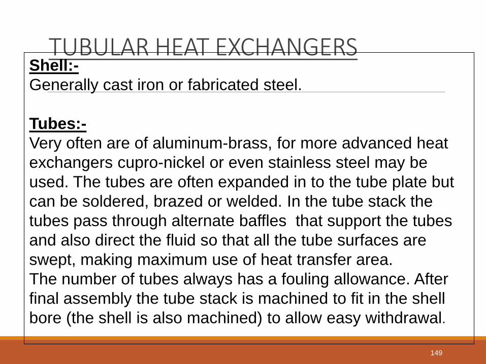
TUBULAR HEAT EXCHANGERS Shell:-
Generally cast iron or fabricated steel.
Tubes:-
Very often are of aluminum-brass, for more advanced heat
exchangers cupro-nickel or even stainless steel may be
used. The tubes are often expanded in to the tube plate but
can be soldered, brazed or welded. In the tube stack the
tubes pass through alternate baffles that support the tubes
and also direct the fluid so that all the tube surfaces are
swept, making maximum use of heat transfer area.
The number of tubes always has a fouling allowance. After
final assembly the tube stack is machined to fit in the shell
bore (the shell is also machined) to allow easy withdrawal.
149

TUBULAR HEAT EXCHANGERS Tube-Plates:-
Material would be to suit the tube material and method of
fixing. Usually assembled so that the water boxes can be
removed without disturbing the tube fastening.
Water Boxes:-
Cast iron or. fabricated steel, always designed to keep
turbulence and pressure loss at a minimum. Coated for
corrosion protection.
Expansion arrangements can be either, 'u' tube, 'Floating
Head', Bayonet Tube, or may have an Expansion Bellows in
the shell.
150
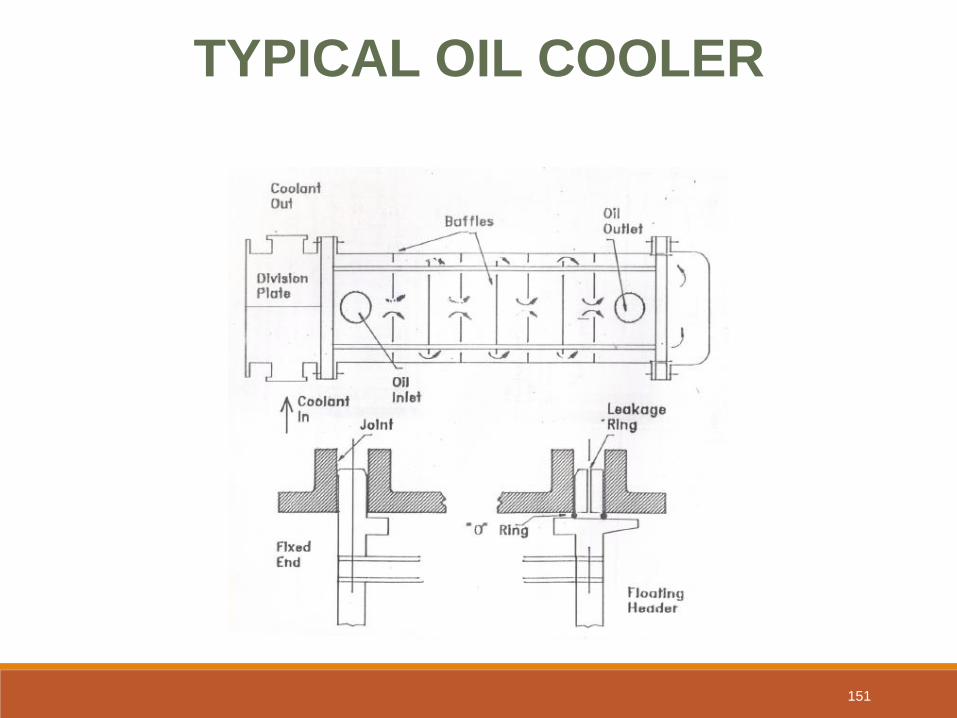
TYPICAL OIL COOLER
151

152

TUBULAR HEAT EXCHANGER
Packing nut
153

TUBULAR HEAT EXCHANGERS ;Types
•Expansion Bellows In Shell:-
Requires an allowance for pipe-work to move. Shell support
required when installing or when maintenance work is done.
Allows the use of welding or brazing of tubes.
•Floating Header:-
Allows removal of stack for cleaning. Requires a machined
shell interior. Possibility of leaks so a leak detection system
needed. This is Expensive
•Fixed 'u' Tube:-
Cheapest to manufacture Tube stack easily removed. Only
uses one tube plate.
Can not be single pass. Non-standard tube so spares are
expensive.
•Bayonet Tubes.
Usually used for sophisticated fuel oil heaters
154

Gasketed PHEs Gasketed plate heat exchangers (the plate and frame )
were introduced in the 30s mainly for the food industries
because of their ease of cleaning, and their design
reached maturity in the 60s with the development of more
active plate geometries, assemblies and improved gasket
materials. The range of possible applications has
widened considerably and, at present, under specific and
appropriate conditions, overlap and competes in areas
historically considered the domain of tubular heat
exchangers. They are capable of meeting an extremely
wide range of duties in as many industries. Therefore
they can be used as an alternative to shell and tube type
heat exchangers for low and medium pressure liquid to
liquid heat transfer applications. 155

Gasketed PHEs
Design of plate heat exchangers is highly
specialized in nature considering the variety of
designs available for plate and arrangement
that possibly suits various duties. Unlike tubular
heat exchangers for which design data and
methods are easily available, plate heat
exchanger design continues to be proprietary in
nature. Manufacturers have developed their
own computerized design procedures
applicable to their exchangers they market.
156

Gasketed PHEs
157

PLATE HEAT EXCHANGERS
Allow the use of contra-flow design, reducing heat
transfer area.
The liquid flows in thin streams between the plates.
Troughs, pressed into the plates produce extremely high
turbulence, this combined with large heat transfer areas
result in a compact unit. The plate form can produce
turbulent flow with Reynolds Numbers as low as ten. This
type of flow produces a very low fouling rate in the heat
exchanger when compared with the tubular type. The
heaters are suitable for circulatory cleaning in place, (CIP)
as there are no dead areas.
Only the plate edges are exposed to the atmosphere so heat loss is
negligible, no insulation is required.
158

PHEs The plates are available in different versions of trough
geometry, this gives flexibility in the "thermal length".
For instance, when a washboard type plate is assembled
adjacent to a chevron type the thermal length will depend on
the chevron angle. Plate heat exchangers can not deal with
high pressures due to the requirement for plate gaskets.
They can not deal with the large volume flows associated with
low pressure vapours and gasses.
For same distance of travel larger time of heat exchange
between the two fluids : “high thermal length”
159

PHEs
Plates
160

PHEs
Gasket
Washboard
type plate
Chevron type
161

PHEs High Thermal length
Low thermal length
162

163

Parallel Flow
164

Contra-Flow
165

Para Flo Vs Contra Flo In a parallel flow heating system, ‘t’ out of heated liquid< ‘T’
out of the heating liquid.
The use of a contra flo heat exchanger is usually more
desirable thermodynamically as there is a reduction in area
compared with parallel flo HE. With the contra flo (assuming
a heating process) the final temperature of the heated fluid
can be higher than the outlet temperature of heating medium.
This is not possible with parallel flow. If it is necessary to
restrict the temperature of the heated fluid, para flow can be
chosen. This concept is used in some thermal heating fluids.
166

Guided Flow Fuel 0il Heater
Conde
nsate
out
S
t
e
a
m
i
n
OIL IN
OIL
Out Condensate Steam
Out In
167

Guided Flow Fuel 0il Heater The guided flow heater uses a bayonet tube arrangement to a. Limit tube wall temperature b. Prevent tube wall distortion. The oil flow is guided by baffle plates to ensure all surfaces are swept by oil with no dead pockets. The extended heating surface obtained by the fins, results in small volume heat exchanger. Due to lower metal temperature in contact with oil there is less damage of oil cracking or carbonizing
168

Heat transfer analysis assumptions •Heat exchanger operates under steady state condition
•Heat losses to/from the surroundings are negligible
•There are no thermal energy sources or sinks in the heat
echangers are fluids as a heater, chemical reaction etc.
•Temperature of each fluid is uniform over every cross
section of the counter and para flo HE. Ie. Proper transverse
mixing and no gradient normal to the flo direction.
•Wall thermal resistance is disributed uniformaly in the entire
heat exchanger.
•There are no phase change in the fluid streams flowing thro’
the exchanger or phase change occurs at single temperature
169

Heat transfer analysis assumptions contd.
•Longitudinal heat conduction in the fluids and in the
walls is negligible
( In heat exchangers temperature gradient exists in both
fluids and in the separating wall in the fluid flow direction.
This results in heat conduction in the wall and in fluids
from hotter to colder regions which will affect the heat
transfer rate, but generally not very critical other than in
special appln., where proper allowances are made while
designing the exchanger.)
•Individual and overall heat transfer coefficients are
constant independent of time, temperature and position.
170

HE pressure drop analysis. assumptions
In any medium, fluid pumping load is proportional to the pressure drop,
which is associated with fluid friction and other pressure drop
contributions from the flow path of fluids.
Fluid pressure drop has direct relations with exchanger heat transfer,
operation, size, mechanical characteristics, economy and other factors.
Heat transfer rate can be influenced by the saturation temperature
change in the condensing /evaporating fluid if large pressure drop is
associated with the flow.
Fluid pressure drop associated with the heat exchanger is the sum of
the pressure drop across the core /matrix, and the distribution devices
like pipe , header , manifolds etc.
Hence , ideally most of the pressure drop available shall be utilized in
the core as this shall improve the uniform flow distribution thro’ the
core. 171

Pressure drop analysis. Assumptions contd.
Flow is steady and isothermal and fluid properties are independent of time.
Fluid density is dependant on local temperature only
The pressure at a point in the fluid is independent of direction
Body forces are caused by gravity only (magnetic, electric etc not to contribute)
The Bernoulli equation shall be valid only for stream line flow.
There are no energy sinks or sources in the stream line flow which can contribute or extract energy internally.
Friction is considered as constant along the length of flow
172

Fouling of heat exchanger This refers to undesirable substance on the exchanger surface. Fouling causes lower heat transfer and increased pressure drop.
If liquids are used for sensible heat exchanging, fouling may substantially increase the required surface area .
For critical appln., chances of the rate of fouling dictates the design of the heat exchanger.
Strangely more heat exchangers are opened for cleaning due to excessive pressure drop than for an inability to meet the heat transfer requirement.
173
Condenser A vessel in which a vapor is removed of its Latent Heat of Vaporization by cooling at constant pressure. In surface condensers steam enters at an upper level, passes over tubes in which cold water passes, condenses and falls as water to the bottom and is removed by a pump.
Construction is similar to tubular HE with sizes varying from small u - tube type double pass to large regenerative condensers for propulsion turbines.
Straight tubes can be (1)expanded into the end plates, (2) expanded at the outlet and fitted with soft packing at the other, (3) or fitted with soft packing at both ends. Tubes are supported at many places by support plates to prevent tubes from sagging and a baffle at the steam entrance prevent damage due to steam impingement.
Corrosion is inhibited by sacrificial anodes or impressed current system
Tube failures can be due to a.. Impingement b.. Corrosion/erosion due to entrapped air, c.. Excessive water flow. D.. Stress/corrosion crack or dezincification etc.
174

BASIC FUNCTION • Remove latent heat from exhaust steam and hence allowing the
distilled water to be pumped back to system, Create vacuum
conditions assisting flow of exh stm. and also allowing for low
saturation tempo and hence increasing recoverable heat energy from
the stm.
• Deaerate
Only latent heat should be removed as this increases thermal efficiency
Even when the steam is expanded to vacuum conditions some 60% of the
initial enthalpy at boiler conditions is thrown away in the condenser
Air must be removed from the condenser because;
-it dissolves in water and subsequent reasons for corrosion
-it destroys the vacuum
-poor conductor of heat and forms a thin film on pipes
-increases under cooling due to the following circumstances
The stm quantity reduces and hence it is responsible for less of the total
pressure. Hence it is at a lower pressure ,has lower saturation temperature
and so is under cooled with respect to the actual pressure within the
condenser ( that is to say the condensate should be at a higher
175

Condensers Daltons law of partial pressure
Each constituent of a gas mix exerts a partial pressure equivalent to that, if it occupied the space alone.
Condensate falling through the lower cooler regions containing the high air content is further cooled and re absorbs gases. Cross flow is adopted for ease of manufacture, this allied to the change of state gives a cooling efficiency approaching that of counter flow
Taking into account tube material ,
max sea water flow rate should be maintained so as to; ◦ maintain a sufficient steam/ coolant tempo difference across the material along the tube
length ◦ prevent silting
Circulating system should offer no undue resistance to flow and supply water equally to all tubes.
The tube batches should be so arranged so as to provide no resistance to the flow of steam. There is normally a narrowing inlet space within or surrounding the bank so as the passage area remains constant as the steam condensers.
Failure to provide even flow leads to ; ◦ reduced efficiency ◦ pockets on non-condensable gasses being formed in the tube banks.
Allowance in the design should be made for some expanding arrangement.
176

PROTECTION OF CONDENSERS
Avoid low water speeds which causes silting. Too high a speed leads to
erosion.
Cathodic protection for plates and tubes by using soft iron / mild steel
anodes.
The effect can be increased with the use of impressed current using
anodes of larger size and different material.
Alternately coating of the tubes with a 10% ferrous sulphate solution too
helps.
Rubber bonding of water boxes.
Marine growth prevention
-chlorine dosage
-Electro chlorine generator making sodium hypochlorite ( switched off
when dosing with ferrous sulphate )
Erosion protection
-Inlet of tubes streamlined to smooth flow by expanding and bell
mouthing
- the fitting of plastic ferrules
-for aluminum-brass inserts fitted and glued
When laying up the following procedures should be carried out to prevent
damage; 177

CONDENSER CLEANING
Before draining ensure no special chocking arrangements are necessary
to prevent loading on springs or damage to the LP exhaust inlet gasket.
Water side
General inspection before cleaning
Place boards to protect the rubber lining
Use water jets or balls blown by compressed air through the tubes
Only brushes or canes as a last resort
When plastic inserts are fitted work from the inlet end
Test for leaks on completion
Clean or renew the sacrificial anodes
Remove the boards and clean vents and drains clear
Steam side
Inspect the steam side for deposits, clean with a chemical solvent
where required
Examine the baffles, tube plates and deflectors
Look for vibration erosion damage of the tubes
Inspect for possible air leakage
Box up and remove chocks. 178

Leakage
The indications that a leak is in existence is that of high salinity
measured in the condensate and boiler combined with a rapid drop in
pH.
(In the earlier versions the first aid used to be the injection of sawdust
followed by a shut down at the soonest possible time).
There are three methods for leak detection;
Ultrasonic-Here, electric tone speakers are fitted in the steam space,
and a microphone passed down the tubes. Alternately, instead of
speakers a vacuum can be drawn with the microphone picking up air
leakage.
Fluorescent-The water side is cleaned and dried, chocks are fitted
and the steam side filled with water containing a quantity of
fluorescence. A UV lamp is then used on the water side.
Vacuum test- Draw a vacuum and cover the tube plate with plastic or
use the ultrasound microphone
179

Maintenance The only attention that heat exchangers require is to ensure
that the heat transfer surfaces remain clean and flow
passages are clear of obstruction
Electrical continuity is essential; in sea water circulating pipe
work where sacrificial anodes are used.
To avoid the impingement attack care must be taken with
water flow velocities thro’ the tubes. For the cheap aluminum
brass the upper limit is 2.5 m/s. It is equally bad to have a
sea water velocity of less than 1m/s.
The practice of removing the tube stack and replace this
after rotating the stack by 180’ is followed for long time for a
steady performance of the condenser.
While installing the shell and tube heat exchangers,
clearance space is essential for the withdrawal of the stack 180

Regenerative Condenser
As it expands thro’ the turbine maximum available useful work is extracted from the steam by maintaining vacuum condition in the condenser. Part of the duty of the condenser is to condense the steam from the low pressure end of the turbine at as low a pressure as possible. For effective operation sea water need be cooler than the saturation temperature of the steam and this means that there will be under cooling with waste of energy. To avoid this, part of the steam is admitted at the lower part of the condenser where the condensing water is met with and part of the heat transferred to the condensate dripping from the top there by imparting negligible under cooling of the water.
Under cooling can also affect the oxygen presence in the condensate water . Theoretically , if water droplet is at saturation temperature then no dissolved gasses shall be present in the water.
181

Charge air coolers
• The charge air coolers fitted to reduce the air temperature after the turbocharger but before entering the engine cylinder, are provided with fins on the heat transfer surfaces to compensate for the relatively poor heat transfer properties of the medium. Solid drawn tubes with semi flattened cross section is favored. These are threaded thro’ the thin copper fin plates and bonded to them with solder for maximum heat transfer. The tube ends are fixed into the tube plate by expanding and then soldering. Cooling of air results in precipitation of moisture which is removed by water eliminators fitted at the air side. A change of direction in the flow of air is used in some charge air coolers to assist water removal.
182

Metal Specific
Heat
Thermal
Conductivity Density
Electrical
Conductivi
ty
cp c
al/g° C
k watt/cm
K g/cm3 1E6/Ωm
Brass 0.09 1.09 8.5
Iron 0.11 0.803 7.87 11.2
Nickel 0.106 0.905 8.9 14.6
Copper 0.093 3.98 8.95 60.7
Aluminu
m 0.217 2.37 2.7 37.7
Lead 0.0305 0.352 11.2
alpha-beta brass - a brass that has more zinc and is stronger than
alpha brass; used in making castings and hot-worked products
Sp heat capacity of some metals
183

Reynolds Number
The Reynolds number for a flow through a pipe is defined as (1) the ratio of inertial forces (vsρ) to viscous forces (μ/L)
It is also used to identify and predict different flow regimes, such as laminar or turbulent flow. Laminar flow occurs at low Reynolds numbers, where viscous forces are dominant, and is characterized by smooth, constant fluid motion, while turbulent flow, on the other hand, occurs at high Reynolds numbers and is dominated by inertial forces, which tend to produce random eddies, vortices and other flow fluctuations.
Typically it is given as Re= Inertial Forces/Viscous Forces
At larger Reynolds numbers, flow becomes turbulent.
184

185