A Magneto-Fluid-Dynamic Model and Computational Solving Methodologies for Aerospace Applications
Upload
khangminh22Category
view
0download
0
Research Article
Younes Menni, Houari Ameur, Shao-Wen Yao*, Mohammed Amine Amraoui, Mustafa Inc,Giulio Lorenzini, and Hijaz Ahmad*
Computational fluid dynamic simulations andheat transfer characteristic comparisons ofvarious arc-baffled channels
https://doi.org/10.1515/phys-2021-0005received November 20, 2020; accepted January 09, 2021
Abstract: In this analysis, the baffling method is used toincrease the efficiency of channel heat exchangers (CHEs).The present CFD (computational fluid dynamics)-basedwork aims to analyze the constant property, steady, tur-bulent, Newtonian, and incompressible fluid flow (air), inthe presence of transverse-section, arc-shaped vortex gene-rators (VGs) with two various geometrical models, i.e.,arc towards the inlet section (called arc-upstream) andarc towards the outlet section (called arc-downstream),attached to the hot lower wall, in an in-line situation,through a horizontal duct. For the investigated rangeof Reynolds number (from 12,000 to 32,000), the orderof the thermal exchange and pressure loss went from1.599–3.309 to 3.667–21.103 times, respectively, over thevalues obtained with the unbaffled exchanger. The arc-downstream configuration proved its superiority in terms
of thermal exchange rate by about 14% than the othershape of baffle. Due to ability to produce strong flows,the arc-downstream baffle has given the highest outletbulk temperature.
Keywords: Thermal exchange rate, pressure loss, bafflingmethod, turbulent forced-convection, numerical solution
1 Introduction
The enhancement of the efficiency of heat exchangers(HEs) by the deflector insertion technique in the fluidflow domain has many engineering and industrial appli-cations. By using numerical simulations, Pirouz et al. [1]used the Lattice Boltzmann Method (LBM) to explore thethermal behavior in a channel heat exchanger (CHE)equipped by upper and lower wall-inserted baffles. Theinfluence of several geometrical variables of helical baf-fles on the overall performances of HEs was explored byDu et al. [2]. Based on the concepts of permeability andporosity, You et al. [3] introduced a numerical approachfor shell-and-tube heat exchangers (STHXs). They usedthe distribution of turbulence kinetic energy, dissipationrate of energy, and heat source to estimate the effect oftubes on fluid. Eiamsa-ard and Promvonge [4] exploredthe efficiency of a CHE having grooves on the lower wall.Also, Afrianto et al. [5] predicted the hydrothermal char-acteristics of liquid natural gas (LNG) in a HE. Addition-ally, for several Reynolds numbers (from 4,475 to 43,725),Ozceyhan et al. [6] explored the influence of the presenceof rings near the wall and their clearance on the overallperformances of a CHE. Furthermore, the improvementsin heat transfer rates that are yielded by the baffling tech-nique in a pipe heat exchanger (PHE) have been reportedby Nasiruddin and Siddiqui [7]. Moreover, via the CFDsoftware FLUENT, Zhang et al. [8] provided details on aPHE with overlapped helical baffles. Also, under laminarflow conditions and with the help of CFD software,
Younes Menni: Unit of Research on Materials and RenewableEnergies, Department of Physics, Faculty of Sciences, Abou BekrBelkaid University, P. O. Box 119, Tlemcen 13000, Algeria,e-mail: [email protected] Ameur: Department of Technology, University Centre ofNaama, P. O. Box 66, Naama 45000, Algeria,e-mail: [email protected]
* Corresponding author: Shao-Wen Yao, School of Mathematics andInformation Science, Henan Polytechnic University, Jiaozuo 454000,China, e-mail: [email protected]
Mohammed Amine Amraoui: Faculty of Technology, UniversityDjillali Liabes Sidi-Bel-Abbès, BP 89 22000, Sidi-Bel-Abbès,Algéria, e-mail: [email protected] Inc: Department of Mathematics, Science Faculty, FiratUniversity, Elazig, Turkey; Department of Medical Research, ChinaMedical University Hospital, China Medical University, Taichung,Taiwan, e-mail: [email protected] Lorenzini: Department of Engineering and Architecture,University of Parma, Parco Area delle Scienze, 181/A, Parma 43124,Italy, e-mail: [email protected]
* Corresponding author: Hijaz Ahmad, University of Engineering andTechnology, Peshawar, Pakistan, e-mail: [email protected]
Open Physics 2021; 19: 51–60
Open Access. © 2021 Younes Menni et al., published by De Gruyter. This work is licensed under the Creative Commons Attribution 4.0International License.
Sripattanapipat and Promvonge [9] analyzed the hydro-thermal characteristics through a 2D CHE. They used baf-fles with diamond shape and inserted in a staggeredarrangement. Additionally, Santos and de Lemos [10]were interested in a channel having baffles constructedfrom porous and impermeable materials. Via numericalanalysis and for a tube heat exchanger (THE), Xiao et al.[11] used different values of Prandtl number and helicaltilt angles for helical baffles. Mohsenzadeh et al. [12] ana-lyzed the forced convective thermal transfer through ahorizontal CHE. They explored the influence of baffleclearance and Reynolds number. Under turbulent flowconditions, Valencia and Cid [13] used the CFD methodto study the hydrothermal details in a CHE providedwith square bars in the streamwise direction of flow. Inanother study, Promvonge et al. [14] determined thehydrothermal fields in a 3D CHE-inclined V-shaped dis-crete thin VGs (vortex generators).
By experiments, Zhang et al. [15] explored the hydro-thermal fields of STHEs equipped by helical baffles. Also,Wang et al. [16] were interested in the flow througha channel provided with pin fins. Additionally, Duttaand Hossain [17] were interested in a CHE having perfo-rated baffles under various inclination angles. In anotherstudy, Ali et al. [18] studied the thermal transfer phenom-enon from the outer surface of horizontal cylinders.Furthermore, Wang et al. [19] characterized the hydro-thermal fields through a channel having periodic ribs
on one wall. Moreover, Rivir et al. [20] achieved measure-ments of the flow details in a CHE equipped with trans-verse ribs on the sidewalls. They explored the effect ofthree geometrical cases: single rib, staggered multipleribs, and in-line multiple ribs.
Other interesting studies are available in the litera-ture for various fluid flow situations and different numer-ical solutions, for example, see Kazem et al. [21], Rashidiet al. [22], Kumar et al. [23–25], Ghanbari et al. [26], Goufoet al. [27], Shafiq et al. [28], Ilhan et al. [29], Basha et al.[30], Baskonus [31], Guedda and Hammouch [32], Ahmadet al. [33–36], and Menni et al. [37–42]. Most of the stu-dies carried out focused on the HE in order to improve itsperformance. Enhancing heat transfer is the goal of mostresearches in both numerical and experimental studies.So, the topic is very interesting, which led us to search atechnique to increase the effectiveness of the exchanger.This work is a numerical analysis of a constant property,steady, turbulent, Newtonian, and incompressible fluidflow (air) inside a rectangular duct heat exchanger. Twotypes of transverse, solid-type, and arc-shaped obstaclesare attached on the lower hot wall in in-line arrays,namely, an arc towards the inlet section (called arc-upstream) and an arc towards the outlet section (calledarc-downstream). Both obstacle forms give a differentstructure to the flow, which enhances heat transfer indifferent amounts. The study compares the best perfor-mance which identifies the effective model.
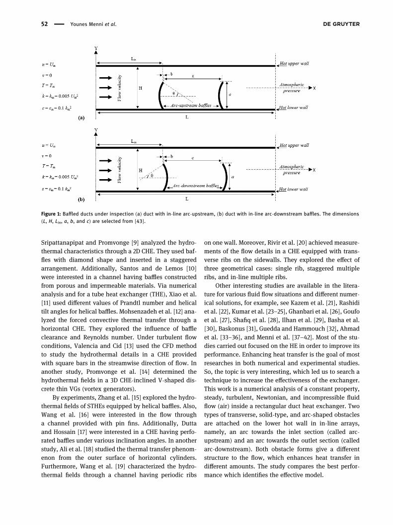
Figure 1: Baffled ducts under inspection (a) duct with in-line arc-upstream, (b) duct with in-line arc-downstream baffles. The dimensions(L, H, Lin, a, b, and c) are selected from [43].
52 Younes Menni et al.

2 Physical model under analysis
A numerical simulation was reported on the turbulentflow and forced-convection of an incompressible Newtonianfluid (air) with constant thermal physical properties andflowing inside a channel (Figure 1). Two transverse, solid,in-line obstacles having various geometrical configura-tions, i.e., arc towards the inlet section of the channel,called arc-upstream (Figure 1a), and arc towards the exitsection of the channel, called arc-downstream (Figure 1b),were fitted into the duct and attached on the bottom wallto lengthen the trajectory of the fluid and increase the heatexchange surface.
Two new models of VGs are suggested in the presentstudy, namely, arc-upstream and arc-downstream baf-fles. The values of height (H) and length (L) of thechannel are 0.146 and 0.554m, respectively. The firstarc-shaped baffle is attached on the lower wall at Lin =0.218m from the entrance section of the channel, whilethe 2nd arc-shaped obstacle is inserted at c = 0.142 mfrom the first obstacle. The baffles height (a), thickness(b), and attack (θ) are 0.08m, 0.01 m, and 45°, respec-tively. Air is used as a working fluid and Reynolds num-bers are changed from 12,000 to 32,000.
3 Modelling and simulation
For the steady state with neglected radiation thermalexchange mode, the equations of mass, momentum, andenergy are expressed as [7]
∇→
=V 0, (1)
(→
⋅∇→
) = −∇ + ∇→
ρ V V P μ V ,2 (2)
(→
⋅∇ ) = ∇ρC V T λ T.p2 (3)
where,→V is the speed vector (m s−1); ρ is the fluid den-
sity (kgm−3); P is the pressure (Pa); μ is the fluiddynamic viscosity (kgm−1 s−1); Cp is the fluid specificheat (J kg−1 K−1); λ is the fluid thermal conductivity(Wm−1 C−1); and T is the temperature (K). The standardk-epsilon [44] is also shown in this study in order tosimulate the turbulent flow, as it is characterized by thekinetic enery (k) and dissipation rate (ε) equations asfollows [38]:
∂
∂( ) =
∂
∂+
∂
∂+ +
xρku
xμ
μσ
kx
G ρε,j
jj
t
k jk
(4)
∂
∂( ) =
∂
∂+
∂
∂+ −
xρεu
xμ
μσ
εx
C εk
G C ρ εk
.j
jj
t
ε jε k ε1 2
2
(5)
where, μt is the fluid turbulent viscosity (kgm−1 s−1);and Cμ, C1ε, C2ε, σk, and σε are the model constants. Thepresent thermal and hydrodynamic limit conditions areexpressed as [45]:
At x = 0
=u U ,in (6a)=v 0, (6b)
=T 300 K,in (6c)
=k U0.005 ,in in2 (6d)
=ε k0.1 .in in2 (6e)
At y = ±H/2= =u v 0, (7a)
= =k ε 0, (7b)
=T 375 K.w (7c)
At x = L
=P P ,atm (8a)
∂
∂=
ϕx
0. (8b)
where, ϕ stands for the dependent variables u, v, k, T,and ε. The calculations are achieved with the finitevolume technique [46], SIMPLE algorithm [46], and theQuick scheme [47]. The Nu0 and f0 values of the unbaffledchannel were verified [38] by comparing them with thecorrelations of Dittus–Boelter [48] and Petukhov [49],respectively. The comparison demonstrated that there isa quantitative agreement between the CFD data and theexperimental relationships results [48,49].
4 Results and discussion
4.1 Stream-function field
Figure 2 illustrates the streamlines for the different arc-baffle configurations, i.e., arc-upstream and arc-down-stream. For the two studied geometrical models, theflow is uniform until reaching the 1st arc-baffle. Then,recirculating flows are formed at the baffled region, refer-enced here as ‘zone A.’ The size of these vortices is sig-nificant in the case of arc-upstream type baffles. The
Simulations and heat transfer characteristics of arc-baffled channels 53

sharp edge of the baffle presents a point of detachment,the so referenced here as ‘zone B.’ The flow is thendetached from the arc-baffle, resulting thus in a depres-sion behind baffles. Furthermore, recirculation areas (zones‘C’ and ‘D’) are formed behind baffles, where the widestrecirculation zone is observed with the arc-downstreambaffle. It is surrounded by iso-surfaces that take ellipticalshapes.
4.2 Mean velocity field
Figure 3 reports the mean velocity fields for different con-figurations of arc-baffles, i.e., arc-upstream and arc-down-stream. The velocities are weak next to the left side of thefirst arc-baffle, region ‘A,’ for both models of arc-obstaclesstudied. The velocity magnitudes are also low behind thesecond arc-VG. The velocity is important at the edge of thefirst and the second arc-shaped baffles, zone ‘E.’ In thissame region, the fluid velocity for the second obstacle type(arc-downstream baffle) reaches up to 3.64m/s, followedby that of the first type (arc-upstream baffle), 3.28m/s. Inthe regions between both the first and the second arc-baf-fles, zone ‘C,’ the airflow velocity is significant in the arc-downstream model than that of the other model.
4.3 Axial velocity field
Figure 4 illustrates the impact of the variation of the arc-VG geometry on the axial velocity field. For both kinds of
baffles, the streamlines are parallel in the unbaffled areasof the duct. However, the velocity magnitudes are almostnegligible in the downstream areas of arc-baffles, zones‘C’ and ‘D,’ which is caused by the presence of recircu-lating flows. An increase in the velocity is observed in thespace between the tip of arc-VG to the upper wall ofthe exchanger, referenced here as ‘zone E.’ This is due tothe presence of the arc-shaped VG and the abrupt modifi-cation in the flow direction.
The fluid flow is accelerated just after the first arc-VGuntil reaching 274–346% of the inlet velocity, dependingon the shape of VGs. It should be noted that the VG con-figuration has a significant influence in the zones ‘C,’ ‘D,’and E,’ which is mainly caused by the modification in thestreamlines. The arc-upstream baffle increased the axialvelocity by about 2.747 times over the inlet velocity Uin
(Figure 4).
Figure 2: Stream-function fields (Ψ) for both cases under investi-gation: (a) arc-upstream baffled channel, (b) arc-downstreambaffled channel, Re = 12,000 (Ψ values in kg s−1).
Figure 3:Mean velocity fields (V) for both cases under investigation:(a) arc-upstream baffled channel, (b) arc-downstream baffledchannel, Re = 12,000 (V values in m s−1).
Figure 4: Axial velocity (u) for various arc-baffle configurations:(a) arc-upstream, (b) arc-downstream, Re = 12,000 (u values inm s−1).
54 Younes Menni et al.

4.4 Transverse velocity field
The distribution of y-transverse velocity is plotted inFigure 5a and b for the arc-upstream and arc-downstreambaffles, respectively. Positive and negative velocity gradi-ents are remarked at the tip of the 1st arc-baffle (zones ‘B’)and 2nd arc-baffle (zone ‘F’), respectively.
4.5 Dynamic-pressure field
The dynamic-pressure fields for both arc-obstacle config-urations are plotted in Figure 6. As illustrated in thisfigure, the values of the dynamic-pressure coefficientare weak near the VGs due to the presence of vortices.
However, the dynamic-pressure augments in theregions between the baffles tip and the upper wall ofthe exchanger, where the maximum values are locatedbetween the 1st and 2nd arc-baffles (zone ‘E’), which isresulted from the high airflow velocities. In addition, thehighest amount of Pd depends on the shape of arc-VG,where it is lower by about 18% for the arc-upstream bafflethan that for the other case.
4.6 Dimensionless axial velocity profiles
The curves of the dimensionless axial velocity (U/Uin) justafter the two baffles are plotted in Figure 7. As observed,the reattachment length for the arc-downstream baffle isgreater than that for the arc-upstream-baffle, regardlessof the value of Re.
4.7 Thermal fields
The thermal fields illustrated in Figure 8 show thatthe baffled region is the most heated. The temperaturedrops in the areas between the tip of arc-obstacle andthe surfaces of the duct, which is due to the high fluidvelocity and interaction between the fluid particles inthese regions.
A comparison of the outlet fluid temperature is pro-vided in Figure 9, where the most considerable values ofthe temperature are reached with the arc-downstreambaffle. Because of its ability to produce strong flows, thearc-downstream-shaped VG is more advantageous thanthe other model.
4.8 Heat transfer
The results of the ratio (Nux/Nu0) are summarized inFigure 10 for both arc-shaped baffles. Both the arc-deflec-tors push the flow towards the upper part of the duct,which allows further absorption of the thermal energyfrom the heated surface. The lowest value of the Nux/Nu0 is observed on the upstream side of the first arc-baffle, while the highest amount is remarked on theopposite side of the 2nd arc-baffle. This figure showsalso that the Nux/Nu0 is considerable in the downstreamarea of the 1st arc-VG. This augmentation is yielded fromthe efficient mixing by vortices, which corresponds tohigh rates of the local thermal exchange. For both shapesof baffles, the values of (Nux/Nu0) are similar at the posi-tions between (0m) and (0.2 m). However, there is animportant increase in the (Nux/Nu0) in the case of
Figure 5: Fields of the transverse velocity (v) for various arc-bafflemodels: (a) arc-upstream, (b) arc-downstream, Re = 12,000(v values in m s−1).
Figure 6: Fields of the dynamic pressure (Pd) for various arc-baffletypes: (a) arc-upstream, and (b) arc-downstream, Re = 12,000(Pd values in Pa).
Simulations and heat transfer characteristics of arc-baffled channels 55

arc-downstream type baffle from the position (0.2 m)until the outlet of the duct.
Figure 11 presents the change of the average ratio(Nu/Nu0), where a proportional increase is observedaccording to Re. The maximum Nu/Nu0 is reached withthe arc-downstream case. Compared to the unbaffledexchanger and for Re = 12,000–32,000, the average Nugains for the arc-upstream and arc-downstream bafflesare 159–284% and 187–331%, respectively. In addition,
x = 0.435 m
Dimensionless axial velocity
-0,8 -0,6 -0,4 -0,2 0,0
)m(
thgiehlennah
C
-0,08
-0,07
-0,06
-0,05
-0,04
-0,03
-0,02
Arc-upstream, Re = 12,000
Arc-downstream, Re = 12,000
Arc-upstream, Re = 17,000
Arc-downstream, Re = 17,000
Arc-upstream, Re = 22,000
Arc-downstream, Re = 22,000
Arc-upstream, Re = 27,000
Arc-downstream, Re = 27,000
Arc-upstream, Re = 32,000
Arc-downstream, Re = 32,000
x = 0.315 m
Dimensionless axial velocity
-3,5 -3,0 -2,5 -2,0 -1,5 -1,0 -0,5 0,0
)m(
thgiehlennah
C
-0,08
-0,07
-0,06
-0,05
-0,04
-0,03
-0,02
Arc-upstream, Re = 12,000
Arc-downstream, Re = 12,000
Arc-upstream, Re = 17,000
Arc-downstream, Re = 17,000
Arc-upstream, Re = 22,000
Arc-downstream, Re = 22,000
Arc-upstream, Re = 27,000
Arc-downstream, Re = 27,000
Arc-upstream, Re = 32,000
Arc-downstream, Re = 32,000(a)
(b)
Figure 7: Influence of arc-baffle orientation on the length of recir-culation cells vs Re. (a) at x = 0.315 m (downstream of the 1st VG)(b) at x = 0.435 m (downstream of the 2nd VG).
Figure 8: Temperature contours (T) for (a) arc-upstream, (b) arc-downstream baffles at Re = 12,000 (T values in K).
at x = L
Fluid temperature (K)
290 300 310 320 330 340 350 360 370
)m(
th
gieh
l en
nah
C
-0,08
-0,06
-0,04
-0,02
0,00
0,02
0,04
0,06
0,08
Arc-upstream baffle
Arc-downstream baffle
Figure 9: Outlet fluid temperature profiles for (a) arc-upstream,(b) arc-downstream VGs, at Re = 12,000.
Axial position (m)
0,0 0,1 0,2 0,3 0,4 0,5 0,6
reb
mu
ntless
uN
lacol
dezilamr
oN
20
30
40
50
60
Arc-upstream baffle
Arc-downstream baffle
Figure 10: Normalized local Nusselt number on upper wall of thechannel for various arc-baffles, Re = 12,000.
56 Younes Menni et al.

and at the highest Re, the arc-downstream baffle over-comes the other shape of baffles by about 14% in terms ofthermal exchange rates (Nu/Nu0) than that reached withthe arc-upstream (Figure 11).
4.9 Friction loss
The variation of the normalized skin friction coefficient(Cf/f0) on the top wall of the duct is provided in Figure 12.From this figure, both shapes of the baffles give the sametrends of Cf/f0. Also, an increased Cf/f0 is observed inthe region between the arc-baffles (0.228m < x < 0.37m).The arc-upstream and arc-downstream baffles provided,respectively, an increase in Cf by about 73 and 117 timesover the unbaffled exchanger. Furthermore, the use of arc-downstream baffles gives higher thermal exchange thanthat of the other model by about 37%.
The changes of the friction factor ratio (f/f0) vs Re areshown in Figure 13. A proportional increase is observed inthe values of Re (f/f0). In addition, and compared to thesmooth duct, the arc-upstream and arc-downstream baf-fles provided, respectively, an increase in (f/f0) by about3–16 and 4–21 times when Re has been changed from12,000 to 32,000. This means that the arc-downstreambaffle generates greater friction loss than the arc-upstreambaffle by around 23.266%, at the highest Re.
4.10 Effect of the arc-shaped baffle
Finally, the results of the thermal performance factor(TEF) are summarized in Figure 14. As observed, the
Upper channel wall
Reynolds number
10000 15000 20000 25000 30000 35000
reb
mu
ntless
uN
egare
vadezila
mro
N
0,0
0,5
1,0
1,5
2,0
2,5
3,0
3,5Arc-upstream baffle
Arc-downstream baffle
Figure 11: Normalized average Nusselt number with Re for variousarc-baffles.
Axial position (m)
0,0 0,1 0,2 0,3 0,4 0,5 0,6
tneiciffe
ocn
oitcirfni
ksdezila
mro
N
0
20
40
60
80
100
120
140Arc-upstream baffle
Arc-downstream baffle
Figure 12: Variation of Normalized skin friction coefficient alongupper channel wall for various arc-baffles, Re = 12,000.
Upper channel wall
Reynolds number
10000 15000 20000 25000 30000 35000
rotcaf
noitcirf
dezilamr
oN
0
5
10
15
20
25Arc-upstream baffle
Arc-downstream baffle
Figure 13: Variation of Normalized friction factor with Re for variousarc-baffles.
Upper channel wall
Thermal enhancement factor
0,0 0,2 0,4 0,6 0,8 1,0 1,2 1,4
reb
mu
ns
dlo
nye
R
10000
15000
20000
25000
30000
35000
Arc-upstream baffle
Arc-downstream baffle
Figure 14: Changes in the thermal enhancement factor vs Re.
Simulations and heat transfer characteristics of arc-baffled channels 57

TEF tends to augment with the rise of Re for both shapesof VGs under inspection. At Re = 32,000, the optimumvalue of the TEF is about 1.138 and 1.212 for the arc-upstream and arc-downstream-shaped baffles, respectively.Accordingly, the highest TEF is found with arc-downstreambaffle, which is estimated to be higher than that of the arc-upstream baffles by about 6%. The effect of arc-downstreambaffles can also be highlighted based on literature data. Inthe presence of the following conditions: L = 0.554m, Lin =0.218m, H = 0.146m, Dh = 0.167m, a = 0.08m, b = 0.01m,and Re = 32,000, their performance has been comparedwith many previously realized baffles [42]. The relative dif-ference of results shows a remarkable improvement in thepresence of an in-line downstream arc-baffle pair by about7.019, 3.958, 3.130, 3.580, 6.572, 10.815, 7.536, 1.715, 11.485,10.971, and 8.221% over the upstream-arc, rectangular(simple), triangular, trapezoidal, corrugated, plus, S, V,W, T, and Γ-shaped one-baffle channel, respectively(Figure 15).
5 Conclusion
A numerical inspection has been conducted on the char-acteristics of the turbulent convection of air flowing in
a baffled rectangular exchanger. Two shapes of arc-baf-fles were considered, namely, the arc-upstream and arc-downstream shapes. These obstacles were inserted onbottom wall of the exchanger in in-line arrays. The resultanalysis shows a reinforcement in fluid dynamics with aconsiderable enhancement in heat exchange in the caseof the arc-downstream second obstacle due to the secre-tion of very strong cells on their back sides, which alsocaused a significant increase in skin friction coefficients,especially at high flow rates. This second configurationof the arc-baffle (arc-downstream) proved its superiorityin terms of thermal exchange rate by about 14% thanthe other shape of baffle. At Re = 32,000, this optimalmodel of the arc-baffle showed an increase in the enhance-ment factor by about 7.019, 3.958, 3.130, 3.580, 6.572,10.815, 7.536, 1.715, 11.485, 10.971, and 8.221% comparedto the cases of one baffle, i.e., upstream-arc, rectangular(simple), triangular, trapezoidal, corrugated, plus, S, V,W,T, and Γ, respectively.
Funding: This work was supported by the National NaturalScience Foundation of China (No. 71601072) and KeyScientific Research Project of Higher Education Institutionsin Henan Province of China (No. 20B110006).
References
[1] Pirouz MM, Farhadi M, Sedighi K, Nemati H, Fattahi E. LatticeBoltzmann simulation of conjugate heat transfer in a rectan-gular channel with wall-mounted obstacles. Sci Iran B.2011;18(2):213–21.
[2] Du T, Du W, Che K, Cheng L. Parametric optimization of over-lapped helical baffled heat exchangers by Taguchi method.Appl Therm Eng. 2015;85:334–9.
[3] You Y, Fan A, Huang S, Liu W. Numerical modeling andexperimental validation of heat transfer and flow resistance onthe shell side of a shell-and-tube heat exchanger with flowerbaffles. Int J Heat Mass Transf. 2012;55:7561–9.
[4] Eiamsa-ard S, Promvonge P. Numerical study on heat transferof turbulent channel flow over periodic grooves. Int CommunHeat Mass Transf. 2008;35:844–52.
[5] Afrianto H, Tanshen MdR, Munkhbayar B, Suryo UT, Chung H,Jeong H. A numerical investigation on LNG flow and heattransfer characteristic in heat exchanger. Int J Heat MassTransf. 2014;68:110–8.
[6] Ozceyhan V, Gunes S, Buyukalaca O, Altuntop N. Heat transferenhancement in a tube using circular cross sectional ringsseparated from wall. Appl Energy. 2008;85:988–1001.
[7] Nasiruddin MH, Siddiqui K. Heat transfer augmentation in aheat exchanger tube using a baffle. Int J Heat Fluid Flow.2007;28:318–28.
[8] Zhang JF, He YL, Tao WQ. 3D numerical simulation on shell-and-tube heat exchangers with middle-overlapped helical
Reynolds number
10000 15000 20000 25000 30000 35000
rotcaf
tne
m ecn a
hne
l amre
hT
0,0
0,2
0,4
0,6
0,8
1,0
1,2
1,4
Present arc-downstream baffles
Upstream-arc baffle
Simple baffle
Triangular baffle
Trapezoidal baffle
Corrugated baffle
Plus baffle
S-shaped baffle
V-shaped baffle
W-shaped baffle
T-shaped baffle
�-shaped baffle
Ch
ann
el (
L,
H,
Dh)
wit
h
a lo
wer
wal
l-at
tach
ed
baf
fle
[42
].
Figure 15: Performance comparison with numerical data for variousbaffles at Re = 32,000.
58 Younes Menni et al.
baffles and continuous baffles – Part I: numerical model andresults of whole heat exchanger with middle-overlappedhelical baffles. Int J Heat Mass Transf. 2009;52:5371–80.
[9] Sripattanapipat S, Promvonge P. Numerical analysis of laminarheat transfer in a channel with diamond-shaped baffles. IntCommun Heat Mass Transf. 2009;36:32–8.
[10] Santos NB, de Lemos MJS. Flow and heat transfer in a parallel-plate channel with porous and solid baffles. Numer HeatTransfer Part A. 2006;49:1–24.
[11] Xiao X, Zhang L, Li X, Jiang B, Yang X, Xia Y. Numerical inves-tigation of helical baffles heat exchanger with differentPrandtl number fluids. Int J Heat Mass Transf.2013;63:434–44.
[12] Mohsenzadeh A, Farhadi M, Sedighi K. Convective cooling oftandem heated triangular cylinders confirm in a channel.Therm Sci. 2010;14(1):183–97.
[13] Valencia A, Cid M. Turbulent unsteady flow and heat transfer inchannels with periodically mounted square bars. Int J HeatMass Transf. 2002;45:1661–73.
[14] Promvonge P, Changcharoen W, Kwankaomeng S,Thianpong C. Numerical heat transfer study of turbulentsquare-duct flow through inline V-shaped discrete ribs. IntCommun Heat Mass Transf. 2011;38:1392–9.
[15] Zhang JF, Li B, Huang WJ, Lei YG, He YL, Tao WQ. Experimentalperformance comparison of shell-side heat transfer for shell-and-tube heat exchangers with middle-overlapped helicalbaffles and segmental baffles. Chem Eng Sci.2009;64:1643–53.
[16] Wang F, Zhang J, Wang S. Investigation on flow and heattransfer characteristics in rectangular channel with drop-shaped pin fins. Propuls Power Res. 2012;1(1):64–70.
[17] Dutta P, Hossain A. Internal cooling augmentation in rectan-gular channel using two inclined baffles. Int J Heat Fluid Flow.2005;26:223–32.
[18] Ali M, Zeitoun O, Nuhait A. Forced convection heat transferover horizontal triangular cylinder in cross flow. Int J ThermSci. 2011;50:106–14.
[19] Wang L, Salewski M, Sundén B. Turbulent flow in a ribbedchannel: flow structures in the vicinity of a rib. Exp Therm FluidSci. 2010;34(2):165–76.
[20] Rivir RB. Turbulence and scale measurements in a squarechannel with transverse square ribs. Int J Rotating Mach.1996;2:756352.
[21] Kazem S, Abbasbandy S, Kumar S. Fractional-order legendrefunctions for solving fractional-order differential equations.Appl Math Model. 2013;37(7):5498–510.
[22] Rashidi MM, Hosseini A, Pop I, Kumar S, Freidoonimehr N.Comparative numerical study of single and two-phase modelsof nanofluid heat transfer in wavy channel. Appl Math Mech.2014;35(7):831–48.
[23] Kumar S. A new analytical modelling for fractional telegraphequation via laplace transform. Appl Math Model.2014;38(13):3154–63.
[24] Kumar S, Rashidi MM. New analytical method for gas dynamicsequation arising in shock fronts. Comput Phys Commun.2014;185(7):1947–54.
[25] Kumar S, Kumar A, Baleanu D. Two analytical methods fortime-fractional nonlinear coupled Boussinesq–Burger’sequations arise in propagation of shallow water waves.Nonlinear Dyn. 2016;85(2):699–715.
[26] Ghanbari B, Kumar S, Kumar R. A study of behaviour forimmune and tumor cells in immunogenetic tumour model withnon-singular fractional derivative. Chaos Solitons Fractals.2020;133:109619.
[27] Goufo EFD, Kumar S, Mugisha SB. Similarities in a fifth-orderevolution equation with and with no singular kernel. ChaosSolitons Fractals. 2020;130:109467.
[28] Shafiq A, Hammouch Z, Sindhu TN. Bioconvective MHD flow oftangent hyperbolic nanofluid with newtonian heating. Int JMech Sci. 2017;133:759–66.
[29] Ilhan OA, Manafian J, Alizadeh AA, Baskonus HM. New exactsolutions for nematicons in liquid crystals by the (ϕ/2)-expansion method arising in fluid mechanics. Eur Phys J Plus.2020;135(3):1–19.
[30] Basha HT, Sivaraj R, Reddy AS, Chamkha AJ, Baskonus HM.A numerical study of the ferromagnetic flow of Carreau nano-fluid over a wedge, plate and stagnation point with a magneticdipole. AIMS Math. 2020;5(5):4197.
[31] Baskonus HM. New acoustic wave behaviors to the Davey-Stewartson equation with power-law nonlinearity arising influid dynamics. Nonlinear Dyn. 2016;86(1):177–83.
[32] Guedda M, Hammouch Z. Similarity flow solutions of a non-Newtonian power-law fluid. arXiv Prepr arXiv. 2009;904:315.
[33] Ahmad H, Khan TA, Ahmad I, Stanimirović PS, Chu Y-M. A newanalyzing technique for nonlinear time fractional Cauchyreaction-diffusion model equations. Results Phys.2020;19:103462. doi: 10.1016/j.rinp.2020.103462.
[34] Ahmad H, Akgül A, Khan TA, Stanimirović PS, Chu Y-M. Newperspective on the conventional solutions of the nonlineartime-fractional partial differential equations. Complexity.2020;2020:8829017. doi: 10.1155/2020/8829017.
[35] Ahmad H, Khan TA, Stanimirović PS, Chu Y-M, Ahmad I.Modified variational iteration algorithm-II: convergence andapplications to diffusion models. Complexity.2020;2020:8841718. doi: 10.1155/2020/8841718.
[36] Ahmad H, Seadawy AR, Khan TA, Thounthong P. Analyticapproximate solutions for some nonlinear parabolic dynamicalwave equations. J Taibah Univ Sci. 2020;14(1):346–58.
[37] Menni Y, Azzi A, Zidani C. Numerical study of heat transfer andfluid flow in a channel with staggered arc-shaped baffles.Commun Sci Technol. 2017;18:43–57.
[38] Menni Y, Azzi Y. Design and performance evaluation of air solarchannels with diverse baffle structures. Comput Therm Sci.2018;10(3):225–49.
[39] Menni Y, Chamkha AJ, Azzi A, Zidani C, Benyoucef B. Study ofair flow around flat and arc-shaped baffles in shell-and-tubeheat exchangers. Math Model Eng Probl. 2019;6(1):77–84.
[40] Menni Y, Azzi A, Chamkha AJ. Developing heat transfer in asolar air channel with arc-shaped baffles: effect of baffleattack angle. J New Technol Mater. 2018;8(1):58–67.
[41] Menni Y, Azzi A, Chamkha AJ. The solar air channels: com-parative analysis, introduction of arc-shaped fins to improvethe thermal transfer. J Appl Comput Mech. 2019;5(4):616–26.
[42] Menni Y, Azzi A, Chamkha A. Modeling and analysis of solar airchannels with attachments of different shapes. Int J NumerMethods Heat Fluid Flow. 2018;29:1815. doi: 10.1108/HFF-08-2018-0435.
[43] Demartini LC, Vielmo HA, Möller SV. Numeric and experimentalanalysis of the turbulent flow through a channel with baffleplates. J Braz Soc Mech Sci Eng. 2004;26(2):153–9.
Simulations and heat transfer characteristics of arc-baffled channels 59

[44] Launder BE, Spalding DB. The numerical computation of tur-bulent flows. Comput Methods Appl Mech Eng.1974;3:269–89.
[45] Menni Y, Ghazvini M, Ameur H, Kim M, Ahmadi MH,Sharifpur M. Combination of baffling technique and high-thermal conductivity fluids to enhance the overall perfor-mances of solar channels. Eng Comput. 2020. doi: 10.1007/s00366-020-01165-x
[46] Patankar SV. Numerical heat transfer and fluid flow. New York,NY: McGraw-Hill; 1980.
[47] Leonard BP, Mokhtari S. Ultra-sharp nonoscillatory convectionschemes for high-speed steady multidimensional flow.Cleveland, OH: NASA Lewis Research Center; 1990. NASA TM1-2568.
[48] Dittus FW, Boelter LMK. Heat transfer in automobile radiatorsof tubular type. Univ Calif Berkeley Publ Eng.1930;1(13):755–8.
[49] Petukhov BS. Heat transfer in turbulent pipe flow with variablephysical properties. In: Harnett JP, ed., Advances in heattransfer, vol. 6. New York: Academic Press; 1970. p. 504–64.
60 Younes Menni et al.
Copyright © 2022 FDOKUMEN