
The Heat Transfer Analysis of an Acting-type Heat Retention ...
19
-
Upload
khangminh22 -
Category
Documents
-
view
0 -
download
0
Transcript of The Heat Transfer Analysis of an Acting-type Heat Retention ...


applied sciences
Article
The Heat Transfer Analysis of an Acting-type HeatRetention Panel used in a Hot Rolling Process
Jiin-Yuh Jang 1,*, Jin-Wei Guo 1 and Chih-Chung Chang 2
1 Department of Mechanical Engineering, National Cheng Kung University, Tainan 70101, Taiwan;[email protected]
2 China Steel Corporation, Kaohsiung 81233, Taiwan; [email protected]* Correspondence: [email protected]; Tel.: +886-6-208-8573
Received: 28 November 2018; Accepted: 3 January 2019; Published: 7 January 2019�����������������
Abstract: In the hot strip rolling process, improvement of the mechanical properties of the strip steelhas been a focus for a long time. After rough rolling, high temperature transfer bars are transportedby conveyors through the heat retention panel in order to decrease the temperature differencebetween the head and the tail of the transfer bars. During the heat retention process, the temperaturedistribution of the transfer bars have a great influence on the mechanical properties of strip steel.A three-dimensional numerical model of a traditional passive heat retention panel is developed toinvestigate the temperature difference between the head and the tail of the transfer bars. A comparisonwith the in-situ data from a steel company in Taiwan shows that the present model works well for theprediction of temperature values of the head and the tail and temperature differences of the transferbars. Based on the developed model, a three-dimensional numerical model of the acting-type heatretention panel is constructed in order to predict whether the temperature difference decreases duringthe heat retention process.
Keywords: hot strip rolling; transfer bar; heat retention panel; heat transfer
1. Introduction
The steel industry in the global market is booming. Due to increased market competition,the demand for quality steel products has attracted a high level of attention in recent decades. In orderto become more competitive in the steel industry, improving the ironmaking process and increasingthe quality control in manufacturing have become a focus of steel plants.
Most steel products are manufactured after high temperature slabs are rolled by rolling mills.In the hot strip rolling process shown in Figure 1, the high temperature slabs are roughly rolled intothe transfer bars and then transported into the finishing rolling through the original heat retentionpanel. During the transport process, in addition to self-radiation heat dissipation, the convective heatdissipation of air, the contact heat conduction cooling of the rollers beneath the conveyors, and thechange in the speed of the conveyors will cause a temperature difference between the head and thetail of the transfer bar. When this temperature difference is too large, it will make the finishing rollingmore difficult and also cause the production line to shut down.
There are three types of equipment that can improve decreases in the temperature difference in thetransfer bars: an inducting heater, an acting-type heat retention panel, and a heat coil box. This studymainly focuses on the acting-type heat retention panel. An acting-type heat retention panel involvesinstallation of a radiation plate inside a traditional passive heat retention panel and a heat source,which can be supplied by burning natural gas or an electric heater, which is used to heat the radiationplate. Eventually, the radiation plate will heat the head and the tail of the transfer bar by radiation heattransfer so that the temperature difference can be decreased. In response to global energy conservation
Appl. Sci. 2019, 9, 189; doi:10.3390/app9010189 www.mdpi.com/journal/applsci

Appl. Sci. 2019, 9, 189 2 of 18
and carbon reduction, as well as goals of green production, numerous numerical models and methodsfor the prediction of the hot strip rolling process have been developed and successfully applied tomany steel plants but there have been few studies focusing on the heat retention panel.
According to a hot rolling plant layout, Wang et al. [1] designed a space for installing heatretention panels. Bu [2] analyzed the hot rolling assembly line without a heat retention panel anddiscussed the influence of temperature at the finishing entrance. Furthermore, he analyzed the hotrolling assembly line with an installed heat retention panel. The results indicated that a heat retentionpanel can effectively decrease the temperature difference between the head and the tail of the transferbar. Zhang et al. [3] utilized a two-dimensional simplified model to simulate a hot rolling assemblyline, both with a heat retention panel and without a heat retention panel. They assumed the heattransfer mode of transfer bar in the heat retention panel to be based on radiation. Thus, they ignoredthe convective effect of air, and in order to simplify the computational calculation, the influence ofthe rollers beneath the conveyor was also ignored. Compared with the in-situ data in a steel plant,the results worked well for the prediction of the temperature history of the transfer bar. Zhang et al. [4]utilized a two-dimensional symmetry finite element method (FEM) to simulate the transfer bar insidea heat retention panel with a high radiation coating. They sprayed a high radiation ceramic coating onthe inner wall of the panel. Their results showed that a high radiation ceramic coating can significantlydecrease the temperature gradient in sections of the transfer bar.
In addition, a significant amount of data on the hot strip rolling process, such as the size of theslab before rolling, the temperature of the slab at the exit of the reheating furnaces, and the runningspeed of conveyors, has been found to be important parameters to affect the quality of steel products.Bu et al. [5] obtained numerous in-situ data from a steel plant, including the size and properties ofslab, the temperature at the exit of the slab reheating furnaces, and the size and the temperaturedistribution of the transfer bar after rough rolling. They used the Microsoft Visual Basic program todesign a computer-aided design program to calculate effect of the temperature of the transfer bar onthe finishing rolling force. Ling [6] analyzed the advantages and disadvantages of a traditional passiveheat retention panel, an acting-type heat retention panel, and a heat coil box. The results indicatedthat a traditional passive heat retention panel consumes the least energy but it is inefficient for heatretention. Although an acting-type heat retention panel consumes the most energy, it is the mosteffective for retaining heat in the transfer bar. A heat coil box exhibits a good performance for heatretention and consumes less energy than an acting-type heat retention panel, but the cost of installationis the most expensive. Speicher et al. [7] used the finite difference method (FVM) combined with heatconduction and heat convection to investigate the impact of the rollers beneath conveyors on slab.Legrand et al. [8] studied the thermal fatigue effect of the rollers beneath the conveyors on slab.
Chielo et al. [9] used the nonlinear heat transfer equation to predict the temperature of thesteel on the run-out table (ROT) process. The results show that the performance with a cooling stoptemperature concept to the temperature and property of the steel was greatly improved. Mei et al. [10]investigated the strip steel, which was heated by induction heater by the finite element method.They found that the temperature difference became more and more obvious with the increase ofthickness. Shulkosky et al. [11] developed a program which allows users to set-up their hot stripmill configuration and simulate the mechanical properties of the steel in the hot rolling process.The program includes reheating furnace, roughing mill stands, heat retention equipment (panels andcoil box), finishing mill stands, the run-out table, and the mill exit area. Panjkovic [12] designed amodel to predict strip temperature from the roughing mill exit to the finishing mill exit. The resultswere compared to those from the plant measurements, and it was shown that this model worked verywell. Grajcar et al. [13] used a semi-industrial physical model to simulate thermomechanical rollingand controlled cooling of advanced high-strength steels with increased Mn and Al content. The resultsindicated that the high-quality strip samples with a thickness up to 3.3 mm could be obtained by usingheat retention panels. Tudball and Brown [14] developed a transient 3D finite element model to obtainthermal variations during the hot rolling process. The numerical model showed that the temperature

Appl. Sci. 2019, 9, 189 3 of 18
results can provided a relatively accurate prediction with less than 10% deviation. Delpature et al. [15]studied the active tunnel furnace in order to minimize heat losses of the transfer bar on the rollertable between roughing mill and finishing mill. With traditional passive heat retention panels, thetemperature difference in the head and the tail of the carbon transfer bar was about 20 ◦C. They foundthat the active heat retention panels was able to compensate for this drop in temperature.
Based on the studies referenced above, it is important to decrease the temperature differencebetween the head and the tail of the transfer bar to enhance the quality of steel products. The traditionalpassive heat retention panel is widely used in many steel plants, but its ability to hold temperature isinefficient. In order to solve this problem, it is necessary to develop other heat retention equipmentas soon as possible. Based on the theory of fluid mechanics and the theory of heat transfer, in thisstudy, the commercial software ANSYS-FLUENT combined with UDF (User-Defined Functions) arefirst used to simulate the traditional passive heat retention panel used in the China Steel Corporation(CSC), Taiwan. After the above results were proved to work well in terms of prediction, an acting-typeheat retention panel model was constructed to investigate the performance of both types of heatretention panels.
Appl. Sci. 2019, 9, x FOR PEER REVIEW 3 of 19
to obtain thermal variations during the hot rolling process. The numerical model showed that the 96 temperature results can provided a relatively accurate prediction with less than 10% deviation. 97 Delpature et al. [15] studied the active tunnel furnace in order to minimize heat losses of the transfer 98 bar on the roller table between roughing mill and finishing mill. With traditional passive heat 99 retention panels, the temperature difference in the head and the tail of the carbon transfer bar was 100 about 20 °C. They found that the active heat retention panels was able to compensate for this drop in 101 temperature. 102
Based on the studies referenced above, it is important to decrease the temperature difference 103 between the head and the tail of the transfer bar to enhance the quality of steel products. The 104 traditional passive heat retention panel is widely used in many steel plants, but its ability to hold 105 temperature is inefficient. In order to solve this problem, it is necessary to develop other heat 106 retention equipment as soon as possible. Based on the theory of fluid mechanics and the theory of 107 heat transfer, in this study, the commercial software ANSYS-FLUENT combined with UDF (User-108 Defined Functions) are first used to simulate the traditional passive heat retention panel used in the 109 China Steel Corporation (CSC), Taiwan. After the above results were proved to work well in terms 110 of prediction, an acting-type heat retention panel model was constructed to investigate the 111 performance of both types of heat retention panels. 112
113 Figure 1. Hot strip rolling process configuration. 114
2. Mathematical Analysis 115
2.1. Physical Model 116 The traditional passive heat retention panel used in CSC has dimensions of 80 m (length) × 3 m 117
(width) × 1.12 m (height). The schematic of the traditional passive heat retention panel is shown in 118 Figure 2a. There are two temperature-measuring devices used to record the temperature of the 119 transfer bars. One is located 3.5 m in front of the heat retention panel and labeled R2DT, and the other 120 one is located 1.5 m behind the heat retention panel and labeled FET. The heat retention panel is 121 divided into two zones, a non-heat retention zone and a heat retention zone. The transfer bars used 122 in the study were stainless steel with dimensions of 70 m (length) × 1.2 m (width) × 0.03 m (thickness). 123 In the process, the transfer bars are transported by the rollers beneath conveyors with various 124 running speeds. The physical model is too large to perform the numerical calculation. Accordingly, 125 the width of the heat retention panel and transfer bar are considered to be a one-half symmetric model 126
Figure 1. Hot strip rolling process configuration.
2. Mathematical Analysis
2.1. Physical Model
The traditional passive heat retention panel used in CSC has dimensions of 80 m (length) × 3 m(width) × 1.12 m (height). The schematic of the traditional passive heat retention panel is shown inFigure 2a. There are two temperature-measuring devices used to record the temperature of the transferbars. One is located 3.5 m in front of the heat retention panel and labeled R2DT, and the other oneis located 1.5 m behind the heat retention panel and labeled FET. The heat retention panel is dividedinto two zones, a non-heat retention zone and a heat retention zone. The transfer bars used in thestudy were stainless steel with dimensions of 70 m (length) × 1.2 m (width) × 0.03 m (thickness).In the process, the transfer bars are transported by the rollers beneath conveyors with various runningspeeds. The physical model is too large to perform the numerical calculation. Accordingly, the width ofthe heat retention panel and transfer bar are considered to be a one-half symmetric model in order toreduce the huge computational time required. Relatively, the running speed of the transfer bars were
Appl. Sci. 2019, 9, 189 4 of 18
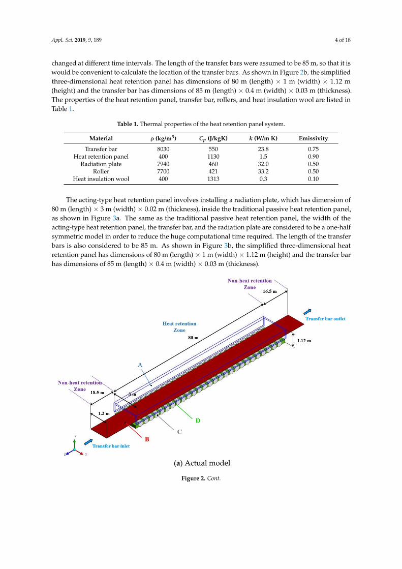
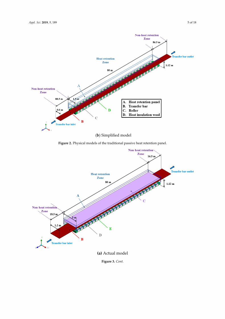
changed at different time intervals. The length of the transfer bars were assumed to be 85 m, so that it iswould be convenient to calculate the location of the transfer bars. As shown in Figure 2b, the simplifiedthree-dimensional heat retention panel has dimensions of 80 m (length) × 1 m (width) × 1.12 m(height) and the transfer bar has dimensions of 85 m (length) × 0.4 m (width) × 0.03 m (thickness).The properties of the heat retention panel, transfer bar, rollers, and heat insulation wool are listed inTable 1.
Table 1. Thermal properties of the heat retention panel system.
Material ρ (kg/m3) Cp (J/kgK) k (W/m K) Emissivity
Transfer bar 8030 550 23.8 0.75Heat retention panel 400 1130 1.5 0.90
Radiation plate 7940 460 32.0 0.50Roller 7700 421 33.2 0.50
Heat insulation wool 400 1313 0.3 0.10
The acting-type heat retention panel involves installing a radiation plate, which has dimension of80 m (length) × 3 m (width) × 0.02 m (thickness), inside the traditional passive heat retention panel,as shown in Figure 3a. The same as the traditional passive heat retention panel, the width of theacting-type heat retention panel, the transfer bar, and the radiation plate are considered to be a one-halfsymmetric model in order to reduce the huge computational time required. The length of the transferbars is also considered to be 85 m. As shown in Figure 3b, the simplified three-dimensional heatretention panel has dimensions of 80 m (length) × 1 m (width) × 1.12 m (height) and the transfer barhas dimensions of 85 m (length) × 0.4 m (width) × 0.03 m (thickness).
Appl. Sci. 2019, 9, x FOR PEER REVIEW 4 of 19
in order to reduce the huge computational time required. Relatively, the running speed of the transfer 127 bars were changed at different time intervals. The length of the transfer bars were assumed to be 85 128 m, so that it is would be convenient to calculate the location of the transfer bars. As shown in Figure 129 2b, the simplified three-dimensional heat retention panel has dimensions of 80 m (length) × 1 m 130 (width) × 1.12 m (height) and the transfer bar has dimensions of 85 m (length) × 0.4 m (width) × 0.03 131 m (thickness). The properties of the heat retention panel, transfer bar, rollers, and heat insulation 132 wool are listed in Table 1. 133
Table 1. Thermal properties of the heat retention panel system. 134 Material ρ (kg/m3) Cp (J/kgK) k (W/m K) Emissivity
Transfer bar 8030 550 23.8 0.75 Heat retention panel 400 1130 1.5 0.90
Radiation plate 7940 460 32.0 0.50 Roller 7700 421 33.2 0.50
Heat insulation wool 400 1313 0.3 0.10
The acting-type heat retention panel involves installing a radiation plate, which has dimension 135 of 80 m (length) × 3 m (width) × 0.02 m (thickness), inside the traditional passive heat retention panel, 136 as shown in Figure 3a. The same as the traditional passive heat retention panel, the width of the 137 acting-type heat retention panel, the transfer bar, and the radiation plate are considered to be a one-138 half symmetric model in order to reduce the huge computational time required. The length of the 139 transfer bars is also considered to be 85 m. As shown in Figure 3b, the simplified three-dimensional 140 heat retention panel has dimensions of 80 m (length) × 1 m (width) × 1.12 m (height) and the transfer 141 bar has dimensions of 85 m (length) × 0.4 m (width) × 0.03 m (thickness). 142
(a) Actual model
Figure 2. Cont.
Appl. Sci. 2019, 9, 189 5 of 18Appl. Sci. 2019, 9, x FOR PEER REVIEW 5 of 19
(b) Simplified model
Figure 2. Physical models of the traditional passive heat retention panel. 143
(a) Actual model
Figure 2. Physical models of the traditional passive heat retention panel.
Appl. Sci. 2019, 9, x FOR PEER REVIEW 5 of 19
(b) Simplified model
Figure 2. Physical models of the traditional passive heat retention panel. 143
(a) Actual model
Figure 3. Cont.

Appl. Sci. 2019, 9, 189 6 of 18Appl. Sci. 2019, 9, x FOR PEER REVIEW 6 of 19
(b) Simplified model
Figure 3. Physicals models of the acting-type heat retention panel. 144
2.2. Governing Equations and Boundary Conditions 145 This study provides an analysis of the traditional passive heat retention panel and the acting-146
type heat retention panel based on the theory of fluid mechanics and the theory of heat transfer. The 147 calculation domain is composed of a fluid domain and a solid domain. The solid domain includes the 148 transfer bars, the heat retention panel, and the rollers beneath the conveyors. The fluid domain 149 includes the air and the transfer bars inside the heat retention panel. The transfer bars are assumed 150 to be a moving fluid coupled with the laminar flow passing through the heat retention panel. The 151 continuity equation, momentum equation, and energy equation are as follows: 152 𝜕𝜌𝜕𝑡 + 𝜕 𝜌𝑢𝜕𝑥 = 0, (1)
𝜕(𝜌𝑢 )𝜕𝑡 + 𝜕 𝜌𝑢 𝑢𝜕𝑥 = − 𝜕𝑃𝜕𝑥 + 𝜕𝜕𝑥 𝜇 𝜕𝑢𝜕𝑥 + 𝜕𝑢𝜕𝑥 , (2)
𝜕𝑇𝜕𝑡 + 𝜕 𝑢 𝑇𝜕𝑥 = 𝛼(𝑇) 𝜕𝜕𝑥 𝜕𝑇𝜕𝑥 − ∇ ∙ �⃑� , (3)
where 𝛁 ∙ �⃑�𝒓𝒂𝒅 is the radiative heat transfer source term. The temperature field of the solid domain 153 is governed by the following transient conduction equation: 154 𝜕𝜕𝑥 𝑘 𝜕𝑇𝜕𝑥 + 𝑞 = 𝜌𝐶 𝜕𝑇𝜕𝑡 , (4)
where 𝝆, 𝑪𝒑, and k are the density, heat capacity, and the thermal conductivity of the solid domain, 155 respectively. The convective heat transfer between the surroundings and the solid surface outside the 156 heat retention panel is calculated using the following equation: 157 𝑞 = ℎ(𝑇 − 𝑇 ), (5)
where h is the convective heat transfer coefficient for the air on the solid surface. In addition, 𝑻𝒔 and 158 𝑻 are the temperature of the air and the solid surface, respectively. 159 Because the effect of the radiative heat transfer dominates the temperature field within the heat 160
retention panel, the S2S (surface-to-surface) radiation model explained in [16] is adopted for the 161 purpose of the current study. The S2S radiation model is used to calculate the radiation exchange in 162
Figure 3. Physicals models of the acting-type heat retention panel.
2.2. Governing Equations and Boundary Conditions
This study provides an analysis of the traditional passive heat retention panel and the acting-typeheat retention panel based on the theory of fluid mechanics and the theory of heat transfer.The calculation domain is composed of a fluid domain and a solid domain. The solid domainincludes the transfer bars, the heat retention panel, and the rollers beneath the conveyors. The fluiddomain includes the air and the transfer bars inside the heat retention panel. The transfer bars areassumed to be a moving fluid coupled with the laminar flow passing through the heat retention panel.The continuity equation, momentum equation, and energy equation are as follows:
∂ρ
∂t+
∂(ρuj)
∂xj= 0, (1)
∂(ρui)
∂t+
∂(ρuiuj
)∂xj
= − ∂P∂xi
+∂
∂xj
[µ
(∂ui∂xj
+∂uj
∂xi
)], (2)
∂T∂t
+∂(ujT)
∂xj= α(T)
∂
∂xj
(∂T∂xj
)−∇·⇀q rad, (3)
where ∇·⇀q rad is the radiative heat transfer source term. The temperature field of the solid domain isgoverned by the following transient conduction equation:
∂
∂xjk
(∂T∂xj
)+ q = ρCp
∂T∂t
, (4)
where ρ, Cp, and k are the density, heat capacity, and the thermal conductivity of the solid domain,respectively. The convective heat transfer between the surroundings and the solid surface outside theheat retention panel is calculated using the following equation:

Appl. Sci. 2019, 9, 189 7 of 18
qCs = h(Ts − T∞), (5)
where h is the convective heat transfer coefficient for the air on the solid surface. In addition, Ts andT∞ are the temperature of the air and the solid surface, respectively.
Because the effect of the radiative heat transfer dominates the temperature field within the heatretention panel, the S2S (surface-to-surface) radiation model explained in [16] is adopted for thepurpose of the current study. The S2S radiation model is used to calculate the radiation exchange in anenclosure comprising gray-diffuse surfaces, for which the governing equation is described as follows:
qout,k = εkσ(
T4k − T4
0
)+ ρkqin,k, (6)
where εk is the emissivity of the solid surface, σ is Boltzmann’s constant, and qin,k is the energy fluxincident on the surface from the surroundings, which can be calculated using the following equation:
qin,k =N
∑j=1
Fkjqout,j, (7)
where qout,j is the energy flux leaving from j surface. The energy exchange between two surfacesdepends in part on their size, separation distance, and orientation. These parameters are accounted forby a geometric function called view factor that can be evaluated with the equation:
Fkj =diffuse energy leaving Ak directly toward and intercepted by Ak
total diffuse energy leaving Ak= 1
Ak
∫Ak
∫Aj
cosθkcosθjπr2 δkjdAj Ak, (8)
The word directly is meant to imply “on a straight path without intervening reflections”.Additionally, the formulation of Fkj must ensure that all surfaces are diffuse surfaces with uniformradiosity. The symmetry boundary conditions of the numerical model are expressed as follows:
∂ui∂n
= 0, (9)
∂T∂n
= 0, (10)
Inside the heat retention panel, the solid surfaces and the air are conjugated heat transferboundaries, which can be expressed as:
ui
[∂(ρCpT
)∂xi
]=
∂
∂xi
(k
∂T∂xi
), (11)
At the transfer bar inlet of the heat retention panel model, the initial temperature of the transferbar is assumed to be uniform at Tin = 1192 ◦C, and the variations in the running speed range from6 m/s to 2 m/s. The initial temperature of the heat retention panel, which includes the traditionalpassive heat retention and the acting-type heat retention panel, rollers, and radiation plate, are 400 ◦C,200 ◦C, and 1095 ◦C, respectively. Furthermore, in general, the heat source of the acting-type heatretention panel is supported by burning natural gas or using an electric heater to heat the uppersurface of the radiation plate in general. In order to simplify the complex heating processes, the heatflux boundaries are substituted, as shown in Figure 4b, for the burning process and the electric heatingprocess mentioned above.

Appl. Sci. 2019, 9, 189 8 of 18Appl. Sci. 2019, 9, x FOR PEER REVIEW 8 of 19
(a) Traditional passive heat retention panel
(b) Acting-type heat retention panel
Figure 4. Boundary conditions of the numerical models. 185
2.3. Numerical Methods and Grid Independence 186 In this study, the commercial software ANSYS-Fluent is adopted to solve the governing 187
equations. The finite volume method (FVM) incorporates a second order upwind scheme and a first 188 order implicit scheme for transient formulation. From CSC research, the convective heat transfer 189 effect of air inside the panel is usually neglected, and the heat transfer is dominated by the radiation. 190 Thus, a surface to surface (S2S) radiation model in fluent is adopted to solve the heat transfer problem. 191 Figure 5 shows the computational grids of the three-dimensional traditional passive heat retention 192 panel model, which is composed of 3,873,445 cells, and Figure 6 shows the computational grids of 193 the three-dimensional acting-type heat retention panel model, which is composed of 3,445,396 cells. 194
Figure 4. Boundary conditions of the numerical models.
2.3. Numerical Methods and Grid Independence
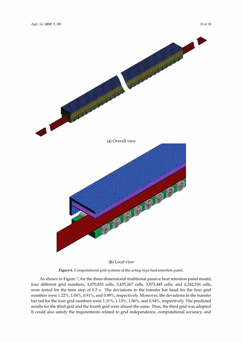
In this study, the commercial software ANSYS-Fluent is adopted to solve the governing equations.The finite volume method (FVM) incorporates a second order upwind scheme and a first order implicitscheme for transient formulation. From CSC research, the convective heat transfer effect of air insidethe panel is usually neglected, and the heat transfer is dominated by the radiation. Thus, a surface tosurface (S2S) radiation model in fluent is adopted to solve the heat transfer problem. Figure 5 shows thecomputational grids of the three-dimensional traditional passive heat retention panel model, which iscomposed of 3,873,445 cells, and Figure 6 shows the computational grids of the three-dimensionalacting-type heat retention panel model, which is composed of 3,445,396 cells.

Appl. Sci. 2019, 9, 189 9 of 18Appl. Sci. 2019, 9, x FOR PEER REVIEW 9 of 19
(a) Overall view
(b) Local view
Figure 5. Computational grid systems of the traditional passive heat retention panel. 195 Figure 5. Computational grid systems of the traditional passive heat retention panel.
Appl. Sci. 2019, 9, 189 10 of 18Appl. Sci. 2019, 9, x FOR PEER REVIEW 10 of 19
(a) Overall view
(b) Local view Figure 6. Computational grid systems of the acting-type heat retention panel. 196
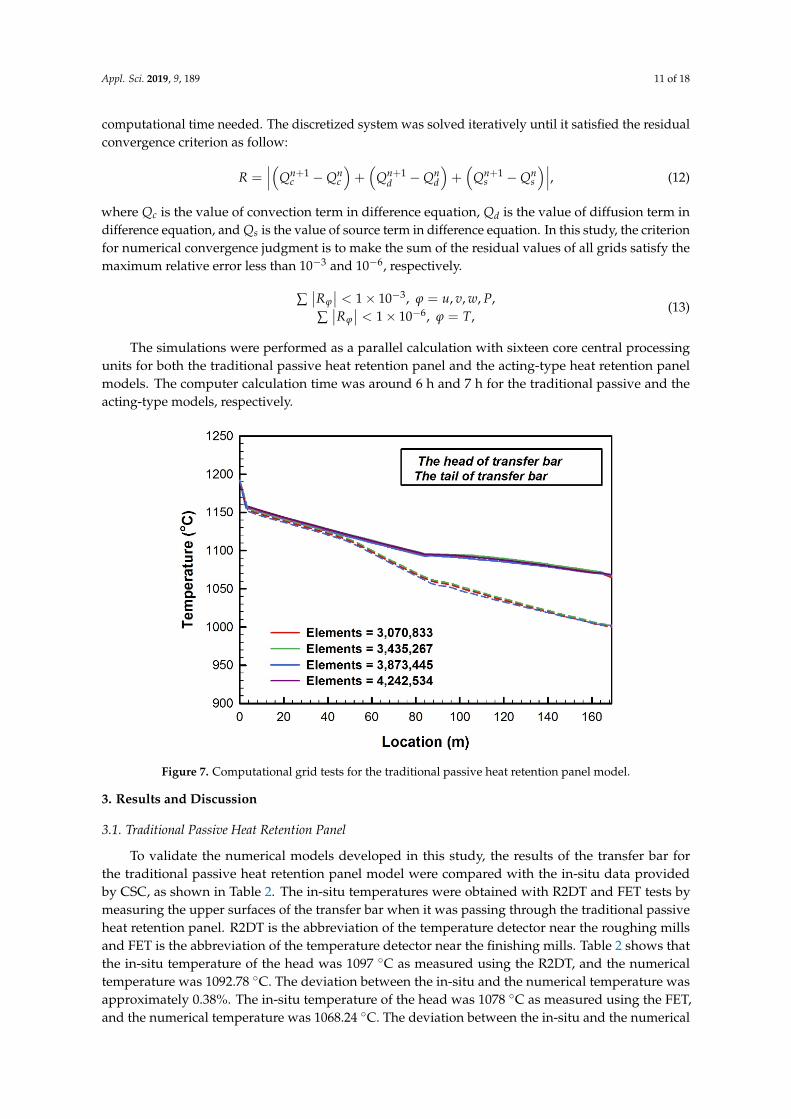
As shown in Figure 7, for the three-dimensional traditional passive heat retention panel model, 197 four different grid numbers, 3,070,833 cells, 3,435,267 cells, 3,873,445 cells, and 4,242,534 cells, were 198 tested for the time step of 0.5 s. The deviations in the transfer bar head for the four grid numbers were 199 1.22%, 1.04%, 0.91%, and 0.89%, respectively. Moreover, the deviations in the transfer bar tail for the 200 four grid numbers were 1.31%, 1.13%, 1.06%, and 0.94%, respectively. The predicted results for the 201 third grid and the fourth grid were almost the same. Thus, the third grid was adopted. It could also 202 satisfy the requirements related to grid independence, computational accuracy, and computational 203
Figure 6. Computational grid systems of the acting-type heat retention panel.
As shown in Figure 7, for the three-dimensional traditional passive heat retention panel model,four different grid numbers, 3,070,833 cells, 3,435,267 cells, 3,873,445 cells, and 4,242,534 cells,were tested for the time step of 0.5 s. The deviations in the transfer bar head for the four gridnumbers were 1.22%, 1.04%, 0.91%, and 0.89%, respectively. Moreover, the deviations in the transferbar tail for the four grid numbers were 1.31%, 1.13%, 1.06%, and 0.94%, respectively. The predictedresults for the third grid and the fourth grid were almost the same. Thus, the third grid was adopted.It could also satisfy the requirements related to grid independence, computational accuracy, and
Appl. Sci. 2019, 9, 189 11 of 18
computational time needed. The discretized system was solved iteratively until it satisfied the residualconvergence criterion as follow:
R =∣∣∣(Qn+1
c −Qnc
)+(
Qn+1d −Qn
d
)+(
Qn+1s −Qn
s
)∣∣∣, (12)
where Qc is the value of convection term in difference equation, Qd is the value of diffusion term indifference equation, and Qs is the value of source term in difference equation. In this study, the criterionfor numerical convergence judgment is to make the sum of the residual values of all grids satisfy themaximum relative error less than 10−3 and 10−6, respectively.
∑∣∣Rϕ
∣∣ < 1× 10⁻³, ϕ = u, v, w, P,∑∣∣Rϕ
∣∣ < 1× 10⁻⁶, ϕ = T,(13)
The simulations were performed as a parallel calculation with sixteen core central processingunits for both the traditional passive heat retention panel and the acting-type heat retention panelmodels. The computer calculation time was around 6 h and 7 h for the traditional passive and theacting-type models, respectively.
Appl. Sci. 2019, 9, x FOR PEER REVIEW 11 of 19
time needed. The discretized system was solved iteratively until it satisfied the residual convergence 204 criterion as follow: 205 𝑅 = |(𝑄 − 𝑄 ) + (𝑄 − 𝑄 ) + (𝑄 − 𝑄 )|, (12)
where 𝑸𝒄 is the value of convection term in difference equation, 𝑸𝒅 is the value of diffusion term 206 in difference equation, and 𝑸𝒔 is the value of source term in difference equation. In this study, the 207 criterion for numerical convergence judgment is to make the sum of the residual values of all grids 208 satisfy the maximum relative error less than 10 and 10 , respectively. 209 𝑅 < 1 × 10 , 𝜑 = 𝑢, 𝑣, 𝑤, 𝑃, 𝑅 < 1 × 10 , 𝜑 = 𝑇, (13)
The simulations were performed as a parallel calculation with sixteen core central processing 210 units for both the traditional passive heat retention panel and the acting-type heat retention panel 211 models. The computer calculation time was around 6 h and 7 h for the traditional passive and the 212 acting-type models, respectively. 213
214 Figure 7. Computational grid tests for the traditional passive heat retention panel model. 215
3. Results and Discussion 216
3.1. Traditional Passive Heat Retention Panel 217 To validate the numerical models developed in this study, the results of the transfer bar for the 218
traditional passive heat retention panel model were compared with the in-situ data provided by CSC, 219 as shown in Table 2. The in-situ temperatures were obtained with R2DT and FET tests by measuring 220 the upper surfaces of the transfer bar when it was passing through the traditional passive heat 221 retention panel. R2DT is the abbreviation of the temperature detector near the roughing mills and 222 FET is the abbreviation of the temperature detector near the finishing mills. Table 2 shows that the 223 in-situ temperature of the head was 1097 °C as measured using the R2DT, and the numerical 224 temperature was 1092.78 °C. The deviation between the in-situ and the numerical temperature was 225 approximately 0.38%. The in-situ temperature of the head was 1078 °C as measured using the FET, 226 and the numerical temperature was 1068.24 °C. The deviation between the in-situ and the numerical 227 temperature was approximately 0.91%. The in-situ temperature of the tail was 1081 °C as measured 228
Figure 7. Computational grid tests for the traditional passive heat retention panel model.
3. Results and Discussion
3.1. Traditional Passive Heat Retention Panel
To validate the numerical models developed in this study, the results of the transfer bar forthe traditional passive heat retention panel model were compared with the in-situ data providedby CSC, as shown in Table 2. The in-situ temperatures were obtained with R2DT and FET tests bymeasuring the upper surfaces of the transfer bar when it was passing through the traditional passiveheat retention panel. R2DT is the abbreviation of the temperature detector near the roughing millsand FET is the abbreviation of the temperature detector near the finishing mills. Table 2 shows thatthe in-situ temperature of the head was 1097 ◦C as measured using the R2DT, and the numericaltemperature was 1092.78 ◦C. The deviation between the in-situ and the numerical temperature wasapproximately 0.38%. The in-situ temperature of the head was 1078 ◦C as measured using the FET,and the numerical temperature was 1068.24 ◦C. The deviation between the in-situ and the numerical

Appl. Sci. 2019, 9, 189 12 of 18
temperature was approximately 0.91%. The in-situ temperature of the tail was 1081 ◦C as measuredusing the R2DT, and the numerical temperature was 1061.55 ◦C. The deviation between the in-situand the numerical temperature was approximately 1.79%. The in-situ temperature of the tail was1013.33 ◦C using the FET, and the numerical temperature was 1002.58 ◦C. The deviation between thein-situ and the numerical temperature was approximately 1.06%. As mentioned above, the numericaltemperature difference in the head and the tail was 65.66 ◦C, which is close to the in-situ temperature,64.67 ◦C.
Table 2. Comparison of the numerical data with the in-situ data for the upper surface of the transferbar with the traditional passive heat retention panel.
R2DT FET
Num. (◦C) In-Situ (◦C) Deviation (%) Num. (◦C) In-Situ (◦C) Deviation (%)
Head 1092.78 1097.00 0.38 1068.24 1078.00 0.91
Tail 1061.55 1081.00 1.79 1002.58 1013.33 1.06
∆T 31.23 16.00 - 65.66 64.67 -
Figure 8 displays the temperature distributions of the transfer bar of numerical results and in-situdata from CSC. After the head of the transfer bar entered the heat retention panel (at the position of90.02 m), it slowed down to 5 m/s at 139.22 m and then slowed down again to 2 m/s at 151.37 m.The residence time inside the heat retention panel of the tail is increased as the running speed of thehead is decreased. This speed difference causes a temperature drop of the tail is larger than the head ofthe transfer bar. Eventually, the temperature difference is generated when the head and the tail reachthe FET position. Figure 9 shows the temperature contours of the traditional passive heat retentionpanel model. It is obvious that the temperature difference was generated after the transfer bar passedthrough the heat retention panel. The local temperature contours of the heat retention panel, rollers,and the insulation wool are presented in Figure 10.
Appl. Sci. 2019, 9, x FOR PEER REVIEW 12 of 19
using the R2DT, and the numerical temperature was 1061.55 °C. The deviation between the in-situ 229 and the numerical temperature was approximately 1.79%. The in-situ temperature of the tail was 230 1013.33 °C using the FET, and the numerical temperature was 1002.58 °C. The deviation between the 231 in-situ and the numerical temperature was approximately 1.06%. As mentioned above, the numerical 232 temperature difference in the head and the tail was 65.66 °C, which is close to the in-situ temperature, 233 64.67 °C. 234
Table 2. Comparison of the numerical data with the in-situ data for the upper surface of the transfer 235 bar with the traditional passive heat retention panel. 236 R2DT FET Num. (°C) In-Situ (°C) Deviation (%) Num. (°C) In-Situ (°C) Deviation (%)
Head 1092.78 1097.00 0.38 1068.24 1078.00 0.91 Tail 1061.55 1081.00 1.79 1002.58 1013.33 1.06 ΔT 31.23 16.00 - 65.66 64.67 -
Figure 8 displays the temperature distributions of the transfer bar of numerical results and in-237 situ data from CSC. After the head of the transfer bar entered the heat retention panel (at the position 238 of 90.02 m), it slowed down to 5 m/s at 139.22 m and then slowed down again to 2 m/s at 151.37 m. 239 The residence time inside the heat retention panel of the tail is increased as the running speed of the 240 head is decreased. This speed difference causes a temperature drop of the tail is larger than the head 241 of the transfer bar. Eventually, the temperature difference is generated when the head and the tail 242 reach the FET position. Figure 9 shows the temperature contours of the traditional passive heat 243 retention panel model. It is obvious that the temperature difference was generated after the transfer 244 bar passed through the heat retention panel. The local temperature contours of the heat retention 245 panel, rollers, and the insulation wool are presented in Figure 10. 246
247 Figure 8. Comparison of the numerical data with the in-situ data for the upper surface and centerline-248 surface of the transfer bar with the traditional passive heat retention panel. 249 Figure 8. Comparison of the numerical data with the in-situ data for the upper surface andcenterline-surface of the transfer bar with the traditional passive heat retention panel.

Appl. Sci. 2019, 9, 189 13 of 18Appl. Sci. 2019, 9, x FOR PEER REVIEW 13 of 19
250
Figure 9. Temperature contours of the traditional passive heat retention panel model (overall view). 251
(a) Heat retention panel (b) Rollers and heat insulation wools
Figure 10. Temperature contours of the traditional passive heat retention panel model (local view). 252
Table 3 shows that the numerical temperatures of the outer and inner wall of the heat retention 253 panel were 114 °C and 711 °C, respectively. In addition, the numerical temperatures of the upper and 254 lower surface of the rollers were 622 °C and 238 °C, respectively. As mentioned above, all the 255 numerical temperatures of the heat retention panel and the rollers matched the in-situ data provided 256 by CSC. 257
Table 3. Comparison of the numerical data and the in-situ data for different surfaces with the 258 traditional passive heat retention panel. 259
Num. (°C) In-Situ (°C) Deviation (%)
Heat retention panel Outer surface 114 100~150 8.80 Inner surface 711 600~750 5.33
Rollers Upper surface 622 600~700 4.31 Lower surface 238 200~300 4.80
3.2. Acting-Type Heat Retention Panel 260 Based on the boundary parameters used in the traditional passive heat retention panel model, 261
this study investigated the temperature difference in the acting-type heat retention panel that was 262
Figure 9. Temperature contours of the traditional passive heat retention panel model (overall view).
Appl. Sci. 2019, 9, x FOR PEER REVIEW 13 of 19
250
Figure 9. Temperature contours of the traditional passive heat retention panel model (overall view). 251
(a) Heat retention panel (b) Rollers and heat insulation wools
Figure 10. Temperature contours of the traditional passive heat retention panel model (local view). 252
Table 3 shows that the numerical temperatures of the outer and inner wall of the heat retention 253 panel were 114 °C and 711 °C, respectively. In addition, the numerical temperatures of the upper and 254 lower surface of the rollers were 622 °C and 238 °C, respectively. As mentioned above, all the 255 numerical temperatures of the heat retention panel and the rollers matched the in-situ data provided 256 by CSC. 257
Table 3. Comparison of the numerical data and the in-situ data for different surfaces with the 258 traditional passive heat retention panel. 259
Num. (°C) In-Situ (°C) Deviation (%)
Heat retention panel Outer surface 114 100~150 8.80 Inner surface 711 600~750 5.33
Rollers Upper surface 622 600~700 4.31 Lower surface 238 200~300 4.80
3.2. Acting-Type Heat Retention Panel 260 Based on the boundary parameters used in the traditional passive heat retention panel model, 261
this study investigated the temperature difference in the acting-type heat retention panel that was 262
Figure 10. Temperature contours of the traditional passive heat retention panel model (local view).
Table 3 shows that the numerical temperatures of the outer and inner wall of the heat retentionpanel were 114 ◦C and 711 ◦C, respectively. In addition, the numerical temperatures of the upperand lower surface of the rollers were 622 ◦C and 238 ◦C, respectively. As mentioned above, all thenumerical temperatures of the heat retention panel and the rollers matched the in-situ data providedby CSC.
Table 3. Comparison of the numerical data and the in-situ data for different surfaces with the traditionalpassive heat retention panel.
Num. (◦C) In-Situ (◦C) Deviation (%)
Heat retention panelOuter surface 114 100~150 8.80
Inner surface 711 600~750 5.33
RollersUpper surface 622 600~700 4.31
Lower surface 238 200~300 4.80

Appl. Sci. 2019, 9, 189 14 of 18
3.2. Acting-Type Heat Retention Panel
Based on the boundary parameters used in the traditional passive heat retention panel model,this study investigated the temperature difference in the acting-type heat retention panel that wasnot developed at CSC. According to the heat flux given on the upper surface of the radiation plate,the results are divided into two cases. Case 1 is given 462 kW/m2 heat flux, and Case 2 is given840 kW/m2, respectively. Table 4 presents the detailed numerical temperatures for Case 1 and Case 2of the head and the tail of the transfer bar. The numerical temperature of the head was 1096.72 ◦C atthe R2DT position, which was quite close to the in-situ temperature of the traditional passive heatretention panel. The numerical temperature of the tail was 1065.73 ◦C at the R2DT position, whichis matched with the in-situ temperatures of the traditional passive heat retention panel. Essentially,the temperatures for the acting-type model of the head and the tail at the R2DT position are almost thesame as those for the traditional passive heat retention panel.
Table 4. Numerical data for the upper surface of the transfer bar with the acting-type heat retention panel.
R2DT FET
Temperature (◦C) Case 1 Case 2 Case 1 Case 2
Head 1096.72 1096.72 1112.73 1121.44Tail 1065.73 1065.73 1081.51 1119.47∆T 30.99 30.99 31.22 1.97
The purpose in this work was to investigate whether the temperature difference between the headand the tail can be reduced after the transfer bar is heated by the radiation plate, so the finishing rollingprocess can go smoothly. The temperature distributions for Case 1 are shown in Figure 11, where it isobvious that the head and the tail were directly heated by the radiative heat transfer of the radiationplate. The temperature distribution of the head rose less than that of the tail due to the variations inthe running speed. The final temperature difference at the FET position decreased from 65.66 ◦C to31.22 ◦C.
Appl. Sci. 2019, 9, x FOR PEER REVIEW 14 of 19
not developed at CSC. According to the heat flux given on the upper surface of the radiation plate, 263 the results are divided into two cases. Case 1 is given 462 kW/m2 heat flux, and Case 2 is given 840 264 kW/m2, respectively. Table 4 presents the detailed numerical temperatures for Case 1 and Case 2 of 265 the head and the tail of the transfer bar. The numerical temperature of the head was 1096.72 °C at the 266 R2DT position, which was quite close to the in-situ temperature of the traditional passive heat 267 retention panel. The numerical temperature of the tail was 1065.73 °C at the R2DT position, which is 268 matched with the in-situ temperatures of the traditional passive heat retention panel. Essentially, the 269 temperatures for the acting-type model of the head and the tail at the R2DT position are almost the 270 same as those for the traditional passive heat retention panel. 271
Table 4. Numerical data for the upper surface of the transfer bar with the acting-type heat retention 272 panel. 273
R2DT FET Temperature (°C) Case 1 Case 2 Case 1 Case 2
Head 1096.72 1096.72 1112.73 1121.44 Tail 1065.73 1065.73 1081.51 1119.47 ΔT 30.99 30.99 31.22 1.97
The purpose in this work was to investigate whether the temperature difference between the 274 head and the tail can be reduced after the transfer bar is heated by the radiation plate, so the finishing 275 rolling process can go smoothly. The temperature distributions for Case 1 are shown in Figure 11, 276 where it is obvious that the head and the tail were directly heated by the radiative heat transfer of the 277 radiation plate. The temperature distribution of the head rose less than that of the tail due to the 278 variations in the running speed. The final temperature difference at the FET position decreased from 279 65.66 °C to 31.22 °C. 280
281 Figure 11. Numerical data for the upper surface and centerline-surface of the transfer bar with the 282 acting-type heat retention panel (Case 1). 283
284
Figure 11. Numerical data for the upper surface and centerline-surface of the transfer bar with theacting-type heat retention panel (Case 1).
Appl. Sci. 2019, 9, 189 15 of 18
Table 5. Numerical data for different surfaces with the acting-type heat retention panel.
Temperature (◦C) Case 1 Case 2
Heat retention panelOuter surface 130.95 131.76
Inner surface 916.17 1326.50
RollersUpper surface 775.31 799.42
Lower surface 227.51 251.69
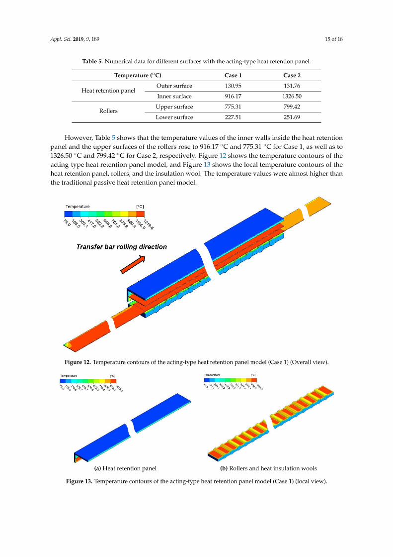
However, Table 5 shows that the temperature values of the inner walls inside the heat retentionpanel and the upper surfaces of the rollers rose to 916.17 ◦C and 775.31 ◦C for Case 1, as well as to1326.50 ◦C and 799.42 ◦C for Case 2, respectively. Figure 12 shows the temperature contours of theacting-type heat retention panel model, and Figure 13 shows the local temperature contours of theheat retention panel, rollers, and the insulation wool. The temperature values were almost higher thanthe traditional passive heat retention panel model.
Appl. Sci. 2019, 9, x FOR PEER REVIEW 15 of 19
Table 5. Numerical data for different surfaces with the acting-type heat retention panel. 285 Temperature (°C) Case 1 Case 2
Heat retention panel Outer surface 130.95 131.76 Inner surface 916.17 1326.50
Rollers Upper surface 775.31 799.42 Lower surface 227.51 251.69
However, Table 5 shows that the temperature values of the inner walls inside the heat retention 286 panel and the upper surfaces of the rollers rose to 916.17 °C and 775.31 °C for Case 1, as well as to 287 1326.50 °C and 799.42 °C for Case 2, respectively. Figure 12 shows the temperature contours of the 288 acting-type heat retention panel model, and Figure 13 shows the local temperature contours of the 289 heat retention panel, rollers, and the insulation wool. The temperature values were almost higher 290 than the traditional passive heat retention panel model. 291
292 Figure 12. Temperature contours of the acting-type heat retention panel model (Case 1) (Overall view). 293
(a) Heat retention panel (b) Rollers and heat insulation wools
Figure 13. Temperature contours of the acting-type heat retention panel model (Case 1) (local view). 294
Figure 14 shows the temperature distributions for Case 2. When the heat flux was increased to 295 840 kW/m2, the temperature difference at the FET position was reduced to 1.97 °C. The temperature 296 distribution of the tail rose more intensely compared with Case 1. Meanwhile, the temperature values 297 of the inner walls inside the heat retention panel and the upper surfaces of the rollers rose to 1329.4 298
Figure 12. Temperature contours of the acting-type heat retention panel model (Case 1) (Overall view).
Appl. Sci. 2019, 9, x FOR PEER REVIEW 15 of 19
Table 5. Numerical data for different surfaces with the acting-type heat retention panel. 285 Temperature (°C) Case 1 Case 2
Heat retention panel Outer surface 130.95 131.76 Inner surface 916.17 1326.50
Rollers Upper surface 775.31 799.42 Lower surface 227.51 251.69
However, Table 5 shows that the temperature values of the inner walls inside the heat retention 286 panel and the upper surfaces of the rollers rose to 916.17 °C and 775.31 °C for Case 1, as well as to 287 1326.50 °C and 799.42 °C for Case 2, respectively. Figure 12 shows the temperature contours of the 288 acting-type heat retention panel model, and Figure 13 shows the local temperature contours of the 289 heat retention panel, rollers, and the insulation wool. The temperature values were almost higher 290 than the traditional passive heat retention panel model. 291
292 Figure 12. Temperature contours of the acting-type heat retention panel model (Case 1) (Overall view). 293
(a) Heat retention panel (b) Rollers and heat insulation wools
Figure 13. Temperature contours of the acting-type heat retention panel model (Case 1) (local view). 294
Figure 14 shows the temperature distributions for Case 2. When the heat flux was increased to 295 840 kW/m2, the temperature difference at the FET position was reduced to 1.97 °C. The temperature 296 distribution of the tail rose more intensely compared with Case 1. Meanwhile, the temperature values 297 of the inner walls inside the heat retention panel and the upper surfaces of the rollers rose to 1329.4 298
Figure 13. Temperature contours of the acting-type heat retention panel model (Case 1) (local view).

Appl. Sci. 2019, 9, 189 16 of 18
Figure 14 shows the temperature distributions for Case 2. When the heat flux was increased to840 kW/m2, the temperature difference at the FET position was reduced to 1.97 ◦C. The temperaturedistribution of the tail rose more intensely compared with Case 1. Meanwhile, the temperaturevalues of the inner walls inside the heat retention panel and the upper surfaces of the rollers rose to1329.4 ◦C and 791.58 ◦C, respectively. Generally, the unit of heat used in the steel industry is kW/ton,which refers to the amount of fuel required to raise each ton of steel by one degree. In this study,the heat flux 462 kW/m2 and 840 kW/m2 were converted to 1743.47 kW/ton and 3169.94 kW/ton,respectively. Meanwhile, Figure 15 shows the relationship between the amount of fuel required andthe temperature difference, which is helpful for steel plants to determine how much fuel will be usedwhen using the acting-type heat retention panel.
Appl. Sci. 2019, 9, x FOR PEER REVIEW 16 of 19
°C and 791.58 °C, respectively. Generally, the unit of heat used in the steel industry is kW/ton, which 299 refers to the amount of fuel required to raise each ton of steel by one degree. In this study, the heat 300 flux 462 kW/m2 and 840 kW/m2 were converted to 1743.47 kW/ton and 3169.94 kW/ton, respectively. 301 Meanwhile, Figure 15 shows the relationship between the amount of fuel required and the 302 temperature difference, which is helpful for steel plants to determine how much fuel will be used 303 when using the acting-type heat retention panel. 304
305 Figure 14. Numerical data for the upper surface and centerline-surface of the transfer bar with the 306 acting-type heat retention panel (Case 2). 307
308 Figure 15. Relationship between the temperature differences in the transfer bars and the fuel used. 309
310
Figure 14. Numerical data for the upper surface and centerline-surface of the transfer bar with theacting-type heat retention panel (Case 2).
Appl. Sci. 2019, 9, x FOR PEER REVIEW 16 of 19
°C and 791.58 °C, respectively. Generally, the unit of heat used in the steel industry is kW/ton, which 299 refers to the amount of fuel required to raise each ton of steel by one degree. In this study, the heat 300 flux 462 kW/m2 and 840 kW/m2 were converted to 1743.47 kW/ton and 3169.94 kW/ton, respectively. 301 Meanwhile, Figure 15 shows the relationship between the amount of fuel required and the 302 temperature difference, which is helpful for steel plants to determine how much fuel will be used 303 when using the acting-type heat retention panel. 304
305 Figure 14. Numerical data for the upper surface and centerline-surface of the transfer bar with the 306 acting-type heat retention panel (Case 2). 307
308 Figure 15. Relationship between the temperature differences in the transfer bars and the fuel used. 309
310
Figure 15. Relationship between the temperature differences in the transfer bars and the fuel used.

Appl. Sci. 2019, 9, 189 17 of 18
4. Conclusions
In this study, the traditional passive heat retention panel numerical model combined with UDFwas adopted to simulate the temperature distributions and temperature differences when the transferbars pass through the heat retention panel at different running speeds.
For the traditional passive heat retention panel, the deviation in the temperature difference in thetransfer bar at FET position between the numerical simulation and the in-situ data was about 1.53%.Moreover, it was found that the temperature difference was induced by variations in the runningspeed of the transfer bar. Table 3 shows that the temperature deviations between the numericalsimulation and the in-situ data for the inner and outer walls of the heat retention panel were 8.80% and5.33%, respectively. The temperature deviations between the numerical simulation and the in-situ dataof the inner and outer walls of the rollers were 4.31% and 4.80%, respectively. Since the performanceof the numerical results worked well compared with the in-situ data, the corresponding parameters,including the initial temperature, convective heat transfer coefficient of the surroundings, andemissivity of the solid surfaces, could be used in the acting-type heat retention panel numerical model.
According to the numerical results of the acting-type heat retention panel model, providing thetwo heat fluxes on the upper surface of the radiation plate is an effective method by which to replacethe burning process or the electric heating process. The numerical simulation indicates that the transferbars can be heated by the radiation plate. When the heat flux increases, the temperature differencebetween the head and the tail of the transfer bar will be reduced. In contrast, the heat flux will causethe temperatures of the heat retention panel and the rollers to increase. Eventually, by converting theheat flux to the amount of fuel required, steel plants can obtain the relevant information about theirenergy consumption.
Author Contributions: All authors contributed to this work. J.-Y.J. and C.-C.C. performed the theoretical model.J.-W.G. executed the numerical simulation work.
Funding: This research was funded by the China Steel Corporation, Taiwan.
Acknowledgments: The financial support by China Steel Corporation, Taiwan is highly appreciated.
Conflicts of Interest: The authors declare no conflict of interest.
Nomenclature
A area (m2)a acceleration (m/s2)Cp specific heat (kJ/kg·K)Fkj view factor from k surface to j surfaceh convective heat transfer coefficient (W/m2·K)k thermal conductivity (W/m·K)n normal directionP pressure (Pa)q heat flux (W/m2)R numerical residualT temperature (◦C)t time (s)u,v,w velocity (m/s)x,y,z coordinatesGreek symbolsα thermal diffusivity (m2/s)δkj Kronecker deltaε emissivityϕ property of fluidµ viscosity (N s/m2)

Appl. Sci. 2019, 9, 189 18 of 18
ρ density (kg/m3); reflectanceσ Boltzmann’s constant (J/K)∑ summationSubscriptsin state of inlet∞ surroundingsout state of outlets surfaceSuperscriptsC convection
References
1. Wang, P.; Duan, W. Research and Development of Temperature Holding Hood for Hot Charging of ContinuousCasting Slab; The Production Department of WISCO: Wuhan, China, 2003.
2. Bu, H. Simulating and Analyzing of Intermediate Table Insulation Technology in Hot Continuous Rolling.Master’s Thesis, Wuhan University of Science and Technology, Wuhan, China, 2007.
3. Zhang, P.; Zhang, N.; Li, Y. Numerical Simulation of Temperature Field During the Multi-pass Hot StripRolling in Temperature Holding Hood. Metall. Equip. 2007, 163, 5–8.
4. Zhang, P.; Li, Y.; Li, Y.; Zhang, N.; Xiao, H. The simulation of Temperature Field of Hot Rolling IntermediateBillet. In Proceedings of the CSM Annual Meeting 2007, Chengdu, China, 15–17 November 2007.
5. Bu, H. Effect of Heat Preservation Technology on Power Parameters of Finish Rolling in Hot Continuous Rolling;College of Materials Science and Metallurgical Engineering, Wuhan University of Science and Technology:Wuhan, China, 2008.
6. Ling, A. Comparison and Choice of the Temperature Maintaining Equipment in the Thin Slab ContinuousCasting and Rolling. Metal Mater. Metall. Eng. 2009, 37, 36–38.
7. Speicher, K.; Steinboek, A.; Kiefer, T.; Kugi, A. Modeling Thermal Shocks and Air Cooling Using the FiniteDifference Method. IFAC 2012, 45, 364–368. [CrossRef]
8. Legrand, N.; Weisz-Patrault, D.; Horsky, J.; Luks, T.; Labbe, N.; Picard, M.; Ehrlacher, A. Characterization of RollBite Heat Transfers in Hot Steel Strip Rolling and Their Influence on Roll Thermal Fatigue Degradation; Trans TechPublications: Zurich, Switzerland, 2013.
9. Cheol, J.P.; Kang, S.Y.; Chang, H.L. Advanced temperature control of high carbon steel for hot strip mills.J. Mech. Sci. Technol. 2009, 24, 1011–1017.
10. MEI, R.B.; Li, C.S.; Liu, X.H.; Han, B. Analysis of Strip Temperature in Hot Rolling Process by Finite ElementMethod. J. Iron Steel Res. Int. 2010, 17, 17–21. [CrossRef]
11. Shulkosky, R.A.; Rosburg, D.L.; Chapman, J.D.; Barnes, K.R. A Microstructure Evolution Model Used ForHot Strip Rolling. In Proceedings of the Materials Science & Technology Conference, Chicago, IL, USA,9–12 November 2003.
12. Panjkovic, V. Model for prediction of strip temperature in hot strip steel mill. Appl. Therm. Eng. 2007, 27,2404–2414. [CrossRef]
13. Grajcar, A.; Skrzypczyk, P.; Wozniak, D.; Kolodziej, S. Semi-industrial simulation of hot rolling and controlledcooling of Mn-Al TRIP steel sheets. J. Achiev. Mater. Manuf. Eng. 2013, 57, 38–47.
14. Tudball, A.; Brown, S.G.R. Practical finite element heat transfer modelling for hot rolling of steels.Ironmak. Steelmak. 2006, 33, 61–66. [CrossRef]
15. Delpature, Y.; Fantuzzi, M.; Filippi, E.; Venanzini, M. Transfer bar reheating in hot strip mills with the ActiveTunnel Furnace (ATF). Millennium Steel 2006, 28, 180–182.
16. ANSYS Fluent, Version, 18.1 User’s Guide, USA; Fluent Inc.: Lebanon, NH, USA, 2018.
© 2019 by the authors. Licensee MDPI, Basel, Switzerland. This article is an open accessarticle distributed under the terms and conditions of the Creative Commons Attribution(CC BY) license (http://creativecommons.org/licenses/by/4.0/).