
Retention - Nature
12
646 BRITISH DENTAL JOURNAL, VOLUME 189, NO. 12, DECEMBER 23 2000 6 6 Retention Fig. 1 — Retention Retention of an RPD can be achieved by: • Using mechanical means such as clasps (1) which engage undercuts on the tooth surface. • Harnessing the patient’s muscular control (2) acting through the polished surface of the denture. • Using the inherent physical forces (3) which arise from coverage of the mucosa by the denture. Whether reliance is placed on all, or mainly on one of these methods, depends on clinical circumstances. Retention by mechanical means can also be obtained by selecting a path of insertion which permits rigid components to enter undercut areas on teeth or on ridges (Figs 23 and 26 of Part 4). Fig. 2 — Retention In this particular case there are sufficient teeth with suitable undercut areas to allow the RPD to be retained by clasps. Successful clasp retention allows the palatal coverage to be reduced to a minimum. Not only does the patient appreciate this limited coverage but also it reduces the risk of damage to the oral tissues. 2 1 2 3 J. C. Davenport, 1 R. M. Basker, 2 J. R. Heath, 3 J. P. Ralph, 4 and P-O. Glantz, 5 1* Emeritus Professor, University of Birmingham, UK; 2 Professor of Dental Prosthetics, University of Leeds and Consultant in Restorative Dentistry, Leeds Teaching Hospitals NHS Trust, Leeds, UK; 3 Honorary Research Fellow, University of Manchester (Formerly Senior Lecturer in Restorative Dentistry, University of Manchester) and Consultant in Restorative Dentistry, Central Manchester Healthcare Trust, Manchester, UK; 4 Consultant in Restorative Dentistry, Leeds Teaching Hospitals NHS Trust and Senior Clinical Lecturer, University of Leeds and Honorary Visiting Professor, Centre for Dental Services Studies, University of York, York, UK; 5 Professor of Prosthetic Dentistry, Consultant in Prosthetic Dentistry, Faculty of Odontology, University of Malmo, Sweden *Correspondence to: 5 Victoria Road, Harborne, Birmingham B17 0AG email: [email protected] REFEREED PAPER © British Dental Journal 2000; 189: 646–657 New publications: All the parts which comprise this series (which will be published in the BDJ) have been included (together with a number of unpublished parts) in the books A Clinical Guide to Removable Partial Dentures (ISBN 0-904588-599) and A Clinical Guide to Removable Partial Denture Design (ISBN 0-904588-637). Available from Macmillan on 01256 302699 This article describes the mechanisms for retaining RPDs and considers the different types of direct retainer. The factors influencing the effectiveness of retentive clasps and governing the choice of clasp are discussed. In this part, we will discuss • Mechanisms of RPD retention • Clasp types, efficiency and selection • Attachments • RPI system • Other retentive devices PRACTICE pr osthe t ics
-
Upload
khangminh22 -
Category
Documents
-
view
4 -
download
0
Transcript of Retention - Nature

646 BRITISH DENTAL JOURNAL, VOLUME 189, NO. 12, DECEMBER 23 2000
Retention
Fig. 1 — RetentionRetention of an RPD can be achieved by: • Using mechanical means such as clasps (1) which engage undercuts on
the tooth surface.• Harnessing the patient’s muscular control (2) acting through the
polished surface of the denture. • Using the inherent physical forces (3) which arise from coverage of the
mucosa by the denture.Whether reliance is placed on all, or mainly on one of these
methods, depends on clinical circumstances. Retention by mechanicalmeans can also be obtained by selecting a path of insertion whichpermits rigid components to enter undercut areas on teeth or onridges (Figs 23 and 26 of Part 4).
Fig. 2 — RetentionIn this particular case there are sufficient teeth with suitable undercutareas to allow the RPD to be retained by clasps. Successful claspretention allows the palatal coverage to be reduced to a minimum. Notonly does the patient appreciate this limited coverage but also it reducesthe risk of damage to the oral tissues.
2
1
2
3
J. C. Davenport,1 R. M. Basker,2 J. R. Heath,3 J. P. Ralph,4 and P-O. Glantz,5
1*Emeritus Professor, University of Birmingham, UK; 2Professor of DentalProsthetics, University of Leeds and Consultant in Restorative Dentistry, LeedsTeaching Hospitals NHS Trust, Leeds, UK; 3Honorary Research Fellow, Universityof Manchester (Formerly Senior Lecturer in Restorative Dentistry, University ofManchester) and Consultant in Restorative Dentistry, Central ManchesterHealthcare Trust, Manchester, UK; 4Consultant in Restorative Dentistry, LeedsTeaching Hospitals NHS Trust and Senior Clinical Lecturer, University of Leedsand Honorary Visiting Professor, Centre for Dental Services Studies, University ofYork, York, UK; 5Professor of Prosthetic Dentistry, Consultant in ProstheticDentistry, Faculty of Odontology, University of Malmo, Sweden*Correspondence to: 5 Victoria Road, Harborne, Birmingham B17 0AGemail: [email protected] PAPER
© British Dental Journal 2000; 189: 646–657
New publications:All the parts which comprise this series(which will be published in the BDJ) havebeen included (together with a number ofunpublished parts) in the books A Clinical Guide to Removable Partial Dentures (ISBN 0-904588-599)and A Clinical Guide to Removable Partial Denture Design (ISBN 0-904588-637).Available from Macmillan on 01256 302699
This article describes the mechanisms for retainingRPDs and considers the different types of directretainer. The factors influencing the effectivenessof retentive clasps and governing the choice ofclasp are discussed.
In this part, we will discuss• Mechanisms of RPD retention• Clasp types, efficiency and selection• Attachments• RPI system• Other retentive devices
PRACTICE prosthetics

BRITISH DENTAL JOURNAL, VOLUME 189, NO. 12, DECEMBER 23 2000 647
PRACTICE prosthetics
Fig. 4 — RetentionMuscular control is of particular importance for the success of anextensive mandibular bilateral distal extension saddle denture. Althoughthis denture achieves some retention from clasps its success will dependprimarily on the muscles of the tongue and cheeks acting on the correctlydesigned polished surfaces of the saddles.
As will be seen later in this section, there are circumstanceswhere there is a tendency for retentive clasps to lose some oftheir efficiency with the passage of time. Thus, in the long term,successful retention may become more dependent upon thephysical forces and muscular control. However, it is generallyaccepted that retentive clasps are particularly beneficial duringthe early stages of denture wearing as they ensure effectivemechanical retention while the patient learns the appropriate
muscular skills that will either augment or replace the contri-bution of the clasps.
The remainder of this section is devoted to a consideration ofcomponents which provide mechanical retention, namelyclasps, precision attachments and other devices.
ClaspsFig. 5a and b — ClaspsAlthough many designs of retentive clasps have been described, they can be considered in one of two broadcategories: the occlusally approaching clasp on UL7 (27) and the gingivally approaching ‘I’ bar clasp on UL3(23) (Fig. 5a). Common variations in the design of clasps (Fig. 5b) that may be selected primarily according tothe distribution of tooth undercuts include:1 the ring clasp (which is occlusally approaching).2 the ‘L’- or ‘T’-shaped gingivally approaching clasp.
Fig. 3 — RetentionIn contrast to the previous case, this patient’s remaining teeth offer lessopportunity for clasp retention. It is necessary, therefore, to cover moreof the palate in order to harness the physical forces of retention. Thebroad palatal plate connector also provides a surface that the patient’stongue can press against to achieve muscular control of the prosthesis.
1 2

648 BRITISH DENTAL JOURNAL, VOLUME 189, NO. 12, DECEMBER 23 2000
PRACTICE prosthetics
Fig. 7 — ClaspsThe flexibility of a clasp is dependant on its design.• Section
A round section clasp will flex equally in all directions, whereas a half round clasp will flex more readily in the horizontal than in thevertical plane.
• LengthThe longer the clasp arm the more flexible it is. Thus an occlusally approaching clasp on a molar tooth will be more flexible than one on a premolar.
• ThicknessThickness has a profound effect on flexibility. If the thickness isreduced by half the flexibility is increased by a factor of eight.
• Curvature (see Fig. 8)• Alloy (see Fig. 9)
Fig. 8a and b — ClaspsA clasp which is curved in two planes can exhibit the so-called ‘bucket handle’ effect in which torsional move-ment of the clasp increases flexibility of the clasp arm.
Fig. 6 — ClaspsWhatever type of clasp is used a denture will be retained successfully onlyas long as the force required to flex the clasps over the maximumbulbosities of the teeth is greater than the force which is attempting todislodge the denture. The retentive force is dictated by tooth shape andby clasp design.
Tooth shape influences retention by determining the depth andsteepness of undercut available for clasping. Clasps 1 and 2 are positionedin the same amount of undercut and therefore provide the same overallretentive force. However, for the same small vertical displacement, clasp1 is deflected more than clasp 2 and therefore offers greater initialresistance to the displacing forces.
ba

BRITISH DENTAL JOURNAL, VOLUME 189, NO. 12, DECEMBER 23 2000 649
PRACTICE prosthetics
Fig. 11 — ClaspsWhether a gold or stainless steel clasp arm can be provided depends onthe configuration of the denture. In this example the gold clasp onUL5(25) can be held securely within the acrylic of the saddle.
Fig. 10a and b — ClaspsAs shown in (a), a cobalt chromium clasp arm, approximately l5 mm long,should be placed in a horizontal undercut of 0.25 mm. If the undercut isless the retention will be inadequate. If it is greater, the clasp arm will bedistorted because the proportional limit is likely to be exceeded. A cobaltchromium occlusally-approaching clasp engaging the same amount ofundercut on a premolar tooth (b) is likely to distort during functionbecause it is too short. In such a situation a longer
clasp arm can be achieved by using a gingivally-approaching design.Whether this choice is appropriate depends on certain clinical factors thatwill be highlighted later in this chapter. Alternatively, an alloy with a lowermodulus of elasticity but similar proportional limit, such as aplatinum–gold–palladium wire, can be used. Yet another possibility is touse a material with a higher proportional limit but similar modulus such aswrought stainless steel or cobalt chromium (Wiptam) wires.
ba
It will be appreciated that the factors mentioned above interactwith each other. Thus the choice of an appropriate clasp whichwill retain a denture satisfactorily and yet not stress the toothunduly, or be distorted permanently during service, might appear
to be somewhat bewildering. In this book we feel it is appropri-ate to offer the following clinical guidelines which have beenshown to work in practice.
Fig. 9 — ClaspsFlexibility is also dependent upon the alloy used to construct the clasp.The most commonly used alloy, cobalt chromium, has a value formodulus of elasticity (stiffness) indicated by the steepness of the first partof the black curve, which is twice that of gold alloy (the red curve). Thus,under identical conditions the force required to deflect the cobaltchromium clasp over the bulbosity of the tooth will be twice that of agold clasp.
Of particular importance is the proportional limit of the alloy indicatedby the solid circles on the curves. If a clasp is stressed beyond theproportional limit it will be distorted permanently. Hard gold and cobaltchromium have similar proportional limits. Hardened stainless steel wire(blue curve) has a much higher value.

650 BRITISH DENTAL JOURNAL, VOLUME 189, NO. 12, DECEMBER 23 2000
PRACTICE prosthetics
Two final points are worth making before we leave the subjectof clasp construction and progress to further consideration ofdesign and clinical use. First, the efficiency of a retentive claspis also influenced by the support of the denture (Fig. 17, Chapter 5 of our BDJ publication ‘A clinical guide to removable
partial denture design’) and by reciprocation (Figs 12 and 13 ofPart 7). Second, the variables of clasp construction have beensimplified by certain manufacturers producing preformed waxpatterns with dimensions that are appropriate for the proper-ties of the alloy to be used and the tooth to be clasped.
Comparison of occlusally and gingivallyapproaching clasps
RetentionFig. 14 — RetentionOnly the terminal third of an occlusally-approaching clasp (stippledsection) should cross the survey line and enter the undercut area. If, inerror, too much of the clasp arm engages the undercut, the high forcerequired to move it over the maximum bulbosity will put a considerablestrain on the fibres of the periodontal ligament and is likely to exceed theproportional limit of the alloy, thus distorting the clasp.
Fig. 15 — RetentionA gingivally approaching clasp contacts the tooth surface only at its tip.The remainder of the clasp arm is free of contact with the mucosa of thesulcus and the gingival margin.
The length of the gingivally approaching clasp, unlike the occlusallyapproaching clasp, is not restricted by the dimensions of the claspedtooth. The length of the gingivally approaching clasp arm can therefore beincreased to give greater flexibility which can be a positive advantagewhen it is necessary to clasp a premolar tooth or a tooth whoseperiodontal attachment has been reduced by periodontal disease.
Fig. 12 — ClaspsIf a gold clasp were to be provided for UL5(25) in this case, its only meansof attachment to the remainder of the denture would be by soldering it tothe cobalt chromium framework. Such a union is possible but relativelyweak and thus is prone to fracture during use.The metal frame of an RPDideally consists of a single alloy. However, if different metals or alloys arepresent in the same oral environment, as in the examples describedabove, interactions frequently occur between these materials that reducetheir individual properties. Corrosion is the most common reaction and itbegins as soon as different metals or alloys are in contact with each other.
Fig. 13 — ClaspsA cobalt chromium ‘Wiptam’ round wire clasp can be attached to theframework using a ‘cast-on’ technique.
Where it is necessary to add clasp retention to an acrylic transitionaldenture, stainless steel wire is a relatively inexpensive solution to theproblem. Wire of 0.75 mm diameter is appropriate for premolar teethwhile 1 mm diameter wire is suitable for molar teeth.

BRITISH DENTAL JOURNAL, VOLUME 189, NO. 12, DECEMBER 23 2000 651
PRACTICE prosthetics
Fig. 18 — AppearanceTooth-coloured occlusally approaching polyoxymethylene clasps are analternative to metal clasps where the colour of the clasp is a key factor.However, these clasps are bulkier than metal clasps and require a deeperundercut. Other disadvantages include lack of adjustability and increasedcost.
HygieneThe gingivally approaching clasp can be criticized on thegrounds that it crosses a gingival margin. There does not appearto be any evidence to indicate that one clasp encourages moreplaque than the other. However, it is not unreasonable to assumethat if the patient does not practise good oral hygiene the gin-givally approaching clasp could pose a greater threat to peri-odontal health.
The gingivally approaching clasp might also increase the riskof root caries. It should be remembered that this lesion is stronglyassociated with gingival recession, which itself is age-related.
OcclusionAn occlusally approaching clasp must begin, and have two-thirds of its length, in the area bounded by the occlusal contactsof the opposing teeth and the survey line on the tooth to beclasped. Provision of an adequate space for the clasp mayrequire tooth preparation (see Figs 7, 8, 21–22 of Part 12).Occlusal contacts, however, have no influence on gingivallyapproaching clasps.
BracingFig. 16 — BracingThe occlusally approaching clasp is more rigid, and more of it (stippledsection) is in contact with the tooth surface above the survey line. It istherefore capable of transmitting more horizontal force to the tooth andis a more efficient bracing component as a result (Part 7). Whether such ameasure is appropriate depends upon the health of the periodontaltissues and the functional requirements of the RPD.
AppearanceFig. 17 — AppearanceEither type of clasp can detract from appearance when placed on a tooththat is toward the front of the mouth. However, the gingivallyapproaching clasp has more potential for being hidden in the distobuccalaspect of a tooth provided that there is a suitable undercut area for theclasp.

652 BRITISH DENTAL JOURNAL, VOLUME 189, NO. 12, DECEMBER 23 2000
PRACTICE prosthetics
Fig. 21 — The position of the undercutA low survey line (on the buccal side of the tooth) is present because thetooth is tilted; thus there is a high survey line on the lingual side of thetooth. Again, a ring clasp is a solution to the problem: the bracing portionof the clasp is on the left side of the tooth and the retentive portion onthe right side.
Fig. 22 — The position of the undercutA high survey line poses particular difficulties on a premolar tooth. If it isnot appropriate or practical to lower the survey line by altering thecrown shape, it may be possible to position a flexible gingivallyapproaching clasp higher up the crown or, if an occlusally approachingclasp is preferred, to use a more flexible platinum–gold–palladiumwrought wire clasp.
Even if the survey line is not high enough to create difficulties inclasping there will be potential advantages in using one of these moreflexible types of clasp on a premolar tooth (Fig. 10).
Fig. 20 — The position of the undercutThe orientation of the diagonal survey line on this molar creates thelarger undercut area nearer to the saddle. The design of the occlusallyapproaching clasp used on the molar in Fig. 19 would be quiteinappropriate because it would prove difficult to keep the non-retentivetwo-thirds of the clasp out of the undercut whilst, at the same time,offering very little undercut for the retentive portion. An alternativedesign is the ring clasp that commences on the opposite side of the toothand attacks the diagonal survey line from a more appropriate direction.An ‘I’ bar would be suitable for a premolar tooth with a survey line ofsimilar orientation.
The position of the undercutFig. 19 — The position of the undercutThe diagonal survey lines on the molar and premolar teeth shown hereindicate that there is a larger undercut on that part of the tooth which isfurthest away from the edentulous area. Typical designs of retentive claspare the occlusally approaching clasp on the molar and the gingivallyapproaching ‘I’ bar on the premolar tooth.
Buccal Lingual
The choice of retentive clasp for an individual tooth dependsupon the:
• Position of the undercut.• Health of the periodontal ligament.• Shape of the sulcus.
• Length of clasp.• Appearance.• Occlusion.
As we have already discussed the significance of the length ofclasp, appearance and occlusion, particular attention will befocused on the first three factors.

BRITISH DENTAL JOURNAL, VOLUME 189, NO. 12, DECEMBER 23 2000 653
PRACTICE prosthetics
Fig. 25 — The shape of the sulcusIf there is an undercut in the sulcus, the arm of a gingivally approachingclasp would have to be spaced from the mucosa of the ridge to allow thedenture to be inserted and removed without the clasp traumatising thebulbous part of the ridge. If the undercut is deep, the resultingprominence of the clasp arm is likely to irritate the buccal mucosa andtrap food debris, becoming an intolerable nuisance to the patient.
The German slang prosthodontic term for a gingivally approachingclasp, ‘Sauerkrautfänger’ (‘cabbage catcher’), graphically describes thesituation.
Fig. 26 — The RPI systemThe RPI system is a combination of occlusal rest (R) distal guide plate (P)and gingivally approaching I bar clasp (I) used primarily with mandibulardistal extension saddles.
The minor connector carrying the mesial rest contacts the mesiolingualsurface of the abutment tooth and, together with the distal plate, acts as areciprocal for the tip of the retentive clasp which is positioned on oranterior to the midpoint of the buccal surface of the tooth.
The health of the periodontal ligamentIf a retentive clasp is placed on a tooth, it is inevitable that extraforce will be transmitted to the supporting tissues of that tooth.Whether or not these tissues are able to absorb the extra force
without suffering damage depends upon their health, the areaof attachment and the magnitude of the force.
Fig. 23 — The health of the periodontal ligamentThis canine tooth has already lost approximately half its periodontalattachment as a result of previous periodontal disease. Although thedisease process has been arrested, there is the possibility that furtherdamage will occur if a relatively inflexible retentive clasp system, such asa cast cobalt chromium occlusally approaching clasp, is provided. If it isconsidered essential to rely on mechanical retention, a possible solutionis to prescribe a more flexible gingivally approaching clasp. However, thisoption should be used with caution if the gingival recession is associatedwith root caries in which case a wrought wire occlusally approachingclasp might then be more suitable.
The shape of the sulcusFig. 24 — The shape of the sulcusIf a gingivally approaching clasp is envisaged, the shape of the sulcus must bechecked carefully to ensure that there are no anatomical obstacles. In thisexample the prominent fraenal attachment would be traumatised by agingivally approaching clasp of correct proportions and position. If there is noreasonable alternative to this clasp, and mechanical retention is thought to beessential, serious consideration must be given to surgical excision of the fraenalattachment.

654 BRITISH DENTAL JOURNAL, VOLUME 189, NO. 12, DECEMBER 23 2000
PRACTICE prosthetics
Fig. 29 — The RPI systemA distal extension saddle should not be rigidly attached to the abutmenttooth by a combination of stiff clasp and long guide plates. If these areincorporated the occlusal loads falling on the saddle, which is in effect along cantilever arm, are likely to result in the RPD acting like extractionforceps, with consequent damage to the supporting structures of thetooth.
AttachmentsAn attachment is made up of two components, one located inor on the abutment tooth and the other housed in the denture.When the two matched parts are linked together they producevery positive retention. Attachments are discussed further inour BDJ publication A Clinical Guide to Removable Partial
Dentures, Figs 3.6 – 3.12. However, it is not the purpose of thisbook to provide detailed information on precision attachmentsbut rather to note their existence and refer the reader to textsthat deal with this topic.
Fig. 28 — The RPI systemThe RPI system is designed to allow vertical rotation of a distal extensionsaddle into the denture-bearing mucosa under occlusal loading withoutdamaging the supporting structures of the abutment tooth. As the saddleis pressed into the denture-bearing mucosa, the denture rotates about apoint close to the mesial rest. Both the distal guide plate and the I barmove in the directions indicated and disengage from the tooth surface.Potentially harmful torque is thus avoided.
When trying in the metal framework, it is advisable to check that it isable to rotate about the abutment tooth in the intended fashion. If this isfound not to be the case, the framework should be carefully adjusted toallow this rotation.
Fig. 27 — The RPI systemThe distal guide plate is positioned at the gingival end of a guide surfaceprepared on the distal aspect of the tooth.

BRITISH DENTAL JOURNAL, VOLUME 189, NO. 12, DECEMBER 23 2000 655
PRACTICE prosthetics
Fig. 33 — AttachmentsIn this example the stud attachment affords positive retention in theanterior region for the extensive saddles.
Fig. 32 — AttachmentsWith attachments like the Kurer system, thestud is fixed to the root face of a root-filledtooth and a retainer held in the acrylic of thedenture base snaps over the stud.
Fig. 30 — AttachmentsTooth LR6 (46) has an example of an intracoronal micro-attachment. Aslot is incorporated within the substance of a crown and is engaged by amatching component on the removable section.
Fig. 31 — AttachmentsThe extracoronal micro-attachment, such as the Dalbo on the right of thefigure, is attached to the outside of the crown. The matched componenton the left is held in the denture and is designed to allow rotatorymovement as the distal extension saddle sinks into the denture-bearingmucosa, thus taking some of the stress off the abutment tooth.
656 BRITISH DENTAL JOURNAL, VOLUME 189, NO. 12, DECEMBER 23 2000
PRACTICE prosthetics
The advantages of attachments include positive retention inthe absence of clasp arms. Their use necessitates extensivepreparation of the abutment teeth and an inevitable increasein cost of treatment. The more rigid attachments require the abutment teeth to have particularly healthy periodontal tis-
sues. As the attachments tend to encourage the formation ofplaque, the standard of oral hygiene must be immaculate.Maintenance of the denture may be complicated by wear of theattachments, which may necessitate replacement of the com-ponent parts.
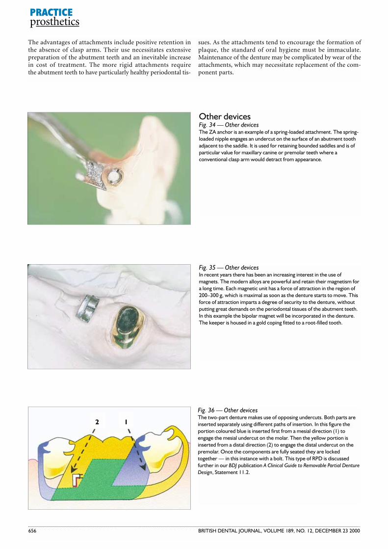
Other devicesFig. 34 — Other devicesThe ZA anchor is an example of a spring-loaded attachment. The spring-loaded nipple engages an undercut on the surface of an abutment toothadjacent to the saddle. It is used for retaining bounded saddles and is ofparticular value for maxillary canine or premolar teeth where aconventional clasp arm would detract from appearance.
Fig. 36 — Other devicesThe two-part denture makes use of opposing undercuts. Both parts areinserted separately using different paths of insertion. In this figure theportion coloured blue is inserted first from a mesial direction (1) toengage the mesial undercut on the molar. Then the yellow portion isinserted from a distal direction (2) to engage the distal undercut on thepremolar. Once the components are fully seated they are lockedtogether — in this instance with a bolt. This type of RPD is discussedfurther in our BDJ publication A Clinical Guide to Removable Partial DentureDesign, Statement 11.2.
Fig. 35 — Other devicesIn recent years there has been an increasing interest in the use ofmagnets. The modern alloys are powerful and retain their magnetism fora long time. Each magnetic unit has a force of attraction in the region of200–300 g, which is maximal as soon as the denture starts to move. Thisforce of attraction imparts a degree of security to the denture, withoutputting great demands on the periodontal tissues of the abutment teeth.In this example the bipolar magnet will be incorporated in the denture.The keeper is housed in a gold coping fitted to a root-filled tooth.
12

BRITISH DENTAL JOURNAL, VOLUME 189, NO. 12, DECEMBER 23 2000 657
PRACTICE prosthetics
a b
Fig. 39a and b — Other devicesThere is an added advantage of the swing-lock denture in that the ‘gate’ can carry a labial acrylic veneer. This veneer can be used to improve the appearance when a large amount of root surface has been exposed following periodontal surgery.
Fig. 37 — Other devicesA bolt retained sectional denture is shown in situ. The patient needs tobe reasonably dextrous to successfully manage a denture of this type.
Fig. 38 — Other devicesThe swing-lock denture has a hinged labial bar which has extensions intoundercuts on the labial surfaces of the teeth. When the ‘gate’ is closedand locked into position, the denture is held securely by the ‘gate’ on thelabial aspect and by the reciprocating components on the lingual aspectsof the teeth. The denture can be particularly helpful where the remainingnatural teeth offer very little undercut for conventional clasp retention.This patient, a trombone player, required a positively retained RPD. Theswing-lock design allowed optimum use to be made of the incisors. Asthis type of denture covers a considerable amount of gingival margin, thestandard of plaque control must be high.