Modified Final Report - Retention aids(1)
86
Indian Institute of Technology - Roorkee is among the foremost of institutes of national importance in higher technological education and in engineering, basic and applied research. Since its establishment, the Institute has played a vital role in providing the technical manpower and know-how to the country and in pursuit of research. The Institute ranks amongst the best technological institutions in the world and has contributed to all sectors of technological development. It has also been considered a trend-setter in the area of education and research in the field of science, technology, and engineering. The University of Roorkee, now the Indian Institute of Technology had a modest beginning as the Thomason College of Engineering in the year 1847, and was converted to the First Technical University of India in the year 1949.Pandit Jawaharlal Nehru, the first Prime Minister of India, presented the Charter in November 1949 elevating the erstwhile college to the First Engineering University of Independent India. This incident not only indicates the deep rooted history of this institution but is also an indication of the service that it has provided in the process of technical escalation of our country. The institution has always provided the path and has Page | 1
Transcript of Modified Final Report - Retention aids(1)

Indian Institute of Technology - Roorkee is among the foremost
of institutes of national importance in higher technological
education and in engineering, basic and applied research.
Since its establishment, the Institute has played a vital role
in providing the technical manpower and know-how to the
country and in pursuit of research. The Institute ranks
amongst the best technological institutions in the world and
has contributed to all sectors of technological development.
It has also been considered a trend-setter in the area of
education and research in the field of science, technology,
and engineering.
The University of Roorkee, now the Indian Institute of
Technology had a modest beginning as the Thomason College of
Engineering in the year 1847, and was converted to the First
Technical University of India in the year 1949.Pandit
Jawaharlal Nehru, the first Prime Minister of India, presented
the Charter in November 1949 elevating the erstwhile college
to the First Engineering University of Independent India. This
incident not only indicates the deep rooted history of this
institution but is also an indication of the service that it
has provided in the process of technical escalation of our
country. The institution has always provided the path and has
Page | 1

been an idol for the other upcoming institutions and
universities to follow. These 150 years have been great years
of technical advancement for our country and the institution
pledges to provide much more in the upcoming years.
On the 21st September 2001, the University was declared an
institute of national importance, by passing a bill in the
parliament, changing its status from University of Roorkee to
Indian Institute of Technology Roorkee.
The Institute offers Bachelor's Degree courses in 10
disciplines of Engineering and Architecture and Postgraduate's
Degree in 55 disciplines of Engineering, Applied Science,
Architecture and planning. The Institute has facility for
doctoral work in all Departments and Research Centers. The
Institute admits students to B. Tech. and B.Arch. courses
through the Joint Entrance Examination (JEE) conducted at
various centers all over India.
About Department of Paper Technology
The Department of Paper Technology located at the Saharanpur
Campus of IITR offers academic programs at various levels in
Pulp and Paper Technology, Polymer Science and Technology,
Process Engineering and Management. The Department has well
developed academic infrastructure. Its faculty is engaged in
teaching, research and industrial consultancy.
The Department is the predecessor of the School of Paper
Page | 2
Technology established by the Government of India in 1964,
with an aid from the Royal Swedish Government. This school was
managed by a society created by the U.P. Government until its
merger with the then University of Roorkee in 1978. The school
was renamed as the Institute of Paper Technology in July 1968
and subsequently Department of Paper Technology in July 1992.
Pulp and Paper Technology Programme
Under graduate:
The Department of Paper Technology offers a 4-year course
leading to a Bachelor of Technology (B.Tech.) degree in Pulp
and Paper Engineering. The assigned intake of students for
this course is 70 and the students are admitted through the
IIT- JEE. The curriculum lays sufficient emphasis on
fundamentals and applications of chemical engineering and
basic sciences in pulp and paper manufacturing. Since the
course is a unique industry oriented programme, students have
a closure industry exposure through mill training and industry
visits.
Post Graduates:
The Department offers a Master of Technology (M.Tech) course
in Pulp and Paper. This is a multidisciplinary course offered
to the students having graduate degree in Pulp and Paper,
Chemical Engineering, Mechanical Engineering, and allied
disciplines. All the students of this course have been able to
Page | 3

secure placement in paper and allied industries through campus
interviews.
ABOUT PROJECT
As a part of our B.Tech Curriculum we have to undergo
vocational training /internship at the end of III year which
lasts for 8 to 10 weeks. A key element in an engineering
curriculum is an exposure to professional engineering practice
sought through industrial training. Industrial training has
traditionally been weighed as a potent grooming of the
professional career of a fresh engineering graduate and it is
the common method of the harvesting skilled engineers.
Training Outcomes and Assessment
Ability to acquire and apply fundamental principles of
science and engineering.
Capability to communicate effectively.
Ability to identify, formulate and model problems and find
engineering solution based on a systems approach.
Ability to conduct research in the chosen fields of
engineering.
Page | 4

Understanding of the importance of sustainability and cost-
effectiveness in design and developments of engineering
solution.
Ability to be a multi-skilled engineer with good technical
knowledge, management, leadership and entrepreneurship
skills.
Awareness of the social, cultural, global and environmental
responsibility as an engineer.
Capability and enthusiasm for self-improvement through
continuous professional development and life-long learning.
Page | 5

ABOUT TNPLINCORPORATION OF THE TNPL
Tamil Nadu Newsprint and Papers Limited (TNPL) was
incorporated in April 1979 as a Public Limited Company under
the provisions of the Companies Act, 1956. The Registered
Office of the company is situated at 67, Mount Road, Guindy,
Chennai - 600 032. The factory is situated at Kagithapuram in
Karur District of Tamil Nadu.
PAPER MAKING PROCESS IN TNPL
PULPING PROCESS
The Pulp Mill consists of the following three pulping
streets:
Page | 6

Hardwood pulping street (HWP)
Chemical bagasse pulping street (CBP)
Mechanical bagasse pulping street (MBP)
About HWP:
The Eucalyptus and other tropical Hardwood logs are drawn
from the Wood yard and chipped in two Disc Chippers of
capacity 30 bdmt per hour.
After screening, cleaning & extraction stage cooking is
done in Super batch cooking plant consist of 3x200 m 3
digesters.
Following the brown stock washing, a two stage Oxygen
Delignification process is carried out where the main
features are higher degree of delignification without
decreased selectivity.
The first stage operates at high pressure and low
temperature (80-85°C) having 30 minutes residence
time.
Second stage at lower pressure and a high temperature
having 60 minutes residence time.
The pulp is then bleached in a Elemental Chlorine free
bleaching sequence consists of Chlorine dioxide (Hot
stage), oxidative alkali extraction using hydrogen
peroxide and Oxygen followed by one more chlorine dioxide
stage (DHT - EOP - D1).
The Hardwood pulp has an installed capacity to produce 300
tpd of bleached pulp.
Page | 7

About CBP:
Having two streets of CBP plants, the washed bagasse is
cooked in the twin tube continuous digesters.
After cooking, the pulp is blown continuously to a common
blow tank in the respective street.
After washing, screening, cleaning and thickening stored
in pulp tower and after that bleaching is done through
elemental chlorine free (ECF) process.
The chemical bagasse streets have a combined capacity to
produce 420bdt-bleached pulps per day.
PAPER MACHINE:
The Company has three Paper Machines with following
specifications.
Sl.
No.
Particulars PM ❶ PM ❷ PM ❸
1 Supplier Beloit
Walmsley,UK
Voith,
Germany
Voith,
Germeny
2 Products Printing &
writing
Paper (PWP)
Newsprint and
PWP
Newsprint &
PWD
3 Operating
speed
650 m/min 850 m/min 1100 m/min
4 Annual
capacity
110,000 MT 120,000 MT 155,000 MT
Page | 8

5 Deckle width 6.80 meters 6.60 meters 5.4 meters
6 Finished
production /
day
350 MT/d 450 MT/d 550 MT/d
7 Commissioning
year
1985 1996 2010
CHEMICAL RECOVERY PROCESS
This section contains three operations viz., Evaporation,
Incineration and causticizing.
EVAPORATION:
The blend liquor concentration is around 8-9%. The recovery
plant has two streets of six-stage Multiple Effect and another
street of seven-effect falling film evaporator. The
concentration level of the evaporator output is 45% and it is
called as "Semi Concentrated Black Liquor (SCBL)".
Under MDP, the Mill installed an additional evaporator to
concentrate the Black Liquor up to 70% solids, which will
enable firing of liquor directly in the Recovery Boiler.
The plant has a capacity to evaporate 500 m3 of water per hour.
Page | 9

RECOVERY BOILER:
The Recovery Boiler is provided with Electrostatic
Precipitators to collect the solids (Sodium salts) escaping
with the flue gas.
The Recovery Boiler has a capacity to incinerate 1300 tonnes
of solids per day with steam generation of 180 tons/hr at 64
Kg/cm2 of pressure.
CAUSTICIZING PLANT:
The reaction is as follows: -
Na2CO3 +Ca(OH)2 + H2O −−−−−→ NaOH +
CaCO3
(Green Liquor) (Burnt Lime) (White
Liquor) (Lime Sludge)
The Caustic zing Plant has capacity to generate 4000 M3 / day
of white liquor.
LIME KILN:
Lime Kiln with the capacity of 170 MT/day of burnt lime has
been installed to recycle the lime sludge generated in the
process of caustisizing. At the required temperature, the
burnt lime with purity of 75% CaO is generated.
Page | 10

INTEGRATED CHLORINE DIOXIDE PLANT:
To meet the requirement of chlorine dioxide in the bleach
plants, an Integrated Chlorine dioxide plant of capacity 15
tpd is established.
The Integrated plant comprises of the following three sub-
systems:
• Sodium Chlorate production system
• Hydrochloric acid generation system
• Chlorine dioxide generation system
The process is depicted in the following illustration.
UTILITIES
STEAM:
The company has five boilers with the following specification:
Page | 11
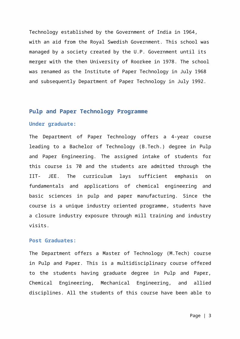
POWER:
The company has five (5) Turbo Generators as detailed below to
meet its power requirements.
A connected load of 8500 KVA for Main Site factory and 250
KVA for Water In-take well from Tamil Nadu Electricity Board
have also been obtained.
WASTE WATER TREATMENT
Waste water from the various processes is clarified and
treated in Effluent Treatment Plant (ETP) and let into
lagoon.
Page | 12

The waste water treatment plant consists of primary and
secondary treatment
primary treatment is based on physico-chemical process
Secondary treatment is based on biological process.
The sludge generated from the waste water treatment is
classified two into:
Primary Sludge
Secondary Sludge
The primary sludge is sold to local board making unit and
secondary sludge is used in Boiler as fuel after solar drying.
The water is used for irrigation by the farmers around the
factory.
BIO-METHANATION PLANT:
TNPL utilises around 7, 00,000 tones of depithed bagasse every
year. The effluent generated from bagasse washing, during
receipt and reclaiming operations is handled in an exclusive
anaerobic treatment system using Anaerobic Lagoon previously
which is based on the UASB OPTIMA Process. To gainfully
utilise the reduction in COD levels, a bio-methanation system
has been installed wherein "Bio-gas (Methane)" generated is
collected and utilized in Lime Kiln as substitute for Furnace
Oil.
Page | 13

SELF SUFFICIENCY IN POWER
TNPL is 100% self sufficient in power generation through the
81.12 MW Power Generation Capacity (TG Sets) installed at the
paper mill site. The surplus power generated is being exported
to the State Grid.
USE OF AGRO FUELS IN BOILERS
The entire pith generated while depicting the bagasse, is also
fired in the boilers as fuel. The usage of above agro fuels
helps contain the consumption of fossil fuel to some extent.
Page | 14

PAPER MACHINE 3Paper Machine 3 (or PM 3) is the newest paper machine to be
installed in TNPL. It was made by VOITH and installed in 2010.
This machine has increased the daily paper production of the
company to go above 1000 MT/Day bringing it among the elites
in Paper making. This Paper machine uses the latest technology
available in the market for paper production, but is also
optimized to work on bagasse pulp as the company uses the
mixture of 55% bagasse pulp and 45% HW pulp for Writing and
Printing quality paper.
This machine like all the Paper Making machines is made up of
various parts and systems working together to ensure the
proper working of the machine. The various systems are
described in the following pages.
Wet End System
The main jobs of Wet End System are:-
To supply the PM with Prepared stock suspension
continuously.
To recover fibers from white water.
Page | 15

To slush paper stock during full production with pulpers
under the PM.
To prepare the uncoated and coated broke and return it to
the production process.
Approach Flow System
Its job is as follows:-
To screen the stock suspension.
To clean the stock suspension.
To deaerate the stock suspension.
To feed the stock suspension continuously to the headbox
of the PM.
Central Mixing Station (ComMix):
The ComMix serves to mix the stock components in a controlled
ratio. The various features of ComMix are:-
Macro mixing in mixing pipe
Micro mixing in static mixer
Attenuating of fluctuations
Page | 16

ComMix
HydroMix ( with White Water Duct):
The white water derived from the PM flows to the HydroMix in
the white water duct.
The various functions of HydroMix are:-
The white water has a dwell time in the white water duct
and is thereby deaerated.
Outlets discharge dilution and backflushing water to the
cleaners and dilution water to the low consistency
dilution water line.
The cleaner pump of the first stage conveys the main flow
with the injection virgin stock speed controlled to the
cleaner system – Ecomizer and stock deaeration station.
Page | 17

HydroMix
Cleaner System (Ecomizer):
On the centrifugal priciple, cleaners separate impurities with
a higher specific gravity. The cleaner principle allows for
higher stock consistencies and minimizes fiber loss. The
Ecomizer cleaner system is structured in cascade shape
consisting of three stages and a final stage.
EcoMizer
Page | 18
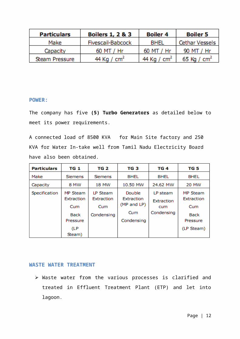
Stock Deaeration (VoithVac):
There is a very high vacuum at the VoithVac. The stock
suspension is sprayed and thereby deaerated.
VoithVac
Screening – Vertical Screen:
Slotted baskets in the vertical screens remove cubic
impurities, contaminants and fiber knots from the suspension.
Fiber Recovery
This system, as its name states, is used for the recovery of
fiber from white water. The various sytems and processes used
are as follows:-
Page | 19

Disk Filter:
It is used to filter the fiber out of the stock suspension.
Its basic functions are:-
It separates fibers from suspension by screen disks and
sweetener stock.
The screen disks are designed with corrugatedstainless
steel segments without clothing (bagless).
Separation is into cloudy, clear, and super clarified
filtrate as well as thick stock.
Machine Pulper
When there is broke, the machine pulper slushes the full
production. Pumps convey the stock suspension for storage in
the corresponding storage tower.
Broke Preparation
It prepares the broke accumulated on the PM and carries the
prepared broke back to the stock circuit.The full broke pump
at the couch broke chestconveys the uncoated broke from the
press pulper and couch broke chest to the uncoated broke
tower. Following this the broke is thickened via a thickener
and pumped consistency controlled through the thickener chest
via high consistency cleaner, MultiSorter and deflaker to the
mixed broke metering chest.
Page | 20

The edge trimming pump at the couch broke chest conveys the
edge trimming broke directly to the thickener.
The pump conveys the uncoated broke from the pre-dryer section
pulper to the couch broke chest.
Thickener
Screen disks installed on a drum thickener, the stock
suspension in the vat and the filtrate flow to the white water
tank.
Screening – Vertical Screen
A drilled basket in the vertical screen removesflat impurities
from the broke.
Deflaker
The screeened broke of the vertical screen is fed to the
deflakers. Deflakers disperse shives in the accepts and
rejects.
HeadBox
The HeadBox is aptly named as it is located at the beginning
of the paper machine. It provides a uniform stock jet to the
wire section.
It has four basic functions:-
Page | 21
The distribution of stock on the wire by a machine wide
calibrated jet system.
Basis weight cross profiling by regulation of the stock
consistency and/or jet thickness.
To provide aeration of defined turbulence degree to
improve the quality of paper.
Influence of jet or jet control.
Pressure Difference Indicator
The pressure difference indicator unit serves to control the
pressure difference between the inlet and the outlet of the
headbox. The pressure equilibrium in the headbox between the
front side and the drive side is indicated in the inspection
window. There is pressure equilibrium if no flow is visible in
the inspection window.
Modulejet Units
The modulejet units control the stock consistency of each
section across the machine width. The modulejet units are
arranged next to one another across the entire slice width of
the paper machine. High consistency stock and low consistency
stock are mixed in the modulejet mixing chamber. The mixing
ratio of two stock flows HC/LC determines the sectional stock
consistency in the individual mixing chamber and thus the
cross profile of basis weight.Page | 22

Edge Module
The edge module unit influences the production of the fiber
orientation by a variable volume flow rate, which is supplied
at the front and drive side edged area of the turbulence
generator. This unit serves for the improvement of fiber
orientation, particularly at the edges of the paper web.
Bottom Lip Adjustment
The bottom lip adjustment influences the jet angle and thus
the jet impingement point of the wire. The bottom lip can be
adjusted horizontally via screw jack units.
Top Lip Beam Vertical Adjustment
The top lip beam vertical adjustment influences the size of
slice opening and thus the jet thickness.
Slice Opening Measuring Device
It indicates the slice opening size. It also tells us about
the slice blade adjustment. The slice blade adjustment is used
for the adjustment of a parallel nozzle slice opening as well
as for control of fiber orientation.
Page | 23

Deckle Plate
The deckle plate covers the headbox nozzle at the side. The
slice measuring unit, Edge master and the static head
transmitter are fastened on the deckle plate.
Edge Master
The Edge master serves for guiding the stock jet laterally
after leaving the headbox nozzle.
Breast Roll Shower
The breast roll shower keeps the headbox covering in the area
of apron board clean.
Hinged Cover Plate
The cover plate protects the module jet against the shower
water.
Pressure Control System
Pressure control system controls the static head in the
headbox nozzle and keeps the jet velocity constant.
Dilution Water Control System
It maintains a defined gauge pressure in Low consistency
header as compared to High consistency header.
Page | 24

Basis Weight Profile Control System
It controls the sectional dewatering of the basis weight from
the pre-set setpoint profile.
Duo former
The DuoFormer D is a hybrid former. This means that the
suspension is initially drained on a fourdrinier section
before entering the twin-wire part with additional drainage
upwards.
The top-wire unit can be installed both in new machines and on
existing fourdriniers. The latter is favoured by the fact that
the wire run in the twin-wire part deviates only slightly from
the wire line on the fourdrinier.
The initial drainage section consists of a forming board,
several foil boxes and/or single foils and one or two wet
suction boxes prior to the top wire unit.
Page | 25

Duoformer
Twin Wire Region of DuoFormer
The top-wire suction box and the lead-in roll are mounted
together on a swivel arm.
The suction box consists of three zones: the vacuum skimmer,
the first and the second suction zone. The white water drained
through the top wire is raised by vacuum up to the overflow
weir of the respective discharge channel, which has a drive-
side outlet. The top-wire suction box is equipped with ceramic
blades. In the outlet area where no blades of the forming box
are pressed against the bottom wire, the ceramics form a
radius for wire support.
Page | 26

The top wire has 4 rolls and is capable of being fully
cantilevered. All rolls of the top wire are located inside the
top wire loop. Only the high-pressure shower for wire cleaning
is arranged outside the top wire loop.
The drainage section in the twin-wire area of the Duo- Former
D consists of the top-wire suction box, the forming box in the
bottom wire below the top-wire suction box and the succeeding
transfer suction box, at which the top and bottom wires
separate.
Twin Wire Section of Duoformer D
Opposing the top-wire suction box, the forming box is arranged
in the bottom wire. It is equipped with ten individually
guided forming blades. These forming blades are positioned
Page | 27
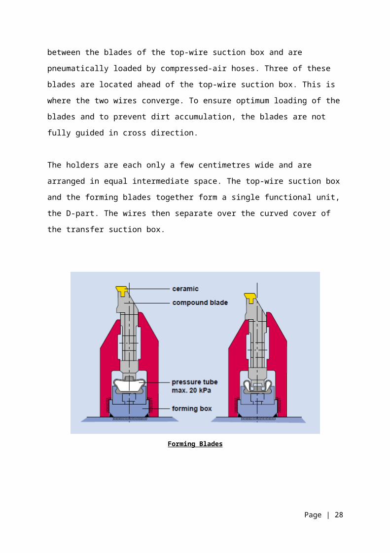
between the blades of the top-wire suction box and are
pneumatically loaded by compressed-air hoses. Three of these
blades are located ahead of the top-wire suction box. This is
where the two wires converge. To ensure optimum loading of the
blades and to prevent dirt accumulation, the blades are not
fully guided in cross direction.
The holders are each only a few centimetres wide and are
arranged in equal intermediate space. The top-wire suction box
and the forming blades together form a single functional unit,
the D-part. The wires then separate over the curved cover of
the transfer suction box.
Forming Blades
Page | 28

Drainage
Drainage is the most important job of the DuoFormer and it is
highly effective in this matter.
Drainage Capacity:
Conventional fourdrinier sections are limited in their
production speed due to the lack of drainage capacity
resulting from the normal overall lengths and due to water
throw at the dandy roll, which increases with speed.
Because of the additional top-wire drainage, the DuoFormer D
has a much larger drainage capacity. No splashing occurs as
with the dandy roll. Therefore production speeds of up to 1200
m/min are readily possible with the DuoFormer D. This speed
limit is attributed to the turbulence that occurs on the
surface of the suspension in the pre-drainage area, which is
caused by friction with the surrounding air.
Drainage Development:
In three drainage sections, skimmer, suction zone 1 and
suction zone 2, the drainage of the suspension mainly occurs
on the top side and takes place during a very short distance.
In this short distance the sheet goes from the initial
drainage phase to sheet consolidation. The drainage begins
with minimum pressure, goes through an area with pressure
pulses and ends at the vacuum-assisted transfer suction box.
Page | 29

The initial drainage through the top wire begins in the area
ahead of the skimmer blade, i.e. the first blade of the top-
wire suction box. In this area the top and bottom wires are
joined on the first flexible forming blades.
White water from the surface of the suspension is then pressed
through the top wire so that a “wet-line” can be observed at
the second forming blade in the bottom wire. The water drained
through the top wire is peeled off by the skimmer blade and
discharged upwards. This gentle initial drainage is a clear
advantage compared to that on a curved shoe or a forming roll,
on which a steeper pressure increase takes place during
initial drainage. During drainage on curved surfaces, the
drainage pressure depends only on the geometry and the wire
tension. On the DuoFormer D the drainage pressure can be
adjusted via the air pressure in the loading tubes. Through
the very gentle drainage pressure increase crushing is
avoided.
Drainage Rates
An overview of the water flow rate distribution at Duo- Former
D is given in. In the initial drainage approx. 50-60% of the
headbox flow is removed. Of the remaining quantity, only a
small portion is drained downwards in the twin-wire part,
because a dense fibre mat is already deposited on the bottom
wire. The main portion is discharged upwards at the skimmer
and in suction zone 1 so that only a small flow occurs in
suction zone 2.Page | 30

Drainage Rate
Tandem-NipcoFlex Press
The Tandem NipcoFlex Press, which consists of two, double-
felted, straight through shoe presses. It is designed for high
speed machines and optimum paper properties.
Tandem-NipcoFlex Press
Page | 31
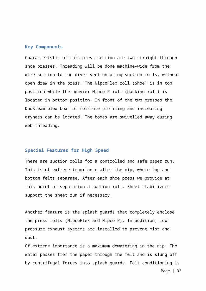
Key Components
Characteristic of this press section are two straight through
shoe presses. Threading will be done machine-wide from the
wire section to the dryer section using suction rolls, without
open draw in the press. The NipcoFlex roll (Shoe) is in top
position while the heavier Nipco P roll (backing roll) is
located in bottom position. In front of the two presses the
DuoSteam blow box for moisture profiling and increasing
dryness can be located. The boxes are swivelled away during
web threading.
Special Features for High Speed
There are suction rolls for a controlled and safe paper run.
This is of extreme importance after the nip, where top and
bottom felts separate. After each shoe press we provide at
this point of separation a suction roll. Sheet stabilizers
support the sheet run if necessary.
Another feature is the splash guards that completely enclose
the press rolls (NipcoFlex and Nipco P). In addition, low
pressure exhaust systems are installed to prevent mist and
dust.
Of extreme importance is a maximum dewatering in the nip. The
water passes from the paper through the felt and is slung off
by centrifugal forces into splash guards. Felt conditioning isPage | 32

a further important topic. It is significant for a long felt
life as for excellent moisture cross profiles. Besides the
Uhle boxes and water showers the successful Duo- Cleaner is
integral part of every felt run to keep the felt open and
improve overall efficiency.
Felt Conditioning
Advantages
The drawless sheet run is a big advantage, especially for low
basis weights (ULWC), despite a minor rewetting. At medium
basis weights (newsprint, SC), the low two-sidedness, reduced
number of breaks and the speed potential are very
advantageous. At high basis weights the Tandem NipcoFlex Press
allows, aside from the already mentioned benefits, much higher
dryness.
In summary, the Tandem NipcoFlex Press, with four felts and
two shoe presses, is, because of all the mentioned advantages,
Page | 33

in many applications the most desirable and most economical
solution:
High dry content and high specific bulk with two NipcoFlex
presses.
Four felts for minimal two-sidedness.
Low paper expansion.
Suction rolls for controlled and safe web run, short
threading time.
Combi-DuoRun
The VoithSulzerCombiDuoRun is a combination of single-tier
dryer group in the first part and double-tier dryer group in
the second part of the dryer section. In modern paper
machines this concept operates successfully at speeds up to
1500 m/min. With rising speeds, the number of double-tier
drying groups and the number of cylinders per group has been
reduced since problems were caused by the damp web in the open
draw of the double-tier dryer group. The dryer section of the
paper machine has six Top DuoRun groups, and at the end of the
dryer sections a double-tier group with six cylinders.
Page | 34

Combi DuoRun
Features
The Salient features of CombiDuoRun are:-
Stable Running:
After leaving the last press nip, the web is sucked on to the
fabric of the first dryer group and fixed. It is then
supported on the fabrics right through the dryer section, thus
ensuring stable running and reducing the risk of a break
rupture to a minimum. The combination of DuoStabilizers and
dryer fabric drilled guide roll transports the web reliably
from cylinder to cylinder. At the cylinder run-out point the
DuoStabilizer fixes the web by suction on the dryer fabric.
The vacuum balances out the centrifugal force around the
drilled guide roll and thus keeps the web fixed to the dryer
fabric.
Page | 35

High Specific Evaporation:
Thanks to the high specific evaporation, dryer sections are
shorter and investment costs lower. To increase the heat
transfer from steam to web, all cylinders are fitted with
spoiler bars.
In order to reach such a high evaporation capacity, the heated
web must be able to dry out sufficiently after leaving the
cylinder. To this purpose the DuoStabilizer provides a long
evaporation distance.
High Availability:
Its stable running characteristics reduce web break frequency
to a minimum. A significant advantage of this cylinder
arrangement is the short tear-off time required.
Waste material falls on to the conveyor belt below and are
transported automatically to the pulper. As a result, time-
consuming removal of waste from the drying section is no
longer necessary. The rope-less edge strip transfer system
ensures fast and reliable transfer, without any time wastage
due to rope wear or breakage.
Controlled Paper Shrinkage:
Due to the rising web temperatures at the beginning of the
dryer section, the initial wet strength falls off and web
Page | 36

extension increases. When the web is tensioned, it extends in
the longitudinal direction and its width shrinks.
The DuoStabilizer fixes the web to the dryer fabric by suction
at the cylinder take-off point. Relatively small forces are
required to remove the web from the cylinder surface, so that
longitudinal extension and lateral shrinkage are low. Thanks
to the small dryer groups, extension in the wet part of the
web can be compensated by speed adjustment, thus preventing
folds.
In single-tier dryer sections, the web is firmly fixed to the
dryer fabric and prevented from shrinking. This generates web
stresses which can cause tearing. By means of short dryer
groups at the end of the dryer section, allowance can be made
by speed adjustments for web shrinkage, thus preventing
breaks.
ProRelease+
To improve the situation, the web must be fixed on the fabric
immediately after the point of separation from the cylinder
and the increased vacuum must be limited to the release area.
The new MultiSeal system meets these requirements excellently.
This sealing system consists of Teflon strips that define the
release zone and guarantee high vacuum in that zone. The
vacuum in the stabilizing zone can be adjusted and optimized
independently.Page | 37

Schematic arrangement of the ProRelease+
SpeedSizer AT
Application systems normally employ corrosion-resistant
stainless steels. This materials’ sensitivity to temperature
changes requires measures to compensate for the thermal
deformation of the applicator head.
The traditional applicator head deflection compensation system
results in adequate dimensional stability under constant
operating conditions, however does not respond quickly enough
Page | 38

in the case of production interruptions due to breaks and/or
maintenance. The radiated heat from infrared and cylinder
drying systems also has negative effects on the production
conditions in wide machines.
Carbon fiber materials are now setting new standards. Compared
to stainless steel, they can be designed to have a very low
thermal expansion coefficient in the longitudinal beam
direction and are thus especially suited for wide machines
with high demands for dimensional stability.
Application Head
Design
The patented design combines the carbon fiber applicator head
with the nozzle applicator of stainless steel in an ideal
manner. The connection of the two functions
Page | 39

“application/metering” and “mechanical precision” is
established by means of special links.
They completely absorb the thermal expansion of the nozzle
applicator without any transfer to the carbon fiber beam. In
this manner, the properties of the materials that are best
suited to the functions are optimally used for the overall
system.
Proven application system of stainless steel.
Supporting structure of carbon fiber for excellent
straightness.
CD Coating
The CD coating in SpeedSizer AT has the following benefits:-
High process stability, regardless of production
interruptions.
Excellent CD coatweight-profiles, both immediately after
start-up and in continuous operation.
Simple maintenance and service due to omission of the
applicator head heating.
RETENTION AID SYSTEMS
Page | 40

Types of Retention Aid Systems
Single Particle Retention Aids
They use only a single particle as retention aids.
Dual-polymer programs
An effective retention program should satisfy the requirements
for both charge neutralization and particle agglomeration. A
single additive will usually not provide optimum retention
because the chemical and physical properties needed for
coagulation and flocculation are different. The most common
retention programs for paper made at acid pH use alum (a
coagulant), along with a high molecular weight flocculent. In
general, these programs have been very effective.
Some paper machines, however, place exceptionally high demands
on the retention program and require the use of an additional
synthetic coagulant, or dual-polymer program. This is most
prevalent under alkaline papermaking conditions where the
effectiveness of alum as a retention aid is greatly reduced.
Retention aids react in a paper machine system by adsorbing
onto the surfaces of colloidal fines and fillers, so any
changes in the amount of fines or fillers in the wet end
system will affect the need for retention aid.
The concentration of dissolved ions and interfering anionic
substances in the furnish will also influence the type of
Page | 41

retention program that will work best. Some of the variables
that should be considered include:
Type of fiber
Pulp cleanliness
Wet end pH
Alum addition
Type and amount of fillers
Cationic starch
Strength additives
Sizing system
Extent of closure
Broke usage
Coated broke
For mills producing coated papers, the use of coated broke can
increase the need for good coagulation and flocculation. In
some of these mills, the broke system contributes a
substantial portion of the sheet ash, or it may be the only
source of filler. Ash from broke systems can be more difficult
to retain than filler pigments.
Typically, the particle size of coating grade pigments is
smaller than filler clays (73 to 92% less than 2 microns
versus 55 to 60% less than 2 microns). Dispersing agents
added to coatings increase the electrostatic charge on the
pigment particle, and thus increase the demand for a cationic
coagulant in the wet end. The amount of dispersant is usually
Page | 42

higher in coating formulations with calcium carbonate or
titanium dioxide than with clay pigment.
Starch binders present additional challenges to the retention
program when coated broke is recycled to the wet end of the
paper machine. Larger quantities of dispersing agents are
used in coating where starch, rather than protein, is present
as the coating adhesive. Oxidized starch is a good pigment
dispersant, but is undesirable in the wet end because it is
detrimental to retention.
In systems like these, and others, an alum-flocculent program
may not be able to provide the desired high level of retention
and sheet quality. So much HMW polymer may be needed that the
system becomes over flocculated, causing formation to suffer.
Excessive use of alum to maintain retention can create
imbalance in wet end chemistry. In closed systems, high
levels of alum may cause sulfate buildup and excess acidity.
This can lead to problems in alum-rosin sizing, increase the
potential for alumina deposits, and affect paper machine run-
ability. Polymeric coagulants can reduce the amount of alum
needed, reducing the deposit potential and corrosivity of the
system.
A dual-polymer program, consisting of a LMW polymeric
coagulant fed before a HMW anionic or cationic flocculent can
be used to achieve good retention while reducing the
Page | 43

possibility of over flocculation and poor sheet formation
without disrupting the wet end chemical balance.
Microparticle flocculation
Colloidal silica is a highly anionic particle approximately 4
mill microns in size. Refer to Figure 6.
It significantly enhances small particle retention by forming
strong ionic bonds with cationic additives or coagulants,
absorbed on the surface of furnish components. Refer to
Figure 7. The silica forms “microflocs”.
Page | 44
The exact mechanism is not known. It is believed the
difference between micro flocculation and conventional
flocculation lies in the ability of colloidal silica to
reflocculate after shear. Once the conventional flocs are
disrupted, they do not reform. Colloidal silica aids in the
reformation of bridging. Reflocculation on a micro scale
imparts high permeability to the sheet, which is favorable in
both cases for dewatering, press-dryness, and the ability to
be dry. These micro-flocs are better distributed throughout
the sheet and, therefore, give better filler distribution.
Mills can take advantage of this improved dewatering capacity
by diluting the stock consistency to improve formation or by
increasing production. Improved retention and filler
distribution can enhance opacity, porosity, brightness, and
reduce two-sidedness. Good formation can also press and dry
easier due to better surface contact. The Microparticle is
typically fed after the screens while the retention aid is fed
prior to the screens. This program allows for greater first
pass and ash retention without over flocculation, which is
typically, associated with traditional flocculent programs.
Retention Mechanism
It is generally accepted that the retention on a paper machine
is largely a filtration process, whereby furnish solids are
captured by filtration through the forming fabric and the
Page | 45

fiber mat. Retention produced through filtration, or
mechanical entrapment, is affected by many operating variables
including basis weight, furnish composition, machine speed,
drainage forces, type of forming fabric, and the design of the
forming section.
High basis weight, low ash sheets produced on slow speed
single-wire machines may have reasonably high retention even
without a retention aid program because these factors tend to
increase the filtration efficiency. But trends in papermaking
are toward lower basis weights, higher filler levels, faster
machine speeds and increasing use of twin-wire formers — which
reduce filtration efficiency and result in lower retention.
Filler loadings of 30% in alkaline papermaking are now
attainable due to chemically assisted retention.
Chemically assisted retention on a paper machine uses the
processes of coagulation and flocculation (and Microparticle
flocculation) to increase the effective size of the particles
Page | 46

in the fines fraction. This enables more fines to be retained
with the sheet. The fibers used for making paper develop an
anionic surface charge in water as a result of the
dissociation of carboxyl and sulfonic acid groups. These raw
materials include the fibers, fines, and fillers, as well as
most of the dissolved and colloidal material liberated from
the wood during the pulping and bleaching processes.
Cations may be attached by electrostatic and adsorptive
forces (van der Waals forces) to these surfaces. The anionic
charge on the surface is partially neutralized by these
cations causing the net potential energy of the system to drop
rapidly in this region as shown in Figure 1. The zeta
potential is determined by the magnitude of the anionic
surface charge minus the magnitude of the anionic surface
charge minus the magnitude of the cationic charge in this
layer of attached counter ions. Beyond the layer of firmly
attached cations, exists a second layer which contains a high
concentration of cations attracted by the zeta potential.
These cations, however, are not attached to the particle. The
edge of this diffuse layer is that point where the net
potential is finally reduced to zero. This description of
charge at various points beyond the surface is called the
Electric Double Layer model.
In a system with a high zeta potential, a large repulsive
force exists which resists the tendency of any two particles
to collide as they jostle about in the solution. The addition
of a coagulant uniformly neutralizes the charge, reducing the
zeta potential. As their diffuse layers shrink, particles arePage | 47

able to approach closer to each other until finally the
attractive van der Waals force overpowers the repulsive force
and coagulation occurs. Usually this occurs when the zeta
potential is reduced almost to zero which is the reason for
naming this the charge neutralization mechanism. To retain
these fillers and fines in the sheet, two things must be done:
first, reduce the repellent forces between the particles
(coagulation) and create cationic patches on the particles.
Then combine or form a “bridge” between these patches
(flocculation) to produce discrete agglomerates that are large
enough to be entrapped in the forming web.
Coagulation
Coagulation is the initial step in the retention process.
During coagulation, the electrostatic sphere of charge that
surrounds the small furnish particles and keeps them well
separated is neutralized by a cationic source (coagulant).
Reducing the extent of the repelling forces allows the
particles to come closer together. Effective coagulation is
reached when the distance that separates the fines is
sufficiently small that a high molecular weight polymer
(flocculent) can span between the particles to form a
“bridge”, producing agglomerates that can be retained by
filtration through the forming web.
The papermaker can choose between two types of coagulants:
inorganic or organic polymers. Alum is the most common
inorganic coagulant for acid papermaking systems. Alum can
Page | 48

function as an effective coagulant at pH 4.0 to 5.5, because
it can carry a strong cationic charge within this pH region.
At higher pH (greater than about 5.5), alum is only weakly
cationic, and becomes much less effective.
Organic coagulant polymers are designed to perform over a
broad pH range. They have been used effectively in systems
ranging from pH 4.0 to 8.5. Organic coagulants are highly
cationic, low molecular weight (LMW) polymers. Most organic
coagulants are polymers having a molecular weight of about
20,000 to 200,000. These polymers are supplied as water
solutions which may be fed directly to the stock line or with
in-line water dilution. Typically, coagulants are added back
in the system — to the pulper, blend chest, machine chest,
white water silo, or at the inlet of the machine screen. They
are always added before the flocculent.
Page | 49

Before coagulation the large sphere of electrostatic charge
prevents a bridge from forming between the polymer coated
particles.
With good coagulation the charge sphere is reduced, allowing the
high molecular weight (HMW) polymer to combine the particles
into larger agglomerates.
Flocculation
Flocculation is the second step in the retention process. HMW
polymeric flocculants are added to furnish after coagulation
to bridge the neutralized particles and hold them in the
sheet. Flocculants are usually acrylamide-based polymers with
a molecular weight from about 500,000 to tens of millions.
Unlike coagulants, which are always cationic, flocculants can
Page | 50

be cationic, anionic, or non-ionic. These high molecular
weight retention aids are available as dry powders and liquid
emulsions. Thus, a variety of flocculants products are
available to accommodate the unique needs of each paper
machine.
How do HMW polymers work in the papermaking system? Although
scientists disagree about the exact mechanisms, most agree
that the HMW polymer attaches to the surface of a filler or
fine and then extends into the liquid where it attaches to
long fibers or other filler particles, forming agglomerates.
The degree of extension, or length of the polymer in solution,
greatly affects how well fillers and fines are retained via
bridging mechanisms. Figure 4 shows how polymers can bridge
between particles to form agglomerates. For simplicity, the
electrostatic charge spheres have been omitted and the system
is assumed to be well neutralized.
The mechanisms for attachment of a HMW polymer to the particle
surface are not completely understood. Two mechanisms are
probably most important: hydrogen bonding and ion pairing.
Page | 51

Acrylamide polymers have a multitude of hydrogen bonding sites
that enables the polymers to attach to the surfaces of fillers
and fines. Cationic polyacrylamides can become attached to
oppositely charged particles through ion pairing.
Selection of Retention Aid System
When selecting a retention program, many variables must be
considered. Coagulant selection is based on the polymer’s
ability to satisfy the cationic demand of the system. Lab
screening of various available coagulants can be conducted on
machine furnish to determine which polymer chemistry will best
neutralize the system.
Flocculent selection can be similarly determined through the
use of the Britt Jar and various drainage tests to determine
which flocculent, along with silica, gives the best retention
and drainage characteristics. There are numerous flocculants
available to the papermaker today. These differ in chemistry,
molecular weight, and charge density.
A product can be chosen which best fits the wet end chemistry
and requirements of the mill. In no way can one flocculent or
coagulant be expected to perform optimally in all systems.
Every mill is unique and an analysis should be carried out to
determine which polymers will function optimally.
Page | 52

Factors influencing Retention and Drainage
Various factors influence the working of the retention and
drainage aids:
Chemicals used
Polymer Makeup
Chemicals used in Retention Aid Systems
Inorganic Salts:Salt is added to stock suspension. It will dissociate into
cations and anions. Cations will be carried into double layer,
reducing surface potential. As more salt is added, the system
will get closer to isoelectric point. At this point, the
inter-particle repulsion minimum and system will flocculate
and improvement in retention is observed. Al is a polymeric
retention aid, PH=4.4-5.5 and it affects the degree of
ionization of functional groups.
Organic Polyelectrolyte:
Natural starch- Improving degree of inter-fiber bonding.
Improvement of drainage and filler retention.
Enhancement of wet strength.
Dry strength improvement.
Page | 53

Physical Modifications-
Fractionation into amylase and amylopectin components.
Thermo mechanical conversion.
Acid hydrolysis.
Chemical modifications-
Oxidation
Derivation
Enzymes conversions
Cationic starches-It minimizes water pollution and good solubility is there.
Degree of substitution is 0.02 i.e. 20 cationic groups per 100
glucose units.
This causes high dispersability and solubility to the starch.
Internal cohesive forces are diminished, hence is cooked
readily. Irreversible adsorption on fiber surface increases
with increasing surface area. At higher paper machine speed
and shear rate, synthetic polymer should used. Generally 1%
concentration starch is added before shearing at forming
section.
Anionic Starches- Only phosphate functional group
1%alum, PH=4.3 to 6.
Reversible adsorption
Up to 80% starch removed on heating.
Page | 54

Amphoteric Starches - Contain both cationic and anionic substituent.
Retain this charge under wide variation of Ph, water
hardness, alum concentration.
Synthetic Polyelectrolytes:
A polyelectrolyte is a polymer that is composed of monomer
units which have charged functional groups. Charged centre
causes water solubility and electrolyte like behavior.
Non-ionic polyelectrolytes- No formal charge but develop transient charge in water
though protonation .E.g. –PVA, polyacrylamide,
polyethylene oxide.
Small and weak floc due to h- bonding.
Sulfonated phenolic polymers are acted as activators to
form strong floc.
Anionic polyelectrolytes- Sulfonic, Phosphonic or carboxylic acid group.
Added as salts to maintain PH. E.g.-polyacrylamide
copolymer
Requires presence of cationic intermediatary so that
anionic polymer can bond with anionic surface like alums.
Alums form sites on the negatively charged surfaces of
fibers and fines. This allows bridging to take place.
Good with rosin alum sizing.
Page | 55

Strong hard floc due to high molecular weight, linear
variety.
Cationic polyelectrolytes- Sulfonium, phosfonium, quaternary ammonium ions.
Ammonium salts retain this cationic charge only in acidic
medium.
Quaternary ammonium salts retain these charges in all
mediums.
High solubility, cost effective.
Cationic electrolytes floc the system by bridging between
negative charges.
Length of loop and tails depends on the molecular weight.
If molecular weight is low then two different cationic
surfaces can be form.
High molecular mass stronger physical connection.
For polyelectrolyte to behave as effective flocculent, the
polymer must have enough charge sites to bond to the
surface, but not be so highly charged that it assumes rod
like conformation.
Amphoteric polyelectrolytes- Contain both positive and negative functional groups.
Usually cationic monomer predominates over anionic.
Works over wide range of Ph.
Page | 56
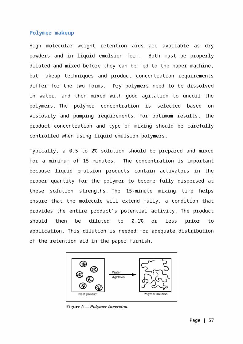
Polymer makeup
High molecular weight retention aids are available as dry
powders and in liquid emulsion form. Both must be properly
diluted and mixed before they can be fed to the paper machine,
but makeup techniques and product concentration requirements
differ for the two forms. Dry polymers need to be dissolved
in water, and then mixed with good agitation to uncoil the
polymers. The polymer concentration is selected based on
viscosity and pumping requirements. For optimum results, the
product concentration and type of mixing should be carefully
controlled when using liquid emulsion polymers.
Typically, a 0.5 to 2% solution should be prepared and mixed
for a minimum of 15 minutes. The concentration is important
because liquid emulsion products contain activators in the
proper quantity for the polymer to become fully dispersed at
these solution strengths. The 15-minute mixing time helps
ensure that the molecule will extend fully, a condition that
provides the entire product’s potential activity. The product
should then be diluted to 0.1% or less prior to
application. This dilution is needed for adequate distribution
of the retention aid in the paper furnish.
Page | 57

The type of mixing is also important. Automatic makeup
systems are designed to impart just the right amount of shear
to develop optimum product efficiency. Too little shear will
not allow the product to reach its full potential; too much
shear can cause polymer degradation and a loss in efficiency.
Retention Aid Equipment
Different types of equipment are required for liquid,
emulsion, and dry polymer makedown. To dissolve in water, each
individual polymer molecule must be wetted. Polymer ionizes in
water; and in doing so, the molecules uncoil as a result of
natural repulsion of similar charges along the length of the
polymer chain.
Dry Polymers
Both cationic and anionic high molecular weight polymers are
available in powdered form. These products have the advantage
of being 100% polymer, which can minimize shipping and
handling costs. It is absolutely essential that dry polymer
materials be handled and diluted properly to prevent quality
problems, underfeeding and overfeeding. If dry polymer
particles are not individually wetted, clumps of undissolved
polymer, often called fisheyes, will form. Since fisheyes are
unusable polymer, they lower the cost effectiveness of the
application. The plugging of ball check valves and filters are
Page | 58

additional problems that result from improperly dissolved
polymers.
Polymer System Makedown Concentration Requirements: Dilution is recommended but not required. These polymers
may be fed neat to areas with extremely good mixing
No lower limits exist. Determine by evaluating tank size
and pump capacity
With automatic makedown units, emulsion polymers need 15-
30 min aging time. Additional mixing is recommended but
not required.
No aging or additional mixing is necessary for
clarification applications.
Storage:
Dry polymers are susceptible to caking if stored under highly
humid conditions. Caking is undesirable because it interferes
with the polymer make-down and dilution process. Dry polymers Page | 59

should be kept in areas of low humidity, and opened containers
of dry material should be sealed prior to re-storage. In
general, polymer products begin to lose their activity after 1
year of storage. Although this process is gradual, it
ultimately affects the cost of chemical treatment. It is
highly recommended that polymers be used before their
expiration dates.
Dilution and Feeding:
Dry polymers must be diluted with water before use. Automatic
dry polymer dilution systems can be used to perform the
wetting, diluting, and mixing functions however, the system
must be manually recharged with dry polymer periodically.
These systems can save appreciable time for plant personnel,
and operations are usually more consistent when automatic
makedown units are used. The contents of the hopper are
conveyed to the mixing tank through a polymer eductor. The
eductor is a device that uses water pressure to create a
vacuum and is designed so that dry polymer particles are
wetted individually by the water as they pass through the
eductor assembly. If dry polymer particles are not wetted
individually before introduction into the dilution tank,
"fisheyes" (undissolved globules of polymer) will form in the
solution tank. Fisheyes represent wasted polymer and cause
plugging in chemical feed pumps. Dry polymer solution
strengths must be limited to approximately 0.5-1% or less by
weight, depending on the product used. This is necessary to
keep the solution viscosity to a manageable level. The mixer
employed in the solution tank should not exceed 350 rpm, and
Page | 60

mixing should proceed only until all material is dissolved.
Normally, a batch of diluted dry polymer should be used within
24 hr of preparation, because the diluted product begins to
lose activity after this amount of time.
It is usually desirable to provide secondary dilution water
capabilities to polymer feed systems, because these products
tend to be most effective when fed at approximately 0.1%
solution strength.
Emulsion Polymers
Both cationic and anionic high molecular weight polymers are
available as emulsions. An emulsion product allows the
manufacturer to provide concentrated liquid polymer
formulations that are not in a water solution form. The active
polymer in emulsion products is tightly coiled in droplets
called micelles. These droplets are polymer emulsified in an
oil phase. It is only after the emulsion polymer has
"inverted" with water that the polymer is available in its
active form. Therefore, these products must be diluted
properly prior to use.
StorageBecause emulsion polymers are not true solutions, they
separate if allowed to stand for a prolonged period of time.
Therefore, emulsion polymers must be mixed prior to use with a
drum mixer, tank mixer, or tank recirculation package. A bulk
tank or bin recirculation package should be designed to
Page | 61
recalculate the tank's contents at least once per week for 30-
60 minutes to prevent separation. Emulsion polymers contained
in drums or totes should also be mixed regularly. Neat
emulsion polymer must be protected from water contamination,
which causes gelling of the product and can make pumping
difficult or impossible. In areas of high humidity, tank vents
should be outfitted with a desiccant in order to prevent water
condensation within the emulsion storage tank. Even small
amounts of condensation can cause significant amounts of
product gelling. As with liquid products, emulsion polymers
must be protected from freezing and should be stored at
temperatures below 120°F.
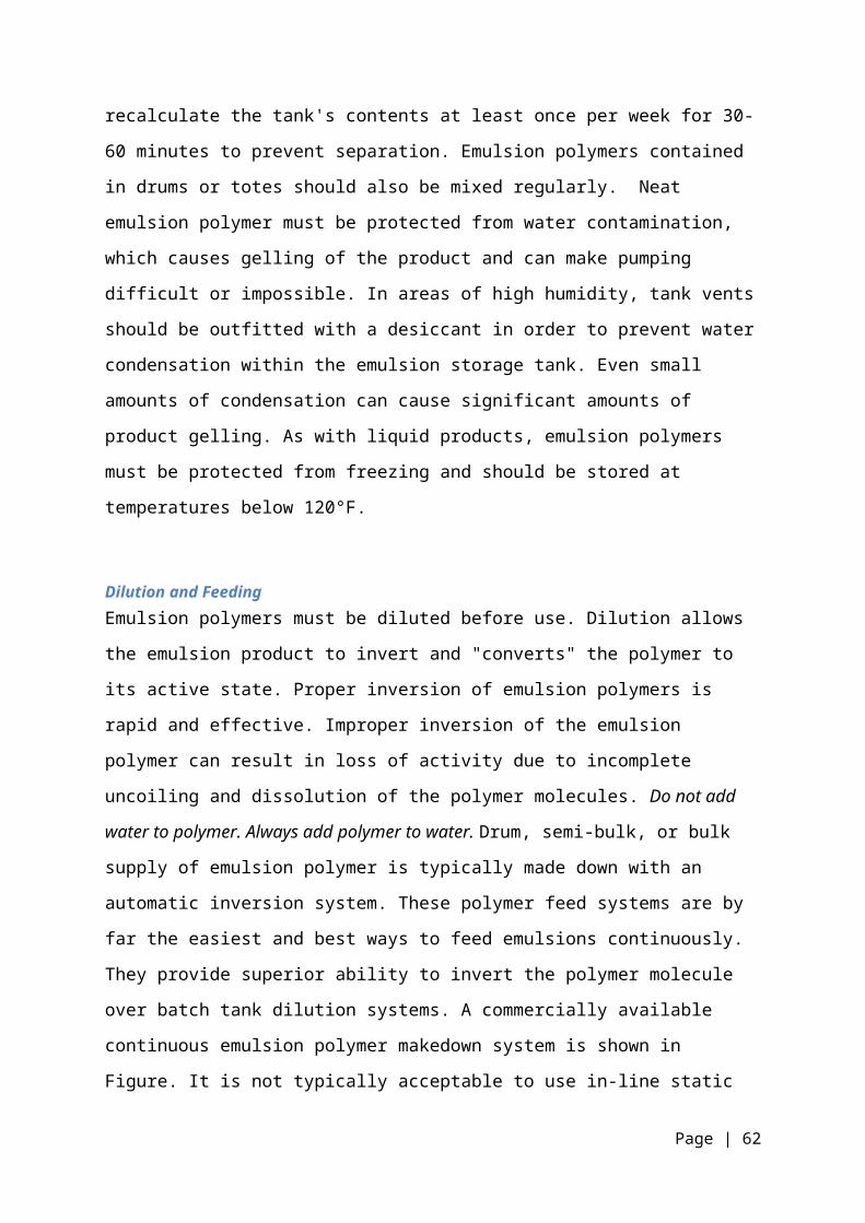
Dilution and FeedingEmulsion polymers must be diluted before use. Dilution allows
the emulsion product to invert and "converts" the polymer to
its active state. Proper inversion of emulsion polymers is
rapid and effective. Improper inversion of the emulsion
polymer can result in loss of activity due to incomplete
uncoiling and dissolution of the polymer molecules. Do not add
water to polymer. Always add polymer to water. Drum, semi-bulk, or bulk
supply of emulsion polymer is typically made down with an
automatic inversion system. These polymer feed systems are by
far the easiest and best ways to feed emulsions continuously.
They provide superior ability to invert the polymer molecule
over batch tank dilution systems. A commercially available
continuous emulsion polymer makedown system is shown in
Figure. It is not typically acceptable to use in-line static
Page | 62

mixing alone for dilution of emulsion polymers. However, in-
line static mixing can be employed for blending secondary
dilution water with diluted emulsion product prior to
application. Initial dilution of emulsion polymers should be
1% or 2% by weight. This solution strength ensures proper
particle-to-particle interaction during the inversion step,
which aids in complete inversion. It is usually desirable to
provide secondary dilution water capabilities to emulsion
polymer feed systems because these products tend to be most
effective when fed at approximately 0.1% solution strength.
Solution Polymers
Solution polymers are usually cationic, low molecular weight,
high charge density products, and are usually used for
clarification of raw water. Solution polymers are easier to
dilute, handle, and feed than dry and emulsion polymers. In
many cases, pre-dilution of a solution polymer is unnecessary,
and the product can be fed directly from the shipping
container or bulk storage tank. Solution polymers offer the
convenience of neat feed, and they can be diluted to any
convenient strength consistent with chemical feed pump output.
StorageSolution polymers should be stored in an area of moderate
temperature to protect them from freezing. Some solution
products are susceptible to irreversible damage when frozen.
Others exhibit excellent freeze-thaw recovery. In no case
Page | 63

should solution polymers be stored at temperatures above
120°F. As solutions, these polymers do not require periodic
mixing (to prevent separation) before use. However, some
solution polymers have a short shelf life, and inventory
should be adjusted accordingly.
Dilution and FeedingSolution polymers may be diluted prior to use or fed neat from
a shipping container, bin, or bulk storage tank. Dilution of
these products becomes necessary if there is insufficient
mixing available to combine the polymer with the water being
treated. In-line static mixer dilution systems are acceptable
for solution polymers and are the simplest method of solution
polymer dilution and feed. Solution polymers can be pumped
most easily with progressing cavity or gear pumps. However,
some solution polymers have a viscosity low enough to be
pumped by diaphragm chemical metering pumps.
General Recommendations:
In addition to the above, some general guidelines apply to the
feeding and handling of all water treatment polymers. In areas
where the temperature routinely drops below freezing, it is
good practice to insulate all polymers feed lines so that feed
line freezing does not occur. For tank batches of diluted
polymers, tank mixer speeds of over 350 rpm should not be
used. On large tank systems where there can be high impellor
tip speeds, lower rpm mixers should be considered to avoid
Page | 64

excessive shear to the polymer. In the preparation of diluted
batches of polymer, water should always be added to the tank
first. Then, the mixer should be started and the polymer added
on top of the water. Do not uses high shear pumps (centrifugal
pumps) to transfer or feed made down polymer solutions.
Instead use gear, progressing cavity, Waukesha, Jabsco
flexible impellor or diaphragm pumps to transfer solutions to
a day tank. Plastic piping can be used in polymer feed
systems; stainless steel is also commonly used for wetted
parts. Most polymers are corrosive to mild steel and brass.
Extra precautions should be taken to prevent spilling of
polymers, because wet polymer spills can become extremely
slippery and present a safety hazard. Spills should be covered
with absorbent material, and the mixture should be removed
promptly and disposed of properly.
Page | 65
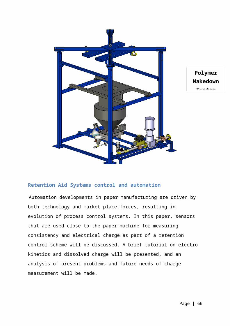
Retention Aid Systems control and automation
Automation developments in paper manufacturing are driven by
both technology and market place forces, resulting in
evolution of process control systems. In this paper, sensors
that are used close to the paper machine for measuring
consistency and electrical charge as part of a retention
control scheme will be discussed. A brief tutorial on electro
kinetics and dissolved charge will be presented, and an
analysis of present problems and future needs of charge
measurement will be made.
Page | 66
PolymerMakedownSystem

White Water Consistency Sensors
The range of these measurements is generally 1% consistency
and below. Accordingly, optical devices, either in
transmission or scatter mode, are the sensors of choice,
relying on the fibre’s interaction with light, as shown below
in Figure 1 for three types of sensors. Sensor A uses
linearly-polarized light from either a halogen bulb or a
semiconductor laser which is passed through the measurement
cell. The transmitted light is split into two beams, one
passing through a second transverse-plane polarizing filter,
the other passing through a third in-plane polarizing filter.
The beams are detected by photodiodes and combined to produce
a relative depolarization signal, which is a function of the
total fiber and filler. The signal is insensitive to
brightness, colour, freeness or soluble additives Sensor B is
based on the transmittance of light being a function of
consistency. Unfortunately, this sensor is relatively
sensitive to changes in freeness and colour, exhibiting non-
linear behaviour with changes in filler and dissolved solids.
Sensor C uses forward and back-scattered light to produce a
signal combined from the several detectors that is
proportional to consistency. This type of sensor can be used
at much higher consistencies, and in general its sensitivity
to variations in the content of non-fibrous substance lies
between that of sensors A and B, except for filler, for which
this sensor is the most sensitive. To manage retention on a
paper machine, the traditional approach has been to use first
pass retention –a delayed quotient of two consistency values.
Page | 67

Instead of retention, the total consistency of white water has
been found to offer a better choice, since this stream carries
the majority of poorly retained pulp components. Several
manufacturers have been active in producing low consistency
optical devices that are incorporated with wet-end chemistry
sensors into retention control schemes for the wet end of the
paper machine, an example of which is shown later.
RETENTION AID SYSTEM USED INPM 3The Retention aid system used in PM 3 is CompozilFx. It is asystem for optimising retention, dewatering, formation and
sheet ash content on high speed fine paper machines. It helps
paper makers to achieve cost effective operation under very
demanding conditions it has become the paper maker’s choice on
high speed fine paper system in Asia Pacific.
Page | 68

Working Conditions are :-
Recommended To Be AvoidedFurnish Virgin Pulp Groundwood, BCTMP,
DIP, WasteGrades Coated Fine Paper,
Uncoated Fine Paper
Wood Containing,
Newsprint, RecycledMachine Speed > 1000 m/min < 500 m/minSheet Ash > 12% (cationic
preferred)
< 10%
pH > 7.0 < 6.0Conductivity < 1500 > 2500Headbox Cationic
Demand
< 100 > 200
ISO Brightness Low - std High – v high
Equipments Used
Page | 69

APAM Mixing Unit
Storage Tanks
Page | 70

APAM dosing unit
Chemicals Used
The various chemicals used in the startup are:-
AKD for Sizing
ATC for Trash control
C PAM for retention control
Silica (Nano Particle) for drainage control
Biocides for slime control
The Major RDA used in PM 3 are :
SmilTex-P
In the convention system it can be added as a paste or
solution at the beater end in a continuous system just before
the refiners. The use of this starch improves the bonding of
loosely attached paper fiber & filler. This will improve burst
Page | 71

tensile strength of untreated can be raised to the desired
level. The picking resistance of offset printing ink can be
greatly improved.
pH - 5-7
Viscosity – 160- 210 cps
Brightness – 82-85%
Then the trials started and imported starch and APAM both were
tried on the paper
Machine with the following specifications:-
EMSLAND Starch
EMSLAND starch was imported from Germany to be used in place
of normal starch. EMSLAND starch has high cationicity of
0.03%. Compared to +300 mV charge for 1 gpl cooked normal
starch solution, EMSLAND starch gives +900 -1200 mV charge
level .Its properties are
pH - 6.3 @10% solution
Brightness (iso%) – 87.2 %
Viscosity – 195 cps @ 50 0C
Anionic Polyacrylamide (A-PAM) PL 8660
Co-polymer of Acrylamide and Sodium Acrylate
More Sodium Acrylate = More Anionic Charge
Page | 72

It is a liner APAM with v high mol wt, 60% molar anionic
charge, 34-37% active.
It is an inverse emulsion i.e.
1) It will need makedown.
2) It will settle out.
3) It will need constant agitation.
Mixing APAM with NP before addition
Mix the NP and APAM together before addition ideally< 5m
before the addition point. Use a static mixer. Filter the
polymer solution before addition. Ensure the velocity of
the final solution is at least 1.5 times stock velocity.
Page | 73

Dosage Points
The dosage points for the various chemicals are:-
AKD – HC Fan Pump Outlet
Wet End Starch – Machine Chest Top
Trial Product – Machine Chest Top
Filler (PCC,GCC) AP1 – Primary Fan Pump
Filler (PCC,GCC) AP2 – Secondary Fan Pump
Targets
The target figures of PM#3 are:-
First Pass Retention – 80%
First Pass Ash Retention – 40%
Ash—14%
OBSERVATIONS
Page | 74

1-May 80 841.7
4
518.71 6.74 280.6
2
500 13.3 80.2 39.2 SMILTEX-
P STARCH2-May 76.8
8
932.5 579.6 7.35 287.4
3
500 12.1 76.1 37.6
3-May 73.3
3
951.3
3
564.2 7.3 333.3
3
500 13.6 76.2 37.6
4-May 70 907.3
7
409.7 7.26 331.6 500 11.7 78.5 39.3
5-May 78.8
9
910.3
3
430.4 10.24 310.9 500 12.1 75.9 36.7
6-May 78.0
9
842.3 492.2 11.4 349.6 500 13.7 79.8 46.16
7-May 80 848.3
3
404.8 9.7 228.5 500 12.7 71.3
4
36.2
8-May 71.1
8
926.6
5
368.3 8.66 278.8
8
500 12.9 64.4
9
25.1
9-May 73.1
4
888.3
3
450.2 10.69 248.3
1
500 12.6 62.5
3
25.3
10-May 75.2
9
848.4
1
357.4 10.99 291.3
5
500 12.6 68.1
3
30.1
11-May 65 880.8
5
374 12.62 336.4
3
500 12.5 65.7
1
28.5
12-May 62.1
9
916.1
4
366.9 12.78 347.0
8
500 11.7 67.3
4
30.7
13-May 54.5
2
952.1
7
396.7 11.64 341.0
5
500 12.7 65.1
4
29.4
14-May 73.5 878.9
2
509.7 9.33 247.6
5
500 12.5 72.1
1
31
15-May 62.0
8
888.2
9
434.5 11.47 263.3
5
500 13.2 65.0
4
29.5
16-May 54 903.7
5
388.7 10.62 316.2
2
500 12.9 66.6
5
29.3
17-May 75.2
7
881.5
9
493.2 9.97 283.4
6
500 13.2 70.8
3
29.18
Page | 75
Date GSM SPEED THROUGHPUT AKD RDA ATC APAM ASH FPR FPAR

18-May 80.5 839.7
5
447.4 11.17 235.2
5
500 12.8 77.1
6
32.2
19-May 70 827.3
9
438.9 9.95 233.2
5
500 12.4 72.3 30.7
20-May 67.8
2
868.4
8
447.6 8.23 233.8
2
500 12.6 63.2
8
28
21-May 80 810 85.6 8.81 215 500 9.2 71.2
5
22.4
22-May 63.6
3
854.3
6
394.4 8.98 238.6
8
500 12.1 67.6
2
29.6
23-May 71.4
3
838.1 413.4 8.79 256.6
5
500 13.2 65.5
2
29.2
24-May 72.2
2
855.5
6
185.2 10.18 211.1 500 11.8 70.3 29.6
25-May 70 886.2
5
496.5 8.75 281.0
5
500 12.4 71.3
9
28.5
26-May 70 919.3
3
512 8.37 298.7
3
500 12.9 67.9
9
28.7
27-May 70 971.6
7
541.1 9.04 304.8 500 13 66.3
6
26.8
28-May 70 994.5
8
553.8 9.97 310.6
6
500 13.3
2
67.8
1
28.61
29-May 67.2
5
1004 532.7 9.55 316.2
5
500 13.3 62.2
2
28.63
30-May 68.3
3
1004.
2
540.8 9.03 319.7
5
500 13.9 64.5
6
24.4
31-May 70 1005.
3
553.2 9.24 320 500 14.0
4
67.9
8
29.44
1-Jun 74.1
7
1005.
7
590.7 8.23 301.8
6
500 13.2 75 32.4
2-Jun 78.7
5
1033.
5
682.5 7.62 268.2
8
500 13.7 74.3
9
37.8
3-Jun 80 1010.
4
482.4 8.59 264 500 13.1 73.0
8
31.1 Emsland
Starch
Page | 76

4-Jun 74.1
7
934.0
4
546.9 10.23 295.1
9
500 13.9 74.6 36.3
5-Jun 69.5
9
941.3
2
412 10.19 322.0
3
500 14.5 73.1
6
35.9
6-Jun 68 1017 407 9.06 312.3 500 14.3 71.9
4
34.2
7-Jun 79.0
8
982.6
7
637.8 9.29 299.2
7
500 14.3 71.3 34.1
8-Jun 68.3
3
1010 547.1 10.11 313.0
1
500 14.6 67.3
1
31.4 New
Addition
Point of
Starch
9-Jun 59.0
6
1065 351.6 10.21 324.7 500 14.7 65.0
6
27.4
10-Jun 57.3
9
1048.
9
458 9.11 347.3
3
500 14.6 63.2
1
29
11-Jun 56 1095.
2
490.3 8.75 340.8
1
500 14.2 63.2
6
26.8
12-Jun 65.6
9
1053.
4
371.8 8.63 301.9
5
500 13.7 67 27.5
13-Jun 72.7
3
990.4
1
525.5 8.26 306.2
1
500 12.6 70.2 33.85
14-Jun 67.9 991.9
1
464.2 8.24 313.4
7
500 12.7 69.0
6
33.33
15-Jun 68.6
1
950.9
6
488.6 8.86 261.8
6
500 14.5 65.9
4
24.83
19-Jun 80 870.9
3
340.8 9.81 230.3
9
500 12.1 69.3
3
25.8
20-Jun 74.0
9
991.6 529.6 7.06 298.7
7
500 13.5
8
71.4
3
37.7
21-Jun 75 985.7
7
420.9 6.51 284.1
2
500 12.5
8
74.8
5
35.86
22-Jun 72.9
2
1023.
1
595.3 7.44 245.9
4
500 84.68 13.7
3
74.2
8
37.5 APAM
23-Jun 56.4
2
1094.
2
494.7 9.47 269.5
1
500 109.62 13.3 66.2
5
29.6
Page | 77
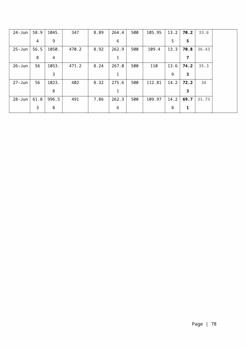
24-Jun 58.9
4
1045.
9
347 8.89 264.4
6
500 105.95 13.2
5
70.2
5
33.6
25-Jun 56.5
8
1050.
4
470.2 8.92 262.9
1
500 109.4 13.3 70.8
7
36.43
26-Jun 56 1053.
3
471.2 8.24 267.0
1
500 110 13.6
9
74.2
3
35.3
27-Jun 56 1023.
8
402 8.32 275.6
1
500 112.81 14.2 72.2
3
36
28-Jun 61.8
3
996.5
8
491 7.86 262.3
6
500 109.97 14.2
8
69.7
1
31.73
Page | 78

Variation in First Pass Retention
01/May
04/May
07/May
10/May
13/May
16/May
19/May
22/May
25/May
28/May
31/May
03/Jun
06/Jun
09/Jun
12/Jun
15/Jun
21/Jun
24/Jun
27/Jun
0
10
20
30
40
50
60
70
80
90
FPR(%)FPR(%)
Page | 79

Variation in First Pass Ash Retention
01/May
04/May
07/May
10/May
13/May
16/May
19/May
22/May
25/May
28/May
31/May
03/Jun
06/Jun
09/Jun
12/Jun
15/Jun
21/Jun
24/Jun
27/Jun
0
5
10
15
20
25
30
35
40
45
50
FPAR(%)FPAR(%)
Page | 80

Speed vs FPAR
01/May
04/May
07/May
10/May
13/May
16/May
19/May
22/May
25/May
28/May
31/May
03/Jun
06/Jun
09/Jun
12/Jun
15/Jun
21/Jun
24/Jun
27/Jun
0
200
400
600
800
1000
1200
0
5
10
15
20
25
30
35
40
45
50
Speed FPAR(%)
Page | 81

GSM vs FPAR
01/May
04/May
07/May
10/May
13/May
16/May
19/May
22/May
25/May
28/May
31/May
03/Jun
06/Jun
09/Jun
12/Jun
15/Jun
21/Jun
24/Jun
27/Jun
0
10
20
30
40
50
60
70
80
90
0
5
10
15
20
25
30
35
40
45
50
GSMFPAR(%)
Page | 82
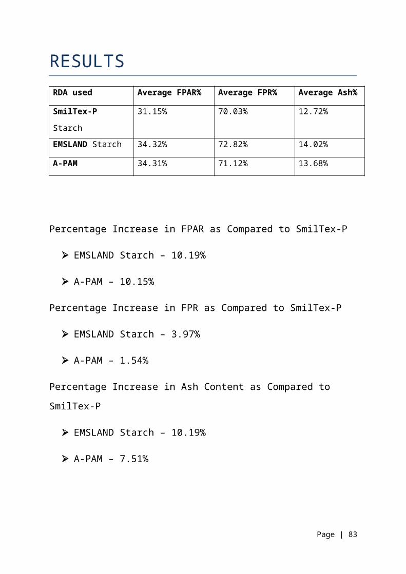
RESULTSRDA used Average FPAR% Average FPR% Average Ash%
SmilTex-P
Starch
31.15% 70.03% 12.72%
EMSLAND Starch 34.32% 72.82% 14.02%
A-PAM 34.31% 71.12% 13.68%
Percentage Increase in FPAR as Compared to SmilTex-P
EMSLAND Starch – 10.19%
A-PAM – 10.15%
Percentage Increase in FPR as Compared to SmilTex-P
EMSLAND Starch – 3.97%
A-PAM – 1.54%
Percentage Increase in Ash Content as Compared to
SmilTex-P
EMSLAND Starch – 10.19%
A-PAM – 7.51%
Page | 83
RECOMMENDATION
One more trial of Emsland starch should be conducted to
obtain repeatability of the results obtained.
Continuation of usage of APAM in PM#3.
Paper Machine should be operated at higher machine speed,
since with the addition of APAM, high FPAR values can be
obtained at higher speeds.
Paper of high GSM could be produced with the addition of
APAM due to higher value of FPAR.
Page | 84
REFERENCES
Reports on NipcoFlex Shoe Press, CombiDuoRun, Speedsizer,
Modulejet, Prorelease, Advanced Wet End Process and
DuoFormer used in Paper Machine 3 from www.voith.com
TRIAL REPORT ON USAGE OF IMPORTED CATIONIC STARCH (NANNY
STARCH FROM M/S.RAISAMYL,THAILAND) IN PM#1 AND PM#2.
Persson, M., Pal, A. and Wickström, O., "High cationic
starch and microparticle for furnish systems with high
levels of disturbing substances”.
Vaughan, C.W., "A new approach to wet end
drainage/retention/formation technology," TAPPI 1996
Papermakers Conference Proceedings, TAPPI PRESS, p. 439.
“Papermaking Chemistry” by Maria Norell, Kjell Johansson
and Michael Persson, Chapter 3.
Page | 85

Volume 6: Stock Preparation Pulp and Paper Manufacture
Series Edited by Robert W. Hagemeyer, Michael J. Kocurek,
and Dan W. Manson, Chapter. 1,2,3,4,5,7.
Page | 86