Heat Transfer Equipment Evaporator
10
SCH1307 – PROCESS EQUIPMENT DESIGN - UNIT 2 HEAT TRANSFER EQUIPMENT Heat Transfer Equipment Evaporator Evaporation is the removal of solvent as vapor from a solution. The aim is to concentrate a non-volatile solute, such as organic compounds, inorganic salts, acids or bases from a solvent. Common solutes are caustic soda, caustic potash, sodium sulfate, sodium chloride, phosphoric acid, and urea. The most common solvent in most of the evaporation systems is water. Evaporation is normally stopped before the solute starts to precipitate in the operation of an evaporator. TYPE OF EVAPORATORS Evaporator consists of a heat exchanger for boiling the solution with special provisions for separation of liquid and vapor phases. Most of the industrial evaporators have tubular heating surfaces. The tubes may be horizontal or vertical, long or short; the liquid may be inside or outside the tubes. 2.1. Short-Tube Vertical Evaporators Short-tube vertical evaporators are the oldest but still widely used in sugar industry in evaporation of cane-sugar juice. These are also known as calandria evaporators. It became so common in process industry that this evaporator is sometimes known as standard evaporator. Short-tube vertical evaporators consist of a short tube bundle (about 4 to 10 ft in length) enclosed in a cylindrical shell. This is called calandria. The feed is introduced above the upper tube sheet and steam is introduced to the shell or steam chest of the calandria. The solution is heated and partly vaporized in the tubes. The central tube in a calandria is of longer diameter. Typically it’s downcomer area is taken as 40 to 70% of the total cross sectional area of tubes. The circulation rate through the downcomer/downtake is many times the feed rate. The flow area of the downtake is normally approximately equal to the total tubular flow area.
-
Upload
khangminh22 -
Category
Documents
-
view
6 -
download
0
Transcript of Heat Transfer Equipment Evaporator

SCH1307 – PROCESS EQUIPMENT DESIGN - UNIT 2 HEAT TRANSFER EQUIPMENT
Heat Transfer Equipment
Evaporator Evaporation is the removal of solvent as vapor from a solution. The aim is to
concentrate a non-volatile solute, such as organic compounds, inorganic salts, acids or
bases from a solvent. Common solutes are caustic soda, caustic potash, sodium
sulfate, sodium chloride, phosphoric acid, and urea. The most common solvent in
most of the evaporation systems is water. Evaporation is normally stopped before the
solute starts to precipitate in the operation of an evaporator.
TYPE OF EVAPORATORS Evaporator consists of a heat exchanger for boiling the solution with special
provisions for separation of liquid and vapor phases. Most of the industrial
evaporators have tubular heating surfaces. The tubes may be horizontal or vertical,
long or short; the liquid may be inside or outside the tubes. 2.1. Short-Tube Vertical Evaporators Short-tube vertical evaporators are the oldest but still widely used in sugar industry
in evaporation of cane-sugar juice. These are also known as calandria evaporators. It
became so common in process industry that this evaporator is sometimes known as
standard evaporator. Short-tube vertical evaporators consist of a short tube bundle
(about 4 to 10 ft in length) enclosed in a cylindrical shell. This is called calandria. The
feed is introduced above the upper tube sheet and steam is introduced to the shell or
steam chest of the calandria. The solution is heated and partly vaporized in the tubes.
The central tube in a calandria is of longer diameter. Typically it’s downcomer area is
taken as 40 to 70% of the total cross sectional area of tubes. The circulation rate
through the downcomer/downtake is many times the feed rate. The flow area of the
downtake is normally approximately equal to the total tubular flow area.

SCH1307 – PROCESS EQUIPMENT DESIGN - UNIT 2 HEAT TRANSFER EQUIPMENT
Long-Tube Vertical Evaporators This is another most widely employed natural circulation evaporator because it is
often the cheapest per unit of capacity. The long vertical tube bundle is fixed with a
shell that extends into a larger diameter vapor chamber at the top (Figure 3.2). The
long-tube vertical (LTV) evaporator consists of one pass shell and tube heat
exchanger. In this type of evaporator, the liquid flows as a thin film on the walls of
long (from 12 to 30 feet in length) and vertical heated tube. Both rising film and
falling types are used. Tube length usually varies from 20 to 65 ft. The main
advantage of this type of evaporators is higher heat transfer rate. The feed enters at the
bottom and the liquid starts boiling at lower part of the tube. The LTV evaporators are
commonly used in concentrating black liquors in the paper and pulp industries.
Falling Film Evaporators In a falling film evaporator, the liquid is fed at the top of the tubes in a vertical tube
bundle. The liquid is allowed to flow down through the inner wall of the tubes as a
film. As the liquid travels down the tubes the solvent vaporizes and the concentration
gradually increases. Vapor and liquid are usually separated at the bottom of the tubes
and the thick liquor is taken out. Evaporator liquid is recirculated through the tubes by

SCH1307 – PROCESS EQUIPMENT DESIGN - UNIT 2 HEAT TRANSFER EQUIPMENT
a pump below the vapor-liquid separator. The distribution of liquid in the inner wall
of the tubes greatly affects the performance of this type of evaporator. The falling film
evaporator is largely used for concentration of fruit juices and heat sensitive materials
because of the low holdup time. The device is suitable for scale-forming solutions as
boiling occur on the surface of the film.
Forced Circulation Evaporators Forced circulation evaporators are usually more costly than natural circulation
evaporators. However the natural circulation evaporators are not suitable under some
situations such as:
- highly viscous solutions due to low heat transfer coefficient
- solution containing suspended particles and for heat sensitive materials All these problems may be overcome when the liquid is circulated at high velocity
through the heat exchanger tubes to enhance the heat transfer rate and inhibit particle
deposition. Any evaporator that uses pump to ensure higher circulation velocity is
called a forced circulation evaporator. The main components of a forced circulation
evaporator are a tubular shell and tube heat exchanger (either horizontal or vertical), a
flash chamber (separator) mounted above the heat exchanger and a circulating pump.

SCH1307 – PROCESS EQUIPMENT DESIGN - UNIT 2 HEAT TRANSFER EQUIPMENT
The solution is heated in the heat exchanger without boiling and the superheated
solution flashes off (partially evaporated) at a lower pressure are reduced in the flash
chamber. The pump pumps feed and liquor from the flash chamber and forces it
through the heat exchanger tubes back to the flash chamber. Forced circulation
evaporator is commonly used for concentration of caustic and brine
solutions and also in evaporation of corrosive solution.
Agitated Thin Film Evaporator Agitated thin film evaporator consists of a vertical steam-jacketed cylinder and the
feed solution flows down as a film along the inner surface of large diameter jacket.
Liquid is distributed on the tube wall by a rotating assembly of blades mounted on
shaft placed coaxially with the inner tube. The blades maintain a close clearance of
around 1.5 mm or less from the inner tube wall. The main advantage is that rotating blades permits handling of extremely viscous
solutions. The device is suitable to concentrate solutions having viscosity as high as
up to 100 P.

SCH1307 – PROCESS EQUIPMENT DESIGN - UNIT 2 HEAT TRANSFER EQUIPMENT
MULTIPLE EFFECT EVAPORATORS Evaporators are classified by the number of effects. In case of a single-effect
evaporator, the vapor from the boiling liquor is condensed and the concentrated
product is withdrawn from the bottom of the evaporator. Although the operation is
simple, the device does not use steam efficiently. Typically 1.1 to 1.3 kg of steam is
required to evaporate 1 kg of water. The steam consumption per unit mass of water evaporated can be increased by putting
more than one evaporator in series such that the vapor from one evaporator is used in
the second evaporator for heating. The vapor from the second evaporator is condensed
and the arrangement is called double-effect evaporators. The heat from the vapor
generated in the first evaporator is used in the second evaporator. Evaporation of
water is nearly doubled in double effect evaporation system compared to single effect
per unit mass of steam used. Additional effects can be added in series in the same way
to get a triple-effect evaporator, quadruple-effect evaporator and so on. There are
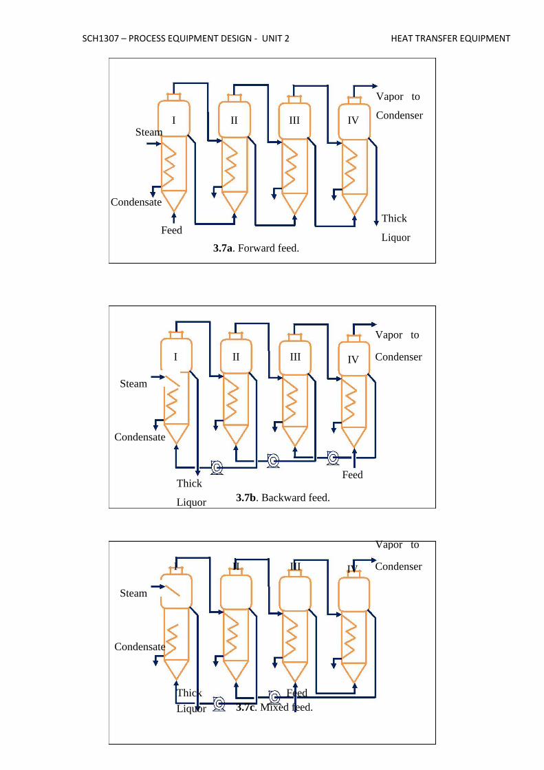
several configurations based on feeding arrangement.
SCH1307 – PROCESS EQUIPMENT DESIGN - UNIT 2 HEAT TRANSFER EQUIPMENT
Vapor to
I II III IV Condenser
Steam
Condensate
Thick
Feed Liquor
3.7a. Forward feed.
Vapor to
I II III IV Condenser
Steam
Condensate
Thick Feed
Liquor 3.7b. Backward feed.
Vapor to
I II III IV Condenser
Steam
Condensate
Thick Feed Liquor 3.7c. Mixed feed.

SCH1307 – PROCESS EQUIPMENT DESIGN - UNIT 2 HEAT TRANSFER EQUIPMENT
4. PERFORMANCE OF EVAPORATORS (CAPACITY
AND ECONOMY) The performance of a steam-heated evaporator is measured in terms of its capacity
and economy. Capacity is defined as the number of kilogram of water vaporized per
hour. Economy (or steam economy) is the number kilogram of water vaporized from
all the effects per kilogram of steam used. For single effect evaporator, the steam
economy is about 0.8 (<1). The capacity is about n-times that of a single effect
evaporator and the economy is about 0.8n for a n-effect evaporators. However,
pumps, interconnecting pipes and valves are required for transfer of liquid from one
effect to another effect that increases both equipment and operating costs.
Boiling point elevation (BPE) Most evaporators produce concentrated liquor having a boiling point considerably
higher than that of pure solvent (or water). This phenomenon is called boiling point
elevation (BPE). BPE occurs as the vapor pressure of a solution (usually aqueous
solution) is less than that of pure solvent at the same temperature. Boiling point of a
solution is a colligative property. It depends on the concentration of solute in the
solution for a pair of solute and solvent.
BPE of the concentrated liquor reduces the effective temperature driving force
compared to the boiling of pure solvent. Equilibrium vapor generated from a solution
exhibiting boiling point elevation is superheated with respect to vapor generated
during boiling of pure solvent. The vapor is generated at the solution boiling point,
which is higher than the pure component boiling point. The vapor, however, is solute
free, so it won’t condense until the extra heat corresponding to the elevation is
removed, thus it is superheated. Therefore the BPE of the concentrated solution must
be known for evaporator design. Design problem A 5% aqueous solution of a high molecular weight solute has to be concentrated to
40% in a forward-feed double effect evaporator at the rate of 8000 kg.h-1
. The feed
temperature is 40°C. Saturated steam at 3.5 kg.cm-2
is available for heating. A
vacuum of 600 mm Hg is maintained. Calculate the area requirements, The overall
heat transfer coefficients are 550 kcal.h-1
m-2
°C-1
in the first and the last effect
respectively. The specific heat of the concentrated liquor is 0.87 kcal.kg-1
°C-1
.
Heat Exchangers

SCH1307 – PROCESS EQUIPMENT DESIGN - UNIT 2 HEAT TRANSFER EQUIPMENT
Classification of heat exchangers Transfer of heat from one fluid to another is an important operation for most of the
chemical industries. The most common application of heat transfer is in designing of
heat transfer equipment for exchanging heat from one fluid to another fluid. Such
devices for efficient transfer of heat are generally called Heat Exchanger. Fixed tube-sheet exchanger: The simplest and cheapest type of shell and tube
exchanger is with fixed tube sheet design. In this type of exchangers the tube sheet is
welded to the shell and no relative movement between the shell and tube bundle is
possible (Figure 1.2).
Removable tube bundle: Tube bundle may be removed for ease of cleaning and
replacement. Removable tube bundle exchangers further can be categorized in
floating-head and U-tube exchanger.
Fouling Considerations The most of the process fluids in the exchanger foul the heat transfer surface. The
material deposited reduces the effective heat transfer rate due to relatively low thermal

SCH1307 – PROCESS EQUIPMENT DESIGN - UNIT 2 HEAT TRANSFER EQUIPMENT
conductivity. Therefore, net heat transfer with clean surface should be higher to
compensate the reduction in performance during operation. Fouling of exchanger
increases the cost of (i) construction due to oversizing, (ii) additional energy due to
poor exchanger performance and (iii) cleaning to remove deposited materials. A spare
exchanger may be considered in design for uninterrupted services to allow cleaning of
exchanger. The effect of fouling is considered in heat exchanger design by including
the tube side and shell side fouling resistances. Selection of fluids for tube and the shell side
Tube-side fluid Shell-side fluid
Corrosive fluid Condensing vapor (unless corrosive)
Cooling water Fluid with large temperature difference (>40°C)
Fouling fluid Less viscous fluid
High-pressure steam
Hotter fluid
Process Design Procedure Step #1. Obtain the required thermophysical properties of hot and cold fluids at the
caloric temperature or arithmetic mean temperature. Step #2. Perform energy balance and find out the heat duty ( Q ) of the exchanger.
Step #3. Assume a reasonable value of overall heat transfer coefficient (Uo,assm). The
value of Uo,assm with respect to the process hot and cold fluids Step #4. Decide tentative number of shell and tube passes ( np ). Determine the
LMTD and the correction factor FT (FT normally should be greater than 0.75 for the
steady operation of the exchangers. Otherwise it is required to increase the number of
passes to obtain higher FT values.
Step #5. Calculate heat transfer area (A) required:
Step #6. Select tube material, decide the tube diameter (ID= di , OD = do ), its wall
thickness (in terms of BWG or SWG) and tube length ( L ). Calculate the number of
tubes
( n ) required to provide the heat transfer area (A): n A
t t do L
.
Calculate tube side fluid velocity, u 4 m ( n p / nt )
d 2
i
.
If u <1 m/s, fix n so that, Re 4 m ( n p / nt ) 104 p
di

SCH1307 – PROCESS EQUIPMENT DESIGN - UNIT 2 HEAT TRANSFER EQUIPMENT
. Where, m, and are mass flow rate, density and viscosity of tube side fluid.
However, this is subject to allowable pressure drop in the tube side of the heat
exchanger.
Step #7. Decide type of shell and tube exchanger (fixed tubesheet, U-tube etc.). Select
the tube pitch (PT), determine inside shell diameter ( Ds )
Step #9. Assign fluid to shell side or tube side (a general guideline for placing the
fluids is summarized in Table 1.4). Select the type of baffle (segmental, doughnut
etc.), its size (i.e. percentage cut, 25% baffles are widely used), spacing ( B ) and
number. The baffle spacing is usually chosen to be within 0.2 Ds to Ds . Step #10. Determine the tube side film heat transfer coefficient ( hi ) using the
suitable form of Sieder-Tate equation in laminar and turbulent flow regimes. Estimate
the shell-side film heat transfer coefficient ( ho ) from: Select the outside tube (shell
side) dirt factor ( Rdo ) and inside tube (tube side) dirt factor. Calculate overall heat
transfer coefficient (U) based on the outside tube area
Design Problem 150000 lb per hour of kerosene will be heated from 75 to 120°F by cooling a gasoline
stream from 160 to 120°F. Inlet pressure will be 50 psia for each stream and the
maximum pressure drop of 7 psi for gasoline and 10 psi for kerosene are permissible.
Published fouling factors for oil refinery streams should be used for this application.
Design a shell and tube heat exchanger for this service.