
Bioprocessing Equipment
89
CHAPTER 2 DESIGN PART SD SYSTEMS DESIGN SD-1 PURPOSE AND SCOPE The purpose of Part SD is to establish design guidelines applicable to bioprocessing equipment. Wherever “equip- ment” is stated in this Part, it shall mean all bioprocessing equipment, components, assemblies, and systems. The purpose of this Part is to provide requirements for the specification, design, fabrication, and verification of process equipment and systems that are fit for intended use, and to minimize risk to the product. Part SD also provides design guidelines that should be applied at the discretion of the owner/user on the basis of assessed risk to the product. Figures in this Part are intended to illustrate accepted applications of general design princi- ples and are not intended to limit alternate designs. The scope of Part SD encompasses requirements for equipment, process systems, and utilities that could potentially impact product quality. Specific guidance is provided for bioburden control in manufacturing processes, including design requirements for cleaning, sanitization, and/or sterilization of bioprocess systems. SD-2 ð19Þ GENERAL GUIDELINES All equipment and/or systems shall be designed according to the bioprocessing application, requirements, and specifications of the owner/user. It shall be the responsibility of the owner/user to specify the cleaning and/or sanitization requirements of the equipment and/ or system. Following installation, to remove construction debris and/or foreign bodies, process contact liquid-service systems should be flushed with deionized or better- quality water and/or chemically cleaned, per owner/ user’s requirements, before being placed into service. This does not apply to single-use or precleaned components. The design shall provide for the removal of components (e.g., pumps, control valves, spray devices, instrumenta- tion) that may be damaged by construction debris during flushing. If removal is not practical, the design shall allow for a temporary strainer installed upstream of the compo- nent, sized to catch the debris. The pipe design and the flushing sequence, including associated variables (e.g., velocity), shall meet the owner/user’s requirements. SD-2.1 Containment The containment level of the system or individual pieces of equipment should be specified and communicated by the owner/user. The owner/user shall determine the containment level for the particular type of equipment or system, in accor- dance with the Centers for Disease Control and Prevention (CDC) and guidelines of the National Institutes of Health (NIH) or directives of the European Union and other ap- plicable local codes or environmental regulations. SD-2.2 Bioburden Control [Reserved for future content] SD-2.3 ð19Þ Bioburden Reduction SD-2.3.1 Thermal Sanitization. Thermal sanitization is the application of heat to reduce bioburden in a system. Bioburden reduction can be accomplished by the appropriate application of moist heat or dry heat. Specific temperatures and exposure times depend on the objectives. Thermal sanitization includes the following: dry heat treatment, SIP for sanitization, SIP for sterilization, steam out of place (autoclaving), hot liquid sterilization, and hot liquid sanitization. SD-2.3.1.1 Steam-in-Place. Equipment parts and components subjected to SIP should be designed and con- structed to withstand continuous exposure to saturated steam at a minimum temperature of 266°F (130°C; rep- resenting 24 psig/1.65 bar under saturated steam condi- tions) for a duration of at least 100 hr under continuous steady-state conditions. All process contact surfaces subjected to SIP shall reach the required temperatures, under the required saturated steam pressure conditions, during the SIP cycle. Executing SIP operations at tempera- tures exceeding 266°F (130°C) may cause degradation of elastomers and/or damage to other components, resulting ASME BPE-2019 19
-
Upload
khangminh22 -
Category
Documents
-
view
0 -
download
0
Transcript of Bioprocessing Equipment

CHAPTER 2DESIGN
PART SDSYSTEMS DESIGN
SD-1 PURPOSE AND SCOPE
The purpose of Part SD is to establish design guidelinesapplicable to bioprocessing equipment.Wherever “equip-ment” is stated in this Part, it shall mean all bioprocessingequipment, components, assemblies, and systems.The purpose of this Part is to provide requirements for
the specification, design, fabrication, and verification ofprocess equipment and systems that are fit for intendeduse, and to minimize risk to the product. Part SD alsoprovides design guidelines that should be applied atthe discretion of the owner/user on the basis of assessedrisk to the product. Figures in this Part are intended toillustrate accepted applications of general design princi-ples and are not intended to limit alternate designs.The scope of Part SD encompasses requirements for
equipment, process systems, and utilities that couldpotentially impact product quality. Specific guidance isprovided for bioburden control in manufacturingprocesses, including design requirements for cleaning,sanitization, and/or sterilization of bioprocess systems.
SD-2ð19Þ GENERAL GUIDELINES
All equipment and/or systems shall be designedaccording to the bioprocessing application, requirements,and specifications of the owner/user. It shall be theresponsibility of the owner/user to specify the cleaningand/or sanitization requirements of the equipment and/or system.Following installation, to remove construction debris
and/or foreign bodies, process contact liquid-servicesystems should be flushed with deionized or better-quality water and/or chemically cleaned, per owner/user’s requirements, before being placed into service.This does not apply to single-use or precleanedcomponents.The design shall provide for the removal of components
(e.g., pumps, control valves, spray devices, instrumenta-tion) that may be damaged by construction debris duringflushing. If removal is not practical, the design shall allowfor a temporary strainer installed upstream of the compo-nent, sized to catch the debris.
The pipe design and the flushing sequence, includingassociated variables (e.g., velocity), shall meet theowner/user’s requirements.
SD-2.1 Containment
Thecontainment level of the systemor individual piecesof equipment should be specified and communicated bythe owner/user.The owner/user shall determine the containment level
for the particular type of equipment or system, in accor-dancewith theCenters forDiseaseControl andPrevention(CDC) and guidelines of the National Institutes of Health(NIH) or directives of the European Union and other ap-plicable local codes or environmental regulations.
SD-2.2 Bioburden Control
[Reserved for future content]
SD-2.3 ð19ÞBioburden Reduction
SD-2.3.1 Thermal Sanitization. Thermal sanitizationis the application of heat to reduce bioburden in asystem. Bioburden reduction can be accomplished bythe appropriate application of moist heat or dry heat.Specific temperatures and exposure times depend onthe objectives. Thermal sanitization includes thefollowing: dry heat treatment, SIP for sanitization, SIPfor sterilization, steam out of place (autoclaving), hotliquid sterilization, and hot liquid sanitization.
SD-2.3.1.1 Steam-in-Place. Equipment parts andcomponents subjected to SIP should be designed and con-structed to withstand continuous exposure to saturatedsteam at a minimum temperature of 266°F (130°C; rep-resenting 24 psig/1.65 bar under saturated steam condi-tions) for a duration of at least 100 hr under continuoussteady-state conditions. All process contact surfacessubjected to SIP shall reach the required temperatures,under the required saturated steam pressure conditions,during the SIP cycle. Executing SIP operations at tempera-tures exceeding 266°F (130°C) may cause degradation ofelastomersand/ordamage toothercomponents, resulting
ASME BPE-2019
19

in reduction of overall equipment life. SIP conditions thatare more stringent may be imposed by the owner/user.The use of elastomers (within a piece of equipment orcertain process instrumentation) that could thermallydegrade during SIP shall be evaluated by the owner/user.
SD-2.3.1.1.1 Requirements. Process systemssubject to SIP shall be designed to(a) provide for air removal within the SIP boundary(b) provide for condensate drainage within the SIP
boundary(c) be drainable in conformance with SD-2.4.3(d) have provisions in place for verification of SIP
performance(e) have no dead legs within the SIP boundary
SD-2.3.1.1.2 Recommendations. Process systemssubject to SIP should be designed to(a) avoid concurrent steam supplies from alternate
locations to prevent stagnant zones/entrained air(b) monitor temperature and pressure at appropriate
locations (e.g., vessels) that confirm saturated steamconditions within the SIP boundary(c) monitor temperature at every SIP boundary point
during performance verification(d) enable continuous verification or periodic confir-
mation of the validated state(e) maintain the integrity of the system post-SIP
SD-2.3.1.2 Depyrogenation. [Reserved for futurecontent]
SD-2.3.2 Chemical Sanitization. [Reserved for futurecontent]
SD-2.4 Fabrication
Fabrication shall be performed in facilities where theprocess contact surfaces are protected from contamina-tion. During field welding and assembly, surface contam-ination shall be prevented.Systems, equipment, and components shall be cleaned
with a suitable cleaning agent and covered for protectionbefore shipment. The use of preservative fluids is notrecommended.Any process contact surfaces that require shipment
with preservatives or coatings shall be(a) mutually agreed to, in advance, by the owner/user
and manufacturer(b) clearly identified to all parties(c) in compliance with FDA or other applicable regula-
tions, as appropriate for the process
SD-2.4.1 Materials of Construction
SD-2.4.1.1ð19Þ General. Generally, materials such asstainless steels (e.g., 316-type and 316L-type alloys),duplex stainless steels, and higher alloys have provento be acceptable. The owner/user shall be responsiblefor the selection of the appropriate materials of construc-
tion for the specific process. Metallic materials ofconstruction are listed in Part MM.When nonmetallic materials are used (e.g., polymeric
materials or adhesives), the owner/user shall specifywhich one of these materials shall carry a Certificate ofCompliance. The conformance of material shall be expli-citly stated (e.g., conforming to FDA 21 CFR 177 and USPSection <88> Class VI). Polymeric materials and othernonmetallicmaterialsof constructionare listed inPartPM.
SD-2.4.1.2 Process Compatibility
(a) Materials of construction shall be capable of with-standing the temperature, pressure, and chemical corro-siveness of the process.(b) Materials shall be compatible with the stated
bioprocessing conditions, cleaning solutions, and SIPconditions, etc., as specified by the owner/user.(c) Surfaces exposed to bioprocessing fluids, cleaning,
and SIP conditions must be(1) homogeneous in nature(2) impervious(3) inert(4) nonabsorbent(5) nontoxic(6) insoluble by process or cleaning fluids(7) resistant to corrosion, scratching, scoring, and
distortion(d) Materials that are in contact with bioprocessing
fluids shall be identified by an industry-recognized stan-dard (see para. MM-4).
SD-2.4.1.3 Surface Coatings. Clad or electroplatedsurface coatings, plating, and surface preparatory chemi-cals may be used provided approval from the owner/userhas been obtained. All surface coatings shall remain intactand be tolerant to the process, SIP and CIP fluids, andtemperatures, without peeling or cracking.
SD-2.4.1.4 Transparent Materials
(a) Transparentmaterials (e.g., glass, polymer) that areused in viewing ports shall be rated for the applicablepressure, temperature range, and thermal shock.(b) Internally coated glass shall only be used if the
coating complies with FDA regulations or another regu-latory authority’s regulations and is approved by theowner/user.
SD-2.4.2 ð19ÞCleanability
(a) The following provisions are applicable to tubing,equipment, or systems intended to be cleaned:
(1) All surfaces shall be cleanable. Surface imperfec-tions (e.g., crevices, gouges, obvious pits) should be elimi-nated whenever feasible.
(2) All surfaces shall be accessible to the cleaningsolutions and shall be accessible to establish and deter-mine efficacy of the cleaning protocol.
ASME BPE-2019
20

(3) Fasteners or threads shall not be exposed to theprocess, steam, or cleaning fluids. The use of threadswithin the process requires owner/user agreement.Bolted attachments should be eliminated wheneverpossible.
(4) No engraving or embossing of materials (foridentification or traceability reasons) should be madeon the process contact side. When markings are requiredon process contact surfaces, other methods of identifica-tion shall be used.(b) The following provisions are applicable to tubing,
equipment, or systems intended to be cleaned in place:(1) Internal horizontal surfaces should be
minimized.(2) The equipment should be drainable and free of
areas where liquidsmay be retained. The equipment shallbe free of areas where soil or contaminants could collect.The equipment should be free of areas of low flow andvelocity or impact where soil or contaminants couldcollect.
(3) Design of corners and radii should meet thefollowing requirements: All internal angles of 135 degor lessonsurfaces shallhave themaximumradiuspossiblefor ease of cleanability. Where possible, these surfacesshall have radii of not less than 1∕8 in. (3.2 mm) exceptwhere required for functional reasons, such as thebonnet/body connection. For special cases, the radiimay be reduced to 1∕16 in. (1.6 mm) when agreed to bythe owner/user. When the 1∕16 in. (1.6 mm) radiicannot be achieved for essential functional reasonssuch as flat sealing surfaces and flow control apertures,the surfaces of these internal angles shall be readily acces-sible for cleaning and examination.
SD-2.4.3 Drainability
SD-2.4.3.1 General. For the purpose of bioburdencontrol and cleaning, gravity is an effective way to facil-itate drainage. Toachievegravitydrainage, lines shouldbepitched to designated points at a specific slope. Refer toNonmandatory Appendix C for suggestedmethod of slopemeasurement. For gravity-drained piping/tubingsystems, the owner/user may define the system slopein accordance with one of the designations listed inTable SD-2.4.3.1-1. Gravity-drained piping/tubingsystems shall have a continuous pitch that is equal toor greater than the slope designation. Line sections up
to 10 in. (25 cm) in length (or longer with advanceapproval of the owner/user) that are level or have a posi-tive slope less than the slope designation are acceptable ifthe section is fitting-bound.
SD-2.4.3.2 Drainability Design Considerations. Thesystem’s process requirements should be considered inthe selection of slope designation.(a) Process contact lines exposed to liquid should be
sloped to minimize pooling in the system.(b) Lines that are steam sterilized in place should be
sloped to facilitate gravity drainage of condensate.(c) Lines that are cleaned in place should be sloped to
facilitate gravity drainage of cleaning fluids.The physical characteristics of the system (e.g., line size,
materials, fluid viscosity, fluid surface tension) will influ-ence drainability at a given slope and should also beconsidered. The owner/usermay apply additional criteriain the selection of slopedesignation to address issues suchas product recovery or maintenance. Fluid retention dueto capillary action should be considered when usingtubing less than 3∕4 in. (20 mm). System levelingshould be considered for mobile equipment that isgravity-drained.
SD-2.4.3.3 SlopeConsiderations.The recommendedminimum slope designation for gravity-drained processcontact lines is GSD2.
SD-2.4.3.4 Drain Points
(a) Piping and equipment should be installed withdesignated drain points tomaximize self-draining proper-ties. The number of drain points should beminimized. Theequipment manufacturer shall indicate the proper orien-tation to optimize drainability. The owner/user shallensure that proper orientation is achieved.(b) Systems or equipment that cannot be gravity-
drained shall use forced expulsion with pressurizedgas where line drainability is required.
SD-2.4.4 Miscellaneous Design Details
SD-2.4.4.1 Lubricants
(a) Grease and other lubricating fluids that are used ingearboxes, drive assemblies, etc., shall be contained toprevent leakage of the lubricants or process, eitherdirectly or indirectly (e.g., through seepage, seal leaks).(b) The equipment manufacturer shall specify the type
of lubricants that are to be used for maintenance. If thespecified lubricant is not accepted by the owner/user, thechoice of an alternative shall be agreed to by the owner/user and the equipment manufacturer.(c) The owner/user shall give his approval for the
lubricants that could come in contact with the process.These lubricants shall be identified by name, manufactur-er, and grade and shall conform to FDAor other applicableregulatory codes.
Table SD-2.4.3.1-1 Slope Designations forGravity-Drained Lines
SlopeDesignation
MinimumSlope,in./ft
MinimumSlope,mm/m
MinimumSlope, %
MinimumSlope,deg
GSD1 1∕16 5 0.5 0.29GSD2 1∕8 10 1.0 0.57GSD3 1∕4 20 2.0 1.15GSD0 Line slope not required
ASME BPE-2019
21
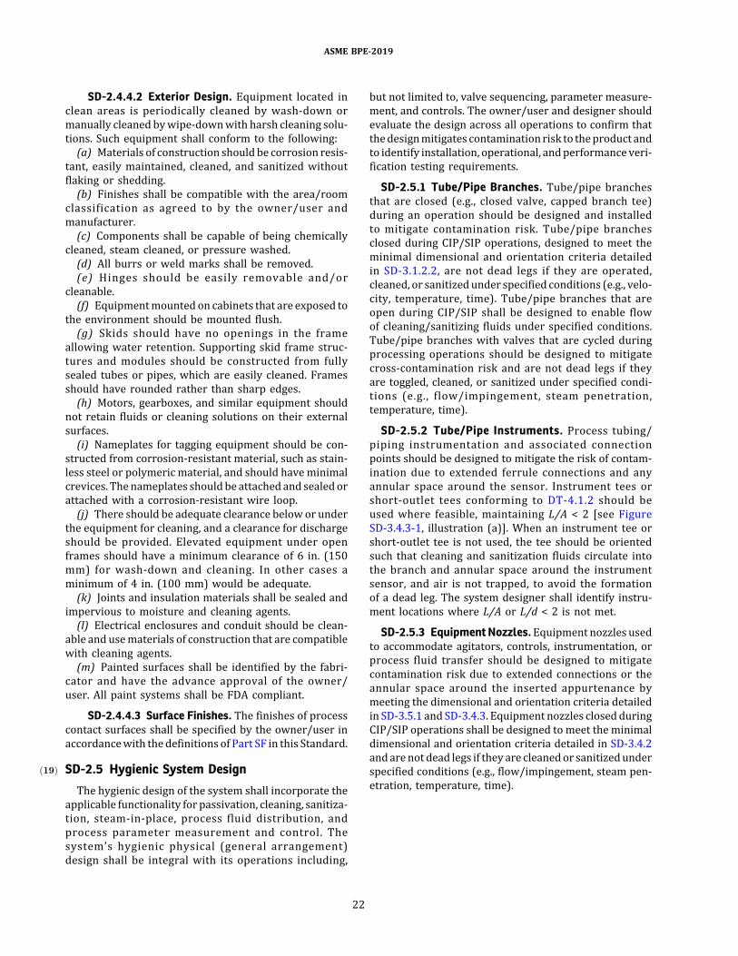
SD-2.4.4.2 Exterior Design. Equipment located inclean areas is periodically cleaned by wash-down ormanually cleaned bywipe-downwith harsh cleaning solu-tions. Such equipment shall conform to the following:(a) Materials of construction should be corrosion resis-
tant, easily maintained, cleaned, and sanitized withoutflaking or shedding.(b) Finishes shall be compatible with the area/room
classification as agreed to by the owner/user andmanufacturer.(c) Components shall be capable of being chemically
cleaned, steam cleaned, or pressure washed.(d) All burrs or weld marks shall be removed.(e) Hinges should be easily removable and/or
cleanable.(f) Equipmentmounted on cabinets that are exposed to
the environment should be mounted flush.(g) Skids should have no openings in the frame
allowing water retention. Supporting skid frame struc-tures and modules should be constructed from fullysealed tubes or pipes, which are easily cleaned. Framesshould have rounded rather than sharp edges.(h) Motors, gearboxes, and similar equipment should
not retain fluids or cleaning solutions on their externalsurfaces.(i) Nameplates for tagging equipment should be con-
structed from corrosion-resistant material, such as stain-less steel or polymeric material, and should have minimalcrevices. Thenameplates should be attached and sealed orattached with a corrosion-resistant wire loop.(j) There should be adequate clearance below or under
the equipment for cleaning, and a clearance for dischargeshould be provided. Elevated equipment under openframes should have a minimum clearance of 6 in. (150mm) for wash-down and cleaning. In other cases aminimum of 4 in. (100 mm) would be adequate.(k) Joints and insulation materials shall be sealed and
impervious to moisture and cleaning agents.(l) Electrical enclosures and conduit should be clean-
able and usematerials of construction that are compatiblewith cleaning agents.(m) Painted surfaces shall be identified by the fabri-
cator and have the advance approval of the owner/user. All paint systems shall be FDA compliant.
SD-2.4.4.3 Surface Finishes. The finishes of processcontact surfaces shall be specified by the owner/user inaccordancewith the definitions of Part SF in this Standard.
SD-2.5ð19Þ Hygienic System Design
The hygienic design of the system shall incorporate theapplicable functionality for passivation, cleaning, sanitiza-tion, steam-in-place, process fluid distribution, andprocess parameter measurement and control. Thesystem’s hygienic physical (general arrangement)design shall be integral with its operations including,
but not limited to, valve sequencing, parameter measure-ment, and controls. The owner/user and designer shouldevaluate the design across all operations to confirm thatthedesignmitigates contamination risk to theproduct andto identify installation, operational, andperformance veri-fication testing requirements.
SD-2.5.1 Tube/Pipe Branches. Tube/pipe branchesthat are closed (e.g., closed valve, capped branch tee)during an operation should be designed and installedto mitigate contamination risk. Tube/pipe branchesclosed during CIP/SIP operations, designed to meet theminimal dimensional and orientation criteria detailedin SD-3.1.2.2, are not dead legs if they are operated,cleaned, or sanitizedunder specified conditions (e.g., velo-city, temperature, time). Tube/pipe branches that areopen during CIP/SIP shall be designed to enable flowof cleaning/sanitizing fluids under specified conditions.Tube/pipe branches with valves that are cycled duringprocessing operations should be designed to mitigatecross-contamination risk and are not dead legs if theyare toggled, cleaned, or sanitized under specified condi-tions (e.g., flow/impingement, steam penetration,temperature, time).
SD-2.5.2 Tube/Pipe Instruments. Process tubing/piping instrumentation and associated connectionpoints should be designed to mitigate the risk of contam-ination due to extended ferrule connections and anyannular space around the sensor. Instrument tees orshort-outlet tees conforming to DT-4.1.2 should beused where feasible, maintaining L/A < 2 [see FigureSD-3.4.3-1, illustration (a)]. When an instrument tee orshort-outlet tee is not used, the tee should be orientedsuch that cleaning and sanitization fluids circulate intothe branch and annular space around the instrumentsensor, and air is not trapped, to avoid the formationof a dead leg. The system designer shall identify instru-ment locations where L/A or L/d < 2 is not met.
SD-2.5.3 Equipment Nozzles.Equipment nozzles usedto accommodate agitators, controls, instrumentation, orprocess fluid transfer should be designed to mitigatecontamination risk due to extended connections or theannular space around the inserted appurtenance bymeeting the dimensional and orientation criteria detailedin SD-3.5.1 and SD-3.4.3. Equipment nozzles closed duringCIP/SIP operations shall be designed to meet the minimaldimensional and orientation criteria detailed in SD-3.4.2andarenot dead legs if they are cleanedor sanitizedunderspecified conditions (e.g., flow/impingement, steam pen-etration, temperature, time).
ASME BPE-2019
22

SD-3 PROCESS COMPONENTS
SD-3.1 Connections, Fittings, and PipingSD-3.1.1ð19Þ General
(a) Design of equipment should minimize the numberof connections. Butt-welded connections should be usedwherever practical.(b) Connections to equipment shall use acceptable
hygienic design connections, mutually agreeable to theowner/user and manufacturer.(c) All connections shall be capable of CIP and SIP.
Fittings shall be so designed that there will not be anycrevices or hard-to-clean areas around the gasketedjoint. ASME raised-face or flat-face flanged jointsshould be avoidedwhere possible (see Figure SD-3.1.1-1).(d) Ferrules and ferrule connections should not consti-
tute a dead leg. Theuse of shortwelding ferrules should beincorporated into the design to promote enhanced clean-ability or bioburden reduction of the system.(e) All process contact fittings exposed to liquid should
be self-draining when properly installed.(f) Threaded fittings, exposed to process fluid, are not
recommended (see Figure SG-2.2.2-5).(g) The use of flat gaskets may be acceptable, when
agreed to by the owner/user and manufacturer, for appli-cations where it is considered self-sanitizing (i.e., in puresteam distribution systems).(h) The centerline radius of factory-bent tubes shall be
in accordance with Table DT-3-1, CLR, (R).(i) Piping systemsdescribed inPart SDrefer tohygienic
tubing systems. Caution should be exercised if using pipe(instead of tube) to ensure that the requirements of thisStandard are met. The requirements of hygienic tubing(e.g., surface finish, dimensions, and tolerances) arenot typically met by pipe.
SD-3.1.2 System Design
SD-3.1.2.1 General
(a) Product holdup volume in the system should beminimized.(b) Bioprocessing piping and tubing design should
have routing and location priority over process andmechanical support systems.(c) Pipingandconnections to in-linevalves shouldbeof
all-welded construction where feasible, practical, andagreed to by the owner/user and manufacturer. Toensure the highest degree of hygienic design, thepiping systems should use welded connections exceptwhere make-break connections are necessary.
SD-3.1.2.2ð19Þ ClosedTube/PipeBranches.Closed tube/pipebrancheswill bemeasuredby the termL/d,whereL isthe leg extension from the I.D. wall normal to the flowpattern or direction, and d is the I.D. of the extensionor leg of a tubing fitting or the nominal dimension of a
valve or instrument. For valves, L shall be measured tothe seal point of the valve. Tables SD-3.1.2.2-1 and SD-3.1.2.2-2 indicate L/d values based on the BPE definitionfor various tubing geometries and configurations.There is evidence that an L/d of 2 or less may prevent
the branch from being a dead leg; however, the size andshape of the branch are also important in determining ifthe branch could lead to contamination. With sufficientflow through a primary pipeline, a branchmay not consti-tute a dead leg.The orientation of a branch is critical to the cleanability
of the system. The branch shall be oriented to avoid a deadleg (e.g., a vertical branch with an L/d of 2 or less may stillresult in adead legwith trappedgasor residualmaterials).For high-purity water systems, an L/d of 2 or less is
attainable with today’s manufacturing and design tech-nology. For other bioprocessing systems, such as purifica-tion, filtration, and fermentation having cluster, block, andmultiport valves, an L/d of 2 or less is achievable.However, itmaynot be achievablewith certain equipmentand process configurations as they are currently manu-factured. An L/d of 2 or less is recommended but shallnot be construed to be an absolute requirement. Thesystem designer and manufacturer shall make everyattempt to eliminate system branches with an L/dgreater than 2. It will be the responsibility of thesystemmanufacturer or designer to identifywhere excep-tions exist or where the L/d of 2 or less cannot be met.An L/d of 2 or less may not be achievable for weir-type
valves clamped to tees and certain sizes of close weldedpoint-of-use valves, as shown in Figure SD-3.1.2.2-1, illus-trations (a), (d), (e), (f), and (g). For the header and valvesize combinations where the L/d of 2 cannot be met usingthese configurations, a specific isolation valve design, asshown inFigure SD-3.1.2.2-1, illustrations (b) and (c),maybe required to achieve the desired ratio.
SD-3.1.2.3 ð19ÞSystem Piping
(a) Routing of piping should be as direct and short aspossible to ensure aminimal quantity of CIP solution to filla circuit and eliminate excessive piping and fittings.(b) Cross-contamination of process streams shall be
physically prevented. Methods of separation used inindustry are
(1) removable spool piece(2) U-bend transfer panel(3) double block-and-bleed valve system (see Figure
SD-3.1.2.3-1)(4) mix-proof valving
(c) Theuseof fluidbypasspiping (around traps, controlvalves, etc.) is not recommended.(d) The use of redundant in-line equipment is not rec-
ommended due to the potential creation of dead legs.(e) Eccentric reducers shall be used in horizontal
piping to eliminate pockets in the system.
ASME BPE-2019
23
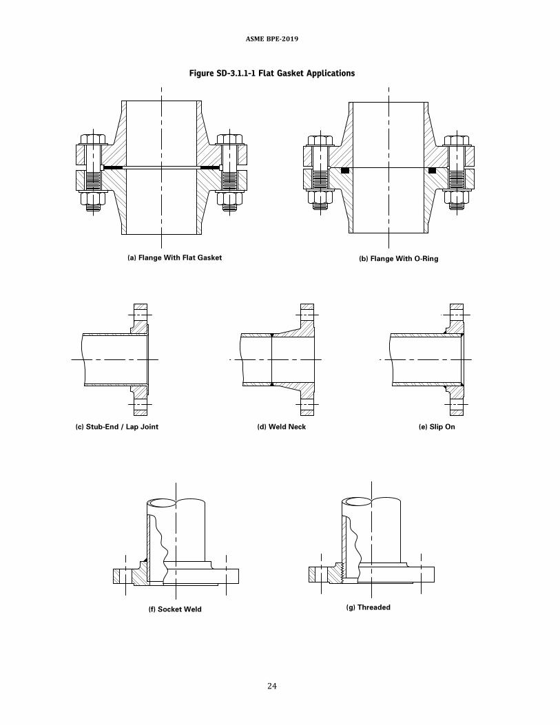
Figure SD-3.1.1-1 Flat Gasket Applications
ASME BPE-2019
24
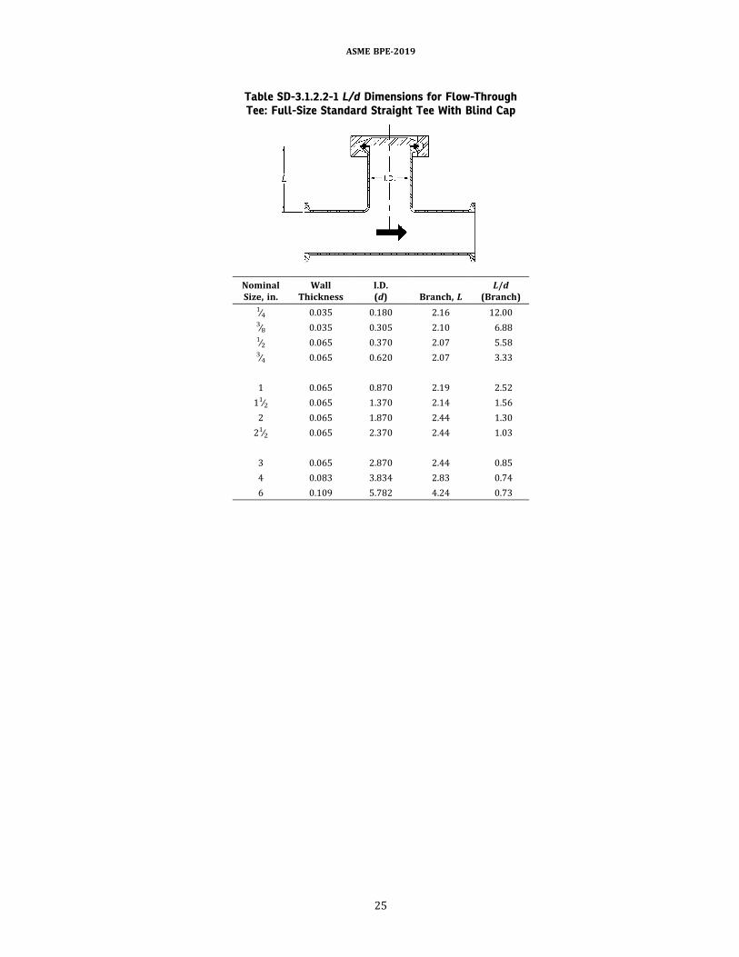
Table SD-3.1.2.2-1 L/d Dimensions for Flow-ThroughTee: Full-Size Standard Straight Tee With Blind Cap
NominalSize, in.
WallThickness
I.D.(d) Branch, L
L/d(Branch)
1∕4 0.035 0.180 2.16 12.003∕8 0.035 0.305 2.10 6.881∕2 0.065 0.370 2.07 5.583∕4 0.065 0.620 2.07 3.33
1 0.065 0.870 2.19 2.5211∕2 0.065 1.370 2.14 1.562 0.065 1.870 2.44 1.3021∕2 0.065 2.370 2.44 1.03
3 0.065 2.870 2.44 0.854 0.083 3.834 2.83 0.746 0.109 5.782 4.24 0.73
ASME BPE-2019
25
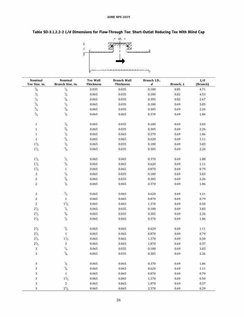
Table SD-3.1.2.2-2 L/d Dimensions for Flow-Through Tee: Short-Outlet Reducing Tee With Blind Cap
NominalTee Size, in.
NominalBranch Size, in.
Tee WallThickness
Branch WallThickness
Branch I.D.,d Branch, L
L/d(Branch)
3∕8 1∕4 0.035 0.035 0.180 0.85 4.711∕2 1∕4 0.065 0.035 0.180 0.82 4.531∕2 3∕8 0.065 0.035 0.305 0.82 2.673∕4 1∕4 0.065 0.035 0.180 0.69 3.833∕4 3∕8 0.065 0.035 0.305 0.69 2.263∕4 1∕2 0.065 0.065 0.370 0.69 1.86
1 1∕4 0.065 0.035 0.180 0.69 3.831 3∕8 0.065 0.035 0.305 0.69 2.261 1∕2 0.065 0.065 0.370 0.69 1.861 3∕4 0.065 0.065 0.620 0.69 1.1111∕2 1∕4 0.065 0.035 0.180 0.69 3.8311∕2 3∕8 0.065 0.035 0.305 0.69 2.26
11∕2 1∕2 0.065 0.065 0.370 0.69 1.8811∕2 3∕4 0.065 0.065 0.620 0.69 1.1111∕2 1 0.065 0.065 0.870 0.69 0.792 1∕4 0.065 0.035 0.180 0.69 3.832 3∕8 0.065 0.035 0.305 0.69 2.262 1∕2 0.065 0.065 0.370 0.69 1.86
2 3∕4 0.065 0.065 0.620 0.69 1.112 1 0.065 0.065 0.870 0.69 0.792 11∕2 0.065 0.065 1.370 0.69 0.5021∕2 1∕4 0.065 0.035 0.180 0.69 3.8321∕2 3∕8 0.065 0.035 0.305 0.69 2.2621∕2 1∕2 0.065 0.065 0.370 0.69 1.86
21∕2 3∕4 0.065 0.065 0.620 0.69 1.1121∕2 1 0.065 0.065 0.870 0.69 0.7921∕2 11∕2 0.065 0.065 1.370 0.69 0.5021∕2 2 0.065 0.065 1.870 0.69 0.373 1∕4 0.065 0.035 0.180 0.69 3.833 3∕8 0.065 0.035 0.305 0.69 2.26
3 1∕2 0.065 0.065 0.370 0.69 1.863 3∕4 0.065 0.065 0.620 0.69 1.113 1 0.065 0.065 0.870 0.69 0.793 11∕2 0.065 0.065 1.370 0.69 0.503 2 0.065 0.065 1.870 0.69 0.373 21∕2 0.065 0.065 2.370 0.69 0.29
ASME BPE-2019
26

Table SD-3.1.2.2-2 L/d Dimensions for Flow-Through Tee: Short-Outlet Reducing Tee With Blind Cap (Cont’d)
NominalTee Size, in.
NominalBranch Size, in.
Tee WallThickness
Branch WallThickness
Branch I.D.,d Branch, L
L/d(Branch)
4 1∕4 0.083 0.035 0.180 0.71 3.934 3∕8 0.083 0.035 0.305 0.71 2.324 1∕2 0.083 0.065 0.370 0.71 1.914 3∕4 0.083 0.065 0.620 0.71 1.144 1 0.083 0.065 0.870 0.71 0.814 11∕2 0.083 0.065 1.370 0.71 0.52
4 2 0.083 0.065 1.870 0.71 0.384 21∕2 0.083 0.065 2.370 0.71 0.304 3 0.083 0.065 2.870 0.71 0.256 1∕4 0.109 0.035 0.180 0.86 4.776 3∕8 0.109 0.035 0.305 0.86 2.826 1∕2 0.109 0.065 0.370 0.86 2.32
6 3∕4 0.109 0.065 0.620 0.86 1.396 1 0.109 0.065 0.870 0.86 0.996 11∕2 0.109 0.065 1.370 0.86 0.636 2 0.109 0.065 1.870 0.86 0.466 21∕2 0.109 0.065 2.370 0.86 0.366 3 0.109 0.065 2.870 0.86 0.306 4 0.109 0.083 3.834 0.86 0.22
ASME BPE-2019
27

Figure SD-3.1.2.2-1 Accepted Point-of-Use Designs
NOTES:(1) L/d of 2 or less.(2) L/d = 0 (preferred).
ASME BPE-2019
28

(f) The system shall be designed to eliminate airpockets and prevent or minimize air entrainment.(g) Field bending of tubing is permitted for diameters
up to and including 1∕2 in. (15mm).The centerline radiusoffield-bent tubes should be not less than 2.5 times thenominal tube diameter to mitigate the risk of interiorsurface damage (e.g., wrinkles, striations, and cracks).Field bending of tubing in larger diameters or smallerbend radii may be used with the approval of theowner/user when appropriate examination techniquesand procedures (e.g., visual, borescope, and sectioning)are used.(h) Ball valves are not recommended in fluid hygienic
piping systems. See SD-4.2.3(b) for further comments.(i) See SF-2.4 regarding cleaning and passivation.
Passivation of electropolished surfaces is not requiredunless the surface has been altered (e.g., welded ormechanically polished) or exposed to external contamina-tion after electropolishing.
(j) The use of blind welds in piping systems should beavoided. Proper installation sequencing of the pipingsystem can reduce the number of blind welds. See MJ-7.3.3(b) and GR-5.3.4 for further details.
SD-3.1.2.4 Hygienic Support Systems
(a) Hygienic supports should be used within classifiedspaces.Hygienic support design should incorporatedrain-able geometry to facilitate cleanability, have no exposedthreads, and have minimal potential for collecting andtrapping debris or liquids on the hanger. Materials ofconstruction shall be corrosion resistant and compatiblewith the chemical, thermal, and physical performance re-quirements of the installed location. The materials shallhave adequate strength and durability to withstand theapplication of continuous and/or cyclic thermal exposurethat may be encountered in the designed service.(b) The piping should maintain proper continuous
slope for drainability. Hygienic support systems shallassist in maintaining the required slope and alignmentunder all operating conditions, taking into accountthermal cycling, distortion, settling, moment loads,
Figure SD-3.1.2.3-1 Double Block-and-Bleed Valve Assembly
ASME BPE-2019
29
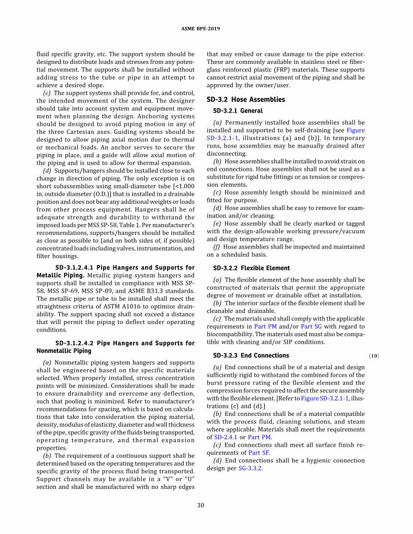
fluid specific gravity, etc. The support system should bedesigned to distribute loads and stresses from any poten-tial movement. The supports shall be installed withoutadding stress to the tube or pipe in an attempt toachieve a desired slope.(c) The support systems shall provide for, and control,
the intended movement of the system. The designershould take into account system and equipment move-ment when planning the design. Anchoring systemsshould be designed to avoid piping motion in any ofthe three Cartesian axes. Guiding systems should bedesigned to allow piping axial motion due to thermalor mechanical loads. An anchor serves to secure thepiping in place, and a guide will allow axial motion ofthe piping and is used to allow for thermal expansion.(d) Supports/hangers should be installed close to each
change in direction of piping. The only exception is onshort subassemblies using small-diameter tube [<1.000in. outside diameter (O.D.)] that is installed in a drainableposition and does not bear any additionalweights or loadsfrom other process equipment. Hangers shall be ofadequate strength and durability to withstand theimposed loads perMSS SP-58, Table 1. Permanufacturer’srecommendations, supports/hangers should be installedas close as possible to (and on both sides of, if possible)concentrated loads including valves, instrumentation, andfilter housings.
SD-3.1.2.4.1 Pipe Hangers and Supports forMetallic Piping. Metallic piping system hangers andsupports shall be installed in compliance with MSS SP-58, MSS SP-69, MSS SP-89, and ASME B31.3 standards.The metallic pipe or tube to be installed shall meet thestraightness criteria of ASTM A1016 to optimize drain-ability. The support spacing shall not exceed a distancethat will permit the piping to deflect under operatingconditions.
SD-3.1.2.4.2 Pipe Hangers and Supports forNonmetallic Piping
(a) Nonmetallic piping system hangers and supportsshall be engineered based on the specific materialsselected. When properly installed, stress concentrationpoints will be minimized. Considerations shall be madeto ensure drainability and overcome any deflection,such that pooling is minimized. Refer to manufacturer’srecommendations for spacing, which is based on calcula-tions that take into consideration the piping material,density,modulus of elasticity, diameter andwall thicknessof the pipe, specific gravity of the fluids being transported,operating temperature, and thermal expansionproperties.(b) The requirement of a continuous support shall be
determined based on the operating temperatures and thespecific gravity of the process fluid being transported.Support channels may be available in a “V” or “U”section and shall be manufactured with no sharp edges
that may embed or cause damage to the pipe exterior.These are commonly available in stainless steel or fiber-glass reinforced plastic (FRP) materials. These supportscannot restrict axial movement of the piping and shall beapproved by the owner/user.
SD-3.2 Hose AssembliesSD-3.2.1 General
(a) Permanently installed hose assemblies shall beinstalled and supported to be self-draining [see FigureSD-3.2.1-1, illustrations (a) and (b)]. In temporaryruns, hose assemblies may be manually drained afterdisconnecting.(b) Hose assemblies shall be installed to avoid strain on
end connections. Hose assemblies shall not be used as asubstitute for rigid tube fittings or as tension or compres-sion elements.(c) Hose assembly length should be minimized and
fitted for purpose.(d) Hose assemblies shall be easy to remove for exam-
ination and/or cleaning.(e) Hose assembly shall be clearly marked or tagged
with the design-allowable working pressure/vacuumand design temperature range.(f) Hose assemblies shall be inspected and maintained
on a scheduled basis.
SD-3.2.2 Flexible Element
(a) The flexible element of the hose assembly shall beconstructed of materials that permit the appropriatedegree of movement or drainable offset at installation.(b) The interior surface of the flexible element shall be
cleanable and drainable.(c) Thematerials used shall complywith the applicable
requirements in Part PM and/or Part SG with regard tobiocompatibility. Thematerials usedmust also be compa-tible with cleaning and/or SIP conditions.
SD-3.2.3 ð19ÞEnd Connections
(a) End connections shall be of a material and designsufficiently rigid to withstand the combined forces of theburst pressure rating of the flexible element and thecompression forces required to affect the secure assemblywith the flexible element. [Refer toFigure SD-3.2.1-1, illus-trations (c) and (d).](b) End connections shall be of a material compatible
with the process fluid, cleaning solutions, and steamwhere applicable. Materials shall meet the requirementsof SD-2.4.1 or Part PM.(c) End connections shall meet all surface finish re-
quirements of Part SF.(d) End connections shall be a hygienic connection
design per SG-3.3.2.
ASME BPE-2019
30

SD-3.3 PumpsSD-3.3.1 Diaphragm Pumps
(a) Diaphragmpumpsmaybeused inpositivedisplace-ment pump applications. Some diaphragm pumps areavailable that provide low shear, constant flow or pres-sure, low pulsation, high turndown ratio (e.g., 1,000:1),and/or low particle generation.(b) The owner/user shall evaluate whether holdup
volume and drainability characteristics of a diaphragmpump are acceptable for the application. Some processapplications require the process system, including thediaphragm pump, to remain continuously flooded withsanitizing solution instead of being drained.(c) Process contact diaphragms, O-rings, gaskets, and
seals shall comply with Part SG. Process contact metallicmaterials of construction shall comply with Part MM.Nonmetallic process contact surfaces includingdiaphragms shall comply with Part PM.(d) Where applicable, check valves shall comply with
SD-3.13(e) Where used, diaphragm fasteners shall be attached
within thepumpheadsuch that crevicesor threadsarenotexposed to the process fluids.(f) The owner/user should consider leak detection
and/or leak path design of the pump to identify afailure that can lead to process contamination and/orbiohazards.
SD-3.3.2 Hygienic Pumps
SD-3.3.2.1 General
(a) Pumps shall be cleanable. Pumps shall be selectedaccording to the operating conditions determined by theowner/user (e.g., process, CIP, SIP, passivation).(b) Allprocess contact connections to thepumpshallbe
of a hygienic design (see Figures SG-2.2.2-1, SG-2.2.2-2,SG-2.2.2-3, and SG-2.2.2-4).
SD-3.3.2.2 Centrifugal Pumps
(a) Hygienic centrifugal pumps shall be capable of CIP.(b) All process contact surfaces shall be drainable
without pump disassembly or removal.(c) Shrouded/closed impellers should not be used.
Figure SD-3.3.2.2-1 illustrates open, semi-open, andclosed impeller configurations.(d) The impeller shall be attached to the shaft in such a
way that all crevices and threads are not exposed to theprocess. Threads, such as in an impeller nut/bolt, shall besealed by an O-ring or hygienic gasket. Refer to Figure SD-3.3.2.2-2. The use of O-rings or hygienic gaskets shall beconsistent with Part SG.(e) Suction, discharge, and casing drain connections
shall be an integral part of the pump casing.(f) Casing drains shall be at the lowest point of the
casing, to ensure drainage (see Figure SD-3.3.2.2-3).
Figure SD-3.2.1-1 Flexible Hygienic Hose Design
ASME BPE-2019
31
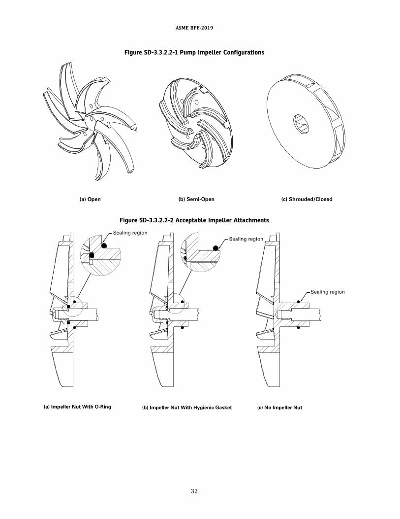
Figure SD-3.3.2.2-1 Pump Impeller Configurations
Figure SD-3.3.2.2-2 Acceptable Impeller Attachments
ASME BPE-2019
32

Figure SD-3.3.2.2-3 Casing Drain Configurations
Figure SD-3.3.2.2-4 Casing Drain L/d Ratios
ASME BPE-2019
33
(g) The use of an elbow-type casing drain is not rec-ommendedwithout the use of an automatically controlleddrain. The casing drain connection shall be designed tominimize the L/d as shown in Figure SD-3.3.2.2-4.(h) The pump discharge connection should be tilted to
allow for full venting of the casing (see Figure SD-3.3.2.2-3).(i) All pump seals should be designed to minimize seal
material degradation.(j) Shaft seals shall conform to Part SG.
SD-3.3.2.3 Positive Displacement Pumps
(a) When possible, positive displacement pumpsshould be configured with vertically mounted inletsand outlets to promote drainability and venting.(b) Whenusing internal bypass pressure relief devices,
they shall be of a hygienic design. It is preferred that anexternal, piping-mounted relief device (hygienic rupturedisk) rather than a pump-mounted bypass be used.
SD-3.3.2.4 Rotary Lobe Pumps
(a) Theowner/user shall specify the chemical, thermal,and hydraulic operating conditions of the pump (e.g,.process, CIP, SIP) to ensure proper component selection.Hygienic rotary lobe pumps are temperature sensitive(e.g., rotor to casing contact due to thermal expansion).(b) Thepump should bedesigned and installed tomini-
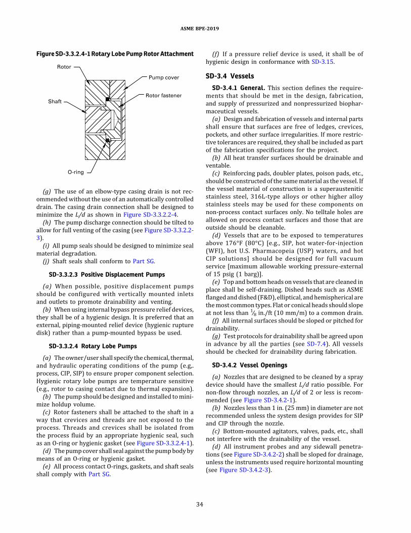
mize holdup volume.(c) Rotor fasteners shall be attached to the shaft in a
way that crevices and threads are not exposed to theprocess. Threads and crevices shall be isolated fromthe process fluid by an appropriate hygienic seal, suchas an O-ring or hygienic gasket (see Figure SD-3.3.2.4-1).(d) Thepumpcover shall seal against thepumpbodyby
means of an O-ring or hygienic gasket.(e) All process contact O-rings, gaskets, and shaft seals
shall comply with Part SG.
(f) If a pressure relief device is used, it shall be ofhygienic design in conformance with SD-3.15.
SD-3.4 Vessels
SD-3.4.1 General. This section defines the require-ments that should be met in the design, fabrication,and supply of pressurized and nonpressurized biophar-maceutical vessels.(a) Design and fabrication of vessels and internal parts
shall ensure that surfaces are free of ledges, crevices,pockets, and other surface irregularities. If more restric-tive tolerances are required, they shall be included as partof the fabrication specifications for the project.(b) All heat transfer surfaces should be drainable and
ventable.(c) Reinforcing pads, doubler plates, poison pads, etc.,
should be constructed of the samematerial as the vessel. Ifthe vessel material of construction is a superausteniticstainless steel, 316L-type alloys or other higher alloystainless steels may be used for these components onnon-process contact surfaces only. No telltale holes areallowed on process contact surfaces and those that areoutside should be cleanable.(d) Vessels that are to be exposed to temperatures
above 176°F (80°C) [e.g., SIP, hot water-for-injection(WFI), hot U.S. Pharmacopeia (USP) waters, and hotCIP solutions] should be designed for full vacuumservice [maximum allowable working pressure-externalof 15 psig (1 barg)].(e) Topandbottomheads on vessels that are cleaned in
place shall be self-draining. Dished heads such as ASMEflangedanddished (F&D), elliptical, andhemispherical arethemost common types. Flat or conical heads should slopeat not less than 1∕8 in./ft (10 mm/m) to a common drain.(f) All internal surfaces should be sloped or pitched for
drainability.(g) Test protocols for drainability shall be agreed upon
in advance by all the parties (see SD-7.4). All vesselsshould be checked for drainability during fabrication.
SD-3.4.2 Vessel Openings
(a) Nozzles that are designed to be cleaned by a spraydevice should have the smallest L/d ratio possible. Fornon-flow through nozzles, an L/d of 2 or less is recom-mended (see Figure SD-3.4.2-1).(b) Nozzles less than 1 in. (25 mm) in diameter are not
recommended unless the system design provides for SIPand CIP through the nozzle.(c) Bottom-mounted agitators, valves, pads, etc., shall
not interfere with the drainability of the vessel.(d) All instrument probes and any sidewall penetra-
tions (see Figure SD-3.4.2-2) shall be sloped for drainage,unless the instruments used require horizontal mounting(see Figure SD-3.4.2-3).
Figure SD-3.3.2.4-1 Rotary Lobe Pump Rotor Attachment
ASME BPE-2019
34

Figure SD-3.4.2-1 Nozzle Design
NOTES:(1) Less dead space.(2) Better CIP/SIP capabilities.(3) Potential problems with CIP and SIP with capped connections.(4) Dead space: stagnant areas.(5) All L/d ratios to be calculated on long-side dimensions for vessel heads.
ASME BPE-2019
35

Figure SD-3.4.2-2 Side and Bottom Connections
NOTES:(1) If a flat gasket is used, mismatch of diameters can result in crevices.(2) Telltale hole required.
Figure SD-3.4.2-3 Sidewall Instrument Ports
NOTE: (1) May also be pitched similar to illustration (b).
ASME BPE-2019
36

(e) Blank covers or hygienic plugs used in processcontact applications shall have the same finish as thevessel internals.(f) Drain valves should optimize drainability and mini-
mize branch L/d.(g) Thenumber and location of spraydevices shouldbe
selected to eliminate shadowing at internal parts such asmixer shafts, dip tubes, and baffles.(h) The number of shell-side nozzles and connections
should be minimized.(i) Manways on the side shell of a vessel shall be
installed only by agreement of the owner/user. If side-shell manways are required, they shall be sloped fordrainage.(j) Sample valves shall be designed in accordance with
SD-3.11.(k) Sample valves shall be installed in accordance with
SD-3.11.
(l) As required by the process, inlet nozzles tangentialto the vessel surface may be used (see Figure SD-3.4.2-4and Figure PI-9.1.3.3-1).(m) Manway covers should be dished rather than a flat
design.(n) Flanges that have metal-to-metal contact on the
process contact side shall not be used.(o) All nozzles should be flush with the interior of the
vessel except where projections are required to ensureadditives are directed into the process fluid (e.g., chemicaladdition) (see Figure SD-3.4.2-5).
SD-3.4.3 Internal Components
(a) Sparger and dip tubes shall be designed in accor-dance with SD-3.4.1(a), SD-3.4.1(d), SD-3.4.1(f), and SD-3.4.1(g). Sparger and dip tubes shall incorporate low-point drains [where applicable, i.e., horizontal linesshould slope at not less than 1∕8 in./ft (10 mm/m)] andbe properly supported to ensure drainability. Refer toTable SD-2.4.3.1-1 to determine the appropriate slopedesignation.(b) Dip tubes and spargers mounted in the nozzle neck
should have an annular space between the O.D. of the diptube or sparger and the I.D. of the nozzle neck in accor-dance with Table SD-3.4.3-1. An L/A of 2 or less is recom-mended (see Figure SD-3.4.3-1). If a larger L/A exists, amethod for cleaning this space shall be specified. In allcases, sufficient annular space to allow access for CIPcoverage shall be provided.(c) Internal support members shall be solid, rather
than hollow, which have a higher risk of fatigue andcontamination problems (see Figure SD-3.4.3-2).(d) Mitered fittings for internal pipe work shall only be
fitted with the prior agreement between the owner/userand manufacturer. When mitered joints are used, theyshall be designed and fabricated in accordance withthe appropriate Codes.(e) Vessels shall drain to a common point and shall not
have multiple draining points, unless agreed to betweenthe owner/user and manufacturer.
SD-3.4.4 ð19ÞFabrication
(a) For process contact surfaces, butt welds should beused and the use of lap joint welds should be minimized.Stitch welding shall not be used on process contactsurfaces.(b) Flanges are not recommended, and their use should
be minimized. The bore of weld neck flanges shall be thesame as the I.D. of the connected pipe or tubing to preventledges and nondrainable areas.(c) Where slip-on nondrainable flanges are used, the
bore-side bevelweld shall be designed to eliminate poten-tial drainability and CIP difficulties.
Figure SD-3.4.2-4 Vessel Design Tangential Nozzles
GENERAL NOTE: CIP through nozzle is recommended.
ASME BPE-2019
37
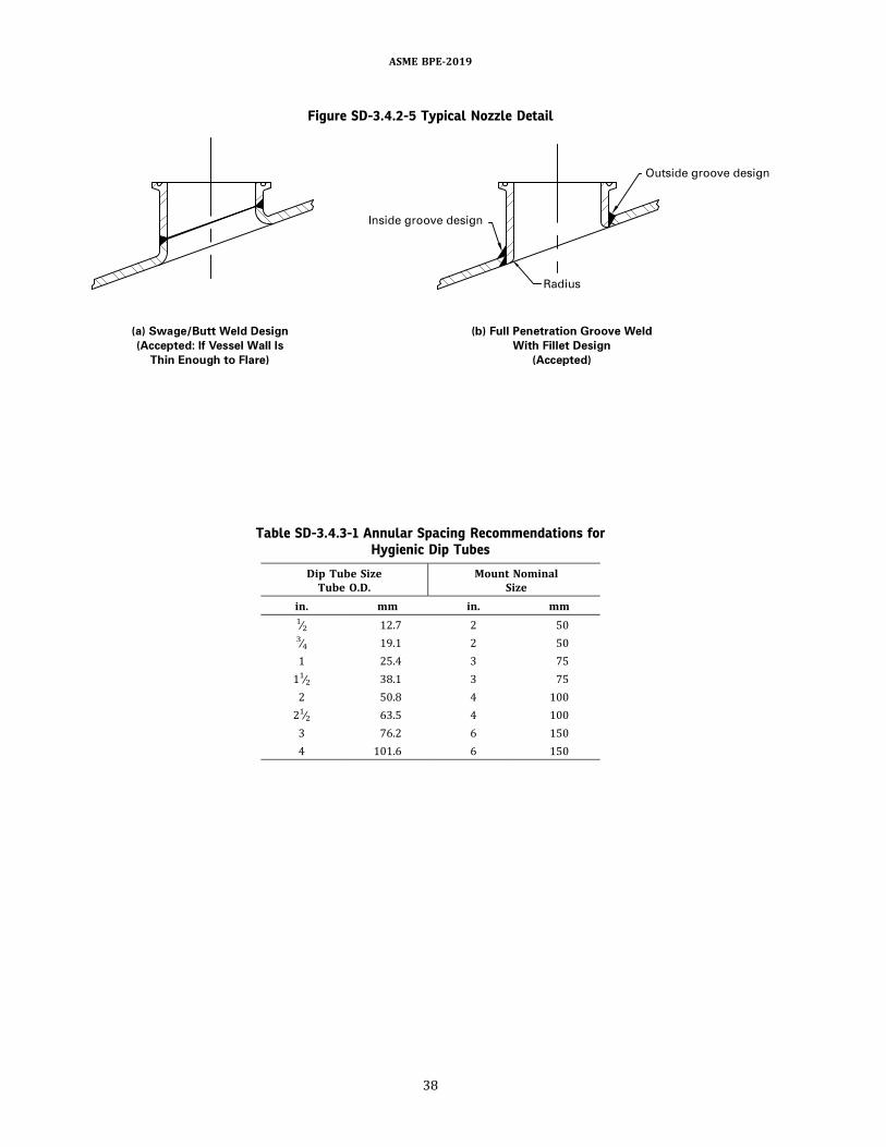
Figure SD-3.4.2-5 Typical Nozzle Detail
Table SD-3.4.3-1 Annular Spacing Recommendations forHygienic Dip Tubes
Dip Tube SizeTube O.D.
Mount NominalSize
in. mm in. mm1∕2 12.7 2 503∕4 19.1 2 501 25.4 3 7511∕2 38.1 3 752 50.8 4 10021∕2 63.5 4 1003 76.2 6 1504 101.6 6 150
ASME BPE-2019
38
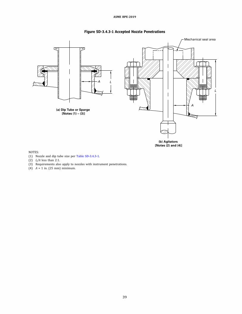
Figure SD-3.4.3-1 Accepted Nozzle Penetrations
NOTES:(1) Nozzle and dip tube size per Table SD-3.4.3-1.(2) L/A less than 2:1.(3) Requirements also apply to nozzles with instrument penetrations.(4) A = 1 in. (25 mm) minimum.
ASME BPE-2019
39

Figure SD-3.4.3-2 Internal Support Members
ASME BPE-2019
40
SD-3.4.5 Finishes
(a) Surface finishes shall be specified in Ra values (seeTable SF-2.4.1-1) and measured as required by Part SF.Surface finish coupons shall be submitted when agreedto by the owner/user and manufacturer.(b) Process contact surface finish specifications shall
pertain to all the wetted or potentially wetted surfaces(e.g., vapor space, nozzle necks, agitators, thermowells,dip tubes, baffles).(c) The polishing of a connection face, body flange, etc.,
shall extend up to the first seal point.
SD-3.4.6 Sight Glasses
(a) Sight glasseson the vessels shouldbedesignedwithreference toSD-3.4.2(a). Sight glassesonvessels shouldbedesigned with the smallest L/d possible and incorporatecleanable O-ring designs when applicable (see Figure SD-3.4.6-1).(b) Refer to PI-9.1.2.3 for additional sight glass
requirements.(c) Surface finish for the metal frame shall meet the
requirements of Part SF in this Standard.(d) Sight glasses shall be marked with the glass type,
maximum pressure, and temperature rating per DT-11.1and DT-11.1.1.(e) Part SG requirements shall bemetwhenmounting a
sight glass.(f) Preferred sight glassmountings are shown in Figure
SD-3.4.6-1.
SD-3.4.7 Portable Tanks. Portable tanks shall bedesigned in accordance with SD-3.4.(a) Casters shall be cleanable and compatible with
cleaning solutions used for external cleaning.(b) Casters should be designed for the environment in
which the vessel will be used.(c) Flexiblehosesused to connectportablevessels shall
meet the requirements of SD-3.2.(d) Provisions for static grounding should be evaluated
and incorporated into the vessel design, if required. Theconnections for static grounding should be designed to becleanable.
SD-3.4.8 Media Bulk Containers. [Reserved for futurecontent]
SD-3.4.9 Cryogenic Containers. [Reserved for futurecontent]
SD-3.5 Agitators and MixersSD-3.5.1ð19Þ General
(a) All process contact surfaces of agitators andmixerswith their associated components shall be accessible tothe cleaning fluids as specified by the owner/user forclean-in-place service (CIP; e.g., via spray, directedflow, immersion).
(b) Process contact surfaces should be self-drainingand shall not inhibit drainage of the vessel.(c) Machined transitions (shaft steps, coupling
surfaces, wrench flats, etc.) should be smooth, with 15-deg to 45-deg sloped surfaces.(d) The annular space between the agitator shaft and
the agitator nozzle shall, for cleaning purposes, have anL/A of 2 or less, or aminimumof 1 in. (25mm) gap, which-ever is larger, to facilitate CIP spray coverage [see FigureSD-3.4.3-1, illustration (b)].(e) Cleaning and sterilization parameters shall be
providedby theowner/userprior todesignof theagitator.Themanufacturers of agitators andmixers shall verify thecleanability of their equipment as specified and agreed towith the owner/user.(f) Top-entering mixers with shaft seals are typically
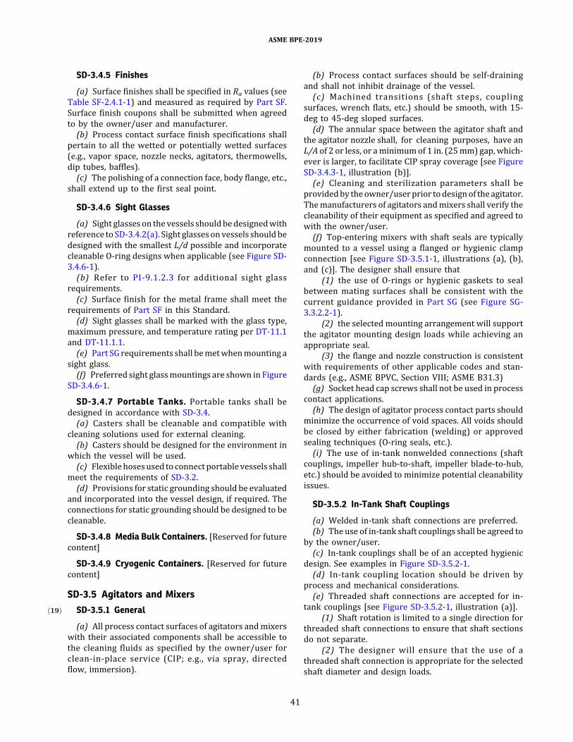
mounted to a vessel using a flanged or hygienic clampconnection [see Figure SD-3.5.1-1, illustrations (a), (b),and (c)]. The designer shall ensure that
(1) the use of O-rings or hygienic gaskets to sealbetween mating surfaces shall be consistent with thecurrent guidance provided in Part SG (see Figure SG-3.3.2.2-1).
(2) the selected mounting arrangement will supportthe agitator mounting design loads while achieving anappropriate seal.
(3) the flange and nozzle construction is consistentwith requirements of other applicable codes and stan-dards (e.g., ASME BPVC, Section VIII; ASME B31.3)(g) Socket head cap screws shall not be used in process
contact applications.(h) The design of agitator process contact parts should
minimize the occurrence of void spaces. All voids shouldbe closed by either fabrication (welding) or approvedsealing techniques (O-ring seals, etc.).(i) The use of in-tank nonwelded connections (shaft
couplings, impeller hub-to-shaft, impeller blade-to-hub,etc.) should be avoided to minimize potential cleanabilityissues.
SD-3.5.2 In-Tank Shaft Couplings
(a) Welded in-tank shaft connections are preferred.(b) The use of in-tank shaft couplings shall be agreed to
by the owner/user.(c) In-tank couplings shall be of an accepted hygienic
design. See examples in Figure SD-3.5.2-1.(d) In-tank coupling location should be driven by
process and mechanical considerations.(e) Threaded shaft connections are accepted for in-
tank couplings [see Figure SD-3.5.2-1, illustration (a)].(1) Shaft rotation is limited to a single direction for
threaded shaft connections to ensure that shaft sectionsdo not separate.
(2) The designer will ensure that the use of athreaded shaft connection is appropriate for the selectedshaft diameter and design loads.
ASME BPE-2019
41

Figure SD-3.4.6-1 Sight Glass Design (Accepted)
ASME BPE-2019
42
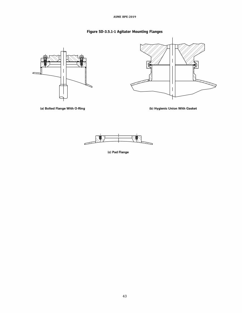
Figure SD-3.5.1-1 Agitator Mounting Flanges
ASME BPE-2019
43
(3) Hygienic bolted coupling construction may beused where appropriate for the particular application[see Figure SD-3.5.2-1, illustration (b)].(f) Threads shall not be exposed in any type of shaft or
coupling hardware connection.(g) The preferred location for fastener hardware is on
the underside of couplings. Accepted fastener typesinclude
(1) hex-head cap screws(2) acorn-head cap screws(3) threaded studs with acorn nuts
(h) Fastener heads shall be free of raised or engravedmarkings that might inhibit cleanability.(i) O-rings rather than flat gaskets are preferred to seal
coupling mating surfaces. Figure SD-3.5.2-2 presents thefollowing acceptable approaches for seal applications:
(1) O-ring located in a single groove inboard of thecoupling O.D. [see Figure SD-3.5.2-2, illustration (a)]; O-ring compression, internal space to accommodatecompression, and outboard clearance space all designedto minimize the intrusion of process fluid between thecoupling faces and to facilitate flow of CIP fluid.
(2) Alternate construction for O-ring located in agroove just inboard of the coupling O.D. [see FigureSD-3.5.2-2, illustration (b)]; O-ring restrained by lip atcoupling circumference with clearance space providedas above to ensure cleanability of the coupling area.
(3) Alternate construction for O-ring located ingrooves in both coupling halves inboard of the couplingO.D. [see Figure SD-3.5.2-2, illustration (c)]; outboardclearance space provided as above to ensure cleanabilityof the coupling area.
(4) O-ring with attached inboard flat segmentlocated between coupling faces [see Figure SD-3.5.2-2,illustration (d)]; outboard clearance space provided asabove to ensure cleanability of the coupling area.(j) Bolted flanges shall be sealed. Examples of accepted
fastener seals are shown in Figure SD-3.5.2-3 as follows:(1) O-ring seal [illustration (a)](2) O-ring seal alternate [illustration (b)](3) seal washer with metal core [illustration (c)]
SD-3.5.3 Shafts and Keyways
(a) One-piece shaft construction, without mechanicalcouplings, is preferred.(b) Solid shafts are preferred over hollow shafts.
Figure SD-3.5.2-1 Shaft Coupling Construction
NOTE: (1) See Figure SD-3.5.2-3 for alternative bolt seals.
ASME BPE-2019
44

Figure SD-3.5.2-2 Shaft Coupling Seal Arrangements
ASME BPE-2019
45

(c) Hollow shafts, if used, shall be of sealed (welded)construction, inspected for integrity, and accepted percriteria given in Part MJ prior to installation.(d) Keyways exposed to the process are not
recommended.(e) Keyways, where employed due to mechanical
design considerations, shall have edge radii as specifiedby SD-2.4.2(b)(3).(f) Keyways may require additional design and/or
cleaning practice to ensure drainage and cleanability(e.g., spray ball and/or wand additions, increased CIPflow, and adjusted spray coverage).(g) Permanent shaft hardware, installed on the process
contact side, that may be required for routine mainte-nance (e.g., support collars formechanical seal installationand removal, lifting eyes for shaft and/or impeller instal-lation and removal) shall be fully drainable and cleanable.
SD-3.5.4 Hubs and Impellers
(a) All-welded impeller assemblies (e.g., hubs, blades)are preferred.(b) Impeller hubs welded to the shaft are preferred
over removable hubs.(c) Removable, hygienic impellers may be used where
impeller adjustment or substitution is required forprocess reasons or where impeller removal is requireddue to mechanica l des ign and/or insta l lat ionconsiderations.
(1) Removable impellers may be one-piece or splithygienic construction.
(2) Hub-to-shaft clearance for removable impellersshall be sufficient to preclude shaft surface finish damageduring installation and removal.
(3) Removable hardware (e.g., impeller hub andshaft, impeller set-screws and hub) should be sealed ina manner consistent with the guidance provided for in-tank couplings (see SD-3.5.2).(d) Removable impellers and impellers with flat, hori-
zontal surfaces (e.g., flat-blade disk turbines, concave-blade disk turbines) may require additional designand/or cleaning practice to ensure drainage and clean-ability, e.g., drain holes, spray ball and/or wand additions,increased CIP flow, adjusted spray coverage, impellerrotation.
SD-3.5.5 Impeller and Shaft Support Bearings ð19Þ
(a) Normal operation of a shaft-steady bearing or a magnetically driven mixer with in-tank impeller or shaft support bearings (see Figures SD-3.5.5-1 and SD-3.5.5-2) generates particulate debris. It is the responsibility of the owner/user to establish compliance with applicable standards (e.g., USP limits for particulate material in injectables) as appropriate.(b) Tank plates that support bottom-mounted magne-
tically driven mixers shall not interfere with drainage ofthe vessel.(c) When an application mandates the use of shaft-
steady/foot bearings, design features and/or procedures are required to ensure cleanability (e.g., drain holes, spray ball and/or wand additions, increased CIP flow, operating the steady bearing immersed in CIP fluid).(d) Shaft-steady bearings, where used, shall not inter-
fere with the drainage of the vessel.(e) Shaft-steady bearing pedestal support members
may be of solid or hollow construction. Hollow pedestalsupports, if used, shall be of sealed (welded) construction,
Figure SD-3.5.2-3 Fastener Seal Arrangements: Alternative Bolting Designs
ASME BPE-2019
46
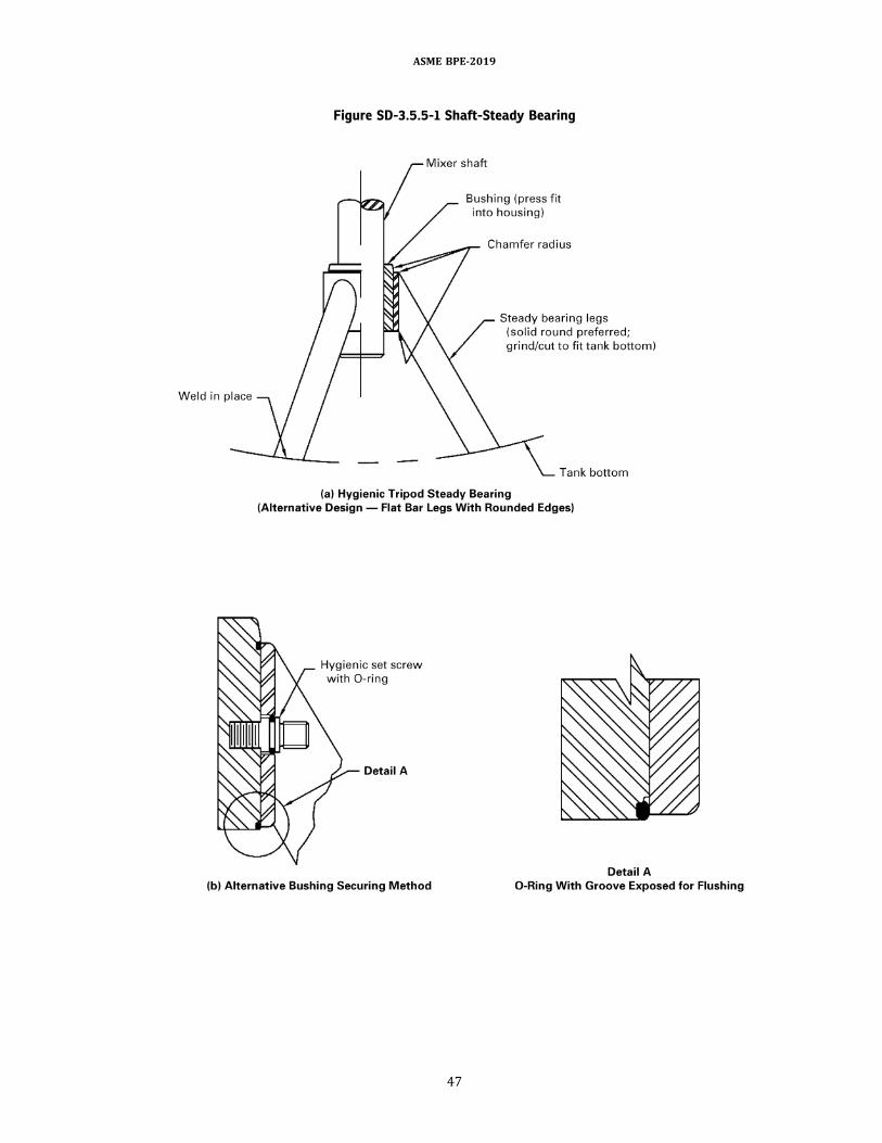
Figure SD-3.5.5-1 Shaft-Steady Bearing
ASME BPE-2019
47

inspected for integrity, and accepted per criteria given inPart MJ after installation.(f) Magnetically driven mixers require design features
and/orprocedures toensurecleanability (e.g., drainholes,spray ball and/or wand additions, increased CIP flow,operating the agitator with the magnetically drivenimpeller immersed in CIP fluid).(g) The arrangement of wear surfaces (bushing, shaft,
or shaft sleeve) shall facilitate drainage.
SD-3.5.6ð19Þ Mechanical Seals
(a) Mechanical shaft seals shall incorporate designfeatures for drainability, surface finish, material ofconstruction, etc., as outlined in Part SD, and shall be suit-able for the application (e.g. , process, CIP, SIP,passivation).(b) Normal operation of a mechanical seal generates
particulate debris. It is the responsibility of the owner/user to establish compliance with applicable standards(e.g., USP limits for particulate material in injectables)as appropriate.(c) Seal debris wells or traps (see Figure SG-2.3.2.3-2)
may be used to prevent ingress of seal face wear particlesthat could contaminate the process fluid.(d) Refer to Part SG of this Standard for specific seal
design details.
SD-3.6 Heat Exchange Equipment
Plate-and-frame-type heat exchangers should be usedonly by agreement between owner/user and designer dueto the difficulty of CIP and SIP.
SD-3.6.1 ð19ÞGeneral
(a) Straight tube heat exchangers are easier to cleanand inspect. The tubes can be seamless or full-finishwelded, as agreed toby theowner/userandmanufacturer.(b) The heat exchanger process and non-process
contact surface inspection shall be possible by conven-tional means.(c) The technique used to form U-bend tubes shall
ensure the bending process does not create structuralimperfections (e.g., cracks, voids, delaminations). Thetechnique should minimize surface imperfections (e.g.,orange peel, rippling). If requested by the owner/user,the manufacturer shall supply a sectioned sample ofthe bend area.
(1) The sectioned sample should be from the sametube batch or heat that will be used to fabricate the heatexchanger.
(2) The sectioned sample shall be the smallest bendradius in the exchanger.
(3) The sample shall be sectioned so that the bend’scenterline is visible.
Figure SD-3.5.5-2 Magnetically Coupled Mixer (Typical Bottom-Mount)
ASME BPE-2019
48

(d) The internal surface of the U-bends shall be free ofrelevant liquid penetrant indications, as defined by ASMEBPVC, Section VIII.(e) The I.D. of the U-bends shall be large enough for a
borescopic examination.(f) Minimumrecommendedbend radii forheat exchan-
gers should be as follows:Nominal Tube O.D. Minimum Bend Radiusin. mm in. mm
0.375 9.5 0.625 15.20.500 12.7 0.750 19.10.625 15.8 0.938 23.80.750 19.1 1.125 28.61.000 25.4 1.500 38.1
(g) Welded shell-and-tubeheat exchangers shall be of adouble tubesheet design to prevent contamination of theprocess in the event of a tube joint failure (see Figure SD-3.6.1-1).
(1) During fabrication, when the tubes are to beexpanded into the inner and outer tubesheets, theprocess contact surface shall not be scored.
(2) Tubes shall be sealwelded to theouter tubesheet.(3) Thedistancebetween inner andouter tubesheets
shall be sufficient to allow leak detection.(4) Tubesheets and channels shall be drainable.
(h) The owner/user shall specify the orientation of theexchanger (i.e., horizontal or vertical), and the manufac-turer shall ensure the complete draining of the processliquid from the process contact side of the heat exchangerat the specified orientation, other than the natural cohe-sive properties of said process liquid. If this holdup is un-acceptable, then the manufacturer shall design some typeof assist to aid draining, such as an air blowdown.
(1) In the specified orientation, the shell side shallalso be drainable (e.g., WFI condensers).
(2) Transverse baffles with notches should beprovided, when necessary, to allow for proper drainingof the shell.
(3) The heat exchanger bonnet shall be matchmarked with the outer tubesheet for proper orientationto ensure drainability or cleanability.(i) Heat exchanger thermal and mechanical calcula-
tions shall be performed for both operating and SIP cycles.(j) In shell-and-tube heat exchangers, the design pres-
sure for the process contact side shall be equal to orgreater than the design pressure of the utility side.(k) The type of connections to the utility side (shell
side) shall be agreed to between the owner/user andmanufacturer.
SD-3.6.2 Cleaning and Steaming
(a) Theprocess contact surfaces shall be constructed towithstand CIP and SIP or other cleaning/bioburdencontrol methods specified by the owner/user.
(b) The cleaning and steaming conditions shall beprovided by the owner/user prior to the design of theheat exchanger.
SD-3.6.3 Gaskets and Seals
(a) Gaskets that are in contact with product shall beremovable and self-positioning and shall have readilycleanable grooves.(b) Channel/bonnet gaskets shall be of a cleanable
design.
SD-3.7 Transfer PanelsSD-3.7.1 General
(a) The transfer panel shall be constructed so that theprocess contact surfaces can be cleaned by a CIP fluid orother method specified by the owner/user. The processcontact surfaces shall be free of crevices, pockets, andother surface irregularities.(b) The transfer panel nozzle elevation shall be prop-
erly designed with respect to the connecting equipmentsuch as tank and pump to ensure drainability, cleanability,and bioburden control during process transfer, CIP, andSIP.(c) Design and fabrication of the transfer panel and
associated components must ensure that the pipingsystem can be fully drained when properly installed.This is not to imply that panel nozzles and/or subheadersshould be sloped (see Figure SD-3.7.1-1).(d) Tagging/labeling of the transfer panel and its
components shall be per SD-2.4.4.2(i). Tagging nozzleson the back side of panels will help reduce the numberof incorrect piping connections during field installation.
SD-3.7.2 ð19ÞNozzles or Ports
(a) Nozzle construction shall accommodate a designfeature that will assist in the elimination of internalsurface anomalies caused in part by joining the nozzleto the panel structure.(b) The method of joining a nozzle into a panel struc-
ture shall be of hygienic design. Acceptance criteria forthese welds shall meet the requirements of Table MJ-8.5-1.(c) Each front nozzle connection shall be of a hygienic
design and the horizontal projection minimized to opti-mize drainability.(d) To ensure proper panel functionality and joint
connection integrity, panel nozzles shall not be sloped(see Figure SD-3.7.2-1).(e) Nozzle-to-nozzle clearance shall be such that
jumper drain valve interference, if applicable, will notoccur when jumpers are connected in all possible oper-ating and cleaning configurations.(f) Nozzles shall be capable of being capped. Caps may
include bleed valves or pressure indicators for safety oroperating purposes.
ASME BPE-2019
49

Figure SD-3.6.1-1ð19Þ Double Tubesheet Heat Exchanger Bonnet Design
NOTE: (1) Owner/user to specify inlet tubing slope. Heat exchanger manufacturer to slope inlet on bonnet to match inlet tubing slope.
ASME BPE-2019
50
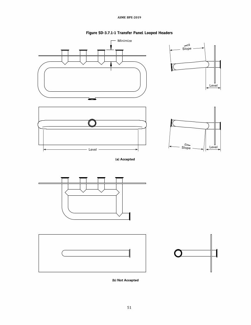
Figure SD-3.7.1-1 Transfer Panel Looped Headers
ASME BPE-2019
51
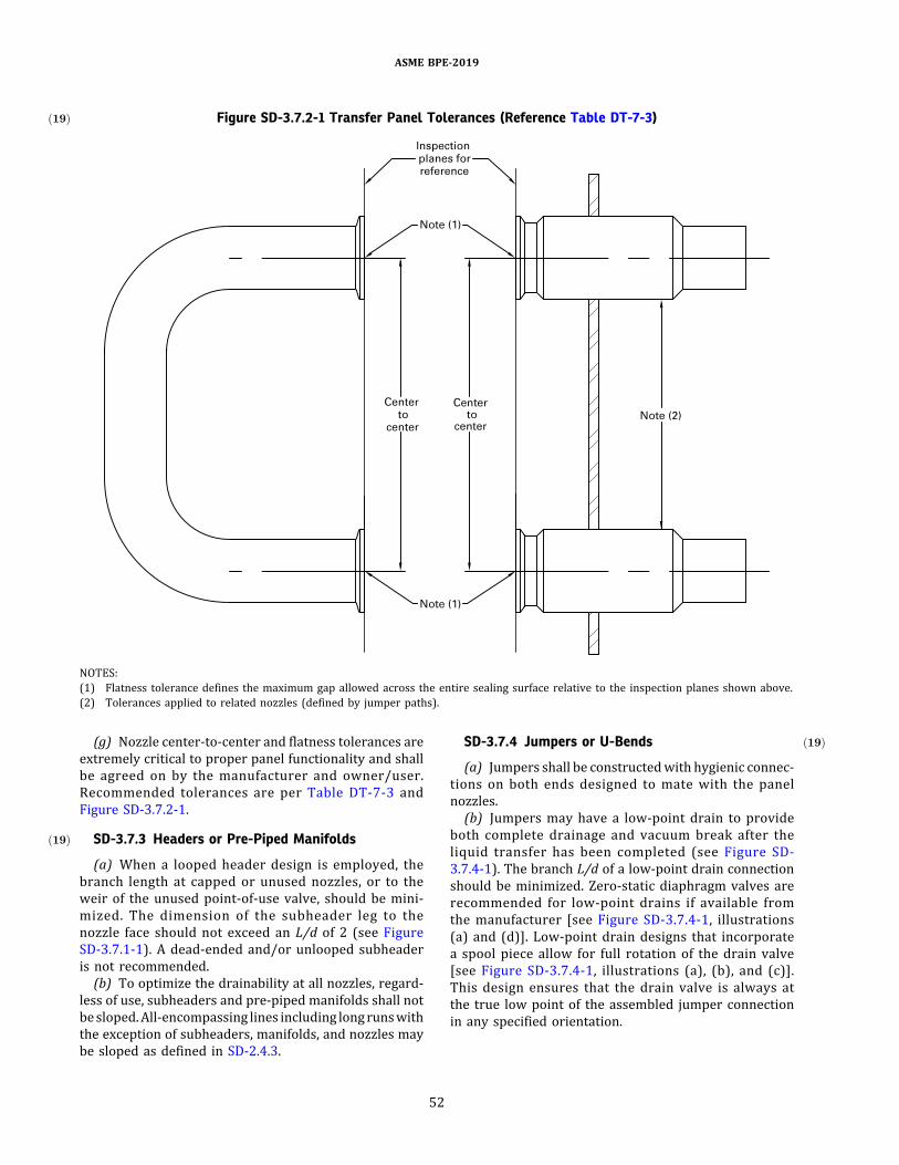
(g) Nozzle center-to-center and flatness tolerances areextremely critical to proper panel functionality and shallbe agreed on by the manufacturer and owner/user.Recommended tolerances are per Table DT-7-3 andFigure SD-3.7.2-1.
SD-3.7.3ð19Þ Headers or Pre-Piped Manifolds
(a) When a looped header design is employed, thebranch length at capped or unused nozzles, or to theweir of the unused point-of-use valve, should be mini-mized. The dimension of the subheader leg to thenozzle face should not exceed an L/d of 2 (see FigureSD-3.7.1-1). A dead-ended and/or unlooped subheaderis not recommended.(b) To optimize the drainability at all nozzles, regard-
less of use, subheaders and pre-piped manifolds shall notbesloped.All-encompassing lines including longrunswiththe exception of subheaders, manifolds, and nozzles maybe sloped as defined in SD-2.4.3.
SD-3.7.4 ð19ÞJumpers or U-Bends
(a) Jumpers shall be constructedwith hygienic connec-tions on both ends designed to mate with the panelnozzles.(b) Jumpers may have a low-point drain to provide
both complete drainage and vacuum break after theliquid transfer has been completed (see Figure SD-3.7.4-1). The branch L/d of a low-point drain connectionshould be minimized. Zero-static diaphragm valves arerecommended for low-point drains if available fromthe manufacturer [see Figure SD-3.7.4-1, illustrations(a) and (d)]. Low-point drain designs that incorporatea spool piece allow for full rotation of the drain valve[see Figure SD-3.7.4-1, illustrations (a), (b), and (c)].This design ensures that the drain valve is always atthe true low point of the assembled jumper connectionin any specified orientation.
Figure SD-3.7.2-1ð19Þ Transfer Panel Tolerances (Reference Table DT-7-3)
NOTES:(1) Flatness tolerance defines the maximum gap allowed across the entire sealing surface relative to the inspection planes shown above.(2) Tolerances applied to related nozzles (defined by jumper paths).
ASME BPE-2019
52
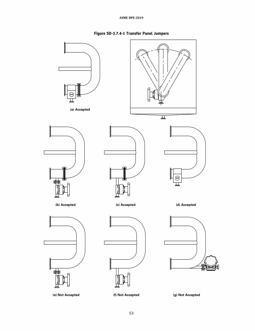
Figure SD-3.7.4-1 Transfer Panel Jumpers
ASME BPE-2019
53

(c) Jumper center-to-center and flatness tolerances areextremely critical to proper panel functionality.Recommended tolerances are per Table DT-7-3 andFigure SD-3.7.2-1.(d) The use of reducing jumpers is not recommended
due to drainability concerns based on jumper orientation.Any reduction in line size should be made behind theprimary nozzle connection (behind panel structure),thus allowing all connections to be the same size onthe front of the panel.(e) The overall panel design should be such that the
quantity of unique jumper centerline dimensions isminimized.(f) The same jumper should be used for process
transfer, CIP, and SIP.(g) If a pressure indicator is installed on a jumper, it
shall be a hygienic design and mounted in a manner thatmaintains drainability in all jumper positions. The L/dshould be 2 or less.
SD-3.7.5 Drain or Drip Pans
(a) Drain pans, if used, shall be built as an integral partof the transfer panel. The intended function is to collectspilled fluids that can occur during jumper or cap removal.(b) Drain pans shall slope [preferred minimum of 1∕4
in./ft (21 mm/m)] to a low point and be piped to theprocess drain. The depth of the drain pan is determinedbycalculating the largest spill volumeandaccommodatingit with a sufficient pan holding volume. Considerationshould be given to increasing the drain port connectionsize in lieu of increasing pan depth. The preferred drainport location is central bottom draining or central backdraining.(c) The elevation of the pan should take into account
the clearance required for the jumper drain valve positionwhen a connection is made to the bottom row of nozzles.The pan should extend horizontally to accommodate thefurthest connectionand/ordrainpoint fromthe faceof thepanel.
SD-3.7.6ð19Þ Proximity Switches
(a) Proximity switches are used to detect the presenceor absence of a jumper with a stem positioned betweenselected nozzles.(b) The use of magnetic proximity switches that are
mounted behind the panel structure to avoid penetrationof thepanel face ispreferred.Thiseliminationof structuralpenetration removes any unnecessary cracks, crevices, orthreads at the point of attachment, effectively mitigatingrisk of process fluid entrapment and/or contaminationconcerns.(c) Jumperswill contain amagnetic stem to activate the
corresponding proximity switch. The use of a ferrousmagnetic material is required; however, it shall befully encapsulated to ensure that the ferrous materialdoes not contaminate the classified manufacturing
area. The acceptance criteria for welds joining thesensor stem to the jumper shall meet the requirementsof Table MJ-8.5-1.(d) The magnet should be of sufficient gauss rating to
properly activate the corresponding proximity switch. Inaddition, the temperature rating of the magnet shouldwithstand the specified temperature ranges for processand SIP without compromising the magnet performance.(e) Theproximity switchmountingshall be structurally
sound tomaintain the specifieddesign location. Theproxi-mity switch shall not interfere with the function, cleaning,or maintenance of the transfer panel to which it ismounted.
SD-3.8 Filters
SD-3.8.1 Code7CartridgeLockDesign.TheASMEBPECode 7 lock is designed to be used with filter cartridgesusing an SAE AS 568-226 double O-ring seal and a two-locking-tab design.
SD-3.8.1.1 Design Features. This design consists ofthe following features:(a) a socket bore that is machined into a base or
cartridge plate into which the filter cartridge O-ringadapter is inserted.(b) a locking tab retainer mechanism that captures the
cartridge locking tabs when the cartridge is inserted intothe socket bore.
(1) Table DT-4.5.1-1 shows a recessed tapered lockretainer design in which the locking tab retainers aremachined into a plate and the machined recessescapture the cartridge locking tabs as the cartridge isrotated into position.
(2) Table DT-4.5.2-1 shows an external tapered lockretainer design in which a set of metal cages captures thecartridge locking tabs as the cartridge is rotated intoposition.(c) the locking tab retainers shall be designed with a
taper to provide a secure lock for the cartridge. Thecartridge tabs shall travel through thenarrowing tab retai-ners until a tight fit is achieved. The taper shall be on theupper portion of the tab retainer. Full capture of cartridgetabs by the locking tab retainers is not required to securecartridges for operation.(d) all surfaces of the cartridge socket shall meet the
required finish for the wetted surfaces as specified by theowner/user.(e) the cartridge O-ring(s) shall be completely
contained within the socket bore.
SD-3.8.1.2 Testing.Thecartridgemanufacturer shallvalidate that its cartridge design fits, seals, and remains inplacewith one of the housing designs shown in Tables DT-4.5.1-1 and DT-4.5.2-1.
ASME BPE-2019
54
SD-3.9 Spray Devices
SD-3.9.1 General. This section covers spray devicesintended for use in bioprocessing equipment, intendedto remain in place or be removed during production.Recommendations in this section are valid for water-based cleaning solutions. The flow rate recommendationsin this section are for metallic vessels.(a) Spray devices distribute rinse and cleaning solu-
tions to interior surfaces of bioprocessing equipmentby direct spray and use sheeting action for remainingtargeted areas. Spray devices are also used in other appli-cations [e.g., water systems to maintain coverage of thestorage tank head space and in clean-out-of-place (COP)cabinet washers].(b) The differential pressure across the spray device
generates liquid velocity exiting through the spraydevice orifices, nozzles, or slots. Differential pressureand its resulting flow are key parameters of spraydevices. Flow is the recommended control parameterbecause it is independent of temperature and locationof the measurement device.(c) The spray pattern, as it exits the device, is deter-
mined by the spray device design. Spray patterns are typi-cally streams/jets or fans.(d) The impactpattern is determinedby the interaction
over time of the spray pattern and the geometry of theequipment.(e) During design, consideration should be given to the
following in the selection of spray device(s):(1) residue characteristics(2) equipment geometry and appurtenances(3) physical location and orientation of spray
device(s)(4) process requirements including air-purge and
steaming, if applicable
(5) cleaning system capacity(6) installation of screen/strainer to protect the
functionality of the spray device(7) cleaning cycle time(8) cleaning chemistry compatibility with materials
of construction(9) potential orifice erosion (e.g., from CIP and SIP)
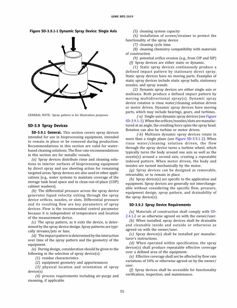
(f) Spray devices are either static or dynamic.(1) Static spray devices continuously produce a
defined impact pattern by stationary direct spray.Static spray devices have no moving parts. Examples ofstatic spray devices include static spray balls, stationarynozzles, and spray wands.
(2) Dynamic spray devices are either single axis ormultiaxis. Both produce a defined impact pattern bymoving multidirectional spray(s). Dynamic spraydevice rotation is rinse water/cleaning solution drivenor motor driven. Dynamic spray devices have movingparts, which may include bearings, gears, and turbines.
(-a) Single-axis dynamic spray devices (see FigureSD-3.9.1-1).When theorifices/nozzles/slots aremanufac-tured at an angle, the resulting force spins the spray head.Rotation can also be turbine or motor driven.
(-b) Multiaxis dynamic spray devices rotate inmore than a single plane (see Figure SD-3.9.1-2). Whenrinse water/cleaning solution driven, the flowthrough the spray device turns a turbine wheel, whichtypically turns the body around one axis as well as thenozzle(s) around a second axis, creating a repeatableindexed pattern. When motor driven, the body andnozzles are turned mechanically by the motor.(g) Spray devices can be designed as removable,
retractable, or to remain in place.(h) Spray device(s) are specific to the application and
equipment. Spray devices are generally not interchange-able without considering the specific flow, pressure,equipment design, spray pattern, and drainability ofthe spray device(s).
SD-3.9.2 Spray Device Requirements
(a) Materials of construction shall comply with SD-2.4.1.2 or as otherwise agreed on with the owner/user.(b) When installed, spray devices shall be drainable
and cleanable inside and outside or otherwise asagreed on with the owner/user.(c) Spray device(s) shall be installed per manufac-
turer’s instructions.(d) When operated within specification, the spray
device(s) shall produce repeatable effective coverageover a defined area of the equipment.(e) Effective coverage shall not be affected by flow rate
variations of 10% or otherwise agreed on by the owner/user.(f) Spray devices shall be accessible for functionality
verification, inspection, and maintenance.
Figure SD-3.9.1-1 Dynamic Spray Device: Single Axis
GENERAL NOTE: Spray pattern is for illustration purposes.
ASME BPE-2019
55

(g) Removable spraydevice(s) shall be capableofbeingre-installed in a repeatable manner by unique identifiersto ensure proper installation location.(h) Spray device selection, orientation, and location
shall be designed to ensure the equipment and thetargeted surfaces of its appurtenances (e.g., manways,dip-tubes, baffles, nozzles, agitator shaft, and impellers)are exposed to rinse water/cleaning solution.(i) Spray device(s) shall be provided with a level of
documentation that is consistent with the equipmentfor which it is to be installed and in accordance withGR-5 documentation requirements.(j) Process contact surface finishes of spray devices
should be consistent with the equipment for which itis installed or otherwise specified by the owner/userand in accordance with the definitions of Part SF.(k) Spraydevices shall notuse lubricantsother than the
process liquid.Dynamicdevices are typically lubricatedbythe rinse/cleaning solution(s).
SD-3.9.2.1 Static Spray Device Requirements
(a) Static spray devices shall have a positioning device(preferred) ormark to allow for proper orientationduringre-installation, as static devices are orientation sensitive(see Figure SD-3.9.2.1-1)(b) Weld-on or self-cleaning slip-joint/clip-on connec-
tions are acceptable. Provision shall be made to ensureproper orientation and location if a slip-joint/clip-on-style static spray device(s) is used.(c) A portion of the flow is directed toward the specific
appurtenances.(d) The flow rate guideline for vertical cylindrical
vessels with dished heads is 2.5 gal/min/ft to 3 gal/min/ft (31 L/min/m to 37 L/min/m) of inner vesselcircumference. Reference Figure SD-3.9.2.1-2. Themajority of the flow is directed toward the upper headto ensure coverage of appurtenances and provide thesheeting action.(e) The flow rate guideline for horizontal cylindrical
vessels with dished heads is 2 gal/min/ft to 3 gal/min/ft (25 L/min/m to 37 L/min/m) of perimeter (2L+ 2d). Reference Figure SD-3.9.2.1-3. The majority ofthe flow is directed toward the upper one-third of the
Figure SD-3.9.1-2 Two-Axis Dynamic Spray Device
GENERAL NOTE: Number of jets is for illustration purposes.
ASME BPE-2019
56

Figure SD-3.9.2.1-1 Static Spray Device
Figure SD-3.9.2.1-2 Flow Rate Guideline for Vertical Cylindrical Vessels
ASME BPE-2019
57

vessel to ensure coverage of appurtenances and providethe sheeting action.(f) Flow requirements for the specific application
should be confirmed with the spray device and/or equip-ment manufacturer or other subject matter experts.
SD-3.9.2.2 Single-Axis Dynamic Spray DeviceRequirements
(a) Rotation and/or frequency verification shall beagreed on with the owner/user.(b) Weld-on or self-cleaning slip-joint/clip-on connec-
tions are acceptable. Other hygienic alternatives shall beagreed on with the owner/user.(c) The flow rate guideline for vertical cylindrical
vessels with dished heads is 1.9 gal/min/ft to 2.3 gal/min/ft (23.6 L/min/m to 28.6 L/min/m) of innervessel circumference. The majority of the flow is directedtoward the upper head to ensure coverage of appurte-nances and provide the sheeting action.(d) The flow rate guideline for horizontal cylindrical
vessels with dished heads is 1.4 gal/min/ft to 2.1 gal/min/ft (17.4 L/min/m to 26.1 L/min/m) of perimeter(2L + 2d). The majority of the flow is directed towardthe upper one-third of the vessel to ensure coverage ofappurtenances and provide the sheeting action.(e) Flow requirements for the specific application
should be confirmed with the spray device and/or equip-ment manufacturer or other subject matter experts.(f) High-velocity gas flow from air-blows or steam
passing through liquid-driven spray devices can resultin wear to bearing surfaces. Consideration should be
taken to restrict gas flow through the spray deviceaccording to the manufacturer’s recommendation.
SD-3.9.2.3 ð19ÞMultiaxis Dynamic Spray DeviceRequirements
(a) Rotation and/or frequency verification shall beagreed on with the owner/user.(b) The time to complete a full impact pattern (see
Figure SD-3.9.2.3-1) at a specified pressure or flowrate shall be provided by the manufacturer.(c) Weld-on or self-cleaning slip-joint/clip-on connec-
tions are acceptable. Other hygienic alternatives shall beagreed upon with the owner/user.(d) The flow rate guideline for vertical cylindrical
vessels with dished heads is 1.3 gal/min/ft to 1.5 gal/min/ft (16.1 L/min/m to 18.6 L/min/m) of innervessel circumference to ensure coverage of appurte-nances and provide the sheeting action.(e) The flow rate guideline for horizontal cylindrical
vessels with dished heads is 0.8 gal/min/ft to 1.2 gal/min/ft (9.9 L/min/m to 14.9 L/min/m) of perimeter(2L + 2d) to ensure coverage of appurtenances andprovide the sheeting action.(f) Flow requirements for the specific application
should be confirmed with the spray device and/or equip-ment manufacturer or other subject matter experts.(g) High-velocity gas flow from air-blows or steam
passing through liquid-driven spray devices can resultin wear to bearing surfaces. Consideration should betaken to restrict gas flow through the spray deviceaccording to the manufacturer’s recommendation.
Figure SD-3.9.2.1-3 Flow Rate Guideline for Horizontal Cylindrical Vessels
ASME BPE-2019
58
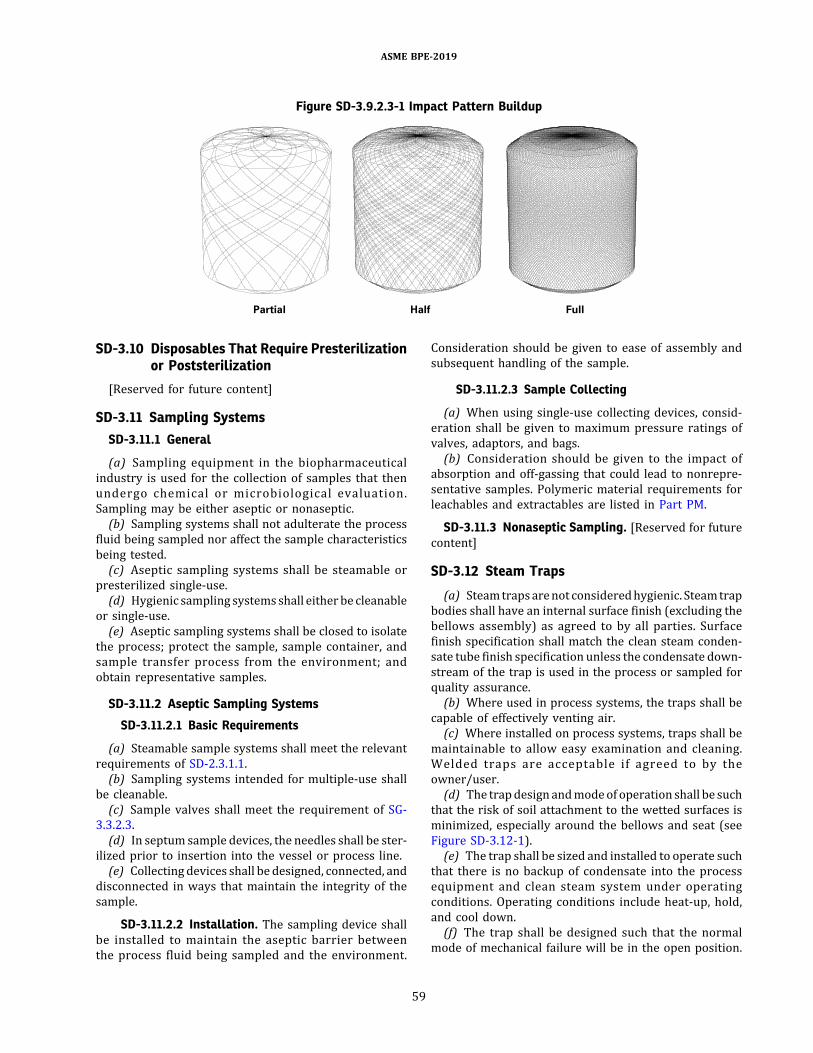
SD-3.10 Disposables That Require Presterilizationor Poststerilization
[Reserved for future content]
SD-3.11 Sampling SystemsSD-3.11.1 General
(a) Sampling equipment in the biopharmaceuticalindustry is used for the collection of samples that thenundergo chemical or microbiological evaluation.Sampling may be either aseptic or nonaseptic.(b) Sampling systems shall not adulterate the process
fluid being sampled nor affect the sample characteristicsbeing tested.(c) Aseptic sampling systems shall be steamable or
presterilized single-use.(d) Hygienic sampling systemsshall eitherbe cleanable
or single-use.(e) Aseptic sampling systems shall be closed to isolate
the process; protect the sample, sample container, andsample transfer process from the environment; andobtain representative samples.
SD-3.11.2 Aseptic Sampling Systems
SD-3.11.2.1 Basic Requirements
(a) Steamable sample systems shall meet the relevantrequirements of SD-2.3.1.1.(b) Sampling systems intended for multiple-use shall
be cleanable.(c) Sample valves shall meet the requirement of SG-
3.3.2.3.(d) In septum sample devices, the needles shall be ster-
ilized prior to insertion into the vessel or process line.(e) Collecting devices shall be designed, connected, and
disconnected in ways that maintain the integrity of thesample.
SD-3.11.2.2 Installation. The sampling device shallbe installed to maintain the aseptic barrier betweenthe process fluid being sampled and the environment.
Consideration should be given to ease of assembly andsubsequent handling of the sample.
SD-3.11.2.3 Sample Collecting
(a) When using single-use collecting devices, consid-eration shall be given to maximum pressure ratings ofvalves, adaptors, and bags.(b) Consideration should be given to the impact of
absorption and off-gassing that could lead to nonrepre-sentative samples. Polymeric material requirements forleachables and extractables are listed in Part PM.
SD-3.11.3 Nonaseptic Sampling. [Reserved for futurecontent]
SD-3.12 Steam Traps
(a) Steamtrapsarenot consideredhygienic. Steamtrapbodies shall have an internal surface finish (excluding thebellows assembly) as agreed to by all parties. Surfacefinish specification shall match the clean steam conden-sate tube finish specification unless the condensate down-stream of the trap is used in the process or sampled forquality assurance.(b) Where used in process systems, the traps shall be
capable of effectively venting air.(c) Where installed on process systems, traps shall be
maintainable to allow easy examination and cleaning.Welded traps are acceptable if agreed to by theowner/user.(d) The trapdesign andmodeof operation shall be such
that the risk of soil attachment to the wetted surfaces isminimized, especially around the bellows and seat (seeFigure SD-3.12-1).(e) The trap shall be sized and installed to operate such
that there is no backup of condensate into the processequipment and clean steam system under operatingconditions. Operating conditions include heat-up, hold,and cool down.(f) The trap shall be designed such that the normal
mode of mechanical failure will be in the open position.
Figure SD-3.9.2.3-1 Impact Pattern Buildup
ASME BPE-2019
59
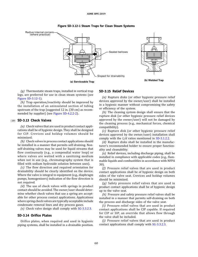
(g) Thermostatic steam traps, installed in vertical traplegs, are preferred for use in clean steam systems (seeFigure SD-3.12-1).(h) Trap operation/reactivity should be improved by
the installation of an uninsulated section of tubingupstream of the trap [suggested 12 in. (30 cm) as recom-mended by supplier] (see Figure SD-4.2.2-2).
SD-3.13ð19Þ Check Valves
(a) Check valves that are used in product contact appli-cations shall be of hygienic design. They shall be designedfor CIP. Crevices and holdup volumes should beminimized.(b) Check valves in process contact applications should
be installed in a manner that permits self-draining. Non-self-draining valves may be used for liquid streams thatflow continuously (e.g., a compendial water loop) orwhere valves are wetted with a sanitizing mediumwhen not in use (e.g., chromatography system that isfilled with sodium hydroxide solution between uses).(c) The flow direction and required orientation for
drainability should be clearly identified on the device.Where the valve is integral to equipment (e.g., diaphragmpumps, homogenizers) indication of the flow direction isnot required.(d) The use of check valves with springs in product
contact should be avoided. The owner/user should deter-mine whether check valves that use a spring are accept-able for other process contact applications. Applicationswhere spring check valves are typically acceptable includecondensate removal lines and dry process gases.(e) Check valve design shall comply with SG-3.3.2.3.
SD-3.14 Orifice Plates
Orifice plates, when required and used in hygienicpiping systems, shall be installed in a drainable position.
SD-3.15 Relief Devices
(a) Rupture disks (or other hygienic pressure reliefdevices approved by the owner/user) shall be installedin a hygienic manner without compromising the safetyor efficiency of the system.(b) The cleaning system design shall ensure that the
rupture disk (or other hygienic pressure relief devicesapproved by the owner/user) will not be damaged bythe cleaning process (e.g., mechanical forces, chemicalcompatibility).(c) Rupture disk (or other hygienic pressure relief
devices approved by the owner/user) installation shallcomply with the L/d ratios mentioned in SD-3.1.2.2.(d) Rupture disks shall be installed in the manufac-
turer’s recommended holder to ensure proper function-ality and cleanability.(e) Relief devices, including discharge piping, shall be
installed in compliance with applicable codes (e.g., flam-mable liquids and combustibles in accordance with NFPA30).(f) Pressure relief valves that are used in product
contact applications shall be of hygienic design on bothsides of the valve seat. Crevices and holdup volumesshould be minimized.(g) Safety pressure relief valves that are used in
product contact applications shall be of hygienic designup to the valve seat.(h) Pressure and safety pressure relief valves shall be
installed in a manner that permits self-draining on boththe process and discharge sides of the valve seat.(i) Pressure relief valves that are used in product
contact applications shall be CIP capable. If requiredfor CIP or SIP, an override that allows flow throughthe valve shall be included.(j) Pressure relief valves that are used in product
contact applications shall comply with SG-3.3.2.3.
Figure SD-3.12-1 Steam Traps for Clean Steam Systems
ASME BPE-2019
60
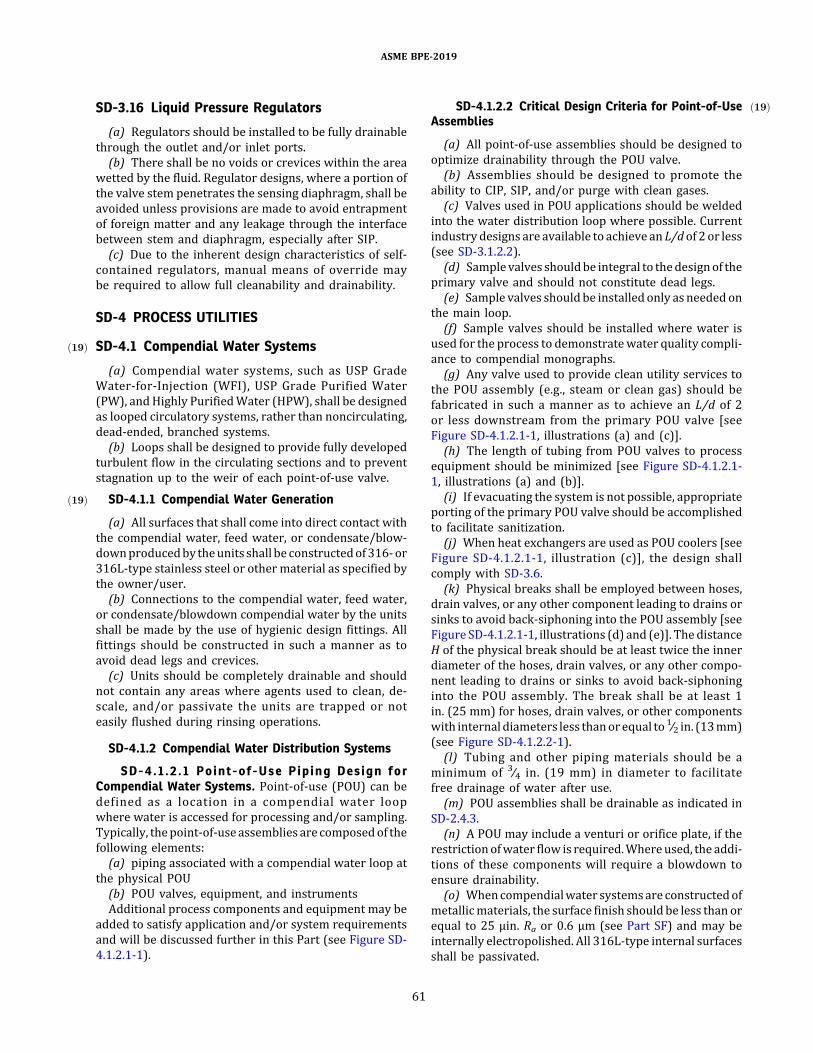
SD-3.16 Liquid Pressure Regulators
(a) Regulators should be installed to be fully drainablethrough the outlet and/or inlet ports.(b) There shall be no voids or crevices within the area
wetted by the fluid. Regulator designs, where a portion ofthe valve stem penetrates the sensing diaphragm, shall beavoided unless provisions are made to avoid entrapmentof foreign matter and any leakage through the interfacebetween stem and diaphragm, especially after SIP.(c) Due to the inherent design characteristics of self-
contained regulators, manual means of override maybe required to allow full cleanability and drainability.
SD-4 PROCESS UTILITIES
SD-4.1ð19Þ Compendial Water Systems
(a) Compendial water systems, such as USP GradeWater-for-Injection (WFI), USP Grade Purified Water(PW), andHighly PurifiedWater (HPW), shall be designedas looped circulatory systems, rather than noncirculating,dead-ended, branched systems.(b) Loops shall be designed to provide fully developed
turbulent flow in the circulating sections and to preventstagnation up to the weir of each point-of-use valve.
SD-4.1.1ð19Þ Compendial Water Generation
(a) All surfaces that shall come into direct contact withthe compendial water, feed water, or condensate/blow-downproducedby theunits shall be constructedof316-or316L-type stainless steel or other material as specified bythe owner/user.(b) Connections to the compendial water, feed water,
or condensate/blowdown compendial water by the unitsshall be made by the use of hygienic design fittings. Allfittings should be constructed in such a manner as toavoid dead legs and crevices.(c) Units should be completely drainable and should
not contain any areas where agents used to clean, de-scale, and/or passivate the units are trapped or noteasily flushed during rinsing operations.
SD-4.1.2 Compendial Water Distribution Systems
SD-4.1.2.1 Point-of-Use Piping Design forCompendial Water Systems. Point-of-use (POU) can bedefined as a location in a compendial water loopwhere water is accessed for processing and/or sampling.Typically, thepoint-of-useassemblies are composedof thefollowing elements:(a) piping associated with a compendial water loop at
the physical POU(b) POU valves, equipment, and instrumentsAdditional process components and equipment may be
added to satisfy application and/or system requirementsand will be discussed further in this Part (see Figure SD-4.1.2.1-1).
SD-4.1.2.2 ð19ÞCritical Design Criteria for Point-of-UseAssemblies
(a) All point-of-use assemblies should be designed tooptimize drainability through the POU valve.(b) Assemblies should be designed to promote the
ability to CIP, SIP, and/or purge with clean gases.(c) Valves used in POU applications should be welded
into the water distribution loop where possible. Currentindustrydesigns are available to achieve anL/dof 2 or less(see SD-3.1.2.2).(d) Samplevalves shouldbe integral to thedesignof the
primary valve and should not constitute dead legs.(e) Sample valves should be installed only asneededon
the main loop.(f) Sample valves should be installed where water is
used for the process to demonstratewater quality compli-ance to compendial monographs.(g) Any valve used to provide clean utility services to
the POU assembly (e.g., steam or clean gas) should befabricated in such a manner as to achieve an L/d of 2or less downstream from the primary POU valve [seeFigure SD-4.1.2.1-1, illustrations (a) and (c)].(h) The length of tubing from POU valves to process
equipment should be minimized [see Figure SD-4.1.2.1-1, illustrations (a) and (b)].(i) If evacuating the system is not possible, appropriate
porting of the primary POU valve should be accomplishedto facilitate sanitization.(j) When heat exchangers are used as POU coolers [see
Figure SD-4.1.2.1-1, illustration (c)], the design shallcomply with SD-3.6.(k) Physical breaks shall be employed between hoses,
drain valves, or any other component leading to drains orsinks to avoid back-siphoning into the POU assembly [seeFigure SD-4.1.2.1-1, illustrations (d) and (e)]. ThedistanceH of the physical break should be at least twice the innerdiameter of the hoses, drain valves, or any other compo-nent leading to drains or sinks to avoid back-siphoninginto the POU assembly. The break shall be at least 1in. (25 mm) for hoses, drain valves, or other componentswith internaldiameters less thanorequal to 1∕2 in. (13mm)(see Figure SD-4.1.2.2-1).(l) Tubing and other piping materials should be a
minimum of 3∕4 in. (19 mm) in diameter to facilitatefree drainage of water after use.(m) POU assemblies shall be drainable as indicated in
SD-2.4.3.(n) A POU may include a venturi or orifice plate, if the
restrictionofwater flow is required.Whereused, the addi-tions of these components will require a blowdown toensure drainability.(o) Whencompendialwater systemsare constructedof
metallicmaterials, the surface finish should be less than orequal to 25 μin. Ra or 0.6 μm (see Part SF) and may beinternally electropolished. All 316L-type internal surfacesshall be passivated.
ASME BPE-2019
61
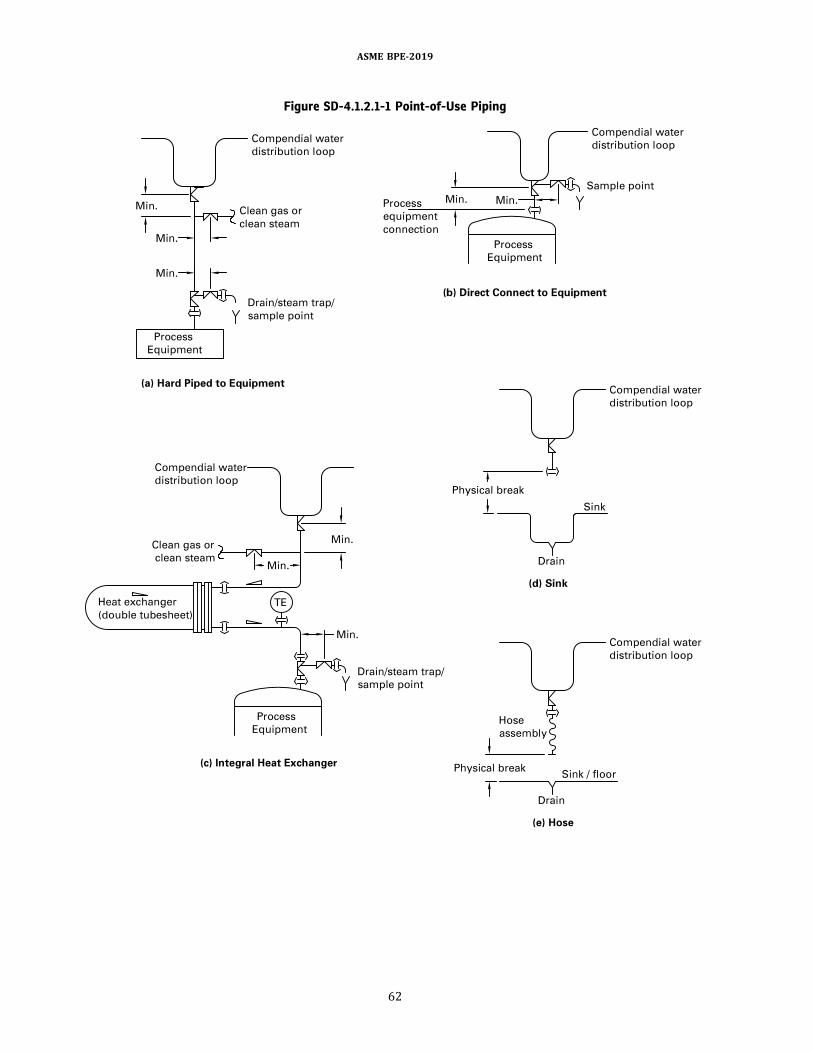
Figure SD-4.1.2.1-1 Point-of-Use Piping
ASME BPE-2019
62
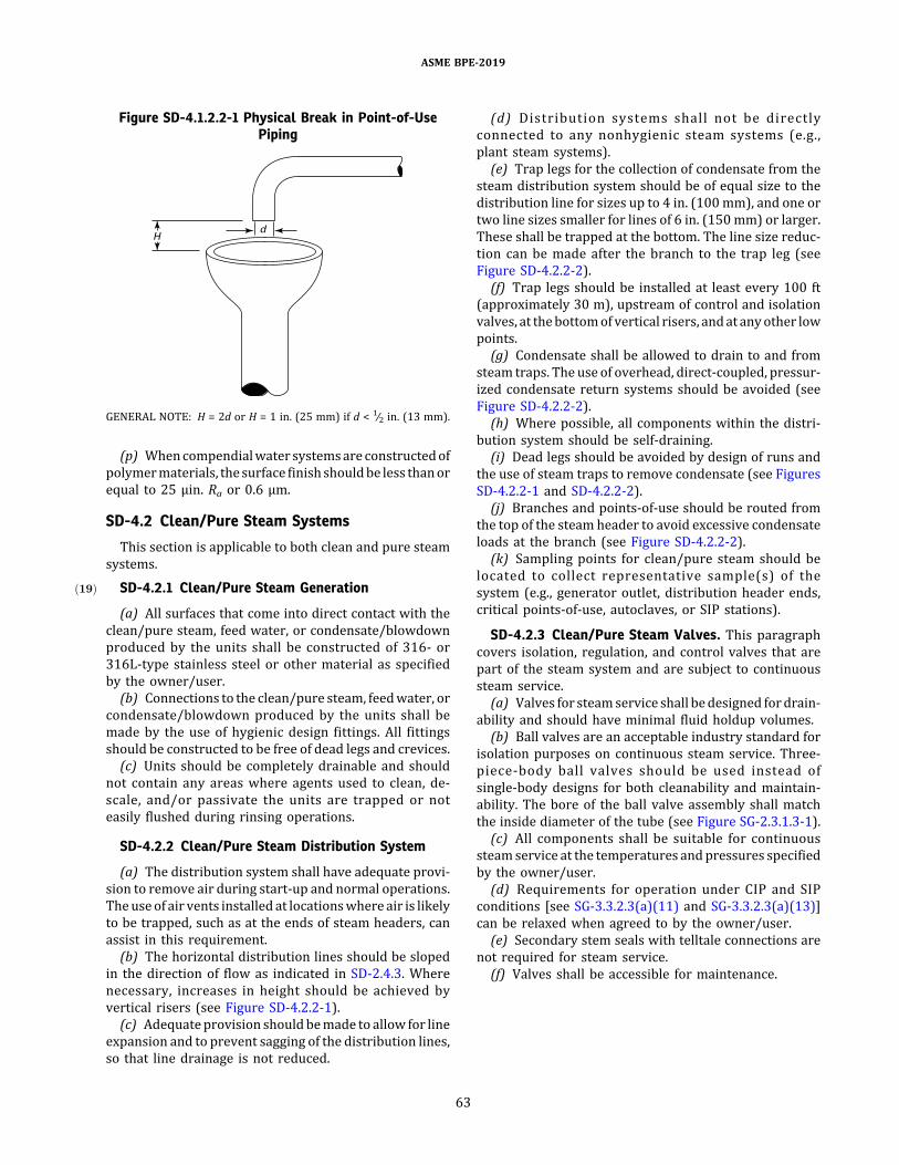
(p) Whencompendialwater systemsare constructedofpolymermaterials, the surface finishshouldbe less thanorequal to 25 μin. Ra or 0.6 μm.
SD-4.2 Clean/Pure Steam Systems
This section is applicable to both clean and pure steamsystems.
SD-4.2.1ð19Þ Clean/Pure Steam Generation
(a) All surfaces that come into direct contact with theclean/pure steam, feed water, or condensate/blowdownproduced by the units shall be constructed of 316- or316L-type stainless steel or other material as specifiedby the owner/user.(b) Connections to the clean/pure steam, feedwater, or
condensate/blowdown produced by the units shall bemade by the use of hygienic design fittings. All fittingsshould be constructed to be free of dead legs and crevices.(c) Units should be completely drainable and should
not contain any areas where agents used to clean, de-scale, and/or passivate the units are trapped or noteasily flushed during rinsing operations.
SD-4.2.2 Clean/Pure Steam Distribution System
(a) The distribution system shall have adequate provi-sion to remove air during start-up and normal operations.Theuseof air vents installed at locationswhere air is likelyto be trapped, such as at the ends of steam headers, canassist in this requirement.(b) The horizontal distribution lines should be sloped
in the direction of flow as indicated in SD-2.4.3. Wherenecessary, increases in height should be achieved byvertical risers (see Figure SD-4.2.2-1).(c) Adequateprovision shouldbemade to allow for line
expansion and to prevent sagging of the distribution lines,so that line drainage is not reduced.
(d) Distribution systems shall not be directlyconnected to any nonhygienic steam systems (e.g.,plant steam systems).(e) Trap legs for the collection of condensate from the
steam distribution system should be of equal size to thedistribution line for sizes up to 4 in. (100mm), and one ortwo line sizes smaller for lines of 6 in. (150mm) or larger.These shall be trapped at the bottom. The line size reduc-tion can be made after the branch to the trap leg (seeFigure SD-4.2.2-2).(f) Trap legs should be installed at least every 100 ft
(approximately 30 m), upstream of control and isolationvalves, at thebottomof vertical risers, andat anyother lowpoints.(g) Condensate shall be allowed to drain to and from
steam traps. The use of overhead, direct-coupled, pressur-ized condensate return systems should be avoided (seeFigure SD-4.2.2-2).(h) Where possible, all components within the distri-
bution system should be self-draining.(i) Dead legs should be avoided by design of runs and
the use of steam traps to remove condensate (see FiguresSD-4.2.2-1 and SD-4.2.2-2).(j) Branches and points-of-use should be routed from
the top of the steam header to avoid excessive condensateloads at the branch (see Figure SD-4.2.2-2).(k) Sampling points for clean/pure steam should be
located to collect representative sample(s) of thesystem (e.g., generator outlet, distribution header ends,critical points-of-use, autoclaves, or SIP stations).
SD-4.2.3 Clean/Pure Steam Valves. This paragraphcovers isolation, regulation, and control valves that arepart of the steam system and are subject to continuoussteam service.(a) Valves for steamservice shall bedesigned fordrain-
ability and should have minimal fluid holdup volumes.(b) Ball valves are an acceptable industry standard for
isolation purposes on continuous steam service. Three-piece-body ball valves should be used instead ofsingle-body designs for both cleanability and maintain-ability. The bore of the ball valve assembly shall matchthe inside diameter of the tube (see Figure SG-2.3.1.3-1).(c) All components shall be suitable for continuous
steamservice at the temperatures andpressures specifiedby the owner/user.(d) Requirements for operation under CIP and SIP
conditions [see SG-3.3.2.3(a)(11) and SG-3.3.2.3(a)(13)]can be relaxed when agreed to by the owner/user.(e) Secondary stem seals with telltale connections are
not required for steam service.(f) Valves shall be accessible for maintenance.
Figure SD-4.1.2.2-1 Physical Break in Point-of-UsePiping
GENERAL NOTE: H = 2d or H = 1 in. (25 mm) if d < 1∕2 in. (13 mm).
ASME BPE-2019
63

Figure SD-4.2.2-1 Typical Clean Steam System Isometric
GENERAL NOTE:Provide steam traps(a) where line transitions from horizontal to vertical (at the bottom of the vertical riser)(b) at least every 100 ft (30 m)(c) at end of each header or branch(d) at thermal expansion loops or transitions(e) where steam is sampled
ASME BPE-2019
64
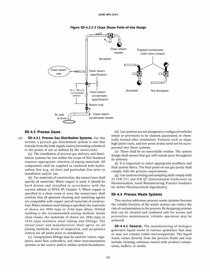
SD-4.3 Process Gases
SD-4.3.1ð19Þ Process Gas Distribution Systems. For thissection, a process gas distribution system is one thatextends from the bulk supply source (including cylinders)to the points of use as defined by the owner/user.(a) The installation of process gas delivery and distri-
bution systems for use within the scope of this Standardrequires appropriate selection of piping materials. Allcomponents shall be supplied or rendered both hydro-carbon free (e.g., oil free) and particulate free prior toinstallation and/or use.(b) Formaterials of construction, the owner/user shall
specify all materials. When copper is used, it should behard drawn and installed in accordance with thecurrent edition of NFPA 99, Chapter 5. When copper isspecified in a clean room or area, the owner/user shallconfirm that all planned cleaning and sanitizing agentsare compatible with copper and all materials of construc-tion.When stainless steel tubing is specified, thematerialsof choice are 304L-type or 316L-type alloys. Orbitalwelding is the recommended joining method. Insideclean rooms, the materials of choice are 304L-type or316L-type stainless steel tubing and fittings. Theowner/user and manufacturer shall agree on alljoining methods, levels of inspection, and acceptancecriteria for all joints prior to installation.(c) Compression fittings may be used for valves, regu-
lators, mass flow controllers, and other instrumentationsystems at the source and/or within system boundaries.
(d) Gassystemsarenotdesignedorconfiguredwith theintent or provisions to be cleaned, passivated, or chem-ically treated after installation. Features such as slope,high-point vents, and low-point drains need not be incor-porated into these systems.(e) There shall be no nonvolatile residue. The system
design shall ensure that gas will remain pure throughoutits delivery.(f) It is important to select appropriate prefilters and
final system filters. The final point-of-use gas purity shallcomply with the process requirements.(g) Gas systems testing and sampling shall complywith
21 CFR 211 and ICH Q7 (International Conference onHarmonization, Good Manufacturing Practice Guidancefor Active Pharmaceutical Ingredients).
SD-4.4 Process Waste Systems
This section addresses process waste systems becausethe reliable function of the waste system can reduce therisk of contamination to theprocess. Bydesigning systemsthat can be cleaned and rendered safe for access andpreventive maintenance, reliable operation may beachieved.
SD-4.4.1 General. The manufacturing of biologicsgenerates liquid waste in various quantities that mayor may not contain viable microorganisms. The liquidwaste comes directly from the process fluids and mayinclude cleaning solutions mixed with product compo-nents, buffers, or media.
Figure SD-4.2.2-2 Clean Steam Point-of-Use Design
ASME BPE-2019
65
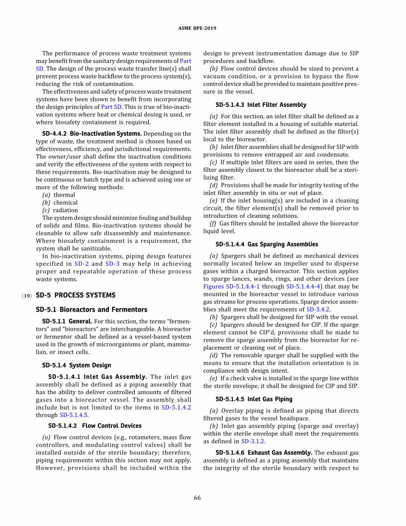
The performance of process waste treatment systemsmaybenefit from the sanitary design requirements of PartSD. The design of the process waste transfer line(s) shallprevent process waste backflow to the process system(s),reducing the risk of contamination.The effectiveness and safety of processwaste treatment
systems have been shown to benefit from incorporatingthe design principles of Part SD. This is true of bio-inacti-vation systems where heat or chemical dosing is used, orwhere biosafety containment is required.
SD-4.4.2 Bio-Inactivation Systems. Depending on thetype of waste, the treatment method is chosen based oneffectiveness, efficiency, and jurisdictional requirements.The owner/user shall define the inactivation conditionsand verify the effectiveness of the system with respect tothese requirements. Bio-inactivation may be designed tobe continuous or batch type and is achieved using one ormore of the following methods:(a) thermal(b) chemical(c) radiationThe systemdesign shouldminimize fouling andbuildup
of solids and films. Bio-inactivation systems should becleanable to allow safe disassembly and maintenance.Where biosafety containment is a requirement, thesystem shall be sanitizable.In bio-inactivation systems, piping design features
specified in SD-2 and SD-3 may help in achievingproper and repeatable operation of these processwaste systems.
SD-5ð19Þ PROCESS SYSTEMS
SD-5.1 Bioreactors and Fermentors
SD-5.1.1 General. For this section, the terms “fermen-tors” and “bioreactors” are interchangeable. A bioreactoror fermentor shall be defined as a vessel-based systemused in the growth of microorganisms or plant, mamma-lian, or insect cells.
SD-5.1.4 System Design
SD-5.1.4.1 Inlet Gas Assembly. The inlet gasassembly shall be defined as a piping assembly thathas the ability to deliver controlled amounts of filteredgases into a bioreactor vessel. The assembly shallinclude but is not limited to the items in SD-5.1.4.2through SD-5.1.4.5.
SD-5.1.4.2 Flow Control Devices
(a) Flow control devices (e.g., rotameters, mass flowcontrollers, and modulating control valves) shall beinstalled outside of the sterile boundary; therefore,piping requirements within this section may not apply.However, provisions shall be included within the
design to prevent instrumentation damage due to SIPprocedures and backflow.(b) Flow control devices should be sized to prevent a
vacuum condition, or a provision to bypass the flowcontrol device shall be provided tomaintain positive pres-sure in the vessel.
SD-5.1.4.3 Inlet Filter Assembly
(a) For this section, an inlet filter shall be defined as afilter element installed in a housing of suitable material.The inlet filter assembly shall be defined as the filter(s)local to the bioreactor.(b) Inlet filter assemblies shall be designed for SIPwith
provisions to remove entrapped air and condensate.(c) If multiple inlet filters are used in series, then the
filter assembly closest to the bioreactor shall be a steri-lizing filter.(d) Provisions shall be made for integrity testing of the
inlet filter assembly in situ or out of place.(e) If the inlet housing(s) are included in a cleaning
circuit, the filter element(s) shall be removed prior tointroduction of cleaning solutions.(f) Gas filters should be installed above the bioreactor
liquid level.
SD-5.1.4.4 Gas Sparging Assemblies
(a) Spargers shall be defined as mechanical devicesnormally located below an impeller used to dispersegases within a charged bioreactor. This section appliesto sparge lances, wands, rings, and other devices (seeFigures SD-5.1.4.4-1 through SD-5.1.4.4-4) that may bemounted in the bioreactor vessel to introduce variousgas streams for process operations. Sparge device assem-blies shall meet the requirements of SD-3.4.2.(b) Spargers shall be designed for SIP with the vessel.(c) Spargers should be designed for CIP. If the sparge
element cannot be CIP’d, provisions shall be made toremove the sparge assembly from the bioreactor for re-placement or cleaning out of place.(d) The removable sparger shall be supplied with the
means to ensure that the installation orientation is incompliance with design intent.(e) If a check valve is installed in the sparge line within
the sterile envelope, it shall be designed for CIP and SIP.
SD-5.1.4.5 Inlet Gas Piping
(a) Overlay piping is defined as piping that directsfiltered gases to the vessel headspace.(b) Inlet gas assembly piping (sparge and overlay)
within the sterile envelope shall meet the requirementsas defined in SD-3.1.2.
SD-5.1.4.6 Exhaust Gas Assembly. The exhaust gasassembly is defined as a piping assembly that maintainsthe integrity of the sterile boundary with respect to
ASME BPE-2019
66
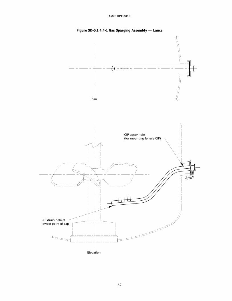
Figure SD-5.1.4.4-1 Gas Sparging Assembly — Lance
ASME BPE-2019
67
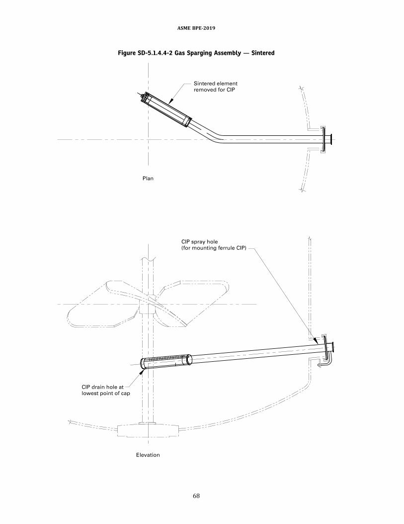
Figure SD-5.1.4.4-2 Gas Sparging Assembly — Sintered
ASME BPE-2019
68
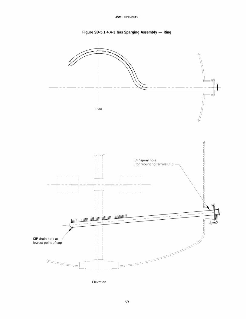
Figure SD-5.1.4.4-3 Gas Sparging Assembly — Ring
ASME BPE-2019
69
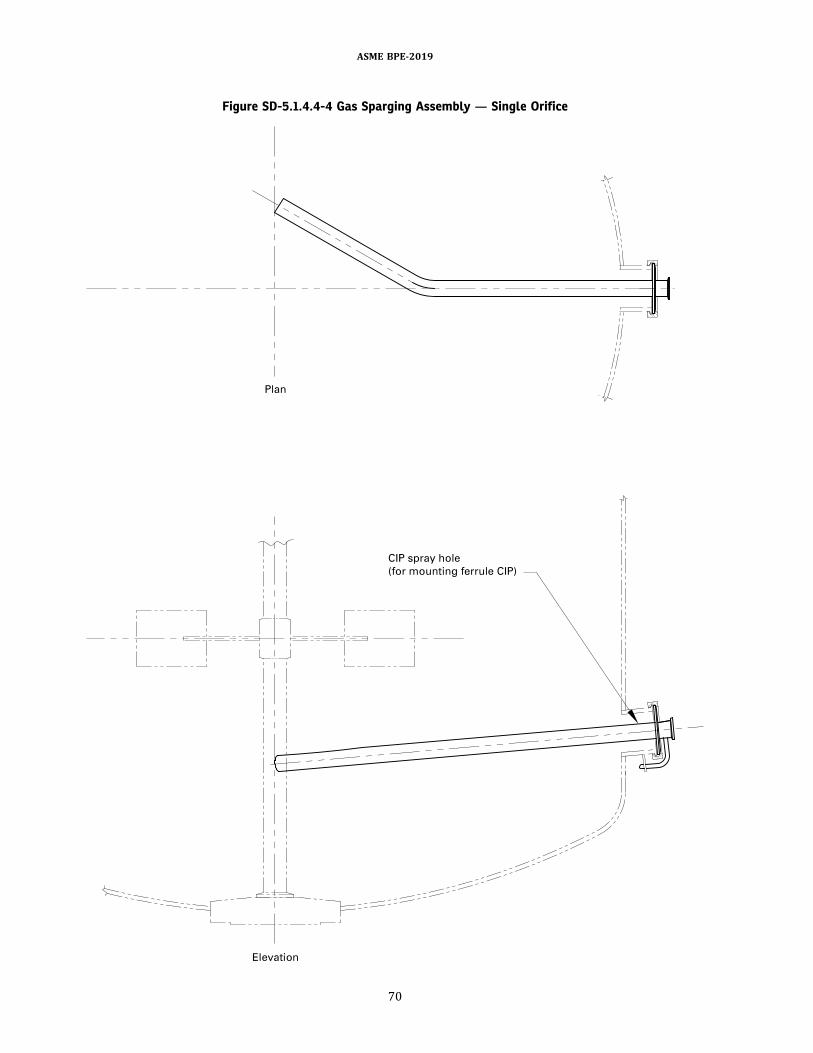
Figure SD-5.1.4.4-4 Gas Sparging Assembly — Single Orifice
ASME BPE-2019
70
sterility and pressure. The assembly shall include but isnot limited to the items in SD-5.1.4.7 through SD-5.1.4.9.
SD-5.1.4.7 Exhaust Filter
(a) For this section, an exhaust filter shall be defined asa filter element (as described in Nonmandatory AppendixT) installed in a housing of suitable material.(b) Exhaust filters shall be designed for SIP. The hous-
ings shall be installed in such a way as to prevent thecollection of condensate in the elements due to SIP.(c) If redundant sterilizing-grade exhaust filters are
used in series, then the filter farthest from the bioreactorshall have a maximum rating of 0.2 μm absolute. In addi-tion, provisions shall be included for draining condensatefrom the piping between the filters.(d) Consideration should bemade for CIP or removal in
the case of cleaning out of place.(e) Provisions shall be made for integrity testing of the
exhaust filter assembly.(f) If the exhaust filter housing(s) are included in a
cleaning circuit, the filter element(s) shall be removedprior to introduction of a cleaning solution(g) To prevent the exhaust filters from becoming
blinded by condensate saturation during operation, theexhaust gas assembly may include exhaust condensers(Figure SD-5.1.4.7-1), exhaust heaters (Figure SD-5.1.4.7-2), or steam jacketed or electrically heat tracedfilter housings (Figure SD-5.1.4.7-3). These items shallbe designed for SIP and CIP.
SD-5.1.4.8 Exhaust Gas Piping
(a) The exhaust gas assembly within the sterileenvelope shall meet the requirements as defined inSD-3.1.2.(b) The design of exhaust gas piping from the bior-
eactor should ensure that there is no condensate accumu-lation in the line downstream of the system.
SD-5.1.4.9 Back Pressure Control Devices
(a) If required, back pressure control devices (e.g.,modulating control valves or regulators) should beinstalled outside of the sterile boundary.(b) Back pressure control devices shall not hinder the
bioreactor’s capability of being SIP’d and CIP’d.(c) If a vapor-liquid separator is used in the exhaust
within the sterile envelope, it shall be designed for CIPand SIP.
SD-5.1.4.10 Feed Lines. This section applies to bior-eactor piping systems used to feed liquid ingredients (e.g.,pH control reagents, antifoam reagents, media, nutrient,
and inoculum). Feed lines shall be designed with theappropriate piping system to allowCIP and SIPof the bior-eactor vessel and the feed line itself. CIP andSIPof the feedline may be done independently or simultaneously withthe bioreactor.
SD-5.1.4.11 Dip Tubes. This section applies to allbioreactor port tube-extensions within the vessel.(a) Bioreactor dip tubes shallmeet the requirements of
SD-3.4.2.(b) Removable dip tubes (see Figure SD-3.4.3-1) shall
be inserted through a hygienic fitting. The removable diptube shall be supplied with the means to ensure that theinstallation orientation is in compliance with designintent.(c) Bioreactor dip tubes shall be designed for CIP or
cleaning out of place (COP).
SD-5.1.4.12 Harvest Valves/Bottom Outlet Valves.This section applies to all valves installed in the vesselbottom head.(a) Harvest valves shall meet the requirements of SG-
3.3.2.3.(b) Bioreactor harvest valves shall be designed for SIP
and CIP or COP.
SD-5.1.4.13 Agitation Assemblies. This sectionapplies to mechanical agitator assemblies mounted inthe bioreactor for achieving one or more mixing-related unit operations (e.g., blending, mass transfer,heat transfer, and solids suspension).(a) Agitators shall meet the requirements of SD-3.5.(b) Agitators with double mechanical seals (see Figure
SG-2.3.2.3-2) or magnetic couplings (Figure SD-3.5.5-2)are recommended to isolate bioreactor contents fromthe environment.(c) Agitator seal or magnetic coupling components
shall be designed for CIP and SIP.
SD-5.1.4.14 Mechanical Foam Breaker Assemblies.This section applies to mechanical foam breaker assem-blies that may be mounted in the bioreactor for reducingor eliminating foamaccumulation in thevapor spaceof thebioreactor.(a) Foam breaker assemblies shall meet the require-
ments of SD-3.5.(b) Foambreakerswith either doublemechanical seals
(Figure SG-2.3.2.3-2) or magnetic couplings (Figure SD-3.5.5-2) are recommended to isolate bioreactor contentsfrom the environment.(c) Foam breaker seal or magnetic coupling compo-
nents shall be designed for CIP and/or SIP as appropriate.
ASME BPE-2019
71

Figure SD-5.1.4.7-1 Exhaust Gas Condenser
Figure SD-5.1.4.7-2 Exhaust Gas Heater
ASME BPE-2019
72

Figure SD-5.1.4.7-3 Electrically Heat Traced FilterHousing
SD-5.1.4.15 Internal Coils
(a) Internal coils should be avoided where possible.(b) Product contact surfaces of internal coils require
provisions for CIP and SIP.
SD-5.1.4.16 Baffles.Baffle assemblies shall meet therequirements of SD-3.4.
SD-5.1.4.17 Spray Devices. This section applies tosprayballs, wands, and other devices (see Figure SD-3.9.2.1-1) that may be mounted in the bioreactorvessel for distributing cleaning solution during CIPoperations.(a) Spray device assemblies shall meet the require-
ments of SD-3.4.2 and SD-3.9.(b) If not removed during processing, spray device
assemblies shall be designed for SIP.
SD-5.1.4.18 Instrumentation
(a) Instruments installedwithin the sterile envelope orboundary shall be designed for SIP. Consideration shouldbe made in the design for instrument removal forcalibration.(b) Instruments installedwithin the sterile envelope or
boundary shall be designed for CIP or removed for COP.(c) Temperature-sensing elements should be installed
in thermowells. Piping associated with in-line thermo-wells shall be sized to allow sufficient steam and conden-sate flow.
SD-5.1.5 Design for Bioburden Control
(a) The area within the bioreactor sterile envelope orboundary shall bedesigned for cleanability andbioburdencontrol. As a minimum, the bioreactor sterile envelope orboundary shall include the following (see Figures SD-5.1.5-1 and SD-5.1.5-2):
(1) vessel internals(2) inlet gas piping from the filter element(s) to the
vessel and any installed isolation valving (If redundantsterilizing-grade filters are used in series, the inletfilter element farthest from the reactor vessel shalldefine the sterile boundary.)
(3) exhaust gas piping from the vessel side of theexhaust filter(s) to the vessel and any installed isolationvalving (If redundant sterilizing-grade filters are used inseries, the exhaust filter farthest from the reactor vesselshall define the sterile boundary.)
(4) agitation assembly including all internal surfacesof the impellers and the shaft up to the mechanical shaftseal in contact with the product
(5) feed systems from the vessel to the seat of theisolation valve nearest to the bioreactor vessel or ifthe feed stream is being filter sterilized, the sterilizing-grade filter element
(6) sampling system(7) product harvesting system from the vessel to the
seat of the isolation valve nearest to the bioreactor vessel(b) A bioreactor is made up of a number of subassem-
blies. Process-contacting subassemblies require specialdesign consideration for cleaning and bioburden control.(c) The bioreactor design for cleanability and sterility
shall take into consideration the biosafety level require-ment for the system. A bioreactor shall be designed inaccordance with a biosafety level requirement asdefined by the National Institutes of Health or equivalentorganization (e.g., BSL-1, BSL-2, BSL-3, or BSL-4). Thebiosafety level requirement should be determinedbased on the organism, the process, the product beingproduced, and/or the owner/user’s preferences. Tomeet a specific biosafety level requirement, special opera-tional considerations (e.g., steam blocks) may have to beaddressedwithin the bioreactors’ subassembly designs. Ifthe bioreactor has been used to grow an organism thatrequires biohazard containment, provision shall be
ASME BPE-2019
73
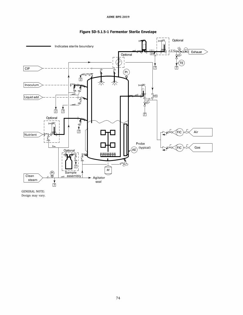
Figure SD-5.1.5-1 Fermentor Sterile Envelope
GENERAL NOTE:Design may vary.
ASME BPE-2019
74

made to decontaminate all surfaces thatmay have come incontact with the product prior to CIP, or to contain anddecontaminate the fluids used for CIP.
SD-5.1.5.1 Drainability
(a) Inlet gas piping within the sterile envelope shallmeet slope requirements as defined for GSD3 in TableSD-2.4.3.1-1.(b) Exhaust gas pipingwithin the sterile envelope shall
meet slope requirements as defined for GSD3 in Table SD-2.4.3.1-1.(c) Allwetted surfaces of spargedevices shall be sloped
to drain by gravity into the vessel.(d) Feed line valves and piping orientation shall be
designed toprovide completedrainageduringCIPandSIP.(e) All wetted surfaces of dip tube(s) shall be sloped to
drain by gravity into the vessel.
(f) Bottomoutlet valves shall bedrainable and installedin such a way as to ensure complete drainage of the bior-eactor contents.(g) Bottom-mounted agitators shall not interfere with
free and complete drainage of bioreactor contents.
SD-5.1.5.2 Cleaning
(a) The area within the sterile envelope should bedesigned for CIP. For components that cannot be CIP’d,the design shall allow removal for replacement ormanual cleaning out of place.(b) If instruments will be cleaned out of place, blind
caps or plugs should be provided tomaintain the integrityof the bioreactor system.(c) If CIP of the ingredient feed system is performed
during active culture operations, then the designshould include provisions to prevent cross-contaminationbetween CIP solutions and product.
Figure SD-5.1.5-2 Bioreactor Sterile Envelope
GENERAL NOTE: Design may vary.
ASME BPE-2019
75
(d) If dip tube(s) are cleaned in place with the vessel,both the inside and outside of the dip tube(s) shall becleaned.(e) Provisions shall be included in the design to clean
theproduct contact surfacesof impellers. Additional sprayelements may be required to achieve coverage.(f) CIP for sparge devices that use porous material for
gas distribution requires particular attention. Thesedevices should be evaluated for CIP cleanability andshould be removed from the bioreactor for externalcleaning and/or replacement when CIP is not feasible.
SD-5.1.5.4 Thermal Sanitization/Sterilization
(a) The area within the sterile envelope should bedesigned for SIP. For those components or assembliesthat cannot be SIP’d, the design shall allow removal forsteamsterilizationusinganautoclave as longas additionalprovisions are provided for sterilizing the interface (e.g.,steam block) once the components or assemblies arereconnected to the remainder of the bioreactor system.Autoclaved components or assemblies shall be capableof being steam sterilized without degradation to any ofthe elastomers or polymers thatmake up the componentsor assemblies.(b) If the bioreactor is sterilized with media in the
vessel, the SIP operation shall direct steam flowthrough the sparge device.(c) If the bioreactor is sterilized with media in the
vessel, and dip tube(s) extends below the workinglevel of the media, the SIP operation shall direct steamflow through the dip tube into the vessel.(d) For dip tube(s), the SIP operation shall direct or
balance steam distribution to establish andmaintain ster-ilization temperature within the tube(s) during the ster-ilization hold period.(e) Special considerations for spray devices are as
follows:(1) The SIP operation shall direct or balance steam
distribution to establish and maintain sterilizationtemperature within the spray device during the steriliza-tion hold period.
(2) With the exception of a combination sparger/spray device, internal spray devices should be locatedabove the bioreactor operating liquid level.
(3) If the bioreactor is sterilized with media in thevessel, and the spraydevice assembly extendsor is locatedbeneath the working level of the media, the SIP operationshall direct steam flow through the device into the vessel.
SD-5.1.7 Testing. The bioreactor vessel should bepressure/vacuum and temperature rated per theowner/user’s design criteria. The vessel shall be con-structed, tested, inspected, and stamped in accordancewith local ordinances, regulations, and codes.
SD-5.2 Cell DisruptersSD-5.2.4 System Design
(a) Product contact material shall not affect productquality or integrity.(b) The design shall incorporate nonshedding compo-
nents and parts.
SD-5.2.5 Design for Bioburden Control
SD-5.2.5.1 Drainability
(a) Thedevice shall bedesignedwith the ability to opti-mize drainability.(b) Safety rupture disks shall be oriented for drain-
ability while maintaining system integrity and safety.
SD-5.2.5.2 Cleaning.Thedisrupter shall bedesignedfor ease of disassembly to allow for COP.
SD-5.3 Centrifuges
SD-5.3.1 General. Centrifugation is a process used toseparate suspended materials of different densities usingcentrifugal force. Centrifugesmay be used for collection ofsolids such as harvest of cells, inclusion bodies of preci-pitated protein, or clarification of bioprocess solutions.Different types of centrifuges include disk stack centri-fuges, tubular bowl centrifuges, single-use centrifuges,and ultracentrifuges.
SD-5.3.2 ProcessParameters.Theowner/user shoulddefine the following process parameters:(a) whether the centrifugewill be used for collection of
solids, for clarification, or for both(b) whether the centrifuge is intended for open, closed,
or briefly exposed operation(s)(c) the biosafety level containment and room classifi-
cation requirements of the process and system(d) product phase (e.g., supernatant or solids)(e) cleaning requirements (e.g., CIP or manual
cleaning)(f) sanitization requirements (e.g., SIP)(g) batch size(h) process liquid feed flow rate(i) solids cell type or particle size and distribution(j) solid concentration [in packed cell volume (PCV)](k) feed pressure(l) process temperature(m) density difference between solvent and suspended
solids(n) viscosity and surface tension of liquid(o) physical properties of solids (e.g., shear sensitivity,
rheology)For each parameter, the user may also define warning
andalarmtolerancesor limits.Additional process require-ments may be defined by the owner/user.
ASME BPE-2019
76
SD-5.3.3 Performance Requirements. The owner/user shall define the following system performancerequirements:(a) maximum allowable processing and cleaning/sani-
tization times(b) desiredpurity (e.g., PCV in supernatant or% solids)For each parameter, the user may also define warning
and alarm tolerances or limits. Additional performancerequirements may be defined by the owner/user.
SD-5.3.4 Disk Stack Centrifuge. In bioprocessing, thedisk stack centrifuge is typically used as a continuous unitoperation to separate cells from cell broth, cell debris oracid precipitates from liquid, or to recover inclusionbodies after homogenization of microbial cells. A diskstack centrifuge consists of a cylindrical bowl containinga stackof conical disks separatedby spacers,which reducethe distance and increase the surface area for particulatesettling when under centrifugal force.
SD-5.3.4.1 Operating Capabilities and SystemFunction. The centrifuge shall be capable of the followingfunctions:
SD-5.3.4.1.1 Cleaning. Centrifuges should bedesigned for CIP. Different parts within the centrifugemay have different cleaning requirements or procedures.Centrifuges thatwill be CIP’d shall be constructed ofmate-rials compatible with the chemistry and conditions of thecleaning process (SD-2.4.1.2). Centrifuges designed forCIP shall comply with SD-2.4.2. Additional requirementsfor disk stack centrifuges subject to CIP include thefollowing:(a) The manufacturer shall ensure that all product
contact surfaces are cleanable with the CIP process.This includes adequate velocity of cleaning solutions inpiping per SD-6.3.5.2. The use of instrument teesconforming with Tables DT-4.1.2-10 and DT-4.1.2-11 isrecommended for instruments. However, all productcontact branches (e.g., instrument tee/ports, processbranches) shall be exposed to cleaning fluids during CIP.(b) The manufacturer should design the equipment to
include sample collection points that allow for represen-tative cleaning verification/validation of all productcontact branches.(c) Spray devices shall conform with SD-3.9.(d) The manufacturer shall recommend CIP solution
supply rate and pressure requirements for effectivecleaning.(e) Due to fluctuations in flow (e.g., bowl discharge),
use of recirculating CIP flow paths may require break-tanks, bypass flows, and pumps that can generatesuction when run dry.(f) The centrifuge manufacturer shall identify all areas
of primary and incidental product contact that requiremanual cleaning in addition to CIP. Centrifuges thatare not designed for CIP shall be capable of disassemblyand reassembly for cleaning and examination.
SD-5.3.4.1.2 Sterilization/Sanitization. Theowner/user shall inform the manufacturer of the sterili-zation/sanitization and storage requirements (e.g.,temperature, pressure, chemistry) and storage condition(e.g., flooded or dry). The owner/user and manufacturershall define the sterile envelope or boundary.Centrifuges thatwill be SIP’d shall be designed in accor-
dancewith SD-2.3.1.1, and, in certain jurisdictions,may beconsideredpressurevessels (seeGR-1). Themanufacturershall demonstrate saturated steam penetration acrosscomponents that define the sterile boundary of thesystem.Centrifuges that will be chemically sanitized shall be
sanitized with an agent and process that have beenproven to achieve the bioburden reduction requirementsof the system.The manufacturer should recommend the operating
conditions (e.g., sanitizing agent supply flow rate, bowlspeed, discharge rate) required to ensure effective chem-ical sanitization.
SD-5.4 Filtration SystemsSD-5.4.4 System Design
(a) All wetted surfaces should be accessible forcleaning and examination.(b) The filter housing shall be designed to allow for
complete ventinganddraining. Liquid tee-type filter hous-ings should be installed vertically, and vent-type in-linefilter housings should be installed vertically with thecondensate/drain port directed downward (see FigureSD-5.4.4-1).(c) All nozzle connections shall be of a hygienic design.(d) Baffle plates, when used, should be cleanable and
designed for SIP.(e) The housing assembly, tube sheets, end plates, and
connections should be designed to prevent bypassing ofprocess fluid around the element.(f) Parts forming internal crevices should be easily
disassembled to enable access for cleaning.(g) Vent filters for hot process services should be heat
traced or steam jacketed. Other methods for preventingmoisture accumulation in vent filters, such as vent heatersor condensers, could be considered.
SD-5.4.4.1 Micro/Ultrafiltration Systems
(a) Skid pumps designed for both process and CIP shallbe designed to provide turbulent flow for cleaning. Allprocess piping systems that include piping, tubing, andfluidic components shall be sloped for adequate drainage.For all low points in the system, a drain port shall beinstalled. A common drain port on the skid is preferred.(b) Piping and equipment holdup volume shall be
minimized.(c) Ultrafiltration cartridge housings shall be designed
with connections and covers that will allow the unit todrain completely.
ASME BPE-2019
77

SD-5.4.5 Design for Bioburden Control. The owner/user is responsible for defining the sanitization require-mentsbasedon the level of bioburden control required forthe unit operation. All components and filter elementsshall be either compatible with the selected sanitizationagents and conditions or capable of being removed orisolated prior to the sanitization process while main-taining a flow path through the system.
SD-5.4.5.2 Cleaning
(a) Filtration systems that are designed for CIP shall bedesigned in accordance with SD-2.4.2 unless otherwiseagreed to by the owner/user and manufacturer.(b) Tangential flow filtration elements may be
designed for repeated use and cleaned along with thesystem. When multiple-use elements are cleaned inplace, system design shall ensure suitable conditions(e.g., flow rates) to properly clean the filtration elements.(c) Direct flow filtration elements are typically not
reused and are not installed during the cleaning process.
SD-5.4.5.3 Chemical Sanitization/Sterilization.Equipment intended to be chemically sanitized shall bedesigned to ensure contact between process contactsurfaces and the sanitization solution.
SD-5.4.5.4 Thermal Sanitization/Sterilization.Temperature, flow direction, and differential pressureof the thermal sanitization or sterilization process shallbe defined by the owner/user. The properties of thefilter elements shall be considered to confirm compat-
ibility of the element with the exposure conditions of athermal sanitization process.
SD-5.5 Chromatography Systems
For this section, the term “system” is intended to coverthe chromatography piping skid, not including the asso-ciated column.
SD-5.5.5 Design for Bioburden Control
SD-5.5.5.2 Cleaning. Chromatography systems shallbe designed for CIP. Systems should be designed in accor-dance with SD-3.1 unless otherwise agreed to by theowner/user and manufacturer.
SD-5.5.5.3 Chemical Sanitization/Sterilization.Chemical sanitization processes are used to reducebioburden. All process contact surfaces of system compo-nents shall either be compatible with the selected saniti-zation agents or be capable of being removed or isolatedprior to the sanitization process.
SD-5.5.5.4 Thermal Sanitization/Sterilization.Chromatography systems may be designed for thermalsanitization. If a system is designed for thermal sanitiza-tion, components shall bedesigned for the specified condi-tions, or shall be removed or isolated prior to thesanitization process. Note that if items are removed forsanitization, they should be sanitized separately and rein-stalled in a controlled environment to avoid contami-nating the system.
Figure SD-5.4.4-1 Tank/Vessel Vent Fillers
ASME BPE-2019
78
SD-5.5.5.5 Post-Use Storage. Chromatographysystemsare typically stored floodedwith a sanitizing solu-tion to maintain bioburden control.
SD-5.6 Lyophilizers/Freeze Dryers
SD-5.6.1 General. For the purpose of this section, theterms “lyophilizer” and “freeze dryer” may be used syno-nymously. This section describes the requirements forcleanability and bioburden control of lyophilizers thatare used for biopharmaceutical processing. Thissection applies to lyophilizers in which product isloaded onto shelves. Other designs that use methodsand components not described in this section shouldbe evaluated and agreed upon by the owner/user. Alyophilizer comprises a number of interconnected compo-nents. Components with process contact surfaces and/orproduct contact surfaces shall be designed for cleanabilityand bioburden control.Lyophilizer surfaces of components, piping, equipment,
or systems that are isolated by design from both productand process fluids are not process contact surfaces norrequired to be designed for cleanability or bioburdencontrol. Examples of surfaces that are not processcontact surfaces include the exterior surfaces of equip-ment, drain lines, vacuum lines, and systems containinghydronic or hydraulic fluids.
SD-5.6.2 Components. A lyophilizer is comprised offunctional components/systems, as shown in Figure5.6.2-1, which are designed for isolation, cleanability,and/or bioburden control. These components/systemshave the potential to affect product quality and includethe following:(a) lyophilizer chamber(b) condenser vessel(c) lyophilizer shelves(d) vacuum systems(e) isolation bellows(f) internal moving parts(g) spray devices(h) gas filter assemblies(i) doors and door seals(j) valves(k) instruments
SD-5.6.2.1 General
(a) All components shall be rated for the applicablepressure, vacuum, temperature range, thermal shock,and exposure to sanitizing agents [e.g., vaporizedhydrogen peroxide (VHP)] when applicable.(b) Process contact surfaces made frommetallic mate-
rial should comply with SD-2.4.1.1 through SD-2.4.1.3.(c) Process contact surfaces made from nonmetallic
material should comply with SD-2.4.1.1, SD-2.4.1.2, SD-2.4.1.4, and Part PM.
SD-5.6.2.2 Lyophilizer Chamber
(a) The interior surfaces of the lyophilizer chamber(chamber vessel) are consideredprocess contact surfaces.(b) The lyophilizer chamber includes all necessary
fittings and closures (e.g., doors, bellows, isolationvalves). The chamber floor shall be self-draining.(c) The surface finishes of the chamber internal
surfaces (i.e., door, walls, ceiling, and floor) shall be speci-fied by the owner/user using the designations in Table SF-2.4.1-1.(d) Where the chamber interfaces with the clean room
or isolator, the surfaces shallmeet theowner/user’s speci-fied requirements.
SD-5.6.2.3 Condenser Vessel
(a) The condenser vessel, used to contain thecondenser heat exchanger, is connected to thechamber vessel and may be separated by a main isolationvalve.(b) All surfaces shall be self-draining.(c) In systems designed with backstreaming preven-
tion (i.e., prevention of reverse flow from the vacuumpumps), the condenser vessel is downstream of thechamber. The condenser vessel surfaces are notprocess contact surfaces and do not have surface finishrequirements.(d) In systems not designed with backstreaming
prevention, the condenser vessel surfaces are processcontact surfaces. The surface finishes of the condenservessel shall be specified by the owner/user using the des-ignations in Table SF-2.4.1-1.
SD-5.6.2.4 Lyophilizer Shelves
(a) The flat surfacesof shelves supporting containersofproduct (e.g., vials containing product) are consideredprocess contact surfaces.(b) The flat surfaces of shelves are considered product
contact surfaces if product without containers is placeddirectly on the shelves.(c) Surfacesof the structural componentsof the shelves
are considered process contact surfaces.(d) The shelf heat transfer performance depends on
shelf flatness. The loading/unloading and initial containerclosure performance require the shelves to be level.Therefore, shelves are not required to be sloped.Methods other than self-draining may be required toremove residual CIP liquid (e.g., collapsible shelvesmay be contracted to remove residual CIP liquid fromshelf surfaces followed by a process that facilitatesdrying, such as SIP followed by a vacuum hold).(e) The surface finishes of shelves shall be specified by
theowner/userusing thedesignations inTableSF-2.4.1-1.A rougher surface may be specified for the bottom side ofthe shelves by the owner/user to meet process require-ments (e.g., stopper adhesion prevention).
ASME BPE-2019
79

Figure SD-5.6.2-1 Typical Lyophilizer Component Assembly
ASME BPE-2019
80

SD-5.6.2.5 Vacuum Systems
(a) The lyophilizer vacuum pumps and condensercooler establish a pressure gradient during lyophilizationfrom the chamber vessel through the condenser vesselresulting in single-direction flow toward the lyophilizervacuum pumps. To maintain an environment appropriatefor aseptic processing in the chamber vessel, the vacuumsystem shall prevent reverse flow (backstreaming).(b) The lyophilizer vacuum pumps are not hygienic
components and should be designed to be outside thesterile boundary.(c) Where vacuum pumps for wet service (e.g., liquid
ring vacuum pumps) are used to evacuate air/vapor fromthe chamber and condenser vessels, they should belocated outside the sterile boundary.
SD-5.6.2.6 Isolation Bellows
(a) Isolation bellows are employed to isolate nonhy-gienic moving components from the lyophilizer sterileboundary.(b) The surfaces of the bellows and its mounting
connections exposed to the inside of the lyophilizerare considered process contact surfaces and should beassessed for cleanability. The bellows shall be extendedduring the cleaning cycle to provide access to all exposedprocess contact surfaces.(c) Thebellows shall be sealed at each end to isolate the
inside of the lyophilizer from external conditions. Bellowsmay be bolted or welded into place. A bellows sealed by abolted flange connection with an O-ring seal within thechamber vessel facilitates replacement and maintenance.The inside of the bellows may be evacuated, vented, orpressurized to facilitate retraction or extension of thebellows. The lyophilizer may be provided with a leak-test system to ensure the bellows are intact.(d) When specified, the bellows shall be suitable for
sterilization and shall allow for full penetration of the ster-ilizing agent at all surfaces inside the sterile boundary.
SD-5.6.2.7 Internal Moving Parts. The followingshould be considered in the design of moving parts(e.g., the raising and lowering of the shelves) withinthe chamber and/or condenser vessels:(a) Nonmetallic material (e.g., PTFE, PEEK, UHMWPE)
may be used for moving parts in order to reduce friction.The selection of the material should consider minimizingparticle generation.(b) Contact surfaces between moving parts shall be
exposed to solutions used for cleaning and bioburdencontrol.(c) A bellows may be used to isolate the chamber and/
or condenser from moving parts that are not of hygienicdesign.
SD-5.6.2.8 Spray Devices
(a) Spray devices are used in lyophilizers to facilitatethe cleaning of surfaces inside the chamber and condenservessels. Spray devices in the condenser vessel may also beused for directing spray at the condenser cooler to facil-itate defrosting of the condenser cooler.(b) Spray devices designed for cleaning should provide
sufficient flow and force to clean flat surfaces (e.g.,shelves) by direct spray. Cleaning the internal surfacesof a lyophilizer by direct spraymay require a supply pres-sure and flow rate that are substantially higher than aretypical for cleaning an empty vessel. The supply pressureand flow rate shouldmeet themanufacturer’s recommen-dation for these spray devices.(c) Both static and dynamic spray devices are accept-
able for use in lyophilizers. The use and application of aparticular spray device design should be agreed uponamong the owner/user, lyophilizer manufacturer, andCIP system integrator. The number of spray devicesmay be reduced if the shelves are allowed to moveduring cleaning. Spraying of shelves should be designedto avoid the interference of spray streams of opposingdirections.(d) The use of threaded connections for spray devices
shall only be used when agreed upon by the owner/user.(e) Spray devices shall meet the provisions of SD-3.9.2.(f) Spray device design, location, and orientation shall
ensure appurtenances (e.g., nozzles, bellows, shelfsupports, and hoses) are exposed to complete spraycoverage.
SD-5.6.2.9 Gas Filter Assemblies
(a) For the purpose of this paragraph, the gas filterassembly is defined as those filters installed for thepurpose of filtering process gases supplied to the lyophi-lizer. The filter assembly includes the filter media, seals,housing, and connected tubing.(b) The last filter in the path of the gas to the lyophilizer
(proximal filter) shall be part of the sterile boundary andbe designed for the chosenmeans of bioburden reduction(e.g., SIP or VHP). This filter shall be a sterilizing-gradefilter. If a redundant sterilizing filter is used, bothfilters shall be included within the sterile boundary.(c) Filter assemblies that are steamed in place shall be
designed to(1) limit the pressure drop across the filter to within
the manufacturer’s specifications in the specified flowdirection
(2) permit temperature monitoring in a locationrepresentative of the coldest location
(3) accommodate the integrity testing of the prox-imal filter, either in situ or out of place(d) If CIP of the gas filter assembly is specified, provi-
sions shall be made in the design for removal of the filterelement(s) prior to the CIP. Filter elements shall be rein-stalled prior to sterilization of the filter assembly.
ASME BPE-2019
81

SD-5.6.2.10 Doors and Door Seals
(a) Lyophilizer doors and door seals shall be designedto withstand vacuum, cleaning, and sterilizationconditions.(b) Lyophilizerdoors shall be accessible, cleanable, and
replaceable and should be capable of undergoing inspec-tion without dismantling.(c) Formultiple-door systems, the doors shall be inter-
locked to allow the opening of only one door at a timeduring normal operation.(d) Doors and locking hardware that interface with the
clean room should not be retracted to uncontrolled space.(e) Both sliding and swing door designs are acceptable.(f) Door seals can be made with either static or infla-
table seals. Static seal grooves that hold the sealmay be oneither the door or the chamber.(g) The seal groove may be set back from the chamber
flange edge to keep the seal in position during vacuumconditions.(h) Compression of a single static seal to achieve a
metal-to-metal contact is preferred to avoid a gapbetween door and chamber vessel.(i) The door static-seal design shall provide access for
manual sanitization as the seal face under compressiondoes not permit penetration of sterilizing agents.(j) A combination (static and inflatable) seal design
with the static seal circumscribing the inflatable sealprovides for penetration of sterilizing agents acrossthe sealing face of the inflatable seal.(k) Door seal lubricants shall not be used in aseptic
processing applications.(l) Refer to Part SG for specifications of seals used in
bioprocessing.
SD-5.6.2.11 Valves
(a) Valve design and selection for service shall followSG-3.3.2.3(a) and Part SD as appropriate. The applicationof a specific valve type for a given service should be agreedon by the manufacturer and owner/user.(b) Hygienic valves shall be used inside the sterile
boundary.(c) Diaphragm valves are acceptable for hygienic fluid
service.(d) Butterfly valves may be used as part of the sterile
boundary when piping/tubing is larger than 2 in. indiameter.(e) Ball valves may be used outside the sterile
boundary to establish positive isolation.(f) Pressure relief devices or rupture disks of hygienic
design may be used as part of the sterile boundary.(g) If the lyophilizer is designed for isolation between
the chamber and condenser, the isolation valve may takethe form of a mushroom valve, butterfly valve, or otherproprietary valve design.
SD-5.6.2.12 Instruments
(a) All instruments within the sterile boundary shouldcomplywith all applicable sections of Part PI, including PI-2.1, PI-2.1.2(c), PI-2.1.2(f), and PI-2.2.2.(b) Instruments in process contact should be of
hygienic design.(c) Instrument probe surfaces and side port penetra-
tions shall be oriented for self-drainage.(d) Instruments installed within the sterile boundary
should be designed for CIP and sterilization. Instrumentsnot designed for CIP should be removed for cleaning andreinstalled for sterilization.(e) Locations with product-sensing instruments (e.g.,
thermocouples and RTDs) and wire lead-throughsshould be considered when designing for cleaning andsterilization.(f) Instrumentation with integral seals or diaphragm
seals is preferred within the sterile boundary. The riskof using instrumentation without integral seals ordiaphragm seals (e.g., Pirani gauges) should be assessedbased on the risk to product quality as determined by theowner/user.
SD-5.6.3 Sterile Boundary. For the purpose of identi-fyingareas that shouldbeexposed tosterilizingagents, thefollowingareaswithin the chamber and condenser vesselsdefine the sterileboundaryas indicated inFigureSD-5.6.3-1:(a) the inside surfaces of the chamber vessel to the
chamber door isolation seal.(b) the inside surface of the condenser vessel to the
condenser door isolation seal.(c) the chamber and condenser drains to the first isola-
tion drain valve.(d) the vacuumpump inlet connection in the condenser
vessel to the first isolation vacuum valve closest to thecondenser vessel.(e) the vacuum break/gas inlet line to the sterile gas
filter. If redundant sterilizing filters in series are used,the sterile boundary ends at the membrane of thefilter farthest from the chamber vessel.(f) the CIP/SIP inlet lines to the first CIP/SIP isolation
valve that is closed during the lyophilization process.(g) the sealing surface on all instruments connected to
the chamber and condenser vessels.(h) thermocouple/RTD seals connected directly to the
chamber and condenser vessels.(i) the exposed surface of the pressure relief valve or
rupture disk.
SD-5.6.4 Internal Connections and Fasteners
(a) Threads sealed by an O-ring or hygienic gasket areacceptable. The use of exposed threads within the lyophi-lizer sterile boundary should be avoided. If othermeans offastening are not practical, the use of exposed threadsmaybe permitted with the agreement of the owner/user. The
ASME BPE-2019
82
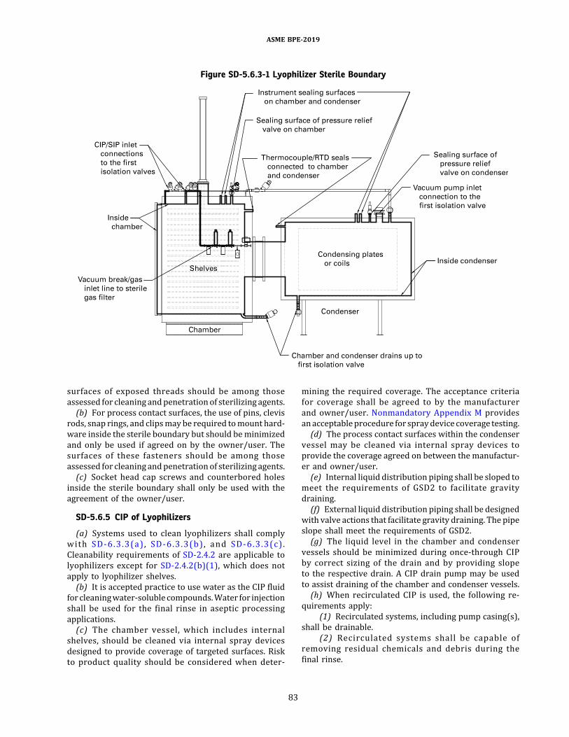
surfaces of exposed threads should be among thoseassessed for cleaning andpenetrationof sterilizing agents.(b) For process contact surfaces, the use of pins, clevis
rods, snap rings, and clipsmaybe required tomount hard-ware inside the sterile boundary but should beminimizedand only be used if agreed on by the owner/user. Thesurfaces of these fasteners should be among thoseassessed for cleaning andpenetrationof sterilizing agents.(c) Socket head cap screws and counterbored holes
inside the sterile boundary shall only be used with theagreement of the owner/user.
SD-5.6.5 CIP of Lyophilizers
(a) Systems used to clean lyophilizers shall complywith SD-6.3.3(a) , SD-6.3.3(b) , and SD-6.3.3(c) .Cleanability requirements of SD-2.4.2 are applicable tolyophilizers except for SD-2.4.2(b)(1), which does notapply to lyophilizer shelves.(b) It is accepted practice to use water as the CIP fluid
for cleaningwater-soluble compounds.Water for injectionshall be used for the final rinse in aseptic processingapplications.(c) The chamber vessel, which includes internal
shelves, should be cleaned via internal spray devicesdesigned to provide coverage of targeted surfaces. Riskto product quality should be considered when deter-
mining the required coverage. The acceptance criteriafor coverage shall be agreed to by the manufacturerand owner/user. Nonmandatory Appendix M providesanacceptableprocedure for spraydevice coverage testing.(d) The process contact surfaces within the condenser
vessel may be cleaned via internal spray devices toprovide the coverage agreed on between the manufactur-er and owner/user.(e) Internal liquid distribution piping shall be sloped to
meet the requirements of GSD2 to facilitate gravitydraining.(f) External liquid distribution piping shall be designed
with valve actions that facilitate gravity draining. The pipeslope shall meet the requirements of GSD2.(g) The liquid level in the chamber and condenser
vessels should be minimized during once-through CIPby correct sizing of the drain and by providing slopeto the respective drain. A CIP drain pump may be usedto assist draining of the chamber and condenser vessels.(h) When recirculated CIP is used, the following re-
quirements apply:(1) Recirculated systems, including pump casing(s),
shall be drainable.(2) Recirculated systems shall be capable of
removing residual chemicals and debris during thefinal rinse.
Figure SD-5.6.3-1 Lyophilizer Sterile Boundary
ASME BPE-2019
83
(i) The chamber and condenser vessels shall be self-drainable.
(1) Process contact surfaces shall be sloped to meetthe requirements of GSD3 for drainage of CIP fluids and toprevent the collection of condensate during the steamingprocesses.
(2) Interior surfaces of nozzles penetrating thevertical walls of the vessel shall be sloped to meet therequirements of GSD3.
(3) The floor of the vessel shall be sloped toward thedrain connection to meet the requirements of GSD3,unless otherwise agreed to by the manufacturer andowner/user.
SD-5.6.6 Bioburden Reduction in Lyophilizers.Lyophilizers designed for bioburden control shouldconsider the following:(a) pressure or vacuum hold testing in preparation for
the bioburden reduction process. Refer to SD-5.6.7.(b) evacuation of air from the chamber and condenser
vessels to reduce the potential for air to be trapped duringthe bioburden reduction process. Effective air evacuationmay be achieved through the use of a liquid ring vacuumpump or similar.
SD-5.6.6.1 Steam-in-Place. When designing lyophi-lizers for steam-in-place(a) steam should enter the lyophilizer at only one point
at a time to minimize the potential to trap air or conden-sate. If steam needs to enter through multiple locationssimultaneously, the design should create flow paths thatavoid air entrapment. The design should ensure thatcondensate will freely flow toward low-point drains.(b) a dual control design may be used to deliver high
steamflowrates that areoften requiredduring theheatingphase and to maintain tight control of temperature andpressure during the exposure phase. For example, oneregulator and/or control valve may be used for theheating phase and a separate regulator and/or controlvalve may be used for tight control during the exposurephase.(c) a vacuum drying phase should be used to eliminate
any condensate remaining within the sterile boundaryfollowing SIP.(d) if cooling and drying are accomplished with the
introduction of a process gas with open drains, a positivepressure differential shall be maintained to preserve thesterile boundary during this operation.(e) temperature monitored throughout the SIP cycle
should include coldest (worst-case) locations. If routinemonitoring of worst-case locations is not practical, thetemperature of locations that have been correlated tothe actualworst-case locationsmay bemonitored instead.(f) to minimize cold locations during SIP, horizontal
penetrations should be sloped to allow condensate todrain.
SD-5.6.6.2 Hydrogen Peroxide Sterilization. Whendesigning lyophilizers for sterilization with hydrogenperoxide gas under vacuum(a) the system should be designed to be dried and have
a surface temperature that meets the supplier’s specifica-tion for the hydrogen peroxide supply system [typically59°F (15°C) and 176°F (80°C)] prior to the start of thesterilization process.(b) the system should be designed to verify that the
residual hydrogen peroxide levels are below the estab-lished thresholds, after the sterilization process hasbeen completed. Threshold levels should be agreed onby the owner/user for both operator’s safety and thepotential impact on the product quality.
SD-5.6.7 Leak Rate
(a) Lyophilizers designed for aseptic lyophilizationprocesses shall be designed to meet leak-rate testingcriteria as agreed to by the owner/user. The sterileboundary should be leak tested before aseptic operationsbegin. The leak rate is calculated as follows:
=Q PVtL
(1)
whereQL = leak rate, mbar-L/sV = the lyophilizer system volume subject to the
vacuum, adjusted toexclude thevolumeoccupiedby internal hardware, L
ΔP = the absolute pressure rise during the test, mbarΔt = the test duration, sec
(b) Leak-rate testing should be performed on a clean,dry, and fully assembled and insulated system with thecondenser cooler in operation to capture residualvapor. Typically, leak rates less than 0.02 mbar-L/s areacceptable for new installations. Leak-rate testing isintended to confirm vacuum integrity of the system.(c) Leak-rate tests are performed at high vacuum
conditions with an absolute pressure typically on theorder of 0.01 mbar.(d) Sufficient stabilization time will avoid misinterpre-
tation of the vacuum leak rate due to virtual leaks. Virtualleaks are identified by a leak rate that stabilizes over time.(e) Individual component assemblies, which are
subjected to vacuum conditions, should be helium leaktested prior to final installation.
SD-5.6.8 Branch Connections
(a) The provisions of SD-3.1.2.2 are applicable toliquid-service process contact piping leading to thelyophilizer.(b) Nozzles within the sterile boundary should be
designed to allow for full exposure to the sterilizing agent.(c) Nozzles and other appurtenances that are cleaned
by liquid spraying should allow complete coverage.
ASME BPE-2019
84

(d) Lyophilizer internals should be designed to avoidlow points where fluid can be trapped.
SD-5.7 Solution Preparation Systems
Solution preparation systems are used for the prepara-tion, storage, and distribution of buffer solutions, mediasolutions, and other reagents used in bioprocessing,formulation, and filling operations. Systems mayinclude components for transfer and mixing of solidsand liquids (e.g., agitators, in-linemixers, vacuum transferequipment, intermediate bulk containers). The systemsmay also include tanks/vessels for solution preparationand for solution storage. Systemsmayalso include compo-nents designed specifically for bioburden reduction orsolution conditioning. Examples of these include filtrationsystems and thermal conditioning systems such as ultra-high-temperature/high-temperature short-time (UHT/HTST) systems.
SD-5.7.1 Operating Capabilities and SystemFunction. The owner/user shall define which processcontact surfaces require cleaning and/or sanitization(e.g., vessel internals, solids transfer equipment, solutiontransfer lines, vent lines) and which cleaning methods(e.g., CIP, COP, water rinses) and/or sanitizationmethods (e.g., chemical sanitization, SIP, hot-waterflush) are to be used. When a solution sterilizing-gradefilter is SIP’d with the system, the sterile envelopeshall include the filtermembrane. Inpractice, this requiresa design that achieves sterilization conditions across thefilter membrane.For systems that require closure, controls to achieve
and maintain a functionally closed system after mixingmay include(a) equipment to achieve required bioburden reduc-
tion in prepared solutions (e.g., sterilizing-grade filters,HTST, sterilization vessels)(b) technologies that prepare equipment for use (e.g.,
CIP, SIP, use of gamma-irradiated single-use components)(c) procedures and designs tomaintain control during
processing and holds after bioburden reduction (e.g.,system closure after sanitization, drying equipment forholds, and hold and processing time limits)
SD-5.7.2 System Design
SD-5.7.2.1 Contamination Control.Measures shouldbe taken to contain powders that are added to mixingtanks and to contain aerosols that may be generatedduring solution preparation to mitigate the risk ofcross-contamination between operations. The owner/user shall assess the risk of cross-contaminationbetween operations. Controls to mitigate the risk ofcross-contamination may include(a) physical separation (e.g., separate rooms, isolators)(b) airflow controls (e.g., dust collection systems, filtra-
tion of circulated air, flow direction)
(c) use of closed-process systems(d) temporal separation(e) procedural separationThe owner/user shall specify requirements for mitiga-
tion of risks from environmental contamination andgrowth of adventitious agents such as bacteria, fungi,and viruses in solutions during processing and hold times.
SD-5.7.3 Design for Bioburden Reduction
SD-5.7.3.1 Filters. Systems used for buffer distribu-tionmay require a filter to reduce bioburdenduring trans-fers to downstream systems, particularly when the bufferis growth-promoting or is transferred to a holding systembefore use.
SD-5.7.3.2 Preparation Tanks. Preparation tanksmay be designed for operations that are brieflyexposed to the room environment (e.g., addition ofreagents through an open port) when appropriatemeasures are exercised for bioburden control andother particulate contamination (e.g., filtration toreduce bioburden after reagents are dissolved).
SD-5.7.3.3 Tanks for Long-Term Storage. Tanksused for long-termstorageof solutions shouldbedesignedto be sterilized unless the intended solution is bactericidalor bacteriostatic.
SD-5.7.3.4 Thermal Sanitization/Sterilization.Systems used for aseptic processing shall have all surfacesthat contact sterile process streams downstream of thebioburden control device capable of being sterilized.This includes interfaces between components that aresterilized separately.
SD-6 ð19ÞPROCESS SUPPORT SYSTEMS
SD-6.1 Cabinet Washers
SD-6.1.1 General. This section describes the require-ments for washers that are designed to clean variousmaterials and components such as glassware, drums,containers, hoses, pallets, and accessories (washableitems) that are not cleaned in place. Requirements inthis section are intended to be applied to cabinetwashers, but may be applied to other types of washersas appropriate.(a) Cabinetwashers shall be fully automatic and should
be capable of multiple cycle types for various load condi-tions.Cabinetwashersmaybedesignedwithan integratedchemical addition system or receive cleaning solutionsfrom a CIP system.(b) Cabinet washers shall include racks or holding
systems designed to enable repeatable exposure of wash-able items to cleaning solutions.(c) The documentation requirements of GR-5 are ap-
plicable to process contact components/instruments ofcabinet washers.
ASME BPE-2019
85

SD-6.1.3 Operating Capabilities and System Function
(a) Cabinet washers shall be capable of deliveringcleaning solutions and of the subsequent rinsing ofcleaning solutions from washed surfaces.(b) Cabinet washers should have the ability to perform
the following general phases during the cycle:(1) prewashing(2) washing(3) rinsing(4) final rinsing(5) drying with heated filtered air(6) cooling with filtered air
SD-6.1.3.1 Rinse Requirements
(a) The final rinse step may be performed using recir-culated water integrated with drain steps or as a single-pass rinse (or series of single-pass rinses) to remove resi-dual cleaning solutions. The final rinse water at the outletof the washer shall meet the owner/user’s acceptancecriteria (e.g., conductivity, total organic carbon, cycletime).(b) The ways of providing a single-pass rinse include(1) direct connection supply from a utility water
system with hygienic safeguards to prevent backflow.If a direct utility connection is used, the design shouldmitigate the effect of variation in supply pressure (e.g.,due todrawbyotherusers) and its impact on the flowrate.
(2) use of a water break-tank. The break-tank shallbe self-drainable and vented. Rinse water from the break-tankshall not contribute to thesoilingorbioburden load inthe cabinet.(c) The hydraulic conditions (i.e., pressure and flow
rate) for the rinsing phases shall be consistent withthose established forwashing phases to ensure consistentrinsing of the washable items, the chamber interior, andthe complete hydraulic circuit.
SD-6.1.4 System Design
(a) Materials of Construction(1) Process contact surfaces shall comply with the
requirements of SD-2.4.1.(2) Allweldedmetallic process contact surfaces shall
be passivated in accordance with SF-2.6.(3) External surfaces of the washer cabinet shall be
fabricated with material that is resistant to cleaning andsanitizing agents as specified by the owner/user.
(4) Process contactpolymericmaterials shall complywith Part SG and Part PM.
(5) Process contact metallic materials shall complywith Part MM.(b) Surface Finish. The surface finishes for the interior
surfaces of the chamber, wetted process contact tubing,and exterior surfaces exposed to cleaning solutions shallbe specified by the owner/user using designationsprovided in Table SF-2.4.1-1. Electropolishing is notrequired unless specified by the owner/user.
SD-6.1.4.1 Wash Chamber
(a) The interior surfacesof the chamber are consideredprocess contact surfaces. These surfaces, which have thepotential to drip onto washed items, shall have completespray coverage (see SD-6.1).(b) The interior of the chamber shall comply with SD-
2.4.2. Internal surfaces that may be difficult to clean (e.g.,wheels, cabling, external surfaces of exposed hygienic-clamp connections) should be minimized and assessedfor the risk to product quality.(c) All internal surfaces shall be sloped for drainability
with a slope agreed on between the owner/user and fabri-cator. Where possible, a slope of not less than 1∕8 in./ft (10mm/m) is recommended.(d) External surfaces should be insulated to minimize
heat transmission and promote cleaning and drying.(e) Breastplates, reinforcing pads, doubler plates,
poison pads, etc., which are required for welding dissim-ilar material to the chamber, should be of the same mate-rial as the chamber.(f) Lubricants shallnotbeusedwhere theymaycome in
contact with cleaning solutions or washable items.
SD-6.1.4.2 Chamber Openings
(a) Nozzles that are designed to be cleaned by a spraydevice should have the smallest L/d ratio practical. Fornon-flow through nozzles, an L/d of less than 2 is recom-mended (see Figure SD-3.4.2-1).(b) Sidewalls and chamber-ceiling nozzles should be
flush with the interior of the chamber (see Figure SD-3.4.2-5).(c) Blank covers shall have the same surface finish as
the chamber internals.(d) Process valves shall meet the requirements of SG-
3.3.2.3.(e) Sample valves shall meet the requirements of SD-
3.11.2.1.(f) Sight glasses on the chamber shallmeet the require-
ments of Figure SD-3.4.6-1. Sight glasses should bedesignedwith the smallest L/d practical and should incor-porate cleanable seal designs.
SD-6.1.4.3 Washer Door and Door Seals
(a) Washer doors and door seals shall be designed toprevent wash fluid leakage during the entire wash cycle.(b) Formultiple-door systems, the doors shall be inter-
locked to allow the opening of only one door at a time forloading and unloading.(c) Both sliding and swing door designs are acceptable.(d) Doors that interface with classified clean rooms
should not be retracted to an uncontrolled space.(e) Construction of the door shall meet SD-2.4.1.(f) The internal surface finish of the door shall be the
same as specified for the chamber internal surfaces.
ASME BPE-2019
86

(g) Solid or inflatable door seals shallmeet the require-ments of SD-2.4.1.1 (e.g., conforming to FDA 21 CFR 177and USP Section <88> Class VI).(h) Refer to Part SG for specifications of seals.
SD-6.1.4.4 Internal Components
(a) Washer cabinet internal components includeloading racksandsupports, thermowells, spraymanifolds,etc.(b) Weld-in thermowells [see Figure SD-3.4.3-2, illus-
trations (e) and (f)] shall have the same finish as thechamber internals.(c) Loading racks/accessories(1) The racks are designed to support the cleaning of
specific washable items. The rack design should be veri-fied to provide complete spray coverage for washableitems defined by the owner/user in an arrangementfor which the loading rack is designed.
(2) Loading racks shall secure the washable itemsduring the wash cycle.
(3) Loading racks may be designed to distributerinse and cleaning solutions to interior and exteriorsurfaces of the washable items.
(4) Loading racks should have a surface finish thatmeets the surface finish requirements of the chamber.Surface finish verification may not be possible for allcomponents of the loading rack.
(5) The loading rack manifold fabrication shallcomply with SD-3.1.2.3.
(6) Loading rack design considerations shouldinclude the disassembly required for inspection andmaintenance.
SD-6.1.4.5 Air Drying, Intake, and Exhaust Systems.Where specified by the owner/user to dry washed items,the following provisions are applicable:(a) The air intake system shall be filtered. A prefilter
and HEPA filter system are recommended to protect thewashed items.(b) The drying system shall provide heated, filtered air
to the chamber, the hydraulic circuit, and in-linecomponents.(c) The filtered air used for drying may be supplied
from a controlled or uncontrolled environment.(d) Temperature and humidity variability of intake air
should be considered in system design.(e) The exhaust ducting should be designed to direct
condensate to a drain.
SD-6.1.4.6 Spray Systems. Design of spray systemsin cabinet washers requires the integration of manifoldedspray devices in the chamber with those installed inloading racks. Spray systems in cabinet washers mayuse both static and dynamic spray devices that complywith SD-3.9.
(a) Loading-rack spray systemsmay have interchange-able spray devices to accommodate a variety of washableitems in a single rack.(b) Translational/reciprocating spray devices in the
cabinet using mechanical devices (e.g., pulleys andPTFE sheathed cables) should be designed for ease ofdisassembly for inspection and maintenance.(c) Mechanical devices used in the chamber shall be
compatible with the process fluids and shall be cleanable.
SD-6.1.4.7 Chemical Addition Systems. Whencleaning solutions are not provided by a CIP system,the following provisions are applicable:(a) A number of chemicals that function as pH adjus-
ters, emulsifying agents, and/or soil removers may beadded during the cabinet washer cycles. The designconsiderations should include positive identification ofeach chemical delivery and connection.(b) Concentrated chemicals may be delivered to the
washer from bulk distribution systems or from localholding containers. The design of concentrated chemicaldelivery and storage systems should consider minimizinghuman contact.(c) Design of concentrated chemical storage and distri-
bution components should consider safety provisionsenumerated in SD-6.3.4(d).(d) The design should include monitoring of adequate
bulk chemical supply (e.g., level) for the entire wash cycle.
SD-6.1.4.8 Recirculation Pumps
(a) The pump shall have sufficient capacity (flow rateand pressure) for all spray configurations used in thewasher.(b) Pumps shall comply with SD-3.3.2.(c) Pump seals shall comply with Part SG.
SD-6.1.4.9 Heat Exchangers
(a) Heat exchangers included in cabinet washers toheat cleaning solutions, rinse water, etc., shall complywith SD-3.6.(b) Heat exchangers using steam or a thermal liquid
may include shell-and-tube, coil, or tube types.(c) Electric heat exchangers may be direct or indirect
immersion type heaters.
SD-6.1.4.10 Instrumentation
(a) All process contact instruments should complywiththe applicable sections of Part PI.(b) The design should enable operators to monitor
process parameters without having to pass throughchanges in room classifications.
SD-6.1.4.11 Interfaces. Where the chamber inter-faces with the clean room, the external surfaces shallmeet the owner/user’s specified requirements.
ASME BPE-2019
87

SD-6.1.5 Design for Bioburden Control
(a) Cabinet washers shall comply with the fabricationrequirements of SD-2.4.1.(b) Tubingwithin the process contact boundary should
be orbital-welded tubingwhere possible and shall complywith Part MJ.(c) All wetted process contact surfaces shall be of
hygienic design per the applicable sections of thisStandard.
SD-6.1.5.1 Branch Connections
(a) The provisions of SD-3.1.2.2 are applicable toliquid-service process contact piping leading to thechamber and delivering cleaning solutions to the spraymanifolds.(b) Liquid-service branch connections with an L/d
greater than 2 shall be provided with low-point drainsthat are opened between each phase of the washingcycle to avoid cross-contamination.
SD-6.1.5.2 Drainability
(a) The chamber drainability should be verified duringfabrication. Verification methods and acceptance criteriafor drainability shall be agreed on in advance by all theparties.(b) Instrument probes and sidewall penetrations (see
Figure SD-3.4.2-2) shall be sloped for drainability, unlessthe instruments used require horizontal mounting (seeFigure SD-3.4.2-3).(c) Loading racks shall be self-drainable.
SD-6.1.5.3 Cleaning
(a) The design should enable multiple chemical addi-tions during the prewashing and washing processes.(b) Cleaning solution temperature shall be controlled
and monitored during washing and rinsing phases.(c) The pressure and flow rates of cleaning solutions
supplied to dynamic and static spray devices within thechamber and/or loading racks should be monitored.(d) If cleaning solutions are recirculated during the
cycle, the recirculation pump shall meet the requirementsof SD-3.3.2.(e) The design should provide final rinse water at an
elevated temperature [e.g., >149°F (65°C)] for sanitizationand improved drying efficiency.(f) The system shall be designed to provide analytical
verification of final rinse water quality (e.g., conductivityand/or total organic carbon).
SD-6.1.6 Design for Serviceability, Examination, andOperation
(a) Cabinet washers should be designed to enableaccess for inspection and service of components thatare subject to wear and to allow periodic calibration ofinstruments.
(b) Mechanical components and instruments thatrequire maintenance may be located in an unclassifiedspace where the maintenance can be performed.(c) The washer design considerations should include
integration with the space where maintenance isper formed (e .g . , min imiz ing mois ture due tocondensation).(d) Pumpsshouldbedesignedandconfigured toenable
access for removal, inspection, and maintenance.
SD-6.1.7 Testing. The test requirements shall bedefined by the owner/user and agreed to by the manu-facturer, andmay include tests beyond those described inthis section. These tests apply to newly installed systemsand tomodifications of existing systems (e.g., the additionof a loading rack to an existing system).
SD-6.1.7.1 Spray Device Coverage Test. Cabinetwashers should be tested to confirm complete spraycoverage of the specified washable items and the interiorprocess contact surfaces of the washer chamber. Thespray device coverage testing described in SD-7.1 is ap-plicable to cabinet washers. The spray device coveragetest procedure described in Nonmandatory AppendixM may be used for cabinet washers with the followingadditional considerations:(a) Testing should include empty configurations (i.e.,
loading rack only).(b) Testing should include racks loaded to capacity.(c) It is acceptable to bypass the drying phase of the
cycle to examine the wet conditions. If parts are drywhen inspected, they should be gently rewetted withambient or cold water to observe any residual riboflavinfluorescence.(d) The sequence in which parts are examined should
be documented to prevent false positive results due totransfer of residual riboflavin from one washable itemto a clean washable item.
SD-6.1.7.2 Drainability Test. The proposed drain-ability test procedure in SD-7.4 for vessels may beapplied to cabinet washers with the following excep-tions/considerations:(a) It is not necessary to fill the chamberwith the outlet
closed. The chamber should be wetted by liquid deliveredthrough the spray system.(b) The chamber drainability test should be performed
without drain pump assistance.
SD-6.1.7.3 Cycle Performance Test. The perfor-mance test should demonstrate the ability to cleanloaded items based on an initial list of washable itemsagreed to by the owner/user and manufacturer. Thetest should verify removal of residue from surfacesand that the final rinse meets the specified waterquality (e.g., an acceptable compendial water require-ment) at the drain within a specified period of time.The test should verify that the process contact surfaces
ASME BPE-2019
88

within the washer are also cleaned to the same specifica-tions used for the washable items.
SD-6.2 Steam Sterilizers/Autoclaves
SD-6.2.1 General. For this section, “autoclaves” and“steam sterilizers” shall be used synonymously. Thissection describes the requirements of autoclaves thatare used in bioprocessing for the steam sterilization ofhard, dry-wrapped, and liquid materials.This sectiondoesnotpertain topasteurizers, ETO(ethy-
lene oxide), VHP (vaporized hydrogen peroxide), or ClO2(chlorine dioxide) type sterilization equipment. Theman-ufacturer shall define the sterile boundary of the system.
SD-6.2.3 Operating Capabilities and SystemFunction. Autoclaves should be capable of multiplecycle types for various load conditions. Autoclavesshall only be used to sterilize the types of goods forwhich they are designed. The most common load typesare specified in SD-6.2.3.1 through SD-6.2.3.3.
SD-6.2.3.1 Hard Goods Cycles. “Hard goods” refersto goods such as metallic instruments, containers, andglassware. Effective removal of noncondensable gasesis required for effective autoclaving of hard goods.Hard goods may be wrapped or unwrapped .Unwrapped goods can often be effectively autoclavedusing either a single vacuum pull or gravity air displace-ment. These goods can sometimes be autoclaved at highertemperatures. Multiple vacuum pulse preconditioning isrequired for wrapped goods to ensure proper evacuationof noncondensable gases from both the autoclavechamber and autoclaved goods. Steam sterilizers usedfor the processing of wrapped or porous goods shallbe able to pull vacuum to levels below 1 psia [69mbar] and maintain the vacuum with a maximum leakrate of 0.1 psi/5 min (6.9 mbar/5 min). Cooling, drying(pulse, vacuum) is an optional cycle step used to drygoods at the end of the autoclave cycle. Heated pulsedrying is also recommended for the drying of porousgoods such as rubber stoppers. Exhaust rates andheating rates should be adjustable for pressure-sensitivematerials.
SD-6.2.3.2 Liquid Cycles. Forced air removalpreconditioning is an optional cycle used to evacuatethe noncondensable gases from the autoclave chamber.Liquid cooling cycles should be provided to efficientlycool the autoclave chamber. Providing the chamberwith overpressure helps prevent the liquid goods fromboiling over during the cooldown phase. Liquids canalso be cooled by slow-rate exhaust. Heating ratesshould be adjustable to help compensate for differencesin heating profiles of items in mixed loads.
SD-6.2.3.3 Air Filter Sterilization. An independentair filter SIP sterilization cycle should be provided forthe in situ sterilizationof the chambervent filters ensuring
supply of sterile air for cooldown phases of autoclaveloads.
SD-6.2.4 System Design. Materials in contact withsteam shall resist corrosion from steam and steamcondensate. The materials shall not affect steamquality and shall not release any substances known tobe toxic or that could adulterate the product. Piping/tubing and fittings shall be pressure and vacuum tight.The piping/tubing layout should be designed to eliminatedead legs within the sterile boundary. Tubing within thesterile boundary should be orbital-welded stainless steeltubing where possible and shall comply with Part MJ(Table MJ-8.4-1) acceptance criteria. All processcontact surfaces within the sterile boundary includingtubing, chamber, and components shall be passivated.The autoclave shall be enclosed with paneling that is
resistant to corrosion and is cleanable.The surface finish within the sterile boundary need not
exceed 35 μin. Ra (0.89 μm). Electropolishing is notrequired for steam sterilization systems.Elastomers shall complywith SG-3.1.1, SG-3.1.2, andSG-
3.3. Elastomers shall be resistant to corrosion and tochemical and thermal degradation. Elastomers used inautoclave applications shall be capable of withstandingpressures of a minimum of 25 psig at 266°F (1.7 bargat 130°C). Seals should meet the testing requirementsspecified in SG-4.2.
SD-6.2.4.1 Chamber. Autoclave chambers are pres-sure vessels and shall be pressure and temperature ratedper the owner/user’s design criteria with a minimumpressure rating of 25 psig at 266°F (1.7 barg at130°C). The chambers shall also be vacuum rated.For systems used in the processing of materials used in
the European market, autoclaves may also be required tocomply with Pressure Equipment Directive (PED) 97/23/EC and/or EN-285.
SD-6.2.4.2 Doors. Autoclave door(s) shall be acces-sible, cleanable, and replaceable, and should be capable ofundergoing inspectionwithout dismantling. The door sealshall be resistant to clean steam and clean steam conden-sate. The door on the nonsterile side shall be capable ofreopening after closing without undergoing a cycle. Thedoor(s) shall not be capable of opening during a steriliza-tion cycle. The doors shall be constructed ofmaterials thatare resistant to clean steam and clean steam condensate.For multiple-door systems, the doors shall be interlockedto allow the opening of only one door at a time. Theunloading (“sterile-side”) door shall remain sealed instandby mode. Refer to Part SG for specifications ofseals used in bioprocessing.
SD-6.2.4.3 Sterile Air/Vent Filters. Where the ster-ilization cycle requires admission of air into the chamber,the air should be filtered with a sterilizing filter (0.22 µmor less). The filter element shall be replaceable. Provisions
ASME BPE-2019
89
for the steam in place of the vent filter elements should beprovided.
SD-6.2.4.4 Steam Traps. Refer to SD-3.12 for re-quirements of steam traps.
SD-6.2.4.5 Loading Carts/Trays. Carts and traysexposed to clean steam shall be constructed of materialsresistant to clean steam and clean steam condensate.Carts, trays, and chamber shall be accessible or removableand cleanable.
SD-6.2.4.6 Valves. Valves and sealing materialslocated within the sterile boundary shall comply withSG-3.3.2.3. Valveswithin the sterile boundary are typicallyonly exposed to clean steam service and chemical(s) usedduring passivation. Exposure to these conditions shouldbe considered when selecting a valve type for thisapplication.
SD-6.2.4.7 Check Valves. Provisions to preventback-siphoning into the service feed systems should beconsidered.
SD-6.2.4.8 Jacket. The jacket shall be constructedusing materials that are resistant to corrosion and degra-dation fromsteamor clean steamandclean steamconden-sate, as applicable.
SD-6.2.4.9 Instrumentation. Autoclave pressureand temperature shall be displayed at all doors. All instru-ments within the sterile boundary should be of hygienicdesign. Instruments shall be capable of being calibratedand replaced. The instrumentation shall include thefollowing:(a) Temperature. Independent temperature elements
(one or two formonitoring and recording and an indepen-dent one for controlling temperature) shall be provided.The chamber temperature recording element should belocated in the chamber drain. Each temperatureelement shall be accurate to ±0.18°F (0.1°C) with asensor response time <5 sec. The element installationshall not affect the maximum leak rate. The temperatureelements shall be temperature and clean steam resistant.(b) Pressure/Vacuum. Pressure/vacuum instruments
shall be provided. The pressure instruments shallmonitor the chamber and jacket pressures. Provisionsfor recording chamber pressure during active autoclavecycles shall be included.(c) Date/Time. Provisions for recording the date and
time during an autoclave cycle shall be included.(d) Recording. Recording may be achieved by paper or
21 CFR Part 11–compliant electronic means.
SD-6.2.4.10 Interfaces
(a) Drain Temperature. Waste to drain temperatureshall comply with owner/user specifications. Theowner/user shall specify discharge temperature require-ments to the manufacturer.
(b) Insulation. External surfaces should be insulated tominimize heat transmission.(c) Biocontainment. Special conditions such as bioseals
may be required for autoclaves used in BSL-3 and BSL-4appl icat ions . P lease refer to the Biosafety inMicrobiological and Medical Labs (BMBL) and Centersfor Disease Control (CDC) guidelines for these specialconditions.
SD-6.3 CIP SystemsSD-6.3.1 General
(a) The following terms are defined for this section:(1) CIP circuit: the sumof pathswithin a process unit
operation that are cleaned aspart of a single CIP cycle (e.g.,bioreactor, buffer hold vessel).
(2) CIP cycle: the executed recipe of rinses, washes,and air blows used to clean soiled equipment.
(3) CIP path: the specific destination contacted withcleaning solution/rinse water during a CIP cycle (e.g.,spray device path, inoculum line path, addition linepath). Multiple paths within a circuit may be cleanedsimultaneously.
(4) clean-in-place (CIP) system: a system used in thepreparation, distribution, delivery, and subsequentremoval of cleaning solutions to soiled equipment.(b) All in-circuit components of the CIP system (e.g.,
filter housings, pumps, vessels, heat exchangers, transferpanels, instrumentation, valving, piping) shall bedesignedto be cleanable, drainable, and of hygienic design appro-priate for use in contact with process fluids per the ap-plicable sections of this Standard.
SD-6.3.2 System Performance Requirements
(a) The following cleaning variables should be consid-ered in the design of the CIP system and CIP cycle:
(1) timeof exposure (contact time) towashand rinsesolutions
(2) temperature of wash and rinse solutions(3) chemical concentration of wash solutions(4) fluid hydraulics
(b) A CIP system should include the capability tocontrol directly or indirectly (monitor and record if ap-plicable) the following CIP variables:
(1) timing of CIP cycle(2) path being cleaned (e.g., valve position indica-
tion, pressure/flow verif ication, manual setupverification)
(3) CIP supply temperature (or return if applicable)(4) conductivity, volume of cleaning chemical added,
or cleaning chemical concentration for wash solutions(5) final rinse conductivity or residual cleaning
chemical concentration(6) CIP supply flow rate(7) totalized flow (if timing not monitored)(8) CIP supply pressure
ASME BPE-2019
90
(9) spray device rotation (if used)(10) interruption or unacceptable decrease in flow
to a path(11) pressureof clean compressedair supply (if used
in air blow)
SD-6.3.3 Operating Capabilities and System Function
(a) The CIP system shall be capable of delivering andsubsequently removing cleaning solutions to soiled equip-ment in a verifiable and reproducible manner.(b) The CIP system shall be capable of removing
process soils to an owner/user-determined acceptancecriteria.(c) The CIP system shall be capable of removing
cleaning chemicals to a verifiable amount characteristicof the final rinse solution.(d) The CIP skid should be designed to deliver feed
water, inject cleaning chemicals, heat, and supply thecleaning solution to the soiled equipment. The skidshall also be designed to remove all residual cleaningchemicals added during the cycle.(e) The CIP distribution system shall be designed to
deliver the cleaning solution to the soiled equipment.The distribution system may also return the solutionto the CIP skid, if applicable.
SD-6.3.4 System Design
(a) A CIP system is a distributed system of properlyintegrated components.(b) For this section, a CIP skid consists of awashand/or
rinse tankwithall requisitevalves, pumps, and instrumen-tation. Provision for separation of feed waters and washsolutions should be considered. CIP skids may be locatedin a fixed, centralized locationormaybeportable andusedadjacent to the soiled equipment.(c) The CIP system design should consider the CIP
circuit volume for water consumption, location of skidin facility (if fixed), chemical consumption, waste effluent,and energy required to clean a given circuit.(d) The design should consider hazardous operation of
cycle considering choice of cleaning chemicals. Chemicalsegregation, spill control, addition handling, materialcompatibility, secondary containment, and personnelsafety should be considered.
SD-6.3.4.1 Wash/Rinse Tank
(a) Thewash/rinse tank(s) shall be designed and fabri-cated per SD-3.4. The tank(s) shall be designed for clean-ability per SD-6.3.5.3 and shall be equipped with a spraydevice(s) per SD-3.9.(b) If used on wash/rinse tanks, a hydrophobic vent
filter shall be designed to prevent moisture accumulationin the vent filters and shall be fabricated per SD-5.4.
SD-6.3.4.2 Heat Exchanger. Heat exchange equip-ment shall be designed and fabricated per SD-3.6.1.
SD-6.3.4.3 Supply Pump
(a) The CIP skid should have flow control, either viapump output or by means of flow control valves.(b) CIP supply pumps shall be designed and fabricated
per SD-3.3.2. The pump design should consider the han-dling of a gas/liquid mixture.
SD-6.3.4.4 Return Pump
(a) CIP return pumps (if required) shall be designedand fabricated per SD-3.3.2. Centrifugal pumps arepreferred for CIP return applications. If a gas/liquidmixture is anticipated, then hygienic liquid ring pumpsare recommended.(b) When a vessel is included in the circuit, CIP return
pumps should be placed as close as possible to the vesselbottom outlet and at the low point of the circuit.(c) Provision shall be made to flush through the casing
drain of CIP return pumps.(d) CIP return pumps shall be designed to maintain
hydraulic balance (supply and return flow) of the CIPcircuit.
SD-6.3.4.5 CIP Return Eductors
(a) For this section, a CIP “return eductor” is defined asadevice that uses amotive fluid to create apressurediffer-ential that returns the CIP solution.(b) Special design factors shall be considered when
using CIP return eductors (e.g., vapor pressure, returnline size).
SD-6.3.4.6 CIP Distribution Piping
(a) General(1) The use and application of a particular distribu-
tion design or combination of designs is to be decided bythe owner/user.
(2) The use of looped headers, transfer panels, andvalve types (e.g., divert, mix-proof, multiport, zero-static,and diaphragm) should all be considered in the design ofthe CIP distribution system.(b) Looped Headers (see Figure SD-6.3.4.6-1)(1) The dimension from the looped header to the
isolation valve weir or seat should conform to SD-3.1.2.2 (see Figure SD-3.1.2.2-1 for details). The use ofshort-outlet tees or zero-static valves should bedecided by the owner/user.
(2) Future connections (if applicable) on the loopedheader should use capped short-outlet tees or cappedinstalled zero-static valves.
(3) Looped header connections should be orientedhorizontally when used in CIP return applications.
(4) CIP supply header design should provide foradequate velocity in parallel cleaning paths (e.g., linesize reduction in loop header).
(5) The entire looped header shall be cleaned duringa CIP cycle.
ASME BPE-2019
91

(c) Transfer Panels. Transfer panels shall be designedand fabricated per SD-3.7.1.(d) Multiport Valves. For this section, a CIP distribution
“multiport valve” is defined as a multiple valve assemblyfabricated as a single body to minimize distances andmaximize drainability [see SG-3.3.2.3(a) for details].(e) Zero-Static Chains (seeFigure SD-6.3.4.6-2). For this
section, a CIP distribution “zero-static chain” is defined asa manifold of circuit-specific zero-static valves. Provisionshall be made to flush the manifold in a zero-static chain.(f) Swing Elbows and Piping Spools (see Figure SD-
6.3.4.6-3). For this section, a “swing elbow” or “pipingspool” is defined as a removable section of pipe usedto provide a positive break between two paths. Swingelbows or piping spools shall be connected to adequatelysupported piping to maintain line slope and connectionalignment.(g) The distribution piping and components in a recir-
culated CIP circuit shall be hygienic for design and fabri-cation as per SD-3.1.2 and SD-2.4.3 .(h) The distribution piping and components in a once-
through CIP circuit or path (not recirculated) shall behygienic for design and fabrication as per SD-3.1.2 andSD-2.4.3 upstreamof the location of cleaning performanceverification.(i) CIP supply piping should be sized to ensure that the
fluid flow meets or exceeds the guidelines stated in SD-6.3.5.2 and SD-6.3.5.3.(j) The distribution circuits shall be designed such that
fluid flow will maintain a positive pressure relative to theprocess drain, preventing backflow.(k) CIP return piping shall be designed to maintain
hydraulic balance (supply and return flow) of the CIPcircuit.
SD-6.3.4.7 Instrumentation. Instrumentation andcontrols architecture (if applicable) should be designedto communicate, monitor, and synchronize the CIPcycle, and report CIP variables.
SD-6.3.5 Design for Bioburden Control
SD-6.3.5.1 Drainability
(a) Processvessels shouldbecleanedvia internal spraydevice(s) designed to consistently expose all internalsurfaces to the cleaning variables described in SD-6.3.(b) CIP return eductors shall be designed and installed
to be drainable.
SD-6.3.5.2 Cleaning: CIP Flow Rate Guidelines forProcess Lines
(a) For effective cleaning, the CIP flow rate shall besufficient to ensure that the cleaning agent and rinsingsolutions wet all targeted surfaces within the CIPboundary. The CIP flow rate should be greater thanthe process flow rate.(b) Table SD-6.3.5.2-1 details flow rates that ensure
solution contact in straight horizontal and verticallines for line sizes up to 2 in. (50 mm) without branches,fittings, and other in-line components. These flow ratescorrespond to a flow velocity of 5 ft/sec (1.5 m/s),which is well into the turbulent range and typical forCIP solutions that are within the scope of this sectionand all line sizes referenced in Part DT.(c) CIP flow rate requirements should be considered in
conjunction with other CIP process variables (e.g.,temperature, chemical concentration, and time).(d) Air trapped in branches may inhibit full contact of
cleaning agent and rinsing solution to those processcontact surfaces. The flow direction, line orientation,
Figure SD-6.3.4.6-1 CIP Looped Header (Supply or Return)
ASME BPE-2019
92
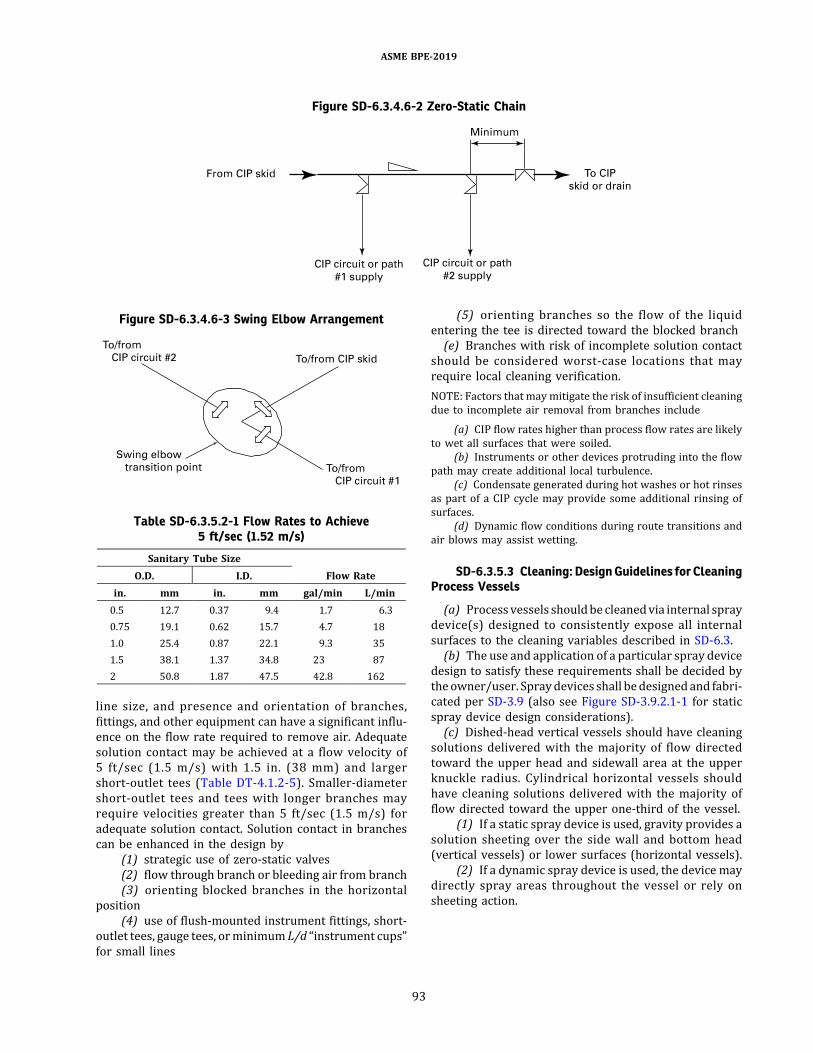
line size, and presence and orientation of branches,fittings, and other equipment can have a significant influ-ence on the flow rate required to remove air. Adequatesolution contact may be achieved at a flow velocity of5 ft/sec (1.5 m/s) with 1.5 in. (38 mm) and largershort-outlet tees (Table DT-4.1.2-5). Smaller-diametershort-outlet tees and tees with longer branches mayrequire velocities greater than 5 ft/sec (1.5 m/s) foradequate solution contact. Solution contact in branchescan be enhanced in the design by
(1) strategic use of zero-static valves(2) flow through branch or bleeding air from branch(3) orienting blocked branches in the horizontal
position(4) use of flush-mounted instrument fittings, short-
outlet tees, gauge tees, orminimum L/d “instrument cups”for small lines
(5) orienting branches so the flow of the liquidentering the tee is directed toward the blocked branch(e) Branches with risk of incomplete solution contact
should be considered worst-case locations that mayrequire local cleaning verification.NOTE: Factors that maymitigate the risk of insufficient cleaningdue to incomplete air removal from branches include
(a) CIP flow rates higher than process flow rates are likelyto wet all surfaces that were soiled.
(b) Instruments or other devices protruding into the flowpath may create additional local turbulence.
(c) Condensate generated during hot washes or hot rinsesas part of a CIP cycle may provide some additional rinsing ofsurfaces.
(d) Dynamic flow conditions during route transitions andair blows may assist wetting.
SD-6.3.5.3 Cleaning: Design Guidelines for CleaningProcess Vessels
(a) Processvessels shouldbe cleanedvia internal spraydevice(s) designed to consistently expose all internalsurfaces to the cleaning variables described in SD-6.3.(b) The use and application of a particular spray device
design to satisfy these requirements shall be decided bytheowner/user. Spraydevices shall bedesignedand fabri-cated per SD-3.9 (also see Figure SD-3.9.2.1-1 for staticspray device design considerations).(c) Dished-head vertical vessels should have cleaning
solutions delivered with the majority of flow directedtoward the upper head and sidewall area at the upperknuckle radius. Cylindrical horizontal vessels shouldhave cleaning solutions delivered with the majority offlow directed toward the upper one-third of the vessel.
(1) If a static spray device is used, gravity provides asolution sheeting over the side wall and bottom head(vertical vessels) or lower surfaces (horizontal vessels).
(2) If a dynamic spray device is used, the device maydirectly spray areas throughout the vessel or rely onsheeting action.
Figure SD-6.3.4.6-2 Zero-Static Chain
Figure SD-6.3.4.6-3 Swing Elbow Arrangement
Table SD-6.3.5.2-1 Flow Rates to Achieve5 ft/sec (1.52 m/s)
Sanitary Tube SizeFlow RateO.D. I.D.
in. mm in. mm gal/min L/min0.5 12.7 0.37 9.4 1.7 6.30.75 19.1 0.62 15.7 4.7 181.0 25.4 0.87 22.1 9.3 351.5 38.1 1.37 34.8 23 872 50.8 1.87 47.5 42.8 162
ASME BPE-2019
93
(3) Figure SD-3.9.2.1-2 details ranges of flow recom-mendations for static spray devices on vertical processvessels under typical cleaning loads. The recommenda-tions in Figure SD-3.9.2.1-2 ensure sufficient coverage.
(4) Thecriteria toensure sufficient coverageonhori-zontal process vessels vary with geometry and size.(d) Spray device design and location shall ensure
appurtenances such as manways, baffles, dip tubes,agitator impellers, and nozzles are contacted withcleaning solution. Some appurtenances may require addi-tional provisions for cleaning.(e) Spray devices only ensure coverage of the exterior
of installed appurtenances and equipment. If not removedduring CIP, cleaning solutions shall flow through appur-tenances to clean their interior.(f) The fluid level should be minimized in the process
vessel during CIP. Proper hydraulic balance (supply andreturn flow) of the CIP circuit and sizing of the bottomoutlet valve should be considered to minimize fluid level.(g) Vortex formation during CIP may adversely affect
the operation. The installation of a vortex breaker may berequired.(h) Vortex breaker design should be decided by the
owner/user. Vortex breaker surfaces shall be sloped toeliminate pooling during CIP and positioned to notadversely affect the hydraulic balance of the CIP circuit.(i) For process vessels equipped with an agitator, the
impeller should be rotated at an appropriate speed duringthe CIP cycle.
SD-6.3.6 Design for Serviceability, Examination, andOperation. CIP return eductors shall be designed to beremovable for examination.
SD-6.3.7 Testing. During the cleaning of processvessels, sufficient exposure shall be confirmed bycoverage testingper SD-7.1 at the site of equipmentmanu-facture and/or installation.
SD-6.4 Thermal Treatment SystemsSD-6.4.1 General
SD-6.4.1.1 Terminology. The following terms areused in this section:average residence time: the volume of the retention tubedivided by the volumetric flow rate. (Average residencetime should always be greater than the required residencetime.)coil heat exchanger: a coiled tube for process liquid flow,inside a shell or a second tube containing heating/coolingmedium.cooling equipment: heat exchangers and/or a flash coolerused to cool the process liquid after the retention tube.energy recovery heat exchange system:optional equipmentthat takes heat from the discharge of the retention tubeand uses it to preheat the incoming process liquid. These
systems may have process fluid on both sides of a heatexchanger.heating equipment: heat exchangers and/or direct steaminjectionequipment.Direct steam injection refers touseofa steam injector valve (typical) or a steam infusionchamber.high-temperature short time (HTST): processing at acombination of temperature and required residencetime that is designed to achieve a desired level ofbioburden reduction or viral inactivation. Treatmentconditions (i.e., exposure temperatures and residencetimes) for HTST systems range broadly, depending onthe performance goal of the system.required residence time: the minimum exposure timerequired at the specified temperature to achievedesired results.retention tube: a section of tubing used in HTST/UHTsystems to retain the process liquid (typically anaqueous solution) at an elevated temperature for a speci-fied time.ultra-high temperature (UHT):processingat temperaturesabove 275°F (135°C) with rapid heating and cooling andshort exposure times to achieve what is generallyaccepted as a sterile condition.
Thermal treatment system example configurations areshown in Figures SD-6.4.1.1-1 and SD-6.4.1.1-2.
SD-6.4.1.2 Scope and Purpose. This sectionaddresses thermal treatment systems used in bioproces-sing to reduce or eliminate viable microorganisms andviruses in a liquid under continuous flow conditionswhile minimizing degradation of the product or aproduct intermediate. Thermal systems may be designedto achieve goals that do not require sterilization of theprocess liquid, such as inactivation of viruses or a parti-cular bacterial species. Bio-inactivation (waste treatment)systems (SD-4.4.2) and food pasteurization systems arenot addressed in the scope of this section.
SD-6.4.2 System Performance Requirements. Thefollowing system performance capabilities shall bedefined:(a) treatment temperature range(b) required residence time at treatment temperature(c) process liquid flow rate(d) discharge temperature range(e) maximum heating surface temperature, heat
transfer fluid temperature, or process liquid heatingrate (°F/sec, °C/s)Additional performance requirements may be defined
by the owner/user. Additional process parametersrequired to confirm system capabilities, including speci-fying the process fluid’s incoming temperature and otherproperties, should be provided by the owner/user.
ASME BPE-2019
94

Figure SD-6.4.1.1-1 Example of HTST Process Flow Schematic Diagram
GENERAL NOTES:(a) Only major piping and instruments are shown.(b) Additional or alternative piping, valves, instruments, and equipment may be required for the following purposes, including:(1) pressure safety(2) media prefiltration with differential pressure monitoring(3) CIP requirements(4) SIP or hot water sanitization requirements(5) alternative skid startup sanitization methods(6) single-pass media startup sanitization methods(7) low-pressure condensate return(8) maintenance and calibration requirements(9) energy recovery
ASME BPE-2019
95

SD-6.4.3 OperatingCapabilitiesandSystemFunction
SD-6.4.3.1 Priming. The system shall be capable of apriming operation to fill the pipingwith liquid, remove air,and establish pressure and flow control. The thermaltreatment system should be primed by the processliquid to be treated or a priming liquid (e.g., WFI), or both.
SD-6.4.3.2 Thermal Sanitization. The owner/usershall define the sanitization condition (e.g., time andtemperature) capabilities required for the system. UHTsystems shall be designed to enable sanitization. HTSTsystems shall be designed to enable sanitization whenthe treated process liquid has the potential to be compro-mised by the priming activities. For a functionally closedsystem, the owner/user shall define which components(e.g., the receiving vessel, cooling exchanger, flashchamber) must be thermally sanitized to meet the func-tional closure criteria.
SD-6.4.3.3 Temperature Stabilization. Thermaltreatment systems shall be designed to stabilize thetemperature of the liquid before initiating forwardflow to the destination. Heating, cooling, flow rate, andback pressure control loops shall be enabled andallowed to stabilize prior to heat treatment.If the system uses a priming liquid, such as WFI, the
system shall be designed to stabilize the temperatureusing the priming liquid and then transition to andmeet the performance requirements using the processliquid. Stabilization using the process liquid shouldcontinue until all the priming liquid has been clearedfrom the system, at which point the system shall initiateforward flow of the heat-treated process liquid to thedestination.
SD-6.4.3.4 Heat Treatment. The system shall bedesigned to deliver heat-treated process liquid to thedestination only if the performance requirements aremet. If they are not met, the system shall divert the
Figure SD-6.4.1.1-2 Example of Direct Steam Injection UHT Process Flow Schematic Diagram
GENERAL NOTES:(a) Only major piping and instruments are shown.(b) Additional or alternative piping, valves, instruments, and equipment may be required for the following purposes, including:(1) pressure safety(2) media prefiltration with differential pressure monitoring(3) CIP requirements(4) SIP or hot water sanitization requirements(5) alternative skid startup sanitization methods(6) single-pass media startup sanitization methods(7) low-pressure condensate return(8) maintenance and calibration requirements(9) energy recovery
ASME BPE-2019
96
liquid to another destination (typically to a drain or acollection vessel). If the heat treatment conditions arenot maintained, the owner/user shall specify whetherthe system resanitizes itself, continues diverting untilthe temperature and flow requirements are reestablishedwithout resanitization, or performs a shutdown sequence.The system shall be designed to continue heat treat-
ment until the desired amount of liquid is treated. Theowner/user shall specifywhether the system flushes resi-dual treated process liquid forward using heat-treatedpriming liquid to maximize recovery at the conclusionof the process batch.
SD-6.4.3.5 Post-Use Sequence. The owner/usershall specify whether the system shall be designed toperform a cold flush of the HTST or UHT equipmentprior to cleaning to minimize soil buildup at the end ofprocessing. The post-use sequence should finish bydraining the system or promptly initiating the CIPsequence.
SD-6.4.4 System Design
(a) The following parameters shall be monitored andcontrolled by the system:
(1) heater outlet temperature(2) cooler outlet temperature(3) flow rate(4) back pressure
(b) The following parameter shall be monitored by thesystem: retention tube outlet temperature.(c) The owner/user shall specify whether the system
shall be primed using compendial water (from a break-tank or from a backflow-protected direct water systemconnection) or sanitized and primed using the processliquid.(d) The following should be considered in selection of
materials used in fabrication of HTST/UHT systems:(1) Cyclic temperature and pressure conditions may
shorten the life of materials.(2) Solutions at high temperaturemay accelerate the
rate of metal corrosion or elastomer/polymerdegradation.
(3) High-temperature operating conditions used inUHT systems may exceed the temperature ratings oftypical bioprocessing equipment or components.(e) Although UHT processing conditions are above the
temperature limit specified in SD-2.3.1.1, process contactmaterials used for these systems shall be selected tomeetthe higher temperature requirements of the process.
SD-6.4.4.1 Heat Exchangers. Heat exchangers shallbe designed tomeet the performance requirements in SD-6.4.2 and the applicable design criteria of SD-3.6. Heatexchangers shall be designed to achieve fully developedturbulent flow conditions during process and CIP opera-tions, on the process liquid contacting side(s) of theexchanger. Heat exchangers should be designed and oper-
ated such that the pressure of the treated process liquid ishigher than thepressureof theutility oruntreatedprocessliquid during heat treatment to reduce the risk of processliquid contamination, unless the owner/user has assessedthe risk of an alternate design. The owner/user shouldidentify any requirements needed to minimize processfouling or enhance cleaning performance (e.g. ,minimum Reynolds number or velocity and/ormaximum process contact surface temperature).Direct energy recovery heat exchangers with process
fluids on both hot and cold sides (Figure SD-6.4.1.1-1)shall be of hygienic design on both sides. Indirectenergy recovery heat exchangers (Figure SD-6.4.1.1-2)shall be of hygienic design on the process fluid side.The following types of heat exchangers may be used in
thermal treatment systems:(a) Shell andTube. Shell-and-tubeheat exchangersmay
be straight tubeorU-tube. Theeffect of bypass through thebonnet drain slots and slippage between the bonnet andtube sheet shall be considered in thermal design of theheat exchanger.(b) Coil-in-Shell. Coil-in-shell heat exchangers shall be
installed in a self-drainable vertical orientation.(c) Electric. Electric heat exchangers shall be designed
to provide uniform heating (e.g., where electric current isapplied directly to the process contact tube).(d) Tube-in-Tube. Process liquid should flow through
the inner tube. Process fluid may also flow through theouter tube in direct energy recovery heat exchangers.(e) Plate-and-Frame. See cautions in SD-3.6 regarding
use of plate-and-frame heat exchangers before consid-ering use in this application.
SD-6.4.4.2 Steam Injectors
(a) Steam injectors shall introduce steam (typicallypure steam) directly into process liquids.(b) Steam injectors shall be installed such that single-
phase flow is achievedat thedesiredoutlet temperature. Asight glass installed downstream of the steam injector isrecommended to confirm single-phase flow.(c) Steam injectors shall be oriented to permit CIP, or
designed for disassembly and cleaning out of place (COP),with agreement from the owner/user. Where the steaminjection system is designed for CIP, it shall be drainableand exposed to CIP solution across the seat of the steaminjection valve.(d) Media dilution and changes in retention time due to
condensate addition shall be accounted for in the systemdesign.
SD-6.4.4.3 Flash Chambers. [Reserved for futurecontent]
SD-6.4.4.4 Pumps. Process contact pumps used inHTST/UHT systems shall be hygienic and shall complywith SD-3.3.
ASME BPE-2019
97
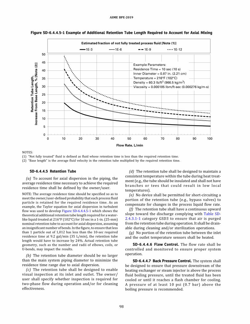
SD-6.4.4.5 Retention Tube
(a) To account for axial dispersion in the piping, theaverage residence time necessary to achieve the requiredresidence time shall be defined by the owner/user.NOTE: The average residence time should be specified so as tomeet the owner/user-defined probability that each process fluidparticle is retained for the required residence time. As anexample, the Taylor equation for axial dispersion in turbulentflow was used to develop Figure SD-6.4.4.5-1 which shows thetheoretical additional retention tube length required for awater-like liquid treated at 216°F (102°C) for 10 sec in a 1-in. (25-mm)nominal retention tube to account for axial dispersion, assumingan insignificant numberof bends. In the figure, to ensure that lessthan 1 particle out of 1,012 has less than the 10-sec requiredresidence time at 9.2 gal/min (35 L/min), the retention tubelength would have to increase by 24%. Actual retention tubegeometry, such as the number and radii of elbows, coils, orU-bends, may impact the results.
(b) The retention tube diameter should be no largerthan the main system piping diameter to minimize theresidence time range due to axial dispersion.(c) The retention tube shall be designed to enable
visual inspection at its inlet and outlet. The owner/user shall specify whether inspection is required fortwo-phase flow during operation and/or for cleaningeffectiveness.
(d) The retention tube shall be designed to maintain aconsistent temperature within the tube during heat treat-ment (e.g., the tube should be insulated and shall not havebranches or tees that could result in low localtemperatures).(e) No device shall be permitted for short-circuiting a
portion of the retention tube (e.g., bypass valves) tocompensate for changes in the process liquid flow rate.(f) The retention tube shall have a continuous upward
slope toward the discharge complying with Table SD-2.4.3.1-1 category GSD3 to ensure that air is purgedfrom the retention tube during operation. It shall be drain-able during cleaning and/or sterilization operations.(g) No portion of the retention tube between the inlet
and the outlet temperature sensors shall be heated.
SD-6.4.4.6 Flow Control. The flow rate shall becontrolled and monitored to ensure proper systemoperation.
SD-6.4.4.7 Back Pressure Control. The system shallbe designed to ensure that pressure downstream of theheating exchanger or steam injector is above the processfluid boiling pressure, until the treated fluid has beencooled or until it reaches a flash chamber for cooling.A pressure of at least 10 psi (0.7 bar) above theboiling pressure is recommended.
Figure SD-6.4.4.5-1 Example of Additional Retention Tube Length Required to Account for Axial Mixing
NOTES:(1) “Not fully treated” fluid is defined as fluid whose retention time is less than the required retention time.(2) “Base length” is the average fluid velocity in the retention tube multiplied by the required retention time.
ASME BPE-2019
98
SD-6.4.4.8 Instrumentation. [Reserved for futurecontent]
SD-6.4.4.9 Interfaces
(a) The owner/user shall specify the maximum allow-able discharge temperature for connections to the systemoutlet and drains.(b) The owner/user shall specify whether system sani-
tization/sterilization ends within the system boundary orextends beyond the system boundary to upstream ordownstream equipment.(c) To design appropriate interfaces with source and
destination systems, the owner/user shall provide thestated purpose of the system and the functional locationwithin the process (e.g., upstream or downstream of ster-ilizing filters). The owner/user shall specify whether thethermal treatment system is intended to be implementedas part of an open, functionally closed, or briefly exposedprocess.
SD-6.4.5 Design for Bioburden Control
SD-6.4.5.1 Drainability. The process contactportions of the system shall be drainable per SD-2.4.3.
SD-6.4.5.2 Cleaning. Thermal treatment systemsshall be designed for CIP of process contact surfaces,unless other methods are specified where necessary.Where fouling of heated surfaces may occur, cleaningand operational procedures (e.g., visual inspection)should address potential fouling of those segments ofthe system. When compendial water from a break-tankis used in nonrecirculating mode to condition andflush the system, provision shall be made for the sanitiza-tion of the water tank and its piping at a minimum.
SD-6.4.5.3 Chemical Sanitization/Sterilization. Ifchemical sanitization or sterilization of the system isrequired, the areawithin the sterile envelope or boundaryshall be designed for exposure to and removal of the sani-tizing agent while maintaining the sanitized state.
SD-6.4.5.4 Thermal Sanitization/Sterilization. Ifthermal sanitization or sterilization of the system isrequired, the areawithin the sterile envelope or boundaryshall be designed for SIP or for sanitizing/sterilizing thesystem with hot liquid.
SD-6.4.5.5 Post-Use Storage. [Reserved for futurecontent]
SD-6.4.6 Design for Serviceability, Examination, andOperation. [Reserved for future content]
SD-6.4.7 Testing. System performance requirements(e.g., residence time at temperature) to be tested forHTST or UHT shall be defined by the owner/user. Thesystem design should accommodate test instrumentationrequired to verify the system performance and confirmthe control/monitoring process performance.
(a) Temperature performance should be verified usingtemperature measurement devices independent of thesystem instruments at the inlet and outlet of the retentiontube. The independent sensors should be positioned in amanner that allows measurement of the bulk fluidtemperature.(b) Average residence time should be determined. It
may be determined by dividing the retention tubevolume by the measured flow rate.(c) If a surface temperature limit has been specified by
the owner/user, the heating surface temperature shouldbe verified. For electrically heated tubing, the exteriorsurface temperature may be measured to provide anindirect, but conservative, measure of the interiorsurface temperature. For steam-liquid or liquid-liquidheat exchangers, the utility-side (e.g., steam or hotwater) inlet temperature may be measured to providean indirect, but conservative, measure of the tubesurface temperature.(d) Initial testing of new equipment should document
the heat supplied to meet the process requirements. Theheat supplied can be documented as power input for elec-trically heated tubes, steam pressure for steam heatexchangers, and non-process liquid inlet and outlettemperatures for liquid-liquid heat exchangers.(e) Initial testing of system performance should docu-
ment the steady-state pump speed, pump differentialpressure, flow rate, system back pressure, and back pres-sure control valve position.
SD-6.5 Immersion Washers
SD-6.5.1 General. This section describes the require-ments for immersion washers used in bioprocessing thatare designed to clean parts out of place from their typicalinstallation. Immersion washers are a subcategory ofclean-out-of-place (COP) washers, which includescabinet washers (see SD-6.1). When using immersionwashers, parts are completely submerged within animmersion tank throughout the cleaning cycle.Requirements in this section are intended to beapplied to immersion washers, but may be applied toother types of washers where appropriate.The following terms are defined for this section:
designed load immersion basket/rack: a basket or rack tohold parts that is designed for a specific, repeatableloading configuration. A designed load basket or rackis used for geometrically complex parts where there isconcern with cleanability of the part due to it requiringspecific orientation or placement, liquid holdup aftersystem draining, or entrapped air during a cleaning cycle.endnozzle zone:ahydraulic circuitwithnozzlesor jets thatencourages end-to-end flow within an immersion tank.general load immersion basket/rack: a basket or rack tohold parts that is not designed for any specific loadingconfiguration or orientation of the parts. A general
ASME BPE-2019
99

load basket or rack is used for geometrically simple parts(e.g., gaskets) and/or non-process contact surface compo-nents (e.g., clamps, tools) where repeatable orientation isnot critical.immersion tank: the vessel designed to hold and allowdelivery of cleaning solutions in which parts areimmersed.parts: any component to be cleaned in the immersionwasher, such as pipes, hoses, clamps, gaskets, fittings,and accessories.side nozzle zone: a hydraulic circuit with nozzles or jetsthat encourages rotational flowwithin an immersion tank.
SD-6.5.2 System Performance Requirements.Immersion washers shall be capable of delivering andremoving cleaning solutions from surfaces of partsacross multiple phases of a cleaning cycle. Immersionwashers may be self-contained, or receive cleaning solu-tions from a CIP system. The following are typical generalphases of an immersion washer cleaning cycle:(a) pre-rinse(b) wash(c) rinse(d) final rinseThedesign should allow formultiple chemical additions
during washing phases. The hydraulic conditions (i.e.,pressure and flow rate) of all rinsing phases should bethe same as for wash phases to ensure consistentrinsing of parts, immersion tank interior, and hydrauliccircuit. The final rinsemaybeperformedwith recirculatedfinal rinse water integrated with drain steps to removeresidual cleaning solutions. The design should becapable of providing a final rinse phase at an elevatedtemperature [e.g., >149°F (65°C)] to improve air-drying efficiency.
SD-6.5.3 OperatingCapabilitiesand SystemFunction
(a) The immersionwasher should control andmonitortime of exposure (contact time) during wash and rinsephases.(b) The immersion washer shall control and monitor
cleaning solution temperature during all washing andrinsing phases.(c) The immersion washer should monitor the pres-
sure and/or flow of cleaning solutions supplied tozones within the immersion tank and/or immersionbasket/rack.(d) The immersionwasher shall be designed to provide
analytical verification of final rinse water quality (e.g.,conductivity, TOC, number of final rinse steps).(e) For immersion washer capabilities for chemical
addition, see SD-6.1.4.7.(f) For immersion washer recirculation pump require-
ments, see SD-6.1.4.8(b) and SD-6.1.4.8(c).
(g) Immersion washer pumps should have sufficientcapacity (flow and/or pressure) for all zones used inthe washer.(h) For immersion washer heat exchanger require-
ments, see SD-6.1.4.9.
SD-6.5.4 System Design
(a) Immersion baskets/racks (general or designedload) should incorporate thermoplastic or thermosetmaterial components to prevent scratching parts and/or immersion tank I.D.(b) Materials of construction of immersion washer
process contact surfaces shall adhere to the same require-ments set forth in the cabinet washers section [see SD-6.1.3(a)].(c) Materials of construction and general design of the
immersion tank shall follow requirements for vesselgeneral design (see SD-3.4.1). The full vacuum servicedesign requirement is not applicable to atmosphericimmersion tanks.(d) The surface finishes for the interior surfaces of the
immersion tank, process contact tubing surfaces, and anyother process contact surfaces shall be specified by theowner/user using designations provided in Table SF-2.4.1-1. Electropolishing is not required for immersionwashers.(e) The surface finish of baskets/racks, supports, ther-
mowells, guards, and other internal tank componentsshould meet the surface finish requirements of thetank. Surface finish verification may not be possible forall components of an immersion washer’s baskets/racks.(f) The internal surface finish of the immersion tank
cover should be the same as specified for the immersiontank internal surfaces.
SD-6.5.4.1 Zone Design
(a) Immersion washer design can include multiplezones to clean parts through various methods. Zonepiping design shall follow SD-3.1.2.2, with the considera-tion that zone branch connections shall be openedbetween each phase to avoid carryover. All zonesshould be targeted during each phase to provide consis-tent flushing.(b) Turbulence is critical for cleaningwithin an immer-
sion washer, and zone design should provide adequateturbulence to all part surfaces. For example, tubing orsimilar parts that are not exposed to turbulence on theI.D. from a side nozzle zone would require an endnozzle zone or direct connection to a zone to provideadequate I.D. flow.(c) For zones with piping manifolds within the immer-
sion tank, baskets, and/or racks, the fabrication of thepipingmanifolds shall complywith the applicable sectionsof system piping (see SD-3.1.2.3).
ASME BPE-2019
100
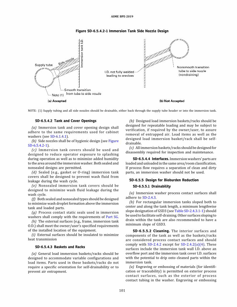
SD-6.5.4.2 Tank and Cover Openings
(a) Immersion tank and cover opening design shalladhere to the same requirements used for cabinetwashers (see SD-6.1.4.1).(b) Side nozzles shall be of hygienic design (see Figure
SD-6.5.4.2-1).(c) Immersion tank covers should be used and
designed to reduce operator exposure to splashingduring operation as well as to minimize added humidityto the area around the immersionwasher. Both sealed andnonsealed designs are permitted.(d) Sealed (e.g., gasket or O-ring) immersion tank
covers shall be designed to prevent wash fluid fromleakage during the wash cycle.(e) Nonsealed immersion tank covers should be
designed to minimize wash fluid leakage during thewash cycle.(f) Both sealed andnonsealed types shouldbedesigned
tominimizewash droplet formation above the immersiontank and loaded parts.(g) Process contact static seals used in immersion
washers shall comply with the requirements of Part SG.(h) The external surfaces (e.g., frame, immersion tank
O.D.) shall meet the owner/user’s specified requirementsof the installed location of the equipment.(i) External surfaces should be insulated to minimize
heat transmission
SD-6.5.4.3 Baskets and Racks
(a) General load immersion baskets/racks should bedesigned to accommodate variable configurations andload items. Parts used in these baskets/racks do notrequire a specific orientation for self-drainability or toprevent air entrapment.
(b) Designed load immersion baskets/racks should bedesigned for repeatable loading and may be subject toverification, if required by the owner/user, to assureremoval of entrapped air. Load items as well as thedesigned load immersion basket/rack shall be self-drainable.(c) All immersionbaskets/racks shouldbedesigned for
disassembly required for inspection and maintenance.
SD-6.5.4.4 Interfaces. Immersionwashers’ parts areloadedandunloaded in the samearea/roomclassification.If process flow requires a separation of clean and dirtyparts, an immersion washer should not be used.
SD-6.5.5 Design for Bioburden Reduction
SD-6.5.5.1 Drainability
(a) Immersion washer process contact surfaces shalladhere to SD-2.4.3.(b) For rectangular immersion tanks sloped both to
center and along the tank length, a minimum lengthwiseslope designation of GSD3 (see Table SD-2.4.3.1-1) shouldbeused to facilitate self-draining.Other surfaces sloping todrain within the tank are also recommended to have aminimum slope of GSD3.
SD-6.5.5.2 Cleaning. The interior surfaces andcomponents of the tank as well as the baskets/racksare considered process contact surfaces and shouldcomply with SD-2.4.2 except for SD-2.4.2(a)(4). Thesesurfaces include the immersion tank wall I.D. above anoverflow port and the immersion tank cover I.D. surfaceswith the potential to drip onto cleaned parts within theimmersion tank.(a) Engraving or embossing of materials (for identifi-
cation or traceability) is permitted on exterior processcontact surfaces, such as the exterior of processcontact tubing in the washer. Engraving or embossing
Figure SD-6.5.4.2-1 Immersion Tank Side Nozzle Design
NOTE: (1) Supply tubing and all side nozzles should be drainable, either back through the supply tube header or into the immersion tank.
ASME BPE-2019
101
should be limited to only what is needed for unique iden-tification or traceability.(b) Adherence toSD-2.4.2(a)(2) for the immersion tank
wall I.D. above anoverflowport and immersion tank coverI.D. surfaces should be considered by the owner/userdepending on the criticality of the parts being cleaned.(c) Final rinse tank level should be higher than wash
solution rinse level to promote quicker achievement offinal rinse conditions.Parts with recessed holes or cavities should not be
cleaned in immersion washers. Risk of air entrapmentor lack of drainability may impede exposure to andremoval of cleaning solution.
SD-6.5.6 Design for Serviceability, Examination, andOperation. Immersion washers should be designed toenable access for inspection and service of componentsthat are subject to wear, and to allow for periodic calibra-tion of instruments.
SD-6.5.7 Testing
SD-6.5.7.1 FlowCoverage.Designed load immersionwasher baskets/racks designed for repeatable loadingshould have flow coverage (e.g., riboflavin) testingperformed for verification of liquid coverage of parts’surfaces. The spray coverage testing described in SD-7.1 is applicable to the flow coverage testing for immer-sion washers. If Nonmandatory Appendix M is used, it isapplicable to immersionwashers,with the following addi-tional considerations:(a) The scope of the riboflavin application and
expected removal should be documented and agreed toby all parties (e.g., parts and baskets/racks only; parts,baskets/racks, and immersion tank process contactsurfaces).(b) Riboflavinmay be appliedwhile parts are loaded in
the baskets/racks inside of the immersion tank, ormay beapplied to parts prior to loading into the basket/rack and/or immersion tank. Application prior to loading may berequired for partswith limited access areas such as tubinglengths.(c) Immersion tank filling should occur as in normal
operation and to the normal operating level. As once-through rinsing is not applicable to immersionwashers, a complete fill, zone(s) rinsing, and drainshould be performed not less than two times. Themaximum number of zone rinses (complete fill anddrain) during the riboflavin testing shall not exceedthe total number of phases with complete fill anddrain steps during an owner/user’s normal operatingwash cycle. Only the zones applicable to the componentsbeing tested shouldbeused. Pertinent information such aszones used, time of rinse, and zone sequencing should berecorded.(d) Riboflavin inspectionmayoccurwhileparts are still
loaded in the immersion tank, outside of the immersiontank, or through a combination of both. Inspection outside
of the immersion tank may be needed for parts withlimitedaccess areas. Care shouldbe takenwhile unloadingparts from the baskets/racks and/or immersion tank toavoid false results due to transfer of residual riboflavinfrom other parts.General load immersion washer baskets/racks are not
subject to the same testing due to the nonrepeatable andnondesignated loading conditions and variations in partsbeing cleaned.
SD-6.5.7.2 Drainability. Drainability testing forimmersion tanks should use methods described in SD-7 .4 for vessels , with the fol lowing addit ionalconsiderations:(a) Atminimum, the immersion tank should be filled to
completely submerge the tank bottom.(b) Drainability testing intended for ensuring immer-
sion tank drainability should be performed without anybaskets/racks loaded.(c) Any outlet strainer or screen used in normal opera-
tion should be installed.(d) Drainability testing can be performed on designed
load baskets/racks and loaded parts to verify draining ofsurfaces on these components. The baskets/racks andparts loading information and configuration should berecorded, and the immersion tank should be filled toat minimum above the highest component of thebasket/rack or loaded part.
SD-6.6 Isolator Systems
SD-6.6.1 General. Isolator systems, hereafter referredtoas isolators, areused to create a controlledenvironmentfor bioprocessing and quality control testing that isisolated fromoperators and thebackgroundenvironment.This section describes the design requirements for twotypes of isolators, as follows:(a) aseptic isolators, which are designed to protect the
process from the environment, enable aseptic processing(e.g., cell bank processing, liquid filling of final product)(b) containment isolators, which are designed to
protect the operator environment from the processand enable safe processing of potent compounds (orother hazards) in an isolated environmentThis section does not address equipment/components
used inside the isolator. Requirements of the process andprocess equipment enclosed by the isolator should beprovidedby the owner/user. This section is not applicableto restricted access barrier systems, which restrict accessbut do not provide environmental isolation.
SD-6.6.2 System Performance Requirements. Thefollowing system performance requirements shall bedefined:(a) environmental classification inside and outside the
isolator(b) airflow conditions as unidirectional or turbulent
ASME BPE-2019
102

(c) pressure differential target to backgroundenvironment(d) log reduction for decontamination(e) overall cycle time limit for decontamination and
aeration(f) temperature operating ranges(g) humidity operating ranges(h) recirculation air, make-up air, and total exhaust air
flow limitations(i) allowable decontamination agent (e.g., vapor phase
hydrogen peroxide) concentration at the end of aerationfor product protection
SD-6.6.3 OperatingCapabilitiesandSystemFunction
SD-6.6.3 .1 Di f ferent ial Pressure Control .Differential pressure set points should be adjustable inthe range of 0.06 in. to 0.18 in. (15 Pa to 45 Pa) of thewater column. Phase transitions in the isolator system(e.g., re-dosing to aeration, aeration to production)shall be controlled without loss of pressure balance inthe surrounding room specified by the owner/user.It is permissible for the set point to be positive or nega-
tive to the surrounding room as defined by the owner/user to meet the product manufacturing requirements.The differential pressure (between the isolator interiorand exterior) should be maintained within 0.02 in. (5Pa) of water column of the set point.
SD-6.6.3.2 Temperature and Humidity. The isolatorshould be designed to monitor operational, decontamina-tion, andaeration temperatureswithin the range specifiedby the owner/user.Humidification requirements are application depen-
dent and should be agreed to by the owner/user.Consideration should be given to decontamination re-quirements, product requirements, potential static elec-tricity discharge, and condensation within the isolator orconnected equipment (e.g., lyophilizer).
SD-6.6.3.3 Decontamination. Unless otherwisespecified by the owner/user, the decontamination cycleshall demonstrate a five log reduction of microorganisms.The complete decontamination cycle includes leak testing,conditioning, decontamination, and aeration of residualdecontamination agents. The isolator shall be designedto reduce the level of the residual decontaminationagent to a concentration to be specified by the owner/user. If vapor phase hydrogen peroxide is used, the aera-tion shall reduce the residual vapor phase hydrogenperoxide to <1.0 ppm at the specified operating tempera-ture foroperator safety.The isolator shouldbedesigned toprevent opening during decontamination (e.g., incorpor-ating door and window interlocks).
SD-6.6.3.4 Venting During Aeration. The isolatorshall be designed to safely exhaust decontaminationgas though a dedicated exhaust system. For example, ifhydrogen peroxide gas is exhausted, a building stack
or catalytic filter may be required to safely convert thehydrogen peroxide into water vapor and oxygen as itis released to the environment.
SD-6.6.4 System Design. Isolator systems containbioprocessing equipment and normally do not haveproduct contact surfaces. The owner/user shall specify(a) surfaces required to be designed for product
contact(b) isolator designation as aseptic and/or containment(c) product sensitivity to decontamination agents(d) specific environmental requirements (e.g., inert gas
blanketing)Process contact surfaces should be impervious,
nonreactive, nonadditive, and resistant to cleaning/decontaminating agents.Metallic process contact surfacesshall be fabricated with 316-type or 316L-type stainlesssteel by welded construction, unless otherwise approvedby the owner/user. Exterior non-process contact surfacesmay be fabricated with 304-type or 304L-type stainlesssteel by welded construction.All equipment should be compatible (chemically resis-
tant, nonpermeable)with cleaning and sanitization agentsspecified by the owner/user, e.g., sporicidal agents, pera-cetic acid, hydrogen peroxide gas, or 70% IPA.Glove ports, comprising a glove and sleeve sealed into
thewall orwindowof an isolator, shall bemadewithmate-rials resistant to decontamination agents and specifiedsanitizing/cleaning agents (e.g., hard coated aluminum,stainless steel, UHMWPE).Unless otherwise specified by the owner/user, process
contact surfaces of metal construction should have asurface roughness of 35 μin. Ra (0.89 μm) or less.Unless otherwise specified by the owner/user, the exte-rior (non-process contact surfaces) of metal constructionshouldhaveasurface roughnesscompatiblewith theasso-ciated environmental classification. If the exterior opera-tional environment is ISO class 8, a surface finish of 48 μin.Ra (1.2μm)or less is recommended formetal construction.
SD-6.6.4.1 Isolator Shell. The isolator shell (themain work chamber of the isolator), which mayincludewindows, lights, and openings, should bedesignedto integrate internal equipment with ergonomic opera-tions. The isolator shell construction should be designedto accommodate the user-specified pressure differentialwith limited shell deformation. Isolator shell deformationlimits should accommodate openings where brittle mate-rial may be used such as glass windows and lights.To ensure isolator shell seal integrity, tolerances for
isolator shell and connection points should accommodatethe potential for weld heat distortion. The shell shall befabricated using welded construction unless otherwisespecified by the owner/user.The isolator shell construction radii of internal corners
and seams shouldbe0.6 in. (15mm)or greater to facilitatecleanability.
ASME BPE-2019
103
The aseptic isolator design should provide a barrier orsufficient space for the separation of particulate gener-ating operations (e.g., stoppering and capping) fromthe product filling operations.
SD-6.6.4.2 Isolator Base Plate. The isolator baseplate (the lowest part of the isolator interior interfacingwith the isolator shell) shall be designed to separate theisolator environment from the area below, which maycontain drives, motors, electrical installation, and othercomponents. The isolator base plate surfaces exposedto the isolator environment are considered processcontact surfaces. Isolator base plate penetrations shallbe designed with integral seals to establish a pressureboundary to avoid contamination. Penetrations shoulduse rounded corners with minimum radii of 0.6 in. (15mm) to facilitate cleanability.The isolator base plate thickness shall be designed to
support process equipment specified by the owner/user.Where isolators are designed for CIP or liquid washing,
the isolator base plate shall be sloped to one or moredrains in the isolator base plate.When the isolator manufacturer does not fabricate the
baseplate, dimensions and tolerances for tight integrationwith the isolator shell shall be provided to the isolatormanufacturer by the isolator base plate fabricator orowner/user.
SD-6.6.4.3 Doors/Windows.Doors/windows shouldbe designed, installed, and sealed to maintain the shellintegrity and cleanability. The design shall provideaccess to clean the inside of the windows.Both fixed and operablewindowdesigns are permitted.
Door and operablewindowdesigns should consider inter-locks to prevent opening during decontamination.
SD-6.6.4.4 Lighting. Lights should be designed,installed, and sealed to allow illumination of the isolatorinterior while maintaining the shell integrity and withoutcompromising cleanability. The owner/user shouldspecify product sensitivities to certain wavelengths(e.g., UV wavelengths) or to light intensity levels. Thetype and intensity of light at the work location shouldbe specified by the owner/user to meet ergonomic re-quirements (e.g., fluorescent lighting at 75 foot-candlesto 80 foot-candles (0.026 lumens/m2 to 0.028 lumens/m2) or LED lighting at 45 foot-candles to 50 foot-candles (0.016 lumens/m2 to 0.017 lumens/m2). If speci-fied, the design should accommodate different levels oflightingwithin the isolator (e.g., at least one for processingand one for cleaning/sanitization). The placement andorientation of the lighting should minimize reflectionand glare on the windows.
SD-6.6.4.5 Glove Ports. The design of an isolatorshould include a mock-up activity to determine thefinal position of any glove port. The mock-up shouldinclude a life-sizemodel of the isolator and the equipment
planned for use in the isolator for verifying ergonomicsand accessibility. Both oval and circular shapes arepermitted. Glove seal construction inside the isolatorshall be free of crevices, threaded fasteners, or anyareas difficult to clean and decontaminate. The gloveport shall be designed to provide an integral seal withthe isolator.For containment isolators, the glove port shall be
designed to allow a glove change without exposing theused glove to operators.
SD-6.6.4.6 ULPA/HEPA Filters. For aseptic isola-tors, the total nonviable particulate concentration shallmeet ISO class 5 requirements using ULPA or HEPAfilters. For aseptic isolators, the design should becapable of unidirectional (downward) airflow duringnormal operation with airflow velocity of 90 ft/min(0.46 m/s) ± 20% as measured 6 in. to 12 in. (15.2 cmto 30.5 cm) below the diffuser membrane. Turbulentairflow conditions are permitted during decontaminationand aeration.For containment isolators,ULPA filtersare recommend-
ed.Airflowbreachvelocity (e.g., asmeasured fromanopenglove port) should be between 100 ft/min and 125 ft/min(0.51m/sand0.64m/s), unlessotherwise specifiedby theowner/user.
SD-6.6.4.7 Transfer Ports. The aseptic isolatordesign shall provide for aseptic transfer of componentsrequired for the operation (e.g., caps, stoppers forfilling). The design should accommodate componenttransfer for initial setup and to replenish suppliesduring operation.Connected tubing from a final filter into filling heads in
an isolator shall have an integral seal at the isolator shell.Therecommended location for the final filter isoutside theisolator.A rapid transfer port (RTP, sometimes referred to as an
alpha-beta port) in which mating ports between theisolator and another container or system, whoseexposed door surfaces become sealed when interlockedtoeachother, shall bedesigned tomaintain isolation integ-rity while transferring materials into and out of anisolator. The mating surfaces of RTPs shall create aseal such that opened ports do not expose the isolatorenv i ronment to sur faces tha t have not beendecontaminated.RTPs should be located to accommodate the operator
access through glove ports and allow adequate clearancefrom internal equipment when open. Sizes should bespecified to include the beta container seal clearancewhen docked. In containment applications, a mechanicalinterlock should be provided to prevent the alpha doorfrom being opened when the beta container is notdocked. The use of RTPs for powder transfers thatcome into direct contact with seals is not permitted.
ASME BPE-2019
104
Split valves that use the same interface technology asRTPs, except that the interlock acts as a butterfly valve,may be used for liquid or solids additions into an isolator.Split valves are permitted for use in both aseptic andcontainment isolators.Pass-in/pass-out holes (openings that allow the
transfer of material into and/or out of isolators whilein operation) shall be designed to be sealed by an externaldoorduringadecontaminationcycle. Thedesignofasepticisolators should not permit opened doors of pass-in/pass-out holes to rest in a position above the aseptic operations.The isolator shall be designed to maintain specified pres-suredifferentials andairflowvelocitieswithopenpass-in/pass-out holes during normal operation.
SD-6.6.4.8 Airlock/Decontamination Chamber.Airlock/decontamination chambers, compartmentswith an inner door and outer door used for moving mate-rial into and out of the isolator, shall be designed withdouble-interlocked doors, which prevent the outerdoor (to room) from being opened while the innerdoor (to isolator) is open. Both doors should also be inter-locked from opening during the decontamination cycle.The inner door shall be interlocked such that it canonly be opened after a successful decontamination cycle.
SD-6.6.4.9 InternalComponents.Forpiping/tubing,all wetted process contact tubing shall comply with SD-2.4.2 and shall be sloped and/or provided with an airpurge to allow draining of lines per SD-2.4.3 andNonmandatory Appendix C. Welded joints are preferred.If disassembling of the pipe/tube system is required,hygienic process connections shall be used. Exposedthreads (e.g., the exterior of hygienic clamps) shouldbe avoided within the isolator.Brackets or other equipment shall not be located
directly above open containers in aseptic isolatorinteriors.
SD-6.6.4.10 Instruments
(a) Hydrogen Peroxide Detection. When hydrogenperoxide is used as a decontaminating agent, thesystem should be designed to detect residual hydrogenperoxide above specified critical levels for product andpersonnel safety. For personnel safety, residual hydrogenperoxide shall be less than 1 ppm. The owner/user shallspecify the residual level limit to protect the product. Themeasurement principle and detection limit of sensorsshould be agreed on between the manufacturer andowner/user. The sensor position shall provide for moni-toring the worst-case location within the isolator.(b) Viable Particle Indicators. The isolators designed to
create ISO class 5 conditions shall include continuousactive air sampling for viable particle monitoringduring active processing.
(c) Nonviable Particle Indicators. The isolatorsdesigned to create ISO class 5 conditions shall includecontinuous particle monitoring for nonviable particles.
SD-6.6.4.11 Seals. All elastomer seals shall meet 21CFR177.2600orequivalent. Gaskets andO-ring sealsusedto seal the isolator are not considered product contactsurfaces, but should be nonshedding where exposed tothe aseptic environment. Where seals are exposed tocleaning and/or decontamination processes, they areconsidered process contact surfaces and shall be resistantto cleaning and/or decontamination fluids. Processcontact elastomers shall comply with the applicable re-quirements in Part PM or Part SG. The potential forseal degradation and chemical absorption and subsequentdesorption should be considered in the selection of sealmaterials. Forexample, siliconeandEPDMoffer resistanceto many cleaning and decontamination agents.Inflatable seals and static seals are permitted. For
example, inflatable seals are acceptable for doors/windows that are designed to be opened during setupand cleaning procedures. The potential for occludedareas should be considered in the design and use of infla-table seals. Inflatable seals shall have a continuous leakcheck, using either constant pressure or constant flow.Seals between the isolator shell and mating equipment
(e.g., depyrogenation tunnel, lyophilizer) should bedesigned to accommodate the effects of the thermal dila-tion/contraction of the mating equipment. The tempera-ture at these interfaces should be considered in theselection of seal material.When an isolator system comprisesmultiple connected
isolators, seals between isolators shall be designed toexpose seal surfaces to decontamination agents duringa decontamination cycle. Single or double seals arepermitted between isolator chambers.
SD-6.6.4.12 External Surfaces. Exterior design re-quirements of SD-2.4.4.2 are applicable to isolators.Theexternal surfacesof anaseptic isolator shall be compa-tible with the environmental classification to which itinterfaces. The following design practices should beconsidered:(a) All cables should be covered.(b) Gaps between the isolator and other equipment,
such as depyrogenation tunnels or lyophilizers, shouldbe sealed.
SD-6.6.5 Design for Bioburden Control
SD-6.6.5.1 Drainability. Horizontal process contactsurfaces of the isolator shall be self-draining. If CIP of theisolator is specified, all permanently installed internalliquid distribution piping (e.g., spray wands) should besloped tomeet the requirements of Table SD-2.4.3.1-1 cat-egory GSD2 where possible or supplied with an air purgeto allow for draining per SD-2.4.3 and NonmandatoryAppendix C.
ASME BPE-2019
105

SD-6.6.5.2 Cleaning. Selection of cleaning agentsshould be made with consideration of all processcontact materials including elastomer seals andsensors. If CIP of the isolator is specified, all processcontact surfaces shall be exposed to cleaning solutionsand accessible for visual verification.
SD-6.6.5.3 Chemical Sanitization/Sterilization. Alltransport systems shall be set in a position (or inmotion) such that all process contact surfaces areexposed to the chemical agent used for the decontamina-tion cycle.
SD-6.6.5.4 Thermal Sanitization/Sterilization.[Reserved for future content]
SD-6.6.5.5 Post-Use Storage. Aseptic isolatorsshouldbedesigned tomaintainan ISOclass5environmentunder dynamic and static conditions for a period of timespecified by the owner/user. A post-use storage timeunder static conditions should be specified by theowner/user and verified through environmentalmonitoring.
SD-6.6.6 Design for Serviceability, Examination, andOperation. The isolator systems should be designed toenable safe access for inspection and service of compo-nents that are subject to wear, and to allow periodic cali-bration of instruments.The isolator systems should be designed to provide
adequate space for maintenance accessibility of allmechanical components.
SD-6.6.7 Testing
SD-6.6.7.1 Isolator Leak Testing. Both the pressuredecay and pressure hold methods of leak-rate testing areacceptable. When choosing a test method, considerationshouldbegiven to the size of the isolator, time required fortesting, and external influences that may affect testing(e.g., roomtemperature changes, roompressure changes).The maximum leak rate shall be no greater than 1% of
the isolator volume per hour with all pass-in/pass-outholes and RTP fittings closed and sealed (ISO 14644-7:2004, ISO 10648-2:1994 class 3). Leak-rate test pres-sures should be selected at 3 times to 5 times theworking pressure as agreed to by owner/user. Thetemperature during the leak test shall not changemore than 0.9°F (0.5°C).
SD-6.6.7.2 Glove Leak Testing. System integrityshould be confirmed by a glove leak test. A glove portassembly tester is recommended to locate a potentialglove leak. It is recommended to test both the installationand the glove sleeve.Leak testing methods found in ISO 14644-7 are accept-
able. Unless otherwise specified by the owner/user, themaximum permissible leak of 0.5% of volume per hour isrecommended. The use of a completely automated devicethat uses pre-assigned test recipes is recommended.
SD-6.6.7.3 ULPA/HEPA Testing. The isolator designshall include integral DOP (dispersed oil particulate) orPAO (polyalphaolefin) ports for HEPA filter integritytesting with dioctyl phthalate or other approvedtesting aerosol challenge. For aseptic isolators, themethods consistent with the certification standards foran ISO class 5 cleanroom should be applied.
SD-6.6.7.4 Mock-Up. Unless otherwise agreed to bythe owner/user, a mock-up at the factory or user siteshould be conducted prior to fabrication of aseptic isola-tors to assess aseptic operations through glove ports andassociated ergonomics. When possible, the actual equip-ment ormodels of the actual equipment should be in placefor the mock-up.
SD-6.6.7.5 Airflow Verification and VisualizationTesting. The design of airflow in aseptic isolatorsshould be verified to maintain ISO class 5 conditions.Airflow visualization studies should be conducted
under specified conditions (e.g., ISO class 5) to demon-strate that the unidirectional airflow minimizes therisk of contamination during operation. It should demon-strate a sweeping action over and away from the steri-lized/decontaminated equipment, product, containers,and closures.Airflow visualization studies should document the
airflow patterns under static conditions, dynamic (oper-ating) conditions, and the airflow during all interventions(e.g., clearing a jammed vial).
SD-7 ð19ÞDESIGN CONFORMANCE TESTING
Design conformance testing shall not result in theformation of any surface anomalies or contamination.All design conformance tests and test results documenta-tion shall have the date and time recorded. Each test docu-ment shall include a record of personnel who performedand confirmed the test results.
SD-7.1 Spray Device Coverage Test
An acceptable spray device coverage test procedure isprovided in Nonmandatory Appendix M. The purpose ofthe spraydevice coverage test is to demonstrate anddocu-ment liquid coverage of the process contact surfaces. Thetest provides information about liquid coverage and theconditions necessary to achieve this coverage as a prere-quisite for cleaning of the process equipment. Effectivecoverage shall be visually determined using a fluorescentsolution and an ultraviolet lamp or by other verificationmethods as agreed to by the owner/user andmanufactur-er. Theminimum acceptable water quality is noncompen-dial purified water (e.g., reverse osmosis or deionized).Acceptance criteria and coverage test protocol shouldbe agreed to by the owner/user and manufacturer.
ASME BPE-2019
106
Spray device coverage tests are not intended to demon-strate system cleanability. System cleanability is achievedthrough the equipment design, the spray design, knowl-edge of the soils, cleaning agent selection, and cleaningprocess parameters. Cleanability is verified using acomplete CIP per protocol during cleaning validation.
SD-7.2 Cleaning,Steaming,andBioburdenControlTesting
Cleaning, steaming, and bioburden control testing (inaddition to spray device testing) shall be as agreed toby the owner/user and manufacturer, and in accordancewith accepted industry standards.
SD-7.3 Fluid Requirements for Leak Testing
Where leak testing is required, the following fluids shallbe used:(a) Hydrostatic testing shall use clean purified or deio-
nized water filtered at 25 μ or better, unless otherwiseagreed to by the owner/user.(b) Pneumatic testing shall use oil-free clean dry air,
nitrogen, or inert gas filtered at 25 μ or better, unlessotherwise agreed to by the owner/user.
SD-7.4 Vessel Drainability Test
Specific steps or operations in a bioprocessmay requirevessels to be self-draining. A drainability test for suchvessels shall be conducted as agreed to by all parties.As a proposed test procedure, the following should beconsidered:
(a) The vessel shall be in its intended operating orien-tation within a tolerance agreed to by the owner/user.(b) The vessel shall be filled approximately to the weld
seam that joins the shell to the bottom head.(c) The outlet valve shall be opened, the vessel shall be
vented to atmosphere, and the vessel shall be allowed todrain by gravity.(d) There shall be no puddles of water left on the
bottom of the vessel greater than as agreed to by theowner/user and manufacturer.It is generally understood that residual water may be
present in the formof droplets that typically donot exceeda diameter of 5 mm. Residual water droplets adhere toprocess surfaces due to surface tension and are not indi-cative of a vessel’s drainability. Observed puddles that aredisplaced with a 1.0-in. (25-mm) rubber dowel appliedperpendicular to the puddle and re-form at the pointof displacement indicate a flat or unintended lowpoint, and that area shall be repaired to the satisfactionof the owner/user. Puddles that are displaced with a 1.0-in. (25-mm) diameter rubber dowel applied perpendi-cular to the puddle and do not return to the point of dis-placement are considered to be large droplets and do notconstitute a test failure.NOTE: Filter housings are available in several designs. In somecases, flat-bottom filter housings are specified by the owner/user based on their risk-assessed process and equipment re-quirements. Flat-bottom cartridge-mount filter housings,including those that will be steamed in place, are exemptfrom this test, and the equipment shall be installed as agreedby the manufacturer and owner/user.
ASME BPE-2019
107