maxgard-interconnection-systems.pdf - TNB.CA
67
004 – 005 Russellstoll interconnection systems overview 006 – 010 Max-Guard overview 011 Competitive checklist, receptacles and numbering system 012 – 015 Load-breaking plugs, receptacles and connectors - 30 Amp 016 – 019 Load-breaking plugs, receptacles and connectors - 60 Amp 020 – 023 Load-breaking plugs, receptacles and connectors - 100 Amp 024 – 027 Load-breaking plugs, receptacles and connectors - 200 Amp 028 – 031 Load-breaking plugs, receptacles and connectors - 400 Amp 032 – 035 Max-Gard accessories 036 – 037 Max-Gard - Engineering specifications 038 Voltage selector 039 –040 Max-Gard dimensions 041– 047 Industrial interlocked receptacles 048 – 051 GSUL Safe indicator system 052 – 055 Dura-Gard overview 056 – 057 20 Amp 058 – 059 30 Amp 060 – 061 50 Amp 062 60 Amp 063 – 065 Dura-Gard accessories 066 Safety interlocks 067 Dura-Gard dimensions 068 – 069 Dura-Gard - Engineering specifications — Table of contents
-
Upload
khangminh22 -
Category
Documents
-
view
0 -
download
0
Transcript of maxgard-interconnection-systems.pdf - TNB.CA
004 – 005 Russellstoll interconnection systems overview
006 – 010 Max-Guard overview
011 Competitive checklist, receptacles and numbering system
012 – 015 Load-breaking plugs, receptacles and connectors - 30 Amp
016 – 019 Load-breaking plugs, receptacles and connectors - 60 Amp
020 – 023 Load-breaking plugs, receptacles and connectors - 100 Amp
024 – 027 Load-breaking plugs, receptacles and connectors - 200 Amp
028 – 031 Load-breaking plugs, receptacles and connectors - 400 Amp
032 – 035 Max-Gard accessories
036 – 037 Max-Gard - Engineering specifications
038 Voltage selector
039 –040 Max-Gard dimensions
041– 047 Industrial interlocked receptacles
048 – 051 GSUL Safe indicator system
052 – 055 Dura-Gard overview
056 – 057 20 Amp
058 – 059 30 Amp
060 – 061 50 Amp
062 60 Amp
063 – 065 Dura-Gard accessories
066 Safety interlocks
067 Dura-Gard dimensions
068 – 069 Dura-Gard - Engineering specifications
— Table of contents
4 R U S S E LL S TO LL PI N & SL EE V E P OW ER CO N N EC TO R S
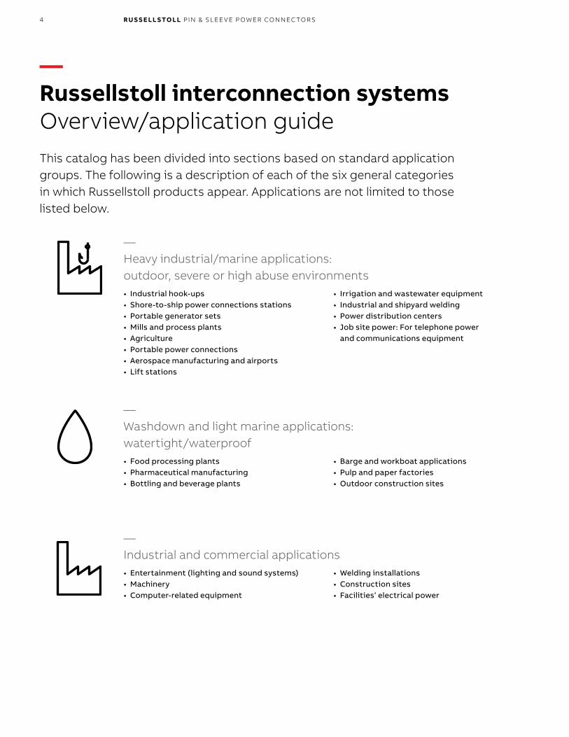
—Russellstoll interconnection systemsOverview/application guide This catalog has been divided into sections based on standard application groups. The following is a description of each of the six general categories in which Russellstoll products appear. Applications are not limited to those listed below.
• Industrial hook-ups• Shore-to-ship power connections stations• Portable generator sets• Mills and process plants• Agriculture• Portable power connections• Aerospace manufacturing and airports• Lift stations
• Irrigation and wastewater equipment• Industrial and shipyard welding• Power distribution centers• Job site power: For telephone power
and communications equipment
• Food processing plants• Pharmaceutical manufacturing• Bottling and beverage plants
• Barge and workboat applications• Pulp and paper factories• Outdoor construction sites
• Entertainment (lighting and sound systems)• Machinery• Computer-related equipment
• Welding installations• Construction sites• Facilities’ electrical power
—Heavy industrial/marine applications: outdoor, severe or high abuse environments
—Washdown and light marine applications: watertight/waterproof
—Industrial and commercial applications
5R USSEL L S TO L L I NTER CO N N EC TI O N S Y S TEMS OV ER V I E W
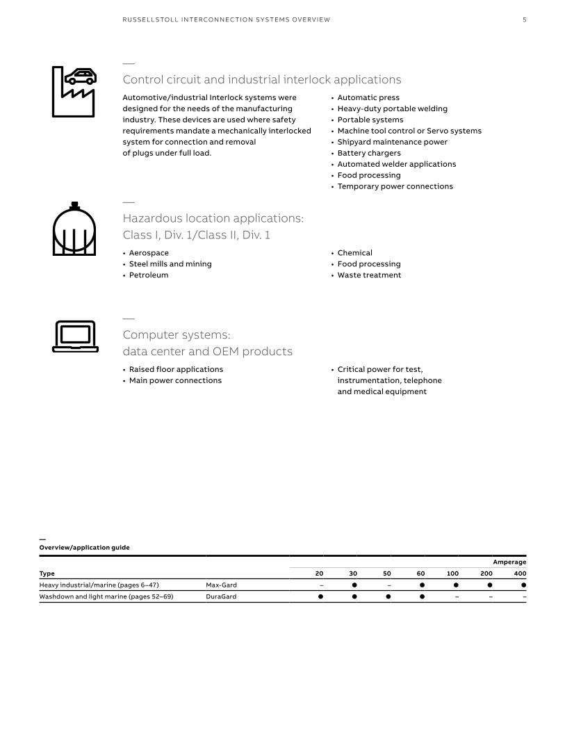
• Aerospace• Steel mills and mining• Petroleum
• Chemical• Food processing• Waste treatment
• Raised floor applications• Main power connections
• Critical power for test, instrumentation, telephone and medical equipment
Automotive/industrial Interlock systems were designed for the needs of the manufacturing industry. These devices are used where safety requirements mandate a mechanically interlocked system for connection and removal of plugs under full load.
• Automatic press• Heavy-duty portable welding• Portable systems• Machine tool control or Servo systems• Shipyard maintenance power• Battery chargers• Automated welder applications• Food processing• Temporary power connections
—Overview/application guide
Amperage
Type 20 30 50 60 100 200 400
Heavy industrial/marine (pages 6–47) Max-Gard – ● – ● ● ● ●
Washdown and light marine (pages 52–69) DuraGard ● ● ● ● – – –
—Hazardous location applications: Class I, Div. 1/Class II, Div. 1
—Computer systems: data center and OEM products
—Control circuit and industrial interlock applications
6 R U S S E LL S TO LL PI N & SL EE V E P OW ER CO N N EC TO R S6
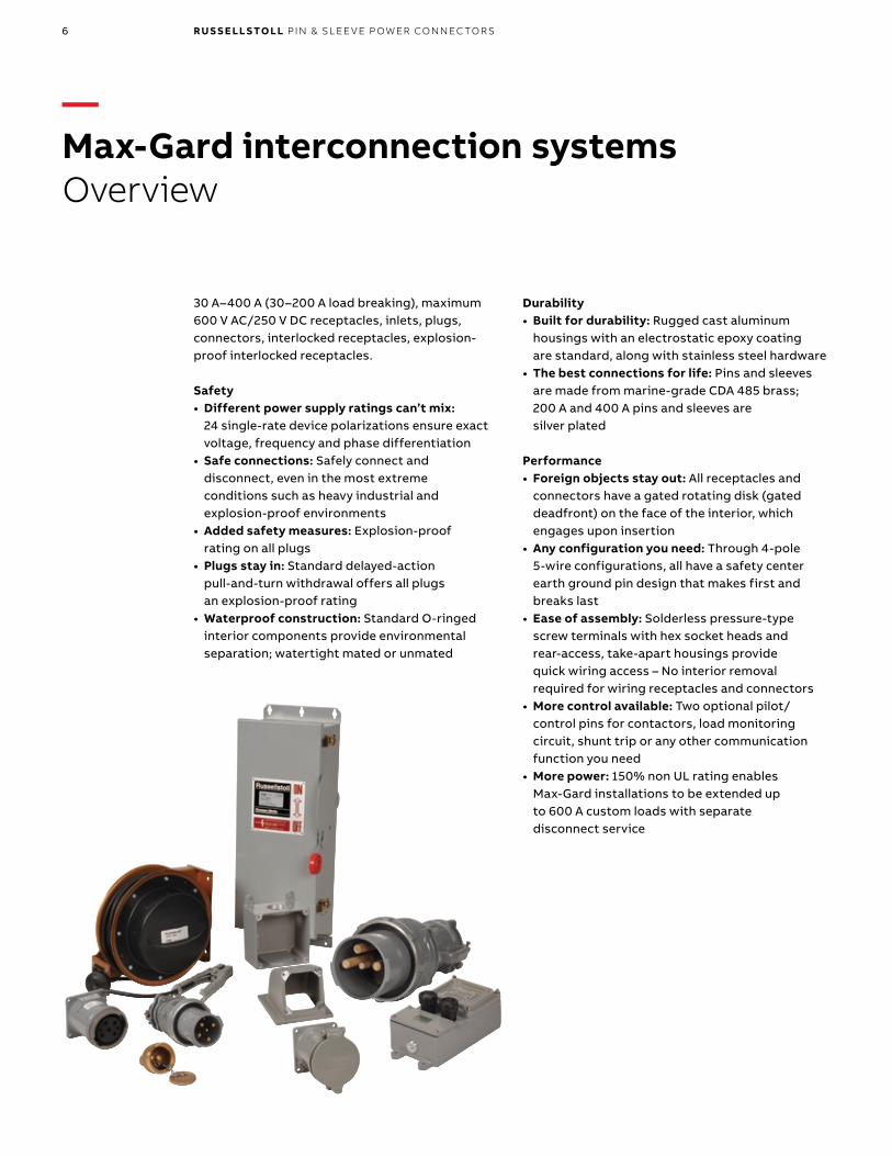
30 A–400 A (30–200 A load breaking), maximum 600 V AC/250 V DC receptacles, inlets, plugs, connectors, interlocked receptacles, explosion-proof interlocked receptacles.
Safety• Different power supply ratings can’t mix:
24 single-rate device polarizations ensure exact voltage, frequency and phase differentiation
• Safe connections: Safely connect and disconnect, even in the most extreme conditions such as heavy industrial and explosion-proof environments
• Added safety measures: Explosion-proof rating on all plugs
• Plugs stay in: Standard delayed-action pull-and-turn withdrawal offers all plugs an explosion-proof rating
• Waterproof construction: Standard O-ringed interior components provide environmental separation; watertight mated or unmated
Durability• Built for durability: Rugged cast aluminum
housings with an electrostatic epoxy coating are standard, along with stainless steel hardware
• The best connections for life: Pins and sleeves are made from marine-grade CDA 485 brass; 200 A and 400 A pins and sleeves are silver plated
Performance• Foreign objects stay out: All receptacles and
connectors have a gated rotating disk (gated deadfront) on the face of the interior, which engages upon insertion
• Any configuration you need: Through 4-pole 5-wire configurations, all have a safety center earth ground pin design that makes first and breaks last
• Ease of assembly: Solderless pressure-type screw terminals with hex socket heads and rear-access, take-apart housings provide quick wiring access – No interior removal required for wiring receptacles and connectors
• More control available: Two optional pilot/control pins for contactors, load monitoring circuit, shunt trip or any other communication function you need
• More power: 150% non UL rating enables Max-Gard installations to be extended up to 600 A custom loads with separate disconnect service
—Max-Gard interconnection systemsOverview
7M A X- G A R D I NTER CO N N EC TI O N S Y S TEMS 7
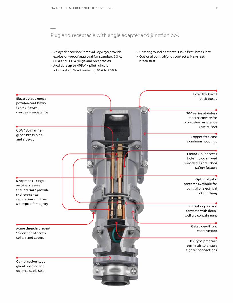
Electrostatic epoxy powder-coat finish for maximum corrosion resistance
CDA 485 marine-grade brass pins and sleeves
Acme threads prevent “freezing ” of screw collars and covers
Padlock-out access hole in plug shroud
provided as standard safety feature
Compression-type gland bushing for optimal cable seal
• Center ground contacts: Make first, break last• Optional control/pilot contacts: Make last,
break first
Extra thick-wall back boxes
300 series stainless steel hardware for
corrosion resistance (entire line)
Copper-free cast aluminum housings
Optional pilot contacts available for
control or electrical interlocking
Extra-long current contacts with deep-
well arc containment
Gated deadfront construction
Hex-type pressure terminals to ensure tighter connections
—Plug and receptacle with angle adapter and junction box
• Delayed insertion/removal keyways provide explosion-proof approval for standard 30 A, 60 A and 100 A plugs and receptacles
• Available up to 4P5W + pilot; circuit interrupting/load breaking 30 A to 200 A
Neoprene O-rings on pins, sleeves and interiors provide environmental separation and true waterproof integrity
8 R U S S E LL S TO LL PI N & SL EE V E P OW ER CO N N EC TO R S
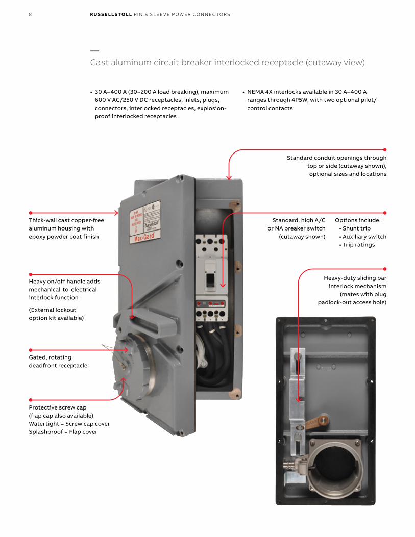
Options include: • Shunt trip • Auxiliary switch • Trip ratings
Heavy-duty sliding bar interlock mechanism
(mates with plug padlock-out access hole)
• 30 A–400 A (30–200 A load breaking), maximum 600 V AC/250 V DC receptacles, inlets, plugs, connectors, interlocked receptacles, explosion-proof interlocked receptacles
• NEMA 4X interlocks avail able in 30 A–400 A ranges through 4P5W, with two optional pilot/ control contacts
—Cast aluminum circuit breaker interlocked receptacle (cutaway view)
Standard conduit openings through top or side (cutaway shown), optional sizes and locations
Standard, high A/C or NA breaker switch
(cutaway shown)
Thick-wall cast copper-free aluminum housing with epoxy powder coat finish
(External lockout option kit available)
Heavy on/off handle adds mechanical-to-electrical interlock function
Gated, rotating deadfront receptacle
Protective screw cap (flap cap also available)Watertight = Screw cap coverSplashproof = Flap cover
9M A X- G A R D I NTER CO N N EC TI O N S Y S TEMS 9
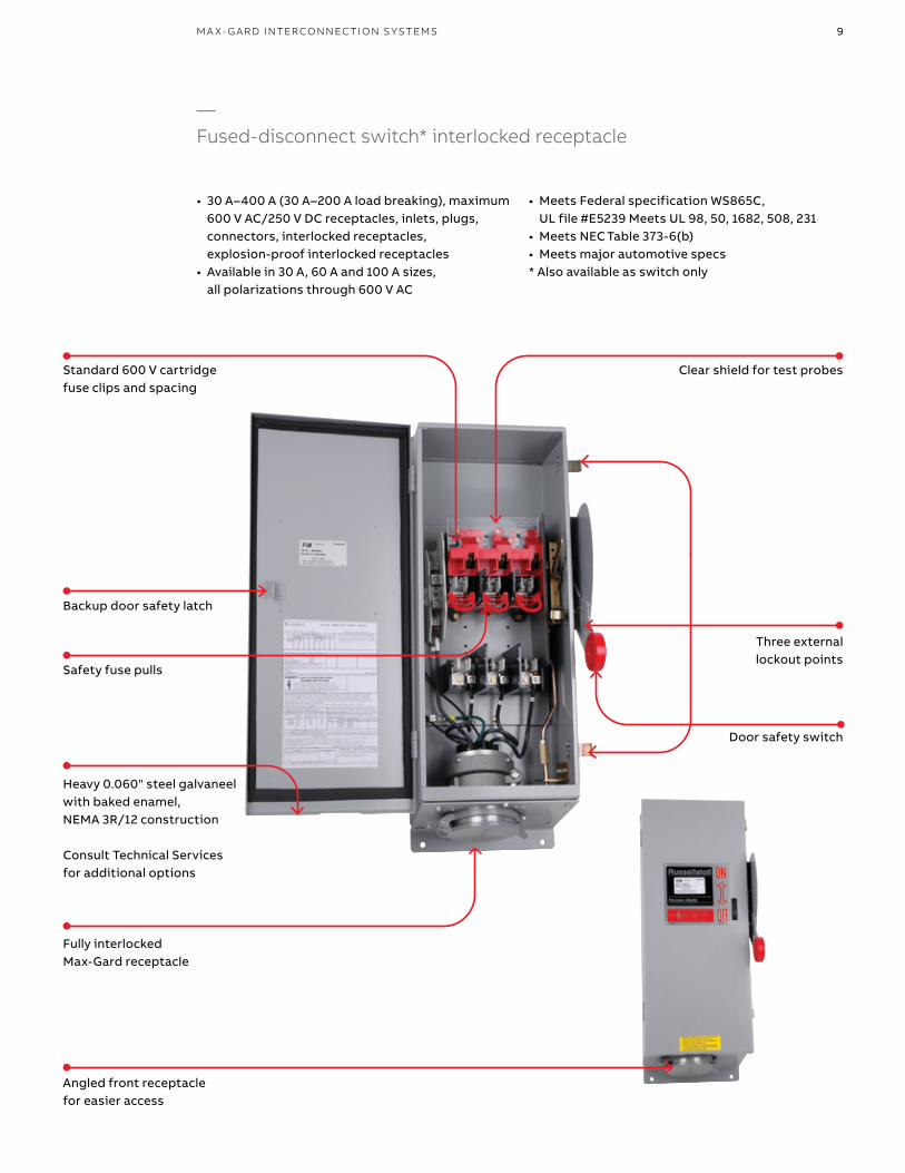
Door safety switch
Backup door safety latch
Heavy 0.060" steel galvaneel with baked enamel, NEMA 3R/12 construction
Consult Technical Services for additional options
Fully interlocked Max-Gard receptacle
Safety fuse pulls
Angled front receptacle for easier access
• 30 A–400 A (30 A–200 A load breaking), maximum 600 V AC/250 V DC receptacles, inlets, plugs, connectors, interlocked receptacles, explosion-proof interlocked receptacles
• Available in 30 A, 60 A and 100 A sizes, all polarizations through 600 V AC
• Meets Federal specification WS865C, UL file #E5239 Meets UL 98, 50, 1682, 508, 231
• Meets NEC Table 373-6(b)• Meets major automotive specs* Also available as switch only
—Fused-disconnect switch* interlocked receptacle
Standard 600 V cartridge fuse clips and spacing
Clear shield for test probes
Three externallockout points
10 R U S S E LL S TO LL PI N & SL EE V E P OW ER CO N N EC TO R S
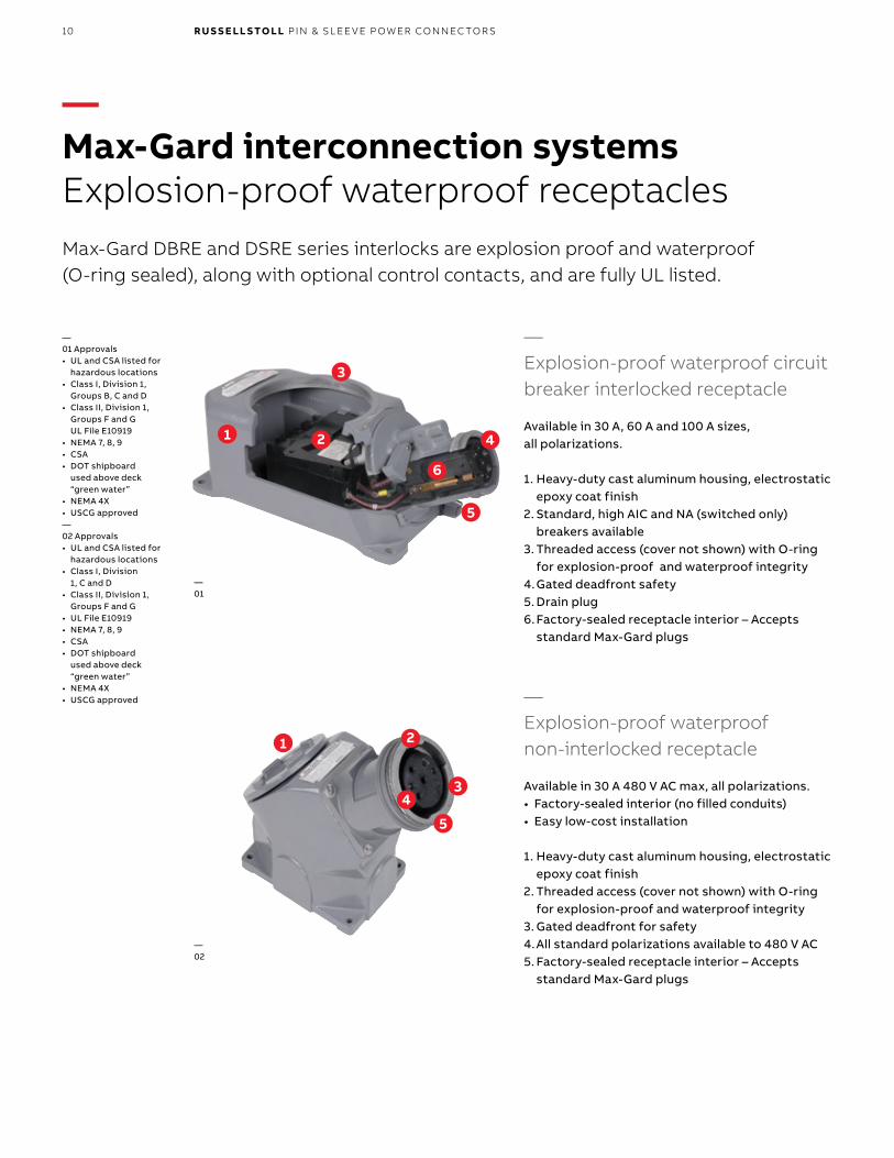
—Max-Gard interconnection systemsExplosion-proof waterproof receptaclesMax-Gard DBRE and DSRE series interlocks are explosion proof and waterproof (O-ring sealed), along with optional control contacts, and are fully UL listed.
—Explosion-proof waterproof circuit breaker interlocked receptacle
Available in 30 A, 60 A and 100 A sizes, all polarizations.
1. Heavy-duty cast aluminum housing, electrostatic epoxy coat finish
2. Standard, high AIC and NA (switched only) breakers available
3. Threaded access (cover not shown) with O-ring for explosion-proof and waterproof integrity
4. Gated deadfront safety5. Drain plug6. Factory-sealed receptacle interior – Accepts
standard Max-Gard plugs
—Explosion-proof waterproof non-interlocked receptacle
Available in 30 A 480 V AC max, all polarizations.• Factory-sealed interior (no filled conduits)• Easy low-cost installation
1. Heavy-duty cast aluminum housing, electrostatic epoxy coat finish
2. Threaded access (cover not shown) with O-ring for explosion-proof and waterproof integrity
3. Gated deadfront for safety4. All standard polarizations available to 480 V AC5. Factory-sealed receptacle interior – Accepts
standard Max-Gard plugs
—01 Approvals• UL and CSA listed for
hazardous locations• Class I, Division 1,
Groups B, C and D• Class II, Division 1,
Groups F and G UL File E10919
• NEMA 7, 8, 9• CSA• DOT shipboard
used above deck “green water”
• NEMA 4X• USCG approved—02 Approvals• UL and CSA listed for
hazardous locations• Class I, Division
1, C and D• Class II, Division 1,
Groups F and G• UL File E10919• NEMA 7, 8, 9• CSA• DOT shipboard
used above deck “green water”
• NEMA 4X• USCG approved
2
3
1
6
4
2
3
1
5
4
—01
—02
5
11
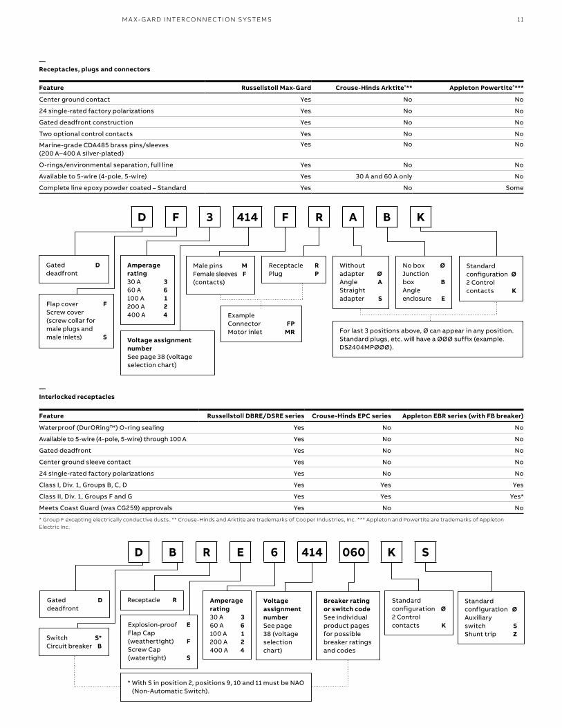
Feature Russellstoll Max-Gard Crouse-Hinds Arktite®** Appleton Powertite®***
Center ground contact Yes No No
24 single-rated factory polarizations Yes No No
Gated deadfront construction Yes No No
Two optional control contacts Yes No No
Marine-grade CDA485 brass pins/sleeves (200 A–400 A silver-plated)
Yes No No
O-rings/environmental separation, full line Yes No No
Available to 5-wire (4-pole, 5-wire) Yes 30 A and 60 A only No
Complete line epoxy powder coated – Standard Yes No Some
—Receptacles, plugs and connectors
D F 3 414 F R A B K
Gated D deadfront
Flap cover FScrew cover (screw collar for male plugs and male inlets) S
Amperage rating30 A 360 A 6100 A 1200 A 2400 A 4
Voltage assignment numberSee page 38 (voltage selection chart)
Male pins MFemale sleeves F (contacts)
Receptacle RPlug P
Without adapter ØAngle AStraight adapter S
No box ØJunction box BAngle enclosure E
Standard configuration Ø2 Control contacts K
ExampleConnector FPMotor inlet MR For last 3 positions above, Ø can appear in any position.
Standard plugs, etc. will have a ØØØ suffix (example. DS2404MPØØØ).
Feature Russellstoll DBRE/DSRE series Crouse-Hinds EPC series Appleton EBR series (with FB breaker)
Waterproof (DurORing™) O-ring sealing Yes No No
Available to 5-wire (4-pole, 5-wire) through 100 A Yes No No
Gated deadfront Yes No No
Center ground sleeve contact Yes No No
24 single-rated factory polarizations Yes No No
Class I, Div. 1, Groups B, C, D Yes Yes Yes
Class II, Div. 1, Groups F and G Yes Yes Yes*
Meets Coast Guard (was CG259) approvals Yes No No
* Group F excepting electrically conductive dusts. ** Crouse-Hinds and Arktite are trademarks of Cooper Industries, Inc. *** Appleton and Powertite are trademarks of Appleton Electric Inc.
—Interlocked receptacles
D B R E 6 414 060 K S
Gated D deadfront
Switch S*Circuit breaker B
Receptacle R
Explosion-proof EFlap Cap (weathertight) FScrew Cap (watertight) S
Amperage rating30 A 360 A 6100 A 1200 A 2400 A 4
Standard configuration Ø2 Control contacts K
Standard configuration ØAuxiliary switch SShunt trip Z
Voltage assignment numberSee page 38 (voltage selection chart)
Breaker rating or switch codeSee individual product pages for possible breaker ratings and codes
* With S in position 2, positions 9, 10 and 11 must be NAO (Non-Automatic Switch).
M A X- G A R D I NTER CO N N EC TI O N S Y S TEMS
12 R U S S E LL S TO LL PI N & SL EE V E P OW ER CO N N EC TO R S
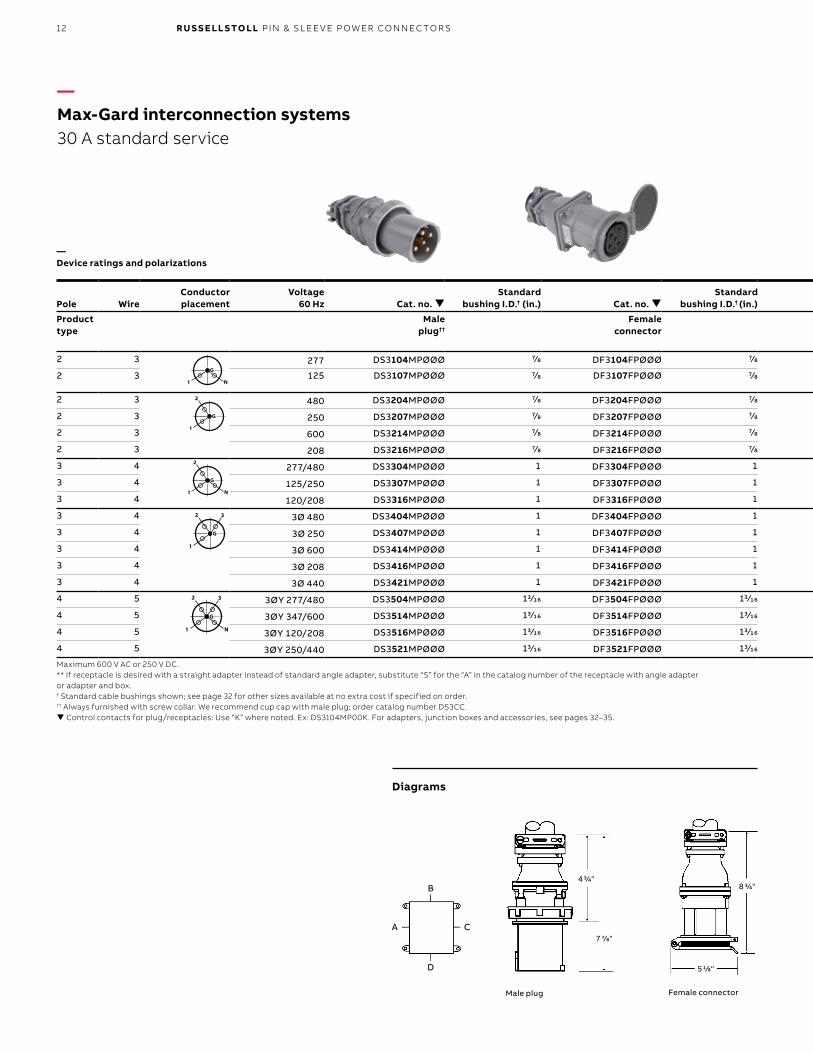
—Max-Gard interconnection systems30 A standard service
Pole WireConductor placement
Voltage 60 Hz Cat. no.
Standard bushing I.D.† (in.) Cat. no.
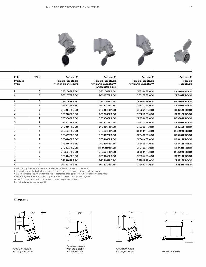
Standard bushing I.D.† (in.) Pole Wire Cat. no. Cat. no. Cat. no. Cat. no.
Product type
Male plug††
Female connector
Product type
Female receptacle with angle enclosure
Female receptacle with angle adapter**
and junction box
Female receptacle with angle adapter**
Female receptacle
2 3
G
N1
2 3
G
1
2 3
G
N1
2
G
1
2
G
N1
277 DS3104MPØØØ 7/8 DF3104FPØØØ 7/8 2 3 DF3104FRØEØ DF3104FRABØ DF3104FRAØØ DF3104FRØØØ
2 3 125 DS3107MPØØØ 7/8 DF3107FPØØØ 7/8 2 3 DF3107FRØEØ DF3107FRABØ DF3107FRAØØ DF3107FRØØØ
2 3
G
N1
2 3
G
1
2 3
G
N1
2
G
1
2
G
N1
480 DS3204MPØØØ 7/8 DF3204FPØØØ 7/8 2 3 DF3204FRØEØ DF3204FRABØ DF3204FRAØØ DF3204FRØØØ
2 3 250 DS3207MPØØØ 7/8 DF3207FPØØØ 7/8 2 3 DF3207FRØEØ DF3207FRABØ DF3207FRAØØ DF3207FRØØØ
2 3 600 DS3214MPØØØ 7/8 DF3214FPØØØ 7/8 2 3 DF3214FRØEØ DF3214FRABØ DF3214FRAØØ DF3214FRØØØ
2 3 208 DS3216MPØØØ 7/8 DF3216FPØØØ 7/8 2 3 DF3216FRØEØ DF3216FRABØ DF3216FRAØØ DF3216FRØØØ
3 4
G
N1
2 3
G
1
2 3
G
N1
2
G
1
2
G
N1
277/480 DS3304MPØØØ 1 DF3304FPØØØ 1 3 4 DF3304FRØEØ DF3304FRABØ DF3304FRAØØ DF3304FRØØØ
3 4 125/250 DS3307MPØØØ 1 DF3307FPØØØ 1 3 4 DF3307FRØEØ DF3307FRABØ DF3307FRAØØ DF3307FRØØØ
3 4 120/208 DS3316MPØØØ 1 DF3316FPØØØ 1 3 4 DF3316FRØEØ DF3316FRABØ DF3316FRAØØ DF3316FRØØØ
3 4
G
N1
2 3
G
1
2 3
G
N1
2
G
1
2
G
N1
3Ø 480 DS3404MPØØØ 1 DF3404FPØØØ 1 3 4 DF3404FRØEØ DF3404FRABØ DF3404FRAØØ DF3404FRØØØ
3 4 3Ø 250 DS3407MPØØØ 1 DF3407FPØØØ 1 3 4 DF3407FRØEØ DF3407FRABØ DF3407FRAØØ DF3407FRØØØ
3 4 3Ø 600 DS3414MPØØØ 1 DF3414FPØØØ 1 3 4 DF3414FRØEØ DF3414FRABØ DF3414FRAØØ DF3414FRØØØ
3 4 3Ø 208 DS3416MPØØØ 1 DF3416FPØØØ 1 3 4 DF3416FRØEØ DF3416FRABØ DF3416FRAØØ DF3416FRØØØ
3 4 3Ø 440 DS3421MPØØØ 1 DF3421FPØØØ 1 3 4 DF3421FRØEØ DF3421MRABØ DF3421FRAØØ DF3421FRØØØ
4 5
G
N1
2 3
G
1
2 3
G
N1
2
G
1
2
G
N1
3ØY 277/480 DS3504MPØØØ 13/16 DF3504FPØØØ 13/16 4 5 DF3504FRØEØ DF3504FRABØ DF3504FRAØØ DF3504FRØØØ
4 5 3ØY 347/600 DS3514MPØØØ 13/16 DF3514FPØØØ 13/16 4 5 DF3514FRØEØ DF3514FRABØ DF3514FRAØØ DF3514FRØØØ
4 5 3ØY 120/208 DS3516MPØØØ 13/16 DF3516FPØØØ 13/16 4 5 DF3516FRØEØ DF3516FRABØ DF3516FRAØØ DF3516FRØØØ
4 5 3ØY 250/440 DS3521MPØØØ 13/16 DF3521FPØØØ 13/16 4 5 DF3521FRØEØ DF3521FRABØ DF3521FRAØØ DF3521FRØØØ
Maximum 600 V AC or 250 V DC.** If receptacle is desired with a straight adapter instead of standard angle adapter, substitute “S” for the “A” in the catalog number of the receptacle with angle adapter or adapter and box.† Standard cable bushings shown; see page 32 for other sizes available at no extra cost if specified on order.†† Always furnished with screw collar. We recommend cup cap with male plug; order catalog number DS3CC. Control contacts for plug/receptacles: Use “K” where noted. Ex: DS3104MP00K. For adapters, junction boxes and accessories, see pages 32–35.
Maximum lug wire 8 AWG 7-strand or flexible, cable entrance 0.187" diameter. Receptacles furnished with flap cap also have screw thread to accept male collar on plug. Catalog numbers shown are for flap cap receptacles; change “DF” to “DS” for ordering screw cap. Boldface figures are for voltage assignment. For different ratings, see page 38.Outlet furnished at location “B” unless otherwise specified. 1" NPT.For full polarization, see page 38.
—Device ratings and polarizations
B
D
A C
43/4"
7 7/8"
8 3/4"
51/8"
Diagrams
Male plug Female connector
13
Pole WireConductor placement
Voltage 60 Hz Cat. no.
Standard bushing I.D.† (in.) Cat. no.
Standard bushing I.D.† (in.) Pole Wire Cat. no. Cat. no. Cat. no. Cat. no.
Product type
Male plug††
Female connector
Product type
Female receptacle with angle enclosure
Female receptacle with angle adapter**
and junction box
Female receptacle with angle adapter**
Female receptacle
2 3
G
N1
2 3
G
1
2 3
G
N1
2
G
1
2
G
N1
277 DS3104MPØØØ 7/8 DF3104FPØØØ 7/8 2 3 DF3104FRØEØ DF3104FRABØ DF3104FRAØØ DF3104FRØØØ
2 3 125 DS3107MPØØØ 7/8 DF3107FPØØØ 7/8 2 3 DF3107FRØEØ DF3107FRABØ DF3107FRAØØ DF3107FRØØØ
2 3
G
N1
2 3
G
1
2 3
G
N1
2
G
1
2
G
N1
480 DS3204MPØØØ 7/8 DF3204FPØØØ 7/8 2 3 DF3204FRØEØ DF3204FRABØ DF3204FRAØØ DF3204FRØØØ
2 3 250 DS3207MPØØØ 7/8 DF3207FPØØØ 7/8 2 3 DF3207FRØEØ DF3207FRABØ DF3207FRAØØ DF3207FRØØØ
2 3 600 DS3214MPØØØ 7/8 DF3214FPØØØ 7/8 2 3 DF3214FRØEØ DF3214FRABØ DF3214FRAØØ DF3214FRØØØ
2 3 208 DS3216MPØØØ 7/8 DF3216FPØØØ 7/8 2 3 DF3216FRØEØ DF3216FRABØ DF3216FRAØØ DF3216FRØØØ
3 4
G
N1
2 3
G
1
2 3
G
N1
2
G
1
2
G
N1
277/480 DS3304MPØØØ 1 DF3304FPØØØ 1 3 4 DF3304FRØEØ DF3304FRABØ DF3304FRAØØ DF3304FRØØØ
3 4 125/250 DS3307MPØØØ 1 DF3307FPØØØ 1 3 4 DF3307FRØEØ DF3307FRABØ DF3307FRAØØ DF3307FRØØØ
3 4 120/208 DS3316MPØØØ 1 DF3316FPØØØ 1 3 4 DF3316FRØEØ DF3316FRABØ DF3316FRAØØ DF3316FRØØØ
3 4
G
N1
2 3
G
1
2 3
G
N1
2
G
1
2
G
N1
3Ø 480 DS3404MPØØØ 1 DF3404FPØØØ 1 3 4 DF3404FRØEØ DF3404FRABØ DF3404FRAØØ DF3404FRØØØ
3 4 3Ø 250 DS3407MPØØØ 1 DF3407FPØØØ 1 3 4 DF3407FRØEØ DF3407FRABØ DF3407FRAØØ DF3407FRØØØ
3 4 3Ø 600 DS3414MPØØØ 1 DF3414FPØØØ 1 3 4 DF3414FRØEØ DF3414FRABØ DF3414FRAØØ DF3414FRØØØ
3 4 3Ø 208 DS3416MPØØØ 1 DF3416FPØØØ 1 3 4 DF3416FRØEØ DF3416FRABØ DF3416FRAØØ DF3416FRØØØ
3 4 3Ø 440 DS3421MPØØØ 1 DF3421FPØØØ 1 3 4 DF3421FRØEØ DF3421MRABØ DF3421FRAØØ DF3421FRØØØ
4 5
G
N1
2 3
G
1
2 3
G
N1
2
G
1
2
G
N1
3ØY 277/480 DS3504MPØØØ 13/16 DF3504FPØØØ 13/16 4 5 DF3504FRØEØ DF3504FRABØ DF3504FRAØØ DF3504FRØØØ
4 5 3ØY 347/600 DS3514MPØØØ 13/16 DF3514FPØØØ 13/16 4 5 DF3514FRØEØ DF3514FRABØ DF3514FRAØØ DF3514FRØØØ
4 5 3ØY 120/208 DS3516MPØØØ 13/16 DF3516FPØØØ 13/16 4 5 DF3516FRØEØ DF3516FRABØ DF3516FRAØØ DF3516FRØØØ
4 5 3ØY 250/440 DS3521MPØØØ 13/16 DF3521FPØØØ 13/16 4 5 DF3521FRØEØ DF3521FRABØ DF3521FRAØØ DF3521FRØØØ
Maximum 600 V AC or 250 V DC.** If receptacle is desired with a straight adapter instead of standard angle adapter, substitute “S” for the “A” in the catalog number of the receptacle with angle adapter or adapter and box.† Standard cable bushings shown; see page 32 for other sizes available at no extra cost if specified on order.†† Always furnished with screw collar. We recommend cup cap with male plug; order catalog number DS3CC. Control contacts for plug/receptacles: Use “K” where noted. Ex: DS3104MP00K. For adapters, junction boxes and accessories, see pages 32–35.
Maximum lug wire 8 AWG 7-strand or flexible, cable entrance 0.187" diameter. Receptacles furnished with flap cap also have screw thread to accept male collar on plug. Catalog numbers shown are for flap cap receptacles; change “DF” to “DS” for ordering screw cap. Boldface figures are for voltage assignment. For different ratings, see page 38.Outlet furnished at location “B” unless otherwise specified. 1" NPT.For full polarization, see page 38.
2 7/8"
41/2"
61/8"
9 5/8"
9 1/8"
9 5/8"
3"
6 3/8"
31/8"
9 7/8"
Diagrams
Female receptacle with angle enclosure
Female receptacle with angle adapter and junction box
Female receptacle with angle adapter Female receptacle
M A X- G A R D I NTER CO N N EC TI O N S Y S TEMS
14 R U S S E LL S TO LL PI N & SL EE V E P OW ER CO N N EC TO R S
Pole WireConductor placement
Voltage60 hz Cat. no.
Standard bushing I.D.† (in.) Cat. no.
Standard bushing I.D.† (in.) Pole Wire Cat. no. Cat. no. Cat. no. Cat. no.
Product type
Female connector
Male plug††
Product type
Male inlet with angle enclosure
Male inlet with angle adapter**
and junction box
Male inlet with angle adapter**
Male Inlet††
2 3 277 DF3104FPØØØ 7/8 DS3104MPØØØ 7/8 2 3 DS3104MRØEØ DS3104MRABØ DS3104MRAØØ DS3104MRØØØ
2 3 125 DF3107FPØØØ 7/8 DS3107MPØØØ 7/8 2 3 DS3107MRØEØ DS3107MRABØ DS3107MRAØØ DS3107MRØØØ
2 3 480 DF3204FPØØØ 7/8 DS3204MPØØØ 7/8 2 3 DS3204MRØEØ DS3204MRABØ DS3204MRAØØ DS3204MRØØØ
2 3 250 DF3207FPØØØ 7/8 DS3207MPØØØ 7/8 2 3 DS3207MRØEØ DS3207MRABØ DS3207MRAØØ DS3207MRØØØ
2 3 600 DF3214FPØØØ 7/8 DS3214MPØØØ 7/8 2 3 DS3214MRØEØ DS3214MRABØ DS3214MRAØØ DS3214MRØØØ
2 3 208 DF3216FPØØØ 7/8 DS3216MPØØØ 7/8 2 3 DS3216MRØEØ DS3216MRABØ DS3216MRAØØ DS3216MRØØØ
3 4 277/480 DF3304FPØØØ 1 DS3304MPØØØ 1 3 4 DS3304MRØEØ DS3304MRABØ DS3304MRAØØ DS3304MRØØØ
3 4 125/250 DF3307FPØØØ 1 DS3307MPØØØ 1 3 4 DS3307MRØEØ DS3307MRABØ DS3307MRAØØ DS3307MRØØØ
3 4 120/208 DF3316FPØØØ 1 DS3316MPØØØ 1 3 4 DS3316MRØEØ DS3316MRABØ DS3316MRAØØ DS3316MRØØØ
3 4 3Ø 480 DF3404FPØØØ 1 DS3404MPØØØ 1 3 4 DS3404MRØEØ DS3404MRABØ DS3404MRAØØ DS3404MRØØØ
3 4 3Ø 250 DF3407FPØØØ 1 DS3407MPØØØ 1 3 4 DS3407MRØEØ DS3407MRABØ DS3407MRAØØ DS3407MRØØØ
3 4 3Ø 600 DF3414FPØØØ 1 DS3414MPØØØ 1 3 4 DS3414MRØEØ DS3414MRABØ DS3414MRAØØ DS3414MRØØØ
3 4 3Ø 208 DF3416FPØØØ 1 DS3416MPØØØ 1 3 4 DS3416MRØEØ DS3416MRABØ DS3416MRAØØ DS3416MRØØØ
3 4 3Ø 440 DF3421FPØØØ 1 DS3421MPØØØ 1 3 4 DS3421MRØEØ DS3421MRABØ DS3421MRAØØ DS3421MRØØØ
4 5 3ØY 277/480 DF3504FPØØØ 13/16 DS3504MPØØØ 13/16 4 5 DS3504MRØEØ DS3504MRABØ DS3504MRAØØ DS3504MRØØØ
4 5 3ØY 347/600 DF3514FPØØØ 13/16 DS3514MPØØØ 13/16 4 5 DS3514MRØEØ DS3514MRABØ DS3514MRAØØ DS3514MRØØØ
4 5 3ØY 120/208 DF3516FPØØØ 13/16 DS3516MPØØØ 13/16 4 5 DS3516MRØEØ DS3516MRABØ DS3516MRAØØ DS3516MRØØØ
4 5 3ØY 250/440 DF3521FPØØØ 13/16 DS3521MPØØØ 13/16 4 5 DS3521MRØEØ DS3521MRABØ DS3521MRAØØ DS3521MRØØØ
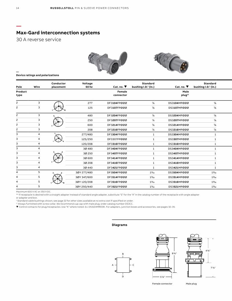
—Max-Gard interconnection systems30 A reverse service
—Device ratings and polarizations
G
N1
2 3
G
1
2 3
G
N1
2
G
1
2
G
N1
G
N1
2 3
G
1
2 3
G
N1
2
G
1
2
G
N1
G
N1
2 3
G
1
2 3
G
N1
2
G
1
2
G
N1
G
N1
2 3
G
1
2 3
G
N1
2
G
1
2
G
N1
G
N1
2 3
G
1
2 3
G
N1
2
G
1
2
G
N1
Maximum 600 V AC or 250 V DC.** If receptacle is desired with a straight adapter instead of standard angle adapter, substitute “S” for the “A” in the catalog number of the receptacle with angle adapter or adapter and box.† Standard cable bushings shown; see page 32 for other sizes available at no extra cost if specified on order.†† Always furnished with screw collar. We recommend cup cap with male plug; order catalog number DS3CC. Control contacts for plug/receptacles: Use “K” where noted. Ex: DS3104MR00K. For adapters, junction boxes and accessories, see pages 32–35.
Diagrams
B
D
A C
43/4"
7 7/8"
8 3/4"
51/8"
Male plugFemale connector
15M A X- G A R D I NTER CO N N EC TI O N S Y S TEMS
2 7/8"
5 1/2"
2 1/2"3 1/8"
10 7/8"
6 1/4"9"
3"
9 5/8"
Pole WireConductor placement
Voltage60 hz Cat. no.
Standard bushing I.D.† (in.) Cat. no.
Standard bushing I.D.† (in.) Pole Wire Cat. no. Cat. no. Cat. no. Cat. no.
Product type
Female connector
Male plug††
Product type
Male inlet with angle enclosure
Male inlet with angle adapter**
and junction box
Male inlet with angle adapter**
Male Inlet††
2 3 277 DF3104FPØØØ 7/8 DS3104MPØØØ 7/8 2 3 DS3104MRØEØ DS3104MRABØ DS3104MRAØØ DS3104MRØØØ
2 3 125 DF3107FPØØØ 7/8 DS3107MPØØØ 7/8 2 3 DS3107MRØEØ DS3107MRABØ DS3107MRAØØ DS3107MRØØØ
2 3 480 DF3204FPØØØ 7/8 DS3204MPØØØ 7/8 2 3 DS3204MRØEØ DS3204MRABØ DS3204MRAØØ DS3204MRØØØ
2 3 250 DF3207FPØØØ 7/8 DS3207MPØØØ 7/8 2 3 DS3207MRØEØ DS3207MRABØ DS3207MRAØØ DS3207MRØØØ
2 3 600 DF3214FPØØØ 7/8 DS3214MPØØØ 7/8 2 3 DS3214MRØEØ DS3214MRABØ DS3214MRAØØ DS3214MRØØØ
2 3 208 DF3216FPØØØ 7/8 DS3216MPØØØ 7/8 2 3 DS3216MRØEØ DS3216MRABØ DS3216MRAØØ DS3216MRØØØ
3 4 277/480 DF3304FPØØØ 1 DS3304MPØØØ 1 3 4 DS3304MRØEØ DS3304MRABØ DS3304MRAØØ DS3304MRØØØ
3 4 125/250 DF3307FPØØØ 1 DS3307MPØØØ 1 3 4 DS3307MRØEØ DS3307MRABØ DS3307MRAØØ DS3307MRØØØ
3 4 120/208 DF3316FPØØØ 1 DS3316MPØØØ 1 3 4 DS3316MRØEØ DS3316MRABØ DS3316MRAØØ DS3316MRØØØ
3 4 3Ø 480 DF3404FPØØØ 1 DS3404MPØØØ 1 3 4 DS3404MRØEØ DS3404MRABØ DS3404MRAØØ DS3404MRØØØ
3 4 3Ø 250 DF3407FPØØØ 1 DS3407MPØØØ 1 3 4 DS3407MRØEØ DS3407MRABØ DS3407MRAØØ DS3407MRØØØ
3 4 3Ø 600 DF3414FPØØØ 1 DS3414MPØØØ 1 3 4 DS3414MRØEØ DS3414MRABØ DS3414MRAØØ DS3414MRØØØ
3 4 3Ø 208 DF3416FPØØØ 1 DS3416MPØØØ 1 3 4 DS3416MRØEØ DS3416MRABØ DS3416MRAØØ DS3416MRØØØ
3 4 3Ø 440 DF3421FPØØØ 1 DS3421MPØØØ 1 3 4 DS3421MRØEØ DS3421MRABØ DS3421MRAØØ DS3421MRØØØ
4 5 3ØY 277/480 DF3504FPØØØ 13/16 DS3504MPØØØ 13/16 4 5 DS3504MRØEØ DS3504MRABØ DS3504MRAØØ DS3504MRØØØ
4 5 3ØY 347/600 DF3514FPØØØ 13/16 DS3514MPØØØ 13/16 4 5 DS3514MRØEØ DS3514MRABØ DS3514MRAØØ DS3514MRØØØ
4 5 3ØY 120/208 DF3516FPØØØ 13/16 DS3516MPØØØ 13/16 4 5 DS3516MRØEØ DS3516MRABØ DS3516MRAØØ DS3516MRØØØ
4 5 3ØY 250/440 DF3521FPØØØ 13/16 DS3521MPØØØ 13/16 4 5 DS3521MRØEØ DS3521MRABØ DS3521MRAØØ DS3521MRØØØ
6"
9 5/8"
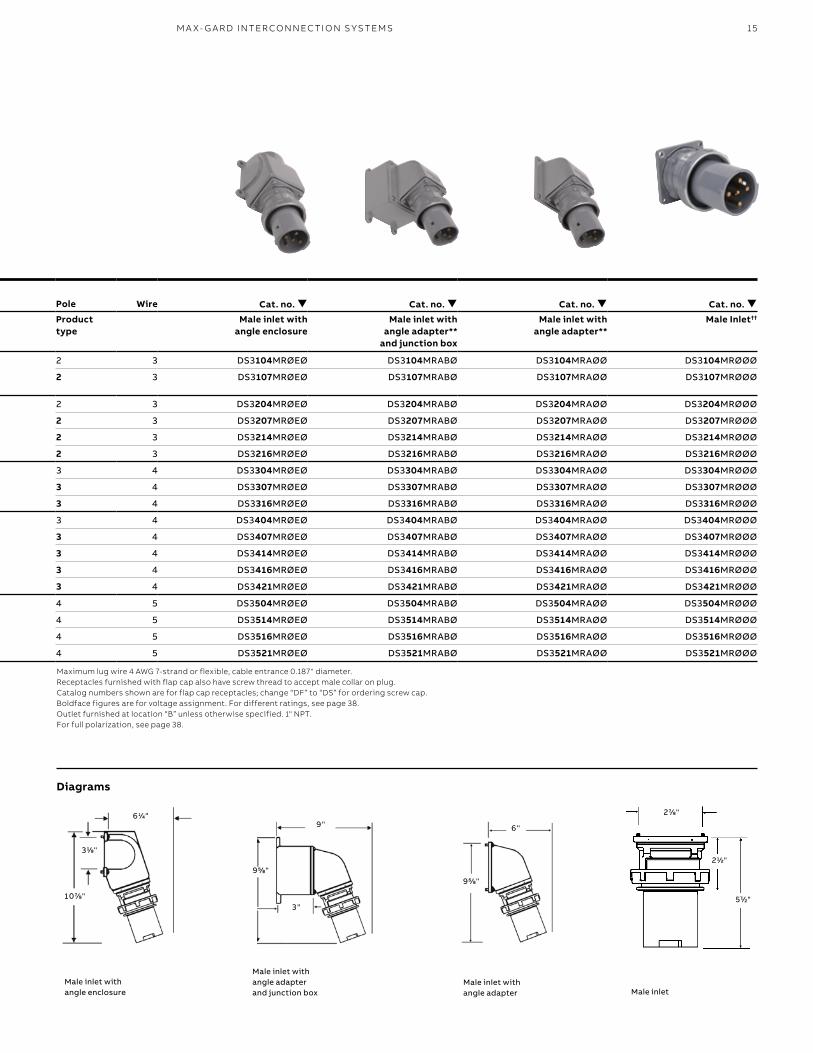
Maximum lug wire 4 AWG 7-strand or flexible, cable entrance 0.187" diameter. Receptacles furnished with flap cap also have screw thread to accept male collar on plug. Catalog numbers shown are for flap cap receptacles; change “DF” to “DS” for ordering screw cap. Boldface figures are for voltage assignment. For different ratings, see page 38.Outlet furnished at location “B” unless otherwise specified. 1" NPT.For full polarization, see page 38.
Diagrams
Male inlet with angle enclosure
Male inlet with angle adapter and junction box
Male inlet with angle adapter Male inlet
16 R U S S E LL S TO LL PI N & SL EE V E P OW ER CO N N EC TO R S
Pole WireConductorplacement
Voltage60 Hz Cat. no.
Standardbushing I.D.† (in.) Cat. no.
Standardbushing I.D.† (in.) Pole Wire Cat. no. Cat. no. Cat. no. Cat. no.
Product type
Male plug††
Female connector
Product type
Female receptacle with angle enclosure
Female receptacle with angle adapter**
and junction box
Female receptacle with angle adapter**
Female receptacle
2 3 277 DS6104MPØØØ 13/16 DF6104FPØØØ 13/16 2 3 DF6104FRØEØ DF6104FRABØ DF6104FRAØØ DF6104FRØØØ
2 3 125 DS6107MPØØØ 13/16 DF6107FPØØØ 13/16 2 3 DF6107FRØEØ DF6107FRABØ DF6107FRAØØ DF6107FRØØØ
2 3 480 DS6204MPØØØ 13/16 DF6204FPØØØ 13/16 2 3 DF6204FRØEØ DF6204FRABØ DF6204FRAØØ DF6204FRØØØ
2 3 250 DS6207MPØØØ 13/16 DF6207FPØØØ 13/16 2 3 DF6207FRØEØ DF6207FRABØ DF6207FRAØØ DF6207FRØØØ
2 3 600 DS6214MPØØØ 13/16 DF6214FPØØØ 13/16 2 3 DF6214FRØEØ DF6214FRABØ DF6214FRAØØ DF6214FRØØØ
2 3 208 DS6216MPØØØ 13/16 DF6216FPØØØ 13/16 2 3 DF6216FRØEØ DF6216FRABØ DF6216FRAØØ DF6216FRØØØ
3 4 277/480 DS6304MPØØØ 15/16 DF6304FPØØØ 15/16 3 4 DF6304FRØEØ DF6304FRABØ DF6304FRAØØ DF6304FRØØØ
3 4 125/250 DS6307MPØØØ 15/16 DF6307FPØØØ 15/16 3 4 DF6307FRØEØ DF6307FRABØ DF6307FRAØØ DF6307FRØØØ
3 4 120/208 DS6316MPØØØ 15/16 DF6316FPØØØ 15/16 3 4 DF6316FRØEØ DF6316FRABØ DF6316FRAØØ DF6316FRØØØ
3 4 3Ø 480 DS6404MPØØØ 15/16 DF6404FPØØØ 15/16 3 4 DF6404FRØEØ DF6404FRABØ DF6404FRAØØ DF6404FRØØØ
3 4 3Ø 250 DS6407MPØØØ 15/16 DF6407FPØØØ 15/16 3 4 DF6407FRØEØ DF6407FRABØ DF6407FRAØØ DF6407FRØØØ
3 4 3Ø 600 DS6414MPØØØ 15/16 DF6414FPØØØ 15/16 3 4 DF6414FRØEØ DF6414FRABØ DF6414FRAØØ DF6414FRØØØ
3 4 3Ø 208 DS6416MPØØØ 15/16 DF6416FPØØØ 15/16 3 4 DF6416FRØEØ DF6416FRABØ DF6416FRAØØ DF6416FRØØØ
3 4 3Ø 440 DS6421MPØØØ 15/16 DF6421FPØØØ 15/16 3 4 DF6421FRØEØ DF6421FRABØ DF6421FRAØØ DF6421FRØØØ
4 5 3ØY 277/480 DS6504MPØØØ 11/2 DF6504FPØØØ 11/2 4 5 DF6504FRØEØ DF6504FRABØ DF6504FRAØØ DF6504FRØØØ
4 5 3ØY 347/600 DS6514MPØØØ 11/2 DF6514FPØØØ 11/2 4 5 DF6514FRØEØ DF6514FRABØ DF6514FRAØØ DF6514FRØØØ
4 5 3ØY 110/208 DS6516MPØØØ 11/2 DF6516FPØØØ 11/2 4 5 DF6516FRØEØ DF6516FRABØ DF6516FRAØØ DF6516FRØØØ
4 5 3ØY 250/440 DS6521MPØØØ 11/2 DF6521FPØØØ 11/2 4 5 DF6521FRØEØ DF6521FRABØ DF6521FRAØØ DF6521FRØØØG
N1
2 3
G
1
2 3
G
N1
2
G
1
2
G
N1
G
N1
2 3
G
1
2 3
G
N1
2
G
1
2
G
N1
G
N1
2 3
G
1
2 3
G
N1
2
G
1
2
G
N1
G
N1
2 3
G
1
2 3
G
N1
2
G
1
2
G
N1
G
N1
2 3
G
1
2 3
G
N1
2
G
1
2
G
N1
5 1/2"
9 1/8"
1 0 "
5 3/8"
B
D
A C
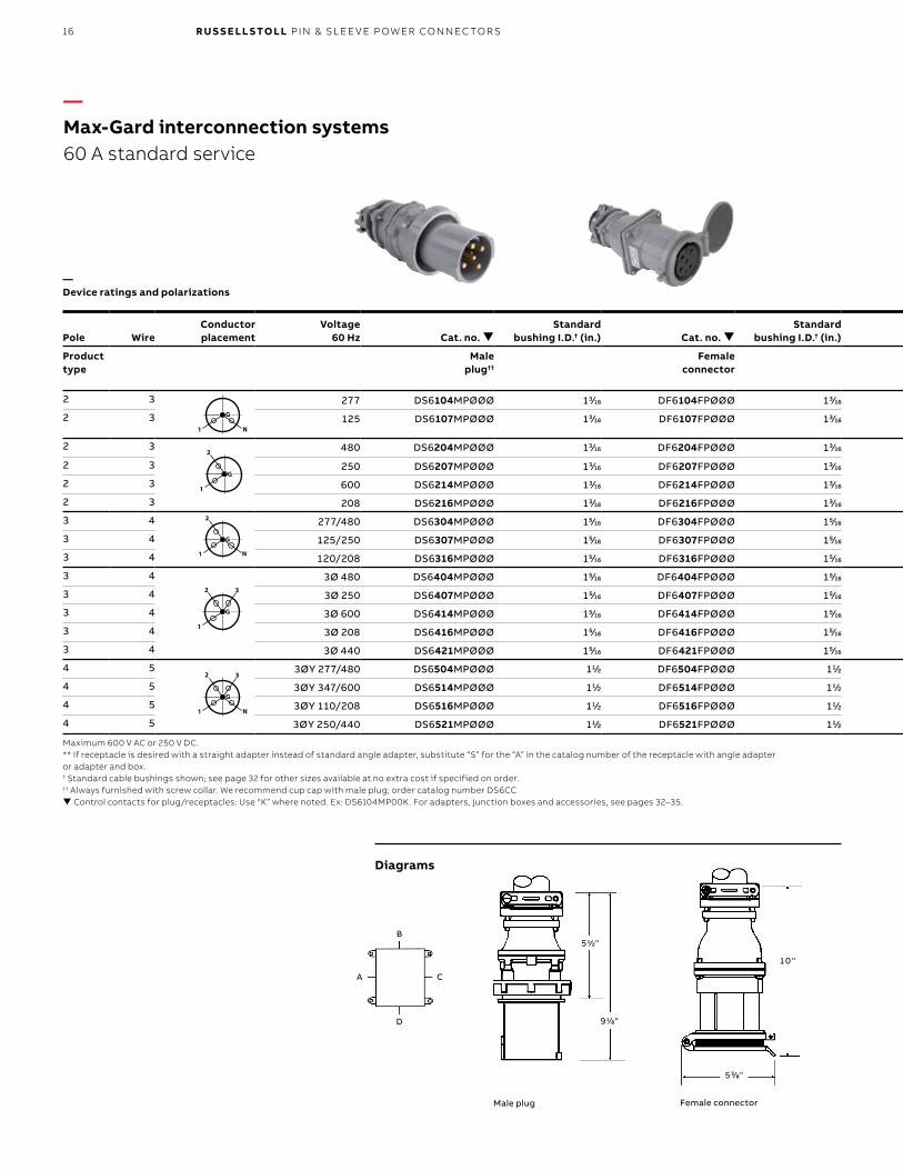
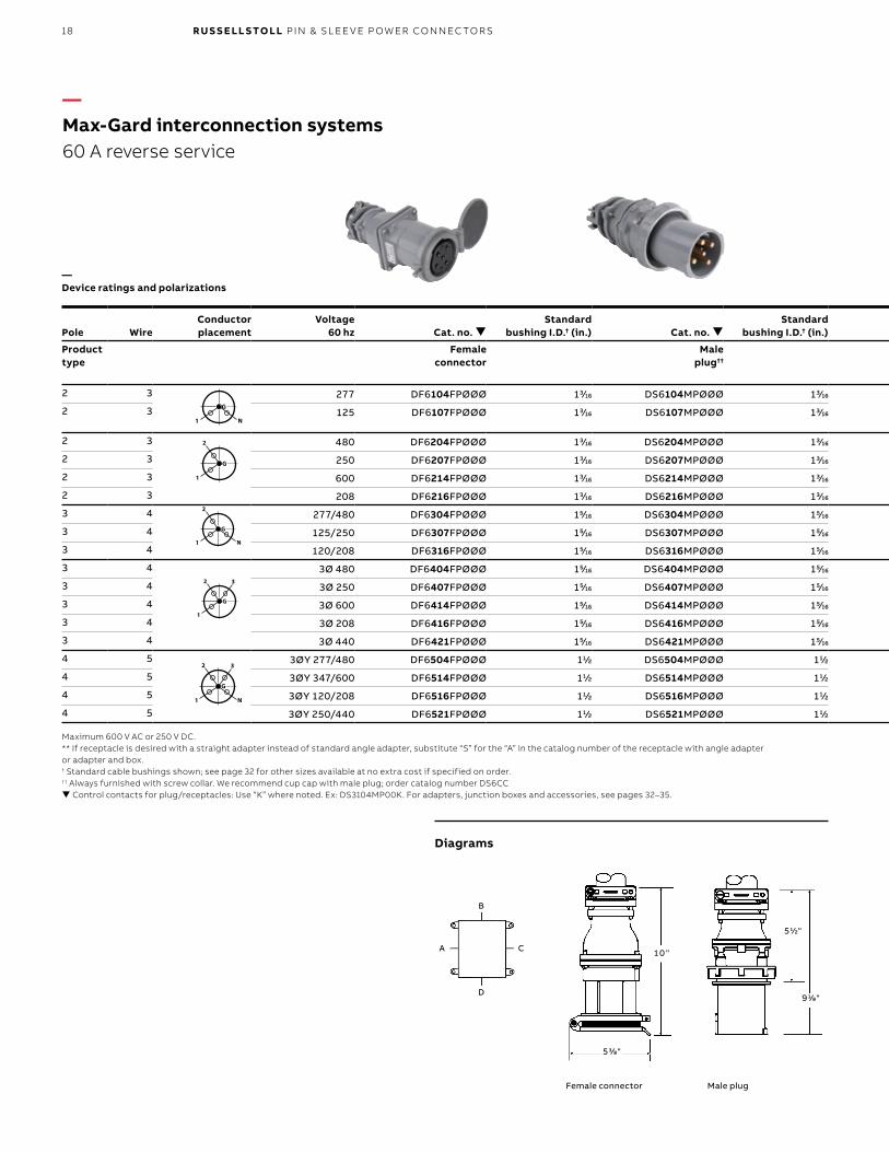
—Max-Gard interconnection systems60 A standard service
—Device ratings and polarizations
Maximum 600 V AC or 250 V DC.** If receptacle is desired with a straight adapter instead of standard angle adapter, substitute “S” for the “A” in the catalog number of the receptacle with angle adapter or adapter and box.† Standard cable bushings shown; see page 32 for other sizes available at no extra cost if specified on order.†† Always furnished with screw collar. We recommend cup cap with male plug; order catalog number DS6CC Control contacts for plug/receptacles: Use “K” where noted. Ex: DS6104MP00K. For adapters, junction boxes and accessories, see pages 32–35.
Diagrams
Male plug Female connector
17M A X- G A R D I NTER CO N N EC TI O N S Y S TEMS
Pole WireConductorplacement
Voltage60 Hz Cat. no.
Standardbushing I.D.† (in.) Cat. no.
Standardbushing I.D.† (in.) Pole Wire Cat. no. Cat. no. Cat. no. Cat. no.
Product type
Male plug††
Female connector
Product type
Female receptacle with angle enclosure
Female receptacle with angle adapter**
and junction box
Female receptacle with angle adapter**
Female receptacle
2 3 277 DS6104MPØØØ 13/16 DF6104FPØØØ 13/16 2 3 DF6104FRØEØ DF6104FRABØ DF6104FRAØØ DF6104FRØØØ
2 3 125 DS6107MPØØØ 13/16 DF6107FPØØØ 13/16 2 3 DF6107FRØEØ DF6107FRABØ DF6107FRAØØ DF6107FRØØØ
2 3 480 DS6204MPØØØ 13/16 DF6204FPØØØ 13/16 2 3 DF6204FRØEØ DF6204FRABØ DF6204FRAØØ DF6204FRØØØ
2 3 250 DS6207MPØØØ 13/16 DF6207FPØØØ 13/16 2 3 DF6207FRØEØ DF6207FRABØ DF6207FRAØØ DF6207FRØØØ
2 3 600 DS6214MPØØØ 13/16 DF6214FPØØØ 13/16 2 3 DF6214FRØEØ DF6214FRABØ DF6214FRAØØ DF6214FRØØØ
2 3 208 DS6216MPØØØ 13/16 DF6216FPØØØ 13/16 2 3 DF6216FRØEØ DF6216FRABØ DF6216FRAØØ DF6216FRØØØ
3 4 277/480 DS6304MPØØØ 15/16 DF6304FPØØØ 15/16 3 4 DF6304FRØEØ DF6304FRABØ DF6304FRAØØ DF6304FRØØØ
3 4 125/250 DS6307MPØØØ 15/16 DF6307FPØØØ 15/16 3 4 DF6307FRØEØ DF6307FRABØ DF6307FRAØØ DF6307FRØØØ
3 4 120/208 DS6316MPØØØ 15/16 DF6316FPØØØ 15/16 3 4 DF6316FRØEØ DF6316FRABØ DF6316FRAØØ DF6316FRØØØ
3 4 3Ø 480 DS6404MPØØØ 15/16 DF6404FPØØØ 15/16 3 4 DF6404FRØEØ DF6404FRABØ DF6404FRAØØ DF6404FRØØØ
3 4 3Ø 250 DS6407MPØØØ 15/16 DF6407FPØØØ 15/16 3 4 DF6407FRØEØ DF6407FRABØ DF6407FRAØØ DF6407FRØØØ
3 4 3Ø 600 DS6414MPØØØ 15/16 DF6414FPØØØ 15/16 3 4 DF6414FRØEØ DF6414FRABØ DF6414FRAØØ DF6414FRØØØ
3 4 3Ø 208 DS6416MPØØØ 15/16 DF6416FPØØØ 15/16 3 4 DF6416FRØEØ DF6416FRABØ DF6416FRAØØ DF6416FRØØØ
3 4 3Ø 440 DS6421MPØØØ 15/16 DF6421FPØØØ 15/16 3 4 DF6421FRØEØ DF6421FRABØ DF6421FRAØØ DF6421FRØØØ
4 5 3ØY 277/480 DS6504MPØØØ 11/2 DF6504FPØØØ 11/2 4 5 DF6504FRØEØ DF6504FRABØ DF6504FRAØØ DF6504FRØØØ
4 5 3ØY 347/600 DS6514MPØØØ 11/2 DF6514FPØØØ 11/2 4 5 DF6514FRØEØ DF6514FRABØ DF6514FRAØØ DF6514FRØØØ
4 5 3ØY 110/208 DS6516MPØØØ 11/2 DF6516FPØØØ 11/2 4 5 DF6516FRØEØ DF6516FRABØ DF6516FRAØØ DF6516FRØØØ
4 5 3ØY 250/440 DS6521MPØØØ 11/2 DF6521FPØØØ 11/2 4 5 DF6521FRØEØ DF6521FRABØ DF6521FRAØØ DF6521FRØØØ
3 3/8"
5 1/8"
7 1/2"
9 3/4"
1 0 1/2"
9 3/4"
3 "
1 1 1/8"
4 "
7 1/8"
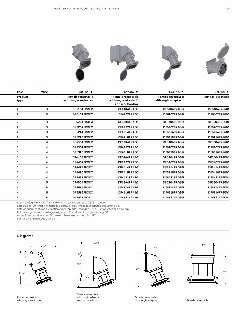
Maximum lug wire 4 AWG 7-strand or flexible, cable entrance 0.302" diameter. Receptacles furnished with flap cap also have screw thread to accept male collar on plug. Catalog numbers shown are for flap cap receptacles; change “DF” to “DS” for ordering screw cap. Boldface figures are for voltage assignment. For different ratings, see page 38.Outlet furnished at location “B” unless otherwise specified. 11⁄2" NPT. For full polarization, see page 38.
Diagrams
Female receptacle with angle enclosure
Female receptacle with angle adapter and junction box
Female receptacle with angle adapter Female receptacle
18 R U S S E LL S TO LL PI N & SL EE V E P OW ER CO N N EC TO R S
Pole WireConductorplacement
Voltage60 hz Cat. no.
Standard bushing I.D.† (in.) Cat. no.
Standard bushing I.D.† (in.) Pole Wire Cat. no. Cat. no. Cat. no. Cat. no.
Product type
Female connector
Male plug††
Product type
Male inlet with angle enclosure
Male inlet with angle adapter**
and junction box
Male inlet with angle adapter**
Male inlet††
2 3 277 DF6104FPØØØ 13/16 DS6104MPØØØ 13/16 2 3 DS6104MRØEØ DS6104MRABØ DS6104MRAØØ DS6104MRØØØ
2 3 125 DF6107FPØØØ 13/16 DS6107MPØØØ 13/16 2 3 DS6107MRØEØ DS6107MRABØ DS6107MRAØØ DS6107MRØØØ
2 3 480 DF6204FPØØØ 13/16 DS6204MPØØØ 13/16 2 3 DS6204MRØEØ DS6204MRABØ DS6204MRAØØ DS6204MRØØØ
2 3 250 DF6207FPØØØ 13/16 DS6207MPØØØ 13/16 2 3 DS6207MRØEØ DS6207MRABØ DS6207MRAØØ DS6207MRØØØ
2 3 600 DF6214FPØØØ 13/16 DS6214MPØØØ 13/16 2 3 DS6214MRØEØ DS6214MRABØ DS6214MRAØØ DS6214MRØØØ
2 3 208 DF6216FPØØØ 13/16 DS6216MPØØØ 13/16 2 3 DS6216MRØEØ DS6216MRABØ DS6216MRAØØ DS6216MRØØØ
3 4 277/480 DF6304FPØØØ 15/16 DS6304MPØØØ 15/16 3 4 DS6304MRØEØ DS6304MRABØ DS6304MRAØØ DS6304MRØØØ
3 4 125/250 DF6307FPØØØ 15/16 DS6307MPØØØ 15/16 3 4 DS6307MRØEØ DS6307MRABØ DS6307MRAØØ DS6307MRØØØ
3 4 120/208 DF6316FPØØØ 15/16 DS6316MPØØØ 15/16 3 4 DS6316MRØEØ DS6316MRABØ DS6316MRAØØ DS6316MRØØØ
3 4 3Ø 480 DF6404FPØØØ 15/16 DS6404MPØØØ 15/16 3 4 DS6404MRØEØ DS6404MRABØ DS6404MRAØØ DS6404MRØØØ
3 4 3Ø 250 DF6407FPØØØ 15/16 DS6407MPØØØ 15/16 3 4 DS6407MRØEØ DS6407MRABØ DS6407MRAØØ DS6407MRØØØ
3 4 3Ø 600 DF6414FPØØØ 15/16 DS6414MPØØØ 15/16 3 4 DS6414MRØEØ DS6414MRABØ DS6414MRAØØ DS6414MRØØØ
3 4 3Ø 208 DF6416FPØØØ 15/16 DS6416MPØØØ 15/16 3 4 DS6416MRØEØ DS6416MRABØ DS6416MRAØØ DS6416MRØØØ
3 4 3Ø 440 DF6421FPØØØ 15/16 DS6421MPØØØ 15/16 3 4 DS6421MRØEØ DS6421MRABØ DS6421MRAØØ DS6421MRØØØ
4 5 3ØY 277/480 DF6504FPØØØ 11/2 DS6504MPØØØ 11/2 4 5 DS6504MRØEØ DS6504MRABØ DS6504MRAØØ DS6504MRØØØ
4 5 3ØY 347/600 DF6514FPØØØ 11/2 DS6514MPØØØ 11/2 4 5 DS6514MRØEØ DS6514MRABØ DS6514MRAØØ DS6514MRØØØ
4 5 3ØY 120/208 DF6516FPØØØ 11/2 DS6516MPØØØ 11/2 4 5 DS6516MRØEØ DS6516MRABØ DS6516MRAØØ DS6516MRØØØ
4 5 3ØY 250/440 DF6521FPØØØ 11/2 DS6521MPØØØ 11/2 4 5 DS6521MRØEØ DS6521MRABØ DS6521MRAØØ DS6521MRØØØ
1 0 "
5 3/8"
5 1/2"
9 1/8"
B
D
A C
G
N1
2 3
G
1
2 3
G
N1
2
G
1
2
G
N1
G
N1
2 3
G
1
2 3
G
N1
2
G
1
2
G
N1
G
N1
2 3
G
1
2 3
G
N1
2
G
1
2
G
N1
G
N1
2 3
G
1
2 3
G
N1
2
G
1
2
G
N1
G
N1
2 3
G
1
2 3
G
N1
2
G
1
2
G
N1
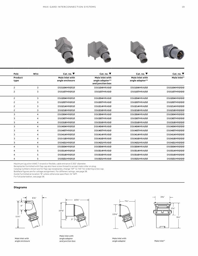
—Max-Gard interconnection systems60 A reverse service
—Device ratings and polarizations
Maximum 600 V AC or 250 V DC.** If receptacle is desired with a straight adapter instead of standard angle adapter, substitute “S” for the “A” in the catalog number of the receptacle with angle adapter or adapter and box.† Standard cable bushings shown; see page 32 for other sizes available at no extra cost if specified on order.†† Always furnished with screw collar. We recommend cup cap with male plug; order catalog number DS6CC Control contacts for plug/receptacles: Use “K” where noted. Ex: DS3104MP00K. For adapters, junction boxes and accessories, see pages 32–35.
Diagrams
Male plugFemale connector
19M A X- G A R D I NTER CO N N EC TI O N S Y S TEMS
Pole WireConductorplacement
Voltage60 hz Cat. no.
Standard bushing I.D.† (in.) Cat. no.
Standard bushing I.D.† (in.) Pole Wire Cat. no. Cat. no. Cat. no. Cat. no.
Product type
Female connector
Male plug††
Product type
Male inlet with angle enclosure
Male inlet with angle adapter**
and junction box
Male inlet with angle adapter**
Male inlet††
2 3 277 DF6104FPØØØ 13/16 DS6104MPØØØ 13/16 2 3 DS6104MRØEØ DS6104MRABØ DS6104MRAØØ DS6104MRØØØ
2 3 125 DF6107FPØØØ 13/16 DS6107MPØØØ 13/16 2 3 DS6107MRØEØ DS6107MRABØ DS6107MRAØØ DS6107MRØØØ
2 3 480 DF6204FPØØØ 13/16 DS6204MPØØØ 13/16 2 3 DS6204MRØEØ DS6204MRABØ DS6204MRAØØ DS6204MRØØØ
2 3 250 DF6207FPØØØ 13/16 DS6207MPØØØ 13/16 2 3 DS6207MRØEØ DS6207MRABØ DS6207MRAØØ DS6207MRØØØ
2 3 600 DF6214FPØØØ 13/16 DS6214MPØØØ 13/16 2 3 DS6214MRØEØ DS6214MRABØ DS6214MRAØØ DS6214MRØØØ
2 3 208 DF6216FPØØØ 13/16 DS6216MPØØØ 13/16 2 3 DS6216MRØEØ DS6216MRABØ DS6216MRAØØ DS6216MRØØØ
3 4 277/480 DF6304FPØØØ 15/16 DS6304MPØØØ 15/16 3 4 DS6304MRØEØ DS6304MRABØ DS6304MRAØØ DS6304MRØØØ
3 4 125/250 DF6307FPØØØ 15/16 DS6307MPØØØ 15/16 3 4 DS6307MRØEØ DS6307MRABØ DS6307MRAØØ DS6307MRØØØ
3 4 120/208 DF6316FPØØØ 15/16 DS6316MPØØØ 15/16 3 4 DS6316MRØEØ DS6316MRABØ DS6316MRAØØ DS6316MRØØØ
3 4 3Ø 480 DF6404FPØØØ 15/16 DS6404MPØØØ 15/16 3 4 DS6404MRØEØ DS6404MRABØ DS6404MRAØØ DS6404MRØØØ
3 4 3Ø 250 DF6407FPØØØ 15/16 DS6407MPØØØ 15/16 3 4 DS6407MRØEØ DS6407MRABØ DS6407MRAØØ DS6407MRØØØ
3 4 3Ø 600 DF6414FPØØØ 15/16 DS6414MPØØØ 15/16 3 4 DS6414MRØEØ DS6414MRABØ DS6414MRAØØ DS6414MRØØØ
3 4 3Ø 208 DF6416FPØØØ 15/16 DS6416MPØØØ 15/16 3 4 DS6416MRØEØ DS6416MRABØ DS6416MRAØØ DS6416MRØØØ
3 4 3Ø 440 DF6421FPØØØ 15/16 DS6421MPØØØ 15/16 3 4 DS6421MRØEØ DS6421MRABØ DS6421MRAØØ DS6421MRØØØ
4 5 3ØY 277/480 DF6504FPØØØ 11/2 DS6504MPØØØ 11/2 4 5 DS6504MRØEØ DS6504MRABØ DS6504MRAØØ DS6504MRØØØ
4 5 3ØY 347/600 DF6514FPØØØ 11/2 DS6514MPØØØ 11/2 4 5 DS6514MRØEØ DS6514MRABØ DS6514MRAØØ DS6514MRØØØ
4 5 3ØY 120/208 DF6516FPØØØ 11/2 DS6516MPØØØ 11/2 4 5 DS6516MRØEØ DS6516MRABØ DS6516MRAØØ DS6516MRØØØ
4 5 3ØY 250/440 DF6521FPØØØ 11/2 DS6521MPØØØ 11/2 4 5 DS6521MRØEØ DS6521MRABØ DS6521MRAØØ DS6521MRØØØ
1 0 1/4"3 3/8"
5 1/2"
2 1/2"
7 1/4"
1 0 1/8"
1 0 1/8"
3 "
4 "
1 1 1/2"
6 7/8"
Maximum lug wire 4 AWG 7-strand or flexible, cable entrance 0.302" diameter. Receptacles furnished with flap cap also have screw thread to accept male collar on plug. Catalog numbers shown are for flap cap receptacles; change “DF” to “DS” for ordering screw cap. Boldface figures are for voltage assignment. For different ratings, see page 38.Outlet furnished at location “B” unless otherwise specified. 11⁄2" NPT. For full polarization, see page 38.
Diagrams
Male inlet with angle enclosure
Male inlet with angle adapter and junction box
Male inlet with angle adapter Male inlet††
20 R U S S E LL S TO LL PI N & SL EE V E P OW ER CO N N EC TO R S
6 1/2"
1 0 1/8"
1 1 1/8"
5 3/8"
B
D
A C
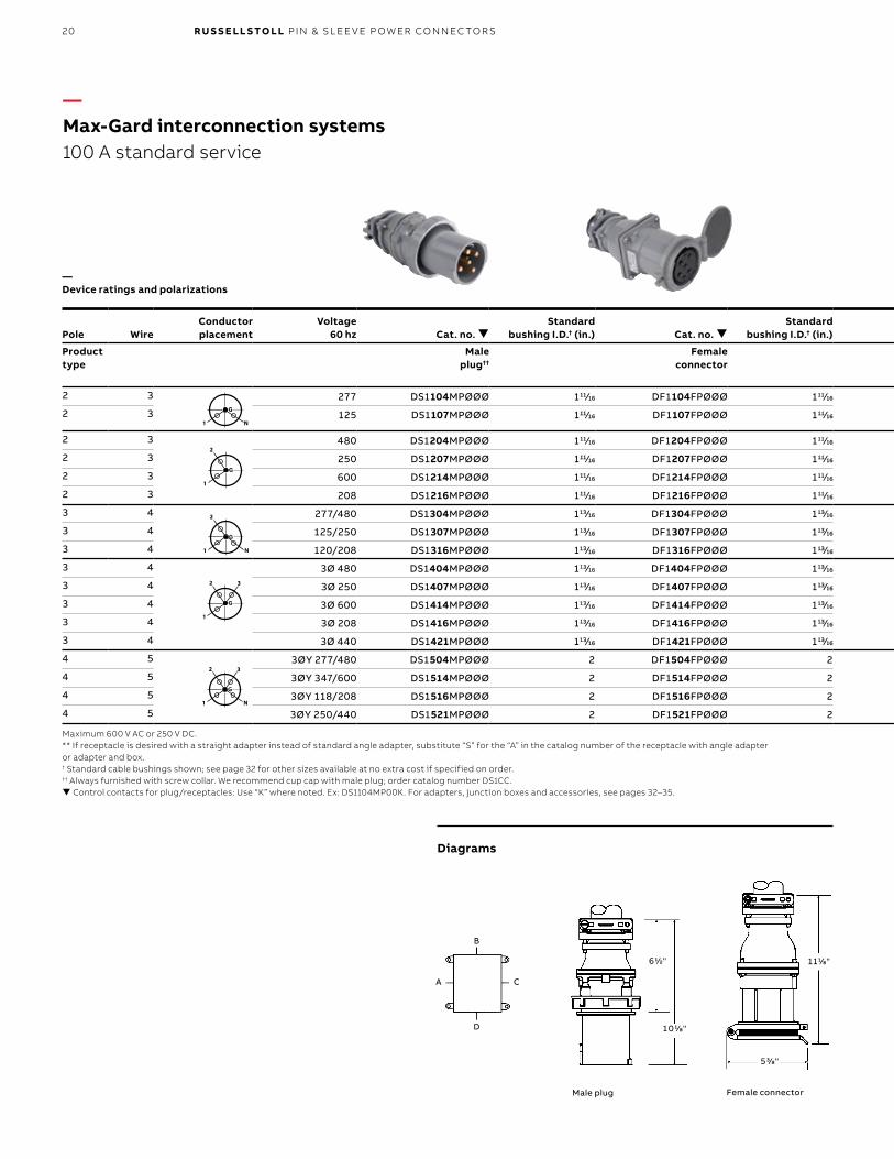
—Max-Gard interconnection systems100 A standard service
—Device ratings and polarizations
Pole WireConductorplacement
Voltage60 hz Cat. no.
Standard bushing I.D.† (in.) Cat. no.
Standard bushing I.D.† (in.) Pole Wire Cat. no. Cat. no. Cat. no. Cat. no.
Product type
Male plug††
Female connector
Product type
Female receptacle with angle enclosure
Female receptacle with angle adapter**
and junction box
Female receptacle with angle adapter**
Female receptacle
2 3 277 DS1104MPØØØ 111/16 DF1104FPØØØ 111/16 2 3 DF1104FRØEØ DF1104FRABØ DF1104FRAØØ DF1104FRØØØ
2 3 125 DS1107MPØØØ 111/16 DF1107FPØØØ 111/16 2 3 DF1107FRØEØ DF1107FRABØ DF1107FRAØØ DF1107FRØØØ
2 3 480 DS1204MPØØØ 111/16 DF1204FPØØØ 111/16 2 3 DF1204FRØEØ DF1204FRABØ DF1204FRAØØ DF1204FRØØØ
2 3 250 DS1207MPØØØ 111/16 DF1207FPØØØ 111/16 2 3 DF1207FRØEØ DF1207FRABØ DF1207FRAØØ DF1207FRØØØ
2 3 600 DS1214MPØØØ 111/16 DF1214FPØØØ 111/16 2 3 DF1214FRØEØ DF1214FRABØ DF1214FRAØØ DF1214FRØØØ
2 3 208 DS1216MPØØØ 111/16 DF1216FPØØØ 111/16 2 3 DF1216FRØEØ DF1216FRABØ DF1216FRAØØ DF1216FRØØØ
3 4 277/480 DS1304MPØØØ 113/16 DF1304FPØØØ 113/16 3 4 DF1304FRØEØ DF1304FRABØ DF1304FRAØØ DF1304FRØØØ
3 4 125/250 DS1307MPØØØ 113/16 DF1307FPØØØ 113/16 3 4 DF1307FRØEØ DF1307FRABØ DF1307FRAØØ DF1307FRØØØ
3 4 120/208 DS1316MPØØØ 113/16 DF1316FPØØØ 113/16 3 4 DF1316FRØEØ DF1316FRABØ DF1316FRAØØ DF1316FRØØØ
3 4 3Ø 480 DS1404MPØØØ 113/16 DF1404FPØØØ 113/16 3 4 DF1404FRØEØ DF1404FRABØ DF1404FRAØØ DF1404FRØØØ
3 4 3Ø 250 DS1407MPØØØ 113/16 DF1407FPØØØ 113/16 3 4 DF1407FRØEØ DF1407FRABØ DF1407FRAØØ DF1407FRØØØ
3 4 3Ø 600 DS1414MPØØØ 113/16 DF1414FPØØØ 113/16 3 4 DF1414FRØEØ DF1414FRABØ DF1414FRAØØ DF1414FRØØØ
3 4 3Ø 208 DS1416MPØØØ 113/16 DF1416FPØØØ 113/16 3 4 DF1416FRØEØ DF1416FRABØ DF1416FRAØØ DF1416FRØØØ
3 4 3Ø 440 DS1421MPØØØ 113/16 DF1421FPØØØ 113/16 3 4 DF1421FRØEØ DF1421FRABØ DF1421FRAØØ DF1421FRØØØ
4 5 3ØY 277/480 DS1504MPØØØ 2 DF1504FPØØØ 2 4 5 DF1504FRØEØ DF1504FRABØ DF1504FRAØØ DF1504FRØØØ
4 5 3ØY 347/600 DS1514MPØØØ 2 DF1514FPØØØ 2 4 5 DF1514FRØEØ DF1514FRABØ DF1514FRAØØ DF1514FRØØØ
4 5 3ØY 118/208 DS1516MPØØØ 2 DF1516FPØØØ 2 4 5 DF1516FRØEØ DF1516FRABØ DF1516FRAØØ DF1516FRØØØ
4 5 3ØY 250/440 DS1521MPØØØ 2 DF1521FPØØØ 2 4 5 DF1521FRØEØ DF1521FRABØ DF1521FRAØØ DF1521FRØØØ
G
N1
2 3
G
1
2 3
G
N1
2
G
1
2
G
N1
G
N1
2 3
G
1
2 3
G
N1
2
G
1
2
G
N1
G
N1
2 3
G
1
2 3
G
N1
2
G
1
2
G
N1
G
N1
2 3
G
1
2 3
G
N1
2
G
1
2
G
N1
G
N1
2 3
G
1
2 3
G
N1
2
G
1
2
G
N1
Maximum 600 V AC or 250 V DC.** If receptacle is desired with a straight adapter instead of standard angle adapter, substitute “S” for the “A” in the catalog number of the receptacle with angle adapter or adapter and box.† Standard cable bushings shown; see page 32 for other sizes available at no extra cost if specified on order.†† Always furnished with screw collar. We recommend cup cap with male plug; order catalog number DS1CC. Control contacts for plug/receptacles: Use “K” where noted. Ex: DS1104MP00K. For adapters, junction boxes and accessories, see pages 32–35.
Diagrams
Male plug Female connector
21M A X- G A R D I NTER CO N N EC TI O N S Y S TEMS
3 5/8"
3 5/8"
7 "
1 0 "
1 0 3/4"
1 0 "
3 3/4"
71⁄2”
4 "
1 1 3/8"
7 1/2"
Pole WireConductorplacement
Voltage60 hz Cat. no.
Standard bushing I.D.† (in.) Cat. no.
Standard bushing I.D.† (in.) Pole Wire Cat. no. Cat. no. Cat. no. Cat. no.
Product type
Male plug††
Female connector
Product type
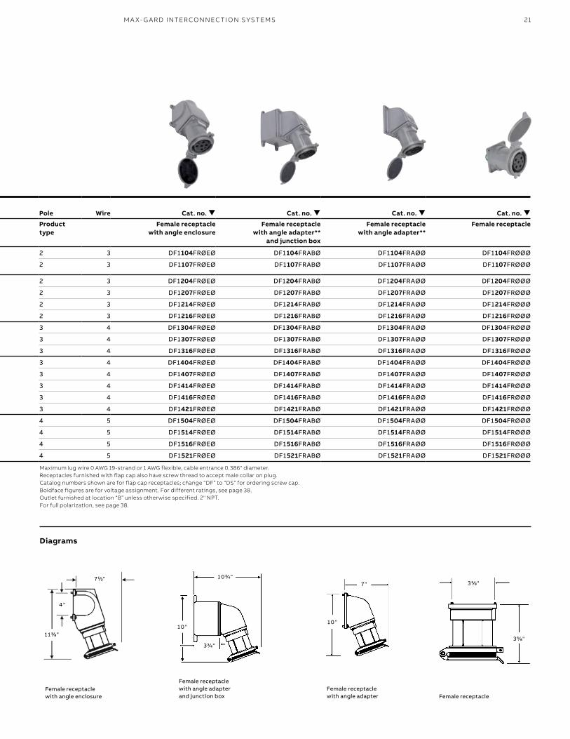
Female receptacle with angle enclosure
Female receptacle with angle adapter**
and junction box
Female receptacle with angle adapter**
Female receptacle
2 3 277 DS1104MPØØØ 111/16 DF1104FPØØØ 111/16 2 3 DF1104FRØEØ DF1104FRABØ DF1104FRAØØ DF1104FRØØØ
2 3 125 DS1107MPØØØ 111/16 DF1107FPØØØ 111/16 2 3 DF1107FRØEØ DF1107FRABØ DF1107FRAØØ DF1107FRØØØ
2 3 480 DS1204MPØØØ 111/16 DF1204FPØØØ 111/16 2 3 DF1204FRØEØ DF1204FRABØ DF1204FRAØØ DF1204FRØØØ
2 3 250 DS1207MPØØØ 111/16 DF1207FPØØØ 111/16 2 3 DF1207FRØEØ DF1207FRABØ DF1207FRAØØ DF1207FRØØØ
2 3 600 DS1214MPØØØ 111/16 DF1214FPØØØ 111/16 2 3 DF1214FRØEØ DF1214FRABØ DF1214FRAØØ DF1214FRØØØ
2 3 208 DS1216MPØØØ 111/16 DF1216FPØØØ 111/16 2 3 DF1216FRØEØ DF1216FRABØ DF1216FRAØØ DF1216FRØØØ
3 4 277/480 DS1304MPØØØ 113/16 DF1304FPØØØ 113/16 3 4 DF1304FRØEØ DF1304FRABØ DF1304FRAØØ DF1304FRØØØ
3 4 125/250 DS1307MPØØØ 113/16 DF1307FPØØØ 113/16 3 4 DF1307FRØEØ DF1307FRABØ DF1307FRAØØ DF1307FRØØØ
3 4 120/208 DS1316MPØØØ 113/16 DF1316FPØØØ 113/16 3 4 DF1316FRØEØ DF1316FRABØ DF1316FRAØØ DF1316FRØØØ
3 4 3Ø 480 DS1404MPØØØ 113/16 DF1404FPØØØ 113/16 3 4 DF1404FRØEØ DF1404FRABØ DF1404FRAØØ DF1404FRØØØ
3 4 3Ø 250 DS1407MPØØØ 113/16 DF1407FPØØØ 113/16 3 4 DF1407FRØEØ DF1407FRABØ DF1407FRAØØ DF1407FRØØØ
3 4 3Ø 600 DS1414MPØØØ 113/16 DF1414FPØØØ 113/16 3 4 DF1414FRØEØ DF1414FRABØ DF1414FRAØØ DF1414FRØØØ
3 4 3Ø 208 DS1416MPØØØ 113/16 DF1416FPØØØ 113/16 3 4 DF1416FRØEØ DF1416FRABØ DF1416FRAØØ DF1416FRØØØ
3 4 3Ø 440 DS1421MPØØØ 113/16 DF1421FPØØØ 113/16 3 4 DF1421FRØEØ DF1421FRABØ DF1421FRAØØ DF1421FRØØØ
4 5 3ØY 277/480 DS1504MPØØØ 2 DF1504FPØØØ 2 4 5 DF1504FRØEØ DF1504FRABØ DF1504FRAØØ DF1504FRØØØ
4 5 3ØY 347/600 DS1514MPØØØ 2 DF1514FPØØØ 2 4 5 DF1514FRØEØ DF1514FRABØ DF1514FRAØØ DF1514FRØØØ
4 5 3ØY 118/208 DS1516MPØØØ 2 DF1516FPØØØ 2 4 5 DF1516FRØEØ DF1516FRABØ DF1516FRAØØ DF1516FRØØØ
4 5 3ØY 250/440 DS1521MPØØØ 2 DF1521FPØØØ 2 4 5 DF1521FRØEØ DF1521FRABØ DF1521FRAØØ DF1521FRØØØ
Maximum lug wire 0 AWG 19-strand or 1 AWG flexible, cable entrance 0.386" diameter. Receptacles furnished with flap cap also have screw thread to accept male collar on plug. Catalog numbers shown are for flap cap receptacles; change “DF” to “DS” for ordering screw cap. Boldface figures are for voltage assignment. For different ratings, see page 38.Outlet furnished at location “B” unless otherwise specified. 2" NPT. For full polarization, see page 38.
Diagrams
Female receptacle with angle enclosure
Female receptacle with angle adapter and junction box
Female receptacle with angle adapter Female receptacle
22 R U S S E LL S TO LL PI N & SL EE V E P OW ER CO N N EC TO R S
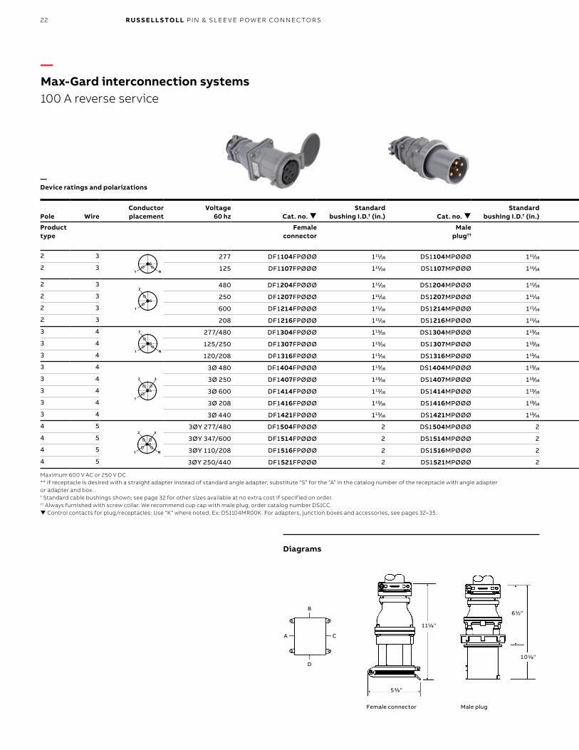
1 1 1/8"
5 3/8"
6 1/2"
1 0 1/8"
B
D
A C
—Max-Gard interconnection systems100 A reverse service
—Device ratings and polarizations
Pole WireConductorplacement
Voltage60 hz Cat. no.
Standard bushing I.D.† (in.) Cat. no.
Standard bushing I.D.† (in.) Pole Wire Cat. no. Cat. no. Cat. no. Cat. no.
Product type
Female connector
Male plug††
Product type
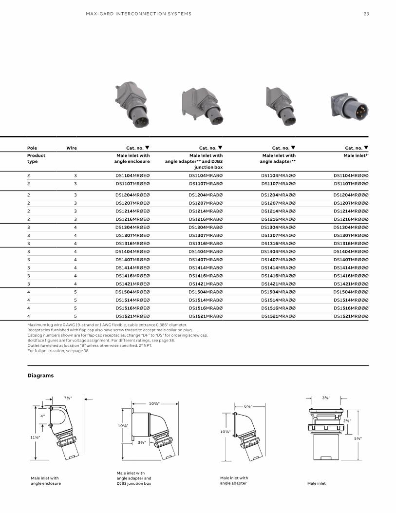
Male inlet with angle enclosure
Male inlet with angle adapter** and DJB3
junction box
Male inlet with angle adapter**
Male inlet††
2 3 277 DF1104FPØØØ 111/16 DS1104MPØØØ 111/16 2 3 DS1104MRØEØ DS1104MRABØ DS1104MRAØØ DS1104MRØØØ
2 3 125 DF1107FPØØØ 111/16 DS1107MPØØØ 111/16 2 3 DS1107MRØEØ DS1107MRABØ DS1107MRAØØ DS1107MRØØØ
2 3 480 DF1204FPØØØ 111/16 DS1204MPØØØ 111/16 2 3 DS1204MRØEØ DS1204MRABØ DS1204MRAØØ DS1204MRØØØ
2 3 250 DF1207FPØØØ 111/16 DS1207MPØØØ 111/16 2 3 DS1207MRØEØ DS1207MRABØ DS1207MRAØØ DS1207MRØØØ
2 3 600 DF1214FPØØØ 111/16 DS1214MPØØØ 111/16 2 3 DS1214MRØEØ DS1214MRABØ DS1214MRAØØ DS1214MRØØØ
2 3 208 DF1216FPØØØ 111/16 DS1216MPØØØ 111/16 2 3 DS1216MRØEØ DS1216MRABØ DS1216MRAØØ DS1216MRØØØ
3 4 277/480 DF1304FPØØØ 113/16 DS1304MPØØØ 113/16 3 4 DS1304MRØEØ DS1304MRABØ DS1304MRAØØ DS1304MRØØØ
3 4 125/250 DF1307FPØØØ 113/16 DS1307MPØØØ 113/16 3 4 DS1307MRØEØ DS1307MRABØ DS1307MRAØØ DS1307MRØØØ
3 4 120/208 DF1316FPØØØ 113/16 DS1316MPØØØ 113/16 3 4 DS1316MRØEØ DS1316MRABØ DS1316MRAØØ DS1316MRØØØ
3 4 3Ø 480 DF1404FPØØØ 113/16 DS1404MPØØØ 113/16 3 4 DS1404MRØEØ DS1404MRABØ DS1404MRAØØ DS1404MRØØØ
3 4 3Ø 250 DF1407FPØØØ 113/16 DS1407MPØØØ 113/16 3 4 DS1407MRØEØ DS1407MRABØ DS1407MRAØØ DS1407MRØØØ
3 4 3Ø 600 DF1414FPØØØ 113/16 DS1414MPØØØ 113/16 3 4 DS1414MRØEØ DS1414MRABØ DS1414MRAØØ DS1414MRØØØ
3 4 3Ø 208 DF1416FPØØØ 113/16 DS1416MPØØØ 113/16 3 4 DS1416MRØEØ DS1416MRABØ DS1416MRAØØ DS1416MRØØØ
3 4 3Ø 440 DF1421FPØØØ 113/16 DS1421MPØØØ 113/16 3 4 DS1421MRØEØ DS1421MRABØ DS1421MRAØØ DS1421MRØØØ
4 5 3ØY 277/480 DF1504FPØØØ 2 DS1504MPØØØ 2 4 5 DS1504MRØEØ DS1504MRABØ DS1504MRAØØ DS1504MRØØØ
4 5 3ØY 347/600 DF1514FPØØØ 2 DS1514MPØØØ 2 4 5 DS1514MRØEØ DS1514MRABØ DS1514MRAØØ DS1514MRØØØ
4 5 3ØY 110/208 DF1516FPØØØ 2 DS1516MPØØØ 2 4 5 DS1516MRØEØ DS1516MRABØ DS1516MRAØØ DS1516MRØØØ
4 5 3ØY 250/440 DF1521FPØØØ 2 DS1521MPØØØ 2 4 5 DS1521MRØEØ DS1521MRABØ DS1521MRAØØ DS1521MRØØØ
G
N1
2 3
G
1
2 3
G
N1
2
G
1
2
G
N1
G
N1
2 3
G
1
2 3
G
N1
2
G
1
2
G
N1
G
N1
2 3
G
1
2 3
G
N1
2
G
1
2
G
N1
G
N1
2 3
G
1
2 3
G
N1
2
G
1
2
G
N1
G
N1
2 3
G
1
2 3
G
N1
2
G
1
2
G
N1
Maximum 600 V AC or 250 V DC.** If receptacle is desired with a straight adapter instead of standard angle adapter, substitute “S” for the “A” in the catalog number of the receptacle with angle adapter or adapter and box.† Standard cable bushings shown; see page 32 for other sizes available at no extra cost if specified on order.†† Always furnished with screw collar. We recommend cup cap with male plug; order catalog number DS1CC. Control contacts for plug/receptacles: Use “K” where noted. Ex: DS1104MR00K. For adapters, junction boxes and accessories, see pages 32–35.
Diagrams
Male plugFemale connector
23M A X- G A R D I NTER CO N N EC TI O N S Y S TEMS
1 0 1/8"
3 3/4"
1 0 5/8"3 3/8"
5 1/2"
2 1/2"
6 7/8"
1 0 1/8"
4 "
1 1 1/2"
7 3/8"
Pole WireConductorplacement
Voltage60 hz Cat. no.
Standard bushing I.D.† (in.) Cat. no.
Standard bushing I.D.† (in.) Pole Wire Cat. no. Cat. no. Cat. no. Cat. no.
Product type
Female connector
Male plug††
Product type
Male inlet with angle enclosure
Male inlet with angle adapter** and DJB3
junction box
Male inlet with angle adapter**
Male inlet††
2 3 277 DF1104FPØØØ 111/16 DS1104MPØØØ 111/16 2 3 DS1104MRØEØ DS1104MRABØ DS1104MRAØØ DS1104MRØØØ
2 3 125 DF1107FPØØØ 111/16 DS1107MPØØØ 111/16 2 3 DS1107MRØEØ DS1107MRABØ DS1107MRAØØ DS1107MRØØØ
2 3 480 DF1204FPØØØ 111/16 DS1204MPØØØ 111/16 2 3 DS1204MRØEØ DS1204MRABØ DS1204MRAØØ DS1204MRØØØ
2 3 250 DF1207FPØØØ 111/16 DS1207MPØØØ 111/16 2 3 DS1207MRØEØ DS1207MRABØ DS1207MRAØØ DS1207MRØØØ
2 3 600 DF1214FPØØØ 111/16 DS1214MPØØØ 111/16 2 3 DS1214MRØEØ DS1214MRABØ DS1214MRAØØ DS1214MRØØØ
2 3 208 DF1216FPØØØ 111/16 DS1216MPØØØ 111/16 2 3 DS1216MRØEØ DS1216MRABØ DS1216MRAØØ DS1216MRØØØ
3 4 277/480 DF1304FPØØØ 113/16 DS1304MPØØØ 113/16 3 4 DS1304MRØEØ DS1304MRABØ DS1304MRAØØ DS1304MRØØØ
3 4 125/250 DF1307FPØØØ 113/16 DS1307MPØØØ 113/16 3 4 DS1307MRØEØ DS1307MRABØ DS1307MRAØØ DS1307MRØØØ
3 4 120/208 DF1316FPØØØ 113/16 DS1316MPØØØ 113/16 3 4 DS1316MRØEØ DS1316MRABØ DS1316MRAØØ DS1316MRØØØ
3 4 3Ø 480 DF1404FPØØØ 113/16 DS1404MPØØØ 113/16 3 4 DS1404MRØEØ DS1404MRABØ DS1404MRAØØ DS1404MRØØØ
3 4 3Ø 250 DF1407FPØØØ 113/16 DS1407MPØØØ 113/16 3 4 DS1407MRØEØ DS1407MRABØ DS1407MRAØØ DS1407MRØØØ
3 4 3Ø 600 DF1414FPØØØ 113/16 DS1414MPØØØ 113/16 3 4 DS1414MRØEØ DS1414MRABØ DS1414MRAØØ DS1414MRØØØ
3 4 3Ø 208 DF1416FPØØØ 113/16 DS1416MPØØØ 113/16 3 4 DS1416MRØEØ DS1416MRABØ DS1416MRAØØ DS1416MRØØØ
3 4 3Ø 440 DF1421FPØØØ 113/16 DS1421MPØØØ 113/16 3 4 DS1421MRØEØ DS1421MRABØ DS1421MRAØØ DS1421MRØØØ
4 5 3ØY 277/480 DF1504FPØØØ 2 DS1504MPØØØ 2 4 5 DS1504MRØEØ DS1504MRABØ DS1504MRAØØ DS1504MRØØØ
4 5 3ØY 347/600 DF1514FPØØØ 2 DS1514MPØØØ 2 4 5 DS1514MRØEØ DS1514MRABØ DS1514MRAØØ DS1514MRØØØ
4 5 3ØY 110/208 DF1516FPØØØ 2 DS1516MPØØØ 2 4 5 DS1516MRØEØ DS1516MRABØ DS1516MRAØØ DS1516MRØØØ
4 5 3ØY 250/440 DF1521FPØØØ 2 DS1521MPØØØ 2 4 5 DS1521MRØEØ DS1521MRABØ DS1521MRAØØ DS1521MRØØØ
Maximum lug wire 0 AWG 19-strand or 1 AWG flexible, cable entrance 0.386" diameter. Receptacles furnished with flap cap also have screw thread to accept male collar on plug. Catalog numbers shown are for flap cap receptacles; change “DF” to “DS” for ordering screw cap. Boldface figures are for voltage assignment. For different ratings, see page 38.Outlet furnished at location “B” unless otherwise specified. 2" NPT. For full polarization, see page 38.
Diagrams
Male inlet with angle enclosure
Male inlet with angle adapter and DJB3 junction box
Male inlet with angle adapter Male inlet
24 R U S S E LL S TO LL PI N & SL EE V E P OW ER CO N N EC TO R S
9 "
1 3 3/4"
1 5 "
9 1/2"
A C
B
D
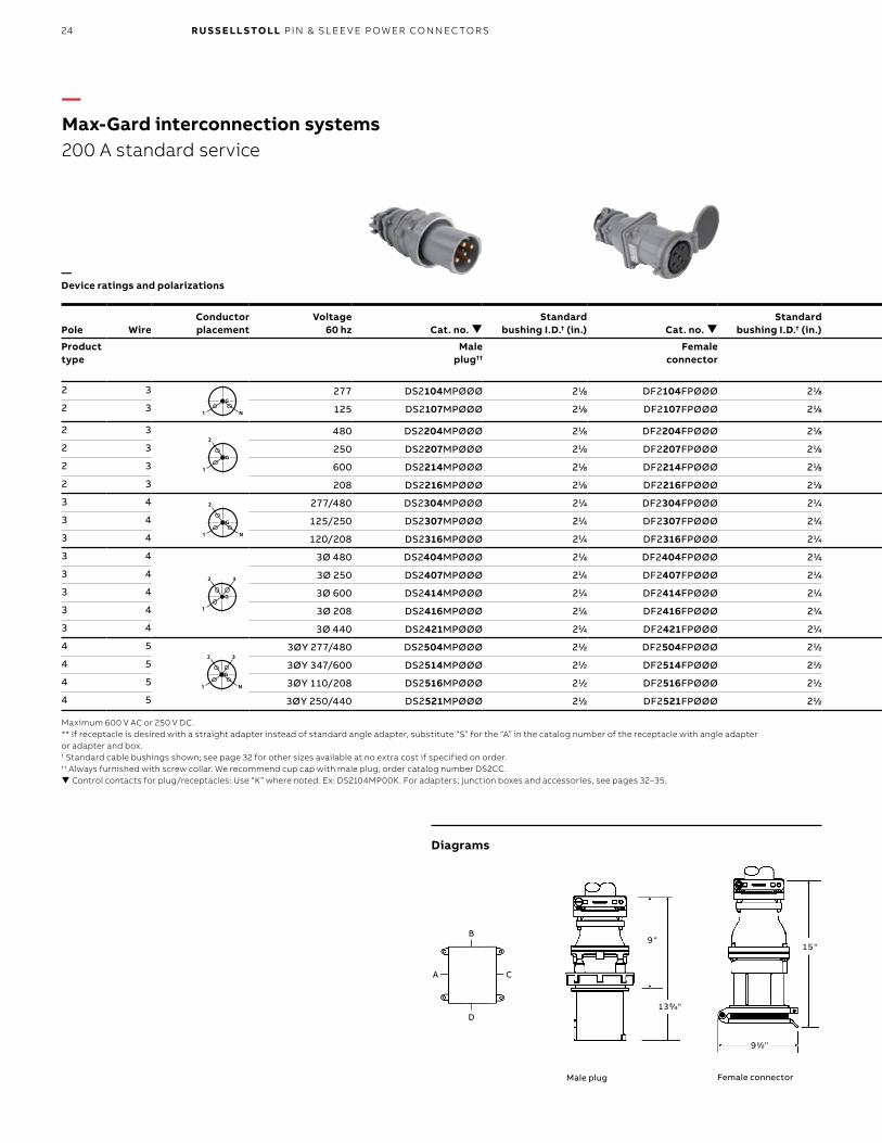
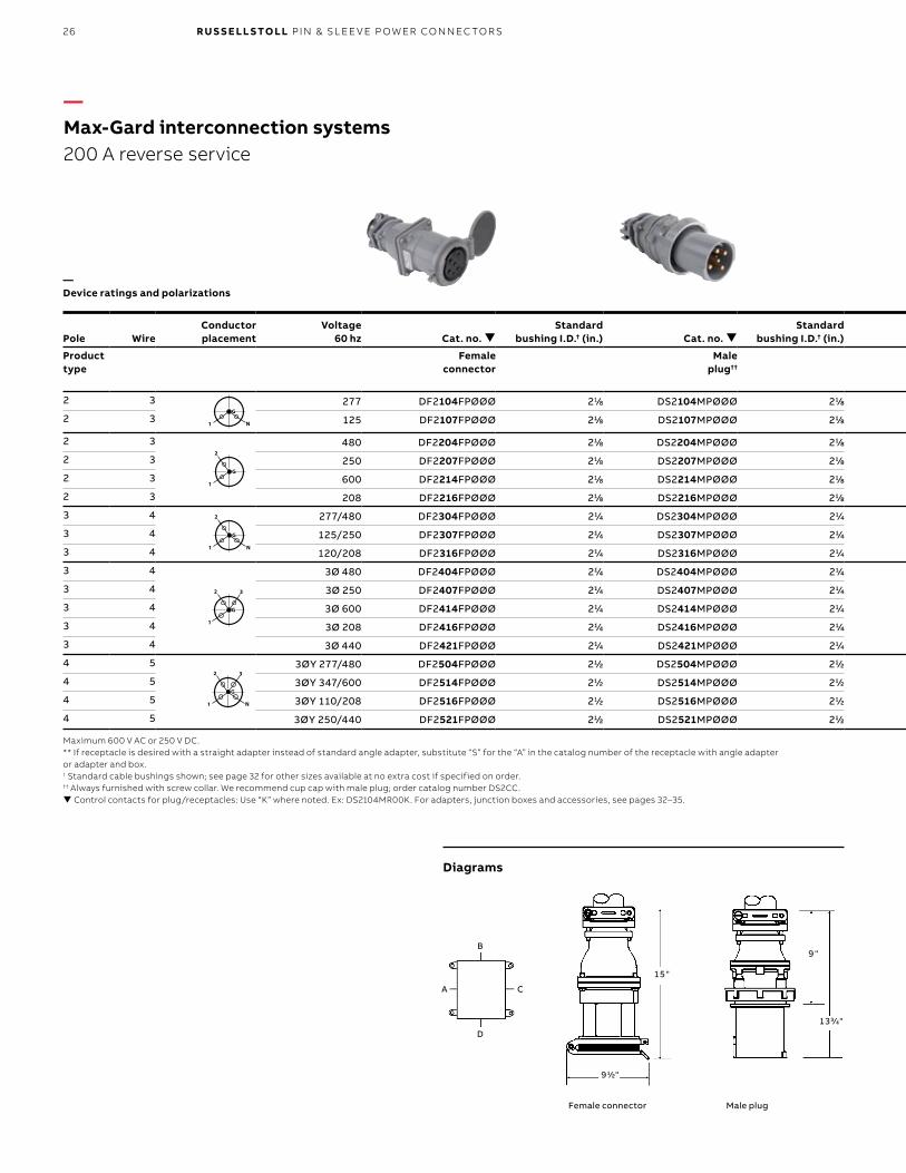
—Max-Gard interconnection systems200 A standard service
—Device ratings and polarizations
Pole WireConductorplacement
Voltage60 hz Cat. no.
Standard bushing I.D.† (in.) Cat. no.
Standard bushing I.D.† (in.) Pole Wire Cat. no. Cat. no. Cat. no.
Product type
Male plug††
Female connector
Product type
Female receptacle with angle adapter**
and junction box
Female receptacle with angle adapter**
Female receptacle
2 3 277 DS2104MPØØØ 21/8 DF2104FPØØØ 21/8 2 3 DF2104FRABØ DF2104FRAØØ DF2104FRØØØ
2 3 125 DS2107MPØØØ 21/8 DF2107FPØØØ 21/8 2 3 DF2107FRABØ DF2107FRAØØ DF2107FRØØØ
2 3 480 DS2204MPØØØ 21/8 DF2204FPØØØ 21/8 2 3 DF2204FRABØ DF2204FRAØØ DF2204FRØØØ
2 3 250 DS2207MPØØØ 21/8 DF2207FPØØØ 21/8 2 3 DF2207FRABØ DF2207FRAØØ DF2207FRØØØ
2 3 600 DS2214MPØØØ 21/8 DF2214FPØØØ 21/8 2 3 DF2214FRABØ DF2214FRAØØ DF2214FRØØØ
2 3 208 DS2216MPØØØ 21/8 DF2216FPØØØ 21/8 2 3 DF2216FRABØ DF2216FRAØØ DF2216FRØØØ
3 4 277/480 DS2304MPØØØ 21/4 DF2304FPØØØ 21/4 3 4 DF2304FRABØ DF2304FRAØØ DF2304FRØØØ
3 4 125/250 DS2307MPØØØ 21/4 DF2307FPØØØ 21/4 3 4 DF2307FRABØ DF2307FRAØØ DF2307FRØØØ
3 4 120/208 DS2316MPØØØ 21/4 DF2316FPØØØ 21/4 3 4 DF2316FRABØ DF2316FRAØØ DF2316FRØØØ
3 4 3Ø 480 DS2404MPØØØ 21/4 DF2404FPØØØ 21/4 3 4 DF2404FRABØ DF2404FRAØØ DF2404FRØØØ
3 4 3Ø 250 DS2407MPØØØ 21/4 DF2407FPØØØ 21/4 3 4 DF2407FRABØ DF2407FRAØØ DF2407FRØØØ
3 4 3Ø 600 DS2414MPØØØ 21/4 DF2414FPØØØ 21/4 3 4 DF2414FRABØ DF2414FRAØØ DF2414FRØØØ
3 4 3Ø 208 DS2416MPØØØ 21/4 DF2416FPØØØ 21/4 3 4 DF2416FRABØ DF2416FRAØØ DF2416FRØØØ
3 4 3Ø 440 DS2421MPØØØ 21/4 DF2421FPØØØ 21/4 3 4 DF2421FRABØ DF2421FRAØØ DF2421FRØØØ
4 5 3ØY 277/480 DS2504MPØØØ 21/2 DF2504FPØØØ 21/2 4 5 DF2504FRABØ DF2504FRAØØ DF2504FRØØØ
4 5 3ØY 347/600 DS2514MPØØØ 21/2 DF2514FPØØØ 21/2 4 5 DF2514FRABØ DF2514FRAØØ DF2514FRØØØ
4 5 3ØY 110/208 DS2516MPØØØ 21/2 DF2516FPØØØ 21/2 4 5 DF2516FRABØ DF2516FRAØØ DF2516FRØØØ
4 5 3ØY 250/440 DS2521MPØØØ 21/2 DF2521FPØØØ 21/2 4 5 DF2521FRABØ DF2521FRAØØ DF2521FRØØØ
G
N1
2 3
G
1
2 3
G
N1
2
G
1
2
G
N1
G
N1
2 3
G
1
2 3
G
N1
2
G
1
2
G
N1
G
N1
2 3
G
1
2 3
G
N1
2
G
1
2
G
N1
G
N1
2 3
G
1
2 3
G
N1
2
G
1
2
G
N1
G
N1
2 3
G
1
2 3
G
N1
2
G
1
2
G
N1
Maximum 600 V AC or 250 V DC.** If receptacle is desired with a straight adapter instead of standard angle adapter, substitute “S” for the “A” in the catalog number of the receptacle with angle adapter or adapter and box.† Standard cable bushings shown; see page 32 for other sizes available at no extra cost if specified on order.†† Always furnished with screw collar. We recommend cup cap with male plug; order catalog number DS2CC. Control contacts for plug/receptacles: Use “K” where noted. Ex: DS2104MP00K. For adapters, junction boxes and accessories, see pages 32–35.
Diagrams
Male plug Female connector
25M A X- G A R D I NTER CO N N EC TI O N S Y S TEMS
5 1/4"
6 5/8"
9 1/2"
1 4 3/4"
1 5 3/4"
1 4 5/8"
6 5/8"
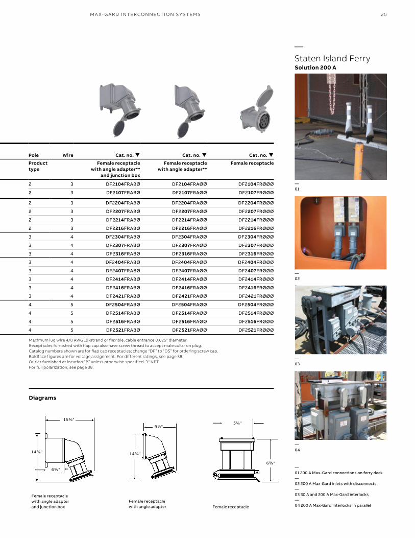
—01
—03
—02
—04
—Staten Island FerrySolution 200 A
Pole WireConductorplacement
Voltage60 hz Cat. no.
Standard bushing I.D.† (in.) Cat. no.
Standard bushing I.D.† (in.) Pole Wire Cat. no. Cat. no. Cat. no.
Product type
Male plug††
Female connector
Product type
Female receptacle with angle adapter**
and junction box
Female receptacle with angle adapter**
Female receptacle
2 3 277 DS2104MPØØØ 21/8 DF2104FPØØØ 21/8 2 3 DF2104FRABØ DF2104FRAØØ DF2104FRØØØ
2 3 125 DS2107MPØØØ 21/8 DF2107FPØØØ 21/8 2 3 DF2107FRABØ DF2107FRAØØ DF2107FRØØØ
2 3 480 DS2204MPØØØ 21/8 DF2204FPØØØ 21/8 2 3 DF2204FRABØ DF2204FRAØØ DF2204FRØØØ
2 3 250 DS2207MPØØØ 21/8 DF2207FPØØØ 21/8 2 3 DF2207FRABØ DF2207FRAØØ DF2207FRØØØ
2 3 600 DS2214MPØØØ 21/8 DF2214FPØØØ 21/8 2 3 DF2214FRABØ DF2214FRAØØ DF2214FRØØØ
2 3 208 DS2216MPØØØ 21/8 DF2216FPØØØ 21/8 2 3 DF2216FRABØ DF2216FRAØØ DF2216FRØØØ
3 4 277/480 DS2304MPØØØ 21/4 DF2304FPØØØ 21/4 3 4 DF2304FRABØ DF2304FRAØØ DF2304FRØØØ
3 4 125/250 DS2307MPØØØ 21/4 DF2307FPØØØ 21/4 3 4 DF2307FRABØ DF2307FRAØØ DF2307FRØØØ
3 4 120/208 DS2316MPØØØ 21/4 DF2316FPØØØ 21/4 3 4 DF2316FRABØ DF2316FRAØØ DF2316FRØØØ
3 4 3Ø 480 DS2404MPØØØ 21/4 DF2404FPØØØ 21/4 3 4 DF2404FRABØ DF2404FRAØØ DF2404FRØØØ
3 4 3Ø 250 DS2407MPØØØ 21/4 DF2407FPØØØ 21/4 3 4 DF2407FRABØ DF2407FRAØØ DF2407FRØØØ
3 4 3Ø 600 DS2414MPØØØ 21/4 DF2414FPØØØ 21/4 3 4 DF2414FRABØ DF2414FRAØØ DF2414FRØØØ
3 4 3Ø 208 DS2416MPØØØ 21/4 DF2416FPØØØ 21/4 3 4 DF2416FRABØ DF2416FRAØØ DF2416FRØØØ
3 4 3Ø 440 DS2421MPØØØ 21/4 DF2421FPØØØ 21/4 3 4 DF2421FRABØ DF2421FRAØØ DF2421FRØØØ
4 5 3ØY 277/480 DS2504MPØØØ 21/2 DF2504FPØØØ 21/2 4 5 DF2504FRABØ DF2504FRAØØ DF2504FRØØØ
4 5 3ØY 347/600 DS2514MPØØØ 21/2 DF2514FPØØØ 21/2 4 5 DF2514FRABØ DF2514FRAØØ DF2514FRØØØ
4 5 3ØY 110/208 DS2516MPØØØ 21/2 DF2516FPØØØ 21/2 4 5 DF2516FRABØ DF2516FRAØØ DF2516FRØØØ
4 5 3ØY 250/440 DS2521MPØØØ 21/2 DF2521FPØØØ 21/2 4 5 DF2521FRABØ DF2521FRAØØ DF2521FRØØØ
Maximum lug wire 4/0 AWG 19-strand or flexible, cable entrance 0.625" diameter. Receptacles furnished with flap cap also have screw thread to accept male collar on plug. Catalog numbers shown are for flap cap receptacles; change “DF” to “DS” for ordering screw cap. Boldface figures are for voltage assignment. For different ratings, see page 38.Outlet furnished at location “B” unless otherwise specified. 3" NPT. For full polarization, see page 38.
Diagrams
Female receptacle with angle adapter and junction box
Female receptacle with angle adapter Female receptacle
—01 200 A Max-Gard connections on ferry deck—02 200 A Max-Gard inlets with disconnects—03 30 A and 200 A Max-Gard interlocks—04 200 A Max-Gard interlocks in parallel
26 R U S S E LL S TO LL PI N & SL EE V E P OW ER CO N N EC TO R S
1 5 "
9 1/2"
9 "
1 3 3/4"
B
D
A C
—Max-Gard interconnection systems200 A reverse service
—Device ratings and polarizations
Pole WireConductorplacement
Voltage60 hz Cat. no.
Standard bushing I.D.† (in.) Cat. no.
Standard bushing I.D.† (in.) Pole Wire Cat. no. Cat. no. Cat. no.
Product type
Female connector
Male plug††
Product type
Male inlet with angle enclosure
Male inlet with angle adapter**
Male inlet††
2 3 277 DF2104FPØØØ 21/8 DS2104MPØØØ 21/8 2 3 DS2104MRABØ DS2104MRAØØ DS2104MRØØØ
2 3 125 DF2107FPØØØ 21/8 DS2107MPØØØ 21/8 2 3 DS2107MRABØ DS2107MRAØØ DS2107MRØØØ
2 3 480 DF2204FPØØØ 21/8 DS2204MPØØØ 21/8 2 3 DS2204MRABØ DS2204MRAØØ DS2204MRØØØ
2 3 250 DF2207FPØØØ 21/8 DS2207MPØØØ 21/8 2 3 DS2207MRABØ DS2207MRAØØ DS2207MRØØØ
2 3 600 DF2214FPØØØ 21/8 DS2214MPØØØ 21/8 2 3 DS2214MRABØ DS2214MRAØØ DS2214MRØØØ
2 3 208 DF2216FPØØØ 21/8 DS2216MPØØØ 21/8 2 3 DS2216MRABØ DS2216MRAØØ DS2216MRØØØ
3 4 277/480 DF2304FPØØØ 21/4 DS2304MPØØØ 21/4 3 4 DS2304MRABØ DS2304MRAØØ DS2304MRØØØ
3 4 125/250 DF2307FPØØØ 21/4 DS2307MPØØØ 21/4 3 4 DS2307MRABØ DS2307MRAØØ DS2307MRØØØ
3 4 120/208 DF2316FPØØØ 21/4 DS2316MPØØØ 21/4 3 4 DS2316MRABØ DS2316MRAØØ DS2316MRØØØ
3 4 3Ø 480 DF2404FPØØØ 21/4 DS2404MPØØØ 21/4 3 4 DS2404MRABØ DS2404MRAØØ DS2404MRØØØ
3 4 3Ø 250 DF2407FPØØØ 21/4 DS2407MPØØØ 21/4 3 4 DS2407MRABØ DS2407MRAØØ DS2407MRØØØ
3 4 3Ø 600 DF2414FPØØØ 21/4 DS2414MPØØØ 21/4 3 4 DS2414MRABØ DS2414MRAØØ DS2414MRØØØ
3 4 3Ø 208 DF2416FPØØØ 21/4 DS2416MPØØØ 21/4 3 4 DS2416MRABØ DS2416MRAØØ DS2416MRØØØ
3 4 3Ø 440 DF2421FPØØØ 21/4 DS2421MPØØØ 21/4 3 4 DS2421MRABØ DS2421MRAØØ DS2421MRØØØ
4 5 3ØY 277/480 DF2504FPØØØ 21/2 DS2504MPØØØ 21/2 4 5 DS2504MRABØ DS2504MRAØØ DS2504MRØØØ
4 5 3ØY 347/600 DF2514FPØØØ 21/2 DS2514MPØØØ 21/2 4 5 DS2514MRABØ DS2514MRAØØ DS2514MRØØØ
4 5 3ØY 110/208 DF2516FPØØØ 21/2 DS2516MPØØØ 21/2 4 5 DS2516MRABØ DS2516MRAØØ DS2516MRØØØ
4 5 3ØY 250/440 DF2521FPØØØ 21/2 DS2521MPØØØ 21/2 4 5 DS2521MRABØ DS2521MRAØØ DS2521MRØØØ
G
N1
2 3
G
1
2 3
G
N1
2
G
1
2
G
N1
G
N1
2 3
G
1
2 3
G
N1
2
G
1
2
G
N1
G
N1
2 3
G
1
2 3
G
N1
2
G
1
2
G
N1
G
N1
2 3
G
1
2 3
G
N1
2
G
1
2
G
N1
G
N1
2 3
G
1
2 3
G
N1
2
G
1
2
G
N1
Maximum 600 V AC or 250 V DC.** If receptacle is desired with a straight adapter instead of standard angle adapter, substitute “S” for the “A” in the catalog number of the receptacle with angle adapter or adapter and box.† Standard cable bushings shown; see page 32 for other sizes available at no extra cost if specified on order.†† Always furnished with screw collar. We recommend cup cap with male plug; order catalog number DS2CC. Control contacts for plug/receptacles: Use “K” where noted. Ex: DS2104MR00K. For adapters, junction boxes and accessories, see pages 32–35.
Diagrams
Male plugFemale connector
27M A X- G A R D I NTER CO N N EC TI O N S Y S TEMS
4 "
9 1/4"
3 1/2"
9 1/4"
1 5 "
1 5 1/2"
1 4 7/8"
6 5/8"
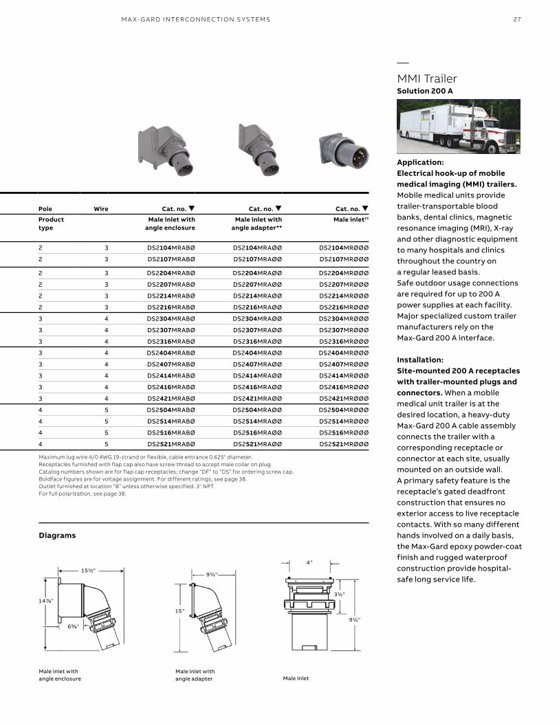
Application:Electrical hook-up of mobile medical imaging (MMI) trailers. Mobile medical units provide trailer-transportable blood banks, dental clinics, magnetic resonance imaging (MRI), X-ray and other diagnostic equipment to many hospitals and clinics throughout the country on a regular leased basis. Safe outdoor usage connections are required for up to 200 A power supplies at each facility. Major specialized custom trailer manufacturers rely on the Max-Gard 200 A interface.
Installation:Site-mounted 200 A receptacles with trailer-mounted plugs and connectors. When a mobile medical unit trailer is at the desired location, a heavy-duty Max-Gard 200 A cable assembly connects the trailer with a corresponding receptacle or connector at each site, usually mounted on an outside wall. A primary safety feature is the receptacle’s gated deadfront construction that ensures no exterior access to live receptacle contacts. With so many different hands involved on a daily basis, the Max-Gard epoxy powder-coat finish and rugged waterproof construction provide hospital-safe long service life.
Pole WireConductorplacement
Voltage60 hz Cat. no.
Standard bushing I.D.† (in.) Cat. no.
Standard bushing I.D.† (in.) Pole Wire Cat. no. Cat. no. Cat. no.
Product type
Female connector
Male plug††
Product type
Male inlet with angle enclosure
Male inlet with angle adapter**
Male inlet††
2 3 277 DF2104FPØØØ 21/8 DS2104MPØØØ 21/8 2 3 DS2104MRABØ DS2104MRAØØ DS2104MRØØØ
2 3 125 DF2107FPØØØ 21/8 DS2107MPØØØ 21/8 2 3 DS2107MRABØ DS2107MRAØØ DS2107MRØØØ
2 3 480 DF2204FPØØØ 21/8 DS2204MPØØØ 21/8 2 3 DS2204MRABØ DS2204MRAØØ DS2204MRØØØ
2 3 250 DF2207FPØØØ 21/8 DS2207MPØØØ 21/8 2 3 DS2207MRABØ DS2207MRAØØ DS2207MRØØØ
2 3 600 DF2214FPØØØ 21/8 DS2214MPØØØ 21/8 2 3 DS2214MRABØ DS2214MRAØØ DS2214MRØØØ
2 3 208 DF2216FPØØØ 21/8 DS2216MPØØØ 21/8 2 3 DS2216MRABØ DS2216MRAØØ DS2216MRØØØ
3 4 277/480 DF2304FPØØØ 21/4 DS2304MPØØØ 21/4 3 4 DS2304MRABØ DS2304MRAØØ DS2304MRØØØ
3 4 125/250 DF2307FPØØØ 21/4 DS2307MPØØØ 21/4 3 4 DS2307MRABØ DS2307MRAØØ DS2307MRØØØ
3 4 120/208 DF2316FPØØØ 21/4 DS2316MPØØØ 21/4 3 4 DS2316MRABØ DS2316MRAØØ DS2316MRØØØ
3 4 3Ø 480 DF2404FPØØØ 21/4 DS2404MPØØØ 21/4 3 4 DS2404MRABØ DS2404MRAØØ DS2404MRØØØ
3 4 3Ø 250 DF2407FPØØØ 21/4 DS2407MPØØØ 21/4 3 4 DS2407MRABØ DS2407MRAØØ DS2407MRØØØ
3 4 3Ø 600 DF2414FPØØØ 21/4 DS2414MPØØØ 21/4 3 4 DS2414MRABØ DS2414MRAØØ DS2414MRØØØ
3 4 3Ø 208 DF2416FPØØØ 21/4 DS2416MPØØØ 21/4 3 4 DS2416MRABØ DS2416MRAØØ DS2416MRØØØ
3 4 3Ø 440 DF2421FPØØØ 21/4 DS2421MPØØØ 21/4 3 4 DS2421MRABØ DS2421MRAØØ DS2421MRØØØ
4 5 3ØY 277/480 DF2504FPØØØ 21/2 DS2504MPØØØ 21/2 4 5 DS2504MRABØ DS2504MRAØØ DS2504MRØØØ
4 5 3ØY 347/600 DF2514FPØØØ 21/2 DS2514MPØØØ 21/2 4 5 DS2514MRABØ DS2514MRAØØ DS2514MRØØØ
4 5 3ØY 110/208 DF2516FPØØØ 21/2 DS2516MPØØØ 21/2 4 5 DS2516MRABØ DS2516MRAØØ DS2516MRØØØ
4 5 3ØY 250/440 DF2521FPØØØ 21/2 DS2521MPØØØ 21/2 4 5 DS2521MRABØ DS2521MRAØØ DS2521MRØØØ
Maximum lug wire 4/0 AWG 19-strand or flexible, cable entrance 0.625" diameter. Receptacles furnished with flap cap also have screw thread to accept male collar on plug. Catalog numbers shown are for flap cap receptacles; change “DF” to “DS” for ordering screw cap. Boldface figures are for voltage assignment. For different ratings, see page 38.Outlet furnished at location “B” unless otherwise specified. 3" NPT. For full polarization, see page 38.
Diagrams
Male inlet with angle enclosure
Male inlet with angle adapter Male inlet
—MMI TrailerSolution 200 A
28 R U S S E LL S TO LL PI N & SL EE V E P OW ER CO N N EC TO R S
1 9 1/8"
1 0 3/4"
A C
B
D
1 2 5/8"
1 7 5/8"
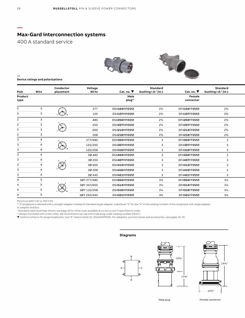
—Max-Gard interconnection systems400 A standard service
—Device ratings and polarizations
Pole WireConductorplacement
Voltage60 hz Cat. no.
Standard bushing I.D.† (in.) Cat. no.
Standard bushing I.D.† (in.) Pole Wire Cat. no. Cat. no. Cat. no.
Product type
Male plug††
Female connector
Product type
Female receptacle with angle adapter**
and junction box
Female receptacle with angle adapter**
Female receptacle
2 3 277 DS4104MPØØØ 23/4 DF4104FPØØØ 23/4 2 3 DF4104FRABØ DF4104FRAØØ DF4104FRØØØ
2 3 125 DS4107MPØØØ 23/4 DF4107FPØØØ 23/4 2 3 DF4107FRABØ DF4107FRAØØ DF4107FRØØØ
2 3 480 DS4204MPØØØ 23/4 DF4204FPØØØ 23/4 2 3 DF4204FRABØ DF4204FRAØØ DF4204FRØØØ
2 3 250 DS4207MPØØØ 23/4 DF4207FPØØØ 23/4 2 3 DF4207FRABØ DF4207FRAØØ DF4207FRØØØ
2 3 600 DS4214MPØØØ 23/4 DF4214FPØØØ 23/4 2 3 DF4214FRABØ DF4214FRAØØ DF4214FRØØØ
2 3 208 DS4216MPØØØ 23/4 DF4216FPØØØ 23/4 2 3 DF4216FRABØ DF4216FRAØØ DF4216FRØØØ
3 4 277/480 DS4304MPØØØ 3 DF4304FPØØØ 3 3 4 DF4304FRABØ DF4304FRAØØ DF4304FRØØØ
3 4 125/250 DS4307MPØØØ 3 DF4307FPØØØ 3 3 4 DF4307FRABØ DF4307FRAØØ DF4307FRØØØ
3 4 120/208 DS4316MPØØØ 3 DF4316FPØØØ 3 3 4 DF4316FRABØ DF4316FRAØØ DF4316FRØØØ
3 4 3Ø 480 DS4404MPØØØ 3 DF4404FPØØØ 3 3 4 DF4404FRABØ DF4404FRAØØ DF4404FRØØØ
3 4 3Ø 250 DS4407MPØØØ 3 DF4407FPØØØ 3 3 4 DF4407FRABØ DF4407FRAØØ DF4407FRØØØ
3 4 3Ø 600 DS4414MPØØØ 3 DF4414FPØØØ 3 3 4 DF4414FRABØ DF4414FRAØØ DF4414FRØØØ
3 4 3Ø 208 DS4416MPØØØ 3 DF4416FPØØØ 3 3 4 DF4416FRABØ DF4416FRAØØ DF4416FRØØØ
3 4 3Ø 440 DS4421MPØØØ 3 DF4421FPØØØ 3 3 4 DF4421FRABØ DF4421FRAØØ DF4421FRØØØ
4 5 3ØY 277/480 DS4504MPØØØ 31/4 DF4504FPØØØ 31/4 4 5 DF4504FRABØ DF4504FRAØØ DF4504FRØØØ
4 5 3ØY 347/600 DS4514MPØØØ 31/4 DF4514FPØØØ 31/4 4 5 DF4514FRABØ DF4514FRAØØ DF4514FRØØØ
4 5 3ØY 110/208 DS4516MPØØØ 31/4 DF4516FPØØØ 31/4 4 5 DF4516FRABØ DF4516FRAØØ DF4516FRØØØ
4 5 3ØY 250/440 DS4521MPØØØ 31/4 DF4521FPØØØ 31/4 4 5 DF4521FRABØ DF4521FRAØØ DF4521FRØØØ
G
N1
2 3
G
1
2 3
G
N1
2
G
1
2
G
N1
G
N1
2 3
G
1
2 3
G
N1
2
G
1
2
G
N1
G
N1
2 3
G
1
2 3
G
N1
2
G
1
2
G
N1
G
N1
2 3
G
1
2 3
G
N1
2
G
1
2
G
N1
G
N1
2 3
G
1
2 3
G
N1
2
G
1
2
G
N1
Maximum 600 V AC or 250 V DC.** If receptacle is desired with a straight adapter instead of standard angle adapter, substitute “S” for the “A” in the catalog number of the receptacle with angle adapter or adapter and box.† Standard cable bushings shown; see page 32 for other sizes available at no extra cost if specified on order.†† Always furnished with screw collar. We recommend cup cap with male plug; order catalog number DS4CC. Control contacts for plug/receptacles: Use “K” where noted. Ex: DS4104MP00K. For adapters, junction boxes and accessories, see pages 32–35.
Diagrams
Male plug Female connector
29M A X- G A R D I NTER CO N N EC TI O N S Y S TEMS
7 "
7 1/8"
1 3 1/4"
2 0 3/4"
2 5 1/4"
2 0 3/4"
1 2 "
Pole WireConductorplacement
Voltage60 hz Cat. no.
Standard bushing I.D.† (in.) Cat. no.
Standard bushing I.D.† (in.) Pole Wire Cat. no. Cat. no. Cat. no.
Product type
Male plug††
Female connector
Product type
Female receptacle with angle adapter**
and junction box
Female receptacle with angle adapter**
Female receptacle
2 3 277 DS4104MPØØØ 23/4 DF4104FPØØØ 23/4 2 3 DF4104FRABØ DF4104FRAØØ DF4104FRØØØ
2 3 125 DS4107MPØØØ 23/4 DF4107FPØØØ 23/4 2 3 DF4107FRABØ DF4107FRAØØ DF4107FRØØØ
2 3 480 DS4204MPØØØ 23/4 DF4204FPØØØ 23/4 2 3 DF4204FRABØ DF4204FRAØØ DF4204FRØØØ
2 3 250 DS4207MPØØØ 23/4 DF4207FPØØØ 23/4 2 3 DF4207FRABØ DF4207FRAØØ DF4207FRØØØ
2 3 600 DS4214MPØØØ 23/4 DF4214FPØØØ 23/4 2 3 DF4214FRABØ DF4214FRAØØ DF4214FRØØØ
2 3 208 DS4216MPØØØ 23/4 DF4216FPØØØ 23/4 2 3 DF4216FRABØ DF4216FRAØØ DF4216FRØØØ
3 4 277/480 DS4304MPØØØ 3 DF4304FPØØØ 3 3 4 DF4304FRABØ DF4304FRAØØ DF4304FRØØØ
3 4 125/250 DS4307MPØØØ 3 DF4307FPØØØ 3 3 4 DF4307FRABØ DF4307FRAØØ DF4307FRØØØ
3 4 120/208 DS4316MPØØØ 3 DF4316FPØØØ 3 3 4 DF4316FRABØ DF4316FRAØØ DF4316FRØØØ
3 4 3Ø 480 DS4404MPØØØ 3 DF4404FPØØØ 3 3 4 DF4404FRABØ DF4404FRAØØ DF4404FRØØØ
3 4 3Ø 250 DS4407MPØØØ 3 DF4407FPØØØ 3 3 4 DF4407FRABØ DF4407FRAØØ DF4407FRØØØ
3 4 3Ø 600 DS4414MPØØØ 3 DF4414FPØØØ 3 3 4 DF4414FRABØ DF4414FRAØØ DF4414FRØØØ
3 4 3Ø 208 DS4416MPØØØ 3 DF4416FPØØØ 3 3 4 DF4416FRABØ DF4416FRAØØ DF4416FRØØØ
3 4 3Ø 440 DS4421MPØØØ 3 DF4421FPØØØ 3 3 4 DF4421FRABØ DF4421FRAØØ DF4421FRØØØ
4 5 3ØY 277/480 DS4504MPØØØ 31/4 DF4504FPØØØ 31/4 4 5 DF4504FRABØ DF4504FRAØØ DF4504FRØØØ
4 5 3ØY 347/600 DS4514MPØØØ 31/4 DF4514FPØØØ 31/4 4 5 DF4514FRABØ DF4514FRAØØ DF4514FRØØØ
4 5 3ØY 110/208 DS4516MPØØØ 31/4 DF4516FPØØØ 31/4 4 5 DF4516FRABØ DF4516FRAØØ DF4516FRØØØ
4 5 3ØY 250/440 DS4521MPØØØ 31/4 DF4521FPØØØ 31/4 4 5 DF4521FRABØ DF4521FRAØØ DF4521FRØØØ
Maximum lug wire 500 kcmil 37-strand or flexible, cable entrance 0.937" diameter. Receptacles furnished with flap cap also have screw thread to accept male collar on plug. Catalog numbers shown are for flap cap receptacles; change “DF” to “DS” for ordering screw cap. Boldface figures are for voltage assignment. For different ratings, see page 38.Outlet furnished at location “B” unless otherwise specified. 4" NPT. For full polarization, see page 38.
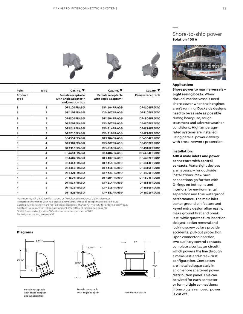
Diagrams
Female receptacle with angle adapter and junction box
Female receptacle with angle adapter Female receptacle
Application:Shore power to marine vessels – Sightseeing boats. When docked, marine vessels need shore power when their engines aren’t running. Dockside designs need to be as safe as possible during heavy use, rough treatment and adverse weather conditions. High amperage-rated systems are installed using parallel power delivery with cross-network protection.
Installation:400 A male inlets and power connectors with control contacts. Watertight devices are necessary for dockside installations. Max-Gard connections go further with O-rings on both pins and interiors for environmental separation and true waterproof performance. The male inlet center ground pin feature and keyed entry design align easily, make ground first and break last, while quarter-turn insertion delayed-action removal and locking screw collars provide accidental pull-out protection. Upon connector insertion, two auxiliary control contacts complete a contactor circuit, which powers the line through a make-last-and-break-first configuration. Contactors are installed separately in an on-shore sheltered power distribution panel. This can be wired for each contactor or for multiple connections; if one plug is removed, power is cut off.
—Shore-to-ship powerSolution 400 A
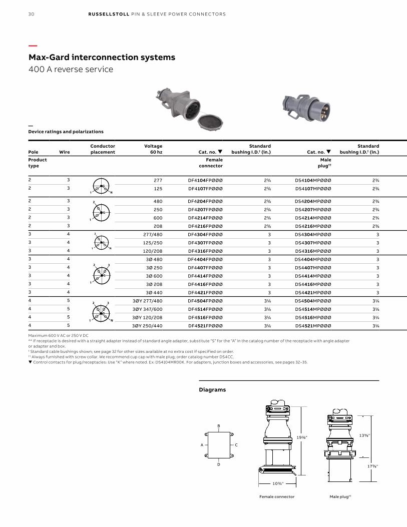
30 R U S S E LL S TO LL PI N & SL EE V E P OW ER CO N N EC TO R S
1 9 1/8"
1 0 3/4"
1 3 5/8"
1 7 5/8"
B
D
A C
—Max-Gard interconnection systems400 A reverse service
—Device ratings and polarizations
Pole WireConductorplacement
Voltage60 hz Cat. no.
Standard bushing I.D.† (in.) Cat. no.
Standard bushing I.D.† (in.) Pole Wire Cat. no. Cat. no. Cat. no.
Product type
Female connector
Male plug††
Product type
Male inlet with angle adapter**
and junction box
Male inlet with angle adapter**
Male inlet††
2 3 277 DF4104FPØØØ 23/4 DS4104MPØØØ 23/4 2 3 DS4104MRABØ DS4104MRAØØ DS4104MRØØØ
2 3 125 DF4107FPØØØ 23/4 DS4107MPØØØ 23/4 2 3 DS4107MRABØ DS4107MRAØØ DS4107MRØØØ
2 3 480 DF4204FPØØØ 23/4 DS4204MPØØØ 23/4 2 3 DS4204MRABØ DS4204MRAØØ DS4204MRØØØ
2 3 250 DF4207FPØØØ 23/4 DS4207MPØØØ 23/4 2 3 DS4207MRABØ DS4207MRAØØ DS4207MRØØØ
2 3 600 DF4214FPØØØ 23/4 DS4214MPØØØ 23/4 2 3 DS4214MRABØ DS4214MRAØØ DS4214MRØØØ
2 3 208 DF4216FPØØØ 23/4 DS4216MPØØØ 23/4 2 3 DS4216MRABØ DS4216MRAØØ DS4216MRØØØ
3 4 277/480 DF4304FPØØØ 3 DS4304MPØØØ 3 3 4 DS4304MRABØ DS4304MRAØØ DS4304MRØØØ
3 4 125/250 DF4307FPØØØ 3 DS4307MPØØØ 3 3 4 DS4307MRABØ DS4307MRAØØ DS4307MRØØØ
3 4 120/208 DF4316FPØØØ 3 DS4316MPØØØ 3 3 4 DS4316MRABØ DS4316MRAØØ DS4316MRØØØ
3 4 3Ø 480 DF4404FPØØØ 3 DS4404MPØØØ 3 3 4 DS4404MRABØ DS4404MRAØØ DS4404MRØØØ
3 4 3Ø 250 DF4407FPØØØ 3 DS4407MPØØØ 3 3 4 DS4407MRABØ DS4407MRAØØ DS4407MRØØØ
3 4 3Ø 600 DF4414FPØØØ 3 DS4414MPØØØ 3 3 4 DS4414MRABØ DS4414MRAØØ DS4414MRØØØ
3 4 3Ø 208 DF4416FPØØØ 3 DS4416MPØØØ 3 3 4 DS4416MRABØ DS4416MRAØØ DS4416MRØØØ
3 4 3Ø 440 DF4421FPØØØ 3 DS4421MPØØØ 3 3 4 DS4421MRABØ DS4421MRAØØ DS4421MRØØØ
4 5 3ØY 277/480 DF4504FPØØØ 31/4 DS4504MPØØØ 31/4 4 5 DS4504MRABØ DS4504MRAØØ DS4504MRØØØ
4 5 3ØY 347/600 DF4514FPØØØ 31/4 DS4514MPØØØ 31/4 4 5 DS4514MRABØ DS4514MRAØØ DS4514MRØØØ
4 5 3ØY 120/208 DF4516FPØØØ 31/4 DS4516MPØØØ 31/4 4 5 DS4516MRABØ DS4516MRAØØ DS4516MRØØØ
4 5 3ØY 250/440 DF4521FPØØØ 31/4 DS4521MPØØØ 31/4 4 5 DS4521MRABØ DS4521MRAØØ DS4521MRØØØ
G
N1
2 3
G
1
2 3
G
N1
2
G
1
2
G
N1
G
N1
2 3
G
1
2 3
G
N1
2
G
1
2
G
N1
G
N1
2 3
G
1
2 3
G
N1
2
G
1
2
G
N1
G
N1
2 3
G
1
2 3
G
N1
2
G
1
2
G
N1
G
N1
2 3
G
1
2 3
G
N1
2
G
1
2
G
N1
Maximum 600 V AC or 250 V DC** If receptacle is desired with a straight adapter instead of standard angle adapter, substitute “S” for the “A” in the catalog number of the receptacle with angle adapter or adapter and box.† Standard cable bushings shown; see page 32 for other sizes available at no extra cost if specified on order.†† Always furnished with screw collar. We recommend cup cap with male plug; order catalog number DS4CC. Control contacts for plug/receptacles: Use “K” where noted. Ex: DS4104MR00K. For adapters, junction boxes and accessories, see pages 32–35.
Diagrams
Male plug††Female connector
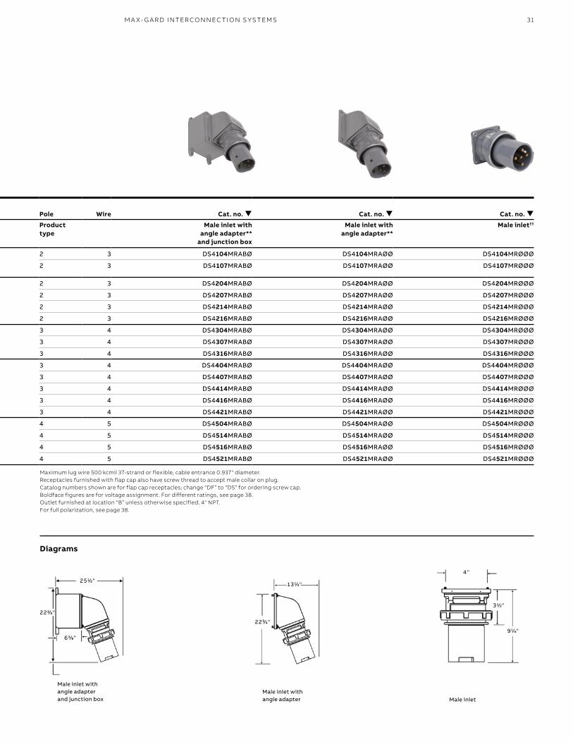
31
4 "
9 1/4"
3 1/2"
1 3 1/2"
2 2 3/4"
2 5 1/2"
2 2 3/4"
6 5/8"
Pole WireConductorplacement
Voltage60 hz Cat. no.
Standard bushing I.D.† (in.) Cat. no.
Standard bushing I.D.† (in.) Pole Wire Cat. no. Cat. no. Cat. no.
Product type
Female connector
Male plug††
Product type
Male inlet with angle adapter**
and junction box
Male inlet with angle adapter**
Male inlet††
2 3 277 DF4104FPØØØ 23/4 DS4104MPØØØ 23/4 2 3 DS4104MRABØ DS4104MRAØØ DS4104MRØØØ
2 3 125 DF4107FPØØØ 23/4 DS4107MPØØØ 23/4 2 3 DS4107MRABØ DS4107MRAØØ DS4107MRØØØ
2 3 480 DF4204FPØØØ 23/4 DS4204MPØØØ 23/4 2 3 DS4204MRABØ DS4204MRAØØ DS4204MRØØØ
2 3 250 DF4207FPØØØ 23/4 DS4207MPØØØ 23/4 2 3 DS4207MRABØ DS4207MRAØØ DS4207MRØØØ
2 3 600 DF4214FPØØØ 23/4 DS4214MPØØØ 23/4 2 3 DS4214MRABØ DS4214MRAØØ DS4214MRØØØ
2 3 208 DF4216FPØØØ 23/4 DS4216MPØØØ 23/4 2 3 DS4216MRABØ DS4216MRAØØ DS4216MRØØØ
3 4 277/480 DF4304FPØØØ 3 DS4304MPØØØ 3 3 4 DS4304MRABØ DS4304MRAØØ DS4304MRØØØ
3 4 125/250 DF4307FPØØØ 3 DS4307MPØØØ 3 3 4 DS4307MRABØ DS4307MRAØØ DS4307MRØØØ
3 4 120/208 DF4316FPØØØ 3 DS4316MPØØØ 3 3 4 DS4316MRABØ DS4316MRAØØ DS4316MRØØØ
3 4 3Ø 480 DF4404FPØØØ 3 DS4404MPØØØ 3 3 4 DS4404MRABØ DS4404MRAØØ DS4404MRØØØ
3 4 3Ø 250 DF4407FPØØØ 3 DS4407MPØØØ 3 3 4 DS4407MRABØ DS4407MRAØØ DS4407MRØØØ
3 4 3Ø 600 DF4414FPØØØ 3 DS4414MPØØØ 3 3 4 DS4414MRABØ DS4414MRAØØ DS4414MRØØØ
3 4 3Ø 208 DF4416FPØØØ 3 DS4416MPØØØ 3 3 4 DS4416MRABØ DS4416MRAØØ DS4416MRØØØ
3 4 3Ø 440 DF4421FPØØØ 3 DS4421MPØØØ 3 3 4 DS4421MRABØ DS4421MRAØØ DS4421MRØØØ
4 5 3ØY 277/480 DF4504FPØØØ 31/4 DS4504MPØØØ 31/4 4 5 DS4504MRABØ DS4504MRAØØ DS4504MRØØØ
4 5 3ØY 347/600 DF4514FPØØØ 31/4 DS4514MPØØØ 31/4 4 5 DS4514MRABØ DS4514MRAØØ DS4514MRØØØ
4 5 3ØY 120/208 DF4516FPØØØ 31/4 DS4516MPØØØ 31/4 4 5 DS4516MRABØ DS4516MRAØØ DS4516MRØØØ
4 5 3ØY 250/440 DF4521FPØØØ 31/4 DS4521MPØØØ 31/4 4 5 DS4521MRABØ DS4521MRAØØ DS4521MRØØØ
Maximum lug wire 500 kcmil 37-strand or flexible, cable entrance 0.937" diameter. Receptacles furnished with flap cap also have screw thread to accept male collar on plug. Catalog numbers shown are for flap cap receptacles; change “DF” to “DS” for ordering screw cap. Boldface figures are for voltage assignment. For different ratings, see page 38.Outlet furnished at location “B” unless otherwise specified. 4" NPT. For full polarization, see page 38.
Diagrams
Male inlet with angle adapter and junction box
Male inlet with angle adapter Male inlet
M A X- G A R D I NTER CO N N EC TI O N S Y S TEMS
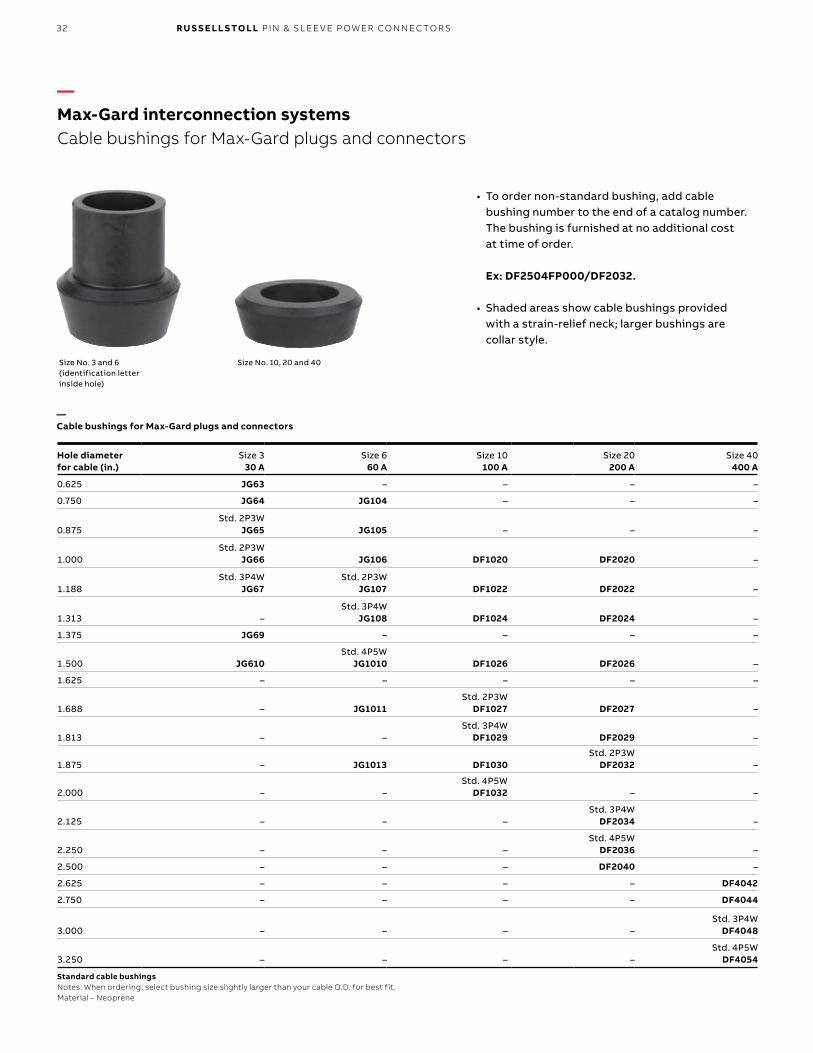
32 R U S S E LL S TO LL PI N & SL EE V E P OW ER CO N N EC TO R S
—Max-Gard interconnection systemsCable bushings for Max-Gard plugs and connectors
• To order non-standard bushing, add cable bushing number to the end of a catalog number. The bushing is furnished at no additional cost at time of order. Ex: DF2504FP000/DF2032.
• Shaded areas show cable bushings provided with a strain-relief neck; larger bushings are collar style.
Size No. 3 and 6 (identification letter inside hole)
Size No. 10, 20 and 40
—Cable bushings for Max-Gard plugs and connectors
Hole diameterfor cable (in.)
Size 330 A
Size 660 A
Size 10100 A
Size 20200 A
Size 40400 A
0.625 JG63 – – – –
0.750 JG64 JG104 – – –
0.875 Std. 2P3W
JG65 JG105 – – –
1.000 Std. 2P3W
JG66 JG106 DF1020 DF2020 –
1.188 Std. 3P4W
JG67Std. 2P3W
JG107 DF1022 DF2022 –
1.313 –Std. 3P4W
JG108 DF1024 DF2024 –
1.375 JG69 – – – –
1.500 JG610Std. 4P5W
JG1010 DF1026 DF2026 –
1.625 – – – – –
1.688 – JG1011Std. 2P3W
DF1027 DF2027 –
1.813 – –Std. 3P4W
DF1029 DF2029 –
1.875 – JG1013 DF1030 Std. 2P3W
DF2032 –
2.000 – –Std. 4P5W
DF1032 – –
2.125 – – – Std. 3P4W
DF2034 –
2.250 – – – Std. 4P5W
DF2036 –
2.500 – – – DF2040 –
2.625 – – – – DF4042
2.750 – – – – DF4044
3.000 – – – –Std. 3P4W
DF4048
3.250 – – – –Std. 4P5W
DF4054
Standard cable bushingsNotes: When ordering, select bushing size slightly larger than your cable O.D. for best fit.Material – Neoprene
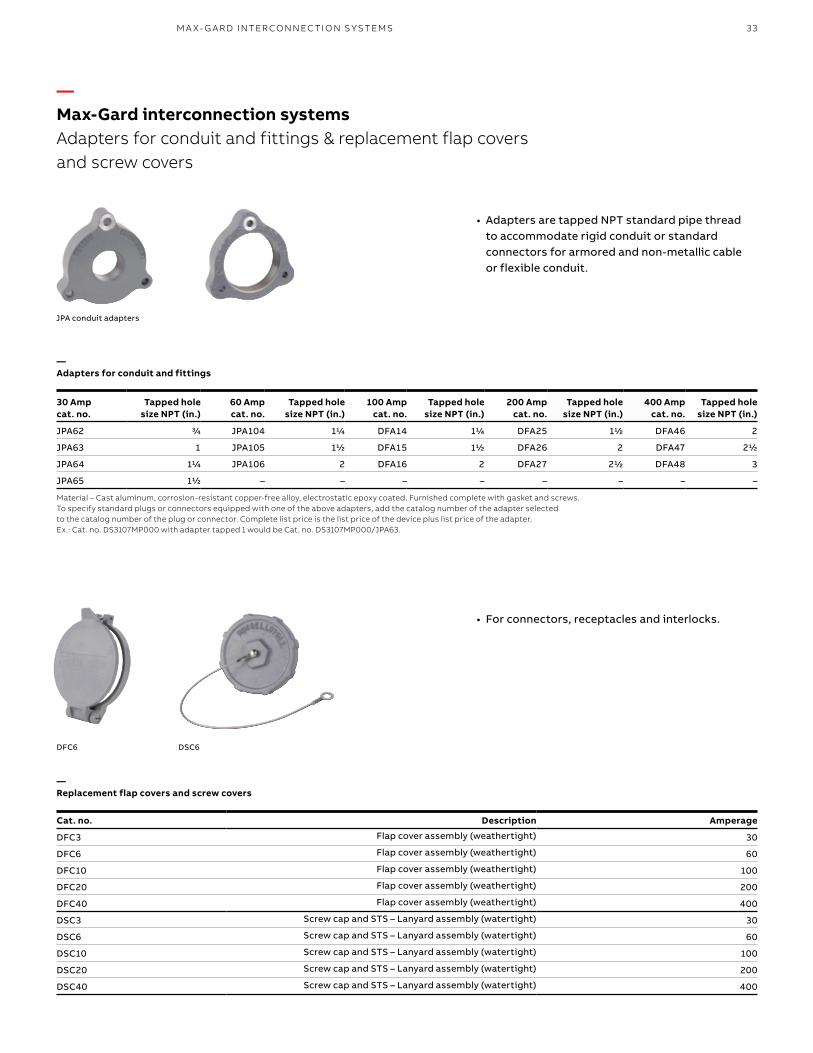
33
—Max-Gard interconnection systemsAdapters for conduit and fittings & replacement flap covers and screw covers
• Adapters are tapped NPT standard pipe thread to accommodate rigid conduit or standard connectors for armored and non-metallic cable or flexible conduit.
JPA conduit adapters
30 Ampcat. no.
Tapped holesize NPT (in.)
60 Ampcat. no.
Tapped holesize NPT (in.)
100 Ampcat. no.
Tapped holesize NPT (in.)
200 Ampcat. no.
Tapped holesize NPT (in.)
400 Ampcat. no.
Tapped holesize NPT (in.)
JPA62 3/4 JPA104 11/4 DFA14 11/4 DFA25 11/2 DFA46 2
JPA63 1 JPA105 11/2 DFA15 11/2 DFA26 2 DFA47 21/2
JPA64 11/4 JPA106 2 DFA16 2 DFA27 21/2 DFA48 3
JPA65 11/2 – – – – – – – –
Material – Cast aluminum, corrosion-resistant copper-free alloy, electrostatic epoxy coated. Furnished complete with gasket and screws.To specify standard plugs or connectors equipped with one of the above adapters, add the catalog number of the adapter selected to the catalog number of the plug or connector. Complete list price is the list price of the device plus list price of the adapter.Ex.: Cat. no. DS3107MP000 with adapter tapped 1 would be Cat. no. DS3107MP000/JPA63.
—Adapters for conduit and fittings
• For connectors, receptacles and interlocks.
Cat. no. Description Amperage
DFC3 Flap cover assembly (weathertight) 30
DFC6 Flap cover assembly (weathertight) 60
DFC10 Flap cover assembly (weathertight) 100
DFC20 Flap cover assembly (weathertight) 200
DFC40 Flap cover assembly (weathertight) 400
DSC3 Screw cap and STS – Lanyard assembly (watertight) 30
DSC6 Screw cap and STS – Lanyard assembly (watertight) 60
DSC10 Screw cap and STS – Lanyard assembly (watertight) 100
DSC20 Screw cap and STS – Lanyard assembly (watertight) 200
DSC40 Screw cap and STS – Lanyard assembly (watertight) 400
—Replacement flap covers and screw covers
DSC6DFC6
M A X- G A R D I NTER CO N N EC TI O N S Y S TEMS
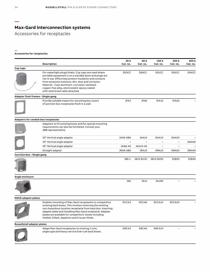
34 R U S S E LL S TO LL PI N & SL EE V E P OW ER CO N N EC TO R S
—Max-Gard interconnection systemsAccessories for receptacles
—Accessories for receptacles
Description30 A
Cat. no.60 A
Cat. no.100 A
Cat. no.200 A
Cat. no.400 A
Cat. no.
Cup caps
For watertight plugs/inlets. Cup caps are used where portable equipment is on a standby basis and plugs are not in use. Effectively protect insulation and contacts from excessive moisture, dirt, dust and corrosion. Material – Cast aluminum, corrosion-resistant copper-free alloy, electrostatic epoxy coated with steel braid cable attached.
DS3CC DS6CC DS1CC DS2CC DS4CC
Adapter flush frames – Single gang
Provide suitable means for mounting box covers of junction box receptacles flush in a wall.
JFA3 JFA6 JFA10 JFA20 –
Adapters for conduit box receptacles
Adapters to fit existing boxes and for special mounting requirements can also be furnished. Consult your ABB representative.
20° Vertical angle adapter JAA6-AB6 JAA10 DAA10 DAA20 –
30° Vertical angle adapter – – – – DAA40
45° Vertical angle adapter JAA6-45 JAA10-45 – – –
Straight adapter JRA6-AB6 JRA10 DRA10 DRA20 DRA40
Junction box – Single gang
JB6-1 JB10-B150 JB10-B200 DJB20 DJB40
Angle enclosure
JE6 JE10 JE10M – –
MACK adapter plates
Enables mounting of Max-Gard receptacles to competitive existing back boxes. This involves removing the existing non-hazardous location receptacle from back box, inserting adapter plate and installing Max-Gard receptacle. Adapter plates are available for competitors’ boxes including Hubbel, Killark, Appleton and Crouse-Hinds.
DCCA3 DCCA6 DCCA10 DCCA20 –
Russellstoll adapter plates
Adapt Max-Gard receptacles to existing J-Line, angle type and heavy-service Ever-Lok back boxes.
DRCA3 DRCA6 DRCA10 – –
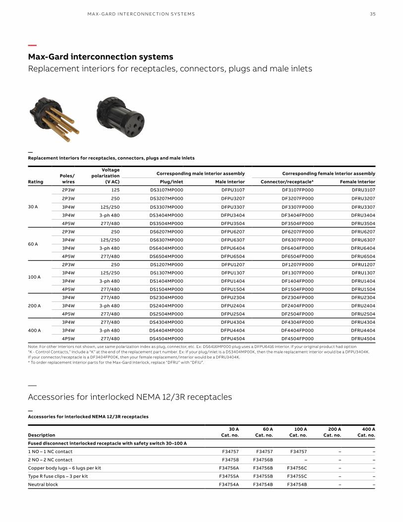
35
—Max-Gard interconnection systemsReplacement interiors for receptacles, connectors, plugs and male inlets
—Accessories for interlocked NEMA 12/3R receptacles
—Replacement interiors for receptacles, connectors, plugs and male inlets
—Accessories for interlocked NEMA 12/3R receptacles
RatingPoles/
wires
Voltage polarization
(V AC)
Corresponding male interior assembly Corresponding female interior assembly
Plug/inlet Male interior Connector/receptacle* Female interior
30 A
2P3W 125 DS3107MP000 DFPU3107 DF3107FP000 DFRU3107
2P3W 250 DS3207MP000 DFPU3207 DF3207FP000 DFRU3207
3P4W 125/250 DS3307MP000 DFPU3307 DF3307FP000 DFRU3307
3P4W 3-ph 480 DS3404MP000 DFPU3404 DF3404FP000 DFRU3404
4P5W 277/480 DS3504MP000 DFPU3504 DF3504FP000 DFRU3504
60 A
2P3W 250 DS6207MP000 DFPU6207 DF6207FP000 DFRU6207
3P4W 125/250 DS6307MP000 DFPU6307 DF6307FP000 DFRU6307
3P4W 3-ph 480 DS6404MP000 DFPU6404 DF6404FP000 DFRU6404
4P5W 277/480 DS6504MP000 DFPU6504 DF6504FP000 DFRU6504
100 A
2P3W 250 DS1207MP000 DFPU1207 DF1207FP000 DFRU1207
3P4W 125/250 DS1307MP000 DFPU1307 DF1307FP000 DFRU1307
3P4W 3-ph 480 DS1404MP000 DFPU1404 DF1404FP000 DFRU1404
4P5W 277/480 DS1504MP000 DFPU1504 DF1504FP000 DFRU1504
200 A
3P4W 277/480 DS2304MP000 DFPU2304 DF2304FP000 DFRU2304
3P4W 3-ph 480 DS2404MP000 DFPU2404 DF2404FP000 DFRU2404
4P5W 277/480 DS2504MP000 DFPU2504 DF2504FP000 DFRU2504
400 A
3P4W 277/480 DS4304MP000 DFPU4304 DF4304FP000 DFRU4304
3P4W 3-ph 480 DS4404MP000 DFPU4404 DF4404FP000 DFRU4404
4P5W 277/480 DS4504MP000 DFPU4504 DF4504FP000 DFRU4504
Note: For other interiors not shown, use same polarization index as plug, connector, etc. Ex: DS6416MP000 plug uses a DFPU6416 interior. If your original product had option “K - Control Contacts,” include a “K” at the end of the replacement part number. Ex: If your plug/inlet is a DS3404MP00K, then the male replacement interior would be a DFPU3404K. If your connector/receptacle is a DF3404FP00K, then your female replacement/interior would be a DFRU3404K.* To order replacement interior parts for the Max-Gard Interlock, replace “DFRU” with “DFIU”.
Description30 A
Cat. no.60 A
Cat. no.100 A
Cat. no.200 A
Cat. no.400 A
Cat. no.
Fused disconnect interlocked receptacle with safety switch 30–100 A
1 NO – 1 NC contact F34757 F34757 F34757 – –
2 NO – 2 NC contact F34758 F34756B – – –
Copper body lugs – 6 lugs per kit F34756A F34756B F34756C – –
Type R fuse clips – 3 per kit F34755A F34755B F34755C – –
Neutral block F34754A F34754B F34754B – –
M A X- G A R D I NTER CO N N EC TI O N S Y S TEMS
36 R U S S E LL S TO LL PI N & SL EE V E P OW ER CO N N EC TO R S
Thermal continuous current amps 120 V
Maximum current amps
600 VMax. volt
ampere240 V 480 V
Make Break Make Break Make Break Make Break Make Break
10 (#12 AWG) 60 6 30 3 15 1.5 12 1.2 7200 720
1.0 Scope1.1 This document covers multi-contact pin
and sleeve, industrial grade, arc-quenching, circuit interrupting-rated electrical plugs, motor plugs, connectors, receptacles, mechanically inter locked receptacles and assorted accessories. Usable in dry, damp, wet, marine and/or hazardous locations for electrical power circuits. Devices are to be rated 30, 60, 100, 200 and/or 400 amperes at 600 V AC, 50–400 Hz and 250 V DC maximum. Devices are also rated for continuous use in temperatures from -40 °C to +130 °C. These devices must provide internal environmental seals for marine and extreme wet applications and can be electrically interlocked.
1.2 The devices described shall be ABB/Russellstoll Max-Gard catalog numbers as specified.
2.0 Product classifications (features)2.1 Gated deadfront – All receptacles and
connectors must have a rotating disk on the face of the interior, which provides live contact isolation and environmental separation.
2.2 Delayed action arc containment – All devices upon disconnect under load shall have provision so the arc is contained and extinguished within the insulation cavity, making it impossible to withdraw a live plug.
2.3 Flap cover or screw cover option – Flap cover option must provide weathertight capability by utilizing a spring actuated self-closing flap. Watertight capability shall be obtained by using a gasketed screw cap.
2.4 Polarization – All devices shall be factory polarized for amperage, voltage, frequency and phase; thus providing a single voltage rating, single interface system.
2.5 Grounding – The grounding of the device shall be accomplished through a separate center ground (earth) make-first and break-last pole on all devices for complete system grounding.
2.6 Pole capabilities – All devices shall accommodate up to four power pins plus a separate center ground pin and they shall be integral with the connector bodies (five pins total).
2.7 Interior type – Interiors must be male (pin type) or female (sleeve type). Pins and sleeves shall also be self-aligning and self-wiping/self-cleaning.
2.8 Control contacts – All devices must have an option for two control contacts, which shall be make-last and break-first for use in electrical interlocks and/or control circuits. See table below.
2.9 Conductor terminals – Pin and sleeve connections shall employ solderless pressure-type screw terminals and be sized to accept stranded or solid copper conductors in AWG sizes (max. O.D.s as noted). The screw terminals shall also have socket heads to ensure proper torquing of wires.
2.10 Environmental seals – Each device must have an environmental seal or O-ring around all interiors and around each pin and sleeve to prevent water and contaminants from entering the wiring compartment. This provides waterproof capability, even when not mated.
2.11 Hazardous location – All standard plugs 30, 60 and 100 A shall be UL and CSA listed for hazardous location class I division 1, groups C and D; class II division 1, groups F and G. A hazardous location circuit breaker-pro tected interlock shall also be applicable to the same environments and possess all the same product features as outlined above. Enclosures shall meet NEMA 8 hazardous outdoor-duty classifications and shall meet shipboard use above deck in accordance with the Department of Transportation (USCG “Green Water”).
—Max-Gard interconnection systemsPin and sleeve plugs, receptacles and systems
—Rating for pilot/control contacts
Contact rating code designation A-600, Table 119.1 – UL 508 heavy pilot duty load (720 VA/600 V AC) maximum
37M A X- G A R D I NTER CO N N EC TI O N S Y S TEMS
—Max-Gard interconnection systemsPin and sleeve plugs, receptacles and systems
2.12 Lockout devices – Plug connection lockout is achieved by a padlock through plug sleeve housing hole provided for this purpose. On Hazardous location/explosion proof interlock receptacles, lockout shall additionally be achieved by separate lockout accessory available from the factory. On standard interlocks, lockout accessory/construction is available from the factory.
3.0 Materials requirements3.1 Housings – Plug, motor plug, receptacles,
connectors and interlock housings, associated covers and caps, screw collars, and clamp holders shall be made of copper-free cast aluminum (max. 0.004% copper).
3.2 Finish – All external surfaces except those that provide means of grounding shall be epoxy powder coated to resist corrosion.
3.3 Hardware – All hardware, external and springs, shall be stainless steel. Cable clamps shall be stainless steel or epoxy powder coated, copper-free cast aluminum.
3.4 Insulators – All device body insulators shall be molded from glass-reinforced high-strength thermoset polyester, minimum of UL 94-V0 flammability rated.
3.5 Contacts – Contacts base material shall be made of a conductive copper alloy (brass CDA485) to prevent dezincification. Accessory material of the contacts shall be made of a compatible corrosion resistant material.
3.6 Environmental seals – Environmental gaskets and O-rings shall be made of Neoprene material.
4.0 Design and construction requirements4.1 circuit interrupting rating – All devices
30, 60, 100 and 200 A shall be tested to be interrupted at 150% of rated current. Additionally, all devices shall be designed and tested to interrupt 100% of rated current.
4.2 Wiring – All devices shall be wired from the rear requiring no disassembly of the pins and/or sleeves from the insulated body.
5.0 Applicable documents (compliances)5.1 Underwriters Laboratories (UL) – The
devices specified herein shall be listed in applicable sections of UL Standards 1010, 231, 1682 and 1686, File Nos. E2630, E57324, E68085, E123752.
5.2 Canadian Standard Association (CSA) – The devices specified shall be listed in the applicable sections of CSA C22.2-182.1, File Number LR14096.
5.3 International Electro-Technical Commission (IEC) – The 30-, 60- and 100 A devices specified shall have been tested and comply with IEC 309-1.
5.4 Federal Department of Transportation – Refrigerated National Shipboard location devices shall meet and comply with Federal Register volume 47, number 68, subpart 111.79.
5.5 Standards – The devices specified shall comply with Military Standards MIL-STD-105 and 1344; ASTM Standards D570 and D2565: NEMA Standard PR4-1983; and OSHA regulations when installed in accordance with the National Electrical Code® (NEC).
5.6 NEMA 250 enclosures standard NEMA 1 – General Purpose for indoor use;
guards against contact with equipment. NEMA 3R – Outdoor use primarily to protect
against rain, sleet, wind-blown dust and damage from external ice formation.
NEMA 4 – Indoor or outdoor use to protect against windblown dust and rain; splashing and hose-directed water.
NEMA 4X – Watertight, dust-tight corrosion-resistant for indoor or outdoor applications.
NEMA 6 – Watertight, casual/ temporary immersion.
NEMA 7 – Class I (Hazardous) for indoor use in Class I areas, per NEC.
NEMA 8 – Class I (Hazardous) for indoor use in Class I, oil-immersed equipment.
NEMA 9 – Class II (Hazardous) for indoor use in Class II areas, per NEC.
NEMA 12 – Industrial use, dust-tight for indoor use to protect against dust, falling dirt and dripping non-corrosive liquids.
NEC and National Electrical Code are registered trademarks of the National Fire Protection Association, Inc.
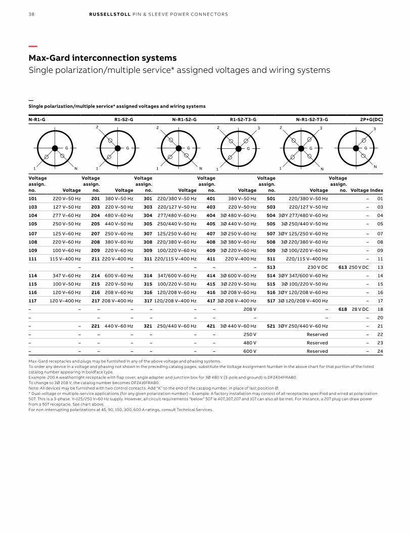
38 R U S S E LL S TO LL PI N & SL EE V E P OW ER CO N N EC TO R S
N-R1-G R1-S2-G N-R1-S2-G R1-S2-T3-G N-R1-S2-T3-G 2P+G(DC)
Voltage assign. no. Voltage
Voltage assign.
no. Voltage
Voltage assign.
no. Voltage
Voltage assign.
no. Voltage
Voltage assign.
no. Voltage
Voltage assign.
no. Voltage Index
101 220 V–50 Hz 201 380 V–50 Hz 301 220/380 V–50 Hz 401 380 V–50 Hz 501 220/380 V–50 Hz – 01
103 127 V–50 Hz 203 220 V–50 Hz 303 220/127 V–50 Hz 403 220 V–50 Hz 503 220/127 V–50 Hz – 03
104 277 V–60 Hz 204 480 V–60 Hz 304 277/480 V–60 Hz 404 3Ø 480 V–60 Hz 504 3ØY 277/480 V–60 Hz – 04
105 250 V–50 Hz 205 440 V–50 Hz 305 250/440 V–50 Hz 405 3Ø 440 V–50 Hz 505 3Ø 250/440 V–50 Hz – 05
107 125 V–60 Hz 207 250 V–60 Hz 307 125/250 V–60 Hz 407 3Ø 250 V–60 Hz 507 3ØY 125/250 V–60 Hz – 07
108 220 V–60 Hz 208 380 V–60 Hz 308 220/380 V–60 Hz 408 3Ø 380 V–60 Hz 508 3Ø 220/380 V–60 Hz – 08
109 100 V–60 Hz 209 220 V–60 Hz 309 100/220 V–60 Hz 409 3Ø 220 V–60 Hz 509 3Ø 100/220 V–60 Hz – 09
111 115 V–400 Hz 211 220 V–400 Hz 311 220/115 V–400 Hz 411 220 V–400 Hz 511 220/115 V–400 Hz – 11
– – – – – 513 230 V DC 613 250 V DC 13
114 347 V–60 Hz 214 600 V–60 Hz 314 347/600 V–60 Hz 414 3Ø 600 V–60 Hz 514 3ØY 347/600 V–60 Hz – 14
115 100 V–50 Hz 215 220 V–50 Hz 315 100/220 V–50 Hz 415 3Ø 220 V–50 Hz 515 3Ø 100/220 V–50 Hz – 15
116 120 V–60 Hz 216 208 V–60 Hz 316 120/208 V–60 Hz 416 3Ø 208 V–60 Hz 516 3ØY 120/208 V–60 Hz – 16
117 120 V–400 Hz 217 208 V–400 Hz 317 120/208 V–400 Hz 417 3Ø 208 V–400 Hz 517 3Ø 120/208 V–400 Hz – 17
– – – – – – – 208 V – 618 28 V DC 18
– – – – – – – – – 20
– – 221 440 V–60 Hz 321 250/440 V–60 Hz 421 3Ø 440 V–60 Hz 521 3ØY 250/440 V–60 Hz – 21
– – – – – – – 250 V Reserved – 22
– – – – – – – 480 V Reserved – 23
– – – – – – – 600 V Reserved – 24
1
G
N 1
2
G
N
2
G
1
2
1
3
G
1 N
32
G
3
N
G
—Max-Gard interconnection systemsSingle polarization/multiple service* assigned voltages and wiring systems
—Single polarization/multiple service* assigned voltages and wiring systems
Max-Gard receptacles and plugs may be furnished in any of the above voltage and phasing systems.To order any device in a voltage and phasing not shown in the preceding catalog pages, substitute the Voltage Assignment Number in the above chart for that portion of the listed catalog number appearing in boldface type.Example: 200 A weathertight receptacle with flap cover, angle adapter and junction box for 3Ø 480 V (3-pole and ground) is DF2404FRAB0.To change to 3Ø 208 V, the catalog number becomes DF2416FRAB0.Note: All devices may be furnished with two control contacts. Add “K” to the end of the catalog number, in place of last position Ø. * Dual-voltage or multiple-service applications (for any given polarization number) – Example: A factory installation may consist of all receptacles specified and wired at polarization 507. This is a 3-phase. Y–125/250 V–60 Hz supply. However, all circuit requirements “below” 507 ie 407,307,207 and 107 can also all be met. For instance, a 207 plug can draw power from a 507 receptacle. See chart above.For non-interrupting polarizations at 45, 90, 150, 300, 600 A ratings, consult Technical Services.
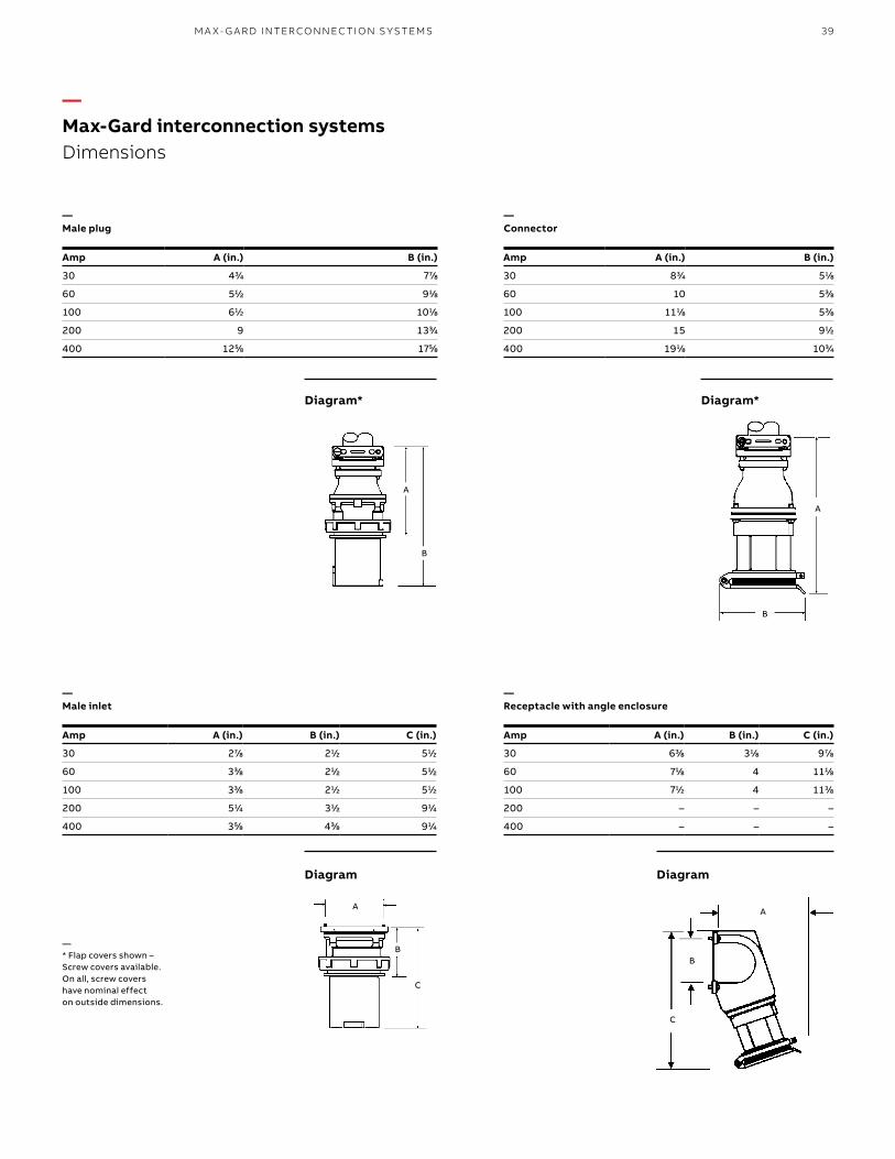
39M A X- G A R D I NTER CO N N EC TI O N S Y S TEMS
A
B
C
A
B
C
A
B
A
B
Amp A (in.) B (in.) C (in.)
30 27/8 21/2 51/2
60 33/8 21/2 51/2
100 33/8 21/2 51/2
200 51/4 31/2 91/4
400 35/8 43/8 91/4
Amp A (in.) B (in.)
30 83/4 51/8
60 10 53/8
100 111/8 53/8
200 15 91/2
400 191/8 103/4
Amp A (in.) B (in.) C (in.)
30 63/8 31/8 97/8
60 71/8 4 111/8
100 71/2 4 113/8
200 – – –
400 – – –
—Max-Gard interconnection systemsDimensions
—Male plug
—Connector
—* Flap covers shown – Screw covers available. On all, screw covers have nominal effect on outside dimensions.
—Male inlet
—Receptacle with angle enclosure
Diagram*Diagram*
Diagram Diagram
Amp A (in.) B (in.)
30 43/4 77/8
60 51/2 91/8
100 61/2 101/8
200 9 133/4
400 125/8 175/8
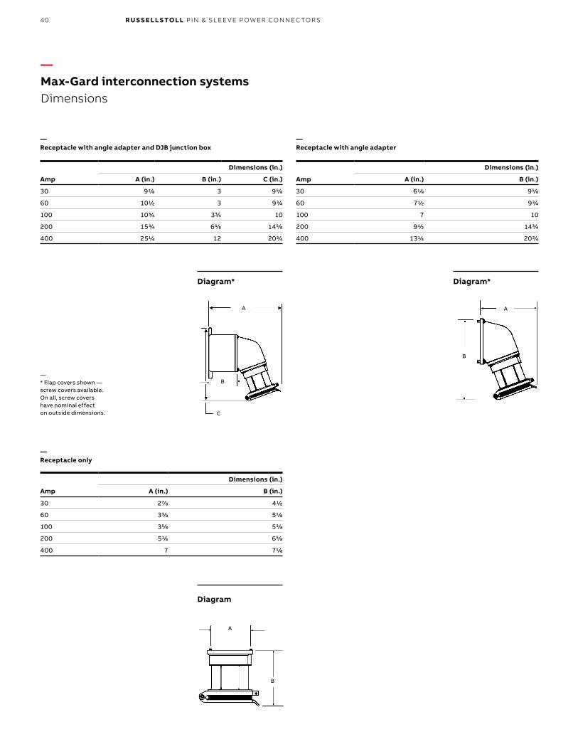
40 R U S S E LL S TO LL PI N & SL EE V E P OW ER CO N N EC TO R S
—Max-Gard interconnection systemsDimensions
A
C
B
A
B
A
B
Amp
Dimensions (in.)
A (in.) B (in.) C (in.)
30 91/8 3 95/8
60 101/2 3 93/4
100 103/4 33/4 10
200 153/4 65/8 145/8
400 251/4 12 203/4
—Receptacle with angle adapter and DJB junction box
—Receptacle with angle adapter
—* Flap covers shown — screw covers available. On all, screw covers have nominal effect on outside dimensions.
Amp
Dimensions (in.)
A (in.) B (in.)
30 61/8 95/8
60 71/2 93/4
100 7 10
200 91/2 143/4
400 131/4 203/4
—Receptacle only
Amp
Dimensions (in.)
A (in.) B (in.)
30 27/8 41/2
60 33/8 51/8
100 35/8 53/8
200 51/4 65/8
400 7 71/8
Diagram*Diagram*
Diagram
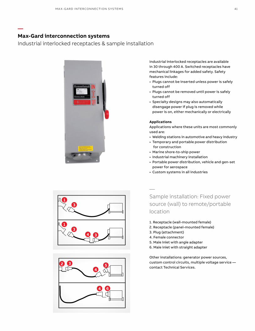
41
—Max-Gard interconnection systemsIndustrial interlocked receptacles & sample installation
Industrial interlocked receptacles are available in 30 through 400 A. Switched receptacles have mechanical linkages for added safety. Safety features include:• Plugs cannot be inserted unless power is safely
turned off• Plugs cannot be removed until power is safely
turned off• Specialty designs may also automatically
disengage power if plug is removed while power is on, either mechanically or electrically
ApplicationsApplications where these units are most commonly used are:• Welding stations in automotive and heavy industry• Temporary and portable power distribution
for construction• Marine shore-to-ship power• Industrial machinery installation• Portable power distribution, vehicle and gen-set
power for aerospace• Custom systems in all industries
—Sample installation: Fixed power source (wall) to remote/portable location
1. Receptacle (wall-mounted female)2. Receptacle (panel-mounted female)3. Plug (attachment)4. Female connector5. Male Inlet with angle adapter6. Male inlet with straight adapter
Other installations: generator power sources, custom control circuits, multiple voltage service — contact Technical Services.
13
13
34
34
4
2 5
6
M A X- G A R D I NTER CO N N EC TI O N S Y S TEMS
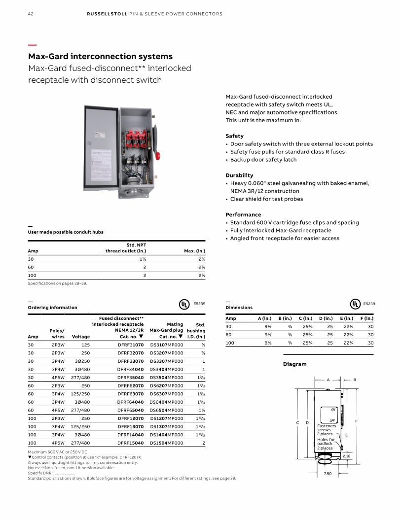
42 R U S S E LL S TO LL PI N & SL EE V E P OW ER CO N N EC TO R S
Fasteners Screws2 PlacesHoles for Padlock2 Places
C D
BA
F
E
7.50
2.18
ON
OFF
AmpStd. NPT
thread outlet (in.) Max. (in.)
30 11/2 21/2
60 2 21/2
100 2 21/2
Specifications on pages 38–39.
Amp A (in.) B (in.) C (in.) D (in.) E (in.) F (in.)
30 91/2 3/4 253/4 25 223/4 30
60 91/2 3/4 253/4 25 223/4 30
100 91/2 3/4 253/4 25 223/4 30Amp
Poles/wires Voltage
Fused disconnect**interlocked receptacle
NEMA 12/3RCat. no.
MatingMax-Gard plug
Cat. no.
Std.bushingI.D. (in.)
30 2P3W 125 DFRF31070 DS3107MP000 7/8
30 2P3W 250 DFRF32070 DS3207MP000 7/8
30 3P4W 3Ø250 DFRF33070 DS3307MP000 1
30 3P4W 3Ø480 DFRF34040 DS3404MP000 1
30 4P5W 277/480 DFRF35040 DS3504MP000 13/16
60 2P3W 250 DFRF62070 DS6207MP000 13/16
60 3P4W 125/250 DFRF63070 DS6307MP000 15/16
60 3P4W 3Ø480 DFRF64040 DS6404MP000 15/16
60 4P5W 277/480 DFRF65040 DS6504MP000 11/2
100 2P3W 250 DFRF12070 DS1207MP000 111/16
100 3P4W 125/250 DFRF13070 DS1307MP000 113/16
100 3P4W 3Ø480 DFRF14040 DS1404MP000 113/16
100 4P5W 277/480 DFRF15040 DS1504MP000 2
A B
F
E
C D
2.18
7.50
Fasteners screws
Holes for padlock
2 places
2 places
E5239
—Max-Gard interconnection systemsMax-Gard fused-disconnect** interlocked receptacle with disconnect switch
Max-Gard fused-disconnect interlocked receptacle with safety switch meets UL, NEC and major automotive specifications. This unit is the maximum in:
Safety • Door safety switch with three external lockout points• Safety fuse pulls for standard class R fuses• Backup door safety latch
Durability• Heavy 0.060" steel galvanealing with baked enamel,
NEMA 3R/12 construction• Clear shield for test probes
Performance• Standard 600 V cartridge fuse clips and spacing• Fully interlocked Max-Gard receptacle• Angled front receptacle for easier access
Diagram
—Ordering information
—Dimensions
—User made possible conduit hubs
Maximum 600 V AC or 250 V DCControl contacts (position 9) use “K” example: DFRF1207K. Always use liquidtight fittings to limit condensation entry.Notes: **Non-fused, non-UL version available:Specify DNRF ________ .Standard polarizations shown. Boldface figures are for voltage assignment; For different ratings, see page 38.
E5239
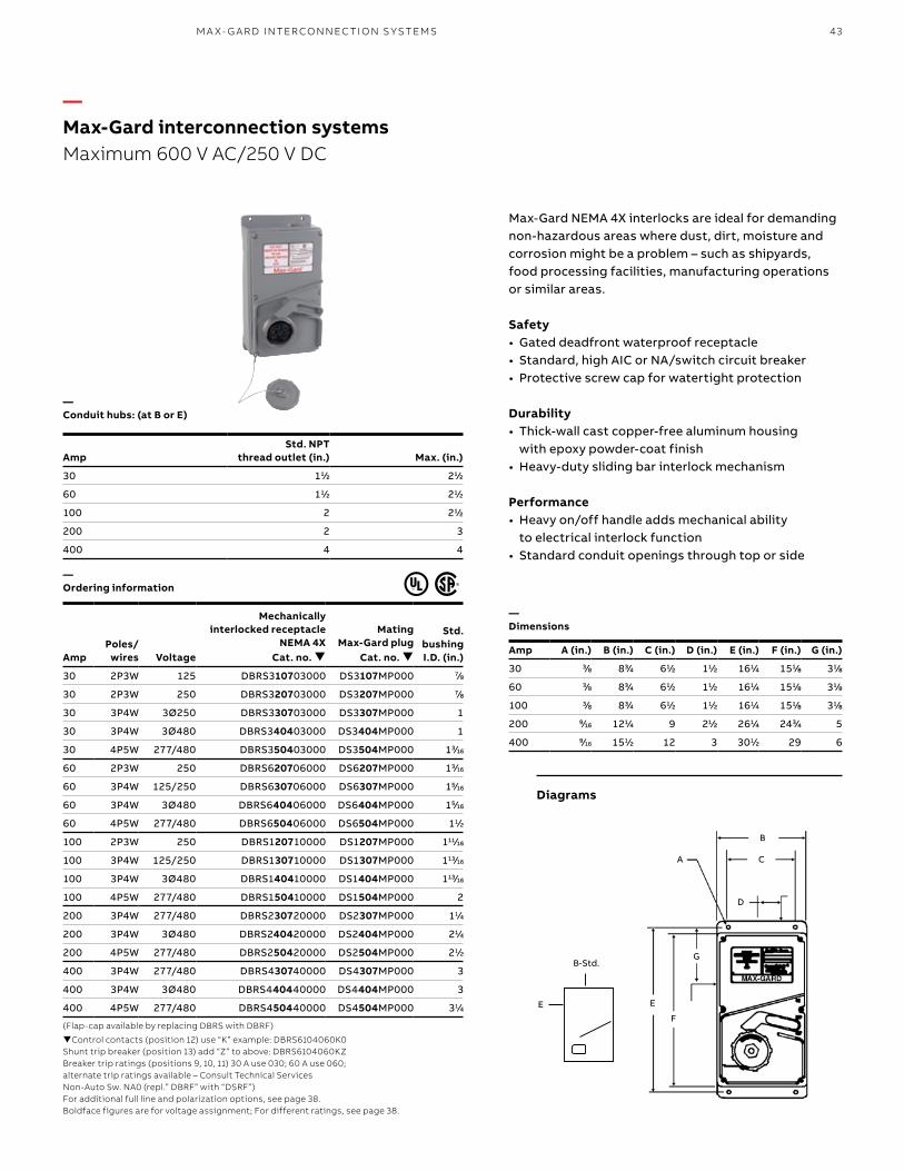
43M A X- G A R D I NTER CO N N EC TI O N S Y S TEMS
Diagrams
—Conduit hubs: (at B or E)
—Ordering information
—Dimensions
Control contacts (position 12) use “K” example: DBRS6104060K0Shunt trip breaker (position 13) add “Z” to above: DBRS6104060KZBreaker trip ratings (positions 9, 10, 11) 30 A use 030; 60 A use 060; alternate trip ratings available – Consult Technical ServicesNon-Auto Sw. NA0 (repl.” DBRF” with “DSRF”)For additional full line and polarization options, see page 38. Boldface figures are for voltage assignment; For different ratings, see page 38.
Max-Gard NEMA 4X interlocks are ideal for demanding non-hazardous areas where dust, dirt, moisture and corrosion might be a problem – such as shipyards, food processing facilities, manufacturing operations or similar areas.
Safety • Gated deadfront waterproof receptacle• Standard, high AIC or NA/switch circuit breaker• Protective screw cap for watertight protection
Durability• Thick-wall cast copper-free aluminum housing
with epoxy powder-coat finish• Heavy-duty sliding bar interlock mechanism
Performance• Heavy on/off handle adds mechanical ability
to electrical interlock function• Standard conduit openings through top or side
E
B-Std.
AmpStd. NPT
thread outlet (in.) Max. (in.)
30 11/2 21/2
60 11/2 21/2
100 2 21/2
200 2 3
400 4 4
Amp A (in.) B (in.) C (in.) D (in.) E (in.) F (in.) G (in.)
30 3/8 83/4 61/2 11/2 161/4 151/8 31/8
60 3/8 83/4 61/2 11/2 161/4 151/8 31/8
100 3/8 83/4 61/2 11/2 161/4 151/8 31/8
200 9/16 121/4 9 21/2 261/4 243/4 5
400 9/16 151/2 12 3 301/2 29 6
Mechanically interlocked receptacle
NEMA 4X Cat. no.
Mating Max-Gard plug
Cat. no.
Std. bushing I.D. (in.)Amp
Poles/ wires Voltage
30 2P3W 125 DBRS310703000 DS3107MP000 7/8
30 2P3W 250 DBRS320703000 DS3207MP000 7/8
30 3P4W 3Ø250 DBRS330703000 DS3307MP000 1
30 3P4W 3Ø480 DBRS340403000 DS3404MP000 1
30 4P5W 277/480 DBRS350403000 DS3504MP000 13/16
60 2P3W 250 DBRS620706000 DS6207MP000 13/16
60 3P4W 125/250 DBRS630706000 DS6307MP000 15/16
60 3P4W 3Ø480 DBRS640406000 DS6404MP000 15/16
60 4P5W 277/480 DBRS650406000 DS6504MP000 11/2
100 2P3W 250 DBRS120710000 DS1207MP000 111/16
100 3P4W 125/250 DBRS130710000 DS1307MP000 113/16
100 3P4W 3Ø480 DBRS140410000 DS1404MP000 113/16
100 4P5W 277/480 DBRS150410000 DS1504MP000 2
200 3P4W 277/480 DBRS230720000 DS2307MP000 11/4
200 3P4W 3Ø480 DBRS240420000 DS2404MP000 21/4
200 4P5W 277/480 DBRS250420000 DS2504MP000 21/2
400 3P4W 277/480 DBRS430740000 DS4307MP000 3
400 3P4W 3Ø480 DBRS440440000 DS4404MP000 3
400 4P5W 277/480 DBRS450440000 DS4504MP000 31/4
(Flap-cap available by replacing DBRS with DBRF)
A
B
C
D
G
F
E
—Max-Gard interconnection systemsMaximum 600 V AC/250 V DC
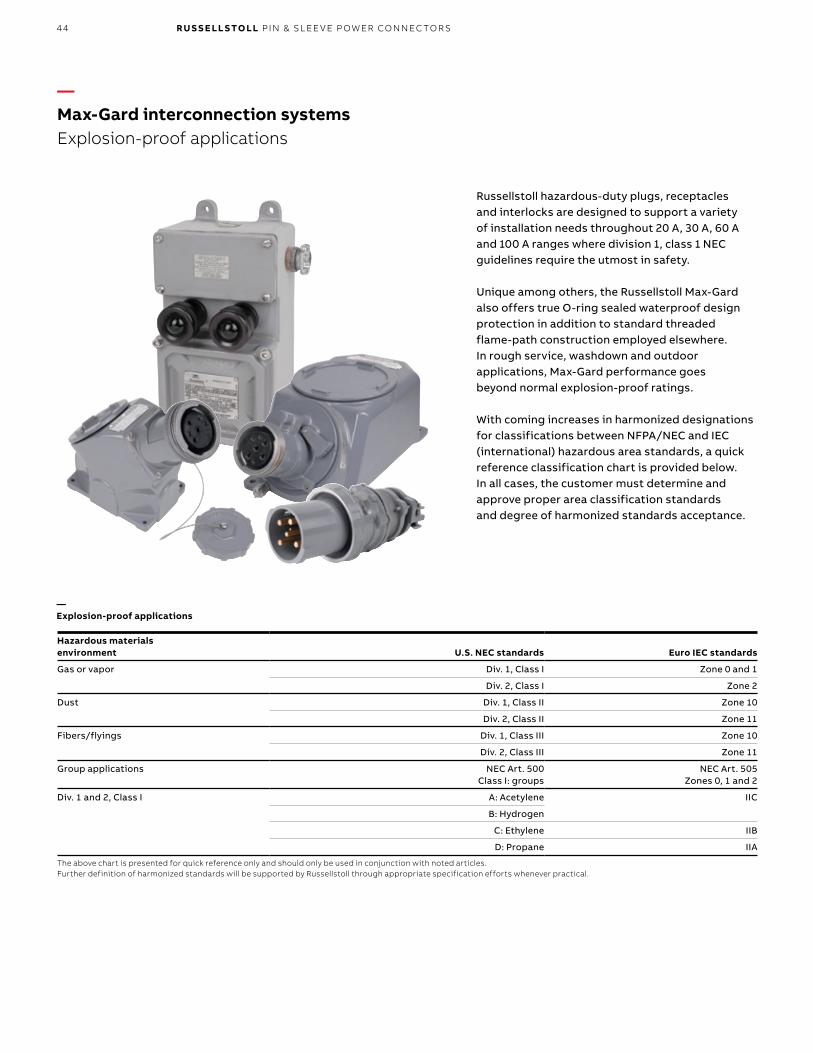
44 R U S S E LL S TO LL PI N & SL EE V E P OW ER CO N N EC TO R S
—Max-Gard interconnection systemsExplosion-proof applications
Hazardous materialsenvironment U.S. NEC standards Euro IEC standards
Gas or vapor Div. 1, Class I Zone 0 and 1
Div. 2, Class I Zone 2
Dust Div. 1, Class II Zone 10
Div. 2, Class II Zone 11
Fibers/flyings Div. 1, Class III Zone 10
Div. 2, Class III Zone 11
Group applications NEC Art. 500Class I: groups
NEC Art. 505Zones 0, 1 and 2
Div. 1 and 2, Class I A: Acetylene IIC
B: Hydrogen
C: Ethylene IIB
D: Propane IIA
The above chart is presented for quick reference only and should only be used in conjunction with noted articles. Further definition of harmonized standards will be supported by Russellstoll through appropriate specification efforts whenever practical.
Russellstoll hazardous-duty plugs, receptacles and interlocks are designed to support a variety of installation needs throughout 20 A, 30 A, 60 A and 100 A ranges where division 1, class 1 NEC guidelines require the utmost in safety.
Unique among others, the Russellstoll Max-Gard also offers true O-ring sealed waterproof design protection in addition to standard threaded flame-path construction employed elsewhere. In rough service, washdown and outdoor applications, Max-Gard performance goes beyond normal explosion-proof ratings.
With coming increases in harmonized designations for classifications between NFPA/NEC and IEC (international) hazardous area standards, a quick reference classification chart is provided below. In all cases, the customer must determine and approve proper area classification standards and degree of harmonized standards acceptance.
—Explosion-proof applications
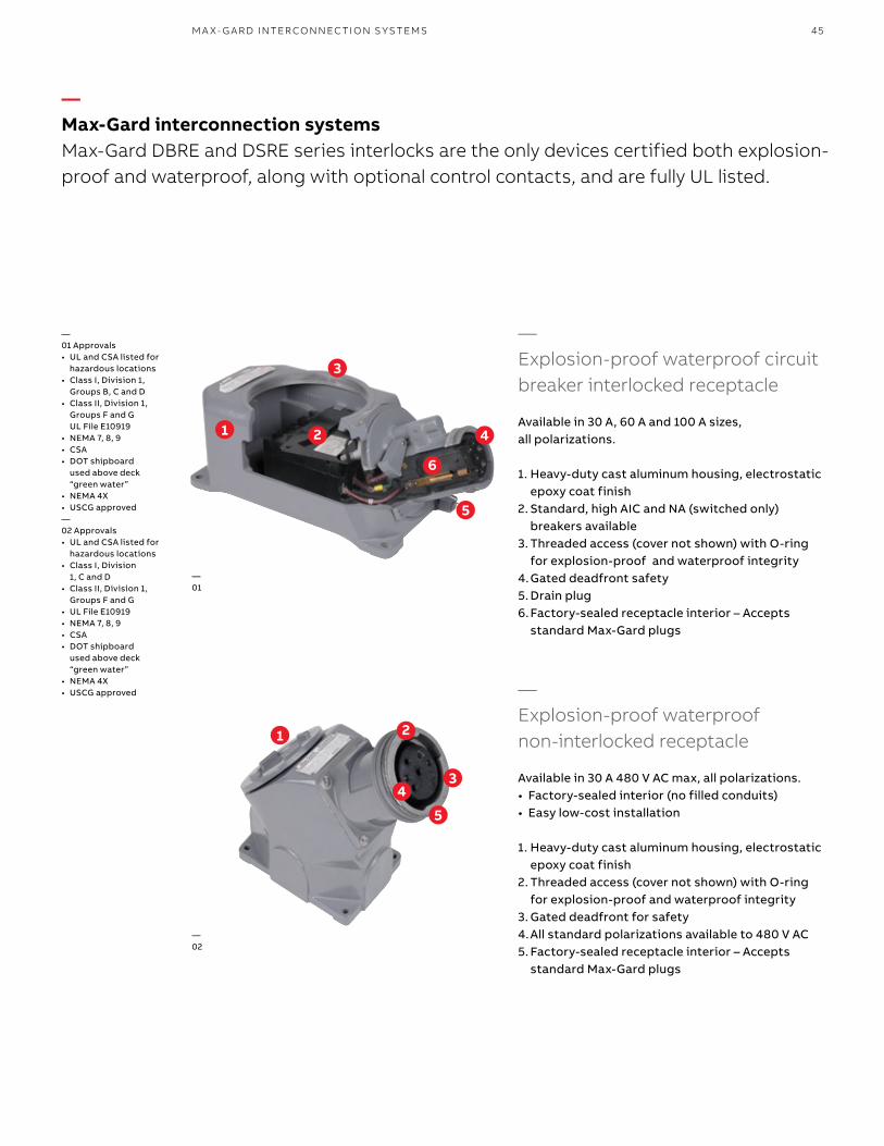
45M A X- G A R D I NTER CO N N EC TI O N S Y S TEMS
—Max-Gard interconnection systemsMax-Gard DBRE and DSRE series interlocks are the only devices certified both explosion-proof and waterproof, along with optional control contacts, and are fully UL listed.
—Explosion-proof waterproof circuit breaker interlocked receptacle
Available in 30 A, 60 A and 100 A sizes, all polarizations.
1. Heavy-duty cast aluminum housing, electrostatic epoxy coat finish
2. Standard, high AIC and NA (switched only) breakers available
3. Threaded access (cover not shown) with O-ring for explosion-proof and waterproof integrity
4. Gated deadfront safety5. Drain plug6. Factory-sealed receptacle interior – Accepts
standard Max-Gard plugs
—Explosion-proof waterproof non-interlocked receptacle
Available in 30 A 480 V AC max, all polarizations.• Factory-sealed interior (no filled conduits)• Easy low-cost installation
1. Heavy-duty cast aluminum housing, electrostatic epoxy coat finish
2. Threaded access (cover not shown) with O-ring for explosion-proof and waterproof integrity
3. Gated deadfront for safety4. All standard polarizations available to 480 V AC5. Factory-sealed receptacle interior – Accepts
standard Max-Gard plugs
—01 Approvals• UL and CSA listed for
hazardous locations• Class I, Division 1,
Groups B, C and D• Class II, Division 1,
Groups F and G UL File E10919
• NEMA 7, 8, 9• CSA• DOT shipboard
used above deck “green water”
• NEMA 4X• USCG approved—02 Approvals• UL and CSA listed for
hazardous locations• Class I, Division
1, C and D• Class II, Division 1,
Groups F and G• UL File E10919• NEMA 7, 8, 9• CSA• DOT shipboard
used above deck “green water”
• NEMA 4X• USCG approved
2
3
1
6
4
2
3
1
5
4
—01
—02
5
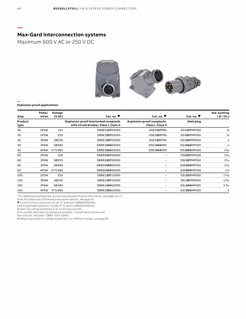
46 R U S S E LL S TO LL PI N & SL EE V E P OW ER CO N N EC TO R S
AmpPoles/
wiresVoltage
(V AC) Cat. no. Cat. no. Cat. no. Std. bushing
I.D.* (in.)
Product type
Explosion-proof interlocked receptacle with circuit breaker, Class I, Class II
Explosion-proof receptacle, Class I, Class II
Male plug
30 2P3W 125 DBRE310703000 DSE3107FR0 DS3107MP000 7/8
30 2P3W 250 DBRE320703000 DSE3207FR0 DS3207MP000 7/8
30 3P4W 3Ø250 DBRE330703000 DSE3307FR0 DS3307MP000 1
30 3P4W 3Ø480 DBRE340403000 DSE3404FR0 DS3404MP000 1
30 4P5W 277/480 DBRE350403000 DSE3504FR0 DS3504MP000 13/16
60 2P3W 250 DBRE620706000 – DS6207MP000 13/16
60 3P4W 3Ø250 DBRE630706000 – DS6307MP000 15/16
60 3P4W 3Ø480 DBRE640406000 – DS6404MP000 15/16
60 4P5W 277/480 DBRE650406000 – DS6504MP000 11/2
100 2P3W 250 DBRE120710000 – DS1207MP000 111/16
100 3P4W 3Ø250 DBRE130710000 – DS1307MP000 113/16
100 3P4W 3Ø480 DBRE140410000 – DS1404MP000 113/16
100 4P5W 277/480 DBRE150410000 – DS1504MP000 2
—Max-Gard interconnection systemsMaximum 600 V AC or 250 V DC
* For additional bushing sizes, accessories and specification information, see pages 32–37.Note: For additional full line and polarization options, see page 40. Control contacts (position 12) use “K” example: DBRE6404060K0Shunt trip breaker (position 13) add “Z” to above: DBRE6404060KZBreaker trip ratings (positions 9, 10, 11) 30 amp use 030; 60 A use 060; alternate trip ratings are available – Consult technical servicesNon-auto Sw. NA0 (repl. “DBRE” with “DSRE”)Boldface figures are for voltage assignment; For different ratings, see page 38.
—Explosion-proof applications
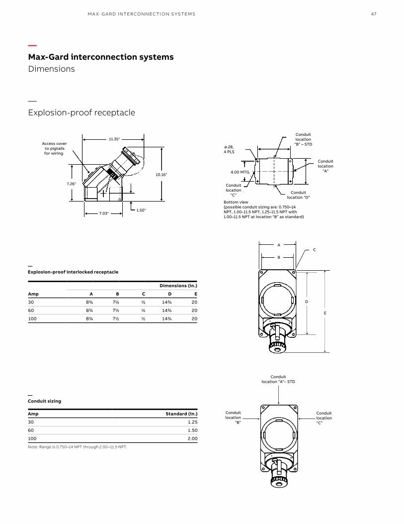
47M A X- G A R D I NTER CO N N EC TI O N S Y S TEMS
—Max-Gard interconnection systemsDimensions
—Explosion-proof interlocked receptacle
—Conduit sizing
Dimensions (in.)
Amp A B C D E
30 83/4 71/2 1/2 143/4 20
60 83/4 71/2 1/2 143/4 20
100 83/4 71/2 1/2 143/4 20
Amp Standard (in.)
30 1.25
60 1.50
100 2.00
Note: Range is 0.750–14 NPT through 2.00–11.5 NPT.
Access coverto pigtails for wiring
10.16"
11.35"
7.26"
7.03"1.50"
Conduitlocation
“C”Conduit
location “D”
Conduitlocation
“B” – STD
Conduitlocation
“A”4.00 MTG.
ø.28, 4 PLS
Bottom view (possible conduit sizing are: 0.750–14 NPT, 1.00–11.5 NPT, 1.25–11.5 NPT with 1.00–11.5 NPT at location “B” as standard)
Conduitlocation “C”
Conduitlocation
“B”
Conduitlocation “A”– STD
—Explosion-proof receptacle
A
B
E
D
C
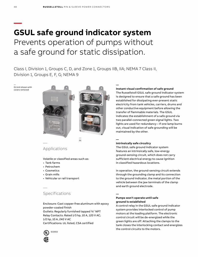
48 R U S S E LL S TO LL PI N & SL EE V E P OW ER CO N N EC TO R S
—GSUL safe ground indicator systemPrevents operation of pumps without a safe ground for static dissipation.
Class I, Division 1, Groups C, D, and Zone 1, Groups IIB, IIA; NEMA 7 Class II, Division 1, Groups E, F, G; NEMA 9
E33553
—Instant visual confirmation of safe ground The Russellstoll GSUL safe ground indicator system is designed to ensure that a safe ground has been established for dissipating ever-present static electricity from tank vehicles, carriers, drums and other conductive equipment before allowing the transfer of flammable materials. The GSUL indicates the establishment of a safe ground via two parallel-connected green signal lights. Two lights are used for redundancy – If one lamp burns out, visual indication of safe grounding will be maintained by the other.
—Intrinsically safe circuitryThe GSUL safe ground indicator system features an intrinsically safe, low-energy ground-sensing circuit, which does not carry sufficient electrical energy to cause ignition in classified hazardous locations.
In operation, the ground-sensing circuit extends through the grounding clamp and its connection to the ground indicator, the metal portion of the vehicle between the jaw terminals of the clamp and earth ground electrode.
—Pumps won’t operate until safe ground is establishedA control relay in the GSUL safe ground indicator system provides interlocked control of pump motors at the loading platform. The electronic control circuit will be de-energized while the green lights are off. Attaching the clamps to the tank closes the interlocking contact and energizes the control circuits to the motors.
—01 Unit shown with covers removed
—01
—Applications
Volatile or classified areas such as:• Tank farms • Petrochem• Cosmetics • Grain mills• Vehicular or rail transport
—Specifications
Enclosure: Cast copper-free aluminum with epoxy powder-coated finishOutlets: Regularly furnished tapped 3/4" NPTRelay Contacts: Rated 1 /3 hp, 10 A, 120 V AC; 1 /2 hp, 10 A, 240 V AC Certifications: UL listed, CSA certified
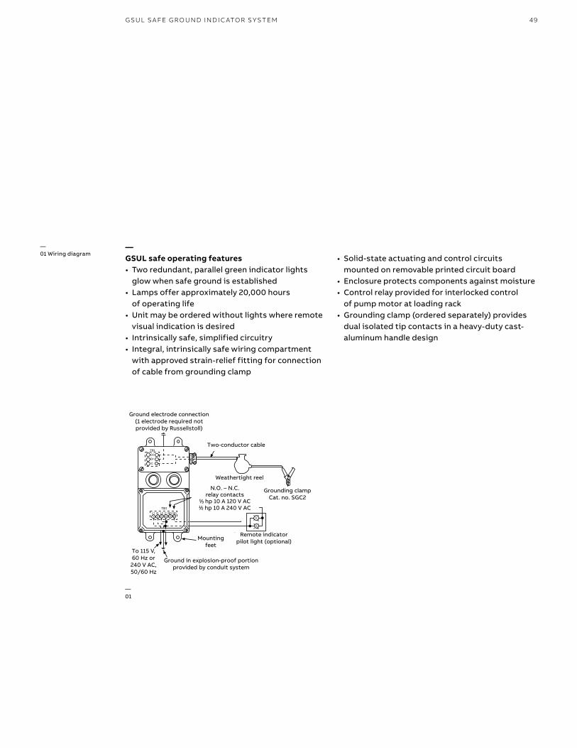
49G SU L S A FE G R O U N D I N D I C ATO R S Y S TEM
TB1L1 G L2 C N.O. N.C.1 2 3 4 5 6 G
G
G2G1C
TB3
Ground Electrode Connection (1 electrode required) not provided by Russellstoll
Two-Conductor Cable
Weathertight Reel
Grounding ClampCat. No. SGC2
Remote Indicator Pilot Light(Optional)Mounting
Feet
N.O. - N.C. Relay Contacts1/3 H.P. 10 Amp 120 VAC1/2 H.P. 10 Amp 240VAC
To 115 Volts,60 Hz Ground in explosion-proof
portion provided by conduitsystem
Weathertight reel
Ground in explosion-proof portion provided by conduit system
To 115 V, 60 Hz or
240 V AC, 50/60 Hz
Ground electrode connection (1 electrode required not provided by Russellstoll)
Two-conductor cable
N.O. – N.C. relay contacts
1/3 hp 10 A 120 V AC 1/2 hp 10 A 240 V AC
N.O. – N.C. relay contacts
1/3 hp 10 A 120 V AC 1/2 hp 10 A 240 V AC
N.O. – N.C. relay contacts
1/3 hp 10 A 120 V AC 1/2 hp 10 A 240 V AC
Grounding clampCat. no. SGC2
Remote indicatorpilot light (optional)Mounting
feet
—01 Wiring diagram
—01
—GSUL safe operating features• Two redundant, parallel green indicator lights
glow when safe ground is established• Lamps offer approximately 20,000 hours
of operating life• Unit may be ordered without lights where remote
visual indication is desired • Intrinsically safe, simplified circuitry• Integral, intrinsically safe wiring compartment
with approved strain-relief fitting for connection of cable from grounding clamp
• Solid-state actuating and control circuits mounted on removable printed circuit board
• Enclosure protects components against moisture• Control relay provided for interlocked control
of pump motor at loading rack• Grounding clamp (ordered separately) provides
dual isolated tip contacts in a heavy-duty cast-aluminum handle design
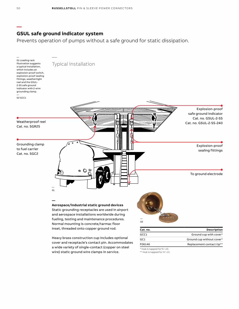
50 R U S S E LL S TO LL PI N & SL EE V E P OW ER CO N N EC TO R S
Explosion-proof safe ground indicator
Cat. no. GSUL-2-SSCat. no. GSUL-2-SS-240
Cat. no. Description
GCC1 Ground cup with cover*
GC1 Ground cup without cover*
F06146 Replacement contact tip**
* Hub is tapped for 3⁄4"–10.** Hub is tapped for 1⁄2"–13.
Weatherproof reelCat. no. SGR25
Grounding clamp to fuel carrierCat. no. SGC2
Explosion-proof sealing fittings
To ground electrode
—Typical installation
—01
—02
—Aerospace/industrial static ground devicesStatic grounding receptacles are used in airport and aerospace installations worldwide during fueling, testing and maintenance procedures. Normal mounting is concrete/tarmac floor inset, threaded onto copper ground rod.
Heavy brass construction cup includes optional cover and receptacle’s contact pin. Accommodates a wide variety of single-contact (copper on steel wire) static ground wire clamps in service.
—01 Loading rack illustration suggests a typical installation, which includes an explosion-proof switch, explosion-proof sealing fittings, weathertight reel and the GSUL-2-SS safe ground indicator with 2-wire grounding clamp.—02 GCC1
—GSUL safe ground indicator systemPrevents operation of pumps without a safe ground for static dissipation.
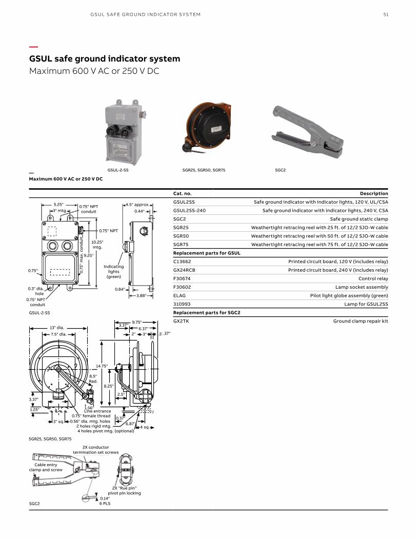
51G SU L S A FE G R O U N D IN D I C ATO R S Y S TEM
13" Dia.7.5"
3.37"
1.25"
3" Sq.
8.5"Rad.
1.56"
.56" Dia. MTG Holes.75" Female Thread
Line Entrance
14.75"
8.25"
2.5"
9.75"3.37" 6.37"
.37"3"2"
4 Holes Pivot MTG (optional)2 Holes Rigid MTG
.37"6.87"
4 Sq
Cat. no. Description
GSUL2SS Safe ground indicator with indicator lights, 120 V, UL/CSA
GSUL2SS-240 Safe ground indicator with indicator lights, 240 V, CSA
SGC2 Safe ground static clamp
SGR25 Weathertight retracing reel with 25 ft. of 12/2 SJO-W cable
SGR50 Weathertight retracing reel with 50 ft. of 12/2 SJO-W cable
SGR75 Weathertight retracing reel with 75 ft. of 12/2 SJO-W cable
Replacement parts for GSUL
C13662 Printed circuit board, 120 V (includes relay)
GX24RCB Printed circuit board, 240 V (includes relay)
F30674 Control relay
F30602 Lamp socket assembly
ELAG Pilot light globe assembly (green)
310993 Lamp for GSUL2SS
Replacement parts for SGC2
GX2TK Ground clamp repair kit
GSUL-2-SS
5.25"3" mtg.
0.75" NPT conduit
0.75" NPT
10.25" mtg.
9.25"
0.75"
0.3" dia. hole
0.75" NPT conduit
0.75
" m
ax. c
ond
uit
4.5" approx.
0.44"
0.84"3.88"
Indicating lights
(green)
GSUL-2-SS
SGR25, SGR50, SGR75 SGC2
—GSUL safe ground indicator systemMaximum 600 V AC or 250 V DC
1.25" 1.56"
2.5"
3.37"13" dia.
7.5" dia.
9.75"6.37"
2" 3" .37"
14.75"
8.25"
4 sq.
3.37"
3" sq.
8.5" Rad.
6.87"2 holes rigid mtg. 4 holes pivot mtg. (optional)
0.56" dia. mtg. holes 0.75" female thread
Line entrance
SGR25, SGR50, SGR75
2X conductor termination set screws
Cable entry clamp and screw
2X “Rue pin” pivot pin locking
0.14"6 PLSSGC2
0.37"
—Maximum 600 V AC or 250 V DC
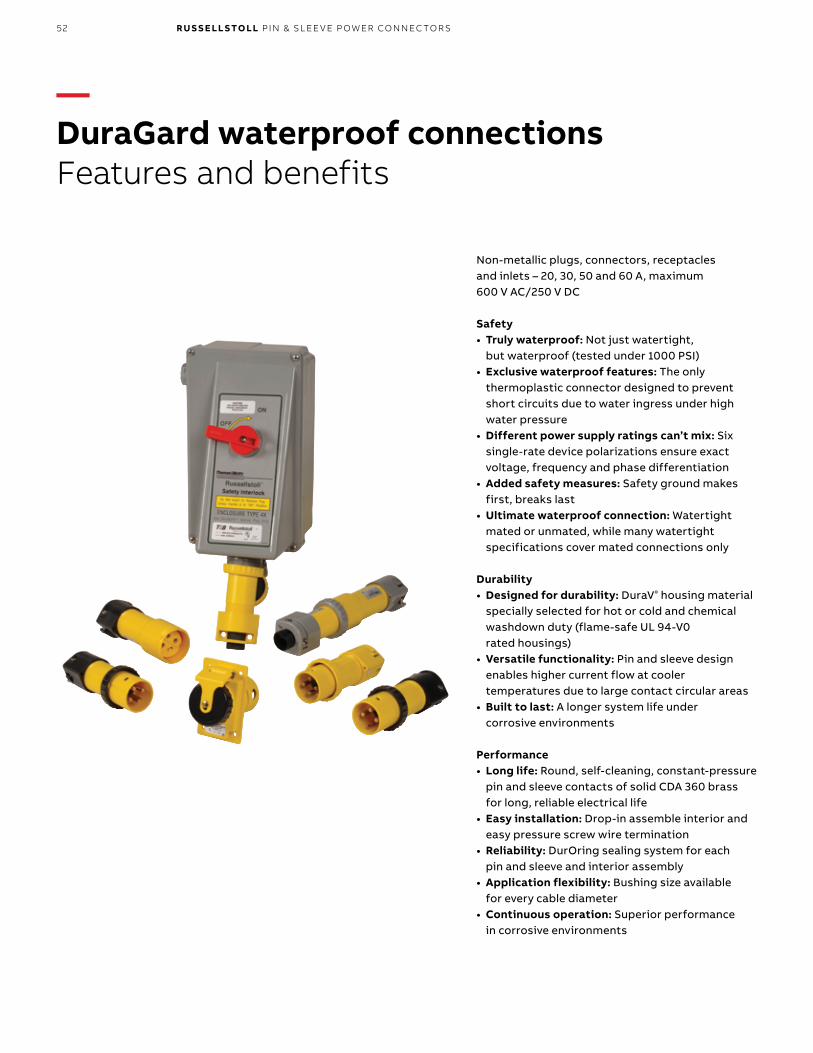
52 R U S S E LL S TO LL PI N & SL EE V E P OW ER CO N N EC TO R S
—DuraGard waterproof connectionsFeatures and benefits
Non-metallic plugs, connectors, receptacles and inlets – 20, 30, 50 and 60 A, maximum 600 V AC/250 V DC
Safety• Truly waterproof: Not just watertight,
but waterproof (tested under 1000 PSI)• Exclusive waterproof features: The only
thermoplastic connector designed to prevent short circuits due to water ingress under high water pressure
• Different power supply ratings can’t mix: Six single-rate device polarizations ensure exact voltage, frequency and phase differentiation
• Added safety measures: Safety ground makes first, breaks last
• Ultimate waterproof connection: Watertight mated or unmated, while many watertight specifications cover mated connections only
Durability• Designed for durability: DuraV® housing material
specially selected for hot or cold and chemical washdown duty (flame-safe UL 94-V0 rated housings)
• Versatile functionality: Pin and sleeve design enables higher current flow at cooler temperatures due to large contact circular areas
• Built to last: A longer system life under corrosive environments
Performance• Long life: Round, self-cleaning, constant-pressure
pin and sleeve contacts of solid CDA 360 brass for long, reliable electrical life
• Easy installation: Drop-in assemble interior and easy pressure screw wire termination
• Reliability: DurOring sealing system for each pin and sleeve and interior assembly
• Application flexibility: Bushing size available for every cable diameter
• Continuous operation: Superior performance in corrosive environments
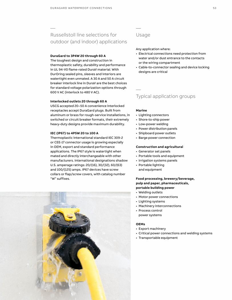
53D U R AG A R D WATER PR O O F CO N N EC TI O NS
Any application where: • Electrical connections need protection from
water and/or dust entrance to the contacts or the wiring compartment
• Cable-to-connector sealing and device locking designs are critical
—Typical application groups
—Usage
Marine• Lighting connectors• Shore-to-ship power• Low-power welding• Power distribution panels• Shipboard power outlets• Barge power connection
Construction and agricultural• Generator set panels• Portable tools and equipment• Irrigation systems panels• Portable lighting
and equipment
Food processing, brewery/beverage, pulp and paper, pharmaceuticals, portable building power• Welding outlets• Motor power connections• Lighting systems• Machinery interconnections• Process control
power systems
OEMs• Export machinery• Critical power connections and welding systems• Transportable equipment
—Russellstoll line selections for outdoor (and indoor) applications
DuraGard to 3P4W 20 through 60 AThe toughest design and construction in thermoplastic safety, durability and performance in UL 94-V0 flame-rated DuraV material. With DurOring sealed pins, sleeves and interiors are watertight even unmated. A 30 A and 50 A circuit breaker interlock line in DuraV are the best choices for standard voltage polarization options through 600 V AC (interlock to 480 V AC).
Interlocked outlets 20 through 60 AUSCG accepted 20–50 A convenience interlocked receptacles accept DuraGard plugs. Built from aluminum or brass for rough-service installations, in switched or circuit breaker formats, their extremely heavy-duty designs provide maximum durability.
IEC (IP67) to 4P5W 20 to 100 AThermoplastic international standard IEC 309-2 or CEE-17 connector usage is growing especially in OEM, export and standard performance applications. The IP67 style is watertight when mated and directly interchangeable with other manufacturers. International designations shadow U.S. amperage ratings: 20/(16), 30/(32), 60/(63) and 100/(125) amps. IP67 devices have screw collars or flap/screw covers, with catalog number “W” suffixes.
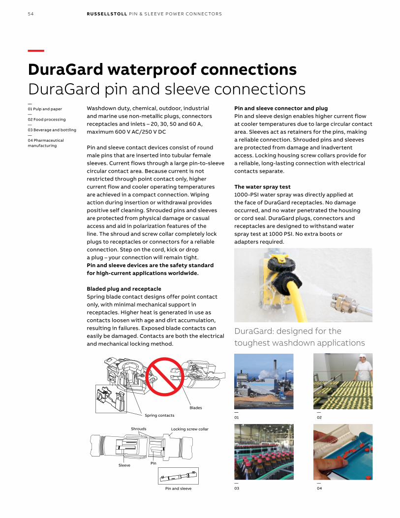
54 R U S S E LL S TO LL PI N & SL EE V E P OW ER CO N N EC TO R S
—DuraGard waterproof connectionsDuraGard pin and sleeve connections
Spring contacts
Blades
Pin and sleeve
Shrouds
Sleeve Pin
Locking screw collar
DuraGard: designed for the toughest washdown applications
Washdown duty, chemical, outdoor, industrial and marine use non-metallic plugs, connectors receptacles and inlets – 20, 30, 50 and 60 A, maximum 600 V AC/250 V DC
Pin and sleeve contact devices consist of round male pins that are inserted into tubular female sleeves. Current flows through a large pin-to-sleeve circular contact area. Because current is not restricted through point contact only, higher current flow and cooler operating temperatures are achieved in a compact connection. Wiping action during insertion or withdrawal provides positive self cleaning. Shrouded pins and sleeves are protected from physical damage or casual access and aid in polarization features of the line. The shroud and screw collar completely lock plugs to receptacles or connectors for a reliable connection. Step on the cord, kick or drop a plug – your connection will remain tight. Pin and sleeve devices are the safety standard for high-current applications worldwide.
Bladed plug and receptacleSpring blade contact designs offer point contact only, with minimal mechanical support in receptacles. Higher heat is generated in use as contacts loosen with age and dirt accumulation, resulting in failures. Exposed blade contacts can easily be damaged. Contacts are both the electrical and mechanical locking method.
Pin and sleeve connector and plugPin and sleeve design enables higher current flow at cooler temperatures due to large circular contact area. Sleeves act as retainers for the pins, making a reliable connection. Shrouded pins and sleeves are protected from damage and inadvertent access. Locking housing screw collars provide for a reliable, long-lasting connection with electrical contacts separate.
The water spray test1000-PSI water spray was directly applied at the face of DuraGard receptacles. No damage occurred, and no water penetrated the housing or cord seal. DuraGard plugs, connectors and receptacles are designed to withstand water spray test at 1000 PSI. No extra boots or adapters required.
—01 Pulp and paper—02 Food processing—03 Beverage and bottling—04 Pharmaceutical manufacturing
—01
—03
—04
—02
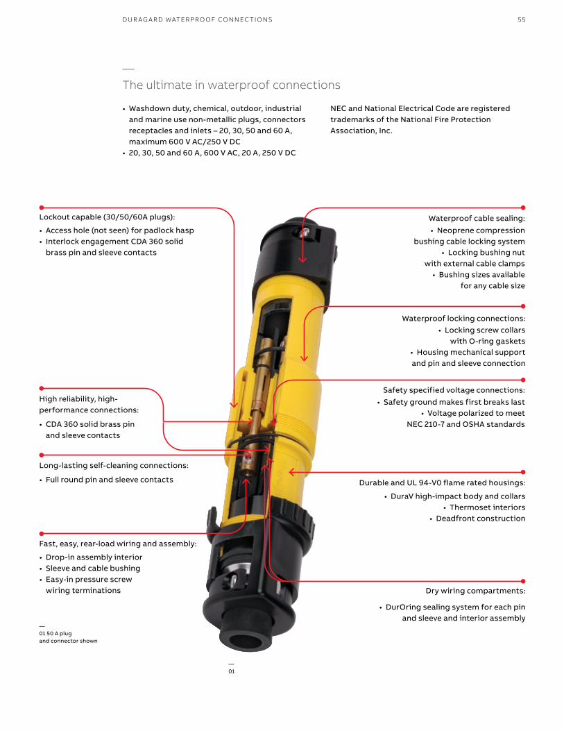
55
High reliability, high- performance connections:
• CDA 360 solid brass pin and sleeve contacts
Long-lasting self-cleaning connections:
• Full round pin and sleeve contacts
Fast, easy, rear-load wiring and assembly:
• Drop-in assembly interior• Sleeve and cable bushing• Easy-in pressure screw
wiring terminations
DuraGard: designed for the toughest washdown applications
• Washdown duty, chemical, outdoor, industrial and marine use non-metallic plugs, connectors receptacles and inlets – 20, 30, 50 and 60 A, maximum 600 V AC/250 V DC
• 20, 30, 50 and 60 A, 600 V AC, 20 A, 250 V DC
NEC and National Electrical Code are registered trademarks of the National Fire Protection Association, Inc.
—The ultimate in waterproof connections
Lockout capable (30/50/60A plugs):
• Access hole (not seen) for padlock hasp• Interlock engagement CDA 360 solid
brass pin and sleeve contacts
Waterproof cable sealing:
• Neoprene compression bushing cable locking system
• Locking bushing nut with external cable clamps
• Bushing sizes available for any cable size
Waterproof locking connections: • Locking screw collars
with O-ring gaskets• Housing mechanical support and pin and sleeve connection
Safety specified voltage connections:• Safety ground makes first breaks last
• Voltage polarized to meet NEC 210-7 and OSHA standards
Durable and UL 94-V0 flame rated housings:
• DuraV high-impact body and collars• Thermoset interiors
• Deadfront construction
Dry wiring compartments:
• DurOring sealing system for each pin and sleeve and interior assembly
—01 50 A plug and connector shown
—01
D U R AG A R D WATER PR O O F CO N N EC TI O NS
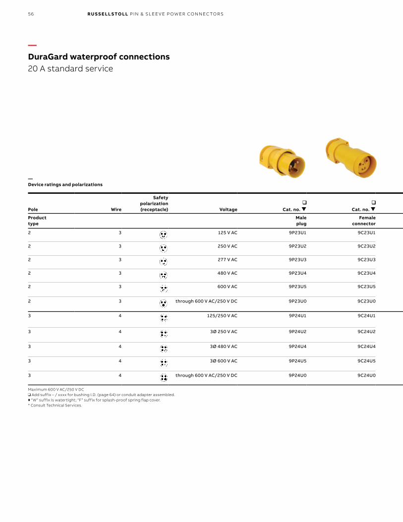
56 R U S S E LL S TO LL PI N & SL EE V E P OW ER CO N N EC TO R S
Pole Wire
Safetypolarization (receptacle) Voltage
Cat. no.
Cat. no. Pole Wire
Standard bushing I.D.: Plug/conn.*
Cat. no.
Product type
Male plug
Female connector
Product type
Female receptacle
2 3 125 V AC 9P23U1 9C23U1 2 3 Standard 0.625"; or optional size, see page 64 9R23U1W
2 3 250 V AC 9P23U2 9C23U2 2 3 Standard 0.625"; or optional size, see page 64 9R23U2W
2 3 277 V AC 9P23U3 9C23U3 2 3 Standard 0.625"; or optional size, see page 64 9R23U3W
2 3 480 V AC 9P23U4 9C23U4 2 3 Standard 0.625"; or optional size, see page 64 9R23U4W
2 3 600 V AC 9P23U5 9C23U5 2 3 Standard 0.625"; or optional size, see page 64 9R23U5W
2 3 through 600 V AC/250 V DC 9P23U0 9C23U0 2 3 Standard 0.625"; or optional size, see page 64 9R23U0W
3 4 125/250 V AC 9P24U1 9C24U1 3 4 Standard 0.625"; or optional size, see page 64 9R24U1W
3 4 3Ø 250 V AC 9P24U2 9C24U2 3 4 Standard 0.625"; or optional size, see page 64 9R24U2W
3 4 3Ø 480 V AC 9P24U4 9C24U4 3 4 Standard 0.625"; or optional size, see page 64 9R24U4W
3 4 3Ø 600 V AC 9P24U5 9C24U5 3 4 Standard 0.625"; or optional size, see page 64 9R24U5W
3 4 through 600 V AC/250 V DC 9P24U0 9C24U0 3 4 Standard 0.625"; or optional size, see page 64 9R24UOW
Maximum 600 V AC/250 V DC❑ Add suffix – / xxxx for bushing I.D. (page 64) or conduit adapter assembled.♦ “W” suffix is watertight; “F” suffix for splash-proof spring flap cover.* Consult Technical Services.
—DuraGard waterproof connections 20 A standard service
—Device ratings and polarizations
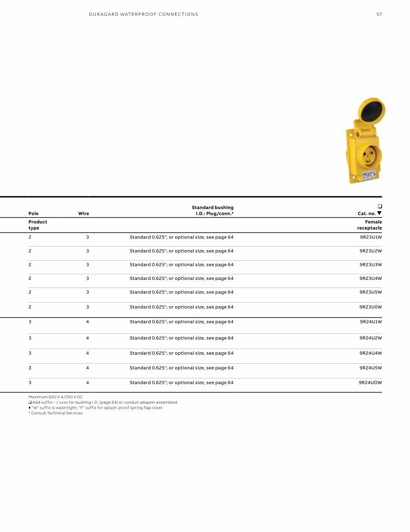
57
Pole Wire
Safetypolarization (receptacle) Voltage
Cat. no.
Cat. no. Pole Wire
Standard bushing I.D.: Plug/conn.*
Cat. no.
Product type
Male plug
Female connector
Product type
Female receptacle
2 3 125 V AC 9P23U1 9C23U1 2 3 Standard 0.625"; or optional size, see page 64 9R23U1W
2 3 250 V AC 9P23U2 9C23U2 2 3 Standard 0.625"; or optional size, see page 64 9R23U2W
2 3 277 V AC 9P23U3 9C23U3 2 3 Standard 0.625"; or optional size, see page 64 9R23U3W
2 3 480 V AC 9P23U4 9C23U4 2 3 Standard 0.625"; or optional size, see page 64 9R23U4W
2 3 600 V AC 9P23U5 9C23U5 2 3 Standard 0.625"; or optional size, see page 64 9R23U5W
2 3 through 600 V AC/250 V DC 9P23U0 9C23U0 2 3 Standard 0.625"; or optional size, see page 64 9R23U0W
3 4 125/250 V AC 9P24U1 9C24U1 3 4 Standard 0.625"; or optional size, see page 64 9R24U1W
3 4 3Ø 250 V AC 9P24U2 9C24U2 3 4 Standard 0.625"; or optional size, see page 64 9R24U2W
3 4 3Ø 480 V AC 9P24U4 9C24U4 3 4 Standard 0.625"; or optional size, see page 64 9R24U4W
3 4 3Ø 600 V AC 9P24U5 9C24U5 3 4 Standard 0.625"; or optional size, see page 64 9R24U5W
3 4 through 600 V AC/250 V DC 9P24U0 9C24U0 3 4 Standard 0.625"; or optional size, see page 64 9R24UOW
Maximum 600 V A/250 V DC❑ Add suffix – / xxxx for bushing I.D. (page 64) or conduit adapter assembled.♦ “W” suffix is watertight; “F” suffix for splash-proof spring flap cover.* Consult Technical Services.
D U R AG A R D WATER PR O O F CO N N EC TI O NS
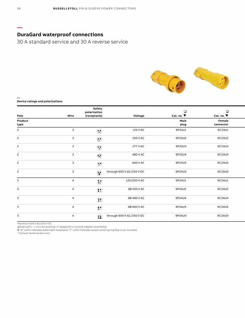
58 R U S S E LL S TO LL PI N & SL EE V E P OW ER CO N N EC TO R S
Pole Wire
Safetypolarization (receptacle) Voltage
Cat. no.
Cat. no. Pole Wire
Standard bushing I.D.: Plug/conn.*
Cat. no.
Cat. no.
Cat. no.
Product type
Male plug
Female connector
Product type
Female receptacle
Female plug (reverse service)
Male receptacle (reverse service)
2 3 125 V AC 9P33U1 9C33U1 2 3 Standard 0.700"; for optional size,
see page 64
9R33U1W 9F33U1 9B33U1F
2 3 250 V AC 9P33U2 9C33U2 2 3 9R33U2W 9F33U2 9B33U2F
2 3 277 V AC 9P33U3 9C33U3 2 3 9R33U3W 9F33U3 9B33U3F
2 3 480 V AC 9P33U4 9C33U4 2 3 9R33U4W 9F33U4 9B33U4F
2 3 600 V AC 9P33U5 9C33U5 2 3 9R33U5W 9F33U5 9B33U5F
2 3 through 600 V AC/250 V DC 9P33U0 9C33U0 2 3 9R33U0W 9F33UØ 9B33UØF
3 4 125/250 V AC 9P34U1 9C34U1 3 4 Standard 0.750"; for optional size,
see page 64
9R34U1W 9F34U1 9B34U1F
3 4 3Ø 250 V AC 9P34U2 9C34U2 3 4 9R34U2W 9F34U2 9B34U2F
3 4 3Ø 480 V AC 9P34U4 9C34U4 3 4 9R34U4W 9F34U4 9B34U4F
3 4 3Ø 600 V AC 9P34U5 9C34U5 3 4 9R34U5W 9F34U5 9B34U5F
3 4 through 600 V AC/250 V DC 9P34U0 9C34U0 3 4 9R34UOW 9F34UØ 9B34UØF
Maximum 600 V AC/250 V DC❑ Add suffix – / xxxx for bushing I.D. (page 64) or conduit adapter assembled.♦ “W” suffix indicates watertight receptacle; “F” suffix indicates splash-proof spring flap cover included.* Consult Technical Services.
❑ Add suffix – / xxxx for bushing I.D. (page 64) or conduit adapter assembled.♦ “W” suffix indicates watertight receptacle; “F” suffix indicates splash-proof spring flap cover included.* Consult Technical Services.
—DuraGard waterproof connections 30 A standard service and 30 A reverse service
—Device ratings and polarizations
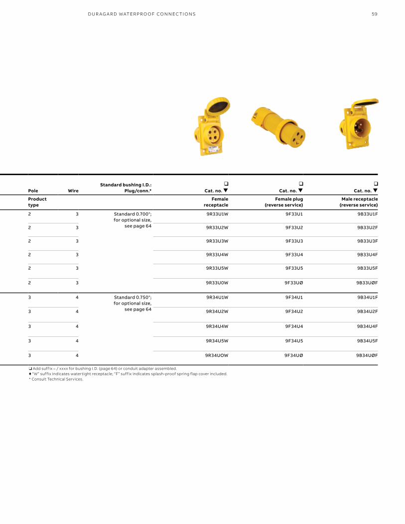
59
Pole Wire
Safetypolarization (receptacle) Voltage
Cat. no.
Cat. no. Pole Wire
Standard bushing I.D.: Plug/conn.*
Cat. no.
Cat. no.
Cat. no.
Product type
Male plug
Female connector
Product type
Female receptacle
Female plug (reverse service)
Male receptacle (reverse service)
2 3 125 V AC 9P33U1 9C33U1 2 3 Standard 0.700"; for optional size,
see page 64
9R33U1W 9F33U1 9B33U1F
2 3 250 V AC 9P33U2 9C33U2 2 3 9R33U2W 9F33U2 9B33U2F
2 3 277 V AC 9P33U3 9C33U3 2 3 9R33U3W 9F33U3 9B33U3F
2 3 480 V AC 9P33U4 9C33U4 2 3 9R33U4W 9F33U4 9B33U4F
2 3 600 V AC 9P33U5 9C33U5 2 3 9R33U5W 9F33U5 9B33U5F
2 3 through 600 V AC/250 V DC 9P33U0 9C33U0 2 3 9R33U0W 9F33UØ 9B33UØF
3 4 125/250 V AC 9P34U1 9C34U1 3 4 Standard 0.750"; for optional size,
see page 64
9R34U1W 9F34U1 9B34U1F
3 4 3Ø 250 V AC 9P34U2 9C34U2 3 4 9R34U2W 9F34U2 9B34U2F
3 4 3Ø 480 V AC 9P34U4 9C34U4 3 4 9R34U4W 9F34U4 9B34U4F
3 4 3Ø 600 V AC 9P34U5 9C34U5 3 4 9R34U5W 9F34U5 9B34U5F
3 4 through 600 V AC/250 V DC 9P34U0 9C34U0 3 4 9R34UOW 9F34UØ 9B34UØF
Maximum 600 V AC/250 V DC❑ Add suffix – / xxxx for bushing I.D. (page 64) or conduit adapter assembled.♦ “W” suffix indicates watertight receptacle; “F” suffix indicates splash-proof spring flap cover included.* Consult Technical Services.
❑ Add suffix – / xxxx for bushing I.D. (page 64) or conduit adapter assembled.♦ “W” suffix indicates watertight receptacle; “F” suffix indicates splash-proof spring flap cover included.* Consult Technical Services.
D U R AG A R D WATER PR O O F CO N N EC TI O NS
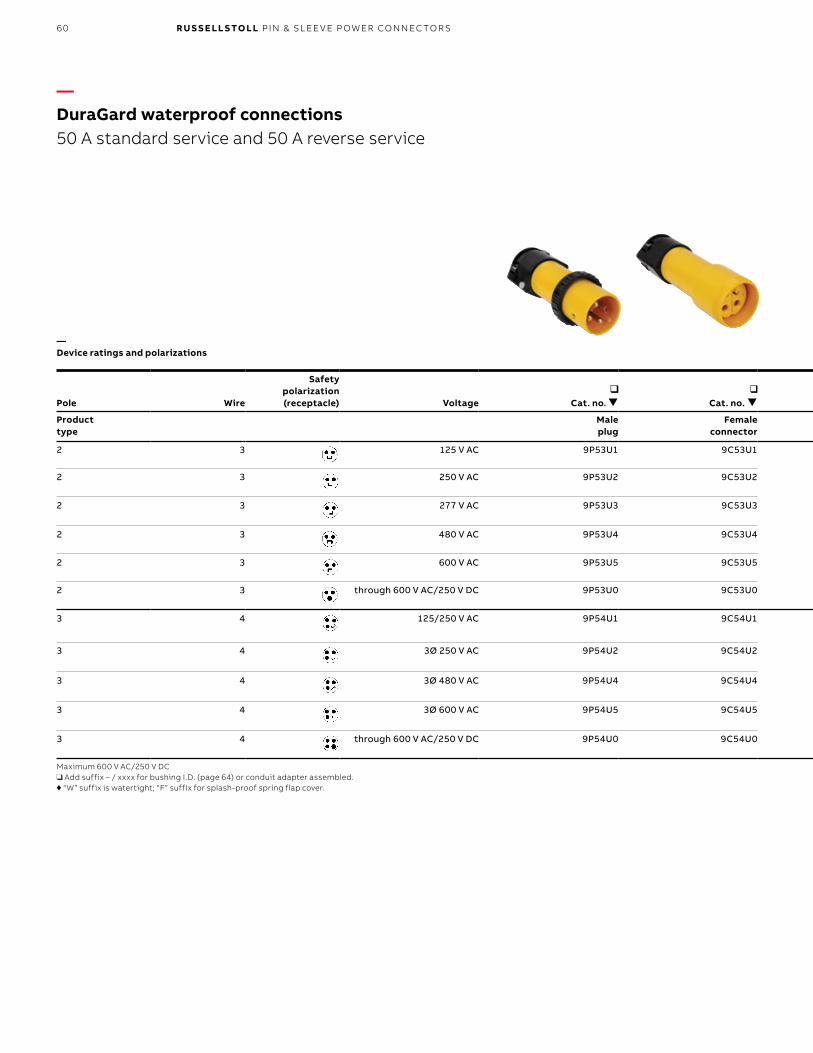
60 R U S S E LL S TO LL PI N & SL EE V E P OW ER CO N N EC TO R S
Pole Wire
Safetypolarization (receptacle) Voltage
Cat. no.
Cat. no. Pole Wire
Standard bushing I.D.:Plug/conn.*
Cat. no.
Cat. no.
Cat. no.
Product type
Male plug
Female connector
Product type
Female receptacle
Female plug (reverse service)
Male receptacle (reverse service)
2 3 125 V AC 9P53U1 9C53U1 2 3 Standard 0.925"; for optional size,
see page 64
9R53U1W 9F53U1 9B53U1F
2 3 250 V AC 9P53U2 9C53U2 2 3 9R53U2W 9F53U2 9B53U2F
2 3 277 V AC 9P53U3 9C53U3 2 3 9R53U3W 9F53U3 9B53U3F
2 3 480 V AC 9P53U4 9C53U4 2 3 9R53U4W 9F53U4 9B53U4F
2 3 600 V AC 9P53U5 9C53U5 2 3 9R53U5W 9F53U5 9B53U5F
2 3 through 600 V AC/250 V DC 9P53U0 9C53U0 2 3 9R53U0W 9F53UØ 9B53UØF
3 4 125/250 V AC 9P54U1 9C54U1 3 4 Standard 0.925"; for optional size,
see page 64
9R54U1W 9F54U1 9B54U1F
3 4 3Ø 250 V AC 9P54U2 9C54U2 3 4 9R54U2W 9F54U2 9B54U2F
3 4 3Ø 480 V AC 9P54U4 9C54U4 3 4 9R54U4W 9F54U4 9B54U4F
3 4 3Ø 600 V AC 9P54U5 9C54U5 3 4 9R54U5W 9F54U5 9B54U5F
3 4 through 600 V AC/250 V DC 9P54U0 9C54U0 3 4 9R54U0W 9F54UØ 9B54UØF
Maximum 600 V AC/250 V DC❑ Add suffix – / xxxx for bushing I.D. (page 64) or conduit adapter assembled.♦ “W” suffix is watertight; “F” suffix for splash-proof spring flap cover.
❑ Add suffix – / xxxx for bushing I.D. (page 64) or conduit adapter assembled.♦ “W” suffix is watertight; “F” suffix for splash-proof spring flap cover.* Consult Technical Services.
—DuraGard waterproof connections 50 A standard service and 50 A reverse service
—Device ratings and polarizations
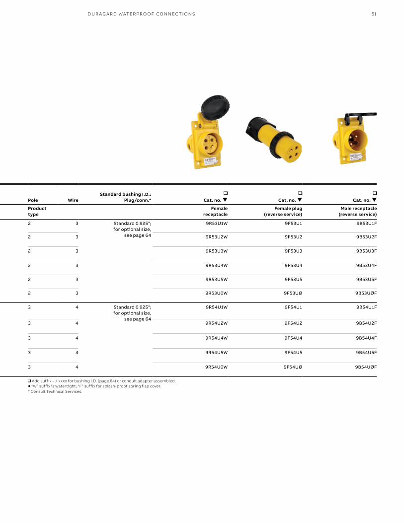
61
Pole Wire
Safetypolarization (receptacle) Voltage
Cat. no.
Cat. no. Pole Wire
Standard bushing I.D.:Plug/conn.*
Cat. no.
Cat. no.
Cat. no.
Product type
Male plug
Female connector
Product type
Female receptacle
Female plug (reverse service)
Male receptacle (reverse service)
2 3 125 V AC 9P53U1 9C53U1 2 3 Standard 0.925"; for optional size,
see page 64
9R53U1W 9F53U1 9B53U1F
2 3 250 V AC 9P53U2 9C53U2 2 3 9R53U2W 9F53U2 9B53U2F
2 3 277 V AC 9P53U3 9C53U3 2 3 9R53U3W 9F53U3 9B53U3F
2 3 480 V AC 9P53U4 9C53U4 2 3 9R53U4W 9F53U4 9B53U4F
2 3 600 V AC 9P53U5 9C53U5 2 3 9R53U5W 9F53U5 9B53U5F
2 3 through 600 V AC/250 V DC 9P53U0 9C53U0 2 3 9R53U0W 9F53UØ 9B53UØF
3 4 125/250 V AC 9P54U1 9C54U1 3 4 Standard 0.925"; for optional size,
see page 64
9R54U1W 9F54U1 9B54U1F
3 4 3Ø 250 V AC 9P54U2 9C54U2 3 4 9R54U2W 9F54U2 9B54U2F
3 4 3Ø 480 V AC 9P54U4 9C54U4 3 4 9R54U4W 9F54U4 9B54U4F
3 4 3Ø 600 V AC 9P54U5 9C54U5 3 4 9R54U5W 9F54U5 9B54U5F
3 4 through 600 V AC/250 V DC 9P54U0 9C54U0 3 4 9R54U0W 9F54UØ 9B54UØF
Maximum 600 V AC/250 V DC❑ Add suffix – / xxxx for bushing I.D. (page 64) or conduit adapter assembled.♦ “W” suffix is watertight; “F” suffix for splash-proof spring flap cover.
❑ Add suffix – / xxxx for bushing I.D. (page 64) or conduit adapter assembled.♦ “W” suffix is watertight; “F” suffix for splash-proof spring flap cover.* Consult Technical Services.
D U R AG A R D WATER PR O O F CO N N EC TI O NS
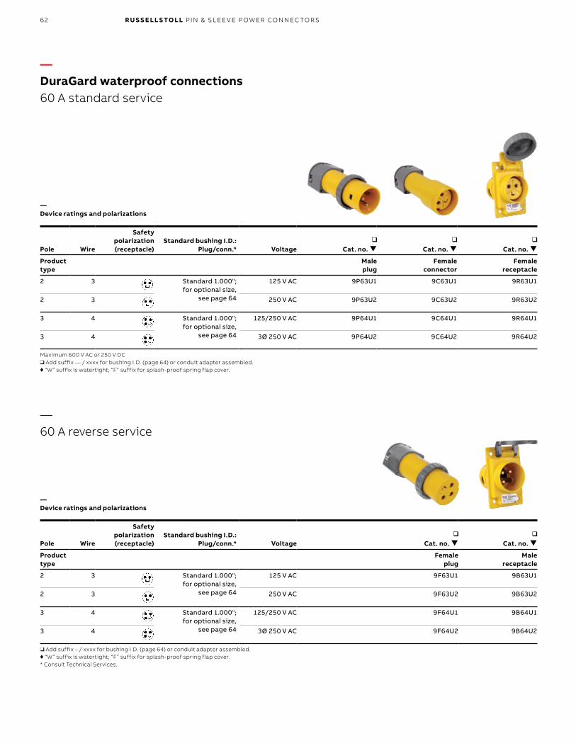
62 R U S S E LL S TO LL PI N & SL EE V E P OW ER CO N N EC TO R S
Pole Wire
Safetypolarization (receptacle)
Standard bushing I.D.:Plug/conn.* Voltage
Cat. no.
Cat. no.
Cat. no.
Product type
Male plug
Female connector
Female receptacle
2 3 Standard 1.000"; for optional size,
see page 64
125 V AC 9P63U1 9C63U1 9R63U1
2 3 250 V AC 9P63U2 9C63U2 9R63U2
3 4 Standard 1.000"; for optional size,
see page 64
125/250 V AC 9P64U1 9C64U1 9R64U1
3 4 3Ø 250 V AC 9P64U2 9C64U2 9R64U2
Maximum 600 V AC or 250 V DC❑ Add suffix — / xxxx for bushing I.D. (page 64) or conduit adapter assembled.♦ “W” suffix is watertight; “F” suffix for splash-proof spring flap cover.
Pole Wire
Safetypolarization (receptacle)
Standard bushing I.D.:Plug/conn.* Voltage
Cat. no.
Cat. no.
Product type
Female plug
Male receptacle
2 3 Standard 1.000"; for optional size,
see page 64
125 V AC 9F63U1 9B63U1
2 3 250 V AC 9F63U2 9B63U2
3 4 Standard 1.000"; for optional size,
see page 64
125/250 V AC 9F64U1 9B64U1
3 4 3Ø 250 V AC 9F64U2 9B64U2
❑ Add suffix – / xxxx for bushing I.D. (page 64) or conduit adapter assembled.♦ “W” suffix is watertight; “F” suffix for splash-proof spring flap cover.* Consult Technical Services.
—DuraGard waterproof connections 60 A standard service
—60 A reverse service
—Device ratings and polarizations
—Device ratings and polarizations
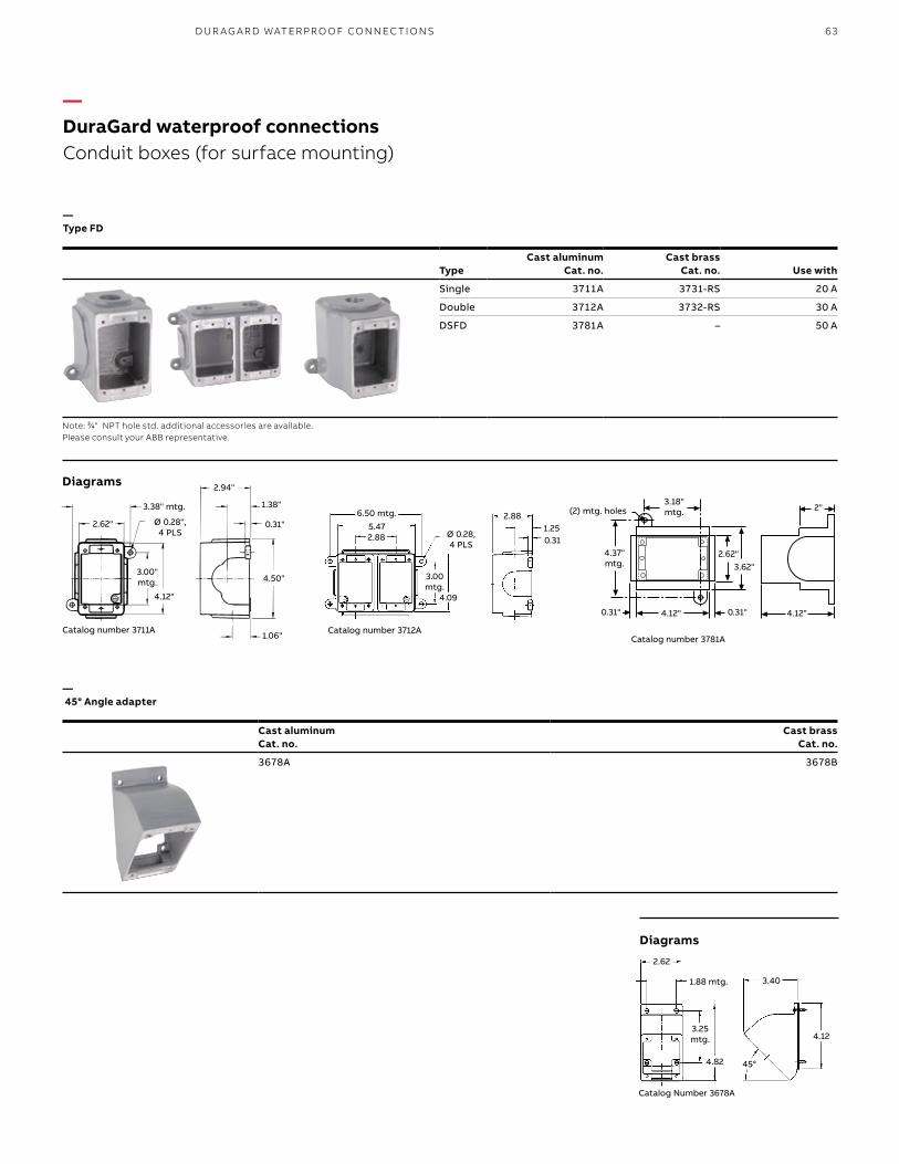
63
Cast aluminum Cat. no.
Cast brass Cat. no.
3678A 3678B
TypeCast aluminum
Cat. no.Cast brass
Cat. no. Use with
Single 3711A 3731-RS 20 A
Double 3712A 3732-RS 30 A
DSFD 3781A – 50 A
Note: 3⁄4" NPT hole std. additional accessories are available. Please consult your ABB representative.
Catalog Number 3678A
2.62
4.82
4.12
3.40
45°
1.88 mtg.
3.25 mtg.
Catalog number 3712A
6.50 mtg.
3.00 mtg.
Ø 0.28, 4 PLS
5.47
4.09
2.88
2.881.250.31
1.38"
.31"
4.50"
1.06"
4.12"
3.00"MTG.
2.62"
2.94"
Ø.28", 4 PLS
3.38" MTG
Catalog number 3711A
3.38" mtg.
Ø 0.28", 4 PLS
2.62"
4.12"
3.00" mtg.
2.94"
1.38"
0.31"
4.50"
1.06"
—Type FD
— 45° Angle adapter
—DuraGard waterproof connections Conduit boxes (for surface mounting)
Diagrams
Diagrams
4.12".31"4.12"
2"
2.62"3.62"
3.18"MTG.
.31"
(2) MTG. Holes
4.37"MTG.
(2) mtg. holes3.18"mtg.
4.37"mtg.
0.31" 0.31"4.12"
2.62"3.62"
2"
4.12"
Catalog number 3781A
D U R AG A R D WATER PR O O F CO N N EC TI O NS
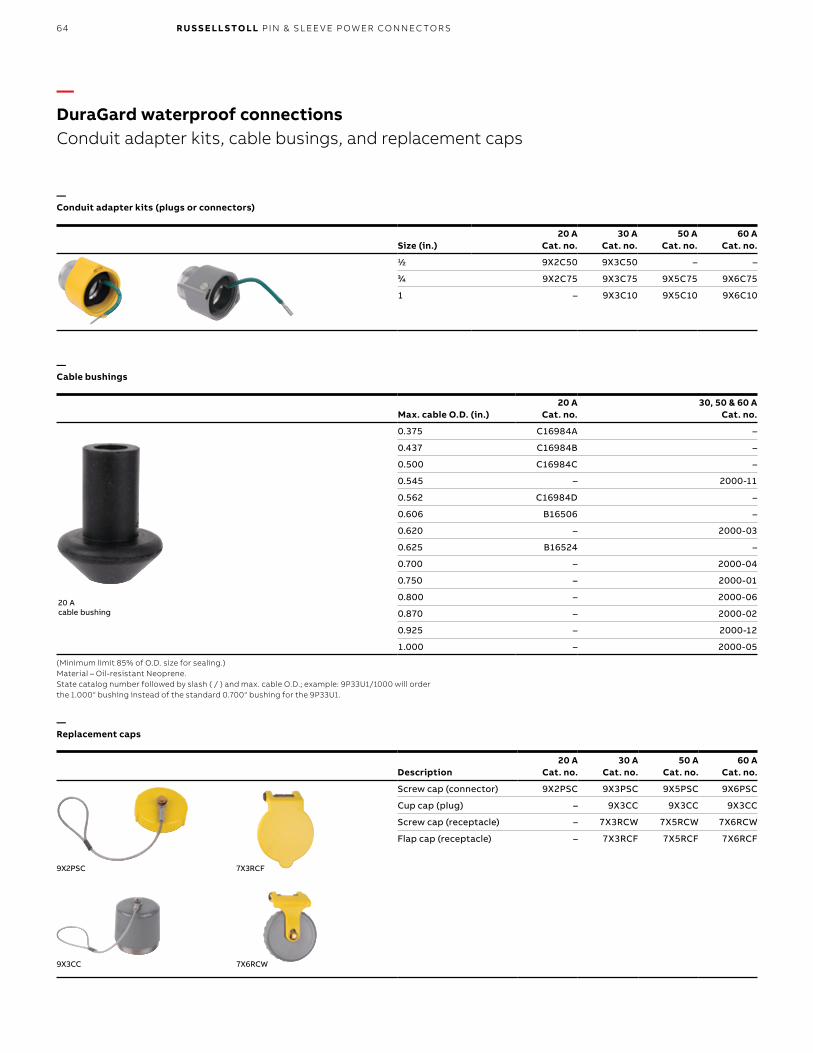
64 R U S S E LL S TO LL PI N & SL EE V E P OW ER CO N N EC TO R S
Size (in.)20 A
Cat. no.30 A
Cat. no.50 A
Cat. no.60 A
Cat. no.1/2 9X2C50 9X3C50 – –3/4 9X2C75 9X3C75 9X5C75 9X6C75
1 – 9X3C10 9X5C10 9X6C10
Max. cable O.D. (in.)20 A
Cat. no.30, 50 & 60 A
Cat. no.
0.375 C16984A –
0.437 C16984B –
0.500 C16984C –
0.545 – 2000-11
0.562 C16984D –
0.606 B16506 –
0.620 – 2000-03
0.625 B16524 –
0.700 – 2000-04
0.750 – 2000-01
0.800 – 2000-06
0.870 – 2000-02
0.925 – 2000-12
1.000 – 2000-05
(Minimum limit 85% of O.D. size for sealing.) Material – Oil-resistant Neoprene. State catalog number followed by slash ( / ) and max. cable O.D.; example: 9P33U1/1000 will order the 1.000" bushing instead of the standard 0.700" bushing for the 9P33U1.
Description20 A
Cat. no.30 A
Cat. no.50 A
Cat. no.60 A
Cat. no.
Screw cap (connector) 9X2PSC 9X3PSC 9X5PSC 9X6PSC
Cup cap (plug) – 9X3CC 9X3CC 9X3CC
Screw cap (receptacle) – 7X3RCW 7X5RCW 7X6RCW
Flap cap (receptacle) – 7X3RCF 7X5RCF 7X6RCF
9X2PSC
7X6RCW9X3CC
7X3RCF
—DuraGard waterproof connections Conduit adapter kits, cable busings, and replacement caps
—Conduit adapter kits (plugs or connectors)
—Cable bushings
—Replacement caps
20 A cable bushing
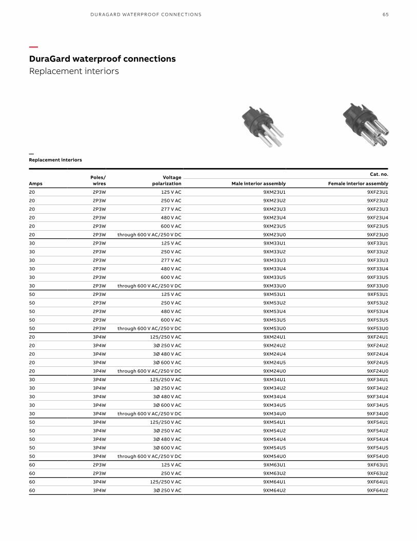
65
AmpsPoles/
wiresVoltage
polarization
Cat. no.
Male interior assembly Female interior assembly
20 2P3W 125 V AC 9XM23U1 9XF23U1
20 2P3W 250 V AC 9XM23U2 9XF23U2
20 2P3W 277 V AC 9XM23U3 9XF23U3
20 2P3W 480 V AC 9XM23U4 9XF23U4
20 2P3W 600 V AC 9XM23U5 9XF23U5
20 2P3W through 600 V AC/250 V DC 9XM23U0 9XF23U0
30 2P3W 125 V AC 9XM33U1 9XF33U1
30 2P3W 250 V AC 9XM33U2 9XF33U2
30 2P3W 277 V AC 9XM33U3 9XF33U3
30 2P3W 480 V AC 9XM33U4 9XF33U4
30 2P3W 600 V AC 9XM33U5 9XF33U5
30 2P3W through 600 V AC/250 V DC 9XM33U0 9XF33U0
50 2P3W 125 V AC 9XM53U1 9XF53U1
50 2P3W 250 V AC 9XM53U2 9XF53U2
50 2P3W 480 V AC 9XM53U4 9XF53U4
50 2P3W 600 V AC 9XM53U5 9XF53U5
50 2P3W through 600 V AC/250 V DC 9XM53U0 9XF53U0
20 3P4W 125/250 V AC 9XM24U1 9XF24U1
20 3P4W 3Ø 250 V AC 9XM24U2 9XF24U2
20 3P4W 3Ø 480 V AC 9XM24U4 9XF24U4
20 3P4W 3Ø 600 V AC 9XM24U5 9XF24U5
20 3P4W through 600 V AC/250 V DC 9XM24U0 9XF24U0
30 3P4W 125/250 V AC 9XM34U1 9XF34U1
30 3P4W 3Ø 250 V AC 9XM34U2 9XF34U2
30 3P4W 3Ø 480 V AC 9XM34U4 9XF34U4
30 3P4W 3Ø 600 V AC 9XM34U5 9XF34U5
30 3P4W through 600 V AC/250 V DC 9XM34U0 9XF34U0
50 3P4W 125/250 V AC 9XM54U1 9XF54U1
50 3P4W 3Ø 250 V AC 9XM54U2 9XF54U2
50 3P4W 3Ø 480 V AC 9XM54U4 9XF54U4
50 3P4W 3Ø 600 V AC 9XM54U5 9XF54U5
50 3P4W through 600 V AC/250 V DC 9XM54U0 9XF54U0
60 2P3W 125 V AC 9XM63U1 9XF63U1
60 2P3W 250 V AC 9XM63U2 9XF63U2
60 3P4W 125/250 V AC 9XM64U1 9XF64U1
60 3P4W 3Ø 250 V AC 9XM64U2 9XF64U2
—DuraGard waterproof connections Replacement interiors
—Replacement interiors
D U R AG A R D WATER PR O O F CO N N EC TI O NS
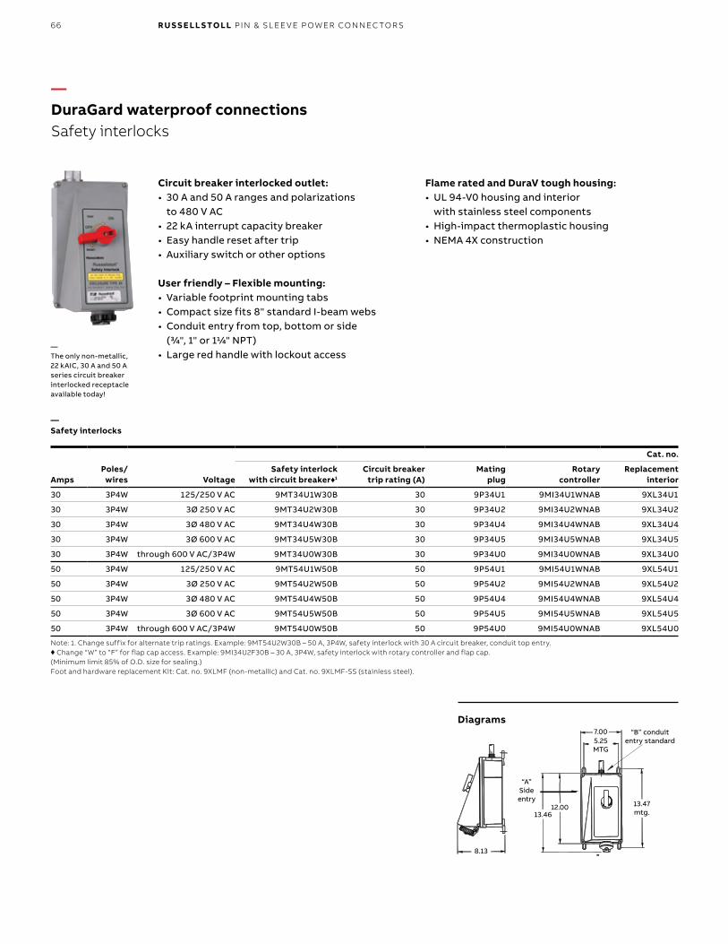
66 R U S S E LL S TO LL PI N & SL EE V E P OW ER CO N N EC TO R S
AmpsPoles/
wires Voltage
Cat. no.
Safety interlockwith circuit breaker♦1
Circuit breakertrip rating (A)
Matingplug
Rotarycontroller
Replacementinterior
30 3P4W 125/250 V AC 9MT34U1W30B 30 9P34U1 9MI34U1WNAB 9XL34U1
30 3P4W 3Ø 250 V AC 9MT34U2W30B 30 9P34U2 9MI34U2WNAB 9XL34U2
30 3P4W 3Ø 480 V AC 9MT34U4W30B 30 9P34U4 9MI34U4WNAB 9XL34U4
30 3P4W 3Ø 600 V AC 9MT34U5W30B 30 9P34U5 9MI34U5WNAB 9XL34U5
30 3P4W through 600 V AC/3P4W 9MT34U0W30B 30 9P34U0 9MI34U0WNAB 9XL34U0
50 3P4W 125/250 V AC 9MT54U1W50B 50 9P54U1 9MI54U1WNAB 9XL54U1
50 3P4W 3Ø 250 V AC 9MT54U2W50B 50 9P54U2 9MI54U2WNAB 9XL54U2
50 3P4W 3Ø 480 V AC 9MT54U4W50B 50 9P54U4 9MI54U4WNAB 9XL54U4
50 3P4W 3Ø 600 V AC 9MT54U5W50B 50 9P54U5 9MI54U5WNAB 9XL54U5
50 3P4W through 600 V AC/3P4W 9MT54U0W50B 50 9P54U0 9MI54U0WNAB 9XL54U0
Note: 1. Change suffix for alternate trip ratings. Example: 9MT54U2W30B – 50 A, 3P4W, safety interlock with 30 A circuit breaker, conduit top entry. ♦ Change “W” to “F” for flap cap access. Example: 9MI34U2F30B – 30 A, 3P4W, safety interlock with rotary controller and flap cap.(Minimum limit 85% of O.D. size for sealing.)Foot and hardware replacement Kit: Cat. no. 9XLMF (non-metallic) and Cat. no. 9XLMF-SS (stainless steel).
7.005.25�MTG
13.47�MTG13.46 12.00
8.13
“A”�side�entry
“B” conduit�entry standard
8.13
13.47mtg.
5.25MTG
7.00
13.4612.00
“A”Sideentry
“B” conduit entry standard
—The only non-metallic, 22 kAIC, 30 A and 50 A series circuit breaker interlocked receptacle available today!
—DuraGard waterproof connections Safety interlocks
Circuit breaker interlocked outlet:• 30 A and 50 A ranges and polarizations
to 480 V AC• 22 kA interrupt capacity breaker• Easy handle reset after trip• Auxiliary switch or other options
User friendly – Flexible mounting:• Variable footprint mounting tabs• Compact size fits 8" standard I-beam webs• Conduit entry from top, bottom or side
(3/4", 1" or 11/4" NPT)• Large red handle with lockout access
Flame rated and DuraV tough housing:• UL 94-V0 housing and interior
with stainless steel components• High-impact thermoplastic housing• NEMA 4X construction
Diagrams
—Safety interlocks
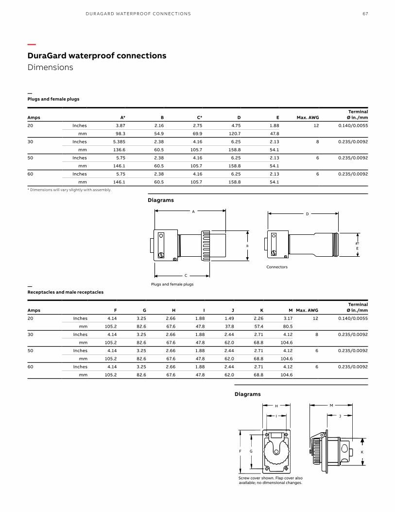
67
—DuraGard waterproof connections Dimensions
Diagrams
Diagrams
Amps A* B C* D E Max. AWGTerminal
Ø in./mm
20 Inches 3.87 2.16 2.75 4.75 1.88 12 0.140/0.0055
mm 98.3 54.9 69.9 120.7 47.8
30 Inches 5.385 2.38 4.16 6.25 2.13 8 0.235/0.0092
mm 136.6 60.5 105.7 158.8 54.1
50 Inches 5.75 2.38 4.16 6.25 2.13 6 0.235/0.0092
mm 146.1 60.5 105.7 158.8 54.1
60 Inches 5.75 2.38 4.16 6.25 2.13 6 0.235/0.0092
mm 146.1 60.5 105.7 158.8 54.1
* Dimensions will vary slightly with assembly.
A
B
C
A
B
C
D
E
D
E
Amps F G H I J K M Max. AWGTerminal
Ø in./mm
20 Inches 4.14 3.25 2.66 1.88 1.49 2.26 3.17 12 0.140/0.0055
mm 105.2 82.6 67.6 47.8 37.8 57.4 80.5
30 Inches 4.14 3.25 2.66 1.88 2.44 2.71 4.12 8 0.235/0.0092
mm 105.2 82.6 67.6 47.8 62.0 68.8 104.6
50 Inches 4.14 3.25 2.66 1.88 2.44 2.71 4.12 6 0.235/0.0092
mm 105.2 82.6 67.6 47.8 62.0 68.8 104.6
60 Inches 4.14 3.25 2.66 1.88 2.44 2.71 4.12 6 0.235/0.0092
mm 105.2 82.6 67.6 47.8 62.0 68.8 104.6
Screw cover shown. Flap cover also available; no dimensional changes.
H
I J
K
M
F G
—Plugs and female plugs
—Receptacles and male receptacles
Plugs and female plugs
Connectors
D U R AG A R D WATER PR O O F CO N N EC TI O NS
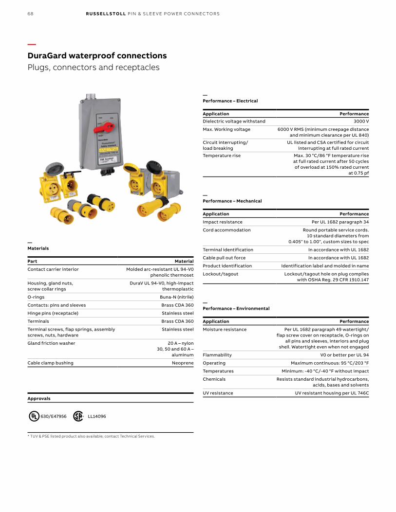
68 R U S S E LL S TO LL PI N & SL EE V E P OW ER CO N N EC TO R S
Approvals
Application Performance
Dielectric voltage withstand 3000 V
Max. Working voltage 6000 V RMS (minimum creepage distance and minimum clearance per UL 840)
Circuit interrupting/ load breaking
UL listed and CSA certified for circuit interrupting at full rated current
Temperature rise Max. 30 °C/86 °F temperature rise at full rated current after 50 cycles of overload at 150% rated current
at 0.75 pf
—Performance – Electrical
* TUV & PSE listed product also available; contact Technical Services.
Application Performance
Impact resistance Per UL 1682 paragraph 34
Cord accommodation Round portable service cords. 10 standard diameters from
0.405" to 1.00", custom sizes to spec
Terminal identification In accordance with UL 1682
Cable pull out force In accordance with UL 1682
Product identification Identification label and molded in name
Lockout/tagout Lockout/tagout hole on plug complies with OSHA Reg. 29 CFR 1910.147
Part Material
Contact carrier interior Molded arc-resistant UL 94-V0 phenolic thermoset
Housing, gland nuts, screw collar rings
DuraV UL 94-V0, high-impact thermoplastic
O-rings Buna-N (nitrile)
Contacts: pins and sleeves Brass CDA 360
Hinge pins (receptacle) Stainless steel
Terminals Brass CDA 360
Terminal screws, flap springs, assembly screws, nuts, hardware
Stainless steel
Gland friction washer 20 A – nylon 30, 50 and 60 A –
aluminum
Cable clamp bushing Neoprene
—Performance – Mechanical
—Materials
Application Performance
Moisture resistance Per UL 1682 paragraph 49 watertight/flap screw cover on receptacle, O-rings on
all pins and sleeves, interiors and plug shell. Watertight even when not engaged
Flammability V0 or better per UL 94
Operating Maximum continuous: 95 °C/203 °F
Temperatures Minimum: -40 °C/-40 °F without impact
Chemicals Resists standard industrial hydrocarbons, acids, bases and solvents
UV resistance UV resistant housing per UL 746C
—Performance – Environmental
—DuraGard waterproof connections Plugs, connectors and receptacles
630/E47956 LL14096
69
Application Performance
Dielectric voltage withstand 3000 V
Max. Working voltage 480 V RMS (minimum creepage distance and minimum clearance
per UL 840) (using circuit breaker)
Circuit interrupting/ load breaking
UL listed and CSA certified for circuit interrupting at full rated current
Temperature rise Max. 30 °C/86 °F temperature rise at full rated current after 50 cycles of overload
at 150% rated current at 0.75 pf
Shrouded contacts Complies with California Code Title 8, Art. 51, S2510.7(b) for devices
exceeding 300 V AC
—Performance – Electrical
Application Performance
Impact resistance Per UL 1682 Paragraph 34
Wiring accommodation Conduit entries at top, side and bottom, 0.750" NPT top entry standard
Terminal identification In accordance with UL 1682
Plug pull out force In accordance with UL 1682
Product identification Identification label
Lockout/tagout Lockout/tagout access on switch complies with OSHA Reg. 29
CFR 1910.147
—Performance – Mechanical
Application Performance
Moisture resistance Per UL 1682 Paragraph 49. Watertight/flap screw cover on receptacle, O-rings on
all pins and sleeves, interiors and plug shell. Watertight even when not engaged
(screw cover closed/locked)
Flammability V0 or better per UL 94
Operating Maximum continuous: 95 °C/203 °F
Temperatures Minimum: -40 °C /-40 °F without impact (Note: per C/B trip at elevated temps.)
Chemicals Resists standard industrial hydrocarbons, acids, bases and solvents
UV resistance UV-resistant housing per UL 746C
—Performance – Environmental
—DuraGard waterproof connections Safety interlocks
Approvals
Part Material
Contact carrier interior Molded arc-resistant UL 94-V0 thermoset material
Housing, gland nuts, screw collar rings
DuraV UL 94-V0, high-impact Thermoplastic
O-rings Buna-N (Nitrile)
Contacts: pins and sleeves Brass CDA 360
Hinge pins (receptacle) Stainless steel
Terminals Brass CDA 360
Terminal screws, flap springs, assembly screws, nuts, hardware
Stainless steel
Gland friction washer 20 A – nylon 30, 50 and 60 A –
aluminum
Cable clamp bushing Neoprene
—Materials
D U R AG A R D WATER PR O O F CO N N EC TI O NS


![A Scalable Space-Time Multi-plane Optical Interconnection Network Using Energy-Efficient Enabling Technologies [Invited]](https://static.fdokumen.com/doc/165x107/633b6900378dc06a3502c283/a-scalable-space-time-multi-plane-optical-interconnection-network-using-energy-efficient.jpg)