Effects of metformin on retinoblastoma growth in vitro and in vivo
Upload
khangminh22Category
view
1download
0
nanomaterials
Article
In Vitro and In Vivo Evaluation of aThree-Dimensional Porous Multi-Walled CarbonNanotube Scaffold for Bone Regeneration
Manabu Tanaka 1,*, Yoshinori Sato 2,3, Mei Zhang 4, Hisao Haniu 1,3, Masanori Okamoto 1,Kaoru Aoki 1, Takashi Takizawa 1, Kazushige Yoshida 1, Atsushi Sobajima 1,Takayuki Kamanaka 1, Hiroyuki Kato 1 and Naoto Saito 1
1 Department of Orthopaedic Surgery, School of Medicine, Shinshu University, Asahi 3-1-1, Matsumoto,Nagano 390-8621, Japan; [email protected] (H.H.); [email protected] (M.O.);[email protected] (K.A.); [email protected] (T.T.); [email protected] (K.Y.);[email protected] (A.S.); [email protected](T.K.); [email protected] (H.K.);[email protected] (N.S.)
2 Graduate School of Environmental Studies, Tohoku University, Aoba 6-6-20, Aramaki, Aoba-ku,Sendai 980-8579, Japan; [email protected]
3 Institute for Biomedical Sciences, Shinshu University, Asahi 3-1-1, Matsumoto 390-8621, Japan4 High-Performance Materials Institute, Florida State University, 2005 Levy Avenue, Tallahassee, FL 32310,
USA; [email protected]* Correspondence: [email protected]; Tel.: +81-263-37-2659, Fax: +81-263-35-8844
Academic Editors: Hicham Fenniri and Adam EkenseairReceived: 2 November 2016; Accepted: 13 February 2017; Published: 17 February 2017
Abstract: Carbon nanotubes (CNTs) have attracted a great deal of attention for the biological andmedical science fields because of their characteristic physical and biological properties. In this study,we investigated the capacity of the 3D porous CNT scaffold (CNT porous block; CNTp) for boneregenerative medicine. Surface observations using a scanning electron microscope (SEM), crystaldepositions on the surface of CNTps immersed in simulated body fluid (SBF), and evaluations ofprotein adsorption and controlled releasing were conducted to assess physical properties. The cellproliferation and cell morphology were observed using SEM and fluorescent microscopy. CNTps wereimplanted into critical-size mouse calvarial defects and evaluated for their osteoconductive abilityand in vivo controlled release of recombinant human BMP-2 (rhBMP-2). Interconnected porous HAceramics (IP-CHAs) were used for comparison. CNTps have multiporous structures with interporousconnections with networks of multiwalled CNTs. Crystals containing calcium and phosphate weredeposited in CNTps and on the surface of the CNT networks by immersing CNTps in SBF. CNTpsadsorbed more significantly and released protein more gradually than IP-CHAs. Preosteoblastsseeded onto CNTps filled pores with stretched actin filaments and filopodia. Compared withIP-CHAs, CNTps showed significantly higher cell proliferation, better osteoconduction, and morebone generation with rhBMP-2. In this study, CNTps demonstrated good osteoconductive ability, cellattachment and proliferation capacity, and growth factor retaining ability. CNTps have the potentialnot only as artificial bones for the treatment of bone defects, but also as scaffolds for regenerativemedicine using tissue engineering approaches.
Keywords: tissue engineering; bone regeneration; carbon nanotube
1. Introduction
Nonunions and large skeletal defects created by tumors, traumas, or congenital malformationsare sometimes impossible to repair. In order to fill the aforementioned defects and promote
Nanomaterials 2017, 7, 46; doi:10.3390/nano7020046 www.mdpi.com/journal/nanomaterials

Nanomaterials 2017, 7, 46 2 of 17
bone regeneration, various approaches have been researched in clinical trials. Autologous bonegrafts (autografts) are most commonly used, because they provide essential characteristics for boneregeneration, such as cells, growth factors, and scaffolds [1]. However, the disadvantages of autologousbone graft include limited availability of cancellous bone, residual pain, nerve injury, and cosmeticdefects. Although allografts solve the above problems, their use may create an immune responseor transmit viral diseases [2]. In order to address these issues, bone regenerative scaffolds made ofsynthetic biomaterials are now being used as bone graft substitutes [3], which are also called “artificialbones”. Type I collagen, demineralized bone matrix (DBM), poly lactic acid (PLA), poly glycolicacid (PGA), hydroxyapatite (HA), and tricalcium phosphate (TCP) have been used for materialsand scaffolds [1]. Because bone graft is the second most common transplantation tissue [2], there isgreat demand for the development of scaffolds that can reduce the risk of autograft and allograft.One of the essential properties of bone regenerative scaffolds is their biocompatibility, which isdescribed as an ability of a material to perform with an appropriate host response in a specificsituation [4]. In addition, optimal bone regeneration scaffolds should be osteoconductive, which meansosteogenic cells can attach, proliferate, and structure extracellular matrix on their surface [3]. In boneregenerative medicine, scaffolds made of HAs that hold approximately 50% of bone weight in variousstructures are used widely because of their osteocompatibility, and such materials are developed andreported to function well. Those with multipore structures measuring more than 100 µm in diameterare becoming mainstream [3]. Interconnected porous hydroxyapatite ceramics (IP-CHAs) are widelyused as bone regenerative scaffolds because of their good biocompatibility, osteoconduction, primarystiffness, and pore size.
On the other hand, tissue engineering techniques using a combination of cells, growth factors,and scaffolds to regenerate various tissues have been researched broadly for their application in theregeneration of bones and cartilages [5]. The use of a drug delivery system [6] that retains and releasesbiomolecules gradually has been anticipated for scaffolds in tissue engineering. Biomolecules retainedby scaffolds are proteins called growth factors, which include transforming growth factor (TGF-β),bone morphogenetic protein (BMP), insulin-like growth factor (IGF), fibroblast growth factor (FGF),and vascular endothelial growth factor (VGEF). These growth factors regulate bone formation byinducing osteoprogenitor cells to differentiate to osteogenic cells [7]. BMPs are known to induce theinitial proliferation and differentiation of osteoprogenitor cells [8] and facilitate repair of critical-sizedbone defects in animal models [9]. However, because BMPs rapidly degrade in the body [10], theirin vivo application have been considered insufficient for clinical use. Thus, a long-term controlledrelease system of BMPs is deemed necessary. To develop an effective method, in vitro drug releaseassays [11] and in vivo evaluations of bone repair in mouse critical-sized bone defects [6] arebroadly researched.
Carbon nanotubes (CNTs) are becoming attractive in the field of regenerative medicine becauseof their mechanical and biological properties [12] and processability [13]. CNTs are also knownto have good biocompatibility and have been reported to accelerate cell differentiation. Moreover,reports have indicated that CNTs promote osteoblastic function but also inhibit osteoclasts [14,15].CNTs are considered to be promising biomaterials for bone defect repair and bone-tissue engineeringapplications because of their unique behavior in the body. The most important concern for the useof CNTs as a biomaterial is safety. However, only few reports suggest that CNTs are toxic whenapplied in higher concentrations [16]. Good osteoregeneration has been reported by using CNTs asnanocomposites with polymers, collagen, PLA, and HA in bone regenerative medicine [17]. However,no research has been reported on the porous bone regenerative scaffold that is made of CNT alone.We compared the biocompatibility, osteoconduction, capacity to retain osteogenic proteins, and in vivocontrolled-release of BMPs of 3D-shaped porous scaffold made of multi-walled carbon nanotube(MWCNT) to those of the IP-CHA for use in the field of bone regenerative medicine.

Nanomaterials 2017, 7, 46 3 of 17
2. Results
2.1. Surface Observation by a Scanning Electron Microscopy
CNTps have substantially uniform micro-pores of approximately 100 µm in diameter,which were interconnected randomly by small 30–50 µm pores (Figure 1a). The pore surface of CNTpswere smooth and fibrous. MWCNTs were observed in higher (20,000×) magnification (Figure 1b).The roughness of the pore surface is in nanometer scale. IP-CHAs have pores of 50–250 µm in diameterwith interpore connections (Figure 1c) and smooth pore surfaces with aligned granular HA crystals(Figure 1d).
Nanomaterials 2017, 7, 46 3 of 18
2. Results
2.1. Surface Observation by a Scanning Electron Microscopy
CNTps have substantially uniform micro‐pores of approximately 100 μm in diameter, which
were interconnected randomly by small 30–50 μm pores (Figure 1a). The pore surface of CNTps were
smooth and fibrous. MWCNTs were observed in higher (20,000×) magnification (Figure 1b). The
roughness of the pore surface is in nanometer scale. IP‐CHAs have pores of 50–250 μm in diameter
with interpore connections (Figure 1c) and smooth pore surfaces with aligned granular HA crystals
(Figure 1d).
Figure 1. Scanning electron microscope (SEM) image of (a,b) carbon nanotube (CNT) porous block
(CNTp) and (c,d) interconnected porous HA ceramic (IP‐CHA). Original magnification is 250× for
(a,c) and 20,000× for (b,d). White arrows: interporous connections.
2.2. Mechanical Strength
Figure 2 shows the stress‐strain curves (a); maximum compressive strength (b); Young’s
modulus (c); and energy to failure (d) of the IP‐CHA and CNTp. The CNTp broke more smoothly
than the IP‐CHA. The maximum compressive strengths of the CNTp and IP‐CHA showed no
significant difference between the two groups (1117 ± 52.21 vs. 1188 ± 135.79 N, p = 0.4460). The IP‐
CHA showed a significantly higher Young’s modulus than the CNTp (37,144 ± 12,359 vs. 4973 ± 3576
N/mm2, p = 0.0123). The IP‐CHA also showed a significantly higher energy to failure than the CNTp
(0.397 ± 0.117 vs. 0.161 ± 0.028 J, p = 0.0275).
Figure 1. Scanning electron microscope (SEM) image of (a,b) carbon nanotube (CNT) porous block(CNTp) and (c,d) interconnected porous HA ceramic (IP-CHA). Original magnification is 250× for(a,c) and 20,000× for (b,d). White arrows: interporous connections.
2.2. Mechanical Strength
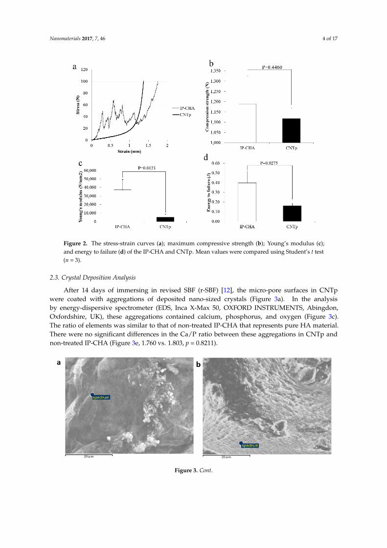
Figure 2 shows the stress-strain curves (a); maximum compressive strength (b); Young’smodulus (c); and energy to failure (d) of the IP-CHA and CNTp. The CNTp broke more smoothly thanthe IP-CHA. The maximum compressive strengths of the CNTp and IP-CHA showed no significantdifference between the two groups (1117 ± 52.21 vs. 1188 ± 135.79 N, p = 0.4460). The IP-CHA showeda significantly higher Young’s modulus than the CNTp (37,144 ± 12,359 vs. 4973 ± 3576 N/mm2,p = 0.0123). The IP-CHA also showed a significantly higher energy to failure than the CNTp(0.397 ± 0.117 vs. 0.161 ± 0.028 J, p = 0.0275).
Nanomaterials 2017, 7, 46 4 of 17Nanomaterials 2017, 7, 46 4 of 18
Figure 2. The stress‐strain curves (a); maximum compressive strength (b); Young’s modulus (c); and
energy to failure (d) of the IP‐CHA and CNTp. Mean values were compared using Studentʹs t test (n =
3).
2.3. Crystal Deposition Analysis
After 14 days of immersing in revised SBF (r‐SBF) [12], the micro‐pore surfaces in CNTp were
coated with aggregations of deposited nano‐sized crystals (Figure 3a). In the analysis by energy‐
dispersive spectrometer (EDS, Inca X‐Max 50, OXFORD INSTRUMENTS, Abingdon, Oxfordshire,
UK), these aggregations contained calcium, phosphorus, and oxygen (Figure 3c). The ratio of
elements was similar to that of non‐treated IP‐CHA that represents pure HA material. There were no
significant differences in the Ca/P ratio between these aggregations in CNTp and non‐treated IP‐CHA
(Figure 3e, 1.760 vs. 1.803, p = 0.8211).
Figure 2. The stress-strain curves (a); maximum compressive strength (b); Young’s modulus (c);and energy to failure (d) of the IP-CHA and CNTp. Mean values were compared using Student’s t test(n = 3).
2.3. Crystal Deposition Analysis
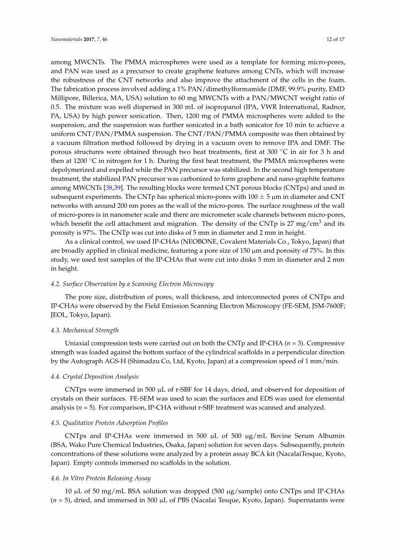
After 14 days of immersing in revised SBF (r-SBF) [12], the micro-pore surfaces in CNTpwere coated with aggregations of deposited nano-sized crystals (Figure 3a). In the analysisby energy-dispersive spectrometer (EDS, Inca X-Max 50, OXFORD INSTRUMENTS, Abingdon,Oxfordshire, UK), these aggregations contained calcium, phosphorus, and oxygen (Figure 3c).The ratio of elements was similar to that of non-treated IP-CHA that represents pure HA material.There were no significant differences in the Ca/P ratio between these aggregations in CNTp andnon-treated IP-CHA (Figure 3e, 1.760 vs. 1.803, p = 0.8211).Nanomaterials 2017, 7, 46 5 of 18
Figure 3. (a) SEM image of hydroxyapatite‐like crystal formation on CNTp scaffolds; (b) SEM image
of a non‐treated IP‐CHA; (c,d) EDS on marked area revealed Ca, P, O in the crystal on (c) CNTp and
(d) the surface of non‐treated IP‐CHA; (e) Ca/P ratio of the crystals appeared on the surface of CNTp
and IP‐CHA. Mean values were compared using Studentʹs t test (n = 5).
2.4. Qualitative Protein Adsorption Profiles
Each sample was immersed into 500 μL of 500 μg/mL Bovine Serum Albumin (BSA) solution
(each solution contained 250 μg of BSA). On day 0 (one hour of immersion), CNTps showed
significantly faster protein adsorption than IP‐CHAs (p = 0.0104). On day 4, CNTps decreased more
protein concentration in the solution compared to IP‐CHAs (p = 0.0006). Similar data was obtained
on day 7 (p = 0.0042). IP‐CHAs did not show further decrease of protein concentration on days 4 and
7 compared to day 0 (Figure 4). Total amounts of protein that adsorbed to CNTps and IP‐CHAs on
day 7 were 100 μg and 12 μg, respectively. Considering the porosity of CNTps (99%) and IP‐CHAs
(75%), the CNTps absorbed 6.3 times more protein than IP‐CHAs.
Figure 3. Cont.

Nanomaterials 2017, 7, 46 5 of 17
Nanomaterials 2017, 7, 46 5 of 18
Figure 3. (a) SEM image of hydroxyapatite‐like crystal formation on CNTp scaffolds; (b) SEM image
of a non‐treated IP‐CHA; (c,d) EDS on marked area revealed Ca, P, O in the crystal on (c) CNTp and
(d) the surface of non‐treated IP‐CHA; (e) Ca/P ratio of the crystals appeared on the surface of CNTp
and IP‐CHA. Mean values were compared using Studentʹs t test (n = 5).
2.4. Qualitative Protein Adsorption Profiles
Each sample was immersed into 500 μL of 500 μg/mL Bovine Serum Albumin (BSA) solution
(each solution contained 250 μg of BSA). On day 0 (one hour of immersion), CNTps showed
significantly faster protein adsorption than IP‐CHAs (p = 0.0104). On day 4, CNTps decreased more
protein concentration in the solution compared to IP‐CHAs (p = 0.0006). Similar data was obtained
on day 7 (p = 0.0042). IP‐CHAs did not show further decrease of protein concentration on days 4 and
7 compared to day 0 (Figure 4). Total amounts of protein that adsorbed to CNTps and IP‐CHAs on
day 7 were 100 μg and 12 μg, respectively. Considering the porosity of CNTps (99%) and IP‐CHAs
(75%), the CNTps absorbed 6.3 times more protein than IP‐CHAs.
Figure 3. (a) SEM image of hydroxyapatite-like crystal formation on CNTp scaffolds; (b) SEM imageof a non-treated IP-CHA; (c,d) EDS on marked area revealed Ca, P, O in the crystal on (c) CNTp and(d) the surface of non-treated IP-CHA; (e) Ca/P ratio of the crystals appeared on the surface of CNTpand IP-CHA. Mean values were compared using Student’s t test (n = 5).
2.4. Qualitative Protein Adsorption Profiles
Each sample was immersed into 500 µL of 500 µg/mL Bovine Serum Albumin (BSA) solution(each solution contained 250 µg of BSA). On day 0 (one hour of immersion), CNTps showedsignificantly faster protein adsorption than IP-CHAs (p = 0.0104). On day 4, CNTps decreased moreprotein concentration in the solution compared to IP-CHAs (p = 0.0006). Similar data was obtained onday 7 (p = 0.0042). IP-CHAs did not show further decrease of protein concentration on days 4 and 7compared to day 0 (Figure 4). Total amounts of protein that adsorbed to CNTps and IP-CHAs on day 7were 100 µg and 12 µg, respectively. Considering the porosity of CNTps (99%) and IP-CHAs (75%),the CNTps absorbed 6.3 times more protein than IP-CHAs.Nanomaterials 2017, 7, 46 6 of 18
Figure 4. Qualitative protein adsorption profiles. Mean values were compared using Studentʹs t test
(n = 3).
2.5. In Vitro Protein Releasing Assay
The protein release was observed in both CNTp and IP‐CHA groups. On day 1, CNTps released
10.1% of the total added protein, which is less than the IP‐CHAs released (46.7%). In following days,
CNTps and IP‐CHAs released protein gradually but CNTps did not release 100% of total loaded
protein as shown in Figure 5. Finally, they released 23.9% of total loaded protein after seven days
compared to IP‐CHA (92.2%).
Figure 5. Qualitative protein released from scaffolds. Graph shows release of bovine serum albumin
(BSA) from CNTp and IP‐CHA. Mean values were compared using Studentʹs t test (n = 5).
2.6. Degradation Assay
Figure 6 demonstrates the percentage of mass lost over time. Both CNTps and IP‐CHAs showed
significant weight loss in 21 days (p = 0.0005 and p = 0.0002, respectively). However, each loss was
very slight (within 0.0002 g/scaffold). IP‐CHAs showed a slightly faster degradation rate than CNTps
for 21 days (p = 0.0040).
Figure 4. Qualitative protein adsorption profiles. Mean values were compared using Student’s t test(n = 3).

Nanomaterials 2017, 7, 46 6 of 17
2.5. In Vitro Protein Releasing Assay
The protein release was observed in both CNTp and IP-CHA groups. On day 1, CNTps released10.1% of the total added protein, which is less than the IP-CHAs released (46.7%). In following days,CNTps and IP-CHAs released protein gradually but CNTps did not release 100% of total loadedprotein as shown in Figure 5. Finally, they released 23.9% of total loaded protein after seven dayscompared to IP-CHA (92.2%).
Nanomaterials 2017, 7, 46 6 of 18
Figure 4. Qualitative protein adsorption profiles. Mean values were compared using Studentʹs t test
(n = 3).
2.5. In Vitro Protein Releasing Assay
The protein release was observed in both CNTp and IP‐CHA groups. On day 1, CNTps released
10.1% of the total added protein, which is less than the IP‐CHAs released (46.7%). In following days,
CNTps and IP‐CHAs released protein gradually but CNTps did not release 100% of total loaded
protein as shown in Figure 5. Finally, they released 23.9% of total loaded protein after seven days
compared to IP‐CHA (92.2%).
Figure 5. Qualitative protein released from scaffolds. Graph shows release of bovine serum albumin
(BSA) from CNTp and IP‐CHA. Mean values were compared using Studentʹs t test (n = 5).
2.6. Degradation Assay
Figure 6 demonstrates the percentage of mass lost over time. Both CNTps and IP‐CHAs showed
significant weight loss in 21 days (p = 0.0005 and p = 0.0002, respectively). However, each loss was
very slight (within 0.0002 g/scaffold). IP‐CHAs showed a slightly faster degradation rate than CNTps
for 21 days (p = 0.0040).
Figure 5. Qualitative protein released from scaffolds. Graph shows release of bovine serum albumin(BSA) from CNTp and IP-CHA. Mean values were compared using Student’s t test (n = 5).
2.6. Degradation Assay
Figure 6 demonstrates the percentage of mass lost over time. Both CNTps and IP-CHAs showedsignificant weight loss in 21 days (p = 0.0005 and p = 0.0002, respectively). However, each loss wasvery slight (within 0.0002 g/scaffold). IP-CHAs showed a slightly faster degradation rate than CNTpsfor 21 days (p = 0.0040).Nanomaterials 2017, 7, 46 7 of 18
Figure 6. Degradation assay. Graph shows weight loss of CNTps and IP‐CHAs immersed in PBS for
21 days. Mean values were compared using two‐way ANOVA (n = 5).
2.7. Cell Morphology
Figure 7a–d shows the morphologies of MC3T3‐E1 cells cultivated on the CNTps and IP‐CHAs
observed by FE‐SEM. Cells were connected via cytoplasmic processes and expanded on the surface
of both CNTps and IP‐CHAs. Cells on CNTps expand more cytoplasmic processes (arrow). Figure
7e,f shows cell morphologies observed by a fluorescent microscope. Cells containing well‐developed
actin filaments and round cells attached to the inner surface of pores.
2.8. Cytotoxicity Determination
On day 1, the mean number of cells in a 20× field of CNTp and IP‐CHA surface were 40.6 and
48.6, respectively, with no significant difference. On day 3, these were 190.3 and 165.7, respectively,
with no significant difference. However, each scaffold showed significantly higher cell proliferation
on day 3 than on day 1 (p < 0.0001 and p < 0.0001, respectively) as shown in Figure 8a. In the live/dead
cell staining, visual inspection was consistent with unimpeded viability (Figure 8b–e).
Figure 6. Degradation assay. Graph shows weight loss of CNTps and IP-CHAs immersed in PBS for 21days. Mean values were compared using two-way ANOVA (n = 5).

Nanomaterials 2017, 7, 46 7 of 17
2.7. Cell Morphology
Figure 7a–d shows the morphologies of MC3T3-E1 cells cultivated on the CNTps and IP-CHAsobserved by FE-SEM. Cells were connected via cytoplasmic processes and expanded on the surface ofboth CNTps and IP-CHAs. Cells on CNTps expand more cytoplasmic processes (arrow). Figure 7e,fshows cell morphologies observed by a fluorescent microscope. Cells containing well-developed actinfilaments and round cells attached to the inner surface of pores.Nanomaterials 2017, 7, 46 8 of 18
Figure 7. MC3T3‐E1 cells spreading on IP‐CHA and CNTp scaffolds. Cells on (a,c,e) IP‐CHA or (b,d,f)
CNTp. SEM images of (a,c) IP‐CHA and (b,d) CNTp. Original magnification is 2000× for (a,b) and
20,000× for (c,d). Cells labeled for actin filaments (red) and nucleus (blue) of (e) IP‐CHA and (f) CNTp.
Figure 8. Cytotoxicity. Graph shows the number of cells per field counted on the surface of the CNTp
and the IP‐CHA (a). Mean values were compared using Studentʹs t test (n = 7). N.S.: Not Significant.
Viable cells were stained with calcein AM (acetoxymethyl) and fluoresced green, while dead cells
Figure 7. MC3T3-E1 cells spreading on IP-CHA and CNTp scaffolds. Cells on (a,c,e) IP-CHA or(b,d,f) CNTp. SEM images of (a,c) IP-CHA and (b,d) CNTp. Original magnification is 2000× for(a,b) and 20,000× for (c,d). Cells labeled for actin filaments (red) and nucleus (blue) of (e) IP-CHA and(f) CNTp.
2.8. Cytotoxicity Determination
On day 1, the mean number of cells in a 20× field of CNTp and IP-CHA surface were 40.6 and48.6, respectively, with no significant difference. On day 3, these were 190.3 and 165.7, respectively,with no significant difference. However, each scaffold showed significantly higher cell proliferation on

Nanomaterials 2017, 7, 46 8 of 17
day 3 than on day 1 (p < 0.0001 and p < 0.0001, respectively) as shown in Figure 8a. In the live/deadcell staining, visual inspection was consistent with unimpeded viability (Figure 8b–e).
Nanomaterials 2017, 7, 46 8 of 18
Figure 7. MC3T3‐E1 cells spreading on IP‐CHA and CNTp scaffolds. Cells on (a,c,e) IP‐CHA or (b,d,f)
CNTp. SEM images of (a,c) IP‐CHA and (b,d) CNTp. Original magnification is 2000× for (a,b) and
20,000× for (c,d). Cells labeled for actin filaments (red) and nucleus (blue) of (e) IP‐CHA and (f) CNTp.
Figure 8. Cytotoxicity. Graph shows the number of cells per field counted on the surface of the CNTp
and the IP‐CHA (a). Mean values were compared using Studentʹs t test (n = 7). N.S.: Not Significant.
Viable cells were stained with calcein AM (acetoxymethyl) and fluoresced green, while dead cells
Figure 8. Cytotoxicity. Graph shows the number of cells per field counted on the surface of the CNTpand the IP-CHA (a). Mean values were compared using Student’s t test (n = 7). N.S.: Not Significant.Viable cells were stained with calcein AM (acetoxymethyl) and fluoresced green, while dead cellswere stained with EthD-III and fluoresced red. Most of MC3T3-E1 cells were alive on CNTp (b,c) andIP-CHA (d,e) scaffolds at day 1 (b,d) and day 3 (c,f). White bars: 100 µm.
2.9. Alkaline Phosphatase Activity Assay
After seven days, cells on CNTps and IP-CHAs showed significantly increased AlkalinePhosphatase (ALP) activities. There was no significant difference between the two groups(p = 0.9774) (Figure 9).
Nanomaterials 2017, 7, 46 9 of 18
were stained with EthD‐III and fluoresced red. Most of MC3T3‐E1 cells were alive on CNTp (b,c) and
IP‐CHA (d,e) scaffolds at day 1 (b,d) and day 3 (c,f). White bars: 100 μm.
2.9. Alkaline Phosphatase Activity Assay
After seven days, cells on CNTps and IP‐CHAs showed significantly increased Alkaline
Phosphatase (ALP) activities. There was no significant difference between the two groups (p = 0.9774)
(Figure 9).
Figure 9. Alkaline Phosphatase (ALP) activity. Graph shows the ALP activity of the MC3T3‐E1 cells
cultured in the presence or absence of rhMP‐2 on the surface of the CNTp and the IP‐CHA. Mean
values were compared using Studentʹs t test (n = 4).
2.10. Bone Regeneration of Mouse Critical‐Sized Calvarial Defects
Little bone regeneration occurred in the empty group. On the other hand, regeneration occurred
in blue‐stained collagen fibers, red‐ or purple‐stained woven bones, and mature bones, filling in the
pores of CNTp and IP‐CHA scaffolds. Vascularizations were also observed in the newly formed
bones (Figure 10a). By image analysis, the CNTp group contained more newly formed bone in a 20×
field than the empty and IP‐CHA group (p = 0.0002 and p = 0.0039, respectively.) (Figure 10b).
Figure 9. Alkaline Phosphatase (ALP) activity. Graph shows the ALP activity of the MC3T3-E1cells cultured in the presence or absence of rhMP-2 on the surface of the CNTp and the IP-CHA.Mean values were compared using Student’s t test (n = 4).
2.10. Bone Regeneration of Mouse Critical-Sized Calvarial Defects
Little bone regeneration occurred in the empty group. On the other hand, regeneration occurredin blue-stained collagen fibers, red- or purple-stained woven bones, and mature bones, filling in thepores of CNTp and IP-CHA scaffolds. Vascularizations were also observed in the newly formed bones(Figure 10a). By image analysis, the CNTp group contained more newly formed bone in a 20× fieldthan the empty and IP-CHA group (p = 0.0002 and p = 0.0039, respectively.) (Figure 10b).

Nanomaterials 2017, 7, 46 9 of 17Nanomaterials 2017, 7, 46 10 of 18
Figure 10. (a) Micro‐CT and histological image of empty control, IP‐CHA, and CNTp scaffold
implanted in the calvarial defects of ddY mice for 12 weeks; (b) A bar diagram showing the newly
formed bone area/20× field in the calvarial defect of ddY mice implanted with each scaffold for 12
weeks. Mean values were compared using one‐way ANOVA followed by Tukey’s post hoc test (n =
7). N.S.: Not Significant.
2.11. Bone Regeneration of Mouse Critical‐Sized Calvarial Defects in Combination with Recombinant
Human Bone Morphogenetic Protein‐2 (rhBMP‐2)
Micro‐CT analysis revealed that the new bone formation in the rhBMP‐2 loaded CNTp group
was comparable to that of the rhBMP‐2 loaded IP‐CHA group. The rhBMP‐2 in saline (empty) group
showed little new bone formation, and only membrane structures comprised of collagen fibers were
observed. However, pores filled with woven and mature bones were observed in the rhBMP‐2 loaded
CNTp and IP‐CHA groups (Figure 11a). CNTps showed a significantly larger area of newly formed
bone in a 20× field (p < 0.0001 and p = 0.0133, respectively.) (Figure 11b).
Figure 10. (a) Micro-CT and histological image of empty control, IP-CHA, and CNTp scaffold implantedin the calvarial defects of ddY mice for 12 weeks; (b) A bar diagram showing the newly formedbone area/20× field in the calvarial defect of ddY mice implanted with each scaffold for 12 weeks.Mean values were compared using one-way ANOVA followed by Tukey’s post hoc test (n = 7).N.S.: Not Significant.
2.11. Bone Regeneration of Mouse Critical-Sized Calvarial Defects in Combination with Recombinant HumanBone Morphogenetic Protein-2 (rhBMP-2)
Micro-CT analysis revealed that the new bone formation in the rhBMP-2 loaded CNTp groupwas comparable to that of the rhBMP-2 loaded IP-CHA group. The rhBMP-2 in saline (empty) groupshowed little new bone formation, and only membrane structures comprised of collagen fibers wereobserved. However, pores filled with woven and mature bones were observed in the rhBMP-2 loadedCNTp and IP-CHA groups (Figure 11a). CNTps showed a significantly larger area of newly formedbone in a 20× field (p < 0.0001 and p = 0.0133, respectively.) (Figure 11b).

Nanomaterials 2017, 7, 46 10 of 17Nanomaterials 2017, 7, 46 11 of 18
Figure 11. (a) Micro‐CT and histological image of empty control, IP‐CHA, and CNTp scaffolds
combined with rhBMP‐2, implanted in the calvarial defects of ddY mice for three weeks; (b) A bar
diagram showing the newly formed bone area/20× field in the calvarial defect of ddY mice implanted
with rhBMP‐2 supplemented scaffolds. Mean values were compared using one‐way ANOVA,
followed by Tukey’s post‐hoc test (n = 5).
3. Discussion
CNTs are considered to have many advantages, such as biocompatibility, strength, and ease of
chemical modification [18]. On the other hand, the essential properties of bone regenerative scaffolds
include biocompatibility, optimal pore size, and controlled release of growth factors [3]. We have
previously reported excellent biocompatibility, bone forming abilities [19], and effect on osteoblasts
[20] and osteoclasts [15] of powdery CNTs. Many researchers have evaluated CNT composite
biomaterials for bone tissue engineering [17]. Significantly more in vivo bone formation was observed
around the CNT‐coated sponges than around the uncoated sponges [20]. PLGA/c‐MWNT
nanocomposites exhibited better adhesion, viability, and differentiation capacity [21]. On the CNT
coated HA scaffold, unrestricted growth of human osteoblasts has been observed near CNT regions
that are aided by CNT surfaces to promote cell growth and proliferation [22]. However, this is the
first study that evaluated the capacity of a pure CNT scaffold with a well‐controlled 3D structure for
the use of bone regenerative medicine.
Crystals deposited on the surface of CNTps have a similar Ca/P ratio to HAs when being
immersed in SBF. Fibrous CNTs are known to deposit HA when being immersed in SBF [12]. X‐ray
diffraction analysis (XRD) is often used to analyze crystals, including HA [23]. We attempted to
Figure 11. (a) Micro-CT and histological image of empty control, IP-CHA, and CNTp scaffoldscombined with rhBMP-2, implanted in the calvarial defects of ddY mice for three weeks; (b) A bardiagram showing the newly formed bone area/20× field in the calvarial defect of ddY mice implantedwith rhBMP-2 supplemented scaffolds. Mean values were compared using one-way ANOVA, followedby Tukey’s post-hoc test (n = 5).
3. Discussion
CNTs are considered to have many advantages, such as biocompatibility, strength, and ease ofchemical modification [18]. On the other hand, the essential properties of bone regenerative scaffoldsinclude biocompatibility, optimal pore size, and controlled release of growth factors [3]. We havepreviously reported excellent biocompatibility, bone forming abilities [19], and effect on osteoblasts [20]and osteoclasts [15] of powdery CNTs. Many researchers have evaluated CNT composite biomaterialsfor bone tissue engineering [17]. Significantly more in vivo bone formation was observed aroundthe CNT-coated sponges than around the uncoated sponges [20]. PLGA/c-MWNT nanocompositesexhibited better adhesion, viability, and differentiation capacity [21]. On the CNT coated HA scaffold,unrestricted growth of human osteoblasts has been observed near CNT regions that are aided byCNT surfaces to promote cell growth and proliferation [22]. However, this is the first study thatevaluated the capacity of a pure CNT scaffold with a well-controlled 3D structure for the use of boneregenerative medicine.

Nanomaterials 2017, 7, 46 11 of 17
Crystals deposited on the surface of CNTps have a similar Ca/P ratio to HAs when beingimmersed in SBF. Fibrous CNTs are known to deposit HA when being immersed in SBF [12]. X-raydiffraction analysis (XRD) is often used to analyze crystals, including HA [23]. We attempted toperform XRD analysis, but it was impossible to detect the crystals that were deposited on the surfaceof CNTps alone. EDS (also called EDX: Energy Dispersive X-ray spectroscopy) is also commonly usedto estimate the crystal component elements, and the Ca/P ratio of HA is known to be approximately1.68 [24]. In this study, crystals observed on the surface of CNTps had a similar Ca/P ratio to HA andappeared to be HA or HA-like structures.
CNTs were known to be cytotoxic when internalized and accumulated in cells [25,26]. MWCNTswere also reported to be dissolved by macrophages, but the speed of dissolution is slow [27] and mayremain in the body semipermanently. However, as we have previously reported, their toxicity in thebody has been largely ignored [28,29]. In this study, because the CNTp is a well formed 3D architecturewhere CNTs are interconnected, there is not enough chance for individual CNTs to internalize in cells.This research demonstrated that the CNTp has low degradation and low cytotoxicity comparable toIP-CHA. Materials that have cytocompatible nano-structured surfaces are reported to promote bettercell proliferation than conventional materials [30], but the optimal structure was different dependingon the type of cells [31,32]. CNTp also has nano-scaled roughness on the surface of micro-pores,which benefits cell attachment and results in effective cell migration and growth.
In addition, CNTps showed good osteoconduction in the mouse calvarial bone defect model.HA crystals deposit around the type I collagen produced by osteoblasts in the bone regenerativeprocess [33]. MWCNTs are considered to be osteocompatible by depositing HA that constructs thebone matrix in the location of bone regeneration.
CNTps showed lower Young’s modulus and energy to failure than IP-CHAs. Some cells showdifferent migration and growth, depending on the stiffness of scaffold. It was reported that softsubstrates promoted cell migration and rigid gels promoted osteogenesis [34]. Although CNTpwas relatively softer than IP-CHAs, its rigidity was comparable to other 3D cells and was sufficientto support cell survival. Moreover, the CNTp showed strong adsorption of proteins and releasedthem more gradually than the IP-CHA. In a BSA protein releasing study [35], the amount of BSAreleased from porous nano-hydroxyapatite/collagen/poly(L-lactic acid)/chitosan microspheres wasapproximately 80% of that of BMP, and the releasing kinetics of BSA were similar to that of BMP [11].In the mouse calvarial defect model, rhBMP-2 loaded CNTps showed better bone regeneration thanIP-CHAs. BMP can be immobilized and activate osteoblasts on the surfaces of various scaffolds [36].CNT can also immobilize proteins on their surface [37]. In this research, CNTps adsorbed more andreleased less protein than IP-CHAs. The CNTps also showed the activation of MC3T3-E1 preosteoblastby loaded rhBMP-2 as well as the IP-CHAs. These facts suggest that BMP immediately immobilizedon the surfaces of CNTps-activated cells and demonstrated better bone regeneration, and that boneregeneration using CNTps with rhBMP-2 is a compelling strategy for precise and enhanced bone repair.However, the true potential of CNTps for bone regeneration can only be realized through preclinicalstudies in large animal models. Moreover, the long-term safety and efficacy of regenerated bone in thebody are still unclear. We are aiming to address these concerns in further research.
4. Materials and Methods
4.1. Sample Preparation
Multi-walled carbon nanotubes (MWCNTs, General Nano LLC, Cincinnati, OH, USA) havea diameter of approximately 10 nm, length of approximately 2 mm, and purity higher than 99%.Two different polymers were used in the foam fabrication processes: polymethyl-methacrylate(PMMA) microspheres (diameter: 100 ± 5 µm, sphericity: >99%, density: ~1.2 g/cc; Cospheric LLC,Santa Barbara, CA, USA) as a template for forming micro-pores, and polyacrylonitrile(PAN, Sigma-Aldrich, St. Louis, MO, USA) was used as a precursor to create graphene features
Nanomaterials 2017, 7, 46 12 of 17
among MWCNTs. The PMMA microspheres were used as a template for forming micro-pores,and PAN was used as a precursor to create graphene features among CNTs, which will increasethe robustness of the CNT networks and also improve the attachment of the cells in the foam.The fabrication process involved adding a 1% PAN/dimethylformamide (DMF, 99.9% purity, EMDMillipore, Billerica, MA, USA) solution to 60 mg MWCNTs with a PAN/MWCNT weight ratio of0.5. The mixture was well dispersed in 300 mL of isopropanol (IPA, VWR International, Radnor,PA, USA) by high power sonication. Then, 1200 mg of PMMA microspheres were added to thesuspension, and the suspension was further sonicated in a bath sonicator for 10 min to achieve auniform CNT/PAN/PMMA suspension. The CNT/PAN/PMMA composite was then obtained bya vacuum filtration method followed by drying in a vacuum oven to remove IPA and DMF. Theporous structures were obtained through two heat treatments, first at 300 ◦C in air for 3 h andthen at 1200 ◦C in nitrogen for 1 h. During the first heat treatment, the PMMA microspheres weredepolymerized and expelled while the PAN precursor was stabilized. In the second high temperaturetreatment, the stabilized PAN precursor was carbonized to form graphene and nano-graphite featuresamong MWCNTs [38,39]. The resulting blocks were termed CNT porous blocks (CNTps) and used insubsequent experiments. The CNTp has spherical micro-pores with 100 ± 5 µm in diameter and CNTnetworks with around 200 nm pores as the wall of the micro-pores. The surface roughness of the wallof micro-pores is in nanometer scale and there are micrometer scale channels between micro-pores,which benefit the cell attachment and migration. The density of the CNTp is 27 mg/cm3 and itsporosity is 97%. The CNTp was cut into disks of 5 mm in diameter and 2 mm in height.
As a clinical control, we used IP-CHAs (NEOBONE, Covalent Materials Co., Tokyo, Japan) thatare broadly applied in clinical medicine, featuring a pore size of 150 µm and porosity of 75%. In thisstudy, we used test samples of the IP-CHAs that were cut into disks 5 mm in diameter and 2 mmin height.
4.2. Surface Observation by a Scanning Electron Microscopy
The pore size, distribution of pores, wall thickness, and interconnected pores of CNTps andIP-CHAs were observed by the Field Emission Scanning Electron Microscopy (FE-SEM, JSM-7600F;JEOL, Tokyo, Japan).
4.3. Mechanical Strength
Uniaxial compression tests were carried out on both the CNTp and IP-CHA (n = 3). Compressivestrength was loaded against the bottom surface of the cylindrical scaffolds in a perpendicular directionby the Autograph AGS-H (Shimadzu Co, Ltd, Kyoto, Japan) at a compression speed of 1 mm/min.
4.4. Crystal Deposition Analysis
CNTps were immersed in 500 µL of r-SBF for 14 days, dried, and observed for deposition ofcrystals on their surfaces. FE-SEM was used to scan the surfaces and EDS was used for elementalanalysis (n = 5). For comparison, IP-CHA without r-SBF treatment was scanned and analyzed.
4.5. Qualitative Protein Adsorption Profiles
CNTps and IP-CHAs were immersed in 500 µL of 500 µg/mL Bovine Serum Albumin(BSA, Wako Pure Chemical Industries, Osaka, Japan) solution for seven days. Subsequently, proteinconcentrations of these solutions were analyzed by a protein assay BCA kit (NacalaiTesque, Kyoto,Japan). Empty controls immersed no scaffolds in the solution.
4.6. In Vitro Protein Releasing Assay
10 µL of 50 mg/mL BSA solution was dropped (500 µg/sample) onto CNTps and IP-CHAs(n = 5), dried, and immersed in 500 µL of PBS (Nacalai Tesque, Kyoto, Japan). Supernatants were

Nanomaterials 2017, 7, 46 13 of 17
retrieved on day 1, 2, 3, 4, 5, 6, 7, and new PBS was added. Protein concentration of each supernatantwas analyzed by a protein assay BCA kit (NacalaiTesque, Kyoto, Japan).
4.7. Degradation Assay
The degradation assay (based on the previous study [40]) was performed on CNTps and IP-CHAsover 21 days. Both scaffolds were weighed and then placed in 15 mL conical centrifuge tubes containing3 mL 0.1 M Phosphate Buffered Saline (PBS) (pH 7.4) at 37 ◦C with constant shaking. The PBS waschanged once a day. At days 1, 3, 5, 7, 14, and 21 scaffolds were removed from the tubes, dried in adesiccator overnight and weighed to determine weight loss over time.
4.8. Cell Culture
MC3T3-E1 preosteoblasts (RIKEN cell bank, Tsukuba, Japan) were cultured in alpha-modifiedminimum essential medium (alpha-MEM; Nacalai Tesque, Kyoto, Japan) with 10% heat-inactivatedfetal bovine serum (Biowest, Nuaillé, France) and 1% Antibiotic-Antimycotic Mixed Stock Solution(NacalaiTesque, Kyoto, Japan) at 37 ◦C with 5% CO2 and 95% relative humidity. Media were replacedtwice a week. Cells up to passage 20 were used.
4.9. Cell Morphology
The pattern of cell attachment on the surface of CNTp scaffolds were observed by fluorescencemicroscopy and SEM.
MC3T3-E1 preosteoblasts were trypsinized using a 0.25% trypsin/EDTA solution (Sigma,Saint Louis, MO, USA), seeded onto scaffolds in 96-well plates at a density of 1 × 10⁴ cells/scaffold,and suspended in 20 µL of media. They were incubated in a CO2 incubator for an hour at 37 ◦C and5% CO2 saturated humidity until cells adhered to the scaffold. Each scaffold was then transferred toother 96-well plates and cultured by adding 200 µL of alpha-MEM. Media were replaced twice a week.
On day 5, scaffolds for fluorescence microscopic observation (n = 5) were fixed for an hourat 4% paraformaldehyde, treated an hour with 0.1% Triton-X, and stained with FITC-phalloidin(Sigma Aldrich, St. Louis, MO, USA) to show F-actin (red) + bisbenzimide H33342 fluorochrometrihydrochloride (Nacalai Tesque, Kyoto, Japan) and nuclei (blue) for an hour. After washing in PBS,they were observed with a fluorescence microscope (IX71, Olympus, Tokyo, Japan).
Scaffolds for SEM observation (n = 5) were fixed by 2.5% glutaraldehyde for 24 h, dried by50–100% ethanol, sputter-coated by osmium, and observed by the FE-SEM (JEOL, Tokyo, Japan).
4.10. Cytotoxicity Determination
To evaluate cytotoxicity, MC3T3-E1 cells were seeded at a density of 5 × 10⁴ cells/scaffold ontoCNTps and IP-CHAs placed in 48-well plates, and cultured for one and five days (n = 7 for each group).After staining by H33342, cells were observed by an IX71 inverted microscope at 400× magnification.
To compensate the limited field depth of 3D-culturing, multiple Z levels were integratedby the Zerene Stacker software (Zerene Systems, Richland, WA, USA). Consequently, cells in asingle 400× field were counted.
Live/dead cell staining was done on the first and third day of incubation to visualize the cellviability. The cells were incubated with 0.1 µM Calcein-AM and 2 µM Ethidium homodimer-III(EthD-III) at 37 ◦C for 30 min (Live/Dead Cell Staining Kit II; PromoCell GmbH, Heidelberg, Germany).Stained cells were viewed using fluorescence microscopy (IX71, Olympus, Tokyo, Japan). Viable cellswere stained with Calcein AM and fluoresced green, while dead cells were stained with EthD-III andfluoresced red.

Nanomaterials 2017, 7, 46 14 of 17
4.11. Alkaline Phosphatase Activity Assay
MC3T3-E1 cells (1.0 × 10⁴ cells/scaffold) were seeded in a 48-well plate and cultured inalpha-MEM in the presence or absence of 100 ng/mL rhBMP-2 with a change of medium everythree days. On differentiation day 7, the cells were washed with PBS twice and sonicated in thelysis buffer consisting of 0.1% Triton X-100. After centrifugation at 10,000× g for 5 min at 4 ◦C,the supernatant was transferred and the ALP activity was measured using a LabAssay ALP kit(Wako Pure Chemicals Industries, Osaka, Japan). The protein concentration of each sample wasmeasured using a BCA Protein Assay kit (Nacalai Tesque, Kyoto, Japan). The relative activity ofthe sample is reported as the ratio of activity and the corresponding protein concentration (µmol/g).The significance was determined by Student’s t test.
4.12. Bone Regeneration of Mouse Critical-Sized Calvarial Defects
All experiments were carried out according to institutional guidelines for animal experimentationof Shinshu University School of Medicine. All protocols used in this study were reviewed and approvedby the Division of Laboratory Animal Research (#260021). All surgery was performed under generaland local anesthesia (intraperitoneal injection of sodium pentobarbital and subcutaneous injection ofridocaine), and all efforts were made to minimize suffering. All mice were euthanized using isofluraneinhalation at the end of the study.
Six-week-old male ddY mice (SLC, Shizuoka, Japan) were anesthetized with intraperitonealinjection of 30 mg/kg sodium pentobarbital (Kyoritsu Seiyaku, Tokyo, Japan) and 1 mL subcutaneousinjection of 1% lidocaine (AstraZeneca, Osaka, Japan). Calvarial defects of 5 mm in diameter weremade with a trephine bur, which were implanted with the CNTp and IP-CHA scaffolds. As a negativecontrol, no scaffolds were implanted in the defects (Empty group) (n = 7 for each group).
After 12 weeks, the mice were euthanized by isoflurane (Abbott Japan, Tokyo, Japan) inhalation.After the heads were dissected, they were fixed in 10% formalin (Wako Pure Chemical Industries,Osaka, Japan), evaluated with µCT, and prepared for histological examination.
The µCT image of a mouse calvaria was collected at 80 kV tube voltage, 80 µA tube current,and scan time of 16 s. Raw data were reconstituted with i-View software (J. Morita, Kyoto, Japan)and analyzed.
Next, the tissues were decalcified in K-CX solution (Falma Co., Tokyo, Japan) for three days.After being embedded in paraffin, they were sliced into sections of 10 µm using a microtome.After being stained with Masson trichrome staining (Muto Pure Chemicals, Tokyo, Japan), sectionswere observed with an optical microscope (BX50; Olympus, Tokyo, Japan) (Masson trichrome-stainedsections were used to define the collagen secreted in the process of bone formation, in whichcollagen fibers and woven bones are stained blue and mineralized bones are stained red [41]). Usinga 2× objective lens, an image was captured to contain the entire bone defect. Then, the area of the newbone occupied in the 20× field was measured using ImageJ software (NIH, Bethesda, MD, USA) [42].
4.13. Bone Regeneration of Mouse Critical-Sized Calvarial Defects in Combination with Recombinant HumanBone Morphogenetic Protein-2 (rhBMP-2)
5 µg of 1 mg/mL rhBMP-2 (ATGen, Seongnam, South Korea) (equivalent to 5 µg of rhBMP-2) wasadded to the CNTp and IP-CHA scaffolds and dried for 24 h in order to prepare rhBMP-2-containingscaffolds. Six-week-old male ddY mice (SLC, Shizuoka, Japan) (n = 5 for each group) were anesthetizedby the same method described in the previous section.
Calvarial defects of 5 mm in diameter were made with a trephine bur, which were implanted withrhBMP-2-containing scaffolds. As a control group, 100 µL of 0.05 mg/mL rhBMP-2 (correspondingto 5 µg of rhBMP-2) dissolved in normal saline (Otsuka Pharmaceutical Co., Ltd., Tokyo, Japan) wasinjected to the bone defect, after which wound closure was performed (Empty group).
Nanomaterials 2017, 7, 46 15 of 17
After three weeks, the mice were euthanized and evaluated with µCT, examined histologically,and the area of the new bone occupied in the 20× field was measured by the same method describedin the previous section.
4.14. Statistical Analysis
Data were expressed as mean and standard deviation. Each statistical analysis was performedusing the Student’s t test, one-way ANOVA followed by Tukey’s post hoc test, and two-way ANOVA.Values of p < 0.05 were considered statistically significant.
5. Conclusions
In this study, we evaluated the capacity of the CNTp in the use of bone regenerative medicine.The CNTp is a highly porous material and has micro-pore size comparable to multi-pore 3DHA scaffolds that are clinically used in bone regenerative medicine. CNTp also had a goodcytocompatibility, protein adsorption, and controlled protein release. In in vivo experiments, it showedexcellent independent osteoconduction and also showed excellent new bone formation when loadedwith rhBMP-2. From these results, we conclude that the CNTp is a promising scaffold that is not only avoid filler for the treatment of bone fractures and bone defects but also a scaffold that allows cells togrow on, retain, or allow controlled release of growth factors to regenerate bones early and rigidly inthe field of tissue engineering.
Acknowledgments: We thank Kayo Suzuki (Research Center for Human and Environmental Sciences,Shinshu University) for their technical assistance in SEM analysis. We would also like to thankSho Steven Sugita for providing professional English editing and proofreading services. This work was supportedby JSPS KAKENHI Grant Number 26670658 and partially by FSU-CRC GAP grant.
Author Contributions: Manabu Tanaka, Hiroyuki Kato, and Naoto Saito conceived and designed the experiments;Manabu Tanaka, Hisao Haniu, Masanori Okamoto, Kaoru Aoki, Takashi Takizawa, Kazushige Yoshida,Atsushi Sobajima, and Takayuki Kamanaka performed the experiments; Manabu Tanaka analyzed the data;Yoshinori Sato and Mei Zhang contributed materials; Manabu Tanaka wrote the paper.
Conflicts of Interest: The authors declare no conflict of interest.
References
1. Oryan, A.; Alidadi, S.; Moshiri, A.; Maffulli, N. Bone regenerative medicine: Classic options, novel strategies,and future directions. J. Orthop. Surg. Res. 2014, 9, 18. [CrossRef] [PubMed]
2. Giannoudis, P.V.; Dinopoulos, H.; Tsiridis, E. Bone substitutes: An update. Injury 2005, 36, S20–S27.[CrossRef] [PubMed]
3. Bose, S.; Roy, M.; Bandyopadhyay, A. Recent advances in bone tissue engineering scaffolds. Trends Biotechnol.2012, 30, 546–554. [CrossRef] [PubMed]
4. Williams, D.F. On the mechanisms of biocompatibility. Biomaterials 2008, 29, 2941–2953. [CrossRef] [PubMed]5. Krampera, M.; Pizzolo, G.; Aprili, G.; Franchini, M. Mesenchymal stem cells for bone, cartilage, tendon and
skeletal muscle repair. Bone 2006, 39, 678–683. [CrossRef] [PubMed]6. Ben-david, D.; Srouji, S.; Shapira-Schweitzer, K.; Kossover, O.; Ivanir, E.; Kuhn, G.; Müller, R.; Seliktar, D.;
Livne, E. Low dose BMP-2 treatment for bone repair using a PEGylated fibrinogen hydrogel matrix.Biomaterials 2013, 34, 2902–2910. [CrossRef] [PubMed]
7. Cao, H.; Kuboyama, N. A biodegradable porous composite scaffold of PGA/β-TCP for bone tissueengineering. Bone 2010, 46, 386–395. [CrossRef] [PubMed]
8. Yamaguchi, A.; Katagiri, T.; Ikeda, T.; Wozney, J.M.; Rosen, V.; Wang, E.A.; Kahn, A.J.; Suda, T.; Yoshiki, S.Recombinant human bone morphogenetic protein-2 stimulates osteoblastic maturation and inhibits myogenicdifferentiation in vitro. J. Cell Biol. 1991, 113, 681–687. [CrossRef] [PubMed]
9. Gul, I.; Hwang, M.P.; Du, P.; Ko, J.; Ha, C.W.; Hee, S.; Park, K. Bioactive cell-derived matrices combined withpolymer mesh scaffold for osteogenesis and bone healing. Biomaterials 2015, 50, 75–86.
Nanomaterials 2017, 7, 46 16 of 17
10. Zhao, B.; Katagiri, T.; Toyoda, H.; Takada, T.; Yanai, T.; Fukuda, T.; Chung, U.I.; Koike, T.; Takaoka, K.;Kamijo, R. Heparin potentiates the in Vivo ectopic bone formation induced by bone morphogenetic protein-2.J. Biol. Chem. 2006, 281, 23246–23253. [CrossRef] [PubMed]
11. Niu, X.; Feng, Q.; Wang, M.; Guo, X.; Zheng, Q. Porous nano-HA/collagen/PLLA scaffold containingchitosan microspheres for controlled delivery of synthetic peptide derived from BMP-2. J. Control Release2009, 134, 111–117. [CrossRef] [PubMed]
12. Akasaka, T.; Watari, F.; Sato, Y.; Tohji, K. Apatite formation on carbon nanotubes. Mater. Sci. Eng. C 2006, 26,675–678. [CrossRef]
13. Edwards, S.L.; Church, J.S.; Werkmeister, J.A.; Ramshaw, J.A.M. Tubular micro-scale multiwalled carbonnanotube-based scaffolds for tissue engineering. Biomaterials 2009, 30, 1725–1731. [CrossRef] [PubMed]
14. Shimizu, M.; Kobayashi, Y.; Mizoguchi, T.; Nakamura, H.; Kawahara, I.; Narita, N.; Usui, Y.; Aoki, K.;Hara, K.; Haniu, H.; et al. Carbon nanotubes induce bone calcification by bidirectional interaction withosteoblasts. Adv. Mater. 2012, 24, 2176–2185. [CrossRef] [PubMed]
15. Narita, N.; Kobayashi, Y.; Nakamura, H.; Maeda, K.; Ishihara, A.; Mizoguchi, T.; Usui, Y.; Aoki, K.; Simizu, M.;Kato, H.; et al. Multiwalled carbon nanotubes specifically inhibit osteoclast differentiation and function.Nano. Lett. 2009, 9, 1406–1413. [CrossRef] [PubMed]
16. Venkatesan, J.; Pallela, R.; Kim, S. Applications of Carbon Nanomaterials in Bone Tissue Engineering.J. Biomed. Nanotechnol. 2014, 10, 3105–3123. [CrossRef] [PubMed]
17. Venkatesan, J.; Kim, S.K. Carbon Nanotube for Bone Repair. In Handbook of Polymer Nanocomposites. Processing,Performance and Application; Springer-Verlag New York, Inc.: New York, NY, USA, 2015.
18. Saito, N.; Haniu, H.; Usui, Y.; Aoki, K.; Hara, K.; Takanashi, S.; Shimizu, M.; Narita, N.; Okamoto, M.;Kobayashi, S.; et al. Safe Clinical Use of Carbon Nanotubes as Innovative Biomaterials. Chem. Rev. 2014, 114,6040–6079. [CrossRef] [PubMed]
19. Usui, Y.; Aoki, K.; Narita, N.; Murakami, N.; Nakamura, I.; Nakamura, K.; Ishigaki, N.; Yamazaki, H.;Horiuchi, H.; Kato, H.; et al. Carbon nanotubes with high bone-tissue compatibility and bone-formationacceleration effects. Small 2008, 4, 240–246. [CrossRef] [PubMed]
20. Hirata, E.; Uo, M.; Takita, H.; Akasaka, T.; Watari, F.; Yokoyama, A. Multiwalled carbon nanotube-coating of3D collagen scaffolds for bone tissue engineering. Carbon 2011, 49, 3284–3291. [CrossRef]
21. Lin, C.; Wang, Y.; Lai, Y.; Yang, W.; Jiao, F.; Zhang, H.; Ye, S.; Zhang, Q. Incorporation of carboxylationmultiwalled carbon nanotubes into biodegradable poly(lactic-co-glycolic acid) for bone tissue engineering.Colloids Surf. B Biointerfaces 2011, 83, 367–375. [CrossRef] [PubMed]
22. Balani, K.; Anderson, R.; Laha, T.; Andara, M.; Tercero, J.; Crumpler, E.; Agarwal, A. Plasma-sprayedcarbon nanotube reinforced hydroxyapatite coatings and their interaction with human osteoblasts in vitro.Biomaterials 2007, 28, 618–624. [CrossRef] [PubMed]
23. Felício-Fernandes, G.; Laranjeira, M.C.M. Calcium phosphate biomaterials from marine algae. Hydrothermalsynthesis and characterisation. Quim. Nova 2000, 23, 441–446. [CrossRef]
24. Joschek, S.; Nies, B.; Krotz, R.; Göpferich, A. Chemical and physicochemical characterization of poroushydroxyapatite ceramics made of natural bone. Biomaterials 2000, 21, 1645–1658. [CrossRef]
25. Haniu, H.; Saito, N.; Matsuda, Y.; Kim, Y.-A.; Park, K.C.; Tsukahara, T.; Usui, Y.; Aoki, K.; Shimizu, M.;Ogihara, N.; et al. Effect of dispersants of multi-walled carbon nanotubes on cellular uptake and biologicalresponses. Int. J. Nanomed. 2011, 3295–3307. [CrossRef] [PubMed]
26. Haniu, H.; Saito, N.; Matsuda, Y.; Tsukahara, T.; Maruyama, K.; Usui, Y.; Aoki, K.; Takanashi, S.; Kobayashi, S.;Nomura, H.; et al. Culture medium type affects endocytosis of multi-walled carbon nanotubes in BEAS-2Bcells and subsequent biological response. Toxicol. Vitr. 2013, 27, 1679–1685. [CrossRef] [PubMed]
27. Elgrabli, D.; Dachraoui, W.; Menard-Moyon, C.; Liu, X.J.; Begin, D.; Begin-Colin, S.; Bianco, A.; Gazeau, F.;Alloyeau, D. Carbon Nanotube Degradation in Macrophages: Live Nanoscale Monitoring and Understandingof Biological Pathway. ACS Nano. 2015, 9, 10113–10124. [CrossRef] [PubMed]
28. Hara, K.; Aoki, K.; Usui, Y.; Shimizu, M.; Narita, N.; Ogihara, N.; Nakamura, K.; Ishigaki, N.; Sano, K.;Haniu, H.; et al. Evaluation of CNT toxicity by comparison to tattoo ink. Mater. Today 2011, 14, 434–440.[CrossRef]
29. Nomura, H.; Takanashi, S.; Tanaka, M.; Haniu, H.; Aoki, K.; Okamoto, M.; Kobayashi, S.; Takizawa, T.;Usui, Y.; Oishi, A.; et al. Specific biological responses of the synovial membrane to carbon nanotubes.Sci. Rep. 2015, 5, 14314. [CrossRef] [PubMed]

Nanomaterials 2017, 7, 46 17 of 17
30. Ahmad, M.; Gawronski, D.; Blum, J.; Goldberg, J.; Gronowicz, G. Differential response of humanosteoblast-like cells to commercially pure (cp) titanium grades 1 and 4. J. Biomed. Mater. Res. 1999,46, 121–131. [CrossRef]
31. Li, X.; van Blitterswijk, C.A.; Feng, Q.; Cui, F.; Watari, F. The effect of calcium phosphate microstructure onbone-related cells in vitro. Biomaterials 2008, 29, 3306–3316. [CrossRef] [PubMed]
32. Degasne, I.; Basle, M.; Demais, V. Effects of roughness, fibronectin and vitronectin on attachment, spreading,and proliferation of human osteoblast-like cells (Saos-2) on titanium surfaces. Calcif. Tissue. Int. 1999, 64,499–507. [CrossRef] [PubMed]
33. Kalfas, I.H. Principles of bone healing. Neurosurg. Focus 2001, 10. [CrossRef] [PubMed]34. Breuls, R.G.M.; Jiya, T.U.; Smit, T.H. Scaffold stiffness influences cell behavior: Opportunities for skeletal
tissue engineering. Open Orthop. J. 2008, 2, 103–109. [CrossRef] [PubMed]35. Yu, X. Controlling Bovine Serum Albumin Release From Biomimetic Calcium Phosphate Coatings.
J. Biomater. Nanobiotechnol. 2011, 2, 28–35. [CrossRef]36. Karageorgiou, V.; Meinel, L.; Hofmann, S.; Malhotra, A.; Volloch, V.; Kaplan, D. Bone morphogenetic
protein-2 decorated silk fibroin films induce osteogenic differentiation of human bone marrow stromal cells.J. Biomed. Mater. Res. Part A 2004, 71, 528–537. [CrossRef] [PubMed]
37. Huang, W.; Taylor, S.; Fu, K.; Lin, Y.; Zhang, D.; Hanks, T.W.; Rao, A.M.; Sun, Y.P. Attaching Proteins toCarbon Nanotubes via Diimide-Activated Amidation. Nano. Lett. 2002, 2, 311–314. [CrossRef]
38. Cui, Y.; Zhang, M. Cross-links in carbon nanotube assembly introduced by using polyacrylonitrile asprecursor. ACS Appl. Mater. Interfaces. 2013, 5, 8173–8178. [CrossRef] [PubMed]
39. Cui, Y.; Zhang, M. Fabrication of Cross-Linked Carbon Nanotube Foam Using PolymethylmethacrylateMicrosphere as Template. J. Mater. Chem A. 2013, 1, 13984–13988. [CrossRef]
40. Gupta, A.; Woods, M.D.; Illingworth, K.D.; Niemeier, R.; Schafer, I.; Cady, C.; Filip, P.; El-Amin, S.F. Singlewalled carbon nanotube composites for bone tissue engineering. J. Orthop. Res. 2013, 31, 1374–1381.[CrossRef] [PubMed]
41. Song, S.H.; Yun, Y.P.; Kim, H.J.; Park, K.; Kim, S.E.; Song, H.R. Bone formation in a rat tibial defect modelusing carboxymethyl cellulose/BioC/bone morphogenic protein-2 hybrid materials. Biomed. Res. Int. 2014,2014. [CrossRef] [PubMed]
42. AbrÒmoff, M.D.; Hospitals, I.; Magalhães, P.J.; Ram, S.J. Image processing with ImageJ. Biophotonics Int.2004, 11, 36–43.
© 2017 by the authors; licensee MDPI, Basel, Switzerland. This article is an open accessarticle distributed under the terms and conditions of the Creative Commons Attribution(CC BY) license (http://creativecommons.org/licenses/by/4.0/).
Copyright © 2022 FDOKUMEN