Holographic three-dimensional displays with liquid crystal on silicon spatial light modulator
10
Holographic three-dimensional displays with liquid crystal on silicon spatial light modulator Aneta Michalkiewicz* a , Malgorzata Kujawinska a , Tomasz Kozacki a , Xinghua Wang b , Philip J. Bos b a Institute of Micromechanics and Photonics, Warsaw University of Technology, 8, Sw. A. Boboli Str., 02-525 Warsaw, Poland b Liquid Crystal Institute, Kent State University, POB 5190, Kent, OH44242 ABSTRACT One of the ways to achieve 3D objects visualization is holography. The recent progress of CCD/CMOS cameras provides quick development of digital holographic recording. Optoelectronic reconstruction of digital holograms can be realized by means of variety of spatial light modulators, however each of them suffers several limitations due to big pixel size, low diffraction efficiency and noise. In the paper high efficiency liquid crystal on silicon (LCOS) spatial light modulator is proposed as the novel solution for optoelectronic holographic reconstruction. The system for holograms reconstruction based on LCOS is presented. The results of initial experiments on reconstruction of computer generated and digital holograms of different classes of 2D and 3D objects are shown and discussed. The problems connected with limited resolution of the recording (CCD) and reconstruction (LCOS) devices are considered. The comparison of the results obtained by numerical and optoelectronic reconstruction of digital holograms is presented, together with a discussion of the limitations and further possibilities of these techniques. Keywords: digital holography, digital holographic interferometry, liquid crystal on silicon spatial light modulator, 3D visualization, hologram reconstruction 1. INTRODUCTION Optoelectronic reconstruction of digital holograms has been a challenging task for many years. Conventional holography offers good three dimensional images. It is connected with excellent resolution of holographic films which reaches 5000 lines\mm. The big challenge is to replace the holographic film by digital media and still obtain good quality of reconstruction. The recent achievements in CCD cameras and new generation of high efficiency liquid crystal devices have provided new tools for realization of optoelectronic reconstruction of digital holograms. Several approaches to this task have been made. The most popular and simple approach is the method based on electronically addressed LCDs [1,2]. As alternative, method based on acoustooptic cells was proposed by [3]. Lately the method based on optically addressed LC cells with DLP hologram projection have been proposed. [1]. However non one of this realizations have fulfill satisfactory the requirements connected with optoelectronic reconstruction of digital holograms. Recently substantial progress in the development of liquid crystal on silicon (LCOS) devices has been observed [4,5]. LCOS is characterized by high diffraction efficiency, high ratio of fill factor and gradually decreasing pixel size [6]. Those features identify LCOS as a very promising solution for optoelectronic reconstruction of digital holograms. The goal of this paper is to define the principle limitations and challenges of digital holographic recording and their optoelectronic reconstruction by means of LCOS devices. Also it shows the results of initial experiments using LCOS working in amplitude and phase modes for reconstruction of computer generated structures and digital holograms captured. Their application for 3D objects visualization and deformation analysis (digital holographic interferometry) is discussed. For DH and DHI the experimental results are compared with numerical reconstruction of the same holograms. * [email protected]. phone: (+48) 22 660 86 35, fax: (+48) 22 660 86 01, http://zto.mchtr.pw.edu.pl Interferometry XII: Techniques and Analysis, edited by Katherine Creath, Joanna Schmit, Proceedings of SPIE Vol. 5531 (SPIE, Bellingham, WA, 2004) 0277-786X/04/$15 · doi: 10.1117/12.560762 85
Transcript of Holographic three-dimensional displays with liquid crystal on silicon spatial light modulator
Holographic three-dimensional displays with liquid crystal on silicon spatial light modulator
Aneta Michalkiewicz*a, Malgorzata Kujawinskaa, Tomasz Kozackia, Xinghua Wangb, Philip J. Bosb
a Institute of Micromechanics and Photonics, Warsaw University of Technology, 8, Sw. A. Boboli Str., 02-525 Warsaw, Poland
b Liquid Crystal Institute, Kent State University, POB 5190, Kent, OH44242
ABSTRACT One of the ways to achieve 3D objects visualization is holography. The recent progress of CCD/CMOS cameras provides quick development of digital holographic recording. Optoelectronic reconstruction of digital holograms can be realized by means of variety of spatial light modulators, however each of them suffers several limitations due to big pixel size, low diffraction efficiency and noise. In the paper high efficiency liquid crystal on silicon (LCOS) spatial light modulator is proposed as the novel solution for optoelectronic holographic reconstruction. The system for holograms reconstruction based on LCOS is presented. The results of initial experiments on reconstruction of computer generated and digital holograms of different classes of 2D and 3D objects are shown and discussed. The problems connected with limited resolution of the recording (CCD) and reconstruction (LCOS) devices are considered. The comparison of the results obtained by numerical and optoelectronic reconstruction of digital holograms is presented, together with a discussion of the limitations and further possibilities of these techniques. Keywords: digital holography, digital holographic interferometry, liquid crystal on silicon spatial light modulator, 3D visualization, hologram reconstruction
1. INTRODUCTION
Optoelectronic reconstruction of digital holograms has been a challenging task for many years. Conventional holography offers good three dimensional images. It is connected with excellent resolution of holographic films which reaches 5000 lines\mm. The big challenge is to replace the holographic film by digital media and still obtain good quality of reconstruction. The recent achievements in CCD cameras and new generation of high efficiency liquid crystal devices have provided new tools for realization of optoelectronic reconstruction of digital holograms.
Several approaches to this task have been made. The most popular and simple approach is the method based on electronically addressed LCDs [1,2]. As alternative, method based on acoustooptic cells was proposed by [3]. Lately the method based on optically addressed LC cells with DLP hologram projection have been proposed. [1]. However non one of this realizations have fulfill satisfactory the requirements connected with optoelectronic reconstruction of digital holograms.
Recently substantial progress in the development of liquid crystal on silicon (LCOS) devices has been observed [4,5]. LCOS is characterized by high diffraction efficiency, high ratio of fill factor and gradually decreasing pixel size [6]. Those features identify LCOS as a very promising solution for optoelectronic reconstruction of digital holograms.
The goal of this paper is to define the principle limitations and challenges of digital holographic recording and their optoelectronic reconstruction by means of LCOS devices. Also it shows the results of initial experiments using LCOS working in amplitude and phase modes for reconstruction of computer generated structures and digital holograms captured. Their application for 3D objects visualization and deformation analysis (digital holographic interferometry) is discussed. For DH and DHI the experimental results are compared with numerical reconstruction of the same holograms. * [email protected]. phone: (+48) 22 660 86 35, fax: (+48) 22 660 86 01, http://zto.mchtr.pw.edu.pl
Interferometry XII: Techniques and Analysis, edited by Katherine Creath, Joanna Schmit,Proceedings of SPIE Vol. 5531 (SPIE, Bellingham, WA, 2004)0277-786X/04/$15 · doi: 10.1117/12.560762
85
2. LIMITATION AND CHALLENGES IN DIGITAL HOLOGRAMS RECORDING AND OPTOELECTRONIC RECONSTRUCTION
2.1 Limitations and challenges in DH recording
Recording of digital hologram is mainly limited by the spatial resolution of a CCD target which is much lower than that of a holographic plate. This means that the sampling theorem limits the spatial resolution of the intensity distribution to be stored. The maximum spatial frequency fmax to be resolved by the recording medium is determined by the maximum angle αmax between the reference and object wave:
( )maxmax sin2 αλ
=f or ∆
≤2max
λα (1)
where λ denotes the wavelength, ∆ is the pixel sampling at CCD. Recently CCD cameras pixel size is between 9-5 µm i.e. up to 200 lines/mm. For that reason the maximum angle
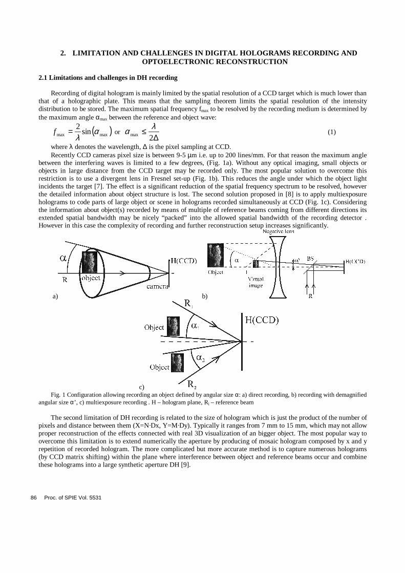
between the interfering waves is limited to a few degrees, (Fig. 1a). Without any optical imaging, small objects or objects in large distance from the CCD target may be recorded only. The most popular solution to overcome this restriction is to use a divergent lens in Fresnel set-up (Fig. 1b). This reduces the angle under which the object light incidents the target [7]. The effect is a significant reduction of the spatial frequency spectrum to be resolved, however the detailed information about object structure is lost. The second solution proposed in [8] is to apply multiexposure holograms to code parts of large object or scene in holograms recorded simultaneously at CCD (Fig. 1c). Considering the information about object(s) recorded by means of multiple of reference beams coming from different directions its extended spatial bandwidth may be nicely “packed” into the allowed spatial bandwidth of the recording detector . However in this case the complexity of recording and further reconstruction setup increases significantly.
a) b)
c) Fig. 1 Configuration allowing recording an object defined by angular size α: a) direct recording, b) recording with demagnified
angular size α’, c) multiexposure recording . H – hologram plane, Ri – reference beam The second limitation of DH recording is related to the size of hologram which is just the product of the number of
pixels and distance between them (X=N·Dx, Y=M·Dy). Typically it ranges from 7 mm to 15 mm, which may not allow proper reconstruction of the effects connected with real 3D visualization of an bigger object. The most popular way to overcome this limitation is to extend numerically the aperture by producing of mosaic hologram composed by x and y repetition of recorded hologram. The more complicated but more accurate method is to capture numerous holograms (by CCD matrix shifting) within the plane where interference between object and reference beams occur and combine these holograms into a large synthetic aperture DH [9].
86 Proc. of SPIE Vol. 5531
2.2 Limitations and challenges in DH optoelectronic reconstruction.
Optoelectronic reconstruction of digital holograms by means of liquid crystal on silicon spatial light modulators posses high requirements towards these devices. The key parameters are:
- high spatial resolution (i.e. small pixel size) At the moment pixel sizes less than ten microns can be fabricated with aperture ratios acceding 90 % [3]. This parameter sets the limit on an object’s spatial frequency bandwidth,
- sufficient field of view of reconstruction, which is responsible together with spatial resolution for producing the realistic 3D effect during 3D visualization of reconstructed object,
- high diffraction efficiency in +1 diffraction order, which allows to obtain bright reconstructed image with efficient use of illuminating source and preferably suppressed zero diffraction order
- minimalization of image multiplication at reconstruction plane, which provides increasing S/N ratio in reconstructed image and allows to record multiexposure holograms [8].
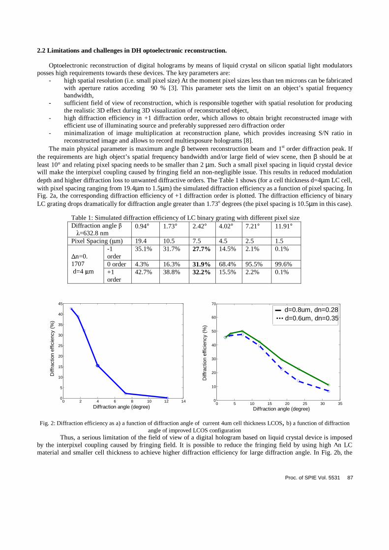
The main physical parameter is maximum angle β between reconstruction beam and 1st order diffraction peak. If the requirements are high object’s spatial frequency bandwidth and/or large field of wiev scene, then β should be at least 10° and relating pixel spacing needs to be smaller than 2 µm. Such a small pixel spacing in liquid crystal device will make the interpixel coupling caused by fringing field an non-negligible issue. This results in reduced modulation depth and higher diffraction loss to unwanted diffractive orders. The Table 1 shows (for a cell thickness d=4µm LC cell, with pixel spacing ranging from 19.4µm to 1.5µm) the simulated diffraction efficiency as a function of pixel spacing. In Fig. 2a, the corresponding diffraction efficiency of +1 diffraction order is plotted. The diffraction efficiency of binary LC grating drops dramatically for diffraction angle greater than 1.73o degrees (the pixel spacing is 10.5µm in this case). Fig. 2: Diffraction efficiency as a) a function of diffraction angle of current 4um cell thickness LCOS, b) a function of diffraction
angle of improved LCOS configuration Thus, a serious limitation of the field of view of a digital hologram based on liquid crystal device is imposed by the interpixel coupling caused by fringing field. It is possible to reduce the fringing field by using high ∆n LC material and smaller cell thickness to achieve higher diffraction efficiency for large diffraction angle. In Fig. 2b, the
0 2 4 6 8 10 12 14 0 5
10 15 20 25 30 35 40 45
Diffraction angle (degree)
Diff
ract
ion
effic
ienc
y (%
)
Table 1: Simulated diffraction efficiency of LC binary grating with different pixel size Diffraction angle β λ=632.8 nm
0.94° 1.73° 2.42° 4.02° 7.21° 11.91°
Pixel Spacing (µm) 19.4 10.5 7.5 4.5 2.5 1.5 -1 order
35.1% 31.7% 27.7% 14.5% 2.1% 0.1%
0 order 4.3% 16.3% 31.9% 68.4% 95.5% 99.6%
∆n=0. 1707 d=4 µm +1
order 42.7% 38.8% 32.2% 15.5% 2.2% 0.1%
0 5 10 15 20 25 30 35 0
10
20
30
40
50
60
70
Diffraction angle (degree)
Diff
ract
ion
effic
ienc
y (%
)
d=0.8um, dn=0.28 d=0.6um, dn=0.35
Proc. of SPIE Vol. 5531 87
improved field of view LCOS design can achieve over large of field of view with very high efficiency. These results indicates that an electronic hologram with diffraction angle of tens of degrees can have efficiency of 20%~40%. More details regarding the ultimate limitation of the spatial resolution of LC SLM can be found in the incoming publication [6]. At the moment it is possible to configure the matching pair of devices CCD-LCOS for holographic registration/reconstruction of an object with angular size 4° and diffraction efficiency of 20%.
3. EXPERIMENTAL SETUP
The experiment have been performed in two steps. At first digital holograms were created by physical recording or numerical calculations. These digital representations of holograms had been coded into LCOS. Then holograms in the form of LCOS were reconstructed and the images were recorded for documentation by CCD camera. 3.1 Objects
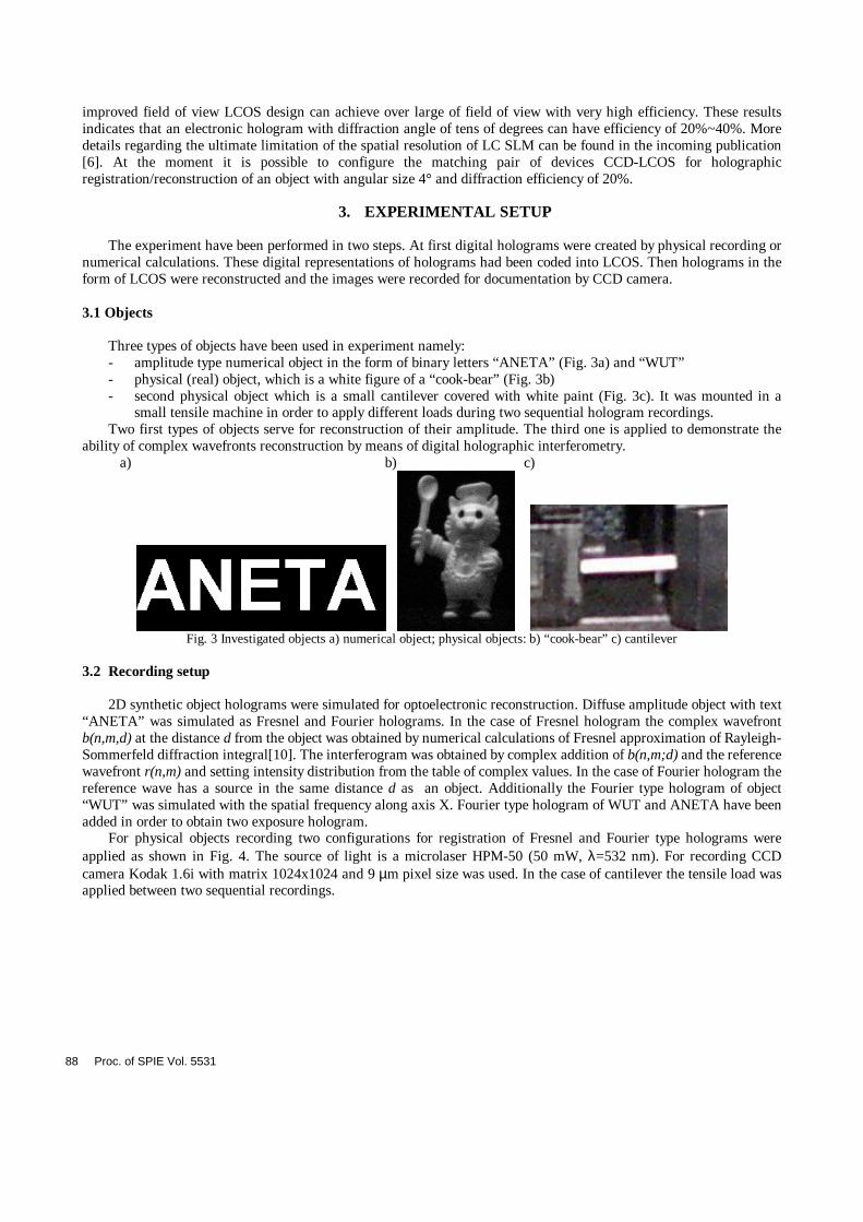
Three types of objects have been used in experiment namely: - amplitude type numerical object in the form of binary letters “ANETA” (Fig. 3a) and “WUT” - physical (real) object, which is a white figure of a “cook-bear” (Fig. 3b) - second physical object which is a small cantilever covered with white paint (Fig. 3c). It was mounted in a
small tensile machine in order to apply different loads during two sequential hologram recordings. Two first types of objects serve for reconstruction of their amplitude. The third one is applied to demonstrate the
ability of complex wavefronts reconstruction by means of digital holographic interferometry. a) b) c)
Fig. 3 Investigated objects a) numerical object; physical objects: b) “cook-bear” c) cantilever
3.2 Recording setup
2D synthetic object holograms were simulated for optoelectronic reconstruction. Diffuse amplitude object with text “ANETA” was simulated as Fresnel and Fourier holograms. In the case of Fresnel hologram the complex wavefront b(n,m,d) at the distance d from the object was obtained by numerical calculations of Fresnel approximation of Rayleigh-Sommerfeld diffraction integral[10]. The interferogram was obtained by complex addition of b(n,m;d) and the reference wavefront r(n,m) and setting intensity distribution from the table of complex values. In the case of Fourier hologram the reference wave has a source in the same distance d as an object. Additionally the Fourier type hologram of object “WUT” was simulated with the spatial frequency along axis X. Fourier type hologram of WUT and ANETA have been added in order to obtain two exposure hologram.
For physical objects recording two configurations for registration of Fresnel and Fourier type holograms were applied as shown in Fig. 4. The source of light is a microlaser HPM-50 (50 mW, λ=532 nm). For recording CCD camera Kodak 1.6i with matrix 1024x1024 and 9 µm pixel size was used. In the case of cantilever the tensile load was applied between two sequential recordings.
88 Proc. of SPIE Vol. 5531
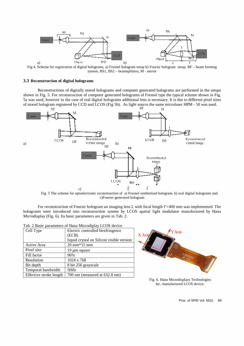
a) b) Fig 4. Scheme for registration of digital holograms, a) Fresnel hologram setup b) Fourier hologram setup. BF – beam forming
system, BS1, BS2 – beamsplitters, M - mirror 3.3 Reconstruction of digital holograms
Reconstructions of digitally stored holograms and computer generated holograms are performed in the setups shown in Fig. 5. For reconstruction of computer generated holograms of Fresnel type the typical scheme shown in Fig. 5a was used, however in the case of real digital holograms additional lens is necessary. It is due to different pixel sizes of stored hologram registered by CCD and LCOS (Fig 5b). As light source the same microlaser HPM - 50 was used.
a) b)
c) Fig. 5 The scheme for optoelectronic reconstruction of a) Fresnel synthetised hologram, b) real digital holograms and
c)Fourier generated hologram For reconstruction of Fourier hologram an imaging lens L with focal length f’=400 mm was implemented. The
holograms were introduced into reconstruction system by LCOS spatial light modulator manufactured by Hana Microdisplay (Fig. 6). Its basic parameters are given in Tab. 2.
Tab. 2 Basic parameters of Hana Microdiplay LCOS device
Cell Type Electric controlled birefringence (ECB) liquid crystal on Silicon visible version
Active Area 20 mm*15 mm Pixel size 19 µm square Fill factor 96% Resolution 1024 x 768 Bit depth 8 bit 256 grayscale Temporal bandwidth 50Hz Effective stroke length 700 nm (measured at 632.8 nm)
Y Axis X Axis
Fig. 6. Hana Microdisplays Technologies
Inc. manufactured LCOS device.
Proc. of SPIE Vol. 5531 89
Two types of devices have been implemented for reconstruction: phase and amplitude type LCOS. They differ by the rubbing direction. In the phase LCOS the rubbing direction is parallel, in amplitude one it is perpendicular. No twisting structure is present in the LC phase type layer. In the amplitude SLM liquid crystal director formed a twisting structure that can selectively rotate the polarization of incoming light by applying controllable voltage to the liquid crystal layer. For comparison purpose and evaluation of the optoelectronic reconstruction efficiency of LCOS the digital hologram of physical objects have been also reconstructed numerically [11]. The reconstructed wave field in this arrangement is given by:
}{' 1 wrhFzb ⋅⋅⋅= − (2) where r – reference wave field in the hologram plane, h – object wave field in the hologram plane and w, z – chirp functions. In order to visualize objects their intensity is calculated and it is given by following equation:
*''),( bbyxI ⋅= (3) The digital interferogram (for third object) has been obtained by adding intensity fields of two separate holograms of loaded cantilever captured for different values of tensile load.
4. RESULTS OF EXPERIMENTS Several groups of experiments were performed in order to check the applicability of COS device to reconstruct digital holograms namely:
- reconstruction of computer generated objects, - reconstruction of 3D objects, - optimization of DH coding process at LCOS. The results of these experiments are shown below.
4.1 Reconstruction of synthetic 2D objects
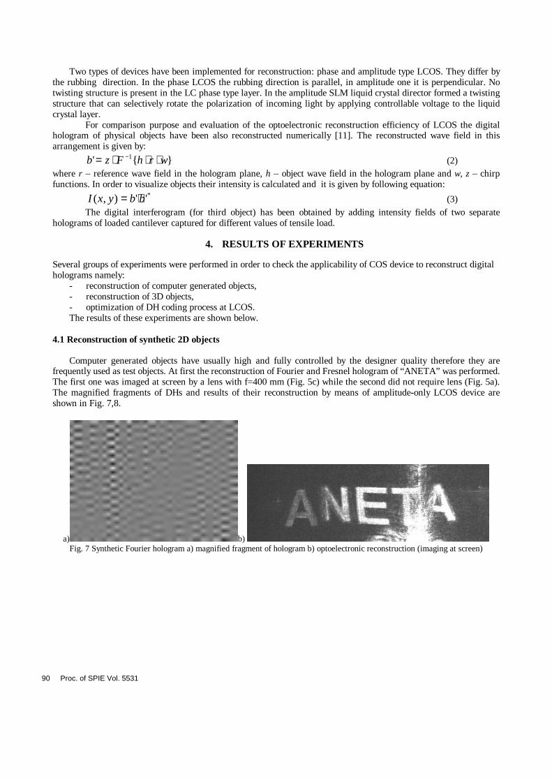
Computer generated objects have usually high and fully controlled by the designer quality therefore they are frequently used as test objects. At first the reconstruction of Fourier and Fresnel hologram of “ANETA” was performed. The first one was imaged at screen by a lens with f=400 mm (Fig. 5c) while the second did not require lens (Fig. 5a). The magnified fragments of DHs and results of their reconstruction by means of amplitude-only LCOS device are shown in Fig. 7,8.
a) b) Fig. 7 Synthetic Fourier hologram a) magnified fragment of hologram b) optoelectronic reconstruction (imaging at screen)
90 Proc. of SPIE Vol. 5531
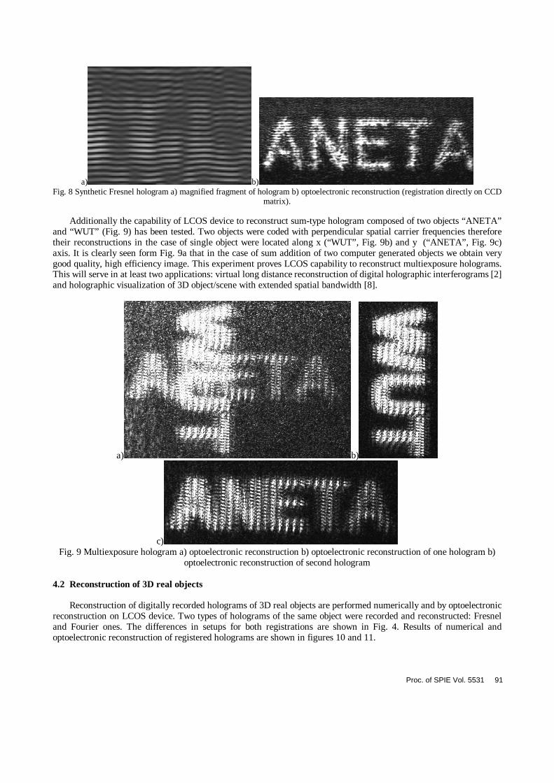
a) b) Fig. 8 Synthetic Fresnel hologram a) magnified fragment of hologram b) optoelectronic reconstruction (registration directly on CCD
matrix).
Additionally the capability of LCOS device to reconstruct sum-type hologram composed of two objects “ANETA” and “WUT” (Fig. 9) has been tested. Two objects were coded with perpendicular spatial carrier frequencies therefore their reconstructions in the case of single object were located along x (“WUT”, Fig. 9b) and y (“ANETA”, Fig. 9c) axis. It is clearly seen form Fig. 9a that in the case of sum addition of two computer generated objects we obtain very good quality, high efficiency image. This experiment proves LCOS capability to reconstruct multiexposure holograms. This will serve in at least two applications: virtual long distance reconstruction of digital holographic interferograms [2] and holographic visualization of 3D object/scene with extended spatial bandwidth [8].
a) b)
c) Fig. 9 Multiexposure hologram a) optoelectronic reconstruction b) optoelectronic reconstruction of one hologram b)
optoelectronic reconstruction of second hologram
4.2 Reconstruction of 3D real objects
Reconstruction of digitally recorded holograms of 3D real objects are performed numerically and by optoelectronic reconstruction on LCOS device. Two types of holograms of the same object were recorded and reconstructed: Fresnel and Fourier ones. The differences in setups for both registrations are shown in Fig. 4. Results of numerical and optoelectronic reconstruction of registered holograms are shown in figures 10 and 11.
Proc. of SPIE Vol. 5531 91
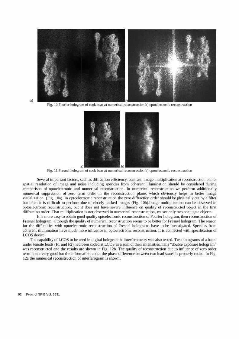
a) b) Fig. 10 Fourier hologram of cook bear a) numerical reconstruction b) optoelectronic reconstruction
a) b) Fig. 11 Fresnel hologram of cook bear a) numerical reconstruction b) optoelectronic reconstruction
Several important factors, such as diffraction efficiency, contrast, image multiplication at reconstruction plane, spatial resolution of image and noise including speckles from coherent illumination should be considered during comparison of optoelectronic and numerical reconstruction. In numerical reconstruction we perform additionally numerical suppression of zero term order in the reconstruction plane, which obviously helps in better image visualization. (Fig. 10a). In optoelectronic reconstruction the zero diffraction order should be physically cut by a filter but often it is difficult to perform due to closely packed images (Fig. 10b).Image multiplication can be observed in optoelectronic reconstruction, but it does not have severe influence on quality of reconstructed object in the first diffraction order. That multiplication is not observed in numerical reconstruction, we see only two conjugate objects.
It is more easy to obtain good quality optoelectronic reconstruction of Fourier hologram, then reconstruction of Fresnel hologram, although the quality of numerical reconstruction seems to be better for Fresnel hologram. The reason for the difficulties with optoelectronic reconstruction of Fresnel holograms have to be investigated. Speckles from coherent illumination have much more influence in optoelectronic reconstruction. It is connected with specification of LCOS device.
The capability of LCOS to be used in digital holographic interferometry was also tested. Two holograms of a beam under tensile loads (F1 and F2) had been coded at LCOS as a sum of their intensities. This “double exposure hologram” was reconstructed and the results are shown in Fig. 12b. The quality of reconstruction due to influence of zero order term is not very good but the information about the phase difference between two load states is properly coded. In Fig. 12a the numerical reconstruction of interferogram is shown.
92 Proc. of SPIE Vol. 5531
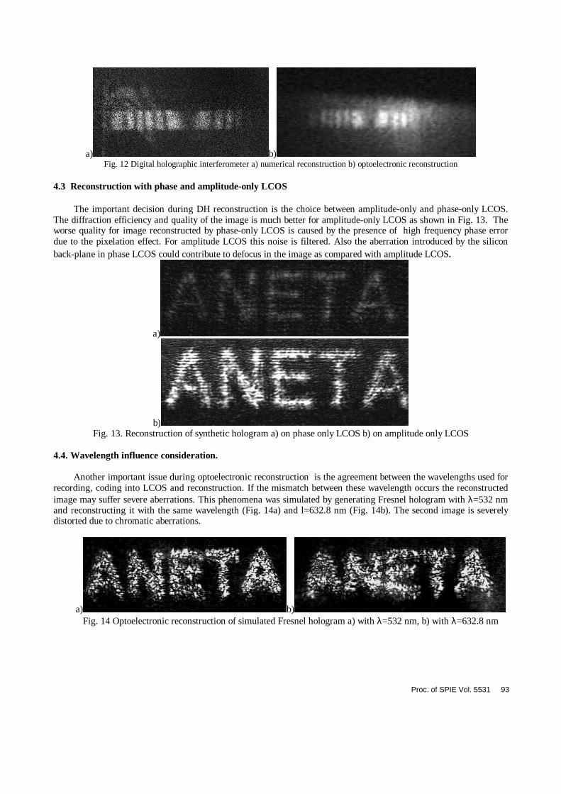
a) b) Fig. 12 Digital holographic interferometer a) numerical reconstruction b) optoelectronic reconstruction
4.3 Reconstruction with phase and amplitude-only LCOS
The important decision during DH reconstruction is the choice between amplitude-only and phase-only LCOS. The diffraction efficiency and quality of the image is much better for amplitude-only LCOS as shown in Fig. 13. The worse quality for image reconstructed by phase-only LCOS is caused by the presence of high frequency phase error due to the pixelation effect. For amplitude LCOS this noise is filtered. Also the aberration introduced by the silicon back-plane in phase LCOS could contribute to defocus in the image as compared with amplitude LCOS.
a)
b) Fig. 13. Reconstruction of synthetic hologram a) on phase only LCOS b) on amplitude only LCOS
4.4. Wavelength influence consideration.
Another important issue during optoelectronic reconstruction is the agreement between the wavelengths used for recording, coding into LCOS and reconstruction. If the mismatch between these wavelength occurs the reconstructed image may suffer severe aberrations. This phenomena was simulated by generating Fresnel hologram with λ=532 nm and reconstructing it with the same wavelength (Fig. 14a) and l=632.8 nm (Fig. 14b). The second image is severely distorted due to chromatic aberrations.
a) b) Fig. 14 Optoelectronic reconstruction of simulated Fresnel hologram a) with λ=532 nm, b) with λ=632.8 nm
Proc. of SPIE Vol. 5531 93
5. CONCLUSIONS
In the paper we have discussed several issues connected with optoelectronic reconstruction of digital holograms by means of LCOS devices. It was proven that it serves well for reconstruction of both single and multiexposure Fresnel and Fourier holograms. It is advised to use amplitude-only LCOS with 2π phase coding in order to achieve better quality images. The special attention should be paid for matching the recording/reconstructing wavelength as well as the wavelength for which LCOS has been calibrated. In the future it is possible to achieve LCOS with pixel size 2 mm and diffraction efficiency up to 20-40%.
6. ACKNOWLEDGMENTS
The work was supported by Foundation for Polish Science and Warsaw University of Technology. The cooperation between Kent State University and Warsaw University of Technology has been supported by
SPIE – the International Society for Optical Engineering.
REFERENCES
1. M. Sutkowski, M. Kujawinska - Application of liquid crystal (LC) for optoelectronic reconstruction of digitally stored holograms - Optics&Lasers in Engineering vol.33, 191-203, 2000
2. W. Osten, T. Baumbach, S. Seebacher, W. Juptner „Shape control by comparative digital holography” Fringe 2001, Editors: W. Osten, W. Juptner, Elsevier, 373-382, 2001
3. P. St. Hillaire - Holographic video: The ultimate visual interface? - Optics & Photonics News, 08-1997 4. R.L. Melcher (ed) Special issue of Journal “Displays” devoted to LCOS, Elsevier Science B.V. V. XX No XX,
2002 5. S. Kruger et al. „Nematic LCOS spatial light modulator: performance in diffractive optics.“ Proc. SPIE Vol.
5457, in print, 2004 6. X. Wang, B. Wang, P. J. Bos, et al. “Limitation of liquid crystal on silicon spatial light modulator for
holographic three-dimensional displays,” SID Tech. Digest , Paper Number 58-1, 2004 7. U. Schnars, T.M. Kreis, W.P.O. Jüptner - Digital recording and numerical reconstruction of holograms:
reduction of the spatial frequency spectrum - Optical Engineering vol.35(4), 1996 8. M. Sutkowski, “Optoelectronic and digital fundamentals of holographic systems for multimedia”, doctoral
thesis, Warsaw University of Technology, 2003 9. Binet R, Colineau J, Lehureau J-C. Synthetic aperture, a way to high resolution active imaging. Proc. SPIE,
Vol.4833, pp.135-42, 2002 10. Goodman J. W. Introduction to Fourier optics. McGraw-Hill Book Co., New York, 1968 11. T. M. Kreis, W. P. O. Jüptner, J. Geldmacher – Digital Holography: Methods and applications – Proc. SPIE
vol. 3407, str. 169-175, 1998
94 Proc. of SPIE Vol. 5531