
Technical Manual FEX2S25-A FM MODULATOR 25W
74
FEX2S25-A FM MODULATOR 25W 1 50 5450202501 FEX 2S25-A FM Modulator A 21/04/2010 F 27/05/2013 Electrosys s.r.l. Località Sferracavallo, 19/A 05010 - Orvieto (TR) Italy P.IVA. 075284451003 Phone: +39 0763 3361 Fax: +39.0763.393957 e-mail: [email protected] website:www.electrosys.it Technical Manual FEX2S25-A FM MODULATOR 25W 1 2 3 4 CHAPTER 1 GENERAL INFORMATION CHAPTER 2: OPERATING INSTRUCTIONS CHAPTER 3: MAINTENANCE APPENDIX: ETHERNET INTERFACE SAFETY PRECAUTIONS FORWORD 5 CIRCUITS DIAGRAMS
-
Upload
khangminh22 -
Category
Documents
-
view
3 -
download
0
Transcript of Technical Manual FEX2S25-A FM MODULATOR 25W

FEX2S25-A FM MODULATOR 25W
1 505450202501 FEX 2S25-A FM ModulatorA 21/04/2010F 27/05/2013
Electrosys s.r.l.Località Sferracavallo, 19/A05010 - Orvieto (TR) ItalyP.IVA. 075284451003
Phone: +39 0763 3361Fax: +39.0763.393957e-mail: [email protected]:www.electrosys.it
Technical Manual
FEX2S25-A FM MODULATOR 25W
1
2
3
4
CH
AP
TE
R 1
GE
NE
RA
LIN
FO
RM
AT
ION
CH
AP
TE
R 2:
OP
ER
AT
ING
INS
TR
UC
TIO
NS
CH
AP
TE
R 3:
MA
INT
EN
AN
CE
AP
PE
ND
IX:
ET
HE
RN
ET
INT
ER
FAC
E
SA
FE
TY
PR
EC
AU
TIO
NS
FO
RW
OR
D
5
CIR
CU
ITS
DIA
GR
AM
S

FEX2S25-A FM MODULATOR 25W
2 505450202501 FEX 2S25-A FM ModulatorA 21/04/2010F 27/05/2013
Restrictions:The use of this equipment is onlyunder authority licence.
Note for countries submitted to1999/05/EC directive:This equipment can be operatedin the following countries:
AT DE MT GBBE GR NL ISCY HU PL LICZ IE PT NODK IT SK CHEE LV SI BGFI LT ES ROFR LU SE TR
As option the equipment may be providedwith telemetering connectors for PTSN,ADSL, or GSM networks
FEX2S25-A FM MODULATOR 25W
3 505450202501 FEX 2S25-A FM ModulatorA 21/04/2010F 27/05/2013
CONTENTS
FORWORD
1. GENERAL INFORMATION 11. . . . . . . . . . . . . . . . . . . . . . . . . . . . . . . . . . . . . . . . . . . . . . . . . . 1.1 INTRODUCTION 11. . . . . . . . . . . . . . . . . . . . . . . . . . . . . . . . . . . . . . . . . . . . . . . . . . . . . . . . . . . 1.1.1 Manual Applicability 11. . . . . . . . . . . . . . . . . . . . . . . . . . . . . . . . . . . . . . . . . . . . . . . . . . . . . . . . . 1.1.2 General information 11. . . . . . . . . . . . . . . . . . . . . . . . . . . . . . . . . . . . . . . . . . . . . . . . . . . . . . . . . 1.2 FUNCTIONAL DESCRIPTION 14. . . . . . . . . . . . . . . . . . . . . . . . . . . . . . . . . . . . . . . . . . . . . . . . 1.2.1 Digital Modulator section 14. . . . . . . . . . . . . . . . . . . . . . . . . . . . . . . . . . . . . . . . . . . . . . . . . . . . . 1.2.2 RF Section 16. . . . . . . . . . . . . . . . . . . . . . . . . . . . . . . . . . . . . . . . . . . . . . . . . . . . . . . . . . . . . . . . . 1.2.3 Power Supply Section 16. . . . . . . . . . . . . . . . . . . . . . . . . . . . . . . . . . . . . . . . . . . . . . . . . . . . . . . 1.3 TECHNICAL CHARACTERISTICS 17. . . . . . . . . . . . . . . . . . . . . . . . . . . . . . . . . . . . . . . . . . . . 1.3.1 General data 17. . . . . . . . . . . . . . . . . . . . . . . . . . . . . . . . . . . . . . . . . . . . . . . . . . . . . . . . . . . . . . . 1.3.2 Remote interfaces 17. . . . . . . . . . . . . . . . . . . . . . . . . . . . . . . . . . . . . . . . . . . . . . . . . . . . . . . . . . 1.3.3 Outputs 17. . . . . . . . . . . . . . . . . . . . . . . . . . . . . . . . . . . . . . . . . . . . . . . . . . . . . . . . . . . . . . . . . . . 1.3.4 Inputs 18. . . . . . . . . . . . . . . . . . . . . . . . . . . . . . . . . . . . . . . . . . . . . . . . . . . . . . . . . . . . . . . . . . . . . 1.3.5 FM Modulator 19. . . . . . . . . . . . . . . . . . . . . . . . . . . . . . . . . . . . . . . . . . . . . . . . . . . . . . . . . . . . . .
LIST OF ILLUSTRATIONSFig. 1.1 - FEX functional areas 12. . . . . . . . . . . . . . . . . . . . . . . . . . . . . . . . . . . . . . . . . . . . . . . . . . . . . . . . . Fig. 1.2 - FEX general bklock diagram 13. . . . . . . . . . . . . . . . . . . . . . . . . . . . . . . . . . . . . . . . . . . . . . . . . . Fig. 1.3 - RF section Block diagram 16. . . . . . . . . . . . . . . . . . . . . . . . . . . . . . . . . . . . . . . . . . . . . . . . . . . .
2. OPERATING INSTRUCTIONS 23. . . . . . . . . . . . . . . . . . . . . . . . . . . . . . . . . . . . . . . . . . . . . . . 2.1 INTRODUCTION 23. . . . . . . . . . . . . . . . . . . . . . . . . . . . . . . . . . . . . . . . . . . . . . . . . . . . . . . . . . . 2.2 LEGEND 23. . . . . . . . . . . . . . . . . . . . . . . . . . . . . . . . . . . . . . . . . . . . . . . . . . . . . . . . . . . . . . . . . . 2.3 MAINS CONNECTION 26. . . . . . . . . . . . . . . . . . . . . . . . . . . . . . . . . . . . . . . . . . . . . . . . . . . . . . 2.4 SWITCHING ON/OFF 26. . . . . . . . . . . . . . . . . . . . . . . . . . . . . . . . . . . . . . . . . . . . . . . . . . . . . . . 2.5 REMOTE CONTROL 26. . . . . . . . . . . . . . . . . . . . . . . . . . . . . . . . . . . . . . . . . . . . . . . . . . . . . . . . 2.6 USING THE CONTROLLER 26. . . . . . . . . . . . . . . . . . . . . . . . . . . . . . . . . . . . . . . . . . . . . . . . . 2.6.1 Keyboard functions 27. . . . . . . . . . . . . . . . . . . . . . . . . . . . . . . . . . . . . . . . . . . . . . . . . . . . . . . . . 2.6.2 General information on data displaying 27. . . . . . . . . . . . . . . . . . . . . . . . . . . . . . . . . . . . . . . . 2.6.3 Typographical Convections 28. . . . . . . . . . . . . . . . . . . . . . . . . . . . . . . . . . . . . . . . . . . . . . . . . . . 2.6.4 Enabling/disabling and resetting the alarms storage 29. . . . . . . . . . . . . . . . . . . . . . . . . . . . . 2.7 MENU AND CONTENTS 30. . . . . . . . . . . . . . . . . . . . . . . . . . . . . . . . . . . . . . . . . . . . . . . . . . . . 2.8 CHANGING THE TRANSMISSION FREQUENCY 41. . . . . . . . . . . . . . . . . . . . . . . . . . . . . . 2.9 REGULATION OF RF OUTPUT POWER 41. . . . . . . . . . . . . . . . . . . . . . . . . . . . . . . . . . . . . . 2.10 CALIBRATIONS AND SETTINGS 41. . . . . . . . . . . . . . . . . . . . . . . . . . . . . . . . . . . . . . . . . . . . . 2.10.1 Settings for N+1 system 41. . . . . . . . . . . . . . . . . . . . . . . . . . . . . . . . . . . . . . . . . . . . . . . . . . . . .
LIST OF TABLESTab. 2.1 - FEX 2S25-A FM Exciter front panel legend (ref. Fig. 2.1) 24. . . . . . . . . . . . . . . . . . . . . . . . . Tab. 2.2 - FEX 2S25-A FM Exciter rear panel legend (ref. Fig. 2.2) 25. . . . . . . . . . . . . . . . . . . . . . . . . Tab. 2.3 - Pin-out assignment of the PARALLEL I/O connector 26. . . . . . . . . . . . . . . . . . . . . . . . . . . . . Tab. 2.4 - List of indications and symbols used on screen-shots 28. . . . . . . . . . . . . . . . . . . . . . . . . . . . Tab. 2.5 - Alarms list of History Log 40. . . . . . . . . . . . . . . . . . . . . . . . . . . . . . . . . . . . . . . . . . . . . . . . . . . . .
LIST OF ILLUSTRATIONSFig. 2.1 - FEX 2S25-A FM Exciter front panel 24. . . . . . . . . . . . . . . . . . . . . . . . . . . . . . . . . . . . . . . . . . . . Fig. 2.2 - FEX 2S25-A FM Exciter rear panel 25. . . . . . . . . . . . . . . . . . . . . . . . . . . . . . . . . . . . . . . . . . . . Fig. 2.3 - Typical data displaying 27. . . . . . . . . . . . . . . . . . . . . . . . . . . . . . . . . . . . . . . . . . . . . . . . . . . . . . .
3. MAINTENANCE 45. . . . . . . . . . . . . . . . . . . . . . . . . . . . . . . . . . . . . . . . . . . . . . . . . . . . . . . . . . . . 3.1 INTRODUCTION 45. . . . . . . . . . . . . . . . . . . . . . . . . . . . . . . . . . . . . . . . . . . . . . . . . . . . . . . . . . . 3.1.1 Introduction to Maintenance 45. . . . . . . . . . . . . . . . . . . . . . . . . . . . . . . . . . . . . . . . . . . . . . . . . . 3.1.2 Types and Levels of Maintenance 45. . . . . . . . . . . . . . . . . . . . . . . . . . . . . . . . . . . . . . . . . . . . . 3.1.3 Maintenance Tools 46. . . . . . . . . . . . . . . . . . . . . . . . . . . . . . . . . . . . . . . . . . . . . . . . . . . . . . . . . . 3.1.4 Test Instruments 46. . . . . . . . . . . . . . . . . . . . . . . . . . . . . . . . . . . . . . . . . . . . . . . . . . . . . . . . . . . . 3.2 PREVENTIVE MAINTENANCE 46. . . . . . . . . . . . . . . . . . . . . . . . . . . . . . . . . . . . . . . . . . . . . . . 3.3 CORRECTIVE MAINTENANCE 48. . . . . . . . . . . . . . . . . . . . . . . . . . . . . . . . . . . . . . . . . . . . . . 3.3.1 Corrective Maintenance Concepts 48. . . . . . . . . . . . . . . . . . . . . . . . . . . . . . . . . . . . . . . . . . . .
�

FEX2S25-A FM MODULATOR 25W
4 505450202501 FEX 2S25-A FM ModulatorA 21/04/2010F 27/05/2013
3.4 MAINTENANCE PROCEDURES 49. . . . . . . . . . . . . . . . . . . . . . . . . . . . . . . . . . . . . . . . . . . . . 3.4.1 Necessary test equipment and preliminary operations 50. . . . . . . . . . . . . . . . . . . . . . . . . . . . 3.4.2 Functional checks on Final stage 50. . . . . . . . . . . . . . . . . . . . . . . . . . . . . . . . . . . . . . . . . . . . .
LIST OF TABLESTab. 3.1 - Functional checks on Final stage 50. . . . . . . . . . . . . . . . . . . . . . . . . . . . . . . . . . . . . . . . . . . . . .
LIST OF ILLUSTRATIONSFig. 3.1 - FEX final stages arrangement (bottom view) 49. . . . . . . . . . . . . . . . . . . . . . . . . . . . . . . . . . . . Fig. 3.2 - FINAL stage (FM Amplifier p/n. 4040028010) layout 50. . . . . . . . . . . . . . . . . . . . . . . . . . . . . .
SAFETY PRECAUTION1. INTRODUCTION2. SAFETY OPERATIONS3. SPECIFICATION ON HANDLING AND DISPOSAL OF BERYLLIA DEVICES4. ABSTRACT OF APPENDIX “E” OF CEI EN 60215 SAFETY RULES
4. APPENDIX“ETHERNET INTERFACE” INSTALLATION GUIDE
5. CIRCUIT DIAGRAMS

FOREWORD (how to consult the manual)
FEX2S25-A FM MODULATOR 25W
5 505450202501 FEX 2S25-A FM ModulatorA 21/04/2010F 27/05/2013
1 MANUAL ORGANIZATION
The manual is composed of the following sections:
- section 1 ”Operator's Manual” including general information, installation guide, operating instructions, mainten‐. . ance and circuit diagrams (wiring diagram of the equipment, other circuit dia‐grams associated to units, sub-units or boards without ”Technical Manual”);
- section 2 ”Technical Manual” dealing with units and sub-units which make up the equipment along with the. . . associated circuit diagrams.
2 PARTS LIST
The parts list of equipment, units, sub-units is delivered as an Excel file (Microsoft Excel 97 & 5.0/95). The search of aspecific part of the equipment is achieved using “Automatic filter” from “Data” menu. The parts list is composed by 6columns as follows:- the 1st column “LEV” (level) is the level of the part within the equipment;- the 2nd column “PROG” (progressive) is the progressive number of each part (keep in mind that two or more
identical parts are identified by the same progressive number);- the 3rd column “PARENT” is the code of the part at the upper level;- the 4th column “COMPONENT” is the code of the part;- the 5th column “DESCRIPTION” is the description of the part;- the 6th column “REF” (reference) is the reference note of the part with which it is referred to on the circuit
diagram of column 3 “PARENT”.
An “ABBRV_PL” file, lists the abbreviations used in “DESCRIPTION” column of the parts list file. For opening“ABBRV_PL” file:
1. close “homepage.pdf” file which automatically starts upon CD manual insertion in the PC driver;2. click on “My Computer” icon to access its contents;3 .click on “Compact Disc (D:)” icon to access it;4 .the window opened shows files and folders included on CD: open “ABBRV_PL” file to access it.
3 CIRCUIT DIAGRAMS (how to consult them)
3.1 Acronyms
Circuit diagrams are identified by acronyms after the drawing number (i.e.: 6300621005ID). A list of the acronymsused is given here below:
acronym explanation acronym explanationSI general wiring diagram
(for 9 digits codes)ST component layout
(for 9 digits codes)
ID general wiring diagram(for 10 digits codes)
CL component layout(for 10 digits codes)
SE circuit diagram(for 9 digits codes)
SD general wiring diagramfor interlock chain
ED circuit diagram(for 10 digits codes)
3.2 Classification of wiring cables
Wiring cables (unipolar, multipolar, flat cables) are identified by an alphanumeric code on circuit diagrams; this codeis composed of 4 digits as follows:- 1st digit is 'W' (for wiring)- 2nd digit identifies the type of wiring (e.g.: AC connections, DC connections, RF connections etc.) as follows:
1 for AC connections;. . .
2 for DC connections;. . .
3 for RF connections;. . .
4 for LF connections;. . .
5 for logic signals, alarms connections.. . .
- 3rd and 4th digits indicate the progressive numbering for each type of wiring.
W312
twelfth RF cableRF connectionwiring cable
W207EXAMPLE
seventh DC cableDC connectionwiring cable

FOREWORD (how to consult the manual)
FEX2S25-A FM MODULATOR 25W
6 505450202501 FEX 2S25-A FM ModulatorA 21/04/2010F 27/05/2013
3.3 Connection of wiring cables
The wiring cables between two connectors, are always intended pin-to-pin unless otherwise specified. In the eventthe wiring is not pin-to-pin, it is shown on the drawing.
3.4 Symbols and identifications of connectors/terminal blocks
Connectors and terminal boards arranged inside an equipment, a unit or a board, are identified on the associated cir‐cuit diagram, by symbols as follows:
symbol objetcBoth for connectors and terminal blocks, the numbering isprogressive within each equipment, unit, or board; that is on ageneral wiring diagram two or more ”J6” (or ”K3”) may existbecause they are arranged inside different equipment, unit orboard.
Male and female connectors are identified respectively by “J”and “P” in some circuit diagrams before the year 2000.
However a connector (or terminal block) will always have thesame identification number both on the general wiring dia‐gram of the unit and on the general wiring diagram of theequipment where the unit is arranged.
male connectoridentified by “Jx”female connectoridentified by “Jx”terminal blockidentified by “Kx”coaxial cableidentified by “Wx”
4 SAFETY INFORMATION
4.1. Introduction
The equipment fully complies with the requirements for the safety of personnel as specified in IEC 215 rules. Theequipment, if operated per specification, is designed and manufactured to protect the operator from high voltage,heat, radiation and other dangers.
Warning labels are attached to enclosures and/or various assemblies to identify potentially dangerous conditions tothe operator. These Warning labels must be adhered to.
4.2.Warning, Cautions and Notes
Throughout the manual Warning and Cautions notices are used to identify procedures, conditions and materials thatcould be potentially cause death, injury or damage to equipment.
WARNING!
Used to indicate a potential hazard that requires correct procedures or practisesin order to prevent personal injury or damage to equipment.
CAUTION!
Used to indicate correct operation or maintenance in order to prevent damage to,or destruction of equipment or other property.
NOTE!
Used to highlight important information or procedures.
�Tips on how alert the operator faster or easier to complete a task
TIP

FOREWORD (how to consult the manual)
FEX2S25-A FM MODULATOR 25W
7 505450202501 FEX 2S25-A FM ModulatorA 21/04/2010F 27/05/2013
4.3.Hazard symbols
Throughout the manual hazard symbols are used to alert the operator of a potential hazard related to the operation tobe carried out.
Warning
Danger of getting crushedwhen working with loads.
Danger of falling off ladderswhile working
Danger when lifting heavyloads.
Danger of getting handscrushed when working.
Danger of burns on contactwith hot surfaces.
Shock hazard
4.4.Beryllia devices
WARNING
components insideBeryllium Oxide
BeO!
Some units or parts of the equipment may contain berylliadevices. Normally these components can be handled withoutrisk, but there is a toxic hazard if beryllia dust from a damagedcomponent is inhaled or implanted in the skin.
Units or parts containing beryllia oxide are identified by thelabel shown on the left.
For handling and disposal of beryllia devices, refer to “SafetyPrecautions” section, para 3. - “SPECIFICATION ON HAN‐DLING AND DISPOSAL OF BERYLLIA DEVICES“.

FEX2S25-A FM MODULATOR 25W
8 505450202501 FEX 2S25-A FM ModulatorA 21/04/2010F 27/05/2013

FEX2S25-A FM MODULATOR 25W
9 505450202501 FEX 2S25-A FM ModulatorA 21/04/2010F 27/05/2013
1. GENERAL INFORMATION1.1 INTRODUCTION 11. . . . . . . . . . . . . . . . . . . . . . . . . . . . . . . . . . . . . . . . . . . . . . . . . 1.1.1 Manual Applicability 11. . . . . . . . . . . . . . . . . . . . . . . . . . . . . . . . . . . . . . . . . . . . . . . 1.1.2 General information 11. . . . . . . . . . . . . . . . . . . . . . . . . . . . . . . . . . . . . . . . . . . . . . . 1.2 FUNCTIONAL DESCRIPTION 14. . . . . . . . . . . . . . . . . . . . . . . . . . . . . . . . . . . . . . 1.2.1 Digital Modulator section 14. . . . . . . . . . . . . . . . . . . . . . . . . . . . . . . . . . . . . . . . . . . 1.2.2 RF Section 16. . . . . . . . . . . . . . . . . . . . . . . . . . . . . . . . . . . . . . . . . . . . . . . . . . . . . . . 1.2.3 Power Supply Section 16. . . . . . . . . . . . . . . . . . . . . . . . . . . . . . . . . . . . . . . . . . . . . 1.3 TECHNICAL CHARACTERISTICS 17. . . . . . . . . . . . . . . . . . . . . . . . . . . . . . . . . . 1.3.1 General data 17. . . . . . . . . . . . . . . . . . . . . . . . . . . . . . . . . . . . . . . . . . . . . . . . . . . . . 1.3.2 Remote interfaces 17. . . . . . . . . . . . . . . . . . . . . . . . . . . . . . . . . . . . . . . . . . . . . . . . . 1.3.3 Outputs 17. . . . . . . . . . . . . . . . . . . . . . . . . . . . . . . . . . . . . . . . . . . . . . . . . . . . . . . . . . 1.3.4 Inputs 18. . . . . . . . . . . . . . . . . . . . . . . . . . . . . . . . . . . . . . . . . . . . . . . . . . . . . . . . . . . 1.3.5 FM Modulator 19. . . . . . . . . . . . . . . . . . . . . . . . . . . . . . . . . . . . . . . . . . . . . . . . . . . .
LIST OF ILLUSTRATIONSFig. 1.1 - FEX functional areas 12. . . . . . . . . . . . . . . . . . . . . . . . . . . . . . . . . . . . . . . . . . . . . . Fig. 1.2 - FEX general bklock diagram 13. . . . . . . . . . . . . . . . . . . . . . . . . . . . . . . . . . . . . . . Fig. 1.3 - RF section Block diagram 16. . . . . . . . . . . . . . . . . . . . . . . . . . . . . . . . . . . . . . . . . .
CH
AP
TE
R 1
GE
NE
RA
LIN
FO
RM
AT
ION
1

FEX2S25-A FM MODULATOR 25W
10 505450202501 FEX 2S25-A FM ModulatorA 21/04/2010F 27/05/2013

FEX2S25-A FM MODULATOR 25W
11 505450202501 FEX 2S25-A FM ModulatorA 21/04/2010F 27/05/2013
1. GENERAL INFORMATION
1.1 INTRODUCTION
1.1.1 Manual Applicability
This manual provides system-oriented information, procedures and data for operation andinstallation of the following units:
� FEX 2S25-A FM Modulator 25W p/n. 5450202501. . . . . . . . . . . . . . . . . . . . . . . . . . . . .
From here on for the sake of simplicity, throughout this manual FEX 2S25-A FM Exciter 25Wwill be referred to as FEX.
The contents of the present manual are arranged in chapters according to the following:
- Chapter 1 : General Information
- Chapter 2 : Operating Instructions
1.1.2 General information
FEX is the State-of-The-Art FM Exciter capable of modulation by means of fully digital signalprocessing. A wise use of the latest technologies and innovative and downsizing design ofthe cards, in particular the innovative single chip MODULATOR, have enabled us to reducesignificantly the overall dimensions of the exciter. The integration of the digital and RF stagesin a single rack simplifies and improves the equipment.
Using FEX is very simple: a keyboard and an LCD display, available to the operator on unitfront panel, allow easy operation, settings and monitoring. Moreover FEX may be remotelycontrolled by using web browser, ESS or SNMP.
With reference to Fig. 1.1 and Fig. 1.2, FEX may be divided into the following functional area:
� digital modulator including the digital modulator circuitry (on a single assembly). . . . . which is able to perform the modulation compliant with the trans‐mission standard. It also includes an analog band pass filter whichfilters the spurious signals generated by DAC.The digital modulator board also includes the control section (notrepresented on Fig. 1.1) which allows commands, configurationsetting and paramenters monitoring of the unit.
� RF section including the RF amplifiers stages and an FM Filter. The RF stages. . . . . . . . . . are able to deliver up to 25W.
� pwr supp. section including two AC/DC Converters and a Power Distribution board‐. . . . which supply all the circuits and assemblies of the unit.
� remote interface is a board allowing the remote control of the unit via parallel inter‐. . . . . face. The remote control is allowed by means of on/off levels, man‐aged by relay line.
The unit may be also remote controlled via web server over HTTP,TFTP, SNMP, Telnet protocols.

FEX2S25-A FM MODULATOR 25W
12 505450202501 FEX 2S25-A FM ModulatorA 21/04/2010F 27/05/2013
Fig. 1.1 - FEX functional areas
RF section(Amplifier stages)
digital modulatorsection
321
321
321
321
RF section(FM Filter)
power supplysection
remoteinterface

FEX2S25-A FM MODULATOR 25W
13 505450202501 FEX 2S25-A FM ModulatorA 21/04/2010F 27/05/2013
Fig. 1.2 - FEX general bklock diagram
SCA
SCA/RDS/RBDS
RBDS/RDS
MPX
RIGHT
LEFT
FM
MODULATOR
ETHERNET
FMAMPLIFIER
RF OUTPUT
RF OUTPUTMONITOR
FWD1PPS
PILOT OUT
REMOTE
INTERFACE
ETHERNET PROG
PARALLEL I/OAC/DCCONV
+/-5V+/-12V
AC/DCCONV
48V
AES/EBU
10MHz FM Filter
POWERDISTRIBUTION
LINE IN
CONTROLLER
ETHERNET
I2C BUS
FEX2S25-A FM MODULATOR 25W
14 505450202501 FEX 2S25-A FM ModulatorA 21/04/2010F 27/05/2013
1.2 FUNCTIONAL DESCRIPTION
1.2.1 Digital Modulator section
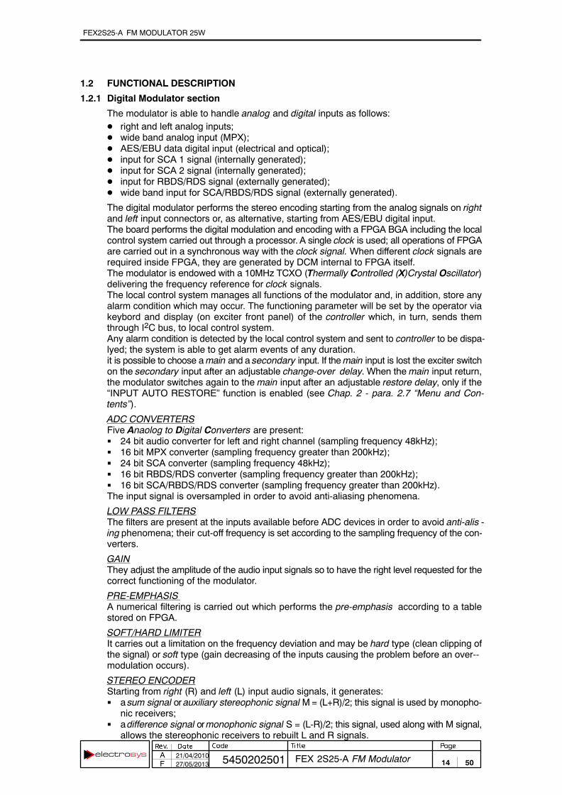
The modulator is able to handle analog and digital inputs as follows:� right and left analog inputs;� wide band analog input (MPX);� AES/EBU data digital input (electrical and optical);� input for SCA 1 signal (internally generated);� input for SCA 2 signal (internally generated);� input for RBDS/RDS signal (externally generated);� wide band input for SCA/RBDS/RDS signal (externally generated).
The digital modulator performs the stereo encoding starting from the analog signals on rightand left input connectors or, as alternative, starting from AES/EBU digital input.The board performs the digital modulation and encoding with a FPGA BGA including the localcontrol system carried out through a processor. A single clock is used; all operations of FPGAare carried out in a synchronous way with the clock signal. When different clock signals arerequired inside FPGA, they are generated by DCM internal to FPGA itself.The modulator is endowed with a 10MHz TCXO (Thermally Controlled (X)Crystal Oscillator)delivering the frequency reference for clock signals.The local control system manages all functions of the modulator and, in addition, store anyalarm condition which may occur. The functioning parameter will be set by the operator viakeybord and display (on exciter front panel) of the controller which, in turn, sends themthrough I2C bus, to local control system.Any alarm condition is detected by the local control system and sent to controller to be dispa‐lyed; the system is able to get alarm events of any duration.it is possible to choose a main and a secondary input. If the main input is lost the exciter switchon the secondary input after an adjustable change-over delay. When the main input return,the modulator switches again to the main input after an adjustable restore delay, only if the“INPUT AUTO RESTORE” function is enabled (see Chap. 2 - para. 2.7 “Menu and Con‐tents”).
ADC CONVERTERSFive Anaolog to Digital Converters are present:� 24 bit audio converter for left and right channel (sampling frequency 48kHz);� 16 bit MPX converter (sampling frequency greater than 200kHz);� 24 bit SCA converter (sampling frequency 48kHz);� 16 bit RBDS/RDS converter (sampling frequency greater than 200kHz);� 16 bit SCA/RBDS/RDS converter (sampling frequency greater than 200kHz).The input signal is oversampled in order to avoid anti-aliasing phenomena.
LOW PASS FILTERSThe filters are present at the inputs available before ADC devices in order to avoid anti-alis ‐ing phenomena; their cut-off frequency is set according to the sampling frequency of the con‐verters.
GAINThey adjust the amplitude of the audio input signals so to have the right level requested for thecorrect functioning of the modulator.
PRE-EMPHASISA numerical filtering is carried out which performs the pre-emphasis according to a tablestored on FPGA.
SOFT/HARD LIMITERIt carries out a limitation on the frequency deviation and may be hard type (clean clipping ofthe signal) or soft type (gain decreasing of the inputs causing the problem before an over-‐modulation occurs).
STEREO ENCODERStarting from right (R) and left (L) input audio signals, it generates:� a sum signal or auxiliary stereophonic signal M = (L+R)/2; this signal is used by monopho‐
nic receivers;� a difference signal or monophonic signal S = (L-R)/2; this signal, used along with M signal,
allows the stereophonic receivers to rebuilt L and R signals.

FEX2S25-A FM MODULATOR 25W
15 505450202501 FEX 2S25-A FM ModulatorA 21/04/2010F 27/05/2013
FM MODULATORFM Modulator uses the obtained signal in base band for modulating the carrier of RF channelchosen. The carrier frequency is digitally generated by a 32 bits programmable NCO. Thecarrier frequency is set by the operator via keybord and display (on exciter front panel) of thecontroller.
BAND PASS FILTERIt filters the spurious signals generated by DAC. The filter is able to self-tune on the channelfrequency.
VCAVoltage Controlled Amplifier amplifies the signal outgoing from DAC with a variable gainaccording to the wanted RF output power. The gain may be both manually and automaticallycontrolled: with automatic gain control (AGC) the RF output power is kept at a constant value.
POWER METERIt measures the Rf output power of the exciter in order to carry out the AGC function.
SOFT PROCESSORIt carries out the local control of the system and communicates with exciter controller via I2Cbus.
CONTROL SECTIONFEX exciter allows commands, configuration and parameters monitoring. An ESS (Elec‐trosys Supervisory System) software allows the remote control and monitoring of the exciterby means of a proprietary Electrosys protocol or HTTP (Web Server) and SNMP protocols.Moreover the ESS supports also TFTP and Telnet protocols for services operations, includ‐ing the remote firmware upgrade of all the exciter digital parts. in this way any adjustment, dueto standard specification changes or specific customer requirements, can be accomplishedwithout replacing any part, from a remote position.
The complete control of the exciter is achieved with a keyboard and a frontal display.
FEX2S25-A FM MODULATOR 25W
16 505450202501 FEX 2S25-A FM ModulatorA 21/04/2010F 27/05/2013
1.2.2 RF Section
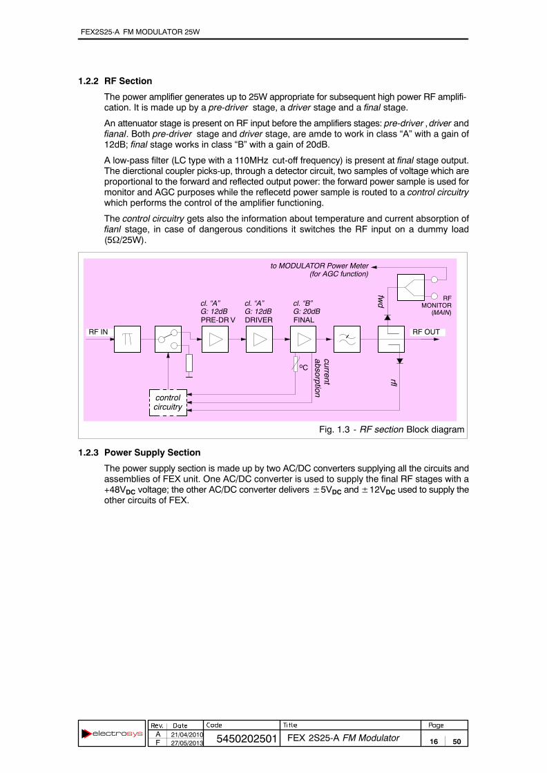
The power amplifier generates up to 25W appropriate for subsequent high power RF amplifi‐cation. It is made up by a pre-driver stage, a driver stage and a final stage.
An attenuator stage is present on RF input before the amplifiers stages: pre-driver , driver andfianal. Both pre-driver stage and driver stage, are amde to work in class “A” with a gain of12dB; final stage works in class “B” with a gain of 20dB.
A low-pass filter (LC type with a 110MHz cut-off frequency) is present at final stage output.The dierctional coupler picks-up, through a detector circuit, two samples of voltage which areproportional to the forward and reflected output power: the forward power sample is used formonitor and AGC purposes while the reflecetd power sample is routed to a control circuitrywhich performs the control of the amplifier functioning.
The control circuitry gets also the information about temperature and current absorption offianl stage, in case of dangerous conditions it switches the RF input on a dummy load(5�/25W).
Fig. 1.3 - RF section Block diagram
oC
RF IN
PRE-DR V DRIVER FINAL
cl. “A”G: 12dB
cl. “A”G: 12dB
cl. “B”G: 20dB
controlcircuitry
fwd
rfl
currentabsorption
RFMONITOR
(MAIN)
RF OUT
to MODULATOR Power Meter(for AGC function)
1.2.3 Power Supply Section
The power supply section is made up by two AC/DC converters supplying all the circuits andassemblies of FEX unit. One AC/DC converter is used to supply the final RF stages with a+48VDC voltage; the other AC/DC converter delivers �5VDC and �12VDC used to supply theother circuits of FEX.

FEX2S25-A FM MODULATOR 25W
17 505450202501 FEX 2S25-A FM ModulatorA 21/04/2010F 27/05/2013
1.3 TECHNICAL CHARACTERISTICS
1.3.1 General data
ENVIRNOMENTAL CONDITIONSOperation temperature range 0°C to +45°CStorage temperature range -40 °C to +70°CRelative humidity 5% to 90%
Altitude a.s.l. up to 3000 m
Ambient air pressure: 65kPa to 105kPa
Cooling system: forced air
AC REQUIREMENTSAC supply 90 to 264V
90 to 253V for EC countries
Frequency 50/60Hz
Power factor 0.9 min.
Power consumption 220VA
MECHANICALFrame: standard 19” - 1HE
Dimensions (wxhxd) (mm): 483x44.5x505
Weight (kg): 15
1.3.2 Remote interfaces
REMOTE INTERFACES
RS-232 for proprietary control protocol
Parallel for simple controls and commands
Ethernet for HTTP, TFTP,SNMP and Telnet protocols
1.3.3 Outputs
PILOT 19KHz
Connector BNC, female
Impedance 50�, unbalanced
Level 1VPP sine wave
RF OUT
Connector , female
Input impedance 50�, unbalanced
Level 25W
RF MONITOR
Connector BNC, female
Input impedance 50�, unbalanced
Level 10dBm at nominal power
FEX2S25-A FM MODULATOR 25W
18 505450202501 FEX 2S25-A FM ModulatorA 21/04/2010F 27/05/2013
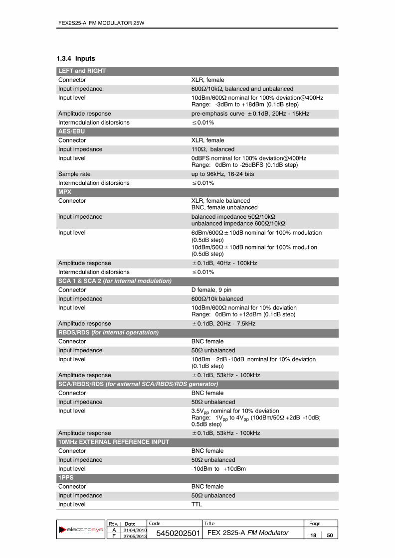
1.3.4 Inputs
LEFT and RIGHT
Connector XLR, female
Input impedance 600�/10k�, balanced and unbalanced
Input level 10dBm/600� nominal for 100% deviation@400HzRange: -3dBm to +18dBm (0.1dB step)
Amplitude response pre-emphasis curve �0.1dB, 20Hz - 15kHz
Intermodulation distorsions �0.01%
AES/EBU
Connector XLR, female
Input impedance 110�, balanced
Input level 0dBFS nominal for 100% deviation@400HzRange: 0dBm to -25dBFS (0.1dB step)
Sample rate up to 96kHz, 16-24 bits
Intermodulation distorsions �0.01%
MPX
Connector XLR, female balancedBNC, female unbalanced
Input impedance balanced impedance 50�/10k�unbalanced impedance 600�/10k�
Input level 6dBm/600��10dB nominal for 100% modulation(0.5dB step)10dBm/50��10dB nominal for 100% modution(0.5dB step)
Amplitude response �0.1dB, 40Hz - 100kHz
Intermodulation distorsions �0.01%
SCA 1 & SCA 2 (for internal modulation)
Connector D female, 9 pin
Input impedance 600�/10k balanced
Input level 10dBm/600� nominal for 10% deviationRange: 0dBm to +12dBm (0.1dB step)
Amplitude response �0.1dB, 20Hz - 7.5kHz
RBDS/RDS (for internal operatuion)
Connector BNC female
Input impedance 50� unbalanced
Input level 10dBm�2dB -10dB nominal for 10% deviation(0.1dB step)
Amplitude response �0.1dB, 53kHz - 100kHz
SCA/RBDS/RDS (for external SCA/RBDS/RDS generator)
Connector BNC female
Input impedance 50� unbalanced
Input level 3.5Vpp nominal for 10% deviationRange: 1Vpp to 4Vpp (10dBm/50� +2dB -10dB;0.5dB step)
Amplitude response �0.1dB, 53kHz - 100kHz
10MHz EXTERNAL REFERENCE INPUT
Connector BNC female
Input impedance 50� unbalanced
Input level -10dBm to +10dBm
1PPS
Connector BNC female
Input impedance 50� unbalanced
Input level TTL

FEX2S25-A FM MODULATOR 25W
19 505450202501 FEX 2S25-A FM ModulatorA 21/04/2010F 27/05/2013
1.3.5 FM Modulator
MODULATOR CHARACTERISTICS
Frequency range 87.5 to 108MHz (1Hz step)
Carrier frequency accuracy �1ppm
Modulation capability �100kHz
Asyncronous AM SNR �80dB below equivalent 100% modulation @ 400Hzand 75 �s deemphasis
Syncronous AM SNR �60dB below equivalent 100% modulation @ 400Hzand 75 �s deemphasis
Spurious and harmonics �90dBc
Pre-emphasis 50 �s (�0.1dB), for CCIR75 �s, for FCC
MPX input FM SNR 90dB below equivalent 100% modulation @ 400Hz and75 �s deemphasis, 22Hz to 22kHz bandwidthunweighted
MPX FM THD + noise �0.01% @ 400Hz, 75 �s deemphasis, 22Hz to 53kHz
FM stereo SNR �80dB below equivalent 100% modulation @ 400Hzand 75 �s deemphasis, 22Hz to 22kHz bandwidthunweighted
FM stereo THD + noise �0.01%, 30Hz to 15kHz
FM mono SNR �90dB below equivalent 100% modulation @ 400Hzand 75 �s deemphasis, 22Hz to 22kHz bandwidthunweighted
FM mono THD + noise �0.01% @ 400Hz, 75 �s deemphasis
L&R stereo separation �60dB, 20Hz to 15kHz
L&R linear cross-talk 90dB below 100% modulation, 20Hz to 15kHz
AES/EBU stereo separation �70dB, 20Hz to 15kHz
MPX Stereo Separation �60dB, 40Hz to 15kHz with MPX stereo separationbetter than 60dB
38/57/67/92 kHz suppression 80dB, below 100% modulation
SCA 1/2 SNR �55dB
SCA 1/2 THD + noise �0.1%, 20Hz to 7.5kHz

FEX2S25-A FM MODULATOR 25W
20 505450202501 FEX 2S25-A FM ModulatorA 21/04/2010F 27/05/2013

FEX2S25-A FM MODULATOR 25W
21 505450202501 FEX 2S25-A FM ModulatorA 21/04/2010F 27/05/2013
2. OPERATING INSTRUCTIONS2.1 INTRODUCTION 23. . . . . . . . . . . . . . . . . . . . . . . . . . . . . . . . . . . . . . . . . . . . . . . . . 2.2 LEGEND 23. . . . . . . . . . . . . . . . . . . . . . . . . . . . . . . . . . . . . . . . . . . . . . . . . . . . . . . . . 2.3 MAINS CONNECTION 26. . . . . . . . . . . . . . . . . . . . . . . . . . . . . . . . . . . . . . . . . . . . 2.4 SWITCHING ON/OFF 26. . . . . . . . . . . . . . . . . . . . . . . . . . . . . . . . . . . . . . . . . . . . . 2.5 REMOTE CONTROL 26. . . . . . . . . . . . . . . . . . . . . . . . . . . . . . . . . . . . . . . . . . . . . . 2.6 USING THE CONTROLLER 26. . . . . . . . . . . . . . . . . . . . . . . . . . . . . . . . . . . . . . . . 2.6.1 Keyboard functions 27. . . . . . . . . . . . . . . . . . . . . . . . . . . . . . . . . . . . . . . . . . . . . . . . 2.6.2 General information on data displaying 27. . . . . . . . . . . . . . . . . . . . . . . . . . . . . . 2.6.3 Typographical Convections 28. . . . . . . . . . . . . . . . . . . . . . . . . . . . . . . . . . . . . . . . . 2.6.4 Enabling/disabling and resetting the alarms storage 29. . . . . . . . . . . . . . . . . . . 2.7 MENU AND CONTENTS 30. . . . . . . . . . . . . . . . . . . . . . . . . . . . . . . . . . . . . . . . . . . 2.8 CHANGING THE TRANSMISSION FREQUENCY 41. . . . . . . . . . . . . . . . . . . . . 2.9 REGULATION OF RF OUTPUT POWER 41. . . . . . . . . . . . . . . . . . . . . . . . . . . . 2.10 CALIBRATIONS AND SETTINGS 41. . . . . . . . . . . . . . . . . . . . . . . . . . . . . . . . . . . 2.10.1 Settings for N+1 system 41. . . . . . . . . . . . . . . . . . . . . . . . . . . . . . . . . . . . . . . . . . .
LIST OF TABLESTab. 2.1 - FEX 2S25-A FM Exciter front panel legend (ref. Fig. 2.1) 24. . . . . . . . . . . . . . Tab. 2.2 - FEX 2S25-A FM Exciter rear panel legend (ref. Fig. 2.2) 25. . . . . . . . . . . . . . Tab. 2.3 - Pin-out assignment of the PARALLEL I/O connector 26. . . . . . . . . . . . . . . . . . Tab. 2.4 - List of indications and symbols used on screen-shots 28. . . . . . . . . . . . . . . . . Tab. 2.5 - Alarms list of History Log 40. . . . . . . . . . . . . . . . . . . . . . . . . . . . . . . . . . . . . . . . . .
LIST OF ILLUSTRATIONSFig. 2.1 - FEX 2S25-A FM Exciter front panel 24. . . . . . . . . . . . . . . . . . . . . . . . . . . . . . . . . Fig. 2.2 - FEX 2S25-A FM Exciter rear panel 25. . . . . . . . . . . . . . . . . . . . . . . . . . . . . . . . . Fig. 2.3 - Typical data displaying 27. . . . . . . . . . . . . . . . . . . . . . . . . . . . . . . . . . . . . . . . . . . .
CH
AP
TE
R 2:
OP
ER
AT
ING
INS
TR
UC
TIO
NS
2

FEX2S25-A FM MODULATOR 25W
22 505450202501 FEX 2S25-A FM ModulatorA 21/04/2010F 27/05/2013

FEX2S25-A FM MODULATOR 25W
23 505450202501 FEX 2S25-A FM ModulatorA 21/04/2010F 27/05/2013
2. OPERATING INSTRUCTIONS
2.1 INTRODUCTION
This chapter describes the operative functions, controls and correct ways in which to useFEX. The contents of the present chapter are arranged in paragraphs according to the follow‐ing:
- 2.2: Legend
- 22.3: Mains connection
- 22.4: Switching on/off
- 22.5: Parallel I/O connector pin-out assignment
- 22.6: Using the controller
- 22.7: Menu and contents
- 22.8: Changing the transmission frequency
- 22.9: regulation of rf output power
- 22.10: Calibrations and settings
2.2 LEGEND
The front panel of FEX is shown in Fig. 2.1; Tab. 2.1 refers to this figure, each number of thetable marks an indicator, a fuse or a connector located on the front panels of the unit.
Fig. 2.2 shows the rear panel of FEX; Tab. 2.2 refers to this figure, each number of the tablemarks an indicator, a fuse or a connector located on the rear panels of the unit.
From now on, every reference to indicators, fuses or connectors is carried out by indicating(between parentheses) the corresponding identification number with which is marked onFig. 2.1 and Fig. 2.2. A simple description of the function carried out is given for each number.

FEX2S25-A FM MODULATOR 25W
24 505450202501 FEX 2S25-A FM ModulatorA 21/04/2010F 27/05/2013
Fig. 2.1 - FEX 2S25-A FM Exciter front panel
1 2 3
6
4 5
Tab. 2.1 - FEX 2S25-A FM Exciter front panel legend (ref. Fig. 2.1)
No. LABEL FUNCTION
1 LCD display of the unit (40 characters, 2 lines); displays informationand data relevant to the functioning of FEX.
ÁÁÁÁÁÁÁÁ
2 ÁÁÁÁÁÁÁÁÁÁÁÁÁÁ
ESCAPE ÁÁÁÁÁÁÁÁÁÁÁÁÁÁÁÁÁÁÁÁÁÁÁÁÁÁÁÁÁÁÁÁÁÁÁÁÁÁÁÁ
Push-button; it allows to quit from the current menu.
3 Controller keyboard. It allows accessing the menu (listed on right-‐hand side of the display) and setting the functioning parameters ofFEX.Accessing the menu and setting of the parameter is as follows:- ”�” and ”�” arrows select the menus (shown between < and >
symbols); once accessed the menu, they select the digit to bechanged.
- ”�” and ”�” arrows allow scrolling the parameters of each menu.- “ENTER” key is used to set the selected parameter and to enter the
setting carried out. A confirmation is requested at the end of theoperation, pushing ”�” arrow.
4 LOCAL Led indicator (yellow); indicates FEX is operating under local control
RF PRES. Led indicator (green/red); indicates FEX status according to thecolours, as follows:
GREEN indicates FEX is delivering its nominal RF output power;RED when FEX is in STOP condition (EXCITER RF=OFF); under
this condition STATUS led is off.
STATUS Led indicator (green/red/yellow); indicates FEX status according tothe colours, as follows:
GREEN indicates FEX is delivering its nominal RF output power;RED indicates a failure condition of FEX (no RF ouput power);YELLOW indicates a warning condition of FEX (FEX is still working);OFF when FEX is in STOP condition (EXCITER RF=OFF).
5 MAIN Monitor connector (BNC female); it allows monitoring the RF outputsignal of the unit.
6 MAINS Push-button; it is the power switch of the unit. The associated greenled is lit when the unit is switched-on.

FEX2S25-A FM MODULATOR 25W
25 505450202501 FEX 2S25-A FM ModulatorA 21/04/2010F 27/05/2013
3
2 1
3
2 1
3
2 1
3
2 1
Fig. 2.2 - FEX 2S25-A FM Exciter rear panel
2 4 5 61 3 7 98 10 11
12131415161718
Tab. 2.2 - FEX 2S25-A FM Exciter rear panel legend (ref. Fig. 2.2)
No. LABEL FUNCTION
1 LINE Line socket.
2 RF OUT Connector (N female); RF signal output of FEX.
3 LAN Connector (RJ45); it allows ethernet control and monitoring overHTTP (web server), TFTP, SNMP, Telnet protocols
4 1PPS Connector (BNC female); it is the input for 1PPS signal.
5 AES/EBU Set of 2 input connectors for AES/EBU digital signal. A “XLR” and a“TOSLINK” connectors are available: the second one allows the con‐nection via optical fiber.
6 ETH-UPLOAD Connector (9 pin/D male); it allows the firmware upgrade of the WebServer and the SNMP manager using an RS232 serial line.
7 RS232 Connector (9 pin/D male); it allows the connection via an RS232serial line by external RS232 master applications.
8 REMOTE I/O Connector (25 pin female); it is the parallel interface connector out‐wards.
9 MPX Connector (XLR female); it is the analog input for an MPX signal.
10 RIGHT Connector (XLR female);it is the input of right channel, for a stereosignal.
11 LEFT Connector (XLR female);it is the input of left channel, for a stereosignal.
12 MPX Connector (BNC female); it is the analog input for an MPX signal.
13 RBDS/RDS Connector (BNC female); it is the analog input for:- an RBDS signal.- an RDS signal;
14 SCA/RBDS/RDS Connector (BNC female); it is the analog input for:- an SCA subcarrier;- an RDS signal;- an RBDS signal
15 SCA Connector (9 pin/D female); it is the analog input for SCA subcarrier.
16 10MHz Connector (BNC female); input of 10MHz external reference fre‐quency.
17 PILOT 19KHz OUTPUT Connector (BNC female); output of 19KHz pilot tone for synchroniz‐ing an external stereo coder.
18 Grounding screw of unit frame.

FEX2S25-A FM MODULATOR 25W
26 505450202501 FEX 2S25-A FM ModulatorA 21/04/2010F 27/05/2013
2.3 MAINS CONNECTION
The unit is connected to the mains by means of line socket ([1] on Fig. 2.2) located on rearpanel. The mains must have the following characteristics:
� 230 Vac � 10 %, 50/60 Hz.
A suitable external protection must be used with a maximum current of 6A.
2.4 SWITCHING ON/OFF
The unit is switched on by pressing the power switch ([6] on Fig. 2.1) located on the frontpanel; the associated green led lights up.
2.5 REMOTE CONTROL
Transmitter remote control is allowed via web server and via parallel interface.
REMOTE CONTROL VIA WEB SERVER
Transmitter remote control is allowed through an “Ethernet” connector available on rearpanel of the unit ([3] on Fig. 2.2). For accessing web type the address (i.e.: 192.4.0.186)associated to the unit.
Further details about ETHERNET interfaces and connection protocols, are given in Appen‐dix: Ethernet Iterface Installation Guide.
REMOTE CONTROL VIA PARALLEL INTERFACE
All the main functions of the unit can be remote controlled via “REMOTE I/O” connector arran‐ged on unit rear panel ([8] on Fig. 2.2). The remote control can be performed by means of freecontacts (open/closed), managed by relay line. The pin-out assignment is listed in the follow‐ing Tab. 2.3 (see also J4 connector on “Remote I/O Interface” dwg. no. 4050006010ED).
Tab. 2.3 - Pin-out assignment of the PARALLEL I/O connectorPIN FUNCTION NOTE PIN FUNCTION NOTE
1 COMMON TLS 14 RF OFF (TLC) 3
2 +24V REM 1 15 PROG1 (TLS) 2
3 RF OFF (TLS) 2 16 RESET (TLC) 3
4 RF ON (TLS) 2 17 EXT. INTERLOCK (TLC) 3-4
5 +24V EXT 1 18 RF ON (TLC) 3
6 SQUELCH ABSENT (TLS) 2 19 PROG2 (TLS) 2
7 SQUELCH PRESENT (TLS) 2 20 PROG3 (TLS) 2
8 FAULT (TLS) 2 21 REMOTE (TLS) 2
9 RF PRESENT (TLS) 2 22 LOCAL (TLS) 2
10 PROG4 (TLS) 2 23 POWERED (TLS) 2
11 PROG5 (TLS) 2 24 NOT POWERED (TLS) 2
12 NOT USED 25 NORMAL (TLS) 2
13 COMMON TLS
_______________________________________________________________________________NOTES(1) “Remote I/O” port needs an external +24VDC on pin 5, for normal opertaing conditions. As alterna‐
tive pin 5 must be linked to pin 2 delivering an internal +24VDC voltage.(2) TLS need an external pull-up with a voltage level set by the operator.(3) TLC must be pulses (500ms minimum duration) to ground.(4) This pin must be connected to ground otherwise the exciter does not deliver RF power. If a ground
connection is not available, access < EXCITER RF OUT > menu and execute:[�] INTERLOCK > [ENTER] > [� or �] CLOSE [ENTER] > [�]� If pin 4 is connected to ground, INTERLOCK may set CLOSE or OPEN.
2.6 USING THE CONTROLLER
The controller allows monitoring and/or setting the functioning parameters of the unit. For thepurpose several menus are available to the operator who accesses them by the keyboard onunit front panel ([3] on Fig. 2.1). The controller can be used either locally (by means of therelevant keyboard,[3] on Fig. 2.1) or remotely by a supervisory software.

FEX2S25-A FM MODULATOR 25W
27 505450202501 FEX 2S25-A FM ModulatorA 21/04/2010F 27/05/2013
2.6.1 Keyboard functions
Accessing the menu and setting of the parameter is as follows:
� ”�” and ”�” arrows select the menus (shown between < and > symbols); once accessedthe menu, they select the digit to be changed.
� ”�” and ”�” arrows allow scrolling the parameters of each menu.
� “ENTER” key is used to enter the selected parameter (pointers will blink). A confirmation ofthe setting carried out, is required.If no setting is performed within about 10 sec, the controller exits from the editing mode.
� “ESCAPE” push-button allows to quit from the current menu.
KEEP IN MIND THAT:
if the parameter to be set is numerical, the digit to be changed must be selected bymeans of ”�” and ”�” arrows of the keyboard ; the current digit is underscored; ”�”arrow increases the value, ”�” arrow decreases the value. Confirm the settingpressing ”ENTER”.The controller will display: ARE YOU SURE?Press ”�” arrow (YES) for confirmation or ”�” arrow (NO) in order to cancel the set‐ting.For non-numerical parameters (or better for the ones which have a limited numberof options, also numerical) ”�” and ”�” arrows change directly to next option.During the set-up, 10 seconds are available for next setting. If no key is pressedwithin about 10 sec, the settings will be cancelled.At the end of the set-up, 10 seconds are available for the confirmation, otherwisethe settings will be cancelled.
2.6.2 General information on data displaying
At the switching-on FEX displays “FM Exciter loading....” after a while and then data relevantto RF ouput power and transmission frequency along with the current menu. The menudisplayed at the switching-on, is always < EXCITER RF OUT >.
In order to access a menu it is necessary to quit from the current one: to quit from an accessedmenu press “ESCAPE” key (this causes going back to the first parameter of the current menu).Now ”�” and ”�” arrows of the keyboard allow accessing the other menu.
The following Fig. 2.3 shows a typical data displaying along with and explanation of symboland items.
Tab. 2.4 lists indications and symbols displayed, and also gives a short explanation for eachof them.
output powerindication
Fig. 2.3 - Typical data displaying
currentmenu
R < MODULATOR > M C
MPX OK � 5 ��
PWR25W
FREQ.96.00 MHZ
indicates the counting ofthe alarms is enabled
(if disabled � is shown)
number ofalarms occurred
currentparameter
status(OK/WRN/ALM)
settableparameter
displayed if RAMlosses data
displayed if FLASHlosses data
indicates RS232 serial portis enabled for remote control
(if Ethernet port is enabled� is displayed)
transmission frequencyindication

FEX2S25-A FM MODULATOR 25W
28 505450202501 FEX 2S25-A FM ModulatorA 21/04/2010F 27/05/2013
Tab. 2.4 - List of indications and symbols used on screen-shots
symbol meaning
< > Indicate a menu including submenus
�� On right-hand side of a parameter, indicates it is settable
� On right-hand side of a parameter, indicates it is a read-only one.
� On right-hand side of a parameter, indicates that the counting of the rele‐vant alarm has been enabled.
� On right-hand side of a parameter, indicates that the counting of the rele‐vant alarm has been disabled.
R On left-hand side of a < MENU > indicates a parameters loss of the RAM
M On right-hand side of a < MENU > indictaes a parameters loss of theFLASH
C On right-hand side of a < MENU > indicates RS232 seral port (on unit rearpanel) is enabled
� On right-hand side of a < MENU > indicates Ethernet port (on unit rearpanel) is enabled
2.6.3 Typographical Convections
Form now on, throughout this manual the commands that you have to execute will be shownin Courier type, the keys are referred [between parentheses]: when you are instructed toexecute a setting, the sequence of the steps is illustrated by “ > “ as follows:
- [� or �] SOFT LIMITER TH > [�] STEREO ENC > [ENTER] >
[� or �] [� or �] [ENTER] > [�]
arrow key(selection)
menuselected
arrow key(parameter selection)
parameterselected
ENTER key(enters setting mode)
arrow key(digit selection)
arrow key(setting value)
ENTER key(enters datum)
arrow key(setting confirmation)
FEX2S25-A FM MODULATOR 25W
29 505450202501 FEX 2S25-A FM ModulatorA 21/04/2010F 27/05/2013
2.6.4 Enabling/disabling and resetting the alarms storage
Functioning parameters of FEX may generate alarms (ALM) or warning (WRN) conditions.An alarm condition stops the exciter and causes “RF PRES” and “FAULT” leds lights-up (red)while a warning condition causes only “FAULT” led lights-up (yellow) and FEX goes on deliv‐ering RF power.
Alarms and warning events are stored on < HISTORY > menu only if the relevant alarm/warn‐ing is enabled (“ � ” symbol displayed), under this condition the related counter will beincreased when that alarm/warning will occur.
� Enabling alarms/warning events1. Select the menu of parameter involved, with “�” or “�” key.2. Select parameter, with ”�” or ”�” keys.3. Press “ENTER” key and select ”EN” with ”�” or ”�” key.4. Press “ENTER” key again and “ � ” symbol is displayed to indicate the alarm/warning
enabling.
� Disabling alarms/warning events1. Select the menu of parameter involved, with “�” or “�” key.2. Select parameter, with ”�” or ”�” keys.3. Press “ENTER” key and select ”DS” with ”�” or ”�” key.4. Press “ENTER” key again and “ � ” symbol is displayed to indicate the alarm/warning dis‐
abling. Under this condition the status is “OK”.
� Resetting alarms/warning counter1. Select the menu of parameter involved, with “�” or “�” key.2. Select parameter, with ”�” or ”�” keys.3. Press “ENTER” key and select ”RS” with ”�” or ”�” key.4. Press “ENTER” key again and “0” is displayed to indicate the alarm/warning resetting.

FEX2S25-A FM MODULATOR 25W
30 505450202501 FEX 2S25-A FM ModulatorA 21/04/2010F 27/05/2013
2.7 MENU AND CONTENTS
< EXCITER RF OUT >EXCITER RF �� enables (ON) disables (OFF) the RF outputPOWER SET �� sets RF output power of the exciter from -7dB through
0.9dB in respect to the nominal output power (25W).
INTERLOCK �� displays status of interlock chain (“CLOSE” or “OPEN” flag).It is also possible to enable/disable the alarm conditionrelevant to interlock chain. The number on right-hand side,indicates how many times the alarm condition has occurred.
AGC �� enables (ON) disables (OFF) AGC (Automatic Gain Con‐trol) function.
MAN. GAIN �� sets gain value (0/1023).
If AGC = OFF fixes the RF output power;
if AGC = ON fix the upper threshold for RF output power.FILT. GAIN �� sets output filter gain value (0/1023).
NOTE Enabled only when “Full Scale” of FACTORY menu has been setat 1 or 2KW.
< EXCITER STATUS >POWER OUT � displays current value of RF output power (Watt) of the unitINPUT � displays input status:
- NORMAL- LOW- OVERDRIVE- ABSENT
MODULATOR � displays modulator status:- NORMAL- FAULT- WARNING
OPERAT. MODE �� sets the operating mode of FEX (LOCAL/REMOTE). Thenew setting must be confirmed.- LOCAL :set-up of exciter parameters is allowed only
locally, but via web server it is possible display‐ing parameters set-up, alarms and history.
- REMOTE: set-up of exciter parameters is allowed onlyremotely. Anyhow for “FACTORY” menu isrequested the password.
1PPS XXX REF. XXX � displays status of the external reference (PRST/ABST).Exciter Elapsed Time:HOURS � displays working hours of the unit
Exc. settings backup: �
� Save Settings �� allows saving the current settings of the parameters (i.e.:when you want change some of them for testing FEX andthen you want to restore the previous settings). The newsetting must be confirmed.
� Restore Settings �� restores the last settings saved with “� Save Settings”.RTC Settings: Real Time ClockSECOND �� sets the value of the field “second”MINUTE �� sets the value of the field “minute”HOUR �� sets the value of the field “hour”
DAY �� sets the value of the field “day”MONTH �� sets the value of the field “month”YEAR �� sets the value of the field “year”WARMUP TIMER �� sets time interval within which alarm conditions are ignored
(range 5 to 50sec., pre-set at 20 sec.)

FEX2S25-A FM MODULATOR 25W
31 505450202501 FEX 2S25-A FM ModulatorA 21/04/2010F 27/05/2013
< INPUT >IN USE � displays the input type:
- MAIN- SECONDARY
MAIN INPUT �� sets the mian input type:- ANALOG: analog left and right inputs- AES EBU: digital AES/EBU left and right inputs- MPX: analog lMPX input
SEC. INPUT �� sets the secondary backup input type:- ANALOG: analog left and right inputs- AES EBU: digital AES/EBU left and right inputs- MPX: analog lMPX input- NOTHING: no secondary input selected.If SEC INPUT = NOTHING, the modulator must use only themain input.
INPUT SEL. �� sets the operative input:- MAIN- SEC.
If SEL MODE = MANUAL it sets the operative input (MAIN/‐SEC).If SEL MODE = AUTO it sets the highest priority input(MAIN/SEC) and the modulator uses this input (if present)according to the following table:
INPUT SEL MAIN SEC INPUT IN USEMAIN ABST ABST MAINMAIN ABST PRST SECMAIN PRST ABST MAINMAIN PRST PRST MAINSEC ABST ABST SECSEC ABST PRST SECSEC PRST ABST MAINSEC PRST PRST SEC
If SEC INPUT = NOTHING, the modulator must use always maininput.
SEL. MODE �� sets the selection mode (MANUAL/AUTO) of the inputs.- MANUAL: the modulator uses main or secondary
input according to “INPUT SEL” setting. Forexample if INPUT SEL = SEC the modula‐tor uses the secondary input.
- AUTO: the modulator uses main or secondaryinput according to the following table:INPUT SEL MAIN SEC INPUT IN USEMAIN ABST ABST MAINMAIN ABST PRST SECMAIN PRST ABST MAINMAIN PRST PRST MAINSEC ABST ABST SECSEC ABST PRST SECSEC PRST ABST MAINSEC PRST PRST SEC
If INPUT SEL is lost, the modulator switches to the otherinput, if present, after an adjustable delay (CH. OVERDELAY).If INPUT SEL returns, the modulator switches back to thisinput, after an adjustable delay (RESTORE DELAY) only ifthe “IN. AUTO STORE” function is enabled.If SEC INPUT = NOTHING the modulator uses the maininput.
CH.OVER DELAY �� sets change-over time delay from 0 to 255 sec..See SEL. MODE description for further details.
RESTORE DELAY �� sets restore delay time from 0 to 255 sec.See SEL. MODE description for further details.

FEX2S25-A FM MODULATOR 25W
32 505450202501 FEX 2S25-A FM ModulatorA 21/04/2010F 27/05/2013
IN.AUTOSTORE �� enables (ON) disables (OFF) the INPUT AUTO RESTOREfunction.
AES/EBU IN USE � displays the input connector in use:- OPT- XLR
AES/EBU SEL. �� If AES/EBU MODE = MANUAL, it sets the operative digital input(XLR, TOSLIINK).If AES/EBU MODE = AUTO, it sets the highest priority digitalinput (XLR, TOSLIINK) and the modulator uses this input (ifpresent) according to the following table:
SEL AES/EBU XLR TOSLINK DIGITAL INPUT INUSEXLR ABST ABST XLRXLR ABST PRST TOSLINKXLR PRST ABST XLRXLR PRST PRST XLRTOSLINK ABST ABST TOSLINKTOSLINK ABST PRST TOSLINKTOSLINK PRST ABST XLRTOSLINK PRST PRST TOSLINK
AES/EBU MODE �� sets the selection mode (MANUAL/AUTO) of the digitalinputs.- MANUAL: the modulator uses XLR or TOSLINK input
according to “AES/EBU SEL” setting. Forexample if AES/EBU = XLR the modulatoruses always XLR input.
- AUTO: the modulator uses XLR or TOSLINK inputaccording to the following table:INPUT SEL MAIN SEC INPUT IN USEMAIN ABST ABST MAINMAIN ABST PRST SECMAIN PRST ABST MAINMAIN PRST PRST MAINSEC ABST ABST SECSEC ABST PRST SECSEC PRST ABST MAINSEC PRST PRST SEC
SCA �� sets the SCA input type:- OFF: no SCA signal- EXTERNAL: SCA from external source (SCA/RBDS/‐
RDS BNC connectors)- INTERNAL 1: analog audio input for internal generation of
67kHz SCA- INTERNAL 2: analog audio input for SCA internal genera‐
tion of 92kHz SCA- INTERNAL 1+2 both 67kHz and 92kHz SCA internal gener‐
ation.
RDS/RBDS �� sets the RBDS RDS input type:- OFF: no RBDS/RDS- EXTERNAL: RBDS/RDS from external source (RBDS/‐
RDS BNC connectors)- INTERNAL: NOT AVAILABLE

FEX2S25-A FM MODULATOR 25W
33 505450202501 FEX 2S25-A FM ModulatorA 21/04/2010F 27/05/2013
< ATTENUATION >LEFT �� sets input level attenuation of left signal (-15.0dB/+10.0dB).RIGHT �� sets input level attenuation of right signal
(-15.0dB/+10.0dB).
MPX �� sets input level attenuation of MPX signal(-10.0dB/+10.0dB; 0.5dB steps).� Digits are not underscored
SCA 1 �� sets input level attenuation of SCA 1 (67kHz) signal(-10.0dB/+1.9dB).
SCA 2 �� sets input level attenuation of SCA 2 (92kHz) signal(-10dB/+1.9dB).
RDS/RBDS �� sets input level attenuation of RDS/RBDS signal(-10.0dB/+10.0dB; 0.5dB steps).� Digits are not underscored
SCA/RDS/RBDS �� sets input level attenuation of SCA/RDS/RBDS signal(-10.0dB/+1.9dB).
AES/EBU �� sets the input level gain of AES/EBU signal (-25dB/0dB).< DEVIATION >
AUDIO 1 � displays frequency deviation (in kHz) of the relevant inputAUDIO 2 � displays frequency deviation (in kHz) of the relevant input
MPX � displays frequency deviation (in kHz) of the relevant inputSCA 1 � displays frequency deviation (in kHz) of the relevant inputSCA 2 � displays frequency deviation (in kHz) of the relevant inputRDS/RBDS � displays frequency deviation (in kHz) of the relevant inputSCA/RDS/RBDS � displays frequency deviation (in kHz) of the relevant inputST.COD.PILOT � displays frequency deviation (in kHz) of the relevant inputCOMPOSITE � displays frequency deviation (in kHz) of the relevant input
< INPUT PRESENCE >ANALOG �� enables/disables the alarm condition relevant to the
absence of ANALOG input. The input status is also dis‐played with an “OK” or “WRN” flag. The number on right-‐hand side, indicates how many times the alarm conditionhas occurred.Further details for enabling/disabling alarms on para. 2.6.4.
MPX �� enables/disables the alarm condition relevant to theabsence of MPX input. The input status is also displayedwith an “OK” or “WRN” flag. The number on right-handside, indicates how many times the alarm condition hasoccurred.Further details for enabling/disabling alarms on para. 2.6.4.
AES/EBU XLR �� enables/disables the alarm condition relevant to theabsence of AES EBU input on XLR connector. The inputstatus is also displayed with an “OK” or “WRN” flag. Thenumber on right-hand side, indicates how many times thealarm condition has occurred.Further details for enabling/disabling alarms on para. 2.6.4.
AES/EBU OPT �� enables/disables the alarm condition relevant to theabsence of AES EBU input on TOSLINK connector. Theinput status is also displayed with an “OK” or “WRN” flag.The number on right-hand side, indicates how many timesthe alarm condition has occurred.Further details for enabling/disabling alarms on para. 2.6.4.

FEX2S25-A FM MODULATOR 25W
34 505450202501 FEX 2S25-A FM ModulatorA 21/04/2010F 27/05/2013
RDS/RBDS �� enables/disables the alarm condition relevant to theabsence of RDS RBDS input. The input status is also dis‐played with an “OK” or “WRN” flag. The number on right-‐hand side, indicates how many times the alarm conditionhas occurred.Further details for enabling/disabling alarms on para. 2.6.4.
SCA/RDS/RBDS �� enables/disables the alarm condition relevant to theabsence of SCA RDS RBDS input. The input status is alsodisplayed with an “OK” or “WRN” flag. The number onright-hand side, indicates how many times the alarm condi‐tion has occurred.Further details for enabling/disabling alarms on para. 2.6.4.
PILOT LEVEL �� enables/disables the alarm condition relevant to the level of19KHz Pilot tone of the internal stereo encoder. The inputstatus is also displayed with an “OK” or “WRN” flag. Thenumber on right-hand side, indicates how many times thealarm condition has occurred.Further details for enabling/disabling alarms on para. 2.6.4.
COMP.H.LIM. �� enables/disables the alarm condition relevant to the level ofthe hard limiter. The status is also displayed with an “OK” or“WRN” flag. The number on right-hand side, indicates howmany times the alarm condition has occurred.Further details for enabling/disabling alarms on para. 2.6.4.
< SOFT LIMITER TH >
NOTE “Soft Limiter” acts only if the deviation of the relevant input over‐comes the preset threshold (OVERDRIVE ALARM). The interven‐tion is not instantaneous and the delay time of the intervention isadjustable.
STEREO ENC �� sets threshold value (50 to 200kHz) of the alarm for freq.deviation overdrive of the stereo encoder. “Soft limiter” doesnot affect the pilot tone but only left and right audio signals.
MPX �� sets threshold value (50 to 200kHz) of the alarm for freq.deviation overdrive of MPX signal. “Soft limiter” does notaffect the pilot tone but only left and right audio signals.
DELAY TIME �� sets the delay time (HIGH/LOW/MEDIUM) of soft limiterintervention as follows:- HIGH 1 sec. approx (advised);- MEDIUM 0.4 sec.;- LOW 0.2 sec.
< HARD LIMITER TH >HARD LIM. �� sets the threshold value (range 50 to 200kHz) of the alarm
for freq. deviation overdrive of the inputs. The interventionof this circuit is faster than the “soft limiter” circuit.
SCA 1 �� sets the threshold value (range 6 to 12kHz) of the alarm forfreq. deviation overdrive of SCA 1 signal.
SCA 2 �� sets the threshold value (range 6 to 12kHz) of the alarm forfreq. deviation overdrive of SCA 2 signal.
< PREEMPHASIS >ANALOG �� disables (OFF) preemphasis filter or sets the preemphasis
value of the filter (50�s/75�s) on analog input.
SCA 1 �� disables (OFF) preemphasis filter or sets the preemphasisvalue of the filter (50�s/75�s) on SCA 1 input.
SCA 2 �� disables (OFF) preemphasis filter or sets the preemphasisvalue of the filter (50�s/75�s) on SCA 2 input.

FEX2S25-A FM MODULATOR 25W
35 505450202501 FEX 2S25-A FM ModulatorA 21/04/2010F 27/05/2013
< IMPEDANCE >ANALOG �� sets the impedance of the relevant input:
- HIGH- 600 OHM
MPX �� sets the impedance of the relevant input:- UNBAL. 50 OHM- UNBAL. HIGH- BALAN. 600 OHM- BALAN. HIGH
SCA �� sets the impedance of the relevant input:- HIGH- 600 OHM
< OVERDRIVE >AUDIO 1 �� enables/disables the alarm condition relevant to an overdri‐
ve of AUDIO 1 input. The input status is also displayed withan “OK” or “WRN” flag. The number on right-hand side,indicates how many times the alarm condition has occurred.Further details for enabling/disabling alarms on para. 2.6.4.
AUDIO 2 �� enables/disables the alarm condition relevant to an overdri‐ve of AUDIO 2 input. The input status is also displayed withan “OK” or “WRN” flag. The number on right-hand side,indicates how many times the alarm condition has occurred.Further details for enabling/disabling alarms on para. 2.6.4.
SCA 1 �� enables/disables the alarm condition relevant to an overdri‐ve of SCA 1 input. The input status is also displayed with an“OK” or “WRN” flag. The number on right-hand side, indi‐cates how many times the alarm condition has occurred.Further details for enabling/disabling alarms on para. 2.6.4.
SCA 2 �� enables/disables the alarm condition relevant to an overdri‐ve of SCA 2 input. The input status is also displayed with an“OK” or “WRN” flag. The number on right-hand side, indi‐cates how many times the alarm condition has occurred.Further details for enabling/disabling alarms on para. 2.6.4.
MPX �� enables/disables the alarm condition relevant to an overdri‐ve of MPX input. The input status is also displayed with an“OK” or “WRN” flag. The number on right-hand side, indi‐cates how many times the alarm condition has occurred.Further details for enabling/disabling alarms on para. 2.6.4.
< MODULATOR >ENCODER �� sets the encoder type:
- RIGHT MONO: the modulator uses only the right audioinput without stereo encoding;
- LEFT MONO: the modulator uses only the left audio inputwithout stereo encoding;
- L+R MONO: the modulator uses the sum of left and rightaudio inputs without stereo encoding;
- STEREO: the modulator performs the stereo encod‐ing using left and right analog inputs.
FREQ.: �� sets the operative frequency (frequency range from87500000Hz to 108000000MHz).

FEX2S25-A FM MODULATOR 25W
36 505450202501 FEX 2S25-A FM ModulatorA 21/04/2010F 27/05/2013
< MODULATOR ALARM >DAC �� enables/disables the alarm condition relevant to DAC. The
status is also displayed with an “OK” or “ALM” flag. Thenumber on right-hand side, indicates how many times thealarm condition has occurred. This check is performed onlyat the power up (FAULT status).Further details for enabling/disabling alarms on para. 2.6.4.
PLL 115MHz �� enables/disables the alarm condition relevant to PLL115MHz circuit. The status is also displayed with an “OK” or“ALM” flag. The number on right-hand side, indicates howmany times the alarm condition has occurred.Further details for enabling/disabling alarms on para. 2.6.4.
VCXO �� enables/disables the alarm condition relevant to VCXO(unlocked). The status is also displayed with an “OK” or“ALM” flag. The number on right-hand side, indicates howmany times the alarm condition has occurred.Further details for enabling/disabling alarms on para. 2.6.4.
VCO �� enables/disables the alarm condition relevant to VCO(unlocked). The status is also displayed with an “OK” or“ALM” flag. The number on right-hand side, indicates howmany times the alarm condition has occurred.Further details for enabling/disabling alarms on para. 2.6.4.
DCM �� enables/disables the alarm condition relevant to DCM(unlocked). The status is also displayed with an “OK” or“ALM” flag. The number on right-hand side, indicates howmany times the alarm condition has occurred.Further details for enabling/disabling alarms on para. 2.6.4.
TEMPERATURE � displays the temperature of the modulator board< REFERENCE >
REFERENCE �� set the type of the frequency reference:- INTERNAL set the internal reference of the unit. 10MHz. . . .
internal reference is adjusted by INT. REF.TUNE menu (see the relevant item).
- EXTERNAL set an external reference. 10MHz internal. . . . reference is locked to the external one, onlyif this last is present, otherwise the exciterworks with the internal reference.
INT.REF.TUNE �� allows adjusting 10MHz internal reference.1PPS �� enables/disables the locking of the unit to 1PPS signal from
GPS if properly connected. Under this conditions Time Off‐set and Phase Offset parameters are enabled.
T. DELAY �� sets the delay time of the FM signal.PHASE OFFSET �� sets the phase displacement of 19KHz pilot tone.
10MHz EXT �� displays the status of 10MHz Ext Reference (“LOCK” or“UNLCK” flag). It is also possible to enable/disable thealarm condition relevant to 10MHz Ext Reference. Thenumber on right-hand side, indicates how many times thealarm condition has occurred. This check is performed onlyat the power up (FAULT status).Further details for enabling/disabling alarms on para. 2.6.4.
NOTE Enabled only if REFERENCE=EXTERNAL and 1PPS=LOCK
1PPS �� displays the status of 1PPS. It is also possible to enable/‐disable the alarm condition relevant to 1PPS. The status isalso displayed with a “LOCK” or “UNLCK” flag. The numberon right-hand side, indicates how many times the alarmcondition has occurred. This check is performed only at thepower up (FAULT status).Further details for enabling/disabling alarms on para. 2.6.4.
NOTE Enabled only if REFERENCE=EXTERNAL and 1PPS=LOCK

FEX2S25-A FM MODULATOR 25W
37 505450202501 FEX 2S25-A FM ModulatorA 21/04/2010F 27/05/2013
< EXC RF OUT Alarm >POWER OUT �� enables/disables the alarm condition relevant to RF output
power, if this one is under the preset threshold (see THmenu). The output status is also displayed with an “OK” or“ALM” flag. The number on right-hand side, indicates howmany times the alarm condition has occurred.Further details for enabling/disabling alarms on para. 2.6.4.
EXC RF OUT TH �� sets alarm threshold (dB) for RF output power from -10dBthrough -1dB in respect to the nominal output power (25W).
REFLECTED � displays value (W) of the reflected powerREFLEC TH �� sets alarm threshold of the reflected power (-13 to -7dB).48V OVERCUR �� enables/disables the alarm condition relevant to an exces‐
sive current absorption of 48VDC power supply of the RFstages. The power supply status is also displayed with an“OK” or “ALM” (on reverse field) flag. The number on right-‐hand side, indicates how many times the alarm conditionhas occurred.Further details for enabling/disabling alarms on para. 2.6.4.
TEMP. HPA � displays heatsink temperature of the RF stages.TEMP. HPA TH �� sets alarm threshold (60 to 100oC) of the temperature of RF
stages heatsink.
TEMP. HPA �� enables/disables the alarm condition relevant to an exces‐sive temperarure of RF stages heatsink. The heatsink sta‐tus is also displayed with an “OK” or “ALM” (on reversefield) flag. The number on right-hand side, indicates howmany times the alarm condition has occurred.Further details for enabling/disabling alarms on para. 2.6.4.
PALLET 1 HPA � displays measurement of the current absorption of pallet 1.
PALLET 2 HPA � displays measurement of the current absorption of pallet 2(only for 2KW units).
PALLET 1 �� enables/disables the alarm condition relevant to pallet 1.The pallet status is also displayed with an “OK” or “ALM”(on reverse field) flag. The number on right-hand side,indicates how many times the alarm condition has occurred.Further details for enabling/disabling alarms on para. 2.6.4.
PALLET 2 �� enables/disables the alarm condition relevant to pallet 2.The pallet status is also displayed with an “OK” or “ALM”(on reverse field) flag. The number on right-hand side,indicates how many times the alarm condition has occurred(only for 2KW units).Further details for enabling/disabling alarms on para. 2.6.4.
REFLECTED �� enables/disables the alarm condition relevant to an exces‐sive reflected power at the RF output. The output status isalso displayed with an “OK” or “ALM” (on reverse field) flag.The number on right-hand side, indicates how many timesthe alarm condition has occurred.Further details for enabling/disabling alarms on para. 2.6.4.
P DERATING �� enables/disables the associated alarm condition. The out‐put status is also displayed with an “OK” or “ALM” (onreverse field) flag. The number on right-hand side, indi‐cates how many times the alarm condition has occurred.Further details for enabling/disabling alarms on para. 2.6.4.With this alarm enabled, if the relected out pwr threshold isreached, the unit carry out the following operations:- cuts off RF output power- try restarting- rises up out pwr until the reflected pwr reaches again the
preset trheshold and goes on delivering this out pwr.Under these conditions power derating alarm shows “ALM”

FEX2S25-A FM MODULATOR 25W
38 505450202501 FEX 2S25-A FM ModulatorA 21/04/2010F 27/05/2013
< DETAILS >Modulator hw v. � displays hardware version of the modulatorMod. FPGA fw v. � displays software version of the modulator FPGAMod. MICRO fw v. � displays software version of the modulator MICROIP: __.__.__.__ � displays IP addressNM: __.__.__.__ � dispalys NM (Net Mask) addressNew value 1 [ ] �� sets a new value for address of IP and NMNew value 2 [ ] �� sets a new value for address of IP and NM
New value 3 [ ] �� sets a new value for address of IP and NMNew value 4 [ ] �� sets a new value for address of IP and NM� Set New IP Address �� sends the new value set to IP� Set New Netmask �� sends the new value set to NM< FACTORY >
STATUSPASSWORD �� allows accessing the editing mode of FACTORY menu.
� LOGOUT �� allows logging out from FACTORY menu.FWD CALIBR.RFL CALIB.RFLECTEDMIN POWER SETREMOTE CONTROLPROG. ETH
AM AM CALIBR.FREQ.:MPX L+R AMP CAL.MPX PILOT CAL. RESERVED
� These parameters are under password and may be modi‐fied only after logging in.MPX L-R PHASE CAL.
ST. PILOT PH ADJST.PILOT LEV.ST.AM PHASE
ST.MONO AMPL.ADJCLOCK TYPESIN AMPL.COS AMPL.DELAY ENABLEINVERTDELAY VALUEIDAC GAIN
FILTER ADJFULL SCALE

FEX2S25-A FM MODULATOR 25W
39 505450202501 FEX 2S25-A FM ModulatorA 21/04/2010F 27/05/2013
< N+1 MODE >N+1 MODE �� allows the following settings:
- addressing a transmitter in a N+1 system (transmittersare referred to as PARENT 1 to PARENT 5 andRESERVE);
- setting (RES. PROG 1 to 5) the functioning parameters(MAIN INPUT, POWER SET, FREQ., ENCOD) for the RESERVEtransmitter.
For further details see para. 2.10.1
TX PROGRAMFREQ. �� sets transmission frequency of the addressed transmitter
(87 500 000 to 108 000 000Hz)
POWER SET �� sets RF output power of the addressed transmitterMPX �� sets the input level attenuation of MPX signal (range
-10.0dB/+10.0dB; 0.5dB steps).� Digits are not underscored
MAIN INPUT �� sets the input type of the addressed transmitter:- ANALOG- AES EBU- MPX
ENCOD. �� sets TX encoder type of the addressed transmitter:- RIGHT MONO- LEFT MONO- L+R MONO- STEREO
< HISTORY >View History Log displays the number of alarms occurred (NONE, 1, 2, 3....).
See details on paragraph 2.6.4.
Reset History Log resets all stored alarms

FEX2S25-A FM MODULATOR 25W
40 505450202501 FEX 2S25-A FM ModulatorA 21/04/2010F 27/05/2013
Tab. 2.5 - Alarms list of History Log
code LABEL TYPE DESCRIPTION
D01 EXC. SWITCH ON ALARM Alarm displayed only on “HISTORY” menu; it indica‐tes the time of the switching-on
D02 RESET HISTORY ALARM Alarm displayed only on “HISTORY” menu; it indica‐tes the time of the reset
D03 INTERLOCK OPEN ALARM It indicates the interlock chain is open
D04 IN. ANALOG ABST WARNING Absence of analog input
D05 IN MPX ABST WARNING Absence of MPX input
D06 AES EBU XLR ABSENT WARNING Absence of AES EBU inputs on XLR connector
D07 AES EBU OPT ABSENT WARNING Absence of AES EBU inputs on TOSLINK connector
D08 RDS RBDS ABST WARNING Absence of RDS RBDS inputs
D09 NO SCA RDS BDS WARNING Absence of SCA RDS RBDS inputs
D10 LOW PIL LEVEL WARNING Low level of pilot tone
D11 COMP .H LIM. WRN WARNING Low level of the hard limiter.
D12 AUDIO 1 OVRDRV WARNING Overdrive of AUDIO 1 input
D13 AUDIO 2 OVRDRV WARNING Overdrive of AUDIO 2 input
D14 SCA 1 OVRDRV WARNING Overdrive of SCA 1 input
D15 SCA 2 OVRDRV WARNING Overdrive of SCA 2 input
D16 MPX OVRDRV WARNING Overdrive of MPX input
D17 MOD. DAC ALM ALARM Digital Modulator
D18 MOD. PLL115 ALM ALARM Unlocking of the 115MHz clock signal
D19 MOD. VCXO ALM ALARM Digital modulator fault
D20 MOD. VCO ALM ALARM Digital modulator fault
D21 MOD. DCM ALM ALARM Digital modulator fault
D22 EXT. REF. UNLOCK ALARM Unlocking of the external reference
D23 LOW POWER OUT ALARM Low level of RF output power
D24 48V OVERCURR. ALARM Excessive current absorption
D25 AMP. TEMP. HIGH ALARM High temperature of the amplifier stages
D26 HIGH REFLECTED ALARM High reflected power at output
D27 1PPS UNLOCK ALARM Unlocking of the relevant signal
D28 POWER DERATING ALARM
D29 CURRENT PALLET 1 ALARM Excessive current absorption of pallet 1

FEX2S25-A FM MODULATOR 25W
41 505450202501 FEX 2S25-A FM ModulatorA 21/04/2010F 27/05/2013
2.8 CHANGING THE TRANSMISSION FREQUENCY
Changing the transmission frequency is allowed by “MODULATOR” menu. Execute:
1. [��] MODULATOR > [�] FREQ. > [ENTER](a blinking cursor will be displayed under a digit of POWER SET value)
2. Shift the cursor under the digit to be changed, using “�” or “�” arrow.
3. Increase (”�” arrow) or decrease (”�” arrow) the digit to the wanted value. Carry out theoperation on each digit to be changed.
4. Press “ENTER” key. Confirm the setting by pressing the ”�” arrow (YES). If ”�” arrow ispressed (NO) the setting is not carried out. If no key is pressed within about 10 sec., nooperation will be carried out.
2.9 REGULATION OF RF OUTPUT POWER
The RF output power of the unit may be set by “EXC. RF OUT” menu. The regulation rangeis from -7 to +0.9dB in respect to the nominal output power (25W). Starting from main menuexecute:
1. [��] EXC. RF OUT > [�] > POWER SET > [ENTER](a blinking cursor will be displayed under a digit of POWER SET value)
2. Shift the cursor under the digit to be changed, using “�” or “�” arrow.
3. Increase (”�” arrow) or decrease (”�” arrow) the digit to the wanted value. Carry out theoperation on each digit to be changed.
4. Press “ENTER” key. Confirm the setting by pressing the ”�” arrow (YES). If ”�” arrow ispressed (NO) the setting is not carried out. If no key is pressed within about 10 sec., nooperation will be carried out.
2.10 CALIBRATIONS and SETTINGS
This paragraph gives information concerning the calibrations that have to be performed onFEX, after a replacement of an assembly or board inside FEX itself, or in the transmitterwhere FEX is arranged.
The calibrations are allowed by “FACTORY” menu, which require a password for the acces:please contact our After SalesDepartment for details.
2.10.1 Settings for N+1 system
FEX is able to operate in a N+1 (N � 5) system. For the purpose it is necessary to addresseach FEX as TX1, TX2......, TXN, TXR (on FEX display TX1, TX2......, TXN, TXR are referredto as PARENT 1, PARENT 2......,PARENT N, RESERVE).
It is also necessary to set on the RESERVE FEX, all the functioning parameter (MAIN INPUT,
POWER SET, FREQ., ENCOD) of each exciter
1. Access “N+1 MODE” menu.
2. Set N+1 MODE = RES. PROG 1
3. Set MAIN INPUT, POWER SET, FREQ., ENCOD as the ones of FEX PARENT 1.
4. Carry out steps 2 and 3 for each FEX of the system (N+1 MODE = RES. PROG 2, and so onup to N+1 MODE = RES. PROG N).
5. Now set N+1 MODE = RESERVE
6. Confirm the settings and quit (ESCAPE)

FEX2S25-A FM MODULATOR 25W
42 505450202501 FEX 2S25-A FM ModulatorA 21/04/2010F 27/05/2013

FEX2S25-A FM MODULATOR 25W
43 505450202501 FEX 2S25-A FM ModulatorA 21/04/2010F 27/05/2013
3. MAINTENANCE3.1 INTRODUCTION 45. . . . . . . . . . . . . . . . . . . . . . . . . . . . . . . . . . . . . . . . . . . . . . . . . 3.1.1 Introduction to Maintenance 45. . . . . . . . . . . . . . . . . . . . . . . . . . . . . . . . . . . . . . . . 3.1.2 Types and Levels of Maintenance 45. . . . . . . . . . . . . . . . . . . . . . . . . . . . . . . . . . . 3.1.3 Maintenance Tools 46. . . . . . . . . . . . . . . . . . . . . . . . . . . . . . . . . . . . . . . . . . . . . . . . 3.1.4 Test Instruments 46. . . . . . . . . . . . . . . . . . . . . . . . . . . . . . . . . . . . . . . . . . . . . . . . . . 3.2 PREVENTIVE MAINTENANCE 46. . . . . . . . . . . . . . . . . . . . . . . . . . . . . . . . . . . . . 3.3 CORRECTIVE MAINTENANCE 48. . . . . . . . . . . . . . . . . . . . . . . . . . . . . . . . . . . . . 3.3.1 Corrective Maintenance Concepts 48. . . . . . . . . . . . . . . . . . . . . . . . . . . . . . . . . . . 3.4 MAINTENANCE PROCEDURES 49. . . . . . . . . . . . . . . . . . . . . . . . . . . . . . . . . . . . 3.4.1 Necessary test equipment and preliminary operations 50. . . . . . . . . . . . . . . . . 3.4.2 Functional checks on Final stage 50. . . . . . . . . . . . . . . . . . . . . . . . . . . . . . . . . . . .
LIST OF TABLESTab. 3.1 - Functional checks on Final stage 50. . . . . . . . . . . . . . . . . . . . . . . . . . . . . . . . . . .
LIST OF ILLUSTRATIONSFig. 3.1 - FEX final stages arrangement (bottom view) 49. . . . . . . . . . . . . . . . . . . . . . . . . Fig. 3.2 - FINAL stage (FM Amplifier p/n. 4040028010) layout 50. . . . . . . . . . . . . . . . . . .
CH
AP
TE
R 3:
MA
INT
EN
AN
CE
3

FEX2S25-A FM MODULATOR 25W
44 505450202501 FEX 2S25-A FM ModulatorA 21/04/2010F 27/05/2013

FEX2S25-A FM MODULATOR 25W
45 505450202501 FEX 2S25-A FM ModulatorA 21/04/2010F 27/05/2013
3. MAINTENANCE
3.1 INTRODUCTION
3.1.1 Introduction to Maintenance
The purpose of this section is to assist the maintenance personnel in keeping the unit at bestoperational status. Maintenance can be subdivided into the following actions:
- PREVENTIVE MAINTENANCE,
- CORRECTIVE MAINTENANCE.
Preventive maintenance refers to maintenance procedures which have to be carried out peri‐odically so as to prevent malfunctions. Corrective maintenance includes a series of tablesrepresenting a troubleshooting guide used to locate the most likely area where a malfunctionhas occurred or reference to the unit manuals.
3.1.2 Types and Levels of Maintenance
The type and level of maintenance to be carried out on unit depends on the adopted mainte‐nance policy, and depends entirely on the operational requirements and level of experienceof the maintenance personnel. In general, there are three maintenance levels that can be car‐ried out:
1st Level (On site), including the following tasks:� switch-on and switch-off procedures, also for emergency situations;� activation and/or deactivation of operative and semi- operative functions, which can
be performed on the relative control panel;� replacement of fuses and monitor lamps located both on panels and switches;� preventive maintenance on both mechanical and electrical/electronic parts. The main‐
tenance tools and instruments will be simple to use (e.g. spanners, screwdrivers,multimeters etc.);
� corrective maintenance which includes the replacement of units or sub-assemblies.These do not require complicated procedures or adjustments and are coherent withthe capabilities of the maintenance personnel.
2nd Level (On Site), including the following tasks:� all first level maintenance tasks;� all corrective maintenance operations which require the use of instruments which are
not part of the equipment (e.g. oscilloscope, counters, function generators, ect.);� all on-site alignments from a single module up to the whole system;� troubleshooting procedures;� corrective maintenance which includes the replacement of faulty modules;� corrective maintenance of mechanical parts;� setting of semi-operative variables (setting-up optimization) depending on the opera‐
tional environment and requirements;� evaluation of the performance of the Equipment and of the System.
3rd Level (Laboratory)This is the highest maintenance level that can be performed and includes procedureswhich allow the personnel to isolate and replace faulty components. This level alsoincludes adjustment procedures for the repaired modules, as well as the calibration ofthe instruments used by the maintenance personnel on site.The way this maintenance is carried out depends on the available technical resourcesand logistic infrastructure. The technical personnel working at this level should havespecific knowledge of the laboratory instruments and tools, and should be skilled incarrying out repairs to a high quality standard.

FEX2S25-A FM MODULATOR 25W
46 505450202501 FEX 2S25-A FM ModulatorA 21/04/2010F 27/05/2013
3.1.3 Maintenance Tools
Maintenance tools include Commercial, Standard and Special Tools used for the 1st and 2ndlevels of Maintenance. Commercial Tools include the tools normally used for the mainte‐nance activities (screwdrivers, pliers,soldering irons, etc.) and are normally available on thelocal market. Standards Tools include those materials considered as standard for mainte‐nance activities (coax cables of standard length, coax adapters, etc.) and are available on thelocal market and/or from the manufacturer of the unit. Special Tools include tools prepared bythe manufacturer for maintenance requirements and are available only from the manufac‐turer of the unit for which they are designed.
3.1.4 Test Instruments
The Test Instruments required on-site in order to carry out the maintenance activities arelisted in paragraph 3.4 ”Maintenance Procedures”. Please note that all the listed Test Instru‐ments are of commercial type and may be substituted by equivalents available on the localmarket.
3.2 PREVENTIVE MAINTENANCE
This paragraph deals with the suggested preventive maintenance operations to guaranteecontinued performance of the RF Amplifier Unit.
All unit parts shall be examined to check for dust or dirt, overheating, loose screws and for‐eign bodies. Dust, for example, may cause current discharges or leakages.
1) FramesFrames, through which the ventilation air flows, need to be internally cleaned from dust.Cleaning can be carried out using a vacuum cleaner for the accessible parts or a clean, drycloth or bristle brush.
2) Printed Circuit Boards (PCB)PCBs shall not be removed unless dust is noted on their surface. In this case, the PCBsshall be removed one at a time. Use only moderately compressed air or a soft bristle brushto remove the dust. Clean the lance contacts of the connectors on the PCB using a bristlebrush soaked in pure alcohol.
3) Power Supply Modules and ConvertersRemoval of the dust accumulated on the housing and components is normally sufficient toclean power supply modules. To clean the PCBs extract them from the Module, then care‐fully clean the connector pins using a bristle brush soaked in pure alcohol.
4) Indicator LampsLamps must be well inserted in their socket. Remove any trace of corrosion, oxidation ordirt by the use of a cloth soaked in carbon tetrachloride.
5) FusesFuse tips are subject to oxidation and must be periodically removed from their holders tocheck for any presence of oxidation. The oxidation or dust increases the resistance of theelectrical circuit. Fuse tips shall be cleaned using a cloth soaked in carbon tetrachloride.
FUSES SHALL BE REMOVED ONE AT A TIME IN ORDER TO AVOID INSERTINGTHEM INTO A WRONG HOLDER.
THE VALUE PRINTED ON THE FUSES SHALL CORRESPOND TO THATPRINTED ON THEIR OWN HOLDERS.
� TIP
6) Connections CablesConnection cables shall be periodically examined to ensure that breaks in the externalinsulating coating are not present to cause possible short‐circuits. Cover the parts show‐ing deterioration of the insulating coating. Coaxial cables shall be carefully examinedsince they can be easily damaged by crushing or sharp bends. Connectors shall bechecked to ascertain that corrosion is not present on their metallic contacts. Cables show‐ing damages must be protected and eventually replaced.

FEX2S25-A FM MODULATOR 25W
47 505450202501 FEX 2S25-A FM ModulatorA 21/04/2010F 27/05/2013
7) Terminal BoardsTerminal boards shall be examined to ascertain that there are no traces of dirt, loose wiresor excess solder on the terminals, which could cause undue contacts with the adjacentterminals. Fixing screws or mounting brackets shall be tightened. Terminal boards shallbe cleaned using a dry cloth or bristle brush.
8) ResistorsResistors shall be checked for evidence of cracks, discoloration or ”cooking”. Discolor‐ation indicates that the resistor is subject to overload which could be caused by an incor‐rect operation of the circuit. Examine resistor leads for dust, dirt or loose connections.
9)Transformers and CoilsExamine transformers and coil leads for any trace of dust, dirt or humidity. Check that theyare secured in their seats; tighten fixing screws and mounting brackets. Housings, termi‐nals and insulators supporting transformers and coils should be free from foreign objects.Use a dry cloth or, if necessary, moisten the cloth with a suitable solvent. Should the wiringbe corroded, tag each wire, disconnect and clean the contact surface using emery paperwith a fine grain and then clean the surfaces using a clean cloth. Reconnect the wires.
10)Potentiometers and Variable ResistorsPotentiometers and variable resistors, with the exception of those with special featuresand mounting, shall be examined to ascertain that there is not mechanical backlash. Ifnecessary, disassemble the knob mounted on the axis and tighten the locking screw. Theknob must be reassembled in its original position. The housing, if any, must be cleanedfrom dust by using a bristle brush or compressed air. Ascertain that there are no traces ofoverheating which indicates an irregular operation of the circuit on which the potentiome‐ter or the variable resistor is inserted. Look for the cause of overheating and eliminate it assoon as possible.
FEX2S25-A FM MODULATOR 25W
48 505450202501 FEX 2S25-A FM ModulatorA 21/04/2010F 27/05/2013
3.3 CORRECTIVE MAINTENANCE
Causes which give rise to a corrective maintenance action can derive from:� Out of tolerance conditions of standard levels, waveforms and timings, detected during
preventive maintenance;� Failure conditions shown either by indicator lamps, displays, LEDs located on PCB (if
any), TTY diagnostic print outs.� Failure conditions detected by operative personnel.
Restoring the unit to operation in a short time also depends on the availability of spare partsand components.
3.3.1 Corrective Maintenance Concepts
1) The corrective maintenance involves the location and isolation of the failure at site level.One or more failed replaceable parts may correspond to each failed function. These partsare classified as follows:� repairable PCB's and assemblies;� single components not included in the above repairable items.
2) Once the failed part has been isolated, it shall be replaced with a serviceable one from theavailable spare parts. The replaceable parts of the ”single components” type (i.e. fans,pushbuttons, transformers, relays, etc.) once replaced shall be discarded. The repairableitems shall be sent to the third maintenance level (laboratory) where they shall be repairedby using Test Stations, repair procedures and personnel suitable for this Level of mainte‐nance. In the same area, calibration and repair of the instruments and tools, both for siteand laboratory maintenance will be accomplished.

FEX2S25-A FM MODULATOR 25W
49 505450202501 FEX 2S25-A FM ModulatorA 21/04/2010F 27/05/2013
3.4 MAINTENANCE PROCEDURESThe maintenance procedures can be utilized for periodic performances checks or after a sub‐stitution of failed component or board.Remove the top cover of the unit in order to access the FINAL stage; location of the pallet isshown on Fig. 3.1. Remove the electric shield to access the components.
Fig. 3.1 - FEX final stages arrangement (bottom view)
FINAL stage

FEX2S25-A FM MODULATOR 25W
50 505450202501 FEX 2S25-A FM ModulatorA 21/04/2010F 27/05/2013
3.4.1 Necessary test equipment and preliminary operations
A digital multimeter (e.g.:”Fluke” model 87) is required the functional check of the unit. Thefollowing procedure must be performed without RF output power. To do this execute:
- [� or �] EXCITER RF OUT > [ENTER] > EXCITER RF > [ENTER] > [� or �] >OFF >[ENTER]
3.4.2 Functional checks on FINAL stage(FM Amplifier p/n. 4040028010)
Remove the top cover of the unit in order to access the FINAL stages; pallet arrangementinside the unit is shown in Fig. 3.1. Remove the electric shield to access the components. Thefunctional checks on the pallet can be carried out by following the indication given in Tab. 3.1.
Tab. 3.1 - Functional checks on FINAL stage
checking measure point / component
measurements regulation
T12 biasing(quiescent curr.)
R120 5mV rotate R8 completely anti‐clockwise; adjust R8 (clck‐wise) in order to read ondigital voltmeter 5mV corre‐sponding to 50mV)
Fig. 3.2 - FINAL stage (FM Amplifier p/n. 4040028010) layout
T12R151
R120

Safety Precautions
1 8SAFETY PRECAUTIONS- 05.03.97B 19.11.04
Electrosys s.r.l.Località Sferracavallo, 19/A05010 - Orvieto (TR) ItalyP.IVA. 075284451003
Phone: +39 0763 3361Fax: +39.0763.393957e-mail: [email protected]:www.electrosys.it
SAFETY PRECAUTIONS��������������������������

Safety Precautions
2 8SAFETY PRECAUTIONS- 05.03.97B 19.11.04
TABLE OF CONTENTS
1. INTRODUCTION1.1 Application notes1.2 Purpose1.3 General
2. SAFETY OPERATION2.1 Introduction2.2 Electric shock2.3 Rescue2.4 Resuscitation2.5 Emergency First Aid instructions2.5.1 Rescue Breathing2.5.2 Burns
3. SPECIFICATION ON HANDLING AND DISPOSAL OF BERYLLIA DEVICES3.1 Handling3.2 Disposal
4. ABSTRACT OF APPENDIX “E” OF CEI EN 60215 SAFETY RULESGuide to safety precautions which must be observed by the personnel operating withradio-transmitters

Safety Precautions
3 8SAFETY PRECAUTIONS- 05.03.97B 19.11.04
1 INTRODUCTION������������������������������������������
1.1 Application notes
The following rules apply to radio-transmitters, included every auxiliary equipmentrequested for their functioning, working under the responsibility of trained personnel.Antennas system and their supplying lines are excluded.
1.2 Purpose
The content of this section provides information concerning safety precautions whichmust be observed by the operating personnel. Para. 4 provides in addition, an abstract ofthe “Appendix E of CEI EN 60215 Safety Rules”.
The information given throughout this section concerns the safety operations (protectionagainst electric shock, burns, dangerous radiations, sundry risks) and the specificationson handling and disposal of beryllia devices.
These directions do not ensure necessarily the safety of not-trained personnel operatingwith the equipment when it is not working in normal conditions.
1.3 General
Electrosys® equipments have been designed and manufactured taking into due consider‐ation:
� personnel safety requirements as specified by IEC 215 Standard;
� Council recommendation of 12 july 1999 on the limitation of exposure of the generalpublic to electromagnetic fields (0Hz to 300GHz) [1999/519/EC].
Depending upon the material to be highlighted, the following attention headings are usedin the technical content.
WARNING!
An operating or maintenance procedure, practice, condition and statementwhich, if not strictly observed, could result in injury to or death personnel.
CAUTION!
An operating or maintenance procedure, practice, condition and statementwhich, if not strictly observed, could result in damage to or destruction of
equipment or loss of mission effectiveness.
NOTE!
An essential operating or maintenance procedure, condition and statementwhich must be highlighted.
When a precaution is required which relates specifically to a part of the technical content,the information is given in the relevant part of the manual. WARNING and CAUTIONS pre‐cede applicable text.

Safety Precautions
4 8SAFETY PRECAUTIONS- 05.03.97B 19.11.04
2 SAFETY OPERATIONS������������������������������������������
2.1 Introduction
The following are general safety precautions that are not related to any specific procedureand therefore do not appear elsewhere in this publication. These are recommended pre‐cautions that personnel must understand and apply during many phases of operation andmaintenance.
KEEP AWAY FROM LIVE CIRCUIT
Operating personnel must at all times observe all safety regulations. Do not replace com‐ponents or make adjustment, inside the equipment with the high voltage supply turned on.
Under certain conditions, dangerous potentials may exist when the power breaker is in theOFF position, also due to charges retained by capacitors. To avoid casualties, alwaysremove power and discharge and ground a circuit before touching it.
DO NOT SERVICE OR ADJUST ALONE
Under no circumstances should any person initiate servicing or adjusting the equipmentexcept in the presence of someone who is capable of rendering aid.
2.2 Electric shock
Factors affecting electric shock consequence are:- amount of current flown thru human body;- current path thru human body;- contact duration.
The following table gives probable effects of electric shock described by MIL-STD-454Cspecification.ÁÁÁÁÁÁÁÁÁÁÁÁÁÁÁÁÁÁÁÁÁÁÁÁÁÁÁÁÁÁÁÁCURRENT (mA)
ÁÁÁÁÁÁÁÁÁÁÁÁÁÁÁÁÁÁÁÁEFFECTÁÁÁÁÁÁÁÁ
ÁÁÁÁÁÁÁÁÁÁÁÁÁÁÁÁ
A.C. 50/60 HZÁÁÁÁÁÁÁÁÁÁÁÁÁÁÁÁÁÁÁÁÁÁÁÁÁÁÁ
D.C. ÁÁÁÁÁÁÁÁÁÁÁÁÁÁÁÁÁÁÁÁÁÁÁÁÁÁÁÁÁÁ
ON HUMAN BODY
ÁÁÁÁÁÁÁÁ0 to 1 ÁÁÁÁÁÁÁÁÁ0 to 4 ÁÁÁÁÁÁÁÁÁÁSENSATIONÁÁÁÁÁÁÁÁÁÁÁÁÁÁÁÁ
1 to 4ÁÁÁÁÁÁÁÁÁÁÁÁÁÁÁÁÁÁ
4 to 15ÁÁÁÁÁÁÁÁÁÁÁÁÁÁÁÁÁÁÁÁ
SURPRISEÁÁÁÁÁÁÁÁÁÁÁÁÁÁÁÁ
4 to 21 ÁÁÁÁÁÁÁÁÁÁÁÁÁÁÁÁÁÁ
15 to 80 ÁÁÁÁÁÁÁÁÁÁÁÁÁÁÁÁÁÁÁÁ
REFLECTED ACTIONÁÁÁÁÁÁÁÁÁÁÁÁÁÁÁÁ
21 to 40 ÁÁÁÁÁÁÁÁÁÁÁÁÁÁÁÁÁÁ
80 to 160 ÁÁÁÁÁÁÁÁÁÁÁÁÁÁÁÁÁÁÁÁ
MUSCLES INHIBITION
ÁÁÁÁÁÁÁÁ40 to 100 ÁÁÁÁÁÁÁÁÁ160 to 300 ÁÁÁÁÁÁÁÁÁÁCHOCKINGÁÁÁÁÁÁÁÁÁÁÁÁÁÁÁÁ
> 100ÁÁÁÁÁÁÁÁÁÁÁÁÁÁÁÁÁÁ
> 300ÁÁÁÁÁÁÁÁÁÁÁÁÁÁÁÁÁÁÁÁ
FATAL
2.3 Rescue
In case of electric shock, shut off the high voltage at once and ground circuits. If the highvoltage cannot be turned off without delay, free the victim from the contact with the liveconductor as promptly as possible.
Avoid direct contact with either the live conductor or the victim's body. An axe with a drywooden handle may be used to cut the high voltage wire. Use extreme caution to avoid theresulting electric flash.
2.4 Resuscitation
Personnel working with or near high voltage should be familiar with modern methods ofresuscitation. Such information may be obtained from the Bureau of Medicine and Sur‐gery.

Safety Precautions
5 8SAFETY PRECAUTIONS- 05.03.97B 19.11.04
2.5 Emergency First Aid instructions
WARNING!
VOLTAGES THAT ARE DANGEROUS TO LIFE ARE INVOLVEDIN THE OPERATION OF THIS ELECTRONIC EQUIPMENT.
OPERATING PERSONNEL MUST AT ALL TIMES OBSERVEALL SAFETY REGULATION.
DO NOT CHANGE TUBES OR MAKE ADJUSTMENTS INSIDETHE EQUIPMENT WITH THE VOLTAGES APPLIED.
DANGEROUS CONDITIONS MAY EXIST IN CIRCUITS WITHPOWER CONTROLS IN THE ”OFF” POSITION DUE TO
CHARGES RETAINED BY CAPACITORS, ETC.
ALWAYS DISCHARGE AND GROUND CIRCUITS PRIOR TOTOUCHING THEM TO AVOID PERSONAL INJURY OR LOSS
OF LIFE.
Personnel engaged in the installation, operation, or maintenance of this equipment orsimilar equipment are urged to become familiar with the following rules both in theory andpractice. It is the duty of all operating personnel to be prepared to give adequate Emer‐gency First Aid and thereby prevent avoidable loss of life.
2.5.1 Rescue breathing
ÁÁÁÁÁÁÁÁÁÁÁÁÁÁÁÁÁÁÁÁÁÁÁÁÁÁÁÁÁÁÁÁÁÁÁÁÁÁÁÁÁÁÁÁÁÁÁÁÁÁÁÁÁÁÁÁÁÁÁÁÁÁÁÁÁÁÁÁÁÁÁÁÁÁÁÁÁÁÁÁÁÁÁÁÁÁÁÁÁÁÁÁÁÁÁÁÁÁÁÁÁÁÁÁÁÁÁÁÁÁÁÁÁÁÁÁÁÁÁÁÁÁÁÁÁÁÁÁÁÁÁÁÁÁÁÁÁÁÁÁÁÁÁÁÁÁÁÁÁÁÁÁÁÁÁÁÁÁÁÁÁÁÁÁÁÁÁÁÁÁÁÁÁÁÁÁÁÁÁÁÁÁÁÁÁÁÁÁÁÁ
1. Find out if the person isbreathing.
You must find out if theperson has stoppedbreathing. If you think heis not breathing, place himflat on his back. Put yourear close to his mouth andlook at his chest. If he isbreathing, you can see hischest move up and down.If you do not feel the air orsee the chest move, he isnot breathing.
ÁÁÁÁÁÁÁÁÁÁÁÁÁÁÁÁÁÁÁÁÁÁÁÁÁÁÁÁÁÁÁÁÁÁÁÁÁÁ
ÁÁÁÁÁÁÁÁÁÁÁÁÁÁÁÁÁÁÁÁÁÁÁÁÁÁÁÁÁÁÁÁÁÁÁÁÁÁÁÁÁÁÁÁÁÁÁÁÁÁÁÁÁÁÁÁÁÁÁÁÁÁÁÁÁÁÁÁÁÁÁÁÁÁÁÁÁÁÁÁÁÁÁÁÁÁÁÁÁÁÁÁÁÁÁÁÁÁÁÁÁÁÁÁÁÁÁÁÁÁÁÁÁÁÁÁÁÁÁÁÁÁÁÁÁÁÁÁÁÁÁÁÁÁÁÁÁÁÁÁÁÁÁÁÁÁÁÁÁÁÁÁÁÁÁÁÁÁÁÁÁÁÁÁÁÁÁÁÁÁÁ
2. If he is not, open the air‐way by tilting his headbackward.
Lift up up his neck withone hand and push downon his forehead with theother. This opens the air‐way. Sometimes doingthis will let the personbreathe again by himself.If it does not, begin rescuebreathing.
ÁÁÁÁÁÁÁÁÁÁÁÁÁÁÁÁÁÁÁÁÁÁÁÁÁÁÁÁÁÁÁÁÁÁÁÁÁÁ
ÁÁÁÁÁÁÁÁÁÁÁÁÁÁÁÁÁÁÁÁÁÁÁÁÁÁÁÁÁÁÁÁÁÁÁÁÁÁÁÁÁÁÁÁÁÁÁÁÁÁÁÁÁÁÁÁÁÁÁÁÁÁÁÁÁÁÁÁÁÁÁÁÁÁÁÁÁÁÁÁÁÁÁÁÁÁÁÁÁÁÁÁÁÁÁÁÁÁÁÁÁÁÁÁÁÁÁÁÁÁÁÁÁÁÁÁÁÁÁÁÁÁÁÁÁÁÁÁÁÁÁÁÁÁÁÁÁÁÁÁÁÁÁÁÁÁÁÁÁÁÁÁÁÁÁÁÁÁÁÁÁÁÁÁÁÁÁÁÁÁÁÁÁÁÁÁÁÁÁÁÁÁÁÁÁÁÁÁÁÁ
3. If he is still not breathingbegin rescue breathing:
Keep his head tiltedbackward.Pinch his nose shut.Put your mouth tightlyover his mouth.Blow into his mouth onceevery five seconds.Do Not Stop RescueBreathing Until HelpComes.
LOOSEN CLOTHINGKEEP WARM
Do this when the victim isbreathing by himself or helpis available. Keep him quietas possible and frombecoming chilled. Other‐wise, treat him for shock.

Safety Precautions
6 8SAFETY PRECAUTIONS- 05.03.97B 19.11.04
2.5.2 Burns
SKIN REDDENED:Apply ice cold water to burned area to prevent burn from going deeper into skin tissue.Cover area with clean sheet or cloth to keep away air.Consult a physician.
SKIN BLISTERED OR FLESH CHARRED:Apply ice cold water to burned area to prevent burn from going deeper into skin tissue.Cover area with clean sheet or cloth to keep away air. treat the victim for shock and take tohospital.
EXTENSIVE BURN-SKIN BROKEN:Cover area with clean sheet or cloth to keep away air. Treat the victim for shock and take tohospital.
3 SPECIFICATION ON HANDLING AND DISPOSAL OF BERYLLIADEVICES
������������������������������������������
3.1 Handling
Normally the components can be handled without risk, but there is a toxic hazard if berylliadust from a damaged component is inhaled or implanted in the skin. It is therefore neces‐sary to follow the indications described below:� cover cuts and abrasions with dressing;� wear disposable gloves;� do not eat, drink, smoke, make up;� wash hands and face after the contact with these damaged components;� if beryllia penetrates under the skins through cuts or abrasions, the wound has to becleaned and treated by a qualified medical personnel.
3.2 Disposal
The disposal procedure is normally laid down by Operating Authority and must be strictlyadhered to. However, in the absence of such instructions the following points will be ofassistance.The disposal procedure is divided into two categories:
� Electrically faulty, but not mechanically damaged.The faulty component should be placed in a polythene bag which is to be sealed andplaced in a Beryllia scrapbox (1).
� Mechanically damaged components.Using disposable gloves and tweezers, all visible parts are to be placed in a polythene bagwhich is to be sealed and placed in a Beryllia scrapbox (1).Still wearing gloves, clean the area with a damp cloth then place the cloth and gloves into apolythene bag, seal the bag and place it in a Beryllia scrapbox.The hands must be thoroughly washed after handling damaged components.
____________________________________________________________________________(1) Ideally the Beryllia scrapbox is a sealed metal container clearly marked with a warning.

Safety Precautions
7 8SAFETY PRECAUTIONS- 05.03.97B 19.11.04
4 ABSTRACT OF APPENDIX “E” OF CEI EN 60215 SAFETY RULES������������������������������������������
E Guide to safety precautions which must be observed by the per‐sonnel operating with radio-transmitters
E.1 INTRODUCTION
For the safety of the staff working on radio-transmitters and associated equipment, a fullevaluation of the several dangers which may occur is necessary.The considered factors are:� the special precautions which have to be taken in presence of voltages over 1000V of
peak;� the special precautions which have to be taken when high radiofrequency voltages,
often higher than the previous ones, are being used;� the effects of electromagnetic fields, present by the antennas and their conductors,
which may present dangers of fire for the surroundings, of electric shock and of burnsfor the staff;
� dangers of explosion in presence of inflammable gas;� dangers of falls of the staff working on structures or buildings, which can get worse
because of shakes caused by the accidental contact with conductors under voltage.
E.4 A RADIO-TRANSMITTER'S FUNCTIONINGE.4.1 The equipment has to be kept in such a way as to fulfil the safety rules.
E.4.2 A person, competent and certified by the responsible units, has to make sure, at regularintervals, of the good functioning of the equipment and of the protection and safetydevices.
Functioning tests have to be carried out on door block devices, on mechanical blocks, online- and earth breakers, on parallel resistors, and on protection devices against overvol‐tages and overcurrents.
The above said tests have to be carried out as well when a protection or safety deviceworks after a failure has occurred.
The safety devices have not either to be altered or disconnected, except for the substitu‐tion, nor to be modified without approval, in any case, of the responsible units.
E.4.3 All the covers assuring protection against accidental contacts with parts under dangerousvoltage must be kept in their position during the ordinary service. They can be taken off, formaintenance or repair operations, only under the responsibility of the charged staff.
E.4.4 All the covers and metal casings of the electric and electronic equipment have to begrounded with effective methods, and particular attention must be paid to the mainten‐ance of these connections to the protection ground.
E.4.5 The rooms occupied by parts of equipment having open structure are considered asfences.
E.4.6 If a radio transmitter is put under voltage, the trained person in charge of it has to per‐sonally verify that: no other person is working on the transmitter or on the associatedantenna; that each work carried out is sufficiently completed in order to allow the trans‐mission; that no tool, test equipment or portable lamp remains inside or on the transmitter;and that all test or auxiliary equipment used for the tests has been disconnected.

Safety Precautions
8 8SAFETY PRECAUTIONS- 05.03.97B 19.11.04
E.6 PROCEDURE TO VERIFY ABSENCE OF VOLTAGEAfter the equipment has been sectioned, the absence of voltage has to be verified on thework place. This can be carried out by using voltage indicators, measuring instruments,neon lamps indicating radiofrequency voltages or any other convenient means.
E.7 WORK ON CIRCUITS UNDER VOLTAGEWork on circuits under voltage with peak voltages over 72V, or in proximity of such circuits,has to be reduced to the lowest. Such a work can be performed only if the following condi‐tions are fulfilled.� The work has to be carried out by an authorized person, qualified in electrical engineer‐
ing, supervised at least by another person who has been trained and who can immedi‐ately interrupt the voltage, and furthermore who has been trained to administer first aidthrough artificial respiration and heart massage.
� No risk of ionizing or non-ionizing radiation has to exist.� The work has to be carried out in such a way as not to run the risk of formation of arcs or
currents through the body.� For the safe execution of the work, adequate equipment, devices and test tools have to
be employed.� Adequate safety measures for the indication of the dangerous areas have to be taken.� The work has to be carried out only for urgent reasons, e.g. if it is not possible to carry
out the work or locate a failure in absence of voltage.
____________________________________________________________________NOTE In some Countries stricter rules and/or regulations may be applied.
E.8 OTHER DANGERSE.8.1 DANGERS OF RADIOFREQUENCY RADIATIONS
a) The utmost power levels in the field of microwaves and/or lower radio frequencieselectric or magnetic field, which the staff can be exposed to, have not to exceed thelimits foreseen by the laws of the considered Country. For those Countries where anational law for the levels of non-ionizing radiation does not still exist, directions fromthe IEC 657 and World Health Organization Publication can be obtained: “Hygienicrules of the surrounding environment 16” (1981).
__________________________________________________________________NOTE Limits given are applied to the radio transmitter, except for its antenna, in a frequency range from 30
MHz to 30 GHz. Under 30 MHz, higher limits can be appropriate.
b) During the transmission period the staff has never to look directly at a radiator, spot‐light, waveguide or any other irradiating element which concentrates energy in a nar‐row, intense beam.

FEX2S25-A FM MODULATOR 25W
1 25450202501 FEX 2S25-A FM ModulatorA 21/04/2010F 27/05/2013
4. APPENDIXETHERNET INTERFACE INSTALLATION GUIDE
4
AP
PE
ND
IX:
ET
HE
RN
ET
INT
ER
FAC
E

FEX2S25-A FM MODULATOR 25W
2 25450202501 FEX 2S25-A FM ModulatorA 21/04/2010F 27/05/2013

1
Ethernet Interface
V.1.1
Installation Guide
Apostoli
Rettangolo
Apostoli
Rettangolo

2
Contents
1. Introduction..................................................................................................................................3
1.1 Telnet Protocol.....................................................................................................................3 1.1.1 How setup the connection for the first time.................................................................4 1.1.2 The available commands..............................................................................................4
1.1.2.1 About server parameters commands ........................................................................4 1.1.2.1.1 Changing the server Ip address ..........................................................................4 1.1.2.1.2 Changing the server Netmask ............................................................................5 1.1.2.1.3 Changing the server gateway .............................................................................5 1.1.2.1.4 Changing the trap destinations...........................................................................5 1.1.2.1.5 Restore The SNMP Manager Ip address to the default address.........................5 1.1.2.1.6 Server parameters view......................................................................................6
1.1.2.2 About privilege management commands.................................................................6 1.1.2.2.1 Management of user table ..................................................................................7
1.1.2.2.1.1 To insert a new user in the table .................................................................7 1.1.2.2.1.2 To erase a user...........................................................................................7 1.1.2.2.1.3 To update user id, password or level...........................................................7
1.1.2.2.2 The SNMP community management.................................................................8 1.1.2.2.3 To disable the privilege system..........................................................................8 1.1.2.2.4 View of the privilege tables ...............................................................................9
1.1.2.3 Miscellaneous command..........................................................................................9 1.1.2.3.1 Logout ................................................................................................................9 1.1.2.3.2 Resetsys............................................................................................................10 1.1.2.3.3 Exit/quit command...........................................................................................10 1.1.2.3.4 Help..................................................................................................................10 APPENDIX A,B,C,D.........................................................................................................11

3
Introduction The Electrosys Ethernet Interface has inside three Internet Protocol Suite protocols: HTTP SNMP Telnet
Telnet Protocol The manufacturer has developed Telnet server as a tools for changing basic parameters remotely. For connection to Telnet server a Telnet client is needed (Each Windows version has a Telnet client), taking care to enable the local echo. (For Windows XP this parameter is already set when the connection is established).
1.1.1 How setup the connection for the first time If you are connecting for the first time, these are the steps to follow: Open a Dos shell (Figure 1)
Figure 1
Type telnet 192.4.0.29 (Figure 2). The default server Ip address is set (all default parameters are
Figure 2
written in Appendix A. If the server does not answer, you have to wait a few seconds and try again. The hardware that handles the Ethernet protocol needs a while to initialize itself. If after some attempts the connection is impossible, you can reset the system. When the connection is established the following view will appear. (Figure 3)
Figure 3
Types admin (this is the default user id) Types system (this is the default password) If the two last operations have correctly executed, the commands prompt > will appear. (Figure 4)

4
Figure 4
Now you can insert the available commands. The description and syntax is available by inserting help.
1.1.2 Available commands The server parameters and privilege tables are stored in the flash memory and RAM. In normal conditions, the server at the boot, loads the information about the parameters server and table from the flash memory. After 3 failures of this operation the server sends a warning message and works with the data stored in the Ram. In this case if transmitter was off, the Ram has a casual data and then, the server will restore the default parameters (see Appendix A). Each time you will change a system parameter the server asks you a confirmation and asks you to reset the system. When you type the characters you have to pay attention to insert the visible characters otherwise the server sends you a command error even if it will seem not to be right. In fact there are some characters that result invisible but they are buffered from the server leading to an erroneous command interpretation.
1.1.2.1 About server parameters commands The commands that will be described, make it possible to set the basic server parameters. These are: Ip address Netmask Gateway SNMP Managers Ip address
1.1.2.1.1 Changing the server Ip address After you have established the connection for the first time using the default parameters you can change the server ip address with the command: Changeip new_ip_address Note. You have to note the new server ip address because this will be the new ip address that you will have to use for server connections. Example: (Figure5) We want change the server ip address. The new ip address that we want set is 192.4.0.28

5
Figure 5
1.1.2.1.2 Changing the server Netmask In order to change the server Netmask, the operations are the same to the operations followed for the previous command. In this case the command is: Changenm new_netmask
1.1.2.1.3 Changing the server gateway In order to change the server Gateway, the command is: Changegw new_gateway Example:(Figure6) We want change the server gateway. The new gateway that we want set is 6.6.6.6
Figure 6
1.1.2.1.4 Changing the trap destinations In order to change the SNMP Managers Ip address or the address where the traps has to be sent it is necessary to use the command: Setmanageripx new_ip_address The settable trap destinations are five. The ‘x’ command parameter will be a number in the range (1 – 5). If you want to set the first Manager: x=1 ecc. In the case that all trap destinations are set to default value (0.0.0.0), the server will send a warning message to indicate this particular state. Example:(Figure7) We want change the SNMP Manager 1 Ip address. The new ip address that we want to set is 5.5.5.5
Figure 7
1.1.2.1.5 Restoring The SNMP Manager Ip address to the default address

6
In order to restore the ip address of one of five SNMP Manager to the default address two ways are allowed: with the previous command ‘setmanageripx’ with the command delmanageripx In this case the ‘x’ parameter as in the previous command indicates the SNMP Manager whose address will be the default ip address 0.0.0.0. Also for this command in case that it is called on the last SNMP Manager not equal from the default ip address, the server will send a warning message and ask you a confirmation before to continue.
1.1.2.1.6 Server parameters view To have a total server parameters view you can use the command: Showparam You will see this view . Example: (Figure8)
Figure 8
1.1.2.2 About privilege management commands The privilege management is completely done for all protocols (HTTP, SNMP, Telnet) trough two tables. The first one contains all users and the relevant passwords of the system. Each user has only one level (0 – 2) that indicates the privilege of the user in the system management. A 2 level user (System Administrator) can access any possible operation on the transmitter: He can enter in the Telnet session and change or update the transmitter parameters and the users parameters but for the users of level 2 (the other administrators). He can access to the dynamic Html page and send the commands to the transmitter. He can access to SNMP. The SNMP access is managed with the community table. Then this table will have a description. A 1 level user (Device Administrator): He can’t access to Telnet but he can access to the Html page; he can send commands to the transmitter and can access to SNMP session if he knows one of the community passwords (See the management of the community in SNMP). A 0 level user (Read Only):

7
He can’t access to Telnet, but can access to the Html page only for reading and can access to SNMP only if he knows a community password.
1.1.2.2.1 Management of user table We are already said that only the users of level 2 can access to Telnet and to modify the user table. Default table has only one user ID and one password of level 2. These parameters are used to login Telnet in the first time.
1.1.2.2.1.1 Inserting a new user in the table In order to insert a new user it needs use the command: Insertuser userid password level The user ID or the password is a word up to 10 characters and not shorter of 4, made up of numbers or letters. The level is a number in the range (0 – 2). If the user ID of the user that you want insert is already present in the table, the server will send you an error message. Also if the table is full the server will send you an error message (The max number of user in the table is 16), otherwise will store the new user in the first free position of the table. In example (Figure9) we want insert the new user with user ID: asdf, password: qwer and level:2.
Figure 9
1.1.2.2.1.2 Erasing an user In order to erase a user from the table it is necessary to use the command: Eraseuser userid Note that the user of level 2 can erase or update only users of level smaller of its or itself. If the user attempts to erase itself when he is the last user of level 2 in the table, the server will send a warning message.
1.1.2.2.1.3 Updating user id, password or level A user of level 2 has also the possibility to update the data of a user of level 1 or 0 or the data of itself. In order to update the user it is necessary the command: Updateuser userid new_user_id

8
The parameter ‘userid’ indicates the user ID of user of which you want update the userid parameter. The parameter ‘new_user_id’ is the new user ID that you want give to the user. In order to update the password, the command is: Updatepass userid new_password Also in this case the ‘userid’ indicates the user that you want update and ‘new_password’ the new password you want give to the user. The same operation lead to the updating of user level. In this case the command is: Updatelevel userid new_level Where the ‘userid’ indicates the table record to be changed and ‘new_level’ the new parameter. In example (Figure10) we want update the user ‘asdf’ with the new user ID ‘cvbn’.
Figure 10
1.1.2.2.2 The SNMP community management The SNMP protocol has a privilege management that we can consider disconnected to the management for HTTP and Telnet. In particular the management is made trough the community table. There are 3 community and the related passwords that to default are: Community Related level Description Public 0 Read Only Private 1 Read and Write commands Trap 2 Read and Write and Receive
Alarms To change the password it needs to be a user of level 2 and to have the possibility to access to Telnet and to use the command: Setcommunityx new_password Where ‘x’, in the range (0 – 2) indicates the level of the related community to update and ‘new_password’ the new password for that community. To summarize, the users that can access to SNMP must know a password related to a community or to be a System Administrator that is to be users of level 2 (the users of level 2 have access to all passwords trough the command ‘showpriv’. We will talk after of this command.
1.1.2.2.3 Disabling the privilege system A user of level 2 has also the possibility to disable all the privilege trough the command:

9
Setflagpriv This command send an information to the user about the state of the flag that disables or enables the privileges and changes the state of the flag. Example: When the flag is in the state ‘DISABLE’, all the tables of the privileges are ignored. In this case each user can access to all the possibilities available in the Http and Snmp server. The community password are reset to the default passwords. Only the Telnet session keeps protected. Only the users of level 2 can access to the Telnet server.
1.1.2.2.4 View of the privilege tables As in the case of the transmitter parameters also for the privilege tables can be created a view, trough the command: Showpriv The command creates a view of users table, of state of flag that disable/enable the privileges and of the community table. This is the view:(Figure 11)
Figure 11
The password of the user of level 2 will result crypted.
1.1.2.3 Miscellaneous command These are commands that not form part of the previous categories.
1.1.2.3.1 Logout The logout command stops the Telnet session without closing the server connection. This command will result useful to the user that are working with the Telnet server and that want to stop the session being sure that nobody (who does not have the password of level 2) can enter in the Telnet session.

10
Example:(Figure12) If I type ‘logout’ after the prompt ‘>’ this is the result:
Figure 12 The connection is not closed but it is temporarily on stand-by.
1.1.2.3.2 Resetsys The command Resetsys simply resets the system. The syntax is: Resetsys
1.1.2.3.3 Exit/quit command Typing Exit or quit The connection is closed. The system will be reset and will be ready (after few seconds) to accept a new connection.
1.1.2.3.4 Help Typing Help The server will give a view of all command, of the syntax and a brief description of each command. Example:(Figure13)
Figure 13

11
Appendix A
Power-up Diagnostics During normal operation , the boot process requires approximately 10 seconds, when the unit is running you have: -)Green leds D4 +5Volt and D5 +3,3Volt light on to indicate the voltage present. -)Green led named LNK (on Rabbit module) light on to indicate an Ethernet connection is made. -)Yellow led named ACT (on Rabbit module) light flashes to indicate the transfer data. -)Green led LD4 blinks every 500 msec. -)Green leds LD7 and LD8 light flashes to indicate the serial link. -)Green leds LD5 and LD6 default light on. Appendix B
Dip switch settings(SW7)
Bit 1 = ON Downloading Ethernet SW OFF = Normal Operation
Bit2 = ON Format Flash (Only Factoring Setup) OFF = Normal Operation
Bit3 = ON Recall Factoring Settings OFF= Normal Operation
Bit4 = ON Reset Ram BackUp OFF=Normal Operation Appendix C The default parameters Server parameters: Server Ip Address: 192.4.0.29 Netmask: 255.255.255.0 Gateway: 0.0.0.0 SNMP Manager 1 Ip Address: 0.0.0.0 SNMP Manager 2 Ip Address: 0.0.0.0 SNMP Manager 3 Ip Address: 0.0.0.0 SNMP Manager 4 Ip Address: 0.0.0.0 SNMP Manager 5 Ip Address: 0.0.0.0 User Table: The default table has only one user with userid: admin password: system level: 2 Community table: public private trap

12
Appendix D In case of bad flash (read,write) of Server Ip Address or Netmask, the system will enter in a fault state in which the Ip address or Netmask will not be initialized. In this case it is necessary to switch the dip3 (SW7)=ON to restore the factory settings.

FEX2S25-A FM MODULATOR 25W
1 25450202501 FEX 2S25-A FM ModulatorA 21/04/2010F 27/05/2013
4. CIRCUIT DIAGRAMS
5
CIR
CU
ITS
DIA
GR
AM
S

FEX2S25-A FM MODULATOR 25W
2 25450202501 FEX 2S25-A FM ModulatorA 21/04/2010F 27/05/2013