
Wide viewing angle holographic display with multi spatial light modulator array
Upload
independentCategory
view
4download
0
MI CROCH ANN E L SPAT I AL L I GHT MODU LATOR
Cardinal Warde
Department of Electr ical Engineering and Computer Science
Massachusetts I n s t i t u t e of Technology Cambri dge , MA
SUMMARY
The Microchannel Spatial L i g h t Modulator (MSLM) i s a v e r s a t i l e , highly-sensi- t i v e , a n d op t ica l ly addressed device t h a t i s being developed f o r real-time opt ical information processing. a charge d is t r ibu t ion a t the surface of an electro-opt ic c rys ta l . bution generates an e l e c t r i c f i e l d which modulates the re f rac t ive index of the c rys ta l and thereby the phase o r in tens i ty of an image readout beam. devices employing 250 vm thick c r y s t a l s have exhibited a spa t ia l resolution of 5 cycles/mm a t 50% cont ras t , an exposure s e n s i t i v i t y of 2.2nJ/cm2 and framing ra tes of 40Hz with f u l l modulation depth. The image processing operations t h a t have been achieved using the internal processing mode of the PlSLM include cont ras t reversal , cont ras t enhancement, edge enhancement, image addition and subtract ion, analog and d i g i t a l i n t e n s i p thresholding, and binary-level logic operations such as AtJD, O R , EXCLUSIVE OR, and NOR.
The MSLM operates by converting an i n p u t optical image i n t o The charge d i s t r i -
Prototype
INTRODUCTION
1 The Microchannel Spatial L i g h t Modulator (MSLH) i s a re la t ive ly new, v e r s a t i l e , highly s e n s i t i v e , and o p t i c a l l y addressed device t h a t i s being developed f o r low- l igh t - leve l real-time optical information processing. In addition t o real-time operation, i t can be designed t o exhib i t long term (months) optical information storage simultaneously.
A var ie ty of sophisticated image processing operations can be achieved using the internal processing mode of the MSLM. These include contrast reversal , cont ras t enhancement, edge enhancement, image addition and subtract ion, analog and d i g i t a l i n t e n s i t y level thresholding, as well as 'binary-level logic operations such a s A N D , O R , EXCLUSIVE O R , a n d NOR. This paper presents an update of i t s c h a r a c t e r i s t i c s .
The MSLM i s i l l u s t r a t e d in F i g . 1 . I t consis ts of a photocathode, a micro- channel p la te ( tSCP) , a planar acceleration gr id (opt iona l ) , and an e lec t ro-opt ic p la te in a proximity focussed configuration. h igh- res i s t iv i ty d i e l e c t r i c mirror on one s ide a n d a transparent conducting electrode on the other. The MCP i s an array of small (-10 u m ) semiconducting-glass pores, each functioning as a continuous dynode electron mu1 t i p l i e r 2 ~ 3 . (+5% var ia t ion) of lo4 w i t h a s ingle MCP or 107 w i t h two cascaded MCPs (chevron configuration) a re typical ?
The e lec t ro-opt ic plate generally c a r r i e s a
Spat ia l ly uniform gains
29 1
In operation, the write l i g h t (coherent or incoherent) incident on the p h o t o - cathode creates an e lectron image which i s amplified by the MCP and proximity focused onto the surface of the e lec t ro-opt ic p la te . creates a s p a t i a l l y varying e l e c t r i c f i e l d which modulates the re f rac t ive index of the e lec t ro-opt ic Plate ( c r y s t a l ) . t h r o u g h the crystal , i s s p a t i a l l y phase modulated.
The resul t inq surface charge d is t r ibu t ion
T h u s the readout l i g h t , which makes a double pass
I t i s the wide choice of photocathodes and e lec t ro-opt ic materials t h a t gives r i s e t o the spectral v e r s a t i l i t y of the MSLM a n d permits i t s charac te r i s t ics t o be ta i lored f o r s p e c i f i c applications. For example, the wavelength of the wri te signal i s l imited only by the spectral response of exis t ing photocathodes. No photocathode i s needed in the extreme u l t r a v i o l e t a n d X-ray regions since the MCP responds d i rec t - ly t o t h i s radiation5.6. The readout l i g h t i s l imited by the spectral transmittance of e lec t ro-opt ic materials ( t h e ranqe between the middle u l t r a v i o l e t and the middle infrared) .
Because of i t s large electron gain and a b i l i t y t o in tegra te charge, the MSLM i s capable of achieving the high photon s e n s i t i v i t i e s of image i n t e n s i f i e r tubes. Devices employing one MCP a re expected t o be able t o record v i s i b l e images w i t h inten- s i t i e s as low as W/cmZ, the primary l imitat ion being MCP dark current.
PRINCIPLES OF OPERATION
The dynam from a study of The g a p current secondary emi ss electron energy
cs of the write and erase processes i n the MSLM can be understood the electron current in the g a p between the g r i d and the c rys ta l . density J g depends on the voltage V g a t the crystal surface, the on charac te r i s t ics of the c rys ta l surface a n d on the NCP o u t p u t d i s t r ibu t ion .
Figure 2 summarizes the dependence of the g a p current on the above-mentioned parameters. coef f ic ien t ( f o r e lectrons removed from the c r y s t a l ) t h a t takes the MCP energy d is t r ibu t ion and the col lect ion geometry i n t o account. The point E in Figure 2 i s a n equilibrium point, and M i s the point a t which electrons can be removed from the c rys ta l a t the f a s t e s t ra te . If the device i s driven i n t o lockout regime by lowering Vb too rapidly, the crystal surface repels the primary electrons from the MCP a n d i t becomes very d i f f i c u l t t o a l t e r the s t a t e of the device.
The parameter 8' ( V k ) i s an e f f e c t i v e secondary electron emission
The MSLM i s therefore operated so t h a t i t i s e i t h e r a t the equilibrium point E in Fig. 2 , or i t i s moving along one of the t r a j e c t o r i e s of Fig. 2 toward equilibrium. For materials exhibi t ing the l i n e a r e lec t ro-opt ic e f f e c t , two write modes are possible. I n the electron deposition write mode, vb i n i t i a l l y divides capacit-ively between the c rys ta l and the gap, thereby rais ing V g i n t o the region f o r which 6'< 1 . Then when the write 1 igh t i s turned on, e lectrons a r e deposited on the c r y s t a l , V g begins t o f a l l toward i t s equilibrium value Veq9 and the crystal voltage V x r i s e s . Electron accumulation may be terminated when the desired V x i s reached by t u r n i n g off the write l i g h t . The crystal may be erased v i a secondary electron emission by flooding - the photocathode w i t h l i g h t a n d lowering Vg (by lowering v b ) i n t o the region where 6 ' > 1 . In prac t ice , Vb i s ramped downward no f a s t e r t h a n Vg can be restored t o Veq by
292

electron removal, so as t o avoid lockout.
In the secondary electron emission write mode, with the write l i g h t o n , vb i s ramped downward a t a r a t e Vb chosen so t h a t lockout i s avoided and the appropriate e lectron d is t r ibu t ion i s removed from the c r y s t a l . The secondary emission wri te process terminates when e i t h e r the write l i g h t i s turned o f f , o r Vb reaches i t s f ina l value and V returns t o i t s equilibrium value. increased a ?I ruptly a n d the photocathode flooded with l i g h t so t h a t the crystal gains e lectrons.
To erase the information, v b can be
Optical information t h a t has been writ ten i n t o the MSLM may be read o u t e i t h e r interferometr ical ly with schl ieren opt ics or with crossed polar izers . The possible readout modes depend on the symmetry and cut of the e lec t ro-opt ic c r y s t a l . out mode t h a t i s used in the prototype devices employs the interference between the f r o n t and back surface re f lec t ions from a plane-parallel e lec t ro-opt ic c r y s t a l . I f d i e l e c t r i c mirrors are deposited on b o t h s ides of such a plane-parallel crystal t o form a Fabry-Perot interferometer of f inesse F , a complete off-to-on t rans i t ion can be achieved w i t h approximately 1/F times the halfwave surface charge density of the c r y s t a l .
The read-
The MSLN can be e i t h e r framed t h r o u g h a d i scre te sequence of wri te , read, and erase periods or operated i n a continuous mode. wri te signal i s integrated and stored i n the form of a charge d is t r ibu t ion; a f t e r the modulation i s read out , the charge d is t r ibu t ion i s removed. In the continuous mode of operation, which can be achieved with low r e s i s t i v i t y c r y s t a l s , the instantaneous modulation i s proportional t o the wri te image i n t e n s i t y f o r a l l temporal var ia t ions w i t h i n the bandwidth of the system.
I n the framed mode, the optical
CHARACTERISTICS OF PROTOTYPE DEVICES
The most recent vacuum-demountable prototype devices b u i l t a t M.I.T. employed 0.25 mm-thick oblique-cut LiNb03 crys ta l s coated on one s ide with a d i e l e c t r i c mirror and on the other with a transparent indium-tin-oxide electrode. A 25-mm diameter MCP was used in these devices, and the metal electrode on the input face of the MCP served as the photocathode f o r the 254 nm write l i g h t .
The spa t ia l resolution of these devices was approximately 5 cycleslmm a t 50% c o n t r a s t , and image degradation a f t e r several hours of storage time was negligible. Figure 3 shows how the s p a t i a l resolution of the MSLM depends on device geometry, and F i g . 4 shows a sample of some of the image processing operations t h a t have been achieved with a vacuum demountable device. The sequence of s teps f o r achieving these operations a r e described i n Ref. 1 .
In an e a r l i e r vacuum demountable device employing a Z-cut LiNb03 Fabry Perot c rys ta l , a framing r a t e of 40Hz a t f u l l modulation depth was achieved. we have observed an exposure s e n s i t i v i t y of 2.2 nJ/cm2 a t 655 nm wavelength in a vacuum sealed device employing a b ia lka l i photocathode and a Z-cut LiTa03 crys ta l 0.5 mm thick. the his tory of image degradation shown in Fig. 5.
Additionally,
This device exhibited extremely long image storage times as shown by
293
C OM M E NT S
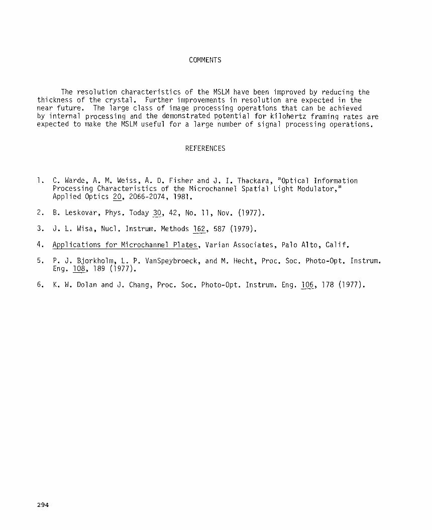
The r e so lu t ion c h a r a c t e r i s t i c s of the MSLM have been improved by reducing the thickness of t he c r y s t a l . near future. by in t e rna l processing and the demonstrated po ten t i a l f o r k i lohe r t z framing r a t e s a re expected t o make the MSLM useful f o r a l a rge number of s ignal processing operat ions.
Further improvements i n reso lu t ion a r e expected i n the The l a rge c l a s s of image processing operat ions t h a t can be achieved
R E F E R E N C E S
1 . C. Warde, A. M. Weiss, A. D. Fisher and J . I . Thackara, "Optical Information Processing Charac t e r i s t i c s of the Microchannel Spat ia l L i g h t Modulator," Appl ied Optics - 20, 2066-2074 , 1981.
2. B. Leskovar, Phys. Today - 30, 42, No. 11, Nov. (1977).
3. J . L. W s a , Nucl. Instrum. Methods 162, 587 (1979).
4. Applicat ions f o r Microchannel P l a t e s , Varian Associates , Palo Alto, C a l i f ,
-
5. P. J . Bjorkholm, L . P. VanSpeybroeck, and M . Hecht, Proc. SOC. Photo-Opt. Instrum. Eng. - 108, 189 (1977).
6. K. H. Dolan and J . Chang, Proc. SOC. Photo-Opt. Instrum. Eng. - 106, 178 (1977).
294

3 0 U c ._I
3
a, U 0 L U 0 0 0 Is Q
t
t
a, 73 0
0 a, W
I c
-
ts L L
0 L t 0
.- - a,
a--, u .- an
V
295
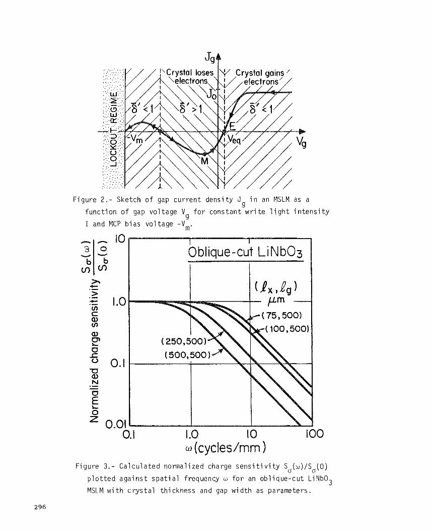
Figure 2 . - Sketch of gap c u r r e n t dens i ty 3 i n an fYlSLM as a g
func t ion of gap vol tage V I and MCP b ias vol tage - V m .
f o r cons t an t w r i t e l i g h t i n t e n s i t y g
c .- > ._. t I .0
0. I
I .I IO IO0
Figure 3.- Calcu la ted normalized charge s e n s i t i v i t y S,(w)/S,(O)
3 p l o t t e d a g a i n s t s p a t i a l frequency w f o r an obl ique-cut LiNbO MSLM with c r y s t a l th ickness and gap width as parameters .
296

ULLT I-W z > ow V O Z
03 W c3 4: E Y
Q:
W W
z . a Y

0 w L7 w u 4 r w
a, -0 0 r c, 5 V 0
*r L 3 -0
S 0
c, 5 -0 5 L m a, 7 3
a, m 5 E
-7
U
298
Copyright © 2022 FDOKUMEN