Design and implementation of OFDM-MFSK IF modulator ...
7
Design and implementation of OFDM-MFSK IF modulator based on FPGA Yuelei Xie 1, a* , DeQian Zeng 2,b and Xiaofu Xia 3,c 1 Guangxi Key Lab of Wireless Wideband Communication &Signal Processing, Guilin University of Electronic Technology, Qixing District, Guilin City , Guangxi Prov. China 541004 a [email protected], b [email protected], c [email protected] Keywords: Multipath fading; Doppler shift; OFDM-MFSK; Modulation scheme; FPGA; Abstract. OFDM-MFSK is a hybrid modulation scheme which is resistant to multipath fading and frequency shift. So it is more suitable for high speed mobile communication scenarios where the channels are distorted by multipath propagation and Doppler shift. In this paper, an OFDM-MFSK modulator is designed and implemented on Xilinx’s ZYNQ-7020 FPGA. The modulator is mainly composed of convolution coding,MFSK mapping, pilots inserting, IFFT, windows filtering and Digital Up converter. Digital up converting is carried by AD9777 to achieve IQ IF modulation signals. The experimental test founded that the transmission data rate can reach more than 20Mbps in the frequency bandwidth of 80MHz conditions. Optimum performance of OFDM-MFSK is achieved for a low or medium rate data transmission even in time variance of mobile environments. Introduction With the development of society and economy in China, more and more people go travelling by high speed railway or plane. When the vehicle is operating at high-speed in a complex geographic environment, broadband communication can only be provided by wireless means. However, the wireless communication environment is become more complex, and the wireless communication channel shows multipath propagation and fast time varying[6]. It leads to a composite fading which composes of both time selective fading and frequency selective fading. At present, 4G and LTE[12] are all based on OFDM[1] technology, OFDM technology can effectively overcome the inter symbol interference caused by multipath propagation, but in time-varying environments, where the estimated channel is outdated very quickly, and the Doppler frequency shift and the Doppler spreads destroyed the orthogonality of OFDM subcarriers, so it makes the performance of the OFDM communication system seriously deteriorated[7]. OFDM-MFSK was discussed in detail by Matthias Karl Wetz for high speed mobile communication in paper[4]. It is a hybrid modulation scheme which combines MFSK and OFDM. The subcarriers of OFDM are divided into several groups, and MFSK modulation scheme is applied to each of these groups. The OFDM-MFSK can take advantages of both OFDM and MFSK. What’s more, it no need equalization and channel estimation to perform the demodulation by a noncoherent receiver. It shows strong ability of anti-multipath and robustness for Doppler spreads. The system can get good performance even at vehicle speeds v = 600 km/h. In this paper, we design a OFDM-MFSK modulator based on the FPGA[16]. All of OFDM baseband signal processing run on Xilinx’s Zynq-7000 AP SoC. The baseband rate is 20MHz, and using AD9777 to achieve DA conversion and I&Q IF modulation. OFDM-MFSK modulation signal frequency is 80MHz. The Basic Principle and Performance Analysis of OFDM-MFSK In time-varying environments, the MFSK is a kind of appropriate digital modulation method that allows noncoherent detection because there is no need for channel estimation and equalization. The idea of OFDM-MFSK is therefore to combine OFDM and MFSK by splitting the N subcarriers into groups of M and to transmit information by assigning energy to one of the M subcarriers in each group International Conference on Manufacturing Science and Engineering (ICMSE 2015) © 2015. The authors - Published by Atlantis Press 373
-
Upload
khangminh22 -
Category
Documents
-
view
3 -
download
0
Transcript of Design and implementation of OFDM-MFSK IF modulator ...

Design and implementation of OFDM-MFSK IF modulator based on FPGA
Yuelei Xie 1, a* , DeQian Zeng2,b and Xiaofu Xia3,c 1Guangxi Key Lab of Wireless Wideband Communication
&Signal Processing, Guilin University of Electronic Technology, Qixing District, Guilin City , Guangxi Prov. China 541004
[email protected], [email protected], [email protected]
Keywords: Multipath fading; Doppler shift; OFDM-MFSK; Modulation scheme; FPGA; Abstract. OFDM-MFSK is a hybrid modulation scheme which is resistant to multipath fading and frequency shift. So it is more suitable for high speed mobile communication scenarios where the channels are distorted by multipath propagation and Doppler shift. In this paper, an OFDM-MFSK modulator is designed and implemented on Xilinx’s ZYNQ-7020 FPGA. The modulator is mainly composed of convolution coding,MFSK mapping, pilots inserting, IFFT, windows filtering and Digital Up converter. Digital up converting is carried by AD9777 to achieve IQ IF modulation signals. The experimental test founded that the transmission data rate can reach more than 20Mbps in the frequency bandwidth of 80MHz conditions. Optimum performance of OFDM-MFSK is achieved for a low or medium rate data transmission even in time variance of mobile environments.
Introduction With the development of society and economy in China, more and more people go travelling by high speed railway or plane. When the vehicle is operating at high-speed in a complex geographic environment, broadband communication can only be provided by wireless means. However, the wireless communication environment is become more complex, and the wireless communication channel shows multipath propagation and fast time varying[6]. It leads to a composite fading which composes of both time selective fading and frequency selective fading. At present, 4G and LTE[12] are all based on OFDM[1] technology, OFDM technology can effectively overcome the inter symbol interference caused by multipath propagation, but in time-varying environments, where the estimated channel is outdated very quickly, and the Doppler frequency shift and the Doppler spreads destroyed the orthogonality of OFDM subcarriers, so it makes the performance of the OFDM communication system seriously deteriorated[7]. OFDM-MFSK was discussed in detail by Matthias Karl Wetz for high speed mobile communication in paper[4]. It is a hybrid modulation scheme which combines MFSK and OFDM. The subcarriers of OFDM are divided into several groups, and MFSK modulation scheme is applied to each of these groups. The OFDM-MFSK can take advantages of both OFDM and MFSK. What’s more, it no need equalization and channel estimation to perform the demodulation by a noncoherent receiver. It shows strong ability of anti-multipath and robustness for Doppler spreads. The system can get good performance even at vehicle speeds v = 600 km/h.
In this paper, we design a OFDM-MFSK modulator based on the FPGA[16]. All of OFDM baseband signal processing run on Xilinx’s Zynq-7000 AP SoC. The baseband rate is 20MHz, and using AD9777 to achieve DA conversion and I&Q IF modulation. OFDM-MFSK modulation signal frequency is 80MHz.
The Basic Principle and Performance Analysis of OFDM-MFSK In time-varying environments, the MFSK is a kind of appropriate digital modulation method that allows noncoherent detection because there is no need for channel estimation and equalization. The idea of OFDM-MFSK is therefore to combine OFDM and MFSK by splitting the N subcarriers into groups of M and to transmit information by assigning energy to one of the M subcarriers in each group
International Conference on Manufacturing Science and Engineering (ICMSE 2015)
© 2015. The authors - Published by Atlantis Press 373
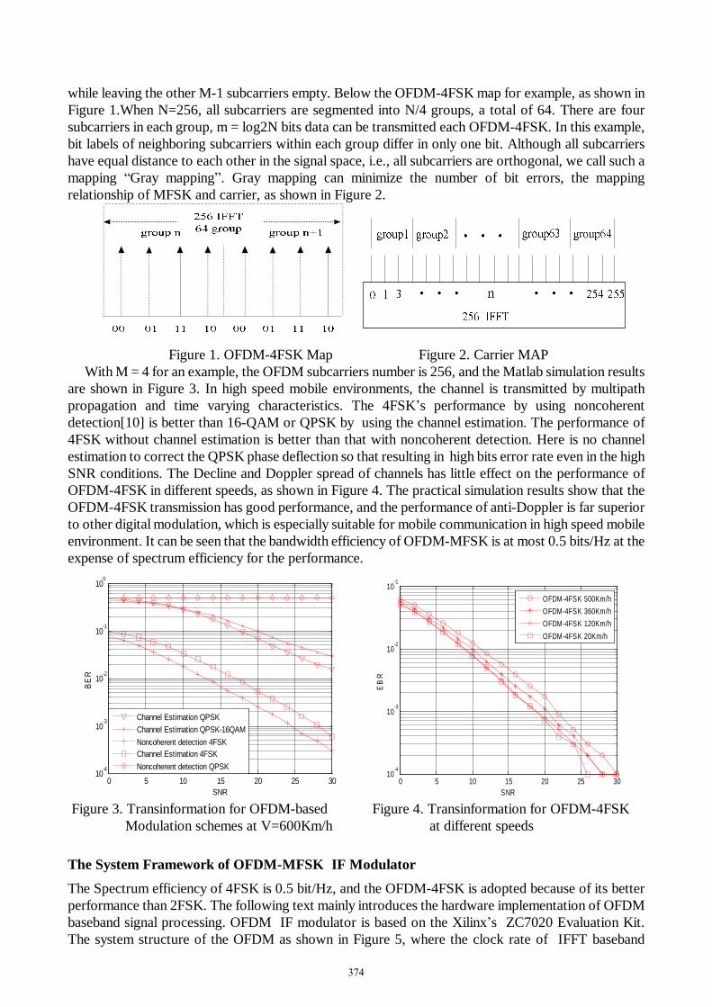
while leaving the other M-1 subcarriers empty. Below the OFDM-4FSK map for example, as shown in Figure 1.When N=256, all subcarriers are segmented into N/4 groups, a total of 64. There are four subcarriers in each group, m = log2N bits data can be transmitted each OFDM-4FSK. In this example, bit labels of neighboring subcarriers within each group differ in only one bit. Although all subcarriers have equal distance to each other in the signal space, i.e., all subcarriers are orthogonal, we call such a mapping “Gray mapping”. Gray mapping can minimize the number of bit errors, the mapping relationship of MFSK and carrier, as shown in Figure 2.
Figure 1. OFDM-4FSK Map Figure 2. Carrier MAP
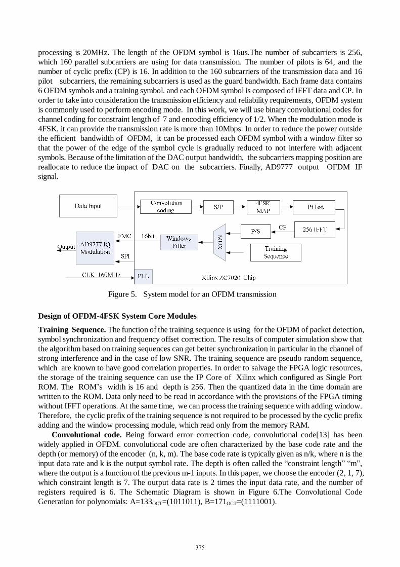
With M = 4 for an example, the OFDM subcarriers number is 256, and the Matlab simulation results are shown in Figure 3. In high speed mobile environments, the channel is transmitted by multipath propagation and time varying characteristics. The 4FSK’s performance by using noncoherent detection[10] is better than 16-QAM or QPSK by using the channel estimation. The performance of 4FSK without channel estimation is better than that with noncoherent detection. Here is no channel estimation to correct the QPSK phase deflection so that resulting in high bits error rate even in the high SNR conditions. The Decline and Doppler spread of channels has little effect on the performance of OFDM-4FSK in different speeds, as shown in Figure 4. The practical simulation results show that the OFDM-4FSK transmission has good performance, and the performance of anti-Doppler is far superior to other digital modulation, which is especially suitable for mobile communication in high speed mobile environment. It can be seen that the bandwidth efficiency of OFDM-MFSK is at most 0.5 bits/Hz at the expense of spectrum efficiency for the performance.
0 5 10 15 20 25 30
10-4
10-3
10-2
10-1
100
SNR
BE
R
Channel Estimation QPSKChannel Estimation QPSK-16QAMNoncoherent detection 4FSKChannel Estimation 4FSKNoncoherent detection QPSK
0 5 10 15 20 25 30
10-4
10-3
10-2
10-1
SNR
EB
R
OFDM-4FSK 500Km/hOFDM-4FSK 360Km/hOFDM-4FSK 120Km/hOFDM-4FSK 20Km/h
Figure 3. Transinformation for OFDM-based Figure 4. Transinformation for OFDM-4FSK
Modulation schemes at V=600Km/h at different speeds
The System Framework of OFDM-MFSK IF Modulator The Spectrum efficiency of 4FSK is 0.5 bit/Hz, and the OFDM-4FSK is adopted because of its better performance than 2FSK. The following text mainly introduces the hardware implementation of OFDM baseband signal processing. OFDM IF modulator is based on the Xilinx’s ZC7020 Evaluation Kit. The system structure of the OFDM as shown in Figure 5, where the clock rate of IFFT baseband
374
processing is 20MHz. The length of the OFDM symbol is 16us.The number of subcarriers is 256, which 160 parallel subcarriers are using for data transmission. The number of pilots is 64, and the number of cyclic prefix (CP) is 16. In addition to the 160 subcarriers of the transmission data and 16 pilot subcarriers, the remaining subcarriers is used as the guard bandwidth. Each frame data contains 6 OFDM symbols and a training symbol. and each OFDM symbol is composed of IFFT data and CP. In order to take into consideration the transmission efficiency and reliability requirements, OFDM system is commonly used to perform encoding mode. In this work, we will use binary convolutional codes for channel coding for constraint length of 7 and encoding efficiency of 1/2. When the modulation mode is 4FSK, it can provide the transmission rate is more than 10Mbps. In order to reduce the power outside the efficient bandwidth of OFDM, it can be processed each OFDM symbol with a window filter so that the power of the edge of the symbol cycle is gradually reduced to not interfere with adjacent symbols. Because of the limitation of the DAC output bandwidth, the subcarriers mapping position are reallocate to reduce the impact of DAC on the subcarriers. Finally, AD9777 output OFDM IF signal.
Figure 5. System model for an OFDM transmission
Design of OFDM-4FSK System Core Modules
Training Sequence. The function of the training sequence is using for the OFDM of packet detection, symbol synchronization and frequency offset correction. The results of computer simulation show that the algorithm based on training sequences can get better synchronization in particular in the channel of strong interference and in the case of low SNR. The training sequence are pseudo random sequence, which are known to have good correlation properties. In order to salvage the FPGA logic resources, the storage of the training sequence can use the IP Core of Xilinx which configured as Single Port ROM. The ROM’s width is 16 and depth is 256. Then the quantized data in the time domain are written to the ROM. Data only need to be read in accordance with the provisions of the FPGA timing without IFFT operations. At the same time, we can process the training sequence with adding window. Therefore, the cyclic prefix of the training sequence is not required to be processed by the cyclic prefix adding and the window processing module, which read only from the memory RAM.
Convolutional code. Being forward error correction code, convolutional code[13] has been widely applied in OFDM. convolutional code are often characterized by the base code rate and the depth (or memory) of the encoder (n, k, m). The base code rate is typically given as n/k, where n is the input data rate and k is the output symbol rate. The depth is often called the “constraint length” “m”, where the output is a function of the previous m-1 inputs. In this paper, we choose the encoder (2, 1, 7), which constraint length is 7. The output data rate is 2 times the input data rate, and the number of registers required is 6. The Schematic Diagram is shown in Figure 6.The Convolutional Code Generation for polynomials: A=133OCT=(1011011), B=171OCT=(1111001).
375

Figure 6. Convolutional encoder
Interleaved coding . In order to withstand the burst error, the data of each OFDM symbol must be interleaved. The basic idea behind the use of interleaved codes is to jumble symbols at the receiver. This leads to randomization of bursts of received errors which are closely located and we can then apply the analysis for random channel. At the receiver, the deinterleaver will alter the received sequence to get back the unaltered original sequence at the transmitter. For example, the serial data sequence is filled with a matrix of n × m. Here, the input symbols are written sequentially in the rows and the output symbols are obtained by reading the columns sequentially, then the continuous data are not adjacent to each other. With FPGA implementation, each OFDM-MFSK symbol can transmit 80 bit data, so the interleaving method can be 10×5 or 8×16; the specific formula of 10×8 is:
m=(N/10)×(kmod10)+floor(k/10) k=0,1,2…N-1 (3-1) where k is the location of the data before the encoding. m is the location of the data after the intertwined encoding, N is 80. The floor(k /10) rounds the elements of k/10 to the nearest integers less than or equal to k/10. For example: When k={0,1,2,3,4,5,6,7,8,9, 31,32,33,34,5…,75,76,77,78,79}. m={0,64,49,34,19,4,68,53,38, …,24,9,73,58,43,…,60,45,30,15,79}. It usually needs two operations by formula (3-1) for improving the system’s performance.
MFSK Mapping. Take 4FSK for example, the Gray code mapping is shown in Figure 2 and Figure 2. It’s known that the 256 subcarriers are divided into 64 groups, each OFDM symbol can transmit 128 bits data, but only 160 subcarriers is occupied, So each OFDM can transmit 80 bits data, the rest of the empty subcarriers is used for pilot Insertion and guard interval. The data are quantized to 8 bits binary, which highest level as the sign bit, “0” represents “+”, “1” represents “–”.Quantized data are listed in the following Table 1. {M1, M2, M3, M4} are total of occupied 32 bits, that stored in the internal RAM of FPGA.
00 01 10 11
M1=8'h40 M2=8'h00 M3=8'h00 M4=8'h00
M1=8'h00 M2=8'h40 M3=8'h00 M4=8'h00
M1=8'h00 M2=8'h00 M3=8'h40 M4=8'h00
M1=8'h00 M2=8'h00 M3=8'h00 M4=8'h40
Table 1. Quantized data
Pilots Insertion. Pilots only is inserted in frequency domain, which is known for the launch and the receiver. The purpose of inserting the pilots is to get better synchronization in particular in the channel of strong interference and in the case of low SNR. But the frequency offset increases will lead to all subcarriers phase deflection as time goes on, So that 16 pilot symbols can keep track of the reference phase. The 256 subcarriers are divided into 64 groups. Pilots location address is {4, 11, 15, 18, 22, 25, 32, 36, 39, 43, 46, 50, 53, 8, 29, 57}. As shown in Figure 7, the Memory Generator IP Block Core is configured to the dual port RAM. Because quantized Data of subcarriers is 8 bits, so each group of 4FSK carriers occupies 32 bits. Allowing continuous data processing, when the RAM’s depth is 128. The scrambler signal control 16 pilot symbols for polarity reversal, then pilot symbols are written into dual port RAM. The processing can be realized by Moore finite state machine. All data are read out from the RAM in order for subsequent IFFT operations.
376
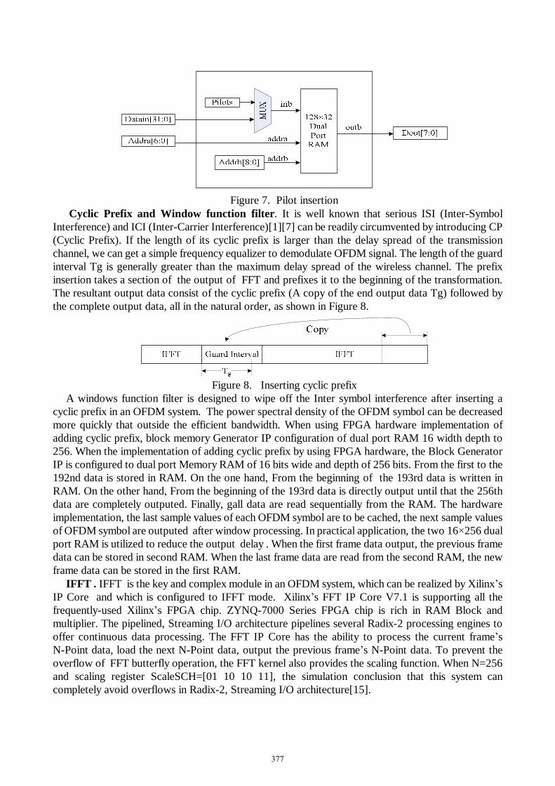
Figure 7. Pilot insertion
Cyclic Prefix and Window function filter. It is well known that serious ISI (Inter-Symbol Interference) and ICI (Inter-Carrier Interference)[1][7] can be readily circumvented by introducing CP (Cyclic Prefix). If the length of its cyclic prefix is larger than the delay spread of the transmission channel, we can get a simple frequency equalizer to demodulate OFDM signal. The length of the guard interval Tg is generally greater than the maximum delay spread of the wireless channel. The prefix insertion takes a section of the output of FFT and prefixes it to the beginning of the transformation. The resultant output data consist of the cyclic prefix (A copy of the end output data Tg) followed by the complete output data, all in the natural order, as shown in Figure 8.
Figure 8. Inserting cyclic prefix
A windows function filter is designed to wipe off the Inter symbol interference after inserting a cyclic prefix in an OFDM system. The power spectral density of the OFDM symbol can be decreased more quickly that outside the efficient bandwidth. When using FPGA hardware implementation of adding cyclic prefix, block memory Generator IP configuration of dual port RAM 16 width depth to 256. When the implementation of adding cyclic prefix by using FPGA hardware, the Block Generator IP is configured to dual port Memory RAM of 16 bits wide and depth of 256 bits. From the first to the 192nd data is stored in RAM. On the one hand, From the beginning of the 193rd data is written in RAM. On the other hand, From the beginning of the 193rd data is directly output until that the 256th data are completely outputed. Finally, gall data are read sequentially from the RAM. The hardware implementation, the last sample values of each OFDM symbol are to be cached, the next sample values of OFDM symbol are outputed after window processing. In practical application, the two 16×256 dual port RAM is utilized to reduce the output delay . When the first frame data output, the previous frame data can be stored in second RAM. When the last frame data are read from the second RAM, the new frame data can be stored in the first RAM.
IFFT . IFFT is the key and complex module in an OFDM system, which can be realized by Xilinx’s IP Core and which is configured to IFFT mode. Xilinx’s FFT IP Core V7.1 is supporting all the frequently-used Xilinx’s FPGA chip. ZYNQ-7000 Series FPGA chip is rich in RAM Block and multiplier. The pipelined, Streaming I/O architecture pipelines several Radix-2 processing engines to offer continuous data processing. The FFT IP Core has the ability to process the current frame’s N-Point data, load the next N-Point data, output the previous frame’s N-Point data. To prevent the overflow of FFT butterfly operation, the FFT kernel also provides the scaling function. When N=256 and scaling register ScaleSCH=[01 10 10 11], the simulation conclusion that this system can completely avoid overflows in Radix-2, Streaming I/O architecture[15].
377
Hardware System Verification The IF DA converter of system is AD9777 Native FMC-125 board of Beijing Orihard Technology. The AD9777 is the 16-bit member of the AD977x pin compatible, high performance, programmable 2×/4×/8× interpolating TxDAC+ family. The AD9777 features the ability to perform FS/2, FS/4, and FS/8 digital modulation and image rejection when combined with an analog quadrature modulator. In this mode, the AD9777 accepts I and Q complex data (representing a single or multicarrier waveform), generates a quadrature modulated IF signal along with its orthogonal representation via its dual DACs, and presents these two reconstructed orthogonal IF carriers to an analog quadrature modulator to complete the image rejection up conversion process. The AD97777 allows configuration mode of as a carrier for the Fs/2, the 4x interpolation in this design.
The Modelsim simulation of OFDM-4FSK output I&Q waveform as shown in Figure 9. The front part of the waveform is the periodic training sequence. The number of cycles is 16. We cannot observe the training sequence data from the oscilloscope. The waveform at the back of the periodic training sequence is the waveform of OFDM data frames, and the output waveform of the DA chip is shown in Figure 10.Yellow waveform is I(real) data path; the blue waveform is Q(imaginary) data path. Because the test data of transmission is the priodic sequence, so AD output the periodic waveform. When mode is: 4× interpolation filters; FS/2 digital quadrature, the waveform of the spectrum is shown in Figure 11. OFDM-4FSK spectrum waveform is similar to the rectangle after adding window filtering. System power outside the effective bandwidth decreases rapidly. The performance indicators of system can meet the requirements in time-varying environments via testing and analysis.
Figure 9. Modelsim Simulation Output I&Q Figure 10. DA Output of OFDM-4FSK
Figure 11. The Spectrum of OFDM-MFSK
378
Conclusion This paper introduces the design method of OFDM-MFSK IF modulator based on FPGA, Which makes full use of the latest Xilinx’s Zynq-7000 AP SoC devices for simplifying the system design. The performance of the system is considered in the selection of hardware algorithm. The experimental results show that the design can use less chip logic resources to achieve the. What’s more, the transmitter has excellent anti-interference performance which can been using for low or medium speed data transmission in high speed mobile environments.
Acknowledgment This work was supported by the National Natural Science Foundation of China (Grant 61461015) and Guangxi Natural Science Foundation (Grant 2013GXNSFFA019004 and 2015GXNSFAA139302).
References [1] Wenbo Wang, Kai Zheng. Broadband wireless OFDM technology[M]. Beijing: The People's Posts
and Telecommunications Press, 2003. (In Chinese) [2] Xueyong Liu, Detailed the MATLAB/Simulink for communication systems modeling and
simulation. Beijing: Electronic Industry Press,2009. (In Chinese) [3] XinHua Niu . The FPGA implementation of the key module of OFDM baseband system based on
DVB-T. Scientific papers online. 2009.12. (In Chinese) [4] WETZ M. Transmission methods for wireless multi carrier systems in time-varying
environments[D].Universität Ulm, 2011. [5] C.-D. Chung and F.-C. Hung, “Noncoherent maximum-likelihood block detection of or-thogonal
NFSK-LDPSK signals,” IEEE Transactions on Vehicular Technology, vol. 51, no.2,pp. 283–292, March 2002.
[6] Dan LI ,Feng Ke. A base extension model of fast time-varying channel estimation methods based on the OFDM frequency domain [J].Journal of signal processing, 2012, 28 (2):194. (In Chinese)
[7] N. Beaulieu and P. Tan, “Receiver windowing for reduction of ICI in OFDM systems with carrier frequency offset” in Proc. IEEE Global Telecommunications Conference - GLOBECOM, December 2005, pp. 2680-2684.
[8] Li F, Xu Z, Zhu S. Variational-inference-based data detection for OFDM systems with imperfect channel estimation[J]. Vehicular Technology, IEEE Transactions on, 2013, 62(3):1394-1399.
[9] Muruganathan S D, Krzymien W A, Sesay A B. A Null-Subcarrier-Aided Reference Symbol Mapping Scheme for 3GPP LTE Downlink in High-Mobility Scenarios[J]. Vehicular Technology[J], IEEE Transactions on, 2012, 61(2): 624-638.
[10] PEIKER - FEIL E.O FDM - MFSK as a special case of noncoherent communication -based on subspaces [C]. OFDM 2012 th International OFDM Workshop 2012. Essen-based, Germany, 2012:1-5.
[11] Huang Jianfeng, Overview of TD-LTE core technology and its prospect [J]. Wireless Internet Technology. 2012.12. (In Chinese)
[12] Zhiguo Shi , Shaohua Hong. Design of OFDM communication system Based on Xilinx[M]. Zhejiang: Zhejiang University Press , 2009. (In Chinese)
[13] Xu C, Liang D, Ng S X, et al. Reduced-complexity non-coherent soft-decision-aided DAPSK dispensing with channel estimation[J].IEEE Transactions on Vehicular Technology, 2013, 62(6):2633-2643.
[14] Senol H, Panayirci E, Poor H V. Nondata-Aided Joint Channel Estimation and Equalization for OFDM Systems in Very Rapidly Varying Mobile Channels[J]. Signal Processing, IEEE Transactions on, 2012, 60(8): 4236-4253.
[15] Information on http://china.xilinx.com/products/intellectual-property/fft.html#documentation. [16] Information on https://sv.wikipedia.org/wiki/Field-programmable_gate_array?wprov=iwsw2.
379