Wide viewing angle holographic display with multi spatial light modulator array
8
Wide viewing angle holographic display with a multi spatial light modulator array Grzegorz Finke, Tomasz Kozacki, Małgorzata Kujawińska Warsaw University of Technology, Institute of Micromechanics and Photonics, 8 Sw. Andrzeja Boboli St., 02-525 Warsaw, Poland ABSTRACT In the paper we present the design of a wide viewing angle display system capable of displaying digital holograms captured in a rotary CCD configuration. We have discussed the two possible configurations of multi LC SLMs system: with a normal LC SLM illumination and with tilted LC SLMs and parallel illumination. The second system was selected and the tilted plane algorithm, necessary for recalculation of displayed holograms was tested. Finally we have presented and discussed different means of visual perception of holographic images: with an asymmetric diffuser and with an eyepiece. Key words: digital holography, spatial light modulators, 3D displays, tilted plane algorithm 1. INTRODUCTION Human's natural world perception is three dimensional. No wonder that people want to transfer the third dimension into entertainment such as TV, cinema or computer games and please their eyes with 3D images. The main idea of underpinning the 3D experience is that of stereoscopic vision [1]: an observer when viewing a scene sees two slightly displaced versions of that scene with the left and right eye. Next brain is processing this information and creates a 3D image. More detailed information about this approach to 3D display devices can be found in [2]. One of the techniques which allows us to see 3D images is holography. The recording process allows to capture full object wave front information – its amplitude and phase. Having this information it is possible to reconstruct the optical wave field in another place and another time [3], using spatial light modulators (SLM). Recreating the full wave field is the only way by which an observer would be exposed to the same scene that had been recorded. However, as traditional version of holography gives very good results in this area, thanks to excellent resolution of holographic films, its digital equivalent sill has a lot to catch up. Usually captured digital holograms were displayed on a single SLM [4]. However this realization has not fulfilled satisfactory requirements connected with an expectation of a wide angle optoelectronic reconstruction. This is caused by some SLM limitations. A limited pixel pitch of SLM causes problems with resolution of displayed holograms which further on delimits the angular view-ability of reconstructed images. Furthermore a relatively large pixel size results in small parallax, which has crucial meaning for good viewing quality of 3D objects. Recently several attempts have been made to enhance these features by employing innovative optoelectronic modules which are adopted to generate a large number of data points [5] or to increase holographic display angular view ability [6,7]. In this paper we present a holographic display configuration where multiple SLMs aligned in circular configuration are put to work together. Such configuration of holographic display allows to increase the viewing angle in horizontal direction and thus to increase the horizontal parallax. The system is based on liquid crystal on silicon high definition spatial light modulators (LC SLMs). In the paper we discus the final setup arrangement and present results obtained from two SLMs. The discussion of linking multi CCD digital holographic capture with LC SLM based display system is presented, allowing in future to display holograms captured for real world objects. Optics, Photonics, and Digital Technologies for Multimedia Applications, edited by Peter Schelkens, Touradj Ebrahimi, Gabriel Cristóbal, Frédéric Truchetet, Pasi Saarikko, Proc. of SPIE Vol. 7723, 77230A · © 2010 SPIE · CCC code: 0277-786X/10/$18 · doi: 10.1117/12.855778 Proc. of SPIE Vol. 7723 77230A-1 Downloaded from SPIE Digital Library on 15 Sep 2010 to 130.231.240.13. Terms of Use: http://spiedl.org/terms
Transcript of Wide viewing angle holographic display with multi spatial light modulator array
Wide viewing angle holographic display with a multi spatial light modulator array
Grzegorz Finke, Tomasz Kozacki, Małgorzata Kujawińska
Warsaw University of Technology, Institute of Micromechanics and Photonics,
8 Sw. Andrzeja Boboli St., 02-525 Warsaw, Poland
ABSTRACT
In the paper we present the design of a wide viewing angle display system capable of displaying digital holograms captured in a rotary CCD configuration. We have discussed the two possible configurations of multi LC SLMs system: with a normal LC SLM illumination and with tilted LC SLMs and parallel illumination. The second system was selected and the tilted plane algorithm, necessary for recalculation of displayed holograms was tested. Finally we have presented and discussed different means of visual perception of holographic images: with an asymmetric diffuser and with an eyepiece. Key words: digital holography, spatial light modulators, 3D displays, tilted plane algorithm
1. INTRODUCTION
Human's natural world perception is three dimensional. No wonder that people want to transfer the third dimension into entertainment such as TV, cinema or computer games and please their eyes with 3D images. The main idea of underpinning the 3D experience is that of stereoscopic vision [1]: an observer when viewing a scene sees two slightly displaced versions of that scene with the left and right eye. Next brain is processing this information and creates a 3D image. More detailed information about this approach to 3D display devices can be found in [2]. One of the techniques which allows us to see 3D images is holography. The recording process allows to capture full object wave front information – its amplitude and phase. Having this information it is possible to reconstruct the optical wave field in another place and another time [3], using spatial light modulators (SLM). Recreating the full wave field is the only way by which an observer would be exposed to the same scene that had been recorded.
However, as traditional version of holography gives very good results in this area, thanks to excellent resolution of holographic films, its digital equivalent sill has a lot to catch up. Usually captured digital holograms were displayed on a single SLM [4]. However this realization has not fulfilled satisfactory requirements connected with an expectation of a wide angle optoelectronic reconstruction. This is caused by some SLM limitations. A limited pixel pitch of SLM causes problems with resolution of displayed holograms which further on delimits the angular view-ability of reconstructed images. Furthermore a relatively large pixel size results in small parallax, which has crucial meaning for good viewing quality of 3D objects. Recently several attempts have been made to enhance these features by employing innovative optoelectronic modules which are adopted to generate a large number of data points [5] or to increase holographic display angular view ability [6,7].
In this paper we present a holographic display configuration where multiple SLMs aligned in circular configuration are put to work together. Such configuration of holographic display allows to increase the viewing angle in horizontal direction and thus to increase the horizontal parallax. The system is based on liquid crystal on silicon high definition spatial light modulators (LC SLMs). In the paper we discus the final setup arrangement and present results obtained from two SLMs. The discussion of linking multi CCD digital holographic capture with LC SLM based display system is presented, allowing in future to display holograms captured for real world objects.
Optics, Photonics, and Digital Technologies for Multimedia Applications, edited by Peter Schelkens,Touradj Ebrahimi, Gabriel Cristóbal, Frédéric Truchetet, Pasi Saarikko, Proc. of SPIE Vol. 7723,
77230A · © 2010 SPIE · CCC code: 0277-786X/10/$18 · doi: 10.1117/12.855778
Proc. of SPIE Vol. 7723 77230A-1
Downloaded from SPIE Digital Library on 15 Sep 2010 to 130.231.240.13. Terms of Use: http://spiedl.org/terms
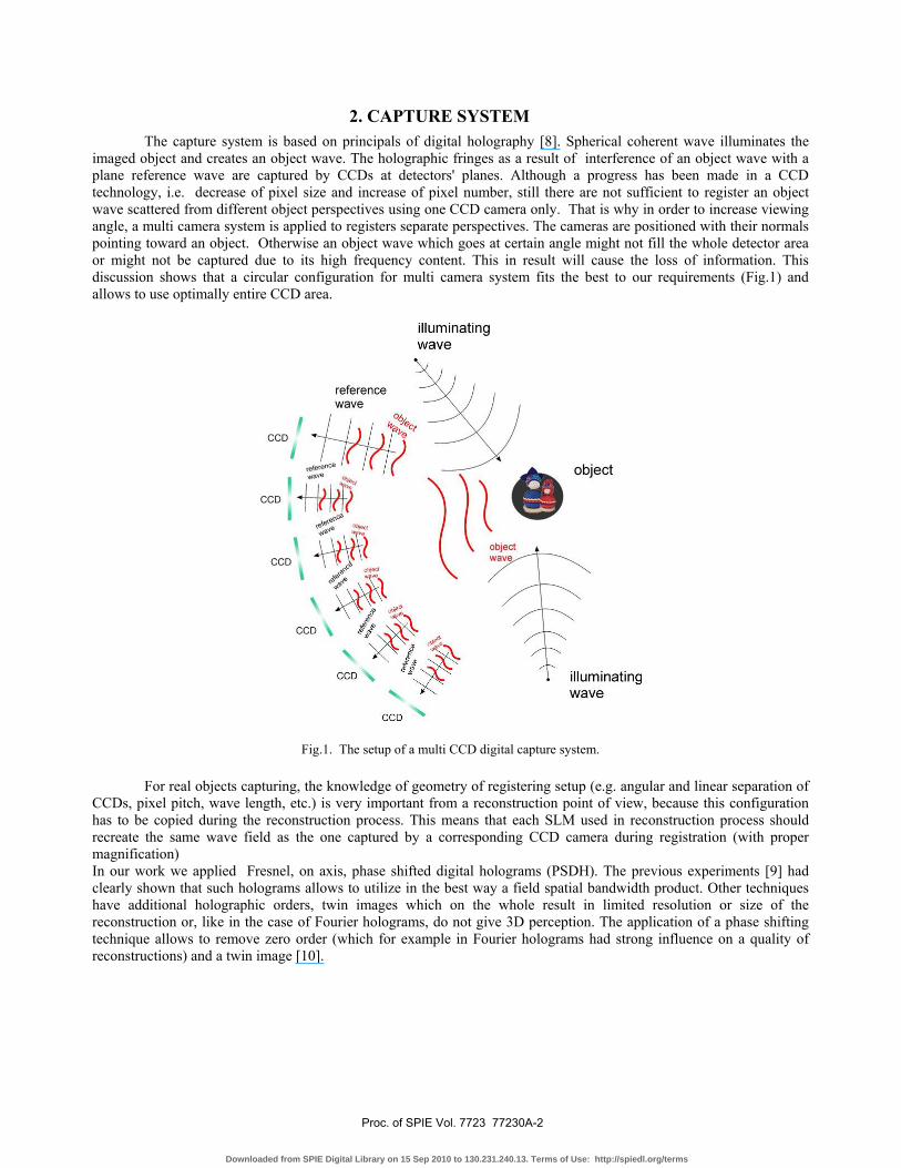
The capture system is based on principals of digital holography [8]. Spherical coherent wave illuminates the imaged object and creates an object wave. The holographic fringes as a result of interference of an object wave with a plane reference wave are captured by CCDs at detectors' planes. Although a progress has been made in a CCD technology, i.e. decrease of pixel size and increase of pixel number, still there are not sufficient to register an object wave scattered from different object perspectives using one CCD camera only. That is why in order to increase viewing angle, a multi camera system is applied to registers separate perspectives. The cameras are positioned with their normals pointing toward an object. Otherwise an object wave which goes at certain angle might not fill the whole detector area or might not be captured due to its high frequency content. This in result will cause the loss of information. This discussion shows that a circular configuration for multi camera system fits the best to our requirements (Fig.1) and allows to use optimally entire CCD area.
Fig.1. The setup of a multi CCD digital capture system.
For real objects capturing, the knowledge of geometry of registering setup (e.g. angular and linear separation of CCDs, pixel pitch, wave length, etc.) is very important from a reconstruction point of view, because this configuration has to be copied during the reconstruction process. This means that each SLM used in reconstruction process should recreate the same wave field as the one captured by a corresponding CCD camera during registration (with proper magnification) In our work we applied Fresnel, on axis, phase shifted digital holograms (PSDH). The previous experiments [9] had clearly shown that such holograms allows to utilize in the best way a field spatial bandwidth product. Other techniques have additional holographic orders, twin images which on the whole result in limited resolution or size of the reconstruction or, like in the case of Fourier holograms, do not give 3D perception. The application of a phase shifting technique allows to remove zero order (which for example in Fourier holograms had strong influence on a quality of reconstructions) and a twin image [10].
2. CAPTURE SYSTEM
Proc. of SPIE Vol. 7723 77230A-2
Downloaded from SPIE Digital Library on 15 Sep 2010 to 130.231.240.13. Terms of Use: http://spiedl.org/terms

The reconstruction system (display) utilizes six Liquid Cristal on Silicon Spatial Light Modulators (LC SLM, model HEP 1080 P) which are illuminated by plane waves. The LC SLMs used in our setup are phase modulators working in high definition and with a pixel pitch of 8μm square. As mentioned before the reconstruction system should comply with a registration one. Thus the first assumption about the SLMs' configuration was to illuminate them along their normals (Setup 1) (Fig.2). This way the direction of reflected beams from SLMs will be the same as direction of a wave field recorded by CCDs. As a result the holographic image with multiple perspective (multiple SLM) will be reconstructed according to the capture system
Fig.2. The scheme of a reconstruction configuration with illumination along LC SLMs' normals (Setup 1). However this type of solution occurred to be complicated in its experimental realization since it was necessary to direct each illumination beam at a specific angle. Because of that we decided to tilt our SLMs and illuminate them with parallel beams (Setup 2) as shown in Fig.3. This gives substantial system flexibility in order to generate holographic images for different reconstruction distances of for various SLM angular separation.
Fig.3. The scheme of a reconstruction configuration with parallel illumination (setup 2)
3. RECONSTRUCTION SYSTEM
Proc. of SPIE Vol. 7723 77230A-3
Downloaded from SPIE Digital Library on 15 Sep 2010 to 130.231.240.13. Terms of Use: http://spiedl.org/terms

In this configuration, since SLMs are arranged on an arc with radius which is two times bigger than the reconstruction distance with illumination going along its optical axis, an image will appear in its focal. Both presented configurations with their geometrical features are compared in Table 1. We have examined two factors - angular orientation of a marginal SLM and angular separation between two adjacent SLMs. The calculations have been made for three different reconstruction distances with an assumption of a 0.35 fill factor. By the statement of "fill factor" we mean the ratio of angular dimension of an active LC SLM area to angular separation of SLMs. This fill factor was calculated by examining the geometrical dimensions and an alignment of CCD cameras in a capture system. In final reconstruction setup, of course, the display fill factor should comply with the fill factor of registering setup.
Table 1. Comparison of the LC SLM working conditions required for setup 1 and 2
Fill factor W: 0.35 (16.6/47.43) Rec. Distance R 400mm 600mm 800mm
SETUP 1 Normal illumination system
Angle of marginal SLM γ
20.286° 13.560° 10.176°
Angular separation SLM α
6.767° 4.520° 3.393°
SETUP 2 One direction of illumination
Angle of marginal SLM γ
10.176° 6.789° 5.094°
Angular separation SLM α
6.767° 4.520° 3.393°
As it can be seen from the table, the angle of the marginal SLM in the first configuration is two times greater than in the second one, which in the final result effects a bigger dimension of the setup. This feature as well as simpler illumination system of the setup 2 decided about the choice of the second setup for the reconstruction system. However the preferred setup 2 differs substantially from registration configuration. The SLM planes do not coincide with capturing CCD matrixes. Therefore using the setup 2 we have to recalculate holograms so that they will fit the new geometry. To do this we have developed a tilted plain algorithm, which is described in section 4. Also some other geometrical and optical parameters of both systems (capture and display) are different. There are usually differences in pixel sizes and their numbers, also different wavelengths may be used for capture and display. We have to consider this effect while linking both systems. This mismatch between hologram's properties and our system effects optical reconstruction in two ways [11]: - it modifies the distance of reconstruction plane to SLM plane according to the equation: z z (1)
where zreg is distance between object and detector, λreg/rec is a wave length used during registration and reconstruction respectively, Δreg/rec is a pixel size of CCD and SLM respectively. - it modifies the transverse magnification by the factor of: ∆∆ (2)
Holograms registered for real objects may also have some errors which can be introduced due to instability during the capture or the phase step error. To avoid them in this paper we study the reconstruction of computer generated holograms, designed to match the features of our setup.
Proc. of SPIE Vol. 7723 77230A-4
Downloaded from SPIE Digital Library on 15 Sep 2010 to 130.231.240.13. Terms of Use: http://spiedl.org/terms
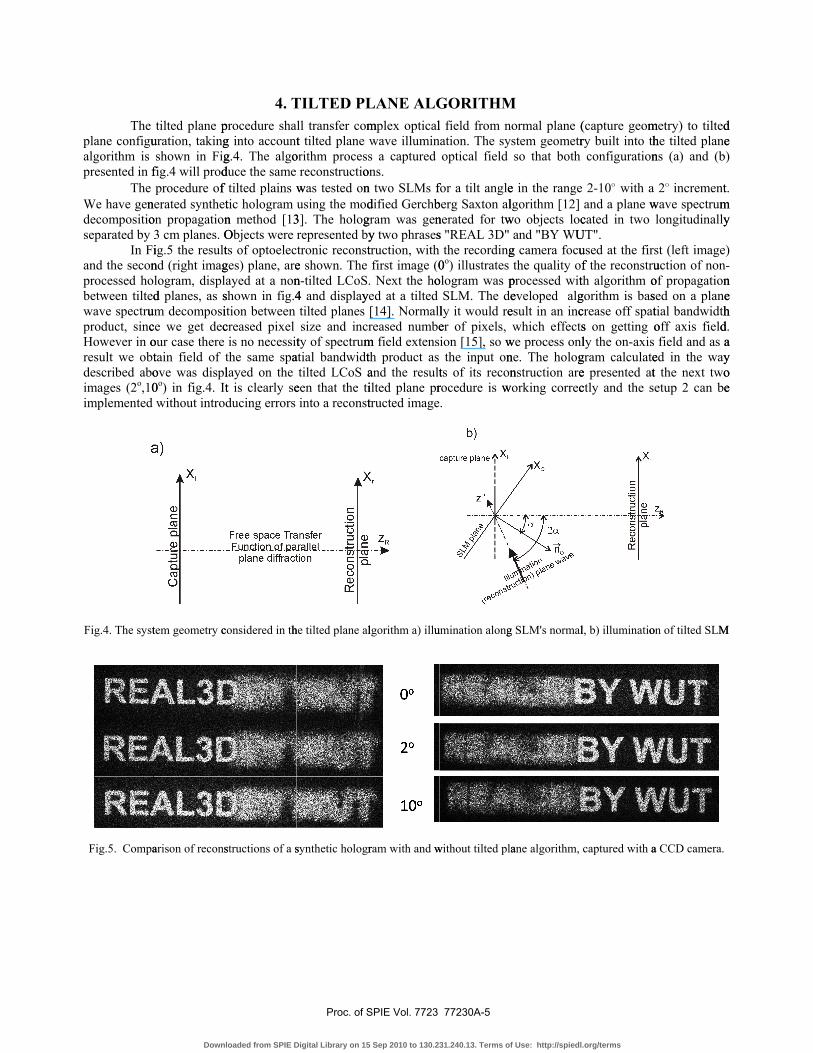
The plane configualgorithm is presented in f The We have gendecompositioseparated by In Fiand the seconprocessed hobetween tiltedwave spectruproduct, sincHowever in oresult we obtdescribed aboimages (2o,10implemented
Fig.4. The syst
Fig.5. Compa
tilted plane puration, takingshown in Fig
fig.4 will prodprocedure of
nerated syntheton propagation3 cm planes. Oig.5 the resultnd (right imaglogram, displd planes, as s
um decomposice we get decour case there tain field of ove was displ0o) in fig.4. Itwithout intro
tem geometry c
arison of recons
procedure shag into accountg.4. The algoduce the same f tilted plains wtic hologram n method [13Objects were ts of optoelecges) plane, areayed at a nonshown in fig.4ition between creased pixel is no necessitthe same spalayed on the t is clearly seducing errors
considered in th
structions of a s
ll transfer comt tilted plane
orithm procesreconstructio
was tested onusing the mod
3]. The hologrepresented bytronic reconste shown. The n-tilted LCoS4 and displaytilted planes size and inc
ty of spectrumatial bandwidt
tilted LCoS aeen that the tiinto a reconst
he tilted plane al
synthetic hologr
mplex opticalwave illumins a captured
ons. n two SLMs fdified Gerchb
gram was geny two phrasestruction, with first image (0
. Next the hoyed at a tilted
[14]. Normallreased numbe
m field extensth product as and the resultilted plane prtructed image
lgorithm a) illu
ram with and w
l field from nation. The syoptical field
for a tilt angleberg Saxton alnerated for tws "REAL 3D"
the recording0o) illustrates
ologram was pSLM. The de
ly it would reer of pixels, ion [15], so wthe input on
ts of its reconrocedure is w.
umination along
without tilted pla
ormal plane (stem geometrso that both
e in the range lgorithm [12]
wo objects locand "BY WU
g camera focuthe quality of
processed witeveloped algesult in an incwhich effects
we process onlne. The holognstruction are
working correc
g SLM's normal
ane algorithm,
(capture geomry built into th
configuration
2-10o with a and a plane w
cated in two UT". used at the firf the reconstruth algorithm ogorithm is bascrease off spats on getting oly the on-axis
gram calculatee presented atctly and the s
l, b) illuminatio
captured with a
metry) to tiltedhe tilted planens (a) and (b
2o incrementwave spectrumlongitudinally
st (left imageuction of nonof propagationsed on a planetial bandwidthoff axis field field and as aed in the wayt the next twoetup 2 can be
on of tilted SLM
a CCD camera.
d e )
t. m y
) -n e h d. a y o e
M
4. TILTED PLANE ALGORITHM
Proc. of SPIE Vol. 7723 77230A-5
Downloaded from SPIE Digital Library on 15 Sep 2010 to 130.231.240.13. Terms of Use: http://spiedl.org/terms
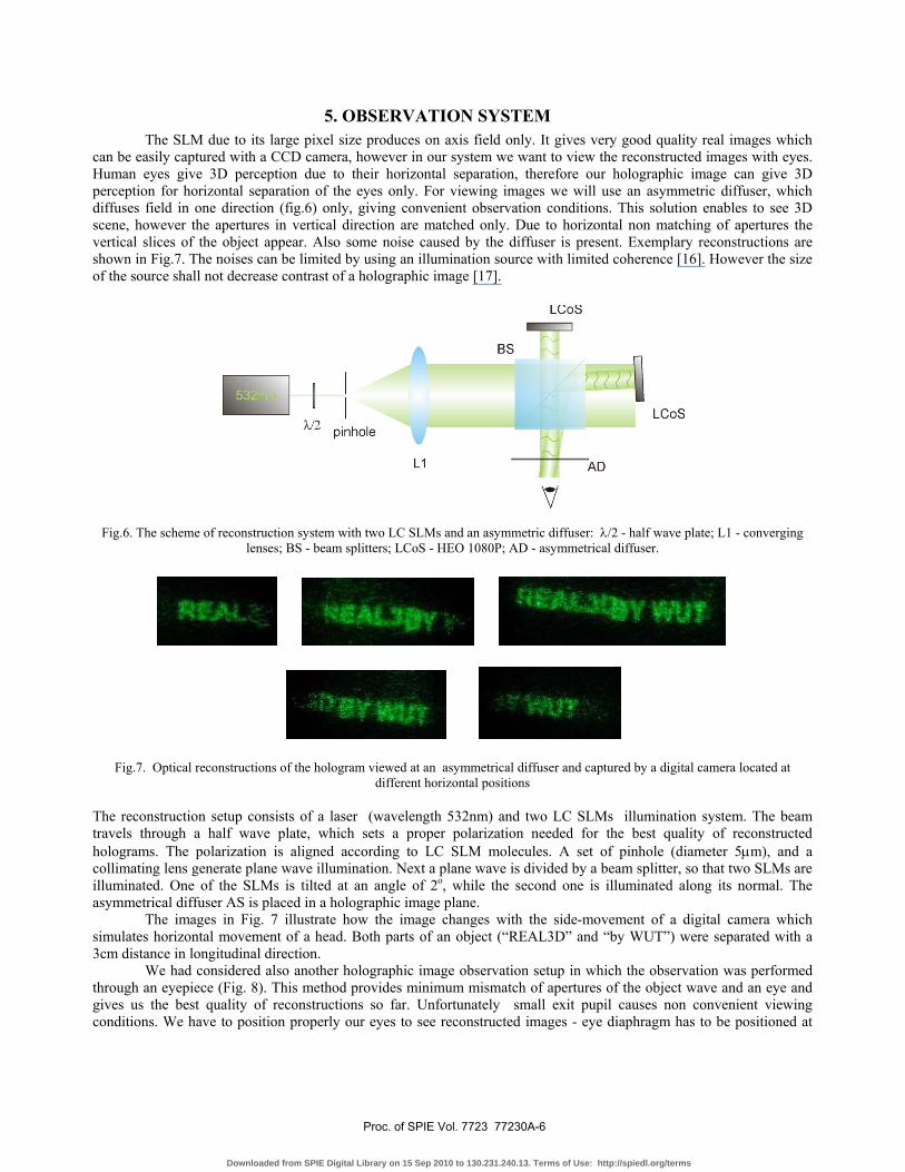
The SLM due to its large pixel size produces on axis field only. It gives very good quality real images which can be easily captured with a CCD camera, however in our system we want to view the reconstructed images with eyes. Human eyes give 3D perception due to their horizontal separation, therefore our holographic image can give 3D perception for horizontal separation of the eyes only. For viewing images we will use an asymmetric diffuser, which diffuses field in one direction (fig.6) only, giving convenient observation conditions. This solution enables to see 3D scene, however the apertures in vertical direction are matched only. Due to horizontal non matching of apertures the vertical slices of the object appear. Also some noise caused by the diffuser is present. Exemplary reconstructions are shown in Fig.7. The noises can be limited by using an illumination source with limited coherence [16]. However the size of the source shall not decrease contrast of a holographic image [17].
Fig.6. The scheme of reconstruction system with two LC SLMs and an asymmetric diffuser: λ/2 - half wave plate; L1 - converging lenses; BS - beam splitters; LCoS - HEO 1080P; AD - asymmetrical diffuser.
Fig.7. Optical reconstructions of the hologram viewed at an asymmetrical diffuser and captured by a digital camera located at different horizontal positions
The reconstruction setup consists of a laser (wavelength 532nm) and two LC SLMs illumination system. The beam travels through a half wave plate, which sets a proper polarization needed for the best quality of reconstructed holograms. The polarization is aligned according to LC SLM molecules. A set of pinhole (diameter 5μm), and a collimating lens generate plane wave illumination. Next a plane wave is divided by a beam splitter, so that two SLMs are illuminated. One of the SLMs is tilted at an angle of 2o, while the second one is illuminated along its normal. The asymmetrical diffuser AS is placed in a holographic image plane. The images in Fig. 7 illustrate how the image changes with the side-movement of a digital camera which simulates horizontal movement of a head. Both parts of an object (“REAL3D” and “by WUT”) were separated with a 3cm distance in longitudinal direction. We had considered also another holographic image observation setup in which the observation was performed through an eyepiece (Fig. 8). This method provides minimum mismatch of apertures of the object wave and an eye and gives us the best quality of reconstructions so far. Unfortunately small exit pupil causes non convenient viewing conditions. We have to position properly our eyes to see reconstructed images - eye diaphragm has to be positioned at
5. OBSERVATION SYSTEM
Proc. of SPIE Vol. 7723 77230A-6
Downloaded from SPIE Digital Library on 15 Sep 2010 to 130.231.240.13. Terms of Use: http://spiedl.org/terms

holographic display exit pupil. Figure 9 presents some exemplary reconstructions, registered by a digital camera simulating visual human perception of holographic image.
Fig.8. The scheme of reconstruction system with two LC SLMs and an eyepiece: λ/2 - half wave plate; L1 - collimating lens;
L2 - converging lens (eyepiece); BS - beam splitters; LCoS - HEO 1080P.
0o
2o
Fig.9. Optical reconstruction of the hologram viewed through an eyepiece and captured by a digital camera located at different horizontal positions
Through both experiments (Fig.7 and Fig.9) is clearly seen that by adding the second SLM we are able to increase the viewing angle. What is more, an overlapping of two parts of 3D object is noticeable with the horizontal movement of a camera (eye).
6. CONCLUSIONS
In the paper we have presented the design of a wide viewing angle display system capable of displaying digital holograms captured in a rotary CCD configuration. We have discussed the two possible configurations of multi LC SLMs system. The first one with a normal LC SLM illumination and the second one with tilted LC SLMs and parallel illumination. The second solution gives a simpler setup, however it requires processing of captured holograms. Therefore we have developed a tilted plane algorithm, necessary for recalculation of holograms. Finally we have presented different means of visual perception of holographic images: with an asymmetric diffuser and with an eyepiece.
7. ACKNOWLEDGMENTS
The research leading to these results has received funding from the EU 7th Framework Programme FP7/2007-2013 under agreement 216105 ('Real 3D' Project).
Proc. of SPIE Vol. 7723 77230A-7
Downloaded from SPIE Digital Library on 15 Sep 2010 to 130.231.240.13. Terms of Use: http://spiedl.org/terms

8. BIBLIOGRAPHY [1] N. A.Dodgson, “Autostereoscopic 3D displays,” Computer, vol.38, no. 8, pp. 31–36, 2005. [2] H. M. Ozaktas and L. Onural, Three-Dimensional Television, Springer, Berlin, Germany, 2008. [3] A. Michalkiewicz, M. Kujawinska, J. Krezel, L. Sałbut, X.Wang, and P. J. Bos, “Phase manipulation and optoelectronic reconstruction of digital holograms by means of LCOS spatial light modulator,” in Eighth International Symposium on Laser Metrology, vol. 5776 of Proceedings of SPIE, pp. 144–152,Merida, Mexico, February 2005. [4] A. Michałkiewicz, M. Kujawińska, T. Kozacki, X. Wang, P.J. Bos, "Holographic three-dimensional displays with liquid crystal on silicon spatial light modulator", Proc. SPIE, vol. 5531 (2004). [5] K. Maeno, N. Fukaya, O. Nishikawa, K. Sato, and T. Honda, “Electro-holographic display using 15 mega pixels LCD,” Proc. SPIE 2652, 15-23 (1996). [6] C. Slinger, P. Brett, V. Hui, G. Monnington, D. Pain, and I. Sage, “Electrically controllable multiple, active, computer-generated hologram,” Opt. Lett. 22, 1113-1115 (1997). [7] S. B. Hasan, T. Kozacki, "Method for enhancing resolution of holographic displays", Photonics Letters of Poland, vol.1(4), 193-195 (2009), doi: 10.4302/plp.2009.4.17 [8] T. M. Kreis, M. Adams, and W. P. O. Juptner, “Methods of digital holography: a comparison,” in Optical Inspection and Micromeasurements II, vol. 3098 of Proceedings of SPIE, pp.224–233, Munich, Germany, June 1997. [9] U. Schnars and W. P. Juptner, "Digital Holography: Digital Recording, Numerical Reconstruction and Related Techniques", Springer, Berlin, Germany, 2005. [10] I. Yamaguchi and T. Zhang, “Phase-shifting digital holography”, Optics Letters, vol. 22, no. 16, pp. 1268–1270, 1997. [11] D. P. Kelly, D.S.Monaghan, N. Pandey, T. Kozacki, A. Michałkiewicz, G. Finke, B.M. Hennelly, and M. Kujawinska, "Digital Holographic Capture and Optoelectronic Reconstruction for 3D Displays", Hindawi Publishing Corporation, International Journal of Digital Multimedia Broadcasting, vol. 2010, Article ID 759323, 14 pages [12] J.R.Fienup, Appl. Opt. 21(15), pp. 2758-2769, 1982. [13] T. Kozacki, "Numerical errors of diffraction computation using Plane Wave Spectrum Decomposition", Optics Communications, vol. 281, Issue 17, 1 September 2008, Pages 4219-4223. [14] N. Delen and B. Hooker, "Free-space beam propagation between arbitrarily orientated planes based on full diffraction theory: a fast Fourier transform approach", J. Opt. Soc. Am. A 15, 857-867 (1998). [15] T.Kozacki, R. Krajewski, M. Kujawinska, "Reconstruction of refractive-index distribution in off-axis digital holography optical diffraction homographic system", Optics Express, 2009, vol. 17, no.16, pages 13758-13767. [16] F. Yaras, H. Kang and L. Onural, "Real-time phase-only color holographic video display system using LED illumination", Appl. Opt.48, H48-H53 (2009). [17] T. Kozacki, R. Jóźwicki, "Near field hologram registration with partially coherent illumination", Optics Communications vol. 252, 188-201, (2005).
Proc. of SPIE Vol. 7723 77230A-8
Downloaded from SPIE Digital Library on 15 Sep 2010 to 130.231.240.13. Terms of Use: http://spiedl.org/terms