High-Penetration Photovoltaic Standardes and Codes Workshop
126
Proceedings NREL/TP-550-48378 September 2010 High-Penetration Photovoltaic Standards and Codes Workshop Workshop Proceedings M. Coddington, B. Kroposki, and T. Basso National Renewable Energy Laboratory K. Lynn U.S. Department of Energy, Office of Energy Efficiency and Renewable Energy C. Herig Solar Electric Power Association W. Bower Sandia National Laboratories Denver, Colorado May 20, 2010
-
Upload
khangminh22 -
Category
Documents
-
view
0 -
download
0
Transcript of High-Penetration Photovoltaic Standardes and Codes Workshop

Proceedings NREL/TP-550-48378 September 2010
High-Penetration Photovoltaic Standards and Codes Workshop Workshop Proceedings M. Coddington, B. Kroposki, and T. Basso National Renewable Energy Laboratory
K. Lynn U.S. Department of Energy, Office of Energy Efficiency and Renewable Energy
C. Herig Solar Electric Power Association
W. Bower Sandia National Laboratories
Denver, Colorado May 20, 2010
National Renewable Energy Laboratory 1617 Cole Boulevard, Golden, Colorado 80401-3393 303-275-3000 • www.nrel.gov
NREL is a national laboratory of the U.S. Department of Energy Office of Energy Efficiency and Renewable Energy Operated by the Alliance for Sustainable Energy, LLC
Contract No. DE-AC36-08-GO28308
Proceedings NREL/TP-550-48378 September 2010
High-Penetration Photovoltaic Standards and Codes Workshop Workshop Proceedings M. Coddington, B. Kroposki, and T. Basso National Renewable Energy Laboratory
K. Lynn U.S. Department of Energy, Office of Energy Efficiency and Renewable Energy
C. Herig Solar Electric Power Association
W. Bower Sandia National Laboratories
Denver, Colorado May 20, 2010
Prepared under Task No. PVC9.1110

NOTICE
This report was prepared as an account of work sponsored by an agency of the United States government. Neither the United States government nor any agency thereof, nor any of their employees, makes any warranty, express or implied, or assumes any legal liability or responsibility for the accuracy, completeness, or usefulness of any information, apparatus, product, or process disclosed, or represents that its use would not infringe privately owned rights. Reference herein to any specific commercial product, process, or service by trade name, trademark, manufacturer, or otherwise does not necessarily constitute or imply its endorsement, recommendation, or favoring by the United States government or any agency thereof. The views and opinions of authors expressed herein do not necessarily state or reflect those of the United States government or any agency thereof.
Available electronically at http://www.osti.gov/bridge
Available for a processing fee to U.S. Department of Energy and its contractors, in paper, from:
U.S. Department of Energy Office of Scientific and Technical Information P.O. Box 62 Oak Ridge, TN 37831-0062 phone: 865.576.8401 fax: 865.576.5728 email: mailto:[email protected]
Available for sale to the public, in paper, from: U.S. Department of Commerce National Technical Information Service 5285 Port Royal Road Springfield, VA 22161 phone: 800.553.6847 fax: 703.605.6900 email: [email protected] online ordering: http://www.ntis.gov/ordering.htm
Printed on paper containing at least 50% wastepaper, including 20% postconsumer waste
iii
Acknowledgements Special thanks to our session moderators Kevin Lynn, DOE; Christy Herig, SEPA; Larry Sherwood, Solar ABCs; and Benjamin Kroposki, NREL; Ward Bower, Sandia National Laboratories; and all of the workshop speakers and participants who contributed their time, knowledge, and feedback at the High Penetration PV Standards and Codes Workshop.
We would like to extend our sincere appreciation to David Glickson and Connie Komomua who were instrumental in organizing and coordinating the workshop activities, and Don Gwinner who did an excellent job recording Q&A’s during the open panel discussions.
We would also like to like to thank Jessica Achtman and Michelle Allgauer from SEPA who flawlessly coordinated the logistical and operational aspects of SEPA’s 2010 Utility Solar Conference that preceded this workshop and were gracious enough to stick around afterwards and help register participants of the High Penetration PV Standards and Codes Workshop.
iv
Table of Contents Acknowledgements ........................................................................................................... iii Introduction ....................................................................................................................... 1 Workshop Agenda ............................................................................................................. 1 Workshop Presentations ................................................................................................... 3
Opening Remarks/Logistics .......................................................................................... 3 Welcoming / Introductory Remarks ............................................................................... 6 Session 1 – High Penetration PV Concerns ............................................................... 14
Review of High Penetration PV Issues.................................................................... 14 Defining High Penetration–Multiple Definitions and Where to Apply Them ............ 21 Distribution System Impacts from PV on Utility Systems ........................................ 26 Session 1 Q&A: High-Penetration PV Concerns .................................................... 31
Session 2 – Gaps in Existing Standards and Codes ................................................... 36 Solar ABCs .............................................................................................................. 36 Systems Interconnection Standards and Codes-IEEE / Smart Grid ....................... 38 Technical Criteria for High Penetration-FERC/State Screens/Penetration Criteria . 50 NIST Priority Action Plan Recommendations .......................................................... 57 Session 2 Q&A: Gaps in Existing Standards and Codes ........................................ 64
Session 3 – High Penetration PV Technical Solutions ................................................ 67 PV Inverters with VAR Control, Low-Voltage Ride-Through, Dynamically Controlled Inverters, etc. .......................................................................................................... 67 Energy Storage and PV Generation Integration-Utility and Manufacturers Perspectives ............................................................................................................ 74 Monitoring, Information, and Control: Energy Management for Tomorrow's PV Technology .............................................................................................................. 80 Session 3 Q&A: High-Penetration PV Technical Solutions ..................................... 88
Session 4 – High Penetration PV Solutions: Modeling and Studies ........................... 91 Modeling Tools, Existing and Future Needs / Modeling PV Systems ..................... 91 Anti-Islanding Assurance and Approach/ Review of Standards Focused on Island Systems ................................................................................................................ 101 Distribution Impact Studies / Review of IEEE P1547.7 ......................................... 106 Session 4 Q&A: High-Penetration PV Solutions-Modeling and Studies ................ 114
Moving Forward with HPPV Standards and Codes / Discussion of Future Workshops, Webinars & Standards Activities ................................................................................... 116 Appendix - List of Attendees ......................................................................................... 117
1
Introduction Effectively interconnecting high-level penetration of photovoltaic (PV) systems requires careful technical attention to ensuring compatibility with electric power systems. Standards, codes, and implementation have been cited as major impediments to widespread use of PV within electric power systems.
On May 20, 2010, in Denver, Colorado, the National Renewable Energy Laboratory, in conjunction with the U.S. Department of Energy (DOE) Office of Energy Efficiency and Renewable Energy (EERE), held a workshop to examine the key technical issues and barriers associated with high PV penetration levels with an emphasis on codes and standards. This workshop included building upon results of the High Penetration of Photovoltaic (PV) Systems into the Distribution Grid workshop held in Ontario California on February 24-25, 2009, and upon the stimulating presentations of the diverse stakeholder presentations.
Fourteen speakers spoke to the audience of over 100 participants from utility, industry, and government organizations. While the focus of the presentations covered a wide spectrum of topics, there was significant focus on how to minimize the negative impacts of PV deployment and how high penetration may support the electric distribution system. Additionally, there was significant discussion on future inverters that would be capable of staying online during grid anomalies while maintaining grid safety and reliability.
Discussions included multiple definitions of high penetration, enhanced monitoring and control opportunities, and the new IEEE P1547.8 Draft Recommended Practice for Establishing Methods and Procedures that Provide Supplemental Support for Implementation Strategies for Expanded Use of IEEE Standard 1547 that may focus on resolution of many concerns of high-penetration PV deployment. Copies of each presentation, as well as notes on the question and answer intervals, are included in these workshop proceedings.
The meeting concluded with general consensus that additional meetings, webinars and conference calls would be desirable. There was overwhelming agreement that developing new standards and codes for high-penetration PV deployment is an extremely important goal for utilities, industry, and government.
Workshop Agenda The workshop was comprised of four sessions, with three panelists presenting within each session. Audience members were asked to hold questions and comments until the Open Panel Discussion following the presentations. Questions and comments were to be focused toward the need for and development of new standards and codes related to high penetration photovoltaic system deployment.
2
3
Fourteen presentations are included in this document, followed by a question and answer transcription (Q&A Transcripts) which captures many of the discussion topics and main points.
Workshop Presentations
Opening Remarks/Logistics Michael Coddington, National Renewable Energy Laboratory (NREL)
Michael Coddington is a Senior Engineer with the National Renewable Energy Laboratory in Golden Colorado, and came to NREL after working 20 years in the electric utility industry. Michael worked in many areas of the utility industry including electric distribution design and planning, system planning, operations, power quality and service investigation, and key account management. He also spent much of his time focusing on rate and tariff design, contract administration, system planning, secondary network engineering, electric metering, customer information services, and advanced metering infrastructure.

4
His work at NREL focuses on the integration of DG systems to the grid, with a focus on standards and codes. He has authored or collaborated on several technical papers focusing on interconnection to the grid with an emphasis on the customer and utility side of the Meter.
Michael received his degree in electrical engineering from Colorado State University and is also a licensed master electrician and licensed electrical contractor in the State of Colorado.
High Penetration Photovoltaics WorkshopMay 20, 2010Denver, Colorado
Opening Remarks & LogisticsMichael Coddington, NREL
HPPV Workshop Logistics
• Breaks & Lunch
• Moderators– Kevin Lynn, DOE SETP
– Ben Kroposki, NREL
– Christy Herig, SEPA
– Larry Sherwood, Solar ABCs
• Four Sessions – 3-4 speakers each– Q&A during Open Panel Discussion
2

5
HPPV Workshop Logistics
• Focus on HPPV Standards and Codes
• Capturing the Discussion – Emails and feedback welcome
• Results and Presentations to be Published
• Future Workshops Possible – Please Comment
3

6
Welcoming / Introductory Remarks Kevin Lynn, U.S. Department of Energy (DOE)
Kevin Lynn works for the Department of Energy in the Solar Energy Technologies Program and is the lead for the Systems Integration subprogram. Kevin manages the work in grid integration, testing and evaluation, and codes and standards. Previously Kevin worked as a support services contractor at the Department of Energy (DOE) in the Solar Energy Technologies Program (SETP). There he provided leadership for the Systems Integration subprogram and the Solar America Board for Codes and Standards, a body of experts receiving funding from DOE to address codes and standards issues. Mr. Lynn has provided leadership in programs requiring technical assistance such as the Solar America Cities program, the Solar America Showcases program, and the Government Solar Installation Program. Before working for Sentech, Mr. Lynn was a Senior Research Engineer at the Florida Solar Energy Center (FSEC) working in a faculty position from 1998 to 2007. In 2005 Kevin was the principal investigator on the Southeast Regional Experiment Station, a project with the Department of Energy focused on photovoltaic system research.
7
Energy Efficiency & Renewable Energy eere.energy.gov
2
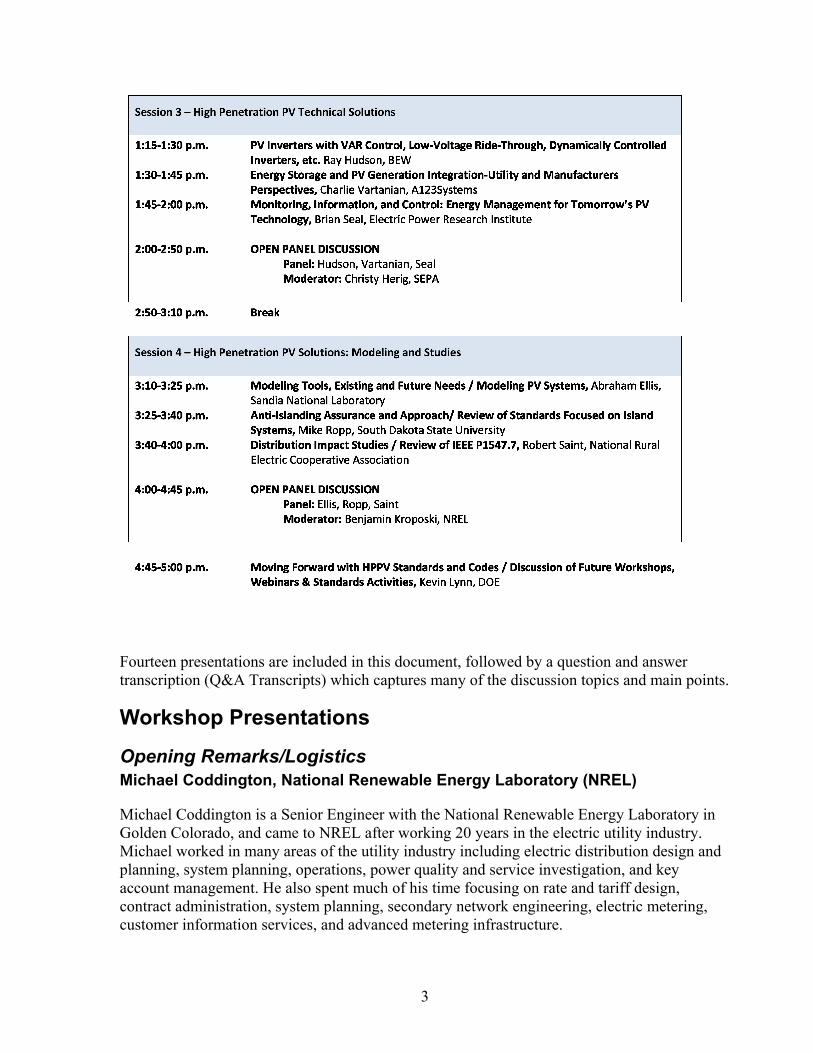
Solar Program Budget Sub-Elements
Photovoltaics (PV)
Concentrating Solar Power (CSP)
DOESETP
Market TransformationSystem Integration
Distributed Generation - on-site or near point of use -
Centralized Generation - large users or utilities -
Energy Efficiency & Renewable Energy eere.energy.gov
3
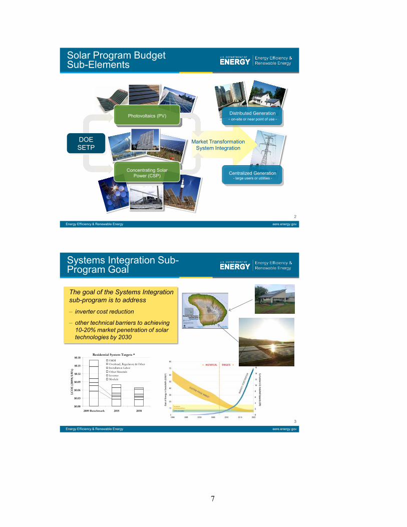
The goal of the Systems Integration sub-program is to address
– inverter cost reduction
– other technical barriers to achieving 10-20% market penetration of solar technologies by 2030
Systems Integration Sub-Program Goal
Residential System Targets *
$0.00
$0.03
$0.06
$0.09
$0.12
$0.15
$0.18
2009 Benchmark 2015 2030
LCO
E (2
009$
/kW
h)
O&M Overhead, Regulatory & Other Installation Labor Other Materials Inverter Module

8
Energy Efficiency & Renewable Energy eere.energy.gov
4
• The Systems Integration Area is organized into the following:• System Technology Development
– Developing technologies for allowing PV systems to integrate into distribution systems at high penetrations and Smart grids (Solar Energy Grid Integration Systems – SEGIS)
• System Level Technical Modeling and Analysis– Developing technical models for high penetration analysis
• System Level Lab and Field Testing – Lab and field testing of high penetration scenarios
• Solar Resource Characterization and Forecasting– Radiometry– Forecasting– Resource Characterization and Modeling
• Systems Integration Codes and Standards – Updating standards and codes to address high penetration solar
• Testing, Evaluation, and Reliability
Areas of Activity
Energy Efficiency & Renewable Energy eere.energy.gov
5
Solar Capacity Growth in 10% and 20% Scenarios
Slide 5
9
Energy Efficiency & Renewable Energy eere.energy.gov
6
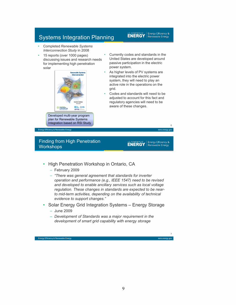
• Completed Renewable Systems Interconnection Study in 2008
• 15 reports (over 1000 pages) discussing issues and research needs for implementing high penetration solar
Systems Integration Planning
Developed multi-year program plan for Renewable Systems Integration based on RSI Study
• Currently codes and standards in the United States are developed around passive participation in the electric power system.
• As higher levels of PV systems are integrated into the electric power system, they will need to play an active role in the operations on the grid.
• Codes and standards will need to be adjusted to account for this fact and regulatory agencies will need to be aware of these changes.
Energy Efficiency & Renewable Energy eere.energy.gov
7
• High Penetration Workshop in Ontario, CA– February 2009– “There was general agreement that standards for inverter
operation and performance (e.g., IEEE 1547) need to be revised and developed to enable ancillary services such as local voltage regulation. These changes in standards are expected to be near-to mid-term activities, depending on the availability of technical evidence to support changes.”
• Solar Energy Grid Integration Systems – Energy Storage– June 2009– Development of Standards was a major requirement in the
development of smart grid capability with energy storage
Finding from High Penetration Workshops

10
Energy Efficiency & Renewable Energy eere.energy.gov
8
The Hawaii utilities (HECO, MECO, HELCO) are proposing to limit the total amount of distributed generation to 5% of the peak capacity. HECO is resetting the frequency cut-off from 59.3 to 57 Hz.
Island Grid
Net System Load at Peak (MW)
Existing DG (MW)
Existing Distribution Level Penetration
Proposed Action
Oahu 1,200 40.1 3.3%Allow DG to 60MW; conduct further study over course of year to confirm ability to accommodate more.
Hawaii 194.6 9.1 4.7%
Defer additional variable DG interconnection requests including standard interconnection agreement and NEM requests, until appropriate mitigation measures are identified and employed. Defer bi-lateral PPA negotiations.
Maui 199.9 5.8 2.9% Same as Hawaii (above)
Lanai 4.70 2.1 43.7% Defer additional DG interconnections
Molokai 5.95 0.3 5.0% Defer additional DG interconnections
System and Integration Issues
Energy Efficiency & Renewable Energy eere.energy.gov
9
Technology DevelopmentSolar Energy Grid Integration Systems (SEGIS)
• Program Scope: Develop highly integrated, advanced inverters/controllers either with built-in energy management functions (including management of energy storage) or capable of interfacing with energy management and energy storage systems to achieve fully grid-interactive PV distribution systems.
• Impact: DOE involvement provides the necessary funding to create new technologies compatible with the Smart Grid.
• Collaborations: Industry, EPRI, NIST, OE, Universities
• Research Category: Advanced Component Development and Prototypes
• TRL Level: 6
Year Budget
1) Scoping $4.7M2) Product Development $21M3) Deployment TBD
11
Energy Efficiency & Renewable Energy eere.energy.gov
10
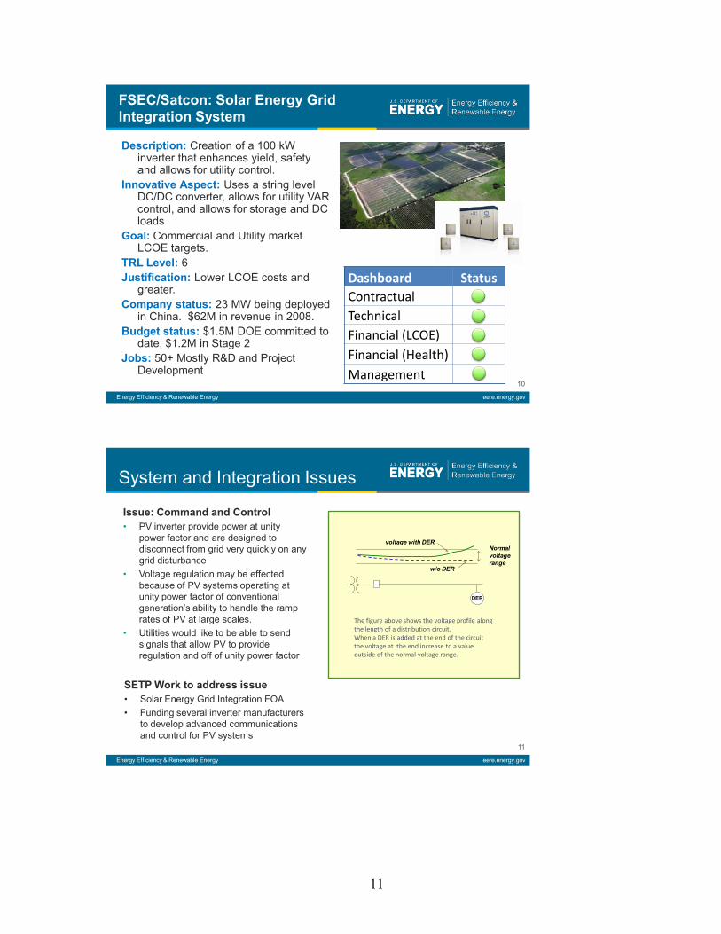
Dashboard StatusContractualTechnicalFinancial (LCOE)Financial (Health)Management
FSEC/Satcon: Solar Energy Grid Integration System
Description: Creation of a 100 kW inverter that enhances yield, safety and allows for utility control.
Innovative Aspect: Uses a string level DC/DC converter, allows for utility VAR control, and allows for storage and DC loads
Goal: Commercial and Utility market LCOE targets.
TRL Level: 6Justification: Lower LCOE costs and
greater.Company status: 23 MW being deployed
in China. $62M in revenue in 2008.Budget status: $1.5M DOE committed to
date, $1.2M in Stage 2Jobs: 50+ Mostly R&D and Project
Development
Energy Efficiency & Renewable Energy eere.energy.gov
11
Issue: Command and Control• PV inverter provide power at unity
power factor and are designed to disconnect from grid very quickly on any grid disturbance
• Voltage regulation may be effected because of PV systems operating at unity power factor of conventional generation’s ability to handle the ramp rates of PV at large scales.
• Utilities would like to be able to send signals that allow PV to provide regulation and off of unity power factor
System and Integration Issues
SETP Work to address issue • Solar Energy Grid Integration FOA• Funding several inverter manufacturers
to develop advanced communications and control for PV systems
The figure above shows the voltage profile along the length of a distribution circuit. When a DER is added at the end of the circuit the voltage at the end increase to a value outside of the normal voltage range.
DG
Normal voltage range
w/o DER
voltage with DER
DER
12
Energy Efficiency & Renewable Energy eere.energy.gov
12
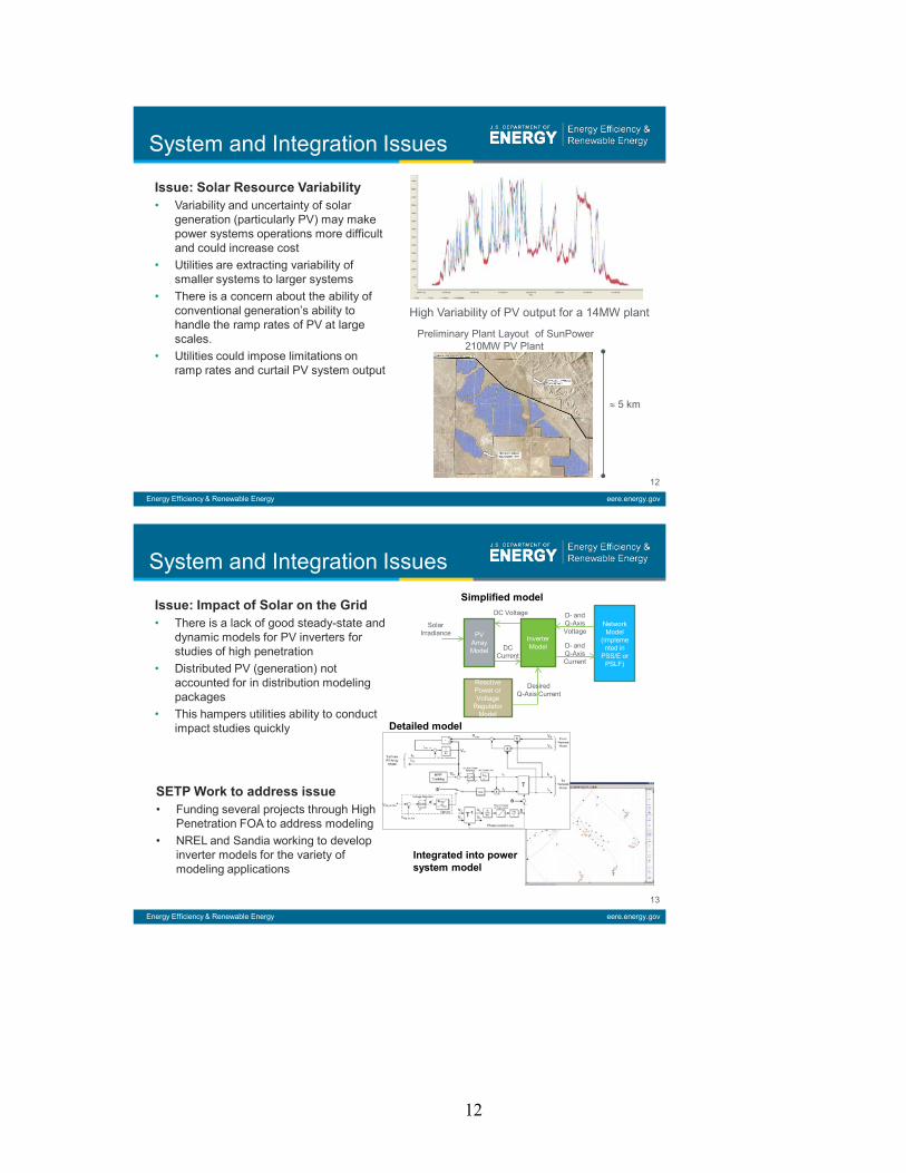
Issue: Solar Resource Variability• Variability and uncertainty of solar
generation (particularly PV) may make power systems operations more difficult and could increase cost
• Utilities are extracting variability of smaller systems to larger systems
• There is a concern about the ability of conventional generation’s ability to handle the ramp rates of PV at large scales.
• Utilities could impose limitations on ramp rates and curtail PV system output
System and Integration Issues
High Variability of PV output for a 14MW plant
Preliminary Plant Layout of SunPower 210MW PV Plant
≈ 5 km
Energy Efficiency & Renewable Energy eere.energy.gov
13
Issue: Impact of Solar on the Grid• There is a lack of good steady-state and
dynamic models for PV inverters for studies of high penetration
• Distributed PV (generation) not accounted for in distribution modeling packages
• This hampers utilities ability to conduct impact studies quickly
System and Integration Issues
SETP Work to address issue • Funding several projects through High
Penetration FOA to address modeling• NREL and Sandia working to develop
inverter models for the variety of modeling applications
PV Array Model
Inverter Model
Network Model
(implemented in
PSS/E or PSLF)
Reactive Power or Voltage
Regulator Model
Solar Irradiance
DC Voltage
DC Current
Desired Q-Axis Current
D- and Q-Axis Current
D- and Q-Axis Voltage
Simplified model
Detailed model
Integrated into power system model

13
Energy Efficiency & Renewable Energy eere.energy.gov
14
High Penetration Solar Deployment
Areas of Activity• Topic 1: Improved Modeling Tools
Development• Topic 2: Field Verification of High-
Penetration Levels of PV into the Distribution Grid
• Topic 3: Modular Power Architecture• Topic 4: Demonstration of PV and
Energy Storage for Smart GridsAwardees• Arizona Public Service Company• Commonwealth Edison Company• Florida State University• National Renewable Energy
Laboratory• Sacramento Municipal Utility District• University of California San Diego• Virginia Polytechnic Institute and
State University
Energy Efficiency & Renewable Energy eere.energy.gov
15
High Penetration AwardNREL/Southern California Edison
SCE MW scale rooftop installation
Description: SCE is installing 500MW of commercial rooftop PV systems on the distribution systems over the next 5 years.
Innovative Aspect: Very high penetration of PV on distribution system that is owned by the utility.
Goal: To monitor systems and develop models of high penetration systems on the distribution system.
TRL Level: 7Justification: Answer questions and
develop solutions to high penetration of solar on the distribution system.
Company status: One of the largest utilities (IOU) in California
Budget status: $3.6M DOE over 5 years; Year 1
Jobs: 50 Project Development
Dashboard Status*ContractualTechnicalFinancial (LCOE)Financial (Health)Management
*Just Starting this Year

14
Energy Efficiency & Renewable Energy eere.energy.gov
16
Thank You
Contact Information:Kevin LynnDepartment of EnergyPhone: (202) 586-1044Email: [email protected]
Session 1 – High Penetration PV Concerns
Review of High Penetration PV Issues Thomas Key, Electric Power Research Institute
Tom Key has over 30 years experience in energy related R&D with the U.S. Navy, Sandia National Laboratory, and EPRI. He currently manages EPRI’s program to enable integration of distributed renewable resources. Tom is a Fellow of the IEEE and a nationally recognized leader in power system compatibility research, integration of distributed and renewable energy resources, application energy storage and power electronic technologies.

15
High Penetration Photovoltaics WorkshopMay 20, 2010Denver, Colorado
It’s Time to Change the RulesThomas Key, EPRI
Review of High Penetration PV Issues
2
• Role of distributed PV in voltage regulation, steady state and dynamic?
• Best response to abnormal grid voltage, setting trip limits?
• Responsibility to prevent unintended islanding? • Coordination with existing protection systems?• Is PV a negative load or a grid asset…adapting to
changing conditions?• To use central or distributed control and
communication?

16
We have been working on theseissues for a while…
3
Codes and Standards• NEC Article 690, PV
System Installations, 1984• IEEE 929 - for Utility Inter-
face of PV Systems, 1988• IEEE 1001 –Recommended
Practice for Grid “Integration”, 1989
• IEEE 1547 and UL 1749 –Std Interconnection, 2003
• FERC Standards ConnectionTom Key, Sandia Lab, July 1987
• IEEE 2030, New Standard for High Penetration Integration with Distribution Grid, 20XX
Voltage Response/Ride Thru Test
4
Early Inverter Test Results
Sandia Lab1982-83
17
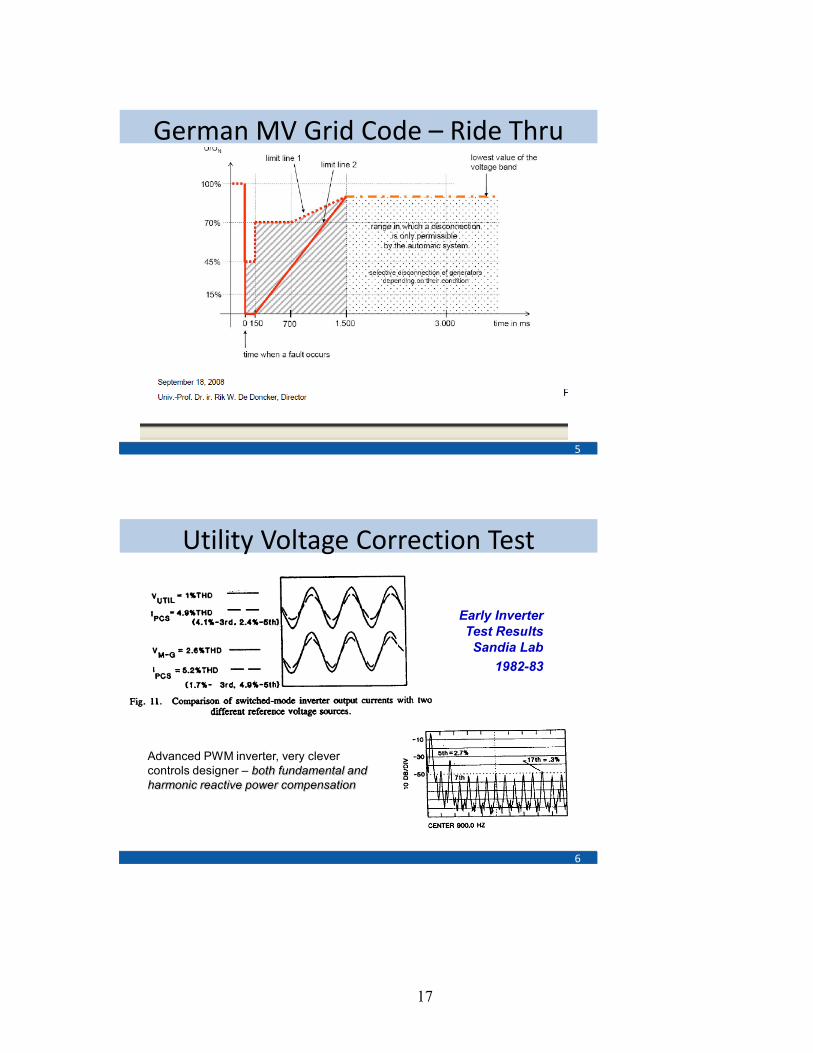
German MV Grid Code – Ride Thru
5
Utility Voltage Correction Test
6
Early Inverter Test Results
Sandia Lab1982-83
Advanced PWM inverter, very clever controls designer – both fundamental and harmonic reactive power compensation
18
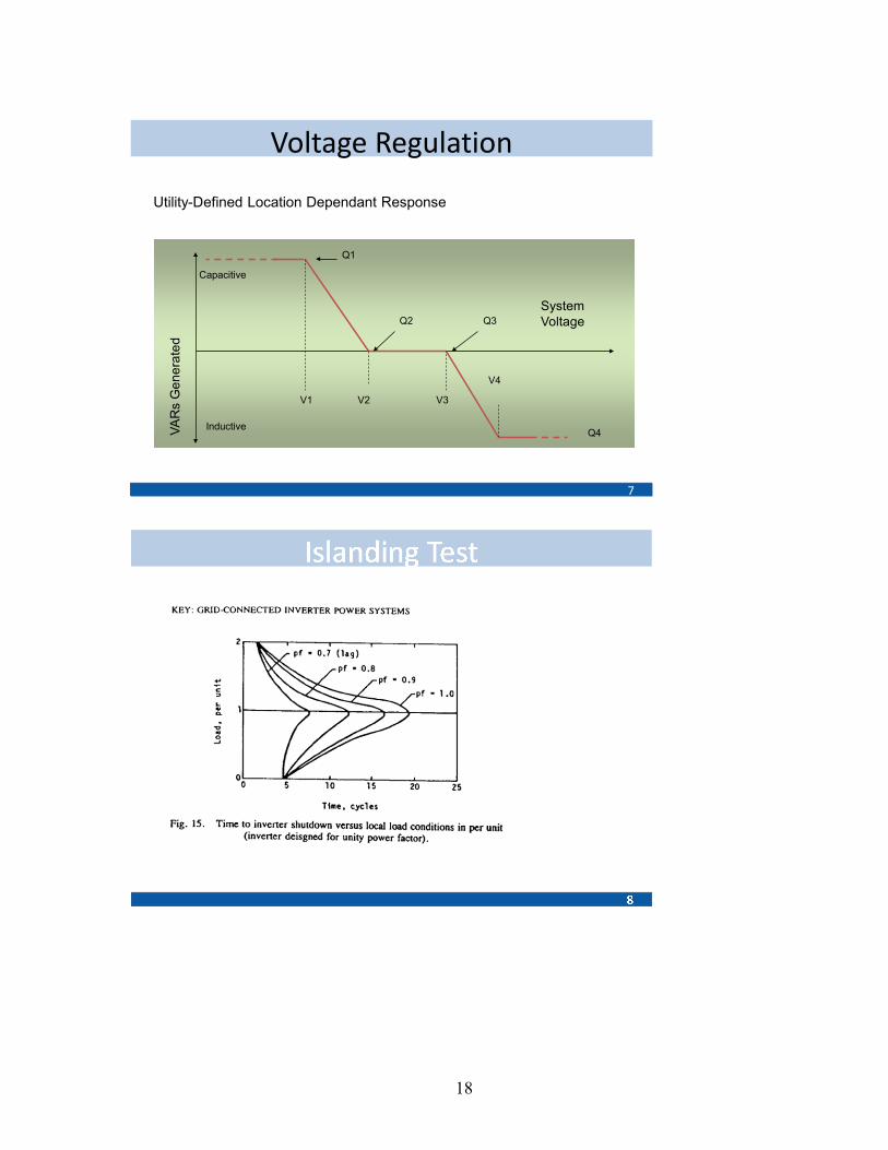
Voltage Regulation
7
VAR
s G
ener
ated
Capacitive
Inductive
System Voltage
V1 V2 V3
V4
Q1
Q4
Q3Q2
Utility-Defined Location Dependant Response
19
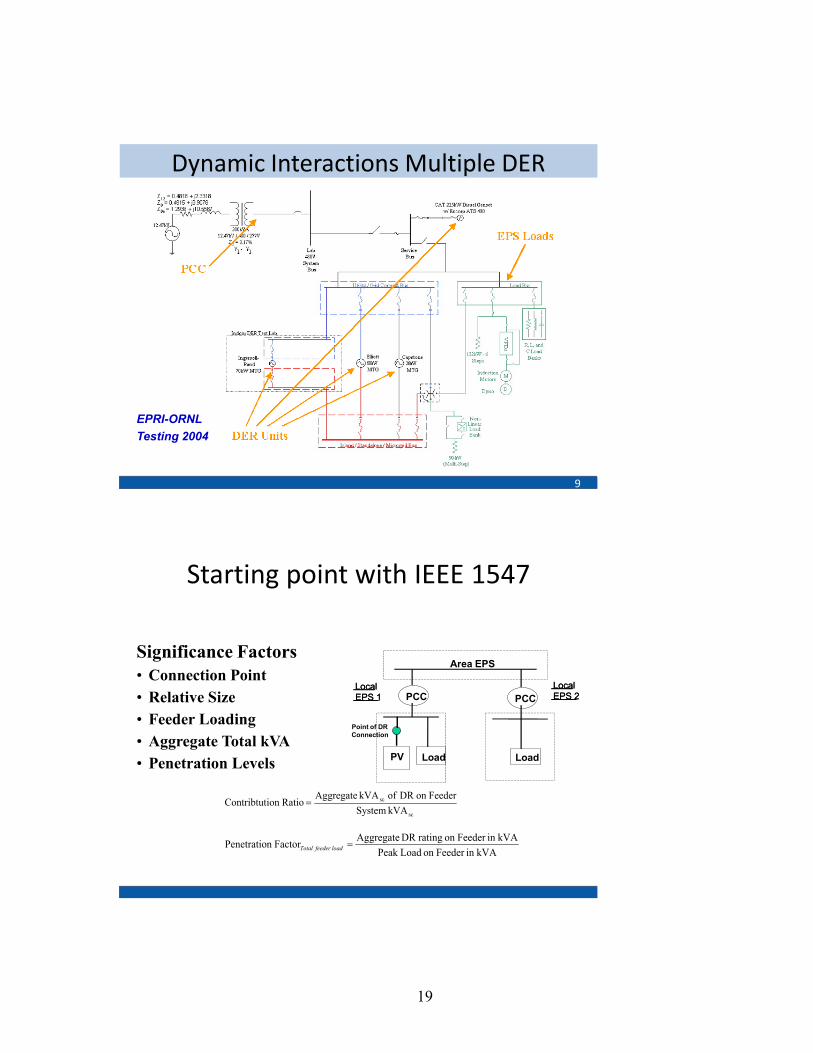
Dynamic Interactions Multiple DER
9
EPRI-ORNLTesting 2004
kVAin Feeder on LoadPeak kVAin Feeder on rating DR AggregateFactorn Penetratio =load feeder Total
sc
sc
kVA SystemFeederon DR of kVA Aggregate
Ratioion Contribtut =
Significance Factors• Connection Point• Relative Size• Feeder Loading • Aggregate Total kVA• Penetration Levels
Local EPS 1
Local EPS 2
Area EPS
LoadPV
PCC PCC
Load
Point of DR Connection
Local EPS 1
Local EPS 2
Starting point with IEEE 1547

20
Make a plan to change the rules
11
% of Generation ≤ 2% ≤ 10% ≤ 30% 100% Grid Penetration Scenarios
I. Low-numbers and level of PV with relatively stiff grid connection
II. Moderate-level of PV with relatively soft grid connection
III. High-level of PV with capacity of grid less than the load demand
IV. PV operates part time as an island or micro-grid
PV Impact and its Role in the Grid
Very low, not significant to grid operation
Non critical, can affect distribution voltage near PV
Critical to power delivery and meeting demand
Primary power source for stand alone operation
Interconnection and Integration Objectives
Non interference, good citizen and compatible
Manage any local distribution impacts
Engage PV for system operations and control
Rely on PV for stability and regulation
Rules/Standard Operating Procedures
IEEE 1547-2003 current practice radial feeders
Modified 1547, add network and penetration limits
New rules include operation and grid support requirement
Standalone rules that are system dependent
Main Concerns with-respect-to system dynamic grid impacts
- Voltage and current trip limits, - Response to faults - Synchronization
- Interfere with regulation, - Recovery times, - Islanding - Coordination.
- Availability - Regulation provided - Ramping response - Interactions of machine controls
- Availability - Load following - Voltage control - Normal and reserve capacity
……Transitions On- and Off-Grid……
Are we ready to do this thing?
12
Tom Key865-218-8082
“Completing the Circuit”

21
Defining High Penetration–Multiple Definitions and Where to Apply Them Phil Barker, NOVA
Phil Barker has worked as a consulting engineer in the electric power industry for 24 years working for Power Technologies, Incorporated, EPRI’s Power Electronics Applications Center, and as the leader of Nova Energy Specialists, a consulting firm he founded.
Phil has extensive experience analyzing the impacts of high penetration distributed generation on power systems, considering factors such as voltage regulation, grounding compatibility, power system losses, stability, overcurrent protection, power quality and reliability. Phil has also assisted several states in the development of first generation distributed generation interconnection requirements.
Phil is a member of ASES, a Senior Member of IEEE and was a participant in the development of IEEE 1547. He received his B.S. and M.S. degrees in Electrical Engineering from Clarkson University, and is the author of 31 technical papers and articles.
High Penetration Photovoltaics WorkshopMay 20, 2010Denver, Colorado
Defining High Penetration PV –Multiple Definitions and Where to Apply Them
Presented by: Phil Barker Founder and Principal Engineer Nova Energy Specialists, [email protected](518) 346-9770
22
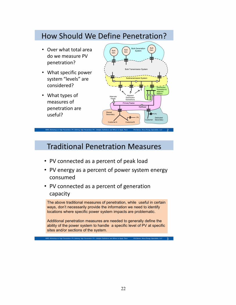
How Should We Define Penetration?
• Over what total area do we measure PV penetration?
• What specific power system “levels” are considered?
• What types of measures of penetration are useful?
2NREL Workshop on High Penetration PV: Defining High Penetration PV – Multiple Definitions and Where to Apply Them Phil Barker, Nova Energy Specialists, LLC
Subtransmission System
PV
PV
Bulk Transmission System
Alternate Feeds
Bulk Gen.Bulk
Gen.Bulk Gen.
Customer A Customer B
Adjacent Distribution Substations
Primary Feeder
Distribution Substation & adjacent feeders
Bulk Generation System
Shared Secondary
Dedicated SecondaryCustomer
Recloser
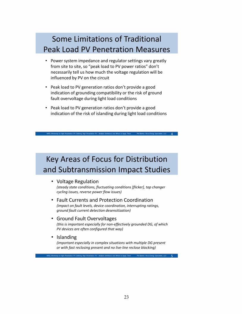
Traditional Penetration Measures
• PV connected as a percent of peak load
• PV energy as a percent of power system energy consumed
• PV connected as a percent of generation capacity
3
The above traditional measures of penetration, while useful in certain ways, don’t necessarily provide the information we need to identify locations where specific power system impacts are problematic.
Additional penetration measures are needed to generally define the ability of the power system to handle a specific level of PV at specific sites and/or sections of the system.
NREL Workshop on High Penetration PV: Defining High Penetration PV – Multiple Definitions and Where to Apply Them Phil Barker, Nova Energy Specialists, LLC
23
Some Limitations of Traditional Peak Load PV Penetration Measures• Power system impedance and regulator settings vary greatly
from site to site, so “peak load to PV power ratios” don’t necessarily tell us how much the voltage regulation will be influenced by PV on the circuit
• Peak load to PV generation ratios don’t provide a good indication of grounding compatibility or the risk of ground fault overvoltage during light load conditions
• Peak load to PV generation ratios don’t provide a good indication of the risk of islanding during light load conditions
4NREL Workshop on High Penetration PV: Defining High Penetration PV – Multiple Definitions and Where to Apply Them Phil Barker, Nova Energy Specialists, LLC
Key Areas of Focus for Distribution and Subtransmission Impact Studies
• Voltage Regulation (steady state conditions, fluctuating conditions [flicker], tap changer cycling issues, reverse power flow issues)
• Fault Currents and Protection Coordination(impact on fault levels, device coordination, interrupting ratings, ground fault current detection desensitization)
• Ground Fault Overvoltages (this is important especially for non-effectively grounded DG, of which PV devices are often configured that way)
• Islanding(important especially in complex situations with multiple DG present or with fast reclosing present and no live-line reclose blocking)
5NREL Workshop on High Penetration PV: Defining High Penetration PV – Multiple Definitions and Where to Apply Them Phil Barker, Nova Energy Specialists, LLC
24
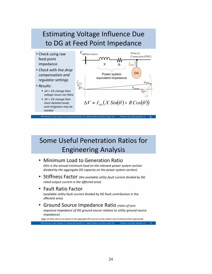
• Check using raw feed point impedance
• Check with line drop compensation and regulator settings
• Results: ∆V < 1% change then
voltage issues not likely
∆V > 1% change then more detailed study and mitigation may be needed
Estimating Voltage Influence Due to DG at Feed Point Impedance
6
( ) ( )( )θθ CosRSinXIV DG +≈∆
Point of Connection (POC)
Vinfinite source
RX IDG
Vsourceθ
DG
IDG
∆V
NREL Workshop on High Penetration PV: Defining High Penetration PV – Multiple Definitions and Where to Apply Them Phil Barker, Nova Energy Specialists, LLC
Power system equivalent impedance
Some Useful Penetration Ratios for Engineering Analysis
• Minimum Load to Generation Ratio(this is the annual minimum load on the relevant power system section divided by the aggregate DG capacity on the power system section)
• Stiffness Factor (the available utility fault current divided by DG rated output current in the affected area)
• Fault Ratio Factor (available utility fault current divided by DG fault contribution in the affected area)
• Ground Source Impedance Ratio (ratio of zero sequence impedance of DG ground source relative to utility ground source impedance)
7NREL Workshop on High Penetration PV: Defining High Penetration PV – Multiple Definitions and Where to Apply Them Phil Barker, Nova Energy Specialists, LLC
Note: all ratios above are based on the aggregate DG sources on the system area of interest where appropriate

25
Type of Ratio
What is it useful for?(Note: these ratios are intended for distribution and subtransmission system impacts of DG listed below, and not necessarily the overall bulk system stability impacts)
Suggested Penetration Level Ratios(1)
Very Low Penetration
(Very low probabilityof any issues)
Moderate Penetration
(Low to minor probabilityof issues)
HigherPenetration(5)
(Increased probabilityof serious issues.
Minimum Load to
Generation Ratio(2)
• Ground fault overvoltage analysis (use ratios shown when DG is not effectively grounded)
• Islanding analysis (use ratios 2/3 of those shown)
>10Synchronous Gen.
10 to 5Synchronous Gen.
Less than 5Synchronous Gen.
>6 Inverters(4)
6 to 3Inverters
Less than 3 Inverters
Fault Ratio Factor
(ISCUtility/ISCDG)
• Overcurrent device coordination• Overcurrent device ratings >100 100 to 20
Less than 20
Stiffness Factor
(IUitliltySC/IRatedDG)
• Voltage Regulation(this ratio is a good indicator of voltage influence. Wind/PV have higher ratios due to their fluctuations. Besides this ratio, may need to check for current reversal at upstream regulator devices.)
>100 PV/Wind
100 to 50PV/Wind
Less than 50 PV/Wind
> 50 Steady Source
50 to 25Steady Source
Less than 25 Steady Source
Ground Source Impedance
Ratio(3)
• Ground fault desensitization• Overcurrent device coordination
and ratings>100 100 to 20
Less than 20
8
Notes: 1. Ratios are meant as guides for radial 4-wire multigrounded neutral distribution system DG applications and are calculated based on aggregate DG on relevant power system sections2. “Minimum load” is the lowest annual load on the line section of interest (up to the nearest applicable protective device). Power factor of load is assumed to be 0.9 inductive.3. Useful when DG or it’s interface transformer provides a ground source contribution. Must include effect of step-up transformer if present.4. Inverters are weaker sources than rotating machines therefore a smaller ratio is allowable5. If DG application falls in this “higher penetration” category it means some system upgrades/adjustments are likely needed to avoid power system issues.
NREL Workshop on High Penetration PV: Defining High Penetration PV – Multiple Definitions and Where to Apply Them Phil Barker, Nova Energy Specialists, LLC
Ratios and Their Uses
Concluding Remarks & Caveats• Ratios we have discussed are only guides for establishing
when distribution and subtransmission system effects of DG become “significant” to the point of requiring more detailed studies and/or potential mitigation options.
• They must be applied by knowledgeable engineers that understand the context of the situation and the exceptions where the ratios don’t work
• It requires a lot more than just these slides here to do this topic justice. We have omitted a lot of details due to the short presentation format so this is just meant as a brief illustration of these issues.
9NREL Workshop on High Penetration PV: Defining High Penetration PV – Multiple Definitions and Where to Apply Them Phil Barker, Nova Energy Specialists, LLC
26
Distribution System Impacts from PV on Utility Systems Russ Neal, Southern California Edison
Russell Neal is a Strategic Program Manager for Southern California Edison, specializing in Smart Grid with an emphasis on distribution systems.
His experience includes five years as an officer in the surface nuclear Navy, seventeen years at Southern California Edison’s San Onofre Nuclear Generating Station, and twelve years in the Transmission and Distribution Business Unit including service in distribution apparatus engineering, and as Manager of Distribution System Engineering. Russell holds a BSEE from the U.S. Naval Academy, an MSEE from the University of Idaho, and an MBA from Azusa Pacific University. He is a registered Professional Engineer in both Electrical and Nuclear Engineering in the State of California.
High Penetration Photovoltaics WorkshopMay 20, 2010Denver, Colorado
Distribution System Impacts from PV on Utility SystemsRuss Neal, Southern California Edison

27
PG&E
SCE
• Serve a population of about 14 million people in a 50,000-square-mile service area within central, coastal and Southern California
• 5 million electric meters
• 12,000 circuit miles of transmission lines and more than 111,500 circuit miles of distribution lines
• 5,000 MW of generating capacity from interests in nuclear, hydroelectric, and fossil-fueled power plants
• Award-winning energy efficiency & DR customer programs
• Industry leader in renewable energy, electric transportation, Smart Grid and smart metering
SDG&ELADWP
Southern California EdisonAn Edison Internat ional Company
Presentation Content
• PV System Impacts on Electric Distribution
• Utility Concerns and Potential Problems with High Penetration
• What are we Doing to Address this Issue?
3

28
Impacts• Seasonal, Daily, Minute Solar Power Fluctuating
• PV Inverter – Grid Interactions
• Low Capacity Factor < 20%
• Inaccurate forecasting
• No storage
• Reverse Power Flow
Identified Issues Relative Priority Identified Issues Relative Priority
Voltage Control High Equipment Specs High
Protection HighInterconnection Handbook
Medium
System Operations High Rule 21 and WDAT Medium
Power Quality High IEEE 1547/ UL 1741 Medium
Monitoring and Control
Medium Application Review High
Feeder Loading Criteria
HighClarification of Responsibilities
High
Transmission Impact
MediumIntegration with Tariffs
Medium
Feeder Design MediumCoordination with Other Initiatives
Medium
Planning Models Medium
Concerns

29
What we are Doing• Inverter Specifications
– DIFG (EPRI)– IEEE 1547.8– Inverter testing
• ISGD AVVC project• DMS/ALCS Project• NREL Testing
– On SPVP impacted circuits– Will include inverter trials as well
• Other studies
Inverter Modes
• Normal Mode– Conservation Voltage
– Supply/Draw VARs to regulate local voltage
– “Qmax Available”
• Emergency Mode– Supply max available
VARs to support transmission
30
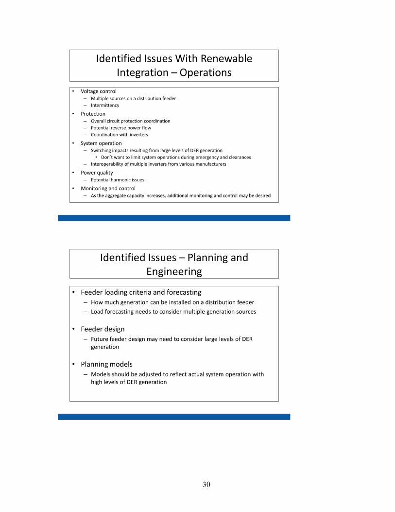
Identified Issues With Renewable Integration – Operations
• Voltage control– Multiple sources on a distribution feeder– Intermittency
• Protection– Overall circuit protection coordination– Potential reverse power flow– Coordination with inverters
• System operation– Switching impacts resulting from large levels of DER generation
• Don’t want to limit system operations during emergency and clearances– Interoperability of multiple inverters from various manufacturers
• Power quality– Potential harmonic issues
• Monitoring and control– As the aggregate capacity increases, additional monitoring and control may be desired
Identified Issues – Planning and Engineering
• Feeder loading criteria and forecasting– How much generation can be installed on a distribution feeder
– Load forecasting needs to consider multiple generation sources
• Feeder design– Future feeder design may need to consider large levels of DER
generation
• Planning models– Models should be adjusted to reflect actual system operation with
high levels of DER generation
31
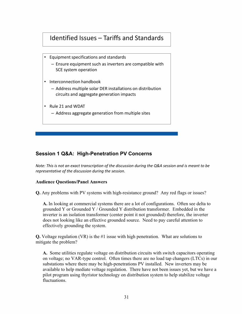
Identified Issues – Tariffs and Standards
• Equipment specifications and standards
– Ensure equipment such as inverters are compatible with SCE system operation
• Interconnection handbook
– Address multiple solar DER installations on distribution circuits and aggregate generation impacts
• Rule 21 and WDAT
– Address aggregate generation from multiple sites
Session 1 Q&A: High-Penetration PV Concerns Note: This is not an exact transcription of the discussion during the Q&A session and is meant to be representative of the discussion during the session. Audience Questions/Panel Answers Q. Any problems with PV systems with high-resistance ground? Any red flags or issues?
A. In looking at commercial systems there are a lot of configurations. Often see delta to grounded Y or Grounded Y / Grounded Y distribution transformer. Embedded in the inverter is an isolation transformer (center point it not grounded) therefore, the inverter does not looking like an effective grounded source. Need to pay careful attention to effectively grounding the system.
Q. Voltage regulation (VR) is the #1 issue with high penetration. What are solutions to mitigate the problem?
A. Some utilities regulate voltage on distribution circuits with switch capacitors operating on voltage; no VAR-type control. Often times there are no load tap changers (LTCs) in our substations where there may be high-penetrations PV installed. New inverters may be available to help mediate voltage regulation. There have not been issues yet, but we have a pilot program using thyristor technology on distribution system to help stabilize voltage fluctuations.

32
A. Close to putting in static VAR compensator, but have not done it yet. Important things to look at: • Rapid changes, like voltage flicker are more rapid than the voltage regulation (VR)
equipment is designed to operate at (time delay of 20-30 s); not meant for rapid changes. Tap changer cycling is a big issue and can be a problem. Back off on the line drop compensation; this is a cheap fix. If you reduce more sensitive, you're degrading VR for the customer. There is a tradeoff.
• Slower steady-state issues. If DG source exporting lots of VARS, then distribution system could back off on providing VARS.
Q. Problem transitioning from steady-state to moving. What solutions for flicker?
A. One of the speakers made their own curve for PV, similar to GE flicker curve in IEEE 519, but not as sensitive. GE is based on rectangular shape, but PV is more sinusoidal shaped. Little more variation with PV and still don’t see anything especially for PV, smoother. There has not yet seen a problem on any feeder that have been studied. Flicker has not been the problem. More issues/problems pertain to LTC cycling and ground-fault overvoltages.
Q. Would the utility let you open up UL1741 or IEEE 1547 constraints to allow inverter support VAR capability? Dynamic voltage compensation.
A. Nothing being done on a commercial product (at distribution level). GE has made adjustments with large wind turbines to meet FERC 661-A requirements at the transmission level.
Q. Is the PUC letting us invest in grid-interactive inverters?
A. Dynamic voltage compensation is not a PUC issue. A. X/R ratio on system is much greater than 1 typically. More reactance than resistance. A little VAR support coming from inverter goes a long way to deal with voltage problems. Very little loss to the inverter and could be very useful.
Q. Control voltage on feeder by backing off on the tap settings in the substation? Does this include any controller communication between substation and the end of the feeder?
A. There are a variety of ways to regulate voltage, LTC control or supplementary VR bank-type control. These have a line drop compensator built into them. It is set for ideal regulation for that particular feeder. You can back off the line settings, thus reducing the sensitivity and the LTC cycling. However, you may need to increase the voltage set-point at the substation.
Q. With knowing what’s going on at the end of the feeder, have you considered developing communication? Automation?
33
A. Smart Grid means making power system more compatible for distributed generation (DG) if communication is better. But don't get carried away, don't make grid too complicated.
Q. Can we put in some simple communication and make basic changes? (He wants to take it a step further with communication.)
A. The technology exists today off the shelf, but it doesn’t solve all the problems, just on the margin.
Q. Emphasizing penetration issues, subdivide into local (voltage) and interconnection-wide (frequency) issues. Use reactive power to control voltage locally. Grid power balance is wider issue. In addition to looking at storage to mitigate PV variability, we should look at loads. When you start to balance the power system at a higher level, you get benefits of aggregation and cloud passing things don’t become an issue. Morning rise and evening drop are more of an issue. It can be counterproductive to balance at local area to try to govern voltage. Reactive power is much more efficient way to do it. GE does market a grid-interactive inverter (based on wind turbine technology) to do such a thing, but it’s hard to market because of IEEE 1547 requirements. Early drafts of IEEE 1547 allowed for grid interaction, but in the end some utilities did not want this capability included. The Commission has adopted IEEE 1547 and can’t deviate from 1547. It is a Catch 22. Choices that were made 10 years are becoming counterproductive.
A. Western Wind Solar Integration Study (WWSIS) coming out very soon. Good point regarding area storage with inverter. Results from WWSIS show you can control for geographical diversity. Diversity of approaches to mitigate problems. Codes and standards (C&S) trying to address 1547 problems and a new standard IEEE 1547.8 should address voltage regulation and other advanced functions. Cal ISO has system above 20 MW with variability generation control variability. A. Storage is not cheap. Watts costs more than VARs. If you add capacity to feeder, putting storage at substation, good concept in addition to using electric vehicles with batteries and integrating them at distribution end.
Q. In deployment of large rooftop systems, have you seen systems kicking on or off due to cloud interaction between different systems? Systems fighting one another?
A. We will have 5 MW in by end of May, another 40 MW (utility owned) by end of year. Another 50 MW IPP contracts, so we are early in the process and have not seen integration issues. A. Worst case is that we have 2 MW on a 10-MW circuit. No operational problems yet.

34
A. In general, you don't have active control going on. Inverter are set to trip off on utility issues. There is not reactive power control and the current systems can’t fight with each other. A. Need to engage the folks in Germany, who have tremendous amount of experience in these issues. They have 1000s of MW of PV. Numerous studies on clouds passing effects on distribution system. U.S. deals with things more loosely, less regulation. Germany has ride-through standards. We don’t need to blaze new territory on these issues; Germany has done much, and we can learn from them.
Q. We should have looked further into the future when drafting 1547 so we wouldn't have to be dealing with some of these problems. We need to look at three things now:
• Reactive support from two directions, not just top down; up to transmission grid from distribution system. When we need reactive support, it would be much more efficient to supply this support from both the distribution and transmission side, instead of top down as we do now.
• Fault-induced-delay voltage recovery. Get more capacity out of our grid. Consider this when we develop new standards. Follow the Volt/VAR schedule.
• Conservation voltage reduction. Optimizing appliances to better efficiencies and more situations. We need to work with appliance manufacturers.
A. Regarding the voltage collapse issue, a little storage goes a long way.
Q. Variability issue. SunEdison has 24 systems in a specific area. On a very cloudy day, in terms of variability, the aggregate takes care of system variability. Variability of less than 5% for aggregate system, when single system has shown variability of 50%. Presentation of the data will be made during PV Specialists Conference in Hawaii.
A. You’re generalizing. System leveling has an impact at the circuit level. The distribution system constraints are not going to benefit from geographical dispersion. A. I take into account how dispersed are the PV on the feeder in my studies. If they are dispersed over several miles, it helps a lot. It’s better than having 1 MW located on top of a building or something like that.
Q. Speak about investing in distribution management system (DMS).
A. DMS is in the very early stages in development. We asked for everything under the sky: integrate DG, regulate PV, etc., in talks with several potential suppliers. Another question is to minimize bandwidth burden on communications systems to have closed-loop control over the system like larger plants. Schedule of behavior or different modes of operation preloaded in DG asset. Don’t want high bandwidth for these operations. Not investing large broadband. Use Internet? What if these things start to fight each other? Has anyone done any full-scale modeling? Trying to regulate voltage from various autonomous inverters? Build in some kind of delay, some randomness.
35
Q. Look at what happened in computer industry. Rapid changes in technology; may cause problems?
A. Doesn’t see the regulatory space changing. Regulators are letting utilities do more research; this is positive. Utilities are getting more funds for research to advance the technology. A. Hawaii is our test lab for new ideas. Utilities have put up cases for owning assets. Filing rate case for owning PV systems. Other utilities have put cases together for owning. Once the utility starts to own the asset, this will change the rules significantly. SEPA is starting to study how to file a rate case.
Q. Delayed voltage recovery after fault. Points out another issue of standards interaction and what would work best. Ride-through needs to be required. There was a study of whole western grid (8 years ago) where GE modeled the system with 20% of the inverters being UL 1741 complaint and the system was shown to have issues with stability. With ride-through capability, it withstood disturbance. UL 1741 compliance is blocking inverters with this capability from market. We need to modernize the grid.
A. Doesn’t make sense to use 1741 for installing batteries. We need IEEE to write a new standard, ties it back to new functionality in IEEE 1547.8. A. An option is to have grid inverters with multimodes. UL1741 or IEEE 1547 or grid-interactive modes. Wind ride-through disturbance is requirement now. Compound problem with not allow wind to remain on line during some fault. UL 1741 trips the inverter. Include VAR support. A. PV has been somewhat more successful than expected; needs of bulk system vs distributed system. IEEE 1547 has accelerated the success of PV. Need to revisit the whole grid PV interaction issue.
Q. What are ways to mitigating problems. Different modes that inverters can behave differetly. Inverter modes Volt/VARs control. In my modeling, I have not run into any problems with inverters fighting each other. It does not take much VARs support to help with voltage regulation.
A. We were surprised by how fast PV came on and can support the grid. Q. Reinforcing these points. Regulatory is a real mess. What is the standard that we should certify our equipment to? Need a standard for inverter compliance.
A. IEEE is working on a new standards IEEE 1547.8 that will include testing to new functionality. That can eventually be integrated with UL 1741 to certify products.

36
Q. Can you use of inverters for frequency regulation?
A. Four-quadrant device, why not make it follow a Watt/Frequency schedule to help stabilize the power grid? This could also apply to refrigerators, electric car chargers. Lots of unexplored territory. We have just barely taken our first steps toward this line.
Q. Defending 1547.4, which has intentional grid-supported capability, but when do you want a grid device interactive? These are exciting times, we now have a 20-MW storage device that is 1547-compliant and meets LVTR requirement.
Session 2 – Gaps in Existing Standards and Codes
Solar ABCs Larry Sherwood, Solar ABCs
Larry Sherwood is President of Sherwood Associates, a renewable energy consulting firm. Mr. Sherwood has nearly 30 years of experience in the renewable energy field. He is Project Administrator for the Solar America Board for Codes and Standards, Executive Director of the Small Wind Certification Council, author of the annual IREC Report, U.S. Solar Market Trends, and Editor of the IREC Small Wind Newsletter. Previously, Mr. Sherwood served as Executive Director of the American Solar Energy Society. He is a graduate of Dartmouth College and lives in a PV-powered home in Boulder, Colorado.
High Penetration Photovoltaics WorkshopMay 20, 2010Denver, Colorado
Gaps in Existing Codes and StandardsLarry Sherwood
37
Solar America Board for Codes and Standards (Solar ABCs)
2
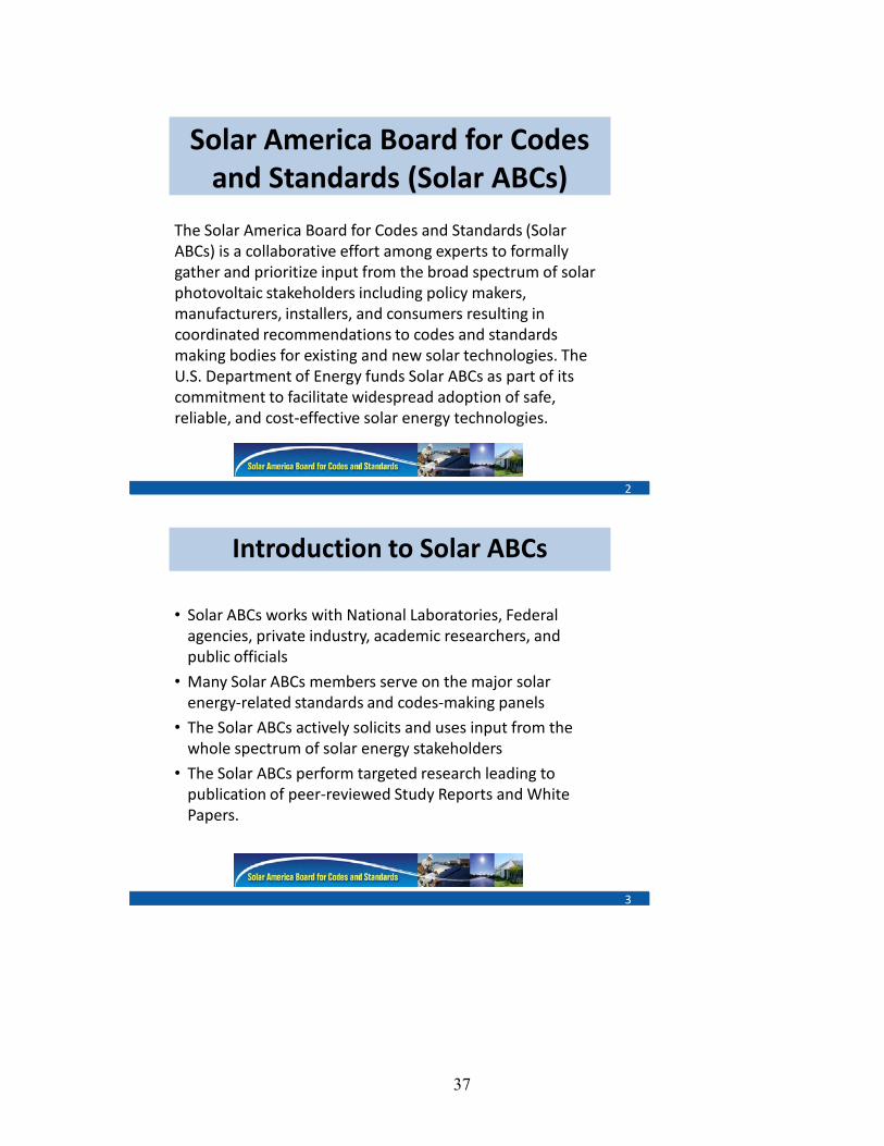
The Solar America Board for Codes and Standards (Solar ABCs) is a collaborative effort among experts to formally gather and prioritize input from the broad spectrum of solar photovoltaic stakeholders including policy makers, manufacturers, installers, and consumers resulting in coordinated recommendations to codes and standards making bodies for existing and new solar technologies. The U.S. Department of Energy funds Solar ABCs as part of its commitment to facilitate widespread adoption of safe, reliable, and cost-effective solar energy technologies.
Introduction to Solar ABCs
3
• Solar ABCs works with National Laboratories, Federal agencies, private industry, academic researchers, and public officials
• Many Solar ABCs members serve on the major solar energy-related standards and codes-making panels
• The Solar ABCs actively solicits and uses input from the whole spectrum of solar energy stakeholders
• The Solar ABCs perform targeted research leading to publication of peer-reviewed Study Reports and White Papers.

38
2010 Gap Analysis
4
• Highest priority topics:– PV Flammability Research (increase in scope for existing activity)
– Ground Fault Protection Improvements to Prevent Fires
– Standards for PV and Storage
– Connection of PV to the Smart Grid
– Guidelines for Utility Inspections
• High Priority but defer until research or work at national labs is complete
– Inverter Qualification Standard
– Standards for Power Conditioning and DC-DC Converters
– Standards for Installation and Operation
– Standards for High Penetration Solar
Systems Interconnection Standards and Codes-IEEE / Smart Grid Tom Basso, NREL
Tom Basso is the NREL Principal Investigator for Smart Grid Interconnection and Interoperability Standards, and the Renewable Systems Impacts areas for DOE Office of Electricity, and the Principal Investigator for the NREL Codes and Standards area for the Solar Energy Technology Program. Tom is Vice Chairman of IEEE SCC21 which sponsors IEEE 1547 interconnection and IEEE 2030 smart grid interoperability standards development. Tom is the US Technical Advisory Group Chair and Technical Advisor for the IEC TC8 Electrical Systems group. Tom received his B.E. Engineering Science, SUNY at Stony Brook and his M.S. in Engineering Thermodynamics and Applied Analysis at the State University of New York at Stony Brook.
39
High Penetration Photovoltaics WorkshopMay 20, 2010Denver, Colorado
Systems Interconnection Standards and Codes: IEEE 1547 and P2030; Tom Basso, NREL
Content• Background
the grid; DER interconnection; standards and applying standards.
• IEEE 1547 and P2030 Standards
• Closing Remarks
2

40
3
Traditional Electric Grid in the USA
3
SmartGrid: Interoperability & DER Interconnection
Distribution System
Communications and Information Technology Information Flow, Data Management,
Monitor & Control
Substations
DE Resources Interconnection
Bulk Power
Combined Heat& Power
Load Managementsensors
sensors
(Also, larger DER on transmission)
sensors
sensors
Systems Approach • Interconnection & Interfaces • Technical Standards • Advanced Technologies • Systems Integration
Transmission System
EV
Recip. Generator
Photovoltaics
Micro Turbine
Storage
Fuel Cell
4
41
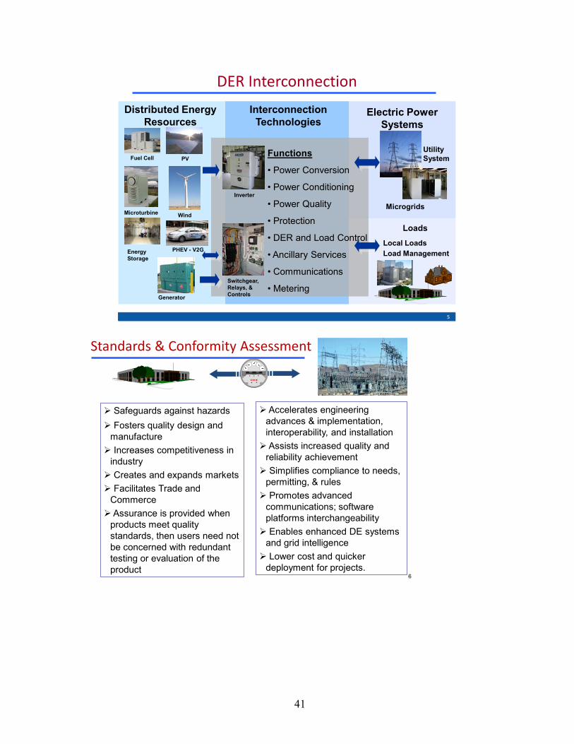
DER Interconnection
Distributed Energy Resources
Interconnection Technologies
Electric Power Systems
Fuel Cell PV
Microturbine Wind
Generator
Inverter
Switchgear, Relays, & Controls
Functions
• Power Conversion
• Power Conditioning
• Power Quality
• Protection
• DER and Load Control
• Ancillary Services
• Communications
• Metering
Microgrids
Energy Storage
LoadsLocal LoadsLoad Management
Utility System
PHEV - V2G
5
Standards & Conformity Assessment
Safeguards against hazards Fosters quality design and
manufacture Increases competitiveness in
industry Creates and expands markets Facilitates Trade and
Commerce Assurance is provided when
products meet quality standards, then users need not be concerned with redundant testing or evaluation of the product
Accelerates engineering advances & implementation, interoperability, and installation Assists increased quality and
reliability achievement Simplifies compliance to needs,
permitting, & rules Promotes advanced
communications; software platforms interchangeability Enables enhanced DE systems
and grid intelligence Lower cost and quicker
deployment for projects. 6
42
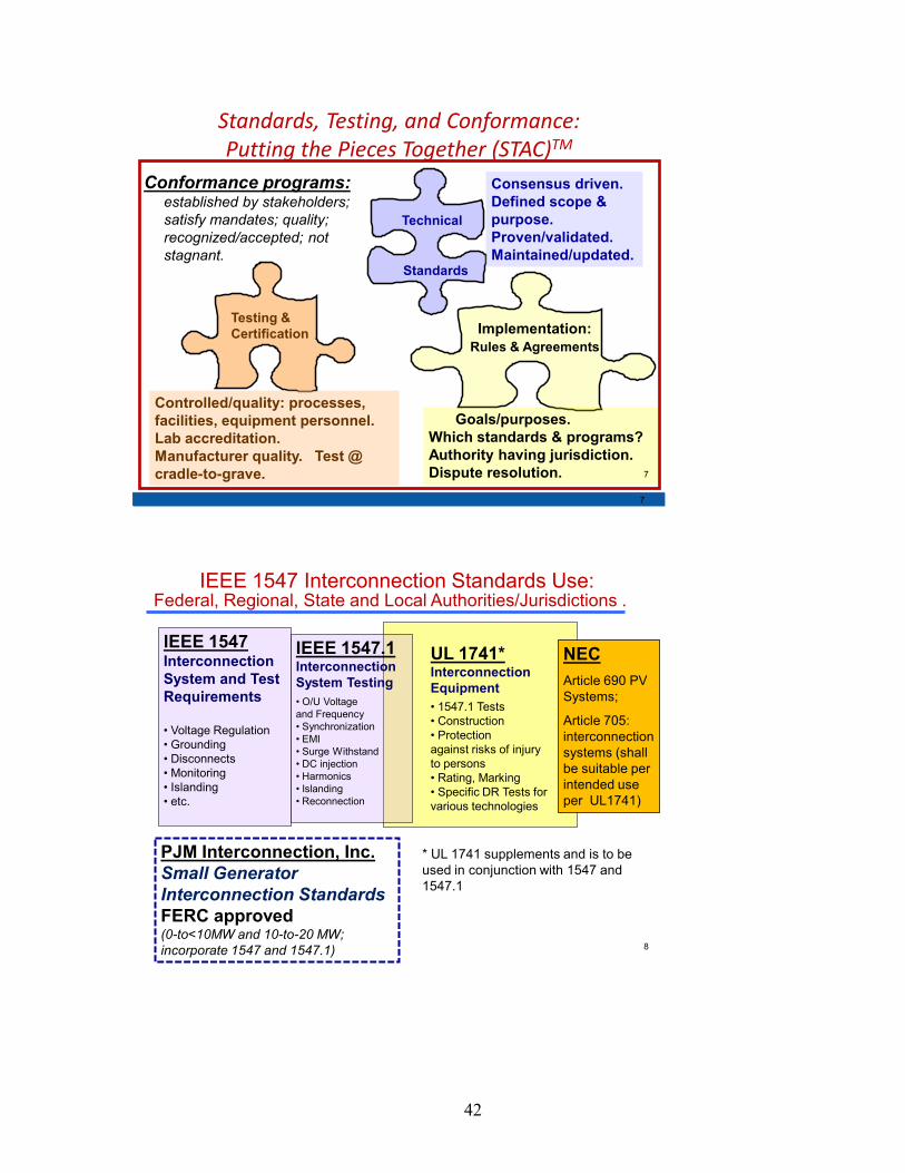
Standards, Testing, and Conformance: Putting the Pieces Together (STAC)TM
Testing & Certification Implementation:
Rules & Agreements
Standards
Technical
Conformance programs:established by stakeholders; satisfy mandates; quality; recognized/accepted; not stagnant.
Controlled/quality: processes, facilities, equipment personnel. Lab accreditation. Manufacturer quality. Test @ cradle-to-grave.
Consensus driven. Defined scope & purpose. Proven/validated. Maintained/updated.
Goals/purposes. Which standards & programs? Authority having jurisdiction. Dispute resolution.
7
7
8
IEEE 1547 Interconnection Standards Use:
UL 1741*Interconnection Equipment • 1547.1 Tests • Construction• Protection against risks of injury to persons• Rating, Marking• Specific DR Tests for various technologies
IEEE 1547.1Interconnection System Testing • O/U Voltage and Frequency• Synchronization• EMI• Surge Withstand• DC injection• Harmonics• Islanding• Reconnection
IEEE 1547Interconnection System and Test Requirements
• Voltage Regulation• Grounding• Disconnects• Monitoring• Islanding• etc.
* UL 1741 supplements and is to be used in conjunction with 1547 and 1547.1
NEC Article 690 PV Systems;
Article 705: interconnection systems (shall be suitable per intended use per UL1741)
PJM Interconnection, Inc. Small Generator Interconnection Standards FERC approved (0-to<10MW and 10-to-20 MW; incorporate 1547 and 1547.1)
Federal, Regional, State and Local Authorities/Jurisdictions .
43
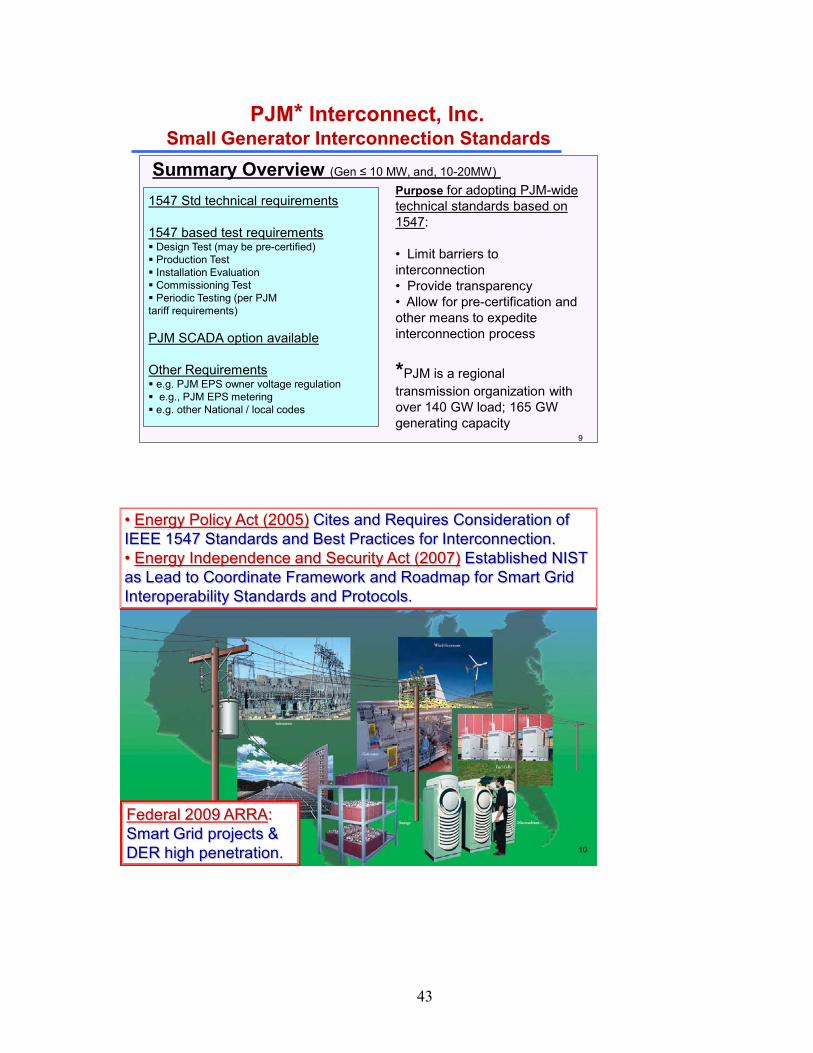
PJM* Interconnect, Inc. Small Generator Interconnection Standards
1547 Std technical requirements
1547 based test requirements Design Test (may be pre-certified) Production Test Installation Evaluation Commissioning Test Periodic Testing (per PJM tariff requirements)
PJM SCADA option available
Other Requirements e.g. PJM EPS owner voltage regulation e.g., PJM EPS metering e.g. other National / local codes
Summary Overview (Gen ≤ 10 MW, and, 10-20MW)Purpose for adopting PJM-wide technical standards based on 1547:
• Limit barriers to interconnection• Provide transparency • Allow for pre-certification and other means to expedite interconnection process
*PJM is a regional transmission organization with over 140 GW load; 165 GW generating capacity
9
• Energy Policy Act (2005) Cites and Requires Consideration of IEEE 1547 Standards and Best Practices for Interconnection. • Energy Independence and Security Act (2007) Established NIST as Lead to Coordinate Framework and Roadmap for Smart Grid Interoperability Standards and Protocols.
Federal 2009 ARRA: Smart Grid projects & DER high penetration. 10
44
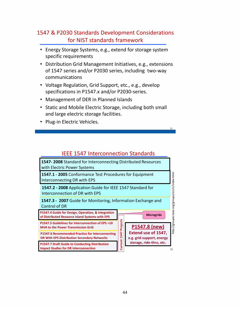
• Energy Storage Systems, e.g., extend for storage system specific requirements
• Distribution Grid Management Initiatives, e.g., extensions of 1547 series and/or P2030 series, including two-way communications
• Voltage Regulation, Grid Support, etc., e.g., develop specifications in P1547.x and/or P2030-series.
• Management of DER in Planned Islands
• Static and Mobile Electric Storage, including both small and large electric storage facilities.
• Plug-in Electric Vehicles.
1547 & P2030 Standards Development Considerations for NIST standards framework
11
1547- 2008 Standard for Interconnecting Distributed Resources with Electric Power Systems
1547.1 - 2005 Conformance Test Procedures for Equipment Interconnecting DR with EPS
1547.2 - 2008 Application Guide for IEEE 1547 Standard for Interconnection of DR with EPS
1547.3 - 2007 Guide for Monitoring, Information Exchange and Control of DR
Curr
ent 1
547
Proj
ects
P1547.4 Guide for Design, Operation, & Integration of Distributed Resource Island Systems with EPS
P1547.6 Recommended Practice for Interconnecting DR With EPS Distribution Secondary Networks
P1547.5 Guidelines for Interconnection of EPS >10 MVA to the Power Transmission Grid
Microgrids
IEEE 1547 Interconnection Standards
http
://g
roup
er.ie
ee.o
rg/g
roup
s/sc
c21/
inde
x.ht
ml
P1547.7 Draft Guide to Conducting Distribution Impact Studies for DR Interconnection
P1547.8 (new) Extend use of 1547, e.g. grid support, energy storage, ride-thru, etc.
12
45
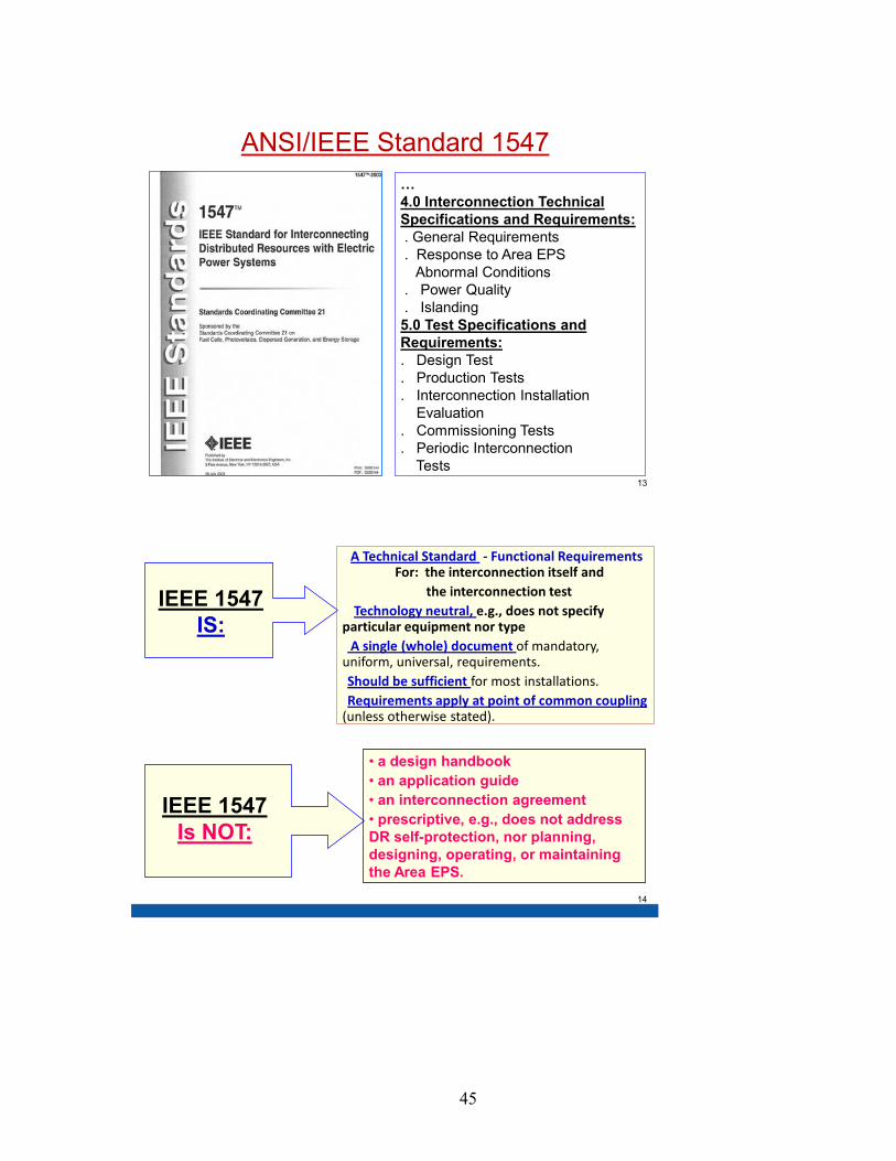
… 4.0 Interconnection Technical Specifications and Requirements: . General Requirements . Response to Area EPS
Abnormal Conditions. Power Quality. Islanding 5.0 Test Specifications and Requirements: . Design Test . Production Tests . Interconnection Installation
Evaluation . Commissioning Tests . Periodic Interconnection
Tests
ANSI/IEEE Standard 1547
13
• A Technical Standard - Functional Requirements For: the interconnection itself and
• the interconnection test • Technology neutral, e.g., does not specify particular equipment nor type • A single (whole) document of mandatory, uniform, universal, requirements. •Should be sufficient for most installations. •Requirements apply at point of common coupling (unless otherwise stated).
IEEE 1547 IS:
IEEE 1547 Is NOT:
• a design handbook • an application guide• an interconnection agreement • prescriptive, e.g., does not address DR self-protection, nor planning, designing, operating, or maintaining the Area EPS.
14
46
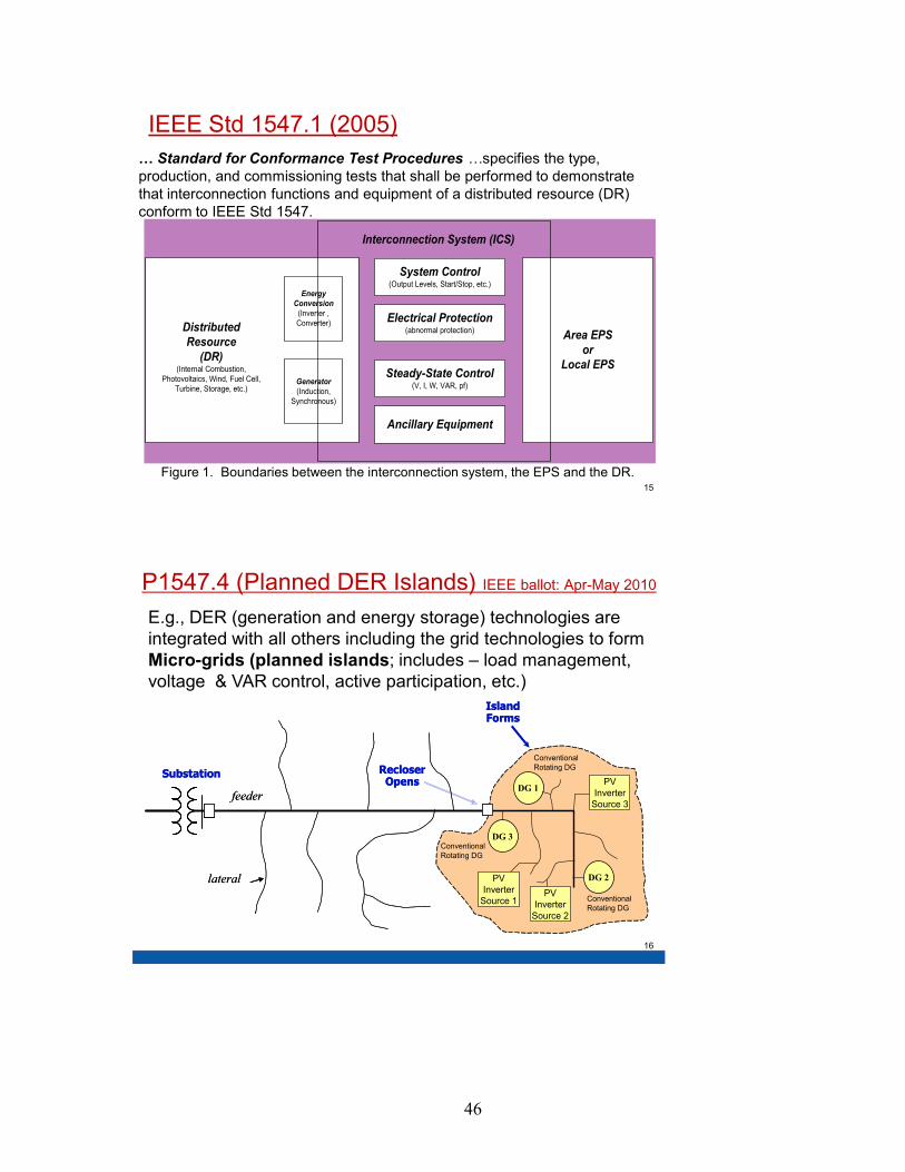
IEEE Std 1547.1 (2005) … Standard for Conformance Test Procedures …specifies the type, production, and commissioning tests that shall be performed to demonstrate that interconnection functions and equipment of a distributed resource (DR) conform to IEEE Std 1547.
Figure 1. Boundaries between the interconnection system, the EPS and the DR.
Energy Conversion
(Inverter , Converter)
Generator(Induction,
Synchronous)
Area EPSor
Local EPS
System Control(Output Levels, Start/Stop, etc.)
Electrical Protection(abnormal protection)
Steady-State Control(V, I, W, VAR, pf)
Distributed Resource
(DR)(Internal Combustion,
Photovoltaics, Wind, Fuel Cell, Turbine, Storage, etc.)
Interconnection System (ICS)
Ancillary Equipment
15
P1547.4 (Planned DER Islands) IEEE ballot: Apr-May 2010
Substation
Island Forms
lateral
Recloser Opens
feeder
DG 3
DG 1
DG 2PV Inverter
Source 1
PV Inverter
Source 3
PV Inverter
Source 2
Conventional Rotating DG
Conventional Rotating DG
Conventional Rotating DG
Substation
Island Forms
lateral
Recloser Opens
feeder
DG 3
DG 1
DG 2PV Inverter
Source 1
PV Inverter
Source 3
PV Inverter
Source 2
Conventional Rotating DG
Conventional Rotating DG
Conventional Rotating DG
E.g., DER (generation and energy storage) technologies are integrated with all others including the grid technologies to form Micro-grids (planned islands; includes – load management, voltage & VAR control, active participation, etc.)
16

47
P1547.7 Guide to Conducting Impact Studies • Describes criteria, scope, and extent for engineering studies of the impact of DR on distribution system. • Methodology for performing engineering studies. • Study scope and extent described as functions of identifiable characteristics of:
- the distributed resource, - the area electric power system, and - the interconnection.
• Criteria described for determining the necessity of impact mitigation. • Guide allows a described methodology for:
- When impact studies are appropriate, - What data is required, - How studies are performed, and - How the study results are evaluated. 17
P1547.8 Recommend Practice to Extend Use of 1547
• Need for P1547.8 is to address industry driven recommendations and NIST smart grid standards framework recommendations (e.g., NIST priority action plans). • Example considerations include: low voltage ride thru; volt-ampere reactive support; grid support; two-way communications and control; advanced/interactive grid-DR operations; high-penetration/multiple interconnections; interactive inverters; energy storage; electric vehicles; etc.
18

48
Photovoltaic systems
Central GeneratingStation
Step-Up Transformer
DistributionSubstation
ReceivingStation
DistributionSubstation
DistributionSubstation
Commercial
Industrial Commercial
Gas Turbine
DieselEngine
Cogeneration
CogenerationTurbine
Fuel cell
Micro-turbine
Wind Power
Residential
Storage
1 - Power System Infrastructure
The Smart Grid - the Integration of: Power, & Communications and Information Technologies
Control Center
Operators,Planners & Engineers
2 - Communications & Information Infrastructure
19
Draft Guide for Smart Grid Interoperability of Energy Technology & Information Technology Operation with the Electric Power System (EPS) &End-Use Applications & Loads
• Provides guidelines in understanding and defining smart grid interoperability of the EPS with end-use applications and loads • Focus on integration of energy technology and information and communications technology • Achieve seamless operation for electric generation, delivery, and end-use benefits to permit two way power flow with communication and control• Address interconnection and intra-facing frameworks and strategies with design definitions• Expand knowledge in grid architectural designs and operation to promote a more reliable and flexible electric power system.
IEEE Std P2030 – Smart Grid Interoperability
20

49
Closing Remarks • IEEE 1547 and IEEE P2030 Standards development
facilitate high penetration of distributed energy resources .
• IEEE P1547.4 (micro-grids/planned islands) discusses advanced DER and distribution system operations.
• IEEE P1547.7 is a guide to conducting DER impacts study
• IEEE P1547.8 establishes recommended practices to extend 1547 use (such as voltage regulation, ride-through, grid support, etc.)
------------------- ----------------------------------------- -----------------
Next P2030 and P1547 series meetings
• P2030 Meeting May 25 – 28
• P1547.7 Meeting August 10 – 11
• P1547.8 Meeting August 12 – 13 21
Contact Information (background slides follow)
• Dick DeBlasio, NREL Technology Manager NREL Distributed Energy & Electricity Reliability (DEER) Program
IEEE Board of Governors, IEEE Standards Board Liaison to DOE; Chair IEEE SCC21, 1547 and P2030;
email: [email protected] voice: (303) 275 – 4333
• Thomas Basso* NRELVice Chair IEEE SCC21 & Sect’y
P1547.2.3.4.6 .7 email: [email protected]: (303) 275 - 3753 * NREL DEER Distribution & Interconnection R&DNREL http://www.nrel.gov1617 Cole Blvd. MS-5202 Golden, CO 80401-3393
• IEEE SCC21 -- IEEE Standards Coordinating Committee 21 on Fuel Cells, Photovoltaics, Dispersed Generation, & Energy Storage http://grouper.ieee.org/groups/scc21/• IEEE Std 1547TM series of standards http://grouper.ieee.org/groups/scc21/dr_shared/ • IEEE Std P2030TM series of standards http://grouper.ieee.org/groups/scc21/P2030/
• Ben Kroposki* NREL Sec’ty 1547.1 & Chair P1547.4 email: [email protected]: (303) 275 – 2979
22
50
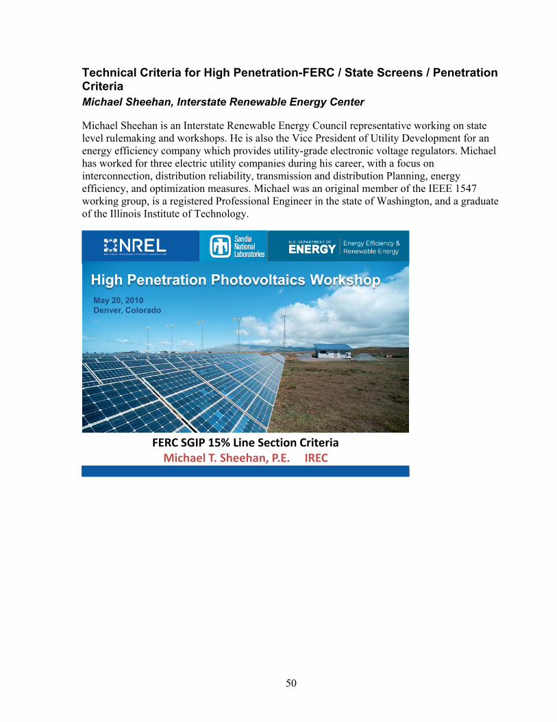
Technical Criteria for High Penetration-FERC / State Screens / Penetration Criteria Michael Sheehan, Interstate Renewable Energy Center
Michael Sheehan is an Interstate Renewable Energy Council representative working on state level rulemaking and workshops. He is also the Vice President of Utility Development for an energy efficiency company which provides utility-grade electronic voltage regulators. Michael has worked for three electric utility companies during his career, with a focus on interconnection, distribution reliability, transmission and distribution Planning, energy efficiency, and optimization measures. Michael was an original member of the IEEE 1547 working group, is a registered Professional Engineer in the state of Washington, and a graduate of the Illinois Institute of Technology.
High Penetration Photovoltaics WorkshopMay 20, 2010Denver, Colorado
FERC SGIP 15% Line Section CriteriaMichael T. Sheehan, P.E. IREC
51
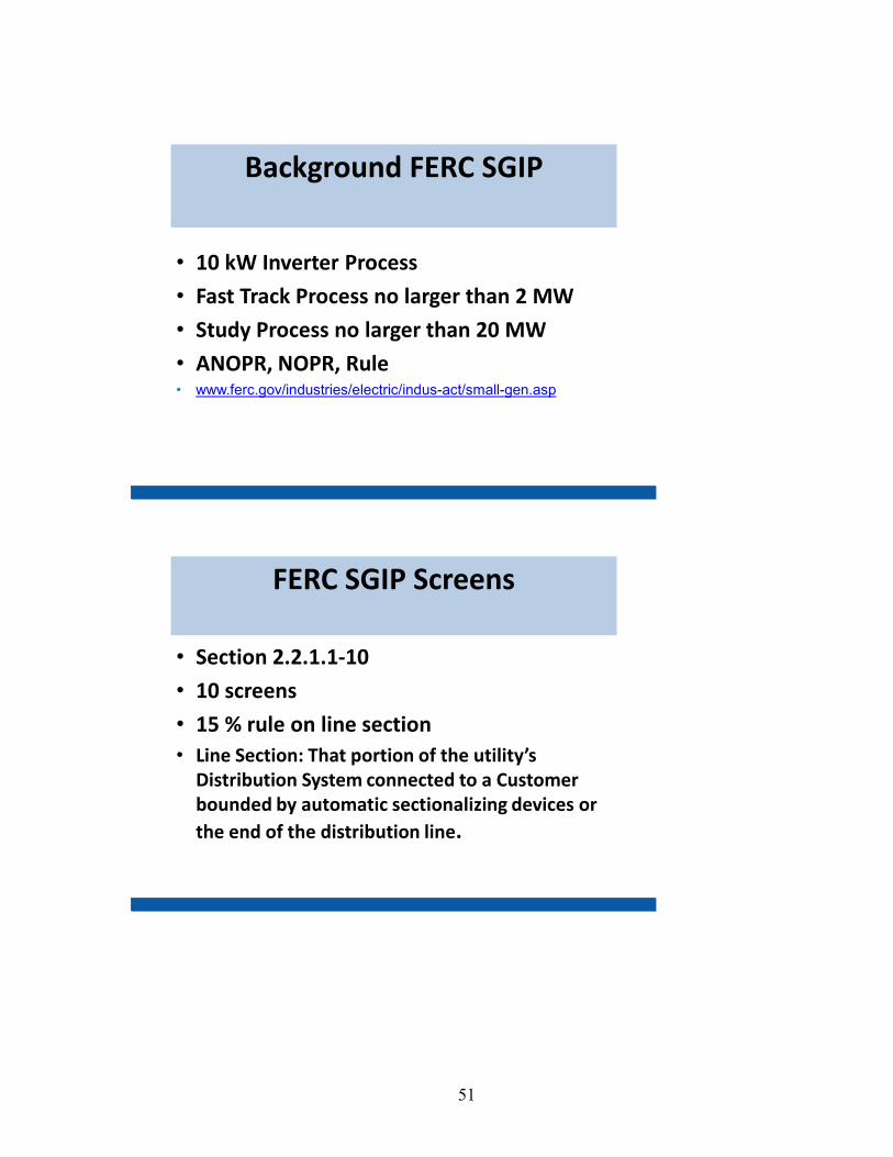
Background FERC SGIP
• 10 kW Inverter Process
• Fast Track Process no larger than 2 MW
• Study Process no larger than 20 MW
• ANOPR, NOPR, Rule• www.ferc.gov/industries/electric/indus-act/small-gen.asp
FERC SGIP Screens
• Section 2.2.1.1-10
• 10 screens
• 15 % rule on line section• Line Section: That portion of the utility’s
Distribution System connected to a Customer bounded by automatic sectionalizing devices or the end of the distribution line.

52
FERC SGIP Subject Matter Experts (SMEs)
• IEEE P1547.6 Draft Recommended Practice For Interconnecting Distributed Resources With Electric Power Systems Distribution Secondary Networks
• IEEE P1547.7 Draft Guide to Conducting Distribution Impact Studies for Distributed Resource Interconnection
• DOE designated SMEs
FERC SGIP Results
• Questionnaire request sent to 157 Subject Matter Experts (SME)• 37 SMEs Completed Questionnaire• 12 from IEEE 1547.6 Working Group• 32 from IEEE P1547.7 Working Group • 5 Solar ABCs/DOE invites

53
FERC SGIP Results – Who completed the questionnaire?
Utility – TransmissionUtility – DistributionUtility – Renewable
Utility – PolicyEngineering firm
ConsultantRegulatory
ManufacturerOther
0
2
4
6
8
10
12
14
16
18
CA NJ NY NM TX AZ CT FL MA MI CO GA HI LA NC DE KY NH NV OH OR PA RI SC TN VA
FERC SGIP Results – Who completed the questionnaire?
In which state or states has the bulk of your recent renewable related interconnection work been focused? (up to 8 states)

54
15 % Line Section
8
0.00
5.00
10.00
15.00
20.00
25.00
1/1/
2009
2/1/
2009
3/1/
2009
4/1/
2009
5/1/
2009
6/1/
2009
7/1/
2009
8/1/
2009
9/1/
2009
10/1
/200
9
11/1
/200
9
12/1
/200
9
Mw
McAuliffe Substation Load ProfileJan 1 - Dec 31 2009
Minimum Load 5.7 MW
Peak 23 MW
Weekly Load Profile
11
0.00
2.00
4.00
6.00
8.00
10.00
12.00
6/26
/200
96/
26/2
009
6/26
/200
96/
26/2
009
6/26
/200
96/
27/2
009
6/27
/200
96/
27/2
009
6/27
/200
96/
27/2
009
6/28
/200
96/
28/2
009
6/28
/200
96/
28/2
009
6/28
/200
96/
29/2
009
6/29
/200
96/
29/2
009
6/29
/200
96/
29/2
009
6/30
/200
96/
30/2
009
6/30
/200
96/
30/2
009
7/1/
2009
7/1/
2009
7/1/
2009
7/1/
2009
7/1/
2009
7/2/
2009
7/2/
2009
7/2/
2009
7/2/
2009
7/2/
2009
Mw
McAuliffe Substation Weekly Load ProfileJune 26 to July 2, 2009

55
Daily Load Profile
12
0.00
1.00
2.00
3.00
4.00
5.00
6.00
7.00
8.00
9.00
10.00
6/28
/200
9
6/28
/200
9
6/28
/200
9
6/28
/200
9
6/28
/200
9
6/28
/200
9
6/28
/200
9
6/28
/200
9
6/28
/200
9
6/28
/200
9
6/28
/200
9
6/28
/200
9
6/28
/200
9
6/28
/200
9
6/28
/200
9
6/28
/200
9
6/28
/200
9
6/28
/200
9
6/28
/200
9
6/28
/200
9
6/28
/200
9
6/28
/200
9
6/28
/200
9
6/28
/200
9
Mw
McAuliffe Substation Daily Load Profile
June 28, 2009
10:00 AM3:00 PM
FERC SGIP Results - #2: DG capacity vs. line section peak load (max 15%)
YES
NO
Not able to answer
Do you support updating this screen?
56
In Summary – Selected Considerations
• Three Stake holders meeting scheduled
November 2009; February 2010,
April 2010
• Draft Report – April 30th, 2010
• Comments – May 17th , 2010
• Consensus – June 15th, 2010
• Final report – July 31, 2010
Feedback
Michael Sheehan, PE
IREC
206.232.2493

57
NIST Priority Action Plan Recommendations Al Hefner, National Institute of Standards and Technology
Allen Hefner is a member of the National Institute of Standards and Technology Smart Grid Team and is NIST’s Project Leader for Power Devices and Thermal Measurements. He is currently focused on interconnection standards and power electronics technologies needed for high penetration of clean energy sources, energy storage, and plug-in vehicles. He is Chairman of the Interagency Advanced Power Group, Electrical Systems Working Group where he leads program coordination and information exchange among different federal government agencies in the area of electrical power conditioning. Dr. Hefner is an IEEE Fellow and has received a number of NIST and US Department of Commerce awards as well as a US Department of Energy Award for contributions to High-megawatt Power Conditioning System Technology for Clean Energy Systems.
High Penetration Photovoltaics WorkshopMay 20, 2010Denver, Colorado
Coordination and Acceleration of Smart Grid Interoperability Standards
Al Hefner
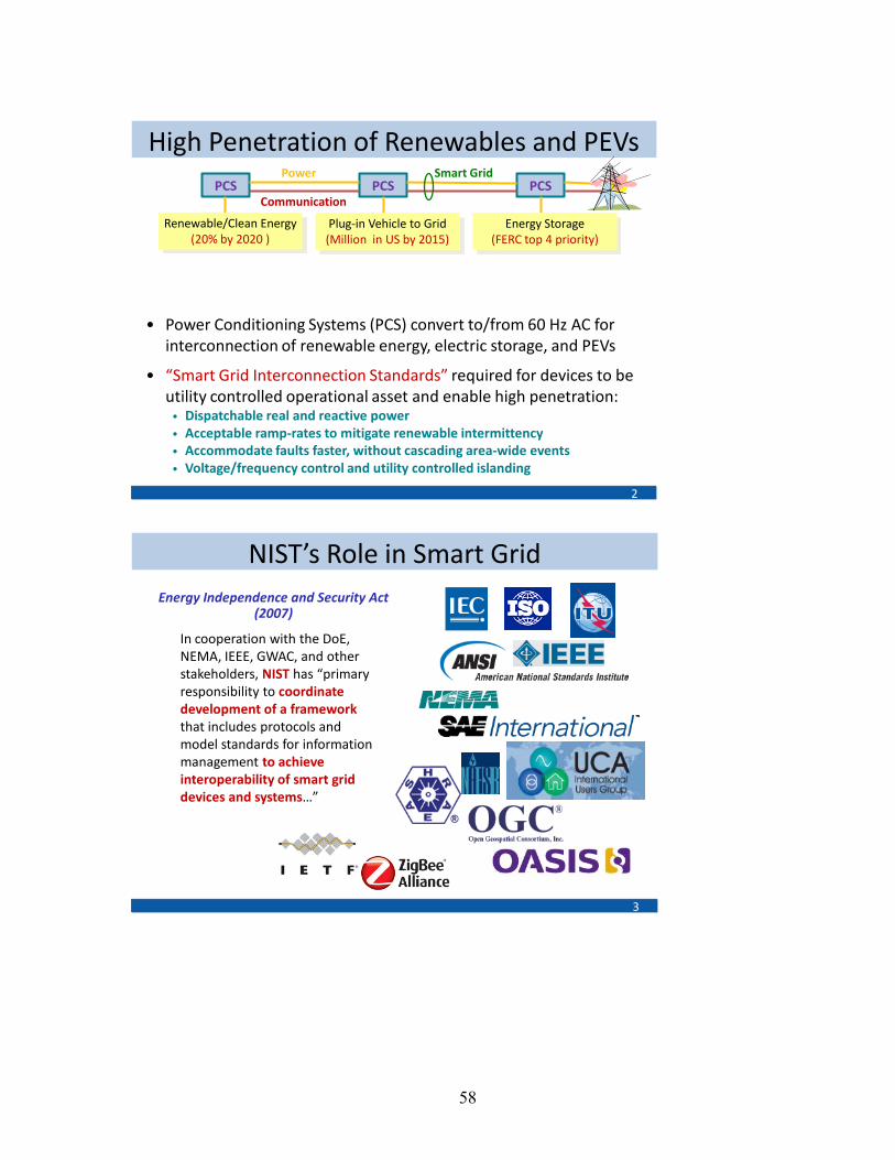
58
High Penetration of Renewables and PEVs
2
• Power Conditioning Systems (PCS) convert to/from 60 Hz AC for interconnection of renewable energy, electric storage, and PEVs
• “Smart Grid Interconnection Standards” required for devices to be utility controlled operational asset and enable high penetration:• Dispatchable real and reactive power • Acceptable ramp-rates to mitigate renewable intermittency • Accommodate faults faster, without cascading area-wide events• Voltage/frequency control and utility controlled islanding
PCS PCS PCS
Energy Storage(FERC top 4 priority)
Plug-in Vehicle to Grid(Million in US by 2015)
Renewable/Clean Energy(20% by 2020 )
Communication
Power Smart Grid
NIST’s Role in Smart Grid
3
Energy Independence and Security Act (2007)
In cooperation with the DoE, NEMA, IEEE, GWAC, and other stakeholders, NIST has “primary responsibility to coordinate development of a framework that includes protocols and model standards for information management to achieve interoperability of smart grid devices and systems…”

59
Government Roles in Smart Grid
4
Public Utility Commissions
Federal
State
FederalEnergyRegulatoryCommission
NIST’s Three Phase Plan
5
NIST role
PHASE 1Identify an initial set of
existing consensus standards and develop a roadmap to fill gaps
January2009 2010
PHASE 2Establish Smart Grid
Interoperability Panel (SGIP) public-private forum with
governance for ongoing efforts
NIST InteroperabilityFramework 1.0 DraftReleased Sept 2009
Smart Grid Interoperability Panel established Nov 2009
PHASE 3Conformity Framework (includes Testing and
Certification)
NIST InteroperabilityFramework 1.0 Released Jan 2010
Summer 2009 workshops

60
NIST Framework and Roadmap
6
http://www.nist.gov/smartgrid/
Conceptual Reference Model
• Revised version January 2010
• Smart Grid Vision / Model
• 75 key standards identified– IEC, IEEE, …
• 16 Priority Action Plans to fill gaps:– One completed
– Another added (wind plant communication)
• Cyber security strategy– Companion document
NISTIR 7628
International Standards are Vital
7
International 77%
US Domestic 13%
US Government 10%
Source of Standards in NIST Roadmap
International Coordination• Bilateral interactions
– China, Japan, Korea, India, Brazil, France, Germany, Ireland…
• US-EU Energy Council activities
– Smart Grids-Electric Vehicles
– Public workshop, USG-European Commission
• Coordination with International Standards Organizations:
– NIST Liaison to IEC-SG3
– SGIP international participation

61
Smart Grid Interoperability Panel
8
• Public-private partnership, started in Nov. 2009
• Over 550 organizations, over 1700 representatives
• Supports NIST in coordinating smart grid standards
• Governing Board elected• SGIP Chair elected• Committees established,
SGIP meetings ongoing• Electronic collaboration
tools, newsletters / communications
• Project management office• Open, transparent process• International
participation welcome
Smart Grid Interoperability Panel and Governing BoardSmart Grid Interoperability Panel and Governing Board
SGIPGBSGIPGB
Products (IKB)Products (IKB)
SGIPSGIP
One Organization,One Vote
(Over 450; over 1500 persons participating including from international organizations)
One Organization,One Vote
(Over 450; over 1500 persons participating including from international organizations)
Working Groups
(DEWG, PAP, Other)
Working Groups
(DEWG, PAP, Other)
Smart Grid Identified Standards
Smart Grid Identified Standards
Use CasesUse Cases
RequirementsRequirements
StandardsDescriptions
StandardsDescriptions
PriorityAction Plans
PriorityAction Plans
At largeMembers (3)
At largeMembers (3)
Ex Officio(non-voting)
Members
Ex Officio(non-voting)
Members
Stakeholder Category
Members (22)including utilities,
suppliers, IT developers
Stakeholder Category
Members (22)including utilities,
suppliers, IT developers
Standing Committees
(Architecture, Conformance and
Security)
Standing Committees
(Architecture, Conformance and
Security)
Conceptual Model
http://www.nist.gov/smartgrid/
(Over 550; over 1700 persons participating including from international organizations)
Priority Action Plans
9
Priority Action PlansSmart meter upgradeability standard (PAP 00, completed by NEMA in 2009)
Standard meter data profiles (PAP 05)
Develop common specification for price and product definition (PAP 03)
Develop common scheduling communication for energy transactions (PAP 04)
Standard demand response signals (PAP 09)
Customer energy use information (PAP10)
Energy storage interconnection guidelines (PAP 07)
Interoperability standards to support plug-in electric vehicles (PAP 11)
Wind Communication Standards (PAP 16)
Priority Action PlansGuidelines for use of IP protocol suite in the Smart Grid (PAP 01)Guidelines for the use of wireless communications (PAP 02)
Harmonize power line carrier standards for appliance communications in home (PAP15)Develop common information model (CIM) for distribution grid management (PAP 08)DNP3 Mapping to IEC 61850 Objects (PAP12)Transmission and distribution power systems model mapping (PAP 14)
Harmonization of IEEE C37.118 with IEC 61850 and Precision Time Synchronization (PAP 13)

62
PAP 7: Smart Grid ES-DER Standards
10
SG Standards Need• Interconnection and object model standards needed for:
– DER grid operational interface with dispatchable: VAR, V, F, etc.
– support for energy storage devices (ES), including PEV
– and hybrid generation-storage systems (ES-DER)
PAP Major Objectives• Revised and updated consistent guidelines and standards:
– Involve broad set of Stakeholders: SDOs, utilities, vendor, etc.
– Scoping Document to determine priorities and timeline for standards development for spectrum of applications
– IEEE 1547 revisions for urgent applications
– Consistent object models for DER, ES, ES-DER in IEC 61850-7-420
– UL, NEC-NFPA70, SAE guidelines for safe, reliable implementation
PAP 7: Task Interactions
11
a)
b)
c)
d
e)
Task 0:Scoping Document
Prioritized timeline for ES-DER standards
Task 1: Use Cases
Define requirements for different scenarios
Task 4: Develop and Harmonize Object Models
IEC61850-7-420 : Expanded to include multifunctional ES-DER operational Interface; harmonized with SEP, CIM, MultiSpeak
Task 5: Safe and Reliable Implementation
UL, NEC-NFPA70, SAE, CSA and IEC
Task 3: Unified interconnection method with multifunctional operational interface for range of storage and generation/storage.
IEEE 1547.8 PAR (a) Operational interface(b) Storage without gen(c) PV with storage(d) Wind with storage(e) PEV as storage
Task 2: IEEE 1547.4 for island applications and IEEE 1547.6 for secondary networks
PAPs

63
Conclusion
• US energy strategy requires high penetration of– renewable and clean electricity generators
– energy storage to mitigate intermittency and for grid stability
– plug-in electric vehicles for fuel diversity and grid storage
• Power Conditioning Systems (PCS) interface DERs to grid
• Existing DER interconnection standards – do not take advantage of PCS value for grid operations
– may lead to stability problems for high penetration
• Smart Grid provides opportunity for change:– communications to utilize DER as utility controlled asset
– coordination of standards for interoperability
12
Contact Information
13
George ArnoldNational Coordinator for Smart Grid Interoperability
David Wollman Dean [email protected] [email protected]
Al Hefner (NIST liaison to IEC SG3, NIST Lead for PAP 7 and PAP 16)
NIST Smart Grid Website: http://www.nist.gov/smartgrid/
NIST SGIP Collaborative Twiki site: http://collaborate.nist.gov/twiki-sggrid/bin/view/SmartGrid/
64
Session 2 Q&A: Gaps in Existing Standards and Codes Audience Questions/Panel Answers Note: This is not an exact transcription of the discussion during the Q&A session and is meant to be representative of the discussion during the session. Q. 1547 didn’t worry much about NOPRs. Do we need to now?
A. Don’t want regulatory lag, barriers to new technologies. Need to move at a higher level, find common ground for everyone. FERC/NARUC should work together, have a joint hearing. Uniform standards would be great, but won’t happen; each state will do its own thing. It would be great to have no regulatory lag. A. Standards dig into technical rationale that others can vet. Get engineering details in B&W for others. FERC and PUC roles are important, but I don’t want them to drive engineering.
Q. Where do we go from here, for near term, for long term? Wise to set up roadmap effort to see what is possible near term, next 2 years, in next 10 years?
A. NIST scoping document identifies use cases and applications for storage and generators, and combinations, and to develop roadmap with timelines based on needs for utilities to be prepared when technology becomes commercially viable. Standards need to support a variety of solutions. The scoping document is an ongoing thing; need further input.
Q. General question about FERC and NARUC getting together. Can they also develop business case guidelines? If we supply VARS, we might get paid for it, that would be nice. Big generators already get paid for supplying VARS in some parts of the U.S. If we had a reliable business case for what VARS are worth and how much we get paid for them, this would help to move things along. DOE thinks that is in FERC’s scope. FERC thinks that it’s a local market issue and it’s outside their scope. It looks like it’s up to the state regulatory bodies to make these decisions. Who is dealing with market issues?? Folks making installation need to understand business case.
A. VAR tariff is a problem. FERC role is not going to help make a business case. VARS at different ends of the feeder have different value. Turf battles in regulatory world; they change people every 3 or 4 years. Detailed business cases are beyond our current scope.
Q. We’re looking for quick fixes, fast application solutions. Standards are slow. In the implementation phase, we need to find a better way. Why don’t we go in with a case on technical basis and with exceptions and argue it at FERC level? Industry needs to do this, no one else will do this for us.
A. FERC does rule making at federal level and at transmission level. PUCs are important too, at the distribution level. Legislation at the distribution level.
65
A. Too complicated to get quick fixes. Industry needs to get to Washington or go to the PUC.
Q. Is PV tied to storage? Ramp rates need to be controlled at the point of interconnection? Trade off between system-level approaches and at project level?
A. The initial EPRI roadmap identified gaps in standards. We need to narrow this list down. We organized it by priority. We looked at FERC’s priorities: storage was high priority. Issues on ramping, intermittency, variability, we are trying to deal with unpredictability, intermittancy. Can storage be used for more predictable variability, like diurnal? Trying to be consistent across all DER applications. Don’t want to have to change standards if something new comes out.
Q. 1547 series basically looks at static interconnection (yes or no decision). Can we add in dynamic capabilities, allowing interconnection, but only if they are willing to be part of ongoing real-time operation, maybe with managing VARS settings?
A. Certain tariffs would help to determine this. A device that supports 1547 today can be turned on or off, can be configured through communication. A. PJM has implemented 1547 in their interconnection requirements; they require voltage regulation on larger systems. DG proponents and the utility need to sit down and figure it out. Quick fix is to get a friendly system integrator and friendly utility and make it work. Needs to be done on case-by-case basis (because not every utility has large interconnection group). A. In Australia, regulators have looked ahead and let utilities know how they want them to move, good signals. We have reactionary framework here. It’s a different model; how do we change the paradigm?
Q. Any discussion to pursuing standards from applications or technology priority point of view? Do some issues hold up everything? Voltage ride-through, difference between how Europe does things and how we do it.
A. The standards need to be itemized to allow FERC or PUCs to select certain classes. Individually implemented, rather than waiting for another standard. We do have a prioritization process. A. SolarABCs is supposed to listen to industry to bring back messages to SDOs. A. IREC is funded by DOE and cannot advocate for one particular technology, cannot favor one industry over another. For all renewable energy and best practices. We capture best practice in interconnection and net metering, for example.
Q. Utilities feel like they are constrained by regulators by 1547. 1547 is non-prescriptive basically for islanding, it gives 3-4 possible solutions. UL 1741 does concentrate on one

66
solution (active anti-islanding). How can we make sure that test standards by independent test labs will conform to all solutions, rather than becoming prescriptive?
A. Looking back, write back for an interpretation of UL 1741 to prove you have a viable anti-islanding scheme. Looking forward, get involved. PUC meetings are open. FERC process: ANOPR, NOPR, rulemaking….so there are multiple pathways to get into process. But it is slow. A. SGIP is another pathway, which supports NIST. Need to make recommendations on standards that are ready for use.
Q. A roadmap question follow up. Could SolarABCs take a look at it?
A. We can look at that.
Q. Who in the audience worked on 1547? (Quite a few people in audience raised their hands). There is support for NIST and what they are doing. NIST and IEEE are well coordinated. If you want to work on IEEE standards, contact Tom Basso, to get involved.

67
Session 3 – High Penetration PV Technical Solutions
PV Inverters with VAR Control, Low-Voltage Ride-Through, Dynamically Controlled Inverters, etc. Ray Hudson, BEW
Ray Hudson is a Principal Engineer at BEW Engineering in San Ramon, California where he leads the PV group. He has worked in the area of power electronics and renewable energy systems for over 20 years including inverter designs for wind and PV systems ranging in size from 10 kW to 5 MW. Before joining BEW, he was Vice President of Advanced Technology at Xantrex and prior to that he had management and engineering roles at Trace Technologies and Kenetech Windpower. He has Bachelors and Masters Degrees in Electrical Engineering from the University of Missouri – Columbia.
High Penetration Photovoltaics WorkshopMay 20, 2010Denver, Colorado
PV Inverters with VAR Control, LVRT, and Dynamic ControlRay Hudson – BEW Engineering
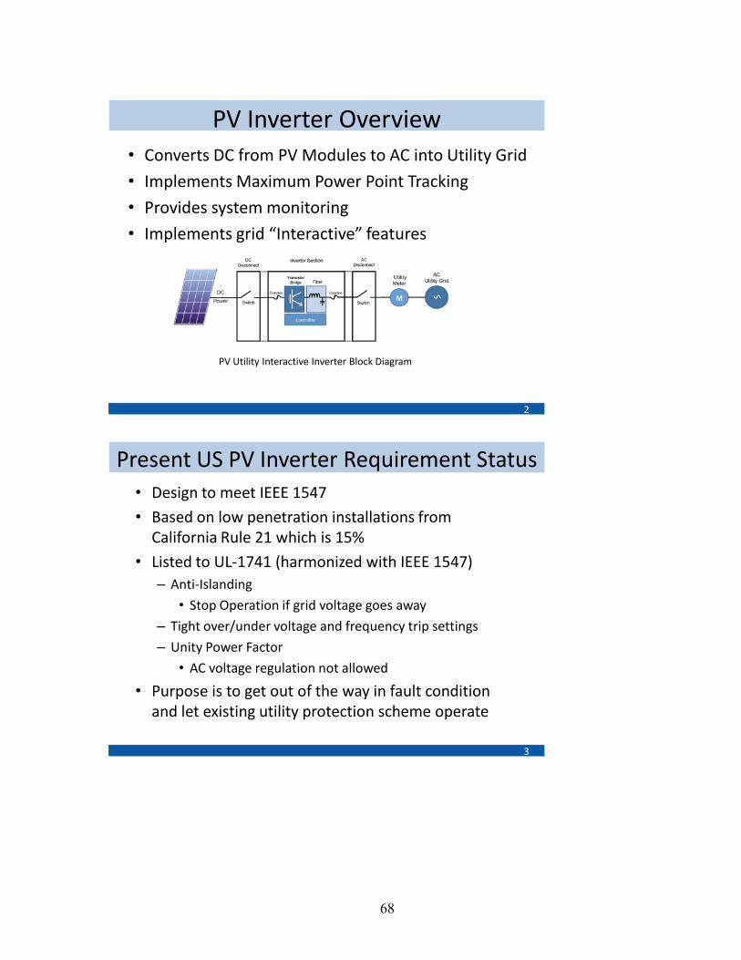
68
PV Inverter Overview• Converts DC from PV Modules to AC into Utility Grid
• Implements Maximum Power Point Tracking
• Provides system monitoring
• Implements grid “Interactive” features
2
PV Utility Interactive Inverter Block Diagram
Present US PV Inverter Requirement Status• Design to meet IEEE 1547
• Based on low penetration installations from California Rule 21 which is 15%
• Listed to UL-1741 (harmonized with IEEE 1547)– Anti-Islanding
• Stop Operation if grid voltage goes away
– Tight over/under voltage and frequency trip settings
– Unity Power Factor
• AC voltage regulation not allowed
• Purpose is to get out of the way in fault condition and let existing utility protection scheme operate
3

69
Utility Friendly Features• Operate like a traditional synchronous generator
• VAR Control
– Non-Unity Power Factor
– Regulate PV plant voltage
• Low Voltage Ride Through
– Stay on-line during grid Voltage dip
– In contrast to Anti-Islanding
– Help improve system stability
• Dynamic Control
– Ramp rate and curtailment of real power
– Communication allows PV to be part of the utility system
• Purpose is to help with grid stability
• Will be required in the future for high penetration levels4
European PV Has These Features
5
E.ON Netz Grid Code for High and Extra High VoltageBDEW Technische Richtlinie Erzeugungsanlagenam Mittelspannungsnetz
Journal Officiel de la Republique Francaise DEVE0808815A
Royal Decree RD 661/2007
Similar but not standardizedOther countries as well
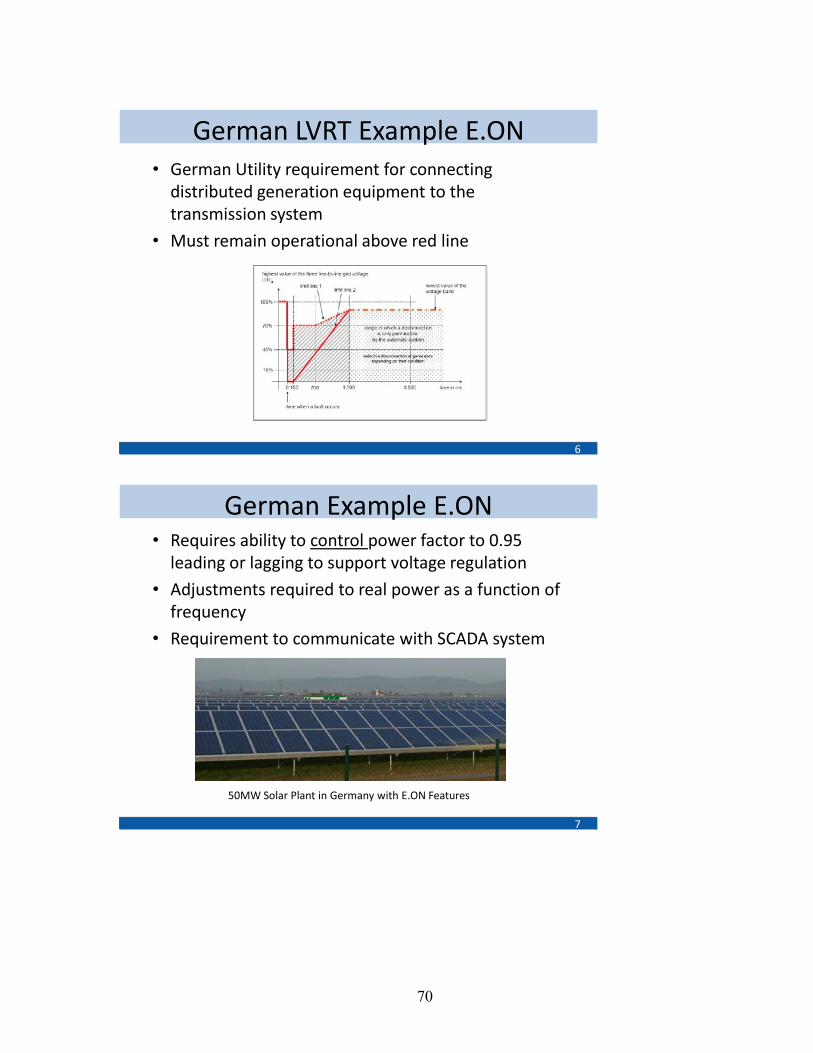
70
German LVRT Example E.ON
6
• German Utility requirement for connecting distributed generation equipment to the transmission system
• Must remain operational above red line
German Example E.ON
7
• Requires ability to control power factor to 0.95 leading or lagging to support voltage regulation
• Adjustments required to real power as a function of frequency
• Requirement to communicate with SCADA system
50MW Solar Plant in Germany with E.ON Features
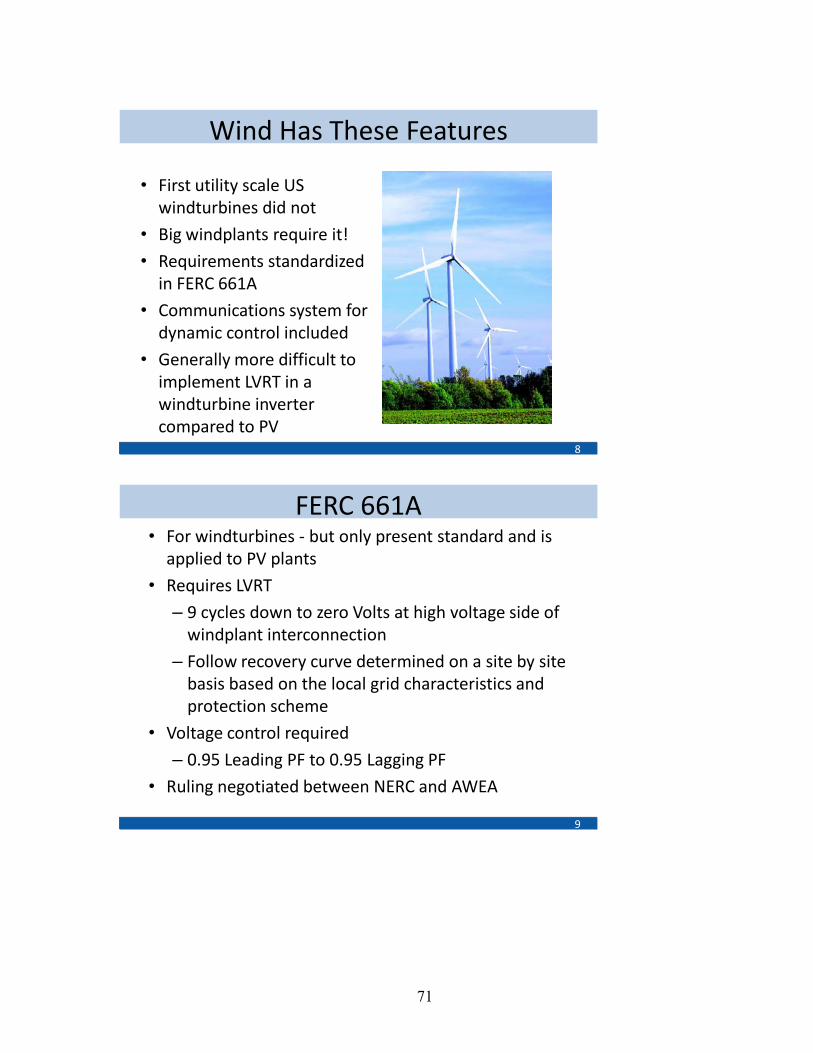
71
Wind Has These Features
• First utility scale US windturbines did not
• Big windplants require it!
• Requirements standardized in FERC 661A
• Communications system for dynamic control included
• Generally more difficult to implement LVRT in a windturbine inverter compared to PV
8
FERC 661A• For windturbines - but only present standard and is
applied to PV plants
• Requires LVRT
– 9 cycles down to zero Volts at high voltage side of windplant interconnection
– Follow recovery curve determined on a site by site basis based on the local grid characteristics and protection scheme
• Voltage control required
– 0.95 Leading PF to 0.95 Lagging PF
• Ruling negotiated between NERC and AWEA
9
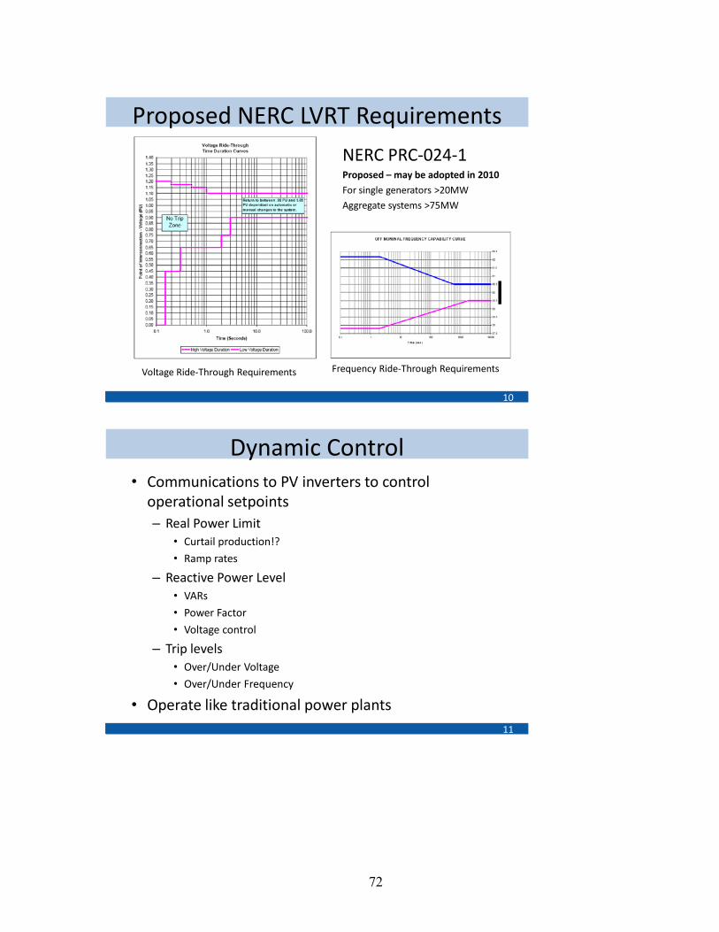
72
Proposed NERC LVRT Requirements
NERC PRC-024-1Proposed – may be adopted in 2010
For single generators >20MW
Aggregate systems >75MW
10
Frequency Ride-Through RequirementsVoltage Ride-Through Requirements
Dynamic Control• Communications to PV inverters to control
operational setpoints– Real Power Limit
• Curtail production!?
• Ramp rates
– Reactive Power Level• VARs
• Power Factor
• Voltage control
– Trip levels• Over/Under Voltage
• Over/Under Frequency
• Operate like traditional power plants11

73
Technical Challenges • Implementing VAR Control, LVRT, and Dynamic
control is not highly technically challenging
• Most of the changes can be done in software
• Minor hardware changes– Additional Sensors
– UPS for LVRT
– Minimal additional cost
• Inverter will operate at higher current levels when off of unity power factor than at unity– Impacts efficiency and reliability
12
Going Forward
• Confusing for inverter manufacturers and PV system developers
• Utility friendly features are required for large plants and high penetration levels
• Opportunity to leverage from Wind and European experience
• Standards need to be modified, accepted, and implemented
13

74
Energy Storage and PV Generation Integration-Utility and Manufacturers Perspectives Charlie Vartanian, A123Systems
Charlie Vartanian is Director of Grid Integration at A123 Systems, which is a manufacturer of advanced Lithium-ion batteries and systems. Charlie focuses on grid application development and market access advocacy to expand the useC of advanced storage technologies for grid benefit. Previously, he was Distributed Energy Resource Development Manager at Southern California Edison where he supported and participated in joint research studies with external entities working on advanced grid concepts. Other prior engagements include Southern California Edison Transmission Planning, Southern California Edison Field Engineering, California Energy Commission Staff, Enron Energy Services, and the U.S. Navy. Charlie received his MSEE from USC, and his BSEE from Cal Poly Pomona. Charlie is a licensed Professional Engineer in California, and is a member of IEEE.
High Penetration Photovoltaics WorkshopMay 20, 2010Denver, Colorado
Energy Storage and PV Generation Integration-Utility and Manufacturers Perspectives
Charlie Vartanian, A123 Systems
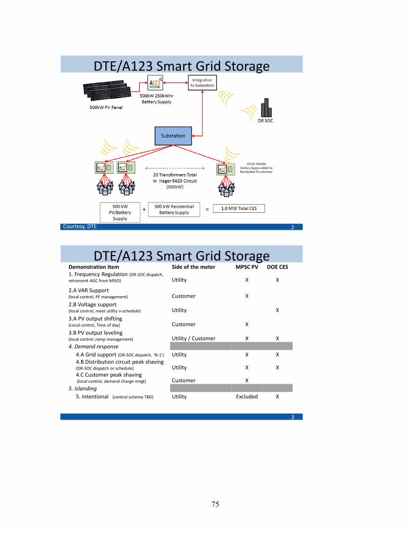
75
DTE/A123 Smart Grid Storage
2Courtesy, DTE
DTE/A123 Smart Grid Storage
3
Demonstration Item Side of the meter MPSC PV DOE CES1. Frequency Regulation (DR-SOC dispatch, retransmit AGC from MISO) Utility X X
2.A VAR Support (local control, PF management) Customer X2.B Voltage support(local control, meet utility v-schedule) Utility X3.A PV output shifting (Local control, Time of day) Customer X3.B PV output leveling (local control ,ramp management) Utility / Customer X X4. Demand response
4.A Grid support (DR-SOC dispatch, ‘N-1’) Utility X X4.B Distribution circuit peak shaving (DR-SOC dispatch or schedule) Utility X X4.C Customer peak shaving(local control, demand charge mngt) Customer X
5. Islanding5. Intentional (control schema TBD) Utility Excluded X
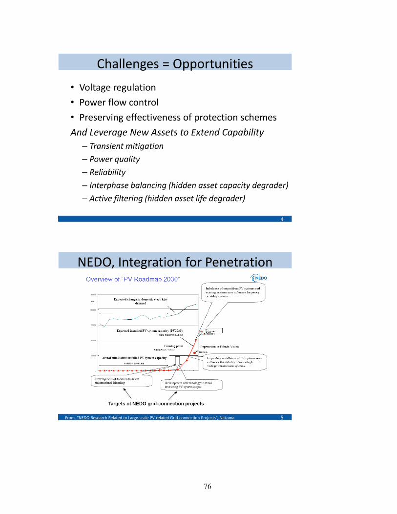
76
Challenges = Opportunities
• Voltage regulation
• Power flow control
• Preserving effectiveness of protection schemes
And Leverage New Assets to Extend Capability– Transient mitigation
– Power quality
– Reliability
– Interphase balancing (hidden asset capacity degrader)
– Active filtering (hidden asset life degrader)
4
NEDO, Integration for Penetration
5From, “NEDO Research Related to Large-scale PV-related Grid-connection Projects”, Nakama

77
NEDO, Avoiding Restriction on PV
6From, “NEDO Research Related to Large-scale PV-related Grid-connection Projects”, Nakama
PV and Circuit Level Voltage, ref’s
7
Technical discussion of the NEDO ‘Ota’ project“STUDY ON THE OVER VOLTAGE PROBLEM AND BATTERY OPERATIONFOR GRID-CONNECTED RESIDENTIAL PV SYSTEMS”, 22nd European Photovoltaic Solar Energy Conference, 3-7 September 2007, Ueda, Y., et al
Technical characterization of the challenge“Clustered PV Inverters in LV Networks: An Overview of Impacts and Comparison of Voltage Control Strategies”, IEEE Paper, Demirok, E., et al

78
Remove Unintended/Simple Std.’s Barriers
8
A123, Disruptive Technology Advances
9

79
A123, Disruptive Technology Advances
10
• 2MW 500kWh Modular Units– Scalable to 200MW Arrays
– 20ms response
• High Cycle Life– >8,000 full DoD,
– >500K micro-cycles to 80% capacity
• High Efficiency – 90% roundtrip
• Energy Storage Enabling New Possibilities for the Electric Grid
FLEXIBLE: Can be used for frequency regulation, spinning reserve, black start, smart grid applications, and integration of renewable sources
A123, Scale to Accelerate Effectiveness
11
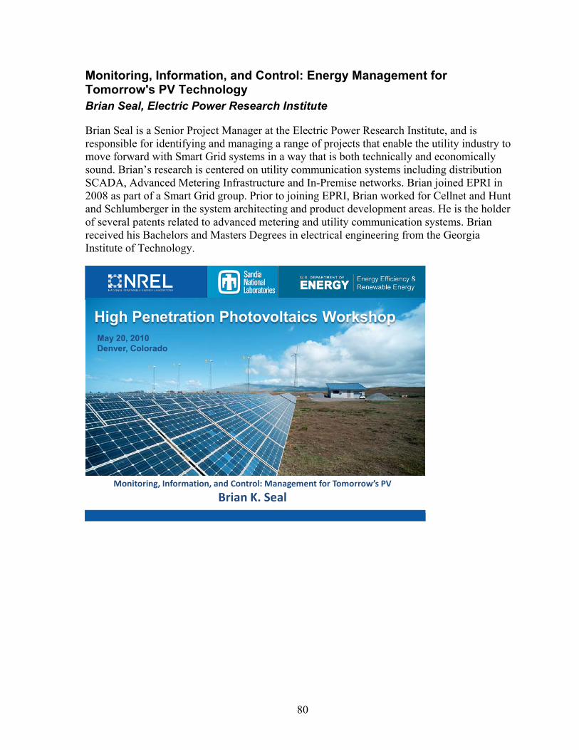
80
Monitoring, Information, and Control: Energy Management for Tomorrow's PV Technology Brian Seal, Electric Power Research Institute
Brian Seal is a Senior Project Manager at the Electric Power Research Institute, and is responsible for identifying and managing a range of projects that enable the utility industry to move forward with Smart Grid systems in a way that is both technically and economically sound. Brian’s research is centered on utility communication systems including distribution SCADA, Advanced Metering Infrastructure and In-Premise networks. Brian joined EPRI in 2008 as part of a Smart Grid group. Prior to joining EPRI, Brian worked for Cellnet and Hunt and Schlumberger in the system architecting and product development areas. He is the holder of several patents related to advanced metering and utility communication systems. Brian received his Bachelors and Masters Degrees in electrical engineering from the Georgia Institute of Technology.
High Penetration Photovoltaics WorkshopMay 20, 2010Denver, Colorado
Monitoring, Information, and Control: Management for Tomorrow’s PV
Brian K. Seal
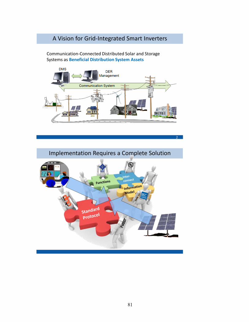
81
A Vision for Grid-Integrated Smart Inverters
2
Communication-Connected Distributed Solar and Storage Systems as Beneficial Distribution System Assets
Implementation Requires a Complete Solution
3
82
Collaborative Industry Project – June 2009
To identify a standards-based way that inverters could support a core set of grid-friendly functions
350 individuals engaged, representing:• 40 PV & Storage equipment providers• 60 utilities• 12 National labs and research organizations
•Engage a broad range of industry stakeholders
• Select a beginning set of functions
• Identify appropriate standards (NIST aligned)
•Work together to define how each function will work
•Map to standard communication protocols, DNP3, Smart Energy Profile, etc.
•Transfer to Standards Organizations
Project Approach & Activities

83
1. Connect / Disconnect from Grid
2. Output Power Management
3. Intelligent Volt-Var Control
4. Storage Management
5. Event/History Logging
6. Status Reporting /Reading
7. Time-sync
Functions Addressed in Phase 1
VARs
Gen
erat
ed
Capacitive
Inductive
System Voltage
V1 V2 V3V4
Q1
Q4
Q3Q2
Volt/Var Mode 1 –Normal Regulation
VARs
Gen
erat
ed
Capacitive
Inductive
System Voltage
V1V2
Q2
Q1
Volt/VarMode 2 –Transmission VAR Support
Utility-Defined Curve Shapes
Simple Broadcast
Advanced Volt-Var Control

84
Time
Pow
er
Watts
Vars
Reactive Intermittent Power Compensation
Circuit Impact Modeling
• Actual 12kV feeder• 1800 customers• ~10MW Peak load• ~ 17 mi 3-phase primary• ~ 115 mi 1-phase primary• 20% PV penetration,
customers randomly selected
• Each with 4KW PV system
Substation
PV

85
Volt-Var Inverter Simulation Model
Residential Load
To Service Transformer
Var Control Algorithm
Meter
Residential PV
P, Q
P,Q
V
Q
Example PV and Customer Load Shape
0
1
2
3
4
5
6
7
8
9
0 2 4 6 8 10 12 14 16 18 20 22Hour
kW
Customer LoadCustomer PV (-)
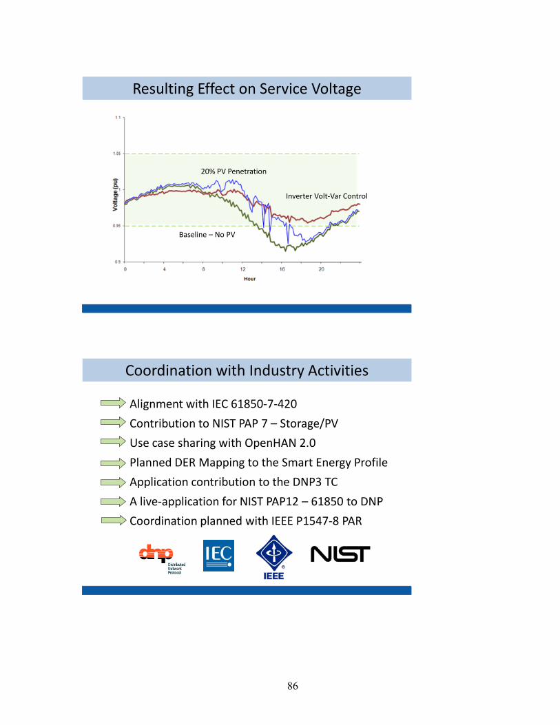
86
Baseline – No PV
Inverter Volt-Var Control
20% PV Penetration
Resulting Effect on Service Voltage
Alignment with IEC 61850-7-420
Contribution to NIST PAP 7 – Storage/PV
Use case sharing with OpenHAN 2.0
Planned DER Mapping to the Smart Energy Profile
Application contribution to the DNP3 TC
A live-application for NIST PAP12 – 61850 to DNP
Coordination planned with IEEE P1547-8 PAR
Coordination with Industry Activities
87
•Invite New Participants•Review Completed Work•Model / Simulate Behavior on Feeders
(OpenDSS)•Interoperability Laboratory Testing•Field Test•Evolve•Repeat
Next Steps
Questions
ContactBrian [email protected]
88
Session 3 Q&A: High-Penetration PV Technical Solutions Audience Questions/Panel Answers Note: This is not an exact transcription of the discussion during the Q&A session and is meant to be representative of the discussion during the session. Q. Interested in VAR control graphic. Constant VARs or dynamic control depending on voltage? (Brian’s slide)
A. Not dynamic. The inverter configuration had the same kind of Volt/VAR characteristics. Q. Any interaction addressing ride-through? Large PV system like Wind FERC 661A. Is it a possible pressure point with someone like AWEA to make things happen?
A. Great question. Not aware of a similar activity. Great opportunity. Will pass that on to SEIA. A. The Utility Wind Integration Group (UWIG) is good model. UWIG has started a solar integration subgroup. Expanding to look at solar integration issues. Workshops in Cedar Rapids in October; UWIG meeting in Portland. A. So far UWIG has concentrated on variability of PV. Not a group for pushing standards. New group formed called Solar Grid Integration Group (SolarGIG) at SEPA.
Q. Take Wind experience on LVRT. 1547.4 San Francisco–take Wind experience with ride-through and expand it to PV. There are answers. Does it need funding or research?
A. There’s a bunch of research going on at NREL, Sandia, EPRI. Coordination is important. Need a forum to get feedback on access to and usability of research.
Q. If inverter is on customer side of meter is there a firewall issue. Google has all sorts of information on line, but there is all sorts of info on homes. How are we going to protect systems? Home area network type system vs. utility SCADA system?
A. Our working group has not been doing security work. Not obvious that PV would be on home area network. It’s alongside the demand response application. Don’t want someone to change signal going onto grid. If you solve the demand response residentially, then you solve it for renewable energy integration at the same time. A. NERC Smart Grid task force. PV people open your horizons, start talking to NREC; they are the 800-pound gorilla you will run into. Looking at cyber security from the home to the bulk grid. There is a NERC report coming out soon.
Q. NIST cyber security work addresses home area network to the utility. NIST Cyber Security work – addresses home area network to the utility. In addition, IEC 68150 is being expanded to include cyber security (run by Annabelle Lee, NIST).
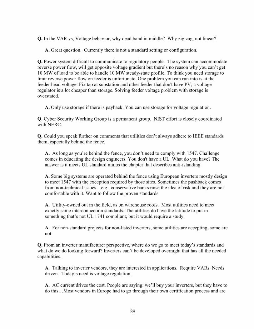
89
Q. In the VAR vs, Voltage behavior, why dead band in middle? Why zig zag, not linear?
A. Great question. Currently there is not a standard setting or configuration. Q. Power system difficult to communicate to regulatory people. The system can accommodate reverse power flow, will get opposite voltage gradient but there’s no reason why you can’t get 10 MW of load to be able to handle 10 MW steady-state profile. To think you need storage to limit reverse power flow on feeder is unfortunate. One problem you can run into is at the feeder head voltage. Fix tap at substation and other feeder that don't have PV; a voltage regulator is a lot cheaper than storage. Solving feeder voltage problem with storage is overstated.
A. Only use storage if there is payback. You can use storage for voltage regulation. Q. Cyber Security Working Group is a permanent group. NIST effort is closely coordinated with NERC. Q. Could you speak further on comments that utilities don’t always adhere to IEEE standards them, especially behind the fence.
A. As long as you’re behind the fence, you don’t need to comply with 1547. Challenge comes in educating the design engineers. You don't have a UL. What do you have? The answer is it meets UL standard minus the chapter that describes anti-islanding. A. Some big systems are operated behind the fence using European inverters mostly design to meet 1547 with the exception required by those sites. Sometimes the pushback comes from non-technical issues—e.g., conservative banks raise the idea of risk and they are not comfortable with it. Want to follow the proven standards. A. Utility-owned out in the field, as on warehouse roofs. Most utilities need to meet exactly same interconnection standards. The utilities do have the latitude to put in something that’s not UL 1741 compliant, but it would require a study. A. For non-standard projects for non-listed inverters, some utilities are accepting, some are not.
Q. From an inverter manufacturer perspective, where do we go to meet today’s standards and what do we do looking forward? Inverters can’t be developed overnight that has all the needed capabilities.
A. Talking to inverter vendors, they are interested in applications. Require VARs. Needs driven. Today’s need is voltage regulation. A. AC current drives the cost. People are saying: we’ll buy your inverters, but they have to do this…Most vendors in Europe had to go through their own certification process and are

90
looking to come to U.S. How do we coordinate this going forward? Demand will push it forward. There are two kinds of demand markets for inverter manufacturers: 1. Distribution market: smaller systems with UL labels 2. Transmission: big systems with other features; can use non UL listed product and be
OK with it.
Q. There is a difference between interconnection requirement and the way the system operator decides to use the capability to manage the system. Europe (Ireland) requires that wind turbine be capable of frequency support on system and operates less than 100% power output. So you can have a positive response to frequency drops. This does not mean operators have to use it because of penetration levels. Q. 1547 originally allowed for DG regulation voltage. Some believe the utility should not have any discretion. We have seen the request for utility not allowing inverters to be connected if it’s not on an approved list of inverters. Lots of uncertainty in this area.
A. 1547 is very important and the industry couldn’t have grown without it. Q. PV has been very successful. Penetration has increased so much that we need to do more. Making exceptions to standards is not unusual. Just make your case to modify. PV is part of the DG community. There are ways to negotiate. IEEE 1547 can be extended but it must address reality of what you’re trying to do.
A. That’s what this forum is about. We need to look at what needs to be addressed and how to do it.
Q. Are inverters capable of increased VAR support today? Second, can you generate reactive power 24/7 with the inverter?
A. Yes, industry can make the jump. Pretty straightforward to modify equipment to meet needs. Second, a PV inverter is similar to a static VAR compensator…same topology. The question becomes, how do you get paid for these VARs?
Q. How many watts did you lose by implementing that strategy with that case?
A. Watts are always favored, and generate as many as you can. You’re not losing any real power production, not curtailing PV to do this.
Q. Not much incentive to buy VARs. Most utility are not allowed to recover cost of VARs they supply.
A. Can you contract with a party to supply VARs from inverters, thus reducing your capital investment of supply capacitors used in substation?
91
A. Could be possible, but would need a guarantee for VAR delivery. A. Had this conversation recently with PUC staffer. Said they’d be willing to take a look.
Q. An inverter can be 95% efficient on its full rating power basis. We’re talking about operating the inverter at close to rated power, then adding VARs perpendicular to this as a vector so the increase of current is low. So the losses will be relatively small (99%+ efficient). You don’t need many VARs; might need only 20% of the magnitude of the real power to get the net effect. If inverter is run at night when no real power is being generated, it would become a very lossy device. Q. Third-party owner of inverters and chargers should be compensated? How do you value VARs at many locations? Value is different from watts because it’s not uniform. It’s more conditional. The amount of money is very marginal. Do all these things as a condition of interconnecting. It’s being driven by two things: electric cars and PV.
Session 4 – High Penetration PV Solutions: Modeling and Studies
Modeling Tools, Existing and Future Needs / Modeling PV Systems Abraham Ellis, Sandia National Laboratory
Abraham Ellis has over 10 years experience in power system analysis and simulation for bulk system planning and operations, including the Transmission Operations Department at Public Service Company of New Mexico. Abraham is technical lead for renewable systems integration at Sandia National Laboratory coordinating various projects involving testing, modeling, simulation and analysis of solar and wind generation, power conversion technology and energy storage. He serves as Chairman of the WECC Renewable Energy Modeling Task Force and the IEEE Dynamic Performance of Wind Power Generation Working Group. He is actively involved in a number of activities related to renewable energy integration and modeling, under IEEE, NERC, UWIG, IEC and WECC. He is a Senior Member of IEEE and registered Professional Engineer in the state of New Mexico. Abraham obtained his Ph.D. and Masters Degrees from New Mexico State University in Electrical Engineering with a concentration in power systems.

92
High Penetration Photovoltaics WorkshopMay 20, 2010Denver, Colorado
Modeling PV Systems in Bulk System StudiesAbraham Ellis, Sandia National Laboratories
PV Systems Characteristics
• Different than conventional generators– Collector system
– Converter interface
– Low short circuit current
– Zero inertia
– Non-dispatchable, variable
• Behavior “programmable”– Trip thresholds
– Reactive power
– Active power
2

93
Why Are Models Needed?
• Generator Interconnection Studies
• Grid Planning/Expansion Studies
• Evaluation of Future Scenarios
• Key questions addressed by simulation– Does the system meet performance standards?
– How does the addition new equipment affect grid reliability or stability?
– What system upgrades are needed?
3
Type of Grid Planning Models
• Power flow– Overloads, static voltage stability & control
• Dynamic– Rotor angle stability, voltage recovery
• Short circuit– Breaker duty, protection design/coordination
• Detailed, high-order– Plant design, control interaction, harmonics, etc.
4
Conventional models OK for conventional CSP, but not PV

94
Desirable Characteristics of Models
5
• NERC Integration of Variable Generation Task Force (IVGTF) has identified the lack of industry-standard validated models as major barrier to renewable energy development
“Validated, generic, non-confidential, and standard power flow and stability (positive-sequence) models for variable generation technologies are needed. Such models should be readily and publicly available to power utilities and all other industry stakeholders. Model parameters should be provided by variable generation manufacturers and a common model validation standard across all technologies should be adopted. The NERC Planning Committee should undertake a review of the appropriate Modeling, Data and Analysis (MOD) Standards to ensure high levels of variable generation can be simulated.”
Source: NERC Special Report, Accommodating High Levels of Variable Generation,
http://www.nerc.com/files/IVGTF_Report_041609.pdf
WECC REMTF• REMTF Charter
– Develop validated generic, non-proprietary, positive-sequence power flow and dynamic simulation models for distributed and central-station solar and wind generation for large-scale simulations
– Issue guidelines, model documentation
– Coordinate with stakeholders groups
• Current Participants– Sandia (lead), NREL, GE, Siemens, Satcon (program
developers), SunPower, American Capital Energy, EPRI, NVEnergy, APS, SCE, PG&E, BEW, NPPT
6
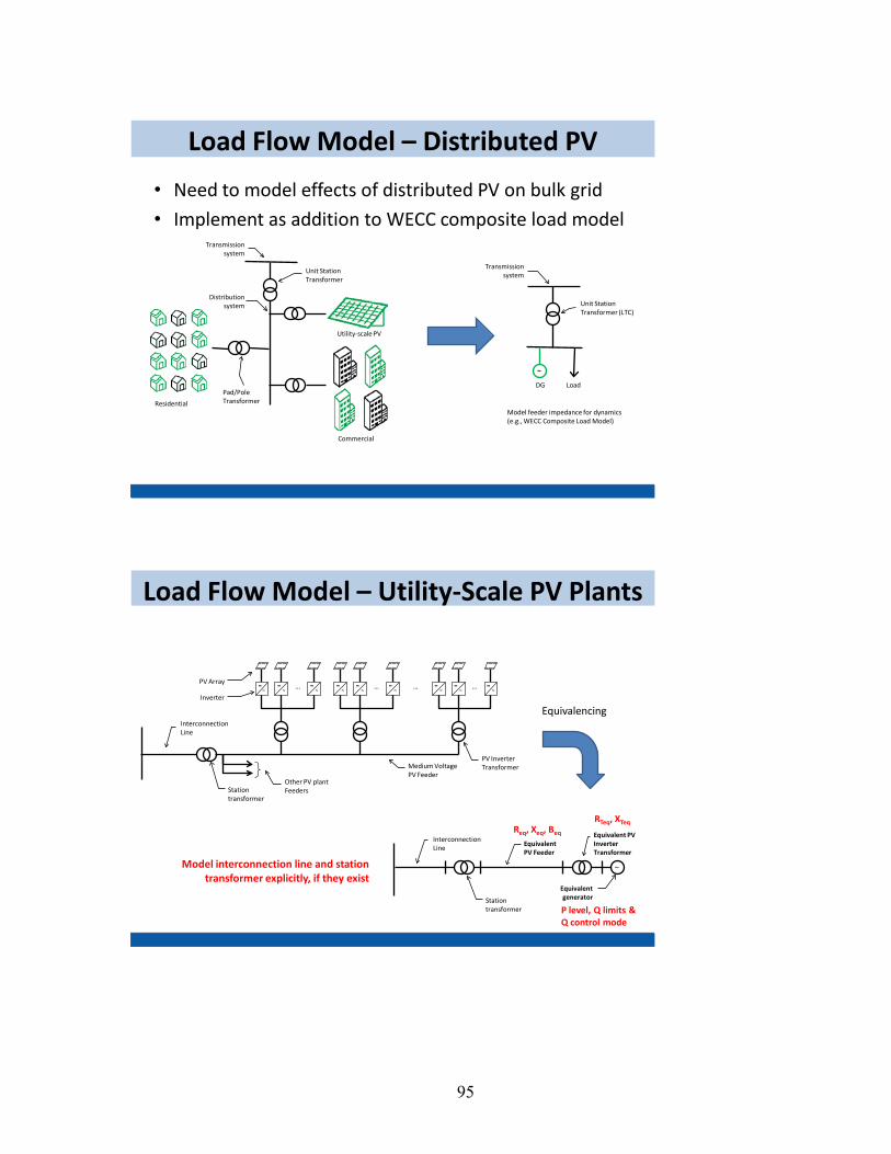
95
• Need to model effects of distributed PV on bulk grid
• Implement as addition to WECC composite load model
Load Flow Model – Distributed PV
Residential
Commercial
Utility-scale PV
Transmission system
Distribution system
Unit Station Transformer
Pad/Pole Transformer
Transmission system
Unit Station Transformer (LTC)
~
LoadDG
Model feeder impedance for dynamics(e.g., WECC Composite Load Model)
Load Flow Model – Utility-Scale PV Plants
… … ……= .
. ~= .. ~
= .. ~
= .. ~
= .. ~
= .. ~
= .. ~
= .. ~
= .. ~
Equivalent PV Feeder
Inverter
PV Array
Station transformer
Interconnection Line
Other PV plant Feeders
Medium Voltage PV Feeder
Station transformer
Interconnection Line
Equivalent PV Inverter Transformer
PV Inverter Transformer
Equivalent generator
~
Equivalencing
Req, Xeq, Beq
RTeq, XTeq
P level, Q limits & Q control mode
Model interconnection line and station transformer explicitly, if they exist
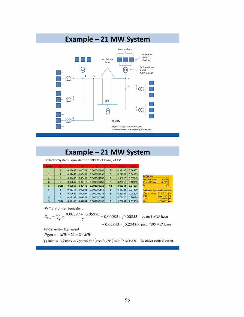
96
1 4
2
3
59
7
6
SUB
8
PV Inverter1 MW+/-0.95 pf
PV Transformer3 MVAZ=6%, X/R=10
UG feeders24 kV
Inverter cluster
To utility
Model station transformer and interconnection line explicitly, if they exist.
Example – 21 MW System
From To R X B n R n^2 X n^21 4 0.03682 0.00701 0.000000691 3 0.33136 0.06307 2 4 0.02455 0.00467 0.000001036 3 0.22091 0.04205 4 5 0.02455 0.00467 0.000001036 9 1.98816 0.37843 3 5 0.02557 0.02116 0.000000235 3 0.23016 0.19042 5 SUB 0.02557 0.02116 0.000000235 12 3.68251 3.04673 6 8 0.03747 0.00868 0.000000561 3 0.33726 0.07809 7 8 0.02455 0.00467 0.000001036 3 0.22091 0.04205 8 9 0.02109 0.02501 0.000000199 6 0.75925 0.90025 9 SUB 0.02109 0.02501 0.000000199 9 1.70831 2.02555
RESULTSPartial R sum 9.4788Partial X sum 6.7666N 21
Collector System Equivalent(Same units as R, X & B data)Req 0.021494 puXeq 0.015344 puBeq 0.000005 pu
j0.28430 0.02843
j0.008530.000857
j0.05970 0.00597
+=
+=+
==MZZ T
Teq
PV Transformer Equivalent
Collector System Equivalent on 100 MVA base, 24 kV
pu on 3 MVA base
pu on 100 MVA base
( )( ) MVARPFPgenQQMWMWPgen
9.6costanmaxmin2121*1
1 =×=−=
==−
PV Generator Equivalent
Reactive control varies
Example – 21 MW System

97
Reactive Control Options
Reactive Power
SPad-mounted Transformer Equivalent
PV Generator Equivalent
Collector System
Equivalent
Interconnection Line
POCC/POI Station Transformer(s)
Voltage Control
• Fixed PF/Var• Volt/Var droop• Closed Loop Voltage control
Reactive Power Capability of Inverters: What is the reactive power capability? What about partial power? Check spec sheet!
Reac
tive P
ower
0.5 Prated
Prated
-0.5 Prated
0
PF = +/- 0.95PF = +/- 0.90
Full capability at any operating point
Grid Voltage Monitoring Enabled – Unit Trips During L-L-L-G Fault
In this case the AC voltage drops instantaneously and triggers an “instantaneous AC under-voltage” trip. Inverter gating stops immediately and the AC contactor releases after a few cycles. The filter capacitor rings with the grid inductance for a short time.
Source: Colin Schauder, Satcon Technology Corporation - Transient Modeling for Inverter-Based Distributed Generation, March 2, 2010
Transient Behavior of PV Inverters
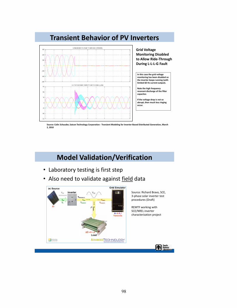
98
Grid Voltage Monitoring Disabled to Allow Ride-Through During L-L-L-G Fault
In this case the grid voltage monitoring has been disabled so the inverter keeps running (with limited 60 Hz current output).
Note the high frequency resonant discharge of the filter capacitor.
If the voltage drop is not so abrupt, then much less ringing occur.
Source: Colin Schauder, Satcon Technology Corporation - Transient Modeling for Inverter-Based Distributed Generation, March 2, 2010
Transient Behavior of PV Inverters
Model Validation/Verification
• Laboratory testing is first step
• Also need to validate against field data
Source: Richard Bravo, SCE, 3-phase solar inverter test procedures (Draft)
REMTF working with SCE/NREL inverter characterization project
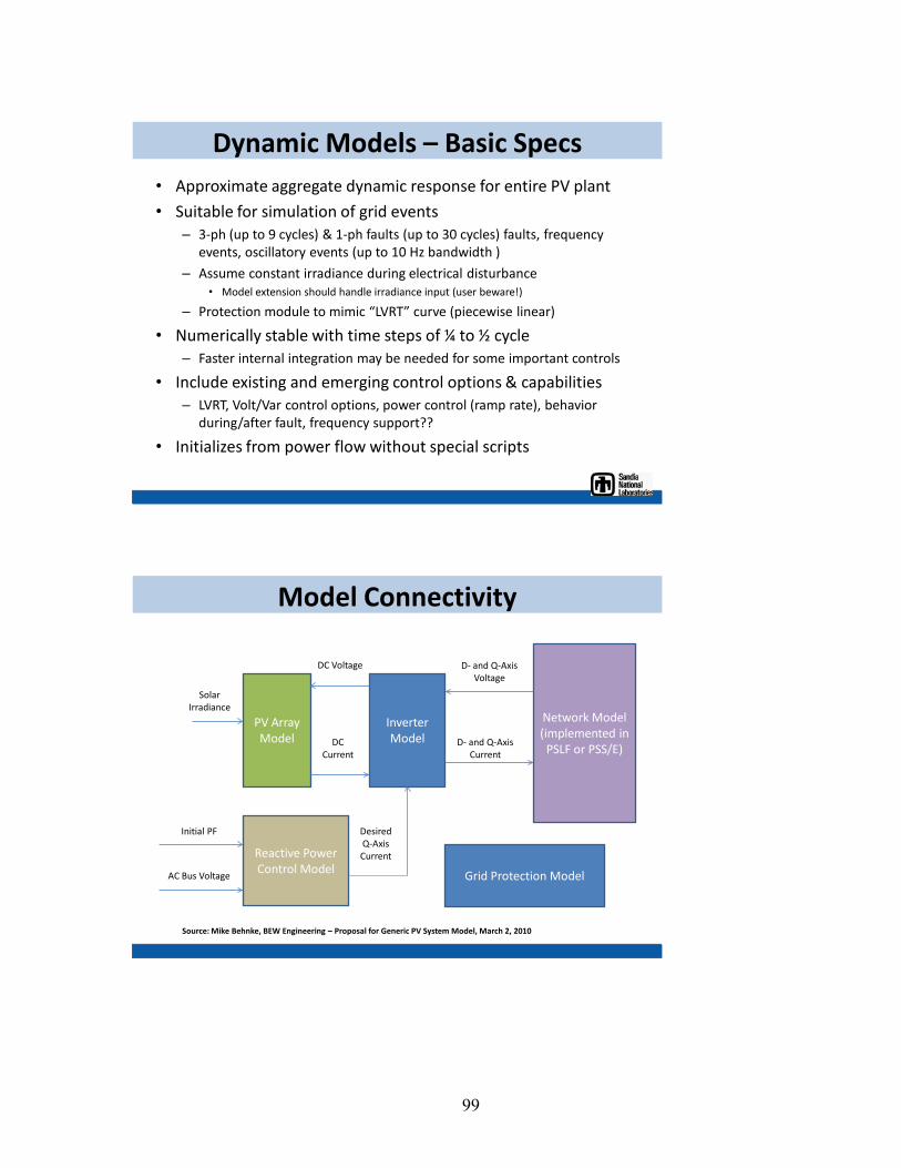
99
Dynamic Models – Basic Specs• Approximate aggregate dynamic response for entire PV plant
• Suitable for simulation of grid events– 3-ph (up to 9 cycles) & 1-ph faults (up to 30 cycles) faults, frequency
events, oscillatory events (up to 10 Hz bandwidth )
– Assume constant irradiance during electrical disturbance• Model extension should handle irradiance input (user beware!)
– Protection module to mimic “LVRT” curve (piecewise linear)
• Numerically stable with time steps of ¼ to ½ cycle– Faster internal integration may be needed for some important controls
• Include existing and emerging control options & capabilities– LVRT, Volt/Var control options, power control (ramp rate), behavior
during/after fault, frequency support??
• Initializes from power flow without special scripts
Model Connectivity
PV Array Model
Inverter Model
Network Model (implemented in
PSLF or PSS/E)
Reactive Power Control Model
Solar Irradiance
DC Voltage
DC Current
Desired Q-Axis Current
D- and Q-Axis Current
D- and Q-Axis Voltage
AC Bus Voltage
Initial PF
Grid Protection Model
Source: Mike Behnke, BEW Engineering – Proposal for Generic PV System Model, March 2, 2010
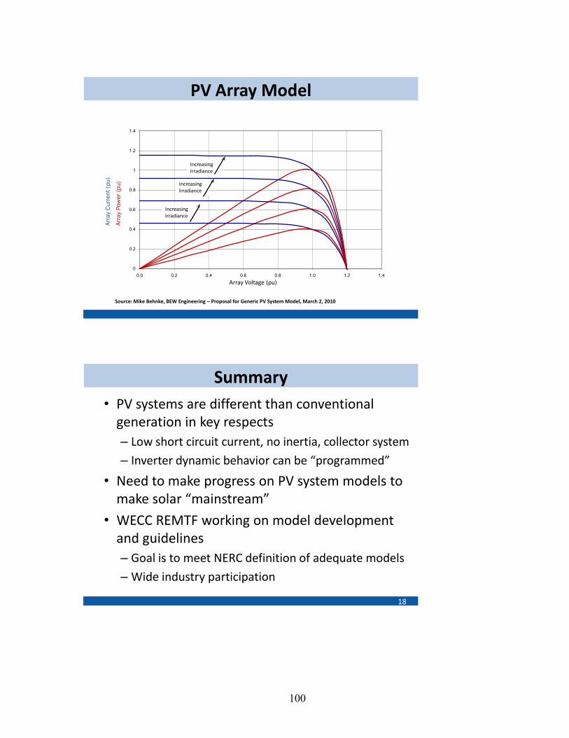
100
PV Array Model
0
0.2
0.4
0.6
0.8
1
1.2
1.4
0.0 0.2 0.4 0.6 0.8 1.0 1.2 1.4
Arra
y Cu
rren
t (pu
)
Arra
y Po
wer
(pu)
Array Voltage (pu)
Increasing Irradiance
Increasing Irradiance
Increasing Irradiance
Source: Mike Behnke, BEW Engineering – Proposal for Generic PV System Model, March 2, 2010
Summary• PV systems are different than conventional
generation in key respects– Low short circuit current, no inertia, collector system
– Inverter dynamic behavior can be “programmed”
• Need to make progress on PV system models to make solar “mainstream”
• WECC REMTF working on model development and guidelines– Goal is to meet NERC definition of adequate models
– Wide industry participation
18
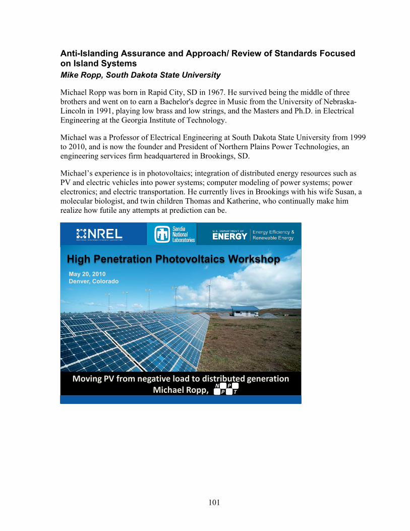
101
Anti-Islanding Assurance and Approach/ Review of Standards Focused on Island Systems Mike Ropp, South Dakota State University
Michael Ropp was born in Rapid City, SD in 1967. He survived being the middle of three brothers and went on to earn a Bachelor's degree in Music from the University of Nebraska-Lincoln in 1991, playing low brass and low strings, and the Masters and Ph.D. in Electrical Engineering at the Georgia Institute of Technology.
Michael was a Professor of Electrical Engineering at South Dakota State University from 1999 to 2010, and is now the founder and President of Northern Plains Power Technologies, an engineering services firm headquartered in Brookings, SD.
Michael’s experience is in photovoltaics; integration of distributed energy resources such as PV and electric vehicles into power systems; computer modeling of power systems; power electronics; and electric transportation. He currently lives in Brookings with his wife Susan, a molecular biologist, and twin children Thomas and Katherine, who continually make him realize how futile any attempts at prediction can be.
High Penetration Photovoltaics WorkshopMay 20, 2010Denver, Colorado
Moving PV from negative load to distributed generationMichael Ropp, N
PP
T
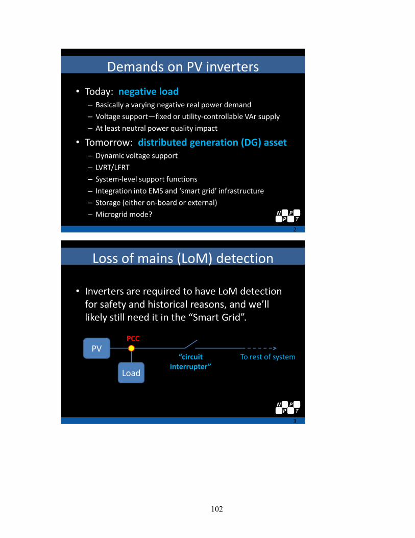
102
Demands on PV inverters
• Today: negative load– Basically a varying negative real power demand
– Voltage support—fixed or utility-controllable VAr supply
– At least neutral power quality impact
• Tomorrow: distributed generation (DG) asset– Dynamic voltage support
– LVRT/LFRT
– System-level support functions
– Integration into EMS and ‘smart grid’ infrastructure
– Storage (either on-board or external)
– Microgrid mode?
2
NP
PT
Loss of mains (LoM) detection
• Inverters are required to have LoM detection for safety and historical reasons, and we’ll likely still need it in the “Smart Grid”.
3
PV
Load
To rest of system
PCC
“circuit interrupter”
NP
PT

103
PV and LoM
• Today’s anti-islanding relies on:– Positive feedback;
– “Perturb-and-observe”, similar to impedance detection; and
– An assumption of a very strong grid source.
• Based on:– Single-inverter case
– No other generation in the potential island
– “Negative load” philosophy
4
NP
PT
PVDG, and LoM
• Today’s anti-islanding is incompatible with high PV penetration or a DG philosophy– Issues with multiple inverter case (?)
– Issues when multiple generator types present
– Incompatible with grid support functions• Hard to distinguish between “trip” and “ride through”
events
5
NP
PT
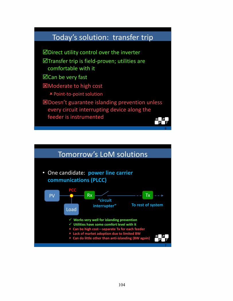
104
Today’s solution: transfer trip
Direct utility control over the inverter
Transfer trip is field-proven; utilities are comfortable with it
Can be very fast
Moderate to high cost Point-to-point solution
Doesn’t guarantee islanding prevention unless every circuit interrupting device along the feeder is instrumented
6
NP
PT
Tomorrow’s LoM solutions
• One candidate: power line carrier communications (PLCC)
7
PV
LoadTo rest of system
PCC
“circuit interrupter”
Rx Tx
Works very well for islanding prevention Utilities have some comfort level with it Can be high cost—separate Tx for each feeder Lack of market adoption due to limited BW Can do little other than anti-islanding (BW again) N
PP
T
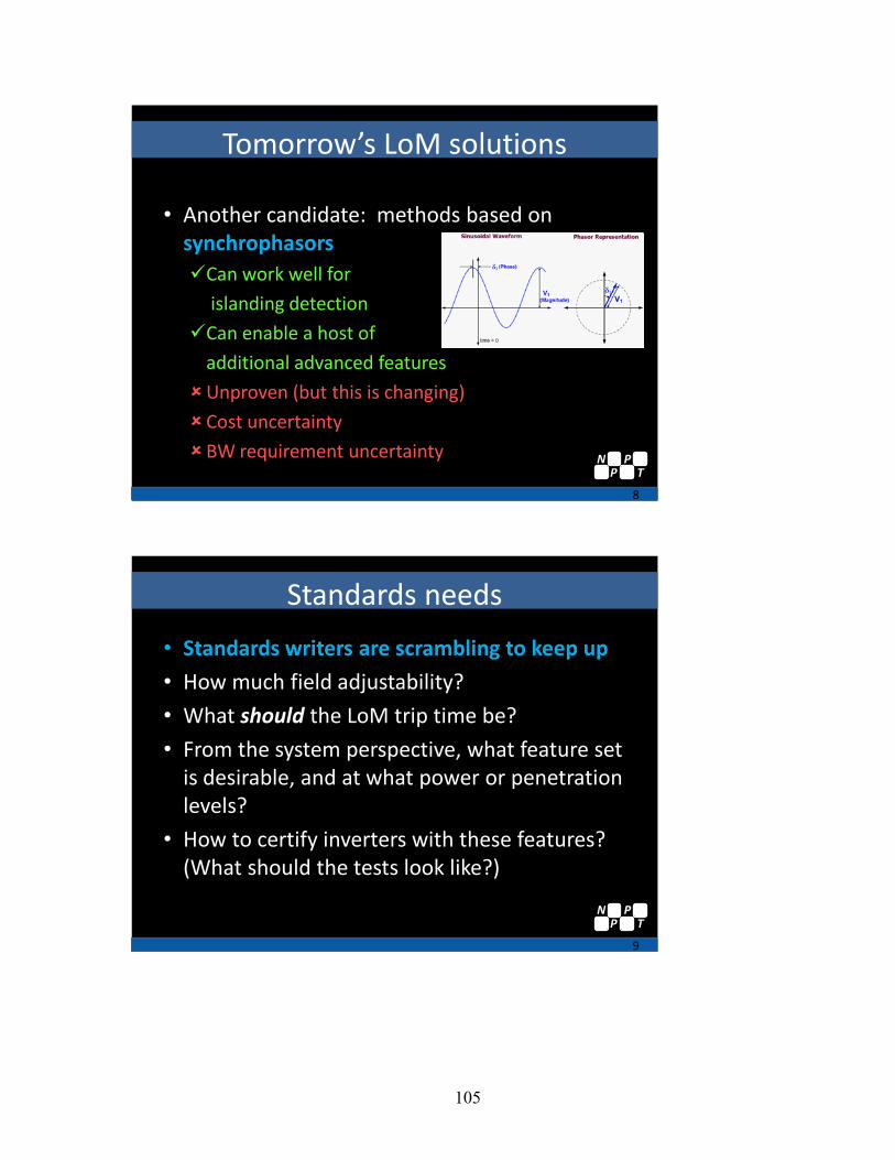
105
Tomorrow’s LoM solutions
• Another candidate: methods based on synchrophasorsCan work well for
islanding detection
Can enable a host of
additional advanced features
Unproven (but this is changing)
Cost uncertainty
BW requirement uncertainty
8
NP
PT
Standards needs
• Standards writers are scrambling to keep up
• How much field adjustability?
• What should the LoM trip time be?
• From the system perspective, what feature set is desirable, and at what power or penetration levels?
• How to certify inverters with these features? (What should the tests look like?)
9
NP
PT

106
Thank you!
10
NP
PT
Distribution Impact Studies / Review of IEEE P1547.7 Robert Saint, National Rural Electric Cooperative Association
Bob Saint has been with NRECA for over 9 years and his primary role is technical advisor for the transmission and distribution Engineering Committee and works with the System Planning Subcommittee. He has worked for rural electric co-ops, primarily distribution cooperatives for over 20 years in Colorado before coming to NRECA. Bob is also the Program Manager for the MultiSpeak Software Integration Initiative.
Bob is chairman of the IEEE P1547.7 and IEEE PES Distributed Resources Integration Working Group. Bob is a member of the GridWise Architecture Council and on the Governing Board of the NIST Smart Grid Interoperability Panel. He is a Professional Engineer in Texas and Virginia and a senior member of IEEE. Bob graduated from Wichita State University with a BS in Electrical Engineering.

107
High Penetration Photovoltaics WorkshopMay 20, 2010Denver, Colorado
Distribution Impact Studies/Review of IEEE P1547.7Bob Saint
1547- 2008 Standard for Interconnecting Distributed Resources with Electric Power Systems
1547.1 - 2005 Conformance Test Procedures for Equipment Interconnecting DR with EPS
1547.2 - 2008 Application Guide for IEEE 1547 Standard for Interconnection of DR with EPS
1547.3 - 2007 Guide for Monitoring, Information Exchange and Control of DR
Curr
ent 1
547
Proj
ects
P1547.4 Guide for Design, Operation, & Integration of Distributed Resource Island Systems with EPS
P1547.6 Recommended Practice for Interconnecting DR With EPS Distribution Secondary Networks
P1547.5 Guidelines for Interconnection of EPS >10 MVA to the Power Transmission Grid
Microgrids
IEEE 1547 Interconnection Standards
http
://g
roup
er.ie
ee.o
rg/g
roup
s/sc
c21/
inde
x.ht
ml
P1547.7 Draft Guide to Conducting Distribution Impact Studies for DR Interconnection
P1547.8 (new) Extension of 1547, e.g. grid support, energy storage, ride-thru, etc.
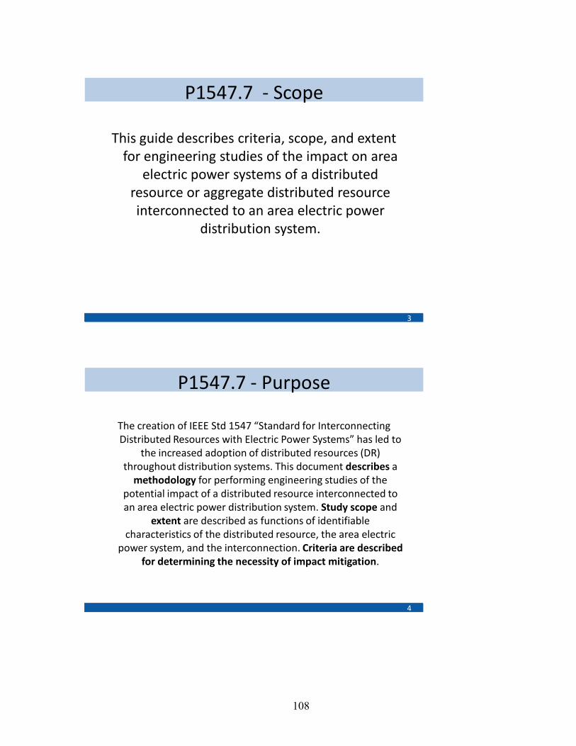
108
P1547.7 - Scope
This guide describes criteria, scope, and extent for engineering studies of the impact on area
electric power systems of a distributed resource or aggregate distributed resource interconnected to an area electric power
distribution system.
3
P1547.7 - Purpose
The creation of IEEE Std 1547 “Standard for Interconnecting Distributed Resources with Electric Power Systems” has led to
the increased adoption of distributed resources (DR) throughout distribution systems. This document describes a
methodology for performing engineering studies of the potential impact of a distributed resource interconnected to an area electric power distribution system. Study scope and
extent are described as functions of identifiable characteristics of the distributed resource, the area electric
power system, and the interconnection. Criteria are described for determining the necessity of impact mitigation.
4
109
P1547.7 – Purpose (cont.)
Establishment of this guide allows distributed resource owners, interconnection contractors, area electric distribution power system owners and operators,
and regulatory bodies to have a described methodology for when distribution system impact
studies are appropriate, what data is required, howthey are performed, and how the study results are evaluated. In the absence of such guidelines, the
necessity and extent of DR interconnection impact studies has been widely and inconsistently defined
and applied.
5
P1547.7 - Outline
1. Overview
1.1 Scope
1.2 Purpose
1.3 Intended Audience
1.4 Limitations
1.5 Document Structure
2. References
3. Definitions, acronyms and abbreviations
3.1 Definitions
3.2 Acronyms and abbreviations
6
110
P1547.7 – Outline (cont.)
4. General Considerations
4.1 Potential System Impacts of DR
4.2 Classes of impact studies
4.3 Classes of tools for studying impacts
4.4 Reliability Perspectives Related to EPS and DR
4.5 DR owner perspective
7
P1547.7 – Outline (cont.)
5. Assessment Methodology
5.1 Assessment Sequence
5.2 Assessment Information
5.3 Preliminary Review
5.4 Routine Distribution Study
5.5 Special System Impact Study
8

111
P1547.7 – Outline (cont.)
6. Data Requirements
6.1 Proposed distributed resource
6.2 Existing and planned area EPS
6.3 Proposed interconnection equipment and system integration
6.4 Specialty Studies
6.5 General considerations
9
P1547.7 – Outline (cont.)7. Operating and Configuration Considerations
7.1 DR Considerations
7.2 Area EPS Considerations
8. Preliminary Review
8.1 Study Types and Tools
8.2 Technical Issues
10

112
P1547.7 – Outline (cont.)
9. Routine Distribution Studies
9.1 Study Types and Tools
9.2 Technical Issues
10. Special System Impact Studies
10.1 Study Types and Tools
10.2 Technical Issues
11
P1547.7 – Outline (cont.)
11. Using the results of impact studies
11.1 Mitigation of system protection concerns
11.2 Mitigation of steady-state performance concerns
11.3 Mitigation of power quality concerns
11.4 Mitigation of system stability concerns
12
113
P1547.7 – Next Meeting
August 10-11, 2010 – San Francisco, CA
http://grouper.ieee.org/groups/scc21/1547.7/1547.7_index.html
13
Contact Me
Bob Saint Principal Distribution Engineer, Energy &
Environmental Policy National Rural Electric Cooperative
Association (NRECA)
Phone: (703) 907-5863
Email: [email protected]
14
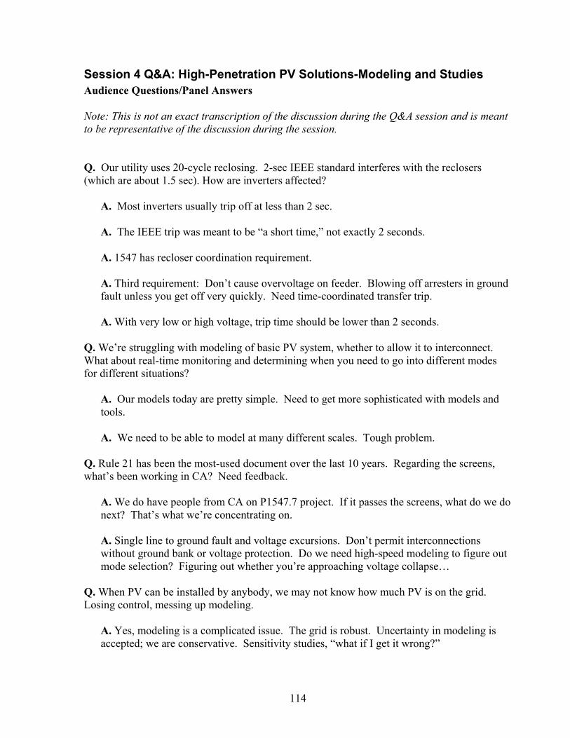
114
Session 4 Q&A: High-Penetration PV Solutions-Modeling and Studies Audience Questions/Panel Answers Note: This is not an exact transcription of the discussion during the Q&A session and is meant to be representative of the discussion during the session. Q. Our utility uses 20-cycle reclosing. 2-sec IEEE standard interferes with the reclosers (which are about 1.5 sec). How are inverters affected?
A. Most inverters usually trip off at less than 2 sec. A. The IEEE trip was meant to be “a short time,” not exactly 2 seconds.
A. 1547 has recloser coordination requirement.
A. Third requirement: Don’t cause overvoltage on feeder. Blowing off arresters in ground fault unless you get off very quickly. Need time-coordinated transfer trip. A. With very low or high voltage, trip time should be lower than 2 seconds.
Q. We’re struggling with modeling of basic PV system, whether to allow it to interconnect. What about real-time monitoring and determining when you need to go into different modes for different situations?
A. Our models today are pretty simple. Need to get more sophisticated with models and tools. A. We need to be able to model at many different scales. Tough problem.
Q. Rule 21 has been the most-used document over the last 10 years. Regarding the screens, what’s been working in CA? Need feedback.
A. We do have people from CA on P1547.7 project. If it passes the screens, what do we do next? That’s what we’re concentrating on. A. Single line to ground fault and voltage excursions. Don’t permit interconnections without ground bank or voltage protection. Do we need high-speed modeling to figure out mode selection? Figuring out whether you’re approaching voltage collapse…
Q. When PV can be installed by anybody, we may not know how much PV is on the grid. Losing control, messing up modeling.
A. Yes, modeling is a complicated issue. The grid is robust. Uncertainty in modeling is accepted; we are conservative. Sensitivity studies, “what if I get it wrong?”
115
A. Wake-up call to utilities. They need to know who is connecting PV to the system! Make it easy to know/find out. A. Scenario to get in our heads. We think of orderly progression to add PV to grid (not much guerilla solar). But let’s say it changes, with people throwing on lots of PV. Then what? A. Bulk system-level model. But there is a need for modeling for day-to-day distribution simulation. DOE is supporting this work.
Q. Data intensity vs. value out. Massive data requirements. Use geographic models.
A. Commercial modeling developers would like someone to come up with models that they can plug into their application. A. Working at NREL to develop validated models that software companies can pick up and put in their packages. A. Utilities want to know what variability could do at the local level. E.g., How cloudy is cloudy? A. Not just models. Need whole new modeling tool. Quasi-steady-state (QSS), for example. Not available now. Write our own code to make QSS dynamic simulation around commercial software. A. Variability of load flows. Packages don’t offer that capability, but OpenDS (EPRI) does. First used for wind, now being applied to PV. A. Transmission planning. Resistance to adopting new models. Resistance to using new software. If planners are not use to something, they don’t like it. It’s difficult. Make it easy to translate databases from one platform to another. A. Simulating cloud shadowing connected to GIS data. Need to simulate the patterns. Important if we really want to get idea.
Q. Evaluating advanced module on CymeDist. Does time analysis. Single- and 3-phase. Don’t need to be a programmer to enter the data. Q. What features do we want to add to our models? Leads to chaos quickly. What are our objectives? What is the purpose of the study? Modeling is an art.
116
Moving Forward with HPPV Standards and Codes / Discussion of Future Workshops, Webinars & Standards Activities Kevin Lynn, DOE
During the closing remarks, there was a discussion of the new IEEE P1547.8 Draft Recommended Practice for Establishing Methods and Procedures that Provide Supplemental Support for Implementation Strategies for Expanded Use of IEEE Standard 1547 that may focus on resolution of many concerns of high-penetration PV deployment.
Kevin Lynn posed several questions to the audience: First step in addressing codes and standards (C&S) for HPPV. Do more workshops? Like this, or something else? Different format? Should we just focus on C&S? Just 1547? What are action items coming out of this workshop? Audience Responses:
• Great session. We need a session with focal point, timeline, dates, what can/can’t be done, reality.
• Issues are interrelated. Difficult to talk about in isolation.
• Consensus on issues. 1547.8 being a priority for moving forward. Address the issue
where there is consensus.
• Some presentations on bulk power efficiency and reliability and what HPPV can have, voltage reduction, what voltage should we target.
• Learn from experience good and bad from Europe, Germany and Spain. Some
interaction with them? They are farther down the road than we are. Let’s not reinvent the wheel or repeat their mistakes.
• New PVPS Task 14, April 2010, High Penetration, IEA member countries. Just getting
kicked off. Next meeting is in December 2010 in Denver.
• Face-to-face is better than Webinars.
• NREC, Intergeneration Task Force (IGTF), bulk generation. Discuss how this fits with our work.
The meeting concluded with general consensus that additional meetings, webinars and conference calls would be desirable. There was overwhelming agreement that developing new standards and codes for high-penetration PV deployment is an extremely important goal for utilities, industry, and government.
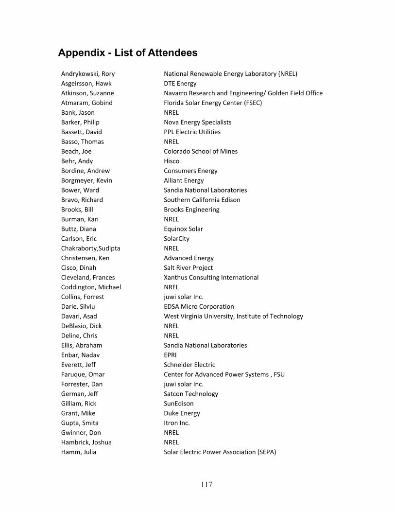
117
Appendix - List of Attendees Andrykowski, Rory National Renewable Energy Laboratory (NREL) Asgeirsson, Hawk DTE Energy Atkinson, Suzanne Navarro Research and Engineering/ Golden Field Office Atmaram, Gobind Florida Solar Energy Center (FSEC) Bank, Jason NREL Barker, Philip Nova Energy Specialists Bassett, David PPL Electric Utilities Basso, Thomas NREL Beach, Joe Colorado School of Mines Behr, Andy Hisco Bordine, Andrew Consumers Energy Borgmeyer, Kevin Alliant Energy Bower, Ward Sandia National Laboratories Bravo, Richard Southern California Edison Brooks, Bill Brooks Engineering Burman, Kari NREL Buttz, Diana Equinox Solar Carlson, Eric SolarCity Chakraborty,Sudipta NREL Christensen, Ken Advanced Energy Cisco, Dinah Salt River Project Cleveland, Frances Xanthus Consulting International Coddington, Michael NREL Collins, Forrest juwi solar Inc. Darie, Silviu EDSA Micro Corporation Davari, Asad West Virginia University, Institute of Technology DeBlasio, Dick NREL Deline, Chris NREL Ellis, Abraham Sandia National Laboratories Enbar, Nadav EPRI Everett, Jeff Schneider Electric Faruque, Omar Center for Advanced Power Systems , FSU Forrester, Dan juwi solar Inc. German, Jeff Satcon Technology Gilliam, Rick SunEdison Grant, Mike Duke Energy Gupta, Smita Itron Inc. Gwinner, Don NREL Hambrick, Joshua NREL Hamm, Julia Solar Electric Power Association (SEPA)

118
Hampton, Tonja National Science Foundation Handy, Mark KenJiva Energy Systems Hefner, Al National Institute of Standards and Technology (NIST) Herig, Christy SEPA Heskin, Daryl Renewable Technologies, Inc. Holmes, Darell Southern California Edison Hudson, Raymond BEW Engineering Huque, Aminul EPRI Johnson, Lars SunPower Corporation Johnson, Walter University of California, San Diego Kalejs, Juris American Capital Energy Keller, Jamie NREL Key, Tom EPRI Kobusch, Andrew Navarro Research & Engineering Krauze, Richard Renewable Energy Advisor Kroposki, Ben NREL Kueck, John Oak Ridge National Laboratory Kulick, John Siemens Corporation Kushner, Linda Progress Energy Kuszmaul, Scott Sandia National Laboratories Lenox, Carl SunPower Corporation Lew, Debra NREL Liang, Nathan Hawaiian Electric Company Lubkeman, David KEMA, Inc. Lynn, Kevin U.S. Department of Energy (DOE) Mander, Art Tri-State G&T Manjrekar, Madhav Siemens Corporate Research Mather, Barry NREL McDonnell, Chad Denver Investments Wealth Management McNutt, Peter NREL McPhail, Keith GST Meeker, Rick FSU Center for Advanced Power Systems Mensah, Adje Petra Solar Metzger, Thomas Navarro Research & Engineering, Inc. Mignogna, Richard Colorado PUC Miklos,Todd Advanced Energy Industries Inc. - Solar Inverters Muller, Matthew NREL Nasr, Elie SMA Neal, Russell Southern California Edison Nichols, David Altairnano Nicole, Kristen Sentech Novachek, Frank Xcel Energy Nowicki, Genevieve Solar Power Partners
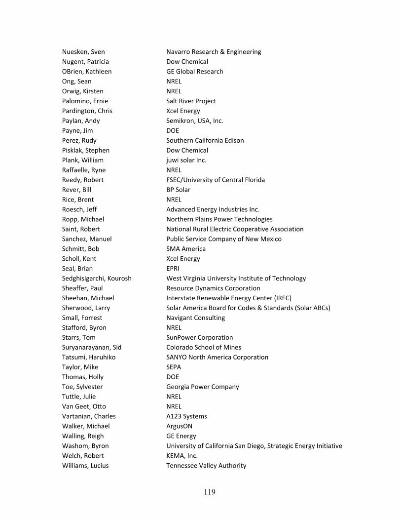
119
Nuesken, Sven Navarro Research & Engineering Nugent, Patricia Dow Chemical OBrien, Kathleen GE Global Research Ong, Sean NREL Orwig, Kirsten NREL Palomino, Ernie Salt River Project Pardington, Chris Xcel Energy Paylan, Andy Semikron, USA, Inc. Payne, Jim DOE Perez, Rudy Southern California Edison Pisklak, Stephen Dow Chemical Plank, William juwi solar Inc. Raffaelle, Ryne NREL Reedy, Robert FSEC/University of Central Florida Rever, Bill BP Solar Rice, Brent NREL Roesch, Jeff Advanced Energy Industries Inc. Ropp, Michael Northern Plains Power Technologies Saint, Robert National Rural Electric Cooperative Association Sanchez, Manuel Public Service Company of New Mexico Schmitt, Bob SMA America Scholl, Kent Xcel Energy Seal, Brian EPRI Sedghisigarchi, Kourosh West Virginia University Institute of Technology Sheaffer, Paul Resource Dynamics Corporation Sheehan, Michael Interstate Renewable Energy Center (IREC) Sherwood, Larry Solar America Board for Codes & Standards (Solar ABCs) Small, Forrest Navigant Consulting Stafford, Byron NREL Starrs, Tom SunPower Corporation Suryanarayanan, Sid Colorado School of Mines Tatsumi, Haruhiko SANYO North America Corporation Taylor, Mike SEPA Thomas, Holly DOE Toe, Sylvester Georgia Power Company Tuttle, Julie NREL Van Geet, Otto NREL Vartanian, Charles A123 Systems Walker, Michael ArgusON Walling, Reigh GE Energy Washom, Byron University of California San Diego, Strategic Energy Initiative Welch, Robert KEMA, Inc. Williams, Lucius Tennessee Valley Authority

120
Worrell , Lynn Xcel Energy Yohn, Thomas Xcel Energy
F1147-E(10/2008)
REPORT DOCUMENTATION PAGE Form Approved OMB No. 0704-0188
The public reporting burden for this collection of information is estimated to average 1 hour per response, including the time for reviewing instructions, searching existing data sources, gathering and maintaining the data needed, and completing and reviewing the collection of information. Send comments regarding this burden estimate or any other aspect of this collection of information, including suggestions for reducing the burden, to Department of Defense, Executive Services and Communications Directorate (0704-0188). Respondents should be aware that notwithstanding any other provision of law, no person shall be subject to any penalty for failing to comply with a collection of information if it does not display a currently valid OMB control number. PLEASE DO NOT RETURN YOUR FORM TO THE ABOVE ORGANIZATION. 1. REPORT DATE (DD-MM-YYYY)
September 2010 2. REPORT TYPE
Proceedings 3. DATES COVERED (From - To)
4. TITLE AND SUBTITLE
High-Penetration Photovoltaic Standardes and Codes Workshop: Workshop Proceedings
5a. CONTRACT NUMBER DE-AC36-08-GO28308
5b. GRANT NUMBER
5c. PROGRAM ELEMENT NUMBER
6. AUTHOR(S) M. Coddington, B. Kroposki, T. Basso: NREL K. Lynn: Department of Energy, EERE C. Herig: Solar Electric Power Association W. Bower: Sandia National Laboratories
5d. PROJECT NUMBER NREL/TP-550-48378
5e. TASK NUMBER PVC9.1110
5f. WORK UNIT NUMBER
7. PERFORMING ORGANIZATION NAME(S) AND ADDRESS(ES) National Renewable Energy Laboratory 1617 Cole Blvd. Golden, CO 80401-3393
8. PERFORMING ORGANIZATION REPORT NUMBER NREL/TP-550-48378
9. SPONSORING/MONITORING AGENCY NAME(S) AND ADDRESS(ES)
10. SPONSOR/MONITOR'S ACRONYM(S) NREL
11. SPONSORING/MONITORING AGENCY REPORT NUMBER
12. DISTRIBUTION AVAILABILITY STATEMENT National Technical Information Service U.S. Department of Commerce 5285 Port Royal Road Springfield, VA 22161
13. SUPPLEMENTARY NOTES
14. ABSTRACT (Maximum 200 Words) Effectively interconnecting high-level penetration of photovoltaic (PV) systems requires careful technical attention to ensuring compatibility with electric power systems. Standards, codes, and implementation have been cited as major impediments to widespread use of PV within electric power systems. On May 20, 2010, in Denver, Colorado, the National Renewable Energy Laboratory, in conjunction with the U.S. Department of Energy (DOE) Office of Energy Efficiency and Renewable Energy (EERE), held a workshop to examine the key technical issues and barriers associated with high PV penetration levels with an emphasis on codes and standards. This workshop included building upon results of the High Penetration of Photovoltaic (PV) Systems into the Distribution Grid workshop held in Ontario California on February 24-25, 2009, and upon the stimulating presentations of the diverse stakeholder presentations.
15. SUBJECT TERMS HPPV; photovoltaic; electric power systems; EPS; DOE; NREL; high-penetration photovoltaics; standards; codes
16. SECURITY CLASSIFICATION OF: 17. LIMITATION OF ABSTRACT
UL
18. NUMBER OF PAGES
19a. NAME OF RESPONSIBLE PERSON a. REPORT
Unclassified b. ABSTRACT Unclassified
c. THIS PAGE Unclassified 19b. TELEPHONE NUMBER (Include area code)
Standard Form 298 (Rev. 8/98) Prescribed by ANSI Std. Z39.18