Messages and error codes
22
Diagnostics information 2-13 7014-xxx Messages and error codes User attendance messages The printer control panel displays messages describing the current state of the printer and indicates possible printer problems that must be resolved. This topic provides a list of all printer messages, explains what they mean, and tells how to clear the messages. The following table lists the messages in alphanumerical order. A message can also be located using the index. User status and attendance messages User primary message Explanation Change <src><Custom type name> This IR allows a user to override the source for the remainder of a job. The page will be printed as it is formatted on the paper installed in the tray. This may cause clipping. No further Change prompts will be posted for the remainder of the current job. The following actions can be taken: • Change the paper source to a custom type / custome string /source and size/ source, type, size. • Continue the print job. • Request more information. • Use the current source. • Reset the active. • Wait fir supplies. Change <src><Custom String> Change <src><size> Change <src><type><size> Close Door Message clears when front doors is closed. Disk Corrupted. Reformat? This message appears if there is a corrupted hard disk. Reformat the drive. If the message remains, replace the disk. Weblink server not setup. Contact system administrator Web Link is being used for e-mail, and either the 'Server' or 'Web Link' fields are NULL in the Web Link Setup. • The system administrator needs to configure the server. SMTP server not setup. Contact system administrator The devices primary and secondary SMTP fields are blank. This needs to be configured by the system administrator. No Analog Phone Line An analog line is not detected as being plugged into the modem. If the device is in Analog mode, this has a source of Fax. If the device is in Fax Server mode, and the 'Enable analog receive' Fax Server setting is set to 'On', this has a source of Fax Receive. If the device is in Fax Server mode and the 'Enable analog receive' Fax Server setting is set to 'Off', then this IR is not generated. Memory Full, cannot print faxes Attempted print is automatically canceled. The Fax code will recognize that the print job has been canceled and will not delete pages in the fax job that have not printed. Fax will not attempt to reprint the fax that generated the out of memory error until a POR is performed. Memory Full, cannot send faxes After a start, there is no memory to do the fax job. Attempted fax is cancelled. Fax server ‘To Format’ not set up Device is in Fax Server mode. The To format for the Fax Server setup is null. Analog receive still possible. Fax Station number not set up. Held jobs may not be restored This message is only posted once after the firmware has tried to restore all of the jobs on disk, regardless of the number of held jobs that were not restored. There are three versions of this IR, depending upon cause. IRHeldA occurs when any other condition occurs which stops the printer from restoring jobs from disk. These might include disk failure, user abort, etc.
-
Upload
khangminh22 -
Category
Documents
-
view
1 -
download
0
Transcript of Messages and error codes

Diagnostics information 2-13
7014-xxx
Messages and error codes
User attendance messages
The printer control panel displays messages describing the current state of the printer and indicates possible printer problems that must be resolved. This topic provides a list of all printer messages, explains what they mean, and tells how to clear the messages.
The following table lists the messages in alphanumerical order. A message can also be located using the index.
User status and attendance messages
User primary message Explanation
Change <src><Custom type name>
This IR allows a user to override the source for the remainder of a job. The page will be printed as it is formatted on the paper installed in the tray. This may cause clipping. No further Change prompts will be posted for the remainder of the current job.
The following actions can be taken:
• Change the paper source to a custom type / custome string /source and size/ source, type, size.
• Continue the print job.• Request more information.• Use the current source.• Reset the active.• Wait fir supplies.
Change <src><Custom String>
Change <src><size>
Change <src><type><size>
Close Door Message clears when front doors is closed.
Disk Corrupted. Reformat?
This message appears if there is a corrupted hard disk. Reformat the drive. If the message remains, replace the disk.
Weblink server not setup. Contact system administrator
Web Link is being used for e-mail, and either the 'Server' or 'Web Link' fields are NULL in the Web Link Setup.
• The system administrator needs to configure the server.
SMTP server not setup. Contact system administrator
The devices primary and secondary SMTP fields are blank. This needs to be configured by the system administrator.
No Analog Phone Line An analog line is not detected as being plugged into the modem. If the device is in Analog mode, this has a source of Fax. If the device is in Fax Server mode, and the 'Enable analog receive' Fax Server setting is set to 'On', this has a source of Fax Receive. If the device is in Fax Server mode and the 'Enable analog receive' Fax Server setting is set to 'Off', then this IR is not generated.
Memory Full, cannot print faxes
Attempted print is automatically canceled. The Fax code will recognize that the print job has been canceled and will not delete pages in the fax job that have not printed. Fax will not attempt to reprint the fax that generated the out of memory error until a POR is performed.
Memory Full, cannot send faxes
After a start, there is no memory to do the fax job. Attempted fax is cancelled.
Fax server ‘To Format’ not set up
Device is in Fax Server mode. The To format for the Fax Server setup is null. Analog receive still possible.
Fax Station number not set up.
Held jobs may not be restored
This message is only posted once after the firmware has tried to restore all of the jobs on disk, regardless of the number of held jobs that were not restored. There are three versions of this IR, depending upon cause. IRHeldA occurs when any other condition occurs which stops the printer from restoring jobs from disk. These might include disk failure, user abort, etc.

2-14 Service Manual
7014-xxx
Held jobs may not be restored (Insufficient Memory 37)
This message is only posted once after the firmware has tried to restore all of the jobs on disk, regardless of the number of held jobs that were not restored. There are three versions of this IR, depending upon cause. IRHeldB occurs when the printer runs out of memory while attempting to restore jobs from disk.
Held jobs may not be restored (Config Change 57)
This message is only posted once after the firmware has tried to restore all of the jobs on disk, regardless of the number of held jobs that were not restored. There are three versions of this IR, depending upon cause. IRHeldC occurs when the printer could not restore jobs from the disk because the configuration of the printer has changed. Some of these said configuration changes are code version changes, paper handling option(s) removed, or the disk was moved from a different model or speed of printer.
Load <source> <custom string>
Printer does not detect media meeting the description <custom string> in <source>, where <source> is Tray 1, Tray 2, Multi-Page Feeder (MP feeder), or Envelope Feeder.
• Load the input source with the correct type and size media.• Cancel the current job.
Load <source> <custom type>
Printer does not detect media meeting the description <custom type> in <source>, where <source> is Tray 1 or Tray 2.
• Load the input source with the correct type and size media.• Cancel the current job.
Load <source> <size>
Printer does not detect media meeting the size requested in the source indicated.
• Load the input source with the correct type and size media.• Cancel the current job.
Load <source> <type> <size>
Printer does not detect media meeting the size or type requested in the source indicated.
• Load the input source with the correct type and size media.• Cancel the current job.
Load Manual <custom type>
Printer does not detect media meeting the description <custom type> in the single sheet feeder (manual feeder).
The following actions can be taken:
• Load paper, and the job continues.• press Select ( ), and choose an alternate source for media.• Cancel the current job.
Load Manual <custom string>
Printer does not detect media meeting the description <custom string> in the single sheet feeder (manual feeder).
The following actions can be taken:
• Load paper and the job continues.• press Select ( ), and choose an alternate source for media.• Cancel the current job.
Load Manual <size>
Printer does not detect media meeting the description <size> in the single sheet feeder (manual feeder).
The following actions can be taken:
• Load paper and the job continues.• press Select ( ), and choose an alternate source for media.• Cancel the current job.
User status and attendance messages (Continued)
User primary message Explanation

Diagnostics information 2-15
7014-xxx
Load Manual <type> <size>
Printer does not detect media meeting the description <type> and <size> in the single sheet feeder (manual feeder).
The following actions can be taken:
• Load paper and the job continues.• press Select ( ), and choose an alternate source for media.• Cancel the current job.
Paper Changes Needed Change or load new media.
PJL OP Message
PJL Seed Message
PJL ST Message Try one or more of the following:
• press Select ( ) to clear the message, and continue printing.• Wait for the message to clear.
Remove Paper ADF This posts when there is paper detected in the ADF upon POR or when the cover is closed (or any other situation that re-inits the scanner). Message clears when paper is removed.
Remove Paper Standard Bin
The standard output bin is full or nearly full. Remove the media from the bin.
Restore Held Jobs. Go/Stop?
Held jobs were found on disk after a power on/off reset. Restoring will make these jobs available. Jobs may also be restored at a later time by turning off and restarting the printer. The following actions can be taken:
• Restore• Do not restore• More information
Securly Clearing Disk Space
This message appears when all blocks of the disk are cleared.
Unsupported USB Device, Please Remove
Remove the unrecognized device from the USB port on the front of the printer.
Unsupported USB Hub, please remove
Remove the unrecognized USB hub/device from the USB port on the front of the printer.
Unsupported Disk Remove the unsupported disk before continuing.
34 Short Paper • press Select ( ) to clear the message and continue printing.The printer does not automatically reprint the page that prompted the message.
• Check tray length and width guides to ensure paper is properly fitted in the tray.
• Make sure the print job is requesting the correct size of paper.• Adjust the Paper Size setting for the size paper you are using.
If MP Feeder Size is set to Universal, make sure the paper is large enough for the formatted data.
• Cancel the current job.
User status and attendance messages (Continued)
User primary message Explanation

2-16 Service Manual
7014-xxx
35 RES Save Off Deficient Memory
This message displays when the printer lacks sufficient memory to enable Resource Save. This message usually indicates the user has allocated too much memory for one or more of the printer link buffers; however, modification of other printer settings which affect the amount of available memory may also create this condition. If restoration of Resource Save is required after this message is received, the customer should install additional memory or set each link buffer to Auto. Once all link buffers are returned to Auto, you should exit the menu to activate the link buffer changes. Once the printer returns to the Ready state, you can enable Resource Save and go back and modify the link buffers again. Note the reduction of available memory to the link buffers when Resource Save has been enabled, and compare it to the memory available when Resource Save is disabled.
• press Select ( ) to disable Resource Save and continue printing.To enable Resource Save after you get this message:
- Make sure the link buffers are set to Auto, then exit the menus to activate the link buffer changes.
- When Ready is displayed, enable Resource Save.• Install additional memory.
37 Insufficient Collation Area
This message is displayed when the printer memory used to store pages is too full to collate the print job.
The following actions can be taken:
• press Select ( ) to print the portion of the job already stored, and begin collating the rest of the job.
• press Menus ( ) to access the Busy/Waiting Menu. The following functions are available.
- Cancel JobNote: Menu Lockout does NOT prevent access to the Busy/Waiting Menu.
37 Insufficient memory for flash defragment operation
This message is displayed when insufficient printer memory is available to perform Flash Memory Defragment operation.
This message appears prior to the actual start of the defragment operation.
press Select ( ) to stop the defragment operation.
To perform the defragment operation, you can:
• Delete fonts, macros, and other data in RAM.• Install additional printer memory.• press Menus ( ) to access the Busy/Waiting Menu.
The following functions are available using the Busy/Waiting Menu:- Cancel Job- Reset Printer
Note: Menu Lockout does NOT prevent access to the Busy/Waiting Menu.
38 Memory Full This message is displayed when the printer is processing an incoming job and there is not enough memory available to continue processing the job.
The following actions can be taken:
• Determine how to make more memory available to your print job by:- Deleting fonts, macros and other data in RAM.- Simplify your print job.- Install additional memory
• press Select ( ) to clear the message and continue printing.The job may not print correctly.
• press Menus ( ) to access the Busy/Waiting Menu.The following functions may be available:
- Cancel Job
User status and attendance messages (Continued)
User primary message Explanation

Diagnostics information 2-17
7014-xxx
39 Complex Page This message is displayed when a page is too complex to print.
The following actions can be taken:
• press Select ( ) to clear the message and continue printing.The job may not print correctly.
• Simplify the print job.• press Menus ( ) to access the Busy/Waiting Menu.
The following functions may be available:- Cancel Job- Reset Printer
Note: Menu Lockout does NOT prevent access to the Busy/Waiting Menu.
50 PPDS Font Error This error only occurs when a printer is formatting PPDS print data.
The PPDS interpreter has detected a font error. When a specific font, which is not installed, is requested based on a PPDS mode Set Font Global command, a Select Code Page command, or a Comprehensive Font Selection command, and the printer Best Fit setting is off. If Best Fit is on, the printer performs a best fit search to find a similar font, and this error does not occur.
This error also displays when the printer receives invalid PPDS download font data.
The following actions can be taken while this message is displayed:
• press Select ( ) to clear the message and continue printing.The job may not print correctly.
• press Menus ( ) to access the Busy/Waiting Menu.The following functions may be available:
- Cancel Job
51 Defective Flash Detected
press Select ( ) to clear the message and continue printing.
You must install different flash memory before you can download any resources to flash.
52 Flash Full • press Select ( ) to clear the message and continue printing.• Delete fonts, macros, and other data stored on the flash memory.• Install a larger capacity flash memory card.
53 Unformatted Flash press Select ( ) to clear the message and continue printing.
You must format the flash memory before you can store any resources on it. If the error message remains, the flash memory may be defective and require replacing.
54 Standard Network Software Error
This message is displayed when the RIP software detects that a network port is installed but cannot establish communications with it.
• press Select ( ) to clear the message and continue printing.The job may not print correctly.
• Program new firmware for the network interface.• Turn the printer power off and then back on to reset the printer.
54 Network <x> Software Error
The printer disables all communications to the associated network interface. No data may be received or sent from or to the associated interface. The user can program new firmware in the network using the parallel port after this message clears.
• press Select ( ) to clear the message and continue printing.The job may not print correctly.
• Program new firmware for the network interface.• Turn the printer power off and then back on to reset the printer.
55 Unsupported Option in Slot <x>
An unsupported option is installed in the specified solutions port. Power off the printer and remove the unsupported option in the specified slot.
Remove the unsupported option.
56 Parallel Port <x> disabled
This error displays when data is sent to the printer across an optional parallel port, but the port has been disabled. Once this message displays, reporting of further errors is suppressed until the menus are entered, or the printer is reset.
User status and attendance messages (Continued)
User primary message Explanation

2-18 Service Manual
7014-xxx
56 Serial Port <x> disabled
This error displays when data is sent to the printer across an serial port, but the port has been disabled. Once this message displays, reporting of further errors is suppressed until the menus are entered, or the printer is reset.
56 Standard USB Port Disabled
This message may appear when data is sent to the printer across a USB port, but the port is disabled.
Note: Once the error is displayed the first time, reporting of further errors is suppressed until the printer is reset or menus are entered.
The following actions can be taken:
• press Select ( ) to clear the message.Any data received on the USB port is discarded.
• press Menus ( ) to access the Busy/Waiting Menu.The following functions may be available:
- Turn the printer power off and then back on to reset the printer.- Reset Active Bin- Check Supply Levels
Make sure the USB Buffer menu item is not set to Disabled. (press Menus to access the Administrative Menus, select Network/Ports, USB Menu, and USB Buffer.)
58 Too many Flash Options Installed
1. Turn off and unplug the printer.2. Remove the excess flash memory.3. Plug in the printer, and turn it on.
58 Too Many Trays Attached
1. Turn off and unplug the printer.2. Remove the additional trays.3. Plug in the printer, and turn it on.
59 Incompatible Tray <x> An incompatible tray is installed. For Tray x, x= 2, 3, 4, or 5.
Remove the incompatible tray and press to clear the message.
If the user installed the incompatible device to satisfy a Check Device Connections/reattach message, the user should reinstall an associated compatible option or hot unplug the option.
1. Turn off and unplug the printer.2. Remove the incompatible trays.3. Plug in the printer, and turn it on.
61 Defective Disk This error code displays when the printer detects a defective disk. This error may occur at power on or during disk format and write operations. While this message displays.
Press to clear the message. The disk is marked defective and normal printer operations continue. Disk operations are not allowed with a defective disk. The Format Disk menu is not shown.
62 Disk Full This error code displays when there is not enough free space on the disk to hold the resources that have been requested to be written to the disk. This message displays for both resource and PostScript Disk operators when the disk is full.
63 Unformatted Disk The optional disk is not formatted.
Format the disk. If the error remains after formatting, the disk may be defective.
80 Routine Maintenance The operator panel displays this message at each 300K page count interval. It is necessary to replace the fuser assembly, transfer roller, charge roll, and pick rolls at this interval to maintain the print quality and reliability of the printer. The parts are available as a maintenance kit. For more information, go to <CH 6 insert x-ref>
84 PC Kit Life Warning Replace the PC kit to ensure print quality.
84 Replace PC Kit
88 Cartridge Low This warning is displayed when the cartridge is low. Press Check to continue.
88 Cartridge Early Life Warning
User status and attendance messages (Continued)
User primary message Explanation

Diagnostics information 2-19
7014-xxx
1565 Emul Error Load Emul Option
This message is displayed when the DLE's version contained in the firmware card will not function with the printer code. The message will automatically clear in 30 seconds, and the DLE will be disabled. Other printer functions are not affected.
The correct version of the DLE must be downloaded. Contact the second level support for the correct DLE version.
Scanner ADF cover open The cover to the ADF is open.
• Close the ADF cover. If this doesn’t remedy the problem, Go to “ADF cover open service check” on page 2-59”.
Scan job too long The scan job exceeds the maximum number of pages
• Break the scan job into multiple small jobs.• Cancel the scan job.
Scan Paper cleared Paper is cleared from ADF
• Cancel job• Restart job - This can only be performed if job recovery is enabled and the job
can be restarted. A new job with the same parameters is started.
User status and attendance messages (Continued)
User primary message Explanation

2-20 Service Manual
7014-xxx
Cartridge error messages
Paper jam error codes (200-series)
Note: The Event log (See “EVENT LOG” on page 3-32) will list any of these errors that have occurred.
Repeating jams or jam messages can be caused by any of the following:
• Faulty/contaminated pick solenoids or worn cams of the solenoids.• Faulty/contaminated flags or springs.• Debris in the paper path.• Media not of the specified length.• Faulty media feed clutch. See “Media feed clutch service check” on page 2-40.
Error Description Action
30 Invalid refill Replace the cartridge.
31 Missing or defective cartridge
32 Unsupported print cartridge
Error Description Action
200.00 Paper jam around input sensor. Remove the PC kit and paper or debris at the input sensor.
200.01 Classic input jam. The media is too long over the input sensor. Possible causes include multi-sheet feed, tray size sensing problem, and media slippage.
First, remove the PC kit and paper or debric at the input sensor. Then, inspect the flag on the input sensor. It should rotate freely. Replace the sensor if necessary. Finally, check the paper size settings in the printer and the driver.200.02 The main input sensor never became uncovered from
the sheet ahead.
200.03 The video never started on the page at the input sensor within two inches after hitting the input sensor
Check the printhead. See “Printhead service check” on page 2-54.
200.04 The media at the input sensor before interrupt occurred–not enough time elapsed since the printhead started to expect the printhead mirror motor lock. Possible causes include bouncy sensor or exceptionally fast pick– perhaps due to media pre-staged in the source tray.
Carefully remove the tray and notice if the leading edge of the media is pointed upward and out of the tray. If so, then inspect the tray wear strips and replace if necessary. Inspect the input sensor flag and replace it if it does not rotate freely or is too loose.
200.06 Imaged page not expected page (bouncy passthru sensor)
Remove the toner cartridge/PC kit. At the front, remove the upper front guide, and inspect the flag on the manual input sensor. If the flag is loose, then replace it. See “Media manual input sensor” on page 2-54.
200.08 Media reached the input sensor before the EP was ready
Inspect the tray for prestaging. Verify the proper media and inspect the tray wear strips. Replace the wear strips if necessary.
200.09 Transfer servo never started Inspect the LVPS/HVPS. See “Engine board service check” on page 2-36.

Diagnostics information 2-21
7014-xxx
200.12 Media detected at manual feeder sensor when not expected. Possible causes include user insert of media when motor is running or pre-staged media in the tray.
Carefully remove the tray and notice if the leading edge of the media is pointed upward and out of the tray. If so, then inspect the tray wear strips and replace if necessary. Inspect the input sensor flag and replace it if it does not rotate freely or is too loose.
200.13 The input sensor is covered when the media is not expected (media in machine during warm-up)
Remove the toner cartridge/PC kit and inspect the input sensor flag. Replace the flag if necessary.
200.14 Trailing edge cleared manual feed, but did not successfully debounce the sensor. Potential causes are a small gap or a bouncy manual feed sensor.
Remove the toner cartridge/PC kit. At the front, remove the upper front guide, and inspect the flag on the manual input sensor. If the flag is loose, then replace it. See “Media manual input sensor” on page 2-54.
200.15 UNRECOVERABLE NO GAP JAM. Engine detected no gap at the manual feeder sensor, attempted to open the gap by stopping the feed rolls, but no trailing edge was ever seen at the input sensor.
Remove the toner cartridge/PC kit. At the front, remove the upper front guide, and inspect the flag on the manual input sensor. If the flag is loose, then replace it. See “Media manual input sensor” on page 2-54. Verify that the media is approved. Inspect the wear strips in the input tray, and replace if necessary.
200.16 Transport motor error detected Inspect the main motor. See “Main motor service check” on page 2-40.
200.17 Took too long to ramp up transport motor
200.18 Manual feeder sensor never became uncovered from the sheet ahead.
Remove the toner cartridge/PC kit. At the front, remove the upper front guide, and inspect the flag on the manual input sensor. If the flag is loose, then replace it. See “Media manual input sensor” on page 2-54.
200.19 The media never reached the input sensor, but was detected at manual feeder sensor.
Remove the toner cartridge/PC kit, and inspect for debris in the paper path. Check the bottom of the PC kit for any obstructions. Remove the upper front guide, and inspect the pinch rollers.
200.20 The media is too long over the manual feeder sensor. Possible causes include multi-sheet feed, media size (length) problem, pre-staged media in the tray.
Verify that the media is approved. Inspect the wear strips in the tray, and replace if they are worn.
200.22 FAILED SMALL GAP OR NO GAP JAM RECOVERY. Engine detected small gap or no gap at the manual feeder sensor, opened the gap by stopping the feed rolls, but never saw the leading edge of the second page at the input sensor.
200.23 Laser Servo never started due to potential conflict with the transfer servo. Possible causes: slow or missing transport motor positional feedback, or the media is transferred too quickly to the input sensor.
Verify that the media is approved. Inspect the wear strips in the tray, and replace if they are worn. Check the main motor. See “Main motor service check” on page 2-40.
200.24 The measured gap at the input sensor is too small to meet the video delivery requirements. (There is not enough time since prior image finished to start new image)
Verify that the media is approved. Inspect the wear strips in the tray, and replace if they are worn.
200.26 The trailing edge never cleared the input sensor when feeding out the media that was detected during warm-up.
Error Description Action

2-22 Service Manual
7014-xxx
200.27 Printhead Driver: Mirror motor fell out of lock condition after the media at the input sensor–more time elapsed since the printhead than the expected stable lock time, but less than the printhead jitter-stable specification.
Check the printhead. See “Printhead service check” on page 2-54.
Mirror motor fell out of lock condition after media at the input sensor–more time elapsed since the printhead than expected stable lock time, but less than the printhead jitter-stable specification.
200.28 First writing line of a page at the developer nip, but laser servo cleanup is not complete. Likely pre staged media or a fast paper feed.
Verify that the media is approved. Inspect the wear strips in the tray, and replace if they are worn.
200.29 Printhead drive control out of range due to an external event beyond what the control is designed to handle. Probable causes: ESD or noise on hsync signal.
Check the cable routing for the printhead. See “Printhead service check” on page 2-54.
200.30 Narrow media sensor covered during warm-up. Check that the narrow media flag rotates freely and securely. If it is dislodged or broken, then repalce the rear exit guide. See “Rear exit guide assembly with sensor and reversing solenoid removal” on page 4-78.
200.32 Media more than 14 inches too long over the manual feeder sensor. Possible causes include multi-sheet feed or pre-staged media in the tray.
Verify that the media is approved. Inspect the wear strips in the tray, and replace if they are worn.
200.33 Page from tray 1 did not reach the input sensor after multiple attempts. Page did make it out of the tray at least as far as the manual feeder sensor. Possible cause is that the page stalled at the alignment gate.
Verify that the pick tires are clean, not worn, or filled with paper dust. Replace the pick tires if necessary. See “ACM pick tire roller removal” on page 4-3. The alignment roller may be binding. Call the next level of support.200.34 Timed out waiting for page from tray 1 to reach the
input sensor after multiple pick attempts, but the page was later detected at the input sensor while waiting for any page(s) ahead to clear the paper path. Possible cause is that the page is delayed at the alignment gate.
200.35 Failed to create hsync during auto alignment Check the printhead. See “Printhead service check” on page 2-54.
200.36 Lost hsyncs during auto alignment
200.37 Timeout on data collection during auto alignment
200.38 Interpage servo gap is smaller than expected for printhead offset target evaluation
200.42 Rogue sheet is at the manual feed sensor while flushing the paper path prior to declaring MPF source empty.
Retry alignment.
200.43 The media is at the input sensor before interruption occurs. Possible causes include bouncy sensor or an exceptionally small gap, perhaps due to the media being pre-staged in the source tray.
Remove the media, realign the stock, and re-insert. Do not let the top sheets to go beyond the wear strips.
201.00 Paper jam between input and exit sensor Remove the toner cartridge/PC kit and check for obstructions between the input sensor and the fuser. if the media continues to stop at the entrance or in the fuser, then replace the fuser. See “Fuser removal” on page 4-28.
201.01 Transport motor identification failed to identify either motor after two tries.
Check the main motor. See “Main motor service check” on page 2-40.
Error Description Action

Diagnostics information 2-23
7014-xxx
201.02 Exit sensor never made by leading edge of page. Also known as internal jam.
Remove the PC kit and paper or debris at the input sensor.
201.03 Video never started on the page at the input sensor within two inches after hitting the input sensor
Check the printhead. See “Printhead service check” on page 2-54.
201.05 Restart attempted after an internal jam without the cover open/close event. It is likely that the jam was never cleared.
Check the paper path and remove any media in the path.
201.25 Exit sensor never made by leading edge of media when feeding out the media that was detected during warm-up.
Remove the toner cartridge/PC kit and check for obstructions between the input sensor and the fuser. if the media continues to stop at the entrance or in the fuser, then replace the fuser. See “Fuser removal” on page 4-28.201.26 Page at fuser nip before fuser started ramping toward
desired temperature. Indicates code may be receiving more interrupts than intended
201.27 Page at fuser nip before fuser reached acceptable operating temperature. Page arrived at fuser earlier than expected, so it was probably staged prematurely.
202.00 Paper jam around exit sensor. Open the rear cover and look for obstructions in the path way. If there are none, then inspect for damage at the fuser, rear door, exit guide, and top cover. Often, the leading edge of the media will indicate the vacinity of damage. If damage is found, then replace the damaged part.
Note: Print a page with the rear door open to isolate the fuser from the other parts.
202.01 Exit sensor never broke on the trailing edge of the sheet at the exit sensor.
Open the rear door, and inspect the flag on the exit sensor. The flag is located behind the fuser exit rollers, about mid printer. If the flag does not rotate freely or has no spring action, then replace the fuser. See “Fuser removal” on page 4-28.
202.02 Exit sensor never broke from sheet ahead of page heading toward the exit sensor.
202.06 Exit sensor bounced
202.13 Exit sensor covered, media not expected (media not in machine during warm-up)
202.25 Exit sensor never broke from the sheet ahead of the page heading toward the exit sensor when feeding out the media detected during warm-up.
202.26 Trailing edge never cleared exit sensor when feeding out media that was detected during warm-up.
Open the rear door, and inspect the flag on the exit sensor. The flag is located behind the fuser exit rollers, about mid printer. If the flag does not rotate freely or has no spring action, then replace the fuser. See “Fuser removal” on page 4-28.
202.32 Long media or shingled multi feed stopped before sending to duplex.
Check the paper setting and correct if needed. While feeding along the media, and immediately after it enters the output bin, open the reat door and obscure the trailing edge and the sensor flag. If there is slippage in the exit guide, then replace the exit guide. See Go to “Rear exit guide assembly with sensor and reversing solenoid removal” on page 4-78.
Error Description Action
2-24 Service Manual
7014-xxx
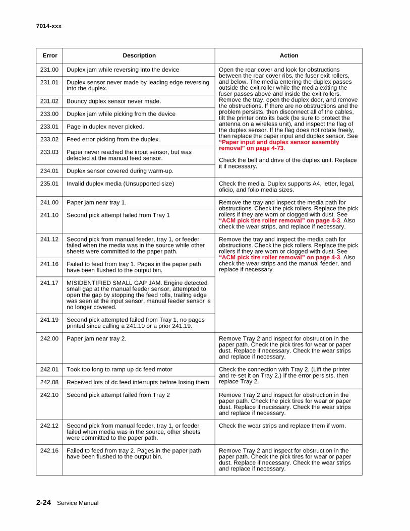
231.00 Duplex jam while reversing into the device Open the rear cover and look for obstructions between the rear cover ribs, the fuser exit rollers, and below. The media entering the duplex passes outside the exit roller while the media exiting the fuser passes above and inside the exit rollers. Remove the tray, open the duplex door, and remove the obstructions. If there are no obstructions and the problem persists, then disconnect all of the cables, tilt the printer onto its back (be sure to protect the antenna on a wireless unit), and inspect the flag of the duplex sensor. If the flag does not rotate freely, then replace the paper input and duplex sensor. See “Paper input and duplex sensor assembly removal” on page 4-73. Check the belt and drive of the duplex unit. Replace it if necessary.
231.01 Duplex sensor never made by leading edge reversing into the duplex.
231.02 Bouncy duplex sensor never made.
233.00 Duplex jam while picking from the device
233.01 Page in duplex never picked.
233.02 Feed error picking from the duplex.
233.03 Paper never reached the input sensor, but was detected at the manual feed sensor.
234.01 Duplex sensor covered during warm-up.
235.01 Invalid duplex media (Unsupported size) Check the media. Duplex supports A4, letter, legal, oficio, and folio media sizes.
241.00 Paper jam near tray 1. Remove the tray and inspect the media path for obstructions. Check the pick rollers. Replace the pick rollers if they are worn or clogged with dust. See “ACM pick tire roller removal” on page 4-3. Also check the wear strips, and replace if necessary.
241.10 Second pick attempt failed from Tray 1
241.12 Second pick from manual feeder, tray 1, or feeder failed when the media was in the source while other sheets were committed to the paper path.
Remove the tray and inspect the media path for obstructions. Check the pick rollers. Replace the pick rollers if they are worn or clogged with dust. See “ACM pick tire roller removal” on page 4-3. Also check the wear strips and the manual feeder, and replace if necessary.
241.16 Failed to feed from tray 1. Pages in the paper path have been flushed to the output bin.
241.17 MISIDENTIFIED SMALL GAP JAM. Engine detected small gap at the manual feeder sensor, attempted to open the gap by stopping the feed rolls, trailing edge was seen at the input sensor, manual feeder sensor is no longer covered.
241.19 Second pick attempted failed from Tray 1, no pages printed since calling a 241.10 or a prior 241.19.
242.00 Paper jam near tray 2. Remove Tray 2 and inspect for obstruction in the paper path. Check the pick tires for wear or paper dust. Replace if necessary. Check the wear strips and replace if necessary.
242.01 Took too long to ramp up dc feed motor Check the connection with Tray 2. (Lift the printer and re-set it on Tray 2.) If the error persists, then replace Tray 2.242.08 Received lots of dc feed interrupts before losing them
242.10 Second pick attempt failed from Tray 2 Remove Tray 2 and inspect for obstruction in the paper path. Check the pick tires for wear or paper dust. Replace if necessary. Check the wear strips and replace if necessary.
242.12 Second pick from manual feeder, tray 1, or feeder failed when media was in the source, other sheets were committed to the paper path.
Check the wear strips and replace them if worn.
242.16 Failed to feed from tray 2. Pages in the paper path have been flushed to the output bin.
Remove Tray 2 and inspect for obstruction in the paper path. Check the pick tires for wear or paper dust. Replace if necessary. Check the wear strips and replace if necessary.
Error Description Action

Diagnostics information 2-25
7014-xxx
251.00 Paper jam near the manual feeder. Inspect the pick roller on the MPF or the rollers on the manual feed. If the MPF pick roller is damaged or worn, then replace the MPF. For a printer with a manual feed only (no MPF), clean the roller.
251.10 Second pick attempt failed from manual feeder.
251.11 Failed to feed from manual feeder. Pages in the paper path have been flushed to the output bin.
251.12 Second pick from manual feeder, tray 1, or feeder failed when media was in the source while the other sheets were committed to the paper path.
251.19 Media never reached the input sensor from the manual feeder.
251.20 The media in the MPF has been pushed in too far. Remove the media, realign the stock, and re-insert. Do not let the top sheets to go beyond the wear strips.
251.21 The media in the MPF has been pushed in too far.
290.02 Scanner ADF Feed Jam. The scanner ADF has failed to feed a page to the ADF interval sensor.
Remove the sheet of paper rom the ADF. Retry the job. If the error recurs, Go to “ADF paper jam service check” on page 2-60.
290.10 Scanner Static Jam - 1st scanner sensor. Scanner ADF detects paper at the first scanner sensor while the ADF is in an idle state.
Remove all paper from the ADF. Retry the job. If the error recurs, Go to “ADF paper jam service check” on page 2-60.
.291.00 Scanner Static Jam - 2nd scanner sensor. Scanner ADF detects paper at thesecond scanner sensor while the ADF is in an idle state.
292 Scanner jam, remove all originals from the scanner. This message appears if the ADF cover is open while paper is fed through the ADF.
Remove the paper from the ADF, and close the ADF cover. If the error recurs, Go to “ADF cover open service check” on page 2-59.
293.02 Flatbed cover open. The MFP senses that the flatbed cover is open.
Close the flatbed cover. See “ADF cover open service check” on page 2-59.
294.04 Scanner jam, remove all originals from the scanner. Jam at the ADF exit sensor.
294.06Remove all paper from the ADF. If the error recurs, “ADF paper jam service check” on page 2-60.
294.05 Scanner jam, remove all originals from the scanner. A jam is detected at the ADF exit sensor.
294.06 ADF Backfeed Jam. A jam is detected at the ADF exit sensor.
295.01 Scanner Disable Page at CCD ADF page gap is too small. Not enough to re initialize the image processing unit.
Remove paper from the ADF.
295.02 Scanner Disable Page at CCD The ADF page gap is too small, not enough room to accelerate after pausing.
Remove paper from the ADF.
Error Description Action

2-26 Service Manual
7014-xxx
Service error codes
Service error codes are generally non-recoverable except in an intermittent condition when the printer can be put into POR to temporarily recover from the error condition.
Error Description Action
8XX Scanner service errors
840.01 Scanner disabled
The scanner is disabled and can’t be used. Enter the configuration menu, and re-enable the scanner module. Go to “840.xx service check” on page 2-55
840.02 Scanner auto disabled
The scanner is disabled and can’t be used. This message is posted when the MFP PORs. Enter the configuration menu, and re-enable the scanner module. Go to “840.xx service check” on page 2-55
841 Image Pipeline Image pipeline ASIC. Go to “CCD service check” on page 2-57. Also,Go to “Flatbed home position service check” on page 2-58.
841.96 SIZAR out of band interrupt
842 Communication Failure Communication failure. Go to “CCD service check” on page 2-57
843 Scanner Failure - Carriage failed to move to Home of desired position
Carriage mechanical failure.Go to “Flatbed motor service check” on page 2-57
843.01 Scanner Failure ADF mechanical failure. Go to “ADF paper jam service check” on page 2-60
843.02 Scanner Failure General mechanical failure
843.03 Scanner Failure Pick Roller engage failure
843.04 Scanner Failure Pick roller disengage failure
844.yy Scanner Failure Lamp failure. Go to “CCD service check” on page 2-57
844 Front scan module output level error Go to “CCD service check” on page 2-57
844.01 Rear scan module output level error
844.02
Front scan module lamp level too low Front Mono channel, Front Color channels, Front Red channel, Front Green channel, and/or Front Blue channel is detected to have low lamp level. Go to “CCD service check” on page 2-57
844.03
Rear scan module lamp level too low Rear Mono channel, Rear Color channels, Rear Red channel, Rear Green channel, and/or Rear Blue channel is detected to have low lamp level. Go to “CCD service check” on page 2-57
845.yyScanner Failure CCD failure
Go to “CCD service check” on page 2-57
845
Front scan module cable failure or SCC card failure CCD channel failure. Check each channel(mono, R, G, B) for identical values indicating bad cable and/or SCC card. Excessive noise test for the dark data indicating some sort of CCD or analog electronics issue on that channel or channels.
Go to “CCD service check” on page 2-57

Diagnostics information 2-27
7014-xxx
845.01
Rear scan module cable failure or SCC card failure CCD channel failure. Check each channel(mono, R, G, B) for identical values indicating bad cable and/or SCC card. Excessive noise test for the dark data indicating some sort of CCD or analog electronics issue on that channel or channels.
Go to “CCD service check” on page 2-57
845.02Cable / SCC Failure Front scan module connector or cable failure
Go to “CCD service check” on page 2-57
845.03Cable / SCC Failure Rear scan module connector or cable failure
Go to “CCD service check” on page 2-57
845.yyCCD Failure The CCD is defective.
Go to “CCD service check” on page 2-57.
846 Front calibration strip unusable Go to “CCD service check” on page 2-57
846.01 Rear calibration strip unusable
846.02 Front calibration strip too far left The font calibration strip is placed to high or to low. Go to “CCD service check” on page 2-57
846.03 Front calibration strip too far right Go to “CCD service check” on page 2-57.
846.04 Front calibration strip has excessive skew
846.05 Front calibration strip has excessive bow
846.06Front calibration strip has excessive dark area Front excessive variability for Mono, Red, Green,
or Blue. Go to “CCD service check” on page 2-57
846.07Front magnification exceeds limits Rear excessive variability for Mono, Red, Green,
or Blue. Go to “CCD service check” on page 2-57
847Modem Failure The Configuration ID bit that describes the
device’s modem doesn’t match the actual modem installed in the device.
847.01
Fax Storage The amount of flash storage available on the device is too small. Note: The NAND Flash partition can shrink as bit failures cause blocks to be invalidated. Go to “Format Fax Storage” on page 3-7. If the issue is not fixed, replace the controller board. Go to “Controller board removal” on page 4-8.
847.02
Fax Storage The devices’ flash partition is invalid or unavailable. Go to “Format Fax Storage” on page 3-7. If the issue is not fixed, replace the controller board. Go to “Controller board removal” on page 4-8.
848.01Modem/Config ID Mismatch A device has a modem installed, but its
Configuration ID indicates that a modem shouldn’t be present.
849HD/Config ID Mismatch A device doesn’t have a hard drive installed, even
though its Configuration ID indicates that a hard drive should be present.
Error Description Action

2-28 Service Manual
7014-xxx
849.01HD/Config ID Mismatch A device has a hard drive installed, but its
Configuration ID indicates that a hard drive shouldn’t be present.
Engine software service errors
900.xx RIP software error Turn off MFP for 10 seconds and restart. If error re-occurs, replace controller board.
902.xx Engine software error Replace the controller board. See Go to “Controller board removal” on page 4-8
903.xx Paperport link driver error
904.xx Interface violation by RIP
905.xx Interface violation by paperport device
906.xx RIP interface drive error
DC pick motor errors
910.xx DC pick motor stall
911.xx DC pick motor excessive PWM
912.xx DC pick motor below speed
913.xx DC pick motor over speed
914.00 DC pick motor error
914.01 Lost encoder feedback
Transfer service errors
917.xx Transfer service error Replace the transfer roll. See “Transfer roll service check” on page 2-54.
Fuser service errors
920.00 Under temperature during steady state control. Replace the fuser. See “Fuser service check” on page 2-39.
921.00 Under temperature during standby control.
922.00 Fuser failed to ramp to target temperature
923.00 Fuser is over temperature.
924.00 Open thermistor check.
925.xx Wrong fuser installed. The fuser type stored in the cartridge ID does not match the actual fuser installed in the printer.
Fan service errors
927.00 Service fan error Replace the fan. See “Cooling fan service check” on page 2-37.
Toner service errors
Error Description Action

Diagnostics information 2-29
7014-xxx
929.00 Toner sensor error Remove the toner cartridge, and shake it Try a different toner cartridge, if possible. If the error persists, then replace the toner level sensor. See “Toner level sensor removal” on page 4-82.
929.01 No home window
929.02 No sensor transition (closed)
929.03 No sensor transition (open)
Printhead service errors
930.xx Wrong printhead installed Replace the printhead. See “Printhead service check” on page 2-54.
931.xx No first hsync
Replace the printhead. See “Printhead service check” on page 2-54.
932.xx Lost hsyncs
933.xx Mirror motor locked: No hsync received
935.xx Motor unable to reach operating speed
Transport motor service errors
936.xx Transport motor initial lock failure Replace the main motor gear drive. See “Main motor service check” on page 2-40
937.00 Main transport motor lost lock Replace the main motor gear drive. See “Main motor service check” on page 2-40
Power supply service errors
940.00 LVPS service error Replace the LVPS/HVPS. See “LVPS/HVPS service check” on page 2-39.
Controller board and operator panel service errors
948.xx Failed engine board Replace the controller board. See “Engine board service check” on page 2-36.
949.xx
950.xx Mismatch between EEPROM and mirror memory
Note: A new controller board or operator panel has been installed, and has not been properly prepared for this use. Install a new note. Do not install both the controller board and the operator panel at the same time without a POR in between.
Install a new controller bored or operator panel. See “Engine board service check” on page 2-36 or “Operator panel service check” on page 2-43.
951.xx Error with secure NVRAM on the controller board Replace the controller board. See “Engine board service check” on page 2-36.
952.xx A recoverable MVRAM Cyclic Redundancy Check error occurred.
Performing POR will clear this error.
953.xx NVRAM chip failure with mirror Replace the engine board. See “Engine board service check” on page 2-36.
Error Description Action

2-30 Service Manual
7014-xxx
954.xx NVRAM chip failure with system part. Replace the controller board. See “Controller board service check” on page 2-35.
955.xx The code ROM or NAND flash failed the Cyclic Redundancy Check or the NAND experienced an uncorrectible multi-bit failure.
956.00 RIP card failure: processor failure
956.01 Processor overtemp
957.xx RIP card failure: ASIC failure
958.xx Printer has performed more than 100 “shift and reflash” operations as a result of ECC bit corrections
Firmware or controller board errors
959.01 Controller verification failure of pensive boot code Call the next level of support to update the firmware, or replace the controller board. See “Controller board service check” on page 2-35.
959.02 Failure to authenticate Signature Verification Code
959.03 Signature Verification Code failed to authenticate a code partition.
Update firmware and call the next level of support, or replace the controller board. See “Controller board service check” on page 2-35.959.04 Jump to unverified address
959.05 Unknown boot failure Update firmware and call the next level of support, or replace the controller board. See “Controller board service check” on page 2-35
959.20 Controller hardware failure Replace the controller board. See “Controller board service check” on page 2-35.
959.21 Code did not respond to command request.
959.22 Challenge secret failure
959.23 Self test failed during initialization. Replace the controller board. See “Controller board service check” on page 2-35.
959.24 EEPROM retention error
959.25 Insufficient device space during HW prog
959.26 Incremental counter reset exceeds maximum value
959.27 Increment count failed due to max value limit
959.28 Invalid SP memory configuration
Memory and emulation errors
960.xx RAM memory error: RAM soldered on the controller board is bad
Replace the controller board. See “Controller board service check” on page 2-35.
961.xx RAM memory error: memory card in slot is bad. Replace the memory card.
964.xx Download Emulation Cyclic Redundancy Check Error: checksum failure detected in the emulation header or emulation file.
Disable the Download Emulation. Program the download emulation into the firmware card again. If this does not resolve the problem, then replace the firmware card and download the emulation again.
Network errors
Error Description Action

Diagnostics information 2-31
7014-xxx
Fax error codes
975.xx Unrecognizable network Call the next level of support.
976.xx Unrecoverable software error in network port
978.xx Bad checksum while programming network port
979.xx Flash parts failed while programing network port
Other errors
980.xx Engine experiencing unreliable communication with the specified device
Call the next level of support.
981.xx Engine protocol violation detected by the specified device
982.xx Communications error detected by the specified device
983.xx Invalid command received by the specified device
984.xx Invalid command parameter received by the specidied device
Call the next level of support.
990.xx An equipment check condition has occurred in the specified device, but the device is unable to identify the exact component failure.
991.xx The specified device has detected an equipment check in its system card.
Fax error log codes
Error code Description Action
000No error occurred during fax
transmission
No action needed
200 Error occurred when transmitting
training.
• Check line quality.• Select a lower ‘Max Speed’.• value under Fax Send settings• Adjust the transmit level.
3XX Error occurred when receiving
image data.
• Check line quality.• Adjust ‘Receive Threshold’.• Select a lower ‘Max Speed’ value
under Fax Receive settings.
4XX Error occurred when sending
image data.
• Check line quality.• Adjust ‘Transmit Level’.• Select a lower ‘Max Speed’ value
under Fax Receive settings.
5XX Received unknown response from
remote fax device.
No action needed. Issue is with the other device.
6XX Error occurred when receiving a frame. • Check line quality.• Adjust ‘Receive Threshold’.
Error Description Action

2-32 Service Manual
7014-xxx
7XX Error occurred when sending a frame. • Check line quality.• Adjust ‘Transmit Level’.• Select a lower ‘Max Speed’ value
under Fax Send settings.
800 Received EOT unexpectedly from
the modem in V34 mode.
• If error persists disable V34 modulation scheme.
802 Too many timeouts occurred
during ECM reception.
• If error persists disable ECM mode.
803 Fax cancelled by user No action needed.
804 Unexpectedly received a disconnect command from the remote end.
• Check line quality.• Adjust Transmit Level/Receive
Threshold values.• Remote device could be requesting an
unsupported feature.
805 Remote fax device failed to respond to the DCS command.
• Adjust Transmit Level/Receive Threshold values.
• Remote device could be malfunctioning.
808 T1 timeout occurred when trying to establish a connection with a remote fax device.
• Adjust Transmit Level/Receive Threshold values.
809 T2 Timeout occurred due to loss of command/response synchronization.
• Adjust Transmit Level/Receive Threshold values.
80A T5 Timeout occurred when transmitting image data to remote fax device.
• Check line quality.• Adjust ‘Transmit Level’.• Select a lower ‘Max Speed’value under
Fax Send settings.
80B Too many errors when transmitting in ECM mode.
• Check line quality.• Adjust ‘Transmit Level’.• Select a lower ‘Max Speed’value under
Fax Send settings.
80C Remote device failed to respond to the CTC command.
• Select a lower ‘Max Speed’ value under Fax Send settings.
• Adjust ‘Transmit Level’.
80D Received too many requests from remote end to repeat the previous command sent.
• Check line quality.• Adjust ‘Transmit Level’.• Check if line conditions on remote end
will facilitate a good connection.
80E Functional limitation- Remote fax device does not support G3 receive capability.
No action needed. Issue with the remote device.
811 Failed to detect a fax device at the remote end.
• Verify MFD is answering to fax call and not a voice call.
• Decrease value of ‘Rings To Answer’ setting.
812 No more data rates available in V34 modulation scheme.
• Adjust to a lower modulation scheme.
Fax error log codes (Continued)
Error code Description Action

Diagnostics information 2-33
7014-xxx
813 Timeout occurred after waiting too long to receive a good frame.
• Adjust “Receive Threshold”.
814 Tried too many times at selected speed using V34 modulation scheme.
• Adjust ‘Transmit Level’.• Adjust to a lower modulation scheme.
815 Fax transmission was interrupted due to power failure.
• Troubleshoot MFP if error persists. See “Modem / fax card service check” on page 2-63.
818 Fax transmission failed due to insufficient memory to store scanned image.
Adjust ‘Memory Use’ setting to allocate more memory for send jobs.
819 Fax transmission failed due to insufficient memory to store received image.
Adjust ‘Memory Use’ setting to allocate more memory for receive jobs.
81A A timeout occurred during transmission of a page in ECM mode.
Select a lower ‘Max Speed’ value under Fax Send settings.
880 Failure to transmit training successfully in V17, V29, V27 terminal modulation schemes.
• Select a lower “Max Speed” under Fax Send settings.
• Adjust the “Transmit Level”.• Check line quality.
881 Failure to transmit training successfully in V33, V29, V27 terminal modulation schemes.
• Select a lower “Max Speed” under Fax Send settings.
• Adjust the “Transmit Level”.• Check line quality.
882 Failure to transmit training successfully in V17, V29 terminal modulation schemes.
• Select a lower “Max Speed” under Fax Send settings.
• Adjust the “Transmit Level”.• Check line quality.
883 Failure to transmit training successfully in V17,V27 terminal modulation schemes.
• Select a lower “Max Speed” under Fax Send settings.
• Adjust the “Transmit Level”.• Check line quality.
884 Failure to transmit training successfully in V29, V27 terminal modulation schemes.
• Select a lower “Max Speed” under Fax Send settings.
• Adjust the “Transmit Level”.• Check line quality.
885 Failure to transmit training successfully in V17terminal modulation scheme.
• Select a lower “Max Speed” under Fax Send settings.
• Adjust the “Transmit Level”.• Check line quality.
886 Failure to transmit training successfully in V29 terminal modulation scheme.
• Select a lower “Max Speed” under Fax Send settings.
• Adjust the “Transmit Level”.• Check line quality.
887 Failure to transmit training successfully in V27 terminal modulation scheme.
• Select a lower “Max Speed” under Fax Send settings.
• Adjust the “Transmit Level”.• Check line quality.
Fax error log codes (Continued)
Error code Description Action

2-34 Service Manual
7014-xxx
888 Failure to transmit training successfully at 2400 bps in V27 terminal modulation scheme.
• Adjust “Transmit Level”.• Check line quality.
889 Failed to connect at the minimum speed supported by the MFP.
• Adjust “Transmit Level”.• Incompatible connection.
88A Failed to connect using V.34 modulation scheme.
• Check line quality.• Adjust to a lower modulation scheme.• Adjust Transmit Level Receive
Threshold values.
901 No fax tones detected from remote end.
• Verify destination phone number.• Verify that the remote fax is authorized
to receive faxes.
902 No dial tone detected. • Check by enabling ‘Behind a PABX’ setting.
• Check phone line.• Check MFD modem hardware.
903 Busy tone detected. Check with remote end if successive attempts fail.
904 Hardware error detected. See “Modem / fax card service check” on page 2-63.
905 A timeout occurred after dialing the number and waiting for a response.
Check with remote end if successive attempts fail.
906 Fax cancelled by user. No action needed.
907 Modem detected a digital line connection.
Verify the MFP is connected to an analog line. See“Fax transmission service check” on page 2-64.
908 Phone line was disconnected Restore phone line connection.
A00 Received request for unsupported function from remote fax device.
No action needed.
A01 Received request for unsupported image width from remote fax device.
No action needed.
A02 Received request for unsupported image resolution from remote fax device.
No action needed.
A03 Received request for unsupported compression type from remote fax device.
No action needed.
A04 Received request for unsupported image length from remote fax device.
No action needed.
F00 Unknown error occurred. No action needed.
Fax error log codes (Continued)
Error code Description Action