
Fuels and Materials for Transmutation: A Status Report
240
Nuclear Science ISBN 92-64-01066-1 Fuels and Materials for Transmutation A Status Report © OECD 2005 NEA No. 5419 NUCLEAR ENERGY AGENCY ORGANISATION FOR ECONOMIC CO-OPERATION AND DEVELOPMENT
-
Upload
khangminh22 -
Category
Documents
-
view
3 -
download
0
Transcript of Fuels and Materials for Transmutation: A Status Report
Nuclear Science ISBN 92-64-01066-1
Fuels and Materials for Transmutation
A Status Report
© OECD 2005 NEA No. 5419
NUCLEAR ENERGY AGENCY ORGANISATION FOR ECONOMIC CO-OPERATION AND DEVELOPMENT
ORGANISATION FOR ECONOMIC CO-OPERATION AND DEVELOPMENT
The OECD is a unique forum where the governments of 30 democracies work together to address the economic, social and environmental challenges of globalisation. The OECD is also at the forefront of efforts to understand and to help governments respond to new developments and concerns, such as corporate governance, the information economy and the challenges of an ageing population. The Organisation provides a setting where governments can compare policy experiences, seek answers to common problems, identify good practice and work to co-ordinate domestic and international policies.
The OECD member countries are: Australia, Austria, Belgium, Canada, the Czech Republic, Denmark, Finland, France, Germany, Greece, Hungary, Iceland, Ireland, Italy, Japan, Korea, Luxembourg, Mexico, the Netherlands, New Zealand, Norway, Poland, Portugal, the Slovak Republic, Spain, Sweden, Switzerland, Turkey, the United Kingdom and the United States. The Commission of the European Communities takes part in the work of the OECD.
OECD Publishing disseminates widely the results of the Organisation’s statistics gathering and research on economic, social and environmental issues, as well as the conventions, guidelines and standards agreed by its members.
* * *
This work is published on the responsibility of the Secretary-General of the OECD. The opinions expressed and arguments employed herein do not necessarily reflect the official views of the Organisation or of the governments of its member countries.
NUCLEAR ENERGY AGENCY
The OECD Nuclear Energy Agency (NEA) was established on 1st February 1958 under the name of the OEEC European Nuclear Energy Agency. It received its present designation on 20th April 1972, when Japan became its first non-European full member. NEA membership today consists of 28 OECD member countries: Australia, Austria, Belgium, Canada, the Czech Republic, Denmark, Finland, France, Germany, Greece, Hungary, Iceland, Ireland, Italy, Japan, Luxembourg, Mexico, the Netherlands, Norway, Portugal, Republic of Korea, the Slovak Republic, Spain, Sweden, Switzerland, Turkey, the United Kingdom and the United States. The Commission of the European Communities also takes part in the work of the Agency.
The mission of the NEA is:
� to assist its member countries in maintaining and further developing, through international co-operation, the scientific, technological and legal bases required for a safe, environmentally friendly and economical use of nuclear energy for peaceful purposes, as well as
� to provide authoritative assessments and to forge common understandings on key issues, as input to government decisions on nuclear energy policy and to broader OECD policy analyses in areas such as energy and sustainable development.
Specific areas of competence of the NEA include safety and regulation of nuclear activities, radioactive waste management, radiological protection, nuclear science, economic and technical analyses of the nuclear fuel cycle, nuclear law and liability, and public information. The NEA Data Bank provides nuclear data and computer program services for participating countries.
In these and related tasks, the NEA works in close collaboration with the International Atomic Energy Agency in Vienna, with which it has a Co-operation Agreement, as well as with other international organisations in the nuclear field.
© OECD 2005 No reproduction, copy, transmission or translation of this publication may be made without written permission. Applications should be sent to OECD Publishing: [email protected] or by fax (+33-1) 45 24 13 91. Permission to photocopy a portion of this work should be addressed to the Centre Français d’exploitation du droit de Copie, 20 rue des Grands Augustins, 75006 Paris, France ([email protected]).
3
FOREWORD
Under the auspices of the NEA Nuclear Science Committee (NSC), the Working Party on Scientific Issues in Partitioning and Transmutation (WPPT) was created in June 2000 to examine and provide information on the status and trends of scientific issues in partitioning and transmutation (P&T). In line with the scope of the WPPT and in order to cover a wide range of different disciplines in the P&T field, four subgroups were formed under the WPPT, each tasked with producing a state-of-the-art report in its specialised field. The four subgroups address:
� accelerator utilisation and reliability,
� chemical partitioning,
� fuels and materials,
� physics and safety of transmutation systems.
The mission of the subgroup on fuels and materials is to (1) evaluate expected performance of fuels and materials for transmutation systems, (2) revisit and summarise fundamental properties of fuels, fuel selection criteria, fabrication and behaviour prediction, cladding and coolant compatibility issues, and long-lived fission products, and (3) organise a workshop for experts on fuels and materials.
This status report, produced by the subgroup on fuels and materials, describes state-of-the-art technology concerning fuels and materials for transmutation, provides information on the availability of pertinent data, and suggests necessary R&D to supplement the existing database.
Acknowledgements
The Secretariat expresses its sincere gratitude to all members of the subgroup for their valuable contributions and to the authors of this report. Special thanks are conveyed to Ms. Hélène Déry for having prepared the report for publication.

5
TABLE OF CONTENTS
Foreword ........................................................................................................................................ 3
Chapter 1. Introduction ................................................................................................................ 7
1.1 Background ...................................................................................................................... 7 1.2 Scenarios and fuel forms.................................................................................................. 7 1.3 Past experiences in fuel engineering................................................................................ 8
References ............................................................................................................................... 10 Appendix 1.1 Burnup Indicators of Inert Matrix Fuels............................................................ 11
Chapter 2. Fundamental Thermophysical and Thermochemical Properties of Relevant Actinide Compounds and Alloys............................................................................ 15
2.1 Actinide elements and ions .............................................................................................. 15 2.2 Metals and alloys ............................................................................................................. 16 2.3 Oxides .............................................................................................................................. 20 2.4 Nitrides and carbides........................................................................................................ 21 2.5 Fluoride salts ................................................................................................................... 26 References ............................................................................................................................... 27
Chapter 3. Fuel Selection Criteria for the Representative Transmutation Scenarios ............ 31
3.1 Fuel selection criteria – Double strata scenario ............................................................... 31 3.2 Fuels for fast spectrum transmutation – United States selection criteria ......................... 42 3.3 Fuel selection criteria and fabrication issues for transmutation in power reactors .......... 46
References ............................................................................................................................... 61 Appendix 3.1 Calculation Hypotheses and Methods ............................................................... 63 Appendix 3.2 Special Irradiation Environment of ADS Systems ............................................ 65
Chapter 4. Fuel Fabrication ........................................................................................................ 75
4.1 Oxide-based ceramic fuels ............................................................................................... 75 4.2 Nitride fuels/targets.......................................................................................................... 83 4.3 VIPAC fuel for transmutation.......................................................................................... 85 4.4 Metal transmutation fuels ................................................................................................ 90
References ............................................................................................................................... 97
6
Chapter 5. Fuel Behaviour Prediction ........................................................................................ 101
5.1 Irradiation performance issues ......................................................................................... 101 5.2 Some considerations about expected fuel behaviour – Oxides ........................................ 103 5.3 Thermomechanical modelling of prototypic targets ....................................................... 106
References ............................................................................................................................... 125 Appendix 5.1 1-eV resonance effect in MOX fuel .................................................................. 127 Appendix 5.2 Fuel characteristics ............................................................................................ 133
Chapter 6. Structural Materials for Transmutation Systems ................................................... 135
6.1 Cladding and duct review................................................................................................. 136 6.2 Materials compatibility with lead and lead-bismuth ........................................................ 187
References ............................................................................................................................... 205
Chapter 7. LLFP Transmutation ................................................................................................. 215
7.1 Introduction...................................................................................................................... 215 7.2 Transmutation of cesium, technetium and iodine ............................................................ 216 7.3 Innovative transmutation studies...................................................................................... 220 7.4 Discussion and outlook .................................................................................................... 221 7.5 Conclusion ....................................................................................................................... 222 References ............................................................................................................................... 223
Chapter 8. Moderator Pin: Hydride Behaviour ......................................................................... 225
8.1 Specific problems – Recall............................................................................................... 225 8.2 Specific effects of irradiation ........................................................................................... 226 8.3 Simulation of hydrogen release........................................................................................ 228 8.4 Material data .................................................................................................................... 229 8.5 Results – Comments......................................................................................................... 231 8.6 Conclusion and remarks .................................................................................................. 232 References ............................................................................................................................... 233
Appendix Summary of the Status of Transmutation Fuel Developments and Major Research Issues .............................................................................................. 235
List of Contributors....................................................................................................................... 237
Members of the Subgroup ............................................................................................................ 239
7
Chapter 1
INTRODUCTION
1.1 Background
According to a global energy scenario survey [World Energy Council, 2000], the world nuclear capacity would be 1 300-2 000 GWe in 2050, depending on the degree of success in promoting the energy efficiency.* A standard light-water power reactor of 1 GWe discharges about 23 tons of actinides each year: cumulatively 900 tons in 40 years lifetime of the reactor [European Technical Working Group on ADS, 2001]. One ton of spent fuel of average burnup of 40 GWd/t contains about 10 kg of Pu and 1.5 kg of the other transuranium elements. The latter consists of mainly neptunium, americium and curium, which are called minor actinides (MA). These transuranium elements are not only long-lived radiotoxic substances, but also major heat sources, which affect the performance of the repository. It is predicted that, without partitioning and transmutation of transuranium elements, “repository availability may be the major constraint to nuclear energy” [Generation IV Fuel Cycle Crosscut Group, 2001]. Fission-products 90Sr and 137Cs consist the other major heat sources that limit the repository capacity. There are also arguments that the radiological safety of geologic disposal in the very long run is dominated by some long-lived fission products rather than actinides. Among the long-lived fission products, 99Tc, 129I and 135Cs are most frequently studied in the context of transmutation, since they can be transformed into stable isotopes by a single neutron capture.
1.2 Scenarios and fuel forms
Transmutation scenarios of transuranium elements are broadly classified into two types: (1) single-stratum; and (2) double-strata concepts [Murata, Mukaiyama, 1984]. In the single-stratum concept, the transuranium elements are recycled within a power-reactor fuel cycle; in the double-strata concept, they are fed into a smaller dedicated fuel cycle, which is annexed to the power-reactor fuel cycle. There are many variants of these two concepts, depending on the way in which the transuranium elements are classified and recycled. All transuranium elements including plutonium are regarded as wastes in the United States; plutonium is regarded as an energy resource and will be recycled into power reactors in some countries like France and Japan. Even in the single-stratum concept, MA, particularly americium and curium, whose properties significantly differ from uranium and plutonium, may be recycled as target elements in a dedicated zone of a power reactor. Those target elements will be fabricated and managed in a separate line outside the stream of the normal fuel elements. This type of MA recycling is called heterogeneous recycling, and may be also regarded as a variant of the double-strata concept. The potential difficulty and the associated economic penalty in handling transuranium elements in the power-reactor fuel cycle prompted the feasibility study of more or less “heterogeneous” approaches. “Multi-tier” approach in the United States seeks the best combination of reactors and transmutation devices.
* In those cases where the nuclear energy is supposed to play an important role in the non-fossil energy
supply.

8
Regarding the fuel forms, the transuranium fuels/targets can be classified into two types: (a) U-based fuels where all or some transuranium elements are mixed to lower concentrations, and (b) fuels/targets in which major components consist of transuranium elements. The type (a) fuels with the uranium matrix can be called “fertile” for brevity, and the type (b) fuels as “nonfertile”. This classification, however, is not very exact, since there are concepts, which use thorium-based materials as the matrix. The existence or absence of uranium has significant effects on the fuel properties. Uranium proved to be an exceptionally good material for making a nuclear fuel in comparison with transuranium elements and recently proposed nonfertile (“inert”) matrices. Higher is the achievable burnup, smaller the burden of recycling transuranium elements. In this context, one has a difficulty in discussing and comparing the performance of different fuel types as a function of fuel burnup. Fuel burnup is measured in different quantities, such as the fissons per initial metal atom (FIMA), the fissions per initial fissile atom (FIFA), the cumulative thermal output per unit heavy-metal mass (MWd/kg HM), etc. These quantities work well for standard fuels, but are not very suitable for inert-matrix fuels. By using several burnup indicators, one can grasp the performance of inert-matrix fuels. Further discusion on the burnup indicator is given in the Appendix 1.1.
1.3 Past experiences in fuel engineering
The power reactors mostly run on oxide fuels [UO2, (U,Pu)O2]. There have been experiences of metallic uranium cores in sodium-cooled fast reactors (U-Mo in Fermi 1; U-Fs1 and U-Zr in EBR-II), although limited in scale compared with the oxides. The most promising metallic fuel candidates containing plutonium are considered to be the U-Pu-Zr alloys developed in the Argonne National Laboratory [Chan, 1990]. In view of the existing database, modern fuel elements with either oxides or alloys of uranium-plutonium are expected to reach 150 000 MWd/t (approximately 15 at.% burnup) or even higher with good integrity, if properly designed and fabricated. There have been fast-reactor cores of experimental scales (<10 MWth) operated with uranium monocarbide (BR-5) and mononitride (BR-10) in Russia [Rogozkin, 2000]. Experience with the UN core in BR-10 extended to a burnup of about 5 at.%. Past irradiation tests in Los Alamos National Laboratory demonstrated the integrity of a (U,Pu)N fuel pin design to 9 at.% burnup [Matthews]. The Th/235U dicarbide fuels have been used in a form of coated particle fuel in high-temperature helium-gas-cooled reactors like the Fort St. Vrain reactor (330 MWe) [Fuller, 1988]. These are the power reactor experiences on which we start designing the transmutation fuels/targets. There are factors such as significant amount of helium production by �-decay in MA-bearing fuels, which have not been encountered in the past fuel experiences.
In burning MA, the fast-neutron environment is preferred, where the formation of higher actinides is prevented due to smaller neutron capture cross-sections at higher neutron energies. Problems associated with the structural materials in the fast-neutron environment to higher doses have to be attended. Efforts to improve the irradiation resistance of structural materials are being made. Application of low-swelling ferritic/martensitic steels appear promising. Application of the oxide dispersion strengthened (ODS) ferritic steels is being examined, but the demonstration tests have yet to be completed.
A gas-cooled reactor with the coated particle fuels is regarded as another promising concept. A graphite-moderated high-temperature gas-cooled reactor (HTGR) may be used to burn plutonium. Irradiation resistance and high-temperature chemical reactions with fission products have to be
1. Fs: “fissium” means simulated fission products containing Mo, Ru, Rh and Pd, which were supposed to
be contained in U and Pu recovered by original pyrometallurgical reprocessing of metal fuels.
9
examined for the coating materials. For instance, fission-product Pd, whose fission yields from transuranium elements are larger than that from 235U, readily migrates out of the oxide or carbide fuel kernels to the coating. The standard coated fuel particle has a SiC interlayer, which is susceptible to the corrosion by Pd, which is a life-limiting factor of the coated fuel particles [Tiegs, 1979]. Pyrolytic carbon, which is a component of the coating for the coated particle fuel, cannot withstand the fast-neutron environment. It is therefore necessary to define proper coating materials for the coated particle fuel containing MA by extensive materials research.
The other important issues are the fabrication and reprocessing of transmutation fuels/targets. High rate of neutron emission and large �-decay heat as shown in Table 1.1 make handling of transmutation fuels/targets extremely difficult. Their impacts on the homogeneous recycling in the power reactors are assessed in a qualitative manner in Table 1.2. In designing the fuel handling and treatment lines, one has to take these points into account.
Table 1.1. Neutron emission and decay heat from actinide nuclides [Schmidet, 1983]
* For thermal neutron with 2 200m/s. ** Assuming oxide.
Table 1.2. Effects of MA addition to LWR and FBR fuels [Mukaiyama, 1993]
x: Little effect. xx: Moderate effect. xxx: Significant effect.
It is the aim of this study within the Working Party on Scientific Issues in Partitioning and Transmutation (WPPT) to review the recent efforts on the fuels and materials for transmutation and to define the state-of-the-art technologies in this field.
Nuclide Half life (y) Fission cross-section (b)*
Total neutron emission** g-1 s-1
Decay heat (W g-1)
238Pu 87.7 17.9 36 000 0.56 239Pu 2.411x10⁴ 748 96 0.002 240Pu 6.54x10³ 0.06 1 300 0.007 241Pu 14.4 1013 1.23 0.004 242Pu 3.763x10⁵ 0.0026 2 000 0.0001 237Np 2.14x10⁶ 0.022 0.90 0.00002 241Am 432.2 3.0 7 000 0.11 243Am 7.38x10³ 0.12 540 0.007 242Cm 0.446 5.1 2.9x10⁷ 120 243Cm 28.5 618 1.3x10⁵ 1.7 244Cm 18.11 1.0 1.2x10⁷ 2.8 252Cf 2.646 33 2.35x10¹² 39
Transportation Case Element Fresh fuel fabrication fresh fuel spent fuel
Reprocessing
Decay heat x x x x MOX-LWR (0.5wt%MA) Shielding xxx xxx xx xx
Decay heat xx (cooling for
assembling fuel elements) xx xx xx MOX-FBR
(5wt%MA) Shielding xxx xxx xx xx
10
REFERENCES
Chang, Y.I., C.E. Till (1990), “Actinide recycle potential in the integrated fast reactor fuel cycle”, in: LMR: A Decade of LMR Progress and Promise, American Nuclear Society, Inc., La Grange Park, IL, pp. 129-137.
The European Technical Working Group on ADS (2001), A European Roadmap for Developing Accelerator Druven Systems (ADS) for Nuclear Waste Incineration, ENEA report.
Fuller, C.H. (1988), “Fort St. Vrain operational experience”, in: Technical committee meeting on design requirements, operation and maintenance of gas-cooled reactors, San Diego, CA (USA). 21-23 September 1988, International Atomic Energy Agency, Vienna (Austria) IWGGCR--19, pp. 55-61.
Generation IV Fuel Cycle Crosscut Group (2001), Generation IV Roadmap: Fuel Cycles, Generation IV Roadmap Session, ANS Winter Meeting Reno, NV, 13 November 2001.
Matthews, R.B., JAERI internal document.
Mukaiyama, T. et al. (1993), presented at the Intern. Conf. Global’93, 12-17 September 1993, Seattle, Washington, USA.
Murata, H., T. Mukaiyama (1984), “Fission reactor studies in view of reactor waste management”, Atomkernenergie-Kerntech., 45(1984), 23.
Rogozkin, B.D. et al. (1983), “Mononitride U-Pu mixed fuel and its electrochemical reprocessing”, in: Schmidet, E., et al. (1983), Assessment studies on nuclear transmutation on by-product actinides – Final Report, Report of the Commission of the European Communities JRC Ispra Establishment, S.A./I.05.03.83.13.
Tiegs, T.N., J.M. Robbins (1979), ORNL-5539.
World Energy Council (2000), Global Energy Scenarios to 2050 and Beyond Molten Salts, IAEA Advisory Group Meeting, RDIPE, Moscow, October 2000.
11
Appendix 1.1
BURNUP INDICATORS OF INERT MATRIX FUELS
Fuel burnup is measured in different quantities, such as FIMA, FIFA, MWd/kg HM, etc. These quantities work well for standard UO2 fuels, but are not very suitable for inert matrix fuels. This is related to the fact that the heavy metal densities of standard fuels and inert matrix fuels differ strongly (up to a factor of 20). In addition, the burnup per unit of heavy metal are strongly different. The use of a volumetric burnup is further motivated below.
A few burnup indicators2 are:
Depletion/consumption:
HM of mass initial
HM of mass) final-mass (initial
Fissioned fraction:
HM of mass initial
HM fissioned of mass
Fissions per initial metal atoms, FIMA:
atoms HM initial
atoms HM fissioned
Fissions per initial fissile atoms, FIFA:
atoms HM fissile initial
atoms HM fissioned
Note that the fissioned fraction actually equals FIMA. FIMA and FIFA are related as:
atoms HM initial
atoms HM fissile initial
atoms HM fissile initial
atoms HM fissioned
atoms HM initial
atoms HM fissioned��
FissileFraction FIFAFIMA ��
2. Some are based on definitions given on page 150 of the OECD/NEA report on “Actinide and Fission
product partitioning and transmutation”.

12
where HM3 refers to heavy metal, which will be assumed to include all actinides. Note that the fissioned fraction is more preferable than FIMA or FIFA because it does not rely on the meaning of “metal atoms”.
The above-mentioned quantities are good for evaluation of reactor physics calculations or scenario studies, but they do not express aspects associated with fuel behaviour. Qualitatively, one could state that the change in fuel behaviour is proportional to the total fission product concentration, which in turn is proportional to the fission energy (MWd) produced per unit volume. Below the specific burnup (per unit of mass) and the volumetric burnup (per unit of volume) are given. The specific burnup is:
mass HM
producedenergy fission
HM kg
MWd burnup Specific ��
�
���
which in fact is the standard burnup measure for UO2. The volumetric burnup is:
volumefuel
producedenergy fission
m
GWd burnup Volumetric
3���
���
where the volume refers to the geometric fuel volume. The burnup measures are related by the heavy metal density:
��
���
���
������
���
HM kg
MWd burnup Specific
cm
HM gramDensity
m
GWd burnup Volumetric
33
whereas burnup is described in terms of MWd/kg HM or %FIMA for UO2 fuels, this is not suitable for inert matrix fuels. This is because in inert matrix fuels the heavy metal density (gram HM/cm3), and consequently the local specific burnup, strongly differs from conventional fuels. Therefore, the use of a volumetric burnup provides a better basis for comparison of burnup of inert matrix and conventional fuels than the specific burnup measure (MWd/kg HM). An easy rule of thumb can be derived for the volumetric burnup:
)Fraction(% Fissioned cm
HM gram10
m
GWdburnup Volumetric
33���
�������
��� �
In the example given below the use of this quantity will be demonstrated for:
1. standard UO2 fuel reaching a rather high burnup of about 5% FIMA or 50 MWd/kg HM. The UO2 density is about 10 g/cm3 such that:
5005 10 10 m
GWdburnup Volumetric
3������
���
3. In this document “kg HM” refers to “kg actinide” and vice versa.
13
2. Inert matrix fuel: a dispersion of 241AmO2 particles reaching 100% fission of the Americium, which corresponds to roughly 1 000 MWd/kg Americium. The Am-density is 0.5 g/cm3, such that:
500 100 5.010 m
GWdburnup Volumetric
3������
���
Standard UO2 Inert matrix fuel + AmO2 Density (g HM/cm3) 10 0.5 Fissioned fraction (%) 5 100 Burnup, MWd/kg HM 50 1 000 Burnup, GWd/m3 500 500
Here we can see that very high burnup values are reached in terms of FIMA or MWd/kg HM for the dispersed inert matrix fuel. However, this specific burnup is normalized on the mass of the fissile inclusions and does not reflect the (fission product damage) to the total fuel volume. A better burnup indicator therefore is the volumetric burnup.
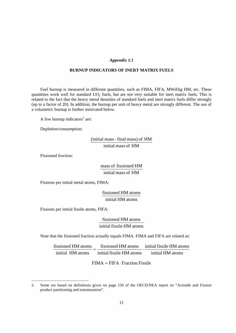
In Figure A1.1 the relation between specific burnup and heavy metal density is shown for the volumetric burnup of 500 GWd/m3. The inert matrix fuels generally have heavy metal densities of roughly 0.5 gram/cm3, whereas the conventional fuels have heavy metal (U+Pu) densities of about 10 gram/cm3. In the given examples, the heavy metal densities differ roughly a factor of 20 and the burnup values (MWd/kg heavy metal) also differ roughly a factor of 20. The volumetric burnup in this example is roughly the same: 500 GWd/m3.
Figure A1.1 Relation specific burnup and heavy metal density for a fixed value of the volumetric burnup
0
500
1000
1500
0 5 10 15
Density (gram HM/cm3)
Spe
cific
bur
nup
(MW
d/kg
act
inid
e)
Volumetric burnup = 500 GWd/m3
IMF
ran
ge
UO2 range
Density (gram HM/cm3)
Volumetric burnup = 500 GWd/m3

14
One gram of fissioned heavy metals produces roughly 1 MWd, which corresponds to 1 000 MWd per kg of fissioned heavy metals. The specific burnup can therefore be rewritten as:
��
���
���
�
���
HM fissioned of kg
MWd1000
kgHM
HM fissioned of kg
HM kg
MWd burnup Specific
or:
)Fraction(% Fissioned10 HM kg
MWd burnup Specific ���
�
���
which gives the well-known approximation that, a fissioned fraction of 1% (or 1% FIMA) gives a specific burnup of about 10 MWd/kg HM. The volumetric burnup equils:
���
�����
������
���
HMton
GWd burnup Specific
m
HMton
m
GWdburnup Volumetric
33�
which can be rewritten in more appropriate units as:
��
���
���
������
���
HM kg
MWd burnup Specific
cm
HM g
m
GWdburnup Volumetric
33�
Inserting the rule of thumb for the specific burnup gives:
)Fraction(% Fissioned cm
HM g10
m
GWdburnup Volumetric
33���
�������
��� �
References
NEA (2003), Actinide and Fission Product Partitioning and Transmutation, Proceedings of The Seventh Information Exchange Meeting, Jeju, Republic of Korea, 14-16 Octobre 2002, OECD, Paris.

15
Chapter 2
FUNDAMENTAL THERMOPHYSICAL AND THERMOCHEMICAL PROPERTIES OF RELEVANT ACTINIDE COMPOUNDS AND ALLOYS
2.1 Actinide elements and ions
In terms of physical and chemical properties, there is a noticeable gap across actinide series, which is found at crossing from Pu to Am. Properties of actinide elements depend on the behaviour of electrons on 5f orbitals. For actinide metals heavier than Am, 5f electrons are localised and their participation to the bonding becomes very small, increasing the atomic volume and decreasing the cohesive energy. This fact significantly affects the miscibility among actinide metals. Thermal conductivities of heavier actinide metals have not been measured. By analogy with lanthanide metals, thermal conductivities of americium and curium are considered to be significantly smaller than uranium.
Trivalent ionic radius monotonically decreases through actinide series, but the difference from uranium to curium is not so large. Coupled with ionisation energies, this fact gives relatively constant lattice energies of actinide trichlorides. On the other hand, the cohesive energy drops at crossing from Pu to Am in the series. As a result, the stability of trivalent ion against metallic state is significantly higher for Pu-Cm compared with U and Np. This fact gives possibility of separation of uranium and heavier actinides in molten salts as utilised in pyrochemical reprocessing. However, the clean separation of plutonium from americium and curium would be difficult, unless one introduces additional element such as oxygen in the molten-salts system. This may be regarded as an advantage in view of the proliferation resistance.
For Am and Cm, the ionisation energy from 3+ to 4+ state is large, and this is a cause of the relative instability of dioxides of Am and Cm against decomposition to sesquioxides (M2O3). Am is unique among the five elements from U to Cm:
(1) lower enthalpy of vaporisation;
(2) relative stability of M2+ state compared with M3+, and M3+ compared with M4+;
(3) the jump in the metallic radius at passing from Pu to Am in contrast to the constant contraction of M3+ ionic radius along the actinide series.
The point (1) results in the americium vaporisation loss during the fuel/target fabrication; (2) the instability of cubic AmO2 compared with less-isotropic and lower-melting Am2O3, and a relative stability of Am2+ in some environments such as molten salts; (3) together with (1), limited mutual solubility in the alloys with U and Np. This uniqueness of Am has to be considered in fuel designing, reprocessing and fabrication.
16
Table 2.1. Properties of actinides [Ogawa, 2000]
Element Mp (K)
�Hfo
(kJ/mol) I1
(eV) I2
(eV) I3
(eV) I4
(eV) rm
(nm) ri(3+) (nm)
� (W/m�K�
U 1 408 536 6.194 11.9 19.7 32.6 1.542 1.025 25 Np 913 465 6.266 11.7 20.7 33.6 1.503 1.01 6~8 Pu 913 342 6.062 11.7 21.6 34.6 1.523 1.00 5~8 Am 1 449 284 5.993 12.0 22.1 36.2 1.730 0.98 – Cm 1 618 387 6.021 12.4 21.0 36.8 1.743 0.97 –
Mp : Melting point.
�Hfo : Enthalpy of sublimation.
In : Ionisation energy.
rm : Metallic radius (CN=12).
ri(3+) : Trivalent ionic radius (CN=6).
� : Thermal conductivity (metal at room temperature).
2.2 Metals and alloys
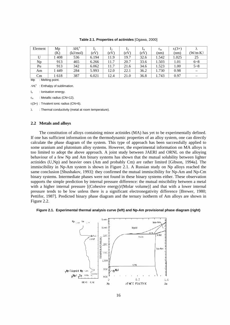
The constitution of alloys containing minor actinides (MA) has yet to be experimentally defined. If one has sufficient information on the thermodynamic properties of an alloy system, one can directly calculate the phase diagram of the system. This type of approach has been successfully applied to some uranium and plutonium alloy systems. However, the experimental information on MA alloys is too limited to adopt the above approach. A joint study between JAERI and ORNL on the alloying behaviour of a few Np and Am binary systems has shown that the mutual solubility between lighter actinides (U,Np) and heavier ones (Am and probably Cm) are rather limited [Gibson, 1994a]. The immiscibility in Np-Am system is shown in Figure 2.1. A Russian study on Np alloys reached the same conclusion [Shushakov, 1993]: they confirmed the mutual immiscibility for Np-Am and Np-Cm binary systems. Intermediate phases were not found in these binary systems either. These observation supports the simple prediction by internal pressure difference: the mutual miscibility between a metal with a higher internal pressure [(Cohesive energy)/(Molar volume)] and that with a lower internal pressure tends to be low unless there is a significant electronegativity difference [Brewer, 1980; Pettifor, 1987]. Predicted binary phase diagram and the ternary isotherm of Am alloys are shown in Figure 2.2.
Figure 2.1. Experimental thermal analysis curve (left) and Np-Am provisional phase diagram (right)
���������
TE
MPE
RA
TU
RE
(K)
�
��
��
�
��
��
�� �� �� ��
�� ���� ��
����
�
����� �����
����
���������������
����� �����
���
���� � ��� � ��
� ���������� �� ���
17
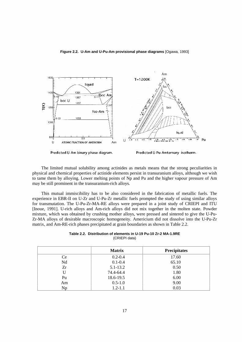
Figure 2.2. U-Am and U-Pu-Am provisional phase diagrams [Ogawa, 1993]
The limited mutual solubility among actinides as metals means that the strong peculiarities in physical and chemical properties of actinide elements persist in transuranium alloys, although we wish to tame them by alloying. Lower melting points of Np and Pu and the higher vapour pressure of Am may be still prominent in the transuranium-rich alloys.
This mutual immiscibility has to be also considered in the fabrication of metallic fuels. The experience in EBR-II on U-Zr and U-Pu-Zr metallic fuels prompted the study of using similar alloys for transmutation. The U-Pu-Zr-MA-RE alloys were prepared in a joint study of CRIEPI and ITU [Inoue, 1991]. U-rich alloys and Am-rich alloys did not mix together in the molten state. Powder mixture, which was obtained by crushing mother alloys, were pressed and sintered to give the U-Pu-Zr-MA alloys of desirable macroscopic homogeneity. Americium did not dissolve into the U-Pu-Zr matrix, and Am-RE-rich phases precipitated at grain boundaries as shown in Table 2.2.
Table 2.2. Distribution of elements in U-19 Pu-10 Zr-2 MA-1.9RE (CRIEPI data)
Matrix Precipitates
Ce 0.2-0.4 17.60 Nd 0.1-0.4 65.10 Zr 5.1-13.2 0.50 U 74.4-64.4 1.80 Pu 18.6-19.5 6.00 Am 0.5-1.0 9.00 Np 1.2-1.1 0.03
18
The MA-Zr alloys have to be studied in detail. Two groups have studied binary alloy phase diagram of Np-Zr system, but they contradict with each other. Gibson et al. [Gibson, 1994b] found that Np and Zr are immiscible as solids; Rodriguez et al. [Rodriguez, 1994] judged that there are continuous series of solid solutions in the bcc phase (�Zr, �Np). Both experiments were handicapped by the limitation of experimental resources. The number of data points was not sufficient to unambiguously determine the phase diagram, and the potential effects of gaseous impurities could not be studied. Thus, there are two types of provisional phase diagram for this binary system (Figure 2.3).
Figure 2.3. Two versions of provisional phase diagram of Np-Zr system (top) Gibson et al. [Gibson, 1994b]; (bottom) Rodriguez et al. [Rodriguez, 1994]
19
A few features are in common between these two diagrams. Among them, it is noted that there is an intermediate phase � around the composition of NpZr2, which resembles to UZr2 and PuZr2. The NpZr2 phase either decomposes to a mixture of �Zr and �Np at about 823K [Gibson, 1994b] or transforms to a (�Zr,�Np) solid solution at about 803K [Rodriguez, 1994].
Ogawa et al. [Ogawa, 1995a] have shown by thermodynamic analysis with a sub-regular solution model that, if the magnitudes of interaction parameters of Np-Zr alloys are similar to those of U-Zr alloys, the miscibility gap in the bcc phase should cross the solidus line. If this is the case, there should not be the continuous series of solid solutions in the bcc phase, which agrees with the observation by Gibson et al. But this point has yet to be verified with further experiments.
The U-Pu-Zr alloys do not change their thermophysical properties by adding MA as seen in Table 2.3 and Figure 2.4, which is expected from low solubilities of americium and curium in U-Pu-Zr matrix [Kurata, 1992]. Density was lower for U-Pu-Zr-5%MA-5%RE (14.5g/cm3) compared with U-Pu-Zr fuel (15.5g/cm3).
Table 2.3. Properties of U-Pu-Zr-MA-RE alloys
U-19Pu-10Zr 2%(MA,RE) 5%(MA,RE) mp. (�C) 1 217 1 207 1 207 �+�+� (�C) 580 580 580 �+�� (�C) 630 630 630 Young’s modulus(GPa) 93.31 – 85.22 Poisson ratio 0.317 – 0.305 Eutectic point with sus cladding (�C) 1 268 – 1 263
Figure 2.4. Thermal conductivity (arbitrary unit) of U-Pu-Zr-5%MA-5%RE alloys compared with U-Pu-Zr alloys
20
2.3 Oxides
The various binary oxides of the transuranium elements Np-Cm have been reported but the majority of the investigations have been for the fcc cubic dioxides, which seem the obvious compounds for fuels or targets. This is true for NpO2 and PuO2, but not for the AmO2 and CmO2. The stability of the latter compounds is limited. The oxygen potential of AmO2 is high and at high temperature it is stable in oxidising atmosphere only [Chikalla, 1966], as shown in Figure 2.5 CmO2 does not exists at temperatures above about 1 200K [Konings, 2001]. For these elements other compounds with O/M<2 have to be considered. For americium the binary compounds that exist at elevated temperature are AmO1.61 and Am2O3, for curium it is the sesquioxide Cm2O3. Targets of americium oxide (O/Am near 1.6) in MgO have been fabricated successfully for the ECRIX experiment [Croixmarie, 2003]. In analogy with the lanthanide sesquioxides, it is to be expected that these compounds form solid solutions with cubic dioxides like UO2 and yttria-stabilised zirconium oxide. Experimentally this has been confirmed in the SUPERFACT experiment for which a UO2-based fuel with 20 wt.% AmO2-x has been fabricated and irradiated [Prunier, 1995].
Figure 2.5. The schematic phase diagrams of the Am-O system (left) [Thiriet, 2003] and Cm-O system (right) [Konings, 2001]
The properties of the actinide oxides change significantly going from Th to Cm. The melting points of the transuranium dioxides gradually decrease along the actinide series, those of the known sesquioxides are also significantly lower than that of UO2 [Konings, 2004]. Also the thermal conductivity of the dioxides decreases along the series (Figure 2.6), though no reliable data exist for the americium oxides. This means that fuels and targets with high MA content cannot operate under the same linear power as standard UO2 fuel as the thermal margin would be different. Also the vaporisation behaviour must be taken into account in this context, but very little is known for the minor actinides. NpO2 vaporises to give NpO2(g) and NpO(g), Cm2O3 likely vaporises in an analogues manner as the lanthanide oxides, to yield CmO(g). The vaporisation of AmO2-x or Am2O3 is not known, though it has been suggested that Am(g) is the predominant vapour species.
21
Figure 2.6. The thermal conductivity of the actinide dioxides
The experimental value (at 333K) for AmO2 is indicated by ����������� ������ ����������������� ����������� ���
probably made on a sub-stoichiometric sample. The values for AmO2 estimated from the trend are indicated by �; the values calculated by Lemehov et al. using a physical model [Lemehov, 2003] are indicated by solid square (298.15K) and solid circle (1 000K).
2.4 Nitrides and carbides
Nitride fuels may be better grasped as carbonitride fuels. Monocarbide (MC) and mononitride (MN) of actinides have the NaCl-type fcc structure. In earlier days of nuclear technology, those fuels were prepared from actinide metals. More recently, the carbothermic synthesis from actinide oxides has become more common, where the mixture of metal oxides and carbon powder is heated in a reducing atmosphere. In preparing MN, the mixed flow of nitrogen and hydrogen or that of ammonia is used as the atmosphere. In those cases, one tends to obtain M[C,N,(O)] where the ratio of C and N depends on preparation conditions such as the initial composition of the mixture, the atmosphere and the temperature. Removal of carbon and oxygen cannot be complete, and some measures have to be adopted to reduce their contents as low as possible.
Bearing these facts in mind, one has to examine the properties of nitrides and carbides. The experimental database on carbide fuels is larger than that of nitride fuels. However, carbide fuels are not very attractive options for MA burning, since thermodynamic stabilities of carbides of Am and Cm are not high enough [Holley, 1984]. Figure 2.7 compares the free energy of formation of oxide, carbide and nitride of actinides. Even with Pu, its vaporisation loss during carbothermic synthesis of the carbide fuels has been a practical problem [Besmann, 1977]. Americium loss during PuC preparation is also significant. The carbothermic reduction of plutonium oxides is actually a useful process for removing americium from old plutonium samples, where a good part of 241Pu has decayed to 241Am [Ohmichi, 1992].

22
Figure 2.7. Free energy of formation of MC1.5, MN and MO
Thermodynamic stability of mononitrides of Am and Cm has yet to be defined. An initial analysis of vaporisation behaviour of impurity Am in PuN suggested that the free energy of formation of AmN is not so different from those of UN and PuN [Ogawa, 1995b]. Even so, the chemical behaviour difference among the mononitrides of actinides is noticeable. With the increasing atomic number, the mononitride becomes more hygroscopic. AmN resembles to the mononitrides of rare earths in this respect. Although the Gibbs free energies of formation of mononitrides of rare earths such as La are similar to those of actinides [Gshneidner, 1972], the mononitrides of rare earths are more susceptible to hydrolysis. Adding ZrN matrix improves the stability against moisture [Takano, 2003].
Only uranium among actinides has stable higher nitrides: U2N3 and probably metastable UN2 [Tagawa, 1974]. There appear no higher nitrides of the transuranium elements.
Thermal conductivities of nitrides are shown in Figure 2.8 [Arai, 1998], which continuously change with composition, reflecting the existence of complete series of solid solutions in these binary systems.
Figure 2.8. Thermal conductivities of actinide mononitrides solid solutions
-800
-700
-600
-500
-400
-300
-200
-100
0
U Np Pu Am Element
��G
f(kJ
/mo
l) MC 1.5 MN MO 2 MO 1.5 MO
T = 1 700K
MN
MO
MC 1.5
MO 2
MO 1.5
23
Vaporisation behaviour of actinide mononitrides and their mixtures is summarised by Ogawa [Ogawa, 1998]. UN dissociates nitrogen at high temperatures to segregate liquid uranium phase. In order to suppress the formation of this liquid metal phase, the partial pressure of N2 should be very large. To prevent the decomposition of the stoichiometric UN to the melting point (~2 830�C), p(N2) should exceed 2-5 atm.
One often mistakes this fact for that the nitrogen pressure over the nitride fuel is very large. The misunderstanding has led to the erroneous analysis on the mechanical effects of nitrogen dissociation from the nitride-fueled core [Umeoka, 1999]. The metal phase, which precipitates by decomposition of UN, then acts as a nitrogen getter. Thus, over the two-phase UN+(liq U) mixtures, equilibrium p(N2) is not so large: 1x10⁻³atm at 2 500K. Here, it should be born in mind that the homogeneity range of UN1-X is very narrow: mere 1-4% of nitrogen release of UN is enough to precipitate the liquid metal phase.
The vaporisation behaviour of PuN and probably those of transplutonium nitrides differ from that of UN: instead of preferential vaporisation of nitrogen, Pu and N2 vaporise congruently. In the congruent vaporisation condition, the total vapour pressure over PuN is significantly smaller than that of pure Pu: ~5x10⁻³ atm over PuN vs. ~10-2 atm over Pu at 2 500K.
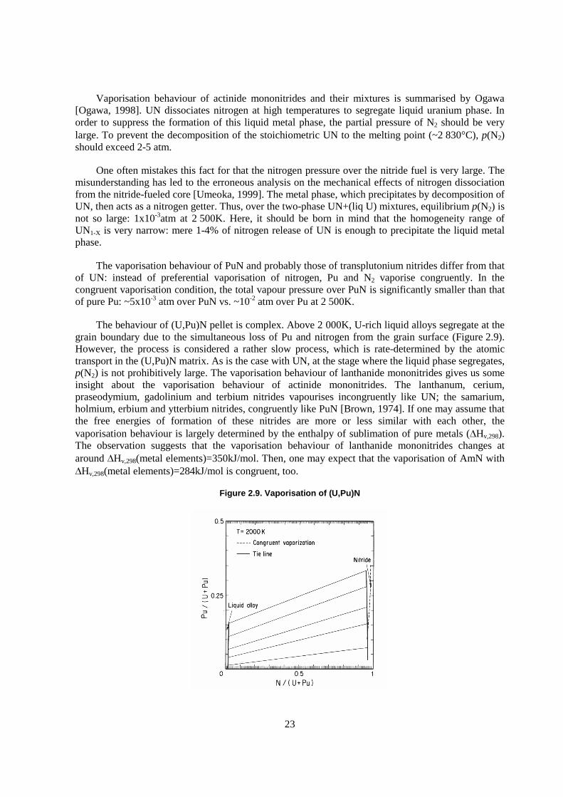
The behaviour of (U,Pu)N pellet is complex. Above 2 000K, U-rich liquid alloys segregate at the grain boundary due to the simultaneous loss of Pu and nitrogen from the grain surface (Figure 2.9). However, the process is considered a rather slow process, which is rate-determined by the atomic transport in the (U,Pu)N matrix. As is the case with UN, at the stage where the liquid phase segregates, p(N2) is not prohibitively large. The vaporisation behaviour of lanthanide mononitrides gives us some insight about the vaporisation behaviour of actinide mononitrides. The lanthanum, cerium, praseodymium, gadolinium and terbium nitrides vapourises incongruently like UN; the samarium, holmium, erbium and ytterbium nitrides, congruently like PuN [Brown, 1974]. If one may assume that the free energies of formation of these nitrides are more or less similar with each other, the vaporisation behaviour is largely determined by the enthalpy of sublimation of pure metals (�Hv,298). The observation suggests that the vaporisation behaviour of lanthanide mononitrides changes at around �Hv,298(metal elements)=350kJ/mol. Then, one may expect that the vaporisation of AmN with �Hv,298(metal elements)=284kJ/mol is congruent, too.
Figure 2.9. Vaporisation of (U,Pu)N
24
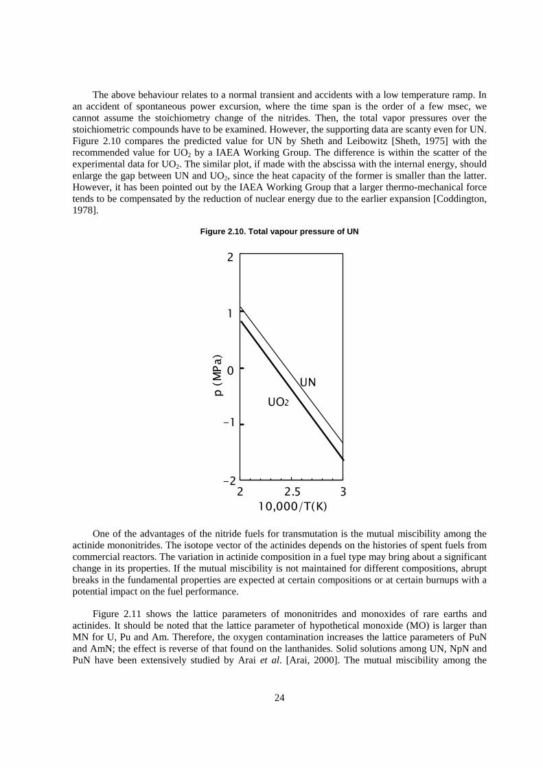
The above behaviour relates to a normal transient and accidents with a low temperature ramp. In an accident of spontaneous power excursion, where the time span is the order of a few msec, we cannot assume the stoichiometry change of the nitrides. Then, the total vapor pressures over the stoichiometric compounds have to be examined. However, the supporting data are scanty even for UN. Figure 2.10 compares the predicted value for UN by Sheth and Leibowitz [Sheth, 1975] with the recommended value for UO2 by a IAEA Working Group. The difference is within the scatter of the experimental data for UO2. The similar plot, if made with the abscissa with the internal energy, should enlarge the gap between UN and UO2, since the heat capacity of the former is smaller than the latter. However, it has been pointed out by the IAEA Working Group that a larger thermo-mechanical force tends to be compensated by the reduction of nuclear energy due to the earlier expansion [Coddington, 1978].
Figure 2.10. Total vapour pressure of UN
��
��
�
�
�
� ��� ���������
������
���
��
One of the advantages of the nitride fuels for transmutation is the mutual miscibility among the actinide mononitrides. The isotope vector of the actinides depends on the histories of spent fuels from commercial reactors. The variation in actinide composition in a fuel type may bring about a significant change in its properties. If the mutual miscibility is not maintained for different compositions, abrupt breaks in the fundamental properties are expected at certain compositions or at certain burnups with a potential impact on the fuel performance.
Figure 2.11 shows the lattice parameters of mononitrides and monoxides of rare earths and actinides. It should be noted that the lattice parameter of hypothetical monoxide (MO) is larger than MN for U, Pu and Am. Therefore, the oxygen contamination increases the lattice parameters of PuN and AmN; the effect is reverse of that found on the lanthanides. Solid solutions among UN, NpN and PuN have been extensively studied by Arai et al. [Arai, 2000]. The mutual miscibility among the

25
actinide mononitrides has been demonstrated recently in the fabrication of (Cm, Pu)N by Takano et al. [Takano, 2001].
Figure 2.11. Lattice parameters of mononitrides and monoxides
Lattice parameters of MN, MO
���
����
����
����
����
����
����
���
����
����
����
����
�� �� � ��� � ��� ���� ���� � ����������
��
��� ��
��
��
��
��
As seen in Figure 2.11, the lattice parameter of CeN is anomalously small. With increasing temperature to 800K, the lattice parameter of CeN increases significantly, which is accompanied by a strong increment of the reduced enthalpy increment, [H(T)-H(298)]/(T-298) [Schram, 1997]. The other nitrides of lanthanides do not show the similar behaviour. This anomaly is explained by the itinerant nature of 4f electrons in CeN at lower temperatures [Delin, 1997]. Its lattice parameter at higher temperatures follows the trend of the other mononitrides of lanthanides, where 4f electrons are localised. Such anomalous behaviour has not been confirmed for actinide mononitrides. In the actinide mononitrides, 5f electrons are itinerant through hybridisation with anion p-states [Brooks, 1984]. This explains smaller lattice parameters of mononitrides of U-Pu when compared with the lanthanide counterparts. The lattice parameters of AmN and CmN are similar to those of the lanthanide counterparts, indicating the more localised 5f electrons than those in U-Pu.
As for the inert-matrix nitrides, it has been shown earlier by Arai et al. [Arai, 2000] that PuN-ZrN can form a series of solid solutions, although there were significant amount of carbon and oxygen impurities carried by ZrN powder used in the preparation. On the other hand, the mixing between PuN and TiN is limited. Mixing properties among metal mononitrides have been examined by Holleck and Ishii [Holleck, 1973]. Table 2.4 summarises the prediction according to their empirical interaction parameter. In good accord with this prediction, AmN is miscible with YN, but there is a miscibility gap in the binary system with ZrN [Akabori, 2002].
26
Table 2.4. Lattice parameter difference and miscibility among metal nitrides
a(nm) ��-MN AmN-MN
LaN 0.5305 0.0417 Complete miscibl. (1 973K) 0.0314 CeN 0.501 0.0122 0.0019 PrN 0.5165 0.0277 0.0174 NdN 0.5151 0.0263 0.016 YN 0.4891 0.0003 0.01
UN 0.4888 – 0.0103 NpN 0.04899 0.0011 0.0092 PuN 0.4905 0.0017 0.0086 AmN 0.4991 0.0103 – CmN 0.5041 0.0153 0.005 BkN 0.495 0.0062 0.0041
ZrN 0.4576 0.0312 0.0415 Miscibility gap (Akabori et al.) TiN 0.4242 0.0646 4 mol.% in UN at 2 672K 0.0749
Bold: Interaction parameter expected to be larger than 5 kcal/mol (critical point of miscibility gap above 1 000°C) by Holleck and Ishii (KFK, 1754).
2.5 Fluoride salts
Fluoride salts have been investigated as fuel carrier for molten salt reactors for the following reasons [Grimes, 1960; Grimes, 1970]:
� Wide range of solubility for thorium and uranium.
� Thermodynamic stability up to high temperatures.
� Stability to radiation (no radiolytic decomposition).
� Low vapour pressure at the operating temperature of the reactor.
� Compatibility with nickel-based alloys (Ni-Mo-Cr-Fe) that can be used as structural materials (Hastelloy).
Most of the investigations have been made for the 7LiF-BeF2 mixture (flibe), which has been used as fuel carrier in the ORNL molten salt reactor experiment (MSRE), performed in the1960s, but some data also exist for NaF-ZrF4 which was used in the aircraft reactor experiment (ARE). The molten salt reactors have received attention at actinide burners recently for two main reasons: (i) the integrated fuel cycle with identical fuel carrier and pyrochemical reprocessing medium has obvious advantages; and (ii) the degradation with burnup that occurs in solid fuel and limits its use does not occur.
The knowledge of the properties of the transuranium fluorides is, however, very limited, even for the fundamental thermodynamic functions. Some experimental data have been reported for PuF3 and PuF4 [Lem, 2001], but for the fluorides of Np, Am and Cm only estimated data. The same is the case for solubility data in the fuels carries. Data exist for the solubility of PuF3 in LiF-BeF2 [Barton, 1960] which indicate that it about 0.5 mol.% at the relevant temperatures, significantly lower then that of ThF4 and UF4. This low solubility in LiF-BeF2 is of the same order of magnitude as that of the lanthanide trifluorides [Ward, 1960] and it can be concluded that the solubility of AmF3 and CmF3 is similarly low. It can be noted that the solubility of the rare earth elements in NaF-ZrF4 is a factor 4 higher.
It is thus clear that the thermodynamic database for this type of transmutation fuel is very limited.
27
REFERENCES
Akabori, M. et al. (2002), J. Nucl. Sci. Technol.
Arai, Y., K. Nakajima, Y. Suzuki, (1998), “Thermal conductivity of actinide solid solutions”, J. Alloys and Compounds, 271-273, 602-605.
Arai, Y., K. Nakajima, (2000), “Preparation and characterization of PuN pellets containing ZrN and TiN”, J. Nucl. Mater. 281, 244-247.
Barton, C.J. (1960), J. Am. Chem. Soc.
Besmann, T.M., T.B. Lindemer, (1977), J. Nucl. Mater. 67, 77.
Brewer, L., L.H. Lamoreaux, (1980), At. Energy Rev., Spec. Issue No.7, 11-194.
Brooks, M.S.S., B. Johansson, H.L. Skriver (1984), “Electronic structure and bulk ground state properties of the actinides”, in Handbook on the Physics and Chemistry of the Actinides, eds. A.J. Freeman and G.H. Lander, Elsevier Science Publishers.
Brown, R.C., N.J. Clark, (1974), “Composition limits and vaporization behavior of rare earth nitrides”, J. inorg. nucl. Chem. 36, 2507-2514.
Chikalla, T.D., L. Eyring, (1960), J. Inorg. Nucl. Chem. 30, 133.
Coddington, P. et al., (1978) “The usage of equation of state data for fuel and sodium in the analysis of hypothetical fast reactor accidents”, in IAEA report on Equation of State of Materials of Relevance to the Analysis of Hypothetical Fast Breeder Reactor Accidents, IWGFR/26 (1978).
Croixmarie, Y., E. Abonneau, A. Fernández, R.J.M. Konings, F. Desmoulière, L. Donnet, (2003), J. Nucl. Mat. 320, 11.
Delin, A. et al., (1997), “Optical evidence of 4f-band formation in CeN”, Phys. Rev., B 55, R10173-R10176.
Gibson, J.K. et al., (1994) “Alloying behavior in selected neptunium binary systems: the role of 5f bonding”, J. Alloys and Compounds, 213/214, 106-110.
Gibson, J.K., R.G. Haire, M.M. Gensini, T. Ogawa, (1994), “Alloying behavior in selected neptunium binary systems: The role of 5f bonding”, J. Alloys and Compounds, 213/214, 106.
Grimes, W.R., D.R. Cuneo, (1960), in: Reactor Handbook, 2nd Edition, C.R. Tipton Jr., Ed, Interscience Publ. New York, Chapter 17.
Grimes, W.R., (1970), Nucl. Appl. Technol. 8, 137.
28
Gshneidner, K.A., N. Kippenhan, (1972), Thermochemistry of the rare earth carbides, nitrides and sulfides for steelmaking, IS-RIC-5, Iowa State University report.
Holleck, H., T. Ishii, (1973), Berechnung von Gleichgewichiten in ternaeren Systemen Uran-Ubergangsmetall-Stickstoff, Kernforschungszentrum Karleruhe, KFK-1754.
Holley, Jr., C.E., M.H. Rand, E.K. Storms (1984), The Chemical Thermodynamics of Actinide Elements and Compounds: Part 6, The Actinide Carbides, TAEA, Vienna.
Inoue, T. et al., (1991), “Characterization of fuel alloys with minor actinides”, Trans Am. Nucl. Soc. 64, 552.
Konings, R.J.M., J. Nucl. Mat.
Konings, R.J.M., L.R. Morss, J. Fuger, in: The Chemistry of Actinide and Transactinide Elements, 3rd Edition, Chapter 19, (in preparation).
Kurata, M., T. Inoue, L. Koch, (1992); CRIEPI-Report T92005 (in Japanese).
Lemehov, S.E., V. Sobolev, P. van Uffelen, (2003), J. Nucl. Mat. 320, 66.
Ogawa, T. (1993), “Alloying behavior among U, Np, Pu and Am predicted with the Brewer valence bond model”, J. Alloys and Compounds 194, 1-7.
Ogawa, T. et al., (1995) “Thermodynamic analysis of Zr-U and Zr-Np alloys in view of f-d interaction”, J. Nucl. Mater. 223, 67-71.
Ogawa, T. et al., (1995) “Vaporization behavior of (Pu,Am)N”, J. Alloys and Compounds 224, 55-59.
Ogawa, T. et al., (1998) “Actinide nitrides and nitride-halides in high-temperature systems”, J. Alloys and Compounds 271-273, 347-354.
Ogawa, T. (2000), “Transmutation of minor actinides and innovative fuel cycle concepts”, in Advanced Nuclear Energy Systems Toward Zero Release of Radioactive Wastes, Susono Seminar House, Shizuoka, Japan, 6-9 Nov. 2000.
Ogawa, T., Y. Arai, (2001), “Nitride/pyroprocess for MA transmutastion and fundamental database”, in Pyrochemical Separations, OECD/NEA Workshop Proceedings, Avignon, France, 14-15 March 2000, ISBN 92-64-18443-0, pp. 157-164.
Ohmichi, T., S. Nomura, A. Maeda, (1992), Jpn. Patent, H4-58593.
Pettifor, D.G. (1987), “A quantum-mechanical critique of the miedema rules for alloy formation”, Solid State Physics, 40, 43-92.
Prunier, C. et al. (1995), “The CEA SPIN Programme: Minor actinide fuel and target aspects”, International Conference on Evaluation of Emerging Nuclear Fuel Cycle Systems, Global-1995, 11-14 Sep. 1995, Versailles, France.
Rodriguez, R.J., C. Sari, A.J.C. Portal, (1994), J. Alloys and Compounds, 209, 263.
29
Schram, R.P.C. et al. (1997), “Enthalpy increment measurements of cerium mononitride”, J. Alloys and Compounds, 252, 20-23.
Sheth, A., L. Liebowitz, (1975), “Equation of state and transport properties of uranium and plutonium nitrides in the liquid region”, Argonne National Laboratory Report. ANL-AFP-12.
Shushakov, V.D. (1993), “Investigation of Americium-Neptunium and Curium-Neptunium Alloys”, in Summary form only, Actinides-2001 Abstracts, P-18 T.
Streit, M. et al., (2002), “(Pu,Zr)N annular fuel pellets shaped by direct coagulation cating”, J. Nucl. Sci. Technol., Supplement 3, November, pp. 741-744.
Tagawa, H. (1974), “Phase relationship and thermodynamic properties of the uranium-nitrogen system”, J. Nucl. Mater. 51, 78-89.
Takano, M. et al. (2001), “Carbothermic synthesis of (Cm,Pu)N”, J. Nucl. Mater., 294, 24-27.
Takano, M., A. Itoh, M. Akabori, K. Minato, M. Numata, (2003), “Study on The Stability of AmN and (Am,Zr)N”, Global 2003, New Orleans.
Thiriet, C., R.J.M. Konings, (2003), J. Nucl. Mat. 320, 292.
Ward, W.T., R.A. Strehlow, W.R. Grimes, G.M. Watson, (1960), J. Chem. Eng., Data 5, 137.

31
Chapter 3
FUEL SELECTION CRITERIA FOR THE REPRESENTATIVE TRANSMUTATION SCENARIOS
3.1 Fuel selection criteria – Double strata scenario
In the Double strata scenario [Murata, 1984; Salvatores, 1987], the americium and curium produced in critical power reactors are supposed to be multi-recycled in dedicated minor actinide burners. An advantage of this approach is that handling of these highly active elements is constrained to a very small part of the nuclear power park. Calculations show that the fraction of power produced in reactors managing minor actinides could be as low as 4-6%. The poor reactivity coefficients of MA based fuel, in conjunction with a very small effective fraction of delayed neutrons, however, makes safe operation of critical dedicated cores questionable. The introduction of accelerator driven systems (ADS) for the purpose of minor actinide burning therefore appears adequate. The core of the ADS should operate on a fast neutron spectrum, in order to minimise production of curium and californium. A substantial part of the technology developed for FBRs hence is directly applicable on ADS. The criteria used for selecting the ADS fuel form and composition may however differ from those used for developing FBR fuels. Here, we intend to discuss the following properties pertaining to potential fuel types:
� Doppler feedback;
� effective delayed neutron fraction;
� reactivity evolution and equilibrium composition;
� coolant void worth;
� expansion coefficients of coolant and structural material;
� fuel linear rating and power to melt;
� proton source efficiency;
� clad damage.
As a result of the account, criteria that ADS fuels should fulfil will be pointed out. Possible candidates will be listed together with their advantages and drawbacks. As a basis for the discussion we use a model core with properties listed in Table 3.1.1

32
Table 3.1.1. Core parameters of the ADS model used in Chapter 3
Core power 800 MWth Spallation target LBE
Target radius 20 cm Core height 100 cm
k-eigenvalue@BOL 0.97
3.1.1 Doppler feedback
The majority of all fast neutron reactors have been operating on oxide fuels. The main temperature feedback in such cores is Doppler broadening of capture resonances. Table 3.1.2 displays the Doppler coefficient calculated for some simplified oxide fuel compositions in a sodium cooled pin lattice. While a standard FBR fuel (80% 238U and 20% Pu) yields a sizable negative feedback of -0.5 pcm/K, the introduction of americium is directly detrimental for the fuel temperature coefficient. A dedicated fuel would have a negligible Doppler feedback even if 238U was present. Note however that 240Pu can provide a significant temperature feedback for a pure plutonium fuel.
Table 3.1.2. Doppler coefficient in a sodium cooled pin lattice as function of Am concentration The Pu-vector was taken to be 75% 239Pu and 25% 240Pu. k-infinity was calculated at T=1 800K and T=600K.
U Th Zr Pu Am �����������
0.80 – – 0.20 – -0.52 0.70 – – 0.20 0.10 -0.18 0.60 – – 0.20 0.20 -0.05
– 0.80 – 0.20 – -0.42 – 0.70 – 0.20 0.10 -0.07 – – 0.80 0.20 – -0.39 – – 0.70 0.20 0.10 -0.01
3.1.2 Effective delayed neutron fraction
The unusually large fraction of delayed neutrons emitted by the fission products of 238U is of significance for the controllability of fast neutron reactors. However, since delayed neutrons have a softer spectrum than fission neutrons, they will have a larger probability of being captured by americium isotopes. Hence, the introduction of americium into the fuel will lead to lower values of beta-effective. Table 3.1.3 shows how the effective delayed neutron fraction is affected by the presence of Am. Note that the (U0.6, Pu0.2, Am0.2)O2 fuel, has a lower effective delayed neutron fraction than the uranium free (Pu0.2, Zr0.8)O2 fuel, due to the capture of delayed neutrons by americium in the former case.
33
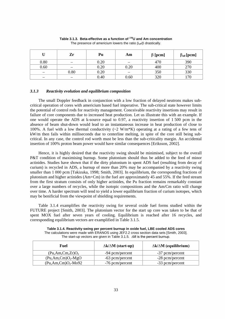
Table 3.1.3. Beta-effective as a function of 238U and Am concentration The presence of americium lowers the ratio �eff/� drastically.
U Zr Pu Am � [pcm] �eff [pcm]
0.80 – 0.20 – 470 390 0.60 – 0.20 0.20 400 270
– 0.80 0.20 – 350 330 – – 0.40 0.60 320 170
3.1.3 Reactivity evolution and equilibrium composition
The small Doppler feedback in conjunction with a low fraction of delayed neutrons makes sub-critical operation of cores with americium based fuel imperative. The sub-critical state however limits the potential of control rods for reactivity management. Conceivable reactivity insertions may result in failure of core components due to increased heat production. Let us illustrate this with an example. If one would operate the ADS at k-source equal to 0.97, a reactivity insertion of 1 500 pcm in the absence of beam shut-down would lead to an instantaneous increase in heat production of close to 100%. A fuel with a low thermal conductivity (~2 W/m*K) operating at a rating of a few tens of kW/m then fails within milliseconds due to centerline melting, in spite of the core still being sub-critical. In any case, the control rod worth must be less than the sub-criticality margin. An accidental insertion of 100% proton beam power would have similar consequences [Eriksson, 2002].
Hence, it is highly desired that the reactivity swing should be minimised, subject to the overall P&T condition of maximising burnup. Some plutonium should thus be added to the feed of minor actinides. Studies have shown that if the dirty plutonium in spent ADS fuel (resulting from decay of curium) is recycled in ADS, a burnup of more than 20% may be accompanied by a reactivity swing smaller than 1 000 pcm [Takizuka, 1998; Smith, 2003]. In equilibrium, the corresponding fractions of plutonium and higher actinides (Am+Cm) in the fuel are approximately 45 and 55%. If the feed stream from the first stratum consists of only higher actinides, the Pu fraction remains remarkably constant over a large numbers of recycles, while the isotopic compositions and the Am/Cm ratio will change over time. A harder spectrum will tend to yield a lower equilibrium fraction of curium isotopes, which may be benificial from the viewpoint of shielding requirements.
Table 3.1.4 examplifies the reactivity swing for several oxide fuel forms studied within the FUTURE project [Smith, 2003]. The plutonium vector for the start up core was taken to be that of spent MOX fuel after seven years of cooling. Equilibrium is reached after 16 recycles, and corresponding equilibrium vectors are examplified in Table 3.1.5.
Table 3.1.4. Reactivity swing per percent burnup in oxide fuel, LBE cooled ADS cores The calculations were made with ERANOS using JEF2.2 cross section data sets [Smith, 2003].
The start-up vectors are given in Table 3.1.5. ���������������� ����
Fuel ������ �����-up) ������ �����������
(Pu,Am,Cm,Zr)O2 -94 pcm/percent -37 pcm/percent (Pu,Am,Cm)O2-MgO -63 pcm/percent -28 pcm/percent (Pu,Am,Cm)O2-Mo92 -76 pcm/percent -33 pcm/percent

34
When interpreting these data, precaution must be taken for a large discrepancy in the predicted swing obtained with different evaluations of the cross section for fission of 242Cm. ENDF/B-VI data gives almost two times higher reactivity losses for start up cores than data from JEF2.2 and JENDL3.2 [Cometto, 2001]. With this caveat in mind, it may be concluded that the reactivity swing of the ADS with 20% burnup can be kept within 2 000 pcm for start-up cores, if a low quality (~50% fissile) Pu feed fraction of approximately 40% is added to the transplutonium stream.
In order to evaluate the maximum permissible reactivity swing, calculations of unprotected transient overcurrent accidents will be required. In order to compensate for reactivity loss in the core, the proton beam current will be lower at start of irradiation than at the end. If the full proton beam power accidentally is used at start of irradiation, the fuel temperature might exceed permissible limits. Here, one should note that the excess current corresponding to 2 000 pcm reactivity loss is about 67%, for a k-value at BOL equal to 0.97, decreasing to 33% if the reactivity loss is constrained to 1 000 pcm.
Table 3.1.5. Actinide vectors at BOC for start-up and equilibrium cores [Smith, 2003] Note that the slightly harder spectrum resulting from use of a molybdenum matrix (see Table 3.1.6) results in significantly
lower equilibrium fraction of Curium isotopes. After a few recycles, the feed consists of Pu from spent ADS fuel, mixed with higher actinides from first and second stratum streams.
Isotope Start-up [wt.%] Equilibrium (MgO) Equilibrium (92Mo) 238Pu 5.0 30.4 28.3 239Pu 37.9 15.7 20.5 240Pu 30.3 37.5 35.9 241Pu 13.2 2.4 2.4 242Pu 13.5 14.1 12.9
Pu fraction 40.0 46.3 45.8 241Am 66.7 59.6 69.1
242mAm – 4.7 3.2 243Am 33.3 35.7 27.6
Am fraction 50.0 33.0 42.2 244Cm 90.0 74.1 72.0 245Cm 10.0 20.6 18.9 246Cm – 5.3 9.1
Cm fraction 10.0 20.7 12.0
Table 3.1.6. Spectrum averaged cross sections and fission probabilities for 241Am for a selection of matrices in an LBE cooled start-up core
Hafnium nitride gives the hardest spectrum.
Fuel/Matrix �f [b] �c [b] �f /(�f + �c )
Oxide/ZrO2 0.31 1.34 0.19 Oxide/MgO 0.33 1.37 0.20
Oxide/W 0.33 1.10 0.23 Oxide/Mo 0.34 1.09 0.24 Oxide/Cr 0.34 1.17 0.22
Nitride/ZrN 0.35 1.18 0.23 Nitride/HfN 0.38 0.97 0.28
35
3.1.4 Void worth
The lack of large negative temperature feedbacks in ADS implies that core configurations yielding prompt super-criticality should be avoided. The combination of MA-bearing fuel and liquid metal cooling will typically yield a positive coolant void worth. The choice of coolant, as well as the fuel design however have a significant impact on the magnitude of the void worth. A parameter study made for an 800 MWth core with a Pu/Am ratio equal to 40/60, has shown that the void worth may differ by up to 5 000 pcm for different ceramic matrices, and by up to 10 000 pcm for different coolants [Wallenius, 2003]. Figure 3.1.1 shows sodium and LBE void worths as function of P/D for an oxide CERCER (zirconia) and an oxide CERMET (chromium) fuel. As in the case of fast reactors, the void worth is lower for fuels having a high thermal conductivity. The reason for this is that a higher linear rating corresponds to a fewer number of fuel pins in the core and consequently a higher radial leakage in the voided state. The drastic difference in void worth between sodium and LBE is due to the large amount of americium in the fuel.
Figure 3.1.1. Void worth for single zone cores as function of P/D An inner/outer clad diameter of 5.0/5.7 mm was assumed. The Pu/Am ratio was kept constant at 40/60, and a k-eigenvalue equal to 0.97 was obtained by adjusting the fraction of inert matrix. The linear ratings were assumed to be 15 and 35 kW/m for zirconia and Cr matrices, respectively.
In Figure 3.1.2, the LBE void worth for oxide fuels is compared to that of nitride solid solutions. Note that matrices based on chromium and yttrium offer an advantage in terms of a low void worth. The explanation is that 52Cr and 89Y are nuclides with a full neutron shell, thus providing a threshold for in-elastic scattering above 1 MeV. Nuclides without a full neutron shell typically have thresholds for inelastic scattering located at about 0.5 MeV. Hence, a larger fraction of newly born fission neutrons will be prone to loose half an MeV kinetic energy or more in a single collision with neutronically non-inert nuclides, which in combination with inelastic scattering in the coolant quickly brings the neutrons below the fast fission threshold of americium. Loss of coolant then leads to a shift in the neutron spectrum to energies above the fast fission threshold, and a positive contribution to the void worth. Chromium and yttrium on the other hand are inelastically transparent for about half of the newly born fission neutrons, yielding not only a harder spectrum, but also a smaller shift of spectrum during coolant voiding.
(Na)
(Na)
(LBE)
(LBE)
36
Figure 3.1.2a. Void worth as function of P/D for oxide fuels The linear rating adopted for the fuels was 35 kW/m for the CERMETs, 25 kW/m for the CERCER with MgO
matrix, and 15 kW/m for the zirconia matrix. An inner/outer clad diameter of 5.0/5.7 mm was assumed.
Figure 3.1.2b. Void worth as function of P/D for nitride fuels The linear rating adopted was 35 kW/m. An inner/outer clad diameter of 5.0/5.7 mm was assumed.
3.1.5 Expansion coefficients
While significant temperature feedbacks are not required for normal operation of an ADS, negative feedbacks may remain useful for minimising fluctuations in core power. For liquid metal coolants, the temperature coefficient will typically be positive. Figure 3.1.3 shows the LBE temperature coefficient at normal operating temperature, for different oxide fuels as function of pin pitch.
ZrO2
Mo
W
MgO
Cr
37
Figure 3.1.3. Lead-bismuth temperature coefficient as function of P/D
Note that the coefficient remains below +1.0 pcm/K for a wide range of pin pitches. Axial expansion of the fuel is a prompt negative feedback mechanism that may compensate for the positive temperature coefficient of the coolant. In Table 3.1.7 the temperature coefficients for a selection of ADS fuels in an LBE cooled core with pin inner/outer diameter = 6.0/6.8 mm and P/D = 1.50 are displayed.
Table 3.1.7. Temperature coefficients of a 3-zone LBE cooled 800 MWth ADS with nitride or oxide fuels The oxides are dispersed in a metallic (92Mo) or a ceramic (MgO) matrix.
Matrix ZrN 92Mo MgO
Coolant expansion (core+plenum) +0.46 pcm/K +0.46 pcm/K +0.59 pcm/K Fuel axial expansion -0.43 pcm/K -0.19 pcm/K -0.25 pcm/K
Radial grid expansion -0.57 pcm/K -0.52 pcm/K -0.48 pcm/K Note how the coolant and fuel axial expansion coefficients tend to cancel each other. Expansion
of the radial grid contributes negatively to reactivity, but is a delayed feedback with a response time of about 0.1 seconds. Sodium cooling would yield a void coefficient in excess of +1.0 pcm/K, even when taking into account that the core may be designed with a smaller pin pitch. Hence the interest in introducing heavy liquid metals or helium gas as coolant for MA burning ADSs.
3.1.6 Linear rating
The lack of large negative temperature feedbacks inevitably leads to a larger vulnerability to overpower accidents in the ADS. Such accidents can be initiated by either insertion of accelerator current margin, control rod withdrawal, or incorrect fuel loading. The 15% overpower margin required for FBR licensing, is likely to increase significantly for ADS. In addition, the poorer thermal conductivity of coolant (LBE or He) and fuel (TRU-compounds) leads to new restrictions on linear rating already during normal operation. Roughly speaking (neglecting feedbacks), the linear rating is set by the condition that the temperature margin to fuel (cladding) failure must be larger than the temperature gradient over the fuel (coolant), in order to cope with a 100% overpower accident. Consequently, a high thermal conductivity of the fuel is desired. A high thermal conductivity (high rating) of the fuel is also beneficial for the coolant void coefficient, as explained in the previous paragraph.
MgO
ZrO2
Cr Mo W
38
Presently three major fuel compositions are planned to be irradiation tested: metals (US), nitrides (Japan, United States and Europe) and oxides (Europe). Out of these, metals and nitrides must be alloyed with/dissolved in an inert matrix in order to guarantee high temperature stability, while oxides must be fabricated with a certain degree of substoichiometry. While zirconium and its nitride/oxide compounds is foreseen as matrix for the first irradiation testing of prototypic ADS fuels, improving thermal conductivity is an incentive to investigate alternatives. A list of matrices under investigation is given in the table below:
Table 3.1.8. Melting temperature and thermal conductivity for some inert matrix materials The conductivities are given at 1 100K. Measured values for the ceramics were adjusted
to100% theoretical density.
Matrix �c [W/(m�K)] Tmelt [K]
Zr 22 2 128 Cr 64 2 180 Mo 108 2 896 W 115 3 695
ZrN 20 3 230 HfN 26 3 580 ZrO2 2.3 2 950 MgO 8.3 3 100
Metals fuels must be fabricated with a liquid metal bond to enable operating temperatures below the melting point. Nitrides may be used with either a helium, sodium or a lead bond, while oxides are incompatible with sodium.
An estimation of the power to melt at BOL is displayed in Table 3.1.9 for each candidate. A core inlet temperature of 600K was adopted, and it was assumed that a linear power of 30 kW/m yields a temperature increase in the coolant channel of 220K. A main approximation is that the radial clad-fuel gap was fixed to 50 microns for the helium bonded fuels and that heat transfer by radiation is neglected. In the case of nitrides and metals, no data for the thermal conductivity of americium was available, and hence the conductivity of Pu and PuN was used. Still, one may infer that sodium bonded nitride fuel and CERMET oxides with Mo and W matrices have extraordinary resistance to power excursions. Other choices yield acceptable ratings, with the exception of oxide fuel in solid solution with zirconia. In order to survive a 100% overpower accident, the zirconia fuel would have to be operated at less than 20 kW/m. The quoted power to melt for the sodium bonded nitride fuel is partly of academic character, since sodium boiling takes place at about 75 kW/m in the given design condition. Lead bonding might be a possibility to use the full potential of nitride fuels.

39
Table 3.1.9. Fuel temperature gradient for c = 30 kW/m and power to melt at BOL The inert matrix volume fraction was set to 60%. A clad inner/outer diameter of 6.0/6.8 mm and a pellet-clad radial gap of 50 micron was used in the calculation. Sodium bonded fuels have a
surface temperature of 850K at c = 30 kW/m, helium bonded 1 110K. The porosity of oxide fuels was taken to be 10%, nitride fuels 15%.
Fuel Matrix Bond �Tfuel [K] Tcenter [K] Tfail [K] Pfail [kW/m]
Metal Zr Na 155 1 005 1 370 60 Nitride ZrN Na 190 1 040 2 2001) 1002)
Nitride ZrN He 190 1 300 2 2001) 74 Oxide Cr He 105 1 215 2 1803) 78 Oxide Mo He 60 1 170 2 650 1002) Oxide W He 55 1 165 2 650 1002) Oxide ZrO2 He 1 010 2 120 2 650 38 Oxide MgO He 540 1 650 2 5504) 65
1) Estimated dissociation temperature of AmN in a pressurised fuel pin [Jolkkonen, 2003].
2) Clad temperature exceeding rapid burst limit (1 330K).
3) Pending measurement of possible low melting eutectic formation with actinide oxide phase.
4) Eutectic melting temperature of PuO2-MgO.
3.1.7 Source efficiency
A feature specific to ADS is the presence of the spallation target, leading to significant neutronic heterogenity. A neutron born in the spallation target has a larger distance to travel before being able to interact with the fuel, than ordinary fission neutrons. Hence, neutrons coming from a lead or lead-bismuth target tend to have lower median energies than average core neutrons. Since Double strata ADS fuel contains a large fraction of americium, the probability for source neutrons to induce fission will typically be lower than that of the average neutron. This effect is enhanced in cores where power flattening techniques have been implemented, as they are usually based on increase of inert/absorbing matrix fraction in central parts of the core. The efficiency of source neutrons is an ambigous concept in the ADS, being dependent on how the distinction between source and non-source neutrons is made. One may instead define the proton source efficiency as
�* = (1/keff - 1) <F�s>/<Sp>
where keff is the eigenvalue of the neutron transport equation, � s is the sub-critical neutron flux, F is the fission production operator and Sp is the proton source [Seltborg, 2003]. The proton source efficiency represents the number of fissions neutrons produced in the core, relative to the eigenmode production.
Figure 3.1.4 shows the proton source efficiency for a nitride fueled core with LBE coolant as function of target radius, for two different fuel compositions; one with Pu/Am = 80/20 and the other with Pu/Am = 40/60. The latter would correspond to a start-up core in the Double Strata concept. The two cores have the same k-eigenvalue, but as can be seen, the proton source efficiency is considerably lower for the americium dominated fuel. This can be attributed to the soft spectrum of neutrons created in the spallation target, having a median energy less than 1 MeV for target radii larger than 20 cm.
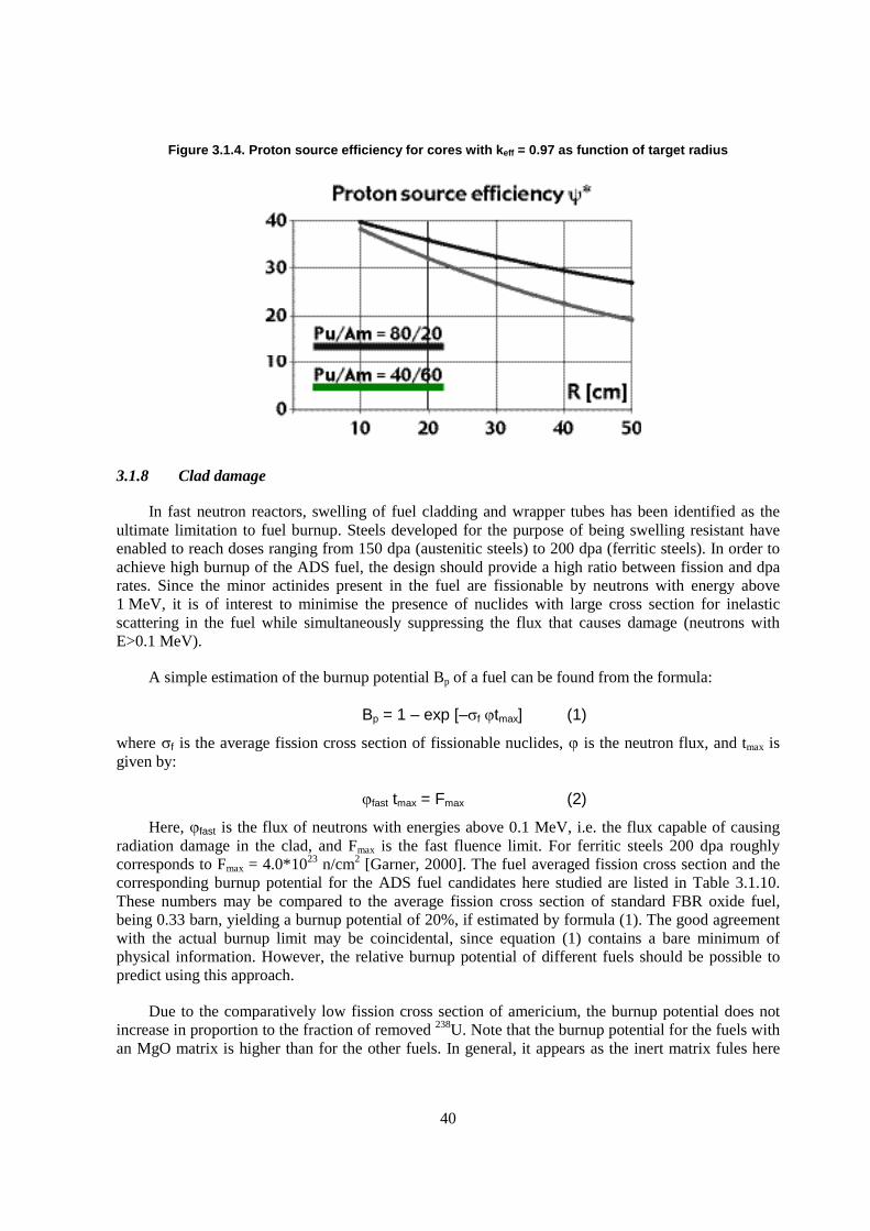
40
Figure 3.1.4. Proton source efficiency for cores with keff = 0.97 as function of target radius
3.1.8 Clad damage
In fast neutron reactors, swelling of fuel cladding and wrapper tubes has been identified as the ultimate limitation to fuel burnup. Steels developed for the purpose of being swelling resistant have enabled to reach doses ranging from 150 dpa (austenitic steels) to 200 dpa (ferritic steels). In order to achieve high burnup of the ADS fuel, the design should provide a high ratio between fission and dpa rates. Since the minor actinides present in the fuel are fissionable by neutrons with energy above 1 MeV, it is of interest to minimise the presence of nuclides with large cross section for inelastic scattering in the fuel while simultaneously suppressing the flux that causes damage (neutrons with E>0.1 MeV).
A simple estimation of the burnup potential Bp of a fuel can be found from the formula:
Bp = 1 – exp [–�f �tmax] (1)
where �f is the average fission cross section of fissionable nuclides, � is the neutron flux, and tmax is given by:
�fast tmax = Fmax (2)
Here, �fast is the flux of neutrons with energies above 0.1 MeV, i.e. the flux capable of causing radiation damage in the clad, and Fmax is the fast fluence limit. For ferritic steels 200 dpa roughly corresponds to Fmax = 4.0*1023 n/cm2 [Garner, 2000]. The fuel averaged fission cross section and the corresponding burnup potential for the ADS fuel candidates here studied are listed in Table 3.1.10. These numbers may be compared to the average fission cross section of standard FBR oxide fuel, being 0.33 barn, yielding a burnup potential of 20%, if estimated by formula (1). The good agreement with the actual burnup limit may be coincidental, since equation (1) contains a bare minimum of physical information. However, the relative burnup potential of different fuels should be possible to predict using this approach.
Due to the comparatively low fission cross section of americium, the burnup potential does not increase in proportion to the fraction of removed 238U. Note that the burnup potential for the fuels with an MgO matrix is higher than for the other fuels. In general, it appears as the inert matrix fules here
41
studied have a burnup potential ranging from 30 to 33%, which of course only may be realised in full extent if core management succeeds in levelling out flux peaking factors.
Table 3.1.10. Fuel and spectrum averaged fission cross section and burnup potential for the fuels here investigated
Values are given for LBE coolant, P/D = 1.75 and an inner clad diameter of 5.0 mm.
Fuel/Matrix �f [b] Bp [%]
Oxide/ZrO2 0.64 32 Oxide/MgO 0.66 33
Oxide/W 0.63 30 Oxide/Mo 0.64 30 Oxide/Cr 0.65 31
Nitride/ZrN 0.66 31 Nitride/HfN 0.67 30
3.1.9 Conclusions
From the neutronic viewpoint the following, sometimes contradictive properties would be beneficial for fuel used for minor actinide transmutation in ADS:
1. Inert matrix fraction: An inert matrix fraction of at least 50 volume percent must be possible to accomodate in a fuel having less than 45% low quality plutonium in the actinide vector. Hence the matrix may not have a too high capture cross section.
2. Power to melt: A high thermal conductivity combined with a high melting temperature is required. A power to melt larger than 60 kW/m will provide sufficient margin to fuel failure in case of overcurrent transients, while ensuring short residence times during normal operation. In LBE cooled systems, residence times larger than two years are still questionable, due to corrosion of clad materials.
3. Void worth: A small cross section for in-elastic scattering combined with a high thermal conductivity minimises void worths. A void worth lower than the sub-criticality margin (~3 000 pcm) is desirable, in order to eliminate the potential for a prompt criticality.
4. Fission probability: A high probability for fission (hard spectrum) minimises buildup of curium, which could reduce the cost penalty related to remote handling.
A ranking of fuel candidates with respect to these criteria is given below. Additional criteria for fabricability, irradiation performance and reprocessability are considered in other parts of this report, and may rule out some of the candidates having good neutronic properties.
42
Table 3.1.11. Preliminary ranking of neutronic and safety performance of ADS fuels
Fuel Matrix Bond Matrix fraction Power to melt Void worth Fission probability
Metal Zr Na High Medium Low ? Nitride ZrN Na High High Low Medium Nitride HfN Na Medium High Medium High Nitride YN Na High ? Low Medium Nitride ZrN He High Medium Low Medium Nitride HfN He Medium Medium Medium High Nitride YN He High ? Low Medium Oxide Cr He Medium Medium Low Medium Oxide 92Mo He Medium High Low Medium Oxide W He Low High Low Medium Oxide ZrO2 He High Low High Low Oxide MgO He High Medium Medium Low
From the table, it may be observed that the use of zirconia as inert matrix for a 800 MWth Double Strata core seems difficult to motivate. The absorption cross section for tungsten is too large to allow for a matrix volume fraction above 50%, if reactivity losses are to remain in the postulated range. Other fuels have acceptable performance, with the sodium bonded nitride fuels ranking slightly higher in average.
3.2 Fuels for fast spectrum transmutation – United States selection criteria
3.2.1 Introduction
The US transmutation programme, which is currently addressed in the larger-scope advanced fuel cycle programme, addresses nearer-term and longer-term transmutation schemes. Because of the 15 to 25 year time period envisioned for deployment of fast-spectrum transmutation technologies, fast reactors (including fast-spectrum accelerator-driven systems) are being considered as long-term transmutation systems. The technologies to be preferred for the long-term scheme will depend on the overall transmutation scheme to be deployed and, in particular, the technologies to deployed for the nearer-term scheme. That presents one difficulty for establishment of specific long-term fuel selection criteria. An additional difficulty is the relative immaturity of some of the proposed fast-spectrum technology options (e.g. fast-spectrum, gas cooled reactors or non-fertile fuels for accelerator-driven systems). However, an understanding of the purpose for a transmutation system and the experience attained thus far with fast reactor fuels provide a basis for establishing general selection criteria – or at least categories of criteria. The criteria identified within the US programme are described in the subsequent subsections.
3.2.2 Transmutation efficiency
It is conceivable that certain fuel types or designs will better enable the meeting of transmutation objectives than others. Therefore, transmutation efficiency is pointedly established as a selection criterion. The following are identified as sub-criteria:
� TRU loss due to fabrication and/or recycle. Because the objective of transmutation is the destruction of actinides such that they are not sent to a waste repository, it is important that actinides not be lost to secondary waste streams. Because such losses are most likely to
43
occur during fuel recycle processing and re-fabrication, the choice of fuel (with its associated fabrication technology) and recycle technology will, therefore, have tremendous implications for transmutation system efficacy.
� Burnup potential. Fuel designs that allow higher burnup operation will allow fewer recycle passes (with associated TRU loss per pass).
� Neutron economy and spectrum considerations. Some reactor or ADS designs might require fuel designs or compositions that preserve neutron economy to accommodate low-fissile fuel compositions.
� Accommodation of burnable poisons. Longer in-core residence times will lead to fewer recycle passes (with associated TRU loss per pass); therefore, burnable poisons, particularly in thermal systems, might be desirable to reduce burnup reactivity swing within cycles.
3.2.3 Fabrication
The longer-term transmutation scheme will likely entail recycle of high-activity actinides. In addition, non-proliferation concerns might influence the selection of recycle technology that leaves residual fission products in the feed for fuel re-fabrication. Fuel fabrication will potentially produce secondary wastes, contaminate equipment, and demand operating resources. Most of these effects will manifest in operating cost. Therefore, the fabrication process associated with a fuel type is a contribution to the cost of transmutation.
The following attributes of a fabrication process have been identified as fuel selection criteria:
� Ease or attractiveness of the process:
– process complexity, indicated by: 1) ease of remotisation; 2) number of process steps; 3) difficulty for achieving desired product; and 4) rigor or difficulty of necessary quality control;
– contamination control considerations;
– waste generation.
� Technical maturity of process. Processes that are more mature are favoured with respect to this criterion, which can be used to reflect technical uncertainty or to emphasise schedule requirements:
– technical readiness of process for established fuels;
– experience applying process to TRU-bearing fuel.
3.2.4 Properties
Characteristics and intrinsic properties of a fuel will have direct bearing on how the fuel can be used (i.e. the conditions under which a reactor can operate), which will consider requirements for safety and for reliable operation. Identified criteria are as follows:
� Thermal margin. Thermo-physical properties of a fuel strongly influence the limits that must be placed on reactor operation. However, the influence of these properties are manifest through the thermal margin, and the flexibility that a designer has to increase or enhance the thermal margin through design. Subcriteria are, therefore, identified as follows:
– thermal conductivity;
44
– heat capacity;
– melting temperature;
– design accommodation (e.g. fuels that are compatible with a liquid metal bond can be bonded to cladding for the purposes of reducing fuel temperatures).
� Americium volatility. Americium metal and some of its compounds (e.g. AmN) are known to be volatile, which complicates the application of standard high-temperature fabrication techniques and may also have implications for actinide transport within a fuel during irradiation.
� Compatibility. Fuel compatibility with reactor coolant and with cladding will influence reactor operating limits, based upon safety and reliability.
– Compatibility with proposed coolants and potential bond materials (i.e. Na, Pb-Bi, He, others)?
– Compatibility with cladding materials (stainless steels, perhaps others).
� TRU density. Transmutation efficiency and economics of reactor construction will depend, in part, on the density of TRU that can be attained in the fuel. A higher density will allow a smaller reactor vessel and will also allow more TRU to be placed into the reactor per each fuel handling unit.
� Phase equilibria considerations. The formation of undesirable phases in a fuel during fabrication or during operation should be avoided. Such phases night include those with higher-than-nominal or lower-than-nominal fissile density (which induces localised fission rate anomalies), low thermal conductivity or melting temperature, or potential to penetrate cladding.
3.2.5 Expected irradiation performance
The irradiation performance characteristics of a fuel are typically the most important – at least for power reactor operation. Because the objectives of transmutation are different than for power reactor operation, and because the nature of the mission necessitates addressing certain technical complications (e.g. those associated with handling and fabricating TRU-bearing fuel), the relative importance of irradiation performance is less clear. However, safety and reliability, maintained within an economically suitable operating envelope, will remain as important considerations. Unfortunately, selection of fuel types for development must be made based on presumptions (and, quite often, speculation) regarding expected irradiation performance. Subsequent selection of a preferred or reference fuel type can likely be made with the benefit of results of an R&D programme. Relevant irradiation performance criteria are as follows:
� Reliable steady-state performance. Economic operation of a transmutation system will require that fuel failures meet certain rate criteria, which will ensure that operation and maintenance of the plant are not complicated by radiation dose to personnel or by unacceptable coolant contamination.
– Fission gas and He considerations. Generation of fission gas and helium (the latter being particularly important for Am- and Cm-bearing fuels) cannot be avoided – therefore, such must be accommodated. Some fuel types (metal, for example) release a large fraction of gases, which must be accommodated by appropriately sizing fuel rod plena. Other fuel types, typically ceramic, retain most gases in the fuel matrix, but because that phenomenon is temperature dependent, potential excursions in fuel temperature must be considered for gas release or fuel stressing effects.

45
– Fuel/cladding chemical interaction during irradiation. Interactions between fuel and cladding constituents (e.g. interdiffusion or chemical reactions) can lead to thinning or weakening of the cladding wall or to the formation of low-melting-temperature phases in the fuel. This behaviour can lead to fuel rod breach, with potential implications for safety.
– Dimensional stability. Fuel swelling must be predictable and accommodated by fuel design. The fuel must also maintain a predictable position within the core.
– Phase stability. The stability of well-behaved phases under irradiation is important to ensure that low-melting-temperature phases, phases with unusual swelling behaviour, and phases with unacceptably high fissile content do not form.
– Mechanical stability. If the fuel becomes excessively soft during irradiation or at operating temperature or if the fuel fragments into pieces then concerns over fuel column location or release into coolant after a breach might be important.
� Safety considerations
– Consequences of breach. The consequences of fuel breach might include behaviour of fuel, solid fission products, or fission gas and could include release of fuel particles or fragments into coolant to block coolant channels, interactions with coolant resulting in reaction product formations that exacerbate cladding breach, or formation of gas voids in the coolant channels.
– Response to events. The behaviour or response of fuel during certain types of off-normal events can be important in the overall safety of the reactor. For example, overpower transients might lead to fuel melting followed by unacceptable fuel damage and release of radionuclides into the coolant, or perhaps to excessive fission-gas-induced swelling that stresses the cladding to failure. Undercooling events might allow temperatures at a fuel/cladding interface that leads to melting of an interdiffusion zone. Alternatively, response during either type of event may have beneficial or degrading reactivity feedback effects.
3.2.6 Recycle
The compatibility of a fuel with a selected recycle process is important. However, this criterion is intended to reflect the implications that a selected fuel type will have for recycle technology requirements. The identified criteria are as follows:
� Ease/attractiveness of process. If certain fuel types require specific recycle processes, then those with simpler or attractive processes are favoured with respect to this criterion.
� Technical maturity of process. Processes that are more mature are favoured with respect to this criterion, which can be used to reflect technical uncertainty or to emphasize schedule requirements.
� Proliferation considerations. It is realised that certain recycle technologies might be found to necessitate additional consideration of proliferation resistance. This criterion for fuel selection is not yet well developed, but it is included in the present discussion as an acknowledgement of its potential importance.
3.2.7 Cladding considerations
Due to fuel/cladding compatibility or cladding/coolant considerations, or perhaps due to requirements for high-temperature operation, certain cladding types might be more important than others. Such a requirement might not pose a strong consideration for fuel selection, unless such a
46
cladding material cannot be identified or is expensive. However, the criterion is listed in the event that it becomes a discriminating factor.
3.3 Fuel selection criteria and fabrication issues for transmutation in power reactors
3.3.1 Introduction
This section presents the consequences on the fuel and fuel fabrication process of the minor actinides (MA) transmutation in fast or thermal reactors. The analysis is based on three main plutonium and minor actinide (TRU) recycle scenarios. Two of them address TRU recycling in reactors of current technology: thermal pressurised power reactor of the EPR-type (PWR) and isogenerator fast reactor cooled with sodium of the EFR-type (FR). Homogeneous recycling, meaning the dilution of a low content of MA (<5 wt.%) in the driver fuel, is considered in thermal and fast reactors. Heterogeneous recycling, that is the concentration of MA in transmutation target located in specific area of the core, is assumed only in fast reactors. The open scenario, in which wastes are reprocessed but not recycled, is used as the reference scenario.
Because of the great chemical and physical similarity of neptunium and plutonium, neptunium is assumed to follow the plutonium stream in the following analysis. It is therefore diluted in the standard fuel and homogeneously transmuted.
The objective of the section is to analyse the consequences of the introduction of MA on the fuel design, fuel behaviour under irradiation and fuel manufacturing. To reach this objective, mass flow of the main contributors to the radiotoxicity (Pu, Am, Cm, Np and Cf when relevant) in the fabrication plants are given in section 3.3.2. Activity, heat power and neutron source are then calculated per tonne of heavy metals and per fuel in section 3.3.3. The equilibrium state, when TRU consumption in reactors equals TRU production and fuel isotopic composition from one cycle to the following one does not change anymore, is only considered. Section 3.3.4 describes consequences of the MA transmutation on the design and performance of TRU fuels and targets.
Calculation hypotheses and methods are defined in Appendix 3.1. All results are presented assuming a nuclear park of 60 GWe, supplying 400 TWeh per year. Fuel cooling time after irradiation is 5 years and the aging time between reprocessing/separation and in-pile recycling is 2 years. Mass loss of actinides (U, Pu, Am, Cm, Np) during reprocessing/separation step is 0.1% for each actinide.
3.3.2 Actinide inventory in the fuel cycle facilities
(1) Homogeneous recycling in PWR
This scenario considers the homogeneous recycling of MA in PWR. All the electricity production of the nuclear park is supplied by PWR. PWR recycle their own production of Pu and MA. To avoid significant reactor safety degradation, to balance the neutronic absorption of the actinides and to meet the fuel burnup requirement, uranium is enriched in 235U. This is the so-called MIX fuel: a MOX fuel enriched in 235U [Grouiller, 2001; Grouiller, 2003]. Calculation is performed assuming that PWR are fully loaded with MIX fuel (100% MIX load).
Figure 3.3.1 presents the actinide mass flow at the different stages of the fuel cycle and Table 3.3.1, column 4 shows the actinide inventories in the park and actinide flow in the fabrication plant and disposal. A comparison with a park of PWR recycling only plutonium (MA are disposed of) is given in Table 3.3.1, column 3 to analyse the impact of the MA separately to the plutonium.

47
Figure 3.3.1. Pu and MA recycling in a nuclear park of PWR
D ia g ra m 1
P W R (M IX ) – 6 0 G w e – 4 0 0 T w h e /Y e a r - - B u rn u p : 6 0 0 0 0 M W d /t
( re p ro c e s s in g lo s s e s : 0 .1 % )
P u + N p + A m + C m r e c y c l in g in P W R (M I X ) A n n u a l b a la n c e
E N R IC H M E N T 5 .7 M S W U
F A B R IC A T IO N 8 2 0 t M IX
P W R 6 0 G W e
8 2 0 t
N a t U : 7 5 8 0 t .
R E P R O C E S S IN G
W a s te s P u : 2 3 K g , N p : 1 K g ,
A m : 2 .6 K g , C m : 3 .6 K g
U . f . R . 7 4 0 t .
D e p le te d U 6 7 9 0 t .
P u : 2 3 t . , N p : 1 t . , A m : 2 .6 t . , C m : 3 .6 t .
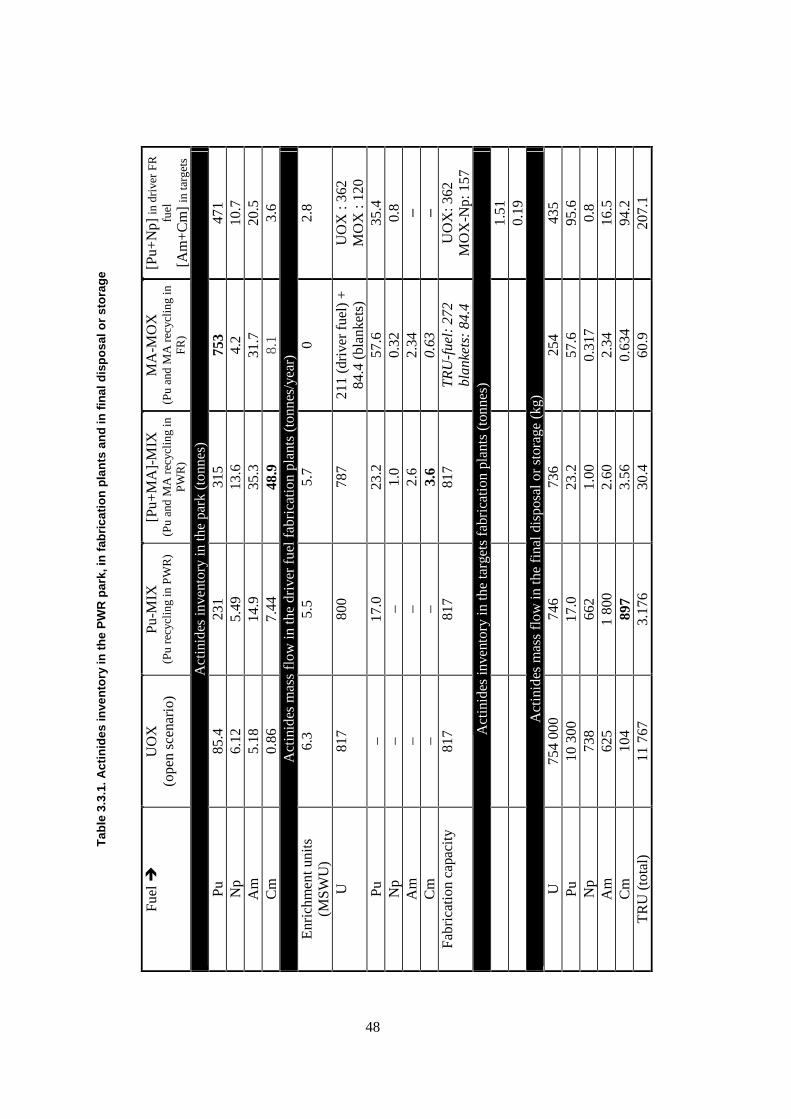
Tab
le 3
.3.1
. Act
inid
es in
ven
tory
in t
he
PW
R p
ark,
in f
abri
cati
on
pla
nts
an
d in
fin
al d
isp
osa
l or
sto
rag
e
Fu
el �
U
OX
(o
pen
scen
ario
) Pu
-MIX
(P
u re
cycl
ing
in P
WR
) [P
u+M
A]-
MIX
(P
u an
d M
A r
ecyc
ling
in
PW
R)
MA
-MO
X
(Pu
and
MA
rec
ycli
ng in
FR
)
[Pu+
Np]
in d
rive
r F
R
fuel
[A
m+
Cm
] in
targ
ets
Act
inid
es in
vent
ory
in th
e pa
rk (
tonn
es)
Pu
85.4
23
1 31
5 75
3 47
1 N
p 6.
12
5.49
13
.6
4.2
10.7
A
m
5.18
14
.9
35.3
31
.7
20.5
C
m
0.86
7.
44
48.9
8.
1 3.
6 A
ctin
ides
mas
s fl
ow in
the
driv
er f
uel f
abri
catio
n pl
ants
(to
nnes
/yea
r)
Enr
ichm
ent u
nits
(M
SWU
) 6.
3 5.
5 5.
7 0
2.8
U
817
800
787
211
(dri
ver
fuel
) +
84
.4 (
blan
kets
) U
OX
: 36
2
MO
X :
120
Pu
– 17
.0
23.2
57
.6
35.4
N
p –
– 1.
0 0.
32
0.8
Am
–
– 2.
6 2.
34
– C
m
– –
3.6
0.63
–
Fabr
icat
ion
capa
city
81
7 81
7 81
7 T
RU
-fue
l: 2
72
blan
kets
: 84
.4
UO
X: 3
62
MO
X-N
p: 1
57
Act
inid
es in
vent
ory
in th
e ta
rget
s fa
bric
atio
n pl
ants
(to
nnes
)
1.51
0.19
A
ctin
ides
mas
s fl
ow in
the
fina
l dis
posa
l or
stor
age
(kg)
U
75
4 00
0 74
6 73
6 25
4 43
5 Pu
10
300
17
.0
23.2
57
.6
95.6
N
p 73
8 66
2 1.
00
0.31
7 0.
8 A
m
625
1 80
0 2.
60
2.34
16
.5
Cm
10
4 89
7 3.
56
0.63
4 94
.2
TR
U (
tota
l)
11 7
67
3.17
6 30
.4
60.9
20
7.1
48
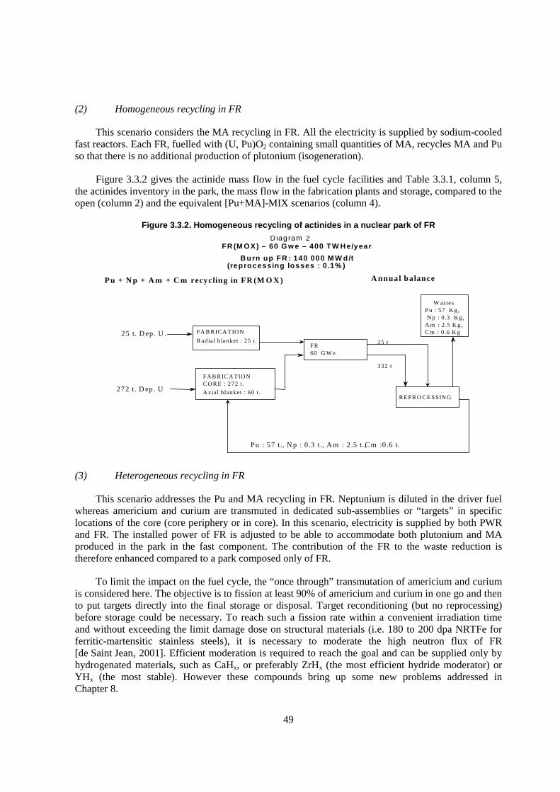
49
(2) Homogeneous recycling in FR
This scenario considers the MA recycling in FR. All the electricity is supplied by sodium-cooled fast reactors. Each FR, fuelled with (U, Pu)O2 containing small quantities of MA, recycles MA and Pu so that there is no additional production of plutonium (isogeneration).
Figure 3.3.2 gives the actinide mass flow in the fuel cycle facilities and Table 3.3.1, column 5, the actinides inventory in the park, the mass flow in the fabrication plants and storage, compared to the open (column 2) and the equivalent [Pu+MA]-MIX scenarios (column 4).
Figure 3.3.2. Homogeneous recycling of actinides in a nuclear park of FR
(3) Heterogeneous recycling in FR
This scenario addresses the Pu and MA recycling in FR. Neptunium is diluted in the driver fuel whereas americium and curium are transmuted in dedicated sub-assemblies or “targets” in specific locations of the core (core periphery or in core). In this scenario, electricity is supplied by both PWR and FR. The installed power of FR is adjusted to be able to accommodate both plutonium and MA produced in the park in the fast component. The contribution of the FR to the waste reduction is therefore enhanced compared to a park composed only of FR.
To limit the impact on the fuel cycle, the “once through” transmutation of americium and curium is considered here. The objective is to fission at least 90% of americium and curium in one go and then to put targets directly into the final storage or disposal. Target reconditioning (but no reprocessing) before storage could be necessary. To reach such a fission rate within a convenient irradiation time and without exceeding the limit damage dose on structural materials (i.e. 180 to 200 dpa NRTFe for ferritic-martensitic stainless steels), it is necessary to moderate the high neutron flux of FR [de Saint Jean, 2001]. Efficient moderation is required to reach the goal and can be supplied only by hydrogenated materials, such as CaHx, or preferably ZrHx (the most efficient hydride moderator) or YHx (the most stable). However these compounds bring up some new problems addressed in Chapter 8.
D iagram 2 FR (M O X) – 60 G w e – 400 TW H e/year
B urn up FR : 140 000 M W d/t (reprocessing losses : 0 .1% )
P u + N p + A m + C m recycling in FR (M O X ) A nnual balance
FA B R IC A T IO N C O R E : 272 t. A xial b lanket : 60 t.
FR 60 G W e
25 t
R E PR O C E SSIN G
W astes P u : 57 K g, N p : 0 .3 K g,
A m : 2.5 K g, C m : 0 .6 K g
Pu : 57 t., N p : 0 .3 t., A m : 2 .5 t., C m :0 .6 t.
272 t. D ep. U
332 t
FA B R IC A T IO N R adial b lanket : 25 t.
25 t. D ep. U .
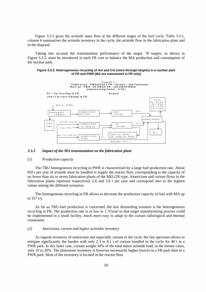
50
Figure 3.3.3 gives the actinide mass flow at the different stages of the fuel cycle. Table 3.3.1, column 6 summarises the actinide inventory in the cycle, the actinide flow in the fabrication plant and in the disposal.
Taking into account the transmutation performance of the target: 78 targets, as shown in Figure 3.3.5, must be introduced in each FR core to balance the MA production and consumption of the nuclear park.
Figure 3.3.3. Heterogeneous recycling of Am and Cm (once-through targets) in a nuclear park of FR and PWR (MA are transmuted in FR only)
3.3.3 Impact of the MA transmutation on the fabrication plant
(1) Production capacity
The TRU homogeneous recycling in PWR is characterised by a large fuel production rate. About 820 t per year of actinide must be handled to supply the reactor fleet, corresponding to the capacity of no fewer than six to seven fabrication plants of the MELOX-type. Americium and curium flows in the fabrication plants represent respectively 2.6 and 3.6 t per year and correspond also to the highest values among the different scenarios.
The homogeneous recycling in FR allows to decrease the production capacity of fuel with MA up to 357 t/y.
As far as TRU-fuel production is concerned, the less demanding scenario is the heterogeneous recycling in FR. The production rate is as low as 1.7t/year so that target manufacturing process could be implemented in a small facility, much more easy to adapt to the curium radiological and thermal constraints.
(2) Americium, curium and higher actinides inventory
As regards inventory of americium and especially curium in the cycle, the fast spectrum allows to mitigate significantly the burden with only 2.3 to 8.1 t of curium handled in the cycle for 49 t in a PWR park. In this latter case, curium weighs 50% of the total minor actinide load, in the former cases, only 10 to 20%. The plutonium inventory is however necessarily higher (twice) in a FR park than in a PWR park. Most of the inventory is located in the reactor fleet.
D ia g ra m 3 P A R K m ix te : P W R ( U O X ) + F R – 6 0 G w e – 4 0 0 T w h e /y e a r
B u rn u p : P W R : 6 0 G W d /t , F R : 1 4 0 G W d /t M W j/t ( r e p r o c e s s in g lo s s e s : 0 .1 % )
P u + N p r e c y c l in g in F R A n n u a l b a la n c e (A m + C m ) o n c e t r h o u g h in F R
E N R I C H M E N T 2 .8 M S W U
F A B R I C A T I O N 3 6 2 t U O X
F A B R I C A T I O N 1 5 7 t M O X F R
F A B R I C A T I O N T a r g e ts
P W R 2 6 .6 G W e
F R 3 3 .4 G W e
3 6 2 t
1 5 7 t
T a rg e ts : P u : 6 0 K g , A m : 1 5 K g , C m : 9 4 K g
0 .8 t N p , 3 5 .4 t P u
A m : 1 .5 1 t C m : 0 .2 t
N a t . U : 3 7 6 0 t .
R E P R O C E S S I N G
W a s te s P u : 3 5 .6 K g , N p : 0 .8 K g ,
A m : 1 .5 K g , C m : 0 . 2 K g
U 4 3 5 t .
U a p .: 1 2 0 t .
D e p .U
3 3 9 8 t .
R e je c t io n s : 0 .1 7 t .
51
Another specific issue of TRU incineration in thermal spectrum is the formation of higher actinides. Among them, the presence of californium 252 is the most penalising for the fuel cycle (practically, the californium should be extracted with the americium and curium during the separation process and then recycled with them) since its spontaneous fission rate is very high (1012 n.g-1.s-1). 252Cf accumulates from one cycle to the other. After 11 recycles its content is not yet stabilised and reaches about 0.4 g/sub-assembly. Despite this very low content, additional difficulties at the fabrication stage are expected and will be discussed in the next paragraph. In a fast spectrum, 252Cf production is negligible: less than 10 µg/sub-assembly is calculated for the homogeneous recycling in FR.
(3) Enrichment capacity
Compared to the open scenario, the recycle scenarios lead to decrease the enrichment units, because of the plutonium balancing. MA transmutation does not increase significantly the enrichment units once Pu is recycled (see values calculated for Pu-MIX and [Pu+MA]-MIX). The small difference is due to the neutron absorption of the minor actinides.
Recycling in fast spectrum allows to save much more uranium resources than in thermal spectrum. A gain of a factor 2 or 3 is calculated when the U flow needed for the MA homogeneous or heterogeneous transmutation in FR is compared to that for homogeneous recycling in PWR.
(4) Radiological impact
The activity, decay heat, and neutron source at the TRU fuel or target fabrication stage are compared for the different scenarios in Table 3.3.2. Values are given per tonne of initial heavy atoms. Additional informative data are given as regards “standard” fabrication of MOX fuel for PWR or for FR. In this table the standard PWR fuel is assumed to be a mixed U and Pu oxide containing up to 12% of plutonium. This is the current limit of Pu content for the French MELOX plant. The standard fuel for FR is a mixed oxide containing 19.9% of plutonium.
Impact of the MA transmutation is significant at the fabrication stage whatever the recycling mode and concerns essentially the decay heat and the neutron source.
Thermal load in the fabrication facility is increased by a factor of 15 when 0.9% of MA is introduced in the MIX fuel and a factor of 6 when 1.21% of MA is introduced in the MOX fuel. The effect reaches its peak with MA targets because of the MA concentration with a factor of 185 compared to a MOX fuel for FR. This is the consequence of heat released by curium, 28 times higher (2.8 W/g) than that released by americium.
Continuous and forced cooling system everywhere in the plant (from the process head-end to the assembly storage or during the transport) will have therefore to be mastered [Pillon, 2002]. No industrial experience is available today to manage such a constraint.
As regards the neutron source, effect is more sensitive for PWR fuel than for FR fuel because of the californium and curium accumulation in the cycle. Neutron source is 7 915 times higher for a fabrication facility of MIX containing MA than of MOX fuel containing 12% of plutonium and 1.5 time higher than for a target fabrication facility. Hot cells with thick concrete walls and remote handling is therefore necessary making much more difficult the processing.
To be noted that the criticality issue, not analysed in this report, is also to be taken into account during manufacturing, storage and transport.
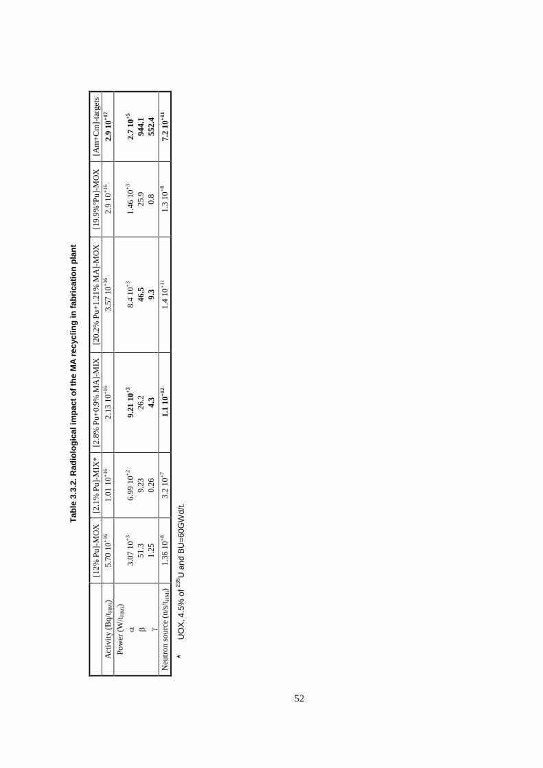
T
able
3.3
.2. R
adio
log
ical
imp
act
of
the
MA
rec
yclin
g in
fab
rica
tio
n p
lan
t
[1
2% P
u]-M
OX
[2
.1%
Pu]
-MIX
* [2
.8%
Pu+
0.9%
MA
]-M
IX
[20.
2% P
u+1.
21%
MA
]-M
OX
[1
9.9%
°Pu]
-MO
X
[Am
+C
m]-
targ
ets
Act
ivit
y (B
q/t H
Mi)
5.70
10+
16
1.01
10+
16
2.13
10+
16
3.57
10+
16
2.9
10+
16
2.9
10+1
7 Po
wer
(W
/tH
Mi)
� � �
3.
07 1
0+3
51.3
1.
25
6.
99 1
0+2
9.23
0.
26
9.
21 1
0+3
26.2
4.
3
8.
4 10
+3
46.5
9.
3
1.
46 1
0+3
25.9
0.
8
2.
7 10
+5
944.
1 55
2.4
Neu
tron
sou
rce
(n/s
/tH
Mi)
1.36
10+
8 3.
2 10
+7
1.1
10+1
2 1.
4 10
+11
1.
3 10
+8
7.2
10+1
1
* U
OX
, 4.5
% o
f 235 U
and
BU
=60
GW
d/t.
52
53
(5) Impact on processing
The heat load and the neutron source impose the implementation of the fabrication process in hot cells behind thick concrete or water shields and the continuous forced cooling of the process line, from the conversion step to the assembly mounting and also during the transport and the handling in the reactor facility [Pillon, 2003]. Process compaction to limit volume and number of cells, process simplification to facilitate the equipment maintenance, process cleanliness to reduce as much as possible the volume of liquid and solid waste contaminated with curium and californium as well as the auxiliary facilities for the secondary waste treatments are therefore objectives of the greatest importance to balance the technological and economical impact of the transmutation.
Consequences on the fuel or target design could be significant. In contrast to standard UO2 or MOX fuel, fuel design sophistication to increase performance in pile is a secondary priority.
As regards the homogeneous transmutation in PWR, the large quantity of transmutation fuel to be fabricated (820 t) as well as the fuel design constraints to be taken into account to reach parity between TRU-MIX and standard fuel makes this scenario unrealistic. Some scenario optimisation could however be proposed by increasing the TRU content in the fuel and reducing the MIX loading in the nuclear park while keeping sufficient reactor safety margins.
Transmutation in FR meets much easily the requirements as regards the fabrication process. Mass flows are less important and even extremely low when heterogeneous recycling is concerned. Furthermore, significant process simplification could be reached by using vibropacking as an alternative process to pellet technology (see §4.3). Pins are loaded directly with granulates or microspheres and compacted by gentle vibration to reach the target smear density. Smear density of 85-92% can be usually achieved by selecting appropriately sized particles fraction. This process has been used in Russia for (U, Pu)O2 fuels. It is well suited to fast neutron reactors since a high operating temperature is required for in-pile sintering of the particles. In addition to the suppression of operations (granulation, pressing, sintering) the vibropacking process has several advantages over pelletisation. In particular pelletisation introduces a series of additional specifications to be controlled and verified (e.g. density, diameter, height, visual aspect, microstructure, homogeneity, etc.) These controls may be eliminated and replaced by less intensive means on welded fuel pins, i.e. controling the actinide and density distribution. These controls are considerably easier and cleaner to perform and allow to decrease process scraps.
The preparation of particles directly from the Am and Cm solution is the key step in the vibropacking process. The liquid-solid conversion phase should allow the direct fabrication of the granulates or microspheres with the targeted composition and size, but could also include the co-precipitation of the inert matrix to avoid the segregation issue in the vibropacking step. Different routes could be considered to synthesize the particles to be loaded directly in the pins. In aqueous media they are:
� co-precipitation or gelation via hydroxide route;
� co-precipitation, via oxalate, formiate or other organo-metallic compounds;
� the infiltration process.
and in molten alkali chloride melts :
� fractional precipitation of oxide (Am, Cm);
� preliminary electrodeposition of metal (Am, Cm) in liquid metallic cathode followed by the removal of the metallic solvent and an oxidation step.
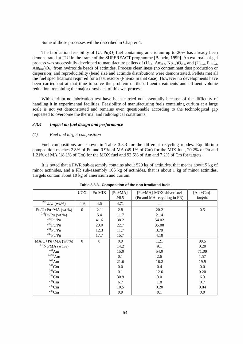
54
Some of those processes will be described in Chapter 4.
The fabrication feasibility of (U, Pu)O2 fuel containing americium up to 20% has already been demonstrated at ITU in the frame of the SUPERFACT programme [Babelo, 1999]. An external sol-gel process was successfully developed to manufacture pellets of (U0.6, Am0.2, Np0.2)O2-x, and (U0.74, Pu0.24, Am0.02)O2-x from hydroxide beads of actinides. Process cleanliness (no contaminant dust production or dispersion) and reproducibility (bead size and actinide distribution) were demonstrated. Pellets met all the fuel specifications required for a fast reactor (Phénix in that case). However no developments have been carried out at that time to solve the problem of the effluent treatments and effluent volume reduction, remaining the major drawback of this wet process.
With curium no fabrication test have been carried out essentially because of the difficulty of handling it in experimental facilities. Feasibility of manufacturing fuels containing curium at a large scale is not yet demonstrated and remains even questionable according to the technological gap requested to overcome the thermal and radiological constraints.
3.3.4 Impact on fuel design and performance
(1) Fuel and target composition
Fuel compositions are shown in Table 3.3.3 for the different recycling modes. Equilibrium composition reaches 2.8% of Pu and 0.9% of MA (49.1% of Cm) for the MIX fuel, 20.2% of Pu and 1.21% of MA (18.1% of Cm) for the MOX fuel and 92.6% of Am and 7.2% of Cm for targets.
It is noted that a PWR sub-assembly contains about 520 kg of actinides, that means about 5 kg of minor actinides, and a FR sub-assembly 105 kg of actinides, that is about 1 kg of minor actinides. Targets contain about 10 kg of americium and curium.
Table 3.3.3. Composition of the non irradiated fuels
UOX Pu-MIX [Pu+MA]-MIX
[Pu+MA]-MOX driver fuel (Pu and MA recycling in FR)
[Am+Cm]-targets
235U/U (wt.%) 4.9 4.5 4.71 –
Pu/U+Pu+MA (wt.%) 238Pu/Pu (wt.%)
239Pu/Pu 240Pu/Pu 241Pu/Pu 242Pu/Pu
0 2.1 5.4
41.6 23.0 12.3 17.7
2.8 11.7 38.2 22.7 11.7 15.7
20.2 2.14
54.02 35.88 3.79 4.18
0.5
MA/U+Pu+MA (wt.%) 237Np/MA (wt.%)
241Am 242mAm 243Am 242Cm 243Cm 244Cm 245Cm 246Cm 247Cm
0 0 0.9 14.2 15.0 0.1
21.6 0.0 0.1
30.9 6.7
10.5 0.9
1.21 9.1
54.0 2.6
16.2 0.4
12.6 3.0 1.8
0.20 0.1
99.5 0.20
71.09 1.57 19.9 0.0
0.20 6.3 0.7
0.04 0.0
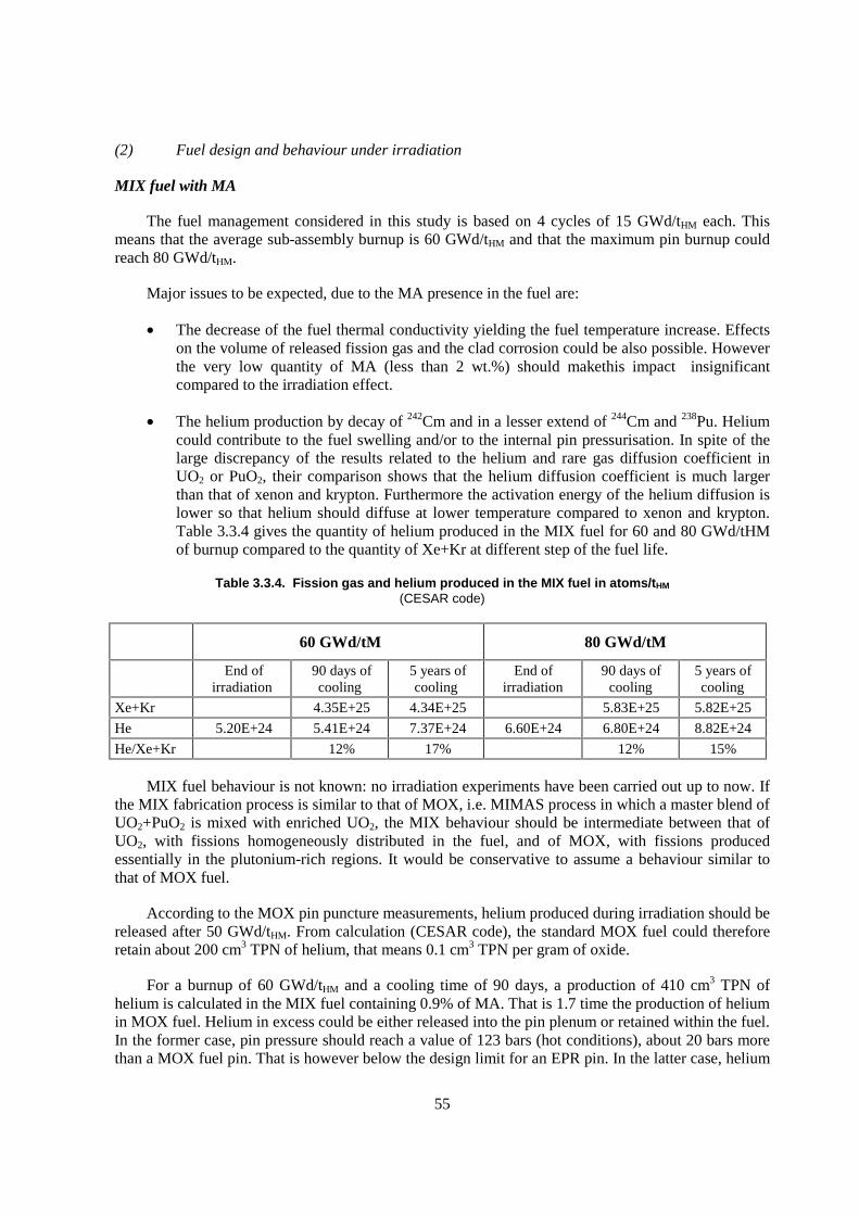
55
(2) Fuel design and behaviour under irradiation
MIX fuel with MA
The fuel management considered in this study is based on 4 cycles of 15 GWd/tHM each. This means that the average sub-assembly burnup is 60 GWd/tHM and that the maximum pin burnup could reach 80 GWd/tHM.
Major issues to be expected, due to the MA presence in the fuel are:
� The decrease of the fuel thermal conductivity yielding the fuel temperature increase. Effects on the volume of released fission gas and the clad corrosion could be also possible. However the very low quantity of MA (less than 2 wt.%) should makethis impact insignificant compared to the irradiation effect.
� The helium production by decay of 242Cm and in a lesser extend of 244Cm and 238Pu. Helium could contribute to the fuel swelling and/or to the internal pin pressurisation. In spite of the large discrepancy of the results related to the helium and rare gas diffusion coefficient in UO2 or PuO2, their comparison shows that the helium diffusion coefficient is much larger than that of xenon and krypton. Furthermore the activation energy of the helium diffusion is lower so that helium should diffuse at lower temperature compared to xenon and krypton. Table 3.3.4 gives the quantity of helium produced in the MIX fuel for 60 and 80 GWd/tHM of burnup compared to the quantity of Xe+Kr at different step of the fuel life.
Table 3.3.4. Fission gas and helium produced in the MIX fuel in atoms/tHM (CESAR code)
60 GWd/tM 80 GWd/tM
End of irradiation
90 days of cooling
5 years of cooling
End of irradiation
90 days of cooling
5 years of cooling
Xe+Kr 4.35E+25 4.34E+25 5.83E+25 5.82E+25
He 5.20E+24 5.41E+24 7.37E+24 6.60E+24 6.80E+24 8.82E+24
He/Xe+Kr 12% 17% 12% 15%
MIX fuel behaviour is not known: no irradiation experiments have been carried out up to now. If the MIX fabrication process is similar to that of MOX, i.e. MIMAS process in which a master blend of UO2+PuO2 is mixed with enriched UO2, the MIX behaviour should be intermediate between that of UO2, with fissions homogeneously distributed in the fuel, and of MOX, with fissions produced essentially in the plutonium-rich regions. It would be conservative to assume a behaviour similar to that of MOX fuel.
According to the MOX pin puncture measurements, helium produced during irradiation should be released after 50 GWd/tHM. From calculation (CESAR code), the standard MOX fuel could therefore retain about 200 cm3 TPN of helium, that means 0.1 cm3 TPN per gram of oxide.
For a burnup of 60 GWd/tHM and a cooling time of 90 days, a production of 410 cm3 TPN of helium is calculated in the MIX fuel containing 0.9% of MA. That is 1.7 time the production of helium in MOX fuel. Helium in excess could be either released into the pin plenum or retained within the fuel. In the former case, pin pressure should reach a value of 123 bars (hot conditions), about 20 bars more than a MOX fuel pin. That is however below the design limit for an EPR pin. In the latter case, helium
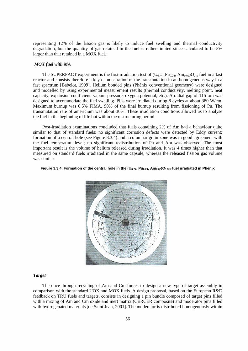
56
representing 12% of the fission gas is likely to induce fuel swelling and thermal conductivity degradation, but the quantity of gas retained in the fuel is rather limited since calculated to be 5% larger than that retained in a MOX fuel.
MOX fuel with MA
The SUPERFACT experiment is the first irradiation test of (U0.74, Pu0.24, Am0.02)O2-x fuel in a fast reactor and consists therefore a key demonstration of the transmutation in an homogeneous way in a fast spectrum [Babelot, 1999]. Helium bonded pins (Phénix conventional geometry) were designed and modelled by using experimental measurement results (thermal conductivity, melting point, heat capacity, expansion coefficient, vapour pressure, oxygen potential, etc.). A radial gap of 115 µm was designed to accommodate the fuel swelling. Pins were irradiated during 8 cycles at about 380 W/cm. Maximum burnup was 6.5% FIMA, 90% of the final burnup resulting from fissioning of Pu. The transmutation rate of americium was about 30%. These irradiation conditions allowed us to analyse the fuel in the beginning of life but within the restructuring period.
Post-irradiation examinations concluded that fuels containing 2% of Am had a behaviour quite similar to that of standard fuels: no significant corrosion defects were detected by Eddy current; formation of a central hole (see Figure 3.3.4) and a columnar grain zone was in good agreement with the fuel temperature level; no significant redistribution of Pu and Am was observed. The most important result is the volume of helium released during irradiation. It was 4 times higher than that measured on standard fuels irradiated in the same capsule, whereas the released fission gas volume was similar.
Figure 3.3.4. Formation of the central hole in the (U0.74, Pu0.24, Am0.02)O1.957 fuel irradiated in Phénix
Target
The once-through recycling of Am and Cm forces to design a new type of target assembly in comparison with the standard UOX and MOX fuels. A design proposal, based on the European R&D feedback on TRU fuels and targets, consists in designing a pin bundle composed of target pins filled with a mixing of Am and Cm oxide and inert matrix (CERCER composite) and moderator pins filled with hydrogenated materials [de Saint Jean, 2001]. The moderator is distributed homogenously within
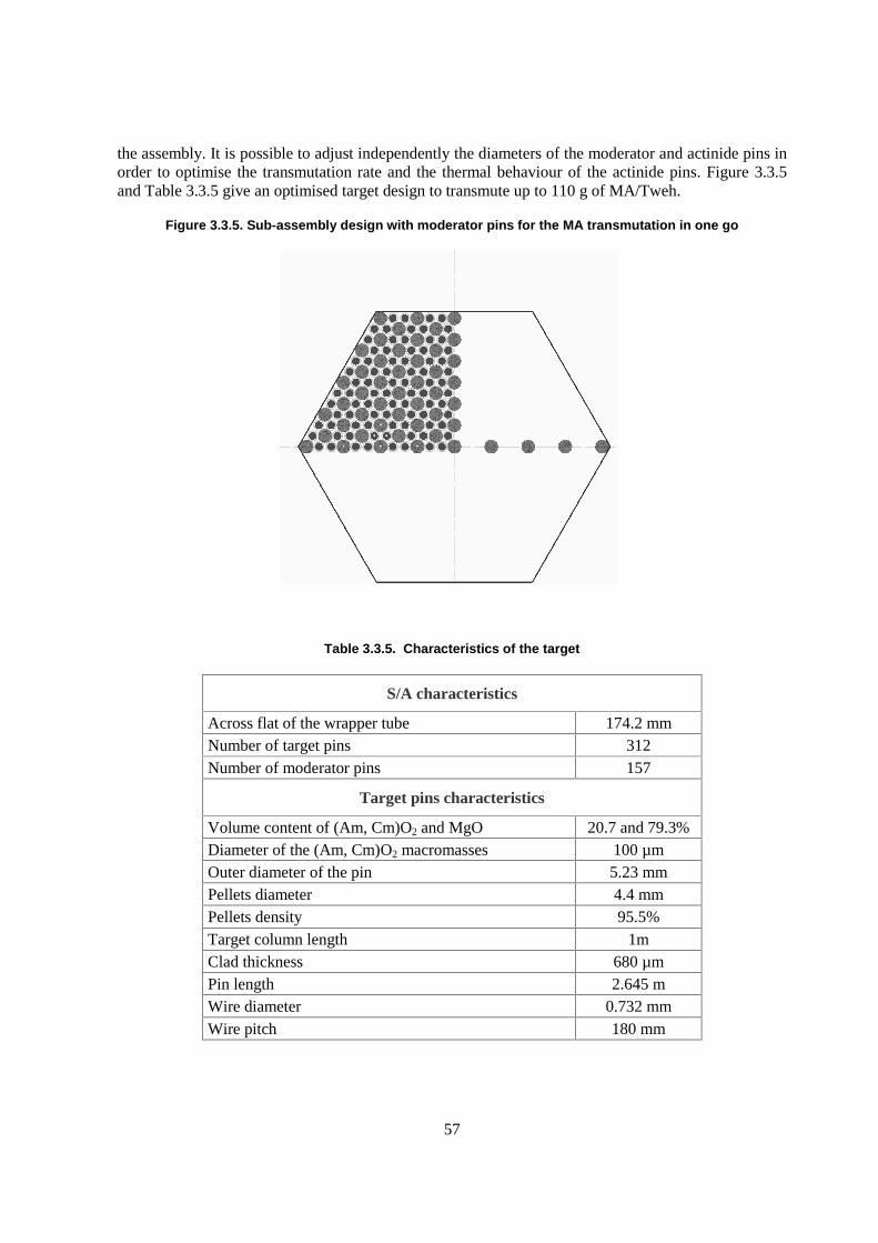
57
the assembly. It is possible to adjust independently the diameters of the moderator and actinide pins in order to optimise the transmutation rate and the thermal behaviour of the actinide pins. Figure 3.3.5 and Table 3.3.5 give an optimised target design to transmute up to 110 g of MA/Tweh.
Figure 3.3.5. Sub-assembly design with moderator pins for the MA transmutation in one go
Table 3.3.5. Characteristics of the target
S/A characteristics
Across flat of the wrapper tube 174.2 mm Number of target pins 312 Number of moderator pins 157
Target pins characteristics
Volume content of (Am, Cm)O2 and MgO 20.7 and 79.3% Diameter of the (Am, Cm)O2 macromasses 100 µm Outer diameter of the pin 5.23 mm Pellets diameter 4.4 mm Pellets density 95.5% Target column length 1m Clad thickness 680 µm Pin length 2.645 m Wire diameter 0.732 mm Wire pitch 180 mm
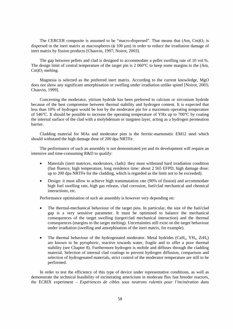
58
The CERCER composite is assumed to be “macro-dispersed”. That means that (Am, Cm)O2 is dispersed in the inert matrix as macrospheres (� 100 µm) in order to reduce the irradiation damage of inert matrix by fission products [Chauvin, 1997; Noirot, 2003].
The gap between pellets and clad is designed to accommodate a pellet swelling rate of 10 vol.%. The design limit of central temperature of the target pin is 2 060°C to keep some margins to the (Am, Cm)O2 melting.
Magnesia is selected as the preferred inert matrix. According to the current knowledge, MgO does not show any significant amorphisation or swelling under irradiation unlike spinel [Noirot, 2003; Chauvin, 1999].
Concerning the moderator, yttrium hydride has been preferred to calcium or zirconium hydride because of the best compromise between thermal stability and hydrogen content. It is expected that less than 10% of hydrogen would be lost by the moderator pin for a maximum operating temperature of 546°C. It should be possible to increase the operating temperature of YHx up to 700°C by coating the internal surface of the clad with a molybdenum or tungsten layer, acting as a hydrogen permeation barrier.
Cladding material for MAs and moderator pins is the ferritic-martensitic EM12 steel which should withstand the high damage dose of 200 dpa NRTFe.
The performance of such an assembly is not demonstrated yet and its development will require an intensive and time-consuming R&D to qualify:
� Materials (inert matrices, moderators, clads): they must withstand hard irradiation condition (fast fluence, high temperature, long residence time: about 2 565 EFPD, high damage dose: up to 200 dpa NRTFe for the cladding, which is regarded as the limit not to be exceeded).
� Design: it must allow to achieve high transmutation rate (90% of fission) and accommodate high fuel swelling rate, high gas release, clad corrosion, fuel/clad mechanical and chemical interactions, etc.
Performance optimisation of such an assembly is however very depending on:
� The thermal-mechanical behaviour of the target pins. In particular, the size of the fuel/clad gap is a very sensitive parameter. It must be optimised to balance the mechanical consequences of the target swelling (target/clad mechanical interaction) and the thermal consequences (margins to the target melting). Uncertainties still exist on the target behaviour under irradiation (swelling and amorphisation of the inert matrix, for example).
� The thermal behaviour of the hydrogenated moderator. Metal hydrides (CaHx, YHx, ZrHx) are known to be pyrophoric, reactive towards water, fragile and to offer a poor thermal stability (see Chapter 8). Furthermore hydrogen is mobile and diffuses through the cladding material. Selection of internal clad coatings to prevent hydrogen diffusion, comparison and selection of hydrogenated materials, strict control of the moderator temperature are still to be performed.
In order to test the efficiency of this type of device under representative conditions, as well as demonstrate the technical feasibility of incinerating americium in moderate flux fast breeder reactors, the ECRIX experiment – Expériences de cibles sous neutrons ralentis pour l’incinération dans
59
Phénix1 – was launched in 1998. This experiment included ECRIX B and ECRIX H irradiation tests, whose aims were identical. The samples are composed of americium micro-dispersed in a magnesia matrix [Gaillard, 2003]. Target diameter was 5.25 mm, conforming to design studies of the target assembly. The experimental stacks were 200 mm high and contained approximately 2.75 g of americium.
The neutron flux is moderated by the assemblies carrying fuel pins. Two assemblies of this type – called DMC1 and DMC2 (Dispositif d’irradiation et de mesures en pile modéré à canal central)2 were designed and fabricated for the Phénix reactor (see Figure 3.3.6).
Figure 3.3.6. DMC1 and DMC2 devices for moderate irradiation in Phénix
1. Targets subjected to slow neutrons for incineration experiments in Phénix.
2. Moderate in-pile irradiation and measurement device with central fuel channel.
60
A boron carbide moderator (B4C) was used in the DMC1 assembly. This moderator was designed in reference to “control rod” technology which boasts a great amount of in-pile experimental feedback.
The DMC2 experiment was designed to implement a more efficient hydride-type moderator. Calcium hydride was employed due to its availability and ease with which it can be fabricated on the one hand, and the available feedback acquired by the CEA thanks to the production of cobalt 60 in a moderated environment in the Phénix core radial blankets on the other hand.
These devices were approved by the Safety Authority in March 2003 and are currently loaded in the Phénix reactor. Experiment feedback should be available from 2006.
3.3.5 Conclusion
The TRU homogeneous recycling in a PWR nuclear park seems to be possible from a technological point of view provided that MOX fuel with enriched uranium is used as support of MA. Compared to the open cycle, the radiotoxicity reduction factor reaches 150 after 500 years, date from which the radio toxicity of the waste is equivalent to that of the natural uranium needed for the energy production of the nuclear park. Such a performance requires reprocessing losses limited to 0.1% of the actinides.
The major drawback of such a scenario is at the fabrication stage. All the fabrication process (in principle, MIMAS process) must be implemented in hot cells since the fuel � activity and especially the neutron emission are much higher than those of MOX fuel. Curium but especially californium, which accumulates from one cycle to the other and should follow the Am and Cm stream, are the major contributors to these activities. Combined with the high mass flow to be manufactured (about 820t, i.e. 6 to 7 MELOX-type plants), that makes this scenario unrealistic from an economical point of view.
To limit the impact of the MA management to a smaller quantity of MIX fuel and consequently to a lower number of fabrication plants, an optimised scenario involving MIX fuel with high Pu and MA content would deserve to be assessed.
The actinides homogeneous recycling in FR is possible and allows to reduce the waste mass flow of about 150 to 450 and the waste radiotoxicity of about 200 to 500 within 500 years. By comparison to the homogeneous recycling in PWR, the advantage of such a scenario is to decrease the Cm inventory and to avoid the californium accumulation in the fuel cycle facilities. Nevertheless, it does not solve the problem of the high neutron source and decay heat at the fabrication stage, which is inherent to the curium whatever the recycle scenario. Despite a very low content of MAs, consequences on the fabrication plant are significant in terms of radioprotection measure and process adaptation. Apart from the shielding requirements, various processes would require additional engineering innovation for simplification and automation.
61
REFERENCES
Section 3.1
Eriksson, M. et al. (2002), Proceedings 3rd Int. Workshop on Utilisation and Reliability of High Power Proton Accelerators, Santa Fe, OECD, Paris.
Garner, F., M.B. Toloczko, B.H. Sencer (2000), J. Nuc. Mat., 276, 123.
Jolkkonen, M., M. Streit, J. Wallenius (2003), J. Nuc. Sci. Tech.
Murata, H., T. Mukaiyama (1984), Atomkernergie-Kerntechnik, 45, 23.
Cometto, M., B.C. Na, P. Wydler (2001), Comparaison Calculation for an Accelerator-driven Minor Actinide Burner, NEA/NSC/DOC(2001)13, OECD, Paris, 223 p.
Salvatores, M. (1997), Nucl. Inst. Meth. A 414, 5.
Seltborg, P. et al. (2003), Nucl. Sci. Eng. 145.
Smith, P. (2003), minutes of 5th FUTURE meeting, CEA, Paris.
Takizuka, T. et al. (1999), Proc. 5th IEM, EUR 18898 EN, OECD, Paris, p. 383.
Wallenius, J. (2003), J. Nucl. Mat. 320, 142.
Section 3.3
Babelot, J.F. et al., Joint CEA/ITU synthesis report of the experiment SUPERFACT 1, JRC-ITU-TN-99/03.
Chauvin, N. et al. (1999), “In pile studies of inert matrices with emphasis on magnesia and spinel”, J. Nucl. Mater. 274, pp. 91-97.
Chauvin, N. et al. (1997), Neutronic and fuel studies for americium target design, GLOBAL’97 proceedings, 5-10 October 1997, Yokohama, Japan.
Gaillard, G. et al. (2003), PHENIX irradiation programme on fuels and targets for transmutation, GLOBAL’03 proceedings, 16-20 November 2003, New-Orleans, Louisiana.
Grouiller, J.P. et al. (2003), “Minor actinides transmutation scenario studies with PWRs, FRs and moderated targets”, J. Nucl. Mater. 320 (2003) 163-169.
Grouiller, J.P. et al. (2001), Waste transmutation scenarios with accessible technology, GLOBAL’01 proceedings, Versailles, France, 9-13 September 2001.
62
Noirot, J. et al. (2003), “Post-irradiation examinations of THERMHET composite fuels for transmutation”, J. Nucl. Mater. 320 (2003) 117-125.
Pillon, S. et al. (2003), “Aspects of fabrication of curium-based fuels and targets”, J. Nucl. Mater, 320, 36-43.
Pillon, S. et al. (2002), Impact of the Curium management on the fabrication of MA-bearing targets at an industrial scale in the frame of a mixed PWR and FR P&T scenario, 7th Information Exchange Meeting on Actinide and Fission Product Partitioning and Transmutation, 14-16 October 2002, Jeju, Korea, OECD, Paris.
de Saint Jean, C. et al. (2001), “Americium and Curium heterogeneous transmutation in moderated S/A in the framework of CNE transmutation scenario studies”, GLOBAL’01 proceedings, 9-13 September 2001, Versailles, France.
63
Appendix 3.1
CALCULATION HYPOTHESES AND METHODS
A. Calculation codes and methods
Studies are based on:
� JEF2 nuclear data.
� CEA neutronic calculation codes: APOLLO2, ECCO, ERANOS, DARWIN and MECCYCO.
� radiotoxicity calculation code: DECLINE.
B. Reactor data
1. PWR
Reactor type: EPR-1450 MWe.
Fuel burnup: 60 GWd/tHM.
Fuel re-loading: ¼ of the core every 18 months.
2. FR
Reactor type: EFR-1450 MWe, iso-generation of Pu provided by radial and axial fertile blankets.
Fuel burnup: 140 GWd/t.
Fuel re-loading: 1/5 of the core every 340 EFPD.
Irradiation time: 1 700 EFPD for driver S/As and 5 100 EFPD for blankets S/As.

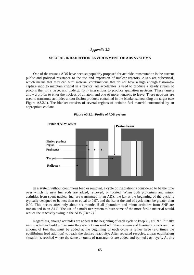
65
Appendix 3.2
SPECIAL IRRADIATION ENVIRONMENT OF ADS SYSTEMS
One of the reasons ADS have been so popularly proposed for actinide transmutation is the current public and political resistance to the use and expansion of nuclear reactors. ADSs are subcritical, which means that they can burn material combinations that do not have a high enough fission-to-capture ratio to maintain critical in a reactor. An accelerator is used to produce a steady stream of protons that hit a target and undergo (p,n) interactions to produce spallation neutrons. These targets allow a proton to enter the nucleus of an atom and one or more neutrons to leave. These neutrons are used to transmute actinides and/or fission products contained in the blanket surrounding the target (see Figure A3.2.1). The blanket consists of several regions of actinide fuel material surrounded by an appropriate coolant.
Figure A3.2.1. Profile of ADS system
In a system without continuous feed or removal, a cycle of irradiation is considered to be the time over which no new fuel rods are added, removed, or rotated. When both plutonium and minor actinides from spent nuclear fuel are transmuted in an ADS, the keff at the beginning of the cycle is typically designed to be less than or equal to 0.97, and the keff at the end of cycle must be greater than 0.90. This occurs after only about six months if all plutonium and minor actinides from SNF are transmuted in an ADS. The use of a multi-tier system to burn some of the more fissile material would reduce the reactivity swing in the ADS (Tier 2).
Regardless, enough actinides are added at the beginning of each cycle to keep keff at 0.97. Initially minor actinides build up because they are not removed with the uranium and fission products and the amount of fuel that must be added at the beginning of each cycle is rather large (2-3 times the equilibrium feed addition) to reach the desired reactivity. After repeated recycles, a near equilibrium situation is reached where the same amounts of transuranics are added and burned each cycle. At this
Proton beam
Target
Reflector
Fission product region
Fuel zones
Profile of ATW system
66
point, about 1 kg/day of the cycle must be added for each GWt of power produced by the system. If at least some of the fissile plutonium is transmuted in a LWR instead, the reactivity swing per cycle would decrease because the resulting mixture of material sent to an ADS would have a lower fission-to-capture ratio and equilibrium conditions would be reached faster. In either case, if equilibrium operation is assumed, total destruction rates in an ADS could be as high as 99.9% assuming very efficient separations processes exist.
Target design
Several different types of targets for ADSs have been examined. The most popular target currently proposed for ADSs is lead-bismuth eutectic (LBE) because of its large production rate along with internal cooling capabilities (it is a liquid target) [Trellue, 2000]. Water-cooled tungsten, tantalum, liquid mercury, and lead targets have been examined as well [Pitcher, 1997; Bultman, 1995; Bowman, 1998; ORNL, 2000; LANL, 2000]. One of the issues addressed in designing accelerator-driven systems involves maximisation of spallation neutron production. This depends on both the target material and the placement of the target with respect to the blanket. It is assumed for the studies presented here that the target is cylindrical and is located in the middle of the system, and the beam enters it from the top (although it also can enter from the bottom or side). The target is bombarded with up to a 1 GeV proton beam and creates about 20-30 spallation neutrons per proton. Some of these neutrons are captured in the actinides or other materials in the system; others go on to produce fissions (and subsequent chain reactions), which attribute to about 400 fissions per source proton with a keff � 0.97 [Bowman, 1998]. To produce a 840 MWt system, the required proton current is ~13 mA, as given in Equation (1) at the same value of keff. If keff drops to 0.94 at the end of a cycle, the required proton beam current doubles (i.e. at a keff of 0.94, the current is 26 mA). Larger reactivity swings see even larger current requirements.
I = � * P * 1.602 x 10⁻¹⁹ C/p, (1) S * keff/(1-keff) * Qave
where:
I = the beam current (amps);
� = the average number of neutrons produced per fission (~2.9);
P = the power defined by user for each material = 840 MWt;
S = the number of neutrons leaking from the target into the blanket (���� ���������neutrons/source proton);
keff = the effective multiplication factor obtained by MCNP = 0.97;
keff/(1-keff) = the number of fission neutrons to number of spallation neutrons because the number of fission neutrons + the number of spallation neutrons must = 1.0; and
Qave = the average recoverable energy released per fission (~200 MeV, or 3.2 x 10⁻¹¹ J).
Blankets
There are two main types of blankets that can be used in an ADS, and like reactors, they are distinguished by the average neutron energy in each. Previous ADS studies for transmutation focused on the use of a molten salt thermal spectrum system which allowed the continuous feed of actinide material and removal of fission products and a constant value of keff [Bowman, 1998]. However
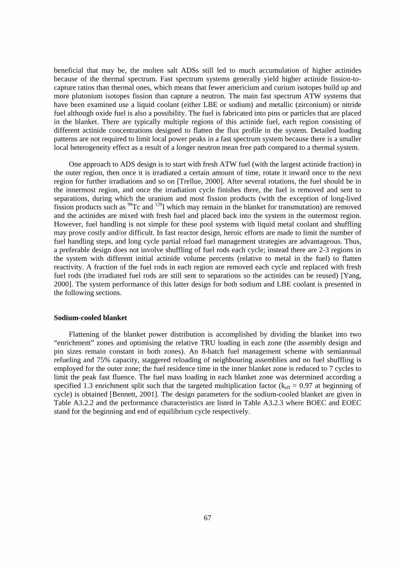
67
beneficial that may be, the molten salt ADSs still led to much accumulation of higher actinides because of the thermal spectrum. Fast spectrum systems generally yield higher actinide fission-to-capture ratios than thermal ones, which means that fewer americium and curium isotopes build up and more plutonium isotopes fission than capture a neutron. The main fast spectrum ATW systems that have been examined use a liquid coolant (either LBE or sodium) and metallic (zirconium) or nitride fuel although oxide fuel is also a possibility. The fuel is fabricated into pins or particles that are placed in the blanket. There are typically multiple regions of this actinide fuel, each region consisting of different actinide concentrations designed to flatten the flux profile in the system. Detailed loading patterns are not required to limit local power peaks in a fast spectrum system because there is a smaller local heterogeneity effect as a result of a longer neutron mean free path compared to a thermal system.
One approach to ADS design is to start with fresh ATW fuel (with the largest actinide fraction) in the outer region, then once it is irradiated a certain amount of time, rotate it inward once to the next region for further irradiations and so on [Trellue, 2000]. After several rotations, the fuel should be in the innermost region, and once the irradiation cycle finishes there, the fuel is removed and sent to separations, during which the uranium and most fission products (with the exception of long-lived fission products such as 99Tc and 129I which may remain in the blanket for transmutation) are removed and the actinides are mixed with fresh fuel and placed back into the system in the outermost region. However, fuel handling is not simple for these pool systems with liquid metal coolant and shuffling may prove costly and/or difficult. In fast reactor design, heroic efforts are made to limit the number of fuel handling steps, and long cycle partial reload fuel management strategies are advantageous. Thus, a preferable design does not involve shuffling of fuel rods each cycle; instead there are 2-3 regions in the system with different initial actinide volume percents (relative to metal in the fuel) to flatten reactivity. A fraction of the fuel rods in each region are removed each cycle and replaced with fresh fuel rods (the irradiated fuel rods are still sent to separations so the actinides can be reused) [Yang, 2000]. The system performance of this latter design for both sodium and LBE coolant is presented in the following sections.
Sodium-cooled blanket
Flattening of the blanket power distribution is accomplished by dividing the blanket into two “enrichment” zones and optimising the relative TRU loading in each zone (the assembly design and pin sizes remain constant in both zones). An 8-batch fuel management scheme with semiannual refueling and 75% capacity, staggered reloading of neighbouring assemblies and no fuel shuffling is employed for the outer zone; the fuel residence time in the inner blanket zone is reduced to 7 cycles to limit the peak fast fluence. The fuel mass loading in each blanket zone was determined according a specified 1.3 enrichment split such that the targeted multiplication factor (keff = 0.97 at beginning of cycle) is obtained [Bennett, 2001]. The design parameters for the sodium-cooled blanket are given in Table A3.2.2 and the performance characteristics are listed in Table A3.2.3 where BOEC and EOEC stand for the beginning and end of equilibrium cycle respectively.
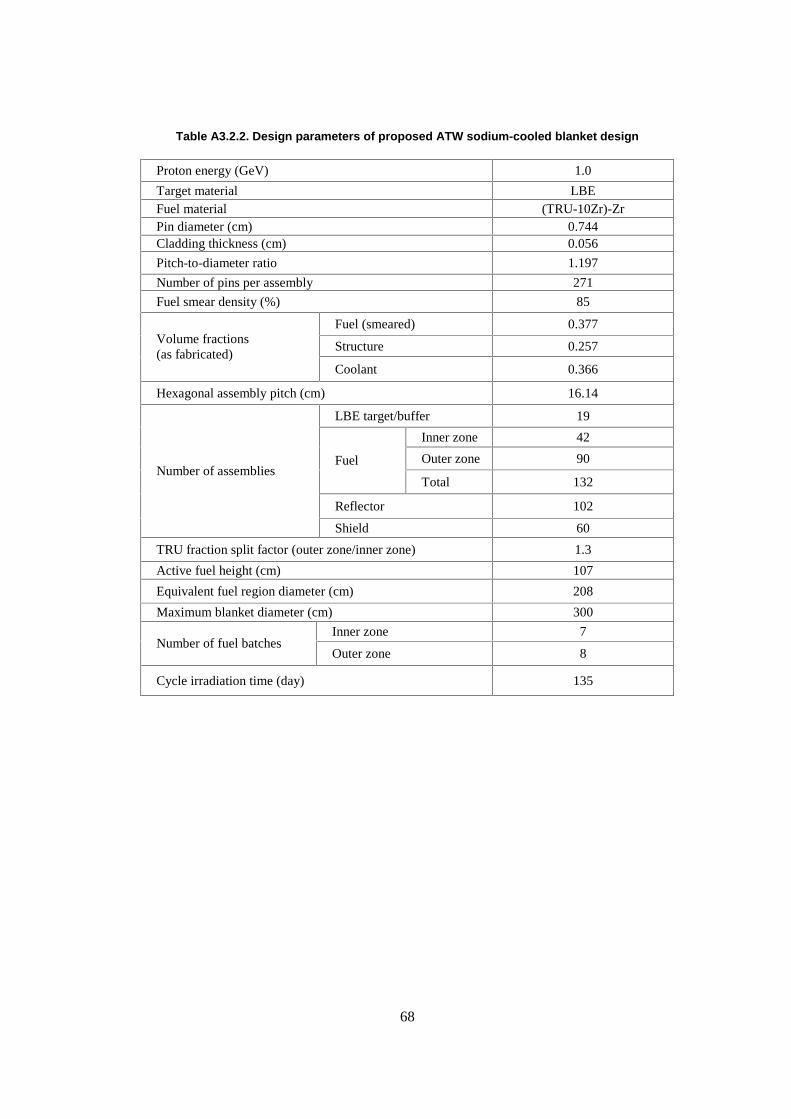
68
Table A3.2.2. Design parameters of proposed ATW sodium-cooled blanket design
Proton energy (GeV) 1.0
Target material LBE Fuel material (TRU-10Zr)-Zr Pin diameter (cm) 0.744 Cladding thickness (cm) 0.056
Pitch-to-diameter ratio 1.197
Number of pins per assembly 271
Fuel smear density (%) 85
Fuel (smeared) 0.377
Structure 0.257 Volume fractions (as fabricated)
Coolant 0.366
Hexagonal assembly pitch (cm) 16.14
LBE target/buffer 19
Inner zone 42
Outer zone 90 Fuel
Total 132
Reflector 102
Number of assemblies
Shield 60
TRU fraction split factor (outer zone/inner zone) 1.3
Active fuel height (cm) 107
Equivalent fuel region diameter (cm) 208
Maximum blanket diameter (cm) 300
Inner zone 7 Number of fuel batches
Outer zone 8
Cycle irradiation time (day) 135
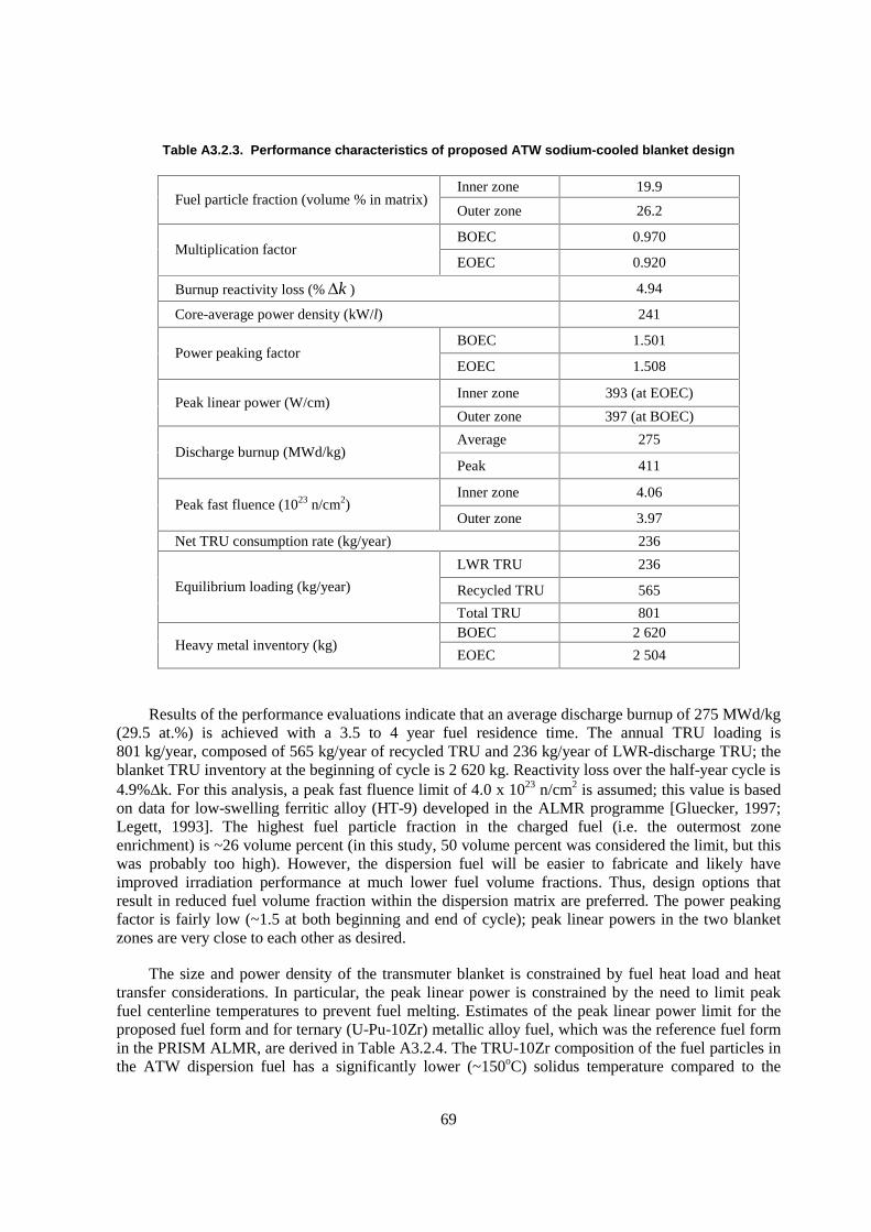
69
Table A3.2.3. Performance characteristics of proposed ATW sodium-cooled blanket design
Inner zone 19.9 Fuel particle fraction (volume % in matrix)
Outer zone 26.2
BOEC 0.970 Multiplication factor
EOEC 0.920
Burnup reactivity loss (% k� ) 4.94
Core-average power density (kW/l) 241
BOEC 1.501 Power peaking factor
EOEC 1.508
Inner zone 393 (at EOEC) Peak linear power (W/cm)
Outer zone 397 (at BOEC)
Average 275 Discharge burnup (MWd/kg)
Peak 411
Inner zone 4.06 Peak fast fluence (1023 n/cm2)
Outer zone 3.97
Net TRU consumption rate (kg/year) 236
LWR TRU 236
Recycled TRU 565 Equilibrium loading (kg/year)
Total TRU 801 BOEC 2 620
Heavy metal inventory (kg) EOEC 2 504
Results of the performance evaluations indicate that an average discharge burnup of 275 MWd/kg (29.5 at.%) is achieved with a 3.5 to 4 year fuel residence time. The annual TRU loading is 801 kg/year, composed of 565 kg/year of recycled TRU and 236 kg/year of LWR-discharge TRU; the blanket TRU inventory at the beginning of cycle is 2 620 kg. Reactivity loss over the half-year cycle is 4.9%�k. For this analysis, a peak fast fluence limit of 4.0 x 10²³ n/cm2 is assumed; this value is based on data for low-swelling ferritic alloy (HT-9) developed in the ALMR programme [Gluecker, 1997; Legett, 1993]. The highest fuel particle fraction in the charged fuel (i.e. the outermost zone enrichment) is ~26 volume percent (in this study, 50 volume percent was considered the limit, but this was probably too high). However, the dispersion fuel will be easier to fabricate and likely have improved irradiation performance at much lower fuel volume fractions. Thus, design options that result in reduced fuel volume fraction within the dispersion matrix are preferred. The power peaking factor is fairly low (~1.5 at both beginning and end of cycle); peak linear powers in the two blanket zones are very close to each other as desired.
The size and power density of the transmuter blanket is constrained by fuel heat load and heat transfer considerations. In particular, the peak linear power is constrained by the need to limit peak fuel centerline temperatures to prevent fuel melting. Estimates of the peak linear power limit for the proposed fuel form and for ternary (U-Pu-10Zr) metallic alloy fuel, which was the reference fuel form in the PRISM ALMR, are derived in Table A3.2.4. The TRU-10Zr composition of the fuel particles in the ATW dispersion fuel has a significantly lower (~150oC) solidus temperature compared to the

70
ternary metal fuel alloy. However, the thermal conductivity of the dispersion (composite) fuel is significantly improved because the zirconium matrix is highly conductive and its thermal properties are not expected to degrade with irradiation as observed for fuel alloys. The net result is an estimated increase in the allowable peak linear power from 375 W/cm to 450 W/cm. Note that the peak linear power limit is lower with LBE coolant, which is discussed in the next section, because of a much larger temperature rise in the coolant itself. This difference is attributed primarily to higher coolant flow rate and improved thermal conductivity in the sodium. Given the large uncertainties associated with thermal properties of the non-uranium dispersion fuel, it was considered prudent to impose a conservative design constraint. Thus, a peak linear power limit of 400 W/cm is recommended based upon a 40% fuel particle fraction. For a 26% fuel particle volume fraction, the estimated limit would be closer to 500 W/cm, allowing additional compaction of the sodium-cooled blanket design (~20% volume reduction), with associated economic and fuel cycle (reduced TRU inventory) benefits. The lattice design is quite loose with a pitch-to-diameter (P/D) ratio of 1.73 resulting in a coolant volume fraction of nearly 70%. The high coolant volume fraction is necessary to achieve the low coolant velocity required for the heavy liquid metal coolant. The difference in performance at startup and equilibrium conditions is compared in Table A3.2.5. It should also be noted that the Zr content in a fuel alloy such as TRU-40Zr or TRU-30Zr (where the Zr fraction is 30-40 weight%) can be derived to yield similar thermal properties (e.g. melting point) as conventional tenary U-30TRU-10Zr metal fuel as tested in EBR2 [Van Tuyle, 2000].
Table A3.2.4. Estimation of peak linear power for ATW dispersion fuel (U-10Zr/Zr) and ALMR metallic alloy Fuel (U-27Pu-10Zr)
Parameter
ALMR Metal fuel
sodium coolant
ATW Dispersion fuel sodium
coolant
ATW Dispersion fuel LBE coolant
Coolant film heat transfer coefficient, W/m2K 1.42E5 1.42E5 3.77E4
Clad thermal conductivity, W/mK 26.8 26.8 26.8
Fuel solidus temperature, °C 990 840 840
Fuel thermal conductivity, W/mK 15.3 13.8 13.8
Matrix thermal conductivity, W/mK – 22.2 22.2
Fuel volume fraction, % 100 ~40 ~30
Irradiation decrease in fuel conductivity, % 50 50 50
Effective fuel matrix thermal conductivity, W/mK
7.65 16.1 17.6
Peak linear power estimate, W/cm 374 454 332
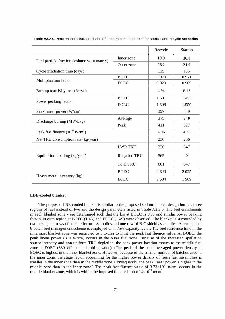
71
Table A3.2.5. Performance characteristics of sodium cooled blanket for startup and recycle scenarios
Recycle Startup
Inner zone 19.9 16.0 Fuel particle fraction (volume % in matrix)
Outer zone 26.2 21.0
Cycle irradiation time (days) 135 135 BOEC 0.970 0.971
Multiplication factor EOEC 0.920 0.909
Burnup reactivity loss (% k� ) 4.94 6.13
BOEC 1.501 1.453 Power peaking factor
EOEC 1.508 1.559
Peak linear power (W/cm) 397 449
Average 275 340 Discharge burnup (MWd/kg)
Peak 411 527
Peak fast fluence (1023 n/cm2) 4.06 4.26
Net TRU consumption rate (kg/year) 236 236
LWR TRU 236 647
Recycled TRU 565 0 Equilibrium loading (kg/year)
Total TRU 801 647
BOEC 2 620 2 025 Heavy metal inventory (kg)
EOEC 2 504 1 909
LBE-cooled blanket
The proposed LBE-cooled blanket is similar to the proposed sodium-cooled design but has three regions of fuel instead of two and the design parameters listed in Table A3.2.6. The fuel enrichments in each blanket zone were determined such that the keff at BOEC is 0.97 and similar power peaking factors in each region at BOEC (1.43) and EOEC (1.49) were observed. The blanket is surrounded by two hexagonal rows of steel reflector assemblies and one row of B4C shield assemblies. A semiannual 6-batch fuel management scheme is employed with 75% capacity factor. The fuel residence time in the innermost blanket zone was restricted to 5 cycles to limit the peak fast fluence value. At BOEC, the peak linear power (310 W/cm) occurs in the outer fuel zone. Because of the increased spallation source intensity and non-uniform TRU depletion, the peak power location moves to the middle fuel zone at EOEC (330 W/cm, the limiting value). (The peak of the batch-averaged power density at EOEC is highest in the inner blanket zone. However, because of the smaller number of batches used in the inner zone, the stage factor accounting for the higher power density of fresh fuel assemblies is smaller in the inner zone than in the middle zone. Consequently, the peak linear power is higher in the middle zone than in the inner zone.) The peak fast fluence value of 3.73×10²³ n/cm2 occurs in the middle blanket zone, which is within the imposed fluence limit of 4×10²³ n/cm2.

72
Table A3.2.6. Design parameters for the proposed LBE cooled blanket point design
Proton energy (GeV) 1.0
Target material LBE
Fuel material (TRU-10Zr)-Zr
Pin diameter (cm) 0.635
Cladding thickness (cm) 0.056
Pitch-to-diameter ratio 1.727
Number of pins per assembly 217
Fuel smear density (%) 75
Fuel 0.140
Structure 0.103 Volume fraction (at operating temp.)
Coolant 0.695
Hexagonal assembly pitch (cm) 16.142
LBE target/buffer 19
Inner zone 42
Middle zone 48
Outer zone 102 Fuel
Total 192
Reflector 114
Number of assemblies
Shield 66
TRU fraction split factor (outer/middle/inner zone) 1.45/1.28/1.00
Active fuel height (cm) 106.68
Equivalent fuel region diameter (cm) 246.21
Maximum blanket diameter (cm) 357.07
Inner zone 5 Number of fuel batches
Middle and outer zones 6
Cycle irradiation time (day) 145
Computed equilibrium cycle performance parameters are summarised in Table A3.2.7. An average discharge burnup of ~26% is achieved with a 3-year fuel residence time. The burnup reactivity loss is 5.7% with the assumed half-year cycle. The highest TRU fraction in the charged fuel
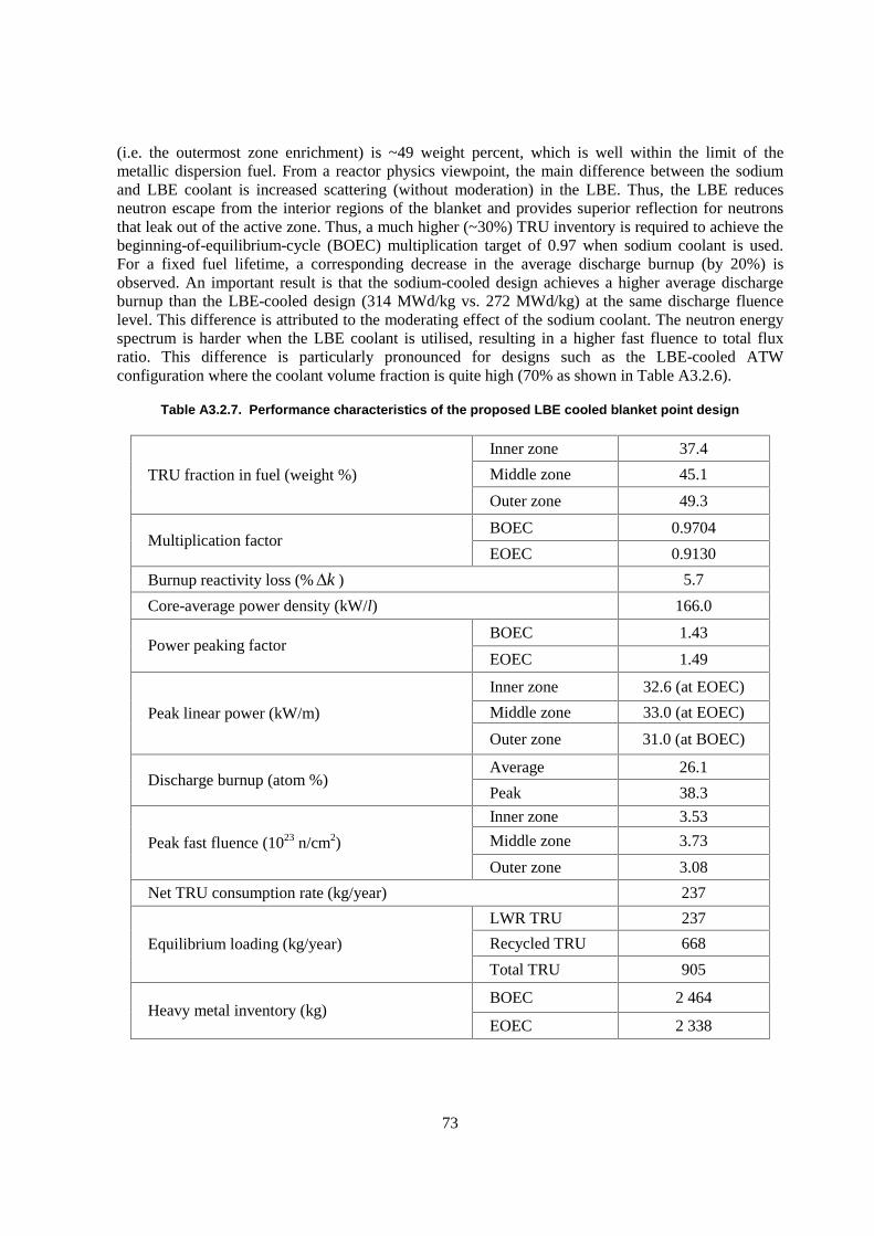
73
(i.e. the outermost zone enrichment) is ~49 weight percent, which is well within the limit of the metallic dispersion fuel. From a reactor physics viewpoint, the main difference between the sodium and LBE coolant is increased scattering (without moderation) in the LBE. Thus, the LBE reduces neutron escape from the interior regions of the blanket and provides superior reflection for neutrons that leak out of the active zone. Thus, a much higher (~30%) TRU inventory is required to achieve the beginning-of-equilibrium-cycle (BOEC) multiplication target of 0.97 when sodium coolant is used. For a fixed fuel lifetime, a corresponding decrease in the average discharge burnup (by 20%) is observed. An important result is that the sodium-cooled design achieves a higher average discharge burnup than the LBE-cooled design (314 MWd/kg vs. 272 MWd/kg) at the same discharge fluence level. This difference is attributed to the moderating effect of the sodium coolant. The neutron energy spectrum is harder when the LBE coolant is utilised, resulting in a higher fast fluence to total flux ratio. This difference is particularly pronounced for designs such as the LBE-cooled ATW configuration where the coolant volume fraction is quite high (70% as shown in Table A3.2.6).
Table A3.2.7. Performance characteristics of the proposed LBE cooled blanket point design
Inner zone 37.4
Middle zone 45.1 TRU fraction in fuel (weight %)
Outer zone 49.3
BOEC 0.9704 Multiplication factor
EOEC 0.9130
Burnup reactivity loss (% k� ) 5.7
Core-average power density (kW/l) 166.0
BOEC 1.43 Power peaking factor
EOEC 1.49
Inner zone 32.6 (at EOEC)
Middle zone 33.0 (at EOEC) Peak linear power (kW/m)
Outer zone 31.0 (at BOEC)
Average 26.1 Discharge burnup (atom %)
Peak 38.3
Inner zone 3.53
Middle zone 3.73 Peak fast fluence (1023 n/cm2)
Outer zone 3.08
Net TRU consumption rate (kg/year) 237
LWR TRU 237
Recycled TRU 668 Equilibrium loading (kg/year)
Total TRU 905
BOEC 2 464 Heavy metal inventory (kg)
EOEC 2 338

74
References to Appendix 3.2
Bennett, D. et al. (2001), “Compendium of Initial System Point Designs for Accelerator Transmutation of Radioactive Waste”, Los Alamos National Laboratory report LA-UR-01-1817.
Bowman, C. (1998), “Once-Through Thermal-Spectrum Accelerator-Driven System for LWR Waste Destruction Without Reprocessing: Tier-1 Description”, ADNA Corporation, ADNA/98-04.
Bultman, N.; Jason, A.J.; Pitcher, E.J.; Russell, G.J.; Sommer, W.F.; Weinacht, D.J.; Woods, R. (1995), “Los Alamos next-generation spallation source”, Los Alamos National Laboratory report LA-UR-95-4300.
Gluecker, E.L. (1997), “U.S. Advanced Liquid Metal Reactor (ALMR)”, Progress in Nuclear Energy, 31, 43-62.
Legett, R.D.; Walters, L.C. (1993), “Status of LMR Fuel Development in the United States”, J. Nuclear Materials, 204, 23-32.
Los Alamos National Laboratory, (2000), “Thermal Hydraulic Analysis of a Liquid-Metal-Cooled Neutron Spallation Target”, LA-UR-99-2340 (July).
Oak Ridge National Laboratory (2000), “Utilization of Monte Carlo Calculations in Radiation Transport Analyses to Support the Design of the U.S. Spallation Neutron Source (SNS)”, Report P00-108239, (23 October 2000).
Pitcher, E.J. et al., “Neutronic design of the APT Target/Blanket”, Los Alamos National Laboratory report LA-UR-97-3627.
Trellue, H.R.; Pitcher, E.J.; Poston, D.I. (2000), “Neutronics Studies of a Lead-Bismuth-Eutectic-Cooled Waste Transmuter”, Proceedings of the Fourth International Topical Meeting on Nuclear Applications of Accelerator Technology, 12-15 Nov. 2000, Washington DC, pp. 81-88.
Trellue, H.R.; Pitcher, E.J.; Poston, D.I. (2000), “Sensitivity Studies on Lead-Bismuth Transmuter for Accelerator Transmutation of Waste” Los Alamos National Laboratory report LA-UR-00-3285.
Van Tuyle, G.J. et al. (2001), “Candidate Approaches for an Integrated Nuclear Waste Management Strategy – Scoping Evaluations”, Los Alamos National Laboratory report LA-UR-01-5572 (November 2001).
Yang, W.S.; Khalil, H.S. (2000), “Reduction of Burnup Reactivity Loss in Accelerator Driven Transmutation Systems”, Proceedings of the Fourth International Topical Meeting on Nuclear Applications of Accelerator Technology, 12-15 Nov. 2000, Washington DC, pp. 75-80.
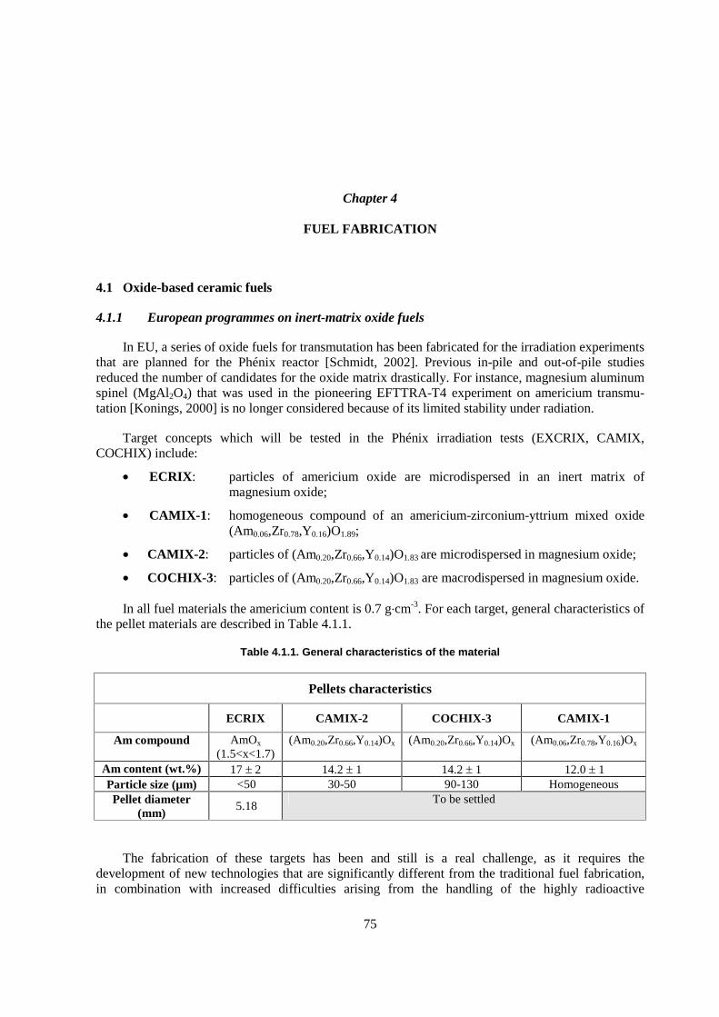
75
Chapter 4
FUEL FABRICATION
4.1 Oxide-based ceramic fuels
4.1.1 European programmes on inert-matrix oxide fuels
In EU, a series of oxide fuels for transmutation has been fabricated for the irradiation experiments that are planned for the Phénix reactor [Schmidt, 2002]. Previous in-pile and out-of-pile studies reduced the number of candidates for the oxide matrix drastically. For instance, magnesium aluminum spinel (MgAl2O4) that was used in the pioneering EFTTRA-T4 experiment on americium transmu-tation [Konings, 2000] is no longer considered because of its limited stability under radiation.
Target concepts which will be tested in the Phénix irradiation tests (EXCRIX, CAMIX, COCHIX) include:
� ECRIX: particles of americium oxide are microdispersed in an inert matrix of magnesium oxide;
� CAMIX-1: homogeneous compound of an americium-zirconium-yttrium mixed oxide (Am0.06,Zr0.78,Y0.16)O1.89;
� CAMIX-2: particles of (Am0.20,Zr0.66,Y0.14)O1.83 are microdispersed in magnesium oxide;
� COCHIX-3: particles of (Am0.20,Zr0.66,Y0.14)O1.83 are macrodispersed in magnesium oxide.
In all fuel materials the americium content is 0.7 g�cm-3. For each target, general characteristics of the pellet materials are described in Table 4.1.1.
Table 4.1.1. General characteristics of the material
Pellets characteristics
ECRIX CAMIX-2 COCHIX-3 CAMIX-1
Am compound
AmOx (1.5<x<1.7)
(Am0.20,Zr0.66,Y0.14)Ox
(Am0.20,Zr0.66,Y0.14)Ox
(Am0.06,Zr0.78,Y0.16)Ox
Am content (wt.%) 17 � 2 14.2 � 1 14.2 � 1 12.0 � 1 Particle size (µm) <50 30-50 90-130 Homogeneous Pellet diameter
(mm) 5.18
To be settled
The fabrication of these targets has been and still is a real challenge, as it requires the development of new technologies that are significantly different from the traditional fuel fabrication, in combination with increased difficulties arising from the handling of the highly radioactive
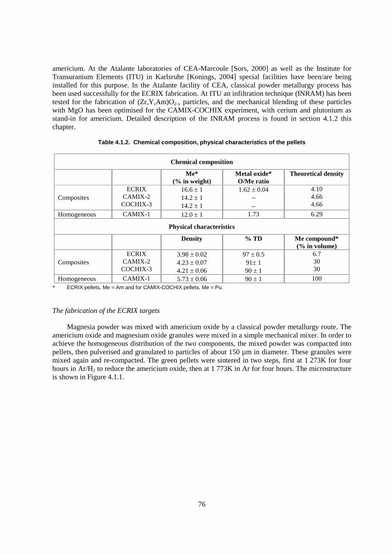
76
americium. At the Atalante laboratories of CEA-Marcoule [Sors, 2000] as well as the Institute for Transuranium Elements (ITU) in Karlsruhe [Konings, 2004] special facilities have been/are being installed for this purpose. In the Atalante facility of CEA, classical powder metallurgy process has been used successfully for the ECRIX fabrication. At ITU an infiltration technique (INRAM) has been tested for the fabrication of (Zr,Y,Am)O2-x particles, and the mechanical blending of these particles with MgO has been optimised for the CAMIX-COCHIX experiment, with cerium and plutonium as stand-in for americium. Detailed description of the INRAM process is found in section 4.1.2 this chapter.
Table 4.1.2. Chemical composition, physical characteristics of the pellets
Chemical composition
Me*
(% in weight) Metal oxide*
O/Me ratio Theoretical density
Composites ECRIX
CAMIX-2 COCHIX-3
16.6 � 1 14.2 � 1 14.2 � 1
1.62 � 0.04 – –
4.10 4.66 4.66
Homogeneous CAMIX-1 12.0 � 1 1.73 6.29
Physical characteristics
Density % TD Me compound*
(% in volume)
Composites ECRIX
CAMIX-2 COCHIX-3
3.98 � 0.02 4.23 � 0.07 4.21 � 0.06
97 � 0.5 91� 1 90 � 1
6.7 30 30
Homogeneous CAMIX-1 5.73 � 0.06 90 � 1 100 * ECRIX pellets, Me = Am and for CAMIX-COCHIX pellets, Me = Pu.
The fabrication of the ECRIX targets
Magnesia powder was mixed with americium oxide by a classical powder metallurgy route. The americium oxide and magnesium oxide granules were mixed in a simple mechanical mixer. In order to achieve the homogeneous distribution of the two components, the mixed powder was compacted into pellets, then pulverised and granulated to particles of about 150 µm in diameter. These granules were mixed again and re-compacted. The green pellets were sintered in two steps, first at 1 273K for four hours in Ar/H2 to reduce the americium oxide, then at 1 773K in Ar for four hours. The microstructure is shown in Figure 4.1.1.
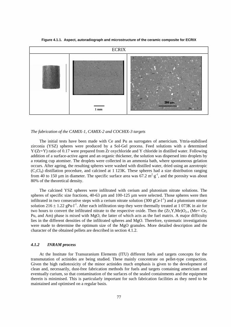
77
Figure 4.1.1. Aspect, autoradiograph and microstructure of the ceramic composite for ECRIX
ECRIX
The fabrication of the CAMIX-1, CAMIX-2 and COCHIX-3 targets
The initial tests have been made with Ce and Pu as surrogates of americium. Yttria-stabilised zirconia (YSZ) spheres were produced by a Sol-Gel process. Feed solutions with a determined Y/(Zr+Y) ratio of 0.17 were prepared from Zr oxychloride and Y chloride in distilled water. Following addition of a surface-active agent and an organic thickener, the solution was dispersed into droplets by a rotating cup atomiser. The droplets were collected in an ammonia bath, where spontaneous gelation occurs. After ageing, the resulting spheres were washed with distilled water, dried using an azeotropic (C2Cl4) distillation procedure, and calcined at 1 123K. These spheres had a size distribution ranging from 40 to 150 µm in diameter. The specific surface area was 67.2 m2�g-1, and the porosity was about 80% of the theoretical density.
The calcined YSZ spheres were infiltrated with cerium and plutonium nitrate solutions. The spheres of specific size fractions, 40-63 µm and 100-125 µm were selected. Those spheres were then infiltrated in two consecutive steps with a cerium nitrate solution (300 gCe�l-1) and a plutonium nitrate solution 216 � 1.22 gPu�l-1. After each infiltration step they were thermally treated at 1 073K in air for two hours to convert the infiltrated nitrate to the respective oxide. Then the (Zr,Y,Me)O2-x (Me= Ce, Pu, and Am) phase is mixed with MgO, the latter of which acts as the fuel matrix. A major difficulty lies in the different densities of the infiltrated spheres and MgO. Therefore, systematic investigations were made to determine the optimum size of the MgO granules. More detailed description and the character of the obtained pellets are described in section 4.1.2.
4.1.2 INRAM process
At the Institute for Transuranium Elements (ITU) different fuels and targets concepts for the transmutation of actinides are being studied. These mainly concentrate on pellet-type compaction. Given the high radiotoxicity of the minor actinides much emphasis is given to the development of clean and, necessarily, dust-free fabrication methods for fuels and targets containing americium and eventually curium, so that contamination of the surfaces of the sealed containments and the equipment therein is minimised. This is particularly important for such fabrication facilities as they need to be maintained and optimised on a regular basis.
1 mm
78
Homogeneous fuels and targets
One candidate fuel or target form is the so-called inert-matrix mixed oxide (IMMOX), in which the actinides are incorporated in a partially yttria-stabilised zirconia (YSZ) solid solution. At the ITU a hybrid process consisting of a combination of Sol-Gel and porous bead infiltration techniques (see Figure 4.1.2) has been developed for the fabrication of these types of materials on a laboratory scale [Fernández, 2002] but with industrialisation being the long term goal. It meets three critical criteria:
� it is dust free;
� there are no liquid wastes; and
� it minimises the steps in which highly radioactive materials are handled.
The infiltration process itself is well known [Marple, 1993; Colvin, 1996] but until now has only been used with porous disks or pellets, either by immersion [Richter, 1997] or dripping [Kinoshita, 2000] to produce actinide compacts directly. In contrast, the process described here has several additional advantages, the most important being the higher actinide content achievable and the homogeneity of the final products. This new process has been tested and validated with cerium and plutonium at the laboratory scale. The actual fabrication of Am- and eventually Cm-containing materials will be performed in a set of specially constructed shielded cells installed in the ITU’s Nuclear Fuel Laboratories [ITU, 2001].
Figure 4.1.2. Infiltration route fabrication process flowsheet
(Pu,Y,Zr)O2-x pellets have already been produced by this process. Yttria-stabilised zirconia (YSZ) spheres were produced by a sol gel process. Feed solutions with a determined Y/(Zr+Y) ratio of 0.17 were prepared from aqueous solutions of Zr oxychloride and Y chloride. Following addition of a surface-active agent and an organic thickener, the solution was dispersed into droplets by a rotating cup atomiser (see Figure 4.1.3). The droplets were collected in an ammonia bath, where they were converted into solid particles by gelation. The resulting spheres were washed with distilled water, dried using an azeotropic (C2Cl4) distillation procedure, and calcined at 800°C. These spheres have a
Zr ,Y Solution
Droplet to ParticleConversion
Pressing
Sintering
Calcination
Actinide Solution
Solution Infiltration40-150 µm
Microspheres
Thermal Treatment
79
polydisperse size distribution in the 40 and 150 µm range, a specific surface area of 65 m2�g-1, and a porosity of about 80%. X-ray diffraction (XRD) of sintered beads indicated a cubic crystal structure with a lattice parameter of 0.5140 ± 0.0003 nm, which is in good agreement with the literature value for (Zr0.85Y0.15)O1.93 (0.5139 ± 0.0001 nm) [International Centre for Diffraction Data] .
Figure 4.1.3. Rotating cup atomiser
The calcined spheres were infiltrated with plutonium nitrate solution (216 � 1.22 gPu�l-1) in a single or multiple steps to reach the desired final Pu content. After each infiltration step they were thermally treated at 800°C to convert the infiltrated plutonium nitrates into the corresponding oxides. The plutonium content was determined by gravimetric analysis of the spheres before infiltration and after the calcination step. The resulting infiltrated beads were free-flowing, and, due to their size and integrity, their physical manipulation does not produce dust in the following fabrication steps. At this stage in the fabrication process, little interdiffusion occurred and XRD measurements show that the materials are comprised of a PuO2 phase dispersed in YSZ.
The beads were pressed into pellets in a biaxial press and then sintered at 1 650°C in Ar/H2/1 000ppmH2O. An �-autoradiograph and a ceramograph of a sectioned (Pu,Y,Zr)O2-x pellet produced by this process are shown in Figure 4.1.4.
Figure 4.1.4. �-autoradiograph (left) and ceramograph (right) of an axial section of a (Pu0.045Y0.163Zr0.792)O2 pellet
1mm 100 µm
80
The final pellet product occasionally exhibits an undesirable microstructure (see Figure 4.1.5). Dense regions corresponding to the original microspheres with banana shaped porosities at their periphery are observed. This is caused by a memory effect (often known as the “Blackberry Structure”) caused by excellent sintering within the precursor particles, but poor inter particle sintering. For many applications, this effect should be avoided. A so-called carbon addition method [Somers] has been developed and tested for the production of YSZ beads by the sol gel external gelation route. Pellets produced form such beads dependably exhibit excellent microstructures, as is shown in Figure 4.1.5.
Figure 4.1.5. Microstructure of an axial section of a (Y0.17Zr0.83)O1.92 pellet fabricated by (a) the conventional sol gel external gelation and (b) the carbon addition method
Heterogeneous fuels and targets
A second candidate fuel or target type is the composite dispersion, in which the actinide oxides are dispersed in a ceramic (cercer) or metallic (cermet) uranium free matrix. The fabrication of composite pellets is considerably more difficult than for solid solution oxides pellets. This is a result of the specific requirements of particle size and homogeneous distribution of the dispersed actinide phase. The major problem to be solved is the control of the distribution of the actinide ceramic phase in the matrix, and major efforts have been made to develop procedures to fabricate both cercer and cermet pellets. Particles containing the actinide phase are prepared by a combination of the sol gel, and infiltration methods. Thereafter they are mixed with the matrix powder by conventional blending methods. Following compaction into pellets by cold pressing, they are sintered at high temperature. The effect of important parameters related to composite pellet fabrication, such as, the volume fraction of ceramic (actinide phase) and the size of the ceramic particles, have been systematically investigated and reported in detail elsewhere [Fernández, 2003a,b,].
Both cercer pellets, in which the actinides are in (near) spherical yttria-stabilised zirconia (YSZ) particles, dispersed in ceramic-ceramic a MgO matrix, and cermet pellets, using Stainless Steel and Molybdenum as matrices have been successfully fabricated at the ITU. After their calcination at 800°C in air, the uninfiltrated YSZ spheres were sieved and specific size fractions (40-60 and 100-125 µm for cercer compounds and 60-80 µm for cermet composites) were selected. Each size fraction was infiltrated with a plutonium nitrate solution (216 g�l-1) to reach the required metal content (i.e. Pu/(Zr+Y+Pu) equal to 0.20 for cercer and 0.24 for cermet composites). To reach these Pu concentrations two infiltration steps were required with an intermediate thermal treatment at 800°C for two hours in air to evaporate excess water and convert the infiltrated plutonium nitrate phase to the
81
oxide. The final Pu content was determined by gravimetric analysis of the spheres before infiltration and after the calcination step.
The (Pu,Y,Zr)O2-x phase was mixed in the desired quantities with the required amount of either MgO (CERAC M-1017) or stainless steel (ALFA AESAR, SS 316L with the following weight composition: Fe 67.5 %, Cr 17 %, Ni 13 %, Mo 2.5 %, and particle size 45µm). After the addition of zinc stearate as lubricant, the mixtures were compacted into pellets. Sintering was performed at 1 650°C for 8 hours in argon for MgO cercer pellets and at 1 275°C for 3 hours in argon for stainless steel cermet pellets.
MgO-(Pu,Y,Zr)O2-x cercer pellets with a Pu density of 0.7 g�cm-3 have been fabricated without cracks and with a random distribution of isolated spheres, for the sphere sizes investigated (see Figure 4.1.6). A stainless steel based cermet fuel with a Pu density of 0.9 g�cm-3 has also been fabricated and characterised for an irradiation experiment (SMART) in the HFR-Petten reactor. The final pellets had a density of 87.2 � 0.2% TD. As the porosity is principally in the ceramic phase, accommodation of fission gases during irradiation is achieved and therefore swelling should be mitigated. The optical micrograph shown in Figure 4.1.6 indicates that all particles are uniformly distributed in the matrix.
Conclusions
The results obtained have demonstrated the feasibility of the fabrication of (Pu,Y,Zr)O2-x based magnesia and stainless steel composite pellets, by a combination of GSP, infiltration and conventional blending techniques. The main advantage of the composite route is its high flexibility to select the particle size and volume fraction of the ceramic phase. Materials exhibiting a homogeneous dispersion of the actinide ceramic bearing phase have been produced. The actual fabrication of Am containing materials will be performed in the minor actinide laboratory, which will soon become fully operational.
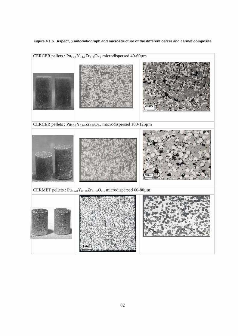
82
Figure 4.1.6. Aspect, � autoradiograph and microstructure of the different cercer and cermet composite
CERCER pellets : Pu0.20 Y0.14 Zr0.66O2-x microdispersed 40-60µm
CERCER pellets : Pu0.20 Y0.14 Zr0.66O2-x macrodispersed 100-125µm
CERMET pellets : Pu0.241Y0.128Zr0.631O2-x microdispersed 60-80µm
1 mm
250 µm
83
4.2 Nitride fuels/targets
4.2.1 Mixed nitrides of actinides by powder route
The carbothermic synthesis of the mixed nitride from the oxides+carbon mixture is formally written, for the typical case of (U0.8Pu0.2)N for the fast breeder reactor, as follows:
N2+H2
0.8UO2 + 0.2PuO2+(2+x)C (U0.8Pu0.2)N+2CO+XCH4
After mechanical blending, the powder mixture is compacted into green pellets and heated at 1 400-1 700�C in the flowing N2+H2 mixture. The reaction is monitored by measuring CO content in the exhaust gas. In the cooling stage, if the nitride contains uranium, the atmosphere is replaced by argon in order to suppress the formation of U2N3.
The nitride of low oxygen content can be obtained by adding an excess amount of carbon. The excess carbon can be removed by heating in a nitrogen-hydrogen gas flow. It is not so easy to reduce the carbon contents in the light actinides (U-Pu), since the carbides are more stable with these elements. On the other hand, carbide is not so stable with americium and curium. Oxygen is not soluble in UN and PuN, and presumably in NpN. However, higher solubilities of oxygen in AmN and presumably CmN are suspected, judging from the recent systematic lattice-parameter measurements of americium nitride [Takano, 2003].
Carbothermic reduction was applied to the preparation of AmN and (Cm,Pu)N for the first time [Takano, 2001]. The mixtures of AmO2+C and (Cm,Pu)O2+C with a large excess amount of carbon were heated in a molybdenum crucible at 1 573 and 1 773K in N2+H2 gas stream, respectively. Lower temperature was chosen for AmN in order to minimise the americium vaporisation loss. Fabrication of high-density pellets of those transplutonium nitrides has not been tried.
The effects of oxygen and carbon contents on the sintering behaviour and the irradiation performance have yet to be clarified in detail. A higher content of carbon may cause carburisation of the cladding steel during irradiation [Matzke, 1991]. The carburisation of the cladding will affect its mechanical property. Oxygen contents have to be minimised if the nitride has to be reprocessed by using molten-salts media. The presence of oxygen impurity in the molten salts may result in the actinide loss in the form of either oxides or oxychlorides [Ogawa, 2001].
The nitride pellets obtained by the carbothermic synthesis are of low density. They are crushed, attrited and pressed into the nitride green pellets. In preparing the green pellets, granulation is not necessary: cold pressing of attrited nitride powder is usually adopted. The nitride green pellets are then sintered at temperatures around 1 700�C. Sometimes, instead of using the mixed-nitride powder, the individual metal nitride powders are prepared separately, and then mixed. In the latter case, the solid solutions of those metal nitrides are formed during sintering process. In the Institute for Transuranium Elements, the DP-process (“direct pressing”) technique has been developed, where the low-density nitride pellets, or granulates right after the carbothermic synthesis are directly fed into a press, recompacted and sintered at 1 600-1 800�C [Richter, 1987]. Irradiation performance of the pellets by the DP-process appears to be better than those by the conventional attrition-compaction process.
As far as (U,Pu)N is concerned, it has been demonstrated by CEA that the nitride fuel fabrication is made on the conventional oxide fabrication line without significant modification [Bernard, 1987].
84
Even the carbothermic synthesis from oxides+carbon powder mixture has been successfully made in an alumina muffle furnace of an industrial size. However, a very dry atmosphere should be necessary in handling the nitrides of transplutonium elements due to their highly hygroscopic nature, as already discussed in Chapter 2 (section 4).
4.2.2 Mixed nitrides of actinides by wet route
In order to minimise the process dust in handling the transuranium elements, the wet routes such as gelation method are being sought. In the gelation method, the concentrated nitrate solution of actinides is directly converted into the oxide gel. For the fabrication of the nitride, so-called internal gelation process has been studied. In the internal gelation method, an ammonium donor such as HMTA (hexamethylene-tetramine) is added in to the nitrate solution. The solution is dropped through the nozzle into a hot oil column. Heating of droplets by microwave has been also tested successfully [Ledergerber, 1982; Yamagishi, 1994]. In the droplets under warming, HMTA decomposes to produce ammonia, which precipitates oxides. Thus, the droplets are turned into solid microspheres. In the synthesis of nitride microspheres, HMTA, urea and carbon black are added to the feed solution.
After the solidification, the microspheres are washed to remove oil, solvents and reaction products, and then dried in air. Calcination in Ar+H2 gas mixture then follows to remove volatile impurities and to adjust the oxidation state of metal elements. The carbothermic synthesis stage is the same as the normal powder routes.
Not only UN, but also (U,Ce)N [Dehadraya, 1997] and (Pu,Zr)N [Streit, 2001] microspheres have been fabricated in this way. However, the control of residual oxygen and carbon has yet to be accomplished for the nitrides containing zirconium.
4.2.3 Mixed nitrides with inert matrix
Mixed nitrides powders of (Zr,Am)N and (Y,Am)N have been prepared from the respective oxides+carbon mixtures [Akabori, 2002; Takano, 2003]. As for the sintered pellets, (Zr,Pu)N and TiN-PuN of nearly equimolar mixtures have been prepared [Arai, 2000]. The PuN powder by carbothermic synthesis and commercially obtained ZrN or TiN powder were mixed, pressed and sintered at 1 673K in flowing N2+H2. The obtained pellets were crushed, compacted and sintered again at 2 003K in flowing argon. It is not correct to write (Ti,Pu)N, since the mutual solubility of TiN and PuN are limited (see Chapter 2.4). The irradiation testing of (Zr,Pu)N and TiN-PuN pellets in the Japan Materials Testing Reactor is planned.
INRAM process (see section 4.1.2) may be also applied to the fabrication of (TRU,Zr)N. ZrO2+C beads may be infiltrated with TRU nitrite, and then supplied to the carbothermic reduction in flowing N2+H2.
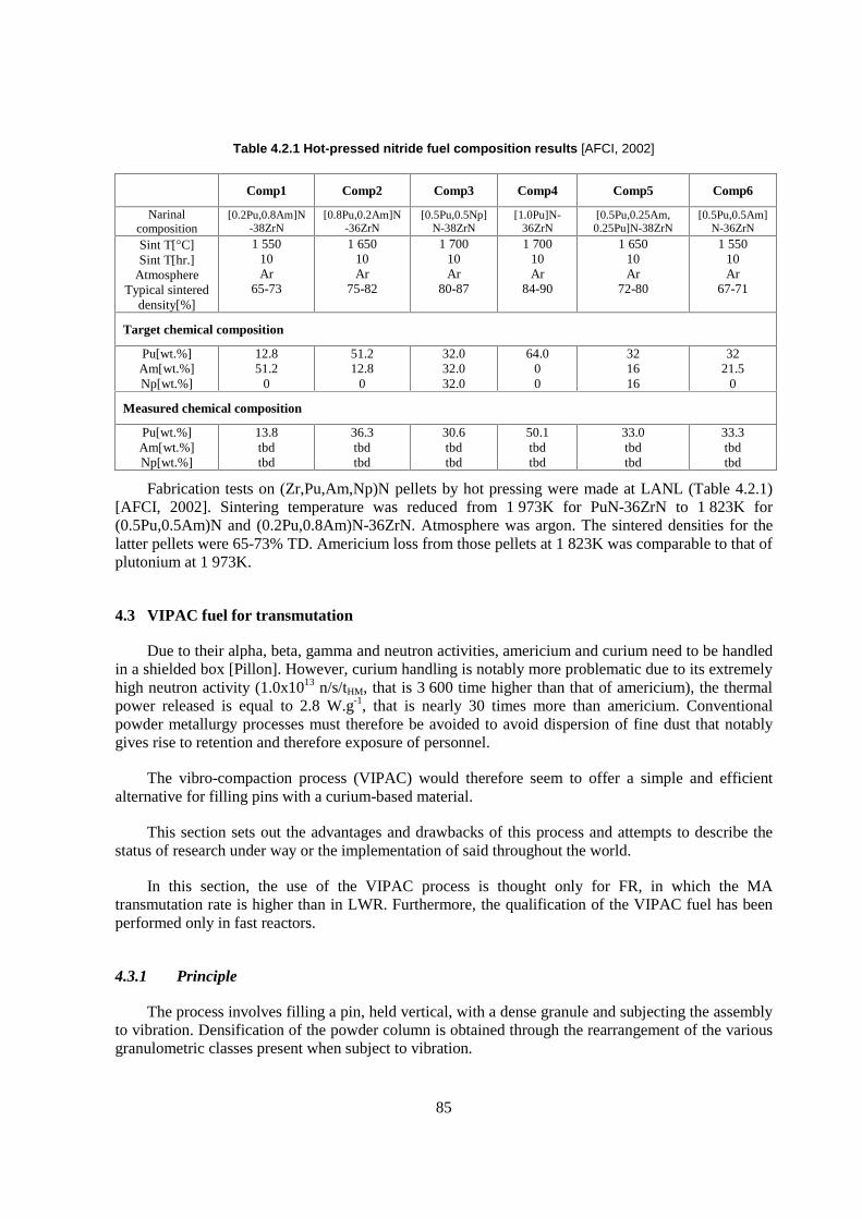
85
Table 4.2.1 Hot-pressed nitride fuel composition results [AFCI, 2002]
Comp1 Comp2 Comp3 Comp4 Comp5 Comp6
Narinal composition
[0.2Pu,0.8Am]N-38ZrN
[0.8Pu,0.2Am]N-36ZrN
[0.5Pu,0.5Np]N-38ZrN
[1.0Pu]N-36ZrN
[0.5Pu,0.25Am, 0.25Pu]N-38ZrN
[0.5Pu,0.5Am]N-36ZrN
Sint T[�C] Sint T[hr.]
Atmosphere Typical sintered
density[%]
1 550 10 Ar
65-73
1 650 10 Ar
75-82
1 700 10 Ar
80-87
1 700 10 Ar
84-90
1 650 10 Ar
72-80
1 550 10 Ar
67-71
Target chemical composition
Pu[wt.%] Am[wt.%] Np[wt.%]
12.8 51.2
0
51.2 12.8
0
32.0 32.0 32.0
64.0 0 0
32 16 16
32 21.5
0
Measured chemical composition
Pu[wt.%] Am[wt.%] Np[wt.%]
13.8 tbd tbd
36.3 tbd tbd
30.6 tbd tbd
50.1 tbd tbd
33.0 tbd tbd
33.3 tbd tbd
Fabrication tests on (Zr,Pu,Am,Np)N pellets by hot pressing were made at LANL (Table 4.2.1) [AFCI, 2002]. Sintering temperature was reduced from 1 973K for PuN-36ZrN to 1 823K for (0.5Pu,0.5Am)N and (0.2Pu,0.8Am)N-36ZrN. Atmosphere was argon. The sintered densities for the latter pellets were 65-73% TD. Americium loss from those pellets at 1 823K was comparable to that of plutonium at 1 973K.
4.3 VIPAC fuel for transmutation
Due to their alpha, beta, gamma and neutron activities, americium and curium need to be handled in a shielded box [Pillon]. However, curium handling is notably more problematic due to its extremely high neutron activity (1.0x10¹³ n/s/tHM, that is 3 600 time higher than that of americium), the thermal power released is equal to 2.8 W.g-1, that is nearly 30 times more than americium. Conventional powder metallurgy processes must therefore be avoided to avoid dispersion of fine dust that notably gives rise to retention and therefore exposure of personnel.
The vibro-compaction process (VIPAC) would therefore seem to offer a simple and efficient alternative for filling pins with a curium-based material.
This section sets out the advantages and drawbacks of this process and attempts to describe the status of research under way or the implementation of said throughout the world.
In this section, the use of the VIPAC process is thought only for FR, in which the MA transmutation rate is higher than in LWR. Furthermore, the qualification of the VIPAC fuel has been performed only in fast reactors.
4.3.1 Principle
The process involves filling a pin, held vertical, with a dense granule and subjecting the assembly to vibration. Densification of the powder column is obtained through the rearrangement of the various granulometric classes present when subject to vibration.
86
The aim is to obtain high powder density in order to minimise the phenomena of redensification in reactor at the operation temperature. Linear density, similarly to the distribution of fissile material, must furthermore be as homogeneous as possible in order to guarantee identical neutron behaviour over the entire length of the pin.
Residual porosity allows the fission gases to be evacuated to the void volumes.
In the event that the fuel rod is not subject to any heat treatment prior to its introduction into the reactor, final compactness of the fissile column is solely a function of the initial density of the powder grains and residual inter granular porous volume. The residual porous volume is a function of several parameters associated with the characteristics of the powder and the vibration applied to the fuel rod.
The process is therefore governed by two parameter families: the characteristics of the material and those of the vibration applied.
Material
The initial powder is selected as dense as possible in order to ensure that the material remains stable at its normal operation temperature. For similar in-reactor stability problems, powder column density must be high, homogeneous and thermally stable. Fuel rod transportation steps, in horizontal position, must furthermore not alter density, notably at the column end points. It may be noted that implementation of the vibro-compaction technique, which is entirely compatible with an integrated cycle (recycling on the reactor site), could avoid these transportation problems [Pillon].
The main powder characteristics are; granulometric distribution, shape, density and the inter-particulate friction coefficient.
The most limiting factor is the granulometric distribution, which must be precisely determined in order to achieve and optimal compaction rate [Wakeman, 1975]. In industrial applications, the column density values of 85% MVTH are achieved with the following granulometric distribution [Table 4.3.1, for (U,Pu)O2].
Table 4.3.1. Example of granulometric distribution
Particule size (µm) % Volume
1 200 60
300 15
30 25
The compaction phenomenon in play is based on the reorganisation of particles under the effect of gravity (their relative movement being provoked by vibration), particles that are too fine are therefore not recommended. There is, in fact, a critical size below which interparticulate forces become dominating and interfere with densification of the system [Yu, 1997; Hausner, 1972].
In this case also, it may be noted that increasing granule density is beneficial, because it allows the working granulometric range to be extended to small sized particles.
87
The powder column weight is an influencing factor that may be adjusted by applying a weight during vibro-compaction.
The “ideal” characteristics of a monophase granule as regards its vibro-compaction are provided in Table 4.3.2.
Table 4.3.2 Ideal characteristics of a monophase granule
Granulate parameter Characteristics
Density As close as possible to the theoretical density Granulometric distribution 3 to 5 classes calibrated Particle shape As spherical as possible Lubricant (optional) 2 to 6% water or alcohol Interpaticulate friction coefficient As low as possible (surface condition)
Vibration applied
The vibration applied to the fuel rod is defined by frequency, vibration mode (sinusoidal, square, etc.), amplitude, acceleration, duration, application cycle (continuous or stepped) and the point in time at which it is applied (during or after filling) [Evans, 1964; Bridgewater, 1997; Gray, 1972].
The frequency and amplitude appear to be driving parameters [Nowak, 1997]. This operation is extremely fast because column compaction only takes between 1 and 5 minutes. Furthermore, in the case of a polyphase granular system, prolongation of vibration always gives rise to segregation of the phases present [Mounfield, 1994].
The characteristics of vibration encouraging compaction are summarised in Table 4.3.3.
Table 4.3.3. Characteristics of vibration encouraging compaction
Vibration parameter Targeted characteristic
Frequency High Amplitude Low Acceleration High (up to 20g) Time of application During and after filling
4.3.2 Particle preparation
The radio toxicity of minor actinides is such that the generation of dust during the process should be avoided. For similar reasons, the manufacturing process must be kept simple and open to automation, this removes the solution from conventional powder metallurgy processes. Here, the processes on the oxide-based fuels are reviewed.
The implementation of a homogeneous fuel by vibro-compaction [for example (Zr,Y,AM)O2] would appear to be feasible as soon as it becomes possible to easily control synthesis in the form of micro spheres of variable sizes [Pillon]. For that which regards heterogeneous fuel [MgO+(Am,Cm)O2 or MgO+(Zr,Y,AM)O2], additional phase segregation problems may arise due to density differences.
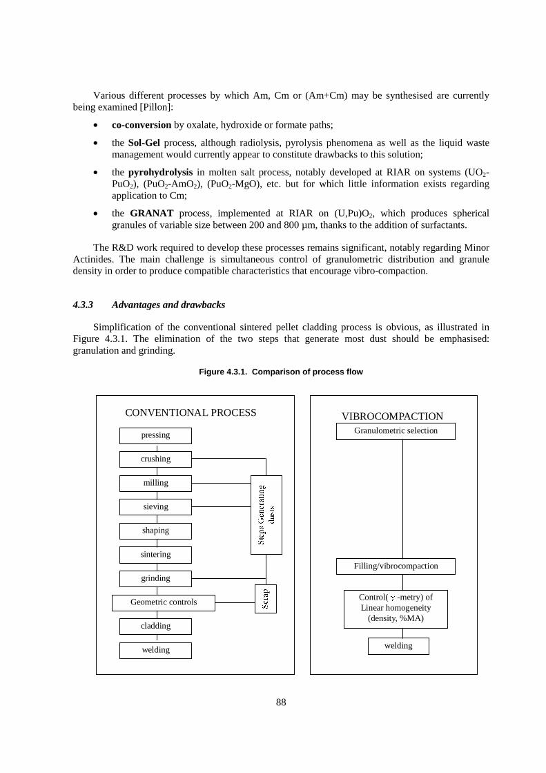
88
Various different processes by which Am, Cm or (Am+Cm) may be synthesised are currently being examined [Pillon]:
� co-conversion by oxalate, hydroxide or formate paths;
� the Sol-Gel process, although radiolysis, pyrolysis phenomena as well as the liquid waste management would currently appear to constitute drawbacks to this solution;
� the pyrohydrolysis in molten salt process, notably developed at RIAR on systems (UO2-PuO2), (PuO2-AmO2), (PuO2-MgO), etc. but for which little information exists regarding application to Cm;
� the GRANAT process, implemented at RIAR on (U,Pu)O2, which produces spherical granules of variable size between 200 and 800 µm, thanks to the addition of surfactants.
The R&D work required to develop these processes remains significant, notably regarding Minor Actinides. The main challenge is simultaneous control of granulometric distribution and granule density in order to produce compatible characteristics that encourage vibro-compaction.
4.3.3 Advantages and drawbacks
Simplification of the conventional sintered pellet cladding process is obvious, as illustrated in Figure 4.3.1. The elimination of the two steps that generate most dust should be emphasised: granulation and grinding.
Figure 4.3.1. Comparison of process flow
VIBROCOMPACTIONGranulometric selection
Filling/vibrocompaction
Control( -metry) ofLinear homogeneity
(density, %MA)
welding
CONVENTIONAL PROCESS
pressing
crushing
milling
sieving
shaping
sintering
grinding
Geometric controls
cladding
welding
89
Two major problems are however encountered during irradiation.
At operation temperature, densification of granules in contact may lead to the creation of play between the fuel and the cladding, or even hot points caused by changes in the particle network structure ensuring the thermal conductivity [Kim, 2001].
Furthermore, cladding failure (crack, hole, etc.) risks entailing pollution of the coolant fluid by fissile particles [Faugere, 1989]. In a two-phase system (mixture of “pure” fissile particles with inert particles (MgO, etc.) of several granulometric sizes, the entire fissile phase may be in the form of larger size particles, thus reducing the risk of contamination in the event of failure of the cladding without however eliminating said risk. In so far as the process allows granules of millimeter size to be synthesised, current modelling tools may be used to assess the performance levels offered by this solution.
Studies performed in 1989 by PSI and CEA (NIMPHE-3) emphasise that wetting of particles by the coolant fluid as well as the sphere sintering kinetics (U,Pu)N (in order to create necks between particles) are essential factors in avoiding fuel loss, a risk which is, furthermore, maximised as of the irradiation half-life.
Heat treatment of vibro-compacted fuel rods with the aim of forming solid bridges between the particles may ensure confinement of the latter in the event of a cladding failure. The heat treatment temperature, intended to provoke the formation of solid bridges without densification, is mainly dependant on the material or compound subject to vibrocompaction. This must however remain compatible with the cladding material creep characteristics in order to avoid deformation of said.
4.3.4 Current status of vibrocompaction experiments
Several irradiations of vibro-compacted fuels have been carried out since the concept was introduced about forty years ago. Studies on this subject have been noted in numerous countries.
Since 1966, the Germans [Hochel, 1966] have manufactured annular fuel rods with internal and external diameters of 8 and 19 mm respectively, in pre-sintered UO2, crushed and then calibrated in 4 granulometric classes between 30 and 2 000 µm. Final density was in the neighbourhood of 90% TD with a dispersion less than 2% TD over a fissile column length equal to 2.60 m. Pins were irradiated in a BWR without any apparent damage, up to 11 000 MWd/tU.
Studies carried out in Belgium [Fossoul, 1963] during the 60s also focused on analysis of the parameters controlling vibrocompaction of (U,Pu)O2. Powder columns achieved densities of 85 to 93% TD with a dispersion of approximately 2% over a length of 1m50. Experimental fuel rods were irradiated in the BR-2 reactor under a flux of 3.1013 n/cm² for 358 hours with a burnup fraction of 1 000 MWD/tUO2
.
In England (UKAEA, BNFL) [Hobbs, 1996], during the 70s and 80s, vibro-compacted fuel rods were manufactured from granules obtained via the Sol-Gel process before this path was abandoned in favour of annular pellet fuel rods. Successive vibro-compaction of 3 families of spheres between 380 and 800 µm, with a density in the neighbourhood of 95% TD led to a column density of approximately 83% TD The main problems encountered concerned difficulty in ensuring radial and longitudinal homogeneity of density in the fuel rod, notably during its transportation, and low thermal conductivity leading to high core temperatures.

90
Russians [Skiba, 1999; Bychkov, 2000] irradiate vibrocompacted fuel rods made of (U,Pu)O2 obtained from a pyro-electrochemical process in the experimental reactor BOR-60. Particle size ranges between 30 and 1 200 µm. It may be noted that, for the particular cases of two-phase fissile material (U and Pu), the Pu content varies slightly with electrolysis conditions. Granule density is close to the theoretical density (98%) and that of the column created achieves 88% TD Work on the UO2 and (U,Pu)O2 (military Pu) vibro-compaction theme is also being conducted in collaboration with Japan (JNC) [Funada, 2002; Shigetomo, 2001].
In Switzerland, the Paul Sherrer Institute (PSI) examined the vibro-compaction of UN and PuN balls made by the Sol-Gel process (Sphere-Pac) [Alder, 1988] in the context of European collabo-ration. Modelling studies of behaviour under irradiation were also conducted by means of the calculation code SPHERE-3 [Wallin, 2000].
Lastly, studies in the theme should be noted in India (Bhabha Atomic Research Center) [Pillai, 1986], in Canada (AEC) [Sullivan, 1991], in Chili (CCEN) [Lagos, 1999] and in Denmark (RER, Roskilde) [Knudsen, 1977].
4.3.5 Conclusions
Simplicity, robustness, rapidity in the absence of any recycling operation render the vibro-compaction process particularly attractive and suitable to the problems of Minor Actinides.
Numerous irradiations carried out in various countries have illustrated the feasibility of the concept and the good behaviour of vibro-compacted fuel rods when subject to irradiation.
The main obstacles are in fact located upstream, at the powder manufacturing and granule synthesis process steps that require further R&D work, notably regarding Minor Actinides. The critical parameters that must be controlled are granule type, density and granulometric distribution, along with the homogeneity of density distribution and Minor Actinides distribution over the entire length of the fissile column.
4.4 Metal transmutation fuels
4.4.1 Introduction
Argonne National Laboratory is participating in the Advanced Fuel Cycle Initiative (AFCI), sponsored and directed by the US Department of Energy. One of the objectives of this programme is the development of metal alloy fuels for actinide transmutation in fast reactors. Development of fuels for such application presents many technical challenges, not least of which is to minimise the loss of the high-vapour-pressure americium constituent of the fuel during fabrication. In addition, the fuel must behave in a benign manner during core off-normal events, maintain integrity to high burn-up, and lend itself to low-loss recycling processes as well as ease of operation and low MA fabrication loss under remote handling conditions. A transmutation system cannot function effectively without a fuel that meets these criteria. Little experimental fuel performance data is currently available to support the selection of a fuel type for a transmutation system, and much research is needed to develop such a fuel.
Metallic fuels have several potential advantages for use in a transmutation system. First, they are easily fabricated remotely. Several thousand metallic fuel pins were fabricated in support of EBR-II in

91
the 1960s. Second, fuel performance is robust, with some EBR-II fuel pins irradiated to more than 20 at.% burnup without breach. Third, metallic fuels are easily recycled using compact pyrochemical processes, allowing on-site processing of fuel. Finally, metallic fuel has been shown to have a benign response to reactor transients. (See, for example, Walters, 1993; Hofman, 1997).
Two types of metallic fuel, non-fertile (no uranium content for use in an accelerator-driven system) and low-fertile (low uranium content for a low-conversion-ratio reactor), are currently under irradiation testing. Five non-fertile fuel alloy compositions (in wt.%), 40Pu-60Zr, 60Pu-40Zr, 48Pu-12Am-40Zr, 50Pu-10Np-40Zr, and 40Pu-10Np-10Am-40Zr, and four low-fertile fuel alloy compositions, 30U-25Pu-3Am-2Np-40Zr, 35U-29Pu-4Am-2Np-30Zr, 35U-28Pu-7Am-30Zr, and 40U-34Pu-4Am-2Np-20Zr, were cast using a modified arc-melting process and are currently under irradiation testing in the advanced test reactor (ATR) at the Idaho National Engineering and Environmental Laboratory (INEEL). In addition, two alloy compositions, 48Pu-12Am-40Zr and 35U-29Pu-4Am-2Np-30Zr, will undergo irradiation testing in the FUTURIX-FTA experiment in the Phénix reactor.
4.4.2 Alloy preparation
A significant effort involving a variety of conventional powder processing techniques were investigated for the purpose of fabricating the alloy fuels. None were fully successful in producing a monolithic uniform alloy with minimal americium loss. However, all alloys were successfully fabricated using an arc-melter in an arc-casting operation modified to cast right cylindrical alloy slugs. A schematic of one design is shown in Figure 4.4.1 and a picture of the apparatus with two sectioned fuel slugs is shown in Figure 4.4.2. Illustrations of two out-of-box stainless steel casts using the technique are provided in Figure 4.4.3.
Figure 4.4.1. Schematic of modified arc-casting hearth used to fabricate AFC-1b and – d alloys
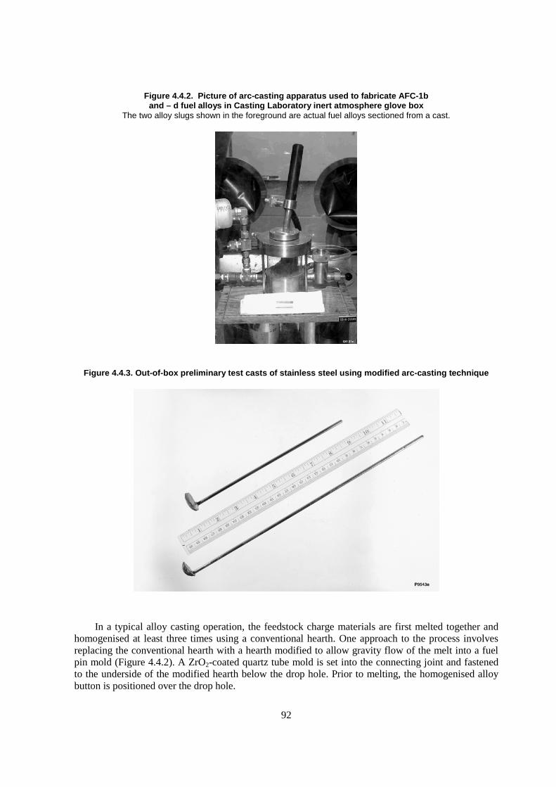
92
Figure 4.4.2. Picture of arc-casting apparatus used to fabricate AFC-1b and – d fuel alloys in Casting Laboratory inert atmosphere glove box
The two alloy slugs shown in the foreground are actual fuel alloys sectioned from a cast.
Figure 4.4.3. Out-of-box preliminary test casts of stainless steel using modified arc-casting technique
In a typical alloy casting operation, the feedstock charge materials are first melted together and homogenised at least three times using a conventional hearth. One approach to the process involves replacing the conventional hearth with a hearth modified to allow gravity flow of the melt into a fuel pin mold (Figure 4.4.2). A ZrO2-coated quartz tube mold is set into the connecting joint and fastened to the underside of the modified hearth below the drop hole. Prior to melting, the homogenised alloy button is positioned over the drop hole.
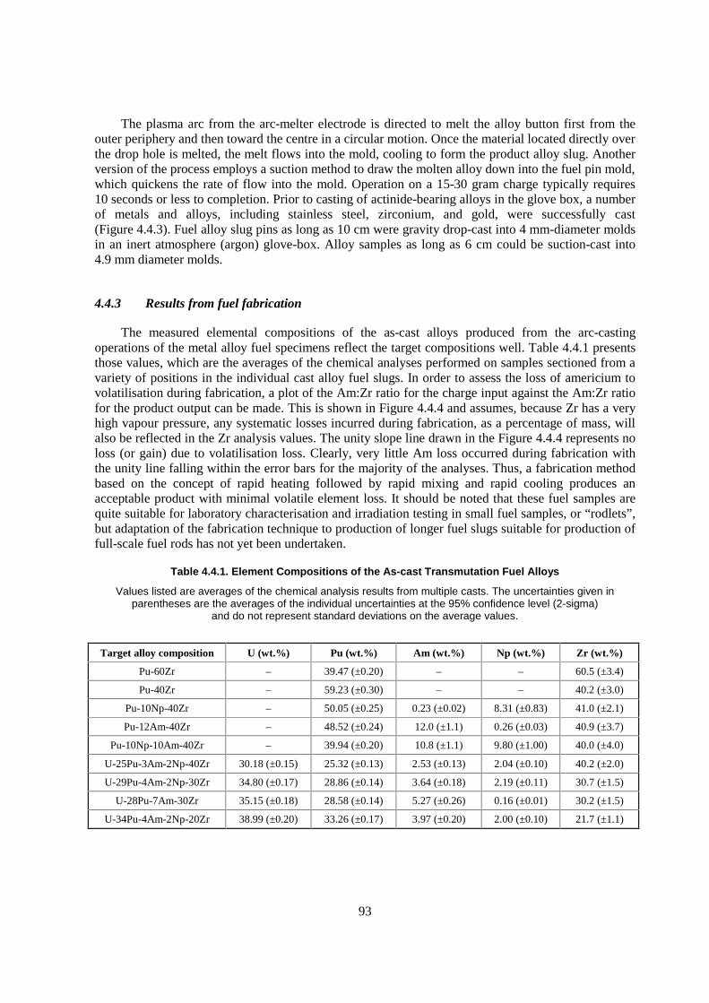
93
The plasma arc from the arc-melter electrode is directed to melt the alloy button first from the outer periphery and then toward the centre in a circular motion. Once the material located directly over the drop hole is melted, the melt flows into the mold, cooling to form the product alloy slug. Another version of the process employs a suction method to draw the molten alloy down into the fuel pin mold, which quickens the rate of flow into the mold. Operation on a 15-30 gram charge typically requires 10 seconds or less to completion. Prior to casting of actinide-bearing alloys in the glove box, a number of metals and alloys, including stainless steel, zirconium, and gold, were successfully cast (Figure 4.4.3). Fuel alloy slug pins as long as 10 cm were gravity drop-cast into 4 mm-diameter molds in an inert atmosphere (argon) glove-box. Alloy samples as long as 6 cm could be suction-cast into 4.9 mm diameter molds.
4.4.3 Results from fuel fabrication
The measured elemental compositions of the as-cast alloys produced from the arc-casting operations of the metal alloy fuel specimens reflect the target compositions well. Table 4.4.1 presents those values, which are the averages of the chemical analyses performed on samples sectioned from a variety of positions in the individual cast alloy fuel slugs. In order to assess the loss of americium to volatilisation during fabrication, a plot of the Am:Zr ratio for the charge input against the Am:Zr ratio for the product output can be made. This is shown in Figure 4.4.4 and assumes, because Zr has a very high vapour pressure, any systematic losses incurred during fabrication, as a percentage of mass, will also be reflected in the Zr analysis values. The unity slope line drawn in the Figure 4.4.4 represents no loss (or gain) due to volatilisation loss. Clearly, very little Am loss occurred during fabrication with the unity line falling within the error bars for the majority of the analyses. Thus, a fabrication method based on the concept of rapid heating followed by rapid mixing and rapid cooling produces an acceptable product with minimal volatile element loss. It should be noted that these fuel samples are quite suitable for laboratory characterisation and irradiation testing in small fuel samples, or “rodlets”, but adaptation of the fabrication technique to production of longer fuel slugs suitable for production of full-scale fuel rods has not yet been undertaken.
Table 4.4.1. Element Compositions of the As-cast Transmutation Fuel Alloys
Values listed are averages of the chemical analysis results from multiple casts. The uncertainties given in parentheses are the averages of the individual uncertainties at the 95% confidence level (2-sigma)
and do not represent standard deviations on the average values.
Target alloy composition U (wt.%) Pu (wt.%) Am (wt.%) Np (wt.%) Zr (wt.%)
Pu-60Zr – 39.47 (±0.20) – – 60.5 (±3.4)
Pu-40Zr – 59.23 (±0.30) – – 40.2 (±3.0)
Pu-10Np-40Zr – 50.05 (±0.25) 0.23 (±0.02) 8.31 (±0.83) 41.0 (±2.1)
Pu-12Am-40Zr – 48.52 (±0.24) 12.0 (±1.1) 0.26 (±0.03) 40.9 (±3.7)
Pu-10Np-10Am-40Zr – 39.94 (±0.20) 10.8 (±1.1) 9.80 (±1.00) 40.0 (±4.0)
U-25Pu-3Am-2Np-40Zr 30.18 (±0.15) 25.32 (±0.13) 2.53 (±0.13) 2.04 (±0.10) 40.2 (±2.0)
U-29Pu-4Am-2Np-30Zr 34.80 (±0.17) 28.86 (±0.14) 3.64 (±0.18) 2.19 (±0.11) 30.7 (±1.5)
U-28Pu-7Am-30Zr 35.15 (±0.18) 28.58 (±0.14) 5.27 (±0.26) 0.16 (±0.01) 30.2 (±1.5)
U-34Pu-4Am-2Np-20Zr 38.99 (±0.20) 33.26 (±0.17) 3.97 (±0.20) 2.00 (±0.10) 21.7 (±1.1)
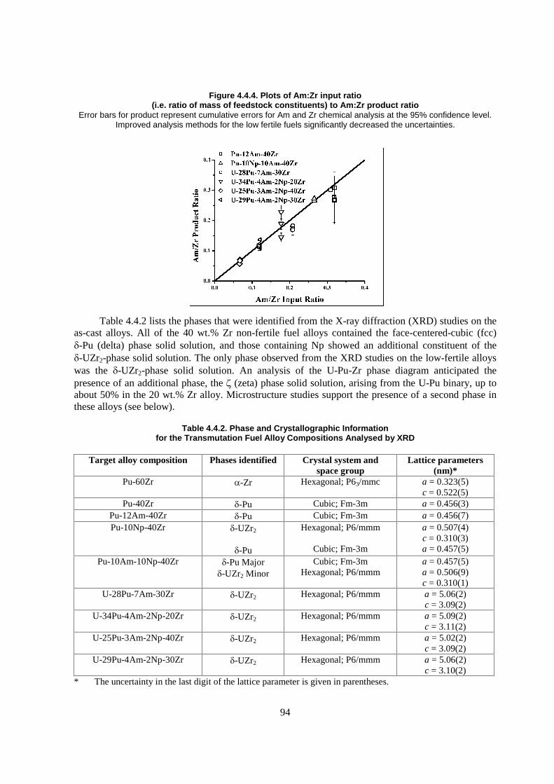
94
Figure 4.4.4. Plots of Am:Zr input ratio (i.e. ratio of mass of feedstock constituents) to Am:Zr product ratio
Error bars for product represent cumulative errors for Am and Zr chemical analysis at the 95% confidence level. Improved analysis methods for the low fertile fuels significantly decreased the uncertainties.
Table 4.4.2 lists the phases that were identified from the X-ray diffraction (XRD) studies on the as-cast alloys. All of the 40 wt.% Zr non-fertile fuel alloys contained the face-centered-cubic (fcc) �-Pu (delta) phase solid solution, and those containing Np showed an additional constituent of the �-UZr2-phase solid solution. The only phase observed from the XRD studies on the low-fertile alloys was the �-UZr2-phase solid solution. An analysis of the U-Pu-Zr phase diagram anticipated the presence of an additional phase, the � (zeta) phase solid solution, arising from the U-Pu binary, up to about 50% in the 20 wt.% Zr alloy. Microstructure studies support the presence of a second phase in these alloys (see below).
Table 4.4.2. Phase and Crystallographic Information for the Transmutation Fuel Alloy Compositions Analysed by XRD
Target alloy composition Phases identified Crystal system and space group
Lattice parameters (nm)*
Pu-60Zr �-Zr Hexagonal; P63/mmc a = 0.323(5) c = 0.522(5)
Pu-40Zr �-Pu Cubic; Fm-3m a = 0.456(3) Pu-12Am-40Zr �-Pu Cubic; Fm-3m a = 0.456(7) Pu-10Np-40Zr �-UZr2
�-Pu
Hexagonal; P6/mmm
Cubic; Fm-3m
a = 0.507(4) c = 0.310(3) a = 0.457(5)
Pu-10Am-10Np-40Zr �-Pu Major �-UZr2 Minor
Cubic; Fm-3m Hexagonal; P6/mmm
a = 0.457(5) a = 0.506(9) c = 0.310(1)
U-28Pu-7Am-30Zr �-UZr2 Hexagonal; P6/mmm a = 5.06(2) c = 3.09(2)
U-34Pu-4Am-2Np-20Zr �-UZr2 Hexagonal; P6/mmm a = 5.09(2) c = 3.11(2)
U-25Pu-3Am-2Np-40Zr �-UZr2 Hexagonal; P6/mmm a = 5.02(2) c = 3.09(2)
U-29Pu-4Am-2Np-30Zr �-UZr2 Hexagonal; P6/mmm a = 5.06(2) c = 3.10(2)
* The uncertainty in the last digit of the lattice parameter is given in parentheses.
95
Backscattered electron micrographs obtained from the nine alloys during scanning electron microscopy studies are shown in Figure 4.4.5. The Pu-40Zr and Pu-12Am-40Zr alloys appear as single-phase, consistent with the XRD results, with some degree of micro-porosity (dark contrast areas in Figures 4.4.5b and c). The Np containing alloys Pu-10Np-40Zr and Pu-10Am-10Np-40Zr (Figures 4.4.5d and e) appear multi-phase, consistent with the XRD results. All of the low-fertile alloys appear to be multi-phase, the degree to which approximately increases with decreasing Zr content. In most of the alloys, some globular Zr-rich precipitates were observed. In the low fertile alloys, these precipitates were exclusively associated with enriched oxygen content but in the low-fertile fuels both oxygen-rich and oxygen-depleted globular Zr-enriched precipitates were observed. Similar observations were noted in studies on the U-Pu-Zr system.
In addition to the phase and microstructure studies on these alloys, the higher temperature thermal behaviour and properties of these alloys and their constituents have been investigated from differential scanning calorimetry (DSC), thermal mechanical analysis (TMA), and laser flash thermal diffusivity measurements (LFTD) as well as fuel-cladding-chemical-interaction (fcci) diffusion couple experiments. From this extensive and ongoing series of studies, preliminary results from some of the first determinations of specific heat, thermal expansion, thermal conductivity and phase diagram development have been obtained.
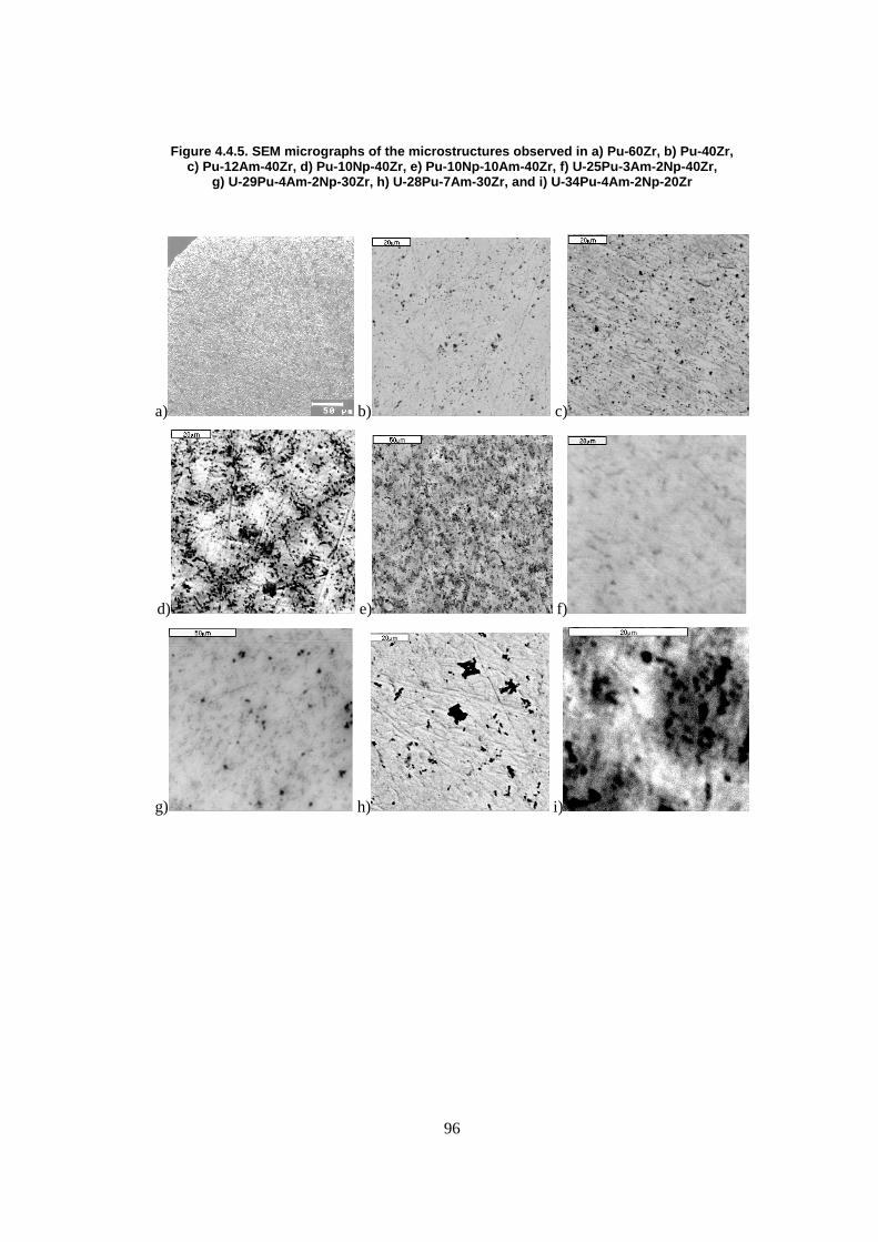
96
Figure 4.4.5. SEM micrographs of the microstructures observed in a) Pu-60Zr, b) Pu-40Zr, c) Pu-12Am-40Zr, d) Pu-10Np-40Zr, e) Pu-10Np-10Am-40Zr, f) U-25Pu-3Am-2Np-40Zr,
g) U-29Pu-4Am-2Np-30Zr, h) U-28Pu-7Am-30Zr, and i) U-34Pu-4Am-2Np-20Zr
a) b) c)
d) e) f)
g) h) i)
97
REFERENCES
Section 4.1
Colvin, P.H., F.F. Lange (1996), “Infiltration of porous alumina bodies with solution precursors: strengthening via compositional grading, grain size control, and transformation toughening”, J. Am. Ceram. Soc. 79, 1810.
Fernández, A., D. Haas, R.J.M. Konings, J. Somers (2003a), “Fabrication of CERamic-CERamic composites pellets for the transmutation of actinides”, J. Mater Sci. Lett. 22, 119-121.
Fernández, A., D. Haas, R.J.M. Konings, J. Somers (2002), Transmutation of actinides. J. Am. Ceram. Soc., 85 [3] 694-96.
Fernández, A., D. Haas, R.J.M. Konings, J. Somers (2003b), “Design and fabrication of specific ceramic-metallic fuels and targets”, J. Nucl. Mater. 319, 44-50.
Institute for Transuranium Elements (2001), Annual Report 2000, EUR 19812, p. 115.
International Centre for Diffraction Data, Powder Diffraction, File No. 30-1468, Newton Square, PA.
Kinoshita, T., K. Kuramoto, M. Uno, T. Yanagi, S. Yamanaka, H. Mitamura, T. Banba (2000), “Phase stability of ytriia-stabilized zirconia with dissolved cerium and neptunium oxides under oxidizing and reducing atmospheres”, J. Am. Ceram. Soc., 83, 391.
Konings, R.J.M., R. Conrad, G. Dassel, B. Pijlgroms, J. Somers, E. Toscano (2000), “The EFTTRA-T4 experiment on americium transmutation”, J. Nucl. Mat. 282, 159.
Konings, R.J.M., D. Haas (in press), “Fuels and targets for transmutation”. Compte rendu Acad. Sci., Ser IV.
Marple, B.R., D.J. Green (1993), “Graded compositions and microstructures by infiltration processing”, J. Mater. Sci. 28, 4637.
Richter, K., A. Fernandez, J. Somers (1997), “Infiltration of highly radioactive materials: a novel approach to the fabrication of targets for the transmutation and incineration of actinides”, J. Nucl.Mater. 249, 121.
Schmidt, N., Y. Croixmarie, E. Abonneau, J.P. Ottaviani, R.J.M. Konings, A. Fernandez, L. Donnet, F. Desmouliere (2003), “Conception and fabrication of innovative Am-based targets: The CAMIX/COCHIX experiment”, 7th Inform. Exch. Meeting on Partitioning and Transmutation, Jeju, Korea, 14-16 October 2002.
Somers, J., A. Fernandez (in prep.), “Production of Yttria Stabilised Zirconia by a Modified External Gelation Route”.
Sors, M., Y. Croixmarie (2000), Nucl. Instr. Methods Phys. Res. A, 4.28, 18.
98
Section 4.2
Advanced Fuel Cycle Initiative (2002), AFCI Quarterly Report, Jul.-Sep.
Akabori, M. et al. (2002), J. Nucl. Sci. Technol.
Arai, Y., K. Nakajima, (2000), “Preparation and characterization of PuN pellets containing ZrN and TiN”, J. Nucl. Mater. 281, 244-247.
Bernard, H., P. Bardelle, D. Warin (1987), “Mixed nitride fuels fabrication in conventional oxide line”, Technical committee meeting on Advanced fuel for fast breeder reactors: Fabrication and properties and their optimization. Vienna (Austria). 3-5 Nov 1987, IAEA, Vienna (Austria), IAEA-TECDOC-466, pp. 42-50.
Dehadraya, J.V. et al. (1997), “The oxidation behavior of uranium-cerium mononitride micro-spheres”, J. Nucl. Mater. 257, 313-321.
Ledergerber, G. (1982), Trans. Am. Nucl. Soc. 40, 55-56.
Matzke, Hj. (1991), “Fabrication and testing of non-oxide nuclear fuels for fast breeders”, in P. Vincenzini ed., Ceramics Today – Tomorrow's Ceramics, Elsevier Science Publishers B.V., pp. 2961-2975.
Ogawa, T., Y. Arai (2001), “Nitride/pyroprocess for MA transmutastion and fundamental database”, in Pyrochemical Separations, OECD/NEA Workshop Proceedings, Avignon, France, 14-15 March 2000, OECD, Paris, ISBN 92-64-1844.2-0, pp. 157-164.
Richter, K., H. Blank (1987), “Fabrication processes and characterization of LMFBR carbide and nitride fuels and fuel pins”, Technical committee meeting on Advanced fuel for fast breeder reactors: Fabrication and properties and their optimization. Vienna (Austria). 3-5 November 1987, IAEA, Vienna (Austria), IAEA -TECDOC-466, pp. 58-67.
Streit, M. et al. (2002), “(Pu,Zr)N annular fuel pellets shaped by direct coagulation cating”, J. Nucl. Sci. Technol., Supplement 3, pp. 741-744, (November).
Takano, M., A. Itoh, M. Akabori, K. Minato, M. Numata (2003), “Study on The Stability of AmN and (Am,Zr)N”, GLOBAL 2003, New Orleans.
Takano, M. et al. (2001), “Carbothermic synthesis of (Cm,Pu)N”, J. Nucl. Mater. 294, 24-27.
Yamagishi, S., A. Hasegawa, T. Ogawa, (1994), JAERI-Tech 94-010.
Section 4.3
Alder, H.P., G. Ledergerber, R.W. Stratton (1988), Advanced fuel for fast breeder reactors produced by gelation methods, Paul Scherrer Inst.
Bychkov, A.V., O.V. Skiba, A.A. Mayorshin (2000), Concept of a plant for the BN-800 reactor fuel recycling with application of pyro-process and vibro-packing technology.
99
De Saint Jean, C. et al. (2001), Americium and Curium heterogeneous transmutation in moderated S/A in the framework of CNE scenarios studies, GLOBAL 2001, 9-13 September 2001, Paris.
Evans, P.E., R.S. Millman (1964), “The vibratory packing of powders”, Powder Metallurgy, Vol. 7, N° 13, Ed. by Werner Lesznyski, (Interscience) Wiley, New York.
Faugere, J.L. (1989), “Étude du risque de perte de combustible lors de l’irradiation dans Phénix d’un nitrure à base de sphères (Analysis of fuel loss risks during irradiation in Phenix of a sphere-based nitrate)”, Remarks by DECPU on the PSI report dated 19.5.1988 by MF BOTTA. Encl. with document DECPU No. 31, dated 28 February (1989).
Fossoul, E., E. Bemden (1963), Vibration and vibration-swaging fabrication of nuclear fuels enriched in plutonium for water reactors, Enlarged colloquium fuel cycles for power reactors. Baden-Baden, 9-14 September 1963. Note BN 6309-09.
Funada T, K. Aratani, A. Shono (2002), The current status of collaboration with Russian institutes for Russian surplus weapons plutonium disposition.
Gray, W.A. (1972), Introductory review paper: a review of the compaction of powders by vibration, Proceedings of the first international conference on the compaction and consolidation of particulate matter. Brighton, UK, pp. 99-105.
Hausner, H.H. (1972), The role of inter-particulate friction in powder technology, Proceedings of the first international conference on the compaction and consolidation of particulate matter. Brighton, UK, pp. 7-12.
Hobbs, J.W., P. Parkes, G.R. Chilton (1996), “Alternative forms of nuclear fuel: vibro-compacted granules”, EUROMAT’96 : Materials and nuclear power, Bournemouth. 21-23 October 1996.
Höchel, Von J., B. Liebmann (1966), “Herstellung von Brennstoffrohren für den HDR-Reaktor”, Atomwirtschaft, November 1966, pp. 530-535.
Kim, Yeon-Soo (2001), Thermal conductivity model of vibro-packed fuel, Argonne National Lab., Nuclear Technology Div., Idaho Falls, ID, US.
Knudsen, P., C. Bagger, N. Kjaer-Pedersen (1977), Performance evaluation of UO sub 2 -Zr fuel in power ramp tests.
Lagos, S., R. Becerra (1999), “Densification of Lithium Titanate sphere”, Comission Chilena de Energia Nuclear, Chile.
McGeary, R.K. (1961), “Mechanical packing of spherical particles”, JACS, Vol. 44, No. 10, pp. 513-522.
Mounfield, C.C., S.F. Edwards (1994), “A model for the packing of irregulary shaped grains”, Physica A, 210, pp. 301-316.
Nowak, E.R., J.B. Knight, M.L. Povinelli, H.M. Jaeger, S.R. Nagel (1997), “Reversibility and irreversibility in the packing of vibrated granular material”, Powder Technology, 94, pp. 79-83.
100
Philippe, P. (2002), “Étude théorique et expérimentale de la densification des milieux granulaires (Theoretical and experimental analysis of granular environment densification)”, Theses of the University of Rennes 1 (France), Groupe Matière Condensée et Matériaux (material and condensed matter Group) defended on 3 July 2002, Order No. 2706.
Pillai, K.T., V.N. Vaydia, D.D. Sood (1986), Vibro compaction studies for preparation of sphere-pac nuclear fuel pins, Bhabha Atomic Research Centre, Fuel Chemistry Division, Bombay, India.
Pillon, S. et al. (2002), Impact of the curium management on the fabrication of MA-bearing targets at an industrial study in the frame of a mixed PWR and FBR P&T scenario, 7th Information Exchange Meeting on Actinide and Fission Product Partitioning and Transmutation. Jeju, Korea, 14-16 October 2002, OECD, Paris.
Pillon, S., J. Somers, S. Granjean, J. Lacquement, “Aspects of fabrication of curium-based fuels and targets”.
Shigetome, Y., H. Miyamoto, M. Suzuki (2001), Development of compaction technology of vibro-compaction fuel fabrication – investigation of compaction behaviour and vibration parameter effect on sphere fuel compaction, (JNC).
Skiba, O.V., A.A. Mershin, A.V. Bychkov (1999), Nuclear reactor fuel cycle technology with pyroelectrochemical processes, Inst. Atomnykh Reaktorov, Dimitovgrad – Russia.
Sullivan, J.D., C.L. Brayman, R.A. Verrall, J.M. Miller, (1991), Canadian ceramic breeder sphere-pac technology, Capability and recent results, (AEC).
Wakeman, R.J. (1975), “Packing densities of particles with Log-Normal Size distributions”, Powder Technology, 11, pp. 297-299.
Wallin, H. (2000), The Sphere-PAC fuel code, “SPHERE-3”.
Yu, A.B., J. Bridgewater, A. Burbidge (1997), “On the modelling of the packing of fine particles”, Powder Technology, 92, pp. 185-194.
Yu, A.B., J.S. Hall, (1994), “Packing of fine powders subjected to tapping”, Powder Technology, 78, pp. 247-256.
Yu, A.B., N. Standish (1993), “A study of the packing of particles with a mixture size distribution”, Powder Technology, 76, pp. 113-124
Yu, A.B., R.P. Zou, N. Standish (1996), “Modifying the linear packing model for predicting the porosity of non-spherical particle mixtures”, Ind. Eng. Chem. Res., 35, pp. 3730-3741.
Section 4.4
Walters, L.C., R.D. Leggett (1993), “Status of LMR Fuel Development in the USA”, Journal of Nuclear Materials, 10, pp. 1-10.
Hofman, G.L., L.C. Walters and T.H. Bauer (1997), “Metallic Fast Reactor Fuels”, Special Issue Progress in Nuclear Energy, The Technology of the Integral Fast Reactor and its Associated Fuel Cycle, 31, No. 1/2, p. 83.
101
Chapter 5
FUEL BEHAVIOUR PREDICTION
5.1 Irradiation performance issues
A great deal of relevant experience exists in general on the irradiation performance of fuel types proposed for transmutation. United States experience with metal alloy fuels comes most recently from Experimental Breeder Reactor-II (EBR-II) operations and the integral fast reactor programme. United States experience with nitride fuels was obtained during the advanced fuel programme, which was associated with the liquid metal fast breeder reactor programme of the 1970s and 1980s, and space reactor development. Experience with oxide fuels is quite broad, with substantial experience gained in France, Japan, the United Kingdom, the United States and others. Experience with dispersion fuels is less substantial but is quite broad, coming from various national programmes with research reactors and space reactor development. However, there is little to no experience with the compositions of the fuel types proposed for transmutation purposes.
The single greatest uncertainty in transmutation fuels technology is irradiation performance of the proposed fuels. It must be demonstrated that the proposed fuels perform acceptably under irradiation to the target burnup. Experience shows that fuel performance almost always degrades as Pu-content (or TRU content) of a fuel is increased. Yet, many of the proposed transmutation schemes call for fuel compositions that are primarily TRU.
The primary performance criteria for a fuel rod in general are that for all anticipated conditions the fuel should retain its position in the core (or at least tend toward less reactive configurations) and the fuel rod should contain fission products and maintain a coolable geometry. Experience with various fuel forms (and metallic fuel, in particular) has proven the following characteristics to be important to fuel performance and lifetime. Some anticipated difficulties with high-MA-content transmutation fuels are noted. However, much of the discussion of such difficulties, though based on experience with uranium-based, analogous fuel types, is speculative.
5.1.1 Dimensional stability
The dimensions of the fuel material can change dramatically if the material exhibits considerable irradiation swelling or irradiation growth. Such effects have implications for neutronic performance of the core and can introduce stresses into the cladding that lead to cladding breach. For the higher-burnup fuel designs currently under consideration today, the dominant effect is fission product-induced swelling. For moderate-to-high burnup, fission gas-induced swelling contributes most signify-cantly. However, for fuel types that release a large fraction of fission gas, e.g. metal alloy fuel, higher burnups lead to appreciable swelling due to solid fission product build-up.
An additional consideration for transmutation fuels is of He generated due the relatively higher amounts of Am and Cm in the fuel. Such He generation is expected to exacerbate the effects that
102
typically arise from continued generation of fission gases; i.e. gas-driven swelling, gas release to the fuel rod plenum, which increases internal rod pressure, and evolution of fuel microstructure and morphology, which influences thermal conductivity and local fuel chemistry.
5.1.2 Fission gas pressurisation
Some fuel types, particularly metallic fuel, release large amounts of fission gas into the fuel rod plenum. Therefore, if the plenum is not adequately sized to accommodate this fission gas content, then pressure-induced stresses can lead to cladding failure, particularly during transient-induced tempera-ture increases. This consideration is particularly important, as noted above, for fuels with relatively high amounts of Am and/or Cm for which He generation would be considerable.
5.1.3 Phase stability or microstructural evolution
The high-temperature, high-flux environment of the reactor core (which also induces temperature gradients) typically alters the microstructure and/or local composition of a fuel material from its as-fabricated state. Such changes include development of porosity that can vary in morphology across the radius of a fuel rod, establishment of different phases and redistribution of fuel constituents through the fuel material. Build-up of fission products during irradiation can also contribute to these effects. Ultimately, such effects manifest themselves by degrading thermal conductivity, by introducing local high-power zones in the fuel, by enhancing fuel-cladding chemical interaction, or by possibly affecting gas release or swelling phenomena.
Enhanced generation of He in high-AM/Cm fuels would likely impact the kinetics of bubble formation in the fuel. However, and perhaps more importantly, the chemistry of transmutation fuels will be impacted by the presence of relatively high amounts of Np, Am, and Cm. Such impacts might include the formation and location of fission products that interact with cladding materials (e.g. metallic lanthanides in metal fuel) or the formation of compositional and/or morphological zones in the fuel. Metallic and oxide fast reactor fuels have been shown to form radial composition zones due to temperature-gradient-associated migration of fuel constituents. It remains to be determined whether minor actinides influence such behaviour.
5.1.4 Fuel compatibility with cladding
For many fuel forms, contact of fuel or fission products with the interior cladding surface leads to interactions that embrittle the cladding or otherwise compromise its ability to withstand stresses. This is particularly true for some metal fuel alloys, in which fuel constituents and fission products interdiffuse with cladding constituents, resulting in thinning of the effective wall of the cladding and incorporation of cladding elements into the fuel. Such interaction also leads to formation of low-melting-temperature phases or compositions in the fuel or cladding or in the interaction zone at the fuel-cladding interface; formation of such zones often has implications for fuel reliability during high-burnup, steady state operation and during certain transients.
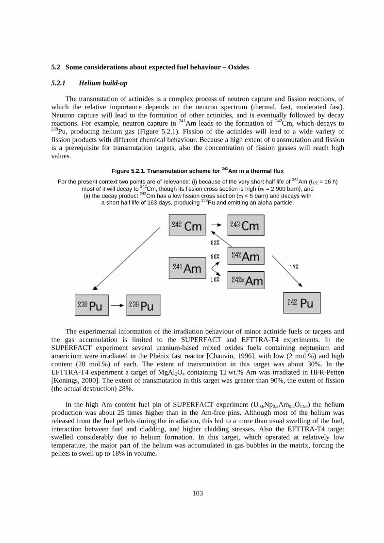
103
5.2 Some considerations about expected fuel behaviour – Oxides
5.2.1 Helium build-up
The transmutation of actinides is a complex process of neutron capture and fission reactions, of which the relative importance depends on the neutron spectrum (thermal, fast, moderated fast). Neutron capture will lead to the formation of other actinides, and is eventually followed by decay reactions. For example, neutron capture in 241Am leads to the formation of 242Cm, which decays to 238Pu, producing helium gas (Figure 5.2.1). Fission of the actinides will lead to a wide variety of fission products with different chemical behaviour. Because a high extent of transmutation and fission is a prerequisite for transmutation targets, also the concentration of fission gasses will reach high values.
Figure 5.2.1. Transmutation scheme for 241Am in a thermal flux
For the present context two points are of relevance: (i) because of the very short half life of 242Am (t1/2 = 16 h) most of it will decay to 242Cm, though its fission cross section is high (�f = 2 900 barn), and (ii) the decay product 242Cm has a low fission cross section (�f < 5 barn) and decays with
a short half life of 163 days, producing 238Pu and emitting an alpha particle.
The experimental information of the irradiation behaviour of minor actinide fuels or targets and the gas accumulation is limited to the SUPERFACT and EFTTRA-T4 experiments. In the SUPERFACT experiment several uranium-based mixed oxides fuels containing neptunium and americium were irradiated in the Phénix fast reactor [Chauvin, 1996], with low (2 mol.%) and high content (20 mol.%) of each. The extent of transmutation in this target was about 30%. In the EFTTRA-T4 experiment a target of MgAl2O4 containing 12 wt.% Am was irradiated in HFR-Petten [Konings, 2000]. The extent of transmutation in this target was greater than 90%, the extent of fission (the actual destruction) 28%.
In the high Am content fuel pin of SUPERFACT experiment (U0.6Np0.2Am0.2O1.93) the helium production was about 25 times higher than in the Am-free pins. Although most of the helium was released from the fuel pellets during the irradiation, this led to a more than usual swelling of the fuel, interaction between fuel and cladding, and higher cladding stresses. Also the EFTTRA-T4 target swelled considerably due to helium formation. In this target, which operated at relatively low temperature, the major part of the helium was accumulated in gas bubbles in the matrix, forcing the pellets to swell up to 18% in volume.
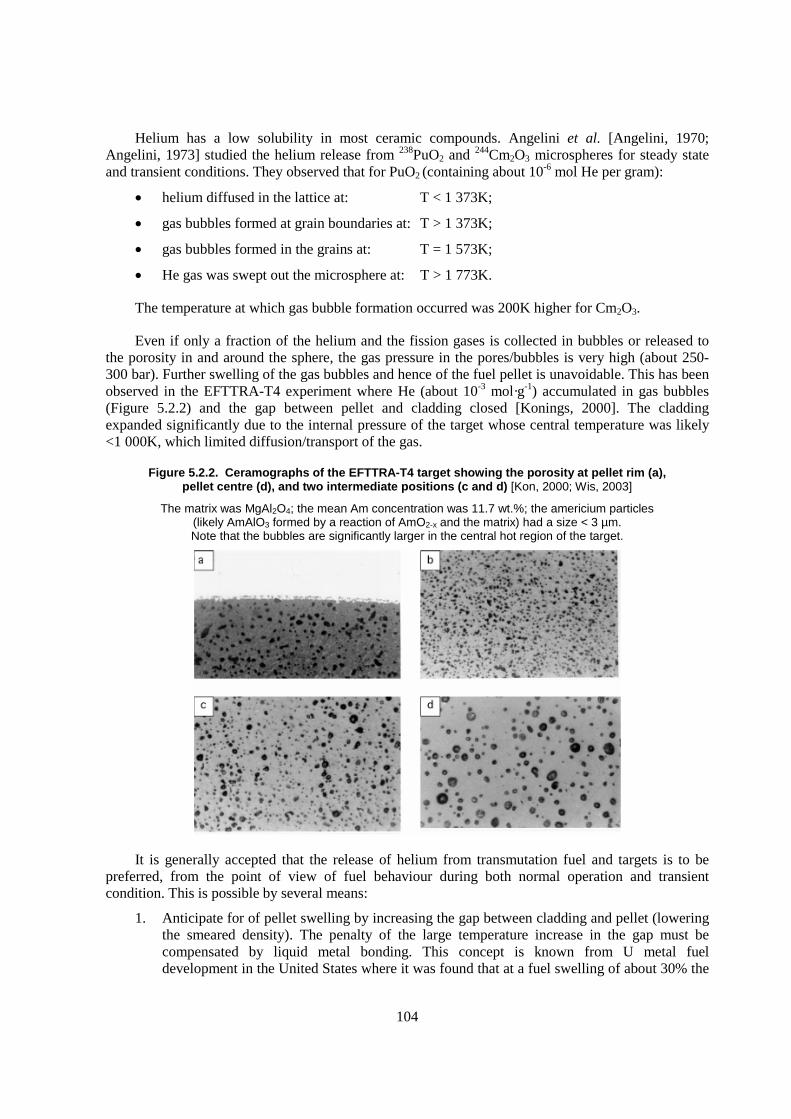
104
Helium has a low solubility in most ceramic compounds. Angelini et al. [Angelini, 1970; Angelini, 1973] studied the helium release from 238PuO2 and 244Cm2O3 microspheres for steady state and transient conditions. They observed that for PuO2 (containing about 10-6 mol He per gram):
� helium diffused in the lattice at: T < 1 373K;
� gas bubbles formed at grain boundaries at: T > 1 373K;
� gas bubbles formed in the grains at: T = 1 573K;
� He gas was swept out the microsphere at: T > 1 773K.
The temperature at which gas bubble formation occurred was 200K higher for Cm2O3.
Even if only a fraction of the helium and the fission gases is collected in bubbles or released to the porosity in and around the sphere, the gas pressure in the pores/bubbles is very high (about 250-300 bar). Further swelling of the gas bubbles and hence of the fuel pellet is unavoidable. This has been observed in the EFTTRA-T4 experiment where He (about 10-3 mol·g-1) accumulated in gas bubbles (Figure 5.2.2) and the gap between pellet and cladding closed [Konings, 2000]. The cladding expanded significantly due to the internal pressure of the target whose central temperature was likely <1 000K, which limited diffusion/transport of the gas.
Figure 5.2.2. Ceramographs of the EFTTRA-T4 target showing the porosity at pellet rim (a), pellet centre (d), and two intermediate positions (c and d) [Kon, 2000; Wis, 2003]
The matrix was MgAl2O4; the mean Am concentration was 11.7 wt.%; the americium particles (likely AmAlO3 formed by a reaction of AmO2-x and the matrix) had a size < 3 µm. Note that the bubbles are significantly larger in the central hot region of the target.
It is generally accepted that the release of helium from transmutation fuel and targets is to be preferred, from the point of view of fuel behaviour during both normal operation and transient condition. This is possible by several means:
1. Anticipate for of pellet swelling by increasing the gap between cladding and pellet (lowering the smeared density). The penalty of the large temperature increase in the gap must be compensated by liquid metal bonding. This concept is known from U metal fuel development in the United States where it was found that at a fuel swelling of about 30% the
105
gas bubbles in the fuel start to interconnect to form paths for release. Sodium bonding was used for this fuel type. Also for (U,Pu)N fuel such a concept has been investigated successfully.
2. High initial porosity so that a stable network of release paths already exists at the beginning of the irradiation. This has a large penalty on the thermal conductivity and the most likely way to compensate this is a composite design.
3. High operating temperature of the fuel to achieve thermally driven release from beginning of irradiation and minimal pellet swelling. The main penalty here is the smaller margin to melting, which cannot be compensated. This concept was essentially applied in the SUPERFACT fuels, for which the central temperature was around 2 000K.
Retention of helium, on the other hand, could be realised in coated particles in which the porous buffer layer is designed to accommodate the helium plus fission gases produced. For fast reactor application the traditional TRISO concept (with layers of porous graphite, SiC and dense graphite) needs to be reconsidered.
5.2.2 Thermal margin
The mixed oxides (U,MA)O2 and (Zr,Y,MA)O2 are the prime candidates for oxide fuels and targets. They have, however, less favourable thermal properties as we have discussed in section 2.3. This results in high central fuel temperatures, already at moderate linear ratings. For example, the maximum centreline temperature in is around 2 200K at beginning of life a linear heating rate of 280 W cm-1 (Figure 5.2.3). This temperature could further increase in case of radiation induced deterioration of the thermal conductivity during irradiation, for which no data are available. Considering the lower fuel melting temperatures for these materials, the thermal margin would be reduced by several hundreds of degrees, which can only be compensated by lower operating power. This is, of course, less problematic for targets with low MA content intended for once through transmutation.
The thermal conductivity of fuels and targets can be tailored to a certain extent by a careful selection of the matrix in a composite target. The most promising matrices are MgO for ceramic-ceramic (CERCER) type and steel for ceramic-metal (CERMET) type targets, both matrices being very good thermal conductors. In such a case much lower centreline temperatures will be obtained, for example 1 400K in a composite target with an MgO also for a linear rating of 280 W cm-1. If the particle size is between 50 and 250 �������������������� ���� �� ��������� ���� ������ � ���������1998] and hot spots will thus not occur.
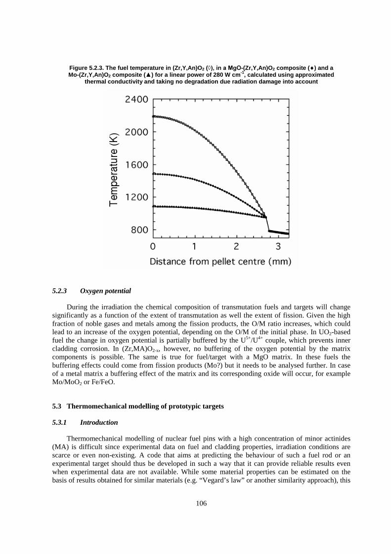
106
Figure 5.2.3. The fuel temperature in (Zr,Y,An)O2 (����������-(Zr,Y,An)O2 composite (�) and a Mo-(Zr,Y,An)O2 composite ( ) for a linear power of 280 W cm-1, calculated using approximated
thermal conductivity and taking no degradation due radiation damage into account
5.2.3 Oxygen potential
During the irradiation the chemical composition of transmutation fuels and targets will change significantly as a function of the extent of transmutation as well the extent of fission. Given the high fraction of noble gases and metals among the fission products, the O/M ratio increases, which could lead to an increase of the oxygen potential, depending on the O/M of the initial phase. In UO2-based fuel the change in oxygen potential is partially buffered by the U5+/U4+ couple, which prevents inner cladding corrosion. In (Zr,MA)O2-x, however, no buffering of the oxygen potential by the matrix components is possible. The same is true for fuel/target with a MgO matrix. In these fuels the buffering effects could come from fission products (Mo?) but it needs to be analysed further. In case of a metal matrix a buffering effect of the matrix and its corresponding oxide will occur, for example Mo/MoO2 or Fe/FeO.
5.3 Thermomechanical modelling of prototypic targets
5.3.1 Introduction
Thermomechanical modelling of nuclear fuel pins with a high concentration of minor actinides (MA) is difficult since experimental data on fuel and cladding properties, irradiation conditions are scarce or even non-existing. A code that aims at predicting the behaviour of such a fuel rod or an experimental target should thus be developed in such a way that it can provide reliable results even when experimental data are not available. While some material properties can be estimated on the basis of results obtained for similar materials (e.g. “Vegard’s law” or another similarity approach), this
107
is not always possible and can lead to large uncertainties. On the other hand, the ultimate dream of thermomechanical modelling, namely being able to calculate the fuel rod features from the first principles, is far from realistic today. We are thus pushed to develop a tool that uses physically sound models with a broad applicability range that can deal with materials for which experimental data are lacking, but at the same time be aware of the fact that such an approach involves a simplification which will also lead to uncertainties. The fact that physical models are used instead of the correlations developed on the basis of the experimental data enables one to judge on their applicability for a given configuration and should lead to a more robust tool for the prediction of material properties for which the experimental database is poor.
In this research, the expected irradiation conditions of the experimental accelerator driven subcritical system (ADS) MYRRHA under design at SCK•CEN [Ait Abderrahim, 2001] has been chosen as a reference. Its design is now sufficiently detailed to define the irradiation conditions. The present chapter outlines the modifications to the fuel performance code MACROS that were essential to cope with the minor actinides (MA) and presents a series of calculations performed on a small set of specific MA containing targets placed in the MYRRHA core.
5.3.2 Outline of the MACROS code
MACROS (Mechanistic Analysis Code for Reactor Oxide fuel Systems) is programmed in FORTRAN 90/95 as a code to analyse neutronic, thermal and mechanical behaviour of fuel rods under quasi-steady-state LWR, FR and ADS irradiation conditions and to address some aspects of a long term storage of spent fuel. The MACROS code uses the one-cell approach where a cell consists of the fuel rod itself and an equivalent amount of coolant/moderator. It is developed to simulate fuel rod behaviour when the power and boundary conditions change slowly. The main objective of the code is to address issues of high burnup as realistically as possible by means of coupling neutronic, hydraulic and thermomechanical fuel performance models. Emphasis is put on applicability of the code to model in-pile behaviour of homogeneous and heterogeneous mixed oxide fuels with a high content of plutonium and/or minor actinides. A brief general description of the code is given in [Lemenov, 2002].
The MACROS code was conceived by coupling the steady-state fuel performance code ASFAD [Lemenov, 1994] with the one-cell depletion code PLUTON [Lemenov, 2001], which originally was developed as a code to generate radial burnup and power profiles needed for the JAERI fuel behaviour code FEMAXI-V [Suzuki, 2000].
The MACROS code calculates temperature, internal pressure, and deformation of a fuel rod as function of the fuel rod power history and coolant/moderator boundary conditions. Light water, heavy water and Pb-Bi coolants/moderators are included in the code database. The main phenomena and properties modelled by the code include: material properties, radial heat conduction through the fuel and cladding, elastic, creep and plastic deformations of the cladding, fuel-cladding mechanical interaction, fission product build-up (including He), solid, pseudo-solid and gas swelling, fission gas release, fuel rod internal pressure build-up, heat transfer between fuel and cladding, clad oxidation on the fuel side and on the coolant side, radial distribution of volumetric heat generation rate, depletion information (evolution of initial vector of fissile and fertile isotopes).
A close coupling of the thermal, mechanical and neutronic modelling is needed when dealing with heterogeneous configurations of fuel arrangement, i.e. separation of moderator-coolant and absorber-fuel. Neutronic effects determine non-uniform power generation and burnup distributions both in radial and axial directions. With burnup increase the as-fabricated fuel properties change considerably following time-power irradiation history and actual hydraulic conditions. MA fuel
108
irradiated in a thermal neutron spectrum is much more sensitive to these changes in comparison to that irradiated in a fast neutron spectrum. However, some scenarios of burning minor actinides consider both spectra. Therefore, the MACROS code was designed with sufficient flexibility to account for either fast or thermal spectra. In order to handle the depletion problem adequately up to high burnup and to provide the inputs for modelling of the fuel rod thermal-mechanical behaviour (i.e. radial power distribution, radial burnup profile and matrix inventory with fission products), a new burnup model in replacement of the original PLUTON burnup model was developed. A summary of the PLUTON burnup model updates is provided below in view of its importance and in order to explain differences between preliminary results published in [Sobolev, 2003] and new code evaluations presented here.
The code itself and some thermal-mechanical models are still under development; integral predictions of mechanical behaviour have not yet been sufficiently verified against qualified data bases. On the other hand, neutronic aspects (depletion modules) of the code and models to predict material properties have been properly validated for UO2, MOX and to a lesser extent for MA-mixed oxides.
5.3.3 Summary of the PLUTON burnup model updates
1. Verification and functional modifications
A complete description of the original PLUTON code and its underlying models is given in [Lemenov, 2001]. Existing models integrated in the PLUTON code (which applicability for fission of U235 and build-up of plutonium in LWR and HBWR conditions had been already extensively verified earlier) have been re-examined and updated for LWR and FR MOX and ADS fuels to apply. These updates are based on some available in-reactor and post-reactor experimental results. In addition, PLUTON code subroutines have been re-programmed with FORTRAN 90/95 standard to be incorporated as neutronic module PLUTON-MG in the MACROS code.
The new PLUTON-MG (Multi-Group) version generates three types of data: inputs for the fission gas release model (fission rate density, concentrations of He, Kr and Xe), inputs for the lattice thermal conductivity model (isotope composition, concentrations of irradiation-induced point defects, burnup); and inputs for the thermal calculations (volumetric heat generation rate). The original list of trans-uranium elements (TRU) of the code has been extended to include the relevant chains of thoria based fuels as well as the fuels containing higher MA.
2. Helium generation
Despite of its importance, generation of helium was not calculated in the original PLUTON code. This limitation was removed by including � -decay chains of fissile and fertile isotopes into the calculation scheme of the code (Figure 5.3.1).
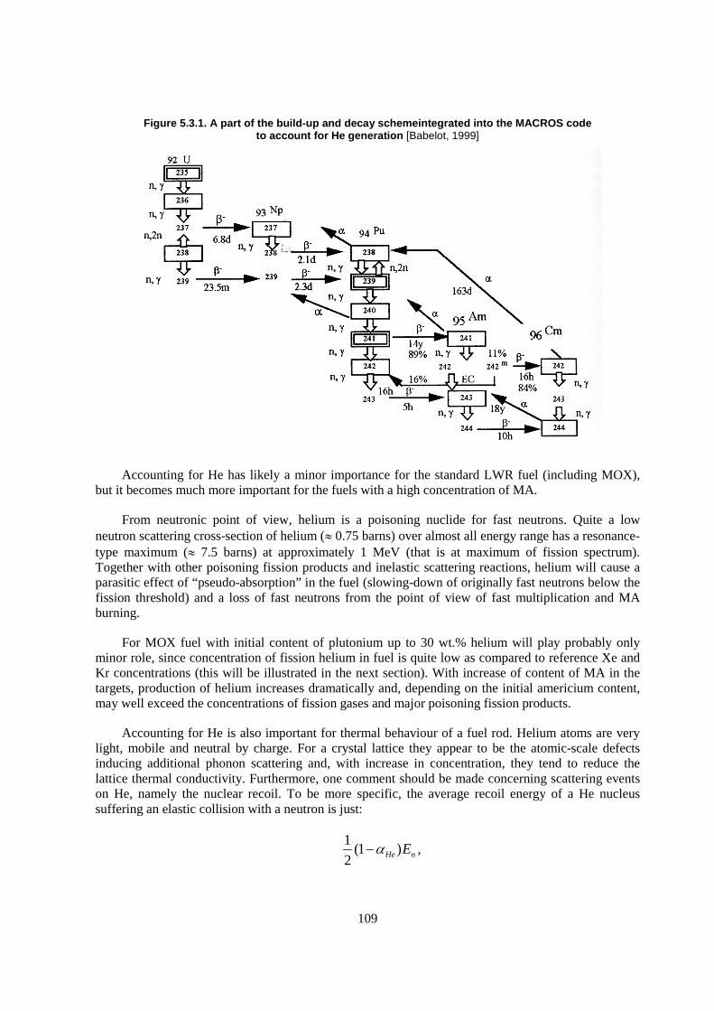
109
Figure 5.3.1. A part of the build-up and decay schemeintegrated into the MACROS code to account for He generation [Babelot, 1999]
Accounting for He has likely a minor importance for the standard LWR fuel (including MOX), but it becomes much more important for the fuels with a high concentration of MA.
From neutronic point of view, helium is a poisoning nuclide for fast neutrons. Quite a low neutron scattering cross-section of helium (� 0.75 barns) over almost all energy range has a resonance-type maximum (� 7.5 barns) at approximately 1 MeV (that is at maximum of fission spectrum). Together with other poisoning fission products and inelastic scattering reactions, helium will cause a parasitic effect of “pseudo-absorption” in the fuel (slowing-down of originally fast neutrons below the fission threshold) and a loss of fast neutrons from the point of view of fast multiplication and MA burning.
For MOX fuel with initial content of plutonium up to 30 wt.% helium will play probably only minor role, since concentration of fission helium in fuel is quite low as compared to reference Xe and Kr concentrations (this will be illustrated in the next section). With increase of content of MA in the targets, production of helium increases dramatically and, depending on the initial americium content, may well exceed the concentrations of fission gases and major poisoning fission products.
Accounting for He is also important for thermal behaviour of a fuel rod. Helium atoms are very light, mobile and neutral by charge. For a crystal lattice they appear to be the atomic-scale defects inducing additional phonon scattering and, with increase in concentration, they tend to reduce the lattice thermal conductivity. Furthermore, one comment should be made concerning scattering events on He, namely the nuclear recoil. To be more specific, the average recoil energy of a He nucleus suffering an elastic collision with a neutron is just:
1(1 )
2 He nE�� ,

110
where
21
0.361He
A
A�
�� �� � �� ,
A = 3 or 4 is the nuclear mass number of He; and
nE is the incident neutron energy in the “center-of-mass” system.
For the fast neutrons, this recoil energy will be in the keV to low MeV range. Hence, the recoiling nucleus will not only be displaced from of its position in the lattice by the collision, but will possess sufficient recoil energy to dislocate other nucleus in the lattice (since displacement energy in materials of our interest is only 25 eV) and lead to significant increase in the material radiation damage. This supplementary damage is to be taken into account in calculation of the lattice thermal conductivity and, ultimately, fuel temperature.
Contrary, release of helium to the fuel rod free volume may have a positive effect on the integral fuel rod performance. Fission gases such as Xe and Kr are contaminating fission products, since their release cause considerable degradation of gap conductance; the released He will compensate this degradation.
The MACROS code first calculates the production of helium as a consequence of alpha-decay of some heavy metal nuclides, namely 232U, 236Pu, 241, 242(m)Am, and 242-244Cm. Its neutronic module is linked with the material properties and fission gas release modules, which then use the calculated local concentrations of the produced helium and other fission products in iterative calculations of the lattice thermal conductivity, gas distribution between lattice (atomic scale), intra-granular bubbles, grain boundaries and free volume, resulting fuel swelling and fission gas release.
3. Fuel depletion analysis
� General approach
One-cell fuel depletion analysis in the PLUTON code is concerned with predicting the long-term changes in fuel composition. A set of equations for build-up/burning fissile and fertile isotopes in its original version of the burnup model was solved and implemented in an analytical form with quite inevitable simplifications. These simplifications were related to the analytical form of the solution of the depletion equations wherein some important cross-contributions were ignored. A second simplification is related to the use of the basic (and standard) assumption known as “constant power approximation”.
In the MACROS code, the depletion module (burnup model) subdivides each step of fuel thermal and mechanical behaviour in a number of shorter depletion steps in such a way that the two basic approximations – constant flux and constant power – become similar. Modifications of the burnup model will not lead to appreciable corrections in the predictions of the depletion rate for standard UO2 fuel irradiated in LWR or HBWR conditions. One may expect, however, important discrepancies for fuels containing elevated MA concentrations and irradiated in a fast flux. In these conditions, the microconstants are characterised by quite small and comparable absolute values, and consequently cross contributions in rate equations of minor actinide nuclides become more important.
Fuel depletion analysis in the MACROS code is coupled with solutions of the static multi-group equations for spatial (radial) distributions of the neutron flux in fuel and moderator. This task also
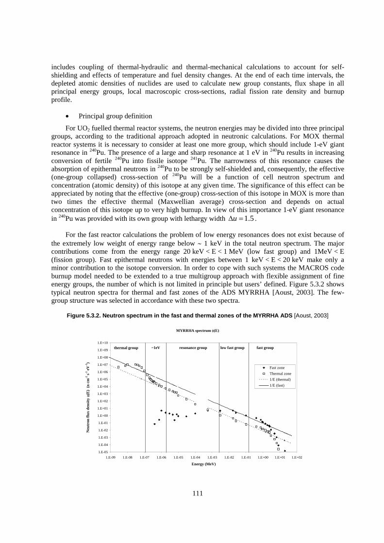
111
includes coupling of thermal-hydraulic and thermal-mechanical calculations to account for self-shielding and effects of temperature and fuel density changes. At the end of each time intervals, the depleted atomic densities of nuclides are used to calculate new group constants, flux shape in all principal energy groups, local macroscopic cross-sections, radial fission rate density and burnup profile.
� Principal group definition
For UO2 fuelled thermal reactor systems, the neutron energies may be divided into three principal groups, according to the traditional approach adopted in neutronic calculations. For MOX thermal reactor systems it is necessary to consider at least one more group, which should include 1-eV giant resonance in 240Pu. The presence of a large and sharp resonance at 1 eV in 240Pu results in increasing conversion of fertile 240Pu into fissile isotope 241Pu. The narrowness of this resonance causes the absorption of epithermal neutrons in 240Pu to be strongly self-shielded and, consequently, the effective (one-group collapsed) cross-section of 240Pu will be a function of cell neutron spectrum and concentration (atomic density) of this isotope at any given time. The significance of this effect can be appreciated by noting that the effective (one-group) cross-section of this isotope in MOX is more than two times the effective thermal (Maxwellian average) cross-section and depends on actual concentration of this isotope up to very high burnup. In view of this importance 1-eV giant resonance in 240Pu was provided with its own group with lethargy width 1.5u� � .
For the fast reactor calculations the problem of low energy resonances does not exist because of the extremely low weight of energy range below � 1 keV in the total neutron spectrum. The major contributions come from the energy range 20 keV < E < 1 MeV (low fast group) and 1MeV < E (fission group). Fast epithermal neutrons with energies between 1 keV < E < 20 keV make only a minor contribution to the isotope conversion. In order to cope with such systems the MACROS code burnup model needed to be extended to a true multigroup approach with flexible assignment of fine energy groups, the number of which is not limited in principle but users’ defined. Figure 5.3.2 shows typical neutron spectra for thermal and fast zones of the ADS MYRRHA [Aoust, 2003]. The few-group structure was selected in accordance with these two spectra.
Figure 5.3.2. Neutron spectrum in the fast and thermal zones of the MYRRHA ADS [Aoust, 2003]
MYRRHA spectrum φ(E)
1.E-05
1.E-04
1.E-03
1.E-02
1.E-01
1.E+00
1.E+01
1.E+02
1.E+03
1.E+04
1.E+05
1.E+06
1.E+07
1.E+08
1.E+09
1.E+10
1.E-09 1.E-08 1.E-07 1.E-06 1.E-05 1.E-04 1.E-03 1.E-02 1.E-01 1.E+00 1.E+01 1.E+02
Energy (MeV)
Neu
tron
flux
den
sity
φ(E
) (n
cm
-2 s
-1 e
V-1
)
Fast zone
Thermal zone
1/E (thermal)
1/E (fast)
thermal group ~1eV resonance group low fast group fast group
112
The current version of the MACROS code employs a few-group approach with the group microscopic cross-sections in accordance with the neutron energy ranges as shown in Table 5.3.1.
All calculations presented in this chapter have been made with this a few group approach.
Table 5.3.1. A few-group structure
Energy range LWR core FR or ADS MYRRHA core 0.0001 to 0.53158 eV Maxwellian spectrum Maxwellian spectrum 0.53158 to 2.3824 eV 1-eV giant resonance 1-eV giant resonance 2.3824 eV to 20 keV
(resonance range) 1/E
“Fermi spectrum” Slowing-down spectrum
20 keV to 1 MeV (non-resonance range)
1/E “Low-fast Fermi spectrum”
1/E “Low fast Fermi spectrum”
1 to 20 MeV Fission spectrum Fission spectrum
� Modelling fast effects
In the original PLUTON burnup model the effect of fast flux advantaging in the fuel was taken into account, but the non-uniformity of the radial distribution of this flux was ignored.
The PLUTON-MG routines for fast effect calculations use the principal approximation known as “the fuel element as a reactor” [Weinberg, 1958], which assumes that a neutron which leaves the fuel element is lost from the point of view of fast multiplication. Such an assumption is surely meaningful in heterogeneous cores consisting of large numbers of “one cell” units. The approximation will be valid if the fuel rods are placed far from each other and if their dimensions are small as compared with the mean free path of fast neutrons in the moderator. Within this approximation, the radial distribution of the fast neutron flux shows a weak parabolic increase towards the fuel rod center. At the same time the non-fast groups show the radial depression. Both effects are considered in the MACROS code and it turns out that they partially compensate each other and as a consequence result in an almost ideally flat profile within � 5%.
� Non-resonance effects
Smooth 1/ E behaviour of the low-fast neutrons is evident in a very important energy group (� 20 keV to 1 MeV). For thermal reactor calculations this group is usually included via resonance integrals by extending integration limits up to upper energy bound of this group.
The neutronic module PLUTON-MG of the MACROS code uses by default the analytical representation of the microscopic capture and fission cross-sections in this group and, optionally, ENDF/B-VI or JENDL-2 libraries [NEA, 1994].
In thermal spectra typical for commercial LWR cores the relative weight of the non-resonance low fast energy group is only about 5%, which is still roughly two times higher than that of fast energy group. In reference fast core MYRRHA spectrum with relative weight 72% and lethargy width
4�� gu this group is manifestly a major neutron group for capture and, to a lesser extent, also a
supplementary group for fission. The significance of this neutron group can be appreciated by noting that roughly half of Am241 is converted to higher isotopes due to this group (in the reference fast MYRRHA spectrum).
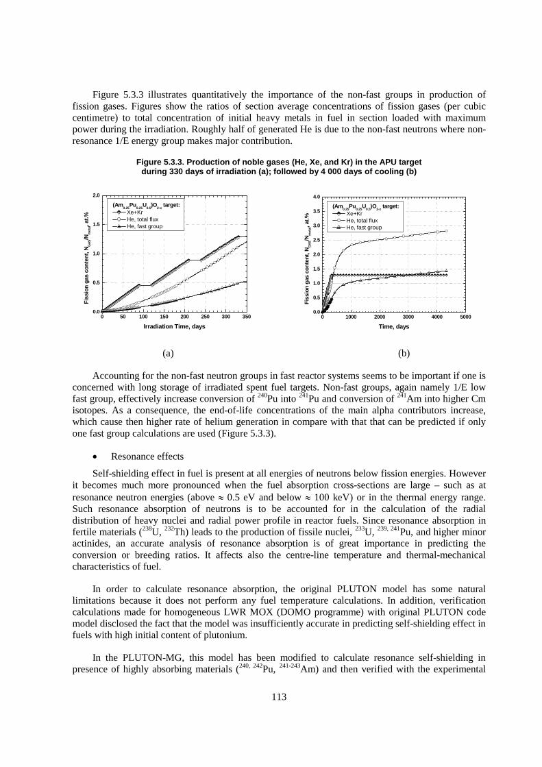
113
Figure 5.3.3 illustrates quantitatively the importance of the non-fast groups in production of fission gases. Figures show the ratios of section average concentrations of fission gases (per cubic centimetre) to total concentration of initial heavy metals in fuel in section loaded with maximum power during the irradiation. Roughly half of generated He is due to the non-fast neutrons where non-resonance 1/E energy group makes major contribution.
Figure 5.3.3. Production of noble gases (He, Xe, and Kr) in the APU target during 330 days of irradiation (a); followed by 4 000 days of cooling (b)
0 50 100 150 200 250 300 3500.0
0.5
1.0
1.5
2.0
Fiss
ion
gas
cont
ent,
NG
AS/N
met
al, a
t.%
Irradiation Time, days
(Am0.25
Pu0.25
U0.5
)O2-x
target: Xe+Kr He, total flux He, fast group
0 1000 2000 3000 4000 50000.0
0.5
1.0
1.5
2.0
2.5
3.0
3.5
4.0
Fiss
ion
gas
cont
ent,
NG
AS/N
met
al, a
t.%
Time, days
(Am0.25
Pu0.25
U0.5
)O2-x
target: Xe+Kr He, total flux He, fast group
(a) (b)
Accounting for the non-fast neutron groups in fast reactor systems seems to be important if one is concerned with long storage of irradiated spent fuel targets. Non-fast groups, again namely 1/E low fast group, effectively increase conversion of 240Pu into 241Pu and conversion of 241Am into higher Cm isotopes. As a consequence, the end-of-life concentrations of the main alpha contributors increase, which cause then higher rate of helium generation in compare with that that can be predicted if only one fast group calculations are used (Figure 5.3.3).
� Resonance effects
Self-shielding effect in fuel is present at all energies of neutrons below fission energies. However it becomes much more pronounced when the fuel absorption cross-sections are large – such as at resonance neutron energies (above � 0.5 eV and below � 100 keV) or in the thermal energy range. Such resonance absorption of neutrons is to be accounted for in the calculation of the radial distribution of heavy nuclei and radial power profile in reactor fuels. Since resonance absorption in fertile materials (238U, 232Th) leads to the production of fissile nuclei, 233U, 239, 241Pu, and higher minor actinides, an accurate analysis of resonance absorption is of great importance in predicting the conversion or breeding ratios. It affects also the centre-line temperature and thermal-mechanical characteristics of fuel.
In order to calculate resonance absorption, the original PLUTON model has some natural limitations because it does not perform any fuel temperature calculations. In addition, verification calculations made for homogeneous LWR MOX (DOMO programme) with original PLUTON code model disclosed the fact that the model was insufficiently accurate in predicting self-shielding effect in fuels with high initial content of plutonium.
In the PLUTON-MG, this model has been modified to calculate resonance self-shielding in presence of highly absorbing materials (240, 242Pu, 241-243Am) and then verified with the experimental
114
results on the radial distribution of the plutonium isotopes in the homogeneous MOX fuel irradiated up to high burnup (56 GWd/t in DOMO experiments). Some illustrative calculation results for the homogeneous LWR MOX in comparison with SIMS measurements [Mertens, 1997] are included in Appendix 5.1.
4. Modelling thermal properties of TRU and Thorium-MA oxides
The current emphasis on TRU and thorium oxides in context of ADS concept has placed an increasing importance on knowledge of their thermal properties, nevertheless, information on these materials is limited compared with that on UO2 and MOX. This is because of the inevitable difficulties in handling TRU materials due to their high toxicity and radioactivity, which obstruct detailed experimental studies. Whereas the importance of experimental studies cannot be neglected, the development of estimation physical models is also important and required in order to evaluate the behaviour of targets for transmutation or for conditioning. Especially the thermal conductivity of TRU and Th-MA oxides is a primary important property, since it determines limiting power and temperatures that can be admitted in ADS targets.
The developed model for thermal conductivity of urania and thoria based oxides with a high content of the minor actinides was already reported earlier [Lemenov, 2002; Lemenov, 2003]. The mechanistic model was programmed and incorporated into material properties module of the MACROS code and coupled with neutronic module, outputs of which (burnup and local concentrations of fission products) are used as inputs.
5. Helium diffusion and release mechanisms
The generation of huge quantities of helium in the MA containing fuels is well established and the problems related to helium generation are experimentally evidenced (e.g. in the SUPERFACT [Babelot, 1999] and EFFTRA [Konings, 2000] experiments). Yet, the similarities and dissimilarities of He with respect to Xe and Kr behaviour are insufficiently understood and quantified. Various laboratory scale experiments are devoted to the behaviour of He in ceramic matrices. A review He-implantation experiments has been published recently by van Veen et al. [van Veen, 2003], and some more recent results are summarised below.
The behaviour of He atoms in mono-crystalline UO2 was estimated in the He-3+ ion implantation experiments (EHe3+ = 7 keV; flux 7·1015 and 2.6·1016 ion/cm2) followed by a series of the isothermal annealing [Sattonnay, 2003]. It was observed that at the annealing temperature of about 870K, helium begins to form micro-bubbles. At the lower dose they were of 20 nm in diameter; for the high dose – 100-200 nm. It is interesting to note that implanted Xe (EXe129+ = 260 keV) atoms forms bubbles at lower temperature (670K) and the mean bubble size was significantly smaller (5 nm).
The energy of activation of the He atoms diffusion in polycrystalline UO2 of 95% TD was measured in the implantation-annealing experiments performed with 3 MeV ions of He-3 [Roudil, 2003]. It was found to be about of 2 eV in the temperature range of 900-1 300K, which is in agreement with earlier data on the He diffusion in UO2. In this temperature region, the activation energy of Xe diffusion is 2-3 times higher and the Xe diffusion coefficient is 2-3 orders of magnitude lower than those of He.
In irradiated UO2 (up to burnup of 70 MWd/kgHM), the total release of He is obtained at temperatures as low as 1 470K [Hiernaut, 2003]. For the same fuel, complete release of Xe and Kr was observed only at 2 580K.

115
The same author reported about the experiments where He release was studied in the annealing experiment performed with PuO2, (
238Pu0.1U0.9)O2 and (239Pu0.1U0.9)O2. Important precipitation of He to the grain boundaries was observed in the range of annealing temperatures of 1 000-1 500K and important diffusion with the precipitation-venting at 1 500-2 200K.
For alpha-doped UO2, two stages of He release during annealing were communicated: ~1 100K and ~1 750K [Wiss, 2003]. A similar behaviour was also observed in the annealing experiments of polycrystalline UO2, reported above [Roudil, 2003], but the temperature regions differ slightly: release of helium begins at 800K and goes in two stages: firstly, a large amount of He is released at temperatures 1 000-1 100K and secondly at temperatures higher than 1 300K.
All experiments confirm that atomic diffusion, clustering into nanometric defects, growth and coalescence of these defects are higher for He than for Xe and Kr. The fast release of He may furthermore be synergetic to the release of Xe and Kr, by earlier formation of intra- and inter-granular clustering sites which may then act as trapping sites for fission gas atoms.
The models of He diffusion and release, taking into account the existing data, were developed and incorporated in the MACROS code.
5.3.4 Results of modelling
In this section, some results of calculations are presented for a limited set of typical minor actinide containing fuels. The choice of parameters was led by preliminary design conditions for the experimental fuel target-rods of the MYRRHA ADS, by choices made in the 5th Framework Program FUTURE [Project FUTURE, 2001] and by knowledge about fuel and cladding properties. The design parameters of the fuel-targets and the isotopic vectors of the materials are summarised in Appendix 5.2. Four fuels with different matrices are considered: 30% enriched MOX U0.7Pu0.3O2-x (designated further as MOX or M30), an urania based, Am and Pu containing ceramic Am0.25Pu0.25U0.5O2-x (named below as APU); a thoria based, Am and Pu containing ceramic Am0.25Pu0.25Th0.5O2-x (indicated below as APT), and an yttria stabilised zirconia matrix, again with Am and Pu - Am0.25Pu0.25Zr0.4Y0.1O2-x (indicated below as APZ). The MOX fuel is the currently considered driver fuel for the ADS MYRRHA. The deviation from stoechiometry was put at x = 0.03 for the MOX, and was put at x = 0.001 for other fuels.
In all cases, the power evolution was estimated using the ORIGEN 2.1 code [Sobolev, 2003]. All calculations consider three typical irradiation cycles of the ADS MYRRHA, each consisting of 90 effective full power days and a shutdown period of 30 days. The linear heat-generation rate (LHGR) evolution as a function of time was estimated under conditions of the constant neutron, which assumes that LHGR is determined by the evolution of the fissile isotope inventory. The obtained power histories are presented in Figure 5.3.4. In order to be able to compare fuel property evolutions, below we will also present normalised results, where the relevant property (radial power, porosity profile etc.) is calculated at a fixed power.
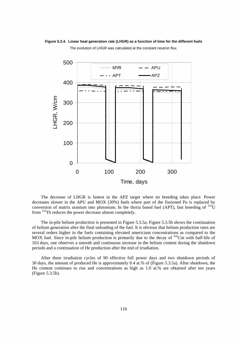
116
Figure 5.3.4. Linear heat generation rate (LHGR) as a function of time for the different fuels
The evolution of LHGR was calculated at the constant neutron flux.
0
100
200
300
400
500
0 100 200 300
Time, days
LHG
R, W
/cm
MYR APU
APT APZ
The decrease of LHGR is fastest in the APZ target where no breeding takes place. Power decreases slower in the APU and MOX (30%) fuels where part of the fissioned Pu is replaced by conversion of matrix uranium into plutonium. In the thoria based fuel (APT), fast breeding of 233U from 232Th reduces the power decrease almost completely.
The in-pile helium production is presented in Figure 5.3.5a; Figure 5.3.5b shows the continuation of helium generation after the final unloading of the fuel. It is obvious that helium production rates are several orders higher in the fuels containing elevated americium concentrations as compared to the MOX fuel. Since in-pile helium production is primarily due to the decay of 242Cm with half-life of 163 days, one observes a smooth and continuous increase in the helium content during the shutdown periods and a continuation of He production after the end of irradiation.
After three irradiation cycles of 90 effective full power days and two shutdown periods of 30 days, the amount of produced He is approximately 0.4 at.% of (Figure 5.3.5a). After shutdown, the He content continues to rise and concentrations as high as 1.0 at.% are obtained after ten years (Figure 5.3.5b).

117
Figure 5.3.5. Helium production during the targets irradiation (a) and after unloading (b)
The end-of-irradiation is indicated by the dashed line. Note the continuous generation of helium also present during the reactor shutdown periods.
(a) (b)
In order to appreciate the amount of helium generation, it should be compared with the amount of generated Xe and Kr. One observes (Figure 5.3.6a) that at the time of unloading, about 0.45 at.% of fission gas (Xe + Kr) is generated, which is of the same order as the helium generation. While this amount of fission gas is normal for fuels of a burnup of about 40 GWd/tM, the total amount of generated gas corresponds to twice this burnup. It is clear that such elevated gas production imposes enormous strains to the ceramic matrix. Helium generation continues even after the final unloading of the targets, and in ten years the He content is more than twice of the total fission gas content (Figure 5.3.6b).
Figure 5.3.6. Helium and fission gas generation during irradiation of the APT target (a) (the results for other Am-containing fuels are similar) and after final unloading (b)
compared to the total fission gas generation
Note that after three cycles, the helium content is of the same order as the total fission gas content.
(a) (b)
In Figures 5.3.7 to 5.3.10, the evolution of the thermal conductivity; power profile, temperature and porosity are given for each of the considered fuel compositions. For each parameter, the radial dependence and the evolution with burnup are represented.

118
Figure 5.3.7. Calculated results as a function of radial position and burnup for the 30% MOX target
Top left: Thermal conductivity. Top right: normalised fission rate density. Bottom left: radial temperature for a LHGR of 350W/cm. Bottom right: deviation from theoretical density (mainly due to porosity development)
For the 30% MOX fuel (Figure 5.3.7), the thermal conductivity more or less follows smooth temperature dependence, with degradation at increasing burnup. The curve of 15 GWd/tM shows visible influence of the increased porosity in the region of equiaxed grain formation (for r/r0 < 0.45). Since the radial density evolution at other burnup values is less pronounced, the effect on thermal conductivity is less visible graphically. The absolute value of the thermal conductivity is quite low, which is primarily due to the off-stoechiometry of this fuel and only slightly due to mass difference effects (<MPu>/<MU> � 1). At BOL, the radial power profile is essentially flat, with the very slight parabolic increase towards the centre being compensated at the pellet periphery by the “low fast flux” contribution. When porosity develops, the power profile (expressed as a volumetric fission rate density) is modified accordingly. Radial temperatures, plotted for a fixed LHGR of 350 W/cm show only a limited increase of centreline temperature, because the degradation of the thermal conductivity is compensated by a smaller gap size (due to fuel swelling) and thus a better thermal contact. Due to the elevated temperature of the fuel (the LHGR of the considered irradiation history being approximately 350 W/cm), important porosity is expected to develop. The porosity indeed strongly increases in the region of equiaxed grain formation, a region that extends up to r/r0 � 0.45 at 15 GWd/tM and extends to r/r0 � 0.75 at EOL. It should be noted that the chosen fuel parameters (grain size and resintering response) do not promote much solid densification. The temperature of this fuel stays below the threshold of columnar grain formation.
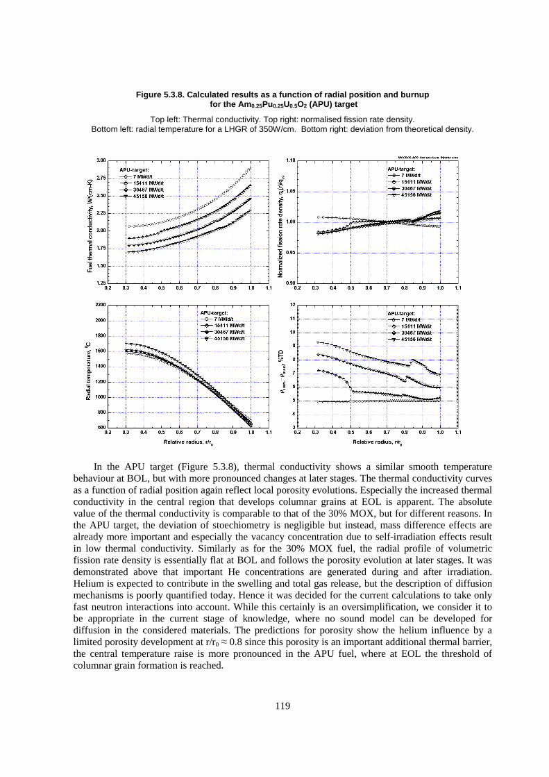
119
Figure 5.3.8. Calculated results as a function of radial position and burnup for the Am0.25Pu0.25U0.5O2 (APU) target
Top left: Thermal conductivity. Top right: normalised fission rate density. Bottom left: radial temperature for a LHGR of 350W/cm. Bottom right: deviation from theoretical density.
In the APU target (Figure 5.3.8), thermal conductivity shows a similar smooth temperature behaviour at BOL, but with more pronounced changes at later stages. The thermal conductivity curves as a function of radial position again reflect local porosity evolutions. Especially the increased thermal conductivity in the central region that develops columnar grains at EOL is apparent. The absolute value of the thermal conductivity is comparable to that of the 30% MOX, but for different reasons. In the APU target, the deviation of stoechiometry is negligible but instead, mass difference effects are already more important and especially the vacancy concentration due to self-irradiation effects result in low thermal conductivity. Similarly as for the 30% MOX fuel, the radial profile of volumetric fission rate density is essentially flat at BOL and follows the porosity evolution at later stages. It was demonstrated above that important He concentrations are generated during and after irradiation. Helium is expected to contribute in the swelling and total gas release, but the description of diffusion mechanisms is poorly quantified today. Hence it was decided for the current calculations to take only fast neutron interactions into account. While this certainly is an oversimplification, we consider it to be appropriate in the current stage of knowledge, where no sound model can be developed for diffusion in the considered materials. The predictions for porosity show the helium influence by a limited porosity development at r/r0 � 0.8 since this porosity is an important additional thermal barrier, the central temperature raise is more pronounced in the APU fuel, where at EOL the threshold of columnar grain formation is reached.
120
In the APT target (Figure 5.3.9), similar effects as in the APU are predicted. At BOL, the thermal conductivity is identical to that of the APU target, but it degrades more rapidly with burnup accumulation. Similarly as for the previous examples, the radial profile of volumetric fission rate density is essentially flat at BOL and follows the porosity evolution at later stages. The porosity evolution is qualitatively identical to that in the APU target, and in this case the columnar grain formation extends up to r/r0 � 0.4.
Figure 5.3.9. Calculated results as a function of radial position and burnup for the Am0.25Pu0.25Th0.5O2 (APT) target
Top left: Thermal conductivity. Top right: normalised fission rate density. Bottom left: radial temperature for a LHGR of 350W/cm. Bottom right: deviation from theoretical
For the APZ target (Figure 5.3.10), the thermal conductivity profiles are quite different. The absolute value of the thermal conductivity is very low (approximately 1.5 W/cm*K) due to the combined effect of large isotope mass differences (causing an important phonon scattering) and the self-irradiation effect resulting in high vacancy concentrations even in the unirradiated material. On the other hand, the thermal conductivity does not degrade further with irradiation, and in contrast to the other cases, even has the tendency to improve a little as a result of columnar grain formation. The radial power profiles are again essentially flat and follow the porosity distribution. As a result of the very bad thermal conductivity, the predicted central temperature at constant power of 350 W/cm is already 1 900°C at BOL and rises above 200°C due to the thermal barriers formed by the porosity development at EOL. The porosity profiles show the restructuring and columnar grain formation during the first cycle with no further qualitative modifications at a later stage.

121
Figure 5.3.10. Calculated results as a function of radial position and burnup for the Am0.25Pu0.25Zr0.4Y0.1O2 (APZ) target
Top left: Thermal conductivity. Top right: normalised fission rate density. Bottom left: radial temperature for a LHGR of 350W/cm. Bottom right: deviation from theoretical density.
5.3.5 Discussion
In this chapter, an overview was given of the approach adopted for the thermomechanical modelling of minor actinide containing fuels and targets. The terms “fuel” and “target” are in this context synonymous. In general, one would rather prefer to use the term target since the study is restricted to the properties of a single rod inserted in an experimental assembly, but which properties do not disturb the reactor. From the standpoint of the fuel thermomechanical code, however, both terms are truly synonymous since the code is a one-cell code in which the neutron flux and spectrum are external inputs. The adopted approach is essentially based on the development of a “generic” or “physically based” code. The reason for this choice is related to the obvious fact that little or no data are yet available for the considered fuels. When using physically based models, one often obtains less accurate results than with parametric models, but they allow calculating results beyond a known data set. The main emphasis of this chapter is laid on the modifications that were needed to cope with the problem of helium generation and release in the context of thermomechanical modelling of fuel rods. The EFFTRA experiment reported already on the problems with He produced by � -decay of MA [Konings, 2000]. In fuel behaviour codes, fission gas production and release is normally covered, but often not helium production. An accurate calculation of He production rates is essential to cope with

122
evolution of the fuel rod features (such as swelling, rod pressure, gap conductance, etc.), because He there is in competition with the normal fission gases, Xe and Kr.
The MACROS code includes an extension of the original PLUTON depletion code. This extension allows now a multiple group approach needed to address the depletion problem various spectra and the build-up and decay schemes were enlarged such as to be able to include the higher isotopes of Am and Cm as well as to cope with thoria based matrices. More fundamental modify-cations to the neutronic module were required in order to be able to cope with the He generation problem in MA containing fuels irradiated in a fast flux. First trial calculations using the original three group approach of the PLUTON code were unsatisfactory when attempts were made to calculate both the radial power profile and He generation in a fast flux. The calculated results showed either power profiles with important and unphysical power peaking to the pellet periphery and correct prediction of helium production or correct flat profiles and largely underestimated He production rates.
A three group approach (fast, thermal and epithermal) works well in a true thermal spectrum, where the neutron spectrum follows a smooth 1/E behaviour between 1 eV and 1 MeV. All resonance cross sections can then be implemented through the resonance integral concept. The neutron spectrum of the fast ADS system considered here (MYRRHA) only shows a smooth 1/E behaviour between roughly 10 keV and 1 MeV. The neutronic module was reprogrammed in order to allow working in a multigroup approach with flexible definition of the energy group boundaries.
The calculated results show that the radial power profile in all fuel types shows little variation, with the increased contribution of fast fission towards the centre of the fuel being compensated by a limited but non-zero breeding in the pellet periphery in the fuels with a fertile matrix. As a consequence, one observes that except for the inert matrix case, the radial power profile flattens completely with increasing burnup (without taking into account the porosity effect).
For all Am-containing targets, the number of generated helium atoms equals almost the amount of generated fission gases Xe and Kr during the irradiation period. The alpha decay of transmutation generated curium of course continues during shutdown and after final unloading of the fuel pin from the reactor. As a consequence, one observes an increase in He content during shutdown and after final unloading. Ten years after the end-of-irradiation, the helium content in the Am containing fuels is twice the content of Xe and Kr. The driver fuel considered here is a 30% Pu enriched MOX (U0.7Pu0.3O2). It contains a low but non-zero amount of americium and as a consequence, the calculations show much lower helium content.
When looking at the spectral contributions to the produced helium, one sees that the low fast group contributes for almost fifty percent to the total generated amount. It is clear that the neutron spectrum has a large influence on the effective amount of produced helium.
Fuel thermal properties are not covered in this chapter, but instead treated in detail in ref. [Lemenov, 2003]. The essential aspects of the thermal conductivity calculation should nevertheless be discussed briefly. The main problem with implementing the thermal conductivity as a function of local temperature, deviation of stoechiometry, porosity distribution and burnup is due to the scarcity of experimental data. A theoretical assessment of the available data was first performed in terms of the classical theory of Callaway. The thermal conductivity assessment showed the important self-irradiation effects on out-of-pile determination of the thermal conductivity of americium oxides. As a result, the thermal conductivity of un-irradiated Am-containing oxides is very low, but it is not expected to decrease much further with increasing burnup.
123
The mechanistic model for thermal conductivity was then incorporated in the MACROS code. Calculated centreline temperatures reflect not only the evolution of thermal properties with increasing burnup, but integrate also the influence of in-pile densification, fission product incorporation, relocation, gap conductance evolution, etc. With the chosen fuel rod characteristics, there is no gap closure in the period covered by the calculations. The main reason for choosing a design with oversized gap is that swelling of the considered fuels is currently considered as insufficiently understood to allow a faithful calculation. As a result of this design choice, the temperature jump across the gap remains of the order of 250°C to 300°C throughout the irradiation period of 200 effective full power days.
The centreline temperature of the different fuels is relatively high due to the combination of various effects. It should be clear that the design is not optimised with respect to temperature, and e.g. the gap is too large, but as is explained above, this choice was made in view of the lack of data on gas clustering and release. The thermal conductivity of the driver fuel (U0.7Pu0.3O1.97), is well known, and the calculations show a reasonable evolution of centreline temperature ranging from 1 700°C at BOL to slightly less than 1 800°C at EOL, in each case for a reference power of 350 W/cm. The degradation of thermal conductivity with burnup is the primary cause of this evolution.
The calculation of Am containing fuels is performed in the assumption of almost perfect stoechiometry, which would normally not be possible to fabricate. The estimated thermal conductivity is slightly higher than that of the hypostoeciometric MOX, despite the important self-irradiation and isotope scattering effects. Within the different Am-containing fuels, the thoria based ones have the lowest thermal conductivity despite the fact that thoria generally has a better thermal conductivity than urania. The main reason for this is that the thermal conductivity calculation considers the isotope scattering effect, and the mass difference between 232Th and 242Am is large enough to cause considerable scattering effects. The thermal conductivity of zirconia is by itself already very low and the scattering and self irradiation effects are even more important for this matrix. As a result of these conditions, the centreline temperature of the solid zirconia based fuel exceeds the melting temperature already at BOL. Thus, introduction of as-fabricated central hole seems to be needed, since in this case centreline will not exceed melting limit.
Even though a lot of progress is made recently in the understanding of He behaviour, the different experiments show far insufficient quantitative correlation to build comprehensive models for helium release. Therefore, models for He clustering and release are to be considered as very preliminary and in the current examples of fuel behaviour modelling only a very rough approximation for He redistribution is made. The results for porosity development should at this stage be considered as indicative only.
5.3.6 Conclusion
We have presented those aspects of the fuel behaviour code “MACROS” that needed to be fundamentally modified in order to cope with the specific problems related to the modelling of minor actinide containing fuels or targets. Since helium generated by alpha decay of transmutation produced curium is known to fundamentally influence the fuel properties, much attention has been paid on the correct treatment of neutronic effects that govern the americium transmutation. It was realised that an extension from three-group approach to multi-group approach was needed in order to cope with the fast neutron spectrum of the liquid Pb-Bi cooled subcritical core of the MYRRHA ADS.
Thermal conductivity estimation is treated in detail in the appendix to this chapter. It should be emphasised that the adopted approach for thermal conductivity evaluation and the model calculations
124
performed in this chapter were all done for homogeneous fuels and a modified approach is to be followed for heterogeneous ceramic-in-ceramic materials.
The modelling exercise performed for four different fuel types shows that in order to properly model all aspects of nuclear fuel evolution for this type of materials; much more effort will be needed.
In this respect, the first effort will be to evaluate in a quantitative way the diffusion, clustering and escape mechanisms for helium and the possible synergetic role between He clustering and regular fission gas release (Xe and Kr). Further improvements are to be made with respect to relocation models, but again these models will need to be based on experimental knowledge that is currently lacking. The aspect of cladding also has not been addressed in this chapter. In the fuel calculations, the material properties of stainless steel (AISI 316) were used, while for the application in Pb-Bi cooled reactors, Fe-Cr martensitic steels, such as T91, are considered to be the most promising candidates. The fuel-cladding interaction properties of the latter alloys are again totally unknown, but similarly as to the development of LMFBR fuels, the fuel cladding interaction can not be disregarded. To what extent the oxygen potential will be modified by fuel cladding chemical interaction and the influence on matrix stability should again be detailed in further studies.
Acknowledgements
The authors gratefully acknowledge the MYRRHA team members Th. Aoust and E. Malambu for their contributions to this work by the MCNP core calculations and N. Messaoudi for the ORIGEN depletion calculations.
This work was partially supported by the funds of the SCK•CEN project MYRRHA and of the FP5 EC project FUTURE.

125
REFERENCES
Section 5.2
Angelini, P., R.E. McHenry, J.L. Scott, W.S. Ernst Jr., J.W. Prados (1970), Helium release from 238PuO2 microspheres, Report ORNL-4507.
Angelini, P., R.E. McHenry (1973), Helium release from 244Cm2O3, Report ORNL-4785.
Chauvin, N., J.-F. Babelot (1996), Rapport de synthèse commun CEA/ITU sur l’expérience SUPERFACT 1. CEA Cadarache, Note Technique SDC/LEMC 96-2028.
Konings, R.J.M., R. Conrad, G. Dassel, B. Pijlgroms, J. Somers, E. Toscano (2000), “The EFTTRA-T4 experiment on americium transmutation”, J. Nucl. Mat. 282, 159 (see also EUR Report 19138 EN, 2000).
Section 5.3
Aït Abderrahim, H., P. Kupschus, E. Malambu, T. Aoust, P. Benoit, V. Sobolev, K. Van Tichelen, B. Arien, F. Vermeersch, Y. Jongen, D. Vandeplassche (2001), In “4th Meeting on Accelerator Driven Transmutation Technology and Applications” (ADTTA 2001). Reno, Nevada, USA.
Aoust, Th. (2003), Internal Calculation Note. Reactor Physics and MYRRHA Department, SCK•CEN (private communication). Mol.
Babelot, J.-F., N. Chauvin (1999), Joint CEA/ITU synthesis report of the experiment SUPERFACT 1. JRC-ITU-TN-99/03, CEA/ITU.
Hiernaut, J.P. (2003), Relâchement d'hélium et des gaz de fission au cours de recuit de combustibles nucléaires. In Journées Scientifiques « Comportement des gaz rares dans les matériaux nucléaires ». CEA, Saclay, France.
Konings, R.J.M., R. Conrad, G. Dassel, B.J. Pijlgroms, J. Somers, E. Toscano (2000), “The EFTTRA-T4 experiment on americium transmutation”, Journal of Nuclear Materials, 282, 159-170.
Lemehov, S.E., V. Sobolev, P. Van Uffelen (2003), “Modelling thermal conductivity and self-irradiation effects in mixed oxide fuels”, Journal of Nuclear Materials, 320, 66-76.
Lemehov, S.E., P. Van Uffelen, V. Sobolev (2002), “Modelling the Burnup Effects in Actinide Fuels with the MACROS Code”. In EHPG Meeting HPR-359, Storefjell. vol. 2, paper 41.
Lemehov, S.E. (1994), “Computer Code ASFAD: Status, Recent Developments and Applications”, In ANS Topical Meeting on LWR Fuel Performance. West Palm Beach, FL. USA.
126
Lemehov, S.E., M. Suzuki (2001), “PLUTON: A three-group model for the radial distribution of plutonium, burnup and power profiles in highly irradiated LWR fuel rods”, Nucl. Technol., 3, 153-168.
Lemehov, S.E., M. Suzuki (2001), “PLUTON: Three-Group Neutronic Code for Burnup Analysis of Isotope Generation and Depletion in Highly Irradiated LWR Fuel Rods”, JAERI Research Report, JAERI-DATA/Code 2001-025. (Available on request: OECD/NEA Data Bank: http://www.nea.fr or RIST-Japan: http://www.rist.or.jp/ehome.htm) JAERI.
Mertens, L. (1997), “DOMO International Research Programme”. Belgonucléaire.
NEA (1994), Tables of simple integral neutron cross section data from JEF-2.2, ENDF/B-VI, JENDL-3.2, BROND-2 and CENDL-2. JEF Report 13. OECD, Paris.
Sattonnay, G., F. Garrido, L. Thomé (2003), Comportement de l'hélium dans des monocristaux de dioxyde d'uranium : étude par microscopie électronique en J.P. Hiernaut. Relâchement d'hélium et des gaz de fission au cours de recuit de combustibles nucléaires. in Journées Scientifiques « Comportement des gaz rares dans les matériaux nucléaires ». 2003. CEA, Saclay, France.
Sobolev, V., S. Lemehov, N. Messaoudi, P. Van Uffelen, H. Aït Abderrahim (2003), “Modelling the behaviour of oxide fuels containing minor actinides with urania, thoria and zirconia matrices in an accelerator-driven system”, Journal of Nuclear Materials, 319, 131-141.
Suzuki, M. (2000), Light Water Reactor Fuel Analysis Code FEMAXI-V, (Ver. 1). JAERI.
Project FUTURE (2001), FP5 Programme Acronym: FP5-EAECTP C. FIKW-CT-2001-00148 FP5 Project Record on the EC website: http://dbs.cordis.lu.
Roudil, D., X. Deschanels (2003), Diffusion thermique de l'hélium et du xénon dans UO2 et la zirconolite. In Journées Scientifiques « Comportement des gaz rares dans les matériaux nucléaires », CEA, Saclay, France.
van Veen, A., R.J.M. Konings, A.V. Fedorov (2003), “Helium in inert matrix dispersion fuels”, Journal of Nuclear Materials, 320, 77-84.
Weinberg, A.M. (1958), The Physical Theory of Neutron Chain Reactors, Chicago: The University of Chicago Press.
Wiss, T. (2003), Étude du comportement de l'hélium dans des matrices de transmutation ou de stockage des actinides mineurs en conjonction avec leur endommagement. In Journées Scientifiques « Comportement des gaz rares dans les matériaux nucléaires ». CEA, Saclay, France.

127
Appendix 5.1
1-EV RESONANCE EFFECT IN MOX FUEL
This Appendix is to illustrate importance of accounting for low energy resonances for LWR MOX. Figure A5.1.1 shows calculation results made with original version of the PLUTON code for homogeneous MOX (sample DOMO-J04) irradiated in Dodewaard BWR reactor in frame of international DOMO programme [Martens, 1997].*
Figure A5.1.1. Sample J04, measured local isotopic Pu compositions (at.%) along directions 1 to 3 and calculation results obtained with the original version of PLUTON code
In general agreement is quite satisfactory except for 240Pu. Introduction an additional group, which cover the 1-eV giant resonance in 240Pu, improves agreement between experimental and calculation results as illustrated in Figure A5.1.2. The relative plutonium isotopic distributions are therefore quite sensitive to resonance absorption in low epithermal energy range of neutrons. The relative Pu/(U+Pu) ratio distributions as measured with SIMS and calculated with the MACROS code are shown in Figure A5.1.3. Both measurements and calculations show that the breading rate of 239Pu and conversion of 240Pu are very high in the first 300 �m (see Figures A5.1.3 and A5.1.4), however this fact does not come out so drastically in the isotopic composition plot (Figure A5.1.2).
* Mertens, L. (1997), DOMO: Postirradiation testing and Irradiation Programme of BWR MOX Fuel Rods,
Final Report, SCK•CEN DOM 99/61, February.
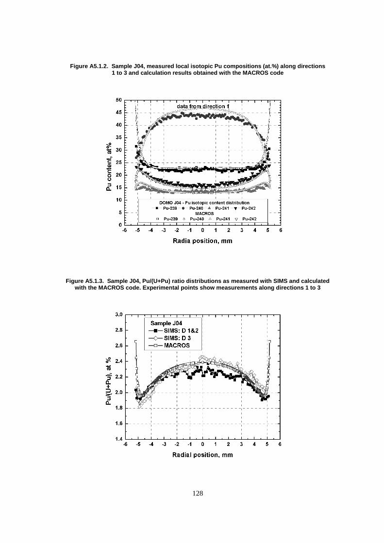
128
Figure A5.1.2. Sample J04, measured local isotopic Pu compositions (at.%) along directions 1 to 3 and calculation results obtained with the MACROS code
Figure A5.1.3. Sample J04, Pu/(U+Pu) ratio distributions as measured with SIMS and calculated with the MACROS code. Experimental points show measurements along directions 1 to 3

129
Figure A5.1.4. Sample J04, experimental 239Pu and 240Pu distributions (relative to average concentration 1.0) along direction 1 to 3 and those calculated with the MACROS code
Apart from that the 241Pu and 242Pu distributions are rather flat (see Figure A5.1.5) indicating thus the dualism of breeding/conversion and fission in the outer half of MOX fuel.
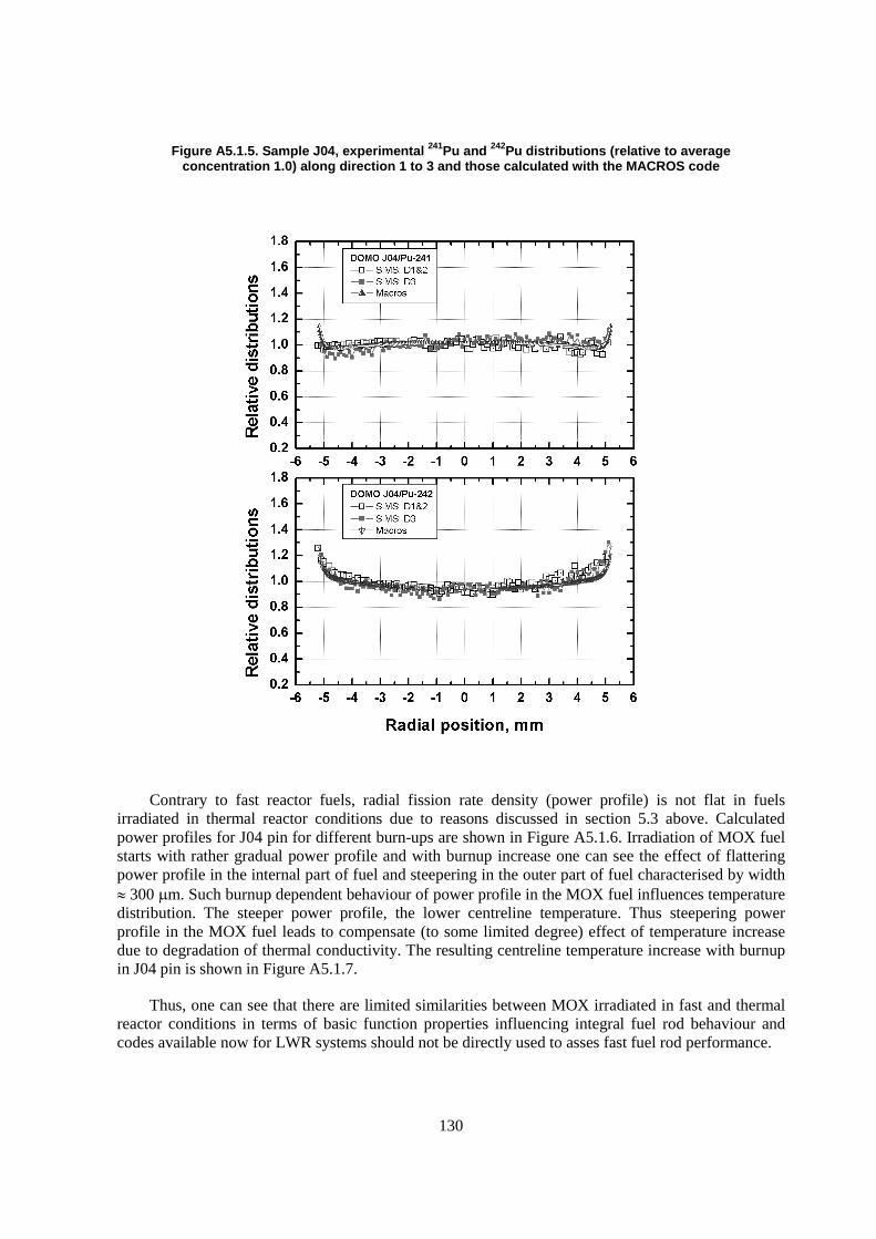
130
Figure A5.1.5. Sample J04, experimental 241Pu and 242Pu distributions (relative to average concentration 1.0) along direction 1 to 3 and those calculated with the MACROS code
Contrary to fast reactor fuels, radial fission rate density (power profile) is not flat in fuels irradiated in thermal reactor conditions due to reasons discussed in section 5.3 above. Calculated power profiles for J04 pin for different burn-ups are shown in Figure A5.1.6. Irradiation of MOX fuel starts with rather gradual power profile and with burnup increase one can see the effect of flattering power profile in the internal part of fuel and steepering in the outer part of fuel characterised by width � 300 �m. Such burnup dependent behaviour of power profile in the MOX fuel influences temperature distribution. The steeper power profile, the lower centreline temperature. Thus steepering power profile in the MOX fuel leads to compensate (to some limited degree) effect of temperature increase due to degradation of thermal conductivity. The resulting centreline temperature increase with burnup in J04 pin is shown in Figure A5.1.7.
Thus, one can see that there are limited similarities between MOX irradiated in fast and thermal reactor conditions in terms of basic function properties influencing integral fuel rod behaviour and codes available now for LWR systems should not be directly used to asses fast fuel rod performance.
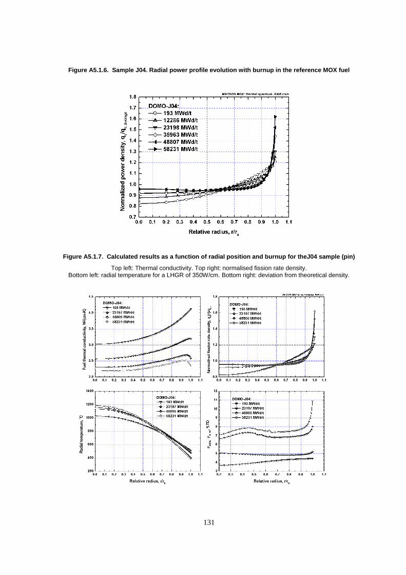
131
Figure A5.1.6. Sample J04. Radial power profile evolution with burnup in the reference MOX fuel
Figure A5.1.7. Calculated results as a function of radial position and burnup for theJ04 sample (pin)
Top left: Thermal conductivity. Top right: normalised fission rate density. Bottom left: radial temperature for a LHGR of 350W/cm. Bottom right: deviation from theoretical density.

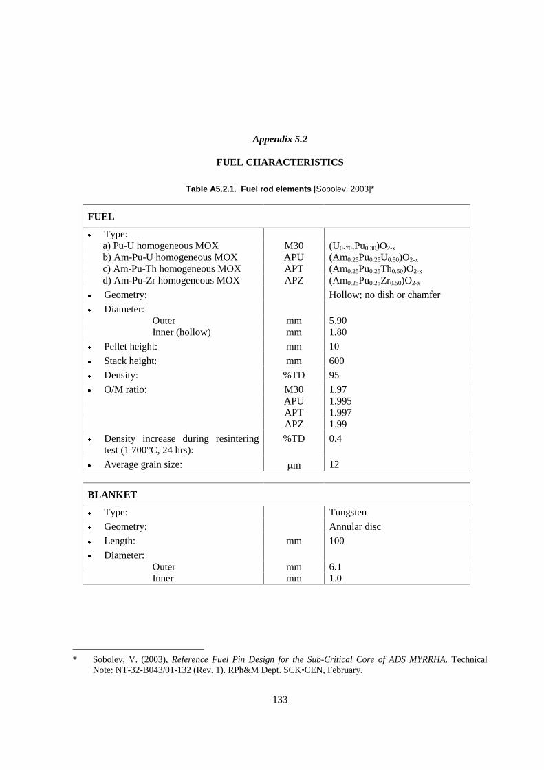
133
Appendix 5.2
FUEL CHARACTERISTICS
Table A5.2.1. Fuel rod elements [Sobolev, 2003]*
FUEL
� Type: a) Pu-U homogeneous MOX M30 (U0.70,Pu0.30)O2-x b) Am-Pu-U homogeneous MOX APU (Am0.25Pu0.25U0.50)O2-x c) Am-Pu-Th homogeneous MOX APT (Am0.25Pu0.25Th0.50)O2-x d) Am-Pu-Zr homogeneous MOX APZ (Am0.25Pu0.25Zr0.50)O2-x
� Geometry: Hollow; no dish or chamfer
� Diameter: Outer mm 5.90 Inner (hollow) mm 1.80
� Pellet height: mm 10
� Stack height: mm 600
� Density: %TD 95
� O/M ratio: M30 1.97 APU 1.995 APT 1.997 APZ 1.99
� Density increase during resintering test (1 700°C, 24 hrs):
%TD 0.4
� Average grain size: �m 12
BLANKET
� Type: Tungsten
� Geometry: Annular disc
� Length: mm 100
� Diameter: Outer mm 6.1 Inner mm 1.0
* Sobolev, V. (2003), Reference Fuel Pin Design for the Sub-Critical Core of ADS MYRRHA. Technical
Note: NT-32-B043/01-132 (Rev. 1). RPh&M Dept. SCK•CEN, February.
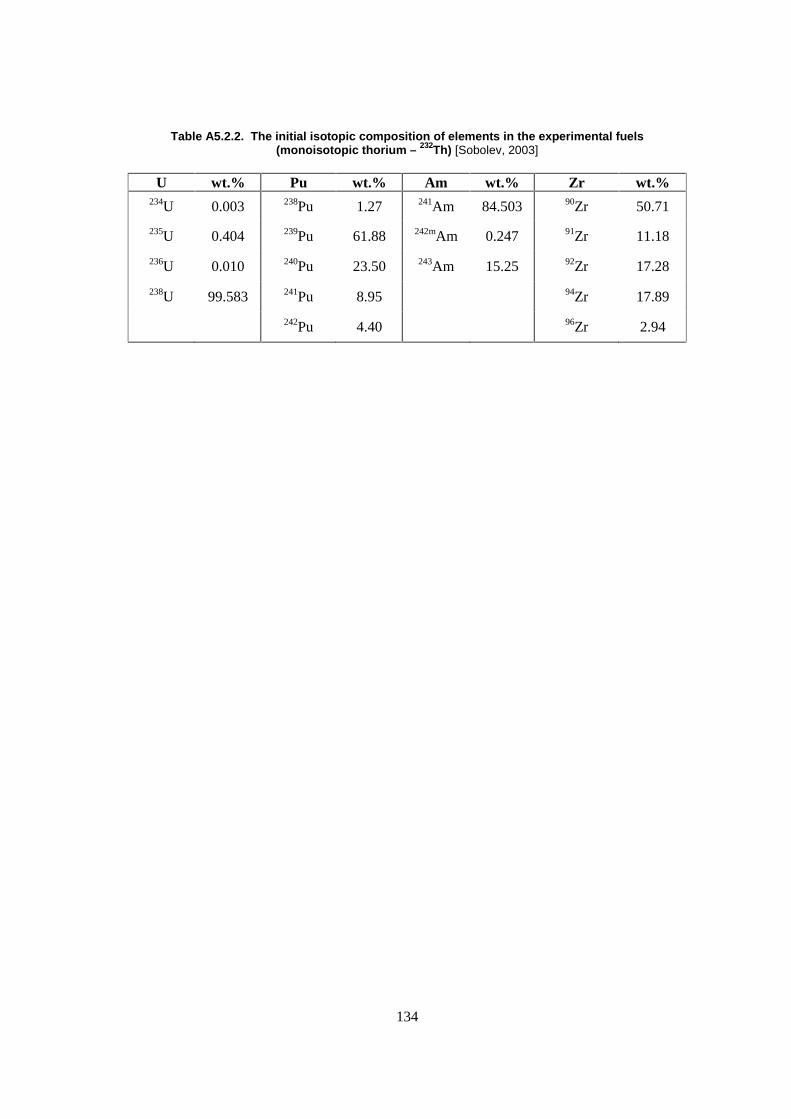
134
Table A5.2.2. The initial isotopic composition of elements in the experimental fuels (monoisotopic thorium – 232Th) [Sobolev, 2003]
U wt.% Pu wt.% Am wt.% Zr wt.% 234U 0.003 238Pu 1.27 241Am 84.503 90Zr 50.71
235U 0.404 239Pu 61.88 242mAm 0.247 91Zr 11.18
236U 0.010 240Pu 23.50 243Am 15.25 92Zr 17.28
238U 99.583 241Pu 8.95 94Zr 17.89
242Pu 4.40 96Zr 2.94
135
CHAPTER 6
STRUCTURAL MATERIALS FOR TRANSMUTATION SYSTEMS
In any population growth and energy growth scenario that assumes a significant role for nuclear energy, minimising the effect of the nuclear fuel cycle on the environment is critical to a successful implementation. Partitioning and transmutation (P&T) of fission products and actinides holds promise for minimising land impacts from mining by optimising the energy use from each gram of fuel extracted from the earth. P&T also holds promise for minimising the heat and radioactivity placed back in the earth following energy extraction.
Transmutation systems can be based on fast reactors, accelerator-driven systems (ADS), or for specialised uses, epithermal spectrum molten salt-cooled reactors. The fast reactor or ADS coolant can be either a liquid metal such as sodium, lead, or lead-bismuth or a gas such as helium. In any transmutation system, structural materials are required to have adequate mechanical properties, dimensional stability, and corrosion resistance throughout the life of each component. Because transmutation systems operate in a fast neutron spectrum, they are subjected to high radiation doses, up to around 200 dpa. Transmutation systems using fast reactors may also operate at high temperature.
Currently, most national P&T programmes are focused on either sodium or lead-bismuth cooled systems. Because of significant previous development programmes in many countries, material performance issues are well understood for sodium-cooled fast reactors. They are less well understood for lead or lead-bismuth cooled systems where corrosion and stress corrosion cracking are more severe for the steels typically used to construct nuclear energy systems. For accelerator driven systems, the high production of transmutation gasses is expected to exacerbate materials degradation, specifically void swelling and loss of low temperature toughness.
Chapter 6 of this report concentrates on two aspects of transmutation system materials with significant open research questions. The first section concentrates on mechanical properties and dimensional stability of candidate steels for cladding, duct, and other structural components. As an example of the issues facing transmutation system materials, the properties of HT9, a typical 12 Cr ferritic-martensitic steel used in the United States fast reactor programme are described. Special consideration is given to the effect of high gas loadings, with reference to relevant studies from fusion system material development experiments. The section also has a detailed description of other candidate materials being considered in United States, Japanese, and European transmutation programmes.
The second section is devoted to a description of corrosion and liquid metal embrittlement in lead alloy-cooled systems. Limiting corrosion of structural components is essential to providing adequate component lifetime. The fundamentals of corrosion as well as corrosion prevention techniques based on the development of a stable oxide film, inhibitors, and corrosion resistant coatings are all described.
136
Successful deployment of transmutation systems will require developing successful solutions to the materials challenges in corrosion, mechanical performance, and dimensional stability described in this section of the report.
6.1 Cladding and duct review
6.1.1 Introduction
Accelerator-driven transmutation systems (ADS) are being considered in several countries for transmutation of long-lived radioactive constituents of spent fuel. Because an ADS uses a fast spectrum for transmutation, the fuel, cladding, and target candidate materials are based on experience with fast reactor systems and experience from high-energy transmutation programmes such as the accelerator production of tritium (APT) materials development project.
Because austenitic stainless steels undergo excessive radiation-induced void swelling prior to reaching the desired burnup, the fast reactor cladding and duct development programmes switched focus from austenitic steels to ferritic or ferritic-martensitic steels for application at high exposure. Selected ferritic-martensitic steels exhibit strong resistance to swelling, adequate microstructural stability under irradiation, and retain adequate ductility at typical reactor operating temperatures. In the United States fast reactor development programme, Sandvik HT9 was eventually selected for cladding and ducts for the integral fast reactor (IFR) concept and as the next-generation driver fuel cladding for EBR-II and FFTF. Accordingly, HT9 has been selected as the reference material for the United States accelerator-driven transmutation programme. In the European programme, T91, a 9Cr-1Mo steel has been chosen as the reference cladding and duct material.
In fast flux test facility (FFTF) tests, HT9 cladding was tested with both oxide and metal fuel. The most extreme test was with mixed-oxide fuel to a burnup of 238 MWd/kgM (a fast fluence of 39x1022 n/cm2, approximately 200 dpa) at a peak cladding temperature of 661°C. At that burnup, no elongation of the duct had occurred nor had any cladding breach been observed. For metal fuel pins, HT9 was irradiated as cladding for a U-Zr alloy to a burnup of 143 MWd/kgM (a fast fluence of 20x1022 n/cm2, approximately 100 dpa) at a peak cladding temperature of 640°C [Leggett, 1993; Pahl, 1992].
Because the neutron spectrum in an ADS is shifted to higher energy than a typical fast reactor system and involves a greater production of hydrogen and helium, the fast reactor data base cannot be directly used to predict material performance in an ADS. Nonetheless, examining the fast reactor database provides a solid underpinning as well as a baseline for further investigation. HT9 and other ferritic-martensitic alloys were also examined as potential first wall materials in the United States fusion energy programme. Because the fusion programme also anticipates a harder neutron energy spectrum and the associated larger transmutation gas loading, studies performed in the fusion materials programme to simulate higher gas loading also provide relevant information in evaluating the acceptability of HT9 or other ferritic steels as cladding and duct material for ADS systems.
This chapter describes: the expected operating environment for cladding and duct materials in an ADS; the fast reactor database of HT9 mechanical properties, dimensional stability, and fuel compatibility; information on the effect of He and H on the properties of HT9, based on studies from the United States fusion energy materials development programme; and background on other advanced alloys that may be considered for ADS cladding and duct materials. The chapter provides similar information on European and Japanese ADS candidates. Ultimately, if ADS components do

137
not require high burnup, austenitic alloys developed in the fast reactor and fusion programmes can also be considered for ADS systems.
This chapter focuses on materials for cladding and duct material. Another important area is the development of transmutation targets. Transmutation targets experience damage from high-energy (600-1 000 MeV) protons as well as from spallation neutrons. This document does not attempt to address the materials candidates and the needed research for transmutation targets.
6.1.2 ADS operating environment
Preliminary target and buffer design studies for liquid metal cooled accelerator driven systems have been completed (the buffer being the coupling between the spallation target and the subcritical blanket). As part of these design studies, the damage rates, H production rates, and He production rates have been calculated for designs using varying target coolants (sodium and lead-bismuth eutectic – LBE), varying high-energy proton beam energies, and varying buffer thicknesses [Yang]. The design assumed was an 840 MW liquid-metal-cooled design. Either a 1 GeV or 600 MeV proton beam is assumed to impact the target. The low energy neutron-induced hydrogen and helium production rates were evaluated for HT9, but all other values reported were calculated for pure Fe. Peak gas production and damage rates occur at the buffer-blanket interface. For the thinnest buffer LBE design, peak damage and production rates are:
� Buffer thickness = 11.5 cm;
� Damage rate ~100 dpa/year;
� H production ~1 200 appm/year;
� He production ~75 appm/year;
� He/dpa ~0.75.
For the current “optimum” LBE buffer design (pending future studies) with ~20 cm buffer thickness, peak damage and production rates are:
� Buffer thickness = 20 cm;
� Damage rate ~60 dpa/year;
� H production ~300 appm/year;
� He production ~20 appm/year;
� He/dpa ~0.33.
For the 600 MeV proton beam, sodium-cooled buffer design, peak damage and production rates at the window are:
� Buffer thickness = 20 cm;
� Damage rate ~140 dpa/year;
� H production ~3270 appm/year;
� He production ~310 appm/year;
� He/dpa ~2.2.
For the purpose of comparison, the helium production rate in a fast reactor such as EBR-II is on the order of 0.1 appm He/dpa. High-energy neutrons generated by the D-T fusion reaction will produce 10-15 appm He/dpa for iron-based alloys [Klueh, 1992c]. The gas production in the blanket

138
region of an ADS will be intermediate between a fast spectrum reactor and a D-T fusion system. As noted by Garner et al., the gas production will be much higher for transmutation targets, reaching levels as high as 150 appm He/dpa and 750 appm H/dpa [Garner, 2001].
6.1.3 The effect of high energy protons
The ADS environment is unique. In addition to the high energy neutron and associated transmutation gas effects that occur in a fission reactor, high-energy protons can also cause damage and increase the available hydrogen gas. The high-energy protons are less likely to affect the properties of the cladding and duct materials as the spallation source. Nonetheless, a review of the data on high-energy proton effects is important background to the development of an ADS.
The majority of the material properties data in a spallation source developed in the United States comes from the now defunct accelerator production of tritium programme. Austenitic stainless steels, ferritic-martensitic steels, and nickel-base alloys were all irradiated at the Los Alamos Neutron Science Center with 1.0 GeV protons at temperatures from 50-164�C to doses of 12 dpa. Gas loadings were as high as 10 000 appm H and 1 000 appm He [Maloy, 2001]. The specific alloys irradiated were 304L and 316L stainless steel, modified 9Cr-1Mo steel, and Alloy 718.
The damage caused by the high-energy protons is generally qualitatively similar to that occurring in fission reactors: increasing yield strength, decreasing ductility and decreasing fracture toughness. Because there is limited data on irradiation damage in a fission spectrum at temperatures less than 164�C, the specific effect of the protons cannot be clearly delineated. One exception is the ductility in 316L stainless steel. At doses greater than ~3 dpa, the ductility of those samples irradiated in the high-energy proton beam decreased dramatically, where those irradiated in a fission reactor at < 100�C remained above 20%. Even though the ductility in the proton-irradiated samples was essentially zero, the fracture surfaces were typical of ductile failure and the reduction in area remained high. Apparently the higher gas loading of the proton irradiated samples caused a very localised ductile fracture.
The data on proton effects on material properties is quite limited, especially at the expected temperatures of operation of an accelerator driven system. This is an area where property measurements and basic understanding is very limited.
6.1.4 Cladding/Duct performance issues
Performance requirements
The design criteria adopted for permanent structures subject to potentially significant neutron exposure is generally the ASME boiler and pressure vessel code, or at least patterned after the intent of the ASME code [Blackburn, 1977]. Two approaches are possible to manage radiation damage on reactor core components. The first is to limit components below the fluence limit at which radiation damage starts to change properties. This approach is typically too conservative to be practical. When service conditions must exceed the fluence limits, the second design approach accounts for radiation damage throughout the component lifetime.
The cladding performance issues for an ADS system are expected to be similar to those of a fast spectrum system. Porter compiled the cladding performance issues and the status of HT9 as a cladding, duct, and wire wrap material for the advanced liquid metal reactor (ALMR) programme [Porter, 1994]. These issues are highlighted in the following section.
139
Cladding and duct performance
The survivability of fuel cladding (prevention of cladding breach) must be predictable. Therefore, the wastage and strain of the cladding under all operating conditions must be understood. Cladding wastage can be caused by corrosion of the cladding by the coolant or fuel cladding chemical interaction (FCCI). Cladding strain can be caused by fission gas pressurisation, swelling of constrained components, or in the fuel region, fuel cladding mechanical interaction (FCMI).
The duct performance must also be predictable. This requires that structural materials maintain adequate toughness, strength, and dimensional stability under all expected conditions. Adequate dimensional stability includes resistance to swelling, creep, growth, and corrosion. The duct performance must be adequate for all temperatures and radiation dose, even under accident conditions.
FCCI is caused by the interdiffusion and reaction of fuel and fission product species and the cladding species. Cladding properties can become degraded by the subsequent solid-state chemical and microstructural changes. This interdiffusion zone in the cladding is considered wastage since the effective cladding wall is reduced. In addition, in the case of metallic fuels, interdiffusion regions with compositions approaching eutectic compositions possess lower melting temperatures. For oxide fuels, diffusion of fission products into the cladding has been associated with cladding embrittlement. To understand cladding performance, the eutectic limit and cladding penetration limit must be understood for all fuels and operating conditions, recognising that the fuel composition changes with burnup. FCMI is the mechanical strain on the cladding as the fuel expands due to swelling during steady-state and from differential thermal expansion during transients when the fuel expands at a rate greater than that of the cladding due to the greater heating in the fuel.
Practical operation of a fast reactor system including an ADS requires the following:
� Creep rupture properties and ductility of the cladding material must be known for the expected steady-state and transient conditions.
� Swelling must be kept low at expected fluences to prevent duct handling problems.
� Because of the possibility of accelerator beam transients, the reactor power may cycle in a manner not naturally occurring in a critical reactor. Therefore, the fatigue life of cladding and duct components must be understood.
Cladding design requirements
The ALMR cladding design limits were as follows and can be referenced for the ADS system until specific ADS designs are available [Porter, 1994]:
� Fast neutron fluence (E>0.1 MeV) < 3.8x10²³ n/cm2.
� Fuel pins should have a mean failure rate of less than 10-5 per pin year over the fuel design life.
� No clad failure or structural failure should result from the design basis events.
� During all design basis events, accelerated fuel-clad attack shall be precluded.
� Core performance criteria for steady-state conditions were limited to thermal creep strain of 1%, total strain of 3%, and swelling of 5%.
� Off-normal events could subject the cladding to high temperatures for short durations. If these temperatures are large enough, significant microstructural changes may occur, which
140
affect the mechanical properties and dimensional stability in the short term and also in the long term after returning to steady-state. Stress-rupture tests at both moderate temperature, long-duration, low-stress and high temperature, short-duration, high-stress must be performed. For the ALMR programme, data were needed for HT9 properties, including short- and long-term transient properties, with emphasis on the anticipated transient without scram (ATWS) transient time scale of 200-600 sec and longer time (20-100 hr) for the reactor vessel auxiliary cooling system (RVACS) decay heat removal transient.
In review of the ALMR designs with metallic fuels, the US Nuclear Regulatory Commission specified the following requirements that remained to be addressed and will be applicable to the ADS design [Porter, 1994]. These issues provide an idea of the materials challenges required to place an ADS in commercial operation.
� Verify uniformity of composition and thermomechanical properties of cladding material from batch to batch.
� Establish quality assurance of material supply and fabrication and welding techniques.
� Minimum eutectic temperature must be determined for the prototypical design.
� Maximum fuel-cladding penetration rate must be determined from irradiated fuel taking into account the lanthanide, zirconium, and plutonium migration, the iron diffusion, and the kinetics of potential transients.
� Provide data on fuel-cladding eutectic formation temperature, cladding wastage or penetration rate as a function of temperature, and other cladding failure mechanisms.
For accommodated ATWS events, the following transient core performance criteria were set for the ALMR programme.
� Liquid phase attack of clad not to exceed 2 mils (10% wall thickness).
� Short-term nominal peak mid-wall clad temperature must be less than simplified thermal creep strength limit (<760°C).
Duct design requirements
Until a specific ADS design is adopted, the duct design limits that were envisioned for the most advanced EBR-II duct assemblies provide a reasonable guide for understanding the issues relative to duct performance and outlining the materials test needs [Kamal]. The functional requirements for a fuel assembly are to:
� Provide support and protection for the fuel-pin bundle and other components of the subassembly.
� Provide a controlled path for the primary coolant.
� Provide a compact structural unit that can be easily moved in and out of the core by a refueling machine.
� Interact with adjacent subassemblies, retaining ring, and core support plates in a manner that assures safe and predictable reactor geometry.
Evaluating duct performance requires an understanding of the allowable stress and strains, creep-fatigue damage, deformation limits, and brittle (non-ductile failure) protection. Additionally, special
141
requirements for weldments are necessary. For normal operation and anticipated faults, the primary membrane stress limit for fuel assembly ducts is given by:
�pm<0.55�f where
�f=minimum{�����y, �u},
and �y is the yield strength and �u is the ultimate tensile strength. In addition to this simple relationship, additional factors considering bending stress, asymmetric loadings, and materials with very low ductility must also be considered. The limits may be less stringent for unlikely and extremely unlikely fault conditions.
The creep-fatigue damage is limited by the total accumulative damage (D). The total accumula-tive damage is the sum of the creep damage (Dc) and the fatigue damage (Df). For normal operation and anticipated faults in fuel assembly ducts, the creep-fatigue damage limited to 0.1. As with primary stress, the creep-fatigue damage limits may be less stringent for unlikely and extremely unlikely fault conditions.
Fuel assembly duct bowing and dilation caused by thermal creep, irradiation-induced creep, and irradiation-induced swelling are limited to ensure no binding of fuel assemblies during unloading and to ensure removed ducts are still compatible with storage and handling fixtures. Specific limits on required fuel handling forces and duct dilation will be required for ADS fuel assembly components.
To ensure no non-ductile failures occur during normal operation and fuel handling, two approaches were envisioned for HT9 ducts. For components operating at 33�C greater than the ductile-to-brittle transition temperature (the highest DBTT expected during irradiation service), a detailed non-brittle evaluation was not required but fracture mechanics calculations were performed to verify the upper-shelf fracture toughness was adequate. For temperatures below the limit, detailed fracture mechanics calculations are required. This low temperature condition is most likely to occur during refueling or other duct handling operations.
For weldments, inelastic strains in the weld material were limited to one-half the strain values permitted for the parent material. Additionally, the creep-fatigue limits are reduced. The number of cycles are reduced to one half that allowed by the parent material and the time duration is reduced by a material specific strength reduction factor.
6.1.5 Status of material databases
Because initial candidate materials for cladding and duct material are expected to be chosen based on information from fast reactor materials development and fusion materials development, it is important to understand the available data. The following sections describe the status of available databases.
Fast reactor materials databases
Since systems are currently envisioned to operate in the same temperature regimes as previously developed fast reactor systems such as EBR-II or FFTF, the baseline choices for materials come from the fast reactor community. For cladding and duct materials in United States fast reactor programmes, the materials evolved from solution annealed AISI 304 stainless steel to cold-worked AISI 316 stainless steel to HT9 a ferritic-martensitic steel. In each case, materials were chosen that delayed the
142
onset of void swelling, allowing greater lifetime of cladding and duct materials [Leggett, 1993]. Detailed property evaluations were developed and maintained in the Nuclear Materials Handbook and Metals Fuel Handbook. Both of these documents still are considered “applied technology” and cannot be shared with foreign governments without specific approval of the US Department of Energy.
Spallation materials databases
In the United States, some data was generated on materials behaviour in prototypic spallation environments. In support of the accelerator production of tritium (APT) programme, irradiations were performed using the LANSCE facility at Los Alamos National Laboratory [Maloy, 2001]. Four separate materials were irradiated: 304L, 316L, Alloy 718, and a modified 9Cr-1Mo alloy. The irradiation temperatures ranged from 50-164°C. The maximum dose achieved was ~12 dpa Gas loadings were as high as 10 000 appm H and 1 000 appm He. Even though these irradiation tempera-tures are much lower than those expected to exist in an accelerator based transmutation system, they do provide insight into the effect of transmutation gasses. The APT programme did develop a materials handbook, which is continually updated as part of the current advanced fuel cycle initiative programme.
Fusion materials database
Because the cladding and duct materials in an accelerator driven system are expected to operate with a neutron spectrum between fusion systems and fast spectrum systems, studies from the fusion energy programme may provide information relevant to ADS performance. Since the D-T fusion reaction produces 14 MeV neutrons, ferrous alloys used in proposed fusion system structural materials experience a higher He production rate (due to He transmutation reactions) than in fast reactors. Since no fusion relevant neutron spectrum has been available for materials testing, the fusion energy programmes have used various simulation techniques to help understand the effect of the higher gas loadings. Studies in the fusion programme have used ion implantation [Lindau, 1999], nickel-doping (in the Ni-doped materials, He is formed by a two-step reaction of 58Ni with thermal neutrons: 58Ni(n,�)59Ni followed by 59Ni(n,�)56Fe) [Klueh, 1992], and boron-doping [van Osch, 2000; Materna-Morris, 2000; Shiba, 2000] to study higher gas loading on mechanical and dimensional stability performance.
The fusion energy programmes in the United States have produced materials handbooks in 13 separate publication packages. These handbooks contain information on many materials of potential interest for accelerator driven systems, including data on both 316LN stainless steel and various ferritic steels. The United States fusion energy handbooks do not contain all the information developed by the United States fusion programme, although most of the information is available in the open literature. These handbooks are open literature data available to ADS programmes. The international ITER programme does contain fairly comprehensive compilations of design data on 316SS (including 316L and 316LN) and about a dozen other materials but is only available to ITER members.
Space reactor database
There have also been some partial database compilations performed on the various space reactor programmes (most recently in the United States the incomplete Multimegawatt Materials Handbook [ORNL, 1991]).

143
6.1.6 HT9 properties
As an example of the state of knowledge of a candidate material for ADS cladding and duct material, in the following sections the properties of HT9, developed as part of the US liquid metal fast breeder reactor (LMFBR) development programme, will be outlined. Following this section, a brief description of the HT9 properties determined as part of the fusion energy studies will also be presented.
Composition and material preparation
The nominal composition of Sandvik HT9 is Fe-12.0%Cr-1%Mo-0.6Mn-0.6Ni-0.3%V-0.5%W-0.38Si-0.2%C [Klueh, 2001]. When first introduced into the fast reactor cladding and duct programme, the heat treatment of HT9 following fabrication was a short (~ five minutes) normalising anneal at 1 038°C with a rapid argon cooldown. The anneal was followed by a tempering treatment at 760°C for 30 minutes followed by a rapid argon cooldown [Lauritzen, 1981]. An improved thermomechanical treatment (TMT) was later developed to improve stress-rupture lifetime. This TMT annealed at 1 100°C followed by tempering at 675°C (annealing and normalising times were similar to the original TMTs) and was chosen as the TMT for the fast flux test facility (FFTF) core demonstration experiment (CDE). Changing the austenitising temperatures changes the prior-austenite grain size. Ductile-to-brittle transition temperature (DBTT) generally increases with increasing grain size (increasing austenitising temperature). For a given grain size, tempering at the higher temperature lowers the strength, which should improve fracture properties [Klueh, 1998]. Therefore, the improved heat treatment provided gains in creep-rupture strength recognising a concurrent increase in DBTT.
Swelling
Swelling and creep can cause bow and distortion of ducts leading to unacceptably high loads for retrieving the components from the core. HT9 was chosen for fast reactor duct and cladding application because of its low swelling and low thermal expansion. Figure 6.1.1 illustrates the low swelling of HT9, manifested as length change of FFTF fuel assembly ducts irradiated to high fluence, as compared to the austenitic alloys Type 316 and D9 stainless steel [Leggett, 1993]. Because of the swelling resistance of HT9, swelling was not considered a problem for HT9 in a fast-spectrum system. As mentioned earlier in the “Design requirements” section, the LMFBR programme chose a limit of 5% swelling for cladding.
Figure 6.1.1. FFTF subassembly length change with various duct materials [Leggett, 1993]
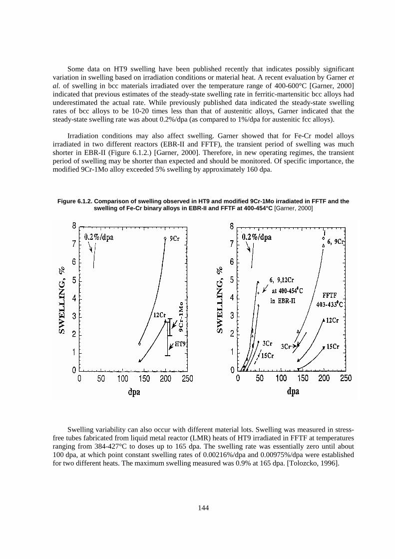
144
Some data on HT9 swelling have been published recently that indicates possibly significant variation in swelling based on irradiation conditions or material heat. A recent evaluation by Garner et al. of swelling in bcc materials irradiated over the temperature range of 400-600°C [Garner, 2000] indicated that previous estimates of the steady-state swelling rate in ferritic-martensitic bcc alloys had underestimated the actual rate. While previously published data indicated the steady-state swelling rates of bcc alloys to be 10-20 times less than that of austenitic alloys, Garner indicated that the steady-state swelling rate was about 0.2%/dpa (as compared to 1%/dpa for austenitic fcc alloys).
Irradiation conditions may also affect swelling. Garner showed that for Fe-Cr model alloys irradiated in two different reactors (EBR-II and FFTF), the transient period of swelling was much shorter in EBR-II (Figure 6.1.2.) [Garner, 2000]. Therefore, in new operating regimes, the transient period of swelling may be shorter than expected and should be monitored. Of specific importance, the modified 9Cr-1Mo alloy exceeded 5% swelling by approximately 160 dpa.
Figure 6.1.2. Comparison of swelling observed in HT9 and modified 9Cr-1Mo irradiated in FFTF and the swelling of Fe-Cr binary alloys in EBR-II and FFTF at 400-454°C [Garner, 2000]
Swelling variability can also occur with different material lots. Swelling was measured in stress-free tubes fabricated from liquid metal reactor (LMR) heats of HT9 irradiated in FFTF at temperatures ranging from 384-427°C to doses up to 165 dpa. The swelling rate was essentially zero until about 100 dpa, at which point constant swelling rates of 0.00216%/dpa and 0.00975%/dpa were established for two different heats. The maximum swelling measured was 0.9% at 165 dpa. [Tolozcko, 1996].
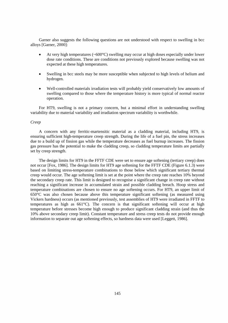
145
Garner also suggests the following questions are not understood with respect to swelling in bcc alloys [Garner, 2000]:
� At very high temperatures (~600°C) swelling may occur at high doses especially under lower dose rate conditions. These are conditions not previously explored because swelling was not expected at these high temperatures.
� Swelling in bcc steels may be more susceptible when subjected to high levels of helium and hydrogen.
� Well-controlled materials irradiation tests will probably yield conservatively low amounts of swelling compared to those where the temperature history is more typical of normal reactor operation.
For HT9, swelling is not a primary concern, but a minimal effort in understanding swelling variability due to material variability and irradiation spectrum variability is worthwhile.
Creep
A concern with any ferritic-martensitic material as a cladding material, including HT9, is ensuring sufficient high-temperature creep strength. During the life of a fuel pin, the stress increases due to a build up of fission gas while the temperature decreases as fuel burnup increases. The fission gas pressure has the potential to make the cladding creep, so cladding temperature limits are partially set by creep strength.
The design limits for HT9 in the FFTF CDE were set to ensure age softening (tertiary creep) does not occur [Fox, 1986]. The design limits for HT9 age softening for the FFTF CDE (Figure 6.1.3) were based on limiting stress-temperature combinations to those below which significant tertiary thermal creep would occur. The age softening limit is set at the point where the creep rate reaches 10% beyond the secondary creep rate. This limit is designed to recognise a significant change in creep rate without reaching a significant increase in accumulated strain and possible cladding breach. Hoop stress and temperature combinations are chosen to ensure no age softening occurs. For HT9, an upper limit of 650°C was also chosen because above this temperature significant softening (as measured using Vickers hardness) occurs (as mentioned previously, test assemblies of HT9 were irradiated in FFTF to temperatures as high as 661°C). The concern is that significant softening will occur at high temperature before stresses become high enough to produce significant cladding strain (and thus the 10% above secondary creep limit). Constant temperature and stress creep tests do not provide enough information to separate out age softening effects, so hardness data were used [Leggett, 1986].
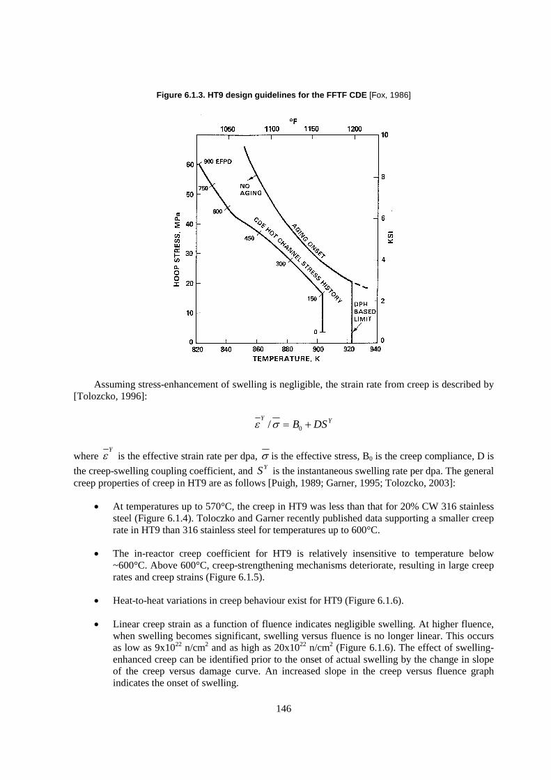
146
Figure 6.1.3. HT9 design guidelines for the FFTF CDE [Fox, 1986]
Assuming stress-enhancement of swelling is negligible, the strain rate from creep is described by [Tolozcko, 1996]:
YYDSB �� 0/��
where Y
� is the effective strain rate per dpa, � is the effective stress, B0 is the creep compliance, D is
the creep-swelling coupling coefficient, and YS is the instantaneous swelling rate per dpa. The general creep properties of creep in HT9 are as follows [Puigh, 1989; Garner, 1995; Tolozcko, 2003]:
� At temperatures up to 570°C, the creep in HT9 was less than that for 20% CW 316 stainless steel (Figure 6.1.4). Toloczko and Garner recently published data supporting a smaller creep rate in HT9 than 316 stainless steel for temperatures up to 600°C.
� The in-reactor creep coefficient for HT9 is relatively insensitive to temperature below ~600°C. Above 600°C, creep-strengthening mechanisms deteriorate, resulting in large creep rates and creep strains (Figure 6.1.5).
� Heat-to-heat variations in creep behaviour exist for HT9 (Figure 6.1.6).
� Linear creep strain as a function of fluence indicates negligible swelling. At higher fluence, when swelling becomes significant, swelling versus fluence is no longer linear. This occurs as low as 9x10²² n/cm2 and as high as 20x1022 n/cm2 (Figure 6.1.6). The effect of swelling-enhanced creep can be identified prior to the onset of actual swelling by the change in slope of the creep versus damage curve. An increased slope in the creep versus fluence graph indicates the onset of swelling.
147
� A comparison of in-reactor creep of HT9 at 400°C (Figure 6.1.5) and at 600°C (Figure 6.1.7) shows that at higher temperature, creep is dominated by thermal creep with no dependence on irradiation dose.
Figure 6.1.4. Comparison of diameter change in pressurised tubes as a function of stress between 316 SS and bainitic and martensitic steels to about 6x10²² n/cm2 in EBR-II at:
a) 420°C, b) 490°C, c) 570°C and to 2x10²² n/cm2 at d) 653°C [Puigh, 1989]
Figure 6.1.5. Temperature dependence of the in-reactor creep coefficient for HT9 pressurised tubes [Puigh, 1989]

148
Figure 6.1.6. Comparison of pressurised tube specimens of martensitic steels in FFTF as a function of fluence at 400°C; a) HT9 fusion heat 9607R2; b) HT9 heat 84425; c) HT9 heat 91353;
d) modified 9Cr-1Mo heat 30394; e) HT9 heat 91353 in a stronger heat-treatment condition; and f) HT9 heat 92235 in a stronger heat-treatment condition [Puigh, 1989]

149
Figure 6.1.7. Total midwall creep strains observed in HT9 at ~600°C [Garner, 1995]
For the high-burnup tests using HT9 cladding in the FFTF CDE, the only negative observation was some HT9 cladding deformation (creep strain dilation) toward the top of the fuel column in the highest temperature, highest smeared density pins. The deformation was assumed to be caused by: (1) the migration and buildup of fission products (e.g. cesium compounds) at the fuel-cladding interface; and (2) the reduced creep strength of the cladding materials due to high temperature. While HT9 was seen as acceptable as duct or wrapper material, confirmation of its ability to be used for pin cladding was not established by examination of samples taken to higher burnup [Klueh, 1993].
For HT9, high-temperature creep strength is a limiting factor in determining the allowed temperature of operation. An effort in understanding creep variability due to material variability and irradiation spectrum variability is needed. To improve performance, research into alternative alloys with improved high-temperature creep strength is necessary. These alloys will be discussed in a later section.
Tensile properties
In the absence of significant swelling and creep, the minimum duct thickness is essentially determined by the yield strength of the material. This is because the duct has to withstand the imposed loads during seismic loading events [Lauritzen, 1981].
HT9 maintains adequate strength and ductility to the maximum neutron fluence tested (up to 16.5x10²² n/cm2) at irradiation temperatures from 400-725°C and tensile test temperatures of 25-730°C. At low irradiation temperatures (~425°C), yield strength increases with increasing dose while it decreases with increasing dose at higher temperature. At lower temperatures, where the
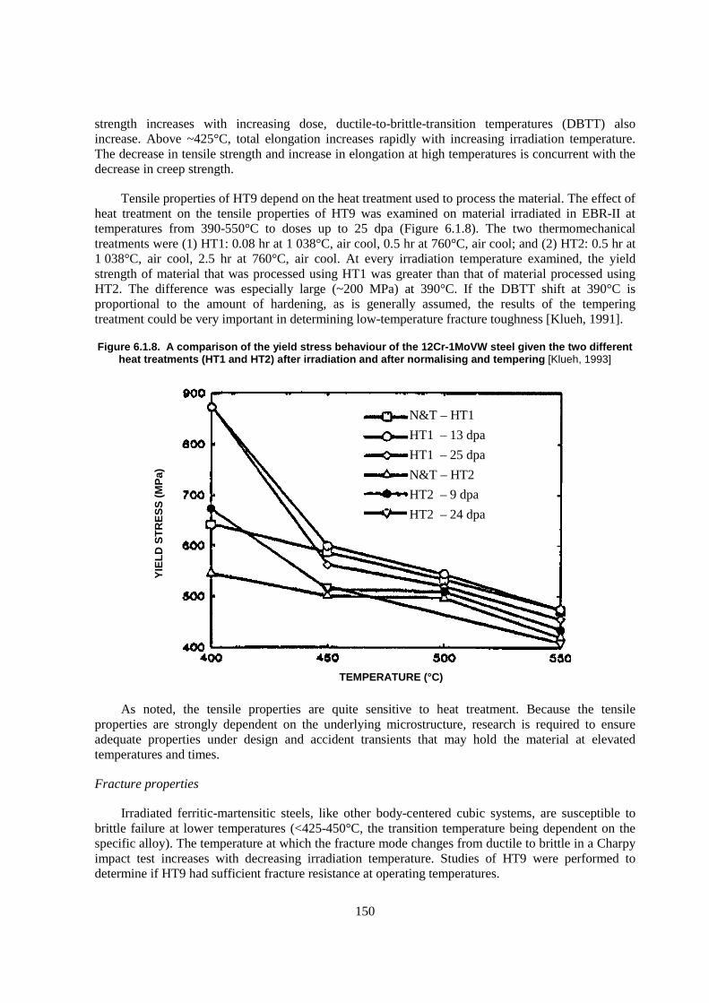
150
strength increases with increasing dose, ductile-to-brittle-transition temperatures (DBTT) also increase. Above ~425°C, total elongation increases rapidly with increasing irradiation temperature. The decrease in tensile strength and increase in elongation at high temperatures is concurrent with the decrease in creep strength.
Tensile properties of HT9 depend on the heat treatment used to process the material. The effect of heat treatment on the tensile properties of HT9 was examined on material irradiated in EBR-II at temperatures from 390-550°C to doses up to 25 dpa (Figure 6.1.8). The two thermomechanical treatments were (1) HT1: 0.08 hr at 1 038°C, air cool, 0.5 hr at 760°C, air cool; and (2) HT2: 0.5 hr at 1 038°C, air cool, 2.5 hr at 760°C, air cool. At every irradiation temperature examined, the yield strength of material that was processed using HT1 was greater than that of material processed using HT2. The difference was especially large (~200 MPa) at 390°C. If the DBTT shift at 390°C is proportional to the amount of hardening, as is generally assumed, the results of the tempering treatment could be very important in determining low-temperature fracture toughness [Klueh, 1991].
Figure 6.1.8. A comparison of the yield stress behaviour of the 12Cr-1MoVW steel given the two different heat treatments (HT1 and HT2) after irradiation and after normalising and tempering [Klueh, 1993]
As noted, the tensile properties are quite sensitive to heat treatment. Because the tensile properties are strongly dependent on the underlying microstructure, research is required to ensure adequate properties under design and accident transients that may hold the material at elevated temperatures and times.
Fracture properties
Irradiated ferritic-martensitic steels, like other body-centered cubic systems, are susceptible to brittle failure at lower temperatures (<425-450°C, the transition temperature being dependent on the specific alloy). The temperature at which the fracture mode changes from ductile to brittle in a Charpy impact test increases with decreasing irradiation temperature. Studies of HT9 were performed to determine if HT9 had sufficient fracture resistance at operating temperatures.
TEMPERATURE (°C)
YIE
LD
ST
RE
SS
(M
Pa)
N&T – HT1
HT1 – 13 dpa
HT1 – 25 dpa
N&T – HT2
HT2 – 9 dpa
HT2 – 24 dpa
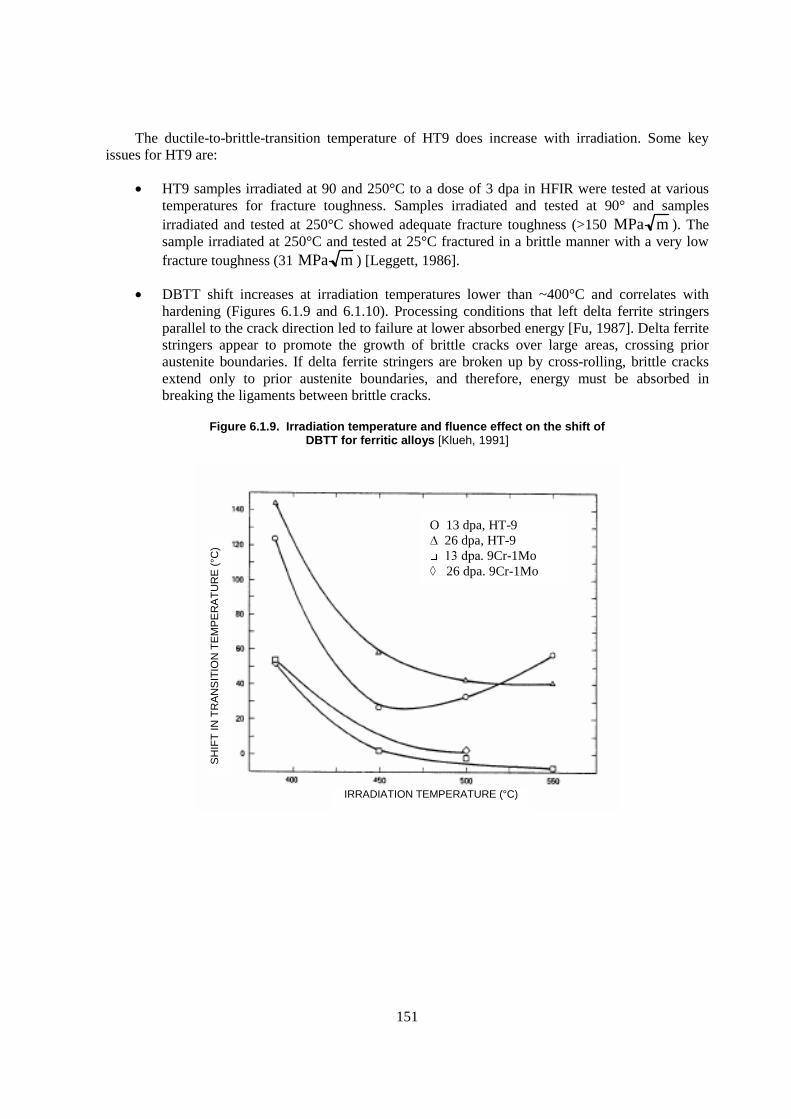
151
The ductile-to-brittle-transition temperature of HT9 does increase with irradiation. Some key issues for HT9 are:
� HT9 samples irradiated at 90 and 250°C to a dose of 3 dpa in HFIR were tested at various temperatures for fracture toughness. Samples irradiated and tested at 90° and samples irradiated and tested at 250°C showed adequate fracture toughness (>150 MPa m ). The sample irradiated at 250°C and tested at 25°C fractured in a brittle manner with a very low fracture toughness (31 MPa m ) [Leggett, 1986].
� DBTT shift increases at irradiation temperatures lower than ~400°C and correlates with hardening (Figures 6.1.9 and 6.1.10). Processing conditions that left delta ferrite stringers parallel to the crack direction led to failure at lower absorbed energy [Fu, 1987]. Delta ferrite stringers appear to promote the growth of brittle cracks over large areas, crossing prior austenite boundaries. If delta ferrite stringers are broken up by cross-rolling, brittle cracks extend only to prior austenite boundaries, and therefore, energy must be absorbed in breaking the ligaments between brittle cracks.
Figure 6.1.9. Irradiation temperature and fluence effect on the shift of DBTT for ferritic alloys [Klueh, 1991]
O 13 dpa, HT-9 ���26 dpa, HT-9 ��������. 9Cr-1Mo
����26 dpa. 9Cr-1Mo
IRRADIATION TEMPERATURE (°C)
SH
IFT
IN T
RA
NS
ITIO
N T
EM
PE
RA
TU
RE
(°C
)
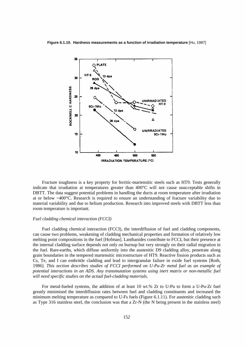
152
Figure 6.1.10. Hardness measurements as a function of irradiation temperature [Hu, 1987]
Fracture toughness is a key property for ferritic-martensitic steels such as HT9. Tests generally indicate that irradiation at temperatures greater than 400°C will not cause unacceptable shifts in DBTT. The data suggest potential problems in handling the ducts at room temperature after irradiation at or below ~400°C. Research is required to ensure an understanding of fracture variability due to material variability and due to helium production. Research into improved steels with DBTT less than room temperature is important.
Fuel cladding chemical interaction (FCCI)
Fuel cladding chemical interaction (FCCI), the interdiffusion of fuel and cladding components, can cause two problems, weakening of cladding mechanical properties and formation of relatively low melting point compositions in the fuel [Hofman]. Lanthanides contribute to FCCI, but their presence at the internal cladding surface depends not only on burnup but very strongly on their radial migration in the fuel. Rare-earths, which diffuse uniformly into the austenitic D9 cladding alloy, penetrate along grain boundaries in the tempered martensitic microstructure of HT9. Reactive fission products such as Cs, Te, and I can embrittle cladding and lead to intergranular failure in oxide fuel systems [Roth, 1986]. This section describes studies of FCCI performed on U-Pu-Zr metal fuel as an example of potential interactions in an ADS. Any transmutation systems using inert matrix or non-metallic fuel will need specific studies on the actual fuel-cladding materials.
For metal-fueled systems, the addition of at least 10 wt.% Zr to U-Pu to form a U-Pu-Zr fuel greatly minimised the interdiffusion rates between fuel and cladding constituents and increased the minimum melting temperature as compared to U-Fs fuels (Figure 6.1.11). For austenitic cladding such as Type 316 stainless steel, the conclusion was that a Zr-N (the N being present in the stainless steel)

153
surface layer is formed which acts as a diffusion barrier to further interaction. During normal operation, FCCI is characterised by solid state interdiffusion. Ni diffusion from the cladding into the fuel plays an important part in FCCI with austenitic stainless steels. Such interdiffusion leads to the formation of eutectic-like compositions in the fuel with lower melting temperatures. In HT9, a martensitic steel with low Ni (0.6%) content but higher carbon, decarburisation removes carbon from the cladding surface, creating a low-carbon ferritic layer on the cladding inner surface.
Figure 6.1.11. Fuel cladding chemical interaction for various metal fuel/clad combinations. Penetration refers to the penetration of fuel-cladding interdiffusion phase into the cladding [Hofman].
154
Diffusion couple experiments at 650°C for 100 hours indicate that major elements (Fe, Cr, Ni) are critical and trace elements play an insignificant role in the phases formed. In general, diffusion layers formed on the cladding side are dominated by U-rich intermetallic phases formed with the Fe, Ni and Cr cladding components. On the fuel side, a two-phase region forms, one phase rich in (U, Pu), the other in Zr containing the major cladding constituents [Kaiser, 1996]:
� In U-10Zr fuel, the presence of Ni in the cladding resulted in larger diffusion zones compared to cladding with low Ni (like HT9).
� In U-19Pu-10Zr fuel, Ni containing diffusion couples had smaller diffusion zones than for couples with low Ni (like HT9).
� The presence of Pu increased the number of phases and size of the diffusion zone in both D9 and HT9.
� The larger diffusion zone in the U-Pu-Zr system (as compared to the U-10Zr) with HT9 correlated to the development of a U6Fe-type phase.
Post-irradiation examinations and annealing experiments show significantly different behaviour of FCCI than that obtained in diffusion couple experiments. Sections of various fuel elements (U-29Pu-10Zr, U-19Pu-10Zr, and U-10Zr fuel with HT9, D9, or 316 SS cladding) were heated in an in-cell apparatus over a range of temperature and time. The range of burnups was between 3 and 17 at.%. The tests were run at temperatures between 700 and 850°C for times of 0.1 to 7.0 hours. These tests have shown no evidence of liquid phase formation due to FCCI below ~725°C for test durations up to seven hours. At 825°C, melting through the cladding wall occurs almost instantaneously. Between 725 and 825°C, the following cladding penetration correlation was recommended [Tsai, 1990]:
RT
QA
eS�
�
where S is the penetration rate of the cladding wastage in �m/s, R=1.987 cal/mol K, T is the clad temperature (K), A=11.65, and Q=-31.13 kcal/mol. The penetration rate is strongly temperature dependent. At lower temperatures, significantly longer times are required for a specific penetration to occur. For example, a fixed penetration at 725°C takes ~4 times longer than the same penetration at 825°C. An important point to note is that penetration rate into the fuel is less important than penetration rate into the cladding, as the cladding wastage is the critical parameter.
FCCI has the potential to limit cladding performance. Fundamental understanding of FCCI on the fuel-cladding combinations proposed for ADS is lacking. If research on cladding materials with improved creep strength or decreased DBTT occurs, research on FCCI is required on these new cladding materials.
Fuel cladding mechanical interaction (FCMI)
To achieve high burnup operation without FCMI in a metal-fueled system, a smeared density of 75% or less and a plenum-to-fuel volume ratio of 0.6 or higher is required. For 75% smeared density fuel, HT9 cladding has been taken to 16 at.% burnup with no evidence of FCMI, although the build-up of solid fission products in the fuel would eventually generate FCMI stresses. For an 85% smear density fuel taken to 12.5 at.% burnup, FCMI did cause an increase in cladding strain [Hofman].
155
6.1.7 Fusion studies of HT9
Because the ADS system is expected to operate with a neutron spectrum between fusion systems and fast spectrum systems, studies from the fusion energy programme may provide information relevant to ADS systems. Since the D-T fusion reaction produces 14 MeV neutrons, ferrous alloys used in fusion system structural materials experience a higher He production rate (due to He transmutation reactions) than in fast reactors such as FFTF and EBR-II. To simulate fusion conditions in ferritic-martensitic steels such as HT9, additions of 2 wt.% Ni were added to the HT9 composition (designated in the papers by the generic composition of 12Cr-1MoVW) [Klueh, 1992; Maziasz, 1986; Klueh, 1992b]. In the Ni-doped materials, He is formed by a two-step reaction of 58Ni with thermal neutrons: 58Ni(n,�)59Ni followed by 59Ni(n,�)56Fe. Studies of both tensile and fracture properties were carried out on these Ni-doped HT9 steels irradiated in the High Flux Isotope Reactor (HFIR), a mixed spectrum reactor at Oak Ridge National Laboratory, in which the thermal neutrons contribute to the formation of helium, while displacement damage is simultaneously formed by fast neutrons in the spectrum.
The pre-irradiation heat treatment was a normalising treatment of 1 050°C for 30 minutes followed by an air cool, which was followed by a temper of 780°C for 2.5 hours for the 12Cr-1MoVW and 700°C for 5 hours for the 12Cr-1MoVW+2%Ni (designated 12Cr-1MoVW-2Ni) [Klueh, 1992; Klueh, 1992b; Maziasz, 1986]. Samples with 2% additional Ni were tempered longer at a lower temperature than the undoped alloys because previous studies showed that nickel lowered the lowest critical austenite-forming temperature, AC1. This difference in tempering conditions produced a finer subgrain structure with more dislocations and some refinement of the M23C6 precipitation. Nickel-doping did not affect the precipitate phases produced during tempering [Maziasz, 1986].
The following sections discuss the results of the Ni-doping experiments. Although the experiments do shed light on the possible effects of additional transmutation gas on cladding and duct performance, the experiments do have limitations and these limitations highlight the necessity to obtain irradiations in a prototypical spectrum.
Tensile properties
Tensile samples of 12Cr-1MoVW with and without Ni were irradiated in both EBR-II and HFIR at temperatures of 390-400°C to doses up to 72 dpa [Klueh, 1992b]. The data are summarised in Table 6.1.1. For both alloys, the samples irradiated in HFIR had significantly more He following irradiation. HFIR irradiation to 8-11 dpa produced 15 appm He in the 12Cr-1MoVW material compared to <3 appm in the EBR-II sample irradiated to ~16 dpa. The addition of Ni to the HT9 composition increased the He to 80 appm in the HFIR samples, but did not change the EBR-II He levels. Additional samples of both alloys were irradiated in HFIR to 37-72 dpa. The higher dpa increased the He to 129 appm in the 12Cr-1MoVW sample and 598 in the 12Cr-1MoVW-2%Ni sample. For the 12Cr-1MoVW material, the increased He did correspond with an increase in yield strength, but for the 12Cr-1Mo-VW-2Ni, the yield strength did not increase even with the greater He concentration. For both the 12Cr-1MoVW and the 12Cr-1MoVW-2Ni, the increases in tensile strength were greater for the samples irradiated in HFIR. Although these comparisons are not perfect in that the compositions and initial heat treatments are not the same, they do indicate that the greater amount of He expected in ADS systems may lead to greater hardening. As discussed in the next section, since brittle behaviour tends to correlate with increased strength, this could be a problem in the ADS spectrum.
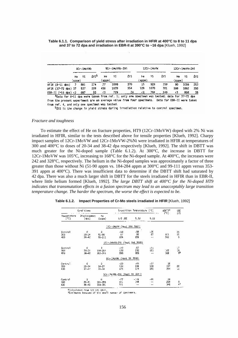
156
Table 6.1.1. Comparison of yield stress after irradiation in HFIR at 400°C to 8 to 11 dpa and 37 to 72 dpa and irradiation in EBR-II at 390°C to ~16 dpa [Klueh, 1992]
Fracture and toughness
To estimate the effect of He on fracture properties, HT9 (12Cr-1MoVW) doped with 2% Ni was irradiated in HFIR, similar to the tests described above for tensile properties [Klueh, 1992]. Charpy impact samples of 12Cr-1MoVW and 12Cr-1MoVW-2%Ni were irradiated in HFIR at temperatures of 300 and 400°C to doses of 20-34 and 38-42 dpa respectively [Klueh, 1992]. The shift in DBTT was much greater for the Ni-doped sample (Table 6.1.2). At 300°C, the increase in DBTT for 12Cr-1MoVW was 105°C, increasing to 168°C for the Ni-doped sample. At 400°C, the increases were 242 and 328°C, respectively. The helium in the Ni-doped samples was approximately a factor of three greater than those without Ni (51-90 appm vs. 184-284 appm at 300°C and 99-111 appm versus 353-391 appm at 400°C). There was insufficient data to determine if the DBTT shift had saturated by 42 dpa. There was also a much larger shift in DBTT for the steels irradiated in HFIR than in EBR-II, where little helium formed [Klueh, 1992]. The large DBTT shift at 400°C for the Ni-doped HT9 indicates that transmutation effects in a fusion spectrum may lead to an unacceptably large transition temperature change. The harder the spectrum, the worse the effect is expected to be.
Table 6.1.2. Impact Properties of Cr-Mo steels irradiated in HFIR [Klueh, 1992]
157
Aging of the two different steels at 400°C for 2 500 hours showed no difference in DBTT shift, indicating that the addition of Ni does not significantly change the unirradiated fracture properties. Comparison of the microstructure of samples irradiated in HFIR (mixed-spectrum) to ~39 dpa with samples irradiated in FFTF (fast spectrum) to ~47 dpa indicates no major differences in the evolution of microstructures. The only exception was the formation of voids and bubbles in the HFIR-irradiated steels, which was attributed to helium [Klueh, 1992].
DBTT shifts measured on Charpy samples irradiated in the Oak Ridge Research Reactor (ORR), which has a much lower thermal-to-fast flux ratio than HFIR, were similar to those irradiated in FFTF or EBR-II [Klueh, 1992c]. The displacement rate is an order of magnitude higher in EBR-II than ORR, but the shift in DBTT was similar. The displacement rate is about the same in EBR-II and HFIR, but the shifts in DBTT are much different, indicating that displacement rate does not strongly affect DBTT shift.
The studies of Ni-doped HT9 samples indicate that the greater He levels that are expected in ADS may lead to unacceptably large DBTT shifts. Confirmatory R&D in an appropriate spectrum will be needed to ultimately answer the question.
Swelling
To estimate the effect of He on swelling, HT9 doped with 2% Ni was irradiated in HFIR [Maziasz, 1986]. The higher helium produced during irradiation in the Ni-doped samples appears to shorten the incubation for void formation, with an estimated decrease in the incubation dose from ~150 dpa to ~50 dpa. The smallest subgrains had fewer and smaller voids than the largest subgrains, indicating that the subgrains may be strong defect sinks which hinder void formation. Since the subgrains were formed as a result of the different thermomechanical treatment (TMT) in the Ni-doped sample, the microstructural development and associated material properties in the Ni-doped samples may not be fully representative of HT9 under fusion conditions. However, the results from these studies demonstrated the effect of helium on swelling, which was the objective of the work [Maziasz, 1986].
The Ni-doped studies performed for the fusion programme indicate that the additional He expected will lead to greater hardening, larger increases in DBTT, and shorter incubation periods for swelling. Because of the differences in the microstructure between the Ni-doped and non Ni-doped materials, these fusion tests are not definitive, but they do indicate a need for caution in pursuing materials for ADS. Confirmatory tests in an actual spectrum are required. Additionally, if advanced materials are studied to replace HT9, the effect of He will need to be studied on those materials as well. An alternative approach to studying helium effects that is being studied by the fusion community (see later section) is doping samples with boron to induce greater He from transmutation reactions.
6.1.8 PNC-FMS properties
The Japan Nuclear Cycle Development Institute (JNC) developed a ferritic-martensitic stainless steel (PNC-FMS) for use as duct and cladding material for fast reactor fuel assemblies [Ukai, 1992; Nomura, 1991]. The PNC-FMS continues to be tested following irradiation in the JOYO reactor. A brief summary of the PNC-FMS properties is described in this section.
158
Composition and heat treatment
The particular emphasis for the development of PNC-FMS as fast reactor fuel cladding and duct material is to improve the high temperature strength while maintaining the Charpy impact properties and strong void swelling resistance. The Cr content is required to be more than 9 mass % in ferritic-martensitic steels to suppress de-carbonisation in flowing sodium. On the other hand, the Cr content must be below 13 mass % to prevent delta-ferrite formation that induces toughness degradation after long-term aging. The solution hardening is expected to be optimised by means of Mo equivalent content (Mo+1/2W) of around 1.5 mass %. Substituting W for a part of the Mo introduces a beneficial effect by increasing the long-term creep rupture strength without degradation of impact properties. The precipitation strength is attained by an uniform distribution of fine VN and Nb(C,N) in the matrix.
Based on the above considerations, the nominal composition of PNC-FMS is Fe-0.12C-11Cr-0.5Mo-2.0W-0.2V-0.05Nb-0.05N (mass %) in a martensitic structure with 5% delta-ferrite [Shikakura, 1991]. Different heat-treatment conditions were adopted for the cladding and wrapper (duct); normalising at 1 100�C for 10 minutes followed by tempering at 780�C for 1 hour for cladding, and 1 050�C for 10 minutes and 700�C for 1 hour for wrapper application, respectively [Shikakura, 1991]. These are chosen because the fuel cladding requires creep rupture strength while the wrapper needs more tensile strength and fracture toughness.
Tensile properties
The tensile properties of PNC-FMS are shown in Figure 6.1.12 as compared with HT9 and austenitic PNC316. The PNC-FMS using the wrapper heat treatment exhibits higher ultimate tensile strength than the PNC-FMS cladding which is similar to HT9 [Shikakura, 1991]. The effect of thermal aging and de-carbonisation in sodium on the tensile strength of PNC-FMS was measured. The ultimate tensile strength for samples thermally aged and treated in sodium at temperatures up to 700�C for as long as 10 000 hours is shown in Figure 6.1.13 [Uehira, 2000]. The strength in the thermally aged condition decreases at higher tempering temperatures. Sodium exposure causes the tensile strength to decrease due to de-carbonisation. The tensile strength of the neutron-irradiated specimens at 482�C and 543�C up to 29 dpa was almost same as that of samples exposed to sodium at each temperature. The effect of neutron irradiation appears be negligible below 29 dpa [Uehira, 2000].
Creep properties
As shown in Figure 6.1.14, the creep rupture strength of PNC-FMS cladding at 650�C is the largest among similar ferritic-martensitic stainless steels [Ukai, 1992]. Tubes internally pressurised with helium gases were irradiated in FFTF-MOTA at 550�C, 605�C, 670�C up to 41 dpa and the measured creep was directly compared with an out-of pile thermal creep rupture correlation (Figure 6.1.15 [Shikakura, 1991]). The PNC-FMS cladding showed no degradation of in-reactor creep rupture strength as opposed to an austenitic stainless steel (PNC316) which exhibited a decrease of in-reactor creep rupture time during a FFTF-MOTA irradiation test [Ukai, 2000].
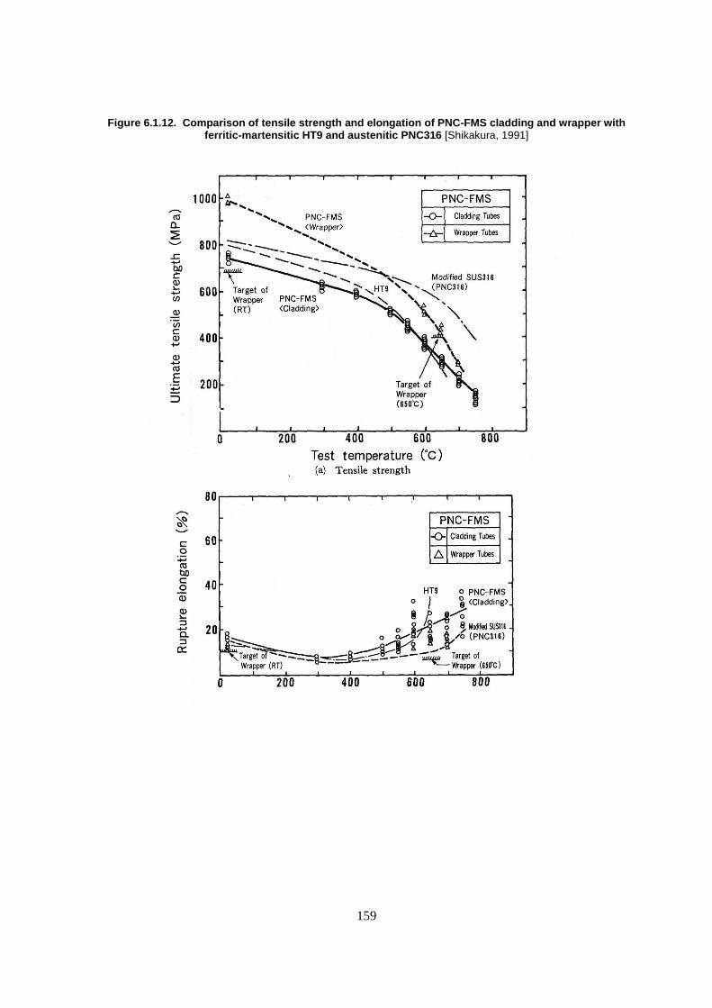
159
Figure 6.1.12. Comparison of tensile strength and elongation of PNC-FMS cladding and wrapper with ferritic-martensitic HT9 and austenitic PNC316 [Shikakura, 1991]
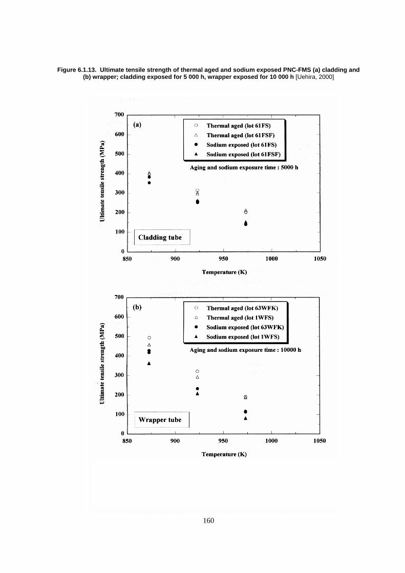
160
Figure 6.1.13. Ultimate tensile strength of thermal aged and sodium exposed PNC-FMS (a) cladding and (b) wrapper; cladding exposed for 5 000 h, wrapper exposed for 10 000 h [Uehira, 2000]
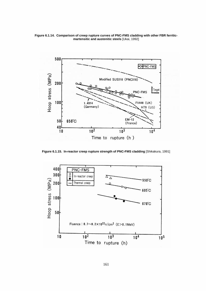
161
Figure 6.1.14. Comparison of creep rupture curves of PNC-FMS cladding with other FBR ferritic-martensitic and austenitic steels [Ukai, 1992]
Figure 6.1.15. In-reactor creep rupture strength of PNC-FMS cladding [Shikakura, 1991]
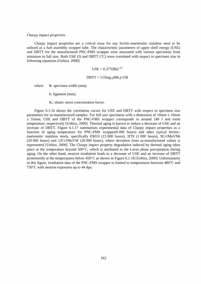
162
Charpy impact properties
Charpy impact properties are a critical issue for any ferritic-martensitic stainless steel to be utilised as a fuel assembly wrapper tube. The characteristic parameters of upper shelf energy (USE) and DBTT for the manufactured PNC-FMS wrapper were measured with various specimens from miniature to full size. Both USE (J) and DBTT (�C) were correlated with respect to specimen size in following equations [Uehira, 2000]:
USE = 0.277(Bb)1.42
DBTT = 115log10(BKt)-158
where B: specimen width (mm);
b: ligament (mm);
Kt: elastic stress concentration factor.
Figure 6.1.16 shows the correlation curves for USE and DBTT with respect to specimen size parameters for as-manufactured samples. For full size specimens with a dimension of 10mm x 10mm x 55mm, USE and DBTT of the PNC-FMS wrapper corresponds to around 140 J and room temperature, respectively [Uehira, 2000]. Thermal aging is known to induce a decrease of USE and an increase of DBTT. Figure 6.1.17 summarises experimental data of Charpy impact properties as a function of aging temperature for PNC-FMS wrapper(6 000 hours) and other typical ferritic-martensitic stainless steels, specifically EM10 (15 000 hours), HT9 (1 000 hours), 9Cr1MoVNb (20 000 hours) and 12Cr1MoVW (20 000 hours), where deviation from as-manufactured values is represented [Uehira, 2000]. The Charpy impact property degradation induced by thermal aging takes place at the temperature beyond 500�C, which is attributed to the Laves phase precipitation during aging. On the other hand, neutron irradiation leads to a decrease of USE and an increase of DBTT prominently at the temperatures below 450�C as shown in Figure 6.1.18 [Uehira, 2000]. Unfortunately in this figure, irradiation data of the PNC-FMS wrapper is limited to temperatures between 480�C and 730�C with neutron exposures up to 44 dpa.
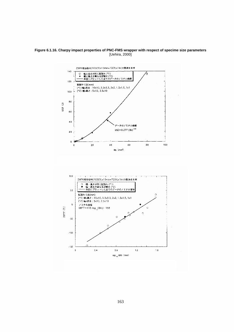
163
Figure 6.1.16. Charpy impact properties of PNC-FMS wrapper with respect of specime size parameters [Uehira, 2000]
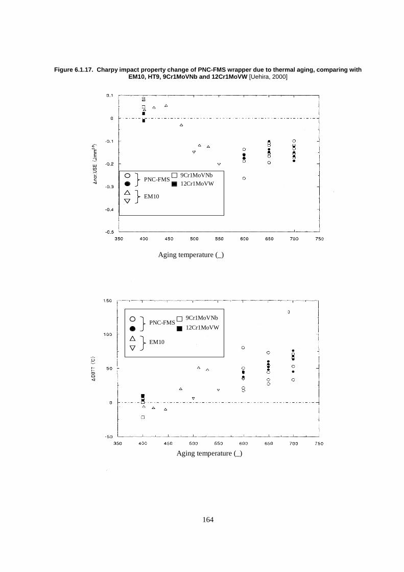
164
Figure 6.1.17. Charpy impact property change of PNC-FMS wrapper due to thermal aging, comparing with EM10, HT9, 9Cr1MoVNb and 12Cr1MoVW [Uehira, 2000]
Aging temperature (_)
Aging temperature (_)
PNC-FMS
EM10
9Cr1MoVNb
12Cr1MoVW
PNC-FMS
EM10
9Cr1MoVNb12Cr1MoVW
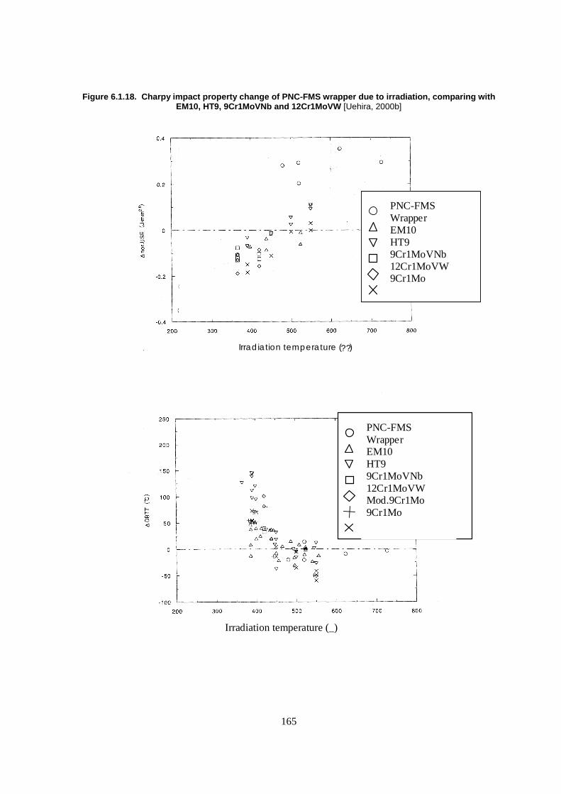
165
Figure 6.1.18. Charpy impact property change of PNC-FMS wrapper due to irradiation, comparing with EM10, HT9, 9Cr1MoVNb and 12Cr1MoVW [Uehira, 2000b]
Irradiation temperature (??)
Irradiation temperature (_)
PNC-FMSWrapperEM10HT99Cr1MoVNb12Cr1MoVW9Cr1Mo
PNC-FMSWrapperEM10HT99Cr1MoVNb12Cr1MoVWMod.9Cr1Mo9Cr1Mo
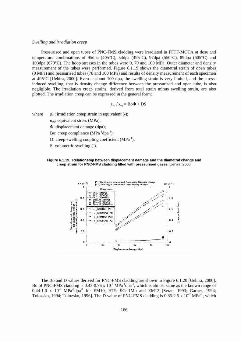
166
Swelling and irradiation creep
Pressurised and open tubes of PNC-FMS cladding were irradiated in FFTF-MOTA at dose and temperature combinations of 95dpa (405�C), 54dpa (495�C), 97dpa (550�C), 89dpa (605�C) and 103dpa (670�C). The hoop stresses in the tubes were 0, 70 and 100 MPa. Outer diameter and density measurement of the tubes were performed. Figure 6.1.19 shows the diametral strain of open tubes (0 MPa) and pressurised tubes (70 and 100 MPa) and results of density measurement of each specimen at 405�C [Uehira, 2000]. Even at about 100 dpa, the swelling strain is very limited, and the stress-induced swelling, that is density change difference between the pressurised and open tube, is also negligible. The irradiation creep strains, derived from total strain minus swelling strain, are also plotted. The irradiation creep can be expressed in the general form:
irr�� eq����� �����
where irr: irradiation creep strain in equivalent (-);
eq: equivalent stress (MPa);
��� ���������������� ��; Bo: creep compliance (MPa-1dpa-1);
D: creep-swelling coupling coefficient (MPa-1);
S: volumetric swelling (-).
Figure 6.1.19. Relationship between displacement damage and the diametral change and creep strain for PNC-FMS cladding filled with pressurised gases [Uehira, 2000]
The Bo and D values derived for PNC-FMS cladding are shown in Figure 6.1.20 [Uehira, 2000]. Bo of PNC-FMS cladding is 0.43-0.76 x 10⁻⁶ MPa-1dpa-1, which is almost same as the known range of 0.44-1.0 x 10⁻⁶ MPa-1dpa-1 for EM10, HT9, 9Cr-1Mo and EM12 [Seran, 1993; Garner, 1994; Tolozsko, 1994; Tolozsko, 1996]. The D value of PNC-FMS cladding is 0.85-2.5 x 10⁻² MPa-1, which
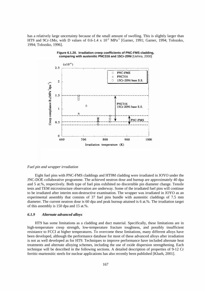
167
has a relatively large uncertainty because of the small amount of swelling. This is slightly larger than HT9 and 9Cr-1Mo, with D values of 0.6-1.4 x 10⁻² MPa-1 [Garner, 1991; Garner, 1994; Tolozsko, 1994; Tolozsko, 1996].
Figure 6.1.20. Irradiation creep coefficients of PNC-FMS cladding, comparing with austenitic PNC316 and 15Cr-20Ni [Uehira, 2000]
Fuel pin and wrapper irradiation
Eight fuel pins with PNC-FMS claddings and HT9M cladding were irradiated in JOYO under the JNC-DOE collaborative programme. The achieved neutron dose and burnup are approximately 40 dpa and 5 at.%, respectively. Both type of fuel pins exhibited no discernible pin diameter change. Tensile tests and TEM microstructure observation are underway. Some of the irradiated fuel pins will continue to be irradiated after interim non-destructive examination. The wrapper was irradiated in JOYO as an experimental assembly that consists of 37 fuel pins bundle with austenitic claddings of 7.5 mm diameter. The current neutron dose is 60 dpa and peak burnup attained is 6 at.%. The irradiation target of this assembly is 150 dpa and 15 at.%.
6.1.9 Alternate advanced alloys
HT9 has some limitations as a cladding and duct material. Specifically, these limitations are in high-temperature creep strength, low-temperature fracture toughness, and possibly insufficient resistance to FCCI at higher temperatures. To overcome these limitations, many different alloys have been developed, although the performance database for most of these advanced alloys after irradiation is not as well developed as for HT9. Techniques to improve performance have included alternate heat treatments and alternate alloying schemes, including the use of oxide dispersion strengthening. Each technique will be described in the following sections. A detailed description of properties of 9-12 Cr ferritic-martensitic steels for nuclear applications has also recently been published [Klueh, 2001].
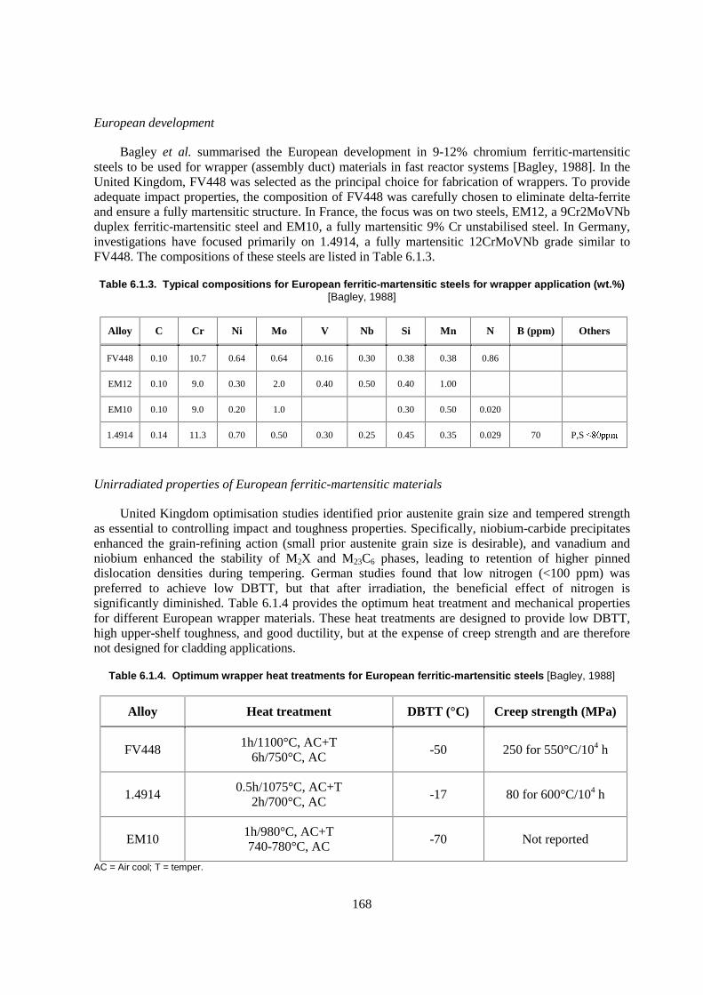
168
European development
Bagley et al. summarised the European development in 9-12% chromium ferritic-martensitic steels to be used for wrapper (assembly duct) materials in fast reactor systems [Bagley, 1988]. In the United Kingdom, FV448 was selected as the principal choice for fabrication of wrappers. To provide adequate impact properties, the composition of FV448 was carefully chosen to eliminate delta-ferrite and ensure a fully martensitic structure. In France, the focus was on two steels, EM12, a 9Cr2MoVNb duplex ferritic-martensitic steel and EM10, a fully martensitic 9% Cr unstabilised steel. In Germany, investigations have focused primarily on 1.4914, a fully martensitic 12CrMoVNb grade similar to FV448. The compositions of these steels are listed in Table 6.1.3.
Table 6.1.3. Typical compositions for European ferritic-martensitic steels for wrapper application (wt.%) [Bagley, 1988]
Alloy C Cr Ni Mo V Nb Si Mn N B (ppm) Others
FV448 0.10 10.7 0.64 0.64 0.16 0.30 0.38 0.38 0.86
EM12 0.10 9.0 0.30 2.0 0.40 0.50 0.40 1.00
EM10 0.10 9.0 0.20 1.0 0.30 0.50 0.020
1.4914 0.14 11.3 0.70 0.50 0.30 0.25 0.45 0.35 0.029 70 P,S ������
Unirradiated properties of European ferritic-martensitic materials
United Kingdom optimisation studies identified prior austenite grain size and tempered strength as essential to controlling impact and toughness properties. Specifically, niobium-carbide precipitates enhanced the grain-refining action (small prior austenite grain size is desirable), and vanadium and niobium enhanced the stability of M2X and M23C6 phases, leading to retention of higher pinned dislocation densities during tempering. German studies found that low nitrogen (<100 ppm) was preferred to achieve low DBTT, but that after irradiation, the beneficial effect of nitrogen is significantly diminished. Table 6.1.4 provides the optimum heat treatment and mechanical properties for different European wrapper materials. These heat treatments are designed to provide low DBTT, high upper-shelf toughness, and good ductility, but at the expense of creep strength and are therefore not designed for cladding applications.
Table 6.1.4. Optimum wrapper heat treatments for European ferritic-martensitic steels [Bagley, 1988]
Alloy Heat treatment DBTT (°C) Creep strength (MPa)
FV448 1h/1100°C, AC+T
6h/750°C, AC -50 250 for 550°C/104 h
1.4914 0.5h/1075°C, AC+T
2h/700°C, AC -17 80 for 600°C/104 h
EM10 1h/980°C, AC+T 740-780°C, AC
-70 Not reported
AC = Air cool; T = temper.
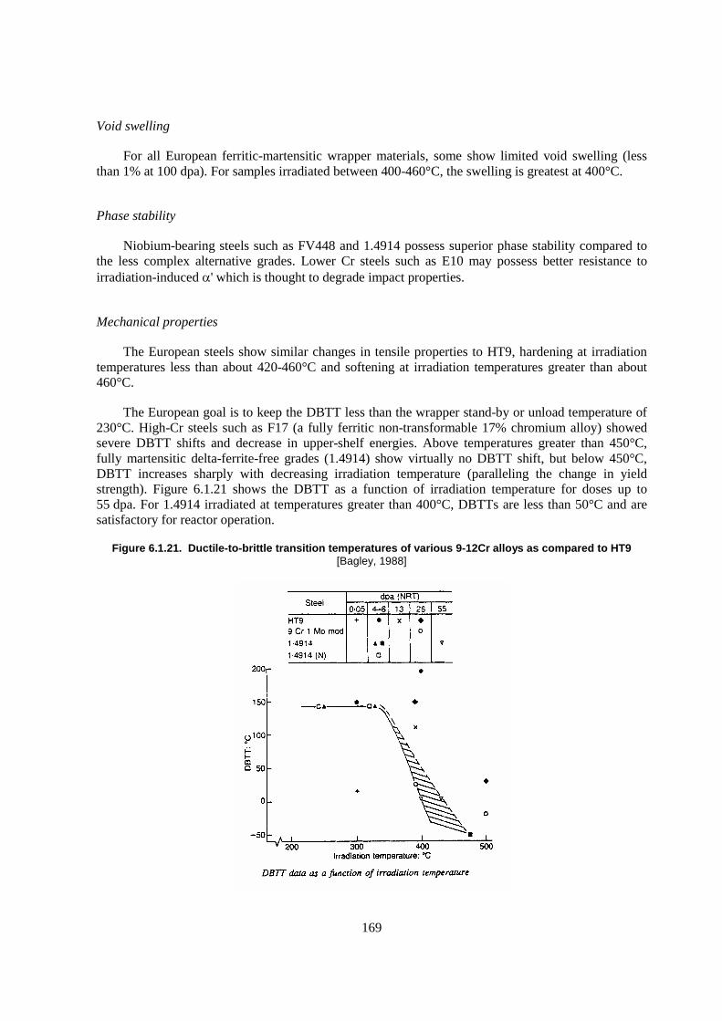
169
Void swelling
For all European ferritic-martensitic wrapper materials, some show limited void swelling (less than 1% at 100 dpa). For samples irradiated between 400-460°C, the swelling is greatest at 400°C.
Phase stability
Niobium-bearing steels such as FV448 and 1.4914 possess superior phase stability compared to the less complex alternative grades. Lower Cr steels such as E10 may possess better resistance to irradiation-induced �' which is thought to degrade impact properties.
Mechanical properties
The European steels show similar changes in tensile properties to HT9, hardening at irradiation temperatures less than about 420-460°C and softening at irradiation temperatures greater than about 460°C.
The European goal is to keep the DBTT less than the wrapper stand-by or unload temperature of 230°C. High-Cr steels such as F17 (a fully ferritic non-transformable 17% chromium alloy) showed severe DBTT shifts and decrease in upper-shelf energies. Above temperatures greater than 450°C, fully martensitic delta-ferrite-free grades (1.4914) show virtually no DBTT shift, but below 450°C, DBTT increases sharply with decreasing irradiation temperature (paralleling the change in yield strength). Figure 6.1.21 shows the DBTT as a function of irradiation temperature for doses up to 55 dpa. For 1.4914 irradiated at temperatures greater than 400°C, DBTTs are less than 50°C and are satisfactory for reactor operation.
Figure 6.1.21. Ductile-to-brittle transition temperatures of various 9-12Cr alloys as compared to HT9 [Bagley, 1988]
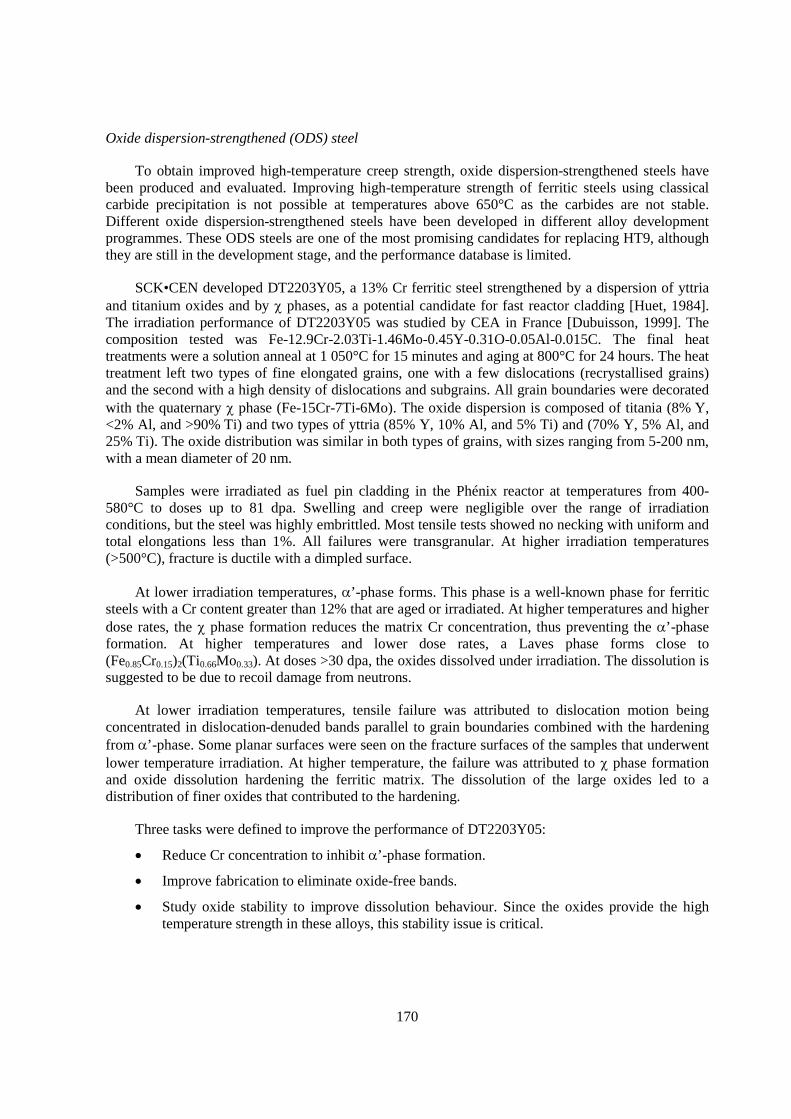
170
Oxide dispersion-strengthened (ODS) steel
To obtain improved high-temperature creep strength, oxide dispersion-strengthened steels have been produced and evaluated. Improving high-temperature strength of ferritic steels using classical carbide precipitation is not possible at temperatures above 650°C as the carbides are not stable. Different oxide dispersion-strengthened steels have been developed in different alloy development programmes. These ODS steels are one of the most promising candidates for replacing HT9, although they are still in the development stage, and the performance database is limited.
SCK•CEN developed DT2203Y05, a 13% Cr ferritic steel strengthened by a dispersion of yttria and titanium oxides and by � phases, as a potential candidate for fast reactor cladding [Huet, 1984]. The irradiation performance of DT2203Y05 was studied by CEA in France [Dubuisson, 1999]. The composition tested was Fe-12.9Cr-2.03Ti-1.46Mo-0.45Y-0.31O-0.05Al-0.015C. The final heat treatments were a solution anneal at 1 050°C for 15 minutes and aging at 800°C for 24 hours. The heat treatment left two types of fine elongated grains, one with a few dislocations (recrystallised grains) and the second with a high density of dislocations and subgrains. All grain boundaries were decorated with the quaternary � phase (Fe-15Cr-7Ti-6Mo). The oxide dispersion is composed of titania (8% Y, <2% Al, and >90% Ti) and two types of yttria (85% Y, 10% Al, and 5% Ti) and (70% Y, 5% Al, and 25% Ti). The oxide distribution was similar in both types of grains, with sizes ranging from 5-200 nm, with a mean diameter of 20 nm.
Samples were irradiated as fuel pin cladding in the Phénix reactor at temperatures from 400-580°C to doses up to 81 dpa. Swelling and creep were negligible over the range of irradiation conditions, but the steel was highly embrittled. Most tensile tests showed no necking with uniform and total elongations less than 1%. All failures were transgranular. At higher irradiation temperatures (>500°C), fracture is ductile with a dimpled surface.
At lower irradiation temperatures, �’-phase forms. This phase is a well-known phase for ferritic steels with a Cr content greater than 12% that are aged or irradiated. At higher temperatures and higher dose rates, the � phase formation reduces the matrix Cr concentration, thus preventing the �’-phase formation. At higher temperatures and lower dose rates, a Laves phase forms close to (Fe0.85Cr0.15)2(Ti0.66Mo0.33). At doses >30 dpa, the oxides dissolved under irradiation. The dissolution is suggested to be due to recoil damage from neutrons.
At lower irradiation temperatures, tensile failure was attributed to dislocation motion being concentrated in dislocation-denuded bands parallel to grain boundaries combined with the hardening from �’-phase. Some planar surfaces were seen on the fracture surfaces of the samples that underwent lower temperature irradiation. At higher temperature, the failure was attributed to � phase formation and oxide dissolution hardening the ferritic matrix. The dissolution of the large oxides led to a distribution of finer oxides that contributed to the hardening.
Three tasks were defined to improve the performance of DT2203Y05:
� Reduce Cr concentration to inhibit �’-phase formation.
� Improve fabrication to eliminate oxide-free bands.
� Study oxide stability to improve dissolution behaviour. Since the oxides provide the high temperature strength in these alloys, this stability issue is critical.

171
The 14% Cr ODS alloy MA957, manufactured by INCO, was studied by the US Fast Reactor Development Program. High-dose data are available on MA957 irradiated to doses up to 200 dpa at temperatures between 370-760°C to fast fluences of ~8 x 10²² n/cm2 in FFTF [Gelles, 1996; Hamilton]. Radiation did not cause significant degradation of the tensile or rupture strength at higher temperatures, but at lower temperatures (410°C) a large increase in DBTT, up to around 350°C, occurred. For these irradiations, the oxide particles and subgrain structure were reported to be stable to high dose.
Toloczko et al. [Toloczko, 1998] measured the irradiation creep behaviour of three steels irradiated under fast spectrum conditions: HT9 (with the 1 038°C/5 min/AC+760°C/30 min/AC heat treatment), D57, a high-Mo ferritic steel strengthened by Laves phase (Fe2Mo) (1 038°C/2 min/AC+25% CW), and MA957, an ODS ferritic steel with Ti and yttria additions (760°C/360 min/AC). MA957 has a highly-elongated grain structure. Creep and swelling were measured, although no accompanying microstructural studies were performed. Irradiation of HT9 in FFTF and the Prototype Fast Reactor (PFR) indicated that irradiation history can affect swelling and creep properties, although no detailed examination of irradiation history was provided. MA957 densified at higher dpa, the only one of the three steels to do so. MA957 also exhibited a decreasing creep rate at the highest doses (from ~70-140 dpa), the only one of the three alloys to do so.
The University of Idaho developed an Fe-13.5Cr-2W-0.5Ti-0.25Y2O3 ODS ferritic steel as a candidate for fusion power systems [Mukhopadhyay, 1998]. The steel composition (Cr and W composition) was chosen to ensure full delta-ferrite stability. W was used instead of Mo to achieve low-activation (discussed in a later section) properties. The unirradiated alloy was tested in uniaxial creep tests in argon at 650 and 900°C. The alloy creep strength was comparable to other ODS steels, such as MA957 and MA956, and superior to standard martensitic steels. No irradiation data are available on this alloy.
6.1.10 JNC-ODS
Over the last decade, the Japan Nuclear Cycle Development Institute (JNC) has lead the technology development of ODS ferritic-martensitic steels, particularly emphasizing fuel cladding application for fast reactors. This development extends the performance of ferritic-martensitic steel beyond 700°C as the fuel cladding. In this section, a brief summary of JNC-ODS development and properties are described.
Chemical composition and nano-structure control
For ODS materials, using a cold-rolling process to manufacture cladding gives rise to an extremely elongated fine grain morphology parallel to the rolling direction. This morphology in the manufactured cladding not only degraded creep rupture strength in the bi-axial hoop direction relative to the longitudinal uni-axial direction (so-called strength anisotropy), but also created extremely poor ductility in the hoop direction [Ukai, 1993; Ukai, 1993b]. The unexpected mechanical properties of manufactured ODS claddings were attributed to the grain boundary sliding among the extremely elongated grains parallel to the rolling direction [Okada, 1996]. Creating cladding with equi-axed grains is a key technology for producing ODS steel cladding with adequate properties.
One approach to overcome this hurdle was to develop a process to induce the to phase transformation in a martensitic 9Cr-ODS steel [Ukai, 2002]. The chemical composition of the 9Cr-ODS steel is 9Cr-0.13C-2W-0.2Ti-0.35Y2O3 (mass %). This steel has a typical tempered martensitic
172
structure with a lath size of less than 1 m. These fine and homogeneous grains with high dislocation density could be advantageous to radiation resistance.
Another approach is to apply a recrystallisation processing for ferritic 12Cr-ODS steels with a composition of 12Cr-0.03C-2W-0.3Ti-0.23Y2O3 (mass %) [Ukai, 2000; Ukai, 2002b]. The recrystalli-sation diagram was developed in the field of yttria-excessive oxygen contents [Ukai, 1997]. The recrystallised grain structure caused improvement in the high temperature strength and ductility of the hoop direction. Because of the higher Cr concentration, the higher chromium 12Cr-ODS could be more advantageous in applications requiring better corrosion resistance.
The expected radiation resistance features of ODS steels come from the introduction of Y2O3 oxide particles into the matrix. These particles block mobile dislocations to improve the high temperature strength and act as a sink for radiation-produced point defects. With regard to the fine oxide particle formation, it was discovered that thermally stable Y2O3 decomposes into yttrium and oxygen atoms and dissolves into the matrix during the mechanical alloying process. Following annealing above 1 100°C, dissolved elements are bonded with Y, Ti and oxygen, and extremely fine nano-scale Y-Ti-O complex oxides precipitate as more stable oxide particles [Okuda, 1995]. This production method for ODS steels should be challenging nano-scale composite materials that can be controlled through dissolution and precipitation of oxide particles by high energy mechanical milling followed by heat-treatment [Ukai, 2004; Ohtsuka, 2004].
Tube manufacturing
The ODS steels are too hard to manufacture cladding by a cold-rolling process alone. Based on the extensive investigation of the continuous cooling transformation (CCT) diagram of 9Cr-0.13C-2W-0.2Ti-0.35Y2O3, a less than critical cooling rate of about 150°C/h gives rise to a ferrite phase at room temperature without martensite, which induces lower hardness. Applying this heat treatment technique, cold-rolling by pilger milling was developed under the softened ferrite structure [Ukai, 2002]. The final heat-treatment consists of normalising at 1 050°C for 1 h, followed by tempering at 750°C for 30 min. With regard to 12Cr-ODS steels, the intermediate heat-treatment was conducted by annealing at 1 100°C and finally at 1 150°C to yield the recrystallised grain structure [Ukai, 2000].
High temperature strength characterisation
The tensile properties of the manufactured martensitic 9Cr-ODS cladding, measured in the hoop stress direction using ring tests at room temperature to 800°C, are represented in Figure 6.1.22 [Ukai, 2002]. The martensitic 9Cr-ODS cladding showed superior ultimate tensile strength (UTS) and uniform elongation (UE) over the entire temperature range when compared with the conventional ferritic-martensitic stainless steel, PNC-FMS. The ratios of UTS and UE to those of PNC-FMS are also represented in Figure 6.1.22. From these comparisons, the strength and ductility improvement in the martensitic 9Cr-ODS claddings are prominent especially above temperatures around 600°C. This advantage could arise from the retardation of recovery and continuing work-hardening due to the pinning of dislocations by finely distributed oxide particles.
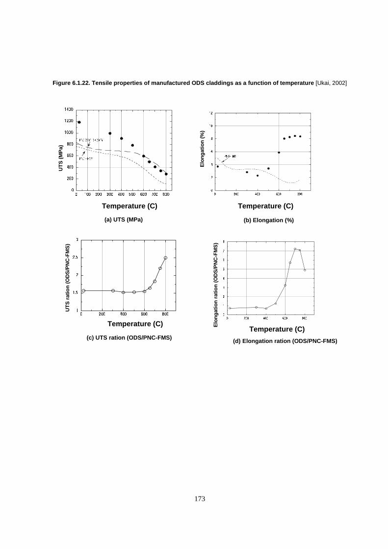
173
Figure 6.1.22. Tensile properties of manufactured ODS claddings as a function of temperature [Ukai, 2002]
�������
������� ��
Temperature (C)
Temperature (C) Temperature (C)
Temperature (C)
UT
S (
MP
a)
Elo
ng
atio
n (
%)
(a) UTS (MPa) (b) Elongation (%)
(c) UTS ration (ODS/PNC-FMS) (d) Elongation ration (ODS/PNC-FMS)
Elo
ng
atio
n r
atio
n (
OD
S/P
NC
-FM
S)
UT
S r
atio
n (
OD
S/P
NC
-FM
S)
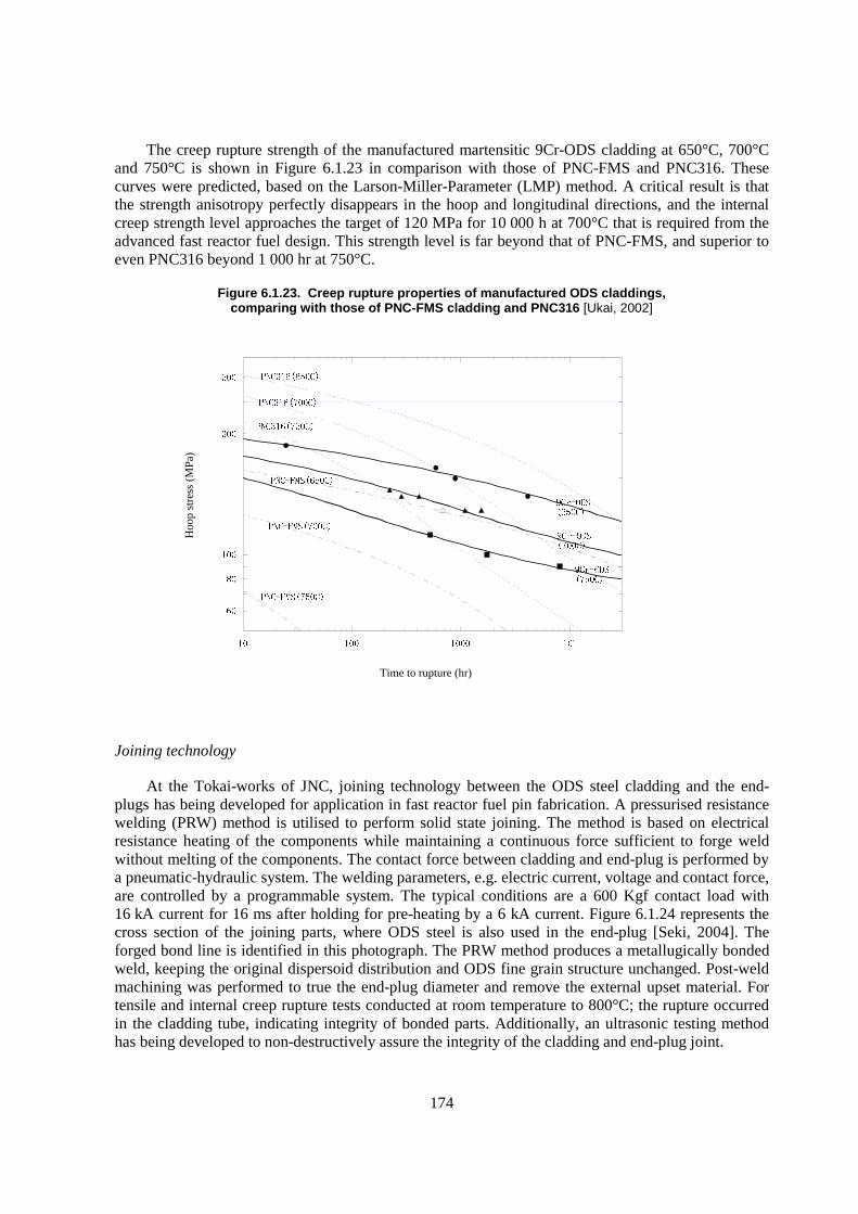
174
The creep rupture strength of the manufactured martensitic 9Cr-ODS cladding at 650°C, 700°C and 750°C is shown in Figure 6.1.23 in comparison with those of PNC-FMS and PNC316. These curves were predicted, based on the Larson-Miller-Parameter (LMP) method. A critical result is that the strength anisotropy perfectly disappears in the hoop and longitudinal directions, and the internal creep strength level approaches the target of 120 MPa for 10 000 h at 700°C that is required from the advanced fast reactor fuel design. This strength level is far beyond that of PNC-FMS, and superior to even PNC316 beyond 1 000 hr at 750°C.
Figure 6.1.23. Creep rupture properties of manufactured ODS claddings, comparing with those of PNC-FMS cladding and PNC316 [Ukai, 2002]
Joining technology
At the Tokai-works of JNC, joining technology between the ODS steel cladding and the end-plugs has being developed for application in fast reactor fuel pin fabrication. A pressurised resistance welding (PRW) method is utilised to perform solid state joining. The method is based on electrical resistance heating of the components while maintaining a continuous force sufficient to forge weld without melting of the components. The contact force between cladding and end-plug is performed by a pneumatic-hydraulic system. The welding parameters, e.g. electric current, voltage and contact force, are controlled by a programmable system. The typical conditions are a 600 Kgf contact load with 16 kA current for 16 ms after holding for pre-heating by a 6 kA current. Figure 6.1.24 represents the cross section of the joining parts, where ODS steel is also used in the end-plug [Seki, 2004]. The forged bond line is identified in this photograph. The PRW method produces a metallugically bonded weld, keeping the original dispersoid distribution and ODS fine grain structure unchanged. Post-weld machining was performed to true the end-plug diameter and remove the external upset material. For tensile and internal creep rupture tests conducted at room temperature to 800°C; the rupture occurred in the cladding tube, indicating integrity of bonded parts. Additionally, an ultrasonic testing method has being developed to non-destructively assure the integrity of the cladding and end-plug joint.
�� ��� ���� ���
��
��
���
���
���
Time to rupture (hr)
Hoo
p st
ress
(M
Pa)
����������
����������
����������
���� ������
���� ������
�����������
�����������
�����������
���� ������
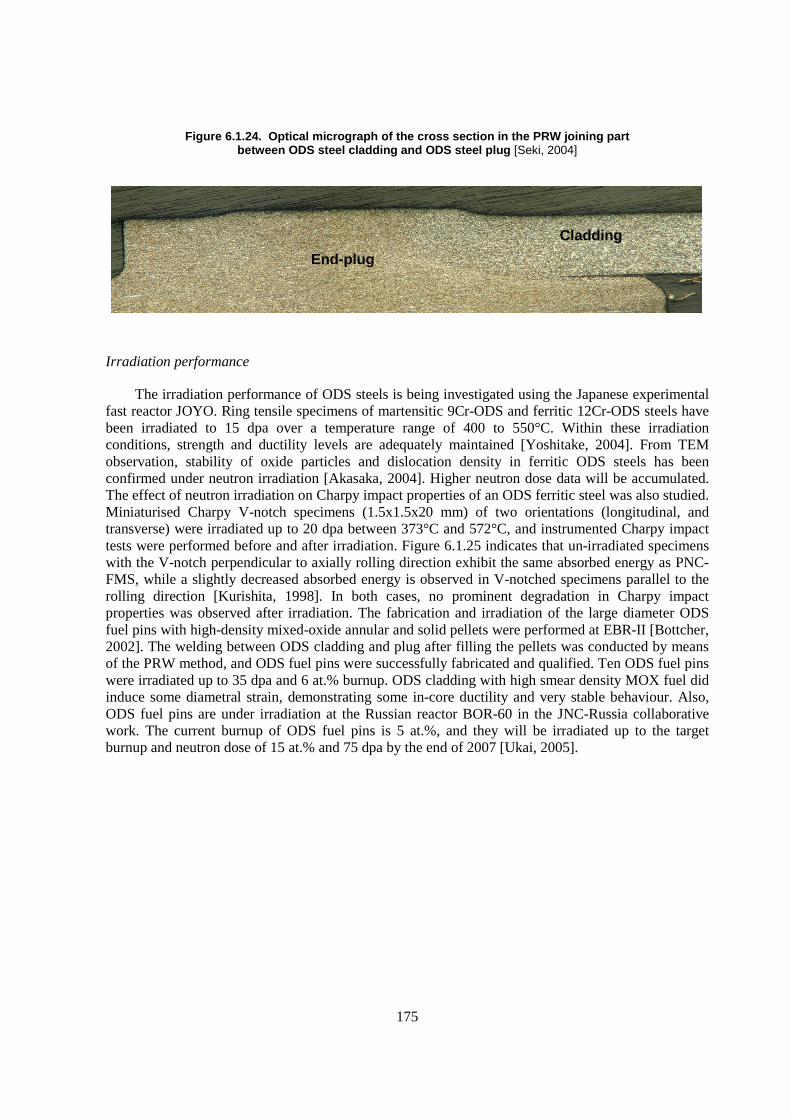
175
Figure 6.1.24. Optical micrograph of the cross section in the PRW joining part between ODS steel cladding and ODS steel plug [Seki, 2004]
Irradiation performance
The irradiation performance of ODS steels is being investigated using the Japanese experimental fast reactor JOYO. Ring tensile specimens of martensitic 9Cr-ODS and ferritic 12Cr-ODS steels have been irradiated to 15 dpa over a temperature range of 400 to 550°C. Within these irradiation conditions, strength and ductility levels are adequately maintained [Yoshitake, 2004]. From TEM observation, stability of oxide particles and dislocation density in ferritic ODS steels has been confirmed under neutron irradiation [Akasaka, 2004]. Higher neutron dose data will be accumulated. The effect of neutron irradiation on Charpy impact properties of an ODS ferritic steel was also studied. Miniaturised Charpy V-notch specimens (1.5x1.5x20 mm) of two orientations (longitudinal, and transverse) were irradiated up to 20 dpa between 373°C and 572°C, and instrumented Charpy impact tests were performed before and after irradiation. Figure 6.1.25 indicates that un-irradiated specimens with the V-notch perpendicular to axially rolling direction exhibit the same absorbed energy as PNC-FMS, while a slightly decreased absorbed energy is observed in V-notched specimens parallel to the rolling direction [Kurishita, 1998]. In both cases, no prominent degradation in Charpy impact properties was observed after irradiation. The fabrication and irradiation of the large diameter ODS fuel pins with high-density mixed-oxide annular and solid pellets were performed at EBR-II [Bottcher, 2002]. The welding between ODS cladding and plug after filling the pellets was conducted by means of the PRW method, and ODS fuel pins were successfully fabricated and qualified. Ten ODS fuel pins were irradiated up to 35 dpa and 6 at.% burnup. ODS cladding with high smear density MOX fuel did induce some diametral strain, demonstrating some in-core ductility and very stable behaviour. Also, ODS fuel pins are under irradiation at the Russian reactor BOR-60 in the JNC-Russia collaborative work. The current burnup of ODS fuel pins is 5 at.%, and they will be irradiated up to the target burnup and neutron dose of 15 at.% and 75 dpa by the end of 2007 [Ukai, 2005].
Cladding
End-plug

176
Figure 6.1.25. The charpy impact properties of ODS ferritic steels in miniature size (1.5x1.5x20 mm) as a function of temperature: (a) V-notch in perpendicular to rolling direction;
(b) V-notch in parallel to rolling direction [Kurishita, 1998]
177
6.1.11 Fusion materials advanced alloy development programme
The fusion reactor materials programmes of Japan, the European Union, and the United States are working toward developing reduced activation (discussed below) ferritic-martensitic steels for use in a fusion energy demonstration reactor. These materials can also be considered for ADS cladding and duct uses. The following issues are considered critical for programme success [Klueh, 1998]: the determination of the effect of simultaneous helium and displacement damage (studies using B and Ni doping are being carried out to induce He), the determination of the effect of transmutations that burn out elements in the steel (Ta, W, etc.), the development of ODS steels to increase the allowable operating temperature (assuming creep and not corrosion is the limiting factor in the design), and the development of fabricability/weldability techniques for ODS steels.
When ferritic-martensitic steels were first considered as structural materials for fusion reactors (late 1970s), HT9 along with modified 9Cr-1Mo were the first steels considered in the US programme [Rosenwasser, 1979]. Similarly, the first ferritic-martensitic steels considered in the fusion programmes in Europe (e.g., FV448, 1.4914, EM10, EM12, etc., which were discussed in the preceding section) and Japan (JFMS) were also candidate steels from their fast reactor programmes [Klueh, 1992d].
In the mid 1980s, programmes to develop “low-activation” or “reduced-activation” ferritic steels began in the European Union, Japan, the Soviet Union, and the United States. This development evolved from calculations that were made to determine which elements must be replaced in conventional Cr-Mo steels to obtain a rapid decay of induced radioactivity levels after irradiation in a fusion reactor [Conn, 1983; Butterworth, 1984]. Such calculations indicated that Mo, Nb, Ni, Cu, and N must be eliminated or minimised to obtain “reduced activation”. The objective in using such steels is that the more rapid induced-radioactivity decay will allow the steels to be disposed of after service by shallow land burial rather than the more expensive deep geological storage. Proposals for reduced-activation ferritic steels involved the replacement of molybdenum in conventional Cr-Mo steels by tungsten [Anderko 1993; Dulieu, 1986; Hsu, 1986; Klueh, 1985; Noda, 1986; Tamura, 1986] and/or vanadium [Butterworth, 1984; Noda, 1986; Hsu, 1986].
Fusion materials programmes in Japan, the European Union, and the United States have developed Cr-V and Cr-W-V steels [Anderko, 1993; Dulieu, 1986; Gelles, 1985; Gelles, 1990; Ghoniem, 1984; Hsu, 1986; Kayano, 1991; Klueh, 1985; Noda, 1986; Tamura, 1986] to which tantalum is sometimes added as a replacement for niobium [Dulieu, 1986; Kayano, 1991; Klueh, 1985; Noda, 1986; Tamura, 1986]. Steels with 7-9% Cr are favoured, because of the difficulty of eliminating �-ferrite in a 12% Cr steel without increasing carbon or manganese for austenite stabilisation. Delta-ferrite can lower toughness, and manganese promotes chi-phase precipitation during irradiation, which can cause embrittlement [Gellles, 1990]. Low-chromium (2.25% Cr) steels were also considered [Ghoniem, 1984; Kayano, 1991], but in the end, 7-9Cr steels were the ones chosen for further study. In Japan, an Fe-7.5Cr-2.0W-0.2V-0.04Ta-0.10C (F82H) and Fe-9Cr-2W-0.2V-0.07Ta- (JLF-1) were chosen, and in Europe, an Fe-9.3Cr-1.0W-0.25V-0.04Cu-0.10C (OPTIFER Ia) and Fe-9.4Cr-1.1Ge-0.30V-0.13C (OPTIFER II) were chosen.
In the United States, an Fe-9.0Cr-2.0W-0.25V-0.07Ta-0.1C (9Cr-2WVTa) reduced-activation steel was developed at ORNL [Kayano, 1991] that subsequently showed the best unirradiated and irradiated properties of reduced-activation steels developed elsewhere in the United States, in Europe, and in Japan [Rieth, 1996]. Table 6.1.5 and Figure 6.1.26 illustrate the improved character of the impact properties of the ORNL 9Cr-2WVTa steel compared to HT9 before and after irradiation in

178
FFTF [Klueh, 1999]. The results are for miniature (1/3-size) Charpy specimens. In the unirradiated condition, the DBTT of the HT9 is -46ºC compared to -88ºC for the 9Cr-2WVTa. After irradiation to 10 dpa at 365ºC in FFTF, the �DBTT for the HT9 was 151ºC to give a DBTT of 105ºC. This compares with a �DBTT of only 15ºC to give a DBTT of -73ºC for the 9Cr-2WVTa after irradiation to 13 dpa at 365ºC in FFTF. Thus, after irradiation, the 9Cr-2WVTa steel had a DBTT well below room temperature, while the DBTT of HT9 was well above room temperature.
Table 6.1.5. Comparison of Charpy properties of 9Cr-2WVTa and HT9 before and after irradiation [Klueh, 1999]
Steel Condition DBTT (ºC) �DBTT (ºC) USE (J) �USE (J) HT9 UI -46 6.0 HT9 I (10 dpa) 105 151 3.2 2.8
9Cr-2WVTa UI -88 11.2 9Cr-2WVTa I (13 dpa) -73 15 8.6 2.6
Figure 6.1.26. Comparison of the unirradiated and irradiated Charpy curves for one-third-size specimens of 12Cr-1MoVW (HT9) and 9Cr-2WVTa steels irradiated in FFTF at 365°C [Klueh, 1999]
The excellent irradiation resistance to embrittlement of 9Cr-2WVTa steel relative to other reduced-activation and non-reduced-activation steels was also demonstrated in irradiation experiments in the HFR reactor in the Netherlands. The 9Cr-2WVTa steel had the lowest shift in DBTT for irradiation at 250-400°C of the reduced-activation steels, which included F82H, a Japanese reduced-activation steel, OPTIFER Ia and OPTIFER II, European reduced-activation steels, and MANET I and MANET II, European non-reduced-activation steels that were developed as improvements on DIN 1.4914 for irradiation applications [Rieth, 1996].
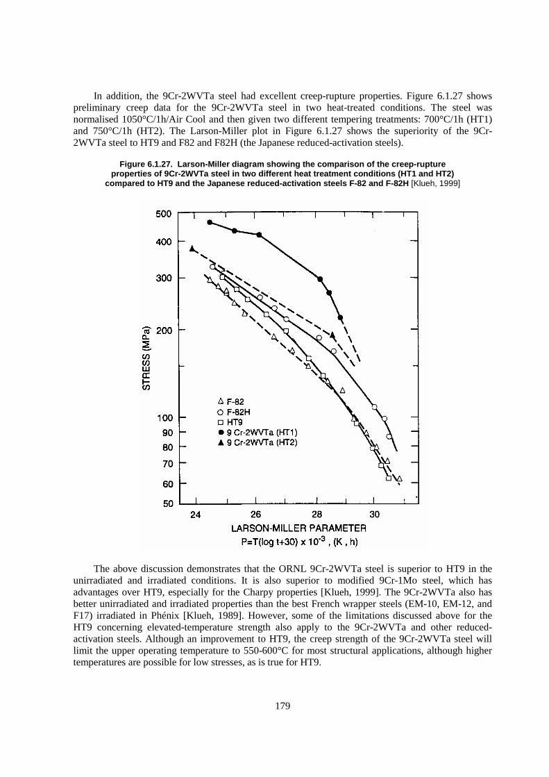
179
In addition, the 9Cr-2WVTa steel had excellent creep-rupture properties. Figure 6.1.27 shows preliminary creep data for the 9Cr-2WVTa steel in two heat-treated conditions. The steel was normalised 1050°C/1h/Air Cool and then given two different tempering treatments: 700°C/1h (HT1) and 750°C/1h (HT2). The Larson-Miller plot in Figure 6.1.27 shows the superiority of the 9Cr-2WVTa steel to HT9 and F82 and F82H (the Japanese reduced-activation steels).
Figure 6.1.27. Larson-Miller diagram showing the comparison of the creep-rupture properties of 9Cr-2WVTa steel in two different heat treatment conditions (HT1 and HT2)
compared to HT9 and the Japanese reduced-activation steels F-82 and F-82H [Klueh, 1999]
The above discussion demonstrates that the ORNL 9Cr-2WVTa steel is superior to HT9 in the unirradiated and irradiated conditions. It is also superior to modified 9Cr-1Mo steel, which has advantages over HT9, especially for the Charpy properties [Klueh, 1999]. The 9Cr-2WVTa also has better unirradiated and irradiated properties than the best French wrapper steels (EM-10, EM-12, and F17) irradiated in Phénix [Klueh, 1989]. However, some of the limitations discussed above for the HT9 concerning elevated-temperature strength also apply to the 9Cr-2WVTa and other reduced-activation steels. Although an improvement to HT9, the creep strength of the 9Cr-2WVTa steel will limit the upper operating temperature to 550-600°C for most structural applications, although higher temperatures are possible for low stresses, as is true for HT9.

180
The materials performance data for Fe-(8-9)% Cr reduced activation steels (where molybdenum is replaced by tungsten and niobium replaced by tantalum) being considered for the US fusion energy programme have been reviewed [Zinkle, 1998]. The significant findings are:
� Non-irradiated reduced activation Fe-(8-9)% Cr steels have similar yield and ultimate tensile strengths and uniform and total elongation as conventional Fe-(8-9)% Cr steels.
� Neutron irradiation increases the yield and ultimate tensile strength at temperatures below ~400°C but has little effect at higher temperatures. Pronounced flow localisation occurred for temperatures less than 400°C. Higher temperature deformation had adequate strain hardening capacity.
� Uniform and total elongation decreased with irradiation, particularly at temperatures less than ~400°C. The uniform elongation was <3% for all irradiation temperatures from 20-700°C. Reduction in area for irradiated samples remained greater than 60% for irradiated samples at temperatures of 300°C and higher. The data reported were for doses up to 65 dpa.
� Adequate creep resistance was seen in stress rupture tests up to ~550°C, but creep resistance dropped significantly at temperatures of 600°C and greater.
� Changes in DBTT at irradiation temperatures greater than ~400°C are very small. For lower temperature irradiation to doses around 15 dpa, increases in DBTT as large as 20-100°C are observed, depending on the steel.
� The effect of He produced in a fusion spectrum has not been adequately tested.
Based on the analysis, the temperature limits for this material in a fusion reactor were set at ~250-550°C, with somewhat higher temperatures allowed for low-stress components. The upper limit was set by creep considerations and the lower limit by loss of ductility and shift in DBTT.
The effect of the transmutation helium generated in the structural material of a fusion reactor first wall on the mechanical properties – especially the fracture properties – has been a constant source of uncertainty for materials studies in the fusion programme. In the absence of a source of fusion 14 MeV neutrons, simulation experiments using ion implantation or 54Fe-, Ni-, or B-doping are the only techniques available to study helium effects. These techniques, with their inherent problems and uncertainties, are being used to further the understanding of a possible helium effect on mechanical properties.
Studies in the fusion programme using ion implantation [Lindau, 1999], nickel-doping (the nickel-doping technique used to study helium effects on HT9 was discussed in an earlier section) [Klueh, 1992e], and boron-doping [Materna-Morris, 2000; Shiba, 2000; van Osch, 2000] have all produced results that indicated that helium increases the shift in DBTT over that due to displacement damage alone. Results with these techniques have also indicated an increased amount of swelling, and recent results [Wakai, 2000; Miwa, 2000] have reiterated such a relationship when F82H with �30 and �60 ppm natural boron and �65 ppm 10B was irradiated in HFIR at 400ºC up to 52 dpa to produce �30, �60, and �330 appm He, respectively (Figure 6.1.28). Helium is produced according to the reaction: 10����� ) 7Li; natural boron contains �20% 10B.
Cavity size, number density, and swelling after 52 dpa for the three steels were respectively 12.7 nm, 6.1x10²⁰ m-3, and 0.52%; 10.6 nm, 2.4x10²¹ m-3, and 1.2%; and 7.6 nm, 6.1x10²¹ m-3, and 1.1%. The swelling of 1.2 and 1.1% after only 52 dpa for the steels with the 60 and 330 appm He, respectively, is much larger than expected for these steels. The higher density of smaller cavities for the steel with 330 appm He than the steel with only 60 appm He evidently suppressed swelling by
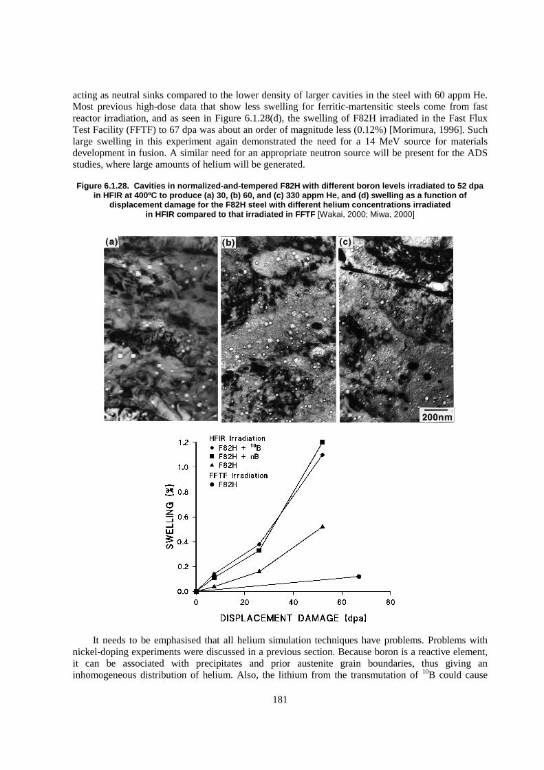
181
acting as neutral sinks compared to the lower density of larger cavities in the steel with 60 appm He. Most previous high-dose data that show less swelling for ferritic-martensitic steels come from fast reactor irradiation, and as seen in Figure 6.1.28(d), the swelling of F82H irradiated in the Fast Flux Test Facility (FFTF) to 67 dpa was about an order of magnitude less (0.12%) [Morimura, 1996]. Such large swelling in this experiment again demonstrated the need for a 14 MeV source for materials development in fusion. A similar need for an appropriate neutron source will be present for the ADS studies, where large amounts of helium will be generated.
Figure 6.1.28. Cavities in normalized-and-tempered F82H with different boron levels irradiated to 52 dpa in HFIR at 400ºC to produce (a) 30, (b) 60, and (c) 330 appm He, and (d) swelling as a function of
displacement damage for the F82H steel with different helium concentrations irradiated in HFIR compared to that irradiated in FFTF [Wakai, 2000; Miwa, 2000]
It needs to be emphasised that all helium simulation techniques have problems. Problems with nickel-doping experiments were discussed in a previous section. Because boron is a reactive element, it can be associated with precipitates and prior austenite grain boundaries, thus giving an inhomogeneous distribution of helium. Also, the lithium from the transmutation of 10B could cause
182
problems. Furthermore, during fission reactor irradiation, all the boron is quickly transformed to helium, which differs from what happens in a fusion reactor, where helium forms simultaneously with the displacement damage.
A final issue for ADS systems is fatigue. Because of possible system transients due to beam instability or accelerator trips, fatigue may play an important role in the ADS. Very few data are available on fatigue of ferritic-martensitic alloys. Stubbins and Gelles studied the fatigue performance of the fusion alloy F82H (Fe-7.71Cr-2.1W-0.18V-0.04Ta-0.096C-0.003P-0.003S) [Stubbins, 1996]. Although the fatigue life was dominated by the elastic strain range over most of the useful fatigue life regime, at low lives where the plastic strain dominates, the alloys undergo softening. The fatigue response is represented by the fatigue strain-life equation:
�� tot2
��
f’
ENf� b �
f’ Nf� c � 0.47Nf�0.085 67.7Nf
�0.78
where E is the elastic modulus, �f’ is the fatigue strength coefficient, and �
f’ is the fatigue strain
coefficient.
6.1.12 Advanced steels in the power-generation industry
In addition to steels evaluated in the fast reactor and fusion programmes, other power industry steels can be valuated for ADS cladding and ducts. The Cr-Mo (2.25-12%) steels, including Sandvik HT9, were originally developed for power-generation applications. They evolved from Fe-Cr and Fe-Mo steels, and since the start of the development of improved steels for the power-generation industry, they have gone through several “generations” of evolution to develop improved elevated-temperature strengths, beginning with 2.25Cr-1Mo (ASTM T22, nominally Fe-2.25Cr-1.0Mo-0.5 Mn-0.12C) and 9Cr-1Mo (T9, Fe-9.0Cr-1.0Mo-0.5 Mn-0.5Si-0.12C). Nominal compositions for all of the steels discussed in this section are given in Table 6.1.6. These two “zero generation” steels were introduced in the 1940s [Masuyama, 1999], and since then, four generations of steels, as indicated in Table 6.1.7, have been introduced into the power-generation industry as replacements for the preceding generations. The T22 and T9 steels had 100 000 h creep-rupture strengths at 600°C of about 35 MPa.
Because each new generation of steels was introduced because of the need for higher operating temperatures, steels beyond the zeroth generation were mainly 9-12% Cr for improved corrosion and oxidation resistance in the pressure vessels, boilers, tubing, etc., where the steels were used.
The first generation of advanced steels involved mainly the addition of the carbide formers vanadium and niobium to the 2.25Cr-1Mo and 9Cr-1Mo compositions to add precipitate strengthening, and, in some cases, a small tungsten addition was made for further solid-solution strengthening, in addition to that provided by molybdenum. Sandvik HT9 was a first generation steel. The 105 h rupture strength at 600°C for these steels was about 60 MPa.
For the second generation of steels developed in the 1970-1985 time period, carbon, niobium, and vanadium were optimised and nitrogen (0.03-0.05%) was added, and the maximum operating temperature increased to 593°C. The new steels included modified 9Cr-1Mo (T91, an Fe-9Cr-1Mo-0.25V-0.06Nb0.05N-0.1C) and HCM12 (Fe-12Cr-1Mo-1W-0.25V-0.05Nb-0.03N-0.1C), which has a ����� � ��� ��� � ����� ��� ��� � ���� -ferrite). These steels have 105 h rupture strengths at 600°C approaching 100 MPa. Of these latter steels, modified 9Cr-1Mo, which was developed at ORNL in the 1970s for the US fast reactor programme as a steam generator material, has been used most extensively in the power-generation industry throughout the world [Masuyama, 1999;
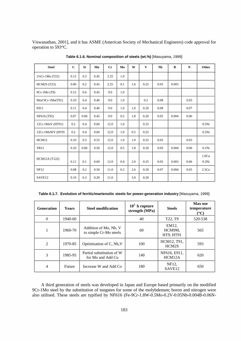
183
Viswanathan, 2001], and it has ASME (American Society of Mechanical Engineers) code approval for operation to 593°C.
Table 6.1.6. Nominal composition of steels (wt.%) [Masuyama, 1999]
Steel C Si Mn Cr Mo W V Nb B N Other
2¼Cr-1Mo (T22) 0.12 0.3 0.45 2.25 1.0
HCM2S (T23) 0.06 0.2 0.45 2.25 0.1 1.6 0.25 0.05 0.003
9Cr-1Mo (T9) 0.12 0.6 0.45 9.0 1.0
Mod 9Cr-1Mo(T91) 0.10 0.4 0.40 9.0 1.0 0.2 0.08 0.05
E911 0.11 0.4 0.40 9.0 1.0 1.0 0.20 0.08 0.07
NF616 (T92) 0.07 0.06 0.45 9.0 0.5 1.8 0.20 0.05 0.004 0.06
12Cr-1MoV (HT91) 0.2 0.4 0.60 12.0 1.0 0.25 0.5Ni
12Cr-1MoWV (HT9) 0.2 0.4 0.60 12.0 1.0 0.5 0.25 0.5Ni
HCM12 0.10 0.3 0.55 12.0 1.0 1.0 0.25 0.05 0.03
TB12 0.10 0.06 0.50 12.0 0.5 1.8 0.20 0.05 0.004 0.06 0.1Ni
HCM12A (T122)
0.11
0.1
0.60
12.0
0.4
2.0
0.25
0.05
0.003
0.06
1.0Cu
0.3Ni
NF12 0.08 0.2 0.50 11.0 0.2 2.6 0.20 0.07 0.004 0.05 2.5Co
SAVE12 0.10 0.3 0.20 11.0 3.0 0.20
Table 6.1.7. Evolution of ferritic/martensitic steels for power-generation industry [Masuyama, 1999]
Generation Years Steel modification 105 h rupture
strength (MPa) Steels Max use
temperature (�C)
0 1940-60 40 T22, T9 520-538
1 1960-70 Addition of Mo, Nb, V to simple Cr-Mo steels
60 EM12,
HCM9M, HT9, HT91
565
2 1970-85 Optimisation of C, Nb,V 100 HCM12, T91,
HCM2S 593
3 1985-95 Partial substitution of W
for Mo and Add Cu 140
NF616, E911, HCM12A
620
4 Future Increase W and Add Co 180 NF12,
SAVE12 650
A third generation of steels was developed in Japan and Europe based primarily on the modified 9Cr-1Mo steel by the substitution of tungsten for some of the molybdenum; boron and nitrogen were also utilised. These steels are typified by NF616 (Fe-9Cr-1.8W-0.5Mo-0.2V-0.05Nb-0.004B-0.06N-
184
0.07C), E911 (Fe-9Cr-1Mo-1W-0.2V-0.08Nb-0.07N-0.1C), and HCM12A (Fe-12Cr-0.4Mo-2.0W-1Cu-0.25V-0.3Ni-0.05Nb-0.003B-0.06N-0.11C). They were developed and introduced in the 1990s for 620°C operation with a 105 h creep-rupture strength at 600°C of 140 MPa.
Finally, the next (fourth) generation of steels is being developed in Japan at the present time. The steels are: NF12 (Fe-11Cr-2.6W-2.5Co-0.2Mo-0.2V-0.07Nb-0.004B-0.05N-0.08C) and SAVE12 (Fe-11Cr-3W-3Co-0.2V-0.07Nb-0.04Nd-0.07Ta-0.04N-0.1C), where the intention is to increase the operating temperatures of the steels to 650°C. These steels, which differ from the previous generation primarily by the use of up to 3.0% Co, have projected 105 h creep-rupture strengths at 600ºC of 180 MPa [Masuyama, 1999; Viswanathan, 2001].
Two of the third-generation steels that are now ASME code approved for applications to 620°C are NF616, developed in Japan, and E911, developed in Europe. They have essentially the same composition as the modified 9Cr-1Mo (T91), except that some of the molybdenum is replaced by tungsten in NF616 and a tungsten addition has been made in the E911 (Table 6.1.6). The E911 also contains slightly higher nitrogen and the NF616 contains a boron addition. Another third-generation steel is HCM12A, a 12Cr-0.4Mo-2WCuVNbB steel developed in Japan (Table 6.1.6). As operating temperatures are increased, the use of 12Cr steels will be required for oxidation resistance. The use of such steels would allow a somewhat higher operating temperature for ADS, fusion, etc., than is possible with the present steels being considered. Of course, before such an application, the effect of irradiation on the steels must be determined.
Only one irradiation experiment on the third-generation steels has been carried out [Horsten, 2000]. In that experiment, two of the new commercial steels, NF616 and HCM12A, along with modified 9Cr-1Mo were irradiated at 300ºC in the mixed neutron spectrum of the High Flux Reactor (HFR) in Petten, the Netherlands. For these experiments, the properties of the modified 9Cr-1Mo were superior to the new steels both before and after irradiation (Table 6.1.8) [Horsten, 2000]. Even the modified 9Cr-1Mo developed a larger shift than normally observed for this steel, for which previous irradiations at 300°C indicated a shift of around 100°C was observed [Klueh, 1992]. No ready explanation is available for these large increases in DBTT. The authors suggested that temperature variations may have played a role, as the temperature on the specimens was said to vary from 265-312°C. Tensile properties indicated that the NF616 showed the least hardening followed by modified 9Cr-1Mo, and the HCM12A hardened the most. The presence of boron in the two new steels might be a factor, since in the mixed neutron spectrum of HFR, the thermal neutrons can transform the 10B in the steel to helium. Indeed, the experimental heat of modified 9Cr-1Mo steel used for the experiments also contained boron [Horsten, 2000]. Around 30-50 appm He were formed in the steels from the boron levels given. There are indications from other work that small amounts of helium generated from boron can affect the impact properties (see previous section). Obviously, more work is required.
Table 6.1.8. Charpy Impact Properties of Steels Irradiated in HFR*
Unirradiated Irradiated Property Change Steel
DBTT (ºC) USE (J) DBTT (ºC) USE (J) �������ºC) USE (J)
Mod. 9Cr-1Mo -78 8.9 97 6.6 175 2.2
NF616 -41 7.3 209 4.5 249 2.8
HCM12A -36 8.3 189 4.3 225 4.0
* Miniature Charpy specimens were used. Irradiation was nominally to 2.5 dpa at 300ºC.
185
All indications are that the properties before irradiation of these new steels are significant improvements on the properties of HT9. In future work on steels for the ADS and other nuclear reactor programmes, these steels should be included. Future irradiations should determine the cause of the large increase in DBTT for the NF616 and HCM12A (and modified 9Cr-1Mo) observed in the only irradiation experiment in which these new steels were included [Horsten, 2000]. Tests of these compositions with and without boron would allow the possible effect of helium to be determined.
6.1.13 Comparison of candidate cladding and duct materials
The candidate ferritic-martensitic steels as ADS cladding and duct are tentatively listed in Table 6.1.9, where widely used steels were selected in the field of fast reactors development. As a comparison, ODS steels for a cladding application are included because of their advantage to extend reactor operation temperature, although they are still in the development stage. The HT9 (United States) and PNC-FMS (Japan) are used as fuel pin cladding as well as assembly duct, and EM10 (France) and FV448 (United Kingdom) are for duct.
Table 6.1.9. Comparison of properties in the candidate feritic-martensitic steels for cladding and duct application
HT9 (United States)
EM10 (France)
FV448 (United Kingdom)
PNC-FMS (Japan)
ODS (Japan)
Application Cladding/Duct Duct Duct Cladding/Duct Cladding
Irradiation 200 dpa (ACO-3)
150 dpa (Boitix-9)
150 dpa 60 dpa 35 dpa
Statistics Fuel pin >2000 pins [Bridges, 1993]
Duct 16 S/A
Phénix driver [Seran, 1992]
(from early 1990’s)
PFR driver [Brown, 1993]
(from early 1990’s)
Fuel pin: 20 pins
Duct: 1 S/A
Fuel pin: 10 pins
0.2% proof strength (Mpa at 600°C)
310 [Bagley, 1988]
300 [Bagley, 1988]
300 [Bagley, 1988]
310/430 [Shikakura, 1991]
510 [Ukai, 2002]
Creep rupture strength (Mpa at 650°C, 1 000 h)
95 [Shikakura, 1991] – –
140 [Shikakura, 1991]
200 [Ukai, 2002]
DBTT after irradiation (°C)
110 [Seran, 1994] (10 dpa at 400°C)
~10 [Seran, 1994] (97 dpa at 400°C)
60 [Brown, 1991] (0-100 dpa at 400°C)
--/30 [Uehira, 2000] (40 dpa at 500°C)
–
The achieved statistics of each candidate steel in fuel pin cladding and duct irradiation are summarised in Table 6.1.9. The ferritic-martensitic steels make possible to promote higher burnup assembly because they have excellent swelling resistance. HT9 claddings and ducts were demonstrated in a large abundant number of fuel pins more than 2 000 and 16 S/A, which were irradiated as the core demonstration experiment (CDE) in FFTF, reaching peak neutron dose of 200 dpa in ACO-3 irradiation rig [Bridges, 1993]. EM10 and FV448 are fuel assembly duct materials, which were used from early 1990s in Phénix and PFR, respectively. The peak neutron dose of EM10 duct attained 150 dpa through Boitix-9 irradiation rig [Seran, 1992]. Similar dose reached in FV448 duct by PFR experiment irradiation [Brown, 1993]. An irradiation experience of PNC-FMS cladding/duct and ODS steel cladding is limited around 50 dpa, and these irradiation experiments are continued in JOYO.
The mechanical properties of the candidate steels are classified in relative manner in Table 6.1.9. As described in the previous section, with regard to HT9, the critical issue for duct application is
186
DBTT increase induced by irradiation at temperature less than 400°C. The helium and hydrogen accumulation could promote brittle fracture manner. On the other hand, EM10 duct sustains better charpy impact properties, even at lower temperature irradiation of less than 400°C. However, its tensile properties are inferior to HT9. The creep rupture strength of PNC-FMS cladding is higher than HT9 cladding, but utilisation of ferritic-martensitic steels are substantially limited to less than around 600°C. As previously mentioned, ODS steel cladding demonstrated the adequate tensile and creep rupture strength even at 700°C. The confirmation of maintaining ductility at high neutron dose should be critical issue for ODS steel claddings.
6.1.14 Conclusions and recommendations
Based on the performance of HT9 in the fast reactor programme and the fusion energy programme, the following conclusions and recommendations are reached for fuel and cladding applications for ADS systems.
� In the temperature range of 400-650°C, HT9 has adequate swelling resistance, toughness, strength, and ductility.
� At room temperature, HT9 that has been irradiated at lower temperatures (conservatively <400°C) can become brittle, and hot cell operations must ensure no excessive stress is placed on cladding and duct material. Notches or stress concentrations in the design must be avoided.
� Because of the high DBTT measured in material irradiated in HFIR at 400°C, which had He concentrations of 353-391 appm, He limits should be applied to HT9 used in ADS cladding and ducts until prototypical experimental data can be obtained. Also, a minimum irradiation and minimum handling temperature for irradiated HT9 components should be set.
� Because of the large amounts of hydrogen and helium generated in ADS materials relative to fast reactor conditions, a test programme to determine the synergistic effects of He and H on mechanical performance and swelling should be undertaken. This test programme could consist of tests in a prototypical spectrum or using ion irradiation facilities as a simulation tool. A test facility producing a prototypical spallation neutron spectrum would be ideal.
� A test programme needs to be continued to better understand the FCCI between fuel and HT9 cladding. Studies of barrier cladding to improve FCCI resistance (increased N content and a Zr liner are two examples) need to be undertaken. Until the mechanisms of FCCI are understood, a transient limit of 725°C should be placed on the cladding inner surface.
� Alloys are under development that may have improved performance relative to HT9. Programmes are in progress aimed to improve high-temperature creep strength and low-temperature toughness. For most of these alloys, insufficient performance data exist. For any new alloys tested, in addition to adequate mechanical properties and dimensional stability, coolant compatibility and fuel-cladding compatibility must be verified. A component of the ADS programme should study the performance of these promising alloy systems.
187
6.2 Materials compatibility with lead and lead-bismuth
6.2.1 Introduction
Lead and lead-bismuth eutectic (55.5 wt.% Bi) are being considered as spallation target and coolant for the accelerator driven systems (ADS) in their use for the transmutation of long-lived actinides. Corrosion and degradation of the mechanical properties of structural materials in heavy liquid metals are essential issues to demonstrate the technical feasibility of subcritical systems. Besides, the availability of the technologies for the operation of lead alloys facilities is also essential.
The use of lead-bismuth eutectic (LBE) as coolant in nuclear reactor was developed for military application, in the early 1950s, in the former URSS. To solve R&D problems, an extensive research programme was developed by different scientific and research institutes and design organisations [Gromov, 1998], and they have more than 40 years of experience in the operation of lead-bismuth loops. On the other hand, lead, bismuth and lead-bismuth eutectic were considered as reactor coolants in several programmes carried out in United States during the 50s. However, compatibility problems in oxygen-contaminated systems led to their abandonment [Weeks, 1971]. In the last years, several initiatives have taken place around the world regarding the use of lead and mainly lead-bismuth as target and coolant for different systems devoted to the transmutation of high radioactive waste [Knebel, 1999; Cinotti, 1998].
The reasons for choosing lead or lead-bismuth eutectic as coolant and target of ADS can be found everywhere [Gromov, 1998b]. Lead-bismuth has a high boiling point (1 670°C) and a low melting point (123.5°C), which improves the efficiency of the system and prevents the coolant loss if depressurisation occurs, a low chemical activity that improves the system safety, and a low working pressure. Lead has a higher melting point (327.4°C), which decreases the temperature working range, and increases the facilities operation temperature. Both have a high atomic number and a good neutron yield but lead produces three orders less polonium than lead-bismuth eutectic [Pankratov, 1998]. However lead and lead-bismuth eutectic show a high aggressiveness for conventional structural materials. Corrosion resistance can be improved if the materials are coated by an oxide layer or by artificial coatings.
This chapter focused on the compatibility of structural materials, mainly stainless steels, with lead-bismuth eutectic and lead. Fundamentals of corrosion and protection methodologies are discussed. Information on the corrosion resistance of structural materials in different conditions and the behaviour of coated materials by in-situ oxidation and by artificial coating is reviewed. Inhibitor effect is also discussed.
6.2.2 Fundamentals
i) Corrosion in heavy liquid metals
Structural materials in liquid metals can undergo dissolution of the solid metal in the liquid metal, by direct dissolution, by a surface reaction involving atoms from the solid and the liquid metals and impurities present in the liquid metal, and by intergranular attack. In a dissolution process or leaching, one component of an alloy is preferentially dissolved, as in the case of nickel that is leached from stainless steels by lead and lead bismuth [Sheir].
188
In the dissolution process two stages can be identified. The first stage involves “cleavage” of the bonds between atoms in the solid metals and the formation of new one with atoms of liquid metal or its impurities, in the boundary layer. At the second stage, the dissolved atoms diffuse through the boundary layer into the liquid metal [Gerasimov, 1983].
The overall rate-controlling step is the diffusion through the boundary film of solute atoms into the flowing stream. Under static conditions at constant temperature,
Ci = Co [1- exp (-�St/V)]
where Ci is the concentration of solute after time t, Co is the saturation concentration of solute; S is the surface area of solid exposed to liquid of volume V, �=�o exp [-�E/RT], where E is the activation energy for dissolution.
The driving force for corrosion is the solubility of the elements of solid materials in liquid metal. Under isothermal conditions the dissolution rate decreases with the time following an exponential law and, the dissolution process is stopped when the concentration of the elements in the liquid metal reaches the saturation value.
Under flowing conditions
dCi / dt = K (S/V) (Co-Ci)
where K is a rate constant, which is usually related to the diffusion rate through the boundary layer. In a flowing recirculating system, the precipitation process in the cold leg or heat removal part of the circuit often control the steady-state concentration of solute. The material dissolved at the highest temperature will precipitate at the lowest temperature until the equilibrium is reached. The corrosion rate is a function of both maximum and minimum temperature in the circuit and the corrosion at the highest temperature can be reduced by increasing the minimum temperature or by reducing the maximum temperature [Weeks, 1997]. This type of corrosion is named thermal gradient mass transfer. It can be illustrated by circulating a corrosive metal such as bismuth round a thermal convection loop of the type shown in Figure 6.2.1, [Tortorelli, 1987]. Mass is transferred from the hot zone to the cold zone and after a period of time it is possible the plugging of the loop. This type of corrosion does not decrease with time contrary to the observed in isothermal conditions.
Figure 6.2.1. Thermal gradient mass transfer [Tortorelli, 1987]
1. Solution2. Diffusion3. Transport of dissolved metal
4. Nucleation5. Transport of crystallites6. Crystal growth and sintering (plug formation)
189
Under flowing conditions, the driving force for corrosion is thus the solubility difference of the solid metal in the liquid over the T range in the liquid metal circuit. At low T, solid state diffusion is negligibly slow compared to the corrosion rate, and the corrosion rate is proportional to the solubility of the major component of the solid metal. In alloys, components can be dissolved selectively and produce some phase transformation in the surface of solid metal, such as it is observed in the austenitic stainless steels in contact with Pb, Bi, Li, and Pb-Bi.
Mass transfer can be also occurring under isothermal conditions. The dissolved elements of an alloy can be transported by the liquid metal and reach the other alloy, forming metal solid solutions or intemetallic compounds.
Intergranular attack occurs because the atoms at the grain boundary have a higher potential energy than the atoms inside the grains. Therefore, the activation energy of the grain boundary atoms is lower and the probability of their transition to the melt and, hence, the dissolution rate, higher. If the concentration of certain elements increases in the grain boundaries, the dissolution rate increases due to the preferential dissolution of these elements with higher solubility [Gerasimov, 1983].
Corrosion is commonly velocity-dependent, the rate-controlling step being the migration of dissolved iron or chromium through the boundary layer of liquid adjacent to the steel surface. However, according to [Weeks, 1960] in liquid bismuth very little difference in corrosion rate was observed between thermal convection loops with a velocity of 1.5 cm/s and pumped loops with a velocity higher than 424 cm/s.
A general discussion of the different types of corrosion in liquid metals and of the influence of several variables (temperature, temperature gradient, ratio metal solid area to liquid metal volume, velocity and others) can be found in [Straudhammer; Bagnall, 1995].
ii) Solubility
The solubility of metals, CS, in molten metals generally varies with temperature according to the relationship:
log CS = A-(B/T),
where A and B are constant for a given system.
The solubility of most potential containment metals is lower in liquid Pb than in Bi. Solubility data of different metals in liquid lead-bismuth alloys can be found in the following references [Weeks, 1971; Park, 1997; Weeks, 1969; Rosenblatt, 1970]. The addition of lead to bismuth reduces the solubility of iron, chromium and copper in a continuous way [Weeks, 1997].
The solubility of the major components of steels in lead-bismuth eutectic in mass%, according to IPPE [Gromov, 1998b], can be expressed as a function of the temperature (K) by the following equations for a temperature range from 400 to 900ºC.
lg CNi = 1.53-843/T(K)
lg CCr = -0.02-2 280/T(K)
lg CFe = 2.1-4 380/T(K)
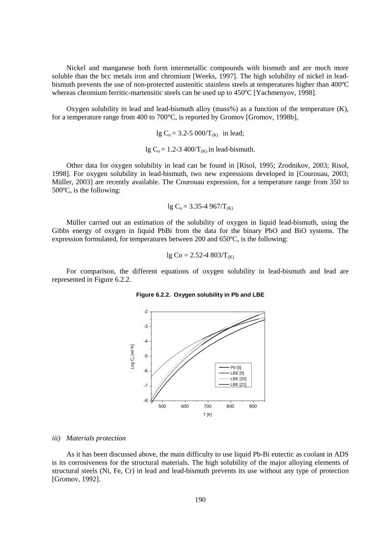
190
Nickel and manganese both form intermetallic compounds with bismuth and are much more soluble than the bcc metals iron and chromium [Weeks, 1997]. The high solubility of nickel in lead-bismuth prevents the use of non-protected austenitic stainless steels at temperatures higher than 400ºC whereas chromium ferritic-martensitic steels can be used up to 450ºC [Yachmenyov, 1998].
Oxygen solubility in lead and lead-bismuth alloy (mass%) as a function of the temperature (K), for a temperature range from 400 to 700°C, is reported by Gromov [Gromov, 1998b],
lg Co = 3.2-5 000/T(K) in lead;
lg Co = 1.2-3 400/T(K) in lead-bismuth.
Other data for oxygen solubility in lead can be found in [Risol, 1995; Zrodnikov, 2003; Risol, 1998]. For oxygen solubility in lead-bismuth, two new expressions developed in [Courouau, 2003; Müller, 2003] are recently available. The Courouau expression, for a temperature range from 350 to 500ºC, is the following:
lg Co = 3.35-4 967/T(K)
Müller carried out an estimation of the solubility of oxygen in liquid lead-bismuth, using the Gibbs energy of oxygen in liquid PbBi from the data for the binary PbO and BiO systems. The expression formulated, for temperatures between 200 and 650ºC, is the following:
lg Co = 2.52-4 803/T(K)
For comparison, the different equations of oxygen solubility in lead-bismuth and lead are represented in Figure 6.2.2.
Figure 6.2.2. Oxygen solubility in Pb and LBE
500 600 700 800 900-8
-7
-6
-5
-4
-3
-2
Log
C0
[wt %
]
T [K]
Pb [5]LBE [5]LBE [20]LBE [21]
iii) Materials protection
As it has been discussed above, the main difficulty to use liquid Pb-Bi eutectic as coolant in ADS is its corrosiveness for the structural materials. The high solubility of the major alloying elements of structural steels (Ni, Fe, Cr) in lead and lead-bismuth prevents its use without any type of protection [Gromov, 1992].
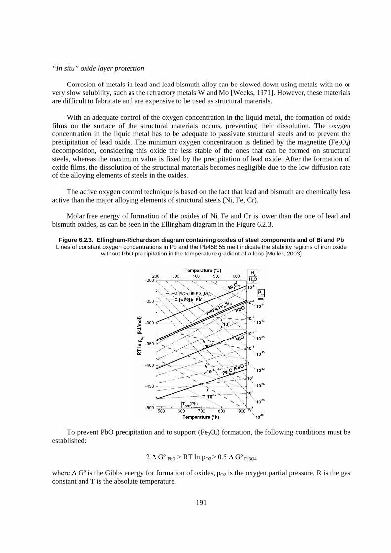
191
“In situ” oxide layer protection
Corrosion of metals in lead and lead-bismuth alloy can be slowed down using metals with no or very slow solubility, such as the refractory metals W and Mo [Weeks, 1971]. However, these materials are difficult to fabricate and are expensive to be used as structural materials.
With an adequate control of the oxygen concentration in the liquid metal, the formation of oxide films on the surface of the structural materials occurs, preventing their dissolution. The oxygen concentration in the liquid metal has to be adequate to passivate structural steels and to prevent the precipitation of lead oxide. The minimum oxygen concentration is defined by the magnetite (Fe3O4) decomposition, considering this oxide the less stable of the ones that can be formed on structural steels, whereas the maximum value is fixed by the precipitation of lead oxide. After the formation of oxide films, the dissolution of the structural materials becomes negligible due to the low diffusion rate of the alloying elements of steels in the oxides.
The active oxygen control technique is based on the fact that lead and bismuth are chemically less active than the major alloying elements of structural steels (Ni, Fe, Cr).
Molar free energy of formation of the oxides of Ni, Fe and Cr is lower than the one of lead and bismuth oxides, as can be seen in the Ellingham diagram in the Figure 6.2.3.
Figure 6.2.3. Ellingham-Richardson diagram containing oxides of steel components and of Bi and Pb Lines of constant oxygen concentrations in Pb and the Pb45Bi55 melt indicate the stability regions of iron oxide
without PbO precipitation in the temperature gradient of a loop [Müller, 2003]
To prevent PbO precipitation and to support (Fe3O4) formation, the following conditions must be established:
�� ��º PbO > RT ln pO2 ������ ��º Fe3O4
w�� ��º is the Gibbs energy for formation of oxides, pO2 is the oxygen partial pressure, R is the gas constant and T is the absolute temperature.
192
The relation between oxygen partial pressure for various metal oxides formation and the corresponding oxygen concentration in lead-bismuth are shown in Figure 6.2.4 [Li, 2002].
Figure 6.2.4. Relation between oxygen partial pressure and Oxygen concentration in Lead-Bismuth [Li, 2002]
The reaction of the formation/dissolution of magnetite in liquid lead or lead-bismuth can be expressed as:
4 O +3 Fe � Fe3O4
with the equilibrium constant:
Ke= a [Fe3O4]/ao4 x a3
Fe
where Fe, O and Fe3O4 are dissolved in the liquid metal, and a is the thermodynamic activity of the substances present in solution.
If a [Fe3O4] =1 � ao4 x aFe
3 = cte at T cte
For example, at 400ºC and for aFe=1, the equilibrium oxygen activity is 1x10⁻⁶ corresponding to an oxygen concentration of 1x10⁻¹⁰ wt.%. If aFe<1, the oxygen activity will be higher.
The equilibrium oxygen activity as a function of the temperature for constant concentrations of oxygen and iron in lead-bismuth eutectic can be seen in Figure 6.2.5, as adapted in [Li, 2002]. Steel corrosion via dissolution occurs below a minimum value of activity, amin, conditions for which Fe3O4 is unstable, whereas coolant contamination by lead oxide formation takes places in the region above a=1. Setting the maximum and minimum values of temperature of the liquid metal in a loop and assuming the oxygen concentration at minimum temperature equal to the saturation value, the permissible range of oxygen activity values can be determined.
193
Figure 6.2.5. Equilibrium oxygen activity [Li, 2002]
During the loop operation, different processes can modify the oxygen activity up to values out of the permissible range. Impurities present in the coolant with oxides more stable than the iron oxide can decrease the oxygen concentration down to values lower than the needed for the formation of magnetite. Transmutation elements generated by the proton beam in the coolant can disturb the chemical equilibrium in the loop. Reduction-oxidation reactions can occur with the formation of non-soluble oxides, and with the reduction of the oxide protective layers [Gromov, 1998b]. On the contrary, air in-leaks can increase the oxygen activity.
To control the oxygen activity in the liquid metals loops, several procedures have been developed in the past for Russian researchers [Efanov, 2001] and, at present, they are being revisited in different labs in Europe and United States [Knebel, 1999].
One of the procedures is based in the reaction of gaseous oxygen with the liquid lead-bismuth. The oxygen activity in the liquid metal increases from the dissolution of lead oxide formed according this reaction:
2Pb(l)+O2 (g) � 2PbO(s) (a)
PbO(s) � [O]diss+Pb (b)
194
Other of the methods is based on the interaction of the liquid metals with the solid oxides of the coolants (PbO) that are used as charge in a mass-transfer device. The oxygen activity in the liquid metal increases due to the reaction (b). Comparative studies of solubility kinetics of solid lead oxide of spheroid shape in lead and lead-bismuth were performed by Efanov [Efanov, 2001].
The third method uses reducing-oxidising gas mixtures. The reaction of the liquid metals with the hydrogen and water vapour is the following:
Pb+H2O � PbO+H2 (c)
In this case, the oxygen partial pressure at the dissociation of water vapour is very low, and the process proceeds without the formation of solid lead oxide. The use of the adequate H2 / H2O ratio allows the reduction of metallic oxides formed in the liquid metal and the simultaneous formation of Fe3O4 on the structural material [Gullevsky, 1998]. Conditions for control of the oxygen concentration in lead and lead-bismuth using a phase gas containing H2/H2O ratios between 10-4 and 1.5 are described in [Muller, 2003].
For oxygen control monitoring on line, electrochemical sensors for oxygen activity measurements were developed by Russian researchers [Shamatko, 2000; Blochin, 1998]. Reference electrodes of In/In2O3, Bi/Bi2O3 and others are being developed and tested in several labs under different conditions [Konys, 2001; Courouau, 2002; Ghetta, 2002; Fernandez, 2002; Konys, 2003; Abella, 2003; Courouau, 2003]. However, more work has to be done to obtain suitable thermodynamic data and to develop more precise calibration methodologies. On the other hand, additional developments are needed to improve the robustness and viability of the sensors to be used under actual conditions.
The corrosion/protection of steels in lead alloys depends on the concentration of oxygen in the liquid metal. According to [Yachmenyov, 1998], an oxygen concentration Ci>Cmin will be necessary to form a protective film with the structure of spinel, being Cmin the minimum concentration of oxygen dissolved in the liquid lead-bismuth to maintain the passivity of structural materials. Cmin is higher than the equilibrium oxygen concentration for the magnetite existence, CT
min, when aFe=1. At Ci<Cmin a substantial corrosion of the steels occurs. The morphology of corrosion depends on the value of C=Cmin-Ci, but also on steels composition, temperature and time. In practice, the corrosion process is kinetically controlled [Shamatko, 2000], and the corrosion of steels occurs for determined values of CT
min<Ci<Cmin for which the process of steel dissolution prevails over that of steel oxidation.
Coatings
Protective coatings are an alternative to the “in situ” protection by oxide layer formation. Apart from a good oxidation/corrosion resistance, a high T coating system has to present interface stability, good adhesion and adequate mechanical strength.
In general, two types of coatings can be identified. The first requires that the composition of the surface layer of the material should be altered by diffusion and the second involves the deposition of a metallic or ceramic overlay with improved oxidation resistance. Diffusion coatings result in a surface enrichment of aluminium, chromium and/or silicium that provides the formation of protective oxide [Cahn, 1996].
Aluminide coatings on martensitic and austenitic stainless steels were developed for fusion materials in contact with Pb-17Li liquid alloy used as tritium breeder material and as coolant. A number of methods including pack- cementation, slurry spraying, plasma spraying, hot-dipping etc can
195
be used to apply the aluminide layers on stainless steels. The characterisation of the aluminide coating on 1.4914 martensitic steels and 316 austenitic stainless steels by hot dipping was performed by Barbier [Barbier, 1997] and the formation and transformation of aluminide phases on F82Hmod. and on MANET II martensitic steels were studied by Glasbrenner [Glasbrenner, 1998]. After hot-dipping, the steels are covered by a homogeneous layer formed by an external layer of pure Al and by an internal layer formed by the brittle compound of type Al5Fe2 with a minor amount of Ni and/or Cr in the case of austenitic or martensitic steels respectively. To improve the mechanical strength of the aluminide layers, a heat treatment can be applied.
Results from compatibility studies of aluminium rich coatings, obtained by different procedures, with Pb-17Li for fusion reactors point out that these types of coatings may be suitable to be used in lead and lead-bismuth eutectic at high temperature [Terlain, 1994]. Aluminium surface alloying of the structural steel can be obtained by a pulsed electron beam (GESA procedure) [Müller, 2000]. Pulsed beam treatment of thin surface layers produces the melting of a surface layer and, due to the high cooling rate very fine grained or even amorphous structure are developed. This type of structure could promote the formation of protective oxide scales with better adhesion [Müller, 1998]. Aluminium surface alloying of steels is produced by applying the electron pulsed to the steel surface covered with an Al-foil. During surface melting 20-25% of the aluminium is dissolved in the melt layer. The concentration profile is not typical of a diffusion process, but have a distribution by turbulence in the melt [Müller, 1998].
Deloffre et al. [Deloffre, 2003] have used different processes to aluminise 316L and T91 tested in lead-bismuth under different conditions. In the case of 316L, a rich aluminium layer of 50-���� �� ��obtained by an industrial pack-cementation process. For T91, modifications to the deposition by pack-cementation were developed to optimise the coated material behaviour in lead-bismuth. With these procedures, an external ���� ��� �� ���� � ��� �� �� ��� ��� ��� ��� �� �� ���� ��� ����� ������� � ���� ���� ������������������� ��
Inhibitors
Zirconium and titanium can be used as inhibitor of corrosion of steels in liquid lead and lead-bismuth eutectic. The mechanism of this inhibition involves the adsorption of Zr at the steel surface and its subsequent reaction with C or N in the steel to form a layer of ZrN or ZrC or a solid solution of the two. The inhibitor effectiveness is a function of the Zr activity in the liquid metal, and of the activities of C and N in the steel. The free energy of formation of ZrN is higher than the one of ZrC, and nitrogen diffuses readily in steel from 500°C to 600°C. Thus ZrN forms first, provided the Al content of the steel and its heat treatment history have not already combined all its nitrogen content as the stable compound AlN. If no N is available, ZrC films form [Weeks, 1971]. ZrC-ZrN mixtures seems to be completely insoluble (inert) in liquid bismuth and Pb-Bi alloys [Kammerer, 1958].
The insoluble films formed on the steel surface by the inhibition process change the rate-controlling step from liquid-phase diffusion to diffusion of the dissolving atoms through the film. According to [Weeks, 1971], the steel just below the inhibiting film becomes depleted in carbon and nitrogen and these films are brittle and tend to spall. At high temperature differentials, the corrosion potentials in the spalled areas are too great, and pits form in the temporary unprotected areas and progress through the depleted zone. The films reheal when the pit reaches metals with higher C and N activity.
Interactions of spallation products with inhibitors can compromise the efficacy of this protection procedure.
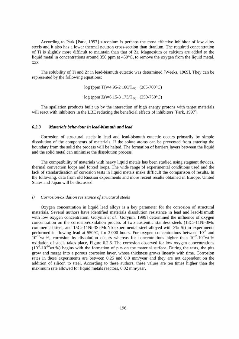
196
According to Park [Park, 1997] zirconium is perhaps the most effective inhibitor of low alloy steels and it also has a lower thermal neutron cross-section than titanium. The required concentration of Ti is slightly more difficult to maintain than that of Zr. Magnesium or calcium are added to the liquid metal in concentrations around 350 ppm at 450°C, to remove the oxygen from the liquid metal. xxx
The solubility of Ti and Zr in lead-bismuth eutectic was determined [Weeks, 1969]. They can be represented by the following equations:
log (ppm Ti)=4.95-2 160/T(K) (285-700°C)
log (ppm Zr)=6.15-3 173/T(K) (350-750°C)
The spallation products built up by the interaction of high energy protons with target materials will react with inhibitors in the LBE reducing the beneficial effects of inhibitors [Park, 1997].
6.2.3 Materials behaviour in lead-bismuth and lead
Corrosion of structural steels in lead and lead-bismuth eutectic occurs primarily by simple dissolution of the components of materials. If the solute atoms can be prevented from entering the boundary from the solid the process will be halted. The formation of barriers layers between the liquid and the solid metal can minimise the dissolution process.
The compatibility of materials with heavy liquid metals has been studied using stagnant devices, thermal convection loops and forced loops. The wide range of experimental conditions used and the lack of standardisation of corrosion tests in liquid metals make difficult the comparison of results. In the following, data from old Russian experiments and more recent results obtained in Europe, United States and Japan will be discussed.
i) Corrosion/oxidation resistance of structural steels
Oxygen concentration in liquid lead alloys is a key parameter for the corrosion of structural materials. Several authors have identified materials dissolution resistance in lead and lead-bismuth with low oxygen concentration. Gorynin et al. [Gorynin, 1999] determined the influence of oxygen concentration on the corrosion/oxidation process of two austenitic stainless steels (18Cr-11Ni-3Mo commercial steel, and 15Cr-11Ni-3Si-MoNb experimental steel alloyed with 3% Si) in experiments performed in flowing lead at 550°C, for 3 000 hours. For oxygen concentrations between 10-8 and 10-10wt.%, corrosion by dissolution occurs whereas for concentrations higher than 10-7-10-6wt.% oxidation of steels takes place, Figure 6.2.6. The corrosion observed for low oxygen concentrations (10-8-10-10wt.%) begins with the formation of pits on the material surface. During the tests, the pits grow and merge into a porous corrosion layer, whose thickness grows linearly with time. Corrosion rates in these experiments are between 0.25 and 0.8 mm/year and they are not dependent on the addition of silicon to steel. According to these authors, these values are ten times higher than the maximum rate allowed for liquid metals reactors, 0.02 mm/year.
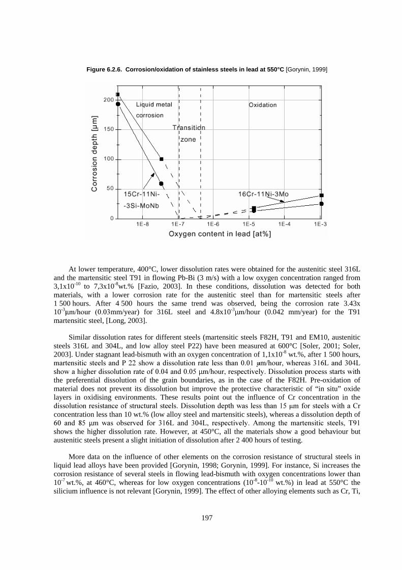
197
Figure 6.2.6. Corrosion/oxidation of stainless steels in lead at 550°C [Gorynin, 1999]
At lower temperature, 400°C, lower dissolution rates were obtained for the austenitic steel 316L and the martensitic steel T91 in flowing Pb-Bi (3 m/s) with a low oxygen concentration ranged from 3,1x10⁻¹⁰ to 7,3x10⁻⁸wt.% [Fazio, 2003]. In these conditions, dissolution was detected for both materials, with a lower corrosion rate for the austenitic steel than for martensitic steels after 1 500 hours. After 4 500 hours the same trend was observed, being the corrosion rate 3.43x 10⁻³ ������ �����mm/year) for 316L steel and 4.8x10⁻³ �/hour (0.042 mm/year) for the T91 martensitic steel, [Long, 2003].
Similar dissolution rates for different steels (martensitic steels F82H, T91 and EM10, austenitic steels 316L and 304L, and low alloy steel P22) have been measured at 600°C [Soler, 2001; Soler, 2003]. Under stagnant lead-bismuth with an oxygen concentration of 1,1x10⁻⁸ wt.%, after 1 500 hours, ����� � ����������� ������������ ������ ���������� ���������� �����!��������"#�������$#�s������� %��� ������ ������������$���������� �����!����� &����' ������ ���������������� ���the preferential dissolution of the grain boundaries, as in the case of the F82H. Pre-oxidation of material does not prevent its dissolution but improve the protective characteristic of “in situ” oxide layers in oxidising environments. These results point out the influence of Cr concentration in the � ������ ���� ������������������������' ������ ������������������������ ����������� �����(�concentration less than 10 wt.% (low alloy steel and martensitic steels), whereas a dissolution depth of "�� ���� )�� �� ���� ���&�� ��� ��"#� ���� ��$#!� ���� &���� *���%� ��� ����� � �� ����!� +,��shows the higher dissolution rate. However, at 450°C, all the materials show a good behaviour but austenitic steels present a slight initiation of dissolution after 2 400 hours of testing.
More data on the influence of other elements on the corrosion resistance of structural steels in liquid lead alloys have been provided [Gorynin, 1998; Gorynin, 1999]. For instance, Si increases the corrosion resistance of several steels in flowing lead-bismuth with oxygen concentrations lower than 10-7 wt.%, at 460°C, whereas for low oxygen concentrations (10-8-10-10 wt.%) in lead at 550°C the silicium influence is not relevant [Gorynin, 1999]. The effect of other alloying elements such as Cr, Ti,
198
Nb, Si and Al on low alloy steels corrosion in flowing lead-bismuth at 600°C was studied by the same authors [Gorynin, 1998]. A significant decrease of the dissolution was observed for concentrations of Si and Al around 2% whereas for the rest of elements, concentrations higher than 3% seem to be needed to obtain similar effects. In general, in reducing environments, in which the formation of protective oxide layers is not possible, steels with lower chromium concentration show lower dissolution rate. Austenitic steels suffer accelerated attack in lead and lead-bismuth due to the high nickel solubility. The limiting temperatures for the application of non-protected stainless steels are around 450°C for ferritic-martensitic steels and 400°C for austenitic steels [Yachmenyov, 1998].
If the adequate oxygen concentration in lead or lead-bismuth exists, the formation of protective oxide layers on the structural materials will be possible. The conditions for the formation of protective oxide layers have been studied for several authors. Fedirko et al. [Fedirko, 1997; Fedirko, 1997b] studied the role of the oxygen concentration on the corrosion process, and the mechanism of the formation of the oxide layers on the Armco iron and Fe-16Cr, Fe-16Cr-1Al and Fe-16Cr-3Al models alloys in liquid lead with an oxygen concentration of 6-8x10⁻³ wt.%, at 650°C, using static devices. For low oxygen concentrations, 10-5 wt.%, Fe3O4-Fe Cr2O4 oxide films formed on model alloys are not permeable to lead. In these conditions, spinels strongly suppress oxygen diffusion into the bulk of the materials but do not prevent it completely, and an internal oxidation process occurs. Under saturated conditions, 10-3 wt.% oxide layers are permeable to lead and the propagation of corrosion occurs. In unalloyed iron, for all the oxygen concentrations a corrosion process was observed.
Under stagnant conditions, the behaviour of two martensitic steels (mod. F82H and MANET II) and one austenitic steel (AISI 316L) in oxygen saturated lead-bismuth at 300, 400 and 550°C, with exposures up to 5 000 hours, has been studied [Fazio, 2001; Benamati, 2002]. The obtained results point out that the thickness of the oxide layer grows with the temperature and the oxide layers seem to be more protective when the chromium concentration increases. AISI 316L and MANET II tested at 300°C up to 5 000 hours were only partially wetted and on both types of steels, a very thin oxide layer ��� �-����� �������*�� $��.C, MANET II specimens were wetted completely and a double layer �� ����� �-����������!������ ������������*/0/���"#���������������������� �������&��and a thin single layer oxide was observed. At 550°C, liquid metal corrosion was exhibited for both materials after 1 500 hours of testing, that grows with time. For both materials, the authors point out that a transition temperature occurs between 475 and 550°C where the corrosion mechanism changes from oxidation to dissolution.
For non-saturated lead-bismuth, with an oxygen concentration of 3-4 x10⁻⁷ wt.%, Gómez-Briceño et al. [Gómez-Briceño, 2002] observed the formation of oxide layers on the F82H martensitic steels at 535°C whereas a dissolution process was detected at 550°C, under stagnant conditions after 1 000 hours. The existence of an apparent threshold of temperature above which material dissolution occurs was confirmed in new experiments [Martin, 2003]. A similar range of temperatures in which a change from oxidation to dissolution occurs was detected also for other martensitic steels (T91, EM10 and F82H) for the same oxygen concentration whereas for higher oxygen concentration, 3-8x10⁻⁶ wt.%, the apparent threshold of temperature was in the range of 550 and 600°C. Similar results were obtained for the 316L austenitic steel whereas for 304L the threshold temperature value seems to be higher than 600°C for the higher oxygen concentration. The oxidation response of 304L may be attributed to the surface conditions of the specimens tested. A possible effect of the surface conditions on the resistance to oxidation has been also suggested [Li, 2001].
The good influence of chromium on the oxidation process of structural steels has been confirmed in several studies. According [Kurata, 2002], the thickness of corrosion films decreases with increasing chromium content for different martensitic (F82H, Mod.9Cr-1Mo, 410ss, 430ss) and austenitic steels (14Cr-16Ni-2Mo named JPCA) in oxygen saturated lead-bismuth at 550°, in stagnant
199
conditions, for 500 hours. In particular, martensitic/ferritic stainless steels (410sss and 430s) with 14-16%Cr show very thin corrosion films. Similar trend has been observed [Soler, 2003] in tests performed in stagnant lead-bismuth with oxygen contents of 2x10⁻³ wt.% and 4.7x10⁻⁴ wt.% at 600ºC after 1 500 hours. Low alloy steel (21/4 Cr-1Mo) showed thicker oxide layers than martensitic steels (F82H, T91 and EM10) particularly in wet atmosphere, whereas austenitic steels (316L and 304L) showed thinner oxide layers than martensitic steels. Oxidation kinetics seems to follow a parabolic law for low alloy steel and martensitic steels in dry atmospheres but a linear law in wet atmosphere. Results obtained in [Müller, 2000] with one high chromium martensitic steel (OPTIFER IV) and one austenitic steel (1.4970) in lead with a controlled oxygen concentration of 8x10⁻⁶ at.% at 550°C up to 3 000 hours, under stagnant conditions agree with the previous observations. In the tested conditions, both materials present oxide layers but the austenitic steel, with higher chromium concentration, shows a better oxidation resistance in liquid lead than the martensitic steels.
In general, results obtained in flowing conditions agree with those obtained in stagnant devices. For instance, Barbier et al. [Barbier, 2001] studied, in flowing conditions, the behaviour of three martensitic steels (OPTIFER IV, T91 and EP823), and one austenitic steel (1.4970) in lead-bismuth with an oxygen concentration of 1-2x10⁻⁶ wt.%. at 300 and 470°C, with a flow velocity close to 2m/s, up to 3 116 hours. Under these conditions, even at 470°C no sign of corrosion damage was observed. *�&�� �� �� ���� �� �������� �����$,1�������� �2� �-���& � �%������ ����%� ���� � 3� �������corrosion. For martensitic steels, an oxide scale was observed in all the materials, the thickness depending on the time of exposure and the substrate, according to a parabolic behaviour. The presence of Si in the EP 823 steel reduces the oxide growth rate, which improves the resistance to oxidation.
In flowing lead-bismuth with an oxygen content of 10-6 wt.%, Müller et al. [Müller, 2002] studied the behaviour of two austenitic steels (AISI 316 and 1.4970) and of one martensitic steel (MANET), in the temperature range from 420 to 600°C. After 2 000 hours of testing, the results point out that no attack was observed in both austenitic steels at 420°C, and partly thick oxide layers were observed on both steels at 550°C. However, at 600°C oxide layers are also formed on 1.4970 steel but deep liquid metal penetration and loss of material by erosion were observed in the AISI 316. At 550°C, after 4 000 hours, spall off of the oxide layer was observed in all the materials but for longer time, 7 200 hours, a regeneration of the oxide layers occur, especially in the case of martensitic steel. The three materials show an acceptable behaviour up to 550°C but, according to the authors [Müller, 2003], the use of austenitic steels for time longer than 7 200 hours is questionable.
Similar results were obtained in flowing lead with an oxygen content of 3-4x10⁻⁵ wt.% at 400 and 550°C [Glasbrenner, 2001]. Thicker oxide layers formed by (Fe, Cr) 3O4 were detected on the martensitic steels (OPTIFER IV and EM 10), whereas the austenitic steels (1.4948 and 1.4970) presented a thin oxide layer after 3 000 hours of exposure. Both types of oxide scales provide protection to the materials in the tested conditions.
Li performed corrosion tests on several US steels (316 tube, 316L rod, T410 rod, HT9 tube and D9 tube) in flowing LBE with an oxygen level of 3-5x10⁻⁶ wt.%, at 460°C and 550°C, with a velocity of 1.9 m/s. The Russian steels EP823 was included for comparison [Li, 2001]. The characteristic of the overall weight change in the first 2 000 hours testing period is different from that in the testing period after 2 000 hours at 550°C. Protective oxide films formed on the surfaces of all steels. However, the experiments revealed the differences in corrosion resistance due to differences in composition, surface conditions and secondary treatment. According to these authors, 316L, D9 and HT9 steels are suitable for short to medium term applications up to 550°C.
Steels corrosion test of SCM420 (1Cr), STBA26 (9Cr-1Mo9, SUS405 (14Cr), SUS430 (18Cr), SS316 (18Cr-12Ni-2.5Mo) were tested in flowing Pb-Bi with a velocity of 2m/s and an estimated
200
oxygen concentration of 5x10⁻⁷ wt.% at 550°C for 959 hours by Takahashi [Takahashi, 2002]. Results point out that all the steels underwent a dissolution process, and the weight loss was larger in the order of SS316 that contained Ni, low Cr steel (SCM420) and high Cr steels (STBA26, SUS405, SUS430). In a second test, with a velocity of 2m/s and an oxygen concentration of 3.6x10⁻⁷ wt.% for 1 000 hours, serious erosion damage was observed in SCM 420 and some erosion damage in low Cr steels, SCM420, F82H, STBA26 and HCM1���*�����%������������� ���������&�� ��00��"�
The kinetic of oxidation of different steels alloyed with silicon in liquid lead at 550°C, determined from experiments up to 13 500 hours, follows an exponential law, hn= cte.t, where n depends on the steel composition [Gorynin, 1999]. Austenitic steels alloyed with silicon present thin oxide layers after 13 000 hours in flowing lead at 550°C [Gorynin, 1998]. Silicon incorporated to the oxide layer increases the stability of the layer.
Similar composition of the oxide layers formed in stagnant Pb-Bi and Pb experiments has been described by several authors [Fazio, 2001; Müller, 2000; Barbier, 2001]. In general, martensitic steels show a double oxide layer formed by an outer layer with a composition comparable to that of magnetite and an inner layer where Cr content is higher than in the material bulk. The composition of this inner layer correspond to Fe(Fe1-xCrx) 2O4. Thickness of the oxide layer depends mainly on the Cr content [Soler, 2001] but also the minor alloying elements, such as W in F82H that is accumulated in the inner corrosion product layer may play some role. In the case of the austenitic steel 316L, the composition of the oxide layers correspond to Fe(Fe1-xCrx) 2O4 with Ni accumulated at the interface between the oxide and the base metal [Soler, 2001].
Refractory metals behaviour
Some information about the corrosion resistance of some refractory metals such as Ta, Mo.W, Re and Os in Pb, Bi and their alloys can be found in [Weeks, 1971]. Tungsten is potentially suitable for a beam window working immersed in a liquid lead spallation target. In experiments performed under static conditions in oxygen saturated lead at 520°C, Benamati [Benamati, 2000] observed that the interaction with the molten lead produces the formation of continuous layers of reaction products on the surface of tungsten. After 2 ������������ �������������������� ����������������� ������detected. Liquid leads reacts with WO3 leading to the formation of non- protective Pb-W-O ternary compounds.
Coating behaviour
An alternative to the protection of structural steels by oxide layers is the use of coatings with better oxidation resistance. Müller et al. [Müller, 2000] studied the behaviour of one martensitic steel (OPTIFER IV) and one austenitic steel (1.4970) with the surface restructured by electron pulsed treatment (GESA procedure) and Al alloyed in lead with a controlled oxygen concentration of 8x10⁶ at.%, at 550°C, up to 3 000 hours in stagnant conditions. GESA procedure improved the behaviour of 1.4970 because it suppressed deep grain boundary penetration of oxygen due to the fine-grained layer formed. Alloying of Al into the surface by GESA procedure improves significantly the corrosion oxidation behaviour of both materials, after 1 500 hours of exposure.
Aluminised F82H, by hot dipping followed by a thermal treatment, was tested by Benamati [Benamati, 2000] in oxygen saturated stagnant lead a 520°C for 3 700 hours. No significant weight change or alteration was observed on the aluminised samples whereas a non-protective oxide layer of $�� ���������������������-coated specimens.
201
Specimens of two austenitic steels (1.4948 and 1.4970) and two martensitic steels (OPTIFER IV and EM10) in flowing lead with a velocity of 1.9 m/s treated with GESA procedure were tested by Glasbrenner et al. [Glasbrenner, 2001]. The test temperatures were 400 and 550ºC and the oxygen content was around 3-4x10⁻⁵ wt.%. The thickness and composition of the multiphase oxide scales formed on ferritic steels with and without GESA treatment do not show any difference. Therefore, the characteristic of the restructured layer did not have an obvious influence on the oxidation behaviour of the martensitic steels. On the contrary, in the case of austenitic steels 1.4970 and 1.4948, multiphase oxide scales were developed like observed for the martensitic steels, whereas a thin dense oxide layer was formed on the untreated materials.
The influence of alloying Al into the surface of steels was studied in [Müller, 2002]. Al alloying was achieved by two different procedures. The first consists in wrapping Al-foil around the steel tube and heating at 1 040°C for 0.5 hours, and the second in hot dipping aluminisation and annealing. Corrosion behaviour of two austenitic steels (AISI 316 and 1.4970) and of one martensitic steel (MANET), in as received and in treated conditions, was tested under flowing conditions. Austenitic steels surface alloyed by Al with formation of FeAl at the surface have no signs of any corrosion in flowing lead-bismuth with an oxygen content of 10-6 wt.%, even at 600ºC They are protected by a thin alumina layer which remains stable. Hot dipped samples of austenitic steels, with no FeAl formation at the surface, are not able to develop protective oxide scales. The Al activity at the surface must be to low enough to minimize the solution rate of Al in LBE and to allow oxide scale formation.
Deloffre et al. [Deloffre, 2003] studied the corrosion resistance of aluminised martensitic and austenitic steels in liquid lead-bismuth under several conditions. Both materials were aluminised using several variants of the pack-cementation process. In the case of T91 martensitic steels, up to 500°C a very satisfying behaviour of the different coatings was obtained for oxygen concentration 10-8-10-9 wt.%, after 3 000 hours, under static conditions, but at 600°C a heterogeneous behaviour was obtained. Heterogeneous wetting of the specimens was observed. In some areas, the coatings disappear, and a corrosion layer with a maximum depth of attack of 150-���� �������������/�����unwetted parts, the Al layer rich with high oxygen concentration is not observed, being the Al content lower than before the tests. Coated austenitic steel 316L was tested under static and dynamic conditions in lead-bismuth with oxygen concentrations from 10-11-10-12 wt.% to 2,5x10⁻⁴ wt.%, and at temperatures from 400 to 600°C. Under static conditions, as for T91 up to 550°C, a good behaviour was also observed even for low oxygen concentrations. At 600°C, a heterogeneous behaviour was obtained for low oxygen concentrations (below10-8 wt.%) after 3 000 hours of testing, similar to the observed for T91. However, at 600°C with high oxygen concentration (around 10-4 wt.%) no modifications of the coatings were observed. In dynamic conditions, at 400 and 600°C, localised corrosion points attributed to a particularly turbulent flow were observed.
Long term experiments in flowing LBE with an oxygen level of 10-6 wt.% performed by Müller [Müller, 2003] show that Al alloyed 316 and 1.4970 austenitic steels show no dissolution attack at temperatures up to 600°C after 7 200 hours. A stable Al2O3 layer formed on the materials surface was identified on the specimens. No coated materials tested as reference show an acceptable behaviour after 7 200 hours but only up to 550°C.
ii) Inhibitor influence
The effects of inhibitors in the corrosion of structural materials have been discussed by Weeks [Weeks, 1971]. Most of the data on the corrosion of structural materials in heavy liquid metals with additions of titanium or zirconium has been obtained in bismuth at high temperature, being the information more scarce for lead and lead-bismuth. The corrosion of steels in uninhibited lead is about
202
40 times less than in uninhibited bismuth at 800°C, under a temperature gradient of 100°C, and the corrosion is reduced by addition of 500 ppm titanium, [James, 1960]. The addition of 250-500 ppm of Zr to the liquid bismuth slows down the corrosion rate of 2¼ Cr-1Mo, from 0.65 in/y to 017in/y, under thermal convection at temperatures up to 625°C and temperature gradients up to 150°C. Under these conditions the film spalls off and is not rehealed, and intergranular attack occurs. If the steels have a high nitrogen concentration (1%) the corrosion rate in inhibited bismuth decreases to 0.010 in/y, the nitride film re-forms if broken, and intergranular penetration is prevented [Horsley, 1958].
Uninhibited Pb-Bi severely attacked a Croloy 1¼ thermal convection loop with a maximum T>500°C and a temperature gradient of 150°C. Reducing the maximum T to 400°C, the dissolution process is limited to allow the operation of Croloy loop with a temperature gradient of 200ºC for nearly 10 000 hours with no signs of corrosion or deposition. The addition of Zr or Ti to Pb-Bi considerably reduced the corrosion of Croloy 1¼ at 650°C with a temperature gradient of 150°C [Romano, 1963]. Recent experiments have been performed to study the layer formation on several steels at high temperature in presence of zirconium [Loewen, 2003]. Specimens of HT-9, 410, 316L and F22 were tested at 550 and 650°C, for 1 000 hours, in a device made of zirconium covered by a zirconia layer. The oxygen potential was from 10-22 to 10-19 Pa. Preliminary results pointed out that at 650°C, a layer of Zr compounds prevented the alloys from dissolving into the LBE, but this layer was liable to spall off.
iii) Irradiation assisted corrosion
The structural materials used in the heavy irradiation areas, such as the target and the core will be exposed to irradiation. The materials resistance to corrosion/oxidation processes in liquid metals can be modified by the synergetic effect between corrosion and irradiation. In some cases, such as the proton beam window the material will be also exposed to high mechanical load, and embrittlement effects cannot be excluded.
LiSoR experiments were proposed to investigate the behaviour of materials under thermal and mechanical loads in the presence of proton irradiation while exposed to a lead bismuth eutectic. LiSoR loop is able to study the behaviour of materials under Pb-Bi with a linear velocity of 0.9 m/s, at temperatures from 350 to 150°C, in a test section irradiated with 72 MeV protons [Kirchner, 2003]. Preliminary results of post irradiation examination on LiSoR –2 test section are discussed in [Dai, 2003]. A liquid metal leak was detected after 34 hours of irradiation. The cause of this failure was identified as a crack attributed to high thermal stress caused by the high temperature gradient cross the tube wall (110°C) introduced thermal fatigue (100 000 cycles due to the wobbling frequency of the beam).
6.2.4 Corrosion models in heavy liquid metals
The kinetic of corrosion processes in liquid lead containing oxygen, taking into account the multiphase and multicomponent nature of the systems and the interaction of components during the process of adsorption and diffusion, is described in the model elaborated in [Matychak, 1999]. A general theoretical scheme of the interaction of solid metals with liquid metals containing non-metallic impurities is proposed in [Eliseeva, 2000] based on the behaviour of the different elements on the phase boundaries.
Recently, a kinetic model for corrosion and precipitation in non-isothermal lead-bismuth loop has been developed [He, 2001]. The model is based on solving the mass transport equations with the
203
assumptions that convective transport dominates in the longitudinal flow direction and diffusion in the transverse direction. This model predicts that the corrosion/precipitation is proportional to v0.6 d-0.067 and L–0.33. That means that the corrosion/precipitation increases with the flow velocity, decreases with length of flow path and depends little of the tube diameter. This model is only valid when the concentration boundary layer is submerged in the laminar sublayer of the turbulent channel flow.
Investigation of models to predict the corrosion of steels in flowing liquid lead alloys has been carried out by Balbaud-Célérier et al. [Balbaud-Célérier, 2001]. In particular, the influence of hydrodynamic parameters on the corrosion behaviour in liquid metals was studied using models developed in aqueous medium. Equations established for the rotating cylinder and the pipe flow geometry can be used effectively in liquid lead alloys (Pb-Li 17) assuming the corrosion process is mass transfer controlled and the diffusion coefficient of dissolved species is known. The corrosion rate of martensitic steels in Pb-Li 17 is shown to be independent of the geometry when plotted as a function of the mass transfer coefficient. Predictions about the corrosion rate in LBE are performed.
6.2.5 Conclusion and recommendations
Lead-bismuth eutectic (LBE) and lead show a high aggresivity to structural materials such as martensitic and austenitic steels, being key parameters the oxygen activity and the temperature. The main corrosion mechanism is the dissolution of main elements of the structural materials such us Ni, Cr, and Fe in a general o localised way.
Oxygen solubility data in LBE and lead, obtained with different procedures, are available for a temperature range from 200 to 650°C. Additional work has to be done to determine the influence of metallic elements in the liquid metal on the oxygen solubility.
For protection of structural materials by oxide layers formed in situ, oxygen activity in the liquid metal has to be higher that the defined by the decomposition of magnetite. To prevent plugging of the loops, oxygen activity has to be lower that the need to form lead oxide.
Protection of structural materials by oxide layers formed in situ seems to be feasible, at least up to an apparent threshold of temperature. For temperatures higher than this value, oxide layers formed on structural materials do not prevent the materials dissolution. The threshold of temperature depends on the oxygen activity and the material compositions.
Different martensitic and austenitic stainless steels has been tested in LBE and lead under stagnant and flowing conditions up to temperatures of 600°C. Experiments have been performed with oxygen activities from saturation to very reductive conditions. Most of them have been performed in the range of 10-5 to 10-6 wt.%. No significant differences has been observed among the different martensitic and austenitic steels.
Both types of stainless steels undergo a dissolution process in reductive environments even at temperatures of 400-450°C. However, they are suitable to be used in LBE and lead up to temperature of 500-550°C always that enough oxygen is present. Higher temperatures could be considered for austenitic stainless steels containing silicon.
Under oxidant conditions austenitic stainless steels show a better behaviour that martensitic steels being the contrary in reductive environment. Higher Cr concentration of the austenitic stainless steels promotes the formation of thin protective oxide layers in oxidant environments whereas the nickel content justify the higher dissolution observed in reductive environments.

204
Available information on the protective characteristic of the oxide layers formed on refractory metals, at temperatures around 500°C, is no conclusive.
Several type of Al based coating have been studied as an alternative to the oxide layer protection. Under reductive conditions, T 91 martensitic steel and 316L austenitic steel showed a good corrosion resistance at temperature up to 500°C whereas at 600°C an heterogeneous behaviour was observed after 3 000 hours. At 600°C, under oxidant conditions aluminised austenitic stainless steels show a good resistance in flowing lead-bismuth at least for 7 200 hours.
Most of the results on the influence on Zr and Ti as corrosion inhibitor in LBE and lead are very old and difficult to evaluate. New results are scarce and no conclusive on the effect of inhibitor in the corrosion process of stainless steels in liquid lead alloys.
Some corrosion models in lead and LBE are available but more work on this topic is needed, especially oxidation models in oxidant environments. Also more work has to be done on corrosion irradiation behaviour in representative conditions.
205
REFERENCES
Section 6.1
Akasaka, N.; Yamashita, S.; Yoshitake, T.; Ukai, S.; and Kimura, A. (2004), J. Nucl. Mater., 329-333, 1053.
Alexander, D.J.; Pawel, J.E.; Grossbeck, M.L.; Rowcliffe, A.F. (1995), DOE/ER-0313/19, 31 December 1995, p. 204.
Anderko, K.; Ehrlich, K.; Schäfer, I.; Schirra, M. (1993), CETA-EinEntwicklungsschritt zu einem Schwach Activierbaren martensitischen Chromstahl, Kernforschungszentrum Karlsruhe, KfK Report 5060, June 1993.
Bagley, K.Q.; Little, E.A.; Levy, V.; Alamo, A.; Erhlich, K.; Anderko, K.; Calza, A. (1988), Bini Nucl. Energy, 27 (5), 295.
Bagley, K.Q. et al. (1988), “European development of ferritic-martensitic steels for fast reactor wrapper applications”, Nuclear Energy, Vol. 27, No. 5, p. 295-303.
Blackburn, L.D.; Knecht, R.L. (1977), Atomkernenergie (ATKE) Bd. 30 Lfg. 4, p. 278.
Bottcher, J.; Ukai, S.; Inoue, M. (2002), J. Nucl. Technol., Vol. 138, 238.
Bridges, A.E. (1993), Nuclear Technology, Vol. 102, p. 353.
Brown C. et al. (1991), “Proceedings International Conference on Fast Reactor and Related Fuel Cycles”, Vol. I, pp. 7.5-1.
Brown, C.; Languille, A.; Muehling, G. (1993), J. Nucl. Mater., 204, 33.
Butterworth, G.J.; Jarvis, O.N. (1984), J. Nucl. Mater., 122 & 123, 982.
Conn, R.W. et al. (1983), “Panel Report on Low Activation Materials for Fusion Applications”, UCLA Report PPG-728, University of California at Los Angeles.
Dubuisson, P.; Schill, R.; Hugon, M.P.; Grislin, I.; Seran, J.L. (1999), “Effects of Radiation on Materials: 18th International Symposium”, ASTM STP 1325, Nanstad, R.K.; Hamilton, M.L.; Garner, F.A.; Kumar, A.S., Eds., American Society for Testing and Materials, West Conshohocken, PA, p. 882.
Dulieu, D.; Tupholme, K.W.; Butterworth, G.J. (1986), J. Nucl. Mater., 141-143, 1097.
Fox, G.L. (1986), Proceedings of the International Conference on Reliable Fuels for Liquid Metal Reactors, Tucson, AZ, September 7-11, p. 5-135.
Garner, F.A.; Tolozcko, M.B. (1995), DOE/ER-0313/18, 31 March 1995.
Garner, F.A.; Oliver, B.M.; Greenwood, L.R.; James, M.R.; Ferguson, P.D.; Maloy, S.; Sommer, W.F. (2001), J. Nucl. Mater., 296, 66.

206
Garner, F.A.; Toloczko, M.B.; Sencer, BH. (2000), J. Nucl. Mater., 276, 123.
Garner, F.A. (1991), J. Nucl. Mater., 179-181, 577.
Garner, F.A. (1994), Mater. Sci. Technol., 19A, 420.
Gelles, D.S. (1985), in: “Optimizing Materials for Nuclear Applications”, Eds. Garner, F.R.; Gelles, D.S.; Wiffen, F.W., The Metallurgical Society, Warrendale, PA, p. 63.
Gelles, D.S. (1990), in: “Reduced Activation Materials for Fusion Reactors”, ASTM STP 1047, Eds. Klueh, R.L.; Gelles, D.S.; Okada, M.; Packan, N.H., ASTM, Philadelphia, p. 113.
Gelles, D.S. (1996), J. Nucl. Mater., 233-237, 293.
Ghoniem, N.M.; Shabaik, A.; Youssef, M.Z. (1984), in: “Proceedings of Topical Conference on Ferritic Steels for use in Nuclear Energy Technologies”, The Metallurgical Society of AIME, Warrendale, PA, p. 201.
Hamilton, M.L.; Gelles, D.S.; Lobsinger, R.J.; Johnson, G.D.; Brown, W.F.; Paxton, M.M.; Puigh, A.J.; Eiholzer, C.R.; Martinez, C.; Blotter, M.A., PNNL-13168.
Hofman, G.L.; Walters, L.C., “Materials Science and Technology, a Comprehensive Treatment”, Volume 10A, Nuclear Materials, Part I.
Horsten, M.; van Osch, G.E.; Gelles, D.S.; Hamilton, M.L. (2000), in: Effects of Irradiation on Materials: 19th International Symposium, ASTM STP 1366, Eds. Hamilton, M.L.; Kumar, A.S.; Rosinski, S.T.; Grossbeck, M.L., American Society for Testing and Materials, West Conshohocken, PA, 579.
Hsu, C.Y.; Lechtenberg, T.A. (1986), J. Nucl. Mater., 141-143, 1107.
Hu, W.L.; Gelles, D.S. (1987), in: “Influence of Radiation on Material Properties: 13th International Symposium (Part II)”, ASTM 956, Garner, F.A.; Henager, C.H., Jr.; Igata, N., Eds., American Society for Testing and Materials, Philadelphia, p. 83.
Huet, J.-J.; Coheur, L.; DeBremaecker, A.; DeWilde, L.; Gedopt, J.; Hendrix, W.; Vandermeulen, W. (1984), Nucl. Tech., 70, 215.
Kamal, S.A., Draft Structural Evaluation Criteria for Mark V Fuel Subassembly, Revision 0, provided by private communication.
Kayano, H., et al., (1991), J. Nucl. Mater., 179-181, 445.
Keiser, D.D.; Petri, M.C. (1996), J. Nucl. Mater., 240, 51.
Klueh, R.L. (1998), DOE/ER-0313/25, p. 111.
Klueh, R.L.; Alexander, D.J. (1992), J. Nucl. Mater., 187, 60.
Klueh, R.L.; Alexander, D.J. (1998), J. Nucl. Mater., 258-253, 1269.
Klueh, R.L.; Alexander, D.J. (1999), in: “Effects of Radiation on Materials: 18th International Symposium”, ASTM STP 1325, American Society for Testing and Materials, Philadelphia, 911.
207
Klueh, R.L.; Alexander, D.J. (1992c), “Effects of Radiation on Materials: 15th International Symposium”, ASTM STP 1125, Stoller, R.E.; Kumar, A.S., Gelles, D.S., Eds. American Society for Testing and Materials, Philadelphia, p. 1256.
Klueh, R.L.; Bloom, E.E. (1985), Nucl. Eng. Design/Fusion, 2, 383.
Klueh, R.L.; Corwin, W.R. (1989), “Impact Behavior of Cr-W Steels”, J. Eng. Mater., 11, 169.
Klueh, R.L.; Ehrlich, K.; Abe, F. (1992d), Nucl. Mater. 191-194, 116.
Klueh, R.L.; Harries, D.R. (2001), High-Chromium Ferritic and Martensitic Steels for Nuclear Applications, ASTM, West Conshocken, PA.
Klueh, R.L.; Maziasz, P.J. (1992b), J. Nucl. Mater., 187, 43.
Klueh, R.L.; Vitek, J.M. (1991), J. Nucl. Mater., 182, 230.
Klueh, R.L.; Vitek, J.M. (1993), J. Nucl. Mater., 204, 109.
Kurishita, H.; Ukai, S.; Narui, M.; Mizuta, S.; Yamazaki, M.; Nagasaka, T.; Kayano, H. (1998), J. Nucl. Mater., 258-263, 1236.
Lauritzen, T.; Bell, W.L.; Knoze, G.M.; Vaidyanathan, S. (1981), GEFR-00575, September 1981.
Leggett, R.D. (1986), Letter to Feelten, L.D., Westinghouse Hanford 8653302, November 1986.
Leggett, R. D.; Walters, L.C. (1993), J. Nucl. Mater., 204, 23.
Lindau, R.; Möslang, A.; Preininger, D.; Rieth, M.; Röhrig, H.D. (1999), J. Nucl. Mater., 271 and 272, 450.
Maloy, S.; James, M.R.; Wilcutt, G.; Sommer, W.F.; Sokolov, M.; Snead, L.L.; Hamilton, M.L.; Garner, F. (2001), J. Nucl. Mater., 296, 119.
Masuyama, F. (1999), in: “Advanced Heat Resistant Steel for Power Generation”, Ed. Viswanathan, R.; Nutting, J., Institute of Materials, London, 33.
Materna-Morris, E.I.; Rieth, M.; Ehrlich, K. (2000), in: “Effects of Irradiation on Materials: 19th International Symposium”, ASTM STP 1366, Eds. Hamilton, M.L.; Kumar, A.S.; Rosinski, S.T.; Grossbeck, M.L., American Society for Testing and Materials, West Conshohocken, PA, 597.
Maziasz, P.J.; Klueh, R.L.; Vitek, J.M. (1986), J. Nucl. Mater., 141-143, 929.
Miwa, Y.; Wakai, E.; Shiba, K.; Hashimoto, N.; Robertson, J.P.; Rowcliffe, A.F.; Hishinuma, A. (2000), J. Nucl. Mater., 283-287, 334.
Morimura, T.; Kimura, A.; Matsui, H. (1996), J. Nucl. Mater., 239, 118.
Mukhopadhyay, D.K.; Froes, F.H.; Gelles, D.S. (1998), J. Nucl. Mater., 258-263 (1998) 1209-1215.
Nishida, T.; Fujiwara, M. (1993), J. Nucl. Mater., 204, 65.
Noda, T.; Abe, F.; Araki, H.; Okada, M. (1986), J. Nucl. Mater., 141-143 (1986) 1102.

208
Nomura, S.; Shikakura, S.; Ukai, S.; Seshimo, I.; Harada, M.; Shibahara, I.; Katsuragawa, M. (1991), Proc. Int. Conf. Fast Reactor Related Fuel Cycles, Vol. I, 7.4.
Ohtsuka, S.; Ukai, S.; Fujieara, M.; Kaito, T.; and Narita, T. (2004), J. Nucl. Mater., 329-333, 372.
Okada, H.; Ukai, S.; Inoue, M. (1996), J. Nucl. Scie. and Technol., Vol. 33, No. 12, p. 936.
Okuda, T.; Fujiwara, M. (1995), J. Materials Science Letters, 14, 1600.
ORNL (1991), Multimegawatt Materials Handbook, Vols. 1 and 2, Wiffen, F.W., et al., eds., Oak Ridge National Lab Report ORNL/TM-11334.
van Osch, E.V.; Horsten, M.G.; Lucas, G.E.; Odette, G.R. (2000), in: “Effects of Irradiation on Materials: 19th International Symposium”, ASTM STP 1366, Eds. Hamilton, M.L.; Kumar, A.S.; Rosinski, S.T.; Grossbeck, M.L., American Society for Testing and Materials, West Conshohocken, PA, 612.
Pahl, R.G. et al. (1992), J. Nucl. Mater., 188, 3.
Porter, D.L. (1994), Fuel Test Plan for ALMR, June 23.
Puigh, R.J.; Gelles, D.S. (1989), DOE/ER-0313/6, March, p. 201.
Rieth, M.; Dafferner, B.; Röhrig, H.D. (1996); J. Nucl. Mater., 233-237, 351.
Rosenwasser, S.N. et al. (1979), J. Nucl. Mater. 85 & 86 177.
Roth, T.S.; Biancheria, A. (1986), Proceedings of the International Conference on Reliable Fuels for Liquid Metal Reactors, Tucson, AZ, 7-11 September 1986, p. 5-93.
Seki, M.; Hirako, K.; Kono, S.; Kihara, Y.; Kaito, T.; Ukai, S. (2004), J. Nucl. Mater., 329-333, 1534.
Seran, J.L. et al. (1993), ASTM STP 1125, 1209.
Seran, J.-L., et al. (1994), J. Nucl. Mater., Vol. 212-215, 588.
Seran, J.-L.; Levy, V.; Dubuisson, P.; Gilbon, D.; Maillard, A.; Fissolo, A.; Touron, H.; Cauvin, R.; Chalony, A.; Le Boulbin, E. (1992), Effect of Radiation on Materials: 15th International Symposium, ASTM STP 1175, p. 1209.
Shiba, K.J. (2000), J. Nucl. Mater. 283-287, 474.
Shikakura, S.; Nomura, S.; Ukai, S.; Seshimo, I.; Kano, Y.; Kuwajima, Y.; Ito, T.; Tsutagi, K.; Fujita, T. (1991), J. At. Energy Soc. Japan, Vol. 33, No. 12, pp. 1157-1170, (in Japanese).
Stubbins, J.F.; Gelles, D.S. (1996), J. Nucl. Mater., 233-237, 331.
Tamura, M.; Hayakawa, H.; Tanimura, M.; Hishinuma, A.; Kondo, T. (1986), J. Nucl. Mater., 141-143, 1067.
Toloczko, M.B.; Garner, F.A. (2003), submitted to Effects of Radiation on Materials, ASTM STP 1447, Grossbeck, M.L., Ed., ASTM International, West Conshohocken, PA.
Toloczko, M.B.; Garner, F.A.; Eiholzer, C.R. (1998), J. Nucl. Mater., 258-263, 1163.

209
Toloczko, M.B. et al. (1994), J. Nucl. Mater., 212-215, 604.
Tolozcko, M.B.; Garner, F.A. (1996), J. Nucl. Mater. 233-237, 289.
Tsai, H. (1990), International Fast Reactor Safety Meeting, Snowbird, Utah, Vol. II, p. 257.
Uehira, A.; Mizuta, S.; Ukai, S.; Puigh, R.J. (2000), J. Nucl. Mater. 283-287, 396-399.
Uehira, A.; Ukai, S. (2000), JNC Report, TN9400 2000-035 (in Japanese).
Uehira, A.; Ukai, S.; Mizuno, T.; Asaga, T.; Yoshida, E. (2000), J. Nucl. Scie. and Technol., Vol. 37, No. 9, pp. 780-786.
Ukai, S.; Fujiwara, M. (2002), J. Nucl. Mater., 307-311, 749.
Ukai, S.; Harada, M.; Nomura, S.; Shikakura, S.; Shibahara, I. (1992), Proc. Int. Symp. on Material Chemistry in Nuclear Environment, Tsukuba, Japan, 12-13 March 1992.
Ukai, S.; Harada, M.; Okada, H.; Inoue, M.; Nomura, S.; Shikakura, S.; Asabe, K.; Ukai, S.; Kaito, S.; Ohtsuka,S.; Narita,T.; Fujiwara,M.; and Kobayashi,T. (2003), ISIJ International, Vol. 43, No. 12, p. 2038.
Ukai,S.; Kaito,T.; Seki,M.; Mayorshin,A.; and Shishalov,O., (in press), J. Nucl. Scie. and Technol.
Ukai, S.; Harada, M.; Okada, H.; Inoue, M.; Nomura, S.; Shikakura, S.; Nishida, T.; Fujiwara, M.; Asabe, K. (1993), J. Nucl. Mater., 204, 74.
Ukai, S.; Mizuta, S.; Fujiwara, M.; Okuda, T.; Kobayashi, T. (2002), J. Nucl. Scie. and Technol. Vol. 39, No. 7, p. 778.
Ukai, S.; Mizuta, S.; Kaito, T.; Okada, H. (2000), J. Nucl. Mater. 278, 320.
Ukai, S.; Mizuta, S.; Yoshitake, T.; Okuda, T.; Hagi, S.; Fujiwara, M.; Kobayashi, T. (2000), J.Nucl.Mater., 283-287, 702.
Ukai, S.; Nishida, T.; Okada, H.; Okuda, T.; Fujiwara, M.; Asabe, K. (1997), J. Nucl. Scie. and Technol., Vol. 34, No. 3, p. 256.
Ukai, S.; Okuda, T.; Fujiwara, M.; Kobayashi, T.; Mizuta, S.; Nakashima, H. (2002), J. Nucl. Scie. and Technol., Vol. 39, No. 8, p. 872.
Viswanathan, R.; Bakker, W. (2001), J. Matls. Eng. and Perf., 10, 81.
Wakai, E.; Hashimoto, N.; Robertson, J.P.; Klueh, R.L.; Shiba, K.; Jitsukawa, S. (2000), J. Nucl. Mater., 283-287, 435.
Yamashita, S.; Watanabe, S.; Ohnuki, S.; Akasaka, N.; Ukai, S., this conference.
Yang, W.S.; Mercatali, L.; Hill, R.N., “Effects of Buffer Thickness on ATW Blanket Performance”, ATW Project Report.
Zinkle, S.J.; Robertson, J.P.; Klueh, R.L. (1998), DOE/ER-0313/24, p. 135.
Yoshitake,T.; Abe,Y.; Akasaka,N.; Ohtuska,S.; Ukai,S.; and Kimura,A. (2004), J. Nucl. Mater. 329-333, 342.
210
Section 6.2
Abellá, J.; Colominas, S.; Victori, L. (2003), “Characterization of an oxygen sensor based on In/ In2O3 reference electrode”, 3rd International Workshop on Materials for Hybrid Reactors and Related Technologies, October 2003, Rome.
Bagnall, C.; Tortorelli, P.F.; DeVan, J.H.; Schrock, S.L. (1995), “Liquid Metals, Corrosion Tests and Standards”, edited by Baboian, R., pp. 87.
Balbaud-Célérier, F.; Barbier, F. (2001), “Investigation of models to predict the corrosion of steels in flowing liquid lead alloys”, Journal of Nuclear Materials, 289, 227-242.
Barbier, F.; Manuelli, D.; Bouché, K. (1997), “Characterization of Aluminide Coatings Formed on 1.4914 and 316 Steels by Hot-Dipping in Molten Aluminium”, Scripta Materialia, Vol. 36, No. 4, pp. 425-431.
Barbier, F.; Rusanov, A. (2001), “Corrosion Behaviour of Steels in Flowing Lead-Bismuth”, Journal of Nuclear Materials, 296, 231-236.
Benamati, G.; Buttol, P.; Imbeni, V.; Martini, C.; Palombarini, G. (2000), “Behaviour of Materials for Accelerator Driven Systems in Stagnant Molten Lead”, Journal of Nuclear Materials, 279, 308.
Benamati, G.; Fazio, C.; Piankova, H.; Rusanov, A. (2002), “Temperature effect on the corrosion mechanism of austenitic and martensitic steels in lead- bismuth”, Journal of Nuclear Materials 301, 23.
Blochin, V.A.; Budylov, E.G. et al. (1998), “Experience of Development and Operation of Oxide Electrolytic Sensors in Lead-Bismuth Coolants”, Proceedings of the Conference Heavy Liquid Metals Coolants in Nuclear Technologies, HCLM-98, Volume 2, pp. 588. Obninsk.
Cahn, R.W.; Haasen, P. (1996), Physical Metallurgy, North-Holland, pp. 1343.
Cinotti, L.; Corsini, G.; Gherardi, G.; Turroni, P. (1998), “Issues Related to the Design of and ADS by the Pb-Bi Eutectic”, Proceedings of the Conference Heavy Liquid Metals Coolants in Nuclear Technologies, HCLM-98, Volume 1, pp. 165, Obninsk.
Courouau, J-L; Deloffre, P.; Adriano, R. (2002), “Oxygen Control in Lead-Bismuth Eutectic: First Validation of Electrochemical Oxygen Sensors in Static Conditions”, J. Physic IV, France, 12.
Courouau, J.L. (2003), “Electrochemical oxygen sensors for on-line monitoring in lead bismuth alloys: status of development” 3rd International Workshop on Materials for Hybrid Reactors and Related Technologies, October 2003, Rome.
Dai, Y.; Glasbrenner, H. et al. (2003), “Preliminary Results of Post Irradiation Examination on LiSoR-2 Test Section, 3rd International Workshop on Materials for Hybrid Reactors and Related Technologies, October 2003, Rome.
Deloffre, P.; Balbaud-Célérier, F.; Terlain, A. (2003), “Corrosion behaviour of aluminized martensitic and austenitic steels in liquid Pb-Bi”, 3rd International Workshop on Materials for Hybrid Reactors and Related Technologies, October 2003, Rome.
Efanov, D.; Orlov, Yu I.; Martynov, P.N.; Gylevsky, V.A. (2001), “Study of Lead Coolant Technology”, 001 ANS Winter Meeting, November 11-15, Reno, Nevada.
211
Eliseeva, O.I.; Fedirko, V.M.; Matychak, Ya. S.; Tsisar, V.P. (2000), “Interaction of Solid Metals with Melts Containing non-Metallic Impurities”, Materials Science, Vol. 36, No. 5.
Fazio, C.; Benamati, G.; Martini, C.; Palombarini, G. (2001), “Compatibility Tests on Steels in Molten Lead and Lead-Bismuth”, Journal of Nuclear Materials, 296, 243-248.
Fazio, C.; Ricapito, I..; Scaddozzo, G.; Benamati, G. (2003), “Corrosion behaviour of steels and refractory metals and tensile features of steels exposed to flowing Pb-Bi in the LECOR loop”, Journal of Nuclear Materials, 318, 3255-332.
Fedirko, V.M.; Eliseeva, O.L.; Kalyandruk, V.LI.; Lopushans`kyi, V.A. (1997), “Corrosion of Armco Iron and Model Fe-Cr-Al Alloys in Oxygen Containing Lead Melts”, Materials Science, Vol. 33, No. 2, pp. 207-211.
Fedirko, V.M.; Eliseeva, O.L.; Kalyandruk, V.LI.; Lopushans`kyi, V.A. (1997), “Effect of Admixtures of Oxygen on the Oxidation of Iron and Fe-Cr Alloy in Lead Melts”, Materials Science, Vol. 33, No. 2, pp. 358-363.
Fernández, J.A.; Abellà, J.; Barceló, J.; Victori, L. (2002 b), “Development of an Oxygen Sensor for Molten 44.5% Lead-55.5% Bismuth Alloy”, Journal of Nuclear Materials, 301, 47-52.
Gerasimov, V.; Monakhov, A. (1983), Nuclear Engineering Materials, MIR.
Ghetta, V.; Fouletier, J.; Henault, M.; Moulec, A. Le (2002), “Control and Monitoring of Oxygen Content in Molten Metals. Application to Lead and Lead-Bismuth Melts”, Journal Physic IV France, 12.
Glasbrenner, H.; Konys, J.; Stein-Fechner, K.; Wedemeyer, O. (1998), “Comparison of Microstructure and Formation of Intermetallic Phases on F82H-mod and MANET II”, Journal of Nuclear Materials, 258-263, 1173-1177.
Glasbrenner, H.; Konys, J.; Müller, G.; Rusanov, A. (2001), “Corrosion Investigations of Steels in Flowing Lead at 400 and 550°C”, Journal of Nuclear Materials, 296, 237-242.
Gomez-Briceño, D.; Soler Crespo, L.; Martín Muñoz, F.J.; Hernández Arroyo, F. (2002), “Influence of Temperature on the Oxidation/Corrosion Process of F82Hmod Martensitic Steel in Lead-Bismuth”, Journal of Nuclear Materials, 303, 137-146.
Gorynin, V.; Karzov, G.P.; Markov, V.G.; Lavrukhin, V.S.; Yakovlev, V.A. (1998), “Structural Materials for Power Plants with Heavy Liquid Metals as Coolants”, Proc. of the Conference Heavy Liquid Metals Coolants in Nuclear Technologies, HCLM-98, Vol. 1, pp. 120, Obninsk.
Gorynin, V.; Karzov, G.P.; Markov, V.G.; Yakovlev, V.A. (1999), “Structural Materials for Atomic Reactors with Liquid Metal Heat-Transfer Agents in the Form of Lead or Lead-Bismuth Alloy”, Metal Science and Heat Treatment, Vol. 41, Nº 9-10, pp. 384-388.
Gromov, B.F. et al. (1992), “Use of Lead-Bismuth Coolant in Nuclear Reactors and Accelerator-Driven Systems”, Nuclear Engineering Design, 173, 208.
Gromov, B.F.; Orlov, Y.I.; Martynov, P.N.; Gulevsky, V.A. (1998), “The Problem of Technology of the Heavy Liquid Metal Coolants (lead, lead-bismuth)”, Proceedings of the Conference Heavy Liquid Metals Coolants in Nuclear Technologies, HCLM-98, Obninsk, Vol. 1, pp. 87.
212
Gromov, B.F.; Toshinky, G.I. et al. (1998), “Designing the Reactor Installation with Lead-Bismuth Coolant for Nuclear Submarines. The Brief History. Summarised Operations Results”. Proceedings of the Conference Heavy Liquid Metals Coolants in Nuclear Technologies, HCLM-98, Obninsk, Vol. 1, pp. 14.
Gullevsky, V.A.; Martynov, P.N.; Orlov, Yu.I.; Chernov, M.E. (1998), “Application of Hidrogen/ Water Vapor Mixtures in Heavy Coolant Technology”, Proceedings of the Conference Heavy Liquid Metals Coolants in Nuclear Technologies, HCLM-98, Obninsk, Vol. 2, pp. 668.
He, B.X.; Li, N.; Mineev, M. (2001), “A Kinetic Model for Corrosion and Precipitation in non-Isothermal LBE Flow Loop, Journal of Nuclear Materials, 297, 214-219.
Horsley, G.W., et al. (1958), “The corrosion of 21/4 Cr –1 Mo Steel by liquid bismuth”, Journal of the Iron and Steel Institute, June.
James, J.A.; Trotman, J. (1960), “Corrosion of Steels in Liquid Bismuth and Lead”, Journal of the Iron and Steel Institute, March, pp. 319.
Kammerer, O.F. et al. (1958), “Zirconium and Titanium Inhibit Corrosion and Mass Transfer of Steels by Liquid Heavy Metals”, Transactions of the Metallurgical Society of AIME, Feb., p. 20-25.
Kirchner, T.T.; Bortoli, Y. et al. (2003), “LiSoR, a liquid metal loop for material investigation under irradiation”, Journal of Nuclear Materials, 318, 70.
Knebel, J.U.; Cheng, X.; Muller, G.; Schumacher, G.; Konys, J.; Glasbrenner, H. (1999), “Thermal hydraulic and Corrosion Challenges for the Target Module of an Accelerator-Driven System (ADS)”, Topical Meeting on Nuclear Applications of Accelerator Technology Acc. App`99, Long Beach CA, November, pp. 14-18.
Knebel, J.U.; Müller, G.; Schumacher, G. (1999), “Gas-Phase Oxygen Control Processes for Lead/Bismuth Loops and Accelerator-Driven Systems (ADS)”, Jahrestagung Kerntechnik.
Konys, J.; Muscher, H.;�4� , Z.; Wedemeyer, O. (2001), “Development of Oxygen Meters for the Use in Lead and Lead-Bismuth”, Journal of Nuclear Materials, 296, 289-294.
Konys, J.; Muscher, H.; Voß, Z.; Wedemeyer, O. (2003), “Electrochemical Oxygen sensors for application in stagnant and flowing lead-bismuth”, 3rd International Workshop on Materials for Hybrid Reactors and Related Technologies, October 2003, Rome.
Kurata, Y.; Futakawa, M.; Kikuchi, K.; Saito, S.; Osugi, T. (2002), “Corrosion Studies in Liquid Pb-Bi alloy at JAERI: R&D Program and First Experimental Results”, Journal of Nuclear Materials, 301, 28-35.
Li, N.; He, X.; Rusanov, A.; Demishonkov, P., “Corrosion Test of US Steels in Lead-Bismuth Eutectic (LBE) and Kinetic Modelling of Corrosion in LBE Systems”, LA-UR-01-5241.
Li, N. (2002), “Active Control of Oxygen in Molten Lead-Bismuth Eutectic System to Prevent Steel Corrosion and Coolant Contamination”, Journal of Nuclear Materials, 300, 73-81.
Loewen, E.P. et al. (2003), “Layer formation on metal surfaces in lead-bismuth at high temperatures in presence of zirconium”, Journal of Nuclear Materials, 321, 269.
213
Long, B. et al. (2003), “Corrosion Behaviour of Steels in flowing Pb-Bi under different oxygen activities”, 3rd International Workshop on Materials for Hybrid Reactors and Related Technologies, October 2003, Rome.
Martín, F.J.; Soler, L.; Hernandez, F.; Gómez-Briceño, D. (2003), “Oxide Layer Stability in Lead-bismuth at High Temperature”, 3rd International Workshop on Materials for Hybrid Reactors and Related Technologies, October 2003, Rome.
Matychak, Ya. S.; Fedirko, V.M.; Pavlyna, V.S.; Eliseeva, O.I. (1999), “A Physicomathematical Model of Corrosion of Iron in Lead Melt with and Admixture of Oxygen”, Materials Science, Vol. 35, No. 1.
Müller, G.; Schumacher, G.; Strauß, D. (1998), “Oxide Scale Growth on McrAlY Coatings after Pulsed Electron Beam Treatment”, Surface and Coating Technology, 108-109, pp. 43-47.
Müller, G.; Schumaker, G.; Zimmermann, F. (2000), “Investigation on Oxygen Controlled Liquid Lead Corrosion of Surface Treated Steels”, Journal of Nuclear Materials, 278, 85.
Müller, G. et al. (2002), “Results of Steel Corrosion Tests in Flowing Liquid Pb/Bi at 420-600°C”, Journal of Nuclear Materials, 301, 40-46.
Müller, G. et al. (2003), “Results of Steel Corrosion Tests in Flowing Liquid Pb45 Bi55 at 420-600°C after 4 000-7 200 h”, 3rd International Workshop on Materials for Hybrid Reactors and Related Technologies, October 2003, Rome.
Müller, G.; Heinzel, A.; Schumacher, G.; Weisenburger, A. (2003), “Control of Oxygen Concentration in Liquid Lead and Lead-Bismuth”, Journal of Nuclear Materials, 321, 256.
Pankratov, D.V.; Yefimov, E.I. et al. (1998), “Polonium Problem in Nuclear Power Plants with Lead-Bismuth as a Coolant”, Proceedings of the Conference Heavy Liquid Metals Coolants in Nuclear Technologies, HCLM-98, Obninsk, Vol. 1, pp. 101.
Park, J.J.; Butt, D.P.; Beard, C.A. (1997), “Potential Containment Materials for Liquid Lead-Bismuth Eutectic Spallation Neutron Source”, LA-13336-MS, November.
Risol, D.; Hallstedt, B.; Gaukler, L.J.; Lukas, H.L.; Fries, S.G. (1995); J. Phase Equilibrium, 16, 223.
Risol, D.; Nagata, J.I.; Suzuki, R.O. (1998), “Thermodynamic Description of the Pb-O System”, Journal of Phase Equilibria, Vol. 19, No. 3, pp. 213.
Romano, A.J.; Klamut, C.J.; Gurinsky, D.H. (1963), “The Investigation of Container Materials for Bi and Pb Alloys. Part I, Thermal Convection Loops”, BNL 811 (T-313).
Rosenblatt, G.; Wilson, J.R. (1970), “The Solubility of Several Transitions Metals in Liquid Lead-Bismuth Eutectic”, Corrosion by Liquid Metals, Ed. by Draley, J.E.; Weeks, J.R., Plenum Press.
Shamatko, B.A.; Rusanov (2000), “Oxide Protection of Materials in Melts of Lead and Bismuth”, Materials Science, Vol. 36, No. 5, pp. 689-700.
Sheir, LL.; Jarman, R.A.; Burstein, G.T., eds., “CORROSION. Metal/Environment Reactions”, Chapter 2.9.
Soler, L.; Martín, F.J.; Gómez-Briceño, D. (2001), “Short-Term Static Corrosion Test in Lead- Bismuth”, Journal of Nuclear Materials, 296, 273-281.
214
Soler, L.; Martín, F.J.; Hernández, F.; Gómez-Briceño, D. (2003), “Corrosion of stainless steel in lead-bismuth up to 600ºC”, 3rd International Workshop on Materials for Hybrid Reactors and Related Technologies, October, Rome.
Staudhammer, “Materials Compatibility and Corrosion Issues for Accelerator Transmutation of Waste”, LA-1227-MS.
Takahashi, M. et al. (2002), “Experimental Study on Flow Technology and Steel Corrosion of Lead-Bismuth”, ICONE 10, April 2002, Virginia, USA.
Terlain, A.; De Vito, E. (1994), “Aluminium-rich Coating as Tritium Permeation Barriers on Manet (1.4914) Stainless Steel”, Fusion Technology, Edited by Herschbach, K., et al.
Tortorelli, P.F. et al. (1987), Metals Handbook, Corrosion, Ninth Edition, Vol. 13.
Weeks, J.R.; Klamut (1960), “Reactions between Steel Surface and Zirconium in Liquid Bismuth”, Nuclear Science and Engineering, 8, 133-147.
Weeks, J.R.; Romano, A.J. (1969), “Liquidus Curves and Corrosion of Fe, Ti, Zr and Cu in Liquid Bi-Pb Alloys”, Corrosion, Vol. 25, No. 3, March, pp. 131-136.
Weeks, J.R. (1971), “Lead, Bismuth, Tin and Their Alloys as Nuclear Coolants”, Nuclear Engineering and Design, 15, 363-372.
Weeks, J.R. (1997), “Compatibility of Structural Materials with Liquid Lead-Bismuth and Mercury”, Proceedings of the Symposium on Materials for Spallation Neutron Sources, Orlando.
Yachmenyov, G.S.; Rusanov, A. Ye. et al. (1998), “Problems of Structural Materials’ Corrosion in Lead-Bismuth Coolant, The problem of Technology of the Heavy Liquid Metal Coolants (Lead, Lead-Bismuth)”, HLMC-98, pp. 133.
Zrodnikov, A.V. (2003), 3rd International Workshop on Materials for Hybrid Reactors and Related Technologies, Rome, October 2003.
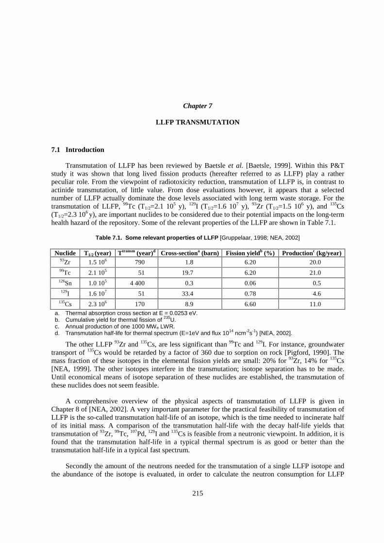
215
Chapter 7
LLFP TRANSMUTATION
7.1 Introduction
Transmutation of LLFP has been reviewed by Baetsle et al. [Baetsle, 1999]. Within this P&T study it was shown that long lived fission products (hereafter referred to as LLFP) play a rather peculiar role. From the viewpoint of radiotoxicity reduction, transmutation of LLFP is, in contrast to actinide transmutation, of little value. From dose evaluations however, it appears that a selected number of LLFP actually dominate the dose levels associated with long term waste storage. For the transmutation of LLFP, 99Tc (T1/2=2.1 105 y), 129I (T1/2=1.6 107 y), 93Zr (T1/2=1.5 106 y), and 135Cs (T1/2=2.3 106 y), are important nuclides to be considered due to their potential impacts on the long-term health hazard of the repository. Some of the relevant properties of the LLFP are shown in Table 7.1.
Table 7.1. Some relevant properties of LLFP [Gruppelaar, 1998; NEA, 2002]
Nuclide T1/2 (year) Ttransm (year)d Cross-sectiona (barn) Fission yieldb (%) Productionc (kg/year) 93Zr 1.5 106 790 1.8 6.20 20.0 99Tc 2.1 105 51 19.7 6.20 21.0 126Sn 1.0 105 4 400 0.3 0.06 0.5
129I 1.6 107 51 33.4 0.78 4.6 135Cs 2.3 106 170 8.9 6.60 11.0
a. Thermal absorption cross section at E = 0.0253 eV. b. Cumulative yield for thermal fission of 235U. c. Annual production of one 1000 MWe LWR. d. Transmutation half-life for thermal spectrum (E=1eV and flux 1014 ncm-2s-1) [NEA, 2002].
The other LLFP 93Zr and 135Cs, are less significant than 99Tc and 129I. For instance, groundwater transport of 135Cs would be retarded by a factor of 360 due to sorption on rock [Pigford, 1990]. The mass fraction of these isotopes in the elemental fission yields are small: 20% for 93Zr, 14% for 135Cs [NEA, 1999]. The other isotopes interfere in the transmutation; isotope separation has to be made. Until economical means of isotope separation of these nuclides are established, the transmutation of these nuclides does not seem feasible.
A comprehensive overview of the physical aspects of transmutation of LLFP is given in Chapter 8 of [NEA, 2002]. A very important parameter for the practical feasibility of transmutation of LLFP is the so-called transmutation half-life of an isotope, which is the time needed to incinerate half of its initial mass. A comparison of the transmutation half-life with the decay half-life yields that transmutation of 93Zr, 99Tc, 107Pd, 129I and 135Cs is feasible from a neutronic viewpoint. In addition, it is found that the transmutation half-life in a typical thermal spectrum is as good or better than the transmutation half-life in a typical fast spectrum.
Secondly the amount of the neutrons needed for the transmutation of a single LLFP isotope and the abundance of the isotope is evaluated, in order to calculate the neutron consumption for LLFP
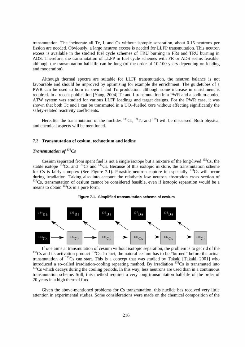
216
134Ba 135Ba 136Ba 137Ba 138Ba
133Cs 134Cs 135Cs 136Cs 137Cs 138Cs
transmutation. The incinerate all Tc, I, and Cs without isotopic separation, about 0.15 neutrons per fission are needed. Obviously, a large neutron excess is needed for LLFP transmutation. This neutron excess is available in the studied fuel cycle schemes of TRU burning in FRs and TRU burning in ADS. Therefore, the transmutation of LLFP in fuel cycle schemes with FR or ADS seems feasible, although the transmutation half-life can be long (of the order of 10-100 years depending on loading and moderation).
Although thermal spectra are suitable for LLFP transmutation, the neutron balance is not favourable and should be improved by optimising for example the enrichment. The guidetubes of a PWR can be used to burn its own I and Tc production, although some increase in enrichment is required. In a recent publication [Yang, 2004] Tc and I transmutation in a PWR and a sodium-cooled ATW system was studied for various LLFP loadings and target designs. For the PWR case, it was shown that both Tc and I can be transmuted in a UO2-fuelled core without affecting significantly the safety-related reactivity coefficients.
Hereafter the transmutation of the nuclides 135Cs, 99Tc and 129I will be discussed. Both physical and chemical aspects will be mentioned.
7.2 Transmutation of cesium, technetium and iodine
Transmutation of 135Cs
Cesium separated from spent fuel is not a single isotope but a mixture of the long-lived 135Cs, the stable isotope 133Cs, and 134Cs and 137Cs. Because of this isotopic mixture, the transmutation scheme for Cs is fairly complex (See Figure 7.1). Parasitic neutron capture in especially 133Cs will occur during irradiation. Taking also into account the relatively low neutron absorption cross section of 135Cs, transmutation of cesium cannot be considered feasible, even if isotopic separation would be a means to obtain 135Cs in a pure form.
Figure 7.1. Simplified transmutation scheme of cesium
If one aims at transmutation of cesium without isotopic separation, the problem is to get rid of the 133Cs and its activation product 134Cs. In fact, the natural cesium has to be “burned” before the actual transmutation of 135Cs can start. This is a concept that was studied by Takaki [Takaki, 2001] who introduced a so-called irradiation-cooling repeating method. By irradiation 133Cs is transmuted into 134Cs which decays during the cooling periods. In this way, less neutrons are used than in a continuous transmutation scheme. Still, this method requires a very long transmutation half-life of the order of 20 years in a high thermal flux.
Given the above-mentioned problems for Cs transmutation, this nuclide has received very little attention in experimental studies. Some considerations were made on the chemical composition of the
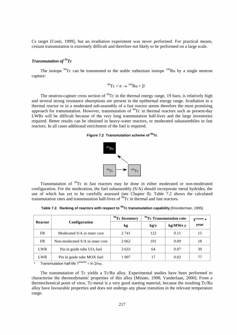
217
Cs target [Conti, 1999], but an irradiation experiment was never performed. For practical means, cesium transmutation is extremely difficult and therefore not likely to be performed on a large scale.
Transmutation of 99Tc
The isotope 99Tc can be transmuted to the stable ruthenium isotope 100Ru by a single neutron capture:
99Tc + n � 100Ru + �-
The neutron-capture cross section of 99Tc in the thermal energy range, 19 barn, is relatively high and several strong resonance absorptions are present in the epithermal energy range. Irradiation in a thermal reactor or in a moderated sub-assembly of a fast reactor seems therefore the most promising approach for transmutation. However, transmutation of 99Tc in thermal reactors such as present-day LWRs will be difficult because of the very long transmutation half-lives and the large inventories required. Better results can be obtained in heavy-water reactors, or moderated subassemblies in fast reactors. In all cases additional enrichment of the fuel is required.
Figure 7.2 Transmutation scheme of 99Tc
100Ru
99Tc 100Tc
Transmutation of 99Tc in fast reactors may be done in either moderated or non-moderated configuration. For the moderation, the fuel subassembly (S/A) should incorporate metal hydrides, the use of which has yet to be carefully assessed (see Chapter 8). Table 7.2 shows the calculated transmutation rates and transmutation half-lives of 99Tc in thermal and fast reactors.
Table 7.2. Ranking of reactors with respect to 99Tc transmutation capability [Kloosterman, 1995]
99Tc Inventory 99Tc Transmutation rate Reactor Configuration
kg kg/y kg/MWe y Ttransm *
year
FR Moderated S/A in inner core 2 741 122 0.11 15
FR Non-moderated S/A in inner core 2 662 101 0.09 18
LWR Pin in guide tube UO2 fuel 3 633 64 0.07 39
LWR Pin in guide tube MOX fuel 1 907 17 0.02 77
* Transmutation half-life Ttransm = ln 2/����
The transmutation of Tc yields a Tc/Ru alloy. Experimental studies have been performed to characterise the thermodynamic properties of this alloy [Minato, 1998; Vanderlaan, 2000]. From a thermochemical point of view, Tc-metal is a very good starting material, because the resulting Tc/Ru alloy have favourable properties and does not undergo any phase transition in the relevant temperature range.
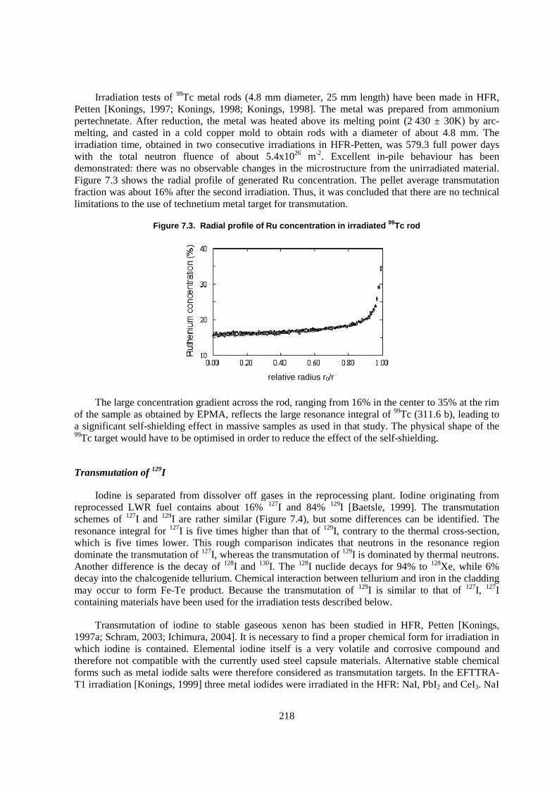
218
Irradiation tests of 99Tc metal rods (4.8 mm diameter, 25 mm length) have been made in HFR, Petten [Konings, 1997; Konings, 1998; Konings, 1998]. The metal was prepared from ammonium pertechnetate. After reduction, the metal was heated above its melting point (2 430 ± 30K) by arc-melting, and casted in a cold copper mold to obtain rods with a diameter of about 4.8 mm. The irradiation time, obtained in two consecutive irradiations in HFR-Petten, was 579.3 full power days with the total neutron fluence of about 5.4x1026 m-2. Excellent in-pile behaviour has been demonstrated: there was no observable changes in the microstructure from the unirradiated material. Figure 7.3 shows the radial profile of generated Ru concentration. The pellet average transmutation fraction was about 16% after the second irradiation. Thus, it was concluded that there are no technical limitations to the use of technetium metal target for transmutation.
Figure 7.3. Radial profile of Ru concentration in irradiated 99Tc rod
The large concentration gradient across the rod, ranging from 16% in the center to 35% at the rim of the sample as obtained by EPMA, reflects the large resonance integral of 99Tc (311.6 b), leading to a significant self-shielding effect in massive samples as used in that study. The physical shape of the 99Tc target would have to be optimised in order to reduce the effect of the self-shielding.
Transmutation of 129I
Iodine is separated from dissolver off gases in the reprocessing plant. Iodine originating from reprocessed LWR fuel contains about 16% 127I and 84% 129I [Baetsle, 1999]. The transmutation schemes of 127I and 129I are rather similar (Figure 7.4), but some differences can be identified. The resonance integral for 127I is five times higher than that of 129I, contrary to the thermal cross-section, which is five times lower. This rough comparison indicates that neutrons in the resonance region dominate the transmutation of 127I, whereas the transmutation of 129I is dominated by thermal neutrons. Another difference is the decay of 128I and 130I. The 128I nuclide decays for 94% to 128Xe, while 6% decay into the chalcogenide tellurium. Chemical interaction between tellurium and iron in the cladding may occur to form Fe-Te product. Because the transmutation of 129I is similar to that of 127I, 127I containing materials have been used for the irradiation tests described below.
Transmutation of iodine to stable gaseous xenon has been studied in HFR, Petten [Konings, 1997a; Schram, 2003; Ichimura, 2004]. It is necessary to find a proper chemical form for irradiation in which iodine is contained. Elemental iodine itself is a very volatile and corrosive compound and therefore not compatible with the currently used steel capsule materials. Alternative stable chemical forms such as metal iodide salts were therefore considered as transmutation targets. In the EFTTRA-T1 irradiation [Konings, 1999] three metal iodides were irradiated in the HFR: NaI, PbI2 and CeI3. NaI
relative radius r0/r
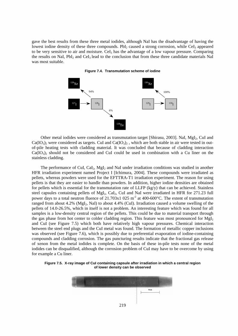
219
gave the best results from these three metal iodides, although NaI has the disadvantage of having the lowest iodine density of these three compounds. PbI2 caused a strong corrosion, while CeI3 appeared to be very sensitive to air and moisture. CeI3 has the advantage of a low vapour pressure. Comparing the results on NaI, PbI2 and CeI3 lead to the conclusion that from these three candidate materials NaI was most suitable.
Figure 7.4. Transmutation scheme of iodine
128Xe 130Xe
127I 128I 129I 130I
128Te
6%
94% 100%
Other metal iodides were considered as transmutation target [Shirasu, 2003]. NaI, MgI2, CuI and Ca(IO3)2 were considered as targets. CuI and Ca(IO3)2 , which are both stable in air were tested in out-of-pile heating tests with cladding material. It was concluded that because of cladding interaction Ca(IO3)2 should not be considered and CuI could be used in combination with a Cu liner on the stainless cladding.
The performance of CuI, CaI2, MgI2 and NaI under irradiation conditions was studied in another HFR irradiation experiment named Project I [Ichimura, 2004]. These compounds were irradiated as pellets, whereas powders were used for the EFTTRA-T1 irradiation experiment. The reason for using pellets is that they are easier to handle than powders. In addition, higher iodine densities are obtained for pellets which is essential for the transmutation rate of LLFP (kg/y) that can be achieved. Stainless steel capsules containing pellets of MgI2, CaI2, CuI and NaI were irradiated in HFR for 271.23 full power days to a total neutron fluence of 21.703x1 025 m-2 at 400-600�C. The extent of transmutation ranged from about 4.2% (MgI2, NaI) to about 4.4% (CuI). Irradiation caused a volume swelling of the pellets of 14.0-26.5%, which in itself is not a problem. An interesting feature which was found for all samples is a low-density central region of the pellets. This could be due to material transport through the gas phase from hot center to colder cladding region. This feature was most pronounced for MgI2 and CuI (see Figure 7.5) which both have relatively high vapour pressures. Chemical interaction between the steel end plugs and the CuI metal was found. The formation of metallic copper inclusions was observed (see Figure 7.6), which is possibly due to preferential evaporation of iodine-containing compounds and cladding corrosion. The gas puncturing results indicate that the fractional gas release of xenon from the metal iodides is complete. On the basis of these in-pile tests none of the metal iodides can be disqualified, although the corrosion problem of CuI may have to be overcome by using for example a Cu liner.
Figure 7.5. X-ray image of CuI containing capsule after irradiation in which a central region of lower density can be observed
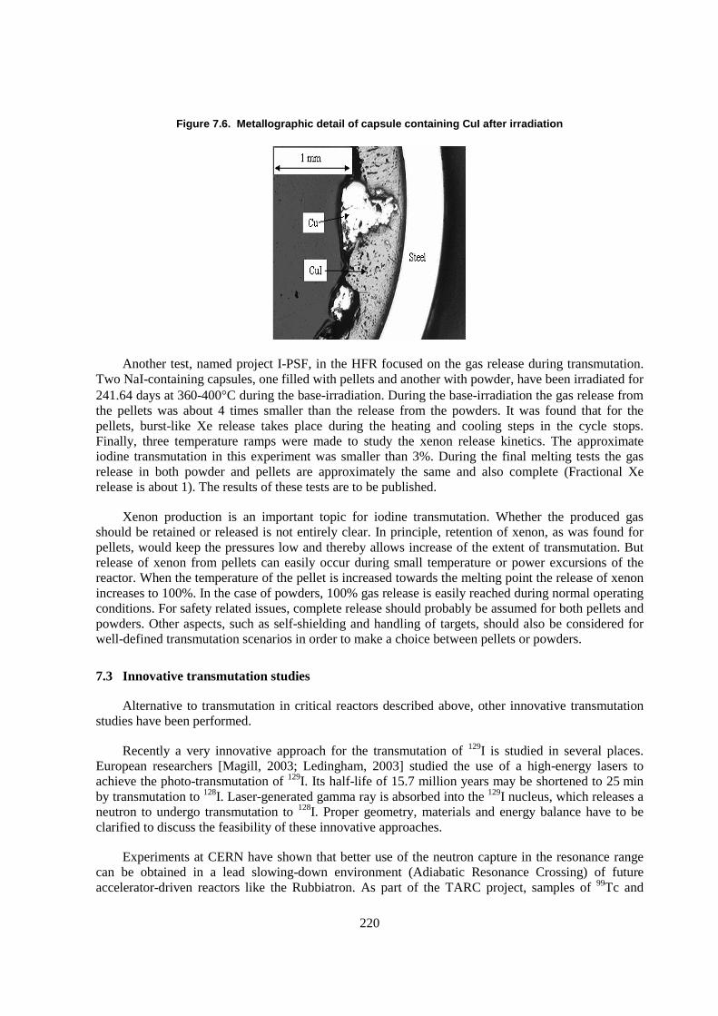
220
Figure 7.6. Metallographic detail of capsule containing CuI after irradiation
Another test, named project I-PSF, in the HFR focused on the gas release during transmutation. Two NaI-containing capsules, one filled with pellets and another with powder, have been irradiated for 241.64 days at 360-400�C during the base-irradiation. During the base-irradiation the gas release from the pellets was about 4 times smaller than the release from the powders. It was found that for the pellets, burst-like Xe release takes place during the heating and cooling steps in the cycle stops. Finally, three temperature ramps were made to study the xenon release kinetics. The approximate iodine transmutation in this experiment was smaller than 3%. During the final melting tests the gas release in both powder and pellets are approximately the same and also complete (Fractional Xe release is about 1). The results of these tests are to be published.
Xenon production is an important topic for iodine transmutation. Whether the produced gas should be retained or released is not entirely clear. In principle, retention of xenon, as was found for pellets, would keep the pressures low and thereby allows increase of the extent of transmutation. But release of xenon from pellets can easily occur during small temperature or power excursions of the reactor. When the temperature of the pellet is increased towards the melting point the release of xenon increases to 100%. In the case of powders, 100% gas release is easily reached during normal operating conditions. For safety related issues, complete release should probably be assumed for both pellets and powders. Other aspects, such as self-shielding and handling of targets, should also be considered for well-defined transmutation scenarios in order to make a choice between pellets or powders.
7.3 Innovative transmutation studies
Alternative to transmutation in critical reactors described above, other innovative transmutation studies have been performed.
Recently a very innovative approach for the transmutation of 129I is studied in several places. European researchers [Magill, 2003; Ledingham, 2003] studied the use of a high-energy lasers to achieve the photo-transmutation of 129I. Its half-life of 15.7 million years may be shortened to 25 min by transmutation to 128I. Laser-generated gamma ray is absorbed into the 129I nucleus, which releases a neutron to undergo transmutation to 128I. Proper geometry, materials and energy balance have to be clarified to discuss the feasibility of these innovative approaches.
Experiments at CERN have shown that better use of the neutron capture in the resonance range can be obtained in a lead slowing-down environment (Adiabatic Resonance Crossing) of future accelerator-driven reactors like the Rubbiatron. As part of the TARC project, samples of 99Tc and
221
Pb(129I)2 were exposed to neutrons generated by a proton beam on a lead target [CERN, 1999]. The purpose of this experiment was to test the concept of adiabatic resonance crossing and to measure the nuclear data involved. This experiment is probably one of the few experiments were 129I containing target was produced and tested. One of the conclusions of the study was that it is possible to envisage LLFP transmutation in a parasitic mode of the Energy Amplifier, were the net consumption rate of both iodine (1 kg/TWh) and Technetium (1.4 kg/TWh) exceeds the production rate in the EA (resp. 0.4 and 0.85 kg/TWh) itself.
7.4 Discussion and outlook
In Table 7.3 an overview of the experimental LLFP studies, performed in the High Flux Reactor in Petten, is presented. From the reported extent of transmutation it is clear that, even in a high thermal flux which is ideal for LLFP transmutation, considerably long irradiation times are needed in order to achieve a reasonably extent of transmutation.
Table 7.3. Overview of LLFP irradiation tests HFR
Nuclide Experiment
name Material
Irradiation time (EFPD)
Extent of transmutation (%)
References
99Tc EFTTRA T1 99Tc-metal 192.95 6 [Konings, 1998a]
EFTTRA T2 99Tc-metal 597.30 15-18 [Konings, 1999]
129I* EFTTRA T1 CeI3, PbI2, NaI 192.95 5.13-5.87 [Konings, 1997]
Project I CuI, MgI2, CaI2, NaI 271.23 4.18-4.36 [Ichimura, 2004]
Project I – PSF NaI 241.64 <3 [to be published]
* For all experimental studies only natural iodine was used.
So far, most studies on LLFP transmutation have focused on the fabrication of the LLFP target and its performance under irradiation conditions. Because of the long transmutation half-life, recycling of the LLFP target seems inevitable. Therefore, in any realistic LLFP transmutation scenario, the LLFP target should fulfill requirements of:
� fabrication;
� irradiation;
� recycling and refabrication.
This means that a complete judgment of LLFP target selection implies also the qualification of the recycling and refabrication properties, which has not been performed up to now. The maximum irradiation time for a LLFP target is probably determined by either:
� The irradiation damage in the cladding. Most claddings are limited to 200 dpa maximum after which the cladding needs to be replaced.
� The pressure buildup which is important for the iodine transmutation. Targets needs to be withdrawn from the reactor core when the maximum allowable pressure is reached.
� Target-cladding compatibility which may be an issue for iodine transmutation. The corrosion of the cladding may be such that the target has to be withdrawn from the reactor after some time.
222
� The cost-efficiency of the transmutation irradiation-process. The target takes up expensive reactor volume and the transmutation efficiency decreases in time, and therefore recycling needs to be performed after a certain time. A transmutation scenario therefore consists of the sequence irradiation – recycling – irradiation – recycling, etc. (the recycling step includes dissolving and fabrication of a target). An optimum irradiation time can be found for which the total cost in minimised, which depends on the unit costs associated with the recycling step and the irradiation step.
For metal iodide targets the recycling step would not be trivial. Because most metal iodides (except for example CuI, PbI2) are soluble in water the fabrication of new metal iodide targets cannot be performed by a simple precipitation step. Alternative fabrication routes do exist for soluble metal iodides, but these are generally rather complex.
7.5 Conclusion
The transmutation of LLFP in fission reactors was discussed. An evaluation of the transmutation half lives shows that transmutation of 93Zr, 99Tc, 107Pd, 129I and 135Cs is feasible. When aspects such as neutron economy and isotopic separation is also considered, it appears that focus should be on 99Tc and 129I in realistic transmutation scenarios.
Various neutron physics studies on transmutation of LLFP in different types of fission reactors such as PWR, FR or ADS have been performed. Essential is the availability of excess neutrons for the transmutation process. The general outcome of these studies is thattransmutation of Tc and I is possible, although the transmutation half-lives are generally high (typically 10-100 years) and the LLFP consumption rates are generally low. Fast reactors and ADS do have a good neutron availability but need moderators to optimise the spectrum for transmutation purpose, whereas thermal reactors have a more suitable spectrum but need improvement of the fuel enrichment in order to provide sufficient neutron availability.
The experimental aspects of the transmutation of Tc and I are well-studied. Both in-pile behavior and material properties of candidate transmutation targets has been studied. The irradiation performance of metallic Tc targets and various metal iodide targets has been studied in irradiation experiments. Technetium metal is a suitable target for Tc transmutation. Transmutation of iodine has special features, such as xenon pressure buildup, which has to be accommodated, and cladding corrosion. Many different types of metal iodides (M=Ce, Pb, Na, Mg, Ca, Cu) have been considered. Metal iodides such NaI, CaI2, MgI2, CuI may be considered for use as iodine-transmutation target, although special measures may have to be taken to minimise the effect of cladding corrosion.
The consumption rate of 99Tc and 129I is generally low (typically of the order of 10-20% in once through mode) such that multi-recycling would be needed. The information on recycling and refabrication of LLFP targets is very limited.
Although Tc and I appears to be feasible from a physical and chemical viewpoint, the required additional measures and facilities are complex and costly. For example, core design aspects and increased fuel enrichment fuel would have to be considered and facilities for target fabrication and reprocessing should be available. The long irradiation time and excess neutrons required for transmutation are costly. An economic evaluation of the LLFP-target cycle scheme should be performed to assess the effect of LLFP transmutation on the electricity price.
223
REFERENCES
Baetslé, L.H. et al. (1999), “Status and assessment report on actinide and fission product partitioning and transmutation”, in Proceedings of the 5th Information Exchange Meeting on Actinide and Fission Product Partitioning and Transmutation, hosted by SCK•CEN, Mol, Belgium, 25-27 November 1998, OECD/NEA, Paris (France), pp. 87-107.
CERN (1999), Neutron driven nuclear transmutation by adiabatic resonance crossing, EUR 19117.
Conti, A.; Ottaviani, J-P.; Konings, R.J.M.; Schram, R.P.C. (1999), Long-lived fission product transmutation studies, Proceedings, GLOBAL1999.
Gruppelaar, H.; Kloosterman, J.L.; Konings, R.J.M. (1998), Advanced Technologies for the reduction of nuclear waste, ECN, ISBN 90-375-0003-X.
Ichimura, E.; Takaki. N.; Schram, R.P.C.; Klein Meulekamp, R.; Bakker, K. (2004), “Iodine transmutation studies using metal iodides”, J. Nucl. Mater, (accepted for publication).
Kloosterman, J.L.; Li, J.M. (1995), “Transmutation of Tc-99 and I-129 in Fission Reactors”, Technical report ECN-R-95-002, ECN.
Konings R.J.M.; Franken W.M.P.; Conrad R.; Guegnon J.-F.; Spirlet J.-C. (1997), “Transmutation of technetium and iodine – Irradiation tests in the frame of the EFTTRA cooperation”, Nucl. Technol. 117, 293.
Konings, R.J.M. (1997), “Transmutation of Iodine: Results of the EFTTRA-T1 irradiation test”, J. Nucl. Mater., 2441, 6-21.
Konings, R.J.M.; Stalios A.D.; Walker C.T.; Cocuaud N. (1998), “Transmutation of technetium – Results of the EFTTRA-T1 experiment”, J. Nucl. Mat., 254, 122.
Konings, R.J.M.; Kloosterman, J.L.; Hendriks, J.A.; Gruppelaar, H. (1998), “Transmutation of Technetium in the Petten High Flux Reactor: A comparison of Measurements and Calculations”; Nucl. Sci. Eng., 128, 70-75.
Konings, R.J.M.; Conrad, R. (1999), “Transmutation of Technetium: Results of the EFTTRA-T2 experiment”, J. Nucl. Mat., 244, 336-340.
Ledingham, K.W.D. et al. (2003), “Laser-driven photo-transmutation of I-129 – a long-lived nuclear waste product”, J. Phys., D36, L79.
Magill, J. et al. (2003), “Laser transmutation of iodine-129”, Applied Physics, B77, 387.
224
Minato, K.; Shirasu, Y. (1999), “Preparation and Characterisation of Technetium Metal and Technetium-Ruthenium Alloys”, in Proceedings of the 5th Information Exchange Meeting on Actinide and Fission Product Partitioning and Transmutation, hosted by SCK•CEN, Mol, Belgium, 25-27 November 1998, OECD, Paris, pp. 223-230.
NEA (1999), Proceedings of the 5th Information Exchange Meeting on Actinide and Fission Product Partitioning and Transmutation, hosted by SCK•CEN, Mol, Belgium, 25-27 November 1998, OECD, Paris, 543 p.
NEA (2002), Accelerator-driven Systems (ADS) and Fast Reactors (FR) in Advanced Nuclear Fuel Cycles – A comparative study, OECD, Paris, 352 p.
Pigford, T.H. (1990), Reprocessing Incentives for Waste Disposal. UCB-NE-4171. Berkeley: University of California.
Schram, R.P.C.; Bakker, K.; Ichimura, E., Iodine transmutation experiments in the High Flux Reactor, Proc. GLOBAL2003, pp. 812-814.
Shirasu, Y. and Minato, K. (2003), “Selection of chemical forms of iodine for transmutation of 129I”, J. Nucl. Mater, 320, 25-30.
Takaki, N.; Ohki, S., Feasibility and challenges of LLFP transmutation in fast reactor, Proceedings GLOBAL2001.
Van der Laan, R.R.; Konings, R.J.M. (2000), “The heat capacity of Tc0.85Ru0.15 alloy”, J. Alloys & Compounds, 297, 104-108.
Yang, W.S.; Kim, Y.; Hill, R.N.; Taiwo, T.A. and Khalil, H.S., Long-lived fission product transmutation.
�
225
Chapter 8
MODERATOR PIN: HYDRIDE BEHAVIOUR
8.1 Specific problems – Recall
Metal hydrides, synthesised in an exothermal reaction, of which three hydrides are envisioned as a moderator, namely, calcium, zirconium and yttrium hydrides, share essentially three particularities which can be problematic during their application:
� a pyrophoric nature, as well as a reactivity to water and water vapour, that varies with the hydride type;
� significant embrittleness;
� a stability requiring the establishment of an equilibrium hydrogen partial pressure, referred to as the dissociation pressure – that differs from one hydride to another – and increases with increasing temperature;
� as hydrogen gas has a strong permeating power, this particularity requires that the release of this gas through the walls of the hydride containment chamber – in this case the cladding – be taken into account as a function of the latter, given that the loss of hydrogen signifies a loss of moderating power.
8.1.1 Dissociation pressure
At constant metal-hydrogen system composition, the change in dissociation pressure with temperature is often described by a relation of the type:
� �2lg H
AP B
T�
� � (a)
where 2HP is the dissociation pressure,T is the absolute temperature and A and B are parameters which
depend on the enthalpy and entropy of the phases present.
Often, a single equation of type (a) – implying a single set of A and B parameters – covers an entire range of system compositions – the “plateau” regions of P-C-T diagrams, wherein isothermal curves describe the variation in dissociation pressure as a function of the solid metal-hydrogen system composition.
�
226
8.1.2 Permeation
The stationary hydrogen flux � , through the wall of a metal containment of thickness x , imposing a partial pressure P (disregarding that outside of the containment) can often be described by a relation of the form:
12
H
PP
x� � (b)
where HP is the permeability coefficient – often expressed in units of (cm3(STP)·mm)/(cm2·h·atm1/2) in the literature – of hydrogen through the wall and is written as:
0
QRT
H HP P e�
�
where0HP and Q are constants over the considered temperature range for the metal-hydrogen system,
R is the gas constant and T is the wall temperature in Kelvin.
Figure 8.1 shows the variation of the permeability coefficient of a certain number of metal-hydrogen and steel-hydrogen systems as a function of temperature.
Note: It has been well established that hydrogen embrittles the steels in which it diffuses; austenitic stainless steels are known for low susceptibility to this embritteling effect, although the degree of work hardening of the steel must also be taken into account (possibility of forming the more hydrogen “receptive” �’ phase).
8.2 Specific effects of irradiation
8.2.1 Hydrides
The CEA does not posses any experience in rapid flux, or partially rapid flux irradiation – or at least none analysed from this standpoint.
Theoretically, hydride behaviour should be a function of two components:
� a pure “irradiation” component;
� an “hydrogen release” component, a phenomena accompanied by a variation in volume.
With reference to this second component, the change in the crystal lattice accompanying this gas release leads to a decrease in the zirconium and yttrium hydride volumes and an increase in volume in the case of calcium hydride.
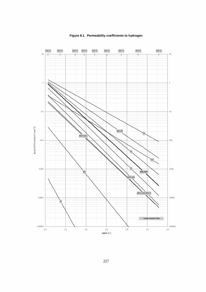
�
227
Figure 8.1. Permeability coefficients to hydrogen
Fe
Ni
AISI 316
16Cr 11Ni 3Mo Ti
AISI 316 *Mo
W
AISI 316 L
F17
430 SS
Cr
200 °C250 °C300 °C350 °C400 °C450 °C500 °C600 °C700 °C
0,00001
0,0001
0,001
0,01
0,1
1
10
1,0 1,2 1,4 1,6 1,8 2,0 2,2
1000/T [K-1]
PH [(
cm3 (S
TP
)·m
m)/
(cm
2 ·h·a
tm1/
2 )]
0,00001
0,0001
0,001
0,01
0,1
1
10
* under neutron flux

228
The first component is manifested as a swelling – to a greater degree than that of the individual metals forming the compound, and which increases with the hydrogen content – which is a result of:
� the creation of vacancies and interstitial atoms/ions within the crystal lattice – which tends to increase diffusion – the elimination of vacancies on fixed wells – such as dislocations, grain boundaries or the surface – and the recombination of vacancies and interstitial atoms/ions with potential pore formation;
� the formation of helium – via the reaction involving hydrogen and its relatives, however, the yield is very low – which in its gaseous form can be a source of nano or micro-bubbles.
8.2.2 Steels
An extremely significant increase of hydrogen permeability in some steels [Polosuhin, 1992] has been noted under “low” temperature neutron flux (~ 200 to 300°C) which can, depending on the steel, achieve a factor greater than 10; however, increasing the temperature lessens this tendency significantly.
8.3 Simulation of hydrogen release
We attempted to predict the behaviour of the three above mentioned hydrides, in terms of the limit operating temperature, by envisioning the different relative hydrogen mass losses that may be compatible with the targeted transmutation rate throughout the selected lifetime of the assemblies, that is 2 355 days; in order to make a choice taking into account an acceptable loss by the hydride and its associated limit temperature versus its initial moderating power.
We have also estimated the impact of an internal (10 µm) tungsten cladding coating (chemical or physical vapour deposition) on these temperatures, tungsten being inherently one of the least hydrogen permeable barrier metals (see Figure 8.1).
Note: in terms of metal permeation, an internal interface coating (where hydrogen penetrates) is not necessarily equivalent to an external coating, different phenomena being involved.
8.3.1 Assumptions and basis retained for the estimations
The calculations were carried out:
� on the basis of a hydride mass and a permeable surface area (internal surface area of the cladding) corresponding to a 1 cm long pin;
� at a cladding temperature (T) equal to that of the hydride;
� disregarding the phase during which the permeation steady state was established (conservatory approach);
� adopting the most appropriate set of A and B parameters [equation (a)] from the literature for the given hydride formulation;
� using a permeability coefficient taken from the literature for the cladding steel – with an estimation of the irradiation effect – and for the tungsten;
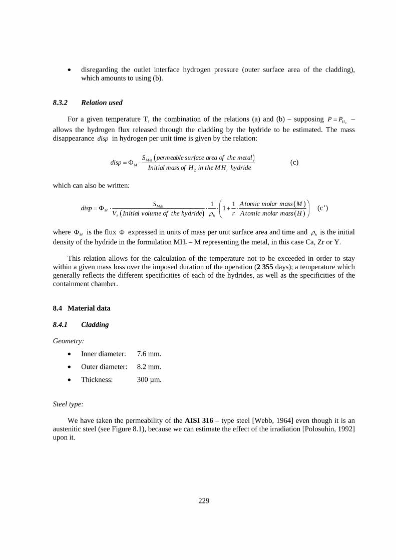
229
� disregarding the outlet interface hydrogen pressure (outer surface area of the cladding), which amounts to using (b).
8.3.2 Relation used
For a given temperature T, the combination of the relations (a) and (b) – supposing 2HP P� –
allows the hydrogen flux released through the cladding by the hydride to be estimated. The mass disappearance disp in hydrogen per unit time is given by the relation:
� �2
Mét
Mr
S permeable surface area of the metaldisp
Initial mass of H in the MH hydride� � (c)
which can also be written:
� �� �� �
1 11
Mét
Mh h
Atomic molar mass MSdisp
V Initial volume of the hydride r Atomic molar mass H� �
� � � � � �
(c’)
where M� is the flux � expressed in units of mass per unit surface area and time and h� is the initial density of the hydride in the formulation MHr – M representing the metal, in this case Ca, Zr or Y.
This relation allows for the calculation of the temperature not to be exceeded in order to stay within a given mass loss over the imposed duration of the operation (2 355 days); a temperature which generally reflects the different specificities of each of the hydrides, as well as the specificities of the containment chamber.
8.4 Material data
8.4.1 Cladding
Geometry:
� Inner diameter: 7.6 mm.
� Outer diameter: 8.2 mm.
� Thickness: 300 µm.
Steel type:
We have taken the permeability of the AISI 316 – type steel [Webb, 1964] even though it is an austenitic steel (see Figure 8.1), because we can estimate the effect of the irradiation [Polosuhin, 1992] upon it.
230
8.4.2 Hydrides
Geometry:
� Pellet diameter: same as the internal diameter of the cladding.
Other characteristics:
All are manufactured by hydriding the metals in their massive form.
Hydride metal
Formulation Density [g/cm3]
Hydrogen mass [g/cm of hydride]
Dissociation pressure (law)
Origin
Calcium CaH1,99
(12-14% porosity) 1.637 0.0300 [Curtis, 1963] Péchiney
Zirconium ZrH1,65
(��phase)�5.650 0.0389
[Vetrano, 1960] (>550°C) [Zuzek, 1986] (<550°C)
Siemens for the Rêve experiment
Yttrium YH1,75 4.324 0.0320 [Yannopoulos, 1965] Russian
Figure 8.2 shows the variation of 2HP – calculated using relation (a) – as a function of
temperature for each of the laws given in the above table and taking the calculation range into consideration.
Figure 8.2. Dissociation pressure
231
With respect to calcium and yttrium hydrides and failing any other sources, we have extrapolated these laws somewhat beyond their lower limit of determination. We estimate this measure acceptable given that these hydrides do not undergo any phase changes over the scanned temperature and composition ranges. Moreover, the dissociation pressure does not vary with respect to the metal-hydrogen system composition (plateau regions) at the anticipated hydrogen release values.
As regards zirconium hydride, in those cases where the temperatures exceeds 550°C, we have employed, a law corresponding to the formulation ZrH
1.60 in order to take into account the changes in
the hydrogen content of the metal-hydrogen system over time. Below this temperature we applied a law corresponding to a phase mixture (�-Zr + �) and therefore to the plateau regions; this explains the “gap” at 550°C between the two laws.
In term of the dissociation pressure, it is clear that yttrium hydride is potentially the best candidate.
The advantage of ZrH1.65
is obvious as regards the initial density of hydrogen atoms and,
therefore, the initial mass of hydrogen per cm of pellet. However, if an increase in the hydrogen density of calcium hydride may be achieved by decreasing its porosity – manufacture by compacting followed by sintering of the powder – and that of yttrium hydride – maximum YH2 – without penalty in terms of dissociation, such an increase in the case of zirconium hydride – maximum ZrH2 – would induce its passage to the � phase, with an increase in its dissociation pressure and the possible appearance of dimensional stability problems due to an at least partial return to the � phase.�
8.4.3 Tungsten
Numerous literature sources deal with the permeability coefficient of the tungsten-hydrogen system; for the most part, they are consistent; we have used reference [Webb, 1964], a priori, the most conservative.
8.5 Results – Comments
The results are summarised in Figure 8.3 which shows the limit operational temperatures not to be exceeded for CaH
1.99, ZrH
1.65 and YH
1.75, corresponding respectively to a 2, 5, 7 and 10% hydrogen
mass loss over 2 355 days; for each of these values, we compared the uncoated cladding to the tungsten coated cladding – which moreover results in only consideration of the 10 µm of tungsten.
Of course, as the authorised hydrogen loss over the 2 355 days is restricted, the limit temperatures decrease.
Only the orders of magnitude should be retained from these results which were obtained from a simplified model. These orders of magnitude show, however, a clear advantage favouring yttrium hydride but also, and especially, of a design including a coated cladding – the presence of the tungsten coating allows a gain in temperature in excess of 100°C. For the purpose of comparison, doubling the cladding thickness would only result in an increase in temperature of 15 to 20°C. The advantage of calcium relative to zirconium is only significant in the presence of the coating – therefore towards higher temperatures; this is mainly explained by a much lower dissociation pressure (see Figure 8.2).
232
Furthermore, the potentially accessible temperatures remaining compatible over time with the expected behaviour of each of the concerned hydrides (swelling, …) should be verified; in this matter and to our knowledge: 600-620, 550 and 1 000°C seem to be the reasonable limit operating temperatures for CaHr [Escleine, 1999], ZrHr and Yhr [Risovany, 1999], respectively.
Figure 8.3. Limit operational temperatures
8.6 Conclusion and remarks
On the basis of our approach, we are concerned that unless yttrium hydride or a coating (potentially other than W) are used, the limit temperatures (less than or to the order of 455°C) will be incompatible with the long-term operation of the studied assembly design, even if we anticipate an acceptable hydrogen loss greater than 10% for zirconium hydride. The repercussions of this loss on transmutation yields will be studied subsequently.
Secondly, in the presence of a coating and all other things being equal, the choice between calcium and zirconium hydride is not obvious for, even though the former allows a higher temperature the latter is superior in terms of hydrogen density.
Nevertheless, other criteria need to be taken into consideration, such as the lack of experiments on calcium hydride – a study programme is however underway – or yttrium hydride, and the water resistance should post-irradiation storage prove necessary – in this case calcium hydride must be eliminated from the choices (violent reaction with hydrogen formation above room temperature).
Finally, we have kept those geometries retained during studies prior to our own, but it is clear that a gap between the hydride and the cladding will have to be provided (due to expansion, swelling, …); we advocate a radial clearance of approximately 6.4% (value retained during the MODIX experiment in Phénix) relative to the internal cladding diameter.

233
REFERENCES
Curtis, R.W.; Premo Chiotti, (1963), “Thermodynamic Properties of Calcium Hydride”, J. Phys. Chem., 67, 1061-1065.
Escleine, J.M. (1999), Matériaux modérateurs – Point sur l’hydrure de calcium, Note technique SESC/LIAC/99-2013 (DR) indice O.
Polosuhin, B.G. et al, (1992), “Hydrogen Isotope Permeability Through Austenitic Steels 18Cr-10Ni-Ti & 16Cr-11Ni-Ti during reactor irradiation”, Journal of Nuclear Materials, 191-194, 219-220.
Risovany, V.D.; Zakharov, A.V. (1999), Investigations of initial characteristics of ZrHx and YHx
samples, Rapport RIAR #1 – Contrat CSDC 98-002a.
Vetrano, J.B.; Atkins, D.F. (1960), The Zirconium-Hydrogen System, A Symposium on Metallic Moderators and Cladding Materials, pp. 57-61.
Webb, R.W. (1964), Hydrogen permeation through metals, NAA-SR-TDR-9844.
Yannopoulos, L.N.; Edwards, R.K.; Wahlbeck, P.G. (1965), “The Thermodynamics Properties of the Yttrium-Hydrogen System”, J. Phys. Chem., 69, 2510-2515.
Zuzek, E . (1986), “On Equilibrium in the Zr-H System”, Surface and Coatings Technology, 28, 323-338.


Appendix
Summary of the status of transmutation fuel developments and major research issues
MA recycling scheme Homogeneous Heterogeneous Dedicated (double strata) Reactor PWR FR ADS Fuel type MA(<1%)-MIX MA(1-2%)-MOX (U,Pu,MA)N Metal fuel:
U-Pu-MA-RE-(<30wt%)Zr, Pu-MA-(40-60wt%)Zr
(Am,Cm)Oxide in MgO, (Am,Cm,Zr,Y)O2-x**
(Am,Cm)Oxide in MgO*
(Am,Cm)N in ZrN*
� (Am,Cm)Oxide microspheres (~����� ���
are dispersed in MgO matrix. MgO appears stable against fission-recoil damage.
� Am and Cm are dissolved in Yttrium-stabilised zirconia.
Fuel characteristics � With MA less than 1%, little effets are expected on the fuel behaviour.
� The neutron emission by heavier actinides has serious impacts on the design of fabrication plant and the fuel transport.
Helium release into the plenum will be signi-ficantly increased from the ordinary MOX.
� Actinide nitrides are mutually soluble, retaining good thermal properties of (U,Pu)N for variety of isotope mix.
� Sintering temperature has to be reduced to suppress americium vaporisation loss.
� Little data base for the high-burnup behaviour even for (U,Pu)N.
� Behaviour beyond cladding breach at high temperatures has to be studied.
� Casting process has to be modified to suppress americium vaporisation loss.
� Substantial high-burnup database exists for U-Pu-Zr. Design allows high fuel swelling and large gas release into plenum.
� Redistribution of Am and its effects during normal and off-normal conditions has to be studied.
� 90% of Am and Cm transmuted in once-through loading.
� Hydride moderator has to be developed to reduce the fast-neutron damage on the cladding.
To be recycled, since the burnup level is limited by irradiation damage of cladding.
� Dissolving in ZrN stabilises actinide nitrides.
� Good thermal properties.
� Little database on the irradiation performance.
� Behaviour beyond cladding breach at high temperatures has to be studied.
Aqueous Dissolved in nitric acid (exception: metal fuel); Compatible with PUREX-based aqueous reprocessing with addition of appropriate partitioning process for recovering MA. Technical measures would be required to handle the increased decay heat.
Repro-cessing
Pyrolytic � Either the RIAR process or the direct reduction in molten salts may be applicable, but the behaviour or americium and curium has yet to be clarified for the efficient recovery.
� Molten-salts electrorefining with dual cathodes may be applicable.
� Sufficient throughput has to be demonstrated. � Effective separation of TRU from RE has yet to be
studied.
(Application is not considered.) � Oxidation potential of ZrN is a little too high, which may cause materials problems.
� Effective separation of TRU from RE has yet to be studied.
* (Am,Cm)-oxide or (Am,Cm)N in 92Mo may be an alternative choice. Molybdenum is also compatible with aqueous reprocessing.
** ZrO2 matrix is also considered for the ADS application (see Table 3.1.10).
235

237
LIST OF CONTRIBUTORS
Chair Toru Ogawa (JAERI, Japan)
Scientific Secretary Byung-Chan Na
(OECD/NEA)
Chapter 1. Introduction T. Ogawa (LANL, USA)
Appendix 1.1: Burnup Indicators of Inert Matrix Fuels R.P.C. Schram (NRG, The Netherlands)
Chapter 2. Fundamental Thermophysical and Thermochemical Properties of Relevant Actinide Compounds and Alloys
T. Ogawa R.J.M. Konings
(JAERI, Japan) (ITU, Germany)
Chapter 3. Fuel Selection Criteria Specific to Representative Transmutation Scenarios
3.1 Fuel Selection Criteria – Double Strata Scenario J. Wallenius (RIT, Sweden)
3.2 Fuels for Fast Spectrum Transmutation – US Selection Criteria D.C. Crawford (ANL, USA)
3.3 Fuel Selection Criteria and Fabrication Issues for Transmutation in Power Reactors S. Pillon (CEA, France)
Appendix 3.1: Calculation Hypotheses and Methods S. Pillon (CEA, France)
Appendix 3.2: Special Irradiation Environment of ADS Systems K. Chidester (LANL, USA)
Chapter 4. Fuel Fabrication
4.1 Oxide-based Ceramic Fuels S. Pillon
A. Fernandez J. Somers D. Haas
(CEA, France) (ITU, Germany) (ITU, Germany) (ITU, Germany)
4.2 Nitride Fuels/Targets T. Ogawa (JAERI, Japan)
4.3 VIPAC Fuel for Transmutation P. Matheron (CEA, France)
238
4.4 Metal Transmutation Fuels J.R. Kennedy
M.K. Meyer (ANL, USA) (ANL, USA)
Chapter 5. Fuel Behaviour Prediction
5.1 Irradiation Performance Issues D.C. Crawford (ANL, USA)
5.2 Some Considerations About Expected Fuel Behaviour – Oxides R.J.M. Konings (ITU, Germany)
5.3 Thermomechanical Modelling of Prototypic Targets S. Lemehov
M. Verwerft V. Sobolev
(SCK•CEN, Belgium) (SCK•CEN, Belgium) (SCK•CEN, Belgium)
Appendix 5.1: 1 eV Resonance Effect in MOX Fuel V. Sobolev (SCK•CEN, Belgium)
Appendix 5.2: Fuel Characteristics V. Sobolev (SCK•CEN, Belgium)
Chapter 6. Structural Materials for Transmutation Systems
6.1 Cladding and Duct Review T. Allen
R.L. Klueh S. Ukai
(Univ. of Wisconsin, USA) (ORNL, USA) (JNC, Japan)
6.2 Materials Compatibility with Lead and Lead-bismuth D. Gómez-Briceño (CIEMAT, Spain)
Chapter 7. LLFP Transmutation R.P.C. Schram
R.J.M. Konings T. Ogawa
(NRG, The Netherlands) (ITU, Germany) (JAERI, Japan)
Chapter 8. Moderator Pin: Hydride Behaviour J.M. Escleine (CEA, France)
Appendix: Summary of the Status of Transmutation Fuel Developments and Major Research Issues
T. Ogawa (JAERI, Japan)
239
MEMBERS OF THE SUBGROUPS
BELGIUM
SOBOLEV, Vitali SCK•CEN VERWERFT, Marc SCK•CEN
FRANCE
PILLON, Sylvie CEA-DEN/DEC/SESC/LIAC
GERMANY
FAZIO, Concetta FZK
JAPAN
IKEGAMI, Tetsuo JNC OGAWA, Toru (Chair) JAERI
KOREA (REPUBLIC OF)
LEE, Byoung-Oon KAERI
NETHERLANDS
SCHRAM, Ronald NRG
SPAIN
GOMEZ BRICENO, Dolores CIEMAT
SWEDEN
WALLENIUS, Jan KTH
UNITED STATES
ALLEN, Todd UW CHIDESTER, Ken LANL CRAWFORD, Douglas ANL
INTERNATIONAL ORGANISATIONS
NA, Byung Chan (Secretary) OECD\NEA KONINGS, Rudy J.M. EC

240
OECD PUBLICATIONS, 2 rue André-Pascal, 75775 PARIS CEDEX 16 Printed in France.