Impact of a high-level nuclear waste repository on the regional ground-water flow
Upload
khangminh22Category
view
1download
0
XA9846549 -i
IAEA-TECDOC-985
Accelerator driven systems:Energy generation and
transmutation of nuclear waste
Status report
INTERNATIONAL ATOMIC ENERGY AGENCY
November 1997

The IAEA does not normally maintain stocks of reports in this series.However, microfiche copies of these reports can be obtained from
IN IS ClearinghouseInternational Atomic Energy AgencyWagramerstrasse 5P.O. Box 100A-1400 Vienna, Austria
Orders should be accompanied by prepayment of Austrian Schillings 100,in the form of a cheque or in the form of IAEA microfiche service couponswhich may be ordered separately from the IN IS Clearinghouse.
The originating Section of this publication in the IAEA was:
Nuclear Power Technology Development SectionInternational Atomic Energy Agency
Wagramerstrasse 5P.O. Box 100
A-1400 Vienna, Austria
ACCELERATOR DRIVEN SYSTEMS: ENERGY GENERATION AND TRANSMUTATIONOF NUCLEAR WASTE. STATUS REPORT
IAEA, VIENNA, 1997IAEA-TECDOC-985ISSN 1011-4289
© IAEA, 1997
Printed by the IAEA in AustriaNovember 1997

FOREWORD
One of the greatest obstacles facing nuclear energy is how to properly handle the highly radioactive wastewhich is generated during irradiation in reactors. In order for nuclear power to realize its full potential as amajor energy source for the entire world, there must be a safe and effective way to deal with this waste. In thepast years more and more studies have been carried out on advanced waste management strategy (i.e. actinideseparation and elimination) in various countries and at an international level. An innovative concept of ahybrid system for transmutation of long-lived radioisotopes, i.e. the combination of a subcritical nuclearreactor with an high energy particle accelerator, has been suggested recently. It is claimed thataccelerator-driven transmutation of waste (ATW), a concept which has being developed in different countriesfor a period of more than 30 years, offers new prospects for transmutation of high level nuclear waste. Thesystem would convert highly radioactive materials, with half-lives as long as one million years, tonon-radioactive materials or materials with much shorter half-lives. In addition, the hybrid system cangenerate electricity converting transuranium waste.
A Special Scientific Programme on "Use of High Energy Accelerators for Transmutation of Actinidesand Power Production" was organized of the IAEA in Vienna on 21 September 1994 in conjunction with the38th General Conference to present and investigate various technical options for transmutation of actinidesand power production using high energy accelerators and to discuss their advantages and disadvantagestogether with prospects for their technical and economic viability and to understand what could be the roleof the IAEA in the further development of this scientific area. Six experts presented their views on key issuesof existing concepts and R&D programmes and discussed in depth short and long term perspectives ofaccelerator driven transmutation concepts.
As recommended by participants of the Special Scientific Programme, the IAEA has initiated work ona status report on accelerator driven systems (ADS). The general purpose of the status report is to provide,in particular for planners, decision makers, and other parties that are not directly involved in the developmentof ADS, an overview of ongoing development activities, different concepts being developed and their projectstatus, as well as typical development trends.
In November 1994, the IAEA convened a consultants meeting on the status of accelerator driven systems,which brought together experts in this field from France, Japan, the Russian Federation, Sweden and CERN.The purpose was to review the current status of ADS technology and to evaluate the incentives andjustifications for this technology in the light of present world energy demands. A draft report based on thisreview was prepared using input from the experts in areas such as the state of the art in ADS technology, thelarge scale technical feasibility and the economics of accelerator driven transmutation technology as well astheir safety and related environmental aspects. These contributions were reviewed and discussed by theexperts at a second consultants meeting and the results of this updated evaluation are summarized in thepresent TECDOC. This document includes the individual contributions by experts from six countries and twointernational organizations in many different areas of the accelerator driven systems technology. The reportwas written during a period of a very dynamic development of different ideas and conceptual designs of theaccelerator driven transmutation technology. It is believed, however, that the report gives a comprehensiveoverview of the most interesting projects which were conducted in that time.
The IAEA would like to thank all those individuals who participated in the consultants meetings, andprovided the written contributions from the various countries. Special thanks are due to W. Gudowski fromSweden, who compiled, processed and edited the input from the experts and to C. Rubbia, who provideda comprehensive report on the ADS concept elaborated by CERN. The valuable contributions from theADTT-division (C. Bowman, F. Venneri and S. Wender) from the Los Alamos National Laboratory areto be acknowledged as well as H. Takahashi's (Brookhaven National Laboratory) invaluable assistance.V. Arkhipov from the IAEA's Division of Nuclear Power and the Fuel Cycle is the officer responsible forpreparing this document. The IAEA would like to thank A. Soltan for his help in the final editing of thisreport.

EDITORIAL NOTE
In preparing this publication for press, staff of the IAEA have made up the pages from theoriginal manuscripts as submitted by the authors. The views expressed do not necessarily reflect thoseof the governments of the nominating Member States or of the nominating organizations.
Throughout the text names of Member States are retained as they were when the text wascompiled.
The "use of particular designations of countries or territories does not imply any judgement bythe publisher, the IAEA, as to the legal status of such countries or territories, of their authorities andinstitutions or of the delimitation of their boundaries.
The mention of names of specific companies or products (whether or not indicated as registered)does not imply any intention to infringe proprietary rights, nor should it be construed as anendorsement or recommendation on the pan of the IAEA.
The authors are responsible for having obtained the necessary permission for the IAEA toreproduce, translate or use material from sources already protected by copyrights.

CONTENTS
A. I N T R O D U C T I O N . . . . . . . . . . . . . . . . . . . . . . . . . . . . . . . . . . . . . . . . . . . . . . . . . . . . . . . . . . . . 9
A.I. Statement ofconcept and goal . . . . . . . . . . . . . . . . . . . . . . . . . . . . . . . . . . . . . . . . . . . . . . . 9A.2. History and current status . . . . . . . . . . . . . . . . . . . . . . . . . . . . . . . . . . . . . . . . . . . . . . . . . . . 10
B. PHYSICAL FEATURES . . . . . . . . . . . . . . . . . . . . . . . . . . . . . . . . . . . . . . . . . . . . . . . . . . . . . . 12
B.I. Classification of the ADS . . . . . . . . . . . . . . . . . . . . . . . . . . . . . . . . . . . . . . . . . . . . . . . . . . . 12B.2. Target and blanket - general issues . . . . . . . . . . . . . . . . . . . . . . . . . . . . . . . . . . . . . . . . . . . . 13
B.2.1. Liquid target/fuel and associated fuel cycle technologies . . . . . . . . . . . . . . . . . . . . . . . . 17H. Katsuta
B.2.2. Concept of the neutron generating targets with molten metal circulation . . . . . . . . . . . 23E.I. Efimov, Yu.I. Orlov, V.T. Gorshkov, V.A. Shulyndin
B.2.3. Physical aspects of neutron generation in the target of an accelerator drivensystem . . . . . . . . . . . . . . . . . . . . . . . . . . . . . . . . . . . . . . . . . . . . . . . . . . . . . . . . . . . . . . 26V.P. Eismont, S.G. Yavshits
B.2.4. Physical features of target and blanket . . . . . . . . . . . . . . . . . . . . . . . . . . . . . . . . . . . . . . 32T. Nishida
B.2.5. The concept of a heavy water-PB grains fluidized bed neutron generatingtarget . . . . . . . . . . . . . . . . . . . . . . . . . . . . . . . . . . . . . . . . . . . . . . . . . . . . . . . . . . . . . . . 44V.R. Mladov, M.L. Okhlopkov, V.D. Kazaritsky, V.F. Batyaev,P.P. Blagovolin, N. V. Stepanov, V. V. Seliverstov
B.2.6. Accelerator driven heavy water blanket on circulating fuel . . . . . . . . . . . . . . . . . . . . . . 48V.D. Kazaritsky, P.P. Blagovolin, V.R. Mladov, M.L. Okhlopkov,V.F. Batyaev, N. V. Stepanov, V. V. Seliverstov
B.2.7. Chemical technology of the systems, partitioning and separation, disposal . . . . . . . . . 54V.I. Volk
B.3. Fuel and fuel cycles . . . . . . . . . . . . . . . . . . . . . . . . . . . . . . . . . . . . . . . . . . . . . . . . . . . . . . . 58B.3.1. Fuel cycle . . . . . . . . . . . . . . . . . . . . . . . . . . . . . . . . . . . . . . . . . . . . . . . . . . . . . . . . . . . . 59
T. Ogawa, Y. SuzukiB.3.2. Solid TRU fuels and fuel cycle technology . . . . . . . . . . . . . . . . . . . . . . . . . . . . . . . . . . 63
T. Ogawa, Y. SuzukiB.4. Accelerator driven systems (ADS): A principal neutronics and transmutation
potential . . . . . . . . . . . . . . . . . . . . . . . . . . . . . . . . . . . . . . . . . . . . . . . . . . . . . . . . . . . . . . . 69/. Slessarev
B.4.1. Overall neutronics of the ADS . . . . . . . . . . . . . . . . . . . . . . . . . . . . . . . . . . . . . . . . . . . . 69B.4.2. Deterministic safety aspects . . . . . . . . . . . . . . . . . . . . . . . . . . . . . . . . . . . . . . . . . . . . . . 70B.4.3. Economics . . . . . . . . . . . . . . . . . . . . . . . . . . . . . . . . . . . . . . . . . . . . . . . . . . . . . . . . . . . 70B.4.4. Toxicity transmutation potential of the ADS . . . . . . . . . . . . . . . . . . . . . . . . . . . . . . . . . 70B.4.5. Conclusions . . . . . . . . . . . . . . . . . . . . . . . . . . . . . . . . . . . . . . . . . . . . . . . . . . . . . . . . . . 78
B.5. General accelerator issues . . . . . . . . . . . . . . . . . . . . . . . . . . . . . . . . . . . . . . . . . . . . . . . . . . 81B.5.1. Cyclotron for proton accelerator . . . . . . . . . . . . . . . . . . . . . . . . . . . . . . . . . . . . . . . . . . . 81

C. RESEARCH AND DEVELOPMENT - GENERAL ISSUES . . . . . . . . . . . . . . . . . . . . . . . . . . 82H. Takahashi, W. Gudowski
C. 1. Radiation damage . . . . . . . . . . . . . . . . . . . . . . . . . . . . . . . . . . . . . . . . . . . . . . . . . . . . . . . . . 82C.2 Nuclear data codes . . . . . . . . . . . . . . . . . . . . . . . . . . . . . . . . . . . . . . . . . . . . . . . . . . . . . . . . 84
D. PERFORMANCE OF THE ADS SYSTEM - REVIEW OF EXISTING PROJECTS,NATIONAL/INTERNATIONAL ACTIVITIES . . . . . . . . . . . . . . . . . . . . . . . . . . . . . . . . . . 87
D.I. JAERJ and PNC - OMEGA Project (Japan) . . . . . . . . . . . . . . . . . . . . . . . . . . . . . . . . . . . . . 87D. 1.1. JAERJ accelerator driven system project . . . . . . . . . . . . . . . . . . . . . . . . . . . . . . . . . . . . 87
T. TakizitkaD.l .2. Development of the partitioning process at JAERJ . . . . . . . . . . . . . . . . . . . . . . . . . . . . 106
M. KubotaD.I.3. High intensity proton linear accelerator development for
nuclear waste transmutation . . . . . . . . . . . . . . . . . . . . . . . . . . . . . . . . . . . . . . . . . . . 108M. Mizumoto et al.
D.I .4. Present status of integral spallation experiments in JAERJ . . . . . . . . . . . . . . . . . . . . . . 117H. Takada, S. Meigo, T. Sasa, T. Nishida, T. Takizuka,K. Ishibashi, T. Nakamoto
D.I .5. Demonstration experiments at PNC . . . . . . . . . . . . . . . . . . . . . . . . . . . . . . . . . . . . . . . . 130S. Tani, H. Nakamura
D. 1.6. PNC - electron linac concept . . . . . . . . . . . . . . . . . . . . . . . . . . . . . . . . . . . . . . . . . . . . . . 132S. Tani, H. Nakamura
D.2. Los Alamos National Laboratory ADS projects . . . . . . . . . . . . . . . . . . . . . . . . . . . . . . . . . . 135D.2.1. Basis and objectives of the Los Alamos accelerator driven transmutation
technology project . . . . . . . . . . . . . . . . . . . . . . . . . . . . . . . . . . . . . . . . . . . . . . . . . . . 135C.D. Bowman
D.2.2. The Los Alamos accelerator driven transmutation of nuclear waste (ATW)concept development of the ATW target/blanket system . . . . . . . . . . . . . . . . . . . . . . 154
F. Venneri, M.A. Williamson, L. NingD.2.3. A small scale accelerator driven subcritical assembly development and
demonstration experiment at LAMPF . . . . . . . . . . . . . . . . . . . . . . . . . . . . . . . . . . . . . 179S. Wenderetal.
D.3. CERN-group conceptual design of a fast neutron operated high power energy amplifier . 187C. Rubbia et al.
D.3.1. Introduction . . . . . . . . . . . . . . . . . . . . . . . . . . . . . . . . . . . . . . . . . . . . . . . . . . . . . . . . . . . 187D.3.2. Physics considerations and parameter definition . . . . . . . . . . . . . . . . . . . . . . . . . . . . . . 199D.3.3. The accelerator complex . . . . . . . . . . . . . . . . . . . . . . . . . . . . . . . . . . . . . . . . . . . . . . . . . 230D.3.4. The energy amplifier unit . . . . . . . . . . . . . . . . . . . . . . . . . . . . . . . . . . . . . . . . . . . . . . . . 244D.3.5. Computer simulated operation . . . . . . . . . . . . . . . . . . . . . . . . . . . . . . . . . . . . . . . . . . . . 267D.3.6. Closing the fuel cycle . . . . . . . . . . . . . . . . . . . . . . . . . . . . . . . . . . . . . . . . . . . . . . . . . . . 294
D.4. ADS program in Russia . . . . . . . . . . . . . . . . . . . . . . . . . . . . . . . . . . . . . . . . . . . . . . . . . . . . 313D.4.1. Weapon plutonium in accelerator driven power system . . . . . . . . . . . . . . . . . . . . . . . . . 313
O. V. Shvedov, B.P. Murin, B.P. Kochurov, Yu.N. Shubin,V.L Volk, P.V.Bogdanov

D.4.2. ITEP concept of the use of electro-nuclear facilities in the atomic power industry . . . . 376/. Chuvillo, G. Kiselev
D.4.3. Physical features and performance accelerator driven systems (ADSs) . . . . . . . . . . . . . 389D.5. Brookhaven National Laboratory ADS concepts (USA) . . . . . . . . . . . . . . . . . . . . . . . . . . . 402
H. TakahashiD.5.1. Accelerator driven energy producer (ADEP) . . . . . . . . . . . . . . . . . . . . . . . . . . . . . . . 402D.5.2. Phoenix c o n c e p t . . . . . . . . . . . . . . . . . . . . . . . . . . . . . . . . . . . . . . . . . . . . . . . . . . . . . . 406D.5.3. Accelerator driven particle fuel transmuter . . . . . . . . . . . . . . . . . . . . . . . . . . . . . . . . . 408D.5.4. Fuel and coolant materials and target . . . . . . . . . . . . . . . . . . . . . . . . . . . . . . . . . . . . . 408D.5.5. Subscriticality and safety issue . . . . . . . . . . . . . . . . . . . . . . . . . . . . . . . . . . . . . . . . . . 409D.5.6. Use of thorium, cross progeny fuel cycle (233U production and
transmutation of minor actinides) and neutron economy . . . . . . . . . . . . . . . . . . . . . 410D.5.7. Issue of non-proliferation (separation of power production and fuel processing) . . . 410D.5.8. A c c e l e r a t o r . . . . . . . . . . . . . . . . . . . . . . . . . . . . . . . . . . . . . . . . . . . . . . . . . . . . . . . . . . 411
D.6. The European Community projects . . . . . . . . . . . . . . . . . . . . . . . . . . . . . . . . . . . . . . . . . . 415D.6.1. Impact of accelerator based technologies on nuclear fission safety - share cost
project of the European Community . . . . . . . . . . . . . . . . . . . . . . . . . . . . . . . . . . . . . 415D.6.2. Swedish perspective on the accelerator driven nuclear system . . . . . . . . . . . . . . . . . . 419
W. Gudowski, H. CondeD.6.3. ADS programs in France . . . . . . . . . . . . . . . . . . . . . . . . . . . . . . . . . . . . . . . . . . . . . . . 423
D.6.3.1. French programs for advanced waste management options . . . . . . . . . . . . . . . 423M. Salvatores, J.P. Schapira, H. Mouney
D.6.3.2. MUSE-1: A first experiment at Masurca to validate the physics ofsub-critical multiplying systems relevant to ADS . . . . . . . . . . . . . . . . . . . . . . . 430M. Salvatores, M. Martini, I. Slessarev, R. Soule, J.C. Cabrillat,J. P. Chauvin, Ph. Finck, R. Jacqmin, A. Tchistiaakov
D.6.4. ADS program in the Czech Republic . . . . . . . . . . . . . . . . . . . . . . . . . . . . . . . . . . . . . 437D.6.4.1. Approaches to a national ADS program in the Czech Republic . . . . . . . . . . . . 437
jp. Janouch, M. Hron, R. Mach, V. ValentaD.6.4.2. Achievement on accelerator parameters needed for energy producing
and waste transmuting ADS . . . . . . . . . . . . . . . . . . . . . . . . . . . . . . . . . . . . . . . 443M. Hron, M. Kuzmiak
E. SAFETY ASPECTS . . . . . . . . . . . . . . . . . . . . . . . . . . . . . . . . . . . . . . . . . . . . . . . . . . . . . . . . . . 447H.U. Wider
E.I. Basic safety features of ADS . . . . . . . . . . . . . . . . . . . . . . . . . . . . . . . . . . . . . . . . . . . . . . . 447E.2. First investigations of the behaviour of an accelerator driven fast oxide reactor
during an unprotected loss-of-flow a c c i d e n t . . . . . . . . . . . . . . . . . . . . . . . . . . . . . . . . . . 453E.3. Investigation of reactivity accidents in a large sodium-cooled ADS . . . . . . . . . . . . . . . . 462
F. CONCLUSIONS AND RECOMMENDATIONS . . . . . . . . . . . . . . . . . . . . . . . . . . . . . . . . . . . 471
LIST OF CONTRIBUTORS TO DRAFTING AND REVIEW . . . . . . . . . . . . . . . . . . . . . . . . . . . 473
NEXT PAGE(S)left BLANK

A. INTRODUCTION
A. 1. STATEMENT OF CONCEPT AND GOAL
The objective of the Status Report on Accelerator Driven Systems (ADS) is to present the state of the art ofthis technology by reviewing the current status and progress of national and international programmes in thisfield. The report aims at helping to identify and possibly stimulate important directions of national andinternational efforts in this area.
The experts working on this report noted the increasing interest among some Member States and internationalresearch groups in exploring possible accelerator impact on the nuclear fuel cycle and consequently on the futureof nuclear energy.
This report is divided into several sections. The basic physical phenomena and physical aspects of ADS aredescribed in the first parts (Section A) followed by a review of existing national/international projects. The mostimportant research and development issues are also reviewed. Nonproliferation aspects, the impact of ADS onthe future of nuclear power and the experts recommendations on the international cooperation are presented inthe final part of the report.
The chapters written by invited experts are signed by their names, the parts in which names are not indicatedare written or/and compiled by the editor, Mr. W. Gudowski of Sweden.
Section B - Physical Features of ADS describes the most important parts of these systems: target, blanket, fuelcycle, associated fuel cycle technologies and general accelerator issues. Special attention is focused on theneutron economy for different concepts of ADS.
Section C is dedicated to some research and development problems : radiation damage and computer codedevelopment necessary for the progress of ADS.
Section D - Performance of the ADS Systems - the most important national/international projects are presentedby the respective project leaders. Some smaller efforts in ADS are also described. Contributions to this sectionwere written by the managers/leading scientists of the selected national/international projects. Many issues fromsections B and C are also extensively described in the context of the particular projects. Planneddemonstration/integral experiments are also reviewed in this section.
Section E with two appendices address some selected safety problems connected to ADS projects proposed byCERN-group.
Section F - formulates briefly the expert recommendations.

A.2. HISTORY AND CURRENT STATUS
In a fission chain reaction the excess of neutrons - if available - may be used for converting non-fissilematerials into nuclear fuel as well as for transmutation of some long-lived radioactive isotopes into short-lived or even nonradioactive ones. This excess of neutrons can also be used to facilitate incineration oflong-lived waste components, for fissile material breeding or for extended burnup. One way to obtainexcess neutrons is to use a hybrid subcritical reactor-accelerator system called just Accelerator-DrivenSystem. In such a system the accelerator bombards a target with high energy protons to produce a veryintense neutron source (a process called spoliation), these neutrons can consequently be multiplied in asubcritical reactor (often called a blanket) which surrounds the spallation target.
The basic process of accelerator-driven nuclear systems is nuclear transmutation. This process was firstdemonstrated by Rutherford in 1919, who transmuted 14N to 17O using energetic a-particles. I. Curie andF. Joliot produced the first artificial radioactivity in 1933 using a-particles from naturally radioactiveisotopes to transmute Boron and Aluminum into radioactive Nitrogen and Oxygen. It was not possible toextend this type of transmutation to heavier elements as long as the only available charged particles werethe a-particles from natural radioactivity, since the Coulomb barriers surrounding heavy nuclei are toogreat to permit the entry of such particles into atomic nuclei. The invention of the cyclotron by E.O.Lawrence [1 ] removed this barrier and opened quite new possibilities [2]. When coupled with the spallationprocess, high power accelerators can be used to produce large numbers of neutrons, thus providing analternative method to the use of nuclear reactors for this purpose. Spallation offers exciting newpossibilities for generating intense neutron fluxes for a variety of purposes.
The first practical attempts to promote accelerators to generate potential neutron sources were madein the late 1940's by E.O. Lawrence in the United States, and W.N. Semenov in the USSR. The first suchapplication for the production of fissile material was the MTA [3] project at the Lawrence LivermoreRadiation Laboratory. This project was abandoned in 1952 when high grade Uranium ores were discoveredin the United States. The Canadian team at Chalk River [4] has always been a strong proponent of sucha producer of fissile material which could be used in conjunction with a conversion-efficient CANDUreactor.
When the United States administration decided to slow down the development the fast breeder to promotenon-proliferation goals, Brookhaven National Laboratory presented several proposals for accelerator breederssuch as the Na-cooled fast reactor target, the Molten Salt target, the He-gas-cooled target, as well as the LWRfuel regenerator.
This concept of the accelerator breeder has also been studied by Russian scientists. Under the guidanceof V.I. Goldanski, R.G. Vassylkov [5] made a neutron yield experiment in depleted Uranium blocks using theaccelerator at Dubna.
The original idea of exploiting the spallation process to transmute actinide and fission products directlywas soon abandoned The proton beam currents required were much larger than the most optimistic theoreticaldesigns that an accelerator could achieve, which are around 300 mA. Indeed, it was shown that the yearlytransmutation rate of a 300 mA proton accelerator would correspond only to a fraction of the waste generatedannually by a LWR of 1 GWe.
To use only the spallation neutrons generated in a proton target, the fission products would be placedaround the target. For the highest efficiency, depending on the material to be transmuted, either the fastneutrons would be used as they are emitted from the target or they would be slowed down by moderators toenergy bands with higher transmutation cross-sections, for example, the resonance or the thermal region.
hi the last few years hybrid systems were proposed for different purposes. ADS on fast neutrons for theincineration of higher actinides was proposed at Brookhaven National Laboratory (PHOENEX-project) andis now carried out in Japan as a part of OMEGA-programme. Los Alamos National Laboratory has developedseveral ideas to use the hybrid system on thermal neutrons with a linear accelerator for incineration ofPlutonium and higher actinides, for transmutation of some fission products in order to effectively reduce long-
10

term radioactivity of nuclear waste as well as for producing energy based on the Thorium fuel cycle, hi 1993Carlo Rubbia and his European group at CERN proposed a cyclotron based hybrid system to produce nuclearenergy with Thorium-based fuel. This is an attractive option reducing the concerns about higher actinides inthe spent fuel and giving the possibility of utilizing cheap and quite abundant Thorium. First experiments havealready been performed by the CERN-group.
Many countries are considering to permanently store long-lived highly radioactive material in stablegeologic formations, e.g. such as the Yucca Mountain in Death Valley. However, there is concern that thewaste remains dangerous for many tens of thousands of years. The concern that such repositories can becomemines for Plutonium has become of even greater concern as the U. S. has made it known that nuclear weaponscan be made from Plutonium generated in commercial power reactors [6]. Therefore, it is worthwhile studyingan alternative approach that would separate the long-lived nuclei from the high-level waste by transmutingsuch nuclei into short-lived or non-radioactive wastes.
ADS operates in non self-sustained chain-reaction mode and therefore minimizes the power excursionconcern. ADS is operated in a subcritical mode and stays subcritical, regardless of the accelerator being onor off. The accelerator provides a convenient control mechanism for subcritical systems than that providedby control rods in critical reactors, and subcriticality itself adds an extra level of operational safety concerningcriticahty accidents. As described later, a subcritical system driven with an accelerator decouples the neutronsource (spallation neutrons) from the fissile fuel (fission neutrons). Accelerator driven systems can in principlework without safe-shutdown mechanisms (like control rods) and can accept fuels that would not be acceptablein critical systems.
The technology of accelerating a charged particle to high energy has been well demonstrated in recentyears, as has the technology of the target. However, extension of this capability to high-current beam-acceleration is required.
11

B. PHYSICAL FEATURES
B.I. CLASSIFICATION OF THE ADS
Figure 1 shows a classification of existing ADS concepts according to their physical features and finalobjectives. The classification is based on neutron energy spectrum, fuel form (solid, liquid), fuel cycle andcoolant/moderator type, and objectives for the system. ADS systems - like reactors - can be designed towork in two different neutron spectrum modes - on fast or on thermal neutrons. There are also attempts[7] to design a system which will exploit the neutron cross-section resonances in what could be classifiedas a "resonance neutron" mode. Both, fast and thermal systems are considered for solid and liquid fuels.Even quasi-liquid fuel has been proposed based on the particle fuel (pebble bed) concept developed byBNL [see later sections]. The objective for some nuclear transmutation systems is to transmute existingnuclear wastes from light water reactors, mainly Pu and minor actinides, with or without concurrent energyproduction. These projects can be classified as an attempt to close the LWR-fuel cycle. Other systems aredesigned to take advantage of the Thorium fuel cycle for energy production. As can be seen in Figure 1most concepts are based on linear accelerators. However, the CERN-group and BNL propose to use aproton cyclotron. The choice of the accelerator is an important issue which is discussed later in this report.
Accelerator-Driven Systemsl
1
Q Fast Neutrons | |
1
| Solid Fueli
1 1
Th/TJFudCycle
Lead cooled
U/Pu FuelCycle
NaorPbcooled
1
Energy ProductionorWaala
TranemutatlonCERN -Energy
Amplifier-
HYDflON - CEAMA-kielneratlon
UA InelnarallonBNL AMP
MA IncinerationJAERI OMEGA
TungatenTergal
-
-
|
Intermediate (Resonance) || Thermal Neutrons |
1 Liquid Fuel |
U/Pu, FuelCyck
MoltenChlorides or
Pbt/Bi)
MAInckiarallooJAERI OMEGA
Molten Sal
NCC ->y«laiiiLiquid Pb/Bt
LANL
HYORON-CEALiquid Pb
MA - ncmraeon
Cyclotron driven
—
1Solid Fuel || Quasi Liquid L
r " ~~\ ' rWeapon Paitide Beads Molten SaltPu,HeTvy H«yHeavy X^T
Water Water "*~Cooled C"d«
1 1 r—|_A
ITEP- Weapon BNL- ADAPT LANL-ADEPP> Burning Pu.MAiome Th/U Energy
Project FP Producer
Linac driven
iquid Fuel
Molten Sail•uel/CooUat Ij/Pu' Htav*U/Pu Fule Water
Cycle So'"*11"
——— ' ———— 1 'NL-ABC/ATW ITEP: MA and FPPu (ABC) Tranamutatlon
"a » MA>FP W|tn Enargy(ATW) Production
FIG. 1. Physical calssification of Accelerator-Driven systems
12

B 2 TARGET AND BLANKET - GENERAL ISSUES
Spallation refers to nuclear reactions that occur when energetic particles leg protons, deuteronsneutrons, pions, muons, etc ) interact with an atomic nucleus - the TARGET nucleus In this conteKt,"energetic" means kinetic energies larger than about 100 MeV per nucleon At these energies it is no longercorrect to think of the nuclear reaction as proceeding through the formation of a compound nucleus Theinitial collision between the incident projectile and the target nucleus leads to a series of direct reactions(intranuclear cascade) whereby individual nucleons or small groups of nucleons are ejected from thenucleus At energies above a few GeV per nucleon, fragmentation of the nucleus can also occur After theintranuclear cascade phase of the reaction, the nucleus is left in an excited state It subsequently relaxes itsground state by "evaporating" nucleons, mostly neutrons [1]
The spallation process is depicted in Fig 2, showing two stages of the process (intranuclear cascadeand evaporation) For thick targets high energy (> 20 MeV) secondary particles (plus their progeny I canundergo further spallation reactions For some target materials, low energy (< 20 MeV) spallation neutronslie the cascade- evaporation neutrons) can enhance neutron production through low energy i n , \ n )reactions For heavier nuclei, high energy fission can compete with evaporation in a highly-excitednucleus High-energy fission competition with evaporation in highly-excited nuclei is illustrated in Fig2 Tantalum Tungsten, and Lead are examples of materials that can undergo spallation/high-energv fission
(n,xn)
Thick target spallation/high-energy fission
Thin target spallation/high-energy fission
J* tt_rb<»»~^0-*" O*# oo *;,
-3 Tungsten
Evaporation <?-q?_
>/*#&Spallationproducts
:Secondaryparticles: 5^ c'
Evaporation competes wi th high energy fissionm the de-excitation of highly-excited nuclei
FIG 2 Illustration of the spallation process in thick targets, with evaporation competinghigh energy fission in the de-e\citatwn of highly excited nuclei
Some spallation-target fissionable materials such as Thorium and depleted Uranium can (in additionto undergoing high-energy fission) be fissioned b> low -energy (-1 MeV to -20 MeV) neutrons Spallationhigh -energv fission and low-energy neutron fission produce different nucelar debns (spallation and fissionproducts I
These processes are calculated by mtra- and inter-nuclear cascade codes developed bv several

laboratories and described in the later sections.Deuteron and triton projectiles produce more neutrons than protons in the energy range below 1-2
GeV; thus, the efficiency of transmutation can be increased using them. However, the high yield ofneutrons among the low-energy deuterons and triton can easily contaminate the low-energy part of theaccelerator with radio-activity from these spilled charged particles; this causes trouble in hand-maintainingthe accelerator. Thus, the maintenance cost of the accelerator becomes high, unless spilling of the beam,which is more likely to occur in the low-energy section than in the high-energy section, is extremelylimited. Figure 3 shows the neutron yield when deuterons or triton are injected into a finite-size U-target.
The function of the target in the ADS is to convert the incident high energy particle beam to low energyneutrons. These requirements can be summarized as [8]:
1. Compact size to enable good coupling to the surrounding blanket,2. High power operation, of the order of 10 to 100 MW,3. High neutron production efficiency,4. Reliable and low maintenance operation,5. Safe and low hazard operation,6. Small contribution to the waste stream.
It is believed today that molten Lead or Lead-bismuth eutectic (LBE) are the best choices to meet mostof these requirements. A significant problem with LBE, however, is the production of radioactive andhighly mobile Polonium from high-energy proton and neutron reactions on Bismuth. This becomes aconcern in accident scenarios where the polonim contained in the LBE is rapidly released at hightemperatures. Lead, on the other hand, has a much reduced Polonium production, but higher operatingtemperatures. Experimental experience and further assessements are needed to make the best choice (seefurther sections).
In accelerator-driven transmution of MA (Minor Actinides) or LLFP (Long Lived Fission Products),a subcritical assembly(blanket) surrounding thespallation target can multiplythe spallation neutrons. Inquantitative terms, the totalnumber of fissions Nfiss in thesubcritical assembly can beexpressed by:
o8UJ —
>5'ff
i.o1 o
where Nfiss = total number offissions,
Nh = total number offissions by high-energyproton reactions,
Fh = number of neutronsproduced by high-energyproton reactions per fission inblanket (spallation, evapora-tion, and very high energy
UJ CC
z,U
UJ
O.I.
ocr
1602zcr
80 <ccou.
40 oui
OeoQD
0.1 1.0PARTICLE ENERGY
10
FIG- •?• Neutron yield vs. energy for proton, triton, deuteron, and neutronparticles
14

fission)v = number of neutrons per 'regular' fissionk^ = multiplication factor for 'regular' fission neutronsBy increasing the k^ value of subcntical target, one can reduce the proton current required to incinerate
the MAs If the k-value reaches 1, then the target becomes critical and does not require an outside sourceof neutron created by the proton accelerator, but instead the safety problem associated with cnticality of"MA-reactor" has to be addressed So far, the k value that is most suitable for acdnide incineration is underinvestigation Furthermore, it should be considered from many aspects, such as safety, the operationalprocedure, choice of material, and the cost of the incinerator k-values studied in many cases span over aninterval of 0 9 - 0 98
The important issue in designing ADS is its inherent subcnticality and stability of reactivity Thisfeature can significantly improve the safety of ADS and furthermore may eliminate the necessity of controlrods Control rods are not only a safety concern (in most cases it is a mechanically driven device), theydegrade - in the most of cases - the neutron economy of the system Good neutron economy is the crucialissue for ADS because it determines the power and consequently the cost of the accelerator
Similar to conventional nuclear reactors, ADS can operate in different neutron spectrum modes Thethermal cross-section for transmuting MA and FP is larger than the fast neutron cross-section, so that theinventory of these materials in the core can be reduced substantially However, the thermal neutron cross-section of the transmuted products is also large, and, as soon as these daughter isotopes are produced inthe core, it is desirable to remove them, otherwise the neutrons will be wasted by neutron capture by thepoison isotopes The capture of fast neutrons by the fission products and the structural material is small,and from the point of view of neutron economy, the fast reactor is better than the thermal reactor Also,one would like to take advantage of the high t| value for 23SPu, the other actimdes and MA to get extraneutrons produced by high-energy fission for transmuting the LLFP
The Thonum-Uramum fuel cycle is an attractive option for future ADS The Thorium-Uranium fuelcycle has advantages over the traditional Uranium-Plutonium cycle used in today's nuclear reactors, amongthem
1) The Thorium-Uranium cycle produces a relatively small amount of higher actimdes comparewith Uranium-Plutonium cycle, because of the small capture to fission ratio in a3U andbecause of the presence of two other fissionable isotopes of Uranium (^U and 237U) in thechain leading to Plutonium and the other heavier actimdes
2) The Thorium-Uranium cycle is regarded as safer than the Uranium-Plutonium cycle from anuclear weapons proliferation standpoint, because of the presence of the hard-gamma emitterin 232U decay chain as a minor product of the cycle, and because of the possibility ofstraightforward isotopic dilution of a3U with depleted or natural Uranium in the feed or start-up fuel
However, Thorium-Uranium fuel cycle has less favourable overall neutron balanceThese issues will be discussed in the later part of this report
REFERENCES
[1] E O Lawrence and N E Edlefsen, "On the Production of High Speed Protons", Science, LXXII,NO 1867, 376, October 10, 1939
[2] G J Russel, E J Pitcher and L L Daemen, "Introduction to Spallation Physics and Spallation TargetDesign", International Conference on Accelerator Driven Transmutation Technologies andApplications, Las Vegas, NV, July 25-29 1994
15

[3] C.M. van Atta, "A Brief History of MTA Project", ERDA Information Meeting on AcceleratorBreeding , January 19-19 (1977)
[4] G.A. Bartholomew and P.R. Tunnicliffe, Eds, "The AECL Study for an Intense Neutron generator",Atomic Energy of Canada Limited, Report No. AECL-2600 (1966)
[5] R.G. Vassylkov, Vi.I. Goldanskii et al., Atomnaya Energiya 4j£, 329 (1978)[6] Management and Disposition of Excess Weapons Pluronium, National Academy of Sciences,
Committee on International Security and Arms Control, National Academy Press, Washington, DC1994
[7] C. Rubbia (coordinator), "Neutron Driven Nuclear Transmutation by Adiabatic Resonance Crossing(TARC)", Proposal submitted to the European Union on 15th March, 1995.
[8] Venneri, F., et al., Accelerator-Driven Transmutation of Nuclear Waste (ATW): Status, NewConcepts, and Future Development, LANL ADTT-Project Office presentation to DOE, December1995
16

XA9846550
B.2.1. LIQUID TARGET/FUEL AND ASSOCIATED FUEL CYCLE TECHNOLOGIES
Hiroji KatsutaJapan Atomic Energy Research InstituteTokai-mura, Naka-gun, Ibaraki-ken 319-11 Japan
B.2.1.1. INTRODUCTION
Accelerator-driven transmutation systems with liquid target/fuel have advantages such as thecapabilityof establishinga continuous transmutation system without accompanying the batch reprocessingindispensable for solid target/fuel systems. In the liquid target/fuel systems, the nuclear waste from thesystem is designed to be restricted to only short-lived waste of fission products (FPs) and spallationproducts (SPs). The conceptional differences between solid and liquid systems in the fuel cycle technologyare shown in Fig. 1. The concepts with liquid target/fuel systems may in principle have the advantage of
HLW
if Partitioning J
FPs1
Noble Metals Sr, Cs Long-k 1 . . —Nuclides
(TRU.Tc.l)
SolidTarget/Fuel
Actinide BurnerReactor / Accelerator
TransmutationSystem
LiquidTarget
AcceleratorTransmutation
System
-f Reprocessing J
1Short-Lived Nuclear Waste
Short-Lived Nuclear Waste
F1C. 1. Conceptual differences between the solid and liquid systems in the fuel cycle technology
17

eliminating the reprocessing processes for the spent fuel. However, since h'quid target/fuel technology hasnot been proven, many R & Ds will be required to realize the liquid target/fuel system.
One of the JAERI proposed concepts with liquid target/fuel is the molten chloride salt system [1] andanother is the liquid alloy system [2]. In the molten salt system, molten chloride salt dissolvingtransuranium (TRU) is adopted as the liquid target/fue]. In this system the heat exchangers are located inthe target/blanket vessel to reduce the total TRU inventory. The TRU inventory in the system, however,is as large as 5,000 kg to transmute about 250 kg of minor actinides (MAs) per year. On the other hand,a liquid TRU alloy target/fuel of Pu-Np-Co-Ce is analyzed to examine the feasibility of a transmutationsystem with a small TRU inventory of less than 1,000 kg.
B.2.1.2. CONCEPT OF TRANSMUTATION TARGET/FUEL AND MATERIAL SELECTION
B.2.1.2.1. Molten salt target/fuel
N6CI(8OO°)
360",2NoCI -ThCU
375'
453'
Conceptional design studies on the transmutation system of TRU and long-lived FP of "Tc and 129Ihave been performed. Thetechnical feasibility of anaccelerator-driven transmutationsystem with the molten chloridesalt target/blanket has beenassessed. To satisfy arequirement of thetransmutation capacity of MAproduced by about 10 units of3,000 MW, LWR, namely about250 kg/a, fast neutron systemswith an effective multiplicationfactor around 0.9 or more areneeded.
To establish an efficienttransmutation system withmolten salt, molten chloride isselected from the point of viewof the TRU solubilities andmass numbers of the componentelements compared with theother possible salts such asfluorides. Concerning TRUsolubilities in chloride saltsystems reported, theNaCl-ThCl4-PuCl3 system [3]is attractive. The lowest meltingtemperature of the system is325°C for the composition46.5NaCl-l 8.5PuClr35.0ThCL,as shown in Fig. 2. To make apreliminary analysis theNaCl-PuCl3 system is adopted,
ThCU(770*)
620*
Mol %PuCl j(762-1
Temp.rcjComposition (niol%)
Type NzCI PuCI, ThCl,
330325
EuiecticEutcclic
58.546.5
18.518.5
23.035.0
The section 2NaCl-ThCL-PuClj was found (O be binary with a minimumlhai occurs ai 370°. 52%NaCl. 22%PuClj, 26%ThCl.,.
whose eutectic temperature is FIG. 2. Phase diagram of NaCl-PuCl3-ThCl<.

453 °C for the composition 64NaCl -36PuCl3. The solubilities of MAs in the salt are not reported, thoughPu may be replaced by other actinides such as Np, Am, and Cm.
The parasitic neutron absorption cross section of the chlorine nuclide is not so large especially for fastneutrons. The amount of sulphur produced by the neutron absorption reaction of chlorine in the molten saltis estimated to be small enough and its effects on the target/blanket system will be ignored.
It is important for corrosion problems to be solved in the application of the molten salt technology tonuclear systems. Corrosion by chloride is a serious problem. It has been found, however, that low carbonsteel may be usable as a structure material up to around 550°C, if water concentration in the salts can becontrolled at sufficiently low values.
B.2.1.2.2. AUoy target/fuel
The liquid TRU target/blanket system is composed of a liquid TRU alloy target, a graphite blanket,and an upper plenum of molten fluoride salt. Eutectic alloys of Pu with Fe, Ni and Co make the meltingtemperature as low as around 450°C as shown in the phase diagram of Fig. 3. In the study, Pu-Co-Ce alloys[4] have been chosen as a fundamental alloy system and (15-45)Pu-25Co-(60-30)Ce is adopted for thenuclear calculation. The chemical properties of Pu and Np are very close at high temperatures and y-Npand e-Pu make a solid solution over a wide composition range. Accordingly, Pu in the alloy is consideredto be easily substituted by Np without a significant change in the melting temperature of the alloy. Theratio of Pu to Np of 1 to 2.6 is adopted as the composition of the alloy. In this concept, transmutation oflong lived FP of Tc is attempted by substituting Co by Tc in the alloy. The preliminary study has beenperformed on a target/fuel alloy with the composition (1 l-32.5)Np-(4-12.5)Pu-24Co-(60-30)Ce-Tc.
008
FIG. 3. Phase diagram ofPu-Co-Ce system.
The roles required of the secondary coolant in the system are heat removal from the liquid target alloyand material transfer to maintain the liquid alloy temperature and composition constant during operation.The TRU concentration in the secondary coolant has to be kept low enough from the safety point of view.In this study, molten salt of the LiF-BeF2 system is selected for the secondary coolant. The solubility of
19

Pu (PuF3) in Li2BeF4 has been measured to be about 0.5 atomic % at 600 °C.
B.2.1.3. REMOVAL OF FISSION PRODUCTS AND SPALLATION PRODUCTS
B.2.1.3.1. Molten salt target/fuel
In a target with an effective neutron multiplication factor of 0.92, more than ninety percent of MA istransmuted by the fission reaction, and several percent by the spallation reaction. The transmutationproducts in the molten salt are expected to be similar in composition to the FPs in fast reactors. The fissionreaction of the TRU chloride may produce free chlorine according to the following reaction,
MACU + n - 3C1 + FPs.
Considerable amounts of FPs and SPs may react with the free chlorine and become chlorides in themolten-salt target/blanket. The major chlorides are shown in Table I arranged in order of the free energyof formation. In the table other chlorides such as actinide chlorides and alkali chlorides are also listed.
TABLE I. CHLORIDE IN TARGET SALTChloride -
BaCl2
KC1RbClSrCl2
CsClSmCl2
LiClCaCl,NaClLaCl3
PrCl3
CeCl3NdCl3
YC13
AGf
83.481.481.281.080.080.078.877.975.767.066.366.364.261.2
Chloride
AmCl3
CmCl3
PuCl3
MgCl2
NpCbUC13
SnCl2
ZrCl2
-AGf
60.458.858.557.7
54.151.851.349.2
Chloride
CdCl2FeCl2TeCl2
MoCl2
TcCl3RhClPdCl2
RuCl3
-AGf(kcal/g.Cl)
30.426.617.18.07.05.83.81.4
Owing to the chloride formation energy the FPs are qualitatively divided into the following 3 groups:
Group 1: Inert gases and volatile chlorides.Xe, Kr, I, TeCl4, ZrC12 (about 23% of total FP).
20

Group 2: Noble metals and transition metals (free energy of formation is smaller than that of Cd-chloridein absolute value).
Nb, Te, Mo, Tc, Rh, Pd, Ru (about 33% of total FP).
Group 3: Alkaline earth metals, Lanthanides and Y (free energy of formation is large in absolute value).Ba, Rb, Sr, Cs, Sm, La, Pr, Ce, Nd, Eu, Gd, Y (about 44% of total FP).
For group 1, the He gas purge method will be applicable. TeCl4, ZrC12 and I are also expected to bepurged away but the experiment has not been performed yet. For group 2, a reductive extraction methodwith liquid Cd may be applicable. The noble metals extracted to Cd metal may be removed continuouslyby a cold trapping. The elements in group 3 may immediately form stable chlorides after being producedby transmutation reactions. These chlorides can not be reduced by Cd metal. The cold trapping method maybe applicable for group 3 elements, since the melting points of these chlorides are high enough to becompared with the target salt matrix. The separation methods applicable to the FPs of these three groupsare listed in Table n. It is important in the FP removal from the target salt to remove the stable andshort-lived FPs without contamination from the long-lived nuclides. If the contamination is low enough,the separated FPs may be easily disposed of.
TABLE H. SEPARATION METHODS FOR FISSION PRODUCTS
He Purge Method Reductive Extraction Method Cold Trap Method(Group 1) (Group 2) (Group 3)
23% 33% 44%
Kr 0.7 Nb 0.1 RbXe 13 Mo 11.3 SrTe(TeCl4) 1.8 Tc 2.3 YI 1.0 Ru 8.7 CsZr(ZrCl2) 7.3 Rh 2.5 Ba
Pd 7.3 LaAg 0.7 Ce
PrNdPmSmEuGd
0.61.30.710.74.43.36.03.1100.23.10.30.4
B.2.1.3.2. Liquid alloy target/fuel
Fission products produced in the liquid alloy target are partly transferred to the secondary molten-saltcoolant through direct contact between the liquid alloy and the molten salt according to the distributioncoefficients of each of the elements between the two liquids. Considering the distribution coefficients the
21

following behavior and separation methods may be expected for the FPs.
(1) Gas species: Kr, Xe, T, I, volatile fluorides.These elements are expected to move to the molten fluoride salt, and then the He purge method willbe applicable.
(2) Noble metals and transition metals: Ru, Rh, Pd, Ag, Nb, Mo, Tc, Ta, W.These elements may mostly remain in the liquid alloy phase, and then the cold trapping method maybe applicable.
(3) Alkali and alkaline earth metals: Rb, Cs, Sr, Ba.These elements may mostly move to the molten-salt phase, and remain in it.
(4) Lanthanides: La, Ce, Pr, Nd, Pm, Sm, Eu, Gd
The behavior of the lanthanides is difficult to estimate in the liquid alloy target system. The free energyof formation of the lanthanide fluorides is almost the same as those of the actinides or higher (in absolutevalue) than the actinides.
B.2.1.4. SUMMARY
Conceptual design studies on accelerator-driven transmutation systems with molten-salt target/fuel andliquid alloy target/fuel have been carried out at JAERI. In the design studies, molten salt and alloyselections, nuclear calculations, and thermal hydraulics calculations have been performed. Theexperimental studies on physical and chemical properties of the molten chloride salts are also underway.
REFERENCES
[1] KATSUTA, H., et al.: Proc.of OECD/NEA Information Exchange Meeting on Partitioning andTransmutation, ANL Chicago (1992).
[2] KATSUTA, H., et al.: Proc. of 7th Int. Conf. on Emerging Nuclear Energy System (ICENES '93),Makuhari(1993).
[3] ROTH, R.S.: Phase Diagrams for Ceramists, Volume V (1983), American Ceramic Soc.[4] HANNUM W. H., and KIRKBRIDE, L. D.: "The Molten Plutonium Bum up Experiment",
LA-3384-MS.[5] THOMA, R. E.: ORNL-Tm-2256 (1968).
22

XA9846551
NEUTRON GENERATING TARGETS WITH MOLTEN METAL
E.I. Efimov', Yu. I. Orlov+, V.T. Gorshkov* and V.A. Shulyndin*'Institute of Physics and Power Engineering, Obninsk, Kaluga Region, Russia* EDO "Hydropress", Podolsk, Moscow, Russia
The structure of a molten Lead-bismuth target has been developed for proton beam power - 10 MW(proton energy Ep=l .6 GeV, current 1=6 mA, beam diameter ~ 100 mm). The target design is illustrated
The target itself is a cylindrical steel tube with inner diameter242 mm and 1 m in length, containing an axis-symmetric tubewith external diameter 204 mm. The coolant flows down theinner tube, cooling the steel hemispherical 1.5 mm thicknessdiaphragm on the guide, then flows up the circular gap betweenthe external and inner tubes and enters the heat exchangers cooledwith water. The circulation is achieved by electromechanicalpumps.
The exchangers (3 units) and the pumps (3 units) are placedabove the target in the same vessel.
The diaphragm (window) on the guide, in which the specificenergy release rate calculated by code MARS-10 is -1.5 kW/cm3
is the most stressed unit in the target structure.Special constructions - coolant flow rate "dividers" have been
designed into the target to improve the window cooling and toachieve a conformity in the coolant flow rate profile inaccordance with the energy release field.The radiation damage stability of the window is a complicatedproblem. According to assessments the diaphragm might have tobe replaced once every 3 months, FIG L pb.m targetdesign. y. beam
The main heat engineering characteristics of the target circuit channel, 2 - diaphragm, 3 - dividers ofand the equipment have been evaluated. The coolant flow rate is fl°w rate' 4 ' circulating alloy-150 m3/hour, input temperature - 250°C, output temperature -400°C.
Assessment of Polonium activity in the target circuit was also made. The specific activity is aboutseveral hundred curies per litre and is determined by 210Po.
As a result of analysis and calculations by engineering methods a preliminary structure of the targetwithout a wmdow was proposed for a beam power -100 MW. The target is a steel cylindrical vessel with1m diameter and 1.2 m height where the guide tube with diameter 175 mm enters. The target design isillustrated in Fig. 2. An axis symmetric inner tube is arranged in the vessel. The tube has diameter 320 mmand its funnel widens in the guide direction up to diameter 550 mm. The length of the transition part is 500mm. The coolant enters the funnel from a circular nozzle, flows down to heat exchangers and is thenpumped up along the circular area between the inner tube and the vessel. The coolant flow rate is 950 m3/hinput temperature - 250°C, output temperature - 500°C.
23

Some preconceptual design of the target circuit has been made and the necessary equipment has beenconsidered.
One of the main difficultiesin the development of a targetwithout a window is adjustmentof the entrance geometry andthe circuit parameters to ensurethe coolant's continuous flowwithout vortexes and immobileareas. This requires numericaland experimental simulation ofthe coolant hydrodynamics inthe entrance area.
Free jet
i conic[ transitionzone
Cylinder zoneof forcedflow
- - - - - - boundary of the free surface in experiment;—————— - boundary of the funnel surface acceding to
calculation;
FIG. 2. a) Scheme of the experimental section; b) Forms of freesurfaces for various designs of annular hole.
The mock-up of theentrance unit was designed andmanufactured for watermodelling of the coolant.Preliminary experimental datawere obtained.
Yet another importantproblem for a target without awindow is evaporation of thecoolant and radioactiveadmixtures into the guide tube.
A theoretical analysis ofthis problem has been made.For this purpose data onelement vapour pressure andthe Langmuire-Knudsen law onmaximum evaporation ratesinto vacuum were used. Theresults of this analysis arepresented in Table I.
A program of experimental research was developed. An experimental mock-up was manufactured forinvestigating the Lead-bismuth evaporation process in static conditions with use of a contact level gauge.Preliminary experiments were carried out. It was found that evaporation of (Pb-Bi) coolant componentstakes place mainly in the form of the intermetallic compounds PbxBi .
TABLE I. Calculated rates of evaporation of Pb, Bi and Po from their eutectic in g/cm2h
Temperature, 130 300 500 700 1000•cPb
Bi
Po
1.7E-15
8.1E-12
2.9E-14
2.7E-8
4.1E-5
1.9E-9
6.9E-4
5.0E-1
1.6E-6
2.6E-1
1.3E+2
8.6E-5
5.7E+1
1.8E+4
3.1E-3
24

The molecular mechanism of evaporation wasconsidered. The model of this vaporization ispresented in Fig. 3.
A preliminary analysis of the problems ofcoolant quality maintenance was carried out for thetarget circuit operation conditions. A number of theelements accumulating in the target as spallationproducts (W,Ta, Hf, Ba etc.) have much higheroxygen affinity than Lead and Bismuth. This maycause a decrease of oxygen concentration in thecoolant below the optimum value, which mayrequire implementation of special measures.
From the point of view of corrosion strengthstainless steels with chromium and nickel wererecommended as construction materials for thetarget circuits.
?BXB,
?3
0 -'
0 igar
Bi
PB - Bi- lead-. O - bismuth:
elementElectro-negati-vity (eV) accor-ding to Poling
Pb
1.87
Bi
2.03
Po
2.00
PB Bi Po
00
PB - Bi - Po
0 - lead; O ~ bismuth-.O - polonium;
FIG.3. The model of Lead-Bismuth melt vaporization
25

XA9846552
B.2.3. PHYSICAL ASPECTS OF NEUTRON GENERATION IN THE TARGET OF ANACCELERATOR DRIVEN SYSTEM
V.P.Eismont, S.G.YavshitsV.G.Khlopin Radium Institute, SL-Petersburg, Russian Federation
B.2.3.1. INTRODUCTION
The massive target of an accelerator-driven system serves as a powerful neutron source for theirradiation of the subcritical reactor (blanket). The high-intensity neutron flux in the accelerator-drivensystem is caused by an interaction of incident protons with target nuclei which has an essentially cascadecharacter at incident energies around 1 GeV. The primary proton knocks fast particles out from the nucleiwith average energy about 100 MeV, which in rum can cause the same reactions on other nuclei. Theresidual nuclei have sufficiently high excitation energy to decay by particle emission or fission. If thecascade stage breeds 4-5 neutrons per primary proton then the multiplicity of evaporated neutrons is about15 particles but the average kinetic energy is about 2-3 MeV only. The target neutrons are used for feedingthe subcritical reactor. The residual nuclei in the target are mainly radioactive and they can decay byemission of electrons and y-radiation. This leads to target activation and heat release after target irradiation.The construction parts of an accelerator-driven system also also activated by the primary and cascadeparticles. All of the processes mentioned are well-known in nuclear physics but their practical applicationneeds precise nuclear data on the characteristics of secondary particles and residual nuclei obtained as fromexperiments and the theoretical simulation of processes inside the target. These data are necessary for arather wide range of nuclei, from light to heavy nuclei, and the large energy range which should cover theregion from the energy of the incident proton and down to energies in ten or hundred times lower. Someof the results obtained in the V.G.Khlopin Radium Institute are presented here.
B.2.3.2. THE SPALLATION AND FRAGMENTATION CROSS-SECTIONS
Spallation and fragmentation are the main reaction channels of the intermediate energy hadroninteraction with middle and heavy nuclei. The cross-sections of radionuclide production in these reactionswere measured by means of the Y-spectrometry method for the chemically unseparated products in the caseof proton-induced reactions with energy 660 MeV (proton beams of the Joint Institute of Nuclear Research,Dubna synchrocyclotron) on thin targets of Al, Ti, V, Fe, Co, Ni, Cu, Zn, Zr, Mo, Ag, and Sn and withenergy 1 GeV (St.-Petersburg Institute of Nuclear Physics synchrocyclotron) on targets of Al, Ti, Fe, Co,Cu, and Au. In the each case from 10 to 50 residual nuclei production cross-sections were measured in theboth ground and isomeric states. Nuclear data on more than 400 reactions were obtained in theseexperiments (see, e.g. [1]). The compilation of our data as well as data of other authors gives us possibilityto estimate the reaction excitation functions which can be used either directly or for the sake of modeltesting. The analysis shows that for reactions where the mass loss is less then half of the target mass theestimation accuracy is about 30 %. The discrepancy between experimental values and those obtained fromsemiempirical systematic and model calculations is often more than the experimental error.
B.2.3.3. FISSION CROSS-SECTIONS
Nuclear fission is a very important reaction channel for heavy nuclei, especially in the case oftransactinide target nuclei. The relative fission cross-sections, Of(232Th)/o f(235U), and a
26

were measured with accuracy 15-20 % for neutron-induced fission with neutrons energies 1-100 MeV fromthe neutron spectrometer GNEYS (the St. -Petersburg Institute of Nuclear Physics) [2]. The absolute valuesof fission cross-section for 238U and 209Bi for neutrons with energies 135 and 160 MeV were obtained atthe quasi-monochromatic neutron source of the TSL synchrocyclotron (Uppsala, Sweden) [3] with thesame accuracy. The same measurements of ^Pb fission cross-section are now in progress. The values ofall of these fission cross-section are also important because they serve as secondary standards in the caseof neutron flux measurements. Measurements on intermediate neutron energies are rather scarce due to thelack of neutron sources, the difficulties of neutron flux definition and the low neutron intensities ascompared to those of proton beams.
More data were obtained on proton beams. With the proton beam of the Radium Institute synchro-cyclotron (Ep=10-100 MeV) fission cross-sections for232™, »"»»«u, a7Np, "'Pu, and MMM3Am weremeasured with an accuracy of 10-15 % [ 4,5]. The results obtained are presented in Fig.la-f in comparisonwith the data from other work. For all nuclei the fission cross-sections increase rapidly near the coulombbarrier, reach the maximum value at approximately 50 MeV proton beam energy and decrease for higherenergies. On the basis of the data presented the total fission probability F,= of /oin, where oin is the cross-section for inelastic scattering, was calculated using the known systematic for oin. The total fissionprobability is shown in Fig.2a-f as a function of proton energy. An analysis of known data on fission cross-sections and probabilities of fission induced by neutrons and y-quanta in the same target mass andprojectile energy region was also performed. It was found that for all cases that the total fission probabilityincreases with projectile energy and reaches saturation at some energy, as can be seen from Fig. 2a-f. Thevalue of the fission probability in the saturation region, TmK, can be expressed as a function of the fissilityparameter Z2 /A as follows:
rmM=l-exp[-1.44(Z2/A-34.0)].
The fission cross-sections of TJ, ^i, 206'207-208pb, and "7Au were measured with the proton beam ofthe Institute of Theoretical and Experimental Physics (Moscow) synchrotron at energies 70, 100, 155, and200 MeV as well as the fission cross-sections of 18lTa at 1 55 and 200 MeV and the cross-sections of Sm,Sn, and Ag at 200 MeV [6]. The fission cross-sections of 235JMU, 232Th, ^i, """Pb, I97Au, 181Ta, Yb,and Sm also were measured at the 1 GeV proton energy beam of the St.-Petersburg Institute of NuclearPhysics synchrocyclotron [7].
These results are now used as the basis for the modem fission cross-section estimation for the numberof nuclei in the intermediate energy region.
B.2.3.4. YIELDS OF RESIDUAL NUCLEI AND NEUTRONS FOR THE MASSIVE TARGETS.
Residual nuclei inside the massive target and neutron radiation from the target arise as a result ofelementary interactions between particles and nuclei inside the target volume. The radionuclide yields aswell as their decay characteristics define the target activation and energy release which is converted intoheat. There are few experiments carried out on massive targets. The measurements of the radioactiveinventory due to irradiation of massive Pb cylinder with diameter 20 cm and height 60 cm by the 1 GeVproton energy beam of the St.-Petersburg Institute of Nuclear Physics synchrocyclotron were performedby the Radium Institute group [8]. The distribution of nuclide yields over the target radius and height hasbeen obtained and the evaluation of yields for 22 nuclides inside the target volume were performed withan accuracy 20-40 %. Some results for radionuclide yields inside a massive Fe target irradiated by protonsof the same energy can be found in [9] and mesurements for Al and U targets are now in progress.
27

2-
C
O
~ 0
O 2
eninO °,_ 2
t232Th + p
»•••• Tewes 1955 « » » « « present worko o o o o Shigoev 1973 ——— o inel
«•««• MeCormick 1964 ooooo Shigoev 1973A4».A Stevenson 1958 •••••Boyce 1974oo&aa Fulmer 1959 « » » » » present workocooJBobo 1971_____ o inel_____
235U+p& & 6 A & Fulmer 1959• •••• Boyce 1974o o o o o Shigoev 1973
present worko inel
a33U+p"" Fulmer 1959"• Boyce 1974«x present work
•••«« Polok 1980o o o o o Shigoev 1973* « « « » present work——— a inel
o o o o o Am+p.——— c inel
0 40 60 80 1 00Proton energy (MeV)
oJD
O
co
v>in
o •
05 •.
00
I 0 •
05 '
00
1 0 •
05 •
00
1 0 -
05 •
00
1 0 •
05
00
I 0
0 5
00
a 23JTh+p,n,7
••••• proton*OQOOO neutrons
- - - 7-quonto
protons, withoutnonequifibriumporticl* emission
• »•> protonsooooo neutrons- - - r- quanta
protons, withoutnonequilibriumparticle emission
235T7 ,U + p.n.y• •••• protons ——— protons, withoutooooo neutrons nonequXbrium
- - - 7-quonto particle emission
d
233
• n ••protonsooooo neutrons
U+P,nprotons, without
noneqiHCbriumparticle emission
237Np+p,n• •••• protonsooooo neutrons
protons, withoutnonequilferiumportide emission
, ttf *m°239,-v 241. 243. .Pu, Am, Am+p •239Pu+n
• • • • • protonsooooo neutrons
protons, without ',noneouilibrium iparticle emission
20 40 60 80 100Projectile energy (MeV)
FIG. 1. The proton-induced fission cross sectionsofactinide nuclei
FIG. 2. The total fission probability in the reactionof actinide nuclei with protons, neutrons and y-quanta
The most important features of a neutron-generated target are the neutron multiplicities and the spatialand energy distribution of neutrons escaping from the target. The energy spectra were measured on thesurface of the 20x60 cm Pb target irradiated by 1 GeV protons and the spectra stiffness and neutron fluxintensities were traced along the target axis [10]. A more detailed investigation of neutron flux from thePb target has been performed with the proton and deuteron beams of the Joint Institute of Nuclear Physicssyncrophasotron with energies 1-4 GeV [11]. The experiments have been carried out for the massive Pbcylinders with dimensions 20x60 cm and 20x20 cm and a cube 8x8x8 cm and for a thin target (theeffective thickness was about 0.7 cm). The neutron yields from the 20x60 cm target are presented in TableI
28

TABLE.I EXPERIMENTAL NEUTRON YIELDS FROM A 20X60 CM PB TARGET
N e u t r o nenergy range
all>!MeV> 20 MeV
Proton energy , GeV
0.991 2.00 3.65
25.1+3.0 44.2 ±3.1 80.7±6.916.3 ±2.1 27.5±2.0 49.9 ±4.52.1±0.3 4.7±0.4 8.6±1.0
Deuteron energy, GeV
1.032 1.98 3.75
24.9±5.0 58.5±8.2 98.9 ±14.013.9±2.8 31.3±4.7 56.6± 8.51.7+0.4 4.1±0.7 8.2 ±1.5
It was shown that 5 % of neutrons which have energies more than 50 MeV brings out the essential partof incident energy increasing from 12 % at Einc = 1 GeV to 20 % at Einc = 3 GeV. The average neutronenergy increases from 8.8 MeV to 13.7 MeV when proton beam energy is changed from 1 GeV to 3.65GeV. In the case of deuteron irradiation within the same energy range the mean neutron energy varies from5.5 MeV to 9.4 MeV. The stiffness of neutron spectra increase for the smaller target and the fraction ofneutrons with energies up to 1 MeV decreases from 38 % for the 20x60 cm target to 17 % in the case ofthe thin target at a proton beam energy near 2 GeV.
B.2.3.5. THEORETICAL SIMULATION OF HADRON-NUCLEUS INTERACTIONS ATINTERMEDIATE ENERGIES.
The description of hadron transport inside a massive target irradiated by intermediate-energy protonsand therefore the choice of optimal neutron source parameters needs detailed knowledge of elementaryinteraction properties. There are two main reasons for the development of a theoretical set of nuclear dataon these properties. First, the proton-nucleus interaction models give us the possibility to obtain data wherethey are still absent and (or) can not be extracted from experiments. The second reason is the possibilityto investigate the characteristics of secondary particles for different targets vs. beam energy in order to findout the optimal combination from the point of view of neutron production, contents of residual radioactivenuclides, and so on.
The theoretical description of neutron generation inside a massive target can be divided into parts. Thefirst is the simulation of hadron transport inside the target volume (intemuclear cascade) and the secondis the calculation of elementary (p,xn+yp) and (n,xn+yp) cross-sections as well as energy and angularspectra of secondary particles arising as result of hadron-nucleus interactions (intranuclear cascade).Monte-Carlo simulation of transport processes is a well-known method for the description of both inter-and intranuclear nucleon-nucleus interactions. The method was proposed in 1946 by M.Goldberger whosuggested considering the intranuclear cascade as a series of quasi-elastic collisions of the fast primaryparticle with nucleons inside the nuclear volume. Now it is clear that such a algorithm is a numerical wayto find the solution of the transport equation. In [12] the connection between the microscopic quantumtheory of nuclear reactions and the intranuclear cascade model has been established and the physical andmathematical foundations and approximations of ICM were analyzed. It was shown in this work that ICMhas at least the same degree of validity as, e.g. the optical model or disturbed wave approximation for targetnuclei with A > 10-20 and beam energies E > 15-20 MeV.
Codes for both the intra- and intemuclear cascade simulations were developed in the Radium Institute.The code for hadron transport inside the massive target (SITHA code [13]) is based on the semiempiricaldefinition of the cross-sections for hadron-nucleus interactions and is intended for neutron transportsimulation and energy release calculations inside the massive complex samples irradiated by intermediate-energy beams. The comparison of SITHA calculations with experimental results has shown [11] that the
29

distribution of neutron flux density at low energies is quite well described by the calculations but the high-energy part is underestimated.
Special efforts were made to improve the intranuclear cascade description (INTRA code) in the lowenergy region as compared to the commonly used approach [14]. At proton energies up to 250 MeV theeffect of the nuclear potential should be taken into consideration. The consideration of trajectory refractiononly on the edge of a diffuse nuclear potential leads to a significant discrepancy with the observed data andthe reduction of final phase volumes due to nuclear centrifugal barriers has to be included. In theintranuclear cascade algorithm this effect can be accounted for together with the Pauli principle by meansof the exclusion of forbidden states lying under the centrifugal barrier. Such a criteria increases theeffective free path length and allows us to reproduce the phenomenological values of the imaginary partof the optical potential in a wide energy region and to apply the model in the low-energy region withoutany cut-off energy. The comparison of calculated data on the absolute cross-section of l97Au (p,pn) reactionwith the experimental ones [14] is presented in Fig. 3.
The consideration of isobar production atproton energies near 1 GeV also improves thedescription of pion cross-sections and spectra ascompared to the approach [14]. The Monte-Carlo algorithm was also used to consider theevaporation stage of hadron-nucleus interactionafter fast particle escape where neutron, proton,alpha-particle, and gamma emission were takeninto account in competition with the fissionchannel.
The combined application of both codesallows us in principle to calculate all necessaryparameters of the massive neutron-generatedtarget irradiated by a proton beam with anenergy around 1 GeV.
.100
o
in
kO
o o o o o exp.theor.
ISO 200proton
250 30O 350energy, MeV
197 AFIG. 3. Excitation function of Au (p,pn) reaction
B.2.3.6. CONCLUSIONS
The above discussion of some nuclear physics aspects of target processes in the accelerator-drivensystem allows us to conclude that there are a number of experimental and calculated nuclear data necessaryfor the choice of optimal target parameters. But this data set is still far from complete and it is necessaryto make additional experimental and theoretical efforts to obtain a detailed understanding of massive targetphysics.
REFERENCES
[1] Alexandrov Yu.V. et al. Proc. Int. Conf. on Nucl. Data for Science and Technology, Gatlinburg,1994, v.l, p.371.
[2] Fomichev A.V. et al. Proc. Int. Conf. on Nucl. Data for Science and Technology, Julich, 1991,p.734.
[3] Eismont V.P. et al. Proc. Int. Conf. on Nucl. Data for Science and Technology, Gatlinburg, 1994,v.l, p.360.
[4] Gorshkov I.Yu. et al. Proc. Int. Conf. on Nucl. Data for Science and Technology, Julich, 1991,p.751.
30

[5] Eismont V.P. et al. Proc. Int. Conf. on Nucl. Data for Science and Technology, Gatlinburg, 1994,v.l, p.397.
[6] Obukhov A.I. et al. Preprint RM7, 1973, Leningrad.[7] Bochagov B.A. et al. Yad. Fiz., 1978, v.28, p.572.[8] Bakhmutkin S.V. et al. Atomnaya Energiya, 1987, v.63, p.137.[9] Alexandrov Yu.V. et al. Proc. Conf. on Nucl. Spectroscopy and Nucl.Structure. Abstracts,
Tashkent, 1989, p.536.[10] Bakhmutkin S.V. et al. Atomnaya Energiya, 1987, v.62, p.59.[11] Yurevich V.I. PhD Dissertation, St.-Petersburg, 1992.[12] Bunakov V.E. et al. LDSfP Communications N 1032, Leningrad, 1982.[13] Daniel A.V. Preprint RI-181, M., 1984.[14] Barashenkov V.S., Toneev V.D. Interactions of high-energy particles and atomic nuclei with
nuclei. Moscow, 1972.
31

XA9846553B.2.4. PHYSICAL FEATURES OF TARGET AND BLANKET
Takahiko NishidaJapan Atomic Energy Research InstituteTokai-mura, Naka-gun, Ibaraki-ken 319-11 Japan
B.2.4.1. TARGET
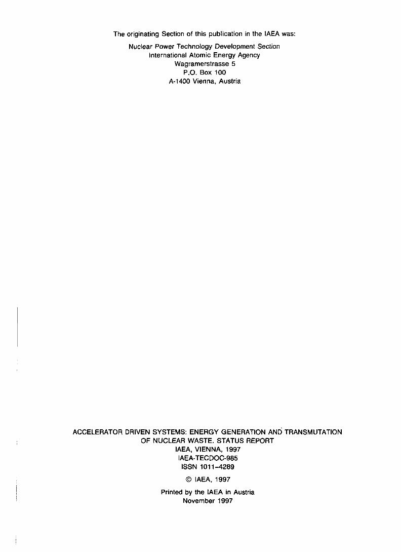
The target installed in the accelerator-driven transmutation system is directly irradiated by high energyprotons with an energy of several GeV. Many spallation reactions in heavy metal targets such as minoractinides (MAs) occur with the emission of many neutrons. Almost all the spallation products have shorthalf-lives but the spallation reactions are of the energy consumption type except for the high energy fissionreaction. Results of our preliminary analysis showed that the target system based mainly on spallationreactions can transmute about 100 kg MA per year, which corresponds to the amount of MA from 4 unitsof 1 GWe LWR driven with a 1.5 GeV and 300 mA proton beam, but can not produce sufficient electricityto operate its own accelerator. It is thought that this system is a very interesting option for a waste disposalstrategy in which a large weight is not given to energy balance.
To investigate the feasibility of an accelerator-driven transmutation system as an engineering systemwith more transmutation of MA and self sustaining energy generation, we adopted the hybrid system ofan intense proton accelerator and a subcritical target/blanket fueled with MA. In this system, the spallationtarget acts mainly as a supplier of source neutrons to the subcritical blanket surrounding it. There thetransmutation of MA by fission is major and the transmutation by spallation minor. The feasibility of anactive target composed of MA metal alloy was examined in the design studies. The analytical resultshowed that the power peaking is generated around the target region due to ionization loss and fissionreactions occurred locally by proton beam irradiation. This phenomenon restricts the beam current to thelower level to keep the target material temperature below the melting point. The existence of peak neutronflux makes the average neutron flux relatively low over the core and reduces the total amount oftransmuted MA.
B.2.4.1.1. Nonactive target
In the solid target and solid fueled blanket system we used a nonactive target made of tungsten to avoidthe power peaking restriction by taking into account that the transmutation of tungsten by spallationreactions is small and a tungsten target is a good neutron supplier. As a result the heat deposition in thetarget becomes lower due only to ionization energy loss of incident protons without fast fission.
For the solid MA alloy fuel transmutation system, the optimization design study [1] on the targetstructure was made to produce the largest number of spallation neutrons uniformly over the target surfaceand to achieve the highest transmutation rate. Here the cascade code NMTC/JAERI [2, 3] was used in thehigh energy range of 15 MeV to 1.5 GeV and the neutron transport code MORSE-DD in the energy rangebelow 15 MeV. In the original design, the solid tungsten target composed of pin-bundle typesubassernblies, like fuel subassemblies was chosen. The metal target subassembly should also be cooledby sodium coolant flow similar to the fuel subassembly in the blanket. The coolant flow channel parallelto the direction of the incident beam also provides the tunneling paths through which some of the incidentprotons escape from the bottom to the outer region. Neutronic survey calculations on four types ofconfiguration: bulk, smear, disc and pin target configurations, were made to search for the optimumstructure of the tungsten target in the solid MA alloy fuel system. The nucleon and neutron transport
32

o2.o.
CM"£o
C.O
OJ
10-6
—0-—Q-
0 40 80 120
Depth(cm)
F/C. 7. Vertical neutron flux, distributions for neutrons emitted from each type target surface.
calculations were made for cases where the uniform proton beam with 20 - 40 cm diameter is injected ontothese targets. The target, in which the volume ratio of tungsten to sodium is assumed to be 1, hasdimensions of 40 cm in diameter and 130 cm in height. The disk-type target gives the highest neutron yieldof these targets. Figure 1 shows the axial flux distributions of neutrons emitted from the target surface tothe blanket for three types of target beside the bulk case. In the modified disctarget the number of disc layers and their thicknesses were adjusted to make aflat flux distribution . The thermal-hydraulics analyses on the disc type targetwere carried out, changing the size of coolant channel on the disc type target.Based on the thermal-hydraulic calculations, the disc has been designed to have19 cooling holes with a diameter of 9 mm and a pitch of 15.4 mm, throughwhich the sodium coolant flows upwards, whilst keeping the temperature at thehot spot in the target below the allowable temperature of 650°C. The targetconfiguration was specified to achieve the maximum neutron gain byconsidering the results of both neutronics and thermal hydraulics calculations.As illustrated schematically in Fig. 2, the optimized target (135 cm in height and40 cm in diameter) contains 13 discs, which are composed of 6 thin discs witha thickness of 1.5 cm and spacing of 5.1 cm and 7 thick discs with a thicknessof 13 cm and spacing of 1.1 cm. About 30 spallation neutrons per incidentproton are emitted from the target. Figure 3 represents the axial distribution ofheat generation in the target [4] and the target withstands the maximum heatdeposition generated by the proton beam with the allowable current of 68 mA.In the proposed design of the target subassembly, the tungsten discs are fixed ina wrapper tube. This is because the coolant pressure drop through the targetsubassembly is higher than those through the pin-bundle type fuel subassemblies.The pressure drop through the target subassembly is about 250 kPa at themaximum coolant velocity of 8 m/s. The coolant flow can sufficiently removethe heat deposited in the discs. The coolant hole pattern of successive discs is a
FIG. 2. Target modelcomposed of 13 disclayers with two differentthicknesses.
33

staggered arrangement so that the protons which pass a disc through the coolant holes should hit the nextdisc. The target composed of stacked discs with different thicknesses is a better choice than a target withpin-bundle type subassemblies, similar to those for fuel blankets because it reduces the proton loss due tochanneling as seen in Fig. 4.
The time evolution process of main residual nuclides was also calculated to estimate the activityinduced by products newly bom in the target during and after proton irradiation using the SPCHAIN code.The calculated results showed that the residual's activities are negligibly small as shown in Fig. 5.
B.2.4.1.2. Active target
In liquid target/blanket transmutationsystems such as those using molten salts andliquid metal alloys as described in a latersection, there are no limitations for preventinga melt down accident of blanket and targetdue to local power peaking. MAconcentration in molten-salt fuel or liquidmetal alloy fuel is lower than in solid metal.For these cases, the power peaking around theirradiated zone is not a critical factor becauseof the relaxed heat condition for liquid fuel.So the high energy proton beam is injecteddirectly into the center of the MA fueled zonewhere there is no target region with a definiteboundary, the so-called "distributed target".The flowing fuel (MA molten salt or liquid target.
Heat deposition
100Depth(cm)
Axial heat generation distribution in the disc type
.Wrapper Tube
Coolant HoleTungsten Disk (Odd Layer) Tungsten Disk (Even Layer)
2660
V \ f \ ,Wrapper Tube \ Lower Support Plate \ Entarance Nozzle
Upper Support Plate \ Reflector BlockHandling Head Tungsten Disk
FIG. 4. Optimized tungsten target subassembly.
34

MA alloy) also forms the subcritical blanket and itself acts as a primary coolant which circulates throughthe target/blanket and heat exchangers.There are many light nuclides such as Cl or Ce in the active fluidtargets in JAERI liquid transmutation systems. In the target region spallation reactions of MA and lightnuclei such as Cl or Ce, of which the molten salt or liquid metal alloy mainly consists, occur simultaneouslyin addition to transmutation of MA. Cascade calculations of high energy hadron nuclear reaction in the lightnucleus and transport processes in the dilute fluid target need to be analyzed with high precision. The QMD(Quantum Molecular Dynamics) code that is being developed at JAERI in collaboration with universitieswill give a more accurate solution for the cascade process in the light nucleus medium in the near future.
B.2.4.2. BLANKET
Target ActivityAccording to the national research and development
program OMEGA, on partitioning and transmutation,conceptual design studies of accelerator-driventransmutation systems are being performed at JAERI for thefollowing three types:
(a) Tungsten target and solid MA alloy fueled blanketsystem,
(b) MA molten-salt target/blanket system and(c) Liquid MA alloy target and molten-salt blanket
system.
The solid MA alloy fueled system (a) is composed of atungsten target and solid type fuel subassemblies like metalfueled fast reactors. Its R&D work is considered to be arelatively short term project so that the technologies andknow-how about fast reactors already obtained can beapplied to perform the design study of this type of system. FIG 5' DePendence of activities of residualThe molten-salt system (b) and liquid alloy system (c) have nuclides in tar8et on cooling time.a liquid fueled target/blanket without a solid target. Theseare expected to be more promising systems with the possibility of on-line fuel reprocessing but containingmore problems that need to be resolved than the solid fuel one. Both systems have the active, subcriticalblanket region with hard neutron energy spectra The liquid alloy system (c) has a graphite moderator inthe blanket to transmute long-lived fission products (LLFPs) by using thermalized neutrons.
Here we discuss the nuclear characteristics including the neutron energy and neutron fluxes in theseaccelerator-driven transmutation systems.
10° 10' 102
Time (year)103
B.2.4.2.1. Neutron energies
The long-lived waste nuclides to be transmuted in the JAERI transmutation research program are MAs(U7Np, 24lAm, 243Am, 243Cm, 244Cm, 245Cm) and LLFPs ("Tc, 129I) with half-lives between a few hundredyears and several million years. MA should be transmuted through fission reaction because thetransmutation of MA by neutron capture has the possibility of increasing higher actinides. Figure 6represents the comparison of 237Np fission cross section and capture cross section data dependent onneutron energy between the nuclear data libraries of JENDL3.2, ENDF/B-VI and JEF-2. Fissioning of MAoccurs dominantly in relation to neutron capture above the threshold energy of about 500 keV. JAERIselected the transmutation method of MA by fast fission induced by a spallation neutron source despite
35

± 10"
Fission cross section
—— J E K O l - 5 1—— (HOFO/1 »l—- JEf I
IO ' 1 1C1 10'
Neut ron
10'
• V)
requmng the large initial MA inventory In the ATW project at LANL, MAs and LLFPs are transmutedby thermalized spallation neutrons As illustrated in Fig 7 this method requires two or three neutrons perone MA fission since MA must be converted at first to a fissionable actmide through one neutron captureIts fission reaction after two thermal neutron absorptions occurs only with high thermal neutron flux ofabout 1016 n/cm2/s This fact implies that neutron economy with fast fission is better than one with thermalfission for transmutation of MA by fission. LLFP can be transmuted only through thermal neutron captureto a stable nuchde as seen in Fig 8 because of the small capture cross section for fast neutrons For thisreason, the thermalized neutron region needs to be included around the fast subcntical target/blanket totransmute MA and LLFP simultaneously in one system
Nuclear calculations in theaccelerator-driven transmutationsystem must cover the wide ^ _ ___ _______________energy range from several eV to afew GeV and calculate both highenergy reaction and neutrontransport process For the highenergy region above 15 MeV thespallation reaction with manyreaction channels is dominant butsufficient experimental andestimated nuclear data are not yetavailable for high energy neutronand charged particles At present,the best way to analyze the highenergy process in the aocderator-dnventransmutation system is to use thecascade codes, such asNMTC/J AERI, HETC/KFA2, andLAHET, based on the two-bodycollision approximation modelJAERI are using the codeNMTC/JAERI (High EnergyNuclear Reaction and Nucleon-Meson Transport Code) whichtreats the proton-induced nuclearspallation and subsequentintemuclear transport process forenergies above 15 MeV and alsocalculates high energy fissionreaction as a competing processwith evaporation Since most ofthese codes include, however, theold calculation model and data Pjr *about the nucleus, which were 237installed before -1975, they p'should be improved and upgraded by the newly developed nuclear theory and data based on recent highenergy experiments, respectively So, JAERI is performing benchmark calculations, taking part in theOECD/NSC code benchmark task force work, and spallation integral experiments as basic studies relevantto accelerator-driven transmutation
To evaluate the validity of the simulation code and upgrade it, JAERI is carrying out spallaoon integralexperiments at the National Laboratory for High Energy Physics (KEK) in Tsukuba [5, 6] The 500-MeV
- 10'
- 10'
2 10"
10"
Neutron capture cross sectionJEKOl-J !
——— JEF-2
Ktutron En«rg>< I
10'
e Y )
10*
Comparison of fission and neutron capture cross sections for
36

Fast Neutron:FIuxFission + 2.9 n
. Very High Thermal:Neutrpn.Flux:
Fission + 2.9 n
Decay(2.1 days) / <*, = 2 i o o b
>./ °e- 3V3 b
Th e r m a I N.e u tro n ;Fly xPu-240 "1—9*- Fission + 2.9 n
ff, = 10 bo,= 5-10 b
o, = 7-10 boc= 209 b
F/G. 7. 237Np burning with fast and thermal neutron fluxes.
booster synchrotron facility at KEK is used for the experiments. A Lead/tungsten target was installed inthe center of a Lead assembly with a diameter of 600 mm and a length of 1000 mm. The activation samplesof Al, Fe, Ni, and Cu were distributed in holes drilled through the assembly along the beam axis at variousradial positions. The number of induced activities in the samples was obtained by measuring gamma rayswith 100-cc Ge detector. Some experimental results agreed fairly well with predictions obtained usingNMTC/JAERI. The double differential cross sections (DDX) of neutron emission in a thin Al sample
irradiated by 800 MeV protonsin the synchrotron facility atKEK were also measured by thetime of flight method incooperation with the KyushuUniversity, the TohokuUniversity, and KEK, andcompared with calculations bythe code HETC. It was foundthat the calculated results are inrelatively good agreement withthe experimental ones. Thedetection efficiency and theresponse function of the NE-213scintillation counter for -65MeV neutrons were measured atthe cyclotron in the JAERITakasaki Research Establish-ment to improve the counting
RulOOStable
n Ru101Stable
— - Ru102Stable
X \Tc992x10 y
n TdOO16 sec
n—— (^ Tc10114m
Xn\TC1024-5 sec
Isotope
Tc991129Sr90Cs137
q (thermal)
20 barns
10.25
a (fast)
0.2 barns0.2(0.1)(<0.f01?)
FIG. 8. Transmutation ofLLFP using the thermal neutron flux.
efficiency for neutrons withenergies of tens of MeV.Detailed experimental results are
37

described in a companion paperby Takada. The benchmarkstudies on the mass distributionof spallation products in thin andthick targets of Np for 800 MeVproton incidence and DDX ofneutron or proton emission in Zr,induced by the 80 MeV protonbombardment, were carried out toverify and upgrade the accuracyof the predictions computed bythe codes NMTC/JAERI andNUCLEUS.
Neutronic calculations on thetransmutation system below 15MeV are carried out usingtransport codes, Sn codeTWOTRAN 2 or Monte Carlocode MCNP, since they werewell prepared for analyzing theneutron transport process in ausual reactor. In the energy rangebelow about 20 MeV the nuclearcross section libraries such asENDF/B-V and JENDL3.2 areapplicable to calculate the nuclearcharacteristics of thetransmutation blanket. Figure 9shows the code system ACCELfor analyzing an accelerator-driven transmutation system atJAERI. By using these codes wecalculated the nuclear
ft" If*characteristics of three types oftransmutation systems in the
Input CardIncident Energy.Trul NumberTarget Material Information
Charge Number. Mm Number.Number Density,Target Geometry
Incident Beam Profile
NMTC/JAERINuclear Reaction CalculationFaroe le Transport Calculation
( Ei > 15 MeV. i=p,n. pions
Nuclear RadiusNuclcon DensityNucleon-NuclconCollision Cross SectionsPion-Nucleon .Collision Corss SectionsDifferentia! Coss SectionsFile
Low EnergyNeutron Data(En < 15 MeV)
High EnergyHistory Daia(Ei > 15 MeV)
MCNPOLow Energy (En<15 MeV)
euoron Transport Calcul
SPCHAINCalculation of Accumulation and Decay ofProduced Nuclide During Irradiation andCooling________
Low EnergyNeutron Flux
. 9. Main part of upgraded ACCEL code system.
D-StrlppInq In Be
12 16 2ONtutron Energy •
32 36MeV
FIG. 10. Normalized neutron spectra in various neutron sources.
whole energy range. The spectrumof spallation neutrons evaporatedfrom an excited heavy nucleusbombarded by high energy particlesis similar to the fission neutronspectrum but shifts a little to higherenergy, as seen in Fig. 10 in whichthe normalized neutron spectra forvarious reactions are compared.Information about spallationneutrons with energies below 15MeV is transferred from the cascadecode to the neutron transport codeas source neutron terms.
Figure 11 shows the calculatedneutron energy spectrum averagedover the total target/blanket volume
38
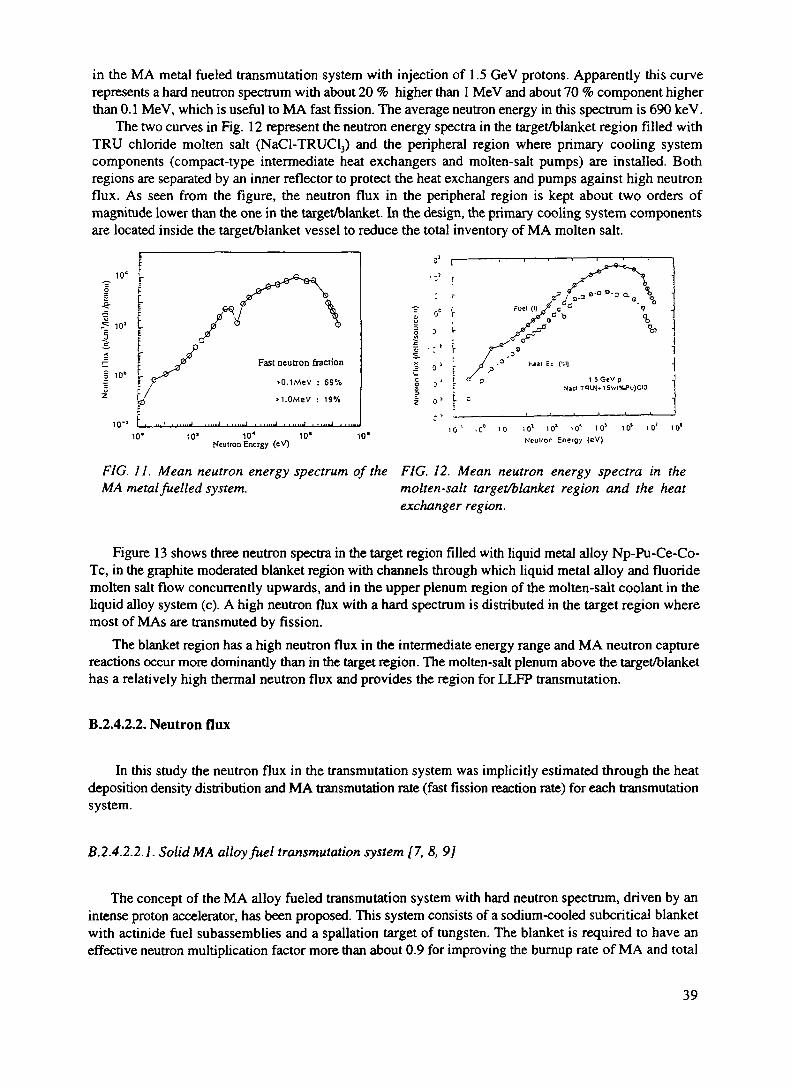
in the MA metal fueled transmutadon system with injection of 1.5 GeV protons. Apparendy this curverepresents a hard neutron spectrum with about 20 % higher than 1 MeV and about 70 % component higherthan 0.1 MeV, which is useful to MA fast fission. The average neutron energy in this spectrum is 690 keV.
The two curves in Fig. 12 represent the neutron energy spectra in the target/blanket region filled witihTRU chloride molten salt (NaCl-TRUCl3) and the peripheral region where primary cooling systemcomponents (compact-type intermediate heat exchangers and molten-salt pumps) are installed. Bothregions are separated by an inner reflector to protect the heat exchangers and pumps against high neutronflux. As seen from the figure, the neutron flux in the peripheral region is kept about two orders ofmagnitude lower than the one in the target/blanket. In the design, the primary cooling system componentsare located inside the target/blanket vessel to reduce the total inventory of MA molten salt.
Fast neutron fraction
>0 . lMeV : 69%
>i .OMeV : 19%
* r _,f / a-3
hssi Ei c:i|1 5 Gev p J
NjclT1U{»lSvy|%Pu)CI3 '
10° 10' 10" 10'Neutron Energy (eV)
10'
FIG. 11. Mean neutron energy spectrum of theMA metal fuelled system.
10' . c" 10 i o! i o1 i o' i o1 i o' i o' i o1
NcuUor Energy (eV)
FIG. 12. Mean neutron energy spectra in themolten-salt target/blanket region and the heatexchanger region.
Figure 13 shows three neutron spectra in the target region filled with liquid metal alloy Np-Pu-Ce-Co-Tc, in the graphite moderated blanket region with channels through which liquid metal alloy and fluoridemolten salt flow concurrently upwards, and in the upper plenum region of the molten-salt coolant in theliquid alloy system (c). A high neutron flux with a hard spectrum is distributed in the target region wheremost of MAs are transmuted by fission.
The blanket region has a high neutron flux in the intermediate energy range and MA neutron capturereactions occur more dominantly than in the target region. The molten-salt plenum above the target/blankethas a relatively high thermal neutron flux and provides the region for LLFP transmutation.
B.2.4.2.2. Neutron flux
In this study the neutron flux in the transmutation system was implicitly estimated through the heatdeposition density distribution and MA transmutation rate (fast fission reaction rate) for each transmutationsystem.
B.2.4.2.2. ]. Solid MA alloy fuel transmutation system [7, 8, 9]
The concept of the MA alloy fueled transmutation system with hard neutron spectrum, driven by anintense proton accelerator, has been proposed. This system consists of a sodium-cooled subcritical blanketwith actinide fuel subassemblies and a spallation target of tungsten. The blanket is required to have aneffective neutron multiplication factor more than about 0.9 for improving the burnup rate of MA and total
39

10
TargetBlanketMolten-salt
10'^Q•2
Energy (MeV)
FIG. 13. Mean neutron energy spectra in the liquid alloy target, graphite blanket, and upper molten-saltplenum.
energy balance. When driven by a 39-mA proton beam with an energy of 1.5 GeV, a system with a meanblanket neutron flux of 4.6x10¹⁵ n/cm2/s can transmute about 250 kg of MA after one year in operation andgenerate a thermal power of 820 MW, which is converted to an electric power of about 240 MW. Thiselectricity is sufficient to power its own accelerator. The power density distribution is shown in Fig. 14.The maximum power densities are 930 MW/m3 in the blanket region and 400 MW/m3 in the target region.The power distribution is considered to be a measure of the neutron flux distribution in the blanket region.It is supposed that the neutron flux in the blanket around the target has become relatively flat without apeak. The mean neutron flux can be increased with the nonactive target.
B.2.4.2.2.2. MA molten-salt transmutation system [10, 11]
The concept of an advanced MA molten-salt transmutation system has been studied to take advantageof a simple fluid target/blanket for the transmutation system. This system has the target/blanket with aheight 170 cm and a radius of 105 cm and the stainless steel reflector with thicknesses of 20 - 40 cm,including the internal heat exchanger. The MA chloride molten salt 64NaCl-36TRUCl3 with a meltingpoint of around 453 °C, was adopted as the fuel salt due to the high solubility of MA and a good nuclearcharacteristics for a hard neutron spectrum. MA molten salt is circulated between the target/blanket regionand the heat exchangers by motor-driven mechanical pumps. MAs in the target/blanket region aretransmuted mainly through fast fission reactions and less through spallation reactions. The high energyproton beam is injected vertically downward directly onto the molten salt which acts as the fuel and thespallation target material and serves also as the primary coolant. The fluoride molten salt NaBF3-NaF isselected as the secondary coolant. The target/blanket with an effective neutron multiplication factor of 0.92
40

can transmute 250 kg of MA per year with a 1.5 GeV-25 mA proton beam, and produces 240 MW ofelectricity sufficient to power its own accelerator. The power density distribution in the target/blanketregion is shown in Fig. 15. The maximum power density is 1,660 MW/m3 at 25 mA.
eo
COCOQu,o£oPu,
1000
MA fuelled core500
Proton beam
0.7 0
FIG. 14. Power density distribution in the target/blanket of the MA metal fuelled system.
The molten-salt transmutation system is expected to have the possibility of removing FPs from thesystem and controlling the MA in the system by the on-line processing.
B.2.4.2.2.3. Liquid MA alloy target transmutation system [12]
The preliminary neutronic calculations for the liquid alloy transmutation system have been started toexamine the possibility of simultaneous transmutation of both MAs and LLFPs. A TRU alloy of Np-Pu-Co-Ce-Tc with melting point of around 450°C was selected as the target liquid which circulates throughthe channels in the graphite moderator and transfers the heat and reaction products to the secondary coolantof fluoride molten salt. A target/blanket with an effective neutron multiplication factor of 0.9 can transmute70 kg of MA per year with 1.5 GeV-16 mA proton beam and the thermal power is 450 MW. Theperformance parameters of the Liquid alloy system are summarized in Table I. The advantages of the liquidalloy system are small MA inventory, high transmutation rate and the simultaneous transmutation of MAsand LLFPs, together with the possibility of on-line charging of MA and removal of reaction products.
To examine the actinide burning performance of each transmutation system, the one group cross sectionlibrary and the bumup code COMRAD has been prepared. The accelerator-driven transmutation plant
41

designing code system SPACE has been extended to calculate the burnup and transmutation characteristicsof the accelerator-driven MA alloy fuel transmutation system. The one group cross section libraries neededfor MAs and other nuclides in the burnup calculation have been produced by degenerating the 295 groupsJSSTDL cross section libraries with the neutron spectra computed by the one-dimensional transport codeANISN. The new version of the burnup code COMRAD was prepared to speed up the computation. Apreliminary burnup calculation was made for the proposed MA alloy fuel transmutation system.
^ (W/cm3)
so(cno TOO
150200 TOO
FIG. 15. Power density distribution in the target/blanket of the MA molten-saltsystem (1 mA proton beam).
TABLE I. MAJOR PARAMETERS FOR LIQUID ALLOY SYSTEM
Fuel
TargetSecondary CoolantActinide InventoryMultiplication FactorSpallation NeutronsProton BeamThermal PowerBurnupTemperature, Target Inlet/Outlet
Liquid Metal Alloy12.5Np-4.8Pu-24Co-57.7Ce-TcLiquid Metal AlloyFluoride Molten Salt890kg0.946.3 n/p1.5GeV-15mA450 MW141 kg/a (15.8 %/y)1050/1250 °C
42

REFERENCES
[I] NISHIDA, T., et al.: "Minor Actinide Transmutation System with an Intense Proton Accelerator",Proc. ICENES' 93, Makuhari (1993) 419.
[2] NAKAHARA, Y., TSUTSUI, T.: "NMTC/JAERI - A Simulation Code System for High EnergyNuclear Reactions and Nucleon-Meson Transport Process", JAERI-M 82-198 (1982) (in Japanese).
[3] NISHIDA, T., et al.: "Improvement of Spallation Reaction Simulation Codes NMTC/JAERI andNUCLEUS", 2nd Int. Symp. on Advanced Nuclear Energy Research, Mito (1990).
[4] NISHIDA, T., NAKAHARA, Y.: JAERI-M 84-154 (1984) (In Japanese).[5] TAKADA, H., et al.: "Production of Radioactive Nuclides in a Lead Assembly wirh 500 MeV
Protons", Proc. OECD/NEA Specialists' Meeting on Accelerator-based Transmutation (PSI, 1992).[6] TAKADA, H., et al.: JAERI-M 93-181 (1993) 210.[7] TAKIZUKA, T., et al.: " A Study of Incineration Target System", Proc. 5th Int. Conf. Emerg. Nucl.
Systems, Karlsruhe (1989).[8] MIZUMOTO, M., et al.: "High Intensity Proton Accelerator for Nuclear Waste Transmutation",
16th Int. Linear Accelerator Conf. LINAC-92 (Ottawa, 1992).[9] TAKIZUKA, T., et al.: " Conceptual Design Study of an Accelerator-based Actinide Transmutation
Plant with Sodium-cooled Solid Target/Core", Proc. 2nd OECD/NEA Information ExchangeMeeting on P-T (1993) 397.
[10] KATSUTA, H., et al.: "A Continuous Transmutation System for Long-lived Nuclides withAccelerator-driven Fluid Target", ibid.
[II] KATO, Y., et al.: Proc. OECD/NEA Specialists' Meeting of Accelerator-based Transmutation, PSI(1992).
[12] KATSUTA, H., et al.: "A Concept of Accelerator Based Incineration System for Transmutation ofTRU and FP with Liquid TRU-Alloy Target and Molten Salt Blanket", Proc. ICENES '93, Makuhari(1993)424.
43
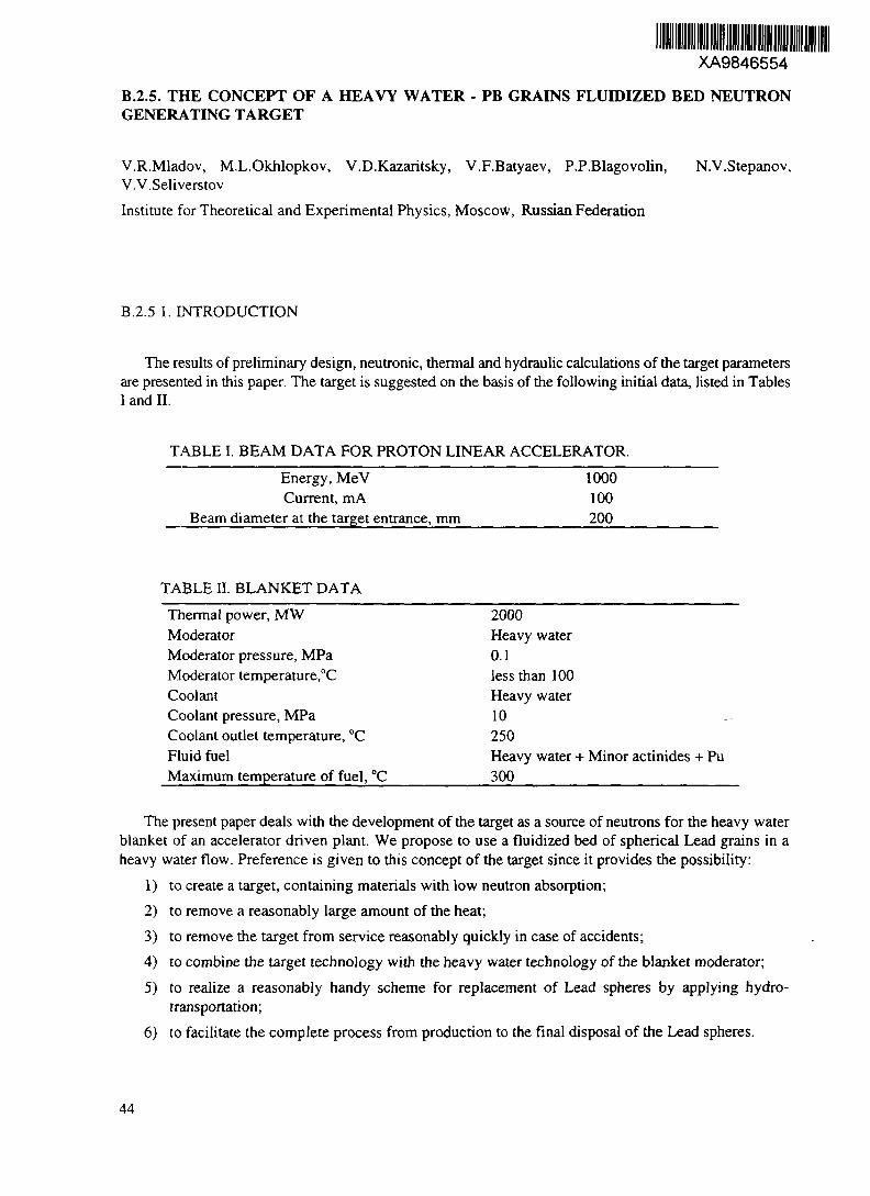
XA9846554
B.2.5. THE CONCEPT OF A HEAVY WATER - PB GRAINS FLUIDIZED BED NEUTRONGENERATING TARGET
V.R.Mladov, M.L.Okhlopkov, V.D.Kazaritsky, V.F.Batyaev, P.P.Blagovolin, N.V.Stepanov,V.V.Seliverstov
Institute for Theoretical and Experimental Physics, Moscow, Russian Federation
B.2.5 1. INTRODUCTION
The results of preliminary design, neutronic, thermal and hydraulic calculations of the target parametersare presented in this paper. The target is suggested on the basis of the following initial data, listed in TablesI and II.
TABLE I. BEAM DATA FOR PROTON LINEAR ACCELERATOR.Energy, MeVCurrent, mA
Beam diameter at the target entrance, mm
1000100200
TABLE n. BLANKET DATAThermal power, MWModeratorModerator pressure, MPaModerator temperature,°CCoolantCoolant pressure, MPaCoolant outlet temperature, °CFluid fuelMaximum temperature of fuel, "C
2000Heavy water0.1less than 100Heavy water10250Heavy water + Minor actinides + Pu300
The present paper deals with the development of the target as a source of neutrons for the heavy waterblanket of an accelerator driven plant. We propose to use a fluidized bed of spherical Lead grains in aheavy water flow. Preference is given to this concept of the target since it provides the possibility:
1) to create a target, containing materials with low neutron absorption;2) to remove a reasonably large amount of the heat;3) to remove the target from service reasonably quickly in case of accidents;4) to combine the target technology with the heavy water technology of the blanket moderator;5) to realize a reasonably handy scheme for replacement of Lead spheres by applying hydro-
transportation;6) to facilitate the complete process from production to the final disposal of the Lead spheres.
44

B.2.5.2. THE CONCEPT OF THE TARGET SCHEME
The basic design of the target is shown on Fig. 1. The heart of the target is a fluidized bed of Leadspheres in a heavy water flow, which circulates from bottom to top in a tube, isolating the target from theblanket moderator. The diameter and height of the fluidized bed are 500 mm and 2500 mm respectively,regardless of the fluidized bed porosity. The top line of the fluidized bed is located at a depth of 1000 mmfrom the top line of the blanket core. At the bottom of the target a Lead spheres receiver, a beam stop anda heat exchanger are located.
Target x al=
\X\\\\\1FIG. 1. Cros section of the heavy-water cooled target. 1 - proton beam channel withwindow, 2 -fluidized bed target (core), 3 - inner reflector, 4 - Pb-shot receiver tankand beam stop.
45

The proton beam finds its way into the target from above through a conical window, plunged into thefluidized bed. Non-neutron poisonous alloys are selected as structural materials for the target (compositionsbased on Aluminum and (or) Zirconium). Outside the blanket, stainless steel may be used.
B.2.5.3. THE HEAT REMOVAL
Fig. 2 shows a concept of heat removal from the blanket. The heavy water flow arrives from a pumpat the bottom heat exchanger to the receiver and through a pipeline to the working zone of the target. Theflow then passes to the top part of the moderator tank and the jet pump, is mixed with the moderator flowand goes to the basic heat exchanger, from which it goes to the bottom part of the tank. The jet pump,working from the excess pressure of the pump, assists the natural circulation of the blanket moderator. Twoheat exchangers are needed to balance the parameters of the moderator and the target coolant.
/ J-B.2.5.4. RESULTS OF NEUTRONYIELD AND THERMO-HYDRAULIC CALCULATIONS.
Calculations of neutron yieldand energy deposition distributions,caused by a 1.0 GeV proton beam,were performed by two differentMonte Carlo codes HETC [1] andPHOENIX [2] for various Pb-volume compositions of a targetwith 50 cm diameter and 200 cmheight.
The proton beam was simulatedas uniformly distributed within aradius of 10 cm. The results of thecalculations by both codes aresatisfactorily similar as far as themain target functions areconcerned: neutron yield, totalenergy deposition and itslongitudinal distribution.Longitudinal energy deposition,calculated by the PHOENIX code,is adopted for furtherthermodynamics calculations,because its values are greater thanones computed by the HETC code(approximately by 3%).
A flat top side (surface) to thetarget was assumed at the currentstage calculations. In fact the targetwindow should be made as a cone,which is sunk into the pseudo-
-10FIG. 2. Principal scheme of the target and moderator cooling. 1 -proton beam channel, 2 - fluidized bed target, 3 - internal heavy-water refelector, 4 - heavy water blanket, 5 - jet pump, 6 - heatexchanger for moderator and target cooling, 7 - pump, 8 - beamstop, 9 - Pb-shot receiver, 10 - the target heat exchanger
liquid target for providing more efficient heat removal from the window. Such a window may be takeninto account at the next stage of calculations of heat and neutron production distributions. The proton
46

beam, which is not distributed uniformly but by Gauss' law, should also be taken into account.The number of neutrons that escape to the blanket is an important target quality. This quality is defined
as the number of neutrons, that were produced by the initial proton, multiplied by a probability that theneutron reaches the target surface. The longitudinal distribution of neutrons, transmitted from the targetto blanket, is another target quality. Results of the initial calculations of total neutron losses as a functionof the porosity of the fluidized bed show that the longitudinal distribution of neutrons entering the blanketmay be spread out. Though the neutron-to-proton efficiency of the proposed target goes down (about twicefrom 100% to 50% Pb-volume), the number of neutrons absorbed by construction materials is low.
Results of the tentative thermohydraulic calculations give the flow rate as a function of the diametersand porosity of the Lead spheres, as well as the dependence of the removed thermal power versus the Leadspheres diameter with the varied values of the porosity and flow pressure. The dependencies obtained areillustrated on Fig. 3. It can be seen that
- the porosity and flow pressure markedlyaffect the removed thermal power;
- for every value of the porosity there exists anoptimum diameter of Lead spheres.
B.2.5.5. CONCLUSION
It is suggested that a heavy water-Pb grainsfluidized bed be used as a neutron generatingtarget. The preliminary design investigations,based on neutron yield and thermal hydrauliccalculations, revealed that there is a possibility ofa wide range of parameters to realize a fluidizedbed target as an intensive neutron source of anaccelerator driven subcritical nuclear reactor.
It should be noted that the proposed targetprovides for removal from service andreplacement of the Lead spheres. This is anessential feature of the target for providing nuclearsafety. The removed thermal power may beelevated as compared to the proposed design, ifthe directions of the proton beam and the heavy FIG 3 Output power (MWJ dependence on spherewater How are the same. Besides the non uniform diameter, Pb-volume of fluidized bed and output waterporosity throughout the target height may be used pressure in MPa, e - Pb-volume in the target, P - waterto improve the efficiency of the neutron source, pressure
C/.ftM
REFERENCES
1. T.W.Armstrong, K.C.Chandler - HETC - A High Energy Transport Code // Nucl.Sci.&Eng.1972,49.p.llO.
2. N. V.Stepanov - Computer Simulation of Fission of Exited Nuclei. 1. Description of theModel, M. Preprint ITEP 81-1987, 1987 (in Rus.).
47

XA9846555B.2.6. ACCELERATOR DRIVEN HEAVY WATER BLANKET ON CIRCULATING FUEL
V.D.Kazaritsky, P.P.Blagovolin, V.R.Mladov, M.L.Okhlopkov, V.F.Batyaev, N.V.Stepanov,V.V.SeliverstovInstitute for Theoretical and Experimental Physics, Moscow, Russian Federation
B.2.6.1. INTRODUCTION
A conceptual design of a heavy water blanket with circulating fuel is described. Radiation safety fora reactor with fluid fuel is provided by the same means as in traditional nuclear power, namely by securityin depth and control. As compared with fixed fuel reactors, the radiation situation in the suggested systemcan be improved, for, on the one hand, activity of the fission products is reduced through the continuousremoval of the irradiated fuel for reprocessing, and, on the other hand, there is no need to open the reactorfor reloading.
A design of a heavy water blanket with circulating fuel has been proposed in ITEP [1]. A lattice ofpower channels is placed inside a cold heavy water tank under about normal pressure. The channels madeof proven Zr-Nb alloy isolate the fuel from the moderator and keep it constantly exposed to irradiation.Inside each channel there are two loops: a fuel loop (solution or slurry in heavy water) and a loop ofpressurized heavy water coolant. The latter cools the fuel, circulating in the channel, while the fuel iscontinuously fed and removed in small portions for chemical reprocessing. After reprocessing the actinidescome back to the fuel loop, while the remainder is fractionated and further sent for transmutation or storageand burial.
B.2.6.2. GENERAL CHARACTERISTICS OF THE FACILITY
The hybrid system consists of a high-current linear accelerator of protons and 4 targets, each placedinside a subcritical blanket. The plan view of target-blanket and its cross section are presented in Fig. 1and 2. The accelerator current is 100 mA, the proton energy is 1 GeV and its power is 100 MW. The RF-to-beam conversion ratio is 40-50%.
Control magnets split the beam up into 4 separate beams, each of 25 mA current. After passing throughdefocusing magnets the beam of 30 cm in diameter goes through a diaphragm (window), isolating theaccelerator vacuum from the target space, and strikes a 50 cm diameter target. The thermal power of sucha separate beam is about 15 MW. The target consists of coated Pb elements or Pb grains cooled by heavywater flow. The Pb- heavy water volume ratio is 50%. The target, encased in a Zr tube, is surrounded byan inner reflector, made up of pure heavy water 70 cm thick. This heavy water layer is isolated from theblanket by a Zr cylinder wall. Control rods could be inserted into the inner reflector, and in a emergencysome neutron poison for example, boric acid could be quickly released into the reflector water.
The subcritical blanket consists of a regular lattice of channels (modules), arranged with a step of 30cm. The module design is shown in Fig. 3. The channel is constructed from Zr material. Heavy watercoolant is pumped through an outer heat exchanger. Fluid fuel circulates inside the channel. The fuel isdischarged in small portions for chemical reprocessing. Fresh fuel feeding and spent fuel discharge takeplace incessantly. The circulating fuel is either a heavy water solution of Pu, MA and fission products (FP)salts or their slurry.
48

The power of the channel, which is put under maximum load, is 5 MW. The depth of the active partof the channel is 4 m. The power of a channel in the blanket is on average about 3 MW (variation is 1.6).The blanket unit contains about 160 channels, the facility total being 640 channels.
The blanket is surrounded on an outer reflector. The subcriticality of the blanket is close to 5%. Thethermal power is 500 MW (for the whole plant 2000 MW). Due to its heat-to-electricity conversion rate,close to 20%, the electric power of the whole plant will be 400 MW. An average thermal neutron flux inthe blanket is expected to be about 3.* 1014 n/ cm2 s.
-100
FIG. I. Vertical cross-section of the accelerator drivenheavy-water facility. The numbers show the approximateheights and diamaters in meters. The line A-A shows a crosssection presented in Fig. 2
B.2.6.3. GENERAL PRINCIPLES OFTHE SUGGESTED FLUID FUELMODULE
The suggested fluid fuel module (FFM ) is a unit of the blanket assemblyof the accelerator driven nuclear plantcontaining circulating fluid fuel withinthe blanket core. Water solutions of saltsor water slurry of oxides could be used asfluid fuel. The proposed design of thefluid fuel module is illustrated in Fig. 3.
The conceptual design scheme ofFFM is as follows: the circuit of FFMcontains a centra] 1.5 mm thick liftingtube of 83 mm in diameter (CLT) and 90outlying 0.5 mm thick lowering tubes of11 mm in diameter each ( OLT ). TheOLT are joined with the CLT andarranged as a stringer with lattice spacing13 mm. The forced circulation of the fluidfuel is realized by a centrifugal pumpplaced in the lower part of the CLT anddriven by a hydraulic turbine, which usesthe energy of a fluid fuel coolant. TheFFM active zone is 4.0 m in height, theexternal diameter of the coolant channel is165 mm.
The FFM is installed into an assemblychannel, which is a component of theblanket structure.
The design scheme of the FFM also provides :continuous withdrawal of the irradiated fuel,compensation of the fluid fuel volume by changes of the temperature,support of the pressure drop between the coolant and the fluid fuel within hydraulic losses of thecoolant,guide grids of the heat-exchange tubes.
49

The initial data for developing the blanket design are determined by the following factors:heavy water is the coolant and the fluid fuel carrier,production of electrical power for feeding the Linac.
A -
I x^T — — ~T ~~ —
FIG. 2. Cross section of the facility. 1 -steam generator, 2 - heat exchanger, 3 -channel for inlet-outlet of fuel regeneration
On the basis of the literature on thesubject and the preliminary calculatons of thedesign characteristics of the FFM, thefollowing starting conditions are accepted:
maximum temperature of the fluidfuel - 300 ;pressure - 10 MPa.
These conditions can provide:good enough characteristics for thepower circuit of the plant (see anillustration of the suggested scheme FIG 3 Vertical cross section of the fluid fuel element. I -on Fig. 4) ; fluid fuel circuit, 2 - coolant inlet, 3 - coolant outlet, 4 -flow
- practically complete suppression of guider, 5 - turbo-drive, 6 - pump, 7 - feed Met, 8 - fueli.he radiolytic gas release in the fluid regeneration outletfuel under normal operatingconditions, moderate content of bivalent cuprous ions in fluid fuel (0.8 g/dm3 and accordinglySc<0.29-10-4cm-');use of the Zirconium alloys such as H-l and H-2 as construction materials;
- reasonable corrosion velocity (to 0.0107 mm\a by 280-300°C);
50

good erosion resistance of the materials in the slurry with a flow velocity up to 6 m\sec.
Preliminary module design calculations show that the accepted above-mentioned parameters of thefluid fuel can be realized under the module parameters listed in Table I.
FIG. 4. Schematic thermodynamical layout of the facility. 1- target-blanket, 2 - steam generator, 3 - highpressure cylinder of the turbine, 4 - low pressure cylinder of the turbine, 5- electro-generator, 6 -condenser, 7 - condensation pump, 8 - condensation cooler, 9 - low pressure heater, 10 - heat exchangerof the moderator, 11 - deairator, 12 - water feeding pump, 13 - the first loop circulator, 14 -steamoverheater, 15 - heat exchanger of coolant, 16 - water-water heat exchanger ocf coolant, 17 - water-airheat exchanger of coolant, 18 - reservoir of the emergency cooling, 19 - moderator cooling, 20 -comensator, 21 - target coolant circulator
TABLE I. PARAMETERS OF FLUID FUEL MODULE.
Thermal output, MWFuel circulation rate, kg/s
Coolant circulation rate, kg/sFuel velocity, m/s
Coolant velocity, m/sFuel temperature (av), °C
Coolant:outlet temperature, °C
average temperature, °C
5103526
285
250230
51
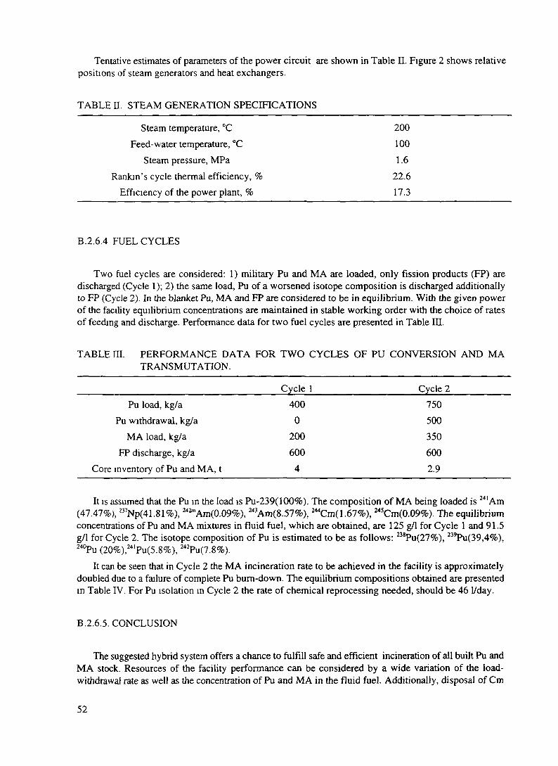
Tentative estimates of parameters of the power circuit are shown in Table II. Figure 2 shows relativepositions of steam generators and heat exchangers.
TABLE H. STEAM GENERATION SPECIFICATIONS
Steam temperature, °C 200Feed-water temperature, °C 100
Steam pressure, MPa 1.6Rankin's cycle thermal efficiency, % 22.6
Efficiency of the power plant, % 17.3
B.2.6.4 FUEL CYCLES
Two fuel cycles are considered: 1) military Pu and MA are loaded, only fission products (FP) aredischarged (Cycle 1); 2) the same load, Pu of a worsened isotope composition is discharged additionallyto FP (Cycle 2). In the blanket Pu, MA and FP are considered to be in equilibrium. With the given powerof the facility equilibrium concentrations are maintained in stable working order with the choice of ratesof feeding and discharge. Performance data for two fuel cycles are presented in Table in.
TABLE III. PERFORMANCE DATA FOR TWO CYCLES OF PU CONVERSION AND MATRANSMUTATION.
Pu load, kg/aPu withdrawal, kg/a
MA load, kg/aFP discharge, kg/a
Core inventory of Pu and MA, t
Cycle 14000
200600
4
Cycle 27505003506002.9
It is assumed that the Pu in the load is Pu-239(100%). The composition of MA being loaded is 241 Am(47.47%), 237Np(41.81%), 242mAm(0.09%), 243Am(8.57%), 244Cm(1.67%), 245Cm(0.09%). The equilibriumconcentrations of Pu and MA mixtures in fluid fuel, which are obtained, are 125 g/1 for Cycle 1 and 91.5g/1 for Cycle 2. The isotope composition of Pu is estimated to be as follows: B8Pu(27%), 239Pu(39,4%),240Pu (20%),241Pu(5.8%), 242Pu(7.8%).
It can be seen that in Cycle 2 the MA incineration rate to be achieved in the facility is approximatelydoubled due to a failure of complete Pu bum-down. The equilibrium compositions obtained are presentedin Table IV. For Pu isolation in Cycle 2 the rate of chemical reprocessing needed, should be 46 I/day.
B.2.6.5. CONCLUSION
The suggested hybrid system offers a chance to fulfill safe and efficient incineration of all built Pu andMA stock. Resources of the facility performance can be considered by a wide variation of the load-withdrawal rate as well as the concentration of Pu and MA in the fluid fuel. Additionally, disposal of Cm
52

to interim storage and its return back to the blanket in 2 years' time are expected to be promising.
TABLE IV. EQUILIBRIUM ISOTOPE COMPOSITIONS (g/1) IN BLANKET CORE.
ElementNpNpPuPuPuPuPuAmAmAmAmAmCmCmCmCmCmCmCm
Atom number237238238239240241242241
242m242243244242243244245246247248
Cycle 1 (g/1)9.33
0.41E-19.489.7710.783.4525.53.075
0.33E-10.14E-1
7.990.41E-3
2.610.22323.540.9014.681.082.77
Cycle 2 (g/1)17.15
0.76E-18.28
12.096.131.812.425.58
0.61E-10.25E-1
4.150.23E-3
4.800.4215.570.619.570.721.86
REFERENCE
[1] V.D.Kazaritsky, P.P.Blagovolin, V.R.Mladov et al. - Fluid Carrier Problem of Blankets onCirculating Fuel, Preprint ITEP 20-1994, M., 1994 (In Rus.).
53

XA9846556
B.2.7. CHEMICAL TECHNOLOGY OF THE SYSTEMS, PARTITIONING AND SEPARATION,DISPOSAL
V.I. VolkInstitute of Inorganic Materials, Moscow, Russian Federation
B.2.7.1. ASSESSMENT OF INSTALLATION STRUCTURE "REACTOR - ACCELERATORREPROCESSING COMPLEX"
Pu(MA) MA(Pu)
The general outline of the reprocessing complex is shown in Fig. 1. The complex comprises anelectronuclear transmutation installation and chemical and technological support units, the function ofwhich is maintenance of the steady-state of the blanket, separation of short-lived transmutation productsto be disposed of from other components of the blanket, chemical conversion to relevant stable speciesof products to be disposed of for interim storage and disposal.
The objectives can be resolved as follows.Pu that is fed to the complex from external
sources is subjected to conditioning whichinvolves formation of chemical species acceptablefor membrane-extraction transport (e.g., Pu (IV)or Pu (III) nitrate solution not containing excessacid).
Minor actinides (MA) that arrive fortransmutation from external sources need the sameconditioning. In this case the MA flow can alsocontain Pu.
The conditioned flows enter the feeding anddischarging unit of the blanket that comprisestwo stages, namely, those of feeding anddischarging (Fig. 2.). Each stage is equipped with f/G / General outline of reprocessing complex.a membrane-extraction unit and necessary ;. ELNU, 2 - out-reactor portion of heavy waterauxiliary equipment. blanket, 3- unit for blanket feeding and discharging,
At (he blanket feed stage the membrane- 4,5 - unit for Pu and minor actinides conditioning toextraction transport unit operates at a giving be supplied to feeding and discharging unit, 6 -off/receiving flow ratio much less than 1 and at partitioning unit, 7 - unit for short lived transmutationhigher Pu and MA concentrations in the feeding product conditioning for disposal, 8 - disposal ofsolution. The joint impact of the two factors short-lived transmutation productsdefines the direction of Pu and MA transport tothe blanket. Evaporation of the feeding solution is feasible as the simplest way of reducing the flow amountand proportionally increasing concentration.
At the blanket discharge stage the membrane-extraction transport unit also operates at a relatively highflow of the receiving solution. The receiving flow is a by-pass flow of protium water sent to thepartitioning unit.
A need for short-term cooling of the blanket flow prior to its entering the feeding and discharging unit
54

is not excluded. It is also possible to use the spent giving off flow from the discharge stage as a receivingflow at the blanket feed stage.
The aqueous flow from the discharge stage, containing practically all the components of the blanketflow (the membrane-extraction transport block of the discharge stage accomplishes non-selective transportof the elements), arrives at the partitioning unit. The function of the latter is to remove Pu and MA fromthe fraction of short-lived transmutation products, i.e., to shape a flow of radionuclides for supervisedstorage and subsequent disposal.
A 1
2L7
FIG. 2. Schematics of blanket feeding and discharging unit:1 - out-of- reactor portion of blanket; 2 - by-pass lines of feeding unit; 3 - by-pass lines of dischargingunit; 4 - evaporation of feeding flow; 5 - cooling of discharge flow; 6 - flow for partitioning
Pu and MA are brought back to the heavy water blanket through one of the conditioning units. Theconditioning is accomplished together with those flows of Pu and MA that arrive at the complex from anexternal source, that is, together with the feeding flows.
The purified flow of short-lived transmutation products arrives at the waste chemical reprocessing unit,the function of which is to convert short-lived nuclides to chemically stable species and to incorporate theminto special matrix materials having a high resistance to leaching and the necessary thermophysical andmechanical characteristics.
Waste chemical reprocessing comprises pre-conditioning (mixing) and evaporation of solutions, theirconcentration in a direct flow evaporator (DE) or calcination in a spray dryer (SD) and solidification ofconcentrates or calcinates in an induction melter having a cold crucible (IMCC).
Depending on the location of the complex in relation to a radiochemical spent fuel reprocessing planta flow of short-lived fission products (SFP) can arrive at waste reprocessing operations from an externalsource.
The high initial heat release by solidified composite species containing short-lived nuclides demandsa preliminary supervised storage with a forced transfer of heat. This storage could be realized on the basis
55

of the technical solutions used at "Mayak" and related to the interim storage of vitrified high activity levelwaste (Fig. 3.).
FIG. 3. Forced cooled storage facility. 1- blowers; 2 -shutters and filtration station; 3 - crane; 4 -dismantable floor; 5 - reinforced concrete wells for cans; 6,7 - air channels; 8 - air intake; 9 - vent pipe
B.2.7.2. EVALUATION OF INITIAL CHEMISTRY AND TECHNOLOGY REQUIREMENTS FOREXTENT OF COMPONENT EXTRACTION
Components are extracted in the blanket feeding and discharging and partitioning units.In the former unit (feeding and discharging) the intensity of removal from feeding solutions is only
defined by technical and economical practicability. The necessary quantities of transmuted elements shouldbe fed in the best way to the blanket feeding unit with an optional intensity of removal from the feedingsolution. In the discharging unit the process is reversed for the intermediate and final products oftransmutation.
Thus, the intensity of the removal of the elements at the stages indicated controls an additionalparameter - the stable state of the blanket. Residual (not extracted) amounts of products circulate in thereprocessing complex as uncompleted products (UP), and the structure of the complex is optimized by theratio between expenditures for complete extraction and UP amount.
In the latter unit the depth of extraction of the not transmuted Pu and MA from the flow of short-livedtransmutation species that in the end are to be disposed, is governed by the radioecology requirements ofa material which is in contact with the environment for an infinitely long period of time.
An analysis of the technical potentialities of the available and prospective technologies as well asprotective properties of matrix materials already known and those under development produces thefollowing requirements. The depth of long-lived alfa-emitter (Pu, MA) extraction has to meet therequirement that the activity ratio of long-lived active materials Ci, to short-lived ones Cish in a materialto be disposed of is not higher than 5xlO"2, with the prospective improvement of Ci/Cish to IxlO"2 .
56

B.2.7.3. ANALYSIS OF TRANSMUTATION PRODUCT COMPOSITION AND FEASIBLEMETHODS OF IMMOBILIZATION OF RADIONUCLIDES TO BE TEMPORARILY STORED
The structure of the reprocessing complex provides chemical co-reprocessing and conditioning disposalof short-lived fission products from an external source and short-lived transmutation products. The full setof transmutation products has to be identified after defining the optimized steady-state of the blanket.However, even now one can be guided by specific constituents of the products to be disposed of (alsoincluding fission products of co-reprocessing), namely, isotopes of Cs, Sr, Sb, Te, Zr, Mo and rare-earthelements.
To immobilize radionuclides matrix materials are needed that comply with the rigid requirements forthe following parameters:
chemical stability, determined from the rate of the radionuclide leaching with natural water, to benot more than 10"* g/cm2 /day of l37Cs, "'Sr and not more than 10'7 g/cm2/day of 239Pu;radiation and thermal stability, determined from the invariability of material properties under theaction of high irradiation doses and temperature (10+1° rad under P and v-radiation at temperaturehigher than 559 °C);mechanical strength, Young modules not less than 5.4 xlO*7 N/m2 and compressive strength (0.9-1.3)xlO+7N/m2;thermophysical characteristics, namely, heat conductivity 1-2 W/m/K and linear expansioncoefficient not more than 9x10"* °C"'.
These requirements are best met by matrices which are mineral-like systems of the ferrosilicate type,formed by (% mass) Fe,O3 - 40; CaO - 10; SiO2 - 50.
In materials of this type isomorphic substitution is feasible: calcium by alkaline and alkaline earthnuclides, iron by nuclides of+3 and +4 valencies.
The level of possible incorporation of radionuclides in a matrix material of this kind is about 10" Ci/1of p and y - nuclides and about 1 Ci/1 of alfa- nuclides which represents the initial heat release of about30 kW/m3.
The supervised storage continues until the heat release is reduced to 1.0-1.5 kW/m3. After that theradionuclides, immobilized in a matrix material, are to be placed in an additional protection can anddisposed of.
57

B.3. FUEL AND FUEL CYCLES
Any type of reactor can be arranged to be in a subcritical state. As shown in section B.I. Fig. 1different fuel and fuel cycle concepts have been investigated. Los Alamos National Laboratory abandonedits earlier design based on slurry-type fuel suspended in the heavy water moderator (CANDU-reactortechnology) and has developed a concept based on molten fluoride fuels in the thermal neutron spectrumwith different fissile materials like: weapon-grade Plutonium, LWR-spent fuel (minor actinide and somefission product burner) and even Thorium fuels (based on molten salt reactor technology). JAERI hasfocused its attention on minor actinides burning in the fast neutron spectrum with a solid fuel (based onsodium-cooled fast reactor technology) or molten chloride fuel (unproven technology). The CERN-groupadvocates solid ThCV^UOj fuel in the liquid Lead fast spectrum system (liquid Lead - liquidLead/Bismuth reactor technology). Brookhaven National Laboratory has proposed several concepts basedmainly on the fast spectrum, liquid sodium-cooling and oxide or metal solid fuels (sodium-cooled fastreactor technology). BNL also tried to implement the idea of a particle bed/bead fuel (space propulsionreactor technology) in the thermal neutron spectrum. In Russia, the Institute of Theoretical andExperimental Physics in Moscow is leading a big scientific project financed by the International Scienceand Technology Centre (ISTC) "Feasibility Study of Technologies for Accelerator Based Conversion ofMilitary Plutonium and Long-Lived Radioactive Waste". Different types of systems and fuels are underinvestigation: like heavy water suspensions, molten fluoride systems and liquid Lead fast spectrumsystems.
All these concepts require some sort of reprocessing of the fuel - more extensive for some projects, lessfor other. It is however believed that ADS can offer a reprocessing option which can accomplish highutilization of the nuclear fuel with reprocessing based on simple processes fulfilling non-proliferationobjectives. In the case of weapons Plutonium incineration systems ADS can significantly contribute to thereduction of Plutonium stockpiles for ever.
The diversity and different objectives together with the different scientific and social perspectives makeintercomparison of all these systems very difficult. Moreover, the scientific communities in many countriesare still assessing what would be the best choice for ADS taking into account specific requirements. Allthe major projects and connected fuel cycle technologies are described in details in the following sections(partially in section B and for some of the projects - in section D).
58

XA9846557
B.3.1. FUEL CYCLE
Tom Ogawa and Yasufumi SuzukiJapan Atomic Energy Research InstituteTokai-mura, Naka-gun, Ibaraki-ken 319-11 Japan
B.3.1.1. DOUBLE STRATA CONCEPT AND ALTERNATIVE TRU FUEL SYSTEMS
The partitioning-transmutation (P-T) scheme is based on a double strata fuel cycle concept, where theminor actinides (MA: Np, Am, Cm etc.) from the commercial fuel cycle flow into the second-stratumtransmutation ("actinide-buming") cycle, exiting only after being converted to fission products [!]. It ispreferable to realize a dense fuel cycle for this second stratum, where high atom densities of the actinidesare maintained throughout the whole cycle, and the system's volume and envelope are minimized.
The annual discharge of MA from 10 PWR units of 3410 MW, each in open fuel cycle consists of 145kg Np, 99 kg Am and 14 kg Cm. Bumup of PWR fuel is assumed to be 33 GWd/tHE; the irradiated fuelis reprocessed after 3 years and the MA is separated from high-level waste after an additional 5 yearscooling. With a bumup of -15 at% of the TRU fuel in an acdnide burner, about 1.6 t of TRU (Pu and MA)would have to be reprocessed in order to incinerate the annual discharge of TRU elements given above(-250 kg). Even if one assumes a low plant load factor of 30%, only 15 kg TRU a day would have to betreated in the fuel cycle facility. If those actinides are treated in a condensed state, the total daily volumeof TRU fuel is of the order of one liter.
One promising concept is the metal fuel cycle being studied by the Argonne National Laboratory, US,and the Central Research Institute of Electric Power Industry, Japan. JAERI is studying the feasibility ofemploying a mixed nitride fuel and pyrochemical reprocessing, with metal (alloy) fuel being regarded asan alternative. Another attractive concept is to use a liquid fuel such as a molten salt, where in-situdecontamination of the fuel from the fission products would be possible.
B.3.1.2. NITRIDE FUEL CYCLEHLW
Partit ioning
Actinide nitrates
Sol-gel process
Figure 1 shows schematically the flowof the TRU-nitride fuel cycle. Actinide saltsfrom the partitioning processes of high-levelwaste in commercial plants can be convertedto mononitride microspheres via sol-geltechniques. Thus, a high-density liquid canbe converted to a high-density solid.Problems associated with the actinide dustare minimized by the use of the sol-gelprocess. The irradiated fuel will bereprocessed with a molten-salt electrorefiningtechnique, which is very similar to that usedfor metal fuels [2]. The nitride fuel isanodically dissolved in a LiCl-KCl eutecticmelt, and the actinide metals deposit on thecathode. Solid and liquid-Cd cathodes will be FIG L Scheme °fTRU nitride fuel cycle.used for recovering U and transuraniummetals, respectively. The recovered metals are then nitrided in a liquid Cd bath.
Oxide (hydroxide) + carbonmicrospheres
Carbothermic reduction
Nitride microspheres
—•• Press/Sintering
IFuel element/Assembly
"Actinide Burner"
Irradiated Fuel
Pyrochemical reprocessing
Accinide metals
Nitridation
Nitride particle
59

Though nitride fuels can be reprocessed by the PUREX process, pyrochemical reprocessing ispreferable from the view of I5N recycling. 15N-enriched N2 would have to be used to minimize ]Cproduction by the (n,p) reaction of 14N. Then, the recycling of 'N-enriched N2 would be necessary,considering its predictably high price even at the mass production stage. In the electrorefining process theactmide nitrides are anodically dissolved into a molten salt; the actinide metals are deposited on thecathode. With such a process the N2 liberated would be readily recovered for recycling.
B.3.1.3. IRRADIATED TRU FUEL CHARACTERISTICS AND THEIR ENGINEERINGIMPLICATIONS
There is a significant difference in fuel characteristics between commercial power reactor fuels and"actinide burner" fuels. In the latter the larger concentration of minor actinides gives a higher dose rate anda-decay heat. These effects are illustrated in a study of a hypothetical alloy fuel system, where (Am, Cm,Pu)-5 at% Y and (Np, Pu)-20 at% Zr alloys are assumed [3,4]. The reason why two types of alloys areassumed is that Am and Np are predicted to be mutually insoluble [5]. Alloying elements, Y and Zr, areadded to adjust the fuel power density. This is also expected to raise the melting points of the alloys, buthas yet to be demonstrated. The solubility of Zr in Np might be much lower than previous expectation [6].
In the initial core, reactor-grade Pu is added to the alloys to adjust the core reactivity. Bumup of Pucompensates for the reactivity increase due to the generation of fissionable nuclides from the minoractinides. In succeeding cycles, no Plutonium is added, because sufficient fissionable nuclides are formedin the fuel: in the (Np, Pu)-Zr, for instance, loss of 239Pu is compensated for by the generation of 238Pu. Inthis core the neutron spectrum is very hard: the average neutron energy exceeds 0.76 MeV. Tables I and
TABLE I. ACTINIDE COMPOSITION IN IRRADIATED TRU FUELAT 17.3 % OF HEAVY ATOM BURNUP AFTER TWO YEARSCOOLING.
(Am, Cm, Pu)-Y (Np, Pu)-Zr1st cycle 8th cycle___1 st cycle 8th cycle
U-234U-235
Np-237
Pu-238Pu-239Pu-240Pu-241Pu-242
Am-241Am-242mAm-243
Cm-242Cm-243Cm-244Cm-245Cm-246
0.002
0.0610.1500.1570.0250.033
0.3060.0190.130
0.00070.00080.1070.0080.0001
0.007
0.1340.0390.1740.0130.069
0.2320.0330.094
0.00060.00010.1540.0230.0024
0.003
0.625
0.1130.1140.1060.0190.015
0.004
0.0001
0.0390.004
0.569
0.2640.0680.0380.0040.007
0.003
0.001
60

n give the characteristics of the irradiated fuels. The high dose rate requires that all fuel-cycle processesare performed remotely with heavy shielding. This is not considered a real disadvantage, since the metallicfuel cycle proposed for the commercial fast reactor also presumes the use of concrete cells for the whole
TABLE n. CHARACTERISTICS OF IRRADIATED TRU FUEL AT 17.3 % OFHEAVY ATOM BURNUP AFTER TWO YEARS COOLING.
(Am, Cm, Pu)-Y (Np, Pu)-Zr__________________1st cycle 8th cycle 1st cycle 8th cycle
y strength (MeV/s.gHM)fission products 5.3x10'° 5.2x10'° 6.2x10'° 6.6x10'°actinides 2.7xl09 3.1xl09 2.0x10" 4.4xl08
structural metals 8.8x10" l.OxlO9 1.3xl09 1.5xl09
Heat (W/gHM)fission products 0.029 0.028 0.033 0.035actinides 0.47 0.62 0.066 0.15structural metals 1.6x10^ l.SxlO'5 2.3X10"4 2.7x10-"
Neutron (n/s-gHM)_____1.2xl06 l.SxlO6 3.9xlQ3 1.7x10"
TABLE m. SOURCE STRENGTH OF IRRADIATED TRU ALLOYS ANDREQUIRED NORMAL CONCRETE THICKNESS FOR SHIELDING TOACHIEVE 0.625 MREM/H ON THE SURFACE.
(Am, Cm) alloys8.14 kg HM
NeutronY
totalactinides
Point sourcestrength1.5x10'° n/s
6.2x1 04Ci9.9x10' Ci
Thickness(cm)130
13683
Np alloys9.35 kg HM
NeutronY
totalactinides
1.2xl08n/s
8.6x1 04Ci7.8xl02Ci
90
140100
process due to lower decontamination by pyrochemical reprocessing. Table HI shows the source strengthand required shielding. Though the neutron emission from the actinides is large, the wall thickness ismostly determined by the strength from the fission products. However there may be unexpected problemsassociated with high-energy neutrons such as those related to the life times of automated equipment.
Real difficulty comes from a large cc-decay heat. With the assumed cooling time of two years, the a-decay heat is governed by that of ^Cm in (Am, Cm, Pu)-Y and 238Pu in (Np, Pu)-Zr alloys. It is needlessto say that P/y heating from the fission products predominates directly after the fuel discharge. However,the a-decay heat starts to predominate after some cooling time: after about 100 days for (Np, Pu)-Zr. Werecall that U-Fs (Fs: fissium) alloy fuels of EBR-n after 2 at% bumup and 15 days cooling had a heatgeneration equal to that of the alloy fuels in Table n [7]. The EBR-H fuels could be successfully transportedin a specially designed cask equipped with an argon blower for cooling. However, unlike the EBR-n fuelwhose heat came from fission products, the heat comes from the actinides in the actinide burner fuels.
61

Therefore, it accompanies the fuel in all recycling stages. All processes, as well as the transportation of therecycled fuel to the core, should be designed with this problem of a-decay heat in mind. The design of thefuel assembly should also take this factor into account.
For the irradiated fuels with the compositions in Table I, the criticality is determined by 242mAm. Witha fully reflected but sufficiently dry condition, the subcriticality mass of the (Am, Cm, Pu) alloys is about12 kg. A 91-pin assembly would contain about 4 kg HM. For the nitride fuels, water solution with a highheavy metal loading is used in the sol-gel process. The subcritical mass is then about 3 kg. In any case, thecriticality problem would not be more severe than for a power reactor fuel cycle based on similar fuels andprocess schemes.
REFERENCES
[1] MUKAIYAMA, T., et al.: "Conceptual study of actinide burner reactors", 1989 Int. Reactor PhysicsConf., Jackson Hole, Wyoming, Sept. 18-22, vol.4, 369.
[2] TILL, C. E. and CHANG, Y. I.: Conf-860422-1 (1986).[3] TAKANO, H., et al.: JAERI-M 89-072 (1989).[4] OGAWA, T., et al.: JAERI-M 89-123 (1989).[5] OGAWA, T.: J. Alloys and Compds. 194 (1993) 1.[6] GffiSON, J. K., et al.: J. Alloys and Compds., 213/214 (1994) 106.[7] HESSON, J. C., et al : ANL-6605 (1963).
62
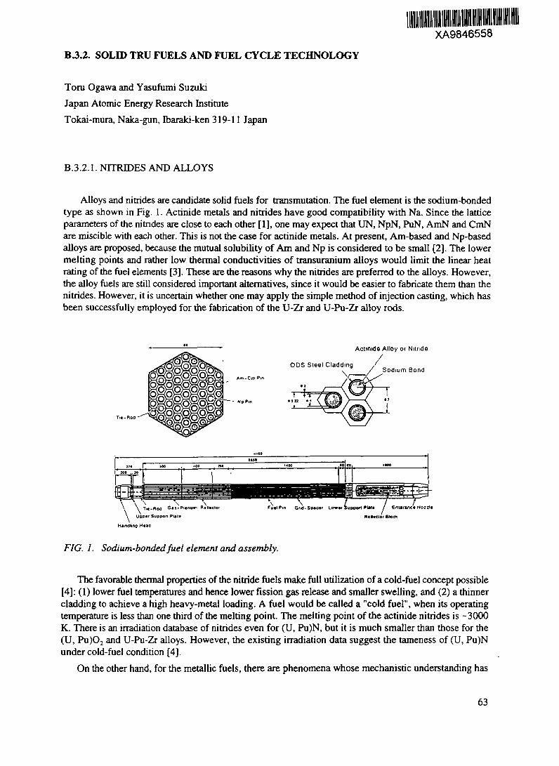
XA9846558
B3.2. SOLID TRU FUELS AND FUEL CYCLE TECHNOLOGY
Toru Ogawa and Yasufumi SuzukiJapan Atomic Energy Research InstituteTokai-mura, Naka-gun, Ibaraki-ken 319-11 Japan
B.3.2.1. NITRIDES AND ALLOYS
Alloys and nitrides are candidate solid fuels for transmutation. The fuel element is the sodium-bondedtype as shown in Fig. 1. Actinide metals and nitrides have good compatibility with Na. Since the latticeparameters of the nitrides are close to each other [1], one may expect that UN, NpN, PuN, AmN and CmNare miscible with each other. This is not the case for actinide metals. At present, Am-based and Np-basedalloys are proposed, because the mutual solubility of Am and Np is considered to be small [2]. The lowermelting points and rather low thermal conductivities of transuranium alloys would limit the linear heatrating of the fuel elements [3]. These are the reasons why the nitrides are preferred to the alloys. However,the alloy fuels are still considered important alternatives, since it would be easier to fabricate them than thenitrides. However, it is uncertain whether one may apply the simple method of injection casting, which hasbeen successfully employed for the fabrication of the U-Zr and U-Pu-Zr alloy rods.
Actinide Alloy o< Niinde
ODS Steel Cladding /
VSodium Bond
\ \ x\ \ T»c-Roa G*i-Plenum Rtlltcio
Upper Support Putt\/ Enurinct No
FIG. 1. Sodium-bonded fuel element and assembly.
The favorable thermal properties of the nitride fuels make full utilization of a cold-fuel concept possible[4]: (1) lower fuel temperatures and hence lower fission gas release and smaller swelling, and (2) a thinnercladding to achieve a high heavy-metal loading. A fuel would be called a "cold fuel", when its operatingtemperature is less than one third of the melting point. The melting point of the actinide nitrides is -3000K. There is an irradiation database of nitrides even for (U, Pu)N, but it is much smaller than those for the(U, Pu)O2 and U-Pu-Zr alloys. However, the existing irradiation data suggest the lameness of (U, Pu)Nunder cold-fuel condition [4].
On the other hand, for the metallic fuels, there are phenomena whose mechanistic understanding has
63

not yet been reached the amsotropy in swelling, the component redistribution under a thermal gradient,the variation of apparent thermal conductivity with porous structure development and bond-sodiumintrusion into pores etc [5] The reaction between stainless steel cladding and actmide alloys is also severeat higher temperatures, and imposes a performance limit [6] JAERI has prepared (U, Pu)N fuel elementsand irradiated them in a thermal spectrum in JMTR [7] UN and PuN were prepared by carbothermicreduction of powder mixtures of respective oxides and carbon in flowing H2 + N2 Then UN and PuN weremixed and sintered to form (U, Pu)N The irradiation test of (U, Pu)N in the fast reactor, JOYO, was begunin Augusi, 1994, as a JAERI/PNC joint program Suzuki et al [8] have prepared NpN by carbothermicsynthesis Thermal conductivity [9] and high-temperature vaporization [10] of NpN have been studied bythe same group The thermal conductivity of NpN was intermediate between UN and PuN Thermalproperties will be further studied for (U, Pu, Np)N
B 3 2 2 NITRIDE FUEL CYCLE TECHNOLOGY
The scheme of the nitride fuel cycle is shown in Fig 2 For the nitnde fuel cycle, technicaldevelopments are being made on (1) the internal gelation method to form (oxide + carbon) gel microspheresfrom the actmide nitrates and (2) the electrorefming process for reprocessing irradiated nitnde fuels
HLW
Parti t ioning
Actmide nitrates
Sol-gel process
Oxide (hydroxide) + carbonmicrospheres
Carbothermic reduction
Nitnde microspheres
Press/Sintering
Fuel element/Assembly
"Actmide Burner"
Irradiated Fuel
Pyrochemical reprocessing
Actinide metals
Nitridation
Nitride particle
FIG 2 Scheme ofTRUnitride fuel cycle
64

B.3.2.3.1. Nitride fabrication by sol-gel process
The internal gelation method is presently being studied because of the simplicity of feed solutionpreparation compared with the external gelation method, particularly when one wants to obtainmulticomponent ceramics. In the internal gelation method, hexamethylenetetramine (HMTA), added to thesolution, decomposes on heating to form ammonia which then reacts with the actinide nitrates. Then thesolution of actinide nitrates with a carbon suspension turns into a solid mixture of oxide (hydroxide) andcarbon in the form of microspheres. Normally the droplets of feed solution are heated in an oil column, butthe use of a microwave heating for the internal gelation process has been proposed by Ledergerber et al.[11] Because of its potential to reduce the treatment of alpha contaminated oil, a 2.5 GHz microwaveheating apparatus has been developed for this gelation process (Fig. 3) [12]. Also, in order to prevent theinstability of the feed solution by the a-decay heat, techniques to mix the actinide nitrate solution and theHMTA solution right above the droplet-forming nozzle are being developed [13]. The gel microspheresare heat treated in a nitrogen atmosphere and converted to the nitride.
a(C)0.1
10,-180.5
o'a.
0:04
p'(CO)=^0.005 0:01 0:02
po
po
CMCOp
1.42 I
1.30 -|
1.14 61.03 o
0.90 o
po
po
C/U of Carbonitride
p (N2)=0.92T=1823K
FIG. 4. Stability diagram of U-C-N-O system at1823 K with p*(N2) = 0.92 atm.
It should be noted that the N2 supply has to be in greatFIG. 3. Microwave gelation apparatus 6XCeSS f°r the carbothermic synthesis of the nitrides. Thisand ammonium uranate gel microspheres. P0^ °an be illustrated ^ c°™dering the case of UN
synthesis. Figure 4 shows a stability diagram for the U-C-N-Osystem at an arbitrary nitrogen partial pressure of p*(N^) = 0.1 atm at 1823 K [ 14]. The mixture of UO2 andcarbon is heated in a nitrogen atmosphere to form Uranium carbonitride, U(C, N), and oxynitride,UO2.YN3Y/4. The amount of the latter decreases with time; so does the fraction of UC in U(C,N). Carbonactivity, a(C), and p*(O2) are given by the upper abscissa and left ordinate, respectively. Progress of thecarbothermic reaction is measured by the cumulative evolution of CO. The dashed line gives theequilibrium partial pressure of CO, p*(CO). p*(CO) at a(C)=l is -0.03 atm. As the reaction proceeds, C/Udecreases to further reduce the equilibrium CO pressure, p*(CO). That is, in order to obtain UN, one hasto supply nitrogen in a large excess to effectively remove CO from the system. Though excess N, from theprocess exhaust can be purified and circulated, the demand on "N-enriched N, makeup could be larger thanthat simply expected from the reaction stoichiometry. This is another incentive to recycle 15N from thepyrochemical reprocessing.
65

B.3.2.3.2,. Pyrochemical reprocessing
The irradiated fuels are reprocessed with molten-salt electrorefining techniques. The configuration ofthe electiorefiner can be common for the nitride and alloy fuels. For reprocessing nitride fuels, theelectrorefiner has to be flushed with an inert gas to purge N2 from the anode. '5N-enriched N2 is recycledto the nitnde refabrication.
The anode basket contains either nitride or alloy fuels. The cathode is either a solid metal rod or a liquidmetal bath such as molten Cd depending on the combination of actinide elements in the molten salt bath.A molten Cd cathode would be preferred torecover transuranium elements in the presenceof U3+ in the molten salt phase.
The recovered N2 can be fed to theprocess to convert actinide metals to nitrides.Conversion can be made in a liquid cadmiumbath: actinide metals dissolve into Cd, reactwith N2 which is in contact with Cd, andsegregate as nitrides on the bottom of thebath. Cd can be readily distilled away fromthe nitrides.
The anodic dissolution of UN has beenstudied in laboratory-scale experiments [15].UN powder was contained in a graphite anodebasket. The counter electrode was amolybdenum rod. The LiCl-KCl-UCl3 meltwas contained in a recrystallized aluminacrucible. The Ag/AgCl reference electrodeconsists of pure silver in LiCl-KCl-10 mol%AgCl. The measurements were done at 773 K.Fig. 5 shows that the anodic dissolution ofUN occurs with the characteristic potential atabout -0.66 V against the reference electrode.The pertinent reaction is the formation ofsolid UC1, on UN:
260 r-
220|
180
(' 3eiore ospos c(2) Af t r r deposition
UJp;GC!DO
100-1200 1000 800 600 -400 -200
ANODE POTENTIAL (mV)
FIG. 5. Current and electrode potential for UNcontained in a graphite anode basket in LiCl-KCl-UCl3
melt at 773 K. The reference electrode was LiCl-KCl-10mol% AgCl.
UN + 3 [AgCl] = UC13 + N2 + 3Ag 0)
AG = AGf(UCI3) - AGf (UN) - 3{AGf (AgCl) + RT In XAgC1)==-192,030 J/mol
E = AG/3F = -0.66 V
where AGf is the free energy of formation, XAgC, is the mole fraction of AgCl in the reference electrode,and F is the Faraday constant. Above this characteristic potential UN becomes unstable.
Electrolytic decomposition of UN was made with the working-electrode potential of -0.20 V. Almostall UN was dissolved, and a-U was deposited on the counter electrode. Similar runs have been made inLiCl-KCI-CdCI, melt, where Cd-U alloys were deposited on the cathode. Further tests with (U, Ln)N, PuNand NpN are scheduled (Ln: lanthanides). Table I shows the standard electrode potentials of actinide and
66
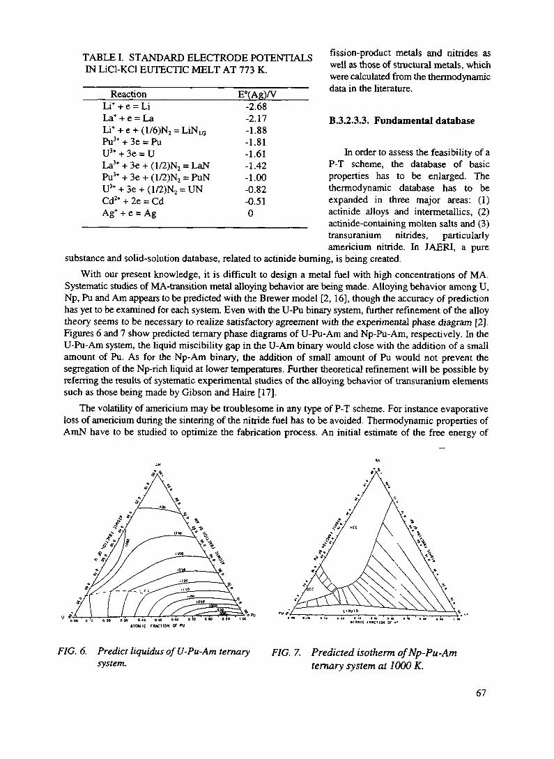
TABLE I. STANDARD ELECTRODE POTENTIALSIN LiCl-KCl EUTECTIC MELT AT 773 K.
ReactionLi+ + e = LiLa+ + e = LaLi+ + e + (1/6)N2 =Pu3+ + 3e = PuU3+ + 3e = ULa3* + 3e + (1/2)N2Pu3* + 3e + (1/2)N2U3+ + 3e + (1/2)N2 :Cd2+ + 2e = CdAg+ + e = Ag
UN./3
= LaN= PuN
= UN
E°(Ag)/V-2.68-2.17-1.88-1.81-1.61-1.42-1.00-0.82-0.510
fission-product metals and nitrides aswell as those of structural metals, whichwere calculated from the thermodynamicdata in the literature.
B.3.2.3.3. Fundamental database
In order to assess the feasibility of aP-T scheme, the database of basicproperties has to be enlarged. Thethermodynamic database has to beexpanded in three major areas: (1)actinide alloys and intermetallics, (2)actinide-containing molten salts and (3)transuranium nitrides, particularlyamericium nitride. In JAERI, a pure
substance and solid-solution database, related to actinide burning, is being created.With our present knowledge, it is difficult to design a metal fuel with high concentrations of MA.
Systematic studies of MA-transition metal alloying behavior are being made. Alloying behavior among U,Np, Pu and Am appears to be predicted with the Brewer model [2, 16], though the accuracy of predictionhas yet to be examined for each system. Even with the U-Pu binary system, further refinement of the alloytheory seems to be necessary to realize satisfactory agreement with the experimental phase diagram [2].Figures 6 and 7 show predicted ternary phase diagrams of U-Pu-Am and Np-Pu-Am, respectively. In theU-Pu-Am system, the liquid miscibility gap in the U-Am binary would close with the addition of a smallamount of Pu. As for the Np-Am binary, the addition of small amount of Pu would not prevent thesegregation of the Np-rich liquid at lower temperatures. Further theoretical refinement will be possible byreferring the results of systematic experimental studies of the alloying behavior of transuranium elementssuch as those being made by Gibson and Haire [17].
The volatility of americium may be troublesome in any type of P-T scheme. For instance evaporativeloss of americium during the sintering of the nitride fuel has to be avoided. Thermodynamic properties ofAmN have to be studied to optimize the fabrication process. An initial estimate of the free energy of
ATOMIC FWCTKM Of PU
FIG. 6. Predict liquidus of U-Pu-Am ternarysystem.
FIG. 7. Predicted isotherm of Np-Pu-Amternary system at 1000 K.
67
formation, AGP, of AmN has been made from the vaporization behavior of impurity W1 Am in reactor-gradePuN [18] AGf°(AmN) appears not to be significantly different from those of UN and PuN. This gives amuch higher vapor pressure of Am over AmN compared with Pu over PuN. If so, either a technique tolower the sintering temperature has to be devised or the application of low-density fuel has to beconsidered.
As long as one seriously considers the use of Plutonium and the recycle of the other transuraniumelements in nuclear technology, the thermodynamic behavior of actinide(An)-noble metal alloys such An-Pd alloys has to be better defined. The fission yields of noble metals are much greater from thetransuraniums than from 235U, and they form very stable intermetallics with actinides. The existence ofstable intermetallics would cause a significant actinide loss during reprocessing.
REFERENCES
[I] KOCH, G., et al.: GMELIN Handbuch der Anorganishen Chemie, Transurane, Teil C: DieVerbindungen, Springer Verlag.
[2] OGAWA, T.: J. Alloys and Compds., 194 (1993) 1.[3] OGAWA, T., et al.: JAERI-M 89-123 (1989).[4] BLANK, H.: J. Less-Common Metals 121 (1986) 583.[5] WALTERS, L. C.: Nucl. Technol. 65 (1984)179.[6] VOHEN, A. B., et al.: Trans. ANS 66 (1992) 202.[7] ARAI, Y., et al.: JAERI-Research 95-008 (1995).[8] SUZUKI, Y., et al.: J. Nucl. Sci. Technol. 31 (1994) 677.[9] ARAI, Y., et al. • J. Nucl Mater. 211 (1994) 248.[10] NAKAJIMA, K., et al.: 1995 Annual Mtg. Atomic Energy Society of Japan, paper No. K9., Tokyo,
March, 1995.[ I I ] LEDERGERBER, G.: Trans. ANS 40 (1982) 55.[ 12] Y AM AGISHI, S., et al.: J AERI-Tech 94-010(1994).[13] YAMAGISHI, S.: 1995 Annual Mtg. Atomic Energy Society of Japan, paper, No. L48, Tokyo,
March, 1995.[14] OGAWA, T., et al.: JAERI internal document.[15] KOBAYASHI, F., et al.: J Am. Cer. Soc. (submitted).[16] BREWER, L.: J. Alloys and Compds. 213/214 (1994) 132.[17] GDBSON, J. K., et al.: J. Alloys and Compd. 213/214 (1994) 106.[18] OGAWA, T., et al.: J. Alloys and Compds. (in press).
68

XA9846559
B.4. ACCELERATOR DRIVEN SYSTEMS (ADS): A PRINCIPAL NEUTRONICS ANDTRANSMUTATION POTENTIAL
I. SlessarevCEA, Cadarache, France
The proposed accelerator-based systems [1] use a beam of high energy protons to producesupplementary (external) neutrons as a result of spallation processes in a target. These neutronsare successively used to feed a subcritical blanket and can be used for the following goals:• to create or to enhance a neutron surplus available for incineration of those long lived toxic
nuclei which require neutrons (they can be long lived fission products, Minor Actinides(MA's) in the case when thermal neutron spectrum is applied, etc.);
• to enhance the deterministic safety features for reactivity-type of accidents.
B.4.1. OVERALL NEUTRONICS OF THE ADS
The external neutron source ji due to heavy nuclei spallation in a subcritical (keff < 1) medium canbe defined as
H = r-f ( neutrons per fission in the medium )
where F - is the number of neutrons returning to the ADS-medium if each fission has been transformedinto proton current (spallation effectiveness),f - is the fission fraction (fraction of energy) actually being used for spallation.
The following equations describe the neutronics of the ADS-blanket:
(1)
wherev - averaged secondary neutron number of fission process,
<p* - importance of spallation neutrons in the given ADS,I - proton current (mA),W - ADS thermal power (MW),z - the number of neutrons gained due to spallation per proton.
69

B.4.2. DETERMINISTIC SAFETY ASPECTS
One of ADS important potential is relating to deterministic safety concerning reactivity types ofaccidents. Evidently that all similar accidents can be certainly eliminated if ADS-reactivity could neverexceed k,fr = 1. It means that the sum of the initial k°eff and all possible reactivity effects (burnup reactivityswing, including Np (or Pa) effect, power reactivity and void effects as well as other similar effects), takenfor unfavorable situations, will never exceed critical value.
Obviously, subcriticahty ( k°eff < 1 ) can not guarantee these properties (except the case of a too lowlevel k^ when economics is not acceptable usually), while a combination of subcriticahty and "stabilizedreactivity" is a predisposition of deterministic safety features.
Further detailed simulations of all important accident scenarios are necessary in order to make a reliabledeterministic safety potential analysis.
B.4.3. ECONOMICS
Economics puts an important impact on ADS-parameters choice [2,9].For transmutation problems, which are not dependent on neutron surplus production (e.g. Pu burnup),
it is important too keep k°eff - value close to critical state, because it allows to decrease requirements toproton beam power as well as to proton current. A benefit of ADS for these cases is relating to in the mostcases deterministic safety enhancement. In turn, this is important to have small reactivity effects includingbumup reactivity swing in ADS. Otherwise, one has to keep kcff during a long core life at rather low levelresulting in an economic penalty.
For example, in ADS with proton energy 1 GeV, the F is evaluated as 0.8 - 1.0 neutron/fission atz = 25 neutron/proton. It gives approximately 0.1 neutron/fission per each 10% of energy spent for theaccelerator ((p* = 1). Meanwhile, the analysis of a neutron surplus production potential shows (seeparagraph B.I.4) that there is another way to enhance neutron surplus: ADS-blanket neutronicsoptimization.
Hence, both deterministic safety and economics considerations show an importance of "stablereactivity" concepts for ADS.
The economics of ADS depends upon the following negative factors: the necessity to have a "beam-target" system, as well as to spend a part of energy for proton current. Capital cost of the accelerator canaffect ADS-economics. At the same time, enhanced safety potential of ADS allows to simplify reactorcontrol.
A very rough preliminary estimation shows that a cost of the accelerator must not exceed 1/3 of theblanket cost to allow ADS to be economically acceptable.
Hence, a low capital cost of the accelerator, small fraction of consumed energy and a high k°cff - valuemay give an opportunity to be economically competitive with critical reactor.
In some Np-scenarios, even small fraction of ADS allows to reduce essentially MA-masses and fueltoxicity of all NP (as in the case of ADS/TransPu-Burners, see next paragraphs). For these cases, ADS-economic potentials will not be too important.
B.4.4. TOXICITY TRANSMUTATION POTENTIAL OF THE ADS
Minimization of the sources of a long-term toxicity in relation to energy production can be consideredas the mam goal of neutronics transmutation of both fuel and long-lived fission products (LLFP).
There are at least three types of long-term toxicity source [1]:
70

• fuel inventory in the nuclear reactors (systems),• fuel wastes in the process of a discharged fuel reprocessing,• long-lived radioactive fission products.
It seems that the last two sources mentioned are the most important due to toxicity accumulation duringthe normal functioning of the nuclear power industry [3].
For perspective development of nuclear power there is a state of "equilibrium", when similar operations(reactor fuel feeding, fuel burning, reprocessing, etc.) are constantly repeating. This leads inevitably to a"quasi-stabilization" of fuel and fuel waste contents.
B.4.4.1. Reduction of the long term toxicity of fission products
The neutron surplus potential of nuclear system depends on the overall neutron balance ofevery nucleus - "predecessor" (participating in reactor fuel feeding) and his "family", neutron"parasitic" losses (neutron leakage, absorption in construction materials (L + CM), et c.) andexternal neutron source n [1 - 3].
For an equilibrium state, a neutron surplus potential G; of a J-family being under irradiationcan be expressed through the "neutron consumption" Dj (note: negative consumption meansproduction) during family life (up to be fissioned completely):
Gj (neutrons/fission) = - Dj - (L + CM)The neutron consumption level Dj depends mostly on neutron spectrum and neutron flux level
(the last one defines the competitiveness between neutron processes and radioactive decay).Generally, if a reactor is feeding by a set of nuclei, one has a total neutron surplus potential G ofa system (in presence of an external source):
G(neutrons> 'fission) = (XyxGy)+n = - (XyxDy)-(L-t-CM)+u=G0+Mj j
where Xj is an "enrichment" of J-family "predecessor" (i.e. normalized fraction of J-nucleus) inthe feed fuel and ^ is a corresponding internal neutron surplus potential (for critical reactorsG-G0).
A necessity to increase the neutron surplus potential (to increase LLFP-incineration rate) leadsto ADS-concepts with a lower k°eff - level, which allows to increase the i - value. It contradictsto some opinion, that the highest neutron "amplification" is more favorable for transmutationpurposes. However, a low k°eff leads to a high energy consumption and the final value has to bechosen taking into account ADS-economics.
In practice, G-value reflects the neutron balance and its enhancement has a reasonable limit:for almost all realistic power reactors the (L + CM) value is roughly 0.3 neutrons/fission.
Criticality condition of a fissionable medium at equilibrium corresponds to G0 = 0 and the G0value defines generally the potentially achievable multiplication factor Jkeff as:
71

Table I gives the G0 - value potential (neutrons/fission) for fuel nuclei in different neutron spectra with"standard" and "high" averaged neutron fluxes F, when (L + CM) being taken equal to 0.3 neutrons/fissionfor all reactors and ADS.
TABLE I THE INTERNAL NEUTRON SURPLUS: G0- VALUES FOR LWR AND FR SPECTRAFOR SOME IMPORTANT FAMILIES
J-families
235U238U232Th239pu
242Pu241Am243Am
The LWR-Spectrum<j>= 1014 + 1015 nycm2-s
+ (0.32+0.35)
- (0.37+0.29)
- (0.06+0.06)
+ (0.42+0.53)
-(1.54+0.98)
-(1.37+1.11)
- (0.59+0.58)
The FR-spectrum<J> = 1014+1015n/cm2-s
+ (0.58+0.60)
+ (0.32+0.35)
+ (0.09+0.09)
+ (1.16+1.21)
-(0.26+0.41)
+ (0.32+0.43)
+ (0.30+0.70)
Table I shows that:fast spectrum is the most favorable for all families regarding on neutron surplus production
• 232Th is the "poorest" among all natural fuels; its neutron production is 0.2 - 0.3 neutrons/fissionless then of 23SU. The internal neutron surplus of the Thorium family is not very sensitive to thespectrum type,
• the sensitivity of the neutron surplus to the neutron flux level is not of a high importance;nevertheless it can be helpful for some special problem resolution.
A neutron surplus gained directly from spallation (u,) depends on blanket thermal efficiency and fissionenergy. Then fast spectrum blankets can give some supplementary advantage - about 20 - 30% in the u, -value when compared to thermal spectrum blankets [1].
Table II shows the neutron surplus potential of TransPu-fuel discharging from LWR's (closed cyclefor U, Pu, Np) at different neutron flux levels for important neutron spectra. It can be seen that TransPu-fuel does not require a neutron surplus being burnt in a fast spectrum.
B.4.4.2. Fuel waste toxicity (FWT) reduction.
The source of fuel waste toxicity risk is originated from the "losses" of discharged fuel. In the caseof an open cycle, "losses" represent 100% discharge to a repository. In the case of reprocessing, "losses"are related to the decontamination efficiency of the chemical fuel reprocessing. The Fuel Waste Toxicity(FWT) is the consequence of the losses of the equilibrium fuel mass. The FWT (per electricity productionunit) can be easily evaluated by the following expression [3,4]:
FWT = Y(l -B)/Bx TjjxLOS, (2)
72

TABLE H. NEUTRON PRODUCTION (NEUTRONS PER FISSION) POTENTIAL OF TransPu-BURNERS ((-D) VALUES [1]
Spectra Flux level
1015
Fast 10"
1017
1014
Thermal 1015
1016
1014
Super- 10'5thermal jQie
1017
'Pu
+1.46
+1.51
+1.52y. - t>. ;
+0.72
+0.83
+0.85
+1.01
+1.04
+1.07
+1.13
^'Arn
+0.62
+0.73
+0.78
-1.07
-0.81
+0.02
-0.74
+0.04
+0.54
+0.66
242mAm
+1.36
+1.48
+1.54
-0.11
+0.16
+1.00
+0.25
+1.03
+1.53
+1.66
243 Am
+0.60
+1.00
+1.07
-0.29
+0.28
+0.45
-0.89
-0.53
-0.21
+0.36
^Cm
1.39
+1.84
+1.92
+0.68
+ 1.24
+1.32
+0.10
+0.42
+0.48
+0.49
TransPu
+0.68-
+0.90-
+0.96-
-0.69 -
B- TransPuE
+0.80
+1.15
+1.22
-0.20
-0.31-+0.30
+0.26 -
-0.72 -
+0.58
-0.64
-0.11 --0.18
+0.55- +0.11
+0.45(TransPu8) and (TransPuE) are "neutron production" of the transplutoniums discharging from LWR-open fuel cycle(i.e. in the beginning "B" of the closing cycle procedure) and from LWR (closed fuel cycle for U+Pu+Np) atequilibrium "E".
In equation (2) we have summed up all nuclei which make up the feed fathers (U5U, 238U, 239Pu, MA's,TransPu, et c.) And we have used the following notations:
y - mass (gram) of fission products per net electric energy production unit; its value dependsmostly on a reactor thermal efficiency and varies between 0.9 xlO6 (fast reactors ) and 1.2xl06
gram/GWe per year (thermal reactors),B - fuel bumup (in 5 of heavy atoms, h.a.),LOS, - a fraction of I-nucleus being lost in fuel cycle operations,Z, Tj, - toxicity of J-family in a fuel (I - index of a family member) in one gram of reactor fuel atequilibrium (i.e. unit fuel mass toxicity after irradiation, see Table HI).Hence, fuel waste toxicity source depends mostly on neutron spectrum (through family toxicities), fuel
bumup and losses during reprocessing. Subcriticality level does not play an important role in the FWT: itchanges the fuel feeding relative concentration, but total FWT (for exception of special cases) usually variesslightly.
The fuel waste toxicities time-dependent distribution at equilibrium is shown on Fig. 1 for the mainprincipal nuclear reactors with closed Uranium and Thorium fuel cycles. The standard LWR (open fuelcycle) and "conservative" fuel loss data have been taken as a reference: 0.1% for Uranium, 0.1% forPlutonium and 1% for MA's.
Closed fuel cycles give always the lower fuel waste toxicities when compared to the standard LWR(open cycle), having even more toxic fuel then the standard LWR due to much smaller losses (<1%) of thetotal fuel mass of the standard LWR discharge.
73

Nuclear Reactors Fuel Waste Toxicity
10 —
9 —
•7 __]_
6 —
5 —
4 _.
I1E+2
LWR open cycle
LWR closed cycle
FR standard closed cycle
LWR Thorium closed cycle
FR Thorium closed cycle
I I 1 1 I I 1 1
1E+3 1E + 7 1E+81E+4 1E+5 1E+6time (years)
FIG 1 The fuel waste toxicities time-dependent distribution at equilibrium for the main principalnuclear reactors with closed Uranium and Thorium fuel cycles The standard LWR (open fuel cycle) isused as the reference
B.4.4.3. On ADS- "niches" in nuclear power
Considering possible "niches" for ADS in nuclear power, three stages of NP-development can beconsidering starting, long-term development and stagnation or power reduction
Let suppose that on starting stage (due to a power industry inertia) the share of new reactor generation(including fast reactors) can not be high enough and it will be possible to use a small option of newinstallations only Hence, the most realistic scenario of the "starting stage" of NP development can assumeto use of all potential of the current reactor park for maximum FWT-reduction (to avoid Pu and MAaccumulation)
It is not evident that LWR fully closing fuel cycle can be realized at an industrial scale, since theaccumulation of MA affects strongly the LWR properties It seems that is more easy to close fuel cycle forU, Np and Pu fuel components only
Hence, at current stage, nuclear power can use• the closed LWR fuel cycle (for U, Np and Pu) and a special reactor - TransPu-Burner to
prevent an accumulation of transplutoniums.A pielimmary assessment of the FWT-reduction potential shows that TransPu-bummg is extremely
important theoretically, closing of LWR fuel cycle (for U, Np and Pu components) in a combination withTransPu-bumout in a fast spectrum TransPu-Burner (closed cycle, bumup 15 % h a) Allows to reduce theFWT up to a factor 100
Due to some "negative" physics property (such as very low delayed neutron fraction, low Doppler
74

reactivity effect, positive void reactivity effects, et c.), due to some specific technologic difficulties,TransPu produces problems of being used in standard critical reactors. This can be the case to usesubcritical ADS/TransPu-Bumers.
Potentially, molten salt concepts are more suitable to play the TransPu-Burner role. They are:• less sensitive (due to a possibility of continuous fuel feeding) to burnup reactivity swing effects.
They do not demand a variable accelerator power due to constant subcriticality during bumup; canhave a higher k^ with an acceptable deterministic margin to reactivity type accidents. Hence, theycan spent less energy for accelerator needs;
• less sensitive to "peaking" flux shape due to fuel mixing;Besides, they have:• the highest average to maximum burnup ratio (fuel mixing effect) that reduces the FWT-level;
maximum neutron spallation importance (p* due to possibility of proton beam insertion directly toregion with maximum neutron importance and to fissile nuclei.
It was evaluated that Transplutonium fuel provides (see Table HI) a rather high neutron surplus (ca 0.5neutron per fission) in fast neutron spectrum, while other neutron spectra require additional fuel to supporta k^ as well as a higher fraction of Burners in NP.
TABLE III. NORMALIZED TOXICITIES OF J-FAMILIES Tj AT EQUILIBRIUM (in Sv/gram offamily). Tj WAS AVERAGED ON SHORT (102 -=-104 YEARS) AND LONG (102 -=- 106 YEARS) TIMEINTERVALS (NEGLIGIBLE LOSS RATES) [2].
Predecessorsof families
232Th
233U
235u
238u
239pu
Thermal reactors((J>=1014 n/cm2s)
Tj T,Short Long
21 4.6221 53372 1997 1
4851 46
Fast((j)=10
Short
3811792841
4290
reactorsl14 n/cm2s)
TjLong
1162195.728
Superthermal reactors(cj>=1014 n/cm2s)
Tj TjShort Long
41 3.8168 23173 2.5275 3.5
4610 58
Natural toxicity(4>=1014 n/cm2s)
Tj T;
Short Long
0.0052 0.0052111 46
0.037 0.480.0008 0.00682300 13
Due to a small burnup reactivity swing, lack of Pa-Np types of reactivity effects, the following choiceof subcriticality level seems to be reasonable, if TransPu burnout not demand an external neutron "help":1^ = 0.95-0.97.
The principle parameters of fast spectrum ADS-TransPu-Burners can be the following:krfj = 0.95 and z = 25 n /1 GeV-proton, (p* = 1.5. Then one needs < 5% of ADS-TransPu-Bumers inall park of reactors. Proton current is expecting to be 50 mA/GWe and the fraction of NP-energy spentfor accelerator needs: 0.5 %. The system consisting of LWR's (closed cycle) and TransPu-Burners canproduce (as a neutron surplus) 0.03 neutron per every fission in NP, which is available for partialLLFP-incineration.Such ADS-Bumer can be used as well for Pu-burnout (if needed). In this case, it will be reasonable touse a high neutron surplus of Pu for LLFP-incineration. However, the justification of ADS for Pu-burning is more difficult; it can be done in critical reactors also.For comparison, one can assess a potential of the LWR standard neutron spectra for TransPu-burnout
75

(cp* = 1.5, F = 0,8 n/fission instead of F = I/fission for fast spectrum systems) in the standard neutronflux level: 1014 n/cm2s. One can get: DTransPu = 0.69 (see Table III), G0 = -1 n/fission, k^ = (1 - G</v)''= 0.7, proton current I = 520 mA/GWc. One needs all ADS energy to spend for the accelerator needs.As for "superthermal" neutron spectrum and elevated flux level (1015 n/cm2s), one can get: DTransPlI =0.11, G0 = -0.41, krff = 0.85 and proton current I = 210 mA/GWe. Moreover, there are no neutrons forLLFP-incmeration and the FWT reduction potential is approximately one order lower than of fastspectrum (lower bumup, thermal efficiency, et c.).In the hypothesis of continuation of nuclear power in the long term future, with the possibility to
increase its energy output if required by eventual energy demand, one has to provide a system which beable:
• to breed fuel to make use of natural resources,• to reduce LLFP toxicity in a large scale.For this stage it is necessary to have a nuclear system with a sufficient neutron surplus to minimize fuel
waste toxicity, LLFP-incmeration and fuel breeding. It would be hopeful (particularly important for itspublic acceptability) if this system has deterministic safety features allowing to be definitely resistant toheavy accidents which lead to fuel disintegration.
ADS economics will play an important role if one wants to use a large park of innovative nuclear powerinstallations. Competitive ADS (slightly subcritical: k^ = 0.98) and reactivity stabilized blanket on the baseof competitive fast reactor technology (i.e. lead coolant, dense fuel) seems to be attractive.
More important that supplementary neutrons of ADS can allow to compensate a drawback of oxide fuel- relatively large bumup reactivity swing. It means that fast spectrum ADS with oxide fuel can havedeterministic safety features and can be economically acceptable.
To be sure in the optimum choice of ADS-spectrum, one can compare the potential of a thermalspectrum ADS (cp* = 1, F = 0.8 n/fission for proton beam 1 GeV): the same subcriticality level (k,.ff = 0.98)leads to higher proton current (factor of 1.3). Meanwhile, the reduction of the FWT is a factor of one orderless than for fast spectrum, as well as many less neutrons are available for LLFP-transmutation.
B.4.4.4. On specific features of fuel cycles.
The Uranium fuel cyclePotentially fast spectra have the following neutronics regarding transmutation problems:• in fully closed Uranium fuel cycle (averaged bumup level B = 15%) the reduction of the FWT is
assessed as two orders in magnitude when compared with standard LWR-open fuel cycle,• neutron surplus for fuel self-sustaining fast reactors (zero breeding gain) is varying from 0.3
neutrons/fission for oxide fuel up to 0.5 neutrons/fission for metal fuel.Example: the neutronic potential of an ADS - slightly subcritical lead cooled fast breeder system withnitride fuel and proton beam source (lead is used as a coolant as well as a liquid target for proton beam)and kjff = 0.98 can be the following:
• neutron surplus - about 0.4 neutron per fission (zero breeding gain) in fuel plus 0.05neutrons/fission due to spallation in lead target,
• relatively small (about 5% of the total energy) consumption for proton beam support.The total neutron surplus (that can be available) both for breeding and for LLFP-mcineradon is assessed
0.45 neutrons/fission that seems to be enough to burnout all dangerous fission products and/or to reproducenew fuels for NP further development.
Economics of this system allows it to be rather competitive taking into account the simplicity advantagefeatures: no needs in control rods, 2-circuits scheme, no needs in anti-coolant fire and anti-coolant
76

explosion protections, et c. Subcriticality plus a stabilized reactivity allow to increase a deterministic marginregarding reactivity type of accidents.
Hence, a reasonable compromise between safety features, reduction fuel waste potential and economicsseems to be achieved for ADS with Uranium fuel cycle.
The Thorium fuel cycleThorium fuel cycle can have an attractive potential feature related to relatively small production of
transplutonium [5,6] and, hence, to low MA concentrations (except ^"Np, ^Pu) at equilibrium. As a result,the FWT level for both thermal and fast spectrum reactors during the first 103 years after incineration ismuch lower (see Fig. 1) than for Uranium fuel cycle. Later on, the advantage of Thorium cycle in the FWTis disappearing due to large concentrations of very long term toxic 233U, ^U, as well as 231Pa.
232Th-fuel has relatively tight neutron balance both in fast and thermal neutron spectra; for every fissionit produces many fewer neutrons than U8U (see Table I).
To use an advantage of subcriticality in deterministic safety features, one needs to have a bumupreactivity swing and reactivity effects as low as possible. A low burnup reactivity swing can be realized intraditional reactor designs if fuel concentration in the beginning of cycle (BOL) is "below" of equilibriumone (to compensate of core poisoning by fission products). It si more easy to realize this condition forsubcritical ADS than for critical reactors. However, at a low k°eff, an accelerator energy consumption is toohigh. For example, for medium size fast reactors (0.5 -1) GWe with 232Th- feeding, if equilibrium k°eff valueis to be close to 0.95 and one has the reactivity stable (during burnup) core. If one propose to increase k0^by 233U-enrichment change, it leads to a loss of reactivity during core life and to a loss of reactivity marginregarding reactivity accidents.
Another disadvantage of thorium cycle is a high "protactinium effect" of reactivity (much higher thancorresponding "neptunium effect" for Uranium cycle for standard fluxes), which demands to keep a lowk°eff - value. To avoid problems with the protactinium effect and to increase neutron surplus, the Thoriumcycle needs "reduced flux level" concepts.
Hence, for Thorium cycle, a compromise between deterministic safety, subcriticality level andeconomics will be more difficult as either one has a low k0^ and deterministic safety features with "weak"economics, or one has an acceptable economics (higher k^) with a "standard" safety level.
B.4.4.5. The long-term toxicity of fuel inventory.
The total fuel inventory toxicity is proportional to the mass of fuel inventory (per power unit) and tofuel toxicity. Fuel inventory INV is inversely proportional to the product (af x F), where F is the averagedneutron flux. To minimize INV, one should increase (af x F) both for thermal and fast neutron spectra. Thisgives an advantage to the high fluxes and thermal spectrum concepts. If the (<jf x F) growth in a criticalreactor can be achieved by a fuel concentration decrease (avoiding an increase of the specific power), thenthe neutron balance becomes tighter, and it leads to a bumup decrease and finally to the FWT increase.
One could increase F by decreasing k^ (subcriticality effect), accounting for a possible fuelconcentration drop, but the corresponding inventory reduction is expected to be relatively modest. For areasonable level of subcriticality (k^ = 0.8 - 0.9) the total effect will not exceed roughly a factor of = 1.5in inventory toxicity reduction.
B.4.4.6. Power Reduction or Stagnation Stage Scenarios.In this type of scenarios, subcritical systems can be helpful due to their lower sensitivity to fuel mass
inventory and isotopic content. Besides, they can give more flexibility for the elimination of residual fueland LLFP toxicities.
77

The principal goal for this stage can be to approach a minimum (close to zero) mass inventory and zerotoxicity of MA:s and LLFP:s.
It is very important to have the appropriate installations and one can use Burners (or a part of a reactorpark) eventually used in previous stages, such as ADS/TransPu-Bumers, FR-ADS with Uranium orThorium fuels, et c.
For burning-out the residual toxic fuel (or stocked fuel) some versions of ADS can be particularlysuitable since no critical mass is demanded, larger masses of LLFP (if one will use a large neutron surpluspotential: low k°eff - options) can be eliminated, smallest fuel inventory (particularly, high neutron flux andthermalized neutron spectrum systems [7,8] can be exploited).
It has to be mentioned, however, that for high flux ADS concept with relatively short core lives (one-several months), a corresponding rapid reprocessing technology has to be available. Otherwise, standard(relatively long) cooling and reprocessing times leads to elimination of all advantages of these concepts.In the case of delayed reprocessing, the averaged neutron flux level is rapidly decreasing and fuel massesin fuel cycle is increasing.
B.4.5. CONCLUSIONS
Looking on futuristic fission systems with maximum reduction of long-term radiotoxicity risk forenergy production unit one can conclude that the ACCELERATOR DRIVEN SYSTEMS are able toimprove NP acceptability• ADS can increase the neutron surplus available for LLFP incineration. This is important for thefuel
cycle with reduced neutron surplus production (e.g. Thorium fuel cycle). Meanwhile, this potentialdepends on ADS-economics, i.e. on a fraction of energy spent for accelerator and a capital cost ofaccelerator [9];
• The advantage of ADS - a tolerance to large reactivity insertion and to other anticipated reactivitytransients without scram, seems to be essential. However, this advantage can be realized in the frameof economical acceptability if there is no large bumup-swing or other large "internal" sources ofreactivity insertions;
• The potential of ADS in the fuel toxicity reduction and fuel inventory toxicity reduction seems to beimportant at near future (transPu-burnout), as well as for long-term perspective (regarding deterministicsafety features realization) and for "reduction power" scenarios (residual waste burners with lowinventories).The most promising ADS (regarding neutron surplus production) is the fast spectrum system based on
Uranium fuel cycle due to higher external (|i) and internal (G) neutron surplus production potentials.Thorium fuel cycle is the most attractive regarding on a fuel waste toxicity for 100 - 30000 years. This cycleseems to be attractive, if the importance of LLFP toxicity reduction and fuel breeding would be estimatedas less important. ADS can help to compensate a shortcoming of Thorium cycle in neutron surplusproduction. However, deterministic safety feature concept realization can demand a higher fraction ofenergy.
According to the general transmutation potential, TransPu-Burner is one of the most promising systemat near future for waste fuel toxicity reduction and LLFP-incineration. If one wants to minimize a park ofthese Burners and to reduce an energy consumption for proton beam; it needs to use fast spectrum ADS(slightly subcritical) with a stabilized (regarding reactivity swing) blankets. These ADS in a combinationwith LWR's (closed Uranium cycle) allow to reduce the fuel waste toxicity by a factor of 100 in magnitudeand can be deterministic safe regarding reactivity type of accidents. Concluding, one has to reveal anecessity and profitability of ADS use in nuclear power. The corresponding "niches" for ADS can beformulated as the following:• for transplutomum burnout (Uranium fuel cycle)
78

It seems that TransPu-fuel can not be used in critical reactors because an unacceptable neutronics (smalldelayed neutron fraction, small Doppler effect, positive void effect, et c.)- Meanwhile, this fuel has someattractive features: lack of Np-Pa type effects, a low burnup reactivity swing, positive neutron surplus infast spectrum. This stimulates to use the fast spectrum ADS with attractive economics.
Pu-bumup is also possible in similar ADS. However, Pu-fuel is rich of neutrons in any neutron spectra.Hence, a justification of this ADS application is more problematic.• for wide deterministic safety principles application, fuel breeding and LLFP-incineration (Uranium fuel
cycle) at the stage of long-term nuclear power development.Breeding potential as well as LLFP-transmutation are sensitive to neutron surplus. ADS can enhance
this surplus. However, spallation neutrons are rather expensive and it seems reasonable to increase neutronsurplus firstly for the account of inherent neutronics potential of blankets (e.g. using fast spectrumadvantages) and then to use an external source if needed. An attractive compromise can be achieved on thebase of a fast spectrum slightly subcritical ADS with oxide or dense fuel.• for a minimization both MA-production and fuel waste toxicity as well as for deterministic safety
principles use (Thorium fuel cycle).ADS plays a more important role for Thorium cycle concepts due to an inherent neutron "tightness"
of Thorium family. The compromise between acceptable economics, deterministic safety and neutronsurplus potential is more difficult to achieve than for Uranium cycle.• for residual waste bumout ("reduction nuclear power" scenarios) with a high flux and/or thermalized
neutron spectra ADS-concepts, due to a low fuel inventory requirement.The potential niches of ADS are presented in the Table IV.
TABLE IV. ADS-PERSPECTIVE "NICHES"
Scenarios
near futurelong-term future
(Uranium and Thorium fuel cycles)stagnation or nuclear power
reduction
+ TransPu-Burners(closed fuel cycle)Goals:TransPu-intensive burnup;Deterministic safety forreactivity accidents;Pu-rapid burnout (ifneeded).
• Waste Reducer-Burner(closed Uranium fuel cycle)Goals:Reduction of fuel waste and LLFP;Deterministic safety for reactivityaccidents;Acceptable economics.
• Fuel Waste Toxicity Reducer(closed Thorium fuel cycle)Goals:Small TRU-production:Deterministic safety for reactivityaccidents.
• Residual Waste Burner
Goals:Minimization of residualwaste masses;Reduction of LLFP-toxicity.
79

REFERENCES
[1] International Information Exchange Meeting on Actmide and Fission Product Partitioning andTransmutation Cadarache, France, 12-14 Dec 1994
[2] M SALVATORES, I SLESSAREV, M UEMATSU A Global Physics Approach toTransmutation of Radioactive Nuclei NSE, 116, 1-18 (1994)
[3] M SALVATORES,! SLESSAREV, M UEMATSU, "Physics Characteristics of Nuclear PowerSystems with Reduced Long-Term Radioactivity", Nucl Sci Eng , 120,18-39(1995)
[4] M SALVATORES, I SLESSAREV, M UEMATSU, A TCHISTIAKOV, "the NeutromcPotential of Nuclear Power for Long-Term Radioactivity Risk Reduction", Proc CLOBAL-95 IntConf , Versailles, France, September 11-14, 1995, V 1, p 686
[5] F CARMINATI et al, An Energy Amplifier for Cleaner and Inexhaustible Nuclear EnergyProduction Driven by a Particle Beam Accelerator CERN/AT/93-47(ET), (1994)
[6] C RUBBIA et al, "Conceptual Design of a Fast Neutron Operated High Power Energy Amplifier"CERN/AT/95-44(ET), European Organisation for Nuclear Research (1995)
[7] F VENNERI, C BOWMAN, S WENDER, "The Physics Design of Accelerator-DrivenTransmutation Systems", Proc CLOBAL-95 Int Conf , Versailles, France, September 11-14,1995, V l,p 474
[8] C D BOWMAN et al, "Nuclear Energy Generation and Waste Transmutation Using anAccelerator-Driven Intense Thermal Neutron Source", LA-UR-91-2601, Los Alamos NationalLaboratory (1991)
[9] I SLESSAREV, M SALVATORES, "The potential of Nuclear Transmutation "NeutronEconomics" of Critical Reactors and Hybrids",Proc GLOBAL-95 Int Conf , Versailles, France,September 11-14, 1995, V 1, p 482
80

B.5. GENERAL ACCELERATOR ISSUES
The high power accelerator technology required for ADS has been under continuous developmentover past decades. Linear accelerators, linacs, have been developed into highly reliable and efficientresearch (and military) tools. There is confidence that a high power (200 mA, 1.6 GeV), continuouswave (CW) accelerator can be built at a reasonable cost. On the other hand the technology of circularproton accelerators, such as the segmented cyclotron or synchrotron recently improved so that a protonbeam of 10-15 mA is achievable. The cyclotron does not require a large physical area and has someother benefits compared to a linac. In a recent evaluation it was found that the most efficient operatingcurrent for a cyclotron-type machine would be -10 mA and for a linear accelerator -100 mA [seereferences in the accelerator chapters in section D - Project Review].
To provide external neutrons for a subcritical reactor, the proton beam must be stable, and the beamcurrent well controlled so that there would be minimal power fluctuations in the subcritical assembly.Persistent power fluctuations may damage the fuel elements, especially in the case of metal fuel. Thechoice of the accelerator will be determined by economy and by the physical limitation of the protoncurrent intensity.
The cyclotron is definitely cheaper, however, the space charge limitation puts the upper limit of theproton current - for the current state of the art - at about 10-20 mA. Linear accelerators do not have thislimitation and it is believed that the construction of the linear accelerator with 100 mA proton currentand energy of the order 1 GeV is possible without an extensive R&D program. However, if one linearaccelerator will drive a few subcritical reactors by splitting the beam, there is a serious safety concern inthe case of malfunction of the dividers leading to dumping of the full beam power into one target.Moreover, malfunction of the single accelerator supplying several subcritical reactors with sourceneutrons shuts down the entire system. This is not a desirable situation for a commercial facilitysupplying electricity to the consumers.
B.5.1 CYCLOTRON FOR PROTON ACCELERATOR
Although one large accelerator can run several reactor targets, it might be practical to use a numberof small cyclotrons. Cost might be increased by independently operating several small reactors, but itwould alleviate several difficulties, such as splitting and controlling the high current beam. A cyclotronof 1.1 MW beam power has been developed in PSI for a 600 MeV proton accelerator.
Because of the nearly linear energy-dependence of the number, of spallation neutrons for protonswith energies ranging from 1 -3 GeV, beam current and beam energy can be traded off. These factorsmay favor the use of "multistage-parallel" cyclotrons over the linear accelerator.
While the price is almost proportional to the energy needed for the latter system, doubling ortripling the energy of a cyclotron is much less costly. On the other hand, the maximum achievable beamcurrent of a cyclotron is rather limited, especially at low energies.
These conditions lead to the concept of the so-called "multistage-parallel" cyclotron arrangement,consisting of several low-energy, low-current cyclotrons feeding into one high energy cyclotron. (SeeSection D.3.)
81

XA9846560
C. RESEARCH AND DEVELOPMENT - GENERAL ISSUESH Takahashi and W Gudowski
C 1 RADIATION DAMAGE
High-current medium-energy protons injected into the target generate, by spoliation reactions,neutrons and charged particles with energies reaching the level of the accelerated protons This causessevere radiation damage in the section of the window, the target, and the wall material surrounding thetarget The most important type of radiation damage to materials stems from the displacement of latticeatoms resulting from the collision of the projectile particle upon the target atom or from the recoilenergy that the atom receives upon emission of a nuclear particle, for example the atom recoil uponabsorption of a neutron and emission of a capture y-ray When an atom is displaced from its lattice siteand comes to rest in between lattice atoms, a vacancy and an interstitial have been created [1] Thevacancies may aggregate together, and similarly the interstitials, form vacancy-type and interstitial-typedefect clusters These defect clusters are primary agents for causing radiation hardening andembnttlement The primary effects of concern with regard to the use of materials in the vicinity of theproton beam are changes in mechanical properties and dimensional stability The major mechanicalproperty changes are hardening and embnttlement, and the embnttlement manifests itself in severalways radiation-produced defect clusters (aggregates of vacancies and interstitials), helium aggregationinto bubbles and ductile-bnttle transition defects A further type of radiation damages consists of theimpurities introduced by the formation of transmutation products [2]
The analysis indicate that the surrounding wall as well as the window suffers high radiationdamage, so that the former must be replaced frequently in a transmuter with a high current accelerator
The analysis of hydrogen and helium production indicates that hydrogen is deposited in the systemby the spreading of the proton beam ansmg from multiple Coulomb scattenng Hydrogen generated asa secondary proton of (n,xp) or (p,xp) as well as deuterons and He generated through evaporationprocesses, are slowed down and deposited mainly in the target
Because accelerated protons produce spallation neutrons and protons in the target and window areaswith energies above the atomic displacement, and also produce hydrogen and helium, the problem ofradiation damage is expected to be substantial when a high-power accelerator is used for a largesubcntical reactor Using the small proton current associated with small sub-cnticality avoids thissenous problem
These findings indicate that, in designing the proton-accelerator based transmuter, the radiationdamage to the beam window section and the side walls of the target should be investigated carefullyMoreover, the radiation damages in structural matenals of the accelerator-dnven system can be higherthan in c orrespondmg critical reactors because of the existence of high energy spallation neutrons[3][4] Calculations of neutron energy spectra and fluxes are required so damage parameters can bedetermined and a better assessment of candidate alloys can be made
REFERENCES
[1] Monroe S Wechsler, Chubin Lin and Walter F Sommer, "Basic Aspects of Spallation RadiationDamage to Matenals", ABP Conference Proceedings 346 on International Conference onAccelerator-Dnven Transmutation Technologies and Applications, Las Vegas, NV, July 1994, AIP(1995)
[2] Wechsler, M S , Srubbms, J F , Sommer, W F et al, "Selection and Qualification of Matenals forthe Accelerator Transmutation of Waste Proiect", Report LA-UR-92-12-1211, Los Alamos
82

National Laboratory, Los Alamos, MM, (1992)[3] Takahashi.H., Takashita, H., and Chen, X, "Transmutation of High_level Radioactive Waste and
Production of 233U Using an Accelerator-Driven Reactor", AIP Conference Proceedings 346 onInternational Conference on Accelerator-Driven Transmutation Technologies and Applications,Las Vegas, NV, July 1994, AIP (1995)
[4] DeVan, J.H., DiStefano, J.R. et al., "Materials Considerations for Molten Salt Accelerated.basedPlutonium Conversion Systems", AIP Conference Proceedings 346 on International Conferenceon Accelerator-Driven Transmutation Technologies and Applications, Las Vegas, NV, July 1994,AIP (1995)
83

C.2 NUCLEAR DATA CODES
Proper calculations of accelerator-driven systems require more elaborate computer models thanmodeling for conventional critical reactors It is necessary to couple two transport problems thetransport of the medium energy charged particle (1-3 GeV) in the spoliation target with the transport ofneutrons down to low energy range Neutron transport problems in the fission-range of the energieshave been the subject of reactor physics for half of a century Transport problems with the chargedparticles were mainly the domain of accelerator physics and radiation protection
A descnption of fission neutron transport codes and burn-up codes is far beyond the scope of thisreport, we give here only a brief descnption of the codes which integrate/couple modeling of thecharged particle transport and spallation processes with the neutron transport in the energy range up tothe GeV region
Due to interest in accelerator-driven systems, as well as in other areas of application, such asradiooncology, accelerator shielding, astrophysics, and radiation dunng space travel, the nuclear reactorcommunity undertook new initiatives to assess the reliability of the current nuclear models and todevelop better transport codes, for example, the OECD NEA meeting (The findings are documented inthe proceedings of a specialist meeting at Issy-Les Mouhnaux, France, 30 May-1 June 1994)
When medium-energy protons collide with a nucleus, the nuclear reaction occurs by a two-stepprocess of spallation and evaporation of the residual nucleus (see Fig 1 section B 2 ) When the residualnucleus has a large mass and a moderately high excitation energy, then it might undergo fission incompetition with the evaporation reaction The third process is emission of the cluster and emission ofthe partic le, the so-called pre-equilibnum emission particle, before reaching the thermal equihbnumstate Neutron and photon transport below the energy of 20 MeV has been accurately estimated inconventional reactor calculations which are very familiar to the nuclear engineer
In the first step of the spallation process, the transport of the nucleon in the nucleus can be treatedwith the classical model because the nucleon's wavelength inside the nucleus is smaller than theaverage 'spacing The collision of the nucleon with a nucleon is treated as a two-body collision The nmeson of 7t* and K which are created in the nucleon-nucleon collision are also included in calculationsof the cascade process, thus, the basic data for a two-body collision between a pion and nucleon isrequired to descnbe the cascade process for the meson In the nuclear cascade codes NMTC [1] andHETC [2], [3], the evaluation of a nucleon-nucleon collision is obtained from Bertim's [4] data, and theproduction of a meson is treated by using the Isobar model developed by Sternheimer and Lmdenbaum15]
Since the nucleon is a fermion, the nucleon which is scattered below the Fermi energy is forbiddenas a real scattenng event Such events are discarded, and another scattenng event is calculated Whenthe kinetic energy of the scattered nucleon through the nuclear surface is above the binding energy ofthe nucleon, this nucleon escapes from the nucleus with kinetic energy minus its binding energy
When the nucleon's kinetic energy inside the nucleus is less than the binding energy , the nucleongives kinetic energy to the nucleus as excitation energy This energy thermahses the nucleus, andneutrons,, protons, or other light nuclei are evaporated When this excitation energy surpasses the fissionbamer in the heavy nucleus, fission events will compete with the evaporation of light-element particles
The particle emitted from the collision of the nucleus travels until its next nuclear collision (calledan inter-nuclear cascade) This process is repeated until the energy of the particle falls below the cut-offenergy When the particle emitted or scattered from the nucleus is a charged particle, its energy is lostby exciting the electron surrounding its tracking path As the particle slows down its wavelengthbecome^ longer than the average distance between the nucleons, then, the reaction cannot be describedas a two-body collision of the nucleon or meson, and must be descnbed by quantum mechanics, using
84

the optical potential model.The NMTC and HETC codes are the system codes which calculate, by the Monte Carlo method, the
nuclear reactions of protons, neutrons, and pions above the cut-off energy and the transport of theseparticles in heterogeneous media. In these codes, the cascade of a nucleon in the nucleus is calculatedby the code MECC2, developed by Bertini; the evaporation process is calculated from the excitednucleus by EVAP developed by Dresner [6]. Particle transport within the heterogeneous medium iscalculated by many subroutines developed in the O5R codes [7]. Furthermore, many subroutines wereadded to calculate the transport of the charged particle and the nuclear reactions associated with thepions.
The original NMTC and HETC codes cannot calculate high energy fission which is very importantfor targets with high atomic number, such as Uranium or the actinides. To treat this high-energy fissionreaction, many authors have developed their own codes. By adding their own fission models to theNMTC code, the NMTC/JAERI [8]and NMTC/BNL [9] codes were generated. The LAHET code[10]was made by adding the Rutherford Appleton Laboratory (RAL) [11] and ORNL models [12] tothe HETC code. Besides the NMTC and HETC, the ISABEL code [13] was developed from theVEGAS code [14] which can treat the refraction process. The LAHET code offers the option of usingthe ISABEL model in addition to the HETC code; LAHET treats the light mass nuclei's cascade byFermi's break-up model. Furthermore NMTC/JAERI and LAHET (see section D) have the capabilityto handle the pre-equilibrium process based on the Exciton model.
Other nuclear cascade codes, such as FLUKA [15] (see also section D.3.) and CASIM [16] weredeveloped by the high energy community and are continuously upgraded in order to be useful for ADS-calculations (e.g. through incorporation of the high energy fission processes).
At the OECD/NEA, conducted a study in two areas of microscopic nuclear physics, using the datafrom a thin target benchmark, and developing transport capability using thick target physics. Modelcodes such as ALICE92, PREQAQ2, GNASH, KAPSIES, FLUKA, FKK_GNASH, CEM92, andLAHET codes have been evaluated. In the evaluation of the thick target, the codes of LAHET(LANL)and FLUKA (CERN/Milano) and NMTC (JAERI) and HETC-THERMES (KFA-Jiilich), LAHET-MCNP(LANL), CALOR(ORNL), SHffiLD-SITHA(INR, Dubna) and SOURCE (Ansaldo, Italy) werediscussed, as well as the group cross-section libraries -HELO86/400 MeV, LANL/800MEV and LAHI-KFA/2.8 GeV. As benchmark experiments, the following experimental data were described;COSMOTRON/ FERICON-LANL/CHALK RIVER, SUNNYSJDE-LANL, Stop Targets-LANL,Vassylkov experiments [17] (see also ICANS-XI, 1990, Shielding experiments at beam stop at PSI andLANL, a Japanese review of shielding experiments). For evaluating energy deposition and targetheating, LANL-LANSCE and ANL/ RAL spoliation sources provide very valuable data.
To evaluate calculations of radionuclide decay, it is desirable that the newly developed codes, suchas ORJJHET/PSI and CINDER 90/LANL, are available to the scientific community.
REFERENCES
[1] W.A. Coleman and T.W. Armstrong, "NMTC Monte Carlo Nucleon Meson Transport CodeSystem", ORNL 4606 (1970)
[2] K.C. Chandler and T.W. Armstrong,, "Operating Instructions for the High-Energy Nucleon-MesonTransport Code HETC", ORNL-4744 (1972)
[3] Radiation Shielding Information Center, "HETC Monte Carlo High-Energy Nucleon-MesonTransport Code", Report CCC-178, Oak Ridge National Laboratory (1977)
[4] H.W. Bertini, "Monte Carlo Calculation of Intranuclear Cascade", ORNL-3383 (1963)
85

[5] R.M. Sternheimer and S.J. Lindenbaum, Phys. Rev. 105. 1974 (1957); Phys. Rev. 109. 1723(1958); Phys. Rev. 123. 333 (1961)
[6] L Dresner, "EVAP - A Fortran Program for Calculating the Evaporations of Various Particlesfrom Excited Compound Nuclei", ORNL-TM-196 (1962)
[7] D.C. Irving et al., "O5R a General Purpose Monte Carlo Neutron Transport Code", ORNL-3622(1965)
[8] Y. Nakahara and T. Tsutsui, JAERI Memorandum M82-198 (1982)[9] H. Takahashi, "Fission Reaction in High Energy Cascade", BNL-NCS-51245 (1984)
[10] R. Prael and H. Lichtenstein, LA-UR-89-3014 (1989)[11] F. Atchison, "Spallation and Fission in Heavy Metal Nuclei under Medium Energy Proton
Bombardment", Meeting on Targets for Neutron Beam Spallation Sources, G. Bauer (Editor),KFA-Julich, FRG, 11-12 June 1979, Jiil-Conf.-34 (January 1980)
[12] R.G. Alsmiller, Jr. et al., "Neutron Production by Medium Energy (-1.5 GeV) Protons in ThickUranium Targets", ORNL-TM-7527 (1981);R.G. Alsmiller, Jr. et al, "A Phenomenological Model for Particle Production from the Collisionof Nucleons and Pions with Fissile Elements at Medium Energies", ORNL-TM-7528 (1981)
[13] Y. Yariv and Z. Fraenkel, Phys. Rev. C, 20, 2227 (1979)[14] K. Chen, Z. Fraenkel, G. Friedlander, J.R. Grover, J.M. Miller and Y. Shimamoto, Phys. Rev.
.166, 949(1968);K. Chen, G. Friedlander, and J.M. Miller, Phys. Rev. 176. 1208 (1968)
[15] J. Ranft et al., "FLUKA82", CERN Divisional report TIS-RP/156/ CF (1985)[16] A. VanGinnekin and T. Borak, EEE Trans. Nucl. Sci. Vol. NS-18, No. 3, 746 (1971)[17] R.G. Vassylkov et al., Atomnaya Energiya 44, 329 (1978)
86

D. PERFORMANCE OF THE ADS SYSTEM - REVIEW OFEXISTING PROJECTS, NATIONAL/INTERNATIONALACTIVITIES
XA9846561D. 1. JAERI AND PNC - OMEGA PROJECT (JAPAN)
D.1.1. JAERI ACCELERATOR DRIVEN SYSTEM PROJECT
Takakazu TakizukaJapan Atomic Energy Research InstituteTokai-mura, Naka-gun, Ibaraki-ken 319-11 Japan
D. 1.1.1. INTRODUCTION
Among the issues relevant to development and utilization of nuclear energy, the management of high-level radioactive waste (HLW) arising from the reprocessing of spent nuclear fuels is the most important,as well as the safety assurance of nuclear installations. The hazard potential of transuranic actinides andfission products in the HLW is high due to their radioactivity. Of particular concern are the nuclides withvery long half-life whose hazard potential remains high for millions of years.
The scheme, which is the main candidate for long-term waste management in most nuclear countriesis the permanent disposal of unpartitioned HLWs, or unreprocessed spent fuels, into a stable geologicalformation to isolate them from the human environment. However, considerable attention has been directedtowards partitioning and transmutation (P-T); separating long-lived nuclides from HLW and convertingthem into shorter-lived or non-radioactive ones. Improvements of long-term safety assurance in the wastemanagement and possible beneficial use of valuable resources in the wastes can be expected through theestablishment of the P-T technologies.
In Japan, a national program called OMEGA was started in 1988 for research and development of newtechnologies for P-T of nuclear waste. Under the OMEGA program, the Japan Atomic Energy ResearchInstitute (JAERI) is carrying out research and development for proton accelerator-driven transmutation,together with transmutation with fast burner reactor and advanced partitioning technology.
The project on proton accelerator-driven transmutation at JAERI includes a conceptual design studyof transmutation systems and development of an intense proton accelerator. Two types of accelerator-driventransmutation system are proposed: a solid system and a molten-salt system. They are dedicated systemsspecifically designed for the purpose of nuclear waste transmutation. In either system, an actinide loadedsubcritical blanket is driven by a proton accelerator and utilizes a hard neutron spectrum to bum actinidesefficiently.
In this report, an outline of the OMEGA program in Japan and the P-T studies at JAERI will be givento enable a good understanding of the background of the JAERI project. The description of proposedsystem concepts will then be presented in some detail.
87

D 1 1 2 OMEGA PROGRAM IN JAPAN
Nauonal policy for managing the HLW in Japan is based on disposal in a deep underground repositoryin a stable geological formation after solidification into a stable form and decay heat cooling for 30 to 50years Many R&D efforts have been devoted to establishing technologies for safety disposal andmethodologies for safety assessment
In addition to this national project, the Japan Atomic Energy Commission submitted in October 1988a report entitled "Long-Term Program for Research and Development on Nuchde Partitioning andTransmutation Technology" to promote research and development on separation of nuchdes contained inHLW according to their half-lives and potential usefulness, and transmutation of long-lived nuchdes intoshort-lived or non-radioactive ones This program is nicknamed "OMEGA", which is the acronym derivedfrom "Opuons Making Extra Gains from Actimdes and fission products "
It was stated that the research on P-T is extremely important from the standpoint of conversion of HLWinto a useful resource and improvement of the safety and efficiency of disposal The report plots a coursefor technological development up to the year 2000
The program aims to widen options for future waste management and to explore the possibility ofutilizing HLW as useful resources The program is also expected to revitalize the nuclear option as wemove into the 21st century In addition, the advancement of technologies such as accelerator technology,as advocated in this program, will provide potential spin-offs for other fields of science and technology
The program is led by the Science and Technology Agency (STA) with the collaboration of three majorresearch organizations, JAERI, the Power Reactor and Nuclear Fuel Development Corporation (PNC) andthe Centnd Research Institute of Electric Power Industry (CRJEPI) The program is to be conducted in twosteps phase-I and II Phase-I covers a period up to about 1996, and phase-JJ covers a period from about1997 to about 2000 In general basic studies and testing are to be conducted in phase-I to evaluate variousconcepts and to develop required technologies In phase-El, engmeenng tests of technologies ordemonstrations of concepts are planned After the year 2000, pilot facilities will be constructed todemonstrate the P-T technology
It is 10 be noted that the program is conceived as a research effort to pursue benefits for futuregenerations through long-term basic research and development, and hence not to seek a short-termalternative to established or planned fuel cycle back-end policies
The OMEGA program consists of two major R&D areas, the group separation of elements from HLWbased on their physical and chemical properties and potential value of utilization, and the transmutationof minor actmides (MAs) and long-lived fission products (FPs) into shorter-lived or stable nuchdes Theoutline of the program is shown in Fig 1
D 1 1 3 PARTITIONING AND TRANSMUTATION STUDIES AT JAERI
A partitioning process has been developed to separate elements in the HLW into four groups,transuranium elements (TRU), Sr-Cs, Tc-platinum group metals and the other elements [1] A series oflaboratory-scale tests with the actual or synthesized HLW indicated that the proposed partitioning processwas promising The hot test of the entire process is to be conducted with the actual HLW at the NuclearFuel Cycle Safety Engineering Research Facility (NUCEF), Tokai The chemical engmeenng test is alsoplanned to start in 1996
A special transmutation device designed to operate with a very hard neutron energy spectrum and highneutron flux can be very efficient and effective for MA transmutation In this context, JAERI has beenpursuing the concepts of an actmide burner reactor (ABR) [2] and an accelerator-driven system as dedicatedtransmuler, rather than transmutation schemes based on MA recycling to commercial power reactors

Spent
[Partitioning]Wel ProcessDry Process
|-T
'"•An-[c.-
HlfkLevel
Wme(HU.W)
Insolu
!|
II
t tWel Process ^
JAERI1 PNC
, ______ _ j
..Dry Process t I"*'CRIEPI . l^-PNC •
| JAERI ,1
die Residue ' rTe-N»PNC I 1 Tc-
nif
RU Group-. |j4p-U7 k>Ml. -MJ. iU4.0C. \
i
i'
Ci Group -. ^!0. Ci-l}7| ''"
bk Metal Groap,
)9.«h. Ku Pd I
1
fransmutation]
ActinideBurnet Reacto.
F8R
LWR
Accelerator
utilization
Accelerate
Utilization
Utilization
JAEBl
PNCCRIEPI
JAERI
JAERI
PNC
FIG. 1. P-T R&D activities under OMEGA Program.
With a dedicated transmuter, the troublesome MAs from the waste management view point could beconfined in a P-T fuel cycle for transmutation, which forms a second stratum separated from the first oneof a commercial fuel cycle for power generation. The concept of double-stratum fuel cycle is illustrated inFig. 2. It can offer substantial advantages such as high transmutation rate, high transmutation capability,effective confinement of MAs, and no negative impact on the power reactor operation. There will be noadditional shielding and cooling requirements to the existing commercial fuel cycle.
JAERI has proposed construction of an intense proton linear accelerator called the Engineering TestAccelerator (ETA) with 1.5-GeV beam energy and 10-mA average current. The main objective of ETA isto perform various engineering tests for accelerator-driven transmutation and other possible nuclearengineering applications. Toward this end, accelerator components have been developed and tested [3].
D.I. 1.4. ACCELERATOR-DRIVEN TRANSMUTATION SYSTEM CONCEPTS
JAERI R&D includes the conceptual design study of an accelerator-driven transmutation plant, thedevelopment of a spoliation simulation code system [4, 5], and the spoliation integral experiments [6].
In the design study of the transmutation plant, two types of system concepts are being investigated; asolid system and a molten-salt system. In either system, an MA-loaded subcritical blanket is driven by ahigh-intensity proton accelerator and makes use of a hard neutron spectrum to transmute MAs efficientlyby fission.
A small delayed neutron fraction in actinide fuel and a short neutron life-time, coupled with a smallDoppler coefficient, tend to make the consequences of reactivity-initiated transient severe in critical fastreactors. The accelerator-driven subcritical system that is driven by external spoliation neutrons can mitigatethis safety problem and provide large margins for increasing flexibility in the design and operation. It alsohas an advantage in that the power of the subcritical blanket can be easily controlled by adjusting the powerof incident proton beam.
The goal of the conceptual design study is to develop technically feasible concepts of the accelerator-driven transmutation system. The proposed plant is designed as a dedicated system that transmutes about
89

First Stratum of Fuel Cycle (Commercial Power Reacior Fuel Cycle)
Fuelj Fabrication
LWRs3410MWt x 10-14
>c £==Sr\ b \
-U U Pu
Second Stratum of Fuel Cycle (P-T Cycle)
u. PUMA,
HLW (MA FP|
Fuel Fabrication PartitiomnaI A MA.y T___Long-lived FP
Dedicated Transmuter Reprocessing800-1000 MWt
Useful Elements
Short-lived FP Shorl-l ived FP
Final Disposal
FIG 2 Concept of double stratum fuel cycle.
250 kg of MAs per year, which corresponds to the actimde production rate from operation of about 10 unitsof 3,000 MW, light water reactor The capacity of the unit transmutation plant was chosen tentatively basedon a preliminary strategic study of the partitioning and transmutation system [7] The subcritical blanketis required to operate at a multiplication factor of around 0.9 or more to reduce the scale of the protonaccelerator and improve the energy balance of the total system.
90

Dl . l 5 SOLID SYSTEM
A schematic diagram of the proposed transmutation system concept [8] is shown in Fig. 3. The designof the system is based on the state of the art technology for a sodium-cooled fast reactor.
Proton Linear Accelerator
BeamWindow x
TungstenTarget
ActmideBlanket
0 9
to Grid
146 MWe
Proton Beam1 5 GeV, 39 mA
Intermediate SteamHeat Exchanger Generator
Steam
100 MWe
1ry Pump 2ry Pump
246 MWe
Alternator
Condenser
FIG 3 Concept of accelerator-driven transmutation system.
The accelerator injects a 1 5 GeV proton beam through the beam window into the target located at thecenter of the target/blanket The target is made of solid tungsten. Surrounding the target is the subcnticalblanket loaded with actmide alloy fuel
A large number of neutrons are released by spallauon reactions in the target, and induce further fissionin the actmide blanket region The target/blanket generates a total thermal power of 820 MW, and is cooledby the forced upward flow of sodium primary coolant. Heat is transported through the pnmary and thesecondary loops to the power conversion system. In the energy conversion system, thermal energy isconverted into electricity A part of electric power is supplied to the systems own accelerator.
D.l.1.5.1. Actinide alloy fuel
A metallic alloy of MAs is used as the fuel in the reference design of the solid system. In order tomaintain a sufficiently high phase stability of the alloy, the fuel is composed of two distinct alloy systems:Np-15Pu-30Zr and AmCm-35Pu-10Y. These alloy systems are proposed for a conceptual sodium-cooledactmide burner reactor [2]. Metallic fuel allows to implement a compact fuel cycle based on pyrochemicalprocesses and provides a hard neutron spectrum.
In this design, the maximum fuel temperature is limited to 1173 K, because of the expected low meltingpoint of MA alloy An actmide fuel slug with a diameter of 4 mm is sodium-bonded to cladding that ismade of oxygen dispersion strengthened (ODS) steel. The outside diameter of the cladding is 5.22 mm, andthe thickness is 0 3 mm The maximum cladding temperature is limited to 998 K.
91
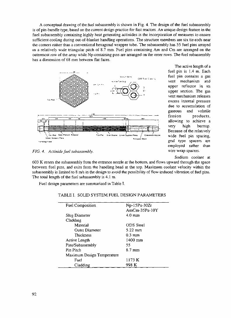
r „=„,.?,:., __
A conceptual drawing of the fuel subassembly is shown in Fig. 4. The design of the fuel subassemblyis of pin-bundle type, based on the current design practice for fast reactors. An unique design feature in thefuel subassembly containing highly heat generating actinides is the incorporation of measures to ensuresufficient cooling during out-of-blanket handling operations. The structure members are six tie-rods nearthe corners rather than a conventional hexagonal wrapper tube. The subassembly has 55 fuel pins arrayedin a relatively wide triangular pitch of 8.7 mm. Fuel pins containing Am and Cm are arranged on theoutermost row of the array while Np-containing pins are arranged on the inner rows. The fuel subassemblyhas a dimension of 68 mm between flat faces.
The active length of afuel pin is 1.4 m. Eachfuel pin contains a gasvent mechanism andupper reflector in itsupper section. The gasvent mechanism releasesexcess internal pressuredue to accumulation ofgaseous and volatilefission products,allowing to achieve avery high burnup.Because of the relativelywide fuel pin spacing,gnd type spacers areemployed rather thanwire wrap spacers.
Sodium coolant at603 K enters the subassembly from the entrance nozzle at the bottom, and flows upward through the spacebetween fuel pins, and exits from the handling head at the top. Maximum coolant velocity within thesubassembly is limited to 8 m/s in the design to avoid the possibility of flow-induced vibration of fuel pins.The total length of the fuel subassembly is 4.1 m.
Fuel design parameters are summarized in Table I.
Reileclor Block
FIG. 4. Actinidefuel subassembly.
TABLE I. SOLID SYSTEM FUEL DESIGN PARAMETERS
Fuel Composition
Slug DiameterCladding
MaterialOuter DiameterThickness
Active LengthPins/SubassemblyPin PitchMaximum Design Temperature
FuelCladding_________
Np-15Pu-30ZrAmCm-35Pu-10Y4.0 mm
ODS Steel5.22 mm0.3 mm1400 mm558.7mm
1173 K998 K
92

D.l.1.5.2. Target
A conceptual drawing of the target subassembly is shown in Fig. 5. Tungsten was chosen as thematerial for the solid target because of its high temperature capability. The target is inactive, or it does notcontain any fissile or fissionable materials. This eliminates the high power peaking at the target, and thusconsiderably flattens the lateral power distribution in the target/blanket.
The target consists oflayers of tungsten disk.This type of targetconfiguration was chosenfrom the nuclear andt h e r m a l - h y d r a u l i cconsiderations. It isdesigned to maximize thenumber of emittedneutrons and to flattenthe shape of axialdistribution of neutronflux. The upper part ofthe target subassemblyhas six 15-mm thickdisks spaced 51 mmapart and the lower parthas seven 130-mm thickdisks spaced 11 mmapart. Each disk hasthrough holes with a
Tungsten Disk (Odd Laytr) Tungsun Disk (Even Layer)
VWr«pp«f Tub*
Upptf Support Plaitv
Handling H*ad
Tungsttn Oak//Lower Support Plat* / Entaianc* Noul«
Redactor Block
, . ,. ,. rdiameter of 9 mm for_FIG. 5. Tungsten target subassembly6 6 j
coolant passage. They are arranged to stagger from layer to layer to avoid the possibility of directpenetration of high energy particles through the target.
The target subassembly has the same dimension of 68 mm between flat facesas that of the fuelsubassembly. Unlike the fuel subassembly, the target subassembly has a hexagonal wrapper tube to preventan undesirable cross flow, which would be driven by lateral pressure difference due to the dissimilarhydraulic characteristics between the target and the fuel subassemblies.
In the target subassembly design, the maximum coolant pressure drop is limited to 250 kPa, and themaximum coolant velocity is limited to 8 m/s. The allowable peak tungsten temperature and maximumtungsten surface temperature are conservatively set at 1830 K and 950 K, respectively. The coolanttemperature rise through the target is limited within the average coolant temperature rise through thetarget/blanket so that the target exit coolant flow can further cool the beam window sufficiently.
Sodium coolant at 603 K enters the subassembly from the entrance nozzle at the bottom, and flowsupward through the coolant channels in the tungsten disks, and exits from the handling head at the top. Thetotal length of the target subassembly is 2.86 m. The shorter total length compared with the fuelsubassembly is due to the absence of upper reflector.
D.I. 1.5.3. Target/blanket configuration
The target/blanket consists of a tungsten target region, an actinide fuel region, and reflectors. Figure6 shows the plan view of the target/blanket. The target region is located in the center of the target/blanket.The target consists of 61 target subassemblies, which together form an approximate right circular cylinder,
93

with a diameter of about 0 56 m and a height of 1.4 m.
Beam Window (o«60|
Blanket Barrel (*3000)
69
Tungsten Target Subassembly (61)
Acimide Fuel Subassembly (378)
Rellecior Subassembly (918)
FIG. 6. Target/blanket configuration.
Surrounding the target region is the actinide fuel region having the form of an annulus, 1.52 m inoutside diameter and 1.4 m in height. The fuel region is made up of 378 fuel subassemblies.
The actinide fuel region is in turn surrounded by reflectors made of stainless steel. The approximatethickness of the side reflector is 0.6 m. The side reflector is made up of 918 reflector subassemblies havingthe same cross sectional dimensions as the target and the fuel subassemblies. The upper and lower partsof the Subassembly constitute the upper and lower axial reflectors, respectively. The thickness of the axialreflector is about 0.4 m. Above the target region, the upper reflector is not provided for an incoming highenergy pioton beam.
All of these subassemblies are arranged in a common triangular array with a pitch of 69 mm. The wholetarget/blanket including reflectors is contained within a target/blanket vessel made of steel as shown in Fig.7 The vessel diameter is about 4.6 m and the height is about 14 m.
A vertical tube for the beam path is inserted into the target/blanket vessel down to just above the targetregion. The bottom end of the tube is the beam window which separates the accelerator vacuum and thetarget/blanket operating pressure. The beam window is made of ODS steel and has the form of ahemispherical shell. High energy protons are injected vertically downward through the beam window intothe targei.
The target/blanket has a loop type configuration. The inlet temperature of the primary sodium coolantis 603 K. The coolant enters the vessel through inlet nozzles, flows downward through the annular spacealong the vessel wall to the lower plenum. Then, it turns upward through the target/blanket, removing theheat from the target and fuel subassemblies. The beam window is cooled by impinging coolant flow fromthe target exit. The coolant then flows into the upper plenum and exits from the vessel through outletnozzles. The outlet temperature of the coolant is 703 K on average.
The volume of active blanket is about 2 m3. Maximum coolant flow velocity through the activetargetyblanket is set to 8 riVs. Sodium temperature at the target/blanket inlet is selected to be 603 K. Thissomewhat lower coolant temperature than in standard sodium-cooled reactors helps to achieve a hightarget/blanket power density, or a high transmutation rate, at the expense of degrading the power
94

, . „ .\\\ Bending Magnet
Quadrupole Magnet
Primary Sodium In —
r- 5 m4
3
2
1
0
Actinide Blanket
on Magnet
- Primary Sodium Out
Proton Beam
Beam Window
Tungsten Target
Target/Blanket Vessel
FIG. 7. Solid target/blanket system.
conversion efficiency.Target/blanket design parameters of the solid system are summarized in Table n. A conceptual drawing
of the target/blanket facility is shown in Fig. 8.
TABLE H. SOLE) SYSTEM TARGET/BLANKET DESIGN PARAMETERS
Proton BeamEnergyDiameterTungstenTarget
FuelReflector Stainless SteelActive Blanket
VolumeHeight
Coolant SodiumMaximum Velocity
________Inlet Temperature
1.5 GeV400mm
TRU Alloy
2m3
1.4m
8m/s603 K
95

> 20m
t 10 m
SecondaryrPump If
10 n
-20m
Nuclear Island
Crane
Accelerator
IHX
PrimaryPump
' 1
n\T
ifr —
i
1iii
VL
L
)
\^.^../r
MM
Jni 'iiiilr
Targel/Blankel
(a) Section View
PRACSAn Cooler
Accelerator
Nuclear Island
(h) Plan View
= Stack
SG
Turbine Hall
tDump Tank
j.
FIG 8 Target/blanket facility layout
96

D.I.1.5.4. Heat transport system
Heat transport and power conversion systems in the plant design is based on the current technology fora sodium-cooled fast breeder reactor plant. Figure 9 depicts the schematic flow diagram of the heattransport and power conversion systems.
The primary heat transport system consists of two sodium coolant loops. Each primary loop has anintermediate heat exchanger and a primary pump. The secondary system also consists of two sodium loops,with each having a steam generator and a secondary pump. Steam produced in the steam generators issupplied to the power conversion system.
A primary auxiliary cooling system consists of two NaK loops. This system is provided as anindependent means of removing afterheat in the target/blanket. The afterheat is ultimately rejected fromthe air coolers to natural draft of atmospheric air through stacks
A Air Out
Proton Accelerator
Alternator
Feed Pump
Target/BlanketPnP
I 330-cIntermediate SecondaryHeat Exchanger Pump
\_A Loop
FIG. 9. Schematic flow diagram of heat transport and power conversion systems.
Parameters of the heat transport system are summarized in Table III
D.l.1.5.5. Power conversion system
In the power conversion system, steam raised in the steam generators drives a single turbine alternatorto produce electricity Because of the relatively low operating coolant temperature for a sodium-cooledsystem, the steam condition is similar to that of a conventional light water reactor plant, thermal efficiencybeing roughly 30%.
97

TABLE IE. HEAT TRANSPORT SYSTEM DESIGN PARAMETERS
Primary SystemCoolant Loops 2 x Na LoopTemperature
IHX Inlet 703 KIHX Outlet 603 K
Components IHXs, Primary PumpsSecondary System
Coolant Loops 2 x Na LoopTemperature
SG Inlet 663 KSG Outlet 563 K
Components SGs, Secondary PumpsAuxiliary Cooling System
Coolant Loops 2 x NaK Loop_____Components__________Air Coolers, EM Pumps
Parameters of the power conversion system are summarized in Table IV.
TABLE IV. POWER CONVERSION SYSTEM DESIGNPARAMETERS
Cycle Saturated Steam CycleWorking Fluid Water/SteamTurbine Inlet Temperature 558 KComponents Turbine, Alternator,
Condenser, Feed PumpElectric Output 246 MWEfficiency_______________30%_______ __
D.I.15.6. System performance
Figure 10 is the calculated power density distribution in the target/blanket. The target/blanket generatesa total thermal power of 820 MW for the 1.5 GeV and 39 mA proton beam. The actinide fuel regiongenerates 800 MW, and the target region, 20 MW,. In the fuel region, the maximum power density is about920 MW/m3 and the average power density, about 400 MW/m3. The maximum power density in the targetregions is about 360 MW/m1. considerably lower than that in the fuel region.
The calculated temperature distributions along the fuel pin in the hot channel are shown in Fig. 11.Sodium coolant temperature at the hot channel exit is 746 K. The maximum temperature of the ODS steel
98
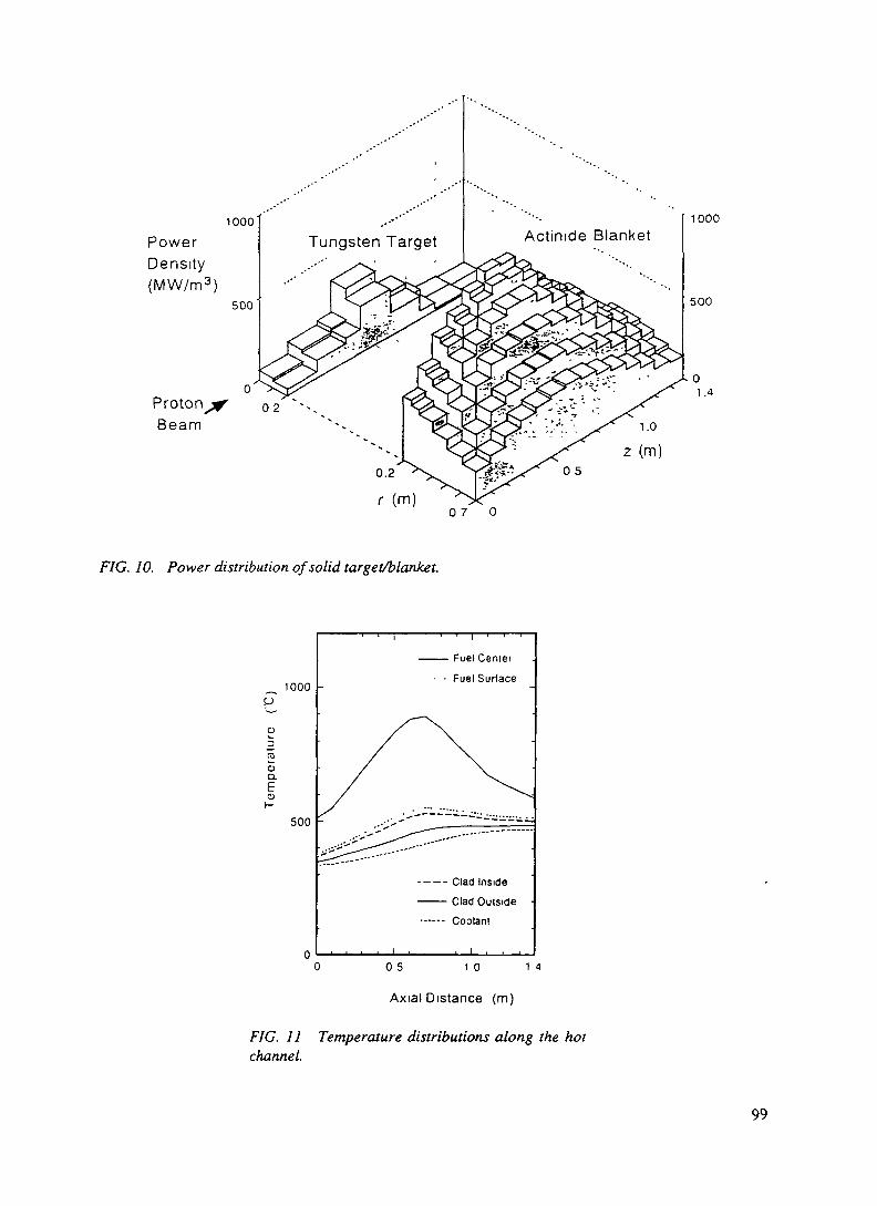
1000'
PowerDensity(MW/m3)
500
Beam
1000
500
07 0
FIG. 10. Power distribution of solid target/blanket.
1000
o3raoCL
500
FuelCenier
Fuel Surface
---- Clad Inside
- Clad Outside--—- Coolant
0 05 10 14
Axial Distance (m)
FIG. 11 Temperature distributions along the hotchannel.
99
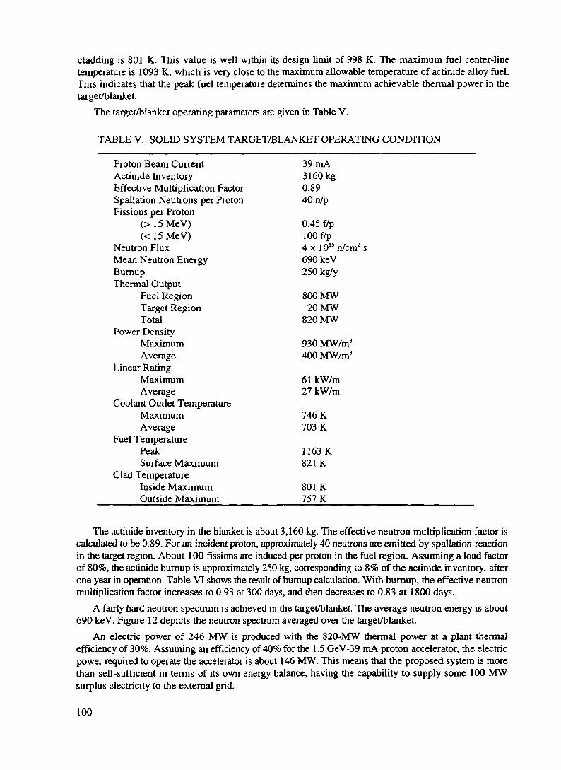
cladding is 801 K. This value is well within its design limit of 998 K. The maximum fuel center-linetemperature is 1093 K, which is very close to the maximum allowable temperature of actinide alloy fuel.This indicates that the peak fuel temperature determines the maximum achievable thermal power in thetarget/blanket.
The target/blanket operating parameters are given in Table V.
TABLE V. SOLED SYSTEM TARGET/BLANKET OPERATING CONDITION
Proton Beam Current 39 mAActinide Inventory 3160 kgEffective Multiplication Factor 0.89Spallation Neutrons per Proton 40 n/pFissions per Proton
(> 15 MeV) 0.45 f/p(< 15 MeV) 100 f/p
Neutron Flux 4 x 10¹⁵ n/cm2 sMean Neutron Energy 690 keVBumup 250 kg/yThermal Output
Fuel Region 800 MWTarget Region 20 MWTotal 820 MW
Power DensityMaximum 930 MW/m3
Average 400 MW/m3
Linear RatingMaximum 61 kW/mAverage 27 kW/m
Coolant Outlet TemperatureMaximum 746 KAverage 703 K
Fuel TemperaturePeak 1163KSurface Maximum 821 K
Clad TemperatureInside Maximum 801 KOutside Maximum 757 K
The actinide inventory in the blanket is about 3,160 kg. The effective neutron multiplication factor iscalculated to be 0.89. For an incident proton, approximately 40 neutrons are emitted by spoliation reactionin the target region. About 100 fissions are induced per proton in the fuel region. Assuming a load factorof 80%, the actinide burnup is approximately 250 kg, corresponding to 8% of the actinide inventory, afterone year in operation. Table VI shows the result of bumup calculation. With burnup, the effective neutronmultiplication factor increases to 0.93 at 300 days, and then decreases to 0.83 at 1800 days.
A fairly hard neutron spectrum is achieved in the target/blanket. The average neutron energy is about690 keV. Figure 12 depicts the neutron spectrum averaged over the target/blanket.
An electric power of 246 MW is produced with the 820-MW thermal power at a plant thermalefficiency of 30%. Assuming an efficiency of 40% for the 1.5 GeV-39 mA proton accelerator, the electricpower required to operate the accelerator is about 146 MW. This means that the proposed system is morethan self-sufficient in terms of its own energy balance, having the capability to supply some 100 MWsurplus electricity to the external grid.
100

TABLE VI. BURNUP CALCULATION RESULTS
Nuclides Initial Inventory(kg)
Mass Balance in EOC (unit: kg)BOC EOC EOC - BOC
FuelUranium
U-235U-236U-238
000
000
0.90.20.0
+ 0.9+ 0.2+ 0.0
PlutoniumPu-238Pu-239Pu-240Pu-241Pu-242
134012926938
13401292
6938
4701561933447
+ 457-246-99-35+ 8.9
Minor ActinidesNeptunium
Np-237 1861 1861 593 - 1268
AmericiumAm-241Am-242mAm-243
CuriumCm-242Cm-243Cm-244Cm-245
Other Actinides
2920
133
00.3
575.1
0
2920
133
00.3
573.1
0Transmutation Capability (kg/GWt EFPY)
959.5
57
7.21.0
6110
0307
-197+ 9.5
-77
+ 7.2+ 0.7+ 4.8+ 7.2
0
coo
10"
10'
10"
ID''
Fraction of Fast Neutron
> 0 1 MeV 69%
> 1 0 MeV 19%
10° 10J 10° 10'
Neutron Energy (eV)
D. 1.1.6. MOLTEN-SALT SYSTEM
A preliminary conceptual design study is beingperformed on an 800-MWt molten-salt target/blanketsystem as an advanced option for an accelerator-drivennuclear waste transmutation system [9]. Figure 13schematically shows the proposed molten-salt systemconcept. Chloride salt with a composition of 64NaCl-5PuCl3-31MACl3 (where MA represents Np, Am, andCm) is chosen for the molten-salt system based mainlyon the consideration of actinide solubility. The molten-salt acts both as fuel and as target material, and at thesame time it also serves as coolant in the molten-salt
c,~ ,~ ,, f ,., . n, , system. This significantly simplifies the target/blanketFIG. 12. Neutron spectrum of solid tar-get /blanket. J 6 J F &
101

system configurationA high energy proton
beam at 1.5 GeV isinjected into the centraltarget/blanket regionthrough the beamw indov* The target/blanket region issurrounded by aninternal reflector Inter-mediate heat ex-changersand salt pumps areinstalled in the annularregion around the inter-nal reflector This m-vessel heat exchangerdesign minimizes thetotal actmide inventoryin the system
The molten state offuel provide the possi-bility of on-line proces-sing of reaction productremoval Fig 14 showsthe conceptual flowdiagram of on-lineseparation system for amolten-salt target/blanket
Rellecioi
Pump
Compacl-TypeHeal E tchanger
Inlernal Relleclor
FIG 13 Concept of molten-salt target/blanket system
Proton Beam
Molten-SaltPump Molten-Salt
Target/Blanket
Gas Separator
Cold Trap
500 - S50°C
ExtractorMolten-Salt Flow
D.I.1.6.1. Actinide fuel salt
Molten fluonde salt fuel of LiF-BeF2-ThF4-UF4 has been demonstratedin the 1960s at the Oak Ridge NationalLaboratory in the Molten Salt ReactorProgram The solubility of Th in thefluonde salt is sufficiently high (> 10mol%) in the operating temperaturerange, whereas the solubilities of Uand Pu are rather low (< 1 mol%) Thesolubilities of MAs in the salt are notexpected to be sufficiently high Thelow solubilities of MAs together withthe low mass numbers of constituentelements preclude the use of LiF-BeF2as fuel for fast neutron systems
Molten chlonde salt is moreattractive since it has high Pusolubility and the mass number of Cl is
FIG 14 Conceptual flow diagram of on-line separation system about twice of that of F The NaCl-for molten-salt target/blanket
Cd Flow
4DOtCd
Cold Trap
( EM PumpJ
102

PuCl3 system has an eutectic terriperature of 726 K for the composition 64NaCl-36PuCl3. The solubilitiesof MAs in the salt are not known, but Pu in the chloride salt may be replaced by any MAs. The chloridesalt selected for the design study of the molten-salt system is 64NaCl-5PuCl3-31MACI3 (where MArepresents Np, Am, and Cm).
One of the major problems with molten chloride salts is the material compatibility, which is vitallyimportant in the application to nuclear systems.
D.I.1.6.2. Target/blanket configuration
The target/blanket is designed for 800-MW thermal power. As shown in Fig. 13, a high energy protonbeam is injected downward into the central cavity filled with molten chloride salt through the beamwindow. The central cavity has the form of a right circular cylinder of 0.8 m in diameter and 1.7 m inheight. The molten salt acts as target material and also as fuel. This eliminates the physical and functionalseparation between target and blanket, and thus significantly simplifies the target/blanket configuration.MA is mainly transmuted in this region by fast fission and spoliation reactions.
The central cavity is surrounded by an internal reflector with a thickness of 0.3 m. The intermediateheat exchangers and molten-salt pumps are located around the internal reflector in the target/blanket vessel.The internal reflector protects the heat exchangers and pumps from the radiation damage. The intermediateheat exchangers are of compact type with plate-and-fin configuration, where heat in the primary molten saltis transferred to the secondary fluid of molten fluoride salt The in-vessel heat exchanger design minimizesthe total volume of the primary salt and the total inventory of actinides in the system. The molten-saltpumps are of a motor-driven mechanical type and circulate the primary salt through the heat exchangersto the central cavity. The dimensions of the target/blanket vessel are 2.9 m in diameter and 2.3 m in height.The thickness of the upper, lower, and side reflectors are 0.2 m, 0.4 m, and 0.4 m, respectively.
The beam window is a hemispherical shell of 0.4 m in diameter cooled by primary molten-salt flow.
D.l.1.6.3. System performance
The molten-salt target/blanket has an effective neutron multiplication factor of 0.92, and produces 800-MW thermal power with a 1.5 GeV-25 mA proton beam. In the molten-salt system, the maximum thermalpower is limited not by the maximum fuel temperature or the maximum power density, but the heat transferrate through the heat exchangers. The maximum power density in the target/blanket region is about 1660MW/m3. Assuming a load factor of 80%, the actinide bumup is approximately 250 kg/y, or 4.6%/y. Thesystem operates at a molten-salt temperature in the range of 920-1020 K. With such a high operatingtemperature, a power conversion efficiency around 45% becomes feasible by using a supercritical steamcycle, which can improve the total energy balance of the system.
Table Vn summarizes design parameters and operating conditions of the molten-salt system.The molten state of the fuel salt offers several attractive features for the design of the transmutation
system. The main advantage over a solid system is the capability of continuous on-line processing. The fuelcomposition can be continuously controlled and fission and spallation products can be continuouslyremoved from the fuel. Furthermore, the rather laborious process of actinide fuel fabrication is not requiredfor the molten-salt system. Blanket melt-down accidents would be impossible as the molten fuel is readyto be dumped from the blanket in case of emergency, which may add a high degree of safety.
D.I. 1.7. SUMMARY
The accelerator-driven transmutation system project at JAERI has been presented. This project is being
103

carried out under the Japanese long-term R&D program on partitioning and transmutation, called OMEGA.
TABLE VII. MAJOR PARAMETERS OF MOLTEN-SALT TARGET/BLANKET SYSTEM
Fuel Chloride Salt64NaCl-5PuCl3-31MACl3(MA: Np, Am, Cm)
Target Chloride SaltCoolant Chloride SaltActinide Inventory 5430 kgNeutron Multiplication Factor 0.92Spallation Neutrons per Proton 38 n/pProton Beam 1.5 GeV - 25 mAThermal Power 800 MWBurnup 250 kg/y (4.6 %/y)Power Density
Maximum 1660 MW/m3
Average 310 MW/m3
Coolant TemperatureInlet 923 KOutlet 1023 K
Coolant Maximum Velocity______3.6 m/s__________
In the design study for a transmutation plant, two types of dedicated system concepts are beinginvestigated; a solid system and a molten-salt system. In either system, an MA-loaded subcritical blanketis driven by a high-intensity proton accelerator and makes use of a hard neutron spectrum to transmute MAsefficiently by fission.
The design of the solid system is based on the current status of liquid-metal fast reactor technology,whereas the design of the molten-salt system relies largely on next generation technology.
REFERENCES
[1] Kubota, M. et al.: "Development of Partitioning Process in JAERI", Proc. 2nd OECD/NEA Int.Information Exchange Meeting on Actinide and Fission Product Separation and Transmutation,ANL (1992).
[2] Mukaiyama, T. et al.: "Higher Actinide Transmutation using Higher Actinide Burner Reactor", Proc.Int. Conf. Physics of Reactors, Marseille, (1990).
[3] Mizumoto, M. et al.: "High Intensity Proton Accelerator for Nuclear Waste Transmutation", 16* Int.Linear Accelerator Conf. LINAC-92, Ottawa (1992).
[4] Nishida, T. et al.: "Improvement of Spallation Reaction Simulation Codes NMTC/JAERI andNUCLEUS", 2nd Int. Symp. on Advanced Nuclear Energy Research , Mito (1990).
[5] Nakahara, Y. and Tsutsui, T.: "NMTC/JAERI - A Simulation Code System for High Energy NuclearReactions and Nucleon-Meson Transport Process", JAERI-M 82-198 (in Japanese) (1982).
[6] Takada, H. et al.: "Production of Radioactive Nuclides in a Lead Assembly with 500 MeV Protons",Proc. Specialists' Mtg. on Accelerator-Based Transmutation, PSI (1992).
[7] YOSHIDA, H. et al.: "A Strategic Study of the Partitioning and Transmutation System being
104

Developed at JAERI", Proc. Int. Information Exchange Meeting on Actinide and Fission ProductSeparation and Transmutation, ANL (1992).
[8] Takizuka, T. et al.: "Conceptual Design Study of an Accelerator-based Actinide Transmutation Plantwith Sodium-cooled Solid Target/Core", ibid.
[9] Katsuta, H. et al.: "A Continuous Transmutation System for Long-lived Nuclides with Accelerator-driven Fluid Targets", ibid.
105

XA9846562D.1.2. DEVELOPMENT OF THE PARTITIONING PROCESS AT JAERI
Masumitsu KubotaJapan Atomic Energy Research InstituteTokai-mura, Naka-gun, Ibaraki-ken 319-11 Japan
D.I.2.1. INTRODUCTION
Partitioning of nuch'des such as transuranium elements (TRU), Tc-99, Sr-90 and Cs-137 in a high-levelliquid waste (HLLW) generated in nuclear fuel reprocessing and transmutation of long-lived nuclides bynuclear reactions are expected to increase the efficiency of high-level waste disposal and will allowutilization of existing resources in spent fuel.
Since 1985, much effort has been directed to developing an advanced partitioning process forseparating elements in HLLW into four groups; TRU, Tc-Platinum group metals (PGM), Sr-Cs and theother elements [1,2]. The most recent studies are mainly focused on how to increase the efficiency of TRUseparation with diisodecylphosphoric acid (DJDPA) solvent.
D.I.2.2. SEPARATION OF TRU, ESPECIALLY NEPTUNIUM
Effectiveness of DJDPA for the complete extraction of Am, Cm, Pu and U had been alreadydemonstrated with an actual HLLW before 1984. Therefore much attention has been given to how toincrease Np extraction with DEDPA. Penta-valent Np, which is dominant in HLLW, is the TRU mostdifficult to extract with general organic solvents. We found that the addition of hydrogen peroxide to theTRU extraction with DJDPA accelerated penta-valent Np extraction. Through experiments oncounter-current continuous extraction using a mixer-settler, more than 99.96% of penta-valent Np wasfound to be extracted when hydrogen peroxide was fed at a level to compensate for its decomposition.
The behavior of fission and corrosion products in continuous counter-current extraction with DJDPAwas also tested with a simulated HLLW. More than 99.99% of Nd, which was used as a stand-in for rareearths, Am and Cm, was found to be extracted and recovered by back-extraction with 4 M nitric acid. Mostof the Fe was extracted with DJDPA, but not back-extracted with 4 M nitric acid. Therefore, Fe could beseparated from Nd with a decontamination factor of about 100. About 6% of Ru and 11% of Rh wereextracted in this experiment. Their extraction behavior might change in a practical application because theirchemical forms seem to differ in actual HLLW. Almost all Cs and Sr were transferred to the raffinatefraction and Nd was found to be completely separated from these heat generating nuclides in HLLW.
D.l.2.3. SEPARATION OF AMERICIUM AND CURIUM FROM RARE EARTHS
In order to produce a more continuous process, we are developing a preferential back-extraction of Amand Cm, leaving rare earths in the DJDPA solvent, by using a stripping solution which contains 0.05 MDTPA (diethylenetriaminepentaacetic acid), 1 M lactic acid and ammonia.
The continuous back-extraction experiment was performed with the DJDPA solvent containing Nd andLa, which are stand-ins for Am-Cm and rare earths respectively. The experimental results revealed thatmore than 99.9% of Nd was back-extracted, while more than 98% of La was left in the solvent, and the Ndand La concentration profiles agreed very closely with calculated profiles.
These findings show that the estimation of the back-extraction behavior of Am, Cm and rare earths bycalculation would be valid enough for optimization of the back-extraction process.
106

The calculated back-extraction behavior of Am-Cm and rare earths in the optimized process showedthat 99.995% of Am-Cm was back-extracted and only 1.1% of rare earths accompanied Am-Cm. As theweight ratio of Am and Cm to rare earths is only 3.3% in HLLW, it would become about 75% afterseparation.
We are going to confirm this estimation by performing a continuous experiment with a solventcontaining both Am and rare earths.
D.I.2.4. BACK-EXTRACTION OF URANIUM
After Am and Cm back-extraction with DTPA solution, all rare earths and other TRU (Np and Pu) canbe back-extracted with 4 M nitric acid and 0.8 M oxalic acid solution, respectively. As for theback-extraction of U, the effectiveness of phosphoric acid has already been studied. However, it has somedifficulties in practical use.
We are developing the application of a sodium carbonate solution to the back-extraction of U from theDIDPA solvent.
Batch experiments showed that the distribution ratio of U became lower than 0.1 when the 0.8 to 2 Msodium carbonate solution was used as back-extractant. However, an emulsion was formed. We found thatthis could be avoided by increasing temperature and/or adding alcohol.
When the temperature was increased to 65°C, no emulsion was observed. When ethanol was addedwith a ratio of 15 vol%, the temperature could be lowered to 15°C and the distribution ratio of U becamelower than 0.1. U could be back-extracted in a small number of stages in a mixer-settler.
D.I.2.5. CONSTRUCTION OF PARTITIONING PROCESS
Through these fundamental studies, the advanced four group partitioning process was constructed andits effectiveness will be demonstrated with an actual HLLW at the NUCEF (Nuclear Fuel Cycle SafetyEngineering Research Facility) in 1996.
REFERENCES
[1] KUBOTA, M., et al: "Development of a partitioning process for the management of high-level waste",Future Nuclear Systems: Emerging Fuel Cycles and Waste Disposal Options GLOBAL '93 (Proc. Int.Symp. Seattle, 1993), 588.
[2] KUBOTA, M.: "Recovery of technetium from high-level liquid waste generated in nuclear fuelreprocessing", Radiochimica Acta 63, 91 (1993).
107

XA9846563
D.1.3. HIGH INTENSITY PROTON LINEAR ACCELERATOR DEVELOPMENT FORNUCLEAR WASTE TRANSMUTATION
M. Mizumoto, K. Hasegawa, H. Oguri, N. Ito, J. Kusano, Y. Okumura, H. Murata and K. SakogawaJapan Atomic Energy Research InstituteTokai-mura, Naka-gun, Ibaraki-ken 319-11 Japan
D.I.3.1. INTRODUCTION
Design studies of accelerator-driven nuclear waste transmutation system have been carried out for theOMEGA project (Options Making Extra Gains of Actinides and Fission Products). The high-intensityproton linear accelerator (ETA: Engineering Test Accelerator) with an energy of 1.5 GeV and an averagecurrent of 10 mA has been proposed for various engineering tests for the transmutation system by JAERI.Nuclear spallation reactions with high energy proton beams will produce various intense beams that canalso be utilized for other nuclear engineering applications. These include material science, radio isotopeproduction, nuclear data measurements and other basic sciences with the proton, neutron and othersecondary beams in addition to nuclear waste transmutation.
In the course of the accelerator development, the R&D work for the low energy portion of theaccelerator (BTA: Basic Technology Accelerator), with an energy of 10 MeV and a current of 10 mA, hasbeen made, because the maximum beam current and quality are mainly determined by this low energyportion. R&D for the main accelerator components such as the high current hydrogen ion source,radio-frequency quadrupole (RFQ), drift tune linac (DTL) and RF power source is in progress.
The conceptual and optimization studies for the high energy accelerator ETA have been performedsimultaneously with regard to proper choice of operating frequency, high b structure, mechanicalengineering considerations and RF source aspects in order to ensure low beam loss, hands-on maintenanceand low construction cost.
D.I.3.2. ACCELERATOR DEVELOPMENT
The conceptual layout of the ETA is shown in Fig. 1. In the case of a high intensity accelerator, it isparticularly important to maintain good beam quality (low emittance; small beam size and divergence) andminimize beam losses to avoid damage and activation of the accelerator structures. Because the beamquality and maximum current are mainly determined by the low energy portion of the accelerator, theaccelerator (BTA) will be built as a first step in the ETA development [1]. The layout of BTA is shown inFig. 2.
The basic specification of BTA is given in Table I. The beam dynamics design calculations for theBTA, which will consist of the ion source, RFQ and DTL including the beam transport system, have beenmade with the computer codes PARMTEQ and PARMILA [2]. Because of the high beam current and highduty factor, the problem of heat removal from the accelerator structure is also an important issue for themechanical design. The electromagnetic field distribution, temperature distribution and thermal stressesare carefully studied with the three dimensional modelling codes, MAFIA and ABAQUS. The beam energyfor the BTA is chosen to be 10 MeV in order to avoid proton induced reactions in accelerator structuralmaterials where the Coulomb barriers are barely exceeded. The acceleration frequency of 201.25 MHz isselected both for RFQ and DTL mainly due to the large bore radius, manageable heat removal problem andthe availability of an RF source
108
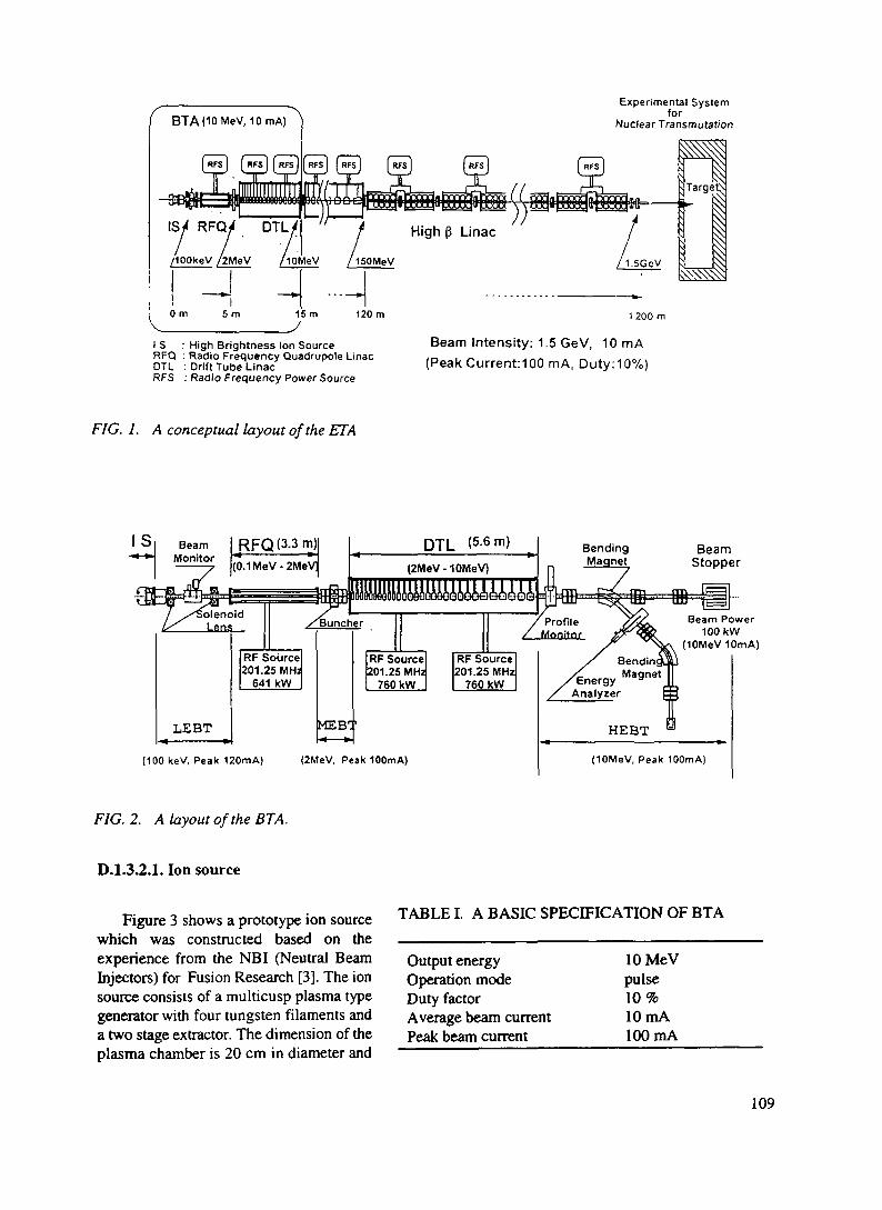
BTA(10MeV, 10 mA)Experimental System
forNuclear Transmutation
1200 m
I S : High Brightness Ion SourceRFQ : Radio Frequency Quadrupole LinacDTL : Drift Tube LinacRFS : Radio Frequency Power Source
Beam Intensity: 1.5 GeV, 10 mA(Peak Current: 100 mA, Duty: 10%)
FIG. I. A conceptual layout of the ETA
BeamMonitor
JRFQO,3 m)|(0.1MeV-2MeV
Lensaid
RF Source201.25 MH2
641 kW
/Bunc
LEBT
BendingMagnet
BeamStopper
Beam Power100 kW
(10MeV10mA)
[MEET
(100 keV, Peak 120mA) (2MeV, Peak 100mA)
Bendin
Energy Ma9net
Analyrer
FIG. 2. A layout of the BTA.
D.l.3.2.1. Ion source
Figure 3 shows a prototype ion sourcewhich was constructed based on theexperience from the NBI (Neutral BeamInjectors) for Fusion Research [3]. The ionsource consists of a multicusp plasma typegenerator with four tungsten filaments anda two stage extractor. The dimension of theplasma chamber is 20 cm in diameter and
TABLE I. A BASIC SPECIFICATION OF BTA
Output energyOperation modeDuty factorAverage beam currentPeak beam current
lOMeVpulse10%10mA100mA
109
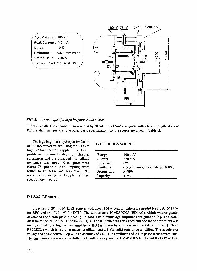
IpOkV 76kV Ground
Ace. Voltage : 100kV
Peak Current: 140mADuty: 10%
Emittance : 0.5 K mm mradProton Ratio : > 85 %H2 gas Flow Rate : 4 SCCM
FIG. 3. A prototype of a high brightness ion source.
17cm in length. The chamber is surrounded by 10 columns of SmCo magnets with a field strength of about0.2 T at the inner surface. The other basic specifications for the source are given in Table n.
The high brightness hydrogen ion beamof 140 mA was extracted using the 100 kVhigh voltage power supply. The beamprofile was measured with a multi-channelcalorimeter and the observed normalizedemittance was about 0.45 pmm.mrad(90%). The proton ratio and impurity werefound to be 80% and less than 1%,respectively, using a Doppler shiftedspectroscopy method
TABLE II. ION SOURCE
Energy lOOkeVCurrent 120mADuty factor CWEmittance 0.5 pmm.mrad (normalized 100%)Proton ratio > 90%Impurity < \%
D.l.3.2.2. RF source
Three sets of 201.25 MHz RF sources with about 1 MW peak amplifiers are needed for BTA (641 kWfor RFQ and two 760 kW for DTL). The tetrode tube 4CM2500KG (EIMAC), which was originallydeveloped for fusion plasma heating, is used with a multistage amplifier configuration [4]. The blockdiagram of the RF source is shown in Fig. 4. The RF source was designed and one set of amplifiers wasmanufactured. The high power amplifier (HPA) is driven by a 60 kW intermediate amplifier (IPA ofRS2058CJ) which is fed by a master oscillator and a 3 kW solid state drive amplifier. The acceleratorvoltage and phase control loop with an accuracy of < 0.1 % in amplitude and < 1 in phase were constructed.The high power test was successfully made with a peak power of 1 MW at 0.6% duty and 830 kW at 12%
110
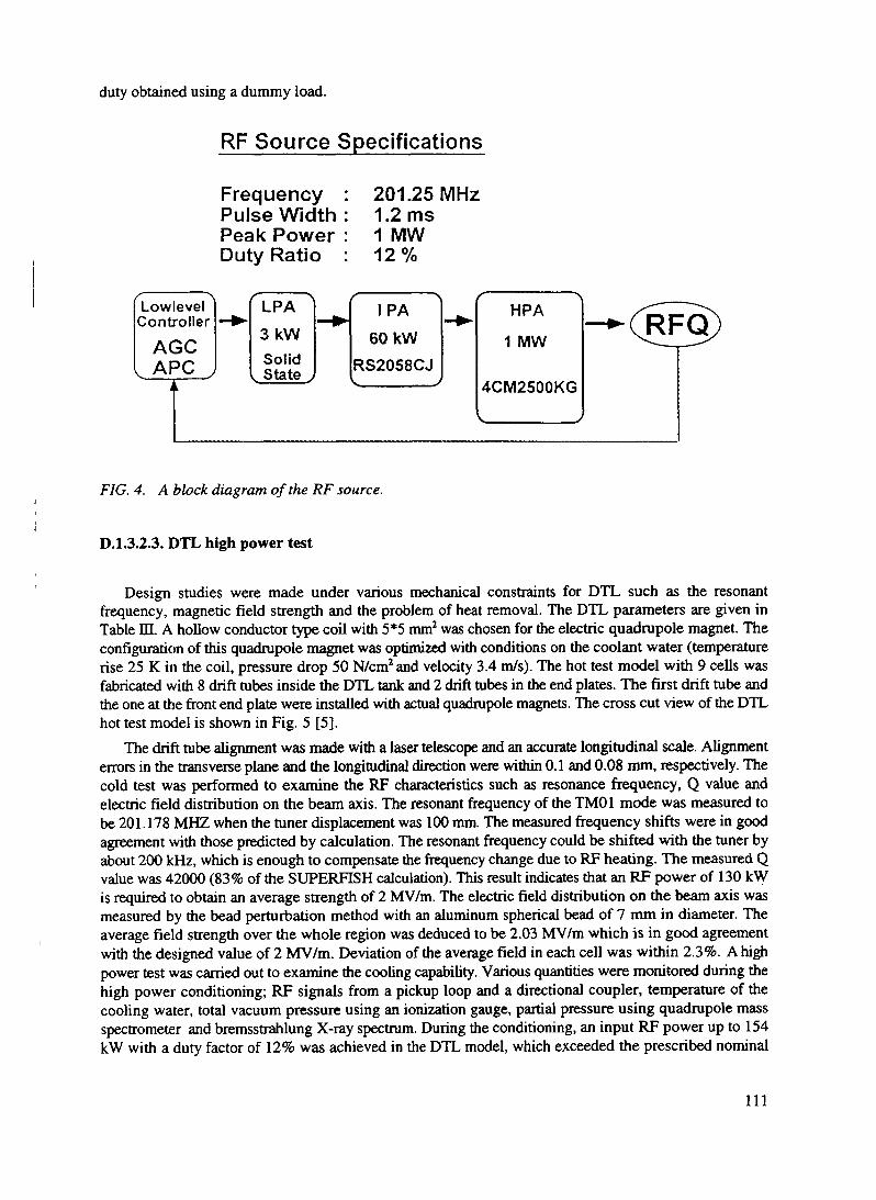
duty obtained using a dummy load.
RF Source Specifications
FrequencyPulse WidthPeak PowerDuty Ratio
201.25MHz1.2 ms1 MW12%
/• \LowlevelController
AGC1 APC J
t
«^ ~/ \
LPA
3kWSolid
I State J
— **
/• -\IPA
60 kWRS2058CJ
~- - HPA
1 MW
4CM2500KG
V J
_ fc.l^pp^(vr\r
FIG. 4. A block diagram of the RF source.
D.l.3.2.3. DTL high power test
Design studies were made under various mechanical constraints for DTL such as the resonantfrequency, magnetic field strength and the problem of heat removal. The DTL parameters are given inTable HL A hollow conductor type coil with 5*5 mm2 was chosen for the electric quadrupole magnet. Theconfiguration of this quadrupole magnet was optimized with conditions on the coolant water (temperaturerise 25 K in the coil, pressure drop 50 N/cm2and velocity 3.4 m/s). The hot test model with 9 cells wasfabricated with 8 drift tubes inside the DTL tank and 2 drift tubes in the end plates. The first drift tube andthe one at the front end plate were installed with actual quadrupole magnets. The cross cut view of the DTLhot test model is shown in Fig. 5 [5].
The drift tube alignment was made with a laser telescope and an accurate longitudinal scale. Alignmenterrors in the transverse plane and the longitudinal direction were within 0.1 and 0.08 mm, respectively. Thecold test was performed to examine the RF characteristics such as resonance frequency, Q value andelectric field distribution on the beam axis. The resonant frequency of the TM01 mode was measured tobe 201.178 MHZ when the tuner displacement was 100 mm. The measured frequency shifts were in goodagreement with those predicted by calculation. The resonant frequency could be shifted with the tuner byabout 200 kHz, which is enough to compensate the frequency change due to RF heating. The measured Qvalue was 42000 (83% of the SUPERFISH calculation). This result indicates that an RF power of 130 kWis required to obtain an average strength of 2 MV/m. The electric field distribution on the beam axis wasmeasured by the bead perturbation method with an aluminum spherical bead of 7 mm in diameter. Theaverage field strength over the whole region was deduced to be 2.03 MV/m which is in good agreementwith the designed value of 2 MV/m. Deviation of the average field in each cell was within 2.3%. A highpower test was carried out to examine the cooling capability. Various quantities were monitored during thehigh power conditioning; RF signals from a pickup loop and a directional coupler, temperature of thecooling water, total vacuum pressure using an ionization gauge, partial pressure using quadrupole massspectrometer and bremsstrahlung X-ray spectrum. During the conditioning, an input RF power up to 154kW with a duty factor of 12% was achieved in the DTL model, which exceeded the prescribed nominal
111
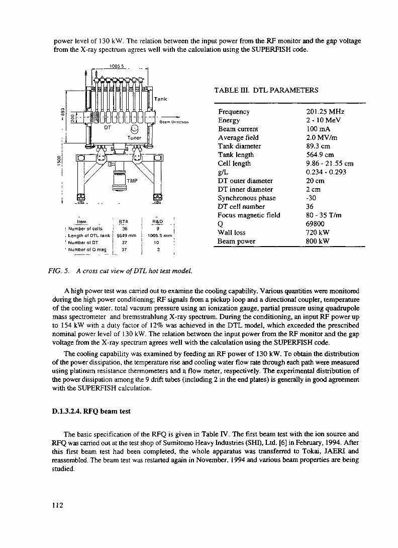
power level of 130 kW. The relation between the input power from the RF monitor and the gap voltagefrom the X-ray spectrum agrees well with the calculation using the SUPERFISH code.
10055
Beam Direction
TABLE III. DTL PARAMETERS
ItemNumber of cellsLength of DTL tankNumber of DT
Number of Q mag
BJA36
5649 mm3737
R&D
"9 "I1005.5 mm j
10 !2 ;
FrequencyEnergyBeam currentAverage fieldTank diameterTank lengthCell lengthg/LDT outer diameterDT inner diameterSynchronous phaseDT cell numberFocus magnetic fieldQWall lossBeam power
201.25MHz2 - 10 MeV100mA2.0 MV/m89.3 cm564.9 cm9.86-21.55 cm0.234 - 0.29320cm2cm-303680 - 35 T/m69800720 kW800 kW
FIG. 5. A cross cut view of DTL hot test model.
A high power test was carried out to examine the cooling capability. Various quantities were monitoredduring the high power conditioning; RF signals from a pickup loop and a directional coupler, temperatureof the cooling water, total vacuum pressure using an ionization gauge, partial pressure using quadrupolemass spectrometer and bremsstrahlung X-ray spectrum. During the conditioning, an input RF power upto 154 kW with a duty factor of 12% was achieved in the DTL model, which exceeded the prescribednominal power level of 130 kW. The relation between the input power from the RF monitor and the gapvoltage from the X-ray spectrum agrees well with the calculation using the SUPERFISH code.
The cooling capability was examined by feeding an RF power of 130 kW. To obtain the distributionof the power dissipation, the temperature rise and cooling water flow rate through each path were measuredusing platinum resistance thermometers and a flow meter, respectively. The experimental distribution ofthe power dissipation among the 9 drift tubes (including 2 in the end plates) is generally in good agreementwith the SUPERFISH calculation.
D.l.3.2.4. RFQ beam test
The basic specification of the RFQ is given in Table IV. The first beam test with the ion source andRFQ was carried out at the test shop of Sumitomo Heavy Industries (SHI), Ltd. [6] in February, 1994. Afterthis first beam test had been completed, the whole apparatus was transferred to Tokai, JAERI andreassembled. The beam test was restarted again in November, 1994 and various beam properties are beingstudied.
112

The layout of the 2 MeV RFQ beam test isshown in Fig. 6. The 100 keV H* beam wasextracted by a multi-cusp type ion source to theRFQ. Two focusing solenoids in the low energybeam transport (LEBT) were used to match theion source beam emittance to the RFQacceptance. The transmission was deduced fromthe RFQ input and output currents measuredwith the two Faraday cups. The RFQacceleration current as a function of thenormalized vane voltage (a normalized vanevoltage of unity corresponds to nominal gapvoltage of 113 kV) is shown in Fig. 7. Theresults of the measured beam transmission werelower by 20 - 30% than the design values withPARMTEQ. The various causes of these lowertransmissions are being investigated. The beam
TABLE IV. RFQ PARAMETERS
FrequencyEnergyBeam currentDuty FactorSynchronous phaseVane voltageFocusing parameter BNumber of cellCavity diameterVane lengthQuality factor (Q)Wall loss powerBeam power
201.25MHz0.1 -2 MeV110mA10%-90--350.113 MV7.11418136.6 cm334.8 cm13000(100% Q)432 kW (60% Q)209 kW
RFQ PM-2
/FC-1 JFC-
LEBT100keV
-22
F
201.25MHz1MW
RF Source
7.7m
nz
ce MEET2MeV
MEA: Magnetic Energy AnalyzerFC: Faraday CupPM: Beam Profile Monitor
FIG. 6. A layout of the 2 MeV RFQ beam test.
energy spectra from the RFQ were also measured using a compact magnetic energy analyzer (MEA), witha pole radius and gap length of 40mm and 6mm, respectively. The deflection angle was 25° and the energyresolution was assumed to be 5% for a 2 MeV proton beam. The 100 keV H+, H2+ and H3* beam from theion source through the RFQ (without RF) was used as an energy calibration source for five vane voltages.The intervane voltage dependence of the proton energy spectra is shown in Fig. 8. As the intervane voltagewas reduced, the energy spectrum shifted to lower energies with a prominent discrete energy distribution.This interesting phenomenon was well predicted by PARMTEQ as indicated in the figure.
113

KOi -—— — —— -
100 |——
=. 80
60U
20 j-
0 L _ .0 -I 0.6 08
Norni,ili7cJ Intci v a n e
FIG. 7. Intervane voltage dependence ofRFQ acceleration current. »J 1 1.5 2 1.5
Emro (MtV)li sviih mjfffclic cnct(y loilyicr
FIG. 8. Intervane voltage dependence ofproton energy spectra from the RFQ.
D.I.3.3. SUMMARY
R&D work has been carried out on the design and construction of prototype accelerator structures (Ionsource, RFQ, DTL and RF source). The low-power tests were made to study the RF characteristics for theRFQ and DTL accelerating structures and have verified the design prediction. The first 2 MeV beam testwith the ion source and RFQ in combination with a single high power RF source unit was successfullycarried out with a peak acceleration current of 52 mA (for the duty factor of 5%). For the DTL high powertest, measurements of the electromagnetic characteristics were made satisfactorily. Problems of heatdissipation and heat removal in the structure were studied. Table V summarized the major results of theR&D work. The detailed design work for the BTA construction will follow in the next stage based on theseR&D results. Further improvement is however still required to increase the average beam current (the goalis 10 mA) by improving the peak current and duty factor. More detailed studies of the beam properties areneeded to improve transmission.
114

The RFQ beam testMethods
Energy spectrumVane voltageProfileBeam current & transmission
100W140mA0.5 7i mm.mrad (90%)>80%
9,420 (7 1%Q)
< 2.5 %
TABLE V. THE PRESENT STATUS OF THE PROTON LINAC DEVELOPMENT FOR THE JAERIOMEGA PROGRAM
(1) Ion source: Multi-cusp ion sourceHigh voltageAccelerating currentEmittanceProton ratio
(2) Radio frequency quadrupole (RFQ): 4 vane typeQ
Electromagnetic field distributionField balanceField flatness
(3) DTL: hollow conductor type DTMagnetic field centerTemperature riseHeat expansion
Hot test model (9 cell)
QElectromagnetic field distribution
Field flatnessHigh power test
(4) RF sourceMaximum power
< 30 urn<25°C<4 jam
42,000 (83% Q)
< 2.3 %154kW(duty 12%)
830 kW (duty 12%)1 MW (duty 0.6%)
Analyzing magnetX-ray detection with Nal and Ge detectorProfile monitorFaraday cup
CurrentDutyPulse widthRep. rate
Present status
52mA5%1.0ms50 Hz
Goal
100mA10%1.0ms50 Hz
115

REFERENCES
[1] MIZUMOTO, M., et al.: "High Intensity Proton Accelerator for Nuclear Waste Transmutation", 1992Linear Accelerator Conf. Proc., 1992 August 24-28, Ottawa, Ontario, Canada, C.R. Hoffman Editor,AECL-10728, 749.
[2] Los Alamos Accelerator Code Group: "Computer Codes for Particles Accelerator Design andAnalysis", LA-UR-90-1766, 1990.
[3] OGURI, H., et al.: "A High Brightness Hydrogen Ion Source for the BTA at JAERI", Proc. of 1994Int. Linac Conf., August 21-26, 1994, Tsukuba, Japan, K. Takata Editor, 381.
[4] TOUCHI, Y., et al.: "A High Power RF System for the JAERI BTA", 4* European Particle AcceleratorConf., June 27 - July 1, 1994, London, edited by V. Suller and C. Petit-Jean-Genaz.
[5] ITO, N., et al.: "Fabrication and Tests of the DTL Hot Model in the R&D Works for the BasicTechnology Accelerator (BTA) in JAERI", Proc. of 1994 Int. Linac Conf., August 21-26, 1994,Tsukuba, Japan, K. Takata Editor, 119.
[6] HASEGAWA, K., et al.: "First Beam Test if the JAERI 2 MeV RFQ for the BTA", ibid., 113.
116

XA9846564
D.1.4. PRESENT STATUS OF INTEGRAL SPALLATION EXPERIMENTS IN JAERI
Hiroshi Takada, Shin-ichirou Meigo, Toshmobu Sasa,Takahiko Nishida and Takakazu TakizukaJapan Atomic Energy Research InstituteTokai-mura, Naka-gun, Ibaraki-ken 319-11 Japan
Kenji Ishibashi and Tatsushi NakamotoKyushu UniversityHakozaki, Higashi-ku, Fukuoka-shi, Fukuoka-ken 812 Japan
D.I.4.1. INTRODUCTION
Interest is growing for the use of accelerator-driven subcntical systems for the transmutation of long-lived radioactive nuclear wastes The subcntical blanket design is generally one [1-5] in which high energyprotons with energies of 0 8 to 1 6 GeV are injected into a spallation target surrounded by a fuel blanketregion made of actmides and/or fission products. The actmide nuchdes are transmuted by the fissionreactions induced by the neutrons produced via the spallation reactions in the target.
There are many options for the choice of both target materials and fuel elements. One is the solidsystem [2] which consists of a tungsten target and the actinide metal alloy fuel with a pin bundle structureAnother is the liquid system which employs a liquid heavy metal or a molten salt target with molten saltactimde/fission products fuels [1,4] As for the neutron energy, thermal neutrons [1, 4] and fast neutrons[2, 3] produced by the use of heavy water coolant or of liquid sodium coolant respectively are studied
In the design study, it is necessary to use a code system which can estimate such quantities as neutronyield, neutron energy spectrum and nuclide yield with high accuracy because these are important factorsdetermining the performance of the system However, since there is little evaluated nuclear data availablein the energy region above 20 MeV,, the neutron transport codes which have been used in the neutromcdesign of commercial reactors cannot be applicable. Therefore, a Nucleon Meson Transport Code such asNMTC/JAERI [6] or LAHET [7] which simulates nuclear reactions and the subsequent particle transporthave been used in connection with the neutron transport code for the neutronics calculation of theaccelerator-driven subcntical system
In order to study the accuracy of the physical model used in the Nucleon Meson Transport Code,several neutron double differential cross section measurements have been earned out for a variety of targetswith proton energies up to 800 MeV [8-15]. With these experimental data, an international codecompanson [16, 17] was organized and has been earned out by OECD/NEA to test the predictive powerof vanous physical models and codes applicable for the calculation of intermediate energy nuclearreactions
Some integral experiments [18-21] have been carried out to validate the accuracy of the code system.At JAERI, an spallation integral experiment using a large-scale Lead assembly is in progress using 500MeV protons to estimate the accuracy of NMTC/JAERI A supplemental neutron energy spectrummeasurement has been carried out as a part of neutron differential cross section measurements by KyushuUniversity [22, 23] with the protons of 0 8, 1.5 and 3.0 GeV.
There is a proposal [24] by the Proton Engineering Center in which high energy protons of 1.5 GeVwith a maximum current of 10 mA are available at the OMEGA Nuclear Energy Development Facility.This intense proton beam enables us to make a variety of experiments ranging from differential ones to
117

demonstration tests of the accelerator-driven subcritical system. This paper describes the present status ofthe integral experiments in JAERI and shows the results of preliminary analysis for engineeringexperiments in the OMEGA Nuclear Energy Development Facility .
D.I.4.2. EXPERIMENTS
D.I.4.2.1. Measurement of nuclide yield in Lead assembly
In order to validate the accuracy of the nucleon meson transport code NMTC/JAERI, an integralspallation experiment has been carried out using a Lead assembly bombarded with 500 MeV protons atthe beam dump room of the booster synchrotron facility of the National Laboratory for High EnergyPhysics (KEK). Figure 1 shows the cross sectional view of the Lead assembly. Lead was melted into amould of stainless steel with a thickness of 2.5 mm. The size of the assembly was 60 cm in diameter and100 cm in length. The protons were transported through the beam entrance hole of 10 cm in diameter and20 cm in length and were injected perpendicular to the target of 16 cm in diameter and 30 cm in lengthinstalled in the assembly. Lead and tungsten alloy were used as targets, respectively.
Trfu961^ Pb Irradiation Hole(PborW) / /_
3-, •&•O (D
U
•/• •/•
flQA1
Unit (cm) View from A-A' plane
FIG. 1. Cross sectional view of Lead assembly. Thin and thick hatched areas indicate the Leadassembly and the target in which Lead or tungsten is installed. Thick solid lines of a' to 'g' represent theirradiation holes for activation samples.
In order to study the transport of the secondary particles induced by spallation reaction using anactivation method, some irradiation holes were made along the beam axis of the assembly at the radialdistances of 0, 3, 6, 10, 1 5, 20 and 25 cm. Using of various high purity metal activation samples of Al, Fe,Ni, Cu and Au, yields of the nuclides produced in the samples were measured by the technique of y-rayspectrometry. The size of the samples was 6 or 8 mm in diameter and 4 or 10 mm in length. The sampleswere packed together with Pb samples into an aluminum capsule having an outer diameter of 8 or 9.4 mmwith a thickness of 0.5 mm and a length of 500 mm so that they could be placed with a ratio of 1 to 2 cmper 10 cm in the Lead assembly to suppress the perturbation of the neutron field in the irradiation hole asmuch as possible.
During irradiation, the number of injected protons was monitored by a calibrated pick up coil set inthe booster beam line. The experiment was made using 2xl014 to 3xl015 protons. The y-ray spectrum fromthe activated samples was measured with a 100 cm3 Ge detector with 20% efficiency relative to Naldetector. Peak area counting in the measured y-ray spectrum was made with the code BOB-73 [25].
118

Nuclide yield was obtained by considering the time relative to the irradiation time, the cooling, themeasurement and the half life. Here, the correction for the self-absorption of y-rays in a sample was madeby a Monte Carlo calculation. The estimation of the systematic error on the y-ray spectrum measurementis still in progress. For this reason, preliminary results including only the statistical error are shown in thisreport.
D.l.4.2.2. Measurement of neutron energy spectrum from thick target
Measurements of the energy spectrum of leakage neutrons from a thick Lead target bombarded withprotons of 500 MeV and 1 .5 GeV were carried out by the time of flight (TOP) technique in a series ofneutron double differential cross section measurements at the 7t2-line of the 12 GeV proton synchrotronfacility of KEK. The protons used in this experiment were produced at an internal target which was placedin the synchrotron accelerator ring. The intensity of the protons was quite weak as low as fA level. Theexperimental setup is illustrated in Fig. 2. The size of the Lead target was 20 cm in length and 15 cm by15 cm in cross section. Pilot U scintillation detectors were set just in front of the target and at a point 20m upstream. These pilot U scintillation detectors enable us to separate protons from charged pions and togive the start signal for the neutron counting systems consisted of NE213 scintillation detectors of 5 inchesin diameter with 5 inches in thickness. Here, NE102A plastic scintillation detectors were employed asVETO counters to remove charged particle induced events from the counting system. The bias given tothe NE213 detectors was set at the value of the half height of the l37Cs Compton edge.
NE102A(VETO)
NE2135"x5"
Pilot U
Beam Line
FIG. 2. Illustration of the experimental arrangement for neutron energy spectrum measurement bythe time of flight method.
In the data acquisition procedure, a two-gate integration method [26] was employed to give n-ydiscrimination in the measured pulse height data. The fast gate was 50 ns and the slow gate was 500 nsafter a delay of 130 ns. In the data analysis, the detection efficiency calculated with the code SCINFUL[27] was employed for the energy region below 80 MeV; the accuracy of the code was confirmed to beabout 10%. Since the applicable energy range of SCINFUL is up to 80 MeV, however, the detectorefficiency above 80 MeV was determined by results calculated using the code CECIL [28] which wasnormalized to the value of SCINFUL at 80 MeV. The resultant detector efficiency is shown in Fig. 3.
In the TOP measurement with a thick target it should be noted that the scattering of the neutrons in the
119

target delays their flight time so that they might give a different energy from the real one. This effect makesthe low energy component of the neutron energy spectrum increase. In order to remove the scatteringeffect, an unfolding method was also employed in the data analysis because the energy of the emittedneutrons was determined merely from the pulse height irrespective of the flight time. A saturation wasobserved in the pulse height signals for neutrons with the energies higher than several tens of MeV. Theunfolding method was applied to the energy region below 14 MeV. Here, the calculation was carried outwith the code FORIST [29] by the use of the response matrix obtained by the code SCINFUL.
Meigo et ai.Verbinski et al
1 03
co
CD
10-
JO5 io-2CD
CO
11°-
— UnfoldingTOP
30O.SGeV p on Pb
r (15x15x20 cm3)
Neutron Energy(MeV)
1 3 5 7 9Neutron Energy(MeV)
20
FIG. 3. The detector efficiency based on the FIG. 4. Comparison of measured neutron energycalculation with the code SCINFUL and CECIL, spectrum at 30' for 500 MeV proton incidence onSolid marks indicate the experimental results [38]. thick Lead target of 15 by 15 cm in width and 20 cm
in length. Solid circle stand for the results obtainedby time of flight method. Solid line represents theones obtained by unfolding method.
In Fig. 4, the neutron energy spectrum at 30° obtained by the unfolding method is compared to the oneobtained by the TOP method for 500 MeV proton incidence. An oscillation seen in the results for theunfolding method is due to the poor statistics of the detected events. A difference of more than 50% isobserved in the energy region below 3 MeV between the two methods. This is because of the ambiguityof the efficiency near the threshold of l17Cs bias used in the TOP method. It has been concluded from thisresult that the neutron spectrum obtained by the unfolding method is more reliable below 3 MeV than thatobtained by the TOP method. Since good agreement is seen in the neutron spectrum above 3 MeV betweenthe two methods, the results of the TOP method were adopted as final results. It has been found that thereis no influence of the scattering effect in the measured neutron energy spectrum above 3 MeV.
D.I.4.3. CALCULATION
The calculation were made with the codes NMTC/JAERI and MCNP4.2 [30]. In the calculation of thenuclide yield in the Lead assembly, the beam profile was the Gaussian shape whose FWHM is 1.75 cm.The value was determined by the measurement of the activity induced in an aluminum foil put on thesurface of the target. The irradiation hole was divided into 40 cells in the longitudinal direction with aradial thickness of 1.5 cm. In the calculation of the neutron leakage spectrum from thick target, the profileof the beam had a uniform circular shape with a diameter of 3 cm. The neutron energy spectrum wasobtained by a surface crossing estimation at a curved surface with a width of 5 inches formed on a sphere
120

obtained by a surface crossing estimation at a curved surface with a width of 5 inches formed on a sphereof 1 m in radius.
NMTC/JAERI simulates the nuclear reaction and nucleon transport in the energy region above 20MeV. The nuclear reaction is simulated by intranuclear cascade evaporation including the high energyfission model. MCNP4.2 calculates the transport of neutrons with energies below 20 MeV based on thecross section library processed from JENDL3.1 [31]. A calculation of 1,000,000 events was made toestimate the neutron energy spectrum in NMTC/JAERI.
It should be noted in the calculation with NMTC/JAERI that a modification was made to take intoaccount the total cross section and the elastic cross section of nucleon-nucleus reactions by using Pearlsteinsystematics [32]. Since the geometric cross section was as the default value so far, irrespective of theincident energy, the code was improved by this modification so that it could accurately estimate the meanfree path of neutrons travelling in matter. Figure. 5 compares the total cross sections evaluated byPearlstein systematics with the geometric ones for 56Fe and 208Pb. Figure. 6 shows the calculated neutronenergy spectra at a depth between 30 and 32.5 cm in radial positions of 10 and 20 cm. The influence ofthe inclusion of Pearlstein systematics is seen to be significant in the calculated neutron energy spectrum
cou<L>00
O
u
Fe(Evaluated)'°Fe(Geometric)
T O ONeutron Energy (MeV)
1000
ooQ.
>
10 -6
c0
o 10"
<Uc
3io"u_co3 <<i> 10
500 MeV p c- w Traget"'-..installed Fb -Hsembiy
• r=10 cm
• r=20 cm:(x0.1)
---:NMTC/JAERIr (Geome(nc):——:NMTC/JAERI-S<
(Pearlstein)Neutron30
(Pearlstein) ^K -utron Flux at Depth or |
10 100Neutron Energy (MeV)
FIG. 5. Total cross sections for incident neutronson *Fe and 20SPb. The solid lines represent thevalues obtained by Pearlstein [1J. The dotted anddot-dashed lines denote the geometric crosssections.
FIG. 6. Calculated neutron energy spectra at thedepth between 30 and 32.5 cm at radial distances of10 and 20 cm for 500 MeV protons incident on atungsten target installed in the Lead assemblyhaving a size of 60 cm in diameter and 100 cm inlength.
in the energy region between 20 and 50 MeV. In order to obtain the nuclide yield, the evaluated nuclideproduction cross sections compiled in JENDL3.1 and the ones calculated by the code NUCLEUS [33] areemployed in the energy region below and above 20 MeV, respectively. NUCLEUS is based on theintranuclear cascade evaporation model and corresponds to the nuclear reaction calculation part ofNMTC/JAERI. In this calculation, the level density parameters derived by Baba were employed. Theenergy bins above 20 MeV were 20 groups with lethargy width of 0.05 up to 54 MeV and 30 groups withthat of 0.075 above 54 MeV.
121

D.I.4.4. RESULTS AND DISCUSSIONS
In this description, we focus on nuclide yields induced by the spallation neutrons which were obtainedat radial distances greater than 8 cm, that is the region out of the target. Figure 7 shows the measuredspatial distribution of the yields of 57Ni in natNi samples for both Lead and tungsten targets. It is observedthat the yields obtained around the depth of 20 to 35 cm are almost the same independent of the targetmaterials. On the other hand, the differences of a factor of 2 to 3 are seen at longitudinal positions deeperthan 50 cm in all radial positions. The neutron yield estimated by the calculation differs about 10 %between tungsten and Lead. The major differences between those materials are the range of 500 MeV
lOcm(Pb)l5c<n(Poj2Scm(Pbl_10cm(W):l5cm(W):
25cm(W)~
40 60Deplh (cm)
100
FIG. 7. Comparison of measured yields of ^Niproduced in ""Ni samples between Lead andtungsten targets at radial positions of 10 to 25 cmfor 500 MeV protons incident on the Lead assembly.The open and solid marks stand for the results forLead and tungsten targets, respectively. The linesare a guide for the eye.
I ' i • i500 MeV p on W-TargetInstalled Pb AssemblyMi
40 60Depth (cm)
TOO
ooo.
uDC
5 10•3C
_13C
ID''3'
500 i-'cv p on w-TargeiPb AsscmWy"Co (E :20 Mev)
.Expi.(r*10cm):Expi.(r.20CTi)
NMTC/JAERI-94(Modified Total Cross Section)NMTC/JAERI(Geometric Cfoss Section)I ,_, , I , , , j j
20 40 60Depth (cm)
80 100
FIG. 9. Experimental and calculated yields of57NiM samples inserted into a tungsten targetn
installed Lead assembly for 500 MeV protonbombardment. The solid marks stand for theexperimental data at the radial positions of 10, 15,20 and 25 cm, respectively. The solid lines representthe calculated results of NMTC/JAERI andMCNP4.2.
FIG. 8. Experimental and calculated yields of56Co in ""Wi samples inserted into a tungsten targetinstalled in the Lead assembly for 500 MeV protonbombardment. The solid marks stand for theexperimental data at radial positions of 10, 15, 20and 25 cm, respectively. The solid lines representthe calculated results of NMTC/JAERI andMCNP4.2.
protons and the macroscopic total cross sections.The range is 12 cm in tungsten and 19 cm in Lead.The macroscopic total cross section of tungsten isabout twice as large as that of Lead. Therefore, thespallation neutron has a much greater possibility tolose its energy by collision in tungsten than in Lead.
Figure 8 shows the measured and the calculatedspatial distributions of the yield of 56Co in a MtNisample at the radial positions of 10 and 20 cm in thetungsten target installed Lead assembly. Thethreshold energy of the reaction is 20 MeV. It isobserved that the results calculated with themodified total cross sections improve on the onesobtained with the geometric cross sections and arein reasonable agreement with the measured data,although overestimations up to about 40% are seen.
In Figs 9 to 12, comparisons are made betweenthe calculated and the measured results for thereactions of n"Ni(n,x)57Ni and Al(n,x)24Na,
122

respectively. The threshold energies for these reactions are 12.4 and 3.9 MeV, respectively. In the resultsfor M'Ni(n,x)57Ni, good agreement is obtained between experimental and the calculated results for bothtungsten and Lead targets although slight overestimation is observed in the calculated results for thetungsten target in comparison with those for the Lead target. For the yield of AKn.xn^Na, the calculatedresults are in good agreement with the experimental results for the tungsten target. For the Lead target,however, the calculation underestimates the experiment by about 50%. This discrepancy becomessignificant as the longitudinal distance increases.
oo
uJc
2 10
SCO MeV p on Pb-Targe;installed Pb Assembly
N. -*- \'i(E =12
•31
0 20 40 60 80 100Depth (cm)
FIG. 10. Experimental and calculated yields of 57Niin ""Ni samples inserted into a Lead target installedLead assembly for 500 MeV proton bombardment.The open marks stand for the experimental data atthe radial positions of 10, 15 and 25 cm,respectively. The solid lines represent the calculatedresults ofNMTC/JAERI and MCNP4.2.
DOO MeV p on W-Targetinstalled Pb Assembly
Expi (Expl (t-15cm)Expi (r=20cm)
: Expl
20 40 60
Depth (cm)80 100
FIG. 11. Experimental and calculated yields of2'Na in Al samples inserted into a tungsten targetinstalled Lead assembly for 500 MeV protonbombardment. The solid marks and the solid linesrepresent are the same as for Fig. 9.
500 MeV p on Pb-TargeCinstalled Pb Assembly .Al -^"Na (E :3.9 MeVV.
A.Expt(r=1Scm)-0 D Expt(r=25cmf
40 60Depth (cm)
100
FIG. 12. Experimental and calculated yields of 24Na inAl samples inserted into a Lead target installed Leadassembly for 500 MeV proton bombardment. The openmarks and the solid lines represent are the same as forFig. 10.
Figures 13 and 14 show the cross sections ofthe reactions of ""Nifox^Ni and Alfox^Na,respectively. The results of NUCLEUS, whichwere used in the calculation of nuclide yield inthe Lead assembly, are compared with themeasured cross sections [34, 35] in these figures.It is observed that the calculated resultsoverestimated the measured data of n"Ni(n,x)37Niby about a factor of 2. In contrast, NUCLEUSgives a cross section lower than the experimentalone by about 40% for Al(n,x)24Na. Thesediscrepancies indicate that the approximationmade in the intranuclear cascade evaporation(INCE) model is too crude to predict nuclearreactions in the tens of MeV region.
In Figs 15 and 16, calculated neutron energyspectra are compared with the experimental onesfor 500 MeV and 1.5 GeV incident protons,respectively. In both cases, the calculated resultsreproduce the experimental ones successfully in
123

cv_re
co
<u00
oG
10U
10"
10"
: "'N,(n x)vN, ———— JENDL31- - -ALICE-85
- .»- -- ALICE-F\ - - -NUCLEUS
' \ • seN,(n.2n)i7N,.-. \ Unoet al
: i' ^ • '' . ~~ "•": /•• .- N -. -^: f N——N--' 1 . 'A ....^-
x 063.
.-.-
100Neutron Energy (MeV)
10
FIG. 13. Cross section of^NifaxfNi reaction.Solid lines represent the values compiled in theJENDL3.1. The dotted, dashed and dot-dashedlines stand for the calculated results of ALICE-F,ALICE-85 and NUCLEUS, respectively. The solidcircle indicates the measured data [34] forS8Ni(n,2n)57Ni reaction normalized to the fractionofssNi in "Wi.
the energy region below 10 MeValthough a slight underestimation isseen in the results at backwardangles beyond 90°. On the otherhand, the calculation underestimatesthe experimental results in theenergy region between 20 and 100MeV at all angles. Since the similardiscrepancies are observed betweenthe calculated and experimentalresults on the differential crosssection measurements, it isnecessary to improve the INCHmodel.
Judging from the presentpredictive power for the neutronenergy spectrum and the nuclideproduction cross sections shown inFigs 13 to 16, it is consistent that thecalculated nuclide yields are lowerthan the experimental results for theAKn.x^Na reaction in the case of aLead target. As for the results fornltNi(n,x)57Ni, reasonable agreementis obtained as a result of acancellation of the overestimatednuclide production cross section andthe underestimation of the neutronenergy spectrum.
10 20 30 40Neutron Energy (MeV)
50
FIG. 14. Cross section of Al(n,x)24Na reaction.Solid lines represent the values compiled in theJENDL3.1. The dot-dashed line stand for thecalculated results of NUCLEUS. The solid circleindicates the measured data [35].
— NMTC/JAERI + MCNP 4.215' x100 * 90' xO.1
xO.01xO.001
101 102
Neutron Energy(MeV)103
FIG. 15 Experimental and calculated leakage neutron energyspectrum from thick Lead target of 15 by 15 cm width and 20 cmin length bombarded by 500 MeV protons. Open marks indicatethe experimental results at emission angles from 15" to 120°. Solidlines stand for the calculated results with NMTC/JAERI andMCNP4.2.
124

D. 1.4.4. PRELIMINARY STUDY FOR TARGET-BLANKET EXPERIMENTS IN OMEGA NUCLEARENERGY FACILITY
In this section, we give an overview of the experimental subjects through a preliminary neutronic andhydraulic analysis of the subcritical blanket of the solid system [3] which is composed of a tungsten targetand actinide metal alloy fuels cooled with liquid sodium. The size of the subcritical blanket was 140 cmin diameter and 140 cm in length; the diameter of the tungsten target installed at the center of the blanketwas 40 cm. The effective multiplication factor of the blanket is 0.89. The calculated results were obtainedunder the condition that 1.5 GeV protons with a current of 10 mA were injected in the tungsten target witha uniform circular configuration. Figures 17 and 18 show the neutron flux distribution in the subcriticalblanket with energies above 1 and 50 MeV, respectively.
It is seen that the high energy neutrons are produced near the point of incidence and diverge in theforward direction. The distribution of the neutrons above 1 MeV has a peak value in the blanket regionnear the surface of the tungsten region. This is because the multiplication of neutrons by the fissionreaction contributes predominantly near thesurface of the tungsten target. From theexperience of the integral experimentdescribed in the previous section, theneutronic characteristics of the subcriticalblanket, such as neutron spectra, fluxdistribution and fission reactiondistribution can be experimentally
10'
10C
investigated by the foil activation methodwith a current of nA to mA.
1 10-o
1-2
-3io10
§10-S
10-10-
10:
—'——•- ' ' ' "'I————'——•- ' ' ' " i
— NMTC/JAERI + MCNP 4 2• 15' x100 * 90' xO 1° 30' x10 o 120" xOOl* 60' « 150' x0001
1.5 GeV p on Pb(15x15x20 cm3)
10l 102
Neutron Energy(MeV)103
For a real accelerator-driventransmutation system, the target must bedurable enough to be irradiatedcontinuously for a long period. Thefollowing issues should be studied indetail: the evolution of neutroniccharacteristics during irradiation, thechange of mechanical characteristicsinduced by radiation damage and thecorrosion in the cooling system. It isreported [36] that a water cooled spallationtarget made of tantalum has been irradiatedthrough 1500 mAh without observing anyradiation damage at ISIS, but corrosionwas found in the cooling system in the case FIG ]6 .Experimental and calculated leakage neutronof a bare tungsten target used at LANSCE. energy spectrumfrom thick Lead target of 15 by 15 cm width
In order to estimate the strength of the and 20 cm in length bombarded by 1.5 GeV protons. Opentarget, it is necessary to know the marks indicate the experimental results at emission anglesaccumulation of spallation products during from 15" to 15CP. Solid lines stand for the calculated resultsthe irradiation time. Figure 19 shows the with NMTC/JAERI and MCNP4.2.calculated nuclide yield by spallationreactions above 15 MeV in a tungsten target after 10 days operation with a current of 10 mA. Thiscalculation was made without taking into consideration the change of composition of the target nuclides.It is expected from these results that the neutron yield might not decrease as fast because most of theproducts have a mass number close to tungsten.
When an accelerator is used a beam window is required to separate the high vacuum regime and the
125

5GeV Proion
(En>50MeV)
(n/cm^/sec)10
5GeV Frc:on
(En>1MeV)
(n/cm2/sec)4
140
W-Target TRU Fuel
FIG. 17. Calculated neutron flux distributionwith the energies higher than 1 MeVfor 1.5 GeVprotons with the current of 10 mA incidence onthe tungsten target installed subcritical blanket[3] for actinide transmutation.
0 \ 20 40 \ 60 70\ \
W-Targei TRU Fuel
FIG. 18. Calculated neutron flux distributionwith the energies higher than 50 MeVfor 1.5 GeVprotons with the current of 10 mA incidence onthe tungsten target installed subcritical blanket13] for actinide transmutation.
environment. Since the beam window is exposed to a high current beam, it is necessary to cool the windowto remove the heat produced. In the design of a solid target system, the window is assumed to be cooledby slightly pressurized coolant which flows from the target region. In a spallation neutron source facility,it is ensured [36] that the allowable current density is 80 uA/cm2 at the beam window. In a transmutationsystem the proton beam injected in the target is designed to have diameter of several tens of cm so that heatproduction is suppressed. This reduces the current density limit to 3 [iA/cm2 for a total current of 10 mAthrough a semi-spherical beam window of 46 cm in diameter.
In Fig. 20, the calculated stress generated in oxide dispersed strengthened (ODS) steel is shown as afunction of beam current. It is evident that the stress increases as the beam current increases. In order touse ODS steel safely, the amount of stress has to be suppressed below the creep rupture strength. The resultindicates that the window can be used in the allowable range even at 80 mA if the thickness is chosen tobe 1 mm. As the radiation damage evolves with irradiation, however, the creep rupture strength becomessmaller than 230 MPa. If the strength decreases down to 100 MPa, a beam current of 40 mA cannot beallowed. It is important therefore to obtain elemental data on the change of mechanical characteristics asradiation damage accumulates. The use of a high current beam is expected to shorten the irradiation timewithin which the required amount of damage is accumulated.
D.I.4.5. CONCLUDING REMARKS
The neutron energy spectrum from a thick Lead target and nuclide yield distributions of variousthreshold reactions in a Lead assembly have been measured using 500 MeV protons. Calculations usingthe codes NMTC/JAERI and MCNP4.2, which are used for the neutronics calculation of the accelerator-driven subcritical system, reproduced the low energy component with the energy lower than 10 MeV wellbut underestimated the neutron yield from 20 to 100 MeV.
126

10"
10
£. 10
O 10
10
1 0 '
10'
Mass Yield at W Target10 days Irradiation1.5 GeV. 10mA protons
NMTC/JAERI (En>15 MeV)
300
reo.
— 200
CO
100 -
50 100 150Mass Number
20
Creep Rupture Strength(DOS Steel at 922 K)
D - 460 mmp = 245kPa
BucklingLimitation
2 4 6
Window Thickness (mm)
FIG. 19. Calculated mass yield In a tungsten target of40 cm in diameter and 140 cm in length whichcontains sodium coolant of 50 vol%. The solid marksindicate the calculated results of NMTC/JAERI in theenergy region above 15 MeV.
FIG. 20. Estimated stress generated inoxide dispersed strengthened steel with theconfiguration of a semi-sphere of 460 mm indiameter under a pressure of 245 kPa.
In the analysis of the nuclide yield distribution in the Lead assembly, the calculated results reproducedthe shape of the measured nuclide yield distribution. Because of the ambiguity in the predictive power ofthe INCH model for the nuclide production cross section, the degree of the agreement differs from reactionto reaction. Based on the present results, it has been concluded that the code system composed ofNMTC/JAERI and MCNP4.2 can estimate the nuclide yield through neutron induced reactions with athreshold energy up to a couple of tens of MeV, within a factor of two.
It has been found from the integral experiment that further improvements are required for the INCHmodel to remove the discrepancies in both the nuclide production cross section and the neutron energyspectrum. As has been reported in the international code comparison, inclusion of the pre-equilibriumanalysis and reassessment of the various cross sections employed in the calculation code, may lead to theimprovement of the predictive power of NMTC/JAERI. Moreover, a study to introduce the technique usedin quantum molecular dynamics (QMD) seems likely to improve on the INCE model since the QMD hasachieved a successful description of various nuclear reactions [37].
From the experimental point of view, a comparison of the yield of proton induced spallation productsis being planned as the next step in our integral spallation experiment to obtain further understanding ofthe predictive power of NMTC/JAERI.
At the OMEGA Nuclear Energy Facility of the Proton Engineering Center, we expect to carry out avariety of experiments concerning the effect of radiation damage not only the neutronic characteristics butalso the mechanical characteristics of the accelerator-based subcritical system.
REFERENCES
[1] BOWMAN, C. D., et al.: "Nuclear Energy Generation and Waste Transmutation Using anAccelerator Driven Intense Thermal Neutron Sources", Nucl. Instr. and Meth., A320 (1992) 336.
[2] TAKIZUKA T et al.: "Conceptual Design Study of an Accelerator-based Actinide TransmutationPlant with Sodium-cooled Solid Target/Core", (Proc. of OECD/NEA Mtg., Argonne, 1992) (1993)398.
127

[3] TAKAHASHI, H., RIEF, H.: "Concept of Accelerator Based Transmutation Systems", (Proc. ofSpecialists' Mtg., Villigen, 1992) (1992) 2.
[4] CHUVELO, I. V., et al.: "Nuclear Fuel Cycle Using Nuclear Power Facilities Based on SubcriticalBlankets Driven by the Proton Accelerator", (Proc. of Int. Conf. and Exhibition (Global '93), Seattle,1993) (1993) 924.
[5] TAKASHITA, H., et al.: "Transmutation of Long-Lived Radioactive Nuclides", ibid. 797.[6] NAKAHARA, Y., TSUTSUI, T.: "NMTC/JAERI A Simulation Code System for High Energy
Nuclear Reactions and Nucleon Meson Transport Code", JAERI-M 82-198 (1982), (in Japanese).[7] PRAEL, R., LICHTENSTEIN, H.: "User Guide to LCS: The LAHET Code System", LA-UR 89-
3014(1989).[8] MEIER, M.M., et al.: "Differential Neutron Production Cross Sections and Neutron Yields from Sto
pping Length Targets for 113 MeV Protons", Nucl. Sci. Eng., 102 (1989) 310.[9] MEIER, M. M., et al.: "Differential Neutron Production Cross Sections and Neutron Yields from
Stopping Length Targets for 256 MeV Protons", LA-11656-MS (1989).[10] MEIER, M. M., et al.: "318 and 800 MeV (p,xn) Cross Sections, Radiation Effects", 96 (1986) 73.[11] MEIER, M. M., et al.: "Differential Neutron Production Cross Sections for 597 MeV Protons", LA-
UR 91-3410 (1991)[12] AMIAN, W. B., et al.: "Differential Neutron Production Cross Sections for 800 MeV Protons",
Nucl. Sci. Eng., 112 (1990) 78.[13] TRABANDT, M.: "Preequilibrium Neutron Emission in the Reactions "'Zr, 208Pb(p,xn) with 80
MeV Projectiles", et al., Phys. ReV. C39 (1989) 452.[14] SCOBEL, W., et al.: "Preequilibrium (p,n) Reactions as a Probe for the Effective Nucleon Nucleon
Interaction in Multistep Direct Processes", Phys. Rev. C41 (1992) 2010.[15] STAMER, S., et al.: "Double Differential Cross Sections for Neutron Emission Induced by 256 and
800 MeV Protons", Phys Rev. C47 (1993) 1647.[16] BLANN, M., et al.: "International Code Comparison for Intermediate Energy Nuclear Data",
OECD/NEA (1994).[17] OECD/NEA, "Intermediate Energy Nuclear Data: Models and Codes", (Proc. of Specialists' Mtg.,
France) (1994).[18] STRATTON, T. F., et al.: "Targets for Accelerator Transmutation for Waste", LA-UR 94-1182
(1994).[19] ULLMANN, J. L., et al.: "Thick Target Spallation Product Yields From 800 MeV Protons on
Tungsten", LA-UR-94-1575 (1994).[20] VASSYLKOV, R. G., YUREVICH, V. I: "Neutron Emission from an Extended Lead Target under
the Action of Light Ions in the GeV Region.", (Proc. of 11 * Mtg. of Int. Collaboration on AdvancedNeutron Sources, KEK, Tsukuba, October 22-26) 1990.
[21] BELYAKOV-BODIN, V. I., et al.: "Heat Deposition in Targets Bombarded by Medium-energyProtons", Nucl. Instr. and Meth., A335 (1993) 30.
[22] ISHIBASHI, K., et al.: "Measurement of Neutron Production Double Differential Cross Sectionsfor Incident Protons of 0.8, 1.5 and 3.0 GeV", (Proc. Int. Conf, Gatlinburg, 1994) (1994)
[23] NAKAMOTO, T., et al.: "Spallation Neutron Measurement by the Time of Flight Method with aShort Flight Path" (to be published).
[24] Proc. 1Sl Workshop on Proton Engineering Center, 1995, JAERI-CONF (to be published).[25] BABA, H., et al.: "A Method of the Gamma-ray Spectrum Analysis: FORTRAN IV Programs
"BOB73" for Ge(Li) Detectors and "NAISAP" for NAI(Tl) Detectors", JAERI1227 (1973).
128

[26] ZUCKER, M. S., et al.: "An n-y Pulse Discrimination System for Wide Energy Ranges", Nucl. Instr.Meth., A299( 1990) 281.
[27] DICKENS, J. K.: "SCINFUL: A Monte Carlo Based Computer Program to Determine a ScintillatorFull Energy Response to Neutron Detection for En Between 0.1 and 80 MeV: Program Developmentand Comparisons of Program Predictions with Experimental Data", ORNL-6463 (1988).
[28] CECIL, R. A., et al.: "Improved Predictions of Neutron Detection Efficiency for HydrocarbonScintillators from 1 MeV to about 300 MeV", Nucl. Instr. Meth. 161 (1979) 439.
[29] JOHNSON, R. H., WEHRING.B. W.: "The FORIST Unfolding Code", ORNL/RSIC-40 (1976) 33[30] BRIESMEISTER, J. F., (Ed.): "MCNP4A - A General Monte Carlo N-Particle Transport Code",
LA-12625 (1993).[31] SHEBATA, K., et al.: "Japanese Evaluated Nuclear Data Library", JAERI-1319, (1990).[32] PEARLSTEIN, S.: "Medium Energy Nuclear Data Libraries: A Case Study, Neutron and Proton
Induced Reactions in 56Fe", Astrophys. J., 346 (1989) 1049.[33] NISfflDA, T., NAKAHARA, Y., TSUTSUI, T.: "Development of a Nuclear Spallation Simulation
Code and Calculations of Primary Spallation Products", JAERI-M 86-116 (1986) (in Japanese).[34] UNO, Y., et al: "Measurement of Neutron Activation Cross Section between 15 and 40 MeV",
(Proc. of Symposium, JAERI, 1993) (1993) 247.[35] UWAMINO, Y., et al.: "Measurement of Activation Cross Sections by Using p-Be Neutrons of
Energy up to 40 MeV", (Proc. Int. Conf.Julich, 1991) (1991) 726.[36] BAUER, G. S., et al.: "A Target Development Program for Beamhole Spallation Neutron Sources
in the Megawatt Range", (Proc. Int. Conf., Las Vegas, 1994) (1994) (in press).[37] NllTA, K., et al.: "Unified Description of the Nuclear Reactions by Quantum Molecular Dynamics
Plus Statistical Decay Model. I. The Basic Model and Analysis of the (n, xn') Reactions", Phys. Rev.C. (to be published).
[38] VERBINSKU, V. V., et al.: "The Response of Some Organic Scintillators to Fast Neutrons", (Proc.Am. Nucl. Soc., San Francisco 1964) (1964)
129

XA9846565
D.I.5. DEMONSTRATION EXPERIMENTS AT PNC
S. Tani and H. NakamuraPower Reactor and Nuclear Fuel Development Corporation
D.I.5.1. MEASUREMENT OF CROSS SECTION
The cross sections of photonuclear reactions are important for estimation of the energy balance of thetransmutation system for long-lived FPs, such as Cs-137 and Sr-90. It is known that a giant resonant peakexists in the range of 10-20MeV for most nuclides; however, most cross section data are still missing ortheir accuracy is not sufficient enough.
PNC is therefore planning to measure the cross sections of photo nuclear reactions precisely using aCompton suppressed Ge(Li) detector surrounding BGO scintillators. The energy resolution will be lOkeVand this system will improve the sensitivity of measurements of the cross section.
D.I.5.2. GENERATION OF MONOCHROMATIC GAMMA RAY
To improve the energy balance of transmutation by photonuclear reactions, it is very effective to usemonochromatic gamma rays. This makes it possible to select a gamma ray energy corresponding to that ofthe giant resonant peak.
The basic concept for obtaining intense monochromatic gamma rays has been proposed by K.Imasakiet. al.fl]. Figure 1 shows a schematic diagram of the experiment, which will be conducted as acollaboration between the Institute for Laser Technology, Osaka University and PNC.
Mode Matching LD Pumped Nd : YAG Laser
——cm—r~
Ion Pump
Isolator
PD1
Beam DumperA
Cathode
lOOkVCW Electron Gun
Supercavity
CW C02 Laser
FIG. I. Schematic diagram for monochromatic gamma ray generation.
130
Photons generated by an intense laser system are stored by, so called, supercavity mirrors and electronsaccelerated by a high power linac are injected into the cavity. This makes the probability of Comptonscattering three or four orders higher and intense monochromatic gamma rays are expected.
D.I.5.3. DEMONSTRATION OF FP TRANSMUTATION
Based on the above results, PNC would like to demonstrate FP transmutation by an electron linac. In thefirst step, the target design will be fixed and its resistance to enormous heat will be examined using a highpower electron linac and a non-active target. Next, FP transmutation will be demonstrated using aradioactive target and preferably intense monochromatic gamma rays. Based on the test results, the designof a future transmutation system will become clearer and additional R&D items will be identified.
REFERENCE
[1] K. Imasaki et. al.,"Compact High-Brightness Radiation Sources",The Proceedings of the 16th
International Free Electron Laser Conference.
131

[Illl!•!•« !•«" "'"— ———
XA9846566D1.6. PNC - ELECTRON LINAC CONCEPT
S Tani arid H NakamuraPower Reactor and Nuclear Fuel Development Corporation
D 1 6 1 OBJECTIVE
It is quite important to pursue the possibility of transmuting long-lived fission products (FPs), especiallyi37Cs and Sr, because of their extremely high decay heat Significant reduction of these elements wouldconsiderably benefit safety and economy of nuclear waste storage
It is difficult to transmute most of these FPs in fission reactors, because of their smaller neutron crosssections The Power Reactor and Nuclear Fuel Development Corporation (PNC) has been studying thepossibility to transmute FPs, mostly 137Cs and ^Sr using electron accelerator [1] The basic idea is to applya photonuclear reaction, using gamma rays produced by the accelerator The advantages of this method area smaller production of secondary radioactive wastes and a broader base of accelerator technology Thiswork has been conducted as a part of the OMEGA program in JAPAN
Figure 1 shows the electron hnacs in the world An extremely high power CW electron Imac (e glOOMeV. 1A) will be required in a future transmutation system , because of the high production rate of thetarget nuchdes It is quite difficult to achieve such a high power in one step Thus, an energy of lOMeVand a maximum/average current of 100mA/20mA have been selected as the present objective
100
10
?u
01
001
0001 I-"-"1
• KEKrfjJNAC
re.
Nuclear Transmutation\ ^ s
<*vmi D/vuM0eru^( vruDV3caue.!>**. iw, TatPtont V^Test Ptam
200kW
Power 100k WLne
0001 001 01 1 .10 100 1000 10000Avenge Beam Current (mA)
FIG I Electron hnacs in the world
D 1 62LINAC
DESIGN OF THE ELECTRON
The main specification and the basicstructure of the hnac are shown in Table Iand Fig 2, respectively The beam lineconsists of a 200kV DC gun, an RFchopper, a prebuncher, a buncher,accelerator guides, and a beam dump
The basic common technical challengesfor a high power hnac are the suppression ofBBU(Beam Break Up), the removal of heatgenerated in the hnac and the achievementof high efficiency To overcome thesedifficulties, various new ideas have beenadopted in the design, such as anon-intercepting aperture grid for the highcurrent electron gun, an RF chopper systemfor low erruttance growth, the TWRR(Traveling Wave Resonant Ring)accelerator guides for good maintenance ofmaximum accelerator performance, a highpower solid beam dump and a high powerCW L-band klystron using a pill-box typewindow The details of the design are shownelsewhere [2].
132
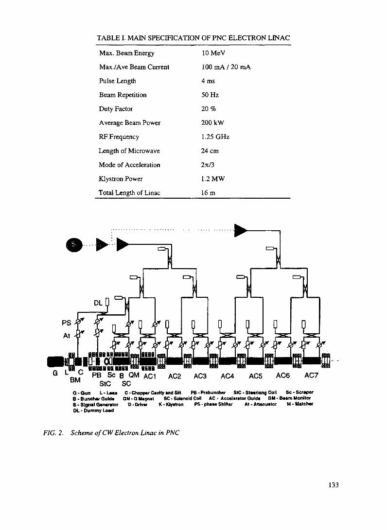
TABLE I. MAIN SPECIFICATION OF PNC ELECTRON LINAC
Max. Beam Energy
Max./Ave Beam Current
Pulse Length
Beam Repetition
Duty Factor
Average Beam Power
RF Frequency
Length of Microwave
Mode of Acceleration
Klystron Power
Total Length of Linac
lOMeV
100 mA / 20 mA
4 ms
50 Hz
20%
200 kW
1.25 GHz
24cm
27t/3
1.2MW
16m
BHHiHIHIEraHBRPB Sc B QM AC1
StC SCAC2 AC3 AC4 ACS AC6 AC7
G-Oun L-Leas C - Chopper Cavity and SHl PB - Prebuncber SIC - Steeriong Coll Sc-ScraperB - Buncher Quid* QM • Q Uagnet SC - Solenoid Coll AC - Accelerator Guide BM - Beam MonitorS-Signal Generator D- Driver K- Klystron PS - phase Shifter At. Attenuator M- MatcherOt - Dummy Load
FIG. 2. Scheme of CW Electron Linac in PNC
133

D.I.6.3. PRESENT STATUS AND FUTURE PLANS
In addition to the design and analysis, important components such as an accelerator guide and a highpower L-band klystron were built and successfully validated many of the design concepts as a collaborationwork between PNC and KEK (National Laboratory for High Energy Physics) in 1992. Figures 3 and 4show the view of the TWRR and the klystron used for the test, respectively.
RF Window
Phase Shifter
Dummy Load
RF Window
DirectionalCoupler
Stub Tuner
Accelerator Guide
FIG. 3. Layout of traveling wave resonant ring
It was demonstrated that the accelerator guidecould endure a power of SOOkW, without anyelectric discharge or thermal deformation. Basedon the test results, the klystron window wasmodified to increase heat resistance. Theconstruction of the high power electron linac is inprogress and all the components will be installedby March 1997.
Collector
RF Window
Output Cavity
Focusing Coil
3.5mInput Cavity
Anodetthode
FIG. 4. High power klystron
REFERENCES
[1] H. Nakamura et. al.,"Transmutation of Fission Products through Accelerators", 3"1 InternationalExchange Meeting on Actinide and Fission Product Partitioning and Transmutation.
[2] T. Emoto et. al.,"PNC High Power CW Electron Linac Status", Proceedings of the 1994International Linac Conference.
134

XA9846567
D.2. LOS ALAMOS NATIONAL LABORATORY ADS PROJECTSD.2.1. BASIS AND OBJECTIVES OF THE LOS ALAMOS ACCELERATOR DRIVENTRANSMUTATION TECHNOLOGY PROJECT
Charles D. BowmanLER-ADTT, Los Alamos National LaboratoryLos Alamos, NM 87545 USA
The Accelerator-Driven Transmutation Technology (ADTT) Project carries three approaches fordealing with waste from the defense and commercial nuclear energy enterprise. First, the problem of excessweapons Plutonium in the U. S. and Russia originating both from stockpile reductions and from defenseproduction site clean-up is one of significant current and long-term concern. The ADTT technology offersthe possibility of almost complete destruction of this Plutonium by fission. The technology might beparticularly effective for destruction of the low quality Plutonium from defense site clean-up since thesystem does not require the fabrication of the waste into fuel assemblies and can tolerate a high level ofimpurities in the feed stream. Second, the ADTT system also can destroy the Plutonium, other higheractinide, and long-lived fission product from commercial nuclear waste which now can only be dealt withby geologic storage. And finally, and probably most importantly the system can be used for the productionof virtually unlimited electric power from Thorium with concurrent destruction of its long-lived wastecomponents so that geologic containment for them is not required. In addition Plutonium is not a significantby product of the power generation so that non-proliferation concerns about nuclear power are almostcompletely eliminated. All of the ADTT systems operate with an accelerator supplementing the neutronswhich in reactors are provided only by the fission process, and therefore the system can be designed toeliminate the possibility of a runaway chain reaction. The means for integration of the accelerator intonuclear power technology in order to make these benefits possible is described including estimates ofaccelerator operating parameters required for the three objectives.
D.2.1.1. INTRODUCTION
Concerns about waste from the defense and commercial nuclear sectors has grown to such an extentin recent years that it now dominates the nuclear enterprise. The emphasis in the nuclear technology fieldhas moved from its earlier reactor-design focus into clean-up of defense production sites and a resolutionof the commercial nuclear waste problem. The development of cleaner and safer systems for nuclear energygeneration is almost at a standstill because of growing international concerns about the waste issues. Thepredominant approach to this problem for the past thirty years has been the geologic storage of wastewhether it be from the defense or the commercial sector. Geologic storage offers the prospect of confiningnuclear waste by the features of a stable geologic structure rather than relying on long-term containmentof the waste in man-made containers. In addition the waste is made much less accessible by its placementdeep underground. Therefore many countries are providing significant funding for the development andsiting of geologic waste storage facilities. While a number of sites might be under study in a given country,the intent is to provide a single site capable of confining the high level waste.
It has become increasingly difficult to convince a community to become host to a nation's single sitefor storage of waste which many consider to be the nation's most dangerous. The fact that the waste remainsdangerous for many tens of thousands of years exacerbates these concerns. The concern that suchrepositories can become mines for Plutonium has become of even greater concern as the U. S. has madeit known that dangerous nuclear weapons can be made from commercial Plutonium [1]. The natural
135

transformation of commercial Plutonium into weapons Plutonium by radioactive decay1 means thateventually many thousands of tons of weapons Plutonium will be stored at many sites around the world.Some are becoming concerned about the possibility of natural or induced supercriticality of fissile materialstored underground [2]. As a consequence of these and other concerns remaining to be resolved aboutgeologic storage, no nation is expected to begin emplacement of high level waste in a geologic repositorybefore the year 2010 and the ultimate viability of the geologic storage concept remains to be demonstrated.
The world is therefore in need of an acceptably priced and safe alternative to the geologic storageconcept. In the U. S. commercial nuclear waste is accumulating at reactor sites and the defense site clean-up effort is struggling to understand what will happen to the Plutonium and other high-level waste whichwill be gathered together after the clean-up has been completed. The Los Alamos National Laboratoryalong with a rapidly developing national and international community has therefore been studyingAccelerator-Driven Transmutation Technology (ADTT) as a possible means of destruction of this nuclearwaste and of generating nuclear power by systems which do not generate the most dangerous componentsof this waste and which concurrently destroy their own waste. If the full capability of the ADTT systemscan be realized at acceptable cost, geologic storage of defense and commercial waste would not be required.
The main elements and function of an ADTT system are illustrated in Fig. 1 for a system whichgenerates nuclear energy from Thorium, avoids the production of Plutonium and concurrently destroys itslong-lived high-level fission product waste. This system is referred to as Accelerator-Driven EnergyProduction (ADEP). The system starts with benign 232Th and converts it by neutron absorption into theexcellent fissile fuel ^U from which electric power is produced. The system consists of a reactor-likecomponent referred to in the figure as the target-blanket which contains the fissile material and the wasteto be destroyed. For a reactor each fission on average produces enough neutrons after losses to causeanother fission so that the chain of fissions is continuous. For all ADTT systems, the losses are madesomewhat larger by the expenditure of neutrons on waste destruction so that there are about 5-10 % fewerneutrons than necessary to maintain the chain. Therefore by itself the system is totally passive andinoperative. However, by making up for the 5-10 % loss of neutrons from an external neutron source, thesystem would function effectively even though the chain reaction would not be self-sustaining.
The essential conceptual difference between the ADTT system and a reactor is the presence of anaccelerator to produce neutrons and the presence of a target inside of the reactor-like component to converta beam of protons from the accelerator into neutrons. All electric-power-producing reactors presentlyoperating have means for removing the heat from the system, converting it to steam, and driving generatorsfor electric power production. These elements are also shown in Fig. 1 with most of the power being sentinto the commercial grid except for 10-15 % being used to power the accelerator. Operation of the systemstops when the accelerator stops because the system fission chain is not self-sustaining. For this reason thesystem can be made safe from a runaway chain reaction such as that which occurred at Chernobyl byentirely different means than that incorporated in other reactors, and many of the safety features requiredin accelerators such as control rods may be omitted.
To understand the value of the accelerator more clearly, consider a system containing 233U fuel whichundergoes fission with 92 % probability upon absorption of one thermal neutron and which releases 200MeV per fission. Assume further that no neutrons are released in fission. The 100,000 MeV released by500 such fission events would be converted with 42 % efficiency to 42,000 MeV of electric energy. Theaccelerator would convert this with 45 % efficiency to 18,900 MeV of proton beam power if all of theelectric power were fed back to the accelerator. For a proton energy of 800 MeV, the accelerator wouldproduce 18,900/800 = 23.6 protons. At the conversion rate of 25 neutrons per proton which probably canbe achieved, a total of 23.6 x 25 = 590 neutrons per 500 fissions is possible. Upon absorption, 92 % ofthese neutrons would lead to fission of 543 nuclei of 233U. Comparing this number with the original 500fission events, we see that an accelerator-linked chain reaction is possible even if no neutrons were emitted
'The isotope that makes the principle difference between commercial Plutonium and weaponsPlutonium is u which decays with a half life of 6,600 years. After about 13,000 years commercialPlutonium containing about 24 % w>Pu transforms to weapons Plutonium containing about 6 % 240Pu.
136

from fission' Of course instead of no neutrons per fission 2 49 neutrons are produced per fission of a 2"Unucleus so that altogether one has 590 + 500 > 2 49 = 1835 neutrons per 500 fissions for an increase inthe effective number of neutrons from fission from 2 49 to 3 67 if all of the electric power from the targetblanket were fed back to the accelerator This is an increase of more than one neutron per fission and is anenormous increase in the number of neutrons per Fission which are available to a nuclear system designerThe latter figure is far more neutrons than are required to maintain the fission process and to breed the 21:Ufrom the Thorium, so that only a small portion of the electric power must be consumed by the acceleratorThe possibility to dial the neutron production requirement as desired and to operate effectively a systemwell away from cnticality greatly broadens the parameter space available to the nuclear system designer
AcceleratorDelivers 800 MeV proton
beam to target
TargetProtons striKirig target
product spailatfonttetttrons
* tne surrounding fcsstonabte; fuel fctrcuiatngimotten salt)
Blanket
Power SystemSteam-generated electricalpower f 10-20 % returned to
accelerator)
fteston products removed fromfuel Long-lfved elementsIsolated for transmutation
Waste StreamShort-lived fisstoft products to
local engineered storage
FIG 1 ADTT System Components An accelerator produces 800-MeV proton beam which is directedinto a reactor-like assembly consisting of a Lead target for the beam and a surrounding blanket containingfissile material The beam strikes the liquid Lead target and produces about 22 neutrons per proton Theneutrons are moderated in the surrounding blanket which consists mostlv of graphite and molten saltwhich carries the fissile fuel as actimde fluonde The system operates at ke^ = 0 95 so that the systemmultiplies the beam-produced neutrons by about a factor of 20 The blanket contains internal heatexchangers which transfer the heat from the working salt to a secondary external salt stream and then toa steam generator for electric power production Most of the power is fed into the commercial grid butsome of it is used to power the accelerator The liquid fuel allows the system to be continuously refueledand allows the waste products from fission to be continuously removed
Owing largely to the enhanced safety of the system one need no longer remain attached to solid fuelassemblies as in ordinary reactors Liquid fuel becomes an option with all of the many ad\antages itprovides In Fig 1 we show at bottom center a loop carrying the liquid fuel outside of the target-blanketin a continuous flow An obvious advantage is that the fuel can be continuously added to the system tomake up for that which is burned without shutting down for refueling as in the case of the reactor Ofcourse, the whole process and expense of solid fuel fabrication required for the reactor is a\oided as wellBut there is e\en greater benefit from the ability to remove the fission products from the liquid fuel on-linewithout stopping the system for removal of solid fuel assemblies By means which will be described later,
137

the liquid fuel can be continuously cleansed of the fission products which act as neutron poisons Thoselong-lived fission products which would ordinarily require geologic storage can be returned to the systemto be converted by neutron absorption to stable or short-lived fission product
Since only fission product is removed from the system, there is no actmide waste etcept for a verysmall amrunt which sbps through in the fission product separation process Because the long-h\ed wasteis destroyed, the only waste from the system is the short-lived and stable fission product This waste is madeup of a number of different species but none of the waste species have half-lives longer than 30 yearsContainers can be made to confine this remnant waste until the radioactivity has decayed away b> a factorof 1,000 or so Geologic confinement of the waste is not required because, as is shown later, the remnantwaste can be made to satisfy near surface disposal criteria of the NRC and the EPA If the site of the ADEPsystem meets the criteria for near-surface disposal, the waste need not leave the site Therefore only benignThorium need be brought to the site and no waste need be earned away
More will be said later about the Thonum-burning system about weapons Plutonium and commercialwaste destruction, and the relationship between the latter two technologies
D 2 1 2 TARGET-BLANKET DESCRIPTION
More detail on the target-blanket system is shown in Fig. 2 The system consists of a stainless steel tankvv hich contains graphite blocks for neutron moderation and reflection and a molten salt earner for the fertileand fissile fuel which w ill be descnbed below The graphite and molten salt are known to be compatiblewith one .mother from extensive expenence at Oak Ridge National Laboratory with the Molten Salt Reactor
BeamDulivered through vacuum
window to central target
largetMoten lead
BlanketModerating graphBe
lattice vr8h channels formolten sat!
UquldFue!Fuel bearing moften salt
arcuated through graphitemoderator
Pumps and HeatEicfeangers
irrtamaJ and dose to core toreduce liquid fuel inventory
VesselToiaHy enclosing the liquidlust to eliminate fuel spills
through pipe ruptures
ReflectorGraphite
FIG 2 Target blanket function The proton beam enters through a window at the top of the system andstrikes a liquid Lead target at the center The Lead is circulated and cooled from above Five layers ofgraphite blocks are shon n which moderate the neutrons The molten salt fuelflou s upn ard through holesin the blocks and to the outside through pumps and heat e changers and back to the bottom Graphite onall sides sen'es as a neutron reflector A cover-gas of helium collects the volatile species and carries themawa\ for appropriate separations
138
Experiment (MSRE) [5]. The molten salt flows upward through holes in the graphite blocks across the topof the system to internal magnetic pumps and heat exchangers and back to the bottom of the system. Theheat from fission is transferred in the heat exchangers to an external salt loop which carries the heat tosteam generators for electric power production. The molten salt is a LiF-BeF2 eutectic which melts at about450 degrees centigrade and operates at between 650 and 720 °C. Almost all elements react as fluorides andcan be dissolved in small but adequate amounts into the carrier salt for the transmutation and fissionrequirements. A cover gas of helium is circulated above the molten salt to collect and remove the noble gasand volatile fluoride fission products from the salt. The molten salt never leaves the tank, except for a smallslip-stream for on-line refueling and waste removal, and therefore there is no possibility for spillage of thesalt through pipe breaks.
Other liquids such as water could be chosen for the carrier. However the salt has the advantage of beingan excellent solvent for almost any of the elements present in the system. It also has a low vapor pressureat high temperature which is a major safety advantage allowing operation without a pressure vessel whichwould be required for a higher vapor pressure medium such as water. The higher operating temperatureallows a thermal-to-electric efficiency which might be as high as 44 %. Also the salt is non-reactive withair, nitrogen, or concrete, in contrast with for example, the liquid sodium coolant on which fast reactortechnology is now based.
The neutrons are produced at the center in a liquid Lead target. Protons enter from the top through awindow and are stopped in the Lead, with the Lead pump and heat exchanger on top of the tank. The Leadis confined by metal resistant to corrosion by the Lead. Since the corrosion properties of the Lead aredifferent from those of the molten salt, the Lead and salt are separated by an inner container compatiblewith the Lead and an outer container compatible with the salt. The metal for the salt containment probablywill be Hastelloy-N developed for the MSRE and for the Lead it probably will be Inconel.
The system operates at a k^ of about 0.95 compared to Ic^ = 1 for a reactor. The neutrons produced bythe accelerator therefore are multiplied by a factor of about 20 for and therefore an ADEP system producingpower from Thorium with a fission power of 250 MW, for an electric power output of 100 MW wouldrequire an accelerator capable of producing 6 ma at 800 MeV and consuming 11 MW of electric power.
The thermal-to-electric conversion efficiency for such a system would be 44 %. The bussbar-to-beamefficiency would be 45 %.
All systems which produce nuclear power from fission must protect against a potential loss of coolantaccident (LOCA) which might occur when the primary coolant system fails and the fission product decayheat builds to dangerous levels. The nuclear reactors now operating have active redundant systems whichcome into action when the coolant system fails. Newer designs for reactors include passive means to dealwith this situation. For example the power density and total power capacity of the reactor might be keptsmall enough so that the heat can be transferred to the outside of the reactor vessel and from there awayfrom the system into the surroundings by convection or radiant heat loss. The power of such a passivesystem is usually limited by the rate of heat transfer to the vessel with the components at the center of thereactor being at highest risk.
The ADTT systems are also designed with passive capability for after-heat removal. They have theadvantage over water-containing systems that the temperature can be allowed to rise much higher becausethe ADTT system contains mostly low vapor pressure high melting or vaporization temperature materialssuch as graphite and molten salt. Therefore much higher temperatures can be tolerated in the ADTTsystems without risk of internal damage or dangerously high pressures. In addition to the use of liquid fuel,the incorporation of an internal inside-to-outside flow path and natural convection both contribute toenhanced heat transfer from the inside to the outer wall of the blanket. Therefore ADTT systems can bedesigned for substantially higher electric power capacity than conventional reactors while still maintainingthe passive heat removal capability.
139

D.2.1.3. GEOLOGIC STORAGE AND THE ADTT SYSTEM
From the beginning of the development of the ADTT program, the discussion has continued as towhether the ADTT system requires a geologic storage facility as back-up for the untransmuted waste. Thepurpose of this section is to address the question of the requirement for geologic storage of remnant wasteafter destruction of the actinide and the long lived constituents of the fission products. It will be shown herethat near-surface storage of this waste might be made consistent with existing NRC and EPA regulationswith an addition to the regulations for storage of Cs, Sr, and Kr for about 200 years until they meet low-level radioactivity levels covered by existing regulations.
D.2.1.3.1. Review of Regulations
To begin the discussion, it is useful to review several aspects of near-surface waste storage. Wastedestined for near-surface storage is divided into three classifications as class A, B, and C waste.
Class A waste is the most benign and it can be stored at the surface without stabilization. That is, nospecial precautions must be made to protect the system from natural dispersion mechanisms such as rainfall,wind, etc. There are of course some restrictions such as exclusion from flood plains and from unstable land.The site must be clearly marked, and monitored for 100 years but no fencing is required. After that timeit is assumed that controls are no longer operative and that the site should not be dangerous to aninadvertent intruder. An inadvertent intruder is defined in NRC Regulation 10 CFR 61.2 as;"a person who might occupy the disposal site after closure and engage in normal activities such asagriculture, dwelling construction, or other pursuits in which the person might be unknowingly exposedto radiation from the waste."
Class B waste must be immobilized or contained by components in the waste site that maintain their"gross physical properties and identity" for 300 years. Surface storage is permitted and institutional controlis required for 100 years. Productive use of the land during this 100-year period is possible so long as the"integrity and long-term performance of the site are not disturbed." Therefore the site perhaps might beused as a parking lot. Elsewhere in 10 CFR 61 the use of concrete in such systems is suggested and it isproposed later in this report to use that means for immobilization.
Class C is reserved for waste with even greater radioactivity concentrations. This waste also requiresstabilized waste forms or waste containers. This waste must be stored at least five meters below the groundsurface such that after 500 years the waste would not be a hazard to an inadvertent intruder or to the publichealth and safety.
There is no absolute limit on the amount of radioactivity which can be emplaced at one site, whetherdesignated Class A, B, or C. The amount is only limited by the radiation released to the surroundings andrisk to an inadvertent intruder. The radiation released from the site "must not result in an annual doseexceeding 25 millirems to the whole body, 75 millirems to the thyroid, and 25 millirems to any other organof any member of the public." This release criterion for near surface disposal is the same as that for asingle geologic storage system built to confine all of the radioactive waste of the nation. The siting criteriafor surface storage of waste are specifically stated in 10 CFR 60 and are easily met so that such facilitiescan be sited almost anywhere except in flood plains, areas of unstable land, etc. Therefore there could bemany such sites and almost certainly many more than one in every state. If there were 100 such sites in theU. S., the total radioactivity burden in a single site could be 1/100 of that at a national central repository.If in addition these sites were receiving the remnant waste from an ADTT system which reduces the longlived constituents by a factor of about 1000, the long-lived radioactive waste burden for any single sitewould be smaller by a factor of 100,000 than that of a single geologic repository without transmutation. Ittherefore seems likely that the surface storage sites for remnant waste following transmutation could meetthe whole body and specific organ dose limits for a much smaller radiation source term even though theconfinement capability of the surface site would be less than that from a geologic site. This probably would
140

have to be demonstrated on a site-by-site basis.It might be argued that if the waste is distributed over 100 sites instead of a single geologic site, that
more people would be endangered. The spirit of the release limit however is that the dose received be toolow to risk harm to the surrounding population. Therefore the same release limits apply to each of the manylow-level waste sites as apply to a geologic storage site for the nation's entire commercial spent fuel. Thenumber of people exposed is considered not to be a factor because no member of the public is to besubjected to a dangerous dose from any waste site...either high or low level.
The other type of restriction for the inadvertent intruder into the site relates to the concentration of thewaste and to whether the waste stream from a transmutation system meets the concentration limits for classA, B, or C waste. Classes B and C waste require stabilization before emplacement. The method ofstabilization chosen for this report is mixing with concrete, a material already mentioned in 10 CFR 60 asappropriate for use in surface storage systems. The stabilization before emplacement as required by theregulations will obviously result in the dilution of the waste. There are no statements in the regulationsabout the degree of the dilution allowable....only limits regarding radiation release to the surroundings anddose to the inadvertent intruder, which depend on dose concentration. Weakly contaminated dirt whichis being cleaned up from some of the sites at Los Alamos and elsewhere can be disposed of in surfacestorage if the contaminated material meets the regulatory limits for radiation release or dose to aninadvertent intruder. For the remnant waste after transmutation from a 3000 MW, commercial reactor, weassume stabilization with 50 m3 of concrete per year. Assuming the waste to be Class C, these blocks whichmight be 1m xlm x2m = 2m3 would have to be stored under 5 meters of overburden according to 10CFR 60. If stacked end-on, one year's remnant waste from a 3000 MWt system would occupy a surface areaof 5m x 5m. The waste from 35 years of operation of the facility would therefore occupy approximatelya 30 m by 30 m area. Since the land can be put to some beneficial use, this area would be much smallerthan a 3000 MW, plant's parking lot and could be used as a small part of the plant's parking lot.
It would be correct to argue that stabilization amounts to dilution, but stabilization is required for classC storage and dilution is not forbidden by the regulations. In fact stabilization, which is required, demandssome level of dilution by the stabilization medium. The operating criteria are (1) dose to an inadvertentintruder and (2) leakage of radiation from the site into the surrounding environment.
D.2.1.3.2. Disposition of remnant waste from ADIT systems
For ADTT the issue then is what should happen to the remnant waste stream. This stream may beconsidered to have three components for the accelerator-driven transmutation of waste system (ATW). Weassume here a system designed to deal with the actinide and fission product waste from a single 3000 MW,LWR thermal reactor destroying the waste at the rate that the waste is being produced in the reactor. Thefirst components of the waste encountered in transmutation are the Uranium, which is the primaryconstituent of the spent fuel, and the Zirconium cladding. These components probably could be stored forreuse and are discussed later. The liquid fuel system allows the continuous feed of all of the waste left overafter Uranium and Zirconium removal including both higher actinide and fission products. The ATWsystem destroys the higher actinide waste by fission generating an average fission power of about 750 MW,per 3000 MW, reactor. The liquid fuel system also allows the continuous removal of fission products. Theonly actinides which escape are those which contaminate the fission product removal process. We assumethat the atom fraction of actinides in the fission product removal stream can be held to 1 part per 10,000and next compare the actinide loss rate with the Class C criteria for actinides.
This is illustrated in Table I where the first four columns show the isotopes, the annual production rates,the half-lives, and the decay rates. The fifth column shows the decay rate of the 1/10,000 of the actinideescaping from the transmuter through the separations process into the fission product stream. Stabilizationof this annually escaping quantity of actinide waste with 50 m3 of concrete as described above gives thedecay rate per gram of column 6. This may be compared with the class C decay rate limits for theseactinides given in 10 CFR 61 and shown in column 7. Except for the shorter half-life nuclides Pu, Ml Am
141

and Cm, the concentrations are about a factor of 10 lower than the limits. For ^Pu we use the limit givenin 10 CFR 61.55 for the parent ^m. For MIAm we use the limit given for the parent ^'Pu. Applying thesum-of-fractions rule for combining the decay rates for several isotopes as given in paragraph (a) (7) of 10CFR 61.55, the sum is still well below the decay rate limits. Therefore if the separations can beaccomplished at the 1/10,000 level, the remnant could be disposed of as Class C waste.
A similar evaluation of fission products is summarized in Table n where those isotopes with half-lives10 years or greater are listed along with their production rates, half-lives, and decay rates. The isotopes aredivided into groups according to the treatment received and each group is discussed below.
1. l37Cs, !3iCs, andwSrThese isotopes cannot be handled as near-surface low-level waste and they cannot be transmuted with
significant beneficial effect using accelerators. Therefore they must be removed from the waste stream witha separation factor of 10-100. Column 6 shows the decay rate of the isotope left after the separation. Onceisolated, the cesium and strontium must be stored until their radioactivity decays by about a factor of 100or for about 200 years before they can also be disposed of as Class C waste. Containers can be built forcontainment for this storage period so that geologic storage is not necessary. The cans must be isolated fromthe public and protected so that they maintain their integrity. They must be stored with passive means fordecay heat removal through this storage period. While geologic containment is not required for theserelatively short-lived nuclides, they do not qualify for near-surface storage and new regulations must bedeveloped for handling them on the transmutation site or at a central limited period storage site.
2. '07Pdand93ZrThese nearly noble metals materials are almost benign with long half-lives and weak decay energies.
No Class C limit is given explicitly for these in 10 CFR 61.54. However the limit for the semi-noble metalwNb is given as 0.2 curies/m3. It is more chemically active than either Zirconium or palladium and its decayenergy is more than a factor of ten higher than both. Therefore we assume that the Class C limit for 107Pdand 93Zr would be at least a factor of ten higher than for Nb and use the 94Nb limit increased by a factorof ten to 2 curies/m to estimate the regulatory limit. With this limit no separation of these isotopes fromthe rest of the fission product waste would be required before storage as Class C waste and transmutationwould not be necessary.
3. 79Se and '26SnNo regulatory limit has been established for these nuclides. We assume their chemical reactivity is
comparable to wNb as are their decay energies. Therefore we use the Class C limit for wNb of 0.2Curies/m3. A separation of a factor of ten must be achieved to reach the assumed Class C limit for each ofthese. These isotopes must be transmuted.
4. "Tc,andn9IThese nuclides are perhaps the most chemically mobile of the long-lived fission products and regulatory
Class C limits exist for them. To reach these limits, the "Tc must be separated by a factor of 100 and the129I by a factor of 10. These nuclides must be transmuted.
5. >5'SmThis nuclide exhibits a very weak decay energy and we therefore assume the limit of 2.0 curies/m3
derived from the established limit for ^Nb. To reach this limit, the separation factor must be about 300.The separated material must then be transmuted.
142

TABLE I. CHARACTERIZATION OF THE LONG-LIVED FISSION PRODUCT WASTESIsotope
79Se
^Sr
93Zr
"Tc
.07pd
126Sn
I29j
l35Cs
l37Cs
151Sm
85Kr
Annual HalflifeProduction (years)
(Atoms/a)xlOM
0.13
9.0
15
15
4.1
0.46
2.7
4.2
14
0.16
1.0
65,000
29.1
1,500,000
213,000
6,500,000
100,000
15,700,000
2,300,000
30.2
90
10.7
Decay Rate(Curies)
11.9
1,860,000
60
426
3.8
27
1.0
8.4
2,800,000
11,000
560,000
Separation factorand decay rate(Curies)
10
10
1
100
1
10
10
100
100
300
1
1.2
190,000
60
4.26
3.8
2.7
0.1
0.084
28,000
37
560,000
Concentration Class CAfter Decay RateStabilization" Limit(Curies/m3) (Curies/m3)
0.024
3800
1.2
0.85
0.076
0.054
0.002
0.0017
560
0.74
0.2
7000
2.0
3.0
2.0
0.2
0.08
0.08
4600
2.0
Stabilized with 50 m of concreteOJ

TABLE II CHARACTERIZATION OF THE LONG-LIVED ACTINIDE WASTESIsotope
238Pu
239pu
240pu
24,pu
242pu
237Np
241Am
243Am
AnnualProduction(Atoms/a)
1.13 x 1025
41.6 x 1025
19.2 x 1025
6.4 x 1025
3.9 x 1025
3.7 x 1025
4.1 x 1025
0.73 x 1025
Half life(Years)
88
24,100
6,560
14.4
375,000
2,140,000
433
7,370
Decay Rate(Curies)
7.5 x 10⁴
1.0 x 10⁴
1.7 x 10"
2.7 x 10⁶
6.1 x 10'
1.1 x l O 1
5.5 x 10"
5.9 x 10²
Reduction bySeparation0
(Curies)
7.5
1.0
1.7
270.0
.006
.001
5.5
.059
ConcentrationAfterStabilization*1
(Nanocuries/gram )
68
9.1
15.
2454.5
0.05
0.009
50.
0.54
Class CDecay Rate Limit*(Nanocuries/gram)
20,000b
100
100
3500
100
100
3500b
100Used decay limits from 10 CFR 61.55
b Used decay limit for parent from 10 CFR 61.55c For a separation factor of 10,000d Stabilization with 50 m3 of concrete

This noble gas is difficult to transmute because its cross section is small and gas-containing systemsinside a nearly critical system must be avoided for criticality safety reasons. According to regulation, itmust therefore be stored in 100 Curie or smaller amounts in separate containers with a volume of about100 ml. These containers must then be immobilized in the Class C waste in accordance with 10 CFR 61.54.There are no regulatory limits to the number of containers, but 5600 would be required per year. It wouldtherefore probably be preferable to collect the gas in yearly production volumes of about 10m3 and storeit along with the cesium and strontium. After 200 years the container confining the remnant could be storedas Class C waste according to regulations.
Of the eleven long-lived fission products, two require no action. The other nine must be separatedusing eight chemical separations and five of these must be transmuted and stored as Class C waste withthe other fission product. The remaining three (Kr, Sr and Cs) must be placed in engineered storage forabout 200 years. After the 200-year period, the latter four can be stored permanently as Class C waste also.The five isotopes to be transmuted constitute about 6 % of the fission product and will require about 300moles of neutrons per 3000 MW,-year of reactor operation. These neutrons may come either from anaccelerator or from the excess neutrons produced by the fission of weapons Plutonium or highly enrichedUranium. Once the five long-b'ved fission products have been destroyed, the remnant fission product wastecan be diluted and stored in concrete at the rate of 50 m3 per year per 3000 MW, fission power. For the LosAlamos Thorium burner, which transmutes its own fission product and produces 200 MWe (500 MW,) for35 years, the subsurface storage area required for Class C waste immobilized in concrete if stored twometers thick would be about 12 m x 12 m.
The Uranium and Zirconium cladding are nearly benign materials and could be stored in containersat some central site for probable future use. There is no apparent reason now to place them in geologicstorage where they would be almost inaccessible by definition.
In summary, with transmutation and separations factors which need not exceed 10,000 and more nearly1,000 for actinides and about 100 for fission product, remnant waste would not require geologic storage.For the on-site transmutation of the waste from a commercial nuclear power plant, the fission productimmobilized in concrete could stay on the reactor site as Class C near-surface waste. The Cs, Sr, and Krcould stay or be moved in accordance with state and local government decisions. Without the need for acentral geologic repository, the federal government need not become involved in the siting of waste storagefacilities. Its role would be limited to providing the regulatory framework for near-surface storage.
D.2.1.4. WEAPONS PLUTONIUM DESTRUCTION (ABC SUBPROJECT OF ADTT)
This is the first of the three applications which were mentioned at the beginning of this paper and hasbeen pursued under the acronym ABC for Accelerator-Based Conversion. Excess weapons Plutonium (w-Pu) is being made available by major reductions in the U. S. and Russian stockpile of nuclear weapons andby the clean-up of U. S. and Russian w-Pu production sites. Altogether more than 100 tons of this materialexists [1] with perhaps 20 % of it being material reclaimed from the production sites. The ultimatedisposition of w-Pu has been the subject of recent intensive study in the U. S. Basically three options areconsidered: (1) burning of the Plutonium to the point where it has roughly the same isotopic compositionas commercial Plutonium (c-Pu), referred to as the "spent fuel standard" followed by geologic storage, (2)geologic storage of the w-Pu without burning after vitrification with defense radioactive waste, or (3)complete burn-up of w-Pu.
Since there is about ten times as much c-Pu as w-Pu in the world today and the c-Pu is increasingrapidly, present U. S. policy appears to favor burning the w-Pu to the spent fuel standard. The advantagesof this seem to be that the w-Pu then becomes a small increment on the already larger c-Pu inventory, the
145
w-Pu is less effective as weapons material, the radioactivity of the burned w-Pu is a deterrent to thehandling of this material in nuclear weapons fabrication, geologic storage of the burned Plutonium makesit much less accessible than it now is, and the technology to burn the w-Pu to the spent fuel standard existsnow. The arguments against the spent fuel standard are that the resulting material is still quite effective forweapons construction, that it probably could be recovered from geologic storage without great difficulty,and that there is very little near-term political advantage because it will probably take 30-50 years tocomplete the conversion to the spent fuel standard and the placement of the material in geologic storage.
Perhaps most importantly, disposing of the material this way costs money or yields negative value fromthe w-Pu whereas there are clearly large positive-value uses for this material for start-up of the ADEPsystem and for ADTT commercial waste destruction. The destruction of commercial nuclear wasterequires supplemental external neutrons all of which could be supplied by an accelerator. However theneutrons could also be supplied by fission of weapons material. The weapons materials are valuable forweapons precisely because they are an excellent source of neutrons. Each fission of 239Pu produces 2.88neutrons of which one per fission must be used to sustain the chain reaction. An additional 0.35 per fissionare lost because not all neutron absorptions in 239Pu lead to fission and a total of about 10 % of the neutronsper fission are lost to parasitic capture and leakage. After subtracting off these losses of neutrons, one isleft with about 1.2 excess neutrons per fission available for other uses. The number of neutrons from HEUis slightly smaller. In the burning of commercial waste using the ADTT technology, the accelerator supplyof neutrons can be reduced by about a factor of two by the use of w-Pu or HEU. Since the acceleratorsource can be reduced significantly and we know roughly what the cost of the accelerator-producedneutrons is, the price which could be paid for w-Pu and HEU in this application can be estimated from thesavings in cost of the accelerator, which are relatively well known. The value for w-Pu is found to beperhaps as high as $250,000 per kilogram[3]. This value is far more than the value of HEU blended downfor commercial reactor fuel. An even higher price could be paid for w-Pu and HEU for the one initial loadrequired for the ADEP system without bootstrapping from the commercial grid using the accelerator.
If one compares the present inventory in the U.S. and Russia of w-Pu and HEU to the amount requiredfor destruction of the world's nuclear waste, there is a surprisingly good match, so that all of these materialscould be used for commercial waste destruction. It can be argued that the price quoted above is artificiallyhigh because HEU can be separated from natural Uranium at a much smaller price and that therefore amajor need for either w-Pu or HEU would be satisfied by lower priced newly produced HEU. Howevercontinued production of HEU would not be consistent with international agreements to forego theenrichment of Uranium to HEU when much smaller enrichments are quite sufficient for use as fuel in allof the world's commercial nuclear power plants. International political agreements therefore probablywould make it difficult or impossible to produce HEU for commercial waste destruction. Nevertheless, auser of HEU or Plutonium would argue effectively against paying the high accelerator-displacement valuewhen it could be produced anew much more cheaply. A value higher by a factor of two than that for newHEU might be paid for existing HEU or w-Pu in which case the 100 tons of w-Pu might be valued at about$50 billion and the ten times larger amount of HEU at about $500 billion. Such high positive values forthese weapons materials would be good news from the perspective of weapons material security since wewillingly guard our valuables and grudgingly pay to dispose of our waste. Fortunately Russia still considersits weapons material valuable and we can expect that it will be more carefully guarded if the U. S. policyis directed toward maintaining the high value perspective. Furthermore, since the value for the material isnot received until the weapons material is sold for the desired purpose, one can expect the desire forconverting the book value to real value to drive the sale of the material as soon as the waste destructionfacilities are able to use it. The temptation to hold on to the material for weapons purposes is counteredby the high value which could be obtained when it is sold.
Quite obviously these arguments for use of the weapons material for high value purposes areinconsistent with w-Pu destruction which is the purpose of the discussion in this section of the paper. Noneof the three options for near-term negative value w-Pu disposition identified by the National AcademyStudy [1] would be favored from the perspective of ADTT. This is especially true since the burning of w-Pu (or HEU) produces many more neutrons than are required to sustain a chain reaction so that the main
146

purpose of the accelerator, which also is to produce surplus neutrons, is superfluous. The accelerator ishowever useful if high bum-up of the Plutonium is required so that there is virtually no Plutonium in thewaste stream and the isotopic composition is incompatible with use of the remnant as weapons material.
Thus the Los Alamos National Laboratory has proposed an accelerator-driven subcritical system [4]in which fission product poisons are allowed to build up they consume not only the excess fission neutronsfrom w-Pu fission, but also the supplemental neutrons from the accelerator. The system achieves very highburn up without fuel reprocessing or fuel fabrication and refabrication. Also no chemistry for fissionproduct removal is required. The General Atomic Corporation has proposed a program with a similarobjective. Its helium-cooled graphite-moderated reactor with w-Pu fuel particles suspended in the graphitehas been proposed as the first stage of w-Pu destruction. After the Pu has been burned sufficiently that itwill not sustain criticality, the fuel is transferred to an accelerator-driven assembly which continues todestroy the Plutonium using accelerator-generated neutrons until keff of the system has dropped to about0.6. The bum-up of the Los Alamos and the General Atomic systems are similar and are the highest of anyof the proposed w-Pu-buming systems; neither require fuel reprocessing or fuel refabrication. Present U.S. DOE policy towards w-Pu burning seems to be to burn the Pu only to the spent fuel standard. The LosAlamos ADTT Project Office position is that preferably the w-Pu either should be burned completely orreserved for enhancing commercial spent fuel waste transmutation as described above with the latter choicemuch preferred.
D.2.1.5. ACCELERATOR-DRIVEN ENERGY PRODUCTION (ADEP SUBPROJECT OF ADTT)
Perhaps the most important element of the ADTT project in the long term is the Accelerator-DrivenEnergy Production (ADEP) which uses Thorium as a nuclear fuel. The system is based on the Th-U cyclein which 232Th is converted by neutron capture to thermally fissile 233U. This cycle has been studiedextensively [5] for use in commercial nuclear reactor power generation. The primary objective of themolten salt reactor experiment was to show that an effective breeder reactor could be built on this cyclewhich produced more 233U than it consumed. This reactor technology lost out to the fast breeder based onthe U-Pu cycle because its breeding ratio was barely larger than unity even when fission products werepromptly removed from the fuel. The U-Pu cycle showed much higher breeding ratios at a time whenPlutonium was in demand rather than in excess.
A major advantage in the present climate is that the Th-U cycle produces almost no Plutonium. TheTh-U cycle development program also focused on a molten salt liquid fuel program with on-line removalof fission products, and the operation of a liquid fuel reactor was demonstrated with the several-yearMolten Salt Reactor Experiment (MSRE) at the Oak Ridge National Laboratory. Not only could fissionproducts be continuously removed from this system but the liquid fuel allowed the reactor to becontinuously refueled. For this reason the MSRE still holds the world record for the longest continuouschain reaction. A great deal of successful research was done on the materials to contain the salt and all ofthe ADTT projects rely on the materials work done for the MSRE. While the MSRE had virtually noactinide waste stream, it had the usual fission product waste and its neutron economy did not allow it tobreed as much 233U as it bumed and still have excess neutrons left for transmutation of its fission products.
By preserving many of the design features of the MSRE and introducing an accelerator into the system,one achieves the capability to produce as much 233U as is burned so that the nearly unlimited energyavailable in Thorium can be accessed. In addition the extra accelerator-produced neutrons enable the long-lived fission products to be avoided so that there is no long-term high-level waste stream from this system.Because of the subcriticality of the system a runaway chain reaction can be made much smaller than anyreactor and perhaps the probability for such an event can be reduced truly to zero. These three features of"unlimited" energy, criticality safety, and absence of high-level waste are the highly touted features offusion systems which have been heavily studied for the many years. We believe that we can demonstratethese benefits to society during the coming decade by merging established reactor technology with theexisting highly developed accelerator technology. The system produces almost no Plutonium and it is has
147

excellent non-proliferation features. This system has already been described in some detail at the beginningof this report so we will concentrate mostly here on the non-proliferation features which are of vitalimportance for any new nuclear power system
All existing commercial reactors for production of nuclear power produce Plutonium as a by-productwhich is seen by many as an asset because of the additional power which can be derived from it. Otherssee it as a serious liability since it can be used for nuclear weapons and because of radiological concerns.The established means for separating the Plutonium for reuse in reactors produces a stream of "naked"Plutonium. This Plutonium is pure and unmixed with other material which would inhibit its usefulness innuclear weapons. This material might be diverted in the separation facility, in storage, in transport to fuelfabrication facilities, etc. There is the fear that in some countries it will simply be stockpiled for plannedor possible future use in nuclear weapons. Therefore the U. S. has followed a policy of discouraging thereprocessing of commercial spent fuel and the use of Plutonium for energy generation.
Instead the U. S. and Sweden follow a once-through cycle where the spent fuel would go directly fromreactor storage to geologic repository storage. Some are concerned about the consistency of U. S. policyif the once-through policy is proposed as a waste management solution, which will promote the muchgreater use of nuclear power throughout the world. In that case there eventually would be manyrepositories spread all over the world which could be mined for Plutonium. Furthermore the reactor-gradePlutonium decays into weapons-grade Plutonium. Therefore neither reprocessing, as it is presentlyperformed, nor once through geologic storage are entirely satisfactory solutions. The ADEP program offersthe opportunity to have the benefits of nuclear energy without the weapons potential from Plutonium orother material which could be used for nuclear weapons.
The ADEP system is fed 232Th and transforms it to 233U which is then fissioned to obtain the nuclearelectric power. After a stable equilibrium is reached, there will always be a fixed amount of B3U in thesystem which might be accessed for nuclear weapons.
A number of non-proliferation features of the ADEP system will be described below, which limit theamount of 233U available to a much lower amount than 239Pu in current LWRs. They also limit itsaccessibility, allow simple detection of any diversion attempt, and allow low impact actions to forcefullyterminate any diversion which is underway, if necessary.
Limiting the amount of fissile material presentFast reactor technology which is being pursued in many countries around the world carries a large
inventory of Plutonium. The fundamental reason for this is that the fission cross section for 239Pu in the fastneutron spectrum is smaller by about a factor of 100 than that for thermal spectrum fission of 239Pu.Therefore, other things being equal, the inventory for the thermal spectrum system is smaller by about afactor of 100 than for a fast spectrum system. The neutron flux for the thermal system is about a factor often smaller so that as a practical matter the thermal system requires about 10-30 times less material thana fast spectrum system. The same situation is true for 233U when fast and thermal spectrum systems arecompared. Generally speaking the ADEP system will carry about the same amount of a3U as an LWR hasof a5U and 239Pu together if the flux and power level are the same. The primary point here therefore is thatthe ADEP system carries a much smaller inventory of potential weapons material than the fast reactorsunder development in other countries.
Isotopic dilution of233U in ADEPIf the 233U were diluted with 238U to the 20 % level or lower, the B3U would be classified as non-
weapons material according to present regulations. A 500-MWt thermal ADEP system can be broughtimmediately into power production by a start-up inventory of 10,000 kg of Th and 700 kg of 20 % lowenriched Uranium (LEU) where the 20 % is 235U. The original 235U will be burned out over time andreplaced with U3U derived from the Thorium. The distribution of isotopes reached after ten years ofoperation is given in Fig. 3 where the amount is given in grams. At ten years, which is essentially
148

equilibrium, the Uranium fissile material inventory will be 100 kg of 233U along with 10 kg of 235U for atotal fissile content of 110 kg. The amount of ^'U present at this time is about 600 kg so that the requiredisotopic dilution of about 20 % is maintained. However the inclusion of B8U in the systems will result inthe production of a small amount of 239Pu. The isotopic distribution of Plutonium as 239, 240, 241, 241,and 242 is present in the amounts of 1.2,1.2,0.3, and 2.5 kilograms. The ratio of fissile to total Plutoniumis 0.29 so that the Plutonium would be very poor quality weapons material and there would be only 5.2kg of Plutonium altogether to be accessed.
"Raiding" the ADEPfor 233U through 233PaThe conversion of 232Th to 233U is a three-step process involving neutron capture by 232Th to produce
which decays almost immediately to 233Pa, which itself subsequently decays with a 26-day half-lifeto 233U. Fig. 3 shows that the inventory of ^Pa in the system is about 22 kilograms. If operation of theADEP system were interrupted and the molten salt removed, it would be possible in principle to separatethe 233Pa before it decayed to 233U from the 8000 kg of other actinide. If such a separation could becompleted in about 26 days, about half of the ^a could be recovered. When this half decayed to 233U, the11 kilograms of 233U resulting would be useful weapons material. The separation in question would be adangerous activity in view of the very high radioactivity of the salt so soon after shut-down. Ordinarilyspent reactor fuel is allowed to decay 300 times longer (about 10 years) before separations begin. A furtheroperational factor would be that the value for kg^ for the system would have dropped to about 0.85 fromthe normal value of about 0.95 by the removal of the 11 kg of 233Pa. This may be compared with about 100kg of Plutonium which could be recovered from the interruption of operation of an LWR operating at thesame thermal power level. A fast spectrum reactor of similar power would carry about 1000 kg ofaccessible Plutonium.
With the removal of the 11 kg of 233Pa, the thermal power level would have decreased by a factor ofthree and the net electric power into the commercial grid by a factor of about five while the acceleratorpower would have remained the same. The power level would recover over a period of several months,but the inconsistency between the accelerator power and the electric power output would be readilyobserved by infrared mapping from satellites or by other means.
Benefits from "lock-up" of733 PaThere are two disadvantages if the 233Pa is allowed to circulate freely in the salt. The first is that a "raid"
on the 233Pa might be started by draining the salt, although the follow on separations would be exceedinglysophisticated and dangerous. The second is that performance degradation through neutron capture on 233Palimits the flux to about 2 x 10¹⁴ n/(cm2s). The gain from internal isolation of the 233Pa during its decayperiod would offer many benefits in overall system performance.
Start-up without fissile materialThere might be nations which could benefit greatly from nuclear power but which are considered to
be substantial proliferation risks. In those cases providing non-radioactive LEU at 20% enrichment to startup the system might be considered a proliferation risk in that much of the enrichment towards highlyenriched Uranium has already been done. The start-up load might be diverted for enrichment for weaponsuse instead of being used for its intended purpose. The ADEP system can be brought into operation withno fissile material at all. For a system initially containing only "^h, the accelerator can be powered offthe commercial grid and the neutrons produced used to produce 233U. As the fission of the 233U increases,the neutron flux also increases generating even more ^HJ so that over a period of six to twelve months thesystem bootstraps itself to full power. No reactor existing or under development can operate withabsolutely no fissile fuel load.
149
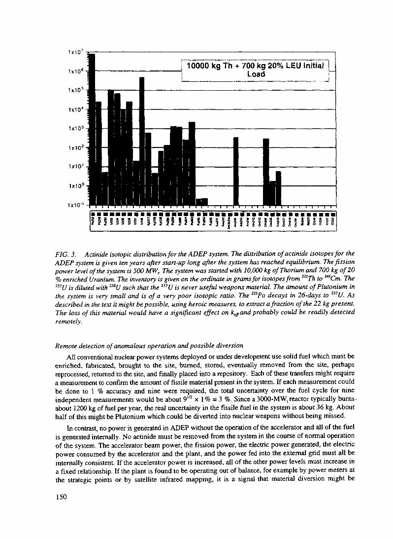
f 10000 kg th~+ 700 kg 20% LEU Initial 1Load i~
1x10
H il!l!!H!H3 I I !
FIG. 3. Actinide isotopic distribution for the ADEP system. The distribution ofactinide isotopes for theADEP system is given ten years after start-up long after the system has reached equilibrium. The fissionpower level of the system is 500 MWr The system was stoned with 10,000 kg of Thorium and 700 kg of 20% enriched Uranium. The inventory is given on the ordinate in grams for isotopes from 232Th to 246Cm. The233 U is diluted with 233U such that the 233U is never useful weapons material. The amount of Plutonium inthe system is very small and is of a very poor isotopic ratio. The 233Pa decays in 26-day>s to 233U. Asdescribed in the text it might be possible, using heroic measures, to extract a fraction of the 22 kg present.The loss of this material would have a significant effect on keff and probably could be readily detectedremotely.
Remote detection of anomalous operation and possible diversionAll conventional nuclear power systems deployed or under development use solid fuel which must be
enriched, fabricated, brought to the site, burned, stored, eventually removed from the site, perhapsreprocessed, returned to the site, and finally placed into a repository. Each of these transfers might requirea measurement to confirm the amount of fissile material present in the system. If each measurement couldbe done to 1 % accuracy and nine were required, the total uncertainty over the fuel cycle for nineindependent measurements would be about 9m x 1% = 3 %. Since a 3000-MW,reactor typically bums-about 1200 kg of fuel per year, the real uncertainty in the fissile fuel in the system is about 36 kg. Abouthalf of mis might be Plutonium which could be diverted into nuclear weapons without being missed.
In contrast, no power is generated in ADEP without the operation of the accelerator and all of the fuelis generated internally. No actinide must be removed from the system in the course of normal operationof the system. The accelerator beam power, the fission power, the electric power generated, the electricpower consumed by the accelerator and the plant, and the power fed into the external grid must all beinternally consistent. If the accelerator power is increased, all of the other power levels must increase ina fixed relationship. If the plant is found to be operating out of balance, for example by power meters atthe strategic points or by satellite infrared mapping, it is a signal that material diversion might be
150

underway. A more detailed study of these anomalous conditions and their dependence on the rate of feedof Thorium and the rate of removal of fission products might provide means to sense remotely when thesource of the anomaly is nuclear material diversion.
Limited consequences of extreme measures to control diversionIf an existing operating reactor is suspected or determined to be used for production of nuclear weapon
material, the ultimate response by those alarmed could be the destruction of the nuclear reactor. There isa significant possibility that such action could lead to widespread death for the surrounding public and landcontamination near the reactor. With such consequences the destruction of a reactor after it has begunoperation is probably impractical. The accelerator component of the ADEP system is large and easilydamaged into inoperation without significant possibility of damage to the target-blanket itself and therelease of radiation. Diversion can therefore be terminated without exposing the surrounding populationto significant danger.
D.2.1.6. COMMERCIAL WASTE TRANSMUTATION (ATW SUBPROJECT OF ADTT)
The objective of the Accelerator Transmutation of Waste (ATW) subproject of ADTT is to destroy theactinide and long-lived fission product waste from commercial nuclear reactor spent fuel. If the separationscan be done sufficiently well, storage of the remnant waste could be in near-surface sites rather than ingeologic storage facilities. The amounts of material requiring transmutation and the selectivity of chemistryseparations has already been described in the section of this report entitled, "Geologic Storage and theADTT System." Separation factors of about 1/100 are shown to be adequate to meet Class C storagecriteria for fission product and about 1/10,000 for the Plutonium and other minor actinides.
The ATW system also has means for continuous feed of waste from commercial light water reactors.To many this would appear to require the separation of Plutonium and other components of the wastebefore feeding them into the system. This is referred to as reprocessing which was forbidden in the U. S.by President Carter by Executive Order. Even though this order expired when he left office, as a practicalmatter it has continued to govern U. S. internal policy on spent fuel and our foreign policy position hasstrongly attempted to discourage the reprocessing option for commercial spent fuel. The purpose is toreduce the opportunity for diversion of commercial Plutonium to nuclear weapons purposes and to preventthe accumulation of large inventories of this material which is considered by many to be highly dangerous.Because of the excess neutrons provided by the accelerator, front end reprocessing is not required. TheATW system would require only the removal of the Zirconium cladding and the Uranium. All of the otheractinide and all of the fission product can be fed into the blanket, because the capabilities for removal ofthe fission product already exist in the back-end separations system.
The front-end removal system has not been selected but there are at least two options underconsideration. One would involve the crushing of the spent fuel assemblies which contain mostly UO2 andthe oxidation of this to U3O8. The volume expansion on the transformation to a higher oxide and theresulting conversion of the spent fuel to fine powder allows the spent fuel to be poured out of the spent fuelassemblies. Separation of the spent fuel from the cladding might approach 99 % for this process, but thatmight not be adequate and it might be difficult to clean the hulls further. Another means of removing thecladding might be to burn the spent fuel assemblies in a chlorine atmosphere over a plasma torchconverting the Zirconium to volatile ZrCl4. The oxide in the cladding however would fall as rubble intothe bottom of the chlorination facility and be collected for subsequent fluorination. The bulk of the spentfuel is Uranium and this would be removed as volatile UF6. All of the other spent fuel material includingthe fission products, the Plutonium and other higher actinides would be converted to fluorides and feddirectly into the ATW system by dissolving them in the molten salt carrier.
In contrast to the aqueous reprocessing system developed long ago and now in common use, theprocesses described do not produce a pure stream of "naked" Plutonium. The Plutonium is never separated
151

from the most highly radioactive components of the spent fuel, but only from the relatively benignZirconium and Uranium. The front-end separation required for the ATW therefore produces a streamwhich is mostly highly radioactive fission product and separation of the Plutonium from this fissionproduct and from the other actinides would be required before it could be used in weapons. It is alsoimportant to mention that the front-end separations for the ATW system would be an integral part of theATW system so that product stream from the Zr and U removal would be difficult to access.
Commercial nuclear power plants are typically sized at 3000 MW thermal and produce about 300 kgof Plutonium and other higher actinide per year while fissioning 1200 kg of fissile material per year.Therefore an ATW system operating at the same fission power level of the LWRs could bum the wastefrom four LWRs if its operating life were the same as the LWRs. Destroying the LWR waste arising fromthe roughly 100 LWRs in the U. S. using ATW systems would require the deployment of about twenty five3000-MW, ATW systems if the waste were to be destroyed in about 30 years. Unless the income fromelectric power sales were sufficient to offset the capital and operating costs of the ATW system, the costof destroying the waste by this means could be prohibitive. The economic picture for the ATW system willbe less favorable than for the ADEP system because the ADEP system need only destroy its own wasteand only a modest accelerator is required for the modest neutron supplement. However the ATW systemmust destroy not only its own waste but also that from the four LWRs. Substantially more accelerator-produced neutrons are required therefore with greater capital cost for the larger accelerator and for theadditional power which the accelerator consumes.
There is an attractive way around this. Presently the U. S. and Russia are reducing their weaponsstockpiles and freeing up large amounts of highly enriched Uranium and Plutonium. Both are excellentsources of neutrons, which is part of the reason why they are ideal weapons materials. Over the long runit is probably unsafe to store these materials and so they will have to be destroyed almost certainly byfission. If some of these weapons materials are consumed in the ATW system, the excess neutrons canmake up for some of the neutrons which otherwise would have to be supplied by the accelerator. Thereforeby burning these weapons materials concurrently with the destruction of the commercial nuclear waste,the size of the accelerator probably can be reduced by at least a factor of two. With the resulting benefitto the economic picture for the ATW system, the destruction of the waste using the ATW system mightbe practical. A comparison between the amount of LWR waste and the amount of excess weapons materialavailable shows that there is a satisfactory match.
There are other practical matters concerned with the practical deployment of the ATW systems. Thesesystems will probably have to be located at government reservations and operated in clusters both becauseof the sheer size and the use of the weapons material. If four ATWs were located on the same site, theelectric power output into the local commercial grid would be about 3-4 GWel from each reservation andthere would have to be about three sites if all of the waste was to be burned in 60 years. It is not easy toreliably estimate the U. S. power requirements over the next 30-50 years and how the power will beproduced, but having access to a commercial market for the electric power from the ATW systems is animportant consideration for this deployment option for the ATW system.
There is a second ATW deployment option for the destruction of the LWR waste which is a hybrid ofthe ATW and ADEP systems. This would involve the replacement of existing LWRs at the end of theirlife with an ATW system on the same site feeding the same amount of electric power into the grid. TheATW system would over its life destroy the waste from the LWR and also its own waste stream. About25 % of its power would be derived from the actinide waste from the LWR and the rest from Thorium. Theaccelerator requirement would be about the same as that for the other ATW deployment option, but noweapons material would be required. Of course it probably would not be desirable to have these weaponsmaterials being delivered to the approximately 100 ATW systems operating in follow-on to the existing100 LWRs. An advantage of this deployment scenario is that the waste need not leave the site, some levelof radioactivity inventory already exists on the site, and there is probably a clear market for the ATWelectric power and an existing distribution system. Under this scenario, the amount of nuclear power wouldcontinue to be at least as large as that produced today. The present system would have been replaced withsystems which do not produce the waste stream of existing LWRs, which avoid the criticality and after heat
152

safety concerns of existing reactors, and which nullify the requirement for a nuclear infrastructure ofmining, enrichment, fuel fabrication, reactor, fuel storage, reprocessing plants, and fuel refabrication. Therequirements for geologic storage of remnant waste would be greatly reduced or perhaps made entirelyunnecessary depending on the technical and economic performance of the system.
In summary, the first ATW deployment option carries more of the features which might be associatedwith a nuclear close-out option. The second option could provide a bridge over the next 30-50 years fromthe present LWRs with their major infrastructure requirements to the ADEP systems which operate withlittle infrastructure support.
D.2.1.7. PRESENT STATUS AND SUMMARY
This paper describes a new accelerator-based nuclear technology which offers total destruction of theweapons Plutonium inventory, a solution to the commercial nuclear waste problem which greatly reducesor perhaps eliminates the requirement for geologic waste storage, and a system which generates potentially"unlimited energy from Thorium fuel while destroying its own waste and operating in a new regime ofnuclear safety The accelerator technology is already rather mature after 50 years of development and isbeing driven by other programs. Reactors are also well understood after 50 years of development of manydifferent reactor types. The next essential step in the ADTT program is demonstration of the successfulintegration of reactor and accelerator technology in an experiment of significant size. Such an experimenthas been proposed for the Los Alamos Meson Physics Facility (LAMPF) at Los Alamos and for theMoscow Meson Factory at Troitsk, Russia. For a system operating at a k&ff = 0.96, LAMPF would drivethe system at a power level of 40 MW, thermal. Of course lower powers are contemplated for the earlierstages of the experiment which might extend over about seven years including both construction andoperation. The experiment would be accompanied by research and demonstration, at about the sametechnical effort as the experiment, on the required separations in the molten salt context. Perhaps sevenyears hence, an integrated demonstration of the ADTT system could be in operation at the 200 MW, level,with the deployment of the ADTT system beginning in about fifteen years. This time scale isapproximately the same as the earliest planned opening of a geologic repository in the U. S. or elsewhere.
REFERENCES
[1] Maintenance and Disposition of Excess Weapons Plutonium, National Academy of Sciences,Committee on International Security and Arms Control, National Academy Press, Washington, DC1994
[2] R. W. Benjamin, Savannah River Laboratories, Private communication, 1994; P.J. Sentieri andK. B. Woods, Idaho National Engineering Laboratory, Private Communication, 1994
[3] C. D. Bowman, "High Value use of Weapons Plutonium by Burning in Molten Salt Accelerator-Driven Systems or Reactors," International Seminar on Nuclear War and Planetary Emergencies,18* Session, pp. 400-411, E. Majorana Center for Scientific Culture, Erice, Italy, 1993
[4] "The Los Alamos Accelerator-Based Conversion Concept for Plutonium Disposition,"transparency set prepared for review by the JASON Group in January 1994, available from TheADTT Project Office, Los Alamos National Laboratory, Los Alamos, New Mexico; and C. D.Bowman, "Weapons and Commercial Plutonium Ultimate Disposition Choices...DestroyCompletely or Store Forever," in Managing the Plutonium Surplus: Applications and TechnicalOptions, pp 125-138, Kluwer Academic Publishers, Dordrecht, The Netherlands, 1994
[5] Alvin M. Weinberg, "Molten Salt Reactors," in Nuclear Applications and Technology 8, 102-219(1970)
153

XA9846568
D.2.2. THE LOS ALAMOS ACCELERATOR DRIVEN TRANSMUTATION OF NUCLEARWASTE (ATW) CONCEPT DEVELOPMENT OF THE ATW TARGET/BLANKET SYSTEM
F. Venneri, M.A. Williamson, L. NingLER-ADTT Project OfficeLos Alamos National Laboratory
D.2.2.1. THE ATW OBJECTIVE
The objective of the ATW project is to provide a compelling, proliferation-resistant and economicallyviable alternative to partial reactor burning and geologic storage in the management of nuclear spent fueland other plutonium bearing materials.
In the ATW concept, highly efficient and robust waste cleanup procedures produce a feed directlysuitable for nearly complete subcritical burning, without significant additional waste generation. ATWtechnology will significantly reduce waste streams from the nuclear power cycle and essentially eliminateexcess fissile materials. Plutonium and other hazardous components of nuclear waste will be destroyed toa high degree and with very low process inventories. Demands on permanent repositories will thereforebe greatly reduced, and such repositories (containing no fissile plutonium or highly-mobile long-livedfission products) will become more technically feasible and politically acceptable and economicallyattractive.
The immediate technical goal is to demonstrate the feasibility of effective treatment of spent fuel andother types of plutonium-bearing materials (including residues and excess weapons plutonium), toeliminate fissile plutonium (utilizing it to produce energy and neutrons) and destroy by transmutationcertain fission product nuclides of particular concern to long-term repository performance. Partitioning andisolation of plutonium will not be required to accomplish the project's goal. If ATW is to become thepreferred option for nuclear waste management in the US, economic viability of the entire ATW-basedfuel cycle must also be demonstrated.
The program will rely on the innovative application of proven technologies with emphasis on safetyand anti-proliferation features.
For the past several years researchers at Los Alamos have been studying and analyzing a fundamentallydifferent approach to nuclear power and the elimination of nuclear waste. At Los Alamos this approachis called Accelerator Driven Transmutation Technology (ADTT). We feel that ADTT has the potentialfor mitigating many of the difficulties inherent in present day nuclear power systems including nuclearwaste disposal and the buildup of plutonium inventories [1]. In dealing with the problems of nuclear wasteand management of excess plutonium, we believe that ATW has the potential to place nuclear power intoa regime with significantly reduced waste streams and no accessible plutonium or highly enriched fissilematerials.
ATW-based systems can consume nuclear waste (plutonium, minor actinides and long-lived fissionproducts), burning down existing inventories and producing very little new actinide waste, whilegenerating power and can further use the substantial excess neutrons that they are capable of generatingto do useful work, such as transmute long-lived fission products or reconstitute uranium or thorium basednuclear fuel for further use in reactors. ATW comes to the scene with four unique attributes, which are theresult of the combination of its subcriticality and use of liquid fuel. These are process robustness, poisoninsensitivity, neutron efficiency and completeness. The robustness of the ATW system processes allowsit to accept a wide range of nuclear waste with significant variability in isotopic assay and chemicalcontamination, from defense spent fuel and scrap plutonium to commercial spent fuel. Since there is noneed to reach and maintain criticality, the ATW systems are relatively insensitive to poisons and burnupfuel variation or poor fuel characterization. Because of the rapid elimination of fission product poison and
154

the achievement of high neutron fluxes, ATW systems should be able to burn plutonium and most othercomponents of nuclear waste efficiently , with low standing inventories, and to a high degree ofcompleteness, so that the waste load destined for permanent storage in a repository might be reduced, andsuch repository (containing no significant TRU waste or mobile fission products) would becometechnically feasible and politically acceptable.
ATW can accept the spent fuel generated by any of the existing and conceivable future types of nuclearreactors. ATW's front-end processes produce a feed of unseparated actinides directly suitable for nearlycomplete subcritical burning in the actinide burn unit. The unit operates subcriticaHy, driven by a largecurrent LINAC. Power production to offset operational costs is optional.
In ATW, the excess neutrons generated by the accelerator and the fission of the higher actinides areused in a blanket/reflector containing long-lived fission products to be transmuted. The separated uraniumis collected and sent to permanent storage. Plutonium and higher actinides are completely eliminated, aswell as the most troublesome fission products
The successful implementation of ATW systems will lead to the elimination of plutonium, higheractinides and selected fission products from the nuclear waste stream. With the implementation of ATWsystems the efficient (and eventually full) utilization of the existing uranium and thorium energy resourceswill become possible, with strong proliferation barriers.
D.2.2.2. GENERAL FEATURES OF ATW
Fuel preparation. Spent fuel coming from operating nuclear reactors (LWRs, HTGRs, CANDU, andothers) is processed using the "Hydrofluorination+Electrowinning in Molten Fluorides" process conceivedat LANL. The process allows the separation of the enriched uranium and/or thorium contained in the spentfuel without plutonium or actinide separation. The role of the fuel preparation part is to prepare thewaste feed for use in the target/blanket cell. The process is designed to be relatively insensitive to thecomposition of the waste feed. A unique feature of ATW is that the system can accept a wide range offeeds with minimal chemical preparation. The use of stable high-temperature molten salts as the primarychemical medium is key to this opportunity.
Actinide and selected fission-product burn. Subsequent to fuel preparation, destruction ofplutonium, higher actinides and selected fission products is accomplished in the passively safe, deeplysubcritical blanket conceived at LANL. Neutrons to sustain the bum phase are produced in a liquid metalspallation target driven by a large-current proton accelerator operating in the 1- GeV energy range. Whena proton beam is injected into the target, over 30 neutrons per incident particle per GeV are generated viaspallation reactions. These neutrons are multiplied by fissions in the surrounding subcritical blanketcontaining the actinides. Electricity may be generated from the heat released by the fission processes, anda fraction of the electric power generated will be available to the commercial grid for distribution. Thehigh-flux, low-inventory bum phase is assisted by the cleanup processes for fission product removalconceived at LANL for use in the ATW burner (sparging, electrowinning and reductive extraction). Thebum is nearly complete and only certain fission products are discharged by the process.
At the end of ATW operations, practical processes will be used for removal and recycle of radioactivematerials from the salt The long-lived hazardous fission products, e.g. 129I and "^Tc, will be transmuted intostable isotopes by neutron irradiation. Because there are no significant amounts of actinides andtechnetium or iodine (the long-term hazards) in the waste stream, the waste need not be guarded for fearof diversion of fissionable material, and its long-term toxicity is greatly reduced. A general layout of theATW components is illustrated in Fig. 1.
155

Fuel PreparationRobust Processing ofAcnnide and Fission
Product Waste
Fission ProductSTORED (95%)
All Actinides,Long-lived Fission Products (5%)
TRANSMUTED
AcceleratorDelivers l.SGeV proton
beam to target
TargetEach proton produces 30
neutrons per CeV
BlanketNeutrons transmute and destroy
waste
Povvcr SvstcniA fraction of generatedelectricity is relumed to
accelerator
FIG. 1. A general layout of the ATW components
D.2.2.3. THE VALUE OF SUBCRITICALITY
The ATW system is operated in a subcritical mode, thereby precluding a self-sustained chain reactionregardless of whether the accelerator being on or off. From a dynamic standpoint, driving a system withan accelerator decouples the source of neutrons from the fissile fuel: subcritical systems can operaterelatively unconstrained by the internal workings of the blanket. Critical systems, on the other hand, aredriven by the internally generated delayed neutron "source." Their control mechanism depends on theabsorbing properties of the control rods and their influence on the reactivity of the system, and is deeplyaffected by the internal conditions of the core, e.g. neutron flux and spectrum, and fission-product buildup.Critical reactors are therefore constrained by the flux, spectrum and internal composition tolerated in thecore because these parameters determine the effectiveness (reactivity worth) of the control mechanism.
From a static point of view, the accelerator provides a convenient control mechanism for subcriticalsystems that is much faster than that provided by scram rods in critical reactors. Subcriticality itself addsan extra level of operational safety concerning possible criticality accidents.
Although additional safe-shutdown mechanisms might be required, accelerator-driven subcriticalsystems can work without control rods, and in principle are insensitive to flux, spectrum, fission-productbuildup and core composition changes to a much higher degree than the equivalent critical reactor. Theresponse to reactivity transients is also much less severe and higher neutron fluxes are possible. Thisinherent robustness allows subcritical systems to accept fuel that would not be acceptable in criticalsystems, and burn it with minimal processing requirements [2].
A considerably larger excess of neutrons per fission can be produced in deeply subcritical systems thanit is possible to generate in critical (reactor) systems. Although these neutrons are not inexpensive, the
156

substantial progress recently achieved in accelerator design and operation efficiency, allows the effectiveuse of such neutrons for the transmutation of long lived fission products and other tasks.
Neutron economy of subcritical systems,The basic equation relating source- and fission- generated neutrons and governing the behavior of
subcritical systems is the following:
k ^eff \+a+P+L
where keff is the reactivity of the system, related to its neutron multiplication M factor by the equation:
«._!_
Critical (self-driven) systems have keff =1 and infinite multiplicationr|= average number of neutrons released by each fissiona= ratio of neutron-absorption-to-fission cross section in the active component of the fuel (plutonium and
actinides in the case of the ATW burner)P= number of neutrons parasitically absorbed in the system per fissionL= number of neutron that leave the system (leakage) per fission. These are the "excess neutrons"
available for work (waste transmutation and fuel enrichment)If the ATW burner is operated with a fast neutron spectrum then the values for the parameters are:
a=0.6; P=0.2 ; r|~3. If the ATW burner is operated with a more thermal spectrum (molten salt reflectedby graphite), then the values for the parameters are: a=l .4 ; P=0.4 ; r|~3. Values of n significantly largerthan 3 may be possible in "hyperfast", deeply subcritical systems directly driven by spallation neutronsgenerated in the fuel, where a substantial number of fissions are initiated by high energy spallation neutronsinstead of the relatively slow fission neutrons. These systems (which could be obtained in liquidlead/bismuth fueled ATW systems) have a spectrum substantially harder than that of fast reactors and offerspecial advantages in neutron-intensive applications. A schematic view of thermal and fast ATW burneris illustrated in Fig. 2. The number of available neutrons per fission (the L parameter) can be explicitlywritten as:
A cursory examination of this relation reveals the existence of two contribution to the number of neutronsavailable from a given system: the first term is determined by the subcriticality level, the second term bythe neutron spectrum. The use of the accelerator drive (systems with lower k^) will improve thecontribution from the first term. The use of fast neutrons will improve the contribution to the total number
157

Molten saltblanketmult ipKmgassembl}
thermal fissions inblanket
Liquid metal ti e lead orlead/bismuthno fissions in target
of available neutrons perfission from the secondterm It should be notedthat "hyperfast" systems(directly driven byspoliation neutrons)could provide alsoadditional neutrons b\increasing the value ofthe parameter nApplying the values forthe parameters n. A, andP to the expression for L,it is apparent that moreneutrons are available foruse in the fast-spectrumsystem than in the morethermal system for thesame value of keff
Just how many neutronsper fission are necessarywill of course depend onthe extent of the workthat is required from theATW s> stem Animportant task for these pu and highersystems is thetransmutation of fissionproducts Some of thefission products targetedfor transmutation remainin the fuel of the ATW FIGburner and their
ATW (molten salt, thermal spectrum)
ihne reflector
ATW (liquid lead/bismuth, ''fast" spectrum)
Neutron utilization blanket
Liquidlead/bismutltarget
actmide fuel loons.
liquid dissolved inmetal or salt earners
2 A schematic view of thermal and fast ATW burners
transmutation is accounted for in the fuel capture parameter P Some will have to be transmuted in specialloops, b> leakage neutrons The number of neutrons per fission needed to destroy the long-lived fissionproducts is directly related to the power produced in the ATW burner The relation depends on the extentof the fission-induced power production in previous operation (fuel burnup), and the type of fuel cycle(whether uranium- or thorium-based) For uranium-based spent fuel, with a burnup of 33,000 MWd/t(typical of a majority of present-da> spent fuel), 0 25 extra neutrons per fission in the ATW burner areneeded to destroy the long-lived fission products generated during previous and present fission processesThis is the number of extra neutrons per fission that is to be made available through leakage in ATWsystems where the transmutation of the long-lived fission products is sought in addition to the destructionof the plutonium and higher actimdes) In a near-thermal spectrum configuration (molten salt reflected bygraphite), a subcntical system (driven by the accelerator), operating at a keff =0 95 will free the additionalneutrons to allow 0 25 leakage neutrons per fission to be used for fission product transmutation It is truehowever that most of the usable leakage neutrons will have to come from the accelerator-dnven sourceA fast-spectrum system will have more than enough neutrons available even in a critical configuration(without accelerator) to perform the required transmutations of fission products Unfortunately a criticalsystem cannot be constructed to operate on pure plutonium and higher actimdes, especially in the fastspectrum Therefore some degree of subcnticahty (accelerator drive) must be used also in fast spectrumsystems, its extent to be determined by safety considerations more than by neutron economy factors Moredemanding applications, such as spent fuel reconstitution or the transmutation of a larger number of fission
158
products, will require a larger number of neutrons available per fission. For these applications, fast or"hyperfast" subcritical systems, capable of supplying over 2 available neutrons per fission, are clearlypreferable.
In the following discussion we will concentrate on the ATW systems with application to actinide andlong-lived fission product burning from spent fuel, and in particular to subcritical systems operating in thethermal neutron spectrum. As we have hinted and will show in more detail, the neutrons introduced intothese subcritical systems by the accelerator, the absence of neutron absorbing reactivity control devices,and the possibility of achieving high neutron flux levels can improve the neutron economy to the point thatfuels that were considered very difficult to use in the thermal spectrum due to their poor neutron economy,i.e. minor actinides, can be burned subcritically by thermal or near-thermal neutrons [3], with the ensuingadvantage of lower inventory.
Liquid-fuel subcritical systemsWhile it is strictly correct that any type of reactor can be arranged in a subcritical configuration, the
attractive features that subcriticality makes possible in ATW (fuel feed flexibility, completeness of bum,low sensitivity to changes in core parameters, relatively high flux, large number of excess neutrons) arebest accomplished with liquid-fuel systems, where the burnup is uniform, continuous fueling is available,regular fuel cleanup is possible, and no excess reactivity is required. Furthermore, because of the stronglyspatially non-uniform power distribution typical of deep-subcritical systems, fluid fuels are most likely tobe used in high-power configurations [4].
Among liquid fuel carriers, both liquid lead and molten fluoride salts, similar to the fuel used in theOak Ridge National Laboratory (ORNL) experiment [5], offer a good interface for the versatile,proliferation-resistant front-end process identified for the waste plutonium (molten salt hydro-fluorinationand electrowinning). Both molten salt and liquid lead, because of their chemical and electrochemicalstability, also can provide a natural medium for simplified back-end fuel cleanup processes. Both carriersare low vapor pressure liquids even at high temperatures, and therefore add to the safety and performanceof the systems, allowing low-pressure operation of the blanket and high-efficiency power production. Thecomplete absence of water in the primary system also eliminates the possibility of hydrogen generation andthe attendant risk of accidental explosions. Designs based on both options are currently underinvestigation at Los Alamos. In the following chapters, the molten salt fuel carrier option will be explored.The lead-fueled system, which form the basis of the "hyperfast" system currently under investigation atLANL, and other variants where both fast and thermal spectra are used to minimize the required acceleratorsize, will not be described in this paper.
D.2.2.4. BASIC DESIGN CHOICES FOR THE ATW MOLTEN SALT CONCEPT
Molten salt reactors have been operated and elements of the molten salt fuel cycle were developed anddeployed at ORNL during the 1970's. The addition of the accelerator drive and the absence of breedingrequirements for the fuel cycle make the ATW system considerably simpler and more forgiving than thecritical reactor proposed and carried to a considerable level of design detail in the ORNL work. After along search through a broad parameter space of options [6, 7, 8, 9 and 10], the Los Alamos molten saltATW concept has converged on a system reflected by graphite, a liquid lead-bismuth neutron productiontarget, and pyrochemical separation processes.
High-current accelerators and liquid-lead targetThe high-power accelerator technology required for ATW has been under continuous development for
the past three decades at Los Alamos. Presently, Los Alamos is involved in a major project to develop alarge accelerator (100 mA, 1300 MeV) for the production of tritium (APT) for defense applications.
159

BCOTI. Section CCLS«c*>nTMMHzlOOmA TOOUHzlOOmA Kfctan
Similar accelerator designs were reviewed by the Energy Research Advisory Board of the U.S. Departmentof Energy [11] and by the JASONS [12]. These reviews gave general endorsement of the proposedaccelerator technology with the provision that appropriate pilot and demonstration steps be made along theway towards the construction of a full scale facility [13]. In October 1995 the DOE committed to thedemonstration of the accelerator technology for application to tritium production (APT). The operatingparameters of the proton linac envisioned for the APT project will be similar to those needed for the ATWsystem.
The average power needed for the very largest of systems we propose requires an accelerator powerof around 200 MW (100 mA beam at 2000 MeV). This can most readily be achieved with a linearaccelerator. At present, the highest-power, linear proton accelerator is at LANSCE (formerly calledLAMPF), and operates at around 1 MW (1 mA at 800 MeV). At first, proposing an accelerator 100 timesbigger might seem like a very large extrapolation, but it is not as demanding as it appears. First, theLANSCE linac is operated with only every fourth bucket filled with proton beam. Filling every bucket(by use of funneling) or every other bucket (if unfunneled) immediately increases the average power bya factor of four (or two). Also, the LANSCE linac is a pulsed machine operated at 6% duty factor: goingto 100% duty factor would produce a factor of 17 increase in power. The charge in each microbunch canbe increased by about a factor of four and still stay well within the stable space-charge regime. Therefore,an improvement by a factor of more than 200 (4 x 17 x 4) is possible by the extension of proven protonlinac technologies. This should enable operation of 100-rnA, 2000-MeV linacs based on currenttechnology. Figure 3illustrate the possibi- __ _ .Hru __ runiwlity of using LANS- ^^^^^ an-CE LINAC for ATWapplications.
The function ofthe target in the ATWsystem is to convertthe incident high-
. FIG. 3. The ADTT linear accelerator design for multiple targets.to neutrons. Among 6 J r &the requirements for an ATW target are:
1. Compact size to enable good coupling to the surrounding blanket,2. High power operation, up to 200 MW,3. High proton-to-neutron conversion efficiency,4. Reliable and low maintenance operation,5. Safe operation,6. Small contribution to the waste stream.These system requirements are best met by molten lead or lead-bismuth eutectic (LBE). LBE has a
melting point of 125°C (200°C lower than for pure lead) and considerable experience exists in the use ofLBE in reactor systems. A significant problem with LBE, however, is the production of radioactive andhighly mobile polonium from high-energy proton and neutron reactions on bismuth. This becomes aconcern in accident scenarios where the polonium contained in the LBE is rapidly released at hightemperatures. Irradiation of lead, on the other hand, produces much less polonium, but there is alsoconsiderably less experience for pure liquid lead systems in reactor operation.
The use of molten lead or lead-bismuth eutectic in the neutron production target provides the followingadvantages:1. High power operation. For compact solid-target systems, the maximum incident beam power is
limited by the ability to cool the targets. In liquid metal targets, the medium can be circulated to
160

external heat exchangers, eliminating the need for coolant in the target production volume.2. Lead and LBE have good proton-to-neutron conversion efficiency because of their high atomic
number, high density and low neutron absorption cross section. The neutron production of large-sizelead targets has been measured at LANL to be 22 neutrons per 800-MeV proton, substantially betterthan any of the other materials tested [15]. The absorption cross sections are about one hundred timeslower for thermal neutrons than that of tungsten .
3. Radiation damage and shock issues that exist in solid targets are less of a concern with liquid targets.The fluid container and window are the only parts of the target system which have radiation-inducedlifetime limitations. The performance of the liquid part of the target is not affected by irradiation, sothat the operational life of the lead or LBE fluid can extend far beyond the lifetime of the container.
4. Lead and LBE are low pressure liquids with boiling points greater than 1600 °C. They are solid atroom temperature, reducing the potential for uncontrolled release of radioactive material when thetarget fluid is removed and cooled.The beam/target/blanket interface (target structure) is the point where three systems converge and
certainly will be the most stressed in the design from the materials point of view. The ATW design for thisstructure will have to "demonstrate ability to maintain system integrity at the beam/target/ blanketinterface" for the anticipated time of operation. In the ATW system, the low pressure of the target andblanket systems and the liquid nature of the target material will be helpful in this regard. The target shouldbe a totally enclosed structure, capable of being rapidly inserted and extracted from the blanket. Thisstructure must be compatible with both the lead and molten-salt liquid interfaces and therefore might sufferfrom limited resistance to radiation damage due to the properties of the available structural materials. Theuse of liquid metal targets however, should allow for the softening of the very hard spallation spectrum atthe target container walls to levels typical of fast reactor systems. The choice of structural matenals cantherefore directly extend to the large number of materials tested and satisfactorily used in fast reactors.Proton and neutron damage rates for the window and the rest of the structural parts of the target are notexpected to exceed the operational limits established at the Los Alamos Neutron Science Center(LANSCE) [16]. Based on LANSCE experience and extensive experimental studies of materials damageby neutrons (HT-9, Cr-Mo alloys, and Inconel), the lifetimes of the parts of the target most exposed to theneutron flux will be one to two years [16]. These materials have also shown good compatibility and nocorrosion problems with LBE as long as the temperature is kept below 400°C [17]. For higher temperaturecompatibility, the use of carbon based ceramic materials will need to be explored. Figure 4 illustrates a
design for the liquid leadtarget currently underdevelopment at Los
1 emper:it«nrBeam \\m<loM
Helium Plenum
Experience Base
• Solid targets and windows at LAMPFaccelerator• Flowing Pb-Bi technology in Russianreactors
Development Areas
• Adaptation of western and Russian moltenmetal technologies• Optimal integration with blanket
FIG. 4. A design for the liquid lead (lead/bismuth) spallation target
Lead Free-surface
Alamos.
Molten-salt liquid fuel.In the homogeneous
molten salt fuel, asopposed to solid fuels orliquid suspensions(slurries), many fissionproducts are readilydissolved into the liquidmedium, and can beextracted readily withoutprocessing the fissilecomponent of the fuel.The use of homogeneousmolten salt fuel, in fact,
161

allows the adoption of fuel preparation (front-end) and on-line cleanup (back-end) processes that do notrequire fuel partitioning and refabncation These processes which will not be detailed m this paper, exceptfor the description contained in Fig 5, do not give nse to extraneous waste streams and provide substantialproliferation and diversion barriers
Process Chemistry Identified for A TW Front-end and Back-endThe processes do no! isolate plutonium
from other higher acttnides or radioactivefission products
Because of the high throughput back endcleanup process the amount of fissilematerial in the back end is small
Theplutoniumpass through into the \iastestream is monitored b\ neutron assa\ offission product u a ste stream
Molten salt fuels
Fuel Preparation• Molten-salt hvdrofluonnation
• Electrowinmns
Metal Separations
Electrowmnmg
FP
Molten SaltDecommissioning and
Cleanup
FP
VolatileSeparations
Helium spargeFractional distillation
LanthamdeSeparations
• Reductive extraction
• Centrifugal Contactor
FIG 5 Process chemistry identified for ATW front-end and back-end
The molten salt envisioned for the ATW system is a mixture of lithium fluonde and beryllium fluonde(7LiF-BeF:, 0 67 0 33), with melting point of ~450°C would be used at between 600°C and 700°C Itsboiling point is 1700°C, and at 700°C the vapor pressure is only 10 milliTorr Isotopically pure 7LiF wouldbe used because of its lower neutron absorption All elements can be dissolved as fluondes in adequateamounts in the earner salt which is inert in dry air and nitrogen at all temperatures However, the meltingpoint of 7LiF-BeF, salt is relatively high, and the presence of lithium in it leads to the production ofundesired tritium under neutron irradiation The use of mixtures of other fluonde salts (e g NaF) tomitigate these concerns may be practical [18]
Molten salts as reactor fuels and as coolants have been under study and development for over 40 years,and their chemical, physical, and irradiation properties are well suited to reactor operation The Molten-Salt Reactor Experiment (MSRE) at ORNL, with several years of successful operation, contributedsignificantly to molten-salt reactor technology This 7 5 MW, reactor was operated continuously from1965 to 1969 with no major problems [19] At that time, two industry/utility advisory groups concludedthat an adequate molten-salt technology base existed and suggested that the Atomic Energy Commissionshould proceed with a molten-salt demonstration power plant [20]
The progress of the ORNL molten-salt design study is presented in the entire February 1970 issue ofNuclear Applications and Technology The issue was devoted to a review of molten-salt reactortechnology and to a descnption of a conceptual design for a molten-salt breeder reactor [21 ] The programat Oak Ridge ended after the Liquid Metal Fast Breeder Reactor (LMFBR) was selected as a superiorbreeder The successful operation of the MSRE and the substantial amount of research and development
162

on molten-salt reactor materials and processes at Oak Ridge indicate that with adequate updating of thattechnology base, a prototype molten-salt ATW plant could be successfully constructed and operated.
Whereas most of the work done at ORNL involved the use of uranium dissolved in the salt, ATWwould use primarily plutonium and higher actinides. This would introduce minor modifications to thesolutions adopted in the Molten Salt Reactor program, as the oxidation/reduction potential associated withfissions in plutonium fluoride tends to be different than for uranium fluoride. Low molar concentrationsof PuF3 were added to the MSRE as makeup fuel during the latter portion of its operation. Binary andternary phase behavior data exists for many of the components of interest [22, 23, 24, 25, 26, 27]. Onlysparse data exists for quaternary and higher order systems.
Graphite reflectorDue to the presence of large amounts of light isotopes in the salt (lithium, beryllium, fluorine) the
neutron spectrum for molten salt systems is always thermalized to a significant extent. To provide optimalmoderation and neutron reflection, graphite can be used in the core because of its high-temperaturecompatibility [28, 5] with the fluoride molten salt fuel. Concerns existed early in the Molten Salt reactorprogram that seepage of fuel salt into small cracks in the graphite could lead to local overheating and crackpropagation. However, there was no evidence that significant salt entrainment took place in the graphite.
In dealing with large amounts of actinides and essentially no resonance absorbers, a well thermalizedspectrum will lead to large positive temperature reactivity coefficients. This is due to the presence of low-temperature fission resonances in the cross section of the higher actinides, especially the plutoniumisotopes. A less moderated spectrum eliminates the problem in the ATW subcritical liquid fuel system.The ATW burner will use no internal moderation besides that provided by the lithium and beryllium in thebase salt. Graphite will be used as a reflector and to protect the nickel-based hastelloy vessel from thedamage of neutron flux.
Graphite is subject to neutron damage. With increasing neutron fluence, graphite first contracts, thenexpands at a fast rate. This rapid growth rate represents a rapid decrease in density and the possibleformation of voids and cracks. In this stage, mechanical properties will quickly deteriorate and the graphitemight become permeable to the molten salt. A fast neutron fluence above BxlO22 n/cm2 in graphite usuallyproduces the onset of the rapid growth phase, with significant dimensional changes and markeddegradation of its mechanical properties [29]. The neutron damage to the graphite is caused by the fastcomponent of the neutron flux, which is usually defined as the flux above 50 keV. For a thermal spectrumsystem, neutrons are quickly moderated so that the neutron damage rate is proportional to the fission rateper cm3. Therefore the neutron damage rate is proportional to the power density rather than the thermalneutron flux. Because of the significant complications involved with the removal of graphite from moltensalt cores, it is highly desirable that the graphite reflector maintain its integrity throughout the plant life.
Because the fuel is kept relatively clean of fission product absorbers, even at the moderate powerdensities present in the ATW burner, the neutron flux is expected to be in the range 2-5x10¹⁵ n/s-cm2 andvery strongly peaked This flux could give reasons for concern about the effects of high cross-sectionfission product poisons, such as xenon, on the stability of the blanket operation. Xenon fixed in positionsuch as by the constraints of solid fuel can cause the onset of spatial power instabilities. In the ATWsystem however, the fuel is continuously mixed, and therefore local concentrations of xenon in the fuelare not expected. Any unstable behavior would be limited to the amount of xenon that might becomeconstrained by the graphite and would not extend to the bulk of the fuel. Since most of the xenon producedin ATW systems would be removed from the salt through sparging on a very fast time scale (1-2 minutes),and since there is no graphite moderator, but only a reflector, it is highly unlikely that xenon could be asource of unstable behavior. Xenon permeation into the graphite would be more of a waste cleanupproblem because of the embedding of radioactive cesium daughter isotopes in the graphite, and should bedealt with accordingly by appropriate surface treatment (i.e. pyrolytic sealing) [28, 18].
163

Secondary coolantAn intermediate (secondary) coolant loop is required in the ATW system to transfer the heat generated
in the molten salt fuel to a power-producing steam cycle. The coolant in this loop must have low vaporpressure at its operating range of 500 to 700 °C. The coolant must be compatible at one end with the fuelsalt, and at the other end with the water/steam of the steam generator loop. The coolant must trap tritiumproduced in the core and keep it from reaching the steam plant. Materials compatibility must be assuredand it is also desirable to provide an environment that is essentially free of hydrogenous materials for safetyreasons. The coolant selected for the intermediate-loop in the MSBR design was a sodiumfluonde/fluoroborate eutectic salt (NaF-NaBFJ. This was chosen because of its compatibility withHastelloy and with the fuel salt, its low cost compared to 7Li-bearing salts, its adequate thermophysicalproperties (melting point, viscosity, specific heat and conductivity), its ability to trap tritium and its valuein shielding the heat exchangers from delayed neutrons coming from the irradiated salt. No nuclearexperience exists with this fluoroborate, but extensive non-nuclear tests were performed on this salt underthe MSBR program, and several concerns were uncovered. At high temperature, the fluoroboratedecomposes and forms chemically hazardous BF3. Fluoroborate also decomposes upon contact with fuelsalt, and has a limited compatibility with steam, in that its corrosivity is greatly increased by the presenceof moisture.
These issues do not rule out the use of the salt. One of the most important reasons for specifyingfluoroborate as the secondary coolant salt is its ability to trap tritium. Significant quantities of tritium, infact, are formed as a result of neutron capture (n, a) in 6Li, which is always present in the salt because of(n,2n) reactions in 7LiF, and tritium is also produced by (n,ncc) reactions in 7LiF. This tritium mightmigrate through the coolant system into the steam system, and from there to the environment. Simulationexperiments using the fluoroborate salt, however, showed that the tritium could be effectively trapped byoxygen-bearing species (Na^B2F6O) contained in the fluoroborate loop, as sodium hydroxy-fluoroborate(NaBFjOT) [30]. Alternative coolants are also possible, such as lead and lead alloys or low melting pointsalts.
Structural materials and componentsThe structural material of choice for the molten salt blanket is Hastelloy-N, that was used at Oak Ridge
during the MSRE work [31, 28]. Two problems, however, were discovered during the operation of theMSRE that required further alloy development:1. Hastelloy-N suffered radiation embrittlement due to the accumulation of helium and, to a lesser
degree, hydrogen at the grain boundaries [5]. The helium and hydrogen resulted from thermal (n, a)and (n,p) reactions on the unstable 59Ni produced by thermal neutron absorption in the Hastelloy nickel.Helium was also produced by (n, a) reactions on boron impurities. To achieve a 30-year lifetime forthe reactor vessel (made of Hastelloy N), the MSBR design had the inside surface protected by a 76-cmthick graphite reflector to reduce the thermal neutron fluence.
2. Post-operation testing of Hastelloy-N samples from the MSRE system revealed the presence of smallcracks on the side exposed to fuel salt [5]. These cracks were later determined to be due to thepresence of the fission product tellurium at the grain boundaries [18].Experimental work following the shutdown of the MSRE laid the basis for eliminating these problems.
It was found that modified Hastelloy-N, with fine carbide precipitants (Ti at first, then Nb, Zr and Hf)within the grains, could restrain the helium migration to the boundaries and mitigate the radiationembrittlement problem [32, 29]. Two solutions to the tellurium cracking problem also were investigated:adjustments to the salt oxidation potential to keep the tellurium from attacking the Hastelloy, and slightmodification of the Hastelloy-N composition (addition of niobium). The combination of both essentiallyeliminated the tellurium problem [29]. The above-cited solutions to the problems observed in the MSREhave all been demonstrated in the laboratory environment. In the ATW system, tellurium would also becontinually extracted from the salt.
164

The availability of a suitable structural material in the Molten Salt Reactor program allowed aconsiderable amount of engineering work to be conducted at Oak Ridge on the design and constructionof components suitable for operation in fluoride molten salt fuel. Corrosion-resistant pumps, valves andheat exchangers capable of reliable operation at high temperature [19] were provided for the MSRE.
Pumps. The pumps for molten salt blankets must reliably circulate fluoride salts in the primary andsecondary salt systems at temperatures as high as 750°C. The low electrical conductivity of moltenfluoride salts hinders the use of electromagnetic pumps. However, centrifugal pumps, albeit of low power,were demonstrated to work very reliably in the MSRE [33]. For full-scale ATW systems, there is yet noexperience in constructing and operating the much larger fuel pumps that will be required.
Valves. Valves are required in the ATW primary and secondary systems for isolating portions ofloops, directing flow to alternate paths, and providing flow variations during startup, shutdown, and off-normal conditions. The only type of molten salt valve that was operated in the MSRE was the freeze valve.This is a type of valve suitable for on/off operations, such as fuel-salt drain. The fuel-salt drain valve usedin the MSRE consisted of a flattened section of a two-inch pipe equipped with external heaters and coolers.It operated reliably. Although a large body of experience exists on several types of valves for operationin liquid metals at comparable temperatures, considerable more work is required for the satisfactoryapplication of these designs to the molten salt environment
Heat Exchangers. The operation of the MSRE heat exchangers was reliable, although the capacity ofthe heat exchangers was somewhat lower than expected. There was no evidence of scaling or corrosion.The experience base with the proposed NaF-NaBF4 secondary coolant derives from numerous tests for theMSBR design, but not from actual heat-exchanger design and construction. The experience base appearshowever to be sufficient to justify that the heat exchanger design be based on correlations for normal fluids,once the physical properties are accurately measured.
Overall, the MSRE fuel salt, LiF-BeF2, its containment system and the associated hardware performedwell throughout the life of the project [21, 5]. The ATW project will build on that experience, using theimproved materials and techniques available in the 1990's.
D.2.2.5. ELEMENTS OF MOLTEN-SALT NUCLEAR SYSTEM DESIGN
In 1960's, the Molten Salt Reactor Program at ORNL worked on thorium-based molten salt breedingsystems. The activity led to the design of the Molten Salt Breeder Reactor (MSBR) and was based on thedesign and operating experience of the Molten Salt Reactor Experiment (MSRE) and its technologysupport programs. In the early 1970's, ORNL proposed, with strong backing by industry and utilities, amajor technology development program that would have culminated in the construction and operation ofa demonstration reactor called the Molten Salt Breeder Experiment [5]. Later, in 1979, the DenaturedMolten Salt Reactor (DMSR) was proposed for power generation with enhanced proliferation resistance[18].
Based on the evaluation of those activities, the National Laboratories of Los Alamos and Oak Ridge,within the ADTT program, have recently started to revisit the technology base for the design of molten-saltsystems, in a framework stressing safety and reliability and with the different goal of waste and/orplutonium destruction replacing the original one of breeding [34, 35]. As a result of this effort, attractivefeatures of molten salt systems were identified as well as special concerns which need to be addressed inthe design of the molten-salt ATW concept.
Low pressure. The very low vapor pressure of molten-salts even at high temperatures and the lowpressure-drop design of the primary molten-salt circulation system allow for an overall low operatingpressure in the primary system. This enhances passive and engineered safety, for example, throughnatural-convection flow capability, design simplifications, and increased system component and structurereliability. To fully take advantage of this feature, the pressure should also be kept low in the secondarycoolant and care should be taken in the steam generator so that the high pressure of that subsystem remains
165
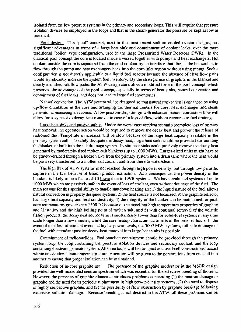
isolated from the low pressure systems in the primary and secondary loops. This will require that pressureisolation devices be employed in the loops and that in the steam generator the pressure be kept as low aspractical.
Pool design. The "pool" concept, used in the most recent sodium cooled reactor designs, hassignificant advantages in terms of a large heat sink and containment of coolant leaks, over the moretraditional "boiler" type configuration, used in the large Pressurized Water Reactors (PWR). In theclassical pool concept the core is located inside a vessel, together with pumps and heat exchangers. Hotcoolant outside the core is separated from the cold coolant by an interface that directs the hot coolant toflow through the pump and heat exchangers back into the core inlet region without using piping. Such aconfiguration is not directly applicable to a liquid fuel reactor because the absence of clear flow pathswould significantly increase the system fuel inventory. By the strategic use of graphite in the blanket andclearly identified salt flow paths, the ATW design can utilize a modified form of the pool concept, whichpreserves the advantages of the pool concept, especially in terms of heat sinks, natural convection andcontainment of fuel leaks, and does not lead to large fuel inventories.
Natural convection. The ATW system will be designed so that natural convection is enhanced by usingup-flow circulation in the core and arranging the thermal centers for core, heat exchanger and steamgenerator at increasing elevations. A low pressure-drop design with enhanced natural convection flow willallow for easy passive decay-heat removal in case of a loss of flow, without recourse to fuel drainage.
Large heat sinks and passive safety. Under the worst-case accident scenario (complete loss of primaryheat removal), no operator action would be required to remove the decay heat and prevent the release ofradionuchdes. Temperature increases will be slow because of the large heat capacity available in theprimary system cell. To safely dissipate the decay-heat, large heat sinks could be provided surroundingthe blanket, or built into the salt drainage system. In-situ heat sinks could passively remove the decay-heatgenerated by moderately-sized molten-salt blankets (up to 1000 MWt). Larger-sized units might have tobe gravity-drained through a freeze valve from the primary system into a drain tank where the heat wouldbe passively transferred to a molten salt coolant and from there to water/steam.
The high flux of ATW systems is not reached through high power density, but through low parasiticcapture in the fuel because of fission product extraction. As a consequence, the power density in theblanket is likely to be a factor of 10 lower than in LWR systems. We have evaluated systems of up to1000 MWt which are passively safe in the event of loss of coolant, even without drainage of the fuel. Themain reasons for this special ability to handle shutdown heating are: 1) the liquid nature of the fuel allowsnatural convection in properly designed systems, 2) the heat source is not localized, 3) the graphite reflectorhas large heat capacity and heat conductivity; 4) the integrity of the blanket can be maintained for peakcore temperatures greater than 1500 °C because of the excellent high temperature properties of graphiteand Hastelloy and the high boiling point of molten salt, and 5) with continual removal of the volatilefission products, the decay heat source term is substantially lower than for solid-fuel systems in any timescale longer than a few minutes, while the core heatup characteristic time is of the order of hours. In theevent of total loss-of-coolant events at higher power levels, i.e. 3000-MWt systems, fail-safe drainage ofthe fuel with attendant passive decay-heat removal into large heat sinks is possible.
Containment of radionuclides. Radionuclide containment should be provided through the primarysystem loop, the loop containing the pressure isolation devices and secondary coolant, and the loopcontaining the steam generator system. All three loops will be designed as closed-cell constructions locatedwithin an additional containment structure. Attention will be given to the penetrations from one cell intoanother to ensure that proper isolation can be maintained.
Reduction of in-core graphite use. The presence of the graphite moderator in the MSBR designprovided the well-moderated neutron spectrum which was essential for the effective breeding of thorium.However, the presence of graphite elements introduces problems concerning (1) the neutron damage ingraphite and the need for its periodic replacement in high power-density systems, (2) the need to disposeof highly radioactive graphite, and (3) the possibility of flow obstruction by graphite breakage followingextensive radiation damage. Because breeding is not desired in the ATW, all these problems can be
166
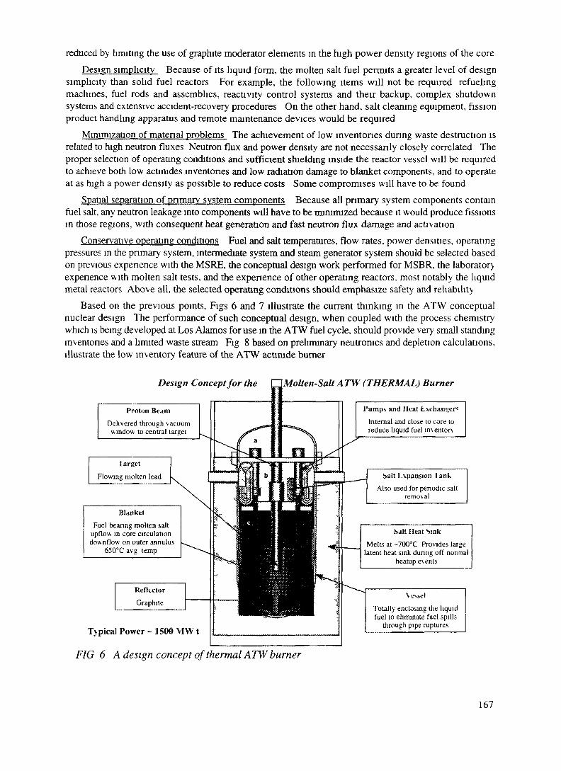
reduced by limiting the use of graphite moderator elements in the high power density regions of the coreDesign simplicity Because of its liquid form, the molten salt fuel permits a greater level of design
simplicity than solid fuel reactors For example, the following items will not be required refuelingmachines, fuel rods and assemblies, reactivity control systems and their backup, complex shutdownsystems and extensive accident-recovery procedures On the other hand, salt cleaning equipment, fissionproduct handling apparatus and remote maintenance devices would be required
Minimization of material problems The achievement of low inventories during waste destruction isrelated to high neutron fluxes Neutron flux and power density are not necessanly closely correlated Theproper selection of operating conditions and sufficient shielding inside the reactor vessel will be requiredto achieve both low actimdes inventories and low radiation damage to blanket components, and to operateat as high a power density as possible to reduce costs Some compromises will have to be found
Spatial separation of pnmary system components Because all pnmary system components containfuel salt, any neutron leakage into components will have to be minimized because it would produce fissionsin those regions, with consequent heat generation and fast neutron flux damage and activation
Conservative operating conditions Fuel and salt temperatures, flow rates, power densities, operatingpressures in the pnmary system, intermediate system and steam generator system should be selected basedon previous expenence with the MSRE, the conceptual design work performed for MSBR, the laboratoryexpenence with molten salt tests, and the expenence of other operating reactors, most notably the liquidmetal reactors Above all, the selected operating conditions should emphasize safety and reliability
Based on the previous points, Figs 6 and 7 illustrate the current thinking in the ATW conceptualnuclear design The performance of such conceptual design, when coupled with the process chemistrywhich is being developed at Los Alamos for use in the ATW fuel cycle, should provide very small standinginventones and a limited waste stream Fig 8 based on preliminary neutronics and depletion calculations,illustrate the low inventory feature of the ATW actmide burner
Design Concept for the ~ Molten-Salt A TW (THERMAL) Burner
Proton Beam
Delivered through vacuumwindow to central target
target
Flowing molten lead
Blanket
Fuel bearing molten saltupflow in core circulationdownflow on outer annulus
650°Cavg temp
RefUctor
Graphite
1'umps and Heat Exchangers
Internal and close to core toreduce liquid fuel m\entor\
Salt L\pansion lank
Also used for periodic saltremoval
Salt Heat SinkMelts at -700°C Provides large
latent heat sink during off normalheatup events
Typical Power ~ 1500 MW t
FIG 6 A design concept of thermal ATW burner
\ e«-,el
Totally enclosing the liquidfuel to eliminate fuel spills
through pipe ruptures
167
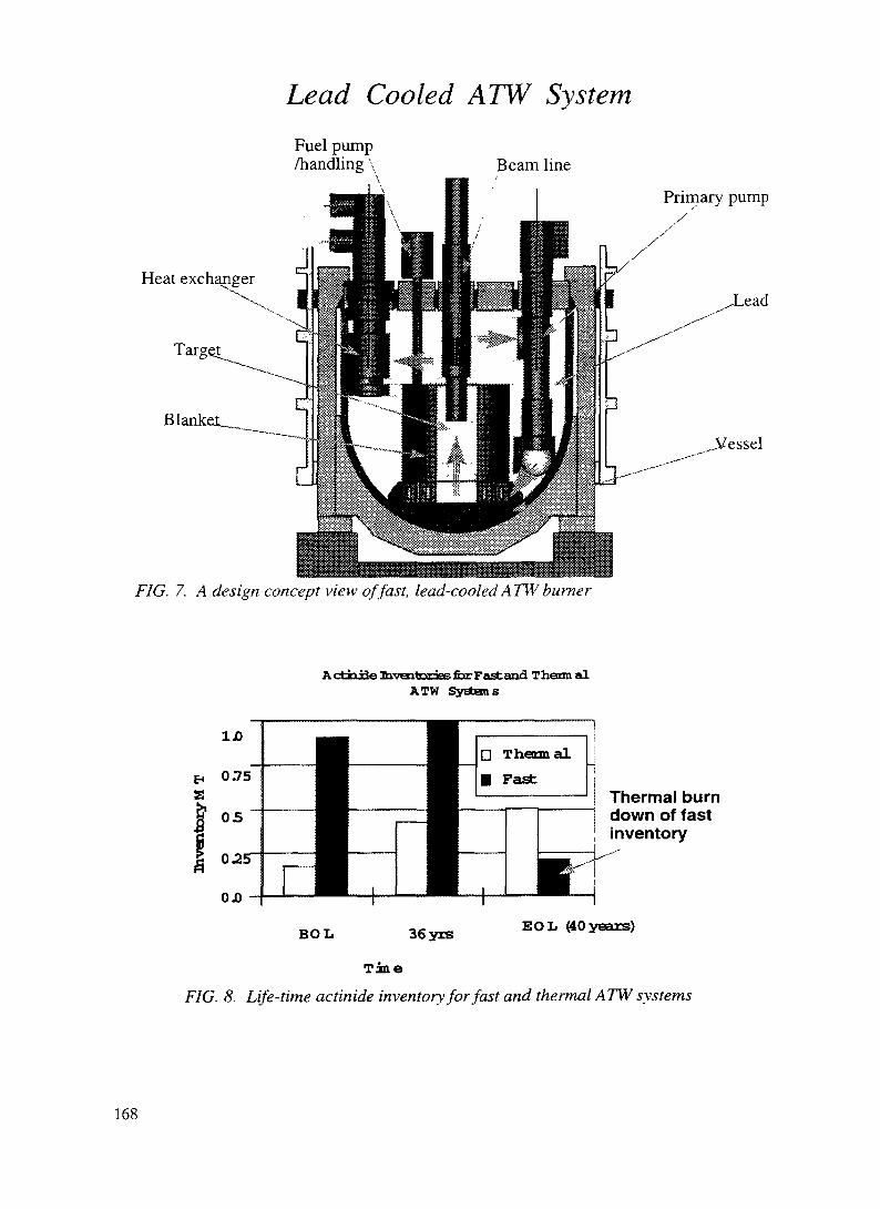
Lead Cooled ATW SystemFuel pump/handling \ Beam line
Primary pump
Heat exchangerLead
^Vessel
FIG. 7. A design concept view of fast, lead-cooled ATW burner
A ctri jfle Inventories for Fast and ThermalATW Systems
1JOD•
ThermalFast:
Thermal burndown of fastinventory
OJD
BOL 36yrs EOL (40 years)
Tine
FIG. 8. Life-time actinide inventory for fast and thermal ATW systems
168

D.2.2.6. THE SAFETY PERSPECTIVE
Accelerator-driven subcritical systems involve sustained fission processes that will produce radiationand fission product levels comparable to conventional power reactors. As such, a nuclear safety approachsimilar to that used for reactors must be employed.
The fundamental nuclear safety objectives applied to the design of fission reactors are [36]: 1) controlof fission power, 2) adequate cooling, 3) containment of radioactive materials, 4) prevention of inadvertentcriticality and 5) control of personnel and public exposure. Also, for an ATW system to be licensed in theUnited States, it would need to have characteristics consistent with those delineated by the NuclearRegulatory Commission (NRC) in its policy statement on regulation of advanced nuclear power plants[37]. These characteristics include: simplicity, slow response, passive system reliability, reduced systeminterdependencies, reduced severe-accident concerns, assured defense-in-depth barriers, and clarity insafety analyses: these features provide the safety robustness and margins that are desired for advancedsystems, which initially will have had little operational history.
Control of fission powerThe response of a neutronically critical system to reactivity insertions is highly nonlinear and rapid:
the initial response is in fact related to the prompt-neutron generation time and the longer-term responseis related to the addition of delayed neutrons from particular decaying fission products. Indeed, it is thesedelayed neutrons that make reactor control practically feasible. Reactivity control systems must be capableof preventing power levels that exceed specific limits, which are set to ensure fuel stability, coolingsufficiency, and first-barrier integrity.
To obtain a general sense of the responses of critical and subcritical systems to reactivity insertionevents, simple point-kinetics calculations have been performed [14] and their results are shown in Fig. 9.
The insertion of 1.0$ of reactivity in ATW systems only increasesthe steady state power level by ~5%
100001
ccuI0.
1000-
CRITICAL SYSTEM•CRITICAL ATK=1.0• 1$/sec REACTIVITY INSERTION• INTOLERANT OF LARGE REACTIVITY
NGES
• STEADY STATE AT K=0.96• 1$/sec INSERTION TERMINATED AT 1$• TOLERANT OF LARGE REACTIVITY CHANGES
400 T I I I I "T
1.5 2.0 2.5TIME (SECONDS)
FIG. 9. Kinetics of the critical and subcritical nuclear systems. Responses toreactivity insertion events: l$/s reactivity insertions.
169

In these calculations, the reactivity insertion rate was 1 $/s, and its duration was assumed to be either 0.5sec or 1 sec. For a typical plutonium-fueled molten-salt system, where up to '/z of the delayed neutronsmay be released beyond the boundaries of the core in pipes or heat exchangers, a dollar of reactivity isapproximately equal to a change in keff of 0.002. No reactivity feedbacks were assumed in either case tosimplify the understanding of the results. The initial multiplication in the subcritical system was assumedto be 0.96, and the initial power for both systems was assumed to be 500 MW. The predicted performanceis plotted in figure.
As expected for the critical system, the power rises rapidly and continues to rise after the reactivityinsertion is completed. Without negative reactivity insertions from inherent negative feedbacks and/oraddition of neutron absorbers, the transients are unterminated. The response of the subcritical system ismarkedly different in that the power changes very little. The power is inversely proportional to the inverseof the degree of subcriticality of the system (initially 1-0.96 or 0.04). At the end of the 1 -sec reactivityinsertion transient, one dollar of reactivity was gained, making the final multiplication of the system equalto 0.962 and the degree of subcriticality equal to 0.038. The power change is approximately 5%, and a newsteady state is established. A subcritical system appears to be robust in accommodating neutronic upsetconditions, because the system's response is predictable and relatively insensitive to the reactivity changes(small power changes for large reactivity changes), as long as the degree of subcriticality is substantial, i.e.large compared to the delayed-neutron worth. Even if the system was assumed to be initially at amultiplication of 0.99 and the same reactivity insertion event occurred, the power would only change byapproximately 25%. To put things into perspective, a dollar worth of reactivity insertion would beequivalent to a plutonium feed error of a factor of ten at beginning of life (the most sensitive condition)[38].
Although these large margins and the decoupling of power changes from reactivity changes areattractive in preventing and limiting potential power excursions, and make subcritical systems inherentlystable, it is also true that other (desirable) feedbacks, such as those from system temperature changes, onlyweakly affect the power for subcritical systems. In subcritical systems, power cannot be easily adjustedby means conventionally used in reactors. For example, active control with absorber rods would not beparticularly effective in subcritical systems because of the weak coupling between reactivity and power.The obvious power control would be by changing the intensity of the driving neutron source by varyingthe intensity of the proton beam current.
A second objective for nuclear systems is the highly reliable and rapid termination of the fissionprocess if the control system were to fail or unforeseen reactivity increases were to occur (scram).Normally, reactors have mechanically inserted neutron absorber components (shutdown rods, safety rods,absorber balls, etc.) to provide the scram function. To achieve the required high reliability of inserting theseabsorbers on demand, redundancy and diversity of components and systems are employed. Because ofthe delays associated with absorber insertion, the power continues to rise above the scram point: thispower over-shoot must be predicted and included in the design of the shutdown system to ensure thatsafety limits are not exceeded. The design must in turn take into account the reactivity properties of thefuel, moderator and coolant. As a result, fuels containing mainly plutonium and higher actinides, for whichthere may be little inherent negative reactivity feedback are typically not manageable in critical systems.
If a scram event were to occur in an accelerator-driven subcritical system, the delays would be limitedto those associated with detection of the condition, and interruption of the proton beam. The sensing andinterruption system could be entirely passive, based for example on fuses for the accelerator beam source,placed in the target/blanket. Once the proton beam is interrupted, the neutron production stops nearlyinstantaneously and the power in the subcritical system drops with a decay time given by the product ofprompt neutron lifetime and multiplication. The shutdown can be accomplished quickly, predictably, andreliably, following detection of abnormal conditions, in milliseconds instead of seconds. The need for in-core neutron absorber insertion with the associated mechanical complications is eliminated. Thecomplexities associated with "managing" the power over-shoot are also eliminated, and inherently unstablefuels like plutonium become acceptable [14].
Analogously, the quick restart of a subcritical system can be performed following a forced shutdown
170

in virtually any situation. A typical problem in reactor operation following shutdown is the buildup ofsamarium-149, a large cross-section daughter of the fission product promethium-149, which has a 53-hourhalf-life. Shutting down a reactor (especially a high flux system) can lead to the growth of such largeamounts of 149Sm that it may not be restartable until the l49Sm has been removed. No such constraint existfor subcritical accelerator-driven systems: these systems can always restart and bum the accumulatedsamarium because they do not need to reach criticality in order to start producing neutrons and destroy thepoison.
Adequate coolingAssuring adequate cooling in all situations is essential for all fission reactors. Because the integrity of
the first barrier is a key element in the defense-in-depth strategy for preventing the release of fissionproducts, and because this integrity is strongly linked to its temperature, adequate cooling of the firstbarrier must be assured for normal power operations and for a variety of accident situations, including off-normal shut-downs with the associated decay heat from the fission products. For conventional solid-fuelreactors fuel cladding is the first barrier, and with high power densities and water coolant, the claddingtemperature can rise rapidly if cooling is interrupted locally. For the molten salt system, the first barrieris the vessel. The thermal response of this first barrier is therefore linked to the heat capacity of the entireprimary system enclosed by the vessel, which is substantially larger than that of the individual fuel pinsor fuel assemblies of an LWR. The rate of temperature rise in molten salt systems, therefore, would bemuch slower than in solid fuel systems. This slow, system-wide response provides substantially increasedopportunities to sense inadequate cooling conditions and to respond appropriately.
The molten salt system also exhibits robustness from the standpoint of heat transport in and out of thecore region. Again the point of reference is a solid-fuel, rod-type core. In this system, the heat is generatedin the solid fuel material and is transferred out of the fuel, across the fuel-clad gap, through the clad, andto the surrounding coolant. The heat transfer processes include conduction, radiation, and convection. Theoverall heat-transport process is sensitive to dimensional changes, fuel restructuring, fission gas contentin the gap, coolant pressure, coolant subcooling, and coolant velocity. Many of these aspects can changesubstantially during core life, for different operating modes, and for off-normal and accident conditions.Although the process is complex, it must beknown reasonably well to assure adequate "oocooling and protection of the first barrier. Ina molten salt system, on the other hand, theheat is generated directly in the molten salt,which is also the heat-transport medium.Heat-transport is therefore greatly simplifiedand rapid dissipation is possible in the eventof inadequate cooling. This arrangementalso appears to have a self-limitingcharacteristic in that if cooling in the core isinadequate, the coolant/fuel salt overheats,eventually boils and is removed from thecore [14].
The final aspect of assured cooling isdecay heat removal. The challenge is to getthe decay heat to an ultimate heat sink beforethe increase in temperature can damage theintegrity of the core. The heat produced inthe compact cores of solid fuel systems mustbe removed into the primary heat transportsystem. In the molten salt system, instead,the decay heat is generated throughout the
1000
sooso 100 150 200 250 300 350 400
radial position (cm)
FIG. 10. Temperature rise of a prototype 500 MWtADTT blanket in a loss of coolant accident. Assumingonly convective cooling and a passive heat removalmechanism, the maximum temperature of 1100 "C isreached in 75 hours.
171

salt inventory in the primary system. Thus, this system has the possibility for predictable natural convectioncooling to the primary system boundary and the possibility of efficient passive heat rejection from theprimary system boundary to an external heat sink in emergency situations. The molten salt fuel would thenallow the attainment of substantially more powerful "passively safe" units than possible with solid fuels,i.e. able to handle the core heat-up in the event of a cooling system failure unattended and withoutpermanent damage (see Fig. 10).
Containment of radioactive materialsThe types of fission products retained in the fuel of an ATW-like molten-salt system are different from
those in solid fuel systems, and because of the extensive cleanup processes, they are present in muchsmaller amounts in the liquid fuel. Their release will, nevertheless, constitute a great hazard. Thus,containment of the radioactive materials at all times and for all conditions must be accomplished for themolten salt system.
In conventional reactors, many individual sealed units (fuel pins) are present with limited liferequirement (approximately three years before replacement). Thus, if a few of the individual units of thefirst barrier were to fail for some reason, only a relatively small fraction of the fission product inventorywould be released to the next barrier. In contrast, the molten salt system's first barrier (the primary systemboundary) must last for the life of the plant, and if it were to fail, a large fraction of the fission productinventory in the salt might well be released to the next barrier.
High reliability in the performance of the primary system boundary must be assured to deal with thischallenge, and a highly reliable and effective second barrier. Because the first barrier is not in the core andtherefore does not affect the neutronic performance and is generally accessible, design flexibility exists tomake the primary system boundary highly robust and to provide inspectability by remote means. Sealedvaults with appropriate heat removal systems, atmosphere control systems, and spill recovery systemscould be used as the second barrier. Finally, a surrounding containment or confinement structure wouldcomplete the three-barrier strategy to radioactivity release envisioned in the defense-in-depth approach[14].
A special challenge for the accelerator-driven molten-salt system is the integration of the beamtransport equipment with the containment barriers. The proton beam can not pass directly through heavy-walled structures without substantial losses and the generation of significant heat and radiation. Some typeof redundant thin-window approach is necessary, in order to avoid making the whole accelerator cavitypart of the containment enclosure.
Prevention of inadvertent criticalityPrevention of inadvertent criticality in conventional reactors is a relatively straightforward matter
because it is a concern only for fuel handling, new fuel storage, and spent fuel storage. Solid fuelsegregated into numerous individual assemblies can be handled in a very controlled manner, monitoredfor structural deterioration, and stored in well characterized and robust structures. In contrast, the moltensalt system presents challenges in assuring that the location of all fissile material is known at all times. Thepotential for precipitation of fissile materials from the molten salt must be considered and taken intoaccount in the design of the various subsystems. The potential for criticality in the fissile material feedsystem and in the salt cleanup and processing systems will have to be considered. Care will also berequired to assure that potential spills and leaks would only accumulate in subcritical configurations.Overall, criticality concerns would be mitigated by the subcritical margin of the accelerator-driven systemand by the lower inventories of fissile material.
Radiation exposures to personnelLimitation of the integrated exposure to the operating staff of a conventional reactor power station
172

involves equipment reliability and provisions in the design for ease of maintenance, inspections, testingand repairs. In this respect, the ATW system presents a challenge to designers and operators because offour reasons: 1) the fission products distributed throughout the primary system will produce high radiationfields in all areas adjacent to the primary system and potentially high exposures during incident recoveryoperations. 2) delayed neutrons produced throughout the primary system will activate all primary systemequipment resulting in radiation exposure potential even after decontamination. 3) the target system willhave limited life and require periodic replacement which could lead to additional personnel exposure. 4)the use of a lithium-based salt will result in the generation of substantial amounts of tritium, which coulddiffuse through metallic boundaries. All of these exposure potentials will have to be recognized in thedesign process, and special provisions will have to be included to protect workers during inspections,testing, maintenance, and repairs [14]. A considerable premium will be placed on highly reliableequipment and remote maintenance.
Safety features of the Oak Ridge MSBR designA conceptual design for the ATW does not exist yet, and therefore a valid safety analysis of this
concept cannot be performed. For reference, however, it is useful to look at the safety features of theMolten Salt Breeder Reactor (MSBR), for which a substantially developed conceptual design does exist[5], or the Molten Salt Reactor Experiment (MSRE) [19]. While the safety philosophy of the 1960's and1970's was different from today's, many of the safety concerns and features would be directly applicableto the ATW system [35].
Passive safety features. The MSRE operation was found to be stable and self-regulating. Responsiblefor this behavior were the strong negative temperature coefficients of the fuel salt and the large heat sinkoffered by the graphite moderator. The MSRE was simple to control. In over 14,000 hours of criticaloperation, nuclear parameters never exceeded the operational limits and a reactor scram was never initiated.The criticality of the reactor was controlled by regulating the feed of fissile material. Similar operationalcharacteristics could have been expected for the MSBR. Both reactors, however, were equipped withcontrol rods, even though the MSRE never used them during operation.
Control rods. The control rods for the MSBR design were movable graphite cylinders, whosewithdrawal from the core left an under-moderated region causing a reduction in reactivity. Should any ofthese control rods have broken, they would have floated out of the core, automatically resulting indecreased reactivity.
Decay-heat removal. Major passive decay-heat removal features were missing from the MSBRdesign. However, this was not a general limitation, but only specific to the MSBR design. It is reasonablein fact to expect that a properly designed molten salt system will exceed the level of passive decay-heatrelated safety of all conventional and advanced reactor designs.
Loss of primary coolant. Whereas a primary-system pipe break accident in a solid fuel reactor can leadto loss of coolant with resultant fuel overheating, fuel melting, and eventually fission product release; sucha failure in the MSBR would lead directly to the spillage of molten salt fuel. This is equivalent to a partialfuel meltdown with breach of the primary system boundary in a solid fuel reactor. In the MSBR design itwas argued that in such an accident situation the fuel would immediately freeze and most likely retain thefission products (especially since the volatiles would have been virtually absent from the fuel) so thatcleanup of the contamination, repair and restart of the reactor could follow quickly. This procedurehowever might not meet modem standards of plant safety.
Steam pressure. The MSBR was designed to operate with a steam pressure of 3800 psig, by far thehighest steam pressure found in any nuclear steam generator. The steam generator and power conversionplant were based upon the coal-fired Bull Run Power Plant that produced a net efficiency greater than 44%.Obviously the intent was to capitalize on the large thermal efficiency possible at the high molten salttemperature using the supercritical steam conditions. Pressure relief systems had to be provided in theintermediate loop to prevent over-pressurization in the event of a steam generator tube rupture. Such high
173

pressures in the steam generator would probably not be acceptable today in a molten salt system even inthe presence of pressure relief systems, because of the very low pressure present in both the primary andsecondary systems. It may therefore be desirable to consider lower pressure steam systems, i.e. 1000 psi,analogous to those employed in current low-pressure reactor designs such as the Integral Fast Reactor(IFR). While lowering the steam pressure will tend to lower the energy conversion efficiency, thedecreased severity of steam line break accidents will facilitate the design of highly reliable heat exchangersand relax the requirements for the design pressure in the containment structure.
Natural convection capability. The MSBR core and heat exchanger, and also the steam generator, weredesigned to be all at about the same height, with little difference in the elevation of the respective thermalcenters. Such a configuration did not encourage natural convection as a means of heat transport in case ofa loss of forced flow. A configuration promoting natural convection would be required in the ATWdesign.
Shutdown capability. Because the MSBR was to operate with only a very small amount of excessreactivity to be compensated by external control, withdrawal of the control rods placed in the core wassufficient to ensure shutdown under all circumstances. Fuel drainage was not relied upon to shut downthe reactor.
D.2.2.7. COST ESTIMATES FOR ATW SYSTEMS
Before a new and potentially expensive concept like ATW can be funded for feasibility studies and ademonstration research and development program, one has to be convinced that it does not have excessiveintrinsic economical penalties. The extra costs incurred by an accelerator and a chemical processing plantin the ATW systems immediately raise the cost issue to a prominent level.
Lacking a complete conceptual design, costing of ATW systems is obtained by comparison to similarplants. The following analysis is based on the model developed in [39]. It is assumed that thetarget/blanket system would not cost more than a critical reactor of equivalent thermal power using similartechnology (in terms of operating conditions, the IFR/ALMR reactor is the most similar to the molten saltblanket). The accelerator costs were estimated from the LANL-APT concept and the processing systemcost was based on existing facilities, such as the LANL plutonium processing facility and on facilitiesevaluated for the IFR project.
Further details used in our cost estimates are as follows: The accelerator produces 1-GeV protons. 50mA to drive the ATW burner. Using a liquid lead target, the yield from 1-GeV protons is 30 n/p.Assuming operating k^ = 0.96, thermal to electric conversion of 40%, the engineered efficiency is 88%(12% of the electricity generated goes to the accelerator and the auxiliary operation). This ATW systemgenerate 3000 MWt, or 1200 MWe power. Of this amount, 1060 MWe is available to the grid. It cansupport four 1000-MWe LWRs.
The cost for the chemical plant ($500M) should be lower than previously estimated for aqueoussystems [8] and it is based on a comparison with the IFR processing costs [40]. The ATW fuel cycleincludes: spent-fuel hydrofluorination, fuel and waste storage at the front end; reduction extraction oflanthanides, off-gas systems and in-blanket electrorefining at the back-end; replacement operation andstorage space; waste treatment and end-of-life decommissioning. The ATW system does not require fuelpin (re)fabrication, and the separation requirements are in general lower than in the IFR/ALMR.
The blanket cost is estimated at $300M, which is a conservative estimate based on IFR core costs,augmented to include the target. The other component costs are adapted from [39], with proportionaladjustments in turbine machines, miscellaneous equipment and electricity equipment. The result is$1700M. Adding the contingency and interest cost during construction, it amounts to $2590M.
The size of the ATW plant was taken at 3000 MWt, to match it with the standard LWRs to be serviced.One ATW system would process and transmute the spent fuel produced by four identical LWR plants of
174

equal thermal power.Using the total cost of S2590M derived for the actinide burner system and standard accounting
practices [39], the surcharge on the nominal cost of nuclear-generated electricity (50 mils/kWhr) to destroyplutonium and the higher actimdes is calculated to be 3 mils/kWhr. Further surcharges will apply to payfor the destruction of selected long-lived fission products.
This exercise in ATW system costing is not an attempt to put a hard number on costs. It does,however, provide a general indication on the cost issue. It seems reasonable to expect that the ATWsystems will cost more than other types of nuclear reactors, and that their introduction in the nuclear energyproduction infrastructure will increase the cost of nuclear-produced electricity. These extra charges,however, will enable the nuclear industry to deal with the waste problem without depending on geologicstorage. It is our belief that such disposal costs are not accurately known for the geologic repositorysolution at this point, given the uncertainty concerning the feasibility and public acceptance of this option.
It is possible that a centralized geological repository will not be realized, or that permanent nuclearwaste storage will become acceptable only in conjunction with a transmutation process that destroys theactinides and the hazardous, long-lived fission products contained in the spent fuel. The increase inelectricity rates introduced by transmutation systems might then be properly viewed as the adjustment thatneeds to be paid in order to take into account the real costs of waste disposal.
D.2.2.8. SUMMARYIn the past several years, the Los Alamos ADTT program has conducted studies of an innovative
technology for solving the nuclear waste problem and building a new generation of safer and non-proliferant nuclear power plants.
Based on the LANSCE accelerator experience and the advent of high power accelerator technologies,drawing from the extensive development and operation knowledge bases of the Molten Salt ReactorExperiment at the Oak Ridge National Laboratory, the ALMR/IFR program at the Argonne NationalLaboratory and plutonium processing experience at Los Alamos, we are developing ATW as a nuclearconcept with unique features and capabilities, and we deem it to be technically feasible with a reasonableamount of research and development.
The ATW concept destroys higher actinides, plutonium and selected fission products in a liquid-fuelsubcritical assembly. The accelerator provides the extra neutrons and the level of subcriticality needed toperform these operation safely and effectively.
Among the special features of ATW, the following four are especially important:1. ATW flexibly accepts nuclear spent fuel from any existing type of nuclear reactor using practicalandefficient processes2. Inhibits plutonium accumulation, proliferation and diversion at all levels3. Effectively destroys plutonium, higher actinides (utilizing them for energy and neutron production),and selected fission products, removing them from the nuclear waste stream4. Is fully compatible within the existing or foreseeable future nuclear infrastructure of base-load reactors
Admittedly, the ATW system uses technology which is not as developed as present-day commercialnuclear technologies, and actual realization of its objectives will take 15-20 years of hard work anddevelopment (see timeline in Fig. 11). No pure actinide burner, subcritical or otherwise, has ever beenoperated and the experience base for pyroprocessing (molten salt and liquid metal chemistry) is smallerthan for more established techniques (i.e. aqueous processing). In the paper we have only hinted at theprocess chemistry required by ATW. While these processes have been identified and look promising, theirfull characterization is still far from complete, including the determination of the all-importantdecontamination factors in the waste streams.
175

We are clearly justbeginning to explore thepossibilities of these liquid-fueled accelerator-assistednuclear systems. However, amolten salt fuel reactor wasoperated satisfactorily in thepast and the liquid leadtechnology proposed for theneutron target is still wellestablished in Russia. High-power linacs are currentlyon the drawing board in theUS and, through theinnovations introduced bythe MSR and IFR program,pyroprocessing is nowconsidered a viablealternative toprocessing,system will capitalize on these assets and take advantage of the experience.
ATW Project Kmeliae
Ti i i i Ti i i
I ———
Development Program •
Zfilfl . . 2fi2fl .1 1 1 1 1
pment and Preconceptual DesignS2-SM/yr
HYSICS" DEMONSTRATION (<5 MW)$ 10-20 NUyr
(<50 MW)$ 20-50 Mfyr
FULL-SCALE PROTOTYPE (>SOO MW)————————————————————————————— J*.
aqueous F/G ;/ Anticipated ATW project timeline at LANL./\ l w
Acknowledgments:The help and interest of the following individuals are acknowledged: E.D. Arthur, W. Barthold, T.S.
Bathia, C.R. Bell, C.D. Bowman, J.C. Browne, R. Camasssa, B.H. Choi, G.D. Doolen, R. Ecke, M.G.Houts, Y. Hu, B. Newnam, W. Sailor, S. Wender, U. Shin.
REFERENCES
[1] C. D. Bowman, "Basis and Objectives of the Los Alamos Accelerator-Driven TransmutationTechnology Project," Proc. Intl. Conf. on Accelerator-Driven Transmutation Technologies andApplications, Las Vegas, NV, 1994, p. 22.
[2] E. D. Arthur, "Enhancements to Transmutation System Performance through Use of anAccelerator/Fluid Fuel Combination," Proc. Intl. Conf. on Evaluation of Emerging Nuclear FuelCycle Systems, Versailles, Vol. 1, p. 466, Amer. Nucl. Soc. (1995).
[3] C. D. Bowman et al., "Nuclear Energy Generation and Waste Transmutation Using Accelerator-Driven Intense Thermal Neutron Source," Nucl. Instrum. Methods A230, 336 (1992).
[4] J. Powell et al., "The ADAPT Concept - an Accelerator Driven System for the Rapid and EfficientDisposal of Plutonium," Proc. Intl. Conf. on Accelerator-Driven Transmutation Technologies andApplications, Las Vegas, NV, 1994, p. 151.
[5] R. C. Robertson et al., "Conceptual Design Study of a Single-Fluid Molten-Salt Breeder Reactor,"Oak Ridge Natl. Lab. Rept. ORNL-4511, June, 1971.
[6] M. Cappiello et al., "Los Alamos Aqueous Target/Blanket System Design for the AcceleratorTransmutation of Waste Concept," Proc. Int. Conf. Future Nuclear Systems: Emerging Cycles andWaste Disposal Options, Seattle,Vol. 1, p. 397, Amer. Nucl. Soc. (1993).
[7] J. Cornwell et al., "Accelerator Based Conversion of Plutonium," JASONS Rept. JSR-94-310, Nov.,1994.
176

[8] R. A. Krakowski, "Parametric Studies of Aqueous-Slurry Blankets of ATW," Proc. Intl. Conf. FutureNuclear Systems: Emerging Cycles and Waste Disposal Options, Seattle,Vol. 2, p. 781, Amer. Nucl.Soc. (1993).
[9] W. C. Sailor, and C. A. Beard, "Neutronic Analysis for an Accelerator-Based Nuclear WasteTransmuter," Proc. Intl. Conf. Future Nuclear Systems: Emerging Cycles and Waste DisposalOptions, Seattle, Vol. 1, p. 369, Amer. Nucl. Soc., (1993).
[10] F. Venneri, C. D. Bowman and R. Jameson, "Accelerators Address Nuclear Waste Problem," PhysicsWorld, p. 40, Aug., 1993.
[11] "Accelerator Production of Tritium," Energy Research Advisory Board of the U.S. Dept. of Energy,Washington, DC (1990).
[12] "Accelerator Production of Tritium," JASONS Rept. JSR-92-310, The Mitre Corporation, Mclean,VA (1992).
[13] Accelerator Topical Report, Los Alamos Natl. Lab. Rept. LA-CP-94-48, Mar., 1994.[14] C. R. Bell, "Safety Features of Subcritical Fluid Fueled Systems," Proc. Intl. Conf. on Accelerator-
Driven Transmutation Technologies and Applications, Las Vegas, NV, 1994, p. 167.[15] G. Morgan et al., "LANL Sunnyside Experiment: Study of Neutron Production in Accelerator-
Driven Target," Proc. Intl. Conf. on Accelerator-Driven Transmutation Technologies andApplications, Las Vegas, NV, 1994, p. 682.
[16] J. F. Stubbins et al., "Behavior of Structural and Target Materials Irradiated in Spallation NeutronEnvironments," Proc. Intl. Conf. on Accelerator-Driven Transmutation Technologies andApplications, Las Vegas, NV, 1994, p. 879.
[17] J. J. Park and J. J. Buksa, "Selection of Flowing Liquid Lead Target Structural Materials forAccelerator Driven Transmutation Applications," Proc. Intl. Conf. on Accelerator-DrivenTransmutation Technologies and Applications, Las Vegas, NV, 1994, p. 512.
[18] J. R. Engel et al., "Conceptual Design Characteristics of a Denatured Molten-Salt Reactor with Once-Through Fueling," Oak Ridge Natl. Lab. Rept. ORNL/TM-7207, July, 1980.
[19] P. N. Haubenreich and J. R. Engel, "Experience with Molten-Salt Reactor Experiment," Nucl. Appl.and Tech. 8, p. 119, Feb., 1970.
[20] H. G. McPherson, 'The Molten Salt Reactor Adventure," Nucl. Sci. and Eng. 90, 374 (1985).[21] Nuclear Applications and Technologies, Issue dedicated to the Molten-Salt Reactor Program. Vol.
8, Feb., 1970.[22] C. J. Barton, "Solubility of Plutonium Trifluoride in Fused-Alkali Fluoride - Beryllium Fluoride
Mixtures," J. Chem. Phys. 64, 306 (1960).[23] C. J. Barton et al., "Phase Equilibria in the Systems BeF2-CeF3, LiF-CeF3, and LiF-BeF2 - CeF3," J.
Inorg. Nucl. Chem. 36, 1271 (1974).[24] J.C. Mailen et al., "Solubility of PuF3 in Molten 2 LiF - BeF2," J. Chem. Eng. Data 16 (1), 68 (1971).[25] K.A. Romberger et al., "New Electrochemical Measurements of the Liquidus in the LiF-BeF2
System. Congruency of Li2BeF4," J. Phys. Chem. 76, 1154 (1972).[26] R.E. Thoma, ed., "Phase Diagrams of Nuclear Reactor Materials," Oak Ridge Natl. Lab. Rept.
ORNL-2548 (1959).[27] R.E. Thoma et al., "Equilibrium Phase Diagram of the Lithium Fluoride -Beryllium Fluoride-
Zirconium Fluoride System," J. Nucl. Mater. 27, 166 (1968).[28] H. E. McCoy et al., "New Developments in Materials for Molten-Salt Reactors," Nucl. Appl. and
Tech. 8, 156 (1970).[29] J. H. DeVan et al., "Materials Considerations for Molten Salt Accelerator-based Plutonium
177

Conversion Systems," Proc. Intl. Conf. on Accelerator-Driven Transmutation Technologies andApplications, Las Vegas, NV, 1994, p. 476.
[30] G. T. Mays, A. N. Smith, and J. R. Engel, "Distribution and Behavior of Tritium in the Coolant-SaltTechnology Facility," Oak Ridge Natl. Lab. Rept. ORNL-TM-5759, Apr., 1977.
[31] H. E. McCoy and J. R. Weir, ASTM STP-457, pp. 290-310, 1969.[32] D. N. Brasky, and J. M. Leitnaker, "Homogenization of Ti-Hastelloy-N," Metallurgical Transactions
A 10A, 427 (1979).[33] P. G. Smith, "Development of Fuel and Coolant-Salt Centrifugal Pump for MSRE," Oak Ridge Natl.
Lab. Rept. ORNL-TM-2987, Oct., 1970.[34] B. S. Cowell, R. A. Krakowski, et al., "Accelerator-Based Conversion (ABC) of Weapons
Plutonium: Plant Layout Study and Related Design Issues," Los Alamos Natl. Lab. Rept. LA-UR-95-1096, 1995.
[35] W. Barthold and Associates, "Preconceptual ABC Definition and System Configuration Layout",Report to LANL ADTT Project Office, 1995.
[36] NUREG-0410, "NRC Program for the Resolution of Generic Issues Related to Nuclear PowerPlants", U.S. Nuclear Regulatory Commission, Jan., 1978.
[37] Natl. Res. Council, NRC 10CFR, Part 50: Regulation of Advanced Nuclear Power Plants; Statementof Policy, Federal Register Vol. 51, No. 130, July, 1988.
[38] E. Arthur, J. Buksa, W. Davidson, and D. Poston, "Discriminators for the Accelerator BasedConversion Concept Using a Subcritical. Molten Salt System," Los Alamos Natl. Lab. Rept. LA-12949-MS, May, 1995.
[39] R. A. Krakowski, "Accelerator Transmutation of Waste Economics," Nucl. Tech. 110, 295 (1994).[40] "ALMR Fuel Cycle Facility. Design Report and Cost Estimate" Bums & Roe Co., for GE Nuclear
Energy. BRC-448. UC-87Ta. Mar., 1995.
178

XA9846569
D.2.3. A SMALL SCALE ACCELERATOR DRIVEN SUBCRTTICAL ASSEMBLYDEVELOPMENT AND DEMONSTRATION EXPERIMENT AT LAMPF
S. A. Wender, F. Venneri, C. D. Bowman, E. D. Arthur, E. HeighwayC. A. Beard, R. R. Bracht, J. J. Buksa, W. Chavez, B. G. DeVolder, J. J. Park,R. B. Parker, C. Pillai, E. Pitcher, R.C. Potter, R. S. Reid, G. J. Russell,D. A. Trujillo, D. J. Weinacht, W. B. Wilson, K. A. Woloshun
Los Alamos National LaboratoryLos Alamos, NM 87545
A small scale experiment is described that will demonstrate many of the aspects of accelerator-driventransmutation technology. This experiment uses the high-power proton beam from the Los Alamos MesonPhysics Facility accelerator and will be located in the Area-A experimental hall. Beam currents of up to 1mA will be used to produce neutrons with a molten Lead target. The target is surrounded by a molten saltand graphite moderator blanket. Fissionable material can be added to the molten salt to demonstratePlutonium burning or transmutation of commercial spent fuel or energy production from Thorium. Theexperiment will be operated at power levels up to 5 MW.
6.2.3.1. INTRODUCTION
The coupling of a neutron producing accelerator with a subcritical fission assembly has been proposedat Los Alamos as a method of addressing several issues of current importance. This type of subcriticalsystem can be operated in a much larger parameter space than an ordinary reactor. Because of this increasedflexibility in operating conditions, an accelerator driven subcritical fission system can be used to 1) destroyweapons grade Plutonium with little actinide residue, 2) burn spent fuel from commercial reactors withreduced waste stream and 3) generate power using the Thorium/uranium cycle. Because the fuel does notneed to be enriched, it appears that the system can be made more proliferation resistant than other proposedsystems that address these issues.
At present the system concept for an accelerator driven transmutation technology (ADTT) systemconsists of a 500 MW, module driven with 15 mA of 800 MeV proton beam (12 MW) incident on aneutron production target. The neutron production target is at the center of a LiF-BeF2 molten salt (MS)and graphite moderator blanket. In the case of Plutonium destruction, Plutonium can be added to the moltensalt. Other applications such as energy production (EP) and accelerator transmutation of waste (ATW) willprobably use the same basic technology and design philosophy. In these cases Thorium or spent fuel couldbe added to the molten salt to demonstrate energy production or spent fuel transmutation.
Considerable knowledge and experience in the operation of MS systems exists from the Molten SaltReactor Experiment (MSRE) that was operated at the Oak Ridge National Laboratory (ORNL) in the1960's. At the conclusion of the MSRE, the researchers at ORNL felt that they had satisfactorilydemonstrated the basic requirements of MS operation. In the design of this experiment we have assumedthat the major technical issues have been satisfactorily addressed by this work at ORNL. As we design andfabricate the experiment, we will continuously evaluate the technology and update it where possible ornecessary.
179

As a crucial step towards developing a 500 MW, prototype module, we are proposing a small scaledemonstration experiment. The experiment consists of a phased sequence of development anddemonstration activities that begin with the development of a molten-lead target and techniques for moltensalt handling. The experiment will culminate in the operation of an integrated accelerator-target/blanketsubcritical fission assembly that can operate at power levels of up to 20 MW, although significant progresscan be made at lower power levels.
This experiment will demonstrate many of the important aspects of ADTT and will be modeled on thepreconceptual design of a single 500 MW, module. The experiment will take advantage of the high power800 MeV proton beam from the Los Alamos Neutron Science Centre (LANSCE) accelerator and will belocated in experimental Area-A. Proton beam currents of up to 1 mA (800 kW) will be incident on theneutron production target. The experiment has the following ultimate goals:
1. It will demonstrate the integrated operation of a high-power particle beam used to produceneutrons coupled to a subcritical fission assembly. The power levels will be high enough to showsignificant transmutation processes.
2. It will test the analytical, diagnostic and control instrumentation that will be developed to monitorand operate the system. It will verify predicted system responses, time constants and reactivitybehavior of the integrated system.
3. It will demonstrate the operation and performance of the neutron production target both alone andcoupled to the molten salt blanket. It will also demonstrate the beam window technology necessaryto inject the beam into such a target.
4. It will demonstrate techniques for large scale molten salt handling. It will provide a test bed forgaining safety related experience in molten salt operations.
5. It will demonstrate control of molten salt chemistry, material solubilities, material deposition andplate out problems.
6. It will demonstrate the helium sparging techniques for handling and removing the evolved fissionproduct gases and the containment of tritium.
7. At a reduced flux level, it will verify the integrity of the materials and the design concepts used.8. It will demonstrate the control of environment, safety and health (ES&H) issues related to the
operation of the integrated system.
D.2.3.2. MOLTEN LEAD TARGET
The neutron production target consists of a cylindrical container that holds the molten Lead, a Lead-to-helium heat exchanger that is located above this cylinder and a reservoir below the target volume. Awindow on the side of the target allows the proton beam to enter the target volume and internal bafflingdirects the flow of the Lead against the window to ensure proper cooling. A liquid Lead target provides thefollowing advantages:
1. Higher beam powers can be used compared to solid targets. The beam power in solid targets islimited by the ability to cool them. This limits the beam power to approximately 1 MW. ManyADTT concepts as well as spallation targets for material science research involve power levelssubstantially greater than 1 MW. Development of this technology will have wide and futureapplications. Similar liquid Lead targets are being developed at PSI for the SINQ spallationsource.[l]
2. Because the bulk of the material is liquid, the target is not subject to the same radiation damageissues that are present in solid target designs. Radiation damage concerns are only present in thecontainer and window of the target. In addition, the molten Lead can be removed and reused if thecontainer needs to be replaced.
180

3. Because a liquid Lead target does not have to be cooled by the salt it can be decoupled from thesalt tank and physically isolated from it. This means the target can have its own container and canbe removed without having to open up the salt volume that may contain highly radioactive andfissionable material. In addition, removal of the target will be much easier because its volume andmass are only a small part of the salt blanket system. The tank that contains the molten salt doesnot require a window for the beam.
Two types of molten Lead targets are possible: pure Lead and Lead-bismuth eutectic (LBE). LBE hasthe advantage of a lower melting point. LBE has a melting point of approximately 125°C which isconsiderable lower than the 325 °C of pure Lead. This reduced temperature will simplify some of thematerials issues in the operation of the target. The major disadvantage of LBE is that the production ofradioactive Po is approximately 1000 times greater than that of molten Lead [2]. We are presentlyevaluating the choice of Lead for this target.
Heater {Flowmeter
Temp.(Inlet)Temp,(outlet)
Ultrasonic Level SensorPressure SensorPump Control
Heater { } Heater
•]i } Heater
Solenoid(open)
HeSupply
Solenoid(close)
LevelSensor
Temp.Temp.
FIG. 1. Drawing of the molten Lead target for the accelerator driven subcritical assembly.
Figure 1 shows a schematic drawing of the liquid Lead target. A detailed description of the targetdesign and operation is given by Beard et. al [3]. The present choice of material for the target container isNb with 1% Zr. This choice is based on its excellent compatibility with molten Lead and is discussed ina contribution by Park et. al [4].
The Lead is stored in a reservoir below the target volume when not being irradiated. Lead is pumpedinto the target volume with pressurized argon. During normal operation the valve between the reservoir andthe target volume is closed and the Lead circulates between the target volume and the heat exchanger. TheLead is returned to the reservoir to cool and is stored there.
181
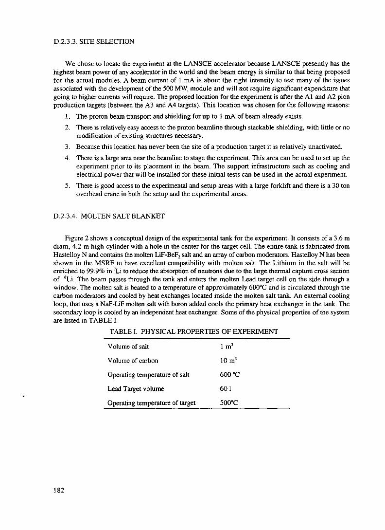
D.2.3.3. SITE SELECTION
We chose to locate the experiment at the LANSCE accelerator because LANSCE presently has thehighest beam power of any accelerator in the world and the beam energy is similar to that being proposedfor the actual modules. A beam current of 1 mA is about the right intensity to test many of the issuesassociated with the development of the 500 MW, module and will not require significant expenditure thatgoing to higher currents will require. The proposed location for the experiment is after the Al and A2 pionproduction targets (between the A3 and A4 targets). This location was chosen for the following reasons:
1. The proton beam transport and shielding for up to 1 mA of beam already exists.2. There is relatively easy access to the proton beamline through stackable shielding, with little or no
modification of existing structures necessary.3. Because this location has never been the site of a production target it is relatively unactivated.4. There is a large area near the beamline to stage the experiment This area can be used to set up the
experiment prior to its placement in the beam. The support infrastructure such as cooling andelectrical power that will be installed for these initial tests can be used in the actual experiment.
5. There is good access to the experimental and setup areas with a large forklift and there is a 30 tonoverhead crane in both the setup and the experimental areas.
D.2.3.4. MOLTEN SALT BLANKET
Figure 2 shows a conceptual design of the experimental tank for the experiment. It consists of a 3.6 mdiam, 4.2m high cylinder with a hole in the center for the target cell. The entire tank is fabricated fromHastelloy N and contains the molten LiF-BeF2 salt and an array of carbon moderators. Hastelloy N has beenshown in the MSRE to have excellent compatibility with molten salt. The Lithium in the salt will beenriched to 99.9% in 7Li to reduce the absorption of neutrons due to the large thermal capture cross sectionof 6Li. The beam passes through the tank and enters the molten Lead target cell on the side through awindow. The molten salt is heated to a temperature of approximately 600°C and is circulated through thecarbon moderators and cooled by heat exchanges located inside the molten salt tank. An external coolingloop, that uses a NaF-LiF molten salt with boron added cools the primary heat exchanger in the tank. Thesecondary loop is cooled by an independent heat exchanger. Some of the physical properties of the systemare listed in TABLE I.
TABLE I. PHYSICAL PROPERTIES OF EXPERIMENT
Volume of salt 1 m3
Volume of carbon 10m3
Operating temperature of salt 600 °C
Lead Target volume 60 1
Operating temperature of target 500°C
182

Proton Beam
Delivered through vacuumwindow to central target
Target
Flowing molten lead
BlanketFuel-bearing molten salt
upflow circulation
Pumps and HeatExchangers
Internal and close to core toreduce liquid luel inventory
Heat SinkLow melting poinl salt
Vessel
Totally enclosing the liquidtuel to eliminate fuel spills
through pipe ruptures
Reflector
Graphite
FIG 2 A conceptual system layout of the molten salt blanket for the accelerator driven subcriticalassembly
There will be a small pipe installed in the tank to allow the removal of small amounts of salt during theexperiment to monitor the oxidation state of the Pu and the build up of fission products (FP) Smallamounts of material will be added to the salt blanket to adjust the redox potential of elements in the moltensalt blanket The control of the salt flow through this drain pipe will be via freeze plugs that have been usedsuccessfully in the MSRE There will be provisions for supplying approximately 1 MW of electrical powerto the MS tank to heat the salt during initial setup when there is no power being supplied by the beam
D 2 3 5 . EXPERIMENT SCHEDULE
The experiment will proceed in three stages. The first stage involves the development of the moltenLead target In the second stage, the molten salt tank is constructed and the technology for molten saltoperation is developed In the final stage, fissionable material is added to the molten salt target/blanket andactual transmutation processes are demonstrated. In this stage, small amounts of fissionable material willbe added and the response of the system will be measured. The measurements will be compared to thepredicted behavior. If the calculations are verified, more fuel may be added to the blanket and the powerincreased
At each stage, the systems will be developed first in off-line test stands Following complete testing,each system will be installed in the LANSCE beamline and tested m-beam For the case of the molten Leadtarget, the radiation testing will occur at the LANSCE beam stop location In the case of the molten salttank, the testing will occur in the new target area in the location described in section D 2 3 3
183

D 2 3 6 SYSTEM PERFORMANCE
We have calculated the performance of a fueled molten salt subcntical target\blanket system based onthe conceptual design of this expenment Figures 3 and 4 show calculations of initial blanket power andinitial k^ following the addition of U9Pu to the molten salt blanket For these calculations we have assumed1 mA of proton beam with a neutron production target that produces 21 neutrons /proton For an initialloading oi 3 kg of239 Pu, the power in the blanket is calculated to be approximately 4 MW and keff isapproximately 0 7
1090807060504
030201
00 1000 5000 6000
FIG 3
2000 3000 4000
Initial Pu Loadng (g)
Initial blanket power for various initial plutomum loadings in the molten salt
100000
~ 100004>
oCL
c 1000jom
1001000 2000 3000 4000
Initial Pu Loading (g)
5000 6000
FIG. 4 Initial keff for different initial plutomum loading in the molten saltblanket
184

Energy production from Thorium is shown in Fig. 5. The solid squares show the time dependence ofthe blanket power when the MS blanket is loaded with 1000 kg of Thorium. The open circles show theperformance of the system for the case where 2 kg of 239Pu is added to the 1000 kg of Thorium. Forcomparison, the triangle curve shows the time dependence of the blanket when only 2 kg of pure 'Pu isadded. As seen from the figure (squares), the power from the fission of 233U slowly rises when onlyThorium is used in the blanket. The power output and the breeding rate of B3U can be increased with theaddition of 239Pu . The fact that the curve for Thorium and Plutonium increases above the curve for purePlutonium is an indication of power generation using the Thorium/uranium breeding cycle.
i.uu
1.60 '
1.40
1 ^T\
51 '20
5 1.00
| 0.80o°- 0.60,
0.40
0.20
nnn i
>A • 1000 kg ThAA. ! o 1000kgTh + 2kgPuAAA i y y
A*A i A 2kg239Pu*AA —————————————————————
..........•••••••-De00i<4iini4 ———_«||l'
•••••••ll">"""• • • B 1 B * * —— : —————— i —————— i —————— i —— . ———— i —————— ! —— . ....... .j ———
:!
1
0 o o O ° c
;;;;::,
0 100 200 303 400 500 600 700 800 900 1000Beam on time (days)
FIG. 5. The blanket power for various initial fuel loadings of the blanket. The solid squaresare for an initial loading of 1000 kg of Thorium. The open squares is for an initial loadingof 1000 kg of Thorium and 2 kg of239Pu. For comparison, the triangles show the blanketpower for 2 kg of239Pu alone.
D.2.3.7. CONCLUSION
This small scale demonstration experiment is a crucial step towards the development of a full scaleADTT system. The experiment addresses many key issues in ADTT technology and will demonstrate thefollowing new technologies:
1. Molten Lead neutron production targets2. Integrated operation of a neutron production target and a subcritical fission blanket assembly.3. Integral heat exchangers and pumps4. On-line criticality measurements5. Helium sparging to remove volatile fission product gases6. Plutonium bum up7. Energy production using the Thorium/Uranium breeding cycle.
REFERENCES
[1] Nucl. Sci. and Eng. 113 (1993) 287.
185

[2] V.T. Gorshkov et. al, "An Accelerator Based Installation of Small Power with the Lead-BismuthCoolant", International Conference on Accelerator Driven Transmutation Technologies andApplications, Las Vegas, NV, July 25-29 1994.
[3} C. A. Beard et. al, "Flowing Lead Spallation Target Design for Use in an ADTT ExperimentalFacility Located at LAMPF",International Conference on Accelerator Driven TransmutationTechnologies and Applications, Las Vegas, NV, July 25-29 1994.
[4] J. J. Park et. al, "Selection of Flowing Liquid Lead Target Structural Materials for AcceleratorDriven Transmutation Applications", International Conference on Accelerator DrivenTransmutation Technologies and Applications, Las Vegas, NV, July 25-29 1994.
186

XA9846570
D.3. CERN-GROUP CONCEPTUAL DESIGN OF A FAST NEUTRON OPERATEDHIGH POWER ENERGY AMPLIFIER
C. Rubbia, J.A. Rubio, S. Buono', F. Carminati, N. Fietier", J. Galvez, C. Geles, Y. Kadi, R. Klapisch,P. Mandrillon™, J.P. Revol and Ch. Roche
European Organization for Nuclear Research, CERN, Geneva, Switzerlandf Sincrotrone Trieste, Trieste, Italyn Laboratoire du Cyclotron, Nice, France
The basic concept and the main practical considerations of an Energy Amplifier (EA) have beenexhaustively described in Ref. [1]. Here the realisation of the EA is further explored and schemes aredescribed which offer a high gain, a large maximum power density and an extended bum-up, well in excessof 100 GW x d/t corresponding to about five years at full power operation with no intervention on the fuelcore. Most of these benefits stem from the use of fast neutrons, as already proposed in Ref. [2].
The EA operates indefinitely in a closed cycle, namely the discharge of a fuel load, with the exceptionof fission fragments, is re-injected in the sub-critical unit with the addition of natural Thorium tocompensate for the burnt fuel. After several cycles an equilibrium is reached, in which the Actinide con-centrations are the balance between burning and "incineration". The fuel is used much more efficiently,namely the power obtained from 780 kg of Thorium is roughly the same as the one from 200 tons of nativeUranium and a PWR (33 GW x d/t of burn-up). The probability of a criticaliry accident is suppressed sincethe device operates at all times far away from it. Spontaneous convective cooling by the surrounding airmakes a "melt-down" leak impossible.
An EA module consists of a 1500 MWt unit with its dedicated 1.0 GeV proton accelerator of 12.5 mA.A compact, highly reliable and modular Cyclotron has been designed. A plant may be made of several suchmodules. For instance a cluster of three such modular units will produce about 2,000 MWe of primaryelectrical power. A relevant feature of our design is that it is based on natural convection to remove the heatgenerated inside the core. The EA is a large, passive device in which a proton beam is dumped and the heatgenerated by nuclear cascades is extracted, without other major elements of variability. The deliveredpower is controlled exclusively by the current of the accelerator. The fuel needs no access during the wholeburn-up and it may be kept sealed up as a non-proliferation safeguard measure. Contrary to Fusion, thereare no major technological barriers.
After ~ 700 years the radio-toxicity left is about 20,000 x smaller than the one of an ordinaryPressurised Water Reactor (PWR with an open fuel cycle and reprocessing losses 10"4) for the same energy.Geological storage (106 years) is virtually eliminated or at least strongly reduced [< 500 Ci/(GWex a) after1000 years]. It could be further reduced (< 35 Ci) "incinerating" some of the nuclides. Radioactivity doseto individuals truncated to 10,000 years and due to operation is about 1/330 of the one of PWR and about1/33 of Coal burning.
D.3.1. INTRODUCTION
The principle of operation of the Energy Amplifier (EA) has been described in detail in Refs. [1-3]. Thepresent paper is aimed at the demonstration of the practical feasibility of an EA with power and powerdensity which are comparable to the ones of the present generation of large Pressurised Light WaterReactors (PWR). This is only possible with fast neutrons [2].
187

Greenhouse induced Global Warming concerns related to a massive use of Fossil Fuels may lead to anew call for nuclear revival. But a much larger share of energy produced by conventional Nuclear methods(PWR) will sharpen concerns and enhance many of the problems which must be solved before extendingits use. We believe that most of the criteria for a revival of nuclear power are very tough:
(1) Extremely high level of inherent safety;(2) Minimal production of long lived waste and elimination of the need of the geologic repositories;(3) High resistance to diversion, since latent proliferation is a major concern.(4) More efficient use of a widely available natural fuel, without the need of isotopic separation.(5) Lower cost of the heat produced and higher operating temperature than conventional PWRs in
order to permit competitive generation of substitutes to fossil fuels [4]. Substitution fuels arenecessary to allow a widespread utilisation of the energy source and to permit retrofitting ofexisting facilities, now operating with CO2 producing fuels.
Our design of an EA has these objectives as goals and it is intended as proof that they can be met fully.The primary fuel is natural Thorium which is completely burnt after a number of fuel cycles through theEA. Actinides present in the fuel discharge at the end of a fuel cycle are re-injected in the EA and becomethe "seeds" for the subsequent cycle. This ensures a very efficient use of the primary fuel element1. Thisobjective is identical to the one eventually met by Fast Breeders. Compared to the consumption of naturalfuel material, the EA is about 250 times more efficient than the present PWRs based on an open fuel cycle.
Nuclear power has successfully developed the methods of retaining large amounts of radioactivitywithin the power plant and in isolation with the biosphere. The limited amount of fuel material of the EAand the sealed, passive nature of the device further simplifies the realisation of such a concept. Thefractions of radioactivity actually injected in the environment during (1) mining, (2) operation and (3)reprocessing and refuelling are considered first Preventive measures to eliminate unwanted accidents andtheir possible consequences on the environment will be considered later on.
The radio-toxicity released by a Thorium driven EA is much smaller than the one of the PWR relatedthrow-away cycle [1] [2]. In the phase of the fuel extraction and preparation, it is about lO^H-lO"4 for thesame delivered energy, since a much smaller amount of Thorium is required (0.78 ton vs. 200 tons ofUranium for 3 GW,,, x a) in the first place and which is much less toxic to extract [5]. The toxicity releasedin form of waste at the back-end of the cycle for Actinides is reduced to the very tiny fraction lost duringfuel re-cycling and reprocessing. Among fission fragments, excluding the short lived and stable elements,there are a few elements which are medium lived (r1/2 = 30 years, ^Sr-^Y, 137Cs, etc.) and some others("Tc, 135Cs, 129I, etc.) which are truly long lived. The policy we propose to follow is to store in man-watched, secular repositories for several centuries the medium lived in order to isolate them from thebiosphere and to promote a vigorous research and development of methods of incinerating the bulk of thelong lived FFs with the help of a fraction of the neutron flux of the EA or with dedicated burners [6].Therefore, and contrary to the PWR related throw-away cycle, the need for a Geologic Repository isvirtually eliminated.
UNSCEAR [7] has estimated collective radioactivity doses to the population associated to variousforms of energy production. Coal burning emits radioactivity in fumes and dust, resulting in a typical,collective radiation exposure of 20 man Sv (GWe a)"1. The practice of using coal ashes for concreteproduction adds as much as 2.5 x 10⁴ man Sv (GWC a)"1. In the case of the PWR throw-away cycle theestimated dose is 200 man Sv (GWe a)"1, with the main contribution coming from the mining andpreparation of the fuel2. Accidents which have plagued some of the present Nuclear Power stations andwhich are expected to be absent because of the new features of the EA, have added as much as 300 man
1 The heat produced burning 70.3 kg of Thorium in the EA is equal to the one of 1 million barrels of oil2 The main nuclide contributions in the nuclear fuel cycle are Radon from Mill Tailings (150 man Sv/GW/y) andreactor operation and reprocessing (50 man Sv/GW/y). The potential accumulation of collective radiation doses inthe far future from the practice of disposing the long lived waste (geologic storage) is not included in the UNSCEARestimates, since it is subject to major uncertainties.
188
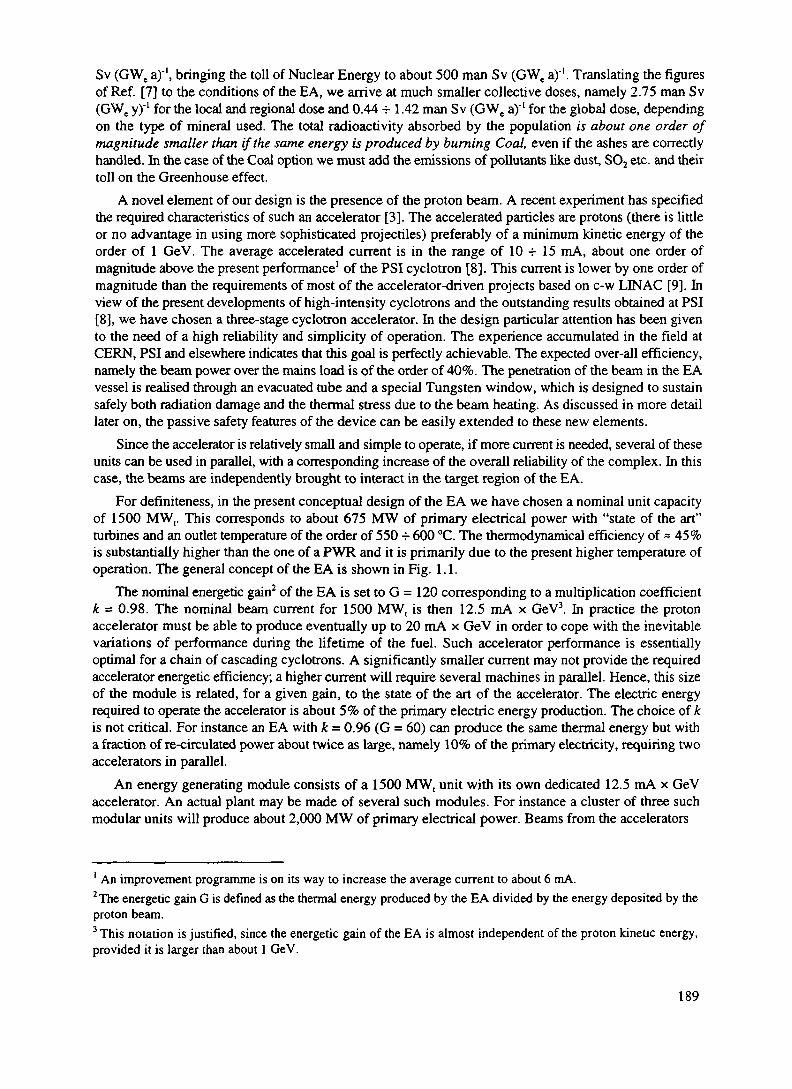
Sv (GWe a)"1, bringing the toll of Nuclear Energy to about 500 man Sv (GWe a)"1. Translating the figuresof Ref. [7] to the conditions of the EA, we arrive at much smaller collective doses, namely 2.75 man Sv(GWe y)'1 for the local and regional dose and 0.44 4-1.42 man Sv (GWe a)"1 for the global dose, dependingon the type of mineral used. The total radioactivity absorbed by the population is about one order ofmagnitude smaller than if the same energy is produced by burning Coal, even if the ashes are correctlyhandled. In the case of the Coal option we must add the emissions of pollutants like dust, SO2 etc. and theirtoll on the Greenhouse effect.
A novel element of our design is the presence of the proton beam. A recent experiment has specifiedthe required characteristics of such an accelerator [3]. The accelerated particles are protons (there is littleor no advantage in using more sophisticated projectiles) preferably of a minimum kinetic energy of theorder of 1 GeV. The average accelerated current is in the range of 10 -r 15 mA, about one order ofmagnitude above the present performance1 of the PSI cyclotron [8]. This current is lower by one order ofmagnitude than the requirements of most of the accelerator-driven projects based on c-w LINAC [9]. Inview of the present developments of high-intensity cyclotrons and the outstanding results obtained at PSI[8], we have chosen a three-stage cyclotron accelerator. In the design particular attention has been givento the need of a high reliability and simplicity of operation. The experience accumulated in the field atCERN, PSI and elsewhere indicates that this goal is perfectly achievable. The expected over-all efficiency,namely the beam power over the mains load is of the order of 40%. The penetration of the beam in the EAvessel is realised through an evacuated tube and a special Tungsten window, which is designed to sustainsafely both radiation damage and the thermal stress due to the beam heating. As discussed in more detaillater on, the passive safety features of the device can be easily extended to these new elements.
Since the accelerator is relatively small and simple to operate, if more current is needed, several of theseunits can be used in parallel, with a corresponding increase of the overall reliability of the complex. In thiscase, the beams are independently brought to interact in the target region of the EA.
For definiteness, in the present conceptual design of the EA we have chosen a nominal unit capacityof 1500 MW,. This corresponds to about 675 MW of primary electrical power with "state of the art"turbines and an outlet temperature of the order of 550 -r 600 °C. The thermodynamical efficiency of = 45%is substantially higher than the one of a PWR and it is primarily due to the present higher temperature ofoperation. The general concept of the EA is shown in Fig. 1.1.
The nominal energetic gain2 of the EA is set to G = 120 corresponding to a multiplication coefficientk = 0.98. The nominal beam current for 1500 MW, is then 12.5 mA x GeV3. In practice the protonaccelerator must be able to produce eventually up to 20 mA x GeV in order to cope with the inevitablevariations of performance during the lifetime of the fuel. Such accelerator performance is essentiallyoptimal for a chain of cascading cyclotrons. A significantly smaller current may not provide the requiredaccelerator energetic efficiency; a higher current will require several machines in parallel. Hence, this sizeof the module is related, for a given gain, to the state of the art of the accelerator. The electric energyrequired to operate the accelerator is about 5% of the primary electric energy production. The choice of kis not critical. For instance an EA with k = 0.96 (G = 60) can produce the same thermal energy but witha fraction of re-circulated power about twice as large, namely 10% of the primary electricity, requiring twoaccelerators in parallel.
An energy generating module consists of a 1500 MW, unit with its own dedicated 12.5 mA x GeVaccelerator. An actual plant may be made of several such modules. For instance a cluster of three suchmodular units will produce about 2,000 MW of primary electrical power. Beams from the accelerators
1 An improvement programme is on its way to increase the average current to about 6 mA.2The energetic gain G is defined as the thermal energy produced by the EA divided by the energy deposited by theproton beam.3 This notation is justified, since the energetic gain of the EA is almost independent of the proton kinetic energy,provided it is larger than about 1 GeV.
189

VOO
Injectors Booster
Intermediate
(30MW)
Beam
Accelerator Complex
EnergyAmplifier
Fuel Discharge
(27.6 t)
Reprocessing(Partition)
Spent fuel
Reprocessing Complex(every 5 years)
Power Generation(675 MW)
Pump
Actinides(24.7 t) (2.9 t)
Fission Fragments(2.9 t)
Waste Packaging(Vitrification)
FreshThoriumSupply
To SecularRepository
FIG. 1.1 General lay-out of the Energy Amplifier complex. The electric power generated is also used to run the Accelerator (re-circulated power < 5%).At each discharge of the fuel (every 5 years) the fuel is "regenerated". Actinides, mostly Thorium and Uranium are re-injected as new fuel in the EA, topped withfresh Thorium. Fission fragments and the like are packaged and sent to the Secular repository, where after ~ 1000 years the radioactivity decays to a negligiblelevel (see Figure 1.4). For simplicity the option of incinerating long-lived fragments is not shown.

can be easily transported over the site and switched between units: a fourth, spare, accelerator should beadded in order to ensure back-up reliability
The modular approach has been preferred in several recent conceptual designs [10] of Sodium cooledfast reactors in the USA (ALMR, Advanced Liquid Metal Beactor), Japan (MONJU) and in Russia (BMN-170), for reasons of cost, speed of construction and licensing. Such modularity permits the use of thedevices in relatively isolated areas. The power plant can be built in a well developed country andtransported to the target area. Decommissioning of the device is also simplified. The European approach(EFR, European East Reactor) is more conservative and is based on a single, large volume pool for anominal power in excess of 3,000 MW,. Such an approach is possible also for the EA. In this case, becauseof the larger power, the beams from two accelerators will be simultaneously injected in the core of the EA.Both designs are robust, cost-effective and they incorporate many features which are the result of theextensive experience with smaller machines. They are designed for a number of different fuelconfigurations and they can easily accommodate those appropriate to the EA. We have taken as "model"for our design many of the features of the ALMR. The ALMR was designed to provide high reliability forthe key safety, including shutdown heat removal and containment. We intend to follow the same basicdesign, with, however, the added advantages of (1) sub-critical operation at all times (2) negative voidcoefficient of molten Lead (3) convection driven primary cooling system and (4) non reactive nature ofLead coolant when compared to Sodium.
The coolant medium is molten natural Lead operated in analogy with our (Sodium cooled) "models"at a maximum temperature of 600 -=- 700 °C. In view of the high boiling temperature of Lead (1743 °C atn.p.t.) and the negative void coefficient of the EA, even higher temperatures may be considered, providedthe fuel and the rest of the hardware are adequately designed. For instance direct Hydrogen generation viathe sulphur-iodine method [4] requires an outlet temperature of the order of 800 °C. A higher operatingtemperature is also advantageous for electricity generation, since it may lead to an even better efficiencyof conversion. Evidently, additional research and development work is required in order to safely adapt ourpresent design to an increased operating temperature. In particular the cladding material of the fuel pinsmay require some changes, especially in view of the increased potential problems from corrosion andreduced structural strength. With these additions the present design should be capable of operating attemperatures well above the present figures.
A most relevant feature of our design is the possibility of using natural convection alone to remove allthe heat produced inside the core. Convection cooling has been widely used in "swimming pool" reactorsat small power levels. We shall show that an extension of this very safe method to the very large power ofthe EA is possible because of the unique properties of Lead, namely high density, large dilatationcoefficient and large heat capacity. Convection is spontaneously and inevitably driven by (any) temperaturedifference. Elimination of all pumps in the primary loop is an important simplification and a contributiontowards safety, since unlike pumps, convection cannot fail. In the convective mode, a very large mass ofliquid Lead (~ 10,000 tons), with an associated exceedingly large heat capacity1 moves very slowly(< 2.0 m/s inside the core, about 1/3 of such speed elsewhere) transferring the heat from the top of the coreto the heat exchangers located some 20 metres above and returning at a lower temperature (AT * - 200 °C)from the heat exchangers to the bottom of the core.
The geometry of the EA main vessel is therefore relatively slim (6.0 m diameter) and very tall (30 m).The vessels, head enclosure and permanent internal structures are fabricated in a factory and shipped as anassembled unit to the site2. The relatively slender geometry enhances the uniformity of the flow of the liquidLead and of the natural circulation for heat removal. The structure of the vessel must withstand the large
1 The heat capacity of liquid Lead at constant pressure is about 0.14 J/g/"C. For an effective mass of = 10* tons = 10'°grams and a power of 1.5 GW (full EA power), the temperature rise is of the order of 1 .OuC/s. The mass flowingthrough the core for AT = 200°C is 53.6 t/s, corresponding to some 1.5 minutes of full power to heat up the half ofthe coolant in the "cold" loop, in case the heat exchangers were to fail completely.2 The shipping weight is about 1500 tons. Removable internal equipment is shipped separately and installed throughthe top head.
191

weight of the liquid Lead There are four 375 MWt heat exchangers to transfer the heat from the primaryLead to the intermediate heat transport system They are located above the core in an annular regionbetween the support cylinder and the walls of the vessel
The vessel is housed below floor level in an extraordinarily robust cylindrical silo geometry lined withthick concrete which acts also as ultimate container for the liquid Lead in case of the highly hypotheticalrupture of the main vessel In the space between the mam vessel and the concrete wall the Reactor VesselAir Cooling System (RVACS) is inserted This system [11], largely inspired from the ALMR design, iscompletely passive and based on convection and radiation heat transfer The whole vessel is supported atthe top by anti-seismic absorbers Even in the case of an intense earthquake the large mass of the EA willremain essentially still and the movement taken up by the absorbers
The fuel is made of mixed oxides, for which considerable experience exists More advanced designshave suggested the use of metallic fuels or of carbides [12] These fuels are obviously possible also for anEA We remark that the use of Zirconium alloys is not recommended since irradiation leads totransmutations into the isotope 93Zr, which has a long half-life and which is impossible to incinerate withoutseparating it isotopically from the bulk of the Zirconium metal The choice of the chemical compositionof the fuel is strongly related to the one of the fuel reprocessing method A relative novelty of our machinewhen compared to ordinary PWRs is the large concentration of ThO2 in the fuel and the correspondingproduction of a small but relevant amount of Protactinium A liquid separation method called THOREXhas been developed and tested on small irradiated ThO2 fuel samples [13] The extrapolation from thewidely used PUREX process to THOREX is rather straightforward and this is why we have chosen it, atleast at this stage Methods based on pyro-electnc techniques [14], which imply preference to metallic fuels,are most interesting, but they require substantial research and development work Since the destination ofthe Actimdes is now well defined i e to be finally burnt in the EA, the leakage of Actimdes in the FissionFragment stream must be more carefully controlled, since they are the only Actimdes in the "Waste" Wehave assumed that a "leaked" fraction of 10"4 is possible for Uranium The recycled fuel has a significantradio-activity We have checked that the dose at contact is similar to the one of MOX fuels made ofUranium and Plutonium, already used in the Nuclear Industry
The average power density in the fuel has been conservatively set to be p - 55 W/g-oxide, namelyabout 1/2 the customary level of LMFBR1 (ALMR, MONJU, and EFR) The nominal power of 1500 MW,requires then 27 3 tons of mixed fuel oxide The fuel dwelling time is set to be 5 years equivalent at fullpower The average fuel bum-up is then 100 GW d/ton-oxide Since the fissile fuel is internally regeneratedinside the bulk of the Thorium fuel, the properties of the fuel are far more constant than say in the case ofa PWR As shown later on, one can compensate to a first order the captures due to fission fragments,operating initially with a breeding ratio below equilibrium All along the bum-up, the growth of the fissilefuel concentration counterbalances the poisoning due to fission fragments Therefore neither re-fuellingnor fuel shuffling appear necessary for the specified duration of the burn-up
No intervention is therefore foreseen on the fuel dunng the five years of operation, at the end of whichit is fully replaced and reprocessed Likewise in the "all-convective" approach there are no moving partswhich require maintenance or surveillance In short the EA is a large, passive device m which a protonbeam is dumped and the generated heat is extracted, without other major elements of variability
Safety and nuclear proliferation are universal concerns In the case of conventional Nuclear Power,accidents have considerably increased the radioactivity exposure of individuals and the population [7] Thetotal nuclear power generated, 2000 GW x a, is estimated to have committed an effective dose of 400,000man Sv from normal operation Accidents at Windscale, TMI and Chernobyl have added 2000, 40 and600,000 man Sv respectively These types of accidents are no longer possible with the EA conceptChernobyl is a cnticality accident, impossible in a sub-cntical device and TMI, a melt-down accident, ismade impossible by the "intrinsic" safety of the EA
' This choice is motivated by the relative novelty of the "all-convective" approach and the relative scarce experiencewith ThOj, when compared with UO2
192

A thermal run-off is the precursory sign of a number of potentially serious accidents. The presentconceptual design is based on a swimming pool geometry where the heat generated by the nuclear cascadeis extracted from the core by convection cooling, completely passive and occurring inevitably because oftemperature differences.Thermal run-off is prevented, since a significant temperature rise due for instanceto an insufficiency of the secondary cooling loop and of the ordinary controls will inevitably produce acorresponding dilatation of the liquid Lead. Because of the slim geometry of the vessel, the level of theswimming pool will rise by a significant amount (-21 cm/100 °C), filling (through a siphon) additionalvolumes with molten Lead, namely :
(1) The Emergency B_eam J^ump Volume (EBDV), a liquid Lead "beam stopper" sufficiently massiveas to completely absorb the beam some 20 metres away from the core and hence bring the EAsafely to a stop. In the unlikely event that the beam window would accidentally break, molten Leadwill also rise, so as to fill completely the pipe and the EBDV, thus removing the incoming protonbeam from the core.
(2) A narrow gap normally containing thermally insulating Helium gas, located between the coolantand the outer wall of the vessel, which in this way becomes thermally connected to the coolant mainconvection loop. The outer wall of the EA will heat up and bleed the decay heat passively throughnatural convection and radiation to the environment (RVACS) [11]. This heat removal reliesexclusively on natural convection heat transfer and natural draught on the air side.
(3) A scram device based on B4C absorbers which are pushed into the core by the liquid Leaddescending narrow tubes. These absorbers anchor the device firmly away from criticality.
These passive safety features are provided as a backup in case of failure of the active systems, namelyof the main feed-back loop which adjusts the current in order to maintain constant the temperature at theexit of the primary cooling loop. Multiply backed-up but simple systems based on current transformers andphysical limitations in the accelerator (available RF power in the cavities, space charge forces, etc.) sharplylimit the maximum current increase that the accelerator can deliver. Were these methods all to fail, thecorresponding increase of temperature will dilate significantly the Lead, activating the ultimate shut-off ofthe proton beam from the accelerator, the emergency cooling and the scram devices, before any limit isexceeded in the EA.
Normally the EA is well away from criticality at all times, there are no control bars (except the scramdevices) and the power produced is directly controlled by the injected beam current. However in someunforeseen circumstances the EA may become critical. In itself, this is not an unacceptable thoughexceptional operation mode, provided the amount of power produced does not exceed the ratings of the EA.Indeed even a quite large reactivity insertion is strongly moderated by the large negative temperaturecoefficient (Doppler) of the fuel. Since the operating temperature of the fuel is relatively low, even a rapidincrease of the instantaneous power will increase the temperature of the fuel within limits, large enough,however, to introduce a substantial reduction of k as to exit from criticality. The safety of multiplyingsystems depends to a large extent on fast transients. A kinetic model dealing with fast transients due toaccidental reactivity insertions and unexpected changes of the intensity of the external proton beam showsthat the EA responds much more benignly to a sudden reactivity insertion than a critical Reactor. Indeed,no power excursions leading to damaging power levels are observed for positive reactivity additions whichare of the order of the sub-criticality gap. Even if the spallation source is still active (the accelerator is notshut-off), the power changes induced are passively controlled by means of the increase of the naturalconvection alone (massive coolant response) thus excluding any meltdown of the sub-critical core.
Any very intense neutron source (2 1013 n/s) could in principle be used to produce bomb gradePlutonium by extensive irradiation of some easily available depleted Uranium. This is true both for fissionand fusion energy generating devices. We propose to prevent this possibility by "sealing off the mainvessel of the EA to all except a specialised team, for instance authorised by IAEA. This is realistic for anumber of reasons. The energetic gain of the EA is almost constant over the lifetime of the fuel, though itchanges significantly after a power level variation. Convection cooling is completely passive and occurringinevitably because of temperature differences. There are no active elements (pumps, valves etc.) which mayfail or need direct access to the interior of the main vessel. In addition the fuel requires no significant
193

change in conditions over its long lifetime of five years, since the fissile material is continuously generatedfrom the bulk of Thorium. The only two maintenance interventions to be performed are the periodicreplacement of the beam window about once a year and the possible replacement of some failing fuelelements, performed remotely with the pantograph. Both activities can be carried out without extractingthe fuel from the vessel. We can therefore envisage conditions in which the EA is a sort of "off limits black-box" accessed very rarely and only by a specialised team, for instance authorised by IAEA. The ordinaryuser (and owner) of the EA will have no access to the high neutron flux region and to the irradiated fuel,a necessary step towards any diversion which may lead to proliferation or misuse of the device.
Proliferating uses of the fuel are further prevented by the fact that the fissile Uranium mixture in thecore is heavily contaminated by strong y-emitter 'Tl which is part of the decay chain of 232U and by thefact that the EA produces a negligible amount of Plutonium. As shown later on, a rudimentary bomb builtstarting with EA fuel, in absence of isotopic separation, will be most impractical and essentially impossibleto use or to hide.
The EA can operate with a variety of different fuels. Several options will be discussed in detail in thesubsequent sections. A specialised filling can transform Plutonium waste into useful 233U, for instance, inorder to accumulate the stockpile required at the start-up of the EA. More generally one could envisage acombined strategy with ordinary PWRs. Presently operating PWRs represent an investment in excess of1.0 Tera dollars. It is important to make every possible effort in order to minimise their impact on theenvironment and to increase their public acceptability. A specially designed EA could be used to (1)transform Plutonium waste into useful 233U and (2) reduce the stockpile of "dirty" Plutonium waste. TheEA will be initially loaded with a mixture of Actinide waste and native Thorium, in the approximate ratio0.16 to 0.84 by weight. Other Actinides, like Americium, Neptunium and so on can also be added. Themixture is sub-critical and the EA can be operated with k = 0.96-0.98.
During operation, the unwanted actinides are burnt, while 233U is progressively produced. The freshlybred 233U compensates the drop of criticality due to the diminishing and deteriorating Actinide mixture andthe one due to the build-up of Fission Fragments. A balanced operation over a very long burn-up of up to200 GW d/t is thus possible without loss of criticality, corresponding to 5-10 years of operation withoutexternal intervention. The fuel of the EA is then reprocessed, the 233U is extracted for further use. FFs aredisposed with the standard procedure of the EA. The remainders of Plutonium1 and the like, could eitherbe sent to the Geological Repository to which they were destined or further burnt in the EA, topped withfresh Thorium. This combination of a PWR and an EA has several advantages:
1) It eliminates permanently some of the Actinide waste of the PWR reducing the amount to be storedin a Geological Repository. -
2) It produces additional power through the EA, thus increasing by about 50% the energetic yield ofthe installation.
3) The amount of fissile Uranium, which is by weight about 80% of the incinerated Plutonium is avaluable asset. It can be used either to start a new, Thorium operated, EA or it can be mixed withdepleted Uranium to produce more fuel for PWRs. As is well known, 233U is an almost perfectsubstitute for B5U in a ratio very close to 1. The yearly Plutonium and higher Actinides dischargeof a typical = 1 GWe PWR operated 80% of the time is of the order of 300 kg, thus producing viathe EA 240 kg of 233U, which in turn can be used to manufacture = 8 tons of fresh fuel fromdepleted U with 0.3% B5U and 3.0 % ^U. This is = 1/3 of the supply of enriched Uranium fuelfor the operation of the PWR.
We have also considered as an alternative a fast neutron driven EA operated on Plutonium only, namelywithout Thorium. Similar schemes, though mostly operated with thermal neutrons are under consideration
1 The discharge after = 150 GW x d/t contains about 50% of the initial Pu, but is highly depleted of 23iTu (1/5) and241Pu (1/4), while other Pu isotopes are essentially unchanged. Am and Cm isotopes stockpiles are essentiallyunchanged. Note that the Plutonium is "denatured" of the highly fissile isotopes, making it worthless for militarydiversions.
194

at Los Alamos [15], JAERI [16] and elsewhere [17]. Such potential devices require frequent refills andmanipulations of the fuel, since the reactivity of the Plutonium is quickly deteriorated by the burning andchoked by the emergence of a large relative concentration of FFs. At the limit one is lead to the "chemistryon line" proposed by the Los Alamos Group [15]. Adding a large amount of fertile Thorium greatlyalleviates such problems and the device can bum Plutonium and the like for very many years withoutintervention or manipulation of the fuel, since the bred 233U is an effective substitute to Plutonium tomaintain a viable and constant criticality. In addition FFs are diffused in a much larger fuel mass. Finallythe 233U recovered at the end of the cycle constitutes a valuable product.
In principle our method of a Th-Pu mixture could be extended to the operation of a Fast Breeder usedas incinerator [18], however, probably at a much higher cost and complexity due to the higher degree ofsafety involved.
We have indicated Thorium as main fuel for the EA since the radio-toxicity accumulated is muchsmaller than Uranium and it offers an easier operation of the EA in a closed cycle. But there are alsoreasons of availability. Thorium is relatively abundant on earth crust, about 12 g/ton, three times the valueof Uranium [19]. It ranks 35-th by abundance, just after Lead [20]. It is well spread over the surface of theplanet. In spite of its negligible demand (= 400 t/y) the known reserves in the WOCA1 countries areestimated [21] to about 4x10* tons (Table 1.1). Adding a guessed estimate from the USSR, China and soon, we reach the estimate of perhaps 6 x 10⁶ tons, which can produce 15,000 TW x a of energy, if burntin EAs, namely about a factor 100 larger than the known reserves of Oil or Gas and a factor 10 larger thanCoal. This corresponds to 12.5 centuries at the present world's total power consumption (10 TW).
There are reasons to assume that this figure is largely underestimated. Firstly the demand is now verylow and there has been very little incentive to date to search for Thorium "per se". Additional resourcesof any mineral have always been found if and when demand spurs a more active prospection. The presentlyexploited Thorium ores are richer, by a factor 10 4- 100, than the ones which are exploitable at a priceacceptable by market conditions applicable to the case of Uranium. In view of the small contribution of theprimary Thorium to the energy cost, one may try to estimate how the recoverable resources would grow ifexploitation is extended to ores which have a content for instance an order of magnitude smaller, i.e. similarto the best Uranium ores. Such analysis has been performed for Uranium [22], assuming that thedistribution in the crust follows a "log-normal" (Figure 1.2) distribution. Other metals for which a bettermining history is known, show a similar trend, though the slope parameter may be different in each case(Figure 1.3). In the case of Thorium, in absence of better information, we may assume the same slope asin the case of Uranium. Then, a tenfold decrease in the concentration of the economically "recoverable"ores2 would boost reserves of Thorium by a factor of 300, still a small fraction (3 x 10"5) of what lies in theEarth crust. Reserves of Thorium energy would then be stretched to 4.5 million TW x a, correspondingto ~ 2200 centuries at twice the present world consumption level which can be considered truly infiniteon the time scale of human civilisation 3.
Several other projects have sought the realisation of a "clean" Nuclear Energy. The project CAPRA[23] focuses on the incineration of Plutonium in a Fast Breeder. On a longer time scale, Fusion holds thepromise of a "cleaner" energy. Amongst the various projects, Inertial Fusion offers the largest flexibilityin design of the combustion chamber and hence the best potentials of reduction of the activation effects dueto neutrons [24]. But neither inertia! nor magnetic fusion have so far achieved ignition4. We have compared
1 This stands for World Outside Centrally Planned Activities.2 We remark that even this 10-fold decrease would make these minerals somewhat more concentrated than the 2000ppm "high content ores" used today for Uranium.3 In order to estimate the magnitude of the error in such a "prediction", we note that the somehow extreme cases ofTungsten and of Copper have boost factors of 500,000 and 40 respectively. But even the lower limit of Copperpredicts z 300 centuries at twice the today's world consumption.4 The project ITER is aimed at demonstrating Ignition in magnetically confined fusion, presumably 2005. The newlarge megajoule range optical LASERs in development at Livermore and in France have the potential for ignitionwith inertial fusion.
195
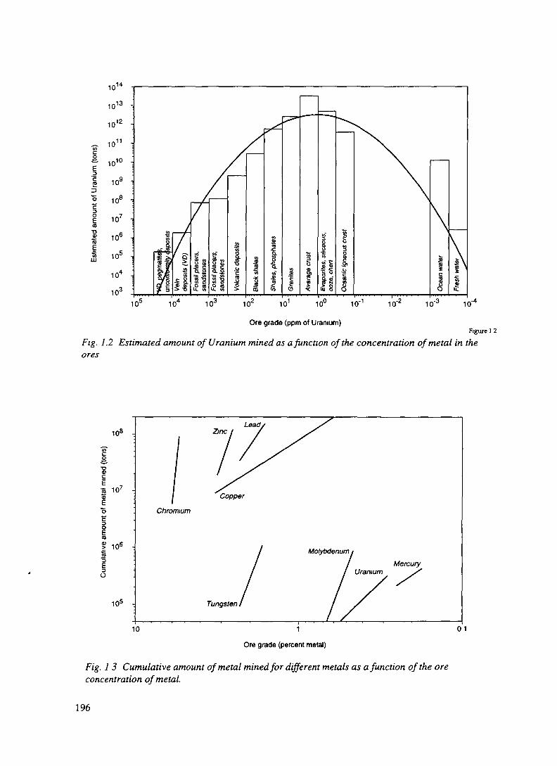
I
o(0
101
10'
10'10' ID- 10
Fig.lores
Ore grade (ppm of Uranium)Figure 1 2
.2 Estimated amount of Uranium mined as a function of the concentration of metal in the
108 -
CO
I 106
CO
IO
10s -
Zinc
Copper
Chromium
MolybdenumMercury
Tungsten I
10 01
Ore grade (percent metal)
Fig. 1 3 Cumulative amount of metal mined for different metals as a function of the oreconcentration of metal.
196
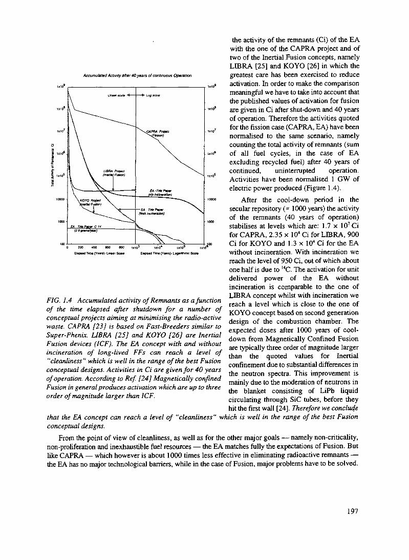
Accumulated Activity after 4Q years of continuous Operation
0 200 400 GOO 800
EupMd Tim* (Y*ir*}> Un»ar Sc*M:103
the activity of the remnants (Ci) of the EAwith the one of the CAPRA project and oftwo of the Inertial Fusion concepts, namelyLIBRA [25] and KOYO [26] in which thegreatest care has been exercised to reduceactivation. In order to make the comparisonmeaningful we have to take into account thatthe published values of activation for fusionare given in Ci after shut-down and 40 yearsof operation. Therefore the activities quotedfor the fission case (CAPRA, EA) have beennormalised to the same scenario, namelycounting the total activity of remnants (sumof all fuel cycles, in the case of EAexcluding recycled fuel) after 40 years ofcontinued, uninterrupted operation.Activities have been normalised 1 GW ofelectric power produced (Figure 1.4).
After the cool-down period in thesecular repository (= 1000 years) the activityof the remnants (40 years of operation)stabilises at levels which are: 1.7 x 10⁷Cifor CAPRA, 2.35 x 10" Ci for LIBRA, 900Ci for KOYO and 1.3 x 10⁴ Ci for the EAwithout incineration. With incineration wereach the level of 950 Ci, out of which aboutone half is due to I4C. The activation for unitdelivered power of the EA withoutincineration is comparable to the one ofLIBRA concept whilst with incineration wereach a level which is close to the one ofKOYO concept based on second generationdesign of the combustion chamber. Theexpected doses after 1000 years of cool-down from Magnetically Confined Fusionare typically three order of magnitude largerthan the quoted values for Inertialconfinement due to substantial differences inthe neutron spectra. This improvement ismainly due to the moderation of neutrons inthe blanket consisting of LiPb liquidcirculating through SiC tubes, before theyhit the first wall [24]. Therefore we conclude
that the EA concept can reach a level of "cleanliness" which is well in the range of the best Fusionconceptual designs.
From the point of view of cleanliness, as well as for the other major goals — namely non-criticality,non-proliferation and inexhaustible fuel resources — the EA matches fully the expectations of Fusion. Butlike CAPRA — which however is about 1000 times less effective in eliminating radioactive remnants —the EA has no major technological barriers, while in the case of Fusion, major problems have to be solved.
1x10 1X10
Tim* (YMrs>- Logvfthmc Sc«J*
FIG. 1.4 Accumulated activity of Remnants as a functionof the time elapsed after shutdown for a number ofconceptual projects aiming at minimising the radio-activewaste. CAPRA [23] is based on Fast-Breeders similar toSuper-Phenix. LIBRA [25] and KOYO [26] are InertialFusion devices (ICF). The EA concept with and withoutincineration of long-lived FFs can reach a level of"cleanliness" which is well in the range of the best Fusionconceptual designs. Activities in Ci are given for 40 yearsof operation. According to Ref. [24] Magnetically confinedFusion in general produces activation which are up to threeorder of magnitude larger than ICF.
197

TABLE I.I. THORIUM RESOURCES (IN UNITS OF 1000 TONS) IN WOCA (WORLD OUTSIDECENTRALLY PLANNED ACTIVITIES)1 [21]
EuropeFinlandGreenlandNorwayTurkey
Europe Total
AmericaArgentinaBrazilCanadaUruguayUSA
America total
AfricaEgyptKenyaLiberiaMadagascarMalawiNigeriaSouth Africa
Africa total
AsiaIndiaIranKoreaMalaysiaSri LankaThailand
Asia totalAustralia
Total WOCA
Reasonably Assured
54132380566
1606451
137790
15no estimates
12
no estimates1836
319
618
no estimatesno estimates
34319
1754
Additional Resources
6032132500724
7001282
2951125
280no estimates
209
no estimatesno estimates
309
30no estimates
no estimatesno estimates
30
2755
Total
60862648801290
113061733
432191'5
29581
22929115479
319302218410
40319
4106
'This compilation does not take into account USSR, China and Eastern Europe. Out of 23 listedcountries, six (Brazil, USA, India, Egypt, Turkey and Norway) accumulate 80% of resources. Brazil has thelargest share followed by Turkey and the United States.
198

D.3.2. PHYSICS CONSIDERATIONS AND PARAMETER DEFINITION
D.3.2.1. SPATIAL NEUTRON DISTRIBUTION
While the neutron distribution inside a Reactor is determined primarily by the boundary conditions, inthe EA the geometry of the initial high energy cascade is dominant. The two spatial distributions areexpected to differ substantially. The flux distribution is of fundamental importance in order to determinethe generated power distribution and the uniformity of the burning of the fuel, both of major relevancewhen designing a practical device.
We shall consider first, in analogy to a Reactor a simple, uniform fuel-moderator medium operatedaway from criticality [27]. It turns out that in such "reactor like" geometry, the neutron flux non uniformityassociated to sub-critical regime1 may be so large as to hinder the realisation of a practical device. Aradically different geometry, described in paragraph D.3.2.2, can be used to solve this problem.
We neglect the fine structure of the sub-critical assembly and consider a fictitious material with uniformproperties. We assume no reflector and therefore the EA is a uniform block of specified size. The highenergy beam interacts directly with the fuel material. The basic diffusion equation for the neutron flux formono-energetic or thermal neutrons in a steady state is
DV2(f>-Sa(t>+S =0
where S is the source term, namely the rate of production of neutrons per cm3 per second, Z)=Sv/3 S2is thediffusion coefficient and S,S5 and Sa respectively the macroscopic total, elastic and absorption crosssections, all homogenised over the fuel-moderator mixture. This formula is strictly applicable only to mono-energetic neutrons of velocity v and then only at distances greater than two or three mean free paths fromboundaries.
Let k. be the number of neutrons produced at each absorption in the fuel-moderator mixture. Thesource term is decomposed in two parts, namely S=ka2,a<\>+C where the first term is due to fissionmultiplication in the fuel and the second is the inflow of neutrons (per cm3 and second) emitted by the highenergy cascade. Upon dividing by D and rearranging terms the diffusion equation becomes
V2d)——'——$+— =0 (1)L2 D
i\ __where Lc is equal to D/Sa. Boundary conditions are determinant. The neutron density at the outer boundaryof the medium is quite small. It cannot be exactly zero because neutrons diffuse out of the medium. Inanalogy with Reactor theory [27] we shall use the boundary condition that at the extrapolated distance d= 2/3S, from the boundaries of the medium the flux must vanish, 0=0.
In order to solve Eq. (1) we find it useful to introduce a new function \\i(x) where x=(x,y,z) which isdefined by the following differential equation, in which only the geometry of the device is relevant:
V2iff(x) + B2ifr(x) = 0 (2)
1 As shown later on, a subcritical device far from criticality has a neutron flux distribution which is exponentiallyfalling from the target region, while a critical reactor has the well known cos-like distribution. The exponential isobviously falling very fast and the bum-up is therefore highly non uniform and concentrated around the beam area.
199

The boundary conditions iftx) =0 at the extrapolated edges introduce a quantization in the eigen-valuesof B2 and the corresponding eigen-functions ip(x). Therefore we have a numerable infinity of solutions.
For instance in the case of rectangular geometry, namely a parallelepiped with dimensions a, b, c andorigin at one edge, such as iftx) =0 for the planes x = a,x = 0, y = b, y = 0, and z = c, z = 0, we find
8 . [ . me . jtysin / — sin m— —abc a b
Analogue expressions can be given for different geometries. The eigen-functions iftx) are normalisedto one and constitute a complete ortho-normal set. Hence it is possible to express any function as theappropriate series of such eigen-functions, provided the boundary conditions are the same. In particular thehigh energy neutron source C(x) produced by the beam interactions (zero outside, in order to satisfyboundary conditions) is expanded to
volume
It is then possible to express the neutron flux as a series expansion with the help of Eq. (1) and of Eq.(2):
= £ ^(a where r =„ + r LNote that the only parameter which is not geometry related is F. The critical! ty condition can be
defined as a non zero flux for the limit of c/iiBi/l-0 . Therefore one of the denominators fi^ +F of Eq. (3)must vanish, which of course implies F<0 or equivalently k^>\ . The smallest value of fi,^ and thereforethe smallest value of k_ which makes the system critical occurs for 1 = m = n = 1 , namely the fundamentalmode of Eq. (2). This result exhibits the well known sinusoidal distribution of the neutron flux of a Reactorand the classic condition for criticality, k^-\ =B^L^, where 50
2 is the "buckling" parameter.The significance of B^ is further illustrated if one considers the neutron absorption and escape rates
or probabilities for the mode i=(l,m,n), P^s and P®c respectively. Let us consider a case in which the i-theigen-mode of the wave function is dominant. It is easy to show that
p<0 _ p« D R2 _ p(0 , 2 p 2^esc ~ ^abs TT ai ~ ^absLcKi
Lawhere LC is the (already defined) diffusion length. The (small) escape probability for each mode P® is
then simply equal to Bt in units of the inverse of the square of the diffusion length. Note that since B, isa rapid rising function of the mode i, higher modes escape much more easily from the volume. Thereforethe containment of the cascade is improved if the source geometry is such as to minimise the excitation ofthe higher eigen-modes.
This interpretation of fi,2 makes also more transparent the classic condition for criticality of a Reactor,k^ - 1 =B0 Lc . Evidently in order to have criticality, the number of neutrons produced at each absorption k.must exceed 1 precisely by P^L^B^ , the fraction of neutrons escaping the active volume. To extend thisformula to the EA it is then natural to introduce the mode dependent multiplication coefficientk^k^-L^B? , in which the escape probability has been taken into account. In the case of the fundamentalmode, the corresponding fc-value has the classic significance of the Reactor Theory. This makes even moretransparent the significance of the denominator of Eq. (3), which becomes
200

We can then re-write Eq. (3) as
l,m,n l~Ki^n
where the "(1-k) enhancement" of each mode is further emphasised. The formula can be used to readilycalculate the neutron flux distribution in the uniform EA starting from the known initial cascadedistribution.
In contrast with the case of the critical reactor in which only the fundamental mode is active, anyreasonable source configuration in an EA will excite a large number of different modes, each with itsdifferent criticality coefficient k,. The neutron distribution will be wider than the source distribution onlybecause Btmn grows with increasing order and therefore expansion coefficients are indeed different fromcljnn. In general the distribution of neutrons inside a uniform medium operated as an EA reasonably farfrom criticality will remain strongly non uniform. One can show that far from the source it decaysapproximately exponentially rather than having the characteristic cos-like shape of a Reactor.
Since the neutron inventory is very critical, the neutron containment inside the EA must be as completeas possible. Inevitably this implies a large fraction of the volume with a low neutron flux and hence witha small specific energy production. An EA made of a uniform volume of fuel with the beam interacting inthe central region will therefore be highly impractical.
D.3.2.2. EA UNEFORMISATION WITH A DIFFUSIVE MEDIUM
One can overcome this difficulty by embedding discrete fuel elements in a large, diffusing medium ofhigh neutron transparency. In Figure 2.1 we show the capture cross sections at the typical energy of theneutrons in the EA as a function of the element number. One can remark very pronounced dips, which aredue to the occurrence of closed shell in the nuclei. This is why their "nuclear reactivity" is minimal. Thesedips are somehow the equivalent of the Noble Gases in the atomic shell structure. The unique propertiesof the Lead and Bismuth are evident. The uniformisation of the fuel bum up is then ensured by the longmigration length of the diffusing medium. Since the present design of the EA is based on fast neutrons, themedium must have also a very small lethargy, i.e. a high atomic number. Two elements appear particularlysuited: Lead and Bismuth. In general Lead will be preferable because of its lower cost, smaller toxicity andsmaller induced radioactivity. Both elements have the added advantage that the neutron yield of the highenergy beam is large: the same medium can therefore be the high energy target and the diffuser at the sametime.
While i is a single isotope, natural Lead is made of Pb (1.4 %), ^Pb (24.1 %), Pb (22.1 %) and208Pb (52.4 %), which have quite different cross sections. Isotopically enriched ^Pb would be veryattractive because of its smaller capture cross sections. However, we shall limit our considerations to theuse of natural Lead.
Assume a large, uniform volume made of Lead, initially without fuel elements. The proton beam isarranged to interact in the centre, producing a relatively small, localised source of spallation neutrons. Thesolution of the diffusion equation (Eq. (2) in the case of an infinite diffusing medium and a small sourceof strength Q(n/s) is given by [27]:
Kr
201

where D is the diffusion coefficient and K The reciprocal of the diffusion length with K2=Safcv/D. In thecase of Lead, D is very small (£>~Af/3 = 1.12 cm) and 1/K very large, about 1 metre, the exact valuesdepending on the energy dependent cross sections. Neutrons will then fill a very large volume of few I/Kunits and they will execute a brownian motion, stochastically "stored" in the medium by the very largenumber of diffusing collisions.
10"Oad Z target nucleiEven Z ia-'get micfii withevsn-s'sen vcrnporent weighted fcymultiplying by factor of 2 4
10 20 30 40 50 60 70 80 90 10010°
Fig. 2.1 Capture cross sections at 65 keV, as a function of the element number.
Spallation neutrons above a few MeV are rapidly slowed down because of the large (n,n') cross section.Once below threshold (= 1 MeV), the well known slowing-down mechanism related to elastic collisionstakes over. The logarithmic average energy decrement for Pb and Bi is very small E, = 9.54x 10~3 and themean number of collisions to slow down the neutron for instance from 1 MeV to 0.025 eV (thermalenergies) is very large, ncoU = ln(l MeV/0.025 eV)/!; = 1.8 x 10³ The elastic cross section, away fromresonances is about constant, around 10 b corresponding to a scattering mean free path of As = 3.38 cm(700 °C). The total path to accumulate n^ is then the enormous path of 62 metres! The actual average driftdistance travelled is of course much smaller, of the order of 1 metre, since the process is diffusive.
During adiabatic moderation, the neutron will cross in tiny energy steps a resonance region, locatedboth for Pb and Bi in the region from several hundred keV to few keV. We introduce the survivalprobability PS(E,, EJ, defined as the probability that the neutron moderated through the energy interval E,- E2 is not captured. The probability that a neutron does not get captured while in the energy intervalbetween E and E + dE is [1 - (£ita/(£ab.+Lic)) (dE/EOl where Y,x and £,,,, are the macroscopic elasticscattering and absorption cross sections. Evidently such probability is defined for a large number ofneutrons in which the actual succession of energies is averaged. Combining the (independent) probabilitiesthat it survives capture in each of the infinitesimal intervals, PS(E,, E2) is equal to the product over theenergy range:
£2
E,1-
S..,. dEJabs =exp 1 dE
202

where the resonance integral Ires is defined as
If the cross sections are constant, the integral is easily evaluated
PS(EVE2) = exp
which evidences the large enhancement factor due to the slow adiabatic process,ln(E{/E^=l04.S ln(El/E2) with respect to a single scattering. For instance, if E,/E2=50, the effective valueof the absorption cross section Sflfcv is increased by a factor 410. The values of the resonance integral Irafor the Lead isotopes are given in Table ELI for E,= 1.0 MeV and several final energies E2.
TABLE H.l. RESONANCE INTEGRAL ANDBISMUTH (E, = 1 MeV, T = 20 °C)
SURVIVAL PROBABILITY FOR LEAD AND
Element
Integral Ires
E2=l eVE2=10eV
E2=100eVE2=l keV
E2=10 keVE2=100 keV
Surv.prob.,Ps(E,,E2)E2=l eV
E2=10 eVE2=100 eV
£2=1 keVE2=10 keV
E2=100 keV
204pb
0.07810.06490.06070.05680.02870.0124
0.0002780.001110.00170.00260.04940.272
206pb
.00787
.00728
.0071
.00706
.0065
.00435
0.4380.4660.4750.4770.5060.633
207pb
.0272
.0125
.00783
.006350.005.00395
0.05780.2690.4400.5140.5820.661
208pb
.000685
.000676
.000673
.000672
.000671
.000636
0.9300.9310.9310.9310.9320.935
NatPb
.00974
.00626
.00516
.00475
.00283
.0018
0.3600.5190.5820.6070.7430.828
209Bi
.00621
.0054
.00512
.00331
.00223
.00195
0.5210.5670.5840.7060.7910.815
Natural Lead and Bismuth have similar properties, while a pure 208Pb will be vastly superior. Thetemperature coefficient of the survival probabilities is (slightly) negative, since Doppler broadeningincreases the extent of the resonances. About 20% of the fission neutrons are absorbed in pure diffusingmedium before they reach an energy of 100 keV, which is the typical energy in a practical EA. In realitythe presence of a substantial amount of fuel in the EA will reduce such a loss: typically one expects thatabout 5% of the neutrons will end up captured in the diffusing medium.
203

Let us assume that a localised, strongly absorbing fuel element is introduced in the diffusing medium.The effects on the flux due to its presence will extend over a volume of the order of the migration length,as one can easily see describing the localised absorption as a "negative source". Hence one can in a goodapproximation use averaged properties for a diffuser-fuel region.
In a fuel-diffuser mixture with a relatively small concentration r\ of fissile material, Sre=SJf whilstSab^r)2^'=t|(^'+2^')>>2ff. The survival probability is therefore strongly reduced, namely due to thelarge probability of absorption in the fuel. Adding fuel elements in the otherwise "transparent" mediummakes it "cloudy". Evidently a large fraction of the absorptions will occur in the fuel even if in relativelysmall amounts, because of the very high transparency of the pure medium.
Once the capture in the added materials becomes dominant, a larger fuel concentration with respect tothe diffuser concentration implies an earlier neutron capture and hence a higher average neutron energy.This leaves a large freedom in the quantity of fuel to be used, depending on the power required for theapplication. An analytical analysis of such a composite system is necessarily approximate, lengthy andoutside the scope of the present paper. For more details we refer to Ref. [28]. (The actual behaviour of somespecific designs will be derived with the help of numerical calculations).
The conceptual design of the diffuser driven EA consists of a large volume of diffusing medium inwhich one can visualise a series of concentric regions around the centre, where the proton beam is broughtto interact (Figure 2.2):
Lead Fueland
reflector breedlnSregion
BeamSpallationtargetregion
Bufferregion
FIG. 2.2 Conceptual design of the diffuser driven EA.
i) A spallation target region, in which neutrons are produced by the high energy cascade initiatedby the proton beam. This region is made of pure diffuser. The proton beam is brought in throughan evacuated pipe and a thin window.
ii) A buffer region, again of pure diffuser in which neutrons are migrated and the energy spectrumis softened by the (n,n') reactions. This ensures that the structural elements (fuel assembly) is notexposed to high energy neutrons from the proton beam which may produce an excessive radiationdamage.
204
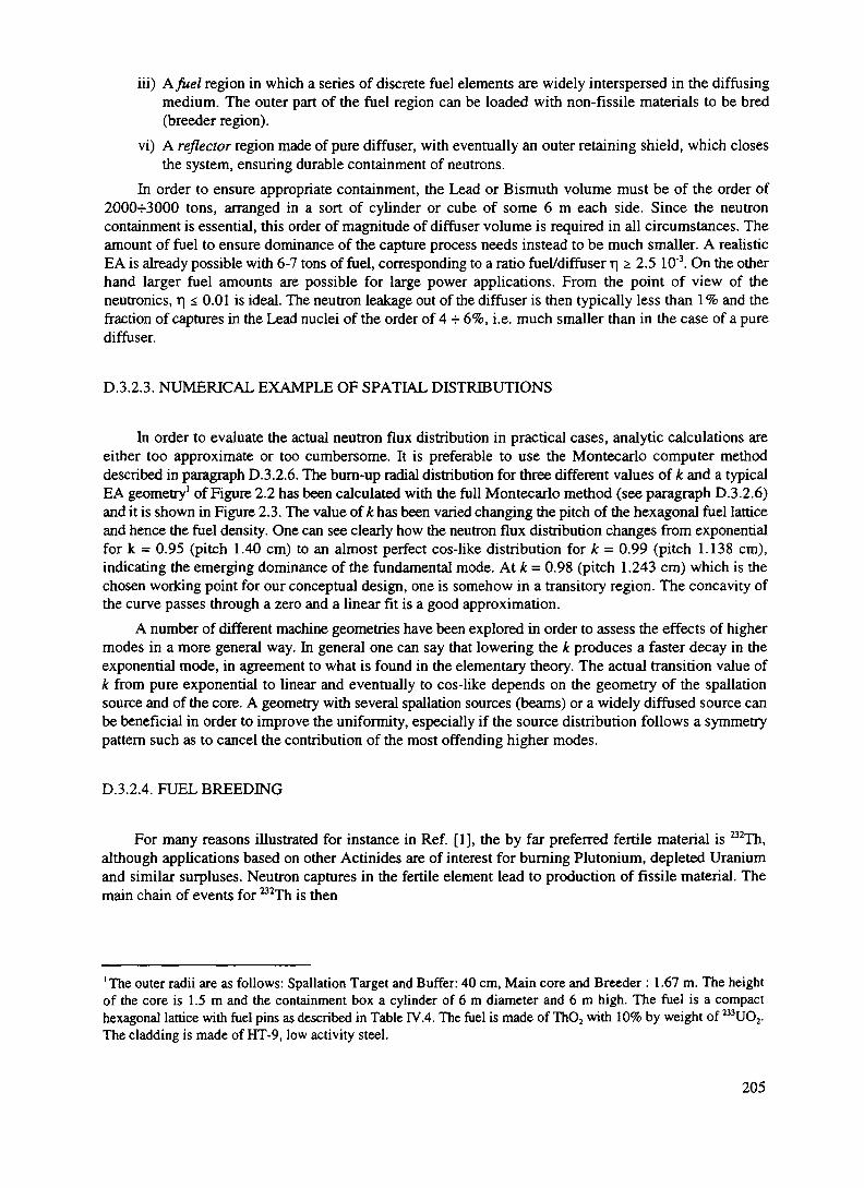
iii) A. fuel region in which a series of discrete fuel elements are widely interspersed in the diffusingmedium. The outer part of the fuel region can be loaded with non-fissile materials to be bred(breeder region).
vi) A reflector region made of pure diffuser, with eventually an outer retaining shield, which closesthe system, ensuring durable containment of neutrons.
In order to ensure appropriate containment, the Lead or Bismuth volume must be of the order of2000-=-3000 tons, arranged in a sort of cylinder or cube of some 6 m each side. Since the neutroncontainment is essential, this order of magnitude of diffuser volume is required in all circumstances. Theamount of fuel to ensure dominance of the capture process needs instead to be much smaller. A realisticEA is already possible with 6-7 tons of fuel, corresponding to a ratio fuel/diffuser t| z 2.5 10"3. On the otherhand larger fuel amounts are possible for large power applications. From the point of view of theneutronics, r| < 0.01 is ideal. The neutron leakage out of the diffuser is then typically less than 1% and thefraction of captures in the Lead nuclei of the order of 4 H- 6%, i.e. much smaller than in the case of a purediffuser.
D.3.2.3. NUMERICAL EXAMPLE OF SPATIAL DISTRIBUTIONS
In order to evaluate the actual neutron flux distribution in practical cases, analytic calculations areeither too approximate or too cumbersome. It is preferable to use the Montecarlo computer methoddescribed in paragraph D.3.2.6. The burn-up radial distribution for three different values of k and a typicalEA geometry1 of Figure 2.2 has been calculated with the full Montecarlo method (see paragraph D.3.2.6)and it is shown in Figure 2.3. The value of k has been varied changing the pitch of the hexagonal fuel latticeand hence the fuel density. One can see clearly how the neutron flux distribution changes from exponentialfor k = 0.95 (pitch 1.40 cm) to an almost perfect cos-like distribution for k = 0.99 (pitch 1.138 cm),indicating the emerging dominance of the fundamental mode. At k = 0.98 (pitch 1.243 cm) which is thechosen working point for our conceptual design, one is somehow in a transitory region. The concavity ofthe curve passes through a zero and a linear fit is a good approximation.
A number of different machine geometries have been explored in order to assess the effects of highermodes in a more general way. In general one can say that lowering the k produces a faster decay in theexponential mode, in agreement to what is found in the elementary theory. The actual transition value ofk from pure exponential to linear and eventually to cos-like depends on the geometry of the spallationsource and of the core. A geometry with several spallation sources (beams) or a widely diffused source canbe beneficial in order to improve the uniformity, especially if the source distribution follows a symmetrypattern such as to cancel the contribution of the most offending higher modes.
D.3.2.4. FUEL BREEDING
For many reasons illustrated for instance in Ref. [1], the by far preferred fertile material is 232Th,although applications based on other Actinides are of interest for burning Plutonium, depleted Uraniumand similar surpluses. Neutron captures in the fertile element lead to production of fissile material. Themain chain of events for 232Th is then
' The outer radii are as follows: Spallation Target and Buffer: 40 cm, Main core and Breeder : 1.67 m. The heightof the core is 1.5 m and the containment box a cylinder of 6 m diameter and 6 m high. The fuel is a compacthexagonal lattice with fuel pins as described in Table IV.4. The fuel is made of Th02 with 10% by weight of 233UO2.The cladding is made of HT-9, low activity steel.
205

k = 0.99 (pitch=11.38 mm
6 8 10 12
Radial distance (arbitrary units)
16 18 20
FIG. 2.3a The burn-up radial distribution for different criticality coefficients, namely for(a) for k=0.99, (b)for k=0.975 and (c)for k=0.950. Open points have not been included inthe fits.
c.I<0ffl
k = 0.975 (pitch=12.45 mm)
0 2 4 6 8 10 12 14 16 18
Radial distance (arbitrary units)
FIG. 2.3b k=0.975 - see caption for Fig. 2.3 a.
206

oc 0.4-
k = 0.95 (prtch=14.3 mm)
8 10 12 14 16 18
Radial distance (arbitrary units)
FIG. 2.3c k=0.950 - see caption for Fig. 2.3 a
233ThP ", 22 min P -, 27.0 days 233
In steady neutron flux conditions, the chain will tend to an equilibrium, namely in a situation in whicheach fissioned 233U nucleus is replaced by a newly bred fuel nucleus. To a first order, the equilibriumcondition can be summarised by the equations:
(232Th)<ft=N(233PaVT(233Pa 233U)=N(233U)aflss ,
where cross sections are averaged over the neutron spectrum of integrated flux <f). Such a "breeding"equilibrium is naturally attained with a specific value of the fuel/breeder concentration ratio determinedsolely by the ratio of cross sections
/•23277i)
N(2i2Th) /233 U)
This equation assumes no alternatives besides the main chain, justified as long as the rate of neutroncaptures by B3Pa competing with natural decay is kept negligible with a sufficiently low neutron flux. Thisis the "decay dominated" regime [1] in contrast with the high flux, "capture dominated" regime investigatedby Bowman et al [15] where the B3Pa must be quickly extracted to avoid capture.
The breeding ratio at equilibrium is about f=1.35xlO"2 for thermal energies and it rises to f= 0.126for fast neutrons and cross sections of Table H.2. An EA based on fast neutrons (F-EA) will then requirea fuel concentration which is about nine times the one of a device based on fully thermalised neutrons(T-EA). However, it can operate with much higher bum-up rates and hence the total mass of fuel iscorrespondingly reduced: for the same output power, the stockpiles of 233U are in general comparable.
207

During the actual bum-up of the fuel following an initial fuelling, the equilibrium equation above isonly approximately attained, since the concentration of the bulk, fertile material is decreasing with time.Solving the related Bateman equations with an initial breeding material exposed to a constant neutron fluxshows that correction terms have to be introduced to the asymptotic value of the breeding ratio1:
a+
f " So "
The first correction is negligible for a T-EA, but it increases significantly (by 10%) the breedingequilibrium of the F-EA. The second, flux dependent term is smaller but not negligible (A£"= 0.31 x 10"3
for a burn-up rate p = 60 W/g and cross sections of Table n.2) and it compensates partially the fluxdependent losses due to captures of the intermediate state 233Pa.
The energetic gain G, namely the energy produced in the EA relative to the energy dissipated by thehigh energy proton beam is given by the expression [1]
G o= —— = —
where G,, is the gain proportionaJity_constant, typically 2.4 •=- 2.5 for a well designed EA; k is the fission-driven multiplication coefficient k =rj(l -L)/2; L is the sum of fractional losses of neutrons (absorbed in avariety of ways, like captures in structures and coolant, in fission-product poisons, diffused outside the EAand so on); 77 is the (spectrum averaged) number of fission neutrons produced by a neutron absorbed inthe fissile isotope2. The parameter rj(E) has a rather complicated neutron energy dependence, with asomewhat lower value in some parts of the resonant region, before rising to larger values for fast neutrons.
As is well known, in order to achieve criticality the denominator must become zeio,_tj =2(1 -L). Moreprecisely, criticality is achieved when neutron losses are reduced to the value Lcrit =1 -2/rj. Note that sinceL > 0 in order to reach criticality 77 >2, one neutron being required to maintain the chain reaction and thesecond being absorbed by the fertile material.
The F-EA has the advantage, when compared to a T-EA that it operates in a region where 77 issignificantly larger. In addition because of the higher energies, additional neutrons are produced at eachgeneration by different processes, like for instance fast fissions in the fertile material 232Th and (n,2n)reactions in the fuel and_the moderator. In order to take into account these contributions it is customary toreplace the parameter 77 with 772 where e (fast fission factor) is the ratio of all neutrons produced to theones from the main fission reaction. For a F-EA we expect Tje =2.4-2.5, conveniently and significantlylarger than 2 and larger than rje =2.1 "2.2 [2] appropriate for a T-EA. The larger allowance for losses(f.i.Lcr(/ =1 -2/T)£ =0.167-0.200 vs. Lm,=0.048«0.091)is an important asset of the F-EA, even if operationis always with L>Lcra. As discussed in more detail later on, these extra neutrons do not necessarily haveto be thrown away: they may for instance be used to breed additional fuel or to eliminate radiotoxic sub-
1 In our (reatment we do not include the captures in 233Pa, which of course are also a rate dependent effect. Theselosses are instead counted in L.2This equation is easily worked out realising that at the breeding equilibrium the number of neutron captures in ^"Uand in H:Th at each generation must be the same and normalised to 1 neutron are equal to (l-L)/2, since, by neutronconservation, [captures in mU\ + [captures in ^^Th] + [Losses]= 1 = (l-L)/2+(l-L)f2+L = 1. As the number of nextgeneration neutrons r|(l-L)/2 generated by ^'U fissions is also, by definition, the multiplication coefficient k, weconclude that k = n.(l-L)/2.
208

TABLE E2.EA.
Element230Th232Th
231Pa233Pa232UB3U2*u235u236u237u238u
B7Np238Np239Np238Pu"'Pu240Pu241PuM2PuM3Pu^Pu'"AmM2Am^AmM2CmM3Cm^Cm^Cm^Cm247Cm"'CmM9Bk249Cf
250Cf
251Cf252Cf253Cf
AVERAGED CROSS SECTIONS (BARN) OF ACTINIDES RELEVANT TO THE FAST
Capture
0.1986720.3868553.3091761.1216380.7319030.2890030.6155640.5740710.4901420.4921990.4282651.6749210.0892782.0832010.7568400.5570410.6671030.4250300.5352880.4030970.2360481.9639670.0797281.5824310.3720920.2652100.9091530.3351780.2302610.3485360.2655141.4479880.6672230.6147950.3689200.3200390.180410
Fission
0.0189180.0059660.1797910.0389892.0963172.7839230.2489501.9720080.0687860.6100420.0253510.2331760.5952020.3538371.0251751.7805160.2880792.5774700.1905780.8107720.1570110.1904690.5308190.1462450.1057672.6552230.3181022.4750360.1816691.9267540.2184380.1131462.7079750.9442132.4885280.5738750.716114
Elastic
14.06092510.9235019.1332898.0930039.3682978.91914110.0313398.85896811.1254229.18902511.2548049.15709410.4394879.18416211.0463889.15621410.3317358.10438911.0246489.28331310.8058799.58090010.23351310.00394810.36250810.01280010.5159908.75010910.8440259.11773111.29577610.2200599.0649808.9276518.81581511.8653609.940411
(n->2n)
0.0005980.0005600.0003980.0001620.0002810.0002110.0000540.0004570.0002940.0009200.0005290.0001150.0000000.0001350.0001520.0002370.0000830.0008800.0002290.0022540.0008080.0000040.0004620.0000280.0000070.0004560.0001350.0008310.0001740.0013530.0002340.0000520.0001890.0004060.0015730.0003350.000000
(n->n')
0.9891350.6992211.1109331.7548080.4338750.2804450.7180690.6408600.8559510.4919000.8320770.7599340.0000000.8658350.3428880.7702270.5730450.8019860.6676790.6232180.8130810.5657410.0735280.9352820.7242421.0054760.5409120.8625130.7801900.3721270.8131421.1869270.4255890.4688600.4178320.4144250.000000
Total
15.26824512.01613113.73361911.00861512.63069012.27273811.61397612.04637812.54062010.78410412.54104511.82525011.12396612.48720613.17146312.26424511.86004511.90976112.41842211.12266112.01283312.30109510.84405912.66793811.56461513.93917212.28429712.42366912.03633611.76651812.59312212.96819212.86597310.95594312.09267913.17403110.836935
209

stances [6]. It is also convenient to start operation of a F-EA with a B3U concentration smaller than the onecorresponding to the breeding equilibrium. During operation, the increase of criticality due to the build-upof the ^U relative concentration can be used to compensate growing neutron losses due to captures byfission fragments, thus ensuring a more uniform gain during a longer period of operation withoutinterventions.
D.3.2.5. FLUX DEPENDENT EFFECTS
It has been pointed out [1] that there are sharp limitations to the neutron flux at which an EA canoperate in acceptable conditions. The power produced is directly proportional to the neutron flux. Wedefine with p the specific power, in units of thermal Watt produced by one gram of Thorium in fuel1. Atthe breeding equilibrium the fluxes for thermal and fast neutrons are given by
= l-80xlO'2xW/g
cm'V ; (pfast = 3.88xlOI3xW/g
-2..-1cm s
where for the latter we have used the cross sections of Table H.2. Let us estimate some orders of magnitude.For thermal neutrons (E = 0.025 eV), a power of p = 15.0 W/g corresponds to a flux (J> = 2.7 x 1013 cm'2s"1, which is considered optimal for a T-EA [1]. In practice the flux in a T-EA will depend somewhat onthe energy spectrum of the neutrons, which in turn depends on the operating temperature of the device andon the choice of the moderator. For the same power yield, the neutron flux in a F-EA is approximately 20times larger. As is well known, it simply reflects the fact that at higher energies cross sections are generallysmaller. A practical bum-up rate of a F-EA is about p = 60 W/g : the flux will then be (p = 2.33 x 10IS cm"2
s"1, about 80 times larger than the one optimal for a T-EA.There are several flux dependent effects which have a direct influence on the value and the stability
during operation of the multiplication factor k, and hence on the gain:1) Neutron capture by the intermediate elements of the breeding process and specifically by the "'Pa
which destroys a nascent 233U atom at the price of an extra neutron. Such a loss involves a competitionbetween neutron capture and radioactive decay, and it is proportional to the total flux <J> through theparameter AA,=oa(233Pa) x T( ™Pa~233U) x <f> «1 where T is the mean life. The absorption crosssection aa( 233Pa) is about 43 b at thermal energies, it has a resonance integral of 850 b and it is equalto 1.12 b for fast neutrons (Table H.2). The corresponding value for a T-EA is /U,~7.45x70"'V,corresponding to a contribution to L of AL=(1 -L)t|eAA,/2=3.78x 10~3 for the typical flux of 2.7 x 10¹³
cm"2 s"1. For fast neutrons the cross section is much smaller but the flux is correspondingly larger: fora given bum-up rate p, AA, is 0.56 times the value for thermal neutrons. Note however that theallowance for neutron losses is much greater for the F-EA and therefore larger bum-up rates arepractical: for p = 60 W/g, AA, = 8.81 x 10"3 which is quite acceptable.
2) A consequence of the relatively long mean life of 233Pa (1/e decay after t = 39 days) is that asignificant reactivity increase occurs during an extended EA shut-down. Conversely, any prolongedincrease in bum-up rate produces a temporary reduction of reactivity until the 233Pa inventory has beenre-established. The magnitude of such a reactivity change following a shut-down need not be aproblem, but appropriate measures would be required to correct its effects. The density of 233Pa isgiven by
= ( l+<r)r (-33Pa->233£
where a is the ratio of the non-fission (n,v) to fission reactions and the last term A^(233(/)oyii.v(233f/)<{)
1 In this chapter we define the power density with reference to the main Thorium content, unlike the rest of the paperwhere we have taken as reference the unit weight of the actual chemical mixture of the fuel.
210
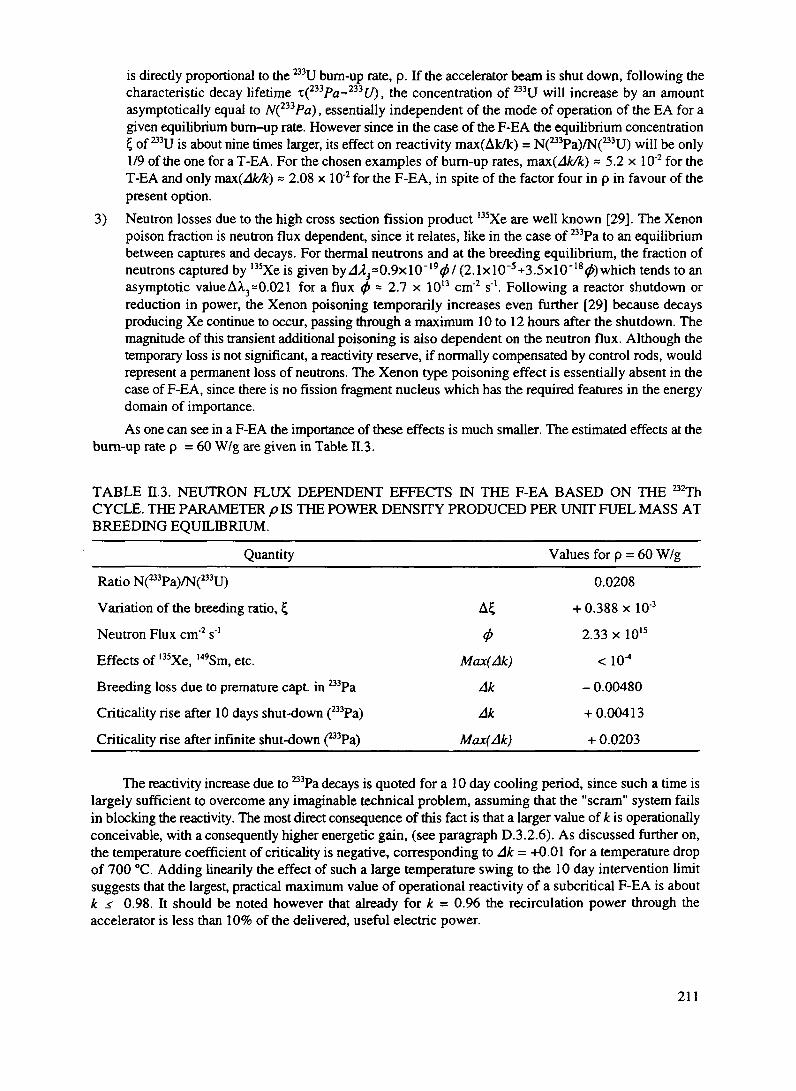
3)
is directly proportional to the 233U bum-up rate, p. If the accelerator beam is shut down, following thecharacteristic decay lifetime T(233fa-233C/). tne concentration of 233U will increase by an amountasymptotically equal to N(n3Pa), essentially independent of the mode of operation of the EA for agiven equilibrium bum-up rate. However since in the case of the F-EA the equilibrium concentration£ of ^U is about nine times larger, its effect on reactivity max(Ak/k) = N(233Pa)/N(233U) will be only1/9 of the one for a T-EA. For the chosen examples of burn-up rates, max(Ak/k) ~ 5.2 x 10"2 for theT-EA and only ma\(Ak/k) ~ 2.08 x 10'2 for the F-EA, in spite of the factor four in p in favour of thepresent option.Neutron losses due to the high cross section fission product 135Xe are well known [29]. The Xenonpoison fraction is neutron flux dependent, since it relates, like in the case of 233Pa to an equilibriumbetween captures and decays. For thermal neutrons and at the breeding equilibrium, the fraction ofneutrons captured by 135Xe is given by A^O^xlCT'V/ (2.1xlO"5+3.5xlO"180)which tends to anasymptotic value AX3=0.021 for a flux (f> ~ 2.1 x 1013 cm"2 s"1. Following a reactor shutdown orreduction in power, the Xenon poisoning temporarily increases even further [29] because decaysproducing Xe continue to occur, passing through a maximum 10 to 12 hours after the shutdown. Themagnitude of this transient additional poisoning is also dependent on the neutron flux. Although thetemporary loss is not significant, a reactivity reserve, if normally compensated by control rods, wouldrepresent a permanent loss of neutrons. The Xenon type poisoning effect is essentially absent in thecase of F-EA, since there is no fission fragment nucleus which has the required features in the energydomain of importance.As one can see in a F-EA the importance of these effects is much smaller. The estimated effects at the
bum-up rate p = 60 W/g are given in Table H.3.
TABLE H.3. NEUTRON FLUX DEPENDENT EFFECTS IN THE F-EA BASED ON THE 232ThCYCLE. THE PARAMETER p IS THE POWER DENSITY PRODUCED PER UNIT FUEL MASS ATBREEDING EQUILIBRIUM.
Quantity Values for p = 60 W/g
Ratio N(233Pa)/N(233U)
Variation of the breeding ratio, £
Neutron Flux cm'2 s"1
Effects of 135Xe, 149Sm, etc.
Breeding loss due to premature capt. in 233Pa
Criticality rise after 10 days shut-down (233Pa)
Criticality rise after infinite shut-down (233Pa)
Max(Ak)
Ak
Ak
Max(Ak)
0.0208
+ 0.388 x 10'3
2.33 x 10¹⁵
- 0.00480
+ 0.00413
+ 0.0203
The reactivity increase due to 233Pa decays is quoted for a 10 day cooling period, since such a time islargely sufficient to overcome any imaginable technical problem, assuming that the "scram" system failsin blocking the reactivity. The most direct consequence of this fact is that a larger value of k is operationallyconceivable, with a consequently higher energetic gain, (see paragraph D.3.2.6). As discussed further on,the temperature coefficient of Criticality is negative, corresponding to Ak = +0.01 for a temperature dropof 700 °C. Adding linearily the effect of such a large temperature swing to the 10 day intervention limitsuggests that the largest, practical maximum value of operational reactivity of a subcritical F-EA is aboutk < 0.98. It should be noted however that already for k = 0.96 the recirculation power through theaccelerator is less than 10% of the delivered, useful electric power.
211

D.3.2.6. COMPUTING METHODS
The exact definition of the parameters of the F-EA implies an appropriate account of the resonanceor otherwise complex energy behaviour of the cross sections of the many elements which intervene in thecascade reactions.
As in Ref. [1] we have adopted a Montecarlo method in which a large number of individual neutronsare followed from their birth to absorption. We make use of the concept of neutron generation andintroduce the effective multiplication coefficient k^, the fraction of neutrons which are regenerated at eachgeneration. Both fissions and (n, 2n) reactions are considered. Cross sections are finely interpolated fromthe most complete sets of cross section data available today [30] and include all main channels, like forinstance inelastic (n,n') scattering. Thermal movement of the target nuclei (Doppler broadening) is includedin the simulation.
The elementary structure of the EA is subdivided in a number of different regions, which reflect thegeometrical properties of the device. The composition of each of these regions is allowed to change as afunction of time taking into account the changes in concentrations of the newly produced elements due to(1) the nuclear transformations and (2) the spontaneous decay chain. A complete database of all knownelements with their decay modes and rates is used [31] and new elements are introduced to the listwhenever a decay or a reaction channel justifies it.
Particular attention has been given to fissions, since they are the dominant, driving process for themultiplication. The energy dependence of the neutron multiplicity has been parametrized from existing data[30].
One important feature of the programme is the one of calculating the evolution of the (poisoning)fission fragments. In order to do so effectively many hundreds of different elements must be followedduring the calculations. This very complete method of simulation has been made possible only recently dueto the availability of more powerful computers. It is still somewhat limited in the statistical accuracy dueto lack of computing power [32].
In practice, the computer programme requires that one defines the different geometrical regions, theirinitial composition and their operating temperatures. One has to define then the scale of time and ofreaction activity. The programme then calculates the time evolution of the system — based of course ona much smaller random neutron population but with changes of concentrations scaled to the actual flux —and calls on further elements whenever required. The calculation can be coupled with a Montecarloprogramme which simulates the high energy cascade. Hence the Montecarlo emulates the whole processinitiated by an incoming beam of specified characteristics. More often it is used as a stand-alone moduleto determine the multiplication coefficient kcff, starting from an initial spectrum due to fission neutrons.
The Montecarlo method has the advantage over other methods that in principle it provides a veryrealistic evolution of the system. However the computing time is long and the results affected by statisticalerrors. Therefore it has been coupled with another, simpler evolution programme, which permits a fasterexploration of the main features of an EA. This programme makes use of some of the information from thefull Montecarlo, namely
1) the averaged cross sections for all relevant elements are extracted as the average over the energyand the fuel volume of the flux as computed by the Montecarlo. Since (see paragraph D.3.2.2) theflux is rather uniform over the fuel elements, the spatial average is a good approximation. Theaveraging over energy may introduce some approximations in presence of strong resonances,where the flux may be locally affected. The extent of this approximation has been checkedcomparing true Montecarlo with the evolution programme and found acceptable for our purposes.
2) the parameter L, namely the sum of fractional losses of neutrons (absorbed in a variety of ways,like captures in structures and coolant, diffused outside the EA and so on) is divided into twocomponents, namely a term which is constant, but geometry dependent and another (mainly dueto fission-product poisons, spallation and activation nuclei etc.) which is linear in the bum up.
212

This parametrization is in excellent agreement with the Montecarlo results. Actual values to beused in the evolution programme are fitted from the Montecarlo simulation. Hence they take intoaccount all burn-up dependent neutron losses.
The time evolution in a slab of material subject to a neutron flux and with spontaneous decays cannotbe calculated following the classic Bateman evolution equations [33]. This is due to the fact that theBateman's description assumes an open, successive chain of decay nuclei, eventually leading to the finalstable isotopes, namely a specific path in the (A,Z) plane. Under the simultaneous action of neutrons anddecays, nuclei can both rise (neutron induced reactions) and fall in the atomic A, Z number (spontaneousdecays). Hence the decay paths in the (A,Z) plane perform loops which may bring back the same nucleusan arbitrary number of times and imply products of an infinite number of terms, although with a decreasingprobability. For this reason our time evolution programme is based on numerical step-wise methods. In ouranalysis both programmes are used and give consistent results. Furthermore the neutron flux and criticalitypredicted by the Montecarlo programme is in good agreement with the results of standard, non evolutionaryprogrammes [34].
D.3.2.7. CUMULATIVE FISSION FRAGMENT POISONING
One of the most serious limitations in the T-EA comes from the losses of neutrons due to slowlysaturating or non saturating fission fragments (FFs). In contrast to I35Xe and 149Sm, which have a very largeneutron cross section and therefore reach saturation in a short time, the majority of the fission products havecross sections which are comparable or smaller than the one of the fuel itself. Hence the aggregatepoisoning effect of such fission products is roughly proportional to the fractional burn-up of the fuel. Theaccumulated effect depends significantly on the past history of the fuel. Computer calculations have beenused to analyse the poisoning as a function of the integrated burn-up for a variety of different conditions.
One important result is that losses due to fission fragment poisoning are much less important for a F-EA, when compared to a T-EA (Figure 2.4). In both cases however the build up of FFs implies aprogressive reduction of criticality.
An important feature of the F-EA is that it is possible to operate the device for a long time (severalyears) without intervention on the fuel. In order to enhance such a feature we have investigated thepossibility of starting with a ^"U concentration smaller than at the breeding equilibrium £ and thuscompensate as much as possible the drop of criticality due to fission fragment poisoning with the help ofthe increasing fraction of bred ^U.
In Figure 2.5 we have considered with the help of the evolution programme the criticality coefficientk for the EA device described in paragraph D.3.2.3 as a function of bum-up for a constant neutron flux andgiven initial 233U concentration. Since the neutron flux will in practice depend on time, the criticalitycoefficient will be slightly affected also by the dependence of the 233Pa concentration with flux. The initialcriticality coefficient is adjusted "ad hoc" to k = 0.965 by slightly increasing the neutron losses L. Theinitial filling of U is set to f=0.117, significantly lower than the breeding ratio at equilibrium. The graphshows three different fluxes and hence power yields, p. The general behaviour of the curves shows aninitial drop related to ^Pa production, followed by a rise due to the increment of £"due to breeding. Fissionfragment captures eventually become important and bring down k. A higher p gives lower k values sinceearly captures in 233Pa reduce the breeding yield. Curves without fission fragment poisoning arealsoshown.One can conclude that (1) a very smooth running is possible up to a burn up of the order of150 GW d/t, essentially without intervention and (2) a power yield of the order of p = 100 W/g is perfectlyacceptable1. An extended shut-down will move to the curve for p - 0, still sufficiently far away fromcriticality. Of course, as already pointed out, in view of the long 233Pa lifetime, there is plenty of time tointroduce corrective measures.
1 Note that in the present design, we have conservatively set the power density to about one half of this value.
213

0.2
<2 0.18-c
|> 0.16-
.2 0.14-
£ 0.12-•o&f 0.1-
| 0.08-3S 0.06-
1 0.04-
2 0.02-
0
Thermal neutrons......Xe.-1.35.ODlx......
Thermal neutronsAll fission fragments
Fast neutronsAll fission fragments.
*•""*"
20 40 60 80 100
Integrated burn-up (GW d/t)
120 140 160
FIG. 2.4 Fraction of neutrons capture by the fission fragments as a function of theintegrated burn-up, for thermal and fast EA.
Without fission fragmentcaptures
* = 4.4x101<s"1 cm"2
p =8.0W/g
6 = 2.0x10 s cm
100 150
Bum-up (GW d/t)
200 250
FIG. 2.5 Criticality coefficient k as a function of the integrated bum-up for differentpower yields. The effect on k due to the neutron captures by the fission fragments is alsoshown.
For a fixed beam power the flux is time dependent, and will vary proportionally to gain. Since gainis related to the B3Pa concentration and in turn to its capture probability, the dependence of fc as a functionof burn up is even smoother. In Figure 2.6 we show the typical k behaviour for a somewhat larger initial
214

1.06
1.04-
„. 1.02-1jc
1.a 1
0.98-
IIo 0.94-
0.92-
0.9
With fission fragments
20 40 60 80 100
Integrated bum-up (GW d/t)
120 140 160
FIG. 2.6 Behaviour ofk as a function of the integrated burn-up.
value of k. Almost constant conditions can be ensured without intervention over a burn up of 100 4- 150GW d/t, namely over several years.
D.3.2.8. HIGHER URANIUM ISOTOPES AND OTHER ACTINIDES
Higher Uranium isotopes and higher Actinides are produced by successive neutron captures. The timeevolution of an initially "pure" 232Th and a3U fuel mixture can be easily calculated and is given in Ref. [1]for a T-EA. The build-up of the several isotopes introduces more captures and some fissions. Hence inprinciple the multiplication coefficient k is also modified. It was shown in Ref. [2] that the asymptoticmixture preserves an acceptable value of k for initial U2Th both in thermal and fast neutron-conditions,while for initial 238U only fast neutrons preserve an acceptable gain.
In the EA the initial fuel is completely burnt in a closed, indefinite cyclic chain in which Actinidesof the spent fuel become the "seeds" of the next fuel cycle [1]. At each discharge an appropriate amountof fresh fuel is added to compensate for the bum-up and the accumulated nuclear species, products of thefission (fission fragments, FFs) are removed. The initial fuel nuclei (either Th232 or U238 or eventually amixture of both) undergo a series of transformations induced by neutron captures and spontaneous decays,until they achieve ultimate fission. The first of these transformations is the initial "breeding" reactionswhich continue to be the dominant source of fissions (B3U or 'Pu respectively) even after a long burn-up.However a rich hierarchy of secondary processes builds up at all orders. These secondary processes becomeessential in determining the atomic concentration vector c(A^ of Actinides and hence the neutron economyof the cascade. For stationary conditions the atomic concentration vector c(AX>(<p) tends asymptotically, (i.e.after long bum-ups) to a limiting equilibrium value.
In order to estimate the actual evolution of c(A^(<p) we have studied the time evolution of some fuelexposed to the average flux of an F-EA with the help of the evolution programme and using the crosssections of Table n.2. Results have been checked with the full Montecarlo programme. The chain of manysuccessive re-fillings has been simulated. Although the results are widely independent of the power density,for definiteness the value p = 100 W/g has been used. After a pre-assigned bum-up of 150 GW d/t,Actinides are discharged and the fuel topped-up with fresh 232Th. Since the amount of fuel burnt is not
215

negligible the stockpile of 233U is affected by the over-all reduction of the fuel mass, even if the relativeconcentration with respect to 232Th has remained constant (at the breeding equilibrium) or significantlyincreased (if initially below the breeding equilibrium). It is therefore necessary in general to add to therenewed fuel an amount of 233U which is larger than what is recovered at the discharge. For this reason asmall breeder section has to be added to the EA: initially made of pure Thorium, it is designed to supplysuch a needed difference. The total 233U stockpile as a function of bum up has been calculated with the fullMontecarlo for the geometry given in paragraph D.3.2.3 and shown in Figure 2.7. With the help of suchan extra breeding, it is realistic to expect that the initial volume of 233U can be made available at the endof the cycle. Therefore in our simulation of the evolution of c(A^(<p) we assume that both 232Th and ^Uare topped up to the initial values at each filling. The new fuel will contain in addition all the remainingActinides produced by the previous combustion.
2.0
1.6 -
£ 1.2 -
0.8 -
0.4 .
0.0
Breeder
20 40 60 80
Bum-up (GW CM)100 120
FIG. 2.7 U stockpile as a Junction of the integrated bum-up.
In Figures 2.8a, 2.8b and 2.8c we show the Actinide distribution at discharge, as a function of thedischarge number. The relative concentrations are listed in Table n.4. All elements clearly reach anasymptotic concentration, in which production and incineration are in equilibrium. Concentrations of higheractinides tend to a stable equilibrium condition which is a fast decreasing function of A and Z. This is dueto the fact that almost at each step of the neutron induced evolution ladder, fissions subtract a significantfraction of nuclei. The most offending isotopes, because of their amount and their radio-toxicity, namelyB1Pa and 232U are practically close to the asymptotic values of 1.06 x 10"4 and 1.30 x 10^ already at the firstdischarge. Note also the large concentration of 234U which quickly reaches an asymptotic concentrationwhich is about 38% of 233U. The Uranium composition at (asymptotic) discharge is therefore 9.354 x 10"4
of ^U, 63.88 % of ^U, 24.12 % of ^U, 5.870 % of B5U, 6.01 % of 236U and 1.03 x lO^of BBU, whichconstitutes about 14% of the spent fuel mass. Likewise the Neptunium and Plutonium, produced innegligible amounts during the first fillings grow to asymptotic values of 0.2% and 0.1 % respectively.Plutonium is dominated by the isotope 238Pu which has the short half life of 87.7 years and therefore hasno practical military application. Higher Actinides, Americium and Curium, never reach concentrationsof significance. Note that for instance after 20 refilling the fuel seeds have produced an integrated burn upof the order of 3000 GW d/t and therefore these contaminating amounts, once normalised to the producedenergy are totally negligible. For instance the Plutonium concentration at the discharge of an ordinary PWRis about 1.1 % for 33.0 GW d/t. The amount of transuranic Actinides produced per unit of energy deliveredis about three orders of magnitude less than in an ordinary PWR.
216

0.0x10°
232,
231Pa
500 1000 1500 2000
Integrated "seeds' bum-up (GW d/t)
2500 3000
FIG. 2.8a 231Pa and 232U stockpile as a Junction of the discharge number (integrated seedsburn-up).
0.0*10°500 1000 1500 2000 2500
Integrated 'seeds' bum-up (GW d/t)SK 1000 1500 2000 2500
Integrated 'seeds' bum-up (GW d/t)
500 1000 1500 2000 2500
Integrated 'seeds' bum-up (GW d/t)500 1000 1500 2000 2900
Integrated "seeds' bum-up (GW d/t)
FIG. 2.8b Other actinides stockpile as a function of the discharge number (integrated seeds bum-up).
217

60x10'
0.0x10500 1000 1500 2000
Integrated "seeds' bum-up (GW d/t)
2500 3000
FIG. 2.8c Trans-uranic production/unit energy relative to ordinary PWR as a function of thedischarge number (integrated seeds burn-up).
We have compared the evolution of k as a function of burn-up obtained with the simple evolutionprogramme and the "exact" calculations of the Montecarlo programme. As shown in Figure 2.9, theagreement is excellent.
1 00
> 0 9 3 -i
092-
0.91-
090
Points' Montecarlo CalculationContinuous Line: Analytic
50 100 150 200Burn-up , GW d/l
250 300
FIG. 2.9 Comparison ofkeff calculated analytically and by Montecarlo.
218

TABLE H.4. RELATIVE CONCENTRATIONS OF ACTINIDES AT THE DISCHARGE AFTER 150GW d/t OF BURN UP. THE POWER DENSITY WAS p = 100 W/g, CORRESPONDING TO A CYCLEOF ABOUT 5 YEARS. CONCENTRATIONS ARE NORMALISED TO THE FUEL MASS WHICH ISMADE OF CORRESPONDING OXIDES.
Element
23Cth232Th
23,pa
232uB3u234u
235UBey
238U2MNpB7Np238pu
239pu
240PuMIPu242pu
244Pu241Am
"'Am
^Cm244Cm
"'Cm
"•Cm247Cm
^Cm
First discharge
1.408E-7
7.637 E-l
9.246 E-5
7.942 E-5
8.919 E-2
1.403E-2
1.851 E-3
2.420 E-4
3.239 E-8
2.626 E-l 0
1.669 E-5
3.163E-6
2.274 E-7
1.172 E-8
5.192 E-10
1.694E-11
2.494 E-17
2.924 E- 11
5.577 E-l 3
1.647 E-14
4.859 E-14
2.185 E-15
3.693 E-17
3.660 E-19
5.510 E-21
5th discharge
1.378E-6
7.637 E-l
1.055 E-4
1.298 E-4
8.919 E-2
3. 102 E-2
7.242 E-3
4.475 E-3
3.145E-6
1.047 E-7
9. 127 E-4
5.975 E-4
1.422 E-4
3.709 E-5
5.084 E-6
9.800 E-7
8.631 E-12
7.003 E-7
1.406 E-7
4.741 E-9
5.683 E-8
9.850 E-9
9.783 E-10
4.102 E-l 1
3. 492 E-l 2
10th discharge
2.586 E-6
7.637 E-l
1.059 E-4
1.304 E-4
8.919 E-2
3.340 E-2
8.101 E-3
7.428 E-3
9.390 E-6
5.787 E-7
1.832 E-3
1.545 E-3
4.706 E-4
2.144 E-4
3.756 E-5
1.536 E-5
3.155 E-10
7.21 8 E-6
3.575 E-6
7.930 E-8
2.479 E-6
6.417 E-7
1.5 19 E-7
1.038 E-8
2.011 E-9
15th discharge
3.271 E-6
7.637 E-l
1.061 E-4
1.305 E-4
8.919 E-2
3.365 E-2
8.185 E-3
8.214 E-3
1.296 E-5
1.228 E-6
2. 104 E-3
1.875 E-3
6.029 E-4
3.307 E-4
6. 172 E-5
3.508 E-5
1.163 E-9
1.316 E-5
9.807 E-6
1.646 E-7
8.489 E-6
2.550 E-6
1.023 E-6
8.604 E-8
2.743 E-8
Asymptoticlimit
3.642 E-6
7.637 E-l
1.061 E-4
1.306 E-4
8.919 E-2
3.368 E-2
8.196 E-3
8.395 E-3
1.440 E-5
1 .924 E-6
2. 168 E-3
1.958 E-3
6.374 E-4
3.703 E-4
7.034 E-5
4.572 E-5
1.999 E-9
1.547 E-5
1.372 E-5
2.010 E-7 '
1.303 E-5
4. 158 E-6
2.329 E-6
2. 166 E-7
9.6 18 E-8
219

The behaviour of the multiplication coefficient k as a function of the bum-up during successive refillsis given in Figure 2.10. One can see that in spite of the significant change of the fuel composition, the valueof k remains remarkably constant.
20 40 60 80 100
Integrated 'seeds' bum-up (GW d/t)
120 140 160
FIG. 2.10 Behaviour ofk as a function of the burn-up for different fillings.
We conclude that the fuel can be indefinitely used in an open ended chain of cycles. Indeed the fuelcan survive the lifetime of the installation and be re-used as long as there is demand for EAs, with verysmall or no loss of performance. In contrast with an ordinary reactor the EA produces no " Actinide Waste"to speak of, but only valuable "Seeds" for further use and once the asymptotic concentrations have beenreached, there is no significant increase with operation of the radio-toxicity of the Actinide stockpile (seenext paragraph).
D.3.2.9. ELEMENTARY, ANALYTIC FORMULATION OF ACTINIDE EVOLUTION
A number of simplifying assumptions permits calculating analytically the essential features of theevolution of the concentration vector c(A ~[<f>). We ignore the discontinuity of the refills and assume aL(A,2)'constant inflow of the father element and neglect the (n,2n) and other channels which may introduce"loops" in the (A,Z) evolution plane, as already mentioned. We assume that in the presence of the neutronflux <f>, for all elements there is only one transformation channel (either with neutron capture averaged crosssection o^pror radioactive decay with decay rate A.w whichever is dominant) and a dissipative, fissionchannel with spectrum averaged cross section o^.v. For very high values of A spontaneous fission and otherforms of nuclear instability will contribute to such dissipative terms. The rate of transformation in a neutronflux <f> is <f>o and the total rate H.(l)=0(o^p,+ojiJj) or jiw=0o^v+A.(l> if the transformation is decaydominated. The survival, chaining coefficient, which represents the probability of continuation to the nextstep of the evolution chain is defined as aw =o^w/(aJJtf+o^I) ora(;)=Xw/(A(l')+a^.vx0)respectively. Theprocedure is schematically shown below:
220

ChainInitialamount
Removalrate
P-N,-l
N,(0)
HI
N2- AT,- W,-J J 1
0 0 0
*>£ *p£ 0<Transfer rate
Survivalcoeff. a<;)
Totairate
ecapt ftss
(3)capt
(0capt
Assuming first no refill (P = 0 ) and an initial number of nuclei /V,(0) the time evolution is givenaccording to the Bateman equation (i >1):
k'in
i=i -_ •^n
If alternatively, there is refill at the constant rate P per unit time and no initial nuclear sample, i.e. N, (0)= 0, the formula becomes (i > 1)
N®(t) = p\ n
In practice, both refilling and initial nuclei are present and the actual number of nuclei will be simply thesum of the two above terms. Note that for p = 100 W/g, <f> ~ 5 x 1015 cm"2 s"1 and that the sum of crosssections is of the order of magnitude of = 2 x 10"24 cm2, leading to an evolution time constant l/n(0 of theorder of * 3 years.
The asymptotic distribution is reached at the limit t~<*>. At this stage the process is dominated by therefill term P and one can easily calculate the equilibrium amounts:
The time required by /Vw to grow to yv(l)(r-oo)(l -lie) is approximately given by Sl/p(l) where thesum is extended up to i. Since the order of magnitude of the time constant is typically 3 years, equilibriumis reached after = 3 (i-1) years where we have used i-1 to take into account that the step through the ^Pais fast. The fast decrease of Nll)(t-"o) with the rank in the chain is due to the product of the a « 1 terms.To a fast decreasing degree of concentrations, the whole table of elements is eventually involved. Asalready pointed out, in practice the chain is not open-ended since spontaneous fissions and otherinstabilities ensure very small a-values toward the end.
221

D.3.2.10. PRACTICAL CONSIDERATIONS
Strictly speaking, continuing operation of the EA requires merely the recycling of the Uraniumisotopes. However at each refill of the fuel, inevitably, individual Actinides are separated during thereprocessing. Furthermore their relative incineration rate is independent of the concentration. Therefore,although their elimination requires permanence in the EA for a long time, it is not mandatory to dilute theseextra products in every fuel refill of each EA. They can be accumulated and inserted instead in a dedicateddevice. Whichever strategy is chosen, the already calculated evolution of the trans-uranic stockpile as afunction of the integrated bum up (Figures 2.8a-c ) remains valid.
In order to positively destroy such trans-uranic Actinides, the exposure time is long, extending overmany refilling steps. Since their relative amount is very small it is possible to concentrate them in a few,dedicated fuel bars, to be inserted somewhere in the bundles of ordinary fuel, which is then made ofUranium and Thorium only. After irradiation, such dedicated bundles do not need further reprocessing,since even if the local Fission Fragment concentration becomes very high, it will not affect the over-allcriticality of the device which is not appreciably different than if they were generally distributed. Thereforeit may be sufficient at each refill of the main fuel to bleed the gaseous fragments produced and to add a newprotecting sleeve or otherwise ensure the continuing mechanical strength of such specialised fuel bars: itwill make sense not to reprocess them any more, until all actinides are positively transformed into fissionfragments and their incineration completed.
Therefore a practical scenario will consist in (1) reprocessing of the bulk of the spent fuel at eachrefill, with separation of Thorium and Uranium which are to be used to fabricate the next fuel refill and (2)separation at each reprocessing stage of the trans-uranic Actinides and of Protactinium in a small stockpilewhich is then introduced in the neutron flux of the EA once and for all and up to its total incineration, withgas bleeding and strengthening of the cladding at each refill.
The amount of elements at the discharge depends critically on the concentration of "'U, which actsas the gateway to ^'Np. Therefore we have considered the production of trans-uranic elements after 150GW d/t, starting from the asymptotic mixture of Uranium in the fuel. Much smaller amounts will beproduced during the early fillings, as seen from Figures 2.8a-2.8c. Results are listed in Table n.5. Thedischarge consists primarily of ^Np (66.0 %), 'Pa (4.24 %), medium lived ""Pu (26.1 %, half-life of 87.7years) and B9Pu (3.3%) and it is ridiculously small, namely 276 g/t of fuel, or 4.14 kg for a 15 t discharge.The radioactive heat of this discharge is = 600 W, primarily due to 238Pu, and quite manageable.
The relative radiotoxicity of such trans-uranic products is also very modest, when normalised to theproduced energy. The volume is only a few percent of the production of a PWR for the same energy. Asalready pointed out, once inserted in an appropriate fuel containment rod, they will not be handled againuntil fully incinerated. In view of the simplicity of such a procedure, geologic storage of trans-uranic wastefrom an EA is unnecessary. Clearly the best place to put the unwanted long lived waste is the EA itself,where an incineration lifetime of years is at hand.
D.3.2.11. PROLIFERATION ISSUES
A great concern about Nuclear Power is that military diversions may occur with the spent fuel. Thepresent EA scheme offers much better guarantees against such a potential risk. We assume that theprocedure of fuel loading and reprocessing is the one described in the previous section. Critical Masses(CM) and other relevant parameters for bare spheres of pure metal are listed in Table H.6. The addition ofa neutron reflector, a few inches thick may be used to reduce the CM by a factor two or so. One can see thatthree chemical elements of the discharge, namely the asymptotic Uranium Mixture, Neptunium andPlutonium exhibit potential nuclear explosive features. However several other features limit the feasibilityof an actual explosive device. We consider them in turn, following the arguments given in Ref. [35]:
1) Decay heat produced by the a-decays of the material in some instances is much larger than the
222

eight Watts emitted from the approximately three kilograms of weapon grade plutonium whichis suggested to be in a modern nuclear warhead. Since the high-explosive (HE) around the fuelwould have insulating properties (= 0.4 W m °C"'), only 10 cm of HE could result in anequilibrium temperature of about 190 °C for 100 W of heat. Apparently the breakdown rate ofmany types of HE becomes significant above about 100 °C. Although methods could be envisagedto add heat sinks to the device, we assume that cc-heat yield much larger than 1000 W will not beacceptable.
TABLE H.5. TRANS-URANIC AND PROTACTINIUM FROM DISCHARGE FOR ASYMPTOTICFUEL CONCENTRATION. INTEGRATED BURN UP IS 150 GW d/t
Element Partial density (g/cm3)231Pa
Total Pa236Np237Np
Total Np
239pu
240Pu
Total Pu
243AmTotal Am
242CmTotal Cm
0.9179 E-040.9179 E-040.5469 E-070.1428 E-020.1428E-020.5640 E-030.7141 E-040.6185E-050.3924 E-060.1 887 E-070.6420 E-030.2638 E-070.8461 E-090.2722 E-070.41 82 E-090.5500 E-09
Total discharge 2.1618 E-03
TABLE H.6. SOME PROPERTIES OF ACTINIDES FROM EA DISCHARGE HAVING RELEVANCETO POSSIBLE MILITARY DIVERSIONS OF FUEL.
Element from EA________Uranium Mix____Neptunium_____PlutoniumCritical mass (CM), kg
Decay Heat for CM, W
Gamma Activity, Ci/CM
28.0
24.3
790
56.5
1.13
small
10.4
4400
small
Neutron Yield, n g1 s'1____________very small_______2.1 105________2.6 10
2) Gamma activity from some of the decay products of the chain are making the handling of thedevice during construction and deployment very risky and eventually impossible. In particular thehard y-rsy emitted by "'Tl is very hazardous. The corresponding dose rate of 30 kg of Uraniummixture with 103 ppm of B2U contamination is asymptotic after 103 days [36] and is about 3.6x10*
223

mSv/hour which corresponds to a 50% lethal dose after 10 minutes exposure to the bare mass.3) Spontaneous fissions produce neutrons which could cause the pre-initiation of the chain reaction
and thus dramatically reduce the potential yield of the device. Gun-type implosion systems, whichare the easiest to realise, are particularly sensitive to pre-ignition. This effect for instancediscourages the use of such simple systems in the case of weapon grade Plutonium, which has ayield of 66 n g"1 s"1, where high power explosives providing an implosion speed of one order ofmagnitude larger must be used. We assume therefore that fuels with a neutron yield much largerthan 1000 n g~'s~' are not practical, leading to a too small "fizzle yield", namely the smallestpossible yield resulting from pre-initiation.
As already mentioned, the total discharge of Neptunium and Plutonium is of the order of 4 -r 5kilograms after a long burn-up (5 years of operation ) of a typical EA. Hence in order to accumulate theamount of explosive to reach a single CM the full discharges of many decades of operation, and the resultof the reprocessing of hundreds of tons of spent fuel must be used. Note that according to our scenario, thisis impossible since the spent fuel is re-injected in the EA right after reprocessing and completelyincinerated. Clearly the accumulation of a CM demands suspending such a procedure for decades. Inaddition it will be a very poor explosive, since as one can see from Table H6, both cases will have a verysmall "fizzle yield" which will require HE ignition. This effect is particularly large in the case ofNeptunium, since the CM will produce 10'° n/s! In the case of Plutonium, this effect is also large, but theignition method will be heavily hampered by the large heat production of the short-lived (half-life 87.7 a)238Pu isotope, 4.4 kW for the CM.
Therefore the main concern stems from the possible diversion of the Uranium Mixture, which isabundantly produced. It has been suggested to denature the Uranium adding a significant amount of ^'U.In our view such a method is not foolproof since the 238U will quickly produce ample amounts of 239Puwhich is a well proven, widely used explosive and which could be extracted maliciously duringreprocessing, as is the case of ordinary PWRs. Instead we believe that the very strong y-radiation from the208T1 contaminant constitutes a strong deterrent and an excellent way to "denature" the fuel. A newtechnology in constructing, assembling and handling the weapon must be developed, which we believe ishighly self-discouraging, with respect to other ways of achieving such a goal.
D.3.2.12. BURNING OF DIFFERENT FUELS
As one can see from Table n.2 the majority of Actinides have a large cross section for fission.Therefore the required level of sub-criticality can be attained with a very large variety of different fuels.Clearly the choice is application dependent and an almost infinite number of alternatives are possible. Inthis report we shall limit ourselves to a number of specific cases.
1) Fuel based on 238U, in which the fissile element bred is Plutonium, which might be of interest inview of the huge amount of unused depleted Uranium. The main draw-back of this fuel, whencompared with Thorium is the large amount of Plutonium and higher Actinides produced.However they are eventually incinerated and the stockpile remains constant, just as in the case ofthe previous example based on Thorium.
2) Initial mixture of Thorium and "dirty" Plutonium from the large amount (z 1000 t) of the surplusPlutonium stockpile, presently destined to the geologic storage. In this way one can actually"transform" Plutonium into 233U with about 85% efficiency, to be used for instance to start-upother EAs, besides incinerating the unwanted ashes and producing a considerable amount ofuseful energy.
We shall briefly review the basic properties of the breeding cycle based on 238U,(n,Y) P ", 23 min P ", 2.3 days238t/+/i---— 239(/ -----— 239A//7 -------— 239Pw. Such a burning cycle is of interest in view
of the huge amount of surplus of depleted Uranium, but it implies a major concern in view of the largerradio-toxicity of the spent fuel and of the possible military diversion of the large amounts of Plutonium.
224

It has been shown in Ref. [1] that the thermal EA cannot use this fuel, since the asymptotic fuel has areactivity £„ which is smaller than the one of Thorium. With fast neutrons, however, this cycle has "per se"some advantages over the Thorium cycle, namely an even higher reactivity k^ which in principle couldpermit envisaging even a critical device and a shorter half-life (2.12 days) of the intermediate 239Np whichconsiderably reduces the reactivity changes with power, as shown in Table H7.
Cross sections have been integrated over the neutron spectrum calculated with Montecarlo methodson a realistic model (see paragraph D.3.2.6). The breeding ratio E, is somewhat larger than the one forThorium, while the amount of intermediate state "'Np is much smaller, mainly because of its shorterlifetime. The main consequence is that the variation Max(Ak) subsequent to an extended shutdown and thebreeding loss due to premature captures in 239Np are much smaller. Note that the value of k. at breedingequilibrium is for the binary mixture 'U - 239Pu. As we shall see the Plutonium mixture will rapidly evolvein a mixture of several isotopes, which reduce the value of km at the asymptotic limit. Notwithstanding, asalready
TABLE H.7. NEUTRON FLUX DEPENDENT EFFECTS IN THE F-EA BASE ON ""U CYCLE. THEPARAMETER p IS THE POWER DENSITY PRODUCED PER UNIT FUEL MASS AT BREEDINGEQUILIBRIUM.
Quantity
Neutron Flux cm"2 s"1
Breeding ratio, zero flux /V(239Pu)/W(238U)
Rate variation of the breeding ratio, ^
Ratio AT(239Np)//V(239Pu)
Fuel intrinsic mult, factor at breeding equil.
Effects of 135Xe,M9Sm, etc.
Breeding loss due to premature capt. in 'Np
Criticality rise after infinite shut-down (239Np)
0
(
A?
k.Max(Ak)
Ak
Max(Ak)
Values for p=\ 20 W/g
5.967 x 10¹⁵
0.190
-6-OOxlO-4
3.66 x 10'3
1.250
<W4
- 3.816 xlO'3
3.256x 10'3
pointed out in the introduction, the large value of km at first sight would indicate that for instance atraditional Fast Breeder might suffice to exploit the fuel cycle [37] [18]. But in the case of an EA the excesscriticality could be used to extend the burn up, typically in excess of 200 GW d/t, in presence of fissionfragments, starting the EA with a mixture well below the breeding equilibrium. The radiation damage ofthe fuel sleeves and the gas pressure built up have to be periodically taken into account, for instance by aperiodic renewal of the fuel encapsulation and gas bleeding. These procedures are much simpler than a fullreprocessing and in principle do not have to be exposed to the full radio-toxicity of the fuel.
Reprocessing and in general the fuel handling strategy implies that several components of the spentfuel are assembled into a renovated fuel, eventually with the external supply of additional fuel (i.e. "dirty"Plutonium) and/or with additional fissile material produced in the breeder section. A simplified, elementarymethod of estimating the relevant multiplication coefficient can be formulated assuming that the neutronspectrum in the EA is not appreciably affected by the variations in the mixture. This is only approximatelyvalid in the case of strong resonances which may produce "screening", namely local "dips" in the spectrum.Also large variations of fuel concentration will affect the spectrum and hence the performance of the systemsince the fraction of captures and the lethargy effects in the Lead diffuser will change. Notwithstanding,such a treatment could be very useful to understand at least qualitatively the general evolution during burn-up and refills. The multiplication coefficient k, of a small amount of element mixture of two componentsexposed to an "external" neutron flux <j>(E) is given by
225

where vw is the spectrum averaged neutron multiplicity due to fissions and the multiplication coefficientsfor the two media are, as obvious
and k -
The weights are given simply by the relative absorption rates (per unit time) in the two mediaIn order to simplify the algebra we have limited our consideration to the dominant contribution due
to fission. The discussion can be easily extended to other processes, like (n,2n) and so on. Generalising,the multiplication coefficient of a mixture of n-elements is simply given by the "stoichiometric" weight ofthe coefficients of the components. In particular, after n cycles with refills of fuel with no external additions(each after a predetermined flux exposure $=\<j> dt) the multiplication coefficient can be easily estimatedas stoichiometric sum of the same fuel which is subject to a series of successive exposures correspondingto If at each cycle some fresh amount of fuel is added or eventually some component is removed, itscontribution must obviously be added or subtracted stoichiometrically.
Linearization of the problem permits using simple "chemistry" considerations which are very usefulfor instance in defining the strategy of the refills. The definition of the elements of the mixture is of coursedependent on the problem one wants to solve. They can be either the refill mixture or even single isotopes.Each of the elements will then independently evolve inside the fuel i.e. TV, will change with time. In ourapproximation the total number of nuclei 22V, will decrease because of fissions. Clearly the gain G is nota linearized quantity and it must be estimated with the help of the parameter k. In order to calculate k, onehas to introduce the effect of the losses L as discussed in the previous paragraphs, starting from the valueof*.,
The total burn up of the fuel is the sum of the burn-ups of the elements, since the power produced isthe sum of the power delivered by each of the elements, p=Spw=$e, 5Woi,v, wheree, =3.2x10'" joules is the energy produced by each fission.
We have estimated the evolution of some of the primary ingredients of the fuel strategy. Spectra aretaken from the exemplificative designs of section D.3.2.3. They should be a good representation of theactual situation, with the above mentioned provision. We have considered sub-fuel elements made of pure232Th, a3U, ^U, 239Pu and the typical trans-uranic discharge of a PWR after 33 GW d/t of bum-up, in whichNp, Pu, Am and Cm isotopes have been included. In Figure 2.1 1 we have plotted *_ as a function of thedays of exposure to a flux (p = 4.0xl015 n cm"2 s"1. One can distinguish the difference between the fissileelements which have a kn decreasing with the isotopic evolution of the mixture and the breeder elementsin which /:„ starts very small (some fission is present even for pure elements) and grows because of theprogressive breeding of fissionable elements.
In order to estimate the value of Jk_ for a mixture of such elements as a function of the bum-up one hasto introduce the stoichiometric weights n,. In Figure 2.12 we plot r^ the relative absorption rates (per unittime) for 1 initial gr/cm3 of each element, which must then be multiplied by the actual initial concentrationof each element d{ to compute n,. Likewise the power produced for 1 gram of the mixture by the flux (f) iseasily calculated with the help of Figure 2.13, in which p( the power/g of each element is given as afunction of the integrated flux. The irradiation dependence and the power/g of the mixture are then
Note that in practice one might prefer to set the more relevant parameter p and derive the consequentflux, which is trivially done with the above formula. Finally in Figure 2.14 we give the disappearance rateof nuclei due to fissions as a function of the integrated flux. Note that the bum-up for full disappearanceis about 950 GW d/t and therefore the burn-up for a given integrated exposure can be calculated with theappropriate weights directly from the Figure 2. 14, rather than integrating p. Fission fragment captures mustbe evaluated in order to calculate k from /:„ An approximate formula has been derived from the full Monte-
226

1000 2000 3000 400015 -1 -2Irradiation days & 4.0 x 10 n s cm
5000 6000
FIG. 2.11 Behaviour ofk,as a function of the irradiation time at a constant flux of 4.0 x 10'5n s'1 cm'2.
7-
— 5-
I
1-
1000 2000 300015 -1Irradiation days 9 4.0 x 10 n s cm
4000-2
5000 6000
FIG. 2.12 Relative absorption rates for different isotopes as a function of the irradiation time at aconstant flux of 4.0 x 10¹⁵ n s~' cm'2.
227

to to oo
K)
Non.
fiss
ione
d at
omic
frac
tion
(incl
udin
g de
scen
dent
s)
x - ' 1 ft'
K)
Powe
r del
ivere
d pe
r unit
mas
s (W
/g)
a.*
-
(V 3 '3 a. a' »^ I'

carlo calculation and gives a linear dependence of the fraction of neutrons vs. burn-up, with L = 0.065 for100 GW d/t.
As one can see from Figure 2.11 to Figure 2.14, the features amongst the various fissionableelementson one hand and of the two main breeding materials on the other are surprisingly similar. Thismeans that a large flexibility exists in substituting a fissionable material for another or in building aconvenient mixture of them: a wide spectrum of choices is possible, depending on the availability of fuelsand on the application. The same EA can be used (even simultaneously) (1) to produce energy (2) totransform fuels, like for instance Plutonium discharge into 233U and (3) to incinerate unwanted Actinides.In general using mixtures other than 232Th/B3U would, however, produce fuel discharges with a muchgreater radio-toxicity.
D.3.2.13. CONCLUSIONS
In order to ensure a practical utilisation of the fuel, the neutron distribution in an EA must besufficiently uniform. This in turn requires abandoning the classic homogeneous fuel-moderator mixturegeometry of an ordinary reactor and instead inserting sparse fuel elements in a strongly diffusive medium.Lead or Bismuth appear to be ideal materials for such purposes, at least for a F-EA. Other media withsimilar properties, like for instance Graphite or Heavy Water could be used for a T-EA.
The energetic gain of a T-EA, as discussed in Ref. [1] is of the order of G = 30+50. In practice thisis realised operating the EA at an effective multiplication k in the range 0.92 < k < 0.95. Fission poisoninglimits the bum-up of the T-EA to some 30-50 GW d/t. There are other reasons which suggest operation ofthe T-EA with relatively small values of k, namely its relatively large variations due to decay mechanismsafter shut-down or power variations (^"Pa and I35Xe) so as to leave enough margin from risk of criticality.
The same type of considerations would however suggest a much greater gain for a F-EA [2], forwhich an operating point in the vicinity of k = 0.98 is an optimal operating point, corresponding to anenergetic gain in the interval G = 100-=-150. A first reason for this choice stems from the much larger valueof er)=2.5, which implies k, z 1.20 and AL = 8.6 10'3 for k = 0.980. On the other hand the fission poisoningis much smaller and linearly growing with the bum-up, amounting to about AL = 0.05 after 100 GW d/t.The flux dependent 135Xe effect is absent and the time dependent k variation due to ^Pa decays is muchsmaller for a given power density. All these considerations suggest k = 0.98 as quite appropriate for aF-EA.
The multiplication factor k, is such as to permit to reach such a k value with a 233U concentrationbelow the breeding equilibrium, thus permitting to compensate the growth due to fission fragment capturesduring operation with the increase of &„. In this way, very long burn-ups are possible without interventionand in exceptionally stable conditions.
At the end of each of these very long cycles, reprocessing is necessary in order to remove FissionFragments and replace the burnt fuel mass with fresh Thorium. Uranium isotopes are chemically recoveredand reused as seeds for the next fuel load. The rest of the trans-uranic Actinides are of modest amount (fewkilograms) and they should be stored indefinitely in the EA where they are progressively incinerated. Thus,Geological Storage of Actinides is unnecessary.
Although the optimal performance of the EA is ensured with the Thorium cycle, a variable amountof other isotopes could be used instead, with very little or no change in performance. For instance depletedUranium (B8U) of which vast amount of surplus exists, could be used to replace 232Th. The fissionable 233Ucould be replaced in part or totally with 235U, 239Pu or even the trans-uranic discharge mix of a PWR.Burning such unwanted "ashes" of the present PWR power plants is not only providing a very large amountof extra energy from an otherwise useless waste destined to geologic storage, but also helps to eliminatepermanently materials that nobody wants.
229

D.3.3. THE ACCELERATOR COMPLEX
D.3.3.1. A THREE-STAGE CYCLOTRON FACILITY
The accelerator has to provide a proton beam of 10 -f 15 mA, one order of magnitude lower than theone of most of the accelerator-driven incineration projects based on continuous-wave (c-w) LINAC [9].The relatively modest requirement of the present application, primarily related to the high gain of the F-EA,allows alternative and much simpler solutions based on circular machines producing a continuous beam,such as ring cyclotrons [38] [39] which have a lower cost and a much smaller size.
Taking into account the recent development of high-intensity cyclotrons and the outstanding resultsobtained at PSI [8], we have chosen a scheme based on a three-stage cyclotron accelerator (Figure 3.1),namely in succession: (1) the injector, made of two 10 MeV, Compact Isochronous Cyclotrons (CIC).Beams are merged with the help of negative ion stripping; (2) the intermediate stage, a cyclotron with fourseparated sectors (ISSC) bringing the beam up to 120 MeV; (3) the final booster with ten separated sectorsand six cavities (BSSC), raising the kinetic energy up to about 1 GeV.
2 Injectors 10 MeV 42MHz Booster 120-990 MeV 42MHz
Main-cavities
Intermediate 120 MeV 42MHz Flat-top
Main-cavities
Fig. 3.1 General lay-out of the accelerator complex.
The main novelty of our design, besides the about tenfold increase of the accelerated current, wellwithin me expectations of the present knowledge of space charge effects and beam instabilities, is theincreased power efficiency. This extrapolation can be made with confidence and relies primarily on theperformance of the RF cavities, which is confirmed by specific model studies that we have made. Inparticular we believe that the increased beam loading can be adequately handled. This conclusion has beenconfirmed by a similar study of the PSI Group [8].
The main parameters of the two separated sector cyclotrons are given in Table m.l. An essential aspectof the accelerator complex is the overall efficiency which depends mainly on the RF performances. Power
230

estimates have been made assuming a 70 % yield of the RF power amplifiers and taking into accountmeasurements on cavity models for the RF losses. Further optimisations of the cavity shape which are inprogress show that a global efficiency slightly greater than 40 % is within the reach.
TABLE m.l. MAIN PARAMETERS OF THE TWO RING CYCLOTRONS
AcceleratorExternal diameter
Magnet iron weight
Magnet powerRF power
ISSC10.5m
1000 tons
0.6 MW
1.54MW
BSSC16m
3 170 tons
2.7 MW
12.5MW
An important aspect of the Accelerator complex when used in conjunction with the EA is the high levelof reliability required. Based on previous experience with similar machines and possible improvementswithin reach we believe that the unscheduled down-time of the accelerator can be kept to the level of 3-=-5
D.3.3.2. OVERALL DESIGN CONSIDERATIONS
Acceleration of intense beams requires a very efficient extraction. To this effect, the main parametersof the accelerators should follow several design criteria:
1) Injection energy should be high enough in order to reduce the longitudinal space charge effectsespecially during the first turns after injection in the intermediate stage.
2) Separated sectors magnets with small gap (5 cm) to obtain good vertical focusing and to provideplenty of free space between sectors for accelerating structures, injection and extraction devices.A high energy gain per turn is important in order to reduce the number of turns to reach theextraction radius. The number of sectors is mainly determined by engineering considerations(number of RF cavities as well as extraction channel problems).
3) Flat-topping RF cavities: in order to decrease the energy spread flat-topping accelerating cavitiesare added, namely, two additional RF resonators working on a harmonic of the main RF cavityfrequency in order to obtain an "as flat as possible" accelerating voltage wave form. These cavitiesoperate on a third (or fifth) harmonic mode with a peak voltage between 12 and 14% (or 4 and 5%)of the main RF cavities.
4) Single turn extraction: in order to get a high extraction efficiency, it is necessary to achieve a largeradial separation of the last turns. In turn this requires choosing a large extraction radius, i.e. a lowaverage field and a high energy gain per turn. The effective turn separation depends somewhat alsoon the phase width of the beam; for 20 ° (30 °) it is 12.9 mm (12.4 mm) in the intermediate (ISSC)cyclotron and 9.0 mm (8.4 mm) for the final booster (BSSC).
5) Matching the three stages: in order to avoid any beam loss, matching conditions must be satisfiedbetween the different stages. To simplify the overall design of the RF system, a good choice is tooperate all three machines at the same frequency, i.e. 42 MHz in the proposed design, and toaccelerate protons on the same harmonic number at least in the ISSC and BSSC, since at the sametime the magnetic fields can be kept sufficiently far away from saturation.
The main parameters of the Accelerator complex for the RF option at 42 MHz are given in Table m.2.Equilibrium orbits and related properties have been calculated numerically using realistic magnetic field
231

maps.
D.3.3.3. THE INJECTOR CYCLOTRON
It consists of a four sector isochronous cyclotron capable of delivering 5 mA in the acceptable phasewidth of the intermediate stage. The beams of two such injectors working at the same frequency are thenmerged before injecting them into the intermediate stage (ISSC) and the final booster. Commercial compactcyclotrons accelerating negatively-charged H~ ions [40] operate routinely with an internal ion source (i.e.an injection at low energy, about 30 KeV) at about 2 mA intensities. In our case a higher current is required
TABLE m.2. MAIN PARAMETERS FOR THE 42 MHz DESIGN
Accelerator typeInjection
Extraction
Frequency
Harmonic
Magnet gap
Nb. sectors
Sector angle (inj/ext)
Sector spiral extraction
Nb. cavities
Type of cavity
Gap Peak Voltage injec.
Gap Peak Voltage extrac.
Radial gain per turn ext.
Injector100 keV
lOMeV
42 MHz
4
6 cm
4
15/34deg
Odeg
2
delta
HOkVolt
1 10 kVolt
16 mm
IntermediatelOMeV
120MeV
42MHz
6
5 cm
4
26/31 deg
Odeg
2
delta
170 kVolt
340 kVolt
12mm
Booster120 MeV
990 MeV
42MHz
6
5 cm
10
10/20 deg
12 deg
6
single gap
550 kVolt
1 100 kVolt
10 mm
and therefore the injection energy must be increased to about 100 keV in order to avoid space chargelimitations in the source-puller gap. Taking into account the possibility to inject large currents from anexternal source at high voltage [41], we have chosen an axial injection system at about 100 kV for variousreasons:
1) A high extraction voltage for the source.2) A multicusp ion source for the production of negatively charged ions. This source is cumbersome
and therefore it could not be installed in the central region of the cyclotron.3) A high brightness beam accelerated by the cyclotron requires a careful 6D matching (the two
transversal and the longitudinal phase space); in particular, it is necessary to use a buncher in away to avoid too strong effects of the space charge.
4) Increasing the reliability of the cyclotron: the absence of an internal source assures a bettervacuum in the cyclotron, which allows higher RF peak voltages.
232
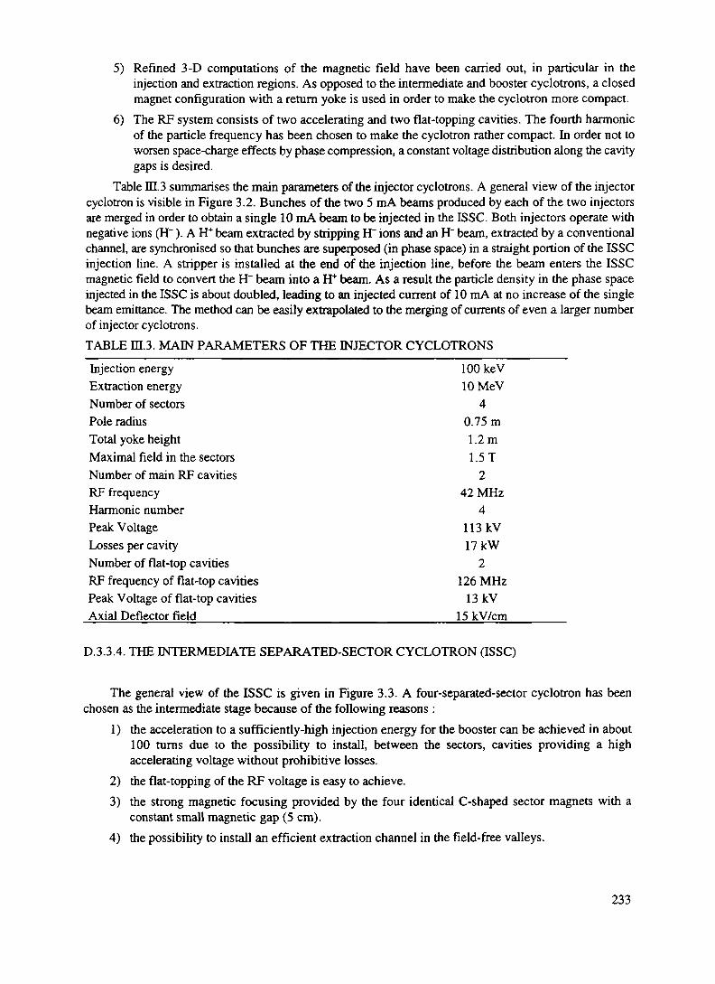
5) Refined 3-D computations of the magnetic field have been carried out, in particular in theinjection and extraction regions. As opposed to the intermediate and booster cyclotrons, a closedmagnet configuration with a return yoke is used in order to make the cyclotron more compact.
6) The RF system consists of two accelerating and two flat-topping cavities. The fourth harmonicof the particle frequency has been chosen to make the cyclotron rather compact. In order not toworsen space-charge effects by phase compression, a constant voltage distribution along the cavitygaps is desired.
Table ffl.3 summarises the main parameters of the injector cyclotrons. A general view of the injectorcyclotron is visible in Figure 3.2. Bunches of the two 5 mA beams produced by each of the two injectorsare merged in order to obtain a single 10 mA beam to be injected in the ISSC. Both injectors operate withnegative ions (H~). A H+ beam extracted by stripping H" ions and an H" beam, extracted by a conventionalchannel, are synchronised so that bunches are superposed (in phase space) in a straight portion of the ISSCinjection line. A stripper is installed at the end of the injection line, before the beam enters the ISSCmagnetic field to convert the H~ beam into a H+ beam. As a result the particle density in the phase spaceinjected in the ISSC is about doubled, leading to an injected current of 10 mA at no increase of the singlebeam emittance. The method can be easily extrapolated to the merging of currents of even a larger numberof injector cyclotrons.TABLE m.3. MAIN PARAMETERS OF THE INJECTOR CYCLOTRONS
Injection energy lOOkeVExtraction energy lOMeVNumber of sectors 4Pole radius 0.75 mTotal yoke height 1.2 mMaximal field in the sectors 1.5 TNumber of main RF cavities 2RF frequency 42 MHzHarmonic number 4Peak Voltage 113kVLosses per cavity 17 kWNumber of flat-top cavities 2RF frequency of flat-top cavities 126 MHzPeak Voltage of flat-top cavities 13 kVAxial Deflector field_____________________________15kV/cm______
D.3.3.4. THE INTERMEDIATE SEPARATED-SECTOR CYCLOTRON (ISSC)
The general view of the ISSC is given in Figure 3.3. A four-separated-sector cyclotron has beenchosen as the intermediate stage because of the following reasons :
1) the acceleration to a sufficiently-high injection energy for the booster can be achieved in about100 turns due to the possibility to install, between the sectors, cavities providing a highaccelerating voltage without prohibitive losses.
2) the flat-topping of the RF voltage is easy to achieve.3) the strong magnetic focusing provided by the four identical C-shaped sector magnets with a
constant small magnetic gap (5 cm).4) the possibility to install an efficient extraction channel in the field-free valleys.
233

FIG. 3.2 General view of the injector.
FIG. 3.3 General view of the ISSC.
234

The choice of the injection energy into the ISSC is certainly one of the most important parameterswhich influences the overall performances of the cyclotron complex. The space charge effects are strongat low energy. They are present in both transversal and longitudinal directions of the beam. Figure 3.4shows the simulation of the evolution of the accelerated beam in the radial-longitudinal plane during thefirst 16 turns under the following conditions: intensity 20 mA, injection energy 10 MeV, energy spread 0.05MeV, normalised emittances it mm.mrad in both radial and vertical directions. Rat-topping with a thirdharmonic voltage and a shift in phase (-10 RF deg.) with respect to the accelerating voltage have been usedin order to compensate the linear effects of the space charge and increase the longitudinal acceptance(± 15 RF deg.) of the bunch. It has been observed that the beam shape in the r-(|> plane seems to stabilizeafter a certain number of turns (cf. Figure 3.4). The beam radial spread is about ±15 mm in the extractionregion. The result of these simulations is that a nominal 10 mA beam can be handled at an injection energyof the order of 10 MeV.
PhM* RF (OtgrM)
FIG. 3.4 Beam evolution in the r-(f> plane for the first 16 turns.
Acceleration of the beam is provided by two main resonators located in opposite valleys giving anenergy gain per turn of 0.6 MeV at injection and 1.2 MeV at extraction, increasing the beam energy from10 MeV to 120 MeV. The RF frequency of the accelerating (main) cavities has been chosen equal to 42MHz, which corresponds to the sixth harmonic of the particle revolution frequency in the cyclotron. Dueto the large (30 RF deg.) beam phase width, flat-topping cavities would operate on the third harmonic ofthe main cavities i.e. on the eighteenth harmonic of the revolution frequency.
Double-gap cavities have been selected (as opposed to single-gap) because their radial extension ismuch smaller, thus leaving more space in the centre of the machine for the bending and injection magnetsand the beam diagnostics. A voltage (or phase compression) ratio of 2.0 is used between injection andextraction. In order to reduce the number of turns in the cyclotron and to have sufficient turn separation,accelerating voltages of 170 kV and 340 kV are required at injection and extraction. The maincharacteristics of the RF cavities are given in Table ffl.4.
The shape of the cavities has been defined with the help of the 3D electromagnetic code MAFIA [42].Models of the main and flat-top cavities have been respectively built at 1:3 and 1:1 scales in order to check
235

the computations with MAFIA. These models are of the low-power type and are mainly made of wood andcopper. Photographs of the accelerating and flat-topping cavity model during assembling and measurementsare shown in Figure 3.5.
For a current of 10 mA, the power to be delivered to each main cavity of the ring cyclotron isestimated to be about 770 kW (550 kW beam power and 220 kW cavity loss), which correspond to about1.1 MW electrical power load (assuming a 70% DC to RF conversion efficiency). The beam power to beabsorbed by each cavity is 65 kW, which is about seven times the power dissipated in the walls (9 kW).
The injection channel of the ISSC cyclotron brings the beam from outside the cyclotron to the firstRF cavity gap where it is accelerated. It starts after the stripper which is located at the end of the beam linethat transports the combined HYH~ beam from the injectors. The stripped H+ beam is injected in thecyclotron through a valley along a flat-top RF cavity as shown in Figure 3.6. When it reaches a radius lowerthan the injection radius it is deflected in a first bending magnet BMI1 in the clockwise direction (seen
TABLE DI.4. MAIN CHARACTERISTICS OF THE ISSC CYCLOTRON RF CAVITIES
_____________________________Main cavities________Flat-top cavities___Number of cavities 2 2Type of cavity A/2, double-gap, tapered A/2, double-gap, tapered
walls walls
FrequencyCavity heightCavity lengthVoltage at injectionVoltage at extractionQuality factorLosses/cavityBeam power/cavityTotal power/cavityTotal electric power/cavity(70% efficiency)
42.0 MHz2.6m2.6m
2xl70kV2x340 kV
13000220 kW550 kW770 kW
1.1 MW
126.0 MHz (h=3)1.0m2.45m
2x20 kV2x40 kV
110009kW65 kW56 kW
13 kW
from above). It is then deflected counter-clockwise, first by a second bending magnet BMI2 and by aelectromagnetic channel EMDI located in one of the cyclotron sector gap so that it reaches the first RFcavity gap where beam acceleration starts. Injecting at 10 MeV allows to take benefit of enough room tolocate the deflecting magnets and use a simple set of deflecting elements with moderate magnetic fieldrequirements. The main parameters of the injection channel are given in Table ffl.5. The location of theinjection and extraction channel elements of the ISSC are given in Figure 3.6.
TABLE Itl.5. ISSC INJECTION CHANNEL CHARACTERISTICS
Elemenl____________________Length (m)_________Magnetic field DB (T)BMI1 0.4 0.4BMI2 0.6 1.0EMDI 0.8 0.25
236

FIG. 3.5 Photographs of the cavity models (top: main cavity during assembling, bottom: flat-toppingcavity during assembling.
The extraction channel allows deflecting the accelerated beam outside the cyclotron. In order toachieve an extraction efficiency of nearly 100% so as to reduce induced radioactivity, the extracted orbitat the channel entrance should be fully separated from the last internal orbit. It consists of an electrostaticdeflector (ESDE), an electromagnetic deflector (EMDE) and a bending magnet (BME). The three channelcomponents are located in two successive valleys. After the beam is kicked outwards from the last internalorbit, by the electrostatic deflector located at the exit of a main RF-cavity it passes through the magnetsector. It is then further deflected to the entrance of the next valley by the electromagnetic deflector. Thelast section is a conventional bending magnet which is located in the valley behind the RF flat toppingcavity as shown on Figure 3.6. Table III.6 gives the main parameters of the extraction channel.
237
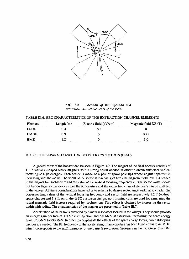
FIG. 3.6 Location of the injection andextraction channel elements of the ISSC.
TABLE ffl.6. ISSC CHARACTERISTICS OF THE EXTRACTION CHANNEL ELEMENTS
ElementESDEEMDEBME
Length (m)0.40.91.2
Electric field (kV/cm)8000
Magnetic field DB (T)0
0.251.0
D.3.3.5. THE SEPARATED-SECTOR BOOSTER CYCLOTRON (BSSC)
A general view of the booster can be seen in Figure 3.7. The magnet of the final booster consists of10 identical C-shaped sector magnets with a strong spiral needed in order to obtain sufficient verticalfocusing at high energies. Each sector is made of a pair of spiral pole tips whose angular aperture isincreasing with the radius. The width of the sector at low energies fixes the magnetic field level Bs neededin the magnet for isochronism and the value of the vertical focusing frequency vr The sector width shouldnot be too large so that devices like the RF cavities and the extraction channel elements can be installedin the valleys. All these considerations have led us to select a 10 degree sector angle width at low radii. Thecorresponding values of the vertical focusing frequency and sector field are respectively 1.2 T (withoutspace-charge) and 1.8 T. As in the ISSC cyclotron design, no trimming coils are used for generating theradial magnetic field increase required by isochronism. This effect is obtained by increasing the sectorwidth with radius. The characteristics of the magnet are presented in Table ITJ.7.
Acceleration of the beam is provided by 6 main resonators located in the valleys. They should providean energy gain per turn of 3.0 MeV at injection and 6.0 MeV at extraction, increasing the beam energyfrom 120 MeV to 990 MeV. In order to compensate the effects of the space charge forces, two flat-toppingcavities are needed. The RF frequency of the accelerating (main) cavities has been fixed equal to 42 MHz,which corresponds to the sixth harmonic of the particle revolution frequency in the cyclotron. Since the
238

beam phase width can be reduced to 15 degrees at the intermediate cyclotron exit, fifth harmonic operationhas been selected for the flat-top cavities. This enables to decrease the flat-top cavity power compared tooperation on the third harmonic. Single-gap cavities are the most suitable candidates because azimuthalspace is restricted and they have high quality factors. This type would be used for both accelerating andflat-topping cavities. A voltage (or phase compression) ratio of 2.0 is used between injection and extractionin order to reduce the number of turns in the cyclotron and to have sufficient rum separation at extraction.The main characteristics of the accelerating cavities are given in Table IDL8. Measurements on theaccelerating cavity model (1:3 scale) which can be seen on Figure 3.8 where the upper part has beenremoved, have been carried out in order to check and determine precisely the cavity characteristics. A verygood agreement has been found between theoretical calculations and experimental results.
FIG. 3.7 General view of the booster ring cyclotron.
TABLE ffl.7. MAIN CHARACTERISTICS OF THE BOOSTER MAGNETS
Number of sectors 10Angular aperture at injection 10 degAngular aperture at extraction 20 degSpiral angle at extraction 12.0 degMagnetic gap in the sector 50 mmOverall external diameter 15.8 mTotal iron weight 3170 tonsMaximum field in the sector 1.8 TTotal electric power ___________________________2.7 MW
239

The power to be delivered to each main cavity of the ring cyclotron is estimated to be about 2.05 MW(1.45 MW beam power and 0.60 MW cavity loss), which corresponds to about 2.9 MW electrical power(assuming a 70% IX! to RF conversion efficiency). The beam power to be absorbed by each flat-top cavityis 220 kW, which is about 20 times the power dissipated in the walls (10 kW). Operating on the fifthharmonic allows to reduce the power absorption in flat-top cavities by a factor slightly larger than 2. Allthe figures above are given for a current of 10 mA.
The injection channel of the BSSC cyclotron is the system that allows to bring the beam from outsidethe cyclotron to the first RF cavity gap where it is accelerated. Its layout can be seen in Figure 3.9, whereboth injection and extraction channel components are visible. The main parameters of the injection channelare given in Table DI.9. The main parameters of the extraction channel are given in Table IE. 10.
TABLE m.8. MAIN CHARACTERISTICS OF THE BOOSTER CYCLOTRON ACCELERATINGCAVITIES ____Frequency (MHz) 42.0Number of cavities 6Type of cavity A/2, double-gap, curved wallsVoltage at injection 550 kVVoltage at extraction 1100 kVQuality factor 31000Losses (estimated) 600 kW
TABLE m.9. BSSC INJECTION CHANNEL CHARACTERISTICS
_______Element_____________Length (m)___________Field drop DB (T)BMI1 0.90 1.70BMI2 0.50 1.30BMD 0.50 1.70BMI4 0.50 1.70BMI5 0.50 1.30EMDI 0.90 0.25
TABLE m.10. BSSC EXTRACTION CHANNEL CHARACTERISTICS
ElementESDEEMDEBME
Length (m)0.800.301.30
B-Field drop (T)-
0.16 TLOT
E-Field (kV/cm)55--
D.3.3.6. BEAM TRANSPORT TO THE EA
The beam extracted from the cyclotron complex has a typical transverse invariant emittance of eim = 2it W6 rad m (the true emittance is £ = s^/fly where /ty is the usual relativistic factor), and a momentumspread of the order of a few 10"4. The current density is roughly uniform in the transverse phase-space,leading to an approximately parabolic current density in a focal point. It is not difficult to transport such
240
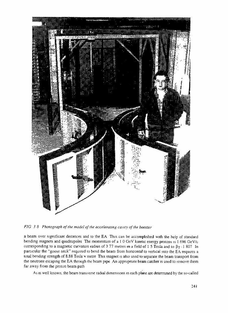
FIG 38 Photograph of the model of the accelerating cavity of the booster
a beam over significant distances and to the EA This can be accomplished with the help of standardbending magnets and quadrupoles The momentum of a 1 0 GeV kinetic energy protons is 1 696 GeV/ccorresponding to a magnetic curvature radius of 3 77 metres in a field of 1 5 Tesla and to py = l 807 Inparticular the "goose neck" required to bend the beam from horizontal to vertical into the EA requires atotal bending strength of 8.88 Tesla x metre This magnet is also used to separate the beam transport fromthe neutrons escaping the EA through the beam pipe An appropriate beam catcher is used to remove themfar away from the proton beam path
As is well known, the beam transverse radial dimensions in each plane are determined by the so-called
241

betatron function Ax(z) = V(fi(z)E/n). Over the beam transport channel, typically P(z)= 20 m and the beamradius is Ax - 5.0 mm. At the EA beam window we want Ax=7.5 cm and therefore (%z) ~ 4000 m. Thisis realised by creating a focal point some L = 30 metres away from the window and letting the beam spread-out naturally because of its emittance. In absence of magnetic fields, the evolution of the /3-function at adistance L from the focal point is given by the well known formula $z) = /%0) + L2/ffO) ~ L2//3(0).Setting ftz) = 4000 m we find yflfOj ~ L2/ ftz) = 0.225 m, which is within reach with the help of anordinary quadrupole triplet1. The beam radius at the focal point is very small, Ax(0) = -/(fi(0)£/n) = 0.70mm. In short the idea is the one of enhancing the angular divergence of the beam by making a very tinyfocal spot7. A long drift space following such a focal point will traduce this angular divergence into a largespot.An appropriate collimator is limiting the aperture available to the beam in this point to about 10 times itsnominal radial size, large enough in order to let thebeam through with no loss in ordinary conditions.In case of the accidental mis-steering of the beam orof a malfunctioning of the focusing lenses, the spotwill grow in size and the beam will be absorbed bythe collimator. In this way the beam window can beprotected against accidental "hot spots" caused bythe wrong handling of the beam. It has beenverified that the defocusing forces due to the beamcurrent do not appreciably affect the beam optics3.
The beam must be transported under areasonable level of vacuum. In our design the lastpart of the beam tube is filled with Pb vapour at thepressure of about 5 x 10"4 Torr, the vapour tensionof the coolant at the operating temperature.Differential pumping and a cold trap will removethese vapours which may be radioactive before theyreach the accelerator. There are no appreciableeffects of this residual pressure on the beampropagation. The need of clearing electrodes will befurther studied, but it appears unnecessary at thislevel.
The extracted beam current and positions arecarefully monitored with non-destructive probes,beam profile monitors and pick-up electrodes. Incase of a malfunctioning of the beam, theaccelerator current can be cut-off very easily on the FIG 39 1^^^ of the injection and extractionaxial injection line of the injectors in times of the channei eiements Ofthe booster ring cyclotron.order of microseconds (the transition time from theion source to the final focus), thus avoiding any damage of the hardware due to beam mis-steering. Analternate beam dump should be provided to which the beam could be dumped during accelerator tuning
'it may not seem entirely obvious to obtain such a low beta value with a beam transport if the actual emittance fromthe accelerator were less than what is quoted. If so, one could easily increase the emittance of the beam through thebeam transport with the help of multiple scattering or with a pair of orthogonal small steering magnets operated athigh frequencies (Lissajous pattern).2 From phase-space conservation in fact through the beam transport the product of the beam size and angulardivergence is a constant.3For instance the CERN-PS Booster routinely handles and transports peak currents of the order of 100 mA, aboutone order of magnitude larger than the present case.
242

and the like.
D.3.3.7. CONCLUSIONS
The above preliminary studies have shown that a 3-stage Cyclotron facility could provide a solutionfor a = 10 GeV x mA beam to drive the Energy Amplifier. Detailed design studies are now beingundertaken in order to clarify the following points in beam dynamics:
1) detailed calculations on the beam dynamics in the injectors in order to assess the intensity limitsof this kind of injector.
2) more refined calculations of the merging of the 2 beams (H+ and H") coming out of the injectorsin order to define the beam characteristics at injection in the ISSC.
3) detailed beam dynamics in the ISSC with space charge effects taking into account the particledistribution after stripping.
Besides this, technical design studies on the three accelerators have to be started, in particularmechanical design studies (vacuum chamber of the large SSCs, optimisation of the shape of the maincavities of the SSCs, etc.). Finally, a conceptual study aiming at increasing the final energy towards 1200MeV is in progress.
243

D.3.4. THE ENERGY AMPLIFIER UNIT
D.3.4.1. INTRODUCTION
The general layout of the EA unit is shown in Figure 4.1 a-b. The main design parameters are given inTable IV. 1. In short it consists of a main vessel, about 6 m in diameter and 30 m tall, filled with moltenLead. The vessels, head enclosure and permanent internal structures are fabricated and shipped as anassembled unit to the site. The shipping weight is then about 1500 tons. Removable internal equipment isshipped separately and installed through the top head. The relatively slender geometry enhances theuniformity of the flow of the molten Lead and of the natural circulation for heat removal.
A high energy beam is injected through the top and made to interact in the Lead near the core. The heatproduced by the nuclear cascade is extracted by the Heat Exchangers. Most of the inside of the vessel isfree of obstructions, in order to permit a healthy circulation of the cooling liquid. The circulation of the
air inlet
stack
grade
Seismic isolator
Main vessel
Contairnent vessel
Hot air riser
Cold air downcomer
Mam silo
Heat exchanger EBDV
Thermal insulating wall
Plenum region
Fuel region
Spallation region
FIG. 4. la General layout of the Energy Amplifier unit.
244

Proton Beam
EBDV
Mam vessel
Contaiment vessel
Hot air riser
Cold air downcomer
Main silo
Secondary coolant
Overflow path
•Normal Coolant level
Heat exchanger
Thermal insulating wall
Lead in the vessel is ensured exclusivelyby natural convection. There are four 375MW, heat exchangers to transfer the heatfrom the primary Lead to the intermediateheat transport system. They must bedesigned in such a way as to introduce asmall pressure drop in order not to slowdown too much the convective coolingflow. The liquid once cooled by the heatexchangers, descends along the peripheryand feeds the lower part of the core andthe target region. A thermally insulatingwall separates the two flows. In order tohave an effective circulation at the chosenpower level (1500 MWJ, the temperaturegradient across the Core must be of theorder of 250 °C. Consequently the volumeinside the vessel can be ideally divided inthree separate regions, namely (1) thetarget/core/breeder region, (2) theconvection draft generating region and (3)the heat exchangers region. A remotelycontrolled pantograph transfer machine isused to transfer fuel between the core,storage racks located in the convectiongenerating region and the transfer station,where they can be inserted or removedfrom the EA vessel by a transfer cask1. Thefuel storage region can be used also as acooling down region for spent fuel. Fuelbundles can be extracted or introducedinto the vessel with the help of appropriatetooling through the top cover of thevessel2. According to previous experiencewith such pantographs, widely used in FIG. 4.1bexisting Fast Reactors, the refuelling timemay require of the order of 1-2 weeks. As described in the text, it is to be performed about once every fiveyears or so.
The proton beam enters the vessel through a long cylindrical evacuated tube of about 30 cm diameter,which restricts to 20 cm before entering the core region. The beam diameter at the window is about 15 cm.The life expectancy of the beam penetration window is estimated to be about 1 year, namely it requiresperiodic replacement, performed extracting the full beam tube. The window is cooled by the main Leadcirculation in the vessel. Accidental breaking of the window will fill the beam tube with molten Lead. Thiswill bring the Energy Amplifier to a halt, since the injected lead will act as a beam stopper. The design ofthe beam penetration channel is more amply discussed further on.
Plenum regionFuel regionSpallabon region
The energy producing unit, side view.
1 Refuelling machines of this type have been applied in the UK's PFR, Italy's PEC and Japan's MONJU. Theconceptual design for the ALMR transfer machine was provided by Ansaldo (Italy).2 As already pointed out, in order to reduce the proliferation risk, the fuel extraction or injection operation may berestricted to the user (owner) of the plant and allowed only to specialized team. This is possible since refuellingoccurs only once about every 5 years and there are no major, active elements which need access during operation.
245

TABLE IV. 1. MAIN PARAMETERS OF THE ENERGY AMPLIFIER
Gross Thermal Power/unitPrimary Electric PowerType of plantCoolantSub-criticality factor k, (nominal)Doppler Reactivity Coefficient, (Ak/AT)Void coefficient (coolant) Ak/(A p / p)Nominal energetic GainAccelerator re-circulated PowerFraction Electric Power recirculated in Accel.Control BarsScram systems(S)Seismic PlatformMain Vessel
Accelerator typeNumber of beamsAccelerator overall efficiency1
Kinetic energyNominal currentNominal beam PowerMaximum currentSpoliation Target materialBeam radius at spoliation targetBeam windowMax. power density in windowMax. Temp, increase in windowWindow expected lifetime
1500625Pool
Molten Lead0.98
-1.37x 10'5
+ 0.12712030
0.0465none
CB4 rodsyes
MWMW
MW
Gross heightDiameterMaterialWalls thicknessWeight (excluding cover plug)Double Liner
Proton Beam and Spoliation Target
306 m
HT-970
2000yes
mm
mmt
Cyclotron1
43%1.0 GeV
12.5 mA12.5 MW20 mA
Molten Lead7.5 cm
Tungsten, 3.0 (1.5) mm113 W/cm2
137 °Cs 1 year
1 Beam power/Mains Load
246

TABLE I V.I (CONT.)Fuel Core
Initial fuel mixtureInitial fuel massCladding materialSpecific powerPower densityAverage Fuel TemperatureMaximum Clad TemperatureDwelling time (eq. @ full power)Average Bum-up
Breeder CoreInitial fuel mixtureInitial fuel massCladding materialU233 stockpile at dischargePower density at end cycle
Primary cooling systemApproximate weight of the coolantPumping methodHeight convection columnConvection generated primary pressureHeat exchangersDecay heat removalInlet temperature, CoreOutlet temperature, CoreCoolant Flow in CoreCoolant speed in Core, average
Decay Heat Passive Cooling (RVACS)
Riser channel gap widthDowncomer channel gap widthTrigger TemperatureEA Coolant max Temperature riseTime to max. Temperature riseOutlet air Temperature (@ max. temp.)Outlet air Speed (@ max. temp.)Air flow Rate (@ max. temp.)Extracted Heat (@ max. temp.)
ThO2 + 0.1233UO2
28.41low act. HT-9
52.85239087075
100
ThO2
5.6low act. HT-9
242.73.0
10,000Nat. Convection
250.637
4x375RVACS
40060053.61.5
1857
500 600 700110 83.5 64.5
17.5 11.2 9.5273 302 334.313.4 14.2 15.252.8 56.1 608.57 9.65 10.84
t
W/gW/cm3
°C°CyearsGWd/t
t
kgW/g
t
mbarMW
°C°Ct/sm/s
cmcm°C°Chours°Cm/sm3/sMW
247

There are no control bars and the power produced is controlled with the beam current. A feed-backsystem ensures that the inlet temperature of the heat exchangers is maintained to the specified value. Forfurther safety however the ultimate shut down assembly which drops CB4 by gravity, is retained, followingthe ALMR design, but slightly modified since the buoyancy of the Lead is much greater than the one ofSodium. This simple scram system is however used to anchor the EA solidly away from criticality whennot operating. In contrast with an ordinary Reactor, in the EA there are no main elements of variability inthe neutronics of the device.
Accidental thermal run-off is ultimately prevented using the natural expansion of the coolant. In caseof an overheating of the EA, its lead level rises at the rate of 27 cm/100 °C. Such a level rise (see Figure4.1b) is used to activate an overflow path which
(1) fills through a siphon a cavity located about 25 m above the Core, in which the proton beam issafely absorbed. Natural convection is sufficient to remove the residual power of the proton beam,which represents about 1/6 of the amount of the initial decay heat.
(2) fills with molten Lead the narrow gap between the vessel liner and the containment vessel,ordinarily filled with Helium' gas at normal pressure (Figure 4.1b). The thermal conductivityincreases from the 0.03 W/m/K of Helium at 1 bar pressure to 16 W/m/K for Pb. This allows thesurplus heat to be dissipated away into the environment through air convection and radiation(RVACS),
(3) scrams the EA to a low lvalue. Safety is also enhanced by the strong negative void coefficient andthe negative temperature coefficient (Doppler) of the fuel which operates at relatively lowtemperatures.
These passive safety features are provided as a backup in case of failure of the active systems, basedon the ultimate shut-off of the proton beam from the accelerator, which brings to an immediate stop thefission generated power of the Amplifier. These functions are achieved by passive means without operatoraction. The key processes underlying these functions are governed by thermal expansion, natural circulationof molten Lead, natural air circulation on the outer containment surface, and thermal radiation heat transferwhich becomes very effective at elevated temperatures. Our design integrates all these effects into anefficient passive safety system which can accommodate primary coolant flow loss and loss of heat removalof secondary transport system with benign consequences on the Core, which can survive with no damage.
The various main components constituting the EA will be separately discussed.
D.3.4.2. MOLTEN LEAD AS SPALLATION TARGET AND COOLANT
Lead constitutes an ideal spallation target, since its neutron yield is high, and it is very transparent toneutrons of energies below 1 MeV. It has also excellent thermodynamical properties which make it easyto dissipate the intense heat produced by the beam. As illustrated in the previous sections, Lead has alsothe required properties in terms of small lethargy and small absorption cross sections to perform thefunction of main coolant. Its very high density and good expansion coefficient make convection sufficienteven for large power production. Finally it is an excellent shielding material and most of the radiationproduced by the EA core is readily and promptly absorbed. There is no need to add additional internalshields or reflectors like in the case of Liquid Sodium to protect structurally important elements inside thevessel. The radiation dose transmitted to the outer Main vessel is very small. Hence, unlike for instance inPWRs, its active life is very long since the neutron fluence is about 1020 n/cm2/year its radiation damageis negligibly small (see Table V.5).
Molten Lead when compared to Sodium, has considerable advantages on safety. The void coefficient
1 The choice of helium gas is justified by the fact that the more commonly used Argon will mix with the radio-activenuclide 4i!Ar produced by the spallation cascade.
248

of Sodium is notoriously positive, namely creation of bubbles increases the reactivity. In Lead the voidcoefficient is negative. The absence of void coefficient problem allows for instance a less flattened shapeof the fuel core. Hence the fuel pins in our design are substantially longer. The boiling point of Lead (1743°C) is also much higher than the one of Sodium (880 °C) and it does not react like Sodium in contact withair. Thermodynamic properties of both molten metals are given in Table IV .2. Saturation vapour pressureand evaporation rate against vacuum are shown in Figure 4.2. Since these quantities are very small(respectively 5 x 10^ Torr and 10'5 g cm"2 s"1) it is possible to keep molten Lead in an evacuated region:this feature is very important to ensure safety for the proton beam. In general, in order to have the samepressure and temperature changes through the core for a given specific power production, the speed ofcirculating Lead must be about 0.38 times the one of Sodium and the pitch in the fuel lattice must beenlarged in order to provide a flow area which is 1.8 times larger. The flow speed of Lead in the core istypically of the order of few m/s. The mass flow through the core is approximately doubled with respectto Sodium. Once these changes are easily implemented the two fluids become essentially equivalent.
Notwithstanding there is little or no experience in the use of Lead as a coolant in Reactors, with theexception of Military applications in the former USSR. For instance the use of molten Lead requires furtherstudies to overcome corrosion. As discussed further on, such a problem appears fully manageable.
TABLE IV.2. MAIN PROPERTIES OF MOLTEN SODIUM AND LEAD.
Melting TemperatureBoiling TemperatureValues at 600 °C
Vapour pressureDensityHeat capacity ( by mass)Heat capacity (by volume)Volumic dilatation coeff. (x 104)Therm, conductivityHeat transfer coeff (x 104)Dynamic viscosity (x 10'3)Surface tension (x 10"3)Electric conductivity (e.m. pumps)
Sodium98880
24.130.811.301.053
3.193862.24
3.60.206146
Lead3281743
5x 10⁻⁴
10.330.15
1.54951.393516.452.31.55431
9.4 xlO'7
°C°C
Torrg/cm3
J/g°cJ/cm3 °Co/-<-l
W/m°CW/m2 °CNs/m2
N/mQ m
Natural Lead exposed to an intense neutron flux in the EA will become activated. Since the Lead iscirculating in the EA this activity will spread from the core to the rest of the device. Fortunately the mainactivation channels are benign. Natural Lead is made of several isotopes, 208Pb (52.4%), ^Pb (24.1%),^Pb (22.1%) and 204Pb(1.4%). If the target is ideally made of pure ^'Pb, a neutron capture will produce^b, which quickly (t,Q= 3.25 h) decays into the stable 209Bi (with a P" decay of 645 keV end point andno Y~ray emission) which will remain as eutectic mixture with the target material. Reactions of type (n, 2n)occur at a level which is few percent of captures and create 207Pb, also stable. Both daughter nuclei arestable elements and excellent target material themselves. A target with natural Lead will produce anappreciable amount of 205Pb from captures of ^Pb and to a smaller level from (n, 2n) of Pb. This elementis long lived (t1/2= 1.52 107 a) and decays into stable 205T1 by electron capture (i.e. by neutrino emission)and no y-ray emission. The Q of the decay is only 51 keV. Therefore its presence is relatively harmless.Neutron capture properties of ^'Pb are unknown and therefore it is impossible to estimate the possibilityof further transformations. However it is likely that the main channel will be neutron capture, leading to
249

Molten Lead
Vapour prreswv
SSO 600 650
Temperature CC)
the stable ^Pb. Finally 203Pb from (n, 2n) of204Pb is short lived (t1/2 = 51.8 h) and decaysinto stable 203T1 by electron capture and y-rayemission. Reactions of the type (n,p) which |are very rare since they occur only for high |energy neutrons, transform Pb isotopes into |the corresponding Thallium isotopes (208Tl, I^Tl, Tl and "Tl) which all p-decay quickly |into Pb nuclei again. &
The situation is more complex in the caseof a Bismuth target. Neutron captures lead toshort lived 210Bi which decays (t1/2= 5.0 d) in2IOPo which, in turn, decays witht1/2 = 138 days to stable 206Pb. There is a long FJQ 42 Saturation vapour pressure and evaporation ratelived (t1/2= 3xl06 a) isomeric state 210mBi, also against vacuum for molten Lead.excited by neutron capture, which decays bya-decay to short lived 206T1 (RaE), which in turn p-decays in stable 206Pb. Reactions of the (n,2n) typewould produce the long lived (t1/2= 3.68 105 a) Bi, which ends up to stable 208Pb via internal conversion.Therefore a Bismuth moderator may present significant problems of radio-toxicity which must be furtherexamined before seriously considering such material as target. Consequently the use of Bismuth or ofBismuth-Lead eutectic mixtures is not considered as main coolant, since Bismuth via the leading singleneutron capture produces sizeable amounts of Polonium which is radio-toxic and volatile at thetemperatures considered for the present study. However such mixture is envisaged for secondary coolingloops because of its lower melting point (125 °C).
Additional fragments are produced by the spallation processes due to the high energy beam (see TableV.10). The toxicity problem is investigated later on, although there is expectation that no major problemsshould arise, provided the appropriate precautions are taken.
D.3.4.3. CORROSION EFFECTS DUE TO MOLTEN LEAD
Molten lead has a significant solubility for many metals (Ni and Mn > 100 ppm; Fe, Cr, Mo, 1 -r 10ppm at 600 °C), which is a rising function of temperature (Figure 4.3). As a consequence, after prolongedimmersion some metals and alloys exhibit a significant deterioration. This is a relevant problem and it mustbe mastered. Some experience on the use of Leadand Bismuth coolants in Nuclear Reactors existsin the former Soviet Union. Extensive studies of ?corrosion of Lead-Lithium mixtures have been fcarried out in the context of Fusion, where a jneutron multiplying, Tritium breeding blanket is Inecessary. For instance a steel type HT-9 |immersed in liquid Lead for 50,000 hours iexhibits a corrosion loss of about 80 urn at about j500 °C [43]. In general Ferritic steels are Jmoderately corroded by lead and in particularthey do not exhibit inter granular damage(typically 30 u after some 3000 hours at 575 °Cfor EM 12). The effect is more pronounced for .,,,-,., c , .... , ,.„ , • , , ,.. . . • n ,on a u FIG.4.3 Solubility of different metals in molten Lead.austemtic steels (typically 120 u after the sameperiod at 700 °C for 800 H, where also mass transfer from the hot to cold regions is observed). Severalsuccessful methods have been devised and demonstrated effective in order to suppress corrosion due toprolonged hot Lead Immersion:
ID4 •
SCO 700
T»mp«r«Uir» CO
250

1) Purification and additives to the liquid metal. When a de-oxidant (225 ppm Mg) is added to lead,no corrosion (0 u) is observed [44] for 15 CD 9-10 loops after 28000 hours (3.2 years) of tests at550 °C. In comparison, the same conditions and no additive would result in a corrosion in excessof 300 \i. Similar results are obtained with Titanium or Zirconium additions to the liquid Lead,where no corrosion is observed after 750 hours at 950 °C [45], in contrast to a 400 u for anuncoated steel. Their beneficial effect is probably related to the formation of nitrides at the interfaceSteel/Lead. The Nitrogen is contained in the Steel, if not treated beforehand. If the Zirconium ismaintained constantly the film is self-healing and its long term effectiveness is preserved.
2) Coating materials. Amongst all the coated materials which have been tested, some seem to givethe best results (i) 15 CD 9-10 low chromium steel coated with plasma sprayed Molybdenum[46][47], where no cracking or dissolution is observed after 1500 hours at 720 °C; (ii) Aluminiumon low Chromium steel [46] where no evolution of the specimen is observed after 1500 hours at750 °C. The coated material is prepared by heating the specimen in contact with a mixture ofaluminium oxide and Aluminium. The coating probably reacts with traces of Oxygen to form a self-healing protective Alumina film; (iii) Z6 CN 91-9 coated with ZrN: this coating is self-healing ifZirconium is added to Lead. These last two possibilities are considered the most promising in viewof to their self-healing capacity.
A small amount of embrittlement may also occur for some alloys (45 CD 4 and 35 CD 7) mostly aroundthe melting point of Lead. Liquid metal embrittlement is a reduction of the fracture strength of a metalstressed in tension while in contact to a surface active liquid metal. This effect is enhanced when someelements such as Sn, Sb and Zn are added to the Lead. As for 15 CD 9-10, no significant embrittlementeffect has been evidenced, even in the 320-350 °C temperature range. Hence specifications on themaximum concentration of certain elements in Lead must be established.
In conclusion there is no doubt that some type of additives and/or coating can effectively stop corrosionin the domain of interest [37]. But an important experimental work has to be done (non isothermalexperiments, effects of cyclic load and so on).
D.3.4.4. THE PROTON BEAM
The proton beam (= 10 mA) after acceleration and beam transport is brought to the Amplifier byconventional beam transport and a 90 degrees bending on top of the vessel. The amount of power of thebeam is comparable to the one envisaged in Neutron Spallation sources under design [48]. The magneticbending helps also in separating leakage neutrons, which are absorbed in an appropriate beam dump. Byswitching off the bending magnets of the last bending, the beam can be safely diverted to an appropriatebeam dump. An appropriate but conventional design of the beam channel allows to perform the switch tothe beam dump in a time of the order of 1 millisecond, which is extremely short in view of the thermalinertia of the Amplifier. The beam, focused by conventional quadrupoles, traverses the whole beampenetration tube and enters in the lead coolant and target through a window made of Tungsten = 3 mmthick. The material has been chosen for its high melting temperature (3410 °C), its excellent thermalconductivity, its high mechanical strength1 and acceptable activation properties. In addition it exhibits anegligible corrosion by molten Lead [49].
The beam spot size is determined by the physical distance from the focal point (= 30 m), where anarrow collimator has been installed (see paragraph D.3.3.6). This arrangement ensures that the beam sizeat the window cannot become abnormally small, for instance as the result of a miss-steering or a failure of
1 The use, for example, of alloys like Tungsten-Rhenium can further enhance the mechanical resistance of thewindow and its weldability. In particular such an alloy has a higher re-crystallisation Temperature (1650 °C vs. 1350°C for pure Tungsten). However it has a considerable disadvantage, namely the thermal conductivity is about a factor2 lower. Note that the operating temperature of the window is about 540 °C and the incipient re-crystallisationtemperature is considerably higher (1150 °C).
251

Proton beam
J, .1Evacuated Volume HT-e
the beam transport. The proton beam window has a spherically curved profile and it is cooled by the bulkof the Lead coolant circulating in the target region at a speed of the order of a few m/sec. At the windowthe proton beam spot size has a parabolic profile, 27 Ar0
2[l -r2/r02] with 2>"o = 15 cm corresponding to a
peak current density of 113.2 A/cm2 for /„= 10 mA. Montecarlo calculations show that the beam depositsabout 1% of its kinetic energy in passing through the window, mostly due to ionisation losses, namely =95 kW, with a peak power density inthe centre of 113 W/cm2, which iscomparable to the peak power densityof the fuel rods. The same Montecarlocalcula-tions, in excellent agreementwith experimental data [50] have beenused in conjunction with a fluid-dynamic code to predict thetemperature and flow of the coolantand the conditions of the window1. Themaximum tem-perature rise for theTungsten and the surrounding Lead isrespectively AT = 137 °C and AT = 107°C. Thermal stresses associated withbeam intensity variation have beenestimated and found largely within thelimits set by the properties of thematerial2. We have reduced suchthermal stresses by reducing thethickness of the window from 3 mm inthe welding of the pipe to 1.5 mm inthe centre of the hemisphere, along the *beam axis and were most of the energy iis released (see Figure 4.4). Moregenerally the energy deposited by the Fig. 4.4 Layout of the beam windowbeam predicted by the Montecarlocalculations is pictured in Figure 4.5. The temperature profiles of the window and of the surrounding Leadare shown in Figure 4.6 for a local Lead speed of 5 m/s. The main parameters of the final beam transportin the Vessel are listed in Table IV.3.
The window should safely withstand accidental power densities which are more than one order ofmagnitude larger than the design value. The expected peak radiation damage in the window after 6000hours at full beam intensity is of 171.1 d.p.a. and the associated gas production are of 1.1 x 10⁴ He (appm)and 9.97 x 10⁴ H (appm). These values are reasonable but suggest that the window should be periodicallyreplaced. A high quality vacuum ( ^ 10"* Torr) in the final beam transport and in the Accelerator is easilyensured by differential pumping and a Cold Trap in which Lead vapour will condense. The low Leadvapour pressure in the last part of the beam transport (~ 5 x 10^ Torr at 600 °C) has no appreciableinfluence on the proton beam which has a high rigidity and penetrating power.
In the unlikely possibility that the proton beam will persist even for instance if the main cooling systemof the Amplifier would fail, a totally passive system (Figure 4.7), driven by the thermal dilatation of theLead coolant will ensure that an enlarged volume region, sufficiently massive to stop the proton beam willbe automatically filled with liquid Lead, the Emergency £eam Dump Volume (EBDV). A shut-off valve
1.5mm
Load How direction
' The thermal hydraulic model has been built using the code STAR-CD [51] and describes at the same time, thethermal behaviour of the lead (liquid) and of the beam window (solid).2 The static structural analysis of the window has been performed using the code ANS YS [52]. The model developedused detailed pressure and temperature maps coming from the thermal hydraulic calculations.
252

Map of the energy deposit of a 1 GeV proton into the FEA target
GeV
-4
10,-6
80
70
60
50
40
30
20
10
0
-10
-2030 40
x (cm)
FIG 4 5 Contour Map of the Energy Deposit of a 1 GeV Proton into the F-EA Target
at the bottom of the volume ensures that the whole beam pipe is not filled with Lead This measure has nocharacter of necessity, but only of convenience Indeed in the unlikely case that the Tungsten windowwould break, liquid Lead will nse, such as to fill completely the pipe and the Emergency Beam DumpVolume, though at a slightly lower level, but still sufficient to kill the beam and bring the Amplifier safelyto a halt It has been verified that convection cooling can safely transfer the heat produced in the EBDV(10 MW) to the main Lead coolant This method is applicable because of the high density (10 55 g/cm3)and the low vapour pressure (= 5 x 10⁴ Torr at 600 °C) of the molten Lead (Table IV 2)
D 3 4 5 FUEL DESIGN AND BURN-UP GOALS
Fuel and Breeder elements are loaded in the form of thin rods (pins) Pins are clustered in sub-assemblies, each with a pre-determmed number of pins, arranged at constant pitch roughly in an hexagonalconfiguration Pins are made of small oxide pellets inserted in a robust steel cladding Each pin has twoextended void regions, called "plenums", one at each end, intended to accumulate the gaseous fissionfragments The pins are kept separate by a wire wrapped around the pin, which also improves thecoolantflow The main parameters of the fuel assemblies are listed in Table IV 4 They are quite similar
253

TABLE IV.3. MAIN PARAMETERS OF THE FINAL BEAM TRANSPORT TO THE VESSEL
Beam pipe material
Beam pipe shape
Beam pipe lengthBeam pipe external diameterBeam pipe thicknessWindow materialWindow shapeWindow external diameterWindow thickness (edge.centre)Beam radius at spallation targetValues for 1 GeV, 10 mA beam
Lead coolant nominal speedHeat deposition in the leadMax. Temperature increase of LeadHeat deposition in the windowMax. Temperature increase of windowMax. power density in windowMax. thermal window stress1 (britt, duct)
HT9
cylindrical
-30203
Tungstenhemispherical
203.0, 1.5
7.5
5.06.9710795137113
48.2, 82.2
mcmmm
cmmmcm
m/sMW°CkW°CW/cm2
MPa
550
500-
450-
Wlndotr fnner surface)
Lead at the windtnr
to the ones used in Fast Breeders(FB).But in order to adapt these wellproven designs to our case wemust (1) modify the pitch betweenpins to the different thermo-dynamical properties of the Leadcoolant when compared to Sodiumand (2) reduce the coolantpressure losses through theplenum region. The temperatureand pressure drop across the coremust be adjusted to therequirements of convectivecooling. We have chosen twodifferent, subassemblies withdifferent pitches: a wider pitch is FIG. 4.6 Temperature profiles of the beam window and theused in the central part of the core surrounding Lead.where the specific power is larger.The flat to flat distance is the same for all sub-assemblies but the number of pins is slightly different toaccommodate the two different pitches.
The bum-up of an ordinary reactor varies from the 7 GW x d/t of a natural Uranium fuel of CANDUreactors to the 30 -r 50 GW x d/t of enriched Uranium in PWRs. The fuel burn-up of the EA is of the order
30030 40 50 60 70 90
Angle from the beam axis (degree)
1 Tensile strength of Tungsten at 550 °C: 380 MPa
254
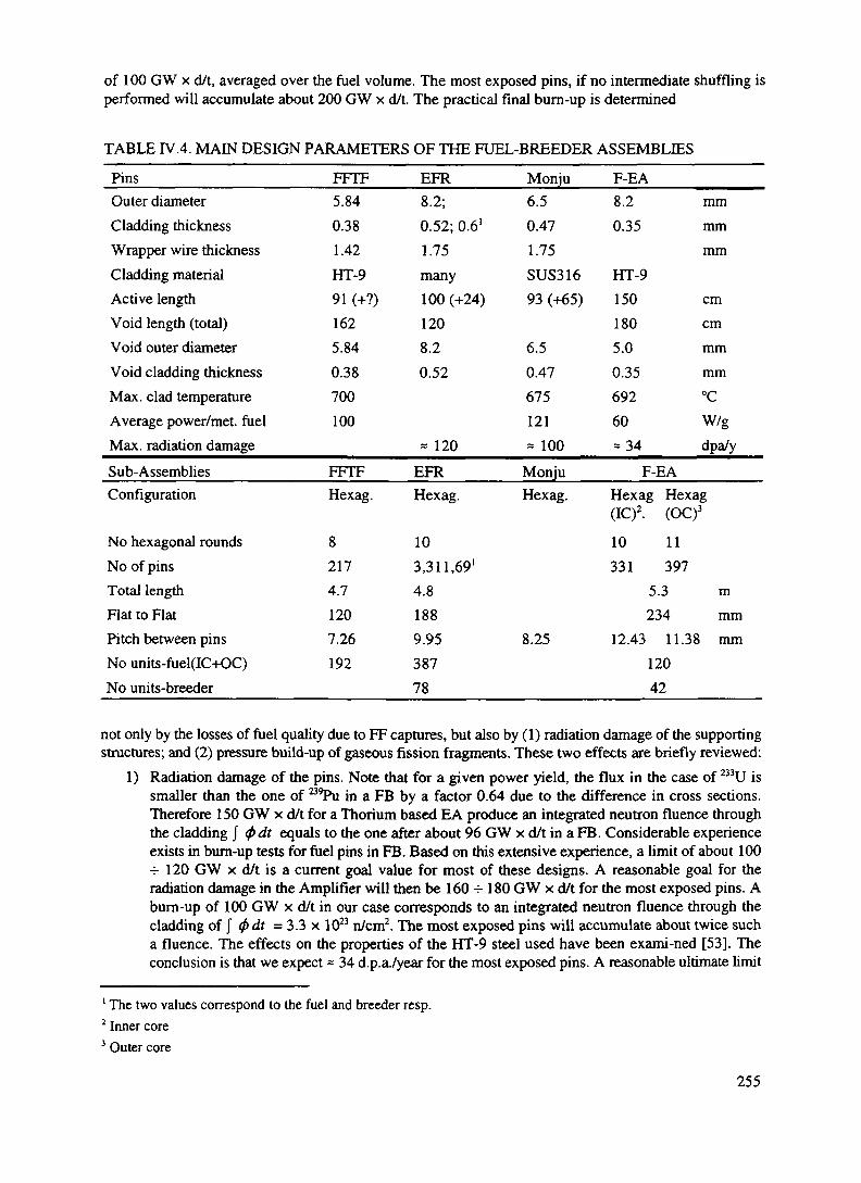
of 100 GW x d/t, averaged over the fuel volume. The most exposed pins, if no intermediate shuffling isperformed will accumulate about 200 GW x d/t. The practical final burn-up is determined
TABLE IV.4. MAIN DESIGN PARAMETERS OF THE FUEL-BREEDER ASSEMBLIES
PinsOuter diameterCladding thicknessWrapper wire thicknessCladding materialActive lengthVoid length (total)Void outer diameterVoid cladding thicknessMax. clad temperatureAverage power/met, fuelMax. radiation damageSub-AssembliesConfiguration
No hexagonal roundsNo of pinsTotal lengthFlat to FlatPitch between pinsNo units-fuel(IC+OC)No units-breeder
FFTF5.840.381.42HT-991 (+?)1625.840.38700100
FFTFHexag.
82174.71207.26192
EFR8.2;0.52; 0.6'1.75many100 (+24)1208.20.52
« 120
EFRHexag.
103,311,69'4.81889.9538778
Monju6.50.471.75SUS31693 (+65)
6.50.47675121« 100
MonjuHexag.
8.25
F-EA8.2 mm0.35 mm
mmHT-9150 cm180 cm5.0 mm0.35 mm692 °C60 W/g= 34 dpa/y
F-EAHexag Hexag(1C)2. (OC)3
10 11331 397
5.3 m234 mm
12.43 11.38 mm12042
not only by the losses of fuel quality due to FF captures, but also by (1) radiation damage of the supportingstructures; and (2) pressure build-up of gaseous fission fragments. These two effects are briefly reviewed:
1) Radiation damage of the pins. Note that for a given power yield, the flux in the case of 233U issmaller than the one of B9Pu in a FB by a factor 0.64 due to the difference in cross sections.Therefore 150 GW x d/t for a Thorium based EA produce an integrated neutron fluence throughthe cladding / <f>dt equals to the one after about 96 GW x d/t in a FB. Considerable experienceexists in burn-up tests for fuel pins in FB. Based on this extensive experience, a limit of about 100-=-120 GW x d/t is a current goal value for most of these designs. A reasonable goal for theradiation damage in the Amplifier will then be 160 -r 180 GW x d/t for the most exposed pins. Aburn-up of 100 GW x d/t in our case corresponds to an integrated neutron fluence through thecladding of J <f> dt = 3.3 x 10²³ n/cm2. The most exposed pins will accumulate about twice sucha fluence. The effects on the properties of the HT-9 steel used have been exami-ned [53]. Theconclusion is that we expect ~ 34 d.p.a./year for the most exposed pins. A reasonable ultimate limit
1 The two values correspond to the fuel and breeder resp.2 Inner core3 Outer core
255

|To beam transport &accelerator vacuum
Evaporation ratei'5 g /cm2.10'
Emergency beam dumpvolume
(Lead filled)
Normal lead level(atmospheric pr)
Beam focal point
1 meter
Beam collimator
applicable to this material is225 d.p.a. A five year lifetimeis therefore reasonable.Likewise other effects, namelyHe production andembnttlement appear fullyacceptable.
2) The fuel material in form of(mixed) Oxides will undergoconsiderable damage andstructural changes in view ofthe considerable fraction whichis burnt and transformed intoFFs. The behaviour of ThO2 isnot as well known as the one ofthe UO2 which is presentlyuniversally used. However, thethermal conductivity, theexpected mechanical propertiesand the melting point of ThO2are more favourable than in thecase of UO2 and we do notanticipate any major problemFor these reasons we havechosen at least at this stage therather conservative averagepower density of p - 55 W/g1.The most exposed pins willoperate at p = 110 W/g. Thetemperature of the fuelaveraged over the core is then908 °C. The averagetemperature of the most FIG. 4.7 The Emergency Beam Dump Volume (EBDV).exposed pins is then 1210 °C —and its corresponding hottest point 2350 °C, well below the melting point of ThO2 which is 3220 °C
3) Some space must be provided for the fission fragments, which have in general a significantmobility, especially at high temperatures. The pressure build-up is not very different for differentfissionable fuels and therefore the volume of the plenum for the gases due to FFs has beencalculated taking into account the mechanical properties of the cladding under a specified pressureincrease, assuming that all gaseous products escape the fuel. The plenum fractional volume turnsout to be essentially the same as the one of the conventional pin designs for Fast Breeders (ALMR,EFR etc.). The hottest point of the cladding is 707 °C, well below the structural limits of the steelof the cladding2. Note also that, when compared to Sodium cooled pins, we are dealing with asingle phase coolant with negative void coefficient.
We have therefore taken as reference parameters for our design pins (Figure 4.8) which are essentiallythe same as those used in our "FB-models" designs with, however, the following changes
(1) longer fuel pins to improve neutron containment in the core (1.5 m);
Evacuated beam tube(residual Pb vapour pressure
Q 600 "C-5 Id4 Torr)
Tungsten beamwindow & tip
Beam diameter(- 15 cm)
' This value is about one half of what is currently used in SuperPhenix and Monju2 The corresponding value for Monju is 675 °C
256

(2) a larger, variable pitch to accomodate the differences in hydraulics of molten Lead in a convectiveregime. Two different pitches have been used, a wider one for the Inner Core and a tighter one forthe Outer Core;
(3) an appropriate "plenum" to ensure the required bum-up, but with smaller diameter andcorrespondingly more elongated in order to reduce the pressure drop through the core;
(4) cladding made of steel with low activation and small corrosion rate by molten lead (HT-9). Moreresearch work is still required to ensure an effective protection against corrosion ( see paragraphD.3.4.3).
500mm035mm
Steel Cladding T
Fuel Pin Fuel Lattice
Pitch (12.43 mm, 11 38 mm)
Void
Fuel
Void - -•-
Fuel
i LJFIG. 4.8 Pin layout.
The general layout of the two fuel subassemblies is shown in Figure 4.9. Many of these subassemblieswhich have all the same flat to flat dimensions are arranged in a continuous, quasi circular geometry withan empty central region for the Spallation Target assembly and the molten Lead diffusing region. A fewhexagonal elements are left empty for the scram device and other control functions.
The Breeder is designed to compensate for the reduction of the B3U stockpile during the long bum-upand the inevitable losses due to reprocessing. Especially if the EA is started well below the breedingequilibrium, such an additional amount is small. Hence the breeder mass is typically some 20% of the totalfuel mass. For simplicity, the pin and subassembly geometry have been taken to be the same as in the caseof the Fuel elements. Toward the end of the fuel cycle, some significant power is produced also by theBreeder (p = 3.0 W/g), though much smaller than in the Fuel.
During successive fuel cycles, the isotopic composition of the Uranium changes, especially due to theproduction of a substantial amount of 23*U. In order to accomodate the extra mass some additional 20 cmof the fuel pin are left initially empty and progressively filled. Hence for asymptotic fuel composition, theactive length of the fuel pins may be increased to as much as 1.70 m.
257
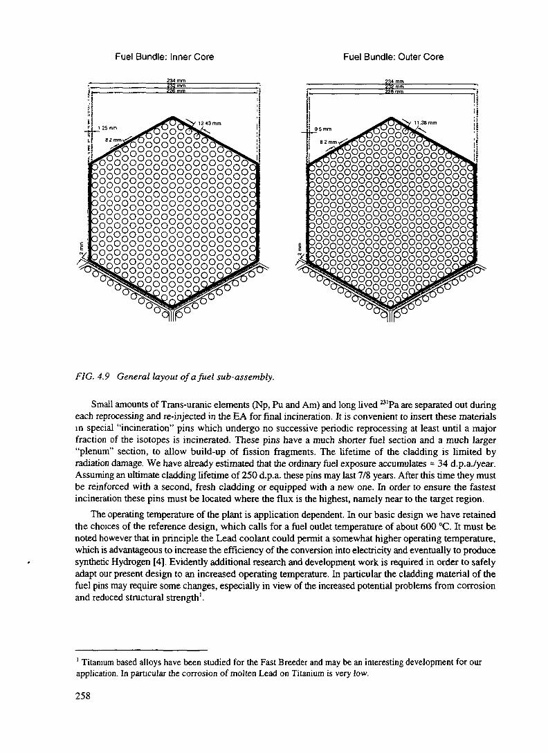
Fuel Bundle: Inner Core Fuel Bundle: Outer Core
234 mm
b°o°o°o°o°o°o°o°o°o°o°o°o°o°0°0°0°0°°o°o
O0o0o0o°ogogogogogn n^n^n^ounununungogogogoggogogogoggogogogogunun^nunununun^Jnuon o n nnunuounuogogogogog°oxoxoxo
OXOXOXOdn^n^o^n^°ogogogoogogogodn^o^o^nugogogogo^ouo^ounXoXo°oqgogogod0X0x0x0°ooXoXoXQ
D0000000000000000000°0000000000000000000000°0
00000000000000000000°0000000000000000000000°00O 0 0 0 0 0 0 0° 0 0 0
F/G. 4.9 General layout of a fuel sub-assembly.
Small amounts of Trans-uranic elements (Np, Pu and Am) and long lived "'Pa are separated out duringeach reprocessing and re-injected in the EA for final incineration. It is convenient to insert these materialsin special "incineration" pins which undergo no successive periodic reprocessing at least until a majorfraction of the isotopes is incinerated. These pins have a much shorter fuel section and a much larger"plenum" section, to allow build-up of fission fragments. The lifetime of the cladding is limited byradiation damage. We have already estimated that the ordinary fuel exposure accumulates = 34 d.p.a./year.Assuming an ultimate cladding lifetime of 250 d.p.a. these pins may last 7/8 years. After this time they mustbe reinforced with a second, fresh cladding or equipped with a new one. In order to ensure the fastestincineration these pins must be located where the flux is the highest, namely near to the target region.
The operating temperature of the plant is application dependent. In our basic design we have retainedthe choices of the reference design, which calls for a fuel outlet temperature of about 600 °C. It must benoted however that in principle the Lead coolant could permit a somewhat higher operating temperature,which is advantageous to increase the efficiency of the conversion into electricity and eventually to producesynthetic Hydrogen [4]. Evidently additional research and development work is required in order to safelyadapt our present design to an increased operating temperature. In particular the cladding material of thefuel pins may require some changes, especially in view of the increased potential problems from corrosionand reduced structural strength1.
1 Titanium based alloys have been studied for the Fast Breeder and may be an interesting development for ourapplication. In particular the corrosion of molten Lead on Titanium is very low.
258

D.3.4.6. CORE LAY-OUT AND MAIN PARAMETERS
The EA is based on a highly diffusive structure (molten Lead) in which a number of fuel elements areinserted. In absence of fuel, spallation neutrons produced roughly in the centre of the device will diffuseand loose adiabatically energy until either they are captured or they escape. If fuel is inserted gradually inthe molten Lead medium, both the captured fraction in Lead and the escape probability will decrease. Thefuel properties will gradually influence the neutronics. We consider as reasonable design parameter anescape probability <.\% and captures in the Lead moderator of the order of 5-6% (Table IV.5). Note thatTABLE IV.5. TYPICAL NEUTRON CAPTURE INVENTORY OF A EA.
Zone-Wise
CoreBlanketPlenumDiffuserBeam Tube + WindowMain VesselLeakage
Fraction
0.88790.04560.02770.03090.00050.00730.0012
Material- WiseFuel (Th + U)Breeder (Th)Lead of which
DiffuserPlenumCoreBlanket
Lead TotalStructures of which
CladdingWindowMain Vessel
Structures TotalLeakage
percentage(48.75 %)(12.11 %)(37.13 %)(2.01 %)
percentage(83.28 %)(1.03 %)(15.69 %)
Fraction0.84930.0427
Abs. Fraction0.03051750.007580860.023243380.00125826
0.0626Abs. Fraction0.037809120.0004676
0.007123260.04540.0012
in an EA the neutron inventory is of primary importance and that these losses must be as small as possible.While in an ordinary PWR losses can be easily compensated with a more enriched fuel, the necessity offull breeding does not offer much degrees of freedom in an EA. On the other hand the void coefficient formolten Lead is negative and therefore the rather awkward measures ordinarily taken in a Sodium cooleddevice are no longer necessary. In particular one does not need to make the shape of the fuel core "pancake"like. A more spherical profile improves the neutron containment and hence the losses in the moderator.
Because of the long migration length in the Lead medium, these parameters are largely independenton the detailed geometry of the fuel and depend primarily on the fuel and diffuser masses. The core can beideally divided into three concentric regions. The first region (the Spallation Target) has no fuel and it is
259
naturally filled by the molten lead. In this volume beam particles interact to produce primary neutrons. Theradial size of such a volume has to be sufficiently ample in order to ensure that the neutron spectrum ismade softer by the occurrence of (n,n') inelastic interactions in Lead. In this way the spectrum at the firstfuel element is softened sufficiently as to ensure a minimal radiation damage to the structural materials andto unifonnise by diffusion the vertical illumination of the fuel pins. We have chosen a radial distance ofthe order of z 40 cm. With this choice, the calculated spectrum at the edge of the target region is notappreciably different from the one in the core. The second region is the Main Fuel region, in which avariety of fuels can be inserted (generally subdivided in two parts, the Inner Core and the Outer Core withdifferent pitches), followed by a third region, the Breeder region, initially loaded with pure ThO2 breedingmaterial.
The nominal power of 1500 MW, requires 27.3 tons of mixed fuel oxide at the average power densityof 55 W/g. The duration of the fuel is set to be 5 years equivalent at full power. The average fuel bum-upis then 100 GW d/t-oxide. The main parameters of the Fuel/Breeder core are listed in Table IV.4. Asalready pointed out the breeding equilibrium concentration of B3U, referred to 232Th is ^= 0.126. With sucha high concentration there is obviously no problem in setting the wanted value of k and eventually even ofreaching criticality. However with continued bum-up the fraction of captures due to FFs, AL~ will growlinearly with time, absorbing for instance about 6% of all neutrons at 100 GW x d/t and causing acorresponding reduction in the criticality. The reduction of the multiplication coefficient Ak~= -(r)e/2) ALwill be very large. For instance, if initially we have k = 0.98 and G= 120, after 100 GW x d/t, k = 0.90and G = 26.0. Such fivefold decrease of gain would be completely catastrophic. It is therefore preferableto start with a 233U concentration lower than the breeding equilibrium and let it grow toward such a limitduring burn-up. As already pointed out in paragraph D.3.2.7 one can realise a first order cancellationbetween the approximately linear rise of the FF captures and the exponentially approaching breadingequilibrium. This leads to a much smaller initial ^"U concentration, x = 0-105.
D.3.4.7. CONVECTF/E PUMPING
Convection pumping is realised with the help of a sufficiently tall Lead column in which the warmcoolant from the Core rises as a result of the large value of the Lead expansion coefficient, 1.32 kg m"3K"'.The coolant returns to the Core after being cooled down to the initial temperature by the heat exchangers.The pressure difference generated in the loop by the convective pumping action is given by AP = KAThg,where AT is the temperature change, K is the coolant expansion coefficient, h is the height of the columnand g the gravity acceleration constant. Typically for AT = 200 °C, h = 25 m, we find AP = 0.637 bars!Such a pressure difference is spent in order to put into movement the coolant and in stationary conditionsit is equal to the sum of the pressure drops in the loop, primarily the pressure drops across the Core and theHeat exchangers. The pumping power required to move a volume V = 10 m3/s of coolant with a pressuredifference AP across the Core is W = VA P = 0.647 MW. Such power must evidently be produced bythe convective pump.
In order to dissipate a power q produced by nuclear reactions in the pin with a resulting temperaturedifference AT, the coolant must traverse the core with a speed v given by
v =
where fa is the flow area and p and are cf respectively the density and specific heat of the coolant. Forcylindrical pins of radius r= [r~r ] of the fuel and the plenum respectively arranged in an infinite hexagonallattice of pitch p, the flow area is/a = v3p2 /2-jn2 Neglecting end effects and the temperature dependenceof the parameters, the pressure drop through the core AP consequent of a given flow speed v in the fuelwhich the pump must supply is given by
260

AP=WPS., ,-_o.079x(^Va25; dde \ V ) I I e,P
where x is a geometry dependent factor, / = lf+ /pthe pin length, divided in the fuel section and the plenumsection; r\ is the friction factor, function of the Reynolds number, which in turn depends on the viscosityu.; de=[dej,de ] is the effective diameter of the fuel and the plenum and, function of the coolant flow areafa ~\frfp\ an<^ °f ^e so-called wetted perimeter. Additional corrections which typically amount to amaximum of 8% are due to the abrupt changes of the coolant flow area:
AP =
/. J
+2J
where /„ is the free flow area. With these corrections, the results of the formula [54] are in excellentagreement with the full hydrodynamic code COBRA [55].
In practice we take the temperature difference AT as an input design parameter, which determines theprimary pressure difference APfamy for a givenconvective pump column of length L. Such pressuredifference must get the coolant through the Core, theheat exchangers and the full loop (> 2L long) at asufficiently high speed as to transfer the large 5amount of heat produced from the Core to the isecondary loop. In order to provide sufficient margin ffor the other pressure drops, somewhat arbitrarily we *have set the pressure drop across the core to0.7 AP , setting in this way the pressure and thepump'temperature differences across the core. The pitch
f t t • I I • 1 • 1 mm inwn;size of the lattice can be adjusted next in order to setthe coolant speed v through the core to the value FIG. 4.10a Power density in the pins as a functionrequired by the actual power density and by AT. of pitch.The resulting pitch and coolant speed as a functionof the power density in the pins is given in Figure4.10a and Figure 4.1 Ob for L= 25 m and differenttemperature differences in the range 150 °C to 250°C. They appear quite acceptable.
Since the power density produced in the fuel Irods is falling about linearly with the inverse of the I «°radius, the resulting pitch will be a smooth functionof the core radial co-ordinate, leading to a pitch sizedecreasing with radius. In practice and in order topermit the same flat to flat dimensions for the fuelbundles across the core and a given fuel pin radius, _r_ „ ,„, „ , . . , . ,-, „ .,. , ° . , . ,. _ FIG.4.10b Power density in the pins as a functionwe have actually quantified the pitch into discrete J * J
values corresponding to different number of integer * "rounds of hexagonal shape. This leads to someresidual radial dependence of AT, which is partially absorbed by natural mixing along the convectivecolumn and it should be compensated restricting the flow for instance at the entry of the fuel bundles.Evidently a radial pitch variation affects also the neutronics of the core, which in turn has effects onto thepower density. Hence, all these parameters have to be recurrently adjusted to their optimal values.
261
The motion of the warm coolant in the convective column is the key to the convective pumping andit has been carefully simulated with help of the full hydrodynamic code. The actual temperature and speeddistributions at the exit of the core have been used as input in a simulation of the rising liquid.
The speed and temperature of the coolant gently homogenise along the path through the column asshown in Figure 5.12 in the following section. The programme described in paragraph 5.5 to which werefer for more details reproduces the main results of our simpler analysis.
The previous calculations are made for the nominal power of the EA and stationary conditions. It hasbeen verified that correct cooling conditions persist over the full range of conceivable powers, includingdecay heat and major transients. In general, convective cooling has "self-healing" features, namely thepumping action is directly related to the amount of power to be transported.
In stationary conditions and at the nominal power, the = 10,000 tons of coolant will flow through thecore at the rate of some 52 t/s, corresponding to a turn-around time of the order of 200 seconds for a totallength of the loop of the order of 50 metres. In view of the large mass of the coolant, a considerablemomentum is stored in the coolant during normal operation and it has considerable effect in (fast) changesof condilions.
D.3.4.8. SEISMIC PROTECTION
As already pointed out in order to reduce capital costs and increase flexibility large portions of the EAplant should be standardised. Furthermore, to gain public acceptance, the plant must be reliable and shouldhave passive inherent features. Seismic design can play a major role in achieving a standardised designwhich could accommodate a range of seismic conditions. One approach to standardisation would be todesign a plant using traditional methods for a Safe Shutdown Earthquake (SSE) which envelopes theresponses of 90 percent of existing nuclear sites in the USA. This is the present licensing seismic basis (RC1.60) and it calls for a maximum horizontal and vertical acceleration (PGA) of 0.30 g.
This approach, however, would lead to high seismic loads, especially in components and equipment,and would still exclude for instance California sites and limit the export potential of these plants to highseismic countries such as in the Pacific Rim region. Liquid Metal designs which consist of thin walledvessels designed to accommodate large thermal transients under low operating pressures are more sensitiveto seismic loads and thus the EA would be particularly penalised by this approach. An appropriate designof a modular EA requires to be able to accommodate a variety of seismic conditions expected at a widerange of sites, from deep soil sites with a minimum shear wave velocity to stiff rock sites.
The alternative is to seismically isolate the plant. Several studies performed in Japan have shown thatit would not be possible to design large LMR plants which are economical in areas of high seismicitywithout incorporating seismic isolation [56]. In an isolated plant, the design and qualification of equipmentand piping and their supports become a simpler task than it is today and the impact of seismic design onpreferred equipment layouts is minimised. Since the response of isolated structures is highly predictable,the risk of accidents due to uncertainties in the input motions is reduced, safety margin is increased, andplant investment protection is enhanced. Additionally, if seismic design criteria are upwardly revised, forexample due to the discovery of unexpected geo-tectonic conditions, the standard plant design wouldprobably not have to be altered and only the isolation system would need to be upgraded.
Seismic isolation is a significant development in earthquake engineering that is gaining rapid world-wide acceptance in the commercial field [57]. This approach introduces a damped flexible mechanismbetween the building foundation and the ground to decouple the structure from the harmful componentsof earthquake induced ground motion, thus resulting in significant reductions in seismic loads on thestructure and more significantly on equipment within the structure. In recent years, seismic isolation ofnuclear structures has been receiving increased attention. To date, six nuclear power plant units in Franceand South Africa have been isolated. It is expected that seismic isolation will play a major role in the designof the advanced nuclear plants of the future in the US as well as in Japan and Europe.
262

Several technological advancements are responsible for making seismic isolation a practical alternative.These include the development of highly reliable elastomeric compounds used in seismic bearings whichare capable of supporting large loads and accommodating large horizontal deformations during theearthquake without becoming unstable. Additionally, the development of high damping elastomers andother mechanical energy dissipators has provided the means to limit the resulting displacements in theisolators to manageable levels. Other factors include the availability of verified computer programmes, thecompilation of reliable test results of individual seismic isolators under extreme loads, shake table tests forevaluating system response, and validation of computer programmes and confirmation of the response ofisolated buildings during earthquakes [58].
Seismic isolation has been included in the EFR and in the ALMR designs. Most of this work is relevantalso to our case. The ALMR design calls for a seismically isolated platform which supports the reactormodule, containment, the reactor vessel auxiliary cooling system and the safety related reactor shut-downand coast-down equipment. The total mass to be insulated is of the order of 25,000 tons. The fragility ofcomponents appears greatly improved by insulation [59]. Some model tests have confirmed the results ofthese estimates [60]. Our present design can include most of the features of the ALMR design.
D.3.4.9. DECAY HEAT REMOVAL BY NATURAL AIR CONVECTION
Nuclear industry has developed a number of passive natural convection air cooling systems to removedecay heat in the unlikely event that all active cooling systems of a reactor fail [ 11 ] [61 ]. We have appliedthe design made for the ALMR (RVACS) to the EA, in order to study the behaviour of our system in caseofsuch an event1.
The application of the RVACS to the Fast Energy Amplifier is illustrated in Figure 4.1b.In the unlikely case of a scram event in which all the active cooling systems fail to operate, the heat
produced by the fission products decay in the core increases the average temperature of the lead containedin the vessel. Lead expands (the level rising at the rate of 27 cm/100 °C) and when its temperature exceedsa determined safety margin, it overflows into a narrow gap between the main vessel and the containmentvessel. This gap is normally filled with Helium which ensures a reasonable thermal isolation during normaloperations.
The containment vessel is in contact with ambient air entering the system through a cooling channel.Air reaches the bottom of the vessel through adowncomer channel which is thermally isolated froma riser channel, in direct contact with the vessel.
When the lead fills the gap, a good thermalcontact is established between the main and the ?containment vessels, and heat can be transferred to -the air in the riser channel. Air temperature increases, *and a natural circulation starts. Air draft is enhancedif a long chimney (about 30 m) is added at the end ofthe riser channel. The downcomer and riser channelsconsist of two annular regions around the vessel ofrespectively 18 and 57 cm thickness. In suchconditions, for a vessel temperature of 500 °C, the air FIG. 4.11 Decay heat generation and heat removalvelocity attained in the hot channel is of the order of rates during a scram event.10 m/s, corresponding to a flow rate of 53 m3/s. The
1 We built a thermal-hydraulic model using the code STAR-CD [51]. The numerical model simulates the natural convection ofair in the system, by taking into account convective and radiative heat transfer from the surface of the vessel to the air coolingchannel.
263

r,m. .«.,.*»»-.c
average outlet temperature of the air is about 177 °C and the heat removal rate of the order of 6.5 MW,which is linearly dependent on the vessel temperature.
Decay heat is therefore extracted by a simultaneous process of internal (lead) and external (air) naturalconvection, conduction (through the steel of the vessels) and radiation (from the external vessel into theriser channel).
The core decay heat generation and the RVACS heat removal rates during a scram event are shown inFigure 4.11. At the beginning the decay heat generation is at a much higher rate than the heat removal.Consequently, the lead heats up very slowly, thanksto the large thermal capacitance of the F-EA. TheRVACS heat removal rate increases slowly with thegradual increase in the reactor vessel temperature.When the decay heat generation rate and the heat _ 70°removal rate are equal, the system reaches its highest |temperature. From then on, the removal rate exceeds |the decay heat generation rate, and the average | «°°-temperature of the vessel slowly decreases.
The thermal transient experienced by the F-EAvessel for different starting temperatures is shown in !
Figure 4.12. It consists of a slow increase over manyhours to a peak temperature followed by a gradual _, _ „ _ ,cool down. The peak temperature is reached much FIG~4J2 Evolution °fthe vessel ^mperature durmgearlier (and has a lower value compared to the a scram even •starting temperature) in the case of higher starting temperatures, since the heat removal rate is higher.
The RVACS is based on the natural mechanism of lead dilatation and air convection. It is thereforecompletely independent on active components or operator actions, and insensitive to human errors.
D.3.4.10. MISCELLANEA
The on-line, continuous determination of the multiplication coefficient k is essential in order to monitorthe correct operation of the EA. The method we propose is based on the lifetime of the fast neutrons aftera sudden shut-off of the proton beam (source). This is easily performed gating-off the ion source for aperiod of time of the order of a few hundred microseconds. The effects on the RF-cavities of suddenlyremoving the beam load is still being investigated, but it should be manageable by the control system. Thetime of the neutron activity is roughly exponential, with a time constant proportional to l/(l-k). Monitoringof the k-value can be performed continuously as a part of the standard operation mode of the Accelerator.
Scram devices are used to anchor the k of the EA to a sufficiently low value during shutdowns,emergencies, etc. This is performed with the help of a series of blocks of CB4) conveniently locatedthroughout the Core. This material is very effective: about 20 kg of CB4 diffused uniformly throughout thecore produce a reactivity change Ak = - 0.04. There are three types of such devices: (1) ordinary scram,performed with an appropriate, fast-moving mechanical device, (2) emergency scram, based on the designof the ALMR "ultimate shut-off in which many small spheres of CB4 are dropped by gravity inside anevacuated tube which descends to the Core, and (3) the Molten Lead Activated Scram (MLAS), associatedwith the siphon overflow triggered by the excessive expansion of the Lead and consequent level increasein the vessel. As already amply discussed, this trigger activates also the RVACS to convey the extra heatto the surrounding air and blocks the proton beam from entering in the core region, filling with Lead theemergency beam dump volume (EBDV).
The conceptual design of the MLAS is shown in Figure 4.13. If the molten Lead is penetrating throughthe siphon, RVACS dedicated volume etc., a small fraction fills the long thin tube descending down to wellbelow the core region. At this depth the pressure of the liquid will be of the order of 30 atm, which is amply
264

Lead Overflowinlet
= 4 1 cm. L = 1 5 m)Inserted Position(Lead In Tube)
B4C rod pushed upwardsby the Lead pressure
4 1 cm, L = 1 5 m)Sand-by Position(No Lead n tub*)
sufficient to push upwards the CB4 blocks well G.S overflowinside the core. A second tube is used to exhaust theneutral gas (Helium) which is normally filling thetubes. The CB4 blocks, in presence of Lead, will beheld firmly in place by the buoyancy of the liquid.
A lead purification unit is needed to removeimpurities from the liquid and to ensure that therequired additives against corrosion are effective.The detailed parameter list of this device is for themoment largely unknown, pending the results of thecorrosion studies (see paragraph D.3.4.3). Some wayas to heat-up the Lead whenever appropriate is alsonecessary.
The heat exchangers are relatively conventional,except that they must be designed in order tointroduce a small pressure drop across the primarycircuit in order not to hamper natural convectivecooling. At this stage we have assumed that thepressure drop is about 1/3 of the one across the mainCore. We have verified that this choice is not criticalto the performance of the convective cooling. Wehave indicated that the primary coolant should notcontain an appreciable amount of Bismuth because CT/^ ,,-,,-, , r\ • st*r*c, • ., ™_. - j FIG. 4.13 Conceptual Design of MLAS.of activation problems. This precaution does notapply of course to the secondary loop which can be filled with a Lead-Bismuth eutectic mixture. The Pb-Bieutectic mixture has a melting point in the vicinity of 125 °C and it has been chosen to avoid freezing ofthe coolant in the transmission line.
The EFR design has foreseen a convection driven cooling loop which performs a function similar tothe RVACS. If considered necessary it could be added also to our design, although it is introducing aduplication which may be redundant. It could be considered as an alternative to the RVACS system. In theEFR design the decay heat is extracted by six additional heat exchangers of 15 MW each which rejectexcess heat directly in the environment. These Hired Cooling Systems (DCS) consist each of a (Lead-Bismuth eutectic mixture) filled loops. These loops extract heat from the hot pool of the primary moltenmetal by immersed Pb/Pb-Bi heat exchangers and reject the heat to the environment with Pb-Bi/air heatexchangers located well above the pool level. One of these DRC units relies exclusively on naturalconvection heat transfer and natural draught on the air side. The other is normally operated with forcedflow. Each loop is equipped with an electromagnetic pump and two fans in parallel on the air side. Theseactive loops possess passive heat removal, if pumps and fans are off to about 2/3 of that of the active flowmode. A special Pb-Bi heat exchanger freezing protection insures that the temperature in individual pipescannot fall below 140 °C.
A large number of monitoring devices are required to follow the radiation monitoring, neutronics, thehydraulics (speed and temperatures) and the potential corrosions due to molten Lead.
D.3.4.11. CONCLUSIONS
In this section, we have presented the conceptual design of an EA with a power rating (1500 MWt, 675MWJ that is of direct relevance to the modules presently considered by nuclear industry to meet the needsof utilities. Such a machine represents in our view a real breakthrough in the prospects of nuclear energyin setting the highest standards for safe and economical operation, coupled with realistic solutions for wastedisposal and non-proliferation issues.
265

The machine is always subcritical. There are no control bars and in normal operation, the level of poweris controlled entirely by the accelerator beam via a feed-back loop. The separation between the acceleratorvacuum and the active medium (a "frequently asked question") appears entirely solved by a speciallydesigned window that would be routinely changed once a year. Even if the window broke, which isunlikely, there would be no serious consequence and the EA would be brought to a safe halt, even withouthuman intervention.
Conspicuous in our design is the absence of coolant pumps: the heat is evacuated by convection aloneand transferred to the outside world through heat exchangers via a secondary cooling loop. Convectioncooling is a unique feature for such a large power, and is only made possible by the use of molten Lead ascoolant. The absence of pumps has advantages from the safety and maintenance point of view (no movingparts). In fact the whole vessel could be sealed during the long interval (five years) between refuelling asthe owner utility has no valid reason to intervene inside. Obviously this offers an extra means ofmonitoring, by the controlling bodies of non-diversion of fissile material. The economical aspect is alsoimportant. Suppressing the pumping system is a substantial simplification in construction as well as asizeable economy in capital costs.
The bum-up of the fuel is a key parameter in the economic performance of the EA. The EA achievesan average bum-up of 100 GW x d/t, whilst maintaining during that time a practically constant gain at thenominal value of G=120, corresponding to k = 0.98 with no external control devices. This is possiblebecause one can compensate the loss of reactivity due to FF accumulation by starting the EA with less 233Uthan the amount which would correspond to breeding equilibrium. Such a bum-up is matched to theradiation damage and the pressure build-up of fission product gases of the fuel pins. The average powerdensity has been set to the conservative value of 55 W/g which is one half the value considered in FastBreeders. This necessitates of course having a larger fuel load (for the nominal power of 1500 MW, onerequires a 27.3 tons load of mixed fuel oxide) which has no serious consequence since the fuel isinexpensive. On the other hand, the low bum-up rate translates into a rather long time between refuelling(5 years). This long time between access to the fuel has the important consequence of minimising theradiation dose absorbed by workers. There is no need to have a permanent crew on site devoted to fuelchanges and this could probably be the task of travelling crews of specialists, conceivably under some kindof international supervision to insure no possibility of fuel diversion.
A machine designed today should put strong emphasis on safety issues. This has been a primeconsideration during our design. First of all, the machine is safely subcritical, since any reactivity excursionleading to an increase in power output, will be immediately corrected by a strong negative temperatureeffect. The main difference with a Sodium based FB here is the absence of a positive void coefficient whichcould cause the latter to become prompt critical. Then, in the unlikely case of an accident that would notbe corrected by human intervention or electronic feedbacks, passive measure would be implemented relyingon basic properties such as thermal expansion of Lead, gravity, natural convection in molten Lead,circulation of air, and radiation. The result would be to bring the machine quickly to a halt and safely bleedthe radioactive decay heat to the environment. At no point could a temperature increase occur that wouldcause the core to melt or otherwise lead to a radioactive release in the environment.
Molten Lead has in our view considerable advantages over Sodium, and its choice has been essentialto us, not only in the physical principle of a Fast Neutron EA, but also for the inherent safety features whichwe have just discussed. Objections against the use of Lead have often been raised in the past on the groundsof its supposedly corrosive action on steel. We believe that up to the 550 °C - 600 °C region, on which wehave based the present model, there is enough experience (or reasonable extension of known facts) to plansafely on using a known material such as HT-9 for fuel cladding. However, we believe it would bedesirable in the future to go to higher temperatures (800 °C), for processes such as Hydrogen productionor in order to increase the efficiency of electricity production. For that temperature range, further R&Dwould be needed.
266

D.3.5. COMPUTER SIMULATED OPERATION
D.3.5.1. SIMULATION METHODS
Many classic programmes [34] exist which can calculate the neutronic behaviour of a sub-criticalsystem. However such programmes have major limitations, namely (i) they operate on a given concentrationof isotopes, while in our Amplifier the concentration of elements varies dynamically during bum-up or (ii)they are based on multi-group calculation methods and therefore take only approximately into account thenarrow resonances in the Lead Moderator and in the Fuel. Finally the proton initiated cascade involvesmany reactions (spallation etc.) which have important effects on the composition of materials, especiallyat discharge. Therefore, appropriate Montecarlo methods have been developed in which the full evolutionwith time of the Amplifier is simulated.
The high energy cascade has been simulated with the help of the programme FLUKA [50] which isknown to give a very realistic representation of the many processes in the energy interval of interest. Thespallation neutron yield predicted by FLUKA has been compared with experimental data collected atCERN, where a proton beam of different kinetic energies in the interval of interest has been made tointeract with Lead targets of different dimensions [3]. The neutron flux emitted has been measured afterthermalization in water. The results show an excellent agreement between the experimental results and thepredictions of FLUKA [62]. The agreement is typically better than a few percent.
The FLUKA cascade development is, however, still insufficiently accurate to emulate the complexneutronic behaviour below a few MeV. A second programme has been written, based on the ENDF-6 crosssections [30], which follows with Montecarlo technique the fate of neutrons in the Amplifier and thecorresponding evolution of the local composition of the fuel elements. The volume of the Amplifier issegmented in a large number of separate regions with independently evolving concentrations and anaccurate model of the geometry has been used. The validity of our calculations has been cross-verified withmore classic programmes [34]. However all programmes rely on the same cross section data.
While the basic Nuclear Data used in the calculations on the 238U/239Pu cycle have been repeatedlychecked and improved over the years, some uncertainties have persisted on the cross section data requiredto predict the Thorium based cycle. Fortunately a rather precise integral experiment has been carried outin the PSI zero-power reactor facility, PROTEUS [63]. These results indicate that the breedingcharacteristics of heterogeneous 232Th-containing fast reactor cores are predictable to an accuracycomparable to that of 238U-containing systems. Measured and calculated spectra appear in generalagreement with calculations based on cross section data [30]. We believe that the underlying physicsinformation is sufficiently well known and verified to predict the behaviour of the EA.
Neutrons spend a considerable fraction of their life span in molten Lead. Lead cross sections have beenwell measured, but very little experience exists to date on the behaviour of neutrons in a LeadModerator/Reflector. An experiment in which a spallation neutron source is imbedded in a large Lead blockis in progress at CERN in order to compare predictions and experimental data [6].
The Montecarlo simulation starts with a proton beam of specified geometry and a given initialcomposition of elements in the Amplifier. The geometry of the EA is realistically represented. Variousgeometrical components are segmented in smaller units that we denominate as "pixels", in order to be ableto record the differences in composition as a function of the location during bum-up. In the case of mixingliquids, like for instance the molten Lead, a common concentration table is used. The continuous protonbeam is replaced with a limited number of protons which enter the EA at a specified event rate^, = l/tp.The fate of these protons is initially determined by FLUKA in a phase in which a number of spallationneutrons are generated. These neutrons are subsequently followed inside the EA to their final destiny byour dedicated programme. Each particle is given a "weight" w in order to scale up the event rate to thenumber of protons actually introduced by the Accelerator, namely w = i t^e , where obviously i is theproton current and e its elementary charge. Wherever available, a set of 35 possible reaction channels [30],which include inelastic processes like n-n', n-2n, n-p, n-a and so on, are used to construct the development
267

of the cascade. Secondary neutrons produced by these reactions become the source of additional cascades.As a consequence of the cascade produced by each proton, the chemical composition of the target
pixels is significantly affected. We therefore change the composition of each relevant pixel according tothe nature of the interaction, replacing the initial nucleus with the fragments of the reaction and in the caseof fission with the appropriate fission fragments, but with a weight w, namely as if all the protons over thetime tp had produced the same reaction. Clearly this approximation will vanish over a large number ofevents. Spallation products generated by FLUKA are also included.
After the full cascade of a given proton has been followed to its finish line and all pixel concentrationshave been changed accordingly, concentrations of all pixels are evolved over the time interval tp with thehelp of a full Bateman formalism, in preparation for the next proton shot. In particular the complete decaychain for each element is followed up to the stable elements with the corresponding concentrations in thepixels of the relevant new elements, whenever appropriate. The decay schemes for all known elements,including all possible branching ratios is provided by an appropriate database [31].
Typically the programme will operate with some 1200 different nuclear species (mostly fission andspallation fragments) and up to 256 different pixels of a variety of shapes and sizes. The computing speedon an ALPHA computer is of 50 neutron histories/sec. About one week of computer time is needed in orderto obtain adequate statistics on a typical burn-up of 100 GW x d/t, corresponding to about 3 x 10⁶ neutronhistories.
The Montecarlo technique and the evolutive nature of the programme permits to introduce quiterealistic simulations of the operation of the EA. For instance it is possible to adjust the beam current inorder to ensure a specified power output or to simulate power variations and transients. The relevantparameters of the neutronics, (multiplication coefficient k, neutron spectrum, fission fragment poisoning,fuel/breeder ratio and so on) are in this way accurately followed over a specified burn-up. Periodically, thefuel pin location may be shuffled to improve uniformization of burning. At the end of the calculation, thecomplete list of elements in the various parts of the Amplifier is provided and used to study reprocessingand refuelling. The refuelling can also be simulated, introducing appropriate changes in the pixelconcentrations. The asymptotic concentrations after many refuelling and the overall performance of thedevice can be realistically simulated. The activation of the various parts of the EA can be accuratelystudied.
We have verified that the values of the main parameters of a sub-critical device obtained with ourprogramme are in excellent agreement with the results of more classic programmes [34], In particular thevalue of the multiplication coefficient k in the two methods typically agree to better than a fraction of apercent. ~~
D.3.5.2. SIMULATION OF THE STANDARD OPERATING CONDITIONS
We consider first the simulation of an initial load of fuel made of 232Th-oxide with an initialconcentration of pure ^U-oxide, chosen to ensure the wanted initial value of the multiplication coefficientk0. The initial choice of the multiplication parameter is set high enough in order to make the best possibleuse of the current of the Accelerator, but low enough as to avoid that the machine in some circumstancemay become critical. The main parameters of the EA are the ones listed in Table IV. 1. Note that a real lifesituation may be slightly different since the Uranium fuel bred, for instance starting with spent fuel froma PWR (see section D.3.5.3) or coming from a previous cycle, will contain also some other isotopes, like232U, 234U etc. As amply discussed in paragraph D.3.2.8, they are not such as to modify the general featuresof the results, which become more transparent by our simplifying assumption.
In order to simulate as closely as possible the real operating conditions of the EA, the programme can,during execution, change the current of the accelerator in order to ensure a constant power output. This isdone introducing a sort of "software feedback" in which the beam current is adjusted for instance every 100incident protons in such a way as to maintain constant the output power. The typical computer run covers
268

of the order of some 2000 days of operation or abum-up in excess of 100 GW x d/t. The integratedburn-up versus simulated time of operation isshown in Figure 5.1. The proton beam feed-back isthe only control mechanism and control rods areabsent.
In Figure 5.2a we display the acceleratorcurrent chosen by the programme as a function ofthe bum-up in order to produce a constant power of1500 MW (Figure 5.2b). The variations of thecurrent reflect the variation of the gain G (Figure5.3), which in turn is primarily determined by thevalue of the multiplication coefficient k (Figure5.4).
IB ol (ooMranuc) OpmMn
FIG. 5.1 Integrated burn-up versus simulated timeof operation for an initial 233U filling and pre-setregime atk = 0.98. Related parameters of the EA aregiven in Table IV. 1.
TABLE V.I. POWER DENSITY DISTRIBUTION, IN UNITS OF AVERAGED POWER, OVER THECORE. DATA ARE FOR AN AVERAGE POWER DENSITY p = 52.76 W/g OF MIXED FUEL OXIDE.
RadialJ Segm. 1
(Bottom)1 2 3
Segmentation along fuel pins4 5 6 7 8 9
(Top)10
Averageover pin
Fuel section56789101112131415161718
1.421.281.21.121.050.970.910.820.740.660.60.510.440.38
Breeder section:19.0020.00
0.070.07
1.741.581.471.361.291.21.121.010.910.820.710.60.490.4
2.151.881.771.661.521.451.321.191.070.970.830.70.560.46
2.432.181.991.841.711.581.471.331.191.070.920.770.620.5
2.622.352.121.971.791.671.531.41.261.110.950.810.650.52
Power proportional to burn-up.0.070.08
0.090.07
0.100.08
0.110.09
2.622.332.111.971.811.691.541.421.251.120.960.80.660.52
2.412.141.991.861.71.571.461.321.21.060.920.780.630.51
2.11.881 741.631.541.431.31.21.080.950.840.70.570.46
Values for 100 GW x0.110.09
0.090.09
0.090.08
1.71.541.451.351.281.181.11.010.910.80.690.590.490.4
d/t0.070.07
1.41.241.161.11.020.960.90.820.740.660.580.50.420.37
2.061.841.71.591.471.371.271.151.040.920.80.680.550.45
0.070.07
0.090.08
The other two most relevant quantities are the (atomic) concentration of 233U, normalised to B2Th, averagedover the core (Figure 5.5) and the B3Pa (breeding) concentration, normalised to "U (Figure 5.6). As is wellknown, this last concentration is closely proportional to the power density. By inspection of thesefigures,during burn-up we can distinguish two phases.
269

FIG. 5.2a Accelerator current chosen by theprogramme as a function of the burn-up in order toproduce a constant power of 1500 MW. Relatedparameters of the EA are given in Table IV. 1.
I ~
F/G. 5.2b Resulting EA power output as a functionof burn-up with appropriate variation ofaccelerator.
woWMy'fen
F/G. 5.3 Energetic gain G of the EA as a function ofthe burn-up. Same conditions as Figure 5.1.
A first, relatively short initial phase in whicha fraction of the initial 233U is burnt and thebreeding process based on the 233Pa is setting on.During this period the multiplication coefficient,and hence the gain, is dropping typically by Ak =-0.01. This is normally handled by modulatingthe proton beam current automatically through thefeed-back control system. Since the regime valueof k = 0.98 has been set (see Table IV. 1) theinitial value of k at the cold initial start-up will becorrespondingly higher, namely about k0 = 0.99.In real life and provided such a number would beconsidered as too high, one can during this initialphase introduce for instance some small amountsof neutron absorbing, "burnable poison" materials
which an; quickly transmuted and keep the value of k within the specified range. Alternatively the fuellingcan be done in phases, installing inside the core a small fraction of fuel elements only after an initial period( = 1 0 GW x d/t) with the help of the refuelling machine. Note that storage space is provided inside thevessel for such elements.
This initial phase is followed by a regime phase in which the 233U and the other isotopes tendexponentially to the breeding equilibrium and in which the Fission Fragments (FF) captures' grow roughlylinearly with bum-up (Figure 5.7) and their effect on k is almost compensated by the increase inconcentration of 233U tending to the breeding equilibrium (Figure 2.5). One can adjust such a compensationnumerology in such a way as to achieve an almost perfect cancellation over a long burn-up with aremarkably constant value of k and hence of the gain. But towards the end of the chosen bum-up theexponential growth of the 233U concentration flattens out, while the FF growth remains essentially linear,thus causing a drop of the gain and a corresponding increase of the proton beam current required tomaintain a constant power output. The maximum available current is set by the parameters of Table IV. 1and hence it determines the ultimate burn-up of the system without refuelling. This effect can be attenuatedwith more elaborate multiple refuelling schemes. In analogy to standard techniques of PWRs fresh batches
' Of course only those elements for which cross sections are known are accounted for. We believe that the correctionfor the other elements is not very large.
270

0000
0005-
0010-
0015-
0020
OO40
0040
400 ODDM*pr«»d Bwivup OWdA
1000 MOO
FIG. 5.4a Multiplication coefficient k of the EA as FIG. 5.4b Multiplication coefficient k of the EA asa function of the burn-up: linear time scale. Same a function of the bum-up: logarithmic time scale,conditions as Figure 5.1. Same conditions as Figure 5.1.
of fuel are periodically introduced. Such schemes do not seem necessary in our case, since the single burn-up is long enough to reach the expected limit of the fuel elements due to radiation damage and gas pressurebuild-up.
The bum-up is not constant over the volume of the Core. Even if periodic, partial refuelling is notnecessary, it may seem appropriate to shuffle the fuel elements locations every maybe ~ 20 GW x d/t,namely about once a year, in order to uniformise the bum-up of the fuel load. This procedure can beperformed without extracting fuel elements from the tank, using the fuel storage facility as a buffer location.If performed fast enough (for instance ^ 10 days) as not to let a major fraction of the 233Pa decay, itproduces negligible effects on k. We have simulated this with our programme and found no real benefitfor instance in extending the bum-up of the fuel. Consequently at this stage, we have concluded that thisrepresents an additional complication with little or no advantage and we have therefore not applied thisprocedure to our simulations.
The relative power density distribution over the Core for unit fuel mass is shown in Table V. 1. Its radial(r) dependence is roughly linear, as expected because of the value of k (see Figure 2.3b). The (z,f)-dependence is easily parametrized using as a universal parameter (r2 + z2)"2 the distance from theapproximate centre of the source (r = z = 0). This is why the z-dependence flattens out at larger radii.Likewise the concentration of 233Pa in the various pixels of the core is directly proportional to the powerdensity distribution. We have verified that the power distribution does not change appreciably during bum-
FIG. 5.5 Atomic concentration of233U, normalised FIG. 5.6 Atomic concentration of233Pa, normalisedto Th, averaged over the core (Breeding Ratio) as to *»[/, averaged over the core as a function of thea function of the bum-up. Same conditions as Figure burn-up. Same conditions as Figure 5.1.5.1.
271

up in the specified range, namely< 100 GWxd/tSimilar distributions can be generated for the Breeder The concentration of bred a3U rises
approximately linearly with time As already pointed out, such a Breeder is necessary since although therelative concentration of 233U is growing with bum-up, its stockpile is in fact reduced because of the
TABLE V 2 (DIRTY) PLUTONIUM INTO 233U CONVERSION STOCKPILES AT START-UP ANDAT DISCHARGE THE PLUTONIUM ISOTOPIC CONCENTRATIONS CORRESPOND TO THEDISCHARGE AFTER 33 GW x d/t OF A STANDARD PWR WITH INITIAL 235U ENRICHMENT TO33%
Nuchde
238Pu239Pu240Pu^'Pu242Pu
All Plutonium's233TJ
Mass at start-up
67981,636671 631491099
2,800.380
Mass at discharge(kg)
3949323527783
10541,073 11,809
Difference
-2849-1,313-1446-2366-45
-1,727 19+1809
significant fraction of 232Th which is burnt The stockpiles of 233U are shown in Figure 5 8 The total amountof 233U is at the end of the bum-up slightly larger than at start-up Note that the full amount of 233Pa duringfuel cool down will also transform itself into 233U Consequently, there is enough fissile material to starta new cycle at a convenient value of k0
!.„£
£ 001
(hid9
100 110 120 130bM^Md Buin-up QW<M
FIG 5 7 Fraction of all neutrons captured by FIG 5 8 Concentration of the main Actimdes as aFission Fragment products, as a function of the function of the bum-up Same conditions as Figureburn-up Same conditions as Figure 51 51
The concentration of the main Actimdes as a function of the burn-up is given in Figure 5 8 They arein good qualitative agreement with the simpler analytical calculations of Section D 3.2
The simulation programme has been used to explore successive fuel cycles The simulated procedureis the following After 100 GWxd/t the fuel is extracted from the Amplifier and chemically reprocessedUranium and Thorium isotopes are extracted and after a cool-down period of some 200 days to let primarilythe 233Pa decay into 233U, these are used to manufacture new fuel elements, topped up with additionalThorium Although some 12% of the B2Th has been burnt, the stockpile of ^U in the fuel has only slightlychanged We have reloaded in the EA exactly the initial concentration of 233U Since the separation is
272

chemical, the new Uranium fuel will be made of several isotopes. The tiny quantities of 231Pa (4.68 kg), of^Np (400 g) and of Plutonium P'Pu (62 g) and U9Pu (4.6 g)] are separated out and inserted again in theEA for an indefinite period of time until they are essentially incinerated.
The initial multiplication factor k0 of the renewed fuel is extremely close to the initial one and persiststo be so over several fuel cycles, in agreement with the analytic description of Section D.3.2.
Finally we have simulated the effects of power variations. As is well known, any major change ofpower requires that the 233Pa can adjust itself to the new conditions. If the power output is suddenlyincreased (decreased) the value of k decreases (increases) with the characteristic decay time of the Pa (39days). It has been verified that the magnitude of this effect is in good agreement with the predictions ofSection D.3.2.
D.3.5.3. START-UP FUEL CYCLE WITH "DIRTY" PLUTONIUM
There are many ways to initiate the sub-critical operation of an EA. The most naive approach, but mostimpractical would consist in starting with a pure ThO2 fuel. This method is most inefficient, since initiallythe multiplication factor k is hopelessly low and the power of the accelerator will be correspondingly huge.Fortunately large amounts of readily fissile material exist in the form of enriched ^U or of a "waste" trans-uranic elements from ordinary PWRs and either of them can be used as initial substitute for the 233U.
We propose to use for the first fill a mixture of ThO2 spiked with about 14% of "dirty Plutonium" fromthe discharge from a PWR, normally destined to geologic Storage. Our scheme permits to start-up the EAat the nominal power and gain right from the beginning and smoothly evolve from the initial to the regimeconditions essentially in one fuel cycle. At the end of the first cycle, most of the 239Pu is burnt, convertedwith a high efficiency into 233U. The higher actinides can then either follow their initial destiny of geologicstorage, with a significant reduction in toxicity and reduced military proliferation risk or can becontinuously incinerated in the successive cycles until they ultimately fission inside the EA.
The simulation programme has been used in order to simulate the bum up of the initial mixture of"dirty" Plutonium and of Thorium. The fuel is — as previously — made of mixed oxides. Theconcentrations at start-up and at the discharge are given in Table V.2. Americium and Neptunium can befreely added to the mixture with little effects on the over-all performance. The concentration of Plutoniumis chosen such as to produce areasonable value of initial k,,. Duringoperation, a large amount of breedinginteractions occur in 232Th with rapidproduction of 233U, while thePlutonium isotopes are progressivelyburnt. We are witnessing a genuinetransformation of Plutonium into 233U(Figure 5.9). The multiplicationcoefficient k (Figure 2.9) and thereforethe EA gain is now the resultant ofmutual interplay amongst three mainprocesses, namely (1) disappearance ofthe Plutonium and higher Actinides (2)the formation of 233U and (3) theemergence of captures due to FFs. It isa fortunate circumstance that these „ , _ , . „ „ ... .. „. . ,., „. ^ ,. . , , FIG. 5.9 Stockpile of Plutonium ana Americium isotopes as athree effects combined produce a value , . , , , f • - . , - - , j f ,<j • „,. , .,. ,. ,. cr- • . i junction of the burn-up, for an initial fuel made of dirtyof the multiplication coefficient kj
nt . J/ - , , , , , ? . , . _,. . _,. .. . . . . . . . . . , Plutonium (see Table V.2) and native Thorium. The concentrationwhich is almost constant, in spite of , 2 » ? r , • , ,, . , . , . of produced u is also shown.the large changes in concentrations, r
1x10*100 150
htopMd Bum-Up. GW OH
273

although not as constant as in the case of an EA operated with Th-U mixture. Note also that the fast dropof k during the early life of the cycle, due in the case of the Th-U mixture to the formation of the ^Pa isessentially absent in our case, since the initial operation is dominated by the Plutonium. The variations ofk are now sufficiently large to justify some compensatory measure, justified by the exceptional nature ofthe initial EA fuel generation and start-up. The easiest way is to play with the refuelling machine andintroduce the fuel assemblies progressively in the EA.
Because of the "external" contribution of the Plutonium, the burn-up of this fuel load can be extendedwel] beyond the one of the normal cycles and a value in the vicinity of 150-5-200 GW x d/t is appropriate.In order to reach such a long bum-up, it may be necessary to exchange the fuel assemblies during operation,in order to uniformise the radiation damage on the pins. As already mentioned this operation is easilyperformed in a short time.
D.3.5.4. NEUTRON SPECTRA AND ESTIMATES OF THE RADIATION DAMAGE
1x10 1x10³ 1x10" INeutron kinetic Energy. eV
106 1X10'
Neutron flux distribution can beeasily calculated by the Montecarloprogramme by adding the path lengthinside each "pixel". Its energydependence is easily obtained bybinning the accumulated path length 1according to energy. The results have |been cross checked by a less accurate •method in which a standard multi- ^group (reactor-like) calculation hasbeen performed on the structure. Thelatter method does not take intocomplete account the sub-criticalnature of the device, like for instancespallation neutrons. Since it is not anevolutionary programme, it does nottake into account of the variations of MG. 5.10 Neutron flux spectrum in the different material regionsthe chemical composition during bum- of the F-EA. The breeder and the Fuel have similar distributionsup. As anticipated, the high energy with fine resolution due to the resonant structure of the materialcomponent of the spectrum due to the cross sections.high energy beam is quickly attenuatedby the (n,n') inelastic collisions in Lead (Figure 5.10). By the time the neutrons reach the closest structuralelement of the Fuel the spectrum has softened to the point of becoming similar to the one of Liquid MetalFast Reactors' (LMFBRs) for which a considerable experience exists already. For instance the flux 2 100keV (2: 1.0 MeV) is in both cases 55% (10%) of the whole flux. Neutron damage for LMFBRs [64] hasbeen studied in the past theoretically and experimentally, and a large experience up to high fluences hasbeen accumulated. Testing and development of materials for such reactors has arrived at fluences wellwithin the range of the present design (see section D.3.4.5).
Neutron irradiation in structural materials is an important design parameter and it determines their rateof replacement. The main physical and mechanical effects of the irradiation of metals are summarised inTable V.3 [65]. In the case of fast neutrons, for fluences J4>dt < 1022 cm"2 changes are usually undetectable.Structural modifications start to appear at larger fluences, eventually approaching saturation for very largeirradiation. Effects on metals are relevant to our case and they are generally smaller at higher temperaturessince recovery (annealing) of the Frenkel defects produced by irradiation is facilitated. After irradiation one
SuperPhenix (inner core)
274

generally observes an increase of the yield strength and, to a smaller extent, of the ultimate tensile strength.Hence, irradiation results in a decrease in ductility and an increase in the temperature characterising thetransition from ductile to brittle fracture (NDT). This is an important effect in nuclear power systems.
There are several mechanisms by which irradiation may cause modifications besides direct heating. Weshall mention two of them, namely creation of defects in the lattice and gas production. Particles ofsignificant energy traversing the material collide both with electrons and nuclei, which in turn recoil insidethe lattice generating lattice defects. The magnitude of the corresponding effects on properties such aselasticity, can be described in terms of an empirical parameter, the number of displaced atoms (DPA). SuchDPA depends in turn on the total energy spent to cause displacements, Ea, and the (average) energyrequired to displace an atom from its lattice position, Ed:
DPA° (1)
TABLE V.3. GENERAL EFFECTS OF NEUTRON IRRADIATION ON METALS
________Irradiation increasesLength (growth)Volume (swelling)Yield strength (usually)Ultimate tensile strengthNDT temperatureHardnessCreep rate
Irradiation decreasesDuctilityStress-rupture strengthDensityFracture toughnessThermal conductivityYield strengthCorrosion resistanceStrain hardening rate
The denominator Ed is a purely empirical but universal parameter of the material and of which a widerange of values are available in the literature [66] [67]. The energy Ea depends on the spectrum and natureof the incident radiation and on the energy partition between electronic excitations and atomic recoils. Wehave used in our computer simulations the module HEATR of the nuclear data processing code systemNJOY [68]. The partition function used was given by Robinson [69] based on the electronic screeningtheory of Lindhard [70]. HEATR calculates the damage energy production cross section, foE\ (bam-keV).An estimate of the number of displacements per second in the metal is given by:
dpa(2)
where r|=0.8 is the collision efficiency factor and <f> the particle flux (cm'V).Helium, Hydrogen and other light gases are produced in structural materials by nuclear reactions
process with a, p, T and so on in the final state. In the case of fast neutrons (n,cc) and (n,p) reactions havesignificant cross sections. In conditions of large fluence, these locally generated gases may be in sufficientamount as to have a pronounced effect on the mechanical and dimensional properties of components, likefor instance:
- The radiation induced swelling due to vacancy agglomeration (voids), in which the internallyproduced gas acts as a nucleating agent for voids, promoting their growth and stabilising them oncethey are formed.
- The high temperature embrittlement due to inert gas bubbles.- The low temperature embrittlement due to defect clusters-vacancy or interstitial clusters.
275

The "in-pile-creep" producing dimensional changes like swelling.
Swelling and "in-pile-creep" may cause some dimensional changes of the core components which mayeven affect the dynamics of the energy amplification.
We consider next in more detail the radiation damage in two main structural components namely (1)the beam window and (2) structure and cladding of the Fuel Core. Note that molten Lead is not a"structural material" and it is continuously recirculated from a very large mass. Paradoxically, radiationdamage in the highest flux by the highest energy particles can be neglected, evidently with the exceptionof the beam window! Molten Lead acts as a "filter", moderating the most radiation damaging componentsof the spallation spectrum.
The rate of radiation damage in the beam window is comparable to the one in high-yield spallationsources under design and construction (see for instance SINQ [71]). The most severe effect is produced bythe incoming proton beam. Effects due to the secondary neutrons produced by the cascade are small incomparison with the high energy charged particles. According to Eq. (2), the damage rate is given by:
dpa = 3.18xlO'6 ° a I (mA)2EdD2
where D is the beam diameter. Production yields of He and H can be obtained from cross sections andincident flux (current density):
appm = 7.95x1 CT3—— I (mA)
Parameters for a proton energy of 800 MeV and several relevant materials are given in Table V.4. Sincecross sections change only very slowly with energy, these values are applicable to a wide interval of protonenergies and in particular to our design. The relevant parameters after 7000 hours at the nominal (seesection D.3.4.4) peak current density of 113 |u A/cm2 are about 200 dpa, 13150 He (appm), and 116,350H (appm). With these numbers, because of embrittlement and swelling, in order to guarantee safety, thewindow should be replaced after about one year [53]. The periodic replacement of the proton window canbe easily accomplished as a routine maintenance task.
TABLE V.4. PARAMETERS RELEVANT TO A PROTON ENERGY OF 800 MEV (EXTRACTEDFROM REFERENCE [71])
Material
AlSteelCuMoW
(oEJ [barn-keV]
633003309001430
B.I.V]4040305865
oHe[barn]
0.210.320.400.580.58
oH[barn]
0.862.522.584.005.13
It is however evident that some experimental work is required in order to ensure safe conditions ofoperation of this relatively new component which is the beam window. In particular we remark that thepeak beam current density is inversely proportional to the square of the beam diameter. If required by these
276

additional investigations, the beam size could be enlarged without major consequences in the rest of thesystem.
The irradiation effects on the Fuel Core region have been already mentioned. They must not limit themaximum burn-up due to FFs poisoning which has been set to be of the order of 100 GW x d/t. Thiscorresponds to an integrated neutron fluence through the cladding of J<J>dt = 3.3 x 10²³ n/cm2, averagedover the core. The most exposed pins will accumulate about twice such a fluence. Two structuralcomponents deserve consideration namely (1) the Fuel itself, a mixture of ceramic oxides and (2) the steelcladding of the fuel pins and other structural materials holding the pins together.
If Thorium is mixed with Uranium using Thorium-Uranium oxides, the irradiation experience availablefor these components indicates a small incidence on fuel swelling. However, more data needs to becollected to attain a high degree of confidence for long-term performance [53].
It is expected that our cladding material will experience conditions similar to those of an LMFBR at600 -r 700 °C and neutron fluences above 0.1 MeV of about 1023 cm"2. As already mentioned we mustconsider four major effects: (1) radiation hardening, (2) irradiation creep, (3) embrittlement and (4)swelling. Different alloys have been proposed and studied as cladding in these neutron environments: (i)stainless steels (304, 316, 321, 347, Incoloy 800); (ii) Nickel based alloys (Inconel 600, Inconel X750,Hastelloy X, Inconel 718, Inconel 625). Type 316 is the reference material for many LMFBR in-corecladding and structural applications.
In the design of the EA there are the added requirements of corrosion in molten Lead (see sectionD.3.4.3) and the necessity of keeping the activation stockpile to a minimum at long times. For thesereasons we prefer to use instead low-activation HT-9 steel [72]. Ferritic steels (e.g. HT-9) havedemonstrated a high swelling resistance, a good stress-corrosion resistance, and a particularly hightemperature strength which could increase significantly the fuel element lifetime. The rates ofdisplacements and gas production in different material zones of interest are given in Table V.5. Combiningthese with the data of ref. [72] it is expected a swell fraction of = 1 % and a shift in the temperaturecharacterising the transition from ductile to brittle fracture (DBTT) of about 30°C at design fluence. Underthese conditions, our design lifetime of approximately 5 years corresponds to an acceptable radiationdamage level for the fuel cladding.
TABLE V.5. DISPLACEMENTS AND GAS PRODUCTION RATES EN THE ENERGY AMPLIFIER
RegionInner CoreOuter CoreBreederPlenumMain Vessel
Fluence/yl.lxlO23
6.5xl022
2.3x1 022
2.5X10²²
9.7x10'"
dpa/y25153.52.5
0.001
He [appm]/y2.01.50.20.1-
H [appm]/y402731-
D.3.5.5. TEMPERATURE DISTRIBUTIONS AND COOLANT FLOW
The temperatures reached by the different elements of the core are important parameters related withthe safety of the EA. In particular, a safe operation requires the cladding and fuel temperatures to be wellbelow the structural limits of the constituent materials.
The lead temperature distribution along any cooling pin channel can be estimated on the basis of thepin axial power density distribution. The internal temperature of the pin cladding can be calculated addingto the lead temperature the temperature increases from the lead to the outer part of the cladding and fromthere to the inner part. The fuel temperature is then obtained by adding to the internal cladding temperature
277

the increment inside the fuel.For the EA the linear power density axial distribution (q') can be expressed as:
(1)
where z is the axial coordinate, q 'mo. is the maximum linear power density, reached in the middle of the pin(z = z 'm,j), and b is a parameter given by the power distribution shape. Both q' and b are function of the pinradial position in the core. The temperature distribution of lead can be calculated by using the expression
dT(z) _ q\z)favpC
(2)
where T is the lead temperature and/,, u, p and Cp are the lead flow area, velocity, density and specific heatrespectively. In the approximation in which these quantities are kept constant (as an averaged value) thelead axial temperature through the channel distribution is given by
= •*Lead, in
b(z-~(z- >-V- '-mid (3)
The heat flow between the cladding and the lead surface is described by the Newton law of convection
) + q"(z)h
where q" is the surface power density distribution and h is the local heat transfer coefficient which can becalculated as a function of the Nusselt number
Nu{ upC d
= 4.82+0.0185 x p e
V
0827
h=-Nu-k,
de is the effective diameter, defined in section D.3.4.7, and kL is the lead thermal conductivity. By usingfor the surface power density (q") the same z behaviour for the linear power density, the temperatureincrease between the lead and the outer surface of the cladding can be obtained,
T lz) = Tout clatr- ' Lead,b,'•~—(z~zn3 " <-mid
(4)
A similar calculation allows to get the temperature difference between the outer and inner part of thecladding, which depends on the HT-9 thermal conductivity kt and the cladding thickness e, according tothe following expression
278

The temperature increase inside the fuel, without considering the axial pin heat transfer, can be written asa function of the radius and the fuel length:
= T1 r2<r<r,
Where q'"(z) =
"no.
r being the radial position and r,, r2 the fuelpellet radius _and the inner void radiusrespectively. kjhO is the temperatureaveraged thorium oxide thermal conductivity.
The calculations were performed with asimulation programme [73]. The results,which are in excellent agreement with the fullthermal-hydraulic code COBRA [55], give amaximum cladding and fuel temperature of707 °C and 2250 °C, well below 1470 °C and3220 °C, which are the HT-9 and ThO2melting temperatures respectively.
As described in section D.3.4.7 the EAcooling is achieved by convective pumping.The pressure difference generated in the leadloop is sufficient to extract the heat from thecore. For a fixed AT in the core, a variablepitch value is used in order to adjust thecoolant speed through the core to the pinpower density. In practice, however, thepitch value is quantified and there is aresidual radial dependence of AT. Thiseffect is particularly important if the breederis to be included in the same coolant loopand if its pitch value is not drasticallydifferent from that of the fuel, since itspower density is very low. A simple methodof cancelling this residual dependence is todecrease the pressure at the entry of thebundles such as to get the same AT than forthe hottest channel, for which the pressuredecrease is set to zero. For the otherchannels this extra pressure drop increaseswhen the power density decreases. Thisimplies a tuning of the coolant flow rate as
OS
07
06-
- 0.5
<f 04-
\ 03.0.
I 0.2-
0 1 -
Spi/lttnnrapun pitch . 12 43 rrm pneft-fltt
Pnssttn dut to comtcoan pumprip
10 15
Radii dttOTce (aitolmry inl»
FIG.5.1 la Pressure drop inserted as a function of theradial position. As a reference the total pressure drop dueto the Lead column is also displayed.
Sfttiien ' Fudngunreport pitch f T2 43 mm
fiMngon(•»>•"» ayan
10 ISRxtaJ cfcuane* (arb.lr.cy mtt|
FIG. 5. lib Lead velocity distribution as a function of theradial position.
219

implies a tuning of the coolant flow rate as a function of the bundle radial position.The calculations were done by a simulation programme using the expressions already described in sect.
D.3.4.7. The results, pressure drop inserted and lead velocity distribution, are shown in Figures 5.1 la andb. Finally, the speed map at the exit of the core has been used as input in a simulation of the coolant flow.As observed in Figure 5.12, the speed gently homogenises along the path through the lead column.
The convection start-up has, been simulated using a computational model based on the followingexpression
where lf is the fuel length, AP^ium,,, ^core are ^e Pressure induced by the lead in the column and in thecore and AP( are the pressure terms losses due to friction and changes in flow area, as defined in sectionD.3.4.7.The lead outlet core temperature Tm, has been obtained as:
T = T + qout in r f,
where TM is the lead inlet core temperature.The equation was solved by time steps and for each time kPColumn and APCor<, have been estimated by
averaging, with the appropriate weights, the temperatures of the lead in the column and in the core withthe temperatures of the lead leaving and entering the core respectively. Li the model the time of heating thefuel has been neglected and the heat transmission to lead was supposed instantaneous.TABLE V.6. SIMULATION OF CONVECTION START-UP AND SHUT-DOWN (HOTTEST FUELCHANNEL)
Steady conditions:
qst 102 w/gTSl
in 400 °C
Tol» 649 °C
J^__________________________________2.02 m/s___________________Start-up l: Power Density, quadratic for (0 < t < at,2), exponential for at! < t < t,,constant = q" for t,< t
Tmitt 649 +439 e^05", 10<t ,<120T™, = 649 t, > 120Time in which the Lead Tma is reached, in seconds:t(TmJ 0.43 t, 10 <r, <120
Shut-down: Power Density for t < 0, q = q" ; for t>0,q = q"
v(r)(m/s) u(t) =
T Ctlf^C") T (t\ =1 OUt\lA ^~) l ou,\l)
(1^0.2r°-725)
(Tst -Tst)j,st *••* out in'
'n + (l+0.4r0-76)
'Steady conditions reached at t=t,, in seconds1 The results are for a=0.35 but they do not change significantly for other values giving a smooth time dependence.
280

The results show that it is possible toreach the operating power conditions in a fewminutes without overheating the Lead leavingthe core beyond the nominal operatingtemperatures (Table V.6). For start-up timesbelow 2 minutes the lead is overheated, forinstance by about = 20 °C if the start-up isdone in 1 minute or by = 100 °C if it is donein 30 s. Also, after an instantaneous shutdown and without considering the residualheating, the inertia of the coolant is such as tomaintain the lead speed in = 8% of its steadystate value after 5 minutes, and = 3% after 15minutes.
Radius (m)
FIG. 5.12Core.
Velocity map of Lead in the column above the
D.3.5.6. SAFETY AND CONTROL OF FAST TRANSENTS
The safety of multiplying systems depends to a large extent on fast transients caused by accidentalreactivity insertions. To study the power changes in accelerator driven systems a kinetic model dealing withfast transients as a function of reactivity insertion, Doppler feedback and the intensity of an external neutronsource, was developed and programmed.
A kinetic model is given by the diffusion equation, in one energy group. This equation relates thechange in time of the neutron density with the physical constants of the system, specially the reactivity, andhas to consider the prompt and delayed neutron production rates [74]:
*C+SV) CD' 'ac /?dt !-/?($)/? A
-/i.e. (2)
where N is the neutron density, p,, P are the delayed neutron fraction of the i-th delayed precursor groupand the total delayed neutron fraction respectively, X( and C, are the decay constant and the concentrationof the i-th delayed precursor group respectively, p($) is the total reactivity, expressed in dollars, A is theaveraged prompt-neutron lifetime and S(t) is the external source term.
For a sub-critical device, fed by a spallation neutron source, the source term may be expressed as [75]:
= -^E (3)A
where p0< 0 is the total reactivity in the steady state and nip is the number of spallation neutrons densityper source proton. At the steady state the external source term is kept constant. Establishing the k9 effectivemultiplication factor, at this steady state, the n^ value is expressed as:
' .M,
281

S(t) = 0-*o)-
Here N0 is the neutron density at the steady state.The coupled equations (1) and (2) are solved by a numerical method described later. The general
features of the program include time dependence of the total reactivity, prompt neutron generation time andtime size step, and a maximum of six delayed neutron precursors groups. In addition, the total stored energyis also calculated by integrating the reactor power from t = 0 to the time of interest.
The total reactivity of the sub critical device is then a sum of four terms:
cp
where P4V,(0 is the external reactivity inserted, simulating an accident. It is time dependent, usuallyrepresented by a linear or quadratic ramp; PDoppler is the reactivity decrease due to the fuel temperatureincrease (<x < 0) and P(t) is the power density. The reference fuel temperature is the one at the steady state.This effect is very fast, it is therefore the main stability feedback of an external reactivity insertion accidentwhich would rise at high speed. The rapid fuel answer is due to the direct relationship between the powerdensity change with the reactivity increase and the fuel temperature variation, PModdenslt. is the reactivitydecrease (a'< 0) due to the moderator density change, which is a moderator temperature function. Thisnegative reactivity evolves at a lower speed because of the thermal inertia of the moderator. Hence, thiseffect is less important than the one mentioned above.The last equations, necessary to complete the cycle, are the power density and neutron density relationships,and the temperature changes due to a power density variation. The first one is given as
&SfN(t)v—— - ———Fuel density
where £= 3.044-10'" J (190 MeV/fission), v is the averaged neutron speed. Once the averaged powerdensity at the steady state is known (P0) and also the neutron density (N0) is fixed, it is not necessary tocalculate the neutron group constants (S,, v)
(5)
The reactivity reduction by the Doppler coefficient is calculated as a heat generation coefficient [74]. LetPo represent the initial reactivity increase resulting from a step change. If a = -dp/dT is the negative of thetemperature coefficient of reactivity, i.e. a is a positive quantity, the reactivity resulting from a temperatureincrease T is given by
P = Po~aT
Suppose the time scale of the power excursion is such that the heat loss from the system is insignificant.The increase in thermal energy E will then be related to T by
E = CTwhere C is the heat capacity, i.e., mass x specific heat, of the system. Hence,
282

P = PO- (6)
where Y =<x/C= -dp/dE is the negative of the energy coefficient of reactivity. The reactor power P is equalto the time rate of energy change, i.e., dE/dt; it is obtained by differentiating equation (6) with respect totime, so that
dE_dt y dt
It follows, therefore, that
- -yP.dt(7)
The coupled equations (1) and (2) were integrated by discrete time steps. It is important to note thatthe time step has to be of the same order of magnitude as the prompt-neutron average lifetime. Three typesof unprotected reactivity accidents have been considered.
A slow reactivity ramp insertion: the reactivity increases at a rate of 170 $/s for a period of 75 ms(this corresponds to a control rod withdrawal speed of 0.55 cm/ms in the case of a reactor). Afterthis time the reactivity is kept constant.A fast reactivity ramp insertion: the reactivity increases at a rate of 250 $/s for a period of 15 ms(0.81 cm/ms).A thermal run-off of the accelerator, due to a variation in the proton beam intensity. The newsource term is:
S'(f) =
where IQ is the nominal beam intensity and !„„, is the accidental new proton current, increased bya factor 2.
The analysis of this problem allows a comparison with transient calculations obtained for a criticalreactor (Figure 5.13). It gives a first indication of the mitigating effect of using a sub critical acceleratordriven system. The parameters used for theEnergy Amplifier transient study, extractedfrom references [76] [77], are indicated in iTable V.7. Figures 5.14(a-d) show thepower, fuel average temperature andreactivity change in a critical reactor (leadcooled) and in the Fast Energy Amplifiersubjected to a slow reactivity insertion. The fimportant reactivity effects all occur withinone second.
- The power excursion curve whichcorresponds to a critical reactoroscillates and has two distinct peaksin a short time interval. Super T™(™'prompt criticality produces thesepeaks (Figure 5 14b) The power ™7.5.7J LMFBR power excursion benchmark (as definedrises rapidly during the period of '" a comparative NEACRP exercise) assuming a rodsuper prompt criticality and reaches eJectlon accident
283

its peak, 100 times nominal after 7 ms, atthe time when the Doppler effect reduces the reactivityto values below super prompt limit. However, the fuel average temperature continues to rise rapidlyduring 15 ms (due to the thermal inertia of the fuel), until the Doppler counter-reactivity has fullyestablished itself. By this time, the average temperature of the fuel has increased by 50 % (T^, «1250°C), assuming that the heat loss from the fuel is insignificant during the power excursion. Theintegrated power, after 20 ms, measured from the start of the ramp is ~ 0.8 full power seconds.In the case of the Fast Energy Amplifier operated at k = 0.98, the power increases only by 42 %after 15 ms and after 20 ms the power decreases almost proportionally with the neutron sourcestrength. If on the other hand the neutron source is maintained (the accelerator is not shut-off), thepower remains almost constant in this time range. The total energy released during the excursionis much less than for a critical reactor (0.025 full power seconds after 20 ms). The averagetemperature of the fuel rises gradually but at a much lower rate. After 20 ms, the fuel averagetemperature has increased by 8%. Note, that in this case the Doppler reactivity feedback is almostnegligible and very much delayed (appears only after 23 ms). The long time constant of theresponse implies that the heat loss from the fuel cannot be neglected anymore. In fact, there issufficient time (of the order of a few seconds, as estimated by the convection studies described insection D.3.5.5) for the natural convection mechanism to safely adapt itself to the new operatingconditions without occurring any fuel damage.
TABLE V.7. MAIN KINETIC PARAMETERS USED FOR THE ENERGY AMPLIFIER TRANSIENTSTUDY
Prompt neutron lifetime:
A= 2.9xlO'8s
Doppler effect coefficient:
Ak\-^, -1.38xlO-5°C'
AT I ,2! AT! -1.44xlO-7sC'"L I fuel KQ\ *J1 / f u e l
Moderator density change coefficient:
Ak ,9.68x10-5m3kg-'
Ap } if Ak'-
Dens,Md(kg/m3) 1 1 149.7442-1 .3595xTlead (°C)
Tlead€ [400 °C, 900 °C]
( Ap] _ ( Ap } ( ADens]( AT) teud~ \ADens\J AT ) „ -1.37xlO««Cl
The next examples illustrated in Figures 5.15(a-d) and 5.16(a-d) deal with a fast reactivity rampinsertion and a thermal run-off of the accelerator, respectively. Compared to the previous case, the powerpeak values are higher. The power and temperature changes are faster, and so is the response (fuel Dopplerreactivity feedback). The integrated power, i.e. the total energy released during the excursion, is slightlylarger.
284

Fast Energy Amplifier(kef, =0.98)
Time (ms)
: -ooi
-0015
•0.02
-0025
b)
Kelt-1
20 25 »
Time (ms)
Time (ms)
d)
(Beam ON)
(Beam OFF)
to 100 120
Time (ms)
FIG. 5.14 Comparison of power excursions in a critical reactor (lead cooled) with the Fast EnergyAmplifier for an accidental reactivity insertion of 170 $/sfor 15 ms.
J? -001
Time (ms)
K,H - ' Critical reactor t>Doppie< E*- /
, Pooppter Critical reactor
Time (ms)
100 120
Time (ms)
FIG. 5.15 Comparison of power excursions in a critical reactor (lead cooled) with the Fast EnergyAmplifier for an accidental reactivity insertion of 255 $/sfor 15 ms.
285

I
b)
P Doppler
Kgff-1
Time (ms) Time (ms)
_ 120.
§u.t ' "
c)
SS 01ill
d)
(Beam ON)
(Beam OFF)
Time (ms)M M 100 120
Time (ms)
FIG. 5.16 Power excursion and reactivity behaviour during a beam run-off in the Fast EnergyAmplifier
An interesting result of this analysis is the fact that the Fast Energy Amplifier responds much morebenignly to a sudden reactivity insertion than a critical reactor. Indeed, no power excursions leading to highpower levels are possible for positive reactivity additions which are of the order of the sub criticality andsimilarly for a thermal run-off of the accelerator. More importantly, even if the spallation source is stillactive (the accelerator is not shut-off), the relative slow power changes induced could be passivelycontrolled by means of natural convection alone (massive coolant response) thus avoiding anymeltdowTiofthe sub-critical core.
D.3.5.7. COMPOSITIONS AT DISCHARGE
The evolution programme computes the full composition of the elements of the EA during operation.The composition at discharge is therefore directly obtained, with the proviso however that the beam is madeof discrete pulses separated in time. Appropriate corrections have to be introduced if short-livedcomponents, with lifetime shorter than the proton repetition rate (typically 5xl03-r3xl04 s) have to beexactly estimated. In the case of the Fuel discharge also an appropriated, averaged mixture of elementssubstitutes the actual fine structure of the fuel pins and of the lead coolant. Therefore, the dischargecomposition will include also the small amount of new elements produced in the closely surrounding Lead.
The discharge composition of the Fuel after 110 GW x d/t corresponding to approximately 5 years inthe standard operating conditions are listed in Table V.8. We have listed only those elements which havea 1/e lifetime longer than 10 days and an amount larger then 100 mg. The relative scarcity of trans-uranicelements reflects the conditions of the first Fuel cycle. The evolution of the Actinide with fuel cycle hasbeen amply discussed in section 2.9 to which we refer for further details. The FF mass composition issubstantially different from the one of an ordinary PWR for two main reasons, namely (1) the fission yieldsfor 233U and 235U are quite different and (2) incineration of some of the FFs is quite strong for thermal
286

spectrum and it is quite small in our case. We have listed in Table V.8 the ratio of mass yields for the samethermal energy produced by the EA and a PWR after 33 GW x d/t and initial enrichment of the 235U to3.3%. Some of the elements show a ratio very different than 1.
The activation of the Fuel cladding material (HT-9) leads mainly to about 0.2 kg of "Mn (1.24 a), 1.72kg of "Fe (3.95 a), 0.234 kg of 185W (108.6 d) and 2.52 kg of l87Re (6.30xl010a), the last two elements dueto the very small content of just 162.6 kg of W in the steel alloy. Other radioactive elements like Co, 51Cr,59Fe etc. are present in traces at the level of ^ Ig.
The Lead coolant within the core volume accumulates over 5 years of operation about 20.3 kg of ratherinoffensive ^Pb (2.2 x 10⁷ a, K-capture at 0.065 MeV, no y i.e v-emission), some 45 g of ^Pb (7.5 x 10"a) and very small traces of 194Hg (751.9 a),20^! (5.47 a),208Bi (5.32 x 10⁵a) and 210Po (200 d). The verysmall amount of l94Hg is in contrast with the much larger production rate of the same isotope in theSpoliation target (see next paragraph). Its absence evidences the sharp confinement of the spallationprocesses in the target region, away from the fuel core. Radioactive isotopes in the coolant are rapidlymixed in the bulk of the coolant, about 104 tons, leading to very small relative concentrations', in manyinstances measured in units of parts per billion. The fate of these impurities is to a major extentunpredictable and specific experiments are required.
The discharge from the Breeder has to a major extent the same general features as the one from theFuel, with the exception of the much smaller number of FFs and the smaller neutron flux.
The Lead coolant surrounding the Core and Breeder volumes, with the exception of the spallationregion which will be discussed separately, is relatively unaffected by the neutron flux (paragraph D.3.4.2).Two unstable Lead isotopes are present, the long lived ^Pb with 43.71 kg and the short lived (4.7 h) 209Pbwith traces at the level of 1 g. Its modest activation is related to the lower energy and flux in the regionimmediately surrounding the core. Even smaller is the activation of the containment vessel, dominated by55Fe (3.95 a) and 59Fe (64.35 d), with 400 g and 1 g respectively.
The Actinide composition is also radically different from the one for instance of a PWR and itsconsequences need some consideration. The main differences are:
(1) the presence of several Protactinium isotopes. At the design power level, the stockpiles of 233Pa isof 53.25 kg in the Core and of 5.60 kg in the Breeder. This relatively short lived element is thesource of a substantial amount of decay heat, 2.99 MW (2.70 MW in the Fuel Core) immediatelyafter shut-off and decaying with the characteristic 1/e time of 38.99 days. Since the B3Paconcentration is proportional to thepower produced during steadyoperation, its decay heat represents aconstant fraction of this last quantity,initially 0.2 % of the design power.In view of its relatively long decayconstant, the contribution of B3Pa iscomparable to the decay heatproduced by the FFs and it must betaken into account (Figure 5.17). Thebreeding transformation isaccompanied by intense y-emission.More specifically we have calculatedthe time dependence of the y-spectraproduced by Actinides of Table V.8.In Figure 5.18 we give the time
Tnw ttMr ihmdown (hourt)
FIG. 5.17 Effect of 233Pa on the decay heat of the FastEnergy Amplifier.
1 1 kg of dissolved material corresponds to 0.1 ppm in relative mass. Many radioactive impurities which amounttypically to = 1 g, once diluted in the bulk of the coolant, reprresent a concentration of 10'10 by weight in thecoolant.
287

dependence of the y-activity of the Fuel weighted proportionally to energy over the spectrum,namely the number of 1 MeV equivalent y's produced per second. As one can see, the dominantcontribution comes from 233Pa, at least during the early times. A corresponding cooling time ofabout one year is strongly recommended, which also insures that the major fraction of 233Pa hasdecayed into useful ^U. With these provisos, the presence of B3Pa should not introduce additional,specific problems. Other Protactinium Isotopes are some 4.47 kg (including the 0.15 kg in theBreeder) of the long-lived 231Pa (4.74 x 10⁴a), amply discussed in paragraphs D.3.2.8 -=- D.3.2.10and traces (< 1 g) of the short-lived 232Pa (1.89 d) and ^Pa (9.69 h). The long-lived isotope 231Paprimarily produced by fast neutrons through the (n,2n) reaction on the main element 232Th followedby 6-decay, constitutes a considerable source of radio-toxicity and it must be incinerated, re-injecting it inside the subsequent Fuel Loads, as discussed in paragraph D.3.2.10. Fortunately thecross section for neutron capture, leading to 232U is quite large and equilibrium between productionand decay is reached already at the end of the first cycle. This means that a net stockpile of theorder of 5 kg of 231Pa will persist during the whole lifetime of the EA plant as balance betweenproduction and incineration.
(2) The presence of a specific composition of Uranium isotopes, evolving toward an asymptoticdistribution. A relative novelty is the presence of a substantial amount (1.46 kg) of the long livedisotope ^U (99.6 a) produced by fast neutrons and the (n,2n) reaction on the main fissile material223U. As in the case of 231Pa, the concentration of D2\J reaches practically its asymptotic limitalready at the end of the first fuel cycle. As already pointed out, the presence of such an isotope,which has a decay chain prolific of high energy 7-rays is a major inconvenience if some of theUranium fuel were to be diverted to military applications. The y-ray activity of the Fuel is ofprimary importance also during reprocessing and new fuel preparation. We show in Figure 5.18the number of 1 MeV equivalent y's produced per second by the discharge fuel of an EA andcompared with the one of an ordinary PWR. This last curve has been normalised to the sameelectric energy produced in the EA. As one can see, after the cooling down period of about oneyear needed to transform the 233Pa, the y-doses of the spent fuel of an EA are not substantiallydifferent than the one of an ordinary PWR.
(3) The isotopic composition of the Uranium is a rapidly decreasing function of the atomic number.There is essentially no 238U produced, since the previous element, 237U is short lived (9.76 d) andit p-decays into 237Np, which is the main gateway to the trans-uranic elements.
(4) A remarkable scarcity of trans-Uranic elements. Concentrations are fuel cycle dependent and valuesof Table V.8. refer to the most favourable case of the first fuel cycle. The main productionmechanism is neutron capture of the long-lived 237Np producing 238Np, which then quickly (3.06d) decays into 238Pu (127 a). The family of Plutonium isotopes with A z 239 becomes accessibleby successive neutron captures. Even asymptotically, as shown in detail in paragraph D.3.2.9,concentrations decrease rapidly with growing A, because of the competing fission channel at eachstep. Asymptotic concentrations are also many orders of magnitude lower than for instance in thecase of a Uranium driven Reactor. Seven neutrons are needed for instance to transform 232Th into239Pu, while a single neutron capture can achieve the same result starting from 238U.
Amongst the unstable elements which require special consideration in the Table V.8, there is asignificant amount (14.5 g) of HC (8286 a) produced by n-capture reaction on the isotope 17O, present insmall amounts (1.84 kg) in the natural Oxygen of the ThO2 and UO2 in the Fuel and in the Breeder. Theproduction of this isotope is however of importance since it is one of the main contributors to the radio-toxicity emitted in the environment during reprocessing. It is difficult to separate out such a small amountof Carbon with the methods proposed to reprocess the Fuel (see paragraph D.3.6.2). The relevant neutroncapture cross section for the process 17O(n,cc) (averaged over the Fuel spectrum) is the relatively large valueof 23.3 mbam. An additional source of 14C in the EA, not included in Table V.8 could be due to thepresence of N2 impurities in the fuel, typically of the order of 10 ppm by weight (0.3 kg). The cross sectionfor the relevant process I4N(n,p) is of the order of 2 mbarn and its contribution for the integrated neutronfluence J$dt = 3.3 x 10²³ n/cm2 is then only 0.198 grams. Note that the total amount of chemical Carbon
288

produced in the Fuel is 0.587 kg, mostly of 13C. It is expected to be almost completely oxidised at the fueloperating temperatures and therefore be mostly in the form of CO2 at the time of reprocessing.
TABLE V.8. DISCHARGE OF CORE VOLUME AT THE END OF THE FIRST FUEL CYCLE.
14C
4»V
51Cr
53Mn54Mn
55Fe59Fe
"Co
70Zn
79Se
85Kr
^Rb87Rb
89Sr^Sr
88y
91 Y
93Zr95Zr
*Nb95Nb
97Tc^Tc"Tc
103Ru106Ru
Mass(kg)
0.0145
0.0003
0.0078
0.0040.2019
1.7170.0033
0.0006
0.006
0.9983
21.64
0.008846.52
2.40274.76
0.00063.313
88.343.537
0.001 12.026
0.00030.001456.08
0.7081.147
EA/PWR
—
—
—
_—
——
—
___
1.916
10.160
4.2612.157
1.1271.578
—0.991
1.3870.623
—0.649
__
———
0.827
0.1760.074
1/e Lifetime
8286. a
1.339 a
40.06 d
0.540E+07 a1.237 a
3.948 a64.35 d
7.622 a
0.723E+15 a
0.94E+06 a
15.55 a
26.94 d0.687E+lla
73.07 d41.62 a
154.2 d84.61 d
0.221E+07 a92.57 d
0.293E+05 a50.57 d
0.376E+07 a0.607E+07 a0.305E+06 a
56.77 d1.480 a
102Rh
,07pd
l"Ag
123Sn125SnIMSn
l24Sb125Sb126Sb
129I131I
134Cs135Cs136Cs137Cs
I40Ba
137La138La
139Ce14lCeI44Ce
M3pr
147Nd
146Pm147Pm
147Sm151Sm
Mass(kg)
0.0007
1.926
0.0063
0.10470.01494.236
0.00841.1270.0026
27.280.2924
6.062115.90.1134118.5
0.8585
0.01350.0040
0.00232.533017.300
0.9254
0.2539
0.001015.410
12.0104.7700
EA/PWR
—
0.096
0.152
2.6451.4351.734
1.0870.8892.253
1.7220.458
0.5464.5052.1031.109
0.470
——
—0.5750.515
0.547
0.401
__
1.315
2.5510.568
1/e Lifetime
299.3 d
0.939E+07 a
10.77 d
186.8 d13.94 d
0.144E+06a
87.05 d3.988 a
18.02 d
0.227E+08 a11.63 d
2.982 a0.332E+07 a
19.03 d43.52 a
18.44 d
0.867E+05 a0.151E+12a
199.0 d47.00 d1.129 a
19.62 d
15.88 d
7.996 a3.793 a
0.153E+12a130.1 a
289

TABLE V.8 (CONT.). DISCHARGE OF CORE VOLUME AT THE END OF THE FIRST FUELCYCLE.
I52Eu154Eu155Eu156Eu
Mass(kg)
0.03240.60740.43760.0046
EA/PWR
12.8430.1640.2900.012
1/e Lifetime
19.58 . a12.43 a6.767 a21.96 d
160Tb 0.0028 0.300
185W 0.2344 —
""Re 2.5220 —
104.5 d
108.6 d
0.629E+11 a
194Hg203Hg
Mass(kg)
0.00260.0001
EA/PWR
—
1/e Lifetime
751.9 a67.40 d
204'Tl 0.0049 —
202Pb 0.0455205Pb 20.300
208Bi 0.0011
210Po 0.0055
5.466 a
0.759E+05 a0.221E+08 a
0.532E+06 a
200.1 d
TABLE V.8(CONT.). ACTINIDES OF CORE VOLUME AT THE END OF THE FIRST FUEL CYCLE.
Element Mass (kg) 1/e Lifetime Element Mass (k§) 1/e Lifetime
228Jh
230Th232Th
234Th
23.pa
233pa
0.02130.235220,850 '0.0059
4.312053.2500
2.766 a0.1090E+06a0.2032E+11 a
34.85 d
0.4737E+05 a38.99 d
232U233U234u235u236u237'Np
238Pu239pu
1.42702,463260.4024.08002.7860
0.2889
0.07120.0003
99.63 a0.2302E+06 a0.3543E+06 a0.1018E+10a0.3387E+08 a
0.3094E+07 a
126.9 a0.3486E+05 a
D.3.5.8. SPALLATION PRODUCTS
The spallation process produces a large amount of fragments. These fragments, which are generatedprimarily by high energy particles, have been properly taken into account in the FLUKA part of thesimulation programme. The mass spectrum of the spallation fragments is strongly energy dependent. Atlow proton energies (< 40 MeV), the mass (A,Z) spectrum is peaked close to the father nucleus. Atintermediate energies (= 400 MeV) a splitting similar to fission occurs, in which two fragments of roughlysimilar mass are formed. At very high energies, the spallation spectrum changes again and all (A,Z) areproduced in a roughly flat distribution. This complex phenomenology is only approximately representedby FLUKA and the mass yield could be uncertain to up to a factor two.
In order to evidence them the spallation target region, namely the Lead volume to which the core isconcentric has been considered as a different material. In our design however the whole coolant is mixed
1 Initially 24.230 Kg. Difference due to burn-up.
290

during operation. Hence in reality spallationproducts will diffuse inside the whole EAvolume.
As shown in Figure 5.18, the overall y-activity of the spallation products is manyorders of magnitude smaller then the one ofthe Fuel. Still it is sizeable and it must beconsidered carefully. We give in Table V.9the list of unstable elements with lifetimelarger than 10 days. As already mentionedthis corresponds to very small concentrations(1 g = 0.1 ppb) and therefore it is difficult topredict what will be their actual fate withoutadditional experiments.
Qualitatively we can say that severalelements will come out in the form of gas orvapours and accumulate in the (inert) gasinside the vessel1. This is definitely the caseof (1) some Tritium and the noble gases 39Ar(389 a), 42Ar (47.6 a),81Kr (3.3 x 10⁶ a),85Kr (15.5 a),127Xe (52.6 d), which areproduced at the modest total rate of aboutfew g/a, (2) traces (< 1 g) of some elementswhich have a significant vapour tension atthe operating temperature of the EA, namely%C1 (4.3 x 10⁶ a), "As (116 d), 125Sb( 4.0 a),125I (86 d), 134Cs (2.98 a) and the mainelements which are 15.25 g of 202T1 (17.68d), 386 g of 204T1 (5.5 a), 415.9 g of 194Hg(751.9 a) and 6.2 g of ^Hg (67 d).
Others will remain in solution inside thecoolant. There is a large number of elementswhich will form with Lead inter-metalliccompounds. Some elements will combine
a
1x1
1x10'° .
1x10'° -
1x10" .
•5o
1x10'" .
1x10'=.
1x10".
1x10¹⁰ 100 1000
Elapsed Time, yearsfigur* 5.18
FIG. 5.18 Time Evolution of the y-activity of the fuel afterdischarge of the EA. The number of y-rays is normalizedaccording to their energy in MeV. The curve for the PWRhas been calculated for the same energy delivered and abum-up of 33 GW x d/t.
chemically with Lead (S, Se and Te) and remain dissolved. We note that 210Po (200 d) belongs to the sameseries but its precise chemistry is unknown. There are several elements which will remain metalhc but havea large solubility in Lead and therefore should be retained. Finally some elements have a very high meltingpoint and presumably will also remain trapped inside the coolant.
During operation some of the spallation products may be "incinerated" by the neutron bombardment.The programme records the secondary interactions of all the materials of the spallation target and thereforethe effect is taken into account in Table V.9. The effects of these secondary interactions are negligiblysmall, since the concentrations are insufficient to produce a sizeable interaction probability.
' Note that the quoted values for the masses are the values at dicharge after 5 years of continuous operation. Ifcontinuously extracted, the total amount of the short-lived elements is correspondingly larger.
291

TABLE V.9. PRODUCTS AT DISCHARGE PRODUCED IN THE SPALLATION TARGET VOLUME.
3H
35S
36C1
39Ar42Ar
45Ca
49y
53Mn
5SFe60Fe
56Co"Co58Co"Co
59Ni63Ni
65Zn70Zn
^Ge71Ge
73 As
75Se79Se
81Kr85Kr
Mass
1.435
0.009
0.204
0.3360.336
0.007
0.072
0.387
0.0490.586
0.0290.0650.0021.084
0.2532.134
0.0042.424
0.0320.079
0.329
0.1842.03
5.7774.326
1/e
17.83 a
126.5 d
0.435E+6 a
389.0 a47.57 a
236.9 d
1.339 a
0.540E+7 a
64.35 d0.216E+7 a
111.7 d1.077 a102.4 d7.622 a
0.109E+6a144.7 a
353.2 d0.723E+15a
1.073 a16.53 d
116.1 d
173.2 d0.939E-I-6 a
0.331E+6a15.55 a
Vapour[boil. T]Gaseous[-252°C]Gaseous[445 °C]Bound +>
(- 34°C]GaseousGaseous[-186°C]Intermet0.2 Torr
Solid[3409°C]Solid(*)1 0'5 Ton-50 lid(*)Solid(*)
[2862°C]Solid(*)Solidf*)Solid(*)SolieK*)
[2928 °C]Solid(*)Solid(*)
[2914°C]VolatileVolatile40 TorrSolidSolid
[2834°C]Gaseous[615 °C]IntermetIntermet[685 °C]GaseousGaseous
[-153 °C]
83Rb86Rb
85Sr89Sr^Sr
8Sy
91y
88Zr93Zr95Zr
91Nb92Nb*Nb9SNb
93Mo
97Tc99Tc
103Ru106Ru
101Rh102Rh
107pd
105Ag
109Cd
113Sn123Sn126Sn
Mass
0.0360.181
0.2640.213.88
0.2470.318
0.5816.4260.46
4.1390.496
1.131.187
4.726
1.8968.333
0.1821.069
4.320.244
5.207
0.108
1.627
0.4270.2060.622
1/e
124.6 d26.94 d
93.76 d73.07 d41.62 a
154.2 d84.61 d
120.6 d0.221E+7 a
92.57 d
983.3 a0.501E+8 a0.293E+5 a
50.57 d
5784. a
0.376E+7 a0.305E+6 a
56.77 d1.480 a
4.772 a299.3 d
0.939E+7 a
59.71 d
1.833 a
166.4 d186.8 d
0.144E+6a
Vapour[boil. T]GaseousGaseous[688 °C]IntermetInternetIntermet
0.40 TorrSolidSolid
[3338°C]Solid(*)Solid(*)Solid(*)[4409 °C]
SolidSolidSolidSolid
[4744 °C]Solid
[4639°C]SolidSolid
[4265 °C]SolidSolid
[4150°C]SolidSolid
[3697 °C]Solid
[2964 °C]Solid ?
5 10-6ToVolatile200 TorrSolid(*)Solid(*)Solid(*)3 10-8 To
+) Lead Cloride, PbCl2, b.p. 950 °C (*) Dissolved in the Molten Lead
292

TABLE V.9 (CONT.). PRODUCTS AT DISCHARGE PRODUCED IN THE SPALLATION TARGETVOLUME.
124Sb125Sb
121Te
.25J
I27Xe
131Cs134Cs
I31Ba133Ba
137La
139Ce141Ce
143PmI45Pm146Pm
145Sm146SmmSm
149Eu150Eu154Eu
I5IGd
l60Tb
159Dy
Mass
0.0430.404
0.008
0.014
0.37
0.0030.282
0.0010.396
2.653
0.7220.002
1.10.4190.205
1.0640.4062.492
0.0010.760.932
0.05
0.214
0.021
1/e
87.05 d3.988 a[1585°C]24.26 d
85.90 d
52.63 d
14.01 d2.982 a
17.06 d15.21 a
0.867E+5 a
199.0 d47.00 d
1.050 a25.59 a7.996 a
1.347 a0.148E+9a
130.1 a
134.6 d51.77 a12.43 a
179.3 d
104.5 d
208.8 d
Vapour[boil. T]VolatileVolatile0.5 Torr
Intermet °
Gaseous[184°C]Gaseous[-108°C]GaseousGaseous[671 °C]IntermetIntermet2 10'2 To
Solid[3464 °C]
SolidSolid
[3443 °C]SolidSolidSolid
[3520°C]IntermetIntermetIntermet210'4ToIntermetIntermetIntermet8 10'3To
Solid[3273 °C]
Solid[3230 °C]
Solid[2587 °C]
l73Lu
172Hf175Hf
179Ta182Ta
mw
183Re187Re
1850s
189Ir
188pt
190pt
!93pt
I95Au
194Hg^Hg
202T1204T]
202pb
205pb
205Bi207Bi208Bi
210Po
Mass
0.908
0.2880.029
2.4671.025
1.621
3.2671.829
8.957
3.362
1.515196.2307.4
109.5
415.96.252
15.25386
2,07111,960
4.29969.7914.63
0.995
1/e
1.981 a
2.704 a101.2 d
2.588 a165.5 d
175.3 d
101.2 d0.629E+lla
135.3 d
19.09 d
14.75 d0.94E+12 a
72.30 a
269.1 d
751.9 a67.40 d
17.68 d5.466 a
0.759E+5 a0.22 1E+8 a
22.14 d45.62 a
0.532E+6 a
200.1 d(boils at
Vapour[boil. T]
Solid[3402°C]
SolidSolid
[4603 °C]SolidSolid
[5458°C]Solid
[5555°C]SolidSolid
[5596°C]Solid
[5012°C]Solid
[4428 °C]SolidSolidSolid
[3827°C]Solid
[2857 °C]GaseousGaseous[357 °C]
Volatile ?Volatile ?6 10'2ToDissolvedDissolved30 TonEutecticEutecticEutectic
Volatile254 °C )
-) Lead Telluride, PbTe, m.p. 917 °C
293

D.3.6. CLOSING THE FUEL CYCLE
D.3.6.1. GENERAL CONSIDERATIONS
There are significant, conceptual differences between what one means by "reprocessing" in the caseof a PWR and an EA. In the case of a PWR, the primary purpose of reprocessing — if one excludesrecovery of Plutonium for military applications — is the one of preparing for a more orderly, definitiverepository of the radio-toxic products, separating for instance Actinides from FFs. Many conceptual designshave been proposed for the purpose of further healing the strong radio-toxicity of such individual productswith nuclear transformations with the help of neutrons from Accelerators and Reactors. We shall mentionas our reference case the project CAPRA [23] in which one intends to reduce the radio-toxicity of thePlutonium from spent fuels by about a factor 30 with the help of Fast-Breeders similar to SuperPhenix. Inaddition to producing a large amount of electric energy, one such device could process Plutonium andeventually Americium produced by about five ordinary PWRs.
In the case of the EA, at "replacement" time the fuel itself (Actinides) is still perfectly sound and itcould continue to bum much further if it were not for the neutron absorption due to the accumulated FFs.Hence after a "reprocessing", which is in fact basically a "FF separation and disposal", the fuel can andshould be used again. This is a fundamental difference with a PWR, where spent fuel is hardly more thanwaste material and for which reprocessing is arguable. In the case of an EA, fuel reprocessing could bebetter described as fuel regeneration. The purpose of such a procedure is
(1) to remove the poisoning FFs;(2) to add the fraction of the Thorium fuel which has been burnt;(3) to re-establish mechanical solidity to the fuel and the cladding which has been affected by the
strong neutron flux.In nuclear power generation, radioactive materials must be isolated at all times from the environment
with an appropriate, multiple containment. The residual radio-toxicity is defined as the toxicity of productsextracted from such a closed environment. Since the bulk of the Actinides are recycled inside the core forfurther use, the relevant toxicity is basically the one which is spilled out during the fuel regenerationprocess and the one of the elements which are deliberately removed, like for instance the one of the FFswhich are not incinerated and of the sleeves which contain the fuel which are not reused. This is in contrastwith an ordinary PWR — at least if no incineration is performed — in which the totality of the radio-toxicity of the spent fuel constitutes "Waste" and it must be isolated from the environment by a GeologicRepository over millions of years.
D.3.6.2. STRATEGY FOR THE SPENT FUEL
The main requirement of the reprocessing of the fuel from the EA is the one of generating a new fuelfree of FFs. Therefore reprocessing is inevitable in our conception of the EA. In practice one must separatethe Fuel into two different stock piles, the first destined to the next fuel load and the remainder which isusually called the high activity stream (HLW). The bulk of the Actinides are to be recycled into new fueland they belong to the former stockpile. There is no need to worry about their long lasting consequences,since they will be burnt in the successive, cycles. The latter stockpile will contain all fission fragments andactivity in the cladding plus the tiny fraction/of Actinides which is not separated by the reprocessing. Theyrepresent a considerable radio-toxicity, which will be handled either with natural decay or with activeincineration of some specific radio-nuclides. Figure. 6.1 gives the ingestive radio-toxicity [31] of such ahigh activity stream assuming/= 1.0 x 10"4 (the choice of such a value will be clearer later on). The totalradio-toxicity of a PWR initially loaded with 3.3% enriched Uranium and without reprocessing is alsoshown for comparison. Data are given for the fuel discharge after the first fill and for asymptotic fuel
294

1x10,11
1X10¹⁰JPWR for same
delivered energy'no reprocess
£
I
1x10s
1x10⁸ .
1x10' .
1x10⁶ J
1x1
1x10'
O5 .
TH-232 in EA EA discharge, f= W4
(First Fill)
composition. The two distributions are verysimilar, since the fuel remaining radio-toxicity at long times is dominated by the^"U contamination which is the same for allfillings. After a large drop over the first =500 years due to the decay of mediumlifetime FFs (^Sr-9^, l37Cs), the ingestiveradio-toxicity stabilises to a roughly constantlevel, dominated by the truly long lived FFs(129I, "Tc, 126Sn, 135Cs, 93Zr and 7»Se) and toa lower extent by the residual fraction / ofActinides. After such a cooling-off time theresidual radio-toxicity is comparable to theone of the **Th in the EA and about 5 x 10"5
times smaller than the one of a throw-awayPWR of equivalent yield. The a-activity isvery modest since it is dominated by theleaked fraction/of Actinides.
Inspection of Figure 6.1 suggests that theHLW should be stored for about500 -=- 700 years in what we call the "SecularRepository". Beyond such period, theresidual radio-toxicity is considerablyreduced as shown in Figure 6.2. The specificFFs contributing to radio-toxicity after 1000years are listed in Table VI. 1. It is possibleto consider at this point the survivingradiation as Class A (10 CFR 61) for surfacestorage material even if the waste materialwill remain buried and provided it is dilutedins 1000m3/(GWexa).
It is possible to further reduce theactivity of the residual waste by extracting some or all the sensitive elements of Table VI. 1 and"incinerating" them with neutrons in the EA. A more detailed paper on incineration is in preparation [78]and an experiment is in preparation at CERN [6], since most of the relevant cross sections are poorlyknown. Here we shall limit our considerations to the ones on general strategy. Three possible further stepsare possible:
1) Technetium and Iodine are chemically extracted and incinerated. The first is a pure "Tc isotope andthe second besides 129I contains about 33% of stable isotopes which are kept in the incinerationstream. The total mass to be incinerated is about 19 kg/(GWe x a), which is modest. The ingestiveradio-toxicity of the remainder after 1000 years is reduced from 63.4 kSv to 16.2 kSv and the ClassA dilution volume from 1194 m3/(GWe x a) to 68 m3/(GWe x a).
2) Procedure as point 1) but also Caesium is chemically extracted. The amount of Caesium is muchlarger, = 100 kg/(GWe x a). In addition isotopic separation is necessary in order to separate the 34kg/(GWe x a) of 135Cs from the very radio-toxic (3.92 x 10⁶ Sv) but shorter lived 137Cs. This maybe difficult, although a feasibility study has been carried out [79]. After incineration of 135Cs, theingestive radio-toxicity after 1000 years of the remainder is reduced to 6.3 kSv and the Class Adilution volume to 29 m3/(GWe x a).
3) Procedure as point 2) but also Zirconium and Tin are chemically extracted. Both elements requireisotopic separation. One of the other isotopes of Tin is radioactive and slightly toxic. In this waythe only known long lived isotope left in the discharge is 79Se (0.3 kg) which represents 0.745 kSv
100 200 300 400 500 600 700Elapsed Time, years
800 900 1000
FIG. 6.1 Evolution of the ingestive radio-toxicity of HighLevel Waste (HLW) during Secular Repository period.
295

arid the ridiculously small Class A dilution volume of 0.6 m3/(GWe x a).These procedures (Figure 6.3) will ensure that the radio-toxicity of the FFs in the "Secular Repository"
is exhausted in less than 1000 years, which is a sufficiently short time to be absolutely confident thatcurrent technologies of vitrification and of containment can make the storage totally safe.
o
xlO9 -
S 1x10° -
£ wo
I ,1 1s§ 1X10⁶-
1x10³ -
PWRforstmedelivered energy
no reprocess
EA discharge . /=JcH(Asymptotic Fuel composition)
EA discharge. < =(First Fill)
1x10
1x10'
figure 6 2
1000 1x1
Elapsed Tme, yearsFigures 3
FIG. 6.2 Evolution of the ingestive radio-toxicity of FIG. 6.3 Evolution of the ingestive radio-toxicity ofHLW beyond the "Secular Repository " period. the FFs for different incineration procedures.
In addition to the FFs, in the High Level Stream there will be leaks of Actinides due to theimperfections of the reprocessing. These radio-nuclides are more worrisome since some of them areimportant a-emitters. The radio-toxicity and the a-activity in Ci for leaked fractions/= 10"4 and/= 2 x 10"6
are displayed in Figure 6.4 and in Figure 6.5 respectively. The radio-toxicity has two maxima or "bumps",the first roughly for time span of the secular repository and a second for very long times, namely 105 -r 10s
years. The second maximum is due to 233U and its descendants. The first bump in the toxicity in the earlyfillings is due to ^^U and it grows substantially in the later fillings and in the asymptotic fuel compositionbecause of the increased presence of B8Pu and its descendants. The a-activity is instead always determinedby the B2U and its descendants at short times and by 233U and its descendants at long times. The total cc-activity of Actinides is about 105 Ci, for a fuel mass of the order of 22 tons, which corresponds to anaverage activity of about 5 mCi/g. Note that the activity of Thorium which is the largest mass is very smalland that if Uranium's are separated out they will have a specific activity which is about ten times largerthan the bulk of the spent fuel.
D.3.6.3. FUEL REPROCESSING METHODS
In our case production of the lighter Neptunium and Plutonium isotopes is very low and higheractinides are nearly absent. However the (n,2n) reactions, more probable at high energies, increase the
296

amount of highly toxic Pa and 3 U
10000
; 10.00-
100
0.10 •
1000 1x10*Elapsed Time, years
1x10
Figure 6 4
BapMd Time, yearsFgm 6.5
FIG. 6.4 Radio-toxicity of the residual Actinide FIG. 6.5 a - activity of the residual Actinide wastewaste stream for different leak fractions. stream for different leak fractions.
The EA requires the recovery of the Uranium (B3U). However, it offers the opportunity of destroyingthe other Actinides by concentrating them, after each discharge, in a few dedicated fuel bars (targets)inserted somewhere in the bundles of ordinary fuel, where an incineration lifetime of years is at hand. Theamount of leaking Actinides in the High activity Waste stream destined to the Secular repository must bea small fraction/£ 10"4 of the produced amount. If incineration of the long lived FFs is performed toalleviate the radio-toxicity of the stored products after 500 years, an even higher performance in separatingpower is advisable, / <, 2.0 x 10"6. The efforts in order to attain such a figure is justified by the considerablebenefit attained by the practical elimination of the "Geologic times Repository". We remark that such anincentive has been so far absent.
Two methods have been considered and appear suitable to our application: (1) aqueous methods,presently in use and (2) the newly developed pyro-electric method. We shall review both of them insuccession.
Aqueous reprocessing methods have proven to be efficient, particularly for the separation of U and Th(99.5% and higher). The best known example is the THOREX process, based on solvent extraction throughthe use of tributyl phosphate (TBP), which extracts and separates the Thorium and Uranium. OtherActinides can also be extracted although their concentrations are so low that the extraction efficiency willbe lower.
Figure 6.6 describes schematically the overall fuel cycle. The fuel rods should be stored for cooling atleast for one year, to allow the U3Pa to decay to 233U. Fuel rods are then sheared and chopped. The gaseousfission products will be accumulated, with in particular attention for the 85Kr and 14CO2 which are destinedto the secular repository. Dissolution should be made with a mixture of nitric acid (HNO3) and hydrofluoricacid (HF) since ThO2 is a very refractory ceramic material. The HF concentration should not be higher than
297

jThO2 Fuel Fabrication!
(Th - U)O, Fuel Fabrication
Energy Amplifier675 MWe
Flux 2.33 x 1015cm'2s~1
Thermal efficiency 0.45Exposure time 5 yearsCapacity Factor 100%
U +Th
99.5 % Pu + 99.5 % Pa+ Other Actinides
Irradiated Fuel StorageCooling > 1 year
|Fuel recycling!——^.
FIG. 6.6 Flow diagram of the partitioning process of spent fuel.
0.1 M and the addition of aluminium nitrate A1(NO3)3 as reagent could be needed in order to avoidcorrosion of the stainless steel dissolver. Before carrying out the solvent extraction process from theobtained liquids they should be cleared of the remaining solids. The main components of the liquid willthen be Thorium, Uranium, Fission Products, Protactinium and other trans-uranic Actinides.
The classic process to carry out the separation of Th and U from fission fragments is the acidTHOREX. It uses TBP 30% v/v diluted with an organic solvent like dodecane. The partition of U from This done by washing the organic phase with diluted nitric acid. The U stream will also contain the very smallamount of Pu and some contamination of Th and FF. The contamination of the Thorium stream will bemainly FF. The high active liquid waste stream will mainly contain FF, trans-uranic Actinides ( 'Pa, "'Np)and some residual contamination of Th and U. Further cycles for purification of Uranium and Thoriumshould be applied using TBP as extractant.
There is little information on the recovery of Pa and it will possibly require some additional studies.Tests carried out at Oak Ridge have shown [80] that Pa could be absorbed from solutions with high contentof nitric acid by using various absorbents like unfired Vycor glass, silica gel or Zirconium phosphate. Itsextraction should be done from the high level waste stream. Relative to the other Actinides its extractionwill be less efficient since their concentration in the Highly Radioactive liquid Waste stream, although itcan and should be increased, will nevertheless be very low.
The performance quoted in Figure 6.6 is above the current values according to standard experienceon the THOREX process [13], [81], but appropriate tuning of the chemical parameters should allow higherefficiencies. The minimisation and ultimate disposal of High-Level radioactive Waste (HLW) generatedfrom the reprocessing of spent fuel (THOREX) is an important part of the global nuclear fuel recyclingstrategy proposed in the framework of the Energy Amplifier Concept, as an alternative to classical disposalmethods. The goal is twofold, (i) to recover from the insoluble residue useful metals such us Ru, Rh and
298
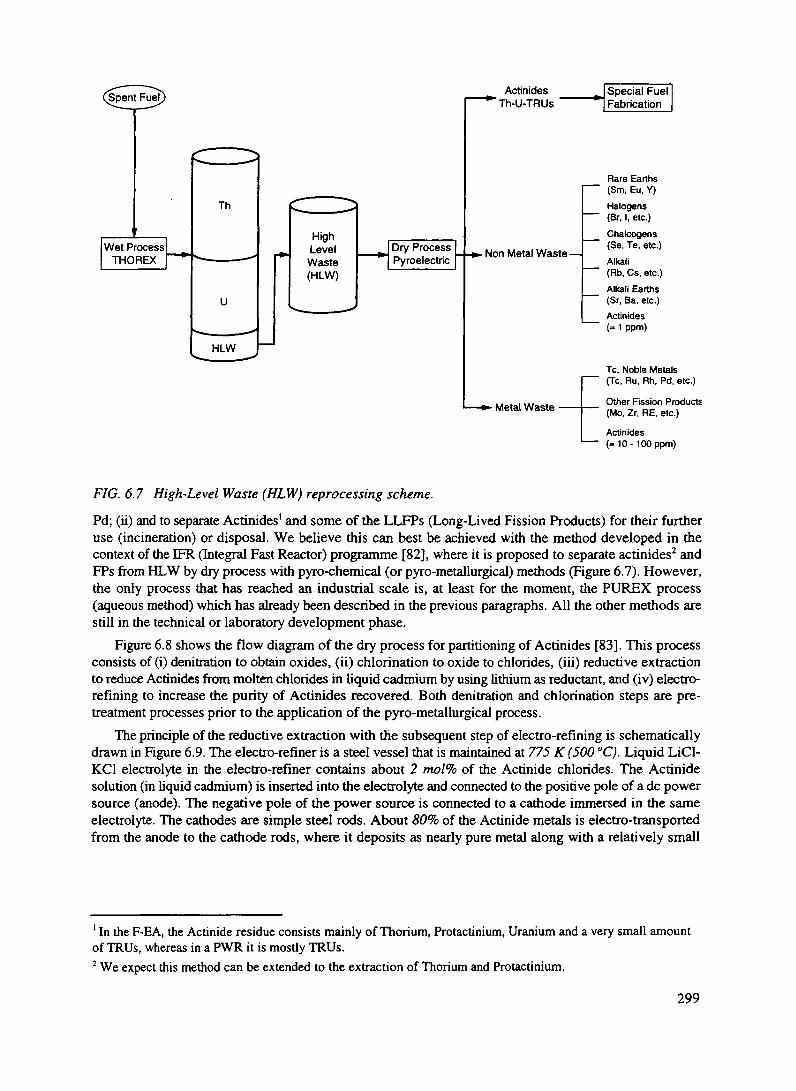
Th
HLW
HighLevelWaste(HLW)
Actinides' Th-U-TRUs
-Non Metal Waste—
• Metal Waste •
Rare Earths(Sm. Eu, Y)
Halogens(Br, I, etc.)
Chalcogens(Se. Te, etc.)Alkali(Fib, Cs, etc.)Alkali Earths(Sr, Ba, etc.)Actinides(= 1 ppm)
Tc, Noble Metals(Tc, Ru, Rh, Pd, etc.)
Other Fission Products(Mo, Zr, RE, etc.)
Actinides(- 10- 100 ppm)
FIG. 6.7 High-Level Waste (HLW) reprocessing scheme.
Pd; (ii) and to separate Actinides1 and some of the LLFPs (Long-Lived Fission Products) for their furtheruse (incineration) or disposal. We believe this can best be achieved with the method developed in thecontext of the EFR (Integral Fast Reactor) programme [82], where it is proposed to separate actinides2 andFPs from HLW by dry process with pyro-chemical (or pyro-metallurgical) methods (Figure 6.7). However,the only process that has reached an industrial scale is, at least for the moment, the PUREX process(aqueous method) which has already been described in the previous paragraphs. All the other methods arestill in the technical or laboratory development phase.
Figure 6.8 shows the flow diagram of the dry process for partitioning of Actinides [83]. This processconsists of (i) denitradon to obtain oxides, (ii) chlorination to oxide to chlorides, (iii) reductive extractionto reduce Actinides from molten chlorides in liquid cadmium by using lithium as reductant, and (iv) electro-refining to increase the purity of Actinides recovered. Both denitration and chlorination steps are pre-treatment processes prior to the application of the pyro-metallurgical process.
The principle of the reductive extraction with the subsequent step of electro-refining is schematicallydrawn in Figure 6.9. The electro-refiner is a steel vessel that is maintained at 775 K (500 °C). Liquid LiCl-KC1 electrolyte in the electro-refiner contains about 2 mol% of the Actinide chlorides. The Actinidesolution (in liquid cadmium) is inserted into the electrolyte and connected to the positive pole of a dc powersource (anode). The negative pole of the power source is connected to a cathode immersed in the sameelectrolyte. The cathodes are simple steel rods. About 80% of the Actinide metals is electro-transportedfrom the anode to the cathode rods, where it deposits as nearly pure metal along with a relatively small
1 In the F-EA, the Actinide residue consists mainly of Thorium, Protactinium, Uranium and a very small amountof TRUs, whereas in a PWR it is mostly TRUs.2 We expect this method can be extended to the extraction of Thorium and Protactinium.
299

HLW
| Dentation j
Oxide Cl,
CWcmnationCO, CO2 Off gas
Chloride(ACT+FP+CP+SC)
Fteducfive Extraction
Liquid Metal(ACT+FP)
ItecttoreJirung
Molten Salt(FP+CP+SC)
amount of rare earth fission products'. All the products are retorted to remove salt (and Cadmium from theCadmium electrode). Ingots from the retort are blended to appropriate composition, and recast into specialfuel pins. The fission products, with the exception of Tritium, Krypton and Xenon, accumulate in theelectro-refiner during processing, and some noble metal fission products are removed with the anode aftereach batch of fuel has been processed. The three gases are released into the process cell which has an argonatmosphere. They are recovered at high concentrations by the cell gas purification system.
Several dozen batches of fuel areprocessed in a "campaign". At the end of acampaign, the salt in the electro-refiner istreated by a series of steps to remove activemetal fission products, paniculate noblemetals, and any oxide or carbide impuritiesfor incorporation in high-level waste forms.The salt and its associated Actinide chloridesare returned to the electro-refiner. TheActinide inventory in the electro-refineramounts to about 20% of the Actinideelements fed; this must be recovered toachieve more than 99.9% overall Actiniderecovery. A non-metal and a metal wasteform will accommodate all of the high-levelwastes. The non-metal waste form willcontain Samarium, Europium and Yttrium;the halogens and chalcogens; the alkali, andalkaline earth fission products; and a smallamount of excess salt generated in theprocess. The Actinide content of that wasteform will be exceptionally low (less than 1part in I06 of the Actinides in the fuel that isprocessed). The only significant long-livedactivity in this waste will be Se-79, 1-129and Cs-135: the total alpha activity shouldbe less than 10 nd g'. Metal wastes fromthe electro-refiner - noble metals, claddinghulls and salt filter elements - will be Figu«?0scombined with any process scrap such as FIG. 6.8 Flow diagram of the pyro-metallurgical processbroken electrodes and the rare earths from for partitioning of the residual Actinides from HLW.the salt purification process in the metalwaste form. The metal waste form will have a very low Actinide content, because of the effective Actiniderecovery in the pyro-metallurgical process, but its Actinide level will not be quite as low as that of the non-metal waste form. This whole process can be made continuous, and thus can take place in a matter of onlya few hours.
Pyro-processing offers a simple, compact means for closure of the fuel cycle, with anticipated high-decontamination factor (> 99.9%), minimal production of high-level radioactive waste, and significantreductions in fuel cycle costs. In addition, mainly from the weapons proliferation viewpoint, it offers anadvantage over the PUREX and/or TRUEX methods, in that there is only partial removal of the fissionproducts. Even though the process is based on the use of a metallic fuel alloy with nominal compositionU-20Pu-10Zr, we believe it can be readily adapted to the EA fuel cycle without much efforts.
Electrolysis
Cd+FP(Anode)
Distillation
Actinide Mixture(Cathode)
rx
Waste
^Special Fuel Fabrication
1 In reprocessing F-EA fuel, the complete removal of fission products may not be necessary since their effect onthe neutron economy is much less in a fast neutron spectrum than it is in a thermal spectrum.
300

Pre - Processing
Molten San
ACT = Actuudes
Liquid Cd
T Liquid Cd^\[(ACT + RE)J
Anode
(Recovered ACT) Electrorefining
The final content of the HLW streamcoming from the EA fuel reprocessing ismainly FFs, with only traces of Actinides.The volume generated is about 5 m3 per tonof fuel. The following step is to concentratethe aqueous raffinate and to transfer it to anintermediate storage of the reprocessingplant. The volume of the concentrate will beabout 1 mVt. of fuel and the usualintermediate storage are tanks of suitablestainless steel such as to minimise the acidwaste corrosion. To prevent the highly activeliquid from boiling a redundant coolingsystem is required. Then, the concentrate iscooled for a period of about 10 years in orderto reduce the heat generation by more thanan order of magnitude before proceeding towaste solidification. Among the fissionfragments, excluding the short lived andstable elements, there are a few elementswhich are medium lived (30 years, Sr, 90Y,l37Cs, etc.) and some others ("Tc, l35Cs, 129I,etc.) which are long lived (Table VI. 1).Since Actinides are essentially absent fromthe HLW concentrates the policy weproposed to follow is to store in man-watched, secular repositories for severalcenturies the medium lived, in order toisolate them from the biosphere and topromote a vigorous research anddevelopment of methods for incinerating thebulk of the long lived FFs. The EA is anefficient tool to incinerate these wastes at the price of fraction of the neutron flux [6], but alternativelydedicated burners can be used.
In parallel with the R&D on incinerators, development on solvent extraction methods of long lived FF,which in some cases may additionally require isotopic separation, should be promoted, the goal being tovirtually eliminate the need for Geological Repositories.After the concentrates will be cooled down for the 10 years period and the long-lived FF extraction appliedfor later incineration the wastes will be solidified by using well known techniques. For instance bycalcination and vitrification. The first step allows to get waste oxides and in the second step glasses areobtained by melting the waste oxides together with additives such as SiO2, B2O3, A12O3, P2O5, N&fi, andCaO. Borosilicate glass is the most studied solidification product but others like phosphate glass, glassceramic, etc. are also used. When the solidification process is finished the wastes are ready for disposal inthe appropriate secular repositories.
D.3.6.4. SPALLATION INDUCED RADIO-NUCLIDES
In addition to the radioactive waste produced in the Fuel and in a minor extent in the Breeder,substantial amounts of radio-nuclides are produced by the spallation target. As pointed out they divideroughly into two batches, those which remain inside the molten Lead and those which are either gases orvolatile and which can be found in the neutral filling gas of the main vessel.
Figure 6 9
FIG. 6.9 Schematic illustration of the pyro-metallurgicalpartitioning process.
301

TABLE VI.1. FISSION FRAGMENTS' ACTIVITY AFTER 1000 YEARS OF COOL-DOWN ESf THESECULAR REPOSITORY. VALUES ARE GIVEN FOR 1 GWe x year.
Radio-Isotope
P.9j
9*Tcl26Sn135Cs93Zr79Se
1/e Life
2.27E+73.05E+51.44E+53.32E+62.2 1E-H59.40E+5
Mass
8.0916.611.18734.1226.110.3
OtherIsotopes
(kg)3.48—
1.78366.7799.113.02
Activity @1000 a
(Ci)1.43
284.2933.7939.3265.642.06
IngestiveToxicity
(Sv) x 103
19.5827.673.2
9.872.38
0.745
DilutionClass A
(m3)178.47947.659.6539.3218.750.59
1x10
101x10
1x10'
__ EA discharge, f= 10(Asymptotic Fuel composition)
CS
U)
.fr
Gases & Vapours'9 700 °C
These last compounds are collected from thegas and stored in an appropriate way in orderto avoid leaks in the biosphere (paragraphD.3.5.8). The relative ingestive radio-toxicity of the various components of theSpallation target are given in Figure 6.10.Following Table V.9 spoliation products at700 °C can be broadly divided into threedifferent categories namely (1) gases orvapours in which the contribution of l94Hg(751.9 a, 123 g/(GWe x a)) is largelydominant in size and duration; (2) volatileswhich, after a few years, are essentiallydominated by to 204T1 (5.466a, 114 g/(GWe xa)), (3) inter-metallic combinations (alloys)with the molten Lead which at short times,shows a leading contribution from '"Sr and,at longer times by 202Pb (7.59 x 10 a, 614g/(GWe x a)). The radio-toxicity of thespallation products is by no mean negligible:at early times it is about 10"3 of the totalradio-toxicity produced. At the end of theSecular repository time for FFs, the effectsof l94Hg exceed all other contributions untilabout 2,000 years. There is no majordifficulty in extending safely andeconomically the storage of about 2.3kg/(GWe x a) of Mercury collected asvapours from the top main Vessel up toabout 2000 years. Note that at least in thepresent design, the molten Lead of theTarget region is directly mixed with the bigvolume (~ 1000 m3) which constitute the main coolant. Therefore at least the elements which remain insidethe liquid are largely dispersed. They will follow the fate of the Lead at the time of final decommissioningof the installation.
We finally remark the existence of another lead isotope, M5Pb (2.21 x 10⁷a) which is abundantlyproduced by neutron capture of 204Pb, namely 3.54 kg/(GWe x a) in the target region and 23.15 kg/(GWe
1x10³ .
1x10¹⁰ 1X10² 1x10"
Elapsed Time, years1x1 tr 1x O5
Figure 6 10
FIG. 6.10 Relative ingestive radio-toxicity of the spoliationtarget products.
302
x a) in total, and fortunately it is also rather inoffensive, since it is very long lived and it decays by K-conversion with an energy release of 51 keV mostly in the form of neutrinos.
D.3.6.5. RADIO-TOXICITY EMITTED IN THE ENVIRONMENT
Nuclear power production is based on the concept that pollutants and toxic materials are retained withinthe plant and in total isolation from the biosphere. The limited mass of such products makes it possible toachieve such a goal. Mining process however cannot retain all products and a significant amount ofradiation is emitted in the biosphere during preparation of the fuel. Likewise in the reprocessing of the spentfuel some radioactive elements are currently re-emitted in the biosphere. Finally the ultimate storage of suchmaterials (geologic repository) have raised some question on the ability of isolating them from thebiosphere for times which largely exceed what can be considered an experience based retention. The EAconcept strongly reduces such environmental impacts, when compared to the present reactor technology.We examine these points in turn.
(1) Mining. Thorium is largely present in the Earth's crust, but in small concentrations. In additionseveral minerals exist, which have an excellent concentration of Thorium and which can beexploited economically. The primary choice is the monazite, which is a phosphate of Cerium andother lantanides, containing a variable amount of Thorium and Uranium in a solid mixture. Usuallythe Thorium concentration is of the order of 10% but some mineral may reach as much as 20% byweight. Uranium minerals are usually much less rich, its concentration being in the best cases ofthe order of 0.2%. Incidentally one can remark that the solubility of Thorium is 1000 times smallerthan the one of Uranium. Taking into account that Thorium burnt in the EA has an energetic yieldwhich is 250 times larger than one of natural Uranium destined to PWRs, we conclude that therelative mining effort is reduced by a factor of the order 250 x 50 = 12500 times for a givenproduced energy. Starting with mineral containing 10% of Thorium by weight we need to dig only70 tons of mineral to produce GWe x a. For comparison and for the same energy produced thestandard PWR methodology would require 0.875 106 ton of mineral. In the case of Coal, the massof fuel (TEC) is 4.24 106 ton.A pure Thorium mineral out of which the totality of Thorium is extracted will produce tailings witha negligible radio-toxicity after some sixty years, since all descendants of 232Th have short decaylifetimes. Their evolution is governed by the 5.7 year half-life of 228Ra. Furthermore there will beno risk associated to Radon, since ""Rn has a half-life of 55.6 seconds and it decays beforeescaping the minerals. As pointed out by Schapira [5] the situation in reality is somewhat morecomplex, mainly because the monazite, which is the primary source of Thorium is generally mixedwith some Uranium contamination. Such a contamination is strongly source dependent, as shownin Table V1.2, taken from Ref. [5]. Assuming somewhat pessimistically that the Uranium contentis about 10% of the one of Thorium and that the long lived toxicity and Radon contamination areprimarily due to Uranium, we conclude that the radio-toxicity produced at the mine is in the caseof an EA about 250 / (10%) = 2500 times smaller than the one of today's PWR for a given energyproduced.The UNSCEAR report [7] has estimated that the level of exposure of individuals to mining fortoday's PWRs amounts to about 1.5 man Sv (GW y)"1 as local and regional component and to 150man Sv (GW y)'1 as global component We remark that according to the same report the productionof electricity from Coal is estimated to result in a global collective dose of 20 man S v (GW y)"1. Thepractice of using coal ashes for production of concrete will add as much as 20,000 manSv (GWy)"1.Values relative to Thorium and its use in the EA for some possible mineral sources are listed inTable VI.2. We conclude that the typical radiation exposure to public with the EA due to mineralmining for the same energy produced are much smaller than today's PWRs and also Coal burning,even if solid ashes are correctly handled.
303

TABLE VI.2. URANIUM AND THORIUM CONTENT IN PERCENT [5] AND LEVELS OFPOPULATION EXPOSURE FOR TYPICAL ORES [7].
Ratio U/Th Local GlobalSource UO7 ThO,
ItalySri LankaCaliforniaIndia
15.640.1
6.950.29
11.3414.324.229.80
1.380.0071.64
0.029
8.28 x 10'3
4.20x 10'5
9.84 x 10'3
1.74x IQ-4
0.8284.2 x 10°
0.9840.0174
The same report estimates the collective dose due to initial Uranium enrichment and fuelfabrication to as little as 0.003 man Sv (GW y)"1. In the case of the EA it is expected to be atleast 1/4 of such a number, since the bum-up is four times longer and there is no isotopicseparation. The collective doses are negligible in both cases.
(2) EA Operation. During the EA operation the fuel and the spallation target volumes are keptstrictly sealed. Indeed also for proliferation protective measures it is recommended that suchvolume be opened only in occurrence with the re-fuelling, namely once every about five yearsand only by a specialised team. While the fuel is safely sealed, the Lead coolant produces asignificant amount of radioactive products, some of which remain in the liquid phase, butothers are either gaseous or volatile and are found in the neutral gas (Helium) with which themain Vessel is filled. These volatile compounds are summarised in Table VI. 3, extracted fromTable V.9. Some of these are noble gases and Tritium which remain gaseous at roomtemperature.Other, mostly Mercury and Thallium can be condensed and preserved in the solidstate. Some other elements will be collected by the Lead purifier. In view of its small amountinvolved we believe that the gaseous elements can be released in the atmosphere. The collectiveeffective dose per unit energy release is given by the UNSCEAR report [7] and summarisedin Table VI.4. It is assumed that gases are released every 6 months, without cool-down period.A short cool-down will dramatically reduce the effects of 127Xe (52.63 d) and it isrecommended. The total local and regional doses are 0.42 man Sv (GW y)"1. The global doses,integrated over 10,000 years, following the convention of Ref. [7] are of 0.18 man Sv (GW y)"1.Both values are dominated by the effects of Tritium. The rest of the solid high activity wastefrom the spallation products (dominated by Mercury and Thallium) has a substantial ingestiveradio-toxicity (Figure 6.10) and it should be carefully accumulated and destined to therepository.
(3) Fuel reprocessing has to deal with the very large radioactivity of the spent fuel. Since thetechniques are not different that those generally in use, we can make direct use of the estimatedcollective doses of Ref. [7] (Table VI.5), taking into account the differences in stockpile of theradio-nuclides produced (see Table V.8). It is however assumed that both MC and 85Kr areextracted during reprocessing and sent to the repository for cool-down. Separation of 85Kr canbe performed cryogenically according to a well documented procedure [84]. Also I4C oncereduced in the form of CO2 can be extracted on the same time by the same method.
The total doses to members of the public are summarised in Table VI.6. Total global dose truncatedat 10,000 years is 0.6 man Sv (GWa)"1, namely for the same energy produced about 0.003 of the one of anordinary Reactors [7] — without counting occurred criticality and melt-down accidental releases, avoidedby the EA, (* 300 man Sv (GW y)'1) —and about 0.03 of the alternative of Coal burning, even if solidashes are correctly handled.
304

TABLE VI.3. RADIO-NUCLIDES EMITTED IN THE NEUTRAL GAS INSIDE THE VESSEL BY THESPALLATION TARGET AND THE MOLTEN LEAD COOLANT (* 700 °C).
________Gas at Room Temperature_____Solid at Room Temperature__________Boils at Mass 1/e Boils at
Mass 1/e 0/-> op3H 1.435 17.83 a -252 35S 0.009 126.5 d 445
39Ar 0.336 389.0 a -186 65Zn 0.004 353.2 d 90742Ar 0.336 47.57 a -186 70Zn 2.424 0.723E+15y 907
81Kr 5.777 0.331E+6a -153 73As 0.329 116.1 d 61585Kr 4.326 15.55 a -153 615
83Rb 0.036 124.6 d 688127Xe 0.37 52.63 d -108 86Rb 0.181 26.94 d 688
(675)'_________________
I09Cd 1.627 1.833 a 767
125I 0.014 85.90 d 184
124Sb125Sb
131Cs134Cs
194Hg203Hg
202JJ
204T1
210Po
0.0430.404
0.0030.282
415.96.252
15.25386
0.995
87.05 d3.988 a
14.01 d2.982 a
751.9 a67.40 d
17.68 d5.466 a
200.1 d
1,5851,585
671671
357357
1,4731,473
254
1 Total integrated production, without decay over 5 years.
305
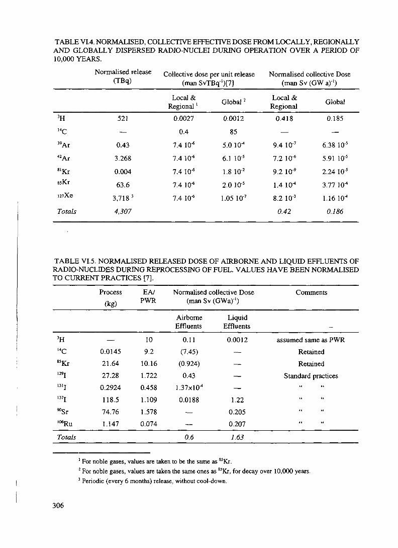
TABLE VI.4. NORMALISED, COLLECTIVE EFFECTIVE DOSE FROM LOCALLY, REGIONALLYAND GLOBALLY DISPERSED RADIO-NUCLEI DURING OPERATION OVER A PERIOD OF10,000 YEARS.
Normalised release Collective dose per unit release Normalised collective Dose(TB(l) (man SvTBq')[7] (man Sv (GWa)'1)
3H14C
39 Ar42ArslKrssKr
i2?Xe
Totals
521
—
0.43
3.268
0.004
63.6
3,718 3
4,307
Local &Regional '
0.0027
0.4
7.4 10"*
7.4 10'6
7.4 lO'6
7.4 10'6
7.4 10*
Global 2
0.0012
85
5.0 10^
6.1 lO'5
1.8 10'2
2.0 10'5
1.05 10'7
Local &Regional
0.418
—
9.4 10'7
7.2 10-6
9.2 10'9
1.4 10"4
8.2 10'3
0.42
Global
0.185
—
6.38 10'5
5.91 10-5
2.24 1C'5
3.77 10^
1.16 10"1
0.186
TABLE VI.5. NORMALISED RELEASED DOSE OF AIRBORNE AND LIQUID EFFLUENTS OFRADIO-NUCLIDES DURING REPROCESSING OF FUEL. VALUES HAVE BEEN NORMALISEDTO CURRENT PRACTICES [7].
Process(kg)
3H —14C 0.014585Kr 21.64129I 27.28131I 0.2924137I 118.5^Sr 74.76106Ru 1.147
Totals
EA/PWR
109.2
10.161.722
0.4581.1091.5780.074
Normalised collective Dose(man Sv
AirborneEffluents
0.11(7.45)
(0.924)
0.43
1.37x10^
0.0188——
0.6
(GWa)'1)
LiquidEffluents
0.0012————
1.220.2050.207
7.63
Comments
assumed same as PWRRetainedRetained
Standard practices"(( a
<( it
tt if
1 For noble gases, values are taken to be the same as 83Kr.2 For noble gases, values are taken the same ones as 85Kr, for decay over 10,000 years.3 Periodic (every 6 months) release, without cool-down.
306

D.3.6.6. CONCLUSIONS
Realistic schemes are possible in which the spent Fuel from the EA is "regenerated" for further uses.Separation of the fuel materials into two streams is performed, the Actinide stream destined to the fuelfabrication and the FFs stream which is destined to the Secular repository. After 500 years the radio-toxicityfor unit energy produced of the EA is about 20,000 smaller than the one of a PWR with a "throw-away"cycle. Incineration with the help of neutrons of some of the critical, long lived radio-nuclides can stronglyreduce the radio-toxicity of the waste beyond 500 years. If sufficiently diluted it could be also let "dieaway" without incineration since it can be made to satisfy the requirements for Class A repository. Notealso that at that time the residual ingestive radio-toxicity is comparable with the one of the Thorium metalburnt in the EA.TABLE VI.6. SUMMARY OF NORMALISED, COLLECTIVE DOSES TO MEMBERS OF THEPUBLIC FROM RADIO-NUCLIDES RELEASED FROM THE EA.
Source Local and regional Doses(manSv(GWa)'1)
Global Doses(manSv (GW a)"')
Mining ', Milling, Fuel fabrication
EA operation
Reprocessing (Atmospheric)
Reprocessing (Aquatic)
Miscellanea2
Totals (variation over mining range)
4.2 10'5 H-9.8 10'3
0.42
0.60
1.63
0.12.75 -r 2.76
0.0042 -=- 0.984
0.188
0.1
0.1
0.050.44 -r 1.42
An essential element in the clean disposal of the spent fuel is the small leakage of Actinides (mainlyUranium) into the FFs stream. A level of 100 ppm. or better is required. We believe that it is within thestate of the art, eventually with a few improvements.
An important source of radio-toxicity are the spallation products due to the proton beam interactingwith the molten Lead target. A specific element of concern is 194Hg which is the main surviving source oftoxicity of the EA in the period of time between 500 and 2000 years. It can either be preserved far fromthe biosphere that long or, alternatively, incinerated, following the fate of the Actinides inside the EA.Unfortunately the relevant cross sections are only poorly known but they should be measured soon [6].
An experimental test of the feasibility of incineration with neutrons in a Lead diffuser [6] is inpreparation at CERN. Would it be successful it could offer the right technique in order to eliminate alsothe modest amount of long lived radio-toxic elements produced.
Likewise important is the total radioactivity doses to members of the public due to operation. Totalglobal dose of the EA truncated at 10,000 years is estimated to be 0.6 man Sv (GW a)"1, namely about1/330 of the one of an ordinary Reactors for the same energy produced (200 man Sv (GW a)'1)— withoutcounting occurred criticality and melt-down accidental releases, avoided by the EA (=300 manSv (GW a)"1)— and about 1/33 of the alternative of burning Coal (= 20 man Sv (GW a)"1), even if solid ashes arecorrectly handled.
1 The dose range depends on the Uranium content in the Thorium mineral. We have taken extreme values ofTable VI. 1.
2This includes mainly Transportation, Fuel fabbrication, Solid Waste disposal. Figures are taken from Ref. [1].
307

ACKNOWLEDGEMENTS
We would like to acknowledge the superb and dedicated work of Susan Maio and F. Saldana, withoutwhom this paper could not have become a reality. We would like to thank many of our CERN colleagues forfrequent discussions of various aspects of the project and for their continuing and enthusiastic support. Stressanalysis and hydrodynamic calculations have been performed with the help of M. Battistin and A. Catinaccio.I. Goulas has helped with programming. M. Cobo, M. Embid and R. Femandez have diligently helped duringtheir stay as summer students at CERN.
We have profited from (too) short, but illuminating visits of E. Greenspan (Univ. California at Berkeley),V. Orlov (RDIPE, Moscow), H. Branover (Ben Gurion University, Israel) and K. Mileikowski.
Many experts have helped us in different fields. We would like to thank in particular: A. Ferrari andP. Sala (University of Milan) for the code FLUKA; J.P. Schapira and R. Meunier (IN2P3) for theircontributions to radio-toxicity and end-of-cycle aspects; E. Gonzalez and A. Uriarte (CIEMAT, Madrid);R. Caro and A. Alonso (Consejo de Seguridad Nuclear, Madrid); M. Perlado, J.L. Sanz, E. Gallego andP. Trueba (Universidad Politecnica, Madrid) and A. Perez-Navarro (Alfonso X El Sabio) for numerous andextended contributions pertinent to safety, radiation damage and end of cycle aspects; H. Rief (JRC, Ispra)for contributions to the question of reactivity insertions; P. Gerontopoulos, J. Magill, M. Matzke, C. O'Carrol,K. Richter and J. Van Geel (JRC Karlsruhe) for proliferation aspects; D. Finon and Ph. Menanteau (Institutd'Economie et de Politique de 1'Energie, Grenoble), M. Gigliarelli-Fiumi (INFN, Frascati) andM.A. Rodriguez-Borra (SERCOBE, Madrid) for the economic and industrial aspects; E. Sartori (NEA), TheInternational Dosimetry and Computation Group of NRPP (UK); C. Dunford and S. Ganessan (IAEA) andG. Audi, (CSNSM, Orsay), for their invaluable assistance in facilitating our access to relevant Data Banks.
The design of the accelerator has been made possible with the help of Laboratoire du Cyclotron, CentreAntoine Lacassagne. We thank its Director, F. Demard, and wish to acknowledge J.M. Bergerot, A. Giusto,P. Montalant, J.F. Di Carlo, V. Rossin. We had helpful discussions with W. Joho, U. Schryber and P. Sigg(PSI, Zurich) and J. Pamela (CEN, Cadarache). Last but not least, we would like to acknowledge thecontinuing support of the CERN Management (in particular of H. Wenninger), of the Sincrotrone Trieste (inparticular G. Viani), and the DGXU of the European Commission, in particular its Director General,P. Fasella and H.J. Allgeier, G.C. Caratti and W. Baltz.
REFERENCES
[1] F. CARMJJMATI, C. GELES, R. KLAPISCH, J.P. REVOL, CH. ROCHE, J.A. RUBIO ANDC. RUBBIA, "An Energy Amplifier for Cleaner and Inexhaustible Nuclear Energy Production Drivenby a Particle Beam Accelerator", CERN/AT/93-47 (ET) (1993).
[2] C. RUBBIA ET AL., "A High Gain Energy Amplifier Operated with Fast Neutrons", Contributionto the Las Vegas Conference on Accelerator Driven Transmutation Technologies and Applications,25-29 July 1994, to be published.
[3] S. ANDRIAMONJE ET AL., Physics Letters B 348 (1995) 697-709.[4] C. RUBBIA, "On the Feasibility of Fission Driven Hydrogen Production as Substitute for Natural
Gas", CERN/AT/95-12 (ET) (1995).IT. OZTURK, A HAMMACHE AND E. BELGEN, Trans. IChemE, 241,72A, (1994). and referencetherein. The original Dprocess has been described in J.H. Norman et al. General Atomic CompanyReport, GA-A16713, 1982.S. SHIMIZU ET AL. "Iodine-Sulphur Process for Thermochemical Hydrogen Production",Proceedings of ICENES '93, H. Yashuda Editor, World Scientific, 1993.
[5] S. MENARD AND J.P. SCHAPIRA, "Impact Radiologique a long terme de 1'extraction duThorium", JPNO-DRE 95-07, Orsay, France.
308

[6] S. ANDRIAMONJE ET AL., "Experimental Study of the Phenomology of Spallation Neutrons in aLarge Lead Block", Proposal to the SPSLC, SPSLC/P291, May 1995.
[7] "Sources And Effects Of Ionising Radiation", United Nations Scientific Committee on the Effects ofAtomic Radiation, UNSCEAR 1993 Report to the General Assembly, with Scientific Annexes, NewYork, 1993.
[8] TH. STAMMBACH ET AL., "Potential of Cyclotron Based Accelerators for Energy Production andTransmutation", Contribution to the Las Vegas Conference on Accelerator Driven TransmutationTechnologies and Applications, 25-29 July 1994, to be published.
[9] R.A. JAMESON ET AL., "Accelerator-driven transmutation technology for energy-production andnuclear-waste treatment", 3rd EPAC, Berlin 1992, pp. 230-234.
[10] For a comprehensive description of these Projects, see for instance "Status of liquid metal fast reactordevelopment", IAEA-TECDOC-791, March 1995.
[11] See for instance H. ALTER, p. 2 in "Specialists' Meeting on Decay Heat removal and NaturalConvection in LMFBRs", BNL (1985) and additional information in the same Proceedings.
[12] D. GEITHOFF, G. MUHLING AND K. RICHTER, "Performance of a Mixed Carbide Fuel Sub-Assembly in KNK JJ", in Proceedings of Global '93, 12-17 September, 1993, published by theAmerican Nuclear Society, Inc., Vol. 2, p. 1173.
[13] L. KUECHLER, L. SCHAFER, B. WOJTECH, "The Thorex Two-Stage Process for Re-ProcessingThorium Reactor Fuel with High Burn-Up", Farbwerke Hoechst AG, Kemtechnik 13. No. 78, pp.319-322(1971).
[14] J.J. LAIDER ET AL, "Development of IFR Pyroprocessing Technology", in Proceedings of Global'93, 12-17 September, 1993, published by the American Nuclear Society, Inc., Vol. 2, p.1061 andalso McPheeters et al, "Pyrochemical Methods for Actinide Recovery from LWR Spent Fuel", Vol.2, p. 1094.
[15] C. BOWMAN ET AL., Nucl. Instr. Methods, A320, 336 (1992). More recent developments are tobe found in the Proceedings of the International Conference on Accelerator-Driven TransmutationTechnologies and Applications, Las Vegas, 25-29 July 1994.
[16] T. TAKEUKA ET AL., Specialist Meeting on Accelerator-driven Transmutation for Radwaste andother Applications (Stockholm, 24-28 June 1991).
[17] G. VAN TUYLE ET AL., BNL Report 52279 (1991);H. TAKAHASHI, Fusion Technology 20 (1991) 657.V.D. KAZARITSKY ET AL., in Accelerators Applied to Nuclear Waste, 8th Joumees Saturne,Report LNS/Ph/94-12.
[18] H. TAKANO ET AL, "A concept on self-completed fuel cycle based on Lead-cooled Nitride-fuel FastReactors", in Proceedings of ICENES-93, World Scientific.
[19] PROCEEDINGS OF THE FIRST INTERNATIONAL CONFERENCE ON PEACEFUL USES OFATOMIC ENERGY (Geneva 1955) Vol 4.
[20] CRC HANDBOOK OF CHEMISTRY AND PHYSICS, D.R. Lide Editor, CRC Press, 73rd Editionp. 4-29.
[21] F.H. BARTHEL AND F.J. DAHLKAMP, "Thorium Deposits and their Availability", IAEATECDOC-650, Vienna, 1992, pp 104-115.
[22] K.S. DEFFEYES AND I.D. MACGREGOR, "World Uranium Resources", Scientific American,January 1980, pp. 50-66.
[23] J. ROUAULT ET AL., "Physics of Pu burning in Fast Reactors: Impact on Burner core design", Proc.ANS Topical Meeting on Advances in Reactor Physics, Knoxville, 11-15 April (1994).
[24] J. SANZ, J.M. PERLADO, A.S. PEREZ AND D. GUERRA, J. of Nucl. Materials, 191-194, (1992),1450.
309

[25] J. PERLADO AND J. SANZ, "Irradiation Effects and Activation in Structural Material", in "NuclearFusion by Inertial Confinement", edited by G. Verlarde, Y. Ronen and J.M. Martinez-Val, CRC Press(1993).
[26] J. PERLADO, Private Communication.[27] C RUBBIA, "An analytic approach to the Energy Amplifier", Internal Note CERN/AT/ET/Intemal
Note 94-036.J.P. REVOL, "Analytical Study of the Energy Amplifier Microscopic Physics", internal NoteCERN/AT/ET/Internal Note 95-025.
[28] C. RUBBIA, paper in preparation.[29] S. GLASSTONE, Principles of Nuclear Reactor Engineering (D. Van Nostrand, New York, 1955).[30] F. CARMINATI, "EET Code Collection User Guide", Internal Note, CERN/AT/ET/Intemal Note 95-
027, 16 March 1995.[31] I. GOULAS, J.P. REVOL, "Further Update of Nuclear Data for the EET Group", Internal Note
CERN/AT/ET/Intemal Note 95-012, 26 April 1995 and "Corrections to the EET Nuclear Data Base",Internal Note CERN/AT/ET/Intemal Note 95-026, 19 June 1995.
[32] F. CARMINATI, I. GOULAS, Y. KADI, "Proposal for transforming the evolution and MC programinto a general purpose code", Internal Note CERN/AT/ET/Internal Note 95-020, 9 June 1995.
[33] H. BATEMAN, "The Solution of a System of Differential Equations Occurring in the Theory ofRadioactive Transformations", Proc. Cambridge Phil. Soc. Vol. 15, p. 423, 1910.
[34] 1) MCNP: Judith F. Briesmeister, "MCNP™ - A General Montecarlo N-particle Transport Code",Los Alamos National Laboratory Report, LA-12625-M, November 1993.2) TWODANT: R.E. Alcouffe, F.W. Brinkley Jr., D.R. Marr and R.D. O'Dell, "User's Guide forTWODANT: A Code Package for Two-Dimensional, Diffusion-Accelerated, Neutral-ParticleTransport", Los Alamos National Laboratory Report, LA-10049-M, February 1990.
[35] J. CARSON MARK, "Explosive Properties of Reactor-Grade Plutonium", Science & Global Security,1993, Volume 4, pp. 111-128.
[36] J. MAGILL, C. O'CAROLL, P. GERONTOPOULOS, K. RICHTER, J. VAN GEEL, "Advantagesand Limitations of Thorium Fuelled Energy Amplifiers", Contribution to the Nuclear Society 5thAnnual Conference on Nuclear Power and Industry, Obninsk, 7-11 November 1994.
[37] V. ORLOV, Private Communication, November 1994.[38] P. BONNAURE, P. MANDRILLON, H. RDEF, H. TAKAHASHI, Actinide Transmutation by
Spallation in the Light of Recent Cyclotron Development, ICENES 86, Madrid, July 1986.[39] C. RUBBIA, P. MANDRILLON, N. FIETIER, "A High Intensity Accelerator for Driving the Energy
Amplifier for Nuclear Energy Production", 4th EPAC, London 1994, pp. 270-272.[40] Y. JONGEN ET AL., "Extremely high intensity cyclotrons for radio-isotope production", Proc. of
EPAC 1994, London.[41] P. MANDRILLON, "Injection into Cyclotrons", CERN Accelerator School, La Hulpe, Belgium, 2-6
May 1994.[42] "MAFIA, A Three-Dimensional Electromagnetic CAD System for Magnets, RF Structures and
Transient Wake-Field Calculations", The MAFIA Collaboration, T. Weiland et al., TechnischeHochschule Fachbereich 18, Fachgebiet Theorie Elecktromagnetischer Felder, 6100 Darmstadt,Germany.
[43] E. BRANOVER, Private Communication.[44] AJ. ROMANO, C.J. KLAMUT, D.H. GURINSKY, B.N.L. 811 (T 313), (1963).
310

[45] U.K. BJERMAN, B. LINCH, W.M. VAN DE WIJGERT, Patent No. 2516296, Neth., (1974).[46] R.C. ASHER, D. DAVES, S.A. BEETHAM, Corrosion Science, 12, (1977), 545-557.[47] F.R. BLOCK, V. SCHWICH, Mater.Behav.Phys.Chem.Liq.Met.Syst., (1982), 253-264.[48] H. LENGELER, "Proposal for Spallation Sources in Europe", EPAC '94, Proc. 4th European Particle
Accelerator Conference, Vol. I, p. 249, 1994.[49] SHUNK, "Constitution of Binary Alloys", McGraw-Hill, 1969.[50] A. FASS6 ET AL, in "Intermediate Energy Nuclear Data: Models and Codes", Proceedings of a
Specialists' Meeting, Issy les Moulineaux (France) 30 May-1-June 1994, p. 271, published by OECD,1994, and references therein.A. FASS6, A. FERRARI, J. RANFT, P.R. SALA, G.R. STEVENSON AND J.M. ZAZULA,Nuclear Instruments and Methods A, 332, 459 (1993), also, CERN Divisional Report CERN/TIS-RP/93-2/PP(1993).
[51] AA.VV., "STAR-CD Version 2.2 Manuals", Computational Dynamics.[52] AA.VV., "ANSYS User's Manual, Version 5.0", Vol. I, H, m, IV, Swanson Analysis System, Inc.
Huston.[53] We Would Like To Acknowledge The Contribution From J.M. PERLADO AND J. SANZ. A part
of their work is included in "Radiation Damage in Structural Materials", J.M. PERLADO, J. SANZ,Institute de Fusion Nuclear, Universidad Politecnica de Madrid (1995).
[54] S. BUONO ET AL., "An Energy Amplifier System cooled by natural convection", Internal NoteCERN/AT/ET/Intemal Note 95-022, 21 August 1995.
[55] C.L. WHEELER, C.W. STEWART, R.J. CENA, D.S. ROWE AND A.M. SUTEY, "COBRA-IV-I.An Interim Version of COBRA for Thermal-Hydraulic Analysis of Rod Bundle Nuclear FuelElements and Cores", Battelle Pacific Northwest Laboratories Report, BNWL-1962, March 1976.
[56] H. SHJJ3ATA ET AL., "On Problems to be solved for utilizing shock isolation system to NPP", Proc.SMIRT-10, Vol. E, Anaheim, August 1989.
[57] J.M. KELLY, "Aseismic Base Isolation: Review and Bibliography", Soil Dynamics and EarthquakeEngineering, Vol. 5, No. 3, 1986.
[58] F.F. TAJIRIAN, J.M. KELLY, I.D. AIKEN, "Seismic Isolation for Advanced Nuclear PowerStations", to appear in Earthquake Spectra, Earthquake Engineering Research Institute (EERI), May1990.
[59] F.F. TAJIRIAN, M.R. PATEL, "Response of Seismic Isolated Facilities: A Parametric Study of TheALMR", submitted to SMIRT 12, Stuttgart, Germany, August 1993.
[60] O. GOKCEK ET AL., "Seismic Risk Reduction through Seismic Isolation", Proc. ANP '92, Tokyo,October 1992.
[61] J.M. BERKOE, "Modelling Passive Decay Heat Removal in Modular High Temperature Gas-cooledReactor", Proceedings of the 5th FIDAP Users Conference, Chicago, H, May 2-4, 1993.
[62] F. CARMINATI ET AL. "Analysis of 4th Week Data", Internal Note CERN/AT/ET/Intemal Note95-003, 17 January 1995.
[63] R. CHAWLA ET AL., "Fast Reactor Experiments with Thorium at the PROTEUS Facility, PaulScherrer Institute Report, EIR-Bericht Nr. 444, November 1981.
[64] A.E. WALTAR, AND A.B. REYNOLDS, "Fast Breeder Reactors", Pergamon Press (1981).[65] S. GLASSTONE, AND A. SESONSKE, in Nuclear Reactor Engineering: Reactor Design Basics.
Vol. 1, Chapter 7, p. 242, Chapman & Hall, Fourth Edition (1994).[66] T.A. GABRIEL, J.D. AMBURGY, AND N.M. GREENE, "Radiation Damage Calculations: Primary
Knock-On Atom Spectra, Displacement Rates, and Gas Production Rates", Nucl. Sci. Eng. 6J., 21(1976).
311

[67] D.G. DORAN, "Neutron Displacement Cross Sections for Stainless Steel and Tantalum Based on aLindhard Model", Nucl. Sci. Eng. 49_, 130 (1972).
[68] R.E. MACFARLANE, D.W. MUIR, AND R.M. BOICOURT, "The NJOY Nuclear Data ProcessingSystem, Volume I: User's Manual", Los Alamos National Laboratory Report, LA-9303-M (ENDF-324) (1982).
[69] M.T. ROBINSON, in Nuclear Fusion Reactors (British Nuclear Energy Society, London, 1970).[70] J. LINDHARD ET AJL, Mat-Fys. Medd. 21 (1963).[71 ] W.E. FISHER, "Target System Materials and Engineering Problems", in ICANS X, LA-UR-89-2920
(1988).[72] J.M. PERLADO ET AL., "Radiation Damage and Activation in the HT-9 Structure of ICF Reactors
Using INPORT Protection", Ninth Topical Meeting on the Technology of Fusion Energy, Oak Brook(USA), October 1990. Fusion Technology, Vol. 19, 3, Part. 2A, 709 (1991).
[73] M. COBO, M. EMBID, R. FERNANDEZ, J. GALVEZ, C. RUBBIA, J. A. RUBIO, "Study of themaximum cladding temperature reached in the Energy Amplifier", Internal Note, CERN AT/EET 95-023, 21 August 1995.
[74] SAMUEL GLASSTONE & ALEXANDER SESONSKE, Nuclear Reactor Engineering. ReactorDesign Basics. Vol. I, Chapter 5, p. 238-321 Chapman & Hall, Fourth Edition.
[75] H. RIEF & H. TAKAHASHI. "Safety and Control of Accelerator-Driven Subcritical Systems".[76] FEDERICO CODED & VICENTE SERRADELL, Teoria de Reactores y Elementos de Ingenieria
Nuclear. Tomo I. Publicaciones Cientificas de la Junta de Energia Nuclear. Tercera Edicion, 1975.[77] REACTOR PHYSICS CONSTANTS, Argonne National Laboratory, United States Atomic Energy
Commission, 1963.[78] C. RUBBIA, paper in preparation.[79] R. MEUNIER, "Faisabilite et Evaluation Exploratoires d'un Projet pour la Separation Isotopique du
Cesium Issu de la Fission", CSNSM, IN2P3-CNRS, Orsay, October 1994.[80] A. URIARTE, "The Energy Amplifier, Considerations about the back-end of the Fuel Cycle",
CEEMAT ITN/TR-05/n-95 and ITN/TR-13/11-95, 1995 (and references therein).[81] J.T. LONG, "Engineering for Nuclear Fuel Reprocessing", Gordon and Breach Science Publishers,
1967 (and references therein).[82] J. P. ACKERMAN AND T.R. JOHNSON, "New High-Level Waste Management Technology for the
IFR Pyroprocessing Wastes", in Proceedings of Global '93, published by the American NuclearSociety, Inc., Vol. 2, p. 969.
[83] T. HIJIKATA ET AL., "Development of Pyrometallurgical Partitioning of Actinides from High-LevelRadioactive Waste", in Proceedings of Global '93, published by the American Nuclear Society, Inc.,Vol. 2, p. 1074.
[84] A. VAN DALEN ET AL., "Sea Disposal of Radioactive Krypton", European Applied and ResearchReports, Nuclear Science and Technology Section, Vol. 4, 111-190, 1982
312

XA9846571
D.4. ADS PROGRAM IN RUSSIA
D.4.1. WEAPON PLUTONIUM IN ACCELERATOR DRIVEN POWER SYSTEM
Shvedov O.V. (ITEP), Murin B.P. (MRTI)., Kochurov B.P. (ITEP), Shubin Yu.N. (IPPE), Volk V.I.
(VNIINM), Bogdanov P.V.(MNP)
with participation of:Azshnin E.I.Belygin V.M. -Blokhin A.I.Bondarev B.I. -Durkin A.M.Fedotov A.P. -Gay E.V.Vassiliev V.V. -Ivanov Yu.D. -Ignatyuk A.V. -Igumnov M.M.-Kvartsakheli A.Yu. -Kozodaev A.M.-Konev V.N.Konobeev A.Yu.-Lasarev N.V. -Lunev V.P.Malygina H.U.-Petrunin V.V. -Rabotnov N.S.-Selivanova N.N.-Sobolev A.M. -Strahov E.B. -Shumakov I.V. -Uksusov N.I.Vasiliev V.V. -Zavadsky I.M.-
SSC DBMBMRTIRASSSC PhPIMRTIRASMRTI RASMRTIRASSSC PhPISSC ITEPMRTIRASSSC PhPISSC ITEPSSC ITEPSSC ITEPSSC ITEPSSC PhPISSC ITEPSSC PhPISSC DBMBSSC DBMBSSC PhPISSC ITEPSSC DBMBSSC ITEPMRTIRASMRTIRASSSC ITEPRPDPT
D.4.1.1. INTRODUCTION.
D.4.1.1.1 Introductory commentsCompletion of cold war between the former USSR and the countries of NATO and USA has
called global reducing of nuclear weapon. Use (or destruction) of several dozens of tons of weapon-
313

grade Plutonium (W-Pu ) is a many-sided problem, including various aspects, such as W-Pu use inexisting nuclear reactors or creation of Nuclear Power (NP) installations of a new generation. Amongthem the main places take the projects of Accelerator Driven Systems (ADS), development of meth-ods of long-duration safe storage of W-Pu, maintenance of its physical safety and the problem of non-proliferation.
This report is devoted to the substantiation of advantages of W-Pu use in ADS power installation.The problems are determined:- area of research - W-Pu use in ADS power installations;- purpose and problems of research - creation of safe and reliable ADS installation for processing
of ~ 50 t of W-Pu in 30 years on the basis of a linear accelerator of proton with energies 0,8-1,2 GeVand a current 10-30 mA; melt-down Pb-Bi eutectic targets; partitioned fast - thermal blanket withPlutonium fuel. Thorium is used as reproducing materials; actinides formed being incinerated in fastzone of blanket;
- objects of research - linear accelerator with beam transport systems, neutron-producing target,partitioned blanket, monitoring and controlling system fuel cycle, electro-nuclear neutron generator;
- modem status of objects in consideration.Method of W-Pu utilisation is substantiated. It consists on understanding of unconditional prior-
ity of safety of ADS power installation over economic considerations and, accordingly, priority ofsubcritical systems over critical, which are cheaper but have not a sufficient level of safety on condi-tion that Pu and actinides are used as fission materials.
Choice of accelerator with superconducting accelerating structures is justified. At a current ofprotons 10 mA and higher common efficiency of accelerator will be not below 60 %. The large stockson throughput provide losses of proton beam not more than 10"5, that guarantees radiation cleanlinessof accelerator, hand-operated service, and opportunity of accelerator burial during its removing fromoperation without use of special storage.
Consumed capacity and cost of operation for superconducting linear accelerator is essentially re-duced, the reliability is increased, length is not less than 2 times decreased.
In the offered report the description of a variant of ADS installation, the most acceptable for Rus-sia from the point of view of opportunity of its realization in reasonable terms (7-10 years ) on thebase of feasible technologies is given. For main elements of installation alternative variants and exis-tent prototypes in Russia and abroad are considered. Evaluations of possible experimental and calcu-lational support of chosen installation variant are given.
Techniques of calculation of main parameters of installation, including processes of fuel bum- upin blanket and optimum library of neutron constants are chosen.
With the use of existent analogues the cost of ADS installation as well as the cost of its operationduring a scheduled period and removing from operation on the basis of cost valuations of variouskinds of activity, characteristic for Russia, is determined.
The decision of W-Pu utilization problem in ADS installation is based on the following mainprinciples:
- Pu (weapon and energetic grade) is national riches of Russia and is a subject of only rationalutilization in NP installation (immediately or after some period of storage ).
- Pu utilization should not result in diminishing nuclear and radiation safety of NP installation.The refusal from critical NP installation in favour of ADS installation having a powerful externalsource of neutrons is one of the most effective means of increasing safety of NP installation.
- At preservation of necessary level of safety of ADS installation with Pu and effective working-out of electric power, it should use excess fission neutrons for producing new perspective fission ma-terials (for instance, 233 U) with their partial buming-up ( it increases efficiency of working-out of
314

electric power per unit of initial fission material), radionuclides of various purposes, transmutation ofa number radionuclides ("Tc, 129I) not requiring large neutron fluxes.
- For maintenance of technical realization of ADS installation and technical reliability at the stageof formation of active zone, blanket elements should be used the serviceability of which are checkedon operating critical NP installation or in special loop resource experiments.
- For fuel elements and fuel compositions the worked out and operating ( or have to be put in op-eration to a certain term) radiochemical technologies must exist.
- Complete refusal from conventional reactor control system leads to diminishing of nuclearsafety and work efficiency of blanket, that requires conservation of useful elements of a system.Creation of control system for ADS installation - a new, yet by nobody investigated problem.
- Justifying impossibility of restoration of W-Pu after its use in blanket of ADS installation, itshould note that nuclear fuel of ADS installation is better protected from thefts or switching it onmanufacturing of weapon in comparison with the fuel of critical systems, since the opportunity towork in subcritical mode reduces the requirements to fuel composition, enabling including in it highactive or high absorbing components.
- The problems of maintenance of physical protection of W- Pu in ADS installation do not differin essence from appropriate problems for critical NP installation.
-The fitness of ADS installation is stipulated by the fact that acceptability of nuclear power forthe population is impossible within the framework of conventional nuclear technologies with criticalNP installation.
- ADS installation - in essence a new approach, completely excluding reactivity failure at the ex-pense of deep subcriticality of blanket, failure caused by melting of blanket because of impossibilityessentially to increase current of accelerator, as well as at the expense of guaranteed switching-off fora time ~1 ms with any given probability.
- The level of thermal neutrons flux in blanket with W-Pu in a mode of 232 Th-233!! productionfrom Th does not exceed - 1014 n/ cm2 s therefore such type of active zone have relatively low spe-cific power.
- Thermal neutrons flux of a necessary level in blanket is provided by a linear proton acceleratorwith technically realizable parameters on the basis of worked-out technologies as well as by justifiedeffective neutron-multiplication factor in blanket.
- Including of actinides for transmutation and fission products into blanket should not result indiminishing safety below limit characteristic for critical NP installation.
- At formation of blanket scheme the partitioned approach with the best use of neutron propertiesof multiplicating lattices with various spectrum of neutrons is necessary. For this purpose the fastneutron multiplication zone with coolant coincided with target material should be arranged aroundsuperfast neutron source target.
By choice of parameters of multiplicating zones of blanket unique experience of creation fast re-actors in Russia and other countries as well as heavy-water reactors of various types and purposes andthe most perspective type of NP installation on thermal neutrons from the point of view of economiesof neutrons and maintenance of internal safety properties is to be used.
Chemical technology defines reliability, technical safety and economy of ADS power plant inmany respects. Significance of chemical technology is conditioned by using of heavy water, that istied, besides problems of water preparation, special water purifying and degassing, with conditioningof initial heavy water, its detritization, deprotization, with necessity of deuterization and dedeuteriza-tio of used ion exchange materials and so on.
The decision of a problem of ADS installation on W-Pu will essentially speed up creation in thenearest years ADS installation small power on the basis of already operating accelerators and multi-plicating systems.
315
Support experiments for heavy water blanket zone physics could be realized on zero power heavywater reactor MAKETITEP.
- In parts of the report, relating to various elements of ADS installation, the information on theprograms and neutron constant maintenance of calculation of installation elements is given. The list ofexperiments for project support, testing of programs and libraries of constants made for creation ADSinstallation is defined.
D.4.1.1.2. Comparison of circular and linear accelerators for intensive proton beam production
The circular and linear accelerators of intensive proton beams, being machines of differentclasses, have own areas of effective application. The region where a sharp competition between theseclasses of installations is possible, is rather narrow.
The main attractive quality of cyclic accelerators - repeated use of an accelerating field and, as aconsequence, their compactness. The external diameter of terminal cyclotron BSSC of an acceleratingcomplex on energy 990 MeV, suggested by C. Rubbia for "the energy amplifier" [1], is equal only 16m. However current limit, which authors rely on, makes only 10 - 12,5 mA. Note, that on today high-est current, received on cyclotron SIN, is equal only 1,5 mA. If in opportunity of easy progress incurrent from 1,5 up to 10 mA one makes doubt because of plenty of resonances, an achievement ofsubstantially large currents is not assumed even by the authors of the project.
Another situation is in linear accelerators. Here, efficiency of the accelerator rises with beam cur-rent growth. Today, a structure of high efficiency linear accelerators on current 300-500 mA and moreis real. The area of average currents from several units up to few tens of milliamperes is covered athigh efficiency with use of superconductivity or pulsing mode. There is no doubt in principle possi-bility of current acceleration up to several hundreds of milliamperes, since the stage is for a long timecovered in pulsing mode.
At natural extraction of particles along straight line, particle losses in a linac are less. For in-stance, relative losses are 10"4 on the whole length of the accelerator LAMPF, while only in extractingnode of SIN, they are equal 2-10"4 locally.
Large length of linear accelerators is sometimes considered like a disadvantage. The machine onenergy 1 GeV in "warm" variant has length about 1 km. However, for intensive beam production it israther plus, than minus. On large length of the accelerator it is easier to solve problems to feed RFpower, making tens-hundreds MW, and heat removal, and at the same time a distributed level of aradiation field is less, that facilitates service.
Complete efficiency of C. Rubbia's accelerating complex is estimated as 40-42 %. For linear ac-celerator in "warm" variant (continuous or pulsing mode) this parameter lays in the range of 40-60 %(depending on beam current), and in superconducting variant - 60-70 %.
Application of superconductivity in linear accelerators permits to increase rate of acceleration aswell as to reduce length of resonators and building. Use of superconductivity in cyclotrons is probablycomplicated, in particular, because of presence of a magnetic field destroying superconductivity,which, to the point, is the essential consumer of the electric power, and which is not present in linearmachines.
For production of currents more than 10 mA, the supporters of cyclic machines offer to use sev-eral complexes, similar mentioned above. We compare (see Tab. I) variants of production of required30 mA beam current at energy 1 GeV in case of offered in present project LPA and in variant of sev-eral complexes of cyclic accelerators [1.2.1]. The items of information on cyclotron complex dimen-sions have rough character, since they were estimated on schemes and drawings. However commoninsight can give the following comparison:
From Table I one can see, that in cyclotron variant capital expenses on building construction andoperational expenses on service for 3 independent accelerating complexes will be essentially more, assoon as reliability (at least, of the vacuum system) - is much lower, than in case of linear accelerator.
316
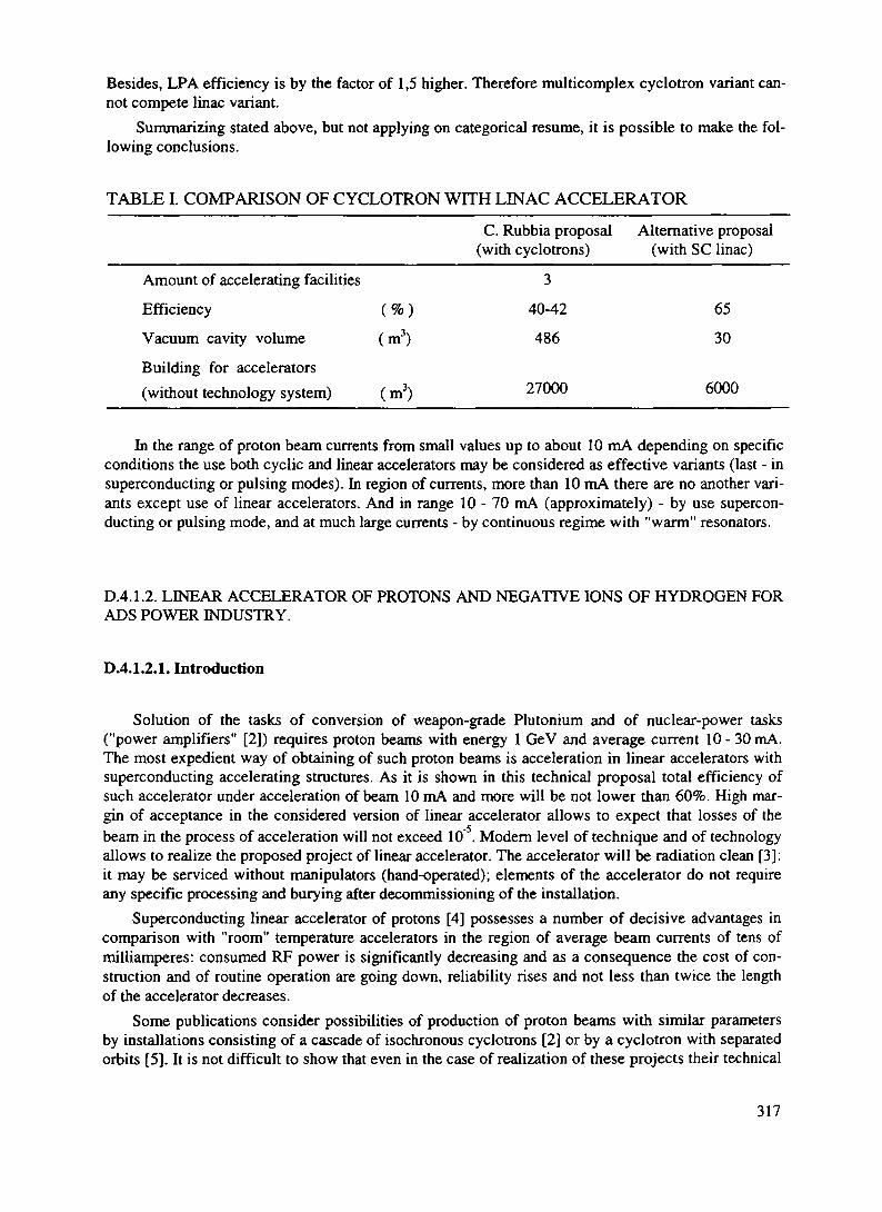
Besides, LPA efficiency is by the factor of 1,5 higher. Therefore multicomplex cyclotron variant can-not compete linac variant.
Summarizing stated above, but not applying on categorical resume, it is possible to make the fol-lowing conclusions.
TABLE I. COMPARISON OF CYCLOTRON WITH LINAC ACCELERATOR_______
C. Rubbia proposal Alternative proposal(with cyclotrons) (with SC linac)
Amount of accelerating facilities 3
Efficiency (%) 40-42 65
Vacuum cavity volume (m3) 486 30
Building for accelerators(without technology system) (m3) 27000 6000
In the range of proton beam currents from small values up to about 10 mA depending on specificconditions the use both cyclic and linear accelerators may be considered as effective variants (last - insuperconducting or pulsing modes). In region of currents, more than 10 mA there are no another vari-ants except use of linear accelerators. And in range 10-70 mA (approximately) - by use supercon-ducting or pulsing mode, and at much large currents - by continuous regime with "warm" resonators.
D.4.1.2. LINEAR ACCELERATOR OF PROTONS AND NEGATIVE IONS OF HYDROGEN FORADS POWER INDUSTRY.
D.4.1.2.1. Introduction
Solution of the tasks of conversion of weapon-grade Plutonium and of nuclear-power tasks("power amplifiers" [2]) requires proton beams with energy 1 GeV and average current 10 - 30mA.The most expedient way of obtaining of such proton beams is acceleration in linear accelerators withsuperconducting accelerating structures. As it is shown in this technical proposal total efficiency ofsuch accelerator under acceleration of beam 10 mA and more will be not lower than 60%. High mar-gin of acceptance in the considered version of linear accelerator allows to expect that losses of thebeam in the process of acceleration will not exceed 10 . Modem level of technique and of technologyallows to realize the proposed project of linear accelerator. The accelerator will be radiation clean [3]:it may be serviced without manipulators (hand-operated); elements of the accelerator do not requireany specific processing and burying after decommissioning of the installation.
Superconducting linear accelerator of protons [4] possesses a number of decisive advantages incomparison with "room" temperature accelerators in the region of average beam currents of tens ofmilliamperes: consumed RF power is significantly decreasing and as a consequence the cost of con-struction and of routine operation are going down, reliability rises and not less than twice the lengthof the accelerator decreases.
Some publications consider possibilities of production of proton beams with similar parametersby installations consisting of a cascade of isochronous cyclotrons [2] or by a cyclotron with separatedorbits [5]. It is not difficult to show that even in the case of realization of these projects their technical
317

parameters - efficiency and losses - will be lower than of a superconducting linear accelerator. Effi-ciency of cascade cyclotrons [2] will be not higher than 40%.
Description and the characteristics of the accelerator of protons and negative ions of hydrogenare presented in this work. Energy of accelerated particles is 1 GeV, current - up to 30 mA. Acceler-ating structures are superconducting. The base of the work is taken from [6].
D.4.1.2.2. Principal scheme of the linear accelerator. The main parameters
The proposed scheme of the CW proton linear accelerator to energy 1 GeV and current 10 -30 mA with superconducting accelerating resonators [6] is shown in the Fig.2.1.
The injector produces a beam of protons with energy 60 keV. Further the protons are acceleratedin the initial part of the linear accelerator (DPA) - an accelerator with space-uniform quadrupole fo-cusing (RQF). A four-chamber H-resonator excited with the wave TE2M of 425 MHz accelerates pro-tons to energy 3 MeV.
The first part of the linear accelerator consists of short four-gap resonators with drift tubes ex-cited at the frequency 425 MHz. Energy of protons in this part of the accelerator rises to 50 MeV (thisfigure will be corrected after detailed investigations). Separation of the accelerating structure to shortresonators is dictated by necessity to place between them quadrupole focusing lenses of permanentmagnets. The structure of the period of focusing is FODO. Total number of resonators -28.
60keVUP
3,5m
3 MeV
20m425 Mhz
50 MeV 1 GeV
Main Pan380m
1275 Mhz
0H0
JIB - 2
FIG. 2.1. Scheme of superconducting proton linear accelerator with the energy of 1 GeV and thecurrent of 10-30 mA: H - injector; RFQ - initial part of accelerator; P2-P333 - resonators; K - per-manent magnet quadrupoles; KY-] - HF amplification channel at 425 MHz; KY-2 - HF amplificationchannel at 1275 MHz; M 3 V - powerful master device.
The second (main) part of the linear accelerator provides acceleration of protons to energy1 GeV. Accelerating structure consists of 304 nine-cell axially symmetric resonators with cells ofelliptical shape excited at the frequency 1275 MHz. Odd ratio the frequencies of the first and the sec-ond parts of the linear accelerator is equal 3 and this allows in case of necessity to accelerate simulta-neously protons and negative ions of hydrogen. Acceleration rate at the "pure" length of the resona-
318

tors is 5 MeV/m. Averaged along the whole length of the accelerator rate of acceleration is 2.5MeV/m.
HF system and the system of automatic control are proposed as classic for proton linear accel-erator scheme.
The main parameters of the linear accelerator are presented in the Table EL Value of power foracceleration of the beam is given for the current 10 mA. For higher intensity beams of protons thisfigure should be proportionally increased. Losses taken by Helium do not change. The parameters ofthe acceleration will not change for the case of acceleration a beam of negative ions of Hydrogen.
In order to provide superconductivity the resonators, operating surface of which is covered withNiobium layer, are cooled by liquid Helium. Adopted temperature 2K corresponds to minimum ofcapital investments and the cost of routine operation. The version of the cryogenic system consistingof typical cryomodules is chosen in these technical proposals. A cryomodule consists of a cryostatwith several resonators together with adjacent devices inside of it. Different versions of cryomoduleswere considered. As an example a cryomodule of the main part of the linear accelerator is shown inthe Fig.2.2. it consists of two accelerating resonators: 1 - a quadrupole lens, 2 - resonators, 3 - Heliumvessel, 4 - magnetic and nitrogen shield, 5 - vacuum housing, 6 - superinsulation, 7 - tubes for liquidHelium, 8 - can-type RF window, 9 - waveguide, 10 - mechanical drive, 11 - a mechanism for adjust-ing of the resonators, 12 - a load to suppress higher modes, 13 - 14 - supports, 15 - a frame with ad-justing devices.
The following ideology linked with quantitative characteristics of heat removal by Helium isadopted. Total power of losses for Helium in the resonators of the linear accelerator is approximately4000 W (Tablell). Acceptable losses by Helium due to losses of the beam in the linear acceleratorwith hand controlling are 380 W or approximately 10% of the losses in the resonators. The samevalue is taken for acceptable heat flux from the external space through the cryostat. It defines the re-quirements to thermal insulation of the cryostat. So the total thermal power (PHe) removed by Heliumis 4700 - 5000 W.
One of the main characteristics of particle accelerators for the considered nuclear-power utiliza-tion is the value of total efficiency defining efficiency of utilization of electric power put to the accel-erator. Estimation of the efficiency for the proposed linear accelerator is given later [7].
Full efficiency of a superconducting linear accelerator
r\ = Pb/(Pe + Peke),where Pb is HF power for acceleration of the proton beam, PC and Peke - powers of electric
feeding of the HF system and of cryogenic system of the accelerator. Let us introduce notations forefficiency of HF system T)rf = Prf / Pe and Tjk = PHe/Peke- Then
Tl = Pb/[(Pb + P rf.cOV1 + PHe V1],Where Prf.c is power of HF losses in the walls of the resonators.
AsPb»Prf.c then r\ = Pb/(PbV1 + Phe-Tlif1),The efficiency of cryogenic system may be estimated from the relationship [8]
Tlk = 0.3 T2/(T] - T2).3
For T, = 300 K and T2 = 2K we have r|k = 2-10 . Accepting for estimation T|rf = 0.7 andPHe = 5 kW we shall obtain expression for calculation of efficiency of superconducting accelerator asa function of Pb:
Ti = Pb/(1.41-Pb +2.5-106)
Under beam current 10 mA Pb = 107 W efficiency of the accelerator is equal 60%. For beam cur-rent 30 mA we have T| = 65%.
319

FIG. 2.2. Cryomodules
D.4.1.2.3. Beam dynamics
DA. 1.2.3.1. Initial part of the accelerator (RFQ accelerator)
Calculations and investigation of beam dynamics allowed to define main parameters of RFQ sec-tion which 1S the initial part of the accelerator (Table II). Voltage between the electrodes is 60 kV.
A matching fun of 3pX length is placed to match the beam at the input of the accelerator.Variation of the main parameters along the channel is shown in the Fig. 2.3 where the curves of
variation of average radius of the beam R, coefficient of electrodes modulation m, equilibrium phaseFS, efficiency of acceleration T, voltage between the electrodes U are presented. All curves are pre-sented in three scales: in dependence of the distance to the beginning of the accelerator Z, particleenergy W, number of a period N (length of a period - pA,).
Figs 2.4 and 2.5 show behaviour of phase and radial trajectories of the beam; the last are pre-sented at the background of the aperture of the channel: upper line corresponds to the largest apertureat a period, the lowest - to minimal, medium - to medium radius of the aperture. Trajectories showthat the beam may pass through the accelerating-focusing channel practically without losses.
Results of calculations allow to shows: a) phase width of output beam is rather small in order tostart acceleration in the following sections with equilibrium phase -45° (with some margin);b) coefficient of rising of the emittance due to dependence of the phase portrait of the beam uponphase of leaving at RF-period is 1.5 - 2; this was the reason why under calculation of the followingpart of the accelerator emittance of input beam was supposed to be 0.1 Ticm-mrad (with some mar-gin)-
320
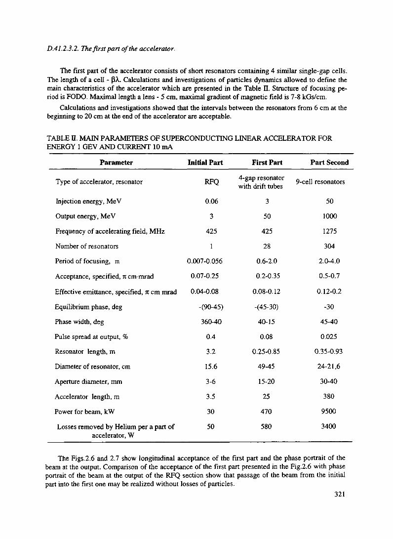
D.41. 2.3.2. The first part of the accelerator.
The first part of the accelerator consists of short resonators containing 4 similar single-gap cells.The length of a cell - PX. Calculations and investigations of particles dynamics allowed to define themain characteristics of the accelerator which are presented in the Table n. Structure of focusing pe-riod is FODO. Maximal length a lens - 5 cm, maximal gradient of magnetic field is 7-8 kGs/cm.
Calculations and investigations showed that the intervals between the resonators from 6 cm at thebeginning to 20 cm at the end of the accelerator are acceptable.
TABLE n. MAIN PARAMETERS OF SUPERCONDUCTING LINEAR ACCELERATOR FORENERGY 1 GEV AND CURRENT 10 mA
Parameter
Type of accelerator, resonator
Injection energy, MeV
Output energy, MeV
Frequency of accelerating field, MHz
Number of resonators
Period of focusing, m
Acceptance, specified, n cm-mrad
Effective emittance, specified, n cm mrad
Equilibrium phase, deg
Phase width, deg
Pulse spread at output, %
Resonator length, m
Diameter of resonator, cm
Aperture diameter, mm
Accelerator length, m
Power for beam, kW
Losses removed by Helium per a part ofaccelerator, W
Initial Part
RFQ
0.06
3
425
1
0.007-0.056
0.07-0.25
0.04-0.08
-(90-45)
360-40
0.4
3.2
15.6
3-6
3.5
30
50
First Part
4-gap resonatorwith drift tubes
3
50
425
28
0.6-2.0
0.2-0.35
0.08-0.12
-(45-30)
40-15
0.08
0.25-0.85
49-45
15-20
25
470
580
Part Second
9-cell resonators
50
1000
1275
304
2.0-4.0
0.5-0.7
0.12-0.2
-30
45-40
0.025
0.35-0.93
24-21,6
30-40
380
9500
3400
The Figs.2.6 and 2.7 show longitudinal acceptance of the first part and the phase portrait of thebeam at the output. Comparison of the acceptance of the first part presented in the Fig.2.6 with phaseportrait of the beam at the output of the RFQ section show that passage of the beam from the initialpart into the first one may be realized without losses of particles.
321

FIG 2 3 Parameters of RFQ section with energy of 006 - 3 MeV R - minimal aperture radius , m-electrode modulation factor, FS- equilibrium phase U- voltage between electrodes (relative units), T-acceleration efficiency
In order to define conditions of passage from the first part into the main accelerator and alsofrom the initial part into the first additional investigations were carried out As it is seen from the
Fig 2 7 phase length of 50-MeV beam at the output of the first part does not exceed 20° i e it is possi-ble to think that acceleration by three times higher frequency under equilibrium phase -30 has foun-
dation As it will be shown later transverse matching of the beam also does not create any difficulties
D 4 1 2 3 3 Mam part of the accelerator
Mam part of the accelerator consists of a sequence of nine-cell resonators Length of a cell is(3A72 Resonators operate with three times higher frequency
Matching of the beam under passage from the first part into the mam is simpler as the lengths ofthe periods of focusing in both parts less differ In this case period of the first part is 10 0A. and in themain - 30 (3X i e in optimal case the period contains 60 cells The period of FODO containing 4 nine-cell resonators is of approximately similar to the finite number of focusing in the first part That is thereason why it is expedient to choose the structure of the FODO period with lenses placed between theresonators (pairs)
The characteristics of the main part of the accelerator obtained as result of calculation of particledynamics are presented in the Table II We notice that acceptance far exceeds beam ermttance at theinput of this accelerator part
Press iS For- Switch
322

FIG. 2.4. Beam phase trajectories in RFQ section.
FIG. 2.5. Beam radial trajectories in RFQ section.
W-Ws(MeV) .57
: : : : : : : : : : : : : : j : : : : : : j f l 0 0
Fi-Fs
FIG. 2.6. Accelerating channel acceptance of the first accelerator part.
D.4.1.2.4. Superconducting accelerating structure
DA.1.2.4.1. Initial pan of the accelerator. Superconducting H - resonator
A four-chamber H - resonator with space-uniform focusing (RFQ) will be used in the initial partof the accelerator (0.06 MeV - 3 MeV). Operating mode is H2n. Oscillation of H type creates quad-rupole focusing field and modulation of the tops of the electrodes introduces local variation adequateto appearance of longitudinal accelerating field.
As a design the four-chamber H - resonator is a cylinder loaded with V - shaped plane plates(electrodes) symmetrically fixed to the cylindrical wall. The tops of the plates are modulated alongtheir length. The plates have their edges at some distance from the bottom walls of the cylinder. Thefour-chamber H - resonator is relatively simple for fabrication, mechanical adjusting and cooling.Utilisation of the resonator in the pointed limits of energies for "room" accelerators became tradi-tional.
323
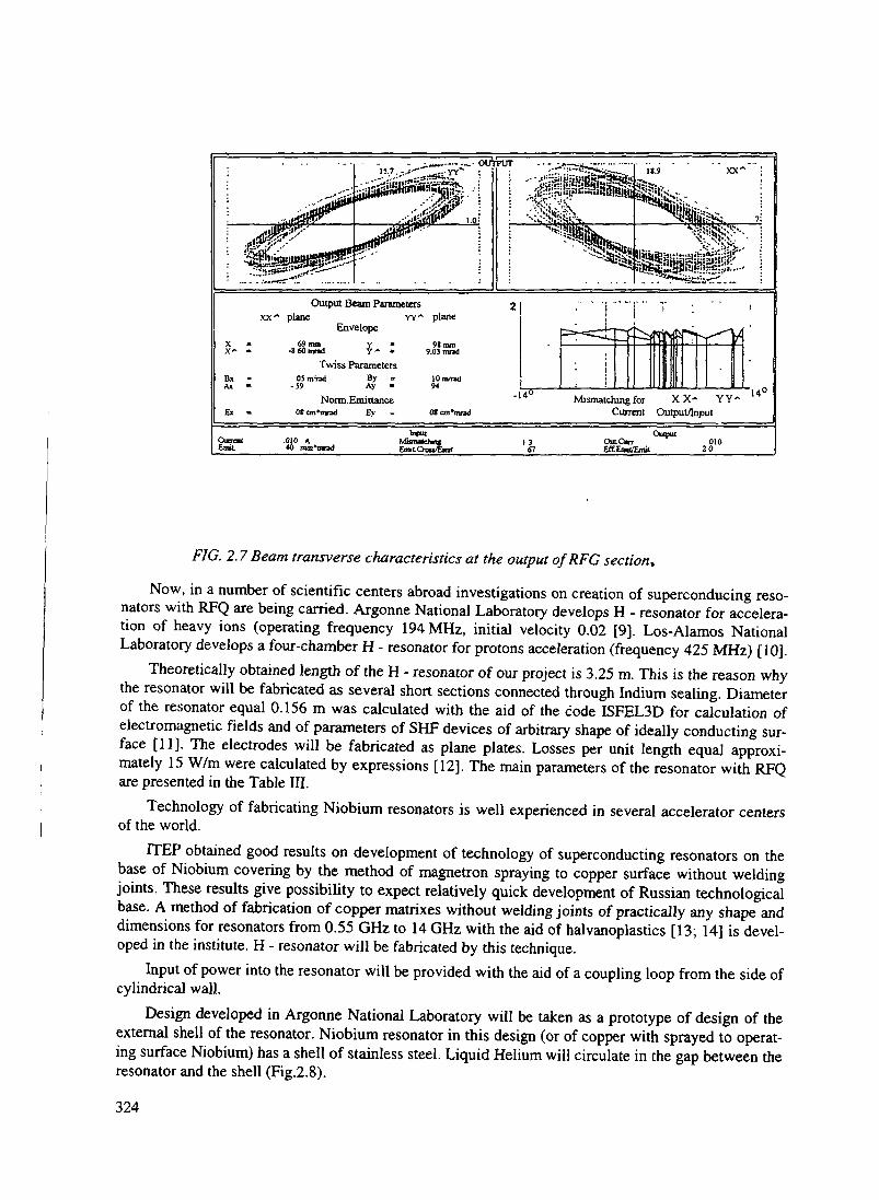
_;.„.,....--,.. OUTPUT
Output Beam Parametersxx" plane
69am-S 60 and
Envelope
Y- ^Twiss Parameters
YY" plane
98 mm9.03 mrad
OSnVod-J9
ByAy
Norm.Emi nanceOf cnt*imd £y
Mismatching for XX- YY~Current Output/Input
14°
CuncntEmit.
.010 A40 mm1
InputMiunuchfvEiratCrowEmn
1367
OutputOutCwr 010Eff.Emu/EmiL 20
FIG. 2.7 Beam transverse characteristics at the output of RFC section*
Now, in a number of scientific centers abroad investigations on creation of superconducing reso-nators with RFQ are being carried. Argonne National Laboratory develops H - resonator for accelera-tion of heavy ions (operating frequency 194 MHz, initial velocity 0.02 [9]. Los-Alamos NationalLaboratory develops a four-chamber H - resonator for protons acceleration (frequency 425 MHz) [10].
Theoretically obtained length of the H - resonator of our project is 3.25 m. This is the reason whythe resonator will be fabricated as several short sections connected through Indium sealing. Diameterof the resonator equal 0.156 m was calculated with the aid of the code ISFEL3D for calculation ofelectromagnetic fields and of parameters of SHF devices of arbitrary shape of ideally conducting sur-face [11]. The electrodes will be fabricated as plane plates. Losses per unit length equal approxi-mately 15 W/m were calculated by expressions [12]. The main parameters of the resonator with RFQare presented in the Table III.
Technology of fabricating Niobium resonators is well experienced in several accelerator centersof the world.
ITEP obtained good results on development of technology of superconducting resonators on thebase of Niobium covering by the method of magnetron spraying to copper surface without weldingjoints. These results give possibility to expect relatively quick development of Russian technologicalbase. A method of fabrication of copper matrixes without welding joints of practically any shape anddimensions for resonators from 0.55 GHz to 14 GHz with the aid of halvanoplastics [13; 14] is devel-oped in the institute. H - resonator will be fabricated by this technique.
Input of power into the resonator will be provided with the aid of a coupling loop from the side ofcylindrical wall.
Design developed in Argonne National Laboratory will be taken as a prototype of design of theexternal shell of the resonator. Niobium resonator in this design (or of copper with sprayed to operat-ing surface Niobium) has a shell of stainless steel. Liquid Helium will circulate in the gap between theresonator and the shell (Fig.2.8).
324
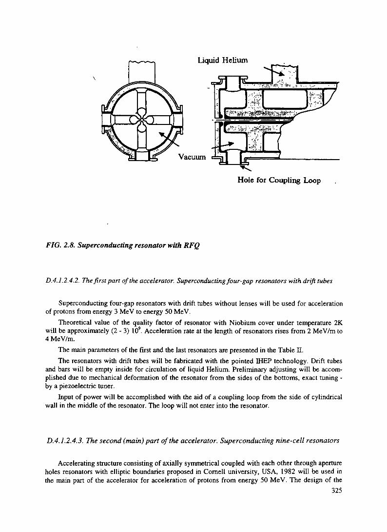
Liquid Helium
T3IE
Vacuum
Hole for Coupling Loop
FIG, 2.8. Superconducting resonator with RFQ
DA.1.2.4.2. The fir si pan of the accelerator. Superconducting four-gap resonators with drift tubes
Superconducting four-gap resonators with drift tubes without lenses will be used for accelerationof protons from energy 3 MeV to energy 50 MeV.
Theoretical value of the quality factor of resonator with Niobium cover under temperature 2Kwill be approximately (2 - 3) 109. Acceleration rate at the length of resonators rises from 2 MeV/m to4 MeV/m.
The main parameters of the first and the last resonators are presented in the Table II.The resonators with drift tubes will be fabricated with the pointed IHEP technology. Drift tubes
and bars will be empty inside for circulation of liquid Helium. Preliminary adjusting will be accom-plished due to mechanical deformation of the resonator from the sides of the bottoms, exact tuning -by a piezoelectric tuner.
Input of power will be accomplished with the aid of a coupling loop from the side of cylindricalwall in the middle of the resonator. The loop will not enter into the resonator.
D.4.1.2.4.3. The second (main) part of the accelerator. Superconducting nine-cell resonators
Accelerating structure consisting of axially symmetrical coupled with each other through apertureholes resonators with elliptic boundaries proposed in Cornell university, USA, 1982 will be used inthe main part of the accelerator for acceleration of protons from energy 50 MeV. The design of the
325

structure is the most suitable from the point of view of simplicity of fabrication and possibility toobtain the highest possible accelerating field. TC - mode wave is the operating wave of the structure.The period of the structure is consequently pXopet/2, where P is relative velocity of particles, A^ -operating wavelength which is equal 23.53 cm.
This structure is used in several electron accelerators abroad [12]."These are - accelerator CEBAF(USA), accelerating complex LEP (CERN), laboratory SACLAY (France), accelerating complex onDarmstadt (Germany), accelerator LISA (Italy). Large experience on development and creation of thestructure is accumulated.
A nine-cell resonator is chosen for the main part of the supposed accelerator. Total number ofresonators is 304. Accelerating-focusing modules of the main part consists of two resonators and ofone quadrupole with permanent magnets. Design of such modules is presented in the Fig.2.2.2. Inputof HF power is accomplished outside of the cells of the resonator through a travel tube.
On the base of the data obtained from calculations of particles dynamics (diameter of the aper-ture hole, longitudinal dimensions, amplitude of accelerating wave) with the aid of the codes AZI-MUTH [15], ISFEL3D [11] and of service (auxiliary) codes allowing to simplify description of thestarting data for these codes geometrical dimensions and parameters of two resonators - of the first toenergy 50 MeV and of the last for energy 1000 MeV were defined. Intervals of drift tubes with thelength 50 mm at the beginning and at the end of the resonators necessary under large aperture hole tosuppress irradiation of waves were taken into account in calculations. Final (exact) calculation ofgeometry of every of the resonators and their parameters will require sequential correlation with cal-culations of beam dynamics (taking into account the real fields) and also to take into account variationof frequency under cooling of resonators and under vacuum pumping.
The cells of the first and of the last resonators of the main part of the accelerator are shown inthe Figs.2.9. The parameters of these resonators are presented in the Table in.
FIG. 2.9 Sketch of the cell of the .last resonator of the main part of the accelerator.
326

D.4.1.2.4.4. Focusing quadrupoles with permanent magnets
Focusing of protons in the linear accelerator is implemented by permanent magnet quadrupoles(except the initial part where RFQ is used). There are 28 quadrupoles in the first part and 152 - in thesecond. The structure of focusing period in the both parts - FODO. Quadrupoles of the second partshould have gradient of magnetic field 1-2 kGs/cm under diameter of the aperture 30 - 40 mm. Thelength of a quadrupole lens is 10-20 cm.
TABLE ffl. PARAMETERS OF THE FIRST AND OF THE LAST RESONATORS OF THE MAINPART OF THE ACCELERATOR.
Energy, MeV
3Period of accelerating structure H, mmDiameter of the aperture, 2a, mmRadius of rounding if the iris, Ri, mmRadius of rounding of the cell, Rrc, mmRadius of cell, RC, mmAngle of wall slope, a, gradLength of nine cells of the resonator, cmCoupling coefficient Kcol. %Losses in Helium, W/mLosses in BKSh, W/mAnomal losses, W/mStatistic losses, W/mLosses in Helium in resonators, W
50
0.32538.477.4
36
119.78
36.48.8717.50.48.48.76.1
1000
0.87102.77.4
637
107.15
92.63.5211.80.42.78.7
10.9
Necessity to make short interresonator gaps providing optimal beam dynamics and a wish to sim-plify the cryostats lead to relatively longer cryostats - not less than 5 - 1 0 meters. Magnetic quad-rupoles turn out to be put into liquid Helium.
Alloy Samarium-Cobalt is supposed to be used as magnetic material. It possesses high volumedensity of magnetic energy (BH)^ , comparatively high temperature stability and strictly fixed posi-tion of magnetization vectors. This alloy may operate under Helium temperature [16].
The gradient of the field may be calculated for a sector lens (8 sectors in a lens) by the followingexpression
G = [2 Sin(3p/8)/(3p/8)] M(l/ro - 1/r)Here G is gradient of the field in kGs/cm, M - magnetization in kGs, TO, r internal and external
radii of a lens in cm.For the alloy "Samarium-Cobalt" M = 10 kGs. In order to obtain G = 2 kGs/cm under ro = 2 cm
the external radius of the lens should be equal 2.8 cm.
327

D.4.1.2.5. High frequency system and system of automatic control
D.4.1.2.5.1. Peculiarities of the system
Principal scheme of the linear accelerator (Fig.2.1) contains a system of high frequency feedingof the initial and first parts with operating frequency 425 MHz and a system of feeding the resonatorsof the main part with operating frequency 1275 MHz. Synchronous excitation of these systems is re-alized from a powerful master device through excitation lines and of reference phase LB-1 and LB-2.Master device contains a modules of stabilization of the phases of HF oscillations inter outputs of 425and 1275 MHz.
Taking into account necessity to provide high reliability of operation of the linear accelerator andaccepting into consideration Russian and world experience of development of similar by parametersHF systems it was supposed to use amplifying klystrons in the output cascades of HF channels. Suit-able by (he parameters klystrons of continuous way of operation are produced by different Russianand foreign firms [17].
Creation of a multichannel HF system for superconducting linear accelerator with proton current10-30 mA is linked with solution of a number of specific technical tasks arising in particular due tohigh loading of the superconducting resonators by beam current and due to high quality factor of theseresonators. So there are some additional requirements to the channels of HF system:
- possibility of smooth controlling of HF power;- stable operation of HF channel under conditions of significant variations of load;- high electric stability of feeding system;- provision of stability of HF field in resonators at levels of accuracy approximately 1% of am-
plitude and 1 degree by phases under significant variation of load and output power of HF generator;- quick shut up of HF power in case of loss of accelerated proton beam.
Meeting to these requirements is simplified due to utilization of continuous way of operation ofthe linear accelerator and under utilization of decoupling devices between the klystrons and resonatorsproviding mode of operation of klystrons to matched load. Calculations showed that reverse attenua-tion should be not less 15-20 db. Circulators produced in Russia meet these requirements. Thesedevices will also stabilize frequency characteristics of the system "HF generator - feeding line - reso-nator" that will simplify operation of the systems of amplitudes and phases stabilization and of auto-matic tuning of the resonators.
Coupling of feeding lines and the resonators is usually taken in the HF systems of linear ac-celerators with strong load by the beam on condition of matching of the feeding lines under accelera-tion of nominal value of beam current. In dependence of used system of automatic tuning of resonantfrequency of resonators the following two versions of operation are possible:
- resonator is tuned exactly in resonance with exciting frequency;- resonator is detuned to such extent that its input impedance together with beam loading is purely
active.Comparison of these versions allows to make the following conclusions:1. In both versions under acceleration of the beam power of HF generator must be increased by
the factor of four times in comparison with zero value of beam current. In these conditions in the firstversion HF generator must generate higher power than in the second version by the value of HF powerreflected by resonator.
2. Under utilization of the second version of tuning in dependence of the value of the beam cur-rent it is necessary to rerune the resonator.
3. Under decreasing of synchronous phase difference of these modes of operation decreases.
328

Any mode of operation may be realised in a HF system. If to choose the average length of reso-nator of the main part of the linear accelerator equal 0.6 m (see Table H) and acceleration rate 5MeV/m then HF power necessary for acceleration of beam 10 and 30 mA will be correspondingly 30and 90 kW. Routine power of generator in a channel of HF system of such resonator must be 40 kWfor current 10 mA and 120 kW for current 30 mA. Limits of variation of output power of HF genera-tor in the process of tuning of the accelerator to acceleration of normal current should be provided bycontrolling systems in the ranges 10 - 40 kW and 30 - 120 kW correspondingly.
Construction of systems of automatic control of amplitude (ACA), of phase (ACP) and tuning ofresonators (ACF) are of traditional type and they are described in [18, 19]. Principles of constructionare described briefly in the next section.
D.4.1.2.5.2. HF system and system of automatic controlling
The system of HF feeding and the system of automatic control may be designed on classical prin-ciples adopted for high current linear accelerators where every accelerating resonator is excited by aseparate HF channel with system of ACA, ACP and ACF. But in order to rise reliability of HF systemand of automation systems and to lower the costs it is desirable to decrease number of HF channelsdue to excitation of a group of resonators by one HF generator. At the facility LEP-2 [20], for exam-ple, one HF channel of amplification operating with frequency 352 MHz and of 1300 kW outputpower excites 16 resonators.
The main part of the accelerator consists of 304 resonators operating with frequency 1274 MHz.In a group of four sequentially placed resonators these resonators consume approximately equal HFpowers (even without optimization this difference does not exceed 1%). That is the reason why it ispossible to excite such groups by one generator (Fig.2.10). System of distribution of HF power to theresonators is constructed with the aid of bridge-type devices [21] proposed for decoupling of twoloads and division of HF power to equal parts, Split-type of double T-shape bridges may be used asprototypes of such devices. Amplifying klystrons with output power approximately 500 kW for accel-eration of 30 mA beam and 150 - 200 kW under beam current 10 mA will be needed for excitation ofa group of four resonators.
Systems of ACA and of ACP are constructed by traditional for linear accelerators schemes [19].Control signals are extracted from each resonator as it is shown in the Fig.2.10. Systems of ACF areapplied to each resonator. Adjusting of phases of HF fields in resonators is carried out with the aid ofphase-controllers 6 placed at the outputs of the bridges M2 and M-,. Adjusting of phases is accom-plished with the aid of phase-controllers 6 at the inputs of amplification channels and in the line ofreference phase cpref •HF system of initial part and of the first part of the accelerator provides excitation of one resonator ofRFQ type and 28 short resonators with drift tubes. RFQ resonator requires approximately 90 kW ofHF power for acceleration of current 30 mA and 30 kW for acceleration of 10 mA. Resonators withdrift tubes require 45 - 108 kW and 15-36 kW for acceleration of 30 and 10 mA correspondingly. HFpower rises with rising of the number of resonators. Due to the fact that under constant along thewhole length of the accelerator rate of acceleration and different levels of power in separate resona-tors here a "classical" scheme with individual excitation of every resonator by a separate klystrongenerator might turn to be expedient. In this case a circulator should be installed in the feeding linebetween the klystron and resonator. The resonators with corresponding HF channels are covered withsystems of stabilization of amplitudes, phases and resonant frequencies. Klystrons of equal power -130 kW -are supposed to be used for unification of the devices for acceleration of beams to 30 mA.For current 10 mA the required HF power is three times less. Under corresponding optimization of theaccelerating channel the version of excitation of two or four resonators of the first part of the linearaccelerator becomes possible (see Fig.2.5.1).
329

D.4.2.6. Characteristics of the alternative technical decisions
The intensive supercounducting linear accelerator is technically feasible and should ensure ex-treme high performance on economic and power efficiency. The reason on realization proposal ispossible to support, having specified on opportunity of reception of enough high parameters by use ofnew ideas in traditional techniques of warm resonators.
JIBft
t
«
FIG.2.10 Scheme of excitation of 4 resonators by one channel of amplification with system for con-trolling the parameters of HF field. P1...P4 are accelerating resonators; Ml, M2, M3 bridges fordistribution of HF power; Rbl, Rb2, /?« - balasting loads; a - circulator; Y - amplifier of HF power;EA - line of reference phase excitation; B-APA - a set for processing of the error signal in the systemACA; P APA - executing mechanism ofACA system; B-AP 0 - a set for processing of the error signalin the system ACP; P AP& - exacuting mechanism of ACP system; Jl - a probe ofACF system; PAP V - executing mechanism ofACF system; T - phasecontroller.
So, as spare variant to use of superconductivity at higher temperature it is useful to consider alsopulsing mode of operations of warm resonators, when the high meaning efficiency of acceleration oflarge beam currents is transformed to area of smaller currents and is supported high irrespective ofvalue of an average current of a beam, which is defined by frequency of pulse repetition rate [22].Calculations show, that the efficiency of resonators in pulsing mode can come near to 90 % in wholerange of average currents 10-30 mA of the offered accelerator, that will ensure general efficiency(from ac network to beam) about 50 %.
Pulsing mode is rather effective, if a current in pulse in 2 and more time exceeds necessary aver-age meaning, and duration of pulses more than 500 ms. The natural pauses between pulses of a beamcurrent thus can be used in this case for switch on and off deflecting of the output beam at it distribu-
330

tion on several directions, that would be economically expedient in case to work of a target on low-ered power or functioning of several targets.
Restriction of relative losses of particles by value smaller, than 10'5 is determined by necessity ofa level of induced radioactivity reduction with the purpose of reception of access to acceleratorthrough small time after switch off the beam and maintenance of radiating cleanness of linac units incase of their dismantle. The reduction stipulated in the present proposal of radiating fields (at the ex-cess value of the channel acceptance and reduction of losses of particles) can be considerablystrengthened, if to provide accommodation along accelerating channel of graphite proton absorbers[23], dropping out from mode of resonant acceleration. Thus on 1-2 order (up to 10"4) the require-ments to limit of allowable losses are reduced, that is a reached a stage on working linear accelerators[24]. Thus, one of main problems of acceleration of intensive beams - problem of reduction of radia-tion up to acceptable level in the linac can be confidently resolved.
Reliability of rather expensive installation, which is the high-current the accelerator, requires ofthe special attention. In heaviest degree it depends on reliability of RF system.
Calculations show, that supplying of 1-5 cells from individual RF of channels of rather smallpower (as it is already done on SC resonators of heavy ions post - accelerators) and having increasedtotal number of cells (or intensity of a field in their gaps) only on 1-2 %, it is possible to ensure trou-ble-free RF excitation of cells necessary for nominal acceleration [26]. In case of the RF channel fail-ure all elements of the given section, including cells of section, pass in category of switched off, andcompensating influence on a beam is provided at the expense of automatic increase of RF field inten-sity and updating of its phase in operating sections. The failed channel after repair comes back inwork, and the intensity of the field in all sections is automatically lowered.
The additional rather valuable quality of the recommended circuit is that the failure of a section(or some their amount) does not cause a stop of the accelerator and does not require immediate re-placement or repair (if, certainly, it is not connected with loss of high vacuum or occurrence of a me-chanical obstacle to flight of beam bunches). Failure of a section is compensated by work of stayingin operating conditions, and the elimination of malfunction can be postponed on long time beforescheduled preventive maintenance.
ITEP has a unique opportunity prior to the beginning creation of electronuclear installation tocheck up experimentally number of principally important questions on prototype of full - scale elec-tronuclear installation - the subcritical neutron generator [27], which is constructed on the basis of theproton linear accelerator ISTRA-36 and equipment of shut-down heavy-water reactor HWR. The gen-eral scheme of the generator is shown on Fig. 9.1 and section D.4.1.9. Now this installation consistsof the accelerator - driver and subcritical blanket is the most advanced ones. The generator will serverange for study and improvement:
- Principles of a beam dosage of the accelerator - driver,- Formation of optimum distribution of density of a proton flux on target,- Safe for resonators and RF system of the accelerator at beam manipulations,- Uninterrupting beam diagnostics ,- Reliable way of measurement of proton flux on target.
D.4.1.3. Pb-Bi TARGET AND PARTITIONED SUBCRITICAL BLANKET
Subcritical blanket with fast and thermal zones (Fig.3.1) consists of the following compo-nents:- proton beam transport duct;
- fast spectrum blanket zone;- thermal spectrum blanket zone;
331

- coolant and moderator circulation loops;The fast spectrum blanket zone is a separate cylindrical vessel which encloses:- vertical section of a proton beam transport duct ending with a window which separates a vac-
uum plenum of the accelerator from the internal space of the vessel with Pb-Bi coolant.- a vessel separating coolant flows in downcomer and riser sections;- a zone with fuel assemblies;Steam generators providing heat removal from liquid metal coolant and generation of steam with
specified parameters are arranged at the top part of the vessel at a boundary between the riser anddowncomer sections.
The separating vessel above the zone with fuel assembles consists of two concentric shells witha vacuum plenum between, which provides thermal insulation between the downcomer and riser sec-tions of coolant flow path to eliminate heat losses.
Natural circulation of liquid-metal coolant is provided in the vessel.The fast spectrum blanket zone is installed into a cylindrical central plenum of the thermal spec-
trum blanket zone and is supported by a removable cover of the thermal zone.The fast zone of the blanket (Fig. 3.1) comprises 18 fuel assemblies (Fig.3.2), each consisting of
311 fuel pins with nuclear fuel made of oxide weapon-grade Plutonium and Thorium (Fig.3.3).Eutectic alloy 45% Pb + 55% Bi has been selected as a coolant. It serves also as a neutron-absorbingtarget located in a center of the fast-spectrum zone. Proton beam reaches the central plenum with theeutectic alloy via an ion-transport duct which ends by a spherical window made of Titanium.
A steam generator installed in the upper part of the fast-spectrum blanket 'zone vessel is in-tended for heat removal from liquid-metal coolant. It represents a straight-tube heat exchanger com-prising 4180 tubes of 16x2.5 mm diameter and 8m length. Pb-Bi coolant flows downwards in an inter-tube space by natural convection, while secondary coolant (water) circulates upwards inside the tubes.The tubes are united in separate sections which can be isolated in a water side, if necessary. Further,after design optimization of the breeding zone and SG's elements a possibility may appears to reduceboth sizes of the components and length of a section between them.
The thermal-spectrum blanket (Fig.3.4) zone is arranged around the fast-spectrum one andconsists of a vessel made from two cylindrical shells one of which is installed inside another. Theshells are connected in their lower part by a welded semitorous bottom, while in its upper part theyare connected by a removable cover made as a flat ring-shaped plate with orifices through whichtechnological channels (Fig.3.5) containing the fuel assemblies, as well as instrumentation and controlchannels (if necessary) are penetrated.
The channels upper end fittings are attached hermetically to the removable cover of the blanket'svessel.
A plenum of the vessel between the cylindrical shells is filled with heavy water moderator. Aspecial circuit with feed and discharge portions of pipelines, a heat exchanger, pumps and isolationvalves is provided for cooling the moderator.
The technological channels (Fig. 3.2 ) installed in the heavy water thermal blanket zone are pro-vided with their own high-temperature cooling circuit with DiO coolant. For this aim the channels aremade as Field-type tubes (tube-in-tube structure). Coolant flows downward through an annular gapbetween the tubes, then it moves upward along the inner tube cooling a column of fuel assembliesarranged in it. To organize coolant circulation through the channels they are provided with individualfeed and discharge tubes connected to in the region above the blanket vessel removable cover(Fig.3.6). Beyond the blanket these tubes are united in collectors. Control valves are installed in thetubes to provide flowrate shaping through the channels.
Taking into account a substantial difference of temperatures between moderator in interchannelspace and coolant in the channels they are mutually insulated with the aid of a gas layer formed by a
332

plenum between a channel's pressure tube and a guard jacket around it. Leak-tightness of the techno-logical channels may be monitored by moisture and pressure control in this plenum.
The core of thermal blanket (Fig.3.2 ) comprises 684 fuel assemblies of a Field-tube type, ar-ranged in a triangular lattice with 280 mm pitch and surrounded by inner and outer heavy water re-flectors. Each of the assemblies includes 36 fuel rods made of anixed oxides of weapon-grade Pluto-nium and Thorium (Fig.3.6). Up to 36 control rods can be arranged in the thermal-spectrum blanket, ifnecessary.
The choice of liquid-metal coolant. Lead - bismuth alloy (in 45:55 by weight) taken as liquid-metal coolant for the fast-spectrum blanket zone is eutectic with melting temperature appr.!25°C.Low melting temperature of the alloy is main advantage of this coolant type in comparison with purelead (melting temperature of ~327°C).
Lower melting temperature of the coolant allows maintenance operations for replacement of in-vessel equipment during planned outage with a higher safety and lower consumption of energy tomaintain coolant in melted state. At present, technology for this alloy handling has been developed,which takes into account many-years experience in practical utilization of Pb-Bi coolant. Applicationof special additives together with protective coatings on structural materials enables to minimizenegative effect of such processes as erosion, corrosion and mass transfer.
Furthermore, application of Pb-Bi alloy as coolant and a target material simultaneously providesthe same level of primary neutrons bom in spallation reactions as for lead target. The advantage ofmother lead in lower induced activity under neutron irradiation at spallation reaction disappears sincethe main contribution to long lived activity (T]/2>100-days) for both target materials is caused not byPo-210, but by various isotopes of Bi, Te, Hg and Au accumulated due to (p, xn) and (n, xn) reactionsin high-energy part of proton and neutron spectra .
TABLE IV. THE MAIN PARAMETERS OF SUBCRITICAL BLANKET WITH FAST-THERMALZONES.
Parameters Units Fastzone
Thermalzone
Gross thermal powerMain vessel
heightouter diameter
Coolant target spallation materialmoderator
Coolant massPumping method
Coolant flow in coreCoolant pressureHeight of convection columnSpallation target powerCoolant flow in targetFull coolant flow in exchanger -
MW
mm
t
kg/sMPa
mMWkg/s
300
272
moltenlead andPb-Bi400
naturalconvection
7560
2510
502
2000
99
heavywater
circulationpumps13890
110
333

TABLE IV (Cont.)steam generator
Water flow in steam generatorHeight of steam generator
Fuel core: number of fuel assembliesnumber of fuel pinsnumber of control rods
Max. coolant speed in fuel assemblyHeight of active coreRadial power flattening factorAxial power flattening factorMaximum fuel pin powerMaximum fuel power densityMaximum fuel temperatureClad temperatureMaximum outlet coolant temperature
Volume water in coolant loopSurface of stainless steelVolume of moderator in tankTotal volume of moderatorTemperature of moderatorPressure in moderator loopSurface of stainless steel
kg/skg/sm
m/sm
kWkW/m3
°C°C°Cm3
m2
m3
m3
kMPam2
80621376
818
331
1,481,51,41,6
112,91,42.10*
1609760628
68436247,46,02,2
1784,6.10s
49433631045,93000801603400,1350
334

Beam pipe
Removableplate
Coplanl"nlet
Steam generatorSeismic isolator
Technological channel
Coolant outletSeismic isolator
Target core
Blanket
Fast spectrumblanket zone
Thermal spectrumblanket zone
Fig. 3.1 Layout of the subcritical blanket with fast and thermal zones.
Fuelassembly
Technological channel
Fig. 3.2 The fuel assembly of the fast zone
335

Coolantrirriiit
Coolan
1,25 inn
Gas loop(N2 , He)
232 urn22Gim
12,43 m8.2nni
nwnwnwnwnwowr)wnwn^nogogogogogogogogogogoo n^nununuououn ou
ogogogogogogogogogoo o o o o o o o o o
o o o o o o o o o o
Fuel pin
Removableplate
Fig. 3.3 The fuel asembly of thefast spectrum sone
Gas caviti
Fig.3.4 Layout of the thermal spectrum blanket
336

Coolantoutlet
Coolantinlet
Outletcollector
Inletcollector
Fig. 3.5 Thermal spectrum blanket - a part of the vessel containing fuel assemblies
0 9.1 mm
Outsidetube
Fig. 3.6 Pressurize tube containing fuel rods.
337

D.4.1.4. INTERACTION OF PROTONS AND IONGUIDES AND ACCUMULATION OF LONG-LIVED ACTIVITY IN IRRADIATED TARGETS.
Energy release and attenuation of beam in the window
Main power production in thin windows fabricated of stainless steel or titanium of 2 -5 mm ofthickness is due to ionization losses of the beam. Using well known tables of ionization losses [28]we can obtain the values of power production in the window (Tab. V):TABLE V. POWER GENERATION IN THE WINDOW
Beam
E,MeV
8001600
Current, mA
3060
Stainless steeldE/dx,
MeV/mm
1.341.20
Powerproduction
kW/mm40.2072.00
TitaniumdE/dx,
MeV/mm
0.770.69
Powerproduction
kW/mm23.1041.40
Losses of intensity of the beam due to nuclear collisions are defined by cross-sections ofinelastic interactions which are well known for 800 MeV protons with rather high accuracy: 775 mbfor steel (iron) and 695 mb for titanium [29]. Attenuation of beam intensity per one centimetre oftarget 6.5% for steel and 3.9% for titanium corresponds to these sections. Transfer energy of nucleiand of light charged particles leads to 10 -12% rise of full power production relative to ionizationpower production. Carried out analysis shows that replacing of stainless steel by titanium decreasespower production in the window approximately by a factor of 1.7 under the same thickness of thewindow.
Radiation damages of the target window
Experimental data on radiation stability of the target window under passage through it of highenergy protons are compiled and discussed in [30]. On the base of these data conclusion is made thatreplacing of a window in the project of the transmutation installation will be necessary only in a halfof a year (if it will necessary at all).
The results of estimations on the base of the codes NMTC/JAERY, LAHET and HTAPE andalso of [31-34] contradict each other and this makes it necessary to continue the works on comparisonof approaches and programs and also to carry on experiments at proton accelerators.
Analysis of long-lived activity of targets
Analysis of accumulation of radioactive nuclei in the target showed [30,35,36] that long-livedactivity normalised to similar conditions of irradiation may differ by several orders of the values.Estimations of activity of dominating isotope 2l°Po (T1/2 = 138 days) given in [36] for lead-bismuthtarget are more than 103 times higher than estimations of other authors. It is obvious that so seriousdiscrepancies in the estimations are defined by discrepancies in the used values of sections ofcorresponding channels of accumulation of the isotopes. It was found that the discrepancy is definedby the fact that the section (n,y) for reaction Bi was taken approximately 10" times higher. This isthe reason why it is very important to use only reliably tested libraries of activation data in
338

calculations of induced activities from one hand and to find out the reasons of contradictions ofcalculations of accumulation of radioactive nuclei in the targets from the other hand.
Calculations for a lead and a lead-bismuth targets irradiated by a 800 MeV 30 mA proton beamfor one year are presented in the Figures 4.1 and 4.2 and also in the Tables VI and VEL
Total and partial activities (Ci/kg) in Lead target (Tab.4.1) and Lead-Bismuth (Tab.4.2) forprimary proton beam energy 800 MeV and Current 30 mA after a year of irradiation for differentcooling times
TABLE VI. ACTIVITY OF THE LEAD TARGET AFTER ONE YEAR IRRADIATIONCooling timeTotal activity
Po-210Bi-207Pb-202Tl-204Hg-194Au-194Pt-193
TABLE VH. ACTIVITYIRRADIATION
Cooling timeTotal activity
Po-210Po-208Bi-207Tl-204Hg-203Hg-194Au-195Pt-193
180 days1.0 102
6.0 10^1.7 10'1
5.4 10'3
1.9 10'1.3 10°1.3 10"'
1.3
2 years2.7 10'3.9 10'5
1.6 10-'5.4 10'3
1.5 10'1.3 ID'1
1.3 10''1.3
OF THE LEAD/BISMUTH TARGET
180 days1.1 102
1.1 10'1.6
1.6 10'9.2
2.2 10'1
1.1 10'1
4.8 10'1.1
2 years3.4 10'7.1 10"'
1.11.5 10'
7.06.2 10'5
1.0 lO'1
6.21.1
20 years2.0
2.8 10'7
1.2 10''5.4 lO'3
5.9 10-'1.3 10'1
1.3 10°9.9 10'1
AFTER ONE
20 years1.2 10'9.3 10'6
1.5 10'2
1.1 10'2.8 10'1
-1.0 10°1.0 10'1
8.4 10''
100 years6.0 10'1
2.3 lO'8
2.7 10'2
5.3 10'3
-1.1 10'1
1.1 10'1
3.3 10-'
YEAR
100 years3.0
7.8 10'7
7.6 10-"2.7
1.8 10'7
-9.3 10'2
-2.8 10'1
339

ACTIVITY OF TARGET10*1 Pb target (50x100)
Proton energy 0.8 GeVI = 30 mAOne year irradiation
10 - 10 -3 10 ~2 10 1 10 10 2 10 ' 10 * 10 5 10 ' 10 7 10 ' 10 ' 10TIME OF COOLING (DAY)
FIG. 4.1 . Total and partial activities of Lead target as a Junction of cooling time.
ACTIVITY OF TARGET
Pb-Bi target (50x100)Proton energy 0.8 GeVI = 30 mAOne year irradiation
10 " 10 10 10 10 2 10 ' 10 * 10s 10 • 10 7 10 ' 10 * 10TIME OF COOLING (DAY)
FIG. 4.2. The same as in Fig.4.1 for Lead-Bismuth target
340

D.4.1.5. PHYSICAL PROPERTIES OF SUBCRTTICAL SYSTEM WITH FAST -THERMALONE-DIRECTION COUPLED BLANKET ZONE.
D.4.1.5.1. General description
General concept of ABC system with two blanket regions - inner fast spectrum blanket (F-blanket) and outer - thermal spectrum blanket (T-blanket) is presented (tables 5.1.1, 5.1.2, 5.1.3).Liquid Pb-Bi with natural convection pumping is used as target material and coolant in F-blanket.Outer T-blanket is a vessel with heavy water moderator and CANDU-type pressure tubes. Fuel pinsare made of mixed W-Pu -Th oxides clad in stainless steel for F-blanket and Zirconium alloy for T-blanket. Stainless steel wall of F-blanket and inner wall of T-blanket present a fast neutron reflectorfor F-blanket and a structural component (together with an inner heavy water reflector) providingone-direction neutron coupling. Due to the latter property total system can operate at low level ofsub-criticality (multiplication factor K 0.99) resulting in a low proton beam current (10 mA forprotons with energy 1 GeV) at safety conditions corresponding to much higher sub-criticality of themain - thermal part of blanket (K 0.95). Due to increased non-uniformity of radial power distributionin T-blanket compared to CANDU reactor, mean power output from fuel assemblies is twice lowerand their number is two times higher than in CANDU reactor.
TABLE VII. MAIN PARAMETERS OF ABC F-T INSTALLATION__________________________F-blanket____T-blanket_______________Gross Thermal Power/unit 300 MW 2000MWPrimary Electric Power 120 MW 580 MWType of plant Pool Pressure tubes in heavy water vesselCoolant Liquid Pb-Bi Heavy waterMultiplication factor K of total system 0.99Reactivity control and protection system_____Control rods+Tc- 99 dissolved in heavy water
TABLE Vm. FAST SPECTRUM BLANKET ZONE (F-BLANKET)Height of fuel 3.0mInner/Outer diameter 0.246 /1.071 mCoolant liquid Pb-BiFuel assembliesNumber of units 18 (36)Configuration hexagonalNumber of hexagonal rounds 2 (3)Number of pins/unit 331Flat to Flat 0.234 mpitch between pins 1.243 cmVolume of fuel per 1cm of length 174.8 cm**3Total volume of fuel 471965 cm**3Density of mixed oxides 10 g/cm**3Downward section for liquid Pb-Bi coolant the wall 1.247 m / 4 cmof F-blanket vessel, inner/thickness diameter___________________
341

TABLE EX. THERMAL SPECTRUM BLANKET ZONE(T-BLANKET)_______Heavy water vessel
inner diameter 132.7 cmthickness of inner wall 4 cm
Inner heavy water reflector - thickness 44.4 cmHeavy water core - inner/ outer diameter 2.295 / 8.025 m
height 6 mHeavy water reflector - thickness 0.5 mNumber of fuel assemblies 684Lattice (hexagonal) pitch 0.28 mFuel assemblyTube, (Zr - 2.5%) Nb , inner diameter / thickness 10.0 / 0.15 cm(Downward section for cold coolant)Pressure tube - inner diameter / thickness 13.4/0.45 cmGap 0.2 cmCalandria tube(Zr- 2% Nb), inner diameter 14.7 cm
thickness 0.2 cmpellet diameter 1.2154 cmmean density (effective) 7.9 g/cm**3clad, outer diameter 1.308 cmNumber of fuel pins 36element to element spacing 0.155cmelement to pressure tube spacing 0.102cmdiameters of centres 2.977,5.751,8.661Volume of fuel per 1 cm of length 41.808 cm**3Total volume of fuel 17.16m**3
D.4.1.5.2. The results of fuel cycles simulation
Calculations have been performed by modification of computer code TRIFON [37] for the caseof sub-critical systems with external sources and zero flux boundary conditions. An option forsupport of a constant level of sub-criticality (and consequently constant total power ) by continualremoval of reactivity control element was used. For this purpose wTc was supposed to be dissolved inheavy water moderator of T-blanket. The amount of "Tc is limited by the value 9.5 g/1 in heavywater moderator, as it is estimated below ( these values provide negative or zero reactivity effectcaused by moderator density decrease). Burn-able poisons (supposed to be added into outer row offuel pins in T-blanket) - Gd and Am isotopes (simultaneously transmuted ) - may be used fordecrease of "Tc concentration.
Several cases were considered:1. 99Tc as control reactivity element, F-blanket power 300 MW (18 fuel assemblies);
342

2. wTc as control reactivity element, F-blanket power 600 MW (36 fuel assemblies);3. 99Tc as control reactivity element , F-blanket power 300 MW. U-Th fuel cycle in thermal
blanket;4. 2nd cycle with Pu , Am and Cm nuclides from T-blanket after 1st cycle re-loaded into
F-blanket, T-blanket composition the came as in Case 1.
DA.1.5.2.1. Burn-up calculations in a cell of T-blanket.
The model of multi-layer cylindrical cell was used with fuel pin material and clad materialsmeared separately inside concentric cylindrical regions in correspondence with 3 fuel pin rows(Tables X and XI).
Typical neutron balance and mean concentrations of nuclides in the cell for beginning of a cycleare presented in Table XII.
TABLE X. COMPOSITION OF CELL IN T-BLANKET - DIMENSIONS AND TYPES OFREGIONS.
Zone123456789
10111213141516171819
thick., cm.50.15.40.06.74.06.51.06.77.06.56.06.77.06.22.15
1.55.85
7.15
Rmin, cm.00.50.65
1.061.121.861.922.432.493.263.323.893.954.714.785.005.156.707.55
Rmax, cm.50.65
1.061.121.861.922.432.493.263.323.893.954.714.785.005.156.707.55
14.70
Volume, cm3 *7.854E-015.583E-012.169E+004.020E-016.961E+006.99 IE-016.964E+009.419E-011.392E+011.260E+001.278E+011.497E+002.088E+011.813E+006.907E+004.783E+005.770E+013.805E+014.999E+02
Typevoidclad
coolantcladfuelclad
coolantcladfuelclad
coolantcladfuelclad
coolanttube
coolanttube
moderatorper 1 cm of height of fuel assembly
343

TABLE XI. INITIAL ISOTOPIC COMPOSITION OF MATERIALS, NUCLEAR DENSITIES(CM'3, 1024). FUEL (T=900 K), CLAD(TUBE) (T=570 K/ 550 K/ 340 K), COOLANT (T=550 K),MODERATOR (T=340 K).
Materialvoid
clad (tube)
coolant
fuel
moderator*
NuclideOZrNbDOHO
Th232Pu239Pu240Pu241
DOH
Nucl. Densityl.OOOE-044.144E-021.062E-035.117E-022.571E-022.570E-043.600E-022.056E-029.480E-046.085E-055.064E-066.592E-023.313E-023.310E-04
*) Some amount of Tc may be assumed to be dissolved for compensation of reactivity.
TABLE XII. NEUTRON BALANCE IN THE CELL OF T-BLANKET. TOTAL NEUTRONABSORPTION IS NORMALISED TO 1.
Cell compositionElement
OZrNbDH
Th232RZTh232 **
Pu239Pu240
RZPu240**Pu241Gdl57Gdl55"Tc
Cone. *2.988E-022.496E-036.398E-055.506E-022.764E-041.054E-031.054E-034.860E-053.119E-063.119E-062.596E-071.304E-081.230E-081.399E-04
EpithermalCapture
3.093E-036.137E-034.869E-031.8 HE-051.950E-042.290E-026.125E-022.456E-021.653E-031.944E-021.496E-045.760E-051.195E-041.391E-01
Fission0.0.0.0.0.
3.628E-030.
4.827E-022.716E-04
0.6.266E-04
0.0.0.
ThermalCapture
2.408E-041.382E-022.203E-031.33 IE-034.438E-034.620E-02
0.1.353E-015.848E-03
0.6.074E-042.504E-025.257E-031.376E-01
Fission0.0.0.0.0.0.0.
2.858E-010.0.
1.863E-030.0.0.
*- mean value of nuclear density (cm, 10 ) in the cell**- RZTh232 and RzPu240 present neutron capture and fission by resonance levels.
Since the mean value of mixed oxides (7.9 g/cm**3) used in fuel pins of T-blanket is less thanits natural density (10 g/cm**3) non-uniform initial fuel density distribution in fuel assembly - 20%higher compared to mean value in the 1st and 2nd rings of fuel pins (18 pins) and decreased by thesame value in the 3rd ring (18 pins) - may be used for flattening of power distribution. The results ofbum-up calculations are presented in Fig. 5.1.
344

0.2 0.4
FIG. 5.1 Power distribution across 3 rings of pins in fuel assembly ofT-blanket depending on time(years)
Burn-able poison ( Gd or Eu) and transmuted isotopes of Am may be added to fuel material in the3rd ring to improve power distribution within the first period of time ( 1 year).
DA.1.5.2.2. Case 2.Simulation of burn-up in the V cycle during 5.8 years with Tc99 as controlreactivity element.
F-blanket power 300 MW; Total power = 2400 MW.Total mass of heavy nuclides = 130662 kg.
The results of calculations - power dependence of time in F- and T- blankets (with total powerconstant) and time dependence of isotopes masses in F- , T - blankets and total in the system - arepresented in Tables XIII - XIV and Figs 5.2 - 5.. 11.
During 30 years period of operation at full power 27 t of Pu239 is destroyed and 28 t of W-Puincinerated - converted into Pu of different composition , other heavy nuclides and fission fragments.11 t of Th are involved into fuel cycle with of 7 t of U233 accumulated and 4 t spent in theinstallation for power production.
345

Fast spectrum blanket
TH228 Th229 TH230 TH232
FIG. 5.2. The dependence ofTh isotopesmasses (kg) on time.
BO year
• 1 yearQ2 year
D3 year• 4 yearE3 5 year
5.8 year
Thermal spectrum blanket
Th228 TH229 Th230 Th232FIG. 5.3. The dependence ofTh isotopes masses(kg) on time
EJO year
• 1 year
D2 year
D3 year
• 4 year
D 5 year
5.8 year
6.00E+OOV' ——~———————————————Fast spectrum blanket5.ooE+nn. ' —————••••-———————-—-
O.OOE+00
Pa233
FIG. 5.4 The dependence of Pa isotopes masses(kg) on time.
BO year• 1 yearD 2 yearD3 year
4 year05 year• 5.8 year
346
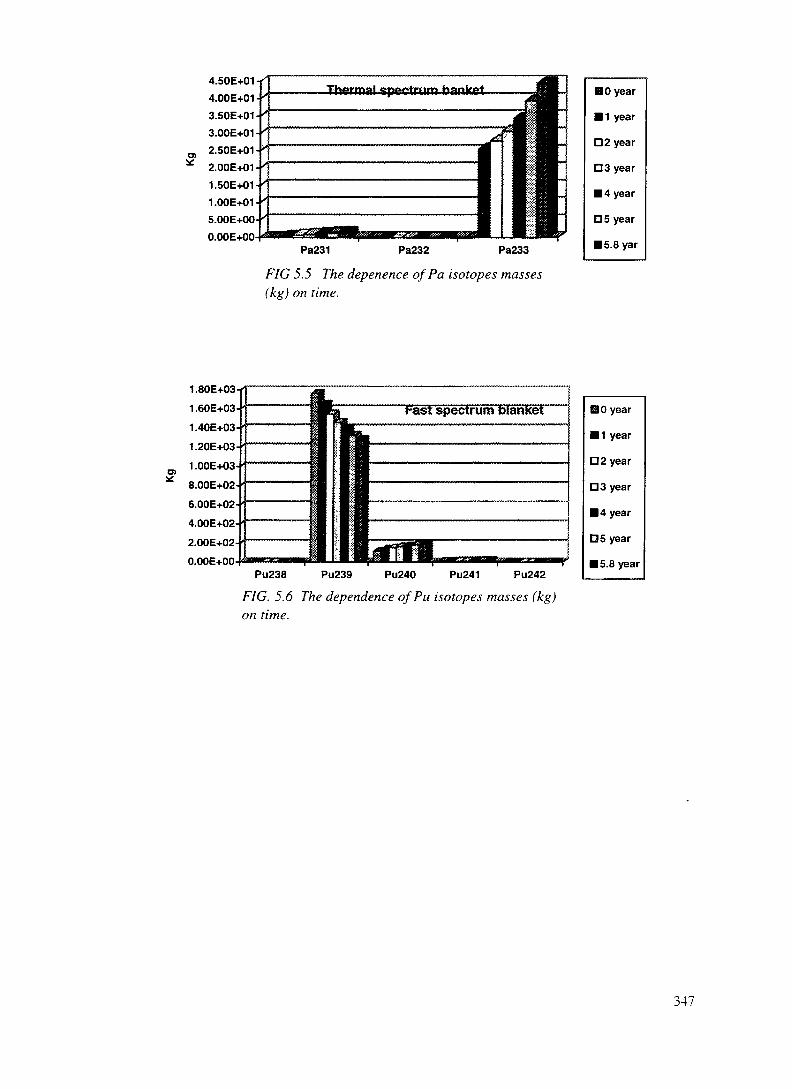
4.50E+014.00E+013.50E+013.00E+012.50E-F01-2.00E+01 -1.50E+01-1.00E+01-5.00E+00-O.OOE+00
Pa231 Pa232 Pa233
F/G 5.5 TTze depenence of Pa isotopes masses(kg) on time.
H 0 year• 1 yearD2 yearD3 year• 4 yearD5 year• 5.8 yar
t-ast spectrum oianKet
Pu238 Pu239 Pu240 Pu241 Pu242FIG. 5.6 The dependence ofPu isotopes masses (kg)on time.
HO year
• 1 year
D2 year
D3 year
• 4 year
OS year
• 5.8 year
347

00TABLE XIII. ISOTOPES MASSES (KG) DEPENDENCE ON TIME IN F-BLANKET, T-BLANKET AND TOTAL IN THE SYSTEM
Time (y)
Th228TH229Th230TH232Pa231Pa232Pa233U232U233U234U235U236U237U238
Np237Np239Pu238Pu239Pu240Pu241Pu242Am241Am242Am243Cm242Cm243Cm244Cm245Cm246Cm247Cm248
F-bl0.00.00.0
6.50+30.00.00.00.00.00.00.00.00.00.00.00.00.0
1.76+31.16+29.490.00.00.00.00.00.00.00.00.00.00.0
0.0T-bl0.00.00.0
1.16+50.00.00.00.00.00.00.00.00.00.00.00.00.0
5.53+33.56+22.98+10.00.00.00.00.00.00.00.00.00.00.0
F-bl9.58-64.04-049.28-066.38+33.44-12.75-55.38+07.15-39.65+19.94-11.29-21.02-43.60-89.36-96.26-76.82-132.31-21.55+31.51+21.13+12.30-19.52-17.45-34.33-31.88-21.55-49.14-51.05-63.68-90.00.0
2.0T-bl2.76-41.62-036.91-051.16+56.24-013.18-42.78+15.80-24.10+28.29+03.22-13.43-32.30-069.41-73.32-51.22-109.95-13.46+37.48+22.98+21.76+11.32+18.19-38.87-11.14+08.29-37.23-21.18-031.63-055.21-80.0
F-bl4.03-51.50-36.08-056.29+36.24-14.17-54.40+02.36-21.69+22.79+06.29-29.03-42.69-072.70-71.03-51.65-111.08-11.39+31.75+21.29+14.44-11.99+02.55-21.41-23.95-26.22-45.12-41.06-56.84-80.00.0
4.0T-bl1.78-36.33-35.82-041.15+51.12+07.45-43.43+12.46-18.05+23.17+12.54+06.32-25.00-57.67-51.28-31.13-081.00+11.74+038.40+25.11+27.88+13.84+13.36-27.60+05.96+08.98-21.25+03.72-21.42-38.88-61.45-7
F-bl8.70-52.89-31.49-46.23+38.18-14.25-53.47+04.05-22.15+24.45+01.30-12.45-35.87-71.26-63.68-56.08-112.19-011.28+31.89+21.39+16.07-12.99+04.58-22.43-24.98-21.08-31.10-32.99-52.56-72.16-90.0
5.8T-bl4.54-31.25-21.84-31.15+51.42+01.23-34.45+15.41-11.11+37.00+18.24+03.66-13.31-41.05-31.07-21 .72-73.14+16.83+26.81+25.27+21.78+25.11+14.63-22.46+11.30+13.01-16.29+02.34-11.91-21.72-44.70-6
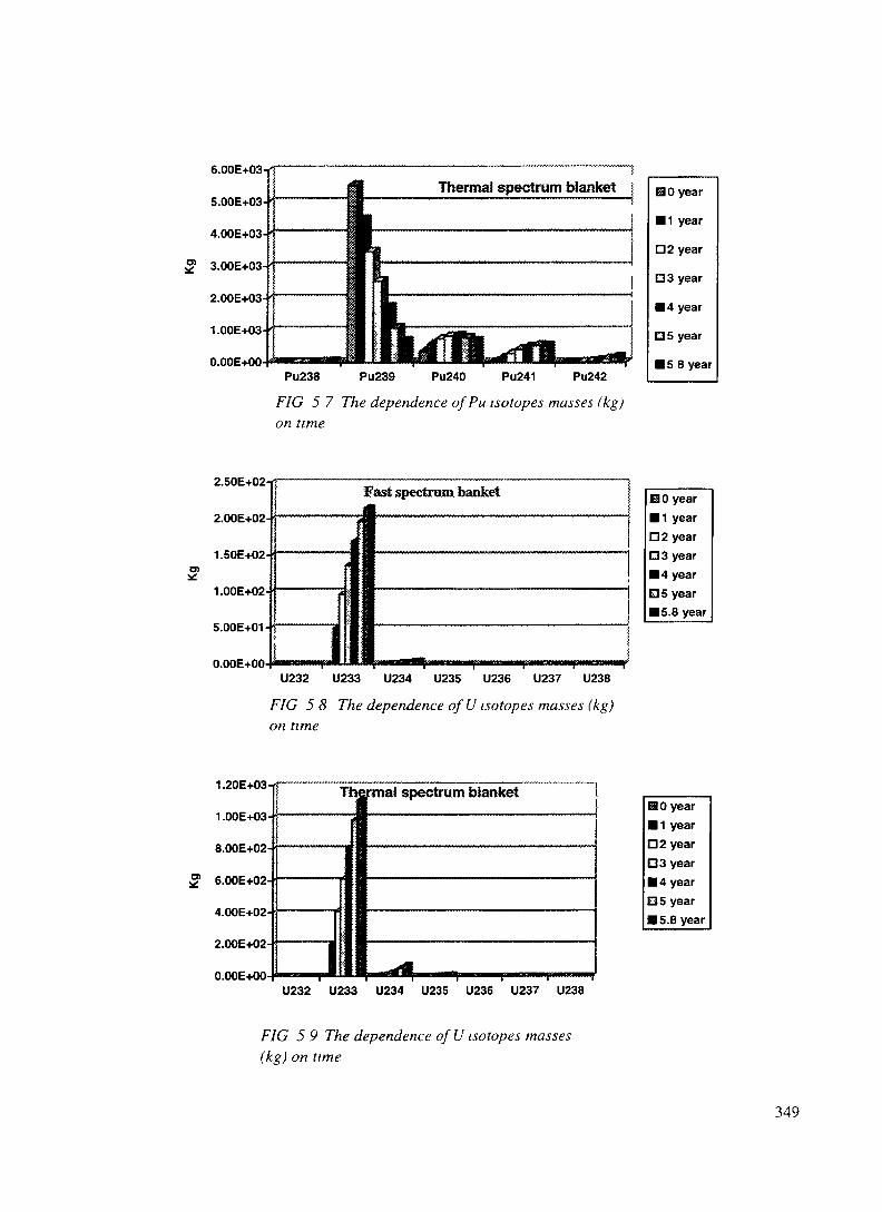
Thermal spectrum blanket
Pu238 PU239 Pu240 Pu241 Pu242FIG 5 7 The dependence ofPu isotopes masses (kg)on time
• 1 year
D2 year
D 3 year
• 4 year
O 5 year
• 5 8 year
2.00E+02-
1.50E+02-
1.00E+02-
5.00E+01-
'
f
I I
east spectrum banKet B 0 year
D2 yearD3 year• 4 yearO 5 year• 5.8 year
U232 U233 U234 U235 U236 U237 U238
FIG 5 8 The dependence of U isotopes masses (kg)on time
1.ZOE-MJ3-
1.00E+03-
8.00E+02-
^ o.UUt+Ui-
4.00E+02-
2.00E+02-
n nnFj.nn-
Tl
H
•mal spectrum blanketHO year• 1 yearD2 yearD3 year• 4 yearD5 year• 5.8 year
U232 U233 U234 U235 U236 U237 U238
FIG 5 9 The dependence of U isotopes masses(kg) on time
349

3.00E+00-
2.50E+00-
2.00E+00-
1.50E+00-
1.00E+00-
5.00E-01-
• Fast spectrum blanket J
<
i1 I1
BO yearB1 yearD2 yearD3 yearB4 year05 yearB5.8 year
Am241 Am242 Am243 Cm242 Cm243 Cm 244
FIG. 5.10 The dependence of Am and Cmisotopes masses (kg) on time.
b.UUb+Ul -
5.00E+01-
4.00E+01-
5" 3.00E-tO1-
2.00E+01-
1.00E+01-
O.OOE+00-A
I
j"1
—
iJH241
Thermal spectum blanket
I B
£•ft -ff 'M M M
Am243 Cm243 Cm245
BO yearB1 yearD 2 yearO3 yearB 4 yearE35 yearB 5.8 year
FIG. 5.11 The dependence of Am and Cmisotopes masses (kg) on time.
TABLE XIV. INITIAL AND FINAL ISOTOPES MASSES (KG) FOR 5.8 YEARS BURN-UP PERIOD
PU238PU239PU240PU241PU242Th232Pa233U232U233U234U23:5U236U237
F-bl.017271119.306497
InitialT-bl.
05528.5356.429.80116400
F-bl.0.221283.1189.413.90.61
6226.23.54.05-2
214.44.5
0.132.5-35.9-7
FinalT-bl.
31.4683.1680.7527.4177.61 14650
44.50.51 106.6
70.08.240.373.3-4
DifferenceF-bl.
0.22-478.372.634.420.61-270.73.54.05-2214.44.50.132.5-35.9-7
T-bl.31.4-4845324.3497.6177.6
-175044.50.51 106.6
70.08.240.373.3-4
Total31.62-323.7396.9 .502.178.2-2020.7480.51321
74.58.40.373.3-4
350

TABLE XIV (Cont.)U238Np7Np9AmiAm3Cm3Cm4Cm5Cm6Cm?Cm8
1.3-63.7-56.1-11
2.992.4-21.1-31.1-33.0-52.6-72.2-91.7-11
1.1-31.1-21.7-751.12.60.306.30.20.021.7-44.7-6
.3-63.7-56.1-112.992.4-21.1-31.1-33.0-52.6-72.2-91.7-11
1.1-31.1-21.7-751.12.60.306.30.20.021.7-44.7-6
1.1-31.1-21.7-754.12.60.36.30.20.021.7-44.7-6
D.4.1.5.2.3. Case 2. Simulation of bum-up during 5.5 years, with Tc99 as control reactivity element, F-blanket size and power increased twice - 600 MW (36 fuel assemblies) .
Total mass of heavy nuclides : 127430 kg.Main results are presented in Table XV and Fig. 5. 12
TABLE XV. INITIAL AND FINAL ISOTOPES MASSES (KG) FOR 5.5YEARS BURN-UP PERIODInitial Final
F-bl.Pu238 0Pu239 2748.3Pu240 177.0Pu241 1.5Pu242 0Th232 13023Pa233U232U233U234U235U236U237U238
Np237NP239Am241Am243Cm243Cm244Cm245Cm246Cm247Cm248
T-bl. F-bl.0 0.5
5520.6 1817.9355.7 332.329.8 26.5
0 1.5116230 12297
10.60.01
541.815.50.60.02
6.0-061.6-053.3-041.3-094.9
6.9-023.3-034.2-031.5-041.8-062.0-082.3-10
T-bl.29.2732.7678.2540.4172.3
1 1452045.30.5
1092.568.38.10.3
3.3-041.0-04
l.OE-021.8-07
59.923.90.36.10.2
1.8-021.6-044.4-06
DifferenceF-bl.0.5
-930.4155.325.01.5
-726.10.60.01
541.815.50.60.02
6.0-061.6-053.3-041.3-09
4.96.9-023.3-034.2-031.5-041.8-062.0-082.3-10
T-bl.29.2
-4787.9322.5510.6172.3-171045.30.51092.568.38.10.3
3.3-041.0-04
l.OE-021.8-0759.923.90.36.10.2
1.8-021.6-044.4-06
351

2500
500
HO• 1D2D3• 405• 5.5
F-blanket T-blanket
FIG. 5.12 Time dependence of power in F- and T-blankets (total power 2600 MW).
During 30 years period of operation at full power 31.2 t of Pu239 is destroyed and 32.8 t of WG Puincinerated - converted into Pu of different composition , other heavy nuclides and fission fragments;13.3 of Th are involved into fuel cycle with of 9.2 t of U233 accumulated and 7.9 t spent in theinstallation for power production.
DA. 1.5.2.4. Case 3. U-Thfuel cycle in thermal blanket (fuel cycle 1.5 years)
U233 accumulated in Pu-Th-U fuel cycle (about 4 t total during 30 years) may be used in the sameinstallation for power production in U233-Th fuel cycle with low consumption of fissile material. Theresults of calculations for lower enrichment (1.46%) are presented in Table XVI.
TABLE XVI. INITIAL AND FINAL ISOTOPES MASSES (KG) FOR 1.5 YEARS BURN-UPPERIOD, CASE 3.
InitialF-blanket T-blanket
Th228Th229Th230Th232 6497.4 128800Pa231Pa232Pa233U232U233 1903.7U234U235U236U237
FinalF-blanket
4.9-062.4-044.4-066406.9
0.32.2-05
5.94.1-0377.00.7
6.9-034.4-051.7-08
T-blanket4.0-041.1-021.1-031275304.5-016.9-0490.90.1
1787.2127.510.20.4
3.8-04
DifferenceT-blanket
4.9-062.4-044.4-06-90.70.3
2.2-055.9
4.1-0377.00.7
6.9-034.4-051.7-08
F-blanket4.0-041.1-021.1-03
- 12704.5-016.9-0490.90.1
-116.5127.510.20.4
3.8-04
352
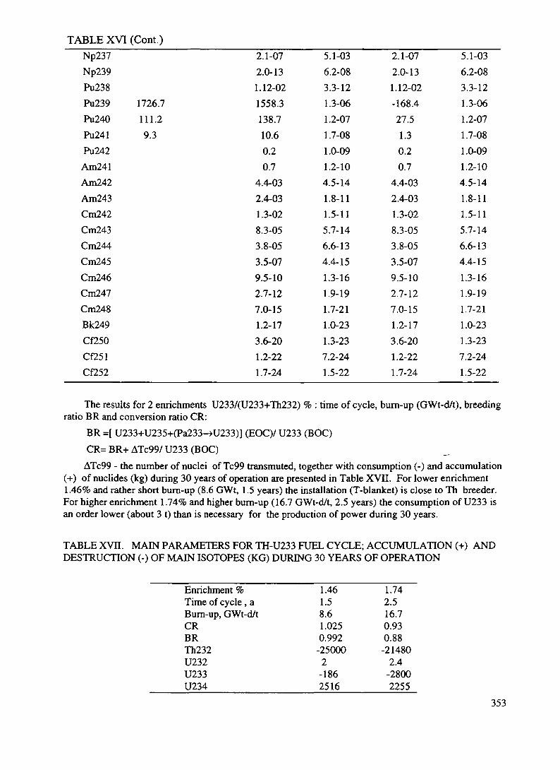
TABLE XVI (Cont.)Np237Np239Pu238Pu239 1726.7Pu240 111.2Pu241 9.3Pu242Am241Am242Am243Cm242Cm243Cm244Cm245Cm246Cm247Cm248Bk249Cf250Cf251Cf252
2.1-072.0-131.12-021558.3138.710.60.20.7
4.4-032.4-031.3-028.3-053.8-053.5-079.5-102.7-127.0-151.2-173.6-201.2-221.7-24
5.1-036.2-083.3-121.3-061.2-071.7-081.0-091.2-104.5-141.8-111.5-115.7-146.6-134.4-151.3-161.9-191.7-211.0-231.3-237.2-241.5-22
2.1-072.0-131.12-02-168.427.51.30.20.7
4.4-032.4-031.3-028.3-053.8-053.5-079.5-102.7-127.0-151.2-173.6-201.2-221.7-24
5.1-036.2-083.3-121.3-061.2-071.7-081.0-091.2-104.5-141.8-111.5-115.7-146.6-134.4-151.3-161.9-191.7-211.0-231.3-237.2-241.5-22
The results for 2 enrichments U233/(U233+Th232) % : time of cycle, bum-up (GWt-d/t), breedingratio BR and conversion ratio CR:
BR =[ U233+U235+(Pa233-»U233)] (HOC)/ U233 (BOC)CR= BR+ ATc99/ U233 (BOC)
ATc99 - the number of nuclei of Tc99 transmuted, together with consumption (-) and accumulation(+) of nuclides (kg) during 30 years of operation are presented in Table XVII. For lower enrichment1.46% and rather short bum-up (8.6 GWt, 1.5 years) the installation (T-blanket) is close to Th breeder.For higher enrichment 1.74% and higher bum-up (16.7 GWt-d/t, 2.5 years) the consumption of U233 isan order lower (about 3 t) than is necessary for the production of power during 30 years.
TABLE XVn. MAIN PARAMETERS FOR TH-U233 FUEL CYCLE; ACCUMULATION (+) ANDDESTRUCTION (-) OF MAIN ISOTOPES (KG) DURING 30 YEARS OF OPERATION
Enrichment %Time of cycle , aBurn-up, GWt-d/tCRBRTh232U232U233U234
1.461.58.61.0250.992-250002
-1862516
1.742.516.70.930.88-21480
2.4-28002255
353

TABLE XVII(Cont.)U234U235U236NP237Tc99
25162018.30.1
-535
225527020.40.4
-540
DA. 1.5.2.5. Case 4. 2nd cycle with Pu , Am and Cm nuclides from T-blanket of after r' cycle re-loadedinto F-blanket, T-blanket composition the came as in Case 1.
Total mass of heavy nuclides =127200 kg. The results are presented in Table XVIII and Fig. 5.13
• 1D2O3• 4EJ5• 5.5
F-blanket T-blanket
FIG. 5.13 Power dependence on time in F-blanket and T-blanket (total 2300 MW).
TABLE XVIII. INITIAL AND FINAL ISOTOPES MASSES (KG) FOR 5.5 YEARS BURN-UPPERIOD, CASE 4.
Th228Th229Th230Th232Pa2:;iPa232Pa233U232U233U234U235U236U237U238NP237Np239Pu238
F-bl.
2958.2
0000000
31.4
InitialT-bl. F-bl.
4.3-051.3-037.8-05
116400 2839.03.4-011.89-51.41.7-0295.23.71.1-012.2-034.7-071.2-063.3-055.4-1149.2
FinalT-bl.4.4-031.2-021.8-031 146601.41.3-0345.15.4-011102.769.78.23.6-013.3-041.0-031.1-021.7-0730.1
DifferenceF-bl.4.3-051.3-037.8-05
-119.23.4-011.89-05
1.41.7-02
95.23.71.1-012.2-034.7-071.2-063.3-055.4-11
17.8
T-bl.4.4-031.2-021.8-03
-17401.41.3-0345.15.4-011102.769.78.23.6-013.3-041.0-031.1-021.7-0730.1
354

TABLE XVIII (Cont)Pu239Pu240Pu241Pu242Am241Am242Am243Cm242Cm243Cm244Cm245Cm246Cm247Cm248Bk249Cf250Cf251Cf252
682.9680.0527.2177.551.1
24.613.0
6.3
5528.5 505.7356.4 637.629.8 310.8
182.6136.32.830.92.41.5-017.56.3-011.3-022.0-042.8-061.2-081.6-102.3-121.9-14
694.1685.1529.7177.349.94.5-0223.312.83.0-015.92.2-011.8-021.6-044.4-063.8-087.5-092.4-099.0-10
-177.2-42.4-216.55.185.22.86.3-10.81.5-01
1.26.3-011.3-022.0-042.8-061.2-081.6-102.3-121.9-14
-4834.4328.7499.9177.349.94.5-0223.312.83.0-015.92.2-011.8-021.6-044.4-063.8-087.5-092.4-099.0-10
D.4.1.5.3 Comparison of 4 Cases (for fuel cycles 5.8 years, 5.5 years, 1.5 years and 5.5 years).Comparison of results for build-up or destruction of materials -in Figs 5.14 - 5.21
Caset Case 2 Case 3 Case 4
FIG. 5.14 Masses (kg) of eliminated Pu239for 4 cases
Pu238 Pu240 Pu241 Pu242
FIG. 5.15 Masses of other Pu isotopes accumulated or eliminated for 4 cases
355

HTh232
Case Case Case Case1 2 3 4
FIG. 5.16 Masses ofTh232, converted to Pa and U isotopes
B Pa233
Case 1 Case 2 Case 3 Case 4
FIG 5.I 7 Build up (kg) of Pa233 (decays into U233 after unloading)
U232 U233 U234 U235 U236 U237 U238
FIG. 5.18 Masses of U isotopes (kg) produced in 4 cases.
356

Np237
FIG 5 19 Masses ofNp isotopes produced in 4 cases
Np239
Case 1 Case 2 CaseS Case 4
FIG 5 20 Production (kg) of Am isotopes for 4 cases
Cm243 Cm244 Cm245 Cm246 Cm247 Cm248
FIG 521 Accumulation of Cm isotopes for 4 cases
D.4.1.5.4 Physical Properties ( Case 1).
D 4 1 5 4 1 Thermal Neutron FluxNeutron flux <3> at the beginning of cycle is estimated as
357

" I/cm2 sec
By the end of fuel cycle (- 6 years) fissile material mass decreases so that:
1.6* 1013 I/cm2 sec
D.4.1.5.4.2. Capture and Decay ofPa233
Neutron capture by intermediate element Pa233 in the breeding process (conversion of Th232 intoU233) results in a loss of neutron in the competition between neutron capture and radioactive decay andis proportional to neutron flux that brings about the loss of reactivity and consequently a decrease ofbreeding ratio. The loss of reactivity is estimated by the value:
dK/K(Pa233) = -0.13%
After shut-down the of ABC F-T system the decay of Pa233 results in an increase of U233concentration and consequently in reactivity increase. This effect was estimated for the end of fuel cycle:
dK/K(Pa233-»U233) = + 0.45 % (K=0.99 -» K=0.9945)
This low value may be explained by low neutron flux in T-blanket (In E-A system [1] a similar effectis estimated to be about 2%). It should be noted that multiplication factor K defined as the ratio :
[number of secondary neutrons emitted in fission] / [number of secondary neutrons emitted infission + number of neutrons produced by external source]
for subcritical system is different from eigen-value K« (that determines the properties of the systemwith external sources switched off). The corresponding values were:
Ke=0.9710 (instead of K=0.99); Ke=(Pa233->U233) =0.9777
As a matter of fact internal properties of the system and consequently safety conditions are governedby Ke that is less than K. In this sense the system remains in a deeper sub-critical state even after decayofPa233.
DA. 1.5.4.3. Doppler reactivity effect.Doppler reactivity effect was estimated by calculation of T-blanket cell for two different fuel
temperatures - 800 K and 900 K. The difference in reactivity per 1 °C - Doppler reactivity effect isequal: dK/dT =-7.8 E-6 l/°
D. 4.1.5.4.4. Liquid Pb-Bi Void Reactivity Effect
Of much importance is the negativity of Pb-Bi void effect. Calculations with Pb-Bi density decreasedtwice led to the result:
dK/K vo,d = - 0.01 % /1 % of void
Loss of a half of Pb-Bi liquid (substitution for a void) leads to the loss of reactivity 0.5%.
D.4.1.5.4.5. Moderator Density (with Tc99 Dissolved) Reactivity Effects
358

The decrease of moderator density results in a reactivity effect that depends on the concentration ofTc99 dissolved in heavy water. As was estimated reactivity effect is negative or zero for weightconcentration of Tc99 about 10 g/1. If this limit is exceeded the other ways of reactivity compensationshould be applied : burn-able poisons - Gd for short period processes; Am241 (thermal capture cross-section 600 b, resonance integral 1500 b) and Am243 - for long periods; control rods; continual reloadingat full or decreased level of power (like in CANDU reactors).
D.4.1.5.4.6. The Property of One-Directional Neutron Coupling
This property may be defined as having two features: 1) weak influence of multiplication capabilitiesin T-blanket on the number of secondary neutrons bom in fission in F-blanket, 2)weak influence ofphysical properties changes in T-blanket on the reactivity of total system.
Calculations led to the following results:
1) [ d(nF)/ nF)]F.blanket / [ d(nF)/ nF)]T.blinkel = 0.005
2) dK/dConc(Pu239) = 0.033% /1%.
For a system without one-directional coupling (fission material removed from F-blanket and the samelevel of sub-criticality reached by an increase of initial Pu239 concentration -1.5 times), the 2nd valueoccurred to be an order higher : 0.33%/ 1%. This means that total system may be operated at the level ofsub-criticality with K=0.99 and have the same safety conditions as a system without this property withmuch deeper sub-criticality (K around 0.9-0.95) and consequently the system proposed here needs muchlower (5-10 times) proton current of accelerator beam.
359
D.4.1.6. MONITORING AND CONTROLLING OF ADS INSTALLATION
In order to provide optimal and safe routine operation of the electro-nuclear installation, it isnecessary to conserve all elements of traditional systems of controlling and protection of criticalinstallation and to add to them some necessary specific elements to create by this a quite new systemfor monitoring and controlling the electro-nuclear installation.
The functions of quick response (with response time ~ 1 ms) will be implemented by a subsystemof interruption of the beam in the very beginning of the accelerator (after injector or/and the very firstaccelerating sections). This will allow to stop the beam of accelerator with practically any given rateof reliability.
The blanket must be equipped with well developed structures of operating heads of controllingand monitoring in order to provide:
- reliable shut-down of the blanket for periods of reloading or long stops;-possibilities to flatten specific power production through the whole volume of the blanket to
maintain satisfactory economical parameters of the installation.Presence of a traditional subsystem of controlling and monitoring in the total system will allow to
reach critical state of the installation (for specific experiments) and to rise significantly reliability ofassessment of the level of subcriticality of the blanket.
But traditional system should be complemented with channels of continuous reactivity control.This system is based on analysis of back edge of a neutron pulse resulting due to time pause arisingdue to separation of H" and HP beams as each type of accelerated beam irradiates its own blanket.
If this reactivity parameter falls out of the limits of a certain interval, the control system shouldcorrect the level of reactivity or to stop the whole NP installation by operating drives of the controlsystem and by switching off the charged particles beam.
To guarantee the possibility to control power variations of the installation and to find out thereasons of these variations a special system capable to measure charged particle beam directly fallingon the target is quite necessary.
D.4.1.7. FUEL CYCLE
The fuel cycle incorporates the operations of fresh oxide fuel manufacture for "fast" and"thermal" blanket zones, irradiation of finished fuels, cooling prior to reprocessing, chemicalreprocessing of spent fuel and refabrication to produce a fresh fuel charge from fissionable materialsrecovered upon reprocessing with minor actinides (MA) included.
The fuel cycle does not directly involve operations of separation of short-lived transmutationproducts and conditioning of products of this type to chemical forms suited for the disposal, however,these operations are indispensable for the ecologically safe closure of the fuel cycle.
Fundamentally specific feature of the fuel cycle under discussion is the availability of twofissionable actinides (Pu-Th) in the primary charge and three ones (Pu-Th-U) in the spent fuel; Pu, Thand U being macrocomponents of the composition.
To-day there are no commercial or semi-commercial processes of both fabrication of Pu-Thoxide fuel and regeneration of Pu-Th-U compositions that are formed under irradiation. However,some fragments of such processes have been mastered adequately to form the process flow outline forthe needed fuel cycle.
These main fragments cover:- reprocessing U-Pu (discharged) fuel (Purex process and its versions);- manufacture of mixed U-Pu oxide fuel (MOX);
360

- reprocessing Th-U (discharged) fuel (Thorex process, interim and their versions).The above mentioned technological processes are basic ones in considering the fuel cycle route.Fabrication of fuel. The fuel fabrication may be based on two main technologies, namely, dry
blending of oxides and chemical coprecipitation of fuel components followed by processing theprecipitate to prepare mixed oxide.
Dry blending of oxides. The process involves operations of blending Pu and Th oxides,briquetting, primary sintering, comminution with a binder (zink stearate), granulation, pellet pressingand sintering. The sintered pellets are checked for their geometric sizes, density, chemicalcomposition and structure. Then, the operations of certifying pellet columns, fuel rod stacking,welding and tightness check-up are carried out.
The basic technology is the process used to fabricate U-Pu fuel for the complex "300" at the PU"Mayak".
The dry route can be considered to realizable for the primary charge of both "fast" and "thermal"blanket zones as well as for the refabrication of the thermal blanket charge. Problematic is theapplication of the dry route to the refabricated charge of "the fast" blanket that is to incorporate highlytoxic oxides of Np, Am, Cm and long-lived fission products (e.g., Tc). The main obstacle is theavailable dust forming operations and problems relevant to the staff protection and gas clean-up.
Chemical coprecipitation of elements. Mostly mastered are carbonate and ammonia processesdeveloped for the MOX fuel fabrication. For the fuel cycle under consideration the ammonia processis preferable. Ammonium hydroxide is a more universal precipitant and can be used for fabrication ofboth the primary charge of "fast" and "thermal" blanket zones and the refabricated charges containingoxides of MA and fission products.
Initial solution contains nitrates of Pu and Th in the specified ratio (the primary charge) andadditionally nitrates of MA (the refabricated charge). Pu is stabilized in the tetravalent state. Metalhydroxides are precipitated with ammonia hydroxide in presence of surface-active substances asshape formers. The precipitate that is adequately flocculated granules is readily separable from amother solution. After washing and drying the precipitate is calcined in an inert environment to form ahomogenized oxide mixture. Pellet pressing and subsequent operations are the same as are used forthe dry route of fuel fabrication. Incorporation of long-lived fission products into a fuel compositionrequires the process to be additionally mastered (e.g., Tc-99 may be also incorporated into thecomposition as TcO2, however, the stage remains to be determined at which Tc can be added, Tc (IV)stabilization, precipitated and blended).
The basic technology is the "Granat" process also developed for the MOX fuel production at thecomplex "300", PU "Mayak".
Fuel irradiation. On one hand, duration of irradiation is governed by nuclear transmutation and,on the other, by life-time of oxide fuel rods. Real time of a fuel rod staying in "fast" and "thermal"blanket zones is 6 to 8 years.
Interim storage of fuel. The time of the interim storage of fuel prior to reprocessing is summedup of the time of the at-reactor storage (immediately after the discharge) and the time of holding in acooling pond at a reprocessing facility. Storage condition differs in intensity of heat removal. If thespent fuel is not to be shipped transmutation reactor and reprocessing facility are sited at the sameutility. A single special schedule of interim storage is feasible. The total time of interim storage mustnot be less than 3 years.
Spent fuel reprocessing. The process flow outline for spent fuel reprocessing integrates themost rational elements of known extraction routs (Purex, Impurex, Thorex), involving also additionaloperations such as evaporation and crystallization.
Since in both "fast" and "thermal" blanket zones new fuel - U-233 is generated and burnt, despitedifferent rations of the main components (Th, Pu and U) in the spent fuel of the "fast" and "thermal"blanket zones it is advisable to co-reprocess it.
361
After removal of structural components of a fuel assembly and mechanical chopping fuel rods thefuel is dissolved in nitric acid under the conditions close to those used for the dissolution of powerreactor fuel rods. Adjustments are possible as small additive of fluorine ion to dissolving solution toaccelerate dissolution of thorium oxide. Then the solution is isolated from cladding elements and goesfor filtration and acidity adjustment for extraction reprocessing. Fuel rod cladding components arewashed and transferred to a special tank and their subsequent handling may be different (disposal,decontamination etc.).
While dissolving non-dissolvable residue may be available; it mainly consists of intermetallicphases of Rh, Pd, Ru, Tc and Mo. Handling of undissolvable residue is a special operation of deepdissolution and storage.
The solution as conditioned to extraction reprocessing goes to the first extraction cycle theobjective of which is to extract and purify Th, Pu and U from fission products. Separation of Pu fromTh and U and preparation of the cycle products, namely, Pu and Th-U streams. An extractant is astandard solution of TBP (30% vol.) in a hydrocarbon dilutant; the apparatuses are commerciallyoperated equipment of any type (mixer-settlers, centrifugal extractors, counter-current columns). Theoperations of the cycle are co-extraction of U, Pu and Th, washing of an extract to remove fissionfragments, reductive stripping of Pu and removal of Pu from the cycle, co-stripping of Th and Uregeneration of an extractant. As a reductant it is advisable to use no-salt forming reagents on thebasis of hydrazine or U (IV) derivatives from the U regenerate.
Pu extracted from the head end cycle is sent to the refinement cycle. The refinement cyclestructure is not discussed since similar operations are well known and are a constituent port ofcommercial facilities for power reactor spent fuel reprocessing. From the refinement cycle Pu as a Punitrate solution purified is directed to the operations of refabrication of a fuel charge for the "fast"blanket.
The Th-U co-product is evaporated at the evaporation ration of 8-12 and cooled for hydratedthorium nitrate to be crystallized. If it is necessary thorium nitrate is subjected to recrystallization,washing and sent to the operations of the fuel charge refabrication for both "fast" and "thermal"blankets.
The mother solution from thorium nitrate crystallization containing U and Th (with U-Thincreased proportionally to the evaporation ratio) is adjusted in terms of the HNOs content andreprocessed in the U-Th cycle with relatively low efficiency. The extractant of the cycle is similar tothat of the head end cycle. The cycle operates under supercritical conditions with a partial discard ofTh to the cycle raffinate since the objective of the cycle is to produce pure U product. The washingsolutions of the cycle also containing thorium join the raffinate and the joint flow is transferred forreprocessing in the head (Th-Pu-U) end cycle. The purified U product of the cycle is used as a"plutonium substituting" fuel in the thermal blanket or is reprocessed to oxide (by the knownprocesses and is stock-piled).
Thus, the products of chemical reprocessing spent fuel of "fast" and "thermal" blanket zones arepurified nitrated of Pu, Th and U that are suited for refabrication into fuel.
Unburnt MA and fission products go to the high activity raffinate of the head end cycle. Theraffinate is evaporated to recover nitric acid that is recycled.The presented basic process flow outline does not involve operations of partitioning high-activitywaste of the cycle and isolating the MA fraction to be incorporated into the fuel composition of a"fast" blanket zone. This operation is to be carried out jointly both for the major source of MA,namely, high-activity waste of power reactor spent fuel reprocessing and the waste of transmutationreactor fuel reprocessing. The products of this co-reprocessing are a MA stream arriving at therefabrication of "fast" blanket zone fuel and a stream of short- and medium-lived nuclides purifiedfrom long-lived nuclides; they are sent for the preparation of immobilizable forms (glass, mineral-likematerials etc.) to be disposed of.
362

FBfuel .TBfuel
claddingmaterial
Tto partitioning
evaporation
raffinate
(HAW)
1Pu - product
Pu refinement
enPu-regenerate
choppingHNO,
dissolution andseparation of
clarification,conditioning
Head end (Th - U - Pu)extraction cycle
i rTh - U product condensate
evaporation
mothersolution
— »•
^
cooling,crystallization ofthorium nitrate
i T
recrystallization
Th regenerate
Th - U extractioncycle
raffinate
Pu regenerate
FIG. 7.1 Basic process Jlow outline of "fast1 and "thermal" blanket spent fuelreprocessing.
D.4.1.8. WATER-CHEMICAL REGIME OF HEAVY-WATER BLANKET ZONE
The main parameters of the blanket of ADS are presented in Tables XVin and XIX.
363

D.4.1.8.1. Water-chemical conditions of heavy-water loops
Water-chemical conditions are composited on basis of quality standards for heavy water medium,worked for all exploitation conditions (start of operation, stationary and transition states).Correctionless, near neutral water-chemical conditions are adopted in coolant and moderator loops.Quality standards are presented in Table XVIII.
In order to check characteristics of water medium it is necessary to find out: concentration ofdeuterium dissolved in water, radioactivity of water, stipulated by tritium and concentration ofdeuterium and oxygen in gaseous volumes of technological and auxiliary equipment.
D.4.1.8.2. Providing of settled water-chemical conditions
The rate of bypass flow (part of water loop, directed to purification) is usually measured by rateof entrance component in the water; in our situation - by product of corrosion in count on iron [38].
Rate of bypass flow ("blow off) for above mentioned loops is calculated from the equation [39]:W=q,/Ce.Ti (8.1)
W-bypassflow, t*h"';qi - rate of i - component entrance in water medium, q*h"!;C£ - standardized concentration of i - component, q*m":i;T| - efficiency of water purification plant; this coefficient may be in range 0.6^-0.8 for iron
corrosion products (oxides).Corrosion rate of stainless steel under routine conditions in the loops according to [40,41]:1*10"" - for coolant loop; 0.2* 10"4 - for moderator loop.Share of stainless steel corrosion products released in water in insoluble form (crud) at these
conditions usually is accepted equal 0.2.
Then for coolant: ^ = 0.006? xh~l ; WC = 1.7m3 h'1
for moderator: q j? = 0.014 q*h"'; Wm = 0.4 m3*rf'
Summary value of bypass flow will be equal 2.1m?*h~1 or 3% of the volume of water loops, thatis considered technically and economically reasonable in practice of nuclear power plant operation.Bypass flow enters on special water purification plant, where after preliminary degassing it is passedthrough ion exchange columns.
D.4.1.8.3. Evaluation of deuterium stationary concentration in heavy water loops
Basic factors, that define absolute stationary values of radiolysis of molecular products,including deuterium, are specific dose rate of radiation and standard values of water quality.Maximum values of deuterium stationary concentration that may be reached in modern powerfulnuclear plants with specific power up to several MW*dm'3 of core, can't exceed 5*10^ mol*dm"3 [42].Power density in coolant (in water volume of core) and moderator of ENP is, accordingly: 130kW*dm'3 and 3.5 kW*dirf\
Stationary equilibrium concentration of deuterium in heavy water loops of coolant and moderatormay be calculated, in particular, by dependence [42]:
(8.2)
364

[D2] jj" -stationary concentration of deuterium at power density in the water 103kW*dm 3
,mol*dm~3;Nsp - specific power in considered water system, kW*dm~3;
N™** - specific power in high loaded water system, 103 kW*dnT3.
for coolant [D2] sct = 1.8*10^mol*dm~3 = 4 ml s.t.pV dm3
for moderator [D2] £ = 3.5* 10'5 mol'dm'3 = 0.6 ml s.t.pVdm3
Reliability of these results is confirmed by criterion evaluation. Received values of stationary,equilibrium concentration for deuterium in stationary conditions of coolant and moderator loops arepresented in Table XIX
Deuterium in heavy water media of coolant and moderator must be in solved state and volumeliberation of gases is impossible.
D.4.1.8.4. System for removing and catalytic recombination of radiolytic gas mixtures
Gas liberation (in particular liberation of deuterium) may take place from bypass flow of ADSheavy water medium. Rate of deuterium liberation from bypass flow in gas loop is calculated fromvalues of bypass flows and stationary, equilibrium concentrations of dissolved gases in each loop. It ispreferably to use helium as bearer gas in gas loop (cavity) of ADS, because this gas have highpermissible limit of explosive concentration and small volume for dilution of radiolytic gas.
Productivity of radiolytic gases "blow off' system is calculated on the base of adopted standardson content of deuterium or explosive mixture and on the rate of entrance of these gases in gas volume(cavity) by following dependence:
Q=102*qD2*K/[D2]N (8.3)
Q - productivity of "blow off" system, m3*h~';qD2 - rate of deuterium liberation from liquid phase, m3*h~';
[D2]N - standardized limit of deuterium concentration in gas cavity, % mol;K - coefficient of multiplicity (K=2 or 3).As above mentioned, flow rate of water on "blow off from coolant loop is 1.7 m3*h~', from
moderator loop - 0.4 m3*h~', concentration of deuterium in water of these loops is found at a level 4ml s.t.p./dm3 and 0.6 ml s.t.p./dm3, accordingly. It follows from these data that flow rate of deuteriumfrom "blow off water in helium cavity is 6.8 dm3*h~' for coolant loop and 0.24 dm3*h"' formoderator loop.
Local productivity of "blow off is calculated from equation (8.3) and adopting value ofmultiplicity coefficient equal 3 and standard on content of deuterium in helium loop (cavity) < 5.5 %vol. is 0.4 m3h~'. Taking into account necessity of "blow off deuterium from gas volume of auxiliaryequipment and from technology volumes, given productivity must be increased by one order and willbe 4 m3*h~1 in first approximation.
D.4.1.8.5. Detritization and deprotonization of ADS heavy water medium
Radioactivity of water caused by tritium in heavy water is related with value of mean neutronflux. Thus, at flux 1014 n*cm~2*c~', radioactivity of tritium rises by 2.146*10" Bk*dm"3 per a year.Equilibrium concentration of tritium will be reached in 20 years of plant operation and will be equal
365

58 Ci*dm 3. Supporting of tritium concentration in heavy water at level 1.0 Ci*dnf3 for reactors isconsidered as technically sufficient.
In this connection plant for detritization and deprotonization must be provided in thetechnological scheme. Isotopic concentration of heavy water in coolant and moderator loops must besupported of level not less than 99,5 % mol. D2O and concentration of tritium (DTO) at the level3.7* 1010 Bk*dm~3 by means of continuous purification of heavy water from accumulative admixtures(HDO and DTO) should be provided.
TABLE XVIH. TECHNICAL REQUIREMENTS TO QUALITY OF HEAVY WATER COOLANTAND MODERATOR
Index of heave water quality Unit of measuringNormal value
First filling andmake-up water
Specific conductivity Sm*m° <2*IQ'4
Value of pD unit pD 5.5-6.5Chlorides concentration mg*dm~3 <5*10"2
Concentration of corrosion product(account on iron) mg*dm"3 <5*10~2
Isotopic concentration of D in water % mol > 99.75
Loopwater<4*10'4
5.0+7.0<5*iO'2
<5*10'2
>99.0
TABLE XIX. STATIONARY CONCENTRATION OF DEUTERIUM IN LOOPS OF COOLANTAND MODERATOR
Heave water loopEquilibrium, stationary concentration
of deuterium in loop water,dm3s.t.p./dm3
Limit of deuteriumsolubility at exploitation
parameters,dm3 s.t.p./dm3
coolantmoderator
4*10"6*10"
6.02*10 ,-2
D.4.1.9. ELECTRO-NUCLEAR NEUTRON GENERATOR - PROTOTYPE OF ADSINSTALLATION
Electro-nuclear neutron generator planned to be constructed uses the ITEP decommissionedreactor HWR for housing of subcritical blanket with fast and thermal (heavy water) neutronmultiplication zones (Fig.9.1).
Be-target irradiated by proton is from ISTRA-36 linear accelerator is the source of fast neutron.
366

U + D,O - blanket
9.1. Electro - nuclear neutron generator
FIG. 9.1 Electro-nuclear neutron generator
Electro-nuclear neutron generator main parameters:- Accelerator proton energy 36 MeV- Proton pulse time 150 inks- Proton pulse current 150mA- Mean proton current 0,5 mA- Proton pulse frequency 25 Hz- Target fast neutrons intensity 1.5 1014 n/s- K ef start-up blanket 0.95- Start-up blanket power 25 kW
- Reflector thermal neutron flux235T- Start-up blanket load "JDU (90%)
1.5 1012n/sm2s2kg
The purpose of the facility:- application as a full scale physical model of ADS installation blanket;- investigation of Th-heavy water cells;- check and improvement of the control and protection system ADS installation;- fundamental research (acdnide constants for fast neutron parameters of proton interaction withtarget and accelerator materials).
367

DA 1.10. ZERO POWER HEAVY WATER REACTOR MAKET AT ITEP
Zero power reactor MAKET is designed for precision experiments with full-scale lattice modelsof fast and heavy-water thermal blankets of ADS installations.
S h i l d i n g
Tank of active zone
S a f e t y t a n k
C o n t r o l r o d :
S u p p o r t s
F u e l c h a n n e l
F u e l c h a n n e I
FIG. 10.1. Zero power heavy water reactor MAKET.
Reactor main parameters:- facility's maximum power- core diameter / height- maximum volume of heavy water in the core- number of power and reactivity control channels- CPS rods number- number of channels for control and limitation
of the heavy water level in the core
IkWt3,4 m/ 3,5m
19 t77
368
- measurement accuracy of the heavy water absolutelevel in the core - 1,5mm
- measurement accuracy of the relative variationsin heavy water level in the core - 0,5 mm
D.4.1.11. ECONOMICAL ESTIMATIONS.
D.4.1.11.1. Expenditures for superconducting linear accelerator
Capital investments and expenditures for routine operation of superconducting 1 GeV, 10 mA 30mA proton accelerator were defined on the costs of similar parameters devices of constructedaccelerators, in particular of the linear accelerator of meson factory of INI of RAS and of thesuperconducting accelerator CEBAF. Full expenditures for accelerator with current 10 mA will be150 million dollars. Their components are presented in the table:
E q u i p m e n t Expenditures (millions dollars)Superconducting resonators with cryostats 60HF channels with automatics systems 20Automated control/parameters measurement systems 5Standard equipment 40Cost of construction 25Expenditures for the accelerator with current 30 mA will be 185 million dollars. This rise is
mainly caused by necessary increase of HF power. Annual expenditures for routine operation of theaccelerator itself are estimated as 6 million dollars including 2 million dollars for salary.
Judging on experience of operation of linear accelerators life-time of the proposed accelerator isdefined to be equal 30 years.
After decommissioning the accelerator and its main devices may be used for construction ofother physical installations. The accelerator will be radioactive and ecologically "clean", withoutradioactive wastes. Costs necessary for decommissioning in this case will not be higher than 35million dollars.
As to technical feasibility of the project it is possible to say that techniques of fabrication ofthe main devices of the accelerator is well experienced in the world though quite similar acceleratorswere not yet constructed. The accelerator of ENI of RAS (protons energy is 600 MeV, average current- 1 mA) developed by MRTI of RAS jointly with invited institutions and superconducting electronaccelerator CEBAF may be looked as prototypes. Time necessary for realization of the project isestimated as 7 - 10 years. If to invite to development and construction of the accelerator some offoreign laboratories and firms then this time may be decreased to 5 - 6 years.
At the stage of designing the cost of which is estimated as 40 million dollars and necessary time- 4 years, construction of three experimental installations is supposed: RFQ accelerator with a cryostatand a proton injector, cryomodules of the first and the main parts of the superconducting acceleratorwith HF and automation systems. Design solutions and the main procedures will be developed at thesestands. Expenditures for creation of these stands will not be higher 10 million dollars; expendituresnecessary for routine operation will be approximately 0.5 million dollars per a year.
Development and creation of equipment and of technologies of the accelerator will providefurther progress in the area of HF superconductivity, powerful HF systems of continuous way ofoperation, effective systems of cryogenics under temperatures 2K. Significant numbers of specialists
369

in accelerators techniques and in adjacent specialities will obtain working places in the works on thisproject.
So full expenditures for the whole life of the accelerator will be185 + 40 + 10 + 35 + 180 + 2 = 452 million dollars.
D.4.1.11.2. Expenditures for target-blanket part and the installation
A fast neutron reactor of BN-800 type and a heavy water gas-cooled reactor of TR-1000 typemay be chosen as prototypes as real technical and economical foundations exist for them. In this casecapital investments for creation of the installation (without accelerator) will be 1.5 billion dollars.Annual routine operation expenditures will be 160 million dollars. Cost of the project is 150 milliondollars.
Costs for construction of a prototype of electro-nuclear generator of neutrons is 5 milliondollars, expenditures for routine operation - 1 million dollars per a year. Costs for decommissioningof the power installation (by estimation of specialists of industrial association MA YAK) is 500million dollars.
So for the whole life time of the installation (without accelerator) 1500 + 150 + 4800 + 500 +5 + 30 = 6985 million dollars will be spent.
D.4.1.11.3. Expenditures for the whole installation
Total expenditures for the whole installation may be estimated by the sum 6985 + 452 = 7437million dollars.
Relatively small expenditures for superconducting accelerator make full price of the electro-nuclear installation of such type quite comparable with the price of traditional NFS. All elaborated forNFS economical approaches and estimations may be fully applied to electro-nuclear systems with asuperconducting accelerator.
Under power production of electric power 10 billion kW h all earlier presented expenditures willbe recouped during the first years of operation of the installation as sale price of electric power inRussia is very high (6 cents per a kW h for February 1, 1996).
In accordance with the project of the reactor TR-1000 and estimations of MRTI on linearaccelerator, total number of personnel necessary for routine operation of the Electro-Nuclear PowerInstallation, administration, technical and additional service will be approximately 2100 specialists.
All above presented estimations should be obligatory corrected by detailed technical andeconomical foundations but, nevertheless, accuracy of the presented estimations is comparable withestimations of the prices of traditional nuclear power installations at similar stages of development.
D.4.1.12. EFFECT ON ECOLOGY
The absence of appreciable losses of a beam of proton in a accelerator makes it relativelyradioactive-safe in a operating time and in the process of removing it from operation.
Biological shielding of operating accelerator can be realized with the use of checked on Y-10(ITEP ) and Y-70 (IPHE ) technical decisions in such a manner that outside a sanitarian zonecharacteristic radiation will not be above a background.
Fumes-off noble gases out of blanket will not be as much as indicated in [43]. Specific for heavywater system fumes-off tritium can be evaluated by a value not exceeding 1600 Ci per year in view of
370

measures on clearing heavy water of tritium, with maintenance of tritium concentration at a level notexceeding 1 Ci/1 D2O.
D.4.1.14. CONCLUSION
Presented data on superconducting linear accelerator show that such linear accelerator willpossess unique characteristics:
- It will be capable to accelerate currents of protons and negative hydrogen ions up to 30 mAunder losses not higher than 10"5 . Total efficiency on utilization of applied electric power will beapproximately 60 %.
- The accelerator will be radioactive "clean" installation which will not require utilization ofremote controlled techniques.
- Life time of the accelerator will be more than 30 years. After decommissioning there will not benecessity to bury separate elements and they may be used for other purposes.
ADS installation has Pb-Bi target and partitioned fast-thermal subcritical blanket. Totalinstallation power is 2300 MWt. The coolant of fast blanket zone is Pb-Bi. The coolant and moderatorof thermal zone is heavy water.
Analysis of accumulation of activity in Pb and Pb-Bi targets irradiated by protons has shownactivity Po-210 to be not determining factor. It will allow to choose Pb-Bi (melting point 125°C) as atarget and a heating agent in fast zone instead of Pb having relatively high-level melting point 327°Cthat essentially facilitates and makes cheaper operation of such system.
A general concept of ABC installation with an estimation of its main physical properties waspresented above.
Fast spectrum blanket presents a source multiplying region that with a combination with thermalspectrum blanket and some elements of system composition (downward section of Pb-Bi coolant,steel walls of F- and T-blanket vessels and inner heavy water reflector) provides a property of one-directional coupling leading to a sufficient decrease of accelerator proton beam current (with (1-K) -0.01) at safety conditions corresponding to much higher level of sub-criticality ((1- K) around 0.05-0.10) . On the other hand this section - F-blanket core - may be used for deeper incineration ofactinides accumulated in both cores.
Deep burn-up values - about 70 GW-day/t in F-blanket and 35 GW-day/t in T-blanket -correspond to - 6 years of operation at full power without re-loading. About 90% of initial Pu239 inT-blanket is converted to fission fragments or higher isotopes during 6 years fuel cycle. The dischargeof spent fuel (except fission fragments) - Pu and higher actinides - can be re-injected into F-blanketfor further incineration .
During 30 years period of operation at full power about 25 of WG Pu is destroyed - converted ininto Pu of different composition , other heavy nuclides and fission fragments, about 10 tons of Th areinvolved into fuel cycle with 6 t of U233 accumulated and 4 t spent in the installation for powerproduction. A sufficient amount of Tc99 (dissolved in the moderator) or Am may be transmuted ifthey are used as a reactivity control materials in T-blanket.
Liquid Pb-Bi void reactivity effect is negative, reactivity effect of Pa233 decay (into U233) issmall.
U233 accumulated in the system may be used in Th-U233 fuel cycle with conversion breedingratio close to 1.
The system may effectively be used for destruction of WG Pu with power production andaccumulation of U233 as a new fissile material that at the next stage can be used in a closed Th-U233fuel cycle with breeding ratio close to 1.
371

It is shown that all stages of fuel cycle may be practically realized on the basis of technologiesexperienced in Minatom' plants in Russia.
Chemical technology defines reliability, technical safety and economy of electronuclear plant(ADS) in many respects. Significance of chemical technology is conditioned by using of heavy water,that is tied, besides problems of water preparation, special water purifying and degassing.
For successful realization of the project it is necessary to create a series of stands insubstantiation of accelerator systems , to create stands for study of thermohydraulic parameters of Pb-Bi targets as well as parameters of fast zone cooled by Pb-Bi and at last to create accelerator drivengenerator of neutrons - a full scale model of power installation..
Significant part of technical solutions on accelerator, blanket, systems for monitoring andcontrolling may be checked and tested at the Electro-Nuclear Neutron Generator which is now underconstruction in ITEP. This Generator is based on the existing proton accelerator ISTRA-36 and theITEP shut-down heavy water reactor HWR.
Neutron-physical blanket parameters of the electro-nuclear systems and physical foundations ofthe method of controlling reactivity by analysing the rear edge of a neutron pulse will be investigatedat the experimental heavy-water reactor of zero power MAKET ITEP.
The problems of ecology and physical protection for offered ADS installation are traditional anddo not differ from appropriate problems for critical NP installations in action and under design. Thespecific problem, connected with fume-off tritium formed in heavy water can be resolved with thehelp of installation on separating of hydrogen isotopes developed in ITEP, enabling to support tritiumcontents in heavy water at a level not exceeding 1 Ci/1. In this case total annual tritium fume-off doesnot exceed 1600 Ci (experience of CANDU reactors).
Preliminary economic evaluations have shown that relatively small contribution of acceleratorcost to total installation one permits to apply to ADS installation of such type all economicapproaches and criteria, characteristic for traditional PN installations and makes the cost andrecuperation of ADS installation comparable with appropriate NP installation.
Cooperation with Foreign Centers and Companies
1. Neutron physical properties of sub-critical systems with external sources (theoretical methodsand computer codes, benchmark calculations, nuclear data, investigation of neutron physicalproperties of AD systems for current design) - collaboration ITEP-LANL
2. Design development and manufacturing of next subject:- Superconducting cavities (with drift tubes and Cornell-type) - Grumman (USA), CERN,
KEK (Japan), CEBAF (USA), INFN (Legnaro, Italy).- Cryostat, cryogenic-system - Grumman, USA,
CERN- RFQ-accelerator - Grumman, USA,
LANL, USA,ANL, USA.
- Permanent magnet quadruple lenses - Grumman, USA,LANL, USA,JAERI, Japan.
- High- intensity ion sources - LANL, USARAL - Rutherford Lab.
- Beam loses, halo, emittance increase (research and suppression) - LANL, USA,
372

Maryland University,GSI, Germany.
3. ITEP Neutron Generator Prototype of fuel-scale electro-nuclear plant (Linac+Target+HWR).Present - readiness is -50%. Purchasing of modulators, finishing of construction and thenparticipation in experiments on NG Complex _ TTO.r r r - Grumman, USA,
LANL, USA,JAERI, Japan.
4. Calculation and analysis of target characteristics (isotope concentration long-lived activity etc)for Pb and Pb-Bi (and other alternative materials if necessary) targets irradiated by high energyproton beams using various computer codes;
- Testing of available input data (cross sections for spallation reactions and fission decayproperties etc.) necessary for calculations, development of nuclear data base;
- Comparison between cat calculation results using various codes for standard spectra standardthermonuclear reactor spectrum here many results are available;
-Work out the recommendations for various hybrid systems - LANL, USA,JAERI, Japan,PSI, Switzerland.
REFERENCES
[1] C.Rubbia et al. Conceptual Design of a Fast Neutron Operated High Power Energy Amplifier.CERN/AT/95-44 (ET).
[2] Fitier N., Mandrillon P. A three-Stage Cyclotron for Driving Energy Amplifier, CERN/AT 9503 (ET), Geneva, 1995
[3] Murin B.P., Fedotov A.P. Towards a Radiation - Free Linacs of Meson or Neutron GeneratorType. Proc. of the 1976 Proton Linear Accelerator Conf. (Canada) - Chalk-River NuclearLaboratories, 1976, p. 377 - 380.
[4] B.P.Murin et al. The New Concept in Designing of the CW High-Current Linacs. Internal.Conf on High-Energy Accelerators, Dallas, Texas, May 1 - 5, 1995.
[5] Cost Optimisation Studies of High Power Accelerators. R.Mc. Adams et al. in "AIP Conf. Proc346, Las-Vegas, NV 1994.
[6] Proposals on linear accelerators of protons of continuous way of opera-tion to energy 1 GeVand currents 250/ 10 mA with utilisation of superconducting technics. Cipher of the theme"Kovyl", Resulting report of MRTI No 39-KL-95, 1995.
[7] Munn B.P., Fedotov A.P. Direction of development of powerful proton linear accelerators ofcontinuous way of operation for nuclear-power goals. MRTI report, No 39-10-95, 1995.
[8] Weingarten W., Superconducting Cavities, CERN SL/94-15 (RF), 1994,[9] Shepard K.W. at el. Construction of a superconducting RFQ structure. Proc. of the 1993
Particle Accel. Conf, USA, v.2, pp. 1042 - 1044.[10] Wangler T.P. et al. Superconducting RFQ Development at Los-Alamos. 1992 Linear Accel.
Conf. Proc. Canada, v. 2, pp. 627 - 629.
373

[11] Silaev S. Isoparametric Finite Element Analysis of Time-Harmonic Electromagnetic Field inThree Dimensions. Nuclear Instruments and Methods in Physics Research, A328, (1993), pp.535-541.
[12] Proc. of the 4-th Workshop on RF Superconductivity, v.l, v.2, 1989, KEK, Tsukuba, Japan.[13] Efremov V.M. et al. Improved Method for Electrochemical Polishing of Nb Superconducting
Cavities. Proc. of the 5-th Workshop on RF Superconductivity, DESY, Hamburg, Germany,1991, v.l, pp. 433-456.
[14] Korotkov A.M. at el. Special system of axial magnetron spraying of SC covers to operatingsurface of accelerating SHF structures of complex shape. Proc. of the Conf. "Vacuum scienceand techniques" Gurzuf, oct, 1994.
[15] Grigoriev A.D., Silaev S.A. Calculation of electromagnetic field of azymuthally-uniform modesof axially symmetrical resonators with arbitrary shape of the forming line. Serie Electronics ofSHF, 1981, iss. 2, pp. 62 - 65.
[16] Kogen-Dalin V.V., Komarov E.V. Calculation and test of systems with permanent magnets.Moscow, Energy, 1977.
[17] B.P.Murin. Powerful sources of high frequency feeding for accelerators of charged particles.Preprint of MRTI ,No. 833, Moscow 1983.
[18] B.P.Murin. Stabilization and controlling of high frequency fields in linear accelerators of ions.Atomizdat, Moscow, 1971.
[19] Linear accelerators of ions. Under direction of B.P. Murin. V2, Atomizdat, Moscow, 1978.[20] The LEP-II RF Power Generation System. H. Frischolz, CERN, Proc. of the 1983 Particle
Accel. Conf. v. 2, p. 1247.[21] Proposals on proton linear accelerators of continuous way of operation for energy 1 GeV and
currents 250 and 10 mA with utilization of superconducting technics. Cipher of the theme -"Kovyl". Final report of MRTI No. 39-10-95, 1995.
[22] Kozodaev A.I., Lazarev N.V., Raskopin A.I. Pulsing mode of operations of linac-driver:advantages and peculiarities. The report on Third working meeting under Project No. 17. St.-Petersburg, on February 5-8, 1996.
[23] Lazarev N.V., Andreev V.A., Balabin A.I. et al. THIS YEAR. Technical lity of the radiation-safe linear accelerator at increase of a beam particles losses norm. The report on Third workingmeeting ISTC under Project No. 17. St.-Petersburg, on February 5-8, 1996.
[24] Lawrence G.P. Los Alamos High-Power Proton Linac Designs, Proc. of the Int. Conf. OnAccelerator-Driven Transmutation Technologies and Applications, Las Vegas, NV, July 1994,p.177.
[25] Cost J.P., Brown P.D. et al. Radiating effects in REC-permanent magnets. Los Alamos, 1987,LA-UR-1455.
[26] Kozodaev A.I., Plotnikov V.K., Raskopin A.I. Reliability of RF systems of linacs. The reporton Third working meeting ISTC under Project No. 17. St.-Petersburg, on February 5-8, 1996.
[27] Shvedov O.V., Vasilev V.V. et al.. Subcritical neutron generator of ITEP, conrolled by theaccelerator of charged particles. Proc. of the Int. Conf. on Accelerator-Driven TransmutationTechnologies and Applications, Las Vegas, NV, July 1994, p.425.
[28] Janni J.F. Proton Range-Energy Tables, 1 keV-10 GeV. Atomic Data and Nuclear Data,1982,v.27,p.417.
[29] Konobeev-A.Yu et.al. Helium production cross section in structural materials irradiated byprotons and neutrons at energies up to 800 MeV. J.Nucl.Maters., 1992, v.195, p.286.
[30] Ireland J.R. ATW Aqueous Base Case Target/Blanket System Design. The Los AlamosAccelerator Transmutation of Nuclear Waste (ATW) Concept, Los Alamos, April 15-16,1992.
374

[31 ] Takizuka T. et al. Conceptual Design of Transmutation Plant.Workshop on NuclearTransmutation,July l-5,1991,Obninsk.
[32] Harada H. et al. Transmutation of Fission Products, PSI-Procceed. of Specialist Meeting 92-02.ISSN 1019-6447,p.383.
[33] Takashita H.et al. Transmut. of Long-Lived Radioactive Nuclides. Global-93,Sept. 12-17,1993,Seattle-Washingt.Proceedens,p.797.
[34] Konobeev-A.Yu., Korovin Yu.A. BISERM library for radiation damage analysis of thestructural material, irradiated by 800 MeV nucleons At. Energy, 1992, v.72, '.2, p.190.
[35] Dementyev A.V et.al. SHIELD-Monte Carlo Hadron Transport Code. Proceedings of SpecialistMeeting Intermediate Energy Nuclear Data: Models and Codes, Paris, France, 1994, p.237.
[36] Artisyuk V.V., et.al. Long-lived radionuclide formation in Lead and Lead-Bismuth targetsirradiated by high energy protons. Izvestiya Vuzov, Yadernaya Energetica, 1994, v.l, p.41.
[37] Kochurov B.P., Kwaratzheli A.Yu., " Method of Calculation of Space-Time Processes inSubcritical Systems with External Source in ID Cylindrical Geometry", Preprint ITEP 28-95, Moscow, 1995.
[38] Kulsky L.A. at. el. Technology of water purification on NP. Kiev, Sci. Thought, 1986.[39] Honsharuk V.V. at el. Water-chemical technology of and ecology. Ref, Kiev, Sci.Th., 1993.[40] Dowson Y.K. Sowden R.G. Chemical aspects of nuclear reactors, Vol.2, London, 1963.[41] Gerasimov V.V. Corrosion of reactor materials. M.: AP, 1988.[42] Trenin V.D. Research of water radiolysis in VVR-M reactor. Dissertation. LINP, L., 1975.[43] Ermakov N.I., Murogov V.M. Role of fast reactors in the future of power engineering, the fuel
supply and the environment. Reports on US /Russian Experts Meeting of long-time dispositionof Plutonium. Los-Alamos, January 23, 1995.
375

XA9846572
D.4.2. ITEP CONCEPT OF THE USE OF ELECTRO-NUCLEAR FACILITIES IN THEATOMIC POWER INDUSTRY
I. Chuvillo and Genadji KiselevInstitute for Theoretical and Experimental Physics, 117259 Moscow, Russian Federation
D.4.2.1. INTRODUCTION.
In the last few years specialists from Russian and foreign research centers have been conductingconceptual investigations into the use of electro-nuclear facilities (ENFs) or Accelerator Driven Systems(ADS) in the atomic power industry. The ADS consists of a subcritical core (blanket), a neutron producingtarget and a charged particle accelerator.
The main goals of the ADSs are:• To minimize the problems with radioactive waste that exist in the atomic industry and atomic
power industry.• Improvement of the environment.• Provision of the conditions necessary for public acceptance of atomic power.There are two important problems in the modem atomic power industry: the safety of NPP's and the
large amount of high level radioactive waste (HLW). The safety problem of existing nuclear power plants(NPPs) is being solved through evolutionary improvement of control and protection systems (CPS). Anincrease in safety is effected by using the inherent features of self-protection, passive safety systems,"in-depth protection" principles, etc.
In most countries, including Russia, the main strategy of HLW management is surface burial insolidified form with further geological disposal.
In accordance with the "Concept of development of the atomic power industry in the RussianFederation" [1] a transfer to the closed nuclear fuel cycle (MFC) is being planned (at the present time apartially closed nuclear fuel cycle is implemented in Russia). In this case technically justified solutions forsafe management of long-lived radioactive waste (LLRW) are required. Furthermore, other problems ofequal importance in the atomic power industry should be kept in mind:
1) Storage of large amounts of spent nuclear fuel (SNF) from NPPs.2) Storage of large amounts of depleted Uranium which has no application at the present time.3) The large amount of highly enriched Uranium being released as a result of nuclear disarmament.4) Large amounts of the weapon-grade and power (commercial) Plutonium.5) The need to extend the fuel basis of the atomic power industry after 2010 in the case of further
development.6) Reduction in environmental effects.7) Non proliferation problems associated with processing of weapons-grade Plutonium, its storage and
the possibility of its use as nuclear fuel.8) Economics.As will be discussed later, ADSs could provide solutions to all the problems listed above in an
integrated way whereas advanced power reactors could only partially solve the problems indicated.The complexity of the solutions to the above problems requires the combination of the efforts of
specialists from Russian institutes and foreign centers.The following Russian institutes participate in the work dealing with the use of ADSs:
376

- State Scientific Center (SSC) Institute of Theoretical and Experimental Physics (ITEP),MoscowSSC Institute of Experimental Physics, Arzamas-16
- SSC Institute of Technical Physics, Chelyabinsk-70Russian Research Institute for Inorganic Materials (RRIIM) named after A.A. Bochvar,MoscowScientific Production Association Radium Institute (SPA RI) named after V.G. Khlopin, S.Petersburg
- SSC Physics and Power Institute (SSC PPI), ObninskSpecial Design Bureau for Machine Building (SDBMB), N.NovgorodResearch and Design Institute for Power Technology (RDIPT), S. Petersburg
- Moscow Radiotechnical Institute, MoscowDesign Bureau Hydropress (Podolsk, Moscow Region)Moscow Engineering Physics Institute (MEPI), MoscowJoint Institute for Nuclear Research (JINR), Dubna.
D.4.2.2. POSSIBLE SCHEMES FOR FUTURE DEVELOPMENT OF THE ATOMIC POWERINDUSTRY
The need to solve the problems indicated in the Introduction is determined by the prospects fordevelopment of the atomic power industry both worldwide and in Russia. Possible scenarios for the futuredevelopment of the atomic power industry in Russia are:
1. The number of NPPs and their total electric power is kept constant over a long period of time.2. The scale of NPP use will be increased compared to the existing level beginning at some point
in time, e.g. following an increase in industrial production.3. The atomic power industry for certain objective and subjective reasons, will cease to exist after
a period of time.It is quite obvious that the need for ADS development should be determined by the prospects for
development of the atomic power industry in Russia. It is difficult to predict right now which direction willbe chosen by the Russian atomic power industry for its further development. To answer the questions aboutthe need to develop ADS as an alternative to power reactors and the existing technologies of LLRWmanagement let us consider two mutually exclusive possibilities for the Russian atomic power industry (thesecond and third possibilities mentioned above):
1. The Russian atomic power industry will begin to develop progressively with a certain rate ofcommissioning of new capacities.In accordance with the "Concept" the period from the year 2000 to 2010 should be marked by anincrease of capacity based on the new generation NPPs. Further development of full scale atomicpower after 2010 is anticipated. It is noted in the "Concept" that the main designs of the thirdgeneration NPPs are improved NPPs with WWER-type reactors with a capacity of 1000 MWe andabout 630 MWe. Construction of 3 BN-800 fast reactors at the South Urals NPP is expected to becompleted.In the case of further development of the atomic power industry the amount of LLRW will growprogressively as NPPs are operated, as is shown in Fig. 1 curve 2 [2]. At the same time the adoptionof ADSs in the atomic power industry will permit reduction of the amount of LLRW by severalorders of magnitude compared with thermal (PWR) and fast (LMFBR) reactors. The NFCs for
377
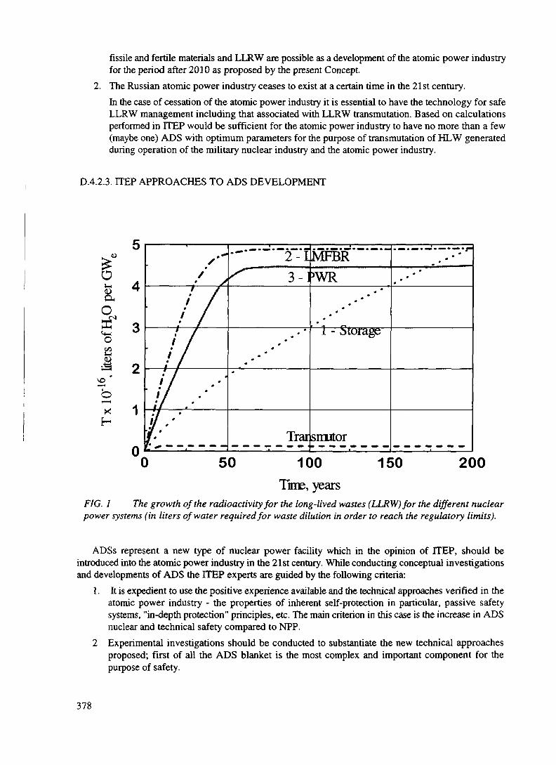
fissile and fertile materials and LLRW are possible as a development of the atomic power industryfor the period after 2010 as proposed by the present Concept.
2. The Russian atomic power industry ceases to exist at a certain time in the 21st century.In the case of cessation of the atomic power industry it is essential to have the technology for safeLLRW management including that associated with LLRW transmutation. Based on calculationsperformed in ITEP would be sufficient for the atomic power industry to have no more than a few(maybe one) ADS with optimum parameters for the purpose of transmutation of HLW generatedduring operation of the military nuclear industry and the atomic power industry.
D.4.2.3. ITEP APPROACHES TO ADS DEVELOPMENT
oJ-l&§•
<4-4o
XH
V
4
3
2
1
s'~»
/JL!/ • ••'•/ ••'if .- ——
• /
[••'
•~'~ 2-1•^ 3-]
**
**
••
*
Trai
MFBR>WR
***••**•*•
1 - Storage
smutor
•*
•*•**
50 100Time, years
150 200
FIG. 1 The growth of the radioactivity for the long-lived wastes (LLRW) for the different nuclearpower systems (in liters of water required for waste dilution in order to reach the regulatory limits).
ADSs represent a new type of nuclear power facility which in the opinion of ITEP, should beintroduced into the atomic power industry in the 21st century. While conducting conceptual investigationsand developments of ADS the ITEP experts are guided by the following criteria:
1. It is expedient to use the positive experience available and the technical approaches verified in theatomic power industry - the properties of inherent self-protection in particular, passive safetysystems, "in-depth protection" principles, etc. The main criterion in this case is the increase in ADSnuclear and technical safety compared to NPP.
2 Experimental investigations should be conducted to substantiate the new technical approachesproposed; first of all the ADS blanket is the most complex and important component for thepurpose of safety.
378

3. Experimental work should be done on the nuclear data base primarily for the radionuclides to betransmuted.
4. At the stage of conceptual investigations it is expedient to study various types of targets andblankets with estimates of their possible implementation, determination of technical andeconomical characteristics and then choose one version for further development.
5. The ADS operation should be performed with a positive power balance and decrease inradiotoxiciry compared with the initial level.
6. The possibilities of ADS operation in combination with other improved power reactors, includingfast reactors, should be investigated at the stage of conceptual studies.
7. Studies on the place of ADS in the future of the atomic power industry should be conducted withan estimation of the radiation load on operating staff and population(this has not been done because of the lack of financing).
8. The technical requirements and ADS criteria should be formulated as the result of conceptualinvestigations including:
- Minimization of the amount of LLRW in the various technological processing stagesof the future MFC.
- The possibility of useful application of some transuranic elements from the LLRW list.- Power efficiency, i.e. the ratio of the useful power to consumed power.- Environmental efficiency, i.e. the reduction in LLRW radiotoxicity under irradiation in
the ADS per unit of time.
D.4.2.4. PRINCIPLE POSSIBILITIES OF ADS
We shall indicate in the present section only the principle features of ADSs and the possibilities whichshould be justified as the result of conceptual studies. These possibilities are presented on Fig. 2, page 328.
D.4.2.4.1. Safety
The available operating experience of the atomic power industry allows us to specify three kinds ofsafety for nuclear facilities: nuclear, technical and radiation. Nuclear safety means the absence of conditionsfor self-sustaining chain fission reactions (SCFR), with an effective multiplication coefficient above unity,to develop.
Technical safety means the absence of conditions for core meltdown in non-stationary and emergencymodes, in the event of vessel damage, damage to pipelines or other equipment failures which could Leadto dangerous consequences.
Radiation safety means the absence of conditions for increased radiation effects on operating staffor the population during normal operation or in the event of an accident.
At the present level of knowledge the ADS permits:- exclusion of the class of accidents associated with a change in reactivity (reactivity
margin); first of all, a power excursion of instantaneous neutrons in relation to the ADSblanket operation in subcritical mode with a sufficient margin for the value of theeffective multiplication ratio with consideration for the feedback;
- to exclude in principle absorber rods in the emergency protection system as a possiblecause of potential accidents;
379
- to use a new type of ADS passive emergency protection, without moving working headsat accelerator de-energization, which makes it possible to increase the speed of responseseveral orders of magnitude compared to existing at the present time.
D.4.2.4.2. The use of NPP spent nuclear fuel as ADS fuel
ADS can use NPP spent nuclear fuel (SNF) as material for power generation, after its unloading fromthe power reactor and without radiochemical reprocessing. Estimations performed in ITEP suggest that inan ADS heavy-water blanket loaded with SNF from VVER-type reactors the specific power generationcould be increased approximately a factor of two compared with the level of bumup achieved at the presenttime [3]. To implement this mode it is necessary to perform an analytical study of a particular blanketdesign scheme with consideration of material problems.
D.4.2.4.3. The use of depleted Uranium in ADS
A large amount of Uranium with a 235U content of 0.25% or less is held in the stores of the Ministryof Russian Federation on Atomic Energy. The depleted Uranium is a potential source of power because ofits transformation into Plutonium. The ADS could use the depleted Uranium as fertile material to producePlutonium fuel and power at the same time (7-10% of ^U is fissioned in a fast neutron spectrum) withoutany limitations on content of the B8U. After the exhaustion of cheap natural Uranium resources in the futuredepleted Uranium will probably a valuable fuel.
D.4.2.4.4. The use of highly enriched Uranium
As the result of nuclear disarmament a possibility emerges of using highly enriched (90%) Uraniumin the atomic power industry. It could be used either in the form of 90% Uranium dioxide or in the formof isotopic diluted dioxide, e.g. with 4.4% enrichment for VVER-type reactors. 90% Uranium, without itsisotopic dilution, could be safely used in the ADS blanket for power generation and production of excessneutrons. In doing so the load of 90% Uranium dioxide into the blanket could, in principle, be less thanthe critical mass value. The excess neutrons are consumed for LLRW transmutation and production of newfissile materials.
D.4.2.4.5. The use of weapons-grade and power Plutonium
The ADS can use weapons-grade and power Plutonium as a nuclear fuel for power generation andproduction of excess neutrons which can be used for LLRW transmutation and production of newfissionable materials. The involvement of Plutonium in the MFC will make it possible to expandsignificantly the fuel basis of the atomic power industry.
D.4.2.4.6. The necessity to expand the fuel basis of the atomic power industry
One of the possibilities for expanding the fuel basis of the atomic power industry is the closure of thenuclear fuel cycle. In doing so a set of problems emerge which have a pronounced effect on the NPPnuclear fuel cycle and solutions are called for.These are the following problems:
380

236U buildup in the SNF as multiple irradiation of regenerated Uranium takes place that willrequire an increase in fuel enrichment,generation and continued increase in the amount of 232U in the SNF as multiple irradiation ofthe regenerated Uranium takes place, that requires remote technology for fuel elementmanufacture starting from a certain cycle;extraction of the reactor-grade Plutonium from the NPP SNF and the need to use it as a fuel,with attendant problems (the need for remote technology for fuel element manufacture,nonproliferation, etc.),generation of a large amount of LLRW containing fission products and transuranium elements,especially with aqueous methods of SNF reprocessing,an increase in the amount of depleted Uranium with a low content of ^U (0.1 -0.2%).
Another way of extending of fuel basis of atomic power industry is to involve Thorium in the NFCfor the purpose of generating new nuclear fuel, namely 233U.
The problems indicated above could effectively be solved with the help of ADS, using previouslyelaborated approaches and techniques proved in NPP operation.
A formulation of the future problem of the atomic power industry in supplying itself with fuel isadvisable. This could be solved not only through the use of fast reactors with breeding, but also byutilization of ADSs for breeding purposes. One possible conceptual solution is the utilization of atwo-module ADS (a module consists of a target and a blanket) [4]. Depleted Uranium is loaded into theblanket of one module to produce Plutonium. Plutonium and actinides produced in that module areextracted from irradiated ^'U and directed into the power blanket to generate power and produce excessneutrons which could be used for LLRW transmutation or production of the new nuclear fuel. Such atwo-module ADS will in principle permit implementation of ADS fuel self-supply.
D.4.2.4.7. Safe HLW management and environmental effects
The ADS can incinerate the main fission products except, for ^Sr, 93Zr, 1MSm and transuraniumelements, by a process of transmutation. This is characterized by the following parameters:
1. necessary neutron flux;2. neutron consumption per one incinerated nucleus;3. secondary radioactivity;4. radiotoxicity.As the result of the transmutation process the amount of HLW and the period required for storage is
reduced as well as environmental effects.
D.4.2.4.8. Safeguards of fissionable materials and the problem of non-proliferation
The ADS makes new approaches available for preservation and non-proliferation of fissionablematerials, most importantly weapon-grade Plutonium in connection with possibilities for its denaturation.The first technical possibility is irradiation of the mixture of Plutonium and fission products, e.g. Sr or Cs,to complicate their theft during storage, with subsequent irradiation of this mixture in the ADS blanket. Ithas been demonstrated that in this case no significant change in the ADS blanket reactivity takes place [5].The second technical possibility is dilution of 'Pu with 238Pu either by addition of 238Pu or by irradiationof the 237Np and 239Pu mixture. At specific 238Pu content the mixture of 'Pu + a9Pu is unsuitable for
381

nuclear weapon manufacture. This possibility could be effectively implemented both in power reactors andin ADSs.
D.4.2.4.9. Economics
The ADS is at first glance a more expensive facility than a power reactor. The capital investment inADS will be higher in connection with the accelerator and the target. The qualitative considerations,however, demonstrate the high profitability and economic efficiency of the ADS in a systematic approachrather than in comparison of individual facilities.
If we assume that a fast reactor of BN-800 type could transmute the minor actinides (MA) from 3loads of WER-1000 reactors and its own, 7 BN-800 reactors with total power of 3.6 GWe are necessaryto destroy MA from the existing Russian NPPs [6]. According to our estimation the cost of one reactor isnowadays appr. 2xl09 US$ i.e. appr. 14xl09 US$ are required for commissioning 7 BN-800 reactors.
One optimized ADS could in the limiting case transmute all the actinides from all NPPs existing inRussia. If we assume that capital investment in an ADS is twice as large as that for a BN-800 reactor owingto the accelerator and target, the amount is 4x10⁹ US$. Moreover, it is necessary to commission 5VVER-1000 reactors with a total capacity of 5 GW(e), and investment of appr. 5xl09 US$, to compensatefor the power generation by the BN-800 reactors. In this case the expense for LLRW transmutation withthe use of BN-800 reactor is 1.5-2.0 times higher than for ADS. For a final conclusion on the economicefficiency of ADS, however, systematic investigations are necessary and these have not been yet performed.
The study of the possibilities for ADSs mentioned in the present section, and the place of ADSs inthe future plans of the nuclear power industry, are the main purposes of this conceptual study.
D.4.2.5. POSSIBLE OPERATION MODES AND FUEL CYCLES
The following ADS operation modes could be considered:1. A transmutation mode without power utilization.2. A transmutation mode with concurrent power generation and utilization.3. A mode with power generation and utilization as well as production of new fissionable
materials and LLRW transmutation.4. An after-bum mode for power generation with use of NPP spent fuel assemblies as nuclear
fuel.The ADS can also serve as a high intensity neutron source for producing radionuclides with high
specific activity.The ADS can have various fuel cycles depending upon the mode of operation. The following materials
could be used as fuel materials for transmutation modes: enriched Uranium, power and weapon-gradePlutonium, actinides (in a mixture with Plutonium and without it), and 233U. Depleted Uranium andThorium could be used as fertile materials for the production of new fuel.
The possibility of implementing the following fuel cycles (FCs) in the ADS could be indicated:1. The Uranium FC. In this version of the FC various Uranium fuels could be used in the
blanket: 90% enriched Uranium released as the result of nuclear disarmament; regeneratedUranium produced after multiple irradiation and reprocessing cycles of the SNF with a highcontent of actinides and fission products (FPs) could be loaded into the blanket in variouscombinations and proportions for transmutation purposes. Depleted Uranium without anyrestriction in content should be loaded into the blanket in Plutonium production mode. ^Ucould also be used as a nuclear fuel in the ADS blanket.
382

2. The Plutonium FC. Plutonium fuel with different isotopic compositions: weapon -gradePlutonium only, or power Plutonium only, or their mixture could be loaded into the blanketin this version. Actinides and FPs could be loaded into the ADS blanket for transmutationpurposes. Depleted Uranium could be used for the purpose of nuclear fuel production inthe ADS blanket. Neptunium or Plutonium fuel could be used for the special purpose ofweapon-grade Plutonium denaturization.
3. The Uranium-Thorium and Plutonium-Thorium PCs. Enriched Uranium or Plutonium isused as a nuclear fuel in these FC versions (Thorium is used as fertile material for npurposes).
4. The actinide FC. In this version alternative actinides in various combinations with FPs areused as a nuclear fuel in the ADS blanket for transmutation purposes.
The form of the fuel, fertile, and target materials has been a matter of interest. Two main alternativesare possible for the application of fissionable fuel materials: a solid and a liquid form. Each alternative hasits own advantages and disadvantages. If the available experience in production of the nuclear fuel forNPPs is kept in mind, it is advisable to chose dioxide fuel in Zirconium cladding. It will be a MOX-fuelin the case of power or weapon-grade Plutonium. In recent years Russian experts have conductedinvestigations on cermet and nitride fuels with increased burnup levels. In relation to the problem of nonproliferation, Plutonium fuel in an inert matrix may be of interest. However, in the case of 3-5% actinideaddition to the MOX-fuel, its radiation resistance should be experimentally verified; this requiressubstantial expense and is time consuming.
Some research groups in LANL, JAERI and ITEP are conducting investigations on liquid fuel basedon fluoride molten salts of the type Li-BeF2-ThF4-PuF4.
The advantages of liquid fuel are the absence of radiation damage problems, the possibility ofbreaking away from metallurgical production of fuel assemblies, a reduction in amount of FPs andfissionable materials in the core, etc. The main objection in Russia against liquid fuel lies in the absenceof a technological basis for its implementation in the atomic power industry, rather complex technicalproblems emerging in the reactor facility, etc. It could be argued that the problems of liquid fuel applicationare somewhat in advance of needs of the atomic power industry at the present time. However, R&D shouldbe conducted on the prospects and possibilities for liquid fuel applications in ADSs in order to have a basisfor decision making.
The variety of operation modes and fuel cycles in ADSs mentioned above requires certain prioritiesto be set in order to concentrate the small resources available into one or two R&D lines. For this purpose,systematic investigations have to be pursued which have not been performed yet because of lack of funding.However priorities in the fuel cycle development could be determined even now. The highest priority isthe ADS Plutonium cycle, where Plutonium is used as nuclear fuel, to generate power and excess neutronswhich in turn are directed toward transmutation of actinides and FPs. This could help solve the problemsof nuclear weapons non-proliferation and the production of new fissionable fuel.
This is explained by the availability of large stocks of power and weapon-grade Plutonium with a highpower potential and the need to prepare a technological basis for its safe use as a nuclear fuel in a futureatomic power industry. Hence the transmutation mode with power generation and the use of theweapon-grade and power Plutonium, wherein a Plutonium FC with actinides and FPs is used as a targetmaterial has priority in R&D.
The second priority is a Plutonium FC wherein the ADS operates in the mode of power generationand Plutonium production from depleted Uranium. The priority of this mode and FC is explained by theavailability of large amounts of depleted Uranium in storage in the nuclear nations, including Russia. Theinvolvement of depleted Uranium makes it possible to increase nuclear fuel resources substantially asresources of cheap natural Uranium become exhausted. All necessary technologies are available for thisversion and have been verified on an industrial scale.
383

The third priority is a Plutonium FC wherein the ADS operates in the mode of power generation and233U production from Thorium. However, the involvement of FC implies that the development of newtechnologies will be necessary after all resources of natural Uranium have been exhausted.
In accordance with the decision of the Scientific and Technical Council of the Russian Ministry forAtomic Power, fast reactors are considered to be the main nuclear and power facilities for utilization ofRussian weapon-grade Plutonium. At the same time the RF Ministry of the Atomic Power Industry supportsthe ADS development as an alternative line, keeping in mind the possibility of operating the ADS blanketin a subcritical mode which increases the nuclear safety level in the event of its loading with weapon-gradePlutonium.
D.4.2.6. PECULIARITIES OF THE TRANSMUTATION PROCESSES
The process of transmutation of FPs and actinides transmutation in neutron fluxes must has its ownpeculiarities which must be taken into account in the development of ADS. The transformation of FPs isperformed mainly by (n,Y)-reactions through sequential capture of neutrons being transmuted by a nuclideand formed by intermediate nuclides. The destruction of actinides occurs mainly through fission reactions.Despite this difference the following LLRW transmutation processes are characterized by the followingparameters:
1. Aj, the actinide destruction rate which is determined by the neutron flux density $ and a,, theeffective microscopic interaction cross-section.
2. The process power efficiency which is determined by the value of the power spent for thedestruction of one nucleus of the nuclide being transmuted or by the number of neutrons spentfor the destruction of one nucleus.
3. The secondary radioactivity which is formed as a result of the transmutation of LLRW.4. The value of the radiotoxicity of nuclides before and after the transmutation.
Investigation of the mentioned above features allows us to determine the list of nuclides which aresuitable for transmutation.
A short analysis of the features mentioned above is given below.
D.4.2.6.1 A^ destruction rate of the nuclide being transmuted
Since the value of A; is proportional to (Jxj; for FPs it will be higher for the higher <j> and q values. Theupper limit of <j> which can be reached with present-day knowledge and experience is probably in the rangeof 7.xl015 - S.xlO16 n cm'V. The value of a, depends on the neutron spectrum. It is advisable to use athermal neutron spectrum for FP transmutation through (n,y) reactions where interaction cross-sectionvalues are rather high. Actinide transmutation is possible both in thermal and fast neutron spectra. Acomparison has been performed of neutron cross-sections for actinides at comparable neutron fluxes in athermal blanket (1014 cm'V) and in a fast reactor (l^xlO^cm'V). As can be seen from the results givenin Tables I and II, the effective cross-section of actinides in a thermal spectrum is in most cases muchhigher than for a fast reactor [7].
Specialists from ITEP and other institutes have estimated the value of the neutron flux density
384

Nuclide,I
07Np238Pu239Pu240^
^'PuM2Pu
^'AmMtaAm243 Am™CmMCm^CmMSCm^Cm
Oc(bam)
1.40.50.50.50.40.41.70.41.0
0.2880.30.60.4
0.77
Of(bam)
0.31.11.80.42.40.30.33.20.2
0.1852.6.4
2.80.47
oa(barn)
1.71.62.30.92.80.72
3.61.2
0.4732.91
3.21.24
V
(n /fis.)2.93.02.93.13.03.03.43.23.63.53.83.53.83.5
TABLE I. EFFECTIVE CROSS-SECTIONS AND THE necessary for Sr and l37Cs [8] incineration. ForNUMBER OF NEUTRONS PER FISSION FOR THE ^Sr separation the capture cross-section value isFAST REACTOR. for o= 0.014 [9] or 0.0097 [10] bam according to(oc - cross section for capture, o f - Cross section for the latest data. According to older data it wasfission, a, - cross section for absorption, v - number of believed that o=0.8 ± 0.5 [11]. If we are adhereneutrons per fission.)__________________ to contemporary data and believe that o=0.01,
then a neutron flux of 7.6xl0ls cm'^s"1 isrequired for the ^Sr transmutation rate to beequal to its radioactive decay rate 0^=28.8years). In this case the "half-destruction period"will be half of the half life, i.e. 15 years. Higherflux densities (more than 1017 cm"2-s'') would berequired for more rapid destruction. Even thoughsuch flux densities could be achieved in theADS, it is unlikely that this will be economicallyjustified.
For 137Cs 0=0.11 barn [12] or 0.25 bam[13]. For the transmutation rate to be equal to theradioactive decay rate (Tw=30 years) a fluxdensity of 6.7xl015 or 2.9xl015 cnV2-s° isaccordingly necessary which is achievable inmodern reactors. In this case the "half-destructionperiod" will be 15 years. Flux densities higherthan 1016 n cm'V are required for more rapiddestruction of l37Cs. It should be kept in mindthat the radiotoxicity of %Sr is significantly (37times) higher than that of l37Cs (the maximum
permissible concentration of "'Sr in water is 4.0xlO'10 Ci/1, and that of l37Cs is ' 5xlO'8 Ci/l).
D.4.2.6.2. Transmutation process efficiency
It is quite obvious that the power consumption required for HLW destruction should be substantiallyless than the amount of power generated by NPPs. According to investigations carried out by specialistsfrom the Moscow Engineering Physics Institute the FP transmutation process is effective if the powerconsumed for transmutation is appr. 30% of that generated in the NPP [14]. It is obvious that the powerbalance in actinide incineration is positive. The power consumption for HLW transmutation could only bedetermined after development of a particular ADS design. Therefore such a characteristic as R;, theconsumption of neutrons necessary to incinerate one FP nucleus, could be used to estimate the powerconsumption. The calculation results for Rj are tabulated in Table in [15]. It is evident from Table ffl thata considerable number of neutrons is required for transmutation of 93Zr and 151Sm. This demonstrates thattheir incineration in a neutron flux is ineffective from the power viewpoint. At the same time it is advisableto state the problem of their recycling in the NFC, for example l5'Sm is an absorbing material in the CPSrods. The transmutation of the other radionuclides listed in Table IV is energetically advisable.
D.4.2.6.3. Secondary radioactivity under transmutation
The process of neutron generation for transmutation is accompanied by electric power consumptionfrom an external source for the accelerator supply. If we believe that this electric power is generated in the
385

TABLE H. EFFECTIVE CROSS-SECTIONS AND THE NPP, then neutrons are produced asNUMBER OF NEUTRONS PER FISSION FOR THERMAL the result of fission reactions of theREACTORS. nuclear fuel in the reactor of the NPPOV - half-life, oc - cross section for capture, of - cross section for which energizes the accelerator,fission, oa - cross section for absorption, v - number of neutrons per Moreover, nuclear reactionsfission.)_______________________________ generating neutrons also occur in the
blanket of the ADS itself. Hence thetransmutation process, i.e. the processof destruction one radioactivity unit isaccompanied by generation of FPs,that is secondary radioactivity.Because in the first 100 years afterunloading of the NPP's spent nuclearfuel (SNF) its activity will bedetermined to appr. 90% by activity of^Sr and 137Cs, the secondary activity ismainly the activity of themedium-lived nuclides - ^Sr and137Cs. The calculations of thesecondary activity performed by ITEPspecialists show that, with theelimination of all primary activity ofthe FPs (except for ^Sr and 137Cs),secondary radioactivity is generatedwhich accounts for 10-12% of theradioactivity (see Table IV) [15]. Inthe event of elimination of 100% ofthe primary activity, including Sr and137Cs, the secondary activity generatedis equal to 40% of the ^Sr and 137Csprimary activity. This result can beinterpreted in the following way. First,the long-lived activity is transformedto medium-lived with the help of anADS. Second, we have to pay for thiswith the generation of an additional10-12% of secondary activity of themedium-lived ^Sr and 137Csradionuclides (Tw up to 30 years).
This is a very important result. It follows that with the use of an ADS all long-lived FPs (except ^Sr) couldbe destroyed.
Nuclide,I
237Np238Np239Np08Pu239Pu240PuM1Pu242pu
243Pu241AmM*Am""•Am243 Am244 Am
244,nAm
M2Cm243Cm^Cm^Cm"•Cm247CmMICm"'Cm""Bk
T,fl(years)
2.14xl06
2. 12 days2.36 days
87.712.41x10"
656914.35
3.76xl05
4.96 hrs432.6
16.1 hrs141
7348.10.1 hrs26. min
161. days28.518.1
8500.4700.1560.
3.4xl05
64.15 min329 days
oc(bam)203.462.
67.5433.268.1050.316.126.97.
540.-
1637.243.
--
23.657.77.2292.13.199.
29.11.3995
Of(barn)0.7061773.
-17.1666.0.93910.0.7
213.4.011725.6372.1.16
1856.1291<4.127.2.631735.1.13142.1.8--
oa(barn)204.11183567.5
450.1934
1050.91226126.7310
544.011725.8009
244.161856.129127
78479.83202714.2324131.1.3995
V
(n/fis.)2.252.8
-2.9
2.877-
2.937--
3.213.263.26
----
3.43-
3.717-----
D.4.2.6.4. Radiotoricity
The main radiobiological hazard is actinides with long half lives.Taking into consideration the high radiation hazard of actinides a comparison of the radiotoxicity has
been performed for fuel loads of the ADS thermal and fast blankets [7]. For the comparison to berepresentative a stationary operation mode has been chosen with continuous nuclear fuel replenishmentsuch that the change in concentration of nuclides in the next cycle is the same as for the previous one. The
386

effective neutron flux density for the fast reactor wasassumed to be equal to 1.2xl016 cm"2-s"'; the effectivecross-sections are b'sted in Table I. In Table n thecross-sections are listed for a thermal blanket and theeffective neutron flux density averaged over aMaxwellian neutron spectrum was assumed to be equalto 5.xl015 cnV2-s"'. The results of the calculations aretabulated in Tables V, VI and VH The followingconclusions could be reached:
1. The equilibrium mass of all actinides in thefast reactor stationary mode is 40 timeshigher than in the thermal blanket.
2. The main contributions to the actinides massare made by: B7Np (18%), ""Pu (26%),'"Am (15%), "'Cm (4%) and Cm (9%) inthe fast reactor and^Np (15%), 23Pu (2.9%), ^Am (4.9%),
M2Cm (37%), ^Cm (16%) and Cm (13%)in the thermal blanket.
TABLE m. NEUTRON CONSUMPTION FORFP's TRANSMUTATION
Nuclide, I^Sr
l37Cs15lSm99Tc93Zr
126Sn79Se135Cs107Pd
,29j
T1/2 (years)28.8
30.1793
2.14xl05
1.5xl06
l.OxlO5
6.5xl04
3.3xl06
6.5xl06
1.6xl07
oc
5.94xlO'2
6.23x1 0'2
4.16xlO'3
6.15X10'2
6.35xlO'2
5.72xlO'4
4.49x10-"6.55xlO'2
1.42xlO'3
7.68xlO'3
R,23
30-2501.15-1.5
150-
1.5--2
TABLE IV. SECONDARY RADIOACTIVITY IN INCINERATION OF NUCLIDES CONTAINED IN1 TONNE OF THE WER-1000 SPENT NUCLEAR FUEL
Nuclide I
^Sr137Cs
15ISm
"Mo93Zr125Sn79Se135Cs,07pd
,29j
Total without
Total without Zr,
m,, g/t
678
1460
14.9
950
907
22.4
5.9
422
254
220
Zr, Sm
Sm, Cs, Sr
m.Q/0', Ci/t
9.4x1 04
1.3xl05
405
16-2
2.3
0.64
0.41
0.486
0.13
0.039
2.4xl05
m.Q/2), Ci/t
2.2x1 04
4.8x10"
4.5xl03-2.2xl04
2.0x1 06
165
5.xl03
9.2x1 04
(2.1-2.7)xl04
niiQ,'2', Ci/t
4.3x10"
9.1xl04
(0.7 - .75)xl04
4.0xl06
320
9.7xl03
1.7xl05
(4.1-5. 1)xl04
Note: The secondary radioactivity m.Q, is caused basically by Sr and Sr
3. The long-lived activity of actinides in the fast reactor is 40 times higher than in the thermalblanket. The long-lived activity in the fast reactor is 34% due to 238Pu and 54% to ^Cm and is90% due to ^Cm in the thermal blanket.
4. T,, the value of the radiotoxicity for long-lived actinides in the fast reactor is 100 times higher
387
than in the ADS thermal blanket. The value TIAc corresponding to a stationary amount oflong-lived actinides in the fast reactor is 33 times higher than the TI^ for its own annualreplenishment. For the thermal blanket the TIAc is 3 times less than TIAc for the annualreplenishment. These results demonstrate the ecological hazard of actinide transmutation in fastreactors and the advantages of the ADS thermal blanket.
(Note: the above results have been obtained without considering the change in radiotoxicity of actinidesduring SNF radiochemical processing because of irreversible losses).
The analytical mentioned studies made it possible to chose FPs and actinides for transmutation. Withconsideration of the above mentioned characteristics, and talcing into account conclusions made in the workperformed by RRDEPT and the Radium Institute [16], it is advisable to transmute the following FPs andtransuranium elements: 14C, 79Se, "Tc, 107Pd, 125Sn, 129I, l35Cs and 137Cs (possibly during their isotopicseparation) and Np, Am and Cm using Plutonium for the generation of excess neutrons.
D.4.2.7. THE USE OF THE WEAPON- AND REACTOR-GRADE PLUTONIUM IN ADS.
The investigations carried out by ITEP and other institutions demonstrate that existing power reactorsand reactors under development are, despite the technical measures taken, are not guaranteed free fromaccidents such as those dealing with reactivity (accidents with a change in the core reactivity). Theprobability of an accident associated with reactivity increases when Plutonium fuel is used in thermalreactors because a decline in the safety parameters occurs. According to calculations performed byspecialists from the Physical Power Institute RSC (Obninsk) for example the temperature and powercoefficients of reactivity are increased in the VVER-500 reactor when MOX-fuel is used (4.8% and 2.7%instead of 3.6% and 2.1% respectively),the keff value is decreased (from 6.0xlO'3 to 4.4xlO"3 ) with acondition that the efficiency of the operating groups of the CPS rods is decreased by a factor of 1.3 [17].
The addition of actinides to Plutonium fuel results in a degradation of the safety features of fastbreeders. These features of Plutonium, especially of weapons-grade, require special approach for usingPlutonium as a nuclear fuel for the atomic power industry. In the ITEP specialists opinion an ADSoperation with a subcritical blanket permits us to exclude accidents associated with reactivity, firstlyaccidents such as reactor runaway on prompt neutrons. The ADS safety level could therefore be in principlesubstantially higher than that of power reactors with a critical core. This fundamental advantage givesgrounds for using weapon-grade and power Plutonium as nuclear fuel for power generation and excessneutrons production in an ADS.
388

XA9846573
D.43. PHYSICAL FEATURES AND PERFORMANCE ACCELERATOR DRIVEN SYSTEMS(ADSs)
D.4.3.1. PHYSICAL FEATURES
D.4.3.1.1. Target
The ADS target principally transforms the energy of charged particles taken from an accelerator intothe energy of neutrons produced by reaction with the target nuclei. The following factors have a significanteffect on the efficiency of this transformation process:
1. The type, energy and intensity of the charged particle flux.2. The possibility of developing a charged particle accelerator with specified parameters and
minimum possible losses of charged particles in the acceleration process.3. The target material.4. The possibility to remove the heat generated in the target as a result of charged particle interaction
with target nuclei.5. Economic characteristics.
At the same time there is a simple criterion which can be used in considering items 1 and 2, that is n/p,the number of neutrons generated per proton interacting with the target nuclei.The general requirement on ADS power efficiency has also been taken into consideration in the analysisof these factors. This requirement is related to the fact that ADS power consumption, especially in theHLW transmutation regime, should not exceed 30% of the power generated in a NPP as was demonstratedin studies conducted by specialists from the Moscow Physical Engineering Institute.
The following types of charged particles have been considered in ITEP during the conceptual studyas possible for use in ADS: protons, deuterons, and a particles. Analysis of the available data on theneutron yield in spallation reactions of these particles at the same energy and with the same target materialshows that the value of n/p is 10-15% higher for deuterons than for protons and a particles. It should beemphasized, however, that protons are preferable from the point of view of ensuring the required low levelof particle losses in the acceleration process. It should be noted that such particle losses will determine thelevel of induced activity of accelerator structures and, consequently, the possibility of acceleratormaintenance without use of remote technology and devices.
The available experimental data testify that the proton energy range of 1.0-1.5 GeV is preferable fromthe point of view of increasing the neutron yield in spallation reactions. A proton energy equal to 800MeV has been chosen for an ADS demonstration facility bearing in mind the experience with developmentand operation of linear accelerators in LANL (USA) and the Institute of Nuclear Physics (Troitsk, Russia).
To increase the neutron yield, i.e. the value of n/p, it is necessary to use materials with a large massnumber, for example, Plutonium, neptunium, Uranium, Thorium, Tungsten, Lead, and Bismuth, as targetmaterials. A significant (up to 50%) absorption of neutrons generated in spallation reactions is observedin multiplication-type targets (made of such materials as Uranium, Thorium, neptunium, Plutonium)according to calculations performed in various Russian research institutes. Therefore, it is inadvisable touse targets made of fissile materials for ADS with target and blanket placed separately and designed forpurposes of HLW transmutation. Lead and Lead-bismuth eutectic have the lowest absorption of neutronsgenerated in the target through spallation reactions.
389

The yield of neutrons per proton, or n/p, is 35 at a proton energy of 1000 MeV for Lead [21].Comparison of Lead and Lead-bismuth eutectic demonstrates that they could be used as target materials.Lead, however, has some disadvantages: high melting temperature (327.44 °C), high coefficient oftemperature expansion (28.5xlO~6 K"1). Pb-Bi eutectic (56.5% Pb, 43.5%) have the following features:melting temperature - 125 °C, a density of appr. 9.83 kg/m3, a low thermal expansion coefficient [22]. Thedisadvantage of this eutectic is the production of 210Po in a neutron flux. Taking into consideration theexisting experience with application of Lead-bismuth eutectic in transport reactors it is advisable to acceptit as the target material in ADS because of the existing advantages of this coolant (low melting temperature,high yield of neutrons per proton, mastered technology).
D.4.3.1.2. Types of fuel and associated fuel cycle technologies
Among fuel materials the oxides of Uranium, Plutonium, and their mixtures should first be noted. Thisis because all actinides are alike in their chemical properties and oxide fuel materials are the mostadvantageous for the production of fuel element cores with doping of minor actinides (MA) and fissionproducts (FPs). If MA could reside in solid solutions with the oxides of the fuel elements, then somefragmented elements could form precipitates of excess oxide phases in the fuel matrix, or phases of morecomplex composition, and some elements (elements of the platinum group, alkaline elements) could formmetallic precipitates. This, however, has little effect on the radiation resistance of the core. Oxides ofUranium and Plutonium, even with a doping of several percent of americium, have demonstrated goodradiation resistance during their burnup at a level above 10% of the heavy atoms with fairly good economicfeasibility for production. A sufficient data base of operational data has been accumulated on dioxides ofUranium, Plutonium, and their mixtures.
Fuel materials where the fissile component is distributed in an inert oxide matrix should also bedesignated as oxide fuel materials. Such compositions were considered for the first time during anassessment of the possibility of designing fast reactors with a core containing only Plutonium oxide andwith breeding occurring only in the reflector which surrounds the core. A range of materials could beviewed as inert oxide diluents, including BeO, MgO, A12O3, ZrO2, CaO, La^, Nb2O5, SiO2, SrO, TiO,V2O5, etc. The above mentioned set consists of rather high-melting and resistant oxides which have lowparasitic capture of neutrons. Compact pellets for clads could be manufactured from a powder made ofthese materials mixed with an oxide powder of MA. Tentatively, the thermophysical features of the mostpreferred oxides are given in Table IV.
TABLE IV. THERMOPHYSICAL FEATURES OF INERT MATRIX OXIDESMaterial
MgO'ZrO2A1203SrO'CaO*
Melting temperature,°C
28252700205026502600
Thermal conductivity,W/mole°CaOOO°C)
7.51.65
= 3.0
Heat capacity,kcal/mole °C
12.3118.7230.7913.3813.38
Material interacts with water
The selection of materials, the design and technology of fuel element manufacturing should be lookedat first of all from the viewpoint of economic feasibility of the whole closed fuel cycle. Reliability shouldnot be provided at any cost. One of the main requirements is for ease of radiochemical reprocessing. Thisinvolves both cost assessments and environmental assessments. For example, the application of the fuelcomposition in the form of nuclear fuel dispersions in a neutral aluminum matrix has a clear disadvantage.Dissolution of the matrix material is necessary, and in spite of the low parasitic capture cross-section ofneutrons in aluminum this produces a great amount of liquid radioactive waste which must be concentrated
390

and rendered harmless.MA which are produced as matrix solid solutions with high thermodynamic characteristics are easily
introduced into mononitride fuel. Besides, the recovery of the mononitride fuel (or carbide) could beperformed using the technology of oxide fuel recovery (the PUREX-process) with the same equipment.In doing so the process of nitride fuel dilution in nitric acid proceeds quiescently with great completenessand a high rate. The above types of fuel allow rather economic manufacture of fuel elements andradiochemical reprocessing without clad dissolution. With a guaranteed provision that the temperature onthe interface of the metallic fuel core, with metallic cladding of the fuel element, does not exceed 450-500°C in any of the possible modes of ADS operation, it is quite possible to use metallic fuel.
At the present time hydrometallurgical methods for radiochemical reprocessing of spent fuel elementsare being industrially developed. They are based on the dissolution of SNF in nitric acid, with subsequentextraction of the fissile component and waste reprocessing. It has been demonstrated that completion ofthe radiochemical reprocessing of fuel elements by fractionation of radionuclides according to half livesand radiotoxicity is economically and environmentally advisable, as well as from the viewpoint ofutilization of radioisotopes. In this case the possibility of keeping MA and long-lived FPs not subject todisposal for further transmutation can also be considered.
Although extraction technologies for actinide concentration permit a drastic reduction in the amountof liquid radioactive waste, the problem of its further concentration, thickening, solidification, and waterpurification exists. All these processes are power-intensive.
The possibilities for drastic reduction in the amount of water used are in the application of high-temperature methods of spent fuel element reprocessing. In the case of the use of power or weapon-gradePlutonium as a material for production of fuel without oxygen (mononitride, monocarbide) it is advisableto use an electrochemical process for the recovery of irradiated fuel in melts.
Also of some interest are technological processes for crystallization of MA dioxides of mixedcomposition from molten salts. Along this pathway the number of technological procedures in the cycleof spent fuel element reprocessing could be significantly reduced.
D.4.3.2. PERFORMANCE OF THE ADS SYSTEMS
D.4.3.2.1. ADS schematic diagram
There are two alternative designs of the ADS: one with a horizontal (version A) and the other with avertical (version B) placement of the target and blanket (Fig.2). In accordance with an investigationconducted by specialists from the Special Design Bureau of Machine Building (SDBMB) in NizhnyNovgorod the vertical arrangement of target and blanket is preferable [18]. The use of one, two or moreADS modules operating from one accelerator is possible. The number of modules is determined by anumber of factors, the first being the end use of the ADS.
The choice of a vertical arrangement predetermines the need to rum the beam 90° which requires theinstallation of a magnetic system. In the case when two or more modules are used it is necessary to dividethe proton beam from the accelerator into two or more beams. In this event it is necessary to provide forthe development and installation of the relevant device. Because a large amount of power is generated inthe target and blanket, systems for heat removal and power utilization should be provided in ADS.
391

Power Distribution
i
3
i \
3
1
G
SU>
r \
depleted U
Jreactor er. Pu .J
enriched U
J
ADS
N enriched U . ——————^(kpletedU^ weapon gr. PuIMA"-FP
Military Industry
j \
Reprocessing Plant
Storage
i r \ r 1 r \ r \ •
ADS
———————— >
r
Losses
i p
Storage
deoletedU „
weapon p. Pa ^
^ ————————
£
' i
s>>Ju>
' 1
reactor trade Pu J
d
r i r
Power Plant
Reprocessing Plant
Storage
Power Plant
FIG.2 Closed fuel cycle at the nuclear power facility
D.4.3.2.2. The conceptual design of the blanket
Li the present concept the development of the blanket design has been performed along several lineson the basis that heavy-water is used as coolant and moderator. The choice of heavy water is explained bythe possibility of having significant irradiated space for placement of the target and fertile materials. Belowa description is given of alternative conceptual blanket designs proposed by ITEP:
1. A blanket design with solid fuel.2. A blanket design with liquid fuel and a modular (channel) blanket.3. A design with liquid fuel and a homogeneous blanket.
In the solid fuel alternative a MOX-fuel or a Plutonium fuel without natural or depleted Uranium in
392

an inert matrix is considered. In this version targets and fertile materials could be used in a solid and liquidstate located either in technological channels or in special loops. It should be emphasized that the solid fuelversion is based on verified technical approaches which increase the possibility of its implementation. Atthe same time repeat radiochemical reprocessing of the SNF is necessary because of restrictions on thevalue of fuel burnup, which increases irretrievable losses during reprocessing.
In the second version the main units of the modular ADS are liquid fuel assemblies placed in the formof a channel array in the heavy-water moderator of the ADS proposed by ITEP specialists V.D. Kazaritsky,B.P. Kochurov and V.R. Mladov [19]. The design of the liquid-fuel heat generating assembly is shown inFig.3 . As can be seen from Fig. 3 there are two circuits inside a channel: the fuel circuit (the solution orsuspension of Plutonium dioxide in heavy water) and a circuit of heavy-water coolant under pressure. The
coolant is circulated in the channeland leaves the blanket for chemicalreprocessing only. Part of the fuel is
a' continuously directed toreprocessing, is fractionated andactinides are returned into the fuelcircuit; the remainder is subject tofurther reprocessing, fractionation,storage, transmutation and disposal.
In the third version the blanketis a cylinder with a liquid metaltarget placed on the blanket axis andfilled with liquid fuel in the form ofa solution or suspension of MA inheavy water. A heat exchanger forheat removal is placed directlyabove the blanket so that the timethat liquid fuel stays outside theirradiation zone is minimized.
b)
FIG. 3 A conceptual scheme of the accelerator-driven system, a)horizontal target system; b) vertical target system. 1 - linac, 2 -target, 3 - blanket, 4 - energy transformation system.
Maintaining the concentration ofactinides at a level of appr. 10 g/1,the lack of constructional materialsin the blanket and continuouspurification from FPs makes it
possible to provide a thermal neutron flux, averaged over the blanket, exceeding 1015 neutron/cm2 s andto operate without nuclear fuel replenishment (or with small additions of Plutonium). One such facilityproposed by B.R. Bergelson and S.A. Balyuk permits the destruction of actinide radioactivity generatedby several tens of VVER-1000 power reactors.Some performance data for these versions of blanket operation are given in Tables V, VI, VII.
D.4.3 J.3 The conceptual target design
ITEP specialists, together with specialists from the Physics Power Institute (Obninsk, Russia) and theSpecial Design Bureau for Machine Building (Nizhny Novgorod, Russia) are now studying two types oftargets:
- a solid target made of tungsten and other materials for low values of the proton current (up to 30 mA);- a solid target made of tungsten and other materials for low values of the proton current (up to 30 mA);- a liquid target made of Lead or Lead-bismuth eutectic for high values of the proton current.
393

TABLE V. ADS BLANKET PERFORMANCEDATA FOR WEAPON-GRADE Pu.
TABLE VI. ADS MAIN PERFORMANCE DATAFOR 237Np TRANSMUTATION
ENR thermal powerENR electrical powerLinac electrical powerCoolant pressureCoolant temperature:
inputoutput
Number of linacsNumber of target and blanketmodulesProton beam powerProton energyProton currentTarget:
material (solid target)cylinder size
Neutron source intensityPower density in targetMultiplication factor, kBlanket power
Mode of the fuel replenishmentNumber of channels in blanketLattice pitchWeapon-grade Plutoniumconsumption
2200 MW680 MW100 MWlOMPa
226°C310°C1
2
30-60 MW800 MeV28mA
CuorW3000x6000 mm2
3xl018 n/s30 MW
0.971100MWcontinuous380280mm
850 kg/a
ACCELERATORproton energyproton current
TARGETinner diametermaterialproton to neutronconversion rationeutron source intensity
BLANKET
thermal powercore heightdiameter of the core withNpmultiplication factor, kthermal neutron fluxNp incineration rate
1.6GeV0.3 A
0.38mPb
50 n/proton
9.36x10" n/s
1.8GW
2.5m2.12m
0.572-0.598
3xlO l5n/cm2-s484.6 kg/a
There are two important problems related to normal operation of the target:- the permissible target power with consideration for the need to divide and expand the proton beam;- the possibility to operate without a separating membrane ("window") so as to exclude losses ofprotons and the need for removal of the membrane in the process of ADS operation.
D.4.3.3. LINAC [23]
The proton linear accelerator has been selected on the basis of a set of considerations. Among theseare:- the high level of scientific and technical R & D based on new methods of charged particle acceleration(RFQ - radio frequency quadrupole) which have been developed and verified at ITEP and have been
394

TABLE VH. PERFORMANCE OF THE ADSMODULES___________________
TARGETmaterial
BLANKETheightdiameter (with reflector)
type of assemblies
number of assembliespressure tube size:
Inner tube radius
outer tube radiuspitch (hexagonal lattice)tube material
moderator
widely used in modem accelerators in variouscountries worldwide;spallation reactions in the target;
- the possibility to achieve a low value ofproton losses at a high beam density.- the high efficiency of medium energyprotons (1000 - 1500 MeV) for neutrongeneration because of The linearaccelerator consists of 3 parts: initial,intermediate, and final (see Fig. 3). Theinitial part is an electrostatic generator witha voltage level less than 100 kV and anaccelerator with a RFQ and a proton energyequal to 3 - 5 MeV. The intermediate part isan Alvarez accelerator (a Drift Tube Linac,DTL) to accelerate protons from the initialenergy up to 100-150 MeV. The final partprovides acceleration of protons to anenergy of 1.5 GeV using disk and washeror DAW-structures.The selection of operational frequencies for
RFQ, DTL, and DAW should provide a marginfor channel throughput necessary fromconsiderations of radiation safety. An optimumrelation should be found, however, since therise in throughput, which requires a decrease inoperational frequencies is accompanied by asharp increase in geometric size and the weightof resonators, the area of the working surfacesand losses of RF power in the copper, i.e. asharp rise in the cost of construction andoperation. The selection of the transition energyfrom one structure to another should also beoptimized.
The Moscow Radio Technics Institute hasalso proposed another design for the initial partof the accelerator with focusing which uses asuperconducting solenoid. This is supposedlypossible, although practical implementationwill require the solution of a variety of complextechnical problems (thermal isolation of theexternal superconducting solenoid and thermal
resonator, marginal effects, etc.).The following part of the DTL is an Alvarez accelerator with drift tubes as studied comprehensively
on pulse accelerators. We must note that positioning of the focusing lenses in the narrow space of the drifttubes seems to be a problem which is difficult to solve. Quadrupole lenses with rare-earth magnets (REMs)provide the necessary focusing, have small overall dimensions, high operational frequency, and reduce theRF power consumed. The radiation resistance of REM materials is insufficient compared toelectromagnetic lenses with mineral isolation of the windings, however, which could make one abandonREM lenses, although this will increase the overall lens dimensions and the power consumed noticeably.
Module thermal power
Module electric powerADS life cyclePu initial load in eachmoduleSubcriticality levelPu consumption in 30 years233U production in 30 yearsTransmutation of "Tc, 129I,and partially Sm from ADS
Pb
2.5m
5mCANDU withpressure tubes250
5.42/5.0 cm
6.23/5.81 cm23.8 cmZr-NbD2O withdissolved nitritesalts, Tc, Th
1800MW600 MW
30 years305kg
0.97-0.98100 tonnes78 tonnes
395

As regards the final part of the accelerator, there are at least 3-4 types of resonators with the necessaryparameters. The first is the disk and washer (DAW) type proposed and developed by V.G. Andreev atMRTI. The peculiarity of the structure proposed by V.G. Andreev is its lower sensitivity to drift ingeometric size (for example, under temperature deformation) and it is preferable in our opinion.
One of the possible circuits for a high current (up to 300 mA) linac is a design with one accelerationchannel proposed by ITEP. Detailed calculations confirm the possibility of constructing such a linac. Acharacteristic feature of the proposed design is the reduction in the bunch phase extension at the transitionfrom one structure to another. The existing abrupt change (from 150 to 900 MHz, i.e. an increase by afactor of 6) in the operational frequencies of the DTL and DAW sections gives rise to certain concerns. Atthe present time other alternatives in the selection of operational frequencies are being considered at ITEP,especially as we have already accumulated practical experience in operating 300 MHZ resonators.
The operation of the multiresonator linac can not be ensured without systems which maintain thedesign parameters of the accelerating RF field within specified tolerances. Among such systems are:- the field amplitude automatic control (AAC);- the phase automatic control (PAC) between resonators;- the master oscillators with quartz crystals;- the multifunctional timer in the form of a specialized computer connected to simpler computers whichcontrol processes in each technological system.
The great power of the accelerated beam and the hazard of radiation contamination of the linacequipment determine the importance of developing a rigid hierarchy of command algorithms in allinterrelated automatic control systems which manipulate the operation mode of the machine.
The most complex part, from a technological point of view, is the RF power supply system, namelyits reliability and efficiency. The industrial facility should operate 75% of the total service time, that is6,570 hrs per year with a reliability of no less than 85%, the reliability of the RF system in this case shouldnot be worse than 90%. In the 25% of the time planned for stops, all scheduled and unscheduled preventivemaintenance, as well as machine adjustment and tuning with and without beam should be carried out.These requirements are very stringent, and to meet them new generating devices should be developedwhich are optimized for the parameters specified by the design of the facility.
D.4.3.4. RESEARCH AND DEVELOPMENT
D.4.3.4.1. Technical problems of ADS development. New technologies
The blanket is the most complex unit in ADS. It is complex because it is desirable to provide a highvalue of the thermal neutron flux exceeding 5xlO'5neutron/cm2 s. Therefore it is necessary, firstly, to finda possibility of increasing the density of power generation in comparison with the value achieved inexisting power reactors, without a decrease in safety level. Secondly, it is essential to experimentallysubstantiate the possibility of using a sectioned blanket [20] with a neutron valve without a decrease insafety level. Thirdly, in the case of fuel and target in liquid form it is necessary to develop a technologyfor removing undesirable impurities from the irradiated materials. It is also essential to substantiate theradiation resistance of Plutonium fuel with the addition of minor actinides if such a version is to beaccepted. It is necessary to check the possibility of implementing ADS protection from a sudden loss ofthe electric power supply or a break in the rods of the accident protection system.
In the case of a liquid target a problem emerges of developing the membrane ("window") whichdivides the space used by the target and accelerator, it should have a minimum absorption of neutrons,should be manufactured of heat-conducting material (or have cooling) and should be remotely replaceablewhen a specified neutron fluence has been achieved. It is also advisable to investigate the possibility of
396

using a separating membrane. It is a difficult problem. A technology for purification of the target materialshould be developed. To provide an acceptable value of power generation in the target from interactionwith a proton beam, two complex technical problems should be solved:
1. Separation of the proton beam into several beams with lower intensity;2. Expansion of the proton beam to the size needed.
Rather complex technical problems face the proton accelerator designers. One of these problems isrelated to the development of a reliable RF-power supply for the accelerator. Existing 1 MW klystrongenerators with an efficiency of 60-70% have a short service life and poor reliability. The second problemis to guarantee the required level of proton losses at various stages of acceleration. In accordance withcalculations performed at ITEP by Prof. Kapchinsky the beam losses should be appr. 10'6 of the ratedvalue. Specialists at ITEP and other institutes dealing with these problems reason that existing technicalproblems in ADS development could be solved, provided that the necessary finance and specialist effortwill be concentrated on them.
D.4.3.4.2. Need for ADS R&D
To justify the feasibility of ADS a set of experimental studies should be carried out to verify parametersobtained analytically, as well as safety and reliability levels. The main design solutions should be verifiedfor the following systems and technologies:
- blanket;- target;- accelerator;- control and protection system (CPS);- technology of the rapid purification of fuel and target materials in a liquid state.A large amount of work should be done to compile the necessary nuclear data bases. In accordance
with the decision of the Scientific and Technical Council of the Ministry of Atomic Power of the RussianFederation a program of R&D has been set out for 1995-2000 which provides for R&D on both ADS andfast reactors for incineration of actinides.
With regard to ADS the following experimental studies are included in this program:1. Modeling of various alternative designs of the blanket with a subcritical assembly driven by a 36MeV proton accelerator. For this purpose the program provides for the construction of an experimentalfacility called the 'Transmutation Neutron Source" (TNS) using the building and biological shieldingof the heavy-water research reactor (HWR) existing at ITEP. Beryllium will probably be used as thetarget material. The "Istra-36" experimental proton accelerator already exists at ITEP and when testedat a pulse current of 200 mA, will also be used.The main goals of the experimental facility are [24]:
- its application as a full-scale physical model of the blanket for a power transmutation facility;- development and verification of the ADS control and protection system;- fundamental investigations (values of constants for actinides and FPs from interaction of protonswith matter, production and use of ultracold neutrons, etc.).
The Transmutation Neutron Source will have the following parameters:- proton energy, Ep = 36 MeV;- proton pulse duration, Tp = 150 /^s;- proton pulse current, Ip= 150 mA;
397
- average proton current Ip = 0.5 /uA;- proton pulse energy, Wp= 5.4 MW;- intensity of the target fast neutron flux 1.5x10" s"1;- keff of the starting blanket 0.95- starting blanket power 25 kW;- thermal neutron flux 1.5.1012 neutron/cm2 s;- blanket load with BSU (90%) 2 kg.The commissioning of this facility will be determined by the level of funding, which is insufficient
at present.2. The study of heat deposition in various targets as the result of interaction with protons, investigationsof the yield of neutrons and gamma-quanta in spallation reactions and rates of reactions.3. Investigation of the interaction cross-sections of protons and neutrons with FPs and actinides.4. Analysis of the hydrodynamics of the liquid target models.5. Experimental verification of certain accelerator units.6. Analytical studies of the radiation load on population and operating staff during ADS service.
This work will permit the start of ADS design development not earlier than 1998. At the same time ananalysis of ADS feasibility and a site selection for construction of a demonstration facility will beperformed.
D.4.3.4.3. Engineering problems of materials
The selection of structural materials depends on the accepted design and the end use of the ADS.Information is given below about possible technical approaches to the selection of structural materials forvarious designs of the target and blanket.
1. Target materialsIt was pointed out above that tungsten, Lead or Lead-bismuth eutectic could act as possible target
materials. The selection of the target material will be performed at the stage of conceptual studies. At thepresent moment it is possible only to note the fact that experimental data on the radiation and thermalbehaviour of these materials under the prolonged effect of proton and neutron fluxes are unavailablealthough they are rated in the radiation resistant class. Their behaviour should therefore be studied duringoperation of the demonstration ADS.
The technology of Lead-bismuth eutectic has been mastered fairly well in relation to its use as a coolantin the nuclear reactors of Russian submarines. As far as Lead is concerned as a target material, thetechnology for its use has not been mastered.
Besides target material selection, the selection of construction materials for the target/blanket vesseland the "separating" window between target space and accelerator should also be made in the period ofconceptual studies. At this stage austenitic stainless steels are targeted for use, characterized by a maximumfluence of damaging neutrons of appr. 2-3 xlO23 neutron/cm2. Preliminary data are available on thepossibility to increase this value. This means that a possibility for vessel and "window" replacement shouldbe provided in the ADS design.
2. Blanket materialsThe selection of structural materials for the blanket is determined by the requirement to ensure high
radiation, thermal and corrosion resistance during operation. In the case of the solid-fuel design theselection is facilitated by the fact that positive experience is available from the application of construction
398

materials in nuclear power reactors of various types. Zirconium alloys and stainless steels are used inreactors using water and liquid metals as coolants, and austinite and special steels are used for reactorvessels. The only point which is unclear is the selection of the material for technological channels in thecase when liquid-phase target materials are used. For the design with liquid fuel in the form of Plutoniumor actinide salts dissolved in heavy water the selection will be performed at the stage of conceptual studies.At the same time there are grounds for optimism on this point in relation to the experience available inoperation of equipment in radiochemical plants.
3. Problems associated with radiolysisThe problem of radiolitic generation of hydrogen is of fundamental importance for heavy-water designs
with a high neutron flux density. In this respect the problems of safety provision are also of greatimportance.
Radiolysis of the coolant in pressurized water reactors is determined first of all by the specific characterof the reactor design, mode of operation, and water-chemical conditions in the first circuit: hightemperature (up to 600°K) means a considerable (up to 0.05 dm3kg"1) hydrogen concentration in the firstcircuit water. The total decomposition reaction could be presented as
2H2O = 2H2 + O2
In this case the reaction is strongly displaced to the left even at hydrogen concentrations higher thanZxlO^molekg.
For water homogeneous reactors the problem of radiolysis is the most serious. In these reactors allfission energy is essentially released in water, with the major part in the form of kinetic energy of highlyionizing fission fragments. The results of this are high yields of molecular products, radiolysis andinsignificant yields of radicals.
Heavy-water nuclear reactors, pool-type research reactors, and power reactors supplied with a de-aerator can be fitted into the group of reactors with a renewed atmosphere. In some of these reactors thewater surface is continuously blown by an inert gas.
In the of nuclear power facilities with VVER-type reactors the hydrogen concentration, from 1.3xlO"3
to 2.8xlO"3 mole/dm3, is kept in stationary conditions in the circuit water. This guarantees virtuallycomplete suppression of radiolysis. Ammonia is used for maintaining such concentrations of hydrogen.In this case its content in solution is kept in the range of 1.76xlO"3 to 3.5xlO"3 mole/dm3 respectively. Aboutone quarter of the ammonia is subjected to radiolytic decomposition; the yield of the ammoniadecomposition is proportional to the ratio of ammonia to hydrogen in the coolant. The effect of a highconcentration of hydrogen on this ratio depends on the competition between hydrogen and ammonia whenreaction with OH radical is in progress. The stationary ammonia concentration, once established, ismaintained through the use in the water purification system of a cationic exchanger in ammonia orammonia-potassium form which has superior buffer effect.
All kinds of conceptual approaches to the development of ADS and transmutation facilities whereinthe application of heavy-water media is anticipated are repeatedly hindered by the need to solve of theradiolytic gas emission problems, which actually seen to be tractable on the basis of the results of targetedinvestigations and reactor tests. It has been determined, in particular, that some materials dissolved inheavy water containing, for example, ions of Copper, Nickel, Cobalt, Lead, etc. are capable of acting ashomogeneous catalysts for thermal combination of Deuterium and Oxygen. The effect of salts containingbivalent Copper has been studied in most completely. The creation of a certain concentration of bivalentcopper in the heavy-water medium (solution of the fissionable radionuclide salt or suppression based onfissionable radionuclides) at certain temperatures and pressure is capable of reducing radiolytic gasemission practically to zero. In doing so, the concentration of Copper ions remains at the initial levelbecause there are no conditions for Copper restoration in the operational volume. This does not lead to a
399

need for additional introduction of a Copper containing compound in the circuit and, which is moreimportant, does not establish conditions for metallic Copper deposition on the metalwork.
Corresponding analytical and pilot data demonstrate that the value of bivalent Copper concentrationnecessary to suppress radiolytic gas emission depends, for a specific facility, upon the optimumcombination of the specific power density and temperature of the Deuterium partial pressure, via a systemwhereby the concentration of the bivalent Copper and Deuterium dissolved in the aqueous medium wouldbe kept at a technically acceptable level.
With a concentration limit for bivalent Copper of < 0.1 mole/dm3 corresponding to the macroscopiccross-section of 2.2X10"4 cm"1 and a technically acceptable concentration of Deuterium dissolved in theheavy-water medium corresponding to a partial pressure of 1.0 MPa, the permissible specific power densityshould not exceed a value of 20 kW/dm3 (at 5231C) or 130 kW/dm3 (at 573 K) in the event of theapplication of heavy-water salt solutions, and 100 kW/dm3 (at 523°K) or 260 kW/dm3 (at 573°K) in theevent of the application of heavy-water suspensions.
Taking into consideration the importance of the problem of radiolysis, as well as tritium build up inheavy-water systems a R&D program is being developed to investigate this problem under real reactorsconditions.
ACKNOWLEDGEMENTS
Author would like to acknowledge an invaluable assistance of the experts from SSC RF ITEP: DrsB.Bergelson, A.Gerasimov, B.Kochurov, V.Lazarev and O.Shvedov and of MEPI prof.A.Shmelyov whoexamined this review.
REFERENCES
[1] N.N. Egorov. Organization of the Nuclear Wastes Management in Russia. Information Bulletin,No. 5, 1993, pp. 22-27.
[2] B.R. Bergelson, S.A. Balyuk. Parameters of a facility for minor actinides transmutation withoutuse of nuclear fuel and with small additions of Plutonium. ITEP preprint No. 10-94, 1994.
[3] T.S. Zaritskaya, G.V. Kiselev, A.K. Kruglov, A.P. Rudik. Physics of light-water reactor spentnuclear fuel bumuot in heavy-water reactors. VANT, Physics of nuclear reactors series, 1991,issue 6.
[4] B.R. Bergelson, S.A. Balyuk. The Concept of the Double Purpose Electro-Nuclear Facility. Reportfor International Conference on Accelerator-Driven Transmutation Technologies and Application,July 25-29, 1994, Las Vegas, USA.
[5] A.S. Gerasimov, T.S. Zaritskaya, G.V. Kiselev. Possibilities to lower requirements for Plutoniumpurification as nuclear fuel. ITEP report No. 889,1994.
[6] A.N. Shmelyov, G.G. Kulikov, V.A. Apse. Physical aspects of the weapon-grade Plutonium"conversion in fast reactors. Izvestiya Vuzov, Ser. Yadernaya energetika, No. 1, 1993, pp. 59-64.
[7] A.S. Gerasimov, T.S. Zaritskaya, G.V. Kiselev, A.P. Rudik. Comparison of the radiological hazardof fast neutron reactors and electro-nuclear reactors under LLRW and Plutonium transmutation.ITEP preprint No. 14-94, 1994.
[8] G.V. Kiselev, I.V. Chuvilo, O.V. Shvedov, A.S. Gerasimov, E.V. Kulikov. The application ofelectro-nuclear facilities in perspective nuclear power industry. Atomic power, 1994, v. 77, No 3,pp. 167-174.
[9] L. A. McVey, R.L. Brodzinski, T.M. Tammer. J.Radioanal. Chem.76(1983),131.
400

[10] M.A. Lone, WJ. Edwards, R. Collins. Cross section of the S^n, y)91Sr for a D2O moderatedReactor Fuel. Proceedings of International Conference Future Nuclear Systems: Emerging FuelCycle&Waste Disposal Options, September 12-17,1993, Seattle, Washington.
[11] G. Zeisel. Acta Phys.Austr.,23(1966),223.[12] Stupegia,J.JNE,12,16(1960).[13] H.Harada, W.Watanabe, T. Sekine at. al. J. Nucl. Sci. Tech. 27, 577 (1990).[14] N.G. Basov, N.I. Belousov, et. al. Requirements for power and nuclear physical parameters of the
nuclear power systems with a transmuter. MPEI preprint No. 011-92, 1992.[15] A.S. Gerasimov, T.S. Zaritskaya, A.P. Rudik, I.V. Chuvilo. Stationary Transmutation of the
Long-lived Fission Products in Nuclear Power Engineering and Secondary Radioactivity Producedin Transmutation of Long-lived Fission Products. Global-93 Proceedings, v. 1, p. 301.
[16] Physical, radiochemical and ecological fundamentals of the nuclear transmutation of fissionproducts and nuclear fuel cycle actinides. ARDIPT and RI report, No. 6014, 1990.
[17] V.M. Murogov, V.I. Subbotin, M.F. Troyanov et. al. The Use of Weapon-Grade Plutonium inAtomic Power Industry (A Concept of U-Pu Fuel Cycle Implementation). Information Bulletin,No. 11, 1993, p. 22.
[18] The solid target - a heavy-water blanket system for electronuclear facility. Explanatory note toSDBMB design investigation, 1994.
[19] V.D. Kazaritsky, N.N. Blagovolin, V.R. Mladov. An Approach to an Accelerator-Driven ThermalReactor and Requirements in Nuclear Data Improvement. ITEP preprint No. 32-94, 1994.
[20] The nuclear power facility. Vasiliev A.A, Grebyonkin K.F., Danilov M.M. et. al. Russian patentNo. 93025526/21 of 27.04.1993.
[21] Vasillkov R.G., Barashenko V.S. et. al. Nuclear-physical aspects of the electronuclear method.OYa IP patent R2-11071,1977, Atomic Energy, 1970, v. 29, p. 151.
[22] Physical data. A handbook. Editor I.S. Grigorieva, E.Z. Meilikhova. Moscow, Energoatomizdat,1991.
[23] I.M. Kapchinskiy, I.V. Chuvilo, A.A. Kolomiets at al. Linear Accelerator for PlutoniumConversion and Transmutation of NNP Waste. Proceedings of International Conference on Particleaccelerator, May 17-20, 1993, Washington, USA.
[24] O.V. Shvedov, I.V. Chuvilo, E.V. Kulikov, V.V. Vasiliev, M.M. Igumnov, A.M. Kozodaev, E.B.Volkov, A.V. Lopatkin. ITEP subcritical neutron generator driven by charged particle accelerator.Report for International Conference on Accelerator-Driven Transmutation Technologies andApplication, July 25-29, 1994, Las Vegas, USA.
401

XA9846574
D.5. BROOKHAVEN NATIONAL LABORATORY ADS CONCEPTS (USA)
Hiroshi TakahashiBrookhaven National LaboratoryUpton, New York, 11973.
Presently three types of accelerator driven system have been studied at BNL. The first is the acceleratordriven energy producer (ADEP) which is intended for energy production, incineration of minor actinides(MA) and long-lived fission products (LLFP) using a small power accelerator like a segmented cyclotron[1]. The second is the Phoenix concept [2] aimed at transmuting large amounts of MA and LLFP using ahigh current linear accelerator. The third is the accelerator driven particle fuel transmutor (ADPF) [3] whichalso transmutes the MA and LLFP at high rate by using a high neutron flux.
D.5.1. ACCELERATOR DRIVEN ENERGY PRODUCER (ADEP)
The ADEP concept is very close to the conventional Pu-fueled fast reactor which has been developedby heavy investment over the last few decades. In contrast to the fast reactor, which is run in criticalconditions, ADEP runs in slightly subcritical conditions of krfpO.98-0.99 [4] by providing the smallspallation source created by the segmented cyclotron with a few mA current and 3 GeV energy protons.
The Pu-fueled fast reactor has a superior neutron economy compared to a thermal reactor; the r\ valueof Pu increases as the neutron spectrum becomes harder. However this results in a positive Na coolant voidcoefficient, smaller Doppler coefficient, smaller delayed neutron fraction and short neutron life time. Thusthe operation of the reactor in critical condition requires very careful control [5].
By running this fast reactor even in a slightly subcritical condition these safety problems related to thecriticality, especially a sudden increase of the reactivity, become greatly alleviated. The flattening of coregeometry which is adopted in the fast reactor [6] for reducing the positive Na void coefficient is notnecessary and the solid core with D/H can be close to 1 so that the neutron economy is improved. Thus theinventory of fissile material can be reduced, and the internal conversion from fissile or from MA materialto fissile material can be increased. This will lengthen the period for which the fuel can be burnt withoutreprocessing, provided that the fuel can withstand radiation damage, or that the accumulation of fissionproducts does not affect the fuel's metallurgic properties. Consequently the superior neutron economy inthe subcritical reactor can be improved for transmuting LLFPs.
This reactor has Thorium oxide instead of Uranium oxide in the blanket region [7] and 233U producedwill be supplied to a light water reactor as fuel in place of 235U. This reduces the production of MA, anddue to the larger r\ value of 233U than 235U the inventory of fissile material required to start this fuel cyclecan be reduced by about 70% compared the ^U-fuel cycle.
The geometry of the ADEP is cylindrical as shown in Fig. 1. The proton beam is injected from the topdirectly into the central target through a window.
The fuel composition in the ADEP core region is 'Pu + 238U, and MA in the form of metal and oxide.The composition of MA is the same as that coming out of the LWR reactor (see Tables I-VI). Fortransmuting the LLFP such as "Tc and 129I, the moderator region is installed between the outer core andthe blanket region; these LLFP are transmuted by neutron capture. This installation of a moderator regionmakes the positive Na void coefficient lower and a smaller core makes it negative. Since it also providesa large Doppler coefficient and longer neutrons life-time, the safety of the reactor can be improved.
To increase the production of 233U, this moderator region can be filled with Thorium oxide.This makesthe Na void coefficient less positive without sacrificing the production of 233U. The production rate of fissile
402

material and the transmutation rate of LLFP are shown together with the initial multiplication factor inTable I.
Proton Bum
PrimaryCoolantEntrance
Fig. 1 The geometry ofADEP system.
TABLE I. MULTIPLICATION FACTOR, NEUTRON LIFE-TIME, PRODUCTION OF 239Pu & 233U.TRANSMUTATION OF MA AND LLFP, AND INITIAL BREEDING RATIO OF VARIOUSCONFIGURATIONS OF THE REACTOR
Uranium Blanket *
Thorium Blanket b
Thorium Blanket with30% Th 70% YH1 inmoderator region d
Thorium BlanketCore0
Thorium Blanket5 w% MA in core d
Thorium Blanket"Tce
Thorium Blanket129I (30%)
Multiplication FactorNeutron life-time
CIO'8 s)1.0343 ±.0043129.41.025431 ±.0011134.561.02423 ±.00111.02060 ±.00111.00154 ±.00120.99649 ± .0012
0.9503 ± .0042123.940.9808 ± .0042123.49
.9920 ±.00 12353.77
1.002 ±.006462.18
1 Uranium-oxide (UO2) in core and blanket (BL), b
BL, d ThO2 in BL & 5 w%withYHl.7.
Production of 2J9Pu & M3UMA or LLFP
Transmutation (kg)"'Pu 243.8
239Pu 126.3233U 137.9Sum 264.2
239^
233U 265.5
239Pu 122.2M3U 106.2MA (cap.) 41.MA (fiss.) 10.9239Pull2.7B3U60.1"Tc 34.7239Pu 173.6129I34.4
Thorium-oxide (ThOj) in BL, c
MA in core, e ThO2 in BL & "Tc with YH1 .7, f UO2 in
Initial BreedingRatio
0.96026
0.98544
1.00723
1.0528
1.02716
0.698
0.7014
ThO2 in core andBL & 129I (30%)
403

TABLE H. SUBCRTTICAL CORE COMPOSITION AND DIMENSION
Subcritical core type ADEP (A) ADEP (B) ADEP (C) ADEP (D) ADEP (E)____________________________________________Blanket
Material Pu+238U+MA Pu+238U+MA Pu+08U+MA Nitrate Coated 232ThO2composition Particle FuelFuel/Clad+struct./CoolantChemical form of Solid oxide Metalfuel fuel
Coolant Na Na
Solid
Pb
Solid
He
Solid Oxideblanket
NaAveraged fresh fuel PuO2+UO2+MA Pu+U+MA+Zr PuO2+UO2+MAcompositionU/Pu/MA/LLFP(%) 72/16/10/0 67/21/12/0 72/16/10/0 0/34/66/0
Averaged 93% "Tc/composition of 7%12>ILLFPCore diameter (cm) 1 50.Core height (cm) 150.
93% "Tc/7%129I
130.130.
93% "Tc/7%129I
150.150.
93% "Tc/7%129I
130.150.
93%"Tc/7%129I
25. Thickness150.
TABLE ffl. SPECIFICATION OF FUEL AND BLANKET ELEMENTS (ADEP.ADPF)
Fuel pin diameter(mm)Clad thickness(mm)Fuel pelletdiameter (mm)Wire spacerdiameter (mm)Fuel smearingdensity (%TD)
Pu -oxideNa coolant (A)7.44
0.425
6.43
1.43
87.6
Pu-metallicNa coolant (B)5.22
0.3
4.4
1.22
90.
Pu -oxidePb coolant (C)9.6
0.525
8.6
2.0
87.6
Th-oxide blanketNa coolant (D)9.6
0.525
8.6
2.0
87.6
TABLE IVa. Pu ISOTOPIC RATIO
Pu 238 239 240 241 242Oxide+Metallic 0 58 24 14 4
Particle Fuel 15.8 49.6 35.7 8.4 4.6
404
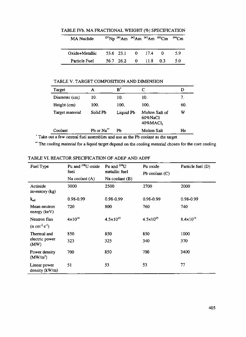
TABLE IVb. MA FRACTIONAL WEIGHT (%) SPECIFICATION
MA Nuclide 7Np 243Am 244,Cm
Oxide+MetallicParticle Fuel
53.6 23.156.7 26.2
0
0
17.4 0
11.8 0.35.95.0
TABLE V. TARGET COMPOSITION AND DIMENSION
TargetDiameter (cm)Height (cm)Target material
Coolant
A10.100.Solid Pb
PborNa"
B*10.100.Liquid Pb
Pb
C10.100.Molten Salt of60%NaCl40%MAC13
Molten Salt
D7.60.W
He* Take out a few central fuel assemblies and use as the Pb coolant as the target" The cooling material for a liquid target depend on the cooling material chosen for the core cooling
TABLE VI. REACTOR SPECIFICATION OF ADEP AND ADPF
Fuel Type
Actinideinventory (kg)
keff
Mean neutronenergy (keV)Neutron flux(n crn'V)Thermal andelectric power(MW)
Power density(MW/m3)
Linear powerdensity (kW/m)
Pu and M8U oxidefuelNa coolant (A)3000
0.98-0.99720
4xl014
850323
700
51
Pu and 238Umetallic fuelNa coolant (B)2500
0.98-0.99800
4.5x10"
850325
850
53
Pu oxidePb coolant (C)
2700
0.98-0.99760
4.5xl015
850340
700
53
Particle fuel (D)
2000
0.98-0.99740
8.4xl015
1000370
3400
77
405

D.5.2. PHOENIX CONCEPT [2]
The idea of a large-scale accelerator incinerator was studied by enlarging the earlyEuratom-BNL-CERN concept using state-of-the-art technology [1]. The Phoenix concept consists ofmodules of accelerator-driven subcritical lattices containing minor actinide fuel (see Fig. 2). Classicalfast-reactor technology is assumed, such as oxide fuel elements and sodium cooling. Each moduleresembles the core of the Fast Flux Test Facility (FFTF) with a k^ = 0.9; however, from 1 to 8 targetmodules are aligned in front of a 104 mA beam of 1.6GeV protons. The entire bank of reactor modulesserves as a target for a proton beam that is expanded before entering the core region. With these parameters,eight modules would generate 3600 MWt. The target chamber as viewed from three perspective and fuelassembly lattice based on FFTF oxide fuel are shown in Figures 3 and 4.
The study showed that after 2 years of operation at 73% capacity, the fuel reaches an average burn-upof 8.6%, with an additional 12.7% converted to Plutonium. Using a 2-year cycle assures that most of thePlutonium (> 83%) is a8Pu, which is valuable as a long-term remote source of power, and also reduces anyconcerns about degradation in the fuel or in the structural steels. During the 2-year reprocessing step, thePlutonium and fission products are replaced by new minor actinides from the LWRs. Plutonium that is notuseful for isotopic applications could be blended with the highly fissile Plutonium from the LWR wastesteam, so that the resulting mixture would contain enough ^'Pu and 236Pu to make weapon productiondifficult.
Burn-up calculations were carried out for six two-year cycles; they reach equilibrium after two years,and produce little 239Pu and only a modest amount of M2Pu. The fraction of 238Pu varies between 83% and87% after each cycle. There is little variation of Np, but a noticeable increase of ^Am and ^'Am.
The combined neptunium and americium inventory decreases by about 2.6 Tones/a, with 1.33 tones/yrbeing converted to Plutonium. Thus, one incinerator unit would transmute the minor actinide wastes fromabout seventy three 1 GWe LWRs.
In this concept, a number of modules are irradiated by one high-current proton beam; the beam mustbe spread significantly to reduce radiation damage and the steep power distribution. This necessitates a long
850 MW(electric)
Input per Year2.6 tonnes of
Minor Actinides580 kg Iodine
410 MW(electric) toAccelerator
Steam 7^ 1260Generator |MW(electnc>
System
Output per Year1.05 tonnes Fission Product
1.55 tonnes Plutonium580 kg Xenon
Fig. 2 The PHOENIX concept (intermediate sodium system not shown)
406
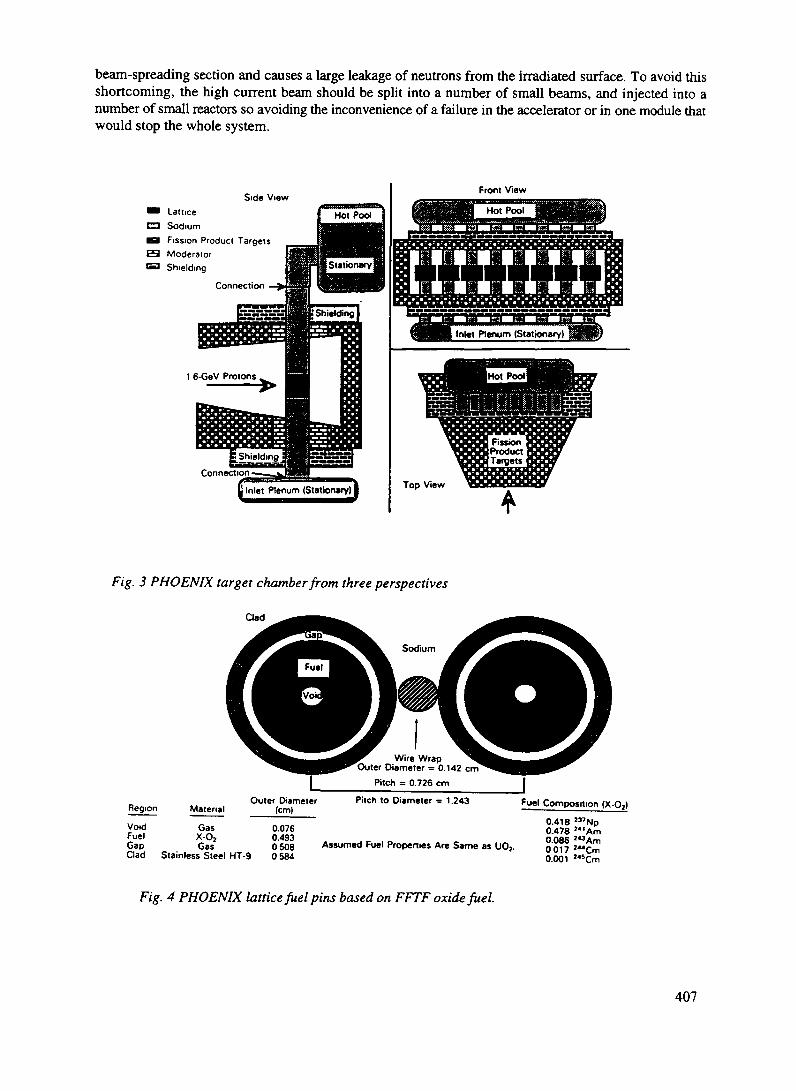
beam-spreading section and causes a large leakage of neutrons from the irradiated surface. To avoid thisshortcoming, the high current beam should be split into a number of small beams, and injected into anumber of small reactors so avoiding the inconvenience of a failure in the accelerator or in one module thatwould stop the whole system.
Side ViewLatticeSodiumFission Product TargetsModeratorShielding
Connection
BShieldiSm
Connection
Inlet Plenum (Stationary!
1 6-GeV Protons
Fig. 3 PHOENIX target chamber from three perspectives
Clad ^^^^^^
^^^^ .Sodium
Wire WrapOuter Diameter = 0.142 cm
Region MaterialOuter Diameter
(cm)
Void Gas 0.076Fuel X-Oj 0.493Gap Gas 0 608Clad Stainless Steel HT-9 0 584
Pitch = 0.726 cm
Pitch to Diameter = 1.243
Assumed Fuel Properties Are Same as UOS.
Fuel Composition (X-Oj)
0.418 2J7Np0.478 '"Am0.086 '"Am0017 '"Cm0.001 "sCm
Fig. 4 PHOENIX lattice fuel pins based on FFTF oxide fuel.
407
D.5.3. ACCELERATOR DRIVEN PARTICLE FUEL TRANSMUTER
To increase transmutation efficiency of the MA or LLFP, a high neutron flux is required and it can becreated by using a particle fuel [3]. Similar to liquid fuels, such as molten salt and slurry fuels, a particlefuel that is directly cooled has several advantages over a regular, solid fuel. Particle fuel has an extremelylarge heat-transfer area (of the order of 100 C nv/cm3), and the small size (less than 1 mm) of the particlesconfers three major benefits:
1) very high power densities,2) a small temperature difference between the fuel and coolant,3) minimum thermal stress and shock in the fuel.
Thermal power densities in the packed bed can be 10MW/1 or more because of the large heat-transfer area.Due to this large power density, this fuel is suitable for transmuting LLFP or MA at a high rate.
Loading and unloading of the particle fuel can be performed with high-pressure coolants. In the caseof an emergency, rapid unloading from the core can quickly lower the multiplication factor of the coreassembly. Also, dumping the particle fuel into a large pit of liquid coolant removes the decay heat from thebumed fuel, so that it can reduce the risk associated with the melt-down of solid fuel by decay heat. Thisproblem of removing decay heat is more serious for regular rod-type solid fuel where decay heat is removedby natural circulation of coolant liquid through the solid fuel components.
In contrast to liquid fuel, for the purpose heat removal the particle fuel can remain in the core whereit is irradiated by neutrons, so that the neutrons are effectively used for burning the fuel or transmuting theMA or LLFP.
For liquid fuel, unless a heat exchanger is included in the core region, the fuel is circulated outside thecore and so the effective neutron flux for transmutation is reduced; also a larger inventory of fuel is needed.
To transmute the LLFP or MA quickly and more effectively, the transmuted products, which have alarge neutron-capture cross-section, should be removed as soon as they are produced. Thus, the neutronsare not wasted as is the case when they remain in the reactor. If the cost of separating the transmuted FPfrom the particle fuel is not great, the particle fuel can be taken out of the reactor core frequently, and theseproducts can be removed by chemical methods.
D.5.4. FUEL AND COOLANT MATERIALS AND TARGET
Use of metal fuel, for which technology has been developed at Argonne National Laboratory [6], hasseveral advantage over oxide fuel.
Due to high heat conductivity an inherently safe operation can be achieved. Pyrometallurgical fuelprocessing will decrease the capital cost of the fuel processing plant
This metal fuel has large a content of fissile material so the neutron spectrum can be hardened andtransmutation of the MA can be increased. Although this hardening of the neutron spectrum increases thepositive Na void coefficient, operation in subcritical conditions solves the safety problem. Anotheradvantage of this metal-fuel reactor over the oxide-fuel reactor is that it has only a small swing in reactivityduring fuel burn-up, so that very few control rods are required to control the excess reactivity; alternatively,the reactivity-worth of a single control rod can be much lower. Thus, the probability of having an accidentafter withdrawing a control rod can be reduced.
The coolant material of the ADEP and Phoenix reactor is Na; the option to use Pb is also reserved.Although high-temperature liquid Pb coolant is more corrosive than Na, it has many interesting featureswhich improve the neutronic characteristics beneficial for transmuting MA. A harder neutron energyspectrum can be obtained, making this system resistant to recriticality in the case of a core-melt accidentbecause the mass density of Pb is comparable to that of the fuel material. In the case of Na coolant, the
408

melted core is much heavier than the Na, so that the possibility that a melted core might sink to the bottomof the core vessel and bring the reactor into a critical condition is higher than in the case of Pb coolant.Furthermore, due to the high mass density of Pb, the volume ratio of coolant to fuel can be increasedwithout lowering the neutron energy, and a large amount of Pb coolant can be used to remove heat fromthe core.
For the particle fueled reactor ADPF, He is chosen as the coolant because of a large data base ofinformation has been accumulated from the high temperature reactor.
As the target material for ADEP and ADPF, liquid Lead has been adopted because of the lack of aradiation damage problem and the efficient heat removal capacity. When Pb is very corrosive, the followingthree types of target materials will be chosen; solid Lead, molten salt ^'Np, and solid tungsten. Thecomposition of the molten salt MA target, including 237Np, is 60NaCl-40MACl3, and due to the smallfission cross section of the MA material for low energy neutrons, the amount of heat generated is not asgreat as in a target composed of fissile material.
The size of the double-shelled target is determined from the heat generated and from the heat-removalcapacity of the coolant, as shown in Table V.
When Pb is chosen as the coolant, the target need not be contained in a double-shelled wall. By takingout the some of the fuel assemblies from the center section, the liquid coolant material irradiated by highenergy protons, can be used as target.
In the Phoenix concept, the proton beam is expanded by a magnetic field to reduce the beam densitywhich is injected directly into the core assembly, and to flatten the power density.
D.5.5. SUBCRITICALITY AND SAFETY ISSUE
The degree of subcriticality adopted for an accelerator-driven system is very important for many aspectsof safety and economy. Although some proposals have suggested having large subcriticality to avoidrecriticality conditions occurring in the melt-down accident, a large subcriticality creates other kinds ofsafety problems, such as a high power-peaking factor when the accelerated proton beam is injected locally.Furthermore, larger power of a proton beam accelerator requires a more stringent design of the beamwindow, and radiation damage to the target material and its surrounding area is much more serious. Inaddition to this problem of radiation damage, a high current beam has to be controlled very strictly to avoidinstability, such as breakup and beam spilling which makes any hands-on maintenance of the acceleratordifficult and very expensive. These problems become a considerable burden in the running of a largecurrent accelerator in addition to the economical problems of the high initial cost.
To decrease the difficulties associated with a high powered accelerator, our ADEP and ADPF isoperated with a slightly subcriticality such as k=0.98-0.99. Although a small number of control rods willthen be needed to adjust the reactivity change due to bum up of the fuel, the reactor safety problemassociated with critical operation can be substantially reduced. This small subcriticality is enough to avoida sudden change of the power of the reactor due to a small change of reactivity [8].
Due to this advantage, the amounts of minor actinides that are mixed into to the Pu fueled reactor canbe increased and hence, the transmutation rate of MA also increases.
The Phoenix concept which use a high current proton beam power, has a rather large subcriticality ofk=0.9.
409

D.5.6. USE OF THORIUM, CROSS PROGENY FUEL CYCLE (^U PRODUCTION ANDTRANSMUTATION OF MINOR ACTINTDES) AND NEUTRON ECONOMY
At the last international fuel-cycle evaluation (INFCE), several options for producing 233U wereproposed; however, this study was carried out before the end of the cold war, and so the use of Pu was notconsidered. The United States has accumulated a great deal of military Pu from the last 40 years of ColdWar era, and also large quantities of Pu from operating LWRs. To incinerate military Pu completely it wassuggested that an accelerator could be used, as well as a LWR. However Pu is a very valuable fuel forfuture generations and we should consider using this surplus Pu to start up a 233U and Thorium fuel cyclein addition to a Pu-fuel cycle.
Instead of producing M3U fuel in a thermal reactor as discussed in the Thorium cycle, in our concept,^U fuel is produced in the blanket region of the Pu fueled fast reactor. Due to the larger TJ-value of 233Ucompared to 233U for thermal neutrons, the inventory of the fissile material for a LWR can be reduced toabout 70% of B5U fuel. The production of MA from M3U is extremely small and reduces the burden oftransmutation or disposal of MA.
233U is produced with B2U, whose descendant nucleus 208T1 emits high-energy y-radiation so that it isa more theft-resistant fissile material. Until a few years ago, using the Thorium and B3U fuel-cycle systemwas opposed because of this high-energy y-radiation generated by 208T1. Now, with the general endorsementfor mixing minor actinides into the fuel cycle, the prospects for using it are far better.
To prevent the removal of pure 233U, 232Th should be mixed with a small amount of 238U.From the point of view of neutron economy, transmutation of MAs is much simpler than that of LLFPs,
because neutrons are produced by fission processes in the MA transmutation process; LLFP transmutationrequires neutron capture. A LWR reactor produces substantial quantities of long-lived radioactive ^Zr fromthe neutron capture process of Zr fuel-cladding material, as shown in Table VII. Thus, transmutation ofthese long-lived radioactive isotopes requires a transmutor which has a higher neutron economy, like a Pu-fueled fast reactor, than the thermal reactor, because it has high r| value for high-energy neutrons and smallparasitic neutron capture by structural and fission products in a thermal reactor. Subcritical operation ofa fast reactor provides a higher neutron economy suitable for transmuting LLFP. To incinerate LLFP and93Zr isotopes efficiently, the spallation neutrons should be multiplied by coupling this neutron source to aPu-fueled subcritical reactor with a hard spectrum. As shown in Table VII, the reduction of the k^ valueby neutron capture is large, so it is not an easy task to get a long bum-up time. As an alternative way ofsolving the transmutation of LLFP such as ''Tc and I29l we are studying the disposal of these isotopes intoouter space a the small accelerator instead of the rocket proposed by NASA [9].
D.5.7. ISSUE OF NON-PROLIFERATION (SEPARATION OF POWER PRODUCTION AND FUELPROCESSING)
From the point of view of non-proliferation, it is desirable to separate power production and fuel-processing facilities; a small number of fuel processing facilities, which are internationally controlled, isparticularly beneficial for purposes of inspection.
In contrast to fuel production by a breeder reactor, fuel production by an accelerator does not requireany fissile material, only electricity and fertile material. If and when the world needs a large amount offissile material within a short period due to a rapid growth in energy demand, then a high-power protonaccelerator can produce fissile material from fertile material and electricity only, without needing any fissilematerial. Although the cost of producing fissile material in this way is higher than it is with a breederreactor, this high cost can be reduced somewhat by using a subcritical assembly.
Since a breeder reactor can only produce the fissile fuel by producing energy, it should be located nearan area where this energy will be consumed. An accelerator fuel producer does not necessarily produce
410

TABLE VH. LLFPs FISSION YIELD, HALF-LIFE TIMES, THERMAL AND FAST (N,F) CROSSSECTION, TRANSMUTATION FLUXES
^SrFission yield (%) 5.91sub sum
I37f"<_ 9^T*rtV_^o 1
6.15 6.1212.06
129j
3.56
85Kr1.33
93Zr5.4516.46
135Cs
total sum 28.52Half-life (years)
ojb)
°f«(b)<}>„, (n cnvV)~3yHLeff '(J), , (n cm'2-s"')-10yHLeff
29.0.010.47.7xl017
2.xl016
30.20.250.43.xl016
2.xl016
2.1xl05
200.24.0x10'"
4.xl016
1.6xl07
310.22.5x10'"
4.xl016
10.731.72.0 (R.I.)4.5xl015
4.xl016
11.5x10*
15. (R.I.)7
5
.7xl016
.1x10'"
3.X106
8.762. (R.I.)
8.9xl015
1.2x10'"
*- HLeff - effective half-life, R.I. - resonance integralmore energy than is required to run it, so that fuel production facilities can be located in a remote area, as
can the facilities for processing the fuel and transmuting high-level waste. A remote location where thereis a fossil-fueled bunning power plant or a hydraulic power generator is an ideal place for an acceleratorproducer, and if asubcritical reactor is used, the electric energy required for operating the accelerator caneasily be obtained.
By locating such facilities in this way, the risk of proliferation of fissile material can be reduced,although transportion of the fuel elements and spent fuel must be protected.
A subcritical reactor gives a flexible choice between fuel production and power production. When thereis plenty of electricity in the remote area, the accelerator can operate with a fission-suppressed reactor witha small k^; fission is suppressed, so that the accelerator's power can be increased to get a higher rate of fuelproduction without jeopardizing safety with an overpowered condition.
Fuel production and power production can be adjusted by the subcriticality. Thus, there are manyoptions and much flexibility which cannot be obtained in a reactor system operated in the critical condition.In operating a subcritical target, k^ can be less than one, and the neutrons which are needed to maintainthe critical condition can be diverted into producing fuel. Hence, the rate of fuel production can beincreased by running the operation at a low k^ value. The initial requirement for fissile material willdepend on the reactivity; this can be adjusted by the initial inventory of the fuel.
D.5.8. ACCELERATOR
For accelerator fuel production, we have promoted the high power linear accelerator of about 300-450MW. In this scheme, we assumed that the target is a fission-suppressed core with large subcriticality. Witha higher beam current of more than 100 mA, the linear accelerator has higher efficiency than the cyclotron,which is efficient at less than 10 mA. ADEP and ADPF can be operated by a small size segmentedcyclotron of the order of a few MW. This circular machine does not require a long beam transport buildingand proton energy can be increased without jeopardizing the economy of the accelerator; we envisage usinga high energy of 3 GeV instead of the 0.8-1.0 GeV energy customarily used for our previous conceptualdesign study and for the linear accelerator. This use of high energy protons can reduce the beam currentto produce the same number of spallation neutrons, the current required is almost inversely proportionalto proton energy. Furthermore, the use of high energy protons can reduce the radiation damage in thematerial of the beam's window section and the surrounding sections of the target region because of the
411

smaller proton beam current. The range of high energy protons is longer than that of low energy ones; thus,the axial distribution of the spallation neutron source is flattened and this is beneficial for heat removalfrom the core.
For the Phoenix concept which requires a large proton current accelerator, a linac of 100 MW beampower has been considered. For high the powered accelerator, the superconductor linac (SC-linac) has beenstudied. The SC-linac has a higher efficiency and a higher accelerating electric field with a larger irisaperture than a conventional linac so that the linac can be shortened. The linac can also accommodate awide range of P by the supply RF to each cavity without reducing the accelerator efficiency compared tothe regular conductor linac, although the radiation heating and damage in the superconductor requiresfurther study, and the practicality of SC-linac is being investigated [10].
The splitting of the high current beam and its injection into many reactors is desirable to reduce theinventory cost per beam power. A negatively charged H' beam or HI22" molecular beam accelerated by alinac can be slit with a gas jet, using laser irradiation, or by ionizing the beam and extracting it withmagnetic field. When the beam is slit time-wise, we must take into account the thermal shock generatedin the target by injecting pulsed beams. To avoid thermal shock, the proton beam should be slit in such away that the interval between pulses is smaller than the thermal relaxation time of the target assembly.
Although one large accelerator can run several reactor targets with higher efficiency than can acyclotron, a failure of the large accelerator would result in the shutting down of all reactors; therefore, itmight be practical to use numbers of small cyclotrons. Cost might be increased by independently operatingseveral small reactors, but it would alleviate several difficulties, such as splitting and controlling the highcurrent beam.
Besides the transmutation of MA and LLFP, other projects concerning accelerator tritium productionand spallation neutron sources have been going on. The concept of ATP was developed in 1980, just afterstudying the accelerator breeder, and collaborative work continued with Los Alamos National Laboratoryand Hanford Westinghouse Laboratory untill 1987. After temporary closure the project started again 1992in collaboration with Los Alamos National Laboratory (LANL) and Lawrence Livermore NationalLaboratory(LLNL).
D.5.8.1 Cyclotron for proton accelerator
As mentioned before it might be practical to use numbers of small cyclotrons instead of a linac. Atpresent a cyclotron of 1.1 MW beam power has been developed at PSI for a 600 MeV proton accelerator[11].
As discussed earlier, to incinerate the minor actinides produced from 10 units of LWR, it is sufficientto use medium-energy proton with a 15-30 MW current. Because of the nearly linear energy-dependenceon number, if the spallation neutrons have energies ranging from 1-3 GeV then beam intensity and beamenergy are exchangeable. These factor may favor the use of "multistage-parallel" cyclotrons over the linearaccelerator.
While the price is almost proportional to the energy requirement for the latter system, doubling ortripling the energy of a cyclotron is much less costly. On the other hand, the maximum achievable beamcurrent of a cyclotron is rather limited, especially at low energies.
412

Flnol Stwe:15 Sector Cyclotron12 Accelerating Covltleo 600 KeV. 2 to 3 tt(3CMS fH B.P.) ,,
These conditions lead to theconcept of the so-called"multistage-parallel" cyclotronarrangement, consisting of severallow-energy, low-current cyclotronsfeeding into one high energy cyclotron.
For example, (as shown in Fig. 5)a multistage cyclotron arrangementproviding 15 mA at an energy of atleast 2 GeV would require thefollowing assembly:
- Three sources of 60-70 keVions,a low-energy 2 Mev, 5 mAinjector stage, consisting ofthree radio-frequencyquadrupole linacs (37 MHz),developed by Mu'ller fromDarmstadt (Split CoaxialResonator)an intermediate stage, made ofthe same number of four-sector „. , ., , . .... rig. 5 Multistage cyclotron arrangementcyclotrons with a phase widthof 36 and frequency of 36 MHz accelerating the 5 mA proton current to the upper limit around 200MeV.a final-stage 15-sector cyclotron, fed by the three intermediate stages (3x5 mA at 200 MeV).
This cyclotron works at 3x36=108 MHz, using 12 accelerating cavities of 600 keV. The final stage canreach a proton energy of 2 to 3 GeV at a beam power of 30-45 MW.
As the next generation of neutron sources a spallation neutron source using 3 GeV protons fromsynchrotron has been studied. In addition, intermediate energy proton and neutron cross-section data, whichis required to evaluate ADS has also been obtained.
Ion Source60-70 KeV
(os developed by nailer)2 Hev
REFERENCES
[1-1] P. Bonnaue, H. Rief, P. Mandrillon, and H. Takahashi: "Actinide Transmutation by Spallation inthe Light of Recent Cyclotron Development"; NEACRP-A-910, Session B.1.2 (1987). (EuropeanAmerican) Reactor Physics Committee Report, and ICENES 86, Madrid, July 1986.
[1-2] H.Takahashi1" Actinide Transmutation by the Spallation Process," presented at WorkshopFeasibility of Resarch Program in Actinide Transmutaiion by Spallation Process, Ispra, Varese,Italy, June 18-21, 1985.
[2] G.Van Tuyle, M.Todoso, M.Geiger, A.Aronson and H.Takahashi, "Accelerator-Driven SubcriticalTarget Concept for transmutation of Nuclear Wastes, Nucl. Tech. p.l, Vol. 101, 1993
[3] H. Takahashi, The Role of Accelerator in the Nuclear Fuel Cycle, Proc. of 2nd Intemat. Symp. onAdvanced Nucl. Energy Research, p.77, Mito, JAERI, Jan. 24-26 (1990).
[4-1] H. Takahashi, A Fast Breeder and Incinerator Assisted by a Proton Accelerator, Fusion
413
Technology, 20(1991)657.[4-2] H. Takahashi."Safe Economical Operation of Subcritical Fast Reactor and Transmutor with a
Small Proton Accelerator" Proc. Int. Conf. on Reactor Physics and Reactor Computations, P.79,edited By Y. Ronen and E.Elias, Tel-Aviv, Jan 23-26,1994.Ben-Gurion Unv. of the Negev Press(1994).The 8th Juness SATURNE Accelerator Applied to the Nuclear waste Problem held atSaclay on May 5-6, 1994.
[5-1] X. Elie and J. M. Chanmont, Operation Experience with the Phenix Prototype Fast Reactor,Internal. Conf. on Fast Reactor and Related Fuel Cycles (ICFRRFC) 5.1-1, (1991)
[5-2] J. Mchaumont, D. Goux and L. Matin, Some Safety Related Characteristics of Phenix, a 250 MWeFast Reactor 1989 and 1990 Negative Reactivity Trip Investigations, Internal. Conf. on Design andSafety of Advanced Nuclear Power Plants (ICDSANPP) Oct. 25-29, 1992, Tokyo Japan.
[6] C. L. Cockey and M. L. Thompson, ALMR Potential for Actinide Consumption, Internal. Conf.on Fasl Reactor and Related Fuel Cycles (ICFRRFC), P3.4-1, (1991).
[7] H. Takahashi, and X.Chen " Accelerator Driven Cross-Progeny Nuclear Fuel Cycle" InternationalConference on Evaluation of Emerging Nuclear Fuel Cycle Systems. Global,1995, P. 1436,Sept. 11-14,1995 Palais des Congres, Versailles, France.
[8] H. Rief and H.Takahashi, Safety and Control of accelerator-driven Subcritical System. InternationalConference on Accelerator-driven Transmutation technologies and Applicalions.p.159, Las Vegas,NV 1994 AIP Conf. Proc. 346.
[9-1] Takahashi, H. and Chen, X. (1995) "Alternative Way to Dispose of High-Level Waste in OuterSpace," Twelfth Symposium on Space Nuclear Power and Propulsion, AIP Conference, Proc.324:347-354." Disposal of Type n Fission Products into Outer Space" Thirteenth SymposiumonSpace Nuclear Power and Propulsion, AIP Conference, Proc. 361:967-973.
[9-2] Takahashi, H. and Chen, X. (1996) "Disposal of type -II long-lived fission products into outerspace" Thirteenth Symposium on Space Nuclear Power and Propulsion, AD? Conference, Proc.361:967-973.
[10] A. Ruggiero, Personal Communication (1995)[11-1] T. Stammbach "Experience wilh the High Current Operation of the PSI Cyclotron Facility, Proc.
of the 13-th Internal. Conf., Vancouver, 1992, p.28-36, ed. G. Dutto and M. K. Craddick, WorldScientific New Jersey.
[11-2] S. A. Martin, E. Zaplatin, P. F. Meads, Jr., Wuestefeld and K.Ziegler, Study of an FFAGSynchrocyclotron for a Pulsed Neutron Source, Proc. of the 13-th Internal. Conf., P. 701-704,Vancouver, 1992, ed. G. Dutlo and M. K. Craddick, World Scientific New Jersey.
414

XA9846790
D.6. THE EUROPEAN COMMUNITY PROJECTS
D.6.1. IMPACT OF ACCELERATOR BASED TECHNOLOGIES ONNUCLEAR FISSION SAFETY - SHARE COST PROJECT OF THEEUROPEAN COMMUNITY
D.6.1.1. INTRODUCTION
Over the last few years the interest in ADS has grown in many European countries. As a result of thissome European institutes have decided to establish a shared cost project in the framework of the EuropeanCommunity. The overall objective of this project is to make a European assessment of the possibilities ofaccelerator-driven hybrid reactor systems from the point of view of safe energy production, minimum wasteproduction and transmutation capabilities. In particular:
a) to perform system studies on accelerator driven hybrid systemsb) to assess the accelerator technologyc) to study the radiotoxicity of the fuel cycle for ADS and its nonproliferation aspectsd) to provide basic nuclear and material data for ADS by means of evaluation and experiments
The final objective is to concentrate and coordinate different efforts from member states to create aEuropean scientific and technological basis for further projects aimed at developing environmentallyfriendly, more publicly acceptable and safer nuclear fission energy sources. The final results will be models,tools, validated routines and some new experimental data for future experimental activity on a larger scale.
D.6.1.2. WORK CONTENTS
This project is divided into 4 tasks presented in Fig. 1:
1. system studies on the accelerator driven hybrid2. assessment of the accelerator technology3. basic nuclear and material data ~~4. studies of the fuel cycle for ADS
Task 1: System studies of an accelerator driven hybrid
System studies will be focused on the following systems :a) Energy production using the Thorium fuel cycleb) Energy production using LWR spent fuel and burning of TransUranium elementsc) Dedicated Plutonium burning with energy productiond) Transmutation of fission products combined with burning of TransUranium elements
415

Project :Impact of the Accelerator Based Technologies
( I A B A T )
A: System Studies B-.AcceleratorTechnology
_LC : Basic Nuclearand Material Data
_L
D:Studies of theFuel Cycle
AEAA s s e s s m e n t o f
Acce le ra to r and TargetTechnology
ECNENDF for Protons
on Lead
ENEA • CasacclaRadiation Damages
at Target-BlanketInterface
V VN u c l M o d e l V a l i d a t i o nX-sec t a b o v e 20 MeV
U , Th f i s s ion y ie lds
ENEA, BolognaE N D F fo r Selected
Isotopes
KTIIStud ies of A DS Tor
LWR wisic Trinimulinon
KFAOptimisuon oT Accelerator
Breeding biscdon Thorium Cycle
ITUSlnlegy Tor the ADS
Fuel Cycles RldioloxicityConsideration of the Cycles
ENEA . CatacclaEvilmnon of ADS Burning
Cipibilmes for Pu and MinorAclinides
KTHSafe iy /R isk /Economica l
A s s e s s m e n t sAccident Scenar ios
CEAPhysics of ADS
Fast and Thermal Sys tems(Molten salts)
KFATRU-mcineral iom w i t h
Liquid Lead Sys tem
FZKSpallal ion Target Stud ies
Opt im iza t ion of Subcri l icahtyCompar ison to Reactors
ENEA • CasacciaYields & Radio tox of
Spall Prod Va l ida t ion ofComputer Codes,
AEAObject ive for ADS
Transmutat ion Based onHLW Repository Risk
CTHAna lys i s o f ADS Dynamics
KTH - Kungliga Tekniska Hogskolan (Sweden), CEA - Commissariat 6 1'Energie Atomique (France)ECN - Energieonderzoek Centrum Nederland (Netherlands), KFA - Forschungszentrum Jiilich GmbH (Germany)ENEA -Enea Nationale per la Ricerca e lo Sviluppo dell'Energia Nucleare e delle Energie Alternative ( I taly, Casaccia and Bolognma)FZK - Forschungszentrum Karlsruhe (Germany) , AEA - Atomic Energy Authority Technology (United Kingdom)UU - Uppsala University (Sweden), CTH - Chalmers Tekniska Hogskolan (Sweden)
FIG. 1 Task structure of the European project: Impact of the Accelerator Based Technologies on Nuclear Fission Safety

These studies will be performed for thermal, fast and intermediate neutron energies to optimize theperformance of the system. The neutron energy range strongly determines the choice of the materials usedfor the coolant and reflectors/moderators and requires multidimensional optimization which has to beperformed in respect of material compatibility, engineering aspects, corrosion, safety, economy and otherfactors.
In Europe large quantities of Pu from reprocessed spent LWR fuel are available. These can be recycledto some extent in existing LWRs using the MOX option, or by using fast reactors. However, multiplerecycling of MOX in thermal reactors is not very efficient in LWRs. The possibilities of using recycled Puin hybrid systems will be investigated.It is also very important for Europe to monitor and, if required, to help to destroy excess Russian weaponsPlutonium. Therefore the potential of ADS to efficiently burn weapon Plutonium with a simultaneousenergy production has to be investigated.
The spallation target will be chosen and optimized with respect to proton energy, neutron production,thermodynamics and radiotoxicity of spallation products.
The safety/risk assessment of the different ADS will be performed and reference scenarios for severeaccidents will be worked out for these different systems. Optimization of the subcriticality level withrespect to safety and efficiency will be investigated. Transient behaviours of the ADS will be investigated.The environmental and economical impact of the ADS on the geological repository of HLW will beestimated.
A preliminary economic assessment, based on the results of studies in this project, will be made in orderto estimate the feasibility of these ideas as well as to validate the results.
Task 2: Assessment of the accelerator technology
Accelerator technology will be assessed with respect to: construction (cyclotron vs linac), proton currentand energy levels. These results will strongly influence the economical aspects of the system studies.
Task 3: Basic nuclear and material data
A relatively high yield of neutrons up to several hundreds of MeV is produced by the proton interactionsin the thick, heavy element ADS target. Nuclear reaction calculations will be performed and experimentaldata will be collected in order to create an evaluated data file.
Nuclear model codes will be validated for basic nuclear reaction cross section data of importance for ADSneutronic calculations. The validation is based on a number of protons and neutrons induced cross sectionmeasurements performed at the The Svedberg Laboratory, Uppsala in the energy range 50 to 200 MeV.Measurements will also be made of the thermal fission yield for 233U and the fast fission yield for 232Th.
Task 4: Studies of the fuel cycle for ADS
The use of the Thorium cycle for energy production seems to be extremely attractive due to the breedingpotential generated by the excess neutrons in the system. Apart from operating in a self-sufficient modesupplying large amounts of energy, there is simultaneous production of fissile material and negligibleproduction of TRU-elements.
A combined Th and LWR-spent fuel cycle is another attractive option opening new possibilities forsynergetic coexistence of conventional nuclear reactors and ADS. Generic aspects of the Th-cycle will bestudied in the framework of another project entitled "Thorium cycles, a nuclear waste management option",
417

coordinated by W.M.P. Franken, ECN. In our project we shall only concentrate on specific aspects of thehybrid systems and the studies will be coordinated with ECN.
The following fuel options will be investigated:inert matrix using liquid Lead as a carrier/cooling materialinert matrix using molten salt (fluoride, chloride) as a carrier/cooling materialaqueous systems with heavy wateroxide fuelsmetallic fuel
The proliferation and radiotoxicity characteristics of the different fuel cycles and fuel options will beinvestigated. The efficiency and costs of fission products transmutation will also be assessed.
D.6.1.2. EXPECTED BENEFITS
The strategic aim of the project is to broaden the nuclear power option and to make it more attractiveand acceptable to the general public, for the benefit of present and future generations. By addressingsome of the most important problems of nuclear power, namely improving safety and reducing the burdenof the waste radiotoxicity, we may significantly contribute to the permanent solution of the world long termenergy supply. The strategic studies planned in this project will result in the comparison of different optionsin the form of the cost/benefit impact of accelerator based transmutation on different strategies such as:direct geological disposal of irradiated fuel, with or without reprocessing and Pu recycling in reactors etc.Up to now, individual studies have been very difficult to compare due to the significant differences inhypothesis, method and data. This difficulty has been compounded when comparisons have been attemptedon the use of different fuel cycles and/or different neutron spectra for transmutation. This project willprepare the platform for future analysis of diverse nuclear power systems.
In the frame of this project, the problems of weighting the long-term low-level risks versus short-termhigher-level risks will be addressed for comparison of geological repositories with the transmutationoption.
Many questions have also been raised concerning the economic costs of introducing accelerators intonuclear power. Even at this very early stage it is necessary to make a preliminary economic assessmentto prepare the ground for future decisions concerning the eventual construction of such systems. Thisproject addresses these issues.
In conclusion, the project will result in the following benefits:1. preparation of the platform for future analysis of diverse nuclear power systems2. grounds for weighting the long-term low-level risks versus short-term higher-level risks for
comparison of geological repositories with the transmutation option3. preliminary economic assessment to prepare the ground for future decisions concerning the
eventual construction of accelerator driven systems4. a framework for future international collaboration aimed at performing an ADS integral
experiment will be prepared.
418

XA9846575
D.6.2. SWEDISH PERSPECTIVE ON THE ACCELERATOR DRIVEN NUCLEAR SYSTEM
Waclaw Gudowski and Henri CondeSweden
D.6.2.1. INTRODUCTION
The nuclear power programme in Sweden consists of 12 nuclear reactors located at four different sitesand with a combined capacity of 10 000 MW net electric power. The nuclear power plants generated about42% of the total Swedish electric power produced in 1993.These nuclear power plants are owned by four companies which have formed the Swedish Nuclear Fueland Waste Management Company, SKB (SKB - Svensk Kambranslehantering AB). SKB's duties are todevelop, plan, construct and operate facilities and systems for the management and disposal of spentnuclear fuel and radioactive wastes from the Swedish nuclear power plants. On behalf of its owners SKBis responsible for all handling, transport and storage of nuclear waste outside of the nuclear powerproduction facilities [1]. SKB is also in charge of a comprehensive research programme in the radwastefield.
A complete system has been planned for the management of all radioactive residues from the 12nuclear reactors and from the research facilities. The system is based on the projected generation of wasteup to the year 2010. A central interim storage facility, CLAB, was put into operation in July 1985 for thestorage of spent fuel. This facility has a current capacity of 5 000 tonnes of spent fuel. The spent fuel willbe stored in CLAB for about 40 years. It will then be encapsulated in corrosion-resistant canisters anddeposited at depth in the Swedish bedrock. The construction of the deep repository will be made in stages.The first stage of the repository, for 5 - 10% of the fuel, is planned to be put into operation in 2008. Thenext stage for the full repository will only be built after thorough evaluation of the experience of the firststage and renewed licensing. The site for the deep repository has not yet been chosen.
The estimated costs for the Swedish deep rock repository amounts to about 40 billion SEK. Oneattractive option to reduce these costs would be to transmute the most cumbersome components of thespent fuel using accelerator-driven transmutation technology.
D.6.2.2. ACCELERATORS ENTER THE NUCLEAR ENERGY FIELD
As described in this Status report, new concepts for treating spent fuel from fission reactors have beendeveloped in recent years. This has initiated rapidly growing international research activities in which anumber of Swedish, mostly university-linked, groups participate. It is believed that Accelerator-DrivenSystems can effectively convert the long-lived radioactivity in the burned nuclear fuel, to short-lived andby so reduce the need for geological repositories. ADS offers in the long-term a possibility to producecleaner fission energy over an indefinite period, a concept which would fit Swedish needs andtechnological skill. However, due to environmental requirements the Swedish parliament decided that thetwo dominating energy sources - nuclear power and fossil fuels - will be either shut down (nuclear power)or its use will be limited (fossil fuels), so in the long run the Swedish energy supply is a problem area. Theparliamentary decisions are based on the perceived risks which in the first case are linked to a possiblerelease of radioactivity from a large reactor accident and/or the handling of the highly radioactive spentfuel and also to proliferation concerns. In the second case the decisions are linked to the risk of a globalenvironmental catastrophe through the "green house effect". Although research on alternative renewableenergy sources has been in progress, no large scale solutions which can meet the future energy demandshave been found so far. At the same time the research problems connected with the utilization of fusion
419
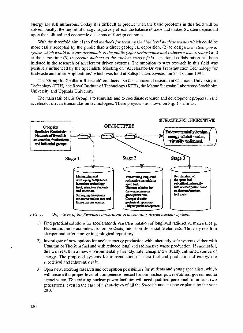
energy are still numerous. Today it is difficult to predict when the basic problems in this field will besolved. Finally, the import of energy negatively effects the balance of trade and makes Sweden dependentupon the political and economic decisions of foreign countries.
With the threefold aim (1) to find methods for treating the high level nuclear wastes which could bemore easily accepted by the public than a direct geological deposition, (2) to design a nuclear powersystem which would be more acceptable to the public (safer performance and reduced waste streams) andat the same time (3) to recruit students to the nuclear energy field, a national collaboration has beeninitiated in the research of accelerator driven systems. The ambition to start research in this field waspositively influenced by the Specialists' Meeting on "Accelerator-Driven Transmutation Technology forRadwaste and other Applications" which was held at Saltsjobaden, Sweden on 24-28 June 1991.
The "Group for Spallator Research" conducts - so far - concerted research at Chalmers University ofTechnology (CTH), the Royal Institute of Technology (KTH), the Manne Siegbahn Laboratory-StockholmUniversity and Uppsala University.
The main task of this Group is to stimulate and to coordinate research and development projects in theaccelerator driven transmutation technologies. These projects - as shown on Fig. 1 - aim to :
Group forSpanateritaK«rtft-NetwodtofSwediah
(DBJECTUVE(DffiJECTIVIES
developingin nuclear technologyfield, attracting students
Surveying the optionsfor stored nuclear fuel andfuture nuclear energy.
radioactive materials inspent fusl,l/ttODilto SOulbOD. u)tthe weapon/reactorRZ8QO T*l f *fp** Py*** -Cheaper ft safergeological repository- higher pubbc acceptance.
1ne spent fool -subcritical, inherentlysafe nuclear power basedontfuel cycle.
FIG. 1. Objectives of the Swedish cooperation in accelerator-driven nuclear systems
1) Find practical solutions for accelerator driven transmutation of longlived radioactive material (e.g.Plutonium, minor actinides, fission products) into shortlife or stable elements. This may result incheaper and safer storage in geological repository;
2) Investigate of new options for nuclear energy production with inherently safe systems, either withUranium or Thorium fuel and with reduced longlived radioactive waste production. If successful,this will result in a new, environmentally friendly, safe, cheap and virtually unlimited source ofenergy. The proposed systems for transmutation of spent fuel and production of energy aresubcritical and inherently safe.
3) Open new, exciting research and occupation possibilities for students and young specialists, whichwill ensure the proper level of competence needed for our nuclear power utilities, governmentalagencies etc. The existing nuclear power facilities will need qualified personnel for at least twogenerations, even in the case of a shut-down of all the Swedish nuclear power plants by the year2010.
420

The Group is now in the process of establishing long term financing for this national collaboration.
D.6.2.3. RESEARCH WITHIN THE SPALLATOR GROUP
The research projects are so far driven by the scientific interests of particular groups:Department of Nuclear Chemistry Chalmers University of Technology (CTH) is studying separationprocesses proposed for use in connection with nuclear transmutation. The project, conducted incooperation with research groups in the US, Japan and the EC contains both experimentalinvestigations as well as modeling of different separation systems. The project is mostly directedtowards fundamental research and aims to help judge whether different proposed separation andtransmutation processes are realistic.Department of Neutron and Reactor Physics and Centre for Safety Research, the Royal Institute ofTechnology is conducting a research program focused on conceptual studies based on computersimulations of ADS, safety and system assessments.Department of Neutron Research and Department of Radiation Science, Uppsala University (UU) hasfor many years been carrying out research on basic nuclear data such as cross sections for neutron andproton induced reactions, fission yields, half-life of short lived fission products, delayed neutron yieldsetc.Manne Siegbahn Laboratory (MSL) - Stockholm University has a long tradition in accelerator designand operation and conducts studies of space-charge current-limitation in the low energy part of theaccelerator and a minimization of the particle losses due to residual gas collisions in the vacuumsystem.An industrially oriented group of reactor physicists, formerly at ABB Atom, and neutron physicistsfrom Uppsala University and KTH is also taking part in this collaboration and have investigated thetechnical and economical possibilities of implementing an inherently safe reactor concept for anaccelerator driven system.
D.6.2.4. INTERNATIONAL PERSPECTIVE
The research activities of the Group for Spallator Research have been primarily devoted to system andfeasibility studies together with participation in a number of international efforts mainly in the US (LosAlamos), Russia (ITEP-Moscow, BPPE-Obninsk), France (Saturne) and in the future possibly in Japan(PNC-JAERI), CERN and Switzerland (PSI).
Collaborative projects on ADS research are already in progress with leading international laboratoriesas described above. In particular, a project aimed at the construction and testing of a 1 MW liquid lead-bismuth spallation target has been started as a collaboration between the U.S.A., Russia, France andSweden. It is anticipated that the Swedish groups (coordinated and financed through the Centre forSpallator Research) will prepare some part of the experimental equipment and take responsibility for itsinstallation and performance.
The Group for Spallator Research is also going to work actively to create an international organisationor centre for advancement of ADTT.
D.6.2.5. FINAL REMARKS
Accelerator-driven nuclear systems can become an important complement for nuclear reactors openingnew options for the nuclear fuel cycle and furthermore, in countries like Sweden, where of conventional
421

nuclear power has no future prospects, these systems can make nuclear energy an attractive source ofenvironmentally friendly energy again. Also the idea of burning weapon grade Plutonium in acceleratordriven systems has a lot of advantages and should be thoroughly exploited. The best way to achieve thesegoals is through intensive international cooperation and common efforts to build the first demonstrationfacility.
REFERENCE
[1] 8KB Annual Report 1993, Stockholm May 1994
422

XA9846576D.6.3. ADS PROGRAMS IN FRANCE
D.6.3.1 FRENCH PROGRAMS FOR ADVANCED WASTE MANAGEMENT OPTIONS
M. Salvatores *, J.P. Schapira**, H. Mouney**** CEA-DRN, ** CNRS-EN2P3, *** EDF-DE
Several organisms (CEA, CNRS, EdF, etc) are cooperating in France on Accelerator-Driven Systems. Themajor motivation is the investigation of innovative options for the radioactive waste management. Thepaper describes the ongoing activities and future directions of the cooperative efforts.
D.6.3.1.1 INTRODUCTIONThe management of long-lived radioactive wastes, has been the subject in France of a Parliament law
(December 1991), which requires that R and D work should be performed, in particular by researchorganism , on : partitioning/transmutation (P/T); underground laboratories for deep storage assessment;intermediate storage technology, in order to provide the scientific elements to evaluateadvantages/disadvantages of the different options to be submitted to the Government for a decision in2006. As far as transmutation, most work has been done up to now on the potential of standard (oradvanced) fission reactors. However, the national body Commission Nationale d' Evaluation (CNE) incharge of evaluating step by step the R and D work performed, has recently recommended to explore alsomore advanced solutions for waste management and in particular for transmutations. Accelerator-DrivenSystem fall clearly in this category.
D.6.3.1.2 THE ISAAC PROGRAM AT CEAD.6.3.1.2.1 Background
As mentioned above, most work on transmutation is focused on the potential of fission reactors(thermal or fats). The CEA is conducting a research program [1] in the frame of the wider SPIN program(which includes actinide chemistry) in partnership with EdF, FRAMATOM and COGEMA.From a strictly point of view, "transmutation" is a matter of neutron availability [2], and standard fissionreactors can provide them : a PWR with increased fuel enrichment or a Fast Neutron Reactor used in the"burner" mode [3]. Accelerator-Driven System can provide extra neutrons [2] and can play a role in a longterm P/T strategy, or, in general, they can play a role in the assessment of different long term options forthe back-end of the fuel cycle.
D.6.3.1.2.2 The Fields of Activity of the ISAAC Program
At CEA, different laboratories have been working in recent years on several aspects of the technologyand of the physics of Accelerator-Driven Systems (high intensity accelerator technology, physics of source-driven multiplying systems, spallation physics). It has been decided in 1995 to launch a program, devotedto the experimental validation of the major items related to a generic accelerator-driven system (namely,accelerator technology, target physics and multiplying sub-critical system physics). The program ofresearch concerns the physics of multiplying subcritical systems, in the feasibility of high intensityaccelerators, the physics and the experimental validation of spallation phenomena modelisation and systemstudies, devoted both to minor actinide transmutation potential and to feasibility/safety studies.
423

D.6.3.1.2.3 The Physics of Multiplying subcritical Systems
It is recognized that, whatever the application, the multiplying subcritical core will play a central role.The physics of such systems (I. e. source-driven subcritical systems) is known in principle. However, nospecific experimental program has been performed, in particular for near-critical subcritical systems.Methods and data needed are fairly sophisticated, in terms of geometrical configurations, neutrons modessuperposition, spatial flux distribution, etc, and in a specific experimental program is needed to gainconfidence in the assessment of the performances of hybrid systems.An experimental program has been launched at the MASURCA facility in CADARACHE. A firstexperiment (MUSE) has been performed in December 1995 and it will be reported in a companion paperat this conference [4]. These experiments can help to understand the role of the neutron importance of thesource and the impact of the source spectrum and environment, at different levels of subcriticality. The"homogenisation" of the results will be indicated at this conference. The first MUSE-1 experiment didallow to confirm that the high accuracy measurements can be performed to evaluate the systemsubcriticality Ap (to less than 3%), the reaction rate spatial distributions (to ± 1%), and the neutron sourceeffectiveness <p* [4].The next phase, MUSE-2, will be devoted to the study of the influence of neutron diffusing mediumaround the source (see Figs 1 and 2). This program has been performed in late summer 1996.A MUSE-3 experiment, to be performed in early 1997 is under study , possibility using a lead bufferaround the source and attempting delayed neutron effective fraction measurement in the subcriticalmedium.In the frame of these studies , actinide and fission product neutron cross-sections have been or will alsobe measured at the Geel LINAC (in particular Np, 9*Tc). Moreover, a large scale experiment is underwayat SUPERPHENIX (the SUPERPROFIL experiment), in which a large number of pure, separated isotopesamples are irradiated in two standard fuel pins in a clean environment inside the core. In particularsamples of 07Np . 'Pu, ^'Am, ^Am, ^Cm will be analyzed after irradiation and transmutation rates willbe determined with high accuracy.
D.6.3.1.2.4 Feasibility of High Intensity Accelerators
Studies are underway on accelerator structures with coupling cells, on halo phenomena and thedynamics of the beam and on radiofrequency chains. Theoretical studies are completed by an experimenton the beam dynamic (FODO experiment) and by the design of a proton source of 100 mA at SATURNE.Of course, this activity has wider scope than hybrid system applications. At present, no uniquespecifications for a high intensity accelerator have been given, since the role and applications of hybridsystems are still to be fully defined (see section D.6.3.2.6).
D.6.3.1.2.5 Physics and Modelisation of Spallation
The experimental programs at SATURNE will be detailed in other companion papers at thisconference (thin and thick targets, spoliation residual nuclei measurements, double differential cross-sections measurements, neutron production etc) [6].New code systems are developed and validated on these experiments. In particular, a project for a new codesystem, dedicated to the physics of spallation, has been launched at CEA (1996-1998). This code system(called "SPARTE") will handle intranuclear cascades (with improved models) , high energy particletransport, neutron transport below a threshold energy Et (initially E,=20 MeV, later Et=150 MeV ) with
424

Q PuO2-\K>2 °°m p Pilot rod_ Diffusing medium _.* (b«h Na or SS) " Position for axial measurements
Q Shield
FIG. 1. Proposed configuration for the MUSE-2 experiment
425

+110
+60
+30
Z(cm)
AXIAL SHIELD
Na/SS (25/75)
Source
Diffusing medium(Na or SS)
dium
CORE(ZONA2PIT)
-30
-60
-110
Na/SS (25/75)
Na/SS (25/75)
AXIAL SHIELD
I
RADIAL SHIELD
R (cm)
0.0 11.96 45.00 76.08 120.80
FIG. 2. RZ model for the proposed configuration of the MUSE-2 experiment
the continuous Monte Carlo code TRIPOLI, and full nuclide time evolution description (activity, decayheat, toxicity) by the code DAEWIN (developed for standard applications).Nuclear data bases will be enlarged, as far as possible in the frame of international collaborations (likeWorking Party on Evaluation Collaboration of the OECD-NEA). The coupling with the standard neutronicscode systems (e. g. ERANOS [7]) will be realized. A principle scheme of SPARTE is given in Fig.3 .
D.6.3.1.2.6 System Studies
The physics of the accelerator driven system has been the object of studies and the main conclusionsand present views have be presented in a paper by M. Salvatores and I. Slessarev [8]. The main potentialrole for accelerator driven systems can be found in cases where the external neutron supply can help toshape a radioactivity clean nuclear power (RCNP), i. e. concentrate radioactive wastes (e. g. Am and Cm)in a very limited number of installations inside a standard nuclear power park of reactors, also dedicatedif possible to eliminate long-lived fission products.This approach is close to the "double strata" concept proposed by JAERI [9].Two more fields of application of hybrid systems seem to be promising:-Optimized use of the Uranium cycle in a large subcritical fast reactors, with long burn-up and lowreactivity loss per cycle.
426

-Enhanced and adaptable neutron source, for driving small power systems with high subcridcah'ty forinnovative irradiation studies and fundamental physics studies. This last type of system could be eventuallyused as pilot experiment for hybrid system feasibility demonstration.
Codes Data
ENDF
\NJOY
General Architecture of the SPARTE system (N-N = nucleon-nucleon data,DD - decay data, o » cross-section library)
s- —
- Intermediate energy
- Nuclear Models
Low energyTransportTR1POLI4
S^
>
/
Evolution 'DARWIN-PEPIN |
J
ERANOSFast Reactor Code
System
SAPHYRThermal Reactor Code
System
PROMETHEEShielding Code System
FIG. 3 The SPARTE computer code system
427

D.6.3.1.3 THE PRACEN RESEARCH PROGRAM AT IN2P3
In France, basic research in nuclear and particle physics are carried out by IN2P3 (Institute Nationalde Physique Nucleaire et de Physique des Particles), which is a part of CNRS (Centre National de laRecgercge Scientifique), as well as by a part of CEA (Direction Des Sciences de la Materie). The activityof IN2P3, related to nuclear waste management was restricted to a radiochemistry and nuclear chemistrystudies, at least until 1993 when it was decided to make larger contribution on certain aspects of the backend of the fuel cycle for which basic research could be needed.In June 1993 , a coordinated research program, called PRACEN (Programme de Recherche sur 1' Aval duCycle ElectroNucleaire) was officially set up on two subjects, in accordance with the above mentioned1991 law (article 4) and with the competencies identified among the radiochemists and physicists of IN2P3:-Radiochemical studies related to the physico-chemical conditions of deep geological storage as well as tothe chemical separation of certain long-lived radioelements.-Nuclear storage properties and accelerator studies in relation with accelerator driven systems.The first theme is up to now the most active, and it is carried out, since 1995, in the frame of a nationalprogram called PRACTIS (Physicochimie des Actinides at Autres Radioelements en Solutions et auxInterfaces), with part of CEA (Direction du Cycle du Combustible) and the department of ChemicalSciences of CNRS. On the other hand, IN2P3 is partner to an EC program on "Thorium Cycles as Nuclearwaste Management Option" and is specifically in charge of the mining aspects and of the residual risks indeep geological storage.The main activity on the second theme is carried out in the frame of collaboration with the Rubbia's groupET at CERN. Physicists from various IN2P3 laboratories (Grenoble, Bordeaux and Orsay ) have taken avery active part in the first experimental study carried out in 1994 at CERN to establish the EnergyAmplifier concept [10]. In relation with the new C. Rubbia's proposal of subcritical fast reactor, driven bya cyclotron , and cooled by lead, IN2P3 has recently designed a lead structure to be used near the Grenoblecyclotron, which produces a pulsed neutron beam. Such a device is designed for neutron transport studiesin lead and for some transmutation rates measurement at various neutron energy, the lead being used as aslowing down spectrometer [11]. It is also part of the project TARC (Transmutation by AdiabaticResonance Crossing) developed at the ET group of CERN, which should be applied to the transmutationof some long-lived fission products (such as 99Tc).
D.6.3.1.4 THE "GEDEON" COLLABORATIVE PROGRAM
At the national level, a joint research program has been recently established among CNRS, EDF, andCEA. The program covers the common areas of interest of the ISAAC and PRACEN programs. Theobjective is to explore innovative options in common for radioactive waste management. The HybridSystems potential evaluation is at the core of the GEDEON program, but the potential of alternative fuelcycles (e. g. Thorium) is also explored . Starting in 1996 , efforts are put in common to run the previouslymentioned experiments (e.g. the MUSE and the Grenoble lead experiments), and to plan future experimentsand activities. Moreover, the international collaboration (underway with PSI-Switzerland, CERN, ENEA-Italy, FZK-Germany, GSI-Germany, RTF-Sweden, ECN-Netherlands, Politecnico di Torino etc), shouldstrongly expand in the near future.
REFERENCES
[1] Viala, M. Salvatores, M. "An overview of the SPIN Programme". Proc. 3rd Int. InformationExchange Meeting on Partioning an Transmutation, Cadarache, Dec. 1994 (OECD-NEA/PT Reportn. 13).
428
[2] Salvatores, M. et al., Nucl. Sci. Eng. 116, 1 (1994).[3] Languille , A. et al. "CAPRA core studies", Proc GLOBAL' 95 Int. Conference, Versailles, Sept.
1995.[4] Salvatores, M. et al. "MUSE-1 : A first experiment of MASURCA to validate the physics of sub-
critical multiplying systems relevant to ADS", this conference.[5] D' Angelo, A. et al. Nucl. Sci. Eng. 105, 244 (1990).[6] Leray, S. "Spallation Neutron Studies at SATURNE", this conference.[7] J. Y. Doriath, J. M. Ruggieri, G. Buzzi , J. M. Rieunier, P. Smith, P. Fougeras, A. Maghnouj,
"Reactor Analysis Using a Variational Nodal Method Implemented in the ERANOS System", ANSTopical Meeting, Knoxville, TN, USA, vol. U, p. 20 (April 1994).
[8] Salvatores, M. , Slessarev, I. "Nuclear Power Development and hybrid system role", 2nd
International Conference on Accelerator Driven Transmutation Technologies and Applications,3 - 7 June 1996, Kalmar, Sweden.
[9] Mukaiyama, T. "Importance of the Double Strata Fuel Cycle for Minor Actinide Transmutation"..Proc. HI Int. Information Exchange Meeting on Partitioning and Transmutation, Cadarache, Dec1994 (OECD-NEA/PT Report n. 13).
[10] Andriamonie, S. et al., "Physics letters" B348 (1995) 697-709.[11] Asghar, M. et al., "Lead slowing-down time spectrometer at SARA", ISN Report 96-42, Grenoble
(1996).
429

XA9846577
D.632. MUSE-1: A FIRST EXPERIMENT AT MASURCA TO VALIDATE THE PHYSICS OFSUB-CRITICAL MULTIPLYING SYSTEMS RELEVANT TO ADS
M. Salvatores, M. Martini, I. Slessarev, R. Soule, J. C. Cabrillat, J. P. Chauvin, Ph. Finck, R. Jacqmin, A.TchistiaakovCEA - Nuclear Reactor Directorate - Cadarache
ABSTRACTIn the framework of CEA programme ISAAC, devoted to Accelerator-Driven Systems, several experimentsactivities have been launched. A significant experimental programme is underway in MASURCAexperimental reactor in Cadarache to validate the physics of subcritical multiplying media. The firstexperiment MUSE-1 performed in December 1995 is described in the present paper, and a first analysisof the result obtained is geven.
D.6.3.2.1 INTRODUCTION
External source-driven subcritical systems (here called "hybrid systems) have been widely discussedin recent years.. The behavior of the subcritical reactor is mostly determined by the inherent neutronicscharacteristics related to the Boltzmann operator of that system. A flexible installation like the MASURCAexperimental facility in Cadarache can be used to investigate experimentally a large range of differentconfigurations (geometry, composition etc) at different subcriticality levels (k^ ~ 0.9 to 1). As far asanalysis is concerned, one can decouple the study of the spallation neutron source and its validation fromthe study of the neutronic behavior of the subcritical system. In that case the subcritical system can bedriven by a known (I. E. in space and energy spectrum) source.
D.6.3.2.2 THE PHYSICS OF SUBCRITICAL MULTIPLYING SYSTEMS
The simplest way to represent the steady state condition in a source-driven subcritical systemis as follows:
where v is the average number of prompt neutrons per fission and Sext is the external neutron source(expressed in neutrons/fission).The neutron flux distribution (J) inside the multiplying system is given by the solution of :
= M(J) + 5 (2)
where A and M are, respectively the net neutron loss and fission production operators of the standardBoltzmann equation.
More explicitly :
C (3)
430

where the source can be represented as :
S(E,r) = x,(Wr) (4)
with the following normalization :
fS(E,r)dEdr = fP(r)rfr = T (neutrons /fission) (5)
where F is the total number of spallation neutrons which feed the subcritical system, if all the fission energyis transformed in proton current.It is easy to verify that the true balance equation is :
IV + v = j- (r)K0where <p* is the neutron source effectiveness, defined as the ratio of the importance of the source neutronsto the importance of the fission neutrons :
'' - 5iwhere (using the notation < >= IdE ) :
S* = fdr«b*,S>
X* =
and 4>* is solution of :
VS,(E) r (E'tr)dr (8)
(p* is in general # 1 , and affects in a significant way the energy balance of the system. A cp*>l value isdesirable, since in that way once can reduce, for example, the current needed to feed the system.
In case of a known source S (neutron/s), corresponding to W0 fissions/s, one can measure (p */v :
cp*/v = [Wx3.1xlO'°(l- keff)lkeff]/s
where W (in watts) is the power in the multiplying system, which can be measured, together with thesubcriticality level (1- )71 .
431

Obviously, in a subcritical system, one can measure physical quantities, such as reaction rates, which aredirectly related to the neutron flux spatial distribution, with and without external source.
D.6.3.2.3 THE EXPERIMENTAL PROGRAM
The MASURCA zero-power critical facility in Cadarache allows to set up a wide range of criticalconfigurations with fast neutron spectrum, using a variety of different fuels and simulated coolant materials(Tike Na), in different proportions. For the MUSE-1 experiment in December 1995, and in order to reduce thetime needed to unload/load the core, an existing loaded core was used (fueled with UO2-PuO2 with a ratio ofPu/(Pu+U) approximately equal to 0.25 , and with simulated Na coolant). The core axial and radialdimensions were, respectively, h = 60 cm and r = 45 cm. In the central channel of the core it was possible toload a f neutron source (s = 7.55 x 10⁷ n/s), which was located successively at three axial position (in themidplane, at +15 cm and at +25 cm above the midplane). The geometrical arrangement of the experiment isshown in Fig. 1. The core composition is given in Table I.
Corezoneswhicti
have beensuppressed
to be at
coreboundary
core(PuO,-UO,
fuel)
reflector
• Source position• Axial channel
positions
FIG. 1. MUSE-1 configuration -XY section at midplane
432

TABLE I. MUSE-1 CORE COMPOSITION_______________Volume Fraction
Fuel: UO2-Pu02 34%Pu/(Pu+U) = 0.25
Simulated coolant: Na 43%
Structural material: SS 12%
Void 11
Starting from a critical configuration withoutexternal source), the core was made subcritical, byunloading some peripheral fuel elements.The following measurements have been performed
-sub-criticality level,- 235U fission rate radial and axial distributions,- (p* measurement.
D.6.3.2.3 EXPERIMENTAL RESULTS AND ANALYSIS
The reactivity of the subcritical configuration has been measured by modified source multiplicationmethod (MSM).The analysis has been performed with the latest version of ERANOS code system [1], used for the neutronicanalysis of fast reactors, hi particular fixed-source 3-dimensional transport methods have been used, sincediffusion theory is not adequate for this type of configurations. A comparison of calculation and experimentof reactivity is given in Table II.TABLE II. CALCULATION/EXPERIMENT COMPARISON FOR REACTIVITY
CalculationExperiment 3D(XYZ) Diffusion
Finite Differences3D(XYZ) DiffusionNodal
3D(XYZ) TransportNodal
k-rE-CApE-C
0.98345±0.00250
-0.01572±.00060
0.967290.01515--
0.968210.01524--
0.981110.00234-0.015600.00012±.00060
The agreement is very satisfactory. The relative distributions of U fission rates were measured usingfission chambers both in a radial channel at core mid-plane and in three axial channels located at three radialpositions (see Fig. 1).
The relative precision of the measurement was high enough (±1%), to make it possible to detect theperturbations caused by the presence of the Californium source. Some typical results are shown in Figs 2 and3. Figure 2 shows a radial profile of the U fission rate measured both with and without the external source.Figure 3 shows the three axial distributions of the 235U fission rate, relative to the cases when the externalsource, which becomes less pronounced when the fission rate is measured in an axial channel far from thecenter. Calculations have been performed using the same calculation scheme as indicated previously. ExcellentC/E agreement was found as illustrated in Figs 4 and 5. Most C/E values are inside the experimental error bars(±1 -s- 2%).
Finally Table III compares the measured and calculated <p*/v values relative to the external source:
good agreement is observed, often within experimental uncertainties.
433
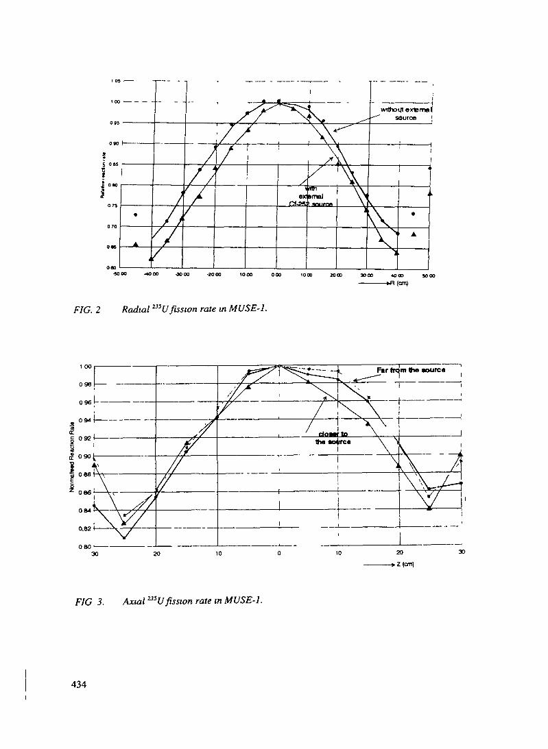
wtthoifl externalsource '
S
ex »malJOUCDB.
V-SOOO -4OOO -30OO -JOOO 1000 000 1000 ZOGO 3OOO 400O SOOO
—————»H (on)
FIG. 2 Radial 235U fission rate in MUSE-1.
30
FIG 3. Axial ^U fission rate in MUSE-1.
434

O
005
004
003
002
001
0
-001
-O02
-003
-004-
? rw eo TT W in
Radius (cm)
Core center
F/G. 4. C/E values for the radial 235U fission rate at midplane (2S2Cf source at midplane)
«"
002 •
001
-001
-002
-003
-004
Core midplane
-30 -25 -20 -15 -10 -5 10 15 20 25 30
Axial Z (cm)
FIG. 5. C/E values for the axial 23SU fission rate at midplane (252Cf source at +25 cm with respectto midplane)
435

TABLE IH. CALCULATION/EXPERIMENT COMPARISON FOR (p Vv
252Cf Source Position: At core center
E=0.495±4%C=0.534(E-C)/C=-7.1±4%
+15cm<a)
0.460±4%0.468-1.7±4%
+25 cm(b)
0.380±4%0361+5.3±4%
(A): Z with respect to midplane
D.6.3.2.4 CONCLUSIONS AND FUTURE PLANS
The MUSE-1 experiment performed on the MASURCA assembly in Cadarache has shown the potentialof that facility to investigate the physics of subcntical multiplying systems in the presence of an externalsource. The accuracy of the measurements is very high, and known experimental techniques, used instandard experiments to validate the physics of fast neutron cores, can be applied with confidence.
The short, exploratory MUSE-1 programme has provided some insight into the physical behavior ofthe neutron population in the subcritical system.
Moreover, a relevant integral parameter, I. e. the external neutron source effectiveness <p*, was definedand measured with high accuracy. This point is very relevant, since (p* can be a key parameter in theoptimization of a hybrid system, to improve the energy balance and to provide an optimized neutronimportance distribution.
Future experiments will focus on the study of neutron diffusing media placed around the source, withdifferent positions of the source and at different levels of subcriticality.
Kinetics parameters (like Peff) will be measured, to gain insight in the time dependent behavior of asubcritical system.
REFERENCE
[1] J. Y. Doriath, J. M. Rggieri, G. Buzzi, J. M. Rieunier, P. Smith, P. Fougeras, A. Maghnouj, "ReactorAnalysis Using a Variational Nodal Method Implemented in the ERANOS System", ANS TopicalMeeting, Knoxville, TN, USA, vol. E, p. 20 (April 1994).
436

D.6.4. ADS PROGRAM IN THE CZECH REPUBLIC XA9846578
D.6.4.1 APPROACHES TO A NATIONAL ADS PROGRAM IN THE CZECH REPUBLIC
Frantisek JanouchThe Royal Institute of Technology, Stockholm, Sweden andThe Institute of Nuclear Physics, Czech Academy od Sciences, Rez,Miloslav HronNuclear Research Institute, Rez, Czech RepublicRostislav MachThe Institute of Nuclear Physics, Rez, Czech republicV. ValentaSkoda, Nuclear Machinery, Ltd., Czech Republic
D.6.4.1.1. NUCLEAR ENERGY IN THE CZECH REPUBLIC
The Czech Republic is a highly developed industrial country with a dense population.The country isvery poor in conventional energy resources: hydroenergy - fully exploited - provides less than 3% of thetotal electricity production; fossil reserves are reduced to coal only, most of it being low quality and sulphurrich brown coal and lignites. Its use for electricity production caused, and still causes, heavy environmentaldamage especially in the northern part of the Czech republic which is internationally declared to be anecological disaster region. The atmospheric pollution caused by coal power stations is causing graveconcerns even in the neighboring countries. At the end of the eighties, Czechoslovakia, having a populationof about 0.3% of the total world population, was burning app.10% of the total world production of lignites.At the beginning of the nineties, about 90% of Czechoslovakia's oil and natural gas were imported fromthe former USSR i.e. from abroad, making the country's economics very vulnerable and dependent.
The Czech republic had considerable reserves of Uranium ores. Although a large part of it wasexploited between 1945 and the seventies, a reasonable amount of Uranium ore is still available.
These are the main reasons why the Czech Republic decided to build several nuclear power stations.Four of them, Russian designed WER-440 (V-213) reactors have been in operation at Dukovany sincethe middle of eighties. Two additional reactors, VVER-1000, are near to completion in Temelfn, SouthBohemia.
The completion of the Temelfn nuclear power plant initiated hectic discussions both at the national andinternational levels. Although the VVER-1000 is the most modem russian designed NPP, provided witha very solid containment, additional significant steps were undertaken to increase its safety standards. TheAmerican company Westinghouse is in charge of further modernization the NPP, providing moderninstrumentation and control system and newly designed fuel elements.
D.6.4.1.2. SPENT FUEL MANAGEMENT
Until 1986 the spent fuel did not present any problems since the country manufacturing the fuel - i.e.the USSR - had a contract obligation to take care of it. Since the end of 199la Russian Federation lawprohibits the acceptance of spent fuel from abroad, so the Soviet/Russian option for handling of the spentfuel has been out of the question.
This is why the Czech Republic since 1992 has had to reconsider the whole problem of the spent fuelwaste. The Czech energy board tried unsuccessfully to negotiate the storage of spent fuel abroad inGermany, Italy, Finland, Belgium and Sweden - i.e. in countries with spare storage capacity. After rejecting
437

the reprocessing option, the only remaining solution was to build both an interim and a final repository inthe Czech republic. Due to considerable public opposition, spent fuel management has become a seriouspolitical problem in the Czech republic during the last couple of years. According to present political plans,the final underground repository should not be opened before 2050-2070; therefore enough time exists fora thorough investigation of alternative solutions.
D.6.4.1.3. THE 1994 AND 1995 LIBLICE SYMPOSIUM
The above are, in brief the reasons why the new ideas presented on the Los Alamos ATW project andby the Rubbia energy amplifier project met a positive response not only in political quarters but also in thenuclear power industry and utilities. Even the mass-media reacted positively and published several reportsabout the Los Alamos project.
In 1994 the Ministry of Industry and Commerce asked a group of Czech scientists to prepare apreliminary study on projects dealing with accelerator driven nuclear reactors and nuclear wastetransmutation. The study has been completed in the spring of 1994 and published in Czech [1].
The Initiative Group for the accelerator driven transmutation of waste was set up in September 1993.Its activities were financially supported by the Czech Energy Board (CEZ), Czech Ministry of Industry andCommerce and the SKoda industrial group.
This financial support has allowed small symposiums to be convened on June 27-29, 1994 and thenon September 1995 at the Liblice castle near Prague on accelerator driven reactors and nuclear wastemanagement projects in the Czech Republic [2].
The symposiums met with a considerable interest from Czech scientists and nuclear engineers. Over40 people, including several scientists from Sweden, the U.S., Slovakia and Russia, took part in its workand around 20 papers, covering different aspects of this problem and reporting related activities in theCzech republic were presented. The participation of a group of engineers from SKODA NM Ltd whopresented several papers was encouriging, showing that these new ideas are seriously discussed and studiedin the industry.
The Liblice symposiums reviewed the competencies of Czech scientists and engineers in the field ofaccelerator driven reactor and transmuters. Many interesting proposals and topics were presented at thesymposium [3].
In the spring of 1995, the Iniative Group presented another more detailed and complex study to theCzech Ministry of Industry and Commerce under the title "Possibilities of incineration of spent fuel andradioactive wastes by new methods" [4].
The nuclear program was initiated in the former Czechoslovakia in the late fifties. Since then Czechand Slovak scientists and engineers and the nuclear industry gained considerable experience in nuclearscience and technology:
(1) several accelerators, research and experimental reactors were successfully operated for severaldecades;
(2) considerable experience was also gained in the field of hot chemistry - separation, partitioning andsolidification;
(3) jointly with Russian specialists, a new type of nuclear power reactor was designed, constructed andoperated between 1972-1977. The nuclear power station, called Al, had a graphite moderated gas-cooled (CO2) reactor using natural Uranium with a designed net electrical output of 150 MWe;
(4) the Skoda nuclear engineering factory produced 14 NPP, twelve of them with VVER 440 powerreactor units with modernized design and two with VVER-1000 reactors.
The Liblice symposiums allowed assessment of both the interest and the competences available in theCzech republic for the transmutation projects. The main centers in the Czech Republic which possess
438

know-how and competence for the future accelerator driven systems and transmutation studies aredescribed here:
Nuclear Research Institute, Rez ':Two research reactors (LVR-15 for material testing and LR-0 developed for testing cores of the VVERreactors)Research reactor department.Division of reactor physics.Division of radiation chemistry (hot cells).,Division of fuel cycle.Division of metallurgy of Uranium and of reactor materials, .
Institute of Nuclear Physics, Rez near Prague:Cyclotron ( U120M, energy for protons 36 MeV, alpha-particles 40 MeV)Van de Graaf (protons 2-5 MeV).Accelerator department.Department of Nuclear reactions.Department of Nuclear spectroscopy.Collaboration with the Joint Institute for Nuclear studies in Dubna, Russia and access to its facilities.
Institute of Special Inorganic Chemistry, RezPartition, extraction, solidification etc.
Institute of Physics, Czech Academy of Sciences, PragueHigh Energy physics, detectors.Collaboration with CERN. _
Faculty of Mathematics and Physics and Faculty of Nuclear Physics and Engineering, PragueExperimental reactor VR-1Nuclear PhysicsHigh Energy PhysicsDosimetryNuclear ChemistryNeutron Physics,Reactor Engineering.Reactor Safety.
1 Nuclear Research Institute originally belonged to the Czechoslovak Academy of Sciences, and later to theCzechoslovak Atomic Energy Commission. It was privatized in 1993.
439

§koda Nuclear Machinery Co, Plzen.This company has built 14 reactors (12 VVER 440, 2 VVER 1000), many testing loops, transport andstorage casks for spent fuel and performed reactor safety studies.
Institute of Thermomechanics, Czech Academy of Sciences, Prague:Fluid dynamicsThermodynamicsDynamic fracture and impact problemsVibrations
Institute of Nuclear Fuel, ZbraslavEncapsulation of nuclear fuel
The Liblice symposiums and numerous discussions after it concluded that the Czech ADS program willdeal with the following topics:
Review of the present knowledge on feasibility of transmutation of actinides and fission productsInvestigation of nuclear processes in a spoliation target hit by a high energy particle beam.Determination of optimal target-projectile combination(s).Specific problems of transmutation of long-living nuclides and neutron economics. Photonuclearreactions.Studies of subcritical systems, their geometry and their static and dynamic behaviour. Control of suchsystems.Trends in development of separation techniques. Dicarbollides Extraction and Sorption. Assessmentof approaches developed in other countries.Studies on technical and economical efficiency of subcritical systems.Studies of thermodynamical processes in subcritical systems.Studies of suitable materials for the most exposed parts of subcritical systems.Feasibility studies of the application of an ADS in the framework of the national nuclear powerprogram conditions and Skoda's own nuclear power technology manufacturing tradition.The 1994 and 1995 Liblice symposiums concluded that the Czech Republic has significant theoretical,
experimental and engineering potential and know-how in several fields important for the rapid developmentat accelerator driven systems.
Reflecting the strong interest of Czech scientists and engineers and the favorable attitude of Czechindustry and Czech policy makers it was decided to establish an information and coordination center, basedat the Institute of Nuclear Physics in Prague. The main task of this Center will be the formulation andcoordination of national policy in this field. The center will also collect information about the developmentof transmutation technologies and assist in establishing contacts and collaboration with similar centresabroad.
The interest and financial support for this initiative group both from the Czech Energy Board and Skodacompany and the interest shown to these programs by the Ministry of Industry and Commerce is noted aspositive and promising.
440

6.3.1.4. INDUSTRIAL PARTNERSHIP
Being one of the first European industrial companies traditionally involved in nuclear power technologymanufacturing, Skoda Nuclear Machinery (NM), Ltd. started the first feasibility studies of the applicationof an ADS in the framework of the national nuclear power program conditions and its own nuclear powertechnology manufacturing tradition [3,5-8].
Skoda NM decided to concentrate on the LANL liquid fuel (molten salt) concept of the blanket withan accelerator concept adjusted to the applicability of the redundance principle (modular system). Forexample: Several accelerators of lower power could be employed. The use of their integrated proton beamsto bombard the lead target will not only raise the strength of the neutron source but will play one of themost significant roles of the above mentioned modular systems:
One of the accelerators can be used as a spare in case of e.g. malfunction of one of the other machines,periodic maintenance and inspection, etc. A concept that assumes accelerated proton beams bombardingseveral different targets in various reactor/blanket units also seems to be feasible for the Skoda NMdesigners.
The first results of the study mention a series of engineering problems in the area of materials and theirdegradation in the fields of intensive high energy particles, both charged and neutrons. The problem of thewindow and its life time, the problem of the target and others are proposed to be solved by the alreadymentioned modular system principle. The proton channel section, including the window, will be designedas remotely replaceable, by a vacuum preservation at an optimal level and by a proton channelcontamination prevention. A replaceable window design solution has been proposed as well with the designof a proton channel closing valve and a quick-operating valve for a window break emergency event.
The obviously high level of complexity, and thus also the price, of such systems produces a need toaccelerate the procedure to reduce the number of options and to go rather into more detailed system designand engineering in order to reach a realistic technological and economical image of the concept and projectitself.
D.6.4.1.5. CONCLUSIONS
Czech scientists and engineers are fully aware of the fact that the accelerator driven transmutation andreactors are projects which are too large to be handled individually by small European nations. Scientistsand engineers from the Czech republic consider therefore that a large scale international collaboration isan essential condition for further progress in this important and promising project and would welcome acreation of an international coordination body as the first step. In a more - but not too - distant perspectivealso the creation of an international institute, laboratory or center specializing in accelerator driventransmutation and energy production is desirable and will be supported by Czech specialists.
REFERENCES
[1] Jech C., Niederle J., PospfSil S.: New possibilities of obtaining nuclear energy from radioactivewastes by means of accelerators. Study report for the Ministry of industry and Commerce (InCzech), Prague 1994.
[2] Accelerator driven reactors and nuclear waste management. Abstract from the Liblice symposium,June 27-29,1994.
[3] Janouch F., Mach R., Accelerator driven reactors and nuclear waste management projects in theCzech republic. International conference on Accelerator-Driven Transmutation Technologies andapplications. Las Vegas, July 25-29, 1994.
441

[4] Z. Dlouhy, M. Hron, F. Janouch, L. Kuca, A. Kugler, M. Kuzmiak, M. Kyrs", V. Lelek, R. Mach,L. Nachmilner, M. Sumbera, M. Vognar, A. Vokal. Possibilities of liquidation of burnt nuclear fueland radioactive wastes by new methods (In Czech). Report for the Ministry of Industry andCommerce of the Czech Republic, released in Prague, March 1995.
[5] Some comments by Skoda, Nuclear Machinery, Ltd., Plzen, to Accelerator Driven Reactor (ADR)problems, personal communication, 1995
[6] Valenta V., Hep J., : Safety Aspect of Reactors Controlled by Accelerator for TransuranidesBum-up Symposium on Accelerator Driven Reactors and Nuclear Waste Management, Liblice,Czech Republic, June 20-29, 1994
[7] Jilek M., Valenta V., Lelek V.: Temporary Storaging of Burned Fuel from Nuclear Power Stationsin the Light of New Technologies, Symposium on Accelerator Driven Reactors and NuclearWaste Management, Liblice, Czech Republic, June 20-29, 1994
[8] Jflek M., Hep J., Hosnedl P., Hejplik K., Pedal L., Valenta V. : Nuclear Waste ManagementProjects with Regard to ADR in Skoda Nuclear Machinery, Plzen, Co. Ltd., Internal ReportSkoda, 1995
442
XA9846579
D.6.4.2. ACHIEVEMENT OF ACCELERATOR PARAMETERS NEEDED FOR ENERGYPRODUCING AND WASTE TRANSMUTING ADS
Miloslav Hronf and Mikulas Kuzmiak*,fNuclear Research Institute Rez, pic, CZ-250 68 Rez*The Institute of Nuclear Physics of the Academy of Sciences of the Czech Republic, CZ-250 68 Rez
D.6.4.2.1. INTRODUCTION
The accelerators needed for ADS, especially for the systems producing energy and burning waste,have to satisfy some minimum technological requirements. This is not a principal problem as for reachingthe necessary level of beam energy. High energy accelerators are quite common in the field offundamental particle physics. The accelerator needed for power production, at an energy of 800 MeV, isin the mid-range of energies for such devices, much higher than those used for cancer therapies in hospitals(tens of MeV) but much lower than those used for fundamental physics research at the biggest worldcenters (thousands of MeV and beyond). This energy is sufficiently high that a single proton colliding withseveral nuclei as it moves through the heavy metal target releases about 20 to 30 neutrons which are thenmultiplied in number in the surrounding blanket as reported by the scientists of LANL, USA [1].
There are two types of accelerators that could drive the system at approximately 1 GeV and averagecurrents in the range of 10 to 100 mA. The first option is to use a linear accelerator that would be anadvanced, high intensity version of, e.g. the Los Alamos Meson Physics Facility (LAMPF) 800 MeVaccelerator. The second is to use a circular accelerator, e.g. the 500 MeV ring cyclotron operating at thePaul Scherer Institute in Switzerland or a series of others of that or similar type. Both of the options canachieve energy required without difficulty but both require technology development to achieve thenecessary beam intensities. The cyclotron machines, in particular, are limited to currents of 10 to 15 mAdue to the difficulty in adequately confining the beam.
Linear accelerators are foreseen to be able to deliver perhaps 100 to 300 mA of beam current. Theyalready produce such current in pulsed mode but the technology will have to be extended to provide thenear-continuous operation which would be needed for the highest currents. Although the beam physics fora continuous operation is a modest extrapolation of that for pulsed operation, significant engineeringdevelopment is still needed. A system delivering 15 mA of protons and 800 MeV (12.5 MW of beampower) can drive a blanket assembly to produce 200 MW of electrical power and so a circular acceleratoris an attractive option at this power level.
To achieve the usual level of approximately 1,000 MWe it possible to apply the LAMPF-like linearaccelerator with much higher current capability, which would allow a single accelerator to drive either alarge transmutor or a small cluster of separate blanket assemblies with a total system power of 1.200 MWe.In either case only about 15% of the electrical power would be used to drive the accelerator. However, theexclusive use of only one accelerator unit would represent a weak point of such a systems operationalreliability. On the other hand, the employment of more than one accelerator of such a class would be anextremely costly approach.
An attractive approach to the achievement of the accelerator parameters needed to employ circularmachines that beside others have an advantage of being more compact systems, has recently been proposedby Czech scientists [2]. A brief description of their idea is introduced in the following paragraph.
443

D.6.4.2.2. JOINING MANY BEAMS INTO ONE WITH INTEGRATED INTENSITY [2]
The proposal is based upon an octupole magnet. Atransversal cross-section of such an octupole magnet isschematically outlined in Figure 1.
This octupol magnet has two focusing planes (0 =0 and0=71/2) and two defocusing planes (0 = rc/4 and 0=3 n/4).Taking the octupol magnet symmetry into account andmaintaining the terms up to the fifth order in the expansionwe may obtain the magnetic field components from thegeneral expressions for the magnetic field expansion:
FIG. 1. Cross section of an octupole magnet
20
20 (1)
Br
with B0 the field on the pole, a the aperture radius of the octupole magnet, f(z) the function describing thefield distribution along the z axis; the prime denotes a derivative with respect to the z variable.
The joining of two beams into one beam isschematically outlined in Figure 2.
Let us note that this scheme can be applied toboth twins of the focusing and defocusing planesof the octupole magnet as mentioned above, sothat totally 4 individual beams being generatedby 4 individual accelerators can be joined to onebeam with an integrated intensity through thefollowing process:
The charged particle beams (B) enter anoctupole focusing magnet (OF) which deflectsthem towards the longitudinal axis z. Behind thisoctupole focusing magnet, the beams transit
FIG. 2. Funnel of beamsthrough solenoids (S). These solenoids focus thebeams in a transverse direction. There is anoctupol a defocusing magnet (OD) behind thesolenoids. It deflects the beams towards the longitudinal axis z. The proximity to the longitudinal axiscan be expressed either by the transverse coordinate of the central trajectory of the beam or by the anglebetween the central trajectory and the longitudinal axis. If these two values are in the range of the
444
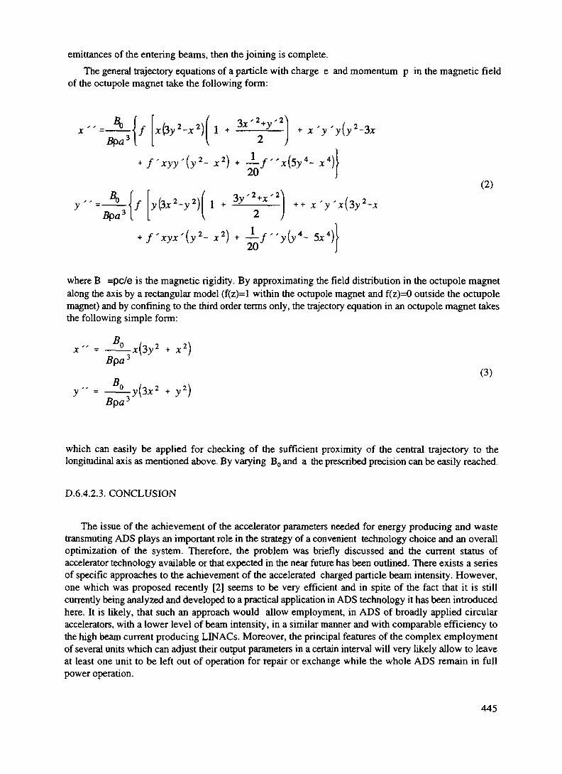
emittances of the entering beams, then the joining is complete.The general trajectory equations of a particle with charge e and momentum p in the magnetic field
of the octupole magnet take the following form:
(2)
where B =pc/e is the magnetic rigidity. By approximating the field distribution in the octupole magnetalong the axis by a rectangular model (f(z)=l within the octupole magnet and f(z)=0 outside the octupolemagnet) and by confining to the third order terms only, the trajectory equation in an octupole magnet takesthe following simple form:
jc" = -^x(3y2 + x2
Bpa'(3)
Bpa:-y\Jx2
which can easily be applied for checking of the sufficient proximity of the central trajectory to thelongitudinal axis as mentioned above. By varying B0 and a the prescribed precision can be easily reached.
D.6.4.2.3. CONCLUSION
The issue of the achievement of the accelerator parameters needed for energy producing and wastetransmuting ADS plays an important role in the strategy of a convenient technology choice and an overalloptimization of the system. Therefore, the problem was briefly discussed and the current status ofaccelerator technology available or that expected in the near future has been outlined. There exists a seriesof specific approaches to the achievement of the accelerated charged particle beam intensity. However,one which was proposed recently [2] seems to be very efficient and in spite of the fact that it is stillcurrently being analyzed and developed to a practical application in ADS technology it has been introducedhere. It is likely, that such an approach would allow employment, in ADS of broadly applied circularaccelerators, with a lower level of beam intensity, in a similar manner and with comparable efficiency tothe high beam current producing LINACs. Moreover, the principal features of the complex employmentof several units which can adjust their output parameters in a certain interval will very likely allow to leaveat least one unit to be left out of operation for repair or exchange while the whole ADS remain in fullpower operation.
445

REFERENCES
[1] VENNERI, F., HEIGHWAY, E. and BOWMAN, C, Accelerators Add a New Option to ourEnergy Future , Los Alamos National Laboratory, Los Alamos, personal communication, 1995
[2] HRON, M., KUZMIAK, M.: The proposal of a funnel for joining more beams into one, TheInstitute of Nuclear Physics, Rez (in preparation).
446

XA9846580E. SAFETY ASPECTS
H.U. Wider, JRC Ispra, EC, Italy
E. 1. BASIC SAFETY FEATURES OF ADS
E. 1.1. ACCIDENT TYPES
In this overview it is assumed that in an accelerator-driven system (ADS) the same type of accidentscan be envisaged as in critical reactors. The ADSs proposed in this State-of-the-Art report include fastsystems with solid fuel and Lead or sodium cooling (also gas cooling was discussed at one time}, fastsystems with circulating molten salt/minor actinides, thermal systems with circulating molten salt/minoractinide/Pu and graphite moderation and thermal systems in which the latter mixture or a water/oxide slurryis circulated in pipes and heavy water is used as moderator.
The generic accidents that can occur in low pressure fast or thermal systems are cooling-failureaccidents, either due to a rapid primary flow decay caused by loss of power to the pumps (Loss-of-Flow:LOF) or due to the loss of the heat sink (LOHS) due to loss of power to the pumps in the heat removal loopsor to the feedwater pumps. For a gas-cooled fast reactor the loss of coolant accident (LOG A) is a possibilityif a sudden depressurization occurs due to a leak. For the low pressure systems the loss of coolant accidentis of low probability and a guard vessel should assure that the coolant cannot escape completely. Decay heatremoval problems can also lead to accidents, e.g. if the diesels driving the blowers for the forced convectioncooling in a gas-cooled system fail to start.
The ADS systems mentioned in the Studies of Accidents in Reactors (SOAR) are also susceptibleto reactivity accidents which are called Reactivity Induced Accidents (RIAs) for thermal reactors andTransient Overpower (TOP) accidents for fast reactors. All types of ADSs that have some control rods couldexperience an inadvertent withdrawal of the latter. In pressurised systems the blow-out of one control rodcluster is considered to be a possibility. Since ADSs will probably use fewer control rods than a criticalreactor this will reduce the potential for reactivity accidents. Different types of reactivity insertions can alsobe postulated due to the inadvertent insertion of moderator material in a fast system, accumulations of fissilematerial in a system with circulating salt/fuel or earthquakes causing core distortions. The proposed sodium-cooled fast ADS will probably have a positive void coefficient which could lead to a reactivity excursion ifthe sodium overheats and boils. If the core of a fast ADS melted down there would be the potential for thecore to slump down and form a molten pool in which molten fuel sloshing can occur. These fuel motions canalso cause reactivity ramps.
Whether an ADS-specific accident due to a sudden and significant increase of the accelerator powerabove its nominal value is possible, is not clear at this time but it should be investigated whether suchincreases are possible.
E. 1.2. PREVENTION OF ACCIDENTS IN ADSs
As for critical reactors a high quality of the safety grade components, their inspectability and an in-service inspection programme during the whole reactor life are necessary. Components which should beparticularly reliable are the accelerator shut-off system and the decay heat removal systems. The design ofthe ADS should ideally be such that it cannot lead to a severe accident or that accidents develop slowlyenough so that there is time for a corrective response. Because the shut-off of the neutron source is of majorimportance for cooling-failure accidents it is discussed below and compared with shutdown systems in criticalreactors.
E. 1.3. SWITCHING OFF THE ADS NEUTRON SOURCE IN CASE OF AN ACCIDENT
The reactor part of an ADS is a subcritical neutron-multiplying medium with a more or less powerful
447

neutron source. If one switches the external (spallation) neutron source off, the power will decrease to decaypower levels. This will occur at a faster rate for larger neutron sources and their corresponding initialsubcriticalies.
As will be discussed in the later sections on major cooling-failure accidents without beam shut-off,the rapid turning off of the neutron source is central for avoiding a core melt at least in fast systems with solidfuel. This is because the neutron source prevents a rapid power decrease even if some negative feedbackscome in [1] - see also the later discussion of cooling failure accidents in ADSs without beam shut-off.
For reactivity accidents in ADSs - even rather strong ones - the switch-off of the source may onlybe necessary after some time in order to prevent a limited core damage. The reasons for this will also bediscussed in the later sections on reactivity accidents in which the source is left on.
E.I.3.1 Scramming a Regular Critical Reactor in Case of an Accident
To switch off the neutron source in an ADS is similar to the scramming of a critical reactor byrapidly inserting control rods. In reactor types in which a loss of coolant doesn't lead to a strong negativereactivity (i.e. gas cooled thermal reactors or thermal CANDU and sodium cooled fast reactors which evenlead to positive void reactivities) a scram is an essential safety requirement in a major cooling failure accidentat full power. PWRs or BWRs shut down by themselves in LOCA or station blackout accidents but it willbe impossible to establish proper decay heat cooling if the scram is not actuated. The only type of reactorthat could have survived a major cooling disturbance (LOF, LOHS) without scram would have been the nowabandoned US Integral Fast Reactor (IFR) with metal fuel [1]. Even the Swedish PIUS concept uses a scramby adding large amounts of borated water into the core region in case of a cooling failure accident [2].
Reactivity insertions in LWRs or fast reactors at full power due to the inadvertent withdrawal ofcontrol rods, the ejection of a control rod cluster in a PWR or the dropping of such a cluster in a BWR requirea fast scram in order to avoid core damage. The introduction of cold and unborated emergency cooling waterinto an LWR can also introduce an RIA which has to be terminated by a scram. All reactors have a certainpotential for reactivity accidents and the main line of defence against them is the scram. The fact that an ADScan overcome sizeable reactivity insertions without a fast scram (see E. 1.5.1 and E.I.5.2) is a unique propertyof this system.
E.I .3.2 Comparison of a Reactor Scram and Switching-off an Accelerator Beam
The delay time from the trip signal to a control rod release is about 0.5s for an LWR [3] and thisdelay will be similar for activating the beam shut-off system of an ADS. However, turning off the current toan accelerator should be considerably faster than the mechanical insertion of control rods which takes about1.5 - 3s in an LWR [3] and should be less for fast reactors cores which are smaller.
Comparing the redundancy and diversity of a shutdown system with that of the beam shut-off system,the latter has a disadvantage because it is only one beam that can be shut off whereas many - even different -control rods can be inserted and e.g. in an LWR and an alternate shutdown mode is possible through theinsertion of borated water. However, many diverse trip signals can feed into the beam shut-off.
Because the beam shut-off is mainly important for cooling failure accidents, the current to theaccelerator should be coupled to the electrical current driving the primary pumps, the pumps for the secondaryand - if existing - tertiary loops and also to the feedwater pumps. A different and fully passive system toshut the neutron source off, could involve the dropping of the spallation target by using a support made ofa low melting point metal which would heat up and melt in a cooling failure or slow reactivity accident. Thetarget could also be magnetically supported and if the magnets reached the Curie temperature, the targetwould drop. Another shut-off system could consist of deflecting the proton beam by demagnetising amagnetic lens through the cutting off of its current by bi-metallic devices located at the core outlet. In theADS design by Rubbia, which is described earlier in this report, a passive beam interrupt devise is based onthe rising Lead coolant level due to a cooling failure and leads to the overflow of the Lead into a containerwhich is in the path of the proton beam. This appears to be a reliable and clearly transparent passive beam
448

shut-off system.
E.1.4. COOLING-FAILURE ACCIDENTS IN ADSS WITH THE SPALLATION SOURCE STILL ON
E.I.4.1 Loss-of-Flow Accident in a Sodium-cooled Fast ADS
In chapter E.I.7 calculations of LOF accidents in a large fast ADS (SOOMWe) are discussed andcompared with those of a corresponding critical reactor. The main results are that fast sodium-cooled ADSswith their source still on Lead to much lower and wider power peaks than in the critical reactor. These powerincreases are caused by the positive sodium void reactivity. The power in the ADS also rises somewhat earlierbecause the negative feedbacks due to Doppler, axial expansion and structure feedbacks do not decrease thepower as much as in a critical system (see also [1]). The sodium voiding phase is considerably longer lastingbut pin failures still occur earlier in an ADS. Once strong negative feedbacks come in due to dispersive fuelmotion, the power decreases much less than in a critical system. This is due to the neutron source whichmakes the ADS less sensitive to feedbacks (positive and negative ones). This "inertia" of the ADS tofeedbacks has been recognised earlier [4].
The more subcritical an ADS, the more the above statements hold, i.e. the initial power peak becomeseven lower, but after a strong negative feedback comes in, the power doesn't decrease much. The latter willlead to a complete core meltdown unless the spallation source is switched off. Two calculations with asimulated beam switch-off show that the ADS can be safely brought to decay power levels if the turning offis done before much sodium voiding has occurred. The later the switch-off takes place, the more core damageis likely. If the switch-off is too late, the meltdown will proceed by fuel slumping down leading to a moltenfuel pool. Fuel sloshing around can lead to recriticalities and a power excursion [5]. A basic reason for thispossibility is that a fast system is not in its most critical configuration initially.
On balance a sodium-cooled ADS would have advantages over a critical fast reactor with regard toLOF and probably LOHS accidents in which no beam switch-off or reactor scram is considered. This ismainly because no rapid power excursions are possible at least when the ADS is in its initial configuration.A smaller but still important point is that the phenomena such as sodium boiling and pin failures in differentparts of the core are stretched out in time and therefore easier to detect. That a beam switch-off is necessaryfor an ADS during a LOF accident is similar to the necessity for a scram in a regular fast reactor. Bothsystems have the potential for recriticalities if the beam isn't shut off or a scram is not activated. With regardto regular decay heat removal, both systems can rely on passive natural convection cooling with the liquidsodium. With regard to post-accident heat removal both systems have equal uncertainties whether an in-vesselcoolability is possible or not. Also both systems have the potential for sodium fires and sodium/waterinteractions.
E.l.4.2 Cooling Failure Accidents in Gas-Cooled Fast ADSs
Relative to sodium-cooled fast ADS, a gas cooled variant has the advantage that there is nochemically reactive coolant and that there will be no positive reactivity effect due to a decrease in the coolantdensity. Moreover, it may be possible to use water cooling in a post-accident heat removal situation if aproperly designed in-vessel or ex-vessel core catcher could be designed that avoids recriticalities.
On the other hand there is the possibility of a LOCA accident if a leak occurred in the pressurisedprimary system. LOF and LOHS accidents are also possible. In all these cooling failure type accidents thetimely switch-off of the accelerator beam is also crucial for avoiding a core melt. If a core melt occurred itcould lead to recriticalities as in the sodium-cooled ADS. A significant disadvantage is that the regular decayheat removal can not be done in a passive natural circulation mode (or at least not for larger systems), hi ashutdown condition with no electricity available, the forced convection cooling has to rely on dieselgenerators.
449

E.I.4.3 Cooling Failure Accidents in Lead Cooled Fast ADSsLead cooling has many safety advantages relative to sodium cooling. Hot Lead does not react
chemically with air or water. Equally or more important is that it is a very weak moderator that will not leadto a significant spectrum change or positive reactivity effect when the coolant should experience a decreasein density due to heating of the coolant or due to boiling and voiding. In comparison to a gas coolant, Leadwould be at much lower pressure and would not be susceptible to a Loss-of-Coolant Accident (LOGA). Aleak of the primary vessel would only lead to the flowing of the low pressure coolant into the surroundingguard vessel.
A disadvantage of a Lead coolant is its high melting point of 327°C which probably requireselectrical heaters during reactor start-up and possibly also at very low decay power levels. The failure of suchelectrical heaters could lead to some Lead freezing and blockage formation which could impede the coolantflow in the core. However, it should be investigated whether conduction cooling would not be sufficient forvery low power conditions.
In the conceptual design of C. Rubbia (see chapter D.3), presented earlier in this SOAR, Loss-of-Flow (LOF) accidents due to pump failures cannot occur because the Rubbia design is based on naturalconvection cooling. However, a Loss-of-Heat Sink (LOHS) accident is still conceivable if e.g. the steamgenerators dried out due to a loss of feedwater. For the LOHS accident or for slow but long lasting reactivityinsertions (see chapter E. 1.7) these could lead to a partial or full meltdown of an ADS if the proton beam wasnot interrupted or the accelerator switched off. The Rubbia design includes a passive shutdown device basedon the rise of the coolant level caused by the heating up of the Lead coolant. As explained earlier this will leadto the overflow of the Lead into a container that is in the path of the proton beam which will thus becomea new target on top of the reactor. This would rapidly decrease the reactor power, and thus, the coolanttemperature.
However, the decay heat would slowly increase the coolant temperature again, In the Rubbia design,the renewed and further level swell will lead to an overflow of the Lead into the relatively small gap betweenthe main and the guard vessel and will largely increase the heat transfer between the two vessels, this will starta natural air convection cooling of the guard vessel. This type of decay heat removal, which was earlierproposed by the US ALMR programme, has the disadvantage that the containment has to have openings(which could possibly be closed in an emergency). An alternate way for the decay heat removal could be in-vessel Lead-air heat exchangers.
E.I.4.4 Coolant Failure Accidents in Thermal ADS with a Circulating Salt/Fuel Mixture.
An important advantage of thermal systems is that they have a lower power density than fast systems(for the same power, their cores are therefore much larger than those of fast ADSs). This makes the heatingup of a core slower in a LOF or LOHS accident and allows more time for the detection of off-normalconditions. Moreover, the thermal expansion and the potential boiling of the salt/fuel mixture will reduce itsdensity and will decrease the full power to a certain degree. However, this would lead soon (possibly withinminutes) to extensive boiling and pressure generation if the accelerator wasn't switched off. If the switch-offwouldn't take place, the spallation source might melt, disintegrate and lead to neutronic shutdown before theprimary system would be challenged.
A positive safety feature of this system is also that a problem with the decay heat removal does notlead to a rapid heating up of the primary system but allows tens of hours to re-establish the regular decay heatremoval (Bell, 94). This is due to the fact that about 2/3 of the fuel is not in the core but in a natural •circulation mode in the primary system which therefore gets heated up in its entirety. A smaller fluid fueledADS (< 800 MW,) will probably loose all the decay heat to the surrounding. For a larger ADS of this type,the salt/fuel mixture will eventually have to be drained into a cooled reservoir. (In contrast a fast ADS withliquid coolant could have relatively small coolant/air heat exchangers which can passively remove all thedecay heat from the primary system).
Another advantage relative to ADS systems with solid fuel is the on-line removal of short - livedfission products which will considerably reduce the fission product inventory.
Certain problems with the salt/fuel ADS could be due to the precipitation of the heavy fuel or minor
450

actinides which might lead to a temporary increase in density of the latter in the core. As will be discussedunder reactivity accidents, this would lead only to a limited increase in power. However, one could alsoimagine that such a precipitation could lead to an accumulation somewhere in the primary system away fromthe graphite moderator and lead to a fast criticality. However, such an accumulation may blow apart withoutdoing damage to the strong primary system.
An interesting problem for fluid fuel/molten salt systems may be a strongly positive temperaturecoefficient for a pure salt / Pu / minor actinide mixture because no 23*U or232 Th, with their absorptionresonances, is present [6]. If this were true, a LOF or LOHS would lead to some power increase rather thandecrease during the heating up of the salt/fuel mixture if the beam was not switched off.
A potential problem is also the explosive interaction between molten salt and water [7] which couldoccur in the Russian design in which molten salt / fuel is pumped through pipes which are surrounded byheavy water. In such a system a leak could lead to a molten salt / water explosion which could destroy otherpipes and lead to a propagating explosion. In the LASL design there could also be a potential problem ifwater was used in the secondary loop .
A genera] weakness of a molten salt / fuel design is that it is a relatively "dirty" system in whichradioactive material gets into the pumps and heat exchangers and makes the inspection of these importantcomponents difficult A related problem is that the vessel is the first safety boundary and if a leak occurred,the whole containment would be radioactive.
E. 1.5. REACTIVITY ACCIDENTS WITH THE ACCELERATOR BEAM STILL ON
£.1.5.1 TOP Accident in a sodium cooled fast ADS
In chapter E.3. calculations of reactivity accidents in the same sodium-cooled ADSas used for thecase described in E.2. are discussed and compared with reactivity accidents in an equivalent critical fastreactor. The results are rather clear. The sodium cooled ADS has no significant problems to cope with veryfast and medium ramp rates (170 $/s for a total insertion of up to 2.65 $ and 6 $/s for a total insertion ofup to 3$) - the subcriticality of the ADS was -3$ in the first case and -5$ in the second. The correspondingruns for the critical system gave power peaks of around 2000 times nominal and led to complete coredestructions.
For a rather slow ramp of 10 c/s inserted for 30 s to give a total insertion of 3$, the critical reactorwill lead to pin failures in 1 out of 10 calculational channels. The negative feedback from the fuel dispersalmakes the net reactivity low enough to prevent further failures. In the corresponding ADS case with a - 3$subcriticality, a failure of one channel occurred also - but later, for a -5$ subcriticality it occurred even later,and for a subcriticality of -10$ not at all.
For fast ramp rates, which could not be counteracted in a timely manner by a scram in a regularreactor, the ADS behaves benignly. For slow ramp rate accidents the ADS may lead to late failures andlimited core damage if the beam is not shut off and the subcriticality is not large enough. However, since abeam shut-off system has to be in place for cooling - failure accidents, there is probably no need to go to lowsubcriticalities to avoid late pin failures. The unscrammed regular reactor will definitely experience somelimited core damage for slow ramps which will probably not spread to the rest of the core.
E.I.5.2 TOP and RIA Accidents in other ADSs
The gas cooled fast ADS should behave similarly benignly when subjected to fast transients. Forslow ramp rates and late pin failures, the fuel dispersal may be more limited in a gas cooled system and giveless of a negative feedback which could lead to further pin failures.
A thermal ADS with a molten salt/fuel mixture will also react benignly to fast ramp rate insertion[Bell, 94]. For slow reactivity insertions, the advantage is certainly that no pins can fail in the fluid-fueledsystem and that it can probably survive an enhanced power situation without problems.
451

E. 1.6 CONCLUSIONS
The ADS has a clear advantage for coping with fast ramp rate accidents which would occur toorapidly for scram systems in regular reactors. This ability to overcome fast reactivity insertions is importantto avoid Chemobyl type power excursions.
In cooling-failure accidents without beam shut-off, rapid power excursions are not possible - evenfor positive void worth cores. However, the power of an ADS cannot be decreased very much due to negativefeedbacks. The only way to decrease the power to decay heat levels is the switching off of the acceleratorbeam - otherwise a core melt will occur in a cooling failure accident (which would eventually happen inLWRs too if no scram were activated). Therefore emphasis will have to be put on a highly reliable beam shut-off system in an ADS. If the ADS had a low pressure cooling system and a guard vessel there could be noproblems with Loss-off-Coolant Accidents (LOCA). Of general importance for safety in any reactor typeas well as for ADSs is a reliable emergency decay heat removal system which should preferably be a passivesystem.
Comparing fast ADS with solid fuel and thermal ADS with a circulating salt/fuel mixture a fewpoints are important. The thermal systems have a slower response time in accident situations which makesthe detection of the off-normal conditions easier. In severe accident situations without beam switch-off, thesalt/fuel will expand and boil and could lead to leakages whereas the fast system could melt down andpossibly lead to a recriticality which could cause a power excursion. In the salt/fuel system pumps andprimary heat exchangers are all radioactive and therefore difficult to inspect. Moreover, there are uncertaintiesabout the precipitation and accumulation of fuel and minor actinides leading to mild excursions and there isalso an uncertainty about the temperature coefficient of reactivity.
452

E.2. FIRST INVESTIGATIONS OF THE BEHAVIOUR OF AN ACCELERATOR DRIVEN FASTOXIDE REACTOR DURING AN UNPROTECTED LOSS-OF-FLOW ACCIDENT
E.2.1 INTRODUCTION
A new concept for an Energy Amplifier (EA) has been proposed by C. Rubbia [8]. It consists of asubcritical fast system that is driven by the proton beam of a compact cyclotron which hits a target in thereactor and generates about 50 fast neutrons per proton through a spallation process. The proposed F-EAis cooled by Lead and uses 233U/232Th fuel.
Safety considerations of such new approaches and in particular the investigation of severe accidentconditions are important. An investigation of a severe reactivity accident was earlier undertaken [9].Although the reactivity ramp used was rather steep and it started from initial reactor conditions this studyshowed that accelerator driven fast systems are rather insensitive to fast reactivity insertions.
The present study deals with a Loss-of-Flow accident in which the primary pumps are assumed to coastdown (e.g. due to a station blackout) and which can lead to a major coolability problem for a fast reactorif no scram occurs. Different from the study above in which only the point kinetics and the Dopplerfeedback were considered, this study used the EAC2 code [10,11] which calculates coolant heating up andvoiding, fuel pin heating up and axial expansion, pin ruptures and subsequent molten fuel motion insidethe pins and in the coolant channels. The reactivity feedbacks due to axial pin expansion, sodium voiding,fuel motion as well as the Doppler feedback are considered. So far only sodium cooling has beenconsidered. The subcriticality is simulated by a programmed negative reactivity. To simulate the spallationneutrons coming from the target a source was introduced into the point kinetics module. This representsa source that is uniformly distributed in the reactor which is only a simple approximation for the real caseof a central neutron source. The reactor under consideration is a 800 MWe reactor design used in theEuropean WAC benchmark calculations [12]. The pump coastdown times and a negative ramp of -2cent/s, which roughly simulates a structural expansion feedback, were taken from the WACLOFbenchmark. The core set-up with half of the fuel near fresh and the remainder with a bumup of 275 daysand the dividing of the core into 10 representative calculational "channels" were also taken from theWACLOF benchmark. Since this benchmark dealt with a sodium coolant, the comparison calculationswere also made for sodium cooling. The investigation of the accident behaviour with Lead cooling maybe a further step.
E.2.2. CALCULATIONAL RESULTS
Figs 1 and la show the EAC-2 results for the standard WACLOF case. The important reactivity effectsall occur within one second. Sodium voiding gets the total reactivity to prompt critical despite negativeDoppler and axial pin expansion reactivities. Subsequently the fuel pins fail near the midplane and somein-pin fuel motion towards the failure location leads to positive reactivity effects (see the small positivepeak of the total reactivity) and this leads to superprompt critical conditions and a power peak of 1800times nominal. Once the fuel moves in the coolant channels away from the midplane, the fuel motionreactivity becomes strongly negative and shuts the reactor down. However more than 85 % is of the fuelis now molten. The integrated power measured from the first pin failure is 4.5 full power seconds
Fig.2 and 2a show a modified WACLOF case for which stress failure criteria were used for failing thepins. These mechanistic criteria lead to earlier pin failures than the melt fraction criteria in the original case.This leads to a more limited in-pin fuel motion to the pin rupture site, and thus, only to a power peak of265 times nominal and only 1.8 full power seconds integrated power after the first pin failure .
453

20OO
1500 -
1000 -
5OO
POWER
10TIME s
15 20
FIG. 1. Power history in the original WACLOF case (pin failures based on melt fraction criterion).
oo-5
-10
-15
——— TOTREAC
• • - • • REAPROG
- - REAVOID
-•- REAOOPP
— •• REAFUEX
— - REAFUMO
10TIME
15 20
FIG. la. Reactivities causing the power history in Fig.l.
Fig.3 and 3a show the results of a run in which the WAC reactor was initially subcritical by -3$ andan accelerator driven neutron source was active and provided the neutrons necessary to maintain nominalpower. The negative ramp of -2 cents/s was maintained in order to compare with the WACLOF case. Forthe pin failure criteria the melt fraction criteria from the WACLOF benchmark were also kept (70%maximum areal melt fraction for irradiated pins and 90% for fresh pins). The main difference in this
454

400
300
200
100
10TIME
15 20
FIG. 2. Power of WACLOF case with more realistic pin failure criteria.
oo-5
- 1O
- i 5
——— TOTREAC
REAPROG
— - REAVOID
— - READOPP
— REAFUEX
— - REAFUMO
10TIME
15 2O
FIG. 2a. Reactivities causing the power history in Fig. 2.
calculation is that the power rises to only 5 times nominal and that the total reactivity gets only slightlyabove delayed critical. It can also be seen that the time from the onset of sodium voiding to the onset offuel motion (i.e. pin failures) is about 3s, and thus, about 3 times longer than in Fig.l. However, fuelmelting also occurs and leads to the failure of 3 of the 10 calculational channels. The subsequent fueldispersal reduces the total reactivity to -10$, but the power reduces only to 0.3 times nominal because theneutron source is still on. This is further addressed in the discussion of Fig.5 below The integrated power
455

from the first pin failure to reaching 0.3 times power is 1.5 full power seconds.
oCL
Qt
POWER
10TIME s
15 20
FIG. 3. Power history of WACLOF case with -3$ and neutron source
oo
1 -
-1
-2
——— TOTREAC
REAPROG
— - REAVOID
— - READOPP
— REAFUEX
— - REAFUMO
20 40TIME s
60 8O
FIG. 3a. Reactivities causing the power history in Fig. 3.
In Figs. 4 and 4a the WAC reactor was initially at -10$ and the neutron source active and providingmore neutrons than in the previous case. The power rises to only 1.4 times nominal and the time betweenvoiding onset and pin failures is extended to 6s. The pins fail in 3 calculational channels and lead to moltenfuel dispersal which causes a decrease in the total reactivity to -15$. However, the power only decreases
456

oQ_
4 -
POWER
o(3 5
v_. . 1 . . . . 1 . . . . 1 . , — , —
10 15 2O
-
\
2TIME s
FIG. 4. Power history of WACLOF case - 10$ and neutron source
en
1_iOo
-5 -
——— TOTREAC
• • • • • REAPROG
- - REAVOID
-•- READOPP
— •• REAFUEX
— - REAFUMO
FIG. 4a. Reactivities causing the power history in Fig. 4.
to about 0.7 times nominal because of the relatively strong neutron source which is assumed to be stillactive. This rather high longer-term power level will lead to more core melting (see discussion of Fig.5).The integrated power from the first pin failure to reaching 0.7 times nominal power is 2.8 full powerseconds. However, with the power remaining at 0.7 the integrated power would continue to increase witheach additional second by 0.7 full power seconds . The EAC2 results presented in Figs. 4 and 4a cannotbe considered very reliable because the cladding melted in this case before the fuel and EAC2 does notmodel molten cladding motion. The latter would have introduced additional positive reactivity and reduced
457

the fuel dispersal.
0 8 -
O 6 -
O 2
O O2O
WAC LQF —
SO
E -^
i O
O 6
O 2
O O20
LOF-3S
soTIME S
BO i 00
o s
O 2
i_or— i os
soTIME X
• 00
F/G. 5. Comparison of later power histories with core configuration fixed.
458

Fig 5 shows the later power histories in three cases no initial subcnticahty, -3$, and -10$ initialsubcnticality These power traces are based on the final configurations calculated by the thermo-hydraulicmodels (near the ends of Figs 2, 3, and 4) and a continuation of the calculation solely with the pointkinetics model It can be seen that the power in the subcntical cases decreases only rather slowly (and thedecrease is even partially due to the negative ramp of -2 cents/s which is still introduced) The maintainingof a relatively high power level due to the still active neutron source will cause the reactor core to meltdown further unless the neutron source is switched off
Figs 6 and 6a shows the power history and the reactivity histories for the -10$ case including a switch-off of the accelerator beam starting at 12 3 s and decreasing with
e""where was chosen to be 0 1 s The switching off of the source reduces the power level drastically Theeffect of the switchmg-off of the source is similar to the introduction of many control rods in a critical fastreactor When the source was switched off the core was already hot enough to cause sodium boilingHowever, the latter removed enough heat from the core so that the liquid sodium could re-enter and the
CL
1 2
1 0
0 8
0 6
O 4
0 2
O 020 40 60 80
POWER
i
100TIME s
FIG 6 Power for case - 10$ but neutron source switched off at 12 3sremaining small flowrate suffices to cool the core at the low power
Fig 7 and 7a show the power and reactivity histories for the -3$ case with the same switch-off of thebeam as in Fig 6 However, due to the smaller subcnticahty, the power doesn't drop as fast as in the casewith the 10$ subnticahty and the lead channel becomes vapour bound i e the liquid Na cannot penetrateanymore Whether the cladding in this channel will start melting or whether the liquid sodium caneventually get back into the channel depends on a more detailed calculation At any rate, it would havebeen better to shut the beam off earlier
459

E.2.2.1 Means of shutting off the beam
C/1tt<
O
5
0
-5
-10
-15(
! !• _ } .x-'- c __-
; rK_______^ •— j . " ~^ — — — -i , . . i . . . i , . , i , , .
D 20 40 60 80 K
—— TOTREACREAPROG
- - REAVO10--- REAOOPP— REAFUEX
— - REAFUMO
DOTIME s
FIG. 6a. Reactivity changes responsible for power history in Fig. 6.
1 2
1.0
0.8 -
0 6
0.4
0.2
O.O20 40 60
TIME s80
POWER
FIG. 7 Power of-3$ case with source switched off a little too late.
One can think of passive means to switch off the effect of a spallation source in case of an accident inwhich the coolant heats up. For a liquid lead target that is located in the middle of the core and hit by a
460

1 -
1/1cc5 -oQ
-2
-3
-4
——— TOTREAC
•• • REAPROG
- - REAVOID
- - READOPP
— REAFUEX
— - REAFUMO
20 40TIME s
6O 80
FIG 7a. Reactivity changes responsible for power history in Fig. 7
proton beam from above, one could use a metal plate with a low melting point as the bottom of a containerfor the target. If the cooling of the core and the target decreased, this bottom plate would melt and theliquid target would run down. The proton beam would then hit the target below the core where the neutronmultiplication is low. - Off course all means for detecting coolant overheating (many differentthermocouple indications, the de-magnetising of magnets) which are used in present LMFBRs foractivating control rod insertion could also be used to switch off the cyclotron. Moreover there could be aconnection between the electric current to the coolant pumps and the cyclotron which would cut the currentto the latter off when the current to the primary or secondary pumps decreased.
E.2.3. CONCLUSIONS
The main safety advantage of a subcritical fast system driven by a spallation source is that no powerexcursions leading to high power levels are possible for positive reactivity additions which are of the orderof the subcriticality. The possibility of power excursions during the initiation phase in present FastReactors is a disadvantage with regard to safety (recriticalities in the subsequent transition phase, post-accident coolability problems and sodium fires are the other ones)
An important remaining problem for subcritical fast systems undergoing a Loss-of-Flow or Loss-of-Heat-Sink accident is that a core melt-down cannot be prevented unless the spallation source is switchedoff (in present fast reactors the control rods have to be inserted to prevent a core melt down - it could beargued that the activation and the insertion of control rods is more complex than switching off anaccelerator beam). If the spallation source is not switched off in any accident at full power, the latter willnot decrease strongly even if a considerable negative reactivity has been introduced (e.g. negative Dopplerfeedback,..)
As a general tendency it was confirmed that accelerator driven systems react benignly to theintroduction of rather strong positive reactivities. On the other hand, massive cooling disturbances lead tocore melting at low power if the accelerator beam is not switched off. Therefore investigations into passivemeans for shutting off the proton beam are of importance.
461
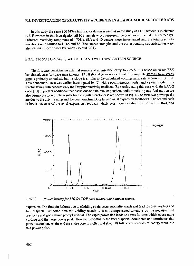
E.3. INVESTIGATION OF REACTIVITY ACCIDENTS IN A LARGE SODIUM-COOLED ADS
In this study the same 800 MWe fast reactor design is used as in the study of LOF accidents in chapterE.2. However, in this investigation all 10 channels which represent the core were irradiated for 275 days.Different reactivity ramp rates of 170$/s, 6$/s and 10 cents/s were investigated and the total reactivityinsertions were h'mited to $2.65 and $3. The source strengths and the corresponding subcriticalities werealso varied in some cases (between -3$ and -20$).
E.3.1. 170 $/S TOP CASES WITHOUT AND WITH SPALLATION SOURCE
The first case considers no external source and an insertion of up to 2.65 $. It is based on an old FZKbenchmark case for space-time kinetics [13]. It should be mentioned that this ramp rate starting from steadystate is probably unrealistic but it's slope is similar to the calculated voiding ramp rate shown in Fig. lOa.This benchmark case was earlier investigated by [9] with a point kinetics model and a point model for areactor taking into account only the Doppler reactivity feedback. By recalculating this case with the EAC-2code [10] important additional feedbacks due to axial fuel expansion, sodium voiding and fuel motion arealso being considered. The results for the regular reactor case are shown in Fig. 1. The first two power peaksare due to the driving ramp and the counteracting Doppler and axial expansion feedbacks. The second peakis lower because of the axial expansion feedback which gets more negative due to fuel melting and
20OO
POWER
00.000 0.010 0.020 0.030 0.040 0.05O
TIME
FIG. 1. Power history for 170 $/s TOP case without the neutron source.
expansion. The first pin failures due to cladding strain occur soon afterwards and lead to some voiding andfuel dispersal. At some time the voiding reactivity is not compensated anymore by the negative fuelreactivity and goes above prompt critical. The rapid power rise leads to stress failures which cause morevoiding and the large power peak. However, eventually the fuel dispersal dominates and terminates thispower excursion. At the end the entire core is molten and about 18 full power seconds of energy went intothis power pulse.
462

-8O 000
TOTREAC
REAPROG
REAVOID
READOPP
REAFUEX
REAFUMO
0 010 020 0.030 0 O40 0 050TIME
FIG. la. Reactivities causing the power history in Fig. 1.
The corresponding case with an external neutron source and a -3 $ subcricticality behaves benignly ascan be seen in Fig. 2. The case was actually run up to 92 seconds when the power was 1.27 times nominal.After 60 s a few pin meshes indicated strain failures. But no fuel ejection was predicted because EAC-2starts fuel ejection only when 25% areal melt fraction is reached and this did not happen. Most likely fission
oQ.
o L
POWER
10TIME s
15 20
FIG. 2. Power history for 170 $/s case with the spoliation source and -3 $ subcriticality.
gases will get released under these conditions. On the one hand there is some time to switch off thespallation source and on the other hand one could make the subcriticality larger.
463

oa
-2
-4
TOTREAC
REAPROG
REAVOID
READOPP
REAFUEX
REAFUMO
0 10TIME s
15 20
FIG 2a. Reactivity changes responsible for power history in Fig 2.
2000
15OO
1000
500
00 4O 0 42 0 44 0 46
TIME s0 48 0 50
POWER
FIG. 3 Power history for 6 $/s TOP case without the spoliation source.
464

oo-5
- 10
-150 4O 0 42 0 44 0 46 0 48
TIME s
— TOTREACREAPROG
- REAVOID
- READOPP
REAFUEX
- - REAFUMO
0 50
FIG. 3a Reactivities causing the power history in Fig. 3.
E.3 2. 6 $/S TOP CASES WITHOUT AND WITH SPALLATION SOURCE
The first case is without external source and the ramp is introduced up to 3 $. It should also bementioned here that this is a very unlikely ramp rate Figs 3 and 3a show only the time interval from 0.4to 0.5 s because nothing special happens before When the pins start failing and ejecting fuel, a rapidsodium voiding starts. The energy produced is about 9 full power seconds and the core is about 90%
oCL
2 0
1 8
1 6
1 4
1 2
POWER
1 O I10
TIME s15 20
FIG. 4. Power history in 6 $/s TOP case with source and -5$ subcriticality
465

-2oO
-610
TIME s15
——— TOTREAC
REAPROG
— ~ REAVOlO
— - READOPP
— REAFUEX
— - REAFUMO
20
FIG 4a Reactivities causing the power history in Fig 4
molten This large peak is still less powerful than the one shown in Fig la This is due to an earlier rapidfuel dispersal in this case and in turn due to initial failure locations that are higher up
oo_
POWER
10 20TIME s
30 40
FIG 5 Power history for JO cents/s TOP without the spoliation source
The case with external source and a -5$ subcnticality is shown in Figs 4 and 4a The case was run outto 92 s and did not show any failure although the power at 92 s was 1 37 times nominal With a
466

subcriticality of only -3$ a strain failure led to fuel ejection in one channel. This caused enough of anegative reactivity to prevent failures in the other channels.
E.3.3. 10CENT/S TOP CASE WITHOUT AND WITH EXTERNAL SOURCE
encc
oQ
-2
-4
——— TOTREAC
REAPROG
— - REAVOID
— ~ READOPP
— REAFUEX
— - REAFUMO
10 20TIME
30 40
FIG. 5a. Reactivities causing the power history in Fig. 5.
The first calculation is for a regular fast reactor and the ramp inserts up to 3$. These slower ramp ratesare considered more realistic but still of low probability. The power and reactivity histories are shown inFig. 5 and 5a. The power rise is rather uneven and this is due to the axial fuel expansion reactivity whichreflects the loss of fuel/clad contact in different channels which is modelled in the TRANSURANUS pinbehaviour code [4] which is part of EAC2. This case leads inevitably to the failure of one calculationalchannel. The negative reactivity from the fuel dispersal just prevents another failure.
The alternate case with source uses a -10 $ subriticality to avoid any failure - Figs 6 and 6a. At 92 s thepower level is about 1.3 times nominal. In another case a -$20 subcriticality was tried. This led to a powerlevel of 1.15 times nominal at 92 s. With a -3$ subcriticality a strain failure occurred at 30 s at a powerlevel of 1.65 times nominal power. With a -5$ subcriticality a strain failure occurred at 60s at 1.4 timesnominal power. This means that one still gets the failures leading later than for a critical reactor and if onewants to avoid these failures one has to go to a larger subcriticality.
E.3.4. CONCLUSIONS
For fast or medium fast reactivity ramps the ADS has a major advantage in coping with such seriousreactivity accidents. For slower ramps there is still somewhat of an advantage because pin failures willoccur later or one can avoid them with a larger subcriticality. Moreover, they can be avoided with largersubcriticalities
467

o
2 0
1 5
1 0
0 5
0 0
POWER
20 60 80 100TIME s
FIG 6 Power history in 10 cents/s TOP case with the spoliation source and -10$subcriticality
oQ
-2
-4
-6
-8
-10
——— TOTREAC
REAPROG
— - REAVOID
— - READOPP
— REAFUEX
— REAFUMO
20 60 80 100TIME s
FIG 6a Reactivities causing the power history in Fig 6
468

REFERENCES
[I] F. Lypsch, and R. N. Hill, "Development and Analysis of a Metal-fueled Accelerator-DrivenBurner", Int. Conference on Accelerator-Driven Transmutation Technologies ans Applications, LasVegas, USA, 1994.
[2] B. Pershagen, "Light Water Reactor Safety", Pergamon Press[3] D.J. Diamond, "The Control Rod Ejection Accident", Proc. of the First Technical Committee
Meeting on Reactivity Transient Accidents, IAEA, Vienna, 1987[4] C.R. Bell, "Safety Features of Subcritical Fluid Fueled Systems", International Conference on
Accelerator-Driven Transmutation Technologies ans Applications, Las Vegas, USA, 1994.[5] T.G. Theofanous, C.R. Bell, "An Assessment of CRBR Core Disruptive Accident Energetics",
Proc. of the Int. Topical Meeting on Fast Reactor Safety, Vol. 1, Knoxville, USA, 1985[6] Landeyro, ENEA, Rome, private communication[7] H. Hohmann, H. Kottowski, H. Schins and R.E. Henry, "Experimental Investigations of
Spontaneous and Triggered Vapour Explosions in the Molten Salt/Water System", Int. Meeting onThermal Nuclear Safety, Chicago, USA, 1982
[8] C. Rubbia, "A High Gain Energy Amplifier Operated with Fast Neutrons", Int. Conf. onAccelerator-Driven Transmutation Technologies and Applications, Las Vegas, USA, July 1994
[9] H. Rief and H. Takahashi, "Safety and Control of Accelerator-Driven Subcritical Systems", Int.Conf. on Accelerator-Driven Transmutation Technologies and Applications, Las Vegas, USA, July1994
[10] H. Wider et al., "The European Accident Code-2: Overview and Status", Proceedings of the 1990International Fast Reactor Safety Meeting, Snowbird, Utah, USA, Aug. 1990
[II] Lassmann K. et. al., "Analysis of CABRI Experiments Using the TRANSURANUS Code and theCoupled Codes TRANSURANUS-CAMDYN", Technical Note K 0292158, CEC Institute forTransuranium Elements, Karlsruhe, 1992
[12] H. Wider et al., "Comparative Analysis of a Hypothetical Loss-off-Flow Accident in an IrradiatedLMFBR Core Using Different Computer Models for a Common Benchmark Problem", NuclearScience and Technology, EUR 11925 EN, 1989
[13] L. Va'th et al. "Survey of the Results of a Two-Dimensional Kinetic Benchmark ProblemTypical for a Fast Reactor", Proc. Joint NEACRP/CSNI Specialist Mtg. on New Developmentsin the Three Dimensional Neutron Kinetics Benchmark Calculations, Garching, FRG, 1975
NEXTPAQE(S)l«ft BLANK
469
F. CONCLUSIONS AND RECOMMENDATIONS
ADS have the attractive potential to broaden and revitalize nuclear power. ADS address the mainconcerns and worries of the public regarding nuclear energy. There are still many questions which have tobe answered before the engineering design of ADS can become a reality but already today the followingpoints can be made:(1) ADS offer a subcritical mode of operation for nuclear power systems, and make them flexible from
the operational point of view.(2) ADS reduce the long-lived waste burden and offer the way to transmute existing nuclear reactor
waste.(3) A well designed ADS can ensure a proliferation-resistant fuel cycle and fuel treatment.(4) ADS open a promising way to utilize Thorium resources for energy production.(5) ADS offer an alternative way to utilize the existing excess of weapons-grade Plutonium for energy
production.
Economic and technical developments throughout the world should not be achieved at the expenseof the environment. In this context ADS is an attractive option which research institutes and industry shoulddevelop and offer to the international community.
The international cooperation under the auspices of international organizations could be focused on:
1 Encouraging and stimulating ADS research in the different countries, particularly in the fields of:a) Assessment of accelerators as drivers for nuclear subcritical systemsb) Transmution of nuclear wastes from commercial nuclear power plants, with special
attention to reactor grade Plutonium stocked in the wastesc) Utilization of the excess of weapons-grade Plutonium for power productiond) Introduction of the Thorium nuclear fuel cyclee) Non-proliferation / aspects of the ADS-fuel cyclef) Safety assessment of ADSg) Impact of ADS on the radiotoxicity of the fuel cycle
3 Preparing the evaluation of possible synergetic nuclear energy systems based on different scenariose.g. LWR - FBR - ADS, LWR - ADS etc.
4. Supporting international efforts to organize demonstration experiments on ADS5. Extending the nuclear data research into the reactions and energy regions of interest for ADS6. Organizing meetings for information exchange and for coordination of further international efforts.
NEXT PAQE(S) I(•ft BLANK I 471

LIST OF CONTRIBUTERS TO DRAFTING AND REVIEW
Czech Republic Miloslav HronThe Institute of Nuclear PhysicsCzech Academy of Sciences, Rez
Frantisek JanouchThe Institute of Nuclear PhysicsCzech Academy of Sciences, Rez
Mikulas KuzmiakThe Institute of Nuclear Physics of the Academy
of Sciences of the Czech Republic
Rostislav MachThe Institute of Nuclear PhysicsCzech Academy of Sciences, Rez
V. ValentaSkoda, Nuclear Machinery, Ltd.Czech Republic
France J.C. CabrillatCEA - Nuclear Reactor DirectorateCadarache
J.P. ChauvinCEA - Nuclear Reactor DirectorateCadarache
Ph. FinckCEA - Nuclear Reactor DirectorateCadarache
R. JacqminCEA - Nuclear Reactor DirectorateCadarache
M. MartiniCEA - Nuclear Reactor DirectorateCadarache
H. MouneyEDF-DE
M. SalvatoresCEA-DRN
J.P. SchapiraCNRS-IN2P3
473

I. SlessarevCEA, Cadarache
R. SouleCEA - Nuclear Reactor DirectorateCadarache
A. TchistiaakovCEA - Nuclear Reactor DirectorateCadarache
Italy S. BuonoSincrotrone TriesteTrieste
N. FietierLaboratoire du CyclotronNice
P. MandrillonLaboratoire du CyclotronNice
H.U. WiderEC JRC Ispra
Japan K. HasegawaJapan Atomic Energy Research InstituteTokai-mura, Naka-gun, Ibaraki-ken319-11 Japan
Kenji IshibashiKyushu UniversityHakozakiHigashi-ku, Fukuoka-shiFukuoka-ken 812
N. ItoJapan Atomic Energy Research InstituteTokai-mura, Naka-gun, Ibaraki-ken319-11 Japan
Hiroji KatsutaJapan Atomic Energy Research InstituteTokai-mura, Naka-gun, Ibaraki-ken319-11 Japan
Masumitsu KubotaJapan Atomic Energy Research InstituteTokai-mura, Naka-gun, Ibaraki-ken319-11 Japan
474

Mr. J. KusanoJapan Atomic Energy Research InstituteTokai-mura, Naka-gun, Ibaraki-ken319-11 Japan
Shin-ichirou MeigoJapan Atomic Energy Research InstituteTokai-mura, Naka-gun, Ibaraki-ken319-11 Japan
M. MizumotoJapan Atomic Energy Research InstituteTokai-mura, Naka-gun, Ibaraki-ken319-11 Japan
H. MurataJapan Atomic Energy Research InstituteTokai-mura, Naka-gun, Ibaraki-ken319-11 Japan
Tatsushi NakamotoKyushu UniversityHakozakiHigashi-ku, Fukuoka-shiFukuoka-ken812
N. NakamuraPower Reactor and Nuclear Fuel Development Corporation
Takahiko NishidaJapan Atomic Energy Research InstituteTokai-mura, Naka-gun, Ibaraki-ken319-11 Japan
Toru OgawaJapan Atomic Energy Research InstituteTokai-mura, Naka-gun, Ibaraki-ken319-11 Japan
H. OguriJapan Atomic Energy Research InstituteTokai-mura, Naka-gun, Ibaraki-ken319-11 Japan
Y. OkumuraJapan Atomic Energy Research InstituteTokai-mura, Naka-gun, Ibaraki-ken319-11 Japan
475

K. SakogawaJapan Atomic Energy Research InstituteTokai-mura, Naka-gun, Ibaraki-ken319-11 Japan
Toshinobu SasaJapan Atomic Energy Research InstituteTokai-mura, Naka-gun, Ibaraki-ken319-11 Japan
Yasufumi SuzukiJapan Atomic Energy Research InstituteTokai-mura, Naka-gun, Ibaraki-ken319-11 Japan
Hiroshi TakadaJapan Atomic Energy Research InstituteTokai-mura, Naka-gun, Ibaraki-ken319-11 Japan
Takakazu TakizukaJapan Atomic Energy Research InstituteTokai-mura, Naka-gun, Ibaraki-ken319-11 Japan
S. TaniPower Reactor and Nuclear Fuel Development Corporation
Russian Federation V.F. BatyaevInstitute for Theoretical and Experimental PhysicsMoscow
P.P. BlagovolinInstitute for Theoretical and Experimental PhysicsMoscow
P.V. BogdanovMNP
I. ChuvilloIPPE117259, Moscow
E.I. EfimovEDO "Hydropress"Podolsk, Moscow
V.P. EismontV.G. Khlopin Radium InstituteSt-Petersburg
476

Yu.T. GorschkovEDO "Hydropress"Podolsk, Moscow
V.D. KazaritskyInstitute for Theoretical and Experimental PhysicsMoscow
Genadji KiselevIPPE117259, Moscow
B.P. KochurovITEPMoscow
V.R. MladovInstitute for Theoretical and Experimental PhysicsMoscow
B.P. MurinMRTIMoscow
M.L. OkhlopkovInstitute for Theoretical and Experimental PhysicsMoscow
Yu. I. OrlovInstitute of Physics and Power EngineeringObninsk, Kaluga Region
V.A. ShulyndinEDO "Hydropress"Podolsk, Moscow
S.G. YavshitsV.G. Khlopin Radium InstituteSt-Petersburg
V.V. SeliverstovInstitute for Theoretical and Experimental PhysicsMoscow
Yu.N. ShubinIPPEObninsk, Kaluga Region
O.V. ShvedovITEPMoscow
477

Sweden
Switzerland
N.V. StepanovInstitute for Theoretical and Experimental PhysicsMoscow
V.I. VolkInstitute of Inorganic MaterialsMoscow
H. CondeUppsala UniversityUppsala
W. GudowskiRoyal Institute of TechnologyStockholm
C. RubbiaEuropean Organization for Nuclear ResearchCERNGeneva
J.A. RubioEuropean Organization for Nuclear ResearchCERNGeneva
F. CarminatiEuropean Organization for Nuclear ResearchCERNGeneva
J. GalvezEuropean Organization for Nuclear ResearchCERNGeneva
C. GelesEuropean Organization for Nuclear ResearchCERNGeneva
Y. KadiEuropean Organization for Nuclear ResearchCERNGeneva
R. KlapischEuropean Organization for Nuclear ResearchCernGeneva
478

J.P. RevolEuropean Organization for Nuclear ResearchCERNGeneva
Ch. RocheEuropean Organization for Nuclear ResearchCERNGeneva
USA E.D. ArthurLos Alamos National LaboratoryLos Alamos, NM 87545
C.A. BeardLos Alamos National LaboratoryLos Alamos, NM 87545
Charles D. BowmanLER-ADTTLos Alamos National LaboratoryLos Alamos, NM 87545
R.R. BrachtLos Alamos National LaboratoryLos Alamos, NM 87545
J.J. BuksaLos Alamos National LaboratoryLos Alamos, NM 87545
W. ChavezLos Alamos National LaboratoryLos Alamos, NM 87545
E.G. DeVolderLos Alamos National LaboratoryLos Alamos, NM 87545
E. HeighwayLos Alamos National LaboratoryLos Alamos, NM 87545
L. NingLER-ADTT Project OfficeLos Alamos National LaboratoryLos Alamos, NM 87545
J.J. ParkLos Alamos National LaboratoryLos Alamos, NM 87545
479

R.B. ParkerLos Alamos National LaboratoryLos Alamos, NM 87545
C. PillaiLos Alamos National LaboratoryLos Alamos, NM 87545
E. PitcherLos Alamos National LaboratoryLos Alamos, NM 87545
R.C. PotterLos Alamos National LaboratoryLos Alamos, NM 87545
R.S. ReidLos Alamos National LaboratoryLos Alamos, NM 87545
G.J. RussellLos Alamos National LaboratoryLos Alamos, NM 87545
H. TakahashiBrookhaven National LaboratoryUpton, New York 11973
D.A. TrujilloLos Alamos National LaboratoryLos Alamos, NM 87545
F. VenneriLos Alamos National LaboratoryLos Alamos, NM 87545
M.A. WilliamsonLER-ADTT Project OfficeLos Alamos National LaboratoryLos Alamos, NM 87545
S.A. WenderLos Alamos National LaboratoryLos Alamos, NM 87545
D.J. WeinachtLos Alamos National LaboratoryLos Alamos, NM 87545
W.B. WilsonLos Alamos National LaboratoryLos Alamos, NM 87545
480

K.A. WoloshunLos Alamos National LaboratoryLos Alamos, NM 87545
IAEA V. Arkhipov(Scientific Secretary)Internationa] Atomic Energy AgencyWagramerstrasse 5, A-1400, Vienna.
481
Copyright © 2022 FDOKUMEN