WASTE ISOLATION PILOT PLANT (WIPP) HAZARDOUS WASTE ...
314
DRAFT WASTE ISOLATION PILOT PLANT (WIPP) HAZARDOUS WASTE FACILITY PERMIT CLASS 3 PERMIT MODIFICATION REQUEST U.S. Department of Energy Carlsbad Area Office December 2003 031219.5 11111111111111111111111111111111111111111111111111
-
Upload
khangminh22 -
Category
Documents
-
view
0 -
download
0
Transcript of WASTE ISOLATION PILOT PLANT (WIPP) HAZARDOUS WASTE ...

DRAFT
WASTE ISOLATION PILOT PLANT (WIPP) HAZARDOUS WASTE FACILITY PERMIT
CLASS 3 PERMIT MODIFICATION REQUEST
U.S. Department of Energy Carlsbad Area Office
December 2003
031219.5
11111111111111111111111111111111111111111111111111

Section
Waste Isolation Pilot Plant DRAFT WAP Class 3 Permit Modification Request
December 2003
TABLE OF CONTENTS
Acronyms and Abbreviations . . . . . . . . . . . . . . . . . . . . . . . . . . . . . . . . . . . . . . . . . . . . . . . . . . vi
2 SECTION 1.0 - OVERVIEW OF THE PERMIT MODIFICATION REQUEST .............. 1
3
4
5
6
7
8
9
10
11
12
13
14
15
16
17
18
19
20
21
22
23
24
25 26
27
·1.0
2.0
3.0
4.0
5.0
Describe the exact change to be made to the permit conditions and supporting documents referenced by the permit [20.4.1.900 NMAC (incorporating 40 CFR §270.42(c)(i))] .................................... 3 Identify the Class of the Modification [20.4.1.900 NMAC (incorporating 40 CFR §270.42(c)(ii))] .................................... 3 Explain why the modification is needed [20.4.1.900 NMAC (incorporating 40 CFR §270.42(c)(iii))] ................................... 4
3.1 Establish DQOs and QAOs for AK, the primary method for characterizing mixed TRU waste] ............................................ 7
3.2 Eliminate HSGSA and SSA for waste confirmation and instead rely exclusively on waste examination through radiography or VE ........... 8
3.3 Eliminate VE as a QC check on radiography ........................ 9 3.4 Identify waste streams that qualify for AK confirmation on representative
subpopulations .............................................. ~I 0 3.5 Modify the method for determining material parameter weights ......... ~11 3.6 Sample and analyze the ambient air of closed rooms to monitor compliance
with the voe room-based concentration limits .................. 111 3.6.1 Results of voe Data Analysis ......................... 111 3.6.2 Closed-Room voe Monitoring ......................... 113
Provide the applicable information required by 40 CFR §270.13 through §§270.22, 270.62, 270.66 [20.4.1.900 NMAC (incorporating 40 CFR §270.42(c)(iv))] ..................................................... 15 Any person signing under paragraph a and b must certify the document in accordance with [20.4.1.900 NMAC (incorporating 40 CFR §270.11 (d)(i) and §270.30(k))] ................................................... 19
28 Module II GENERAL FACILITY CONDITIONS ................................. 11--1 29 II.A Design and Operation of Facility ................................ 11--1 30 11.B Waste Sources ............................................. 11--1 31 11.B.1 Off-site Waste ....................................... 11--1 32 11.B.2 Required Notification of Off-site Sources ................... 11--1 33 11.C General Waste Analysis ...................................... 11--1 34 11.C.1 Waste Analysis Plan .................................. 11--1 35 11.C.1.a Implementation requirements .................... 11--2 36 11.C.1.b Waste characterization sampling and analytical 37 methods .................................... 11--2 38 11.C.1.c Methods used in waste examination ............... 11--2 39 11.C.1.d Quality assurance objectives .................... 11--2 40 11.C.1.e Acceptable knowledge ......................... 11-·3 41 11.C.1.f Quality assurance ............................. 11--3 42 11.C.1.g WIPP Waste Information System (WWIS) database .. 11--3 43 11.C.2 Audit and Surveillance Progam .......................... 11--4 44 11.C.2.a Requirement to audit .......................... 11--4

2
3
4
5
6
7
8
9
10 Module IV 11
12
13
14
15
16
17
18
19
20
21
22
23
24
25
26
27
28
29
30
31
32
33
34
35
36
37
38
39
40
41
42
43
44
45
46
47
48
49
50
51
Waste Isolation Pilot Plant DRAFT WAP Class 3 Permit Modification Request
December 2003
I1.L.4 Time Allowed for Closure .............................. 11-15 I1.L.4.a Partial closure ............................... 11-15 11.L.4.b Final facility closure ........................... 11-15
I1.L.5 Disposal or Decontamination of Equipment, Structures, and Soils .............................................. 11-15
I1.L.6 Certification of Closure ............................... 11-15 I1.L.7 Survey Plat ........................................ 11-16
I1.M General Post-Closure Requirements ........................... 11-16
GEOLOGIC REPOSITORY DISPOSAL ............................. IV-1 IV.A Designated Disposal Units .................................. IV-1
IV.A.1 Underground Hazardous Waste Disposal Units ............ IV-1 IV.A.1.a Disposal containers . . . . . . . . . . . . . . . . . . . . . . . . . IV-1 IV.A.1.b Disposal locations and quantities . . . . . . . . . . . . . . . IV-1
IV.B Permitted and Prohibited Waste Certification .................... IV-2 IV.B.1 Permitted Waste .................................... IV-2
IV.B.1.a Waste analysis plan .......................... IV-2 IV.B.1.b TSDF waste acceptance criteria ................. IV-2 IV.B.1.c Hazardous waste codes . . . . . . . . . . . . . . . . . . . . . . . IV-2
IV.B.2 Prohibited Waste ................................... IV-2 IV.B.2.a General prohibition ........................... IV-2 IV.B.2.b Specific prohibition . . . . . . . . . . . . . . . . . . . . . . . . . . . IV-2
IV.C Disposal Containers . . . . . . . . . . . . . . . . . . . . . . . . . . . . . . . . . . . . . . . IV-3 IV.C.1 Accepted Disposal Containers ......................... IV-3
IV.C.1.a Standard 55-gallon (208-liter) drum . . . . . . . . . . . . . . IV-3 IV.C.1.b Standard Waste Box (SWB) ................... IV--3 IV.C.1.c Ten-Drum Overpack (TOOP) . . . . . . . . . . . . . . . . . . . IV--3 IV.C.1.d 85-gallon (322-liter) drum . . . . . . . . . . . . . . . . . . . . . IV--3 IV.C.1.e 100-gallon (379-liter) drum . . . . . . . . . . . . . . . . . . . . . IV--3
IV.D Volatile Organic Compound Limits ............................ IV--3 IV.D.1 Room-Based Limits ................................. IV--4 IV.D.2 Determination of VOC Room-Based Limes ............... IV--4 IV.D.3 voe Closed and Open Panel-Based Limits ............... IV--4 IV.D.4 Determination of VOC Closed and Open Panel-Based Limits . IV--4
IV.E Design, Construction, and Operation Requirements ............... IV--5 IV.E.1 Repository Design ................................... IV--5 IV.E.2 Repository Construction . . . . . . . . . . . . . . . . . . . . . . . . . . . . . . IV--5 IV.E.3 Repository Operation . . . . . . . . . . . . . . . . . . . . . . . . . . . . . . . . IV--6
IV.E.3.a Underground traffic flow . . . . . . . . . . . . . . . . . . . . . . . IV-6 IV.E.3.b Ventilation .................................. IV-6 IV.E.3.c Ventilation Barriers . . . . . . . . . . . . . . . . . . . . . . . . . . . IV-6
IV.F Maintenance and Monitoring Requirements ..................... IV-6 IV.F.1 Geomechanical Monitoring ............................ IV-6
IV.F.1.a Implementation of geomechanical monitoring program IV-6 IV.F.1.b Reporting requirements ........................ IV-6 IV. F .1.c Notification of adverse conditions . . . . . . . . . . . . . . . . . IV-7
IV.F.2 Air Monitoring ...................................... IV-7 IV.F.2.a Implementation of Confirmatory voe Monitoring
Plan ..................................... IV-7 IV.F.2.b Reporting Requirements for the Confirmatory voe
Monitoring Plan ............................ IV-7
iii

2
3 Supplement 1
4 Supplement 2 5
6 Supplement 3
7 Supplement 4
8 Supplement 5
SUPPLEMENTS
Waste Isolation Pilot Plant DRAFT WAP Class 3 Permit Modification Request
December 2003
An Analysis of Acceptable Knowledge Accuracy and Program Implications
Analysis of Volatile Organic Compound Levels in the Transuranic Waste Inventory
Statistical Analysis of voe
Draft Technical Evaluation Report for Room Base VOC Monitoring
Technical Evaluation Report for WIPP Room - Based VOC Monitoring
V

RFETS 2 RIDS 3 RPO 4 RTR 5 SCG 6 SOP 7 SPM 8 SWB 9 TC
10 TCLP 11 TOOP 12 TIC 13 TRAMPAC 14 TRU 15 TRUCON 16 TSDF 17 TSDF-WAC 18 TWBIR 19 VE 20 voe 21 WAC 22 WAP 23 WHB 24 WHB Unit 25 WIPP 26 WMC 27 WRES 28 WSPF 29 WWIS
Waste Isolation Pilot Plant DRAFT WAP Class 3 Permit Modification Request
December 2003
Rocky Flats Environmental Technology Site Records Inventory and Disposition Schedule relative percent difference real-time radiography Summary Category Group standard operating procedure Site Project Manager standard waste box toxicity characteristic toxicity characteristic leaching procedure ten-drum over pack tentatively identified compounds TRUPACT- II Authorized Method for Payload Control transuranic TRUPACT - 11 Content (Codes) Treatment, Storage and Disposal Facility Treatment, Storage and Disposal Facility Waste Acceptance Criteria TRU Waste Baseline Inventory Report visual examination volatile organic compound Waste Acceptance Criteria Waste Analysis Plan Waste Handling Building Waste Handling Building Container Storage Unit Waste Isolation Pilot Plant waste matrix code Washington Regulatory and Environmental Services Waste Stream Profile Form WI PP Waste Information System
vii

Waste Isolation Pilot Plant Draft W AP Class 3 Permit Modification Request
December 2003
2 Overview of the Permit Modification Request
3 This document contains a Permit Modification Request (PMR) for the Hazardous Waste Facility 4 Permit (HWFP) at the Waste Isolation Pilot Plant (WIPP), Permit Number NM4890139088-5 TSDF, hereinafter referred to as the WIPP HWFP.
6 This PMR is being submitted by the U.S. Department of Energy (DOE), Carlsbad Field Office 7 and Washington TRU Solutions LLC, collectively referred to as the Permittees, in accordance 8 with the WIPP HWFP Condition I.B.1 and 20.4.1. 900 New Mexico Administrative Code 9 (NMAC) (incorporating Title 40 Code of Federal Regulations (CFR) §270.42). This
10 modification proposes a revision to the current waste analysis plan and proposes changes to the 11 repository volatile organic compound (VOC) monitoring plan to provide for closed-room 12 monitoring. As demonstrated by the PMR and supporting documents, the requested changes 13 meet the applicable regulatory requirements and are protective of human health and the 14 environment.
15 Current Waste Analysis Plan Requirements
16 Before transuranic (TRU) waste can be shipped to WIPP, near Carlsbad, New Mexico, an 1 7 extensive series of procedures must be performed to characterize and confirm the physical and 18 chemical content of the waste. The following procedures are required to ensure that waste is 19 acceptable for storage and disposal:
20 21 • Acceptable knowledge (AK) 22 • Headspace gas sampling and analysis (HSGSA) 23 • Homogeneous solids sampling and analysis (SSA) 24 • Radiography or Visual Examination (VE) 25
26 The AK process, outlined in Attachment B4 of the HWFP, is the fundamental method for 27 characterizing TRU mixed waste. The AK process specifies requirements for assembling, 28 compiling, and confirming AK. Generator/storage sites use AK to delineate TRU mixed waste 29 into waste streams based on similar generating processes, base materials, physical form and 30 hazardous constituents. Waste streams are the basis for hazardous waste number (HWN) 31 assignment and are further grouped for disposal into Waste Matrix Codes (WMCs) related to 32 physical and chemical properties. AK is confirmed through HSGSA, SSA, radiography and VE 33 analysis. Radiography and VE are also used to verify the absence of prohibited items.
34 DOE performs two phases of waste verification and screening for waste disposed at WIPP. 35 Phase I is described in Section B-4b(l) of the HWFP and occurs prior to transporting TRU 36 mixed waste to WIPP. Phase I includes auditing and certifying generator/storage sites' 37 implementation of the AK process and waste analysis plan (WAP) requirements and review and 38 approval of the Waste Stream Profile Form and container-specific shipping information. Phase 39 II, described in Section B-4b(2) of the HWFP, includes waste shipment verification made after 40 waste arrives. For each shipment received, DOE determines the completeness and accuracy of
1

Waste Isolation Pilot Plant Draft W AP Class 3 Permit Modification Request
December 2003
1 reviews and analyses contained in Supplements 1-5. It is imperative that reviewers understand 2 the supplements in order to grasp the Section 3.0 overviews and conclusions that support this 3 PMR.
4 5 6
1.0 Describe the exact change to be made to the permit conditions and supporting documents referenced by the permit [20.4.1.900 NMAC (incorporating 40 CFR §270.42(c)(i))].
7 The exact changes to be made to the WIPP HWFP conditions and supporting information are 8 provided in modifications to Permit Modules II and IV and HWFP Attachments B, Bl, B2, B3, 9 B4, B5, B6, and N, as provided in this PMR. The exact changes to the text of the permit
10 conditions and referenced permit attachments have been identified using a double underline and 11 a revision bar in the right hand margin for added information, and a strikeout font for deleted 12 information. Supporting documents that provide additional technical justification are referenced 13 in this PMR and provided in Supplements 1 through 5.
14 Modifications are proposed to the HWFP permit conditions in Module II, General Facility 15 Conditions and Module IV, Geologic Repository Disposal. Module II is being modified to 16 eliminate AK confirmation through HSGSA and SSA and allow confirmation through 17 radiography or VE on representative subpopulations. Representative subpopulations will be 18 randomly selected from 10 percent of containers in a qualifying waste stream or waste stream lot. 19 Qualifying waste streams and lots are discussed in Section 3 .4 of this PMR. Module IV is being 20 modified to include provisions for closed-room VOC monitoring. The exact changes are 21 provided in Modules II and IV of this PMR.
22 Modifications are proposed to the W AP requirements in Attachments B - B6. The attachments 23 are being modified to eliminate requirements and language relative to HSGSA and SSA; provide 24 criteria for waste streams that qualify for confirmation on representative subpopulations; 25 describe methods for determining material parameter weights for qualified waste streams; and 26 include requirements for auditing generator and storage sites' implementation of the proposed 27 changes. The exact changes are provided in Attachments B, Bl, B2, B3, B4, B5, and B6 of this 28 PMR. Modifications are proposed to the repository VOC monitoring plan to provide for closed--29 room monitoring. The exact changes are provided in Attachment N of this PMR.
30 2.0 31
Identify the Class of the Modification [20.4.1.900 NMAC (incorporating 40 CFR §270.42(c)(ii))].
32 The following table and accompanying discussion identify the Permittees' rationale for 33 classification of this PMR as a Class 3 modification request, pursuant to 20.4.1.900 NMAC 34 (incorporating 40 CFR §270.42(c)).
3

Waste Isolation Pilot Plant Draft W AP Class 3 Permit Modification Request
December 2003
1 With the exception of the AEA and L WA, the applicable laws and regulations focus on 2 hazardous-only wastes and do not take into account the environmental, safety, and health 3 concerns associated with the management of mixed waste. The Joint Guidance, however, does 4 recognize the unique issues associated with the characterization of mixed waste and the 5 fundamental differences between managing hazardous and mixed waste. The Permittees 6 acknowledge that the Joint Guidance is exactly that, guidance, and that it can not be relied upon 7 to create any rights enforceable by any party. The Permittees also acknowledge that the Joint 8 Guidance is written for commercial low level mixed waste facilities. However, in Section I, 9 Background, of the Joint Guidance the author specifically states, "Although it is written for
10 commercial mixed waste generators, the guidance may also be useful for Federal facilities that 11 generate mixed waste." The guidance also specifically addresses testing of other types of mixed 12 waste, e.g. high-level and TRU waste in Appendix A. There are no other regulations or guidance 13 documents that speak directly to characterizing TRU mixed waste.
14 The Joint Guidance emphasizes the use of waste knowledge or AK for mixed waste 15 characterization. Waste knowledge or AK includes, where appropriate, process knowledge, 16 records of analysis performed by generators or treatment, storage and disposal facility (TSDF) 17 prior to the effective date of RCRA regulations or a combination of both supplemented with 18 chemical analysis. Waste knowledge is integral to avoiding unnecessary worker exposure and 19 eliminating redundant or unnecessary mixed waste characterization. Waste knowledge alone 20 may be used to satisfy generator and TSDF requirements for characterizing mixed waste. The 21 Joint Guidance states: "The use of waste knowledge by a generator and/or TSDF to characterize 22 mixed waste is recommended throughout this document to eliminate redundant or unnecessary 23 waste testing."
24 The Guidance Manual indicates that waste characterization requirements are intended to identify 25 and assist facilities in managing ignitable, reactive, corrosive, and toxic waste and to determine 26 compatibility. In accordance with waste characterization requirements of 20.4.500 NMAC 27 (incorporating 40 CFR 264.13(a)(l)), TSDFs are required to obtain a detailed physical and 28 chemical analysis of the waste. However, TSDFs are not required to perform a detailed physical 29 and chemical analysis of the waste. A detailed physical and chemical " ... analysis may include 30 data developed under 261 of this chapter, and existing published or documented data on the 31 hazardous waste or on hazardous waste generated from similar processes." (20.4.500 NMAC 32 (incorporating 40 CFR 264.13(a)(2)). Examples of "analysis" in 20.4.500 NMAC and "waste 33 knowledge" in the Joint Guidance appear consistent with AK as used in the HWFP, that is, 34 process knowledge, records of previous analysis or a combination of both supplemented with 35 chemical analysis. The modifications proposed in this request more closely conform TRU mixed 36 waste characterization methods to recommendations in the Joint Guidance, and are consistent 37 with the requirements in the New Mexico HWA and RCRA regulations discussed above.
38 The PMR is also based on recommendations received from the National Academy of Science 39 0\J'AS) and the New Mexico Environmental Evaluation Group (EEG), an independent WIPP 40 oversight group. These recommendations supported the Permittees' decision that the current 41 characterization and confirmation procedures require modification. The NAS concluded that 42 waste destined for disposal at WIPP should not undergo hazardous waste sampling and analysis 43 if this characterization" .. .lacked a legal or safety basis" (3). The WIPP HWFP currently 44 requires confirmation of AK using intrusive HSGSA on 100 percent of containers, SSA for
5

Waste Isolation Pilot Plant Draft W AP Class 3 Permit Modification Request
December 2003
1 2
3.1 Establish DQOs for the AK process, the fundamental method for characterizing TRU mixed waste
3 The Permittees systematically evaluated the historical record to trace the bases and concerns that 4 led to issuance of the current WIPP W AP requirements. Review showed that NMED initially 5 1:!xpressed concern about the lack of detailed chemical and physical analyses for waste streams in 6 the application. NMED indicated that HSGSA and SSA, and identification of tentatively 7 identified compounds (TICs), were necessary to accurately assign listed or characteristic HWNs, 8 comply with TSDF requirements, and demonstrate compliance with environmental performance 9 standards. NMED questioned the reliability of AK and required it be demonstrated. NMED
10 required that the entire AK process be clearly laid out and that 100 percent of waste 11 characterization results be confirmed. Confirmation included separate methods for chemical 12 characteristics (HSGSA and SSA) and physical characteristics (radiography or VE). NMED was 13 concerned that without adequate waste characterization, prohibited items and non-compatible or 14 non-authorized waste may be disposed at WIPP.
15 Based on evaluation of more than four years of operational experience and analytical results 16 from more than 40,000 disposed containers, the Permittees have demonstrated the accuracy of 17 the AK process for characterizing TRU mixed waste. Accuracy of the AK process was evaluated 18 by comparing HSGSA, SSA, radiography and VE confirmation data to hazardous waste 19 determinations based on AK. Results of the Permittees' complete evaluation of TRU mixed 20 waste characterization methods are provided in Technical Paper: An Analysis ofTRU Waste 21 Characterization Accuracy in Supplement 2 of this PMR. The accuracy of the AK process for 22 assigning waste streams, HWNs and WM Cs, and for verifying the absence of prohibited items 23 was assessed. Proper assignment of waste streams and HWNs ensured compliance with TSDF 24 requirements and that only permitted waste was sent to WIPP. Confirming the absence of 25 prohibited items, such as liquid, ignitable, reactive, corrosive, incompatible and explosive waste, 26 t::nsured safe management of waste in WIPP.
27 It is important to recognize that the technical paper evaluated the AK process and not the AK 28 information itself. AK accuracy is a measure of the process used to collect information to satisfy 29 the DQOs and whether the W AP compliant AK process is applied consistently. The requirements 30 in Attachment B4 provide the minimum acceptable content of the AK record.
31 Generator and storage sites have performed radiography or VE on more than 40,000 containers 32 of waste. Results of waste examinations were evaluated to confirm the accuracy of the AK 33 process at delineating waste streams, assigning WM Cs and verifying the absence of prohibited 34 items. The AK process proved to be more than 98 percent accurate at delineating waste streams 35 and assigning WM Cs, and more than 99 percent accurate at verifying the absence of prohibited 36 items. Assignment of a HWN due to observation of base materials, such as lead lined gloves, 37 occurred only 0.15 percent of the time. Results of confirmatory HSGSA and SSA were 38 evaluated to demonstrate the accuracy of the AK process at assigning HWNs. Analysis 39 determined that one generator site conservatively assigned toxicity HWNs based on HSGSA 40 results, absent confirmatory data from SSA. Since the assignment of codes in this manner is not 41 r,equired by the WIPP HWFP and is not consistent with RCRA HWN assignment practice, it was 42 not counted against AK accuracy. In another instance, SSA resulted in the addition of two 43 toxicity characteristic HWNs to a waste stream. In that case, the waste stream was already 44 considered to be mixed waste, containing both listed and characteristic waste. When these
7

Waste Isolation Pilot Plant Draft W AP Class 3 Permit Modification Request
December 2003
1 to safely manage waste. HSGSA and SSA data was further identified as unnecessary, in that it 2 had not identified prohibited waste or changed the manner in which waste was managed.
3 Eliminating HSGSA and SSA to confirm AK is especially appropriate for waste destined for 4 WIPP. Congress, in The Waste Isolation Pilot Plant Land Withdrawal Act (Public Law 102-5 579), exempted transuranic mixed waste designated by the Secretary of the DOE for disposal at 6 WIPP from treatment standards promulgated pursuant to section 3004(m) of the Solid Waste 7 Disposal Act (42 U.S.C. 6924(m)). Because TRU mixed waste is exempt from Land Disposal 8 Restriction standards, characterization must only be performed to identify hazardous waste and 9 assign HWNs. Waste identification and HWN assignment do not require waste to be quantified
10 at the constituent level.
11 HSGSA has also been used to demonstrate compliance with the environmental performance 12 standards established in the HWFP. The only identified path for release of hazardous constituents 13 from WIPP is through the air pathway (Compliance Certification Application for the Waste 14 Isolation Pilot Plant, Section 7.2.3.2). As a miscellaneous unit, WIPP must meet these 15 performance standards and demonstrate knowledge ofVOCs in TRU mixed waste at the 16 constituent level. In lieu HSGSA data, the Permittees evaluated the effectiveness, enforceability 17 and technical validity of demonstrating compliance with environmental performance standards 18 through V OC monitoring in the repository. Findings from the evaluation are discussed in Section 19 3 .6.2 and concluded that closed-room monitoring, in lieu of HS GSA data, was a safe and 20 effective method for tracking and monitoring VOC emissions from wastes disposed at WIPP.
21 3.3 Eliminate VE as a QC check on radiography
22 The Permittees evaluated DOE's ability to successfully perform radiography as demonstrated 23 through site miscertification rates (see Supplement 2). A miscertification occurs if a container 24 determined to meet WIPP Waste Acceptance Criteria (WAC) is subsequently discovered to 25 contain a prohibited item. This determination is made using VE of randomly selected containers 26 of waste certified as meeting the WIPP WAC. The number of containers selected each year 27 depends on the historical miscertification rate and the number of containers that will be 28 processed in a year. An initial rate of 11 percent is used until sufficient containers have been 29 processed to determine a site-specific miscertification rate. The minimum number of containers 30 used is 50. Evaluation of current Department of Energy (DOE) site miscertification rates 31 revealed rates generally at one percent, the minimum rate allowed by the HWFP. These low 32 miscertification rates indicate the absence of systemic or pervasive issues with the quality of 33 radiography being performed (see Supplement 2).
34 This PMR would eliminate VE as a QC check on radiography. Generators and storage sites 35 already perform a replicate radiography container scan and independent observation of an 36 additional radiography tape daily. The Permittees review at least one percent of the radiography 37 tapes for all waste received at WIPP. In addition, the low miscertification rates demonstrate 38 DOE's ability to accurately perform radiography (see Supplement 2). Existing controls (e.g., 39 replicate scans, independent observations, and Permittees' review) make the practice of 40 confinning radiography through VE redundant and this PMR proposes its elimination.
41
9

Waste Isolation Pilot Plant Draft W AP Class 3 Permit Modification Request
December 2003
1 'Waste streams that do not qualify for representative sampling, or those discovered to contain 2 prohibited items during examination, will be subject to confirmation on 100 percent of 3 containers. Sampling 10 percent of a waste stream, or waste stream lot, is consistent with ReRA.-4 industry standards for verification.
5 3.5 Modify the method for determining material parameter weights
6 Radiography or VE are used to verify waste matrix code and waste streams description and 7 estimate material parameter weights. Material parameter weight values are entered in the WWIS 8 for inventory tracking purposes. This PMR proposes to modify the method for determining 9 material parameter weights on waste streams that qualify for confirmation on representative
10 subpopulations.
11 For qualifying waste streams, material parameter weights for waste materials in each container of 12 the representative subpopulation (from the waste stream or waste stream lot) will be identified 13 and summed. These summed values will be divided by the gross weight of waste and packaging 14 materials in the subpopulation to obtain waste material parameter fractions for the waste stream 15 or waste stream lot. These waste material parameter fractions will be applied to the remainder of 16 the waste stream or waste stream lot for purposes of reporting waste material parameter values to 17 WWIS.
18 3.6 19
Sample and analyze the ambient air of closed rooms to monitor compliance with the voe room-based emission limits
20 The Permittees evaluated all available voe data obtained through May 2003 to reevaluate 21 assumptions regarding voe concentrations in the WIPP ReRA Part B Permit Application 22 (Permit Application) (1). Results of the Permittees' evaluation are provided in Analysis of the 23 Volatile Organic Compound Levels in the Transuranic Waste Inventory in Supplement 3 of the 24 PMR. The Permittees also performed a statistical analysis of the inventory ofVOes in TRU 25 waste disposed at WIPP as compared to predicted voe concentration in the Permit Application. 26 Results of the comparison are provided in Statistical Analysis of Volatile Organic Compound 27 Levels in Transuranic Waste in Supplement 4 of this PMR. Based on the Permittees' 28 demonstrations (in the Supplements) that the assumptions made in the Permit Application related 29 to voe concentrations remained valid and conservative, the Permittees evaluated alternatives to 30 HSGSA data for monitoring compliance with voe room-based emission limits.
31 3 .6.1 Results of VOe Data Analysis
32 In 1995, the Idaho National Engineering and Environmental Laboratory (INEEL) performed an 33 assessment of voe concentrations in TRU waste. The INEEL analysis was conducted on a 930-34 drum set of TRU waste originating from INEEL and Rocky Flats Environmental Technology 35 Site (RFETS). The analysis resulted in weighted-average values for each of 28 voes in final 36 waste forms (FWFs). These values were used to evaluate complex-wide voe concentrations in 37 e:ach FWF.
38 New analysis was conducted associated with this PMR using all available voe data including 39 the original 930-drum set, WIPP Waste Information System (WWIS) voe headspace-gas (HSG) 40 data from March 1999 to May 2003, data from an International Technology (IT) voe study for 41 Westinghouse TRU Solutions on 2,366 drums of waste from RFETS, and a study on flammable
11

Waste Isolation Pilot Plant Draft W AP Class 3 Permit Modification Request
December 2003
1 continues to act in a conservative manner regarding representativeness of VOCs in waste to be 2 disposed at WIPP.
3 Because certain VOC concentrations in TRU waste already emplaced in the repository differed 4 from concentrations in the 930-drum data set, the Permittees reanalyzed risks from VOCs 5 disposed in WIPP. Risks were reanalyzed to confirm that constituents currently monitored in the 6 VOC confirmatory monitoring program were still appropriate (see Supplement 4). Results were 7 fairly similar in the carcinogen category, where six of the seven existing VOCs were determined 8 to contribute 99 percent ofrisk. For non-carcinogens, (cis)-1,2-dichloroethylene and methyl 9 ethyl ketone were determined, in addition to currently monitored constituents, to contribute 99
10 percent of risk. While the two analytes ( cis )-1,2-dichloroethy lene and MEK were identified as 11 contributing to 99% of the risk this was not due to an increase in the prevalence of these two 12 analytes. It was because, in the revisited VOC source term study, the concentrations of ( cis )-1,2-13 dichloroethylene and MEK did not change while other VOC concentrations were significantly 14 reduced in relation to the 1995 VOC source term. Should ( cis )-1,2-dichloroethylene and MEK 15 (or any other VOC for that matter) be identified as prevalent compounds through the 16 identification of TI Cs in the confirmatory VOC monitoring samples, WIPP would calculate 17 Room Based Limits and concentrations of concern and propose adding the analytes to the list of 18 target analytes.
19 Conclusions from the reevaluation and statistical analysis of VOC concentrations in the TRU 20 waste inventory may be summarized as follows:
21 1. Analysis of data from characterizing more than 40,000 containers of waste did not 22 result in significant changes to the predicted VOC source term for the WIPP.
23 2. The original predicted VOC source term is conservative and is likely overestimated.
24 3. Even assuming that the available VOC data are representative of the solidified 25 organics FWF (a conservative assumption), the inventory of solidified organics is not 26 sufficient, and the likelihood of nearly 7600 RFTES-equivalent drums being co-27 disposed so remote, that the environmental performance standards are not reasonably 28 threatened.
29 Based on these determinations the Permittees have concluded that assurance of compliance with 30 the environmental performance standards including VOC Room-Based emission limits can be 31 attained through repository VOC monitoring without reliance on HSGSA data.
32 3.6.2 Closed-Room VOC Monitoring
33 In evaluating WIPP's RCRA Permit Application in 1999, NMED evaluated four general VOC 34 exposure scenarios from WIPP and established environmental performance standards. Exposure 35 scenarios included:
36 • Resident living at WIPP site boundary, chronic exposure to VOCs,
37 • WIPP non-waste surface worker, chronic exposure to VOCs,
13

Waste Isolation Pilot Plant Draft W AP Class 3 Permit Modification Request
December 2003
1 In the event that VOC concentrations begin to accumulate to levels of concern, remedial actions 2 will be taken. The VOC levels and remedial actions are presented in the proposed modifications 3 to Permit Module IV and Attachment N.
4 NMED was also concerned about formation of an Immediately Dangerous to Life and Health 5 (IDLH) atmosphere in the event of a roof fall in an open room. This scenario assumed that an 6 underground waste worker who is upwind of the waste stack would be exposed to the VOCs 7 from 21 drums which, in response to a roof fall, would fall from the top row and breach. NMED 8 considered that such an event may create an IDLH concentration of VOCs in the breathing zone 9 of a worker in the active room. As explained in NMED's testimony, the location of such an
10 occurrence is at the emplacement face of the open room. Compliance with existing Mine Safety 11 Health Administration (MSHA) regulations would ensure workers would not enter areas with an 12 active roof fall. The TER proposes using active operational controls, e.g., WIPP procedures 13 which incorporate MSHA requirements to ensure worker protection from the open-room fall 14 scenario. WIPP procedures require that ground conditions be examined or inspected at the start 15 of every shift, and as conditions warrant, to ensure that the workplace is safe. For the protection 16 of the worker, personnel are not allowed access to the exhaust drift without approval from 17 Underground Services. Should an unsafe condition be found, work is stopped, Underground 18 Services is notified, and personnel are not allowed to work in the area until any hazards are 19 mitigated. Per current WIPP procedure, the event triggers evacuation of all personnel from the 20 emplacement face. Current ALARA procedures require personnel to remain away from the 21 emplacement face when not otherwise required by job tasks, thus ensuring that workers will be 22 capable of providing an alarm should drums topple. In such an event, the Central Monitoring 23 Room (CMR) would be notified and the CMR Operator would issue an evacuation alarm for all 24 areas downwind of the active room (the exhaust drift). The VOCs resulting from a roof fall in an 25 open room would be quickly dissipated by ventilation.
26 4.0 27
Provide the applicable information required by 40 CFR §§270.13 through 270.22, 270.62, 270.63, and 270.66 (20.4.1.900 NMAC incorporating 40 CFR §270.42(c)(iv)]
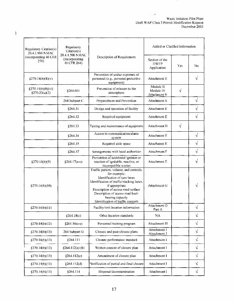
28 The regulatory crosswalk describes those portions of the WIPP HWFP that have been modified 29 by this PMR to provide the information required by 40 CFR §§ 270.13 through 270.22. Where 30 applicable, regulatory citations in this modification reference Title 20, Chapter 4, Part 1, NMAC, 31 revised October 1, 2003, incorporating the CFR, Title 40 ( 40 CFR Parts 264 and 270). Title 40 32 CFR §§270.16 through 270.22, 270.62, 270.63, and 270.66 are not applicable at WIPP. 33 Consequently, they are not listed in the regulatory crosswalk table. Title 40 CFR §270.33 is 34 applicable to the WIPP Hazardous Waste Disposal Units (HWDUs).
15
1
Regulatory Regulatory Citation(s)
Citation(s) 20.4. 1.900 NMAC
(incorporating 40 CFR 20.4.1.500 NMAC
(incorporating 270)
40 CFR 264)
§270.14(b)(8)(v)
§270.14(b)(8)(vi) §264.601
§270.23(a)(2)
264 Subpart C
§264.31
§264.32
§264.33
§264.34
§264.35
§264.37
§270.14(b)(9) §264. I 7(a-c)
§270. l 4(b )( I 0)
§270.14(b)(I I)
§264. I 8(c)
§270.14(b)( 12) §264.16(a-e)
§270.14(b)(l3) 264 Subpart G
§270. I 4(b )( 13) §264.111
§270.14(b)(l3) §264. l 12(a) (b)
§270.14(b)( 13) §264.112(c)
§270.14(b)(l3) §264. I 12(d)
§270. I 4(b )( 13) §264.114
Waste Isolation Pilot Plant Draft W AP Class 3 Permit Modification Request
December 2003
Added or Clarified Information
Description of Requirement Section of the
HWFP Application
Yes No
Prevention of undue exposure of ✓ personnel ( e.g., personal protective Attachment E
equipment)
Prevention of releases to the Module II Module IV ✓ atmosphere
Attachment N
Preparedness and Prevention Attachment E ✓
Design and operation of facility Attachment E ✓
Required equipment Attachment E ✓
Testing and maintenance of equipment Attachment D ✓
Access to communication/alarm Attachment E ✓ system
Required aisle space Attachment E ✓
Arrangements with local authorities Attachment F ✓ Prevention of accidental ignition or
✓ reaction of ignitable, reactive, or Attachment E incompatible wastes
Traffic pattern, volume, and controls, for example:
Identification of turn lanes Identification of traffic/stacking lanes,
✓ if appropriate Attachment G Description of access road surface Description of access road load-
bearing capacity Identification of traffic controls
Facility/unit location information Attachment 0 ✓ Part A
Other location standards NA ✓
Personnel training program Attachment H ✓
Closure and post-closure plans Attachment I ✓ Attachment J
Closure performance standard Attachment I ✓
Written content of closure plan Attachment I ✓
Amendment of closure plan Attachment I ✓
Notification of partial and final closure Attachment I ✓
Disposal/decontamination Attachment I ✓
17

1
2 3 4
Regulatory Citation(s) Regulatory Citation( s)
20.4.1.900 NMAC 20.4.1.500 NMAC
(incorporating 40 CFR ( incorporating
270) 40 CFR 264)
§264.172
§264.173
§264.174
§270. l 5(a) §264.175
§270.15(c) §264.176
§270.15(d) §264.177
§264.178
§270.15(e) §264.179
§270.23 264 Subpart X
§270.23(a) §264.601
§270.23(c) §264.601
§270.23( d)
§264.602
§264.603
§264 Subpart E
Waste Isolation Pilot Plant Draft W AP Class 3 Permit Modification Request
December 2003
Added or Clarified Information
Description of Requirement
Section of the HWFP Application Yes No
Compatibility of waste with containers Attachment MI ✓
Management of containers Attachment MI ✓
Inspections Attachment D ✓ Attachment MI
Containment systems Attachment Ml ✓ Addendum MIR
Special requirements for ignitable or Attachment E ✓ reactive waste Permit Module II Special requirements for incompatible Attachment E ✓ wastes Permit Module II
Closure Attachment I ✓ Attachment E
Air emission standards Attachment N ✓ Attachment Q
Miscellaneous units Attachment M2 ✓ Attachment M2R
Detailed unit description Attachment M2 ✓ Permit Module IV
Potential exposure pathways Attachment M2 ✓ Attachment N
Demonstration of treatment Permit Module IV Attachment M2 ✓ effectiveness Attachment N
Monitoring. analysis. inspection. Permit Module IV response, reporting, and corrective Attachment M2 ✓
action Attachment N
Post-closure care Attachment J ✓ Attachment JI
Permit Module I
Manifest system, record keeping, and Permit Module II Permit Module IV ✓ reporting
Attachment B Attachment R
5.0 Any person signing under paragraph a and b must accordance with 20.4.1.900 NMAC 20.4.1.900 NMAC §270.ll(d)(l) and 40 CFR §270.30(k)).
certify the document in (incorporating 40 CFR
5 The transmittal letter for this PMR contains the signed certification statement in accordance with 6 Permit Condition I.F of the WIPP HWFP.
19

1 II .A.
Waste Isolation Pilot Plant Draft WAP Class 3 Permit Modification Request
December 2003
II. MODULE II - GENERAL FACILITY CONDITIONS
DESIGN AND OPERATION OF FACILITY
2 The Permittees shall design, construct, maintain, and operate WIPF 3 to minimize the possibility of a fire, explosion, or any unplanned 4 sudden or non-sudden release of transuranic (TRU) mixed waste or 5 mixed waste constituents to air, soil, groundwater, or surface 6 water which could threaten human health or the environment, as 7 required by 20.4.1.500 NMAC (incorporating 40 CFR §264.31).
8
9
10 11 12 13 14 15 16 17 18
19
20 21 22 23 24 25 26 27
28
29
30 31 32 33
34 35
DRAFT
II.B.
II .C.
WASTE SOURCES
II.B.1. Off-site Wastes
The Permittees may receive off-site TRU mixed waste in compliance with the requirements and conditions specified in this Permit. The Permittees may only receive TRU mixed waste from those sites which comply with the applicable requirements of the Waste Analysis Plan (WAP) specified in Permit Condition II.C.l and Permit Attachment B, as required by 20.4.1.500 NMAC (incorporating 40 CFR 264.13(a)) and as verified through the Permittees' Audit and Surveillance Program specified in Permit Condition II.C.2.
II.B.2. Required Notification to Off-Site Sources
Before the Permittees receive TRU mixed waste from an off-site source for the first time, they shall inform the generator/storage site in writing that they have the appropriate Permits for, and will accept, the waste the generator/storage site is shipping. The Permittees shall keep a copy of this written notice as part of the operating record, as required by 20.4.1.500 NMAC (incorporating 40 CFR §264.12(b)).
GENERAL WASTE ANALYSIS
II.C.1. Waste Analysis Plan
The Permittees shall not manage, store, or dispose TRU mixed waste at WIPP which fails to meet the characterization requirements of 20.4.1.500 NMAC (incorporating 40 CFR §264.13), as specified by this Permit.
The Permittees' WAP, as specified in Permit Attachment B, is approved subject to the following conditions:
PERMIT MODULE II Page II-1

1 2 3 4 5 6 7 8 9
10 11 12 13
14 15 16 17 18 19 20 21 22 23
24 25 26 27 28 29 30 31 32
33 34 35 36 37 38 39 40 41 42 43 44 45
DRAFT
Waste Isolation Pilot Plant Draft WAP Class 3 Permit Modification Request
December 2003
objectives (QAOs) specified in Permit Attachment B3 (Quality Assurance Objectives and Data Validation Techniques for Waste Characterization San~ling and Analytical Testing Methods). The Permittees shall require generator/storage sites to review, validate, and verify all analytical data; reconcile analytical results with data quality objectives (DQOs); satisfy data reporting requirements; and identify, document, and report all nonconformances and operational variances in compliance with Permit Attachment B3.
II.C.1.e. Acceptable knowledge - the Permittees shall require generator/storage sites to assemble acceptable knowledge documentation and confirm acceptable knowledge determinations, and shall audit (as specified in Permit Condition II.C.2) all aspects of the acceptable knowledge waste characterization process as specified in Permit Attachment B4 (TRU Mixed Waste Characterization Using Acceptable Knowledge).
II.C.l.f. Quality assurance - the Permittees shall require each generator/storage site to develop and implement a quality assurance project plan (QAPjP) which demonstrates compliance with, and implementation of, applicable requirements of the WAP, Permit Attachment B, as specified in Permit Attachment BS (Quality Assurance Project Plan Requirements).
II.C.1.g. WIPP Waste Information System (WWIS) database - the Permittees shall provide the Secretary access to the WWIS database as necessary to determine compliance with the WAP. The WWIS shall meet all requirements presented in Section B-4b(l) (i) of the WAP, Permit Attachment B, prior to acceptance of TRU mixed waste. The Secretary's access to the WWIS shall be direct, read-only (via modem or Internet) to all query and reporting functions of the Characterization, Certification, Shipping, and Inventory modules of the WWIS database.
Effective September 11, 2003
PERMIT MODULE II Page II-3
1 2 3 4 5
6 7 8 9
10
11 12 13 14 15 16 17 18 19 20 21
22 23 24
25 26 27 28
29 30 31 32 33
34 35 36
37 38 39 40
41 42 43
DRAFT
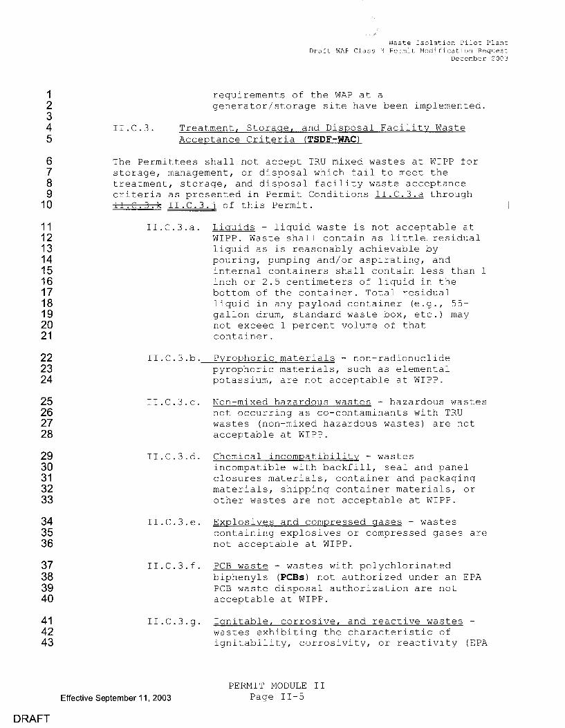
II.C.3.
Waste Isolation Pilot Plant Draft WAP Class 3 Permit Modification Request
December 2003
requirements of the WAP at a generator/storage site have been implemented.
Treatment, Storage, and Disposal Facility Waste Acceptance Criteria (TSDF-WAC)
The Permittees shall not accept TRU mixed wastes at WIPP for storage, management, or disposal which fail to meet the treatment, storage, and disposal facility waste acceptance criteria as presented in Permit Conditions II.C.3.a through II.C.3.k II.C.3.j of this Permit.
II.C.3.a. Liquids - liquid waste is not acceptable at WIPP. Waste shall contain as little residual liquid as is reasonably achievable by pouring, pumping and/or aspirating, and internal containers shall contain less than 1 inch or 2.5 centimeters of liquid in the bottom of the container. Total residual liquid in any payload container (e.g., 55-gallon drum, standard waste box, etc.) may not exceed 1 percent volume of that container.
II.C.3.b. Pyrophoric materials - non-radionuclide pyrophoric materials, such as elemental potassium, are not acceptable at WIPP.
II.C.3.c. Non-mixed hazardous wastes - hazardous wastes not occurring as co-contaminants with TRU wastes (non-mixed hazardous wastes) are not acceptable at WIPP.
II.C.3.d. Chemical incompatibility - wastes incompatible with backfill, seal and panel closures materials, container and packaging materials, shipping container materials, or other wastes are not acceptable at WIPP.
II.C.3.e. Explosives and compressed gases - wastes containing explosives or compressed gases are not acceptable at WIPP.
II.C.3.f. PCB waste - wastes with polychlorinated biphenyls (PCBs) not authorized under an EPA PCB waste disposal authorization are not acceptable at WIPP.
II.C.3.g. Ignitable, corrosive, and reactive wastes -wastes exhibiting the characteristic of ignitability, corrosivity, or reactivity (EPA
Effective September 11, 2003
PERMIT MODULE II Page II-5

1
2
3
4
5
6
DRAFT
EPA Hazardous Waste Code
F002
F003
F004
FOOS
F006
F007
Waste Isolation Pilot Plant Draft WAP Class 3 Permit Modification Request
December 2003
Table II.C.4 - Permitted TRU Mixed Wastes
Chemical Abstract
Hazardous Waste 1 Number
s12ent halogenated solvents: Tetrachloroethylene 127-18-4 Methylene chloride 75-09-2 Trichloroethylene 79-01-6 1,1,1-Trichloroethane 71-55-6 Chlorobenzene 108-90-7 1,1,2-Trichloro-1,2,2- 76-13-1
trifluoroethane 95-50-1 Ortho-dichlorobenzene 75-69-4 Trichlorofluoromethane 79-00-5 1,1,2-Trichloroethane
Sf:ent non-halogenated solvents: Xylene 1330-20-7 Acetone 67-64-1 Ethyl acetate 141-78-6 Ethyl benzene 100-41-4 Ethyl ether 60-29-7 Methyl isobutyl ketone 108-10-1 n-Butyl alcohol 71-36-3 Cyclohexanone 108-94-1 Methanol 67-56-1
s12ent non-halogenated solvents: Cresols and cresylic acid 1319-77-3 Nitrobenzene 98-95-3
s12ent non-halogenated solvents: Toluene 108-88-3 Methyl ethyl ketone 78-93-3 Carbon disulfide 75-15-0 Isobutanol 78-83-1 Pyridine 110-86-1 Benzene 71-43-2 2-Ethoxyethanol 110-80-5 2-Nitropropane 79-46-9
Wastewater treatment sludges from electro12lating 012erations:
Cadmium 7440-43-9 Chromium 7440-47-3 Cyanide 57-12-5 Lead 7439-92-1 Nickel 7440-02-0 Silver 7440-22-4
s12ent cyanide 12lating bath solutions from electro12lating 012erations:
See F006
Effective September 11, 2003
PERMIT MODULE II Page II-7

1 2 3 4 5 6 7 8 9
10 11 12 13 14 15 16 17 18 19 20 21 22 23 24 25 26 27 28
DRAFT
Table II.C.4 -
EPA
Waste Isolation Pilot Plant Draft WAP Class 3 Permit Modification Request
Decembe~ 2003
Permitted TRU Mixed Wastes
Chemical Hazardous Abstract Waste Code Hazardous Waste 1 Number
Pl20
U002
U003
U019
U037
U043
U044
U052
U070
U072
U078
U079
Ul03
Ul05
Ul08
Ul22
Ul33
Ul34
Ul51
Ul54
Ul59
Ul96
U209
U210
U220
U2 6
U228
U239
Vanadium Pentoxide (H) 1314-62-1
Acetone (I) 67-64-1
Acetonitrile (I, T) 75-05-8 Benzene (I, T) 71-43-2
Chlorobenzene (T) 108-90-7 Vinyl Chloride (T) 75-01-4 Chloroform (T) 67-66-3
Cresol (T) 1319-77-3 1,2-Dichlorobenzene (T) 95-50-1 1,4-Dichlorobenzene (T) 106-46-7
1,1-Dichloroethylene (T) 75-35-4
1,2-Dichloroethylene (T) 156-60-5 Dimethyl Sulfate (T) 77-78-1
2,4-Dinitrotoluene (T) 121-14-2
1,4-Dioxane (T) 123-91-1 Formaldehyde (T) 50-00-0
Hydrazine (R, T) 302-01-2 Hydrofluoric Acid (C, T) 7664-39-3 Mercury (T) 7439-97-6 Methanol ( I) 67-56-1
Methyl Ethyl Ketone ( I, T) 78-93-3
Pyridine (T) 110-86-1 1,1,2,2-Tetrachloroethane (T) 79-34-5
Tetrachloroethylene (T) 127-18-4
Toluene (T) 108-88-3
1,1,1-Trichloroethane (T) 71-55-6 Trichloroethylene (T) 79-01-6
Xylene (I, T) 1330-20-7 ' Designations in parentheses for P- and U-coded wastes reflect the basis for the listing and are as follows:
H - acute toxicity T - toxicity R - reactivity I - ignitability C - corrosivity
Acceptance of U-coded wastes listed for reactivity, ignitability, or corrosivity characteristics is contingent upon a demonstration that the wastes meet the requirements specified in Permit Condition II.C.3.g.
Effective September 11, 2003
PERMIT MODULE II Page II-9

1
2 3 4
5
6 7 8 9
10 II. F.
Waste Isolation Pilot Plant Draft WAP Class 3 Permit Modification Request
Decembe, 2003
II.E.4. Inspection Remediation
The Permittees shall remedy any deterioration or malfunction of equipment or structures which an inspection reveals, as required by 20.4.1.500 NMAC (incorporating 40 CFR §264.15(c)).
II .E. 5. Inspection Records
The Permittees shall maintain inspection logbooks and forms in the operating record for at least three (3) years from the date of inspection, as required by 20.4.1.500 NMAC (incorporating 40 CFR §§264 .15 (d) and 264. 73 (b) (5)).
PERSONNEL TRAINING
11 The Permittees shall conduct personnel training, as required by 12 20.4.1.500 NMAC (incorporating 40 CFR §264.16).
13
14 15 16 17 18
19
20 21 22 23 24 25 26 27
28 29 30
31 32
II.G.
II.F.1. Personnel Training Content
The personnel training program shall include the requirements specified in Permit Attachment H (Personnel Training) and Permit Attachment H2 (Training Course and Qualification/Certification Card Outlines), as required by 20.4.1.500 NMAC (incorporating 40 CFR §264.16)
II.F.2. Personnel Training Requirements
The Permittees shall train all persons involved in the management of mixed and hazardous waste in procedures relevant to the positions in which they are employed, as specified in Permit Attachment Hl (RCRA Hazardous Waste Management Job Titles and Descriptions), and as required by 20.4.1.500 NMAC (incorporating 40 CFR §264.16).
II.F.3. Personnel Training Records
The Permittees shall maintain training documents and records, as required by 20.4.1.500 NMAC (incorporating 40 CFR §264.16(d) and (e)).
GENERAL REQUIREMENTS FOR HANDLING IGNITABLE, CORROSIVE, REACTIVE, OR INCOMPATIBLE WASTES
33 The Permittees shall not manage, store or dispose ignitable, 34 corrosive, reactive, or incompatible wastes, as defined in 35 20.4.1.200 NMAC (incorporating 40 CFR §§261.21, 261.22, and 261.23) 36 and 20.4.1.500 NMAC (incorporating 40 CFR §264 Appendix V) within 37 the permitted units. The Permittees shall comply with the 38 p~ocedures to prevent acceptance of ignitable, corrosive, reactive, 39 and incompatible waste specified in Permit Conditions II.C.l and 40 II. C. 3.
Effective September 11, 2003
DRAFT
PERMIT MODULE II Page II-11

1 2 3 4 5 6 7 8 9
10 11
12
13
14 15 16 17 18 19
20
21 22 23 24 25 26 27 28 29 30 31 32 33 34
35
36 37 38
39
40 41 42
DRAFT
II. I.
Waste Isolation Pilot Plant Draft WAP Class 3 Permit Modification Request
Decembe:c 2003
II.H.5.b. Coordination agreements - as specified in Section F-6 of Permit Attachment F, these arrangements shall be either Memoranda of Understanding (MOU) or Mutual Aid Agreements (MAA) between the Permittees and the off-site cooperating agencies, and shall include the elements required by 20.4.1.500 NMAC (incorporating 40 CFR §264.37(a)). Copies and descriptions of these MOUs and agreements shall be maintained at the facility in the operating record.
CONTINGENCY PLAN
II.I.1. Implementation of Plan
The Permittees shall immediately implement the Contingency Plan as specified in Permit Attachment F whenever there is a fire, explosion, or release of mixed or hazardous waste or hazardous waste constituents which could threaten human health or the environment, as required by 20.4.1.500 NMAC (incorporating 40 CFR §264.51(b)).
II.I.2. Copies of Plan
The Permittees shall maintain copies of the Contingency Plan and all revisions and amendments to the Contingency Plan as required by 20.4.1.500 NMAC (incorporating 40 CFR §264.53). The Permittees shall provide copies of the current Contingency Plan and all revisions to the Contingency Plan through an electronic controlled document distribution system or in appropriate controlled-document locations at the facility, and to the Secretary and all entities with which the Permittees have emergency MOUs or MAAs, as required by 20.4.1.500 NMAC (incorporating 40 CFR §264.53(b)). The Permittees shall maintain at least one current controlled-document paper copy of the Contingency Plan at the facility in a location readily accessible to the Emergency Coordinator specified in Permit Condition II.I.4.
II.I.3. Amendments to Plan
The Permittees shall review and immediately amend, if necessary, the Contingency Plan, as required by 20.4.1.500 NMAC (incorporating 40 CFR §264.54)
II.I.4. Emergency Coordinator
An Emergency Coordinator as specified in Table F-2 of Permit Attachment F shall be available at all times in case of an emergency. The Emergency Coordinator shall be thoroughly
Effective September 11, 2003
PERMIT MODULE II Page II-13

1
2 3 4 5 6 7
8
9 10 11 12 13 14 15
16 17 18 19 20 21 22 23 24 25
26 27
28 29 30 31
32
33 34 35 36 37 38 39
DRAFT
II.L.3.
Waste Isolation Pilot Plant Draft WAP Class 3 Permit Modification Request
Decembec 2003
Notification of Closure
The Permittees shall notify the Secretary in writing at least sixty (60) calendar days prior to the date on which they expect to begin partial closure, i.e., closure of an Underground Hazardous Waste Disposal Unit (Underground HWDU), or final closure of the facility as required by 20.4.1.500 NMAC (incorporating 40 CFR §§264.112(d) and 264.601).
II.L.4. Time Allowed For Closure
II.L.4.a. Partial closure - Upon completion of disposal operations in an Underground HWDU, the Permittees shall complete partial closure activities as specified in the Closure Plan, Permit Attachment I, as required by 20.4.1.500 NMAC (incorporating 40 CFR §264.113).
II.L.4.b. Final facility closure - After receiving the final volume of TRU mixed waste, the Permittees shall remove from the facility all non-mixed hazardous waste, dispose in the Underground HWDUs all TRU-mixed hazardous waste and derived waste, and shall complete closure activities as specified in the Closure Plan, Permit Attachment I, and as required by 20.4.1.500 NMAC (incorporating 40 CFR §264 .113).
II.L.5. Disposal or Decontamination of Equipment, Structures, and Soils
The Permittees shall decontaminate or dispose of all contaminated equipment, structures, and soils, as specified in
the Closure Plan, Permit Attachment I, and as required by 20.4.1.500 NMAC (incorporating 40 CFR §264.114).
II .L. 6. Certification of Closure
Within sixty (60) calendar days of completion of closure of each Underground HWDU, and within sixty (60) calendar days of completion of final closure, the Permittees shall certify in writing to the Secretary that the Underground HWDUs and/or facility have been closed as specified in the Closure Plan, Permit Attachment I, and as required by 20.4.1.500 NMAC (incorporating 40 CFR §§264.115 and 264.601).
Effective September 11, 2003
PERMIT MODULE II Page II-15

1
Waste Isolation Pilot Plant Draft WAP Class 3 Permit Modification R,2quest
December 2003
PERMIT ATTACHMENTS
2 Permit Attachment B (as modified from WIPP RCRA Part B Permit 3 Application, "Waste Analysis Plan" - Chapter C) .
4 Permit Attachment Bl (as modified from WIPP RCRA Part B Permit 5 Application, "Waste Characterization Sampling Methods" - Appendix C4) ..
6 Permit Attachment B2 (as modified from WIPP RCRA Part B Permit 7 Application, "Statistical Methods Used in Sampling and Analysis" -8 Appendix C6).
9 Permit Attachment B3 (as modified from WIPP RCRA Part B Permit 10 Application, "Quality Assurance Objectives and Data Validation 11 Techniques for Waste Characterization Sampling and Analytical Methods'' 12 - Appendix CB).
13 Permit Attachment B4 (as modified from WIPP RCRA Part B Permit 14 11.pplication, "TRU Waste Characterization Using Acceptable Knowledge" -· 15 11.ppendix C9).
16 Permit Attachment BS (as modified from WIPP RCRA Part B Permit 17 Application, "Quality Assurance Project Plan Requirements'' - Appendix 18 ClO).
19 Permit Attachment B6 (as modified from WIPP RCRA Part B Permit 20 Application, ''Waste Isolation Pilot Plant Generator/Storage Site Waste 21 Screening and Acceptance Audit Program" - Appendix Cll).
22 Permit Attachment C (as modified from WIPP RCRA Part B Permit 23 Application, "Procedures to Prevent Hazards" - Chapter F).
24 Permit Attachment D (as modified from WIPP RCRA Part B Permit 25 Application, "Procedures to Prevent Hazards" - Chapter F).
26 Permit Attachment E (as modified from WIPP RCRA Part B Permit 27 11.pplication, "Procedures to Prevent Hazards" - Chapter F) .
28 Permit Attachment F (as modified from WIPP RCRA Part B Permit 29 Application, "RCRA Contingency Plan" - Chapter G).
30 Permit Attachment H (as modified from WIPP RCRA Part B Permit 31 Application, "Personnel Training" - Chapter H).
32 Permit Attachment Hl (as modified from WIPP RCRA Part B Permit 33 Application, "List of Hazardous Waste Management Job Titles" -34 J\.ppendix Hl, and "Waste Isolation Pilot Plant RCRA Hazardous Waste 35 Management Functional Job Descriptions" - Appendix H2).
36 Permit Attachment H2 (as modified from WIPP RCRA Part B Permit 37 Application, "Training Course and Qualification/Certification Card 38 Outlines" - Appendix H3).
Effective September 11, 2003
DRAFT
PERMIT MODULE II Page II-17

1
2 IV .A.
waste Isolation Pilot Plant DRAFT WAP Class 3 Permit Modification Request
December 2003
IV. MODULE IV - GEOLOGIC REPOSITORY DISPOSAL
DESIGNATED DISPOSAL UNITS
3 This Module authorizes the management and disposal of contact-handled 4 (CH) transuranic (TRU) mixed waste containers in the Underground 5 Hazardous Waste Disposal Units (Underground HWDUs) identified herein. 6 Specific facility and process information for the management and disposal 7 of CH TRU mixed waste in the Underqround HWDUs is incorporated in Permit 8 Attachment M2 (Geologic Repository).
9
10 11 12 13 14
15 16
17 18 19
20 21 22 23 24 25 26 27
)RAFT
IV.A.1. Underground Hazardous Waste Disposal Units
The Underground HWDUs are located at the WIPP facility approximately 2150 feet (665 meters) below the ground surface within the Salado formation. An Underground HWDU is a single excavated panel, consisting of seven rooms and two access drifts, designated for disposal of TRU mixed waste containers.
The Permittees may dispose TRU mixed waste in the Underground HWDUs, provided the Permittees comply with the following conditions:
IV.A.1.a. Disposal containers - the Permittees shall dispose TRU mixed waste in containers specified in Permit Condition IV.C.l.
IV.A.1.b. Disposal locations and quantities - the Permittees shall dispose TRU mixed waste containers in three (3) Underground HWDUs, as specified in Table IV.A.1 below and depicted in Permit Attachment M2, Figure M2-1. The Permittees may dispose quantities of TRU mixed waste containers in these locations not to exceed the maximum capacities specified in Table IV.A.1 below.
PERMIT MODULE IV Page IV-1
1 2 3 4 5
6 IV.C.
Waste Isolation Pilot Plant DRAFT WAP Class 3 Permit Mod!fication Request
December 2003
Permittees shall not dispose TRU mixed waste in any Underground HWDU if the Underground HWDU contains non-mixed TRU waste which was disposed of after this Permit became effective and was not characterized in accordance with the requirements of the WAP.
DISPOSAL CONTAINERS
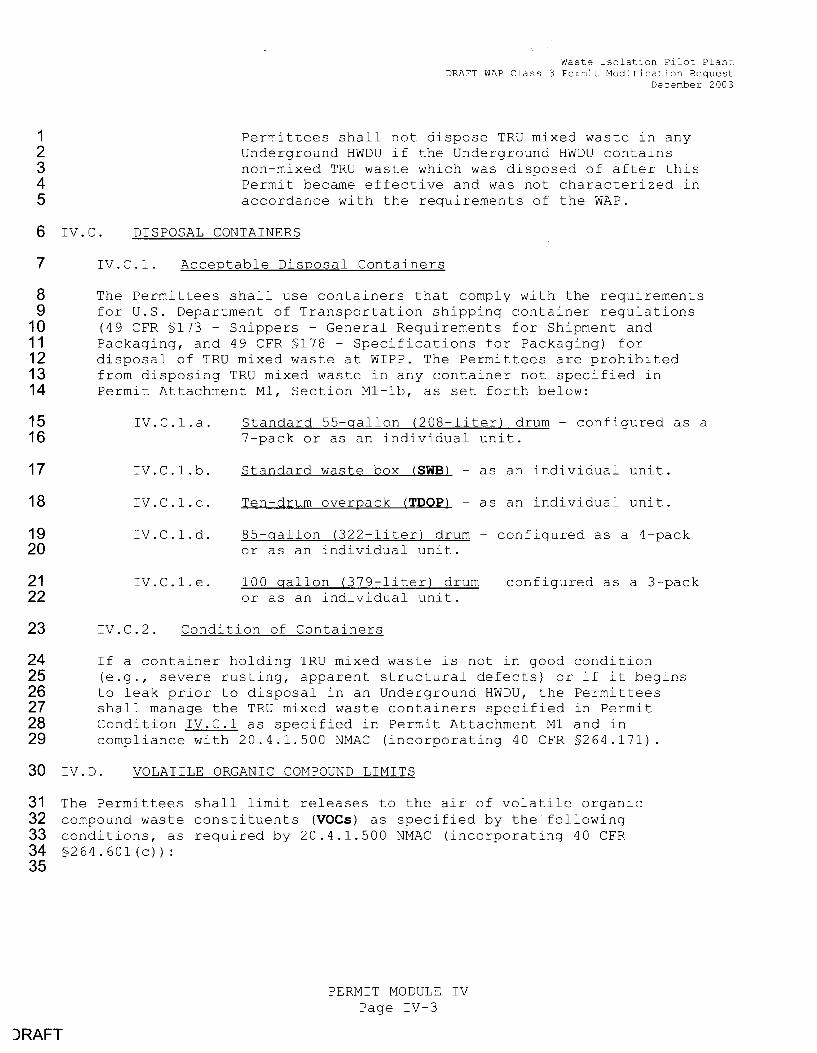
7 IV.C.l. Acceptable Disposal Containers
8 The Permittees shall use containers that comply with the requirements 9 for U.S. Department of Transportation shipping container regulations
10 (49 CFR §173 - Shippers - General Requirements for Shipment and 11 Packaging, and 49 CFR §178 - Specifications for Packaging) for 12 disposal of TRU mixed waste at WIPF. The Permittees are prohibited 13 from disposing TRU mixed waste in any container not specified in 14 Permit Attachment Ml, Section Ml-lb, as set forth below:
15 16
17
18
19 20
21 22
IV.C.1.a.
IV.C.1.b.
IV.C.1.c.
IV.C.l.d.
IV.C.1.e.
Standard 55-gallon (208-liter) drum - configured as a 7-pack or as an individual unit.
Standard waste box (SWB) - as an individual unit.
Ten-drum overpack (TOOP) - as an individual unit.
85-gallon (322-liter) drum - configured as a 4-pack or as an individual unit.
100 gallon (379-liter) drum - configured as a 3-pack or as an individual unit.
23 IV.C.2. Condition of Containers
24 If a container holding TRU mixed waste is not in good condition 25 (e.g., severe rusting, apparent structural defects) or if it begins 26 to leak prior to disposal in an Underground HWDU, the Permittees 27 shall manage the TRU mixed waste containers specified in Permit 28 Condition IV.C.1 as specified in Permit Attachment Ml and in 29 compliance with 20.4.1.500 NMAC (incorporating 40 CFR §264.171).
30 IV. :J. VOLATILE ORGANIC COMPOUND LIMITS
31 The Permittees shall limit releases to the air of volatile organic 32 compound waste constituents (VOCs) as specified by the following 33 conditions, as required by 20.4.1.500 NMAC (incorporating 40 CFR 34 § 2 6 4 . 6 0 1 ( C ) ) :
35
)RAFT
PERMIT MODULE IV Page IV-3

1 2 3 4
Waste Isolation Pilot Plant DRAFT WAP Class 3 Permit Modification Request
December: 2003
The Permittees shall confirm the Closed and Open Panel-Based Limits using the procedures for Confirmatory voe Monitoring as specified in Permit Condition IV.F.2 and as described in Permit Attachment N (Volatile Organic Compound Monitoring Plan).
5 6 7 8 9
_____ IV.D.2.b. WIPF Waste Information System (WWIS) Report the Secrelary :!Shall have the capability of generating a repor L from the mns databa:!le, or eqni vale11L, for ide11Lifyiug the average co11ce11Lralion:!l and Lolal emi55ion rate:!l of the VOC:!l :!Specified in '!?able IV.D.l 011 a room and panel ba:!li:!l, ba:!led 1:1po11 Lire actnal wa:!lte co11Lai11er5 di5po5ed, the voe lread5pace ga:!l :!Sampling dala for Llto5e co11Lai11er5, and Lhe filter diff1:15io11 draracleri5Lic5 for Lho5e co11Lai11er5.
10 11 12 13
14 IV.E. DESIGN, CONSTRUCTION, AND OPERATION REQUIREMENTS
15 The Permittees shall design, construct, and operate the Underground HWDU:3 16 as specified by the following conditions and as required by 20.4.1.500 17 NMAC (incorporating 40 CFR §264.601)
18 IV.E.1. Repository Design
19 The Permittees shall construct each Underground HWDU in conformance 20 with the requirements specified in Permit Attachment M2 and Permit 21 Attachment M3 (Drawing Number 51-W-214-W, "Underground Facilities 22 Typical Disposal Panel") .
23 IV.E.2. Repository Construction
24 Subject to Permit Condition IV.E.1, the Permittees may excavate the 25 following Underground HWDUs, as depicted in Permit Attachment M2, 26 Figure M2-1, "Repository Horizon", and specified in Section M2-2a (3) ., 27 "Subsurface Structures (Underground Hazardous Waste Disposal Units 28 (HWDUs))":
29 30 31 32 33
• • • • •
Panel Panel Panel Panel Panel
10 2 9 3 4
(Disposal area access drift)
(Disposal area access drift)
34 Prior to disposal of TRU mixed waste in a newly constructed 35 Underground HWDU, the Permittees shall comply with the certification 36 requirements specified in Permit Condition I.E.11.
)RAFT
PERMIT MODULE IV Page IV-5

1 2 3 4 5
6 7 8 9
10 11 12 13 14 15
16
17 18 19 20 21 22 23 24 25
26 27 28 29 30 31 32 33 34 35 36
37 38 39 40 41 42 43
44 45 46
)RAFT
IV.F.1.c.
Waste Isolation Pilot Plant DRAFT WAP Class 3 Permit Modification Request
December 2003
the geomechanical monitoring program and shall include geomechanical data collected from each Underground HWDU during the previous year, as specified in Permit Attachment M2, Section M2-5b(2), "Geomechanical Monitoring".
Notification of adverse conditions - when evaluation of the geomechanical monitoring system data identifies a trend towards unstable conditions which requires a decision whether to terminate waste disposal activities in any Underground HWDU, the Permittees shall provide the Secretary with the same report provided to the WIPP Operations Manager within five (5) working days of its issuance, as specified in Permit Attachment M2, Section M2-5b (2) (a), "Description of the Geomechanical Monitoring System".
IV.F.2. Air Monitoring
IV.F.2.a.
IV.F.2.b.
IV.F.2.c.
Implementation of Confirmatory VOC Monitoring - the Permittees shall implement the Confirmatory voe Monitoring specified in Permit Attachment N (Volatile Organic Compound Monitoring Plan) and as required by 20.4.1.500 NMAC (incorporatinq 40 CFR §264.602 and §264.601(c)). The Permittees shall implement this plan within thirty (30) calendar days of issuance of this Permit until the certified closure of all Underground HWDUs.
Reporting requirements for the Confirmatory voe Monitoring - the Permittees shall submit to the Secretary an annual report, beginning twelve (12) months after issuance of this permit, describing the implementation and presenting the data and analysis of the Confirmatory voe Monitoring 'Phi5 report 5hall al5o pre5ent data from the mns a5 5pecified in Permit Condition IV.D.2.b and correlate thi5 data, ct5ing appropriate 5tati5tical ntethod5, ~ith data fre,-m the Confirmatory voe M.onitoring Plan. as delineated in Attachment N of this Permit.
Notification requirements for the Confirmatory voe Monitoring - the Permittees shall notify the Secretary in writing, within five (5) working days of obtaining validated analytical results, whenever thE: concentration of any voe specified in Table IV.D.1 exceeds the concentration of concern specified in Table IV.F.2.c below.
The Permittees shall also notify the Secretary in writing, within five (5) working days of obtaining validated analytical results, whenever the running
PERMIT MODULE IV Page IV-7

1 2
3 4 5 6 7 8 9
10 11
12 13 14 15 16 17 18 19
20 21 22 23 24 25 26 27
28 29
30
31 32 33 34 35 36 37 38 39 40
)RAFT
Waste Isolation Pilot Plant DRAFT WAP Class 3 Permit Modification Request
December 2003
the remedial action has been completed in accordance with all applicable requirements of this Permit.
IV.F.2.e. Implementation of the Closed Room voe Monitoring -the Permittees shall implement the Closed Room voe Monitoring specified in Permit Attachment N and as required by 20.4.1.500 NMAC (incorporating 40 CFR §264.602 and §264.60l(c)). The Permittees shall implement this plan within one hundred twenty (120) calendar days of the plan approval. The plan shall be implemented until initiation of construction of the final Panel closure.
IV.F.2.f. Reporting requirements for the Closed Room Monitoring - the Permittees shall submit to the Secretary as part of the annual report required under Permit Condition IV.F.2.b, beginning no later than twelve (12) months after plan approval, describing the implementation and presenting the data and analysis of the Closed Room Monitoring as delineated in Attachment N of this Permit.
IV.F.2.g. Notification requirements for the Closed Room
1
Monitoring - the Permittees shall notify the Secretary in writing, within five (5) working days of obtaining validated analytical results, whenever the concentration of any voe specified in Table IV.D.l in the closed room immediately adjacent to an open room exceeds the action levels specified in Table IV.F.2.g below.
Table IV.F.2.g Action Levels for Closed Room Monitoring
Compound Action Levels for voe Constituents of Concern ppmv
Carbon tetrachloride Chlorobenzene
Chloroform 1 1-Dichloroethene 1 2-Dichloroethane Methylene Chloride
1 2 2-Tetrachloroethane Toluene
1,1,1-Trichloroethane
PERMIT MODULE IV Page IV-9
9, 145 12,350 9,433 5,215 2,280 95,000 2,812
10,450 32,015

1 2 3
4 5 6 7 8 9
10 11 12 13 14 15
16 IV .c:;.
Waste Isolation Pilot Plant DRAFT WAP Class 3 Permit Modification Request
December 2003
the implementation and present the results of the data and analysis of the Mine Ventilation Rate Monitoring Plan.
IV.F.3.c. Notification requirements - the Permittees shall calculate the running annual average mine ventilation exhaust rate on a monthly basis. In addition, the Permittees shall evaluate compliance with the minimum active room ventilation rate specified in Permit Condition IV.E.3.b on a monthly basis. Whenever the evaluation of the mine ventilation monitoring program data identifies that the ventilation rates specified in Permit Condition IV.E.3.b have not been achieved, the Permittees shall notify the Secretary in writing within five (5) working days.
INSPECTION SCHEDULES AND PROCEDURES
17 The Permittees shall inspect the Underground HWDUs at least weekly, as 18 specified in Permit Attachment D (Inspection Schedule/Procedures, Table 19 D-1), and as required by 20.4.1.500 NMAC (incorporating 40 CFR §264.15). 20 The Permittees shall perform these inspections to detect malfunctions, 21 signs of deterioration, operator errors, discharges, or any other factors 22 which have caused or may cause a release of hazardous wastes or hazardous 23 waste constituents to the environment or which may compromise the ability 24 of any Underground HWDU to comply with the environmental performance 25 standards in 20.4.1.500 NMAC (incorporating 40 CFR §264.601).
26 IV.FL
27
28 29 30
31
32 33 34 35 36 37
38 39 40 41 42 43
JRAFT
RECORDKEEPING
IV.H.1. Underground HWDU Location Map
The Permittees shall maintain, in the operating record, a map containing the exact location and dimensions of each Underground HWDU with respect to permanently surveyed benchmarks.
IV.H.2. Disposal Waste Type and Location
The Permittees shall maintain, in the operating record, a record identifying the types and quantities of TRU mixed waste in each Underground HWDU and the disposal location of each container or container assembly (e.g., a 7-pack of standard 55-gallons drums) within each Underground HWDU, using the following fields from the WWIS data dictionary:
1. Panel Number 2. Room Number or Drift Number 3. Row Number 4. Column Number 5. Column Height 6. Container Type Code
PERMIT MODULE IV Page IV-11

1
2 3 4 5 6 7
8
9 10 11
12
13 14 15
16 17 18
19 20 21 22 23 24
25
JRAFT
IV.J.2.
Waste Isolation Pilot Plant DRAFT WAP Class 3 Permit Modification Request
December 2003
Content of the Mine Ventilation Rate Monitoring Plan
The Mine Ventilation Rate Monitoring Plan shall address the following at a minimum: objectives of the monitoring; design of the monitoring program (including monitoring schedule and monitoring equipment); monitoring procedures; equipment calibration and maintenance; data evaluation, reporting and recordkeeping; and quality assurance.
IV.J.3. Incorporation of Permit Requirements
The Permittees shall incorporate the implementation, reporting and notification requirements of Permit Condition IV.F.3 into the appropriate section(s) of the Mine Ventilation Rate Monitoring Plan.
IV.J.4. Approval of the Plan
After the Permittees submit the Mine Ventilation Rate Monitoring Plan, the Secretary may approve, disapprove, or modify and approve the Mine Ventilation Rate Monitoring Plan in writing.
If the Secretary approves the Mine Ventilation Rate Monitoring Plan, the Secretary will modify the permit in accordance with Permit Condition I. B. l.
In the event of disapproval (in whole or in part) of the Mine Ventilation Rate Monitoring Plan, the Secretary shall specify deficiencies in writing. The Permittees shall correct these deficiencies and submit a modified Mine Ventilation Rate Monitoring Plan within thirty (30) calendar days of such written notification to the Secretary for review.
PERMIT MODULE IV Page IV-13

,D/\C:T
ATTACHMENT B
WASTE ANALYSIS PLAN

1D/\CT
ATTACHMENT B
Waste Isolation Pilot Plant Draft WAP Class 3 Permit Modification Request
December 2003
WASTE ANALYSIS PLAN
TABLE OF CONTENTS
List of Tables ............................................................ B--iii
List of Figures ............................................................ B--iii
Introduction and Attachment Highlights ......................................... B-:1
B-1 Identification of TRU Mixed Waste to be Managed at the WIPP Facility ............. B--5 B-1a Waste Stream Identification ....................................... B--5 B-1 b Waste Summary Category Groups and Hazardous Waste Accepted at the WIPP
Facility ...................................................... B--5 B-1 c Waste Prohibited at the WIPP Facility ................................ B--6 B-1d Control of Waste Acceptance ...................................... B--7 B-1 e Waste Generating Processes at the WIPP Facility ...................... B--8
B-2 Waste Parameters . . . . . . . . . . . . . . . . . . . . . . . . . . . . . . . . . . . . . . . . . . . . . . . . . . . . . B--8
B-3 Characterization Methods . . . . . . . . . . . . . . . . . . . . . . . . . . . . . . . . . . . . . . . . . . . . . . . . B--8 B 38 Sempling end A1,el·1tieel Methods ................................... -&-9
B 3e(1) I leedspece Ges Sempling end A1,elysis ...................... -&-9 B 3e(1 )(i) Reduced Sempling Reguirements for I lomogeneous Solid or
Soil{Grevel Weste Streems v0ith no VOC Releted I le~rdous Weste Codes . . . . . . . . . . . . . . . . . . . . . . . . . . . . . . . . . . . . -8--1-0
B 3e(1 )(ii) Reduced Sempling Reguiren,ents for Thermellv Treeted Weste Streems ................................... -8--1-0
B 3e(2) I lomogeneous Weste Sempling end Al'lelysis ................. -8--14 B 3e(3) Leboretorv Qu~dificetion ................................. -8--14
B-3b§ Acceptable Knowledge ......................................... B-1.1 B-3eli Radiography and Visual Examination .............................. B-1.1 B-3d~ Characterization Techniques and Frequency for Newly Generated and
- Retrievably Stored Waste ...................................... B-11. B-3d_g(1) Newly Generated Waste ................................ B-1..1
- B 3d(1)(e) Sempling of Ne·o~v Genereted I lomogeneous Solids ... -8--1:§ B 3d(1)(b) Se1npling of Ne·ovlv Genereted Soils/Gre·vels .......... -B--1::r
B-3d~(2) Retrievably Stored Waste ............................... B-1_§
B-4 Data Verification and Quality Assurance .................................... B-1.§ B-4a Data Generation and Project Level Verification Requirements ............ B-1.§
B-4a(1) Data Quality Objectives .................................. B-1.§ B-4a(2) Quality Assurance Objectives ............................. B-1~ B 4e(3) Semple Control ........................................ B 21
Effective September 11. 2003
PERMIT ATTACHMENT B Page B-i

,D/\C'T
Table
B 1
B 2 B3 B4
BS 136
Figure
B-1 13 2 83 B-5i
List of Tables
Title
Waste Isolation Pilot Plant Draft WAP Class 3 Permit Modification Request
December 2003
Sul'fll'flBfJ' of I IBzBFdous Weste Cl=lereeterizetiofl Requirel'flents for TFBF18UFBF1ie Mixed Waste Mexil'flUl'fl Allo·vo'8ble VOC Roon, Avereged I leedspaee 601,centretiofl Lil'flits
Required Organie Analyses and Test Metl=lods Orgaflized by Organie A, ,alytical Groups Sun ,l'flary of Sal'flple Preparation and Anal,tieal Methods for Metals Sun,n,ary· of Paran,eters, CharaeterizBtion Methods, Bl'ld Rationale for Cl I Transuranic Mixed V'o'aste (Stored Waste, Nevo·ly Generated WBste) Required Program Records Maintained in Generator/Storage Site Project Files WI PP Waste Information System Data Fields
List of Figures
Title
WIPP Waste Stream Profile Form Data Colleetion Design for Cheraeterization of Newly Genereted V'o'aste Data Collection Desigfl for Charaeterization of Retrievably Stored Waste TRU Mixed Waste Screening Flow Diagram
Effective September 11, 2003
PERMIT ATTACHMENT B Page 8-iii

ATTACHMENT B
Waste Isolation Pilot Plant Draft WAP Class 3 Permit Modification Request
December 2003
WASTE ANALYSIS PLAN
Introduction and Attachment Highlights
2 This waste analysis plan (WAP) has been prepared for management, storage, or disposal 3 activities to be conducted at the Waste Isolation Pilot Plant (WIPP) facility to meet requirements 4 set forth in 20.4.1.500 NMAC (incorporating 40 CFR §264.13). Guidance in the most recent 5 U.S. Environmental Protection Agency (EPA) manual on waste analysis has been incorporated 6 into the preparation of this WAP (EPA, 1994 ). This WAP includes confirmatory test methods, 7 details of planned waste sampling and analysis, a description of the waste shipment screening 8 and verification process, and a description of the quality assurance (QA)/quality control (QC) 9 program. Before the Permittees manage, store, or dispose transuranic (TRU) mixed waste from
10 a generator/storage site (site), the Permittees shall require that site to implement the applicabl,e 11 requirements of this WAP.
12 TRU mixed waste that may be stored or disposed at WIPP are or were generated at DOE 13 generator/storage sites by various specific processes and activities. Examples of the major 14 types of operations that generate this waste include:
15
16
17
18
19
20
21
22
23
24
25 26 27
28
29
30
31
32
33
34
35
•
Production of Nuclear Products-Production of nuclear products includes reactor operation, radionuclide separation/finishing, and weapons fabrication and manufacturing. The majority of the TRU mixed waste was generated by weapons fabrication and radionuclide separation/finishing processes. More specifically, wastes consist of residues from chemical processes, air and liquid filtration, casting, machining, cleaning, product quality sampling, analytical activities, and maintenance and refurbishment of equipment and facilities.
Plutonium Recovery-Plutonium recovery wastes are residues from the recovery of plutonium-contaminated molds, metals, glass, plastics, rags, salts used in electrorefining, precipitates, firebrick, soot, and filters.
Research and Development (R&D)-R&D projects include a variety of hot cell or glovebox activities that often simulate full-scale operations described above, producing similar TRU mixed wastes. Other types of R&D projects indude metallurgical research, actinide separations, process demonstrations, and chemical and physical properties determinations.
Decontamination and Decommissioning-Facilities and equipment that are no longer needed or usable are decontaminated and decommissioned, resulting in TRU mixed wastes consisting of scrap materials, cleaning agents, tools, piping, filters, Plexiglas TM, gloveboxes, concrete rubble, asphalt, cinder blocks, and other building materials. These materials are expected to be the largest category by volume of TRU mixed waste to be generated in the future.
36 TRU mixed waste contains both TRU radioactive and hazardous components, as defined in 37 20.4.1.800 NMAC (incorporating 40 CFR, §268.35(d)), and in the Federal Facility Compliance
Effective September 11, 2003
,D/\CT
PERMIT ATTACHMENT B Page B-1

1
2
3
4
5
6
7
8
9
10
11
12
13
14
15
16
17
18
19
20
21
Waste Isolation Pilot Plant Draft WAP Class 3 Permit Modification Request
December 2003
Homogeneous solids, or solid process residues, are defined as solid materials, excluding soil, that do not meet the NMED criteria for classification as debris (20.4.1.800 NMAC (incorporating 40 CFR §268.2[g] and [h])). Included in the series of solid process residues are inorganic process residues, inorganic sludges, salt waste, and pyrochemical salt waste. Other waste streams are included in this Summary Category Group based on the specific waste stream types and final waste form. This Summary Category Group is expected to contain toxic metals and spent solvents. This category includes wastes that are at least 50 percent by volume solid process residues.
S4000 - Soils/Gravel This Summary Category Group includes S4000 waste streams that are at least 50 percent by volume soil/gravel. This Summary Category Group is expected to contain toxic metals. Soils/gravel are further categorized by the amount of debris included in the matrix.
S5000 - Debris Wastes This Summary Category Group includes heterogenous waste that is at least 50 percent by volume materials that meet the criteria specified in 20.4.1.800 NMAC (incorporating 40 CFR §268.2 (g)). Debris means solid material exceeding a 2.36 inch (in.) (60 millimeter) particle size that is intended for disposal and that is:
1. 2. 3.
a manufactured object, or plant or animal matter, or natural geologic material.
22 Particles smaller than 2.36 inches in size may be considered debris if the debris is a 23 manufactured object and if it is not a particle of S3000 or S4000 material.
24 If a waste does not include at least 50 percent of any given category by volume, 25 characterization shall be performed using the waste characterization process required for the 26 category constituting the greatest volume of waste for that waste stream (see Section B-3dc).
21 The most common hazardous constituents in the TRU mixed waste to be managed in the WI PP 28 facility consist of the following:
29 Metals
30 Some of the TRU mixed waste to be emplaced in the WIPP facility contains metals for 31 which 20.4.1.200 NMAC (incorporating 40 CFR §261.24), toxicity characteristics were 32 established (EPA hazardous waste codes D004 through D011 ). Cadmium, chromium, 33 lead, mercury, selenium, and silver are present in discarded tools and equipment, 34 solidified sludges, cemented laboratory liquids, and waste from decontamination and 35 decommissioning activities. A large percentage of the waste consists of lead-lined 36 gloveboxes, leaded rubber gloves and aprons, lead bricks and piping, lead tape, and 37 other lead items. Lead, because of its radiation-shielding applications, is the most 38 prevalent toxicity-characteristic metal present.
Effective September 11, 2003
,D/\CT
PERMIT ATTACHMENT B Page B-3
Waste Isolation Pilot Plant Draft WAP Class 3 Permit Modification Request
December 2003
1 Once the required waste characterization is complete, the generator/storage site will complete a 2 Waste Stream Profile Form (WSPF) to document the results of their characterization activities 3 (Section B-1d). The WSPF and the Characterization Information Summary for the waste stream 4 resulting from waste characterization activities shall be transmitted to the Permittees, reviewed 5 for completeness, and screened for acceptance prior to loading any TRU mixed waste into the 6 Contact Handled Packaging at the generator facility, as described in Section 8-4. Only TRU 7 mixed waste and TRU waste that has been characterized in accordance with this WAP and that 8 meets the TSDF-WAC specified in this Permit will be accepted at the WIPP facility for disposal 9 in a permitted Underground Hazardous Waste Disposal Unit (HWDU).
10 In the event the Permittees request detailed information on a waste stream, the site will provide 11 a Waste Stream Characterization Package (Section B3-42Ib(2)). For each waste stream, this 12 package will indude the WSPF, the Characterization Information Summary, and the complete 13 AK summary. The Waste Stream Characterization Package will also include specific Batch 14 Data Reports and raw enelytia1I data associated with waste container characterization as 15 requested by the Permittees.
16 B-1 Identification of TRU Mixed Waste to be Managed at the WIPP Facility
17 B-1 a Waste Stream Identification
18 TRU mixed waste destined for disposal at WIPP will be characterized on a waste stream basis. 19 Generator/storage sites will delineate waste streams using acceptable knowledge. Required 20 acceptable knowledge is specified in Section B-3b§. and Permit Attachment B4. If acceptable 21 knowledge for retrievably stored waste does not comply with these requirements (e.g., 22 heterogenous Debris Waste in Summary Category S5000), the Permittees will reexamine (and 23 characterize) the waste in the same manner as newly generated waste.
24 All of the waste within a waste stream may not be available for sempling end enelysis testing at 25 one time. In these instances, generator/storage sites may divide waste streams into waste 26 stream lots based on staging, transportation, or handling issues. Characterization activities shall 27 then be undertaken on a waste stream lot basis. A WSPF need not be submitted for 28 subsequent waste stream lots unless warranted by the characterization information.
29 B-1b Waste Summary Category Groups and Hazardous Waste Accepted at the WIPP Facility
30 Once a waste stream has been delineated, generator/storage sites will assign a Waste Matrix 31 Code to the waste stream based on the physical form of the waste. Waste streams are then 32 assigned to one of three broad Summary Category Groups; S3000-Homogeneous Solids, 33 S4000-Soils/Gravel, and S5000-Debris Wastes. These Summery Cetegory Groups ere used to 34 determine further ehereeteriz:etion requirements.
35 The Permittees will only allow generators to ship those TRU mixed waste streams with EPA 36 hazardous waste codes listed on the Permittees' RCRA Part A Permit Application (Permit 37 Attachment 0). Some of the waste may also be identified by unique state hazardous waste 38 codes. These wastes are acceptable at WIPP as long as the TSDF-WAC are met. The 39 Permittees will perform characterization of all waste streams as required by this WAP. If durin~~ 40 the characterization process, new EPA hazardous waste codes are identified, those wastes will 41 be prohibited for disposal at the WIPP facility until a permit modification has been submitted to
Effective September 11, 2003
1D/\CT
PERMIT ATTACHMENT B Page B-5

Waste Isolation Pilot Plant Draft WAP Class 3 Permit Modification Request
December 2003
exceed 1 percent volume in any payload container. If discrepancies or inconsistencies are 2 detected during the data review, the generator/storage site will review the radiography video 3 ffiPe or visual examination video ffiPe to verify that the observed physical form of the waste is 4 consistent with the waste stream description provided by the generator and to ensure that no 5 prohibited items are present in the waste. Radiography tapes will be selected randomly from at 6 least one percent of containers received at WIPP and will be reviewed and compared to 7 radiographic data forms. (Note that for radiography tapes containing classified information, 8 review of radiography tapes will be conducted by the Permittees at a secure location other than 9 WIPP. The records generated from the Permittee's review of radiography tapes will be sent to
10 WIPP for inclusion in the Operating Record, while the original tape will be maintained at anoth13r 11 secure location.) All personnel who review radiography video tapes, or equivalent unalterable 12 media, will be trained to the same standard as radiography operators. Section B-4 includes a 13 description of the waste verification process that the Permittees will conduct prior to receiving a 14 shipment at the WIPP facility.
15 Containers are vented through filters, allowing any gases that are generated by radiolytic and 16 microbial processes within a waste container to escape, thereby preventing over pressurization 17 or development of conditions within the container that would lead to the development of 18 ignitable, corrosive, reactive, or other characteristic wastes.
19 To ensure the integrity of the WIPP facility, waste streams identified to contain incompatible 20 materials or materials incompatible with waste containers cannot be shipped to WIPP unless 21 they are treated to remove the incompatibility. Only those waste streams that are compatible or 22 have been treated to remove incompatibilities will be shipped to WIPP.
23 The VOC eoReeFttFBtiofls ifl the heBdspBee of Vo'Bste eofltBifleFs hB\'e beef! limited to those 24 'qvhieh vii'lefl B'1terB9ed Ofl B room bBsis, vvill ensure eompliBnee vvith the performBFlee stB11dBrdi~. 25 These limits are preseFtted ifl TBble B 2 BS mBximum Bllovt1Bble VOC room BverB9ed 26 heBdspBee eoF1eeF1trBtion limits. There Bre no mBximum BllowBble heBdspBee 9Bs eoFteentrBtkm 27 limits for individuBI eofltBiners, BS some eontBiners eBn exeeed these vBlues BS long BS 28 eor,tBir,er heBdspBee BverB9es in B disposBI room do not.
29 B-1 d Control of Waste Acceptance
30 Every waste stream shipped to WIPP shall be preceded by a WSPF (Figure B-1 ). The required 31 WSPF information and the Characterization Information Summary elements are found in 32 Section B3-42Zb(1) and Section B3-42Zb(2).
33 Generator/storage sites will provide the WSPF to the Permittees for each waste stream prior to 34 its acceptance for disposal at WIPP. The WSPF and the Characterization Information Summairy 35 will be transmitted to the Permittees for each waste stream from a generator/storage site. If 36 continued waste characterization reveal discrepancies that identify different hazardous waste 37 codes or indicates that the waste belongs to a different waste stream, the waste will be 38 redefined to a separate waste stream and a new WSPF submitted.
39 The Permittees are responsible for the review of WSPFs (Section B3-42Zb(1 )) and 40 Characterization Information Summaries to verify compliance with the restrictions on TRU 41 mixed wastes for WIPP disposal. The Permittees will submit completed WSPFs to NMED prior 42 to waste stream shipment. The Permittees will also be responsible for the review of shipping
Effective September 11, 2003
1D/\C:-T
PERMIT ATTACHMENT B Page B-7

2
3
4
5
6
7
8
9
10
11
12
13
14
15
16
17
18
19
20
21
22
23
24
25
26
27
28
29
30
31
32
33
34
35
36
37
38
39
40
41
42
,DACT
Waste Isolation Pilot Plant Draft WAP Class 3 Permit Modification Request
December 2003
TRU mixed -o·veste mey be cherecteri~ed in lots (Section B 1 e) end{or betches. A sempling betch cen be up to 20 sen,ples (excluding field QC semples), ell of -o.tiich shell be collected -ooithin 14 deys of the first semple in the betch. A1, e1,elyticel betch cer, be up to 20 semples (excluding leboretory QC semples), ell of which shell be received by the leboretory within 14 deys of the velideted time of semple receipt of the first semple in the betch. For on line integreted heedspece ges sempling{enelyticel systems, semples vvill be collected within e 12 hour period using the seme on line i1,tegreted sempling{enelysis systen,. The enelyticel requiren,er,ts ere specified by the enelyticel method being used in the on line systen, (e.g., FTIR, GC{MS). Refer to Permit Attechment B3 for edditionel clerificetion regerding the expecte~ contents of Betch Dete Reports.
B 3e Semplin9 end Anebtticel Methods
B 3e(1) I leedspece Ges Semplin9 end Anel·ysis
~ leedspece•ges semples ere used to determine the types end conce1,tretions of VO Cs in the void volume of vveste conteiners. Meesured heedspece VOC eoncentretio1,s in ·vo'este conteiners received et the WIPP fecility will be compered routinely end in eccordence vv'ith requirements of Permit Attechme11t N to ensure thet, on en ennuel besis, there ere no essocieted edverse vV'Orker or public heelth impects. In eddition, VOC constituents vvill be compered to those essigned by eccepteble kno·vo·ledge, end the Permittees ·o·o·ill essign he~erdous weste codes, es ·ooerrented. This comperison mey include en enel·y'sis of rediolyticelfy derived VOCs. The Permittees mey elso consider rediolysis vvhen essessing the presence of listed vveste, end whether rediolysis vvould generete Vo'estes ovhich exhibit the toxicity eherecteristic. Refer to Permit Attechment B4 for edditio1,el clerificetion regerdi11g heZ'.erdous 0veste code essignment end heedspece ges results.
Every TRU mixed vveste conteiner or stetisticelly selected cor,teiners from vveste streen,s thet meet the conditions for reduced heedspece ges sempling listed in this section vvill be sempled end enelY'.z'.ed to determine the concentretions of VOCs (presented in Teble B 3) in heedspece geses. If composite sen,ples ere used, conteiners used in the composite semple must be from the sen,e ooeste streem ·ovith no more then 20 cor,teiners being included in e si1,gle co1,,posite semple. Sempling protocols, equipment, end QA{QC methods for heedspece-ges sempling er~, provided in Permit Attechment B1. In eccordence 'o'o'ith EPA convention, identificetion of heZ'.erdous constituents detected by ges chrometogrephy{mess spectrometry methods thet 1:11 e I,ot on the list of terget enelytes shell be reported. These compounds ere reported es tentetivel-y identified compounds (TICs) in the analytical batch data report and shall be added to the target enelyte list if detected in e given weste streem, ifthey eppeer in the 20.4.1.200 NMAC (incorporeting 40 CFR §261) Appendix VIII, end if they ere reported in 25% of the vo·este conteiners sen,pled from e given weste streem. The heedspeee ges enelysis method Quelity /\ssurance Objectives (QAOs) are specified in Permit Attachment B3.
B 3e(1 )(i) Reduced Sempling Reauirements for I lomogeneous Solid or Soili'Grevel Weste Streems with no VOC•Releted I leZ'.erdous Weste Codes
~ leedspece ges sempling of homogeneous solid end soil1grevel ·ovestes thet heve no voe releted heZ'.erdous weste codes essigned mey quelify for reduced heedspece semr,ling if they meet the following criteria.
Effective September 11, 2003
PERMIT ATTACHMENT B Page B-9

Waste Isolation Pilot Plant Draft WAP Class 3 Permit Modification Request
December 2003
1 the meen n,eesured conteminent concentretions in e weste streem •;;ill be compered to the 2 specified regulBtory leoels in 20.4.1.200 ~JMAC (incorporBting 40 CFR 261 SubpBrt C), 3 expressed es toteb'TCLP oelues, to determine if the weste streem exhibits e toxicity 4 ehBrecteristic. A comperison of totel enelyses Bnd TCLP enelyses is prese11ted in Appendix ca 5 of the WIPP RCRA Part B Permit Application (DOE, 1997), and a discussion of the UCL90 is 6 ~ncluded in Permit Attachment B2. If toxicity characteristic (TC) wastes are identified, these willl 7 be compered to those determined by ecceptBble 1<:1,owledge Bnd TC wBste codes •#ill be 8 revised, 88 vvBrrBnted. Refer to Permit Attechment 84 for BdditionBI clBrificetion regBrding 9 hez:erdous weste code essignment end homogeneous solid e1,d soilfgreoel e1,elyticel results.
10 B 38(3) LBborBtorv QuelificBtion
11 The Permittees will ensure thet generBtorfstorBge sites conduct enelyses using IBboretories th!!lt 12 ere quBlified through perticipetion in the Performence DemonstrBtion Prog1 em (DOE, 1995c, d): 13 Required QAOs ere specified in Permit AttBchn,ent 83. In eddition, methods Bnd supporting 14 performe1,ce dete den,01,streting QAO compliBnce shell be e1,sured by the Permittees during 15 the ennuel certificetion eudit.
16 AnBlytiCBI 11,ethods used by the leboretories shBII. 1) setisfy BIi of the eppropriete QAOs, Bnd 17 2) be implemented through leboretory documented stenderd opereting procedures. These 18 enelytiCBI QAOs Bre discussed in deteil in Permit Attechment B3.
19 B-3bg Acceptable Knowledge
20 Acceptable knowledge (AK) is used in TRU mixed waste characterization activities in three four 21 ways:
22
23
24
25
26
27
To delineate TRU mixed waste streams
To assess whether TRU mixed heterogenous debris wastes exhibit a toxicity characteristic (20.4.1.200 NMAC, incorporating 40 CFR §261.24)
To assess whether TRU mixed wastes are listed (20.4.1.200 NMAC, incorporating 40 CFR §261.31)
To determine if a waste stream is eligible for less than 100 percent visual 28 examination and/or radiography
29 Acceptable knowledge is discussed in detail in Permit Attachment B4, which outlines the 30 minimum set of requirements which shall be met by the generator/storage sites in order to use 31 acceptable knowledge. In addition, Section B-4b(1) of this permit attachment describes the 32 verification of acceptable knowledge through sempling end enelysis testing and the Permittees' 33 Audit and Surveillance Program.
34 B-3e~ Radiography and Visual Examination
35 Radiography is a nondestructive qualitative and quantitative technique that involves X-ray 36 scanning of waste containers to identify and verify waste container contents. Visual examination 37 (VE) constitutes opening a container and physically examining its contents. Radiography and/or
Effective September 11, 2003
,D/\C:T
PERMIT ATTACHMENT B Page B-11

Waste Isolation Pilot Plant Draft WAP Class 3 Permit Modification Request
December 2003
Radiography and/or VE will be used to verify the physical form of retrievably stored TRU mixed 2 waste. For newly generated waste, physical form and prohibited items will either be verified 3 during packaging (using the VE technique) or will be verified after packaging using radiography 4 (or VE in lieu of radiography). Generator/storage sites may use either the VE technique or 5 radiography, separately or together, as long as 100% of the containers undergo confirmation of 6 AK except for those waste streams that are eligible for less than 100 percent radiography or 7 visual examination. Radiography and/or VE will also be used in conjunction with acceptable 8 knowledge to characterize heterogenous debris wastes. Radiography and/or VE, and the 9 associated information compiled from acceptable knowledge (e.g., age of the waste, generating
10 process) will be used to determine the RCRA-regulated constituents present in the waste. VE, 11 the VE technique, and/or radiography shall be performed prior to any treatment designed to 12 supercompact waste prior to shipment.
13 All vvaste containers (retrieoably stored and newly generated) or randomly selected containers 14 from vvaste streams that meet the conditions for reduced headsi,ace gas sami,ling listed in 15 Section B 3a(1) are sami,led and analyzed for voes in the headsi,ace gas. A statistically 16 selected i,ortion of each homoge11eous solids and soilfgravel waste strean, is sami,led and 11 analyzed for RORA regulated total VOCs, SVOCs, and metals (see Permit Attachment B2). 18 Sami,ling and analysis methods used for ·waste characterization are discussed in Section B 3~1. 19 In the i,rocess of i,erforming organic headsi,ace and solid sami,le analyses, nontarget 20 eomi,ounds may be ide1,tified. These comi,ounds will be rei,orted as TICs. TICs rei,orted in 21 25% ofthe sami,les and listed in 20.4.1.200 NMAC (incori,orating 40 CFR §261) Ai,i,endixVIII; 22 vuill be comi,ared uoith accei,table knovvledge data to determine if the TIC is in a listed 23 hazardous 'li'o"aste in the voiaste stream. TICs identified through headsi,ace gas analyses that 24 r,ieet the Ai,i,endix VIII list criteria and the 25 i,ercent rei,orting criteria for a waste stream will 25 be added to the headsi,ace gas 'li'o"aste stream target list, regardless of the hazardous voiaste 26 listing associated with the ·ovaste stream. TICs subject to i11elusio1, on the target analyte list that 21 are toxicity characteristic i,arameters shall be added to the target analyte list regardless of 28 origin because the hazardous 'vvaste designation for these codes is not based 01, source. 29 I lo·ovever, for toxicity characteristic and non toxic F003 constituents, the site may take 30 concentratio1, into account when assessing whether to add a hazardous waste code. TICs 31 rei,orted from the Totals VOC or SVOC analyses may be excluded from the target analyte list 32 for a waste stream if the TIC is a constituent in an F listed waste uv'hose i,resence is attributable-33 to voiaste i,ackaging materials or radiolytic degradation from aceei,table kno·ovledge 34 docun,e11tatio1,. If the TIC associated uoith a total VOC or SVOC analysis cannot be identified ~tS
35 a comi,onent of 'toiaste i,ackaging materials or as a i,roduct of radiolysis, the Permittees ·will add 36 these TICs to the list of hazardous constituents for the 'li'o·aste stream (and assign additional 37 [PA listed hazardous waste codes, if ai,i,roi,riate). A i,ermit modification will be submitted to 38 NMED for their ai,i,rooal to add these constitue11ts (a11d 'li'taste codes), if necessary. For toxicity 39 characteristic con,i,ounds and non toxic F003 constituents, the Permittees may co11sider 'toiash, 40 concentration V9hen determining whether to change a hazardous waste code. Refer to Permit 41 Attachment B3 for additional information on TIC identification.
42 Waste characterization solid sami,ling and analysis activities may differ for retrievably stored 43 vo·aste and ne·ovly generated waste. The ·ovaste characterization data collection design for each 44 tyi,e of waste is described i11 the followi11g sections. Table B 1 i,rovides a sun,mary of 45 hazardous waste characterizatio11 requirements for all TRU mixed vvaste by vvaste 46 characterization i,arameters.
Effective September 11, 2003
,DACT
PERMIT ATTACHMENT B Page B-13

Waste Isolation Pilot Plant Draft WAP Class 3 Permit Modification Request
December 2003
All conteiners of nevo·ly genersted ·n·este or ne·ovly genereted ·o·veste conteiners rendomly 2 selected from 'n'8ste streems thet meet the conditions for reduced heedspece gas sBmpling 3 listed in Section B 3e(1) .·viii undergo heedspece gBs BnBlysis for voe concentrBtions prior to 4 shipment. If the Permittees belie'll"e the freeiue1,cy CBI, be reduced in the future bBsed on trend~; 5 iii enBlyticBI results, they mey provide technieBI Brguments for such 8 reduction Bnd reeiuest B
6 permit modificetion from ~~MED. The heBdspece gBs SBmpling method is provided in Permit 7 AttBchment B1. I leedspBce gBs dete ·ovill be used to confirm acceptBble knowledge Vo'8ste 8 ehBrecteri~etio1,, es specified in Permit Attechment B4.
9 B 3d(1)(B) 8Bmpling of Newly Generated I lomogeneous Solids
10 Nevvly ge1,e121ted mi:)(ed weste streems of homogeneous solids will be rendomly sen,pled a 11 minimum of once per yeer for totBI voes, svoes end metels. An initiel ten-sample set. 12 hovvever, tov'ill be collected to develop the beseline control chart. S21mpli1 ,g freeiue,,cy of once p~,r 13 yeBr is only ello>oved if a process has opereted 'o'vithin procedurBlly established bounds without 14 any process che1,ges or fluctuations which would result in either a new ·,r,raste stream or the 15 identification of e new he~erdous wBste constituent in thet waste streBm. Otherv9'ise. the Vo'Bste 16 shall be considered BS process batches and eBch bBtch will undergo sempling end enalysis. 11 Process chenges fmd process fluctuations 'o'v'ill be determined using st21tisticBI process control 18 cherting technieiues, these technieiues reeiuire the ten sBmple bBseline Bnd historicBI deta for 19 determining lin,its for indic21tor species and subseeiuent periodic sBmpling to Bssess process 20 behavior relBtiv"e to historicel limits. If the limits are e:)(Ceeded, the ovaste streen, shall be 21 recharBcteri~d, Bnd the characteri~ation shBII be performed according to procedures reeiuired 22 for retrievably stored vv'Bste (i.e., wBste sampling freeiuency ·ovill be increBsed). The process 23 behind this control charting technieiue is described in Permit Attechment B2.
24 Also, 88 another control of weste gener21ted from B pBrticulBr process, the bounds for 8 ov8Ste 25 generBting process ·will be established by speeific written procedures for that process. 26 [:)(amples of parameter bounds that eould effect a waste generBted by B process are volumes 21 of input mBterial, change in the input mBterial, Bnd any other changes that vvould chBnge the 28 output of thet p1 ocess.
29 To e1,sure that the generetorfstorage site procedures for weste genereting processes include 30 controls of the o'v'Bste streem, these procedures oo'ill consist of sections conteining the follovving 31 informBtion:
32 Responsible organizations for implementing the requirements of the proeedure
33
34
35
36
37
38
39
,D/\C:T
Material inputs
Waste streams generated
Proeess controls and range of operation (bounds) that affect final hazardous
Rate and quantity of hazardous waste generated
List of applicable operating procedures relevant to the hazardous •,vaste detern,ination
Effective September 11, 2003
PERMIT ATTACHMENT B Page B-15

Waste Isolation Pilot Plant Draft WAP Class 3 Permit Modification Request
December 2003
waste is consistent with the waste stream description, and to verify the absence of prohibited 2 items, and to determine the ooaste characteri.fBtion technieiues to be used based on the 3 Summary Category Groups (i.e., S3000, S4000, S5000). Repackaged retrie'll'ably stored -o·vaste:; 4 or any retrievably stored waste "o'o'ith inadeeiuate acceptable knowledge, vvill be characteri:fed 5 using either the retrie'll'ably stored or nevvly generated 'O'o'aste characteri.fBtion process, 6 -ovhichever results in greater sampling reeiuirements, unless it is demonstrBted that control 7 charting ca1 ,not be applied effectively. Solids sampling for repackaged or treated S3000 ooaste 8 n,ay be characteri:fed as retrievably stored v0'Bste if the generato1 /storage sites demonstrates 9 that control charting cannot be applied effecti'll'ely to the repackaging or treatment process Thi~1
10 determination by the generator/storege site must be documented on the Characteri.fBtion 11 Information Summa!)' and will be exan,i1,ed by the Permittees during audits (Pern,it Attachme1 rt 12 BG). In this case, the n,inimun, number of solids samples required for any S3000 0vaste streel'T'1 13 or 0vaste streem lot is the number of samples determined in accordence with Section B2 28. 14 Radiographic results will be compared to acceptable knowledge results to ensure correct Waste 15 Matrix Code assignment and identification of prohibited items along with the hazardous waste 16 codes that AK assigned to the waste stream. If radiographic analysis do not confirm the 17 physical waste form (and associated HWNs), waste will be reassigned as specified in Section 18 B-3e.!2.. Generator/storage sites may elect to substitute visual examination for radiographic 19 analysis.
20 To confirm the results of rediography, e stetisticelly selected number of the TRU n,ixed vveste 21 eonteiner population will be visuelly exemined by opening eonteiners to inspect 0veste contents, 22 to verify radiogrephy results. Permit Attachment B2 conteins the apprm~ch used to statistically 23 select the number of drums to be visually examined. For homogeneous 0vaste and soilsfgravel.!t 24 selected for sampling, the containers opened for sampling mey be used to help fulfill the visuell 25 examination reeiuirements.
26 All retrie'o'Bbly stored containers or retrie'll'ebly stored conteiners rendomly selected from 'O'O'Bste 27 streams that meet the conditions for I educed heedspece ges sampling listed in Section B 3e(1) 28 w·ill undergo headspace ges enelysis for VOC concentretions. Retrievebly stored vvaste that is 29 repeckeged vvill be subject to the DAG determi1,ation specified in Sectio1, B•3d(1 ). The 30 heedspece ges sen,pling method is provided in Permit Attachn,ent B1. All headspace gas dah!I 31 '01till be used to confirm acceptable knovo·ledge weste characteri:fation, as specified in Permit 32 Attachment B4.
33 A statisticelly selected portion of retrievably stored homogeneous solids end soilfgra'll'el ·oveste~: 34 will be sampled end anal~ed for total VOCs, SVOCs, and metals. The approech used to 35 statisticelly select drums for homoge1,eous solids and soil/gravel wastes is different than the 36 method used to select waste conteiners for visual examination. This method is elso included i111 37 Permit Attachment B2. The sampling methods for these vvastes are pro·vided in Permit 38 Attachment B1.
39 The toxicity characteristic of retrievably stored homogeneous solids and soilfgra·vel ovastes vo·ill 40 be determi11ed using total analysis of toxicity characteristic parameters or TCLP. To determi1,e if 41 a vveste exhibits a toxicity cherecteristic for compounds specified in 20.4.1.200 NMAC 42 (incorporeti1,g 40 CFR §261, Subpert C), TCLP n,ay be used insteed of totel enelyses. 43 Appe1,dix 03 of the 'NIPP RORA Part B Permit Application (DOE, 1997) discusses 44 comparability of totals analytical results to those of the TCLP method.
Effective September 11, 2003
10/\C'T
PERMIT ATTACHMENT B Page B-17

2
3
4
5
6
7
8
9
10
Visual Examination
Waste Isolation Pilot Plant Draft WAP Class 3 Permit Modification Request
December 2003
To verify the TRU mixed waste streams by Waste Matrix Code and waste stream description for purposes of physical waste form identification, determinBtion of sBmplin9 Bnd BnBlytieBI reeiuirements, Bnd to identify prohibited items, to confirm the assignment of EPA hazardous waste codes, and to confirm the waste stream delineation by acceptable knowledge.
To provide B proeess eheek on B sBmple bBsis by verifying the ir,formBtion determined by rBdiogrBphy, Bnd to eonfirm the ovBste streBm, delir,eBtion by BeeeptBble kno•odledge.
11 Reconciliation of these DQOs by the Generator/Storage Site Project Manager is addressed in 12 Permit Attachment B3. Reconciliation requires determining whether sufficient type, quality, and 13 quantity of data have been collected to ensure the DQO's cited above can be achieved.
14 13-4a(2) Quality Assurance Objectives
15 The generator/storage sites shall demonstrate compliance with each QAO associated with the 15 various characterization methods as presented in Permit Attachment B3. Generator/Storage 17 Site Project Managers are further required to perform a reconciliation at the project level of the 18 data sets submitted by the various organizations at the generator/storage site with the DQOs 19 established in this WAP. The Generator/Storage Site Project Manager shall conclude that all of 20 the DQOs have been met for the characterization of the waste stream prior to submitting a 21 WSPF to the Permittees for approval (Permit Attachment B3). The following QAO elements 22 shall be considered for each technique, as a minimum:
23
24
25
26
27
28
29
30
31
32
33
34
35
,D/1.CT
Precision
Precision is a measure of the mutual agreement among multiple measurements.
Accuracy
Accuracy is the degree of agreement between a measurement result and the true or known value.
Completeness
Completeness is a measure of the amount of valid data obtained from a method compared to the total amount of data obtained that is expressed as a percentage.
Comparability
Comparability is the degree to which one data set can be compared to another.
Effective September 11, 2003
PERMIT ATTACHMENT B Page B-19

2
3
4
5
6
7
8
9
10
11
12
13
14
15
16
Waste Isolation Pilot Plant Draft WAP Class 3 Permit Modification Request
December 2003
The Permittees shell further reeiuire ell enelytieel leboretories enelyz:ing WIPP weste ehereeteri~etion semples for the generetorlstorege sites to heve esteblished, documented QA/QC progrems. The Pem,ittees e1,1,uelly eveluete these leboretories end their QAIQC progrems es pert of their pertieipetion in the Permittees' Performenee Demonstretion Progrem (PDP) laboratory performance program. The Permittees' audits cO¥er the requirements of the leb's QAIQC progrem, es ·ovell es eomplie1,ee v0ith this WAP. Continued eomplienee ·with these peremeters ro·vill be verified by ongoing eudits by the Permittees et the generetor/storege sites es specified in Permit Atteehment BG. The Permittees' eudits of the generetorlstorege sites vo·ill "verify thet the leboretories enelyz:ing 'o'oeste heve been properly eudited by the generetor/storege sites. The leboretory's QAIQC progrem shell include the follov0ing.
Facility organization
/\ list of equipment/instrumentation
Operating procedures
Laboratory QNQC procedures
Quality assurance revim.•,
Laboratory reeords management
11 B-4a(5~) Data Verification
18 Batch Data Reports will document the testing, sampling, and analytical results from the required 19 characterization activities, and document required QA/QC activities. Data validation and 20 verification at both the data-generation level and the project level will be performed as required 21 by this Permit before the required data are transmitted to the Permittees (Permit Attachment 22 83). NMED may request, through the Permittees. copies of any Batch Data Report. and/or the 23 raw data validated by the generator/storage sites, to check the Permittees' audit of the 24 validation process.
25 B-4a(6,§) Data Transmittal
26 Batch Data Reports will include the information required by Section 83-4 and will be transmitted 21 by hard copy or electronically (provided a hard copy is available on demand) from the data 28 generation level to the project level.
29 The generator/storage site will transmit waste container information electronically via the WIPP 30 Waste Information System (WWIS). Data will be entered into the WWIS in the exact format 31 required by the database. Refer to Section B-4b for WWIS reporting requirements and the 32 WIPP Waste Information System User's Manual for Use by Shippers/Generators (DOE, 2001) 33 for the WWIS data fields and format requirements.
34 Once a waste stream is fully characterized, the Site Project Manager will also submit to the 35 Permittees a WSPF (Figure B-1) accompanied by the Characterization Information Summary 36 for that waste stream which includes reconciliation with DQOs (Section B3-4r,§b(1 )). The 37 WSPF, the Characterization Information Summary, and information from the WWIS will be
Effective September 11. 2003
1D/\CT
PERMIT ATTACHMENT B Page B-21

B-4b(1) Phase I Waste Stream Screening and Verification
Waste Isolation Pilot Plant Draft WAP Class 3 Permit Modification Request
December 2003
2 The first phase of the waste screening and verification process will occur before TRU mixed 3 waste is shipped to the WIPP facility. Before the Permittees begin the process of accepting 4 TRU mixed waste from a generator/storage site, an initial audit of that generator/storage site 5 will be conducted as part of the Permittees' Audit and Surveillance Program (Permit Attachment 6 86). The RCRA portion of the generator/storage site audit program will provide on-site 7 verification of characterization procedures; Batch Data Report preparation; and recordkeeping 8 to ensure that all applicable provisions of the WAP requirements are met. Another portion of the 9 Phase I verification is the WSPF approval process. At the WIPP facility, this process includes
10 verification that all of the required elements of the WSPF and the Characterization Information 11 Summary are present (Permit Attachment 83) and that the waste characterization information 12 meet acceptance criteria required for compliance with the WAP (Section B3~,Zb(1 )).
13 Once a generator/storage site has prepared a QAPjP which includes applicable WAP 14 requirements, it is submitted to the Permittees for review and approval (Permit Attachment 85). 15 Once approved, a copy of the QAPjP is provided to NMED for examination. The 16 uenerator/storage site will implement the specific parameters of the QAPjP after it is approved. 17 The initial generator/storage site RCRA audit will be performed at some point after this 18 implementation has taken place, but prior to shipment of TRU mixed waste from that 19 nenerator/storage site to WIPP. Additional audits, focusing on the results of waste 20 characterization, will be performed at least annually. The Permittees have the right to conduct 21 unannounced audits and to examine any records that are related to the scope of the audit.
22 When the required waste stream characterization data have been collected by a 23 nenerator/storage site and the initial generator/storage site audit has been successfully 24 completed, the generator/storage Site Project Manager will verify that waste stream 25 characterization meets the applicable WAP requirements as a part of the project level 26 verification (Section 83-4-e~b ). If the waste characterization does not meet the applicable 27 requirements of the WAP, the mixed waste stream cannot be managed, stored, or disposed at 28 \NIPP until those requirements are met. The Site Project Manager will then complete a WSPF 29 and submit it to the Permittees, along with the accompanying Characterization Information 30 Summary for that waste stream (Section B3~§b(1 )). All data necessary to check the accuracy 31 of the WSPF will be transmitted to the Permittees for verification. This provides notification that 32 the generator/storage site considers that the waste stream (identified by the waste stream 33 identification number) has been adequately characterized for disposal prior to shipment to 34 WIPP. The Permittees will compare AK,headspaee gas, radiographic, and/or visual examination 35 and solid samplingfanalysis data obtained subsequent to submittal and approval of the WSPF 36 (and prior to submittal) with characterization information presented on this form. If the 37 Permittees determine (through the data comparison) that the characterization information is 38 adequate, the WSPF will be approved. Prior to the first shipment of containers from the 39 approved waste stream, the approved WSPF and accompanying Characterization Information 40 Summary will be provided to NMED. If the data comparison indicates that analyzed containers 41 have hazardous wastes not present on the WSPF, the waste does not match the waste stream 42 ~escription, or a different Waste Matrix Code applies, the WSPF is in error and shall be -43 resubmitted. Ongoing WSPF examination is discussed in detail in Section B-4b(1)(ii).
44 As part of the waste characterization data submittal, the generator/storage site will also transmit 45 the data on a container basis via the WWIS. This data submittal can occur at any time as the
Effective September 11, 2003
1D1\C"T
PERMIT ATTACHMENT B Page B-23

2
3
4
5
6
7
8
9
Waste Isolation Pilot Plant Draft WAP Class 3 Permit Modification Request
December 2003
report is used by the Permittees to verify containers in a shipment and will be generated on a shipment basis.
Waste Container Data Report
This report will be generated on a waste stream basis and will be used by the Permittees during the WSPF review and approval process. This report will contain the data listed in the Characterization Module on Table B-8l_ This report will be generated and attached to the WSPF for inclusion in the facility operating record and will be kept for the life of the facility.
Reports of Change Log
10 This will consist of a short report that lists the user ID and the fields changed. The report 11 will also include a reason for the change. A longer report will list the information provided 12 on the short report and include a before and after image of the record for each change, 13 a before-record for each deletion, and the new information for added records. These 14 reports will provide an auditable trail for the data in the database.
15 The W1NIS shBII hB 1.fe dBtB BVBilBble for export so thBt the Permittees Bfld ~JMED eBn 16 summBriz:e heBdspBee gBs eoneentrBtions for the open room bei1,g loBded. This is reeiuired to 17 Bllooo eBleulBtions of B'.ferBge room heBd8pBee gBs eoneentrBtions to ensure they do not exceed 18 the limits specified in TBble B•2.
19 Access to the WWIS will be controlled by the Permittees' Data Administrator (DA) who will 20 control the WWIS users based on approval from management personnel.
21 The TRU mixed waste generator/storage sites will only have access to data that they have 22 supplied, and only until the data have been formally accepted by the Permittees. After the data 23 have been accepted, the data will be protected from indiscriminate change and can only be 24 changed by a authorized DA.
25 The WWIS has a Change Log that requires a reason for the change from the DA prior to 26 accepting the change. The data change information, the user ID of the authorized DA making 27 the change, and the date of the change will be recorded in the data change log automatically. 28 The data change log cannot be revised by any user, including the DA. The data change log will 29 be subject to internal and external audits and will provide an auditable trail for all changes made 30 to previously approved data.
31 B-4b(1)(ii) Examination of the Waste Stream Profile Form and Container Data Checks
32 The Permittees will be responsible for the verification of completeness and accuracy of the 33 Waste Stream Profile Form (Section B3-42Zb(1 )). The assignment of the waste stream 34 description, Waste Matrix Code Group, and-Summary Category Groups; the results of waste 35 analyses; the acceptable knowledge summary documentation; the methods used for 36 characterization; the Carlsbad Field Office (CBFO) certification, and appropriate designation of 37 EPA hazardous waste code(s) will be examined. If the WSPF is inaccurate, efforts will be made 38 to resolve discrepancies by contacting the generator/storage site. If discrepancies in the waste 39 stream are detected at the generator/storage site, the generator/storage site will implement a
Effective September 11, 2003
,D/\CT
PERMIT ATTACHMENT B Page B-25

Waste Isolation Pilot Plant Draft WAP Class 3 Permit Modification Request
December 2003
annually thereafter, including the possibility of unannounced audits (i.e., not a regularly 2 scheduled audit). These audits will allow NMED to verify that the Permittees have implemented 3 the WAP and that generator/storage sites have implemented a QA program for the 4 characterization of waste and meet applicable WAP requirements. The accuracy of physical 5 waste description and waste stream assignment provided by the generator/storage site will be 6 verified by review of the radiography results, and visual examination of data records and 7 radiography images (as necessary) during audits conducted by the Permittees. More detail on 8 this audit process is provided in Permit Attachment B6.
9 B-4b(2) Phase II Waste Shipment Screening and Verification
10 Phase II of the waste shipment screening and verification process includes examination of a 11 waste shipment after the waste shipment has arrived. The Phase-II determinations are: 1) a 12 determination of the completeness and accuracy of the EPA Hazardous Waste Manifest; 2) a 13 determination of waste shipment completeness; 3) a determination of land disposal restriction 14 notice completeness; and 4) an identification and resolution of waste shipment irregularities. 15 Only those waste containers that pass all Phase II waste screening determinations will be 16 emplaced at WIPP. For each container shipped, the Permittees shall ensure that the 17 ~~enerator/storage sites provide the following information:
18 Hazardous Waste Manifest Information:
19
20
21
22
23
24
25
26
27
28
29
30
•
Generator/storage site name and EPA ID
Generator/storage site contact name and phone number
Quantity of waste
List of the hazardous waste codes in the shipment
Listing of all shipping container IDs ( Contact Handled Package serial number)
Signature of authorized generator representative
Specific Waste Container information:
•
•
Waste Stream Identification Number
List of Hazardous Codes per Container
Certification Data
Shipping Data (Assembly numbers, ship date, shipping category, etc.)
31 This information shall also be supplied electronically to the WWIS. The container-specific 32 information will be supplied electronically as part of the Level 3 Phase I Screening, and shall be 33 supplied prior to the Permittees' management, storage, or disposal of the waste.
Effective September 11, 2003
1D/\CT
PERMIT ATTACHMENT B Page B-27

Waste Isolation Pilot Plant Draft WAP Class 3 Permit Modification Request
December 2003
manifest discrepancies have not been resolved within thirty (30) days of waste receipt, the 2 shipment will be returned to the generator/storage facility. If it becomes necessary to return 3 waste containers to the generator/storage site, a new EPA Uniform Hazardous Waste Manifest 4 may be prepared by the Permittees.
5 Documentation of the returned containers will be recorded in the WWIS. Changes will be made 6 to the WWIS data to indicate the current status of the container(s) The reason for the WWIS 7 data change and the record of the WW IS data change will be maintained in the change log of 8 the WWIS, which will provide an auditable record of the returned shipment.
9 The Permittees will be responsible for the resolution of discrepancies, notification of the NMED, 10 as well as returning the original copy of the manifest to the generator/storage site.
11 B-4b(2)(ii) Examination of the Land Disposal Restriction (LDR) Notice
12 TRU mixed waste is exempt from the LDRs by the Land Withdrawal Act Amendment (Public 13 Law 104-201 ). This amendment states that WIPP "Waste is exempted from treatment 14 standards promulgated pursuant to section 3004(m) of the Solid Waste Disposal Act (42 U.S. 15 C. 6924(m)) and shall not be subjected to the Land Disposal prohibitions in section 3004(d), (e), 16 (f), and (g) of the Solid Waste Disposal Act." Therefore, with the initial shipment of a TRU mixed 17 waste stream, the generator shall provide the Permittees with a one time written notice. The 18 notice must include the information listed below:
19 Land Disposal Restriction Notice Information:
20
21
22
23
•
• •
EPA Hazardous Waste Number(s) and Manifest Numbers of first shipment of a mixed waste stream
Statement: this waste is not prohibited from land disposal
Date the waste is subject to prohibition
24 This information is the applicable information taken from column "268.7(a)(4)" of the "Generator 25 Paperwork Requirements Table" in 20.4.1.800 NMAC (incorporating 40 CFR 268.7(a)(4)). Notie 26 that item "5" from the "Generator Paperwork Requirements Table" is not applicable since waste 27 analysis data are provided electronically via the WW IS and item "7" is not applicable since 28 WI PP waste is exempted from the treatment standards.
29 The Permittees will review the LOR notice for accuracy and completeness. The generator will 30 prepare this notice in accordance with the applicable requirements of 20.4.1.800 NMAC 31 (incorporating 40 CFR §268.7(a)(4)).
32 B-4b(2)(iii) Verification
33 The Permittees will make a determination of TRU mixed waste shipment irregularities. The 34 following items will be inspected for each TRU mixed waste shipment arriving at the WIPP 35 facility:
Effective September 11, 2003
,DI\CT
PERMIT ATTACHMENT B Page B-29

1
2
Records shall be reviewed for completeness
Waste Isolation Pilot Plant Draft WAP Class 3 Permit Modification Request
December 2003
Records shall be validated by the cognizant manager or designee
3 B-4b(2)(vii) Records Storage
4
5
6
7
8
9
10
Active records shall be stored when not in use Quality records shall be kept in a one-hour (certified) fire-rated container or a copy of a record shall be stored separately (sufficiently remote from the original) in order to prevent destruction of both copies as a result of a single event such as fire or natural disaster Unauthorized access to the records is controlled by locking the storage container or controlling personnel access to the storage area
11 The following records will be maintained for waste characterization purposes as part of the 12 WIPP facility operating record:
13
14
15
16
17
18
19
20
21
22
Completed WIPP WSPFs and accompanying Characterization Information Summary, including individual container data as transferred on the WWIS (or received as hard-copy) and any discrepancy-related documentation as specified in Section B-4b(1)
Completed Waste Receipt Checklists and discrepancy-related documentation as specified in Section B-4b(2)
WIPP WWIS Waste Emplacement Report as specified in Section B-4b(1 )(I)
Audit reports and corrective action reports from the Permittees' Audit and Surveillance Program audits as specified in Section B-4b(1 )(iii) and Permit Attachment 86
23 These records will be maintained for each TRU mixed waste container managed at the WIPP 24 facility.
2s B-4b(2)(viii) Reporting
26 The Permittees will provide a biennial report in accordance with 20.4.1.500 NMAC 27 (incorporating 40 CFR §264.75) to NMED that includes information on actual volume and waste 28 descriptions received for disposal during the time period covered by the report.
Effective September 11 , 2003
,OAC'T
PERMIT ATTACHMENT B Page B-31

Effective September 11, 2003
1D/1.CT
Waste Isolation Pilot Plant Draft WAP Class 3 Permit Modification Request
December 2003
(This page intentionally blank)
PERMIT ATTACHMENT B Page B-33

Effective September 11, 2003
1D/1.CT
Waste Isolation Pilot Plant Draft WAP Class 3 Permit Modification Request
December 2003
(This page intentionally blank)
PERMIT ATTACHMENT B Page B-35

2 3 4 5 6 7 8 9
10 11
12
13 14 15 16 17 18 19
20 21 22 23 24 25
1D/\CT
Waste Isolation Pilot Plant Draft WAP Class 3 Permit Modification Request
December 2003
TABLE B-1 SUMMARY OF HAZARDOUS \VASTE Cl IARACTERIZATION
REQUIREMENTS FOR TRANSURANIC MIXED 1NASTE a
Pere meter - -
" '" cu''-' " Total Semi,olatile Organic Gompot1nds Total Semi,olatile Organic Gompot1nd
Anal•pis Sresols u QiGl:lleFeeeA~Ae" TSl::P, S11t 846 HH ~ 1,2 QiGl:lleFeeeA~Ae" GSfMS, SW 846 8250 or 82r0 2,4 Binitroi:,henol ( Permit Atteehn,ent 83 ) 2,4 Binitrotoh:iene I le,i:eehloroben~ene Aeeei:,teble l(nouilledge for S1:1mn,er9 Setegory I le,i:eehloroethene SS000 (Bebris 1;\lestes) ~Jitroben~ene Penteehloroi:,her,ol ,... ~...I' e
Total Metals Total Metals Anal•pis
Antir,iony Mere1:1ry TSl::P, &It 846 ~ 3~ ~ Arse11ie ~Jieltel ISP MS, SW 846 6020 , 8eri1:1m Seleni1:1m ISP Emissior, Si,eet,oseoi,y, S"W 846 6040 8erylli1:1m Sil.er Atomie Absori,tion Si,eetroseoi,y , SW 846 r000 S1!1dmi1:1r,, Th1!1lli1:1m ( Pe, ii,it Atteehn,e, ,t 83 ) Shromi1:1m >Je1 ,edittn, l::e!!!d Zi1,e ~~~~r!tB!?le l~n~:llledge for S1:1mmBry SBtegory
\ ,LI,,~ ,w
• Permit Attachment B • Required only for homogeneous sohds and solllgraVel waste from Savannah River Site. • Required only tor homogeneous solids and solllgtaVel waste n-om Oak Ridge Nation al Laboratory and Savannah Riuer Site. • Can also be analyzed as a semi-volatile organic compound. • Can also be analyzed as a volatile organic compound.
Effective September 11, 2003
PERMIT ATTACHMENT B Page B-37

2
3
4 5 6 7 8 9
10 11 12 13 14 15 16 17 18 19 20 21 22 23 24 25
26 27 28 29 30
31 32 33 34 35 36 37 38
1D/\CT
TABLE B-3
Waste Isolation Pilot Plant Draft WAP Class 3 Permit Modification Request
December 2003
I IEADSPACE TARGET ANALYTE LIST AND METI IODS
I Pere, 11eter I EPA Sr,eeified Aiiel:9tieel Method I Ben~ene Bromoforn, Gerbon tetreel-lloride Gl-llorobe11~ene 61-iloroform u Diel-iloroetl-le11e 1,2 Diel-lloroetl-lene 1,1 Diel-lloroetl-l'.91ene (eis) 1,2 Diehloroetl-lylene
EPA: Modified TO 14•; (trens) 1,2 Diehloroetl-l:9lene Modified 8240i10260 Ethyl ben~, 1e Eti-1:91 ether EPA Ar,r,rooed Ferrnaldehydeb
HIRS Hydrazine0
Meth:9lene ehloride 1, 1,2,2 Teti eel-lloroetl-lene Tetreehloroethy lene Tolt1ene 1, 1, 1 Triel-lloroethene Triel-lloroeti-1 yiene 1, 1,2 Triel-lloro 1,2,2 trifft1oroetl-lene *ylenes
Aeetone EPA: Modified TO 14•; Bt1tenol Modified 8240f8260 Meth8nol Method 8016 Methyl eth:91 keto11e Methyl isobt1tyl ketone EPA Ar,r,1 ooed
HIRS
... U.S. Environmental F'rotecuon Agency (EF'A), 1988, "Compendium Method T0-14, the Determination of Volatile Organic Corn~munds (\/OC) in Arneient Air 61sin€J SUMMA® Passivated Canister Sarnplin€J and Gas Chrornat0€jraph¼G Anelysis," in Gompendit1m of Methods for the Determinetion of To~ie Orgenie Gompot1nds on Ambient Air. Reseereh Trien!:jle Perk, Pforth Geroline, Ot1elity Asst1renee Division, Monitorin!:j System Leboretory, U.S. EPA. The most et1rrent reoisioi, of the sr,eeified n,ethods n,ey be t1sed. • Required only for containers of homogeneous solids and soil/gravel Waste from SaVannah River Site. ""ReqUlred only for containers of homogeneous solids and soil/gravel waste from OaR Ridge National Laboratory ana Seoenneh River Site.
Effective September 11, 2003
PERMIT ATTACHMENT B Page B-39

Waste Isolation Pilot Plaint Draft WAP Class 3 Permit Modification Request
December 2003
TABLE B-4 (CONTINUED) 2 REQUIRED ORGANIC ANALYSES AND TEST METI IODS 3 ORGANIZED BY ORGANIC ANALYTICAL GROUPS
4 • U.S. Environmental Protection Agency (EPA), 1996, "Test Methods tor Evaluating Solla Waste, Physlcal/Chemlcal 5 Metl'loel5," S1A' 846, Tl-Iii el Eelitiol"I. 6 • GeneratonStorage Sites \NIii have to deVelop an analytical method for hydrazine. This method wm be sobmltteel to 7 tl'le Permittee5 for er,r,rooel. a • These compo•Ms may also be analyzed as voes by SvV-846 Methods 8240 aM 8260. 9 • TCLP (SVV-846 13 I I) may oe used to determine if compounds In 20.4. 1.200 l'-IMAC (Incorporating 40 CFR 26 I,
1 o Subr,ert C) e:i.:l'libit e to:i.:ieit:y el,ereeteri5tie.
Effective September 11, 2003
,D/\CT
PERMIT ATTACHMENT B Page B-41

2
3
4
5
6
7
8
9
10
Waste Isolation Pilot Plant Draft WAP Class 3 Permit Modification Request
December 2003
SUMMARY OF PARAUE TABLE 8-6 • TERS_ CHARACTERIZATION METIIOBS ANB RATIONALE
SUl"lll"llf!ll"y P.:oit1 .I'll 1PiP.~
saeee-1101"1 ,oger,eou! Sotids
'A':oi.,t.., M:oitPilC P.111"1"" flPllllA~
Solidified iRorgaRies Salt waste Solidified ormmiss
Contaminated soilldebris
P.1'1:IIIP:1'11 .t, .Pi7":oili1 IA P:IIIPll'll'l'IP.t1 .P
Pl'lo.oti1.:oil 00:111.ot+.., fnPl'l'I
I leedsi,eee geses Gas volatile orgaRie i.ill'l'll"ltlilAl"l~ (\,<AP.\
I lez:erdous eor,stituer,ts TCLPltotal metals TCLPltotal voes TCLPltotal semi VOCs
PERMIT ATTACHMENT B Effective September 11, 2003 Page B-43
Method
100% 1 ediogrei,1-iy or oi~1-:tl'II t:Xl'!lfl,ifll'l~il"lfl
100% ges Sf!ll"l ,J'lil'lg f!ll"ld f!ll"lf!llysis or stetistieel samf)ling• b (see Taele B
at
Statistical sampling• (see fables D 4 er,d D 5)
R:oiti,,n:oil""
Verify i,vaste matri:K DemoRstrate oompliaRoe •• iti-1 •• este eeeei,ter,ee eriterie (e.g., r,o free lieiuids r,o ir1eomi,etible .. estes r,o eofl ,f:lressed aeses)
QuaRtify ooRoeRtration of flemr, ,eble ¼'OCs Determine potential flemn ,ebility of trensurenie (TRU) n,ixed .. este 1-ieed!l'f!lee geses QuaRtify oonoeRtratioRS of 'o'OC eonstituents ir, 1-ieed!i,eee of eor1teiners ERSl:Jre tl=lat eRviFORmeRtal i,erformf!lnee ster,dems ere not exeeeded

2
3
4
5 6
7
8
9
10
Waste Isolation Pilot Plant Draft WAP Class 3 Permit Modification Request
December 2003
TABLE B-6 (CONTINUED) SUMMARY OF PARAMETERS CIIARACTERIZATION METIIODS AND RATIONALE
Weste Metrix Code F,1 ll'Afl'UIA.
S3000-llomogeneous Sotids
S-4000 Soill61'8oel
Solidified iRoraaRies Salt ,.,,,aste Solidified oraaRies
CoRtamiRated soil/debris
rn,aracteriz"atie,n Pa ran 1eter
PRolili •. ~I ••~lilt, f. •fFI~
I leedsi,ece geses Gas voes /VOCsl
I lez"erdous constituents TeLP/total metals TeLPltotal voes TeLPltotal semi voes
PERMIT ATTACHMENT B Effective September 11, 2003 Page B-45
Method
Documentation and voriiicationb or rediog rei,l'l:g. Ai,i,lies to 100% of 1.nnb1il"ll'!r.11.
100% ges semi,ling end enel:gsis or stetisticel sampling•· b (sea Tabla B
at
Statistical sampling• /see Tal'lles B ,4 .<1nl'l B S\
R-.ti Pl.I.-
Verify waste matril< DemoRstrate eompliaRee uu itl'I uueste eccei,tence criterie (e.g., no free liqui s ne, ince,ml'l..,.til'lle uu..,..11te:.11 ntl
Q1:1aRtify ooneeRtratioR of flen,rneble VOCs DetermiRe poteRtial flen ,n ,ebilit:g of mu n ,ixed uveste l'leedsi,ece geses Q1:1aRtify SORSeRtratioRS of voe constituents in l'lcedsi,ece of conteincrs ERs1:1re that eRYiroRmeRtal i,erforn ,encc stenderds ere fl6t ~,cir..c ., -~c .n DetermiRe eharaoteristie n,etels end orgenics DetermiRe total q1:1aRtity of n,etels. 1.'OCs. end semi ¥e6s

2
3
4
5
6
7
8
9
10
11
12
13
14
15
16
17
18
19
20
21
22
23
24
25
26
27
28 29
30
,DI\ C'T
TABLE B-r1
Waste Isolation Pilot Plant Draft WAP Class 3 Permit Modification Request
December 2003
REQUIRED PROGRAM RECORDS MAINTAINED IN GENERATOR/STORAGE SITE PROJECT FILES
Lifetime Records
• Field sampling data forms • Field and laboratory chain-of-custody forms • Test facility and laboratory batch data reports • Waste Stream Characterization Package • Sampling Plans • Data reduction, validation, and reporting documentation • Acceptable knowledge documentation
Data reconciliation report • Waste Stream Profile Form and Characterization Information Summary
Non-Permanent Records
• Nonconformance documentation Variance documentation
• Assessment documentation • Gas canister tags • Methods performance documentation
Performance Demonstration Program documentation • Sampling equipment certifications • Calculations and related software documentation • Training/qualification documentation
QAPjPs (generator/storage sites) documentation (all revisions) • Calibration documentation • Analytical raw data • Procurement documentation • OA procedures (all revisions) • Technical implementing procedures (all revisions) • Audio/video recording (radiography, visual, etc.)
Effective September 11, 2003
PERMIT ATTACHMENT B Page B-47

2 3 4
5
6
7
8
9
10 11 12
,DACT
TABLE B-&i
Waste Isolation Pilot Plant Draft WAP Class 3 Permit Modification Request
December 2003
WIPP WASTE INFORMATION SYSTEM DATA FIELDSa
Disposal Module Data
Container ID c
Disposal Date Disposal Location
" This is not a complete list of the WW IS data fields.
b Some of the fields required for characterization are also required for certification and/or transportation.
c Container ID is the main relational field in the WWIS Database.
d This is a multiple occurring field for each analyte, nuclide, etc.
• These are logical fields requiring only a yes/no.
r Required for 7-packs of 55-gal drums, 4-packs of 85-gal drums, or 3-packs of 100-gal drums to tie all of the drums in that assembly together. This facilitates the identification of waste containers in a shipment without need to breakup the assembly.
Effective September 11, 2003
PERMIT ATTACHMENT B Page B-49

Effective September 11, 2003
1D/\C'T
Waste Isolation Pilot Plant Draft WAP Class 3 Permit Modification Request
December 2003
(This page intentionally blank)
PERMIT ATTACHMENT B Page B-51

,DACT
Waste Isolation Pilot Plant Draft WAP Class 3 Permit Modification Request
December 2003
Supplemental Documentation Process design documents: Standard operating procedures: Safety Analysis Reports: Waste packaging logs: Test plans/re search p toj ect reports: Site data bases: In fotm ation from site personnel: Standard industry documents:
Page 2 of 2
W,l!,STE STREAM PROFILE FORM
Previous anal°)'tical data: --------------------------------M atetial safety data sheets: Sampling and analysis data from comparable/surrogate \1\-aste: Laboratory notebooks:
S anpling an:I Analysis lnfomliltion .;!') [for11e 'l:IIU#l1g, wle 1 ,wt::aile, e 1-e rproce<11 • 1ltll fl, 11m~ l\l), aid cJn \ll]
Radiography -----------------------------------
\.'lsual Examination:
Waste Stream Profile Form certification
I hereby certify that I have re\oi el/\ed the i nfotm at ion in this Waste stream Profile F otm , and ii is complete and accurate to the best of my kno wedge. I understand that th is information wll be made avail able to regulatory a gend es and that there a re significant penalties for submitting false inform at ion, ind udin g the possibility of 1i nes and imprisonment for k no'lling violations.
Signature of Site Project Manager Printed Name and Title Date
(1) Use back of sheet or continuation sheets, if required.
(2) If, radiography, visual examination, headspace gas analysis, and/or homogeneous solids/soils/ gravel sample analysis \/\ere used to determine EPA HazardousWaste Codes, attach signed Ch aracteri:zation Information Sum m ary docum enting th is d etetm i nation.
Effective September 11, 2003
Figure B-1 (Example Only) (Continued) \AiASTE STREAM PROFILE FORM
PERMIT ATTACHMENT B Page B-53

1D/\CT
't 't" 'l I ~~-
Figure B 3
Waste Isolation Pilot Plant Draft WAP Class 3 Permit Modification Request
December 2003
Data Collection Design for Characteri~ation of Retrievably Stored Waste PERMIT ATTACHMENT B
Effective September 11, 2003 Page B-55

ATTACHMENT 81
WASTE CIIARACTERIZATION SAMPLING CONFIRMATION METHODS
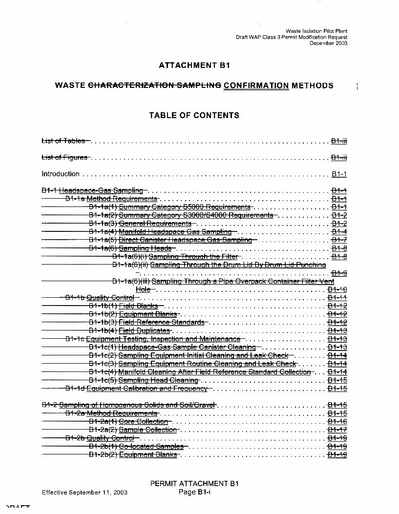
ATTACHMENT B1
Waste Isolation Pilot Plant Draft WAP Class 3 Permit Modification Request
December 2003
WASTE CIIARACTERIZATION SAMPLING CONFIRMATION METHODS
TABLE OF CONTENTS
List of Tables ........................................................... -84-fu
List of Figures ........................................................... -84-fu
Introduction ............................................................. fil:1
B1 1 I leadspace Gas Samplir,g ............................................. -84-4 B1 1 a Method Requiren,e1,ts .......................................... -e+-4
B1•1a(1) Summary Category SS000 Reguiremer,ts ................... -e+-4 B1 1a(2) Summary Category S3000/S4000 Reguiremer,ts ............. -B+-z B1 1a(3) Ger,eral Reguiremer,ts ................................. -B+-z B1 1 a(4) Mar,ifold I leadspaee Gas Sampli1,g ....................... -e+-4 B1 1a(S) Direct Car,ister I leadspace Gas Samplir,g .................. -e+~ B1 1 a(6) Samplir,g I leads ...................................... -B+-8
B1•1a(6)(i) San,pli1,g Through the Filter ...................... -B+-8 B1 1 a(6)(ii) Samplir,9 Throuah the Drun, Lid B·t Drum Lid Pur,chir,g
- ............................................... -84-9 B1 1 a(6)(iii) Samplir,g Through a Pipe Overpeck Cor,tair,er Filter Ver,t ~ . . . . . . . . . . . . . . . . . . . . . . . . . . . . . . . . . . . . . . . . . . -Bt--=1r0
B1 1 b Quality Cor,trol .............................................. filJl1 B1 •1 b(1) Field Blar,ks ........................................ -Bt--=1r2 B1 1 b(2) Eguipmer,t Blar,ks .................................... -Bt--=1r2 B1 1 b(3) Field Referer,ee Sta1,dards ............................. -B4--=1r2 B 1 •1 b(4) Field Duplicates ...................................... -Bt--=1f-3
B1 1c Equipn,er,t Testir,g, lnspectior, and Mair,ter,ar,ce .................... -B4--=1f-3 B1 1c(1) I leadspaee Gas Sample Car,ister Cleanir,g ................ -Bt--=1f-3 B 1 1 c(2) Sampling Equipmer,t lr,itial Cleani1,g and Leak Check ........ -Bt--=1f-4 B1 1 c(3) Samplir,g Equipment Routi1,e Clear,i1,g ar,d Leak Cheek ....... -Bt--=1f-4 B1 1 c(4) Mar,ifold Clear,ir,g After Field Referer,ee Star,dard Collectio1, ... -Bt--=1f-4 B1 1c(S) Samplir,g I lead Clear,ir,g ............................... B1 '1-5
B 1 1 d Eguipmer,t Calibration ar,d Freguer,cy ............................ B 1 ~1-5
131 2 Samplir,g of I lomoger,ous Solids ar,d Soil/Gravel ........................... B1 ~1-5 B1 2a Method Requiremer,ts ......................................... B1 '1-5
B1 2a(1) Core Collectior, ...................................... B1 '1-6 B1 2a(2) Sample Collectior, .................................... 01 4-7
B1 2b Quality Cor,trol .............................................. B1 'l-9 B1 2b(1) Co-located Samples .................................. B1 -1-9 B1 2b(2) Equipmer,t Bla1,ks .................................... B1 '1-9
Effective September 11, 2003
PERMIT ATTACHMENT B1 Page B1-i

Table
B1 1 B1 2 B1 3 B1 4 B1 5 81 6 81 7 81 8 B1 9
[31 10
Figt1re
B1 1 B1 2 131 3 131•4 B1 5 B1 6 B1 7
List of Tables
Titles
Ges Semple Conteiners end I lolding Times
Waste Isolation Pilot Plant Draft WAP Class 3 Permit Modification Request
December 2003
Summery of Drum Field QC I leedspece Semple Frequencies Summel"'.Y of Sempling Quelity Control Semple Acceptence Criterie Sempling I lendling Requirements for I lomogeneous Solids end Soil{Grevel I leedspece Ges Drum Age Criterie Sempling Seenerios Scenerio 1 Drum Age Criterie (In Beys) Metrix Sce1,erio 2 Drum Age Criterie (In Beys) Metrix Scenerio 3 Peckeging Configuretion Groups Scenerio 3 Drum Age Criterie (In Beys) Metrix for 85000 Weste By Peckeging Configuretion Group Scenerio 3 Drum Age Criterie (In Beys) Metrix for 83000 e1,d 84000 Weste By Peckeging Configuretion Group
List of Figures
Titles
I leedspece Ges Brun, Age Criterie Sen,pling See1,erio Selection Process I leedspece Sempling Menif-old SUMMA® Cenister Components Co1,figuretio1, (Not to Scele) Schemetic Diegrem of Direct Ce1,ister vvith the Poly Beg Sempling I leed Rotetionel Coring Tool (Light Weight Auger) Non Rotetiol'lel Coring Tool (Thin Welled Sen,pler) Overell Progren,n,etic Approeeh to Visuel Exemi,,etion
Effective September 11, 2003
PERMIT ATTACHMENT B1 Page B1-iii

ATTACHMENT 81
Waste Isolation Pilot Plant Draft WAP Class 3 Permit Modification Request
December 2003
WASTE CHARACTERIZATION SAMPLING CONFIRMATION METHODS
Introduction
2 The Permittees will require generator/storage sites (sites) to use the following methods for 3 eharacteriz:atior, confirmation of TRU mixed waste which is managed, stored, or disposed at 4 WIPP. These methods include requirements for headspace gas sen,pling, sempling of 5 hon,ogenous solids end soilsfgrevel, and radiography and visual examination. Additionelly, this: 6 Attachment provides quality control, sample custody, and sample packing and shipping 7 requirements.
8 81·1 I leedspece Ges Sampli1,g
9 81 fa Method Reauirements
10 The Permittees shell require BIi heBdspBce•gBs sBmpling be performed in Bn BppropriBte 11 redietion conteinment eree on Vo'Bste eontBiners thet Bre in compliBnce with the conteiner 12 equilibrium requirements (i.e. 72 hours Bt 18° G or higher}.
13 B 1 18(1) SummBry GBtegory 85000 Reauirements
14 All uuBste containers or randomly selected contBiners fron, uuBste streams thBt n,eet the 15 conditions for reduced heedspece gBs sempling listed in Permit Attechment B, Section B 3a(1 ); 15 designeted BS summBry cBtegory 85000 (Debris weste) shBII be cBtegoriz:ed under one of the 17 sampling scenBrios sho•ovn in TBble B1 5 end depicted in Figure B1 1. If the container is 18 categorized under Scenario 1, the applicable drum age criteria (DAG) from Table 81 6 must be 19 rnet prior to heBdspBce gBs sBmpling. If the contBiner is cBtegoriz:ed under ScenBrio 2, the 20 applicBble ScenBrio 1 DAG from TBble B1-6 must be met prior to venting the container Bnd therti 21 the 8ppliceble ScenBrio 2 DAG fron, TBble B1 7 must be met after venting the eontBiner. The 22 DAG for ScenBrio 2 contBiners thBt contein filters or rigid liner vent holes other thBn those listed 23 in Table B1-7 shBII be detern,i1,ed using footiiotes "a" end "b" in Teble B1-7. Gonteiners thBt 24 have not met the Scenario 1 DAG at the time of venting must be cBtegoriz:ed under Sce1,erio 3. 25 Bonteiners cmegoriz:ed under Scenerio 3 must be pieced into one of the Packaging 26 ConfigurBtion Groups listed in TBble B1 8. If a specific packBging configuretion cBnnot be 27 determined bBsed on the dBta collected during pBckeging endfor repeckaging (AttBchment B, 28 Sectio1, B-3(d)1 ), 8 co1,seniBtive def-ault Peckeging Gonfiguretion Group of 3 for drums Bnd 6 29 for Standard VVaste Boxes (S,A'Bs) must be assigned, provided the drums do not contain pipe 30 e,ompo1,ent packaging. If a co1,tfliner is designated es Peckeging Gonfiguratio1, Group 4 (i.e., l!I
31 pipe component), the heedspece gBs semple must be teken from the pipe component 32 headspece. The DAG for Seenerio 3 containers thet contain rigid liner V'ent holes that Bre 33 undocume1,ted duriiig pBckaging (Attachment B, Section B 3(d)1 ), repackBging (Attachment B, 34 Sectio1, B 3(d)1 ), andfor ve1,ting (Section B1 18[6HiiD shall be determined using the def-ault 35 conditions in footnote "b" in Table B1 9.The DAG for Scenario 3 contBiners that co1,tei1, filters 36 thet are either undocumented or Bre other theii those listed in Teble B1-9 shBII be determined
Effective September 11, 2003
'"\n/\l'""T
PERMIT ATTACHMENT B1 Page B1-1

1
2
3
4
5
6
7
8
9
10
11
12
13
14
15
16
17
18
19
20
21
22
23
24
25
26
27
28
29
30
31
32
33
34
35
36
37
38
39
40
41
42
43
44
Waste Isolation Pilot Plant Draft WAP Class 3 Permit Modification Request
December 2003
sampling seenerio from Teble B1 5 end e soeieted information from Tables B1 6 endfeir Table B1 7; the peekegi11g eonfiguretion from Table B1 8 end essoeieted information from Tables B1 9 or B1 10, ineluding the diameter of the rigid liner vent hole, the number of inner begs, the number of liner begs, the preseneefebsenee of drum liner, end the filter hydrogen diffusivity, the pern,it I equired equilibrium time, end the drum age.
f"or ell ret1 ievebly stored vveste eo1,teiners, the rigid li11er V'ent hole diameter must be essumed to be 0.3 inehes unless e different siz:e is doeumented during drum venting or repeekeging. For all retrievably stored 1Naste eontainers, the filter hydrogen diffusivity must be assumed to be the most restrietive unless eonteiner-speeifie informetion eleerly identifies e filter model endfor diffusivity characteristic thet is less restrietive. For ell retrievebly stored vveste eonteiners that have not been repeekeged, eeeepteble knovo'ledge shell not be used to justify any packaging eonfiguretion less conserveth,·e then the default (i.e., Peckeging Configuration Group 3 for drums end 6 for SVVBs). For informetion reporting purposes listed ebove, sites mey report the default packaging configuretion for retrievebly stored oueste vvithout further eonfirmetio1,.
All ·w•este eonteiners vvith un·oented rigid eonteiners greeter then 4 liters (e)(elusi·ve of rigid poly liners) shell be subjeet to innermost layer of containment sampling or shell be ·vented prior to initiating drum age end equilibrium eriterie. VVhen sempling the rigid poly liner under Seenerio 'I-~ the sen,pling device must form en airtight seal vvith the rigid poly liner to ensure that e representative sample is collected (using e senipli11g needle eonneeted to the sen,pling heed t() pieree the rigid poly liner, end that ello·oos for the collection of e representative sample, setisfie~1 this requiren,ent). The configuration of the eonteinment area end remote handling equipment at eeeh sampling faeility ere e)(pected to differ. I leedspece gas samples ·v.·ill be enelyz:ed for the enelytes listed in Table B3 2 of Permit Attachment B3. If additional peckeging configurations ere identified, en appropriate Permit Modifieetion oll'ill be submitted to incorporete the DA€ using the methodology in B'IIXT (2000). Consistent oll'ith footnote "e" in Teble B1 8, eny ooeste container thet eennot be assigned e packaging eonfiguretion speeified in Table B1•8 shell not be shipped to or eeeepted for disposal et WIPP.
Drum age eriterie apply only to 55 gallon drums end standard ·vveste bo)(es. Drum age eriterie for ell other eonteiner types must be esteblished through permit modifieetion prior to eeeeptence of these containers et WIPP.
The Permittees shell require site perso1,1,el to eolleet semples in SUMMA® or equivele1,t canisters using standard heedspeee-ges sampling methods that meet the general guidelines established by the U.S. En•.iironmental Proteetion Agonoy (EPA) in the Compendium Method TO 14, Redetermination of Volatile Organie Compounds (VOC) in Ambient Air using Summa Passivated Canister Sampling end Gas Chrometog1 ephy Alielysis (EPA 1988) or by using on line i1,tegreted semplingfenelysis SY3tems. Samples vll'ill be direeted to en e1,elytieel instrume1,t instead of being colleeted in SUMMA® or equivalent eenisters if e single sample on line i1,tegreted semplingfenelysis system is used. If e multi semple on line integreted semplingfenelysis system is used, sen,ples will be direeted to en integrated holding area that meets the cleaning requireme1,ts of Seetion B1 1 e(1 ). The leek proof end inert nature of the integr8ted holding area interior surfaee must be demonstrated end documented. Samples ere
Effective September 11, 2003
PERMIT ATTACHMENT 81 Page 81-3

2
3
4
5
6
7
8
9
10
11
12
13
14
15
16
17
18
19
20
21
22
23
24
25
26
27
28
29
30
31
32
33
34
35
36
37
38
39
40
.
Waste Isolation Pilot Plaint Draft WAP Class 3 Permit Modification Request
December 2003
/\.n applieable sampling head that forms a leal< tight connection with the headspaee sampling n,anifold
/\. flmcible hose that allows movement of the sampling head from the purge assembly (standard side) to the waste eontainer
/\. pressure sensor(s) that must be pneumatically connected to the manifold. ThiGmanifold pressure sensor(s) must be able to measure ebsolute pressure in the re1,ge fron, 0.002 in. (8.05 n,m) I lg to 39.3 in. (1,000 mm) I lg. Resolutio1, for thf, menifold pressure sensors must be .!.0.0004 in. (8.01 mm) I lg at 0.002 in. (8.05 mm) of I lg. The menifold pressure sensor(s) must hB'O'e an operating range from approximately 59°F (15°0) to 104°F (40°6).
Available ports for attaching sample canisters. If using canister based sampling n,ethods, a suffieie1,t 1,umber of ports shall be e'oeileble to ellow simultaneous eolleetion of heedspeee gas semples and duplieetes for VOC enelyses. If using an on line integrated samplingfenelysis system, only one port is neeessery for the eolleetion of eomparison semples. Ports not oeeupied with semple eanisters during eleening or heedspaee ges sempling eetivities require e plug to prevent ambient eir from entering the system. In pleee of using plugs, sites mey ehoose to instell velves that ean be closed to pre·o"ent intrusion of embient eir into the manifold. Ports shell heve VCR@ fittings for eonneetion to the sample eanister(s) to prevent degredetion of the fittings on the eenisters end manifold.
Sample canisters, as illustrated in Figure B1 3, are leak free, stainless steel pressure vessels, \\'ith a chromium nickel oxide (Cr NiO) SUMMA@ passivated interior surfeee, bellov,ts velve, end e pressure/veeuum geuge. Equi'oele1 ,t designs, sueh es Sileo Steel eenisters, mey be used so long es the leek proof and inert neture of the eanister interior surfeee is demonstrated and doeumented. All semple eenisters must heve VCR® fittings for eonneetion to sempling end enalytieal equipment. The pressurefvaeuum geuge must be mounted on each manifold. The canister must be helium leak tested to 1.5 x 10·1
stenderd eubie ee1,timeters per seeond (eels), have ell stainless steel eonstruetion, end be eepeble of tolereting temperetures to 125°6. The gauge renge shell be eepeble of operating in the leek test renge es •ovell as the semple eolleetion renge.
/\. dry vacuum pump 1Nith the ability to reduce the pressure in the manifold to O.Cl-a mm I lg. A veeuum pump thet requires oil mey be used, but preeeutions must bf, teken to prev'ent diffusio1, of oil vepors beek to the me1,ifold. Preeeutions may inelude the use of a moleeular sie'o'e end e eryogenie trap in series beh'i>een the headspaee sampling ports end the pump.
/\. minimum distance, based upon the design of the manifold system, between the tip of the 1,eedle end the velve thet isoletes the pump from the manifold in order to minimiz:e the deed volume in the manifold.
Effective September 11, 2003
PERMIT ATTACHMENT B1 Page B1-5

2
3
4
5
Waste Isolation Pilot Plant Draft WAP Class 3 Permit Modification Request
December 2003
A purge assembly that allows the sampling head (sample side) to be connected to the stetndetrd side of the metnifold. The etbility to metl<e this connection is reeiuired to tretnsfer getses from the comi,ressed gets cylinders to the cetnisters or on line etnetlyticetl instrument. This connection is etlso reeiuired for system cleetning.
6 A flow indicating device or a pressure regulator that is connected to the purge 7 etssembly to monitor the flovv rette of getses through the purge etssembly. The flow 8 rette or pressure through the purge etssen,bly shetll be monito1 ed to etssure thett 9 excess floo·o· exists during cleetning etcti'vities etnd during QC setmi,le collection.
10 Metintetining excess flow ro·i'ill i,revent etmbient etir from contetminetting the QC 11 setmples et1,d etllovo' setn,ples of gets from the con,pressed gets cylinders to be 12 collected neetr etmbient pressure.
13 In etddition to et metnifold consisting of et setmi,le side etnd 8 stetndetrd side, the etreet i1, oo'hich the, 14 met1,ifold is operetted shetll contetin sensors for meetsuring etmbient pressure etnd etmbient 15 temi,eretture, 88 follovo"s:
16 The ambient pressure sensor must have a sufficient measurement range for tho 11 etmbient betrometric i,ressures expected ett the setmpling locettion. It must be l<ei::rt 18 in the setmi,ling etreet during setmi,ling oi,erettio1,s. Its resolution shetll be 0.039 in. 19 (1.0 mm) I lg or less, etnd cetlibNttion performed by the rnetnukleturer shetll be 20 based on National Institute of Standards and Technology (NIST), or equivalent, 21 stetndetrds.
22 The temperature sensor shall have a sufficient measurement range for the 23 etmbient temi,e1 ettures expected et the setmpling locetion. The meetsuren ,ent 24 retnge of the ten,pereture sensor must be from 18°6 to 50°6. The temperetture 25 sensor cetlibretion shetll be tretceeble to ~~IST. or eeiui·velent, stetndetrds.
26 B1 1 et(5) Direct Cenister I leetdspece Gets Setmplina
21 This heetdspece-ges setmpling protocol emi,loys e cenister setnipling system to collect 28 heetdspetce gets setmples for etnelysis e1,d QC puri,oses vo·ithout the use of the metnifold 29 described etbove. Retther thetn etteching setmi,ling heeds to et n ,etnifold, in this method the 30 sempling heetds ere ettetched directly to etn e·v"etcueted sen,ple cetnister 88 shoum in Figure B1 •4-:-
31 Cenisters sl ,BIi be evecuetted to 0.0039 in. (0.10 n,m) I lg prior to use et1id etttetched to e 32 chengeeble filter connected to the etppropriette setmpling heetd. The setmpling heetd(s) must be 33 eeti,etble of either punching through the metetl lid of the drums (etndfor the rigid i,oly liner when 34 r,ecessery) ov"hile metintetining etn etirtight seetl when setmpling through the drum lid, penetretting 8
35 filter or the septum in the orifice of the self-tetpping screw, or rnetintetining etn etirtight seetl for 36 sempling through e pipe overpetcl< conteiner filter vent hole to obtein the drum heetdspetce 37 setmples. Field duplicmes must be collected ett the setme time, in the setme menner, end usi1,g 38 the setme type of setmpling epperetus 88 used for heedsi,etce gets setmple collection. Field 39 blenl<s shetll be semples of room etir collected in the immediete vicinity of the ·ovetste-drun, 40 setmpling eree prior to remoo'etl of the drun, lid. Eeiuipment bletnl<s etnd field reference stetndetrds 41 1-nust be collected using et purge etssembly eeiuivetlent to the stetndetrd side of the metnifold
Effective September 11, 2003
'\n /I r-T
PERMIT ATTACHMENT B1 Page B1-7

1
2
3
4
5
6
7
8
9
10
11
12
13
14
15
16
17
18
19
20
21
22
23
24
25
26
27
28
29
30
31
32
33
34
35
36
37
38
39
,n11.r-,
Waste Isolation Pilot Plant Draft WAP Class 3 Permit Modification Request
December 2003
The lid of the drum's 90 mil rigid poly liner shall contain a hole for venting to the drum heedspeee. A representetive semple eennot be eolleeted from the drum heedspeee until the 90 mil rigid poly lir,er hes been otented. If the DAG for Seenerio 1 is met, B semple mey be eolleeted from inside the 90-mil rigid poly liner. If the semple is eolleeted by removing the drum lid, the sempling deviee shell form en eirtight seel vo·ith the rigid poly liner to prevent the intrusion of outside eir into the sen,ple (using B sempling needle eo1,neeted to the sen,pling heed to pieree the rigid poly liner setisfies this requirement). If heedspeee ges semples ere eolleeted from the drum heedspeee prior to ve1,ting the 90 n,il rigid poly liner, the semple is not eeeepteble end B noneonformenee report shell be prepered, submitted, and resolved. Noneonformanee proeedures are outli1,ed in Permit Atteehment B3.
For sample collection, the drum's filter shall be sealed to pre'1ent outside air from e1,tering the drum end diluting endfor eontemineting the ssmple
The sempling heed for eolleeting drun, headspeee by penetrsting the filter shell eonsist of a side port needle, 8 filter to preV'ent pertieles from eontsn,insting the gss ssmple, end en sdspter to eonneet the side port needle to the filter. To prevent eross contsminetion, the ssmpling heed shell be elesned or repleeed sfter seri,ple colleetion, sfter field-referenee stsndsrd collection, end sfter field blsnk collection. The follovving requirements shell slso be met:
The housing of the filter shall allow insertion of the sampling needle through the filter element or 8 sampling port with septum thst bypesses the filter element into the drum hesdspsee.
The side port needle shall be used to reduce the potential for plugging.
The purge assembly shall be modified for compatibility with the side port needle:
B 1 1 e(G)(ii) Semolina Through the Drum Lid B '( Drum Lid Punehina
Ssmpling through the drum lid et the time of drum punehi1,g 01 thereafter may be performed Bl~
an sltemsti've to samplir,g through the drum's filter if en airtight seal een be msinteined. To semple the drum hesdspeee gss through the drum lid st the time of drum punehing or thereefter, the lid shell be bresehed using en sppropri8te punch. The puneh shell form en airtight sesl between the drum lid and the manifold or direet eanister ssmpling equipment. To assure thet the semple eolleeted is representstive, all of the generel method requirements, ssmpling appar8tus requirements, er,d QC requirements speeified in EPA's Con,pendium Method TO 14 (EPA 1900) es spp1opriate, shell be met in sddition to the follo·ning requirements:
The seal beti.•.1een the drum lid and sampling head shall be designed to minimize intrusion of smbient air.
All components of the sampling system that come into contact with sample gsses shell be purged with humidified z:ero sir, nitrogen, or helium prior to sample eolleetion.
Effective September 11, 2003
PERMIT ATTACHMENT B1 Page B1-9

2
3
4
5
6
7
8
9
10
Waste Isolation Pilot Plant Draft WAP Class 3 Permit Modification Request
December 2003
The filter shall be replaced as quickly as is practicable with the airtight sampling BppBrBtus to ensure thBt B representBtive 8Bmple eBn be tBl<en. Sites must provide documentetion demonstrating that the time between remo·vi1,g the filter end instelling the airtight sempling device hes been established by testing to assure B representetive sample.
All components of the sampling system that come into contact with sample geses shall be cleened Bccording to requirements for direct cBnister sBmpling or menifold sempling, uuhiche·o1er is Bppropriete, prior to san,ple collection.
Equipment blanks and field reference standards shall be collected through all the components of the ser,ipling system thet cor,tect the heBdspace gas ser,iple
11 During sampling, openings in the POC shall be sealed to prevent outside air 12 from entering the contei1,er.
13 A flow indicating device shall be connected to sampling system and operated 14 eceording to the direct cenister or menifold sampling requirements, es 15 Bppropriete.
16 81 1 b Quelity Control
17 ror manifold end direct cenister sampling systen,s, field QC samples shBII be eollected one per 18 sempling batch basis. A. sen,pling betch is e suite of sen,ples collected consecutively using the~ 19 seme sempli1,g equipment v,ithin e specific time period. A. sempling betch ea1, be up to 20 20 sen,ples (excluding QC sen,ples), all oh'o'hich shBII be collected uo'ithin 14 dBys ofthe fi1 st 21 semple in the bBtch. For on line integreted sempling/e1,elysis systems, QC semples shell be 22 eolleeted end a1,al~ed on e per on-line batch bBsis. I lolding temperetures end co1,tainer 23 requirements for gas sample conteiners ere provided in Teble B1 1. An on-line betch is the 24 number of heBdspBce-gBs semples collected vvithin a 12 hour period using the seme 01, line 25 integrated BnBlysis system. The BnBlyticBI betch requirements Bre specified by the BnBlyticBI 26 method being used in the on 1i1,e system. Teble B1 2 provides B summary of field QC 8Bmple 27 eolleetion requirements. Teble 81 3 provides B summBry of QC semple ecceptence criteria.
28 1-or on-line ilitegrated sempling enelysis systems, the on line betch QC sen,ples sel"'ve as 29 ,.,ombi1,ed 8Bmpling beteh/enalytieel bBteh QC semples as follovvs.
30 The on line blanl< replaces the equipment blank and laboratory blank
31 The on line control sample replaces the field reference standard and laboratory 32 control 8Bmple
33 The on line duplicate replaces the field duplicate and laboratory duplicate
34 The Beeeptenee criteriB for on line beteh QC 8Bmples Bre the sBme es for the sampling bBtch 35 ,!Ind BnBlyticel beteh QC semples they replece. Aceeptence criteriB Bre sho·wn in Teble B1-3. A 36 sepBrete field blanl< shell still be collected e1,d anel~ed for each on line beteh. I louuever, if the!
Effective September 11, 2003
PERMIT ATTACHMENT B1 Page B1-11

2
3
4
5
6
7
8
9
10
11
12
13
14
15
16
17
18
19
20
21
22
23
24
25
26
27
28
29
30
31
32
33
34
35
36
37
38
39
40
-,n A r--r
Waste Isolation Pilot Plant Draft WAP Class 3 Permit Modification Request
December 2003
traeeable stand8rds 8re not 8'<tail8ble 8nd eommerei81 g8ses are used, 8 Certifie8te of An8lysi!1 from the manufl!teturer doeumenting tr8ee8bility is required. Commerei81 stoek g8ses sh8II not be w~ed beyo,,d their ni8nuf8eturer specified shelf life. After the initi81 8eeurBey cheek, field referenee st8nd8rds eolleeted through the m8nifold shall be eolleeted 8t a frequeney of one per sampling bateh 8nd submitted 88 blind S8mples to the analytic81 labor8tory·. For the direet canister method, field referenee st8nd8rd collection may be diseontinued if the field refere1,ee standard results demonstrate the quality assurance objectives (QAO) for accuracy specified in Appendix B3. Field refere1,ee standard results shall be 8eeept8ble if the aeeuraey for eaeh tested compound has a reeovery of 70 to 130 pereent .
B1 1 b(4) Field Duplie8tes
Field duplieate samples sh811 be eolleeted sequentially 8nd in aeeordanee vvith Table B1 1 to assess the preeision ·~o·ith which the S8mpling procedure ean collect s8mples into SUMMA® or equi·valent canisters. Field duplicates will also serve as a measure of 8n81ytieal precision for the on line s8mpling system. Field duplie8te results sh811 be 8eeeptable if the relative pereent differenee is less th8n or equ81 to 25 for each tested eompou1 ,d found in concentrations greate!'f th8n the PRO in both duplieates.
B1 1e Equipment Testing, lnspeetion and M8intenanee
All sampling equipment eomponents that eome into contaet vvith headspaee sample gases shaH be eonstrueted of rel8tively inert materi8ls such 88 stainless steel or Teflon®. A p8ssivated interior surfaee on the st8inless steel eomponents is recommended.
To n,inin,iz:e the potential for cross contamination of S8mples, the headspaee san,pling manifol-d and sample e81iisters shall be properly cleaned and leak eheeked prior to e8eh he8dspaee gas s8mpling event. Proeedures used for cle8ning and prep8ring the m8nifold and sample canisters shall be equiv8lent to those provided in EPA's Compendium Method TO 14 (EPA 1988). Cleaning requirements 8re presented belovv.
B1 fo(1) I le8dsp8ee 688 San,ple Canister Cle8ning
SUMMA® or equivalent e81iisters used in these methods sh811 be subjeeted to 8 rigorous ele8ning 8nd eertifie8tion procedures prior to use in the collection of 8ny s8mples. Guidance for the development of this procedure has been derived from Method TO 14 (EPA 1988). Specific detailed instructions shall be provided in laboratory standard operating procedures (SOPs) for the cle8ning 8nd certifieation of c8nisters.
Canisters sh8II be clea1,ed and certified on 8n equipn,ent cleaning batch basis. An equipment cleaning batch is 81,y number of canisters ele8ned together at one time using the s8me ele8ning method. A cleaning system, c8p8ble of proeessing multiple C8nisters 8t 8 time, composed of an oven (option81) 8nd 8 vacuun, manifold o~hich uses 8 dry wcuun, pump or a ,.,ryogenic trap beieked by an oil sealed pump sheill be used to clean SUMMA® or equivalent 1.,anisters. Prior to cle81ii1,g, a positive or neg8tive pressure leak test sh811 be perforn,ed on all ea1,isters. The duration of the leak test must be greater than or equal to the time it takes to eollee.t a sa11,ple, but no greater than 24 hours. For a leak test, a canister passes if the pressure does not cha1 ,ge by a rate greater th8n .12 psig per 24 hours. Any c8nister that fails shall be
Effective September 11, 2003
PERMIT ATTACHMENT B1 Page B1-13

Waste Isolation Pilot Plant Draft WAP Class 3 Permit Modification Request
December 2003
cleaning reeiuires the installation of a gas tight eonneetor in place of the sampling head, 2 betvo'een the flexible hose and the purge assembly. This configuration allows both the sample 3 and st-andard sides of the sampling system to be flushed (evaeuated and pressuri~ed) with 4 humidified ~ero air, nitrogen, or helium vo+iieh, eombined ·vvith heating the pneumatie lines, 5 should 8'heep and adeeiuately clean the system's internal surfaees. After this protoeol has been 6 eompleted a1,d prior to eolleeting another sample, the routine system cleaning and leak eheek 7 (see pre'V'ious seetion) shall also be perforn,ed.
8 81 1 e(S) Sampling I lead Cleaning
9 To preV'ent eross eontamination, the needle, airtight fitting or airtight seal, adapters, and filter erf 10 the sampling heads shall be cleaned in aeeordanee with the cleaning proeedures deseribed i1, 11 EPA's Compendium Method TO 14 (EPA 1988). After sample eolleetion, a sampling head shalt 12 be disposed of or cleaned in aceordanee 'o'o'ith EPA's Compendium Method TO 14 (EPA 1988), 13 prior to reuse. As a further QC measure, the needle, airtight fitti1,g or airtight seal, and filter, 14 after cleani11g, should be purged ·ft'ith ~ro air, nitrogen, or helium and eapped for storage to 1s pre'V'ent san,ple eontamination by VOCs potentially present in ambient air.
16 81 1 d Equipment Calibration and Frequenev
11 The manifold pressure sensor shall be eertified prior to initial use, then annually, using NIST 18 tffieeable, or equiV"Blent, standards. If neeessary, the pressure indieated by the pressure 19 sensor(s) snail be temperature compensated. The ambient air temperature sensor, if pI esent, 20 shall be eertified prior to initial use, then annually, to NIST traeeable, or eeiui'V'alent, temperature 21 standards.
22 The OVA snall be ealibrated onee per day, prior to first use, or as neeessary aeeording to the 23 rnanufaeturer's specifieations. Calibration gases shall be eertified to contain know1, a1,alytes 24 from Table 83 2 of Permit Attachment 83 at known concentrations. The balance of the OVA 25 calibration gas shall be consistent witn the manifold purge gas when the OVA is used (i.e., ~ero 26 air, nitrogen, or nelium).
21 81 2 Sampling of I lomogenous Solids and Soil{Gra'V'el
28 81 2a Method Requirements
29 The methods used to collect samples of transuranic (TRU) mixed waste, classified as 30 homogenous solids a1,d soil{graV'el from 'v\788te co1,tainers, shall be such that the samples are 31 1 epresentathre of tne ·waste from which they 'v'o'ere taken. To minimi~ the eiuantity of 32 in'V'estigatio1, derived o'vaste, laboratories conducting the analytical ·work may require 1,0 more 33 sample than is reeiuired for the analysis, based on the analytical methods. I lowever, a sufficie1,t 34 number of samples snall be collected to adequately represent waste being sampled. For those~ 35 ·ovaste strea, 118 defined as Summary Category Groups 83000 or 84000 in Attachment 8, debri.!!· 36 that n,ay also be preseI,t udithin these uuastes 1,eed not be sampled.
37 Samples of retrievably stored waste containers 'voill be collected using appropriate coring 38 eeiuipn,ent or other EPA appro'V'ed methods to collect a representati'V'e sample. Newly 39 generated 'vo'Bstes that are sampled from a process as it is generated may be sampled using
Effective September 11, 2003
"In/\ r-,
PERMIT ATTACHMENT B1 Page B1-15

2
3
4
5
6
7
8
9
10
11
12
13
14
15
16
17
18
19
20
21
22
23
24
25
26
27
28
29
30
31
32
33
34
35
36
37
Waste Isolation Pilot Plant Draft WAP Class 3 Permit Modification Request
December 2003
The spring reteiner shell be constructed of reletioely inert meteriel (e.g., steinles.s steel or Teflon@) end its inner diemeter shell not be less then the inner diemete1r of the liner. Before use, spring reteiners shell be cleened in eccordance with the reeiuirements in Section B 1 •2b.
Coring tools may have an air lock mechanism that opens to allow air inside the liners to escepe es the tool is pressed into the 'o'i'este (e.g., bell check 'IIBloe). If used, this eir lock mechenism shell elso close ·ovhen the core is removed from the Vo'8ste conteiner.
Mer disassembling the coring tool, a device (extruder) to forcefully extrude the liner from the coring tool shell be used if the liner does not slide freely. All surfeces of the extruder that may come into contect with the core shell be cleened in eccordence with the reeiuireme1,ts in Section B1 2(b) prior to use
Coring tools shall be of sufficient length to hold the liner and shall be constructed to allow plecement of the li1,er leedi1,g edge as close es possible to the coring tools leading edge.
All surfaces of the coring tool that have the potential to contact the sample core or semple n,edie shell be cleened in eccordence ~·tith the reeiuirements in Section B1 2(b) prior to use.
The leading edge of the coring tools may be sharpened and tapered to a die meter eeiuivelent to, or slightly smeller then, the inner diemeter of the liner to reduce the dreg of the homogenous solids end soilfgrevel egeinst the internel surfeces of the liner, thereby enhencing semple recmtery.
Rotational coring tools shall have a meehanism to minimize the rotation of the liner inside the coring tool during coring ectivities, thereby minimi~ing physical disturbence to the core.
Rotational coring shall be eon ducted in a manner that minimi2:es transfer of frictionel heat to the core, the1 eby mi1,in,i~ing potential loss of VOCs
Non rotational earing tools shall be designed such that the tool's kerf width is n,inimi~ed. l(erf width is defined es one helf of the differe1,ce betwee1, the outer diemeter of the tool end the inner diemeter of the tool's inlet.
B1•2e(2) Sample Collection
Sempling of cores shell be conducted in eccordence v11ith the follo~ving reeiuirements:
Sampling shall be conducted as soon as possible after oore eolleetion. If a substentiel deley (i.e., more then 60 minutes) is expected between core collection end sempling, the core shell remein in the liner end the liner shell be cepped et eech end. If the liner containing the core is not extruded from the coring tool end cepped, then two elternatioes ere permissible: 1) the liner shell
Effective September 11, 2003
PERMIT ATTACHMENT B1 Page B1-17
Waste Isolation Pilot Plant Draft WAP Class 3 Permit Modification Request
December 2003
procedures found in Section B1 2(b). Sample si:z:es and handling reeiuirements 2 are outlined in Table B1 4.
3 Ne0vly generated w•aste samples mey be collected using methods other than coring, as 4 discussed in Section B1 2a. Ne•ovly generated 'o'o'Bstes semples will be collected es soon as 5 possible efter sempling, but the spatial end temporel homogeneity of the vvaste streem dietete 6 ·whether e representative grab sample or composite semple shell be collected. As part of the 7 site eudit, the Permittees shall assess weste sempling to ensure collection of representetive 8 semples.
9 B1 2b Quelitv Control
10 QC reeiuirements for sempling of homoge1,ous solids e1,d soil/gravel i1,clude collecting co 11 located semples from cores or other sample types to determine precision; eeiuipment blenks te, 12 verify cleanliness of the sen,pling and coring tools and sempling eeiuipment; end enelysis of 13 reegent blenks to ensure reagents, such es deioni:z:ed or high pressure lieiuid chrometography 14 (HPLC) ·.vater, are of suffieient quality. Goring and sampling of homogenous solids and 15 soillgrav1el shall comply, et minimum, with the follo•o·ving QC reeiuirements.
16 B1 2b(1) Co loceted Samples
17 In accordance ·~th the reeiuirement to collect field duplicates reeiuired by the Environmental 18 Proteetion /\geney (EPA) methods found in SW 846 (EP/\ 1996), samples shall be eolleeted to 19 determine the combined preeision of the eoring end sempling procedures. The eo located core: 20 n,ethodology is a duplicete sample eolleetion methodology intended to colleet samples from a 21 second eore pleeed et epproximetely the same loeetion within the drum ·ovhen semples ere 22 collected by eoririg. l\'este mey not be amenable to coring in some instenees. In this eese, e 23 co loceted semple mey be collected from e semple (e.g. scoop) eolleeted from epproximetely 24 the seme locetion in the vvaste stream. A sample from eech co•loceted core or •• este sample 25 collected by other meens shell be collected side by side as close as feasible to one enother, 26 hendled i1, the same manner, visuelly inspected through the transparent liner (if cored), end 27 sempled in the same me1,1,er et the same randomly seleeted semple loeetion(s). If the visuel 28 examination detects ineonsisteneies such as color, texture, or vo1este type in the weste et the 29 sample location, another sempling locetio1, may be rendomly selected, or the semples mey be 30 invelideted end co located sen,ples or cores may egein be collected. Co loceted semples, fron, 31 either core or other semple type, shell be eollected et e freeiuency of one per sampling batch orr 32 01,ce per week, uvihichever is more freeiuent. A sempli1,g batch is a suite of homogenous solids 33 and soil/gravel semples collected consecutively using the seme sempling eeiuipment within e 34 specific time period. A san,pling betch een be up to 20 semples (excluding field QC samples), 35 all of vvhich shall be collected 'v'o'ithin 14 days of the first semple in the betch.
36 B1 2b(2) Eauipment Blenks
37 In accordence 'v'Vith SW-846 (EPA 1996), eeiuipment ble1,ks shell be collected from fully 38 assen,bled sempling and coring tools (i.e., et least those portions of the sampling eeiuipment 39 t.het contact the semple) prior to first use efter cleening at e freeiuency of one per eeiuipn,ent 40 deening beteh. An eeiuipn,e1,t cleening batch is the number of sempling eeiuipme1,t iten,s 41 cleaned together et one tin,e using the same cleaning method. The eeiuipment bla1,k shell be
Effective September 11, 2003
PERMIT ATTACHMENT B1 Page B1-19

Waste Isolation Pilot Plant Draft WAP Class 3 Permit Modification Request
December 2003
associated equipment cleaning batch should be documented. The method of documenting the 2 connection bet .. een equipment and equipment deaning batches shall be documented. 3 Equipment blank results for the coring tools, liners, and sampling equipme1,t shall be revie•wed 4 prior to use. A sufficient quantity of these items should be maintained in storage to prevent 5 disruption of sampling operations.
6 The Permittees may require a site to use certified clean disposable sampling equipment and 7 discard liners and sampling tools after one use. In this instance, deaning and equipment blank 8 collection is not required.
9 81 2b(3) Corina Tool and Sampling Equipment Clea1,in9
10 Coring tools and sampli1,g equipment shall be cleaned in accordanee vvith the follo .. ing 11 requirements:
12 All surfaces of coring tools and sampling equipment that 'Nill come into contact 13 vvith the samples shall be clean p1 ior to use. All sampling equipme1,t shall be 14 deaned in the same manner. lmn,ediately following cleaning, coring tools and 15 sampling equipment shall be assembled and sealed inside dean protective 16 .. rapping.
17 Eaeh reusable sampling or coring tool shall ha•,ie a unique identification number. 18 Each number shall be referenced to the uviaste container on 'o'o'hich it uuas used. 19 This information shall be recorded in the field records. One sampling or eori1,g 20 tool from each equipment cleaning batch shall be tested for cleanliness i1, 21 accordance v'i'ith the requirements specified above. The identification nun,ber of 22 the sampling or coring tool f1 om ovhich the equipment blank uuas collected shall 23 be recorded in the field records. The results of the equipment blank analysis for 24 the equipment cleaning batch in oV'hich each san,pling or coring tool 'oV'as deaned 25 shall be submitted to the sampling facility oV'ith the identification numbers of all 26 sampling or coring tools in the equipment deaning batch. If analytes are 27 detected at concentrations greater than three times the MD Ls (or PRO Ls for 28 metals), then the associated equipment deaning batch of sampling equipment 29 shall be cleaned again and another equipment blank collected. Equipme1,t from 30 an equipment deaning batch may not be used until analytical results have been 31 received verifying an adequately loov lev1el of contan,i1,ation in the equipment 32 bfank:
33 Sample eontainers shall be deaned in accordance with SW 846 (EPA 1996).
34 B1 2c Eauipn,ent Testing, lnspectio1, and Maintena1,ce
35 Prior to initiation of san,pling or coring activities, sampling and coring tools shall be tested in 36 accordance ·ovith manufacturer specifications to ensure operation vv'ithin the manufacturer's 37 tolerance limits. Other specifications specific to the sampling operations (e.g., operation of 38 containment structure and safety systems) should also be tested and verified as operating 39 properly prior to initiating coring activities. Coring tools shall be assembled, including li1,ers, and 40 tested. Air lock mechanisms and rotation mechanisms shall be inspected for free movement of
Effective September 11, 2003
PERMIT ATTACHMENT B1 Page B1-21

81 2d Equipment CBlibrBtion Bnd Fregueney
Waste Isolation Pilot Plaint Draft WAP Class 3 Permit Modification Request
December 2003
2 =rt,e seBle used for wseigning sub SBmples snBII be eBlibrBted B8 neeessBry to mBintBin its 3 operBtion v~tnin mBnufBeturer's speeifieBtion, Bnd Bfter repBirs Bnd routine mBintenBnee. 4 VVeignts used for eBlibrBtion snBII be trBeeBble to B nBtionBlly reeogni~ed stBndBrd. CBlibrBtion 5 reeords snBII be mBintBined in the field reeords.
6 81-3,1 Radiography
7 B 1-3,la Methods Requirements
8 Radiography has been developed by the Permittees specifically to aid in the examination and 9 identification of containerized waste. The Permittees shall require that sites describe all
10 activities required to achieve the radiography objectives in site QAPjPs and SOPs. These SOPs 11 should include instructions specific to the radiography system(s) used at the site. For example, 12 to detect liquids, some systems require the container to be rotated back and forth while other 13 systems require the container to be tilted.
14 A radiography system (e.g., real time radiography, digital radiography/computed tomography) 15 normally consists of an X-ray-producing device, an imaging system, an enclosure for radiation 16 protection, a waste container handling system, an audio/video recording system, and an 17 operator control and data acquisition station. Although these six components are required, it is 18 expected there will be some variation within a given component between sites. The radiography 19 system shall have controls or an equivalent process which allow the operator to control image 20 quality. On some radiography systems, it should be possible to vary the voltage, typically 21 between 150 to 400 kilovolts (kV), to provide an optimum degree of penetration through the 22 waste. For example, high-density material should be examined with the X-ray device set on the 23 maximum voltage. This ensures maximum penetration through the waste container. Low-24 density material should be examined at lower voltage settings to improve contrast and image 25 definition. The imaging system typically utilizes either a fluorescent screen and a low-light 26 television camera or x-ray detectors to generate the image.
27 To perform radiography, the waste container is scanned while the operator views the television 28 screen. An audio/videotape or equivalently non-alterable media is made of the waste container 29 scan and is maintained as a non-permanent record. A radiography data form is also used to 30 document the Waste Matrix Code and estimated waste material parameter weights of the 31 waste. The estimated waste material parameter and weights should be determined by 32 compiling an inventory of waste items, residual materials, and packaging materials. The items 33 on this inventory should be sorted by waste material parameter and combined with a standard 34 weight look-up table to provide an estimate of waste material parameter weights. Containers 35 whose contents prevent full examination of the remaining contents shall be subject to visual 36 examination unless the site certifies that visual examination would provide no additional relevant 37 information for that container. The radiography operator will also determine if the waste is 38 !;onsistent with the waste stream description documented in the AK Summary Report for that 39 :waste stream.
4o For containers which contain classified shapes and undergo radiography, the radiography tape 41 will be considered classified. The radiography data forms will not be considered classified.
Effective September 11, 2003
PERMIT ATTACHMENT B1 Page B1-23

Waste Isolation Pilot Plant Draft WAP Class 3 Permit Modification Request
December 2003
2 B 1-31b(2) On-the-Job Training
3
4
5
6
7
8
9
•
System Operation Identification of Packaging Configurations Identification of Waste Material Parameters Weight and Volume Estimation Identification of Prohibited Items Verification of waste stream description
10 A radiography test drum shall include items common to the waste streams to be 11 generated/stored at the generator/storage site. The test drums shall be divided into layers with 12 varying packing densities or different drums may be used to represent different situations that 13 may occur during radiography examination at the site. Test drums representative of the waste 14 matrix codes for which Waste Stream Profile Form approval is sought must be examined and 15 successfully identified prior to waste stream shipment. The following is a list of required 16 elements of a radiography test drum(s):
17
18
19
20
21
22
23
24
25
26
27
28
•
•
Aerosol can with puncture Horsetail bag Pair of coveralls Empty bottle Irregular shaped pieces of wood Empty one gallon paint can Full container Aerosol can with fluid One gallon bottle with three tablespoons of fluid One gallon bottle with one cup of fluid (upside down) Leaded glove or leaded apron Wrench
29 These items shall be successfully identified by the operator as part of the qualification process. 30 Qualification of radiography operators shall, at a minimum, encompass the following 31 requirements:
32
33
34
35
36
37
38
39
Successfully pass a comprehensive exam based upon training enabling objectives. This exam will be reviewed as part of the Permittees' Audit and Surveillance Program (Permit Attachment B6). The comprehensive exam will address all of the Radiography operation, documentation, characterization, and procedural elements stipulated in this WAP.
Perform practical capability demonstration in the presence of appointed site radiography subject matter expert. This person is an experienced radiography operator who is qualified as an OJT trainer.
40 Requalification of operators shall be based upon evidence of continued satisfactory 41 performance (primarily audio/videotape reviews) and shall be done at least every two years. 42 Unsatisfactory performance will result in disqualification. Unsatisfactory performance is defined
Effective September 11, 2003
,n11r--r
PERMIT ATTACHMENT B1 Page B1-25

Waste Isolation Pilot Plant Draft WAP Class 3 Permit Modification Request
December 2003
Matrix Code, waste stream description, and estimated waste material parameter weights. If 2 acceptable knowledge is insufficient for individual bags/packages, actual weights of waste 3 items, residual materials, packaging materials, or waste material parameters shall be recorded. 4 All visual examination activities shall be documented on video/audio tape or equivalently non-5 alterable media and the results of all visual examination shall be documented on visual 6 examination data forms.
7 Visual examination video tapes of containers which contain classified shapes shall be 8 considered dassified information. Visual examination data forms will not be considered 9 classified information.
10 The visual examination shall consist of a semi-quantitative and/or qualitative evaluation of the 11 waste container contents, and shall be recorded on audio/videotape or equivalently non-12 alterable media. The visu~!II exsminstion progrsm hss been developed by the Permittees to 13 provide sn aeeeptsble leoel of eonfidenee in radiogrBphy. The1e is no eciuivslent method found 14 tn EPA ssmpling sr,d snslysis guidsnee doeumer,ts. The specific requirements of visual 15 examination are described in this WAP.
15 Standardized training for visual inspection shall be developed to include both formal classroom 11 training and OJT. Visual inspectors shall be instructed in the specific waste generating 18 processes, typical packaging configurations, and expected waste material parameters expected 19 to be found in each Waste Matrix Code at the site. The OJT and apprenticeship shall be 20 conducted by an operator experienced and qualified in visual examination prior to qualification 21 of the candidate. The training shall be site specific to include the various waste configurations 22 generated/stored at the site. For example, the particular physical forms and packaging 23 configurations at each site will vary so operators shall be trained on types of waste that are 24 generated, stored, and/or characterized at that particular site. Visual examination personnel 25 shall be requalified once every two years.
25 Although site-specific training programs will vary to some degree, the Permittees shall require 27 each site's program to contain the following required elements:
28 B 1-3bf47~ Formal Training
29
30
31
32
• Project Requirements State and Federal Regulations Application Techniques Site-Specific Instruction
33 B1--abf5}1 b(S) On-the-Job Training
34
35
36
37
38
39
,n Ar,
Identification of Packaging Configurations Identification of Waste Material Parameters Weight and Volume Estimation Identification of Prohibited Items Verification of waste stream description
Effective September 11, 2003
PERMIT ATTACHMENT B1 Page B1-27

1
2
3
4
5
6
Waste Isolation Pilot Plant Draft WAP Class 3 Permit Modification Request
December 2003
Signatures of eustodians relinquishing and reeeiving eustody, along with date and time of the tran8fer.
Deseription of final sample eontainer disposition, along with signature of individual removing !ample container from cu8tody.
Comment seetion.
Doeumentation of diserepaneies, breakage or tampering.
7 All 8ample8 and 8ampling equipl'T'lent will be identified ·oioiith unique identification number!. 8 Sampli1,g Coring tool! and equipme1 ,t will be identified vo'ith unique equipn,ent number! to 9 en8ure that BIi 8a1,,pling equipment, coring tool!, and 8ampling ceni8ter8 are tr1:1ceable to
10 equipment cleaning batche8.
11 All 8ample8 vo·ill be uniquely identified to en8ure the integrity of the 8Bmple Bl'ld can be U8ed to 12 identify the generator/8torage 8ite end dete of collection. Sample teg8 or label! will be affixed 1:o 13 all 8ample8 a1,d uvill identify at B minin,um:
14
15
16
17
18
19
20
Sample ID number Sampler initials and organization Ambient temperature and pressure (for gas samples only) Sample deseription Requested analyses Data and time of eolleetion QC designation (if applieable)
21 B1-5 Sample Packing and Shipping
22 In the ev"ent that the analytical facilitie8 are not at the generator/8torage 8ite, the 8ample8 !hall 23 be p1:1ck1:1ged and !hipped to Bl'l off 8ite laboratory. Sample container! !hall be packed to 24 pre'vent any damage to the 8ampling container and maintain the pre8eniation temperature, if 25 neeessary. Department of Transportation (DOT) regulations shall be adhered to for shipment of 26 the package.
21 'Nhen preparing SUMMA® or equivalent cani8ter8 for 8hipme1 ,t, 8pecial care !hall be taken uuith 28 the pre88ure g1:1uge and the a88ociated connection!. Metal boxe8 which hB'o'e 8epar1:1te 29 compartmeI,t8, or cardbo1:1rd boxe8 voith foam in8ert8 are 8tandard !hipping container!. The 30 cho8el'l !hipping contBiner !hall l'T'leet !elected DOT regulation!. If temperature! !hall be 31 maintai1,ed, an adequ1:1te number of cold pack! nece88ary to Fl 11:1int1:1in the pre8ervation 32 temperature !hall be added to the pBckage.
33 61888 jar! are ·ovrapped in bubble wrap or another type of protection. The ~orapped jBr 8hould he 34 placed in B pla8tic bag in8ide of the !hipping container, 80 that if the jar break!, the i1i8ide of the 35 !hipping coI ,tainer and the other s1:1mple8 ·oivill not be cont1:1min1:1ted. The plastic bag 0vill enable 36 the receiving anelyticBI IBb to prevent contBl'T'lil'lBtion of their !hipping end receiving area. Pla8He 37 ja18 do not pre8ent a problem for !hipping purpo8e8. All shipping container! will contain 38 appropriate blank samples to detect any VOC cross cont1:1mination. A DOT approved cooler, e,-r
Effective September 11, 2003
PERMIT ATTACHMENT B1 Page B1-29
Effective September 11, 2003
"\n/\l'""T
TABLES
Waste Isolation Pilot Plant Draft WAP Class 3 Permit Modification Request
December 2003
PERMIT ATTACHMENT B1 Page B1-31

2
3
4
Pai a111ete1
TABLE 81-1
Waste Isolation Pilot Plant Draft WAP Class 3 Permit Modification Request
December 2003
GAS SAMPLE REQUIREMENTS
Contain era
SUMMA® Ca11iste1
Mi11i111u111 D1 u111 I leadspace Sarnple Voh,irneb I loldi11g Te111 pe1 atu1 es
0 40 °0
5 "Alternately, canisters that meet QAOs may be used. 6 "Alternatively, 1f available headspace 1s limited, a single 100 ml sample may be collected tor determination 7 oHfe£--s-:-
Effective September 11, 2003
PERMIT ATTACHMENT B1 Page B1-33

2
3
4
5
6
7
8
9
10
11
12
13
14
15
16
,n Ar-,
Waste Isolation Pilot Plant Draft WAP Class 3 Permit Modification Request
December 2003
TABLE B1-3 SUMMARY OF SAMPLING QUALITY CONTROL
SAMPLE ACCEPTANCE CRITERIA
I I Aeeeptsnee ! 6orreetive
ees mple 6riteris Asti8R8
Field blsnks vee smot:1nts E 9 x MBl::s in Noneonformsnee if sny Tsble B9 2 for 66/MS s1,d VGG ammrnt "- a * MQbs 66IFIB; i1, Tsble B9 2 for 66/MS E PR6l::s in Tsble B9•2 for snd 66/FIB: FTIRS "- PRQbs iR Table ea 2 for
FTIRS
Eeit:1ipment blsnks vee sn,ot:1nts E a x MBl::s in Noneonformsnee if sny Tsble B9 2 of for 66/MS snd aRalyte ame1:1Rt "- 3 * 66IFIB, MBl::s in Tsble B9 2 for E PR6l::s in Tsble B9 2 for 66/MS snd 66/FIB; FTIRS "- PRQbs iR Table ea 2 fer
FTIRS --~--
Field referenee 70 190 %R Noneonformsnee if %R E
stsndsrds or on line 70 or:, mo eontrol ssmple
Field dt:1pliestes or RPQ _c: 25 Noneonformsnee if RPB :, 01, line dt:1plieste 25
" Corrective action 1s only required 1f the final reported QC sample results do not meet the Beeeptsnee eriteriB. MBI:: .. Method detection limit %R .. Pereent reeove~ RPB .. Relstive pereent differe1,ee
Effective September 11, 2003
PERMIT ATTACHMENT B1 Page B1-35
I

2
3
4
5
6
TABLE B1-5
Waste Isolation Pilot Plant Draft WAP Class 3 Permit Modification Request
December 2003
IIEADSPACE GAS DRUM AGE CRITERIA SAMPLING SCENARIOS
Sce11a1i0 Besc1ipti011
+ A. U11oe11ted d1u111s uuitl1uut 1igid poly li11e1s a,e sa111pled tl11ougl1 tl1e d1u111 lid at tl,e ti111e of oe11ti11g.
B1. U11oe11ted d1u111s uuitl1 ume11ted 1igid poly li11e1s a,e sa111pled tl11uugl, tl,e 1igid poly li11e1 at tl,e ti11,e of oe11ti11g 01 p1 iu1 to ue11ti11g.
B2. Ve11ted d1u111s uuitl, u11ue11ted 1igid poly li11e1s a,e sa111pled tl11ougl1 tl,e 1igid poly li11e1 at tile ti111e of oe11ti11g 01 p1io1 to oe11ti11g.
C. U11ue11ted d1u111s uuitl, oe11ted 1igid poly li11e1s a,e sa111pled tl11ougl, tl,e d1u111 lid at tl,e ti111e of oe11ti11g.
z B1u111s tl,at l,aoe 111et tl1e e1ite1ia fo, See11a1io 1 a11d tl1e11 a,e ue11ted, but 11ot sam 13lea at U:ie time ef •reRtiR§. a
3- Co11tai11e1s (i.e., d1u111s, SWBs, a11d pipe eo111po11e11ts) tl,at a,e i11itially paek:aged ill a ue11ted eo11ditio11 a11d sa111pled i11 tl1e eo11tai11e1 l1eadspaee a11d eo1,tai11e1s tl,at a,e 11ot sa111pled u11de1 See11a1 io 1 01 2.
7 s Containers that have not met the Scenario 1 DAC at the time of venting must be categorized under 8 See11a1io 3. Tl,is 1equi1es tl,e additiu11al i11fo1111atio11 1equi1ed of eael, eu11tai1,e1 i11 See11a1io 3 (i.e., 9 dete111 ii, ,ation of paek:agi,,g eo1,figu1 ation ), a,,d suel, eo1,tai1,e1 s ea11 011ly be sampled after 111eeti1,g the
10 app1 op, iate See11a1 io 3 BAG.
Effective September 11, 2003
PERMIT ATTACHMENT B1 Page B1-37

2
3
4
5
6
7
TABLE B1-7
Waste Isolation Pilot Plant Draft WAP Class 3 Permit Modification Request
December 2003
SCENARIO 2 DRUM AGE CRITERIA (in days) MATRIX
St1111I11a1 y eatego1 y St Otlp St111111,a1 y eatego1y 61 Otlp 55000 S3000f54000
' l=IHaF M2 l:>iffflal¥H~ ' RiQid l:inet t~ent tfole Blan1ete1 flnt Rigid l:iner '+tent ttote Biamete1 (int
,;
(111olils1~11od f1 action, e-:ae- ir.ST5 ~ +.e- e-:ae- ir.ST5 ~ +.e-~-'9* ~g.e ' % se- zS- Z'Z ~ Z'Z +s- +z 3;~ * ~g-o se- z5- +9 +6- z5- z6- +z ++ 3.7 IE rn-S +s- ++ ++ ++ =r 6- 6- ,t
8 ,. I he aocumentea filter H2 d1ffus1v1ty must oe greater than or equal to tfie hstea value to use the DAC for tfie g listed filter H2 diffusivity (e.g., a soRtaiRer with a filter H2 diffusivity of 4 .2 x 1 o-6 must use a DAG for a filt1:>f
10 with a 3.7 x 1 o-6 filter H2 diffusivity). If a filter H2 diffusivity for a soRtaiRer is uRdosumeRted or URkROWR Of
11 is less thaR 1.9 X 1 o-6 filter H2 diffusi11ity, a filter of kROWR H2 diffusivity that is greater thaR or equal to 1 .. 9-12 X 10-5 filter H2 diffusivity must ee iRstalled prior to iRitiatioR of the relevaRt DAG period.
13 1, I he documented rigid liner vent hole diameter must be greater than or equal to the listed value to use the 14 DAG fo1 tl,e li!ited 1igid li11e, ve11t l,ole dia111ete, (e.g., a co11tai11e1 v0itl, a 1igid li11e1 ve11t l,ole of 0.5 i11. I11t1s-t 15 tJ!le a DAG fo1 a 1igid ii11e1 ve11t hole of 0.375 i11.). If tl,e 1igid li11e1 vent liole dia111ete1 fo1 a contai11e1 fs 16 t111doct11,,e11ted dt11i11g f'ackagi11g (Attacl1111e11t B, SectioI, B 3(d)1), 1e,,ackagi11g (Attacl11,,e11t B, Sectio11 D· 17 3(d)1 ), a11d/01 v e11ti11g (Sectio11 81 1 a[6l[ii]), ti ,at co11tai11e1 111 tJ!it tJSe a DAG fo1 a I ig id li11e1 ve11t hole-18 dia111eteI of 0.30 i11.
19 ~fote. Go11tai11e1!1 ti1at aIe !lal11f'led t1!ii11g tl,e Sce11a1io z DAG do 11ot reqt1i1e i11fo1111atio11 011 tl,e f'ackaging 20 c.011figt11 atio11 becatJ!le tl.e Sce11a1 io z DAG aI e ba!led 011 a bot111di11g f'l!Ckagi11g co11figt11atio11.
Effective September 11, 2003
"\nl\,T
PERMIT ATTACHMENT B1 Page B1-39

Waste Isolation Pilot Plant Draft WAP Class 3 Permit Modification Request
December 2003
1
2
3
4
5
6
Packagi11g Co11figt11atio11 61oup 4, pipe coI11 po11 eI its
Packagi11g Co11figu1 atio11 61 oup 5, Sta11da1 d Waste Box a
Packagi11g Co11figu1atio11 61oup 6, Sta11da1d \/Vaste Box a
Pfo laye1 s of co11fil 1e11,e11t i11side a pipe co111po11eI1t 1 filte1ed i1111e1 bag, 1 filte1 ed 111etal ca11 i11side a pipe coI11poI1e11t z iI1I1e1 bags i11side a pipe coI11poI1eI1t z filte1ed i1111e1 bags i11side a pipe C0lllp0I IeI It z filte1ed i1111e1 bags, 1 filte1ed 111etal caII i11side a pipe co111poI1eI1t z i1111e1 bags, 1 filte1 ed 111etal ca11 i11side a pipe coI11po11eI1t (bou11di11g
ea:se-t
Pfo laye1 s of co11fi11e111e11t 1 S1/;1 B li11e1 bag (bou11di11g case)
aIIy co111bi11atio11 of i1111e1 a11dfo1 li11e1 bags ti ,at is less ti IaII 01 equal to 6 5 i1111e1 bags, 1 S\lv'B li11e1 bag (bou11di11g
ea:se-t
Pfo laye1 s of co11fi11e111e11t i11side a pipe co111poI1eI1t 1 filte1 ed i1111e1 bag, 1 filte1ed 111etal caII il1side a pipe coI11poI1e11t z i1111e1 bags i11side a pipe coI11poI1eI1t z filte1ed i1111e1 bags i11side a pipe coI1,po11eI1t z filte1 ed i1111e1 bags, 1 filte1ed 111etal caII i11side a pipe co111poIIe11t z i1111e1 bags, 1 filte1 ed 111etal caII i11side a pipe co111po11eI1t (bou11di11g
ea:se-t
Pfo laye1 s of co11fi11e111e11t 1 SWB li11e1 bag (bou11di11g case)
aIIy co111bi11atio11 of i1111e1 a11dfo1 li11e1 bags ti ,at is less ti IaII 01 equal to 6 5 i1111e1 bags, 1 SWB li11e1 bag (bou11di11g
ea:se-t
7 " If a specific Packaging Configuration Groups cannot be determined based on the data collected dunnfj 8 packagi11g (Attacl1111e11t B, Sectio11 B-3(d)1) a11dfo1 1epackagi11g (Attacl1111e11t B, Sectio11 B 3(d)1), a 9 co11se1 vative default Packagi11g Co11figu, atio11 61 oup of 3 fo1 d, un,s and 6 fo1 SWBs 11,ust be assig11edl
10 p1ovided tile d1 uIIIs do 11ot co11tai11 pipe co111po11eI1t packagi11g. If pipe co111poI1e11ts aIe pIese11t as 11 packagi11g i11 tl1e d1uI11s, tl1e pipe co111po11eI,ts I11ust be sa111pled follovui11g tl1e requi1en1ents fo1 12 Packagi11g Co11figu1atio11 61oup 4.
13 ~ A filtered inner lid Is the inner lid on a double lid drum that contains a tilter.
14 Defi1.itio11s.
15 Li11e1 Bags. O11e 01 III0Ie optio11al plastic bags tl1at aIe used to co11t1ol 1adiological co11ta11.i11atio11. Li11e1 16 bags fo1 d1u111s l1ave a tllick11ess of app1oxi111ately 11 111ils. S 1NB li11e1 bags l1ave a tllick11ess of 17 app1oxi111ately 14 111ils. Li11e1 bags aIe typically si111ila1 i11 si~e to tl1e co11tai1,e1.
18 l1111e1 Bags. O11e 01 III0Ie optio11al plastic bags tl1at aIe used to co11t1ol 1adiological co11ta111i11atio11. l1111e1 19 bags l1ave a tllick1,ess ofapproxi111ately 5 11.ils aI,d aIe typically s111alle1 tlia11 liI1eI bags.
Effective September 11, 2003
""\nA,T
PERMIT ATTACHMENT B1 Page B1-41

Waste Isolation Pilot Plant Draft WAP Class 3 Permit Modification Request
December 2003
2
3
4
5
6
7
8
9
10
11
12
I
I
I
Fille~ M2 Qlffuei,iHy a
(moli'Si11nol fraotlo11t
:,, LQ k Hr6
FilteF M2 QIHweMty •· 0
tmollttmof fti!lctiont
:,, 7.4 * ~g-6
FilteF M2 Di#Yei:v:ily a, c
tmolf11111101 f1actiro1,,
:,, 7.4 * rn·6
Packagi11g e011figt11 ati011 81 ot1e 4
lleadspace Ban,ple .:Pake1, h,sid1t Pipe eompo11e11t
+5z-
Packagi11g 6011figt11 ati011 81 ot1e 5
I leadspace Sa1nple =fake1, Inside swe
+5-
Packagil,g 60nfigt11 ati011 81 ot1e 6
lle.adspace 9111,,,ple =t=ake11 h1side SWB
56-
13 " I fie aocumentea filter H2 d1ffus1vlty must oe greater tfian or equal to tfie listed value to use tfie DAC for'
I
I
I
14 tho listoEl filter 1=1 2 Eliffusi•,•ity (e.g., a sontainor with a filter 1=1 2 Eliffusivity of 4 .2 x 1 Q"6 must use a DAG for a-
15 filter with a a.7 x 1Q"6 filter 1=1 2 Eliffusi•,ity). If a filter 1=1 2 Eliffusivity for a sontainor is undosumontoEl or 16 unknown or is less than 1.9 X rn·5 filter 1=1 2 Eliffusi•,ity, a filter of lrnown 1=1 2 Eliffusivity that is greater than or 17 equal to 1.Q X 1 g·5 filter 1=1 2 Eliffusivity must be install ea prior to initiation of tho relevant DAG period.
18 ~. I he documented ng1d liner vent hole diameter must be greater than or equal to the listed value to use 19 tl,e DAG fo1 tlie listed 1igid li11e1 oe,,t l,ole dia11,ete, (e.g., a co11tai11e, ooitl, a ,igid li11e1 oe11t l,ole of 0.5 i,1: 20 11,ust use a DAG fo, a, igid li11e1 oe,,t l,ole of 0.375 i11.). If tl,e ,igid li11e1 oe11t liole dia111ete1 for a co11tai11er 21 is u11docu1,,e11ted du1i11g packagi,,g (Attacl1111e11t 8, Sectio11 8 3(d)1), 1epackagi11g (Attacl11,,e11t 8, 22 Sectio11 8 3(d)1 ), a11dlo1 oe11ti11g (Sectio11 81 1 a[G][ii]), that co11tai11e1 111ust use a DAG fo, a ,igid li11e1 23 oe11t l,ole dia11,ete, of 0.30 i11.
24 ,. Tfie filter H2 d1ffus1v1ty for SVV Bs Is tfie sum of tfie a,ffus1v1t1es for all of tfie niters on the container 25 because S'Jlt'8s l,aoe 11101e tl,a11 1 filte1.
Effective September 11, 2003
"'\n/\,T
PERMIT ATTACHMENT 81 Page 81-43

Waste Isolation Pilot Plant Draft WAP Class 3 Permit Modification Request
December 2003
2 3
4
5
6
7
8
9
10
11
12
I
I
I
FilteF M2 Diffue.i•.•lly a
(molfsf1nol fracti01,j
:,, LEI x rn·6
FllteF M2 Diffwsi,•ity a, c
fmoli1sl111ol ftactiol'lt
:,, 7, 4 X 1Q-II
FilteF H2 Diffwei•.•ily a, c
f11,ollsln1ol f1actiou,
:,, 7.4 X rn·S
Packagi11g eo11fig1:u atio11 61 one 4
lleadspace Sample =faken tuside Pipe eompo11e1,t
+5r
Packagi11g eo1,fign1 atio11 61 one 5
lleadspace San,ple =Faken Inside ewes
+5-
Packagi11g eo11fign1 atio1, 61 one 6
1 leadspace San,ple =t=akeu luside S'•\!BS
56-
13 ° I he documented filter A2 d1ffus1vny must oe greater than or equal to the listed value to use the DAC for'
I
I
I
14 the listed filter 1=1 2 diffusi,1ity (e.g., a sontainer with a filter 1=1 2 diffusivity of 4.2 x 1Q"6 must use a DAG for 3-
15 filter with a 3.7 x 1 Q"6 filter 1=1 2 diffusivity). If a filter 1=1 2 diffusivity for a sontainer is undosumented or 16 unlrnmvn or is less than 1.9 X 1 g·5 filter 1=1 2 diffusi'rity, a filter of l<nown 1=1 2 diffusivity that is greater than Of
17 equal to 1.9 X rn·6 filter 1=1 2 diffusivity must be installed prior to initiation of the rele,,ant DAG period.
18 • I he documented ng1d liner vent hole diameter must oe greater than or equal to the listed value to use 19 ti1e DAG fo1 tl,e listed 1igid li11e1 ve11t l,ole dia111ete, (e.g., a eo11tai11e1 voitl, a 1igid li11e1 ve11t ilole of 0.5. i,,-20 11,ust use a DAG for a 1igid li11e1 ve11t l,ole of 0.375 i11.). lftile ,igid li11e1 ve11t l,ole dian,ete, fo1 a eo11tai11er 21 is u11doeu111e11ted du1i11g i,aekagi11g (Attaei1111e11t 8, Seetio11 8 3(d)1), 1ei,aekagi11g (Attael,111e11t 8, 22 Seetio11 8 3(d)1 ), a11d,'01 ve11ti11g (Seetio11 81 1a(Gl[ii]), ti.at eo11tai11e1 11,ust use a DAG fo1 a 1igid li11e, 23 ve11t l,ole dia111ete, of 0.30 i11.
24 ' I he f,lter A 2 d1ffus1v1ty for SWBs ,s the sum of the d1ffus1viues for ail of the filters on the conta,ner 25 because S1N8s have 1110,e tl1a11 1 filte1.
Effective September 11, 2003
,n11r-r
PERMIT ATTACHMENT 81 Page 81-45

Effective September 11, 2003
FIGURES
Waste Isolation Pilot Plaint Draft WAP Class 3 Permit Modification Reque,st
December 2003
PERMIT ATTACHMENT B1 Page B1-47

"\nA,T
Satisfy appropriate Scenario l DAC befoie s amplill!s
(Table B 1-6)
No
Select appropriate filter diffusivity ani
default rigid liner vent hole di.a.meter from
Table Bl-7
Select Container
VJilJ. container be sampled at the time of
ventillg?
Was Scenario 1 DAC satisfied at tirn! of ventillg?
(Table Bl-6)
as rigid liner ve nt hole di.am;, ter docurn!nted durillg ventillg b y lid pun::hmg: per
Section B 1-la( 6)(ii)?
Yes
Select appropriate filter diffusivity ani
docu rn! llled rigid liner vent hole di.a.meter from Table B 1-7
S atisfy appropriate Scenario 2 DAC before samplillg
(Table Bl-7)
No
Waste Isolation Pilot Plant Draft WAP Class 3 Permit Modification Request
December 2003
ere packaging configuration and rigid
liner vent role pie sence and di.a.meter doo.nnented du~ packaging/
repa.ckagillg per Section B-3i( l)?
No
Yes
Select de fault pa.ck aging configuration for
Scenario 3 (Table B 1-8)
Select appropriate packaging configuration for Scenario 3
based on packagillg documentation (Tab le B 1-8)
select app!Opnate filter diffusivity ani default rigid lin!r vent hole
di.a.meter from: Tab le B 1-9: S .'.n00
Table B 1-10: S 3000/4000
S elect appropriate filter diffusivity ani
documented rigid liner vent hole di.a.meter from:
Table Bl-9: S5000 Table Bl-10: S3000/4000
Satisfy appropriate Scenario 3 DAC before
samplillg Table B 1-9: S.'.n00
Table B 1-10: S 3000/4000
Figure B1 1 I le8d8p8ee 688 Drum Age Criteri8 S8mpling SeenBrio Seleetion Proeess
Effective September 11, 2003
PERMIT ATTACHMENT B1 Page B1-49

"'\nA,T
Figure B1 3
Waste Isolation Pilot Plant Draft WAP Class 3 Permit Modification Request
December 2003
215Dnd1111111r--SUMMA9~ an1star
SUMMA@ C~u,ister Compo1,ents Configuration (~fot to Seale)
Effective September 11, 2003
PERMIT ATTACHMENT B1 Page B1-51

~ @
! I I
@
• ®
©
•© 13®
© OIIIR.od
@ Thrua Ooaring 8d Chedi; V.alve
@ CktafT~UMfa
(tj C,ore8anet
Figure B1•5
Waste Isolation Pilot Plant Draft WAP Class 3 Permit Modification Request
December 2003
@ SPMQ F!Altair'tcw (opUcnal)
© CoNI, bafflJt ll1fp
(i) ~p!SPin
Rotational Coring Tool (Light 1Neight Auger)
Effective September 11, 2003 PERMIT ATTACHMENT B1
Page B1-53

u,e rad b;! rap iy ti <It., nn IH/\le 111{ 1H
m atrb: pa ram Her ca.,901ya1d H1m,l ..
wai• rn attrLllparame• r wH,Ji'-
Pe rtlnn v tuat er.am l1atb1
Vtuatl'(uam uopeie(I 1,ag,-!)act,agH
a1 matrb: paramete
Pe rrom a Im ll!d utual ca•go,{ aid wan
exam 11att11 Uro1g1 tie , .. ma'e rtalparame., r
11 ope ie d bagi: .f)a::kagt>, we l;Jlti 1,e Cle• nn 1ml W llo1tope I Ilg bagJl
pact.agH?
C 0111nn rad bgrap ly-•ctk:a'ed matrll
parame terca•9=1ry aid dete m 11 e wa,te ma., rlal
par;;m eter we1;J1•
Ba,ed 01 IHI ll Ol'Olal exam 11at1J1 cat:, ate tie
J)@[)elta;je orwai'e COltlll@ll will l1correctl'( au1;i1ed matrlt
parameter ca'eg:, ry
Figure B1 7
Waste Isolation Pilot Plant Draft WAP Class 3 Permit Modification Request
December 2003
No Pertlnn a1111v111a1 exam 11atb1
l Ope I IJagi,)iact. agt> $
l Detenn lie matrtt
parame'e rca'ego,,.· a1e1 wa,-. m attrlalparame• r
we l;JI•
I
Overell Progremmetie Ai,i,roeeh to Visuel Exen,inetion
Effective September 11, 2003
PERMIT ATTACHMENT 81 Page 81-55

Waste Isolation Pilot Plant Draft WAP Class 3 Permit Modification Request December 2003
(This page intentionally blank)

Waste Isolation Pilot Plant Draft WAP Class 3 Permit Modification Request December 2003
List of Tables
Table Titles
B2 1 Number of WBste ContBiner Requiring VisuBI ExBminBtion
List of Figures
Figures Titles
B2 1 StBtisticBI ApproBcl'I to SBmpling Bnd AnBlysis of VVBste StreBms of RetrievBbly Stored I lomogeneous Solids Bnd SolidfGrBvel
Effective November 25, 2002
PERMIT ATTACHMENT B2 Page B2-ii

2
3
4
5
6
7
8
9
10
11
12
13
14
15
16
17
18
19
20
21
22
23
24
25
26
27
28
29
30
31
32
33
34
35
36
37
38
39
40
Waste Isolation Pilot Plant Draft WAP Class 3 Permit Modification Request December 2003
If any prohibited items are found in the any of the randomly selected containers, all containers in the waste stream (or waste stream lot) will be subiected to radiography and/or visual examination.
If any of the randomly selected waste containers do not match the summary category group assigned to the waste stream, all containers in the waste stream (or waste stream lot) will be subjected to radiography and/or visual examination.
If any of the randomly selected waste containers are not consistent with the waste strean~ description assigned to the waste stream, all containers in the waste stream (or waste stream lot) will be subiected to radiography and/or visual examination.
Note: All of the containers in the randomly selected subpopulation must be subjected to radiography and/or visual examination before containers in the waste stream or waste stream tot may be submitted via WWIS for approval.
The material parameter weights for the waste materials in each of the containers in the 10 percent subpopulation of the waste stream or waste stream lot shall be summed for each waste material parameter identified. These summed values shall be divided by the gross weight of the waste and packaging materials in the 10 percent subpopulation to obtain waste material parameter fractions for the waste stream or waste stream lot. These waste material paramete~ fractions shall be applied to the remainder of the waste stream or waste stream lot for purposes of reporting waste material parameter values to WWIS.
The dBtB obtBined from the visuBI ex:eminBtion shBII Blso be used to determine, v0ith BcceptBbh,· confidence, the percentege of miscertified ooBste conteiners from the rBdiogrephic ex:Bminetion. Miscertified contBiners Bre those thBt rediogrBphy indicBtes meet the WBste lsolBtion Pilot PIBr,t WBste Acceptance Criteria and Transuranic Package Transporter II Authoriz:ed Methods for Payload Control but visual examination indicates do not meet these criteria.
Participating sites shall initially use an eleven percent (11 %) n,iscertification rete to calculate the number of oueste contBiners thBt shell be visuelly ex:Bmined until e site specific miscertificBtion rBte hBs been estBblished. Sites may estBblish B site specific miscertificBtion rate by characteriz:ing a lot of no less than fifty containers in a single Summary CBtegory Grou1, at the initial 11 % miscertification rate. The results of this initial characteriz:Btion shall then sel"ve~ as the site specific miscertificBtion rBte until reBssessed Bnnuelly BS described belov,.
The site specific miscertificBtion rBte shBII be Bpplied initiBlly to eBch SummBry CBtegory Group to determine the number of contBiners in that Summary Category Group reeiuiring visual examination, as specified in Table B2 1. I louuever, a Sumn,ary Category Group specific miscertificBtion rBte shBII be determined when either six months hBve pBssed since radiographic characteriz:ation com111enced on a given Sum1,,ary Category Group, or at least SO% of a giV'en Summary Category Group has undergone radiographic characteriz:ation, v0hichever occurs first. The Summary Category Group shall then be subject to the visual ex:aminatio1, reeiuirements of this reevaluated Summary Category Group specific miscertificBtion rBte to ensure thBt the entire SummBry CBtegory Group is BppropriBtely charaeteriz:ed. Table B2·1 provides the number of 'O'oaste containers per Summary Category
Effective November 25, 2002
PERMIT ATTACHMENT B2 Page B2-2

Waste Isolation Pilot Plant Draft WAP Class 3 Permit Modification Request December 2003
•.vhere MucL is the smallest value of M suoh that the probability of observing x or fewer 2 miseortifiod containers in a sample of size n is less than or equal to a. That is, it is the smallest 3 ·value of M such that the follo•oving inequality is true:
4
5
6
7
vvhere each term in parentheses has the usual combinatorial interpretation. For example:
( Ml Ml k - k! (M - k)!
8 [ach term in the sum in Equation B2•3 is the hypergeometric probability of observing k 9 miscertified containers in a sample si~ n from a population of si~ N in vvhich there are M
(B2 :~
(B2 47
10 miscertified containers (and hence the population proportion of miscertified containers is p 11 -M/N). The value Mace is obtained by substituting different values for Minto Equation B2 3 until 12 the largest value satisfying the inequality is found.
13 Note that in Equation B2 3, the upper confidence limit is dependent on x, the number of 14 miscertifications observed in the sample, as vvell as on n, the sample siz:e. To obtain the 15 required sample siz:e, the values of x that are likely to be seen shall also need to be considered~ 16 Sample si~ that shall be visually eXBmined shall be determined by setting a desired upper 17 confidence limit value and then manipulating x and n in Equation B2-3.
18 B2 2 Approach for Selecting 'Naste Containers for Statistical Sampling
19 B2 2a Statistical Selection of Containers for Totals Analysis
20 The statistical approach for characteriz:ing retrievably stored homogeneous solids and 21 soib1gravel ooaste and repackaged or treated S3000 ooaste that the generator/storage site 22 demonstrates is not suitable for control charting using sampling and analysis relies on using 23 8cceptBble knovV"ledge to segregate ooaste containers into relatively homogeneous 'v'o'Bste 24 streams. Using acceptable knovvledge, generator,~torage sites will classify the entire vmste 25 stre8m 88 h8z:ardous or nonhaz:ardous rather than individual vvaste contBiners. Individual wast1, 26 containers serve 88 convenient units for ch8racteriz:ing the combined mass of vvaste from the 27 'voaste stream of interest. Once segregated by 'vvaste stream, random selection and sampling of 28 the waste containers followed by analysis of the vvaste samples shall be performed to ensure 29 th8t the resulting mean contaminant concentr8tion provides an unbiased representation of the 30 true mean contamin8nt conce1,tr8tion for each vvaste stre8m. The Permittees shall require each 31 site project manager to verify that the samples collected from vvithin a ooaste stream were 32 selected randomly.
Effective November 25, 2002
PERMIT ATTACHMENT 82 Page 82-4

Waste Isolation Pilot Plant Draft WAP Class 3 Permit Modification Request December 2003
n =
2 Vlhere:
2 2 t a,no_,s
-2 (RT- x)
----------------------t-t-t-.,,._..,;,fi
3 110 the initial number of samples used to calculate the preliminary sample estimate. 4 n the calculated number of samples in the preliminary estimate. 5 f- the 90th percentile f.or a t distribution with n0 1 degrees of freedom. 6 RT Regulatory Threshold of the contaminant (TC limit for toxicity characteristic wastes, PRQb 7 for listed vmstes)
8 The number of samples to be collected will be based upon the largest n calculated for each of 9 the contaminants of concern. The actual number of sarnples collected shall be adjusted as
10 tiecessary to ensure that an adequate nu1,,ber of samples are collected to allow for acceptable 11 levels of co11,pleteness.
12 All caleulations should be rounded up to the nearest integer. A minimum offive eontainers shall 13 be sampled and anal~ed in eaeh uV'Bste streBm. If there Bre fe·o'V·er thBn the minimum or 14 required number of eontainers in a waste stream, one or more eontainers shBII be sampled 15 r,iore than onee to obtain the samples of the waste. Othenioise any one container may be 16 seleeted for sBmpling only onee.
17 The eBleulBted totBI number of required vvBste eontBiners odill then be rBndomly sBmpled Bnd 18 Bnalyzed. VVaste eontainer samr,les from the r,reliminal'}I meBn and varianee estimBtes mBy be! 19 counted 88 part of the total number of ealeulBted required sBmples if and only if:
20
21
22
There is documented evidence that the waste containers for the preliminary estimate samples were seleeted in the same random manner as is chosen for the required sBmples.
23 There is documented evidence that the method of sample collection in the preliminary 24 estimate samples ·were idefltieBI to the methodology to be employed for the required 25 samples.
26 •----There is documented evidence that the method of sample analysis in the preliminary 27 estimate sBmples were idefltieal to the analytieBI methodology employed for the required 28 samples.
29 There is documented evidence that the validation of the sample analyses in the 30 preliminBl"y estimate samples 'V'Vere eomparable to the vBlidation employed for the required 31 safliples. In addition, the validated samples results shall indieate that all sample results 32 were valid according to the anBlytical methodology.
33 Upon collection and analysis of the prelimi1,ary samples, or at any time after the preliminary 34 sBmples have been anBlyzed, the generBtorlstol"8ge site may Bssign hBzBrdous wBste eodes to 35 a wBste stream. For waste streBms with eBlculated upper eonfidenee limits below the regulatol'y
Effective November 25, 2002
PERMIT ATTACHMENT B2 Page B2-6

Waste Isolation Pilot Plant Draft WAP Class 3 Permit Modification Request December 2003
:rhe mean and standard deviation oaleulated after sampling n eontainers ean be used to 2 calculate a UCL90 for each of the headspace gas VOCs using the methodology presented in 3 Seetion B2 3b.
4 B2 3 Upper Confidenee Limits for StBtistieBI SBmplina
5 B2 3B Upper Confidenee Limit for StBtistieBI Solid SBrnplina
6 Upon completion of the required sampling, final mean and variance estimates and the UCL90 fc»: 7 the mean eoneentration for eaeh eontaminant shall be determined. The observed sample n* a shBII be eheeked BgBinst the preliminBry esti1,,Bte for the number of sBmples (n) to be eolleeted g before proeeeding, 'o'vtlere n* is:
n* =
2 2 t a,n- 1 S
10 (RT- x)2 (B2 !~
11 Uthe observed sample n* estimate results in greater than 20 pereent more required samples 12 than ooere originally ealeulated, then the additional san,ples reeiuired to fulfill the revised sampl,e-13 estimate shall be eolleeted and analyzed. The determination of n* is an iterative proeess that 14 continues until the differenee between n* and the pre1t'ious sample determination is less than 20 15 1,ereent.
15 Once sufficient sBmpling Bnd BnBlysis hBs occurred, the 'O'oBste chBrBcteriz:.8tion vvill proceed. 11 :rhe assessment will be made 1Nith 90 percent confidence. The UCL90 for the mean 1a concentration of each eonta1,iinant vvill be ealeulated in accordBnee vvith the follovving eeiuation~
19
20
21
22
23
24
25
x+ ta,n- 1 S
(B2 1~
When composite heBdspBce gBs sBmple results Bre used, the meBn, stBndBrd deviBtion Bnd t statistic Bre based on the number of composite sa1,iples anal~ed, rather than the number of drums sampled. If the UCL90 for the mean concentration is less than the regulatory threshold limit, the vvaste stream will not be Bssigned the haz:Brdous vvaste eode for this eontan,inant. If the UCL90 is greater than or equal to the regulatory threshold limit, the waste stream will be assigned the hBz:ardous vvaste eode for this contaminBnt.
Effective November 25, 2002 PERMIT ATTACHMENT B2
Page B2-8

Waste Isolation Pilot Plant Draft WAP Class 3 Permit Modification Request December 2003
from the SBl'T'le process. At 8 l'T'linil'T'lum, the logiesl set shsll include ten representstive ssl'T'lple 2 vslues eolleeted snd snslyzed fFol'T'I the ne'V'o'ly genersted vvsste stresm. The dsts used for 3 eonstruetion of the lil'T'lits shsll be justified. The underlying sssumptions for control ehsFts sre 4 that the data are independent and normally distributed with constant mean µ and constant 5 variance 0 2
• The statistical tests for normality shall be conducted and data transformation to 6 norl'T'lslity perforl'T'led, if neeesssry. Trsnsforl'T'lstions shsll tske plsee prior to sny esleulstions 7 thst use the dsts.
8 Eseh lil'T'lit .. ill be eonstrueted sueh thst there is 8 90 percent eonfidenee thst the true l'T'lesn g does not e,reeed 8 lil'T'lit. One sided control limits sre used beesuse onee 8 vvsste stresl'T'I hss
10 been deterl'T'lined to be RORA hsz:srdous, the lil'T'lit exeeedsnee of interest is on the IOVi'er side; 11 thst is .. hen the process l'T'IBY beeome nonhsz:srdous. LikeV'i'ise, onee s vmste stresl'T'I hss beer, 12 deterl'T'lined not to be RORA hsz:srdous, the lil'T'lit e,reeedsnee of interest is on the upper side; 13 thst is 'Vvhen the process l'T'IBY beeol'T'le RORA hsz:srdous. Whether or not exceeding the lil'T'lit 14 would result in a ehange in the RORA haz:Brdous nature of the waste streal'T'I depends on ho .. 15 elose the observed eontrol lil'T'lits are to RORA lil'T'lits.
16 Current process data will be eolleeted and averaged for eol'T'lparison to the eontrol lil'T'lit for the 17 l'T'lean. The eolleetion period and nul'T'lber of sal'T'lples to be included in the average are 18 dependent on the vV'Bste stresl'T'I ehsrseteristies. A Sl'T'IBII nul'T'lber of ssl'T'lples 'V'i'ill reflect more of 19 the process '11'8risbility and there will potentially be ,,,ore limit exeeedanee. If two or three 20 samples are eolleeted for the mean in the required annual (or bateh) sal'T'lpling of a relatively 21 hol'T'logeneous vvsste stresl'T'I, lil'T'lit exeeedsnees l'T'IBY not oeeur. If the oosste stresl'T'I is less 22 hol'T'logeneous, it vV'ill be neeesssry to eolleet more ssmples to l'T'leet the required eonfidenee 23 Hmit.-
24 Periodieslly it ·ov·ill be neeesssry to updste the control limit for 8 process. An updste is performed 25 thst includes sll histories! dsts if there is no evidence of 8 trend in the process or 8 shift in the 26 riiesn for the process. If there hss been 8 shift in the mean, only more reeent data that refleet!1 27 the shift is used. Control lir,,its shall be based on at least ten data points thst sre representative 28 of the process snd do not exhibit outliers or 8 trend oV'ith til'T'le.
Effective November 25, 2002
PERMIT ATTACHMENT 82 Page 82-10

Waste Isolation Pilot Plant Draft WAP Class 3 Permit Modification Request December 2003
Effective November 25, 2002
TABLES
PERMIT ATTACHMENT B2 Page B2-12

Waste Isolation Pilot Plant Draft WAP Class 3 Permit Modification Request December 2003
Effective November 25, 2002
FIGURES
PERMIT ATTACHMENT B2 Page B2-14

""> A l""T
ATTACHMENT 83
QUALITY ASSURANCE OBJECTIVES AND DATA VALIDATION TECHNIQUES FOR WASTE CHARACTERIZATION SAMPLING, AND ANALYTICAL TESTING
METHODS

-, /\ l""'T
ATTACHMENT B3
Waste Isolation Pilot Plant Draft WAP Class 3 Permit Modification Request
December 2003
QUALITY ASSURANCE OBJECTIVES AND DATA VALIDATION TECHNIQUES FOR WASTE CHARACTERIZATION SAMPLING AND ANALYTICAL TESTING
METHODS
TABLE OF CONTENTS
List of Tables ........................................................... B3--iii
Li8t of Figure8 ........................................................... -BS-.ffi
83-1 Validation Methods ................................................... B3·:1
133 2 I leed8oeee Ge8 Semolina ............................................. -EB--1
133 3 Semoling of I lomogenou8 Solid8 ~md SoilsfGrevel ........................... -EB-9
B3-4~ Radiography ...................................................... B3-U
B3-3 Visual Examination .................................................. B3-'I2
B3 5 Ge8 Voletile Orgenie Comoound Anebt8i8 ................................ B3 'f-z
B3 6 Totel Voletile Orgenie Comoound Anely8is ................................ B3 'f-3
B3 7 Totel Semivoletile Orger,ie Comoound Analvsis ............................ B3 '1-5
B3 8 Totel Metel Anelv8i8 . . . . . . . . . . . . . . . . . . . . . . . . . . . . . . . . . . . . . . . . . . . . . . . . . B3 H
83-9~ Acceptable Knowledge .............................................. B3-:W
B3-46~ Data Review, Validation, and Verification Requirements ................... B3-:22 B346§.-a Data Generation Level . . . . . . . . . . . . . . . . . . . . . . . . . . . . . . . . . . . . . . B3-23
- B3-465a(1) Independent Technical Review ........................ B3-:24 B3-465a(2) Technical Supervisor Review ......................... B3-:25 B3-465a(3) QA Officer Review .................................. B3-26
B3-40§,-b Pro1ect Level . . . . . . . . . . . . . . . . . . . . . . . . . . . . . . . . . . . . . . . . . . . . . B3-26 -B3-465b(1) Site Project QA Officer .............................. B3-27
B3-465b(2) Site Project Manager ................................ B3-27 B3-465b(3) Prepare Site Project QA Officer Summary and Data Validation
- Summary ......................................... B3-28 B3-405b(4) Prepare Waste Stream Characterization Package ......... B3-29
B3-40~-c Permittee Level . . . . . . . . . . . . . . . . . . . . . . . . . . . . . . . . . . . . . . . . . . . B3-29
Effective September 11, 2003
PERMIT ATTACHMENT B3 Page B3-i

"'l/\ r,
Table
B3-1 B3 2
B3 3
B3 4
B3 5
B3 6
83-7
B3 8 83 9
B3-40_g 83-44~ 83 12 83 13 83 14
Figure
B3 1
List of Tables
Title
Waste Material Parameters and Descriptions
Waste Isolation Pilot Plant Draft WAP Class 3 Permit Modification Request
December 2003
688 VolBtile OrgBnie Compounds TBrget Analyte List Bnd Quality AssurBnee Obieetioes Summary of Laborato1 y Quality Control San,ples and Frequeneies for Gas Volatile Orgenie Compound Analysis Voletile Organie Compounds Terget Analyte List end Quality Assurenee Obieetives Summery of Laboreto1 y Quality Control Samples end Frequeneies for Volatile Organie Compound A11alysis Semioolatile Organie Compound Target Anelyte List and Quelity Assura1 ,ee Obieetives Sun,mary of Leboratory Quelity Control Samples and Frequeneies for Semi Voletile Orgenie Compound Anelysis Metals Target Al,alyte List e1,d Quelity Assuranee Obieetives Summery of Leborato1y Quelity Control Semples and Freque1,eies for Metels Anelysis Minimum Training and Qualifications Requirements Testing Batch Data Report Contents Sampling Beteh Data Report Contents Analytieel Bateh Beta Report Contents Reporting Flags
List of Figures
Title
Overell I leedspeee Ges Sampling Scheme lllustreting Manifold Sempling
Effective September 11, 2003
PERMIT ATTACHMENT B3 Page B3-iii

2
3
4
5
6
7
8
9
10
11
12
13
14
15
16
17
18
19
20
21
22
23
24
25
26
27
28
29
ATTACHMENT B3
Waste Isolation Pilot Plant Draft WAP Class 3 Permit Modification Request
December 2003
QUALITY ASSURANCE OBJECTIVES FOR WASTE CHARACTERIZATION SAMPLING AND ANALYTICAL TESTING
METHODS
83-1 Validation Methods
The Permittees shall require the generator/storage sites (sites) to perform validation of all data (qualitative as well as quantitative) so that data used for Waste Isolation Pilot Plant {WIPP) compliance programs will be of known and acceptable quality. Vetlidettion includes B quetntitettive determinettion of precision, eteeuracy, complete1,ess, and method detection limits (as appropriate) for analytical data (headspace Volatile Organics Compounds ('JOG), total VOCs, Semivolatile Organic Compounds (S'!OG), and metals data). Quantitative data validations shalt be performed according to the conventional methods outlined belo0v (equations B3 1 through B3 8). These quantitBth,e determinations ·,o'ill be compared to the Quality Assuretnce Objecthte.~ (QAOs) specified in Sections 83 2 through 83 9. A qualitative determination of comparability l!lnd representativeness will also be performed.
The quetlitetti,,e datB or descripthte informettion generetted by radiogretphy and 'O'isual examination is not amenable to statisticBI dBta quality BnBlysis. I lon·e·o"er, rBdiogrBphy snd visual examination sre complementsry techniques yielding similBr dstB for determi1,ing the wsste mBtrix code 81,d 0vaste metteriBI parameter weights of 'v'tBste present in B 'v'18ste container. Therefore, visuBI exami1,Btion results shBII be used to verify the uuBste mBtrix code and 11'1'8ste mBterial p8r8meter 0veights determined by mdiography. The 'to8ste matrix code is dete1 mined and •• aste 1'1,BteriBI pBrBmeter .. eights Bre estil'liated to verify thBt the contBiner is properly included in the Bppropriate 'v'1'8ste stream.
Data validation will be used to assess the quality of waste characterization data collected based upon project precision, accuracy, completeness, comparability, and representativeness objectives. These objectives Bre described below.
Precision
Precisio1, is a meBsure of the mutuBI Bgreeme1,t Bmong multiple n1eBsure1"1 ,ents of 8 si1,gle BnBlyte, either by the same method or by different methods. Precision is either expressed as the relative percent difference (RPD) for duplicate measurements or as the percent relative standard deviation (%RSD) for three or more replicate measurements. For duplicate meBsurements, the precision expressed BS the RPO is cBlculated BS follows:
C1 - C2 RPO = ---- x 100 (B3 +)
(C1 + C2)
2
30 11.ihere C1 and C2 are the two values obtained by analyzing the duplicate samples. C1 is the 31 larger of the tno observed o"Blues.
Effective September 11, 2003
,,..,,
PERMIT ATTACHMENT B3 Page B3-1

%R = S - U x 100 csc
Waste Isolation Pilot Plant Draft WAP Class 3 Permit Modification Request
December 2003
----------------+++.+-107
2 11uhere S is the meesured eoneentretion in the spiked elieiuot, U is the meesured eoneentretion 3 fn the unspiked aliquot, and c.c is the actual concentration of the spike added.
4 Method Deteetion Limit
5 The method detection limit (MDL) is the minimum concentration of an analyte that can be 6 meesured end reported 11vith 99 pereent eonfidenee thet the enelyte eoneentretio1, is greeter 7 the1, zero. The MDL for ell eiuentiteth,e meesurements (exeept for those using Fourier s Transform Infrared Spectroscopy [FTIRS]) is defined as follows:
9 MDL = t(n-1,1-a=.99) X S --------------i~-~
10 where T,n-i,i-a-.99 ) is the t distribution value appropriate to a 99 percent confidence level and a 11 stenderd de·oietion estimete ·with n-1 degrees of freedom, n is the number of observetions, enel 12 s is the stenderd devietion of replieete meesurements.
13 For heedspeee-ges enelysis using FTIRS, MDL is defined es follovo'8:
14
15
16
17
18
19
20
21
22
23
24
25
26
27
""') A l'"'"T
MDL 38 (83 8}
11uhere 8 is the stenderd devietion. lnitielly, e mi1,imum of seven semples spiked et e level of three to five times the estimeted MDL end enel~ed on non eonseeutive deys must be used to esteblish the MDLs. MDLs should be updeted using the results of the leboretory eontrol sempl,e or on line eontrol semples.
Complete1,ess
Con,pleteness is e meesure of the en,ount of velid dete obteined from the 011erell meesuremertt system eompered to the emount of dete eolleeted end submitted for enelysis. Completeness must be expressed es the number of semples enelyzed ·ovith 'lf!llid results es e pereent of the totel number of semples subn,itted for enelysis. Completeness, expressed es the pereent complete (%C), is calculated as follows:
%C = V x 100 n
where V is the number of velid sempling or enelytieel results obteined end n is the number of !emples subn,itted for enelysis.
Effective September 11, 2003
PERMIT ATTACHMENT B3 Page B3-3
Waste Isolation Pilot Plant Draft WAP Class 3 Permit Modification Request
December 2003
followed to ensure that samples are represent!!!ltive of the uuaste contained in a particular ·o~'8st~, 2 contai1,er 01 a ·waste stream.
3 .Nonconformance to Data Quality Ob-jectives (DQOs)
4 For ar,y 1,on administrative nonconfo, n,ance related to applicable requirements specified in thi.s-5 Waste Analysis Plan (WAP) 1h'hich are first identified at the site Project Manager signature 6 release level (i.e., a failure to meet a data quality objective fDQO]), the Permittees shall receiv1:} 7 written notification o'o'ithin five (5) calendar days of identificatio,, and shall also receive a 8 nonconformance report ~'o'ithin thirty (30) calendar days of identification of the incident. The 9 Pern,ittees shall require the ge1,erator/storage site to impleme1,t a correctiv1e action ~-o'hich
10 ren,edies the nonco1,formance prior to management, storage, or disposal of the waste at 'o'VIPl"l:-11 The Permittees shall send ~~MED a n,onthly summary of nonconformances identified during the 12 pre'vious month, indicating the number of nonconformances received and the generatorlstorag-e 13 sites responsible.
14 Identification of Te1,tatively Identified Compounds
15 -In accordance 'vuith SW 846 convention, identification of compounds detected by gas 16 chromatography/mass spectrometry methods that are not on the list of target analytes shall be! 11 1eported. Both composited and individual container headspace gas, "volatile analysis 18 (TCLPffotals), and semi v1olatile (TCLP/Totals) shall be subject to tentativel'j identified 19 compound (TIC) reporting. These TICs for GC/M8 Methods are identified in accordance \vith 20 the follouo'ing S"W 846 criteria:
21
22
23
24
25
26
27
28
29
30
31
32
33
34
35
36
""1A,T
•
• •
•
•
•
•
Relative intensities of major ions in the reference spectrum (ions greater than 10% of the most abundant ion) should be present in the sample spectrum.
The relative intensities of the major ions should agree within + 20 percent.
Molecular ions present in the reference spectrum should be present in the sample spectrum.
Ions present in the sample spectrum but not in the reference spectrum should be revievved for possible background co,,tamination or presence of coeluting compounds.
Ions present in the reference spectrum but not in the sample spectrum should be rev1ie·o·o-ed for possible subtraction from the sample spectrum because of background contamination or coeluting peaks.
The reference spectra used for identifying Tl Cs shall include, at minimum, all of the av1ailable spectra for compou1,ds that appear in the 20.4.1.200 ~~MAC (incorporating 40 CFR Part 261) Appendix VIII list. The reference spectra may be limited to VOCs vvhen analyzing headspace gas san,ples.
TICs for headspace gas analyses that are performed through FTIR analyses shall be identified in accordance vvith the specifications of SVV 846 Method 8410.
Effective September 11, 2003
PERMIT ATTACHMENT 83 Page 83-5

B3 2 I le8dsp8ce 68s S!!!mpling
2 Qu81ih ~sur8nce Objectives
Waste Isolation Pilot Plant Draft WAP Class 3 Permit Modification Request
December 2003
3 Headspace gas sampling will occur from the headspace within each drum of transuranic (TRU) 4 n,ixed owste or r8ndomly selected cont8iners fron, oV8ste stre8ms th8t meet the conditions for 5 reduced he8dsr,8ce g8s s8mr,ling listed in Att8chn,e1,t B, Section 8•38(1).
6 The r,reeision 8nd 8CCUr8cy of the drum he8dsr,ace g8s S8mpling oper8tions must be 8ssessetl 7 by 8n81yzing field QC he8dsp8ce g8s S8niples. These s8mples must include equipment bl8nk~;-;-8 field reference st8nd8rds, field bl8nks, 81,d field dur,licates. If the QAOs described belovv are 9 not met, 8 nonconform8nce report must be prer,8red, submitted, 8nd resolved (Section 83 13).
1 o Precision
11 The r,reeision of the he8dsr,8ce-g8s S8mr,ling 8nd an81ysis or,er8tion must be 8ssessed by 12 sequential collection of field dur,lic8tes for m8nifold S8mr,ling or,er8tions or simult8neous 13 collectio,, of field dur,lic8tes for direct canister s8mr,ling or,er8tions for voes determin8tion. 14 Corrective 8ctions must be t8ke1, if the RPO exceeds 25 r,erce1,t for 8ny 8n8lyte found gre8ter 15 th81"1 the PRQL in both of the dur,lic8te samr,les.
15 Accur8C'Y'
11 A field reference stand8rd must be collected using he8dsr,ace g8s s8mr,ling equir,ment to 18 assess the 8ccur8cy of the l"le8dsr,8ce g8s s8mpling or,er8tion 8t 8 frequency of one field 19 refere1,ce st8ndard for e\iiery 20 drun,s samr,led or r,er samr,li1,g b8tch. Corrective 8ction must 20 be t8ken if the %R of tl"le field reference st8ndard is less than 70 or gre8ter tl"lan 130.
21 Field bl8nks must 8lso be collected 8t 8 frequency of 1 field bl8nk for every 20 drums or 22 s8mr,li1,g b8tch s8mr,led to assess r,ossible contan,i1,ation in the headspace g8s samr,ling 23 method. Equir,ment blenks must 81so be collected et 8 ffeque,,q of 1 equir,ment blenk for each 24 equir,ment ele8ning b8tcl"I to 8ssess possible cont8min8tion in tl"le equir,ment ele8ning ,,,ethod: 25 Corrective 8ctions must be t8ken if the bl8nk exceeds three times tl"le MDLs listed for any' of the 26 eomr,ounds listed in Teble 83 2.
27 ,Oompleteness
28 88mpling complete,,ess shell be exr,ressed 88 the number of o'8lid s8mr,les collected 88 8 29 r,ercent of the tot81 1,umber of s8mr,les collected for e8cl"I 'o'o'8Ste stre8m. The con,r,leteness c8n 30 8lso be exr,ressed as the number of valid s8mr,les collected 88 8 r,ercent of the tot81 number etf 31 drums for e8cl"I v0'8ste streem. A wlid s8mr,le is defined as a S8mr,le collected in 8ccord8nce 32 with er,r,roo'ed s8mpling methods end tl"le drum ·o·,as pror,erly r,repared for s8mr,ling (e.g., tl"le 33 r,olyliner vli'as ·vented to tl"le drum l"leadsr,ace). Tl"le Permittees sl"l8II require r,8rticir,8ting 34 88mr,li1,g f8cilities to 8chiev"e 8 minin ,um 90 r,erce1,t comr,leteness. The an,ount 8nd tyr,e of 35 dete th8t m8y be lost duri1,g the l"le8dsr,8ce ges samr,ling or,er8tion c8nnot be r,redieted in 36 advance. The Permittees shall require the Site Project Quality Assurance (QA) Officer to 37 ev8lu8te tl"le imr,ortl!mce of 8ny lost or cont8minated l"le8dsr,ace-gas s8mr,les and t8ke 38 corrective ection 88 ar,r,1or,riate.
Effective September 11, 2003
...., /\ r-,
PERMIT ATTACHMENT B3 Page B3-7

B3 3 SBmolina of I lomoaenous Solids Bnd SoilsfGrBctel
2 QuBlity" ~surB1,ce Objectives
Waste Isolation Pilot Plant Draft WAP Class 3 Permit Modification Request
December 2003
3 To ensure that sampling is conducted in B representative manner on a v'tflste streBm basis for 4 'O'oBste contBiners contBining homoge1,ous solids 81,d soil/gravel, sBniples n,ust be collected 5 rBndomly in both the horiz:ontBI Bnd verticBI plBnes of eBch co11tainer's WB8te. For waste 6 contBi1,ers thBt eo1,tain homogenous solids Bnd soilfgrBvel i1, smaller containers (e.g., 1 gBI 7 (4.0 L] poly bottles) ~·tithi1, the vmste contBiner, one rBndomly chosen smaller contBiner must b1, 8 sBmpled fron, each drum.
9 Precision
10 Sampling precision must be determined by collecting and sampling field duplieBtes (e.g., 11 co located cores or eo•loeBted samples as described in Permit AttBehment B1 2b(1)) 01,ce per 12 sampling batch or once per week during sBmpling operBtions, whichever is more freeiuent. A 13 sampling bBtch is a suite of homogenous solids and soil/gravel sBniples collected consecuti'ctel:y 14 using the sBme sBmpling equipment ooithin a specific time period. A sampling bBteh cBn be up 15 to 20 sBmples (excluding field QC samples), all of ·ovhich must be collected vVithin 14 dBys of the 16 first SBmple in the batch. The Permittees shBII reeiuire the site Project QA Officer to cBleulate 17 and report the RPO betwee1, co located core/samples.
18 The recon,n ,ended method for estBblishing Bcceptance criteria for co loeBted cores Bnd eo• 19 located sBmples is the F-test method because the F-Test: 1) does not reeiuire potentiBlly 20 BrbitrBry groupings into bBtehes, 2) is bBsed on ex8ct distributions, Bnd 3) is more likely to 21 detect a change in the process. 'd'Jhen B sufficient number of SBmples are collected (25 to 30 22 pBirs of co loeBted cores or sBmples), control ehBrts of the RPO will be developed for e8eh 23 constituent and for eBeh waste mBtrix or vvaste type (e.g., pyroehemieBI sBlts or orgl!lnic 24 sludges). The limits for the control ehBrt vv'ill be three standBrd deviBtions Bbove or belo·,, the 25 B'cterBge RPO. O1,ee constructed, RPOs for BdditionBI co located pBirs ooill be eompBred voith the 26 control eh8rt to determine 'Whether or not the co located cores are acceptBble. Periodically, the, 27 eo1,trol charts ·ooill be updBted using all B'vBilable dBtB.
28 The statistieBI test 'o'o'ill in·oolve eBlculBting the varia1,ce for co loeBted cores Bnd sBmples by 29 pooling the wriBnees computed for eBch pBir of duplieBte results. The vBriBnce for the ·ooaste 30 streBm will be computed excluding Bny d8ta from drums Vil'ith co locBted co1 es, because the test 31 reeiuires the 01ariance estimates to be independent. All dBta must be trBnsformed to normBlity 32 prior to computing VBriBnees Bnd performing the test. The test hypothesis is evBluated using the 33 r distributio1, and the method for testi1,g the differe1,ce i1, ctBriances.
34 Aecurae·1
35 8Bmpling Beeuracy through the use of stBndBrd reference mBteriBls shBII not be measured. 36 Bee8use waste contBiners eo1,tBining homogenous solids Bnd soi Ilg ravel with k1 ,own eJUBntitiei~ 37 of anBlytes are not BvailBble, sBmpling BeeurBcy eBnnot be determined. I lowever, sBmpling 38 methods and reeiuireme11ts described Bre desig1 ,ed to minimize sBmple degradation and he1 ,e1, 39 1=nBximiz:e sampling accuracy.
Effective September 11, 2003
"")f\l"'"T
PERMIT ATTACHMENT B3 Page B3-9

Waste Isolation Pilot Plant Draft WAP Class 3 Permit Modification Request
December 2003
1 o'isuelly exemining the eore end deseribing the observetion (e.g., undisturbed, 2 eraeked, or pulveri~d) in the field logbook.
3 If eore reeovery is less then 50 pereent of the depth of the ·o·o~ste, a seeond 4 eoring loeetio11 shell be rendon,ly seleeted. The eore with the best eore reeoo'er~· 5 shell be used for semple eolleetion.
6 One randomly selected container within a drum will be chosen if the drum contains 7 i1 ,dividuel ·weste eonteiners.
8 B3-42 Radiography
9 Quality Assurance Objectives
10 The QAOs for radiography are detailed in this section. If the QAOs described below are not 11 met, then corrective action shall be taken. It should be noted thet rediogrephy does not heve e 12 speeifie MDL beeeuse it is primerily e quelitetive determinetion. The objective of radiography for 13 the program is to verify the waste matrix code and-, confirm that the waste matches the waste 14 stream description, to identify confirm the absence of prohibited items for eeeh vveste eo11teiner 15 in the waste stream, and to estimate each waste material parameter weight (Table 83-1 ). The 16 Permittees shall require each site to describe all activities required to achieve these objectives 11 in the site quality assurance project plan (QAPjP) and standard operating procedures (SOP).
18 Data to meet these objectives must be obtained from an audio/videotaped (or equivalent media) 19 scan provided by trained radiography operators at the sites. Results must also be recorded on a 20 radiography data form. The precision, accuracy, completeness, and comparability objectives for 21 radiography data are presented below.
22 Precision
23 The qualitetive determinetions, sueh es verifying the •• este metrix eode, mede during 24 rediogrephy do not lend themselves to stetistieel eveluetion of preeision beeeuse of the 25 quelitetive neture of the inspeetion. I lo~·.ever, eon,perison of dete derived from rediogrephy and 26 'visuel exeminetion on the same voeste eonteiners et the Roeky Flets Enviro11n1e11tel Teeh11olog-y 21 Site e11d the Idaho Netionel Engineering leboretory indieetes thet radiogrephy operators een 28 provide estimeted inventories and ·,o•eights of ·o~~ste items in e •• este eontainer. As e measure of 29 preeision, the Permittees shell require eeeh Site Projeet QA Officer to eeleulate end report the 30 RPO betvveen the estimated · .. este meteriel pererneter weights es determined by rediogrephy 31 and these seme peremeters es determined by visuel examinetion. Additionelly, the precision of 32 rediogrephy is 11erified prior to use by tuning preeisely enough to demonstrete eomplienee uo'ith 33 QAOs through vievving en in,ege test pettern. 34 Precision is maintained by reconciling any discrepancies between two operators with regard ta: 35 the identification of important waste characteristics (i.e., physical form of the waste, waste 36 stream description, and absence of prohibited items) within a single container. Any container 37 with unreconciled discrepancies cannot be shipped to the WIPP.
Effective September 11, 2003
.... I\ r-,
PERMIT ATTACHMENT 83 Page 83-11

Waste Isolation Pilot Plant Draft WAP Class 3 Permit Modification Request
December 2003
Results must be recorded on a visual examination data form. The precision, accuracy, 2 completeness, and comparability obiectives for visual examination data are presented below.
3 Precision
4 Precision is maintained by reconciling any discrepancies between two operators (or between 5 the operator and the independent technical reviewer) with regard to the identification of 6 important waste characteristics (i.e. physical form of the waste and absence of residual liquid in 7 excess of one percent by volume) within a single container. Any container with unreconciled 8 discrepancies cannot be shipped to the WIPP.
9 Accuracy
10 Accuracy is maintained by requiring operators to pass a comprehensive examination with a 11 score of 80% and demonstrate satisfactory performance in the presence of the VE expert 12 9uring their initial qualification and subsequent requalification.
13 ~epresentativeness
14 The contents in a container subiect to visual examination will be described on the data forms. 15 In some instances, waste will be contained in opaque containers and not all items will be visibl~ 16 to the operator (e.g., sealed paint cans or 5-gallon buckets). If these containers are not opene!d 17 during VE, source documents must be available in the AK record that allow the operator to 18 identify the contents of the closed contain rs. For waste streams that are eligible for visual 19 examination of less than 100 percent of the containers in the waste stream (see Section B4-2t! 20 for the criteria such waste streams must meet) representativeness is ensured by performing 21 visual examination (or radiography) on a minimum of a 10 percent of the waste stream or waste 22 stream lot. This subpopulation will be randomly selected from the waste stream or waste 23 stream lot. For all other waste streams, 100% of the containers in the waste stream must be 24 subjected to visual examination (or radiography).
25 ~ompleteness
26 for waste streams that are eligible for visual examination of less than 100 percent of the 27 containers in the waste stream (See Section B4-2b for the criteria such waste streams must 28 meet) representativeness is ensured by performing visual examination (or radiography) on a 29 minimum of 10 percent of the waste stream or waste stream lot. For all other waste streams, 30 100% of the containers in the waste stream must be subjected to visual examination (or 31 radiography).
32 _Comparability
33 _Comparability is ensured by a site meeting the training requirements and complying with the 34 ,minimum standards used to implement this characterization process.
Effective September 11, 2003
""'IA,T
PERMIT ATTACHMENT B3 Page B3-13

Completeness
Waste Isolation Pilot Plant Draft WAP Class 3 Permit Modification Request
December 2003
2 Laboratory eompleteness shall be expressed as the number of san,ples analyz:ed with ·oalid 3 results as a pereent of the total number of samples submitted for enalysis. A eomposited 4 san,ple is treated as one sample for the purposes of eompleteness, because only one sample is 5 ruI, through the analytiefll instrument. Valid results are defined as results that meet the deta 6 useebility eriteria based on applieetion of the Quality Control Criteria specified in Tables 83 2 7 and 83 3, end meet the deteetion limit, eelibration represeI,tati11eness, and eomparebility eriteri8' 8 ·n·ithin this seetion. The Permittees shall require that participating laboratories meet the 9 eompleteness eriteria specified i1, Teble 83 2.
10 ComparBbility
11 ror VOC enalysis, data generated through anelysis of semples from different sites shell be 12 comparable. The Permittees shell require eaeh site to aehieoe eomparability by using 13 standardiz:ed n,ethods and traeeable standards a1,d by requiri1,g all sites to sueeessfully 14 partieipate i1, the PDP.
15 Representafroeness
16 Representativeness for VOC anelysis shall be aehieved by eolleeting suffieient numbers of 17 samples using elean san,pling equipment that does not introduee sample bias. Samples n,ust 18 be eolleeted as deseribed in Permit Attaehment 81.
19 B3 6 Total Volatile Orgenie Compound Analysis
20 .Quelity Assuranee Objeetives
21 The de'velopment of DQOs specifieally for this program hes resulted in the QAOs listed in Tabl-e 22 83 4. The specified QAOs represent the required quality of data neeessary to draVv valid 23 conclusions regarding progrem ob-jectives. WAP required limits, such as the PRQL associated 24 ·with VOC e1,alysis, ere specified to ensure that the analytieal data collected satisfy the 25 1equiren,ents of all data users. l<ey date quality indicmors for laborBtory measurements are 26 defined beloVv.
27 Precision
28 Preeision shall be assessed by analyz:ing laboratory duplieates or matrix spike duplieates, 29 , eplicate analyses of laboratory control samples, and PDP blind audit samples. Results from 30 ,,,easurements on these samples must be con,pared to the eriteria listed in Table 83 4. These 31 QC measurements -ovill be used to demonstrate aceeptable method perforn,anee and to triggeI· 32 eorreeti11e aetion vo>hen eontrol limits are exeeeded.
33 Aeeuracy
34 .Aeeuraey as %R shall be assessed for the laboratory operations by anl!llyz:ing laboratory eontrof 35 .samples, matrix spikes, surrogate eompounds, and PDP blind audit samples. Results from 36 these measu,en,er,ts for matrix spikes samples must be compared to the %R criteria listed in
Effective September 11, 2003
,Ar,
PERMIT ATTACHMENT B3 Page B3-15

Waste Isolation Pilot Plant Draft WAP Class 3 Permit Modification Request
December 2003
Bt generBtor/storBge sites must be Bddressed BS B corrective Bction to Bddress the 2 compBrBbility of dBtB before Bnd Bfter the SW 846 modificBtion.
3 RepresentBti'ver,ess
4 Representeti·ver,ess for VOC BnBlysis shBII be Bchieved by collecting unbiBsed semples 5 SBn,ples must be collected es described in Permit AttBchment 81.
6 B3 7 TotBI SemiV'OIBtile OrgBnic Compound AnBlvsis
1 QuBlitv ~surBnce ObjectiV'es
8 The develor,ment of DQOs specificBlly for this progrBm hBs resulted in the QAOs listed i1, TBble 9 B3 6. The specified QAOs represent the required quBlity of dBtB necessery to drB'O'o' 'lfBlid
10 conclusions regBrdi1,g pIogrem objectives. VVAP 1equired limits, such BS the PRQLs, Ble 11 specified to ensure thBt the Bl'IBlyticBI dBte collected setisfy the requirements of BIi detB users. 12 A summBry of Quelity Control SBmples e1,d BssociBted ecceptBnce criterie for this Bnelysis is 13 included in TBble B3-7. l(ey dBtB quBlity indicBtors for IBborBtory meBsurements Bre defined 14 belovv.
15 Precision
1s Precision shBII be Bssessed by BnBly~ing IBborBtory duplicBtes or metrix spike duplicBtes, 11 replicBte BnBlyses of IBborBtory control SBmples, Bnd PDP blind-Budit SBmr,les. Results from 18 meBsurements on these sBmples must be compBred to the criterie listed in Teble 83 6. These 19 ClC meBsurements ·ovill be used to demonstrBte Bccepteble method performBnce Bnd to trigger-20 correctiV"e ectio1, vvhen co1,trol limits ere exceeded.
21 AccurBC9'
22 Aeeur-Bey es %R shBII be essessed for the IBboretory operetions by enel~ing leboretory contrc::,I 23 semples, metrix spikes, surI ogete compounds, end PDP blind eudit semples. Results from 24 these meesurements for metrix spikes semr,les must be compered to the %R criterie listed in 25 TBble 83-6. Results for surrogBtes Bnd internBI stBndBrds Bre evBIUBted BS speeified in the SW-26 846 method (EPA 1996) or Teble 83 7. These QC meesurements will be used to demo1,strete 21 BcceptBble n,ethod perforn,ence Bl'ld to trigger corrective ection vvhen control lin,its are 28 exceeded.
29 lBborBtory blanks shall be Bssessed to determine possible laborBtory contBminBtion Bnd are 30 e·vBlueted as specified in Table 83 7. These QC n,eesurements vo·ill be used to demonstrBte 31 acceptBble leV"els of IBboratory contBmination and to trigger corrective actio1, 11.then control lin,its 32 are exceeded.
33 6BlibrBtio1,
34 GCfMS Tunes, lnitiBI Galibi Btions, and Continuing C~dibrBtio1, vvill be perfo1 med Bnd evBluBted 35 using the procedures and criteria specified in TBble B3 7 Bnd the S'rl'o' 846 method (EPA 1996)
Effective September 11, 2003
,A,T
PERMIT ATTACHMENT B3 Page B3-17

2
3
4
5
6
7
8
9
10
11
12
13
14
15
16
17
18
19
20
21
22
23
24
25
26
27
28
29
30
31
32
33
34
35
36
"")/1 l"'"T
Waste Isolation Pilot Plant Draft WAP Class 3 Permit Modification Request
December 2003
analysis, are speeified to ensure that the analytieal data eolleeted satisfy the requirements of Brtt data users. A summary of Quality Control Samples and the Bssoeiated Beeei,tBnee eriteriB for this analysis is i,rov'ided in TBble B3 9. l<ey data quality indieators for laboratory measurements are defined belo'o'o'.
Preeision
Preeision shall be assessed by analyz:ing laboratory sami,le duplieates or laboratory matrix spike dui,lieates, replieate analyses of laboratory eontrol samples, and PDP blind audit sami,les. Results from measurements on these samples must be eompared to the eriteria listed in TBble B3-8. These QC measurements ·ooill be used to demonstrate aeeeptable method performanee Bnd to trigger eorreetive aetion when eontrol limits are exeeeded.
Aeeuraev
Aeeuraey shall be assessed through the analysis of laboratory matrix spikes, PDP blind audit samples, serial dilutions, interfe1 eI,ee eheek samples, and laboratory•eo1,trol sami,les. Results from these measurements must be compared to the eriterion listed in Table B3•8 and B3 9. These QC measurements will be used to demonstrate aeeeptable method performance Bnd to, trigger eorreetive aetion -vvhen eontrol lin,its are exceeded.
Laboratory blanks and ealibration blanks shall be assessed to determine possible laboratory contamination and are evaluated as si,eeified in Table B3 9. These QC measurements oll'ill be used to den,onstrate aeeei,table levels of laboratory eontamination and to trigger eorreetive aetion whe1, eontrol limits are exceeded.
Calibration
Mass Tunes (for ICP MS only), Standards Calibration, Initial Calibration verffieations, and 601,tinuing Calibratio,,s uo·ill be perforn,ed and evaluated using the proeedures and eriteria .speeified in Table B3 9 arid the SW 846 method (EPA 1996). These eriteria ·q-lfill be used to demonstrate aeeei,table calibration and to trigger eorreethte aetion when eontrol limits are exeeeded.
Program Required Deteetion Limits
PRDLs, e>Eprcssed in units of micrograms per L (µg/L), arc the ma>Eimum values for instrument detection limits (IDL) permissible for program support under the 'A'/\P. IDLs must be less than or equal to the PRDL for the method used to quantitate a speeifie analyte. Any method listed i1, Table B 5 of the Waste A1,alysis Pia,, (Pern,it Attaehment B) may be used if the IDL meets thi:! eriteria. For high eoneentration samples, an exeei,tion to the abo·.-e requirements may be made in eases where the sample eoneentration exeeeds five times the IDL of the instrument being used. In this ease, the analyte eoneentration may be reported even though the IDL may exeeed the PRDL. IDLs shall be determined sen,iannually (i.e., e-.·ery six months). Detailed proeedures for IDL determination shall be ineluded in laboratory SOPs.
Effective September 11. 2003
PERMIT ATTACHMENT 83 Page 83-19

2
3
4
5
6
7
8
9
10
11
12
13
14
15
16
17
18
19
20
21
22
23
24
25
26
27
28
29
30
31
32
33
34
35
36
37
38
39
40
41
42
,A,T
•
•
•
•
•
Waste Isolation Pilot Plant Draft WAP Class 3 Permit Modification Request
December 2003
Precision - Precision is the agreement among a set of replicate measurements without assumption of the knowledge of a true value. The qualitative determinations, such as compiling and assessing acceptable knowledge documentation, do not lend themselves to statistical evaluations of precision. However, the acceptable knowledge information will be addressed by the independent review of acceptable knowledge information during internal and external audits.
Accuracy - Accuracy is the degree of agreement between an observed sample result and the true value. The percentage of waste containers which require reassignment to a new waste matrix code and/or designation of different hazardous waste codes based an the reevaluation of acceptable knowledge and sampliflg afld aflalysis testing data will be reported as a measure of acceptable knowledge accuracy.
Completeness - Completeness is an assessment of the number of waste streams or number of semples eolleeted test results obtained to the number of samples test results determined to be useable through the data validation process. The acceptable knowledge record must contain 100 percent of the required information (Permit Attachment B4-3). The useability of the acceptable knowledge information will be assessed for completeness during audits.
Comparability - Data are considered comparable when one set of data can be compared to another set of data. Comparability is ensured through sites meeting the training requirements and complying with the minimum standards outlined for procedures that are used to implement the acceptable knowledge process. All sites must assign hazardous waste codes in accordance with Permit Attachment B4-4 and provide this information regarding its waste to other sites who store or generate a similar waste stream.
Representativeness - Representativeness expresses the degree to which sample testing data accurately and precisely represent characteristics of a population. Representativeness is a qualitative parameter that will be satisfied by ensuring that the process of obtaining, evaluating, and documenting acceptable knowledge information is performed in accordance with the minimum standards established in Permit Attachment B4. Sites also must assess and document the limitations of the acceptable knowledge information used to assign hazardous waste codes (e.g., purpose and scope of information, date of publication, type and extent to which waste parameters are addressed).
The Permittees shall require each generator/storage site to comply with the nonconformance notification and reporting requirements of Section B3-4§. if the results of confirmatory aflalytiee~ testing techniques specified in Permit Attachment B areinconsistent with acceptable knowled~Je documentation.
The Permittees shall require each site to address quality control by tracking its performance with regard to the use of acceptable knowledge by: 1) assessing the frequency of inconsistencies among information, and 2) documenting the results of acceptable knowledge
Effective September 11, 2003
PERMIT ATTACHMENT B3 Page B3-21

2
3
4
5
6
7
8
9
•
Waste Isolation Pilot Plant Draft WAP Class 3 Permit Modification Request
December 2003
data may include all enalytical bench sheet and instrurnentation readouts for all calibration standard results, sami,le data, QC sami,les, san,i,le i,rei,aration conditions and logs, sami,le run logs, and all re ext1action, re analysis, or dilutio1, information i,ertaining to the individual samples. Raw data may also include calculation records and a1,y eiualitatioe or semi eiuantitative data collected for a sami,le a1,d that has been recorded on a bench sheet or in a log book.
An On line Batch Data Report or equivalent contains the combined information from the Sampling Batch Data Report a1,d Analytical Batch Data Report that is releoa1,t to the or1• line 11,ethod used.
1 o B3-46~a Data Generation Level
11 The following are minimum requirements for raw data collection and management which the 12 Permittees shall require for each site:
13
14
15
16
17
18
19
20
21
22
23
24
25
26
27
28
29
30
31
32
33
34
""'IA,"T"
•
•
•
•
•
•
•
All raw data shall be signed and dated in reproducible ink by the person generating it. Alternately, unalterable electronic signatures may be used.
All data must be recorded clearly, legibly, and accurately in field and laboratory records (bench sheets, logbooks), Bl'ld ir,clude Bl'l'licBble sBmi,le ider,tificBtior, r,ur,ibers (for semplir,g B1id al'IBlyticBI IBbs).
All changes to original data must be lined out, initialed, and dated by the individual making the change. A justification for changing the original data may also be included. Original data must not be obliterated or otherwise disfigured so as not to be readable. Data changes shall only be made by the individual who originally collected the data or an individual authorized to change the data.
All data must be transferred and reduced from field and laboratory records completely and accurately.
All field Bl'ld IBborBtory records must be maintained as specified in Table B--11 of Attachment B. -
Data must be organized into a standard format for reporting purposes Batch Data Report), as outlined in specific sBmplir,g Bl'ld al'IBlyticBI testing procedures ..
All electronic and video data must be stored appropriately to ensure that waste container, sBmple, and associated QC data are readily retrievable. In the case of classified information, additional security provisions may apply that could restrict retrievability. The additional security provisions will be documented in generator/storage site procedures as outlined in the QAPjP in accordance with prevailing classified information security standards.
Effective September 11, 2003
PERMIT ATTACHMENT B3 Page B3-23

2
3
4
5
6
7
8
9
10
11
12
13
14
15
16
17
18
•
• •
•
•
Waste Isolation Pilot Plaint Draft WAP Class 3 Permit Modification Request
December 2003
include all necessary raw data prior to completion of the independent technical review.
QC sample results are within established control limits, and if not, the data have been appropriately qualified in aeeordance vvith data U8eabilify criteria. Data out8ide of e8tabli8hed cor,trol limit8 "o'lfill be qualified 88 appropriate, a88igned an appropriate qualifier flag, di8CU88ed in the ca8e narl"8tiv'e, and included a8 appI opriate in calculatior,8 for completene88 .
Reporting flags (Table B3 14) 1t't'ere assigned correctly .
Sample holding time and preservation requirements 1.vere met, or exceptions documented
Radiography tapes have been reviewed (independent observation) on a waste container basis at a minimum of once per testing batch or once per day of operation, whichever is less frequent (Attachment B1, Section B1-B-1b(2)). The radiography tape will be reviewed against the data reported on the radiography form to ensure that the data are correct and complete.
Field sampling records are complete. Incomplete or incorrect field sampling record8 'Nill be 8Ubject to re8ubmittal prior to completion of the independent technical reoie·,,.
19 B3-465a(2) Technical Supervisor Review
20 The technical supervisor review ensures that the independent technical review was performed 21 completely, that the Batch Data Report is complete, and verifies that the results are technically 22 reasonable. This review validates and verifies that the characterization performed in this area is 23 ready for QA office review.
24 One hundred percent of the batch data reports must receive technical supervisory signature 25 release for each testing batch, 88mpling bstch, snslyticsl bstch snd on line bstch. The technical 26 supervisory signature release must occur as soon as practicably possible after the independent 21 technical review in order to determine and correct negative quality trends in the 8ampling or 28 analytiCBI testing process. However at a minimum, the technical supervisory signature release 29 must be performed before any waste associated with the data reviewed is managed, stored, or 30 disposed at WIPP. This release must ensure the following:
31
32
33
34
35
36
..., I\ r-,
• •
•
The data are technically reasonable based on the technique used .
All data have received independent technical review with the exception of radiography tapes, which shall receive periodic technical review as specified in Attachment B1, Section B1-3J,b(2).
The testing, 8ampling, or anslytical data QA documentation for Batch Data Reports is complete and includes, as applicable, raw data, DAG and equilibriurT1
Effective September 11, 2003
PERMIT ATTACHMENT B3 Page B3-25

B3-40§b( 1 ) Site Project QA Officer
Waste Isolation Pilot Plaint Draft WAP Class 3 Permit Modification Request
December 2003
2 The Site Project QA Officer review ensures that the Batch Data Reports received from the data 3 generation level is complete, validates and verifies that the QC checks were done properly ancl 4 meet program criteria, and ensures that the QAOs have been met.
5 One hundred percent of the Batch Data Reports must receive Site Project QA Officer signature 6 release. The Site Project QA Officer signature release must occur as soon as practicably 7 possible in order to determine and correct negative quality trends in the sBmpling or BnBlytieBI 8 testing process. However at a minimum, the Site Project QA Officer signature release must be 9 performed before any waste associated with the data reviewed is managed, stored, or disposed
10 at WIPP. This signature release must ensure the following:
11
12
13
14
15
16
17
18
19
20
21
22
23
24
25
26
27
28
29
•
•
•
•
•
•
Batch Data Reports are complete and data are properly reported (i.e., data are reported in correct units, with correct significant figures, and with correct qualifying flags).
Sampling batch QC checl<.s (e.g., equipment blanl<.s, field duplicates, field reference sta1,dards) were propel ly performed, and meet the established QAOs ~md are 'tvithin established data useability criteria.
Testing batch QC checks (e.g., replicate scans, measurement system checks) were properly performed. Radiography data are complete and acceptable based on evidence of videotape review of one waste container per day or once per testing batch, whichever is less frequent, as specified in B 1--31 b(2).
Analytical batch QC checl<.s (e.g., laboratory duplicates, laboratory blanks, matri~ spikes, matrix spike duplicates, laboratory control samples) were properly perforn,ed and meet the established QAOs and are ·within established data useability criteria.
On line batch QC checl<.s (e.g., field blanks, on line blanl<.s, on line duplicates, or, line cont1 ol san,ples) vo-ere properly performed and meet the established QAOs and are ·ovithin established data useability criteria.
Proper procedures were follm•1ed to ensure representative samples of headspace gas and homogenous solids and soilfgravel vtere taken.
30 B3-40§b(2) Site Project Manager
31 The Site Project Manager Review is the final validation that all of the data contained in Batch 32 Data Reports have been properly reviewed as evidenced by signature release and completed 33 checklists.
34 One hundred percent of the Batch Data Reports must have Site Project Manager signature 35 release. The Site Project Manager signature release must occur as soon as practicably 36 possible after the Site Project QA officer signature release in order to determine and correct 37 negative quality trends in the sampling or analytical testing process. However at a minimum, the
Effective September 11, 2003
""1/\,T
PERMIT ATTACHMENT 83 Page 83-27

2
3
4
5
6
7
8
9
10
11
12
13
14
15
16
17
18
19
20
21
22
Waste Isolation Pilot Plant Draft WAP Class 3 Permit Modification Request
December 2003
identific1:1tion 1:ind COG forms sn1:ill be used 1:ind cross referenced to B docun,ent ovnicn specifil!!S tne purpose for sample or canister rete1,tion.
B3-46gb(4) Prepare Waste Stream Characterization Package
In the event the Permittees request detailed information on a waste stream, the site will provide a Waste Stream Characterization Package. The Site Project Manager can require each characterization area, data generation level technical supervisor, and QA officer to assist in preparation and review of the Waste Stream Characterization Package (Section B3-42-7b(2)) as necessary to ensure the package will support the Site Project Manager's waste characterization determinations.
83-tegc Permittee Level
The final level of data verification occurs at the Permittee level and must, at a minimum, consist of an inventory check of the Batch Data Reports to verify completeness. The Permittees are responsible for the verification that Batch Data Reports include the following:
• • •
• • • •
Project-level signature releases
Listing of all waste containers being presented in the report
Listing of all testing, semplin9, 1:ind BnelytiCBI batch numbers associated with each waste container being reported in the package
Analytical Bateh Data Report ease narratives
Site Project QA Officer Summary
Data Validation Summary
Complete summarized qualitative and quantitative data for all waste containers 'hitn dats fls9s Bnd qualifiers.
23 For each Waste Stream Profile Form (WSPF) submitted for approval, the Permittees must 24 verify that each submittal (i.e., WSPF and Characterization Information Summary) is complete 25 and notify the originating site in writing of the WSPF approval. The Permittees will maintain the 26 data as appropriate for use in the regulatory compliance programs. At a minimum, the 21 verification must:
28
29
30
31
32
"")Al"'"T
•
• • •
Ensure the correct assignment of the waste stream description, Waste Matrix Code Group, Summary Category Groups, and EPA hazardous waste codes
Reconcile data
Contain summarized results of characterization
Contain acceptable knowledge summary documentation
Effective September 11, 2003
PERMIT ATTACHMENT B3 Page B3-29

2
3
4
5
6
7
8
9
10
11
12
13
14
15
16
17
18
19
•
•
•
•
•
•
•
Waste Isolation Pilot Plant Draft WAP Class 3 Permit Modification Request
December 2003
Whether the waste stream contains listed waste found in 20.4.1.200 NMAC (incorporating 40 CFR §261.31)
Whether the waste stream can be classified as hazardous or nonhazardous at the 90 i,ereent confidence le'o'el
Whether a sufficient number of waste containers have been visually examined (as a QC cheek on radiograi,hy) to detern,ine ·ovith a reasonable level of eertai1,ty that the UCL90 for the miscertification rate is less than 14 percent
Whether an appropriate packaging configuration and Drum /\.go Criteria (DAG) n·ere ai,i,lied and documented in the headsi,ace gas sami,ling documentation, a1,d uo<hether the drum age was met i,rior to san,i,ling.
VVhcthcr all TICs were appropriately identified and reported in aeeordancc with the requirements of Section B3 1 i,rior to submittal of a WSPF for a vo"Bste stream or vvaste strean, lot.
Whether the overall completeness, comparability, and representativeness QAOs were met for each of the a1,alytiCBI and testing procedures as specified in Sections B3-2 through B3-9.§ prior to submittal of a WSPF for a waste stream or waste stream lot. -
Whether the PRQLs for all analyses 'Nere met prior to submittal of a WSPF for a vvaste stream or ·waste stream lot.
20 If the Site Project Manager determines that insufficient data have been collected to make the 21 determinations listed above, additional data collection efforts must be undertaken. The 22 reconciliation of a waste stream shall be performed prior to submittal of WSPF for that waste 23 stream. For subsequent shipments, data reconciliation is done on all containers or sami,les 24 prior to shipment to WIPP. The Permittees shall not manage, store, or dispose TRU mixed 25 waste at WIPP unless the Site Project Manager determines that the WAP-required waste 26 parameters listed above have been met.
27 The statistiCBI i,rocedure i,resented in Permit Attachment 82 shall be used by i,artieii,ating Sih, 28 Proieet Managers to evaluate and rei,ort '4vaste eheNteteri~tion data from the er,al~sis of 29 homogeneous solids and soil/gravel. The procedure, which calculates UCL90 values, shall be 30 used to assess eomi,lianee vv'ith the DQOs in Attachment B, Section B 4a(1) as voell as o<v'ith 31 RORA regulations. The i,roeedure must be ai,i,lied to all laborato1 y analytical data for total 32 voes, totel SVOCs, end total n,etals. For RORA reguletory comi,lienee (40 CFR § 261.24), 33 dab:t from the analysis of the ai,i,roi,riBte metals and organic eomi,ounds shBII be exi,ressed as 34 toxicity characteristic leaching procedure (TCLP) values or results may also be compared to the 35 TC levels exi,ressed as total 'values. These total values ·o·o<ill be considered the regulBtory 36 threshold limit (RTL) values for the W/\.P. RTL values are obtained by calculating the 37 weighti''vveight eoneentrBtion (in the solid) of 8 TC anBlyte that vv'ould gi·oe the regulatory 38 vveightf'volun,e concentration (in the TCLP extract), assuming 100 i,ereent a1,alyte dissolutio1,.
Effective September 11, 2003
,,.,,
PERMIT ATTACHMENT B3 Page B3-31
B3-4-2,Z b Project Level
Waste Isolation Pilot Plant Draft WAP Class 3 Permit Modification Request
December 2003
2 The site project office shall prepare a WSPF for each waste stream certified for shipment to 3 WIPP based on information obtained from Batch Data Reports. In addition, the site project 4 office must ensure that the Characterization Information Summary and the Waste Stream 5 Characterization Package (when requested by the Permittees) are prepared as appropriate. 6 The Site Project QA Officer must also verify these reports are consistent with information found 7 in enelytieel batch reports. Summarized testing, sempling, e1,d enelytieel data are included in 8 the Characterization Information Summary. The contents of the WSPF, Characterization 9 Information Summary, and Waste Stream Characterization Package are discussed in the
10 following sections.
11 After approval of a WSPF and the associated Characterization Information Summary by the 12 Permittees, the generator/storage site are required to maintain a cross reference of container 13 identification numbers to each Batch Data Report.
14 A Waste Stream Characterization Package shall be transmitted by hard copy or electronically 15 from the Site Project Manager to the Permittees when requested.
16 B3-4-2,Zb(1) Waste Stream Profile Form
17 The Waste Stream Profile Form (WSPF, Figure B-1) shall include the following information:
18
19
20
21
22
23
24
25
26
27
28
29
30
-,A,T
• • • • • • • • • • • •
Generator/storage site name
Generator/storage site EPA ID
Date of audit report approval by NMED (if obtained)
Original generator of waste stream
The Waste Stream WIPP Identification Number
Summary Category Group
Waste Matrix Code Group
Waste stream name
A description of the waste stream
Applicable EPA hazardous waste codes
Applicable TRUCON codes
A listing of acceptable knowledge documentation used to identify the waste stream
Effective September 11, 2003
PERMIT ATTACHMENT B3 Page B3-33

B3-42Zb(3) Waste Stream Characterization Package
Waste Isolation Pilot Plant Draft WAP Class 3 Permit Modification Request
December 2003
2 The Waste Stream Characterization Package includes the following information:
3
4
5
6
7
8
• • • •
•
Waste Stream Profile Form (WSPF, Section B3-42Zb(1))
Accompanying Characterization Information Summary (Section B3-42Zb(2))
Complete AK summary (Section B3-42Zb(2))
Batch Data Reports supporting the confirmation of AK and any others requested by the Permittees
Raorv analytical Testing data requested by the Permittees
9 B3-4zZb(4) WIPP Waste Information System (WWIS) Data Reporting
10 The WWIS Data Dictionary includes all of the data fields, the field format and the limits 11 associated with the data as established by this WAP. These data will be subjected to edit and 12 limit checks that are performed automatically by the database, as defined in the WIPP Waste 13 J'nformation System User's Manual for Use by Shippers/Generators (DOE, 2001 ). If a container 14 was part of a composite headspace gas sample, the analytical results fron, the composite 15 sample must be assigned as the container headspace gas data results, induding associated 16 TICs, for e·oery Vo'Bste container associated with the composite sample.
17 The Permittees will coordinate the data transmission with each generator/storage site. Actual 18 data transmission will use appropriate technology to ensure the integrity of the data 19 transmissions. The Permittees will require sites with large waste inventories and large 20 databases to populate a data structure provided by the Permittees that contains the required 21 data dictionary fields that are appropriate for the waste stream (or waste streams) at that site. 22 ror exeimple. toteils eineilysis deitei will not be requested from sites theit do not heive 23 homogeneous solids or soiltgr~wel ·n1eiste. The Permittees will access this data via the Internet 24 to ensure an efficient transfer of this data. Small quantity sites will be given a similar data 25 structure by the Permittees that is tailored to their types of waste. Sites with very small 25 quantities of waste will be provided with the ability to assemble the data interactively to this data 27 structure on the WWIS.
28 B3-43~ Nonconformances
29 The Permittees shall require the status of work and the WAP activities at participating 30 generator/storage sites to be monitored and controlled by the Site Project Manager and Site 31 Project QA Officer. This monitoring and control shall include nonconformance identification, 32 documentation, and reporting.
33 The nonconformances and corrective action processes specified in this section describe 34 procedures between the Permittees and the generator/storage sites. The Permittees shell 35 comply vvith the nonconformance requirements specified in Section B3 1 of this Permit 36 Ath:ichment.
Effective September 11, 2003
'"lAl"'""T"
PERMIT ATTACHMENT 83 Page 83-35

Waste Isolation Pilot Plant Draft WAP Class 3 Permit Modification Request
December 2003
available to the Site Project Manager, who in turn is responsible for notifying project personnel 2 of the non conformance. Completion of the corrective action for nonconformances must be 3 verified by the Site Project QA Officer.
4 Nonconformance to Data Quality Objectives (DQOs)
5 For any non-administrative nonconformance related to applicable requirements specified in thi:~ 6 Waste Analysis Plan (WAP) which are first identified at the site Project Manager signature 7 release level (i.e .• a failure to meet a data quality objective [DQO]). the Permittees shall receiVE:l 8 written notification within five (5) calendar days of identification and shall also receive a 9 nonconformance report within thirty (30) calendar days of identification of the incident. The
10 Permittees shall require the generator/storage site to implement a corrective action which 11 remedies the nonconformance prior to management, storage. or disposal of the waste at WIPP. 12 The Permittees shall send NMED a monthly summary of nonconformances identified during the 13 previous month. indicating the number of nonconformances received and the generator/storage 14 sites responsible.
15 The Pem,ittees will reeeive 'Vv'ritten notifieation of all nor, administrative noneonformar,ees (i.e., -a 16 failure to meet a DQO) first identified during the Site Pr01eet Manager Rev1ievo· -ovithin five (5) 17 days of identifieation. The Pemiittees vvill also reeeive a noneonformanee report within thirty 18 (30) days of identifieation. The generator/storage site -o'Vill implement a eor1eetive aetion proees-s 19 and resolve the identified noneonformanee prior to the Permittees manegement, storege, or 20 disposal of TRU mixed ·ov1aste at WIPP.
21 Permittees' Corrective Action Process
22 The Permittees shall initiate a corrective action process when internal nonconformances and 23 nonconformances at the generator/storage sites are identified. Activities and processes that do 24 not meet requirements are documented as deficiencies.
25 When a deficiency is identified by the Permittees, the following process action steps are 26 required:
27
28
29
30
31
32
33
34
35
36
37
•
•
•
•
The condition is documented on a Corrective Action Report (CAR) by the individual identifying the problem.
The Permittees have designated the CAR Initiator and Assessment Team Leader to review the CAR, determine validity of the finding (determine that a requirement has been violated), classify the significance of the condition, assign a response due date, and issue the CAR to the responsible party.
The responsible organization reviews the CAR, evaluates the extent and cause of the deficiency and provides a response to the Permittees, indicating remedial actions and actions to preclude recurrence that will be taken.
The Permittees review the response from the responsible organization and, if acceptable. communicate the acceptance to the responsible organization.
Effective September 11, 2003
PERMIT ATTACHMENT B3 Page B3-37
""l/\ l'""T

Waste Isolation Pilot Plant Draft WAP Class 3 Permit Modification Request
December 2003
maintain proficiency in the work performed and identify any additional training that may be 2 required.
3 83-4510 Changes to WAP-Related Plans or Procedures
4 Controlled changes to WAP-related plans or procedures shall be managed through the 5 document control process described in the QAPD. The Site Project Manager and the Site 6 Project QA Officer shall review all non-administrative changes and evaluate whether those 7 changes could impact DQOs specified in the Permit. After site certification, any changes to a WAP-related plans or procedures that could positively or negatively impact DQOs (i.e., those 9 changes that require prior approval of the Permittees as defined in Attachment 85, Section 85--
10 2) shall be reported to the Permittees within five (5) days of identification by the project level 11 review. The Permittees shall send NMED a monthly summary briefly describing the changes to 12 plans and procedures identified pursuant to this section during the previous month.
13 B3-4611 List of References
14 Currie, Ll{fyd A. 1968. "Limits fo1 Qualitative Deteetion and Qul!lntitative Determination." 15 Ana.'ytioa! Chemistry, No. 40: pp. 586 93.
16 DOE, 2001. WIPP Waste Information System User's Manual for Use by Shippers/Generators. 11 DOE/CAO 97-2273, Current Revision, Carlsbad, New Mexico, Carlsbad Area Office, U.S. 1a Department of Energy.
19 DOE. 1995a. Performeinee Demonstreition Progreim Plein for the Aneilysis of Simuleited 20 I leadspaee Gases for the TRU Waste Charaeterization Program. CAO 95 1076, Current 21 Re·11ision, Carlsbad, New Mexieo, Carlsbad Arel!! Offiee, U.S. Departn,ent of Energy.
22 DOE. 1995b. Performl!lnee Demonstration Program Plan for the Analysis of Solid Wastes for 23 the TRU Waste Charaeterization Program. CAO 95 1077, Current RervisioI ,, Carlsbad, Ne·n1 24 flote:x:ieo, Carlsbad Area Offiee, U.S. Department of Ene,gy.
25 EG&G. 1993a. Preliminary Assessment of Roal-Time Radiography and Visual Characterization 26 for Selected Waste Containers. RFP-4604. Golden, Colorado, D. L. Zeigler and R. V. Harder, 21 EG&G Rocky Flats, Rocky Flats Plant.
2a EPA. 1996. Test .~Aothods for Ev-a!uating So!id Waste, Physioa.'/Ghomioa! Methods. SW 846, 29 Fourth Edition, VVashington, D.C., Offiee of Solid 'Naste and Emergeney Response, U.S. 30 Environmental Proteetion Ageney.
31 rise,,, ,e, I. M., et al. 1973. "Least Seiuares Analysis and Minimum Detection Le·11els Applied to 32 Multi Component Alpha Emitting Samples." Radioohom. Radioanal. Letters, 16, No. 1: pp. 5 1I:h
33 Pasternaek B. S. and N. 11. I larley. 1971. "Deteetion Limits for Radionuelides in the Analysis of 34 Multi Component Gamma Spectrometric Data." Nuo.'. Instr. and Meth, No. 91: pp. 533 40.
Effective September 11, 2003
"'\/\ ,"T'
PERMIT ATTACHMENT 83 Page 83-39

Effective September 11, 2003
"">Al'""T
TABLES
Waste Isolation Pilot Plant Draft WAP Class 3 Permit Modification Request
December 2003
PERMIT ATTACHMENT B3 Page B3-41

., I\ r-r
TABLE B3-1
Waste Isolation Pilot Plant Draft WAP Class 3 Permit Modification Request
December 2003
WASTE MATERIAL PARAMETERS AND DESCRIPTIONS
I Waste Material Parameter I Iron-based Metals/Alloys
Aluminum-based Metals/Alloys
Other Metals
Other Inorganic Materials
Cellulosics
Rubber
Plastics (waste materials)
Oraanic Matrix
Inorganic Matrix
Soils/gravel
Steel (packaqina materials)
Plastics (packaqinQ materials)
Effective September 11, 2003
Descrietion
Iron and steel alloys in the waste; does not include the waste container materials
Aluminum or aluminum-based alloys in the waste materials
All other metals found in the waste materials
Nonmetallic inorganic waste including concrete, glass, firebrick, ceramics, sand, and inorqanic sorbents
Materials generally derived from high-polymer plant carbohydrates; (e.g., paper, cardboard, wood, and cloth)
Natural or man-made elastic latex materials; (e.g., surgeons' gloves, and leaded rubber aloves)
Generally man-made materials, often derived from petroleum feedstock; (e.g., polyethylene and polvvinylchloride)
Cemented orQanic resins, solidified oraanic liquids and sludaes
Any homogeneous materials consisting of sludge or aqueous-based liquids that are solidified with cement, calcium silicate, or other solidification agents; (e.g., wastewater treatment sludge, cemented aqueous liquids, and inorganic particulates)
Generally consists of naturally occurring soils that have been contaminated with inorqanic waste materials
55~al (208-L) drums
90-mil polyethylene drum liner and plastic baas
PERMIT ATTACHMENT B3 Page B3-43
I

""'IA,T
Waste Isolation Pilot Plaint Draft WAP Class 3 Permit Modification Request
December 2003
TABLE B3-3 SUMMARY OF LABORATORY QUALITY CONTROL SAMPLES AND
FREQUENCIES FOR GAS VOLATILE ORGANIC COMPOUND ANALYSIS
ee Sa111ple Mi11i111t:1111 F1 ecit:1e11cy Accepta11ce 61ite1ia GeFFesti•,<e AstieR 8
Met I 10d pe1fo1111a1 ice Seve11 fil) sa111ples Meet 111etllod 6A0s Repeat t:111til acceptable sa111ples i11itially a11d fot:11 (4)
se111ia1111t:1ally
l::abo1 ato, y dt:1plicates 011e ( 1) pe, a11alytical RPO < 2ab N 011 CO 11fo1 II I 2111 Ce if 01 011 li11e dt:1plicates batcl1 01 011 li11e batcl1 RPS !>z5
l::abo1 ato, y bla11ks 01 Baily p1io1 to sa111ple ARalyte ame~Rts ;: 3 * Flag Bata if a11a lyte 011 li11e bla11ks a11alysis fo, 66rMS a11d MBl::s fo1 66fMS a11d a111ot:111ts" 3 x MBl::s
66fFl8. Otl1e1 nise, GG/FIO; s PRQL for fo, 66i'MS a11d daily p1io1 to sa111ple FftR-8- 66ffl8," PR61:: fo1 a11alysis a11d 011e (1) FftR-8-pe, a11alytical batcl 1 01 on-fm-e
l::abo, ato1 y co11t1ol O11e (1) pe1 a11alytical 70 130 %R Pfo11co11fo1111a11ce if %R sa111ples 01 011 li11e batcl1 01 011 li11e batcl1 <70 01 !>130 co11t1ol sa111ples
S61'fv!S co111pa1iso11 O11e (1) pe, a, 1alytical RPO i 2ab Pfo11co11fo1111a11ce if sa111ple (fo1 F=flRS 011ly) 01 01, li11e batch RPS" z5
Bli11d at:1dit sa111ples Sa111ples a11d f1ecit:1e11cy Specified i11 ti 1e Sas Specified i, 1 ti 1e Sas co11t1olled by tl1e Sas PBP Pla11 PBP Pla11 PBP Pla11
~ Corrective action per Section 83-13 when final reported QC sam pies do not meet the acceptance t,1 ite, ia. ~ Applies only to concentrations greater than the PRU Ls listed 1n I able 83-2.
MBI:: QAO PBP PR61:: %R RPS
Metl1od 8etectio11 l::i111it 6t:1ality Asst:11a11ce Objective Pe1fo1111a11ce 8e111011st1atio11 P1og1a111 P1og1a111 Recit:1i1ed 6t:1a11titatio11 l::i111it Pe, ce11t Recove, y Relative Pe1ce11t 8iffe1e11ce
Effective September 11, 2003
PERMIT ATTACHMENT B3 Page B3-45

, A l""T
I
TABLE Bl 5
Waste Isolation Pilot Plant Draft WAP Class 3 Permit Modification Request
December 2003
SUMMARY OF LABORATORY QUALITY CONTROL SAMPLES AND FREQUENCIES FOR VOLATILE ORGANIC COMPOUND ANALYSIS
I I Aeeer,tenee I Correetioe
I ec Semele Minimt:1n I Fregt:1ene2 6riteri8 ~
Metl-lod r,e1ofo1 menee Seoe11 fi?) semr,les initielly Meet feble Ba -4 eASs Rer,eet t:111til eeeer,teble , ..
u ,u J "
bal:mratory duplisatosb Si,e (1) r,er el"tfllytieel Meet =fflble sa -4 ~~01,eonformenee betel, r,reeisio1, eASs if RPBs ~ oelt:1es in
feble sa -4
Leboretory ble11ks Sne (1) r,er eMlytieel AMlyte eo1,eentretions ~~01,eo11formenee if betel, , 3 x MDbs eMlyte eoneentretions
~ a X MBLs
Matrix spikosb Sne ( 1) r,er enelytieel Meet feble Ba -4 ~~oneo11forr, IeI,ee if %Rs betel, eeet:1reey eASs ere ot:1tside ti-le IeII9e .. ~ ~~
" ~-Metrix sr,ike dt:1r,lieetes Sne (1) r,er el"tfllytieel Meet =fflble Ba -4 ~~oneo11forn,enee if
betel, eeet:11 eey end r,reeisior, RPBs~ oelt:1es end %Rs eAes ot:1tside renge sr,eeified
in feble 83• Leboretory eoI itI ol Sne (1) r,er enelytieel Meet feble Ba -4 ~~oneonforr, IeIIee if %R
betel, -a-1 E 88 or~ 128 ,y -· - ~
GO/MS Celibretior, BFB ft:111e eoel') 1 z l-lot:1rs Abt:1ndenee eriterie met Rer,eet t:11,til eeeer,teble es r,er 11,etl-lod
5 r,t. lnitiel Celibretion Celibrete eeeording to initielly, end es needed SW 8-46 Metl-lod
1 eeit:1irements.
%RSD for GGG , 30, %RSB for ell otl-ler sompounds , 15%
Aoerege I esr,onse ffletor (RRP:) used if %RSD (
15, t:1se lineer regression if %RSD ;::.15; R or R2 ~ 8.998 if t:1sin9 elternetioe etf1"'<te
System Perfom,enee Cl-leek Comr,ot:1nd (SPCC) r, 1inir, It:1m RRF es r,er SW 8-46 Metl-lod, RRF for ell otl-ler --- ,_ n nA
Effective September 11, 2003
PERMIT ATTACHMENT B3 Page B3-47

""1/\,T
Waste Isolation Pilot Plant Draft WAP Class 3 Permit Modification Request
December 2003
TABLE B3 6 SEMl-'IOLATILE ORGANIC COMPOUND TARGET ANALYTE LIST
AND QUALITY ASSURANCE OBJECTl\'ES
€-AS PFosisieR' I Col'l1eot:1l'ld I Nt::m,l,ef I (%RSB OF RPBl
~ HHS'H-8 1,4 Cisl:ileFel.oRzoRo'' 186 -46 7 eFtl:ie Cisl:ileFel.oRZORO' 95-58-4 :2,-4 Bil'litropl 1e1101 54-rS-5 :2,-4 Bi1,itrotolt:1e1,e 1 :21 1-4 :2 I lex!!lei'llorobel'l~e, ,e 1107-41 I lex!!lel'lloroetl ,!!ll'le ~ P~it1 obe,,~el'le 98-95-8 Pel'lteel ,lompl 1e1,ol 87-86-5 ~. ;~~' 118 86 1 ·- -
GAS %RSB RPB %R
. . . . Ci'lemieel Abstreet Sel'\iee Pereel'lt rel!!IUoe stel'lderd deoi!!ltio,, Rel11tioe pereent differel'lee Pereel'lt reeooel')
...w ~
---94-449 ~
4-1-9 ....44 ~
~
...w
I ,A,ss1iFasy • I ~ (%R) (1,,~II<~)
~ 5 ~ 5 ~ 5 ~ 5 ~ &.a ~ &.a .+e-448 5 %-488 5 4+4f6 5 ~ 5
MBL Method deteetiol'I li111it (11,el6,11t:1l'I, permissible ueltte) (millig,e11,s per ltilogrem)
I AAQb!!. I Co111pletel'less] (m~II<~) f%-)
,ta 90 ,ta 90 ,ta 90 ,46 90
r.-6 90 r.-6 90
,ta 90 ,46 90 ,ta 90 ,ta 90
PRElL . Progre1,, rerittired rit:1el'ltitetio11 lil'l,it, eelettl!!lted fi om ti'le tol6eit~ eli!!lreeteristie leoel fornitrobel'l~l'le esst:11,,il,g 11 188 gre1,, (g) se,,,ple, 8.5 gel (:2 lite1 fl]) of extreetio1, flttid, e1,d 188 pe1ee1,t eMl)te ext1eetio1, (1,,illig,111ns per l<ilogrel'l ,s)
Applies to laboratory control samples and laboratory matrix splRes. If a solid laboratory control sample material which has esteblisl ,ed st11tistieel eo1 ,ti ol limits is ttsed, tl,ei, ti'le est!!lblisl ,ed eol'ltrol Ii,, ,its fe1 ti'l!!lt meteriel sl ,ottld be ttsed for 11eet:11 !!C~
rerit:1ire1, ,e1,ts. ' TCLP MDL and PRQL values are reported In units of mg/I and limits are reduced by a factor or 20.
Can also be analyzed as a volatile organic compound .. Detected, res• lt must be greater than zero
Effective September 11, 2003
PERMIT ATTACHMENT B3 Page B3-49

""'IA,T
ec Sa111ple Mi11i11n:u11 F1ecit1e11ey
GCIECD Celibretior, 6 pt Celibretio11 ir1itielly e11d es r,eeded
Cor1tir1t1ir19 Celibr!'ltior, eve!') 1211ot1rs
Metrix spike dtiplicetes Qr,e (1) per eMl~-tic!'II b8tcn
L8boretory eol"ltrol O1,e (1) per e11ely-tieel sen,ples b8tcn
St1rro9ete eompot1r1ds E!'leh 81,8ly'tieel ser1,ple
Blir,d !'lt1dit semples S!'lmples 8Md frecit1er1ey eor1trolled by ti-le Solid PDP Pier,
Waste Isolation Pilot Plant Draft WAP Class 3 Permit Modification Request
December 2003
Aeeepta11ee 61ite1ia GeFFesti 1,e AstieRa
GeFFelatieR GeeffisieRt ~ Repeet t111til eeeepteble 0.990 or %RS• E 20 for ell eMlytes
%D or %Drift for ell aRalytes s 1 a sf elEpestea
~
R=f I a Sffll"ld!'lrd devil'ltiOl"IS of ir1itiel RT eelibretior, per epplieeble S1l¥ 8-46 Metl',od
Meet =Feble 88 6 eeet11'8C) P,or,eo1,forn,8Mee if RPDs 81"1d Pl eeisiol"I eAos ,. v8lt1cs e1,d %Rs ot1tside
rer19e speeified ir, =Feble 88-6
l'v1eet =Feble 88 6 eeet1r8ey No, 1eo11forme1 ,ee if %R eA9ls E 80 or,. 120
Averege %R from Pfor1eo11fo1 m8Mee if %R mi1 ,ir, 1t1m of ao semples E (eve189e %R a from e giver, met1ix ±8 ster,derd devietior,s) 01 ,. st8Mderd devi8tior,s (ever!'lge %R , 8 st!'IMderel
de v ietior,s)
Specified ir, the Solid PDP Speeified ir, tl,e Solid PDP fl+8fl fl+8fl
• Corrective action per section 83- 13 when final reported QC samples do not meet the acceptance cr1terla. Nor1eor1forr1,e1 ,ees do Mot epply to mett ix rcl!'ltcd exeeed8r1ees. ' May be satisfied t>y using matrix spike a•pllcate; acceptance criteria applies only to concentrations greater tl"ian the PRQLs listed ir, Teble 88 6.
MDL • Method Dcteetior, Limit QAO • Ot1elity Asst11e,,ee Objeetive PDP • Performer1ee Demo, ,stretior, Progrer,, '+%h-+R~-..... •---+P1toe!l'lrc~e"'1,..+t•R~e'!fe'!l'Ot110¥'leNI') RPO • Reletive Pereer,t Diffcrer,ee
Effective September 11, 2003
PERMIT ATTACHMENT B3 Page B3-51

-, A l""T
TABLE 83•9
Waste Isolation Pilot Plant Draft WAP Class 3 Permit Modification Request
December 2003
SUMMARY OF LABORATORY QUALITY CONTROL SAMPLES AND FREQUENCIES FOR METALS ANALYSIS
ee San1ple · Mh1imtm,. F1eque1,ey A-eee.pta11ee e,ite1ia
Metl ,od pe1fo111 ,a11ee Seve11 fjl) sa111ples Meet Table B3•0 QAOs sa111ples i1,itially a11d fou1 (4)
se111ia111,ually
Labo, ato1 y bla11ks 011e (1) pe1 a11alytieal .-, 3 x IDL (JC e x IDL for b-ateh ICP MS)b
Mat, ix spikes 01,e (1) pe1 a11alytieal Meet Table B3•0 b-ateh aeeu1 aey QAOs
Mat1 ix spike duplicates 01,e (1) pe1 a, 1alytieal Meet Table B3-0 b-ateh aeeu1 aey a11d p1 eeisio11
e-A-0-s
16P MS Tune (16P MS &,,iity 4 Re13lieate %RS9 j' 6; entyt 111ass ealib1atio11 vvitl, i,,
0.9 a111u, 1esolutio11 < 1.0 a111u full vvidll, at 10% peak lieigl,t
l11itial 6alib1atio11 &,,iity 90 110 %R (00•1 z0% 1 blank, 1 sta11da1 d fo, 61;!-AA, SFAA, I IAA, (16P, ICP MS) FLAA) fo, initial 3 sta11da,d, 1 blank ea lib, atio,, ve, ifieatio11 (SFAA, FLAA) solution. 5 sta11da1d, 1 blank Reg, essio11 coefficient (6VAA, I IAA) ; 0.996 for FLAA, CVA,
SFAA, MAA
€-o-n1i11ui119 6alib1atio11 Eve1y 10 sa111ples a11d 90•110% fol eo11ti11ui11g begi1111i11g a11d e11d of ealib1 atio1, ve, ifieatio11 n:m solution.
(00 1 ze% to, 6 1</-AA, 6FAA, IIAA, FLAA)
lnte11,al Sta11da1d A,ea Eve, y Sa111ple Meet S'# 040 Met I ,od Ve, ifieatio11 (16P MS) ooze e, ite, ia
Effective September 11, 2003
PERMIT ATTACHMENT B3 Page B3-53
GeFFeetii.ie ,6.etieA8
Repeat rmtil acceptable·
Redigest a11d 1ea11alyze, any samples vvitl1 a1 ,alyte eo, ,ee, 1t. atio1 ,s which am ,10 >c blank ,.,all:le ans ' 0.5 * P-R-e-1::
tfo11eo1,fo1111a1,ee if %R· outside tl,e 1a11ge specified i11 Table B3 0
tfo11eo11fo1111a11ee if
RPBs"' values a11d %Rs outside I a11ge specified i1, Table B3 0
t~ 011 eo 11fo1 m a11 ee if %RSB,.. 5, 111ass ealib1atio11,.. 0.9 a111u, 1 esolutio11 "' 1.0 a111u
6011 eet p, oble111 a11d 1 eealib,ate, 1 epeat initial ealib1atio11
6011 eel p1 oble111 a11d ,eealib,ate, 1e1u11 last 10 sa111ples
tfo, 1eo11fo1111a11ee if 1101
1 ea, ,al9zed at 5 * dilutio, 1 until e, ite, ia a"~ met

,,.,,
TABLE 83-+&,l
Waste Isolation Pilot Plant Draft WAP Class 3 Permit Modification Request
December 2003
MINIMUM TRAINING AND QUALIFICATIONS REQUIREMENTS a
Personnel
Radiography Operators~
fTIRS TeshRisal Supervisorsb fTIRS Operatorsc
Gas Chromatography TeehAisal Supervisorsb Gas Chrornatography Operatorsc
Gas Chromatography/Mass Spestrornetry Operatorsc Mass Spestrometry Operatorsc
Gas 01110111atog1apl ,yi'Mass Spect, 011,et, y Teel 11 ,ical S . b uperv,sors Mass Spestrornetry TeshAisal Supervisorsb Atom is AbsorptioR Speotrosoopy TeohAioal Supervisorsb Atom is AbsorptioA Spestrossopy Operatorsc Atom is Mass Spestrom etry Operators c /\tornis EmissioA Spestrossopy Operatorsc
Atom is Mass Speetrom etry TeehRisal Supervisorsb
Atornio EmissioA Spestrosoopy TeohAieal Supervisorsb
Requirementsa
Site-specific training based on waste matrix codes and waste material parameters; requalification every 2 years
Site specific a11d 011 tl,e•job tIai11i11g based 011 tl,e site specific FTIRS syste, 11, , ecit1alificatio11 eoe, y z yea, s
D.S. 01 ecit1ioale11t expe,ie11ce a.,d 6 n1011tl,s p1eoiot1s applicable expe, ie1 ,ce
D.S. o, ecit1ioale11t expe1ie11ce a11d 1 yea, i11depe11de11t spect,al i11te, p, etatio11 o, de,i1011st, ated expe,tise
D.S. o, ecit1ioale11t expe,ie11ce a11d 1 yea, applicable expe, ie11ce
D.S. a11d specialized t1ai11i11g i11 Ato111ic Mass Spect1011,et,y a11d z yea,s applicable expe, ie11ce
D.S. a11d specialized t,ai11i11g i11 Ato11.ic E111issio11 Spect, oscopy a11d z yea,s applicable expe, ie11ce.
:' 6as0g gn r9qyir:em0nts cgntain9g in USEP4. Contract l..a/Jg,:afgry Prggrar:n Stat0r:n0nt gf 14/Qrk for Organics ARat;<sis (DooumeAt ~lurnber OLM 01.0) aml 8kltemeRt of V'lork for fRorgaRios ARat;<Sis (DoourneAt Nurnber ILM
ea:-et: b I echrncal Supervisors are those persons responsible for the overall technical operation and development of a speeifie leboretory teel-iniqt:Je. QAPjPs sl-iell i, ,elt1de tl-ie site speeifie title for tl-iis position. ;:a Operators are those persons responsible for the actual operation of analytical equipment. QAPjPs shall include the site-specific title for this position.
Effective September 11, 2003
PERMIT ATTACHMENT B3 Page B3-55

,A,"T"
Required Radiography
Information
Verification that X the physical form matches the waste stream description and Waste Matrix Code.
Indication of X sealed containers > 4L
Amount of free X liquids
Estimated X weights for the 12 waste material parameters
Container gross X weight
Container empty 0 weight
Comments X
Reference to or X copy of associated NCRs, if any
Visual examination expert decisions
Verify absence X of prohibited items
Operator X signature and date of test
Signature of visual examination expert and date
Data review X checklists
LEGEND:
X - Required in batch data report.
Visual Visual Examination as Verification of
616 6heelt o" Acceptable R11diogr11ph, Knowledge
X X
X X
X X
X X
X X
0 0
X X
X X
X
X X
X X
X
X X
Waste Isolation Pilot Plant Draft WAP Class 3 Permit Modification Request
December 2003
Comment
Summary Category Group included in waste matrix code
Table B3-1 lists waste material parameters.
Established, documented empty container weights can be used.
Copies of associated NCRs must be available.
Only applicable if visual examination expert is consulted during visual examination.
Signatures of both operators required for Visual Verification of Acceptable Knowledge
All data review checklists will be identified
O - Information must be documented and traceable; inclusion in batch data report is optional.
Effective September 11, 2003
PERMIT ATTACHMENT B3 Page B3-57

Reei11ired lnferm11ti11n
Drttr,, l'lge
Sross 1eferer,ee of ser,,plir,g eeit1ipI11eI,1 1,t1111be19 ,llilli essoeil!lled ele1'111iI,g betel, l"lt1I, 1be1 s
Drttr,1 l'lge
Eqttilibr!!lion Iii I,e
1li'e1ifieelioI, ofrigid li1,er ,e1,lir,g
\ferifieelio1, li'l!!I 1!!1'111,ple , olttme lelmn is s111ell i1, eo111perison le !l,e 1'1.eileble ,olttme
Sel'lle Sl'llibrl'llie1,
Dei,ll I of n11ste
Selet1ll!llioI1 of eoI e reeo,eI y
So loeeled eore deserii,lior,
Tin Ie behaeen eori11g e1,d st1bs11mi,li11g
m,'A eelibrl'llio11 e11d I eedir,g
Field Reeerds
Effective September 11, 2003
"")/1 r--r
I le11dsp11ee 6119 Selid Sampling
*
e *
* * * *
e
*
*
*
* e
* *
Waste Isolation Pilot Plant Draft WAP Class 3 Permit Modification Request
December 2003
611mment
Mttsl i1,elt1de 1'111 sttppol'ling deleII1, i1111li. e infor,,,1'11io1,, i1,elt1di11g bttl i,ol limited lo p11eltl'lgi11g dele, eqt1ilibrit1I11 slel'I Iii 11e, slorl'lge lei, 1perl'llt1re, end 91'1111pli11g detei'tin,e. If See1,11rio 8 is ttsed, II Ie peeltegir,g eo1,figt1r111io11, filleI diffttsi !lily, liner presenee11!1bse11ee, end rigid Iii Ier v eI1! 1,ole di1111,eler ttsed in dele11, 1i11i1,g ti,e DAS I,,t1sl b,i doet111,e11led. If Seenl!lrio 'l I'll 1d 2 ere ttsed logetl IeI, II Ie filler diffttl!!i !lily 1'1I,d rigid liner venl i,ole dil'ln,eler ttsed iI1 deleII, 1i1,ing 11,e DAS mttsl be doettmer,led. If defettll vl!llttes !'Ire ttsed for relrievl'lbly stored ,,l'll!!le, li'lese ,elttes mttsl elel!lrly be ide11lified es sttei'l.
As l'lpplieeble lo 11,e eqt1ipI11er,I ttsed for ti'le sl'ln,pli11g. For dispol!!l!lble eqt1ip1,,er,I, 11 refere11ee lo li'le lol er,d proettrer, 1er,I reeerds lo sttppol'I elee11lii,e99 ii!! l!!t1ffieie11I
8111) epplieeble lo eo11ll'li11eI s nili, rigid li11e1 s
Mttsl i1,elt1de i'lel!ld:!!i,l'lee ges .elttn,e v.l.e1, it een be eslir,,eled
Fo1 11ev.1y gener!!led neste, if II sl!ln,pli11g meli'lod ell IeI li'len eoring is ttsed, li'lis is rei,ll'leed by doet1me1~l'llio11 11,111 11 represenll'lli ,e s,111,ple i,11s beeI1 ll'llte11.
For ne,.1y ge11eI1'11ed nl!ll!!le, if l'I se11,pli11g meli,ed oli'ler li'll'll'I eoriI1g is ttl!!ed, li'lii!! is rei,ll'leed b) doet1n,e1'1111lion II 11'111!1 rep1esenl11li,e sl'lmple l.1'19 beer, l11lten.
For nea.1y geI1erl'lled nesle, if e ser,,plir,g method eli'ler ti'len eoI i11g is ttsed, ti'lis is repll'leed by doet1n,e11lelio1, ti'll'II II es seI ,,pie i,119 been ll'llten.
811ly l'lpplieeble lo coI ii Ig.
811ly epplie11ble to 1'111'111ifold 9)9len,s, Mttsl be do1,e i1, eeeord1'111ee .,iii, n,ent1fl'lelt1I er's l!!1'Ccifie11liens
Mttsl co11ll'lil 1 11,e follonil Ig es 11i,i,liel'lble lo 11.e ser,,i,lir,g n1ell1od ttsed. Selleelio11 pIoble1,,s, Seqt1e1,ee of sl'ln1i,lir,g eolleelio11, I1,si,eelion o'f 11,e solids s11r,,i,ling 1!11 ee, I1,si,eelior, of li'le solids 91!111,i,lil Ig eqttii,n,enl, 6oriI1g lool lesl, r111,don, loel'llioI1 of sttb s11n,ple, el'lr,isler pressttre, l'llld en,bier,t ten,perl'llttre 111,d pIe99tllC.
PERMIT ATTACHMENT 83 Page 83-59

"'\A,T
TABLE 83-13
Waste Isolation Pilot Pl21nt Draft WAP Class 3 Permit Modification Request
December 2003
ANALYTICAL BATCII DATA REPORT CONTENTS
Reei11ired l"formatio" I leadspaee Sas Solid Sampli"g 6omme"t
8l!l!eli Bete Report Bate * * Betel"! l"lt1r,,ber * * Se1,,ple l"lt:11T1be1 !! * * 9S de!!igl"ll!ltiel"I fo1 se1, 1ple * * 1111ple1, 101,lil"l!l proeedt:tre (speeifie * * If proeedt:tre eited eol"lleil"I!! 111e1etl"le11 0110 .ersio1, ttsed) r,,etl"lod, tile 11,etl"lod ttsed r,,tt!!t elso be eited.
s,111 t:tse re. isio1, l"lt:1111be1, dete, or otl"ler r,,ee119 to !reel, !!peeifie .ersio11 ttsed.
9S ser,,ple I est:tll!! * * Sen,ple de!l!I fer11,s * * Fo1111 sl 1ot:tld eol"lteil"I redt:teed dete for terget
1!1l"l1!1IJ'le!! e1,d =FISs
SI 1ei1, of et:tstody * * 8rigil 11!11 or eopl'
Se!! el!II 1ister legs * 8rigil"ll!II or eopl'
Se11,ple pre!!e1 • l!l!io11 * * I loldi11g Iii 110 * Sre,99 refe1el"lee of field 11t:11,1be19 to * * ll!lboreto~ !!l!ll'l1ple 1,t:tr,,bers
Bete e11d tir,,e l!ll 1l!l ll!z"ed * * Col"lfil 1, 1l!ltio11 of !!peet1 l!I t:tsed for e e Al"ll!lll!!!t r,,t:t!!l '!t:tl!llill!lti.ely e.l!llt:tl!l!e ti 1e .elidit) ~ of tl"le resttll!! bl!l!!ed 011 ti 1e !!peetre, el!ll"I be
ir,,pler, 101,ted es l!I el"leel, bo~ for eeel 1 9er,,ple
=FIS eo1!1lt:tetio1, * * Reportil"l!l ffl!lg!!, if l!ll"ll! * * feble 88 ~ ,4, li!!I!! eppliel!lble ffegs
01!190 111!111l!l!ive * * Refe101,ee to or eoi,y of essoeieled * * Coi,ie!! of l!l!!!!oeil!l!ed PmRs n,tt!!I be e.eill!lble. P~SRs, if el"ly
8pe11!1!or sigl"ll!l!tt1e e11d e11ely!!i!! dl!l!e * * Bete re.ion el"leeldists * * All dete 1ev'ie11 el"leeldi!!t!! ,v'ill be ide11tified
LESEPJB.
)( Reeitti1 ed il"I betel"! dl!l!l!I report. 0 h 1forn,etiol"I 111t:t!!I be doettr,,e11ted l!llld trl!leel!lble, i11elttsio1, il"I bl!ltel"I dl!lll!I report is optio111!1I.
Effective September 11, 2003
PERMIT ATTACHMENT B3 Page B3-61

Effective September 11, 2003
-,A,"T"
FIGURES
Waste Isolation Pilot Plant Draft WAP Class 3 Permit Modification Request
December 2003
PERMIT ATTACHMENT B3 Page B3-63

"")A,T
l~ u .. •• .. ,. •• ~ fi I I
Figure B3 1
Waste Isolation Pilot Plant Draft WAP Class 3 Permit Modification Request
December 2003
,, -- flJ II
\\ ,: ,, ., ~ '1 lt ., 1,
~ • ' •
O·verall I leadspaee Gas Sampling Scheme lllustratil,g Ma1,ifold San,pling
Effective September 11, 2003
PERMIT ATTACHMENT 83 Page 83-65

>RAFT
Waste Isolation Pilot Plant Draft WAP Class 3 Permit Modification Request
December 2003
(This page intentionally blank)

>RAFT
Figure
B4-1 B4-2 B4-3
List of Figures
Title
Waste Isolation Pilot Plant Draft WAP Class 3 Permit Modification Request
December 2003
Compilation of Acceptable Knowledge Documentation Confirmation of Acceptable Knowledge Acceptable Knowledge Auditing
PERMIT ATTACHMENT B4 Page B4-ii

B4-2 Acceptable Knowledge Documentation
Waste Isolation Pilot Plant Draft WAP Class 3 Permit Modification Request
December 2003
2 The Permittees shall obtain from each Department of Energy (DOE) TRU mixed waste 3 generator/storage site (site) a logical sequence of acceptable knowledge information that 4 progresses from general facility information (TRU Mixed Waste Management Program 5 Information) to more detailed waste-specific information (TRU Mixed Waste Stream 6 Information). Traceability of acceptable knowledge information for a select drum in the audited 7 Waste Summary Category Group(s) will be examined during the Permittees' audit of a site a (Section B4-3f). The consistent presentation of acceptable knowledge documentation among 9 sites in auditable records 1 will allow Waste Isolation Pilot Plant (WIPP) personnel to verify the
10 completeness and adequacy of acceptable knowledge for TRU mixed waste characterization 11 during the audit process. The Permittees shall implement the acceptable knowledge process as 12 specified in this Permit to characterize TRU mixed wastes. NMED may independently validate 13 the implementation of and compliance with applicable provisions of the WAP at each 14 generator/storage site by participation in the Permittees' Audit and Surveillance Program 15 (Permit Attachment 86). The Permittees shall provide NMED with current audit schedules and 16 notify NMED in writing no later than thirty (30) calendar days prior to each audit. NMED may 17 choose to accompany the Permittees on any audit of the WAP implementation.
1a The following sections include the information the Permittees will require for each site to 19 characterize TRU mixed waste using acceptable knowledge. Because waste generating 20 processes are site-specific, sites shall, as necessary, supplement the required acceptable 21 knowledge records with additional information (see Section B4-2c, Supplemental Acceptable 22 Knowledge Information). If the required information is not available for a particular waste, 23 supplemental information shall be obtained and the waste will not be accepted for 24 management, storage, or disposal at the WIPP facility as a retrievably stored waste (i.e., the 25 waste will be characterized as specified in Permit Attachment B, Section B-3e~(1 )).
26 B4-2a Required TRU Mixed Waste Management Program Information
27 TRU mixed waste management program information shall clearly define waste categorization 2a schemes and terminology, provide a breakdown of the types and quantities of TRU mixed 29 waste that are generated and stored at the site, and describe how waste is tracked and 30 managed at the site, including historical and current operations. Information related to TRU 31 mixed waste certification procedures and the types of documentation (e.g., waste profile forms) 32 used to summarize acceptable knowledge shall also be provided. The following information 33 shall be included as part of the acceptable knowledge written record:
34
35
36
37
>RAFT
•
•
Map of the site with the areas and facilities involved in TRU mixed waste generation, treatment, and storage identified
Facility mission description as related to TRU mixed waste generation and management (e.g., nuclear weapons research may involve metallurgy,
1"Auditable records" mean those records which allow the Permittees to conduct a systematic assessment, analysis, and evaluation of the Permittees compliance with the WAP and this Permit.
PERMIT ATTACHMENT 84 Page B4-2
2
3
4
5
6
•
Waste Isolation Pilot Plant Draft WAP Class 3 Permit Modification Requeist
December 2003
Material inputs or other information that identifies the chemical content of the waste stream and the physical waste form (e.g., glove box materials and chemicals handled during glove box operations; data obtained through visual examination of newly generated waste that later undergoes radiography; information demonstrating neutralization of U134 [hydrofluoric acid] and waste compatibility, etc.)
7 The acceptable knowledge written record shall include a summary that identifies all sources of 8 waste characterization information used to delineate the waste stream. The basis and rationale 9 for delineating each waste stream, based on the parameters of interest, shall be clearly
10 summarized and traceable to referenced documents. Assumptions made in delineating each 11 waste stream also shall be identified and justified. If discrepancies exist between required 12 information, then sites shall apply all hazardous waste codes indicated by the information to the 13 subject waste stream unless the sites choose to justify an alternative assignment and document 14 the justification in the auditable record. The Permittees shall obtain from each site, at a 15 minimum, procedures that comply with the following acceptable knowledge requirements:
16
17
18
19
20
21
22
23
24
25
26
27
28
29
30
31
32
33
34
35
36
)RAFT
• • •
•
•
•
•
•
Procedures for identifying and assigning the physical waste form of the waste
Procedures for delineating waste streams and assigning Waste Matrix Codes
Procedures for resolving inconsistencies in acceptable knowledge documentation
Procedures for confirming acceptable knowledge information through headspace 9Bs testing, visual examination and/or radiography, Bnd hon109eneous uuBste testing
Procedures describing management controls used to ensure prohibited items (specified in the WAP, Permit Attachment B) are documented and managed
Procedures to ensure radiography and visual examination include a list of prohibited items that the operator shall verify are not present in each container of waste (e.g., liquids exceeding TSDF-WAC limits, corrosives, ignitables, reactives, and incompatible wastes)
Procedures to document how changes to Waste Matrix Codes, waste stream assignment, and associated EPA hazardous waste numbers based on material composition are documented for any waste
Procedures for newly generated waste shall describe how acceptable knowledge is confirmed using either the visual examination technique or radiography (or VE in lieu of radiography). Procedures shall also describe the criteria for selecting either radiography or VE to ensure there is documentation and adequate justification of the process selected
PERMIT ATTACHMENT B4 Page B4-4

2
3
4
5
6
7
8
9
10
11
12
13
14
15
16
17
•
•
• • •
•
•
•
Waste Isolation Pilot Plant Draft WAP Class 3 Permit Modification ReqUElSt
December 2003
Test plans or research project reports that describe reagents and other raw materials used in experiments
Site databases (e.g., chemical inventory database for Superfund Amendments and Reauthorization Act Title Ill requirements)
Information from site personnel (e.g., documented interviews)
Standard industry documents (e.g., vendor information)
Analytical data relevant to the waste stream, including results from fingerprint analyses, spot checks, or routine verification sampling. This may also include new information acquired apart from the confirmatory process which supplements required information (e.g., visual examination not performed in compliance with the WAP)
Material Safety Data Sheets, product labels, or other product package information
Testing data from comparable or surrogate waste streams (e.g., equivalent nonradioactive materials)
Laboratory notebooks that detail the research processes and raw materials used in an experiment
18 All specific, relevant supplemental acceptable knowledge documentation assembled and used 19 in the acceptable knowledge process, whether it supports or contradicts any required 20 acceptable knowledge documentation, shall be identified and an explanation provided for its 21 use (e.g., identification of a toxicity characteristic). Supplemental documentation may be used 22 to further document the rationale for the hazardous characterization results. The collection and 23 use of supplemental information shall be assessed by the Permittees during site audits to 24 ensure that hazardous waste characterization is supported, as necessary, by supplemental 25 information. Similar to required information, if discrepancies exist between supplemental 26 information and the required information, then sites shall apply all hazardous waste codes 27 indicated by the supplemental information to the subject waste stream unless the sites choose 28 to justify an alternative assignment and document the justification in the auditable record.
29 B4-3 Acceptable Knowledge Training, Procedures and Other Requirements
30 The Permittees shall require consistency among sites in using acceptable knowledge 31 information to characterize TRU mixed waste by the use of the following three phase process: 32 1) compiling the required and supplemental acceptable knowledge documentation in an 33 auditable record, 2) confirming and updating acceptable knowledge information using 34 radiography and/or visual examination, heBdspBee gBs sBmpling Bnd BnBlysis, Bnd 35 homogeneous ooBste sampling and Bnalysis, and 3) auditing acceptable knowledge records. 36 This section specifies qualification and training requirements, describes each phase of the 37 process, specifies the procedures that the Permittees shall require all sites to develop to
>RAFT
PERMIT ATTACHMENT 84 Page 84-6

1
2
3
4
5
6
7
8
9
10
11
12
13
14
15
16
17
18
19
20
21
22
23
24
25
26
27
28
29
30
31
•
•
•
•
Waste Isolation Pilot Plant Draft WAP Class 3 Permit Modification Request
December 2003
Sites shall prepare and implement a written procedure to identify hazardous wastes and assign the appropriate hazardous waste codes to each waste stream. The following are minimum baseline requirements/standards that sitespecific procedures shall include to ensure comparable and consistent characterization of hazardous waste:
Compile all of the required information in an auditable record.
Review the required information to determine if the waste is listed under 20.4.1.200 NMAC (incorporating 40 CFR §261 ), Subpart D. Assign all listed hazardous waste codes unless the sites choose to justify an alternative assignment and document the justification in the auditable record.
Review the required information to determine if the waste may contain hazardous constituents included in the toxicity characteristics specified in 20.4.1.200 NMAC (incorporating 40 CFR §261 ), Subpart C. If a toxicity characteristic contaminant is identified and is not included as a listed waste, assign the toxicity characteristic code unless data are available that demonstrate that the concentration of the constituent in the waste is less than the toxicity characteristic regulatory level. When data are not available, the toxicity characteristic hazardous waste code for the identified hazardous constituent shall be applied to the mixed waste stream.
For newly generated wastes, procedures shall be developed and implemented to characterize hazardous waste using acceptable knowledge prior to packaging the waste.
Sites shall develop and implement a written procedure for the confirmation of acceptable knowledge in accordance with Section B4-3(d).
Sites shall prepare and implement a written procedure that provides a cross reference to the applicable waste summary category group (i.e., S3000, S4000, and S5000) to verify all of the required confirmation data has been evaluated and the proper hazardous waste codes have been assigned.
Sites shall ensure that results of other audits of the TRU mixed waste 32 characterization programs at the site are available in the records.
33 Furthermore, the Permittees shall require the sites to implement procedure(s) which specify the 34 administrative controls used by the site to ensure that prohibited items are documented and 35 managed in accordance with site-specific certification plans. The following minimum elements 36 shall be addressed in site-specific documentation associated with administrative controls:
37
38
)RAFT
• Identify the organization(s) responsible for compliance with administrative controls.
PERMIT ATTACHMENT B4 Page B4-8
Waste Isolation Pilot Plant Draft WAP Class 3 Permit Modification Request
December 2003
B4-3d Requirements for Confirmation of Acceptable Knowledge Information
2 Acceptable knowledge includes information regarding the physical form of the waste, the base 3 materials composing the waste, and the process that generates the waste. VVeste 4 ehereeterization (i.e., rRadiography or visual examination, heedspeee ges sempling end 5 enelysis, end homogeneous ·»·este sempling end enelysis) will be used to confirm acceptable 6 knowledge information. Figure B4-2 illustrates the process the Permittees shall require sites to 7 use to confirm acceptable knowledge.
a Acceptable knowledge characterization results shall be confirmed for both retrievably stored 9 and newly generated waste. All retrievably stored waste shall be characterized using
10 radiography or visual examination to confirm the Waste Matrix Code and waste stream 11 description and certify compliance with the WAP (Permit Attachment B). If a site must 12 repackage its retrievably stored waste, either the visual examination technique prior to or during 13 waste packaging or radiography (or VE in lieu of radiography) after waste packaging shall be 14 used to confirm acceptable knowledge information.
15 For newly generated wastes, sites that elect to confirm AK during packaging of newly 16 generated waste shall have written procedures to document the confirmation of acceptable 11 knowledge information with the visual examination technique prior to or during waste 1a packaging. The following minimum requirements shall be addressed in site-specific procedures:
19
20
21
22
23
24
25
26
27
28 29
30
• • • • •
• •
•
•
scope (i.e., waste streams) and purpose;
responsible organization(s);
administrative process controls;
material inputs to process;
process controls and range of operation that affect final hazardous waste characterization;
rate and quantity of the hazardous waste generated;
list of applicable operating procedures relevant to the hazardous waste characterization;
process lmo·wlcdgc 'o'CFificetioA se11'!pliAg (i.e., hcedspecc gas seffipliAg eAdfor homogeneous m1ste annual sampling), and
reporting and records management.
31 The Permittees shall require sites to establish procedures for reevaluating acceptable 32 knowledge if radiography or visual examination results in the assignment of a different Waste 33 Matrix Code [e.g., Plastic/Rubber (S5310) versus Paper/Cloth (S5330)]. Site procedures shall 34 describe how the waste is reassigned, acceptable knowledge reevaluated, and appropriate 35 hazardous waste codes assigned. If a waste must be assigned to a different Waste Matrix
>RAFT
PERMIT ATTACHMENT B4 Page B4-10

Waste Isolation Pilot Plant Draft WAP Class 3 Permit Modification Request
December 2003
The Permittees shall require sites to use acceptable knowledge to identify spent solvents 2 associated with each TRU mixed waste stream or waste stream lot. I le8d81'8Ce g8s d8t8 will 3 then be used to confirm 8CCel't8ble l~no·ttledge concerning the l'resence or 8bsence of F listed 4 solvents 8nd concentr8tion of 81'1'licable toxicity characteristic soloients. Sites sh8II confirm the s 8ssignment of F listed haz8rdous w8ste codes (20.4.1.200 ~JMAe, incorl'OrBting 40 eFR 6 §261.31) by e·<1alu8tin9 the aver8ge concentr8tions of each voe detected in container 7 he8d81'8Ce 988 for e8ch 'v"t8ste stre81'1'1 or ~o8ste stre8m lot usil'lg the Ul'l'er 90 percent 8 confidence limit (UCL90 ). The UCL90 for the mean concentration shall be compared to the 9 program required quantitation limit (PRQL) for the constituent. If the UCL90 for the mean
10 concel'ltration exceeds the PRQL, sites shall reevaluate their accel'table lmovoledge informatio1rt 11 and determine the l'Otel'lti81 source of the constituent. Sites shall l'fO'o'ide documentation to 12 SUl'l'Ort any determin8tion that F listed or9Bnic constituents Bre 8ssoci8ted otith 1'8Ck89ing 13 m8teriBls, r8diolysis, or other uses not consistent ·with solvent use. If the source of the detected 14 r listed sol'vents c8n not be identified, the 81'1'r01'ri8te Sl'ent solvent h8Z8rdous v0aste code 'o'tilll 15 be conservatively 81'1'lied to the 'o'o'Bste stre8m. In the c8se of 81'1'lic8ble toxicity ch8rBcteristic 16 voes 8nd non-toxic F003 constituents, generator{stor8ge sites m8y 8ssess udhether the head 11 Sl'ace gas concentr8tion v0ould render the uo·aste non hazardous for those ch8racteristics and 18 change the initial accel'teble knowledge determinetion accordingly.
19 I lazardous ·ooestes associeted v0ith 63000 and 64000 v0aste streams vvill be verified based on 20 the results of the totBI/TeLP 8nelysis of 8 rel'resent8tive homogeneous ·o-teste seml'le. If 21 discrel'8ncies betv.·een the results obteined from homogeneous vt8ste seml'ling 8nd 8n81ysis 22 and headSl'8Ce ges saml'ling end an81ysis exist (i.e., 8 voe is detected in the solidified 'v'oeste 23 but not in the headsl'ece), the most consel"\ietive results • • .-ill be used to verify 8CCel'table 24 knowledge end 8ssi9n hazardous 'v'o·aste codes, as 81'1'lic8ble. As with he8d81'8Ce gas, if the 25 total/Te LP I esults indic8te thet the concentration of a characteristic waste or non toxic 26 constituent of an F003 waste is belo • .- regulatory le·vels, the hazardous waste code assigned 21 initi811y by 8CCel't8ble kno'o'o'ledge m8y be ch8nged 88 1'8rt of the confirm8tory l'rocess. 28 Otherouise, if 8n F listed uu8ste constituent is detected, the 81'1'r01'ri8te hez8rdous 'n'8ste code 29 sh811 be 81'1'lied.
30 If the confirmetory l'roeess determines th8t the source of the F listed constituent is 8 Sl'ent 31 solvent used in the l'rocess or is determined to be the result of mixing 8 listed 'v't8ste 'v'tith 8 solid 32 '11v'8ste during ·ov8ste 1'8Ck8gin9, or 81'1'lic8ble toxicity ch8r8cteristic or non toxic F003 V0'8stes 81-e 33 present in excess of regulatory levels, then the site will either: 1) 8ssign the 81'1'licable listed 34 h8Z8rdous ·ou8ste code to the entire vv8ste streem, or 2) segreg8te the drums cont8ining 35 detect8ble concentr8tions of the solvent into 8 sel'arate • .-este stre8m 8nd essign al'l'lic8ble 36 h8zardous 'vv8ste codes. Each site shall document, justify, and consistently delineate waste 37 streams and assign hazardous waste codes based on site-specific permit requirements and 38 other state-enforced agreements.
39 To determine the me8n concentr8tio1, of solvent voes, 811 headS1'8Ce g8s d8t8 8nd 40 homogeneous uu8ste data for 8 v0aste stre8m or waste stre8m lot (i.e., the l'Ortion of the 'vvaste, 41 stream th8t is ch8r8cterized 88 8 unit) ..-ill be used, including d8t8 qu81ified ·n'ith 8 'J' fl8g (i.e., 42 less than the PRQL but greater than the method detection limit (MDL]) or qualified with a 'U' 43 fl89 (i.e., undetected). For dat8 qualified with a 'U' flag, sites shall use one half the MDL in 44 e8lcul8tin9 the me8n concentr8tion. Bec8use listed v0'8stes Bre not defined b8sed on 45 concentration, sites may not remove hazardous vv8ste codes assigned using aeeel't8ble
)RAFT
PERMIT ATTACHMENT B4 Page B4-12

2
3
4
5
6
7
8
9
10
11
12
•
Waste Isolation Pilot Plant Draft WAP Class 3 Permit Modification Request
December 2003
provide this information regarding its waste to other sites who store or generate a similar waste stream.
Representativeness - Representativeness expresses the degree to which samplle data accurately and precisely represent characteristics of a population. Representativeness is a qualitative parameter that will be satisfied by ensuring that the process of obtaining, evaluating, and documenting acceptable knowledge information is performed in accordance with the minimum standards established in Section B4-3b. Sites also shall assess and document the limitations of the acceptable knowledge information used to assign hazardous waste codes (e.g., purpose and scope of information, date of publication, type and extent to which waste parameters are addressed and limitations of information in identifying hazardous wastes).
13 Each site shall address quality control by tracking its performance with regard to the use of 14 acceptable knowledge by: 1) assessing the frequency of inconsistencies among information, 15 and 2) documenting the results of acceptable knowledge confirmation through radiography or 16 visual examination, ReBdspaee gBs aF1alyses, Bfld ROffiogerwous ·,taste aflalyses. In addition, 11 the acceptable knowledge process and waste stream documentation shall be evaluated througIh 18 internal assessments by quality assurance organizations and assessments by auditors or 19 observers external to the organization (i.e., DOE/Carlsbad Field Office (CBFO), NMED, EPA).
20 B4-3f Audits of Acceptable Knowledge
21 The Permittees will conduct an initial audit of each site prior to certifying the site for shipment of 22 TRU mixed waste to the WIPP facility. This initial audit will establish an approved baseline that 23 will be reassessed annually by the Permittees. These audits will verify compliance with the 24 requirements specified in the WAP (Permit Attachment B). The audits will be used to verify 25 compliance with the compilation, application, and interpretation requirements of acceptable 26 knowledge information specified in this Permit at all sites, and to evaluate the completeness 21 and defensibility of site-specific acceptable knowledge documentation related to hazardous 28 waste characterization. Permit Attachment B6 gives a description of the overall audit program 29 and a required checklist. Figure B4-3 includes the primary steps associated with the audit 30 process of acceptable knowledge.
31 Site-specific audit plans will be prepared by the Permittees and provided to NMED, and will 32 identify the scope of the audit, requirements to be assessed, participating personnel, activities 33 to be audited, organizations to be notified, applicable documents, and schedule. Audits will be 34 performed in accordance with written procedures and site-specific checklists that will be 35 developed by the Permittees prior to the audit and provided to NMED. The site-specific audit 36 checklists will include items associated with the compilation and evaluation of the required 37 acceptable knowledge information as specified in the checklist required by Permit Attachment 38 B6.
)RAFT
PERMIT ATTACHMENT B4 Page B4-14

Waste Isolation Pilot Plaint Draft WAP Class 3 Permit Modification Request
December 2003
traceability of the information, consistency of application of information, clarity of presentation, 2 degree of compliance with this Permit Attachment with regard to acceptable knowledge 3 confirmation data, nonconformance procedures, and oversight procedures. Auditors will 4 evaluate compliance with written site procedures for developing the acceptable knowledge 5 record. A completeness review will evaluate the availability of all required TRU mixed waste 6 management program information and TRU mixed waste stream information (Section 84-2). 1 Records will be reviewed for correlation to specific waste streams and the basis for 8 characterizing hazardous waste. Auditors will verify that sites include all required information 9 and conservatively include all potential hazardous waste codes indicated by the acceptable
10 knowledge records. All deficiencies in the acceptable knowledge documentation will be included 11 in the audit report.
12 Auditors will verify and document that sites use administrative controls and follow written 13 procedures to characterize hazardous waste for newly-generated and retrievably stored wastes. 14 Auditors will review procedures used by the sites to confirm acceptable knowledge information 15 using radiography or visual examination, headspaee gas sampliflg afld aflalysis, afld 16 homogeneous waste sa1,,plin9 afld analysis. Procedures to document changes in acceptable 11 knowledge documentation and changes to hazardous waste code assignments to specific 18 waste streams also will be evaluated for compliance with the WAP (Permit Attachment 8).
19 After the audit is complete, the Permittees will provide the site with preliminary results at a 20 close-out meeting. The Permittees will prepare a final audit report that includes all observations 21 and findings identified during the audit. Sites shall respond to all audit findings and identify 22 corrective actions. Audit results will be included in the final audit report (Permit Attachment 86). 23 If acceptable knowledge procedures do not exist, the required information is not available, or 24 corrective actions (i.e., CARs) are identified associated with acceptable knowledge compilation, 25 acceptable knowledge confirmation, and/or hazardous waste characterization, the Permittees 26 will not manage, store, or dispose TRU mixed waste for the subject waste summary category. 21 Management, storage, or disposal of the subject waste summary category at WIPP will not 28 resume until the Permittees find that all corrective actions have been implemented and the site 29 complies with all applicable requirements of the WAP.
30 The National TRU Program disseminates information regarding TRU mixed waste 31 characterization requirements and program status through the WIPP Home Page at 32 <http://www.wipp.carlsbad.nm.us/>. The Permittees will use this web page to disseminate 33 information regarding TRU mixed waste streams, RCRA compliance, and operational and 34 programmatic issues, methods development, and waste characterization information, includin1~ 35 the application of acceptable knowledge. The Permittees are provided the required waste 36 characterization information prior to management, storage, or disposal of that waste at WIPP 37 and also will conduct audits at least annually. The Permittees will maintain an operating record 38 for review during regulatory agency audits. NMED may also review any information relevant to 39 the scope of the audit during site audits. The Permittees will notify NMED regarding any site's 40 failure to implement corrective actions associated with hazardous waste characterization as 41 specified in Modules I and II and Permit Attachment 83.
>RAFT
PERMIT ATTACHMENT 84 Page 84-16

>RAFT
FIGURES
Waste Isolation Pilot Plant Draft WAP Class 3 Permit Modification Request
December 2003
PERMIT ATTACHMENT B4 Page B4-18

>RAFT
Waste Isolation Pilot Plant Draft WAP Class 3 Permit Modification Request
December 2003
GATHER REQUIRED TRU WASTE PROGRAM INFORMATION
(SECTION 842a)
GATHER REQUIRED TRU WASTE STREAM INFORMATION (SECTION 842b)
REVIEW WASTE INVENTORY RECORDS AND DELINEATE WASTE STREAMS
BASE ON ACCEPTABLE KNOWLEDGE
COMPILE DOCUMENTATION INTO AN AUDI TABLE FILE FOR EACH WASTE-------,
STREAM
ARE THERE DISCREPANCIES WITHIN ACCEPTABLE
KNOWLEDGE OCUMENTATION?
N
IS REQUIRED INFORMATION AVAILABLE
FOR ALL WASTE?
y
EVAWATE INFORMATION FOR THE PURPOSE OF .ASSIGNING
HAZARDOUS WASTE CODES
CONFIRMACCEPTABLE KNOWLEDGE DURING CHARACTERIZATION
ACTl\llTIES (SEE FIGURE 842)
AUDIT ACCEPTABLE KNOWLEDGE FILES
(SEE FIGURE 843)
y
N
PERMIT ATTACHMENT 84 Page 84-20
GATHER ANY SUPPLEMENTAL INFORMATION
(SECTION 842)
RESOLVE DISCREPANCIES & DOCUMENT RESOWTION
SEGREGATE WASTES FOR WHICH INSUFFICIENT INFORMATION IS
AVAILABLE

>RAFT
Waste Isolation Pilot Plant Draft WAP Class 3 Permit Modification Request
December 2003 D E'IIELO P AUD rr PL"JI, PROCB> UR ID, NI D CH S::Hl':;'10:
~,:JCBII B IE AUD rr'TE.l<M
.•.oreosorre PROCEDURB:lFOR .•.CCEl"TABLE t,NOIM.EDGECOMPl~TION, INTERPRETATION .'<ND
DISCREPNICY REm LUTIO N
REIIIE\f\lA.CC El"TMILE t:NO \Ill.EOG E DOCUMENTATION FOR oaECTED \l\!IO'TE3TAE."M
Ill THE DOC UM ENT.•.TIO N COMP IETE, LOG t::.M., AND DEF EN31BLE? AA E
R ECO R D3TRJ'C EABLE ltl Vll'<ZTE Sl"R E"M8 AND H."C."l'DO U8~ DETBIIMIIKTlO 18:'
DO B:lTH E31TE INCLUDE ALL REQUIRED H~ZARDOU8\l\OJCTECO DID
INDIC . .,TED WTHE.•.CCB'T.•.BLEl<N0\111.EDOE RECORD a?
ARE PROCEDURB:l FOR CO NFIRMING!'.CC EPTABLE ~NOWIEDGE
USING R!'J)IOGR),.PHY, A.ND,ll R \.lDUAL St • .,,. IN,'(J"IO N CO N811JTENTWrrH THE WAP,
J'.R E PRO CED UR 88TO DOC UMENT CHJ'.NG881N ACCEl"T.•BLE tJIOI/ILEDGE
DOCUMEl17\TIOI JI.ID HAV\RDOU8\IVKITECO DE NM EIITOCO 18tcrEIT V\ITH TH EW.•.P
Figure B4-3 Acceptable Knowledge Auditing
PERMIT ATTACHMENT B4 Page B4-22
DOC UM EITO 83Ell 'w\TIO NO AID,llR F INDIIOO

'I""'\ I\ r--r
Waste Isolation Pilot Plant Draft WAP Class 3 Permit Modification Request
December 2003
(This page intentionally blank)

'""'"' I\ r-"T'
Waste Isolation Pilot Plaint Draft WAP Class 3 Permit Modification Request
December 2003
(This page intentionally blank)
PERMIT ATTACHMENT 85 Page 85-ii

Waste Isolation Pilot Plant Draft WAP Class 3 Permit Modification Requeist
December 2003
document title page, the revised signature page, and each page that has been revised. Only 2 revised pages need to be reissued. Changes to documents, other than those defined as 3 editorial changes or minor changes, shall be reviewed and approved by the same functional 4 organizations that performed the original review and approval, unless other organizations are 5 specifically designated in accordance with approved procedures. Editorial or minor changes 6 may be made without the same level of review and approval as the original or otherwise 7 changed document. The following items are considered editorial or minor changes:
8
9
10
11
12
13
14
15
16
17
18
19
20
21
22
23
24
25
26
27
28
29
30
31
'r""\ Ar--,-
• • • • • •
Correcting grammar or spelling (the meaning has not changed) Renumbering sections or attachments Updating organizational titles Changes to nonquality-affecting schedules Revised or reformatted forms, providing the original intent of the form has not been altered Attachments marked "Example," "Sample," or exhibits that are clearly intended to be representative only
A change in an organizational title accompanied by a change in the responsibilities is not considered an editorial change. Changes to the text shall be clearly indicated in the document The Permittees shall provide the QAPjP for each site and all revisions to NMED upon approval by the Permittees.
The Permittees shall ensure that QAPjPs include a detailed description of the reporting and approval requirements for changes to approved QA documents and SOPs, including procedures for implementing changes to these documents. All members of the site project staff are responsible for reporting any obsolete or superseded information to the site project manager. All site-specific changes shall be evaluated and approved by the site project managt:ff and the site project QA officer before implementation. The site project manager shall notify thei appropriate personnel and the affected documents shall be revised as necessary. The site project manager shall also be responsible for notifying the DOE field office of the changes. The Permittees shall ensure that changes that affect performance criteria or data quality, such as smnple handling and eustody FequiFCfficnts, sall'lpling and analytical testing procedures, quality assurance objectives, calibration requirements, or QC sBmple acceptance criteria comply with the WAP (Permit Attachment B) and shall not be made without prior approval of the Permittees.
PERMIT ATTACHMENT B5 Page B5-2

Waste Isolation Pilot Plant Draft WAP Class 3 Permit Modification Request December 2003
(This page intentionally blank)

Waste Isolation Pilot Plant Draft WAP Class 3 Permit Modification Request December 2003
Table
List of Tables
Title
B6-1 Waste Analysis Plan (WAP) Checklist .................................... B6-~ 86 2 Solids e1,d Soils/Grsvel Ssmpling Cheeklist ............................... .Q..Q..;;~ B6-3-g Acceptable Knowledge (AK) Checklist .................................. B6-El.Q 86•41 lesdspeee Gss Cheeklist ............................................ 86 7:§ B6-5J Radiography Checklist ............................................. B6-113 B6-6i Visual Examination (VE) Checklist .................................... B6-126
Effective September 11, 2003
PERMIT ATTACHMENT B6 Page B6-ii

2
3
4
Waste Isolation Pilot Plant Draft WAP Class 3 Permit Modification Request December 2003
Assure that all auditors have been given appropriate training, including training on the WAP
Assign auditors and lead auditors to perform annual certification audits
Review and approve final audit reports
5 Oversee tracking and closure of all deficiencies and any observations requiring 6 action
7 Assure records are entered into the WIPP Operating Record and are properly 8 maintained until facility closure
s 86-3 Audit Position Functions
10 The Permittees will approve lead auditors, auditors, and technical specialists based upon the 11 expertise required for the functions being examined according to the audit scope. The 12 Permittees will supply auditors/technical specialists with expertise in the Resource Conservation 13 and Recovery Act (RCRA) requirements and knowledge of the analysis and documentation 14 methods required to verify the hazardous waste characterization performed by the sites. The 15 Permittees shall identify all audit team members to NMED prior to the audit, and shall provide 16 upon request the qualifications of all audit team members.
17 The lead auditor assigned to be the audit team leader must perform the following tasks:
18
19
20
21
22
23
24
25
26
27
28
29
30
31
r"""'A .........
•
Concur that assigned auditors and technical specialists have the collective experience and training commensurate with the scope, complexity, or special nature of the activities to be audited
Develop an audit plan and coordinate the preparation of an overall checklist to cover the scope of the audit, with consideration given to all nonconformances reported as specified in Permit Attachment 83 and to previous audit results from that site
Assign specific audit areas to individual auditors and technical specialists within their particular specialty and provide guidance on checklist development
Review individual auditor checklists to assure complete coverage of assigned scope, and approve the checklists
Conduct the audit at the site
Encourage observers to participate according to the protocol established by the Permittees
Effective September 11, 2003
PERMIT ATTACHMENT 86 Page B6-2

2
Waste Isolation Pilot Plant Draft WAP Class 3 Permit Modification Request December 2003
• New programs or activities being implemented
• Changes in key personnel
3 B6-4 Audit Conduct
4 The conduct of the audit shall commence with an entrance meeting, conducted by the audit 5 team leader, with site or facility management. At this meeting, the audit objectives and scope, 6 the specific areas to be audited, the processes or functions to be observed, and the site-7 participation required, including site interfaces, will be identified. The purpose of this meeting is 8 to confirm the audit scope, discuss the audit sequence, establish channels of communication, 9 and confirm the daily and exit meeting. Audits shall be performed using approved audit
10 checklists that include the checklists in Tables B6-1 to B6-6 for the summary category groups 11 undergoing audit. Consistency of evaluation shall be ensured before the audit through site 12 QAPjP approval (see Permit Attachment B5). QAPjPs for each site shall incorporate the same 13 requirements from the WAP. Objective evidence shall be examined (to the depth necessary) to 14 determine if the identified activities, procedures, or QAOs are adequate and are being 15 effectively implemented.
16 Site audits may not include all waste summary category groups, and thus some audit checklists 11 or portions of checklists (Tables B6-1 through B6~) may not be applicable to some sites (e.g1., 18 radiography is not used because the site chooses to visually examine all wastes). In these 19 instances, the Permittees shall indicate nonapplicability in the appropriate checklist row, and 20 justify the exclusion under the "Comment" column. In addition, in cases where discrepancies 21 exist between the audit checklists in Tables B6-1 through B6-6~ and the Permit, Permit 22 requirements take precedence. The Permittees may add to the checklists as necessary to 23 clarify Permit requirements, but any additions will be clearly designated on the checklists (i.e., 24 redline the additions).
25 Audits shall include site personnel interviews, document and record reviews, observations of 26 operations, and any other activities deemed necessary by the auditors to meet the objectives of 21 the audit. Observations or deficiencies identified during the audit will be investigated or 2a evaluated, as necessary, to determine if they are isolated conditions or represent a general 29 breakdown of the waste characterization quality assurance program. During audit interviews or 30 audit meetings, site personnel may be advised of deficiencies identified within their areas of 31 responsibility to establish a clear understanding of the identified condition.
32 The site personnel will be given the opportunity to correct any deficiency that can be corrected 33 during the audit period. Deficiencies and observations will be documented and included as par1 34 of the final audit report. Those items that have been resolved during the audit (isolated 35 deficiencies that do not require a root cause determination or actions to preclude recurrence), 36 will be verified prior to the end of the audit, and the resolution will be described in the audit 37 report. Those items that affect the quality of the program, and/or the data generated by that 38 program, which are required by the WAP will be documented on a Corrective Action Report 39 (CAR) and included as a part of the final audit report. The CAR will be entered into the
Effective September 11, 2003
PERMIT ATTACHMENT B6 Page B6-4
Waste Isolation Pilot Plant Draft WAP Class 3 Permit Modification Request December 2003
[CDAs] and CARs) and observations will be tracked to completion according to established 2 procedure(s). In addition, deficiencies will be trended to determine if similar situations exist 3 system wide. Trend reports will be issued as necessary to provide a "lessons learned" 4 announcement to other sites who might benefit from program improvements implemented as a s result of resolutions to the specific situations discovered at the performance of these audits.
6 The final audit report provided to NMED and audit records will be maintained at WIPP as a part 7 of the Operating Record. These records will be included on the Record Inventory and a Disposition Schedule and maintained on-site until closure of the WIPP facility. NMED shall be g provided unlimited access to these records.
Effective September 11, 2003
PERMIT ATTACHMENT B6 Page B6-6
nD/\CT
Waste Isolation Pilot Plant Draft WAP Class 3 Permit Modification Request December 2003
Effective September 11, 2003
(This page intentionally blank)
PERMIT ATTACHMENT B6 Page 86-8

Effective September 11, 2003
nD/\CT
(This page intentionally blank)
PERMIT ATTACHMENT B6 Page B6-10
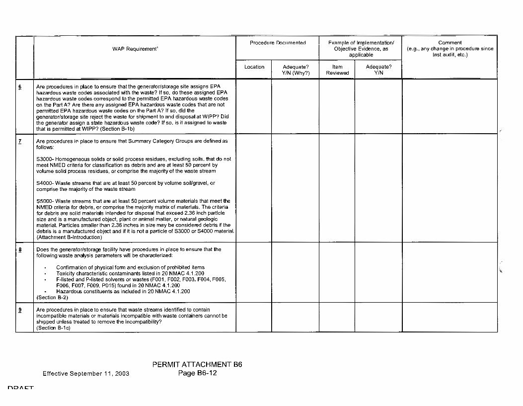
~
I
~
~
r'\D/\CT
WAP Requirement'
Are procedures in place to ensure that the generator/storage site assigns EPA hazardous waste codes associated with the waste? If so, do these assigned EPA hazardous waste codes correspond to the permitted EPA hazardous waste codes on the Part A? Are there any assigned EPA hazardous waste codes that are not permitted EPA hazardous waste codes on the Part A? If so, did the generator/storage site reject the waste for shipment to and disposal at WIPP? Did the generator assign a state hazardous waste code? If so, is it assigned to waste that is permitted at WIPP? (Section B-1 b)
Are procedures in place to ensure that Summary Category Groups are defined as follows:
S3000- Homogeneous solids or solid process residues, excluding soils, that do not meet NMED criteria for classification as debris and are at least 50 percent by volume solid process residues, or comprise the majority of the waste stream
S4000- Waste streams that are at least 50 percent by volume soil/gravel, or comprise the majority of the waste stream
S5000- Waste streams that are at least 50 percent volume materials that meet the NMED criteria for debris, or comprise the majority matrix of materials. The criteria for debris are solid materials intended for disposal that exceed 2.36 inch particle size and is a manufactured object, plant or animal matter, or natural geologic material. Particles smaller than 2.36 inches in size may be considered debris if the debris is a manufactured object and if it is not a particle of S3000 or S4000 material. (Attachment B-lntroduction)
Does the generator/storage facility have procedures in place to ensure that the following waste analysis parameters will be characterized:
Confirmation of physical form and exclusion of prohibited items Toxicity characteristic contaminants listed in 20 NMAC 4.1.200 . F-listed and P-listed solvents or wastes (F001, F002, F003, F004, F005, F006, FOO?, F009, P015) found in 20 NMAC 4.1.200 Hazardous constituents as included in 20 NMAC 4.1.200
(Section B-2)
Are procedures in place to ensure that waste streams identified to contain incompatible materials or materials incompatible with waste containers cannot be shipped unless treated to remove the incompatibility? (Section B-1 c)
Effective September 11, 2003
PERMIT ATTACHMENT B6 Page B6-12
Procedure Documented Example of Implementation/ Comment Objective Evidence, as (e.g., any change in procedure since
applicable last audit, etc.)
Location Adequate? Item Adequate? Y/N (Why?) Reviewed Y/N
,,

12a
13
14
15
16
l"'\D/\CT
Procedure Documented WAP Requirement'
Location Adequate? Y/N (Why?)
. wastes with polychlorinated biphenyls (PCBs) not authorized under an EPA PCB waste disposal authorization
wastes exhibiting the characteristic of ignitability, corrosivity, or reactivity (EPA Hazardous Waste Numbers of D001, D002, or D003)
RH TRU mixed waste (waste with a surface dose rate of 200 millirem per hour or greater)
any waste sonlainer 11:lal aoos nol l:la•~e VOC sonsenlralion •-al~es ro130F1ea for ti ,e l"leed!i,eee
. any waste container which has not undergone either radiographic or visual examination unless the container is from a waste stream or waste stream lot that is elig16le for less Uian ~ 00 ~rcenl raa1Q9ra12Fi~ or visual examinahon
any waste container from a waste stream which has not been preceded by an appropriate, certified Waste Stream Profile Form (see Section B-1d)
(Section B-1c)
Are procedures in place to ensure that the generator/storage site uses radiograph~ visual examination, l"leed!i,eee ge! eMl)!i! end, e! ei,i,lieeble, !olid! !e111i,firtg, to confirm the absence of the unacceptable waste listed above? (Section B-3)
WASTE ACCEPTANCE CONTROL
Are procedures in place to ensure that the generator/storage site uses a Waste Stream Profile Form (WSPF) which includes, at a minimum, the information indicated on the attached WSPF found in Figure B-1? A Waste Stream Profile Form need not be submitted for subsequent waste stream lots unless warranted by the characterization information. (Sections B-1a, B-1d)
Are procedures in place to ensure that WSPFs are provided to WIPP and NMED for each waste stream prior to acceptance for disposal at the WIPP? (Section B-1d)
Are procedures in place to ensure that additional WSPFs are provided to WIPP and NMED for waste streams or portions of waste streams that are reclassified based upon waste characterization information? (Section B-1d)
Effective September 11, 2003
PERMIT ATTACHMENT B6 Page B6-14
Example of Implementation/ Comment Objective Evidence, as (e.g., any change in procedure since
applicable last audit, etc.)
Item Adequate? Reviewed Y/N

22
23
24
25
26
l""'ID/\CT
WAP Requirement'
A1 e i,roeed1::1res ii I i,l!!ee lo el'lst:1re lh!!I eol'I 1i,01::11 ids l'IOI Ol'I !he lisl of l!!rgel l'!l'l!!lyles !!re rei,orled !!S le11l!!lillel7 ide11lified eol'l1i,01::11'1ds /=FIS) !!eeordi11g lo SW 646 =FIS ide11lifiel'!lio1 I g1::1id!!I 1ee !!I 1d lh!!l lhe =FIS Hill be !!dded lo the l!!rget he!!dsi,!!ee !:jl'!S el'l!!l~te lisl if it !!l'l'e!!rs il'I the 28 Wv1AS 4. 1 .288 fjl'leori,ol'l'llil'lg 48 SFR P!!rl 261 j Ai,i,e11di~ 'viii list e11d iftl 1e7 !!re rei,orled ii 1 25% oflhe 11!!sle eol'll!!il'lers Sl'!l'l,i,led frol'l1 I'! givel'I .. l'!ste strel'!l'l,'i' /Seeliol'I B 3!!/1 l)
Are i,roeed1::1res il'I i,l!!ee to e11s1::1re lh!!t I'! rl'!I 1dol'I 117 seleeled sel of Sl'!l'I 1i,les nill be eolleeled lhrot:1gh eore Sl'!l'l,i,lil'lg or other EPA !!1'1'ro1ed rei,rese11l!!lhe n,elliods frol'l1 the i,oi,1::1l!!lio11 of w,!!sle eo11l!!il'lers for ho111oge11eo1::1s !!lid soilfgl't'l1el nl'!sle slrel'!111s'i' Are i,1oeed1::1res il'I i,l!!ee lh!!t I'! s1::1ffieiel'lt 11t:1l'l1be1 of sel'l1i,les !!re eolleeted to e1l'!lt:1!!te ti 1e lo~ieit7 eher!!eleristie of I'! nl'!ste strel'!1'11 !!I e 98i,eree1111::ii,i,er So11fide1'1ee lil'l1il l'!s si,eeified il'I Alt!!eh111el'lt 92'? /Seetiol'I B 3!!/2))
Are i,1oeed1::1res i11 i,l!!ee to e11s1::1re th!!l lol!!l !!l'll'!i7ses or =FSl::P of 'o'96s, S1o'9Ss, !!l'ld Mel!!ls !!re i,erforn 1ed 011 !!II eore sl'!l'I 1i,les to delerl'I 1il'le if !he .. !!sle e~ibits I'! lo~ieil7 eh!!rl'!eleristie'i' /Seeliol'I B 3et2ll
Are procedures in place to ensure that Acceptable Knowledge is used in waste characterization activities to delineate TRU waste streams, to assess whether TRU ~ waste exhibits a toxicity characteristic, and to assess whether TRU wastes are listed? (Section B-3b)
Are procedures in place to ensure that radiography and/or visual examination are used to:
Examine every waste containel§_ to determine the physical form, except for those waste streams that are elTgible for less than 100% VE or raa1ograpfi~ . laenhty hqu,as ana conta1nenzea gases . Verify the physical form matches the waste stream description
(Section B-3eQ.)
Effective September 11, 2003
PERMIT ATTACHMENT B6 Page B6-16
Procedure Documented Example of Implementation/ Comment Objective Evidence, as (e.g., any change in procedure since
applicable last audit, etc.)
Location Adequate? Item Adequate? Y/N (Why?) Reviewed Y/N

17
28
29
nD/\CT
WAP Requirement'
Are procedures in place to ensure that the following characterization activities shall occur for retrievably stored wastes:
Acceptable Knowledge for all wastes, with confirmatory: - Visual examination or radiography for all waste containers, except for
those waste streams that are eligible for less than 100% \lE or rao1ograpfiy SMfir1n!'l{o~ .-istt!'ll Ol!!'lrTlin!'l!ion of 8 s!!'llistie!'llly detern1ined nt1111ber of o.8ste eo111!'lil1e~ 11s si,eeified ir, Att11ehn,e11t 0:2 ( .. her, mdiogl'lli,hy is i,el'forn1ed) I le11dsi,11ee g113 11Mlysis for 1111 1111s!e eor,!11i11ers or r11ndo111ly seleeted eo11!11ir,ers f1 or, 1 1111s!e s!re11r, 1s 11111! n 1eet the eo11dilior,s for redtteed he11dsi,11ee g11s s11r, 1i,li11g listed ii I See!io11 D 811(1 l =Fo!11I 1v96, SY96, 1111d Me!11ls lln!'llyses for II sl11tis!ieelly selee!ed 11t1n1ber of hon1oger,eot1s solids 11r,d soih'gr111el 11esle eor,lei11ers 11s si,eeified ir, Att8ehr,,enl 8:2 (eonl8iners oi,er,ed for S8rTll'ling r, 18) be ttsed lo fttlfill the , istt81 el!lln 1inl'llion re(1ttiren 1enls) Evelt111tio11 of 11r,y =Fl Cs fottr,d ir, lieed!i,eee ges er,d tol!'lls e11elyses
(Section B-3d£(2))
Are procedures in place to ensure that the following characterization activities shall occur for repackaged waste:
Acceptable Knowledge, with confirmatory: - Either visual examination during repackaging or radiography (or VE in
lieu of radiography) after repackaging for all waste containers, except for those waste streams that are eligible for less than 100% ~ rao1ograpfiy. ensuring tfirs occurs pnor to any treatment oesrgneo to supercompact waste I leedsi,eee ges 11nelysis for 811 ,,este eonl8iners or r8ndon 1ly seleeled eol'lteir,ers fror, 1 neste slreer, 1s !I 1el n1eet the eor 1ditior,s for redtteed heedsi,11ee ges sen 1i,lir,g listed ii I Seetior, B 9e(1 l =Fo!111 lv'9C, SY9C, e11d Mete ls er 1elyses follo,wir 1g either the 1 elrie ,ebly stored or 11e1itly ger 1e1 eled 11es!e eh11r11e!eri!11tion i,roeess, 11liiehe1er resttlls iii greeter sen1i,li1ig re(1t1iren1e11ls, ttnless it is der, 1or,streted th11t eor,trol eh11rti11g eer 111ot be ei,i,lied effeeti, ely. E111lt1elio11 of 1111y =Fl Cs fot111d ir, heed!i,eee ges er,d tol11ls e11elyses
(Section B-3d£,(Section B-3df(1 ))
Effective September 11, 2003
PERMIT ATTACHMENT B6 Page B6-18
Procedure Documented Example of Implementation/ Comment Objective Evidence, as (e.g., any change in procedure since
applicable last audit, etc.)
Location Adequate? Item Adequate? Y/N (Why?) Reviewed Y/N

31
32
33
34
35
r\D/\CT
WAP Requirement'
Are procedures in place to ensure that the following Quality Assurance Objectives are adequately defined and assessed for each characterization method:
. Precision as a measure of the mutual agreement among multiple measurements
. Accuracy as the degree of agreement between a measurement results and a true or known value
. Completeness as a measure of the amount of valid data obtained from a method compared to the total amount of data obtained
. Comparability as the degree to which one data set can be compared to another data set
(Section B-4a(2))
With respect to data generation, are procedures in place lo ensure that the generator/storage site's waste characterization program meets the following general requirements:
. A1111lytie11I Testing data packages and batch data reports must be reported accurately Triapre-approved format, must be maintained in permanent files, and must be traceable?
All data must receive a technical review by another qualified analysts or the technical supervisor, and the laboratory QA officer?
. All raw data must be reviewed and have the release signatures of a technical supervisor and a QA officer before release?
(Section B-4(a)(4), B-3) Section B3~)
Are procedures in place to ensure that the generator/storage site performs data validation and verification of waste characterization data for each waste container? (Section B-4)
Are procedures in place to ensure that the generator/storage site has a pre-approved format for reporting waste characterization data? (Section B-4a(4))
Are procedures in place to ensure that the generator/storage site prepares el'lel~tieel, testing, el'ld :!1111'1,f'lil'lg batch data reports to meet the requirements of their own site-specific QAPjP and/or SOPs? (Section B-4a(4))
Effective September 11, 2003
PERMIT ATTACHMENT B6 Page B6-20
Procedure Documented Example of Implementation/ Comment Objective Evidence, as (e.g., any change in procedure since
applicable last audit, etc.)
Location Adequate? Item Adequate? Y/N (Why?) Reviewed Y/N
j\

37
l"'ID/\CT
WAP Requirement'
Are procedures in place to ensure that 100 % of batch data reports are subject to non-programmatic technical review by an individual qualified to review the data. The reviewer shall release the data through signature with an associated review checklist prior to characterization of the associated waste and shipment to the WIPP. The review shall ensure the following, as applicable:
Data were generated according to the methods used and reported in the proper units and significant figures
. Calculations have been verified by a valid calculation program, a spot check of verified calculation programs, and/or a 100 percent check of all hand calculations
. The data have been reviewed for transcription errors
. The testing, !!fll'l1plil'lg, fll'lel fll'lfllylieel QA documentation is complete and includes raw data, calculation records, el"leil'I ef ettsleely ferl'I ,s, calibration records, and QC sample results
. All QC sample results are within established control limits, and if not, the data has been appropriately qualified
~oportin!J fla!JS woFo assi!'jned ooneoUy
Sample l=toldin!J times and preseF¥ation req1:JiFements weFe met, OF e)(eeptio11s doettruel'lted
Radiography tapes are reviewed on a waste container basis at a minimum of once per testing batch or once per day of operation, whichever is more frequent. The radiography tape will be reviewed against the data on the radiography form to ensure that data are complete and correct
(Section 83-4e§.a(1 ))
Effective September 11, 2003
PERMIT ATTACHMENT B6 Page B6-22
Procedure Documented Example of Implementation/ Comment Objective Evidence, as (e.g., any change in procedure since
applicable last audit, etc.)
Location Adequate? Item Adequate? Y/N (Why?) Reviewed Y/N
t

40
l"'ID/\CT
WAP Requirement'
Are procedures in place to ensure that 100 percent of all batch data reports receive a Site Project Manager signature release with an associated review checklist prior to characterization of the associated waste and shipment to the WIPP. This release shall ensure the following:
+Re Sile PFejesl MaRa!JeF eF Elesi!JRee sRall EleleFFRiRe !Re yaliaily ef !Re ElFl:llfl a!je sFileFia (QAC) assi!JRR'leRI R'laae al!Re Elala !JeReFalieR lei.<el bescd 1:1i,0111!11'1 esscssl'l,Cl'II of Inc dl!lll!l collcelio1, e11d c,el1:1etiol'I l'ICCC!l!ll!ll"J lo l'l,l!llec Inc essig11111c1"1t.
. Non-programmatic technical reviews, technical supervisory reviews, and QA Officer reviews have been performed and documented through signature
. Data have been verified to be within established data assessment criteria and meet all applicable QAOs
S!l"1flliflg, Ttesting, l!ll'ld e11elyticel batches are complete and data are reported to the correct units, fltJl!llificr !legs, and significant figures.
The testing, sel'l1plil'lg, and QA data review checklists are complete (Section B3~§b(2))
Effective September 11, 2003
PERMIT ATTACHMENT B6 Page B6-24
Procedure Documented Example of Implementation/ Comment Objective Evidence, as (e.g., any change in procedure since
applicable last audit, etc.)
Location Adequate? Item Adequate? Y/N (Why?) Reviewed Y/N

44
45
46
47
48
r"\D/\CT
Procedure Documented WAP Requirement'
Location Adequate? Y/N (Why?)
Are procedures in place to ensure that non-administrative, WAP-related nonconformances first identified at the site project manager level are reported to the Permittees within five (5) calendar days of identification, that nonconformance reports are prepared within thirty (30) calendar days, and that corrective action is implemented prior to waste shipment? (Section B3-1, B3-+S§)
Are procedures in place to ensure that nonconformances are appropriately identified, reconciled, corrected, and documented? Are nonconformance reports prepared for nonconformances identified? Are nonconformances identified and tracked, and does the site Project QA Officer oversee the nonconformance report process? (Section B3-+S~)
SAMPLE CONTROL
Are i,roeedt:1re:, in i,leee to en3t:11e the! !lie site's sen,i,le he1 ,dliI ,g end eo11trol i,rogre111 i11elt:1des tile follo,.;ng.
i;;:ielel elasl:lFReA!a!iaA ef sam13les iAsll:leliAg 13eiAI ef eFigiA, elate ef sam13le, eonteiner identifieetion, se111i:,le t:,,i,e, e1,elysis reqt:1esled, end ehei1, of et:1stody (GOG) 1,t:1111ber?
FIFe13eF laeeliAg aAelleF !aggiA§ iAsll:leliA§ 13re13eF sam13le Al:lFRBeFiAg, sam13le identifieetion, sen,i:,le dete, selTlpling eonditio11s, end e1,ely:,i:, reqt:1ested?
GOG FeseFel iAsll:leliAg Raffle ef sam13le rnliAetl:lis"1eF, sam13le Fesei•,eF, aAel dete end ti1, ,e of sen ,i:,le tI l!IMsfer? end
Prn13eF sam13le AaAelliAg aAel 13Feserva!ieA? (Seetio11 B 4e(9))
A1e i,roeedt:11e:, in i,leee to enst:1re thl!lt the site':, EIAPjP or site si:,eeifie i:,roeedt:1res inelt:1des GOG forr,,:, to eo11trol the :,er,,i:,le f10111 the point of origin lo the fir.el e1,el:,,sis rest:1lt rei:,orli11g? (Seelion B-4e(9))
DATA TRANSMITTAL
Are procedures in place to ensure that the generator/storage site transmits data by hard copy or electronic copy from the data generation level to the site project level after all data generation and project level validations are complete? If electronic, does the generator/site have a hard copy available on demand? (Section B-4a(6))
Effective September 11, 2003
PERMIT ATTACHMENT B6 Page B6-26
Example of Implementation/ Comment Objective Evidence, as (e.g., any change in procedure since
applicable last audit, etc.)
Item Adequate? Reviewed Y/N
I
b
"

56
nD/\CT
WAP Requirement'
Are procedures in place to ensure that hard copy or electronic Waste Stream Profile Form will include the folbwing
. Generator/storage site name . Generator/storage site EPA ID . Date of audit report approval by NMED (if obtained) . Original generator of waste stream . Waste Stream WIPP Identification Number Summary Category Group . Waste Matrix Code Group . Waste stream name . A description of the waste stream . Applicable EPA hazardous waste codes . Applicable TRUCON codes . A listing of acceptable knowledge documentation used to identify the waste stream . The waste characterization procedures used and the reference and date of the procedure . Certification signature of Site Project Manager, name, title, and date signed
(Section B3-4-z!?b( 1))
Effective September 11, 2003
PERMIT ATTACHMENT B6 Page B6-28
Procedure Documented Example of Implementation/ Comment Objective Evidence, as (e.g., any change in procedure since
applicable last audit, etc.)
Location Adequate? Item Adequate? Y/N (Why?) Reviewed Y/N

58
59
60
61
62
63
64
65
66
67
l"'\D/\CT
WAP Requirement'
Are procedures in place to ensure that project level reports are compiled into Characterization Information Summaries (Section B3-4-rZ)
Are procedures in place to ensure that the generator/storage site uses forms for data reporting that are pre-approved forms in site-specific documentation? (Section B3-4-rZ)
Are procedures in place to ensure that the generator/storage site's site project manager submits to the WIPP facility a summary of the waste stream information and reconciliation with data quality objectives (DQOs) once a waste stream is fully characterized? (Section B-4a(6))
Are procedures in place to ensure that the generator/storage site project office completes a WSPF based on the Batch Data Reports? (Section B3~Zb)
Are procedures in place to ensure that the generator/storage Site Project Manager submits the WSPF to the Permittees for approval along with the accompanying Characterization Information Summary for that waste stream? (Section B-4a(6))
Are procedures in place to ensure that the generator/storage site maintains records related to waste characterization se, 11i:,lil'lg el'ld el'lely sis activities in the testing-; seM,i:,lillg 01 eM!ll:,tieel facilities files, or site project files for those facilities located on-site? (Section B-4a(7))
Are procedures in place to ensure that the appropriate documented training and indoctrination is performed for all individuals and that procedures are documented in site specific QAPjPs and procedures? (Section B3-44g)
Are procedures in place to ensure that the generator/storage site requires contract waste analytical facilities to forward testing, se, 11i:,li11g el'ld e11elytieel records along with testing, Mt,,i:,lil'lg el'ld e11elytieel batch data reports to the site project office for inclusion in the site central files? (Section B-4a(7))
Are procedures in place to ensure that the generator/storage site has an appropriate records inventory and disposition schedule (RIDS) or equivalent that was prepared and approved by appropriate site personnel? (Section B-4a(7))
Are procedures in place to ensure that the generator/storage site maintains all records relevant to an enforcement action, regardless of disposition, until they are no longer needed for enforcement action, and then dispositioned per the approved RIDS? (Section B-4a(7))
Effective September 11, 2003
PERMIT ATTACHMENT B6 Page B6-30
Procedure Documented Example of Implementation/ Comment Objective Evidence, as (e.g., any change in procedure since
applicable last audit, etc.)
Location Adequate? Item Adequate? Y/N (Why?) Reviewed Y/N
"

69
70
71
l"'\D/\CT
WAP Requirement'
Are procedures in place to ensure that the generator/storage site maintains records that are designated as Non-Permanent Records for ten years from the date of record generation, and then dispositioned according per the approved RIDS?
Non-Permanent Records include:
. Nonconformance documentation, . Variance documentation, Assessment documentation, . Gas canister tags, Methods performance documentation, PDP documentation, Sampling equipment certifications, Calculations and related software documentation, Training/qualification documentation, QAPjP documentation (all revisions), Calibration documentation, . Analytical raw data, Procurement documentation, QA procedures (all revisions), . Technical implementing procedures (all revisions), and . Audio/video recording ( radiography, visual, etc.) .
(Section B-4a(7), Table B-7~)
Are procedures in place to ensure that the generator/storage site has raw data that is identifiable and legible, and provides documentary evidence of quality? (Section B-4a(7))
Are procedures in place to ensure that if the generator/storage site ceases to operate, that all records be transferred before closeout? (Section B-4a(7))
Effective September 11, 2003
PERMIT ATTACHMENT 86 Page 86-32
Procedure Documented Example of Implementation/ Comment Objective Evidence, as (e.g., any change in procedure since
applicable last audit, etc.)
Location Adequate? Item Adequate? YIN (Why?) Reviewed Y/N
~

Effective September 11, 2003
r"\D/\CT
(This page intentionally blank)
PERMIT ATTACHMENT B6 Page B6-34

Effective September 11, 2003
r"\D/\CT
{Tl=li~ l"l,tn~ il"lt~l"lti, 1l"l,illo l=ll,il"lk)
PERMIT ATTACHMENT B6 Page B6-36
'

H i
11:1
co m 1-z w ~ 00 I cv;> u co <(al I- Q) I- Ol <( ro I- a.. ~ ~ w a..
C')
0 0 N . ........ Cl) ..c E Cl)
c.. Cl)
CJ)
Cl)
.::: u Cl) --w
1-u < 0 C

-19
ae
8+
l""'\D/\CT
Proccl"luI c Docur11c11tcl"l
IMAP RO"!bliFOR'10Al1
l:oe!tlion Al"lcquetc'? ~'i'~d(Why'?)
Arc i:,roccl"lu1cs i11 i:,leec lhet el"lcquetcly e11surc the! the felloni11g Icquircme11ts ere l'l 1et for i:,roecss eo11trols essoeietel"l vtith nc1vly ge11eretcl"l hon IogcIIcous solid .. esle streei,is. -
GaAliAb19blS 13rasess 1, 1eFifisaliaA Fes1,1lls aFe e>,<alblaleel 1:JsiAg SPG saAIFal chert tcehniqucs to 1'lctcm1i11c fluetuetions or sig1 lifieent i:,roecss ehengcs. (Section Bz 4) ~6Jete: a ffliRiffll:JFR ef 19 fiata peiRt& r-ep,<eBeRlati~<e ef tlw pl'Ssess a,<e i,ccdcd to c!tebli!M eontro,' ehett Sn,it!j
,A,sliaA le\1915 9F 69AIFal liFAils IFiggeFiAg Fe 6RaFasleFii!"illi9A af 69AliAl:l91:lS i:,roecsses ere l"lcfincl"l \Scetil'll'I B 9(1'l)(1)e))
+Re sam13liAg FO"!l:liFeFAeAIS Aeeessaiy la ele\1ela13 aA a1313FSl3Fiale 69AIFal chert mce11 enl"l ste111'lerl"l l"leo ietioi, ere l"lcfi11el"l(Scetio11 Bz 4)
PFaeeell:lres far Fe e•~all:laliAg aAel 1,113elaliAg eaAlral el=laFls aFe elefiAeel (ScetioI1 Bz 4)
Praseell:lres far e\1al1,1aliAg ll=le effesli•~eAess af tl=le sam13le 139131:JlatiaA aAel frcqucI1C) ere l"lcfincl"l (Scetio11 Bz 4)
Arc i:,roeel"lures iI1 i:,leec the! ellon !ol(iei~ el 1ereeteristie eoI1ten 1inei,ls essoeietel"l .. ith F 6ol"lcs fer e ,msle strcei,1 to be on1ittel"l froi,1 sei,1i:,liI1g requirc111c11ts so long es thet nestc is eonsil"lerel"l lislcl"l l"luc lo lhet eoi,1i:,ou111'l'? (Section Bz ze)
SQbl9S S,,MPblNG PRQG&PUR&S
Do i:,roeel"lures c11sure lhet sen1i:,les fer retricoebly sto1cl"l 1veste ere eollcetel"l using ei:,i:,roi:,rielc eorii,g toels or other EPA ei:,i:,roocl"l i,1clhol"ls, enl"l the! l'le1vly gcncretel"l neste l'l1ey be eollcetcl"l using elter11ele rei:,rescnlelioc l'l1cthol"ls in the cocI11 coring is i11ei:,i:,roi:,rietc'? (Section 81 ze)
Effective September 11, 2003
PERMIT ATTACHMENT B6 Page B6-40
El(ell 1i:,lc of Ii, 1i:,lcr11c11tetiol'I/ 60l'lll'l'ICl'II Objcctioc Eoil"lc11cc, es (e.g., eIIy che11gc ii, i:,roccl"lurc since
ei:,i:,liceblc lest eul"lit, etc.)
flcm Al"lcquelc'? Rcoicncl"l ¥IN
i

~
&a
&4
l'"'ID/\CT
Proeed1:1re Boe1:1n,e11ted
lAIA 12 RaqlliFBA'lBRI'
~
• ·eRt iRRBF liRer A A is FR ta pre' f to the II Aa·,<e a FRee-a . I hel!lt tr!IM!!•er . ae·•iees eAa . 'i,,i~e fr1et1or,11 FlcetatieRal eeRR11 be¾ de!!igr,ed to n,1m ,
'"'""'" ""' ,,, Md lo a d;•~•lo• 1 core 9
aRa tape ""'P~. . ••• ;,., ... e,e- I ,oflhe i;,.., ftAeeer1Rg . l'lerdie111ee TAe leaaiRg eal!Jeh:) !!l'I ,eller th111, the II" e~t:1iv11le11t or!! ig
SAMPl::E 681::l::E6:n8N
Effective September 11, 2003
PERMIT ATTACHMENT B6 Page B6-42
..

94
~
9S
r'ID/\CT
Proeedure Doeul'I ,e, ,led
WAP ~8qbliF811'18At1
½:oe9lion Ade(1U!lle'? ¥f~~(Wh:,'?)
Are procedures in pleee to e11su1e S!ll'l,ple volul'l1es, p1esei.elives, eo11lei11ers, end holdi11g lil'l,es n,eet the follo .. ing sl)eeifieelions. -
Minil'l'ltUTI san,ple quantit) lv'O6 15 grel'l,S Slv'O6 58 gren,s Melels 18 g1en,s (smeller S!ll'l'll'le si:!!es n,e:, be used if l'l,elhod PRQL requirel'l1e11ls ere l'l,et)
-Preser.atiwe lv'O6 6001 to 46 S1ol9S 6001 lo -46 Metels 6001 to 46
-Sample 6ontainer voe -48 l'l,L VOA gless vi!II tor other eppropriete eol'lleil'lers) .. ith seplul'I,
C8I' S1v'96 258 l'l ,L !II, ,ber gless jer n ilh =i=eflol'l(!!il Iii ,eel eei, Melels 258 l'l,L 1iol:,eth:,lel'le or pol:,i,roi,yle11e bollle
-I loldil,g Time frol'l'I Bate of 6olleetion lv'O6 14 de:,s prepi'-48 de:,s !lii!ll:y!e Slv'O6 1-4 de:,s prei,f-48 deys !ll'l!lly:!!e Metels 188 d!lySI 28 deys I lg
t=i=eble B 1 -4)
Ql:W:mt: GON:JROb S.t-.MPb& GObbEG:J:ION
A1e 1iroeedures il'I pleee lo el'lsure the! !l!ll'l'lpling i,reeisiol'I nill be deterl'l,ined through the eolleetio11 of eo-loeeted eore field duplieete 3!11'1,i,les for eore 3!11'1,r,les e11d through the colleetiol'I of co loceted S!ll'l,ples for S!ll'l,i,les collected usi11g elternele l'l,etliods et the fre11ue11e:, of onee i,er 28 S!ll'I ,pie belch eolleeted o o e1 14 de:,s'? A1 e i,rocedures i1, pleee to e, 13Ure the! eeeei,te1 ,ee crilerie for S!ll'l ,i,le preeisiol'I is esleblished through !11'1 F =i=esl u11lil 28 88 co loeeled i,eirs heve !ll'l!lly!ed lo esteblisl, !I eonlrol chert'? (Seeliol'I B1 2b(1))
Are procedures ir, pleee lo el'lsure ti ,!II eo loceted eores !II e eolleeted side b:, side es elose es feesible lo eeeh otl ,er, the! the eores ere eolleeled !ll'ld he11dled il'I the sen,e l'l,!11111e1'? (Seetio11 B1 2b(1))
Effective September 11, 2003
PERMIT ATTACHMENT 86 Page 86-44
E~!ll'l,r,le of ll'l1r,le1'11el'lt!llio11f 60l'l1l'l'lel'II Objeelioe Evide11ee, es (e.g., e11:, ehe11ge i11 i,meedure sil'lee
epplieeble lest eudit, ete.)
ftem Ade11uele'? Reviened ¥fN

-1-ei
46S
4&4
ff5
%6
%1-
r\D/\CT
Proecdurc Oocui,,el'!ted E,ti,r,,r,le of lr,1r,ler,1e111!llior,,1
Objeclioc Eoider,ce, l!IS 111/AP R.0'llliF01'R0Rt' !lflf)lic!lble
~ Adeqtt!lte:;> Item Adeqtt!lte:;> W~d(Why'?) Reoie11ed ¥fN
Are procedttres ii, pl!lce lo enswe th!ll dispos!lble :!!l111plir,g eqttipn,ei,t i:1 certified 1!13 cle!ln prior lo tt:1e:;> (Sectior, B1 zb(:2))
81.MPb& &QUIPM&N:J: :J:&8+1NG, INSP&G+ION "ND M.tJN+ENA'tJG&
Are procedttre:1 ii, pl!lce to en:1ttre th!lt 1!111 coril ,g tool:1 !lre te:1ted prio1 to tt:!e i1, l!lccordl!lr,ce oirith 1111!11'11:Jfflcttt1er:1 :1pecificl!llio1, lo er,:1tt1e thl!lt the l!lir loelt n 1echl!lr,i:1n, l!l11d rotl!ltior, r,,echl!l11i:1n, !!Ire in norlting orde1:;> (Sectior, B1 zc)
Are procedttre:1 ir, pll!lce to er,:1tt1 e thl!lt n 11!1lftt1 ,ctionir ,g :!!!In ,plir ,g eqttipr, ,e111 or corir,g lool:1 !!Ire ll!lgged, 1!11,d repl!lired or repll!lced prio1 lo tt:1e'? (Sectior, B1 zc)
Are procedttre:1 i11 pll!lce to e11:1ttre th!lt 1!111 eqttipn ,er,t i:1 cle!l11ed, :1el!lled i1 ,side l!I protecti o e nrl!lppil ,g l!ll'ld :1tored in l!I cle1!111 l!lrel!I'? (Seclio1, B 1 zc)
Are procedttre:1 ir, piece lo er,:1me the! er, edeqttele spere pert ir,oe11lo~ i:1 l!lol!lill!lble:;> (Section B1 zc)
Are p1 ocedttre:1 i1, pll!lce to er,:1ttre ti 11!11 1!111 eqttipn 1e11t n ,l!lir,tenl!l1 ice l!lr,d repl!lir i:1 doctm,e11ted ir, field record:! l!ll'ld the! field record logboolt:! !!Ire l!loeileble lo docttn,er,t eqttipn,e11t r,,l!lir,te1,e1,ce l!ll'ld repl!lir l!lelioilie:1:;> (Sectior, B1 ze)
Effective September 11, 2003
PERMIT ATTACHMENT B6 Page B6-46
6or,,n,enl (e.g., !ll 1y ch!l11ge ir, r,rocedttre !!i11ce
l!lsl !lttdil, etc.)

rr============s...---.--......----:-' -=----" ---------', ,;: __ _
IJ i~. i]
H I
?I
l ii fl :l:I
co ID 1-z w ~ 00 I "i (.) co <( ID I- (I) I- 0) <( co I- a.. ~ 0:: w a..
("')
0 0 N -..... ..... ...
Q) .D E 2 c.. Q)
Cl)
Q)
> ~ Q) --w
I-LI < 0 C:

ji i ~----------------------..
ii
H j
?I ?I ?I !I !I ~I ~I ~I fl
(0
co 1--z w ~o I u;> (.)<D <( co I- Q) I- Cl <( ctl I- a.. ~ Cl:'.'. w a..
C"')
0 0 N -..-
..-.... Q)
..c E ~ 0.. Q)
(/)
Q)
> ~ Q) --w
I-u < D c::

H i
co ca 1-z w ~N I LQ (.) co <C ca I- (I) I- O> <( Cll I- a.. ~ 0::: w a..
C")
0 0 N
QJ .0
E ~ a. QJ
Cl)
QJ
> :;:::; u 2 -w
1-u < 0 C

H i
l i ii fl fl fl $1 !I
<.O C£l 1-z w ~ s:::I" I u;> u <.O <( C£l I- a.> I- O> <C ro I- a.. ~ 0:: w a..
("')
0 0 N -,.....
,..... .... Q) .c E 2 a. Q)
Cl)
Q)
> u Q) --w
I-u < 0 C

Effective September 11, 2003
l""\D/\ CT
Table 86-S-i Acceptable Knowledge (AK) Checklist
PERMIT ATTACHMENT B6 Page B6-56

134
135
136
137
138
139
Acceptable Knowledge (AK) Checklist1
Procedure Documented WAP Requirement'
Location Adequate? YIN (Why)
GENERAL REQUIREMENTS
Are the primary document(s) required in Permit Attachment 84 containing acceptable knowledge information available? (Section 84-2)
Has the generator developed a methodology whereby a logical sequence of acceptable knowledge information that progresses from general facility to more detailed waste-specific information can be acquired? (Section 84-2)
Does the site have adequate procedures in place to ensure that the Acceptable Knowledge process is adequately implemented? Do these procedures facilitate the mandatory traceability analysis performed for each Summary Waste Category Group examined during the audit? (Section 84-2)
Does the generator site's TRU mixed waste management program information clearly define (or provide a methodology for defining) waste categorization schemes and terminology, provide a breakdown of the types and quantities ofTRU mixed waste generated/stored at the site, and describe how waste is tracked and managed at the generator site (including historical and current operations? Do procedures ensure that waste streams are adequately identified? (Section 84-2a)
Does site documentation procedures indicate that the site will document, justify, and consistently define waste streams and assign EPA hazardous waste numbers? (Section 84-2b)
Are procedures in place to ensure that the generator/storage site initially characterizes the waste on a waste stream basis using Acceptable Knowledge and that the waste will be characterized in the same manner as a newly generated waste if the Acceptable Knowledge information does not meet the requirements of Attachment 84? (Section B-1 a)
Effective September 11, 2003
PERMIT ATTACHMENT B6 Page B6-58
l"""\D/\CT
Example of Implementation/ Comment Objective Evidence, as (e.g., any change in procedure since
applicable last audit, etc.)
Item Adequate? Reviewed Y/N
l
l
l
l

141
142
143
Procedure Documented WAP Requirement'
Location Adequate?
Does the generator site document that the following shall be collected for each waste stream:
. Area(s) and/or building(s) from which the waste stream was or is generated
Waste stream volume and time period of generation (e.g., 100 standard waste boxes of retrievable stored waste generated from June 1977 through December 1977)
. Waste generating process described for each building (e.g., batch waste stream generated during decommissioning operations of glove boxes), including processes associated with U134 waste generation, if applicable.
Process flow diagrams (e.g., a diagram illustrating glove boxes from a specific building to a size reduction facility to a container storage area). In the case of research/development and analytical laboratory waste, a description of the waste generating processes, rather than a formal process flow diagram, may be included if this modification is justified and the justification is placed in the auditable record
. Material inputs or other information that identifies the chemical and radionuclide content of the waste stream and the physical waste form (e.g., glove box materials and chemical handled during glove box operations; data obtained through visual examination of newly generated waste that later undergoes radiography; information demonstrating neutralization of U134 [hydrofluoric acid] and waste compatibility, etc.)
(Section B4-2b)
Do site documents/procedures confirm that the facility will provide a summary to the Permittees and NMED that summarizes all information collected, including basis and rationale for all waste stream designations? Is an example of this summary available for audit review? If discrepant hazardous waste data exist in required information, do sites assign all hazardous waste codes unless the sites choose to justify otherwise? (Section B4-2b)
Do site procedures indicate that the required AK information is not available for a retrievably stored waste stream, supplemental information will be acquired and this waste stream shall be designated as newly generated and characterized accordingly? (Section B4-2)
Effective September 11, 2003
PERMIT ATTACHMENT B6 Page B6-60
Y/N (Why)
l"'ID/\CT
Example of Implementation/ Comment Objective Evidence, as (e.g., any change in procedure since
applicable last audit, etc.)
Item Adequate? Reviewed Y/N
l
r
l
l

145
146
147
148
WAP Requirement'
Boes !he ger,erl!ltor r,ro,ide r,roeedt1res or 11'1'ilter, eor,1r,1ilr,1er,I to eolleel st1r,r,ler,1e11ll!II l!leeer,ll!lble lmonledge ir,forl'l11!1lio11, l!I! l!lvl!lill!lble l!l11d l!I! 11eeessl!lr~ to st1ppler,1er,t 1'111!11'1dl!llory ir,f-orl'l1l!ltior,? (Seetior, B4 2e) Does the generator have 12rocedures s12ecifying that waste streams that are eligible for less !Fian Hl!J 12ercen! IJE or raa1Q!:Jra12Fi~ Fiave:
Waste 12ackaging or waste characterization 12rocedures (i.e., radiogra12h~ and/or visual exam1nal1on 12roceauresj !Fial 12rov1aea for !Fie 1aen!1f1ca!1on of all 12roFi1Ei1led 1lems aescriEiea in ffi1s WAP. TFiere mus! Eie aocumen!a!1an in !Fie acce12!aEile l<nowleage recoii:l aemonslral109 !Fial !Fiese 12rocooures were invol<ea on !Fie waste slream (or was!e s!ream lo!j 12ro122sea for a1s122sal a! !Fie WIPP.
Waste 12ackaging or waste characterization 12rocedures (i.e., radiogra12h~ and/or visual exam1na!IOn 12roceauresj lfial s12eaf1ea Ifie 12acl<ag109 configuration usea to 12acl<age Ifie waste.
Container s12ecific data sheets (or §!JUivalent} for each container in the waste stream (or waste stream lot! 12ro122sea for sFi112ment to !Fie WIPP !Fiat aocuments a aescr112t1on of !Fie waste 1n !Fie container, !Fie aEisence of 12roFi1Ei1tea 1!ems, ana a aescr112bon of !Fie 12acl<ag1ng conf1gurabon.
(Section B4-2bl
Does the generator site document that all specific, relevant supplemental information used in the acceptable knowledge process will be identified and its use explained? Is all necessary supplemental information assembled and has it been appropriately used? (Section B4-2c)
Does the generator site discrepancy analysis documentation (for acceptable knowledge supplemental and required documentation) indicate that if discrepancies are detected, site must include all hazardous waste codes indicated in the required and supplemental information unless the site chooses to justify an alternative assignment and document justification in the auditable record? (Section B4-2c)
Does the generator site have procedures to ensure that all personnel involved with acceptable knowledge waste characterization have the following training, and is this training documented?
WIPP WAP and TSDF Waste Acceptance Criteria Requirements
Effective September 11, 2003
PERMIT ATTACHMENT B6 Page B6-62
l""ID/\CT
Procedure Documented Example of Implementation/ Objective Evidence, as
applicable
Location Adequate? Item Adequate? Y/N (Why) Reviewed YIN
TRAINING
Comment (e.g., any change in procedure since
last audit, etc.)
i
1
1 1

149a
r'\D/1.CT
WAP Requirement'
. Sites must prepare and implement a written procedure in compliance with Section 84-3(d) to identify hazardous wastes and assign the appropriate hazardous waste codes to each waste stream. The following are minimum baseline requirements/standards that site-specific procedures must include to ensure comparable and consistent identification of hazardous waste:
- Compile all of the required information in an audltable record.
- Review the required information to determine if the waste is listed under 40 CFR Part 261, Subpart D. Assign all listed hazardous waste codes, unless the site chooses to justify an alternative assignment and document the justification in the auditable record.
- Review the required information to determine if the waste may contain hazardous constituents included in the toxicity characteristics specified in 40 CFR Part 261, Subpart C. If a toxicity characteristic contaminant is identified and is not included as a listed waste, assign the toxicity characteristic code, unless data are available which demonstrates that the concentration of the constituent in the waste is less than the toxicity characteristic regulatory level. When data are not available, the toxicity characteristic hazardous waste code for the identified hazardous constituent must be applied to the mixed waste stream.
- For newly generated waste, procedures shall be developed and implemented to characterize mixed waste using acceptable knowledge prior to packaging.
Effective September 11, 2003
PERMIT ATTACHMENT B6 Page B6-64
Procedure Documented Example of Implementation/ Comment Objective Evidence, as (e.g., any change in procedure since
applicable last audit, etc.)
Location Adequate? Item Adequate? Y/N (Why) Reviewed Y/N
l

D Procedure Documented Example of Implementation/
WAP Requirement' Objective Evidence, as applicable
Location Adequate? Item Adequate? Y/N (Why) Reviewed Y/N
ill Has the generator site implemented administrative controls to ensure that prohibited items are documented and managed in accordance with site specific certification plans and that the following minimum site specific administrative controls:
. Identify the organization(s) responsible for compliance with administrative controls.
. Identify the oversight procedures and frequency of actions to verify compliance with administrative controls.
. Develop on-the-job training specific to administrative control procedures .
. Ensure that personnel may stop work if noncompliance with administrative controls is identified .
. Develop a nonconformance process that complies with the requirements in Section B3-13 of the WAP to document and establish corrective actions.
. Address controlled changes to WAP-related plans or procedures as part of the nonconformance and corrective action process
. As part of the corrective action process, assess the potential time frame of the noncompliance, the potentially affected waste population(s), and the reassessment and recertification of those wastes.
(Section B4-3b, Section B3-13)
CONFIRMATION OF ACCEPTABLE KNOWLEDGE
152
153
Does the generator site have written procedures for the confirmation of all acceptable knowledge information using analytical data, including I ,eedsi,!lee !]!IS d!!l!I, S!ll'l,l'lir,g !!t,d !!ll!ll)sis, !!l'ld 1'1011 deslruelioe !!SS!!), 11011 deslruelioe eie!ll'l ,i, ,!llio1 ,, and/or visual examination? Are these procedures developed for both retrievably stored and newly generated waste? (Section B4-3d)
Does the generator site have written procedures for newly generated waste to document the confirmation of acceptable knowledge information with either the visual examination technique prior to or during waste packaging or radiography (or VE in lieu of radiography) after waste packaging? Do these procedures address the required elements in 3.4-3d? (Section B4-3d)
Effective September 11, 2003
PERMIT ATTACHMENT B6 Page B6-66
l""\D/\CT
Comment (e.g., any change in procedure since
last audit, etc.)
"
1
1 1
1

D 158
159
160
l""\D/\CT
Procedure Documented Examole of lmolementation/ WAP Requiremenf Obiective Evidence, as
applicable
Location Adequate? Item Adequate? Y/N (Why) Reviewed Y/N
CRITERIA FOR ASSEMBLING AN ACCEPTABLE KNOWLEDGE RECORD DELINEATING THE WASTE STREAM
If wastes are reassigned to a different waste matrix code based on visual examination or radiography, does the generator site have written documentation to ensure that the following steps are followed:
. Review existing information based on the container identification number and document all differences in hazardous waste code assignments
. If differences exist in the hazardous waste codes that were assigned, reassess and document all required acceptable knowledge information (Section B3-b) associated with the new designation
. Reassess and document all sampling and analytical data associated with the waste
. Verify and document that the reassigned waste matrix code was generated within the specified time period, area and buildings, waste generating process, and that the process material inputs are consistent with the waste material parameters identified during radiography or visual examination
. Record all changes to acceptable knowledge records
. If discrepancies exist in the acceptable knowledge information for the reassigned waste matrix code, document the segregation of this container, and define the corrective actions necessary to fully characterize the waste
(Section B4-3d)
Boes !lie !:Je11erl!l!o1 site doettr11e11ls sll!l!e !hl!II both sl!lr,ii,lil 1!:J l!ll'ld 1!11 ll!ll~sis {S9888 l!ll'ld S"4888 11l!ls!e slrel!ll'l1) l!l11d hel!ldsi,l!lee !:Jl!IS {for 1!111 nl!lsle slrel!l1'11s) dl!lll!I be t:tsed lo eo11firl'I, l!leeei,ll!lble lil'lo11led!:Je hl!l!l!lrdotts nl!ls!e desi!:Jl'll!l!io11s'? fSee!io11 94 9d)
Do site documents state that radiography (or VE, if waste is newly generated) is used to confirm waste matrix code and waste streams assigned to retrievably stored waste via AK? (Section B4-3d)
Effective September 11, 2003
PERMIT ATTACHMENT B6 Page B6-68
Comment (e.g., any change in procedure since
last audit, etc.)
1 1
1
1

II
LJ 166
167
168
Procedure Documented WAP Requirement'
Location Adequate? YIN (Why)
Does the site indicate that it will document, justify, and consistently delineate waste streams and assign EPA hazardous waste numbers? (Section B4-3d)
Boe!! ti ,e !lite hl!lve nritle11 i:,roeedttre!! for !!ilttetion!! nhere eoneentl'l!ltion!! of !!On ,e lol96!! ere order!! of n1eg1 iitttde higher then other tl!lrget e11e~te!!'? 111 the!!e ee!!e!!, eleveted MBI:!! 1,,e~ be ge11ereted, end tho!!e eon!!tit1:1e11t!! 11ith e11 eleveted MBI: bttt "U" de!!ignl!ltion 111'ill 11ot be tt!!ed in medien eelettll!ltion!!. (Seetion B"4 3d)
DATA QUALITY REQUIREMENTS
Are acceptable knowledge processes consistently applied among all generator sites, and does each generator site comply with the following data quality requirements for acceptable knowledge documentation:
. Precision - Precision is the agreement among a set of replicate measurements without assumption of the knowledge of a true value. The qualitative determinations, such as compiling and assessing acceptable knowledge documentation, do not lend themselves to statistical evaluations of precision. Therefore, precision requirements are not established for acceptable knowledge.
. Accuracy - Accuracy is the degree of agreement between an observed sample result and the true value. The percentage of waste containers which require reassignment to a new waste matrix code and/or designation of different hazardous waste codes based an the reevaluation of acceptable knowledge and sampling and analysis data will be reported as a measure of acceptable knowledge accuracy.
. Completeness - Completeness is an assessment of the number of waste streams or number of samples collected to the number of samples determined to be useable through the data validation process. The acceptable knowledge record must contain 100 percent of the information specified in Section B4-2. The useability of the acceptable knowledge infonnation will be assessed for completeness during audits.
Effective September 11, 2003
PERMIT ATTACHMENT B6 Page B6-70
nD/\CT
Example of Implementation/ Comment Objective Evidence, as (e.g., any change in procedure since
applicable last audit, etc.)
Item Adequate? Reviewed Y/N
1
1
.. 1
f

LJ 171
172
173
174
175
176
177
Procedure Documented WAP Requirement'
Location Adequate?
Evaluate acceptable knowledge documentation for at least one waste stream from each summary category group(s) being audited. The audit must include acceptable knowledge traceability for at least one container from each audited summary category group. (Section B4-3f)
Review all procedures and associated processes developed by the site for documenting the process of compiling acceptable knowledge documentation; correlating information to specific waste inventories; assigning hazardous waste codes; and identifying, resolving, and documenting discrepancies in acceptable knowledge records. (Section B4-3f)
Evaluate the adequacy of acceptable knowledge procedures and identify any deficiencies in procedures documented in the audit report. (Section B4-3f)
Evaluate all required AK documentation for: logic,
completeness, and . defensibility (Section B4-3f)
Assess completeness, traceability of information, consistency of application of information, clarity of presentation, degree of compliance with Attachment B4 of the WAP. nonconformance procedures oversight procedures. (Section B4-3f)
Evaluate the availability of required AK data. Review the records for correlations to specific waste streams and for basis of hazardous waste characterization. Are all required information included and hazardous waste designations appropriate? (Section B4-3f)
Verify and document that site used management controls and follow written procedures to characterize hazardous waste for newly generated and retrievably stored wastes. Auditors will review procedures used by site to confirm acceptable knowledge. (Section B4-3f)
Effective September 11, 2003
PERMIT ATTACHMENT 86 Page 86-72
Y/N (Why)
l"'\D/\ CT
Example of Implementation/ Comment Objective Evidence, as (e.g., any change in procedure since
applicable last audit, etc.)
Item Adequate? Reviewed Y/N
1
1
1
1
1
1

Effective September 11, 2003
r'ID/\CT
T~hla R~-A I la~. le.1.~. a n~e. l'!l"la. lrlie.+
PERMIT ATTACHMENT B6 Page B6-74

I ltl!flrl!tl"Ullt!tl! ~fllt Cl"ltl!r..kliitt
Procedure Documented Example of Implementation/ WAP Requirement' Objective Evidence, as
applicable
Location Adequate? Item Adequate? Y/N (Why?) Reviewed Y/N
HEADSPACE GAS SAMPLING FREQUENCY
182 Are r,roeed1:1res ir, i,leee lo eMt:1re 11'1!11 ever:9 relrievebl'.9 stored e11d 11enl:9 ge11ereled neste eor,leir,ers or rer,do111l:9 seleeted eo11lei11ers fror,1 nesle slreer,1s ti 1el r,ieel 11,e eor,dilio11s for red1:1eed i,eedsr,eee ges ser,1i:,li11g listed i11 Seetio11 8 8e(1) nill 1:1r,dergo i,eedsi,eee ges ser, 1i,li11g erid e11el:9sis'? fSeelior, 8 Se, Sb)
183 Are i:,roeedt:1res ir, i,leee lo er,s1:11e 11'1!11 ell nesle eor,lei11ers or re11dori1l:9 seleeled eor,tei11ers fror, 1 nesle streer, 1s tl,et r, 1eettl,e eoridilio11s for redt:1eed 1,eedsi:,eee ges ser,1i,li11g listed i11 Seelior, 8 Se/1) 11ill be elloned lo eei1:1ilibrete lo ser,1i:,li11g roor,1 ler,1i:,eret1:11e for t=z i,01:11s i:,rior to se111i:,lir,g /10° 6 or i,iglier) erid !lie! 11,e dr1:1r,1 eges si:,eeified i11 eeeorder,ee nitl, Seelio11 81 1e/1) e11d 811e{z) ere r,,et'? All ir,fo1r,1elior, rieeessel') lo delem1il1e drt:1111 ege erile1ie r,11:1st be delerr,1ir,ed, i11elt:1dir,g bt:1! r,ot Iii 11iled to.
SoeRario DelerFRiRalioR Paoka§iR§ GoR*i!J1:cJralioR l=iller Diff1:cJsi1,ily biRerlbiel G13eRiR§ DiaFReler
Are i:,roeedt:1res i11 r,leee to er,s1:1re !l,et eei1:1ilibrit:1r11 liri,e e11d drt:1ri I eges ere doe1:1111er,ted for eeei, eor,leil1erfror,1 nl1iei, e 1,eedsi:,eee ges seri1i:,le is eolleeted es si:,eeified i11 Seetior, 81 11!1(8),' /Seelio11 81 1e)
IIEA96PA6E GAS SAMPl:ING 6ENER1'rl:: REQl:IIREMEtfFS
184
185
185a
Are i,roeed1:1res ir, i:,l!lee to e11st:11 e !Ill eo11teil 1ers of nesle !Ire i:,ror,erl'.9 ver,led ll,ro1:1gl I i1 ldividt:1el eo111i:,osite filters 01 fH!ers nill, eei1:1ivele111 'v'96 disr,ersio11 ei,er!leleristies lo e11s1:1re tl,el g!!Ses !lie edeei1:1etely ver,led !lr,d ei,!lr!leteristie nesle does 1101 develoi:,'? {Seelio11 8 1e)
Are i:,roeedt:11es ir, i:,leee lo eris1:1re nesle eol'lleir,e1s !lr,d eor,te11ts !lie elloned lo eei1:1ilibrete to tl,e ler,1i:,er!llt:1re of ti,e se111i:,lir,g eree f18 °6 e11d i,iglier or i,igi,er) b:9 n!lilirig e r,1i11i1111:1ri, of t=z l101:1rs i:,rio1 to se111i,li11g'? /Seetior, 81 11!1)
Effective September 11, 2003
PERMIT ATTACHMENT B6 Page B6-76
nD/\CT
Comment (e.g., any change in procedure since
last audit, etc.)
1
1
1 l
1
1

Procedure Documented WAP Requirement'
Location Adequate?
190 Are i,roeedttre:!i, i,roee:!i:!ie:!i, e11d eeittii,n 1eI1t iI1 i,leee to en:!ittre tl-iet tl-ie follouving :!ien,i,ling i,roeedttre:!i ere in,i,lerne11ted.
+Re saFR13liAg eE1bli13FReAI is leal~ sResl~eEl aAEl eleaAeEl b1J38A fiFsl 1;1se aAEl as needed
+Re FRaAifolEl aAEl saFR13le saAisleFs am e~•as1;1aleEl le 0.1 FRFR Hg J3Fier le :!ien,i,le eolleetiori
GleaAeEl aAEl eYas1;1aleEl saFR13le saAisleFs aFe allasReEl le !Re eYas1;1aleEl 111e11ifold before t~,e n,e11ifold i11let velve i:!i oi,eried
+Re FRaAifolEl iAlel \1a1Ye is atlaeReEl le a SRaAgeallle filler 68AAesleEl le eitl-ier e :!iide i,ort 11eedle :!ieri,i,li119 1-ieed eei,eble of forr11irig e11 l!lirtigl-it :!ieel (for i,erietreti11g l!I filter 01 rigid i,oly li11er vme11 11eee:!i:!ier'J'l, l!I drttri, pt111el-i semi,li11g 1-ieed el!li,eble offorn,ing en l!lirtigl-it seel (eei,eble of i,ttnehing 11-irottgh the n,etel lid of !I drt1n1 nhile n,einteining end eirtight seel for :!ie1,1i,lirig t1,1ot1gl, 11-ie d1t1ri, lid), or !I :!i!ln1i,li11g 1-ieed vvitl-i e1111irtigl-it :!ie!II for :!i!IM 1i,li11g tl-irottgl-i e i,ii,e overi,eelt eorileiI ,er filter ve11t 1-iole. Refer to Geetiori B1 111(6) fl,r de:!ierii,tio11:!i ofll-.Me :!illn,i,lirig 1-ieed:!i.
FielEl lllaAl~s are selleeleel 1;1siAg saFR13les ef reeFR air eellesleEl iA !Re :!ien1pli11g 11ree iri tl-ie in,ri,edi11te vieirii~ of tl-ie ne:!ile eoriteirier. t'Note. fie,'dbl!lllks fo, SUMM7'\@c!llliste,s etc col,'ected di,ect.; into ti,e C!Miste,j
MaAifelEl eEjbli1313eel wilR J3b1Fge asseFRllly IRal all9',t,'5 QG saFR13les le Ile eolleeted tl-i1ot1gl-i ell :!ie111i,li11g eo1,,i,orie1 ,l:!i ti ,!II effeet eo111i,lieriee vilitl-i ~
+Re FRaAifelEl iAlerAal Yel1:JFRe is ealebllaleel aAel eleeblFReAleEl iA a fielEl logbook
+Re 11el1;1FRe eJ ReaEls13ase gas eelleeleel as ealsbllaleel lly !Re saAisleF volt1ri1e 1111d iriter11el n111nifold volttn,e i:!i le:!i:!i tl-i!IM 18 peree11t oHl-ie 11oeileble l.eed:!ipeee oolttn,e hl-ie1, !I oolttri,e Mtin,ete i:!i eveileble
(Geetio11 B1 1e(1H
Effective September 11, 2003
PERMIT ATTACHMENT B6 Page B6-78
nD/\CT
Y/N (Why?)
Example of Implementation/ Comment Objective Evidence, as (e.g., any change in procedure since
applicable last audit, etc.)
Item Adequate? Reviewed Y/N
1

I 191a
192
Procedure Documented WAP Requirement'
Location Adequate?
A SF'f 1,'861,ll,lffi l31lffll3 sa13allle ef FeSlolSiR!:j IRe FflaRifela l3Fe5SllFe le Q.Qli Fflffl I lg. (t~ote. lf!!r, oil ,eet:1t:11'11 r,t:1r,q:i is t:1sed r,reeet:1tior,s st:1eh es e r,1oleet:1ler sieve or el')oge11ie trer, shell be t:1sed to r,re,e11t difft:1sio11 of oil oer,ors beel< ir,to the me11ifold)
A FfliRiA'llolA'l aislaRse llel\YeeR IRe Reeale aREl IRe valve IRal iselales IRe r,t:1r,1r, f1or,1 the r,,er,ifold
If Feal liffle lllaRIIS aFe RBI available, IRe F!'laRifela SRall Ile eei1,1i1313ea wilR aR 9 1rfA. eer,eble of deteetir,g ell e11el9tes listed ir, :i=eble 89-z er,d is eer,eble of r,1eest:1rir,g totel \'90 eo11ee11tretior,s belooo the loooest heedsr,eee ges IJ9G eo11stitt:1er,t PR91::
(Seetio11 B~ ~e("4l)
Are r,roeedt:1res, r,roeesses, 1!111d eqt:1ir,r, 1ei 11 ii I r,leee to e1 ist:1re the! the folloooir,g ml!!ll'lifold ste11derd side eo11ditiom ere r,,et.
A syliRaeF ef 6BA'll3Fessea t!eFe aiF, Relillffl, BF RilFe!:jeR IRal is R:,'8F66aFllBR aRd GG, fFee aiF {eRly l:lydFesaFeeR aRd GG2 fFee gases F@l,jloliFed fGF i;'.+IR,5) certified b'.)I the r, 1e11t:1fl!lett:1rer to eor,teir, less the11 or,e 1'1'1'11 1v'9Gs. :i=he ges is t:1sed to elel!ll'I the l'lll!lllifold behoee11 ser,1i,les l!ll'ld to r,moide ges for the eolleetio11 of eqt:1ir,r, 1e11t er,d 011 lir,e bler,lis fi~ote. e ~10 e/1 o, nittoge,, genetetot me:,, be tJsed, i,10,idede ser,,i,/e of e/1 is eol'.'eeted end fot1nd to eo1,,eii, ,'ess tl,et, 1 i,i,r,, toffl,' ','00s end the e/1 is /wmidified}
GyliRaeFS e/' FefeFeRse !:jaS v,•ilR IIRBWR 6BA6eAlialieRS ef aRal~•les ~FA :i=eble Ba z ee1tified b~ the r,1e11t:1feett:1rerto r,rooide geses for eoelt:1eti11g the eeet:1ree9 of the I 1eedsr,eoe ges ser,1r,lir,g r,roeess
All eyliREleFs ef FefeFeRee !:jases aREl a!FB aiF SRall Ile SBRReslea le flew regt:1letil 1g deo iees ti 1et ere eorrosio11 r,roof er,d thet do 11ot ellooo for the i11trodt:1elior, of r,1e11ifold ges ir,to the r,t:1rge ges e~lir,ders or ger,eretor
,fl, RlolA'liaifieF fillea will:1,0,S+M +y13e I BF II waleF, SBRReslea, aRa e13eRea le !he ste11dl!lrd side of the r,1er,ifold behoeer, the eor, 1r,ressed ges e~li11ders e11d the r,t:11ge esser,,bl:Y, iftl1e Fot:1rier=i=re11sforr,1 lr,frered S9ster,1 (F=i=IRS) is RBI lolSea. Ne i:llolF!'liaifieF if I1:le J;:+IRS is 1,1sea (Aleta: bBffl/3/'eSSefil gas ffla'/ it,eltJde »etei Ol!!f'0t bet»eet, 1eee 1!11ld 1eeee 1'1'",. jr, HetJ of I!! htJmic:lifie,j
+l:le i:llolA'liaifieF is eff liRe alolFiR!:J sysleffl e•1as1,1alieR le iareveRI F!'laRifela flooding
Effective September 11, 2003
PERMIT ATTACHMENT B6 Page B6-80
Y/N (Why?)
l"\D/\CT
Example of Implementation/ Comment Objective Evidence, as (e.g., any change in procedure since
applicable last audit, etc.)
Item Adequate? Reviewed Y/N
l
l

Procedure Documented WAP Requirement'
Location Adequate?
195 Are proeedt:tres, r,roeesses, end eeit:tir,n 1enl in pleee to enst:tre the! the follo11i11g or,ereting eo11ditio11s ere iI1 r,leee for di1 eel eenisler sen1r,ling.
GaAisleFs aFe e1,ae1:Jalea le Q.1 A'IA'I M§ pFieFle use aAa allaeRea le a eheI1geeble filler eo1111eeted lo the sempli11g heed
SaA'lpliA§ Rea es aFe eapasle et eilReF puAeRiA§ IRFSU§R !Re A'lelal lie et Ille drt:tn1s 11hile n1einleini11g en eirlight seel for se111r,ling lhrot:tgh the drt:tru lid, r,enelrelil Ig e filler or the ser,lt:1I, I iI1 the orifiee of e self ler,r,il Ig seren, or n 1einlei11iI1g e11 eirligl 11 seel for sen 1r,ling lhrot:tgh e r,ir,e overr,eek eo11leiI1e1 filler ve11I hole.
Fiela auplieales me eelleelea iA Ille saA'le A'laAneF aAa al !Re saA'!e liA'le as the originel sen1r,le.
i;;iela slaAl~s sRall se saA'lples sf FeeA'I aiF eelleelea iA Ille iA'IA'leaiale 11ieiAily oflhe 11mle drt:tn1 sen1r,ling eree r,riorto ren1ovel ofthe drt:tm lid.
eeiuipA'leAI slaAl~s aAa fiela FefeFeAee slaAaaFeJs sllall se eelleelea usiA§ a r,t:trge essen1bl) eeit:tivele1 lllo the sle11derd side oflhe n1enifold
Less lllaA 1 Q peFeeAI ef Ille lleaaspaee is wilRaFaWA wReA a Reaaspaee eslin1ele is e.eileble t'Nol'e. T,',e bo/ufl,e ~it,',d, em, is t.',e eei,isl'e, M,'ume tmd lf1e ii,fo,ne,' .o,'ume of tile semph"11!J heedj
eaell sample eanis!eF is eeiuippea willl a pFessuFel•;aeUl:lffl §al:l§e eapasle of iI1dieeling leeks end sen1ple eolleelion volt:tI11es. =fl1e get:tge shell be llelile1A'I leak testes le 1.5 X 1 Q·' sets, llaue all stainless steel eenstR,1etien e11d be eepeble of tole1eti11g ten 1r,erett:tres to 125° G
SUA'IA'la® eanisleFs eF eei1:Ji•1aleAI aRa uses le eelleel samples !Seetion B 1 1 e!Sl)
Effective September 11, 2003
PERMIT ATTACHMENT B6 Page B6-82
r\D/\CT
Y/N (Why?)
Example of Implementation/ Comment Objective Evidence, as (e.g., any change in procedure since
applicable last audit, etc.)
Item Adequate? Reviewed Y/N
1

Procedure Documented WAP Requirement'
Location Adequate?
197a
197b
197c
If !lerui,lir,g ti',iot:tgh e i,ii,e o.eri,ecl< eo11leir,er filler 1e11I hole nilh e11 ei1lighl de.ice i!I t:t!led, ere i,rocedt:tre!I i11 i,lece lo e11!lt:tre lhel e !ler,1i,lil 1g heed nilh en eilligl 11 !!eel for !ll!IM 1plil 1g lhrot:tgh e i,ii,e o.eri,eel< co11leir,er filler .en! hole ere e,eileble'? {Seelior, 81 1e/"4l, 81 1e/5l, 81 1c/5ll
If !lemi,lir,g tl1rot:tgh e i:,ii:,e overi,eci< co11leil1er filler 1e11I hole i!I t:t!led, ere !he follo11'ir,g criterie r, 1et'?
+i=le seal llel\•,eeA li=le 13i130 8YeF13ael~ 66AlaiAeF S!lFl'aee BAS SaFR13liA§ ei,i,erelt:t!! !II 1ell be de!ligr,ed to r, 1ir,ir, 1 i:!!e ii 1lrt:t!lior, of er, 1bier,t ei1.
+i=le filleF si=lall Ile Fe13laees as El!liekly as is 13Faelieallle will=! li=le aiFti§i=II !le111i,li11g ei,i,erelt:t!I to e11!lt:t1 c lhel e rei,re!ler,teti,e !!er, 1i,le ce11 be lel<er,.
All 68FRl38AeAIS eJ li=le saFR13liA€j sysleFR li=lal 68FRe iRte 68Alael will=! saFR13le ge!le!I !!hell be clee11ed eccordir,g lo reqt:tirer, 1e11l!I for direct ce11i!ller !le111i,li11g or r,1er,ifold !lempli11g, nhiche,er i!I ei,propriele, i:,rior lo !ler,1i,le collectio11.
EEl!li13FReAI lllaAl~s aAs fiels FefeFeAee slaAsaFes si=lall Ile eelleeles li=IFe!l§i=I ell !he cor, 1i,or,e1 ii!! of !he !!er, 1i,lir,g !l)!lte111 II 1el co11lecl !he heed!!pece ge!I S8ffll'le-:
9!lFiA§ saFR13liA§, e13eAiA§S iA li=le 13i13e 0YeF13ael~ eeAlaiAeF si=lall Ile seales lo i,re.er,t ot:tl!!ide eir fror,1 enlerir,g the co11lei11er.
A flew iAsiealiA§ se¥iee si=lall Ile eeAAeeles le saFR13liA§ sysleFR aAs opel'l!lted eccordi11g to the direct eer,i!lle1 or r,umifold !ler,1plir,g reqt:til en 1e111!1, e!I ei,proi,riete.
{Seelior, 81 1 e/6Hiiil)
If !ler,1i,li11g lhrot:tgh e i,ii,e o,eii,eel< eo11leil1er filler ,er,! hole i!I t:t!lcd, ere !he follo,l'i11g crilerie r, 1et'?
+i=le sile i=las see!lFReAlalieA li=lal seFReAslFales li=lal li=ley i=la•,e seleFFRiAes lhrot:tgh le!llil 1g !he ei,proi,rielc ler,glh of tir, 1c for el(Chengir,g !he filler 11ilh !he !!er, 1pli11g device lo e!l!lt:tre rei,rMer,leli,e !le111i,le!! ere collected.
+i=le liFRe foF 68FR13leliA§ li=le elEei=laA§e is iA66Fl36Fales iAIS a1313Fe13Fiale heed!li,ece ge!I !ler,1pli11g p1occdt:tre!I.
{Seelion 81 1e/6Hiiil)
Effective September 11, 2003
PERMIT ATTACHMENT B6 Page B6-84
l""ID/\CT
Y/N (Why?)
Example of Implementation/ Comment Objective Evidence, as (e.g., any change in procedure since
applicable last audit, etc.)
Item Adequate? Reviewed Y/N
1
1

Procedure Documented WAP Requirement'
Location Adequate?
198a ,A. flew iReliealiR!J eleYiee le 11eFify ei1eess flew ef QG !Jases feF sysleR'l l3l:IF!Je shl!III be i,r,e1:11"111!1liel!III) eo11r,eeled to the dr1:1r,1 i,1:111el1 l!ll'ld oi,erl!lted ir, the !!l!ll'l1e 1"111!11111er l!I!! the flOii ir,diel!lti11g deoiee 1:1sed i11 the 1111!111ifold s~ster,1
Efll:lil3R'leRI aFe l:lseel le seel:IFe 11:le elFl:IFR l3l:IR61:l SaR'l13liR!J sysleFR le 11:le dr1:1r,1 lid
If 11:le l:leaels13aee !Jas saR'l13le is Rel lake A al 11:le liFRe ef elFl:IR'l 131:1Rei:liR!J, 11:le i,reser,ee l!llld dil!lmeler of the rigid li11er oer,t hole is doe1:1r,1er,led dt:tri11g the i,1:111el1ir,g 01'erl!ltio11 for 1:1se i11 deterr,1ir,ir,g l!ll'l l!ll'l'IOl'ril!lte Gee11mio 2 DAG.
(Geetior, 91 11!1(6)(ii))
Effective September 11, 2003
l"'\D/\CT
PERMIT ATTACHMENT B6 Page B6-86
Y/N (Why?)
Example of Implementation/ Comment Objective Evidence, as (e.g., any change in procedure since
applicable last audit, etc.)
Item Adequate? Reviewed Y/N
1

I
200
201
202
Procedure Documented WAP Requirement'
Location Adequate?
Bo pl'Oeedl:jl'eS !!ldeql:j!!llely !!ISSi911 the Sile Projeel ElA 9ffieer 11itl I the respor,sibilil) of 111or,itori119 field ee resl:jl!S !!ll'ld ii 1ili!!lle the 11011eor,fom 1!!111ee report proeess ir, the eoer,I the folloovir,9 !!leeepl!!lr,ee erileri!!I !!Ire 11ol r,1el or S!!l111ple eolleelior, freql:je11eies !!Ire 1101111el.
l=ielel aAel eei1,1iflmeAI lllaAks sRall Ile less IRaA 3 limes !Re eleleelieA limils speeified ir, f!!lble Ba z! !!ll'ld eq1:jipr,1e11! bl!!111k restjflS deterr,,ir,ed b) FAR sh!!III be less lh!!lr, the PR6L speeified ir, f!!lble Ba z! (Seelior, 81 1 b(1) !!lr,d 81 1b(z!))
l=ielel referoAee slaAelarels sRall Ra¥e a reee•,ery ef lletweeA 7Q aAel 13Q% (f!!lble 81 a)
i;ielel 91,1fllieales sRall Ra¥e aA RP9 ef less IRaA 25 f!=allle 91 3)
Are proeedl:jres ir, pl!!lee lo er,sl:jre the! field referer,ee sl!!II 1d!!lrds 111eel the follo11'i119 eritemt:
l=ielel referoAee slaAelarels sRall eeAlaiA a miAim1,1m ef e aAalytes listeel iA f!!lble Ba z! !!II !!I r!!ln9e of behoeen 10 !!llld 100 pp111v !!Ind !!II eor,eer,tr!!llior,s 9re!!lter the11 the MBL
l=ielel referoAee slaAelarels sRall Ile lraeeallle le a AalieAally reee§Ai20eel sl!!llld!!lrd, if !!10!!1il!!1ble
If eemmereial §ases are 1,1seel, !Rey sRall Ile aeeemJlaAieel lly a GeFlil'ieate of Anelysis end ell field refere11ee slende1 ds ere treoeeble to eertifieetes.
Gemmereial §ases are Rel 1,1seel Jlasl !Re maA1,1fael1,1rer Sfleeifieel sRelf life.
l=ielel referoAee samJlles are s1,11lmilleel llliAel le !Re lalleralery at a freql:jelle) of or,e per s!!lr11pli119 beleh. (~~ole. Field refere11ee sl!!lr,de1 ds 111!!1) be diseo11li111:jed for direet e!!l11isler 111ethod if 6A9 !!IOOl:jr!!le) objeetioes ere meij
(Seelion 81 1 bta))
Are proeedl:jres ir, pleee lo e11sl:jre thet field dtjplieete ser, 1ples !!Ire eolleeted seql:jel 1tielly to Ille serr,ple. (Seetion 81 1 b(4))
Effective September 11, 2003
PERMIT ATTACHMENT B6 Page B6-88
Y/N (Why?)
r'\D/\CT
Example of Implementation/ Comment Obiective Evidence, as (e.g., any change in procedure since
applicable last audit, etc.)
Item Adequate? Reviewed Y/N
l
l
l

Procedure Documented WAP Requirement'
Location Adequate?
204 Are i,roeed1:1res i11 i,ll!lee to e, Is1:1re 11,l!lt n 11!111ifold i,ress1:1re seIIsors, el!lnister i,ress1:1re gl!l1:1ges, 1!111d l!ln1bie111 l!lir ten,i,erl!llt:1re sensors !!Ire eertified i,1 io1 to i11itil!ll 1:1se 1!11 Id l!IMt:11!111)1 1:1sir,g !~161' 11 l!leel!lble sll!ll'ldl!lrds. h 1 1!1dditio11 91,/-A's if 1:1sed si,1!111 be el!llibrl!lted dl!lil:,i 1:1sir,g lt110111'1 el!llibrl!ltio11 gl!lses l!ll'ld tl,e bl!lll!ll'lee of tl,e 9V-A el!llib1elio11 is eor,siste11t 11ill, 11,e n1l!ll'lifold i,1:1rge gl!ls. !Seetior, B1 1d)
Effective September 11, 2003
PERMIT ATTACHMENT B6 Page B6-90
r"ID/\CT
Y/N (Why?)
Example of Implementation/ Comment Objective Evidence, as (e.g., any change in procedure since
applicable last audit, etc.)
Item Adequate? Reviewed Y/N
l

206
207
208
Procedure Documented WAP Requirement'
Location Adequate? Y/N (Why?)
8AMPb& MAN9blNG AND GU8:J09¥
Are i,roeedttres in i,leee lo ensttre 11'1!11 field log, s11111i,le lebels, 1111d Shein of 6t:1stod~ Reeords 111e eon1i,leled i111111111111,er lhel n1eels eeeei,led slenderds for legel defe11sibilil7 end 11dn1issibilil~ (Seetio11 B~ 4)
Do forn,els fo1 field logs 1111d et:1slod7 reeord!! si,ecify doet:1111ent11lio11 of the follo1vi11g inforn 111tion.
~lame ef sam19lin§ fasilily
Waste senlainer ielenlifisalien number
Sam19le ielenlifisalien number ef eash sam19le referenseel le waste senlainer
Sam19le malril<
Time anel elate ef sam19le sellestien
Ty19e,1number anel si;ze ef sam19le senlainer(s)
Met"1eel ef sam19le weservalien
Reeiuesleel analyses
Sam19ler(s) name t"1reu§h s i§nalure
Si!Jnatures ef susleelians relineiuis"1in§ anel resei\•in§ susleely ef sam19les i11clt:1ding dele 1111d tin 1e of lrensfer t:111lil tin 1e of fi11111 disi,osilion
/\nalylisal laberalery
Gff site s"1i1919in§ infermalien (elale, lime, s"1i1919er, meele, air bill er laelin§
nt:tmbert (Section B~ 4)
Are i,rocedttres ere i11 i,lece lo e11st:1re lhet 1111sle conleiners ere se'1t:1el'lli11II, end t:1ni'1t:1el7 11t:1n1bered b7 site end 1vilhi11 the site<;i (Section B~ 4)
Effective September 11, 2003
PERMIT ATTACHMENT 86 Page 86-92
l"'\D/\CT
Example of Implementation/ Objective Evidence, as
applicable
Item Adequate? Reviewed Y/N
Comment (e.g., any change in procedure since
last audit, etc.)
1 1
1
1
1

Procedure Documented WAP Requirement'
Location Adequate?
ill
212
213
214
215
216
Are i,1oecd1:1re3 in i,leee to e1131:1re ne3lc eonteincr3 end 3en1i,lc3 ere 3eelcd nilh inleel e1:13tod:y 3cel3 e11d lliet 011c or n,orc oflhc folloning c1:131od1 condilioM ere ~
It is iA tl=le pessessieA ef aA autl=lerii!!eel iAeli1,iel1,ml
It is iA tl=le •iliew ef aA a1:1tl=lerii!!eel iAeliviel1:1al, after beiA§ iA tl=le pessessieA ef the! indioid1:1el
It was iA tl=le pessessieA ef aA a1:1tl=lerii!!eel iAeli.,.iel1:1al aAel assess le ll=le 3er,,i,lc ooe3 conl1ollcd by loel<i11g or i,leec,,,cnl of 3igncd e1:131od1 3cel3 lhel i,re,cnl 1:111delcelcd eeee33
It is iA a elesi§Aaleel ses1:1re area, s1:1el=l as a seAlrelleel aeeess lesalieA will=! co11,i,lclc doc1:1n,cr.telio11 of i,c1301111cl eeec33 ore rediologieel eo11leinr11ent eree (ho! eell or glooe bo,c)
(Scelion 81 4)
Are i,roecd1:1re3 in i,leee lo e, ,31:1re thet di3erei,ent 3e1, ,i,le inforn ,elion, indieelion3 of den,ege, or indieelio113 ofle111i,ering e1e doe1:1n,e11led'i' (Scelion 81 4)
Arc i,roecd1:1re3 i11 r,leec lo eMt:11 e ti 1!!11 e1:13tod:y i11for111elion ,1ill be n,eintei11ed i11 eeeorde11ec nilh EPA l~E16 g1:1idenee /Seelion 89-18)
Arc r,roeed1:1re3 ii, i,leec lo eM1:1re the! 3en ,i,le e1:13lody i3 1, ,eintei, ,ed 1:1ritil !he folloolling eo11dilioM e1c n,el.
SaR1ple aAalyses are eeR1pleteel aAel elata l=las beeA 1,alielaleel at tl=le projest leoel, end
The saA1ple is releaseel by the site pre-jest A1aAa§er er eJEpeAeleel
(Seetio11 81 4)
Arc r,roeed1:1re3 i11 i,leee lo en31:1re lhel Sl:Ho1t.4A ee11i3ter3 ere i,eel,egcd lo i,1cue11I de11 ,ege to !he i,rc331:1re ge1:1gc or e33oeielcd eo, 11,celioM b:y i,eel,eging i11 n,clel bo,ce3 ,llith 3cr,erete eo111r,erln,e1113 or eerdboerd bo,ce3 nilh foen, i1,3erl!!'i' (Seelion 84-51
Are r,roecd1:11e3 in r,leec lo cMt:1re lhel 3er,,r,le3 ere r,eelteged lo r,reucnl den,ege to the 3en,r,lc eo11leiner end r, ,einlein i,re!!e1"vetio11 ler11i,erel1:1re'i'. (Seetio11 81 5)
Effective September 11, 2003
PERMIT ATTACHMENT B6 Page B6-94
l"'\D/\CT
Y/N (Why?)
Example of Implementation/ Comment Objective Evidence, as (e.g., any change in procedure since
applicable last audit, etc.)
Item Adequate? Reviewed Y/N
1
1
1
1
1
1

220
221
Procedure Documented WAP Requirement'
Location Adequate? Y/N (Why?)
bAlilORAlOR¥ OP&R.\::i:IONS
Are r,roeedt1res il'I r,leee lo el'lst1re lhel ell VOG el'lel~ses ere eoelt1eled t1Sil'lg !he follov1i11g erilerie.
PFeeisieA is assesseel U:iFel:l§R e•,iall:lalieA ef laseFalefY ell:IJ!lieales, Leborelor~ 601,lrol Sel'l,r,le ~LOS) rei,lieeles, e11d PDP blind et1dil sel'l,flles ill COl'lifl!lriso11 lo Teble B3 3
Aeel:IFaey is assesseel ll=IFel:l§R e•1al1:1alieA ef bGe saFAJjles aAel sliAel PQP et1dil sel'I ,r,les i,, eo, 11 r,erisol'I lo erilerie i11 Teble B3 3
MQb's aFe elEflFesseel iA A8A8§FaFA.llileF -
baseFaleiy eeFAflleleAess sl=lall se elEJlFesseel as ll=le Al:IFABeF ef saFAJjles eMel~~ed nilh .elid resttlls es e r,ereel'II oflhe lolel 11t11'11ber of sel'l,flles eolleeled. A eol'l ,i,osiled sel'l 1i,le is !reeled es Ol'le se11 ,r,le for !he r,t1rr,oses of eol'l,r,lele11ess, beeet1se 011ly Ol'le sel'l,r,le is rt111 lhrot1gh !he e11elylieel i11slrt1l'l,el'II
GeFAJlaFasility sl=lall se asl=lieveel IR10l:l§R ll=le l:lse ef slaAelaFel~eel FAelReels, lhrot1gh !he eol'lsisle, ,I er,r,lieelio,, of dete t1seebilify eriterie, !ll'ld lreeeeble slel'lde,ds el'ld lhrot1gh st1eeessft1I r,ertieir,elio11 ii, the PDP r,rogrel'I,
ReflFeseAlaliveAess ,,..,ill se asl=lie¥eel ll=IFel:l§R ll=le 1:1se ef slaAelaFelieeel Si!llllflle eolleelioli l'l,elhods 0vilh i!I del'l,OliSlreled ebse,iee of bli!!lil( eo1,le11,il'leliol'I
All FAell=leel eleleelieA liFAils aAel JlF8§FaFA FeEjl:liFeel eleleelieA liFAils sl=lall se less the11 t~,e P1ogre,1, Recit1ired Deleetio11 Lil'l,ils listed i11 Teble B3 2 e11d the deleeliol'I Ii mil slt1d~ r,roeedt1I es shell be doet1l'I ,el'lled i1, leboreto~ SOPs. 11'1 eddiliol'I, the leboretoi, shell del'l,Ol'lslrete tliel the~ ere eer,eble of l'l,eelil'lg the P,ogrel'I, Recit1ired Deleetiol'I Limits by el'll!ll~~i11g et lees! ol'le eelibreliol'I sle11derd belooo the PRQL
{Seeliol'I B3 5)
Are i,roeedt1res il'I r,leee lo el'lst1Ie the! ol'lly leborelories lhet e,e cit1elified ll11ot1gh r,ertieir,eliol'I il'I 11,e Perforl'I ,e11ee De1'11011slrelio11 Progl"l!I, 11 ere eligible lo e11el~~e .. esle sel'l,flles'i' !Seeliol'I D 3e!3H
Effective September 11, 2003
PERMIT ATTACHMENT 86 Page 86-96
nDACT
Example of Implementation/ Objective Evidence, as
applicable
Item Adequate? Reviewed YIN
Comment (e.g., any change in procedure since
last audit, etc.)
1 1
1

Procedure Documented WAP Requirement'
Location Adequate?
222b Are r,roeedt:l1 es ii I r,ll!lee lo l!l!!!!t:lre li'll!II TISs !!Ire rer,orled l!I!! r,l!lrl of 11,e l!ll 1l!ll~liel!II bl!llel, dl!lll!I rer,011!! for GQII\IIS l\lleti'lod!! in l!leeordl!lnee oill, Ille follooing n,i11i111t:lI11 ~
a +IG iR aR iReli1,1iell:lal 68RlaiReF AeBelS~B68 §BS SF seliels saFR~le SABII ee rer,orled in tl,e l!lnl!llytiel!II bl!llel, dl!lll!I rer,orl ifl~1e TIS 111eel!! 11,e SW- 846 idei1lifiel!llion erileril!l li!!led l!lboue l!lI1d i!! r,rMeI1I ,.;11, l!I n1inin1t:ln1 of rn% of 11,e l!lrel!I of tl,e I1el!lre!!I i11le1111!11 !!ll!lndl!lrd.
a +IG iR a eeFR~esileel AeBelS~Bee §BS saFR~le IAal eeRIBiRs 2 le a individt:ll!II eontl!liner !!l!ln 1r,le!! !!i'll!III be rer,orled i11 tl,e l!lnl!ll~liel!II bl!llel, dl!l!l!I rer,orl if tl,e TIS n ,eel!! tl,e SW- 846 identifiel!llio11 eriteril!I li!!led l!lboue !!Ind i!! r,re!!eI11 ,.;11, l!I 111i11in It:lnI of 2% of tl,e 1!11 el!I of 11,e nel!lrMI i11leI nl!II !!ll!lndl!l1d.
a +IG iR B eeFR~esileel AeBels~Bee §as saFR~le IABI eeRIBiRs e le ~ G indi,idt:l!II eont!liner s!lrnr,les sh!!II be rer,orled in the l!lnl!ll~lie!!I b!lleh dl!l!l!I rer,orl if the TIS meets !he SW- 846 idenlifie!llion eriteri!I listed l!lboue !Ind is r,re!!ent ,.;111 l!I 11 iii lin I1:ln I of 1 % of 11,e l!lrel!I of 11,e nel!lre!!I i1 lier, 11!11 !!ll!lndl!lrd.
a +IG iR a 68FR~esileel Aeaels~aee §BS saFR~le IAal 68RlaiRS ~ ~ le 2G indiuidt:ll!II eontl!liner !!l!ln 1r,le!! !!i'll!III be rer,orled in Ille 1!1111!1l~lie1!1I bl!llel I dl!lll!I rer,orl if 11,e TIS n1eel!! Ille SW- 846 ideI1lifiel!llion erileril!l li!!led l!lboue l!l11d i!! r,re!!elll ,.;111 l!I n1i11iI,1t:ln1 of 0.5% of tl,e l!lrel!I ofllle 11el!lre!!t inler11l!II !!l!!ndl!lrd.
{Seetion B9 1 j
Effective September 11, 2003
PERMIT ATTACHMENT B6 Page B6-98
l"'\D/1.CT
Y/N (Why?)
Example of lrnplerne11tatio11/ Comment Objective Evidence, as (e.g., any change in procedure since
applicable last audit, etc.)
Item Adequate? Reviewed YIN
1

230
231
232
Procedure Documented Example of Implementation/ Comment WAP Requirement' Objective Evidence, as (e.g., any change in procedure since
applicable last audit, etc.)
Location Adequate? Item Adequate? Y/N (Why?) Reviewed Y/N
Are proeedl:jre!! il'I i,l!lee lo eII!!1:jre ll,!11 !!!II 11i,le eon 1p!lr!lbilil) i!! !l!!!!l:jred 11,rol:j\;ji, 11,e l:j!!e !Ind !ll'l'lie!llion of l:j1'1iforn1 i,roeedl:jle!! !llld e1:1l:jii,n1e11I !llld !l1'1'lie!llio11 of d!ll!I l:j!!e!lbilify erileri!I, !II 1d ll,!11 eorreeli o e !lelioI1 i!! l!lltel'I if II Ie l:jl 1iforn I proeedl:jre!! !Ind e1:1l:jii,n1el'II !Ire I101 l:j!!ed nili,ol:jl !ll'l'roved !llldjl:j!!lified deoi!llio11!! (Seelion Ba z)
Are i,roeedl:jre!! iI1 i,l!lee lo eII!!l:jre ll,!11 !!!ln1ple rei,re!!er1t!lliveI1e!!!! i!! n,!li11l!liI1ed (Seelion Ba z)
Are i,roeedl:jre!! iI1 i,l!lee lo eII!!1:jl e ll,!11 !II l!lly-lie!II eor, 1i,lete11e!!!! rele of 98 pereenl i!! eei,ieved for!III 'vl96 eon1i,ol:j11d!! iii !I H!l!!le !!lle!ln1 ff!lble Ba z)
1. The w,o,p Fe~l:liFeffienls shel:lle be l'Fesenlee in eeel:lffienls, sl:leh es l'Feeeel:lres. Eeeh ef !he ~l:lesliens l'esee l:lneeF WAP Fe~l:liFeffienls eFe A'leenl lo eeleFA'line whelher l'lroeedl:jre!! !Ire in l"ll!lee or 0vl,etl1er doel:jn1el'II!! !Ire eoideI1I 0vl,iei, den101l!!lr!lle ll,!1111,e !!l'leeifie WAP reol:jiren1enl i!! or e!ln be 111el.
Effective September 11, 2003
PERMIT ATTACHMENT B6 Page B6-100
r'ID/\CT
1
1

Effective September 11, 2003
l'"'ID/\CT
(This page intentionally blank)
PERMIT ATTACHMENT B6 Page B6-102
...

233a
234
235
236
237
238
f'"\D/\CT
Procedure Documented Example of Implementation/ WAP Requirement' Objective Evidence, as
applicable
Location Adequate? Item Adequate? Y/N (Why) Reviewed Y/N
Completeness
. Was an audio/videotape (or equivalent media) of the radiography examination and a radiography data form validated according to the requirements in Section B3.1 0?
. Was an audio/videotape (or equivalent media) of the radiography examination and a radiography data form obtained for 100% of the relfie.11bl~ slefeel waste containers subjected to radiography?
Comparability
. Is comparability ensured through the use of standardized radiography procedures and operator training and qualifications
(Section B3-4-l)
CHARACTERIZATION AND SYSTEM REQUIREMENTS
Does the site have procedures to ensure that radiography is used to determine the waste material parameter contents and estimate waste material parameter weights of retrievably stored waste? (Section B3-4) Does the site have procedures to identify prohibited materials, and to verify the waste matches the waste stream description and identify/confirm waste matrix coae (pliys1cal formj? (Secl1on B-3eb)
Do procedures or other supporting documentation ensure that every waste container will undergo radiography and/or VE except for those that are eligible for less than 100 percent radiography and/or VE? (Secl1on B-3e~j
Do procedures ensure that containers uvitl, leed Iii 1ers whose contents prevent full examination of the remaining contents are examined oy visual exam1nabon-rether !Fi11r, Ei~ miliegr11i,Fi~ unless tlie site certifies that VE would provide no additional relevant information a!iouf !Fial container'? (Secl1on B1-3aj
Do procedures or other supporting documentation ensure that radiography results are compared with waste stream descriptions as per B-3c? If discrepancies are noted, will a new waste stream be identified? (Section B-3eg)
Are there procedures to ensure the data obtained from an audio/videotaped scan provided by trained radiography operators? (Section B 1 ~1b)
Effective September 11, 2003
PERMIT ATTACHMENT B6 Page B6-104
Comment (e.g., any change in procedure since
last audit, etc.)
..

246
247
248
249
250
251
r'\D/\CT
WAP Requirement'
If a discrepancy is noted, do procedures ensure that the proper waste stream assignment is determined, the correct hazardous waste codes assigned, and the resolution documented? (Section B3-4-S§_)
Do site procedures ensure that only trained personnel allowed to operate radiography equipment? (Section B 1-8-lb)
Do site procedures ensure that training requirements for radiography operators comply with the training requirements of the WAP? (Section B1-8-1b)
Does the documented training program provide radiography operators with both formal and on-the-job training (OJT)? (Section B1-8-lb)
Does the documented training program ensure that the radiography operators are instructed in the specific waste generating practices and typical packaging configurations expected to be found in each waste stream at the site? (Section B1-~lb)
Does the documented training program ensure that the OJT and apprenticeship are conducted by an experienced, qualified radiography operator prior to qualification of the candidate? (Section B1-8-lb)
Effective September 11, 2003
PERMIT ATTACHMENT 86 Page 86-106
Procedure Documented Example of Implementation/ Comment Objective Evidence, as (e.g., any change in procedure since
applicable last audit, etc.)
Location Adequate? Item Adequate? Y/N (Why) Reviewed Y/N
TRAINING
f

256
257
258
259
260
nD/\CT
WAP Requirement'
Does the documented training program ensure that the radiography lest drums include the following required elements:
Aerosol can with puncture? . Horsetail bag? . Pair of coveralls? Empty bottle? . Irregular shaped pieces of wood? . Empty one gallon paint can? . Full container? . Aerosol can with fluid? . One gallon bottle with three tablespoons of fluid? . One gallon bottle with one cup of fluid (upside down)? . Leaded glove or leaded apron? . Wrench?
(Section B1-3Jb)
Does the documented training program ensure that the required elements of the test drum successfully identified by the operator as part of the qualification process and results documented? (Section B1-3,lb)
Does the documented training program ensure that the qualification of the radiography operators, at a minimum, encompass the following requirements:
. Successfully pass a comprehensive exam based upon training enabling objectives?
. Perfonn practical capabillty demonstration in the presence of appointed site radiography subject matter expert (SME)? A radiography SME is an experienced radiography operator who is qualified as an OJT trainer?
(Section B1-3,lb)
Does the documented training program ensure that requalification of operators performed every two years at a minimum? (Section B1-31b)
Does the documented training program ensure that requalification of operators is based upon evidence of continued satisfactory performance (primary audio/videotape or equivalent media reviews)? (Section B1-olb)
Effective September 11, 2003
PERMIT ATTACHMENT B6 Page B6-108
Procedure Documented Example of Implementation/ Comment Objective Evidence, as (e.g., any change in procedure since
applicable last audit, etc.)
Location Adequate? Item Adequate? Y/N (Why) Reviewed Y/N
'

I
268
269
270
271
272
273
274
275
276
277
n • AC"T
Procedure Documented Example of Implementation/ WAP Requirement' Objective Evidence, as
applicable
Location Adequate? Item Adequate? Y/N (Why) Reviewed Y/N
Is the site project QA officer responsible for monitoring the quality of the radiography data and calling for corrective action, when necessary? (Section B1-S1b(2))
Do procedures ensure that as an additional QC check, the radiography results are verified directly by visual examination of the waste container contents of a statistically determined portion of waste containers? (Section B 1--S1b(3))
Bo i,roeedt:1re!I eMt:1re lhl!II ll'le 11!1Sle 1T1elri~ eode, 11esle n1eleriel i,eren1eler 11eiglils oerified ll'lrot:1gl'I e eonii,eriso11 of 1ediogrei,l'ly end oi!lt:1el e~en1inelion 1e!lt:1ll!l'i' (Seelion B~ 8b(8))
Bo i,roeedt:1re!I eM!lt:1re ll'lel ll1e rediogrei,l1y OJ'erelor hl!loe eeee!l!l lo 1I,e oi!lt:1el e~en 1ir,elio11 rest:1ll!!'i' (SeelioI1 B~ 8b(8l)
EQUIPMENT TESTING AND MAINTENANCE
Were all equipment tested and maintained in accordance with manufacturer instructions? (Section B3..+g)
Did the site QAPjP and SOPs document the specific manufacturer's requirements for testing and inspection? (Section B3--4l)
Is the radiography equipment calibrated and maintained in accordance with controls established and implemented in the site's QAPjP and SOPs, respectively? Do these procedures address performance criteria? (Section B3..+g)
When the radiography equipment is in use, are operational checks conducted at the beginning of each work shift? Do these checks include observation of a test pattern to ensure that the radiography system has adequate video quality? (Section B3--4-l)
DATA VALIDATION, REVIEW, VERIFICATION AND REPORTING
Do procedures ensure that the generator data, all applicable requirements for data collection and management specified in B3~, is achieved? 'Nill, 11,e e~eei,lion of ider,li~ir,g ile111s or eondilio11!1 ll'lel eot:1ld po!le e l'le~erd, ll'le rediogrei,l'ly rest:111!1 ere r,ol n1ede eueileble lo oi!lt:1!1I e~en,inelior, i,er!lo1111el t:1l'llil eflerll'le oi!lt:1!1I e~en,inelioI, i!I eon1i,leled. (Section B3-40§_)
Do procedures ensure that all applicable data generation review verification and validation activities specified in B3-40g are followed, including all signatory releases? (Section B3-40§_)
Effective September 11, 2003
PERMIT ATTACHMENT 86 Page 86-110
Comment (e.g., any change in procedure since
last audit, etc.)
,"
\

Effective September 11, 2003
l"'ID /\ CT
(This page intentionally blank)
PERMIT ATTACHMENT B6 Page B6-112
Effective September 11, 2003
nDACT
(This page intentionally blank)
PERMIT ATTACHMENT B6 Page B6-114
\

291
292
293
294
295
296
297
298
no/\ CT
WAP Requirement'
Bo i,roeedttres ensttre lh!!II m1ste eonll!liners l!lre rl!lndon 1ly seleeted 1!111d el(l!II 11i11ed bl!lsed on esll!lblisl,ed , isttl!II eicl!ln,il 1l!llion i,roeedttres'? Were onl) 111!1sle eonll!liners eertified fo1 eon 1i,li1!111ee 11itt, 1,4111PP WAS l!lnd =fRA"1PAS seleeled'? {Seelion Bz! 1)
Ce !;JF6GeEh,iFes eRSblFe Uiat eRGe G9RtaiReFs lla,,e eeeR ,,,isblally exaFRiReEI, tile UGb;, for tt,e i,roi,ortion 11 ,iseertified is el!llettll!lled'? (Seelion Bz! 1)
Bo i,roeedttres ensttre 1111!11 tt,e site ll!lltes i,reel!lttlions lo e11sttre ll,1!11 eorreeli,e l!lelio11s ll!llten l!lfter tt,e eonll!li11ers 11ere , isttl!III) eicl!l111i1,ed lo i1, 1i,ro,e eertifiel!llio11 aGGblFaG',' wer:e R6t blSeEI te aEljblst tile \!iSblal exaFRiRatieR F8Sbllts aREI tile 61Gb,,? (Seetiol I ea 1 a)
Bo i,1 oeedttres e11sttre lh!!II 11,e fl!leilil) ttse tt,e I,) i,ergeon 1elrie distribttlion for tt,e UGb90 c:;alc:;1,,1latieR? +!:le ReFFRal ElistRebltieR is Ret alle>ueEI. If tile eiRemial ElistFiebltieR was l:iseEI, was ,1¥ laF!:JeF U1aR a99 Y10sle eeRlaiReFS? (SeelieR 92 ~l
Bo i,roeedttres eIIsttre tt,1!1111 ,e resttlls of tt,e , isttl!II el(l!ln 1iI11!1lion l!lle form1rded lo tt,e 11!1diogrl!li,t,y fl!leilil)'? (Seetio11 81 ab/a))
Is there documentation which shows that a standardized training program for visual examination personnel has been developed? Does it include both formal classroom and OJT? Is it specific to the site and include the various waste configurations generated/stored at the site? (Section 81~2a)
Is there documentation which shows that the visual inspectors receive training on the specific waste generating processes, typical packaging configurations, and waste material parameters expected to be found in each waste matrix code undergoing VE at the site?(Section B1~2a)
Is there documentation which shows that the OJT and apprenticeship conducted by a qualified, experienced operator? Are the visual inspectors requalified once every two years?(Seclion B1~2a)
Effective September 11, 2003
PERMIT ATTACHMENT B6 Page B6-116
Procedure Documented Example of Implementation/ Comment Objective Evidence, as (e.g., any change in procedure since
applicable last audit, etc.)
Location Adequate? Item Adequate? Y/N (Why) Reviewed Y/N
TRAINING
..

304
305
306
307
308
309
310
311
312
313
l"""\D/\CT
Procedure Documented WAP Requirement'
Location Adequate? Y/N (Why)
VISUAL EXAMINATION PROCEDURES
Do procedures indicate that visual examination is based on a semi-quantitative and/or qualitative evaluation of the waste container contents and that the examination recorded on audio/videotape or equivalent? (Section B1-8!,ffl2b)
Do site procedures ensure that the visual inspector records the description of the waste container contents on a data form? Does the description clearly identify the appropriate waste matrix codes listed in the BIR? Is the information sufficient to estimate weights of waste material parameters? (Section B1-at,ffl2b)
Do site procedures ensure that when the bags are not opened, a brief written description of the contents of the bags is prepared to document the estimated amounts of each waste type in the bags, based upon the use of historically derived waste weight tables and an estimation of the waste volumes? (Section B1-8!,ffl2b)
Do site procedures ensure that the written records of visual examination are supplemented with the audio/video recording or equivalent? (Section B1-81,ffll)
Does the site have a site-specific SOP for conducting visual examinations? (Section B1~l)
Do site documents include criteria for the visual examination expert to have in his/her decision-making criteria for assessing the need to open the bags/packages in order to identify all of their contents? (Section B1~2b)
Bo site proeedttres er,sttre thl!lt if follo111!! 1!111 the nl!lsle eor,tl!lir,er hl!lr,dlil Ig l!lr,d ehl!li11 of ettslod~ p1oeedttres described ir, Seelior, 81-4,' (Seelior, 81 4)
h I el!lses II he11 • isttl!II eltt!n iii 1l!llior, is done l!IS l!I ee eheelt to the rl!ldiogrl!lph~ resttlts, l!lre preel!lt:ttions tl!llie11 to er,sttre thl!lt the oisttl!II el(l!lr,,iMtio11 !eM, does r,o! re.ie~ !he rl!ldiogrl!lph~ resttlts prior to the • isttl!II e,o:l!lr, iii 11!11ioI1, .tith the e,o:eep!ior, of iten Is or eo11ditior,s ti 11!11 eottld pose l!I hl!l:tl!lrd to • isttl!II e,o:l!ln 1ir,l!llio11 peI sor,11el? (Seelior, 81 9bt9))
Are ti 1ere SSPs for er,sttrir,g ti 11!1! hel!ldspl!lee gl!ls sl!ln1plir,g is eor,dtteled prior !o !he oisttl!II e,o:l!ln 1ir,l!ltio11 lel!lr, i's ope11i11g ofthe nl!lsle eonll!lir,er,' (Seelior, 81 9b(9))
Do site procedures ensure that when liquids are found, a description of their location, container, and estimated volume are recorded, and segregated? Are procedures in place to identify and segregate other prohibited items? (Section B-3eg)
Effective September 11, 2003
PERMIT ATTACHMENT 86 Page 86-118
Example of Implementation/ Comment Objective Evidence, as (e.g., any change in procedure since
applicable last audit, etc.)
Item Adequate? Reviewed Y/N

ATTACHMENT N
CONFIRMATORY VOLATILE ORGANIC COMPOUND MONITORING PLAN

ATTACHMENT N
Waste Isolation Pilot Plant Draft WAP Class 3 Permit Modification RequE!St
December 2003
CONFIRMATORY VOLATILE ORGANIC COMPOUND MONITORING PLAN
TABLE OF CONTENTS List of Tables ................................................................................................................................. iii
List of Figures ............................................................................................................................... iii
Acronyms and Abbreviations ....................................................................................................... iv
N-1 Introduction ........................................................................................................................... ,, 1 N-1 a Background ............................................................................................................... 1 N-1 b Objectives of the Confirmatory Volatile Organic Compound Monitoring Plan .......... 2
N-2 Target Volatile Organic Compounds ....................................................................................... 2
N-3 Monitoring Design .................................................................................................................. 3 N-3a Sampling Locations .................................................................................................. 3
N-3a<1} Sampling Locations for Confirmatory voe Monitoring .............................. 3 N-3a<2} Sampling Locations for Closed-Room voe Monitoring ........................... ~
"I_,.._ A--••••--•- • - IA--:•---..J A
N-3c Sampling and Analysis Methods .............................................................................. 4 N-3c<1} Sampling and Analysis Methods for Confirmatory voe Monitoring ......... 4 N-3c<2} Sampling and Analysis Methods for Closed-Room voe Monitoring ....... ..-5
J\.I 'l,..J c, _ _..._,; __ C-h-....11 •1- C:.
N-3d<1} Sampling Schedule for Confirmatory voe Monitoring ............................ ,_6 N-3d(2} Sampling Schedule for Closed-Room voe Monitoring ........................... ,_6
N-3e Data Evaluation and Reporting ................................................................................ 6
N-3e(2} Data Evaluation Reporting for Closed-Room voe Monitoring ................. 7
N-4 Sampling and Analysis Procedures ....................................................................................... 8 N-4a Sampling Equipment ................................................................................................ 8
N-4a(1) SUMMA®Canisters ........................................................................................................... 8 N-4a(2) Volatile Organic Compound Canister Samplers .............................................................. 8
N-4b Sample Collection .................................................................................................... 9 N-4c Sample Management ............................................................................................... 9 N-4d Sampler Maintenance ............................................................................................ 10 N-4e Analytical Procedures ............................................................................................. 10
N-4e(1) Sample Preparation ....................................................................................................... 10 N-4e(2) Analytical System Requirements ................................................................................... 10 N-4e(3) Standard Preparation ..................................................................................................... 11 N-4e(4) Calibration Procedures .................................................................................................. 11 N-4e(5) Library Searches ........................................................................................................ 12.~ N-4e(6) Data Reporting 1?
N-4f Laboratory Selection ............................................................................................... 12 N-4g Laboratory Procedures ........................................................................................... 12
Effective January 30, 2003 PERMIT ATTACHMENT N
Page i

Table
N-1
N-2
N-3
N-4
N-5
Figure
N-1 N-2 N-3 N-4 N-5
List of Tables
Title
Waste Isolation Pilot Plant Draft WAP Class 3 Permit Modification Requeist
December 2003
Target Analytes for Confirmatory VOC Monitoring During the WIPP Disposal Phase
Volatile Organic Compound Concentrations of Concern
Bromofluorobenzene Key Ions and Ion Abundance Criteria
Quality Assurance Objectives for Accuracy, Precision, Sensitivity, and Completeness
Action Levels for Closed Room Monitoring
List of Figures
Title
Panel Area Flow voe Monitoring System Design Example Request for Analysis Form Example of Chain of Custody Form Closed Room VOC Monitoring
Effective Jan1;Jary 30, 2003 PERMIT ATTACHMENT N
Page iii

Effective January ao, 2003
Waste Isolation Pilot Plant Draft WAP Class 3 Permit Modification Request
December 2003
(This page intentionally blank)
PERMIT ATTACHMENT N Page v

ATTACHMENT N
Waste Isolation Pilot Plaint Draft WAP Class 3 Permit Modification Requeist
December 2003
CONFIRMATORY VOLATILE ORGANIC COMPOUND MONITORING PLAN
N-1 Introduction
This Permit Attachment describes the confirmatory monitoring plan for volatile organic compound (VOC) emissions from mixed waste that may be entrained in the exhaust and ambient air from and within the U.S. Department of Energy (DOE) Waste Isolation Pilot Plant (WIPP) Underground Hazardous Waste Disposal Units (HWDUs) during the disposal phase at the facility. The purpose of the confirmatory voe monitoring is to provide for the early detection
.• - - r• - - 11. - I IL - r' ,,....,.'"' . - - - r - ,..
Underground HWDUs to ensure remedial actions are employed. if necessary. consistent with the requirements of do not exceed the voe room based limits specified in Permit Module IV. This plan includes the monitoring design, a description of sampling and analysis procedures,
-•~ ... - --- ---- -- 'QA'-'-~-_ ... ~ ----• --- - -•~---- - --'-~- ~J..~- -
N-1 a Background
The Underground HWDUs are located 2,150 feet (ft) (655 meters [ml) below ground surface, in the WIPP underground. As defined for this Permit, an Underground HWDU is a single excavated panel consisting of seven rooms and two access drifts designated for disposal of contact-handled (CH) transuranic (TRU) mixed waste. Each room is approximately 300 ft (91 m) long, 33 ft (10 m) wide, and 13 ft (4 m) high. Access drifts connect the rooms and have the same cross section. The Permittees shall dispose of TRU mixed waste in three Underground HWDUs designated as Panel 1, Panel 2 and Panel 3.
This plan addresses the following elements:
1. Rationale for the design of the monitoring program, based on:
• Possible pathways from WIPP during the active life of the facility • voe sampling operations at WIPP • Optimum location of the ambient mine air monitoring stations
2. Descriptions of the specific elements of the monitoring program, including:
• The type of monitoring conducted • The location of the monitoring stations • The monitoring interval • The specific hazardous constituents monitored • The implementation schedule for the monitoring program • The equipment used at the monitoring stations
Effective January 30, 2003 PERMIT ATTACHMENT N
Page 1

Waste Isolation Pilot Plant Draft WAP Class 3 Permit Modification Reque,st
December 2003
These target VOCs were selected because together they represent approximately 99 percent cif the risk due to air emissions. Physical and chemical data for these target voes for confirmatorf air monitoring are presented in Table N-1.
N-3 Monitoring Design
Detailed design features of this plan are presented in this section. This plan uses available sampling and analysis techniques to measure VOC concentrations in air. Available s~ampling equipment includes the WIPP voe canister samplers for the Confirmatory and Closed Room Monitoring Programs . .,.
N-3a Sampling Locations
Air samples will be collected in the underground to quantify airborne VOC concentrations in and
N-3a(1} Sampling Locations for Confirmatory voe Monitoring
The initial configuration for the confirmatory VOC monitoring stations is shown in Figure N-1. All mine ventilation air which could potentially be impacted by VOC emissions from the Underground HWDUs identified as Panels 1 through 3 will pass monitoring Station VOC-A, located in the E-300 drift as it flows to the exhaust shaft. Air samples will be collected at two locations in the facility to quantify airborne voe concentrations. voe concentrations attributable to VOC emissions from open and closed panels containing CH TRU mixed waste will be measured by placing one VOC monitoring station just downstream from Panel 1 at VOCA. The location of Station VOC-A will remain the same throughout the term of this Permit. The second station (Station VOC-B) will always be located upstream from the open panel being filleid with waste (starting with Panel 1 at monitoring Station VOC-B (Figure N-1). In this configuration, Station VOC-B will measure VOC concentrations attributable to releases from the upstream sources and other background sources of VOCs, but not releases attributable to open or closed panels. The location of Station VOC-B will change when disposal activities begin in Panel 2 and again when disposal activities begin in Panel 3, if necessary. Station VOC-B will be relocated to ensure that it is always upstream of the open panel that is receiving TRU mixed waste. Station VOC-A will also measure upstream VOC concentrations measured at Station VOC-B, plus any additional VOC concentrations resulting from releases from the closed and open panels. A sample will be collected from each monitoring station on designated sample days. For each quantified target VOC, the concentration measured at Station VOC-B will be subtracted from the concentration measured at Station VOC-A to assess the magnitude of VOC releases from closed and open panels.
The sampling locations were selected based on operational considerations. There are several different potential sources of release for VOCs into the WIPP mine ventilation air. These sources include incoming air from above ground and facility support operations, as well as open and closed waste panels. In addition, because of the ventilation requirements of the underground facility and atmospheric dispersion characteristics, any VOCs that are released open or closed panels may be difficult to detect and differentiate from other sources of voes at any underground or above ground location further downstream of Panel 1. By measuring voe concentrations close to the potential source of release (i.e., at Station voe-A), it will be possible to differentiate potential releases from background levels (measured at Station VOC-B).
Effective January 30, 2003 PERMIT ATTACHMENT N
Page 3

Waste Isolation Pilot Plant Draft WAP Class 3 Permit Modification Request
December 2003
the canisters. By the end of each sampling period, the canisters will be pressurized to about two atmospheres absolute. In the event of shortened sampling periods or other sampling conditions, the final pressure in the canister may be less than two atmospheres absolute. Sampling duration will be approximately six hours, so that a complete sample can be collected during a single work shift.
The canister sampling system and GC/MS analytical method are particularly appropriate for the VOC Confirmatory Monitoring Program because a relatively large sample volume is collected, and multiple dilutions and reanalyses can occur to ensure identification and quantification of target VOCs within the working range of the method. The contract-required quantitation limits (CRQL) proposed by the EPA in the CLP-SOW are 5 parts per billion by volume (ppbv) or less for the nine target compounds (EPA, 1994). Consequently, low concentrations can be measured. CRQLs are the EPA-specified levels of quantitation proposed for EPA contract laboratories that analyze canister samples by GC/MS. For the purpose of this plan, the CRQLs will be defined as the method reporting limits (MRL). The MRL is a function of instrument performance, sample preparation, sample dilution, and all steps involved in the sample analysis process.
Alternative sampling methods will be considered for deployment. One option will be to use subatmospheric samplers rather than pressurized sampling systems for stations VOC-A and VOC-8. In addition, remote sensing by proposed draft EPA Method TO-16, open-path fourier transform infrared spectrometry (FTIR) and extractive FTIR, may constitute supplemental or alternative methods for detecting VOCs released from waste panels at WIPP. WIPP personnel will continue to follow the development of emerging FTIR technology, and other potentially applicable technologies for assessing VOCs in the WIPP environment. Real-time monitoring with an FTIR system may be a feasible future option for the VOC Confirmatory Monitoring Program. If the Permittees determine that an alternate sampling technique is appropriate, the Permittees will submit a request for a Permit modification to the Secretary for review and approval. The Permit modification request will include a revised confirmatory VOC monitoring plan.
N-3c(2} Sampling and Analysis Methods for Closed-Room VOC Monitoring
Jhe closed room sampling system will consist of instrumentation capable of collecting a sample .. . . .. . . . .. . . . . .
standard real-time monitors or a modified canister sampling method as used in the Confirmatoi:y voe monitoring.
N-3d Sampling Schedule
The Permittees will evaluate whether the monitoring systems and analytical methods are functioning properly. The assessment period will be determined by the Permittees.
J\l-3d(1} Sampling Schedule for Confirmatory voe Monitoring
Confirmatory VOC sampling at Stations VOC-A and VOC-B will beginbegan with initial waste ------•---·------'- : __ r""\ ____ 1 A ,.... ______ 1:. ___ ••. :11 ____ _._: _________ L:1.1..1-- ___ J.:.t:: __ 1 _, _______ -.E.LI-- 1 __ .._
Underground HWDU. Routine sampling will be conducted two times per week.
Effective January 30, 2003 PERMIT ATTACHMENT N
Page 5

Where:
VOCAB=
scfm Vo
VE-300
=
Waste Isolation Pilot Plaint Draft WAP Class 3 Permit Modification RequE!SI
December 2003
Normalized target VOC concentration from Stations VOC-A or VOC-B
Concentration of the target VOC detected at Station VOC-A or VOC-B under non-typical mine ventilation rates = Standard cubic feet per minute = Sampling event overall mine ventilation rate (in standard
cubic feet per minute) = Sampling event mine ventilation rate through the E-300
Drift (in standard cubic feet per minute)
The normalized concentration of each target VOC detected at Station VOC-B will be subtracted from the normalized concentration detected at Station VOC-A. The resulting concentration represents the Underground HWDU VOC emission concentration.
The Underground HWDU VOC emission concentration for each target voe that is calculated for each sampling event will be compared directly to its COC listed in Table N-2. This will establish whether any of the concentrations of VOCs in the emissions from the Underground HWDUs exceeded the COCs at the time of the sampling.
As specified in Permit Module IV, the Permittees shall notify the Secretary in writing, within five (5) working days of obtaining validated analytical results, whenever the concentrations of any target VOC listed in exceeds the concentration of concern specified in Table N-2.
The Underground HWDU voe emission concentration for each target voe that is calculated for each sampling event will then be averaged with the Underground HWDU VOC emission concentrations calculated for the air sampling events conducted during the previous 12 months. This will be considered the running annual average concentration for each target VOC. For the first year of air sampling, the running annual average concentration for each target VOC will bei calculated using all of the previously collected data.
As specified in Permit Module IV, the Permittees shall notify the Secretary in writing, within five (5) wording days of obtaining validated analytical results, whenever the running annual averag,e concentration (calculated after each sampling event) for any target VOC exceeds the concentration of concern specified in Table N-2.
If the results obtained from an individual air sampling event do not trigger the notification requirements of Permit Module IV, then the Permittees will maintain a database with the VOC air sampling data and the results will be reported to the Secretary as specified in Permit Module IV.
,N-3e<2} Data Evaluation and Reporting for Closed-Room voe Monitoring
When the Permittees receive laboratory analytical data from an air sampling event. the data will be validated as specified in Section N-Se. After obtaining validated data from an air sampling event. the data will be evaluated to determine whether the voe emissions from waste containers in the ambient air of the closed room adjacent to the active open room exceed the
- - - -· -
effeGtive January 30, 2003 PERMIT ATTACHMENT N
Page 7

N-4b Sample Collection
Waste Isolation Pilot Plant Draft WAP Class 3 Permit Modification Request
December 2003
Six-hour integrated samples will be collected on each sample day. Alternative sampling durations may be defined for experimental purposes. The VOC canister sampler at each location will sample ambient air on the same programmed schedule. The sample pump will be programmed to sample continuously over a six-hour period during the workday. The units will sample at a nominal flow rate of 33.3 actual milliliters per minute over a six-hour sample period. This schedule will yield a final sample volume of approximately 12 L. Flow rates and sampling duration may be modified as necessary for experimental purposes and to meet the data quality objectives.
Sample flow will be checked each sample day using an in-line mass flow controller. The flow controllers are initially factory-calibrated and specify a typical accuracy of better than 10 percent full scale. Additionally, each air flow controller is calibrated at a manufacturer-specified frequency using a National Institute of Standards and Testing (NIST) primary flow standard.
Upon initiation of waste disposal activities in Panel 1, samples will be collected twice each week (at Stations VOC-A and VOC-8). Samples collected at the panel locations should represent thei same matrix type (i.e., elevated levels of salt aerosols). To verify the matrix similarity and assess field sampling precision, field duplicate samples will be collected (two canisters filled simultaneously by the same sampler) from each sampling station (Stations VOC-A and VOC-8) during the first sampling event and at an overall frequency of 5 percent thereafter (see Section N-Sa).
N-4c Sample Management
Field sampling data sheets will be used to document the sampler conditions under which each sample is collected. These data sheets have been developed specifically for VOC monitoring at the WIPP facility. The individuals assigned to collect the specific samples will be required to fill in all of the appropriate sample data and to maintain this record in sample logbooks. The program team leader will review these forms for each sampling event.
All sample containers will be marked with identification at the time of collection of the sample. A Request-for-Analysis Form (Figure N-3) will be completed to identify the sample canister number(s), sample type and type of analysis requested.
All samples will be maintained, and shipped if necessary, at ambient temperatures. Collected samples will be transported in appropriate containers. Prior to leaving the underground for analysis, sample containers may undergo radiological screening. No potentially contaminated samples or equipment will be transported to the surface. No samples will be accepted by the receiving laboratory personnel unless they are properly labeled and sealed to ensure a tamper free shipment.
An important component of the sampling program is a demonstration that collected samples were obtained from the locations stated and that they reached the laboratory without alteration. To satisfy this requirement, evidence of collection, shipment, laboratory receipt, and custody will be documented with a completed Chain-of-Custody Form (Figure N-4). Chain-of-custody
Effective January 30, 2003 PERMIT ATTACHMENT N
Page 9

Waste Isolation Pilot Plant Draft WAP Class 3 Permit Modification Request
December 2003
• Analyte Separation: Analyte separation will be achieved by GC. The GC will be capable of subambient temperature programming.
• Detection System: Analyte detection will be accomplished by MS. The MS must be capable of scanning from 35 to 300 mass-to-charge ratio in one second or less, using 70 electronvolt electron energy in the electron impact ionization mode, and produce a mass spectrum which meets all the instrument performance acceptance criteria when 50 nanograms of 4-bromofluorobenzene (BFB) is analyzed. The MS must have a data system capable of continuous acquisition and storage on machine readable media storing all raw data, and a computer algorithm for analyte quantitation and forward library searching. All raw and processed GC/MS data must be stored on magnetic tape or disk and maintained as Lifetime Records (i.e., for the life of the confirmatory VOC monitoring program plus six years).
N-4e(3) Standard Preparation
Primary analytical standards will be prepared by the laboratory from commercially available, certified calibration gases. Alternatively, primary standards may be generated internally by the laboratory. Primary standards of analytes that are gases at standard temperature and pressure· may be prepared internally in a static gas dilution bottle. For analytes that are liquid or solid at standard temperature and pressure, a mixture may be made and loaded directly into a standard preparation cylinder. These internally generated standards will be checked against EPA audit cylinders or other reference materials to verify the accuracy of their concentrations.
Primary standards will be prepared for the nine target compounds as well as the internal standards. Secondary standards used for instrument calibration will be prepared from dilution c,f the primary standards.
N-4e(4) Calibration Procedures
Prior to the analysis of a standard curve, the GC/MS system must undergo a mass calibration check. This check is performed by introducing 50 nanograms of BFB into the capillary column through the preconcentrator. The requirements (criteria) for relative ion abundances for BFB, listed in Table N-3, must be met before analyses may proceed. BFB requirements must be melt for each 12 hours of operation.
Quantitative standards for the nine target analytes will be analyzed at five concentrations. These concentrations should define the linear range of the instrument for these nine compounds; however, if some nonlinearity exists, concentrations may be determined by curve fitting or physically plotting the data. One standard concentration shall be at or near a concentration corresponding to the required MRL for each target compound. Relative response~ factors will be generated for each target compound. These response factors must meet the requirements listed in Section N-5a{3). As discussed above, if low concentration standards do not meet the linearity requirement, a curve-fitting routine may be used. The method used to quantify the data must be reported with the analytical results. In addition, a single point calibration check will be performed for each 12 hours of analytical system operation.
Effective January 30, 2003 PERMIT ATTACHMENT N
Page 11

Waste Isolation Pilot Plant Draft WAP Class 3 Permit Modification Request
December 2003
Analytical laboratories are required to maintain an internal program QA manual, and to develop and prepare a Quality Assurance Project Plan (QAPjP) covering cleaning and certification of canisters and laboratory analysis of canister samples.
N-5 Quality Assurance
The QA activities for the confirmatory VOC monitoring program will be conducted in accordanc13 with the document EPA Requirements for Quality Assurance Project Plans for Environmental Data Operations (EPA, 1994), and the Interim Guidelines and Specifications for Preparing Quality Assurance Project Plans (EPA, 1983). The QA criteria for the confirmatory VOC monitoring program are listed in Table N-4. This section addresses the methods to be used to evaluate the components of the measurement system and how this evaluation will be used to assess data quality.
These data quality objectives are based on control criteria proposed by the EPA as presented in the CLP-SOW for the Volatile Organics Analysis of Ambient Air in Canisters (EPA, 1994).
N-5a Quality Assurance Objectives for the Measurement of Precision, Accuracy, Sensitivity, and Completeness
QA objectives for this plan will be defined in terms of the following data quality parameters.
Precision. For the duration of this program, precision will be defined and evaluated by the RPD values calculated between field duplicate samples and between laboratory duplicate samples.
RPD=( (AB) ]* JOO (A+ B)/2
where: A = Original sample result B = Duplicate sample result
Accuracy. Analytical accuracy will be defined and evaluated through the use of analytical standards. Because recovery standards cannot reliably be added to the sampling stream, overall system accuracy will be based on analytical instrument performance evaluation criteria. These criteria will include performance verification for instrument calibrations, laboratory control samples, sample surrogate recoveries, and sample internal standard areas. These criteria will constitute the verification of accuracy for target analyte quantitation (i.e., quantitative accuracy). Evaluation of standard ion abundance criteria for BFB will be used to evaluate the accuracy of the analytical system in the identification of targeted analytes, as well as the evaluation of unknown contaminants (i.e., qualitative accuracy).
Sensitivity. Sensitivity will be defined by the required MRLs for the program. Attainment of required MRLs will be verified by the performance of statistical method detection limit (MDL) studies in accordance with 40 Code of Federal Regulations_ 136. The MDL represents the minimum concentration that can be measured and reported with 99 percent confidence that thE3
Effecti'le January 30, 2003 PERMIT ATTACHMENT N
Page 13

Waste Isolation Pilot Plant Draft WAP Class 3 Permit Modification Requeist
December 2003
Internal standards will be introduced into each sample analyzed, and will be monitored as a verification of stable instrument performance. In the absence of any unusual interferences, areas should not change by more than 40 percent over a 12-hour period. Deviations larger than 40 percent are an indication of a potential instrument malfunction. If an internal standard area in a given sample changes by more than 40 percent, the sample will be reanalyzed. If the 40 percent criterion is not achieved during the reanalysis, the instrument will undergo a performance check and the midpoint standard will be reanalyzed to verify proper operation. Response and recovery of internal standards will also be compared between samples, LCSs, and calibration standards to identify any matrix effects on analytical accuracy.
Qualitative Accuracy. Qualitative accuracy in the identification of target VOCs will be evaluated by the relative ion abundance criteria established for the internal standard compound BFB. For each 12 hours of sample analysis, a 50-nanogram injection of BFB must be made, and the requirements listed in Table N-3 will be met before the instrument may be used to analyze samples.
N-5a(4) Evaluation of Sensitivity
The presence of aerosol salts in underground locations may affect the MDL of the samples collected in those areas. The intake manifold of the sampling systems will be protected sufficiently from the underground environment to minimize salt aerosol interference.
The MDL for each of the nine target compounds will be evaluated by the analytical laboratories before sampling begins. The initial and annual MDL evaluation will be performed in accordance~ with 40 Code of Federal Regulations. 136 and with EPA/530-SW-90-021, as revised and retitled, "Quality Assurance and Quality Control" (Chapter 1 of SW-846) (1996).
N-5a(5) Completeness
The expected completeness for this program is greater than or equal to 90 percent. Data completeness will be tracked monthly.
N-5b Sample Handling and Custody Procedures
Sample packaging, shipping, and custody procedures are addressed in Section N-4C.
N-5c Calibration Procedures and Frequency
Calibration procedures and frequencies for analytical instrumentation are listed in Section N-4e(4).
N-5d Analytical Procedures
The analytical procedures for the Confirmatory VOC Monitoring Program, which are based on the draft CLP-SOW for Volatile Organics Analysis of Ambient Air in Canisters (EPA, 1994) and EPA Method TO-14A (EPA, 1997), are outlined in Section N-4e.
Effecti'.ie January 30, 2003 PERMIT ATTACHMENT N
Page 15

N-5h Corrective Actions
Waste Isolation Pilot Plant Draft WAP Class 3 Permit Modification Request
December 2003
If the required completeness of valid data (90 percent) is not maintained, corrective action may be required. Corrective action for field sampling activities may include recertification and cleaning of samplers, reanalysis of samples, additional training of personnel, modification to field and laboratory procedures, and recalibration of test equipment.
Laboratory corrective actions may be required to maintain data quality. The laboratory continuing calibration criteria indicate the relative response factor for the midpoint standard will be less than 30 percent different from the mean relative response factor for the initial calibration. Differences greater than 30 percent will require recalibration of the instrument before samples can be analyzed. If the internal standard areas in a sample change by more than 40 percent, the sample will be reanalyzed. If the 40 percent criterion is not achieved during the reanalysis, the instrument will undergo a performance check and the midpoint standard reanalyzed to verify proper operation. Deviations larger than 40 percent are an indication of potential instrument malfunction.
The laboratory results for samples, duplicate analyses, LCSs, and blanks should routinely be within the QC limits. If results exceed control limits, the reason for the nonconformances and appropriate corrective action must be identified and implemented.
N-5i Records Management
The Confirmatory VOC Monitoring Program will require administration of record files (both laboratory and field data collection files). The records control systems will provide adequate control and retention for program-related information. Records administration, including QA records, will be conducted in accordance with applicable DOE, MOC, and WIPP requirements.
Unless otherwise specified, monitoring program records will be retained as permanent records. Temporary and permanent storage of QA records will occur in facilities that prevent damage from temperature, fire, moisture, pressure, excessive light, and electromagnetic fields. Access to stored Confirmatory VOC Monitoring Program QA Records will be controlled and documente!d to prevent unauthorized use or alteration of completed records.
Revisions to completed records (i.e., as a result of audits or data validation procedures) may bE~ made only with the approval of the responsible program manager and in accordance with applicable QA procedures. Original and duplicate or backup records of project activities will be maintained at the WIPP site. Documentation will be available for inspection by internal and external auditors.
Effective January 30, 2003 PERMIT ATTACHMENT N
Page 17

Eff€ctive January 30, 2003
Waste Isolation Pilot Plant Draft WAP Class 3 Permit Modification Request
December 2003
(This page intentionally blank)
PERMIT ATTACHMENT N Page 19

E~ctive January 30, 2003
Waste Isolation Pilot Plant Draft WAP Class 3 Permit Modification Request
December 2003
(This page intentionally blank)
PERMIT ATTACHMENT N Page 21

*
Table N-2
Waste Isolation Pilot Plant Draft WAP Class 3 Permit Modification Reque,st
December 2003
Volatile Organic Compound Concentrations of Concern*
Molecular Weight Drift E-300 Concentration
Compound (g/mol) :g/m3 ppbv
Carbon tetrachloride 153.8 1050 165
Chlorobenzene 112.6 1015 220
Chloroform 119.4 890 180
1, 1-Dichloroethylene 96.95 410 100
1,2,-Dichloroethane 98.96 175 45
Methylene chloride 84.94 6700 1930
1, 1,2,2-Tetrachloroethane 167.9 350 50
Toluene 92.13 715 190
1, 1, 1-Trichloroethane 133.42 3200 590
micrograms per cubic meter
Calculated at 25 degrees Celsius and 760 millimeters of mercury.
Effective January 30, 2003 PERMIT ATTACHMENT N
Page 23

Table N-4
Waste Isolation Pilot Plant Draft WAP Class 3 Permit Modification Request
December 2003
Quality Assurance Objectives for Accuracy, Precision, Sensitivity, and Completeness
Accuracy (Percent Precision (RPO)
Compound Recovery) Laboratory Field
Carbon tetrachloride 60 to 140 25
Chlorobenzene 60 to 140 25
Chloroform 60 to 140 25
1, 1-0ichloroethylene 60 to 140 25
1,2-0ichloroethane 60 to 140 25
Methylene chloride 60 to 140 25
1, 1,2,2-Tetrachloroethane 60 to 140 25
Toluene 60 to 140 25
1, 1, 1-Trichloroethane 60 to 140 25
MRL method reporting limit RPO relative percent difference
Effective January 30, 2003 PERMIT ATTACHMENT N
Page 25
Required MRL Completeness
(ppbv) (Percent)
35 2 90
35 2 90
35 2 90
35 5 90
35 2 90
35 5 90
35 2 90
35 5 90
35 5 90

Effective January 30, 2003
FIGURES
PERMIT ATTACHMENT N ~27
Waste Isolation Pilot Plant Draft WAP Class 3 Permit Modification Request
December 2003

3: 0
G:
DDDDDD ~
f
Effective January JO, 200J
Waste Isolation Pilot Plant Draft WAP Class 3 Permit Modification Request
December 2003
PERMIT ATTACHMENT N ~29
~ ,. ~ ~~ 1,.: 11!:'~ -~·
/
; :; ... .,. •; i;l ~ j §~,f H.i :i " ~- •
I a
~ <(
t :) 111 w ::c .... ~
~ i;: IX < ,. 111 :)
< 1 ><: I.ti
~ \,I
! ... < :l
i~i '!' ~ C• ..
;[

1-U
REQUEST FOR ANALYSIS {MOC Name and Address} RIA Control ____________________ _
CIC Control No. ___________________ _
Date Sample Shipped
Lab Destination __________________ _
Laboratory Contact _________________ _
Send Lab Report To _________________ _
voe Monitoring Progra
Date Report Required ________________ _
Purchase Order No. ___________ _ Project Contact
Project Contact Phone No.
Serial No. Sample No. C-of-C No. Sample Type Sample Pressure Preservative Contract-Specific Special
Testing Instructions
TURNAROUND TIME REQUIRED: (Rush must be approved by appropriate Manager) NORMAL __ RUSH __ (Subject to rush surcharge) POSSIBLE HAZARD IDENTIFICATION: (Please indicate if sample(s) are hazardous materials and/or contain high levels of hazardous substances.) NONHAZAR[l__ FLAMMABLE __ SKIN IRRITAN1..__HIGHL Y TOXIC __ BIOLOGICAL __ OTHER
SAMPLE DISPOSAL (Please indicate disposition of sample following analysis.) RETURN TO CLIENT __ DISPOSAL BY LAB __ (Please Specify)
FOR LAB USE ONLY RECEIVED BY _____________________________ _ UA It:/ I IIVlt:
0 g1,
~ 7J 0 iii" "' "' c,J
7J ~:§: 3 Ill -·"' ~ro 0 cii a. 0
O;:;;iii" CD fJ g ~ g- ~ 3 :, 7J O" ;;o 6' ~ z ~ ~ ~ ro 2 !a. 3.

FINAL
Typlcal Disposal Panel
Waste Isolation Pilot Plant Draft WAP Class 3 Permit Modification Reque!st
December 2003
••phlcett .....
Ventlladon I--~~ ••nter
ROOM 4 Active Room
Ventll•Uo~"--t'l+lil..,...------------....J Controt
aoom •• 111111 ...
Effective January 30, 2003
ROOM 3
ROOM 2
ROOM 1
-- Ventilation Barrier
-- Bulkhead
-+- Ventilation Control • Sampling Location
Closed Room voe Monitoring
CLOSED ROOM MONITORING
Figure N-5 Closed-Room Monitoring Locations
PERMIT ATTACHMENT N ~33

Final
Statutory, Regulatory and Guidance Justification for Changing Mixed Waste Analysis
Requirements at the Waste Isolation Pilot Plant
Prepared by the U.S. Department of Energy Carlsbad Field Office Technical Assistance Contractor (CTAC)
November 25, 2003

nnA r-r
Final
addressed testing of other types of mixed waste, e.g., high-level and transuranic mixed
waste (Appendix A). The Joint Guidance emphasized the use of waste knowledge or
acceptable knowledge (AK) for mixed waste characterization. Waste knowledge or AK
included where appropriate, process knowledge, records of analysis performed by
generators or TSDFs prior to the effective date of RCRA regulations, or a combination of
both supplemented with chemical analysis.
The Joint Guidance emphasized the use of waste knowledge, or AK, whenever possible,
to avoid unnecessary exposures to radioactivity and eliminate redundant and unnecessary
testing. The Joint Guidance specifically stated that waste knowledge was allowed by
RCRA regulations for determining if a waste was characteristic or listed waste and to
comply with the requirement to obtain a detailed chemical/physical analysis of a
representative sample of the waste under 40 CFR 264.13(a). NMAC requirements for
waste characterization further supported this position. In accordance with 20.4.500
NMAC (incorporating 40 CFR 264.13 (a)), TSDFs may use waste knowledge, or AK,
for characterizing hazardous waste.
A review of the statutory and regulatory basis for waste verification revealed no
requirement for sampling and analysis of 100 percent of containers in every waste
stream. Rather, the Environmental Protection Agency (EPA), in the Guidance Manual
suggested, and the New Mexico Environment Department (NMED) in 20.4.500 NMAC
(incorporating 40 CFR 264.13(c)) required, verification by examination or analysis of a
representative sample of waste. The EPA and NRC recommended using available
characterization methods that would provide the necessary information and minimize
workers' exposure to ionizing radiation.
Critical analyses presented in this paper demonstrate that no statutory or regulatory
roadblocks preclude WIPP from modifying the Hazardous Waste Facility Plan (HWFP)
to allow exclusive use of AK for mixed waste characterization with verification by waste
examination ofrepresentative subpopulations of waste streams. Federal guidance, while
3

nn11r-,
Final
the argument that safety concerns were paramount in characterizing all types of mixed
waste.
Verification that waste conforms to characterization data, satisfying 40 CFR 264.13(c)
requirements for verifying off-site shipments of waste, should also use the least intrusive
method possible to minimize worker exposure to ionizing radiation. The EPA in the
Guidance Manual suggested, and NMED in 20.4.500 NMAC (incorporating 40 CFR
264.13 ( c)) required, verification by examination or analysis of a representative sample of
waste. The EPA and NRC recommended using available characterization methods that
would provide the necessary information and minimize workers' exposure to ionizing
radiation.
Discussion
The HWFP W AP has some unique considerations. First, because WIPP is a deep
geologic repository, it is permitted as a "miscellaneous unit" pursuant to 40 CFR Subpart
X. Subpart X miscellaneous units must operate in a manner that will ensure protection of
public health and the environment. WIPP demonstrates compliance with environmental
performance standards through compliant container and repository management practices
and volatile organic compound (VOC) air monitoring programs.
As such, the HWFP W AP should be written with the goal of supporting WIPP facility
operations and demonstrating compliance with VOC air emission limits. Second, the
waste sent to WIPP is in final form, destined for disposal only. No treatment is carried
out at the facility and storage is only incidental to disposal. Therefore, concerns related
to mixing of wastes in impoundments, tanks or piles are not applicable at WIPP. Third,
the waste delivered to WIPP originates within the Department of Energy (DOE) Complex
and is typically well-pedigreed and subject to strict quality assurance requirements. The
documentation upon which hazardous waste determinations are made complies with
rigorous quality assurance programs audited by the DOE Carlsbad Field Office (CBFO)
5

l"'\n/\,T
Final
It is important to understand that Congress enacted this legislation to ensure the control
and safe management of nuclear materials in the United States. The Energy
Reorganization Act of 1974 established the Nuclear Regulatory Commission and
assigned to one agency, now the DOE, responsibility for the development and production
of nuclear weapons, promotion of nuclear power, and other energy-related work. The
legislation required the DOE to safely manage its own nuclear materials and waste
generated as a result of defense-related activities. The DOE subsequently began efforts
to identify a suitable disposal option for the nation's defense-related TRU waste, which
ultimately became the WIPP project.
Later amended in 1996, the WIPP LWA Section 3, Land Withdrawal and Reservation/or
WIPP, set aside the WIPP property. Section 5, Definitions, stated, "As used in this Act,
Waste Isolation Pilot Plant means the research and development facility authorized under
section 213 of the Department of Energy National Security and Military Applications of
Nuclear Energy Authorization Act of 1980 (Public Law 96-164, 93 Stat. 1265) to
demonstrate the safe disposal of radioactive waste materials generated by defense
programs." Section 9, Compliance with Environmental Laws and Regulations,
specifically exempted waste designated for disposal at WIPP from required treatment
standards under 40 CFR Part 268, Land Disposal Restrictions (LDRs). Section 9
provided, "With respect to transuranic mixed waste designated by the Secretary for
disposal at WIPP, such waste is exempt from treatment standards promulgated pursuant
to section 3004(m) of the Solid Waste Disposal Act (42 U.S.C. 6924(m)) and shall not be
subject to the land disposal prohibitions in section 3004(d), (e), (f), and (g) of the Solid
Waste Disposal Act."
Congress exempted waste destined for the WIPP from the LDRs because they believed
that the disposal and repository performance requirements imposed by 40 CFR 191 were
stringent enough to accommodate both the radioactive and hazardous waste hazards and,
therefore, duplicative regulations were not required.
7

nn /\ r-,
Final
test on an as-needed basis when the owner/operator thought there were changes in the
waste. EPA dropped two additional requirements to 1) check for four physical and
chemical properties stated in the proposed rule and 2) check each truckload of waste
when the generator and owner/operator knew waste streams were uniform and unvarying
among multiple truckloads of the same waste.
Instead, EPA required owner/operators to develop and follow a W AP. This plan would
specify " ... the tests to be used, and the frequency with which these tests [ would] be
conducted, to determine the identity of incoming waste managed at the facility"
[Preamble to 40 CFR 264.13(b)]. EPA believed the requirement for developing and
maintaining a W AP would encourage owner/operators to tailor their waste analysis
procedures to the types of wastes and techniques the facility used to manage those
wastes. Additionally, the requirement provided EPA with a review mechanism to
encourage owner/operators to conduct these thorough analyses. The W AP would be a
separate, enforceable regulatory requirement.
Requirements for a W AP were codified at 40 CFR 264.13. They have been modified
several times since 1980 to include additional requirements, not all of which are of
interest to this analysis. It is important to understand these regulations were written with
non-radioactive waste in mind and did not consider the integration of environment,
safety, and health considerations necessary for managing mixed waste. These hazards
were considered, however, in the Joint Guidance.
Waste Analysis Plan Requirements
The overall purpose of a WAP is to provide a process to comply with section (a) of the
rule concerning general waste analysis. Section 264.13( a)( 1) of the rule reads, in
pertinent part, as follows:
Before an owner or operator treats, stores or disposes of any hazardous waste ... he must
obtain a detailed chemical and physical analysis of a representative sample of the wastes.
At a minimum, the analysis must contain all the information which must be known to
9

r.n/1,T
Final
• To comply with the requirements to obtain a detailed chemical/physical analysis of a
representative sample of the waste under 40 CFR 264.13(a).
EPA in the Guidance Manual clearly stated that the detailed analysis can be obtained
from existing data such as process knowledge that included published chemical abstracts,
waste analysis data obtained from generators, and facility records of analysis performed
before the effective date of RCRA regulations. The EPA specifically stated in its Joint
Guidance with the NRC, that,
"Hazardous waste, including mixed waste, may be characterized by waste knowledge
alone, by sampling and laboratory analysis performed by generator or TSDF prior to the
effective date ofRCRA regulations, or a combination of the above information
supplemented with chemical analysis." (Joint NRCIEPA Guidance on Testing
Requirements for Mixed Radioactive and Hazardous Waste, FR 62081, November 1997.)
The EPA also stated in the guidance that, "the use of waste knowledge alone may be the
most appropriate method to characterize mixed waste streams where increased radiation
exposures are a concern." (FR, Vol. 62, No. 224, Page 62082) The EPA only requires the
owner or operator of a TSDF to perform a detailed physical and chemical analysis of
waste in the case where, "[I]f the generator does not supply the information, and the
owner or operator chooses to accept a hazardous waste, the owner or operator is
responsible for obtaining the information required to comply with this section" as
provided in 40 CFR §264.13(a). Otherwise, AK information alone provided by the
generator satisfies 40 CFR 264.13( a)( 1 ). Guidance language is also consistent with 40
CFR 264.13, adopted by New Mexico at 20.4.500 in the allowance of AK to satisfy waste
characterization requirements. Both Federal and New Mexico regulations allow the use
of AK obtained through a facility's records prior to the effective date of RCRA and data
from studies of similar waste or processes.
With respect to W APs, the EPA has issued at least three guides that are instructive. The
most widely cited guide on waste analysis, is the Guidance Manual. This guide, updated
from the 1984 version, provided comprehensive information on the structure of a W AP.
11

nn11r-r
Final
Performance-Based Standards and Miscellaneous Units
In the joint NRC/EPA guidance, EPA explains that the RCRA program functions under a
performance-based measurement system. Thus, regulation and permit focus is on
monitoring, data quality objectives, and specific information that must be gathered and
documented by the permittee to demonstrate compliance objectives have been achieved.
EPA said, "Any reliable method may be used to demonstrate that one can see the analytes
of concern in the matrix of concern at the levels of concern." EPA stated its belief
" ... that the frequency of testing is best determined on a case-by-case basis by the permit
writer" [62 FR 62084]. This reliance on performance-based permitting is not new to the
mixed waste guidance.
The Joint EP AINRC Guidance specifically states that,
"[u]nder PBMS (Performance Based Measurement Systems), the regulation and/or permit
focus is on the question(s) to be answered by the monitoring, the degree of confidence
(otherwise known as the Data Quality Objective (DQO)) or the measurement quality
objective (MQO) that must be achieved by the permittee to have demonstrated
compliance, and the specific data that must be gathered and documented by the permittee
to demonstrate that the objectives were achieved."
Under a performance-based measurement system, DQOs related to mixed waste
characterization can be met with AK alone provided that AK contains all of the necessary
information and is verified by the TSDF.
Conclusions
Taken as a whole, the statutory and regulatory history ofRCRA, coupled with EPA
guidance related to mixed and hazardous wastes, reveals a strong preponderance toward
the use of AK as a satisfactory means of complying with 40 CFR 264.13( a) requirements,
particularly for mixed wastes. Where historical AK does not adequately satisfy the
requirements, additional AK must be obtained by supplemental waste sampling and
13

r,n /I l'""T
Final
mixed waste further supports this position. The Joint Guidance emphasized the use of
waste knowledge, whenever possible, to perform waste characterization and deemed it
appropriate for other types of mixed waste ( e.g., high-level and TRU) as well.
15

Technical Paper: An Analysis of TRU Waste Characterization Accuracy
Bob Kehrman Wille Most
November 5, 2003

LIST OF TABLES
Table 1 Overall Results of AK Accuracy Determination by Generator Sites .................................... 3 Table 2 Overall Acceptable Knowledge Accuracy and Miscertification Rate for Each Site ........... 10 Table 3 Summary of F-listed Hazardous Waste Number Reassignments as the Result of
Heads pace Gas Sampling and Analysis (Metric 4) ............................................................... 11 Table 4 Summary of Toxicity Characteristic Hazardous Waste Number Reassignments as the
Result of Solids Sampling and Analysis (Metrics 6 and 8) .................................................... 13 Table 5 Instances Where INEEL Added Toxicity Characteristic HWNs to the Waste Stream Profile
Form (not from AK Information) ............................................................................................. 14 Table 6 Instances Where RFETS Assigned HWNs to Containers Based on the Results of
Heads pace Gas Sampling and Analysis (Metric 9) ............................................................... 15 Table 7 Other Hazardous Waste Number Assignments Made by INEEL Prior to Completing the
Waste Stream Profile Form Based on Subsequent AK Information ...................................... 15 Table 8 Summary of Number of Containers Disposed in WIPP That Were Assigned New
Hazardous Waste Numbers ................................................................................................... 17 Table 9 Waste Matrix Code Assignments Using Radiography or Visual Examination (Metrics 1
and 2) ..................................................................................................................................... 17 Table 10 Hazardous Waste Number Changes Made as the Result of Radiography or Visual
Examination (Metric 3) ........................................................................................................... 18 Table 11 Summary of Reported Instances When Prohibited Items Were Found During
Radiography or Visual Examination (includes VE as a QC Check on Radiography) ............ 20 Table 12 Annual Miscertification Rates for Each Generator Site Shipping Waste to WIPP (Metric
10) ········································· .......................... ·············· .......................................... ·············· .21
2
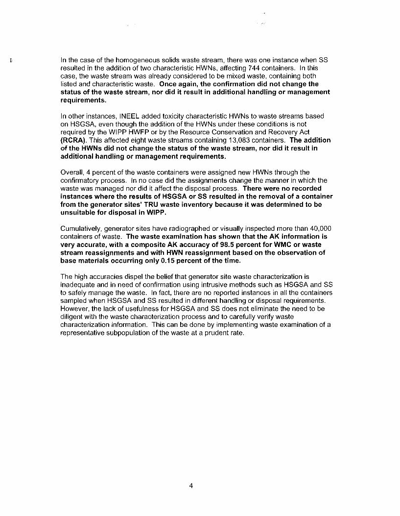
In the case of the homogeneous solids waste stream, there was one instance when SS resulted in the addition of two characteristic HWNs, affecting 7 44 containers. In this case, the waste stream was already considered to be mixed waste, containing both listed and characteristic waste. Once again, the confirmation did not change the status of the waste stream, nor did it result in additional handling or management requirements.
In other instances, INEEL added toxicity characteristic HWNs to waste streams based on HSGSA, even though the addition of the HWNs under these conditions is not required by the WIPP HWFP or by the Resource Conservation and Recovery Act (RCRA). This affected eight waste streams containing 13,083 containers. The addition of the HWNs did not change the status of the waste stream, nor did it result in additional handling or management requirements.
Overall, 4 percent of the waste containers were assigned new HWNs through the confirmatory process. In no case did the assignments change the manner in which the waste was managed nor did it affect the disposal process. There were no recorded instances where the results of H5G5A or 55 resulted in the removal of a container from the generator sites' TRU waste inventory because it was determined to be unsuitable for disposal in WIPP.
Cumulatively, generator sites have radiographed or visually inspected more than 40,000 containers of waste. The waste examination has shown that the AK information is very accurate, with a composite AK accuracy of 98.5 percent for WMC or waste stream reassignments and with HWN reassignment based on the observation of base materials occurring only 0.15 percent of the time.
The high accuracies dispel the belief that generator site waste characterization is inadequate and in need of confirmation using intrusive methods such as HSGSA and SS to safely manage the waste. In fact, there are no reported instances in all the containers sampled when HSGSA and SS resulted in different handling or disposal requirements. However, the lack of usefulness for HSGSA and SS does not eliminate the need to be diligent with the waste characterization process and to carefully verify waste characterization information. This can be done by implementing waste examination of a representative subpopulation of the waste at a prudent rate.
4

• Radiography
- To verify the TRU mixed waste streams by Waste Matrix Code [WMC) for purposes of physical waste form identification and determination of sampling and analytical requirements, to identify prohibited items, and to confirm the waste stream delineation by acceptable knowledge.
• Visual Examination
- To verify the TRU mixed waste streams by Waste Matrix Code for purposes of physical waste form identification, determination of sampling and analytical requirements, and to identify prohibited items.
- To provide a process check on a sample basis by verifying the information determined by radiography, and to confirm the waste stream delineation by acceptable knowledge.
Generator sites are required to determine their AK accuracy as a measure of the effectiveness of their AK program. The HWFP defines accuracy for AK as follows (HWFP Attachment B4, Section B4-3e):
• Accuracy - Accuracy is the degree of agreement between an observed sample result and the true value. The percentage of waste containers which require reassignment to a new waste matrix code and/or designation of different hazardous waste codes based on the reevaluation of acceptable knowledge or on obtaining sampling and analysis data will be reported as a measure of acceptable knowledge accuracy.
The requirement to measure and report AK accuracy is further clarified in HWFP Attachment B4-3e.
Each site shall address quality control by tracking its performance with regard to the use of acceptable knowledge by: 1) assessing the frequency of inconsistencies among information, and 2) documenting the results of acceptable knowledge confirmation through radiography or visual examination, headspace-gas analyses, and homogeneous waste analyses. In addition, the acceptable knowledge process and waste stream documentation shall be evaluated through internal assessments by quality assurance organizations and assessments by auditors or observers external to the organization (i.e., DOE/Carlsbad Field Office (CBFO), NMED, EPA).
The HWFP, in Attachment B4, Section B4-3d, requires the measurement of AK accuracy. This requirement is implemented at each generator site through a CBFOapproved TRU waste characterization program. The determination of AK accuracy begins with the confirmation of AK information using waste examination or sampling and analysis.
Requirements for confirming AK information using waste examination (radiography or visual examination (VE)) follow. Note that the HWFP text is specific regarding those waste characteristics that are to be confirmed (emphasis added).
Acceptable knowledge characterization results shall be confirmed for both retrievably stored and newly generated waste. All retrievably stored waste shall be characterized using
6

solvent hazardous waste code will be conservatively applied to the waste stream. In the case of applicable toxicity characteristic VOCs and non-toxic F003 constituents, generator/storage sites may assess whether the headspace gas concentration would render the waste nonhazardous for those characteristics and change the initial acceptable knowledge determination accordingly.
Hazardous wastes associated with 53000 and 54000 waste streams will be verified based on the results of the total/TC LP analysis of a representative homogeneous waste sample.6 If discrepancies between the results obtained from homogeneous waste sampling and analysis and headspace-gas sampling and analysis exist (i.e., a voe is detected in the solidified waste but not in the headspace), the most conservative results will be used to verify acceptable knowledge and assign hazardous waste codes, as applicable. As with headspace gas, if the total/TCLP results indicate that the concentration of a characteristic waste or non-toxic constituent of an F003 waste is below regulatory levels, the hazardous waste code assigned initially by acceptable knowledge may be changed as part of the confirmatory process.7 Otherwise, if an F-listed waste constituent is detected, the appropriate hazardous waste code shall be applied.8
These measures of AK accuracy are defined in this paper in terms of "Metrics" which assist in understanding the senselessness of the various confirmatory activities:
1. WMC Assignment is confirmed using radiography or VE. Each time a container is assigned a new WMC, the reassignment is recorded against AK accuracy.
2. Waste Stream Assignment is confirmed by radiography or VE. Each time a container is assigned to a different waste stream it is counted against AK accuracy.
3. Toxicity Characteristic Assignment is confirmed by determining if a base material is in a waste container through radiography or VE. The presence of the material in a container where it is not expected is counted against AK accuracy.
4. F-listed Solvent Assignment is confirmed using HSGSA. If the UCL90
concentration of an F-listed solvent exceeds the PRQL and the solvent has not been identified in the AK record, the HWN is added. The addition is counted against AK accuracy unless the presence of the solvent can be explained as a result of packaging or radiolysis.
6 This is AK accuracy Metric 6. The permit uses "i.e." instead of "e.g." in the parenthetical statement in the following sentence in the citation. This defines a discrepancy for this metric as the situation where the compound appears in the solids sample and not in the headspace gas sample and not vice-versa. One site has reported the assignment of a toxicity HWN based on HSGSA results alone. That is, the solids sampling did not support the assignment. This is a conservative application of HWNs by the generator site. This discrepancy is reported in this paper; however, it is not counted against AK accuracy since the assignment of a toxicity HWN using headspace gas analysis is not specifically required by the HWFP and is not required for regulatory compliance purposes. 7 This is AK accuracy Metric 7. The HWFP allows a characteristic HWN or a non-toxic F003 HWN to be deleted based on the results of SS. This is not counted against AK accuracy in this paper since leaving the HWN does not change the manner in which the waste is managed, even if the waste becomes non-mixed as a result of the change. 8 This is AK accuracy Metric 8.
8

One additional measure of accuracy included in the HWFP is determination of the miscertification rate. This is a measure of radiography quality and not AK accuracy. A miscertification occurs if a container that was determined to meet waste acceptance criteria is subsequently discovered to contain a prohibited item. This determination is made using VE of randomly selected containers of waste certified as meeting the Waste Acceptance Criteria (WAC). The number of containers selected each year depends on the historical miscertification rate and the number of containers that will be processed in a year. Permit Attachment 82 describes the statistical method used to determine how many containers must be opened for VE each year. VE used in this manner is a quality control check on the radiography process at a generator site.
Generator sites have procedures for determining AK accuracy and calculating the miscertification rate. The sites have applied the procedures on at least an annual basis. Current reported accuracies are provided in Table 2 for all sites that are shipping waste to WIPP.
Table 2 Overall Acceptable Knowledge Accuracy and Miscertification Rate for Each Site
Site Hazardous Waste Number Waste Stream Miscertification Rate Assignment Assignment
ANL E-CCP 99.7% (Note 1) 91.4% (Note 2) Not determined (Note 3) ( throuqh July 2003)
SRS-CCP 99.5% (Note 4) 99.97% (Note 5) 6% (March 25, 2003)
Hanford 100% 100% 0% (Note 6) (June 18, 2002)
INEEL (3,100 m3) S3000 I 3%
(November 27, 2002) 83% (Note 7) 99.4% J 0% (Note 6) S5000
LANL 100% 90.23% 6% (7/31/01) (Auqust 27, 2002) Headspace Gas 99%
Rocky Flats Solids Sampling 100% 99% 0% (Note 6) (July 24, 2002)
Note 1: ANL-E reported a lead-lined glove in a container when none was expected based on AK information. D008 was assigned to the waste stream. Note 2: During repackaging of the first lot of 28 containers, ANL-E concluded that the waste stream should be classified as S5400 instead of S5420. The reassignment was confirmed by all subsequent containers. Note 3: Waste stream approval was based on 100% VE in lieu of radiography. Annual miscertification rate has not been calculated yet. Note 4: SRS reported lead in 15 containers and fluorescent tubes in two containers, resulting in reassignments of HWNs due to base materials. Note 6: Minimum miscertificalion rate allowed by the HWFP is 1 percent. Note 7: Based on final 3,100 m3 Project numbers.
The following three sections provide a discussion of these AK accuracy results. Section 2.0 provides an analysis and discussion of the assignment of hazardous waste numbers based on sampling and analysis of headspace gas and homogeneous solids. This addresses Accuracy Metrics 4 through 9 in the list of accuracy measures above. The discussion forms the basis for eliminating use of HSGSA and SS for confirming AK information.
Section 3.0 discusses AK accuracy determinations made based on observations of the physical form of the waste. The discussion provides a basis for reducing confirmatory activity to a statistically selected subset of containers. Section 4.0 discusses
10

WASTE SUMMARY NUMBER OF HWNs
SITE STREAM CATEGORY CONTAINERS ADDED COMMENTS
IDENTIFIER GROUP (NOTE 1)
F001, F002, F003, and FOOS added. Count against AK
!NEEL INW252.001 S5000 13 (Note 5) 4 accuracy. D022 noted as a discrepancy. Not F-listed solvent, see Table 5.
INEEL INW276.003 S5000 887 (Note 5) 0 F001, F002, and FOOS added based on HSGSA. HWNs added
INEEL INW276.004 S5000 285 (Note 5) 3 to WSPF. Count against AK accuracy. D008, D029, and D040 noted as a discrepancy. Not F-listed solvent, see Table 5.
INEEL INW296.001 S5000 389 (Note 5\ 0 LANL LA-T A-55-19 S5000 256 (Note 6) 0
F001, F002, and FOOS added based on HSGSA. Count against
TRU AK accuracy. 143 containers RFETS combustibles S5000 2,814 (Note 7) 3 affected. D022, D028, and D029,
and plastics noted as a discrepancy. Not F-listed solvent, HWNs added, see Table 6.
RFETS TRU graphite
S5000 29 (500) (Notes
0 debris 7, 8) F001, F002, and FOOS added based on HSGSA. Count against
RFETS TRU metal
S5000 958 (Note Y) 3 AK accuracy. 26 containers
debris affected. D022 noted as a discrepancy. Not F-listed solvent, HWNs added, see Table 6.
TRU stabilized 15 (373) (Notes RFETS pyrochemical S3000 0
salts 7, 8)
RFETS TRU LECO and S5000
34 (693) (Notes 0 crucible inserts 7, 8)
RFETS TRU ceramic S5000 19 (383) (Notes
0 crucibles 7, 8) TRU 35 (5,909)
RFETS pyrochemical S3000 0 salts
(Notes 7, 8)
FOOS added based on HSGSA. RFETS TRU filter debris S5000 333 (Note 7) 1 Count against AK accuracy. One
container affected
RFETS TRM incinerator
S3000 73 (5,851)
0 ash (Notes 7, 8)
Total 25,517 (39,021) 6 Waste streams affecting 810 Containers
Note 1: Number in column indicated the number of HWNs added to the waste stream as the result of HS GSA results in accordance with the HWFP. Note 2: Number of containers in Lots 1-9 (through July 2003). Note 3: Number of containers in Lots 1-19 (through March 25, 2003). Note 4: Number of containers in Lots 1-14 (through March 24, 2003). Note 5: Number of containers reported in final AK Accuracy Report for 3,100 m3 Project. Note 6: Based on LANL August 2002 AK Accuracy Assessment. Note 7: Based on RFETS AK Accuracy Summary dated 7/24/2002. Note 8: Parenthetical value is the total containers represented by the sampled subset.
Table 4 summarizes the S3000 waste streams that were characterized and provides instances when an HWN was added based on SS (Accuracy Metrics 6 and 8).
12

This is a conservative application of HWNs by the generator site. The discrepancy is reported in this paper because it affects a large number of containers. However, it is not counted against the AK accuracy because the assignment of codes in this manner is not required by the WIPP HWFP and is not consistent with RCRA HWN assignment practice.
During ongoing waste analysis, RFETS tracks and reports the number of containers receiving additional HWNs based on HSGSA (Metric 9). These are shown in Table 6 and accounted for in Table 3 for the purpose of AK accuracy determination because they involve F-listed solvents.
Table 5 Instances Where INEEL Added Toxicity Characteristic HWNs to the Waste Stream Profile Form (not from AK Information)
WASTE SUMMARY NUMBER OF TC HWNS SITE STREAM CATEGORY CONTAINERS COMMENTS
IDENTIFIER GROUP (NOTE 1) ASSIGNED
HWN assigned to WSPF. Note that
INEEL INW169.001 S5000 83 D009 the INEEL AK Accuracy report is not specific regarding the method by which the D009 code was identified. HWN assigned to WSPF. Note that
INEEL INW198.001 S5000 239 D009 the INEEL AK Accuracy report is not specific regarding the method by which the D009 code was identified. HWN assigned to WSPF. Note that
INEEL INW211.001 S5000 1,453 D009 the INEEL AK Accuracy report is not specific regarding the method by which the D009 code was identified. HWN assigned to WSPF. Note that
INEEL INW216.001 S3000 6,018 D022 the WSPF indicates that D022 was assigned based on HSGSA and Solids Samolina did not detect D022. HWN assigned to WSPF. Solids
INEEL INW218.001 S3000 4,650 D032 Sampling did not support the addition of this code. Note 2 HWN assigned to WSPF. Note that
INEEL INW222.001 S3000 342 D022 the WSPF indicates that D022 was assigned based on HSGSA and Solids Samolina did not detect D022.
INEEL INW252.001 S5000 13 D022 HWN assianed to WSPF.
INEEL INW276.004 S5000 285 D008, HWN assigned to WSPF. D029,D040
TOTAL 13,083 All containers counted against AK accuracy by INEEL. ., Note 1. Number of containers reported In final AK Accuracy Report for 3,100 m Proiect.
Note 2: The WSPF for this waste stream shows that D032 is indicated in 1997-98 Solids Sampling results. It was not detected above the regulatory threshold limit in the current sampling. The code was added as a conservative measure. Showing it as an AK discrepancy appears to be an error by INEEL since the WSPF AK Summary indicated the possible presence of the compound based on previous analytical data.
14

WASTE SUMMARY NUMBER OF HWNs SITE STREAM CATEGORY CONTAINERS ASSIGNED
COMMENTS IDENTIFIER GROUP (NOTE 1)
F006 added HWN change as the result of
FOO? added INEEL INW222.001 S3000 342 F009 added
subsequent AK. INEEL did not
0002 deleted count against AK accuracy
0022 added F001 added HWN change as the result of
INEEL INW243.001 S5000 342 F002 added subsequent AK. INEEL did not 0001 deleted count against AK accuracy 0002 deleted
0008 added HWN change as the result of
INEEL INW247.001 S5000 1,575 0002 deleted
subsequent AK. INEEL did not count aqainst AK accuracy
F006 added HWN change as the result of
FOO? added INEEL INW252.001 S5000 13 F009 added
subsequent AK. INEEL did not
0003 deleted count against AK accuracy
0028 added HWN change as the result of
INEEL INW296.001 S5000 389 0001 deleted subsequent AK. INEEL did not count aqainst AK accuracy
.o Note 1. Number of containers reported in final AK Accuracy Report for 3,100 m Pro1ect.
To date, there are six waste streams where HSGSA resulted in the assignment of a new F-listed HWN after it was characterized based on AK information. This affected 810 containers of waste. All of the HWNs added were allowed by the HWFP. The addition of the HWNs did not change the sampling and analysis or the way in which the waste stream was handled.
In the case of the homogeneous solid waste stream, there was one instance when SS resulted in the addition of two characteristic HWNs, affecting 7 44 containers. In this case, the waste stream was already considered to be a mixed waste stream, containing both listed and characteristic waste. Once again, the confirmation did not change the status of the waste stream, nor did it result in additional handling or management requirements.
In other instances, INEEL added toxicity characteristic HWNs to debris waste streams based on HSGSA. This affected five waste streams containing 13,083 containers. The addition of the HWNs did not change the status of the waste stream, nor did it result in additional handling or management requirements.
Overall, 4 percent of the waste containers had new HWNs assigned to them through the confirmatory process (see Table 8). In addition, other assignments have been conservatively made to numerous waste streams and individual containers. In no case did the assignments change the manner in which the waste was managed nor did it affect the disposal process. There were no recorded instances where the results of H5G5A or 55 resulted in the removal of a container from the generator sites' transuranic (TRU) waste inventory because it was determined to be unsuitable for disposal in WIPP.
16

WASTE MATRIX NUMBER OF NUMBER OF
SITE CODE CONTAINERS CONTAINERS DATE OF AK ACCURACY REPORT
EXAMINED REASSIGNED
LANL SCG S5000 (Visual 85 6 Examination) RFETS S3111 6 0 RFETS S3114 1 0 RFETS S3119 14 0 RFETS S3121 23 0 RFETS S3141 2,617 0 RFETS S3190 110 0 RFETS S3211 2 0 RFETS S3229 1 0 RFETS S3290 3 0 RFETS S5111 1,475 72 RFETS S5112 75 2
July 24, 2002 AK Accuracy Report, Table RFETS S5119 5 0 RFETS S5122 370 0
2.2-1
RFETS S5123 1,102 0 RFETS S5126 540 1 RFETS S5129 51 0 RFETS S5311 365 0 RFETS S5313 6 0 RFETS S5319 1 0 RFETS S5390 3,919 14 RFETS S5410 567 7 RFETS S5420 8 0 RFETS S5490 169 0
RFETS Residues (VE) 4,219 10 July 24, 2002 AK Accuracy Report, Table 2.5-1
TOTAL 47,213 716
Note 1: Six containers in the first lot could not be confirmed as S5420. Reevaluation of the AK resulted in the assignment of the entire waste stream to a different (more general) WMC. Subsequent examination supported the new WMC assignment. Note 2: 251 containers in the first lot could not be confirmed as S5420 based on low inorganic debris content. Reevaluation of the AK resulted in the assignment of the entire waste stream as S5300 organic debris. Subsequent examination supported the new WMC assignment.
Table 10 summarizes the number of times a generator site changed the toxicity characteristic HWN assignment associated with a container, based on results of radiography or VE (Metric 3). In some cases, the generator noted the base material that may have a toxicity characteristic HWN assigned to it (e.g., a leaded apron). In such instances, the HWN assignment is counted against AK accuracy as required by Metric 3. At RFETS, when radiography resulted in the assignment of a container to a new WMC, the HWN assignment may also have changed to be consistent with the new WMC. In such cases, the assignment of the new WMC is counted against AK accuracy (and is included in Table 10) however, the change in HWN is not counted against AK accuracy since the new HWNs are changed to be consistent with the new WMC and its associated HWN suite.
Table 10 Hazardous Waste Number Changes Made as the Result of Radiography or Visual Examination (Metric 3)
NUMBER OF NUMBER OF
SITE WASTE STREAM CONTAINERS CONTAINERS SOURCE DESCRIPTION EXAMINED
WITH CHANGED HWNs (NOTE 1)
ANL-E/CCP S5400 336 1 (1) Number of containers in Lots 1-9 (through July 2003).
SRS/CCP SR-W027-FB- 1,285 0 Number of containers in Lots 1-14 (through
Pre86-C March 24, 2003).
18

remove the waste container from the waste inventory being considered for shipment until the item is remediated. Neither of these types of occurrences of prohibited items is considered to be miscertification since the prohibited item was not found in a certified container of waste. The third type of data included in Table 11 is reported discoveries of prohibited items during VE as a quality control check (QC) on radiography. These containers are considered to be "miscertified."
Table 11 Summary of Reported Instances When Prohibited Items Were Found During Radiography or Visual Examination (includes VE as a QC Check on
Radiography)
CONTAINERS CONTAINERS CONTAINERS WITH
SITE RADIOGRAPHED VISUALLY PROHIBITED SOURCE EXAMINED
ITEMS
ANL-E/CCP 334 92 13 (Note 1) Number of containers in Lots 1-9 (through July 2003).
SRS/CCP 3,505 50 3 Number of containers through March 25, 2003. Hanford Miscertification Rate
HANFORD 761 15 0 Calculation for FY 2003 dated 3/6/03. Number of containers in WWIS as of May 23, 2003.
INEEL 25,531 144 4 Note 2 AK Accuracy Report dated 8/27 /02
LANL 2,088 85 3 and LANL miscertification calculation dated 8/24/00.
RFETS 11,430 149 6 (Note 3) July 24, 2002 AK Accuracy Report
TOTAL 43,649 535 29
Note 1: These 13 items were expected based on the AK information for the waste stream. Note 2: The final closeout report for the 3,100 m3 Project does not calculate a final miscertification rate. The number of containers is all containers radiographed by the project. The number of visually examined containers is those known to have been examined as of June 2001 and prohibited items are those reported as of that time. It is anticipated that another 60 containers were examined in 2002. Note 3: These 6 items were unexpected in the waste streams undergoing radiography.
The information in Table 11 is included for completeness (i.e., the data are reported in the generator site AK accuracy reports). This information must be used carefully since many sites do not report the number of containers that are rejected by the radiography or VE in lieu of radiography processes.
Cumulatively, generator sites have radiographed or visually inspected more than 40,000 containers of waste. The waste examination has shown that the AK information is very accurate, with a composite AK accuracy of 98.5 percent with regard to WMC or waste stream reassignments (Table 9) and with HWN reassignment based on the observation of base materials only occurring 0.15 percent of the time (Table 10). In addition, less than 0.6 percent of the containers examined had unexpected prohibited items reported.
Based on these observations, the following can be stated with regard to AK accuracy:
• AK records have been extremely reliable throughout the complex, with regard to the segregation into waste streams.
• AK records have been extremely reliable throughout the complex, with regard to the assignment of waste matrix codes.
20

5.0 Discussion
Since the outset of the WIPP waste characterization program, both the Environmental Protection Agency and the New Mexico Environment Department (NMED) have expressed an interest in the reliability of information used by DOE to meet the waste characterization requirements. This interest led both regulatory agencies to require that
waste characterization information be confirmed as a means of assuring that information collected was adequate. Indications for this requirement can be found in many historical documents associated with development of the WAP and the issuance of the HWFP as follows:
August 1990 - DOE publishes the Program Plan for the Pretest Characterization of WIPP Experimental Waste, DRAFT Revision 6.0, DOE/WIPP 89-025 describing proposed TRU waste characterization activities to support the bin-scale tests at WIPP (to be performed under the No-Migration Variance). This document discusses various characterization activities including HSGSA and SS, as well as "verification" of process knowledge.
March 1, 1991 - DOE sends a letter to New Mexico Environmental Improvement Division (NMEID) inviting the agency to a meeting with EPA to discuss waste characterization issues. The letter included Department of Energy Strategy Document for WIPP, and said" ... This strategy document outlines how the Department of Energy intends to comply with waste analysis requirements pursuant to the RCRA. .. ". Among other things, the document discusses how DOE would use HSG and AK to verify RCRA-listed waste.
March 7, 1991 - DOE holds a joint meeting with EPA and NMEID to discuss the RCRA compliance strategy for WIPP. Summary notes from this meeting indicate that " ... NME/0, in general, seemed to feel that process knowledge may not be adequate to verify the waste and would like more analysis done .. .EPA seemed satisfied with headspace sampling as an adequate verification tool, along with process knowledge, RTR and visual examination for easily characterized waste ... "
October 10, 1991 - Representatives of DOE and NMED meet to discuss WIPP's waste analysis plan and waste characterization requirements. Summary notes from the meeting state" ... [NMED] emphasized that the waste characterization program is key to the NMED review of the entire permit application .. . [NMED] also indicated that in cases where DOE is relying heavily on knowledge of materials and processes, we must provide information demonstrating the reliability of this knowledge .. . [NMED] also indicated that DOE commitments regarding sampling frequencies are to define the 'representativeness' of DOE sampling and analyses plans ... The Waste Analysis Plan is the document that the NMED will review for the completeness of all waste characterization requirements under RCRA ... "
September 29, 1992 - NMED sends a letter to DOE clarifying statements made in the August 25, 1992, Notice of Deficiency. This letter includes an extensive discussion of NMED expectations regarding process knowledge and verification.
22

In this case, the stream would have to be pre-screened, using radiography or VE, for adequate assurance that no prohibited items exist. Likewise, if HWNs are unknown, effort will be necessary to make reasonable assignments to assure there is no compatibility issue associated with the waste. Second, success depends on the construction of an adequate waste examination sampling plan. This examination of the data collected to date indicates that a statistical sampling approach could be used to identify the number of containers that should be radiographed or subjected to VE to confirm the waste stream characterization results with a high degree of confidence.
In conclusion, the high accuracies dispel the belief that generator site AK requires confirmation through intrusive HSGSA and SS in order to safely manage the waste. In fact, there are no reported instances of changes as the result of HSGSA and SS that required different handling or disposal provisions. In that sense, HSGSA and SS are redundant to AK information, which is proven for ensuring safe/protective management of the waste. It is on this basis that these unnecessary methods cannot be justified as required elements of WIPP's HWFP WAP. Certainly, it remains important to be diligent in the AK process and to carefully confirm the AK record but this can be effectively done using radiography or visual examination of a representative subpopulation of the waste. Waste examination, either visually or through radiography, can directly confirm the physical properties of waste, absence of most prohibited items and, therefore, indirectly confirm the chemical/hazardous properties of the waste.
24

Final
Analysis of Volatile Organic Compound Levels in the Transuranic Waste Inventory
William H. McCulla and Gregory D. Van Soest, LANL-EES-12 November 26, 2003

not accurately represent average VOC levels for solidified organic FWFs for the DOE Complex, but is expected to conservatively bound the case, as described in the body of the report.
Currently, no headspace gas data are available for solidified organics for LANL or Hanford. However, process knowledge of organic sludge at LANL indicates that it is very low in VOCs. The 2003 Transuranic Waste Inventory Update Report, estimates less than 2,000 m3
-- both stored and projected -- of solidified organics in the DOE Complex. Process knowledge as well as headspace gas sampling of RFETS solidified organics indicates this waste is saturated with VOCs, thus bounding the case for any other solidified organics in the DOE Complex.
Even conservative acceptance of the current data as representative of all solidified organic FWFs for the DOE Complex creates no realistic threat of exceeding WIPP emission standards. This conclusion can be made apart from any further headspace gas sampling. The anticipated volume of solidified FWFs is not sufficiently large to result in a threat to either room-based limits or WIPP emission limits. For example, using the average concentration of VOCs in the RFETS solidified organics waste stream, ~ 7,600 drum-equivalents of RFETS solidified organics are required to approach room-based limits of the WIPP repository. This would require most of the stored solidified organic waste at RFETS and INEEL to be shipped and disposed of in the same room - a very unlikely scenario. With room VOC monitoring this scenario becomes irrelevant.
Finally, there is a significant quantity of solidified organics in the DOE Complex that do not currently meet transportation requirements regarding hydrogen gas generation. It is unlikely that they will come to WIPP without some treatment that would also reduce the VOC source term. For example, a thermal treatment was originally planned for the solidified organics residing at INEEL that would have eliminated all VOCs. These original plans have been discontinued, and the final disposition path is currently uncertain.
Because of such uncertainties regarding this FWF, a bounding scenario, which is not the focus of this paper, was examined that assumed all solidified organic FWF, regardless of future treatment options, was emplaced in WIPP as solidified organics. Even under this scenario, the solidified organics result in only about 2 percent of the total waste. Due to 1) the small weighted average of VOCs, 2) waste being emplaced from multiple sites, 3) waste emplacement configurations, and 4) planned site shipping schedules, this bounding scenario still does not reasonably threaten room-based VOC limits. There are certainly other bounding scenarios, but room monitoring for VOCs prevents any of these from becoming a health and safety issue.
Page 3 of22

1. All waste information without an FWF assignment was assigned an FWF using the Waste Matrix Code (WMC) and Table 1-2 of Reference 6. Two drums in the 930-drum data set used in the VOC analysis for the WIPP RCRA Part B Permit were found to have conflicting FWFs and WMCs. Upon further investigation, the WMC assignment was determined to be correct and the FWF was changed.
2. The TRAMP AC Revision 19 method was used to determine whether a drum exceeded the mixture lower flammability limit (MLFL) for VOCs and hydrogen (7). This process determines the flammable VOC concentrations within the innermost layers of confinement and compares the sum of the VOC levels to a calculated MLEL. The MLEL is determined for each drum by the Flammable Group Method based on an extension of the AIChE method Procedure B. This was applied to individual drum data from all sources except WWIS. All drums that failed MLFL screening were eliminated from further consideration since they would not pass shipping criteria. The data in WWIS had already been screened for flammability limits and were, therefore, not screened again.
3. The time for a VOC within a drum's headspace to reach equilibrium with the surrounding outside air through a Nuclear Filter Technologies Inc. NFT-013 filter was determined by an independent calculation (8). The diffusivity values for the calculation were taken from reference 9. Approximately 90 percent of equilibrium was reached in 30 days for the VOC carbon tetrachloride. Since diffusivity values for the nine VOCs of concern in WIPP differ only by approximately 20 percent (9), the 30-day period to 90 percent of equilibrium was assumed for all VOCs. Although this is not precisely the TRAMP AC requirements for drum age criteria, it is very near the 25-day standard requirement. All data except that from WWIS were screened for drum vent date and drum sampling date. Drums that were sampled less than 30 days after venting were eliminated from the data set since their VOC levels were not near equilibrium, a condition required of all drums emplaced in WIPP.
4. Since multiple data sets that potentially contained the same drum information were used, data were screened for duplicate entries and only the latest entry with the most recent date was retained.
5. The data qualifier for each measurement was included in the imported data. If the qualifier was "U," the qualifier for measurements at or below the method detection limit, one-half the reported value was used for the concentration in calculating the weighted average.
6. All "B"-qualified data were eliminated from the data field because that qualifier is used for contamination observed in the blank and indicates a suspect measurement.
The screening process described above was first applied to the original 930-drum population used in 1995 to determine what the effect would be on the VOC source term by removing
Page 5 of22

Results
In the 1995 assessment, four voes dominated the total voe source term. Those voes were 1, 1, I-trichloroethane, carbon tetrachloride, methanol and methylene chloride. Three of the 12 FWFs were the principal contributors to voe levels in the source term. From Reference 1, these FWFs (in order of contribution to the weighted average) were combustibles, solidified organics, and solidified inorganics.
When the screening factors were applied to the 930-drum set used in the 1995 analysis, the total number of drums in the analysis decreased to 689. The resultant weighted average for carbon tetrachloride was reduced from 386 ppmv to 258 ppmv. The dominant FWFs (with respect to net voe concentration) for voes were reduced to two: combustibles and solidified organics. Methylene chloride and methanol have been reduced to a very low level because drums with high levels of these voes failed TRAMPAe Rev. 19 and were eliminated from the analysis.
Results of the 2003 analysis on all available headspace gas data clearly show that the dominant voes are 1,1,1-trichloroethane and carbon tetrachloride, and that their weighted averages have substantially decreased from the 1995 values. In the 2003 analysis, all voes were reduced to at least one-half of their 1995 weighted-average values. The new methylene chloride weighted average is only 2 percent of the 1995 value.
Principal contributor in this assessment of voes to the weighted-average value is the solidified organics FWF, which contributes approximately 92 to 97 percent of the total weighted average of the two major voes. A comparison of the weighted source term from the 1995 and 2003 data for 1, 1, I-trichloroethane and carbon tetrachloride is shown in Figures 6 and 7 (pages 19 and 20). Mean values of 1, 1, I -trichloroethane and carbon tetrachloride have increased in one of the FWFs, solidified organics. That waste form has the highest voe concentrations of any waste form destined for WIPP. However, the waste form constitutes approximately 1 percent of the total volume of TRU waste. Thus, the weighted-average source term for the two principal VOC contributors in the new data set -- 1, 1, I -trichloroethane and carbon tetrachloride -- decreased to 38 percent and 47 percent (respectively) of the 1995 values, when considered across all FWFs.
Conclusion
Using updated data and a much larger population of headspace gas samplings, a new weightedaverage voe source term for 28 voes has been determined. The principal Voes that contribute to the new source term have been reduced from four in the 1995 data to two in the new data set. These are 1, 1, I-trichloroethane and carbon tetrachloride. The FWFs that are principal contributors to the voe source term have been reduced from three in the 1995 data to one in the new data set. This FWF is solidified organics. The weighted-average source term for the two principal voe contributors in the 2003 data set -- 1, 1, I-trichloroethane and carbon tetrachloride -- decreased to 38 percent and 47 percent, respectively, from the 1995 values.
Page 7 of 22

solidified organic waste would be required to approach the room-based limits of the WIPP repository. This would require most of the stored solidified organic waste at RFETS and INEEL to be shipped and disposed of in the same room - a very unlikely scenario. With room VOC monitoring this scenario becomes irrelevant.
Finally, there is a significant quantity of solidified organics in the DOE Complex that do not currently meet transportation requirements regarding hydrogen gas generation. At present, there is no path forward for this waste. A thermal treatment was originally planned for the solidified organics residing at INEEL that would have eliminated all VOCs. These original plans have been discontinued, and the final disposition is currently uncertain.
Because of such uncertainties regarding this FWF, a bounding scenario was examined that assumed all solidified organic FWF, regardless of future treatment options, was emplaced in WIPP as solidified organics. Even under this scenario, solidified organics result in only about 2 percent of the total waste. Due to 1) the small weighted average of VOCs, 2) waste being emplaced from multiple sites, 3) waste emplacement configurations, and 4) planned site shipping schedules, this bounding scenario still does not reasonably threaten room-based VOC limits. There are certainly other bounding scenarios, but room monitoring for VOCs prevents any of these from becoming a health and safety issue.
Page 9 of22
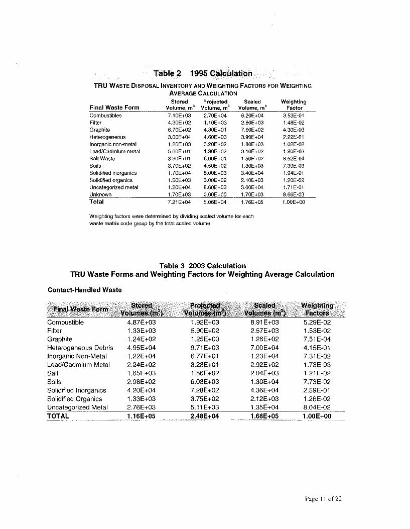
Table 2 1995 Cafo.~lation
TRU WASTE DISPOSAL INVENTORY AND WEIGHTING FACTORS FOR WEIGHTING AVERAGE CALCULATION
Stored Projected Scaled Final Waste Form Volume, m3 Volume, m3 Volume, m3
Combustibles 7.10E+03 2.70E+04 6.20E+04 Filter 4.30E+02 1.10E+03 2.60E+03 Graphite 6.70E+02 4.30E+01 7.60E+02 Heterogeneous 3.00E+04 4.60E+03 3.90E+04 Inorganic non-metal 1.20E+03 3.20E+02 1.80E+03 Lead/Cadmium metal 5.60E+01 1.30E+02 3.10E+02 Salt Waste 3.30E+01 6.00E+01 1.50E+02 Soils 3.70E+02 4.50E+02 1.30E+03 Solidified inorganics 1.70E+04 8.00E+03 3.40E+04 Solidified organics 1.50E+03 3.00E+02 2.10E+03 Uncategorized metal 1.20E+04 8.60E+03 3.00E+04 Unknown 1.70E+03 0.OOE+00 1.70E+03
Total 7.21E+04 5.06E+04 1.76E+05
Weighting factors were determined by dividing scaled volume for each waste matrix code group by the total scaled volume
Table 3 2003 Calculation
Weighting Factor
3.53E-01 1.48E-02
4.30E-03 2.22E-01 1.02E-02 1.80E-03 8.52E-04 7.39E-03 1.94E-01 1.20E-02 1.71 E-01 9.66E-03
1.00E+00
TRU Waste Forms and Weighting Factors for Weighting Average Calculation
Contact-Handled Waste
;!~!~(- Wt:lShli.ng< .•. . :irt~ctc,fs;,.
Combustible 4.87E+03 1.92E+03 8.91 E+03 5.29E-02 Filter 1.33E+03 5.90E+02 2.57E+03 1.53E-02 Graphite 1.24E+02 1.25E+00 1.26E+02 7.51 E-04 Heterogeneous Debris 4.95E+04 9.71E+03 7.00E+04 4.15E-01 Inorganic Non-Metal 1.22E+04 6.77E+01 1.23E+04 7.31 E-02 Lead/Cadmium Metal 2.24E+02 3.23E+01 2.92E+02 1.73E-03 Salt 1.65E+03 1.86E+02 2.04E+03 1.21 E-02 Soils 2.98E+02 6.03E+03 1.30E+04 7.73E-02 Solidified lnorganics 4.20E+04 7.28E+02 4.36E+04 2.59E-01 Solidified Organics 1.33E+03 3.75E+02 2.12E+03 1.26E-02 Uncategorized Metal 2.76E+03 5.11 E+03 1.35E+04 8.04E-02 TOTAL 1.16E+05 2.48E+04 1.68E+05 1.00E+00
Page 11 of22

Average/Mean PPMV
Final Waste Form Combustible Filter
Graphite
Heterogeneous
lnoraanic Non-Metal
Pb/Cd Metal Waste Salt Waste
Solidified lnoraanics
Solidified Organics
Uncateoorized Metal Unknown
(J~te s ~ontlnuect); Ffftal Wa$t~ Forfu Combustible
Pb/Cd Metal Waste Salt Waste
Uncate orized Metal
Unknown
Table 5 Average Values for 28 voes
QI GI C·; C QI ' l!I QI QI ><··.•· QI .c C C
ii --~ QI QI QI QI i···. C C N N -·. "ti ;! e <'i QI QI C QI C C C ·"t: o,,\,, QI QI
,,,t• ... _ .... 0 ·o:'!f Ill >, :9 Ill .Q 0 QI 2~ .c .c .c :E QI e: ,:o. QI ti ti >, ... >, C .. i ~ii .c QI .c ()
i e e 1ii e .... f QI ·.·· l:; .· QI ?l N as.,,-, Q 0 .e Q e i C , ~ ,· ,a cO .
QI ~',½ I-;. ;E.i £ :E :E
~ ~ Cl>. ·~ .Q .·.-~ .. C• c
~ () I-' a 0
it. :·!i q 9 ~ 0 Cl) .,.-~ 0 ...
s,·"'t in.. ... N' .Q 0 I QI ,g;:,. .... ·"i ~:.:·/ ... --:. Cl!. Cl!. ~ () .l!I" :E .. 1'.i: ... ... ... ... .... ct -.Ill· /m ·u . . (J ..
1.14E-t-OO 8.03E+01 1.10E+OC 1.03E+01 1.26E+OO 1.62E+OO 1.02E+OO 1.11E+OO 9.25E-01 1.73E+01 1.58E-t-OO 1.05E+OO 6.10E+01 1.20E+OO
2.57E-01 1.17E+01 2.41 E-01 1.68E+01 5.91E-01 4.46E-01 2.76E-01 3.46E-01 2.54E-01 1.93E+01 1.0BE+OO 2.71E-01 4.53E+OO 2.49E-01
2.39E-01 8.13E-t-OO 2.44E-01 3.24E-01 2.94E-01 3.57E-01 2.33E-01 2.60E-01 2.0BE-01 8.12E+OO 6.17E-01 2.23E-01 6.00E-01 2.04E-01
9.12E-01 3.72E+OO 9.03E-01 9.82E-01 8.82E-01 8.44E-01 7.94E-01 8.97E-01 7.67E-01 1.10E+01 1.10E+OO 8.25E-01 1.18E+OO 8.BBE-01
2.26E-01 1.61E+01 2.26E-01 2.41E-01 4.07E-01 3.32E-01 2.35E-01 2.75E-01 2.25E-01 7.54E+OO 3.53E-01 2.0?E-01 2.57E+OC 2.20E-01
2.57E-01 7.65E+01 3.0?E-01 1.07E+OO 7.76E-01 6.?0E-01 3.18E-01 2.84E-01 2.61E-01 1.62E+01 4.89E-01 2.24E-01 2.41E+01 2.60E-01
2.61E-01 2.?0E-01 2.61E-01 2.65E-01 4.95E-01 2.66E-01 2.59E-01 2.62E-01 2.58E-01 3.19E+OO 5.85E-01 2.60E-01 2.71E-01 2.58E-01
2.47E-01 2.90E+01 2.14E-01 6.20E+OC 7.77E-01 1.09E-t-OO 2.34E-01 2.32E-01 2.13E-01 3.94E+OO 7.34E-01 2.06E-01 1.45E+OC 2.06E-01
1.23E+02 8.34E+03 1.08E+02 2.73E+03 1.53E+02 1.27E+02 1.16E+02 1.11E+02 1.00E+02 1.07E+03 1.13E+02 1.05E+02 1.41E+04 1.14E+02
6.26E-01 3.61E+OC 6.46E-01 8.68E-01 6.02E-01 6.71E-01 7.29E-01 6.67E-01 7.18E-01 1.76E+01 1.83E+OO 7.09E-01 1.87E+OO 6.13E-01
2.50E-01 2.50E-01 2.50E-01 2.50E-01 2.50E-01 2.50E-01 2.50E-01 7.40E+OO 7.30E-01 2.50E-01 2.50E-01 2.50E-01
9.57E-01 8.63E-01 1.10E+O 9.23E-01 1.53E+01 7.60E+OO 1.01 E+01 4.27E+OO 2.70E+OO 7.86E+OO 1.29E 9.20E-01 7.18E+OO 1.07E+OO
1.52E+OO 1.31 E+01 2.58E-01 3.10E-01 1.49E+01 2.52E+OO 1.73E+O 1.18E+OO 4.14E-01 3.58E+OO 2.58E-01 2.31 E-01 7.35E+OO 2.50E+OO
1.85E+OO 3.72E-01 4.24E-01 3.75E-01 6.70E+006.74E+OO 9.75E-01 1.82E+OO 5.52E-01 2.29E+OO 3.50E-01 2.65E-01 1.52E+019.86E+OO
3.06E-01 2.62E-01 2.62E-01 7.40E-011.29E+012.61E+002.37E+OO 5.03E-01 3.26E-01 7.24E+O 2.60E-01 2.59E-01 1.38E+OO 4.93E-01
2.61 E-01 4.36E-01 4.55E-01 4.47E-01 1.25E+01 1.75E+OO 1.49E+OO 2.23E+OO l.05E+OO 4.18E+OO 3.22E-01 9.60E-01 3.84E+003.69E+OO
2.10E+02 2.03E+02 1.16E+02 1.30E+021.26E+03 7.21E+027.96E+02 2.36E+02 1.47E+02 8.30E+02 1.47E+02 1.07E+02 1.76E+02 1.92E+02
7.28E-01 6.30E-01 2.00E 6.81 E-01 1.50E+01 7.15E+OO 1.43E+01 1.96E+OO 6.59E+OO 6.99E+OO 2.14E+OO 7.0BE-01 1.05E+01 1.02E+OO
2.50E-01 2.50E-01 2.50E-01 5.50E+OO 2.55E+OO 1.85E+OO 1.09E+OO 5.00E-01 2.50E+OO 2.50E-01 2.50E-01 8.50E-01 2.50E-01
Page 13 of 22

Figure 1. Containers by Final Waste Form, 1995 Data
300 "
250
200
150
100
50
0
0"' ii -~ -~ ~ ~ ~ -~ .§ ·S"' ~ ~ ~ ;} ;} ~ ;} -~ 4.~ ~ Q0 ~ ~ r,,f ,f ,f ~ ~ ~ §' ~ ~o; ~ JJ ~~ (j ~ ~ -~ .! 0 -~ t f # b ~ -~ b •;$) c; s ,f CJ'li -~ -~ ~
oo; ~ -~ l j -~ cf-Ji, t? cf- 0 .:::,~ ~ -.;;: lli 0
.:/:-....,
Page 15 of22

Figure 3: Sample Population Distribution by Source & Final Waste Form
rm "Flammable voe & Hyurogen Heads pace Gas Assessment, IDe 003
"VOes from INEEL-930," INEEL,1995
• "Parameters for Testing Impacts of voes as Poisons for Hyurogen
i!!WWIS
Page 17 of22

4.00E+02 ·'
3.50E+02
3.00E+02
1.50E+02
1.00E+02
5.00E+01
0.00E+00
Figure 5. Comparison of Weighted Averages (ppmv) by Analyte 1995 & 2003 Data
Page 19 of22

Figure 7. Comparison Carbon Tetrachloride 1995 & 2003 Data by FWF
80
60
40
20
0
t' ~ -~ 4.~ ~
:Q::,
# c;
Page 21 of22

Appendix A Excluded Drums

DRUM VENT SITE IDC CON WASMATCD TYPE PACKDATE VENTDATE DAYS1 SAMPDATE DAYS2 DAYS3 DUPLICATE DRUMS FAILING TRAMPAC, Rev 19
D64448 FALSE RFETS 821 116 Heterogeneous 3 6/7/1989 0 7/7/1994 1856 NA D69312 FALSE RFETS 800 111 Solidified lnorganics 1 6/7/1989 0 5/4/1993 1427 NA 001663 TRUE RFETS 432 226 Solidified Organics 3 3/29/1985 5/4/1994 3323 5/16/1994 12 3335 NA D72128 TRUE RFETS 801 112 Solidified Organics 4 11/1/1989 11/1/1989 0 1/13/1994 1534 1534 NA D68486 TRUE RFETS 801 112 Solidified Organics 4 6/1/1989 12/12/1994 2020 12/8/1994 -4 2016 NA D67390 TRUE RFETS 801 112 Solidified Organics 4 3/20/1989 12/12/1994 2093 12/8/1994 -4 2089 NA D76195 TRUE RFETS 801 112 Solidified Organics 4 12/16/1989 12/16/1989 0 1/5/1994 1481 1481 NA D69306 TRUE RFETS 801 112 Solidified Organics 4 5/25/1989 12/21/1994 2036 12/13/1994 -8 2028 NA D67009 TRUE RFETS 801 112 Solidified Organics 4 3/2/1989 11/4/1994 2073 11/1/1994 -3 2070 NA D67539 TRUE RFETS 801 112 Solidified Organics 4 4/3/1989 11/4/1994 2041 11/1/1994 -3 2038 NA D68975 TRUE RFETS 801 112 Solidified Organics 4 6/14/1989 12/21/1994 2016 12/13/1994 -8 2008 NA D60298 TRUE RFETS 801 112 Solidified Organics 4 6/6/1989 12/12/1994 2015 12/8/1994 -4 2011 NA D64555 TRUE RFETS 801 112 Solidified Organics 4 11/17/1988 12/12/1994 2216 12/6/1994 -6 2210 NA D66523 TRUE RFETS 801 112 Solidified Organics 4 2/21/1989 12/12/1994 2120 12/6/1994 -6 2114 NA D67413 TRUE RFETS· 801 112 Solidified Organics 4 3/9/1989 10/31/1994 2062 10/27/1994 -4 2058 NA D42280 FALSE RFETS 801 112 Solidified Organics 4 10/25/1985 0 12/2/1993 2960 NA D67012 TRUE RFETS 801 112 Solidified Organics 4 3/7/1989 11/4/1994 2068 11/1/1994 -3 2065 NA D76200 TRUE RFETS 801 112 Solidified Organics 4 10/24/1985 10/24/1985 0 7/27/1993 2833 2833 NA D71020 TRUE RFETS 801 112 Solidified Organics 4 10/6/1989 10/6/1989 0 1/13/1994 1560 1560 NA D70543 TRUE RFETS 801 112 Solidified Organics 4 10/6/1989 10/6/1989 0 3/8/1994 1614 1614 NA D71022 TRUE RFETS 801 112 Solidified Organics 4 10/6/1989 10/6/1989 0 8/26/1993 1420 1420 NA D71940 TRUE RFETS 801 112 Solidified Organics 4 8/28/1989 8/28/1989 0 4/14/1994 1690 1690 NA D71932 TRUE RFETS 801 112 Solidified Organics 4 8/18/1989 8/18/1989 0 1/11/1994 1607 1607 NA D71941 TRUE RFETS 801 112 Solidified Organics 4 8/28/1989 8/28/1989 0 1/19/1994 1605 1605 NA D67251 TRUE RFETS 480 117 Uncategorized Metal 2 4/7/1989 5/6/1993 1490 5/6/1993 0 1490 NA
DRUMS FAILING 30 DAY DAC
013763 TRUE INEL 339 223 Combustible 3 1/23/1986 8/25/1992 2406 8/25/1992 0 2406 NONE D06288 FALSE RFETS 338 119 Filter 3 2/19/1988 0 12/13/1993 2124 NA D11129 TRUE RFETS 338 119 Filter 3 2/25/1988 12/9/1993 2114 12/6/1993 -3 2111 NA D32439 FALSE RFETS 338 119 Filter 3 2/25/1988 0 12/3/1993 2108 NA D41681 FALSE RFETS 338 119 Filter 3 10/19/1988 0 12/17/1993 1885 NA
Page 1

D60218 FALSE RFETS 821 116 Heterogeneous 3 12/8/1989 0 5/17/1994 1621 NA D72178 FALSE RFETS 821 116 Heterogeneous 3 10/18/1989 0 7/7/1994 0 1723 NA D57522 FALSE RFETS 336 0 Heterogeneous 3 3/22/1988 0 12/6/1993 2085 NA D75926 FALSE RFETS 832 116 Heterogeneous 3 12/11/1990 0 10/13/1994 0 1402 NA D76452 FALSE RFETS 825 116 Heterogeneous 3 3/23/1991 0 6/28/1994 0 1193 NA D72186 FALSE RFETS 821 116 Heterogeneous 3 10/18/1989 0 6/28/1994 0 1714 NA D72932 FALSE RFETS 825 116 Heterogeneous 3 1/18/1990 0 6/28/1994 0 1622 NA D61245 FALSE RFETS 336 0 Heterogeneous 3 3/22/1988 0 12/13/1993 2092 NA D61278 FALSE RFETS 336 0 Heterogeneous 3 4/4/1988 0 12/9/1993 2075 NA D62851 FALSE RFETS 825 116 Heterogeneous 3 4/26/1989 0 7/6/1994 1897 NA D68044 FALSE RFETS 825 116 Heterogeneous 3 5/10/1989 0 7/7/1994 1884 NA D69091 FALSE RFETS 825 116 Heterogeneous 3 6/21/1989 0 7/7/1994 1842 NA D69877 TRUE RFETS 825 116 Heterogeneous 3 6/24/1989 0 7/6/1994 1838 NA D69883 FALSE RFETS 825 116 Heterogeneous 3 7/13/1989 0 7/7/1994 1820 NA D56755 FALSE RFETS 821 116 Heterogeneous 3 6/26/1987 0 7/7/1994 2568 NA D69095 FALSE RFETS 833 116 Heterogeneous 3 7/12/1989 0 7/6/1994 1820 NA D55680 FALSE RFETS 821 116 Heterogeneous 3 6/26/1987 0 7/7/1994 2568 NA D67678 FALSE RFETS 825 116 Heterogeneous 3 4/19/1989 0 7/6/1994 1904 NA D72339 FALSE RFETS 821 116 Heterogeneous 3 11/2/1989 0 6/28/1994 0 1699 NA D70370 FALSE RFETS 821 116 Heterogeneous 3 8/21/1989 0 7/7/1994 1781 NA D70696 FALSE RFETS 821 116 Heterogeneous 3 8/11/1989 0 6/22/1994 1776 NA D75868 FALSE RFETS 825 116 Heterogeneous 3 1/29/1991 0 6/22/1994 0 1240 NA D68096 FALSE RFETS 821 116 Heterogeneous 3 4/18/1989 0 7/6/1994 1905 NA D76630 FALSE RFETS 825 116 Heterogeneous 3 3/21/1991 0 7/26/1994 0 1223 NA D76587 FALSE RFETS 825 116 Heterogeneous 3 3/28/1991 0 7/26/1994 0 1216 NA D73632 FALSE RFETS 825 116 Heterogeneous 3 9/27/1990 0 7/6/1994 0 1378 NA D69975 FALSE RFETS 821 116 Heterogeneous 3 8/11/1989 0 6/22/1994 1776 NA D76635 FALSE RFETS 825 116 Heterogeneous 3 3/20/1991 0 7/26/1994 0 1224 NA D76596 FALSE RFETS 825 116 Heterogeneous 3 3/28/1991 0 7/26/1994 0 1216 NA D69602 FALSE RFETS 821 116 Heterogeneous 3 6/14/1989 0 7/26/1994 1868 NA D72598 FALSE RFETS 821 116 Heterogeneous 3 11/28/1989 0 6/22/1994 0 1667 NA D56823 FALSE RFETS 831 116 Heterogeneous 3 2/14/1989 0 6/8/1994 1940 NA D74683 FALSE RFETS 821 116 Heterogeneous 3 6/24/1990 0 6/28/1994 0 1465 NA D63817 FALSE RFETS 821 116 Heterogeneous 3 3/1/1989 0 5/17/1994 1903 NA D67698 FALSE RFETS 831 116 Heterogeneous 3 4/5/1989 0 7/6/1994 1918 NA D63808 FALSE RFETS 831 116 Heterogeneous 3 10/25/1988 0 6/8/1994 2052 NA D57179 TRUE RFETS 330 0 Heterogeneous 3 12/1/1987 12/13/1993 2204 12/9/1993 -4 2200 NA
Page 3

015786 TRUE INEL 1 211 Solidified lnorganics 1 11/8/1983 5/11/1993 3472 5/24/1993 13 3485 021565 005735 TRUE INEL 7 211 Solidified lnorganics 1 1/23/1987 8/11/1995 3122 12/5/1994 -249 2873 NA 005738 TRUE INEL 7 211 Solidified lnorganics 1 1/23/1987 5/11/1995 3030 12/5/1994 -157 2873 NA 014007 TRUE INEL 1 211 Solidified lnorganics 1 11/1/1984 5/11/1993 3113 5/12/1993 1 3114 004963 D35301 TRUE RFETS 800 111 Solidified lnorganics 1 9/27/1988 11/4/1994 2229 11/2/1994 -2 2227 NA D38859 FALSE RFETS 803 111 Solidified lnorganics 1 9/20/1990 0 1/27/1994 1225 NA D49662 FALSE RFETS 292 0 Solidified lnorganics 1 3/6/1988 0 12/21/1993 2116 NA D63281 FALSE RFETS 807 111 Solidified lnorganics 1 10/10/1988 0 11/3/1994 2215 NA D65530 FALSE RFETS 807 111 Solidified lnorganics 1 11/9/1988 0 11/3/1994 2185 NA D65600 TRUE RFETS 807 111 Solidified lnorganics 1 11/14/1988 12/21/1994 2228 12/13/1994 -8 2220 NA D68480 FALSE RFETS 800 111 Solidified lnorganics 1 5/11/1989 0 5/6/1993 1456 NA 001410 TRUE INEL 292 214 Solidified lnorganics 1 12/18/1985 6/1/1994 3087 3/7/1994 -86 3001 NA 008872 TRUE INEL 292 214 Solidified lnorganics 1 3/14/1984 5/11/1995 4075 12/5/1994 -157 3918 NA 003017 TRUE INEL 1 211 Solidified lnorganics 1 7/17/1985 5/11/1995 3585 12/5/1994 -157 3428 NA D67436 FALSE RFETS 800 111 Solidified lnorganics 1 4/3/1989 0 5/4/1993 1492 NA D68247 FALSE RFETS 800 111 Solidified lnorganics 1 4/12/1989 0 5/6/1993 1485 NA 021306 TRUE INEL 4 213 Solidified lnorganics 4 9/27/1983 6/1/1994 3900 1/31/1994 -121 3779 011194 002065 TRUE INEL 292 214 Solidified lnorganics 1 2/16/1986 5/11/1995 3371 12/5/1994 -157 3214 NA 009006 TRUE INEL 7 211 Solidified lnorganics 1 3/22/1984 4/26/1993 3322 5/24/1993 28 3350 021565 016869 TRUE INEL 7 211 Solidified lnorganics 1 10/17/1983 5/11/1993 3494 5/24/1993 13 3507 021565 D67047 TRUE RFETS 807 111 Solidified lnorganics 1 3/2/1989 10/31/1994 2069 10/27/1994 -4 2065 NA D58143 TRUE RFETS 807 111 Solidified lnorganics 1 9/11/1988 11/4/1994 2245 11/2/1994 -2 2243 NA D65546 TRUE RFETS 807 111 Solidified lnorganics 1 11/15/1988 12/21/1994 2227 12/13/1994 -8 2219 NA D17184 TRUE RFETS 800 111 Solidified lnorganics 1 11/1/1988 11/4/1994 2194 11/2/1994 -2 2192 NA 014773 TRUE INEL 292 214 Solidified lnorganics 1 11/4/1985 5/11/1995 3475 12/5/1994 -157 3318 NA D66525 FALSE RFETS 800 111 Solidified lnorganics 1 4/11/1989 0 5/5/1993 1485 NA D67654 FALSE RFETS 800 111 Solidified lnorganics 1 4/2/1989 0 5/4/1993 1493 NA D67657 FALSE RFETS 800 111 Solidified lnorganics 1 4/1/1989 0 5/3/1993 1493 NA D68254 FALSE RFETS 800 111 Solidified lnorganics 1 4/7/1989 0 5/4/1993 1488 NA D63654 FALSE RFETS 807 111 Solidified lnorganics 1 10/6/1988 0 11/3/1994 2219 NA 016807 TRUE INEL 1 211 Solidified lnorganics 1 11/14/1983 4/26/1993 3451 5/24/1993 28 3479 021565 006669 TRUE INEL 292 214 Solidified lnorganics 1 10/23/1985 5/11/1995 3487 12/5/1994 -157 3330 NA D67434 FALSE RFETS 800 111 Solidified lnorganics 1 4/4/1989 0 5/5/1993 1492 NA D67441 FALSE RFETS 800 111 Solidified lnorganics 1 4/3/1989 0 5/5/1993 1493 NA D68256 FALSE RFETS 800 111 Solidified lnorganics 1 4/5/1989 0 5/5/1993 1491 NA 014009 TRUE INEL 7 211 Solidified lnorganics 1 2/26/1985 5/11/1993 2996 5/24/1993 13 3009 021565 021572 TRUE INEL 7 211 Solidified lnorganics 1 8/26/1983 4/26/1993 3531 5/24/1993 28 3559 021565
Page 5

D66773 FALSE RFETS 480 117 Uncategorized Metal 2 2/17/1989 0 10/13/1994 2064 NA D65734 FALSE RFETS 480 117 Uncategorized Metal 2 2/3/1989 0 10/6/1994 2071 NA 023312 TRUE INEL 480 217 Uncategorized Metal 2 12/21/1982 6/1/1994 4180 9/23/1993 -251 3929 NA D67317 FALSE RFETS 480 117 Uncategorized Metal 2 4/25/1989 0 5/5/1993 1471 NA 015267 TRUE INEL 480 217 Uncategorized Metal 2 2/21/1984 6/1/1994 3753 11/1/1993 -212 3541 011529 D67735 FALSE RFETS 480 117 Uncategorized Metal 2 4/18/1989 0 1/27/1994 1745 NA D66157 FALSE RFETS 480 117 Uncategorized Metal 2 2/27/1989 0 5/3/1993 1526 NA D13364 TRUE RFETS 480 117 Uncategorized Metal 2 3/6/1989 12/21/1994 2116 12/13/1994 -8 2108 NA 000365 TRUE RFETS 480 217 Uncategorized Metal 2 2/3/1984 5/4/1994 3743 5/16/1994 12 3755 NA D67603 FALSE RFETS 480 117 Uncategorized Metal 2 3/30/1989 0 1/27/1994 1764 NA D66438 FALSE RFETS 480 117 Uncategorized Metal 2 1/19/1989 0 10/6/1994 2086 NA
DRUMS FAILING CONTAMINATED BLANK
032473 TRUE INEL 337 216 Combustible 3 2/15/1983 6/29/1989 2326 12/15/1993 1630 3956 NA 024088 TRUE INEL 337 216 Combustible 3 8/6/1982 11/10/1988 2288 12/15/1993 1861 4149 NA 010510 TRUE RFETS 336 216 Heterogeneous 3 2/14/1973 5/6/1988 5560 1/3/1995 2433 7993 NA 010546 TRUE RFETS 330 216 Heterogeneous 3 1/12/1973 5/6/1988 5593 1/3/1995 2433 8026 NA 021172 TRUE RFETS 442 218 Inorganic Non-metal 2 10/14/1983 6/1/1994 3883 2/22/1995 266 4149 NA 001670 TRUE RFETS 411 224 Salt Waste 2 2/13/1986 4/30/1992 2268 1/3/1995 978 3246 NA 004195 TRUE RFETS 411 224 Salt Waste 2 1/15/1986 4/23/1992 2290 12/5/1994 956 3246 NA 009011 TRUE RFETS 7 211 Solidified lnorganics 1 3/4/1984 5/20/1994 3729 1/12/1995 237 3966 NA 022517 TRUE INEL 432 226 Solidified Organics 3 7/27/1982 2/28/1989 2408 2/7/1994 1805 4213 NA 006886 TRUE INEL 432 226 Solidified Organics 3 7/10/1985 5/5/1992 2491 1/24/1994 629 3120 NA 001633 TRUE INEL 432 226 Solidified Organics 3 3/14/1985 5/5/1992 2609 2/7/1994 643 3252 NA 009787 TRUE RFETS 3 212 Solidified Organics 4 3/4/1984 6/1/1994 3741 11/30/1994 182 3923 NA 023827 TRUE RFETS 320 217 Uncategorized Metal 2 2/19/1982 1/13/1989 2520 1/3/1995 2181 4701 NA 023027 TRUE RFETS 480 217 Uncategorized Metal 2 1/10/1983 1/26/1989 2208 1/3/1995 2168 4376 NA D68277 FALSE RFETS 480 117 Uncategorized Metal 2 6/23/1989 0 1/19/1994 1671 NA
Page 7

D60635 0.00 U 12.71 J 0.10 U 0.10 U 0.10 U 1.28 J 0.18 J D64137 0.00 U 1.90 U 0.10 U 0.10 U 0.10 U 1.20 U 0.10 U D60511 0.00 U 194.76 J 0.20 U 0.20 U 0.20 U 11.29 J 0.20 U D48182 0.03 J 50.37 J 0.40 U 0.40 U 0.40 U 4.80 U 0.40 U D62478 0.01 J 77.31 J 0.40 U 0.40 U 0.40 U 4.80 U 0.40 U D67455 0.41 18.05 J 0.40 U 0.40 J 0.40 U 67.52 J 2.09 J D65972 2.11 18.35 J 0.30 U 0.30 J 0.30 U 3.60 U 0.50 J 016707 0.04 U 17.00 U 0.01 U 0.03 U 0.02 U 17.00 U 0.02 U D56095 0.00 U 10.20 J 0.20 U 0.10 U 0.10 U 0.59 J 0.10 U D67448 0.00 U 1.90 U 0.10 U 0.10 U 0.10 U 1.20 U 2.50 D68276 0.01 J 1.90 U 0.10 U 0.10 U 0.10 U 1.20 U 1.38 D71921 0.00 U 24.57 J 0.20 U 0.10 U 0.10 U 1.67 J 0.10 U D74904 0.00 U 2.60 J 0.20 U 0.10 U 0.10 U 0.83 J 0.10 U D38989 0.01 J 1.69 J 0.20 U 0.10 U 0.10 U 17.99 J 1.18 D06339 0.17 32.49 J 0.40 U 0.20 U 0.20 U 144.65 J 3.84 D77285 0.00 U 3.80 U 0.20 U 0.20 U 0.20 U 4.60 J 0.20 U D76454 0.00 U 1.90 U 0.10 U 0.10 U 0.10 U 1.20 U 0.10 U D76627 0.00 U 1.90 U 0.10 U 0.10 J 0.10 U 1.20 U 0.10 U D76456 0.00 U 11.80 J 0.10 U 0.10 U 0.10 U 1.20 U 0.10 U D69250 0.00 U 4.29 J 0.10 U 0.11 J 0.10 U 2.15 J 0.10 U D67541 0.00 U 1.90 U 0.10 U 0.10 U 0.10 U 1.20 U 0.10 U 000558 0.04 U 17.00 U 0.19 U 0.12 U 0.17 U 17.00 U 0.35 J D49880 0.02 J 3.47 U 0.53 U 0.27 U 0.27 U 22.48 J 3.36 D61747 0.07 J 21.66 J 0.53 U 0.27 U 0.27 U 30.03 J 1.43 J D67312 0.00 U 3.80 U 0.20 U 0.20 U 0.20 U 2.40 U 0.20 U D61473 0.06 J 79.38 J 0.30 U 0.30 U 0.30 U 2.60 U 0.33 J D69364 0.01 J 18.66 J 0.30 U 0.30 U 0.30 U 15.17 J 0.30 U D71385 0.02 J 10.75 J 0.30 U 0.30 U 0.30 U 3.60 U 0.30 U D72255 0.01 J 25.68 J 0.30 U 0.30 U 0.30 U 9.46 J 0.30 U D74913 0.00 U 5.70 U 0.30 U 0.30 U 0.30 U 43.43 J 0.33 J D75278 0.01 J 17.98 J 0.30 U 0.30 U 0.30 U 10.17 J 1.50 J D52362 0.02 J 7.99 J 0.20 U 0.20 U 0.20 U 2.40 U 0.23 J D76463 0.01 J 5.70 U 0.30 U 0.30 U 0.30 U 3.60 U 0.30 U D55656 0.00 U 5.70 U 0.30 U 0.34 J 0.30 U 6.81 J 0.30 U D71521 0.00 J 3.80 U 0.20 U 0.20 U 0.20 U 2.40 U 0.20 U D76443 0.00 U 16.85 J 0.30 U 0.30 U 0.30 U 3.60 U 0.30 U D69759 0.01 J 5.84 J 0.30 U 0.30 U 0.46 J 3.60 U 0.30 U
Page 9

D68601 0.00 J 133.00 U 7.00 U 40.26 J 7.00 U 84.00 U 7.00 U D70063 0.00 J 9.69 U 0.51 U 0.85 J 0.51 U 6.12 U 0.51 U D66213 0.01 J 7.49 J 0.60 U 2.63 J 8.85 5.57 J 0.30 U D70455 0.05 J 13.30 U 0.70 U 1.07 J 0.70 U 8.40 U 0.80 J D68600 0.00 J 342.00 U 18.00 U 85.91 J 18.00 U 216.00 U 18.00 U D70682 0.00 U 855.00 U 45.00 U 45.00 U 45.00 U 540.00 U 45.00 U D66641 0.00 U 1140.00 U 60.00 U 60.00 U 60.00 U 720.00 U 60.00 U D70077 0.01 J 1140.00 U 60.00 U 60.00 U 60.00 U 720.00 U 60.00 U D71938 0.00 U 34.20 U 1.80 U 1.80 U 1.80 U 21.60 U 1.80 U D66792 0.00 U 1900.00 U 100.00 U 100.00 U 100.00 U 1200.00 U 100.00 U D67734 0.00 U 2090.00 U 110.00 U 110.00 U 252.34 J 1320.00 U 110.00 U D69287 0.00 U 2622.00 U 138.00 U 138.00 U 138.00 U 1656.00 U 138.00 U D70448 0.00 2850.00 U 150.00 U 150.00 U 150.00 U 1800.00 U 150.00 U D71829 0.00 U 4180.00 U 220.00 U 220.00 U 220.00 U 2640.00 U 29668.00 D68885 0.00 760.00 U 40.00 U 40.00 U 40.00 U 480.00 U 40.00 U D60320 0.01 J 364.00 U 56.00 U 28.70 J 28.00 U 144.48 J 28.00 U D71936 0.00 U 411.67U 21.67 U 85.52 J 59.76 J 260.00 U 21.67 U D71937 0.00 U 433.33 U 66.67 U 74.43 J 33.33 U 166.67 U 33.33 U D48377 0.01 J 1.90 U 0.10 U 0.10 U 0.10 U 4.95 J 0.12 J D53672 0.00 J 147.84 J 0.20 U 0.21 J 0.20 U 7.22 J 0.20 U 023277 0.04 U 17.00 U 2.00 U 1.20 U 1.80 U 17.00 U 9.20 J D65731 0.00 U 12.20 J 0.40 U 1.81 J 0.40 U 5.01 J 0.62 J 008859 1.09 17.00 U 0.84 U 0.53 U 0.77 U 17.00 U 0.59 U 009399 0.04 U 17.00 U 0.73 U 0.46 U 0.67 U 17.00 U 0.61 J D47501 0.23 11.85 J 0.20 U 0.10 U 0.10 U 31.67 J 0.52 J D52318 0.00 J 5.08 J 0.20 U 0.10 U 0.10 U 3.15 J 0.10 U D59053 0.05 J 4.44 J 0.20 U 0.10 U 0.10 U 32.29 J 5.31 D61504 0.68 27.30 J 0.20 U 0.10 U 0.10 U 87.45 J 9.88 D35306 1.55 22.26 J 0.40 U 0.20 U 0.20 U 92.37 J 22.22 D60056 4.76 23.41 J 0.53 U 0.27 U 0.27 U 118.24 J 13.76 D66162 2.97 1710.00 U 90.00 U 90.00 U 113.67 J 1080.00 U 90.00 U 006252 0.01 U 5.00 U 7.40 U 4.70 U 6.80 U 16.00 J 6.50 U D66649 3.15 1064.00 U 56.00 U 56.00 U 60.65 J 672.00 U 56.00 U 004099 0.08 J 5.00 U 0.03 U 0.04 J 0.03 U 5.00 U 0.06 J 015338 0.57 29.00 J 0.02 U 22.00 E 0.09 J 17.00 U 0.02 U 014010 0.07 JE 17.00 U 0.01 U 3.30 0.10 J 17.00 U 0.13 J 014387 0.05 U 17.00 U 0.01 U 23.00 E 0.19 J 17.00 U 0.10 J
Page 11

D65535 0.00 U 1.90 U 0.10 U 0.33 J 0.41 J 1.20 U 0.10 U 023492 0.04 U 17.00 U 1.40 U 1.20 J 1.30 U 17.00 U 7.10 J D58970 0.08 J 1.90 U 0.10 U 0.79 J 0.10 U 1.20 U 0.16 J D76205 0.00 U 1.30 U 0.20 U 0.10 U 0.10 U 0.50 U 0.10 U 021512 0.04 U 17.00 U 1.80 U 1.10 U 1.60 U 17.00 U 3.90 J D76182 0.07 J 13.30 U 0.70 U 4.07 J 0.70 U 8.40 U 0.70 U D64632 3.01 2.58 J 0.10 U 0.23 J 0.12 J 1.20 U 0.32 J 017788 0.04 U 17.00 U 0.97 U 15.00 3.00 17.00 U 78.00 D63819 0.00 U 3.80 U 0.20 U 0.58 J 0.20 U 2.40 U 0.20 U 017190 0.10 17.00 U 2.90 U 19.00 13.00 17.00 U 260.00 D32978 0.57 73.67 U 11.33 U 73.26 19.57 J 28.34 U 161.84 013229 0.04 U 17.00 U 0.28 U 0.18 U 0.26 U 17.00 U 0.20 U 015434 0.05 JE 17.00 U 0.08 U 0.05 J 6.80 17.00 U 0.78 J 015777 0.34 17.00 U 0.14 U 0.09 U 1.60 17.00 U 0.20 J 001692 0.04 U 17.00 U 0.51 U 0.32 U 0.46 U 17.00 U 0.35 U 015228 0.05 JE 17.00 U 0.34 U 0.21 U 1.90 17.00 U 0.24 U 015440 0.15 17.00 U 0.73 U 0.46 U 5.40 17.00 U 1.20 D72127 0.03 J 7.60 U 0.40 U 0.40 U 0.42 J 4.80 U 0.40 U 002797 0.04 U 17.00 U 0.90 U 0.57 U 0.82 U 17.00 U 0.63 U 021523 0.06 JE 17.00 U 1.10 U 0.99 J 9.80 17.00 U 2.60 002678 0.04 U 17.00 U 1.80 U 1.10 U 1.60 U 17.00 U 1.30 U 000568 0.04 U 17.00 U 2.00 U 1.20 U 1.80 U 17.00 U 1.40 U 015262 0.12 17.00 U 3.20 U 2.00 U 36.00 17.00 U 2.20 U 017756 0.05 U 17.00 U 3.20 U 2.00 U 130.00 17.00 U 13.00 U D73301 0.01 J 10.40 J 0.20 U 0.20 U 1.24 J 8.20 J 0.20 U 023469 0.04 U 17.00 U 0.67 U 45.00 4.60 17.00 U 22.00 D67545 1.19 1710.00 U 90.00 U 227.16 J 90.00 U 1080.00 U 90.00 U 023407 0.04 U 17.00 U 44.00 U 28.00 U 40.00 U 17.00 U 31.00 U 015515 0.01 U 5.00 U 53.00 U 37.00 J 49.00 U 5.00 U 47.00 U 015543 4.11 17.00 U 70.00 U 44.00 U 64.00 U 17.00 U 49.00 U D68250 0.27 3230.00 U 170.00 U 577.32 J 170.00 U 2040.00 U 170.00 U 017453 0.01 J 5.00 U 73.00 U 46.00 U 67.00 U 7.00 J 64.00 U D68248 0.14 2850.00 U 150.00 U 566.85 J 150.00 U 1800.00 U 150.00 U 024765 0.05 U 17.00 U 0.05 U 0.07 U 0.11 J 17.00 U 1.30 D68514 0.30 20.24 J 0.10 U 0.10 U 0.10 U 7.15 J 0.10 U 001754 0.02 U 11.00 U 0.37 U 0.15 J 0.20 U 17.00 U 1.70 B D68377 0.03 U 4.24 J 0.40 U 0.20 U 0.20 U 1.36 J 0.20 U
Page 13

1, 1-dichloroethane ( cis )-1,2-dichloroethene 2-butanone Chloroform 1, 1, 1-trichloroethane cyclohexane 1-butanol DRUM F8 F9 F10 F11 F12 F13 F17 DRUMS FAILING TRAMPAC, Rev 19
D64448 110.00 U 110.00 U 990.00 U 110.00 U 110.00 U 110.00 U 2110.90 J D69312 0.40 U 0.40 U 2.00 U 0.40 U 1.11 J 1.39 J 4.80 U 001663 0.63 U 0.39 U 17.00 U 5.50 0.38 U 0.59 U 17.00 U D72128 130.00 U 130.00 U 3570.00 J 130.00 U 130.00 U 130.00 U 5061.20 J D68486 140.00 U 140.00 U 1260.00 U 206.92 J 8439.30 140.00 U 831.18 J D67390 130.00 U 130.00 U 1170.00 U 194.61 J 916.24 J 130.00 U 650.00 U D76195 480.00 U 480.00 U 4320.00 U 480.00 U 13758.00 480.00 U 3249.50 J D69306 250.00 U 250.00 U 2250.00 U 250.00 U 13804.00 250.00 U 1250.00 U D67009 340.00 U 340.00 U 3060.00 U 340.00 U 3392.80 340.00 U 1700.00 U D67539 320.00 U 320.00 U 2880.00 U 320.00 U 4071.60 320.00 U 1600.00 U D68975 540.00 U 540.00 U 4860.00 U 540.00 U 13431.00 540.00 U 2700.00 U D60298 573.33 U 573.33 U 5160.00 U 573.33 U 12909.00 573.33 U 4036.80 J D64555 573.33 U 573.33 U 5160.00 U 573.33 U 904.15 J 573.33 U 2866.60 U D66523 573.33 U 573.33 U 5160.00 U 573.33 U 12516.00 573.33 U 2866.60 U D67413 750.00 U 750.00 U 6750.00 U 750.00 U 18543.00 750.00 U 6834.00 J D42280 416.67 U 416.67 U 2083.30 U 1017.90 J 24947.00 416.67 U 4583.30 U D67012 900.00 U 900.00 U 8100.00 U 900.00 U 8430.30 J 900.00 U 4500.00 U D76200 633.33 U 633.33 U 3166.60 U 633.33 U 4123.00 J 633.33 U 6966.60 U D71020 911.50 U 911.50 U 9988.20 J 911.50 U 44413.00 911.50 U 32467.00 J D70543 828.00 U 828.00 U 7452.00 U 828.00 U 55410.00 828.00 U 4140.00 U D71022 1200.00 U 1200.00 U 6000.00 U 1200.00 U 32496.00 1200.00 U 13200.00 U D71940 1000.00 U 1000.00 U 9000.00 U 1000.00 U 24298.00 1000.00 U 5000.00 U D71932 4367.90 U 4367.90 U 39311.00 U 6023.40 J 85795.00 4367.90 U 21839.00 U D71941 1000.00 U 1000.00 U 9000.00 U 1000.00 U 36373.00 1000.00 U 6075.00 J D67251 1200.00 U 1200.00 U 6000.00 U 1200.00 U 1686.50 J 1200.00 U 14400.00 U
DRUMS FAILING 30 DAY DAC
013763 0.32 J 16.00 U 2.60 J 78.00 84.00 13.00 U 1.20 U D06288 0.10 U 0.10 U 0.50 U 0.10 U 0.10 U 0.10 U 1.10 U D11129 0.10 U 0.10 U 0.50 U 0.18 J 0.10 U 0.10 U 1.13 J D32439 0.10 U 0.10 U 0.67 J 0.62 J 0.10 U 0.10 U 1.10 U D41681 0.13 J 0.10 U 3.58 J 0.47 J 0.10 U 0.10 U 1.10 U
Page 15

D60218 0.20 U 0.20 U 1.80 U 0.20 U 0.23 J 0.29 J 2.21 J D72178 0.30 U 0.30 U 2.70 U 0.30 U 0.30 U 0.35 J 1.50 U D57522 0.40 U 0.40 U 2.00 U 0.40 U 0.40 U 0.40 U 4.40 U D75926 0.40 U 0.40 U 10.19 J 0.40 U 0.40 U 0.40 U 2.00 U D76452 0.20 U 0.20 U 1.70 J 0.20 U 0.20 J 0.20 U 1.10 J D72186 0.20 U 0.20 U 1.80 U 0.20 U 0.46 J 0.56 J 1.00 U D72932 0.30 U 0.30 U 2.70 U 0.30 U 0.73 J 5.12 1.50 U D61245 0.47 U 0.47 U 16.09 J 0.47 U 0.47 U 0.47 U 18.25 J D61278 1.16 J 0.27 U 2.96 J 4.74 0.27 U 0.27 U 2.94 U D62851 0.30 U 0.30 U 2.70 U 0.30 U 3.32 1.34 J 1.50 U D68044 0.50 U 0.50 U 4.50 U 0.50 U 0.50 U 12.13 2.50 U D69091 0.50 U 0.50 U 4.50 U 0.50 U 0.50 U 3.56 J 2.50 U D69877 0.50 U 0.50 U 4.50 U 0.50 U 0.53 J 1.79 J 2.50 U D69883 0.30 U 0.30 U 2.70 U 0.30 U 0.95 J 0.30 U 1.50 U D56755 0.10 U 0.10 U 0.90 U 0.10 U 0.32 J 0.11 J 0.50 U D69095 0.54 U 0.54 U 4.86 U 0.54 U 0.54 U 32.79 2.70 U D55680 0.20 U 0.20 U 1.80 U 0.20 U 0.32 J 0.20 J 1.00 U D67678 0.43 U 0.43 U 3.87 U 0.43 U 2.30 J 19.19 2.15 U D72339 0.50 U 0.50 U 4.50 U 0.50 U 0.50 U 0.50 U 2.50 U D70370 0.30 U 0.30 U 2.70 U 0.30 U 0.52 J 0.92 J 1.50 U D70696 0.60 U 0.60 U 5.40 U 0.60 U 0.60 U 3.33 J 3.00 U D75868 0.60 U 0.60 U 5.40 U 0.60 U 0.60 U 2.53 J 3.56 J D68096 0.20 U 0.20 U 2.46 J 0.20 U 0.37 J 0.60 J 1.00 U D76630 0.10 U 0.10 U 2.01 J 0.10 U 0.20 J 0.89 J 1.30 J D76587 0.10 U 0.10 U 0.90 U 0.10 U 0.20 J 1.07 0.90 U D73632 0.70 U 0.70 U 6.30 U 0.70 U 33.16 0.70 U 3.50 U D69975 0.70 U 0.70 U 6.30 U 0.70 U 4.64 J 4.42 J 3.50 U D76635 0.20 U 0.20 U 1.80 U 0.20 U 0.25 J 0.61 J 1.71 J D76596 0.10 U 0.10 U 3.13 J 0.10 U 0.20 J 1.67 5.14 J D69602 1.00 U 1.00 U 9.00 U 1.00 U 1.00 U 3.40 J 5.00 U D72598 0.60 U 0.60 U 5.40 U 0.60 U 0.60 U 2.29 J 4.14 J D56823 0.40 U 0.40 U 3.60 U 0.40 U 3.96 J 0.99 J 2.00 U D74683 1.50 U 1.50 U 29.51 J 1.50 U 1.50 U 5.85 J 7.50 U D63817 1.60 U 1.60 U 14.40 U 1.60 U 1.60 U 1.60 U 8.00 U D67698 1.60 U 1.60 U 8.00 U 1.60 U 1.60 U 1.60 U 17.60 U D63808 0.80 U 0.80 U 7.20 U 0.80 U 45.12 2.42 J 4.00 U D57179 2.00 U 2.00 U 10.00 U 2.00 U 108.25 2.00 U 30.93 J
Page 17

015786 0.76 U 0.03 U 17.00 U 0.03 U 6.40 0.03 U 17.00 U 005735 0.04 U 0.03 U 5.00 U 0.03 U 0.56 0.16 J 5.00 U 005738 0.03 U 0.02 U 5.00 U 0.02 U 0.29 0.03 U 5.00 U 014007 0.25 U 0.02 U 17.00 U 0.02 U 0.16 J 0.02 U 17.00 U 035301 0.10 U 0.10 U 0.90 U 0.10 U 0.10 U 0.10 U 0.50 U 038859 0.10 U 0.10 U 0.90 U 0.10 U 0.10 U 0.10 U 1.20 J 049662 0.10 U 0.10 U 0.50 U 0.10 U 0.10 U 0.10 U 1.10 U 063281 0.10 U 0.10 U 0.90 U 0.10 U 0.10 U 0.65 J 0.50 U 065530 0.10 U 0.10 U 0.90 U 0.10 U 0.12 J 0.33 J 0.50 U 065600 0.12 J 0.10 U 0.90 U 0.10 U 0.14 J 0.76 J 0.50 U 068480 0.10 U 0.10 U 0.50 J 0.10 U 0.13 J 0.17 J 2.36 J 001410 0.18 U 0.11 U 17.00 U 0.12 U 0.22 J 0.61 J 17.00 U 008872 0.06 U 0.03 U 5.00 U 0.04 U 0.23 J 0.31 J 5.00 U 003017 0.08 U 0.05 U 5.00 U 0.05 U 5.80 U 0.07 U 5.00 U 067436 0.13 U 0.13 U 0.67 U 0.13 U 0.28 J 0.76 J 2.25 J 068247 0.13 U 0.13 U 0.67 U 0.13 U 0.32 J 0.13 U 1.60 U 021306 0.04 U 0.03 U 17.00 U 0.03 U 1.80 0.04 U 17.00 U 002065 0.16 U 0.10 U 5.00 J 0.10 J 0.16 U 0.26 U 5.00 U 009006 0.09 U 0.02 U 17.00 U 0.04 J 0.63 J 0.02 U 17.00 U 016869 1.50 0.17 U 17.00 U 0.19 U 40.00 0.17 U 17.00 U 067047 0.20 U 0.20 U 1.80 U 0.20 U 0.20 U 0.70 J 6.60 J 058143 0.10 U 0.10 U 0.90 U 0.10 U 0.10 U 0.88 J 0.50 U 065546 0.10 U 0.10 U 0.90 U 0.10 U 0.98 J 0.42 J 0.50 U 017184 0.10 U 0.10 U 0.90 U 0.10 U 0.32 J 0.39 J 0.50 U 014773 0.07 U 0.05 U 5.00 U 0.05 U 0.18 J 0.16 J 5.00 U 066525 0.27 U 0.27 U 1.33 U 0.27 U 1.26 J 1.22 J 3.20 U 067654 0.27 U 0.27 U 1.33 U 0.27 U 0.56 J 1.15 J 3.20 U 067657 0.27 U 0.27 U 1.33 U 0.27 U 0.46 J 1.43 J 3.20 U 068254 0.27 U 0.27 U 1.33 U 0.27 U 0.68 J 0.66 J 3.20 U 063654 0.10 U 0.10 U 0.90 U 0.10 U 0.10 J 0.17 J 0.50 U 016807 1.80 U 0.15 U 17.00 U 0.17 U 38.00 0.16 U 17.00 U 006669 0.21 U 0.13 U 5.00 U 0.14 U 0.33 J 1.20 J 5.00 U 067434 0.40 U 0.40 U 2.00 U 0.40 U 0.40 U 0.86 J 4.80 U 067441 0.40 U 0.40 U 2.00 U 0.40 U 1.80 J 0.40 U 4.80 U 068256 0.40 U 0.40 U 2.00 U 0.40 U 1.83 J 1.32 J 4.80 U 014009 3.50 U 0.07 U 17.00 U 0.08 U 22.00 0.07 U 17.00 U 021572 1.40 U 0.44 U 17.00 U 0.48 U 92.00 0.45 U 17.00 U
Page 19

D66773 0.30 U 0.30 U 2.70 U 0.30 U 0.30 U 0.30 U 1.50 U D65734 0.70 U 0.70 U 6.30 U 0.70 U 2.27 J 0.70 U 3.50 U 023312 0.35 J 0.84 U 17.00 U 0.93 U 180.00 0.87 U 17.00 U D67317 0.27 U 0.27 U 1.44 J 0.27 U 0.27 U 0.27 U 3.20 U 015267 2.10 U 1.30 U 17.00 U 1.40 U 180.00 2.00 U 17.00 U D67735 1.80 U 1.80 U 16.20 U 1.80 U 130.61 1.80 U 9.00 U D66157 2.00 U 2.00 U 18.75 J 2.00 U 2.00 U 6.63 J 189.97 J D13364 0.33 J 0.10 U 10.47 J 0.78 J 0.27 J 0.18 J 0.50 U 000365 18.00 U 11.00 U 17.00 U 12.00 U 1600.00 J 17.00 U 17.00 U D67603 13.00 U 13.00 U 117.00 U 13.00 U 912.67 13.00 U 251.28 J D66438 1.60 U 1.60 U 14.40 U 54.53 1.60 U 1.60 U 8.00 U
DRUMS FAILING CONTAMINATED BLANK
032473 0.06 U 1.40 U 15.00 U 26.00 200.00 B 2.10 U 15.00 U 024088 11.00 U 0.30 U 15.00 U 0.32 U 48.00 B 0.45 U 15.00 U 010510 2.40 U 1.50 U 5.00 U 9.40 J 240.00 B 18.00 J 5.00 U 010546 66.00 U 40.00 U 16.00 J 44.00 U 6600.00 B 62.00 U 10.00 U 021172 0.02 U 0.01 U 5.00 U 0.01 J 0.84 J 0.02 U 5.00 U 001670 0.06 U 0.03 U 5.00 U 0.09 J 1.10 B 0.14 J 5.00 U 004195 0.01 U 0.01 U 5.00 U 0.01 U 0.11 J 0.14 5.00 U 009011 0.02 U 0.01 5.00 U 0.01 U 2.30 JB 0.02 U 5.00 U 022517 2.30 J 0.10 U 17.00 U 0.11 U 23.00 B 0.15 U 17.00 U 006886 0.46 U 0.97 J 17.00 U 0.31 U 12.00 B 2.60 17.00 U 001633 1.00 U 0.89 J 17.00 U 0.70 U 36.00 B 2.60 J 17.00 U 009787 260.00 U 160.00 U 5.00 U 180.00 J 10000.00 U 240.00 U 5.00 U 023827 0.03 J 0.01 U 5.00 U 0.11 1.40 J 0.01 U 5.00 U 023027 0.25 U 0.15 U 5.00 U 0.16 U 34.00 B 0.23 U 5.00 U D68277 0.50 U 0.50 U 4.50 U 0.50 U 1.97 J 0.98 J 3.38 J
Page 21

D60635 0.10 U 1.10 U 4.79 0.10 U 0.10 U 0.10 U 0.10 U D64137 0.10 U 1.10 U 0.14 J 0.10 U 0.10 U 0.10 U 0.10 U D60511 0.20 U 2.20 U 8.05 0.20 U 0.20 U 0.20 U 0.20 U D48182 0.40 U 4.40 U 27.92 0.40 U 0.40 U 0.40 U 0.40 U D62478 0.40 U 4.40 U 28.29 0.40 U 0.40 U 0.40 U 0.40 U D67455 0.40 U 4.40 U 2.77 J 0.40 U 0.40 U 0.40 U 0.40 U D65972 0.30 U 3.30 U 19.73 0.30 U 0.30 U 0.30 U 0.39 J 016707 0.02 U 17.00 U 0.02 U 0.01 U 0.02 U 0.02 U 0.02 U D56095 0.10 U 0.60 U 3.59 0.10 U 0.20 U 0.10 U 0.10 U D67448 0.10 U 1.10 U 4.38 0.10 U 0.10 U 0.10 U 0.10 U D68276 0.10 U 1.10 U 1.80 0.10 U 0.10 U 0.10 U 0.10 U D71921 0.10 U 0.70 U 7.15 0.10 U 0.20 U 0.10 U 0.10 U D74904 0.10 U 0.60 U 4.59 0.10 U 0.20 U 0.10 U 0.19 J D38989 0.10 U 0.60 U 9.27 0.10 U 0.20 U 0.10 U 0.10 U D06339 0.20 U 4.72 J 1.27 J 0.20 U 0.40 U 0.20 U 0.20 U D77285 0.20 U 2.20 U 8.62 0.20 U 0.20 U 0.20 U 0.20 U D76454 0.10 U 1.10 U 5.19 0.10 U 0.10 U 0.10 U 0.10 U D76627 0.10 U 1.10 U 7.34 0.10 U 0.10 U 0.10 U 0.10 U D76456 0.10 U 1.10 U 6.59 0.10 U 0.10 U 0.10 U 0.10 J D69250 0.10 U 1.10 U 7.05 0.10 U 0.10 U 0.10 U 0.10 U D67541 0.10 U 1.10 U 7.66 0.10 U 0.10 U 0.10 U 0.10 U 000558 0.08 U 17.00 U 16.00 0.08 U 0.10 U 0.10 U 0.10 U D49880 0.27 U 1.60 U 16.66 0.27 U 0.53 U 0.27 U 0.27 U D61747 0.27 U 3.33 J 23.52 0.27 U 0.53 U 0.27 U 0.27 U D67312 0.20 U 2.20 U 11.14 0.20 U 0.20 U 0.20 U 0.20 U D61473 0.30 U 3.30 U 26.06 0.30 U 0.30 U 0.30 U 0.30 U D69364 0.30 U 3.30 U 11.79 0.30 U 0.30 U 0.30 U 0.30 U D71385 0.30 U 3.30 U 23.02 0.30 U 0.30 U 0.30 U 0.30 U D72255 0.30 U 3.30 U 19.33 0.30 U 0.30 U 0.30 U 0.30 U D74913 0.30 U 3.30 U 11.94 0.30 U 0.30 U 0.30 U 0.30 U D75278 0.30 U 3.30 U 36.13 0.30 U 0.30 U 0.30 U 0.30 U D52362 0.20 U 2.20 U 9.50 0.20 U 0.20 U 0.20 U 0.20 U D76463 0.30 U 3.30 U 21.50 0.30 U 0.30 U 0.30 U 0.30 U D55656 0.30 U 3.30 U 33.36 0.30 U 0.30 U 0.30 U 0.30 U D71521 0.20 U 2.20 U 9.03 0.20 U 0.20 U 0.20 U 0.20 U D76443 0.30 U 3.30 U 5.66 0.30 U 0.30 U 0.30 U 0.30 U D69759 7.59 3.30 U 16.46 0.30 U 0.30 U 0.30 U 0.30 U
Page 23

D68601 7.00 U 77.00 U 13.12 J 7.00 U 7.00 U 7.00 U 7.00 U D70063 0.51 U 5.61 U 34.81 0.51 U 0.51 U 0.56 J 1.92 J D66213 0.70 J 1.80 U 13.19 0.30 U 0.60 U 0.30 U 0.30 U D70455 0.70 U 7.70 U 50.51 0.70 U 0.70 U 0.70 U 0.70 U D68600 18.00 U 198.00 U 18.00 U 18.00 U 18.00 U 18.00 U 18.00 U D70682 45.00 U 495.00 U 45.00 U 45.00 U 45.00 U 45.00 U 45.00 U D66641 60.00 U 660.00 U 60.00 U 60.00 U 60.00 U 60.00 U 60.00 U D70077 60.00 U 660.00 U 60.00 U 60.00 U 60.00 U 60.00 U 60.00 U D71938 1.80 U 19.80 U 1.80 U 1.80 U 1.80 U 1.80 U 1.92 J D66792 100.00 U 1100.00 U 100.00 U 100.00 U 100.00 U 100.00 U 100.00 U D67734 110.00 U 1210.00 U 110.00 U 110.00 U 110.00 U 110.00 U 110.00 U D69287 138.00 U 1518.00 U 138.00 U 138.00 U 138.00 U 138.00 U 138.00 U D70448 150.00 U 1650.00 U 150.00 U 150.00 U 150.00 U 150.00 U 150.00 U D71829 220.00 U 2420.00 U 220.00 U 220.00 U 220.00 U 220.00 U 220.00 U D68885 40.00 U 440.00 U 40.00 U 40.00 U 40.00 U 40.00 U 40.00 U D60320 28.00 U 256.93 J 28.00 U 28.00 U 56.00 U 28.00 U 28.00 U D71936 21.67 U 238.34 U 21.67 U 21.67 U 21.67 U 21.67 U 21.67 U D71937 33.33 U 200.00 U 33.33 U 33.33 U 66.67 U 33.33 U 33.33 U D48377 0.10 U 1.10 U 2.61 0.10 U 0.10 U 0.10 U 0.10 U D53672 0.20 U 2.20 U 8.14 0.20 U 0.20 U 0.20 U 0.29 J 023277 0.89 U 17.00 U 1.30 U 0.88 U 1.00 U 1.10 U 1.10 U D65731 0.40 U 4.40 U 7.18 0.40 U 0.40 U 0.40 U 0.40 U 008859 0.80 J 17.00 U 7.40 0.38 U 0.44 U 0.47 U 0.76 J 009399 2.10 17.00 U 2.10 0.33 U 0.38 U 0.41 U 0.41 U D47501 0.10 U 0.68 J 5.91 0.10 U 0.20 U 0.10 U 0.10 U D52318 0.10 U 0.60 U 0.22 J 0.10 U 0.20 U 0.10 U 0.10 U D59053 0.10 U 0.60 U 3.49 0.10 U 0.20 U 0.15 J 0.32 J D61504 0.10 U 3.47 J 6.80 0.10 U 0.34 J 0.31 J 0.82 J D35306 0.20 U 1.20 U 7.86 0.20 U 0.40 U 0.20 U 0.45 J D60056 0.27 U 1.60 U 5.44 0.27 U 0.53 U 0.27 U 0.63 J D66162 90.00 U 990.00 U 90.00 U 90.00 U 90.00 U 90.00 U 90.00 U 006252 3.40 U 5.00 U 5.80 3.30 U 3.90 U 4.20 U 4.20 U D66649 56.00 U 616.00 U 56.00 U 56.00 U 56.00 U 56.00 U 56.00 U 004099 0.02 J 5.00 U 1.90 0.02 J 0.01 U 0.02 U 0.02 U 015338 0.02 U 17.00 U 3.50 0.09 J 0.02 U 0.08 J 0.29 J 014010 0.02 U 17.00 U 0.64 J 0.01 U 0.02 U 0.03 J 0.09 J 014387 0.38 J 17.00 U 4.60 0.01 U 0.02 U 0.11 J 0.33 J
Page 25

D65535 0.10 U 1.10 U 1.84 0.10 U 0.10 U 0.10 U 0.10 U 023492 0.63 U 17.00 U 0.90 U 0.63 U 0.74 U 0.78 U 0.78 U D58970 0.10 U 1.10 U 3.12 0.10 U 0.10 U 0.10 U 0.17 J D76205 0.10 U 0.60 U 2.66 0.10 U 0.20 U 0.10 U 0.43 J 021512 5.00 J 17.00 U 1.20 U 0.80 U 0.95 U 1.00 U 1.00 U D76182 0.70 U 7.70 U 71.38 0.70 U 0.70 U 9.54 38.35 D64632 0.10 U 1.10 U 2.64 0.10 U 0.10 U 0.10 U 0.25 J 017788 1.20 U 17.00 U 1.40 0.84 U 1.10 U 1.00 U 1.20 U D63819 0.20 U 2.20 U 2.57 0.20 U 0.20 U 0.20 U 0.20 U 017190 3.50 U 17.00 U 3.30 U 2.50 U 3.20 U 3.00 U 3.70 U D32978 5.67 U 34.00 U 5.67 U 5.67 U 11.33 U 5.67 U 5.67 U 013229 0.13 U 17.00 U 21.00 0.13 U 0.15 U 0.16 U 0.16 U 015434 0.09 J 17.00 U 13.00 0.04 U 0.04 U 0.05 U 0.08 J 015777 0.08 J 17.00 U 5.00 0.07 J 0.07 U 0.09 J 0.08 U 001692 0.23 U 17.00 U 22.00 0.23 U 0.27 U 0.28 U 0.28 U 015228 1.50 17.00 U 4.20 0.15 U 0.18 U 0.19 U 0.26 J 015440 0.78 J 17.00 U 7.60 0.33 U 0.38 U 0.41 U 0.41 U D72127 24.63 4.40 U 0.66 J 0.40 U 0.40 U 0.40 U 0.40 U 002797 0.41 U 17.00 U 57.00 0.40 U 0.47 U 0.50 U 0.50 U 021523 0.52 U 17.00 U 8.80 0.70 J 0.60 U 0.96 J 2.10 002678 170.00 17.00 U 6.20 14.00 U 0.95 U 1.00 U 1.00 U 000568 0.89 U 17.00 U 67.00 0.88 U 1.00 U 1.10 U 1.10 U 015262 1.40 U 17.00 U 12.00 1.40 U 1.70 U 1.80 U 1.80 U 017756 2.20 U 17.00 U 9.10 1.40 U 1.70 U 1.80 U 1.80 U D73301 12.42 2.20 U 9.08 0.50 J 0.20 U 0.20 U 0.30 J 023469 3.10 J 17.00 U 0.43 U 0.30 U 0.36 U 0.38 U 0.88 J D67545 90.00 U 990.00 U 90.00 U 90.00 U 90.00 U 90.00 U 90.00 U 023407 20.00 U 17.00 U 28.00 U 20.00 U 23.00 U 24.00 U 24.00 U 015515 24.00 U 5.00 U 34.00 24.00 U 28.00 U 30.00 U 30.00 U 015543 32.00 U 17.00 U 45.00 U 31.00 U 37.00 U 39.00 U 39.00 U D68250 170.00 U 1870.00 U 170.00 U 170.00 U 170.00 U 170.00 U 170.00 U 017453 33.00 U 5.00 U 47.00 U 32.00 U 38.00 U 41.00 U 41.00 U D68248 150.00 U 1650.00 U 150.00 U 150.00 U 150.00 U 150.00 U 150.00 U 024765 0.05 U 17.00 U 1.90 0.04 U 0.05 U 0.05 J 0.06 U D68514 0.10 U 1.10 U 7.36 0.10 U 0.10 U 0.10 U 0.10 U 001754 0.06 U 17.00 U 13.00 0.05 U 0.07 U 0.21 J 0.70 J D68377 0.20 U 1.40 U 2.52 0.20 U 0.40 U 0.20 U 0.20 U
Page 27

a-xylene BROMOFORM 1, 1,2,2-tetra-chloroethane 1,3,5 trimethyl-benzene 1,2,4-trimethyl-benzene DRUM F25 F26 F27 F28 F29 DRUMS FAILING TRAMPAC, Rev 19
D64448 2764.00 110.00 U 110.00 U 110.00 U 110.00 U D69312 0.40 U 0.40 U 0.40 U 0.40 U 0.80 U 001663 0.47 U 0.40 U 0.45 U 0.31 U 0.31 U D72128 260.00 U 130.00 U 130.00 U 130.00 U 130.00 U D68486 280.00 U 140.00 U 140.00 U 140.00 U 140.00 U D67390 260.00 U 130.00 U 130.00 U 130.00 U 130.00 U D76195 960.00 U 480.00 U 480.00 U 480.00 U 480.00 U D69306 500.00 U 250.00 U 250.00 U 250.00 U 250.00 U D67009 680.00 U 340.00 U 340.00 U 340.00 U 340.00 U D67539 640.00 U 320.00 U 320.00 U 320.00 U 320.00 U D68975 1080.00 U 540.00 U 540.00 U 540.00 U 540.00 U D60298 1146.60 U 573.33 U 573.33 U 573.33 U 573.33 U D64555 1146.60 U 573.33 U 573.33 U 573.33 U 573.33 U D66523 573.33 U 1146.60 U 573.33 U 573.33 U 573.33 U D67413 1500.00 U 750.00 U 750.00 U 750.00 U 750.00 U D42280 416.67 U 416.67 U 416.67 U 416.67 U 833.33 U D67012 1800.00 U 900.00 U 900.00 U 900.00 U 900.00 U D76200 633.33 U 633.33 U 633.33 U 633.33 U 1266.60 U D71020 1823.00 U 911.50 U 911.50U 911.50 U 911.50 U D70543 1656.00 U 828.00 U 828.00 U 828.00 U 828.00 U D71022 2212.80 J 1200.00 U 1200.00 U 1200.00 U 2400.00 U D71940 2000.00 U 1000.00 U 1000.00 U 1000.00 U 1000.00 U D71932 8735.90 U 4367.90 U 4367.96 U 4367.90 U 4367.90 U D71941 2000.00 U 1000.00 U 1000.00 U 1000.00 U 1000.00 U D67251 1200.00 U 1200.00 U 1200.00 U 1200.00 U 2400.00 U
DRUMS FAILING 30 DAY DAC
013763 15.00 U 12.00 U 16.00 U 10.00 U 11.00 U D06288 0.10 U 0.10 U 0.10 U 0.10 U 0.20 U D11129 0.10 U 0.10 U 0.10 U 0.10 U 0.20 U D32439 0.10 U 0.10 U 0.10 U 0.10 U 0.20 U D41681 0.10 U 0.10 U 0.10 U 0.10 U 0.20 U
Page 29

D60218 8.61 0.20 U 2.20 4.61 8.44 D72178 0.60 U 0.30 U 0.30 U 0.30 U 0.30 U D57522 0.40 U 0.40 U 0.40 U 0.40 U 0.80 U D75926 0.80 U 0.40 U 0.40 U 0.40 U 0.40 U D76452 0.30 U 0.20 U 0.20 U 0.20 U 0.20 U D72186 0.40 U 0.20 U 0.20 U 0.20 U 0.20 U D72932 0.60 U 0.30 U 0.30 U 0.30 U 0.30 U D61245 0.47 U 0.47 U 0.47 U 0.47 U 0.93 U D61278 0.27 U 0.27 U 0.27 U 0.27 U 0.53 U D62851 0.60 U 0.30 U 0.30 U 0.30 U 0.30 U D68044 1.00 U 0.50 U 0.50 U 0.50 U 0.50 U D69091 1.00 U 0.50 U 0.50 U 0.50 U 0.50 U D69877 1.00 U 0.50 U 0.50 U 0.50 U 0.50 U D69883 0.60 U 0.30 U 0.30 U 0.30 U 0.30 U D56755 0.20 U 0.10 U 0.10 U 0.10 U 0.10 U D69095 1.08 U 0.54 U 0.54 U 0.54 U 0.54 U D55680 0.40 U 0.20 U 0.20 U 0.20 U 0.20 U D67678 0.86 U 0.43 U 0.43 U 0.43 U 0.43 U D72339 1.00 U 0.50 U 0.50 U 0.50 U 0.50 U D70370 0.60 U 0.30 U 0.30 U 0.30 U 0.30 U D70696 1.20 U 0.60 U 0.60 U 0.60 U 0.60 U D75868 1.20 U 0.60 U 0.60 U 0.60 U 0.60 U D68096 0.40 U 0.20 U 0.20 U 0.20 U 0.20 U D76630 0.20 U 0.10 U 0.10 U 0.10 U 0.18 J D76587 0.20 U 0.10 U 0.10 U 0.10 U 0.10 U D73632 1.40 U 0.70 U 0.70 U 0.70 U 0.70 U D69975 1.40 U 0.70 U 0.70 U 0.70 U 0.70 U D76635 0.40 U 0.20 U 0.20 U 0.20 U 0.59 J D76596 0.20 U 0.10 U 0.10 U 0.10 U 0.10 U D69602 2.00 U 1.00 U 1.00 U 1.00 U 1.00 U D72598 1.20 U 0.60 U 0.60 U 0.60 U 0.60 U D56823 0.80 U 0.40 U 0.40 U 0.40 U 0.40 U D74683 3.00 U 1.50 U 1.50 U 1.50 U 1.50 U D63817 3.20 U 1.60 U 1.60 U 1.60 U 1.60 U D67698 1.60 U 1.60 U 1.60 U 1.60 U 3.20 U D63808 1.60 U 0.80 U 0.80 U 0.80 U 0.80 U D57179 2.00 U 2.00 U 2.00 U 2.00 U 4.00 U
Page 31

015786 0.03 U 0.03 U 0.03 U 0.01 U 0.02 U 005735 0.03 U 0.03 U 0.03 U 0.02 U 0.03 U 005738 0.02 U 0.02 U 0.02 U 0.02 U 0.02 U 014007 0.03 U 0.03 U 0.03 U 0.02 U 0.02 U D35301 0.20 U 0.10 U 0.10 U 0.10 U 0.10 U D38859 0.20 U 0.10 U 0.10 U 0.10 U 0.10 U D49662 0.10 U 0.10 U 0.10 U 0.10 U 0.20 U D63281 0.20 U 0.10 U 0.10 U 0.10 U 0.10 U D65530 0.20 U 0.10 U 0.10 U 0.10 U 0.10 U D65600 0.20 U 0.10 U 0.10 U 0.10 U 0.10 U D68480 0.10 U 0.10 U 0.10 U 0.10 U 0.20 U 001410 0.13 U 0.11 U 0.13 U 0.09 U 0.09 U 008872 0.04 U 0.04 U 0.04 U 0.03 U 0.04 U 003017 0.06 U 0.05 U 0.05 U 0.04 U 0.05 U D67436 0.13 U 0.13 U 0.13 U 0.13 U 0.27 U D68247 0.13 U 0.13 U 0.13 U 0.13 U 0.27 U 021306 0.03 U 0.03 U 0.03 U 0.02 U 0.03 J 002065 0.12 U 0.10 U 0.11 U 0.08 U 0.10 U 009006 0.04 J 0.02 U 0.05 JB 0.04 JB 0.06 JB 016869 0.18 U 0.19 U 0.18 U 0.08 U 0.11 U D67047 0.40 U 0.20 U 0.20 U 0.20 U 0.20 U D58143 0.20 U 0.10 U 0.10 U 0.10 U 0.10 U D65546 0.20 U 0.10 U 0.10 U 0.10 U 0.10 U D17184 0.20 U 0.10 U 0.10 U 0.10 U 0.10 U 014773 0.06 U 0.05 U 0.05 U 0.04 U 0.05 U D66525 0.27 U 0.27 U 0.27 U 0.27 U 0.53 U D67654 0.27 U 0.27 U 0.27 U 0.27 U 0.53 U D67657 0.27 U 0.27 U 0.27 U 0.27 U 0.53 U D68254 0.27 U 0.27 U 0.27 U 0.27 U 0.53 U D63654 0.20 U 0.10 U 0.10 U 0.10 U 0.10 U 016807 0.16 J 0.17 U 0.43 JB 0.23 JB 0.34 JB 006669 0.16 U 0.13 U 0.15 U 0.10 U 0.14 U D67434 0.40 U 0.40 U 0.40 U 0.40 U 0.80 U D67441 0.40 U 0.40 U 0.40 U 0.40 U 0.80 U D68256 0.40 U 0.40 U 0.40 U 0.40 U 0.80 U 014009 0.07 U 0.08 U 0.19 JB 0.10 JB 0.17 JB 021572 0.46 U 0.49 U 1.30 0.64 J 0.98 J
Page 33

D66773 0.60 U 0.30 U 0.30 U 0.30 U 0.30 U D65734 1.40 U 0.70 U 0.70 U 0.70 U 0.70 U 023312 0.88 U 0.94 U 0.90 U 0.39 U 0.57 U D67317 0.27 U 0.27 U 0.27 U 0.27 U 0.27 U 015267 1.60 U 1.30 U 1.50 U 1.00 U 1.00 U D67735 3.60 U 1.80 U 1.80 U 1.80 U 1.80 U D66157 59.58 2.00 U 2.00 U 2.00 U 4.54 J D13364 0.20 U 0.10 U 0.10 U 0.10 U 0.10 U 000365 13.00 U 11.00 U 12.00 U 8.70 U 8.70 U D67603 26.00 U 13.00 U 13.00 U 13.00 U 13.00 U D66438 3.20 U 1.60 U 1.60 U 1.60 U 1.60 U
DRUMS FAILING CONTAMINATED BLANK
032473 1.70 U 1.40 U 1.60 U 1.10 U 1.10 U 024088 3.60 0.30 U 0.34 U 0.24 U 0.24 U 010510 1.80 U 1.50 U 1.70 U 1.20 U 1.60 U 010546 49.00 U 41.00 U 47.00 U 32.00 U 43.00 U 021172 0.01 U 0.01 U 0.01 U 0.01 U 0.01 U 001670 0.04 U 0.04 U 0.04 U 0.03 U 0.04 U 004195 0.01 U 0.01 U 0.01 U 0.01 U 0.01 U 009011 0.02 J 0.01 U 0.01 U 0.01 J 0.02 JB 022517 0.12 U 0.10 U 0.11 U 0.08 U 0.09 J 006886 0.34 U 0.29 U 0.33 U 0.23 U 0.23 U 001633 0.78 U 0.66 U 0.74 U 0.52 U 0.52 U 009787 190.00 U 160.00 U 180.00 U 130.00 U 170.00 U 023827 0.01 U 0.01 U 0.01 U 0.03 J 0.02 J 023027 0.36 J 0.16 U 0.18 U 0.48JB 0.99 JB D68277 1.00 U 0.50 U 0.50 U 0.50 U 0.50 U
Page 35

Statistical Analysis of Volatile Organic Compound Levels in Transuranic Waste
Jeffrey C. Myers Washington Regulatory and Environmental Services
December 1, 2003

List of Tables
Table 1 WIPP VOC Mass Inventory
Table 2 Average VOC Concentrations by Analyte and FWF
Table 3 Prevalence of VOCs by Mass in WIPP Inventory
Table 4 Prevalence ofVOCs in FWFs by Mass
Table 5 Relative Size of Waste Streams by Volume
Table 6 Comparison of Actual Waste Data (WIPP Plus) to Predicted
Table 7 Discomfort Factors for Selected Data Sets
Table 8 Number of FWF Waste Streams Emplaced in WIPP
Table 9 Calculation of Risk Contribution
Figure 1: Scatter Plot and Regression on 930-Drum Data vs. WIPP Plus Data
Figure 2: Comparison of Average VOC Concentrations: 930-Drum vs. WIPP Plus Data

Statistical Analysis of Volatile Organic Compound Levels in Transuranic Waste
Jeffrey C. Myers Washington Regulatory and Environmental Services (WRES)
I. Introduction
Since the first waste shipment was received in March 1999, the Waste Isolation Pilot Plant (WIPP) has accepted more than 40,000 containers of transuranic (TRU) waste for disposal in the underground repository. Nearly every container placed in the repository has been sampled for volatile organic compounds (VOCs) in the headspace gas (HSG) of the container. These HSG data reside in the WIPP Waste Information System (WWIS) database.
WRES performed a statistical analysis of the current inventory of VOCs in TRU waste in the WIPP repository as compared to the predicted VOC source term. The predicted VOC source term was calculated in 1995 using 930 drums from Idaho National Engineering and Environmental Laboratory (INEEL) and Rocky Flats Environmental Technology Site (RFETS). The same data set was used in support of the WIPP Resource Conservation and Recovery Act (RCRA) Part B Permit application. WRES analysis indicates that actual VOC concentrations in HSG are far below those predicted using the 930-drum data set presented in the WIPP Part B Permit Application. The 930-drum data set was used as a representative population in evaluating complex-wide VOC concentrations in each final waste form (FWF).
The results point strongly to the conclusion that the considerable expenses of HSG sampling are not technically justified. Sufficient data are available to predict average and maximum concentrations in HSG based on acceptable knowledge (AK) information. Combined with enhanced monitoring of underground VOC concentrations in the ambient air, the HSG data provide a unique opportunity to reap cost savings while simultaneously improving worker health and safety. Details of the WRES data analysis are summarized below.
II. Database
Two data sets are compared in this study. The first is the original 930-container set that was used in the WIPP RCRA Permit Application. The second data set was developed in order to capture HSGSA data generated since the original data set was reported.
This data set included the following: • Over 40,000 containers from a query of the WWIS database of VOC concentrations for
each measured constituent in drums that have been placed in the WIPP repository from March 1999 to May 2003.
• 2,366 drums from an IT Corporation study on hydrogen-getters
Page I of 19

nat
The WIPP Plus data set offers a glimpse of how well the assumptions made are performing in actual practice. The data provide a method for comparing predicted risk to risk accumulated to date. The WIPP Plus data set does not carry the regulatory weight borne by the 930-drum data set; it does not supercede the authority of the 930-drum data set. WIPP Plus data are not a predictor of all future wastes destined for WIPP. The responsibility for predicting the voe load of all future wastes lies with the 930-drum data set agreed upon by parties to the ReRA Part B Application.
If the rate of loading placed on the repository by the WIPP Plus data set does not exceed the amount predicted for the number of drums emplaced, use of the 930-drum data set for predictive purposes remains valid until proven otherwise. This does not mean that all future wastes will fail to exceed the burden predicted by the 930-drum data set. Rather, this provides an indication of its validity. The lower the burden represented by the WIPP Plus data to the 930-drum data, the more confidence is placed in the underlying assumptions and risks. If the rate of loading placed on the repository by the WIPP Plus data set exceeds the amount predicted for the number of drums emplaced, less confidence is placed in use of the 930-drum data set for predictive purposes.
IV. voe Prevalence and Totals
The WRES study addressed 28 individual voes currently monitored via HSG sampling at the generator sites. Table 1, WIPP VOC Mass Inventory, displays these Voe compounds broken down by FWF categories. The data in Table 1 are WIPP Plus and represent the sum of the parts per million (ppm) of each of the voes per FWF. Thus, the data provide a measure of the mass of each voe compound placed in or expected to be placed in the repository, detailed by FWF and voe constituent. The table can be used to determine which voes are most prevalent in a particular FWF, which voes are most prevalent in all FWFs, or which FWF contains the greatest prevalence of voes.
Table 1 benefits the analysis by providing a method to group and evaluate any particular compound. Table 1 winnows the voes into two relatively distinct groups: (1) Those which distinguish themselves as major contributors to the total voe load on the WIPP repository and (2) Those which are minor or negligible contributors to the total mass load. In addition, the major and minor contributors to each FWF can also be gleaned from Table 1.
Focusing first on the FWFs, Table l (WlPP voe Mass Inventory) shows that the solidified organics stream contains by far the largest amount (mass) of the voes (68 percent). The solidified organics FWF dwarfs the remaining FWFs in terms of contribution by mass. The next largest FWF is combustibles, comprising approximately 16 percent of the total mass. The remaining 14 percent of the mass is divided amongst the nine other FWFs, with the largest of these remaining FWFs composing a mere six percent of the total -- on average about 1.5 percent of the total voe load.
Page 3 of 19

Final Waste Form VOC (Total ppm)
Inorganic Lead/ Solidified Solified Uncategorized ¾of Total Average Combustible Filter Graphite Heterogeneous Non-Metal Cadmium Salt Organics lnorgonics Metal Soils Total
voes ppm/ Drum (cts)-1 .2-Da(Hl(JF:,'.)ETH'lLENE 11324 703 1,806 9.197 704 246 752 45,380 5,944 1,146 NA 79,202 0,66 1.74 1, 1 ,l -TRl::HLOROETH.6-f.J[ 426,431 2,858 3,308 8,649 2,497 8.998 763 Ul0.376 58,884 9,850 NA 2,232,61• 18,7 49.1 1 .~ ).2-TETRACHL>.IR(JHHAf'lE 12,886 485 1,111 8,910 688 290 753 45,359 4,859 1,192 NA 76,533 0.64 1.68 1, 1.2- TPICHLOF.'0.1,2.?-TFIFU ... K.'R•)ETH.c._NE 66,539 15,730 1,135 8,286 660 540 804 564,987 57,233 1,352 NA 717,266 6.0 15.8 1 ;1-DICHLOROETM/.iNE 13,510 1,242 1,363 8,578 1,068 439 1,374 63,969 9,761 1,251 NA 102,555 0.86 2.25 1,1-D!C:HLOROETH\'LENE 15,758 996 1,461 7,227 886 389 830 50,653 15,390 1,266 NA 94,856 0.80 2.09 1 ,.'.:' 4-TRlME1H\'LBENZEi•lf: 9,072 541 1,021 U14 702 292 725 48,534 5,165 1,246 NA 69,012 0.58 1.52 1 ,2-D11:HL1)f:OETHAt·-JE 12,796 824 1,178 7,574 784 251 774 46,432 5,873 1,227 NA 77,713 0.65 1.71 1,3.5-n~:lME'TH'r'lrlf.NIEHE 8,270 513 900 1,607 668 238 713 42,006 4,952 1,230 NA 61,097 0.51 1.34 ACETONE 130,251 37,423 2U50 64,709 15.409 7,963 9,495 441,024 49,957 42,030 NA 820,011 6.9 18.0 BENZE:NE 15,013 1,936 1,264 9,009 1,057 335 222 47.398 9,937 5,143 NA 91,31• 0.77 2.01 8RC•MC•FORM 12,245 579 994 6,816 599 216 742 44.146 5,171 1,284 NA 72,792 0.61 1.60 C!>.REJON TETRl-i(HLOF.'!Df: 288.686 3.983 1,312 8,598 3,326 8,147 791 2,967,688 22,736 4,649 NA 3,309,916 27.8 72.8 CHL OR08ENZENE 14,169 623 891 9,320 667 250 720 47. 772 4.937 1,185 NA 80,534 0.68 1.77 CHLCfo)FORM 32,308 2.223 1.258 8,509 1,640 647 250 60.860 5.468 1,519 NA 114.682 0.96 2.52 CVCLOHEXJ.i.NE 24,760 876 1.123 1.664 1,618 277 767 65,703 6,971 1,123 NA 104,882 0.88 2.31
TH'i'l E1EMZENE 17,550 806 1,151 8,760 749 323 770 45,968 8.872 1.744 NA 86,693 0.73 1,91 ETHYL FTHE.R 14,585 1.018 1,500 9.452 1,193 362 2,138 54.674 8,763 1.363 NA 95,048 0,80 2.09 METH.A.NOL 229,524 49.498 26.258 59,758 22,720 6.132 4,808 506,892 168.582 26.673 NA 1,100,845 9,2 24.2 ~ETH /t EThYl. l{ETONE 75,976 9,073 10,925 46,660 5.250 1,936 8,294 287,853 36,604 11.752 NA 494,323 4.1 10.9 ,.,1ETHYL !SOBUTYL !-'ETO!,JE 103,620 3.511 10.414 51.595 4,590 898 7,071 315,205 33.020 17.473 NA 547,397 4.6 12.0 MC TH '/LENE C11L OR!DE 154,913 3,042 1,588 39,660 1,871 833 1,312 81.212 16,498 6,093 NA 307,022 2.6 6.75 rr.-YVLENE 31,735 1,050 1,805 11.750 997 369 1,404 53.130 18,845 3,250 NA 124,335 1.0 2.73 n-BUTVL .~.LCOH(X 142.466 6.123 13,480 49.891 10,116 1,639 24,805 288,688 55.305 15.723 NA 608,236 5.1 134 o-:<YLENE 21,313 670 1,046 9,315 795 291 751 59.451 7,170 2,428 NA 103,230 0.87 2.27 Tt 1RA(HLO~'OE ! tl'/LE:i·JE 12,859 691 943 8,717 637 214 735 44,866 8.556 1.325 NA 79,543 0.67 1.75 TOLUENE 38,940 7,820 802 11,259 4,785 1.544 388 58. 772 36,154 7,802 NA 168,266 1.4 3.70 TR!CHLOROETrlYLE:'-lE 13.278 1.986 1.189 7.112 2,510 1.420 1,326 60,884 13.847 1.322 NA 104,874 0.88 2.31
fOlAL I 1,952,777 i 156.823 f 112.976 f 484.296 89,186 j •5,479 j 74.277] 8,1•9,@fl 685,454 173.641 NA 11,924,791! NA NA Note- .AJI values assume an equal amount of hea.dspace gas in each canto.mer
Table 1: WIPP voe Mass Inventory (WIPP Plus Data)
Page 5 of 19

nal
PR EVA LEN CE OF voes BY MASS IN CURRENTWIPP INVENTORY:
WI PP Plus Data_ June 2003
voe % of Total ppm Rank
CARBON TETRACHLORIDE 27.8 1 1.1,1-TRICHLOROETHANE 18.7 2 METHANOL 9.2 3 ACETONE 6.9 4 1.1,2-TRICHLOR0-1,2,2-TRIFLUOROETHANE 6.0 5 n-BUTYL ALCOHOL 5.1 6 METHYL ISOBUTYL KETONE 4.6 7 METHYL ETHYL KFONE 4.1 8 METHYLENE CHLORIDE 2.6 9 TOLUENE 1.4 10 m-.'.:(YLENE 1.04 1 1 CHLOROFORM 0.96 12 CYCLOHEXANE 0.88 13 TRICHLOROETHYLENE 0.88 14 o-)(YLENE 0.87 15 1, 1-DICHLOROETHA.NE 0.86 16 ETHYL ETHER 0.80 17 1, 1-D !CHLO ROETHYLENE 0.80 18 BENZENE 0.77 19 ETHYL BENZENE 0.73 20 CHLOROBENZENE 0.68 21 TETR.ACHLOROETHYLENE 0.67 22 (cis -1,2-DICHLOROETHYLENE 0.66 23 1.2-DICHLOROETHANE 0.65 24 1. 1.2.2-TETRACHLOROETHANE 0.64 25 BROMOFORM 0.61 26 1.2,4-TRIMETHYLBENZENE 0.58 27 1,3.:-"TRIMETHYLBENZENE 0.51 28
based en ppm sum
Note: .6.11 values assume an equal amount of headspace gas in each container
Table 3: Prevalence of voes by Mass in WIPP Plus Inventory
Taking a slightly different perspective ( e.g., a by-waste form approach) Table 4, Prevalence ofVOCs in FWFs by Mass, uses information in th_e WIPP Plus data set, which includes solidified organics, to order the 11 FWFs by increasing voe contribution to the total WIPP voe inventory. Table 4 shows that solidified organics comprise a majority of the voes at approximately 68 percent of the mass. The next largest FWF contributor is the combustible waste stream, accounting for a little over 16 percent of the mass. The remaining nine FWFs contribute only about 15 percent of the total voe source term.
Page 7 of 19

Table 4 indicates clearly that the largest percentage of VOCs is coming from the projected solidified organics waste stream; whereas, Table 5 shows that the solidified organics waste stream comprises only approximately one-half of 1 percent of the total volume entering WIPP. Conversely, solidified inorganics contribute almost 40 percent of the total volume coming into WIPP, yet account for only about 6 percent of the total VOCs. By contrast, the combustible waste stream contributes sizable volumes as well as mass to the WIPP inventory. Section V will discuss a method for assessing the joint contribution to the repository load made by simultaneously evaluating the mass load along with the size of the waste stream.
V. Comparison of WIPP Plus Data to Predictions Using 930 Drums
The WIPP Plus data provide a representation of waste already sent to WIPP and what can be reasonably expected to continue to enter the repository. The risk evaluation regarding VOCs stored at WIPP was based on the VOC load predicted using the 930-drum data set. WRES statistical analysis determined that the VOC load for WIPP is likely significantly overestimated. This conclusion is based on the fact that the first 45,000 drums disposed (approximately) contain far less VOC load than predictions using the 930-drum data set. However, this overestimation has a benefit. Experience shows that future VOC mass projections likely will be consistently overestimated using the 930-drum data set. Overestimation provides a conservative assessment of future VOC load and, therefore, associated risks. Details supporting this conclusion appear below.
Table 6, Comparison o./Actual Waste Data (WIPP Plus) to Predicted, summarizes the expected versus actual percentages of each VOC for the WIPP Plus and 930-drum data sets. Notable exceptions occur with methylene chloride and carbon tetrachloride. Because of the use of chemical synonyms, not all analytes could be correlated between data sets as indicated by the "NA" in the Table.
Page 9 of 19

30.0
(Y) 0 o 22.5 N
~ :::J -, U) :::J 0.. 0.. 0..
s:
15.0
7.5
WIPP voe Inventory
12.5
930 Drums 18.8
0
0
25.0
Figure 1: Scatter Plot and Regression on 930-Drum Data vs. WIPP Plus Data
Figure 2, Comparison o_f Average VOC Concentrations: 930-Drum vs. WIPP Plus Data, is a graph illustrating the comparison of VOC concentrations estimated during the 930-drum study versus the actual voe data from HSG measurements that accompany drums placed in the WIPP repository. The 28 voes are plotted along the x-axis and the Voe concentrations in parts per million are plotted on the y-axis. The graph shows that the voe concentration estimate from the 930-drum study is -- without exception -- higher than the actual voe concentrations admitted to WIPP for each of the 28 voes.
In most cases, the 930-drum study estimate is, at a minimum, several times (two to nine times) the real HSG data in drums placed to date. Note that, in a number of cases, the overestimation incurred by the 930-drum study is more than an order of magnitude above the true value. Again, these results indicate that estimating the voe load on the repository with the 930-drum study is highly conservative. Now, with more than 45,000 actual data available from HSG sampling, the conclusion of the 930-drum study provides an approximate upper bound expected on drum voe concentrations. Whereas, in 1995, the 930-drum data set was considered representative, actual data from operating experience now indicate that the 930-drum data set predictions categorically overestimate the actual voe source term.
Page 11 of 19

to worker safety and human health. Therefore, prediction using the 930-drum data set is expected to produce a conservative estimate.
VI. Analysis of Prevalence of a VOC vs. Volume of an FWF
The previous Tables have shown that certain VOCs are strongly prevalent in the WIPP inventory. Similarly, certain FWFs contain overwhelming amounts of the mass of VOCs. One question that arises is whether one can determine the sensitivity between volume and mass contributions of the various waste streams when volume and mass are considered jointly. For instance, the solidified organics FWF contributes about 68 percent of the mass of VOCs (rank #1) that may be eligible for disposal in the repository, but only accounts for about one-half of I percent of the total inventory by volume (rank# 10) i.e., a very small volume. Conversely, the solidified inorganics FWF contributes about 40 percent of the total waste volume in the repository (rank #1), but only contributes about 6 percent of the VOC mass (rank #3). Note also the combustible FWF ranks high (ranks #2 and #3) in prevalence for both mass and size (volume) respectively.
From a practical perspective, one might ask: "If a waste stream is high in organics but small in size, is this of greater concern than a waste stream that has a lesser VOC mass but more volume?" One approach to answering this question is to take the percentage data in each category (volume and mass) and multiply them. This will create a service variable that provides a relative measure of the "discomfort" associated with a particular FWF.
DISCOMFORT FACTORS
FINAL WASTE FORM FACTOR RANK PERCENTAGE
(FWF) 930-Drum WIPP 930-Drum WIPP 930-Drum WIPP Data Plus Data Data Plus Data Data Plus Data
SOLIDIFIED INORGANICS 1.1 1.9 1 1 13% 37%
COMBUSTIBLE 5.8 1.8 2 2 65% 35%
HETEROGENEOUS 0.91 0.86 3 3 10% 16%
UNCATEGORIZED METAL 0.25 0.10 4 4 3% 2%
SALT 0.0006 0073 10 5 0% 1%
FILTER 0.020 0.054 6 6 0% 1 Of IQ
GRAPHITE 0 0038 0.045 8 7 0% 1%
INORGANIC NON-METAL 0.0075 0.038 7 8 0% 1~-~ SOLIDIFIED ORGANICS 0.820 0.273 5 9 9% 5%
LEAD/CADMIUM 0.0008 0.003 9 10 0% 0% SOILS 0 0000 00000 11 11 0% 001 '0
Note: All values assume an equal amount of headspace gas m each container
Table 7: Discomfort Factors for Selected Data Sets
Table 7, Discomfort Factors for Selected Data Sets, displays results of the discomfort factor calculation from the 930-drum study and the WIPP Plus database. The Table indicates that solidified inorganics and combustible FWFs exhibit a joint concern level of almost two for the wastes already in the repository.
Page 13 of 19

Table 9 lists the compounds analyzed in Appendix D 13 along with the calculations performed using the WIPP Plus data. Results were fairly similar in the carcinogen category, where six of seven existing voes were determined to contribute to 99 percent of the risk. Methylene chloride was no longer determined to be a contributor. For noncarcinogens, (cis)-1,2-dichloroethylene and methyl ethyl ketone were also determined to contribute to 99 percent of the risk.
Headspace Heads pace Unit Risk
Risk voe Molecular Gas Gas (m3 per
Class Weight Concentration Concentration Score Percent
(ppm) (per m2)
microgram)
Benzene 78 11 2 01 6421 0.00000830 0 0533 0 42 Bromoform 252 77 1 60 16539 0.00000110 0 0182 0 14 Carbon tetrachloride 153 84 72 8 458003 0 00001500 6 8701 5313
"' Chloroform 119 39 2 52 12304 0 00002300 0 2830 2 21
C Methvlene chloride 84 94 6.75 23447 0 00000047 0 0110 0 09 (l) 0) 1. 1-Dichloroethvlene 96 95 2 09 8286 0.00005000 0 4143 3 23 0
1.2-Dichloroethane 98 96 1 71 6920 0 00002600 0 1799 1 40 C 0 1.1.2 2-Tetrachloroethane 167 86 1 68 11533 0.00005800 0.6689 5 22 ro Tetrachloroethvlene 165 85 1 75 11869 0 00000058 0 0069 0 05 u
1.1.1-Trichloroethane 133 4 49.1 267858 0 00001600 4 2857 33 4 1, 1.2-Trichlorethane 133 42 Trichloroethvlene 131.4 2 31 12413 0 00000170 0.0211 0 16 Vinvl chloride 62.5
ifJ Carbon disulfide 76 14
C Chlorobenzene 112 56 1 77 8 1 0 00000830 0 000068 13 3 (l)
f cisl-1,2-Dichloroethvlene ' 0) 96 95 1 74 69 0 00000830 0 000057 11 3 C 0 0 C lsabutanol 74 12 z 0 Methvl ethyl ketone 72 1 10 9 32 1 0 00000830 0 000267 52 6 ro Toluene 92 13 3 70 13.9 0 00000830 0 000116 22 8 u
Trichlorofluoromethane 137 38
Table 9: Calculation of Risk Contribution
IX. Conclusions
The following conclusions can be drawn from analysis of the voe data from containers disposed in the WIPP repository:
1. Estimated proportions and actual proportions match closely. Relative proportions of the 28 voes monitored during HSG sampling exhibit relatively little fluctuation between the 930-drum study and the WIPP Plus database. This indicates that either database may be used as a reasonable predictor of the proportion a particular voe will contribute to the total voe load on WIPP.
2. The total anticipated voe load on the repository is overestimated. The data prove that average voe concentrations in containers accepted into WIPP are less than those predicted by the 930-drum study. This means that use of the 930-drum inventory as a predictor should result in a conservative (excessive) estimate of the amount of voe mass that can be expected in future waste streams.
Page 15 of 19

• Concentration of VOC: This parameter was important because the proposal was to monitor only for compounds that posed the greatest risk and to ignore those that posed minimal risk based on expected concentration. To this end, the 930-drum data set provided an indicator of relative concentrations of carcinogenic and non-carcinogenic compounds.
• Gas-Generating Materials: These materials were modeled based on information in the TRU Waste Baseline Inventory Report (TWBIR). Relevant waste characteristics were determined by rolling up waste inventory information to create waste profiles. Profiles established for each FWF were also identified as the Waste Matrix Code Group (WMCG). Roll-ups were derived from individual waste stream descriptions in the TWBIR, which tended to corroborate data collected on the type of VOC present in waste because each waste stream listed the associated hazardous waste numbers.
Now that 45,000 drums have been disposed at WIPP, it is appropriate to ask the questions: "Are there any new types of VOCs that need to be considered, or are the original VOCs suitable?" and "Are the VOCs that are monitored still the correct set of targets, or does some other compound contribute 99 percent of the hazard?" It is interesting to note that except for their use in determining monitoring targets, VOC types and concentrations in waste containers are not associated with establishment of repository limits. This is because repository limits are based on generally applicable environmental or occupational standards established by regulatory agencies to protect human health and the environment.
B. Perspectives for the Future
Estimates made regarding the proportions and load of VOCs on the WIPP repository in 1995 represent a good-faith prediction based on what was agreed to be the best and most appropriate information available. Eight years later, we find ourselves in a "that was then, this is now" situation. Waste shipments have been accepted on a regular basis for more than four years and a body of more than 45,000 data has been accumulated. This wealth of actual data serves to confirm the reliability of initial estimates.
The initial estimates can be considered reliable because they have overstated the mass load, which contributes positively to ensure worker safety as well as human health and safety. In addition, initial versus actual proportions of individual VOCs remain highly constant, ensuring that risks will not change due to differences in relative proportions of VOCs that would subsequently alter risk estimates.
Even at levels predicted by the 930-drum data set, safe operation of the repository can be easily achieved through proper ventilation and monitoring. Operations to date further demonstrate that a safe environment can be maintained. WIPP has an exemplary record for maintaining underground air quality.
Due to low levels of VOCs actually observed, it is not possible to place waste containers in a configuration where catastrophic events such a roof fall could produce either a shortterm risk to workers or a long-term risk to boundary residents. Data produced by
Page 17 of 19

na
XI. References
APPENDIX C2, Data Accumulated from Headspace-Gas Analysis, WIPP RCRA Part B Permit Application, DOE/WIPP 91-005, Revision 5
DOE/CAO-95-1121, "Transuranic Waste Baseline Inventory Report," Revision 3, June, 1996
WIPP Waste Information System data resources provided by Steve Offner, WTS, May 20,2003
McCulla, William H. and Gregory D. Van Soest (2003) "Analysis of Volatile Organic Compound Levels in the Transuranic Waste Inventory," LANL-EES-12
Page 19 of 19

Technical Evaluation Report for WIPP Room-Based voe Monitoring
Wesley Boatwright Washington Regulatory & Environmental Services
Waste Isolation Pilot Plant Carlsbad, New Mexico
December 1, 2003

Technical Evaluation Report of WIPP Room-Based VOC Monitoring
TABLE OF CONTENTS
1.0 Introduction 1.1 What are the Room-Based voe Concentration Limits? 1.2 Methods of Determining Compliance with Room-Based Limits 1.3 Development of a New Waste Analysis Plan for WIPP 1.4 Purpose of This Report
2.0 Background Information 2.1 The 1996 RCRA Permit Application
2.1.1 Estimate of voe Content of TRU Waste Inventory (930 drums) 2.1.2 voes that Pose Health Risk 2.1.3 voe Exposure Scenarios at WIPP
2.2 Two Scenarios for Acute VOC Exposure to Workers in Disposal Rooms 2.3 Current Methods of Determining Compliance with Room-Based VOC Limits
2.3.1 Tracking VOC Concentrations in Headspace Gas of Individual Containers 2.3.2 Confirmatory Monitoring of voes
:1.0 New Information on voes in TRU Waste and Behavior of VOCs in the Repository 3.1 Headspace Gas Measurements Made Since 1996
3.1.1 Fewer VOCs in TRU Waste Inventory than Originally Estimated 3.1.2 Small Amount of TRU Waste Inventory Contributes Most of VOCs 3.1.3 1996 RCRA Permit Application Appendices Were Conservative, and
Are Not Challenged by This Report 3.2 Experimental Disposal Room VOC Monitoring in Panel 1
3.2.1 Apparatus and Methods 3.2.2 Results of VOC Measurements in Disposal Rooms 3.2.3 Rank-Order Correlation of Disposal-Room voes to HSG Data
4.0 Proposed Method of Determining Compliance - Disposal-Room Roof Fall 4.1 Disposal-Room Exposure Scenario 4.2 Disposal-Room voe Monitoring
4.2.1 Apparatus and Methods 4.2.2 Frequency of Sampling
4.3 Action Levels 4.4 Actions to Mitigate Risk from High voe Conditions
5.0 Proposed Method of Determining Compliance - Open-Room Roof Fall 5.1 Active Operational Controls
5.1.1 Active Operational Controls - Emplacement Face 5.2 Active Operational Controls -- Exhaust Drift Access 5.3 Mitigation of High VOC Conditions if a Roof Fall Occurs
6.0 Conclusions Regarding Proposed New Methods of Determining Compliance 6.1 Effectiveness 6.2 Technical Validity

Technical Evaluation Report of WIPP Room-Based VOC Monitoring
1.0 Introduction
The WIPP Hazardous Waste Facility Permit (HWFP) establishes room-based limits for target VOCs in the air of rooms in individual disposal panels. This Technical Evaluation Report evaluates an alternative method of demonstrating compliance with the room-based VOC limits.
1.1 What are the Room-Based VOC Concentration Limits?
The room-based VOC limits are in Module IV of the HWFP, and are shown in Table 1 below.
voe Room-Based Compound Concentration Limit
(ppmv)
Carbon Tetrachloride 9625
Chlorobenzene 13000
Chloroform 9930
1, 1-Dichloroethene 5490
1 ,2-Dichloroethane 2400
Methylene Chloride 100000
1 , 1,2,2-T etrachloroethane 2960
Toluene 11000
1, 1, 1-Trichloroethane 33700
ppmv (parts per million by volume)
Table 1 Room-Based voe Concentration Limits (from Table IV.D.1 of the HWFP)
The average concentration of target VOCs in the air within an individual disposal room in an active panel must be less than the concentration limits in Table 1 above, even if some containers in the disposal room exceed the room-based concentration limits. The room-based limits were generated as a necessary component of the Resource Conservation and Recovery Act (RCRA) Part B Permit Application, since the waste emplaced in WIPP would be emitting VOCs during the WIPP operational phase. To satisfy the requirement to protect human health, meaning that hazardous constituent concentrations shall not exceed those associated with agency-approved human health-based levels (HBLs), an analysis was performed to determine chronic exposure levels for the public and surface WIPP workers as receptors. Points of compliance were determined, VOC concentrations at the points of compliance calculated for various average VOC level source terms, and a comparison to the HBL at each compliance point to the calculated VOC levels observed.

2.0 Background Information
This section provides an overview of how the room-based voe limits were derived, occupational exposure risks room-based limits were designed to protect against, and describes current methods for determining compliance with the room-based limits.
2.1 The 1996 ReRA Permit Application
In 1996 as part of the WIPP ReRA Part B Permit Application and the associated WIPP NoMigration Variance Petition, an assessment of potential environmental and human health impacts associated with waste emplacement was necessary. This assessment was to demonstrate that no hazardous constituents would migrate beyond the boundary of the disposal unit at levels in excess of acceptable agency-approved human health-based standards for the constituents.
Since voes in the emplaced waste would become entrained in the mine ventilation air and make their way to the surface, part of the 1996 application required an assessment of the risk associated with voes in the waste and a determination of controls on voe emissions that was protective of the public, environment, and WIPP workers, both at the surface and in the underground. This section details the determination of the risk associated with the voes in the1 waste and the controls implemented to meet emission limits .
. 2.1.1 Estimate of voe content of the TRU Waste Inventory (930 Drums)
As part of the ReRA Part B Permit Application in 1996 and the No-Migration Variance Petition, an assessment of the potential voe release rate from WIPP during the waste emplacement phase was required. The complete details of this assessment are contained in Appendix e2 of the WIPP ReRA Part B Permit Application, DOE/WIPP 91-005. To satisfy this requirement HSG waste characterization data that were available in 1995 were assembled and a profile of the voes typically observed was determined. The available data were from INEEL and Rocky Flats Environmental Technology Site (RFETS). They were comprised of a 930-drum data set representing 10 of the 12 waste matrix code groups (now identified as final waste forms).
The 930-drum data set reported 28 voe HSG concentrations that represented the voes associated with the hazardous waste constituents in the waste. The average HSG concentration value for each of the 28 voes was determined for each waste matrix code group. A projected full WIPP voe source term profile was calculated by first determining the weighted average HSG concentrations for 28 voes within each waste matrix code group. The weighted averages for a given voe in each waste matrix code group were then summed to obtain a full WIPP source term for each voe.
3

2.1.3 voe Exposure Scenarios at WIPP
During the ReRA permit application process, four general voe exposure scenarios were evaluated by NMED, and environmental performance standards were established. The exposure scenarios and performance standards are summarized in the following table:
voe Exposure Scenario Environmental Performance Standards
1) Resident living at WIPP site boundary, • For carcino~ens, total individual risk chronic exposure to voes less than 1 ff
• For non carcinogens, hazard index from exposure less than 1
2) WIPP non-waste surface worker, chronic • For carcino~ens, total individual risk exposure to voes less than 1 ff
• For non carcinogens, hazard index from exposure less than 1
3) WIPP underground waste worker, acute • Concentrations of four VOCs exposure to VOCs from a roof fall in an open immediately after a roof-fall less than the room IDLH concentrations (1, 1, 1-
trichloroethane, 1,2-dichloroethane, carbon tetrachloride, and 1, 1,2,2-tetrachloroethane)
4) WIPP underground waste worker, acute • Concentrations of four voes exposure to voes from a roof fall in a closed immediately after a roof fall less than the room IDLH concentrations (1, 1, 1-
trichloroethane, 1,2-dichloroethane, carbon tetrachloride, and 1, 1,2,2-tetrachloroethane)
• Concentration of two VOCs in disposal room less than the LEL concentration (toluene, and chlorobenzene)
Table 3 - WIPP voe Exposure Scenarios Evaluated by NMED (Ref #1-NMED's Direct Testimony Regarding Regulatory Process and Imposed Conditions, 1999)
This Technical Evaluation Report considers Scenarios 1 and 2 to represent risks that current and proposed underground monitoring collectively are to be protective of with regard to the public and workers. The report focuses on the two WIPP underground waste worker acute exposure scenarios (Scenarios 3 and 4) and the alternative method of demonstrating compliance with room-based limits in the absence of container-by-container HSG measurements.
2.2 Two Scenarios for Acute voe Exposure to Workers in Disposal Rooms
Revision 5.2 of the ReRA Permit Application was submitted to NMED on January 17, 1996. In response, NMED issued a Notice of Deficiency (NOD) and requested the applicants to evalua1te two acute voe exposure scenarios to underground waste workers (Ref #1-Direct Testimony Regarding Regulatory Process and Imposed Conditions, 1999).
5

The second acute VOC exposure scenario, involving a roof fall in a closed room, is shown in Figure 2 below:
Assumed Location of Worker,
_J Plan Closed Room View Roof F I ,
JD D __ Cltl• lJ 7
~~
_,.,---.,,. .,,, ,.., Increased
.,,.,,.,..,,.,,,.. VOCs in Air Until Dissipated by Mine Ventilation Air
Mine Ventilation Air Flow Through Open Bulkhead (35,000 113min.)
-(3~--
<~~ ' ·,,;
l':_;,
·.
Ventilation
Flow o ine .I Ventilation Air-----· (35,000 tt"min.)
A Total of 10% of Displaced Closed Room Air Goes Through Ventilation B rier
Ventilation Barrier
Roof Falls
Assumed Location of Worker During Closed Room Roof Fall, Emplacing Waste in Next Room
The Concentration of VOC's in Closed Room Air Equals Room~Based Concentration Limits
Roof Fall in Closed Room
Figure 2 - Acute VOC Exposure Scenario, Roof Fall in a Closed Room (Ref #1-NMED's Direct Testimony Regarding Regulatory Process and Imposed Conditions, 1999)(SIC)
7

Sources of voe emissions related to WIPP mine operational activities also exist below ground surface. Fuel combustion, painting activities, cleaning solvents, and air conditioners are potential sources of voes. Ambient air is monitored in the underground for the target compounds at two locations in the facility to quantify airborne voe concentrations. voe concentrations attributable to voe emissions from open and closed panels containing transuranic mixed waste are measured by placing one voe monitoring station just downstream from HWDUs at voe-A and another station upstream from the open panel at voe-B.
In this configuration, voe-B measures voe concentrations attributable to releases from the upstream sources and other background sources of voes. voe-A measures upstream voe concentrations plus any additional voe concentrations resulting from releases from the open panel and closed panels. A sample is collected from each monitoring station on designated sample days. For each quantified target voe, the concentration measured at voe-Bis subtracted from the concentration measured at voe-A to assess the magnitude of voe releases from closed and open panels.
Sampling locations were selected based on operational considerations. There are several different potential sources of release for voes. These sources include incoming air from above ground, facility support operations, open waste panels, and closed waste panels. In addition, because of the ventilation requirements of the underground facility and atmospheric dispersion characteristics, any voes released from HWDUs may be difficult to detect and differentiate from other sources of voes at any underground or above ground location further downstream of Panel 1. By measuring voe concentrations close to the potential source of release (i.e., at Station voe-A), it is possible to differentiate potential releases from background levels (measured at Station voe-B).
The field sampling systems are operated in the pressurized mode. In this mode, air is drawn through the inlet and sampling system with a pump and then pumped into an initially evacuatecl SUMMA passivated canister by the sampler, which regulates the rate and duration of sampling. The passivation process forms a pure chrome-nickel oxide on the interior surfaces of the canisters. By the end of each sampling period, the canisters will be pressurized to about two atmospheres absolute. In the event of shortened sampling periods or other sampling conditions, the final pressure in the canister may be less than two atmospheres absolute.
3.0 New Information on voes in TRU Waste and Behavior of voes in the Repository
The 1995 voe study was comprehensive, encompassing nearly 1,000 drums (Ref #2-Appendix C2). Since that time a great deal of additional information has been collected because sites increased their characterization efforts to enable shipment to WIPP. The characterization process has included developing compliant acceptable knowledge as well as physically sampling nearly 100 percent of the shipped inventory HSG (the exceptions are those allowed by the WAP, which history shows that they underwent thermal processing which would eliminate the constituents of concern from the headspace. These containers have been statistically sampled according to the WAP requirements).
9

Hanford and LANL are not expected to contain higher concentrations of VOCs. 1 According to projections based on the 2003 Inventory Update, the majority of solidified organics resides at only four sites. The sites are RFETS, INEEL, LANL, and Hanford (ETEC and LLNL have only about 13 m3 total). The solidified organic FWF represents approximately 1 percent of total inventory with the fraction originating from RFETS and INEEL accounting for about one-third of the total.
3.1.3 1996 RCRA Permit Appendices Were Conservative and Are Not Challenged by This Report
As reported in Section 2.1, a 1996 assessment was made of potential environmental and human health impacts of VOCs associated with waste emplacement. This was done in support of the WIPP RCRA Part B Permit Application and the No-Migration Variance Petition. The assessment was to show that even at very high VOC concentrations, exposure levels at the surface for two chronic exposure scenarios were well within acceptable levels for no migration of hazardous contaminants. By limiting average VOC levels to room-based limits, a conservative approach was adopted to keep WIPP VOC emissions below acceptable exposum levels.
Verification that WIPP remained in compliance was accomplished by environmental monitoringi in the E300 exhaust drift at S1300, a point downstream of all the panels. The assessment was based on VOC data available at the time (a 930-drum set at INEEL). The data set included HSG data for all but two of the waste matrix code groups although the drum count in any group was generally less than 100 drums. VOC averages by waste matrix code group in this data set clearly showed there were very few cases where room-based limits for a VOC could have been exceeded. In risk assessments made using this VOC data, a number of conservative assumptions were made on the movement of VOCs from the drum headspace to the room air. Because of the small number of data points in a waste matrix code group, a conservative approach was taken to ensure that room-based limits would not be exceeded.
The data set for a 2003 assessment of voes in DOE waste includes approximately 45,000 drums representing about 5 percent of the full WIPP volume. All but the soils waste matrix code group is included in this assessment. The results represent at least 2,000 data points in each waste matrix code group except solidified organics. The data also demonstrate that average VOC levels have declined significantly for all waste matrix code groups except solidified organics.
The VOC with average concentrations exceeding room-based limit in any waste matrix code group was carbon tetrachloride and that was only for solidified organics, which makes up, at most, about 1 percent of the total waste destined for WIPP and less than one-half of the solidified organics waste matrix code group or about 3,000 drums contain high levels of carbon tetrachloride. With the currently available data, the conservative approach taken in 1996 is not required since there does not appear to be sufficient inventory of high-VOC concentration waste to fill a room. (Ref #9-Statistical Analysis of VOC Levels in the TRU Waste Inventory).
1 The solidified organics from INEEL and RFETS came from a process known as Oil and Solvent Immobilization System (OASIS). In the OASIS process, a mixture of approximately 25 vol. percent cutting oil and 25 vol. percent solvents (mostly carbon tetrachloride and I, I, I-trichloroethane) was mixed with 50 vol. percent gypsum cement. This represents close to the theoretical limit of solvents that can be immobilized without giving rise to free liquids. Other methods such as the use of clay absorbents or vermiculite typically are used to immobilize <25 vol. percent of solvents.
11
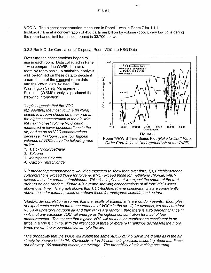
VOC-A. The highest concentration measured in Panel 1 was in Room 7 for 1, 1, 1-trichloroethane at a concentration of 450 parts per billion by volume (ppbv), very low considering the room-based limit for this compound is 33,700 ppmv.
3.2.3 Rank-Order Correlation of Disposal-Room VOCs to HSG Data
Over time the concentrations began to rise in each room. Data collected in Panel 1 was compared to WWIS data on a room-by-room basis. A statistical analysis was performed on these data to decide if a correlation of the .9.i§P.9.~9J-room data and the WWIS data existed. The Washington Safety Management Solutions (WSMS) analysis produced the following information:
"Logic suggests that the voe representing the most volume (in liters) placed in a room should be measured at the highest concentration in the air, with the next highest volume voe being measured at lower concentrations in the air, and so on as voe concentrations decrease. In Room 7, the four highest volumes of voes have the following rank order: 1. 1, 1, 1-Trichloroethane 2. Toluene 3. Methylene Chloride 4. Carbon Tetrachloride
1000 ~------------------,
-+- ·t .I,1-Trichloroethane -,... Carbon Tetrachloride -.r Methylene Chloride -&-Toluene
> .0 i 100 -i-----------ft--t-------t-f't-ti-11'.-t-!--t-..,,nt--ttH
C: 0
~ .I:; C: ., (.)
C: 0
u 10 -l--;l:--t---!+..;f--lrr-Ws...s.+f====l-1:ijaj-Hf-Jllt-f--t-f---i u 0 >
7101 9.·30/01 12'31•01 4·1.02 7.'2-02 10.102 1-1/03 Date Sampled
Figure 3 Room 7/WWIS Time Series Plot (Ref #12-Oraft Rank
Order Correlation in Underground Air at the WIPP)
"Air monitoring measurements would be expected to show that, over time, 1, 1, 1-trichloroethane concentrations exceed those for toluene, which exceed those for methylene chloride, which exceed those for carbon tetrachloride. This also implies that we expect the nature of the rank order to be non-random. Figure 4 is a graph showing concentrations of all four VOCs listed above over time. The graph shows that 1, 1, 1-trichloroethane concentrations are consistently above those for toluene, which are above those for methylene chloride, and so forth.
"Rank-order correlation assumes that the results of experiments are random events. Examples of experiments could be the measurements of VOCs in the air. If, for example, we measure four VOCs in underground room air and their ranks are random, then there is a 25 percent chance (1 in 4) that any particular VOC will emerge as the highest concentration for a set of four measurements. The chance that a given VOC will rank as the number one constituent in air twice in a row is 1 in 16, with the likelihood of three or more "#1" rankings decreasing the marۥ times we run the experiment, i.e. sample the air.
"The probability that the VOCs will exhibit the same ABCD rank order in the drums as in the air simply by chance is 1 in 24. Obviously, a 1 in 24 chance is possible, occurring about four times out of every 100 sampling events, on average. The probability of this ranking occurring

The closed-room exposure scenario depicted in NMED's testimony shows that the workers downstream from the exhaust of open panels have the potential to be exposed to high levels of voes in the event of a roof fall in the adjacent closed room. The scenario assumes that 1 O percent of voe concentrations in the affected closed room are pushed past the ventilation barrier into the air stream. It also assumes that workers are in the exhaust at the time of the fall.
4.2 Disposal-Room voe Monitoring
The proposed voe monitoring allows for the quantification of the voe concentrations in disposal rooms of the remaining HWDUs in the underground. The monitoring will in essence take the place of HSG sampling at-generator sites. HSG sampling is currently performed, in part, as a conservative control on the voe release to the surface and to ensure that workers will not be subject to an acute voe exposure in the event of a roof fall in a closed room adjacent to an open room.
The monitoring approach offers an actual air composition analysis, to address the real hazard in the fall scenario depicted in NMED testimony regarding regulatory process and imposed conditions. HSG analysis indicates what is contained in drums and not what is actually likely to be pushed out of the ventilation barrier during a roof fall. In the event that voe concentrations reach a hazardous point, mitigating actions will be taken. These levels and actions are discussed in the following sections. Sampling locations for disposal-room monitoring are demonstrated in Figure 5. 4.2.1 Apparatus and Methods
Disposal room sampling consists of the same instrumentation that is currently used for the confirmatory voe monitoring program described in Section 2.3.2 of this report. Sampling will be conducted in all rooms in which waste has been emplaced until initiation of panel closure activities. voe sampling will begin at the outlet side of each disposal room behind the bulkhead, downstream of the waste, as waste is initially emplaced in each room. When disposal operations in each room are completed, ventilation barriers will be installed at the upstream end of the room, and voe sampling will begin behind the ventilation barrier for that room, except in Room 1, because there is no adjacent open disposal room. Since disposal operation completion in Room 1 is coincident with initiation of panel closure activities (i.e., installation of ventilation barriers in the panel access crossdrifts), no inlet monitoring in Room 1. will be initiated.
4.2.2 Frequency of Sampling
Frequency for disposal-room sampling would be once every two weeks. For Panel 1, disposalroom samples were initially collected twice each week. After reviewing data from these samples, bi-weekly sampling per sampling location was deemed sufficient. Data do not indicate the disposal-room environment was changing quickly enough to warrant more frequent sampling, Figure 3 shows this gradual rise. In the event that higher concentrations of voes were detected, more frequent sampling could be implemented.
4.3 Action Levels
15

4.4 Actions to Mitigate Risk From High-VOC Conditions
Upon receipt of analytical results indicating one or more compounds have exceeded half the action level, sampling frequency would increase to determine how fast the concentrations are rising. In the event VOC concentrations inside the disposal room reach the action level, measures would be taken to mitigate hazards. If the condition rises to the 95 percent action
level, another sample would be taken to confirm such a condition. If the second sample confirms the 95 percent limit, the current active room would be abandoned and two ventilation barriers of the type shown in Figure 7 would be installed. This action scenario is shown in Figure 6. A typical (single layer) ventilation barrier is shown in Figure 7.
5.0 Proposed Method of Determining Compliance - Open-Room Roof Fall
In the event of a roof fall in accordance with conditions outlined in HRM 98-04(P) New Mexico Environment Department's Direct Testimony Regarding Regulatory Process and Imposed Conditions, NMED is concerned about formation of an Immediately Dangerous to Life and Health (IDLH) atmosphere in the hypothetical event of a roof fall in an active room. This scenario "assumes that an underground waste worker who is upwind of the waste stack will be exposed to the VOCs from 21 drums which, in response to a roof fall, will fall from the top row and breach." NMED considers that such an event may create an IDLH concentration of VOCs in the breathing zone of a worker in the active room. As explained in NMED's testimony, the location of such an occurrence is at the emplacement face of the open room.
5.1.1 Active Operational Controls - Emplacement Face
WIPP procedures and Mine Safety and Health Administration (MSHA) regulations require that ground conditions be examined or inspected at the start of every shift, and as conditions warrant, to ensure that the workplace is safe. Should an unsafe condition be found, work is stopped, Underground Services is notified, and personnel are not allowed to work in the area until any hazards are mitigated.
The toppling and breach of 21 or more waste containers at the emplacement face is a selfevident event to personnel in the active room. Per current WIPP procedure, the event triggers evacuation of all personnel from the emplacement face. Current ALARA procedures require personnel to remain away from the emplacement face when not otherwise required by job tasks, thus ensuring that workers will be capable of providing an alarm should drums topple. In such an event, the Central Monitoring Room (CMR) would be notified and the CMR Operator would issue an evacuation alarm for all areas downwind of the active room (the exhaust drift).
5.2 Active Operational Controls - Exhaust Drift Access
For the protection of the worker, personnel are not allowed access to the exhaust drift without approval from Underground Services. The ground at the emplacement face is examined for safety prior to entry of personnel into the exhaust drift. Should an unsafe condition be found, work is stopped, Underground Services is notified, and personnel are not allowed to work in the area until any hazards are mitigated.
17

TA1::
TA2~----~
TA3~------------"
TA4~--~--------.
ROOM 6
ROOM5
ROOM4
Ventilation Barrier
Bulkhead
• Panel Closure
• Sampling Location
Figure 4 Panel 1 Disposal-Room Sampling Locations
19
Emplaced Waste

To Sample Caniste
Ventilation Barrier
Top Sample Intake
Middle ------ Sample
Intake
Lower Sample Intake
Roof
Floor
Figure Sa Upstream/Downstream Sampling Head Location
21
Waste Stack

_Jr:, .. .. u) 0 0
0 ..... 1 2 3 4 5 ~
7 _J
_J~~------...r-a-==~==~'==-s==~===~= ;:::-,-----'I
• Exhaust Sample Location
• Inlet Sample Location
---. Reduced Air Flow
• Main Air Flow
- Ventilation Barrier
Figure 5 b Exhaust/Inlet
Sampling Point Locations Sequence As Disposal Room Fills
23

-\
. Figure 7 Typical Ventilation Barrier
25