
Pilot 2000
29
-
Upload
khangminh22 -
Category
Documents
-
view
0 -
download
0
Transcript of Pilot 2000

����������
�������������� ���
������������������������������
����������������������������
PILOT 2000 USER GUIDE
To Clear All the Memory...................................................................................................3Operations Keyboard Section...........................................................................................5
Setup button:.............................................................................................................5Copy button:..............................................................................................................5Enter button:..............................................................................................................5Play button:................................................................................................................5
Utility Keyboard Section....................................................................................................5Extra button:..............................................................................................................5Lamp button:..............................................................................................................5Reset button:.............................................................................................................6
Page Button......................................................................................................................6Page button:..............................................................................................................6
Programming Keyboard Section.......................................................................................6Store button:..............................................................................................................6Edit button:................................................................................................................6Levels button:............................................................................................................6Times button:.............................................................................................................6
Memory Button.................................................................................................................6Memory button:..........................................................................................................6
Memory Object Keyboard Section....................................................................................7Program button:.........................................................................................................7Chase button:............................................................................................................7Psycho button:...........................................................................................................7Preset button:............................................................................................................7
Unit Button........................................................................................................................7Unit button:................................................................................................................7
Step Button.......................................................................................................................7Step button:...............................................................................................................7
Grand Master....................................................................................................................8Scan Control Section........................................................................................................8Multifunction Keyboard Section........................................................................................8
To change Page:.......................................................................................................8To select a Memory:..................................................................................................8To select a Program:.................................................................................................8To select a Chase:.....................................................................................................9To select a Psycho:...................................................................................................9To select a Preset:.....................................................................................................9To allocate a Memory Obj to a Memory:....................................................................9To copy the contents of a Memory to another:..........................................................9
1.Select the source Memory..................................................................................9To select a Unit:.........................................................................................................9Group of units:...........................................................................................................9To set and store a group:........................................................................................10To delete a unit from a group:.................................................................................10To recall a group:.....................................................................................................10
Patching..........................................................................................................................11Total Dimmer Channels...........................................................................................11Patching Dimming Channels...................................................................................11Patching Units.........................................................................................................12Patching Extra channels..........................................................................................12
2SGM Light Technology 30/06/2000 Ver. 2.03
PILOT 2000 USER GUIDE
Manual use of the Unit....................................................................................................13To assign a shape to a unit:....................................................................................13
Programming..................................................................................................................14To program a Preset:...............................................................................................14To program a Psycho:.............................................................................................14To edit a Chase:......................................................................................................14To edit a Program:...................................................................................................15To set the Active Effects of a Unit:..........................................................................15To set the Length of a Program or Chase:..............................................................16To change step’s time of a Program or Chase:.......................................................16Times of a Memory Obj :.........................................................................................16Times of a Chase or Program:................................................................................16Times of a Psycho or Preset:..................................................................................17Levels of a Memory Obj :.........................................................................................17To allocate a Memory Obj to a memory :.................................................................17To set or modify the Working Area..........................................................................17To test a new Working Area....................................................................................18
Internal Library................................................................................................................19Edit a New Unit........................................................................................................19To insert a new fixture configuration into the Pilot’s library:.....................................20To insert the new fixture name:...............................................................................20To insert the Total DMX Channel:...........................................................................20To assign the parameters’ name to the faders :......................................................20
Press the right-hand Scroll button to enter the “Effect String” menu..............................20To assign the DMX channels to the parameters:.....................................................21To set the “Stand by values” to each parameters:...................................................21To set the parameter’s type:....................................................................................21To set the Pan and Tilt channels:............................................................................21To set the Hard/Soft Cross:.....................................................................................22To set the Reset/Lamp value:..................................................................................22To set the Dip-switch configuration:.........................................................................22To set the Beam find value:.....................................................................................22To set the Control Type for each parameter:...........................................................22
Synchronization of the Desk with RS232........................................................................24CHANNEL ON.........................................................................................................24CHANNEL OFF.......................................................................................................24REGISTER CHANGE..............................................................................................24ALL CHANNEL OFF................................................................................................24PAGE CHANGE......................................................................................................24DEVICE SELECT....................................................................................................24Connection of the RS -232 CABLE for Pilot 2000:..................................................25
SMPTE...........................................................................................................................25
SGM Light Technology 30/06/2000 Ver. 2.03 3

PILOT 2000 USER GUIDE
To Clear All the Memory
1.Switch on the board while holding down the Reset key (located by the UtilityKeyboard section at the left of the display)2.1-10 will flash on the Multifunction Keyboard (the 20 buttons located at the bottomof the desk)3.Release the Reset key.4.Type in 121297 fast (within 4 seconds),by using the buttons 1-20 of theMultifunction Keyboard.
N.B. this will also delete all the scanners details that have been programmed in, excludingthe existing SGM fixtures that are part of the permanent software of the board.
4SGM Light Technology 30/06/2000 Ver. 2.03
PILOT 2000 USER GUIDE
Operations Keyboard Section
Four key buttons and the white printing identify this section.This section is used to access Setup functions, dedicated to the control of the desk'sparameters (such as channel patching) and the libraries containing the informationregarding intelligent fixtures. It's also possible to record and play back stored events usingthe built-in SMPTE signal generator.
Setup button:1. It enables the selection of the following sub-menus:2. Unit Patch Menu.3. Dimmer Patch Menu.4. Extra Patch Menu5. Total Channels Menu.6. Working Area Menu.7. View Free Memory Menu. 8. SMPTE monitor/mode9. Internal Library Menu.
Copy button:When the Copy button is pressed, then it is possible to copy Programs, Chases,Psychos and Presets.
Enter button:When pressed, it confirms any change made into Programs, Chases, Psychos andPresets.
Play button:It enables the execution of a SMPTE track already made. When used together with Enterbutton, then enable the recording of a new SMPTE track.
Utility Keyboard Section
The key buttons and the white printing identify this section.This section of the Pilot 2000 makes special functions such as Extra, Lamp and Reset,immediately available: these operate directly on the fixtures (switching the lamp on andoff), the intelligent fixtures (remote Reset) and the controls sent to special units such assmoke machines or centerpieces (Extra channels).
Extra button:A maximum of 48 channels can be reserved for particular units or functions.This function allows you to define the DMX channels corresponding to the “extras”, i.e.those units (normally smoke machines or strobe lights) which operators control directly(without going through Memory and Program).When pressed, it gives the access to the Extra Channels.
Lamp button:It enables the remote Lamp On/Off control of a fixture.
SGM Light Technology 30/06/2000 Ver. 2.03 5

PILOT 2000 USER GUIDE
Reset button:It enables the remote Reset control of a fixture. Furthermore it can be used as follows:Psycho: when put on zero; the light output of all the dimming channels set on a givensound frequency band Preset: when put on zero; the light output of all the dimming channelsChase: when put on zero; the light output of all the dimming channels of the selectedChase’s step
Page Button
Page button:It is possible to switch the Multifunction Keyboard on two pages. When the button is notpressed (LED not lit), the Multifunction Keyboard shows the buttons 1-20; with the buttonpressed (red LED lit) the Multifunction Keyboard shows the buttons 21-40.
Programming Keyboard Section
The key buttons and the light blue printing identify this section.This section comprises all the keys and the functions associated with them, which allowyou to edit and set the running times and general output levels of the elements that makeup the Memory Objects.
Store button:When pressed, it enables you to store the steps of a Program or a Chase and modificationmade on the Memories.
Edit button:It enables you to create new Programs, Chases, Psychos and Presets.
Levels button:It enables you to set the DMX values to Programs, Chases, Psychos and Presets. Times button:It enables you to set the running time to Programs, Chases, Psychos and Presets.
Memory Button
Memory button:There are 40 Memories available. Each memory can contain and run at the same time 4different Programs; 4 different Chases; 4 different Presets and 4 different Psychos.It is used to recall Memories.
6SGM Light Technology 30/06/2000 Ver. 2.03
PILOT 2000 USER GUIDE
Memory Object Keyboard Section
The key buttons and the white printing identify this section.This section of buttons is used to select the 4 elements that make up the Memory Objects(Program, Chase, Psycho and Preset). Once they've been programmed, these elementsmust be entered in the Memories in order to be run.
Program button:There are 40 Programs available. A program can drive up to 40 units (fixtures). When thebutton is pressed (red LED lit), the Multifunction Keyboard can be used to select aprogram. If used in edit mode (edit LED blink and program LED lit), the key let the operatorto create or modify the desired program.
Chase button:There are 40 Chases available. A chase drives up to 192 dimming channels. When thebutton is pressed (red LED lit), the Multifunction Keyboard can be used to select a chase.If used in edit mode (edit LED blink and chase LED lit), the key let the operator to create ormodify the desired chase.
Psycho button:There are 40 Psychos available. A psycho let the dimming channels to be assigned tothe sound frequency bands (LOW; MID LOW; MID HIGH; HIGH). When the button ispressed (red LED lit), the Multifunction Keyboard can be used to select a psycho. If usedin edit mode (edit LED blink and psycho LED lit) the key let the operator to create ormodify a psycho.
Preset button:There are 40 Preset available. A preset is a scene, which uses only the dimmingchannels. When the button is pressed (red LED lit), the Multifunction Keyboard can beused to select a preset. If used in edit mode (edit LED blink and preset LED lit) the key letthe operator to create or modify a desired preset.
Unit Button
Unit button:There are 40 Units available, each of which can contains up to 36 channels. When thebutton is pressed (red LED lit), the Multifunction Keyboard can be used to select thedesired unit.
Step Button
Step button:There are 40 steps available on each Program and Chase. When the button is pressed(red LED lit), the Multifunction Keyboard can be used to select a step of the currentProgram or Chase.
SGM Light Technology 30/06/2000 Ver. 2.03 7
PILOT 2000 USER GUIDE
Grand Master
The Pilot 2000 has a general output level control, used to adjust the overall level of all the"dimmer" channels, whether they are of the traditional type or of intelligent fixtures.The value is shown as a percentage, with a range of 0 - 100%.
Scan Control Section
This section includes the universal controls that are used to control the fixtures and theentire Pilot itself.The functions vary according to the operating mode selected on the ProgrammingKeyboard. Moving head unit/scanner controls are completed by a joystick (which operateson absolute coordinates) and 4 cursor buttons (which operates on relative coordinates).The combination of these two systems ensures extremely precise control when positioningfixtures.
Multifunction Keyboard Section
The key function and the white printing identify this section. It consists of the 20 buttonslocated at the bottom of the desk. According to the function selected, this keyboard can beused to recall Memories, Programs, Chases, Psychos, Presets, Units or Steps Following the Multifunction Keyboard will be called MFK.
To change Page:
1.Push the Page button.
Only 2 pages are available: red LED not lit means that the selection of buttons 1-20 isenabled (page 1); when the red LED on the button is lit, it means that the MFK is set toenable the selection of buttons 21-40 (page 2).
To select a Memory:
1. Press Memory key2.Press a button of the MFK according to the memory to be run.
One memory per time can be run.
To select a Program:
1. Press Program key2.Press a button of the MFK according to the program to be created or modified
Up to 4 Programs at the same time can be run in one memory.
8SGM Light Technology 30/06/2000 Ver. 2.03
PILOT 2000 USER GUIDE
To select a Chase:
1. Press Chase key2.Press a button of the MFK according to the chase to be created or modified
Up to 4 Chases at the same time can be run in one memory.
To select a Psycho:
1. Press Psycho key2.Press a button of the MFK according to the psycho to be created or modified
Up to 4 Psychos at the same time can be run in one memory.
To select a Preset:
1. Press Preset key2.Press a button of the MFK according to the preset to be created or modified
Up to 4 Presets at the same time can be run in one memory.
To allocate a Memory Obj to a Memory:
1. Select a Memory2. Select the Memory Obj to be assigned to a Memory3. Press and hold down the Store button4. Press a button of the MFK according to the Memory to be stored5. Release Store button. The memory is now stored.
To copy the contents of a Memory to another:
1. Select the source Memory2. Press and hold down the Store button3. At the same time press a button of the MFK according to the target Memory to be
copied4. Release Store button. The target memory is now copied.
To select a Unit:
1. Press Unit key2.Press a button of the MFK according to the unit to be used manually or plotted in aprogram.
Group of units:
There are 6 groups of units available which can be stored and recalled by using the 6 lightgray buttons located below the faders of the scan control section.
SGM Light Technology 30/06/2000 Ver. 2.03 9

PILOT 2000 USER GUIDE
To set and store a group:
1.Press and hold down the Unit Key. The display will show “select other units to make agroup” and the light gray buttons below the 6 faders become the 6 storable groups;2.Press the button of the scan section corresponding to the group to be stored. 3.Now push the MFK buttons according to the scan to be grouped. Green LED blinkingon the MFK (while pushing) will show the group.4.Release the Unit Key; then the group will be stored automatically.
N.B: At item 2 some of the green LED of the MFK might start blinking, showing in that waythe old group stored.
To delete a unit from a group:
The MFK shows the status of a unit using 3 different way:Green LED not lit: unit not inserted in the patch or not selectedGreen LED lit: unit inserted in the patchGreen LED blink: unit selected
1.Now to disable a unit simply push the button until the green LED becomes OFF
To recall a group:
1. Press and hold down the Unit Key. 2. Press the button of the scan section corresponding to the group to be recalled. 3. Release the Unit Key.
10SGM Light Technology 30/06/2000 Ver. 2.03

PILOT 2000 USER GUIDE
Patching
Total Dimmer Channels
This function allows operators to decide how many DMX channels must be assigned to thedimmer channels.Pilot 2000 can control a minimum of 6 channels up to 192 channels, divided into 32 pageson the display. To avoid patch conflict, set the Total Dimmer Channels before to patch theExtra channels and Unit channels.
1. Press the Setup button.2. Scroll with the up/down arrows until “Total dimmer channels” appears on the display.3. Press the right-hand Scroll button .4. Only “N. Pages” field can be modified by using the UP/DOWN arrows while the
“Channels” field will show how many dimming channels can be used according to thevalue inserted into the “N.Pages” field.
5. Press Setup button to store the settings and leave Total Dimmer Channels Menu.
Patching Dimming ChannelsWARNING!
To avoid patching conflict, don’t let the Dimming channels to overlap the Unit Channelsor the Extra Channels
1. Press the Setup button.2. Scroll with the up/down arrows until “Dimmer Patch” appears on the display.3. Press the right-hand Scroll button .4. Press the UP/DOWN button to set in the “DMX-CH” field, the DMX channel to be
patched to the board’s control channel5. Using the Left/Right arrows, move below the “Channel” field and set the board’s
control channel to be linked to the DMX channel 6. Using the Left/Right arrows, move below the “Lim%” field and set the limiter value to
be applied to the control channel 7. Using the Left/Right arrows, move below the “Equal” field and set the equalization
curve to be applied to the control channel8. Press Setup button to store the settings and leave Dimmer Patch Menu
SGM Light Technology 30/06/2000 Ver. 2.03 11
PILOT 2000 USER GUIDE
Patching UnitsWARNING!
To avoid patching conflict, don’t let the Unit Channels to overlap the Dimming channelsor the Extra Channels
1. Press the Setup button.2. Scroll with the up/down arrows until “Unit Patch” appears on the display.3. Press the right-hand Scroll button.4. Press a key of the Multifunction Keyboard .5. Press the right-hand button of the cursor to set the field to be changed.6. With the buttons Up/Down select the fixture to be patched7. With the Left/Right buttons select the From field (start address) and set the value
required8. Check the configuration of the dip-switches shown on the display and set it on the
fixture.9. Press the Setup button to store the configuration and leave Unit Patch Menu.
Patching Extra channelsWARNING!
To avoid patching conflict, don’t let the Extra Channels to overlap the Dimming channelsor the Unit Channels
1. Press the Setup button.2. Scroll with the up/down arrows until “Extra Patch” appears on the display.3. Press the right-hand Scroll button.4. By using the fader below the Extra field or with the buttons Up/Down, select the Extra
channel to be patched5. With the Left/Right buttons select the DMX-CH field and set the required DMX channel
to be linked to the Extra channel6. In the Label field, it possible to assign a name to the Extra channel. Press the light
gray button below the Label fader to access the field. Then the up/down arrows allowthe selection of the letters while left/right arrows allow the cursor to shift to the nextletter to be modified.
7. Once the name has been inserted push the Label button to exit the field8. To change the Key mode of the Extra channel, press the light gray button below the
Key field. 2 modes are available: OR and AND. When the OR mode is set, it'spossible to control the Extra Channel either by using the universal fader and using thebutton as a flash control (flash always has a value of 255). When AND mode ischosen, the Extra channel is only enabled for as long as the button is pressed and itsoutput level regulated by the fader.
9. To change the equalization curve, press the light gray button located incorrespondence to the Equal field. Two curves are available: ON/OFF and LIN.
10.Press the Setup button to store the settings and leave Extra Patch Menu.
12SGM Light Technology 30/06/2000 Ver. 2.03
PILOT 2000 USER GUIDE
Manual use of the Unit
A unit can be manually controlled at any time whether a Program is enabled or not. Into arunning Program, it’s possible to control only some desired fixture’s channels while theother channels will follow the settings plotted in the program.
1. Press the button Unit2. Select the unit to be manually controlled. Several Units of the same type can be
grouped and controlled at the same time, by pressing and holding down the button ofthe first unit and then press the buttons of the other units. The Led buttons will all flashat the same time.
3. Set the scanner's channel as required using the faders and checking the value of thecommand sent on the display of the Scan Control Section.
To assign a shape to a unit:
Built-in programs (7 at present) which act on Pan and Tilt movement are available for eachunit. They can also be stored into a program scene, reducing in that way the timenecessary to program, and customized to fit the requirements by changing the followingparameters: - X_SCL: scale on the X axis (from 0 to 100%)- Y_SCL: scale on the Y-axis (from 0 to 100%)- SPEED: speed at which the effect is run (from 0 to 255)- ROTAT: direction of movement (forward or backward)- ANG: starting angle of the movement (from 0 to 359).
1. Select the unit required 2. Press the right-hand scroll button till the Shape menu will appears on display3. Select the desired Shape by using the fader to the Shape field4. Set the parameters as necessary5. Press the left-hand scroll button to move back to the unit control channels
SGM Light Technology 30/06/2000 Ver. 2.03 13
PILOT 2000 USER GUIDE
Programming
To program a Preset:
1. Select a Memory2. Press Preset button;3. Press a button 1-20 (21-40) of the MFK according to the preset to be created4. Press Edit key (red LED on the Edit button and the green LED of the MFK preset will
blink)5. Rise the fader below the display to set the desired value to the dimming channels. In
case of more than 6 channels, use the scroll button (located on the right of the display)to set other channels.
6. Press Edit key7. Press Enter key8. Your Preset is now stored
To program a Psycho:
1.Select a Memory 2.Press Psycho button3.Press a button 1-20 (21-40) of the MFK according to the psycho to be created4.Press Edit key (red LED on the Edit button and the green LED of the MFK psycho willblink)5.Select the sound frequency band where you want your dimming channels to work.The first 4 buttons (from left to right) identify the four bands6.Rise the fader below the display to set the desired value for each dimming channel7.Press Edit key8.Press Enter key9.Your Psycho is now stored
To edit a Chase:
1. Select a Memory 2. Press Chase key3. Press a button 1-20 (21-40) of the MFK according to the program to be created4. Press Edit Key5. Press right arrow of the scroll buttons (located on the right of the display)6. Select Edit Step from the edit menu7. Press right arrow of the scroll buttons8. Rise the fader below the display to set the desired value for each channel9. Press and hold down the Store key10.At the same time push the MFK button corresponding to the step to be stored11.Repeat from the above item 7 till the last step is programmed12.Push the left arrow until the display shows the program number and the Length of the
steps13.Press Edit button14.Press Enter button15.Now your Chase is stored
14SGM Light Technology 30/06/2000 Ver. 2.03

PILOT 2000 USER GUIDE
To edit a Program:
1.Select a Memory 2.Press Program key3.Press a button 1-20 (21-40) of the MFK according to the program to be created4.Press Edit Key5.Press right arrow of the scroll buttons (located on the right of the display)6.Select Edit Step from the edit menu7.Press right arrow of the scroll buttons8.Rise the fader below the display to set the desired value for each fixture’s channel orassign a shape9.Press and hold down the Store key10.At the same time push the MFK button corresponding to the step to be stored11.Repeat from the above item 7 till the last step is programmed12.Push the left arrow until the display shows the program number and the Length ofthe steps13.Press Edit button14.Press Enter button15.Now your program is stored
To set the Active Effects of a Unit:
The Active Effects are the control channels of a Unit. By the time, enable or disable thosecontrol channels could be helpful especially when mixing several programs (maximum 4 atonce), which contain the same fixtures. A color chase program (which has only the controlchannel color enabled) can be mixed with another program which makes only the mirrormovement (that means Pan & Tilt enabled while the other control channels are alldisabled). On the other hand, if the above 2 programs were made with all the control channelsenabled, only one program per time could be used.The default settings are with all the control channels enabled.
1. Press Edit Key2. Press right arrow of scroll buttons3. Select Active Effects from the Edit Menu4. Press right arrow5. Push the buttons of the scan section according to the requirements. The buttons’ LED
show the status of the channel: LED lit means channel enabled; LED not lit meanschannel disabled.
6. Press left arrow to escape the menu and store the settings7. Push Up/Down arrow to select the Edit Step Menu and start programming.
SGM Light Technology 30/06/2000 Ver. 2.03 15
PILOT 2000 USER GUIDE
To set the Length of a Program or Chase:
The desk automatically increases the steps of a Program or Chase. By the way, if thelength need to be changed, proceed as follows:
1. Select a Memory 2. Select the desired Chase or Program 3. Press Edit Key4. The display will shows the default length or the value previously set5. By using the fader below the Length field or the UP/DOWN arrows, it is now possible
to set the desired value.6. Press Edit Key7. Press Enter Key8. The Length is now stored
To change step’s time of a Program or Chase:
The default Step’s time is set on 2 sec. and 50% of cross time, but it is possible to changeit up to 99.9 sec and 100% of cross time.
1.Press Edit Key2.Press right arrow of scroll buttons3.Select Step’s Time from the Edit Menu4.Press right arrow5.It is now possible to change the Time and the Cross for each step6.Press Edit button once completed the modification7.Press Enter
Times of a Memory Obj :
1. Press Times button2. The display will show the menu in which you can increase or decrease the speed of a
Memory Obj.
Times of a Chase or Program:
When a Chase or a Program is selected, it’s possible to modify the following fields:
1. TRIG: is the clock, which let the Chase or Program to flow. It could be Internal(INTRN) for a timed changing scenes or Music (MUSIC) for a sound to light changingscenes.
2. RUN: to change the flowing direction of the Chase or Program. It could be Normal (asprogrammed) or Backward (opposite direction than programmed).
3. SPEED%: is the running speed of a Chase or Program which can be set from 25% to400% of default speed
16SGM Light Technology 30/06/2000 Ver. 2.03
PILOT 2000 USER GUIDE
Times of a Psycho or Preset:
When a Psycho or Preset is selected, it’s possible to set the Rise (fade in time) and Fall(fade out time) time. The time can be set at between 0 and 999 tenths of a second and isthe same whether Rise and Fall times.
Levels of a Memory Obj :
Allows to set the general level of the Memory Objects, it acts like a Grand Master for theMemory Obj selected. It’s possible to control up to 4 Memory Obj of the same kind at thesame time.
1. Press Levels button2. The display will show the menu in which you can set the general level of the light
output for the Memory Obj selected.
To allocate a Memory Obj to a memory :
For a quick recall of programmed Memory Obj, it is possible to assign them to theavailable Memories. Up to 4 Memory Obj of the same kind can be run at the same time.
1. Select a Memory2. Select the Memory Obj to be assigned to the Memory3. Press and hold down the Store button4. Press the button of the memory selected at above item 15. Release Store button. The Memory Obj are now assigned to a memory.
Working Area
Operators often have to limit a fixture's scanning area to adapt stored programs to stagesituations, which often change.With a view to this, Pilot 2000 allows to control the 20 different scanning areas for eachfixture (obviously only scanners and moving head units) which operators have at theirdisposal.Reducing the scanning area of a fixture also considerably improves the precision ofmoving parts, whether they're mirrors or heads. In fact, reducing the scanning area doesn'treduce the number of steps for positioning, which remains unchanged (255 for 8-bitfixtures and 65.536 for 16-bit fixtures). If the fixtures being controlled don't havecommands for automatic inversion of scanning co-ordinates, the scanning areas allow tosolve the problem by simply crossing over the corner values.
To set or modify the Working Area
1. Press the Setup button.2. Scroll with the up/down arrows until “Working Area” appears on the display.3. Press the right-hand Scroll button.4. The led Unit lights up to shows that a unit, whose working area has to be modified,
must be selected
SGM Light Technology 30/06/2000 Ver. 2.03 17
PILOT 2000 USER GUIDE
5. With the Left/Right buttons select the SET 1 field and use the fader below to chooseone of the 20 available scanning areas (SET 1 to SET 20)
6. To modify the scanning area, press the light gray button under the one of the 4 smallcorner symbols, showed on the display, then move the joystick to the required newcorner.
7. To store the new mirror position, press the button again. Operating areas can becreated as required, regular or irregular scanning areas can be created.
8. Press the Setup button to store the settings and leave Working Area Menu.
To test a new Working Area
1. Press the Setup button.2. Scroll with the up/down arrows until “Working Area” appears on the display.3. Press the right-hand Scroll button.4. Press the light gray button corresponding to Test writing showed on the display5. Check the scanning area to be tested by moving the joystick6. Press the Setup button to leave Working Area Menu.
18SGM Light Technology 30/06/2000 Ver. 2.03
PILOT 2000 USER GUIDE
Internal Library
This menu, made up of 3 sections, allows you to create, modify or delete the Fixture’sconfiguration from the Pilot’s internal memory.The 3 sections available are:
1. Create New Unit2. Edit Existing Unit3. Delete Unit
Edit a New Unit
13 sub-menus are necessary to create a New Unit.
1. Total DMX Channels: set here the total number of channels the fixture has2. LCD Effect Label: set here the quantity of LCD screens needed to display the fixture’s
functions. It is also used to write the label for the fixture's functions.3. Internal Patch: assign here the DMX channel’s output to the fixture functions.4. Stand-by Values: set here the DMX stand-by values for the HTP channels; dimmer
and strobe are usually set to the close/off position5. Effects Type: set here the fixture’s channels as Effect (Eff) or Dimmer (Dim). Those
channels set as Dimmer channels can be controlled through the Grand Master Faderor Master Reg. Fader
6. Mirror Head Patch: set here the Pan and Tilt channels. In case of 8-bit control set onlythe “H” channel. If 16 bit is required use whether “L” and “H” channels.
7. Hard/Soft Cross: set here if the fixture’s channels must be timed when running into aprogram (Soft) or “snap changing” at the fastest speed available (Hard).
8. Unit Name: enter here the name of the Fixture9. Unit Description: enter here a brief description of the Fixture10.Reset/Lamp Values: set here the DMX values for the remote Lamp ON/OFF and the
remote Reset.11.Dip-Switch Config: set here the quantity of dip-switches the fixture uses to assign the
start address. SGM’s fixtures use 9 switch dip-switches12.Beam Find Value: set here to open position those channels which allows the operator
to see the fixture’s beam when setting the Working Area (iris open; dimmer open;strobe open; white open to gobo and color)
13.Control Type: the control type for the fixture’s channels can be Linear (Lin) or Tabled(Tab). Lin channels use all the DMX range of values to control a fixture’s function whileTab channels use only the DMX values, which select a specific Gobo or Color.
SGM Light Technology 30/06/2000 Ver. 2.03 19
PILOT 2000 USER GUIDE
To insert a new fixture configuration into the Pilot’s library:
1. Press the Menu button.2. Scroll with the up/down arrows until “Internal Library” appears on the display.3. Press the right-hand Scroll button to enter the menu4. Scroll with the up/down arrows until “Create New Unit” appears on the display.5. Press the right-hand Scroll button to enter the menu. 13 sub-menus are available to
create a New Unit.
To insert the new fixture name:
1. Scroll with the up/down arrows until “Unit Name” appears on the display.2. Press the right-hand Scroll button to enter the menu.3. The display will show “-NNNNNNNNNNNN-“4. By using the up/down arrows replace the “N” with the required letters to write the
fixture’s name.5. Use the left/right arrows to shift to next/previous letter6. Refer to above item 4 and 5 to write the fixtur’s name7. Press the right-hand Scroll button to escape the menu.
To insert the Total DMX Channel:
1. Scroll with the up/down arrows until “Total DMX Channel” appears on the display.2. Press the right-hand Scroll button to enter the menu.3. The display will show “Total channels occupied on DMX….. [01] “4. By using the up/down, assign the required DMX channels for the fixture to be set.5. Press the right-hand Scroll button to escape the menu.
To assign the parameters’ name to the faders :
1. Scroll with the up/down arrows until “LCD Effect Label” appears on the display.2. Press the right-hand Scroll button to enter the menu.3. The menu consists of 2 sub-menus: “LCD Pages” and “Effect String”.
3a) LCD Pages: allows to set the amount of required LCD screen to view the fixture’sparameters on display. Each screen can contains 6 parameters, so in case of a fixturehaving 18 channels, the required LCD screen are 3 (no.channels divided by 6).In addition, Pan/Tilt/Remote reset/Remote lamp on/off, must not be considered as theycan be set into other menu.
Press the right-hand Scroll button to enter the “Effect String” menu.
20SGM Light Technology 30/06/2000 Ver. 2.03
PILOT 2000 USER GUIDE
3b) Effect String: allows to write the parameter’s name on top of each scann controlfader.
1. By using the up/down arrows replace the “--------------------------------------“ whichappear on display with the letters required to insert a short name describing eachfixture’s parameter. Allow 4 or 5 letters to each name for a single fader.
2. By using the up/down arrows replace the “-------” with the required letters to writethe fixture’s name.
3. Use the left/right arrows to shift to next/previous letter.4. Use the right-hand button to move to the next LCD screen.5. To escape the menu, push the left-hand button until “LCD Effect Label” appears
on the display.
To assign the DMX channels to the parameters:
1. Scroll with the up/down arrows until “Internal Patch” appears on the display.2. Press the right-hand Scroll button to enter the menu.3. According to the fixture’s configuration, assign the DMX channel to each
parameter’s name previously written by means of “LCD effect Label”.4. Press the left-hand Scroll button to escape the menu.
To set the “Stand by values” to each parameters:
1. Scroll with the up/down arrows until “Stand by values” appears on the display.2. Press the right-hand Scroll button to enter the menu.3. Now, set the DMX stand by values for the HTP channels. Dimmer and
shutter/strobe must be usually set to the close/blackout position. 4. Press the left-hand Scroll button to escape the menu.
To set the parameter’s type:
1. Scroll with the up/down arrows until “Effect type” appears on the display.2. Press the right-hand Scroll button to enter the menu.3. By using the up/down arrow, set here as DIMMER type, those channels to be
overall controlled by the Grand Master. Usually the Dimmer channel is set as DIMMtype.
4. Press the left-hand Scroll button to escape the menu.
To set the Pan and Tilt channels:
1. Scroll with the up/down arrows until “Mirror Head Patch” appears on the display.2. Press the right-hand Scroll button to enter the menu.3. By using the up/down arrow, enter the Pan and Tilt channels. In case of 8-bit
control set only the “H” channel. If 16 bit is required use whether “L” and “H”channels.
4. Press the left-hand Scroll button to escape the menu.
SGM Light Technology 30/06/2000 Ver. 2.03 21
PILOT 2000 USER GUIDE
To set the Hard/Soft Cross:
1. Scroll with the up/down arrows until “Hard/Soft Cross” appears on the display.2. Press the right-hand Scroll button to enter the menu.3. By using the up/down arrow, set here each channel as Soft or Hard. Soft allows to
change the status, of a single parameter, to time. Hard mode, allow the snapchanging, of the status of a single parameter, at the fastest speed available whenrunning into a sequence
4. Press the left-hand Scroll button to escape the menu.
To set the Reset/Lamp value:
1. Scroll with the up/down arrows until “Reset/Lamp value” appears on the display.2. Press the right-hand Scroll button to enter the menu.3. By using the up/down arrow, set the channel for the remote reset and remote lamp
ON/OFF and the On/Off values which enable the parameters to act.4. Press the left-hand Scroll button to escape the menu.
To set the Dip-switch configuration:
1. Scroll with the up/down arrows until “Dip-switch configuration” appears on thedisplay.
2. Press the right-hand Scroll button to enter the menu.3. By using the up/down arrow, set here the quantity of dip-switches the fixture uses to
assign the start address. SGM’s fixtures use 9 switch dip-switches.4. Press the left-hand Scroll button to escape the menu.
To set the Beam find value:
1. Scroll with the up/down arrows until “Beam Find Value” appears on the display.2. Press the right-hand Scroll button to enter the menu.3. By using the up/down arrow, set here the open position to those channels
parameters which allows the operator to see the fixture’s beam when setting theWorking Area (iris open; dimmer open; strobe open; white open to gobo and color)
4. Press the left-hand Scroll button to escape the menu.
To set the Control Type for each parameter:
1. Scroll with the up/down arrows until “Control Type” appears on the display.2. Press the right-hand Scroll button to enter the menu.3. By using the up/down arrow, set here the control type for the fixture’s channels. The
control type can be Linear (Lin) or Tabled (Tab).4. Lin channels use all the DMX range of values to control a fixture’s function while
Tab channels use only the DMX values, which select a specific Gobo or Color.5. Press the left-hand Scroll button to escape the menu.
22SGM Light Technology 30/06/2000 Ver. 2.03
PILOT 2000 USER GUIDE
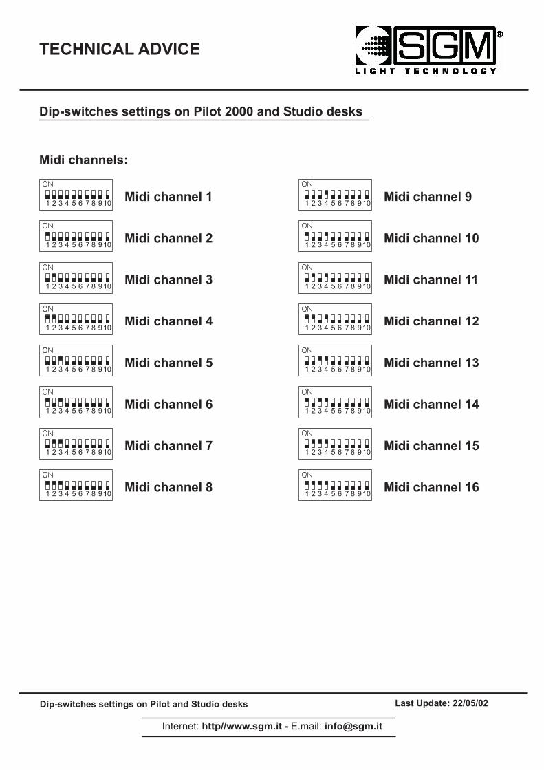
Synchronization of the Desk with MIDI Signal
PILOT 2000 desk can be driven by using an external device, which can provide a MIDIsignal (i.e. a sequencer or keyboard). A MIDI signal is a digital protocol designed to allowMusical Instruments to communicate. It is used frequently in lighting control for remotecontrol. It connects via a 5 pin DIN connector.
First of all the work channel must be set: the Midi protocol allows 16 channels (from 1 to16) to be used. To set the right channel we must use the Settings dip-switch placed onthe rear side panel of the PILOT. In the case of more desks controlled by a Midi device,just select a different channel for each desk.The MIDI INPUT information the desk receives is:
• NOTE ON: the range 0...127 identifies the channels from 1 to 128 to be switched on,while VELOCITY is used to set the light output level;
• NOTE OFF: the range 0...127 identifies the channels from 1 to 128 to be switched off;
• PROG CHG: the range 0-39 select the memory;
• ALL CHANNEL OFF: is used to switch off all the channels. The instruction isCONTROL CHANGE 7Bh 0h;
There is the possibility to control more than one desk via Midi simply using a PILOT 2000desk like a Master and all the others as a Slave. There are no special settings to do onthe Master desk, just plug the Midi cable and play. In this case the Slave desks must beset on Midi Channel 1.The MIDI OUTPUT information sent from the desk is:
• PROG CHG: is used to change a memory on the Slave desk every time you push amemory button on the Master desk;
WARNING: The only way to run Scanner Programs via Midi is assigning them to theMemory.
SGM Light Technology 30/06/2000 Ver. 2.03 23
PILOT 2000 USER GUIDE
Synchronization of the Desk with RS232
The Pilot 2000 can use the serial interface for connection to outboard devices, whichsynchronize its operation. By means of a computer, it is possible to send commands viathe RS232 signal.
CHANNEL ONPurpose: select the channel to be switched ON. The command is followed by 2 values,which select the channel and the light output level. The first value is the channel: it is possible to select 24 channels (1 to 24) and the rangevalues are 0-23.The second value is the light output: the range values 0-127 are used to set the lightoutput (0 is 0% of light while 127 is 100% full light)Status: CH ON(A1h)Example: CH ON - 3 - 64 select the 4th channel to be switched ON at 50% of light output.
CHANNEL OFFPurpose: select the channel to be switched OFF. The command is followed by a value,which select the channel to be switched OFF. The range values is 0-23Status: CH OFF(A2h)Example: CH OFF - 0 switch off the first channel.
REGISTER CHANGEPurpose: enable a register. It is possible to select 1 to 24 registers and the command isfollowed by a value between 0 and 23.Status: REG CHG(A0h)Example: REG CHG - 23 enable the 24th register. If this was already enabled, theinstruction will disable it.
ALL CHANNEL OFFPurpose: it will switch OFF all the channels previously enabled by the instruction CH ON.Status: ALL OFF(A3h)Example: ALL OFF
PAGE CHANGEPurpose: it allows you to change the pages on the desk. It is possible to change 24 pageswhen the command is followed by a value, which selects the pageStatus: PAGE CHG(A4h)Example: PAGE CHG - 10 change the 11th page.
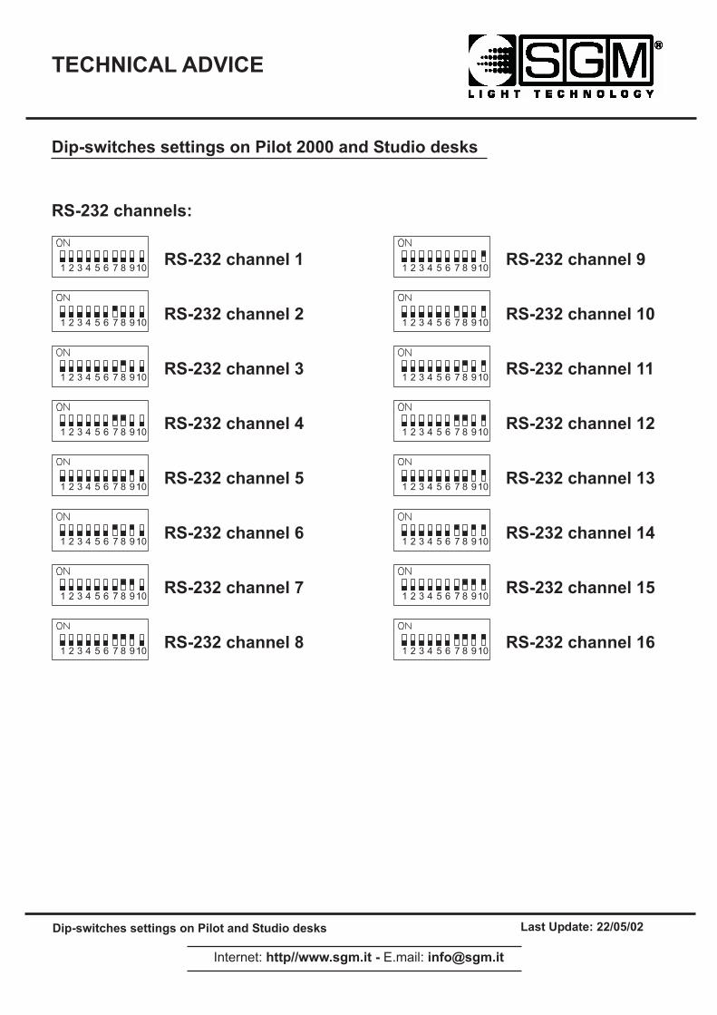
DEVICE SELECTPurpose: select which desk is controlled by the PC or RS232 signal source. It is possibleto select up to 16 desks. To let this instruction works, each desk must have the dip-switchset on the same channel of the command. The dip-switch is located on the side backpanel of the Pilot 2000.Status: DEV SEL(A6h)Example: DEV SEL - 2 select the 3rd desk
24SGM Light Technology 30/06/2000 Ver. 2.03
PILOT 2000 USER GUIDE
Connection of the RS -232 CABLE for Pilot 2000:
3 TX RX 2
7 RTS CTS 8
8 CTS RTS 7
5 GND 5
SMPTE
Society of Motion Picture and Television Engineers (SMPTE) began work to develop astandardized synchronization method for the new medium. The resulting ’SMPTE timecode’ is simply the recording of time information, in hours(HH), minutes(MM), seconds(SS)and frames(FF), as a digitally encoded signal on one of the tracks of a multi-track audio orvideo tape. There are a number of frame rates in use today:24 used in motion-picture film25 EBU standard (European Television)30 NTSC monochrome standard (audio) SMPTE Time code can be recorded to an audio track (Longitude Time Code, or LTC) or itcan be recorded as part of the video signal (Vertical Interleave Time Code, or VITC).Either way, the time code ’word’ is the same.
RECORDING AN SMPTE TRACKThe SMPTE can be used on the Pilot 2000 in 2 ways: INTERNAL TIMING or EXTERNALTIMING. In both cases, it is possible to record 20 tracks with a limit of 24576 “events”recorded for all tracks. That means it is possible to record a memory changes or flash,register cross time variations, page changes. Furthermore, when a track is enabled, it ispossible to work manually on the lights and/or scanners and/or registers.In addition Pilot 2000 has been designed to work with the worldwide SMPTE standards:24, 25 and 30 FPS (Frames Per Seconds). The desk automatically configures theparameters, so that user has only to “plug and play” with it.
INTERNAL TIMINGWhen working without any external devices connected, please proceed as follows:
1. Hold down keys <ENTER> & <PLAY> for at least 4 seconds, until the led blinks.2. Now, exactly at the moment you want to START the recording, press a key from the
Multi Function Keyboard (1...20) selecting the track to record. If the track wasalready done, then it will be replaced.
3. Now you can proceed to record your show, selecting the output memory for eachshow period.
4. When you want to STOP the recording, hold down the <PLAY> key and pressagain the track’s key you selected before.
SGM Light Technology 30/06/2000 Ver. 2.03 25
PILOT 2000 USER GUIDE
5. To PLAY-BACK the track, you must hold down <PLAY> key and then press thetrack’s key you just recorded, exactly at the time you pressed the same key whenyou record the track (this is important to obtain a good synchronization with music,for example). The play-back will stop automatically when the track reaches its end.However, you can stop it any time by holding down <PLAY> and pressing the trackkey. On release 2.00 you can choose to work in SINGLE or LOOPING PLAYthrough the setup menu.
EXTERNAL TIMINGTo use the Pilot 2000 as a slave of an SMPTE device, just connect it, through a 3 pin XLRcable, to an SMPTE source (video recorder, computer, ...) and then proceed as follows:
1. Set the starting time in the source and put it in “pause” (example: if you have a tapeof 120 minutes, you can set 01:23:45:00...).
2. Press and hold down keys <ENTER> & <PLAY> for at least 4 seconds, until the ledblinks.
3. Press a key from the Multi Function Keyboard (1...20) selecting the track to record.If the track was already done, then it will be replaced.
4. When you are ready, you can “PLAY” the source (video recorder, ...) and proceedto record your show selecting the output memory for each show period.
5. When you want to STOP the recording, hold down the <PLAY> key and pressagain the track key you selected previously.
To PLAY-BACK the track, you must rewind your source (to the previous starting position),put it in pause and then hold down <PLAY> key and the press the track key you justrecorded. The play-back will stop automatically when the track reaches its end. However, you can stop it any time holding down <PLAY> and pressing the track key.
26SGM Light Technology 30/06/2000 Ver. 2.03

��������������
� �������������������������������������� ����� ���� !!"#$"#!
������������ ""���%��&%����������'�(��&%��
����)��*������ ������������'���)�����'�)���+�!###�������+�����
� � � � � � � � �
��� ���
����� ������� ����������)��)�����'����������,�����'�)������������*,��)�%���)��)������*�'������������*,��)�
� � � � � � � � �
��� ��� �-.�+�/
��������������������������������� ������!�� ��������"�#$%#�&���!�'�()� *�����������������*�����������!�+,���-������!,�!��
� � � � � � � � �
��� ��� 0�0�+�/
��������������������������������� ������!�� �������%�#.( *����������������*��������������������%�#.(�+*��������!�/���,����-����������������-���*����+�0�*������ ��,�
��������������
� �������������������������������������� ����� ���� !!"#$"#!
������������ ""���%��&%����������'�(��&%��
� ������������������������!###��������������
� � � � � � � � �
)�����������
� � � � � � � � �
� � � � � � � � �
� � � � � � � � �
� � � � � � � � �
� � � � � � � � �
� � � � � � � � �
� � � � � � � � �
� � � � � � � � �
� � � � � � � � �
� � � � � � � � �
� � � � � � � � �
� � � � � � � � �
� � � � � � � � �
� � � � � � � � �
� � � � � � � � �
)����������*
)����������!
)����������+
)����������,
)����������$
)����������-
)����������.
)����������/
)����������0
)����������*#
)����������**
)����������*!
)����������*+
)����������*,
)����������*$
)����������*-
��������������
� �������������������������������������� ����� ���� !!"#$"#!
������������ ""���%��&%����������'�(��&%��
� ������������������������!###��������������
� � � � � � � � �
)��!*!��������
� � � � � � � � �
� � � � � � � � �
� � � � � � � � �
� � � � � � � � �
� � � � � � � � �
� � � � � � � � �
� � � � � � � � �
� � � � � � � � �
� � � � � � � � �
� � � � � � � � �
� � � � � � � � �
� � � � � � � � �
� � � � � � � � �
� � � � � � � � �
� � � � � � � � �
)��!*!�������+
)��!*!�������!
)��!*!�������*
)��!*!�������,
)��!*!�������$
)��!*!�������-
)��!*!�������.
)��!*!�������/
)��!*!�������0
)��!*!�������+#
)��!*!�������++
)��!*!�������+!
)��!*!�������+*
)��!*!�������+,
)��!*!�������+$
)��!*!�������+-


![Studer v Boettcher [2000] NSWCA 263 (24 November 2000)](https://static.fdokumen.com/doc/165x107/633372df3108fad7760f0e34/studer-v-boettcher-2000-nswca-263-24-november-2000.jpg)